169098 Catalog
2016-09-04
: Pdf 169098-Catalog 169098-Catalog B4 unilog
Open the PDF directly: View PDF ![]() .
.
Page Count: 356 [warning: Documents this large are best viewed by clicking the View PDF Link!]
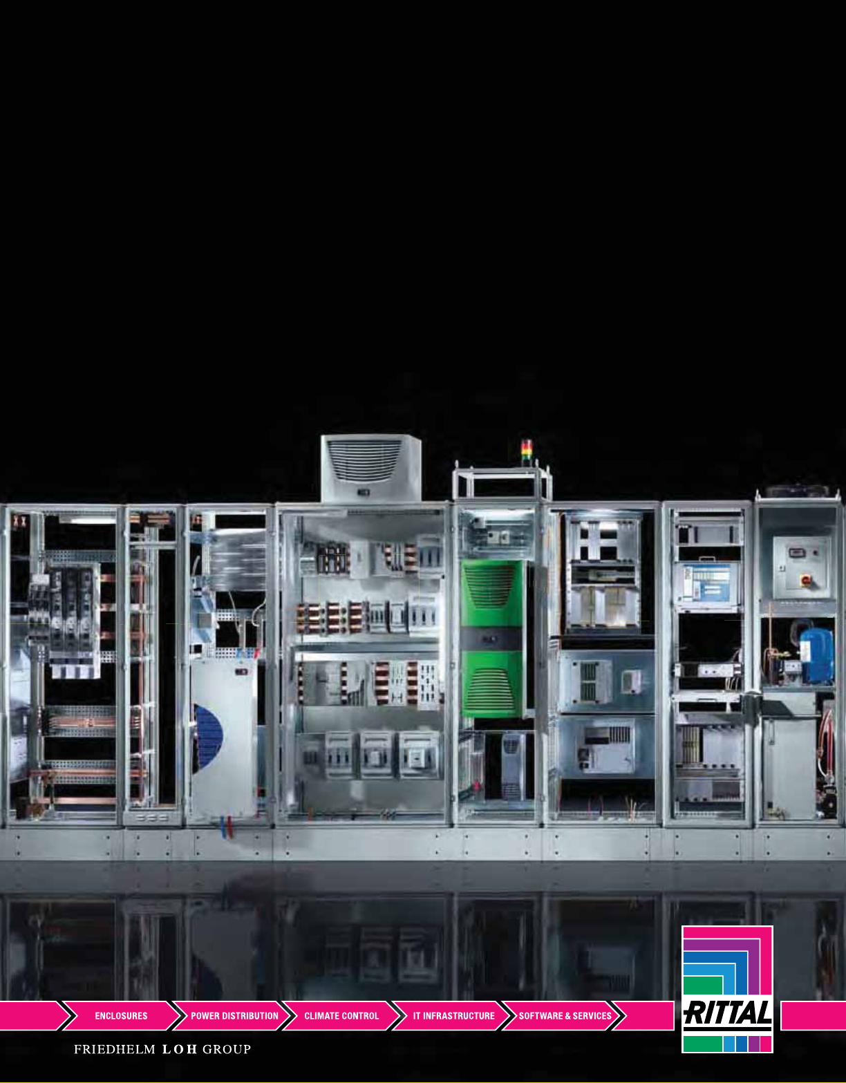
Rittal – North American
Industrial Buyer’s Guide

The Rittal Corporation, the U.S. subsidiary of Rittal GmbH & Co. KG in Germany,
manufactures the world’s leading Industrial and IT enclosures and accessories,
including climate control and power distribution systems. Rittal is backed by a
half-century of pioneering comprehensive product concepts that have set or
redened industry standards – giving us the experience and know-how to help
our customers meet the demands of their applications in better, more effective
ways.
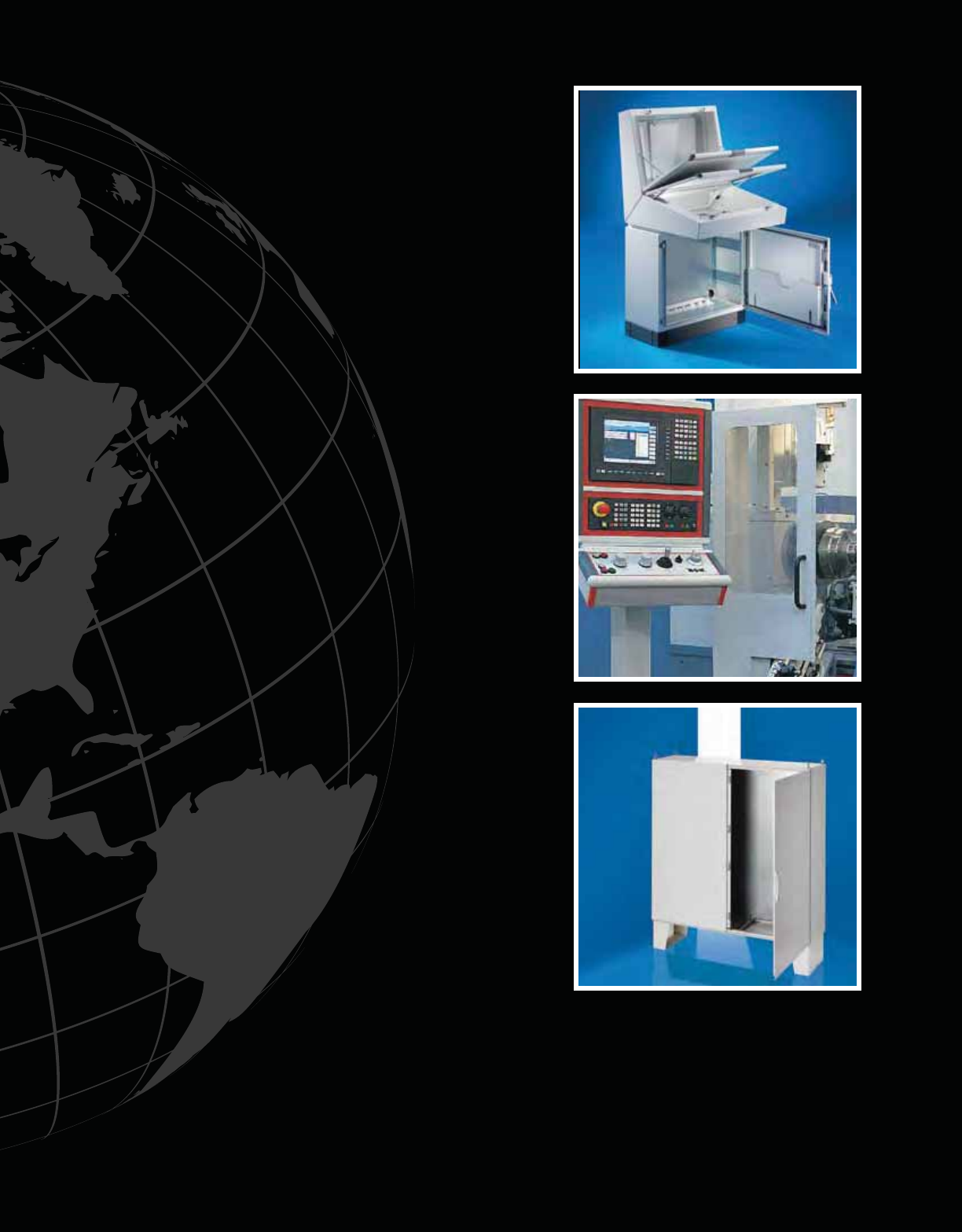
Rittal has offices in over 60 countries worldwide, as well as production facilities
and several channel and support locations in the United States and throughout
North America. Enjoying this kind of proximity to the markets we serve allows us
to thoroughly understand the needs of each one and tailor our product offerings
accordingly. Rittal delivers everything our customers require to successfully
tackle their unique challenges including the expertise and service to assist them
from project specication to on-time delivery.
More than just a manufacturer of superior Industrial and IT products, Rittal is a
trusted ally, providing you with the attention you deserve and the information you
demand to create solutions that work for today and prepare you for tomorrow.
Rittal Corporation
At Rittal, we believe that true innovation
requires purpose, and our purpose is to make
your job easier. Whether our innovations are
driven by new technologies and business
processes or practical improvements derived
directly from customer inputs, we strive
to constantly better our product offerings
and further separate ourselves from the
competition. Thoughtful design, based on real-
world applications is built into everything we
do. We offer a host of resources to assist you
before, during and after the sale including well-
trained, professional sales & support personnel,
comprehensive product literature and an
informative website.
To take full advantage of everything Rittal can do
for you, please visit us online at www.rittal-corp.
com, contact your local Rittal representative or
call our Inside Sales Department at 800-477-
4000.
Rittal Corporation is fully committed to ongoing product improvements. We will not be held responsible for any
subsequent change in product specications, performance claims or other data as well as any unintentional
typographical errors contained herein.

Precision Modications to Suit Your Needs
Because Rittal produces the most exible standard lineup of modular freestanding,
wallmount and junction box enclosures and accessories available in the world
today, there is an excellent chance you may nd what you’re looking for right off
the shelf—in a wide variety of construction materials and protection ratings. If
you decide that a more customized product is right for you, you can choose to
modify any of our standard products or start from scratch with a newly designed,
comprehensive solution.
Rittal’s Focus Factory is an independent production and assembly operation
located in our Urbana, Ohio facility that is dedicated solely to creating customer-
specic products. Assembly and integration of Rittal parts into custom solutions
can be completed and shipped in as little as 4 weeks. Quote-to-order, custom-
engineered products including those with cut-outs and special paint colors or
nishes are evaluated on a case-by-case basis and we will be happy to provide
you with an estimated production time for your specic situation.

Electronic Tools
Rittal customers not only demand the nest affordable enclosures and accessories
available in the world today, but also a wide range of tools at their disposal to aid
in the selection, deployment and routine maintenance of those products. As part of
our ongoing commitment to ensure that our customers have everything they need
to succeed, we have developed a number of easy-to-use electronic tools including
an extensive 3D CAD Model database and industry-leading climate control sizing
software.
These helpful tools are available on our website and allow you to get the most out
of your relationship with Rittal any time of day.
Take advantage of the enhanced capabilities that add even greater value to our
product and service offerings and allow you to tackle your application challenges
easier and more efficiently than ever before!
Enclosures ........................................................................................From page 1
Operator Interface .............................................................................From page 71
Enclosure Accessories ....................................................................From page 193
Climate Control .................................................................................From page 263
Technical Appendix ..........................................................................From page 329
Part Number Index ............................................................................From page 335
Enclosures
1

2 Industrial Buyer’s Guide
2
Ind
ust
ria
l
B
uyer
’
s
Gui
de
Enclosures
Carbon Steel .....................................................................................From page 4
Junction Boxes .........................................................................................................................................4 – 8
Wallmount .................................................................................................................................................9 – 16
Freestanding .............................................................................................................................................17 – 35
Floormount ...............................................................................................................................................36 – 37
Disconnect ................................................................................................................................................38 – 42
Stainless Steel ..................................................................................From page 43
Junction Boxes .........................................................................................................................................43 – 45
Wallmount .................................................................................................................................................46 – 51
Freestanding .............................................................................................................................................52 – 54
Disconnect ................................................................................................................................................55
Polycarbonate ...................................................................................From page 56
Junction Boxes .........................................................................................................................................56 – 57
Aluminum ..........................................................................................From page 58
Junction Boxes .........................................................................................................................................58
Fiberglass ..........................................................................................From page 59
Junction Boxes .........................................................................................................................................59 – 63
Wallmount .................................................................................................................................................64 – 68
Freestanding .............................................................................................................................................69
Disconnect ................................................................................................................................................70
Operator Interface .............................................................................From page 71
Pushbutton Boxes .....................................................................................................................................72 – 76
Consolet ...................................................................................................................................................77 – 78
Command Panel .......................................................................................................................................79 – 82
Comfort Panel ...........................................................................................................................................83 – 92
Optipanel ..................................................................................................................................................93 – 101
Command Panel VIP 6000 .......................................................................................................................102 – 115
Support Arm Systems ......................................................................From page 116
CP-S – Carbon Steel ................................................................................................................................119 – 127
CP-S – Stainless Steel .............................................................................................................................128 – 131
CP-L – Aluminum ......................................................................................................................................132 – 149
CP-XL – Aluminum ...................................................................................................................................150 – 159
Stand Systems ..................................................................................From page 160
Pedestals ..................................................................................................................................................160 – 163
Pillars ........................................................................................................................................................164
Enclosure Reinforcement Plates ...............................................................................................................165
Consoles ...........................................................................................From page 166
Carbon Steel .............................................................................................................................................166 – 177
Stainless Steel ..........................................................................................................................................178
Workstations .....................................................................................From page 179
PC Enclosure Systems .............................................................................................................................179 – 180
Industrial Workstations .............................................................................................................................181 – 190
Stainless Steel PC Enclosure Systems ....................................................................................................191
2
Industrial Buyers Guide 3
Ind
ust
ria
l
B
uyers
Gui
de
3
Enclosure Accessories
Bases ..................................................................................................................................................From page 194
Base/plinth components, assembly hardware, castors, leveling feet,
condensate drains, hole seals and other base-mounted accessories.
Walls ....................................................................................................................................................From page 202
Sidewalls, divider panels, module plates, primer/paint and other
wall-mounted accessories.
Roofs ..................................................................................................................................................From page 208
Rain canopies, dust guards, eyebolts, roof extensions and spacers.
Doors/Locks .................................................................................................................................From page 211
Doors, handles, locks/inserts, hinges, windows, print pockets and
other door-mounted accessories.
Interior Installation .................................................................................................................From page 229
Mounting panels, rails, brackets, assembly and grounding hardware,
lights, dead front kits and 19" installation hardware.
Baying Systems ........................................................................................................................From page 247
Brackets, clamps and connectors for baying multiple enclosures.
Enclosure Mounting Hardware ....................................................................................From page 253
Brackets, clamps and hardware for mounting junction boxes and
wallmount enclosures.
Cable Management ................................................................................................................From page 256
Gland plates, clamps, rails, grommets and other accessories for
cable routing and protection.
3
4 Industrial Buyer’s Guide
Junction Box
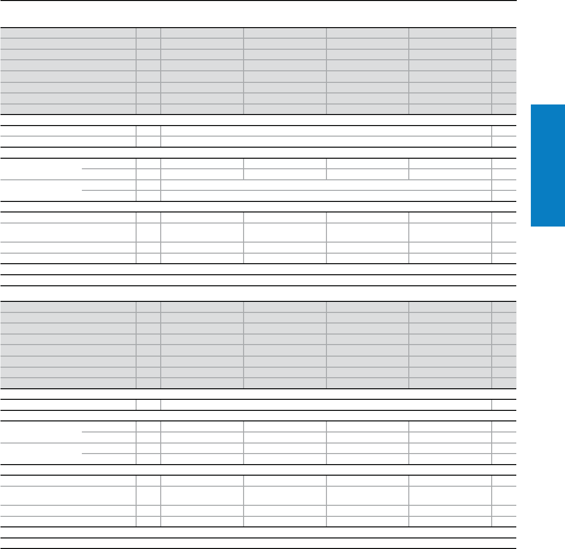
Carbon Steel
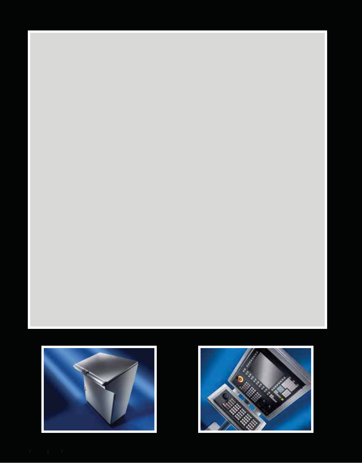
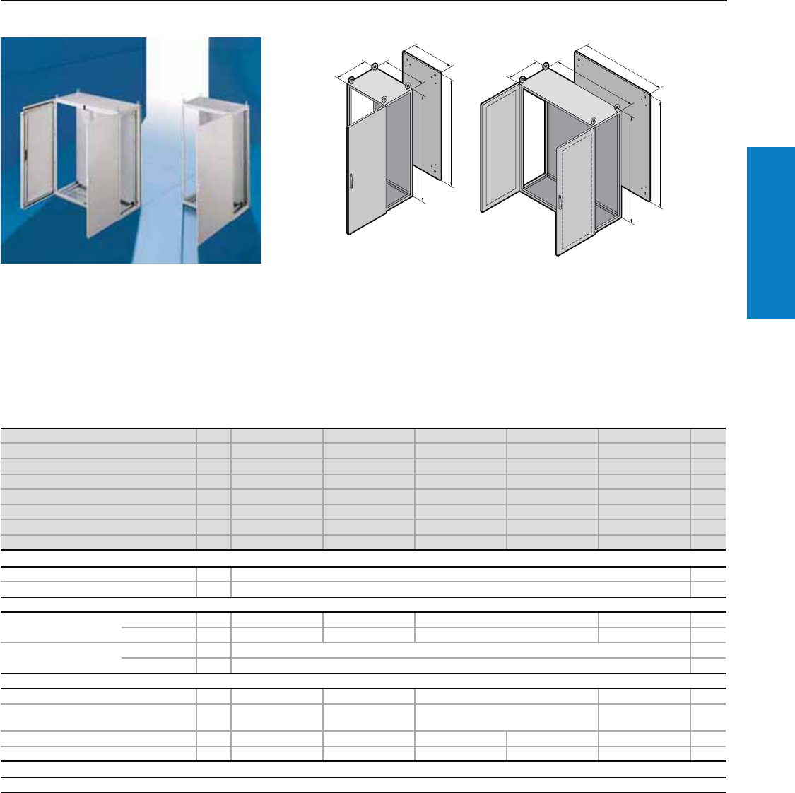
KL Screw Cover - Junction Box
Depth: 3 - 5" (80 - 120 mm), Height: 6 - 8" (150 - 200 mm)
H1
B1
T1
Material:
Sheet steel
Enclosure:
18 ga (1.25 mm);
17 ga (1.38 mm) for
1507.510 to 1513.510
Cover:
18 ga (1.25 mm)
Finish:
Case and cover:
Dipcoat-primed,
powder coated on the outside in
textured RAL 7035 (light gray)
Protection Ratings:
UL Type 4 (IP 66 to EN 60
529/10.91) w/o Gland Plate
UL Type 12 (IP 54 to EN 60
529/10.91) w/ Gland Plate
UL file: E76083
Conguration:
Enclosure, cover with foamed-on
polyurethane seal around the
perimeter and quick-release
cover screws, including
plastic bushes.
Without gland plate
Height (H1) inches (mm) PU 6 (150) 6 (150) 6 (150) 8 (200) 8 (200) 8 (200) 8 (200) 6 (150) Page
Width (B1) inches (mm) 6 (150) 8 (200) 12 (300) 8 (200) 12 (300) 16 (400) 24 (600) 6 (150)
Depth (T1) inches (mm) 3 (80) 3 (80) 3 (80) 3 (80) 3 (80) 3 (80) 3 (80) 5 (120)
Part No. 11514.510 1528.510 1515.510 1516.510 1517.510 1518.510 1519.510 1500.510
Weight lb (kg) 3 (1) 4 (2) 5 (2) 4 (2) 6 (3) 7 (3) 10 (5) 4 (2)
Accessories
Mounting panel 1 1560.700 1575.700 1561.700 1562.700 1563.700 1564.700 1566.700 1560.700 229
Support rail TS 35/7.5 10 2314.000 2315.000 2316.000 2315.000 2316.000 2317.000 – 2314.000 –
Support rail TS 35/15 10 – 2319.000 – –
Cover retainer 3 pairs 1591.000 215
Cover hinge 6 1592.000 215
Wallmount bracket 4 1590.000 253
Without gland plate
Height (H1) inches (mm) PU 6 (150) 6 (150) 6 (150) 8 (200) 8 (200) 8 (200) 8 (200) 8 (200) Page
Width (B1) inches (mm) 8 (200) 12 (300) 16 (400) 8 (200) 12 (300) 16 (400) 20 (500) 24 (600)
Depth (T1) inches (mm) 5 (120) 5 (120) 5 (120) 5 (120) 5 (120) 5 (120) 5 (120) 5 (120)
Part No. 11529.510 1501.510 1589.510 1502.510 1503.510 1504.510 1505.510 1506.510
Weight lb (kg) 4 (2) 6 (3) 7 (3) 5 (2) 7 (3) 8 (4) 10 (4) 13 (6)
Accessories
Mounting panel 1 1575.700 1561.700 1576.700 1562.700 1563.700 1564.700 1565.700 1566.700 229
Support rail TS 35/7.5 10 2315.000 2316.000 2317.000 2315.000 2316.000 2317.000 2318.000 2319.000 –
Cover retainer 3 pairs 1591.000 215
Cover hinge 6 1592.000 215
Wallmount bracket 4 1590.000 253
Inch and pound measurements are rounded to the nearest whole number.
For additional technical information,
please visit www.rittal-corp.com

Industrial Buyer’s Guide 5
Junction Box
Carbon Steel
With gland plate
Height (H1) inches (mm) PU 6 (150) 8 (200) 8 (200) 8 (200) 8 (200) 8 (200) Page
Width (B1) inches (mm) 12 (300) 12 (300) 16 (400) 20 (500) 24 (600) 32 (800)
Depth (T1) inches (mm) 5 (120) 5 (120) 5 (120) 5 (120) 5 (120) 5 (120)
Part No. 11530.510 1531.510 1532.510 1533.510 1534.510 1542.510
Weight lb (kg) 6 (3) 7 (3) 9 (4) 11 (5) 13 (6) 16 (7)
Accessories
Mounting panel 1 1561.700 1563.700 1564.700 1565.700 1566.700 1574.700 229
Gland plate (top + bottom) 1 + 1 2 + 2 2 + 2 3 + 3 –
Support rail TS 35/7.5 10 2316.000 2317.000 2318.000 2319.000 – –
Cover retainer 3 pairs – 1591.000 215
Cover hinge 6 – 1592.000 215
Wallmount bracket 4 1590.000 253
Without gland plate
Height (H1) inches (mm) PU 8 (200) 12 (300) 12 (300) 12 (300) 12 (300) 16 (400) 16 (400) 16 (400) Page
Width (B1) inches (mm) 32 (800) 12 (300) 16 (400) 20 (500) 24 (600) 16 (400) 24 (600) 32 (800)
Depth (T1) inches (mm) 5 (120) 5 (120) 5 (120) 5 (120) 5 (120) 5 (120) 5 (120) 5 (120)
Part No. 11527.510 1507.510 1508.510 1509.510 1510.510 1511.510 1512.510 1513.510
Weight lb (kg) 15 (7) 9 (4) 11 (5) 13 (6) 15 (7) 14 (6) 19 (8) 24 (11)
Accessories
Mounting panel 1 1574.700 1567.700 1568.700 1569.700 1570.700 1571.700 1572.700 1573.700 229
Support rail TS 35/7.5 10 – 2316.000 2317.000 2318.000 2319.000 2317.000 – –
Cover retainer 3 pairs 1591.000 215
Cover hinge 6 1592.000 215
Wallmount bracket 4 1590.000 253
KL Screw Cover - Junction Box
Depth: 5" (120 mm), Height: 6 - 16" (150 - 400 mm)
With gland plate
Height (H1) inches (mm) PU 12 (300) 12 (300) 12 (300) 12 (300) 16 (400) 16 (400) 16 (400) Page
Width (B1) inches (mm) 12 (300) 16 (400) 20 (500) 24 (600) 16 (400) 24 (600) 32 (800)
Depth (T1) inches (mm) 5 (120) 5 (120) 5 (120) 5 (120) 5 (120) 5 (120) 5 (120)
Part No. 11535.510 1536.510 1537.510 1538.510 1539.510 1540.510 1541.510
Weight lb (kg) 10 (5) 12 (5) 12 (5) 17 (8) 15 (7) 20 (9) 27 (12)
Accessories
Mounting panel 1 1567.700 1568.700 1569.700 1570.700 1571.700 1572.700 1573.700 229
Gland plate (top + bottom) 1 + 1 2 + 2 1 + 1 2 + 2 3 + 3 –
Gland plate (left + right) 1 + 1 –
Support rail TS 35/15 10 2316.000 2317.000 2318.000 2319.000 2317.000 2319.000 – –
Cover retainer 3 pairs – 1591.000 – 1591.000 215
Cover hinge 6 – 1592.000 – 1592.000 215
Wallmount bracket 4 1590.000 253
Inch and pound measurements are rounded to the nearest whole number.
6 Industrial Buyer’s Guide
Junction Box
Carbon Steel
Height (H1) inches (mm) PU 4 (100) 6 (150) 6 (150) 6 (150) 8 (200) 8 (200) Page
Width (B1) inches (mm) 4 (100) 4 (100) 4 (100) 6 (150) 6 (150) 8 (200)
Depth (T1) inches (mm) 3 (75) 3 (75) 4 (100) 4 (100) 4 (100) 4 (100)
Panel Height (G1) inches (mm) - 5 (135) 5 (135) 5 (135) 7 (185) 7 (185)
Panel Width (F1) inches (mm) - 3 (75) 3 (75) 5 (125) 5 (125) 7 (175)
Part No. 1JB040403HC JB060403HC JB060404HC JB060604HC JB080604HC JB080804HC
Weight lb (kg) 2 (0.9) 3 (1.4) 3 (1.4) 4 (1.6) 5 (2.0) 6 (2.5)
Accessories
Mounting panel 1 - JBMP0604 JBMP0606 JBMP0806 JBMP0808 230
Wallmount bracket 4 1590.000 253
Height (H1) inches (mm) PU 10 (250) 12 (300) 12 (300) 8 (200) 10 (250) 10 (250) Page
Width (B1) inches (mm) 8 (200) 6 (150) 10 (250) 6 (150) 8 (200) 10 (250)
Depth (T1) inches (mm) 4 (100) 4 (100) 5 (125) 6 (150) 6 (150) 6 (150)
Panel Height (G1) inches (mm) 9 (235) 11 (285) 11 (285) 7 (185) 9 (235) 9 (235)
Panel Width (F1) inches (mm) 7 (175) 5 (125) 9 (225) 5 (125) 7 (175) 9 (225)
Part No. 1JB100804HC JB120604HC JB121005HC JB080606HC JB100806HC JB101006HC
Weight lb (kg) 8 (3.4) 6 (2.7) 9 (4.1) 6 (2.5) 8 (3.4) 9 (3.9)
Accessories
Mounting panel 1 JBMP1008 JBMP1206 JBMP1210 JBMP0806 JBMP1008 JBMP1010 230
Wallmount bracket 4 1590.000 253
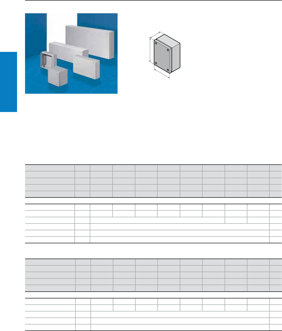
Material:
Sheet steel
Enclosure:
16 ga (1.5 mm)
Finish:
Enclosure and door:
Powder coated
on the outside in textured
RAL 7035 (light gray)
Protection Ratings:
UL/cUL Type 3R
UL/cUL Type 4
(IP 66 to EN 60 529/10.91)
UL Type 12
(IP 54 to EN 60 529/10.91)
UL File Number: E170282
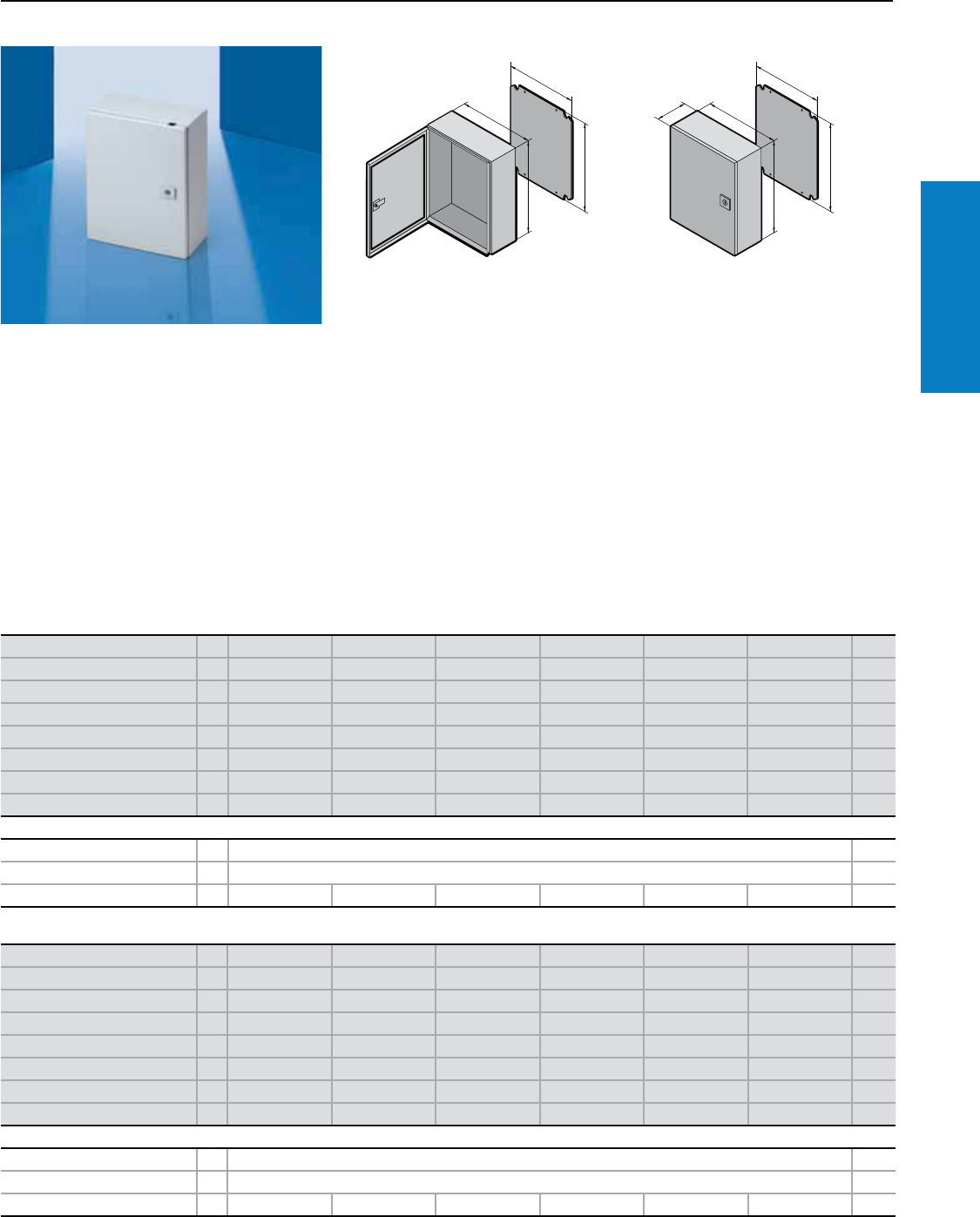
JB Hinge Cover - Junction Box
Depth: 3 - 10" (75 - 250 mm), Height: 4 - 16" (100 - 400 mm)
Note: zinc-plated enclosure
mounting panel sold separately
(see below)
For additional technical
information, please visit
www.rittal-corp.com
Inch and pound measurements are rounded to the nearest whole number.
Height (H1) inches (mm) PU 12 (300) 12 (300) 14 (350) 16 (400) 12 (300) 16 (400) 16 (400) Page
Width (B1) inches (mm) 10 (250) 12 (300) 12 (300) 14 (350) 10 (250) 14 (350) 14 (350)
Depth (T1) inches (mm) 6 (150) 6 (150) 6 (150) 6 (150) 8 (200) 8 (200) 10 (250)
Panel Height (G1) inches (mm) 11 (285) 11 (285) 13 (335) 15 (385) 11 (285) 15 (385) 15 (385)
Panel Width (F1) inches (mm) 9 (225) 11 (275) 11 (275) 13 (325) 9 (225) 13 (325) 14 (350)
Part No. 1JB121006HC JB121206HC JB141206HC JB161406HC JB121008HC JB161408HC JB161410HC
Weight lb (kg) 10 (4.5) 11 (5.0) 12 (5.5) 15 (6.8) 11 (5.0) 17 (7.7) 19 (8.6)
Accessories
Mounting panel 1 JBMP1210 JBMP1212 JBMP1412 JBMP1614 JBMP1210 JBMP1614 JBMP1614 230
Wallmount bracket 4 1590.000 253
G1
F1
H1
B1
T1
H1
G1
F1
B1
T1
Conguration:
Door with 180° left-hand hinges,
includes screwdriver insert.
Industrial Buyer’s Guide 7
Junction Box
Carbon Steel
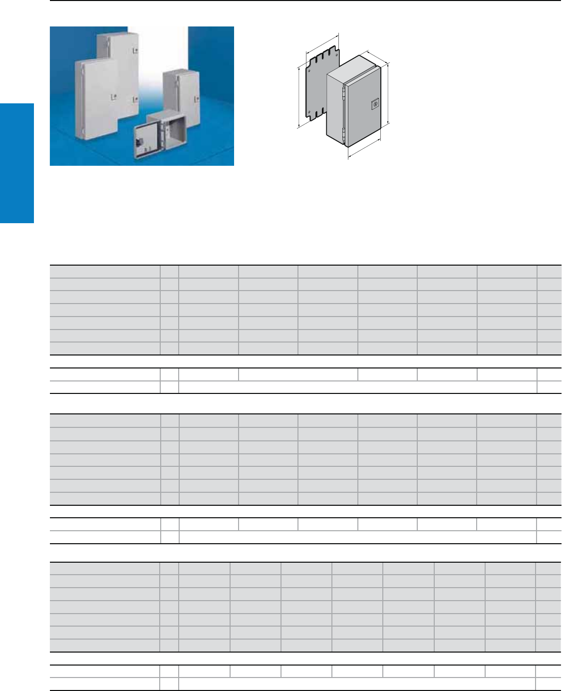
EB Hinge Cover - Junction Box
Depth: 3 - 5" (80 - 120 mm), Height: 6 - 16" (150 - 400 mm)
Material:
Sheet steel
Enclosure:
18 ga (1.25 mm)
17 ga (1.38 mm) for 1555.500,
1556.500, 1577.500 to 1579.500
16 ga (1.50 mm) for 1751.500 to
1755.500
Finish:
Enclosure and door:
Dipcoat-primed, powder coated
on the outside in textured RAL
7035 (light gray)
Mounting panel: Zinc-plated
Protection Ratings:
UL/cUL Type 3R
UL/cUL Type 4
(IP 66 to EN 60 529/10.91)
UL Type 12
(IP 54 to EN 60 529/10.91)
UL file: E76083
G1
F1
H1
B1
T1
Height (H1) inches (mm) PU 6 (150) 8 (200) 12 (300) 12 (300) 16 (400) Page
Width (B1) inches (mm) 6 (150) 8 (200) 6 (150) 8 (200) 8 (200)
Depth (T1) inches (mm) 3 (80) 3 (80) 3 (80) 3 (80) 3 (80)
Panel height (G1) inches (mm) 5 (135) 7 (185) 11 (285) 11 (285) 15 (385)
Panel width (F1) inches (mm) 5 (125) 7 (175) 5 (125) 7 (175) 7 (175)
Part No. 11551.500 1546.500 1545.500 1552.500 1547.500
Weight lb (kg) 4 (1.7) 5 (2.4) 6 (2.6) 7 (3.2) 10 (4.4 )
Accessories
Wallmount bracket 4 1590.000 253
Handle 1 2533.000 219
Height (H1) inches (mm) PU 6 (150) 8 (200) 8 (200) 12 (300) 12 (300) Page
Width (B1) inches (mm) 6 (150) 6 (150) 8 (200) 6 (150) 8 (200)
Depth (T1) inches (mm) 5 (120) 5 (120) 5 (120) 5 (120) 5 (120)
Panel height (G1) inches (mm) 5 (135) 7 (185) 7 (185) 11 (285) 11 (285)
Panel width (F1) inches (mm) 5 (125) 5 (125) 7 (175) 5 (125) 7 (175)
Part No. 11553.500 1751.500 1549.500 1548.500 1554.500
Weight lb (kg) 4 (2.0) 5 (2.4) 6 (2.8) 7 (3.0) 8 (3.6)
Accessories
Wallmount bracket 4 1590.000 253
Handle 1 2533.000 219
Inch and pound measurements are rounded to the nearest whole number.
For additional technical information,
please visit www.rittal-corp.com
Conguration:
Includes mounting panel, cam
lock with double-bit insert,
right-hand hinged
8 Industrial Buyer’s Guide
Junction Box
Carbon Steel
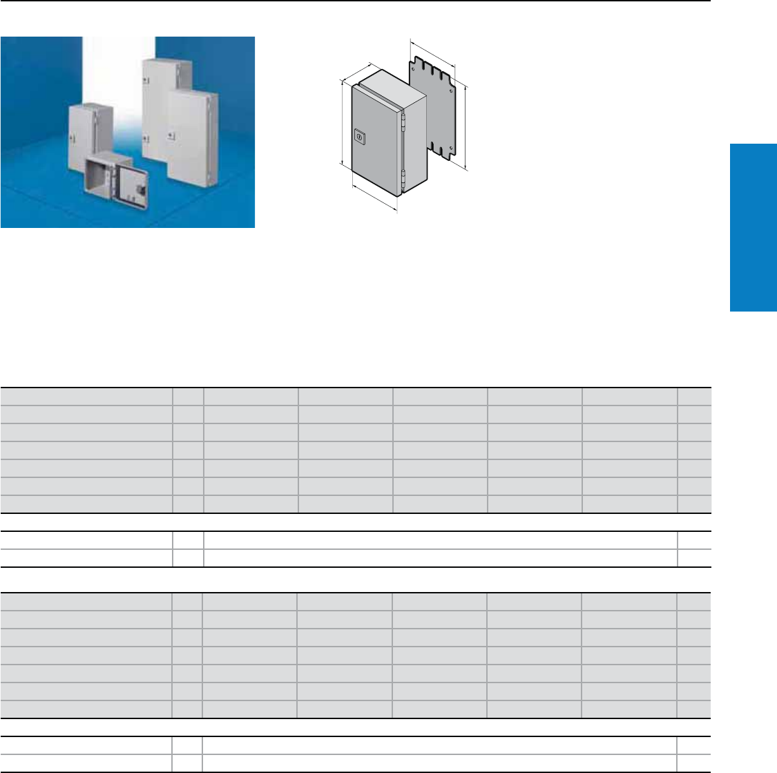
EB Hinge Cover - Junction Box
Depth: 5 - 6" (120 - 155 mm), Height: 12 - 32" (300 - 800 mm)
Height (H1) inches (mm) PU 12 (300) 16 (400) 16 (400) 20 (500) 10 (250) Page
Width (B1) inches (mm) 12 (300) 8 (200) 12 (300) 8 (200) 8 (200)
Depth (T1) inches (mm) 5 (120) 5 (120) 5 (120) 5 (120) 6 (155)
Panel height (G1) inches (mm) 11 (285) 15 (385) 15 (385) 19 (485) 9 (235)
Panel width (F1) inches (mm) 11 (275) 7 (175) 11 (275) 7 (175) 7 (175)
Part No. 11555.500 1550.500 1556.500 1557.500 1752.500
Weight lb (kg) 11 (5.0) 11 (5.0) 14 (6.4) 14 (6.2) 8 (3.6)
Accessories
Wallmount bracket 4 1590.000 253
Handle 1 2533.000 219
Height (H1) inches (mm) PU 12 (300) 14 (350) 16 (400) 16 (400) 24 (600) 32 (800) Page
Width (B1) inches (mm) 10 (250) 12 (300) 12 (300) 14 (350) 12 (300) 12 (300)
Depth (T1) inches (mm) 6 (155) 6 (155) 6 (155) 6 (155) 6 (155) 6 (155)
Panel height (G1) inches (mm) 11 (285) 13 (335) 15 (385) 15 (385) 23 (585) 31 (785)
Panel width (F1) inches (mm) 9 (225) 11 (275) 11 (275) 13 (325) 11 (275) 11 (275)
Part No. 11753.500 1754.500 1577.500 1755.500 1578.500 1579.500
Weight lb (kg) 11 (5.0) 13 (5.8) 16 (7.1) 14 (6.3) 23 (10.4) 29 (13.2)
Accessories
Wallmount bracket 4 1590.000 253
Handle 1 2533.000 219
Inch and pound measurements are rounded to the nearest whole number.
Industrial Buyer’s Guide 9
Wallmount
Carbon Steel
Inch and pound measurements are rounded to the nearest whole number.
Height (H1) inches (mm) PU 12 (300) 16 (400) 16 (400) 16 (400) 20 (500) 20 (500) Page
Width (B1) inches (mm) 12 (300) 12 (300) 16 (400) 20 (500) 16 (400) 20 (500)
Depth (T1) inches (mm) 6 (150) 6 (150) 6 (150) 6 (150) 6 (150) 6 (150)
Panel Height (G1) inches (mm) 11 (275) 15 (375) 15 (375) 15 (375) 19 (475) 19 (475)
Panel Width (F1) inches (mm) 10 (254) 10 (254) 14 (354) 18 (449) 14 (354) 18 (449)
Part No. 1WM121206NC WM161206NC WM161606NC WM162006NC WM201606NC WM202006NC
Door(s) 111111
Weight lb (kg) 16 (7) 20 (9) 23 (10) 28 (12) 31 (14) 37 (17)
Accessories
Wallmount bracket 4 2508.200 253
Handle 1 2533.000 219
Dead front kit 1 DFK1212C DFK1612C DFK1616C DFK1620C DFK2016C DFK2020C 230
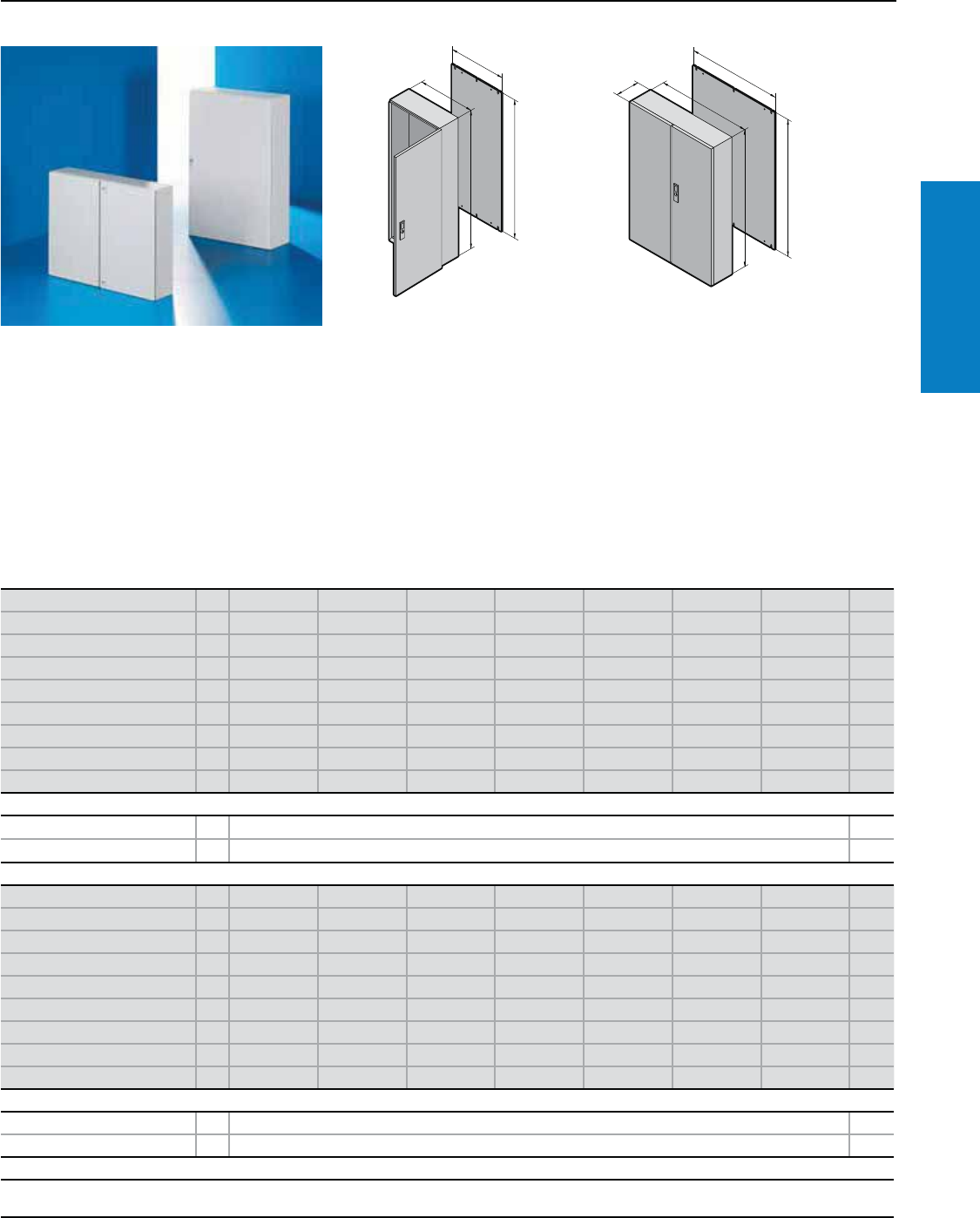
WM - Wallmount
Depth: 6 - 8" (150 - 210 mm), Height: 12 - 30" (300 - 760 mm)
Material:
Sheet steel
Enclosure:
16 - 14 ga (1.5 - 2.0 mm)
-12" H x 12" W – 24" H x 20" W -
16 ga body/ 16 ga door
- 24" H x 24" W – 36" H x 24" W -
16 ga body/ 14 ga door
- 36" H x 30" W – 42" H x 32" W -
14 ga body/ 14 ga door
Finish:
Housing and door:
Powder coated, RAL 7035 (light gray)
Mounting panel:
Zinc-plated carbon steel For additional technical information,
please visit www.rittal-corp.com
Conguration:
Left-hand hinge, slotted head insert
One-piece enclosure body
Single door enclosures less than 20"
high have one 1/4 turn latch
Single door enclosures 20 - 40" high
have two 1/4 turn latches
Single door enclosures greater than
or equal to 42” high and all double
door enclosures have a 3-point locking
L-Handle
Mounting panel
Wall-mounting holes
Foamed-in-place gasket
Protection Ratings:
Single door enclosures:
UL/cUL Type 12
(IP 55 to EN 60 529/10.91)
UL/cUL Type 3R
UL/cUL Type 4
(IP 66 to EN 60 529/10.91)
Double door enclosures:
UL/cUL Type 1
UL/cUL Type 12
(IP 55 to EN 60 529/10.91)
UL File Number: E170282
B1
H1
F1
G1
B1
T1
H1
F1
G1
Height (H1) inches (mm) PU 24 (600) 24 (600) 24 (600) 30 (760) 16 (400) 16 (400) Page
Width (B1) inches (mm) 16 (400) 20 (500) 24 (600) 24 (600) 12 (300) 16 (400)
Depth (T1) inches (mm) 6 (150) 6 (150) 6 (150) 6 (150) 8 (210) 8 (210)
Panel Height (G1) inches (mm) 22 (570) 22 (570) 22 (570) 29 (730) 15 (375) 15 (375)
Panel Width (F1) inches (mm) 14 (354) 18 (449) 22 (549) 22 (549) 10 (254) 14 (354)
Part No. 1WM241606NC WM242006NC WM242406NC WM302406NC WM161208NC WM161608NC
Door(s) 111111
Weight lb (kg) 36 (16) 43 (19) 53 (24) 66 (30) 23 (10) 26 (12)
Accessories
Wallmount bracket 4 2508.200 253
Handle 1 2533.000 219
Dead front kit 1 DFK2416C DFK2420C DFK2424C DFK3024C DFK1612C DFK1616C 230

10 Industrial Buyer’s Guide
Wallmount
Carbon Steel
WM - Wallmount
Depth: 8" (210 mm), Height: 16 - 47" (400 - 1200 mm)
Height (H1) inches (mm) PU 16 (400) 20 (500) 20 (500) 20 (500) 24 (600) 24 (600) Page
Width (B1) inches (mm) 20 (500) 16 (400) 20 (500) 24 (600) 16 (400) 20 (500)
Depth (T1) inches (mm) 8 (210) 8 (210) 8 (210) 8 (210) 8 (210) 8 (210)
Panel Height (G1) inches (mm) 15 (375) 19 (475) 19 (475) 19 (475) 22 (570) 22 (570)
Panel Width (F1) inches (mm) 18 (449) 14 (354) 18 (449) 22 (549) 14 (354) 18 (449)
Part No. 1WM162008NC WM201608NC WM202008NC WM202408NC WM241608NC WM242008NC
Door(s) 111111
Weight lb (kg) 30 (14) 34 (15) 40 (17) 47 (21) 39 (18) 46 (21)
Accessories
Wallmount bracket 4 2508.200 253
Handle 1 2533.000 219
Dead front kit 1 DFK1620C DFK2016C DFK2020C DFK2024C DFK2416C DFK2420C 230
Height (H1) inches (mm) PU 24 (600) 24 (600) 24 (600) 30 (760) 30 (760) 30 (760) Page
Width (B1) inches (mm) 24 (600) 30 (760) 42 (1050) 20 (500) 24 (600) 30 (760)
Depth (T1) inches (mm) 8 (210) 8 (210) 8 (210) 8 (210) 8 (210) 8 (210)
Panel Height (G1) inches (mm) 22 (570) 22 (570) 22 (550) 29 (730) 29 (730) 29 (730)
Panel Width (F1) inches (mm) 22 (549) 28 (704) 39 (1000) 18 (449) 22 (549) 28 (704)
Part No. 1WM242408NC WM243008NC WM244208NC WM302008NC WM302408NC WM303008NC
Door(s) 112111
Weight lb (kg) 57 (26) 70 (32) 110 (50) 60 (27) 70 (32) 86 (39)
Accessories
Wallmount bracket 4 2508.200 253
Handle 1 2533.000 WMLHKL 2533.000 219
Dead front kit 1 DFK2424C DFK2430C – DFK3020C DFK3024C DFK3030C 230
Height (H1) inches (mm) PU 36 (900) 36 (900) 36 (900) 42 (1050) 42 (1050) 47 (1200) Page
Width (B1) inches (mm) 24 (600) 30 (760) 36 (900) 30 (760) 36 (900) 36 (900)
Depth (T1) inches (mm) 8 (210) 8 (210) 8 (210) 8 (210) 8 (210) 8 (210)
Panel Height (G1) inches (mm) 34 (870) 34 (870) 34 (870) 40 (1020) 40 (1020) 45 (1155)
Panel Width (F1) inches (mm) 22 (549) 28 (704) 33 (840) 28 (704) 33 (840) 33 (840)
Part No. 1WM362408NC WM363008NC WM363608NC WM423008NC WM423608NC WM483608NC
Door(s) 111111
Weight lb (kg) 91 (41) 111 (50) 134 (61) 137 (63) 157 (71) 176 (80)
Accessories
Wallmount bracket 4 2508.200 253
Handle 1 2533.000 WMLHKL 219
Dead front kit 1 DFK3624C DFK3630C DFK3636C DFK4230C DFK4236C DFK4836C 230
Industrial Buyer’s Guide 11
Wallmount
Carbon Steel
WM - Wallmount
Depth: 10 - 12" (250 - 300 mm), Height: 20 - 60" (500 - 1500 mm)
Inch and pound measurements are rounded to the nearest whole number.
Height (H1) inches (mm) PU 20 (500) 24 (600) 24 (600) 30 (760) 30 (760) 30 (760) Page
Width (B1) inches (mm) 20 (500) 20 (500) 24 (600) 24 (600) 30 (760) 42 (1050)
Depth (T1) inches (mm) 10 (250) 10 (250) 10 (250) 10 (250) 10 (250) 10 (250)
Panel Height (G1) inches (mm) 19 (475) 22 (570) 22 (570) 29 (730) 29 (730) 28 (710)
Panel Width (F1) inches (mm) 18 (449) 18 (449) 22 (549) 22 (549) 28 (704) 39 (1000)
Part No. 1WM202010NC WM242010NC WM242410NC WM302410NC WM303010NC WM304210NC
Door(s) 111112
Weight lb (kg) 45 (20) 48 (22) 50 (23) 75 (34) 89 (40) 154 (70)
Accessories
Wallmount bracket 4 2508.200 253
Handle 1 2533.000 WMLHKL 219
Dead front kit 1 DFK2020C DFK2420C DFK2424C DFK3024C DFK3030C – 230
Height (H1) inches (mm) PU 20 (500) 24 (600) 24 (600) 30 (760) 30 (760) 36 (900) Page
Width (B1) inches (mm) 20 (500) 20 (500) 24 (600) 24 (600) 30 (760) 24 (600)
Depth (T1) inches (mm) 12 (300) 12 (300) 12 (300) 12 (300) 12 (300) 12 (300)
Panel Height (G1) inches (mm) 19 (470) 22 (570) 22 (570) 29 (730) 29 (730) 34 (870)
Panel Width (F1) inches (mm) 18 (449) 18 (449) 22 (549) 22 (549) 28 (704) 22 (549)
Part No. 1WM202012NC WM242012NC WM242412NC WM302412NC WM303012NC WM362412NC
Door(s) 111111
Weight lb (kg) 48 (22) 52 (23) 63 (28) 77 (35) 93 (42) 89 (40)
Accessories
Wallmount bracket 4 2508.200 253
Handle 1 2533.000 219
Dead front kit 1 DFK2020C DFK2420C DFK2424C DFK3024C DFK3030C DFK3624C 230
Height (H1) inches (mm) PU 30 (760) 36 (900) 36 (900) 42 (1050) 47 (1200) 60 (1500) Page
Width (B1) inches (mm) 47 (1200) 24 (600) 30 (760) 36 (900) 36 (900) 36 (900)
Depth (T1) inches (mm) 10 (250) 10 (250) 10 (250) 10 (250) 10 (250) 10 (250)
Panel Height (G1) inches (mm) 28 (710) 34 (870) 34 (870) 40 (1020) 45 (1155) 57 (1455)
Panel Width (F1) inches (mm) 45 (1150) 22 (549) 28 (704) 33 (840) 33 (840) 33 (840)
Part No. 1WM304810NC WM362410NC WM363010NC WM423610NC WM483610NC WM603610NC
Door(s) 211111
Weight lb (kg) 138 (63) 85 (38) 116 (53) 162 (74) 178 (81) 189 (86)
Accessories
Wallmount bracket 4 2508.200 253
Handle 1 WMLHKL 2533.000 WMLHKL 219
Dead front kit 1 - DFK3624C DFK3630C DFK4236C DFK4836C DFK6036C 230
12 Industrial Buyer’s Guide
Wallmount
Carbon Steel
WM - Wallmount
Depth: 12 - 20" (300 - 500 mm), Height: 36 - 60" (900 - 1500 mm)
Inch and pound measurements are rounded to the nearest whole number.
Height (H1) inches (mm) PU 42 (1050) 42 (1050) 47 (1200) 47 (1200) 60 (1500) Page
Width (B1) inches (mm) 36 (900) 60 (1500) 36 (900) 47 (1200) 36 (900)
Depth (T1) inches (mm) 12 (300) 12 (300) 12 (300) 12 (300) 12 (300)
Panel Height (G1) inches (mm) 40 (1020) 39 (1000) 45 (1155) 45 (1150) 57 (1455)
Panel Width (F1) inches (mm) 33 (840) 57 (1450) 33 (840) 45 (1150) 33 (840)
Part No. 1WM423612NC WM426012NC WM483612NC WM484812NC WM603612NC
Door(s) 12121
Weight lb (kg) 169 (77) 259 (118) 180 (82) 204 (93) 200 (91)
Accessories
Wallmount bracket 4 2508.200 253
Handle 1 WMLHKL 2533.000 WMLHKL 219
Dead front kit 1 DFK4236C – DFK4836C – DFK6036C 230
Height (H1) inches (mm) PU 36 (900) 47 (1200) 60 (1500) 30 (760) 47 (1200) Page
Width (B1) inches (mm) 30 (760) 36 (900) 36 (900) 24 (600) 36 (900)
Depth (T1) inches (mm) 16 (400) 16 (400) 16 (400) 20 (500) 20 (500)
Panel Height (G1) inches (mm) 34 (870) 45 (1155) 57 (1450) 29 (730) 45 (1155)
Panel Width (F1) inches (mm) 28 (704) 33 (840) 33 (840) 22 (549) 33 (840)
Part No. 1WM363016NC WM483616NC WM603616NC WM302420NC WM483620NC
Door(s) 11111
Weight lb (kg) 134 (61) 204 (93) 210 (95) 85 (39) 212 (96)
Accessories
Wallmount bracket 4 2508.200 253
Handle 1 2533.000 WMLHKL 219
Dead front kit 1 DFK3630C DFK4836C DFK6036C DFK3024C DFK4836C 230
Height (H1) inches (mm) PU 36 (900) 36 (900) 36 (900) 36 (900) 36 (900) Page
Width (B1) inches (mm) 30 (760) 36 (900) 42 (1050) 47 (1200) 60 (1500)
Depth (T1) inches (mm) 12 (300) 12 (300) 12 (300) 12 (300) 12 (300)
Panel Height (G1) inches (mm) 34 (870) 34 (870) 33 (850) 33 (850) 33 (850)
Panel Width (F1) inches (mm) 28 (704) 33 (840) 39 (1000) 45 (1150) 57 (1450)
Part No. 1WM363012NC WM363612NC WM364212NC WM364812NC WM366012NC
Door(s) 11222
Weight lb (kg) 120 (55) 140 (64) 167 (76) 186 (85) 226 (103)
Accessories
Wallmount bracket 4 2508.200 253
Handle 1 2533.000 WMLHKL 219
Dead front kit 1 DFK3636C – – – 230
Industrial Buyer’s Guide 13
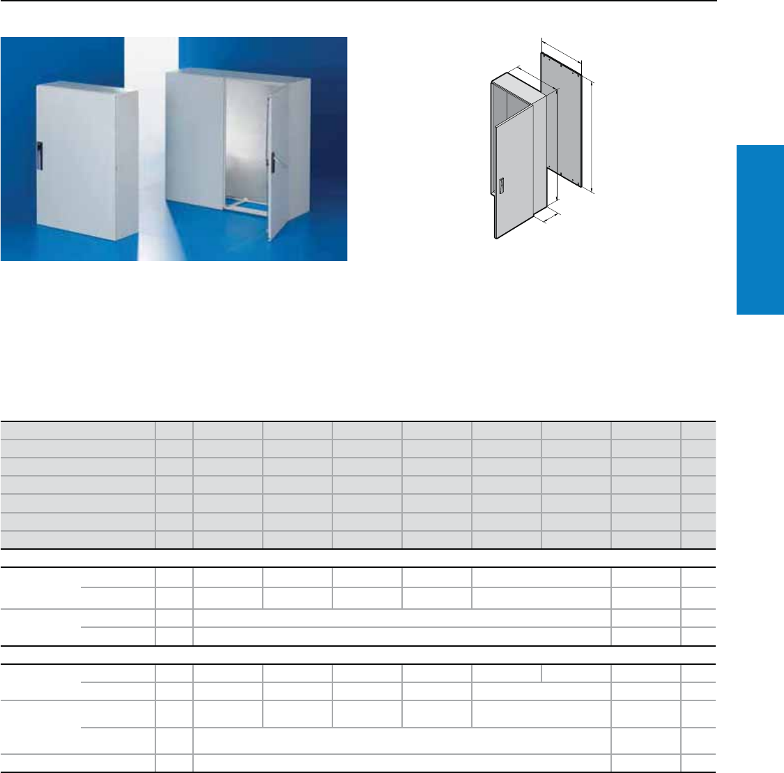
Wallmount
Carbon Steel
AE - Wallmount
Depth: 5 - 8" (120 - 210 mm), Height: 12 - 30" (300 - 760 mm)
Material:
Sheet steel
Enclosure:
16 - 14 ga (1.5 - 2.0 mm)
-12" H x 12" W – 24" H x 20" W -
16 ga body/ 16 ga door
- 24" H x 24" W – 36" H x 24" W -
16 ga body/ 14 ga door
- 36" H x 30" W – 42" H x 32" W -
14 ga body/ 14 ga door
Double door enclosures:
UL/cUL Type 1
UL/cUL Type 12
(IP 55 to EN 60 529/10.91
UL File Number: E170282
Conguration:
Right-hand hinge
Double-bit insert
Gland plate
One-piece enclosure body
Mounting panel
For additional technical information,
please visit www.rittal-corp.com
B1
H1
F1
G1
T1
F1
B1
H1
G1
Enclosures less than 20" high have one 1/4
turn latch
Enclosures 20 - 39" high have two
1/4 turn latches
Enclosures more than 39" high have 3 point
latching
Wall-mounting holes
Foamed-in-place gasket
Height (H1) inches (mm) PU 12 (300) 12 (300) 12 (300) 12 (300) 12 (300) 15 (380) 15 (380) Page
Width (B1) inches (mm) 8 (200) 8 (200) 15 (380) 12 (300) 15 (380) 15 (380) 24 (600)
Depth (T1) inches (mm) 5 (120) 6 (155) 6 (155) 8 (210) 8 (210) 8 (210) 8 (210)
Panel Height (G1) inches (mm) 11 (275) 11 (275) 11 (275) 11 (275) 11 (275) 14 (355) 14 (355)
Panel Width (F1) inches (mm) 6 (162) 6 (162) 13 (334) 10 (254) 13 (334) 13 (334) 22 (549)
Panel Thickness ga (mm) 14 (2) 14 (2) 14 (2) 14 (2) 14 (2) 14 (2) 12 (2.5)
Part No. 11032.500 1035.500 1030.500 1033.500 1031.500 1380.500 1039.500
Door(s) 1111111
Weight lb (kg) 9 (4) 10 (5) 16 (7) 15 (7) 17 (8) 22 (10) 34 (15)
Accessories
Handle 1 2576.000 219
Wallmount bracket 4 2508.200 253
Height (H1) inches (mm) 16 (400) 20 (500) 20 (500) 24 (600) 24 (600) 30 (760) 30 (760) Page
Width (B1) inches (mm) 12 (300) 16 (400) 20 (500) 15 (380) 24 (600) 24 (600) 30 (760)
Depth (T1) inches (mm) 8 (210) 8 (210) 8 (210) 8 (210) 8 (210) 8 (210) 8 (210)
Panel Height (G1) inches (mm) 15 (375) 19 (475) 19 (470) 22 (570) 22 (570) 29 (730) 29 (730)
Panel Width (F1) inches (mm) 10 (254) 14 (354) 18 (449) 13 (334) 22 (549) 22 (549) 28 (704)
Panel Thickness ga (mm) 14 (2) 14 (2) 12 (2.5) 12 (2.5) 12 (2.5) 11 (3) 11 (3)
Part No. 11034.500 1045.500 1050.500 1038.500 1060.500 1076.500 1077.500
Door(s) 1111111
Weight lb (kg) 19 (9) 29 (13) 37 (17) 34 (16) 50 (23) 71 (32) 88 (40)
Accessories
Handle 1 2576.000 219
Wallmount bracket 4 2508.200 253
Lock systems
Standard double-bit lock insert of the locking rod may be exchanged for 1" (27 mm), type A, see page 219, lock cylinder, plastic handles, and T handles,
type B, see page 219.
Finish:
Housing and door:
Powder coated, RAL 7035
(light gray)
Mounting panel:
Zinc-plated carbon steel
Protection Ratings:
Single door enclosures:
UL/cUL Type 12
(IP 55 to EN 60 529/10.91)
UL/cUL Type 3R
UL/cUL Type 4
(IP 66 to EN 60 529/10.91)
14 Industrial Buyer’s Guide
Wallmount
Carbon Steel
AE - Wallmount
Depth: 8 - 14" (210 - 350 mm), Height: 15 - 47" (380 - 1200 mm)
Height (H1) inches (mm) PU 30 (760) 32 (800) 39 (1000) 30 (760) 39 (1000) 39 (1000) 47 (1200) Page
Width (B1) inches (mm) 39 (1000) 24 (600) 24 (600) 39 (1000) 32 (800) 39 (1000) 24 (600)
Depth (T1) inches (mm) 8 (210) 10 (250) 10 (250) 12 (300) 12 (300) 12 (300) 12 (300)
Panel Height (G1) inches (mm) 29 (730) 30 (770) 38 (955) 29 (730) 38 (955) 38 (955) 46 (1155)
Panel Width (F1) inches (mm) 37 (940) 22 (549) 21 (539) 37 (944) 29 (739) 37 (939) 21 (540)
Panel Thickness ga (mm) 11 (3) 11 (3) 11 (3) 11 (3) 11 (3) 11 (3) 11 (3)
Part No. 11100.500 1058.500 1090.500 1130.500 1180.500 1110.500 1260.500
Door(s) 2112121
Weight lb (kg) 115 (52) 75 (34) 111 (51) 124 (56) 126 (57) 157 (71) 121 (55)
Accessories
Handle 1 2576.000 219
Wallmount bracket 4 2508.200 253
Height (H1) inches (mm) PU 47 (1200) 47 (1200) 15 (380) 24 (600) 24 (600) 30 (760) Page
Width (B1) inches (mm) 32 (800) 39 (1000) 24 (600) 15 (380) 24 (600) 24 (600)
Depth (T1) inches (mm) 12 (300) 12 (300) 14 (350) 14 (350) 14 (350) 14 (350)
Panel Height (G1) inches (mm) 46 (1155) 46 (1155) 14 (355) 22 (570) 22 (570) 29 (730)
Panel Width (F1) inches (mm) 29 (740) 37 (940) 22 (549) 13 (334) 22 (549) 22 (549)
Panel Thickness ga (mm) 11 (3) 11 (3) 12 (2.5) 12 (2.5) 12 (2.5) 11 (3)
Part No. 11280.500 1213.500 1339.500 1338.500 1360.500 1376.500
Door(s) 121111
Weight lb (kg) 154 (70) 187 (85) 44 (20) 43 (19) 63 (28) 80 (36)
Accessories
Handle 1 2576.000 219
Wallmount bracket 4 2508.200 253
Lock systems
Standard double-bit lock insert of the locking rod may be exchanged for 1" (27 mm), type A, see page 219, lock cylinder, plastic handles, and T handles,
type B, see page 219.
Inch and pound measurements are rounded to the nearest whole number.
Industrial Buyer’s Guide 15
Wallmount
Carbon Steel
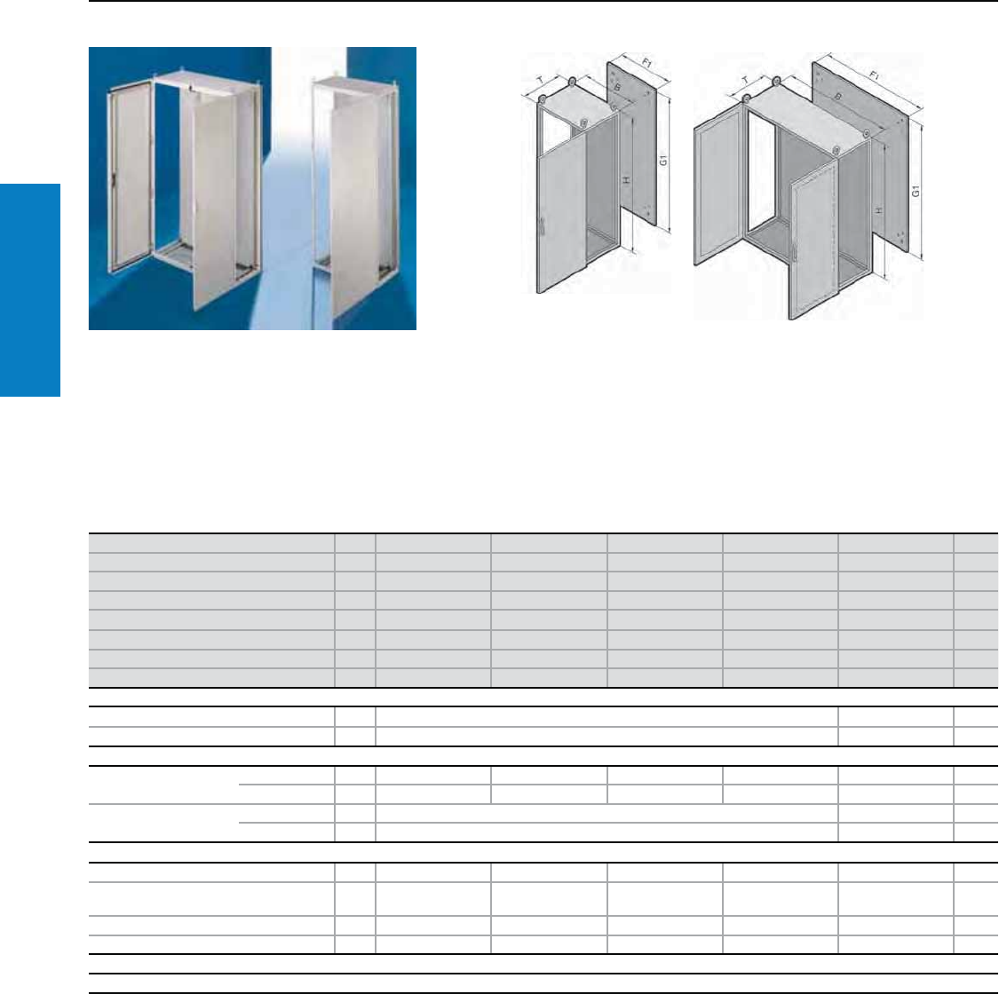
CM - Wallmount
Depth: 12 - 16" (300 - 400 mm), Height: 32 - 55" (800 - 1400 mm)
Material:
Sheet steel
Enclosure: 16 ga (1.5 mm)
Door: 14 ga (2.0 mm)
Mounting panel: 11 ga (3.0 mm)
Finish:
Enclosure and door:
Dipcoat-primed, powder
painted on the outside in
textured RAL 7035 (light gray)
Mounting panel: Zinc-plated
Protection Ratings:
UL Type 12 (IP 55), with
selection of the appropriate
gland plates, see page 259.
UL file: E76083
T
B
H
F
G
Conguration:
Enclosure with one door, right hand
door hinge, may be changed to
the opposite side, mounting panel,
open base for individual cable
entry.
Inch and pound measurements are rounded to the nearest whole number.
Height (T) inches (mm) PU 39 (1000) 39 (1000) 47 (1200) 47 (1200) 47 (1200) 55 (1400) 32 (800) Page
Width (B) inches (mm) 32 (800) 39 (1000) 24 (600) 32 (800) 39 (1000) 39 (1000) 24 (600)
Depth (T) inches (mm) 12 (300) 12 (300) 12 (300) 12 (300) 12 (300) 12 (300) 16 (400)
Panel Height (G) inches (mm) 38 (955) 38 (955) 46 (1155) 46 (1155) 46 (1155) 53 (1355) 30 (755)
Panel Width (F) inches (mm) 29 (740) 37 (940) 21 (540) 29 (740) 37 (940) 37 (940) 21 (540)
Part No. 15114.500 5118.500 5112.500 5116.500 5119.500 5121.500 5110.500
Door(s) 1211221
Base/plinth
Components
front and rear
inches (mm)
Height 4 (100) 1 set 8601.800 8601.000 8601.600 8601.800 8601.000 8601.600 194
Height 8 (200) 1 set 8602.800 8602.000 8602.600 8602.800 8602.000 8602.600 194
Side panels
inches (mm)
Height 4 (100) 1 set 8601.030 8601.040 194
Height 8 (200) 1 set 8602.030 8602.040 194
Accessories
Rail for interior
installation
For height 4 5001.052 5001.052 5001.053 5001.053 5001.053 5001.054 5001.051 233
For width 4 5001.051 5001.052 5001.050 5001.051 5001.052 5001.050 233
Matching
system chassis
with mounting
flange
In width 4 8612.080 8612.000 8612.060 8612.080 8612.000 8612.060 234
In depth 4 8612.130 8612.140 234
Bottom cover plate 1 - 5001.130 200
For additional technical information,
please visit www.rittal-corp.com
Note: CM gland plates (see page 259) or cover plate (see page 200) required for UL Type 12 rating.
16 Industrial Buyer’s Guide
Wallmount
Carbon Steel
CM - Wallmount
Depth: 16" (400 mm), Height: 39 - 55" (1000 - 1400 mm)
Inch and pound measurements are rounded to the nearest whole number.
Height (T) inches (mm) PU 39 (1000) 39 (1000) 47 (1200) 47 (1200) 47 (1200) 47 (1200) 55 (1400) Page
Width (B) inches (mm) 24 (600) 32 (800) 24 (600) 32 (800) 39 (1000) 47 (1200) 39 (1000)
Depth (T) inches (mm) 16 (400) 16 (400) 16 (400) 16 (400) 16 (400) 16 (400) 16 (400)
Panel Height (G) inches (mm) 38 (955) 38 (955) 46 (1155) 46 (1155) 46 (1155) 46 (1155) 53 (1355)
Panel Width (F) inches (mm) 21 (540) 29 (740) 21 (540) 29 (740) 37 (940) 45 (1140) 37 (940)
Part No. 15111.500 5115.500 5113.500 5117.500 5120.500 5123.500 5122.500
Door(s) 1111222
Base/Plinth
Components front
and rear inches (mm)
Height 4 (100) 1 set 8601.600 8601.800 8601.600 8601.800 8601.000 8601.200 8601.000 194
Height 8 (200) 1 set 8602.600 8602.800 8602.600 8602.800 8602.000 8602.200 8602.000 194
Side panels
inches (mm)
Height 4 (100) 1 set 8601.040 194
Height 8 (200) 1 set 8602.040 194
Accessories
Rail for interior
installation
For height 4 5001.052 5001.053 5001.054 233
For width 4 5001.050 5001.051 5001.050 5001.051 5001.052 5001.053 5001.052 233
Matching system
chassis with
mounting flange
In width 4 8612.060 8612.080 8612.060 8612.080 8612.000 8612.020 8612.000 234
In depth 4 8612.140 234
Bottom cover plate 1 5001.130 5001.140 5001.130 5001.140 5001.150 5001.160 5001.150 200
Industrial Buyer’s Guide 17
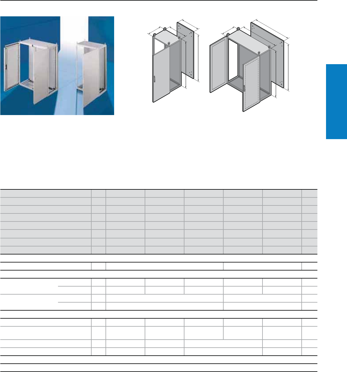
Carbon Steel Freestanding
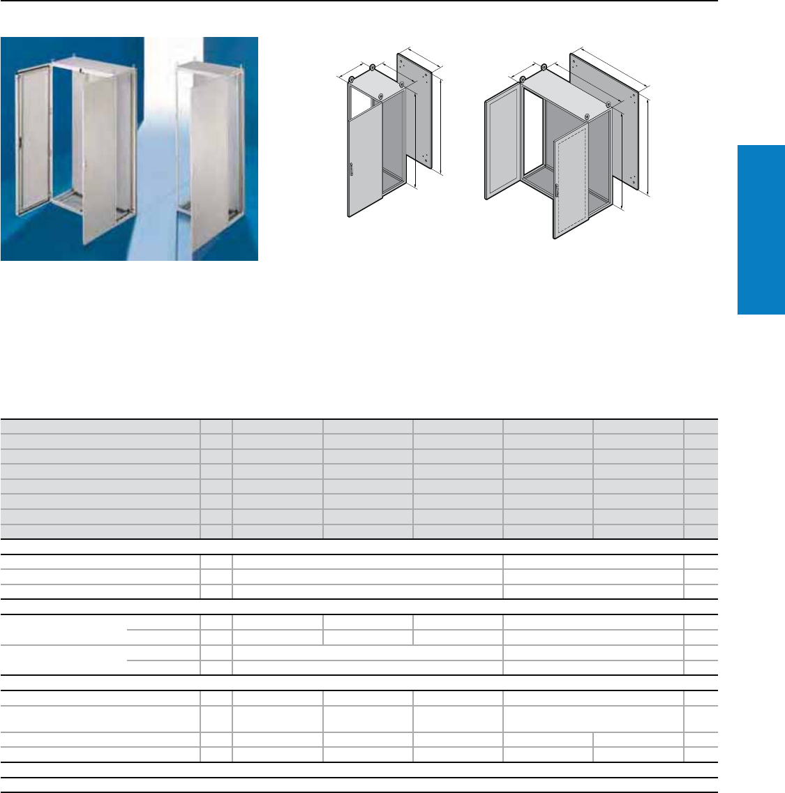
TS8 - Freestanding
Height: 55" (1400 mm), Depth: 20 - 24" (500 - 600 mm)
Material:
Sheet steel
Enclosure frame, roof, rear wall
and gland plates: 16 ga (1.5 mm)
Door: 14 ga (2.0 mm)
Mounting panel: 11 ga (3.0 mm)
Finish:
Enclosure frame: Dipcoat-primed
Door, roof and rear wall: Dipcoat-
primed, powder coated in
textured RAL 7035 (light gray)
on the outside
Mounting panel and gland plates:
Zinc-plated
Protection Ratings:
UL/CUL Type 12
(IP 55 to EN 60 529)
UL, CSA certified
UL file: E76083
Conguration:
Enclosure frame with doors,
mounting panel, gland plates,
rear wall and roof plate
T
F1
G1
H
B
B
T
F1
H
G1
Inch and pound measurements are rounded to the nearest whole number.
For additional technical information,
please visit www.rittal-corp.com
Height (H) inches (mm) PU 55 (1400) 55 (1400) 55 (1400) 55 (1400) 55 (1400) Page
Width (B) inches (mm) 24 (600) 32 (800) 47 (1200) 24 (600) 32 (800)
Depth (T) inches (mm) 20 (500) 20 (500) 20 (500) 24 (600) 24 (600)
Panel Height (G1) inches (mm) 51 (1296) 51 (1296) 51 (1296) 51 (1296) 51 (1296)
Panel Width (F1) inches (mm) 20 (499) 28 (699) 43 (1099) 20 (499) 28 (699)
Part No. 18645.500 8845.500 8245.500 8646.500 8846.500
Door(s) 11211
Weight lb (kg) 190 (86) 237 (108) 361 (164) 217 (98) 270 (123)
Walls
Sidewalls 2 8145.235 8146.235 202
Base/plinth
Components front and rear
inches (mm)
Height 4 (100) 1 set 8601.600 8601.800 8601.200 8601.600 8601.800 194
Height 8 (200) 1 set 8602.600 8602.800 8602.200 8602.600 8602.800 194
Side panels inches (mm) Height 4 (100) 1 set 8601.050 8601.060 194
Height 8 (200) 1 set 8602.050 8602.060 194
Accessories
Cable clamp rails for cable clamps 2 4191.000 4192.000 4196.000 4191.000 4192.000 256
Cable clamp rails (C section) for cable
clamps 6 4944.000 4945.000 4947.000 4944.000 4945.000 256
Support rails for door 20 4596.000 4598.000 4596.000 4598.000 236
Print pocket, sheet steel 1 4116.000 4118.000 4116.000 4118.000 227
Lock systems
Standard double-bit lock insert may be exchanged for other lock inserts and comfort handle, see pages 217-220.
18 Industrial Buyer’s Guide
Carbon Steel Freestanding
TS8 - Freestanding
Height: 55" (1400 mm), Depth: 24 - 32" (600 - 800 mm)
Inch and pound measurements are rounded to the nearest whole number.
Height (H) inches (mm) PU 55 (1400) 55 (1400) 55 (1400) 55 (1400) Page
Width (B) inches (mm) 47 (1200) 24 (600) 32 (800) 47 (1200)
Depth (T) inches (mm) 24 (600) 32 (800) 32 (800) 32 (800)
Panel Height (G1) inches (mm) 51 (1296) 51 (1296) 51 (1296) 51 (1296)
Panel Width (F1) inches (mm) 43 (1099) 28 (699) 28 (699) 43 (1099)
Part No. 18246.500 8648.500 8848.500 8248.500
Door(s) 2112
Weight lb (kg) 187 (412) 289 (131) 360 (163) 549 (249)
Walls
Sidewalls 2 8146.235 8148.235 202
Divider panel 1 - 204
Divider panel for module plates 1 - 205
Base/plinth
Components front and rear
inches (mm)
Height 4 (100) 1 set 8601.200 8601.600 8601.800 8601.200 194
Height 8 (200) 1 set 8602.200 8602.600 8602.800 8602.200 194
Side panels inches (mm) Height 4 (100) 1 set 8601.060 8601.080 194
Height 8 (200) 1 set 8602.060 8602.080 194
Accessories
Cable clamp rails for cable clamps 2 4196.000 4191.000 4192.000 4196.000 256
Cable clamp rails (C section) for cable clamps 6 4947.000 4944.000 4945.000 4947.000 256
Support rails for door 20 4596.000 4598.000 4596.000 236
Print pocket, sheet steel 1 4116.000 4118.000 4116.000 227
Lock systems
Standard double-bit lock insert may be exchanged for other lock inserts and comfort handle, see pages 217-220.
Industrial Buyer’s Guide 19
Carbon Steel Freestanding
TS8 - Freestanding
Height: 63" (1600 mm), Depth: 20 - 24" (600 - 800 mm)
Material:
Sheet steel
Enclosure frame, roof, rear wall
and gland plates: 16 ga (1.5 mm)
Door: 14 ga (2.0 mm)
Mounting panel: 11 ga (3.0 mm)
Finish:
Enclosure frame: Dipcoat-primed
Door, roof and rear wall:
Dipcoat-primed, powder coated
in textured RAL 7035 (light gray)
on the outside
Mounting panel and gland plates:
Zinc-plated
Protection Ratings:
UL Type 12 (IP 55 to EN 60 529)
UL, CSA certified
UL file: E76083
Conguration:
Enclosure frame with doors,
mounting panel, gland plates,
rear wall and roof plate
Height (H) inches (mm) PU 63 (1600) 63 (1600) 63 (1600) 63 (1600) 63 (1600) Page
Width (B) inches (mm) 24 (600) 32 (800) 47 (1200) 24 (600) 32 (800)
Depth (T) inches (mm) 20 (500) 20 (500) 20 (500) 24 (600) 24 (600)
Panel Height (G1) inches (mm) 59 (1496) 59 (1496) 59 (1496) 59 (1496) 59 (1496)
Panel Width (F1) inches (mm) 20 (499) 28 (699) 43 (1099) 20 (499) 20 (499)
Part No. 18665.500 8865.500 8265.500 8666.500 8866.500
Door(s) 11211
Weight lb (kg) 221 (100) 227 (103) 351 (159) 252 (114) 259 (117)
Walls
Sidewalls 2 8165.235 8166.235 202
Base/plinth
Components front and
rear inches (mm)
Height 4 (100) 1 set 8601.600 8601.800 8601.200 8601.600 8601.800 194
Height 8 (200) 1 set 8602.600 8602.800 8602.200 8602.600 8602.800 194
Side panels inches (mm) Height 4 (100) 1 set 8601.050 8601.060 194
Height 8 (200) 1 set 8602.050 8602.060 194
Accessories
Cable clamp rails for cable clamps 2 4191.000 4192.000 4196.000 4191.000 4192.000 256
Cable clamp rails (C section) for cable
clamps 6 4944.000 4945.000 4947.000 4944.000 4945.000 256
Support rails for door 20 4596.000 4598.000 4596.000 4598.000 236
Print pocket, sheet steel 1 4116.000 4118.000 4116.000 4118.000 227
Lock systems
Standard double-bit lock insert may be exchanged for other lock inserts and comfort handle, see pages 217-220.
T
F1
G1
H
B
B
T
F1
H
G1
Inch and pound measurements are rounded to the nearest whole number.
For additional technical information,
please visit www.rittal-corp.com
20 Industrial Buyer’s Guide
Carbon Steel Freestanding
TS8 - Freestanding
Height: 63" (1600 mm), Depth: 24 - 32" (600 - 800 mm)
Height (H) inches (mm) PU 63 (1600) 63 (1600) 63 (1600) 63 (1600) Page
Width (B) inches (mm) 47 (1200) 24 (600) 32 (800) 47 (1200)
Depth (T) inches (mm) 24 (600) 32 (800) 32 (800) 32 (800)
Panel Height (G1) inches (mm) 59 (1496) 59 (1496) 59 (1496) 59 (1496)
Panel Width (F1) inches (mm) 43 (1099) 20 (499) 28 (699) 43 (1099)
Part No. 18266.500 8668.500 8868.500 8268.500
Door(s) 2112
Weight lb (kg) 400 (182) 336 (153) 345 (157) 534 (242)
Walls
Sidewalls 2 8166.235 8168.235 202
Base/plinth
Components front and
rear inches (mm)
Height 4 (100) 1 set 8601.200 8601.600 8601.800 8601.200 194
Height 8 (200) 1 set 8602.200 8602.600 8602.800 8602.200 194
Side panels inches (mm) Height 4 (100) 1 set 8601.060 8601.080 194
Height 8 (200) 1 set 8602.060 8602.080 194
Accessories
Cable clamp rails for cable clamps 2 4196.000 4191.000 4192.000 4196.000 256
Cable clamp rails (C section) for cable
clamps 6 4947.000 4944.000 4945.000 4947.000 256
Support rails for door 20 4596.000 4598.000 4596.000 236
Print pocket, sheet steel 1 4116.000 4118.000 4116.000 227
Lock Systems
Standard double-bit lock insert may be exchanged for other lock inserts and comfort handle, see pages 217-220.
Inch and pound measurements are rounded to the nearest whole number.
Industrial Buyer’s Guide 21
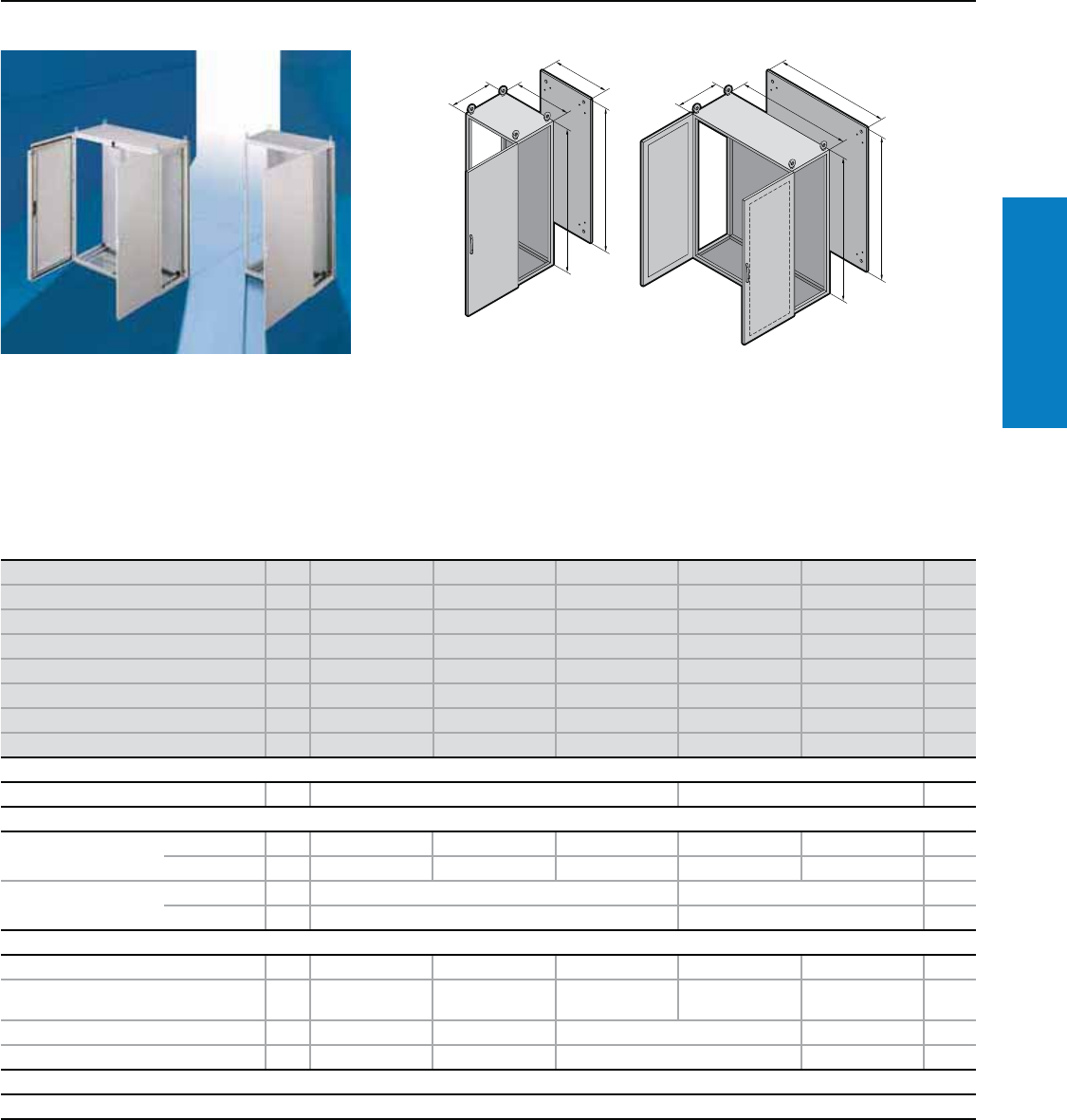
Carbon Steel Freestanding
TS8 - Freestanding
Height: 71" (1800 mm), Depth: 16" (400 mm)
Material:
Sheet steel
Enclosure frame, roof, rear wall
and gland plates: 16 ga (1.5 mm)
Door: 14 ga (2.0 mm)
Mounting panel: 11 ga (3.0 mm)
Finish:
Enclosure frame: Dipcoat-primed
Door, roof and rear wall: Dipcoat-
primed, powder coated in
textured RAL 7035 (light gray)
on the outside
Mounting panel and gland plates:
Zinc-plated
Protection Ratings:
UL Type 12
(IP 55 to EN 60 529)
UL, CSA certified
UL file: E76083
Conguration:
Enclosure frame with doors,
mounting panel, gland plates,
rear wall and roof plate
Height (H) inches (mm) PU 71 (1800) 71 (1800) 71 (1800) 71 (1800) 71 (1800) Page
Width (B) inches (mm) 24 (600) 32 (800) 39 (1000) 39 (1000) 47 (1200)
Depth (T) inches (mm) 16 (400) 16 (400) 16 (400) 16 (400) 16 (400)
Panel Height (G1) inches (mm) 67 (1696) 67 (1696) 67 (1696) 67 (1696) 67 (1696)
Panel Width (F1) inches (mm) 20 (499) 28 (699) 35 (899) 35 (899) 43 (1099)
Part No. 18684.500 8884.500 8084.500 8080.500 8284.500
Door(s) 11122
Weight lb (kg) 201 (91) 250 (114) 301 (136) 309 (140) 376 (171)
Walls
Sidewalls 2 8184.235 202
Divider panel 1 8609.840 204
Base/plinth
Components front and
rear inches (mm)
Height 4 (100) 1 set 8601.600 8601.800 8601.000 8601.200 194
Height 8 (200) 1 set 8602.600 8602.800 8602.000 8602.200 194
Side panels inches (mm) Height 4 (100) 1 set 8601.040 194
Height 8 (200) 1 set 8602.040 194
Accessories
Cable clamp rails for cable clamps 2 4191.000 4192.000 4336.000 4196.000 256
Cable clamp rails (C section) for cable
clamps 6 4944.000 4945.000 4946.000 4947.000 256
Support rails for door 20 4596.000 4598.000 4599.000 4309.000 4596.000 236
Print pocket, sheet steel 1 4116.000 4118.000 4124.000 4115.000 4116.000 227
Lock systems
Standard double-bit lock insert may be exchanged for other lock inserts and comfort handle, see pages 217-220.
T
F1
G1
H
B
B
T
F1
H
G1
Inch and pound measurements are rounded to the nearest whole number.
For additional technical information,
please visit www.rittal-corp.com
22 Industrial Buyer’s Guide
Carbon Steel Freestanding
Height (H) inches (mm) PU 71 (1800) 71 (1800) 71 (1800) 71 (1800) 71 (1800) Page
Width (B) inches (mm) 63 (1600) 71 (1800) 16 (400) 24 (600) 32 (800)
Depth (T) inches (mm) 16 (400) 16 (400) 20 (500) 20 (500) 20 (500)
Panel Height (G1) inches (mm) 67 (1696) 67 (1696) - 67 (1696) 67 (1696)
Panel Width (F1) inches (mm) 59 (1499) 67 (1699) - 20 (499) 28 (699)
Part No. 18901.210 8901.250 8485.510* 8685.500 8885.500
Door(s) 22111
Weight kg (lb) 478 (217) 538 (244) 109 (49) 207 (94) 255 (116)
Walls
Sidewalls 2 8184.235 8185.235 202
Divider panel 1 8609.840 8609.850 204
Divider panel for module plates 1 – 8609.100 205
Base/plinth
Components front and
rear inches (mm)
Height 4 (100) 1 set 8601.920 8901.920 8601.400 8601.600 8601.800 194
Height 8 (200) 1 set 8602.920 8901.930 8602.400 8602.600 8602.800 194
Side panels inches (mm) Height 4 (100) 1 set 8601.040 8601.050 194
Height 8 (200) 1 set 8602.040 8602.050 194
Accessories
Cable clamp rails for cable clamps 2 4338.000 4339.000 4193.000 4191.000 4192.000 256
Cable clamp rails (C section) for cable
clamps 6 – 4944.000 4945.000 256
Support rails for door 20 4598.000 4579.000 – 4596.000 4598.000 236
Print pocket, sheet steel 1 4118.000 4123.000 – 4116.000 4118.000 227
Lock Systems
Standard double-bit lock insert may be exchanged for other lock inserts and comfort handle, see pages 217-220.
* Without tubular door frame, mounting panel and gland plates.
TS8 - Freestanding
Height: 71" (1800 mm), Depth: 16 - 20" (400 - 500 mm)
Height (H) inches (mm) PU 71 (1800) 71 (1800) 71 (1800) 71 (1800) 71 (1800) Page
Width (B) inches (mm) 32 (800) 39 (1000) 47 (1200) 63 (1600) 71 (1800)
Depth (T) inches (mm) 20 (500) 20 (500) 20 (500) 20 (500) 20 (500)
Panel Height (G1) inches (mm) 67 (1696) 67 (1696) 67 (1696) 67 (1696) 67 (1696)
Panel Width (F1) inches (mm) 28 (699) 35 (899) 43 (1099) 59 (1499) 67 (1699)
Part No. 18880.500 8085.500 8285.500 8901.220 8901.260
Door(s) 21222
Weight kg (lb) 270 (123) 328 (149) 382 (173) 485 (220) 546 (248)
Walls
Sidewalls 2 8185.235 202
Divider panel 1 8609.850 204
Divider panel for module plates 1 8609.100 205
Base/plinth
Components front and
rear inches (mm)
Height 4 (100) 1 set 8601.800 8601.000 8601.200 8601.920 8901.920 194
Height 8 (200) 1 set 8602.800 8602.000 8602.200 8602.920 8901.930 194
Side panels inches (mm) Height 4 (100) 1 set 8601.050 194
Height 8 (200) 1 set 8602.050 194
Accessories
Cable clamp rails for cable clamps 2 4192.000 4336.000 4196.000 4338.000 4339.000 256
Cable clamp rails (C section) for cable
clamps 6 4945.000 4946.000 4947.000 – 256
Support rails for door 20 4594.000 4599.000 4596.000 4598.000 4579.000 236
Print pocket, sheet steel 1 4114.000 4124.000 4116.000 4118.000 4123.000 227
Lock Systems
Standard double-bit lock insert may be exchanged for other lock inserts and comfort handle, see pages 217-220.
Inch and pound measurements are rounded to the nearest whole number.
Industrial Buyer’s Guide 23
Carbon Steel Freestanding
TS8 - Freestanding
Height: 71" (1800 mm), Depth: 24 - 32" (600 - 800 mm)
Height (H) inches (mm) PU 71 (1800) 71 (1800) 71 (1800) 71 (1800) 71 (1800) Page
Width (B) inches (mm) 16 (400) 24 (600) 32 (800) 32 (800) 47 (1200)
Depth (T) inches (mm) 24 (600) 24 (600) 24 (600) 24 (600) 24 (600)
Panel Height (G1) inches (mm) – 67 (1696) 67 (1696) 67 (1696) 67 (1696)
Panel Width (F1) inches (mm) – 20 (499) 28 (699) 28 (699) 43 (1099)
Part No. 18486.510* 8686.500 8886.500 8881.500 8286.500
Door(s) 11122
Weight lb (kg) 114 (52) 213 (97) 265 (120) 277 (126) 397 (180)
Walls
Sidewalls 2 8186.235 202
Divider panel 1 8609.860 204
Divider panel for module plates 1 8609.110 205
Base/plinth
Components front and
rear inches (mm)
Height 4 (100) 1 set 8601.400 8601.600 8601.800 8601.200 194
Height 8 (200) 1 set 8602.400 8602.600 8602.800 8602.200 194
Side panels inches (mm) Height 4 (100) 1 set 8601.060 194
Height 8 (200) 1 set 8602.060 194
Accessories
Cable clamp rails for cable clamps 2 4193.000 4191.000 4192.000 4196.000 256
Cable clamp rails (C section) for cable
clamps 6 – 4944.000 4945.000 4947.000 256
Support rails for door 20 – 4596.000 4598.000 4594.000 4596.000 236
Print pocket, sheet steel 1 – 4116.000 4118.000 4114.000 4116.000 227
Lock systems
Standard double-bit lock insert may be exchanged for other lock inserts and comfort handle, see pages 217-220.
* Without tubular door frame, mounting panel and gland plates.
Height (H) inches (mm) PU 71 (1800) 71 (1800) 71 (1800) 71 (1800) 71 (1800) Page
Width (B) inches (mm) 39 (1000) 63 (1600) 71 (1800) 24 (600) 32 (800)
Depth (T) inches (mm) 24 (600) 24 (600) 24 (600) 32 (800) 32 (800)
Panel Height (G1) inches (mm) 67 (1696) 67 (1696) 67 (1696) 67 (1696) 67 (1696)
Panel Width (F1) inches (mm) 35 (899) 59 (1499) 67 (1699) 20 (499) 28 (699)
Part No. 18086.500 8901.230 8901.270 8688.500 8888.500
Door(s) 12211
Weight lb (kg) 314 (142 ) 502 (228) 565 (256) 251 (114) 420 (190)
Walls
Sidewalls 2 8186.235 8188.235 202
Divider panel 1 8609.860 – 204
Divider panel for module plates 1 8609.110 – 205
Base/plinth
Components front and
rear inches (mm)
Height 4 (100) 1 set 8601.000 8601.920 8901.920 8601.600 8601.800 194
Height 8 (200) 1 set 8602.000 8602.920 8901.930 8602.600 8602.800 194
Side panels inches (mm) Height 4 (100) 1 set 8601.060 8601.080 194
Height 8 (200) 1 set 8602.060 8602.080 194
Accessories
Cable clamp rails for cable clamps 2 4336.000 4338.000 4339.000 4191.000 4192.000 256
Cable clamp rails (C section) for cable
clamps 6 4946.000 – 4944.000 4945.000 256
Support rails for door 20 4599.000 4598.000 4579.000 4596.000 4598.000 236
Print pocket, sheet steel 1 4124.000 4118.000 4123.000 4116.000 4118.000 227
Lock systems
Standard double-bit lock insert may be exchanged for other lock inserts and comfort handle, see pages 217-220.
Inch and pound measurements are rounded to the nearest whole number.
24 Industrial Buyer’s Guide
Carbon Steel Freestanding
TS8 - Freestanding
Height: 71" (1800 mm), Depth: 32" (800 mm)
Height (H) inches (mm) PU 71 (1800) 71 (1800) 71 (1800) 71 (1800) Page
Width (B) inches (mm) 39 (1000) 47 (1200) 63 (1600) 71 (1800)
Depth (T) inches (mm) 32 (800) 32 (800) 32 (800) 32 (800)
Panel Height (G1) inches (mm) 67 (1696) 67 (1696) 67 (1696) 67 (1696)
Panel Width (F1) inches (mm) 35 (899) 43 (1099) 59 (1499) 67 (1699)
Part No. 18088.500 8288.500 8901.240 8901.280
Door(s) 1222
Weight lb (kg) 525 (238) 629 (286) 839 (381) 944 (428)
Walls
Sidewalls 2 8188.235 202
Base/plinth
Components front and rear
inches (mm)
Height 4 (100) 1 set 8601.000 8601.200 8601.920 8901.920 194
Height 8 (200) 1 set 8602.000 8602.200 8602.920 8901.930 194
Side panels inches (mm) Height 4 (100) 1 set 8601.080 194
Height 8 (200) 1 set 8602.080 194
Accessories
Cable clamp rails for cable clamps 2 4336.000 4196.000 4338.000 4339.000 256
Cable clamp rails (C section) for cable clamps 6 4946.000 4947.000 – 256
Support rails for door 20 4599.000 4596.000 4598.000 4579.000 236
Print pocket, sheet steel 1 4124.000 4116.000 4118.000 4123.000 227
Lock systems
Standard double-bit lock insert may be exchanged for other lock inserts and comfort handle, see pages 217-220.
Inch and pound measurements are rounded to the nearest whole number.
Industrial Buyer’s Guide 25
Carbon Steel Freestanding
TS8 - Freestanding
Height: 79" (2000 mm), Depth: 16 - 20" (400 - 500 mm)
Material:
Sheet steel
Enclosure frame, roof, rear wall
and gland plates: 16 ga (1.5 mm)
Door: 14 ga (2.0 mm)
Mounting panel: 11 ga (3.0 mm)
Finish:
Enclosure frame: Dipcoat-primed
Door, roof and rear wall: Dipcoat-
primed, powder coated in
textured RAL 7035 (light gray)
on the outside
Mounting panel and gland plates:
Zinc-plated
Protection Ratings:
UL Type 12
(IP 55 to EN 60 529)
UL, CSA certified
UL file: E76083
Conguration:
Enclosure frame with doors,
mounting panel, gland plates,
rear wall and roof plate
Height (H) inches (mm) PU 79 (2000) 79 (2000) 79 (2000) 79 (2000) 79 (2000) Page
Width (B) inches (mm) 24 (600) 32 (800) 47 (1200) 16 (400) 16 (400)
Depth (T) inches (mm) 16 (400) 16 (400) 16 (400) 20 (500) 20 (500)
Panel Height (G1) inches (mm) 75 (1896) 75 (1896) 75 (1896) – 75 (1896)
Panel Width (F1) inches (mm) 20 (499) 28 (699) 43 (1099) – 12 (299)
Part No. 18604.500 8804.500 8204.500 8405.510* 8405.500
Door(s) 11211
Weight lb (kg) 218 (99) 273 (124) 407 (185) 134 (61) 116 (53)
Walls
Sidewalls 2 8104.235 8105.235 202
Divider panel 1 8609.040 8609.050 204
Divider panel for module plates 1 – 8609.120 205
Base/plinth
Components front and
rear inches (mm)
Height 4 (100) 1 set 8601.600 8601.800 8601.200 8601.400 194
Height 8 (200) 1 set 8602.600 8602.800 8602.200 8602.400 194
Side panels inches (mm) Height 4 (100) 1 set 8601.040 8601.050 194
Height 8 (200) 1 set 8602.040 8602.050 194
Accessories
Cable clamp rails for cable clamps 2 4191.000 4192.000 4196.000 4193.000 256
Cable clamp rails (C section) for cable
clamps 6 4944.000 4945.000 4947.000 – 256
Support rails for door 20 4596.000 4598.000 4596.000 – 4594.000 236
Print pocket, sheet steel 1 4116.000 4118.000 4116.000 – 4114.000 227
Lock systems
Standard double-bit lock insert may be exchanged for other lock inserts and comfort handle, see pages 217-220.
* Without tubular door frame, mounting panel and gland plates.
Inch and pound measurements are rounded to the nearest whole number.
For additional technical information,
please visit www.rittal-corp.com
B
T
F1
H
G1
T
F1
G1
H
B
26 Industrial Buyer’s Guide
Carbon Steel Freestanding
TS8 - Freestanding
Height: 79" (2000 mm), Depth: 20 - 24" (500 - 600 mm)
Height (H) inches (mm) PU 79 (2000) 79 (2000) 79 (2000) 79 (2000) 79 (2000) Page
Width (B) inches (mm) 24 (600) 32 (800) 39 (1000) 47 (1200) 63 (1600)
Depth (T) inches (mm) 20 (500) 20 (500) 20 (500) 20 (500) 20 (500)
Panel Height (G1) inches (mm) 75 (1896) 75 (1896) 75 (1896) 75 (1896) 75 (1896)
Panel Width (F1) inches (mm) 20 (499) 28 (699) 35 (899) 43 (1099) 59 (1499)
Part No. 18605.500 8805.500 8005.500 8205.500 8901.290
Door(s) 11222
Weight lb (kg) 223 (101) 278 (126) 346 (157) 420 (191) 583 (264)
Walls
Sidewalls 2 8105.235 202
Divider panel 1 8609.050 204
Divider panel for module plates 1 8609.120 205
Base/plinth
Components front and
rear inches (mm)
Height 4 (100) 1 set 8601.600 8601.800 8601.000 8601.200 8601.920 194
Height 8 (200) 1 set 8602.600 8602.800 8602.000 8602.200 8602.920 194
Side panels inches (mm) Height 4 (100) 1 set 8601.050 194
Height 8 (200) 1 set 8602.050 194
Accessories
Cable clamp rails for cable clamps 2 4191.000 4192.000 4336.000 4196.000 4338.000 256
Cable clamp rails (C section) for cable
clamps 6 4944.000 4945.000 4946.000 4947.000 – 256
Support rails for door 20 4596.000 4598.000 4309.000 4596.000 4598.000 236
Print pocket, sheet steel 1 4116.000 4118.000 4115.000 4116.000 4118.000 227
Lock systems
Standard double-bit lock insert may be exchanged for other lock inserts and comfort handle, see pages 217-220.
Height (H) inches (mm) PU 79 (2000) 79 (2000) 79 (2000) 79 (2000) 79 (2000) Page
Width (B) inches (mm) 71 (1800) 16 (400) 24 (600) 32 (800) 39 (1000)
Depth (T) inches (mm) 20 (500) 24 (600) 24 (600) 24 (600) 24 (600)
Panel Height (G1) inches (mm) 75 (1896) – 75 (1896) 75 (1896) 75 (1896)
Panel Width (F1) inches (mm) 67 (1699) – 20 (499) 28 (699) 35 (899)
Part No. 18901.420 8406.510* 8606.500 8806.500 8006.500
Door(s) 2111 2
Weight lb (kg) 656 (298) 123 (56) 229 (104) 288 (131) 355 (161)
Walls
Sidewalls 2 8105.235 8106.235 202
Divider panel 1 8609.050 8609.060 204
Divider panel for module plates 1 8609.120 8609.130 205
Base/plinth
Components front and
rear inches (mm)
Height 4 (100) 1 set 8901.920 8601.400 8601.600 8601.800 8601.000 194
Height 8 (200) 1 set 8901.930 8602.400 8602.600 8602.800 8602.000 194
Side panels inches (mm) Height 4 (100) 1 set 8601.050 8601.060 194
Height 8 (200) 1 set 8602.050 8602.060 194
Accessories
Cable clamp rails for cable clamps 2 4339.000 4193.000 4191.000 4192.000 4336.000 256
Cable clamp rails (C section) for cable
clamps 6 – 4944.000 4945.000 4946.000 256
Support rails for door 20 4579.000 – 4596.000 4598.000 4309.000 236
Print pocket, sheet steel 1 4123.000 – 4116.000 4118.000 4115.000 227
Lock systems
Standard double-bit lock insert may be exchanged for other lock inserts and comfort handle, see pages 217-220.
* Without tubular door frame, mounting panel and gland plates.
Inch and pound measurements are rounded to the nearest whole number.
Industrial Buyer’s Guide 27
Carbon Steel Freestanding
TS8 - Freestanding
Height: 79" (2000 mm), Depth: 24 - 32" (600 - 800 mm)
Height (H) inches (mm) PU 79 (2000) 79 (2000) 79 (2000) 79 (2000) 79 (2000) Page
Width (B) inches (mm) 39 (1000) 47 (1200) 63 (1600) 71 (1800) 24 (600)
Depth (T) inches (mm) 24 (600) 24 (600) 24 (600) 24 (600) 32 (800)
Panel Height (G1) inches (mm) 75 (1896) 75 (1896) 75 (1896) 75 (1896) 75 (1896)
Panel Width (F1) inches (mm) 35 (899) 43 (1099) 59 (1499) 67 (1699) 20 (499)
Part No. 18006.530 8206.500 8901.400 8901.430 8608.500
Door(s) 12221
Weight lb (kg) 437 (198) 429 (195) 699 (317) 787 (357) 245 (111)
Walls
Sidewalls 2 8106.235 8108.235 202
Divider panel 1 8609.060 8609.080 204
Divider panel for module plates 1 8609.130 3348.200 205
Base/plinth
Components front and
rear inches (mm)
Height 4 (100) 1 set 8601.000 8601.200 8601.920 8901.920 8601.600 194
Height 8 (200) 1 set 8602.000 8602.200 8602.920 8901.930 8602.600 194
Side panels inches (mm) Height 4 (100) 1 set 8601.060 8601.080 194
Height 8 (200) 1 set 8602.060 8602.080 194
Accessories
Cable clamp rails for cable clamps 2 4336.000 4196.000 4338.000 4339.000 4191.000 256
Cable clamp rails (C section) for cable
clamps 6 4946.000 4947.000 – 4944.000 256
Support rails for door 20 4599.000 4596.000 4598.000 4579.000 4596.000 236
Print pocket, sheet steel 1 4124.000 4116.000 4118.000 4123.000 4116.000 227
Lock Systems
Standard double-bit lock insert may be exchanged for other lock inserts and comfort handle, see pages 217-220.
Height (H) inches (mm) PU 79 (2000) 79 (2000) 79 (2000) 79 (2000) 79 (2000) Page
Width (B) inches (mm) 32 (800) 39 (1000) 47 (1200) 63 (1600) 71 (1800)
Depth (T) inches (mm) 32 (800) 32 (800) 32 (800) 32 (800) 32 (800)
Panel Height (G1) inches (mm) 75 (1896) 75 (1896) 75 (1896) 75 (1896) 75 (1896)
Panel Width (F1) inches (mm) 28 (699) 35 (899) 43 (1099) 59 (1499) 67 (1699)
Part No. 18808.500 8008.530 8208.500 8901.410 8901.440
Door(s) 11222
Weight lb (kg) 302 (137) 583 (264) 448 (203) 932 (423) 1049 (476)
Walls
Sidewalls 2 8108.235 202
Divider panel 1 8609.080 204
Base/plinth
Components front and
rear inches (mm)
Height 4 (100) 1 set 8601.800 8601.000 8601.200 8601.920 8901.920 194
Height 8 (200) 1 set 8602.800 8602.000 8602.200 8602.920 8901.930 194
Side panels inches (mm) Height 4 (100) 1 set 8601.080 194
Height 8 (200) 1 set 8602.080 194
Accessories
Cable clamp rails for cable clamps 2 4192.000 4336.000 4196.000 4338.000 4339.000 256
Cable clamp rails (C section) for cable
clamps 6 4945.000 4946.000 4947.000 – 256
Support rails for door 20 4598.000 4599.000 4596.000 4598.000 4579.000 236
Print pocket, sheet steel 1 4118.000 4124.000 4116.000 4118.000 4123.000 227
Lock Systems
Standard double-bit lock insert may be exchanged for other lock inserts and comfort handle, see pages 217-220.
Inch and pound measurements are rounded to the nearest whole number.
28 Industrial Buyer’s Guide
Carbon Steel Freestanding
TS8 - Freestanding
Height: 87" (2200 mm), Depth: 20 - 24" (500 - 600 mm)
Material:
Sheet steel
Enclosure frame, roof, rear wall
and gland plates: 16 ga (1.5 mm)
Door: 14 ga (2.0 mm)
Mounting panel: 11 ga (3.0 mm)
Finish:
Enclosure frame: Dipcoat-primed
Door, roof and rear wall: Dipcoat-
primed, powder coated in
textured RAL 7035 (light gray)
on the outside
Mounting panel and gland plates:
Zinc-plated
Protection Ratings:
UL Type 12
(IP 55 to EN 60 529)
UL, CSA certified
UL file: E76083
Conguration:
Enclosure frame with doors,
mounting panel, gland plates, rear
wall and roof plate
Height (H) inches (mm) PU 87 (2200) 87 (2200) 87 (2200) 87 (2200) 87 (2200) Page
Width (B) inches (mm) 24 (600) 32 (800) 39 (1000) 47 (1200) 16 (400)
Depth (T) inches (mm) 20 (500) 20 (500) 20 (500) 20 (500) 24 (600)
Panel Height (G1) inches (mm) 83 (2096) 83 (2096) 83 (2096) 83 (2096) 83 (2096)
Panel Width (F1) inches (mm) 20 (499) 28 (699) 35 (899) 43 (1099) 12 (299)
Part No. 18625.500 8825.500 8025.500 8225.500 8426.500
Door(s) 11121
Weight lb (kg) 192 (87) 321 (145) 401 (182) 481 (218) 153 (70)
Walls
Sidewalls 2 8125.235 8126.235 202
Divider panel 1 – 8609.260 204
Base/plinth
Components front and
rear inches (mm)
Height 4 (100) 1 set 8601.600 8601.800 8601.000 8601.200 8601.400 194
Height 8 (200) 1 set 8602.600 8602.800 8602.000 8602.200 8602.400 194
Side panels inches (mm) Height 4 (100) 1 set 8601.050 8601.060 194
Height 8 (200) 1 set 8602.050 8602.060 194
Accessories
Cable clamp rails for cable clamps 2 4191.000 4192.000 4336.000 4196.000 4193.000 256
Cable clamp rails (C section)
for cable clamps 6 4944.000 4945.000 4946.000 4947.000 – 256
Support rails for door 20 4596.000 4598.000 4599.000 4596.000 4594.000 236
Print pocket, sheet steel 1 4116.000 4118.000 4124.000 4116.000 4114.000 227
Lock Systems
Standard double-bit lock insert may be exchanged for other lock inserts and comfort handle, see pages 217-220.
Inch and pound measurements are rounded to the nearest whole number.
For additional technical information,
please visit www.rittal-corp.com
Industrial Buyer’s Guide 29
Carbon Steel Freestanding
TS8 - Freestanding
Height: 87" (2200 mm), Depth: 24 - 32" (600 - 800 mm)
Height (H) inches (mm) PU 87 (2200) 87 (2200) 87 (2200) 87 (2200) Page
Width (B) inches (mm) 24 (600) 32 (800) 39 (1000) 47 (1200)
Depth (T) inches (mm) 24 (600) 24 (600) 24 (600) 24 (600)
Panel Height (G1) inches (mm) 83 (2096) 83 (2096) 83 (2096) 83 (2096)
Panel Width (F1) inches (mm) 20 (499) 28 (699) 35 (899) 43 (1099)
Part No. 18626.500 8826.500 8026.500 8226.500
Door(s) 1112
Weight lb (kg) 249 (113) 250 (139) 345 (157) 459 (208)
Walls
Sidewalls 2 8126.235 202
Divider panel 1 8609.260 204
Base/plinth
Components front and
rear inches (mm)
Height 4 (100) 1 set 8601.600 8601.800 8601.000 8601.200 194
Height 8 (200) 1 set 8602.600 8602.800 8602.000 8602.200 194
Side panels inches (mm) Height 4 (100) 1 set 8601.060 194
Height 8 (200) 1 set 8602.060 194
Accessories
Cable clamp rails for cable clamps 2 4191.000 4192.000 4336.000 4196.000 256
Cable clamp rails (C section) for cable
clamps 6 4944.000 4945.000 4946.000 4947.000 256
Support rails for door 20 4596.000 4598.000 4599.000 4596.000 236
Print pocket, sheet steel 1 4116.000 4118.000 4124.000 4116.000 227
Lock Systems
Standard double-bit lock insert may be exchanged for other lock inserts and comfort handle, see pages 217-220.
Inch and pound measurements are rounded to the nearest whole number.
Height (H) inches (mm) PU 87 (2200) 87 (2200) 87 (2200) 87 (2200) Page
Width (B) inches (mm) 24 (600) 32 (800) 39 (1000) 47 (1200)
Depth (T) inches (mm) 32 (800) 32 (800) 32 (800) 32 (800)
Panel Height (G1) inches (mm) 83 (2096) 83 (2096) 83 (2096) 83 (2096)
Panel Width (F1) inches (mm) 20 (499) 28 (699) 35 (899) 43 (1099)
Part No. 18628.500 8828.500 8028.500 8228.500
Door(s) 1112
Weight lb (kg) 260 (118) 320 (145) 358 (163) 470 (214)
Walls
Sidewalls 2 8128.235 202
Base/plinth
Components front and
rear inches (mm)
Height 4 (100) 1 set 8601.600 8601.800 8601.000 8601.200 194
Height 8 (200) 1 set 8602.600 8602.800 8602.000 8602.200 194
Side panels inches (mm) Height 4 (100) 1 set 8601.080 8601.080 8601.080 8601.080 194
Height 8 (200) 1 set 8602.080 8602.080 8602.080 8602.080 194
Accessories
Cable clamp rails for cable clamps 2 4191.000 4192.000 4336.000 4196.000 256
Cable clamp rails (C section) for cable
clamps 6 4944.000 4945.000 4946.000 4947.000 256
Support rails for door 20 4596.000 4598.000 4599.000 4596.000 236
Print pocket, sheet steel 1 4116.000 4118.000 4124.000 4116.000 227
Lock Systems
Standard double-bit lock insert may be exchanged for other lock inserts and comfort handle, see pages 217-220.
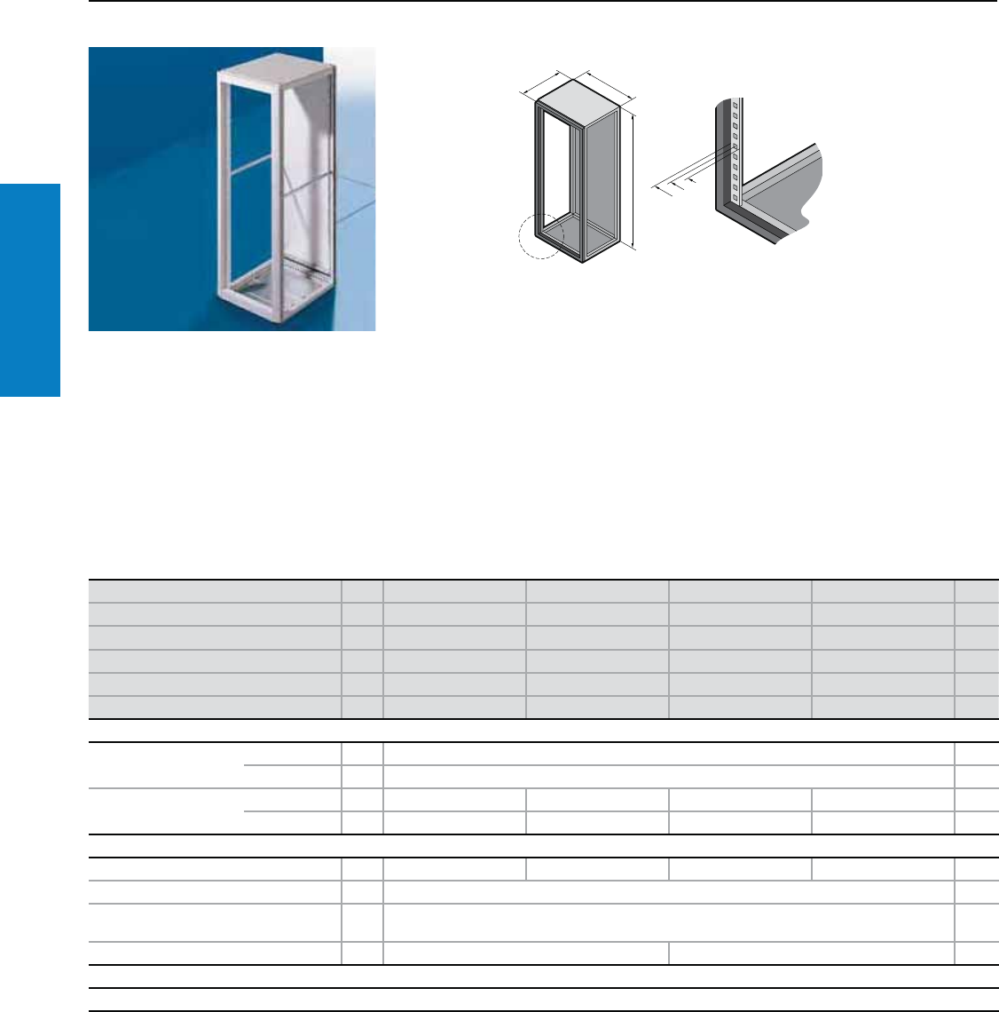
30 Industrial Buyer’s Guide
Carbon Steel Freestanding
TS8 Electronic - Freestanding
Height: 63 - 79" (1600 - 2000 mm), Depth: 24 - 32" (600 - 800 mm)
Material:
Sheet steel
Enclosure frame, roof and gland
plates: 16 ga (1.5 mm)
Rear door: 14 ga (2.0 mm)
19" rail sections: Aluminum
Front frame: Extruded aluminum
sections with die-cast corner
pieces
Finish:
Enclosure frame: Dipcoat-primed
front frame, rear door and roof:
Powder coated in RAL 7035
(light gray)
19" rail sections: Conductive,
corrosion-resistant coating
Gland plates: Zinc-plated
Protection Ratings:
UL Type 1
UL, CSA
UL file: E76083
Conguration:
Enclosure frame with doors (solid
or vented), mounting panel, gland
plates, rear wall and roof plate.
Height rack units (U) PU 33 33 42 42 Page
Height (H) inches (mm) 63 (1600) 63 (1600) 79 (2000) 79 (2000)
Width (B) inches (mm) 24 (600) 24 (600) 24 (600) 24 (600)
Depth (T) inches (mm) 24 (600) 32 (800) 24 (600) 32 (800)
Part No. 18410.510 8418.510 8430.510 8438.510
Door(s) 1111
Base/plinth
Components front and
rear inches (mm)
Height 4 (100) 1 set 8601.600 194
Height 8 (200) 1 set 8602.600 194
Side panels inches (mm) Height 4 (100) 1 set 8601.060 8601.080 8601.060 8601.080 194
Height 8 (200) 1 set 8602.060 8602.080 8602.060 8602.080 194
Accessories
Sidewalls 2 8166.235 8168.235 8106.235 8108.235 202
Cable clamp rails for cable clamps 2 4191.000 256
Cable clamp rails (C section) for cable
clamps 6 4944.000 256
Rear mounting angles 2 8613.360 8613.300 –
Lock systems
Standard double-bit lock insert (in rear door) may be exchanged for other lock inserts and comfort handle, see pages 217-220.
T
H
B
Inch and pound measurements are rounded to the nearest whole number.
For additional technical information,
please visit www.rittal-corp.com
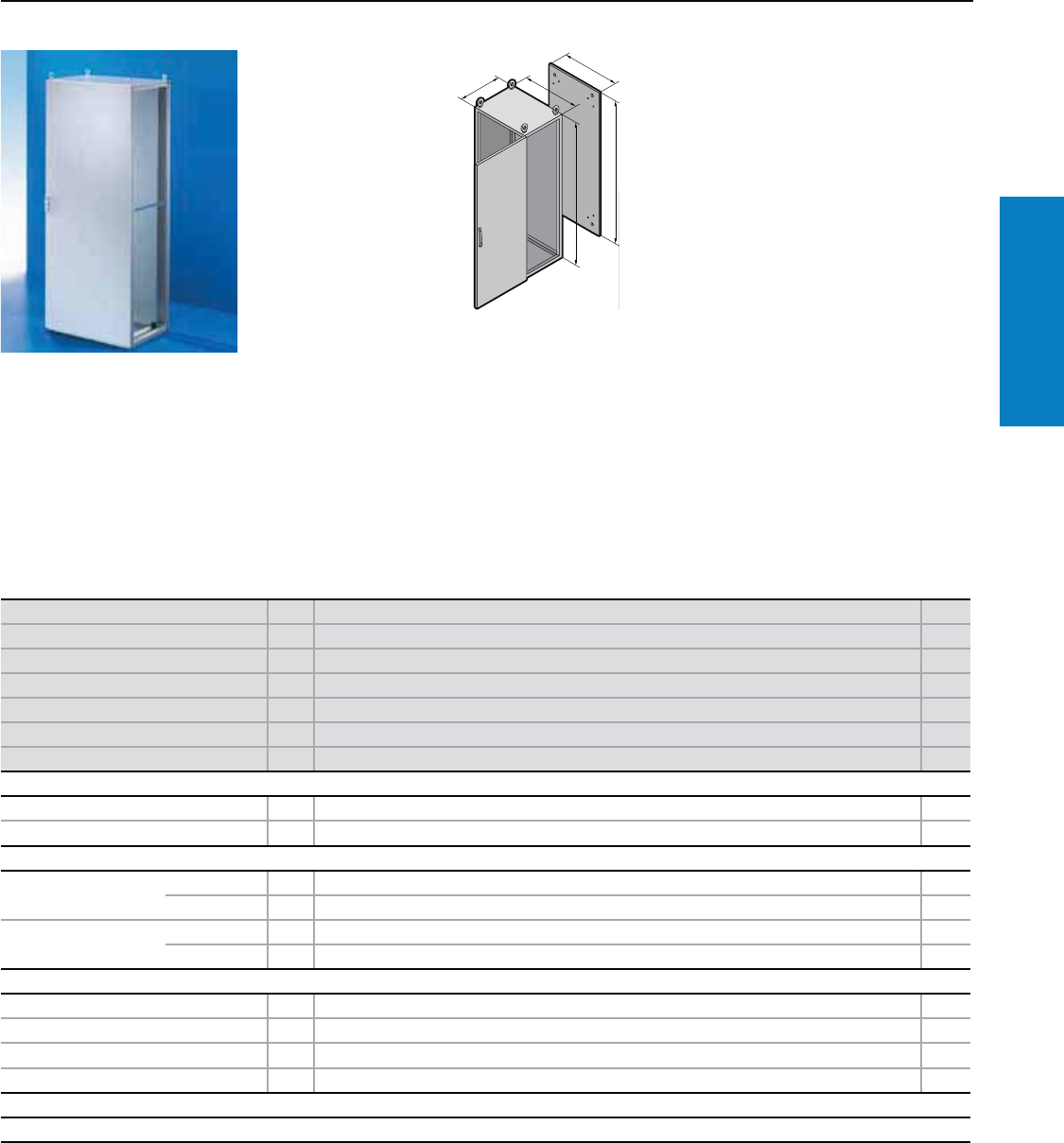
Industrial Buyer’s Guide 31
Carbon Steel Freestanding
TS8 NEMA 4/IP 66 - Freestanding
Height: 79" (2000 mm), Depth: 24" (600 mm)
Material:
Sheet steel
Enclosure frame, roof, base,
rear wall: 1.5 mm (16 ga)
Door: 2.0 mm (14 ga)
Mounting panel:
3.0 mm (11 ga)
Finish:
Enclosure frame, door, roof, base,
rear wall: Dipcoat-primed and
powder coated, textured RAL
7035 (light gray)
Mounting panel: Zinc-plated
Protection Ratings:
UL Type 4
(IP 66 to EN 60 529)
UL file: E76083
Conguration:
Enclosure frame with door, roof/
base plate, rear wall, mounting
panel
Height (H) inches (mm) PU 79 (2000) Page
Width (B) inches (mm) 32 (800)
Depth (T) inches (mm) 24 (600)
Panel Height (G1) inches (mm) 75 (1896)
Panel Width (F1) inches (mm) 28 (699)
Part No. 18806.580
Door(s) 1
Required Accessories
Sidewalls IP 66/UL Type 4 2 8106.580
Baying frame IP 66/UL Type 4 1 8106.504
Base/plinth
Components front and
rear inches (mm)
Height 4 (100) 1 set 8601.800 194
Height 8 (200) 1 set 8602.800 194
Side panels inches (mm) Height 4 (100) 1 set 8601.060 194
Height 8 (200) 1 set 8602.060 194
Accessories
Cable clamp rails 2 4192.000 256
System support rails 2 4362.000 –
Support rails for door 20 4598.000 236
Print pocket, sheet steel 1 4118.000 227
Lock systems
Standard double-bit lock insert may be exchanged for other lock inserts and comfort handle, see pages 217-220.
Additional sizes available upon request.
Inch and pound measurements are rounded to the nearest whole number.
For additional technical information,
please visit www.rittal-corp.com
T
H
B
G
F
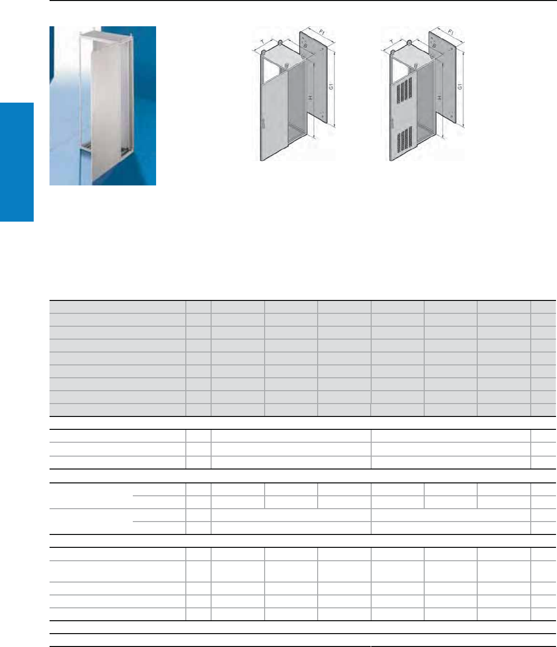
32 Industrial Buyer’s Guide
Carbon Steel Freestanding
Material:
Sheet steel
Enclosure frame and doors:
14 ga (2.0 mm)
Rear walls: 16 ga (1.5 mm)
Mounting Panel: 11 ga (3.0 mm)
Finish:
Enclosure frame: Dipcoat-primed
and powder coated RAL 7035
(light gray)
Door, trim panel, roof and rear wall:
Dipcoat-primed powder coated on
the outside in textured RAL 7035
(light gray)
Mounting panel and gland plates:
Zinc-plated
TS8 UL Type 3R - Freestanding
Height: 79" (2000 mm), Depth: 24 - 32" (600 - 800 mm)
Inch and pound measurements are rounded to the nearest whole number.
Protection Rating:
UL/cUL Type 1, 3R, 12
Vented versions:
UL/cUL Type 1, 3R
UL File: E170282
Height (H) inches (mm) PU 79 (2000) 79 (2000) 79 (2000) 79 (2000) 79 (2000) 79 (2000) Page
Width (B) inches (mm) 24 (600) 32 (800) 39 (1000) 24 (600) 32 (800) 39 (1000)
Depth (T) inches (mm) 24 (600) 24 (600) 24 (600) 32 (800) 32 (800) 32 (800)
Panel Height (G1) inches (mm) 75 (1896) 75 (1896) 75 (1896) 75 (1896) 75 (1896) 75 (1896)
Panel Width (F1) inches (mm) 20 (499) 28 (699) 35 (899) 20 (499) 28 (699) 35 (899)
Part No. with vented door 18606.547 8806.547 8006.547 8608.547 8808.547 8008.547
Part No. with solid door 18606.548 8806.548 8006.548 8608.548 8808.548 8008.548
Door(s) 111111
Weight lb (kg) 229 (104) 288 (131) 355 (161) 245 (111) 302 (137) 335 (151)
Walls
Sidewalls 2 8106.235 8108.235 202
Divider panel 1 8609.060 8609.080 204
Divider panel for module plates 1 8609.130 – 205
Base/plinth
Components front and
rear inches (mm)
Height 4 (100) 1 set 8601.600 8601.800 8601.000 8601.600 8601.800 8601.000 194
Height 8 (200) 1 set 8602.600 8602.800 8602.000 8602.600 8602.800 8602.000 194
Side panels inches (mm) Height 4 (100) 1 set 8601.060 8601.080 194
Height 8 (200) 1 set 8602.060 8602.080 194
Accessories
Cable clamp rails for cable clamps 2 4191.000 4192.000 4336.000 4191.000 4192.000 4336.000 256
Cable clamp rails (C section) for cable
clamps 6 4944.000 4945.000 4946.000 4944.000 4945.000 4946.000 256
Support rails for door 20 4596.000 4598.000 4309.000 4596.000 4598.000 4599.000 236
Print pocket, sheet steel 1 4116.000 4118.000 4115.000 4116.000 4118.000 4124.000 227
Rain canopy 1 9969.921 9969.923 9969.925 9969.922 9969.924 9969.926 –
Lock systems
Standard double-bit lock insert (in rear door) may be exchanged for other lock inserts and comfort handle, see pages 217-220.
For additional technical
information, please visit
www.rittal-corp.com
Solid Door Vented Door
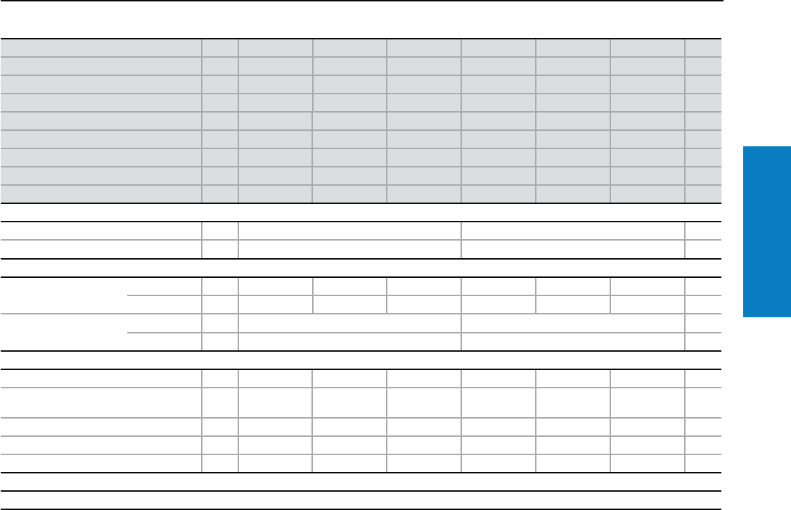
Industrial Buyer’s Guide 33
Carbon Steel Freestanding
TS8 UL Type 3R - Freestanding
Height: 87" (2200 mm), Depth: 24 - 32" (600 - 800 mm)
Height (H) inches (mm) PU 87 (2200) 87 (2200) 87 (2200) 87 (2200) 87 (2200) 87 (2200) Page
Width (B) inches (mm) 24 (600) 32 (800) 39 (1000) 24 (600) 32 (800) 39 (1000)
Depth (T) inches (mm) 24 (600) 24 (600) 24 (600) 32 (800) 32 (800) 32 (800)
Panel Height (G1) inches (mm) 83 (2096) 83 (2096) 83 (2096) 83 (2096) 83 (2096) 83 (2096)
Panel Width (F1) inches (mm) 20 (499) 28 (699) 35 (899) 20 (499) 28 (699) 35 (899)
Part No. with vented door 18626.547 8826.547 8026.547 8628.547 8828.547 8028.547
Part No. with solid door 18626.548 8826.548 8026.548 8628.548 8828.548 8028.548
Door(s) 111111
Weight lb (kg) 249 (113) 250 (139) 345 (155) 260 (117) 320 (144) 365 (164)
Walls
Sidewalls 2 8126.235 8128.235 202
Divider panel 1 8609.260 – 204
Base/plinth
Components front and
rear inches (mm)
Height 4 (100) 1 set 8601.600 8601.800 8601.000 8601.600 8601.800 8601.000 194
Height 8 (200) 1 set 8602.600 8602.800 8602.000 8602.600 8602.800 8602.000 194
Side panels inches (mm) Height 4 (100) 1 set 8601.060 8601.080 194
Height 8 (200) 1 set 8602.060 8602.080 194
Accessories
Cable clamp rails for cable clamps 2 4191.000 4192.000 4336.000 4191.000 4192.000 4336.000 256
Cable clamp rails (C section) for cable
clamps 6 4944.000 4945.000 4946.000 4944.000 4945.000 4946.000 256
Support rails for door 20 4596.000 4598.000 4599.000 4596.000 4598.000 4599.000 236
Print pocket, sheet steel 1 4116.000 4118.000 4124.000 4116.000 4118.000 4124.000 227
Rain canopy 1 9969.921 9969.923 9969.925 9969.922 9969.924 9969.926 –
Lock systems
Standard double-bit lock insert (in rear door) may be exchanged for other lock inserts and comfort handle, see pages 217-220.
Inch and pound measurements are rounded to the nearest whole number.
34 Industrial Buyer’s Guide
Carbon Steel Freestanding
ES - Freestanding
Height: 63 - 71" (1600 - 1800 mm), Depth: 16 - 20" (400 - 500 mm)
Material:
Sheet steel
Enclosure: 15 ga (1.8 mm)
Door: 14 ga (2.0 mm)
Rear wall and gland plates:
16 ga (1.5 mm)
Mounting panel: 11 ga (3.0 mm)
Finish:
Enclosure, door and rear wall:
Dipcoat-primed, powder coated in
textured RAL 7035 (light gray) on
the outside
Mounting panel and
gland plates: Zinc-plated
Protection Ratings:
Single door enclosures:
UL Type 12
(IP 56 to EN 60 529/10.91)
Double door enclosures:
UL Type 12
(IP 55 to EN 60 529/10.91)
UL, CSA certified
UL file: E76083
Conguration:
Enclosure with door(s), right door
hinge, can be changed to the
opposite side (except 5080.500),
mounting panel, gland plates and
rear wall, detachable,
Enclosures < 1000 mm wide:
2 eyebolts , not installed
Enclosures > = 1000 mm wide:
4 eyebolts, installed.
F1
G1
H1
B1
T1
H1
B1
F1
G1
Inch and pound measurements are rounded to the nearest whole number.
For additional technical information,
please visit www.rittal-corp.com
Height (H1) inches (mm) PU 63 (1600) 63 (1600) 63 (1600) 71 (1800) 71 (1800) Page
Width (B1) inches (mm) 24 (600) 32 (800) 47 (1200) 24 (600) 32 (800)
Depth (T1) inches (mm) 20 (500) 20 (500) 20 (500) 16 (400) 16 (400)
Panel Height (G1) inches (mm) 59 (1496) 59 (1496) 59 (1496) 67 (1696) 67 (1696)
Panel Width (F1) inches (mm) 20 (499) 28 (699) 43 (1099) 20 (499) 28 (699)
Part No. 15665.500 5865.500 5265.500 5684.500 5884.500
Door(s) 11211
Weight lb (kg) 226 (103) 275 (125) 387 (176) 230 (105) 276 (125)
Base/Plinth
Base/plinth
inches (mm)
Height 4 (100) 1 set 2807.200 2829.200 2839.200 2804.200 2823.200 196
Height 8 (200) 1 set 2808.200 2830.200 2840.200 2805.200 2824.200 196
Lock systems
Standard double-bit lock insert may be exchanged for other lock inserts and comfort handle, see pages 217-220.
Height (H1) inches (mm) PU 71 (1800) 71 (1800) 71 (1800) 71 (1800) Page
Width (B1) inches (mm) 39 (1000) 39 (1000) 47 (1200) 63 (1600)
Depth (T1) inches (mm) 16 (400) 16 (400) 16 (400) 16 (400)
Panel Height (G1) inches (mm) 67 (1696) 67 (1696) 67 (1696) 67 (1696)
Panel Width (F1) inches (mm) 35 (899) 35 (899) 43 (1099) 59 (1499)
Part No. 15084.500 5080.500 5284.500 5784.500
Door(s) 1 2 2 2
Weight lb (kg) 324 (147) 326 (148) 397 (180) 489 (222)
Base/Plinth
Base/plinth
inches (mm)
Height 4 (100) 1 set 2909.200 2909.200 2836.200 2905.200 196
Height 8 (200) 1 set 2910.200 2910.200 2837.200 2906.200 196
Lock systems
Standard double-bit lock insert may be exchanged for 1” (27 mm) lock insert, type A, and Ergoform-S lock system, see page 218.
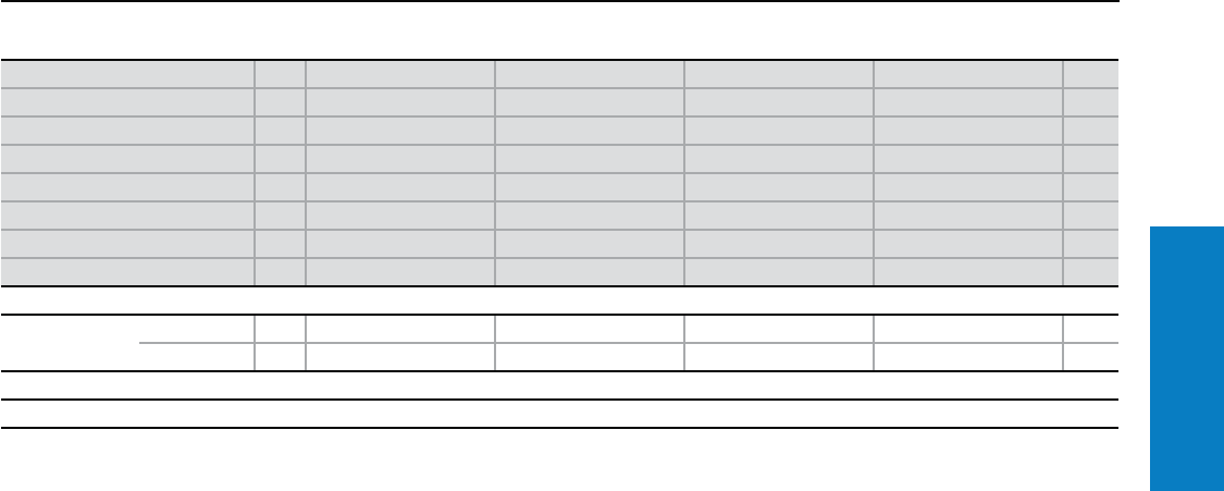
Industrial Buyer’s Guide 35
Carbon Steel Freestanding
ES - Freestanding
Height: 79" (1600 - 2000 mm), Depth: 20" (500 mm)
Inch and pound measurements are rounded to the nearest whole number.
Height (H1) inches (mm) PU 79 (2000) 79 (2000) 79 (2000) 79 (2000) Page
Width (B1) inches (mm) 24 (600) 32 (800) 47 (1200) 71 (1800)
Depth (T1) inches (mm) 20 (500) 20 (500) 20 (500) 20 (500)
Panel Height (G1) inches (mm) 75 (1896) 75 (1896) 75 (1896) 75 (1896)
Panel Width (F1) inches (mm) 20 (499) 28 (699) 43 (1099) 67 (1699)
Part No. 15605.500 5805.500 5205.500 5905.500
Doors 1122
Weight lb (kg) 273 (124) 334 (152) 463 (210) 661 (300)
Base/Plinth
Base/plinth
inches (mm)
Height 4 (100) 1 set 2807.200 2829.200 2839.200 2903.200 196
Height 8 (200) 1 set 2808.200 2830.200 2840.200 2904.200 196
Lock systems
Standard double-bit lock insert may be exchanged for other lock inserts and comfort handle, see pages 217-220.
36 Industrial Buyer’s Guide
Carbon Steel Floormount
Material:
Sheet steel
Enclosure frame: 16 ga (1.5 mm)
Roof, door, rear wall, solid floor
panel: 14 ga (2.0 mm)
Legs, mounting panel:
11 ga (3.0 mm)
Finish:
Enclosure frame:
Dipcoat-primed
Door, roof and rear wall:
Powder coated in RAL 7035
(light gray) on the outside
Mounting panel:
Zinc-plated
Conguration:
Enclosure frame with doors,
12 inch bolt-on leg kit, mounting
panel, roof plate, rear wall, sidewalls,
solid floor panel, comfort handle with
push button insert
Protection Ratings:
UL Type 12 (IP 55 to EN 60 529)
UL file: E76083
For additional technical
information, please visit
www.rittal-corp.com
TS8 - Floormount
Height: 63 - 71" (1600 - 1800 mm), Depth: 12 - 24" (300 - 600 mm)
Height (H1) inches (mm) PU 63 (1600) 63 (1600) 63 (1600) 63 (1600) 63 (1600) Page
Width (B1) inches (mm) 47 (1200) 63 (1600) 47 (1200) 63 (1600) 47 (1200)
Depth (T1) inches (mm) 12 (300) 12 (300) 16 (400) 16 (400) 20 (500)
Panel Height (G1) inches (mm) 59 (1496) 59 (1496) 59 (1496) 59 (1496) 59 (1496)
Panel Width (F1) inches (mm) 43 (1099) 59 (1499) 43 (1099) 59 (1499) 43 (1099)
Part No. 1TSFM634712NC TSFM636312NC TSFM634716NC TSFM636316NC TSFM634720NC
Weight lb (kg) 352 (160) 452 (205) 359 (163) 459 (209) 366 (166)
Accessories
Cable clamp rails for cable clamps 2 4196.000 4338.000 4196.000 4338.000 4196.000 256
Support rails for door 1 4596.000 4598.000 4596.000 4598.000 4596.000 236
Print pocket 1 4116.000 4118.000 4116.000 4118.000 4116.000 227
Lock Systems
Standard comfort handle and PB insert may be exchanged for other lock inserts and comfort handles, see pages 217-220.
Height (H1) inches (mm) PU 63 (1600) 63 (1600) 71 (1800) 71 (1800) 71 (1800) Page
Width (B1) inches (mm) 47 (1200) 63 (1600) 63 (1600) 71 (1800) 63 (1600)
Depth (T1) inches (mm) 24 (600) 24 (600) 12 (300) 12 (300) 16 (400)
Panel Height (G1) inches (mm) 59 (1496) 59 (1496) 67 (1696) 67 (1696) 67 (1696)
Panel Width (F1) inches (mm) 43 (1099) 59 (1499) 59 (1499) 67 (1699) 59 (1499)
Part No. 1TSFM634724NC TSFM636324NC TSFM716312NC TSFM717112NC TSFM716316NC
Weight lb (kg) 415 (189) 481 (219) 486 (221) 546 (248) 493 (224)
Accessories
Cable clamp rails for cable clamps 2 4196.000 4338.000 4338.000 4339.000 4338.000 256
Support rails for door 1 4596.000 4598.000 4598.000 4579.000 4598.000 236
Print pocket 1 4116.000 4118.000 4118.000 4123.000 4118.000 227
Lock Systems
Standard comfort handle and PB insert may be exchanged for other lock inserts and comfort handles, see pages 217-220.
Inch and pound measurements are rounded to the nearest whole number.
T1
H1
B1
F1
G1
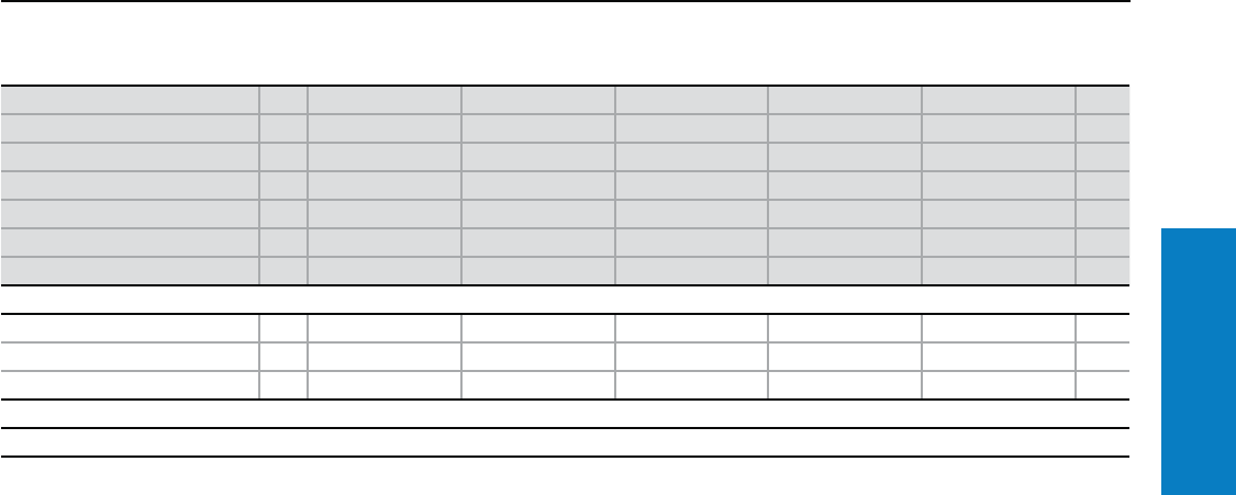
Industrial Buyer’s Guide 37
Carbon Steel Floormount
TS8 - Floormount
Height: 71" (1800 mm), Depth: 16 - 24" (400 - 600 mm)
Height (H1) inches (mm) PU 71 (1800) 71 (1800) 71 (1800) 71 (1800) 71 (1800) Page
Width (B1) inches (mm) 71 (1800) 63 (1600) 71 (1800) 63 (1600) 71 (1800)
Depth (T1) inches (mm) 16 (400) 20 (500) 20 (500) 24 (600) 24 (600)
Panel Height (G1) inches (mm) 67 (1696) 67 (1696) 67 (1696) 67 (1696) 67 (1696)
Panel Width (F1) inches (mm) 67 (1699) 59 (1499) 67 (1699) 59 (1499) 67 (1699)
Part No. 1TSFM717116NC TSFM716320NC TSFM717120NC TSFM716324NC TSFM717124NC
Weight lb (kg) 553 (251) 500 (227) 560 (255) 517 (235) 580 (264)
Accessories
Cable clamp rails for cable clamps 2 4339.000 4338.000 4339.000 4338.000 4339.000 256
Support rails for door 1 4579.000 4598.000 4579.000 4598.000 4579.000 236
Print pocket 1 4123.000 4118.000 4123.000 4118.000 4123.000 227
Lock Systems
Standard comfort handle and PB insert may be exchanged for other lock inserts and comfort handles, see pages 217-220.
Inch and pound measurements are rounded to the nearest whole number.
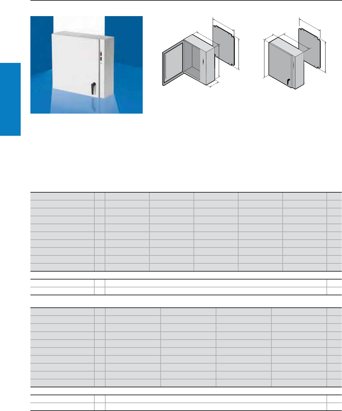
38 Industrial Buyer’s Guide
Carbon Steel Disconnect
Inch and pound measurements are rounded to the nearest whole number.
WM Disconnect - Wallmount
Depth: 8 - 16" (210 - 400 mm), Height : 24 - 60" (600 - 1500 mm)
Material:
Sheet steel
Enclosure and door: 14 ga (2.0
mm) except WM242608XC, which
is 16 ga body/ 14 ga door
Protection Ratings:
UL/cUL Type 12
(IP 55 to EN 60 529/10.91)
UL/cUL Type 3R
UL/cUL Type 4
(IP 66 to EN 60 529/10.91)
UL File Number: E170282
Height (H1) inches (mm) PU 24 (600) 36 (900) 36 (900) 60 (1500) 36 (900) Page
Width (B1) inches (mm) 26 (650) 32 (825) 32 (825) 38 (975) 32 (825)
Depth (T1) inches (mm) 8 (210) 8 (210) 10 (250) 10 (250) 12 (300)
Panel Height (G1) inches (mm) 22 (570) 34 (870) 34 (870) 57 (1455) 34 (870)
Panel Width (F1) inches (mm) 22 (549) 28 (704) 28 (704) 33 (840) 29 (730)
Panel Thickness ga (mm) 11 (3) 11 (3) 11 (3) 11 (3) 11 (3)
Part No. 1WM242608XC WM363208XC WM363210XC WM603810XC WM363212XC
Door(s) 11111
Locking handle points 22232
Weight lb (kg) 68 (31) 119 (54) 125 (57) 205 (93) 127 (58)
Accessories
Handle 1 WMLHKL 220
Wallmount bracket 4 2503.200 253
Height (H1) inches (mm) PU 42 (1050) 47 (1200) 60 (1500) 47 (1200) Page
Width (B1) inches (mm) 32 (825) 38 (975) 38 (975) 38 (975)
Depth (T1) inches (mm) 12 (300) 12 (300) 12 (300) 16 (400)
Panel Height (G1) inches (mm) 40 (1020) 45 (1155) 57 (1455) 45 (1155)
Panel Width (F1) inches (mm) 29 (730) 33 (840) 33 (840) 33 (840)
Panel Thickness ga (mm) 11 (3) 11 (3) 11 (3) 11 (3)
Part No. 1WM423212XC WM483812XC WM603812XC WM483816XC
Door(s) 1111
Locking handle points 3333
Weight lb (kg) 139 (63) 200 (91) 204 (93) 192 (87)
Accessories
Handle 1 WMLHKL 220
Wallmount bracket 4 2503.200 253
Finish:
Enclosure and door: Powder
coated, RAL 7035 (light gray)
Mounting panel:
Zinc-plated carbon steel
Conguration:
Left-hand hinge
Universal disconnect cut-out
One-piece enclosure body
2 or 3-point locking L-handle
Mounting panel
Wall-mounting holes
Foamed-in-place gasket
B1
T1
H1
F1
G1
B1
H1
F1
G1
T1
Note: See page 330 for FMD
Operator Information
For additional technical
information, please visit www.
rittal-corp.com
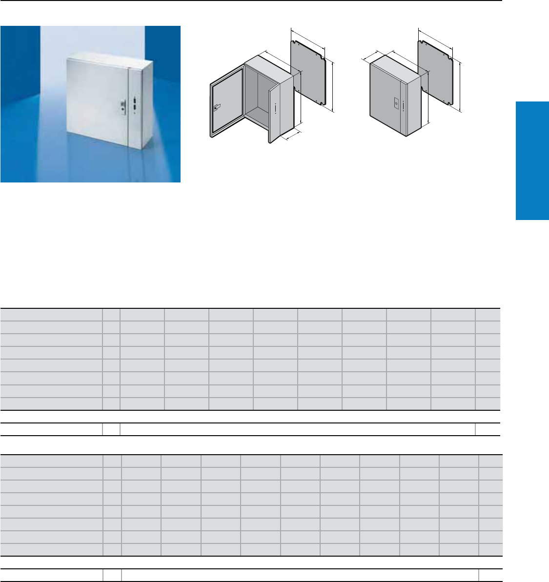
Industrial Buyer’s Guide 39
Carbon Steel Disconnect
AE Disconnect - Wallmount
Depth: 8 - 16" (210 - 400 mm), Height: 20 - 60" (500 - 1500 mm)
Material:
Sheet steel
Enclosure: 16 ga (1.5 mm)
Door: 14 ga (2.0 mm)
Finish:
Enclosure and door: Powder
coated, RAL 7035 (light gray)
Mounting panel: Zinc-plated
Conguration:
Enclosure of unibody
construction, single door:
1 gland plate, 3-point lock
system, foamed-in door seal,
zinc-plated mounting panel.
Height (H1) inches (mm) PU 20 (500) 24 (600) 30 (760) 30 (760) 28 (700) 39 (1000) 20 (500) 30 (760) Page
Width (B1) inches (mm) 20 (500) 24 (600) 24 (600) 30 (760) 20 (500) 24 (600) 20 (500) 30 (760)
Depth (T1) inches (mm) 8 (210) 8 (210) 8 (210) 8 (210) 10 (250) 10 (250) 12 (300) 12 (300)
Panel Height (G1) inches (mm) 19 (470) 22 (570) 29 (730) 29 (730) 26 (670) 38 (955) 19 (470) 29 (730)
Panel Width (F1) inches (mm) 18 (449) 22 (549) 27 (549) 28 (704) 18 (449) 21 (539) 18 (449) 28 (704)
Part No. 11053.500 1063.500 1075.500 1078.500 1097.810 1097.850 1353.500 1074.500
Door(s) 11111111
Weight lb (kg) 42 (19) 57 (26) 71 (32) 88 (40) 68 (31) 114 (52) 46 (21) 98 (45)
Accessories
Wallmount bracket 4 2503.200 253
Inch and pound measurements are rounded to the nearest whole number.
Height (H1) inches (mm) PU 36 (900) 39 (1000) 47 (1200) 47 (1200) 55 (1400) 60 (1500) 24 (600) 30 (760) 60 (1500) Page
Width (B1) inches (mm) 30 (760) 32 (800) 32 (800) 36 (900) 40 (1000) 36 (900) 24 (600) 24 (600) 35 (900)
Depth (T1) inches (mm) 12 (300) 12 (300) 12 (300) 12 (300) 12 (300) 12 (300) 14 (350) 14 (350) 16 (400)
Panel Height (G1) inches (mm) 34 (870) 38 (955) 46 (1155) 46 (1155) 53 (1355) 57 (1455) 22 (570) 29 (730) 57 (1455)
Panel Width (F1) inches (mm) 28 (704) 29 (739) 29 (739) 33 (839) 37 (940) 33 (839) 22 (549) 22 (549) 33 (839)
Part No. 11097.800 1183.500 1283.500 1097.870 1115.500 1097.820 1363.500 1375.500 1097.830
Door(s) 111111111
Weight lb (kg) 112 (51) 125 (57) 154 (70) 161 (73) 213 (97) 213 (97) 68 (31) 84 (38) 220 (100)
Accessories
Wallmount bracket 4 2503.200 253
B1
H1
F1
G1
T1
B1
T1
H1
F1
G1
Protection Ratings:
UL/cUL Type 12
(IP 55 to EN 60 529/10.91)
UL File Number: E170282
Note: See page 330 for FMD
Operator Information
For additional technical
information, please visit www.
rittal-corp.com
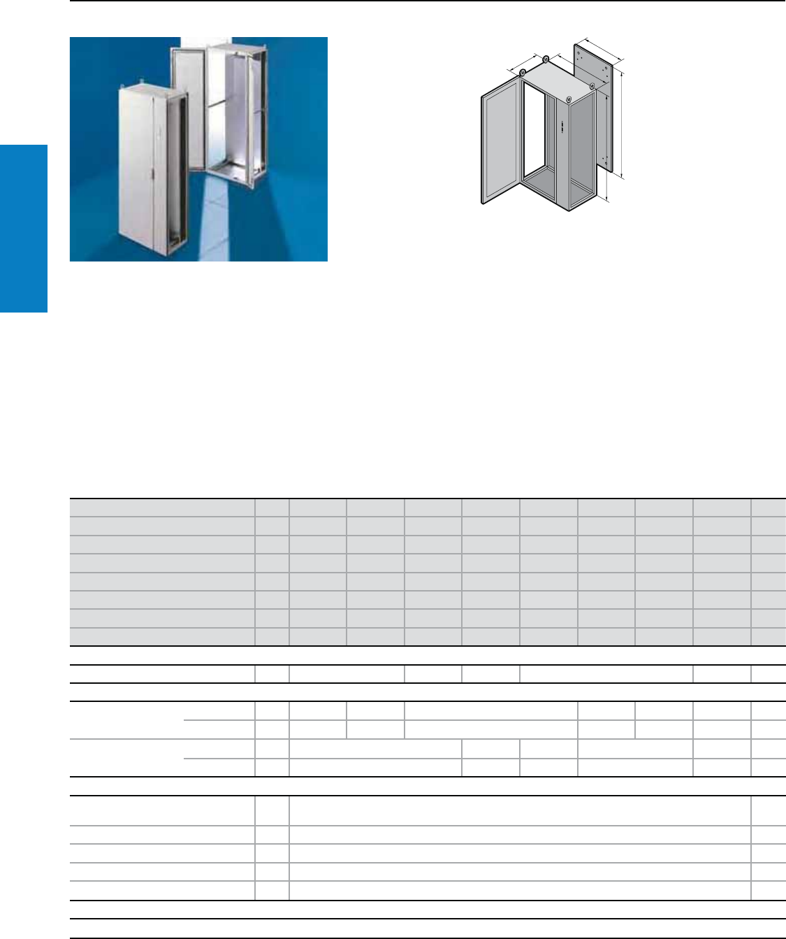
40 Industrial Buyer’s Guide
Carbon Steel Disconnect
TS8 Disconnect - Freestanding
Height: 55 - 71" (1400 - 1800 mm), Depth: 16 - 24" (400 - 600 mm)
T
B
B
H
F
G
Height (H) inches (mm) PU 55 (1400) 55 (1400) 63 (1600) 63 (1600) 71 (1800) 71 (1800) 71 (1800) 71 (1800) Page
Width (B) inches (mm) 32 (800) 39 (1000) 32 (800) 32 (800) 32 (800) 63 (1600) 71 (1800) 32 (800)
Depth (T) inches (mm) 20 (500) 20 (500) 20 (500) 24 (600) 16 (400) 16 (400) 16 (400) 20 (500)
Panel Height (G1) inches (mm) 51 (1296) 51 (1296) 59 (1496) 59 (1496) 67 (1696) 67 (1696) 67 (1696) 67 (1696)
Panel Width (F1) inches (mm) 28 (699) 35 (899) 28 (699) 28 (699) 28 (699) 59 (1499) 67 (1699) 28 (699)
Part No. 18945.580 8945.500 8965.500 8966.500 8984.500 8901.600 8901.620 8985.500
Door(s) 11111221
Weight lb (kg) 163 (74) 203 (92) 186 (84) 223 (101) 250 (114) 335 (152) 377 (171) 255 (116)
Walls
Sidewalls 2 8145.235 8165.235 8166.235 8184.235 8185.235 202
Base/plinth
Components front and
rear inches (mm)
Height 4 (100) 1 set 8601.800 8601.000 8601.800 8601.920 8901.920 8601.800 194
Height 8 (200) 1 set 8602.800 8602.000 8602.800 8602.920 8901.930 8602.800 194
Side panels inches (mm) Height 4 (100) 1 set 8601.050 8601.060 8601.040 8601.040 8601.050 194
Height 8 (200) 1 set 8602.050 8602.060 8602.040 8602.040 8602.050 194
Accessories
Handle interlocking kit (included
with enclosure) 1 kit 8611.310 222
Slave door interlocking kit 1 4911.000 222
Interlocking rods 24" (600 mm) 10 4916.000 222
Interlocking rods 32" (800 mm) 10 4918.000 222
Interlocking rods 47" (1200 mm) 10 4920.000 222
Lock Systems
Standard double-bit lock insert may be exchanged for other lock inserts and comfort handle, see pages 217-220.
Inch and pound measurements are rounded to the nearest whole number.
Material:
Sheet steel
Enclosure frame, roof, rear wall, and
gland plates: 16 ga (1.5 mm)
Door and trim panel: 14 ga (2.0 mm)
Mounting panel: 11 ga (3.0 mm)
Finish:
Enclosure frame: Dipcoat-primed
Door, trim panel, roof, and rear wall:
Dipcoat-primed, powder coated on
the outside in textured RAL 7035
(light gray)
Mounting panel and gland plates:
Zinc-plated
Protection Ratings:
UL Type 12
(IP 55 to EN 60 529/10.91)
(with disconnect handle installed)
UL file: E76083
Note: See page 222 for FMD
Operator Information
For additional technical
information, please visit www.
rittal-corp.com
Conguration:
Enclosure frame, door (left
hinged), trim panel (right
hinged, with a swing lever at
the top and bottom, with cut-
out for disconnect handle),
roof, rear wall, mounting
panel, three-piece gland
plates. Includes handle
interlocking kit 8611.310.
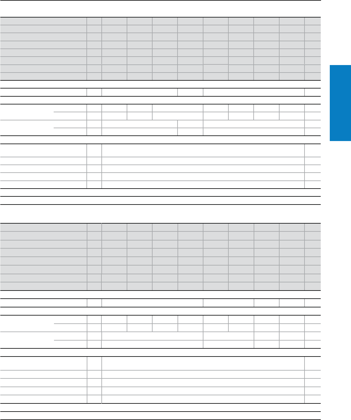
Industrial Buyer’s Guide 41
Carbon Steel Disconnect
TS8 Disconnect - Freestanding
Height: 71 - 87" (1800 - 2200 mm), Depth: 20 - 32" (500 - 800 mm)
Height (H) inches (mm) PU 71 (1800) 71 (1800) 71 (1800) 71 (1800) 79 (2000) 79 (2000) 79 (2000) 79 (2000) Page
Width (B) inches (mm) 39 (1000) 63 (1600) 71 (1800) 71 (1800) 32 (800) 39 (1000) 63 (1600) 71 (1800)
Depth (T) inches (mm) 20 (500) 20 (500) 20 (500) 24 (600) 20 (500) 20 (500) 20 (500) 20 (500)
Panel Height (G1) inches (mm) 67 (1696) 67 (1696) 67 (1696) 67 (1696) 75 (1896) 75 (1896) 75 (1896) 75 (1896)
Panel Width (F1) inches (mm) 35 (899) 59 (1499) 67 (1699) 67 (1699) 28 (699) 35 (899) 59 (1499) 67 (1699)
Part No. 18980.500 8901.610 8901.630 8901.640 8905.500 8995.500 8901.650 8901.680
Door(s) 12221122
Weight lb (kg) 262 (119) 418 (190) 471 (214) 565 (256) 278 (126) 291 (132) 488 (221) 523 (237)
Walls
Sidewalls 2 8185.235 8186.235 8105.235 202
Base/plinth
Components front and
rear inches (mm)
Height 4 (100) 1 set 8601.000 8601.920 8901.920 8601.800 8601.000 8601.920 8901.920 194
Height 8 (200) 1 set 8602.000 8602.920 8901.930 8602.800 8602.000 8602.920 8901.930 194
Side panels inches (mm) Height 4 (100) 1 set 8601.050 8601.060 8601.050 194
Height 8 (200) 1 set 8602.050 8602.060 8602.050 194
Accessories
Handle interlocking kit (included
with enclosure) 1 kit 8611.310 222
Slave door interlocking kit 1 4911.000 222
Interlocking rods 24" (600 mm) 10 4916.000 222
Interlocking rods 32" (800 mm) 10 4918.000 222
Interlocking rods 47" (1200 mm) 10 4920.000 222
Lock Systems
Standard double-bit lock insert may be exchanged for other lock inserts and comfort handle, see pages 217-220.
Height (H) inches (mm) PU 79 (2000) 79 (2000) 79 (2000) 79 (2000) 79 (2000) 79 (2000) 87 (2200) 87 (2200) Page
Width (B) inches (mm) 32 (800) 39 (1000) 63 (1600) 71 (1800) 32 (800) 63 (1600) 32 (800) 39 (1000)
Depth (T) inches (mm) 24 (600) 24 (600) 24 (600) 24 (600) 32 (800) 32 (800) 24 (600) 20 (500)
Panel Height (G1) inches (mm) 75 (1896) 75 (1896) 75 (1896) 75 (1896) 75 (1896) 75 (1896) 83 (2096) 83 (2096)
Panel Width (F1) inches (mm) 28 (699) 35 (899) 59 (1489) 67 (1699) 28 (699) 59 (1499) 28 (699) 35 (899)
Part No. 18906.500 8996.500 8901.660 8901.690 8908.500 8901.670 8926.500 8958.500
Door(s) 11221211
Weight lb (kg) 288 (131) 366 (166) 586 (266) 628 (285) 372 (169) 744 (337) 307 (139) 320 (145)
Walls
Sidewalls 2 8106.235 8108.235 8126.235 8125.235 202
Base/plinth
Components front and
rear inches (mm)
Height 4 (100) 1 set 8601.800 8601.000 8601.920 8901.920 8601.800 8601.920 8601.800 8601.000 194
Height 8 (200) 1 set 8602.800 8602.000 8602.920 8901.930 8602.800 8602.920 8602.800 8602.000 194
Side panels inches (mm) Height 4 (100) 1 set 8601.060 8601.080 8601.060 8601.050 194
Height 8 (200) 1 set 8602.060 8602.080 8602.060 8602.050 194
Accessories
Handle interlocking kit (included with
enclosure) 1 kit 8611.310 222
Slave door interlocking kit 1 4911.000 222
Interlocking rods 24" (600 mm) 10 4916.000 222
Interlocking rods 32" (800 mm) 10 4918.000 222
Interlocking rods 47" (1200 mm) 10 4920.000 222
Lock Systems
Standard double-bit lock insert may be exchanged for other lock inserts and comfort handle, see pages 217-220.
Inch and pound measurements are rounded to the nearest whole number.
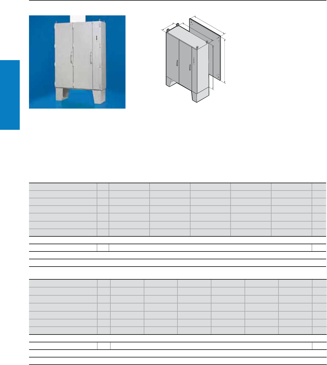
42 Industrial Buyer’s Guide
Disconnect
Carbon Steel
Material:
Sheet steel
Enclosure frame: 16 ga (1.5 mm)
Roof, rear wall, solid floor panel:
14 ga (2.0 mm)
Legs: 11 ga (3.0 mm)
Door: 14 ga (2.0 mm)
Mounting Panel: 11 ga (3.0 mm)
Finish:
Enclosure frame:
Dipcoat-primered
Door, roof, rear wall and floor
panel: Dipcoat-primered and
powder coated in RAL 7035
(light gray) on the outside
Mounting panel: Zinc-plated
disconnect handle), 12 inch bolt-on
leg kit, mounting panel, roof, rear
wall, sidewalls, solid floor panel,
comfort handle with pad lock hasp
and push button insert
Includes handle interlocking kit
(8611.310) for the main door as
well as the adjacent door locking kit
(4911.000) and interlocking rods for
the adjacent door.
TS8 Disconnect - Floormount
Height: 63 - 71" (1600 - 1800 mm), Depth: 16 - 24" (400 - 600 mm)
Height (H1) inches (mm) PU 63 (1600) 63 (1600) 71 (1800) 71 (1800) 63 (1600) Page
Width (B1) inches (mm) 47 (1200) 63 (1600) 63 (1600) 71 (1800) 47 (1200)
Depth (T1) inches (mm) 16 (400) 16 (400) 16 (400) 16 (400) 20 (500)
Panel Height (G1) inches (mm) 59 (1496) 59 (1496) 67 (1696) 67 (1696) 59 (1496)
Panel Width (F1) inches (mm) 43 (1099) 59 (1499) 59 (1499) 67 (1699) 43 (1099)
Part No. 1 TSFM634716XC TSFM636316XC TSFM716316XC TSFM717116XC TSFM634720XC
Weight lb (kg) 370 (168) 470 (213) 505 (229) 565 (256) 378 (171)
Accessories
Print pocket 1 2514.000 227
Lock Systems
The standard comfort handle with pad lock hasp and pushbutton insert may be exchanged for other comfort handles and lock inserts, see pages 217-219.
Height (H1) inches (mm) PU 63 (1600) 71 (1800) 71 (1800) 63 (1600) 63 (1600) 71 (1800)
Width (B1) inches (mm) 63 (1600) 63 (1600) 71 (1800) 47 (1200) 63 (1600) 71 (1800)
Depth (T1) inches (mm) 20 (500) 20 (500) 20 (500) 24 (600) 24 (600) 24 (600)
Panel Height (G1) inches (mm) 59 (1496) 67 (1696) 67 (1696) 59 (1496) 59 (1496) 67 (1696)
Panel Width (F1) inches (mm) 59 (1499) 59 (1499) 67 (1699) 43 (1099) 59 (1499) 67 (1699)
Part No. 1 TSFM636320XC TSFM716320XC TSFM717120XC TSFM634724XC TSFM636324XC TSFM717124XC
Weight lb (kg) 495 (225) 515 (234) 575 (261) 430 (195) 495 (225) 595 (270)
Accessories
Print pocket 1 2514.000 227
Lock Systems
The standard comfort handle with pad lock hasp and pushbutton insert may be exchanged for other comfort handles and lock inserts, see pages 217-219.
Inch and pound measurements are rounded to the nearest whole number.
T1
H1
B1
F1
G1
For additional technical
information, please visit
www.rittal-corp.com
Protection Ratings:
UL Type 12 (with disconnect
handle installed)
UL file: E170282
Conguration:
Enclosure frame with removable
center mullion, two doors (both
left hinged), trim panel (right
hinged with swing lever at the
top and bottom, with cut-out for
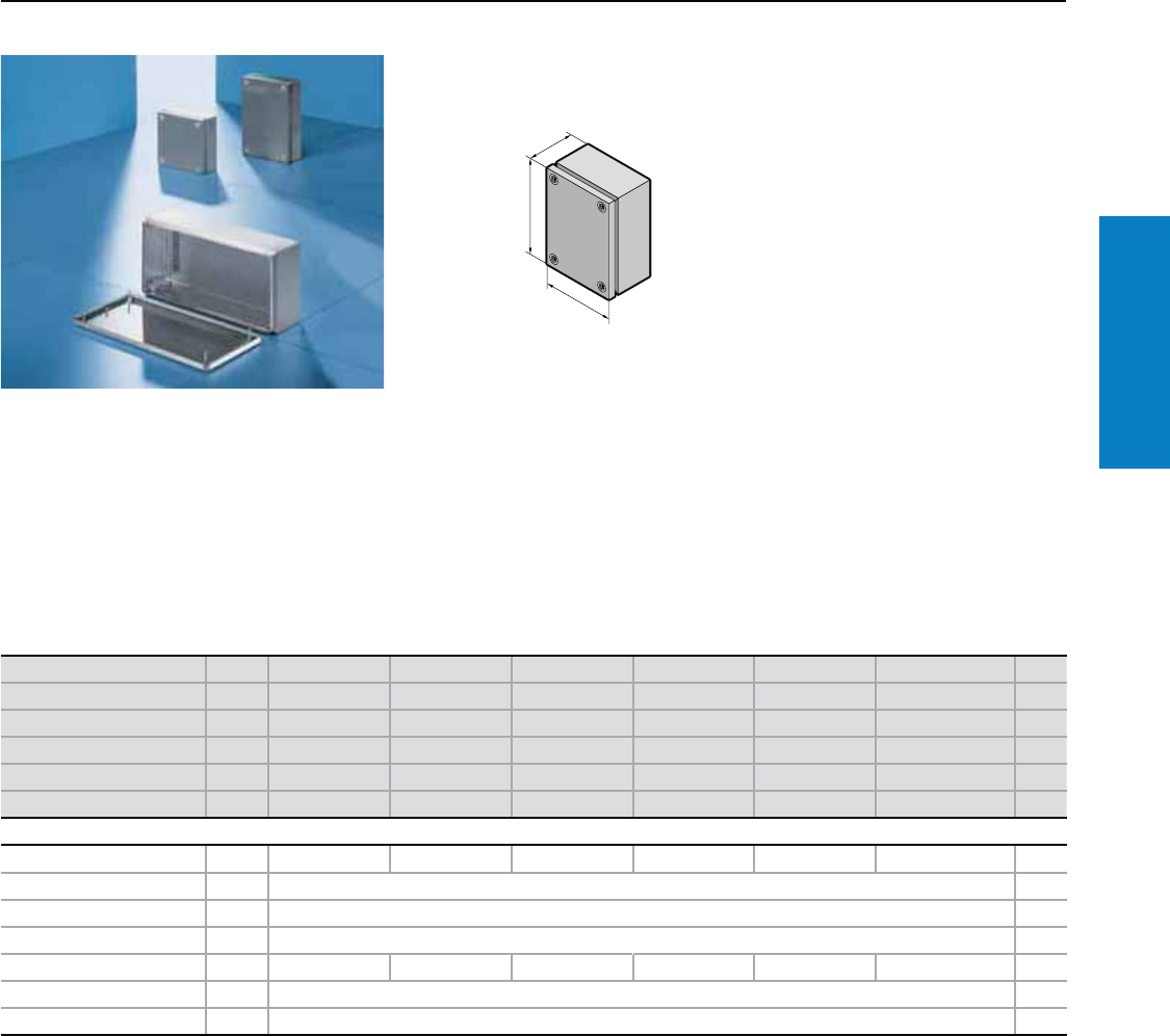
Industrial Buyer’s Guide 43
Junction Box
Stainless Steel
KL Screw Cover - Junction Box
Depth: 3 - 5" (80 - 120 mm), Height: 6 - 12" (150 - 300 mm)
Material:
Type 304 stainless steel
Enclosure: 18 ga (1.25 mm)
Cover: 18 ga (1.25 mm)
Finish:
Case and cover:
Brushed
Protection Ratings:
UL Type 4X
(IP 66 to EN 60 529/10.91)
UL file: E76082
Conguration:
Enclosure, cover with foamed-on
polyurethane gasket and quick-
release cover screws, including
plastic bushes.
H1
B1
T1
Height (H1) inches (mm) PU 6 (150) 6 (150) 8 (200) 8 (200) 8 (200) 12 (300) Page
Width (B1) inches (mm) 6 (150) 12 (300) 8 (200) 12 (300) 16 (400) 12 (300)
Depth (T1) inches (mm) 3 (80) 3 (80) 3 (80) 3 (80) 5 (120) 5 (120)
Part No. 11521.010 1522.010 1523.010 1524.010 1525.010 1526.010
Weight lb (kg) 3 (1) 4 (2) 4 (2) 5 (2) 8 (4) 9 (4)
Cover screws 44444 4
Accessories
Mounting panel 1 1560.700 1561.700 1562.700 1563.700 1564.700 1567.700 229
Wallmount bracket 4 1594.000 253
Wall angle 1 2583.000 254
Pole clamp 1 2584.000 254
Support rails TS 35/7.5 10 2314.000 2316.000 2315.000 2316.000 2317.000 2316.000
Cover retainer 3 pairs 1591.000 215
Cover hinge 6 1592.010 215
Inch and pound measurements are rounded to the nearest whole number.
For additional technical
information, please visit
www.rittal-corp.com
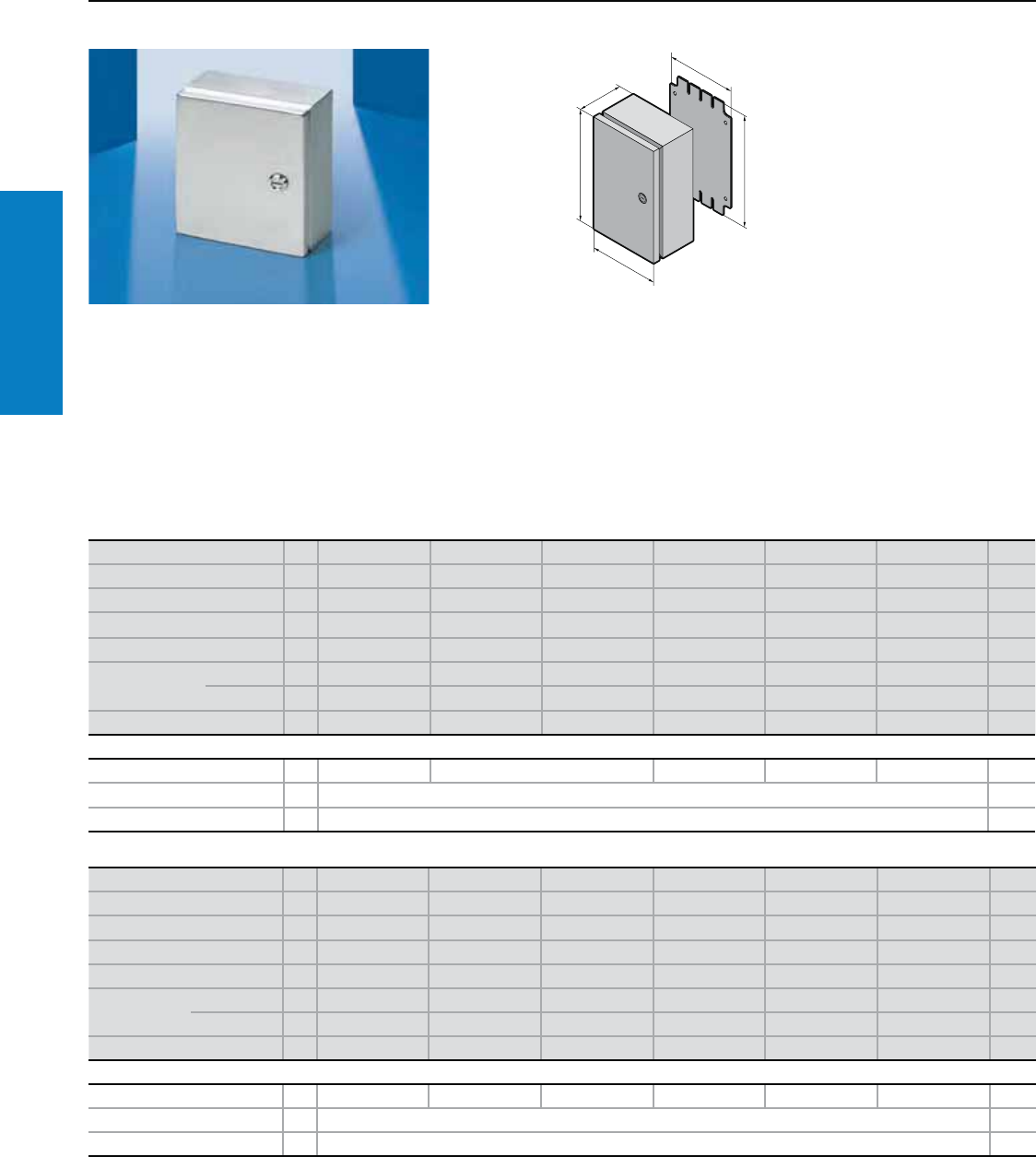
44 Industrial Buyer’s Guide
Junction Box
Stainless Steel
JB Hinge Cover - Junction Box
Depth: 3 - 6" (75 - 150 mm), Height: 4 - 12" (100 - 300 mm)
Material:
Type 304 or 316L stainless steel
Enclosure:
16 ga (1.5 mm)
Finish:
Enclosure and door:
#4 brushed
Protection Ratings:
UL/cUL Type 12
(IP 54 to EN 60 529/10.91)
UL/cUL Type 3R
UL/cUL 4x
(IP 66 to EN 60 529/10.91)
UL file: E76083
Conguration: Door with 180° left-
hand hinges, includes screwdriver
insert and wallmounting blind nuts
Note: zinc-plated enclosure
mounting panel sold separately
(see below)
For additional technical
information, please visit
www.rittal-corp.com
G1
F1
H1
B1
T1
Height (H1) inches (mm) PU 4 (100) 6 (150) 6 (150) 6 (150) 8 (200) 8 (200) Page
Width (B1) inches (mm) 4 (100) 4 (100) 4 (100) 6 (150) 6 (150) 8 (200)
Depth (T1) inches (mm) 3 (75) 3 (75) 4 (100) 4 (100) 4 (100) 4 (100)
Panel Height (G1) inches (mm) – 5 (135) 5 (135) 5 (135) 7 (185) 7 (185)
Panel Width (F1) inches (mm) – 3 (75) 3 (75) 5 (125) 5 (125) 7 (175)
Part No. Type 304 1JB040403H4 JB060403H4 JB060404H4 JB060604H4 JB080604H4 JB080804H4
Type 316L 1JB040403H6 JB060403H6 JB060404H6 JB060604H6 JB080604H6 JB080804H6
Weight lb (kg) 2 (0.9) 3 (1.4) 3 (1.4) 4 (1.6) 5 (2.0) 6 (2.5)
Accessories
Mounting panel 1 – JBMP0604 JBMP0606 JBMP0806 JBMP0808 230
Wallmount bracket Type 304 4 2433.000 253
Wallmount bracket Type 316L 4 2433.500 253
Height (H1) inches (mm) PU 10 (250) 12 (300) 12 (300) 8 (200) 10 (250) 10 (250) Page
Width (B1) inches (mm) 8 (200) 6 (150) 10 (250) 6 (150) 8 (200) 10 (250)
Depth (T1) inches (mm) 4 (100) 4 (100) 5 (125) 6 (150) 6 (150) 6 (150)
Panel Height (G1) inches (mm) 9 (235) 11 (285) 11 (285) 7 (185) 9 (235) 9 (235)
Panel Width (F1) inches (mm) 7 (175) 5 (125) 9 (225) 5 (125) 7 (175) 9 (225)
Part No. Type 304 1JB100804H4 JB120604H4 JB121005H4 JB080606H4 JB100806H4 JB101006H4
Type 316L 1JB100804H6 JB120604H6 JB121005H6 JB080606H6 JB100806H6 JB1010 06H6
Weight lb (kg) 8 (3.4) 6 (2.7) 9 (4.1) 6 (2.5) 8 (3.4) 9 (3.9)
Accessories
Mounting panel 1 JBMP1008 JBMP1206 JBMP1210 JBMP0806 JBMP1008 JBMP1010 230
Wallmount bracket Type 304 4 2433.000 253
Wallmount bracket Type 316L 4 2433.500 253
Inch and pound measurements are rounded to the nearest whole number.
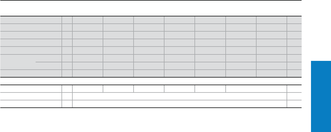
Industrial Buyer’s Guide 45
Junction Box
Stainless Steel
Height (H1) inches (mm) PU 12 (300) 12 (300) 14 (350) 16 (400) 12 (300) 16 (400) 16 (400) Page
Width (B1) inches (mm) 10 (250) 12 (300) 12 (300) 14 (350) 10 (250) 14 (350) 14 (350)
Depth (T1) inches (mm) 6 (150) 6 (150) 6 (150) 6 (150) 8 (200) 8 (200) 10 (250)
Panel Height (G1) inches (mm) 11 (285) 11 (285) 13 (335) 15 (385) 11 (285) 15 (385) 15 (385)
Panel Width (F1) inches (mm) 9 (225) 11 (275) 11 (275) 13 (325) 9 (225) 13 (325) 13 (325)
Part No. Type 304 1JB121006H4 JB121206H4 JB141206H4 JB161406H4 JB121008H4 JB161408H4 JB161410H4
Type 316L 1JB121006H6 JB121206H6 JB141206H6 JB161406H6 JB121008H6 JB161408H6 JB161410H6
Weight lb (kg) 10 (4.5) 11 (5.0) 12 (5.5) 15 (6.8) 11 (5.0) 17 (7.7) 19 (8.6)
Accessories
Mounting panel 1 JBMP1210 JBMP1212 JBMP1412 JBMP1614 JBMP1210 JBMP1614 230
Wallmount bracket Type 304 4 2433.000 253
Wallmount bracket Type 316L 4 2433.500 253
Inch and pound measurements are rounded to the nearest whole number.
JB Hinge Cover - Junction Box
Depth: 6 - 10" (150 - 250 mm), Height: 12 - 16" (300 - 400 mm)
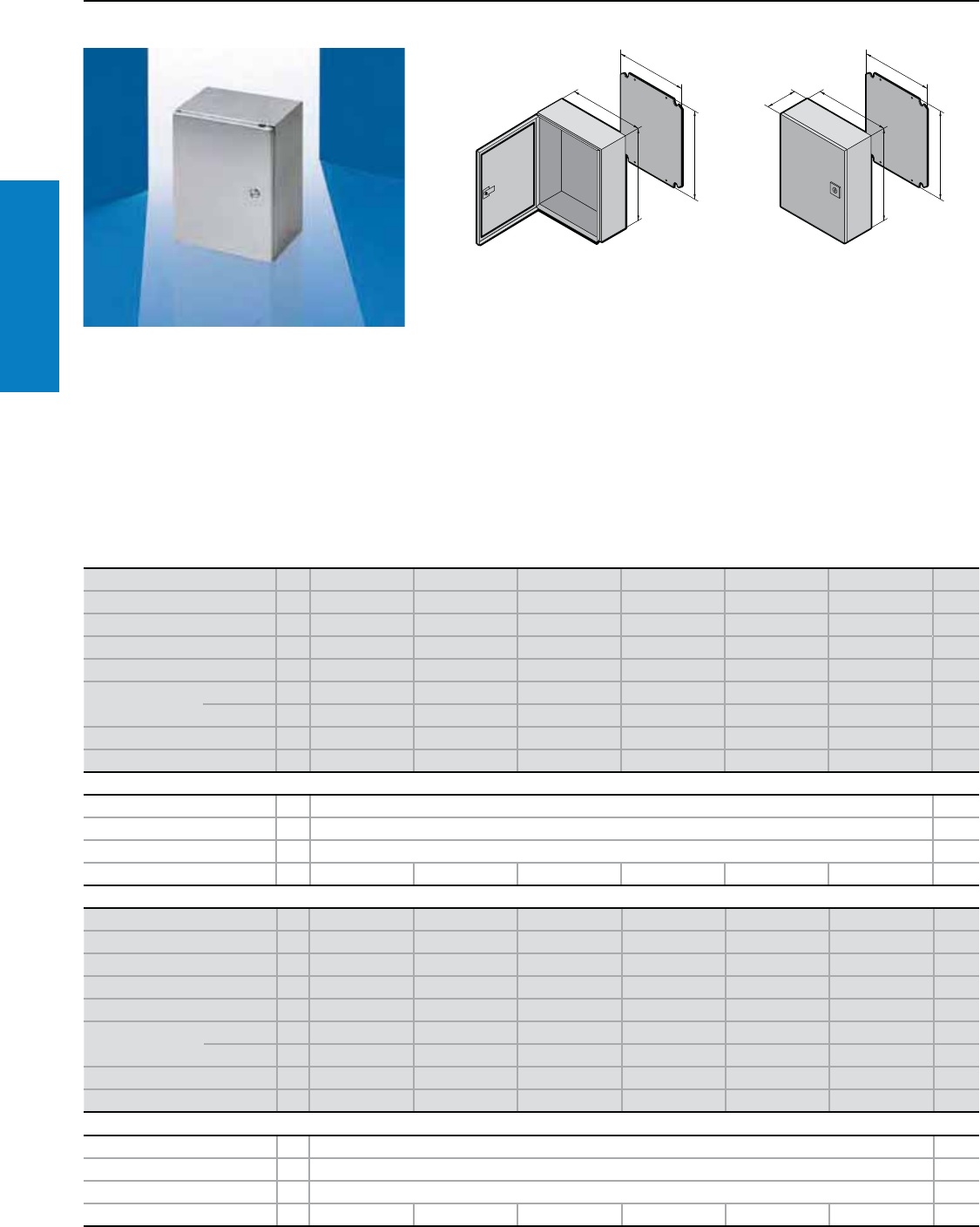
46 Industrial Buyer’s Guide
Stainless Steel Wallmount
WM - Wallmount
Depth: 6 - 8" (150 - 210 mm), Height: 12 - 30" (300 - 760 mm)
Material:
Type 304 or 316L stainless steel
Enclosure and door:
16 - 14 ga (1.5 - 2.0 mm)
-12" H x 12" W – 24" H x 20" W -
16 ga body/ 16 ga door
- 24" H x 24" W – 36" H x 24" W -
16 ga body/ 14 ga door
- 36" H x 30" W – 42" H x 32" W -
14 ga body/ 14 ga door
Protection Ratings:
Single door enclosures:
UL/cUL Type 12
(IP 55 to EN 60 529/10.91)
UL/cUL Type 3R
UL/cUL Type 4
(IP 66 to EN 60 529/10.91)
UL/cUL Type 4X
(IP 66 to EN 60 529/10.91)
For additional technical information,
please visit www.rittal-corp.com
Conguration:
Left-hand hinge
Slotted head insert
One-piece enclosure body
Single door WM enclosures less than 20"
high have one 1/4 Turn latch
Single door WM enclosures 20 - 40" high
have two 1/4 Turn latches
Single door WM enclosures greater than or
equal to 42" high have an L-Handle
Mounting panel
Wall-mounting blind nuts
Foamed-in-place gasket
Height (H1) inches (mm) PU 12 (300) 16 (400) 16 (400) 20 (500) 20 (500) 16 (400) Page
Width (B1) inches (mm) 12 (300) 12 (300) 16 (400) 16 (400) 20 (500) 12 (300)
Depth (T1) inches (mm) 6 (150) 6 (150) 6 (150) 6 (150) 6 (150) 8 (210)
Panel Height (G1) inches (mm) 11 (275) 15 (375) 15 (375) 19 (475) 19 (475) 15 (375)
Panel Width (F1) inches (mm) 10 (254) 10 (254) 14 (354) 14 (354) 18 (449) 10 (254)
Part No. Type 304 1WM121206N4 WM161206N4 WM161606N4 WM201606N4 WM202006N4 WM161208N4
Type 316L 1WM121206N6 WM161206N6 WM161606N6 WM201606N6 WM202006N6 WM161208N6
Door(s) 111111
Weight lb (kg) 16 (7) 20 (9) 23 (10) 31 (14) 37 (17) 23 (10)
Accessories
Handle 1 WMQTPLS6 219
Wallmount bracket for Type 304 4 2433.000 253
Wallmount bracket for Type 316L 4 2433.500 253
Dead front kit 1 DFK1212C DFK1612C DFK1616C DFK2016C DFK2020C DFK1612C 230
Inch and pound measurements are rounded to the nearest whole number.
B1
H1
F1
G1
B1
T1
H1
F1
G1
Finish:
Enclosure and door:
#4 Brushed
Mounting panel:
Zinc-plated carbon steel
Height (H1) inches (mm) PU 20 (500) 20 (500) 24 (600) 24 (600) 24 (600) 30 (760) Page
Width (B1) inches (mm) 16 (400) 20 (500) 16 (400) 20 (500) 24 (600) 24 (600)
Depth (T1) inches (mm) 8 (210) 8 (210) 8 (210) 8 (210) 8 (210) 8 (210)
Panel Height (G1) inches (mm) 19 (475) 19 (470) 22 (570) 22 (570) 22 (570) 29 (730)
Panel Width (F1) inches (mm) 14 (354) 18 (449) 14 (354) 18 (449) 22 (549) 22 (549)
Part No. Type 304 1WM201608N4 WM202008N4 WM241608N4 WM242008N4 WM242408N4 WM302408N4
Type 316L 1WM201608N6 WM202008N6 WM241608N6 WM242008N6 WM242408N6 WM302408N6
Door(s) 111111
Weight lb (kg) 34 (15) 41 (18) 39 (18) 46 (21) 57 (26) 70 (32)
Accessories
Handle 1 WMQTPLS6 219
Wallmount bracket for Type 304 4 2433.000 253
Wallmount bracket for Type 316L 4 2433.500 253
Dead front kit 1 DFK2016C DFK2020C DFK2416C DFK2420C DFK2424C DFK3024C 230
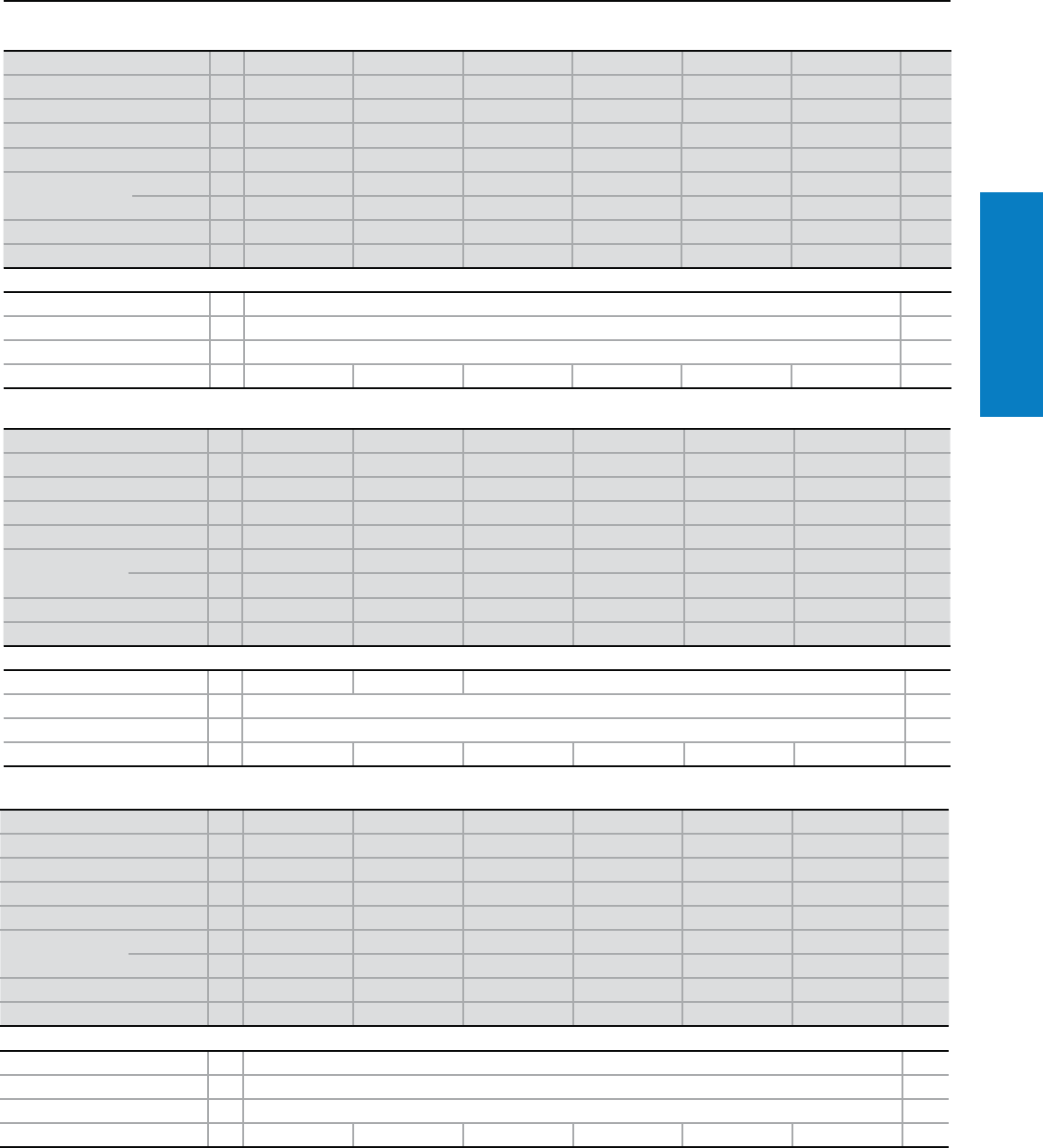
Industrial Buyer’s Guide 47
Stainless Steel Wallmount
WM - Wallmount
Depth: 8 - 16" (210 - 400 mm), Height: 30 - 60" (760 - 1500 mm)
Height (H1) inches (mm) PU 30 (760) 36 (900) 36 (900) 24 (600) 30 (760) 30 (760) Page
Width (B1) inches (mm) 30 (760) 24 (600) 30 (760) 20 (500) 24 (600) 30 (760)
Depth (T1) inches (mm) 8 (210) 8 (210) 8 (210) 10 (250) 10 (250) 10 (250)
Panel Height (G1) inches (mm) 29 (730) 34 (870) 34 (870) 22 (570) 29 (730) 29 (730)
Panel Width (F1) inches (mm) 28 (704) 22 (549) 28 (704) 18 (449) 22 (549) 28 (704)
Part No. Type 304 1WM303008N4 WM362408N4 WM363008N4 WM242010N4 WM302410N4 WM303010N4
Type 316L 1WM303008N6 WM362408N6 WM363008N6 WM242010N6 WM302410N6 WM303010N6
Door(s) 111111
Weight lb (kg) 86 (39) 91 (41) 111 (50) 49 (22) 154 (70) 89 (40)
Accessories
Handle 1 WMQTPLS6 219
Wallmount bracket for Type 304 4 2433.000 253
Wallmount bracket for Type 316L 4 2433.500 253
Dead front kit 1 DFK3030C DFK3624C DFK3630C DFK2420C DFK3024C DFK3030C 230
Height (H1) inches (mm) PU 36 (900) 48 (1200) 24 (600) 30 (760) 36 (900) 36 (900) Page
Width (B1) inches (mm) 30 (760) 36 (900) 24 (600) 24 (600) 30 (760) 36 (900)
Depth (T1) inches (mm) 10 (250) 10 (250) 12 (300) 12 (300) 12 (300) 12 (300)
Panel Height (G1) inches (mm) 34 (870) 45 (1155) 23 (570) 29 (730) 34 (870) 34 (870)
Panel Width (F1) inches (mm) 28 (704) 33 (840) 22 (549) 22 (549) 28 (704) 33 (840)
Part No. Type 304 1WM363010N4 WM483610N4 WM242412N4 WM302412N4 WM363012N4 WM363612N4
Type 316L 1WM363010N6 WM483610N6 WM242412N6 WM302412N6 WM363012N6 WM363612N6
Door(s) 111111
Weight lb (kg) 116 (53) 178 (81) 63 (28) 77 (35) 122 (55) 146 (66)
Accessories
Handle 1 WMQTPLS6 WMLHKLS6 WMQTPLS6 219
Wallmount bracket for Type 304 4 2433.000 253
Wallmount bracket for Type 316L 4 2433.500 253
Dead Front Kit 1 DFK3630C DFK4836C DFK2424C DFK3024C DFK3630C DFK3636C 230
Inch and pound measurements are rounded to the nearest whole number.
Height (H1) inches (mm) PU 42 (1050) 47 (1200) 60 (1500) 36 (900) 47 (1200) 60 (1500) Page
Width (B1) inches (mm) 36 (900) 36 (900) 36 (900) 30 (760) 36 (900) 36 (900)
Depth (T1) inches (mm) 12 (300) 12 (300) 12 (300) 16 (400) 16 (400) 16 (400)
Panel Height (G1) inches (mm) 40 (1020) 45 (1155) 57 (1455) 34 (870) 46 (1155) 57 (1455)
Panel Width (F1) inches (mm) 33 (840) 33 (840) 33 (840) 28 (704) 33 (840) 33 (840)
Part No. Type 304 1WM423612N4 WM483612N4 WM603612N4 WM363016N4 WM483616N4 WM603616N4
Type 316L 1WM423612N6 WM483612N6 WM603612N6 WM363016N6 WM483616N6 WM603616N6
Door(s) 111111
Weight lb (kg) 169 (77) 189 (86) 229 (104) 134 (61) 204 (93) 210 (95)
Accessories
Handle 1 WMLHKLS6 220
Wallmount bracket for Type 304 4 2433.000 253
Wallmount bracket for Type 316L 4 2433.500 253
Dead front kit 1 DFK4236C DFK4836C DFK6036C DFK3630C DFK4836C DFK6036C 230
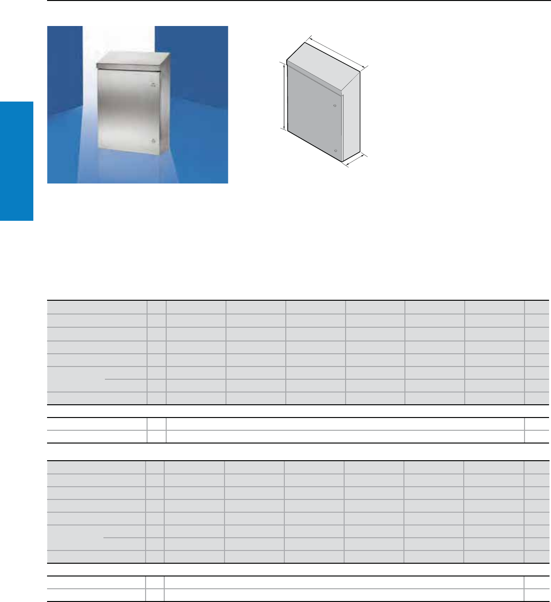
48 Industrial Buyer’s Guide
Stainless Steel Wallmount
WM Slop Top - Wallmount
Depth: 8 - 12" (210 - 300 mm), Height: 16 - 36" (395 - 895 mm)
Inch and pound measurements are rounded to the nearest whole number.
B1
H1
T1
Material:
Type 304 or 316L stainless steel
Enclosure and door:
16 - 14 ga (1.5 - 2.0 mm)
- 16" H x 12" W – 24" H x 20" W -
16 ga body / 16 ga door
- 24" H x 24" W – 30" H x 24" W -
16 ga body / 14 ga door
- 30" H x 30" W – 60" H x 36" W -
14 ga body / 14 ga door
Finish:
Enclosure and door:
#4 Brushed
Mounting panel:
Zinc-plated
Conguration:
20° overhanging sloped roof
Slotted head spring loaded insert
One-piece enclosure body
Foamed-in-place gasket
Includes recessed blind nuts for
mounting enclosure to wall
Enclosures less than 20" high have
one 1/4-turn latch
Protection Ratings:
UL Type 1, 12, 3R, 4, 4X
UL/cUL
UL file: E170282
Height (H1) inches (mm) PU 16 (395) 16 (395) 20 (495) 20 (495) 24 (595) 24 (595) Page
Width (B1) inches (mm) 12 (300) 16 (400) 16 (400) 20 (500) 20 (500) 24 (600)
Depth (T1) inches (mm) 8 (210) 8 (210) 8 (210) 8 (210) 8 (210) 8 (210)
Panel Height inches (mm) 15 (375) 15 (375) 19 (475) 19 (475) 22 (570) 22 (570)
Panel Width inches (mm) 10 (254) 14 (354) 14 (354) 18 (449) 18 (449) 22 (549)
Part No. Type 304 1WMS161208N4 WMS161608N4 WMS201608N4 WMS202008N4 WMS242008N4 WMS242408N4
Type 316L 1WMS161208N6 WMS161608N6 WMS201608N6 WMS202008N6 WMS242008N6 WMS242408N6
Weight lb (kg) 21 (10) 26 (12) 34 (15) 41 (19) 47 (21) 58 (26)
Accessories
Wallmount bracket Type 304 4 2433.000 253
Wallmount bracket Type 316L 4 2433.500 253
Height (H1) inches (mm) PU 30 (755) 30 (755) 36 (895) 20 (495) 20 (495) 24 (595) Page
Width (B1) inches (mm) 24 (600) 30 (760) 30 (760) 16 (400) 20 (500) 24 (600)
Depth (T1) inches (mm) 8 (210) 8 (210) 8 (210) 12 (300) 12 (300) 12 (300)
Panel Height inches (mm) 29 (730) 29 (730) 34 (870) 19 (475) 19 (475) 22 (570)
Panel Width inches (mm) 22 (549) 28 (704) 28 (704) 14 (354) 18 (449) 22 (549)
Part No. Type 304 1WMS302408N4 WMS303008N4 WMS363008N4 WMS201612N4 WMS202012N4 WMS242412N4
Type 316L 1WMS302408N6 WMS303008N6 WMS363008N6 WMS201612N6 WMS202012N6 WMS242412N6
Weight lb (kg) 71 (32) 88 (40) 115 (52) 38 (17) 46 (21) 64 (29)
Accessories
Wallmount bracket Type 304 4 2433.000 253
Wallmount bracket Type 316L 4 2433.500 253
Enclosures 20 - 40" have two
1/4-turn latches
Enclosures greater than or equal
to 42" equipped with L-Handle and
three point lock rod system
Mounting Panel
For additional technical
information, please visit
www.rittal-corp.com
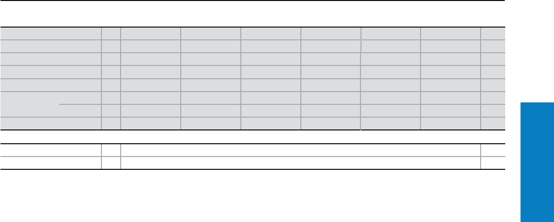
Industrial Buyer’s Guide 49
Stainless Steel Wallmount
WM Slope Top - Wallmount
Depth: 12 - 16” (300 - 400 mm), Height: 30 - 60” (755 - 1495 mm)
Inch and pound measurements are rounded to the nearest whole number.
Height (H1) inches (mm) PU 30 (755) 36 (895) 36 (895) 36 (895) 48 (1195) 60 (1495) Page
Width (B1) inches (mm) 24 (600) 30 (760) 36 (900) 30 (760) 36 (900) 36 (900)
Depth (T1) inches (mm) 12 (300) 12 (300) 12 (300) 16 (400) 16 (400) 16 (400)
Panel Height inches (mm) 29 (730) 34 (870) 34 (870) 34 (870) 45 (1155) 57 (1455)
Panel Width inches (mm) 22 (549) 28 (704) 33 (840) 28 (704) 33 (840) 33 (840)
Part No. Type 304 1WMS302412N4 WMS363012N4 WMS363612N4 WMS363016N4 WMS483616N4 WMS603616N4
Type 316L 1WMS302412N6 WMS363012N6 WMS363612N6 WMS363016N6 WMS483616N6 WMS603616N6
Weight lb (kg) 79 (36) 126 (57) 153 (69) 139 (63) 209 (95) 251 (114)
Accessories
Wallmount bracket Type 304 4 2433.000 253
Wallmount bracket Type 316L 4 2433.500 253
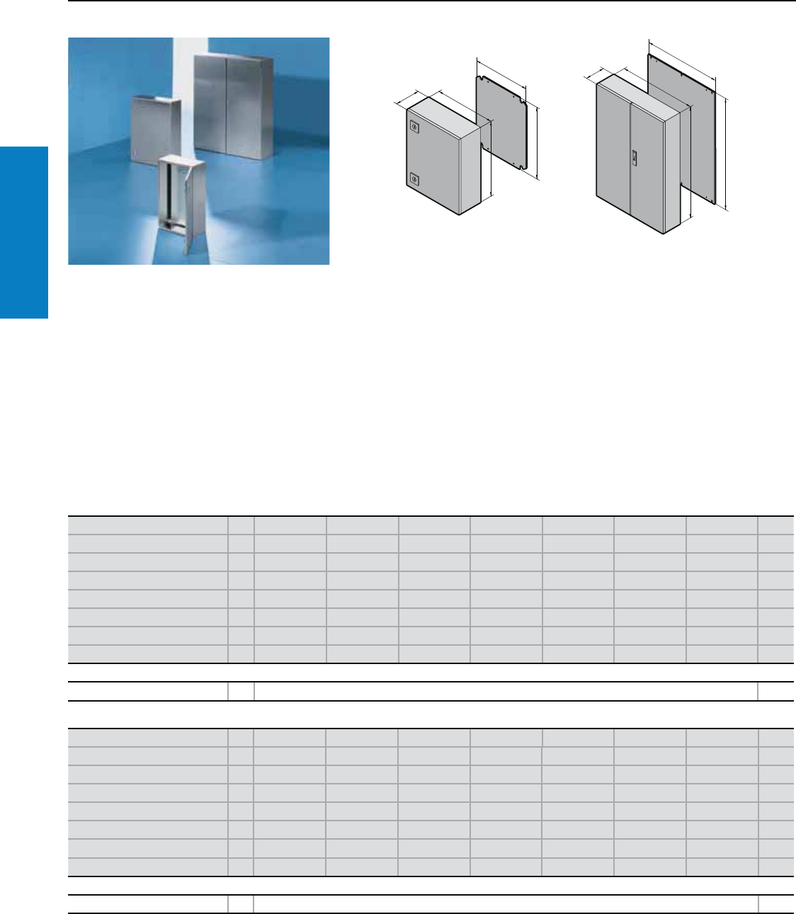
50 Industrial Buyer’s Guide
Stainless Steel Wallmount
AE - Wallmount
Depth: 5 - 12” (120 - 300 mm), Height: 12 - 30” (300 - 760 mm)
Inch and pound measurements are rounded to the nearest whole number.
Material:
Type 304 stainless steel
Enclosure and door:
16 - 14 ga (1.5 - 2.0 mm)
-12" H x 12" W – 24" H x 20" W -
16 ga body/ 16 ga door
- 24" H x 24" W – 36" H x 24" W -
16 ga body/ 14 ga door
- 36" H x 30" W – 47" H x 32" W -
14 ga body/ 14 ga door
Protection Ratings:
Single door enclosures:
UL/cUL Type 12
(IP 55 to EN 60 529/10.91)
UL/cUL Type 3R
UL/cUL Type 4
(IP 66 to EN 60 529/10.91)
UL/cUL Type 4X
(IP 66 to EN 60 529/10.91)
Double door enclosures:
UL/cUL Type 12
(IP 55 to EN 60 529/10.91)
UL File Number: E170282
For additional technical information,
please visit www.rittal-corp.com
Conguration:
Right-hand hinge
Double-bit insert
One-piece enclosure body
Enclosures less than 20" high have one
1/4 Turn latch
Enclosures 20 - 39" high have two
1/4 Turn latches
Enclosures more than 39" high have 3
point latching
Foamed-in-place gasket
B1
T1
H1
F1
G1
T1
F1
B1
H1
G1
Height (H1) inches (mm) PU 12 (300) 12 (300) 12 (300) 12 (300) 12 (300) 15 (380) 15 (380) Page
Width (B1) inches (mm) 8 (200) 8 (200) 15 (380) 12 (300) 15 (380) 12 (300) 15 (380)
Depth (T1) inches (mm) 5 (120) 6 (155) 6 (155) 8 (210) 8 (210) 8 (210) 8 (210)
Panel Height (G1) inches (mm) 11 (275) 11 (275) 11 (275) 11 (275) 11 (275) 14 (355) 14 (355)
Panel Width (F1) inches (mm) 6 (162) 6 (162) 13 (334) 10 (254) 13 (334) 10 (254) 13 (334)
Part No. 11001.600 1002.600 1004.600 1003.600 1011.600 1005.600 1006.600
Door(s) 1111111
Weight lb (kg) 8 (4) 10 (5) 19 (9) 15 (7) 18 (8) 19 (9) 27 (12)
Accessories
Wallmount bracket 4 2433.000 253
Height (H1) inches (mm) PU 15 (380) 20 (500) 20 (500) 24 (600) 24 (600) 30 (760) 20 (500) Page
Width (B1) inches (mm) 24 (600) 16 (400) 20 (500) 15 (380) 24 (600) 24 (600) 20 (500)
Depth (T1) inches (mm) 8 (210) 8 (210) 8 (210) 8 (210) 8 (210) 8 (210) 12 (300)
Panel Height (G1) inches (mm) 14 (355) 19 (475) 19 (470) 22 (570) 22 (570) 29 (730) 19 (470)
Panel Width (F1) inches (mm) 22 (549) 14 (354) 18 (449) 13 (334) 22 (549) 22 (549) 18 (449)
Part No. 11009.600 1015.600 1007.600 1008.600 1010.600 1012.600 1013.600
Door(s) 1111111
Weight lb (kg) 38 (17) 28 (13) 41 (18) 38 (17) 95 (25) 70 (32) 42 (19)
Accessories
Wallmount bracket 4 2433.000 253
Finish:
Stainless steel enclosure:
#4 Brushed
Mounting panel:
Zinc-plated carbon steel
Industrial Buyer’s Guide 51
Stainless Steel Wallmount
AE - Wallmount
Depth: 12" (300 mm), Height: 30 - 47" (760 - 1200 mm)
Inch and pound measurements are rounded to the nearest whole number.
Height (H1) inches (mm) PU 30 (760) 39 (1000) 39 (1000) 47 (1200) 47 (1200) Page
Width (B1) inches (mm) 30 (760) 32 (800) 39 (1000) 32 (800) 39 (1000)
Depth (T1) inches (mm) 12 (300) 12 (300) 12 (300) 12 (300) 12 (300)
Panel Height (G1) inches (mm) 29 (730) 38 (955) 38 (955) 45 (1155) 45 (1155)
Panel Width (F1) inches (mm) 28 (704) 29 (730) 37 (939) 29 (740) 37 (940)
Part No. 11014.600 1016.600 1018.600 1017.600 1019.600
Door(s) 11212
Weight lb (kg) 94 (43) 117 (53) 157 (71) 154 (70) 167 (76)
Accessories
Wallmount bracket 4 2433.000 253
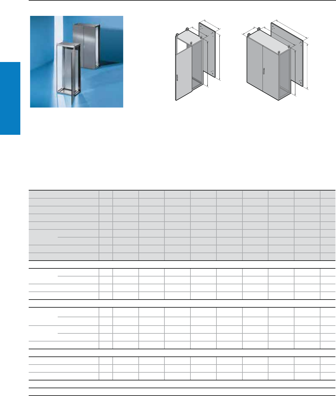
52 Industrial Buyer’s Guide
Stainless Steel Freestanding
TS8 - Freestanding
Height: 71 - 79" (1800 - 2000 mm), Depth: 16 - 24" (400 - 600 mm)
F
G
H
B
T
H
B
F
G
Material:
Type 304 and 316L stainless steel
Enclosure frame, roof, rear panel
and gland plates: 16 ga (1.5 mm)
Door(s): 14 ga (2.0 mm); Mounting
panel: Sheet steel, 11 ga (3.0 mm)
Finish:
Enclosure frame and gland plates:
Uncoated
Door, roof and rear panel: Brushed on
the outside, grain size 400
Mounting panel: Zinc-plated
Protection ratings:
NEMA 12
(IP 55 to EN 60 529/09.2000)
Conguration:
Enclosure frame with door(s),
mounting panel, gland plates,
rear panel and roof,
2 support strips mounted in the
enclosure depth (only with a
depth of 24" [600 mm]).
Note:
Due to the hardness of the
material, we recommend
using metal multi-tooth screw
2486.300, see page 240, for
the interior installation.
For additional technical
information, please visit
www.rittal-corp.com
Height (H) inches (mm) PU 71 (1800) 71 (1800) 71 (1800) 71 (1800) 71 (1800) 79 (2000) 79 (2000) 79 (2000) Page
Width (B) inches (mm) 32 (800) 47 (1200) 24 (600) 32 (800) 47 (1200) 24 (600) 32 (800) 47 (1200)
Depth (T) inches (mm) 16 (400) 16 (400) 20 (500) 20 (500) 20 (500) 24 (600) 24 (600) 24 (600)
Panel Width (F) inches (mm) 28 (699) 43 (1099) 20 (499) 28 (699) 43 (1099) 20 (499) 28 (699) 43 (1099)
Panel Height (G) inches (mm) 67 (1696) 67 (1696) 67 (1696) 67 (1696) 67 (1696) 75 (1896) 75 (1896) 75 (1896)
Part No. Type 304 18454.600 8456.600 8457.600 8455.600 8453.600 8452.600 8450.600 8451.600
Type 316L 18454.500 8456.500 8457.500 8455.500 8453.500 8452.500 8450.500 8451.500
Door(s) 1 2 1 1 2 1 1 2
Weight lb (kg) 112.9 170.4 92.5 116.3 174.9 104.4 129.7 194.7
Walls
Sidewalls Type 304 2 8700.840 8700.840 8700.850 8700.850 8700.850 8700.060 8700.060 8700.060 202
Type 316L 2 8705.840 8705.840 8705.850 8705.850 8705.850 8705.060 8705.060 8705.060 202
Divider panel 1 8609.840 8609.840 8609.850 8609.850 8609.850 8609.060 8609.060 8609.060 204
Divider panel for module plates 1 – – 8609.100 8609.100 8609.100 8609.130 8609.130 8609.130 205
Base/plinth
Components
front and
rear
Height 4" (100 mm) 1 set 8701.800 8701.200 8701.600 8701.800 8701.200 8701.600 8701.800 8701.200 195
Height 8" (200 mm) 1 set 8702.800 8702.200 8702.600 8702.800 8702.200 8702.600 8702.800 8702.200 195
Trim panels
(sides)
Height 4" (100 mm) 1 set 8701.040 8701.040 8701.050 8701.050 8701.050 8701.060 8701.060 8701.060 195
Height 8" (200 mm) 1 set 8702.040 8702.040 8702.050 8702.050 8702.050 8702.060 8702.060 8702.060 195
Base/plinth trim, modular 4 2907.000 2907.000 2908.000 2908.000 2908.000 2913.000 2913.000 2913.000 –
Accessories
Cable clamp rails 2 4192.000 4196.000 4191.000 4192.000 4196.000 4191.000 4192.000 4196.000 256
Cable entry plates 2 8700.800 8700.1201) 8700.600 8700.800 8700.1201) 8700.600 8700.800 8700.1201) 258
Wiring plan pocket, sheet steel 1 4118.000 4116.000 4116.000 4118.000 4116.000 4116.000 4118.000 4116.000 227
Lock systems
Standard double-bit lock insert may be exchanged for type F lock inserts and comfort handle, see page 220.
1) Packs of 4
Inch and pound measurements are rounded to the nearest whole number.
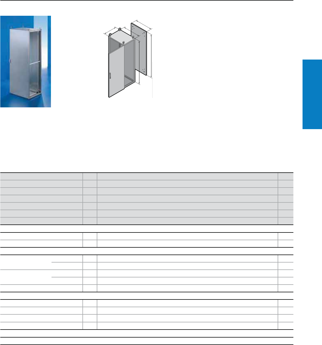
Industrial Buyer’s Guide 53
Junction Box
Stainless Steel Freestanding
Material:
Type 304 stainless steel
Enclosure frame, roof, base,
rear wall: 16 ga (1.5 mm)
Door: 14 ga (2.0 mm)
Mounting panel: 11 ga (3.0 mm)
Finish:
Enclosure frame: Type 304
stainless steel
Door, roof, base, rear wall:
Brushed
Mounting panel: Zinc-plated
carbon steel
Conguration:
Enclosure frame with door, roof/base
plate, rear wall, mounting panel.
Protection Ratings:
UL Type 4X
(IP 66 to EN 60 529)
UL/cUL
UL file: E76083
Height (H1) inches (mm) PU 79 (2000) Page
Width (B1) inches (mm) 32 (800)
Depth (T1) inches (mm) 24 (600)
Panel Height (G1) inches (mm) 75 (1896)
Panel Width (F1) inches (mm) 28 (699)
Part No. 18450.680
Door(s) 1
Required Accessories
Sidewalls IP 66/UL Type 4X 2 8700.680 –
Baying frame IP 66/UL Type 4X 1 8700.064 –
Base/plinth
Components front and
rear inches (mm)
Height 4 (100) 1 set 8701.800 195
Height 8 (200) 1 set 8702.800 195
Side panels inches (mm) Height 4 (100) 1 set 8701.060 195
Height 8 (200) 1 set 8702.060 195
Base/plinth trim, modular 4 2913.000 –
Accessories
Cable clamp rails 2 4192.000 256
System support rails 2 4362.000 –
Support rails for door 20 4598.000 236
Print pocket, sheet steel 1 4116.000 227
Lock systems
Standard double-bit lock insert may be exchanged for other lock inserts and comfort handle, see pages 217-220.
Additional sizes available upon request.
Inch and pound measurements are rounded to the nearest whole number.
For additional technical
information, please visit
www.rittal-corp.com
TS8 UL Type 4X - Freestanding
Height: 79" (2000 mm), Depth: 24" (600 mm)
T
H
B
G
F
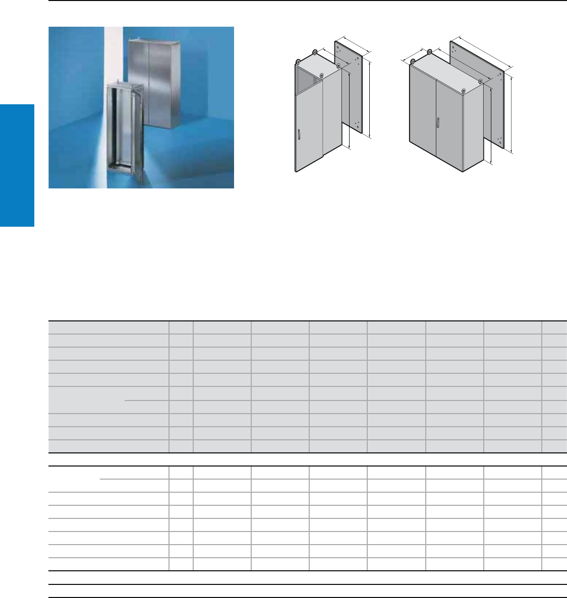
54 Industrial Buyer’s Guide
Stainless Steel Freestanding
ES - Freestanding
Height: 63 - 79" (1600 - 2000 mm), Depth: 16 - 24" (400 - 600 mm)
Material:
Stainless steel
Enclosure: 15 ga (1.8 mm)
Door(s): 14 ga (2.0 mm)
Rear panel: 16 ga (1.5 mm)
Mounting panel: 11 ga (3.0 mm)
Finish:
Enclosure, rear panel and doors:
Brushed, grain size 240
Mounting panel: Zinc-plated
carbon steel
Protection Ratings:
Single door enclosures:
UL Type 12
(IP 56 to EN 60 529/09.2000)
Double door enclosure:
UL Type 12
(IP 55 to EN 60 529/09.2000)
UL file number: E76083
Conguration:
Enclosure, closed top and sides,
removable rear panel, right hand
door hinge, can be changed to
opposite side, except 5455.600;
130° hinges, mounting panel,
three-part gland plates.
Note:
Due to the hardness of the material,
we recommend using metal multi-
tooth screw 2486.300, see page
240, for the interior installation.
Inch and pound measurements are rounded to the nearest whole number.
F
G
H
B
T
H
B
F
G
For additional technical
information, please visit
www.rittal-corp.com
Height (H) inches (mm) PU 63 (1600) 71 (1800) 71 (1800) 71 (1800) 79 (2000) 79 (2000) Page
Width (B) inches (mm) 24 (600) 40 (1000) 24 (600) 32 (800) 47 (1200) 32 (800)
Depth (T) inches (mm) 16 (400) 16 (400) 20 (500) 20 (500) 20 (500) 24 (600)
Panel Width (F) inches (mm) 20 (499) 35 (899) 20 (499) 28 (699) 43 (1099) 28 (699)
Panel Height (G) inches (mm) 59 (1496) 67 (1696) 67 (1696) 67 (1696) 75 (1896) 75 (1896)
Part No. Type 304 15450.600 5454.600 5451.600 5452.600 5455.600 5453.600
Type 316L 15450.500 5454.500 5451.500 5452.500 5455.500 5453.500
Door(s) 111121
Eyebolts 242242
Weight lb (kg) 93 147 170 132 206 154
Accessories
Base/plinth
inches (mm)
Height 4" (100 mm) 1 set 2865.000 2867.000 2868.000 2866.000 2860.000 2856.000 196
Height 8" (200 mm) 1 set 2875.000 2885.000 2876.000 2879.000 2887.000 2880.000 196
Base/plinth trim, modular 4 2907.000 2907.000 2908.000 2908.000 2908.000 2913.000 –
System support rails 2 4361.000 4347.000 4361.000 4362.000 4363.000 4362.000 –
Cable clamp rails 2 4191.000 4336.000 4191.000 4192.000 4196.000 4192.000 256
Mounting bars 20 4596.000 4599.000 4596.000 4598.000 4596.000 4598.000 236
Utility shelf 1 4638.600 – 4638.600 4638.800 4638.600 4638.800 227
Print pocket, sheet steel 1 4116.000 4124.000 4116.000 4118.000 4116.000 4118.000 227
Lock systems
Standard double-bit lock insert may be exchanged for 1" (27 mm) lock inserts, type A, and Ergoform-S lock system, see page 218.
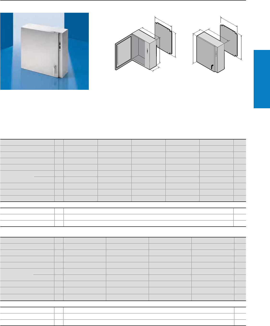
Industrial Buyer’s Guide 55
Junction Box
Stainless Steel Disconnect
WM Disconnect - Wallmount
Depth: 8 - 16" (210 - 400 mm), Height: 24 - 60" (600 - 1500 mm)
Material:
Type 304 or 316L stainless steel
Enclosure and door:
14 ga body/ 14 ga door
except for 24 x 26 - 16 ga body/
14 ga door
Protection Ratings:
UL/cUL Type 12
(IP 55 to EN 60 529/10.91)
UL/cUL Type 3R
UL/cUL Type 4
(IP 66 to EN 60 529/10.91)
UL/cUL Type 4X
(IP 66 to EN 60 529/10.91)
For additional technical information,
please visit www.rittal-corp.com
Height (H1) inches (mm) PU 24 (600) 36 (900) 36 (900) 60 (1500) 36 (900) Page
Width (B1) inches (mm) 26 (650) 32 (825) 32 (825) 38 (975) 32 (825)
Depth (T1) inches (mm) 8 (210) 8 (210) 10 (250) 10 (250) 12 (300)
Panel Height (G1) inches (mm) 22 (570) 34 (870) 34 (870) 57 (1455) 34 (870)
Panel Width (F1) inches (mm) 22 (549) 28 (704) 28 (704) 33 (840) 28 (704)
Part No. Type 304 1WM242608X4 WM363208X4 WM363210X4 WM603810X4 WM363212X4
Type 316L 1WM242608X6 WM363208X6 WM363210X6 WM603810X6 WM363212X6
Door(s) 11111
Locking handle points 22232
Weight lb (kg) 97 (26) 113 (51) 118 (54) 225 (103) 124 (56)
Accessories
Handle 1 WMLHKLS6 220
Wallmount bracket for Type 304 4 2433.000 253
Wallmount bracket for Type 316L 4 2433.500 253
Height (H1) inches (mm) PU 42 (1050) 48 (1200) 60 (1500) 48 (1200) Page
Width (B1) inches (mm) 32 (825) 38 (975) 38 (975) 38 (975)
Depth (T1) inches (mm) 12 (300) 12 (300) 12 (300) 16 (400)
Panel Height (G1) inches (mm) 40 (120) 45 (1155) 57 (1455) 46 (1155)
Panel Width (F1) inches (mm) 33 (840) 33 (840) 33 (840) 33 (840)
Part No. Type 304 1WM423212X4 WM483812X4 WM603812X4 WM483816X4
Type 316L 1WM423212X6 WM483812X6 WM603812X6 WM483816X6
Door(s) 1111
Locking handle points 3333
Weight lb (kg) 162 (74) 191 (87) 231 (105) 205 (94)
Accessories
Handle 1 WMLHKLS6 220
Wallmount bracket for Type 304 4 2433.000 253
Wallmount bracket for Type 316L 4 2433.500 253
Conguration:
Left-hand hinge
Universal disconnect cut-out
One-piece enclosure body
2 or 3-point locking L-handle
Mounting panel
Wall-mounting blind nuts
Foamed-in-place gasket
Inch and pound measurements are rounded to the nearest whole number.
Finish:
Enclosure
#4 Brushed
Mounting panel:
Zinc-plated carbon steel
B1
T1
H1
F1
G1
B1
H1
F1
G1
T1
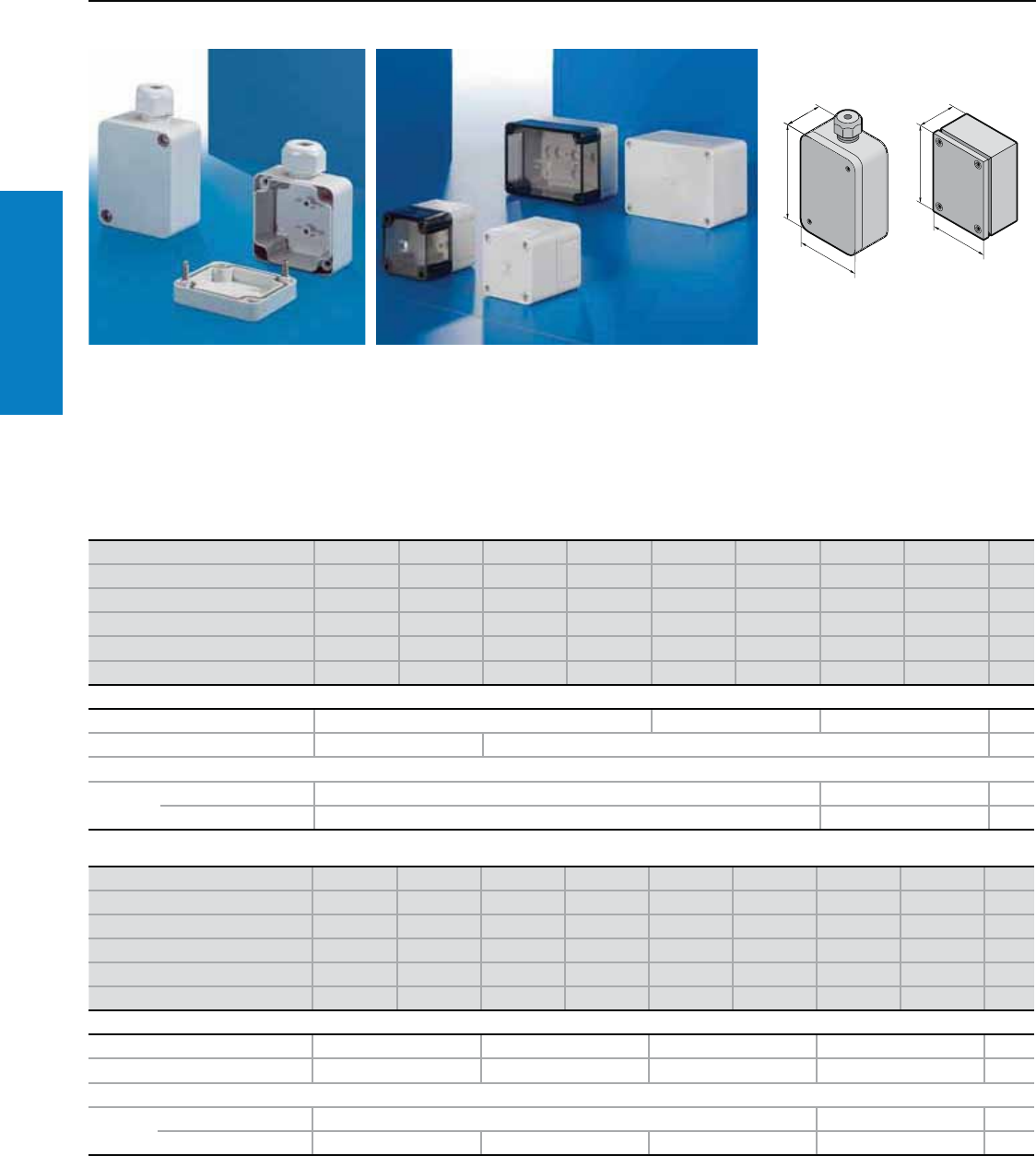
56 Industrial Buyer’s Guide
Junction Box
Stainless Steel
Polycarbonate
PK Screw Cover - Junction Box
Depth: 1 - 4" (35 - 99 mm), Height: 2 - 5" (52 - 130 mm)
Material:
Enclosure and cover (version
XXXX.000) from fiberglass reinforced
polycarbonate, transparent cover
(XXXX.100) from polycarbonate,
cover screws from polyamide,
insulating plugs from polyethylene.
Color:
RAL 7035 (light gray)
Protection Ratings:
NEMA 4X
(IP 66 to EN 60 529/10.91)
Conguration:
Enclosure and cover, cover
screws, insulating plug for
wallmount screws (not with
9530.000 and 9531.000),
foamed-on polyurethane seal
around the perimeter.
Height (H1) inches (mm) 2.0 (52) 2.6 (65) 2.6 (65) 2.6 (65) 2.6 (65) 2.6 (65) 3.7 (94) 3.7 (94) Page
Width (B1) inches (mm) 2.0 (50) 2.0 (50) 2.6 (65) 2.6 (65) 3.7 (94) 3.7 (94) 3.7 (94) 3.7 (94)
Depth (T1) inches (mm) 1.4 (35) 1.4 (35) 2.2 (57) 3.2 (81) 2.2 (57) 3.2 (81) 2.2 (57) 3.2 (81)
Part No. with cable gland 9530.000 9531.000 ––––––
Part No. with solid cover – – 9500.000 9501.000 9502.000 9503.000 9504.000 9505.000
PU 101012128866
Accessories
Mounting panel – 9541.000 9542.000 229
PU 10 12
Support rail (PU 12)
TS 35/7.5 Installation in the height – 9564.000 238
Installation in the width – 9564.000 238
Height (H1) inches (mm) 3.7 (94) 3.7 (94) 3.7 (94) 3.7 (94) 4.3 (110) 4.3 (110) 5.1 (130) 5.1 (130) Page
Width (B1) inches (mm) 5.1 (130) 5.1 (130) 7.1 (180) 7.1 (180) 4.3 (110) 4.3 (110) 5.1 (130) 5.1 (130)
Depth (T1) inches (mm) 2.2 (57) 3.2 (81) 2.2 (57) 3.2 (81) 2.6 (66) 3.5 (90) 3.0 (75) 3.9 (99)
Part No. with solid cover 9508.000 9509.000 9512.000 9513.000 9506.000 9507.000 9510.000 9511.000
Part No. with transparent cover 9508.100 9509.100 9512.100 9513.100 – – 9510.100 9511.100
PU 44226644
Accessories
Mounting panel 9544.000 9546.000 9543.000 9545.000 229
PU 12 10 12 10
Support rail (PU 12)
TS 35/7.5 Installation in the height 9564.000 9565.000 238
Installation in the width 9565.000 9566.000 9564.000 9565.000 238
For additional technical
information, please visit
www.rittal-corp.com
Inch and pound measurements are rounded to the nearest whole number.
H1
B1
T1
H1
B1
T1
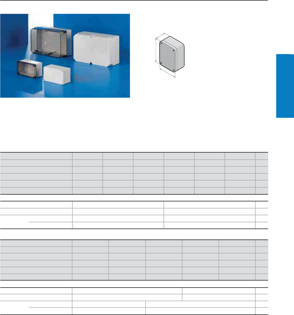
Industrial Buyer’s Guide 57
Junction Box
Stainless Steel
Polycarbonate
PK Screw Cover - Junction Box
Depth: 4 - 7" (90 - 165 mm), Height: 4 - 10" (110 - 254 mm)
Material:
Enclosure and cover (version
XXXX.000) from fiberglass reinforced
polycarbonate, transparent cover
(XXXX.100) from polycarbonate,
cover screws from polyamide,
insulating plugs from polyethylene.
Color:
RAL 7035 (light gray)
Protection Ratings:
NEMA 4X
(IP 66 to EN 60 529/10.91)
Conguration:
Enclosure and cover, cover screws,
insulating plug for wallmount screws
(not with 9530.000 and 9531.000),
foamed-on polyurethane seal
around the perimeter.
Height (H1) inches (mm) 4.3 (110) 4.3 (110) 4.3 (110) 7.1 (180) 7.1 (180) 7.1 (180) Page
Width (B1) inches (mm) 7.1 (180) 7.1 (180) 7.1 (180) 7.2 (182) 7.2 (182) 7.2 (182)
Depth (T1) inches (mm) 3.5 (90) 4.4 (111) 6.5 (165) 3.5 (90) 4.4 (111) 6.5 (165)
Part No. with solid cover 9514.000 9515.000 9516.000 9517.000 9518.000 9519.000
Part No. with transparent cover 9514.100 9515.100 9516.100 9517.100 9518.100 9519.100
PU 222111
Accessories
Mounting panel 9547.000 9548.000 229
PU 10 10
Support rail TS
35/7.5 (PU 12)
Installation in the height 9564.000 9566.000 238
Installation in the width 9566.000 9566.000 238
H1
B1
T1
Height (H1) inches (mm) 7.1 (180) 7.1 (180) 7.1 (180) 10.0 (254) 10.0 (254) Page
Width (B1) inches (mm) 10.0 (254) 10.0 (254) 10.0 (254) 14.2 (360) 14.2 (360)
Depth (T1) inches (mm) 3.5 (90) 4.4 (111) 6.5 (165) 4.4 (111) 6.5 (165)
Part No. with solid cover 9520.000 9521.000 9522.000 9523.000 9524.000
Part No. with transparent cover 9520.100 9521.100 9522.100 9523.100 9524.100
PU 11111
Accessories
Mounting panel 9549.000 9550.000 229
PU 84
Support rail TS
35/7.5 (PU 12)
Installation in the height 9566.000 9567.000 238
Installation in the width 9567.000 9568.000 238
For additional technical
information, please visit
www.rittal-corp.com
Inch and pound measurements are rounded to the nearest whole number.
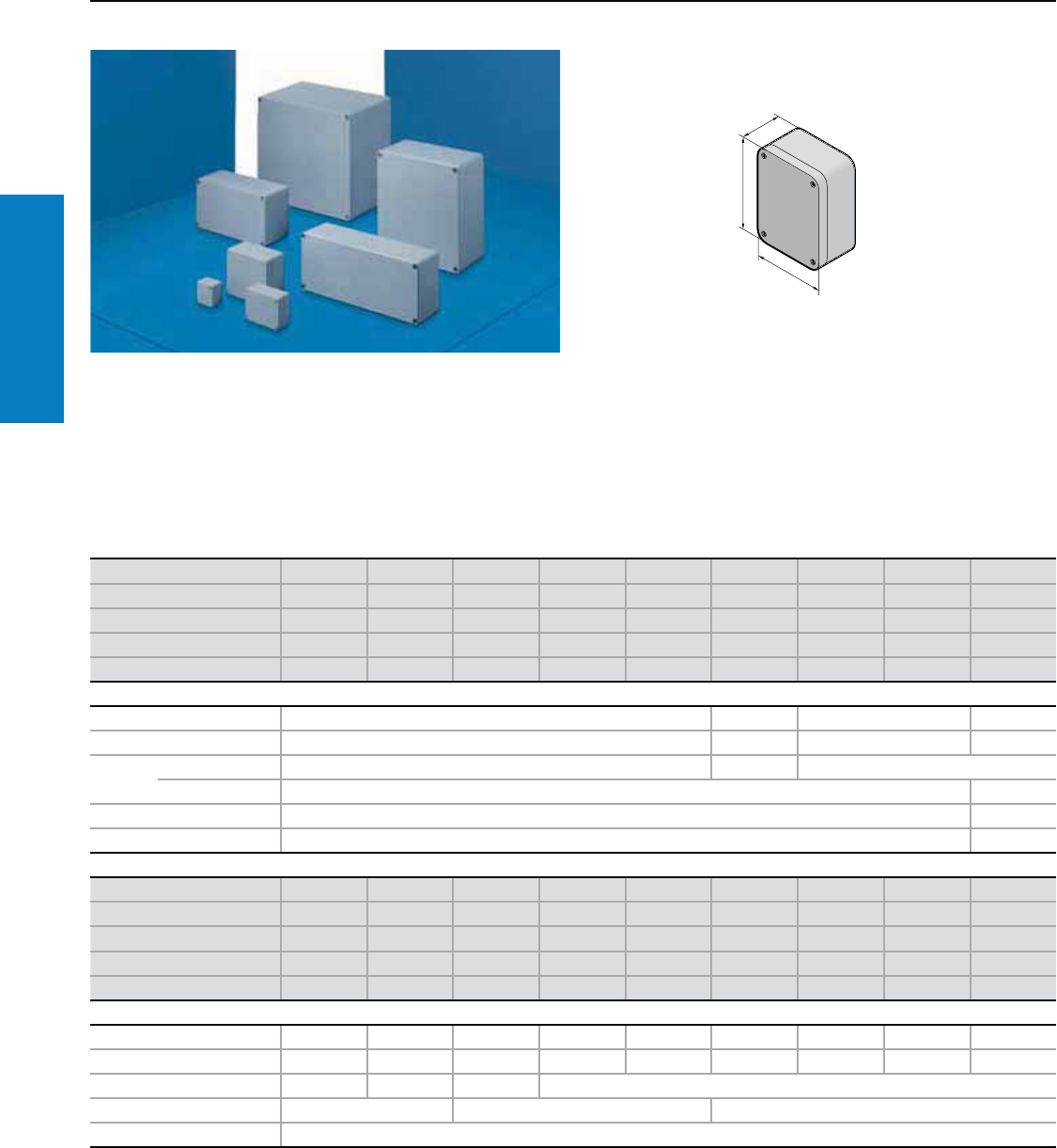
58 Industrial Buyer’s Guide
Junction Box
Stainless Steel
Aluminum
GA Screw Cover - Junction Box
Depth: 1 - 7" (30 - 180 mm), Height: 2 - 9" (45 - 230 mm)
H1
B1
T
1
Material:
Enclosure and lid made from
cast aluminium, lid with neoprene
cord seal.
Finish:
Textured enamel similar to
RAL 7001 (silver gray)
Protection Ratings:
NEMA 4
(IP 66 to EN 60 529/09.2000)
Conguration:
2 or 4 cover screws, captive
mounted, 2 or 4 screws for the
attachment of support rails,
mounting panels etc., 1 screw for
connection of the PE conductor.
For additional technical information,
please visit www.rittal-corp.com
Height (H1) inches (mm) 1.8 (45) 2.5 (64) 2.5 (64) 2.5 (64) 3.2 (80) 3.2 (80) 3.2 (80) 3.2 (80) 4.7 (120)
Width (B1) inches (mm) 2.0 (50) 2.3 (58) 3.9 (98) 5.9 (150) 3.0 (75) 4.9 (125) 6.9 (175) 9.8 (250) 4.8 (122)
Depth (T1) inches (mm) 1.2 (30) 1.4 (36) 1.4 (36) 1.4 (36) 2.3 (57) 2.3 (57) 2.3 (57) 2.3 (57) 3.2 (80)
Part No. 9100.210 9101.210 9102.210 9103.210 9104.210 9105.210 9106.210 9107.210 9108.210
PU 6 5 3 2 1 1 1 1 1
Accessories
Mounting panel – 9105.700 – 9108.700
PU – 10 – 2
Support
rail1)
TS 15/5.5 (PU 10) – 9105.150 –
TS 35/7.5 (PU 5) – 9108.350
Wall mounting brackets (PU 2) – 9121.122
Exterior hinge (PU 2) – 9123.000
Height (H1) inches (mm) 4.7 (120) 4.8 (122) 6.3 (160) 6.3 (160) 6.3 (160) 9.1 (230) 9.1 (230) 9.1 (230) 9.1 (230)
Width (B1) inches (mm) 8.7 (220) 14.2 (360) 6.3 (160) 10.2 (260) 14.2 (360) 7.9 (200) 11.0 (280) 13.0 (330) 13.0 (330)
Depth (T1) inches (mm) 3.5 (90) 3.2 (80) 3.5 (90) 3.5 (90) 3.5 (90) 4.3 (110) 4.3 (110) 4.3 (110) 7.1 (180)
Part No. 9110.210 9111.210 9112.210 9113.210 9114.210 9116.210 9117.210 9118.210 9119.210
PU 111111111
Accessories
Mounting panel 9110.700 – 9112.700 9113.700 9114.700 9116.700 9117.700 9118.700 9118.700
PU 2 – 2 2 1 1 1 1 1
Support rail1) TS 35/7.5 (PU 5) 9110.350 – 9112.350 –
Wall mounting brackets (PU 2) 9121.122 9121.160 9121.230
Exterior hinge (PU 2) 9123.000
1) Installation in the width
Inch and pound measurements are rounded to the nearest whole number.
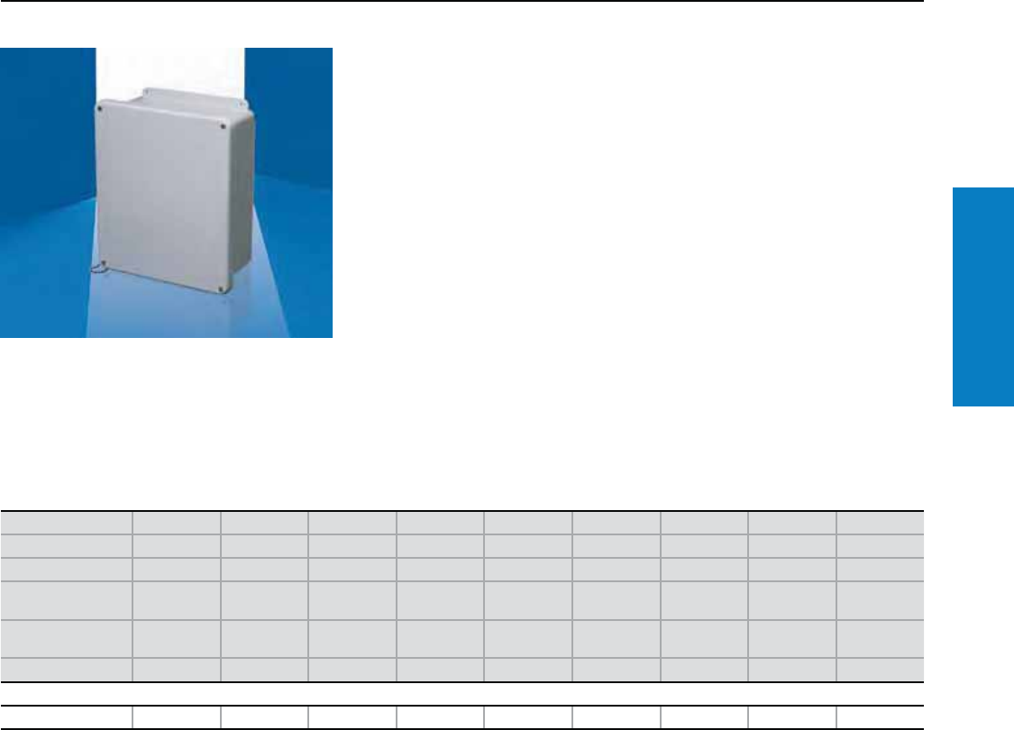
Industrial Buyer’s Guide 59
Junction Box
Stainless Steel
Fiberglass
Height inches (mm) 12 (295) 8 (191) 8 (191) 10 (244) 14 (344) 16 (394) 18 (445) 20 (498) 22 (559)
Width inches (mm) 9 (239) 5 (138) 8 (191) 8 (191) 11 (290) 14 (343) 16 (393) 18 (447) 18 (449)
Depth inches (mm) 4 (108) 5 (121) 5 (121) 5 (121) 5 (132) 6 (159) 6 (158) 9 (224) 9 (224)
Mounting center
height inches (mm)* 11 (273) 7 (171) 7 (171) 9 (226) 13 (324) 15 (371) 17 (425) 19 (480) 21 (540)
Mounting center
width inches (mm)* 6 (152) 2 (51) 4 (102) 4 (102) 8 (203) 10 (254) 12 (305) 12 (305) 10 (254)
Part No. L-FJ1008NFSC L-FJ604NFSC L-FJ606NFSC L-FJ806NFSC L-FJ1210NFSC L-FJ1412NFSC L-FJ1614NFSC L-FJ1816NFSC L-FJ2016NFSC
Accessories
Mounting panel L-MPL108CS L-MPL64CS L-MPL66CS L-MPL86CS L-MPL1210CS L-MPL1412CS L-MPL1614CS L-MPL1816CS L-MPLJ2016CS
Conguration:
Lift-off cover
Stainless steel screw/retention chain
Molded-in mounting provisions
Rounded corners
Overhang cover
Foamed-in-place polyurethane gasketing
Protection Ratings:
UL Type 1, 12, 4X, 6P
UL/cUL, CSA
UL file: E170282
Screw Cover - Junction Box
Depth: 4 - 9" (108 - 224 mm), Height: 8 - 22" (191 - 559 mm)
* Center to center distance between wallmount holes.
For additional technical
information, please visit
www.rittal-corp.com
Inch and pound measurements are rounded to the nearest whole number.
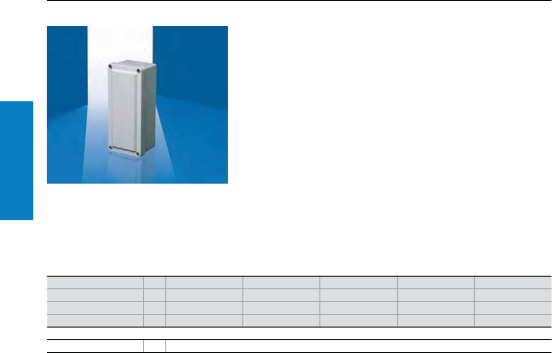
60 Industrial Buyer’s Guide
Junction Box
Stainless Steel
Fiberglass
Screw Cover - Junction Box
Depth: 3 - 4" (75 - 99 mm), Height: 4 - 11" (94 - 283 mm)
Height inches (mm) PU 4 (94) 6 (152) 7 (168) 9 (226) 11 (283)
Width inches (mm) 4 (92) 4 (92) 4 (97) 4 (97) 4 (97)
Depth inches (mm) 3 (75) 3 (80) 4 (99) 4 (99) 4 (99)
Part No. 1L-FJ332HB L-FJ532HB L-FJ644HB L-FJ844HB L-FJ1144HB
Accessories
External mounting brackets 1 L-FIMTGFTKIT
Protection Ratings:
UL Type 1,12, 4X, 6P
UL/cUL, CSA
UL file: E170282
Conguration:
Lift-off cover
Continuous polyurethane cover gasket
Small raised beveled cover flush with
enclosure sides
Recessed captive stainless steel screws
External mounting brackets available
Foamed-in-place polyurethane gasketing
For additional technical
information, please visit
www.rittal-corp.com
Inch and pound measurements are rounded to the nearest whole number.
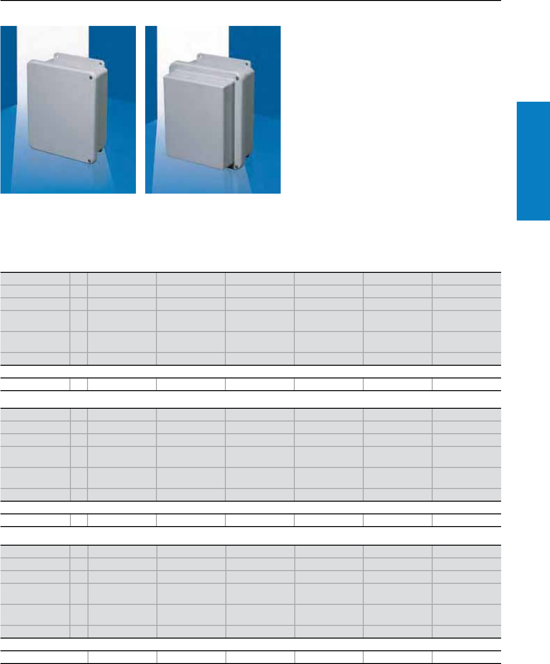
Industrial Buyer’s Guide 61
Junction Box
Stainless Steel
Fiberglass
Conguration:
Full length stainless steel hinged cover
Stainless steel screws
180° door opening
Part numbers ending in "X" come with
extended depth cover
Foamed-in-place polyurethane gasketing
Protection Ratings:
UL Type 1, 12, 4X, 6P
UL/cUL, CSA
UL file: E170282
Hinged Screw Cover - Junction Box
Depth: 4 - 11" (108 - 270 mm), Height: 8 - 22" (191 - 559 mm)
Height inches (mm) PU 12 (295) 8 (191) 8 (191) 10 (244) 14 (344) 8 (191)
Width inches (mm) 9 (239) 6 (138) 8 (191) 8 (191) 11 (289) 6 (139)
Depth inches (mm) 4 (108) 5 (121) 5 (121) 5 (121) 5 (132) 6 (158)
Mounting center
height inches (mm)* 11 (273) 7 (171) 7 (171) 9 (226) 13 (324) 7 (171)
Mounting center
width inches (mm)* 6 (152) 2 (51) 4 (102) 4 (102) 8 (203) 2 (51)
Part No. 1L-FJ1008CHNFSC L-FJ604CHNFSC L-FJ606CHNFSC L-FJ806CHNFSC L-FJ1210CHNFSC L-FJ604CHNFSCX
Accessories
Mounting panel 1 L-MPL108CS L-MPL64CS L-MPL66CS L-MPL86CS L-MPL1210CS L-MPL64CS
Height inches (mm) PU 8 (191) 10 (244) 18 (445) 16 (394) 12 (295) 14 (344)
Width inches (mm) 8 (191) 8 (189) 16 (393) 14 (343) 9 (238) 11 (289)
Depth inches (mm) 6 (158) 6 (158) 6 (158) 6 (159) 7 (168) 7 (168)
Mounting center
height inches (mm)* 7 (171) 9 (226) 17 (425) 15 (371) 11 (273) 13 (324)
Mounting center
width inches (mm)* 4 (102) 4 (102) 12 (305) 10 (254) 6 (152) 8 (203)
Part No. 1L-FJ606CHNFSCX L-FJ806CHNFSCX L-FJ1614CHNFSC L-FJ1412CHNFSC L-FJ1008CHNFSCX L-FJ1210CHNFSCX
Accessories
Mounting panel 1 L-MPL64CS L-MPL86CS L-MPL1614CS L-MPL1412CS L-MPL108CS L-MPL1210CS
Height inches (mm) PU 16 (394) 18 (445) 20 (498) 22 (559) 20 (498) 22 (559)
Width inches (mm) 13 (340) 15 (392) 18 (447) 18 (449) 18 (444) 18 (446)
Depth inches (mm) 8 (195) 8 (196) 9 (224) 9 (224) 11 (270) 11 (270)
Mounting center
height inches (mm)* 15 (371) 17 (425) 19 (480) 21 (540) 19 (480) 21 (540)
Mounting center
width inches (mm)* 10 (254) 12 (305) 12 (305) 10 (254) 12 (305) 10 (254)
Part No. 1L-FJ1412CHNFSCX L-FJ1614CHNFSCX L-FJ1816CHNFSC L-FJ2016CHNFSC L-FJ1816CHNFSCX L-FJ2016CHNFSCX
Accessories
Mounting panel L-MPL1412CS L-MPL1614CS L-MPL1816CS L-MPLJ2016CS L-MPL1816CS L-MPLJ2016CS
* Center to center distance between wallmount holes.
For additional technical
information, please visit
www.rittal-corp.com
Inch and pound measurements are rounded to the nearest whole number.
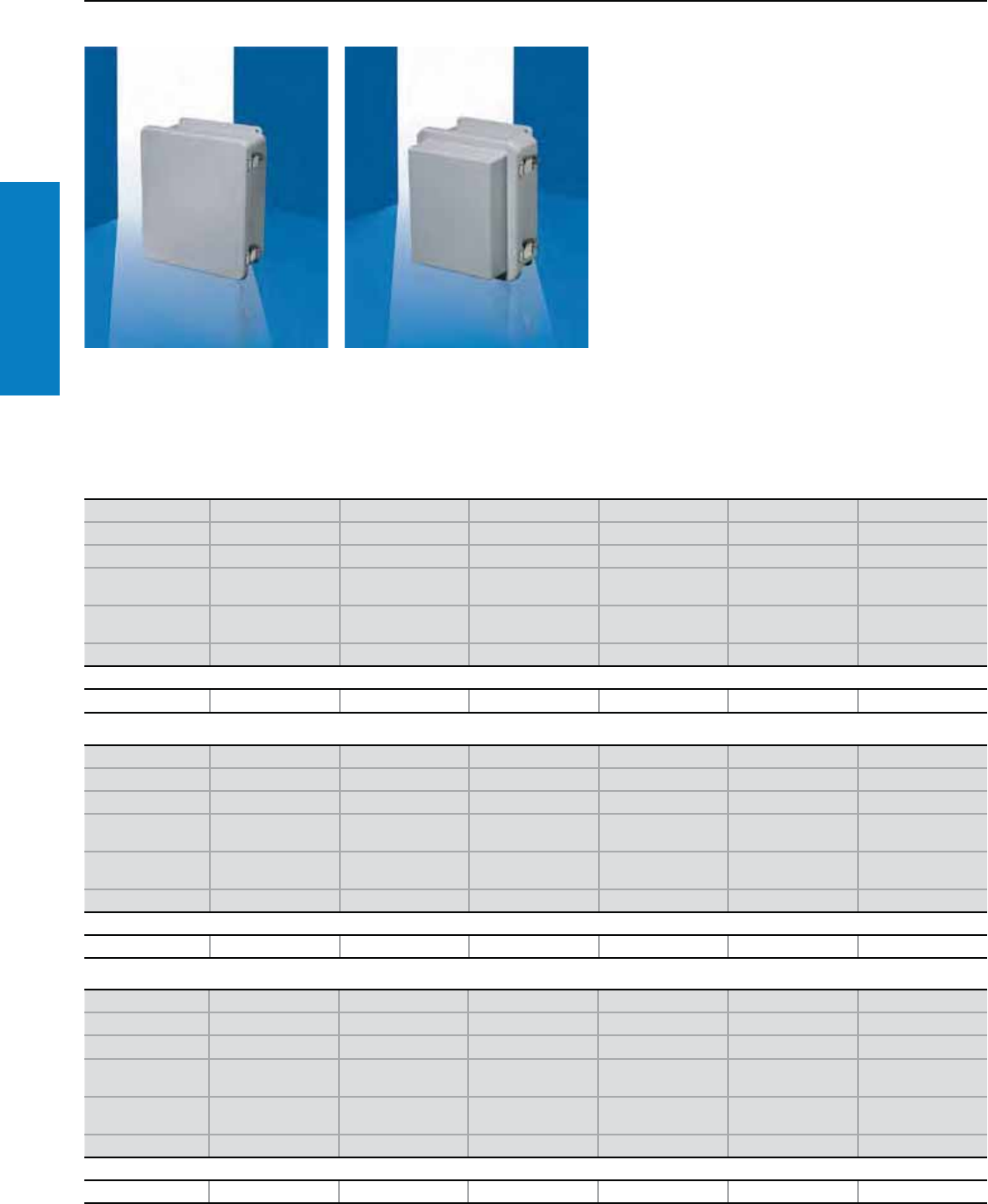
62 Industrial Buyer’s Guide
Junction Box
Stainless Steel
Fiberglass
Lockable Quick Release - Junction Box
Depth: 4 - 11" (108 - 270 mm), Height: 8 - 22" (191 - 559 mm)
* Center to center distance between wallmount holes.
Conguration:
Quick-release clamps with secure loop for
padlock provisions (padlock not included)
Can be lifted and released with ease
180° door opening
Part numbers ending in "X" come with
extended depth cover
Foamed-in-place polyurethane gasketing
Protection Ratings:
UL Type 1, 12, 4X, 6P
UL/cUL, CSA
UL file: E170282
Height inches (mm) 12 (295) 8 (191) 8 (191) 10 (244) 14 (344) 8 (191)
Width inches (mm) 9 (239) 5 (138) 8 (191) 8 (191) 11 (290) 8 (191)
Depth inches (mm) 4 (108) 5 (121) 5 (121) 5 (121) 5 (132) 6 (158)
Mounting center
height inches (mm)* 11 (273) 7 (171) 7 (171) 9 (226) 13 (324) 7 (171)
Mounting center
width inches (mm)* 6 (152) 2 (51) 4 (102) 4 (102) 8 (203) 4 (102)
Part No. L-FJ1008CHNFQ L-FJ604CHNFQ L-FJ606CHNFQ L-FJ806CHNFQ L-FJ1210CHNFQ L-FJ606CHNFQX
Accessories
Mounting panel L-MPL108CS L-MPL64CS L-MPL66CS L-MPL86CS L-MPL1210CS L-MPL64CS
Height inches (mm) 8 (191) 10 (244) 18 (445) 15 (394) 12 (295) 14 (344)
Width inches (mm) 6 (139) 8 (189) 16 (393) 14 (343) 9 (238) 11 (289)
Depth inches (mm) 6 (158) 6 (158) 6 (158) 6 (159) 7 (168) 7 (168)
Mounting center
height inches (mm)* 7 (171) 9 (226) 17 (425) 15 (371) 11 (273) 13 (324)
Mounting center
width inches (mm)* 2 (51) 4 (102) 12 (305) 10 (254) 6 (152) 8 (203)
Part No. L-FJ604CHNFQX L-FJ806CHNFQX L-FJ1614CHNFQ L-FJ1412CHNFQ L-FJ1008CHNFQX L-FJ1210CHNFQX
Accessories
Mounting panel L-MPL64CS L-MPL86CS L-MPL1614CS L-MPL1412CS L-MPL108CS L-MPL1210CS
Height inches (mm) 16 (394) 18 (445) 22 (559) 20 (498) 20 (498) 22 (559)
Width inches (mm) 13 (340) 15 (392) 18 (449) 18 (444) 18 (444) 18 (446)
Depth inches (mm) 8 (195) 8 (196) 9 (224) 9 (224) 11 (270) 11 (270)
Mounting center
height inches (mm)* 15 (371) 17 (425) 21 (540) 19 (480) 19 (480) 21 (540)
Mounting center
width inches (mm)* 10 (254) 12 (305) 10 (254) 12 (305) 12 (305) 10 (254)
Part No. L-FJ1412CHNFQX L-FJ1614CHNFQX L-FJ2016CHNFQ L-FJ1816CHNFQ L-FJ1816CHNFQX L-FJ2016CHNFQX
Accessories
Mounting panel L-MPL1412CS L-MPL1614CS L-MPLJ2016CS L-MPL1816CS L-MPL1816CS L-MPLJ2016CS
For additional technical
information, please visit
www.rittal-corp.com
Inch and pound measurements are rounded to the nearest whole number.
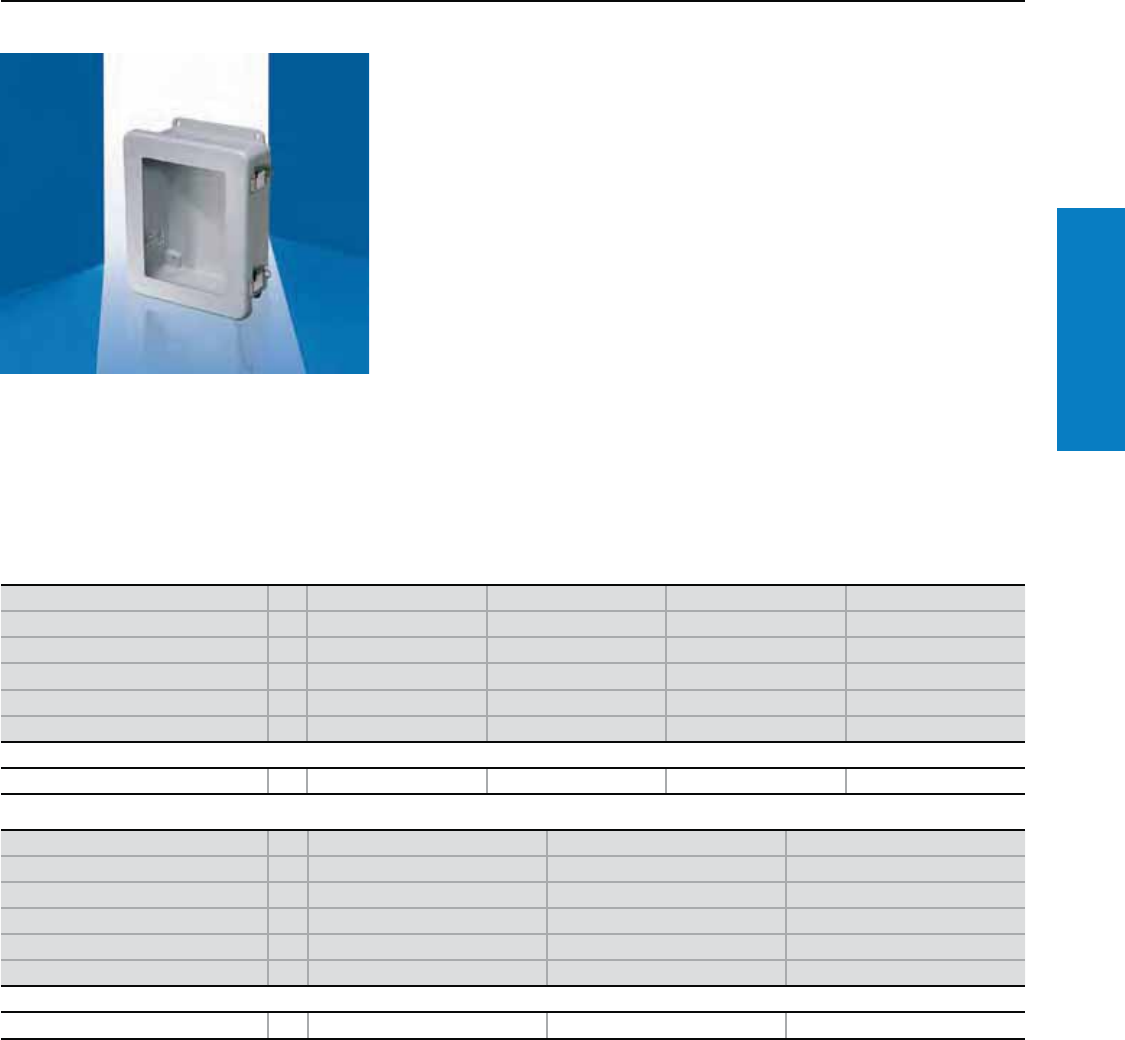
Industrial Buyer’s Guide 63
Junction Box
Stainless Steel
Fiberglass
Flush Viewing Window - Junction Box
Depth: 4 - 9" (108 - 224 mm), Height: 10 - 22" (244 - 559 mm)
* Center to center distance between wallmount holes.
Conguration:
Scratch and abrasion resistant UVA acrylic flush
viewing window
Quick-release clamps with secure loop for padlock
provisions (padlock not included)
Can be lifted and released with ease
180° door opening
Foamed-in-place polyurethane gasketing
Protection Ratings:
UL Type 1, 12, 4X, 6P
(except for
L-FJ1816CHNFQW,
L-FJ2016CHNFQW is not UL
Type 6P)
UL/cUL, CSA
UL file: E170282
Height inches (mm) PU 12 (295) 10 (244) 14 (344) 16 (394)
Width inches (mm) 9 (239) 8 (191) 11 (290) 14 (343)
Depth inches (mm) 4 (108) 5 (120) 5 (132) 6 (159)
Mounting center height inches (mm)* 11 (273) 9 (226) 13 (324) 15 (371)
Mounting center width inches (mm)* 6 (152) 4 (102) 8 (203) 10 (254)
Part No. 1L-FJ1008CHNFQW L-FJ806CHNFQW L-FJ1210CHNFQW L-FJ1412CHNFQW
Accessories
Mounting panel 1 L-MPL108CS L-MPL86CS L-MPL1210CS L-MPL1412CS
Height inches (mm) PU 18 (445) 20 (498) 22 (559)
Width inches (mm) 16 (393) 18 (447) 18 (449)
Depth inches (mm) 6 (158) 9 (224) 9 (224)
Mounting center height inches (mm)* 17 (425) 19 (480) 21 (540)
Mounting center width inches (mm)* 12 (305) 12 (305) 10 (254)
Part No. 1L-FJ1614CHNFQW L-FJ1816CHNFQW L-FJ2016CHNFQW
Accessories
Mounting panel 1 L-MPL1614CS L-MPL1816CS L-MPLJ2016CS
For additional technical
information, please visit
www.rittal-corp.com
Inch and pound measurements are rounded to the nearest whole number.
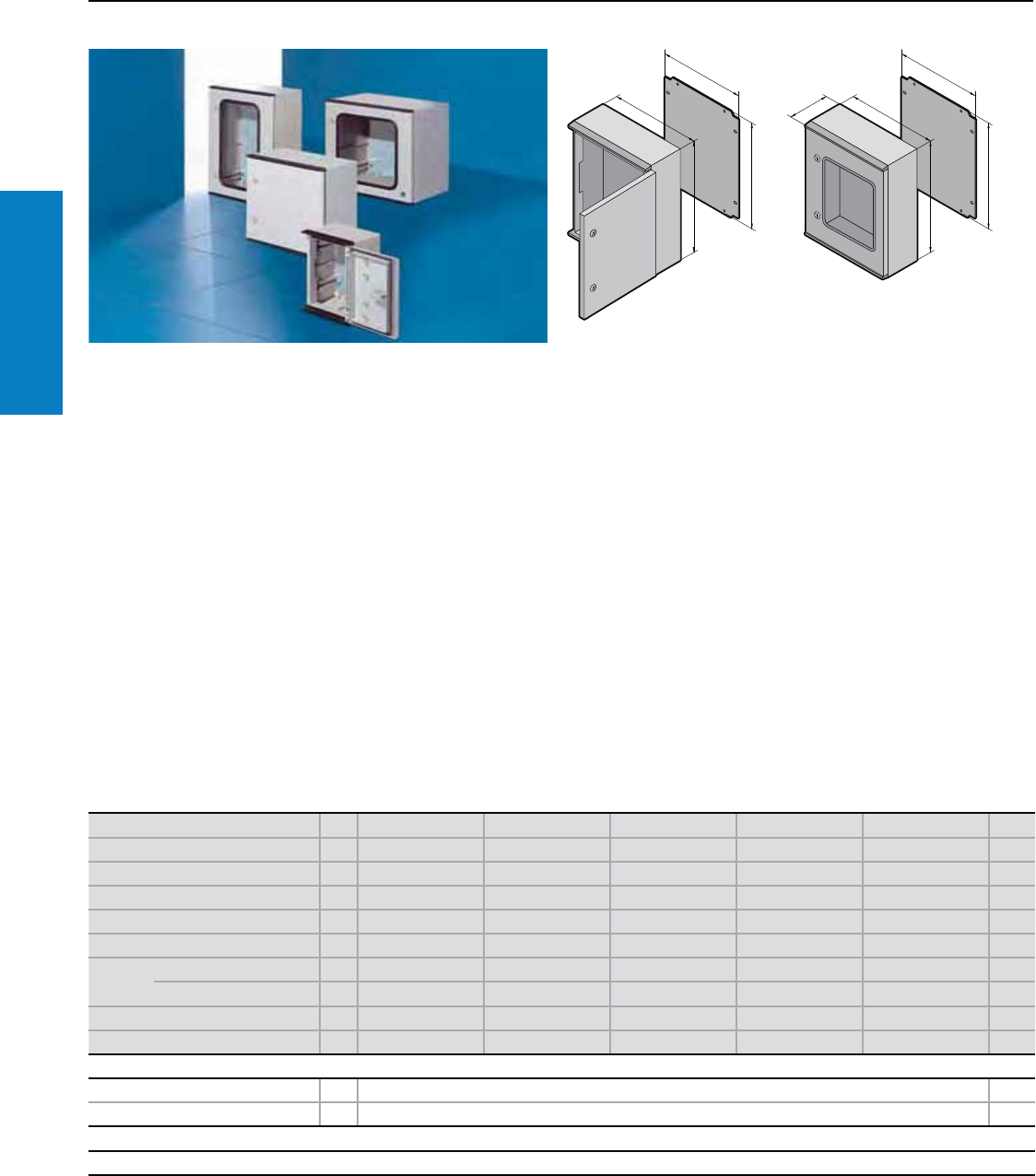
64 Industrial Buyer’s Guide
Junction Box
Stainless Steel
Fiberglass Wallmount
KS - Wallmount
Depth: 6 - 8" (150 - 200 mm), Height: 12 - 24" (300 - 600 mm)
Material:
Enclosure and door:
Fiberglass-reinforced unsaturated
polyester
Mounting panel:
Sheet steel
For KS with viewing window:
Impact resistant viewing acrylic,
11 ga (3.0 mm) with rubber
gasket around the perimeter
Finish:
Enclosure and door:
Dyed fiberglass, similar to
RAL 7035 (light gray)
Mounting panel: Zinc-plated
Protection Ratings:
KS without viewing window:
UL Type 4X
(IP 66 to EN 60 529/10.91)
KS with viewing window:
UL Type 12
(IP 56 to EN 60 529/10.91)
UL file: E76083
Maximum ambient temperature:
-22 - 167° F (-30 - 75° C)
Conguration:
Enclosure of unibody
construction, right-hand door
hinge, door hinge may be
changed to the opposite side by
rotating the enclosure, mounting
panel, foamed-on polyurethane
seal around the perimeter of the
door, twin seal on the top and
bottom edges of the door
(integrated rain protection strip),
press-fitted C sections at the
sides for infinitely variable
mounting panel depth
adjustment (with bracket
1481.000).
Note:
Long-term exposure to UV
radiation (sunlight) in conjunction
with wind and rain may change the
finish visually. The fiberglass strands
may become visible on unprotected
surfaces. This does not impair the
protection of the installed electrical
components in any way. All other
finishes may also be altered by
ultraviolet radiation.
If the enclosure cannot be protected
from UV radiation with
a sun canopy we recommend
that the surface be painted with
a PUR paint. Older enclosures
where the finish already
reveals visible fiberglass
portions can also be painted
after thorough cleaning.
All enclosures can be supplied
painted in RAL colors. For
outdoor applications, we
recommend pale color shades.
F1
B1
H1
G1
T1
F1
B1
H1
G1
Inch and pound measurements are rounded to the nearest whole number.
For additional technical
information, please visit
www.rittal-corp.com
Height (H1) inches (mm) PU 12 (300) 14 (350) 16 (400) 16 (400) 24 (600) Page
Width (B1) inches (mm) 8 (200) 10 (250) 12 (300) 16 (400) 16 (400)
Depth (T1) inches (mm) 6 (150) 6 (150) 8 (200) 8 (200) 8 (200)
Panel height (G1) inches (mm) 10 (250) 12 (300) 14 (350) 14 (350) 22 (550)
Panel width (F1) inches (mm) 6 (145) 8 (195) 10 (245) 14 (345) 14 (345)
Panel thickness ga (mm) 14 (2.0) 14 (2.0) 14 (2.0) 12 (2.5) 12 (2.5)
Part No. Without viewing window 11423.500 1432.500 1434.500 1444.500 1446.500
With viewing window 1- - - 1448.500 1449.500
Door(s) 1 11111
Weight lb (kg) 7 (3) 9 (4) 13 (6) 17 (8) 25 (12)
Accessories
Mounting panel adjustment bracket 4 1481.000 232
Wallmount bracket 4 1483.010 253
Lock systems
Standard double-bit lock insert may be exchanged for Type E lock inserts (see page 220) and 1490.010 ergoform lock system (see page 218)
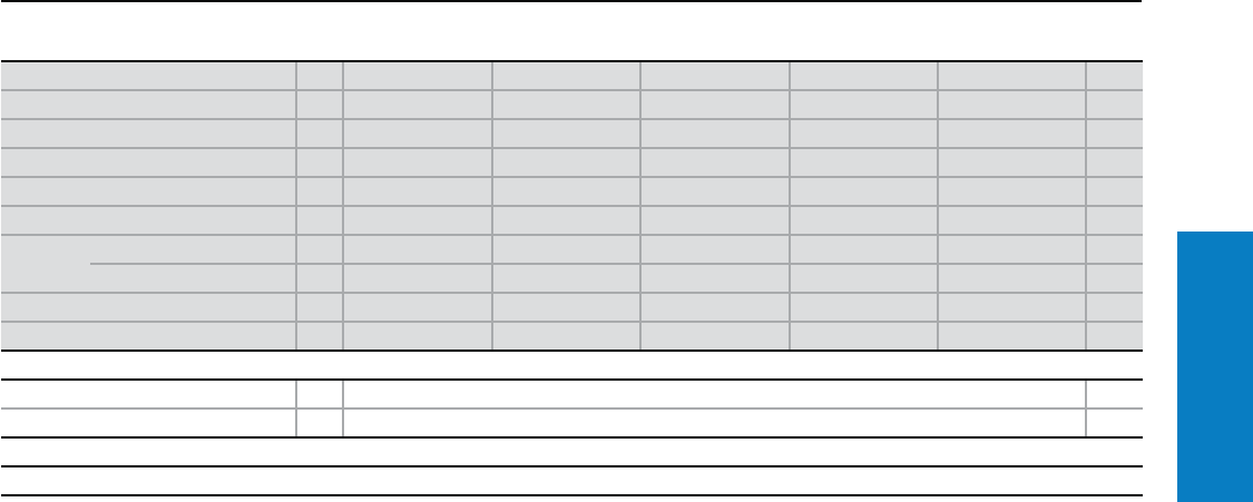
Industrial Buyer’s Guide 65
Stainless Steel WallmountFiberglass
KS - Wallmount
Depth: 8 - 12" (200 - 300 mm), Height: 20 - 39" (500 - 1000 mm)
Inch and pound measurements are rounded to the nearest whole number.
Height (H1) inches (mm) PU 24 (600) 20 (500) 32 (800) 39 (1000) 39 (1000) Page
Width (B1) inches (mm) 24 (600) 20 (500) 24 (600) 32 (800) 39 (1000)
Depth (T1) inches (mm) 8 (200) 12 (300) 12 (300) 12 (300) 12 (300)
Panel height (G1) inches (mm) 22 (550) 18 (450) 30 (750) 37 (950) 37 (950)
Panel width (F1) inches (mm) 22 (545) 16 (417) 20 (517) 28 (717) 36 (917)
Panel thickness ga (mm) 12 (2.5) 12 (2.5) 11 (3) 11 (3) 11 (3)
Part No. Without viewing window 11466.500 1453.500 1468.500 1480.500 1400.500
With viewing window 11467.500 1454.500 1469.500 1479.500 –
Door(s) 1 1 1 2
Weight lb (kg) 35 (16) 28 (13) 57 (26) 86 (39) 110 (50)
Accessories
Mounting panel adjustment bracket 4 1481.000 232
Wallmount bracket 4 1483.010 253
Lock systems
Standard double-bit lock insert may be exchanged for Type E lock inserts (see page 220) and 1490.010 ergoform lock system (see page 218)
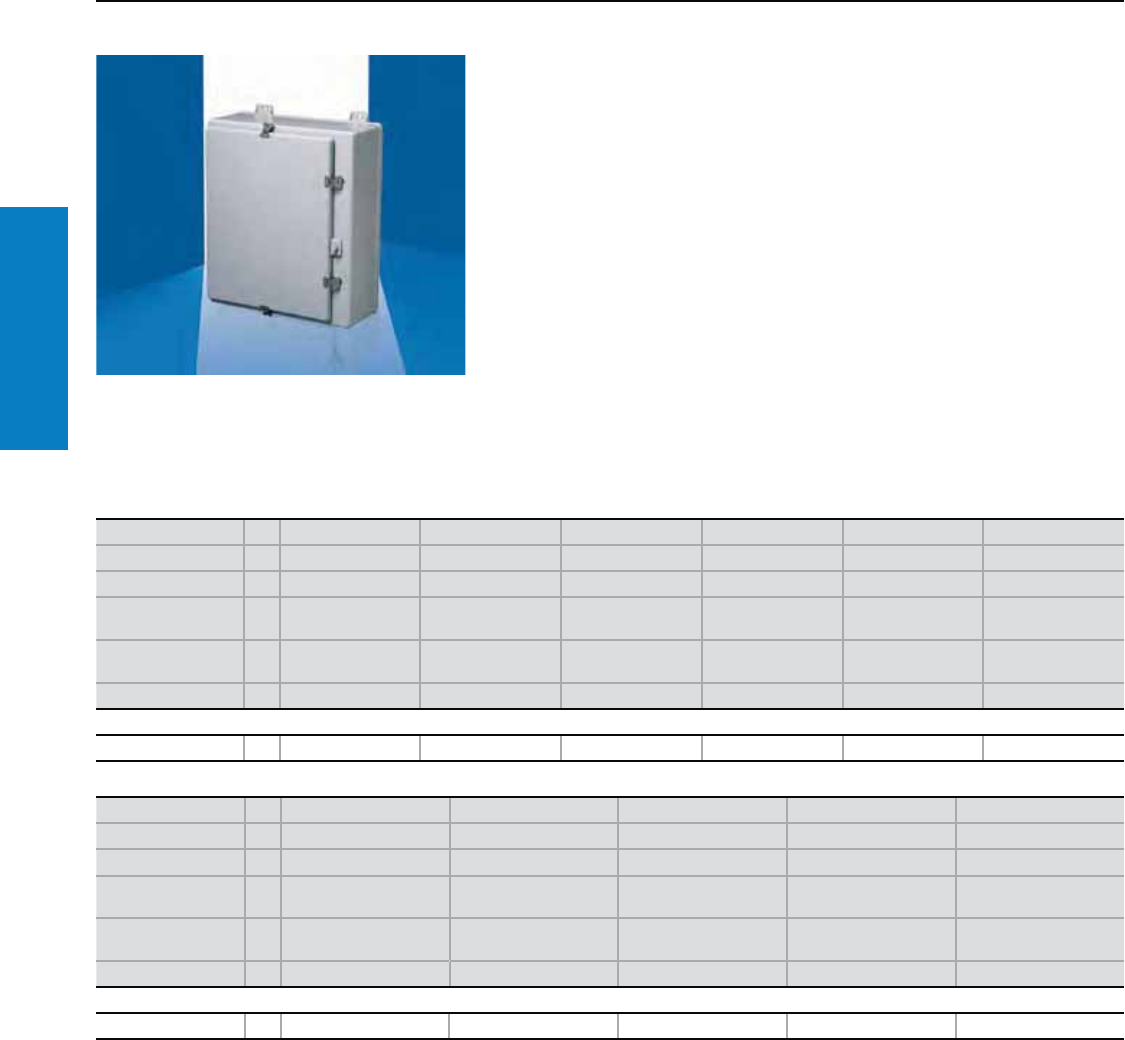
66 Industrial Buyer’s Guide
Junction Box
Stainless Steel
Fiberglass Wallmount
Conguration:
Rigid body construction and watertight seal
Foamed-in-place polyurethane gasketing
Integral mounting brackets
Molded in panel mounting inserts
Built-in padlock hasp
Protection Ratings:
UL/cUL, CSA Type 1, 12, 3R, 4X
UL file: E170282
Hinged Latch Cover - Wallmount
Depth: 9 - 18" (224 - 455 mm), Height: 27 - 51" (686 - 1303 mm)
Height inches (mm) PU 33 (849) 27 (686) 33 (835) 27 (686) 33 (849) 39 (998)
Width inches (mm) 26 (669) 21 (539) 21 (533) 25 (641) 26 (669) 33 (826)
Depth inches (mm) 9 (224) 10 (251) 10 (251) 12 (302) 12 (304) 12 (306)
Mounting center
height inches (mm)* 32 (819) 26 (654) 32 (806) 26 (654) 32 (819) 38 (969)
Mounting center
width inches (mm)* 19 (470) 14 (356) 14 (362) 18 (454) 19 (470) 24 (607)
Part No. 1L-FW30H2407 L-FW24H2008 L-FW30H2008 L-FW24H2410 L-FW30H2410 L-FW36H3010
Accessories
Mounting panel 1 L-MPL3024CS L-MPL2420CS L-MPL3020CS L-MPL2424CS L-MPL3024CS L-MPL3630CS
Height inches (mm) PU 27 (686) 23 (578) 39 (998) 51 (1303) 51 (1303)
Width inches (mm) 25 (641) 17 (428) 33 (826) 37 (930) 37 (930)
Depth inches (mm) 14 (353) 14 (350) 14 (357) 14 (354) 18 (455)
Mounting center
height inches (mm)* 26 (654) 22 (546) 38 (969) 50 (1273) 50 (1273)
Mounting center
width inches (mm)* 18 (454) 10 (257) 24 (607) 29 (743) 29 (743)
Part No. 1L-FW24H2412 L-FW20H1612 L-FW36H3012 L-FW48H3612 L-FW48H3616
Accessories
Mounting panel 1 L-MPL2424CS L-MPL2016CS L-MPL3630CS L-MPL4836CS L-MPL4836CS
* Center to center distance between wallmount holes.
For additional technical
information, please visit
www.rittal-corp.com
Inch and pound measurements are rounded to the nearest whole number.
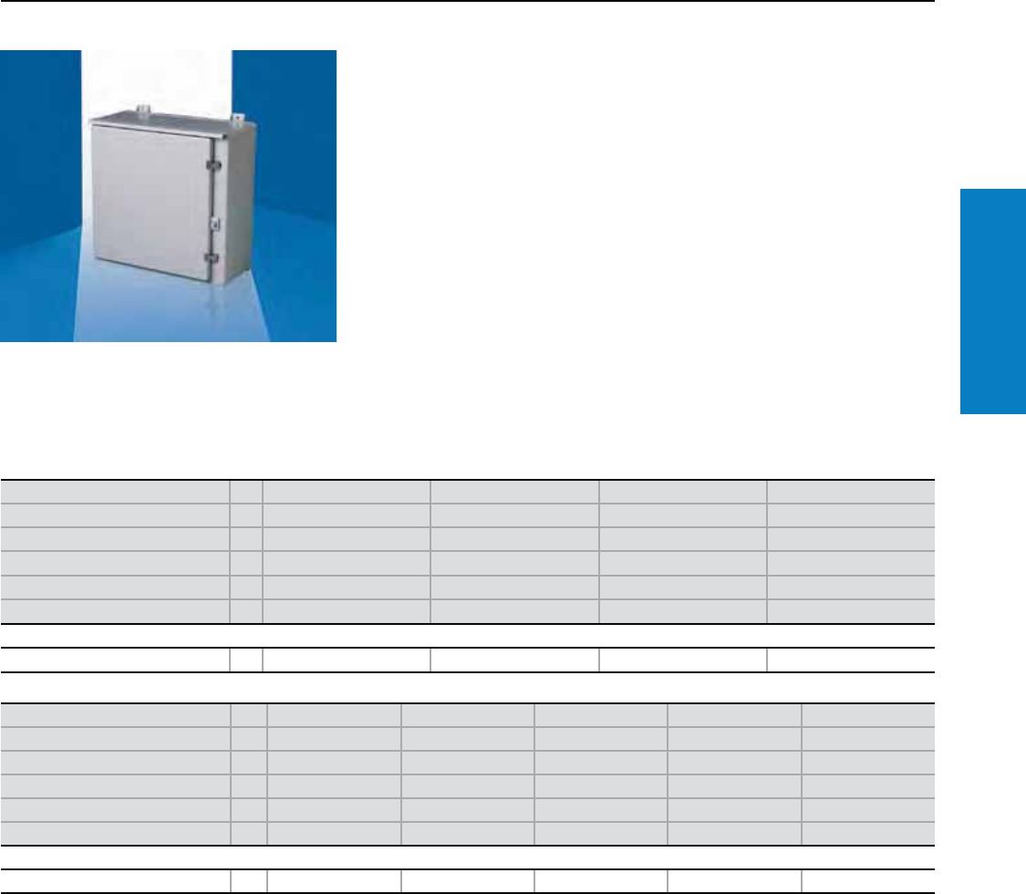
Industrial Buyer’s Guide 67
Wallmount
Fiberglass
Conguration:
Rainshield top for water protection
Rigid body construction and watertight seal
Integral mounting feet for ease of installation
Molded in panel mounting inserts
Built-in padlock hasp
Protection Ratings:
UL/cUL, CSA Type 1, 3R
UL file: E170282
Hinged Latch Cover - Wallmount
Depth: 10 - 18" (251 - 468 mm), Height: 23 - 51" (578 - 1303 mm)
* Center to center distance between wallmount holes.
Height inches (mm) PU 27 (686) 27 (686) 33 (849) 39 (998)
Width inches (mm) 21 (539) 25 (641) 26 (669) 33 (826)
Depth inches (mm) 10 (251) 12 (302) 12 (304) 12 (306)
Mounting center height inches (mm)* 26 (654) 26 (654) 32 (819) 38 (969)
Mounting center width inches (mm)* 14 (356) 18 (454) 19 (470) 24 (607)
Part No. 1L-FW24R2008HCR L-FW24R2410HCR L-FW30R2410HCR L-FW36R3010HCR
Accessories
Mounting panel 1 L-MPL2420CS L-MPL2424CS L-MPL3024CS L-MPL3630CS
Height inches (mm) PU 23 (578) 33 (849) 39 (998) 51 (1303) 51 (1303)
Width inches (mm) 17 (428) 26 (669) 33 (826) 37 (930) 37 (930)
Depth inches (mm) 14 (362) 14 (350) 14 (357) 14 (367) 18 (468)
Mounting center height inches (mm)* 22 (546) 32 (819) 38 (969) 50 (1273) 50 (1273)
Mounting center width inches (mm)* 10 (257) 19 (470) 24 (607) 24 (607) 24 (607)
Part No. 1L-FW20R1612HCR L-FW30R2412HCR L-FW36R3012HCR L-FW48R3612HCR L-FW48R3616HCR
Accessories
Mounting panel 1 L-MPL2016CS L-MPL3024CS L-MPL3630CS L-MPL4836CS L-MPL4836CS
For additional technical
information, please visit
www.rittal-corp.com
Inch and pound measurements are rounded to the nearest whole number.
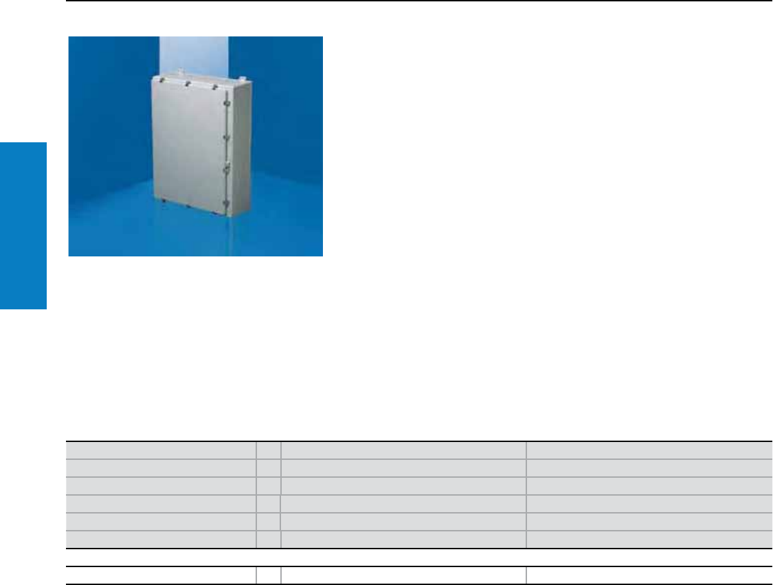
68 Industrial Buyer’s Guide
Junction Box
Stainless Steel
Fiberglass Wallmount
Hinged Latch Cover - Wallmount
Depth: 14 - 18" (359 - 460 mm), Height: 64" (1613 mm)
Height inches (mm) PU 64 (1613) 64 (1613)
Width inches (mm) 37 (927) 37 (927)
Depth inches (mm) 14 (359) 18 (460)
*Mounting center height inches (mm) 62 (1581) 62 (1581)
*Mounting center width inches 29 (724) 29 (724)
Part No. 1L-F60H3612 L-F60H3616
Accessories
Mounting panel 1 L-MPL6036CS L-MPL6036CS
* Center to center distance between wallmounting holes.
Material:
Fiberglass reinforced polyester
Protection Ratings:
UL Type 1, 12, 3R, 4X
UL/cUL, CSA
UL file: E170282
Conguration:
Rigid body construction and water
resistant seal
Foamed-in-place polyurethane
gasketing
Wallmount or freestanding
models available
Molded in panel mounting
inserts or studs
Eyebolts and crossbar construction
Built-in padlock hasp
Stainless steel hardware
For additional technical
information, please visit
www.rittal-corp.com
Inch and pound measurements are rounded to the nearest whole number.
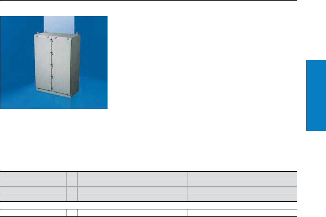
Industrial Buyer’s Guide 69
Junction Box
Stainless Steel
Fiberglass Freestanding
Hinged Latch Cover - Freestanding
Depth: 26" (670 mm), Height: 73" (1842 mm)
Height inches (mm) PU 73 (1842) 73 (1842)
Width inches (mm) 26 (648) 50 (1257)
Depth inches (mm) 26 (670) 26 (670)
Part No. 1L-F72H2525FS L-F72H4925FSDD
Accessories
Mounting panel 1 L-MPL7225CS L-MPL7249CS
Material:
Fiberglass reinforced polyester
Protection Ratings:
UL Type 1, 12, 3R, 4X
UL/cUL, CSA
UL file: E170282
Conguration:
Rigid body construction and water
resistant seal
Foamed-in-place polyurethane gasketing
Molded in panel mounting
inserts or studs
Eyebolts and crossbar construction
Built-in padlock hasp
Stainless steel hardware
For additional technical
information, please visit
www.rittal-corp.com
Inch and pound measurements are rounded to the nearest whole number.
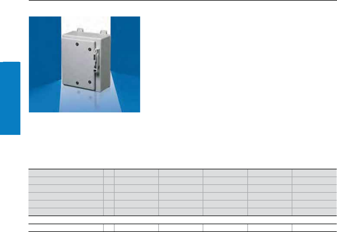
70 Industrial Buyer’s Guide
Junction Box
Stainless Steel
Fiberglass Disconnect
Disconnect - Wallmount
Depth: 10 - 13" (260 - 338 mm), Height: 19 - 39" (476 - 998 mm)
Height inches (mm) PU 19 (476) 23 (578) 27 (686) 33 (849) 39 (998)
Width inches (mm) 11 (278) 17 (428) 25 (641) 26 (669) 33 (826)
Depth inches (mm) 10 (260) 11 (279) 13 (335) 13 (335) 13 (338)
Mounting center height inches (mm)* 17 (445) 21 (546) 25 (654) 32 (819) 38 (969)
Mounting center width inches (mm)* 7 (178) 10 (257) 18 (454) 19 (470) 24 (607)
Part No. 1L-F16HS10 L-F20HS16 L-F24HS24 L-F30HS24 L-F36HS30
Accessories
Mounting panel 1 L-MPL1610CD L-MPL2016CD L-MPL2424CD L-MPL3024CD L-MPL3630CD
Disconnect, fuse block, breaker, yoke, switches, or other components are not furnished with enclosure.
* Center to center distance between wallmounting holes.
Conguration:
Environmentally sealed disconnect
Foamed-in-place polyurethane gasketing
Rigid body construction and watertight seal
Molded in panel mounting inserts
Integral mounting brackets for ease of installation
Disconnect handle included
Protection Ratings:
UL Type 1, 12, 3R, 4X
UL/cUL, CSA
UL file: E170282
Inch and pound measurements are rounded to the nearest whole number.
For additional technical
information, please visit
www.rittal-corp.com
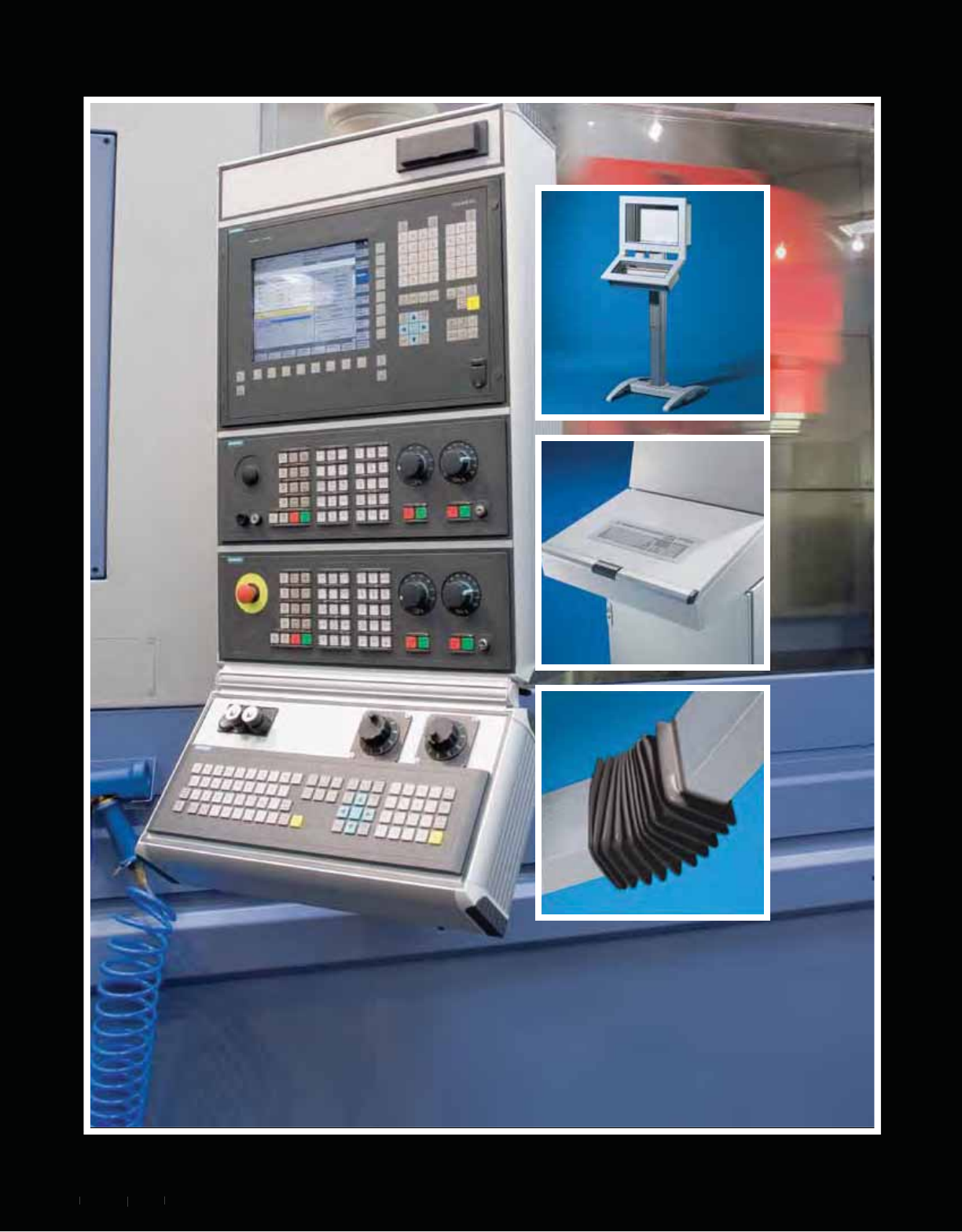
Industrial Buyers Guide 71
Ind
ust
ria
l Buyers
Gui
de
7
1
Operator Interface
71
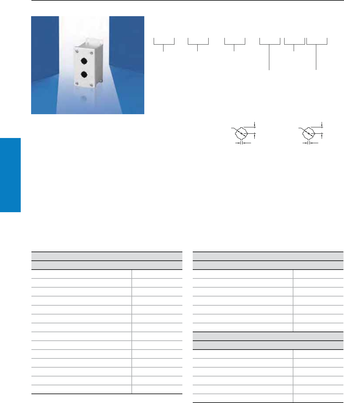
Operator Interface
72 Industrial Buyer’s Guide
Pushbutton Box
Pushbutton Box
Carbon Steel Pushbutton Boxes:
These UL Type boxes are designed
to house pushbuttons, selector
switches, pilot lights, and help
protect such equipment against
dirt, dust, water, oil
or coolant.
• Accepts 0.8 and 1.2"
(22.5 and 30.5 mm) devices
• Available in sizes from a single
position to 42 hole positions.
Designed For Versatility:
The standard holes in these
boxes accept all brands of 0.8
and 1.2" (22.5 and 30.5 mm),
4-way, oil-tight pushbuttons,
switches and pilot lights. Several
of these enclosures can be
mounted onto a Rittal column
and base for use as an operator
station. Additionally, external
mounting brackets and captive,
plated cover screws make
installation quick and easy.
Technical Specications:
• Enclosures and covers are
made from 14-gauge carbon
steel for strength and durability
• Interior and exterior finish is a
polyester-urethane powder coat
over phosphatized surface,
color is RAL 7035 (light gray)
Protection Ratings:
UL Type 12, 13, 4
UL/cUL
UL file: E118617
For Hole Seals see page 200.
Carbon Steel – Standard
Hole Size 30.5 mm
Description Part No.
1 Hole PB01305S1C
2 Hole PB02305S1C
3 Hole PB03305S1C
4 Hole PB04305S1C
4 Hole PB04305S2C
5 Hole PB05305S1C
6 Hole PB06305S2C
6 Hole PB06305S1C
8 Hole PB08305S1C
9 Hole PB09305S3C
10 Hole PB10305S1C
12 Hole PB12305S3C
16 Hole PB16305S4C
Carbon Steel – Slim
Hole Size 30.5 mm
Description Part No.
1 Hole PB01305L1C
2 Hole PB02305L1C
3 Hole PB03305L1C
4 Hole PB04305L1C
5 Hole PB05305L1C
6 Hole PB06305L1C
Carbon Steel – Miniature
Hole Size 22.5 mm
1 Hole PB01225M1C
2 Hole PB02225M1C
3 Hole PB03225M1C
4 Hole PB04225M1C
6 Hole PB06225M2C
9 Hole PB09225M3C
For additional technical information,
please visit www.rittal-corp.com
Understanding the Part Number
PB 01 305 S 1 C
Product
Type
Number of
Holes
Box Type
S = Standard
X = Extra Deep
T = Slope Top
L = Slim
C = Continuous Hinge
M = Miniature
E = Extra Large
Number of
Columns
Material
C = Carbon Steel
4 = 304 Stainless Steel
6 = 316 Stainless Steel
Hole Size
305 = 30.5 mm
225 = 22.5 mm
Standard 4-Way
Keyed Pushbutton
Hole Detail
1.20 .67
.19
.88 .48
.13
Hole Arrangement Centered On Cover
Operator Interface
Industrial Buyer’s Guide 73
Pushbutton Box
Carbon Steel – Miniature (continued)
Hole Size 22.5 mm
Description Part No.
12 Hole PB12225M3C
16 Hole PB16225M4C
20 Hole PB20225M5C
25 Hole PB25225M5C
30 Hole PB30225M5C
Carbon Steel – Extra Large*
Hole Size 22.5 mm
4 Hole PB04225E2C
6 Hole PB06225E2C
9 Hole PB09225E3C
12 Hole PB12225E3C
16 Hole PB16225E4C
20 Hole PB20225E4C
25 Hole PB25225E5C
30 Hole PB30225E5C
36 Hole PB36225E6C
42 Hole PB42225E6C
Carbon Steel – Extra Deep
Hole Size 30.5 mm
1 Hole PB01305X1C
2 Hole PB02305X1C
3 Hole PB03305X1C
4 Hole PB04305X1C
4 Hole PB04305X2C
6 Hole PB06305X2C
9 Hole PB09305X3C
10 Hole PB10305X2C
12 Hole PB12305X3C
16 Hole PB16305X4C
16 Hole PB16305X2C
20 Hole PB20305X4C
25 Hole PB25305X5C
Carbon Steel – Slope Top
Hole Size 30.5 mm
Description Part No.
1 Hole PB01305T1C
2 Hole PB02305T2C
3 Hole PB03305T3C
4 Hole PB04305T4C
4 Hole PB04305T2C
6 Hole PB06305T3C
8 Hole PB08305T4C
9 Hole PB09305T3C
10 Hole PB10305T5C
12 Hole PB12305T6C
12 Hole PB12305T3C
16 Hole PB16305T4C
16 Hole PB16305T8C
20 Hole PB20305T5C
25 Hole PB25305T5C
30 Hole PB30305T5C
Pushbutton Box
*Carbon Steel Extra Large PB enclosures have a continuous hinge cover and include a galvanized mounting panel (2 mm thick, 14-gauge).
All other PB enclosures on these pages use a screw-cover and do not contain a mounting panel.
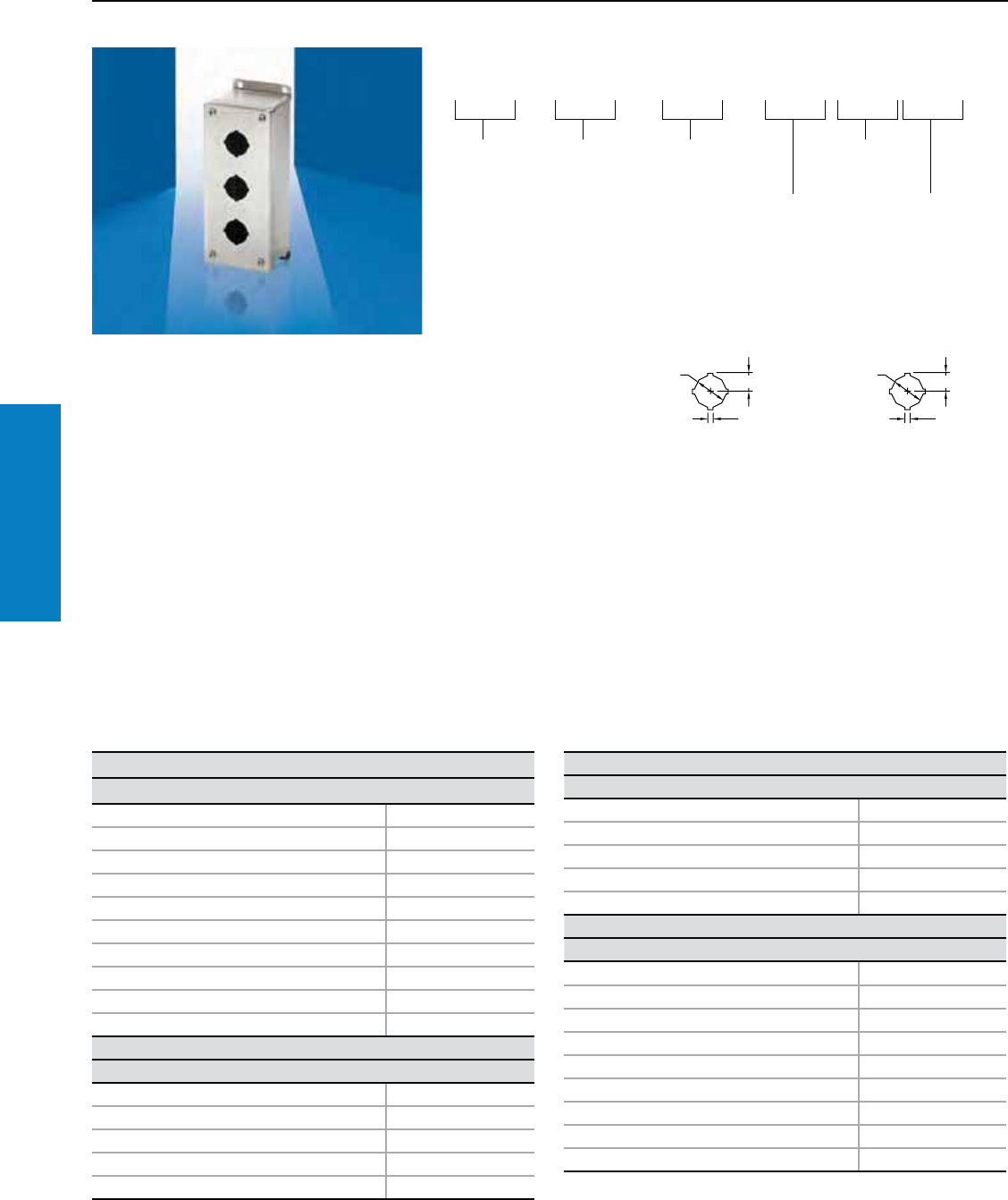
Operator Interface
74 Industrial Buyer’s Guide
Pushbutton Box
Stainless Steel Pushbutton
Boxes:
These UL Type boxes are
designed to house pushbuttons,
selector switches, pilot lights,
and help protect such equipment
against dirt, dust, water, oil or
coolant.
• Accepts 0.9 and 1.2" (22.5 and
30.5 mm) devices
• Available in sizes from a single
position to 42 hole positions
Rugged And Versatile:
The standard holes in these
boxes accept all brands of 0.9 or
1.2" (22.5 and 30.5 mm), 4-way,
oil-tight pushbuttons, switches
and pilot lights. Several of these
enclosures can be mounted onto a
Rittal column and base for use as
an operator station. Additionally,
external mounting brackets and
captive, stainless steel cover
screws make installation quick and
easy.
Technical Specications:
• Enclosures and covers are
made from 14-gauge Type 304
and 316L stainless steel
• Interior and exterior surfaces
have a #4 brushed finish
Stainless Steel Type 304 – Standard
Hole Size 30.5 mm
Description Part No.
1 Hole PB01305S14
2 Hole PB02305S14
3 Hole PB03305S14
4 Hole PB04305S14
4 Hole PB04305S24
5 Hole PB05305S14
6 Hole PB06305S24
9 Hole PB09305S34
12 Hole PB12305S34
Stainless Steel Type 304 – Slim/Miniature
Hole Size 22.5/30.5 mm
1 Hole PB01305L14
1 Hole PB01225M14
2 Hole PB02305L14
2 Hole PB02225M14
3 Hole PB03225M14
Stainless Steel Type 304 – Slim/Miniature (cont.)
Hole Size 22.5 mm
Description Part No.
4 Hole PB04225M14
6 Hole PB06225M24
9 Hole PB09225M34
12 Hole PB12225M34
Stainless Steel Type 304 – Extra Deep
Hole Size 30.5 mm
1 Hole PB01305X14
2 Hole PB02305X14
3 Hole PB03305X14
4 Hole PB04305X14
4 Hole PB04305X24
6 Hole PB06305X24
9 Hole PB09305X34
10 Hole PB10305X24
12 Hole PB12305X34
Pushbutton Box
Protection Ratings:
UL Type 12, 13, 4 & 4X
UL/cUL
UL file: E118617
For Hole Seals see page 200.
Understanding the Part Number
PB 01 305 S 1 C
Product
Type
Number of
Holes
Box Type
S = Standard
X = Extra Deep
T = Slope Top
L = Slim
C = Continuous Hinge
M = Miniature
E = Extra Large
Number of
Columns
Material
C = Carbon Steel
4 = 304 Stainless Steel
6 = 316 Stainless Steel
Hole Size
305 = 30.5 mm
225 = 22.5 mm
Standard 4-Way
Keyed Pushbutton
Hole Detail
1.20 .67
.19
.88 .48
.13
Hole Arrangement Centered On Cover
For additional technical information,
please visit www.rittal-corp.com
Operator Interface
Industrial Buyer’s Guide 75
Pushbutton Box
Stainless Steel Type 304 #4 Brushed Finish – Extra Deep (continued)
Hole Size 30.5 mm
Description Part No.
16 Hole PB16305X44
16 Hole PB16305X24
20 Hole PB20305X44
25 Hole PB25305X54
Stainless Steel Type 316L #4 Brushed Finish – Standard
Hole Size 30.5 mm
1 Hole PB01305S16
2 Hole PB02305S16
3 Hole PB03305S16
4 Hole PB04305S16
4 Hole PB04305S26
5 Hole PB05305S16
6 Hole PB06305S26
9 Hole PB09305S36
12 Hole PB12305S36
Stainless Steel Type 316L #4 Brushed Finish – Miniature
Hole Size 22.5 mm
1 Hole PB01225M16
2 Hole PB02225M16
3 Hole PB03225M16
4 Hole PB04225M16
6 Hole PB06225M26
9 Hole PB09225M36
12 Hole PB12225M36
Stainless Steel Type 316L #4 Brushed Finish – Extra Deep
Hole Size 30.5 mm
Description Part No.
1 Hole PB01305X16
2 Hole PB02305X16
3 Hole PB03305X16
4 Hole PB04305X16
4 Hole PB04305X26
6 Hole PB06305X26
9 Hole PB09305X36
10 Hole PB10305X26
12 Hole PB12305X36
16 Hole PB16305X46
16 Hole PB16305X26
20 Hole PB20305X46
25 Hole PB25305X56
Pushbutton Box
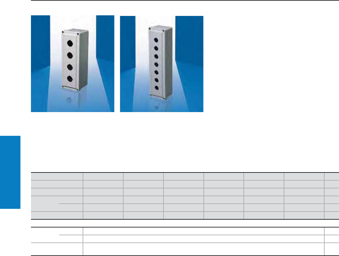
Operator Interface
76 Industrial Buyer’s Guide
Pushbutton Box
Pushbutton Box
Depth: 3 - 4" (80 - 99 mm), Height: 7 - 14" (168 - 350 mm)
Protection Ratings:
UL Type 1, 12, 4X, 6P
UL/cUL and CSA
UL file: E170282
Inch and pound measurements are rounded to the nearest whole number.
Fiberglass Pushbutton Boxes:
Lift-off cover
Recessed captive stainless steel screws to
hold cover
Notched key hole design
Metal grounding strap provided
Foamed-in-place polyurethane gasketing
Height inches (mm) 14 (350) 7 (168) 7 (168) 7 (168) 9 (226) 11 (283) Page
Width inches (mm) 4 (92) 4 (97) 4 (97) 4 (97) 4 (97) 4 (97)
Depth inches (mm) 3 (80) 4 (99) 4 (99) 4 (99) 4 (99) 4 (99)
Part No. 30.5 mm L-F5PB L-F1PB L-F2PB - L-F3PB L-F4PB
25.5 mm - L-F1PBGM L-F2PBGM L-F3PBGM L-F4PBGM L-F5PBGM
Weight lb (kg) 2 (0.9) 2 (0.9) 2 (0.9) 2 (0.9) 2 (0.9) 2 (0.9)
Accessories
Oiltight hole
seals
30.5 mm OHSMPB6 200
25.5 mm OHSSPB6 200
External mounting
brackets L-FIMTGFTKIT
For additional technical
information, please visit
www.rittal-corp.com
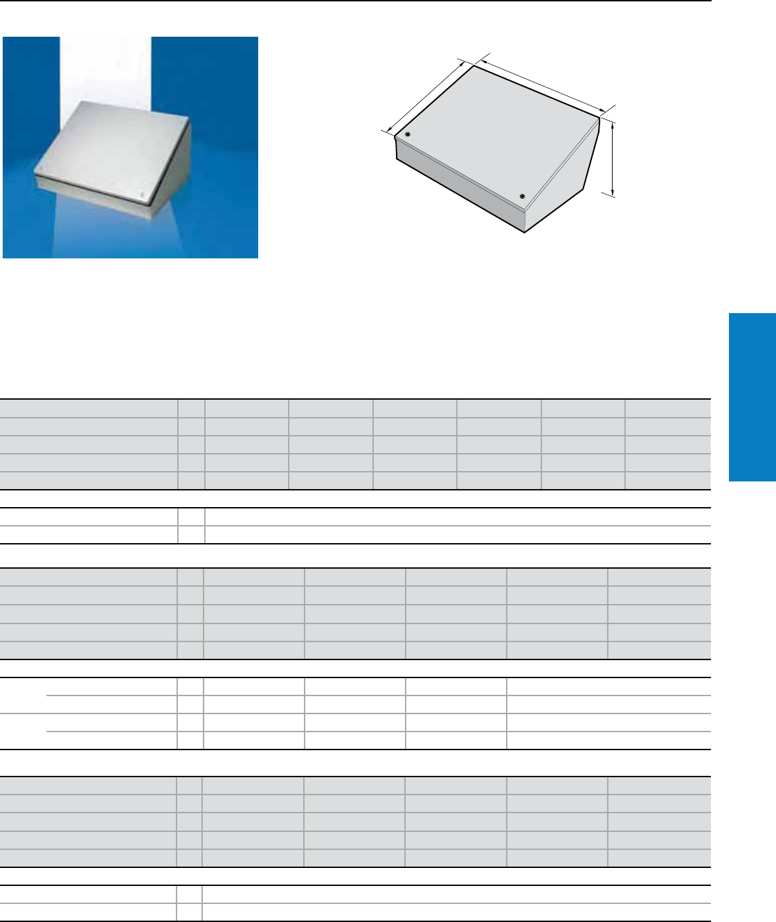
Operator Interface
Industrial Buyer’s Guide 77
Pushbutton Box
Consolet
Inch and pound measurements are rounded to the nearest whole number.
Consolet
Depth: 7 - 13" (180 - 332 mm), Height: 8 - 20" (203 - 508 mm)
H1
B1
T1
Material:
Sheet steel
Enclosure: 14 ga (2 mm)
Door: 14 ga (2 mm)
Finish:
Enclosure and door:
Dipcoat-primed,
powder coated textured RAL
7035 (light gray)
Conguration:
Hinged screw cover,
foamed-in-place gasketing,
control panel slants 30 or 60°
For additional technical
information, please visit
www.rittal-corp.com
Height (H1) inches (mm) PU 8 (203) 8 (203) 8 (203) 8 (203) 12 (305) 12 (305)
Width (B1) inches (mm) 8 (203) 12 (305) 16 (406) 20 (508) 12 (305) 16 (406)
Depth (T1) inches (mm) 7 (180) 7 (180) 7 (180) 7 (180) 9 (231) 9 (231)
Part No. 1C080807HC C081207HC C081607HC C082007HC C121209HC C121609HC
Weight lb (kg) 8 (3.5) 10 (4.7) 13 (5.8) 15 (7.0) 14 (6.5) 18 (8.0)
Accessories
Base 18 x 18 x 1 (457 x 457 x 25) 1 C18SBASEC
Column 4 x 4 x 35 (102 x 102 x 889) 1 C44SCOLC
Height (H1) inches (mm) PU 12 (305) 12 (305) 16 (406) 16 (406) 16 (406)
Width (B1) inches (mm) 20 (508) 24 (610) 16 (406) 20 (508) 24 (610)
Depth (T1) inches (mm) 9 (231) 9 (231) 11 (282) 11 (282) 11 (282)
Part No. 1C122009HC C122409HC C161611HC C162011HC C162411HC
Weight lb (kg) 21 (9.6) 24 (11.1) 23 (10.4) 27 (12.3) 32 (14.3)
Accessories
Base 18 x 18 x 1 (457 x 457 x 25) 1 C18SBASEC - C18SBASEC -
24 x 24 x 1 (610 x 610 x 25) 1 - C24SBASEC - C24SBASEC
Column 4 x 4 x 35 (102 x 102 x 889) 1 C44SCOLC - C44SCOLC -
6 x 6 x 35 (152 x 152 x 889) 1 - C66SCOLC - C66SCOLC
Height (H1) inches (mm) PU 16 (406) 16 (406) 20 (508) 20 (508) 20 (508)
Width (B1) inches (mm) 30 (762) 36 (914) 20 (508) 24 (610) 30 (762)
Depth (T1) inches (mm) 11 (282) 11 (282) 13 (332) 13 (332) 13 (332)
Part No. 1C163011HC C163611HC C202013HC C202413HC C203013HC
Weight lb (kg) 38 (17.0) 44 (19.9) 34 (15.2) 34 (17.5) 46 (20.9)
Accessories
Base 24 x 24 x 1 (610 x 610 x 25) 1 C24SBASEC
Column 6 x 6 x 35 (152 x 152 x 889) 1 C66SCOLC
Protection Ratings:
UL Type 12/13
(IP 55 to EN 60 529)
UL/cUL
UL file: 118617
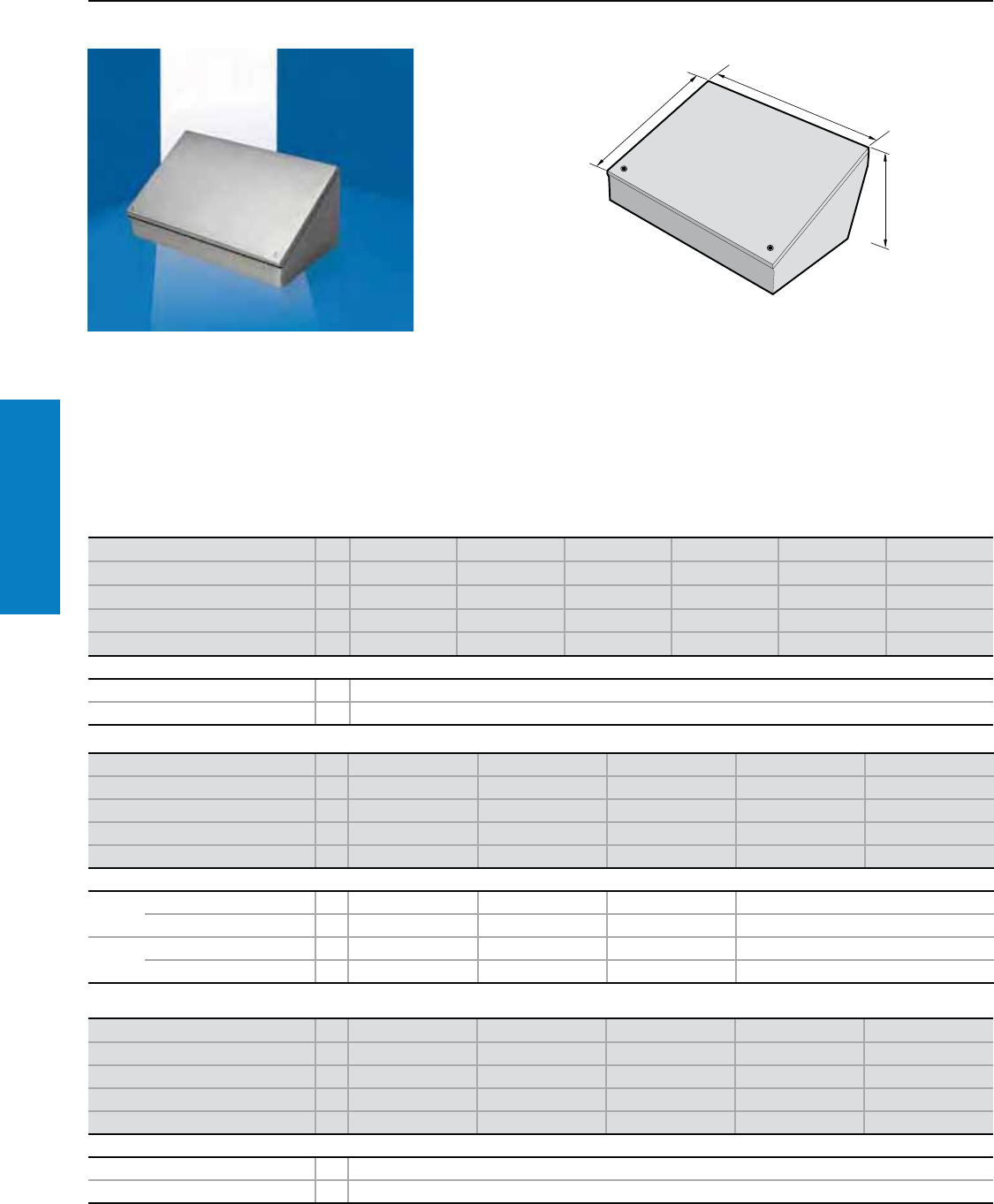
Operator Interface
78 Industrial Buyer’s Guide
Consolet
Consolet
Depth: 7 - 13" (180 - 332 mm), Height: 8 - 20" (203 - 508 mm)
H1
B1
T1
Material:
Type 304 stainless steel
Enclosure: 14 ga (2 mm)
Door: 14 ga (2 mm)
Finish:
Enclosure and door: #4 Brushed
Conguration:
Hinged screw cover, foamed-in-place
gasketing, control panel slants 30 or 60°
Height (H1) inches (mm) PU 8 (203) 8 (203) 8 (203) 8 (203) 12 (305) 12 (305)
Width (B1) inches (mm) 8 (203) 12 (305) 16 (406) 20 (508) 12 (305) 16 (406)
Depth (T1) inches (mm) 7 (180) 7 (180) 7 (180) 7 (180) 9 (231) 9 (231)
Part No. 1C080807H4 C081207H4 C081607H4 C082007H4 C121209H4 C121609H4
Weight lb (kg) 8 (3.5) 10 (4.7) 13 (5.8) 15 (7.0) 14 (6.5) 18 (8.0)
Accessories
Base 18 x 18 x 1 (457 x 457 x 25) 1 C18SBASE4
Column 4 x 4 x 35 (102 x 102 x 889) 1 C44SCOL4
Height (H1) inches (mm) PU 12 (305) 12 (305) 16 (406) 16 (406) 16 (406)
Width (B1) inches (mm) 20 (508) 24 (610) 16 (406) 20 (508) 24 (610)
Depth (T1) inches (mm) 9 (231) 9 (231) 11 (282) 11 (282) 11 (282)
Part No. 1C122009H4 C122409H4 C161611H4 C162011H4 C162411H4
Weight lb (kg) 21 (9.6) 24 (11.1) 23 (10.4) 27 (12.3) 32 (14.3)
Accessories
Base 18 x 18 x 1 (457 x 457 x 25) 1 C18SBASE4 - C18SBASE4 -
24 x 24 x 1 (610 x 610 x 25) 1 - C24SBASE4 - C24SBASE4
Column 4 x 4 x 35 (102 x 102 x 889) 1 C44SCOL4 - C44SCOL4 -
6 x 6 x 35 (152 x 152 x 889) 1 - C66SCOL4 - C66SCOL4
Height (H1) inches (mm) PU 16 (406) 16 (406) 20 (508) 20 (508) 20 (508)
Width (B1) inches (mm) 30 (762) 36 (914) 20 (508) 24 (610) 30 (762)
Depth (T1) inches (mm) 11 (282) 11 (282) 13 (332) 13 (332) 13 (332)
Part No. 1C163011H4 C163611H4 C202013H4 C202413H4 C203013H4
Weight lb (kg) 38 (17.0) 44 (19.9) 34 (15.2) 39 (17.5) 46 (20.9)
Accessories
Base 24 x 24 x 1 (610 x 610 x 25) 1 C24SBASE4
Column 6 x 6 x 35 (152 x 152 x 889) 1 C66SCOL4
Inch and pound measurements are rounded to the nearest whole number.
For additional technical information,
please visit www.rittal-corp.com
Protection Ratings:
UL Type 12/13
(IP 55 to EN 60 529)
UL/cUL
UL file: 118617
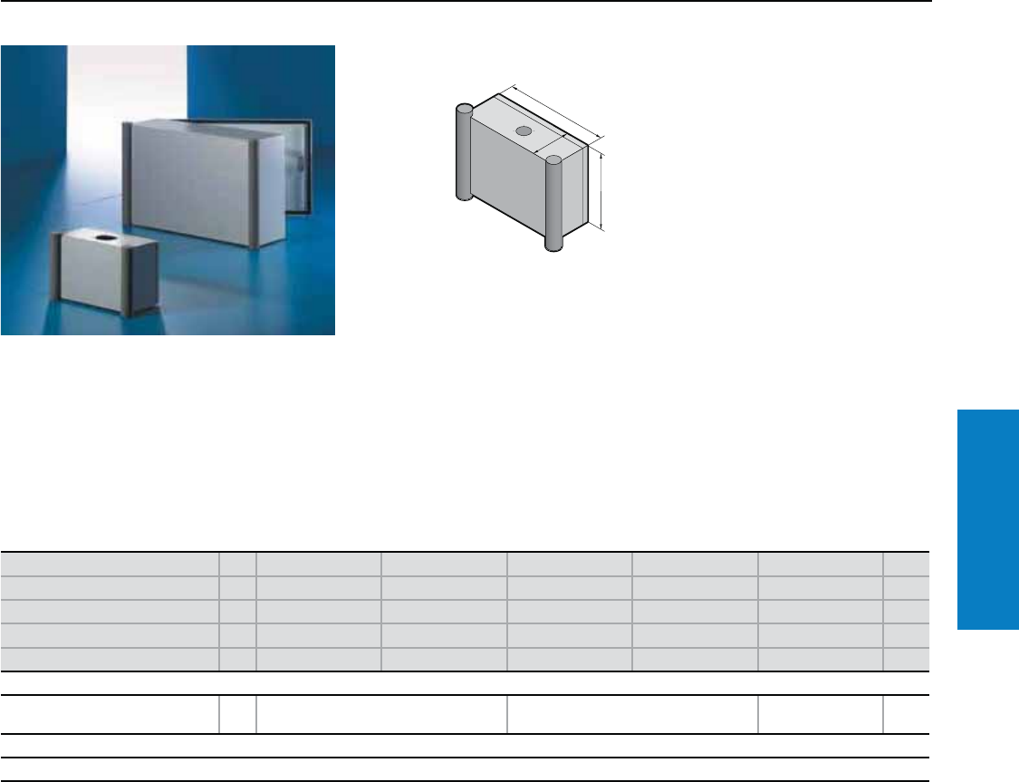
Operator Interface
Industrial Buyer’s Guide 79
Command Panel
Command Panel
Depth: 6 - 8" (155 - 210 mm), Height: 8 - 20" (200 - 500 mm)
Material/Finish
Enclosure and door:
Sheet steel, dipcoat-primed
and powder coated in textured
RAL 7035 (light gray)
Handle strips:
Aluminum in RAL 7030
Cover caps:
Plastic, RAL 7030
Conguration:
Enclosure with cut-out and
reinforcement, prepared for support
arm system CP-L Ø 5" (130 mm)
and with mounting angles spot
welded at the sides. Front with
maximum cut-out, covered with
easily machinable 11 ga. (3 mm)
aluminum front panel and side
handle strips with end caps.
Rear with door.
For additional technical
information, please visit
www.rittal-corp.com
H1
B1
T1
Height (H1) inches (mm) PU 8 (200) 12 (300) 15 (380) 15 (380) 20 (500) Page
Width (B1) inches (mm) 12 (300) 15 (380) 15 (380) 24 (600) 20 (500)
Depth (T1) inches (mm) 6 (155) 8 (210) 8 (210) 8 (210) 8 (210)
Part No. 16540.2001) 6531.200 6530.200 6533.200 6532.200
Weight lb (kg) 11 (4.9) 20 (9.3) 22 (10.2) 32 (14.6) 34 (15.4)
Accessories
Support strips for attaching to the
mounting angles of the side panel 20 – 4594.000 4309.000 236
Lock systems
Standard double-bit lock insert may be exchanged for 1" (27 mm) lock inserts, type A, lock cylinder, plastic handles and T-handles, type B, see page 218.
1) Support arm connection and door hinge at the bottom.
Note:
The support arm connection and
door hinge may be swapped
over by rotating the enclosure.
Inch and pound measurements are rounded to the nearest whole number.
Protection Ratings:
UL Type 12 (IP 55 to EN 60 529)
UL, CSA
UL file: E76083
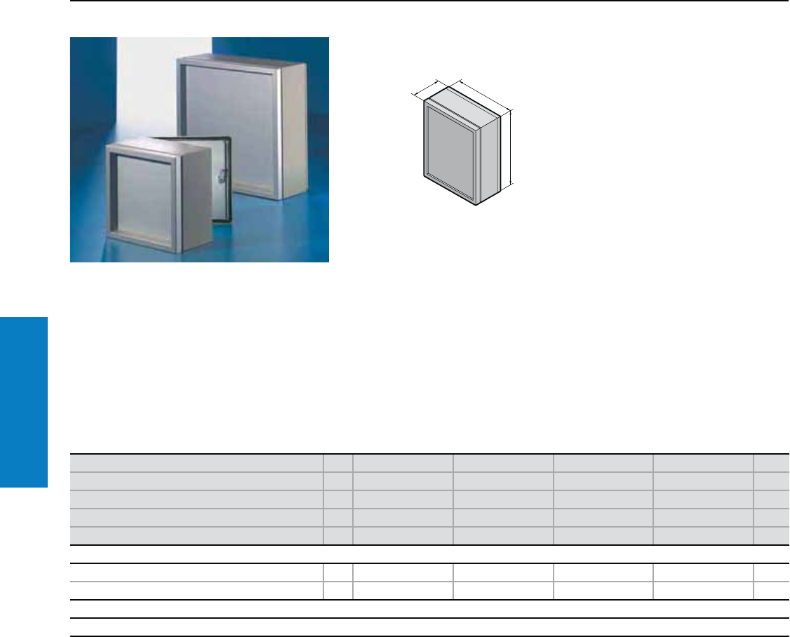
Operator Interface
80 Industrial Buyer’s Guide
Command Panel
Command Panel
Depth: 10" (249 mm), Height: 15 - 24" (380 - 600 mm)
Material/Finish
Enclosure and door:
Sheet steel, dipcoat-primed and
powder coated in textured RAL 7035
(light gray)
Frame and front panel:
Aluminum, natural-anodized.
Protection Ratings:
NEMA 12
(IP 54 to EN 60 529)
Conguration:
Based on AE Wallmount, with display panel
front. Enclosure without support arm connection
with mounting angles spot-welded at the sides.
With maximum cut-out at the front and fitted,
easily machinable 11 ga (3 mm) front panel with
aluminum frame, with right hand hinge, screw-
fastened from the inside. Rear door, right hand
hinge, with two cam locks (6442.500 has only
one lock). For additional technical
information, please visit
www.rittal-corp.com
Inch and pound measurements are rounded to the nearest whole number.
T
B
H
Height (H) inches (mm) PU 15 (380) 20 (500) 24 (600) 24 (600) Page
Width (B) inches (mm) 15 (380) 20 (500) 15 (380) 24 (600)
Depth (T) inches (mm) 10 (249) 10 (249) 10 (249) 10 (249)
Part No. 16442.500 6552.500 6462.500 6662.500
Weight lb (kg) 21 (9.5) 40 (18) 29 (13.4) 43 (19.6)
Accessories
Reinforcement plate with CP-L support arm cut-out 1 6143.210 6143.210 6143.210 – 165
Enclosure reinforcement with CP-L support arm cut-out 1 – – – 6503.000 165
Lock systems
Standard double-bit lock insert may be exchanged for 1" (27 mm) lock inserts, type A, lock cylinder, plastic handles and T-handles, type B, see page 218.
To order Command Panels in RAL 7032, please add extension .200 to the Part No. Delivery times available upon request.
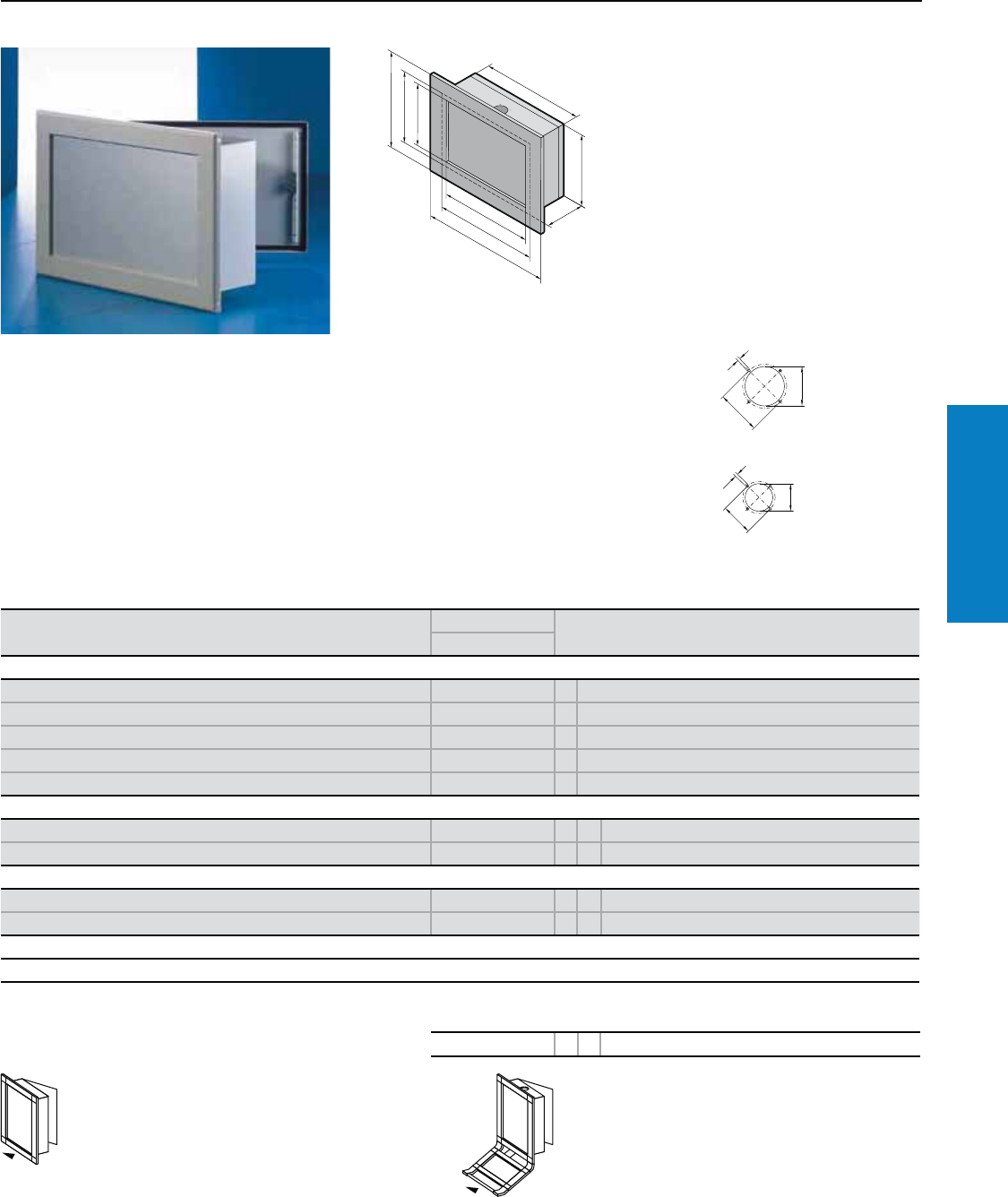
Operator Interface
Industrial Buyer’s Guide 81
Command Panel
Command Panel
Frame section:
Aluminum, powder coated in
RAL 7035 (light gray)
Frame corner pieces:
Die-cast zinc, powder coated in
RAL 7035 (light gray)
Protection Ratings:
NEMA 12 (IP 56 to EN 60 529)
Conguration:
Enclosure with integral roof or base
reinforcement and connection for
CP-L or CP-XL support arm systems.
Aluminum front plate and front frame
supplied loose, door at rear. Upon
request, the AE compact enclosure
can be equipped with a stylish VIP
6000 frame mounted on the rear
panel. The large AE door provides
easy access for servicing.
H
B
T
H
H
H1
B
B
B1
Material/Finish
Enclosure and door:
Sheet steel, dipcoat-primed and
powder coated in textured
RAL 7035 (light gray)
Front plate:
11 ga (3 mm) aluminum,
natural-anodized
Height dimensions:
H = enclosure height
H1 = H + 79 mm, overall height
H2 = H – 42 mm, clearance between the front
frames
H3 = H – 5 mm, front panel height
Width dimensions:
B = enclosure width
B1 = B + 79 mm, overall width
B2 = B – 42 mm, clearance between the front
frames
B3 = B – 5 mm, front panel width
Depth dimensions:
T = enclosure depth
1
11
Support arm
connection for
CP-XL systems
Support arm cut-out
for Ø 5" (130 mm)
CP-L system
Command Panel with wide VIP 6000 frame in the dimensions of AE
compact enclosures or in custom dimensions
Basic Part No. Design code number
6541.009
Support arm connection for support arm system
Without 6541.009 0
CP-XL top 6541.009 1
CP-XL bottom 6541.009 2
CP-L, Ø 5" (130 mm), top 6541.009 3
CP-L, Ø 5" (130 mm), bottom 6541.009 4
Cable tube connection
Without 6541.009 X 0
Bottom 6541.009 X 1
Dimensions
Custom sizes inches (mm) 6541.009 X X H x W x D
Like AE compact enclosure (see above) 6541.009 X X AE Part No.
Lock systems
Standard double-bit lock insert may be exchanged for 1" (27 mm) lock inserts, type A, lock cylinder, plastic handles and T-handles, type B, see page 218.
Order example 6541.009 41H x W x D
Order example
Part No. 6541.009
Design code numbers:
• Support arm connection CP-L, Ø 5" (130 mm),
bottom (4)
• Cable tube connection at the bottom (1)
• Custom dimensions: H x W x D: 14 x 21 x 14"
(352 x 537 x 350 mm)
Additional mounting of a VIP 6000 keyboard
housing is possible via the design code number
(see page 109).
The front panel width refers to an enclosure
width B – 2" (54 mm) and is achieved via a frame
connector, which is included with the supply of
the keyboard housing.
Inch and pound measurements are rounded to the nearest whole number.
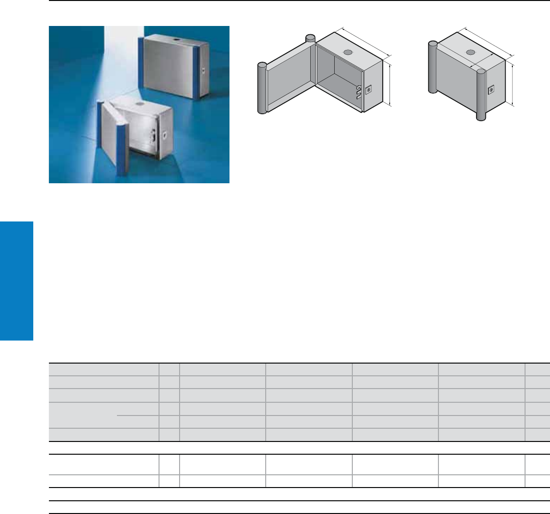
Operator Interface
82 Industrial Buyer’s Guide
Command Panel
H1
B1
T1
H1
B1
Material:
Enclosure and door:
Stainless steel
Handle strips: Plastic-approved
for use with foodstuffs, similar to
RAL 5002 (ultramarine blue).
Conguration:
Based on AE Wallmount, housing
with door. Enclosure sealed all-round,
with cut-out and reinforcement for
support arm system, fastener with
guide plate. Door with sealing frame
and side handle strips. The support
arm connection and door hinge may
be swapped over by rotating the
enclosure.
Mounting panel provisions included.
Use mounting panel from AE
enclosure of corresponding size (see
“Matching mounting panel” in table
below).
Rittal Service:
Separate keyboard housing,
other sizes, modified support
arm connection or door hinge,
drilled holes and cut-outs for
switches and operator panels
available on request.
Height (H1) inches (mm) PU 12 (300) 12 (300) 16 (400) 16 (400) Page
Width (B1) inches (mm) 12 (300) 16 (400) 16 (400) 24 (600)
Depth (T1) inches (mm) 6 (150) 6 (150) 6 (150) 6 (150)
Part No. Type 304 16535.010 6536.010 6538.010 6539.010
Type 316L 16535.510 6536.510 6538.510 6539.510
Weight lb (kg) 14 (6.3) 17 (7.5) 19 (8.8) 27 (12.1)
Accessories
Matching
mounting panel AE type 1033.500 1030.500 1380.500 1039.500 13
Support rails1) Part No. 10 2316.000 2317.000 2317.000 2319.000 –
Lock systems
Standard double-bit lock insert may be exchanged for 2" (41 mm) lock inserts, plastic handle and T handle, type C, see www.rittal-corp.com.
1) Only with vertical attachment of punched rail 0.9" x 0.9" (23 x 23 mm), see page 237.
Command Panel
Depth: 6" (150 mm), Height: 12 - 16" (300 - 400 mm)
For additional technical information,
please visit www.rittal-corp.com
Finish:
Brushed, grain 240
Protection Ratings:
NEMA 4X
(IP 66 to EN 60 529/09.2000)
Inch and pound measurements are rounded to the nearest whole number.
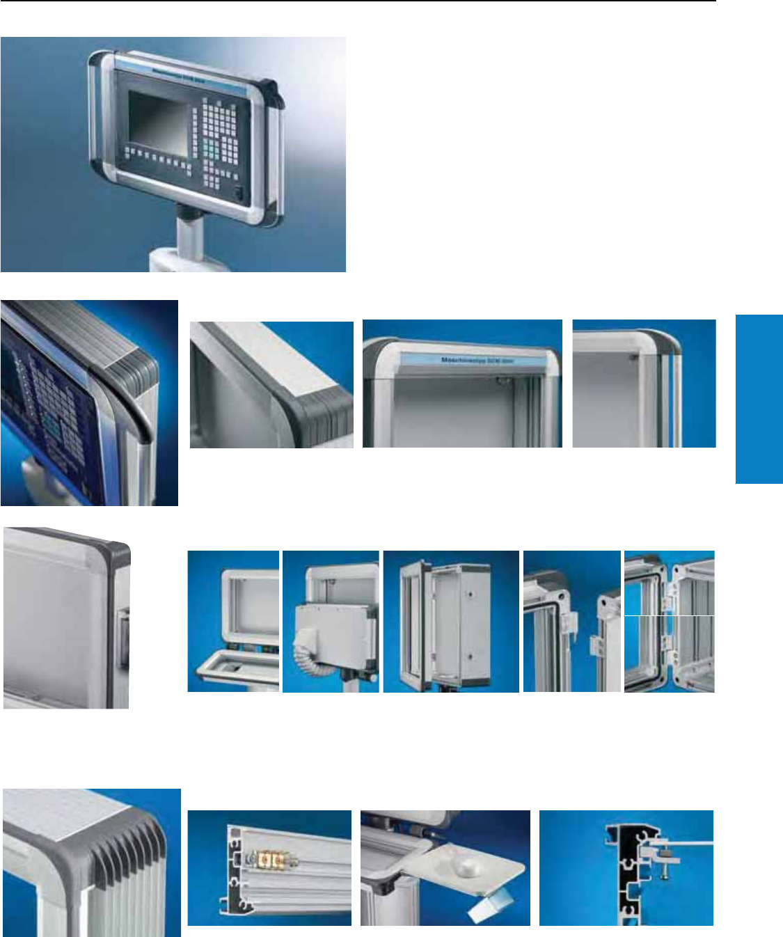
Operator Interface
Industrial Buyer’s Guide 83
Command Panel
Comfort Panel
Features
Soft prole
minimizes the risk of injury.
The Rittal Comfort Panel builds upon the successful Command
Panel platform with lightweight aluminum construction, enhanced
flexibility and available design options that allow you to configure
the ideal operator interface enclosure for your application.
Design and protection
Design prole
Variant for individual design
according to customer
requirements.
Designer handle
as an accessory.
Keyboard housing
vertically hinged via frame
connector. Also suitable for
retrofitting.
Flat front frame section
Optimum access to
integral drives.
Hinges on the outside –
Two functions supported:
1. Front frame for removal
in case of servicing.
2. Door protection due to
symmetrical arrangement
of the hinges.
Perfect in every detail
Assembly made easy
Uniform mounting channels
External and internal mounting
of accessories with easy
grounding.
Plate or mousepad support with
the use of spring nuts in the
mounting channels.
Front panel installation from
the rear via screw/grub screw.
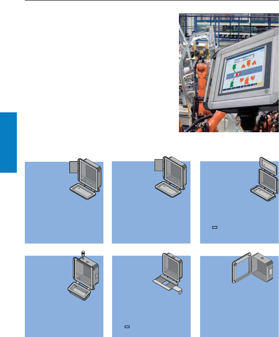
Operator Interface
84 Industrial Buyer’s Guide
Comfort Panel
Comfort Panel
Conguration Examples
Customized Protection
The Rittal Comfort Panel provides the levels of customization needed for you
to create a solution that delivers the protection you need for your equipment
in a user-friendly way that can help to improve productivity.
Example A
• Operator housing,
6.0" (152 mm)
deep
• Keyboard
housing, 1.4"
(35 mm) deep,
with cable tube
• Frame connector, adjustable
• Handle set, vertical and display
board with wall bracket
• With horizontal cross member
• Support arm connection CP-L
bottom, Ø 5.1" (130 mm)
Example B
• Operator
housing,
7.5" (191 mm)
deep
• With spacing
panel and built-
in trim panel
• Clipboard
• Utility bars, vertically hinged
• With horizontal cross member
• Support arm connection CP-L top,
5.1" (130 mm) diameter
Example C
• Operator housing,
2.9" (74 mm) deep
• Handle set, vertical
• Keyboard housing
top, 1.4" (35 mm)
deep, frame
connector adjustable
• Keyboard housing
bottom,1.4" (35 mm) deep, frame
connector adjustable
• Cable tube, flexible
• Support arm connection CP-L,
4.7 x 2.6" (120 x 65 mm),
top and bottom with cover plate
supplied loose
Example D
• Operator
housing,
9.1" (230 mm)
deep
• Keyboard
housing, 4.4"
(113 mm) deep
• Design strip, top
• Enclosure duct
connector
• Handle set, vertical
• Interface flap
• Signal light
• Support arm connection, CP-L top,
Ø 5.1" (130 mm)
Example E
• Operator
housing, 5.1"
(113 mm) deep
• Support for
keyboards
with cable
entry grommet
• Frame connector, adjustable
• With cross member
• Support for mousepad, vertically
hinged
• Holder for mouse
• Support arm connection CP-L,
4.7 x 2.6" (120 x 65 mm), top
Example F
• Operator
housing,
4.7"
(119 mm)
deep,
hinged
• Interface flap
• USB extension
• Support arm connection, CP-L top,
Ø 5.1" (130 mm)
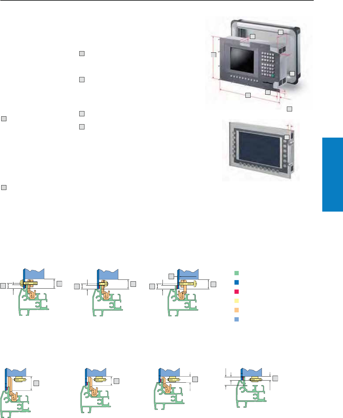
Operator Interface
Industrial Buyer’s Guide 85
Comfort Panel
Comfort Panel
Installation Criteria
1. Panel dimensions
For operator and keyboard housings
For your own sizes/variants, please state the height (H) x width (B) x
depth (T) of the control components and the manufacturer/Part on
the enquiry/order form.
Checking the
installation criteria
Subject to compliance with
criteria 1 to 4, front panels/panels
may be mounted directly with
the appropriate mounting kits.
If these criteria are not met,
installation via an adaptor panel
is possible – see 2.2, version
code 3.
Width of front panel
Different widths of operating
and keyboard housings are
possible (whereby only the
keyboard housing may be
wider than the operating
housing). For minimum size,
refer to minimum front panel
width under technical details,
see www.rittal-corp.com.
B
Height of front panel
H
H
2
3
1
2
B
4
2
Distance from center
of hole/bolt to outer edge of
front panel 0.3 to 0.6"
(8.5 to 15 mm)
1
Installation depth
Operator housing =
2.9, 4.5, 6.0, 7.51), 1.21),10.61),
2.11),13.71), 15.21),16.71), 18.3"1)
(74, 113, 152, 191, 230, 269, 308,
347, 386, 425, 464 mm)
Keyboard housing =
1.4, 2.9, 4.5" (35, 74, 113 mm)
4
3Front panel thickness
1) Also with hinged front frames.
For versions with a hinged
rear panel and cam lock, the
maximum installation depth is
reduced by 1.1" (27 mm) in the
vicinity of the lock.
A.
B.
1
2
1
1
2
1
1
2
3
1
2
1
2
11
2
1
2
Front panel projection
– on sides with attachment,
see drawing below
– from seal at least 0.3"
(6.5 mm)
2
A. Front panel/Panel installation:
From the front via screw From the front via studs From the front via screw/grub screw
Frame section
Front panel
Seal
Screw clamp
Retaining claw
Enclosure/controller
B. Front panel/Panel installation from the front via screw clamp:
Long retaining claw
e.g., Siemens Sinumerik
OP 0122)
Medium retaining claw
e.g., Siemens Simatic MP 377
12" keys, horizontal2)
Short retaining claw
e.g., Siemens Simatic MP 377
12" keys, vertical2)
B&R Automation Panel,
Panel PC2)
Without retaining claw
e.g., Phoenix Contact
PPC 5115
2) For more panels suitable for installation, see www.rittal-corp.com.
Note:
Load information for installed
equipment, see www.rittal-corp.
com.
Operator Interface
86 Industrial Buyer’s Guide
Comfort Panel
Comfort Panel
Selection: Operator Housing/Keyboard Housing
Conguring your ideal enclosure
We need the following three pieces
of information process your order:
• Part No.: 6372.009
• The dimensions and number of panels/
front panels to be installed in the
keyboard/Operator housing
• Design code number
2.1 2.2 2.3 2.4 2.5 2.6 2.7 2.8
Material:
Enclosure:
Extruded Aluminum section
Corner pieces:
Die-cast zinc
Corner protectors:
Plastic, self-extinguishing
Finish:
Enclosure: Natural-anodized
Corner pieces:
Powder coated in finely-textured
RAL 7035 (light gray)
Corner protectors:
Dyed similar to RAL 7024
(graphite gray)
Protection Ratings:
NEMA 4
(IP 65 to EN 60 529/09.2000)
(if the openings in the enclosure are
covered or sealed in accordance
with the protection ratings).
Operator/keyboard housing
Part No.
6 3 7 2 0 0 9
.
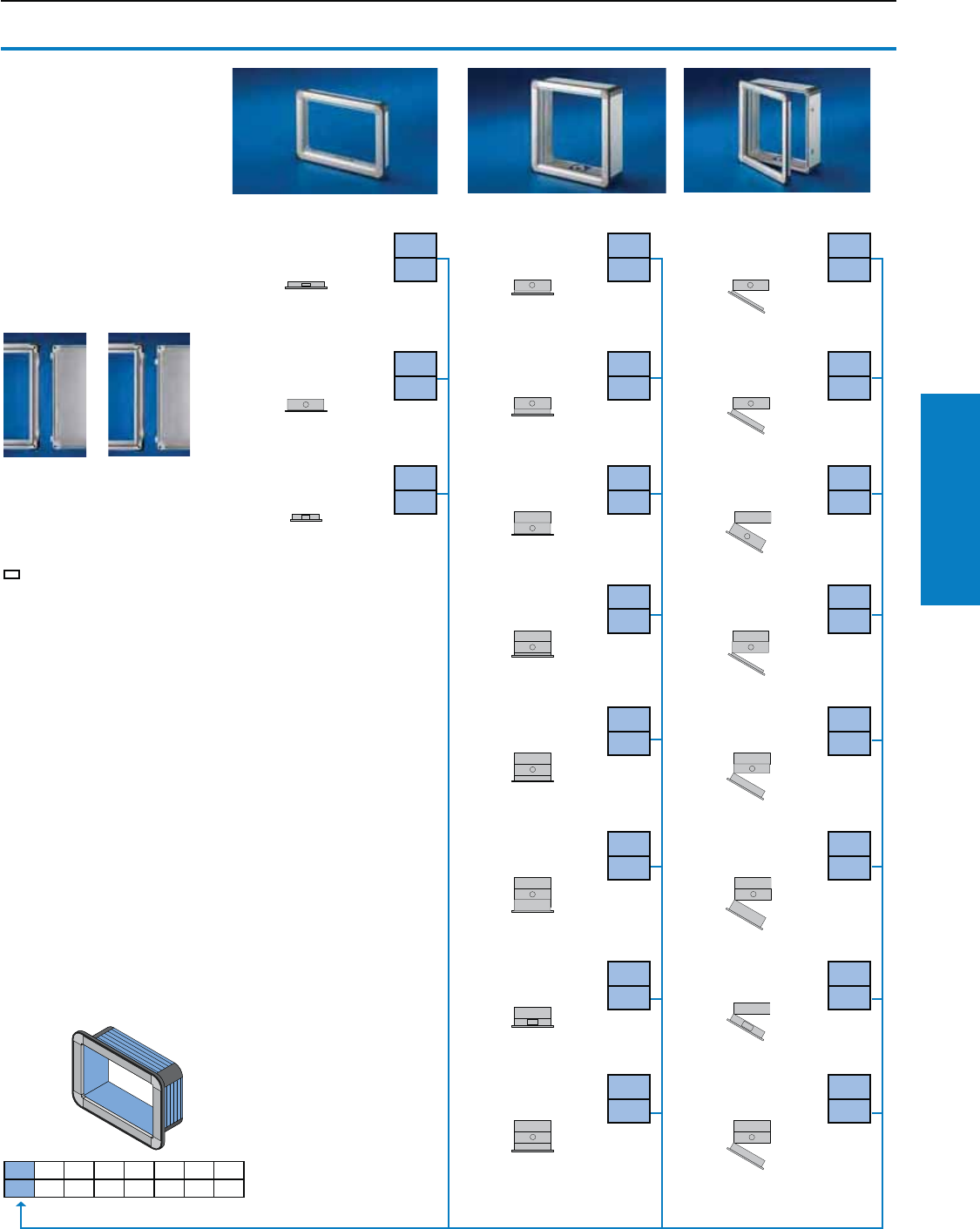
Operator Interface
Industrial Buyer’s Guide 87
Comfort Panel
Comfort Panel
Selection: Operator Housing/Keyboard Housing
Installation depth
2.9" (74 mm)2) 2.1
A.1
Installation depth
7.5" (191 mm) 2.1
B.1
Installation depth
7.5" (191 mm) 2.1
C.1
Installation depth
6.0" (152 mm) 2.1
A.2
Installation depth
9.1" (230 mm) 2.1
B.2
Installation depth
9.1" (230 mm) 2.1
C.2
Installation depth
4.4" (113 mm)2) 2.1
A.3
Installation depth
12.1" (308 mm) 2.1
B.3
Installation depth
12.1" (308 mm) 2.1
C.3
Installation depth
13.7" (347 mm) 2.1
B.4
Installation depth
13.7" (347 mm) 2.1
C.4
Installation depth
15.2" (386 mm) 2.1
B.5
Installation depth
15.2" (386 mm) 2.1
C.5
Installation depth
18.3" (464 mm) 2.1
B.6
Installation depth
18.3" (464 mm) 2.1
C.6
Installation depth
10.1" (269 mm)2) 2.1
B.7
Installation depth
10.1" (269 mm)2) 2.1
C.7
Installation depth
16.7" (425 mm) 2.1
B.8
Installation depth
16.7" (425 mm) 2.1
C.8
2.1 Installation depth
Note:
Support arm connection
see 2.5. Drawing view from
above. Right hand hinge is
also available.
For additional technical
information, please visit
www.rittal-corp.com
One-piece Screw-fastened Hinged1)
2.1 2.2 2.3 2.4 2.5 2.6 2.7 2.8
Removable =
Replace C
with D in the
code number
2) Prepared for support
arm connection
CP-L 5 x 3" (120 x 65 mm)
1) Secured =
As delivered
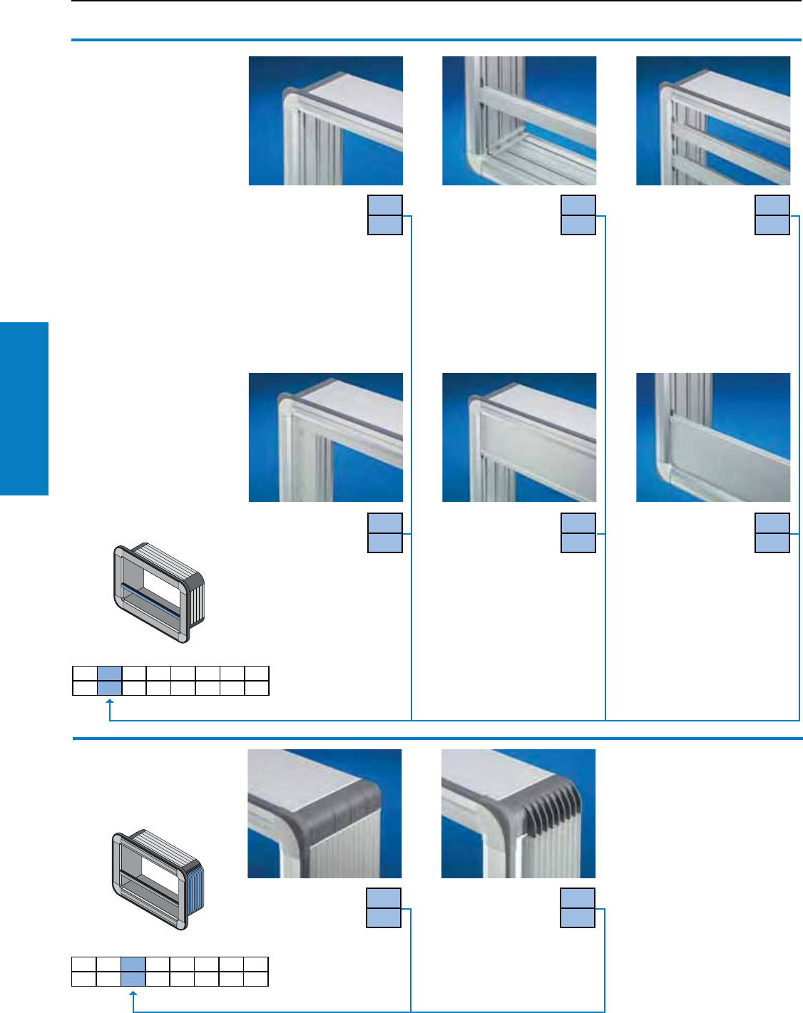
Operator Interface
88 Industrial Buyer’s Guide
Comfort Panel
Comfort Panel
Selection: Operator Housing/Keyboard Housing
2.2 Front design
Also required:
Mounting kit for installing front
panels, operator panels and
keyboards in operator and
keyboard housings.
For additional technical
information, please visit
www.rittal-corp.com
Without cross
member
With one cross
member
For horizontal and/or
vertical division of the
Command Panel front.
With mounting channel on
both sides to accommodate
mounting kits, see www.rittal-
corp.com.
Material:
Extruded Aluminum section,
natural-anodized
With two cross
members
2.2
0
2.2
1
2.2
2
With an adaptor plate
(to specification)
Material thickness:
0.1" (3 mm) Aluminum,
natural-anodized. Please
specify the dimensions for the
front panel and the desired
holes and cut-outs.
2.2
3
With spacing and
built-in trim panel,
at the top
For additional space
for cable entry and for
installing switches/indicator
lights, emergency off/key
switches, CD-ROM/disk
drives, interfaces, interface
flaps, etc.
Material:
Extruded Aluminum section,
natural-anodized
2.2
4
With spacing and
built-in trim panel,
at the bottom
2.2
5
2.1 2.2 2.3 2.4 2.5 2.6 2.7 2.8
2.3 Cooling ns
No ns 2.3
0
Fins on sides
To boost the
dissipated
heat loss with an
installation depth of 2.9"
(74 mm) or more. Guidelines
for dissipatable heat loss, see
www.rittal-corp.com.
2.3
1
2.1 2.2 2.3 2.4 2.5 2.6 2.7 2.8
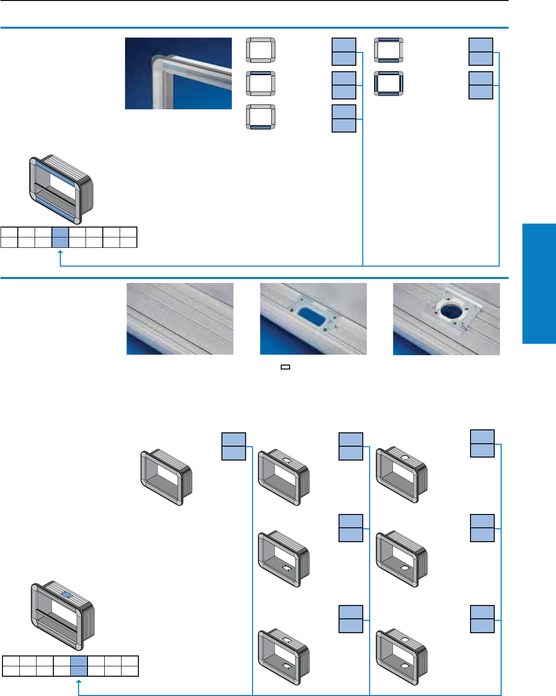
Operator Interface
Industrial Buyer’s Guide 89
Comfort Panel
Comfort Panel
Selection: Operator Housing/Keyboard Housing
2.1 2.2 2.3 2.4 2.5 2.6 2.7 2.8
2.4 Design strip
Material:
Transparent plastic
Note:
Label/color-coded strips:
Your dimensions:
max. H = 0.6" (14.5 mm)
and thickness = 0.03" (0.8 mm)
For additional technical
information, please visit
www.rittal-corp.com
Without
Top
Bottom
2.4
0
2.4
1
2.4
2
2.4
3
2.4
4
Top and
Bottom
All-round
Without
cooling
fins
With cooling fins
for 7.5 and 13.7"
(191 and 347 mm)
installation depths
2.5 Support arm and
pedestal connection
Users may choose from
4 different support arm
systems, see page 118-159,
and a variety of stand
systems, see page 160-164.
1) Including a cover plate for
sealing the unused section.
2) Support arm connection
Without support arm
connection
CP-L 4.7 x 2.6"
(120 x 65 mm)
Installation depth 2.9, 4.4, 10.6"
(74, 113, 269 mm) CP-L, see
page 132/1.4 CP-S, see page
120/3.3
CP-L Ø 5.1" (130 mm)
Installation depth 6.0" (152 mm)
and above
CP-L, see page 132/1.1
CP-XL, see page 150/1.3
Without connection
2.5
0
Connection top 2.5
1
Connection top2) 2.5
4
Connection bottom 2.5
2
Connection bottom 2.5
5
Connection top
and bottom1) 2.5
3
Connection top and
bottom1) 2) 2.5
6
2.1 2.2 2.3 2.4 2.5 2.6 2.7 2.8
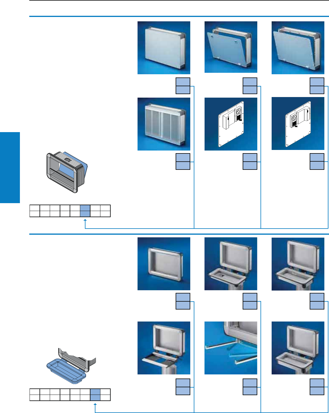
Operator Interface
90 Industrial Buyer’s Guide
Comfort Panel
2.7 Keyboard housing
Width independent from the Operator housing.
The swivel bracket is adjustable from +88° to
-136° from the horizontal in 8° increments.
1) Mounting kit for installing front panels,
operator panels and keyboards in operator and
keyboard housings.
2) Alternatively, the bars may be inserted to
the rear with the support arm connection at
the bottom.
3) By labeling with index A: Rigid connection
via enclosure duct connector (6006.000). With
the support arm connection at the bottom, this
must be checked in each individual case.
Comfort Panel
Selection: Operator Housing/Keyboard Housing
2.6 Rear panel
Material:
Aluminum, natural-anodized.
1) When installing the pull-out keyboard
6002.1X0 (see www.rittal-corp.com) in the
Comfort Panel, design variant 2.1, no. A2 the
cooling fins and screw channels protruding
0.4" (11 mm) into the enclosure may be milled
off in this area. Please state the installation
position when ordering.
2) On the longest side (right/bottom), cam with
double-bit insert, may be exchanged for lock
inserts 1.6" (41 mm), type C, plastic handles
and T handles, type C, see www.rittal-corp.
com. The max. installation depth in the vicinity
of the lock is reduced by 1.1" (27 mm).
2.1 2.2 2.3 2.4 2.5 2.6 2.7 2.8
2.6
1
2.6
2
2.6
3
Screw-fastened Hinged on the
longest edge2)
Hinged with
quick-release
fasteners
Rear cooling
panel, modular1)
Increases the
dissipation of
heat loss from
the enclosure by
approx. 10 %.
2.6
4
Screw-fastened
with built-in VIP
small cooling
unit, condenser
assembly at the top left
Recommended Operator
housing design (see 2.1
from an installation depth
of 7.5" [191 mm])
Material:
Aluminum,
natural-anodized
2.6
5
Condenser
assembly,
top right
2.6
6
Without
keyboard
housing
With keyboard
housing and
cable tube
Installation depth
1.4" (35 mm)1)
2.7
1
With keyboard
housing and
cable tube
Installation depth
2.9" (74 mm)1) 3)
2.7
2
2.7
0
With support
for keyboards
and cable entry
grommet. Specify
keyboard dimensions
2.7
3
Utility bars,
vertically hinged
and cable
grommet2)
2.7
4
2.7
5
2.1 2.2 2.3 2.4 2.5 2.6 2.7 2.8
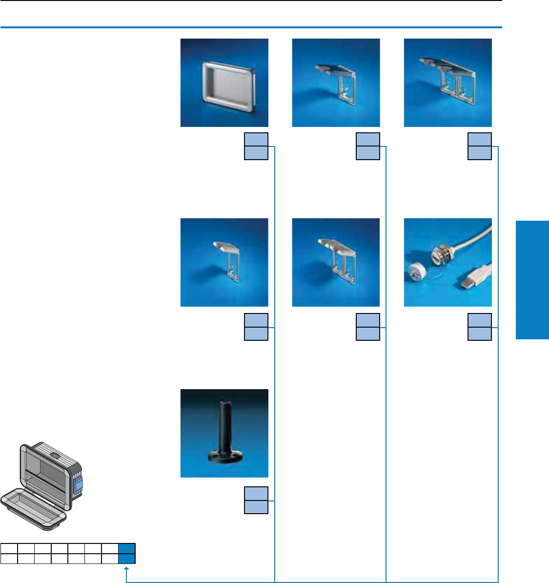
Operator Interface
Industrial Buyer’s Guide 91
Comfort Panel
Comfort Panel
Selection: Operator Housing/Keyboard Housing
2.8 Integration
of accessories
In addition to the design code, you should
also indicate the position or enclose a sketch.
1) Interface inserts may be found on page 225,
these may also be fitted by specifying the
Part No. and position.
2.8
0
2.8
1
Without
accessories
Interface ap,
single, with
plastic ap1)
from installation
depth 4.4" (113 mm)
Interface ap,
double, with
plastic ap1)
only possible in
the front panel, spacer
and built-in trim panel or
rear panel
2.8
2
Interface ap,
single, with
metal ap1)
from installation
depth 4.4" (113 mm)
Interface ap,
double, with
metal ap1)
only possible in
the front panel, spacer
and built-in trim panel or
rear panel
2.8
3
2.8
4
USB/RJ 45
extension
For order
information,
refer to page 226.
2.8
5
2.1 2.2 2.3 2.4 2.5 2.6 2.7 2.8
Mounting
preparations
for signal
pillars, modular
Mounting component,
Signal pillars, modular,
see www-rittal-corp.com.
2.8
6
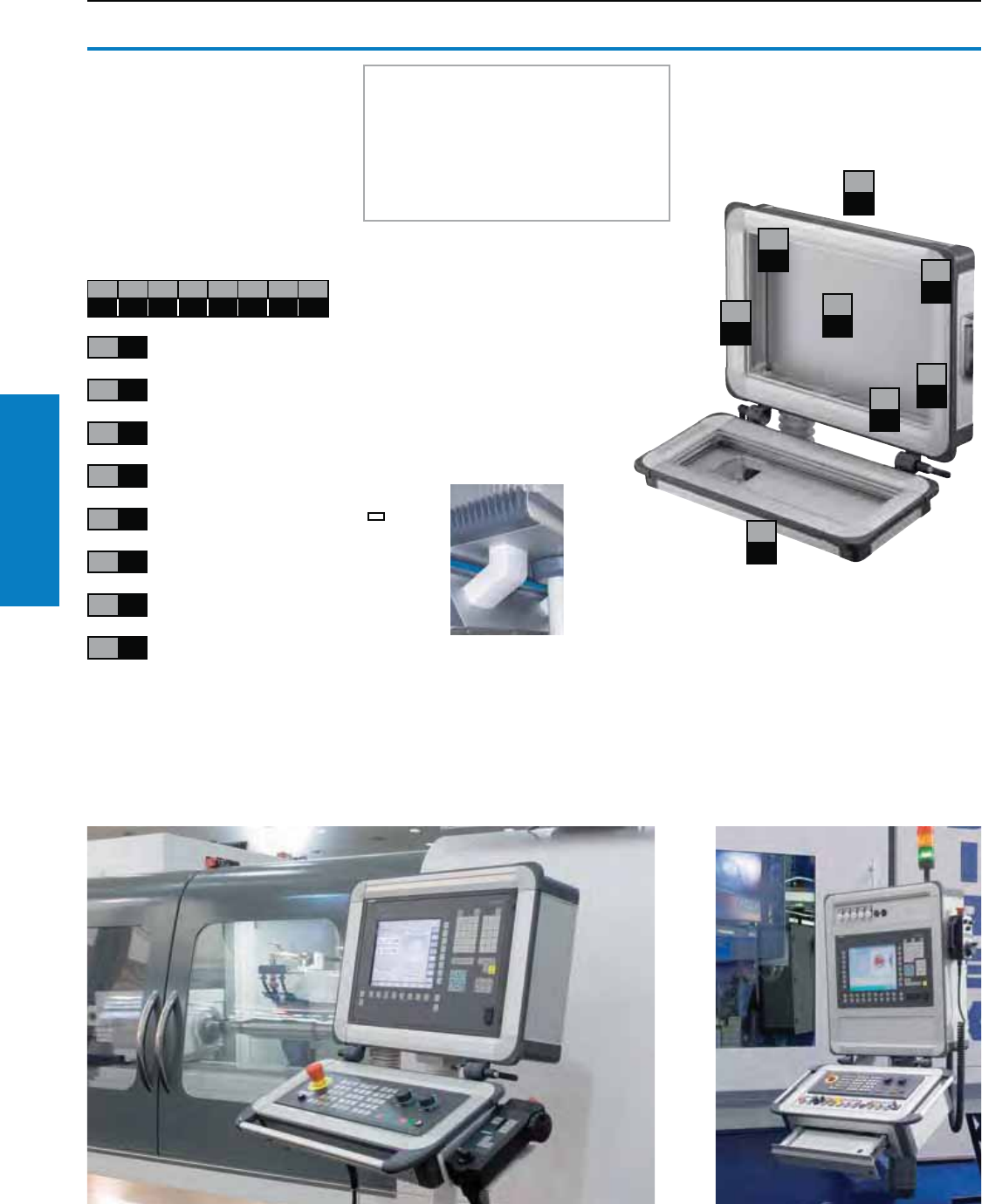
Operator Interface
92 Industrial Buyer’s Guide
Comfort Panel
Comfort Panel
Selection: Operator Housing/Keyboard Housing
Example
The picture opposite shows the solution
we have chosen, together with its
corresponding design code number.
The following key explains how the code
number in our example is created.
Operator/
keyboard housing
Part No.: 6372.009
2.1 2.2 2.3 2.4 2.5 2.6 2.7 2.8
A30002111
Design code number:
2.1 A3
2.2 0
2.3 0
2.4 0
2.5 2
2.6 1
2.7 1
2.8 1
Operator housing,
installation depth 4.5" (113 mm)
Without cross member
No fins
Without design strip
Support arm connection, CP-L
4.7 x 2.6" (120 x 65 mm), bottom
Rear panel, screw-fastened
With keyboard housing,
Installation depth 1.4" (35 mm)
Fitted interface flap
2.1
A3
2.2
0
2.3
0
2.4
0
2.5
2
2.6
1
2.7
1
2.8
1
We need the following three pieces
of information to process your order:
• Part No.: 6372.009
• The dimensions and number of
panels/front panels to be installed in
the keyboard/Operator housing
• Design code number
Note:
If the design code number does not cover
your requirements, please enter an X and
enclose a written explanation.
Rigid keyboard connection
Selection see
design code 2.7.
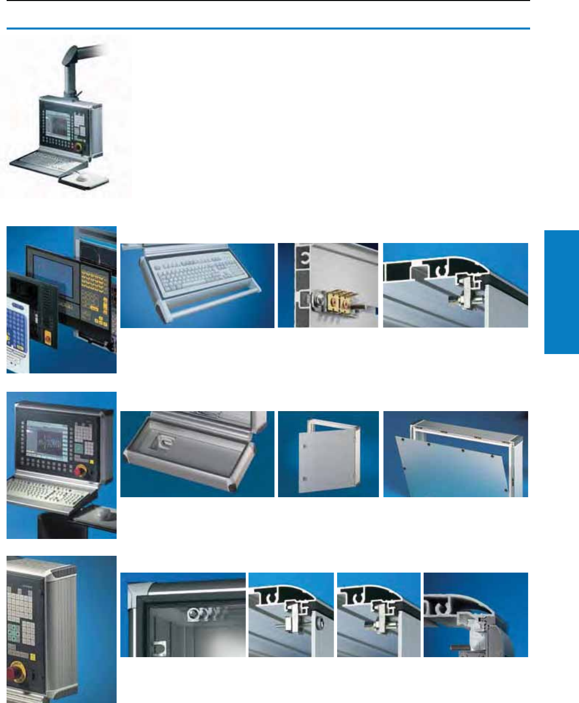
Operator Interface
Industrial Buyer’s Guide 93
Optipanel
Optipanel
Features
The stylish, customized solution with lightweight aluminum design.
Three installation depths: 2.0, 3.9, 5.9" (50, 100, 150 mm)
Hinged rear panels facilitate easy servicing.
Customized to order or in standard sizes off the shelf.
Property rights:
German patent no. 41 09 695
European patent no. 0 505 681
with validity for CH, FR, GB, IT
Jap. patent no. 3221506
German patent no. 199 02 174
German registered design
no. 400 02 955
IR reg. des. No. DM/055 168
with validity for CH, FR, IT
US design patent no. D 456,403
European patent no. 1 269 067
with validity for CH, DE, FR, IT
Always within reach
Tailored precisely to the operator’s
requirements, various handle sets may
be fitted in accordance with ergonomic
requirements.
All-round spring groove
channels for flexible
interior installation and
for mounting accessories.
Superior seal helps to achieve
Protection Ratings IP 65. For
installations flush with the frame
section with a front panel thickness
of approx. 10 ga (3.5 mm).
Keyboard housing/rear panels
Choose a suitable keyboard housing.
There are two installation depths
available, along with the keyboard
support.
Choose the rear panel:
• Screw-fastened
• Hinged with cam lock
• Hinged with quick-release fasteners
All-round attachment
Every attachment point
is accessible on all sides!
Movable retaining claws create sufficient play to accommodate virtually all
hole spacings – distance from the panel’s outer edge 0.3 – 0.5"
(7 – 13 mm). Panels with screw fastening from the front, with studs or screw
clamps, may be used.
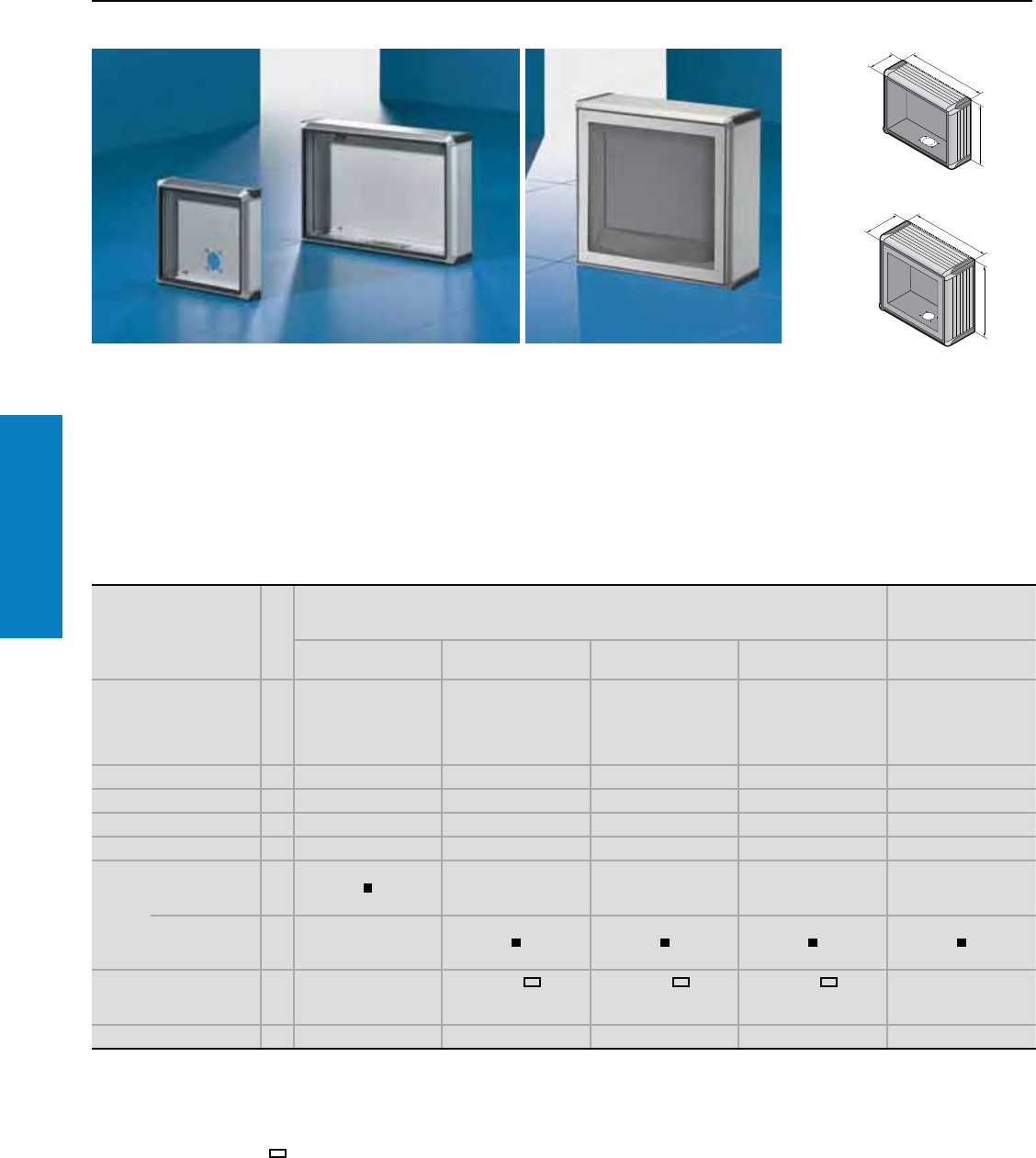
Operator Interface
94 Industrial Buyer’s Guide
Optipanel
Optipanel
Standard Sizes and for Desktop TFT Up to 20.1"
T
H
B
T
H
B
Material:
Enclosure:
Extruded Aluminum section
Corner pieces:
Die-cast zinc
Corner protectors:
Plastic, self-extinguishing
Sealing trim:
Flexible plastic section
For 6380.050:
Front panel:
Aluminum, natural-anodized
Viewing window:
Toughened safety glass 0.2"
(4 mm)
Finish:
Enclosure:
Natural-anodized
Corner pieces:
Powder coated in finely-textured
RAL 7035 (light gray)
Corner protectors and
sealing trim:
Dyed similar to RAL 7024
(graphite gray)
Protection Ratings:
NEMA 4
(IP 65 to EN 60 529/09.2000)
(if the openings in the enclosure
are covered or sealed in
accordance with the Protection
Ratings).
For additional technical
information, please visit
www.rittal-corp.com
To fit front panels1)
Width x height
inches (mm)
PU
Standard sizes
Optipanel for desktop
TFT up
to 20.1"
11 x 9
(270 x 234)
19 x 12
(482.6 x 310.3) 17 x 14 (430 x 343) 19 x 20 (482.6 x 354.8) –
To fit
TFT monitor ––
6450.010/
6450.030/
6450.070/
6450.120/
6450.150
6450.020/
6450.040/
6450.080/
6450.130/
6450.160
–
Height (H) inches (mm) 11 (278) 14 (354) 15 (387) 16 (399) 19 (484.5)
Width (B) inches (mm) 12 (314) 21 (527) 19 (475) 21 (527) 23 (574.5)
Depth (T) inches (mm) 2 (60) 4 (110) 4 (110) 4 (110) 6 (160)
Part No. 16380.100 6380.000 6380.020 6380.040 6380.0507)
Rear
panel,
hinged
Quick-release
fastener
for screwdriver
––––
Cam with
double-bit
insert3)
–
Support arm connection4) CP-S
VESA 755)
CP-L
4.7 x 2.6"
(120 x 65 mm)
CP-L
4.7 x 2.6"
(120 x 65 mm)
CP-L
4.7 x 2.6"
(120 x 65 mm)
CP-L
Ø 5.1"
(130 mm)
Weight lb (kg) 6 (2.8) 14 (6.2) 12 (5.28) 15 (6.6) 31 (14.2)
1) Installation criteria required for direct mounting of the panels, see page 96.
2) For depth 2.4" (60 mm) the power pack must be mounted externally for reasons of space, e. g., in IW Station.
3) Standard double-bit lock insert may be exchanged for 1.6" (41 mm) lock inserts, type C, plastic handles and T handles, type C, see www.rittal-corp.com.
4) Support arm connection at the top or bottom, by rotating the enclosure.
5) Additional marked points for drilling holes, for the external mounting of:
Assembly components with drilling pattern to VESA 75 = Enclosure attachment, tiltable 6902.670
Support arm system CP-L, 4.7 x 2.6" (120 x 65 mm), Support arm system CP-S.
6) Extended delivery times.
7) Screw-fasten the TFT to the mounting panel, slide into the enclosure from behind and secure.
Inch and pound measurements are rounded to the nearest whole number.
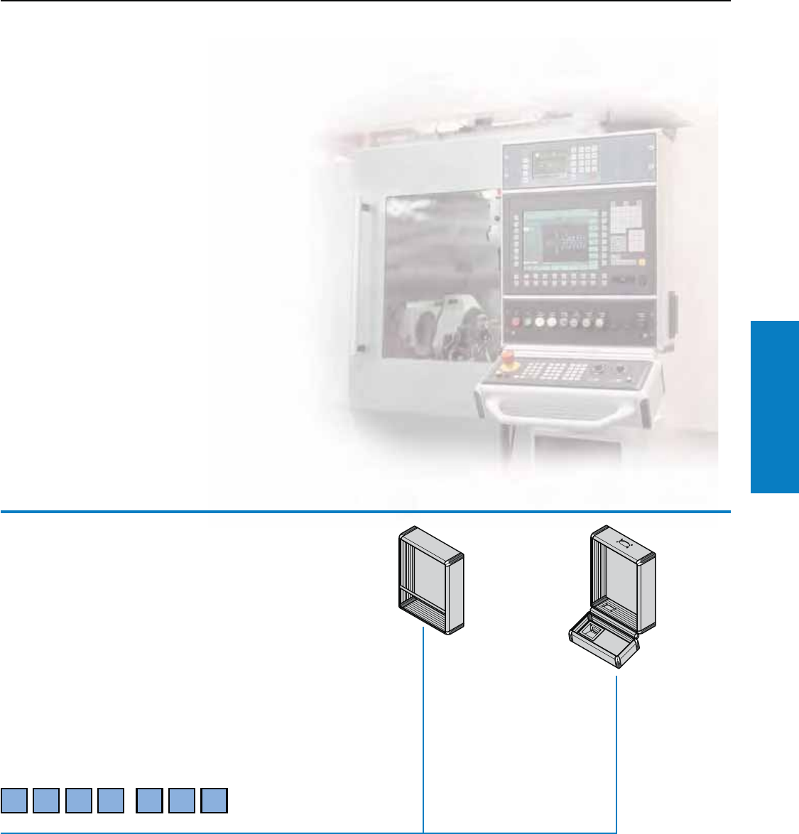
Operator Interface
Industrial Buyer’s Guide 95
Optipanel
Optipanel
Selection: Operator Housing/Keyboard Housing
Conguring your ideal enclosure
We need the following three pieces
of information process your order:
• Part No.: 6382.009
• The dimensions and number of panels/
front panels to be installed in the
keyboard/Operator housing
• Design code number
Operator/keyboard housing
Part No.
6 3 8 2 0 0 9
.
Material:
Enclosure:
Extruded Aluminum
section
Corner pieces:
Die-cast zinc
Corner protectors:
Plastic, self-extinguishing
Sealing trim: Flexible
plastic section
Finish:
Enclosure: Natural-anodized
Corner pieces:
Powder coated in finely-
textured RAL 7035
(light gray)
Corner protectors and sealing
trim:
Dyed similar to RAL 7024
(graphite gray)
Protection Ratings:
NEMA 4 (IP 65 to
EN 60 529/09.2000) (if the
openings in the enclosure
are covered or sealed
in accordance with the
Protection Ratings).
For larger orders, other
colors similar to RAL
• 5018 (turquoise)
• 5005 (bright blue)
are also available.
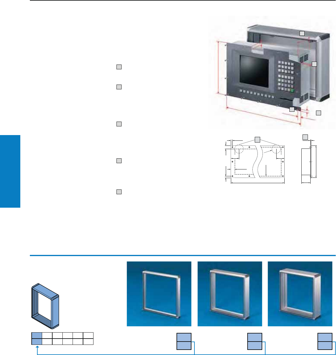
Operator Interface
96 Industrial Buyer’s Guide
Optipanel
Optipanel
Selection: Operator Housing/Keyboard Housing
1. Panel dimensions
1.1 For Operator housings and
1.2 For keyboard housings
On the order form, please state the Height (H) x Width (B) x Depth (T)
of the control components and the manufacturer/part.
(See installation criteria).
Checking the
installation criteria
Please check whether your
operator panel may be installed
directly into the Optipanel.
Subject to compliance with the
criteria, front panels/panels may
be mounted directly with the
appropriate mounting kits,
see www.rittal-corp.com. Otherwise,
an adaptor panel will be required,
see 2.2, design code 2.
The dimensions of the operating
and keyboard housing are
derived from the dimensions of
your panel and the number of
cross members.
Note:
Different widths of operator and
keyboard housings are possible
(whereby only the keyboard
housing may be wider than the
Operator housing).
For minimum size, refer to minimum
front panel width under
technical details, at
www.rittal-corp.com.
10.3 to 0.5” (7 to 13 mm) edge
spacing of the mounting
holes or bolts.
2Front panel projection
on sides with mounting
holes and bolts at least
0.7" (17 mm), on sides
without attachments at
least 0.2" (6 mm).
3Front panels up to
0.2" (5 mm)
From a thickness of approx.
0.1" (3.5 mm) the front panel
is flush with the sealing trim
and the enclosure front.
4Installation depths:
Operator housing = 2.0,
3.9, 5.9" (50, 100, 150 mm).
Keyboard housing = 2.0, 3.9"
(50, 100 mm).
5 For versions with a hinged
rear panel with cam fastener,
the maximum installation
depth is reduced by 1.1"
(27 mm in the vicinity of
the lock).
1
1
T
H
B
3
H
B1
2
3
4
2.1 2.2 2.3 2.4 2.5 2.6
2.1 Installation depth
2.1
1
2.1
2
2.1
3
2.0" (50 mm) 3.9" (100 mm) 5.9" (150 mm)
For additional technical
information, please visit
www.rittal-corp.com
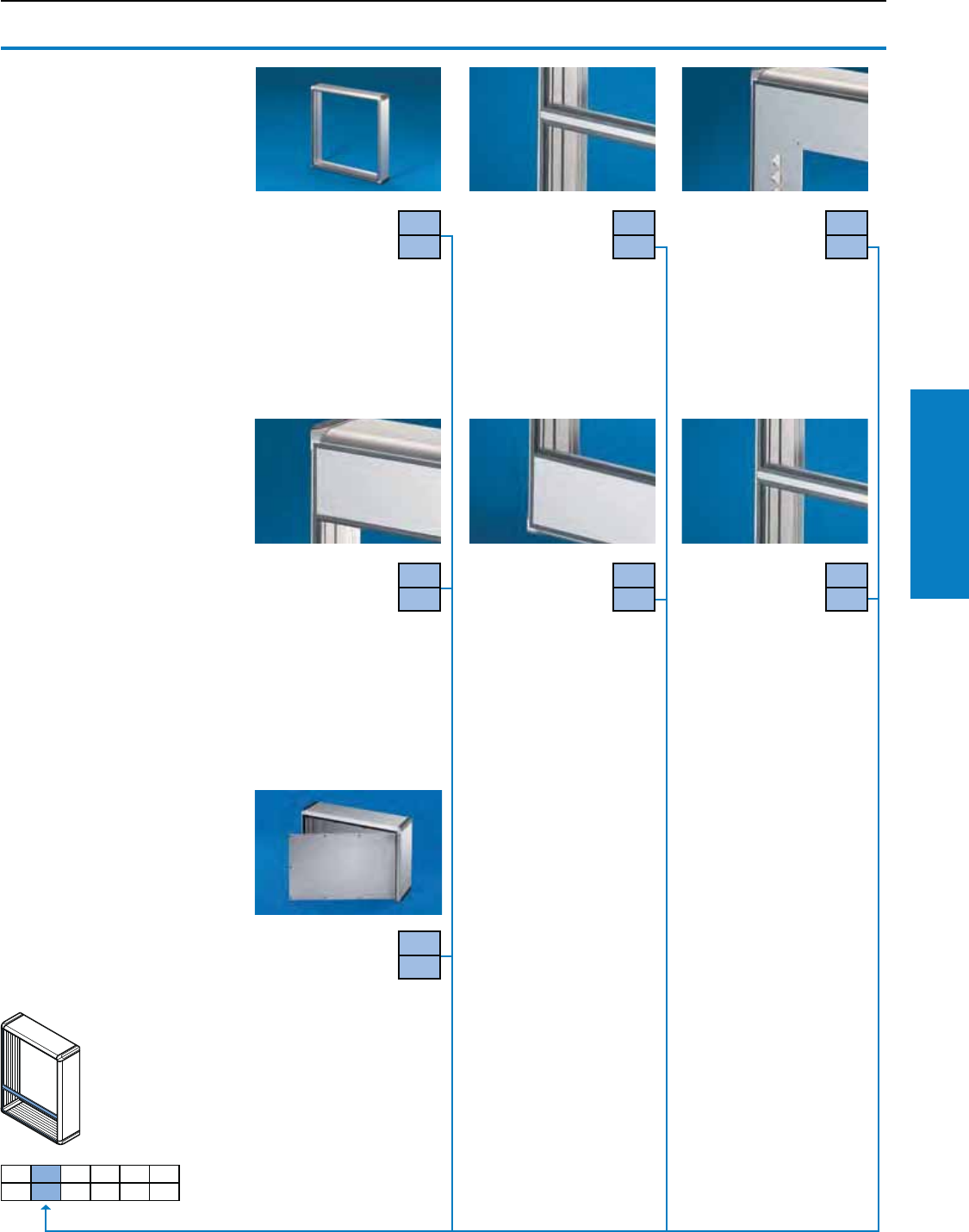
Operator Interface
Industrial Buyer’s Guide 97
Optipanel
Optipanel
Selection: Operator Housing/Keyboard Housing
2.2 Front design
Also required:
Mounting kit for installing front
panels, operator panels and
keyboards in operator and
keyboard housings.
1) Suitable quantity for sealing
the individual separation points.
For example: 3 front panels in
Operator housing = 2
separation points = 2 cross
members/sealing bars included
with the supply.
Other combinations available
on request.
2) Screw-fastened from the
inside, with cam or l/h hinge
on request.
3) Detailed drawing,
see www.rittal-corp.com.
Without cross
member 2.2
0
With cross member1)
For horizontal and/or
vertical division of the
Operator housing front.
With mounting channel on
both sides to accommodate
mounting kits, see www.rittal-
corp.com
Material:
Extruded Aluminum section,
natural-anodized
2.2
1
With an adaptor
plate
(to specification)
Material thickness:
0.1" (3 mm) Aluminum,
natural-anodized.
Please specify the dimensions
for the front panel and the
desired holes and cut-outs.
With spacing and
built-in trim panel3),
at the top
For additional space
for cable entry and for
installing switches/indicator
lights, emergency off/key
switches, CD-ROM/disk
drives, interfaces, etc.
Material:
Extruded Aluminum section,
natural-anodized
2.2
3
With spacing and
built-in trim panel3),
at the bottom*
For additional space
for cable entry and for
installing switches/indicator
lights, emergency off/key
switches, CD-ROM/disk
drives, interfaces, etc.
Material:
Extruded Aluminum section,
natural-anodized
2.2
4
With sealing bar1)
For horizontal and/or
vertical division of
Operator housings.
The "slot-free" division
produces a height gain of
0.9" (22 mm).
Material:
Extruded Aluminum section
0.3 x 0.8" (8 x 20 mm),
natural-anodized
2.2
5
With front panel
hinged2)
For example, if a disk
drive built into the
operator panel requires such
free access, see www.rittal-
corp.com.
Standard design:
• Screw-fastened from the
outside
• Right hand hinge
Material:
Front panel: 0.2" (3 mm)
Aluminum, natural-anodized.
Extruded Aluminum section:
Natural-anodized
2.2
6
2.2
2
2.1 2.2 2.3 2.4 2.5 2.6
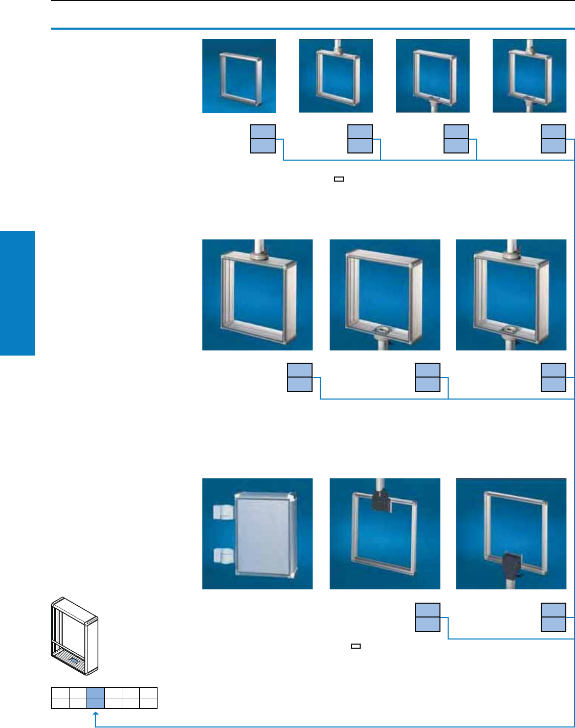
Operator Interface
98 Industrial Buyer’s Guide
Optipanel
Optipanel
Selection: Operator Housing/Keyboard Housing
2.3 Support arm
wall and pedestal
connection
Also required:
Support arm components for
connection of the Optipanel to
the support arm system
CP-S1), CP-L,
see page 116.
Stand systems,
see page 160-164.
Without
connection 2.3
0
2.3
1
2.3
2
2.3
3
Connection
top1)
Connection
bottom1)
Connection
top and
bottom1)
CP-L 4.7 x 2.6" (120 x 65 mm) for
housing coupling 6525.110,
enclosure attachment 6525.610,
housing coupling CP-S, 6501.130
only applies to installation depth
3.9" (100 mm)
Connection top1) 4) Connection
bottom1) 4)
Connection
top and bottom1) 2) 4)
2.3
4
2.3
5
2.3
6
1) For support arm system
CP-S, steel, for installation
depth 3.9" (100 mm) and 5.9"
(150 mm), please add an S
after the design code number.
2) Including a cover plate for
sealing the unused section.
3) Unless otherwise specified,
will be supplied in RAL 7024
(graphite gray)
4) Support arm connection
CP-L Ø 5.1" (130 mm) for
housing coupling 6525.110,
enclosure attachment 6525.610,
angle coupling 6526.010
only applies to installation depth
5.9" (150 mm)
2.3
7
2.3
8
Note:
Wall mounting possible:
hinged with 6016.200,
see www.rittal-corp.com.
Connection rear,
top3)
Connection rear,
bottom3)
CP-L 4.7 x 2.6" (120 x 65 mm) for
housing coupling 6525.110,
enclosure attachment 6525.610,
enclosure attachment, tilting 6902.640/.670,
housing coupling CP-S, 6501.130
only applies to installation depth 2.0" (50 mm)
2.1 2.2 2.3 2.4 2.5 2.6
For additional technical
information, please visit
www.rittal-corp.com
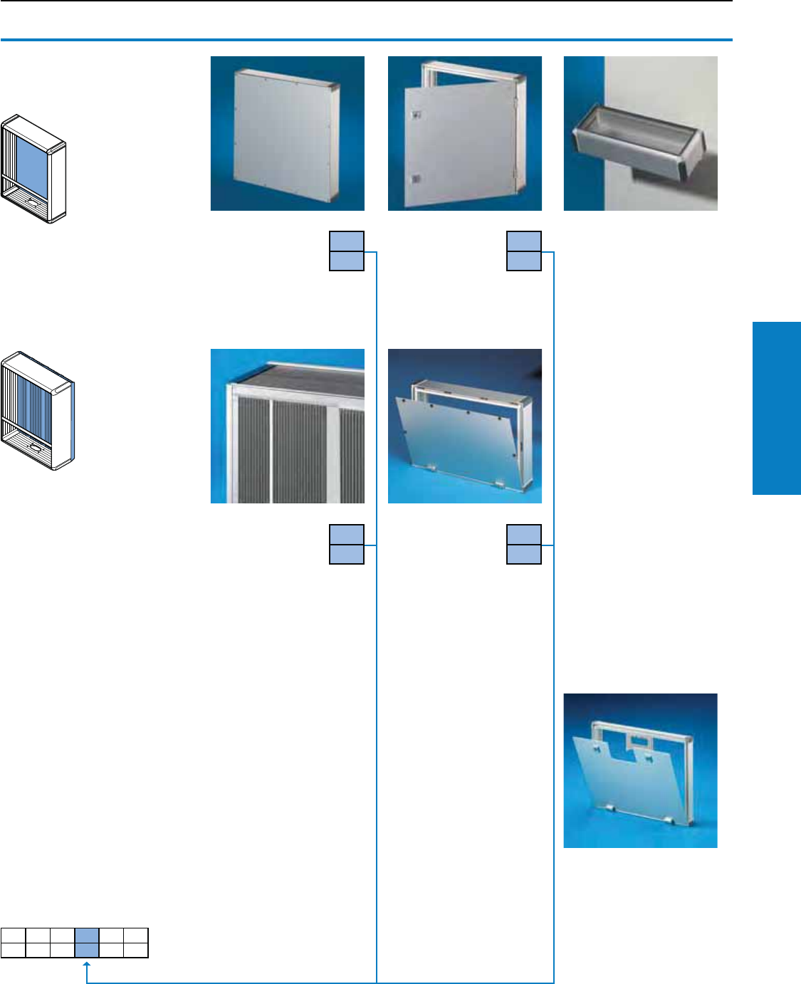
Operator Interface
Industrial Buyer’s Guide 99
Optipanel
Optipanel
Selection: Operator Housing/Keyboard Housing
2.4
1
Rear panel
screw-fastened
Rear panel hinged
on the longest edge
Viewed from the rear,
hinged on the right
or at the bottom1) 2) 3).
2.4
2
Example of the versatility
of the enclosure:
Mounting on doors
With all operator/keyboard
housings, the rear panel
may be supplied prepared
for external mounting on flat
surfaces on request.
Also required:
Enclosure duct connector
6006.000, see www.rittal-
corp.com. For mounting and
cable entry.
Rear cooling panel,
modular
Increases the
dissipation of
heat loss from the enclosure
by approx. 10%.
Guidelines for dissipatable
heat loss, see www.rittal-corp.
com.
Material:
Extruded Aluminum section
Note:
When installing the pull-out
keyboard 6002.110 in an
Optipanel, design variant 2.1,
no. 3, the cooling fins and
screw channels protruding
0.4" (11 mm) into the
enclosure may be milled off
in this area – please specify
when ordering.
2.4
3
Rear panel hinged
with quick-release
fasteners1)
2.4
4
1)
2.1 2.2 2.3 2.4 2.5 2.6
For additional technical
information, please visit
www.rittal-corp.com
2.4 Rear panels
Note:
1) With a support arm
connection at the rear, only
possible on the side opposite
the support arm connection.
2) Standard double-bit lock
insert may be exchanged for
1.6" (41 mm) lock inserts, type
C, plastic handles and lever
handles, type C, see www.
rittal-corp.com.
3) With a hinged rear panel, the
maximum installation depth
in the vicinity of the lock is
reduced by 1.1"
(27 mm) (see page 96,
drawing point "5").
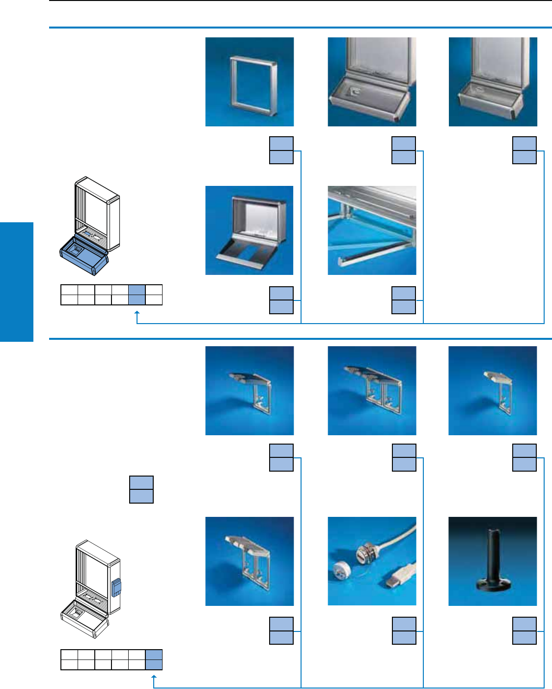
Operator Interface
100 Industrial Buyer’s Guide
Optipanel
Optipanel
Selection: Operator Housing/Keyboard Housing
2.5
0
Without
keyboard
housing
With keyboard
housing
installation
depth 2.0"
(50mm)1)
2.5
1
With keyboard
housing instal-
lation depth 3.9"
(100 mm)1)
2.5 Keyboard
housing
Also required:
1) Mounting kit for installing
front panels, operator panels
and keyboards in operator
and keyboard housings.
2) With a support arm
connection at the
bottom, from depth 5.9"
(150 mm), swivelling
is only supported
in conjunction with
enclosure attachment
CP-S (6501.070),
enclosure attachment
CP-L for support
arm connection 4.7
x 2.6" (120 x 65 mm)
(6525.610). When
mounting beneath
surfaces, the bars may
alternatively be pushed
towards the rear.
2.5
3
2.5
4
With support
for keyboards
Utility bars,
vertically hinged
With cable entry
grommet2)
2.1 2.2 2.3 2.4 2.5 2.6
2.6 Integration
of accessories
In addition to the design
code, you should also
indicate the position or
enclose a sketch.
1) Interface inserts may
be found on page 225,
these may also be fitted
by specifying the Part No.
and position.
Interface ap,
single, with
plastic ap1)
from installation
depth of 3.9" (100 mm).
Interface ap,
double, with
plastic ap1)
only possible in
the front panel, spacer
and built-in trim panel or
rear panel.
Interface ap,
single, with
metal ap1)
from installation
depth of 3.9" (100 mm).
Interface ap,
double, with
metal ap1)
only possible in
the front panel, spacer
and built-in trim panel or
rear panel.
2.6
4
2.6
5
USB/RJ 45
extension
For order
information,
refer to page 226.
2.1 2.2 2.3 2.4 2.5 2.6
2.5
2
2.6
0
Without
accessories
2.6
1
2.6
2
2.6
3
Mounting
preparations for
signal pillars
Mounting
component, Signal
pillars, modular, see
www.rittal-corp.com.
2.6
6
For additional technical
information, please visit
www.rittal-corp.com
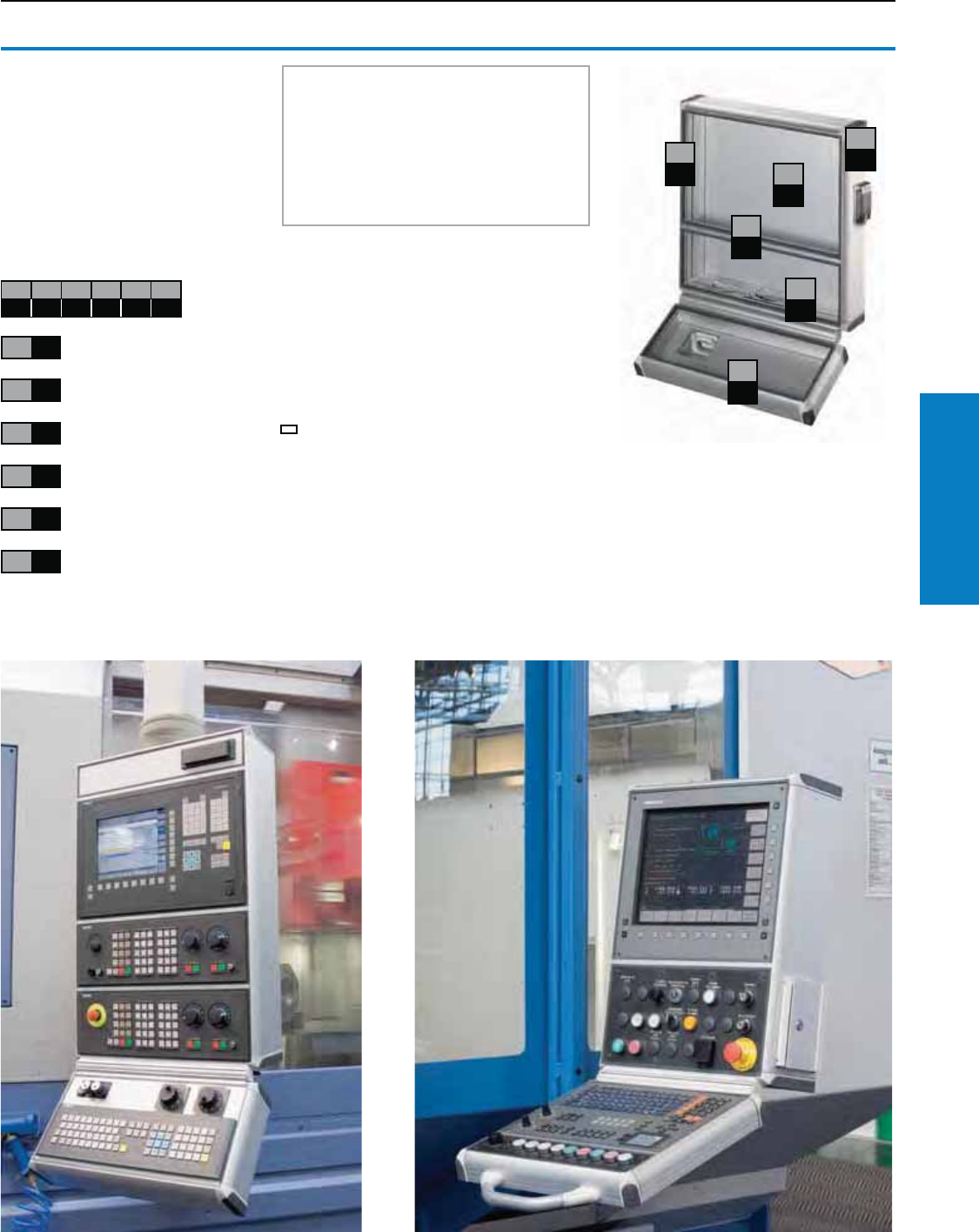
Operator Interface
Industrial Buyer’s Guide 101
Optipanel
Optipanel
Selection: Operator Housing/Keyboard Housing
Example
The picture opposite shows the solution
we have chosen, together with its
corresponding design code number.
The following key explains how the code
number in our example is made up.
Operating/
keyboard housing
Part No.: 6372.009
2.1 2.2 2.3 2.4 2.5 2.6
212111
Design code number:
2.1 2
2.2 1
2.3 2
2.4 1
2.5 1
2.6 1
Operator housing,
installation depth 3.9" (100 mm)
With one cross member
Support arm connection, CP-L
4.7 x 2.6" (120 x 65 mm), bottom
Rear panel, screw fastened
With keyboard housing,
Installation depth 2.0" (50 mm)
Fitted interface flap
We need the following three pieces
of information to process your order:
• Part No.: 6372.009
• The dimensions and number of
panels/front panels to be installed in
the keyboard/Operator housing
• Design code number
Note:
If the design code number does not cover
your requirements, please enter an X and
enclose a written explanation.
2.1
2
2.2
1
2.3
2
2.4
1
2.5
1
2.6
1
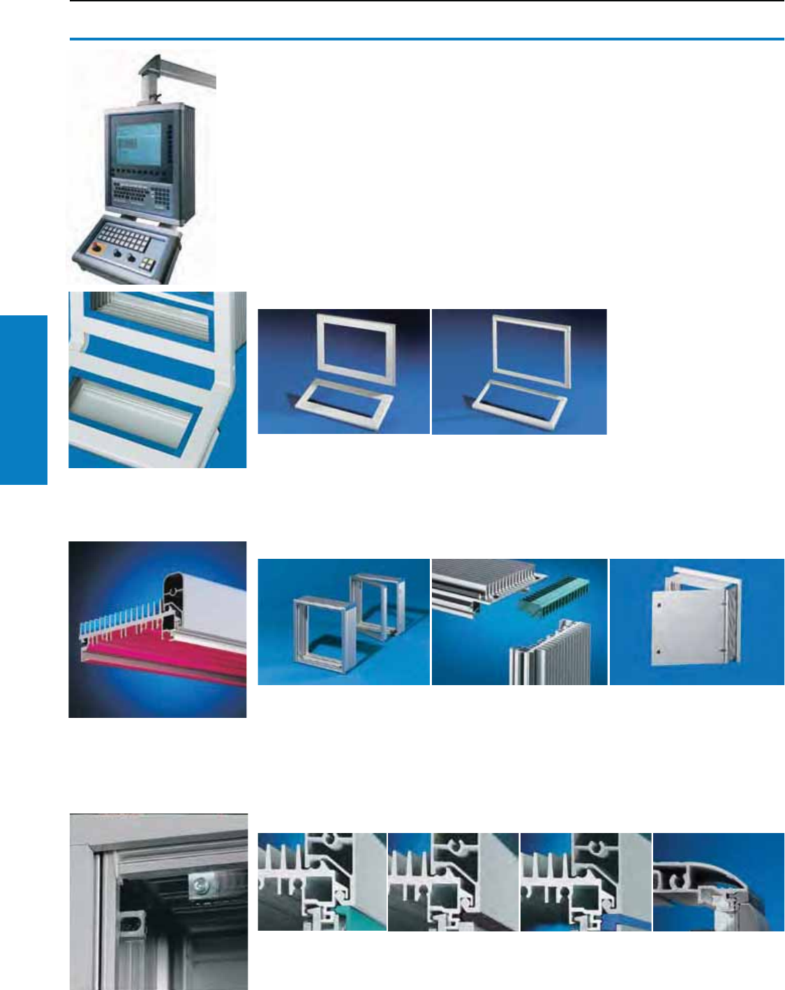
Operator Interface
102 Industrial Buyer’s Guide
Command Panel VIP 6000
Command Panel VIP 6000
Features
The VIP 6000 is available in three customizable designs that give you the ability to tailor the design of
your operator interface enclosure exactly to your requirements.
Property rights for frames:
German patent
no. 195 25 8 76
German patent
no. P 41 09 695
European patent no. 0 505 681
with validity for DE, FR, GB, IT
European patent no. 0 839 299
with validity for FR, GB, IT
Jap. patent no. 3199745
Jap. patent no. 3221506
South Korean patent
no. 97-70 77 12
US patent no. 5,921,050
German registered design
no. M 94 02 325
IR reg. design no. DM/053 168
with validity for BE, CH, FR,
IT, NL
Austral. reg. des. no. 125352
Japan. reg. design no. 983 783
Austrian registered design
no. 17467
Swedish registered design
no. 58 996
UK reg. des. no. 2047055
US design patent
no. des. 375,726
Brazilian design pattern
no. DI 5500 709-0
Approvals,
see www.rittal-corp.com.
Wide frame
A frame and handle in one; the
ideal choice where enclosures
with fins all round are used for
better heat dissipation.
Narrow frame
An eye-catching design with its
stylish lines, particularly for
small enclosures
There is a choice of five
installation depths –
6.1, 7.3, 11.6, 12.9 and
17.2" (155, 185, 295, 328
and 438 mm). Either screw
fastened or hinged, depending
on requirements.
Because it is equipped with
cooling fins, the VIP 6000
enclosure often eliminates
the need for active cooling
components.
Screw-fastened or vertically/
horizontally hinged – choose the
rear panel to suit your servicing
requirements.
Customized design lines
Enclosure/rear panels
Attachment/trim
Each attachment point
all round is achieved
with sliding retaining
claws.
The screw heads disappear stylishly beneath the cover trim (A). Front
panels with threaded bolts may also be combined with the end trim (B) or
spacer trim (C). Panels with screw clamp (D) are mounted with the end
trim.
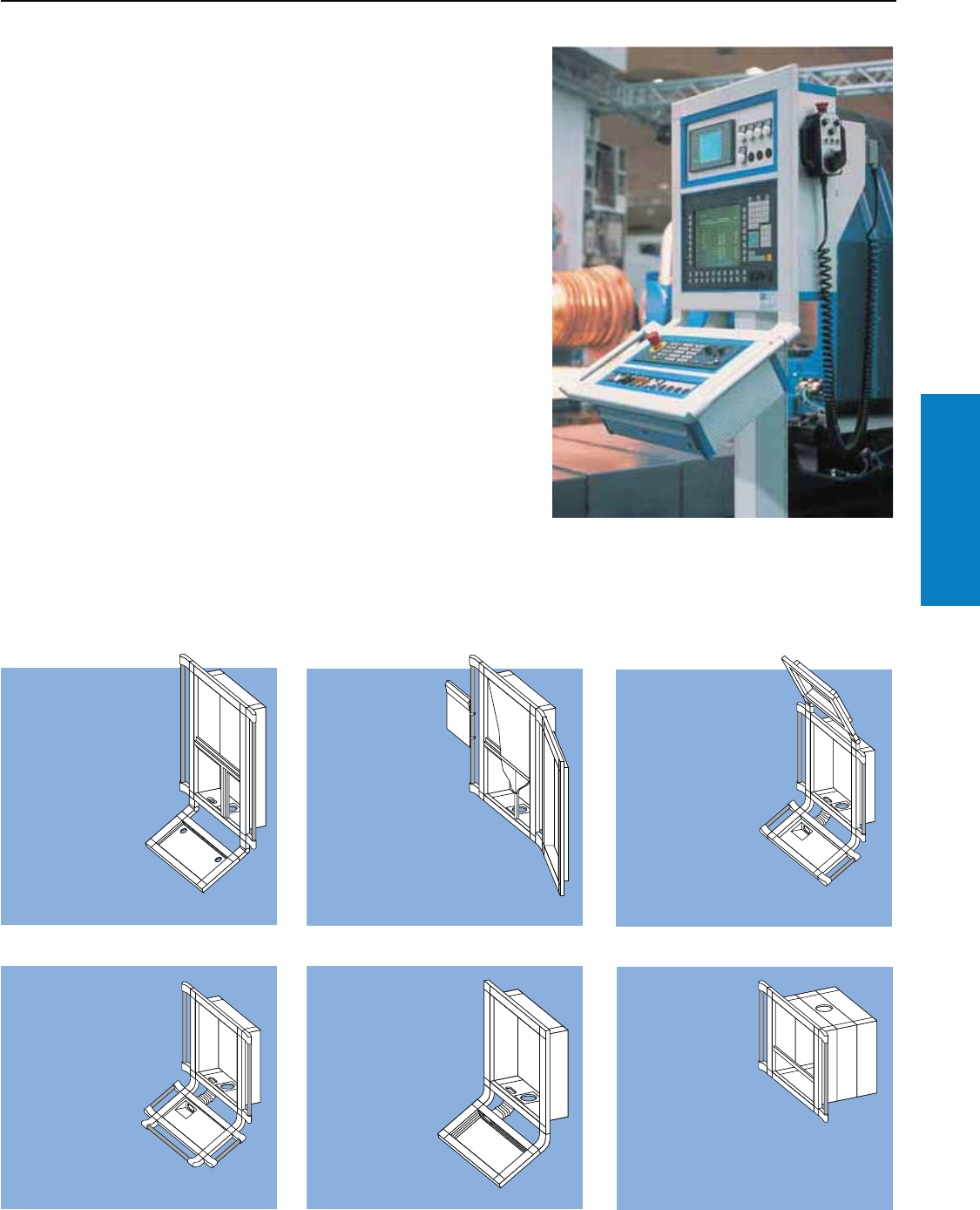
Operator Interface
Industrial Buyer’s Guide 103
Command Panel VIP 6000
Command Panel VIP 6000
Conguration Examples
Explore the Possibilities
Choose from a variety of different styles and configurations and
add your unique customizations to design the perfect enclosure.
Example A
• Operator
housing, 6.1"
(155 mm) deep
• Support for
keyboards with
cable entry
grommet
• Frame connector,
adjustable
• Vertical handle
set
• With vertical and
horizontal cross
member
• Support arm connection at the bottom
Example B
• Operator
housing, 6.1"
(155 mm) deep
• Side keyboard
housing, 1.7"
(44 mm) deep
• Frame connector,
rigid
• Vertical handle set
with clipboard
• With horizontal cross
member and vertical
sealing bar
• Support arm connection
at the bottom
Example C
• Operator housing,
6.1" (155 mm) deep
• Keyboard housing at
top, 1.7"
(44 mm) deep, with
frame connector,
adjustable
• Keyboard housing
at bottom, 1.7"
(44 mm) deep,
with frame
connector, rigid
• Cable tube, flexible
• Vertical handle sets
• Support arm connection at the bottom
Example D
• Operator housing,
6.1" (155 mm) deep,
with vertical handle
set
• Keyboard housing with
handle set horizontal
and vertical
• Cable tube,
flexible
• Support arm
connection at
the bottom
Example E
• Operator housing, 6.1"
(155 mm) deep
• Keyboard housing,
4.1" (105 mm) deep
• Frame connector and
cable tube, flexible
• Support arm
connection at the
bottom
Example F
• Operator
housing, 17.2"
(438 mm) deep,
e. g., for color
screen
• With vertical
handle set
• With horizontal
sealing bar
• Support arm
connection, top
Wide Frame
Attractive and functional, a wide frame is important for enclosures that incorporate cooling fins.
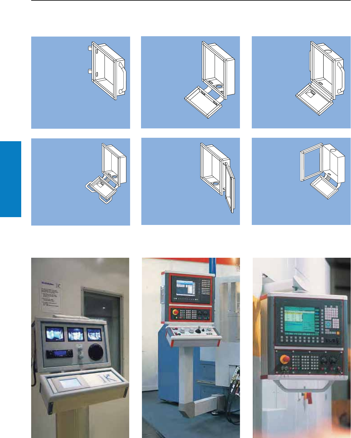
Operator Interface
104 Industrial Buyer’s Guide
Command Panel VIP 6000
Command Panel VIP 6000
Conguration Examples
Narrow Frame
Aesthetic design suitable for smaller enclosures and those without cooling fins.
Example G
• Operator housing,
6.1" (155 mm)
deep
• With U handle,
vertical
• Enclosure
connector,
adjustable, on the
left-hand side for
vertically hinged
wall mounting
Example I
• Operator housing,
6.1" (155 mm) deep
• Keyboard housing,
1.7" (44 mm) deep
• Hinged frame
connector
• U handles, vertical
• Cable tube,
flexible
• Support arm
connection,
top
Example H
• Operator housing,
6.1" (155 mm) deep
• Keyboard housing,
4.1" (105 mm) deep
• Enclosure duct
connector
• Support arm
connection at the
bottom
Example J
• Operator housing,
• 6.1" (155 mm) deep
• Keyboard housing,
• 1.7" (44 mm) deep
• With enclosure bar
connector
• With corner
handles
• Cable tube,
flexible
• Support arm
connection at the bottom
Example K
• Operator housing,
6.1" (155 mm) deep
• Keyboard housing,
1.7" (44 mm) deep
• Enclosure bar
connector
• Support arm
connection at the
bottom
Example L
• Operator
housing, 7.3"
(185 mm)
deep, hinged
• Keyboard
housing, 1.7"
(44 mm) deep
• Enclosure bar
connector
• Cable tube, flexible
• Support arm connection, top
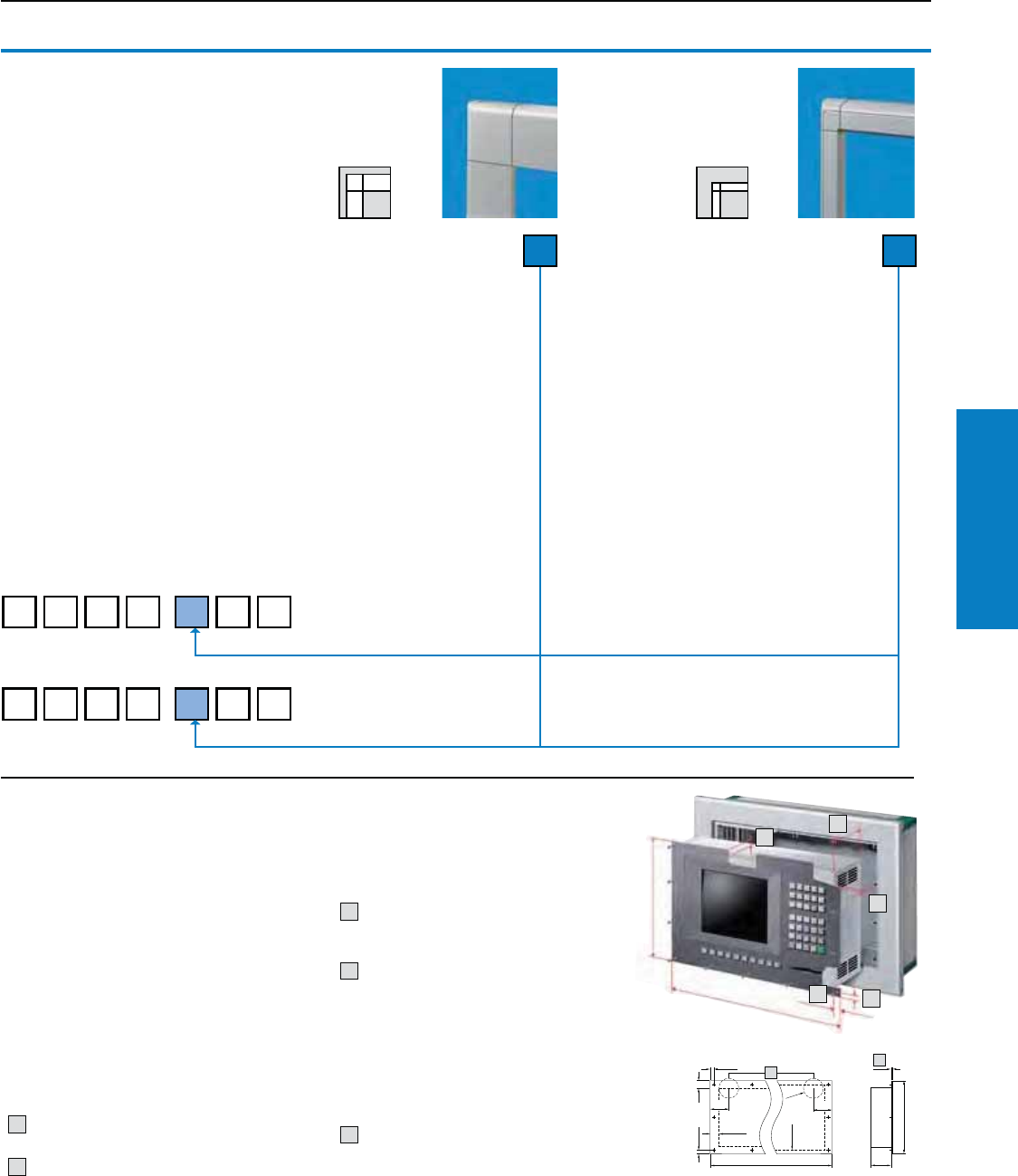
Operator Interface
Industrial Buyer’s Guide 105
Command Panel VIP 6000
1
1
H
BT
3
Command Panel VIP 6000
Selection: Operator Housing/Keyboard Housing
.009 .209
B
H
6 3 9 2 0 9
.
We need the following
information in order to deal
with your enquiry/order:
• Part No. front frame:
6392.X09
• The dimensions and
number of panels/front
panels to be installed in
the operating/ keyboard
housing
• Design code number for
the operator/keyboard
housing
Protection Ratings:
NEMA 4 (IP 65) (if the opening
in the enclosure is covered or
sealed in accordance with the
Protection Ratings).
1. Front frame
Select the frame to match your
requirements. It is automatically
used for a keyboard housing
as well.
Part No.
Command Panel
Part No.
Keyboard Housing
6 3 5 1 0 9
.
Wide frame
Extruded Aluminum
section
Die-cast zinc corner pieces
Color: RAL 7035 (light gray)
Finely-textured
Note:
Other RAL colors
available upon request.
0 2
Narrow frame
Extruded Aluminum
section
Die-cast zinc corner pieces
Note:
For visual reasons, only
enclosures without fins or
with fins at the sides should
be mounted here.
2. Panel dimensions
2.1 For Operator housings 6392.X09 and
2.2 For keyboard housings 6351.X09
On the order form, please state the width (B) x height (H) x depth (T) of the control components
and the manufacturer/Part, with due regard for the installation criteria (see below).
Checking the installation
criteria
Subject to compliance with
criteria 1 – 4, front panels/ panels may be
mounted directly with the appropriate
mounting kits. Otherwise, an adaptor panel is
needed – see 3.2, design code number "6",
page 107. The dimensions of the operator
panel and keyboard housing are
derived from the dimensions of your panel and
the number of cross members.
10.3 to 0.5" (7 to 13 mm) edge spacing of
the mounting holes or bolts.
2Front panel projection
on sides with mounting holes or bolts
at least 0.7" (17 mm), on sides without
attachments at least 0.2" (6 mm).
3Front panel thickness
varies according to the type of trim
section, see page 108, version 3.4.
4 Installation depths:
Command Panels = 6.1, 7.3, 11.6,
12.9, 17.2" (155, 185, 295, 328, 438 mm).
Command Panels with 1.77" (45 mm)
deep rear panel1) = 7.9, 9.1, 13.4, 14.7, 19.0"
(200, 230, 340, 373, 483 mm).
Command Panels with 9.7" (245 mm)
deep rear panel1) = 15.8, 16.9, 21.3, 22.6, 26.9"
(400, 430, 540, 573, 683 mm).
5For versions with a hinged rear panel,
the maximum installation depth is reduced
by 1.1" (27 mm) in the vicinity of the lock.
1) Other depths available on request.
Note: Load information for installed equipment, see
www.rittal-corp.com.
2
2
4
3
1
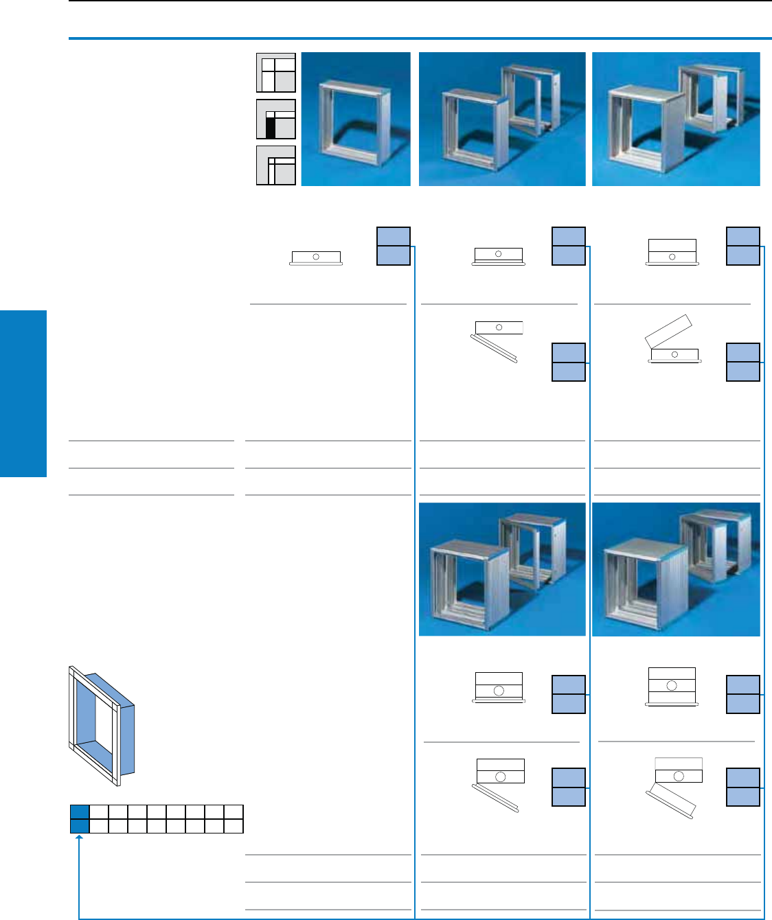
Operator Interface
106 Industrial Buyer’s Guide
Command Panel VIP 6000
Command Panel VIP 6000
Selection: Operator Housing
3.1 Installation depth
Material:
Enclosure:
Extruded Aluminum section
Corner protectors:
Plastic, self-extinguishing
Finish:
Enclosure: Natural anodized
Note:
Support arm connection see 3.6.
Drawing view from above.
Right hand hinge is also possible.
Installation depth 6.1"
(155 mm)
Installation depth 7.3"
(185 mm)
Installation depth 11.6"
(295 mm)
Support arm system
CP-L
Support arm system
CP-XL
prepared
with adaptor
6528.510
prepared
with adaptor
6528.510
prepared
with adaptor
6528.510
Support arm system
CP-L
Support arm system
CP-XL
prepared
with adaptor
6528.5102)
prepared
with adaptor
6528.5102)
screw-fastened screw-fastened screw-fastened
hinged1) hinged1)
screw-fastened screw-fastened
hinged1) hinged1)
Installation depth 12.9"
(328 mm)
Installation depth 17.2"
(438 mm)
3.1
1
3.1
2
3.1
4
3.1 3.2 3.3 3.4 3.5 3.6 3.7 3.8 3.9
3.1
3
3.1
5
3.1
6
3.1
8
3.1
7
3.1
9
1) Cam lock with double-bit lock
insert, may be exchanged for
1.6" (41 mm) lock inserts, type C.
2) Provided the admissible load
capacity of the support arm system
is adequate.
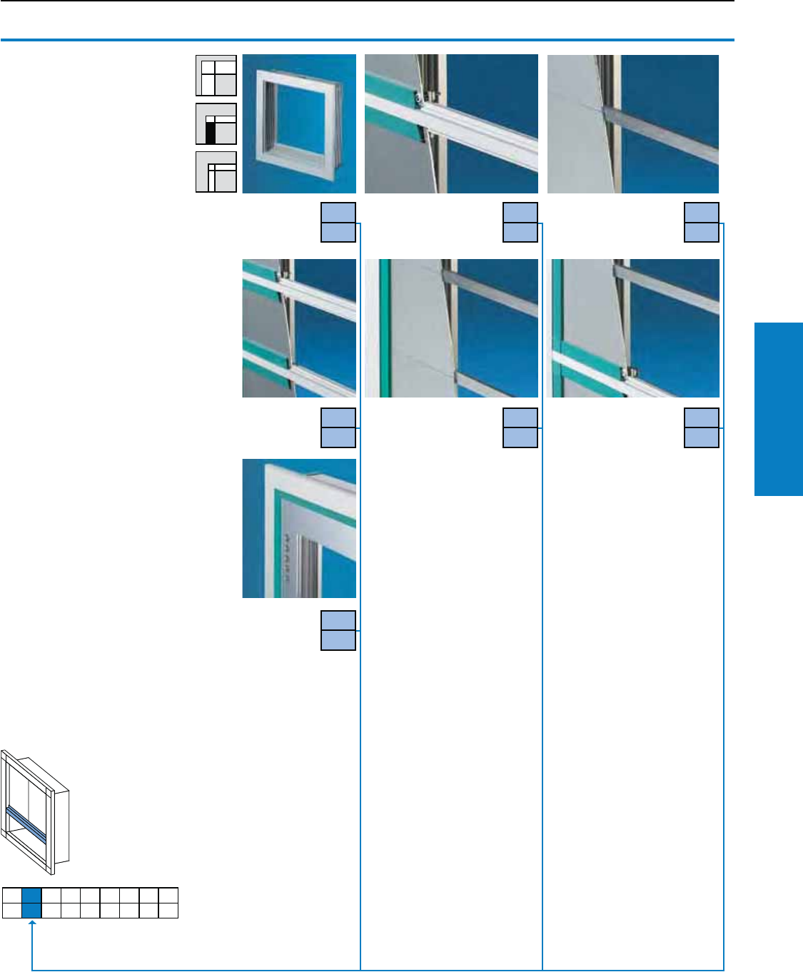
Operator Interface
Industrial Buyer’s Guide 107
Command Panel VIP 6000
Command Panel VIP 6000
Selection: Operator Housing
3.2 Front design
Cross member
For horizontal and/or vertical
division. With channel on both
sides for mounting kits.
Material:
Extruded Aluminum section,
RAL 7035 (light gray)
Sealing bar
For horizontal and/or vertical
division. The "slot-free" division
produces a height gain of 1.1"
(28 mm).
Material:
Extruded Aluminum section
0.3 x 0.8" (8 x 20 mm), natural
anodized
Adaptor plate
Material thickness:
0.1" (3 mm) Aluminum,
natural anodized.
Please specify the dimensions
for the front panel and the
desired holes and cut-outs.
Spacing and
built-in trim panel
For additional space for cable
entry and for installing switches/
indicator lights, emergency off/
key switches, CD-ROM drives,
interfaces etc. With channel on
one side for mounting kits, see
www.rittal-corp.com.
Material:
Extruded Aluminum section,
natural anodized.
Also required:
Mounting kit for the installation of
front panels, operator panels
and keyboards in command
panels and keyboard housings.
3.1 3.2 3.3 3.4 3.5 3.6 3.7 3.8 3.9
3.2
0
Without
cross
member
With one cross
member 3.2
1
With one sealing bar1)
3.2
2
With two
cross
members
3.2
3
3.2
4
3.2
5
With two sealing bars1)
3.2
6
With one
adaptor
plate
To specifications
With one cross member
and one sealing bar1) 2)
1) Not possible with
spacer trim (see 3.4).
2) Unless otherwise specified:
Sealing bar at the top, cross
member at the bottom.
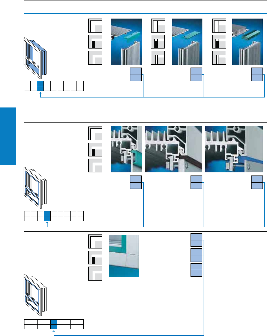
Operator Interface
108 Industrial Buyer’s Guide
Command Panel VIP 6000
Command Panel VIP 6000
Selection: Operator Housing
3.3 Cooling ns
Fins are selected according to the heat loss
to be dissipated.
Enclosures in installation depth 7.3 and 12.9" (185 and
328 mm) are directly behind the front frame at a depth
of 1.7" (44 mm), without fins. The color of the corner
protectors matches the trim color selected under 3.5.
No ns Fins at sides Fins all round
3.4 Trim types
Detailed drawings,
see www.rittal-corp.com.
Cover trim
To conceal
the front
panel
assembly screws.
For front panel
thickness up to
0.1" (3.5 mm.)
End trim
Attractively finishes
off the space between
the front panel and the
frame section. For all front panel
thicknesses. Only this trim may
be selected when installing
drawers.
Spacer trim
For installed equipment
flush with the frame
section. For front panel
thickness approx. 0.1" (3.5 mm).
3.5 Trim colors
Note:
Enclosure corner protectors are likewise
supplied in the chosen color. Other
colors available on request with
larger orders.
Turquoise
(similar to RAL 5018)
Bright blue
(similar to RAL 5005)
Graphite gray
(similar to RAL 7024)
3.1 3.2 3.3 3.4 3.5 3.6 3.7 3.8 3.9
3.3
1
3.3
2
3.3
3
3.1 3.2 3.3 3.4 3.5 3.6 3.7 3.8 3.9
3.4
1
3.4
2
3.4
3
3.1 3.2 3.3 3.4 3.5 3.6 3.7 3.8 3.9
3.5
1
3.5
2
3.5
5
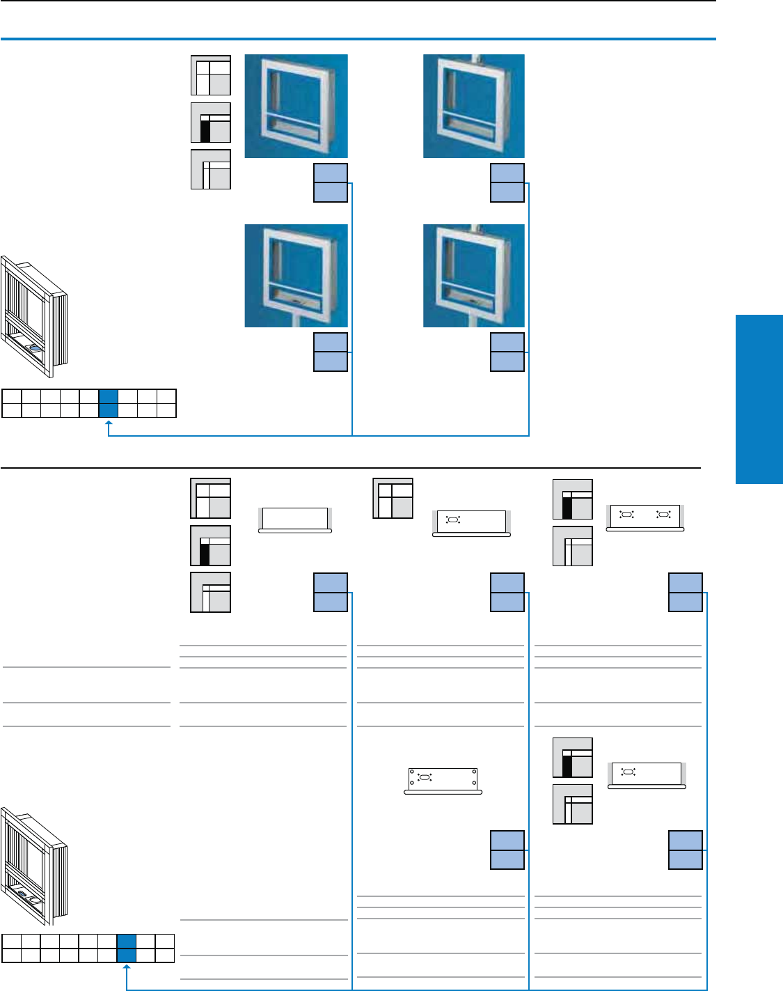
Operator Interface
Industrial Buyer’s Guide 109
Command Panel VIP 6000
Command Panel VIP 6000
Selection: Operator Housing
3.6 Support arm/
wall and pedestal
connection
3 different support arm systems,
see pages 118-159 and a
variety of stand systems,
see page 160-164.
Note:
Support arm connection CP-S
for small enclosures with an
installation depth of 6.51" (155
mm) are selected by adding an
"S" after the design code number.
Without
connection
Connection
top1)
Connection
bottom1)
Connection
top and
bottom1),
one cover
plate included
3.7 Preparation for
mounting keyboard
housings
Without
connection
to the
keyboard
housing
Connection with
hinged frame
connector, rigid or
adjustable
Connection with
enclosure duct
connector
Connection with
hinged frame
connector
–
–
–
–
–
4.1 (105)
1.7 (44)
1.1 (27)
Frame connector,
rigid/adjustable
rigid/flexible
4.1 (105)
–
–
Enclosure duct
connector
Enclosure
duct connector
4.1 (105)
1.7 (44)
Support for keyboards
Hinged
frame connector
flexible
To t
keyboard housing depth:
Connection of Operator housing to
keyboard housing:
(Selection 4.4, page 114)
Cable tube:
(Selection 4.5, page 115)
To t
keyboard housing depth:
Connection of Operator housing to
keyboard housing:
(Selection 4.4, page 114)
Cable tube:
(Selection 4.5, page 115)
3.1 3.2 3.3 3.4 3.5 3.6 3.7 3.8 3.9
3.6
0
3.6
1
3.6
2
3.6
3
1) Support arm connection
for the narrow variant of
connection plate 6528.420,
housing coupling for desktop
mounting 6528.400,
by additionally specifying the
code number: "A"
for the wide variant of
connection plate 6528.430,
housing coupling for desktop
mounting 6528.410,
by additionally specifying the
code number: "B"
3.1 3.2 3.3 3.4 3.5 3.6 3.7 3.8 3.9
3.7
0
3.7
1
3.7
2
–
1.7 (44)
–
Enclosure
bar connector
flexible
Connection with
enclosure bar
connector
3.7
3
3.7
4
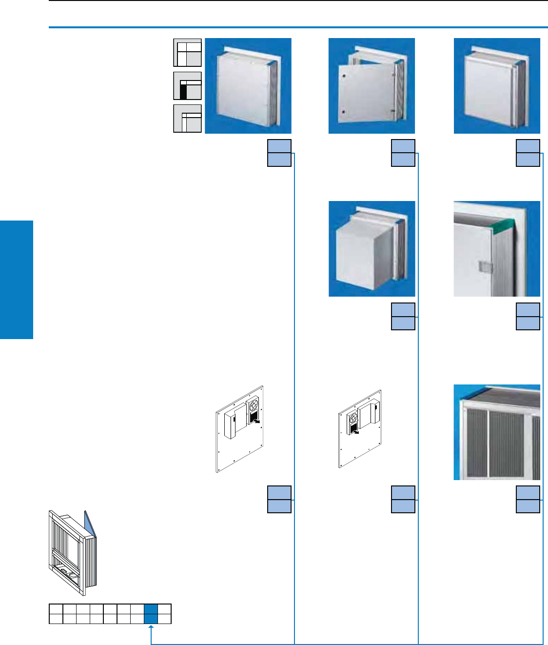
Operator Interface
110 Industrial Buyer’s Guide
Command Panel VIP 6000
Command Panel VIP 6000
Selection: Operator Housing
Screw-fastened
Material:
Aluminum,
natural anodized
3.8 Rear panels
Hinged1)
For rapid
service access
Material:
Aluminum,
natural anodized
1) On the longest side
(right/bottom), cam
with double-bit insert,
may be exchanged for
lock inserts 1.6"
(41 mm), type C, plastic
handles and T handles,
type C, see www.rittal-
corp.com.
2) For 19" (482.6 mm)/7 U
concave
3) When installing the
pull-out keyboard
6002.1X0 in the VIP
6000, design variant
3.1, no. 1, the cooling
fins and screw channels
protruding 0.4" (11 mm)
into the enclosure may
be milled off in this
area. Please state the
installation position when
ordering.
Depth plus
1.8" (45 mm)
hinged,
screw-fastening
Material:
Sheet steel, RAL 7035
(light gray)
3.8
1
3.8
2
3.8
3
Depth plus
9.6" (245 mm),
square2),
screw-fastened
Material:
Sheet steel, RAL 7035
(light gray)
3.8
4
3.8
5
Hinged1)
for heavy
installed
equipment
Material:
Aluminum,
natural-anodized
Screw-fastened
with built-in VIP
SK small
cooling unit,
condenser
assembly at the top left
Recommended for
Operator housing
design (see 3.1 from an
installation depth of
7.3" [185 mm])
Material:
Aluminum,
natural-anodized
3.8
6
Screw-fastened
with built-in VIP
SK small
cooling unit,
condenser
assembly at the
top right
Recommended for
Operator housing
design (see 3.1 from an
installation depth of
7.3" [185 mm])
Material:
Aluminum,
natural-anodized
.
3.8
7
Rear cooling
panel,
modular3)
Increases the
dissipation of heat loss
from the enclosure by
approx. 10%.
Material:
Extruded Aluminum
section,
natural-anodized
3.8
8
3.1 3.2 3.3 3.4 3.5 3.6 3.7 3.8 3.9
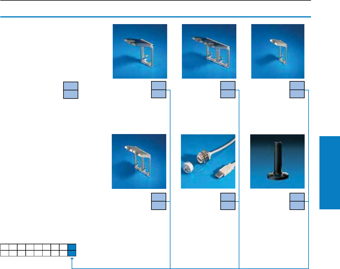
Operator Interface
Industrial Buyer’s Guide 111
Command Panel VIP 6000
3.9 Integration of
accessories
In addition to the design code, you should
also indicate the position or enclose a sketch.
1) Interface inserts may be found on page
225, these may also be fitted by specifying
the Part No. and position.
3.9
1
Without
accessories
Interface ap,
single, with
plastic ap1)
from installation
depth 4.4" (113 mm)
Interface ap,
double, with
plastic ap1)
only possible in
the front panel, spacer
and built-in trim panel or
rear panel
Interface ap,
single, with
metal ap1)
from installation
depth 4.4" (113 mm)
Interface ap,
double, with
metal ap1)
only possible in
the front panel, spacer
and built-in trim panel or
rear panel
3.9
4
USB/RJ 45
extension
For order
information,
refer to page 226.
Mounting
preparations
for signal
pillars, modular
Mounting component,
Signal pillars, modular,
see www.rittal-corp.com
Command Panel VIP 6000
Selection: Operator Housing
3.1 3.2 3.3 3.4 3.5 3.6 3.7 3.8 3.9
3.9
2
3.9
3
3.9
5
3.9
6
3.9
0
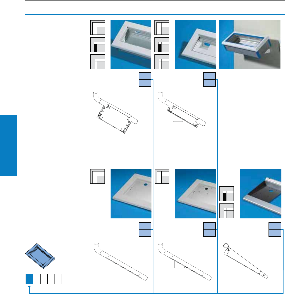
Operator Interface
112 Industrial Buyer’s Guide
Command Panel VIP 6000
Installation depth 4.1"
(105 mm) for built-in
keyboards
Installation depth 1.7"
(44 mm) for built-in
keyboards
Command Panel VIP 6000
Selection: Keyboard Housing
4.1 Keyboard
housing
Without fins.
For the internal or surface
mounting of keyboards.
All keyboard housings are
custom-produced to your
dimensions. When selecting
the wide front frame, the
width of the keyboard
housing depends on the
operating housing.
Material:
Extruded Aluminum section
Detailed drawing,
see www.rittal-corp.com
Also required:
Mounting kit for installing
front panels, operator panels
and keyboards in operator
and keyboard housings.
1) Only in conjunction with
hinged frame connector,
see 4.4 design code
number "5".
4.1
1
4.1
2
Example of the versatility
of the keyboard housing:
Mounting on doors
With all keyboard housings,
the rear panel may be supplied
prepared for external mounting
on flat surfaces on request.
Also required:
Enclosure duct connector
6006.000, for mounting and cable
entry.
Support for
keyboards with cable
entry grommet
4.1
3
4.1
4
4.1
5
Support for keyboards
with cable tube, exible
Support for keyboards
with cable entry
grommet1)
4.1 4.2 4.3 4.4 4.5
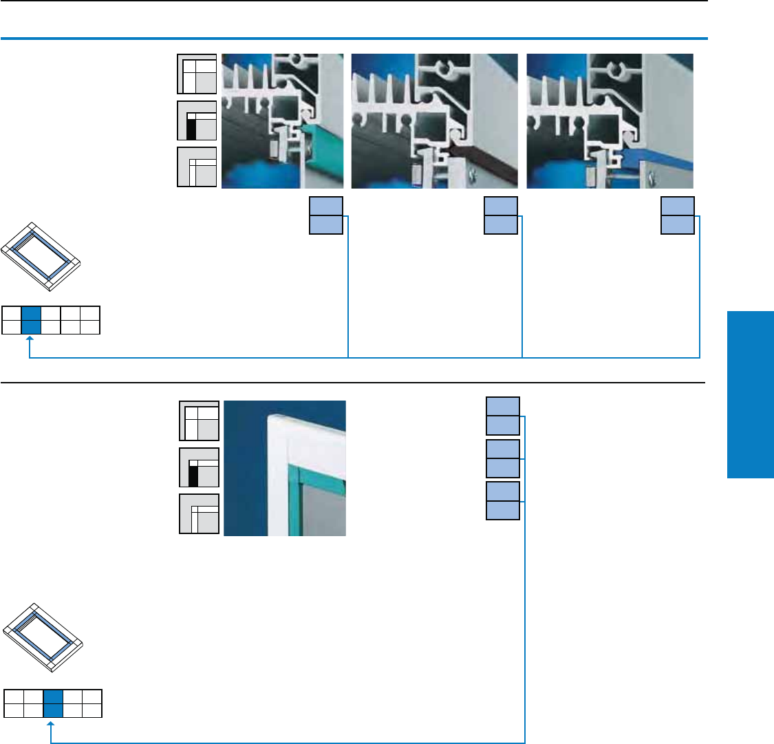
Operator Interface
Industrial Buyer’s Guide 113
Command Panel VIP 6000
Command Panel VIP 6000
Selection: Keyboard Housing
Cover trim
To cover the front
panel assembly
screws. For front
panel thickness
up to 0.1"
(3.5 mm).
End trim
Attractively finishes off
the space between the
front panel and the frame
section. For all front panel
thicknesses.
Spacer trim
For installed equipment
flush with the frame
section. For front panel
thickness approx. 0.1"
(3.5 mm).
Turquoise
(similar to RAL 5018)
Bright blue
(similar to RAL 5005)
Graphite gray
(similar to RAL 7024)
4.2 Trim types1)
Detailed drawing,
see www.rittal-corp.com
1) Selection not possible with
support for keyboards.
In such cases, please enter
an "X".
4.1 4.2 4.3 4.4 4.5
4.2
1
4.2
2
4.2
3
4.3 Trim colors1)
Note: Enclosure corner
protectors are likewise
supplied in the chosen color.
For larger orders, other colors
are available on request.
1) Selection not possible with
support for keyboards.
In such cases, please enter
an "X".
4.1 4.2 4.3 4.4 4.5
4.3
1
4.3
2
4.3
6
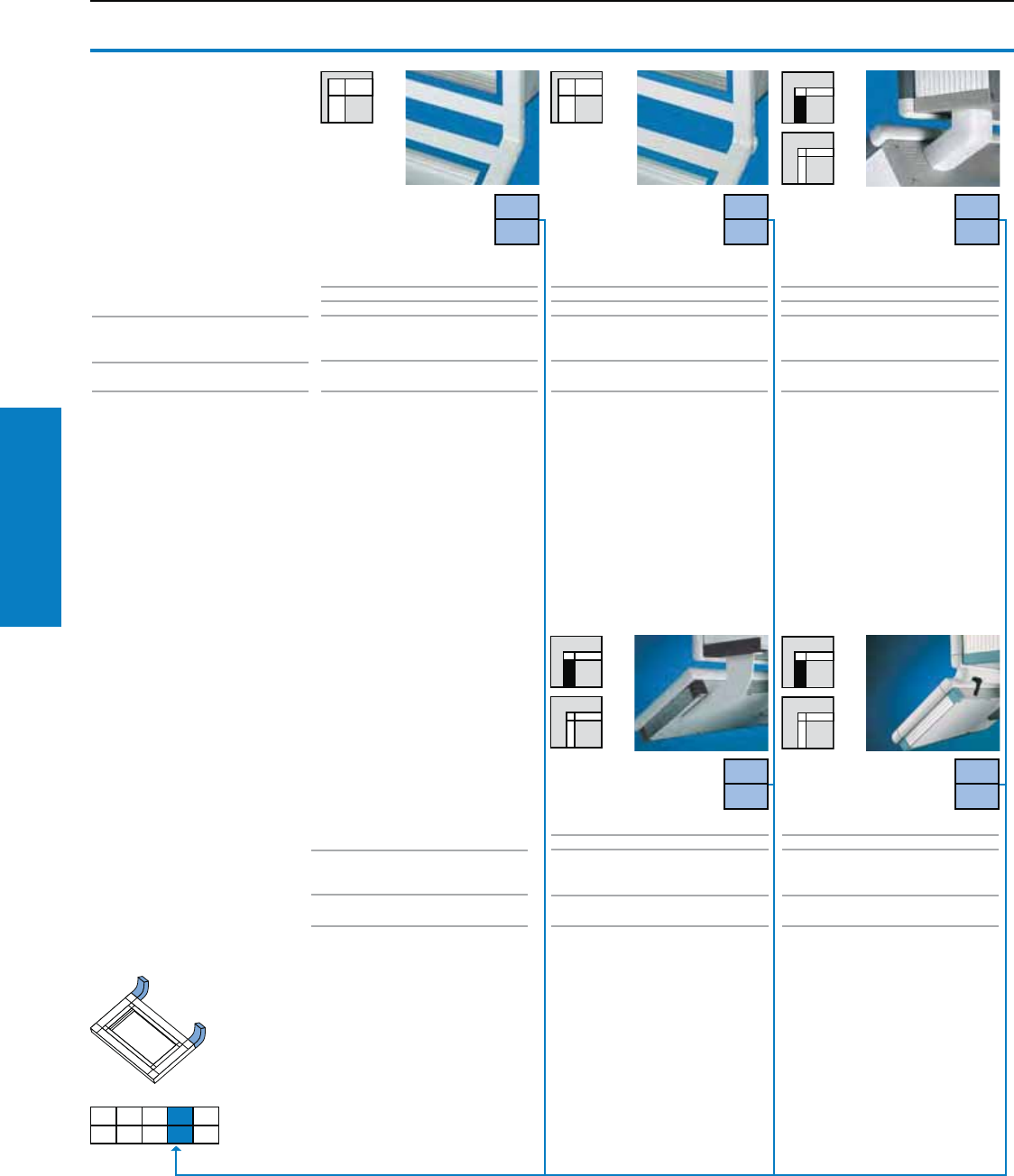
Operator Interface
114 Industrial Buyer’s Guide
Command Panel VIP 6000
Command Panel VIP 6000
Selection: Keyboard Housing
4.4 Keyboard
housing connector
With keyboard housing, supplied
loose to connect operator and
keyboard housings.
Frame Connector
(rigid)
Enclosure duct
connector
Hinged frame
connector
4.1" (105)
–
–
75 – 120°,
adjustable in 7.5° increments
See 4.5
4.1" (105)
–
–
120°, rigid
Integral
Keyboard housing depth:
Tilt
Cable tube:
Frame Connector
(adjustable)
4.1" (105)
1.7" (44)
Support for keyboards
120°, rigid
See 4.5
Keyboard housing depth:
Tilt angle:
Cable tube:
1.7" (44)
4.1" (105)
75 - 120°,
infinitely adjustable
See 4.5
To fit operator and keyboard
housings with a wide frame in the
same width.
Material:
Die-cast zinc, RAL 7035
(light gray)
To fit operator and keyboard
housings with a wide frame in the
same width.
Material:
Die-cast zinc, RAL 7035
(light gray)
To fit operator housings with
keyboard housings 4.1" (105 mm)
deep, also available in different
widths.
Material:
Aluminum, RAL 7035 (light gray)
To fit operator housings with
keyboard housings 1.7, 4.1"
(44, 105 mm) deep and support
for keyboards, also available in
different widths.
Material:
Aluminum, RAL 7035 (light gray)
–
1.7" (44)
120°, rigid
infinitely adjustable
See 4.5
To fit operator housings with
keyboard housings 1.7" (44 mm)
deep, also available in different
widths.
Material:
Sheet steel, RAL 7035 (light gray)
4.1 4.2 4.3 4.4 4.5
4.4
1
4.4
2
4.4
3
Enclosure bar
connector 4.4
4
4.4
5
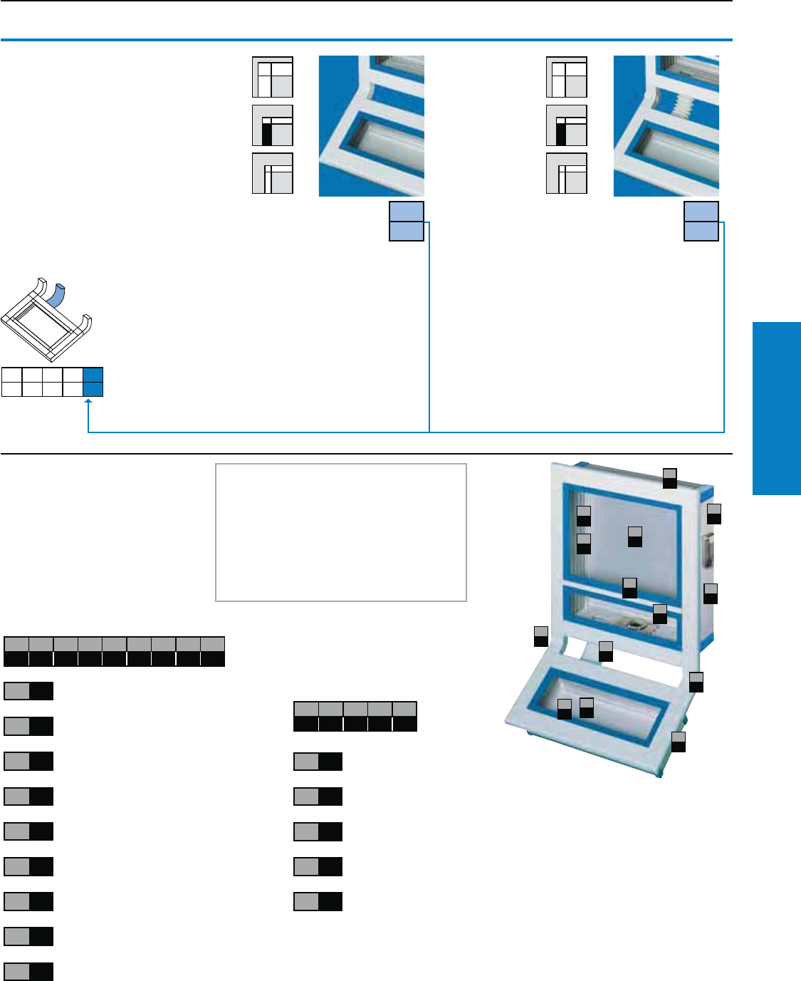
Operator Interface
Industrial Buyer’s Guide 115
Command Panel VIP 6000
Command Panel VIP 6000
Selection: Keyboard Housing
4.5 Cable tube
Without cable tube Cable tube, exible
Suitable for cable entry
when using the frame
connector, adjustable,
hinged frame connector or
enclosure bar connector.
Mounting on keyboard housings
with 4.1, 1.7 or 1.1"
(105, 44 or 27 mm) deep.
Material:
Plastic, RAL 7035 (light gray)
Note:
Not possible with:
4.1 Keyboard housing,
design code numbers 3 and 5.
Examples
The picture opposite shows the
solution we have chosen, together
with its corresponding design
code number. The following key
explains how the code number in
our example is made up.
Keyboard housing
Part No.: 6351.009
Design code number:
Operator housing
Part No.: 6392.009
Design code number:
4.1 4.2 4.3 4.4 4.5
4.5
0
4.5
2
3.1 3.2 3.3 3.4 3.5 3.6 3.7 3.8 3.9
111122121
3.1 1
3.2 1
3.3 1
3.4 1
3.5 2
3.6 2
3.7 1
3.8 2
3.9 1
Operator housing,
installation depth 6.1" (155 mm)
With one cross member
No fins
Cover trim
Trim color: Bright blue
Support arm connection CP-L,
Ø 5.1" (130 mm), bottom
Connection with frame connector,
rigid
Rear panel, hinged
with lock
Fitted interface flap
We need the following three pieces
of information to process your order:
• Part No. front frame: 6392.X091)
• The dimensions and number of
panels/front panels to be installed in
the operator/keyboard housing
• Design code number for the operating/
keyboard housing
4.1 4.2 4.3 4.4 4.5
11212
4.1 1
4.2 1
4.3 2
4.4 1
4.5 1
Keyboard housing,
installation depth 4.1" (105 mm)
Cover trim
Trim color: Bright blue
Frame connector, rigid
Cable tube, rigid
3.4
1
3.5
2
3.1
1
3.9
1
3.8
2
3.2
1
3.6
2
3.3
1
3.7
1
4.5
1
4.4
1
4.1
2
4.2
1
4.3
2
1) Replace X with the number after selecting the front frame.
Note:
If the design code number does not cover your requirements,
please enter an X and enclose a written explanation.
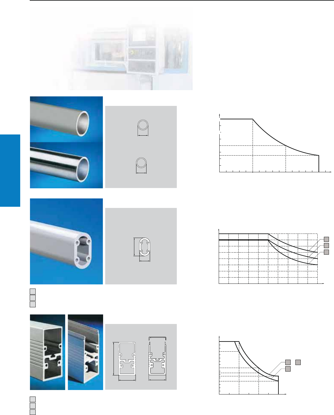
Operator Interface
116 Industrial Buyer’s Guide
Support Arm System
Support Arm System
Overview
Support arm systems from Rittal make the interaction
between man and machine easier. Three different
systems can be custom-configured per required
arm length and enclosure weight.
For use of CP-S in conjunction with CP-L (in
the horizontal run of the system), the CP-L load
diagram applies.
Arm length in inches
Load capacity CP-S steel/stainless steel
Permissible load depending on system assembly
Only one intermediate hinge 6120.010 can be used
per system.
System assembly without joint
System assembly with one joint
System assembly with two joints
Open and solid support section
Solid support section with one joint
Open support section with one joint
Permissible load depending on system assembly
Only one Intermediate hinge 6523.010 can be used
per system.
Arm length in inches
Arm length in inches
Load capacity CP-L
Load capacity CP-XL
Permissible static load in lbf
(Enclosure + vertical support section)
Permissible static load in lbf
(Enclosure + vertical support section)
Permissible static load in lbf
(Enclosure + vertical support section)
1111
1
11111
1
2
3
1
1
1
1
32
1
1
2
3
1
2
3
6120.010
6523.010
Conversion factors (N=lb / .224); (mm=in x 25.4)
180
180
180
292
337
146
124
90
157
135
67
90
45
22
90
135
112
45
0 0
0
0 39 79 118
8 16 24 32 39 47 55 63 71 78
8 16 24 32 39 47 55 63
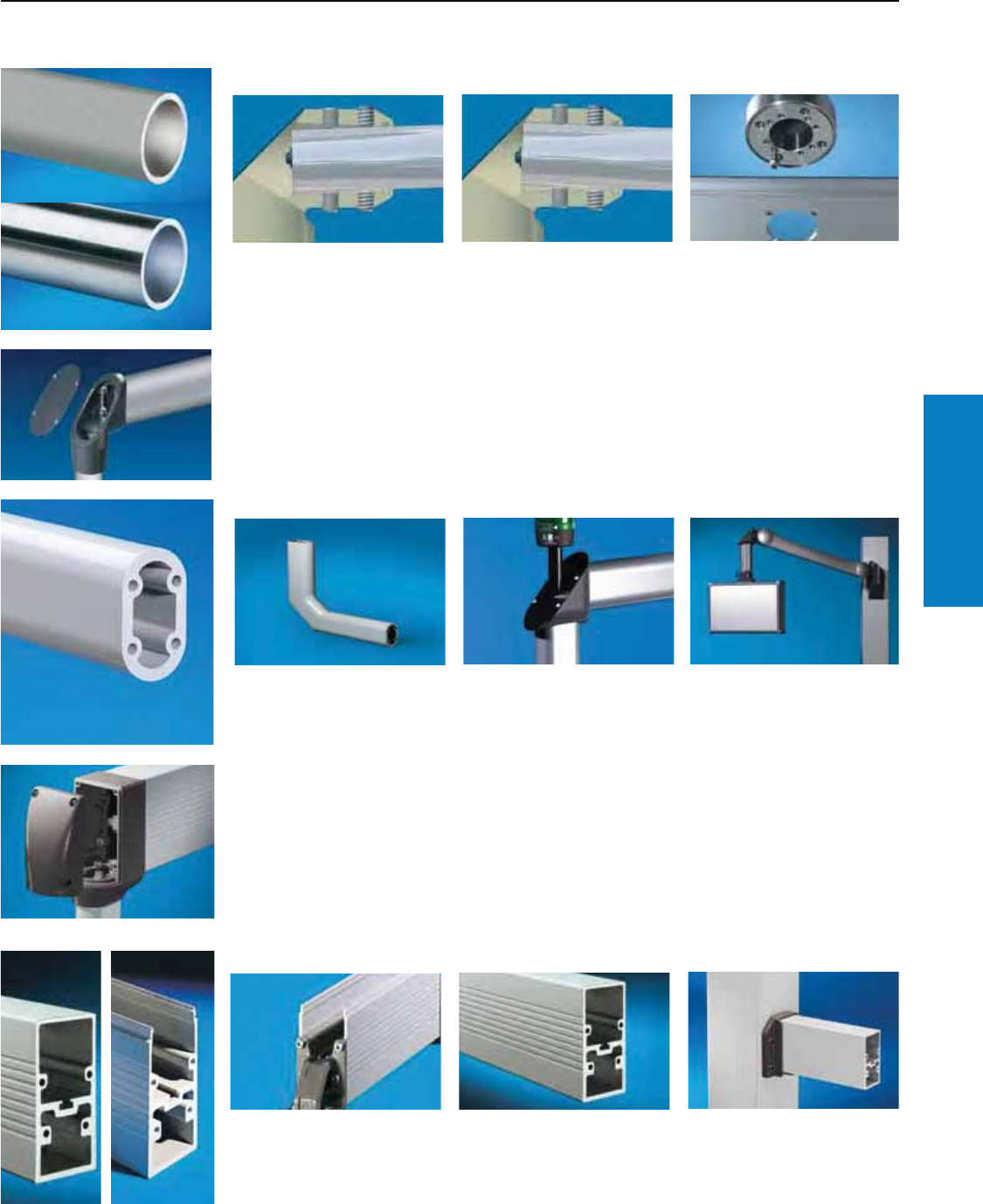
Operator Interface
Industrial Buyer’s Guide 117
Support Arm System
Support Arm System
Overview
The steel angle coupling and
angle piece, wallmounted and
top-mounted joint of the system
have integrated adjustment
capabilities.
CP-S steel and stainless steel
Due to the different
requirements and slightly
deviating attachment types,
the support arm and
enclosure should be made
from the same material (steel
or stainless steel).
90° elbow adaptor
The ideal connection from a small
to medium-sized system.
This means that deviations in
the horizontal of ±2.5° may be
adjusted easily.
The enclosures are easily
mounted on the enclosure
coupling of the stainless steel
system with a pre-assembled
screw.
90° elbow adaptor
The ideal means of adapting
between different sized pendant
arm systems.
The alternative for the
configuration of compact systems
– the 90° support arm bracket.
CP-L aluminum
Signal pillars may be mounted
on many connecting elements
of the systems using the
mounting component,
see www.rittal-corp.com.
The height-adjustable support
arm offers even better
ergonomics.
Four attachment bolts offer a high
level of safety for the system.
CP-XL aluminum
Two ducts allow the control
cable and supply voltage to be
separated.
A stable base point for the
system – the custom-produced
pillar, see www.rittal-corp.com.
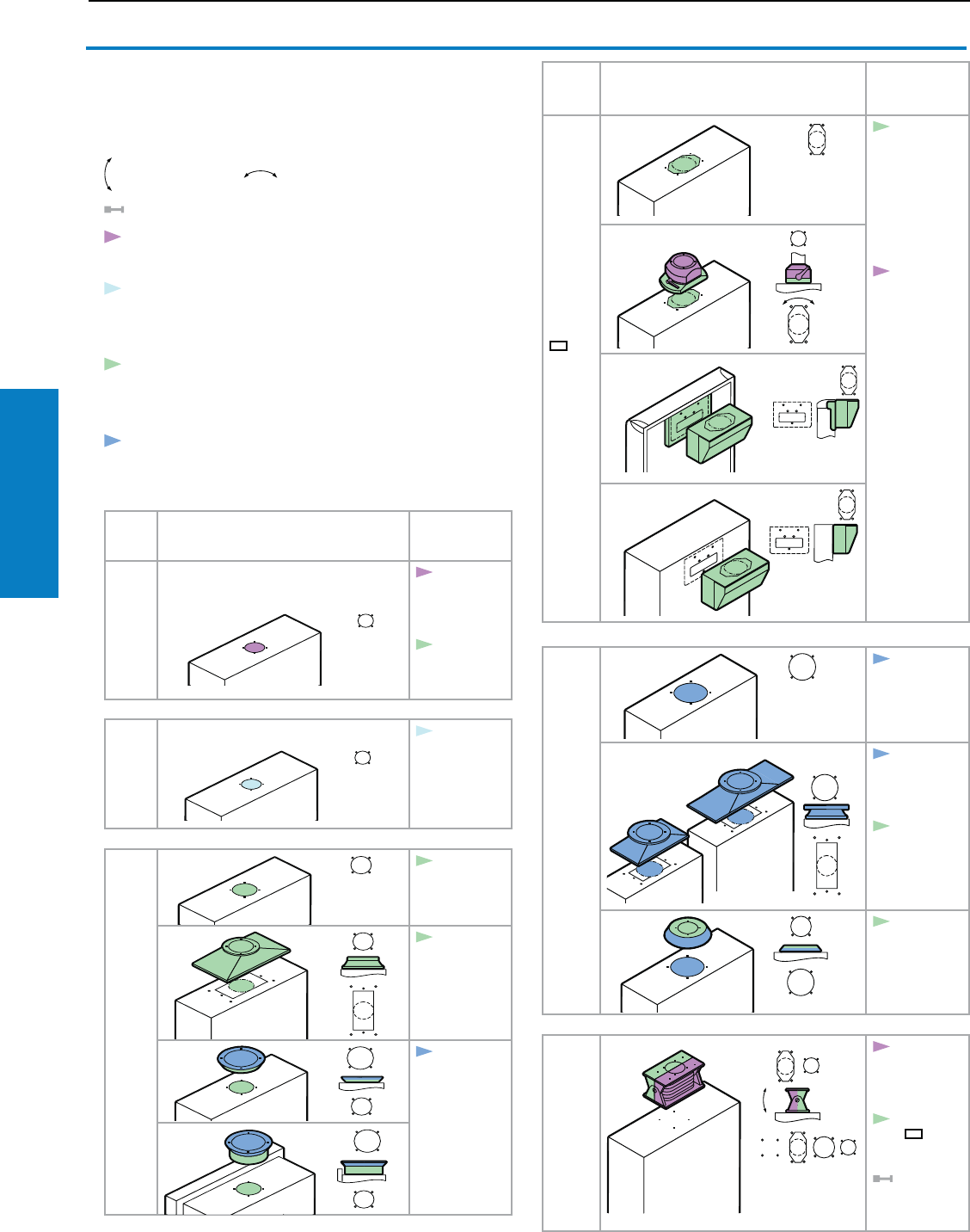
Operator Interface
118 Industrial Buyer’s Guide
Support Arm System
Support Arm System
Selection Guide
The diagrams show how the connection points of the Rittal
enclosures may be continued with support arm systems, either
directly or via adaptors. There is a choice of four support
arm systems, depending on your design, load and cabling
requirements.
tiltable or rotatable components
system end
CP-S steel
For small and lightweight enclosures.
CP-S stainless steel
For use where there are special
requirements in terms of corrosion
and hygiene.
CP-L
The system for average command
panel weights, stylish lines, and
outstanding solution diversity.
CP-XL
The system for extreme loads. Also
with open cable duct for super-easy
cable entry.
Enclosure
Continuation
with support
arm system
CP-S
steel
S
S
CP-S
steel:
1. 1
see page 120
CP-L:
1. 6
see page 132
CP-S
stain-
less
steel
CP-S
stainless steel:
1. 1
see page 120
CP-L
Ø
5"
(130
mm)
L
L
CP-L:
1. 1
see page 132
L
L
L
L
CP-L:
1. 2
see page 132
CP-XL:
1. 3
1. 4
see page 150
Enclosure
Continuation
with support
arm system
CP-L
5 x 3
(120 x
65 mm)
L
L
CP-L:
1. 4
see page 132
CP-S
steel:
1. 2
see page 120
L
L
L
L
CP-XL
CP-XL:
1. 1
see page 150
CP-XL:
1. 2
see page 150
CP-L:
1. 3
see page 132
CP-L:
1. 3
1. 4
see page 132
VESA
75
CP-S:
1. 3
see page 120
CP-L 5 x 3
(120 x 65 mm)
see page 132
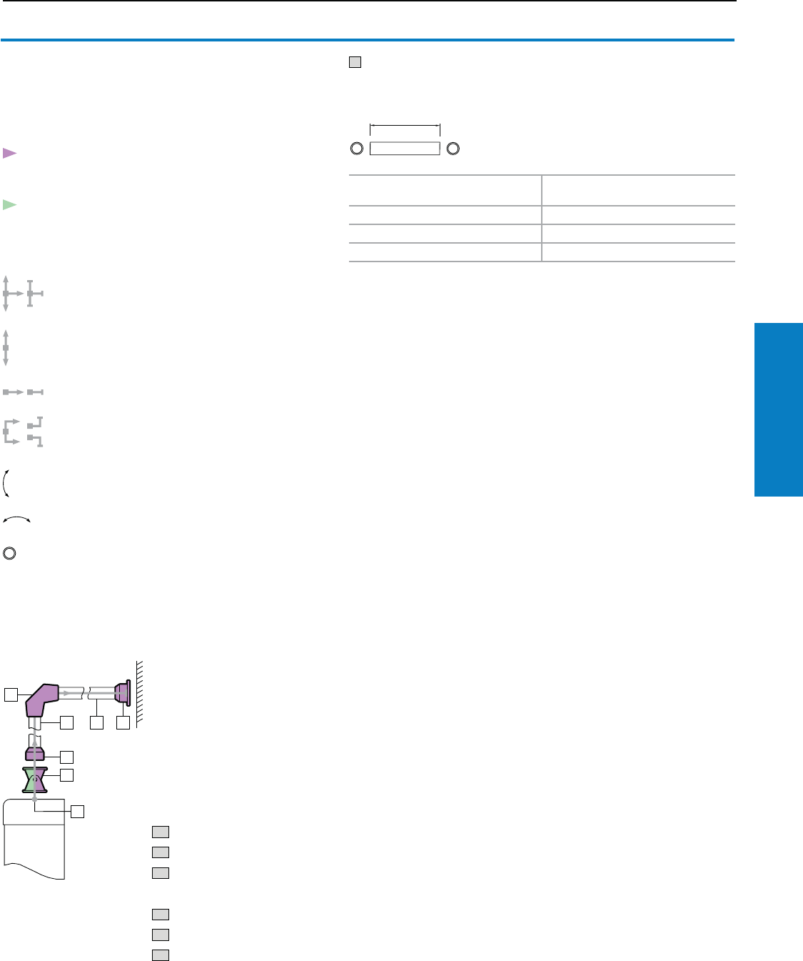
Operator Interface
Industrial Buyer’s Guide 119
Support Arm System
31
2
1
1
21
11
1
Make a simple sketch showing the basic form of the support
arm. Next, select the corresponding support arm
components. Start with "1: System start" (found on following
page) by selecting the appropriate enclosure situation.
T Support sections
T1 Support section CP-S
Continue with CP-S according to
the item numbers.
System continuation/system end:
all directions
vertical
horizontal
angled
rotatable components
Assembly example:
T1 Support section CP-S
1. 1 Mounting cut-out CP-S
2.1 Tilting enclosure attachment,
top mounting
3.1 Enclosure attachment CP-S
4.2 Angle piece 90° CP-S
5.1 Wall/base mounting CP-S
Note:
After any given support section, the 90°
angle adaptor CP-L to CP-S may be used
as a transition to the CP-L system.
Load diagram, see www.rittal-corp.com.
A
A inches (mm) RAL 9006 (white aluminium)
Part No.
20 (500) 6501.010
39 (1000) 6501.030
as per specifications 6501.340
See page 121.
System changes are indicated by the color.
Green = CP-L
tiltable or
From "3 Enclosure attachments", a support
section is required between each component
(minimum length approx. 4" [100 mm], for wall/floor
mounting approx. 6" [160 mm]).
Amin. = 4" (100 mm)
Amax. = 79" (2000 mm)
CP-S Support Arm System
Selection Guide
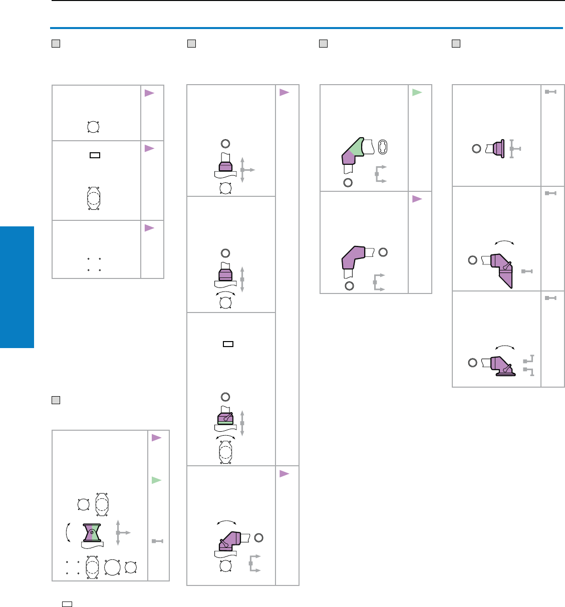
Operator Interface
120 Industrial Buyer’s Guide
CP-S Support Arm System
CP-S Support Arm System
1 System start
Enclosure with mounting
cut-out
1.1 Mounting cut-out
CP-S
see page 118
S
2.1
3.1
3.2
3.4
1.2 Mounting cut-out
CP-L, 3 x 5"
(65 x 120 mm)
see page 118
L
2.1
3.3
1.3 Mounting cut-out
VESA 75
see page 118
2.1
3.1 CP-S attachment
CP-S
6501.070 (RAL 7024
[graphite gray])
see page 122.
S
4.1
4.2
5.1
5.2
5.3
3.2 Housing coupling,
round CP-S
6501.050 (RAL 7024
[graphite gray])
see page 123.
S
3.3 Housing coupling
CP-S, for support
arm connection
CP-L 3 x 5"
(65 x 120 mm)
6501.130 (RAL 7024
[graphite gray])
see page 123.
L
3.4 Angle coupling 90°
CP-S
6501.120 (RAL 7024
[graphite gray])
see page 124.
S
5.1
5.2
5.3
4.1 Angle adaptor 90°
CP-L to CP-S
6501.090 (RAL 7024
[graphite gray]),
see page 146.
CP-
L
2.4
s.p.
133
4.2 Angle piece 90°
CP-S
6501.140 (RAL 7024
[graphite gray]),
see page 125.
5.1
5.2
5.3
5.1 Wall/base mounting
CP-S
6501.110 (RAL 7024
[graphite gray]),
see page 126.
5.2 Wall-mounted hinge
CP-S
6501.150 (RAL 7024
[graphite gray]),
see page 127.
5.3 Top-mounted joint
CP-S
6501.160 (RAL 7024
[graphite gray]),
see page 126.
3 Enclosure
attachments
4 Angle
components
5 System end
2.1 Enclosure attachment,
tilting, top mounting1)
6902.670 (RAL 7024
[graphite gray])
see page 121.
3.1
3.2
3.4
CP-
L
2.4
s.p.
133
1) May also be used rotated
through 180°, e.g., from CP-L
5 x 3" (120 x 65 mm)
CP-S to CP-L Ø 5" (130 mm)
2 Tilting adaptor
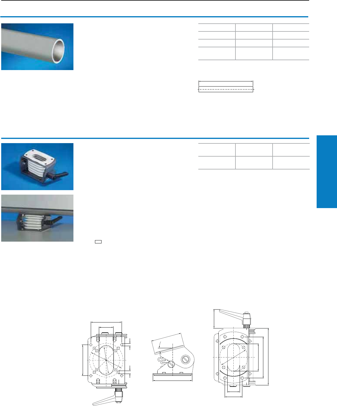
Operator Interface
Industrial Buyer’s Guide 121
CP-S Support Arm System
CP-S Support Arm System
Support section CP-S
Attachment to the connecting components
with 2 clamping screws.
Size:
External diameter: 2" (48.3 mm)
Wall thickness: 0.2" (4.0 mm)
Material:
Steel tube, powder coated
Color:
RAL 9006 (white aluminum)
Note:
Bent support sections available on request.
Amin. = 4" (100 mm)
Amax. = 75" (2000 mm)
Enclosure attachment, tilting,
top-mounting
For mounting on:
• IW worktop, prepared for enclosure attachment
CP-L, Ø 5" (130 mm), see www.rittal-corp.com.
• Surfaces
• Enclosure attachment/coupling CP-L 5 x 3"
(120 x 65 mm), see pages 142, 144.
• Attachment/housing coupling CP-S (may also
be used as tilting adaptor +100°/–60° for CP-S),
see pages 122, 123.
To fit enclosures up to 44.1 lb (20 kg) with
support arm connection
• CP-S
• CP-L 5 x 3" (120 x 65 mm)
• CP-L Ø 5" (130 mm)
• VESA Standard 75
With cable tube for protected cable entry.
Tilt Angle:
+100°/- 60°, adjustable in 7.2° increments using a
clamping lever and may be limited to +100°/-15°
using the stop screw supplied loose.
Material:
Sheet steel, painted
Conguration:
Assembly hardware and plastic bellows section
Accessories:
IW worktops prepared for enclosure attachment,
see www.rittal-corp.com
A inches (mm) Weight lb (kg) Part No.
20 (500) 5 (2.1) 6501.010
39 (1000) 9 (4.2) 6501.030
To specifications
A = 9 (4.2) 6501.340
A
1
11
Color
RAL
Weight
lb (kg) Part No.
7024
(graphite gray) 1 (0.8) 6902.670
Inch and pound measurements are rounded to the nearest whole number.
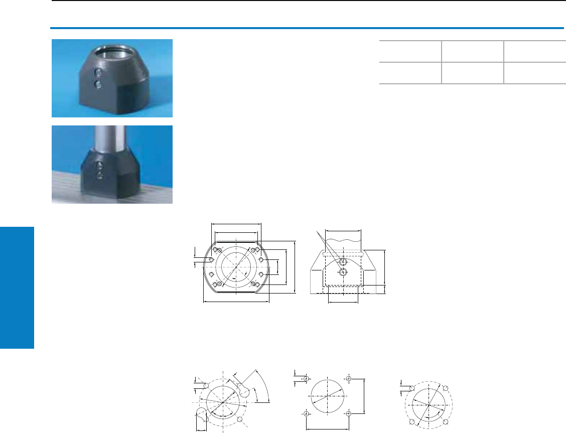
Operator Interface
122 Industrial Buyer’s Guide
CP-S Support Arm System
CP-S Support Arm System
Enclosure attachment CP-S
For fixed attachment of the:
• Enclosure to the support section,
• Support arm to flat surfaces, rear1).
With two drilling patterns for:
a) Rittal Command Panel
b) Complete Control Panel.
1) Maximum load 40 lb (400 N).
Material:
Die-cast zinc
Conguration:
Gasket and 2 clamping screws for support
section CP-S
Mounting cut-outs
Like cut-out "a)",
but without
lock holes
Clamping screw
b)
a)
1
1
1
Color
RAL
Weight
lb (kg) Part No.
7024
(graphite gray) 2 (1.0) 6501.070
Inch and pound measurements are rounded to the nearest whole number.
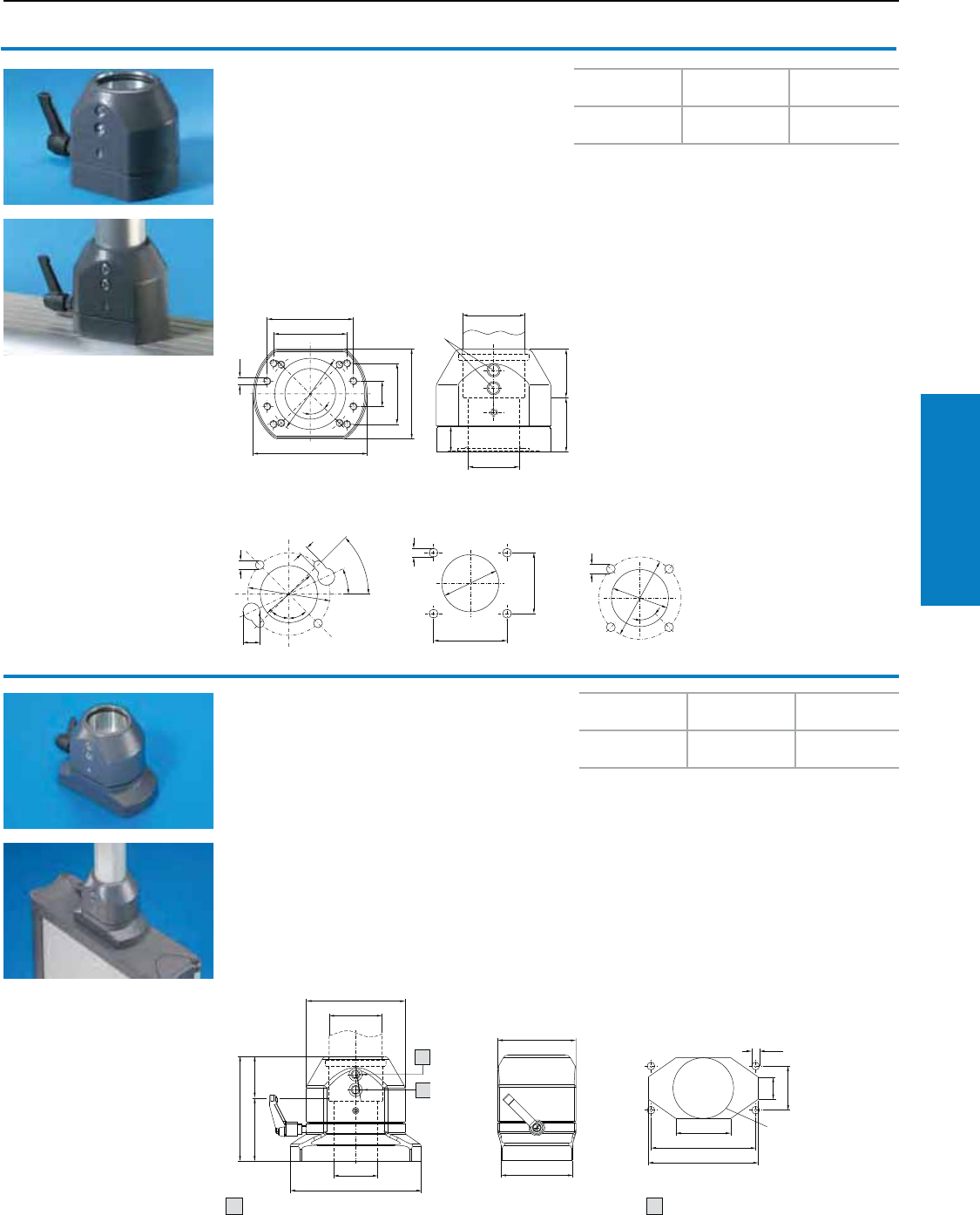
Operator Interface
Industrial Buyer’s Guide 123
CP-S Support Arm System
CP-S Support Arm System
Enclosure coupling CP-S
For support arm connection CP-S, round
For swivel-mounting of the enclosure on the
vertical section of the support arm system.
With two drilling patterns for:
a) Rittal Command Panel
b) Complete Control Panel.
Rotation Range:
Approximately 305°, lockable using a clamping
lever. By inserting additional pins 0.2 x 0.6"
(4 x 16 mm) to ISO 8752 the rotation range may
be limited to ± -7°, 44°, 104°, 142°.
Mounting cut-outs
Like cut-out "a)",
but without
lock holes
1) Clamping screw
b)
a)
1
1
Color
RAL
Weight
lb (kg) Part No.
7024
(graphite gray) 2 (1.1) 6501.050
1
1
1
1
Color
RAL
Weight
lb (kg) Part No.
7024
(graphite gray) 3 (1.5) 6501.130
Material:
Die-cast zinc
Conguration:
Gasket, 2 clamping screws for support section
CP-S and clamping lever
Enclosure coupling CP-S
For support arm connection CP-L,
5 x 3" (120 x 65 mm)
For swivel-mounting of the enclosure on the
vertical section of the support arm system.
For mounting on:
• Optipanel to fit TFT monitors 6380.020 – .040
(see page 94)
• Optipanel H x W x D: 7U x 19 x 4" (100 mm)
6380.000 (see page 94)
• Optipanel installation depth 2" (50 mm),
with rear support arm connection.
Mounting cut-out, enclosure
1) Locking screw Alternative max. Ø 2" (55 mm)
Rotation Range:
Approximately 305°, lockable using a clamping
lever. By inserting additional pins 0.2 x 0.6"
(4 x 16 mm) to ISO 8752 the rotation range may be
limited to ± -7°, 44°, 104°, 142°
Material:
Die-cast zinc
Conguration:
Gaskets, 2 locking screws
12
Inch and pound measurements are rounded to the nearest whole number.
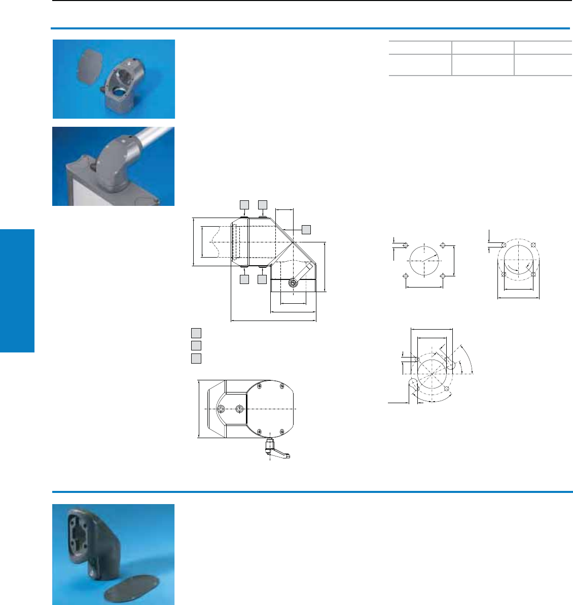
Operator Interface
124 Industrial Buyer’s Guide
CP-S Support Arm System
90° enclosure coupling CP-S
For swivel fastening of the enclosure to the
horizontal support arm system:
• Enclosure top-mounted or suspended
• Adjustment facility for the support arm system
(see page 117)
• Removable panel for easy cable entry
Rotation Range:
Approximately 305°, lockable using a clamping
lever. By inserting additional pins 0.1 x 0.6"
(4 x 16 mm) to ISO 8752 the rotation range may be
limited to ± 7°, 44°, 104°, 142°.
90° adaptor elbow,
CP-L to CP-S
see page 146.
CP-S Support Arm System
Color RAL Weight lb (kg) Part No.
7024
(graphite gray) 4 (1.6) 6501.120
Possible mounting cut-outs of enclosures
Locking screw
Adjusting screw
Removable plate
Version c) for quick/one-man assembly
a) b)
c)
Material:
Cast aluminum/die-cast zinc
Conguration:
Gaskets, 2 locking screws and 2 adjusting screws
1
1
1 2
3
1 2
1
1
2
3
Inch and pound measurements are rounded to the nearest whole number.
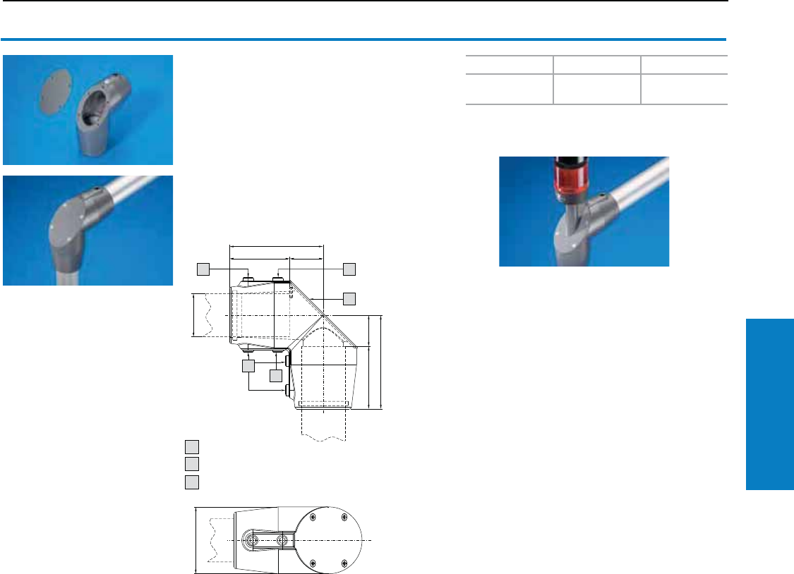
Operator Interface
Industrial Buyer’s Guide 125
CP-S Support Arm System
90° elbow CP-S
For connecting horizontal and vertical support
arm components.
• Adjustment facility for the support arm system
(see page 117)
• Removable panel for easy cable entry
Material:
Cast aluminum
Conguration:
Gaskets, 4 locking screws and 2 adjusting screws
CP-S Support Arm System
Locking screw
Adjusting screw
Removable plate
Accessories:
Mounting component for signal pillars
(2375.030), see www.rittal-corp.com
Color RAL Weight lb (kg) Part No.
7024
(graphite gray) 2 (1.1) 6501.140
1
1
2
1
1
2
3
1
2
3
Inch and pound measurements are rounded to the nearest whole number.
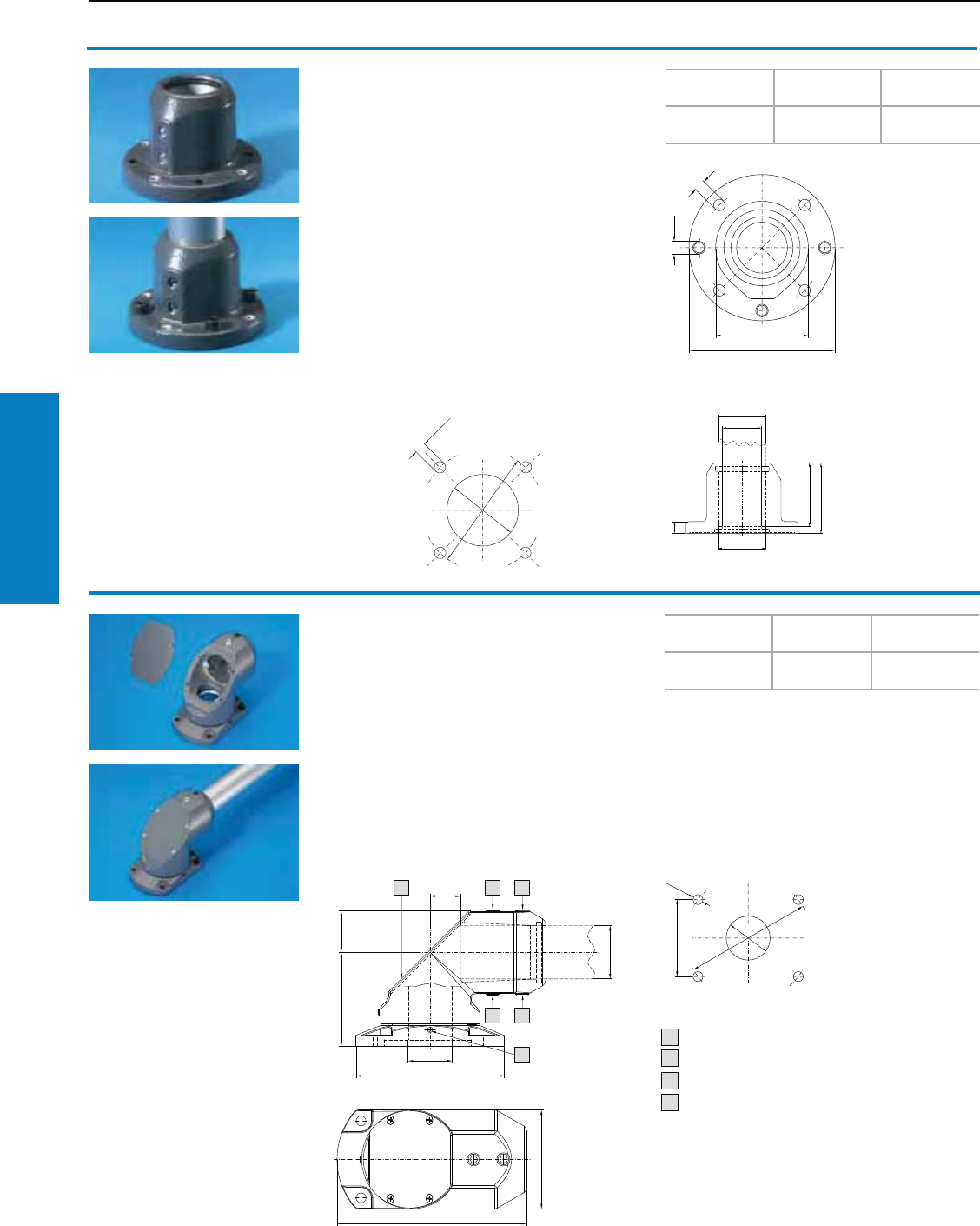
Operator Interface
126 Industrial Buyer’s Guide
CP-S Support Arm System
Wall/base-mounting CP-S
For fixed attachment of the support section to
surfaces. With flange for front-mounting.
Material:
Cast aluminum
Conguration:
Gasket, 2 clamping screws for support section
CP-S and 3 pre-fitted adjusting screws
CP-S Support Arm System
1) Adjusting screw
Mounting cut-out View A
Locking screw
Adjusting screw
Screw for adjusting rotatability
Removable plate
Mounting cut-out
Top-mounted joint CP-S
For swivel-mounting of the support arm system to
horizontal surfaces.
• Enclosure top-mounted or suspended
• Adjustment facility for the support arm system
(see page 117)
• Removable panel for easy cable entry
Rotation Range:
Approximately 300°, by inserting additional pins
0.2 x 0.8" (6 x 20 mm) to ISO 8752 the rotation
range may be limited to ± -6°, 51°, 96°. To lock the
joint, the screw may be exchanged for standard
clamping lever M6 x 1.0" (25 mm).
1
11
1
1
12
1
3
2
11
1
Material:
Cast aluminum
Conguration:
Gaskets, 2 locking screws and 2 adjusting screws
Color
RAL
Weight
lb (kg) Part No.
7024
(graphite gray) 2 (0.7) 6501.110
Color
RAL
Weight
lb (kg) Part No.
7024
(graphite gray) 4 (1.8) 6501.160
1
2
3
4
Inch and pound measurements are rounded to the nearest whole number.
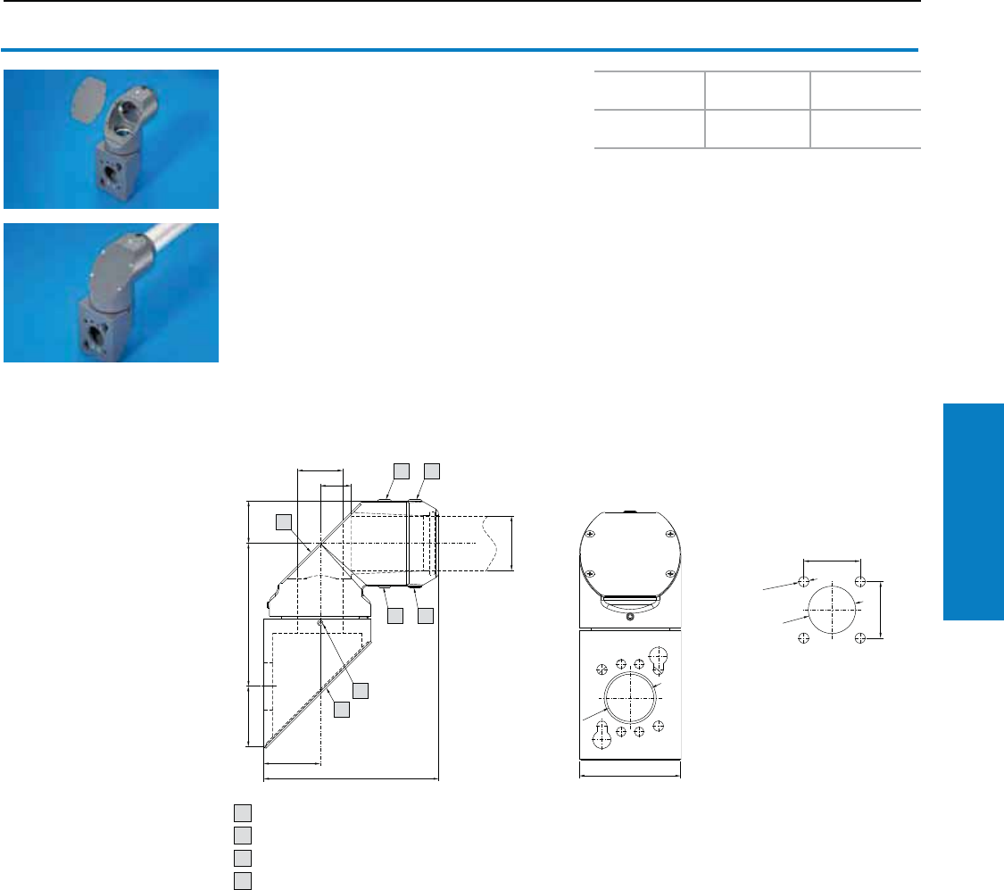
Operator Interface
Industrial Buyer’s Guide 127
CP-S Support Arm System
Wallmounted hinge CP-S
For vertically hinged-mounting of the support arm
on vertical surfaces.
• Machined keyhole for support arm outlet at the
top or bottom for easy one-man assembly:
− Pre-mount the screws on a vertical surface
− Locate the wallmounted hinge (support arm
system pre-mounted)
− Tighten the screws
• Adjustment capabilities for the support arm
system (see page 117)
• Removable panel for easy cable entry
Rotation Range:
Approximately 300°, by inserting additional pins
0.2 x 0.8" (6 x 20 mm) to ISO 8752 the rotation
range may be limited to ± 6°, 51°, 96°. To lock the
joint, the screw may be exchanged for standard
clamping lever M6 x 1.0" (25 mm).
CP-S Support Arm System
Color
RAL
Weight
lb (kg) Part No.
7024
(graphite gray) 5 (2.2) 6501.150
Locking screw
Adjusting screw
Screw for adjusting rotatability
Removable plate
Mounting cut-out 90°
Material:
Cast aluminum
Conguration:
Gaskets, 2 locking screws and 2 adjusting screws
21
12
3
1
1
1
2
3
4
Inch and pound measurements are rounded to the nearest whole number.
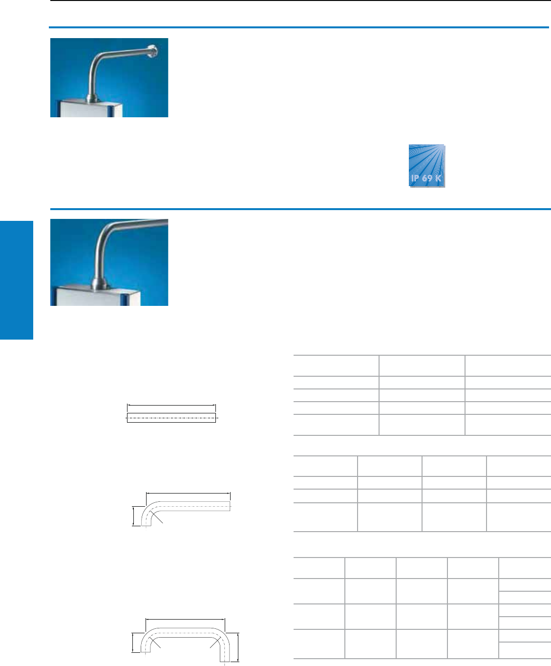
Operator Interface
128 Industrial Buyer’s Guide
CP-S Support Arm System
CP-S Support Arm System
Support arm system CP-S,
Stainless Steel
In conjunction with stainless steel Command Panels,
terminal boxes 5" (120 mm) deep and compact
enclosures AE from stainless steel, this support
arm system is particularly well-suited for meeting
high standards of corrosion protection and
hygiene.
The tilting adaptor and enclosure coupling may
optionally be mounted on the top or bottom of the
enclosure. They are not suitable for use as the
base point of a system. For this purpose, we
recommend wall/base mountings, or with larger
heights and widths, an additional pillar made
of steel tubing or stainless steel (available on
request).
Material:
Type 303 stainless steel
Protection ratings:
IP 69K to DIN 40 050-9
(resistant to high-pressure cleaning)
Load information:
visit www.rittal-corp.com
Support section CP-S,
Stainless Steel
Attached to the connection components via
2 clamping screws.
Dimensions:
External diameter: 1.9" (48.3 mm)
Wall thickness: 0.1" (3.6 mm)
Material:
Type 304 stainless steel
Finish:
Brushed, grain 240
Other sizes to order available
on request.
Order example:
U-shaped = 6660.200
Dimension A = 12" (300 mm)
Dimension B = 31" (800 mm)
Dimension C = 9" (240 mm)
The minimum dimensions must be
adhered to, because of the bending
radius and insertion depth of the
enclosure attachment, housing
coupling and wall/base mountings.
A
B
B
Straight
Amin. = 4" (100 mm),
Amax. = 79" (2000 mm)
L-shaped
Amin. = Bmin. = 9" (240 mm),
Bmax. = 59" (1500 mm)
U-shaped
Amin. = Cmin. = 9" (240 mm),
Bmin. = 16" (410 mm),
Bmax. = 59" (1500 mm)
A inches (mm) Weight
lb (kg) Part No.
20 (500) 4 (2.0) 6660.050
39 (1000) 9 (3.9) 6660.010
79 (2000) 17 (7.8) 6660.020
as per specifications
A = 26 lb/ft (3.9 kg/m) 6660.000
A
inches (mm)
B
inches (mm)
Weight
lb (kg) Part No.
9 (240) 20 (500) 6 (2.6) 6660.110
20 (500) 39 (1000) 12 (5.5) 6660.120
as per
specifications
A =
as per
specifications
B =
26 lb/ft (3.9 kg/m) 6660.100
A
inches (mm)
B
inches (mm)
C
inches (mm)
Weight
lb (kg) Part No.
9 (240) 32 (800) 32 (800) 15 (6.6) 6660.2101)
6660.2302)
9 (240) 20 (500) 20 (500) 10 (4.3) 6660.2201)
6660.2402)
as per
specifications
A =
as per
specifications
B =
as per
specifications
C =
26 lb/ft (3.9
kg/m)
6660.2001)2)
6660.2501)2)
1) Enclosure top-mounted
2) Enclosure suspended
Inch and pound measurements are rounded to the nearest whole number.
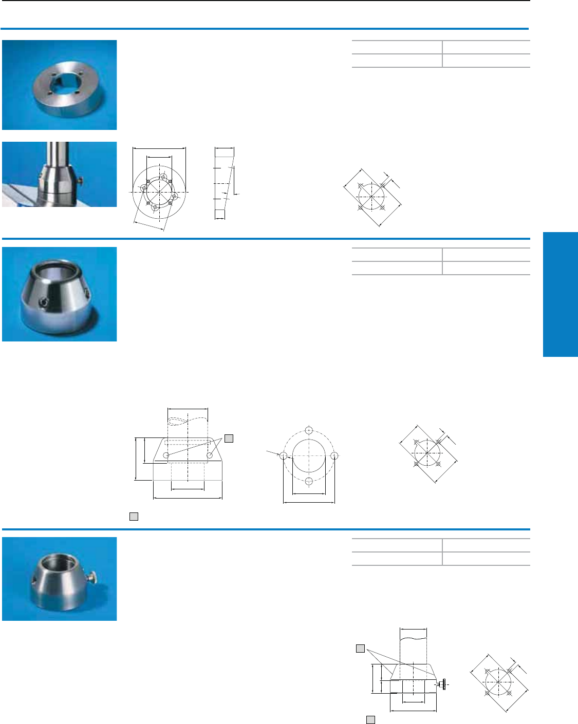
Operator Interface
Industrial Buyer’s Guide 129
CP-S Support Arm System
CP-S Support Arm System
Tilting adaptor
10° CP-S Stainless Steel
For mounting between the Command Panel and
• Enclosure attachment 6664.500
or
• Housing coupling 6664.000
Material:
Type 303 stainless steel
Weight lb (mm) Part No.
2 (0.7) 6664.100
Conguration:
Seal and assembly parts
Mounting cut-out
enclosure
1
1
Enclosure attachment CP-S
Stainless Steel
For rigid fastening of the enclosure to the
support section.
Material:
Type 303 stainless steel
Conguration:
Seals and 2 clamping screws for support section
CP-S, stainless steel
Note:
For assembly of a modular pedestal,
see page 160, 2 pieces are required.
Weight lb (mm) Part No.
3 (1.3) 6664.500
Accessories:
Enclosure reinforcement,
see page 165.
1
1
1 Clamping screw
Mounting cut-out
for pedestal, bottom
Mounting cut-out,
enclosure
Housing coupling CP-S
Stainless Steel
For mounting on the vertical part of the support arm
system.
Rotation range:
Approx. 350°, lockable via knurled screw
Material:
Type 303 stainless steel
Conguration:
Seals and 2 clamping screws for support section
CP-S, stainless steel
Weight lb (mm) Part No.
2 (1.1) 6664.000
Accessories:
Enclosure reinforcement,
see page 165.
1
1 Clamping screw
Mounting cut-out
enclosure
Inch and pound measurements are rounded to the nearest whole number.
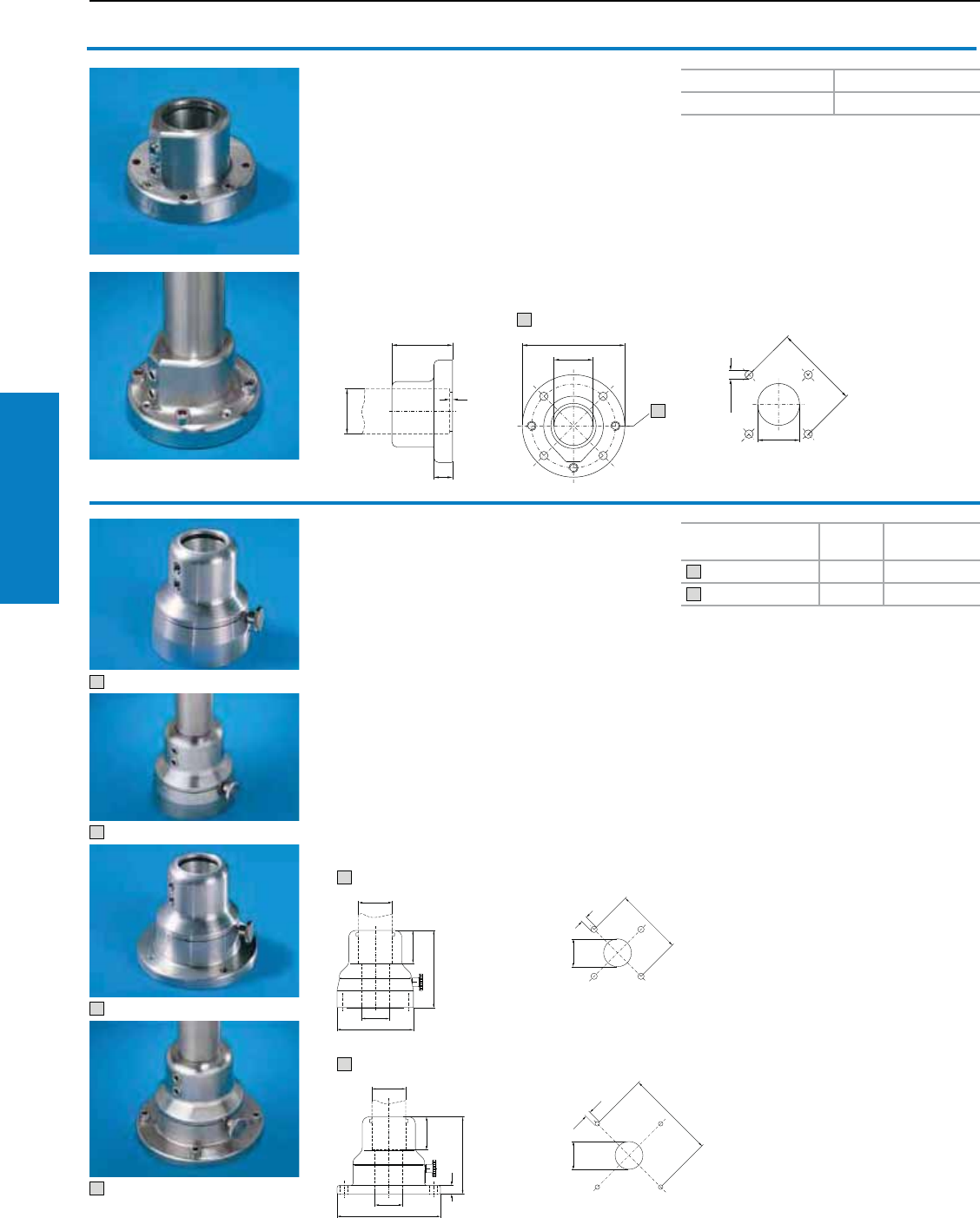
Operator Interface
130 Industrial Buyer’s Guide
CP-S Support Arm System
CP-S Support Arm System
Wall/base mounting, rigid
Stainless Steel
For attaching the support arm system to vertical
or horizontal surfaces.
Material:
Type 303 stainless steel
Conguration:
Seals, 3 adjusting screws to compensate for any
irregularities, and 2 clamping screws for support
section CP-S, stainless steel.
Accessories:
Wall consoles,
see page 131.
Weight lb (kg) Part No.
4 (1.7) 6663.000
11
1
1 Adjusting screw Mounting cut-out
1
1
2
2
Swivel base mount
Stainless Steel
For external mounting on
• Horizontal surfaces (suspended or top-mounted)
• Wall console (6663.500 only)
Rotation range:
Approx. 350°, lockable via knurled screw
Material:
Type 303 stainless steel
Conguration:
Seals and 2 clamping screws for support section
CP-S, stainless steel
Note:
Rotation range may be limited in 60° increments
using a limit plate, supplied loose
Accessories:
Wall consoles,
see page 131.
11
111
1
1111
1
1 Rear attachment 6663.500
2 Rear attachment 6663.400
Mounting cut-out
Mounting cut-out
Attachment Weight
lb (kg) Part No.
Rear, M8 thread 9 (3.9) 6663.500
Front, hole Ø 9 mm 10 (4.5) 6663.400
1
2
Inch and pound measurements are rounded to the nearest whole number.
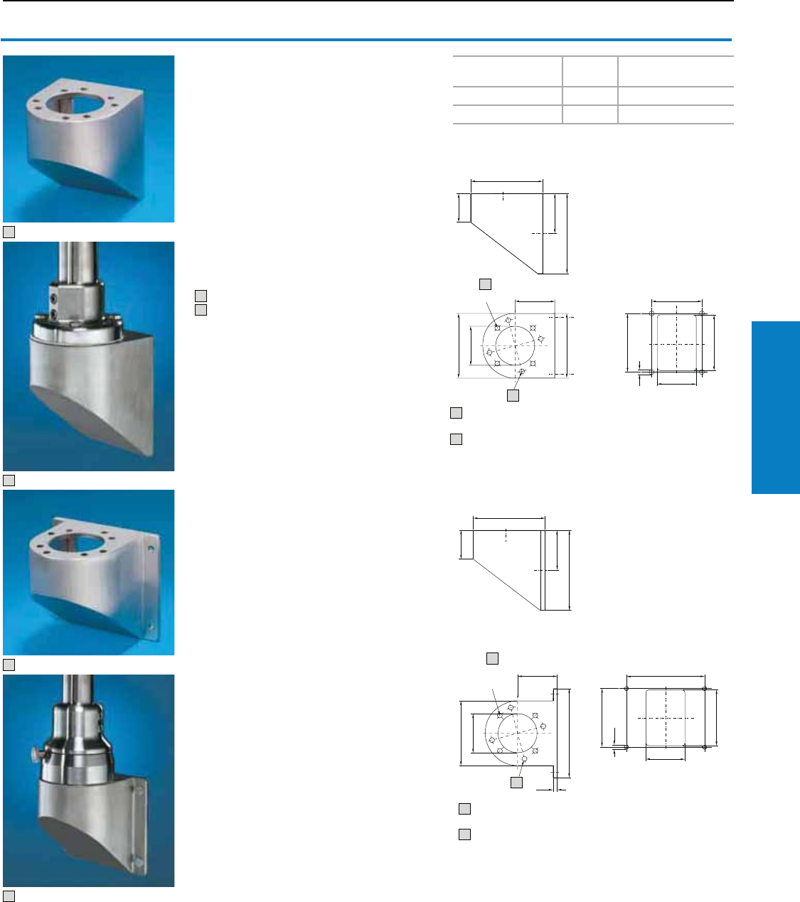
Operator Interface
Industrial Buyer’s Guide 131
CP-S Support Arm System
CP-S Support Arm System
1
1
2
2
Wall console CP-S
Stainless Steel
With holes for mounting
• Base mount, swivel, CP-S (6663.500),
with 4 screws
• Wall/base mount, rigid, CP-S (6663.000),
with 4 screws and nuts
Material:
Type 304 stainless steel
Finish:
Brushed, grain 240
Conguration:
Seals and assembly parts
1 Rear attachment, M8 thread
2 Front, hole Ø 9 mm
Attachment Weight lb
(kg) Part No.
Rear, M8 thread 9 (3.9) 6665.000
Front, hole Ø 9 mm 10 (4.5) 6665.500
1
1
1
Rear fastening
Mounting cut-out
11
11
1
1
1
1
1
1
11
1
1
1
1
1
3 Hole for 6663.000
4 Hole for 6663.500
3
4
Front fastening
3 Hole for 6663.000
4 Hole for 6663.500
Mounting cut-out
3
4
Inch and pound measurements are rounded to the nearest whole number.
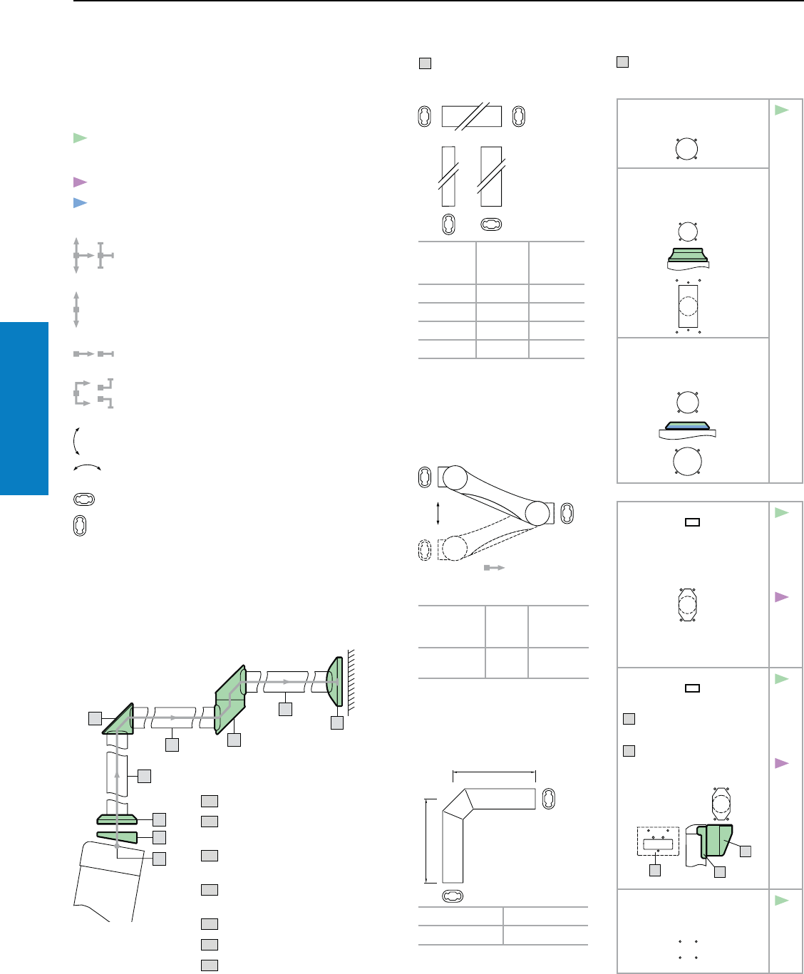
Operator Interface
132 Industrial Buyer’s Guide
CP-L Support Arm System
CP-L Support Arm System
Selection Guide
Make a simple sketch showing the basic form of the support
arm. Next, select the corresponding support arm
components. Start with "1: system start" by selecting the
appropriate enclosure situation.
T Support sections
T1 Support section CP-L.
Length
inches
(mm)
Color
RAL Part No.
10 (250) 70351) 6509.000
20 (500) 70351) 6511.000
39 (1000) 70351) 6513.000
79 (2000) 70351) 6515.000
See page 136
Continue with CP-L according to the item numbers.
System continuation/system end:
all directions
vertical
horizontal
angled
rotatable components
1 System start
Enclosure with mounting cut-out
31
1
1
1
1
1
1
21
11
Assembly example:
T1 Support section CP-L
1. 1 Mounting cut-out CP-L, Ø 5"
(130 mm)
2.1 Tilting adaptor, 10° CP-L, Ø 5"
(130 mm)
3.1 Enclosure attachment CP-L, Ø 5"
(130 mm)
4.1 Angle piece 90° CP-L
5.1 Intermediate hinge CP-L
6.1 Wall/base mounting CP-L
1.1 Mounting cut-out
CP-L, Ø 5" (130 mm)
L
2.1
2.2
2.4
3.1
3.2
3.3
1.2 Connection plate for
support arm CP-L
6528.210, see page 141.
L
L
1.3 Connection adaptor
CP-L to CP-XL
6528.010, see page 140
1.4 Mounting cut-out
CP-L, 3 x 5"
(65 x 120 mm)
L
2.3
2.4
3.4
3.5
3.6
CP-
S
3.3
s.p.
120
1.5 Connection console
CP-L, 3 x 5"
(65 x 120 mm)
A 6508.010
on Optipanel support plate
C for connection console
see page 143.
L
2.3
2.4
3.4
3.5
3.6
CP-
S
3.3
s.p.
120
1.6 Mounting cut-out
VESA 75
see page 118.
2.4
System changes are indicated by the color.
Violet = CP-S
Blue = CP-XL
tiltable or
From "3: Enclosure attachments", a support
section is required between each component
(minimum length approx. 4" [100 mm], for wall/
floor mounting approx. 6" [160 mm]).
The cross-sections indicate the installation
position(s).
T2 Support arm CP-L,
height-adjustable
Color: RAL 7024 (graphite gray)
/9006 (white aluminium)
Weight
Range
lb (kg)
Length
inches
(mm)
Part No.
18 - 88
(8 - 40)
43
(1090) 6510.3X0
See page 134
T3 Support arm bracket 90°,
CP-L
Color RAL Part No.
70351) 6519.000
See page 136
1) light gray
Inch and pound measurements are rounded to the nearest whole number.
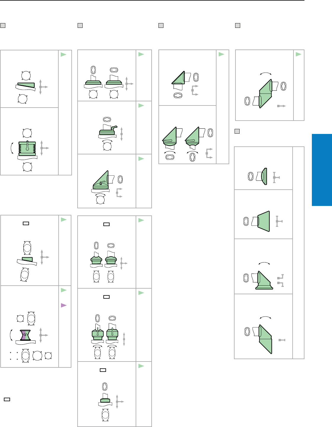
Operator Interface
Industrial Buyer’s Guide 133
CP-L Support Arm System
CP-L Support Arm System
Selection Guide
2 Tilting adaptor
2.1 Tilting adaptor 10°
CP-L, Ø 5" (130 mm)
6527.010, see page 137
L
L
3.1
3.2
3.3
2.2 Tilting adaptor ± 45°
CP-L, Ø 5" (130 mm)
6529.010, see page 137
L
L
3.1 Enclosure attachment
CP-L, Ø 5" (130 mm)
6525.510, see page 138
LL
4.1
4.2
4.3
6.1
6.2
6.3
6.4
3.2 Housing coupling
CP-L, 5" (130 mm)
6525.010, see page 144
L
4.1
4.3
6.1
6.2
6.32)
6.42)
3.3 Angle coupling 90°
CP-L, Ø 5" (130 mm)
6526.010, see page 145
L
4.1
5.1
6.1
6.2
6.3
6.4
3.4 Enclosure attachment
CP-L, 3 x 5"
(65 x 120 mm)
6525.610, see page 139
LL
4.1
4.2
4.3
6.1
6.2
6.32)
6.42)
3.5 Housing coupling
CP-L, 3 x 5"
(65 x 120 mm)
6525.110, see page 144
LL
4.1
4.3
6.1
6.2
6.32)
6.42)
3.6 Enclosure attachment
CP-L, 3 x 5"
(65 x 120 mm), locatable
6525.210, see page 142
L
4.1
4.2
4.3
6.1
6.2
3 Enclosure
attachments
6.1 Wall/base mounting,
small, CP-L
6520.510, see page 147
6.2 Wall/base mounting,
large, CP-L
6520.010, see page 148
6.3 Top-mounted joint
CP-L
6522.010, see page 148
6.4 Wall-mounted hinge
CP-L
6521.010, see page 149
6 System end
2.3 Tilting adaptor, 10°
CP-L, 3 x 5"
(65 x 120 mm)
6527.110, see page 138
L
L
3.4
3.5
3.6
2.4 Enclosure attachment,
tilting, top mounting1)
6902.670,
see page 121
3.4
3.5
CP-
S
3.3
s.p.
120
1) May also be used rotated
through 180°, e.g. from CP-L
3 x 5" (65 x 120 mm) or
CP-S to CP-L Ø 5" (130 mm).
2) Via T3 support arm bracket
90° CP-L.
5 Intermediate
hinge
5.1 Intermediate hinge
CP-L
6523.010, see page 147
4.1
6.1
6.2
4.1 Angle piece 90°
CP-L
6524.010, see page 145
5.1
6.1
6.2
6.3
6.4
4.2 Articulated joint 90°
CP-L
6524.210, see page 146
4 Angle
components
Notes:
Re T2
Support arm, height adjustable,
should always be inserted as the
first horizontal component after
the enclosure.
Re 5.1 / 6.3 / 6.4
It is always expedient to use only
one intermediate hinge or one
wall mounted hinge.
Two joints will restrict load
capacity and make positioning
the Command Panel more
difficult.
Load diagram, see
page 116.
Re 4.1
Two angle pieces may also be
used one after the other.
Inch and pound measurements are rounded to the nearest whole number.
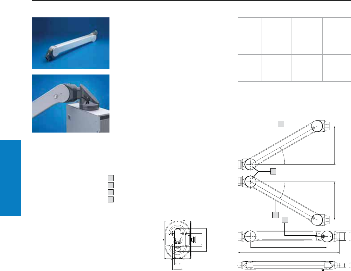
Operator Interface
134 Industrial Buyer’s Guide
CP-L Support Arm System
Support arm, height
adjustable CP-L
Offers enhanced ergonomics thanks to:
• Adjustment range
– for tall and short operators
– for seated and stand-up worktstations
• Precise coordination of the compression spring
to the enclosure weight via an adjusting screw
at the rear of the support arm.
• Complete functional reliabilty – if the compression
spring breaks, the arm will remain in position.
• Clip-off plastic panels for access to integral cable
routing.
• Tilting angle of the mounted enclosure is identical
in every height position.
• More space for cable routing.
• Cables with connectors such as DVI, VGA are
also easily inserted.
• Integral locking in three stages.
• Superior load capacity.
Conguration:
Round tube with compression spring relief and
U-section cable tray, 2 threaded connectors,
plastic casing, including assembly hardware.
CP-L Support Arm System
Overall
length
inches
(mm)
Color RAL
Weight
range lb
(kg)1)
Part No.
43 (1090) 9006 (white
aluminum)
18 - 33
(8 - 15) 6510.320
43 (1090) 9006 (white
aluminum)
33 - 71
(15 - 32) 6510.330
43 (1090) 9006 (white
aluminum)
44 - 88
(20 - 40) 6510.340
1) For configured enclosure and vertical support section
Inch and pound measurements are rounded to the nearest whole number.
1
°
1
°
°
°
1
2
3
4
1 Top end stop
2 Bottom end stop
3 Lockable at ± 20°
4 Max. cross-section for cable entry
0.6 x 1.6" (16 x 40 mm)
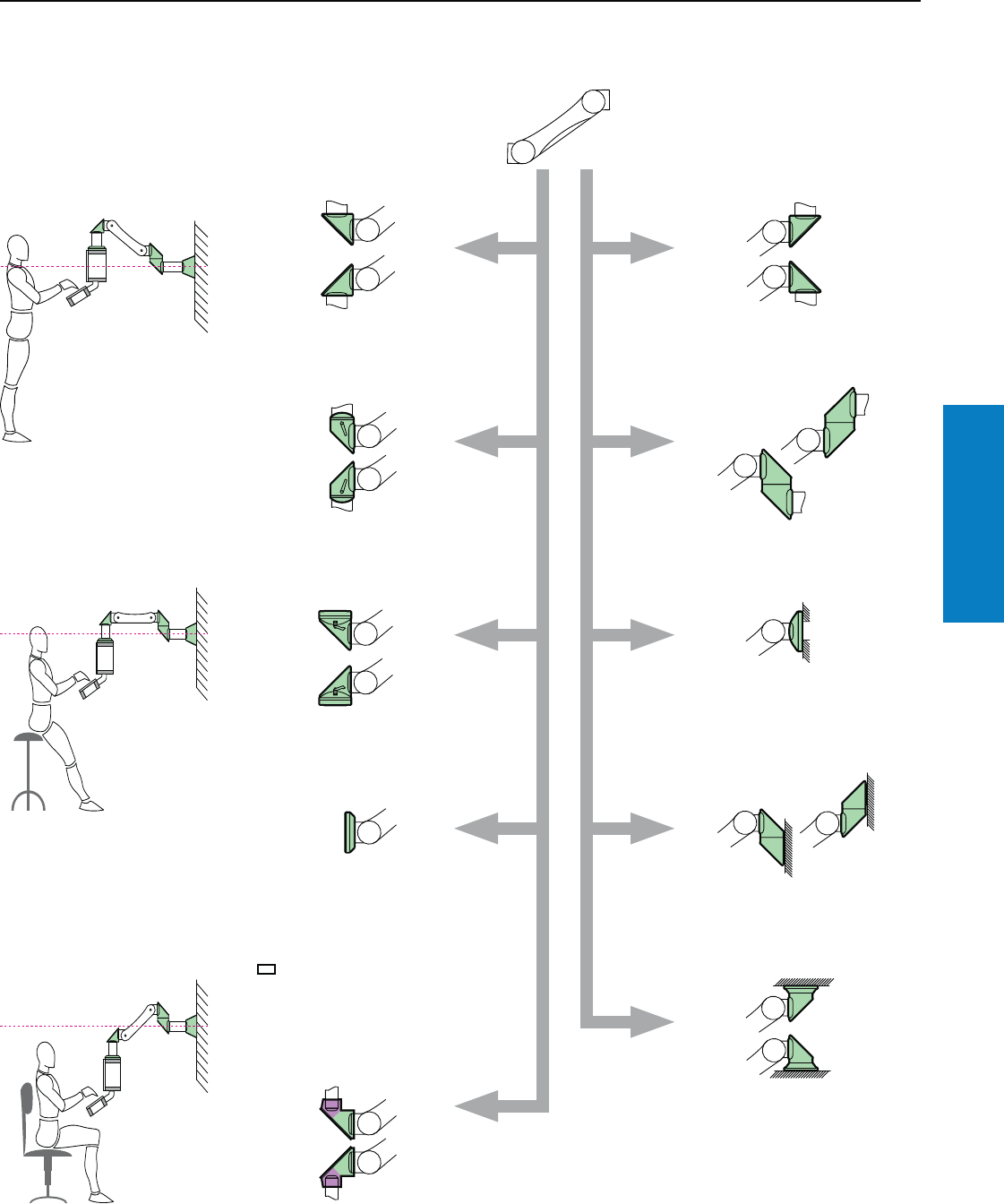
Operator Interface
Industrial Buyer’s Guide 135
CP-L Support Arm System
CP-L Support Arm System
Support Arm, Height Adjustable
Support arm, height
adjustable CP-L
The versatile combination options with horizontal
mounting are illustrated in this diagram.
Enclosure side Attachment side
Angle piece 90° CP-L
Part No. 6524.010,
see page 145.
CP-L
CP-L
CP-L
CP-L
CP-L
CP-L
CP-L
CP-L
Angle piece 90° CP-L
Part No. 6524.210,
see page 146.
Angle piece 90° CP-L
Part No. 6524.010,
see page 145.
Intermediate hinge CP-L
Part No. 6523.010,
see page 147.
Wall/base mounting, small,
CP-L
Part No. 6520.510,
see page 147.
Wall-mounted hinge CP-L
Part No. 6521.010,
see page 149.
Top-mounted joint CP-L
Part No. 6522.010,
see page 148.
Angle coupling 90° CP-L
for support arm connection Ø 5"
(130 mm). Part No. 6526.010,
see page 145.
Enclosure attachment CP-L
for support arm connection Ø
5" (130 mm)
Part No. 6525.510,
enclosure attachment CP-L for
support arm connection
3 x 5" (65 x 120 mm)
Part No. 6525.610,
see page 139.
Enclosure with rear support arm
cut-out/reinforcement available
upon request.
Angle adaptor 90°, CP-L to CP-S
Part No. 6501.090, see page 146.
Enclosure
Enclosure
Enclosure
CP-S
CP-S
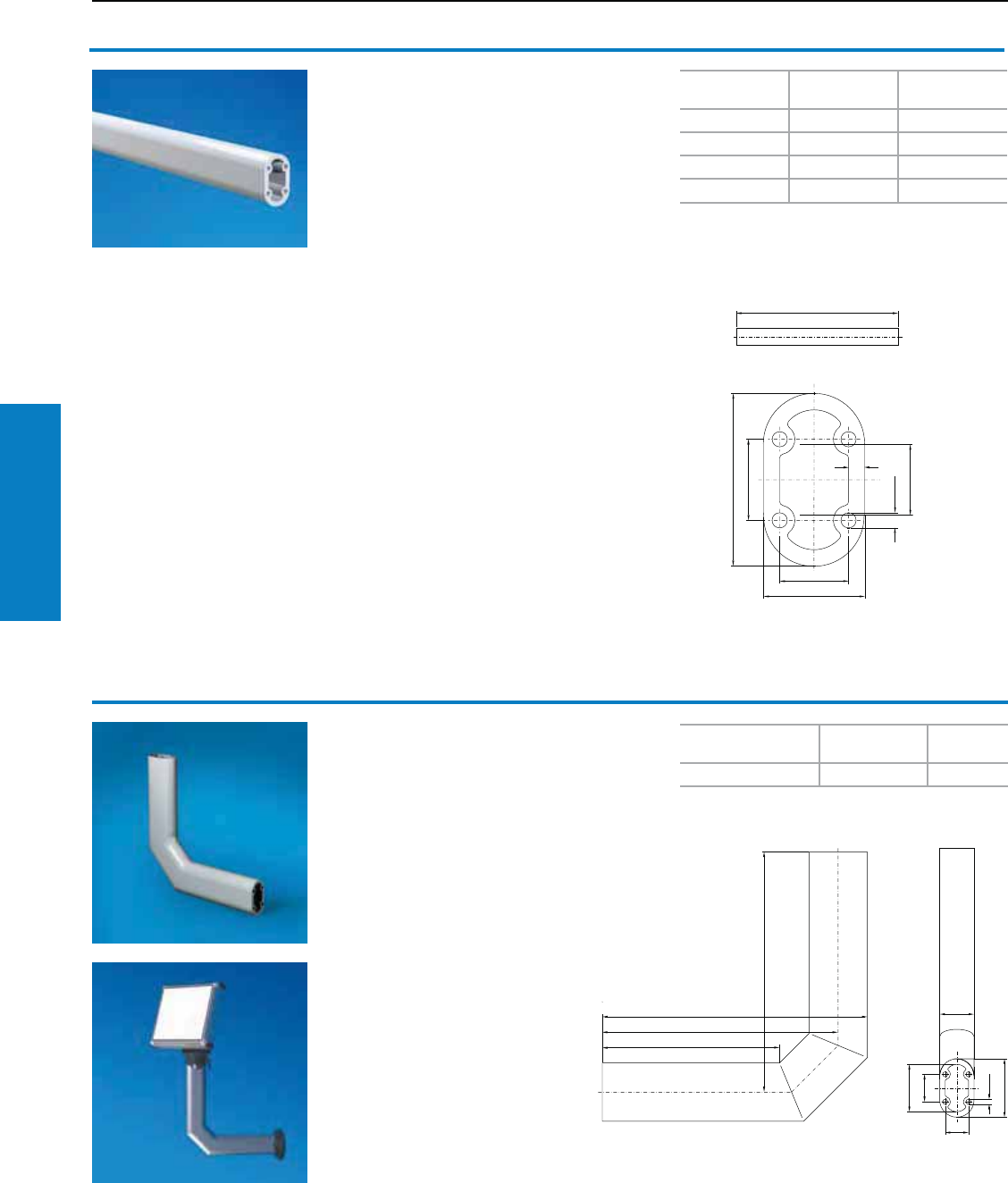
Operator Interface
136 Industrial Buyer’s Guide
CP-L Support Arm System
CP-L Support Arm System
90° support arm bracket CP-L
The compact, robust alternative.
Material:
Extruded aluminum
Color
RAL
Weight
lb (kg) Part No.
7035 (light gray) 8 (3.4) 6519.000
Support section CP-L
Attachment to the connection components with
4 self-tapping screws in a screw channel, may
be cut to any required length, no thread-
tapping required.
Dimensions:
2.0 x 3.3 inches (50 x 85 mm)
Wall thickness:
0.3 inches (8 mm)
Material:
Extruded aluminum
Length (L)1)
inches (mm)
Weight
lb (kg)
RAL 7035
Part No.
9.8 (250) 3 (1.3) 6509.000
19.7 (500) 6 (2.6) 6511.000
39.4 (1000) 11 (5.1) 6513.000
78.7 (2000) 23 (10.2) 6515.000
1) L min = 135 mm
L
Inch and pound measurements are rounded to the nearest whole number.
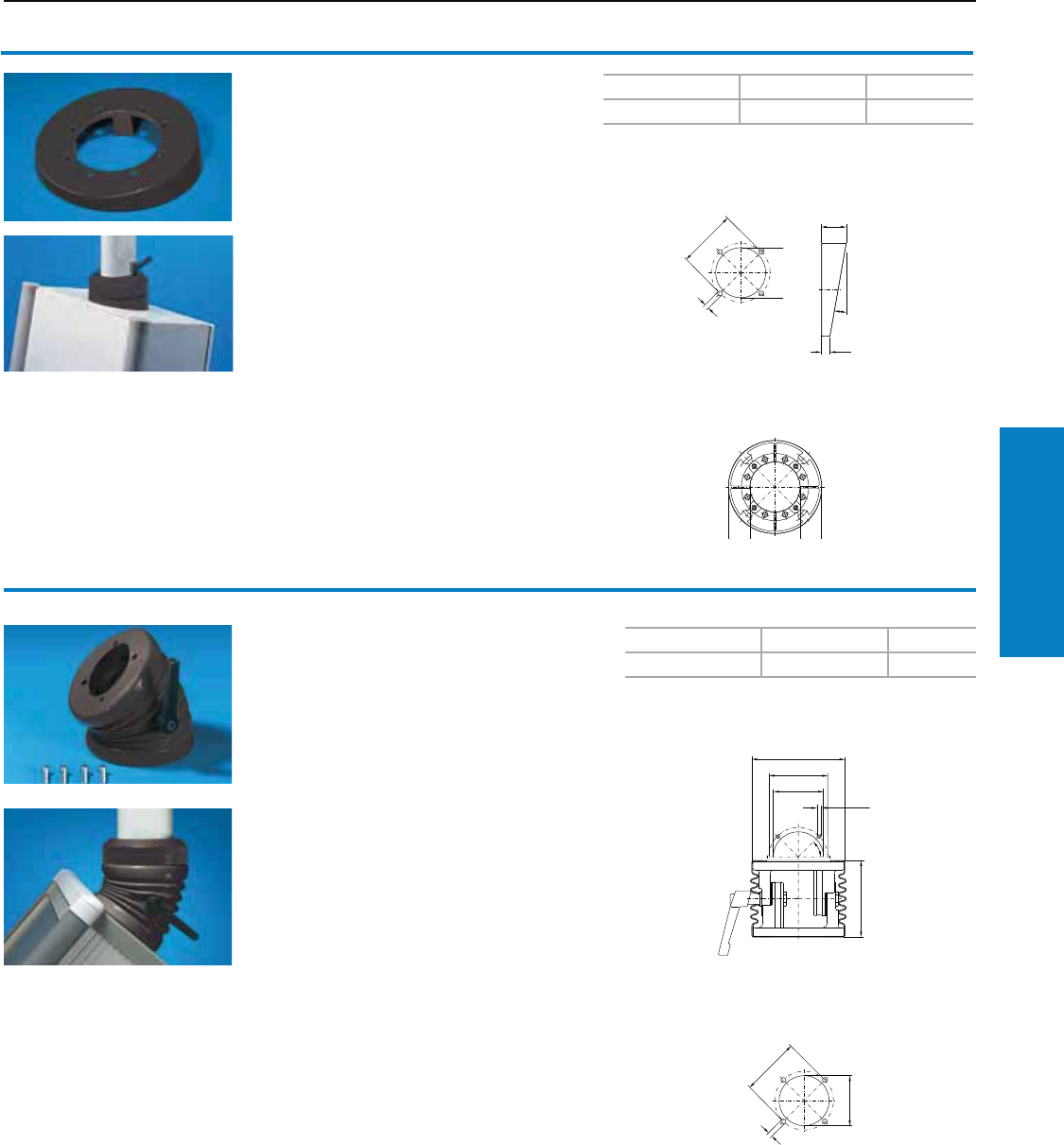
Operator Interface
Industrial Buyer’s Guide 137
CP-L Support Arm System
Tilting adaptor, 10° CP-L
For support arm connection Ø 5" (130 mm)
For mounting between:
• Housing coupling CP-L (6525.010)
or
• Enclosure attachment CP-L (6525.510)
or
• 90° elbow coupling CP-L (6526.010)
and the command panel
Material:
Die-cast zinc
Conguration:
Gasket and assembly hardware
Mounting cut-out
Enclosure CP-L, Ø 5" (130 mm)
Color RAL Weight lb (kg) Part No.
7024 (graphite gray) 1 (0.6) 6527.010
1
1
CP-L Support Arm System
Tilting adaptor, ± 45° CP-L
For support arm connection Ø 5" (130 mm)
For mounting between:
• Housing coupling CP-L (6525.010)
or
• Enclosure attachment CP-L (6525.510)
or
• 90° elbow coupling CP-L (6526.010)
and the command panel
Tilting Angle:
Adjustable in 7.5° increments
Material:
Cast aluminum
Conguration:
Gasket, plastic bellows and assembly hardware
German patent no. 195 40 298
US patent no. 5,911,393 Mounting cut-out
Enclosure CP-L, Ø 5" (130 mm)
Color RAL Weight lb (kg) Part No.
7024 (graphite gray) 3 (1.3) 6529.010
1
1
Inch and pound measurements are rounded to the nearest whole number.
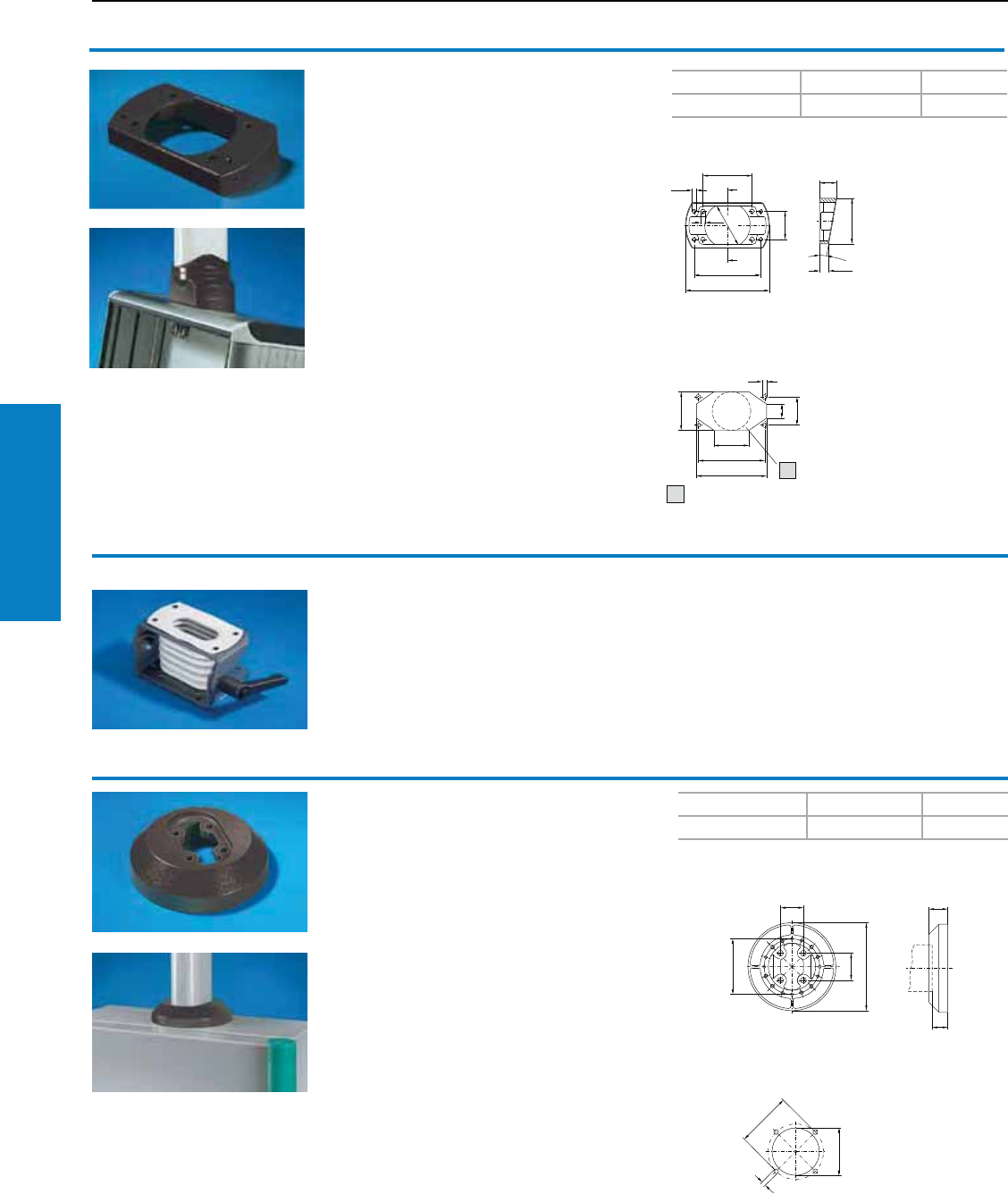
Operator Interface
138 Industrial Buyer’s Guide
CP-L Support Arm System
CP-L Support Arm System
Enclosure attachment, tilting,
see page 121.
Enclosure attachment CP-L
For support arm connection Ø 5" (130 mm)
For secure fastening of the enclosure to the
support arm system.
Material:
Die-cast zinc
Conguration:
Gaskets and self-tapping screws for CP-L
support section attachment
Mounting cut-out
Enclosure CP-L, Ø 5" (130 mm)
1
Color RAL Weight lb (kg) Part No.
7024 (graphite gray) 2 (1.0) 6525.510
Tilting adaptor, 10° CP-L
For support arm connection
5 x 3" (120 x 65 mm)
For mounting between:
• Housing coupling CP-L (6525.110)
or
• Enclosure attachment CP-L (6525.610)
or
• Housing coupling CP-S (6501.130)
and the command panel.
Material:
Die-cast zinc
Conguration:
Gasket and assembly hardware
Color RAL Weight lb (kg) Part No.
7024 (graphite gray) 1 (0.4) 6527.110
Mounting cut-out
Enclosure CP-L 5 x 3" (120 x 65 mm)
1) Alternative maximum Ø 2" (55 mm)
1
1
1
1
1
1
Inch and pound measurements are rounded to the nearest whole number.
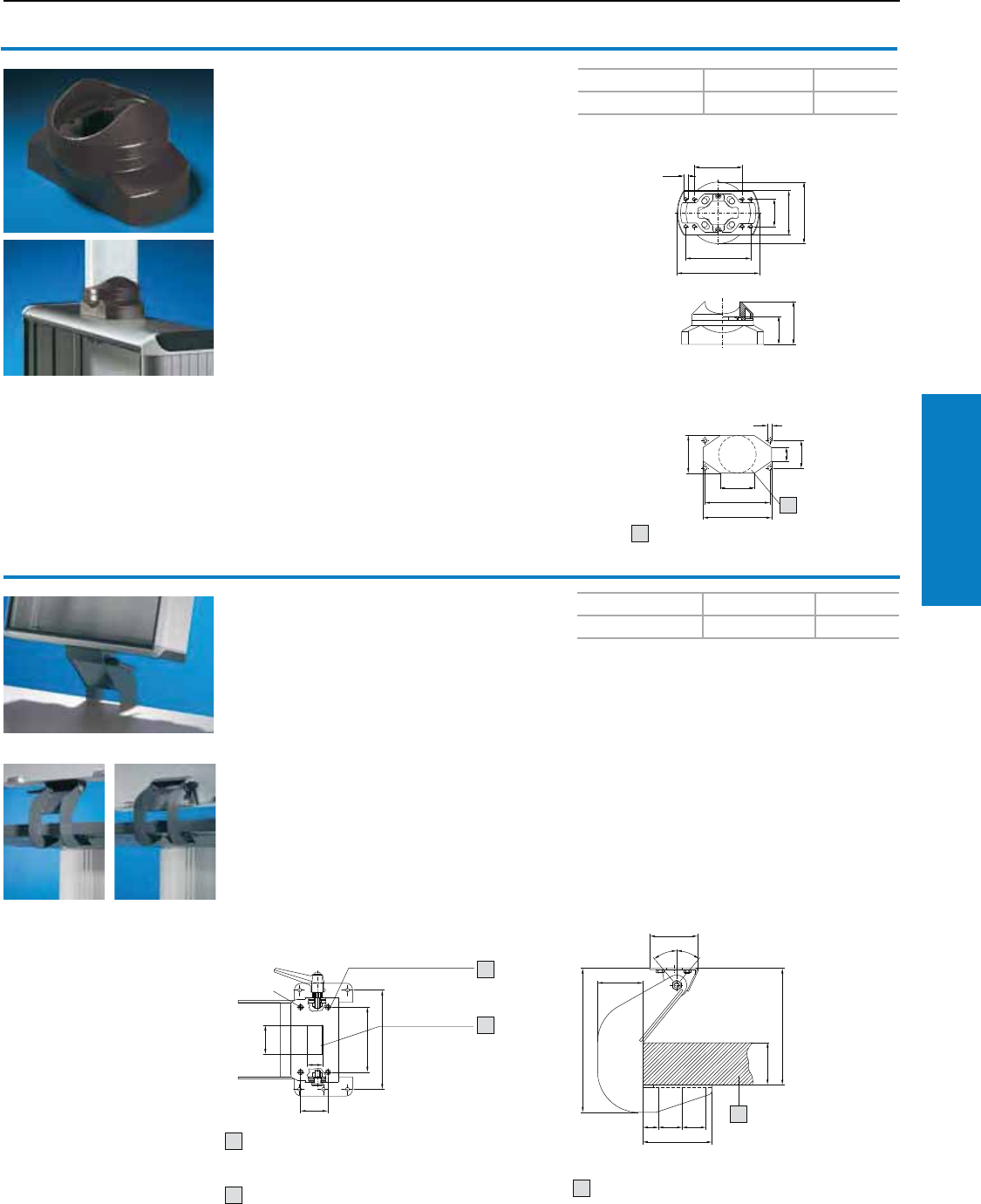
Operator Interface
Industrial Buyer’s Guide 139
CP-L Support Arm System
Enclosure attachment CP-L
For support arm connection
5 x 3" (120 x 65 mm)
For fixed fastening of the enclosure to the support
arm system.
Material:
Die-cast zinc
Conguration:
Gaskets and self-tapping screws for CP-L support
section attachment or support arm connection
5 x 3" (120 x 65 mm)
Accessories:
Connection console CP-L,
see page 143.
Color RAL Weight lb (kg) Part No.
7024 (graphite gray) 2 (1.0) 6525.610
Mounting cut-out
Enclosure CP-L, 5 x 3" (120 x 65 mm)
1) Alternative maximum Ø 2" (55 mm)
1
1
1
1
1
CP-L Support Arm System
Enclosure attachment, tilting,
base-mounting
CP-L 5 x 3" (120 x 65 mm)
For mounting beneath:
• IW worktop with pedestal
• Sufficiently large surfaces
Fits enclosures with mounting cut-out:
• CP-L 5 x 3" (120 x 65 mm)
With mounting cut-out for connector grommet
for sealed cable entry.
Tilt Angle:
± 40°, lockable by a clamping lever
Material:
Sheet steel, painted
Conguration:
Assembly hardware
Color RAL Weight lb (kg) Part No.
7024 (graphite gray) 4 (1.6) 6902.640
1
11
11
11
Prepared for enclosure with connection
CP-L/CP-S, 5 x 3" (120 x 65 mm) or
connection console CP-L 6508.010
Prepared for connector gland
2400.300/2400.500
Note:
The enclosure attachment can be mounted either
on the support arm connection of the Optipanel
enclosure or on the underside or rear of any
enclosure.
Accessories:
Connector grommet, refer to www.rittal-corp.com.
IW worktop, see page 188
Pedestal, see page 161
A = maximum
2" (62 mm)
3) Worktop, 6902.310
1
1
2
23
3
Inch and pound measurements are rounded to the nearest whole number.
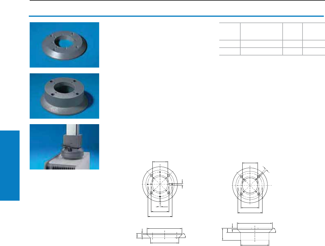
Operator Interface
140 Industrial Buyer’s Guide
CP-L Support Arm System
Connection adaptor
CP-L to CP-XL
For mounting between:
• Enclosure with support arm connection CP-L and
• Support arm system CP-XL
The cut-out for CP-L may also be used for the
attachment of command panels directly to
machines and systems without a support arm.
Assembly Sequence:
• Mount the connection adaptor on the
supporting structure
• Mount the enclosure and tighten the screws
The gasket to the supporting structure is
available on request.
Material:
Cast aluminum
Conguration:
Gasket and assembly hardware
CP-L Support Arm System
11
1
1
11
1
1
Height
inches
(mm)
Color
RAL
Weight
lb (kg) Part No.
1 (20)1) 7024 (graphite gray) 1 (0.6) 6528.010
2 (55)2) 7024 (graphite gray) 2 (0.7) 6528.510
1) Provided the load permits, may also be mounted
between enclosure with support arm connection CP-XL
and support arm system CP-L Ø 5" (130 mm).
2) For command panel VIP 6000, see page 102
3.1 Operator housing, design code number 1 to 5.
Inch and pound measurements are rounded to the nearest whole number.
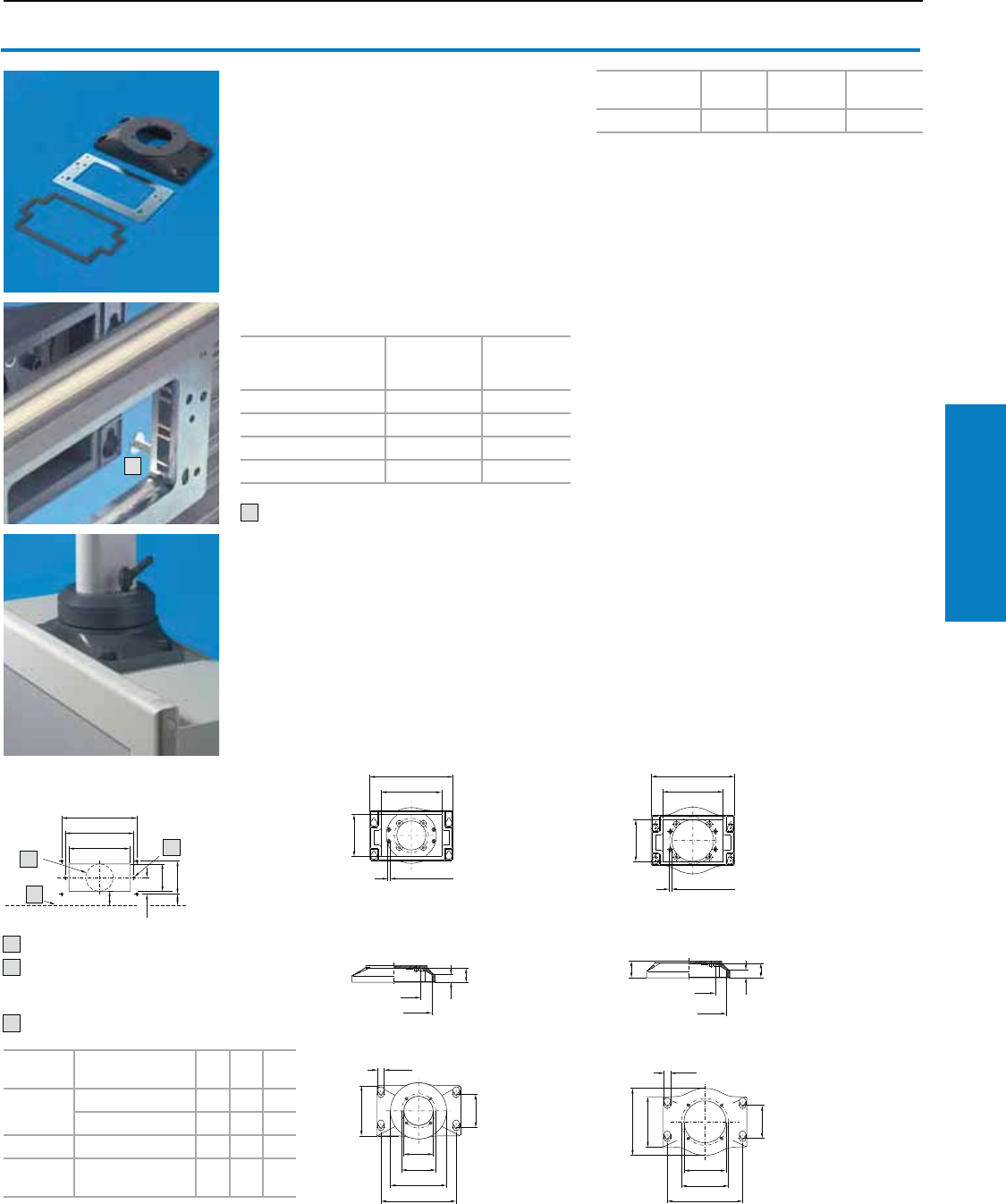
Operator Interface
Industrial Buyer’s Guide 141
CP-L Support Arm System
Connection plate
With reinforcement plate
• For easy location of the command panel on the
support arm or pedestal
• After drilling 4 holes Ø 0.3" (7 mm), screwfasten
the connection plate from the outside
• More space for cable entry plus
clamping bracket
For assembling:
• VIP 60003)
• Optipanel4)
• Sheet steel command panel5) to:
CP-L Support Arm System
Installation
depth inches (mm) ABC
VIP 6000 6 – 7 (155 - 185) 32 81 30
12 – 17 (295 - 438) 174 81 173
Optipanel 6 (150) 34 65 28
Metal
enclosure –1) 86 1)
1) Drill the holes/cut-out in the center of the
reinforcement plate of the enclosure.
Mounting cut-out CP-L/CP-XL
Alternative Ø B
Ø 0.2" (6 mm) only with metal
enclosures for securing the
reinforcement plate
Enclosure outer edge rear
With support
arm connection
Color
RAL
Weight
lb (kg) Part No.
CP-L 70242) 2 (0.7) 6528.210
Support
arm system
components
CP-L CP-XL
Enclosure attachment 6525.510 6130.610
Housing coupling 6525.010 6130.010
Elbow coupling 6526.010 6040.010
Tilting adaptor ± 45° 6529.010 -
2) RAL 7024 (graphite gray)
Note:
The square support arm cut-out can be prepared
on request.
Material:
Connection plate: Cast aluminum Reinforcement
plate: Sheet steel 0.2" (6 mm)
Conguration:
Gaskets and assembly hardware
3) From a front panel width of 10" (265 mm).
The CP-XL version cannot be used in
conjunction with installation depths 6 and 12"
(155 and 295 mm).
4) From a front panel width of 9" (220 mm) and
installation depth of 6" (150 mm).
5) Mounting surface area, minimum W x D =
12 x 5" (300 x 135 mm) (as in the command
panel housing with door).
1) To install the enclosure; pre-install the screws,
mount the enclosure, and tighten the screws.
CP-L CP-XL
1
1
1
B
1
1
1
1
1
1
1
1
1
1
1
1
1
1
1
1
11
1
1
1
1
2
3
12
3
1
1
Inch and pound measurements are rounded to the nearest whole number.

Operator Interface
142 Industrial Buyer’s Guide
CP-L Support Arm System
CP-L Support Arm System
11
1
1
1
11
Color RAL Weight lb (kg) Part No.
7024 (graphite gray) 1 (0.4) 6525.210
Enclosure attachment,
xed CP-L
For support arm connection
5 x 3" (120 x 65 mm)
For fixed fastening of the enclosure to the
support section.
With machined keyholes for easy, secure mounting
by just one person:
• Screw the enclosure attachment to the
support arm
• Secure the supporting plate to the inside of the
enclosure and pre-fit two screws from the outside
• Mount the enclosure and tighten the screws
For enclosures with a depth of 3" (70 mm). More
space for cable entry with connectors.
Material:
Enclosure attachment: Die-cast zinc
Support plate: Sheet steel
Conguration:
Gasket, support plate and assembly hardware.
Enclosure attachment: CP-L for support arm
connection 5 x 3" (120 x 65 mm)
Additional Parts Needed:
90° hinged joint CP-L, see page 146
Mounting cut-out
Enclosure 5 x 3" (120 x 65 mm)
1) Alternative maximum Ø 2" (55 mm)
11)
Inch and pound measurements are rounded to the nearest whole number.
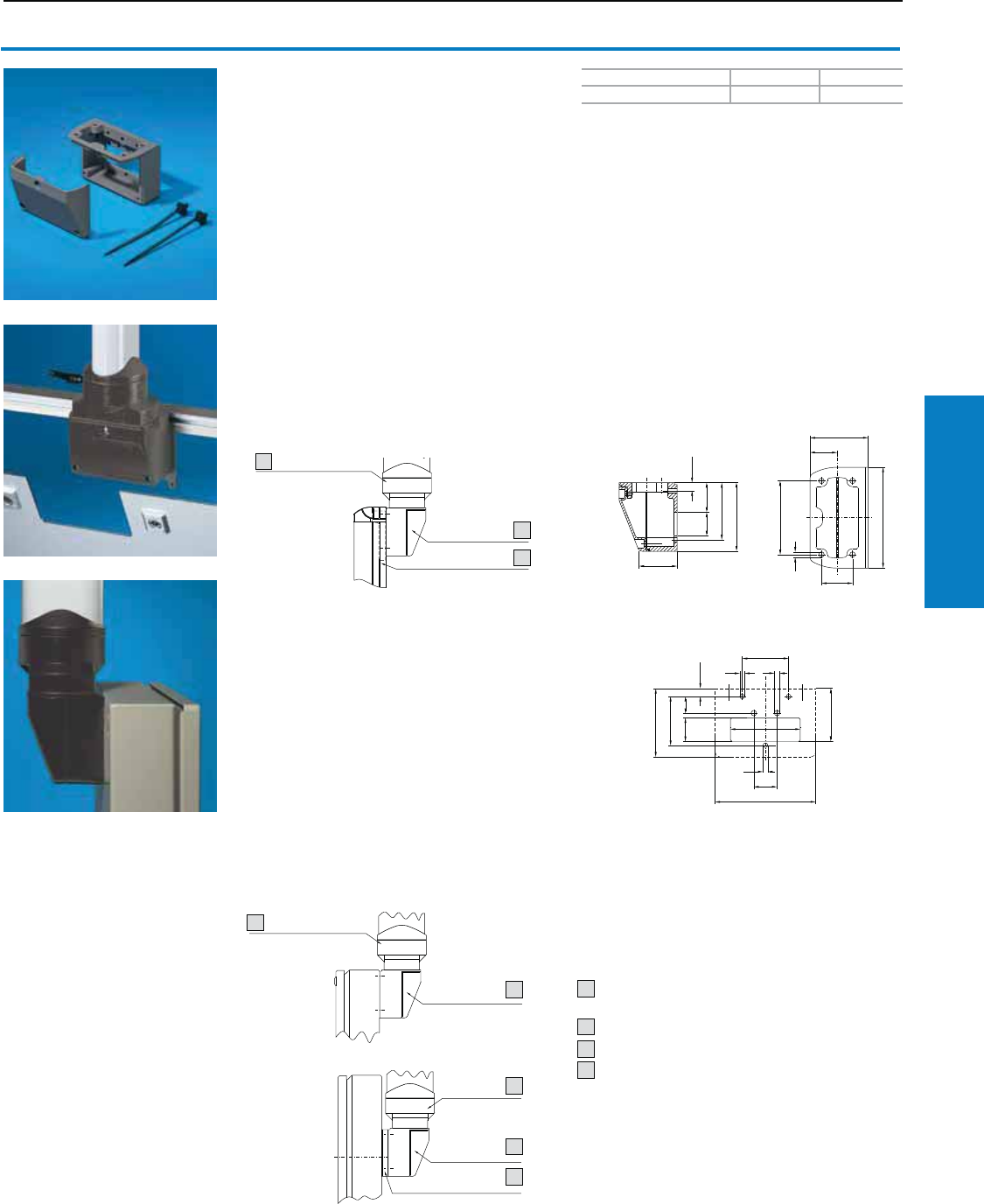
Operator Interface
Industrial Buyer’s Guide 143
CP-L Support Arm System
CP-L Support Arm System
Color RAL Weight lb (kg) Part No.
7024 (graphite gray) 1 (0.7) 6508.010
Connection housing CP-L
For rear connection of slimline operator housings.
Removable lid for simple cable entry.
Material:
Cast aluminum
Conguration:
Gaskets and assembly hardware for mounting on
the enclosure and 2 cable ties.
Mounting Options:
1. Optipanel
Retrofitting:
• Cut-out in rear wall/door
Selection by design code number (see page 98,
item 2.3, selection 7 or 8):
Connection housing and support plate are fitted.
2. General
• Terminal boxes (see page 4),
• Cast aluminum enclosures
(see page 58)
The connection housing may be mounted:
a) Directly, flush with enclosure edge
(see Fig. B top),
b) In the center with spacer plate 6508.200
(on request) (see Fig. B below),
On the rear wall of the enclosure. Additional
reinforcement of the rear wall should be checked in
individual cases.
Additional Parts Needed:
Enclosure attachment (6525.610), see page 139.
Housing coupling (6525.110), see page 144.
Tilting adaptor 10° (6527.110), see page 138.
Housing coupling CP-S (6501.130), see page 123.
Accessories:
Spacer plate (6508.200), available on request.
1. Optipanel
2. General
1)
3)
Fig. A
1
1
View A
A
1
1
1
Mounting cut-out
Support arm component CP-L
5 x 3" (120 x 65 mm)
Connection housing CP-L
Support plate (inside)
Spacer plate
1
2
3
4
1)
4)
1
2
4
1) Fig. B
2
1
1
2
3
Inch and pound measurements are rounded to the nearest whole number.
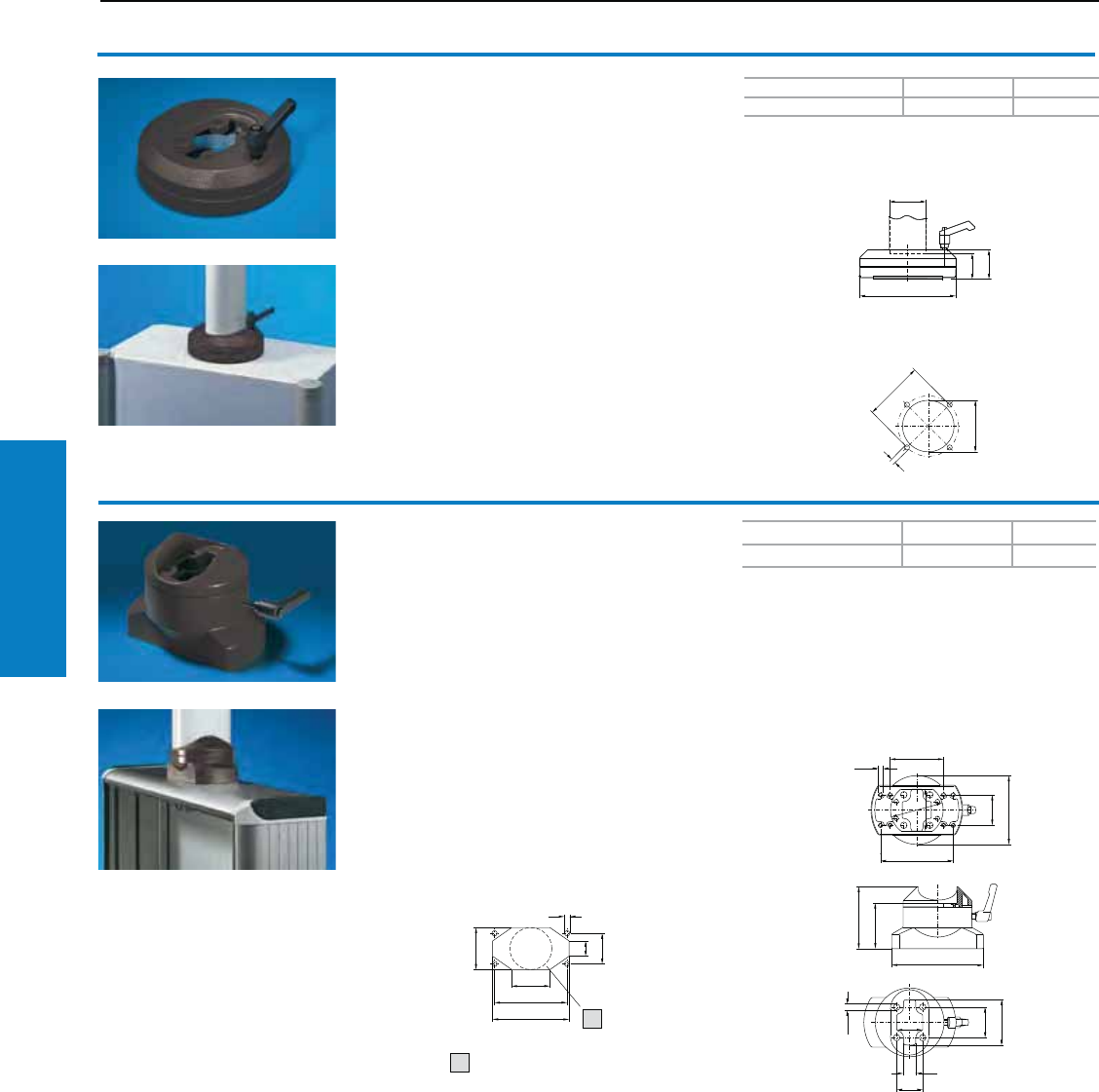
Operator Interface
144 Industrial Buyer’s Guide
CP-L Support Arm System
CP-L Support Arm System
1
1
1
Color RAL Weight lb (kg) Part No.
7024 (graphite gray) 4 (1.7) 6525.010
Color RAL Weight lb (kg) Part No.
7024 (graphite gray) 3 (1.4) 6525.110
Rotating enclosure coupling CP-L
For support arm connection Ø 5" (130 mm)
For swivel-mounting of the enclosure on the vertical
section of the support arm system.
Rotation Range:
Approximately 310°, lockable via clamping lever.
By inserting additional pins 0.2 x 0.7" (5 x 18 mm)
to ISO 8752, the rotation range may be limited to
± 5°, 65°, 95° and 155°.
Material:
Die-cast zinc
Conguration:
Gaskets and self-tapping screws for CP-L support
section attachment
Mounting cut-out
Enclosure CP-L, Ø 130 mm
Rotating enclosure coupling CP-L
For support arm connection
5 x 3" (120 x 65 mm)
For swivel-mounting of the enclosure on the vertical
section of the support arm system.
Rotation Range:
Approximately 350°, lockable via clamping lever.
By inserting additional pins 0.2 x 0.8" (6 x 20 mm)
to ISO 8752, the rotation range may be limited to
± 5° and 100°.
Conguration:
Gaskets and self-tapping screws for CP-L support
section attachment
Mounting cut-out
Enclosure CP-L,
5 x 3" (120 x 65 mm)
1) Alternative maximum
Ø 2" (55 mm)
Material:
Die-cast zinc
11)
1
1
Inch and pound measurements are rounded to the nearest whole number.
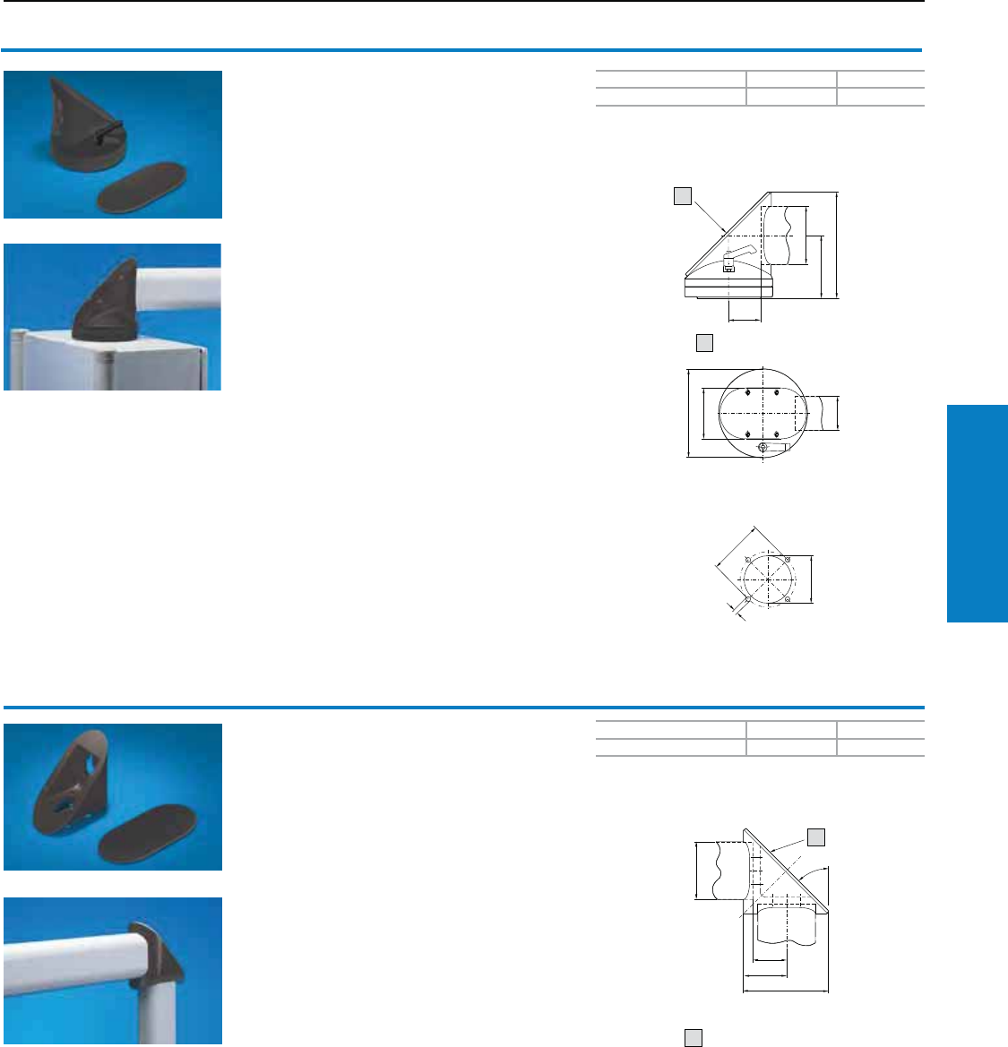
Operator Interface
Industrial Buyer’s Guide 145
CP-L Support Arm System
CP-L Support Arm System
1
Color RAL Weight lb (kg) Part No.
7024 (graphite gray) 4 (1.9) 6526.010
Color RAL Weight lb (kg) Part No.
7024 (graphite gray) 3 (1.4) 6524.010
90° enclosure coupling CP-L
For support arm connection Ø 5" (130 mm)
For swivel-mounting of the enclosure on the
horizontal part of the support arm system.
Enclosure may be suspended or top-mounted.
The removable plate enables easy cable entry.
Rotation Range:
Approximately 310°, by inserting additional pins 0.2
x 0.7" (5 x 18 mm) to ISO 8752, the rotation range
may be limited to ± 5°, 65°, 95° and 155°.
Material:
Cast aluminum/die-cast zinc
Conguration:
Gaskets, adjustment set and self-tapping screws
for CP-L support section attachment
Accessories:
Mounting component for signal pillars
(2375.000), see www.rittal-corp.com
Removable plate
Mounting cut-out
Enclosure CP-L Ø 5" (130 mm)
90° elbow CP-L
For connecting horizontal and vertical support
arm components. The removable plate ensures
easy cable entry.
Material:
Die-cast zinc
Conguration:
Gaskets, adjustment set and self-tapping screws
for CP-L support section attachment
Property Rights:
German patent no. 43 31 125
French patent no. 94 10901
Italian patent no. 012 74 738
Japanese patent no. 2 809 993
US patent no. 5,533,763
Accessories:
Mounting component for signal pillars
(2375.000), see www.rittal-corp.com
1) Removable plate
3 x 7" (75 x 174 mm)
1
1)
1
1
1
1)
1
1
Inch and pound measurements are rounded to the nearest whole number.
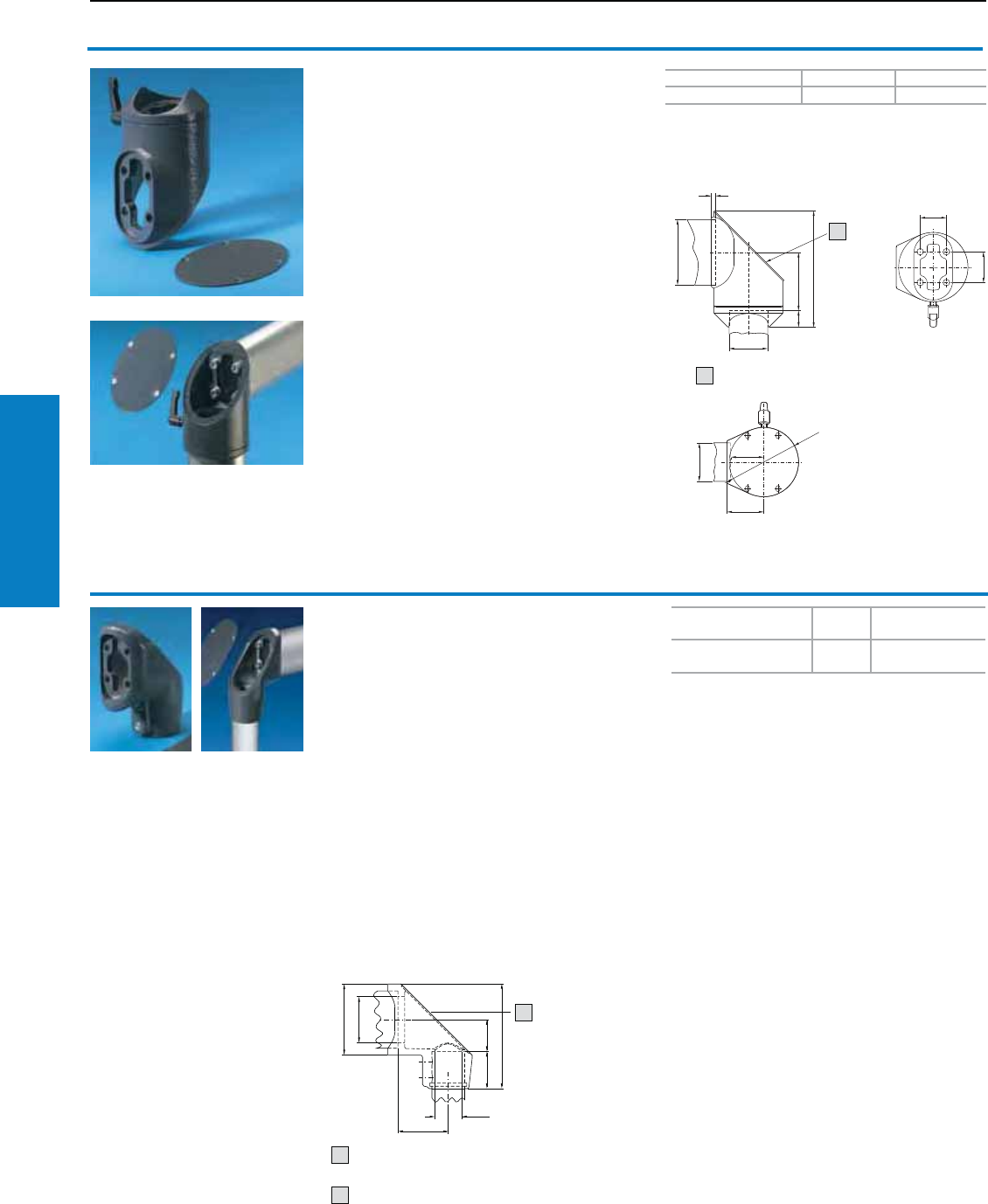
Operator Interface
146 Industrial Buyer’s Guide
CP-L Support Arm System
Removable plate
3 x 6" (71 x 149 mm)
Removable cover
CP-L Support Arm System
Color RAL Weight lb (kg) Part No.
7024 (graphite gray) 3 (1.2 ) 6524.210
Color RAL Weight
lb (kg) Part No.
7024 (graphite gray) 2 (1.0) 6501.090
90° rotating elbow CP-L
The swivel connection between horizontal and
vertical support sections.
With very slimline enclosures, there is no need
for the deep housing coupling. With the shallow
enclosure attachment (6525.210), the support
section may also be attached with its wide side.
Rotation Range:
Approximately 325°. Option of limiting the rotation
range with the use of additional pins 0.2 x 0.7"
(5 x 18 mm) to ISO 8752 to ± 54° and 98°.
Material:
Cast aluminum/die-cast zinc
Conguration:
Gaskets, self-tapping screws for support section
attachment and adjustment set
Additional Parts Needed:
Enclosure attachment, locatable CP-L for support
arm connection 5 x 3" (120 x 65 mm)
(6525.210), see page 142,
or
Enclosure attachment CP-L for support arm
connection 5 x 3" (120 x 65 mm) (6525.610), see
page 144.
Removable plate
11
1)
90° adaptor elbow, CP-L to CP-S
Connection component between:
• Small and larger support arm systems
• Outlet optionally at the top or bottom if this
configuration is chosen for structural and
visual reasons
• The removable cover ensures easy cable entry
Material:
Cast aluminum
Conguration:
Gasket for support section attachment
Note:
Mounting component for signal pillar available
on request
1
1
6501.090
1
1
1)
1
1
2
Inch and pound measurements are rounded to the nearest whole number.
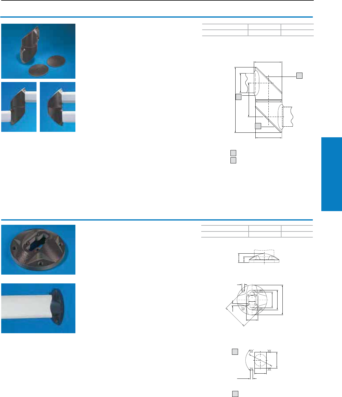
Operator Interface
Industrial Buyer’s Guide 147
CP-L Support Arm System
CP-L Support Arm System
11
1
11
1
1
11
11 1
B
Color RAL Weight lb (kg) Part No.
7024 (graphite gray) 7 (3.2) 6523.010
Color RAL Weight lb (kg) Part No.
7024 (graphite gray) 1 (0.6) 6520.510
Intermediate hinge CP-L
For vertically hinged connection of horizontal
support sections within the support arm system.
The removable plates ensure easy cable entry.
Rotation Range:
Approximately 315°, with the option of restricting
the rotation range in 60° increments using the
screws supplied.
Material:
Cast aluminum
Conguration:
Gaskets, adjustment set and self-tapping screws
for CP-L support section attachment
Property Rights:
German patent no. 44 03 593
French patent no. 94 10902
Italian patent no. 01274751
Japanese patent no. 2 675 264
US patent no. 5,522,118
Accessories:
Mounting component for signal pillars
(2375.020), see www.rittal-corp.com
Screw for adjusting rotatability
Removable plate
Wall/base-mounting, small CP-L
For fixed attachment of the support arm system to
vertical or horizontal surfaces.
Suitable for the configuration of compact support
arm systems with cable infeed from the inside.
Material:
Cast aluminum
Conguration:
Gaskets, adjustment set for support section
and self-tapping screws for CP-L support
section attachment
Mounting cut-out
1) Alternative Ø 2" (52 mm)
A = maximum 2" (52 mm)
B = maximum 3" (70 mm)
1)
1
2
1
1
1
11
1
11
1)
1
2
2
Inch and pound measurements are rounded to the nearest whole number.
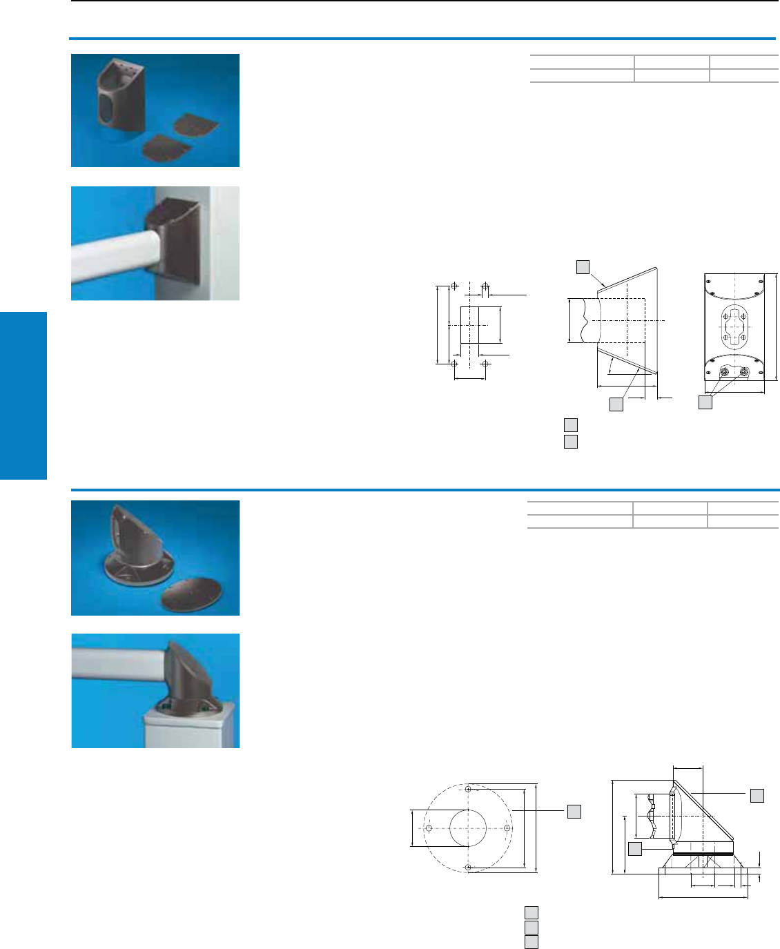
Operator Interface
148 Industrial Buyer’s Guide
CP-L Support Arm System
CP-L Support Arm System
11 1
1
11
Color RAL Weight lb (kg) Part No.
7024 (graphite gray) 4 (1.9) 6520.010
Color RAL Weight lb (kg) Part No.
7024 (graphite gray) 7 (3.0) 6522.010
Wall/base-mounting, large CP-L
For fixed attachment of the support arm system to
vertical or horizontal surfaces with cable entry from
the inside.
Material:
Cast aluminum
Conguration:
Gaskets, opportunity for adjustment with offset
screws and self-tapping screws supplied loose for
CP-L support section attachment.
Accessories:
Pillar, refer to www.rittal-corp.com
Mounting cut-out
Removable plate
Adjusting screws
Mounting cut-out
Top-mounted joint CP-L
For swivel-mounting of the support arm system on
horizontal surfaces – also suitable for suspending
from the ceiling. The removable plate allows easy
cable entry.
Rotation Range:
Approximately 315°, with the option of restricting
the rotation range in 60° increments and adjusting
the mobility of the joint with the screws supplied
loose. To lock the joint, the screw may be
exchanged for a standard commercially available
clamping lever M 1" (8 x 16 mm).
Material:
Cast aluminum
Conguration:
Gaskets, adjustment set and self-tapping screws
for CP-L support section attachment.
Note:
Cannot be used as an enclosure coupling.
Accessories:
Pillar, refer to www.rittal-corp.com.
Mounting component for signal pillars
(2375.020), refer to www.rittal-corp.com.
Screw for adjusting rotatability
Removable plate
Mounting surface
1
2
11
2
11
1)
1
1
1
2
3
111
1
11
1
1
1)
1
2
1
11 1
1
3)
3
Inch and pound measurements are rounded to the nearest whole number.
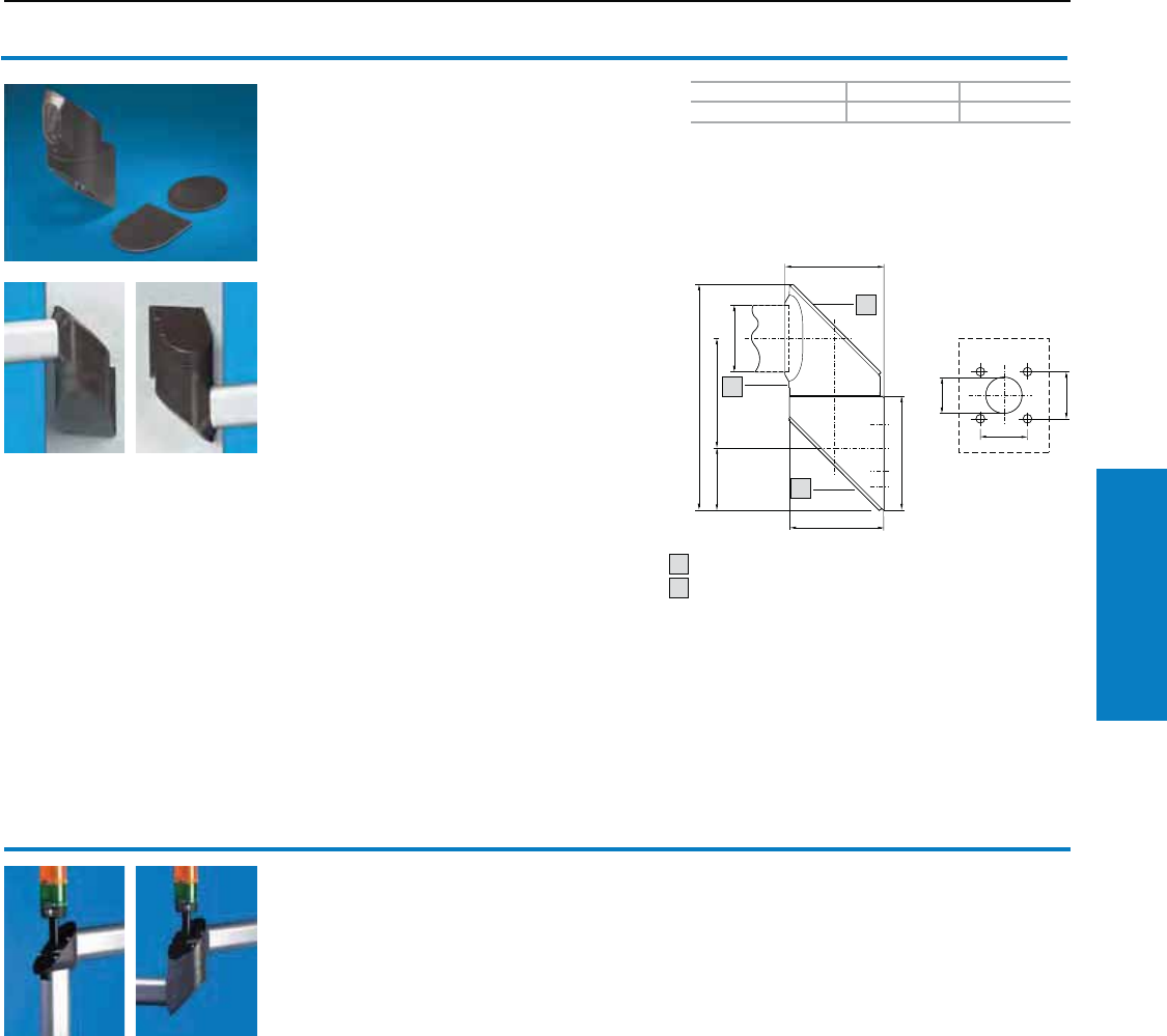
Operator Interface
Industrial Buyer’s Guide 149
CP-L Support Arm System
CP-L Support Arm System
11 1
Color RAL Weight lb (kg) Part No.
7024 (graphite gray) 7 (3.2) 6521.010
Wallmounted hinge CP-L
For vertically hinged-mounting of the support arm
on vertical surfaces. The removable plates
facilitate simple cable routing and cable entry.
Rotation Range:
Approximately 315°, with the option of restricting
the rotation range in 60° increments and adjusting
the mobility of the joint with the screws supplied
loose. To lock the joint, the screw may be
exchanged for a standard commercially available
clamping lever M 1" (8 x 16 mm).
Material:
Cast aluminum
Conguration:
Gaskets, adjustment by grub screws and self
tapping screws for CP-L support section
attachment.
Property Rights:
German patent no. 44 03 593
French patent no. 94 10902
Italian patent no. 01274751
Japanese patent no. 2 675 264
US patent no. 5,522,118
Accessories:
Pillar, see www.rittal-corp.com
Mounting component for signal pillars
(2375.020), see www.rittal-corp.com
Mounting cut-out
Screw for adjusting rotatability
Removable plate
Mounting component CP-L
For signal pillars
For mounting a signal pillar with connection
component for conduit-mounting on support
arm system CP-L, see www.rittal-corp.com.
1
2
1
1
1
11
1
1)
1
2
2
Inch and pound measurements are rounded to the nearest whole number.
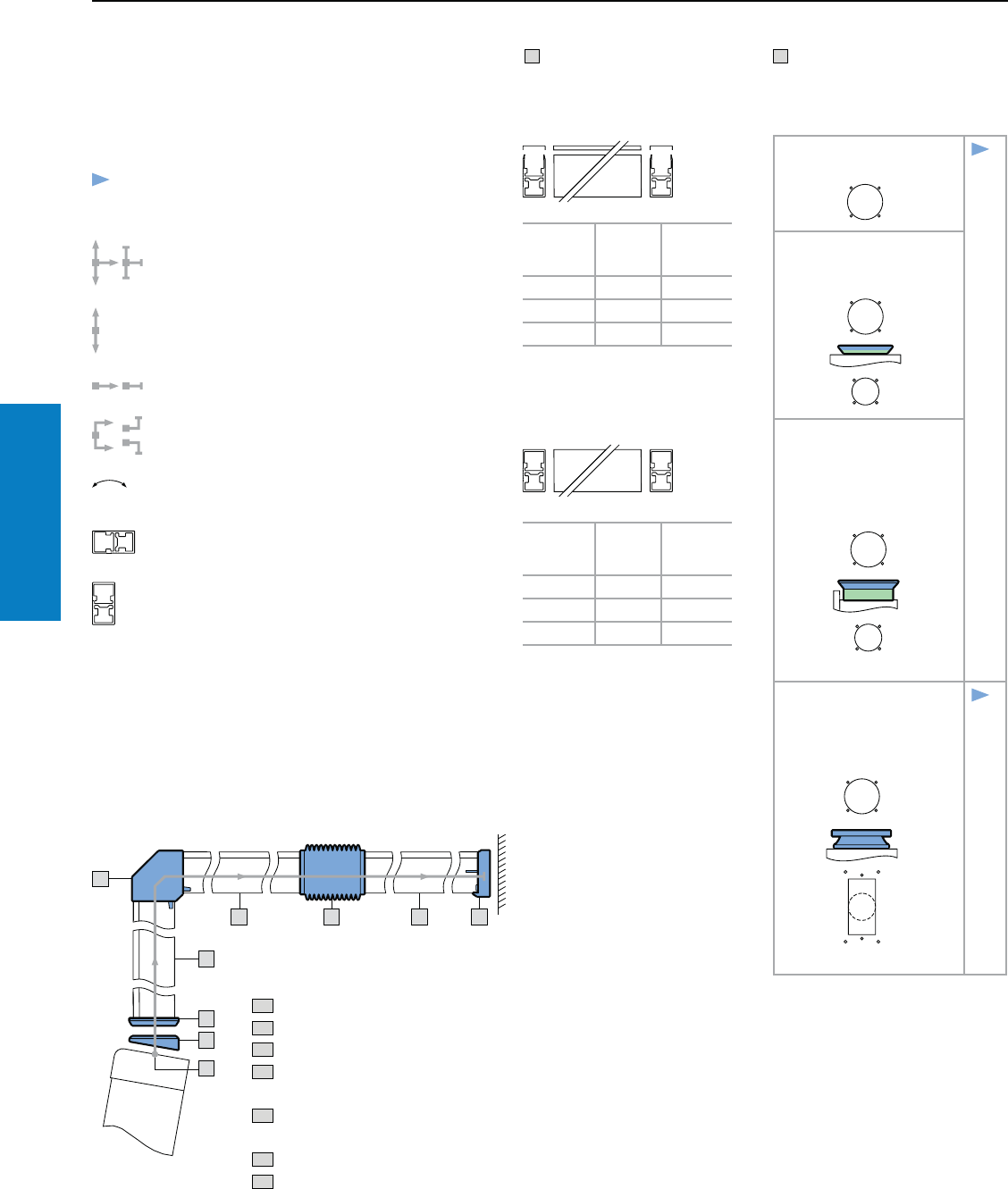
Operator Interface
150 Industrial Buyer’s Guide
CP-XL Support Arm System
31
11 1
1
1
21
11
1
CP-XL Support Arm System
Selection Guide
Make a simple sketch showing the basic form of the support
arm. Next, select the corresponding support arm
components. Start with "1: System start" by selecting the
appropriate enclosure situation.
T Support sections
T1 Support section CP-XL,
open
Length
inches
(mm)
Color
RAL Part No.
20 (500) 70351) 6050.000
39 (1000) 70351) 6100.000
79 (2000) 70351) 6200.000
See page 152
1 System start
Enclosure with mounting cut-out
Assembly example:
T1 Support section CP-XL, open
1. 1 Mounting cut-out CP-XL
2.1 Tilting adaptor, 10° CP-XL
3.1 Enclosure attachment CP-XL,
round
4.1 Angle piece 90° CP-XL, outlet
at bottom
5.1 Intermediate hinge CP-XL
6.1 Wall/base mounting CP-XL
1.1 Mounting cut-out
CP-L
2.1
3.1
3.2
3.3
3.4
3.5
1.2 Connection adaptor
CP-L to CP-XL
6528.010, see page 140
1.3 Connection adaptor
CP-L to CP-XL
for VIP 6000 enclosures
with installation depths 6,
7, 12" (155, 185, 295 mm)
6528.510, see page 140
1.4 Connection plate with
reinforcement plate
6528.420 width 8" (200 mm)
6528.430 width 16" (418 mm),
2.1
3.1
3.2
3.3
3.4
Continue with CP-XL according to the item numbers.
System continuation/system end:
all directions
vertical
horizontal
angled
rotatable components
From "3: Enclosure attachments", a support
section is required between each component
(minimum length approx. 4" [100 mm], for wall/
floor mounting approx. 6" [160 mm]).
The cross-sections indicate the installation
position(s).
T2 Support arm CP-XL,
solid
Length
inches
(mm)
Color
RAL Part No.
20 (500) 70351) 6050.500
39 (1000) 70351) 6100.500
79 (2000) 70351) 6200.500
See page 152
Note:
• Only insert one intermediate hinge
• Two angle pieces may also be used one after
the other
• With angle pieces, take care to ensure
correct positioning of the support section
cable duct
• Load diagram,
see page 116.
1) light gray
Inch and pound measurements are rounded to the nearest whole number.
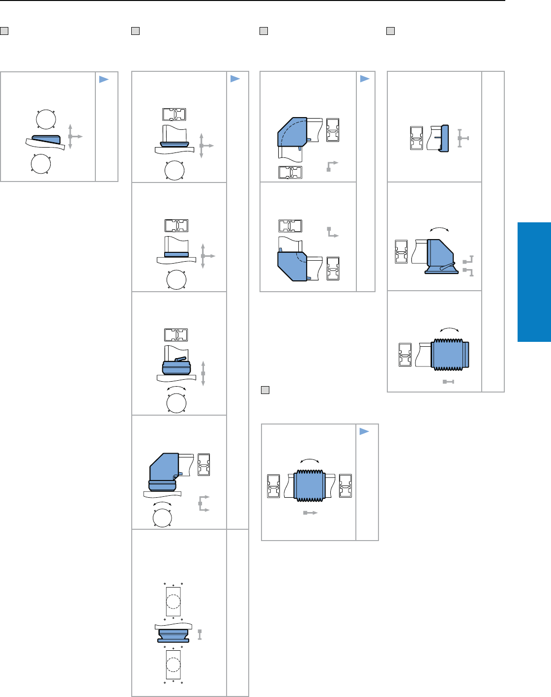
Operator Interface
Industrial Buyer’s Guide 151
CP-XL Support Arm System
CP-XL Support Arm System
Selection Guide
2.1 Tilting adaptor 10°
CP-XL
6023.010 see page 155
3.1
3.3
3.4
3 Enclosure
attachments
3.1 Enclosure attachment
CP-XL, round
6130.610 see page 153
4.1
4.2
5.1
6.1
6.2
6.3
3.2 Enclosure attachment
CP-XL, rectangular
6130.510 see page 154
3.3 Enclosure attachment
CP-XL
6130.010 see page 154
3.4 Angle coupling 90°
CP-XL
6040.010 see page 156
3.5 Housing coupling
for desktop mounting
6528.400 width 8" (200 mm)
6528.410 width 16"
(418 mm)
2 Tilting adaptor
6.1 Wall/base mounting
CP-XL
6160.010 see page 159
6.2 Top-mounted joint
CP-XL
6170.010 see page 159
6.3 Wall-mounted hinge
CP-XL
6110.010 see page 158
6 System end
4.1 Angle piece 90°
CP-XL, outlet at
bottom
6140.010 see page 157
5.1
6.1
6.2
6.3
4.2 Angle piece 90°
CP-XL, outlet at top
6180.010 see page 157
4 Angle
components
5.1 Intermediate hinge
CP-XL
6120.010 see page 157
4.1
4.2
6.2
6.3
5 Intermediate
hinge
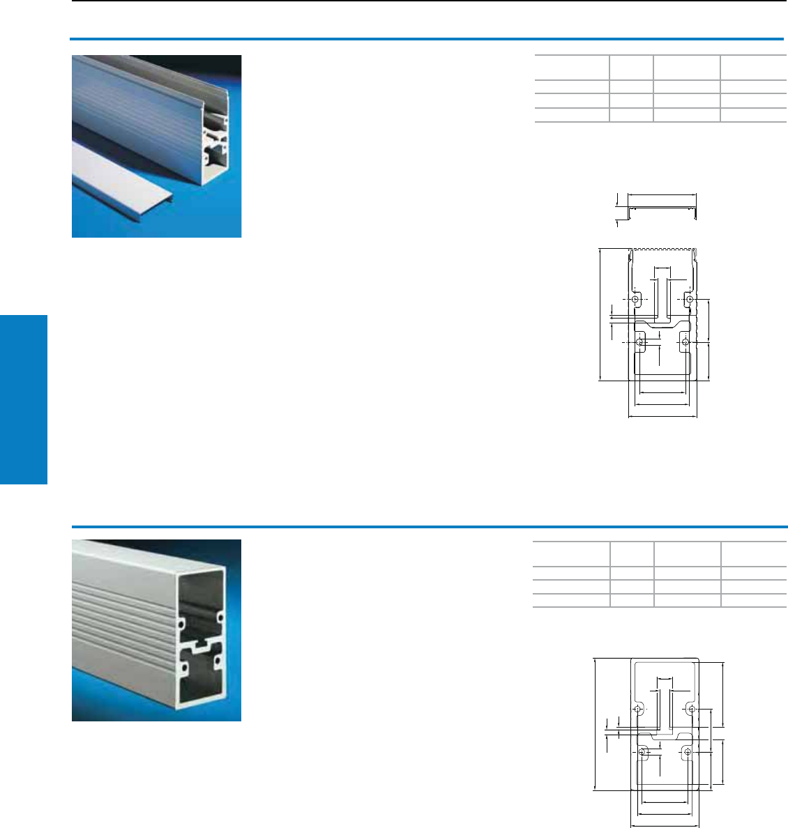
Operator Interface
152 Industrial Buyer’s Guide
CP-XL Support Arm System
CP-XL Support Arm System
11
1
1
1
1
1
Length mm
(inches)
Color
RAL
Weight
lb (kg) Part No.
20 (500) 70351) 11 (4.9) 6050.000
39 (1000) 70351) 22 (9.8) 6100.000
79 (2000) 70351) 43 (19.6) 6200.000
1) RAL 7035 (light gray)
Length mm
(inches)
Color
RAL
Weight
lb (kg) Part No.
20 (500) 70351) 12 (5.5) 6050.500
39 (1000) 70351) 24 (11.0) 6100.500
79 (2000) 70351) 49 (22.0) 6200.500
1) RAL 7035 (light gray)
Support section CP-XL, open
Attachment to the connecting components with 4
self-tapping screws in the screw channel, may be
cut to any required length.
With open cable duct, for easy servicing access
and for pre-assembled cables with connectors;
easily locked using a clip-on lid.
Size:
3 x 6" (80 x 155 mm)
Material:
Extruded aluminum
Conguration:
Clip-on lid
Note:
Load information, see page 116.
Accessories:
Adjustment set for support section, see page 153.
Support section CP-XL, solid
The alternative solution for higher loads and torsion
compared with the CP-L support section, open.
Size:
3 x 6" (80 x 155 mm)
Material:
Extruded aluminum
Note:
Load information, see page 116.
Accessories:
Adjustment set for support section, see page 153.
Inch and pound measurements are rounded to the nearest whole number.
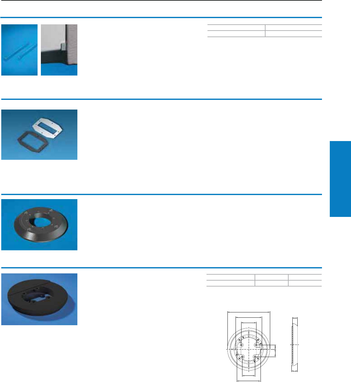
Operator Interface
Industrial Buyer’s Guide 153
CP-XL Support Arm System
CP-XL Support Arm System
PU Part No.
10 6205.000
Adjustment set for support
section CP-XL
The adjustment set permits field alignment of the
CP support section.
Material:
Sheet steel 19 ga (1.0 mm), zinc-plated, passivated
Connection plate
With reinforcement plate
See page 141.
Connection adaptor CP-L to CP-XL
See page 140.
11
1
1
1
Color RAL Weight lb (kg) Part No.
7024 (graphite gray) 4 (1.6) 6130.610
Enclosure attachment
CP-XL, round
For fixed external-mounting of enclosures to:
• Support section
Material:
Die-cast zinc
Conguration:
Gaskets and self-tapping screws for CP-XL support
section attachment
Inch and pound measurements are rounded to the nearest whole number.
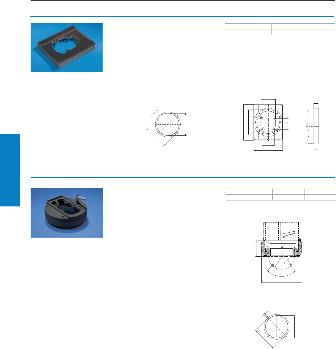
Operator Interface
154 Industrial Buyer’s Guide
CP-XL Support Arm System
CP-XL Support Arm System
11
1
1
11
1
1
Color RAL Weight lb (kg) Part No.
7024 (graphite gray) 3 (1.2) 6130.510
Enclosure attachment
CP-XL, rectangular
For fixed external-mounting on the enclosure.
Material:
Die-cast zinc
Conguration:
Gasket and self-tapping screws for CP-XL support
section attachment.
Mounting cut-out enclosure CP-XL
1
1
11
11
1
Color RAL Weight lb (kg) Part No.
7024 (graphite gray) 15 (6.8) 6130.010
Rotating enclosure coupling
CP-XL
For swivel-mounting of the enclosure on the vertical
section of the support arm system.
Rotation Range:
Approximately 350°
Material:
Die-cast zinc
Conguration:
Gaskets and self-tapping screws for CP-XL support
section attachment.
Note:
By inserting pins 0.2 x 0.5" (5 x 12 mm) to DIN EN
ISO 8741, the rotation range may be limited in 90°
increments. Mounting cut-out
Enclosure CP-XL
Inch and pound measurements are rounded to the nearest whole number.
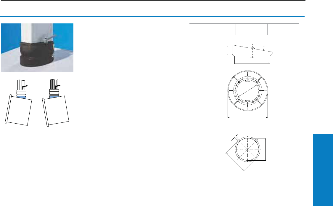
Operator Interface
Industrial Buyer’s Guide 155
CP-XL Support Arm System
CP-XL Support Arm System
1
1
1
11
1
Color RAL Weight lb (kg) Part No.
7024 (graphite gray) 3 (1.4) 6023.010
Tilting adaptor 10° CP-XL
For mounting between:
• Housing coupling (6130.000)
or
• Enclosure attachment (6130.600)
or
• Elbow coupling (6040.000) and the
command panel.
Material:
Die-cast zinc
Conguration:
Gaskets and assembly hardware
Mounting cut-out
Enclosure CP-XL
Inch and pound measurements are rounded to the nearest whole number.

Operator Interface
156 Industrial Buyer’s Guide
CP-XL Support Arm System
CP-XL Support Arm System
1
1
11
11
1
Color RAL Weight lb (kg) Part No.
7024 (graphite gray) 14 (6.2) 6040.010
90° enclosure coupling CP-XL
For swivel-mounting of the enclosure on the
horizontal part of the support arm system.
Enclosure may be suspended or supported.
Rotation Range:
Approximately 350°
Material:
Spheroidal-graphite cast iron and die-cast zinc
Conguration:
Gaskets, plastic housing and self-tapping screws
for CP-XL support section attachment.
Note:
By inserting pins 0.2 x 0.5" (5 x 12 mm) to DIN EN
ISO 8741, the rotation range may be limited in 90°
increments.
Property Rights:
German patent no. 4033747
Italian patent no. 1252120
Mounting cut-out
Enclosure CP-XL
Support mounting is only possible as shown in the
diagrams below (without intermediate hinge).
Enclosure coupling 6040.010
Support section 6050.500
Wall/base-mounting bracket 6160.010
Enclosure coupling 6040.010
Support section 6050.500
Top-mounted joint 6170.010
1
2
3
1) 3)
123
1
2
3
1) 3)
123
Inch and pound measurements are rounded to the nearest whole number.
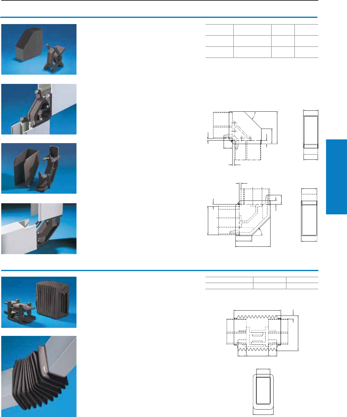
Operator Interface
Industrial Buyer’s Guide 157
CP-XL Support Arm System
CP-XL Support Arm System
1
1
1
1
1
1
1
1
1
Mounting* Color RAL Weight
lb (kg) Part No.
Suspended 7024
(graphite gray) 5 (2.4) 6140.010
Supported 7024
(graphite gray) 8 (3.6) 6180.010
* Suspended mounting is secured to the top of an
enclosure. Supported mounting is secured to the
bottom of an enclosure.
Color RAL Weight lb (kg) Part No.
7024 (graphite gray) 14 (6.5) 6120.010
90° elbow CP-XL
For connecting horizontal and vertical support
arm components.
Material:
Spheroidal-graphite cast iron
Conguration:
Gaskets, plastic housing and self-tapping screws
for CP-XL support section attachment.
Property Rights:
German patent no. 58901106
European patent no. 0330027 with validity for IT
Intermediate hinge CP-XL
For vertically hinged connection of horizontal
support sections within the support arm system.
Rotation Range:
Approximately 180°
Material:
Spheroidal-graphite cast iron
Conguration:
Self-tapping screws for CP-XL support section
attachment and divided bellow section with zipper
for easy access to the cable duct.
Note:
Rotation range may be reduced with rotation limiter.
Property Rights:
German patent no. 3805424
European patent no. 0330029 with validity for IT
Accessories:
Rotation limiter CP-XL, see page 158.
Inch and pound measurements are rounded to the nearest whole number.
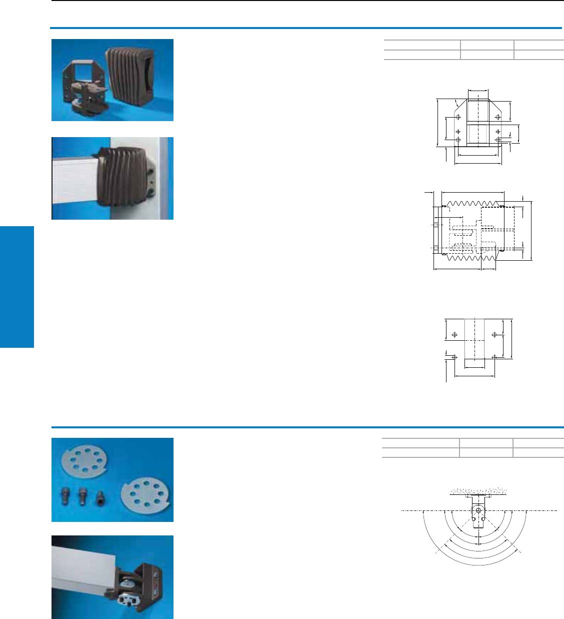
Operator Interface
158 Industrial Buyer’s Guide
CP-XL Support Arm System
CP-XL Support Arm System
1
1
11
1
1
1
1
1
1
1
1
1
Color RAL Weight lb (kg) Part No.
7024 (graphite gray) 19 (8.5) 6110.010
PU Weight lb (kg) Part No.
1 set 1 (0.6) 6110.100
Mounting cut-out
Adjustable swivel area:
Wallmounted hinge CP-XL
For vertically hinged-mounting of the support
arm on vertical surfaces.
Rotation Range:
Approximately 180°
Material:
Spheroidal-graphite cast iron
Conguration:
Gaskets, bellow section and assembly hardware
Note:
Rotation range may be reduced with rotation limiter
CP-XL.
Accessories:
Rotation limiter CP-XL, see below.
Rotation limiter CP-XL
Suitable for:
• Wallmounted hinge (6110.010)
• Intermediate hinge (6120.010).
Material:
Steel, zinc-plated, passivated
Conguration:
2 steel disks, slotted, including 3
cheese-head screws for assembly
Inch and pound measurements are rounded to the nearest whole number.
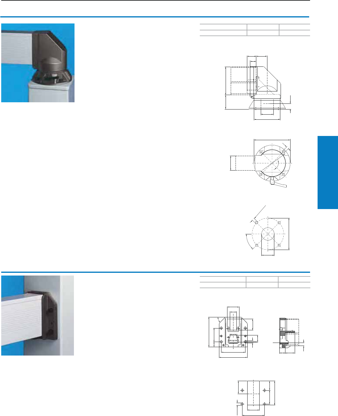
Operator Interface
Industrial Buyer’s Guide 159
CP-XL Support Arm System
CP-XL Support Arm System
1
1
1
1
11
1
1
1
1
1
1
1
11
1
1
Color RAL Weight lb (kg) Part No.
7024 (graphite gray) 26 (11.9) 6170.010
Color RAL Weight lb (kg) Part No.
7024 (graphite gray) 9 (4.1) 6160.010
Mounting cut-out
Mounting cut-out
Top-mounted joint CP-XL
For swivel-mounting of the support arm system on
horizontal surfaces – also suitable for suspending
from the ceiling.
Rotation Range:
Approximately 350°, lockable
Material:
Steel and cast parts
Conguration:
Gaskets and plastic housing, self-tapping screws
for CP-XL support section attachment
Note:
Safety end stop as anti-twist protection.
Wall/base-mounting CP-XL
For fixed attachment of the support arm system to
vertical or horizontal surfaces.
Material:
Spheroidal-graphite cast iron
Conguration:
Gaskets and self-tapping screws for CP-XL
support section attachment
Inch and pound measurements are rounded to the nearest whole number.
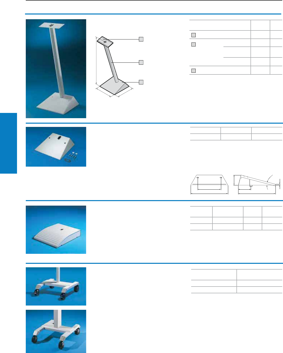
Operator Interface
160 Industrial Buyer’s Guide
Pedestal
Stand Systems
CP-L Pedestal, Bases
May be compiled from the
following modules: Part No. Page
1 Enclosure reinforcement 6143.310 165
2 Support
section, straight
(may be shortened
to required length
by sawing)
20" (500 mm) 6660.050 128
40" (1000 mm)
(H + 65mm) 6660.010 128
80" (2000 mm) 6660.020 128
3 Pedestal base plate, small 6143.200 160
Pedestal,
modular, CP-L
For additional technical information,
please visit www.rittal-corp.com
3
1
H
2
Pedestal base plate
small
• With one hole at the rear for commercially
available cable conduit gland M20.
• With two holes at the top (including sealing
bung) for floor attachment.
• Prepared on the inside for a cable clamp for
strain relief.
Material:
Sheet steel, 2.5 mm
1
1
1
1°
Weight lb (kg) Color RAL Part No.
14 (6.3) 7035 (light gray) 6143.200
Supply includes:
Assembly parts.
Note:
Commercially available screws up to M8
may be used for floor attachment.
Pedestal base plate
large
• Cut-out for concealed mounting of cable
conduit adaptor M50
• Cut-out for PG segments (2235.010 to
2235.080) or cable conduit adaptor up to
Ø 70 mm
• Integral cable clamping bracket
Material:
Sheet steel, powder-coated
Supply includes:
Integral reinforcement and mounting cut-out for
support section CP-L or CP-XL, complete with
assembly parts for configuration of the support
section.
For support
section Color RAL Weight
lb (kg) Part No.
CP-L 7035 (light gray) 27 (12.4) 6137.535
CP-XL 7035 (light gray) 29 (13.1) 6137.035
Inch and pound measurements are rounded to the nearest whole number.
Pedestal
mobile
Consisting of:
2 sheet steel axles, each with 2 die-cast zinc
roller bearings with plastic coating, 4 twin
castors, 2 x with, 2 x without locks, 1 cross-
brace, screw-fastened, of sheet steel with
integral cable clamping bracket, 1 support
section of aluminium (for 6136.000 with clip-in
lid), partially pre-assembled.
Color:
Powder-coated in RAL 7035,
corner pieces in RAL 7030.
Pedestal, mobile
with support section Part No.
CP-L 6136.500
CP-XL 6136.000
For additional technical information,
please visit www.rittal-corp.com
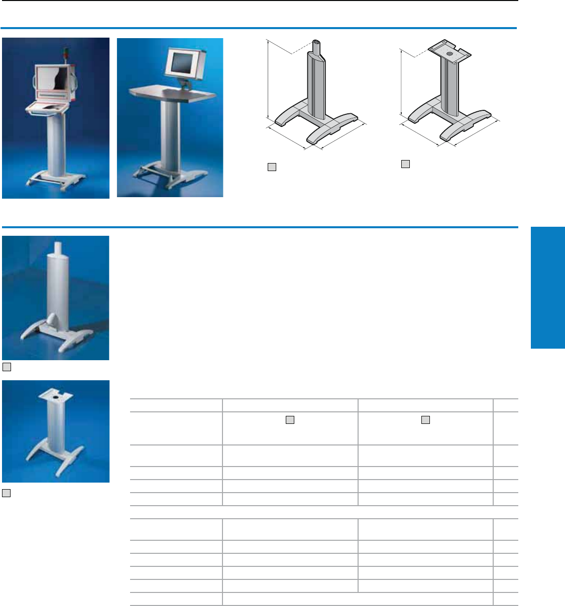
Operator Interface
Industrial Buyer’s Guide 161
Stand Systems Pedestal
Command Panel and IW Pedestal
1
1
2
1
Pedestal
One oval panel is permanently screw-fastened,
while the other can be opened by "spreading"
with a screwdriver for easy laying of cables.
In order to ensure opening of the front panels, we
recommend that the adjustable frame connector be
used with all panels with keyboard housings.
Material:
Feet: cast aluminum
Cross member, vertical support tubes: Steel
Panels: Aluminum section
Conguration:
for Command Panel:
2 cast aluminum feet,
1 cross member made of steel,
2 steel support tubes welded to cross member,
2 oval panels made from aluminum section,
1 top cover made from cast aluminum with
support section CP-L, partially pre-assembled.
for IW worktops:
2 cast aluminum feet,
1 cross member made of steel,
2 steel support tubes welded to cross member,
2 oval panels made from aluminum section,
1 worktop attachment of sheet steel.
For Command Panel For IW worktops
Design
1
with cable conduit adaptor and drilled
hole for cable entry in cross member
2
with drilled hole for cable entry in cross
member
Page
H x W x D inches (mm) 43 x 24 x 28
(1093 x 600 x 700)
37 x 24 x 28
(946 x 600 x 700)
Part No. 6141.100 6141.200
Weight lb (kg) 77 (35.1) 74 (33.7)
Color RAL 70351)/ natural-anodized 70351)/ natural-anodized
Accessories
Twin castors 6148.000,
4634.500
6148.000,
4634.500
201,
168
Leveling feet 4612.000 4612.000 201
Base mount 6147.000 6147.000 163
Foot rest 6145.100 6145.100 163
Trim panel 6144.100 6144.100 163
Cable conduit 262
1) light gray
2
Inch and pound measurements are rounded to the nearest whole number.
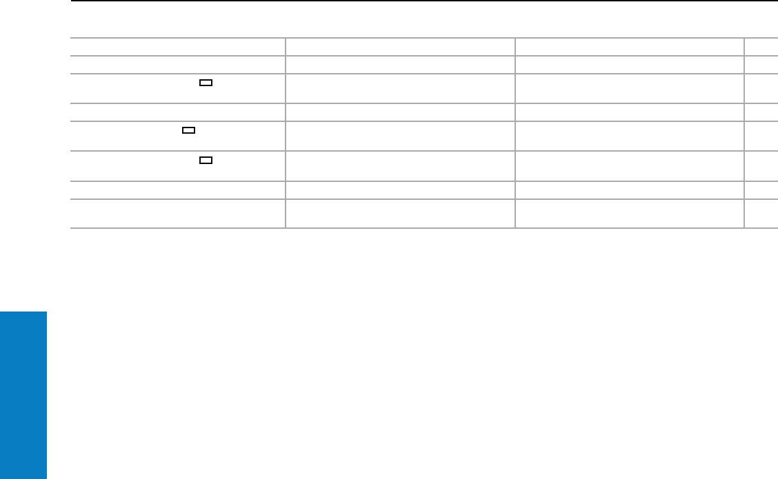
Operator Interface
162 Industrial Buyer’s Guide
Pedestal
Stand Systems
Command Panel and IW Pedestal
For Command Panel For IW worktops Page
Enclosure attachment CP-L, Ø 5" (130 mm) 6525.510 – 138
Enclosure attachment CP-L, 3 x 5"
(65 x 120 mm) 6525.610 – 139
Housing coupling CP-L, Ø 5" (130 mm) 6525.010 – 144
Housing coupling CP-L, 3 x 5"
(65 x 120 mm) 6525.110 – 144
Enclosure attachment CP-L, 3 x 5"
(65 x 120 mm), locatable 6525.210 – 142
Enclosure attachment, tilting – 6902.640 139
Worktop without handle (H x W x D: 1 x 37 x
24" (38 x 950 x 600 mm) – 6902.310 188
1) Other widths and heights and support tubes available upon request.
Inch and pound measurements are rounded to the nearest whole number.
Operator Interface
Industrial Buyer’s Guide 163
Stand Systems Pedestal
Feet and Trim - Pedestal
Cross member
with cast feet
Steel cross member with mounting holes for
lifting pillar or other individual assemblies,
including 2 cast aluminum feet.
Color RAL PU Weight lb (kg) Part No.
7035 (light gray) 1 13 (5.8) 6142.100
Accessories:
Foot rest 6145.100,
Trim panel 6144.100,
Base mount 6147.000,
See below.
Twin castors, see page 201.
Base mount
Brackets for screw-fastening from below to the
cast feet with posidrive raised countersunk
screws M12.
Optionally with projection at the front, interior
or sides, with Ø 0.5" (11 mm) hole for screw-
fastening to the base.
Material:
Sheet steel, zinc-plated, passivated
Conguration:
Posidrive raised countersunk screws M12.
PU Part No.
46147.000
Trim panel
Material:
Cast aluminum
Conguration:
Assembly parts for screw-fastening between
the cast feet at the front or rear.
Color RAL PU Part No.
7035 (light gray) textured 1 6144.100
Foot rest
Material:
Connector pieces: Cast aluminum
Round tube section: Aluminum
Conguration:
Assembly parts.
Color RAL PU Weight
lb (kg) Part No.
7035 (light gray) textured/
natural-anodized 1 1 (0.6) 6145.100
Inch and pound measurements are rounded to the nearest whole number.
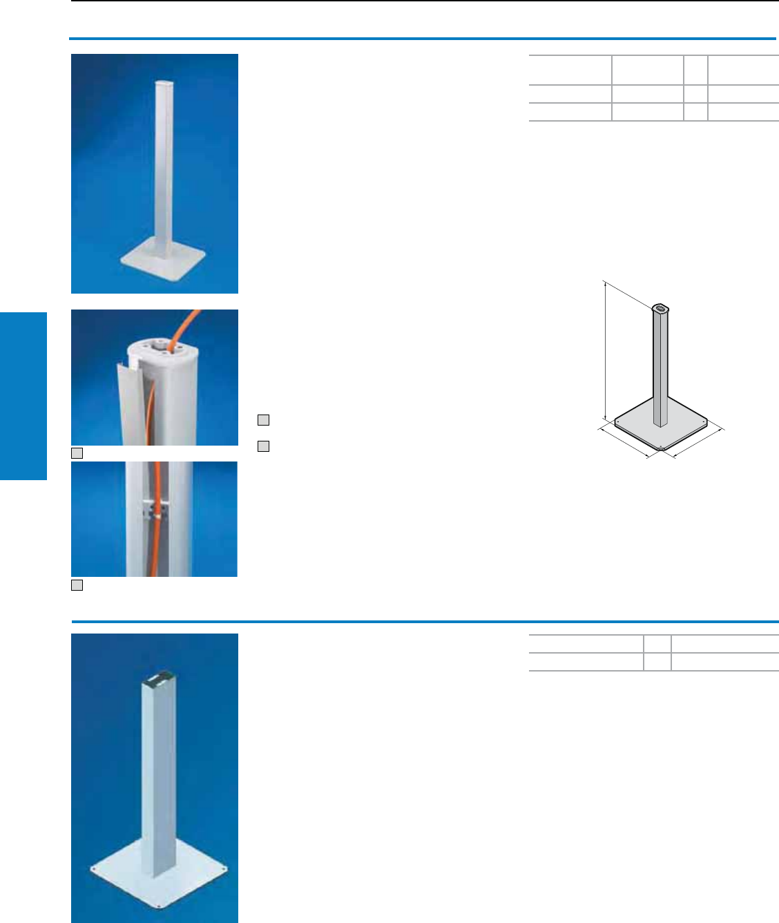
Operator Interface
164 Industrial Buyer’s Guide
Pedestal/Pillar
Stand Systems
Pedestal/Pillar
1
2
Pedestal, open
With cable duct open
• for inserting cables with pre-assembled
connectors for optimum service access
Head plate with accommodation for:
• CP-L housing coupling for support arm
connection Ø 5" (130 mm), 6525.010,
see page 144
• CP-L enclosure attachment for support arm
connection Ø 5" (130 mm), 6525.510,
see page 138
Material:
Pedestal tube: Steel, spray-finished in RAL 7035
Cover section: Plastic RAL 7030
Design:
16 x 16" (400 x 400 mm), 0.4" (10 mm) thick
base plate, with 0.2 x Ø 0.4" (4 x 11 mm)
mounting holes.
Pedestal tube H x W 3 x 3" (73 x 86 mm), 11 ga
(3 mm) thick, head and base plate welded on.
Conguration:
Assembly parts and cover section.
1 Cover section just clips on
2 With cable clamping bracket
Height (H)
inches (mm) Weight lb (kg) PU Part No.
43 (1093) 53 (24) 1 6215.000
To specifications – 1 6215.100
Accessories:
Cable tie 2597.000, see www.rittal-corp.com
For additional technical information,
please visit www.rittal-corp.com
H
Pillar
Small
For heavy assemblies, connection plates at the
top for CP-XL support arm components.
• With cut-out for 24-pole connectors for cable
entry at the bottom rear
• Height: 45" (1150 mm)
Material:
Steel
Design:
Base plate cross-section 20 x 20"
(500 x 500 mm), 0.5" (12 mm) thick,
with 4 mounting holes.
Pedestal tube (cross-section 3 x 6" (80 x 160 mm),
wall thickness 11 ga (3.2 mm) welded to base
plate.
Accessories:
CP-XL housing coupling, see page 154.
CP-XL enclosure attachment, see pages 153-154.
Color RAL PU Part No.
7035 (light gray) 1 6214.500
For additional technical information,
please visit www.rittal-corp.com
Inch and pound measurements are rounded to the nearest whole number.
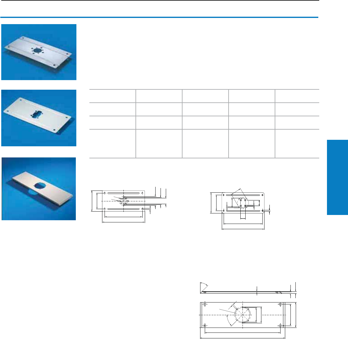
Operator Interface
Industrial Buyer’s Guide 165
Stand Systems Reinforcement Plate
Enclosure Reinforcement Plate
Enclosure reinforcement plate
For external or internal reinforcement of
enclosures of a corresponding size.
Smaller enclosures may also be mounted
directly without enclosure reinforcement.
Conguration:
Assembly parts for the enclosure and support
section plus 2 seals.
For enclosure Support arm
connection Material Weight lb (kg) Part No.
B1 ≥ 12" (300 mm)
T1 ≥ 6" (150 mm) CP-S Type 304
stainless steel 2 (0.9) 6143.310
B1 ≥ 12" (300 mm)
T1 ≥ 6" (150 mm) CP-L Sheet steel 2 (0.9) 6143.210
6662.000
or
AE
(B1 = 24" [600 mm],
T1 ≥ 8" [210 mm])
CP-XL Sheet steel 5 (2.2) 6503.000
6143.310
6143.210
6503.000
11
1
6143.310
11
1
6143.210
1
1
1
11
1
1
6503.000
Inch and pound measurements are rounded to the nearest whole number.
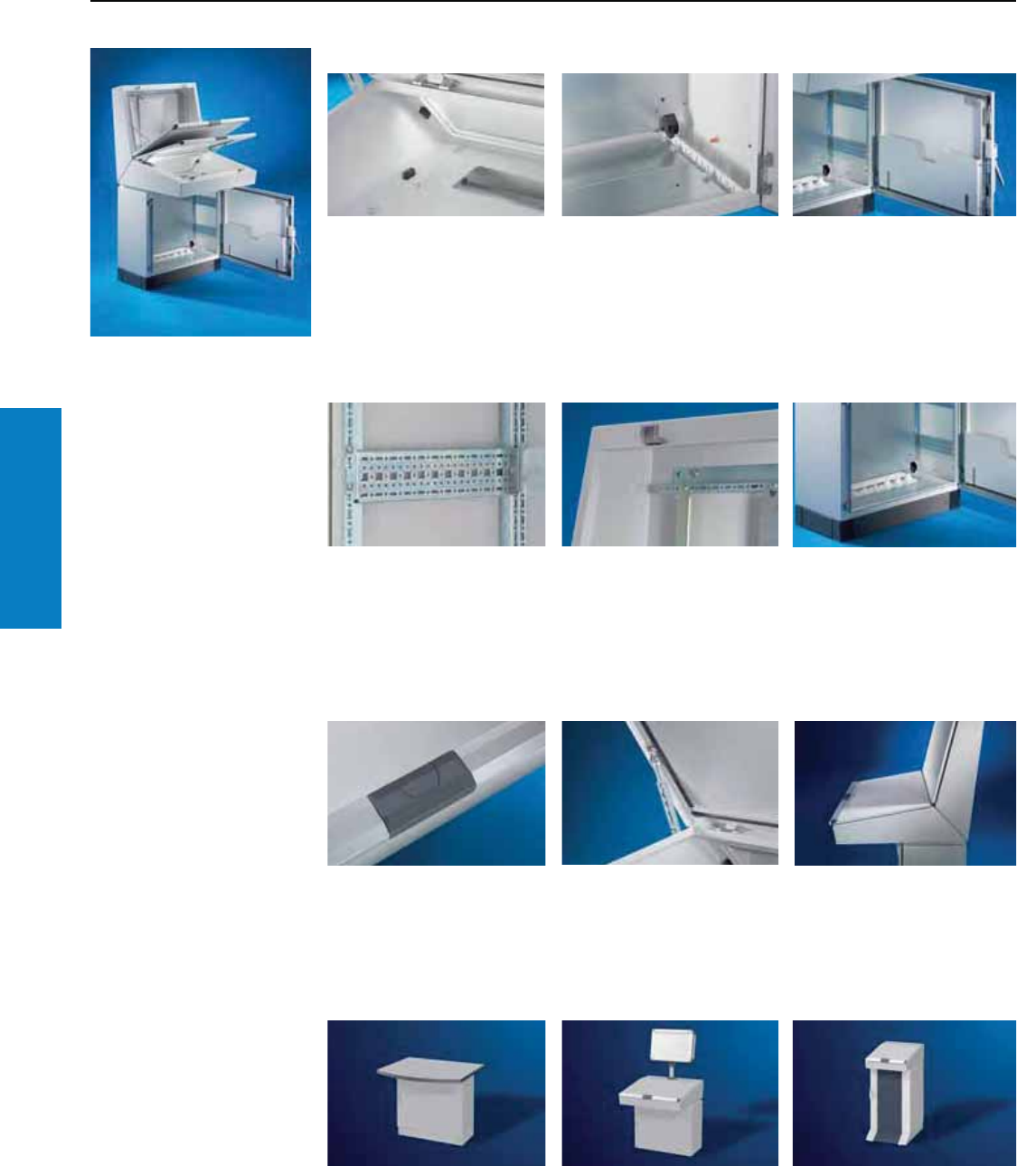
Operator Interface
166 Industrial Buyer’s Guide
TopConsole
Consoles
TopConsole System
Features
Assembly
Easy assembly
The integrated “mounting
assistant" can be used as an
adjustment and securing aid:
Simply insert, snap into position,
and screw fasten.
Simple assembly
The fitted mounting panel slides
in and locks easily into position
(in a 25 mm pitch pattern). This
depth variable installation and
securing technology saves a lot
of time and money during
assembly and servicing.
Practical diversity
Perforated system strips fitted
to doors and covers for TS
compatible installation, i.e., for
mounting rails or wiring plan
pockets.
Individual interior conguration
The numerous components from
the Rittal modular system
produce a host of individual
solutions which you are sure to
find worthwhile.
Extra advantage
All TopConsole modules are fitted
with threaded studs and are
therefore ready for use in TS
compatible configurations (rails,
partial mounting panels and
many more besides).
Exemplary cable routing
TopConsole system – also
stands for more combination
options for cable entries, thanks
to individual gland plates.
Design line
The integrated lock, which
is shielded by a hinged flap,
is visually aligned with the
handle strip.
Single-handed operation
The desk unit lid stay locks
home automatically and it can
be unlocked in one operation.
Stylish ergonomics
Screens, displays and operating
controls are mounted at an
ergonomically favorable angle.
System conguration
Design, safety, ergonomics
Example 1:
The pedestal of a TopConsole
combined with an IW worktop.
Example 2:
The TopConsole pedestal
combined with a desk unit,
CP-L support arm components
and a Command Panel.
Example 3:
A TopConsole desk unit combined
with an IW pedestal, 24 inches
(600 mm) deep.
Combination diversity
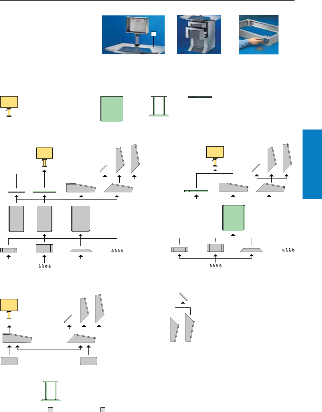
Operator Interface
Industrial Buyer’s Guide 167
TopConsole
Consoles
TopConsole System
Combination Options
1
Easy selection of your desired
combination
The TP TopConsole System components can
be combined in many user-specific versions
as shown in the diagrams below.
The table opposite allows you to immediately
find the order number for your selection. In
addition to this, the IW and Command Panel
range make the new TopConsole system TP
combination options virtually infinite.
Small operator units are easily
integrated into separate
Command Panels.
Completely new options
for space utilization are
available when used in
conjunction with our range
of IW enclosures.
The TS modular base/plinth
system also ensures more
cable entry flexibility when
used with consoles.
Rittal human/machine interface family
Command Panels may be
found on page 102-115.
Industrial Workstations
(IW) may be found from
page 182.
Combination with console base sections Combination with IW enclosures
Combination with worktop base Upper section used as wall enclosure
11 Worktop base for 31" (800 mm) width
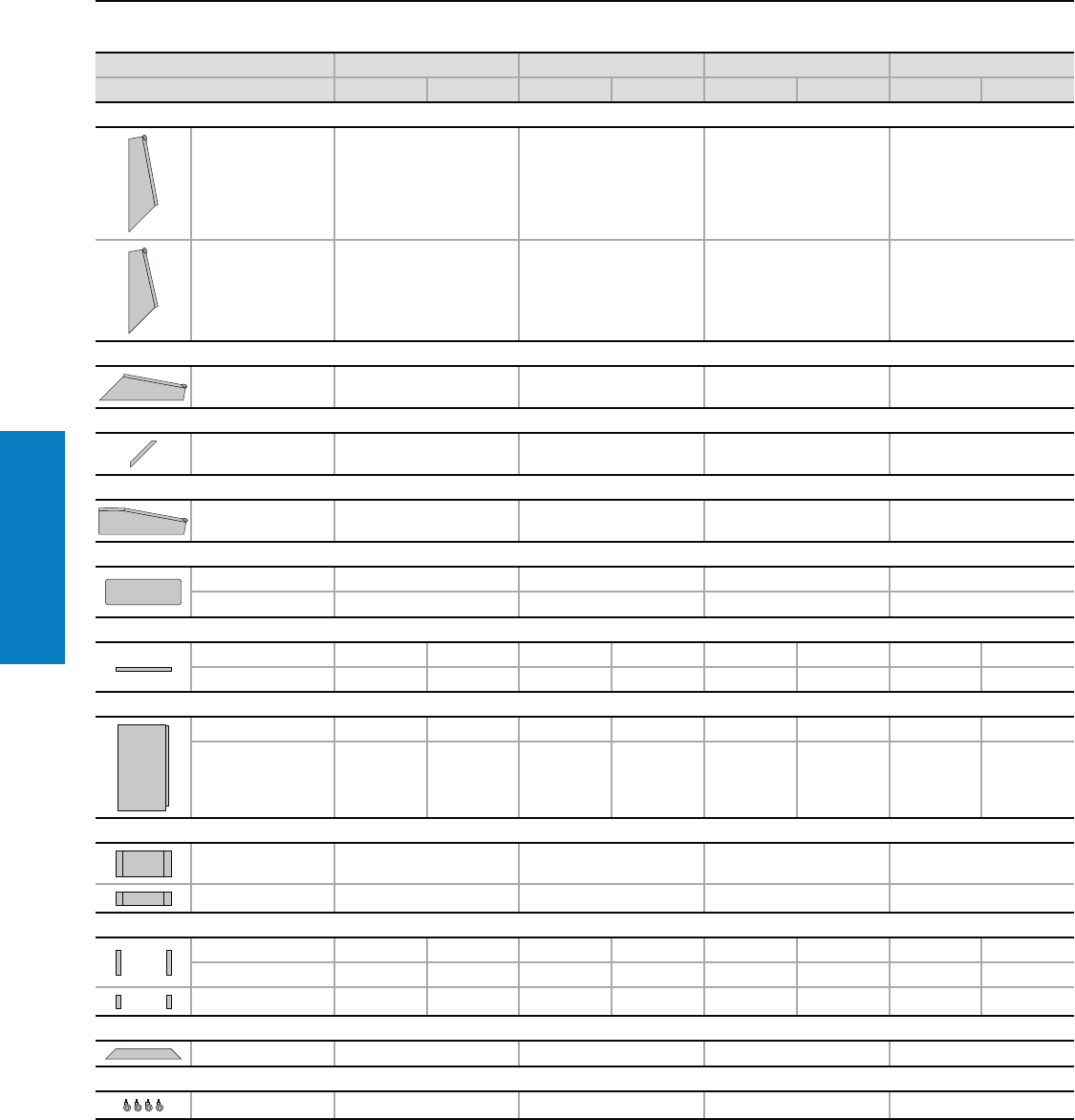
Operator Interface
168 Industrial Buyer’s Guide
TopConsole
Consoles
TopConsole System
Overview Table
Width inches (mm) 24 (600) 32 (800) 47 (1200) 63 (1600)
Part No. Part No. Part No. Part No. Part No. Part No. Part No. Part No.
Console, upper section
Height 30" (750 mm) 6720.500 6721.500 6722.500 6723.500
Height 26" (650 mm) 6724.500 6725.500 6726.500 6727.500
Desk unit already prepared for an upper section
Depth 30" (755 mm) 6714.500 6715.500 6716.500 6717.500
Console/desk unit trim panel
for height
26/30" (650/750 mm) 6730.200 6730.210 6730.220 6730.230
Rear of desk unit, with hinged lid
Depth 30" (755 mm) 6710.500 6711.500 6712.500 6713.500
Gland plate for desk unit (from page 278)
Size 4545
Qty.1122
Trim panel
Depth inches (mm) 16 (400) 20 (500) 16 (400) 20 (500) 16 (400) 20 (500) 16 (400) 20 (500)
6730.000 6730.100 6730.010 6730.110 6730.020 6730.120 6730.030 6730.130
Pedestal
Depth inches (mm) 16 (400) 20 (500) 16 (400) 20 (500) 16 (400) 20 (500) 16 (400) 20 (500)
Height 27" (675 mm) 6700.500 6704.500 6701.500 6705.500 6702.500 6706.500 6703.500 6707.500
Base/plinth components, front and rear
Height 8" (200 mm) 8602.600 8602.800 8602.200 8602.920
Height 4" (100 mm) 8601.600 8601.800 8601.200 8601.920
Base/plinth trims, side
Depth inches (mm) 16 (400) 20 (500) 16 (400) 20 (500) 16 (400) 20 (500) 16 (400) 20 (500)
Height 8 " (200 mm) 8602.040 8602.050 8602.040 8602.050 8602.040 8602.050 8602.040 8602.050
Height 4 " (100 mm) 8601.040 8601.050 8601.040 8601.050 8601.040 8601.050 8601.040 8601.050
Cross member, adjustable
Height 3" (75 mm) 8601.450 8601.450 8601.450 8601.450
Castors
Height 5" (125 mm) 4634.500 4634.500 4634.500 4634.500
Inch and pound measurements are rounded to the nearest whole number.
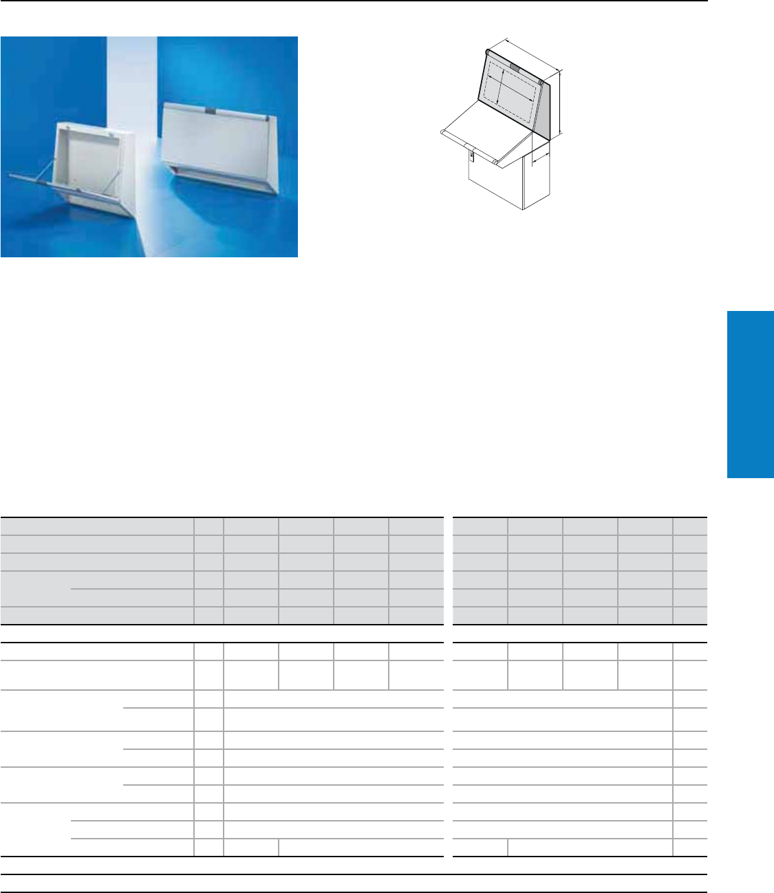
Operator Interface
Industrial Buyer’s Guide 169
TopConsole
Consoles
TopConsole System
Depth: 9" (240 mm), Height: 26 - 30" (650 - 750 mm)
H
B
T
H1
B1
Material:
Sheet steel
Enclosure: 16 ga (1.5 mm)
Cover: 14 ga (2.0 mm)
Design handle strip: Aluminum
Corner protectors and lock lid:
Plastic, self-extinguishing
Finish:
Enclosure and cover:
Dipcoat-primed, powder coated
in textured RAL 7035 (light gray)
on the outside
Design handle strip:
Natural-anodized
Corner protectors and lock lid:
RAL 7015 (slate gray)
Protection Ratings:
UL Type 12 (IP 55 to EN 60 529)
(when using a suitable trim panel, see
page 174, or mounting on a desk unit,
see page 172).
UL File: 76083
Conguration:
Enclosure with lid, hinged at the bottom,
may be swapped to the top, includes
lid stay, open base for individual
cable entry
For additional technical information,
please visit www.rittal-corp.com
Inch and pound measurements are rounded to the nearest whole number.
Height (H) inches (mm) PU 26 (650) 26 (650) 26 (650) 26 (650) 30 (750) 30 (750) 30 (750) 30 (750) Page
Width (B) inches (mm) 24 (600) 32 (800) 47 (1200) 63 (1600) 24 (600) 32 (800) 47 (1200) 63 (1600)
Depth (T) inches (mm) 9 (240) 9 (240) 9 (240) 9 (240) 9 (240) 9 (240) 9 (240) 9 (240)
Max. cut-out Height (H1) inches (mm) 12 (313) 12 (313) 12 (313) 12 (313) 16 (413) 16 (413) 16 (413) 16 (413)
Width (B1) inches (mm) 19 (488) 27 (688) 43 (1088) 59 (1488) 19 (488) 27 (688) 43 (1088) 59 (1488)
Part No. 16724.500 6725.500 6726.500 6727.500 6720.500 6721.500 6722.500 6723.500
Accessories
Trim panel (when used alone) 1 6730.200 6730.210 6730.220 6730.230 6730.200 6730.210 6730.220 6730.230 174
Rail for interior installation,
horizontal for width 4 5001.050 5001.051 5001.053 5001.055 5001.050 5001.051 5001.053 5001.055 233
Punched section with
mounting flange
2.9 x 0.7" (73 x 17 mm)1)
for lid 4 8612.140 8612.150 234
for enclosures 4 8612.150 8612.150 234
Support strip1) for lid 20 4694.000 4695.000 236
for enclosures 20 4695.000 4695.000 236
Punched rail
1.5 x 0.7" (38 x 18 mm)1)
for lid 4 8612.240 8612.250 233
for enclosures 4 8612.250 8612.250 233
Partial
mounting
panel
8" (200 mm) width 1 6730.310 6730.310 232
20" (500 mm) width 1 6730.330 6730.330 232
28" (700 mm) width 1 – 6730.340 – 6730.340 232
Lock systems
Standard double-bit lock insert may be exchanged for 1” (27 mm) lock inserts, type A, see page 218
To order primed consoles please add extension .800 to the Part No.
1) Can be vertically mounted in lid and rear enclosure wall.
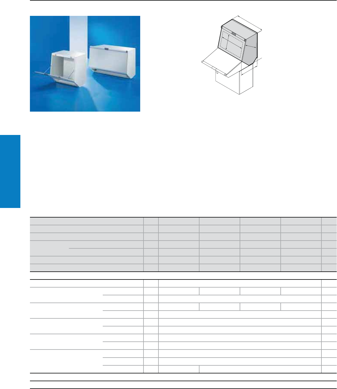
Operator Interface
170 Industrial Buyer’s Guide
TopConsole
Consoles
TopConsole System
Depth: 21" (525 mm), Height: 31" (785 mm)
Material:
Sheet steel
Enclosure: 16 ga (1.5 mm)
Cover: 14 ga (2.0 mm)
Design handle strip: Aluminum
Corner protectors and lock lid:
Plastic, self-extinguishing
Protection Ratings:
NEMA 12 (IP 55 to EN 60 529)
(when mounting on a desk unit)
Conguration:
Enclosure with cover at the front,
hinged at the bottom, including
cover retainer, rear door, hinged
at the bottom with cam locks,
base open for individual
cable entry.
H
B
H1
B1
T
T
T1
Console for mounting on pedestal
with depth 20" (500 mm) in
conjunction with desk unit. Opening
at the rear, with rear panel hinged
at the bottom and cam locks. Side
panels with bolts for mounting rails for
interior installation.
Inch and pound measurements are rounded to the nearest whole number.
Height (H) inches (mm) PU 31 (785) 31 (785) 31 (785) 31 (785) Page
Width (B) inches (mm) 24 (600) 32 (800) 47 (1200) 63 (1600)
Depth (T) inches (mm) 21 (525) 21 (525) 21 (525) 21 (525)
Max. cut-out Height (H1) inches (mm) 16 (413) 16 (413) 16 (413) 16 (413)
Width (B1) inches (mm) 19 (488) 27 (688) 43 (1088) 59 (1488)
Installation depth (T1) inches (mm) 16 (415) 16 (415) 16 (415) 16 (415)
Part No. 16720.200 6721.200 6722.200 6723.200
Accessories
Rail for interior installation For height 4 5001.051 233
Punched section with mounting
flange 2.9 x 0.7" (73 x 17 mm)
For width 4 8612.060 8612.080 8612.020 – 234
For depth 4 8612.030 234
Mounting bars For width 20 8800.130 4579.000 – – 236
For depth 20 4594.000 236
Punched section with mounting
flange 2.9 x 0.7" (73 x 17 mm)
For front cover 4 8612.150 234
For rear cover 4 8612.060 234
Mounting bars For front cover 20 4695.000 236
For rear cover 20 8800.130 236
Partial mounting panel
8" (200 mm) width 1 6730.310 232
20" (500 mm) width 1 6730.330 232
28" (700 mm) width 1 – 6730.340 232
Lock systems
Standard double-bit lock insert, in both covers, may be exchanged for 1" (27 mm) lock inserts, type A, see page 218.
To order primed consoles please add extension .800 to the Part No.
For additional technical information,
please visit www.rittal-corp.com
Finish:
Enclosure and cover:
Dipcoat-primed, powder coated in
textured RAL 7035 (light gray)
on the outside
Design handle strip: Natural-
anodized Corner protectors and
lock lid:
RAL 7015 (slate gray)
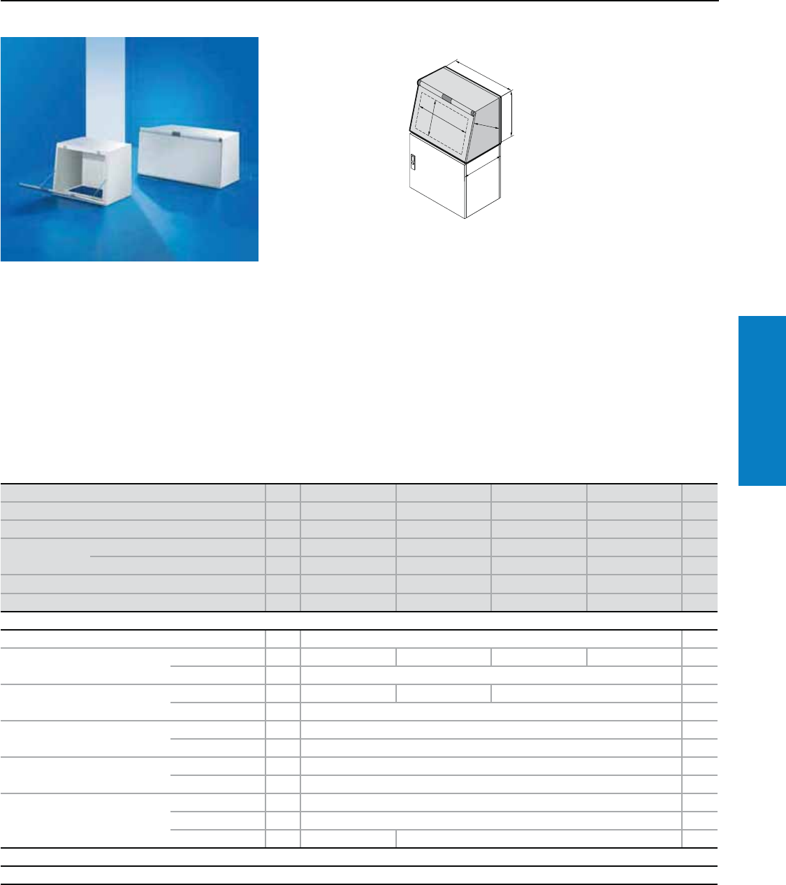
Operator Interface
Industrial Buyer’s Guide 171
TopConsole
Consoles
TopConsole System
Depth: 21" (525 mm), Height: 22" (565 mm)
Material:
Sheet steel
Enclosure: 16 ga (1.5 mm)
Cover: 14 ga (2.0 mm)
Design handle strip: Aluminum
Corner protectors and lock lid:
Plastic, self-extinguishing
Protection Ratings:
NEMA 12 (IP 55 to EN 60 529)
(when mounting on a desk unit)
Conguration:
Enclosure with cover at the front, hinged
at the bottom, including cover retainer,
rear door, hinged at the bottom with
cam locks, base open for individual
cable entry.
For additional technical information,
please visit www.rittal-corp.com
Console for mounting on pedestal
with depth 20" (500 mm) in conjunction with
desk unit. Opening at the rear, with rear panel
hinged at the bottom and cam locks. Side
panels with bolts for mounting rails for interior
installation.
H
B
T
H1
B1
T1
Inch and pound measurements are rounded to the nearest whole number.
Height (H) inches (mm) PU 22 (565) 22 (565) 22 (565) 22 (565) Page
Width (B) inches (mm) 24 (600) 32 (800) 47 (1200) 63 (1600)
Depth (T) inches (mm) 21 (525) 21 (525) 21 (525) 21 (525)
Max. cut-out Height (H1) inches (mm) 16 (413) 16 (413) 16 (413) 16 (413)
Width (B1) inches (mm) 19 (488) 27 (688) 43 (1088) 59 (1488)
Installation depth (T1) inches (mm) 16 (415) 16 (415) 16 (415) 16 (415)
Part No. 16720.100 6721.100 6722.100 6723.100
Accessories
Rail for interior installation For height 4 5001.050 233
Punched section with mounting
flange 2.9 x 0.7" (73 x 17 mm)
For width 4 8612.060 8612.080 8612.020 – 234
For depth 4 8612.030 234
Mounting bars For width 20 8800.130 4579.000 – 236
For depth 20 4594.000 236
Punched section with mounting
flange 2.9 x 0.7" (73 x 17 mm)
For front cover 4 8612.150 234
For rear cover 4 8612.150 234
Mounting bars For front cover 20 4695.000 236
For rear cover 20 4695.000 236
Partial mounting panel
8" (200 mm) width 1 6730.310 232
20" (500 mm) width 1 6730.330 232
28" (700 mm) width 1 – 6730.340 232
Lock systems
Standard double-bit lock insert, in both covers, may be exchanged for 1" (27 mm) lock inserts, type A, see page 218.
To order primed consoles please add extension .800 to the Part No.
Finish:
Enclosure and cover:
Dipcoat-primed, powder coated in textured
RAL 7035 (light gray) on the outside
Design handle strip: Natural-anodized Corner
protectors and lock lid: RAL 7015 (slate gray)
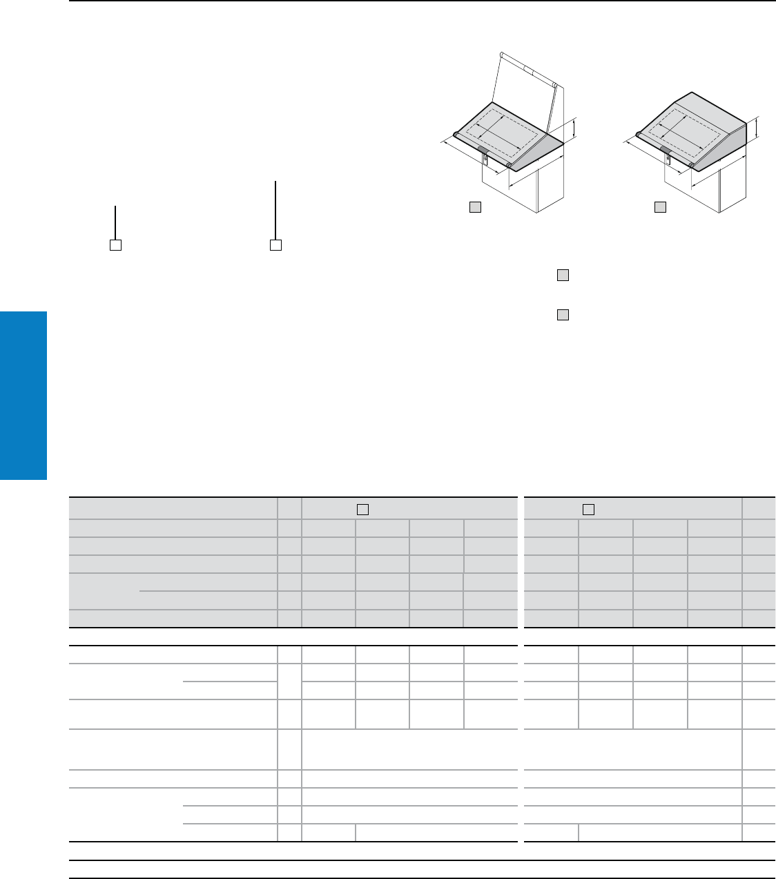
Operator Interface
172 Industrial Buyer’s Guide
TopConsole
Consoles
TopConsole System Desk Unit
Depth: 30" (750 mm), Height: 9" (235 mm)
Material:
Sheet steel
Enclosure: 16 ga (1.5 mm)
Cover: 14 ga (2.0 mm)
Design handle strip: Aluminum
Corner protectors and lock lid:
Plastic, self-extinguishing
Finish:
Enclosure and cover:
Dipcoat-primed, powder coated in textured
RAL 7035 (light gray) on the outside
Design handle strip:
Natural-anodized
Corner protectors and lock lid: RAL 7015
(slate gray)
Protection Ratings:
UL Type 12 (IP 55 to EN 60 529) in
combination with console, trim panel
for console/desk unit and pedestal.
UL File: 76083
Conguration:
Enclosure with lid, hinged at rear, 2
stays with automatic locking and
unlocking, gland plate opening for
cable entry in the enclosure base.
For additional technical information,
please visit www.rittal-corp.com
H
B
T
T1
B1
H
B
T
T1
B1
1 2
21
1 Prepared for console:
open at top
2 Closed rear with hinged lid
Inch and pound measurements are rounded to the nearest whole number.
PU 1 Prepared for console 2 Rear with hinged lid Page
Height (H) inches (mm) 9 (235) 9 (235) 9 (235) 9 (235) 9 (235) 9 (235) 9 (235) 9 (235)
Width (B) inches (mm) 24 (600) 32 (800) 47 (1200) 63 (1600) 24 (600) 32 (800) 47 (1200) 63 (1600)
Depth (T) inches (mm) 30 (750) 30 (750) 30 (750) 30 (750) 30 (750) 30 (750) 30 (750) 30 (750)
Max. cut-out
console lid
Height (H1) inches (mm) 19 (488) 27 (688) 43 (1088) 59 (1488) 19 (488) 27 (688) 43 (1088) 59 (1488)
Width (B1) inches (mm) 16 (413) 16 (413) 16 (413) 16 (413) 16 (413) 16 (413) 16 (413) 16 (413)
Part No. 16714.500 6715.500 6716.500 6717.500 6710.500 6711.500 6712.500 6713.500
Accessories
Trim panel for console/desk unit 1 6730.200 6730.210 6730.220 6730.230 – – – – 174
Gland plate Size 4 5 4 5 4545
Qty. 1122 1122
Rail for interior
installation for width 4 5001.050 5001.051 5001.053 5001.055 5001.050 5001.051 5001.053 5001.055 233
Punched section with
mounting flange 2.9 x
0.7" (73 x 17 mm)1)
in depth 4 8612.150 8612.150 234
Support strip1) in depth 20 4695.000 4695.000 236
Partial mounting panel
8" (200 mm) width 1 6730.310 6730.310 232
20" (500 mm) width 1 6730.330 6730.330 232
28" (700 mm) width 1 – 6730.340 – 6730.340 232
Lock systems
Standard double-bit lock insert may be exchanged for 1" (27 mm) lock inserts, type A, see page 218.
To order primed consoles please add extension .800 to the Part No.
1) Can be vertically mounted in lid and rear enclosure wall.
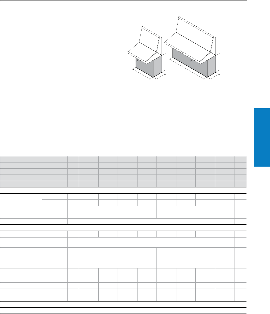
Operator Interface
Industrial Buyer’s Guide 173
TopConsole
Consoles
TopConsole System Pedestal
Depth: 16 - 20" (400 - 500 mm), Height: 27" (675 mm)
Material:
Sheet steel
Enclosure: 16 ga (1.5 mm)
Door: 14 ga (2.0 mm)
Mounting panel: 13 ga (2.5 mm)
Finish:
Enclosure and door:
Dipcoat-primed, powder coated
in textured RAL 7035 (light gray)
on the outside
Mounting panel: Zinc-plated
Protection Ratings:
UL Type 12 (IP 55 to EN 60 529) in
combination with gland plates (p. 259)
and one of the following:
- Trim panel for pedestal (p. 174)
- UL Type 12 console unit
UL File: 76083 For additional technical information,
please visit www.rittal-corp.com
H
T
H
B
T
H
B
T
Height (H) inches (mm) PU 27 (675) 27 (675) 27 (675) 27 (675) 27 (675) 27 (675) 27 (675) 27 (675) Page
Width (B) inches (mm) 24 (600) 32 (800) 47 (1200) 63 (1600) 24 (600) 32 (800) 47 (1200) 63 (1600)
Depth (T) inches (mm) 16 (400) 16 (400) 16 (400) 16 (400) 20 (500) 20 (500) 20 (500) 20 (500)
Part No. 16700.500 6701.500 6702.500 6703.500 6704.500 6705.500 6706.500 6707.500
Door(s) 11221/11/12/22/2
Base/plinth
Components front and
rear inches (mm)
Height 4 (100) 1 set 8601.600 8601.800 8601.200 8601.920 8601.600 8601.800 8601.200 8601.920 194
Height 8 (200) 1 set 8602.600 8602.800 8602.200 8602.920 8602.600 8602.800 8602.200 8602.920 194
Side panels inches (mm) Height 4 (100) 1 set 8601.040 8601.050 194
Height 8 (200) 1 set 8602.040 8602.050 194
Cross member, adjustable 2 8601.450 199
Accessories
Trim panel for pedestal 1 6730.000 6730.010 6730.020 6730.030 6730.100 6730.110 6730.120 6730.130 174
Rail for interior
installation for height 4 5001.050 233
Punched sections with
mounting flanges
2.9 x 0.7" (73 x 17 mm)
in depth 4 8612.140 8612.150 234
Mounting bars in depth 20 4694.000 4695.000 236
Punched sections with
mounting flanges
2.9 x 0.7" (73 x 17 mm)
for door 4 8612.050 – 8612.050 – 8612.050 – 8612.050 – 234
Mounting bars for door 20 4596.000 4598.000 4596.000 4598.000 4596.000 4598.000 4596.000 4598.000 236
Cable clamp rail 1 5001.080 5001.081 5001.083 5001.084 5001.080 5001.081 5001.083 5001.084 262
Wiring plan pocket 1 4116.500 4118.500 4116.500 4118.500 4116.500 4118.500 4116.500 4118.500 –
Lock systems
Standard double-bit lock insert may be exchanged for 1" (27 mm) lock inserts, type A, and for the Ergoform-S lock system, see page 218.
To order primed pedestals please add extension .800 to the Part No.
Conguration:
Enclosure, open at the top, door or double
door with locking rod (with 16" (400 mm)
depth at the front, with 20" (500 mm) depth
at the front and rear), depth-adjustable
mounting panel, open base for individual
cable entry options.
Inch and pound measurements are rounded to the nearest whole number.
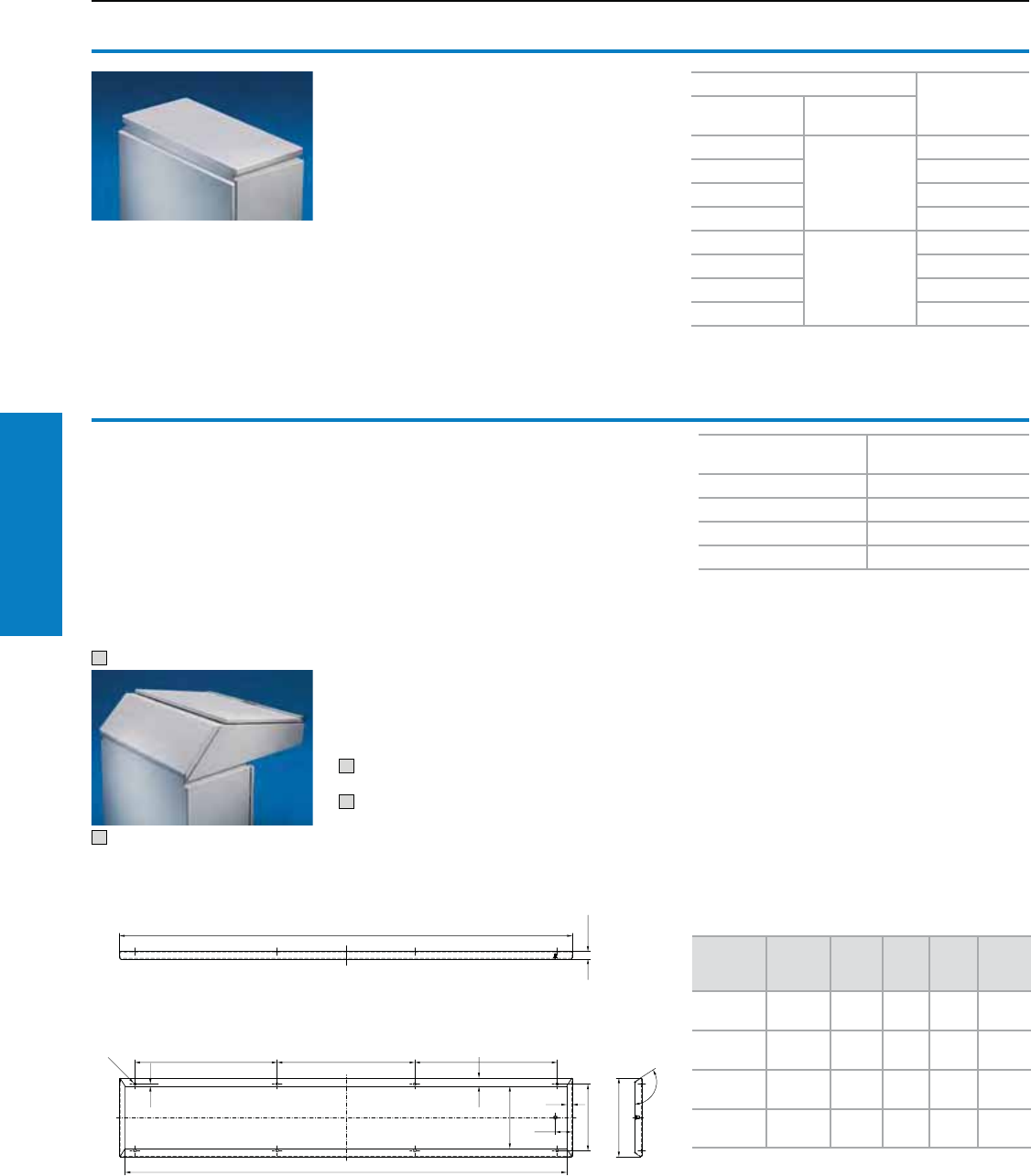
Operator Interface
174 Industrial Buyer’s Guide
TopConsole
Consoles
TopConsole System Accessories
Trim Panels
Trim panel
for pedestal
For covering the complete top opening when
using the pedestal on its own.
Material:
Sheet steel
Color:
Textured RAL 7035 (light gray)
Protection Ratings:
UL 12 (IP 55 to EN 60 529)
UL File: 76083
Conguration:
Assembly parts
For pedestal
Part No.
Width inches
(mm)
Depth inches
(mm)
24 (600)
16 (400)
6730.000
32 (800) 6730.010
47 (1200) 6730.020
63 (1600) 6730.030
24 (600)
20 (500)
6730.100
32 (800) 6730.110
47 (1200) 6730.120
63 (1600) 6730.130
Trim panel
for console/desk unit
For covering the entire top opening when used
alone.
Material:
Sheet steel
Color:
Textured RAL 7035 (light gray)
Protection Ratings:
UL Type 12 (IP 55 to EN 60 529)
UL File: 76083
Conguration:
Assembly parts
1 Console used as a wall-mounted enclosure
2 Trim panel on desk section
1
2
For console width inches
(mm) Part No.
24 (600) 6730.200
32 (800) 6730.210
47 (1200) 6730.220
63 (1600) 6730.230
Note:
Can be used with desk unit prepared for an
upright console as well.
B
1
1
1
Part No.
Width
inches
(mm)
ABCD
6730.200 24
(600)
23
(592)
19
(484) –22
(552)
6730.210 31
(800)
31
(792)
27
(684) –30
(752)
6730.220 47
(1200)
47
(1192)
15
(384)
14
(350)
45
(1152)
6730.230 63
(1600)
63
(1592)
19
(484)
20
(500)
61
(1552)
Inch and pound measurements are rounded to the nearest whole number.
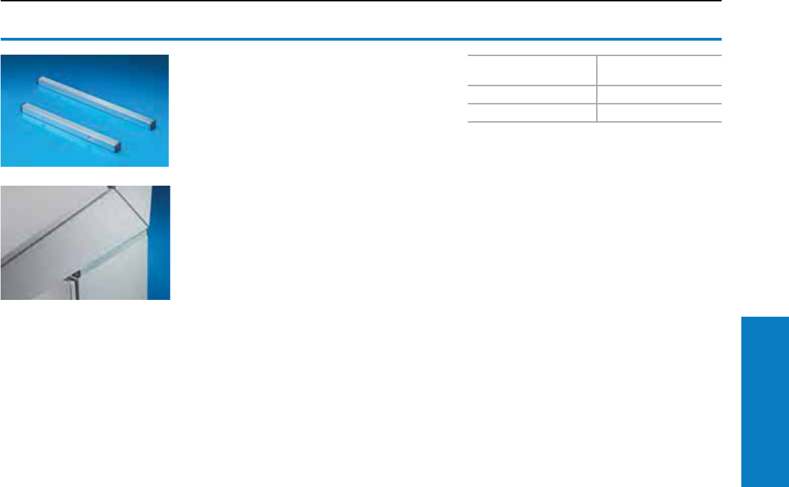
Operator Interface
Industrial Buyer’s Guide 175
TopConsole
Consoles
TopConsole System Accessories
Attachment/Baying Rails
Attachment rail
For accessories such as a scanner holder, or
a shelf for printer etc. Mounting on the existing
holes in the side groove between the pedestal
and console. The enclosure protection ratings
remain unaffected by this installation. No additional
reinforcements are required for the pedestal.
Holes can be drilled in the attachment rail prior
to installation (e.g., for fitting screws, self-tapping
screws or rivets).
To fit pedestal depth
inches (mm) Part No.
16 (400) 6730.500
20 (500) 6730.510
Material:
Rail: Sheet steel, zinc-plated, passivated
Cover caps: Plastic, black
Conguration:
Assembly parts
Inch and pound measurements are rounded to the nearest whole number.
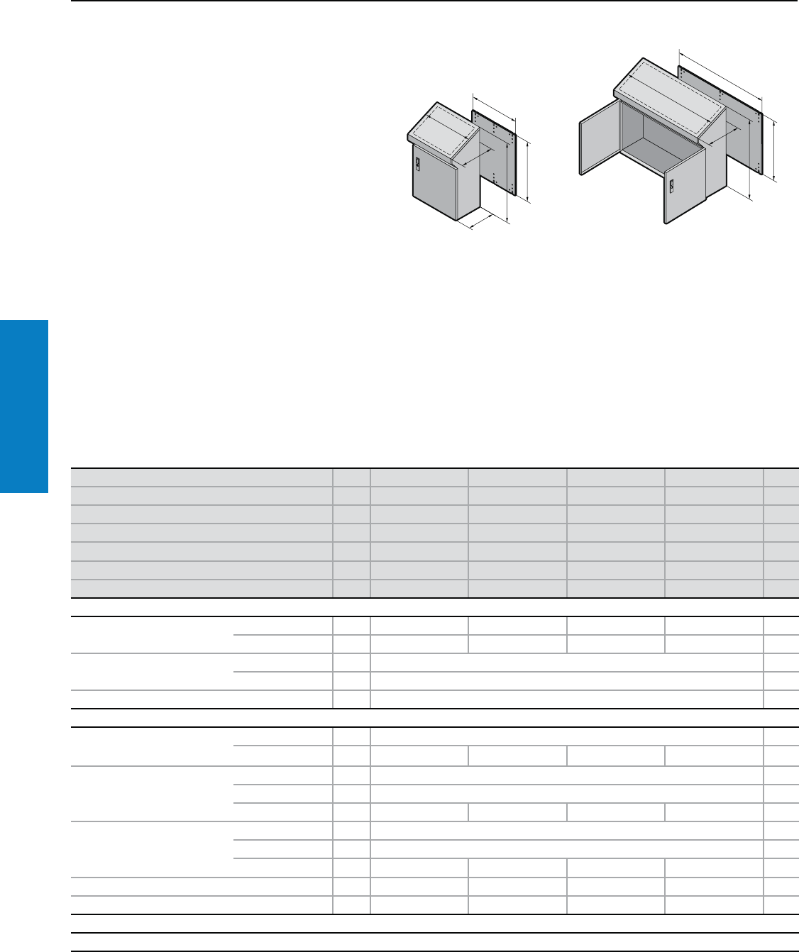
Operator Interface
176 Industrial Buyer’s Guide
TopConsole
Consoles
One-piece TopConsole
Depth: 16/20" (400/520 mm), Height: 38" (960 mm)
Material:
Sheet steel
Enclosure: 16 ga (1.5 mm)
Door and console lid: 14 ga (2.0 mm)
Mounting panel: 11 ga (3.0 mm)
Designer handle strip: Aluminum
Corner protectors and lock cover:
Plastic, self-extinguishing
Conguration:
Enclosure, solid rear and sides, door or
double door at the front, with locking rod,
console lid hinged at rear, 2 stays with
automatic latching and unlatching, base
open for individual cable entry.
For additional technical information,
please visit www.rittal-corp.com
Inch and pound measurements are rounded to the nearest whole number.
T
H
G1
F1
T
B1
T
H
G1
F1
B1
Finish:
Enclosure, cover, and door:
Dipcoat-primed, powder coated in textured
RAL 7035 (light gray) on the outside
Mounting panel: Zinc-plated
Design handle strip: Natural-anodized
Corner protectors and lock cover: RAL 7015
(slate gray)
Protection Ratings:
UL 12 (IP 55 to EN 60 529), with
selection of the appropriate
gland plates, see page 259.
UL File: 76083
Height (H) inches (mm) PU 38 (960) 38 (960) 38 (960) 38 (960) Page
Width (B1) inches (mm) 24 (600) 32 (800) 39 (1000) 47 (1200)
Depth Base/ Console (T) inches (mm) 16 (400)/ 20 (520) 16 (400)/ 20 (520) 16 (400)/ 20 (520) 16 (400)/ 20 (520)
Panel height (G1) inches (mm) 35 (900) 35 (900) 35 (900) 35 (900)
Panel width (F1) inches (mm) 20 (499) 28 (699) 35 (899) 43 (1099)
Part No. 16746.500 6748.500 6740.500 6742.500
Door(s) 1122
Base/plinth
Components front and rear Height 4" (100 mm) 1 set 8601.600 8601.800 8601.000 8601.200 194
Height 8" (200 mm) 1 set 8602.600 8602.800 8602.000 8602.200 194
Trim panels (sides) Height 4" (100 mm) 1 set 8601.040 194
Height 8" (200 mm) 1 set 8602.040 194
Cross member, adjustable 2 8601.450 199
Accessories
Rail for interior installation
For height 4 5001.051 233
For lid 4 5001.050 5001.051 5001.052 5001.053 233
Punched section with mounting
flange 2.9 x 0.7" (73 x 17 mm)
For lid 4 8612.040 234
For enclosure 4 8612.140 234
For door 4 8612.050 – 8612.040 8612.050 234
Mounting bars
For lid 20 4309.000 236
For enclosure 20 4694.000 236
For door 20 4596.000 4598.000 4309.000 4596.000 236
Cable clamp rail 1 5001.080 5001.081 5001.082 5001.083 262
Wiring plan pocket 1 4116.000 4118.000 4115.000 4116.000 227
Lock systems
Console lid: Standard double-bit lock insert, may be exchanged for 1" (27 mm) lock inserts, type A, and for Ergoform-S lock system, see pages 218.
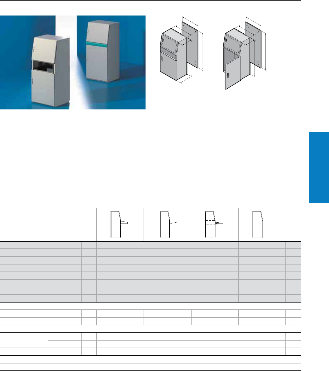
Operator Interface
Industrial Buyer’s Guide 177
TopConsole
Consoles Universal
Universal AP Console
Depth: 16/20" (418/500 mm), Height: 51" (1300 mm)
Material:
Sheet steel
Enclosure, gland plates: 16 ga
(1.5 mm); doors: 14 ga (2.0 mm)
Mounting panel: 11 ga (3.0 mm)
Design strips (2695.500):
Aluminum section
Finish:
Enclosure: Dipcoat-primed,
powder coated on the outside
Mounting panel and gland
plates: Zinc-plated
Color:
Enclosure: textured RAL 7035 (light
gray). Design strips (2695.500):
RAL 5018 (turquoise blue)
Protection Ratings:
UL Type 12
(IP 55 to EN 60 529/10.91)
With a short door at the bottom
(2694.500), in order to
maintain the protection ratings,
a drawer or desk section must
be installed.
UL Type 12 when assembled per
instructions.
UL file: E76083
Conguration:
Enclosure with doors, mounting
panel, gland plates, design strips
(2695.500).
Note:
Top door with studs left and right
for installing vertical perforated
mounting strips 2310.038 and
horizontal support strips 2325.000
to be mounted on top.
AP universal consoles are based
on the freestanding enclosure
ES 5000; therefore, a variety of
accessory components can be
installed.
H
G1
F1
T
B1
T
H
G1
F1
B1
T
Version PU With short front door With tall front door Page
Height (H) inches (mm) 51 (1300) 51 (1300)
Width (B1) inches (mm) 24 (600) 24 (600)
Depth Base/ Console (B1) inches (mm) 16 (418)/ 20 (500) 16 (418)/ 20 (500)
Panel height (G1) inches (mm) 47 (1196) 47 (1196)
Panel width (F1) inches (mm) 20 (499) 20 (499)
Part No. 12694.500 2695.500
Weight lb (kg) 170 (77.0) 176 (80.0)
Also required
Desk section 2696.500 2696.500 – –
Drawer for keyboard – – 4757.5001) –
Accessories
Base/plinth inches
(mm)
Height 4 (100) 1 2807.200 196
Height 8 (200) 1 2808.200 196
Cable clamp rail 4191.000 256
Lock systems
For lock options, see www.rittal-corp.com.
1) Only suitable for installation without a mounting panel.
For additional technical
information and conguration,
please visit www.rittal-corp.com
Inch and pound measurements are rounded to the nearest whole number.
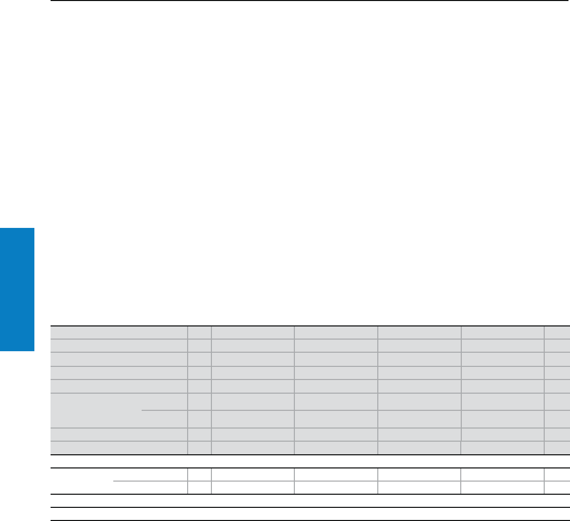
Operator Interface
178 Industrial Buyer’s Guide
TopConsole
Consoles Universal
One-piece AP Console
Depth: 16/19" (400/480 mm), Height: 38" (960 mm)
Material:
Stainless steel
Enclosure: 16 ga (1.5 mm)
Door(s) and console lid:
14 ga (2.0 mm)
Mounting panel: Sheet steel
11 ga (3.0 mm)
Finish:
Enclosure, door and console lid:
Brushed, grain size 120
Mounting panel: Zinc-plated
Protection Ratings:
NEMA 12
(IP 55 to EN 60 529/09.2000)
Conguration:
Enclosure sealed at the rear and
sides, door or double door at the
front, with locking rod, console lid
with lid stay and stainless steel cam
latched in the enclosure, two-piece
gland plate, mounting panel, zinc-
plated.
For additional technical
information, please visit
www.rittal-corp.com
Height (H) inches (mm) PU 38 (960) 38 (960) 38 (960) 38 (960) Page
Width (B1) inches (mm) 24 (600) 32 (800) 39 (1000) 47 (1200)
Depth Base/ Console (T) inches (mm) 16 (400)/ 19 (480) 16 (400)/ 19 (480) 16 (400)/ 19 (480) 16 (400)/ 19 (480)
Mounting panel width (F1) inches (mm) 21 (530) 29 (730) 37 (930) 44 (1130)
Mounting panel height (G1) inches (mm) 31 (780) 31 (780) 31 (780) 31 (780)
Part No.
Type 304 12683.600 2684.600 2685.600 2686.600
Type 316L 12683.5001) 2684.5001) 2685.5001) 2686.5001)
Door(s) 1122
Weight lb (kg) 114 (52.0) 143 (65.2) 175 (79.5) 199 (90.3)
Accessories
Base/plinth Height 4" (100 mm) 1 2865.000 2869.000 2867.000 2870.000 196
Height 8" (200 mm) 1 2875.000 2878.000 2885.000 2886.000 196
Lock systems
Standard double-bit lock insert in the locking rod may be exchanged for 27 mm lock inserts, type A, and for the Ergoform-S lock system, see page 218.
1) Delivery times available upon request.
Inch and pound measurements are rounded to the nearest whole number.
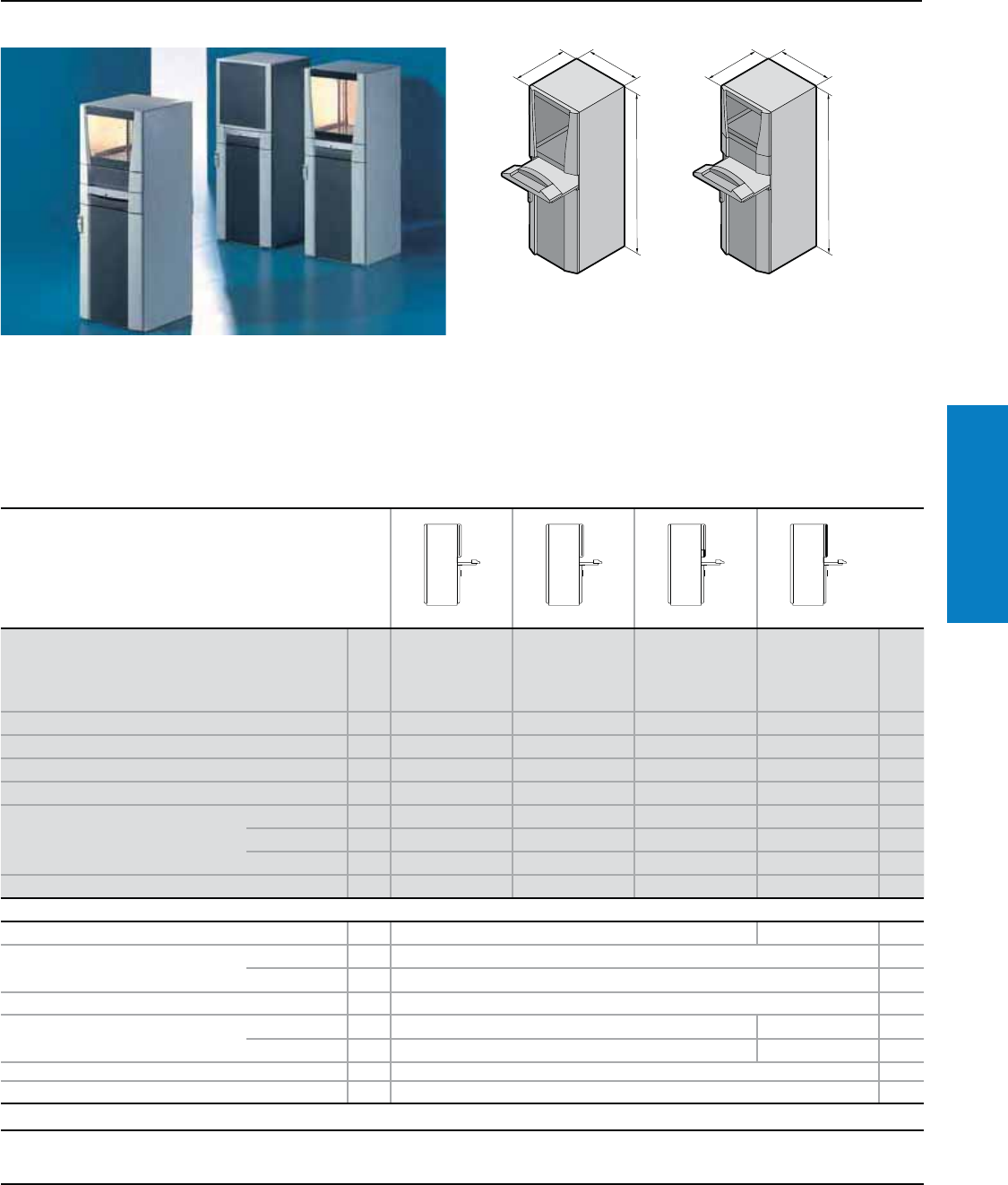
Operator Interface
Industrial Buyer’s Guide 179
PC Enclosure
Workstations
PC Enclosure System
Depth: 25 - 33" (636 - 836 mm), Height: 63" (1600 mm)
Conguration:
Based on TS8 enclosure
Foamed-in-place polyurethane gasket
Front and rear doors right
hand hinged
2-pt locking system
Vented shelf for monitors
up to 24 inches
Material:
Sheet Steel
Frame, sidewalls, roof, front door:
16 ga (1.5 mm)
Rear door: 14 ga (2.0 mm)
Version PU
With keyboard
drawer, viewing
door
With keyboard
drawer, viewing
door, mounting
compartment,
small
With keyboard,
mounting
compartment,
large
With keyboard
drawer, viewing
door
Page
Height (H) inches (mm) 63 (1600) 63 (1600) 63 (1600) 63 (1600)
Width (B) inches (mm) 24 (600) 24 (600) 24 (600) 24 (600)
Depth (T) inches (mm) 25 (636) 25 (636) 25 (636) 33 (836)
Part No. 18366.000 8366.300 8366.400 8368.000
Maximum keyboard
dimensions inches (mm)
Height 3 (70) 3 (70) 3 (70) 3 (70)
Width 19 (480) 19 (480) 19 (480) 19 (480)
Depth 10 (260) 10 (260) 10 (260) 10 (260)
Weight lb (kg) 4.6 (118) 4.6 (118) 4.6 (118) 4.6 (118)
Accessories
Base/plinth, stationary 1 8800.920 on request –
Base/plinth components front and rear
inches (mm)
Height 4 (100) 1 set 8601.600 194
Height 8 (200) 1 set 8602.600 194
Base/plinth trim, front inches (mm) Height 8 (200) 1 set 8360.920 –
Base/plinth trim, side inches (mm) Height 4 (100) 1 set 8601.060 8601.080 194
Height 8 (200) 1 set 8602.060 8602.080 194
Cross member, adjustable inches (mm) Height 3 (70) 2 8601.680 199
Partial mounting panel inches (mm) Height 31 (775) 1 8614.675 231
Lock systems
Standard lock insert, may be exchanged on rear door: TS lock inserts, see page 217, comfort handle, see pages 217.
Designer door, front: TS lock inserts, see pages 217-220, comfort handle, see page 217 (via handle adaptor 8611.300,
see www.rittal-corp.com). Keyboard drawer/fold-out tray: Lock inserts, 1" (27 mm), version A, see pages 219.
T
H
B
T
H
B
For additional technical
information, please visit www.
rittal-corp.com
Protection Ratings:
UL Type 12
(IP 55 to EN 60 529)
when assembled per
instructions.
UL file: E76083
Inch and pound measurements are rounded to the nearest whole number.
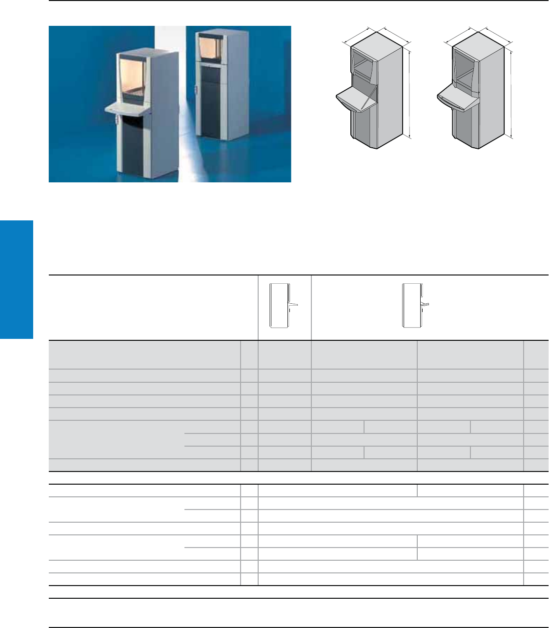
Operator Interface
180 Industrial Buyer’s Guide
PC Enclosure
Workstations
PC Enclosure System
Depth: 25 - 33" (636 - 836 mm), Height: 63" (1600 mm)
Conguration:
Based on TS8 enclosure
Foamed-in-place polyurethane gasket
Front and rear doors right
hand hinged
2-pt locking system
Vented shelf for monitors
up to 24 inches
Material:
Sheet Steel
Frame, sidewalls, roof, front door:
16 ga (1.5 mm)
Rear door: 14 ga (2.0 mm)
Version PU
With desk
section,
viewing door
With fold-out keyboard tray,
viewing door
With fold-out keyboard tray,
viewing door Page
Height (H) inches (mm) 63 (1600) 63 (1600) 63 (1600)
Width (B) inches (mm) 24(600) 24 (600) 24 (600)
Depth (T) inches (mm) 25 (636) 25 (636) 33 (836)
Part No. 18366.200 8366.100 8368.100
Maximum keyboard dimensions
inches (mm)
Height 2 (40) 2 (60) 2 (50) 2 (60) 2 (50)
Width 21 (540) 19 (475) 19 (475)
Depth 7 (175) 8 (200) 10 (250) 8 (200) 10 (250)
Weight lb (kg) 238.1 (108) 260.1 (118) 273.3 (124)
Accessories
Base/plinth, stationary 1 8800.920 on request –
Base/plinth components front and rear
inches (mm)
Height 4 (100) 1 8601.600 194
Height 8 (200) 1 8602.600 194
Base/plinth trim, front inches (mm) Height 8 (200) 1 8360.920 –
Base/plinth trim, side inches (mm) Height 4 (100) 1 8601.060 8601.080 194
Height 8 (200) 1 8602.060 8602.080 194
Cross member, adjustable inches (mm) Height 3 (70) 2 8601.680 199
Partial mounting panel inches (mm) Height 31 (775) 1 8614.675 231
Lock systems
Standard lock insert, may be exchanged on rear door: TS lock inserts, see page 219, comfort handle, see pages 217.
Designer door, front: TS lock inserts, see pages 219-220, comfort handle, see page 217 (via handle adaptor 8611.300,
see www.rittal-corp.com). Keyboard drawer/fold-out tray: Lock inserts, 1" (27 mm), version A, see pages 219.
T
H
B
T
H
B
*Also available in Stainless Steel N12 and N4X - see www.rittal-corp.com.
For additional technical
information, please visit
www.rittal-corp.com
Protection Ratings:
UL Type 12 (IP 55 to EN 60 529)
when assembled per instructions.
UL file: E76083
Inch and pound measurements are rounded to the nearest whole number.
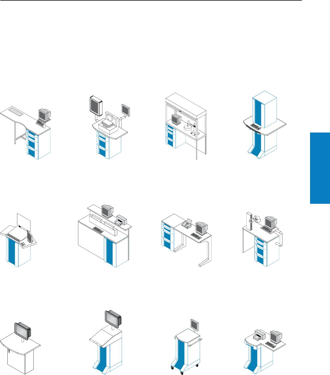
Operator Interface
Industrial Buyer’s Guide 181
Industrial
Workstations
Industrial Workstations
Features
Rittal's Industrial Workstations give you the ability to create professional
workstations for practically any application from a comprehensive
modular system.
Combined with operator housings, support arm systems, PC enclosures,
and a diverse range of system accessories, there is virtually no limit to the
possibilities. Here are a few examples:
Workbench/assembly bench
consisting of:
• IW enclosure
• IW pedestal
• Individual worktop
Laboratory equipment and small
machinery consisting of:
• IW enclosure
• Worktop
• Support arm system
• Operator housings
Protective cabinets:
With lockable roller blind upon
request.
Measurement/control systems:
"More space" with the enclosure
on top of the worktop.
Control desks e.g. for printing
presses consisting of:
• IW enclosure
• Individual worktop and
assemblies
Workbench consisting of:
• IW enclosure for tools, etc.
• Individual worktop with shelf for
monitor, printer, etc.
Calibration/measuring station
consisting of:
• IW enclosure
• IW pedestal
• Worktop
Programming station:
Ergonomically adaptable via the
support arm system.
Production workstation
consisting of:
• TP pedestal
• IW worktop
• Support arm system
• Operator housing
Workstation consisting of:
• Base/plinth
• IW enclosure
• TP desk unit
• Support arm system
• Operator housing
Mobile workstation/workshop
trolley consisting of:
• Base/plinth with castors
• IW enclosure
• Worktop
• Handle system
• Operator housing
Scanner/PC station consisting of:
• IW enclosure
• Individual worktop
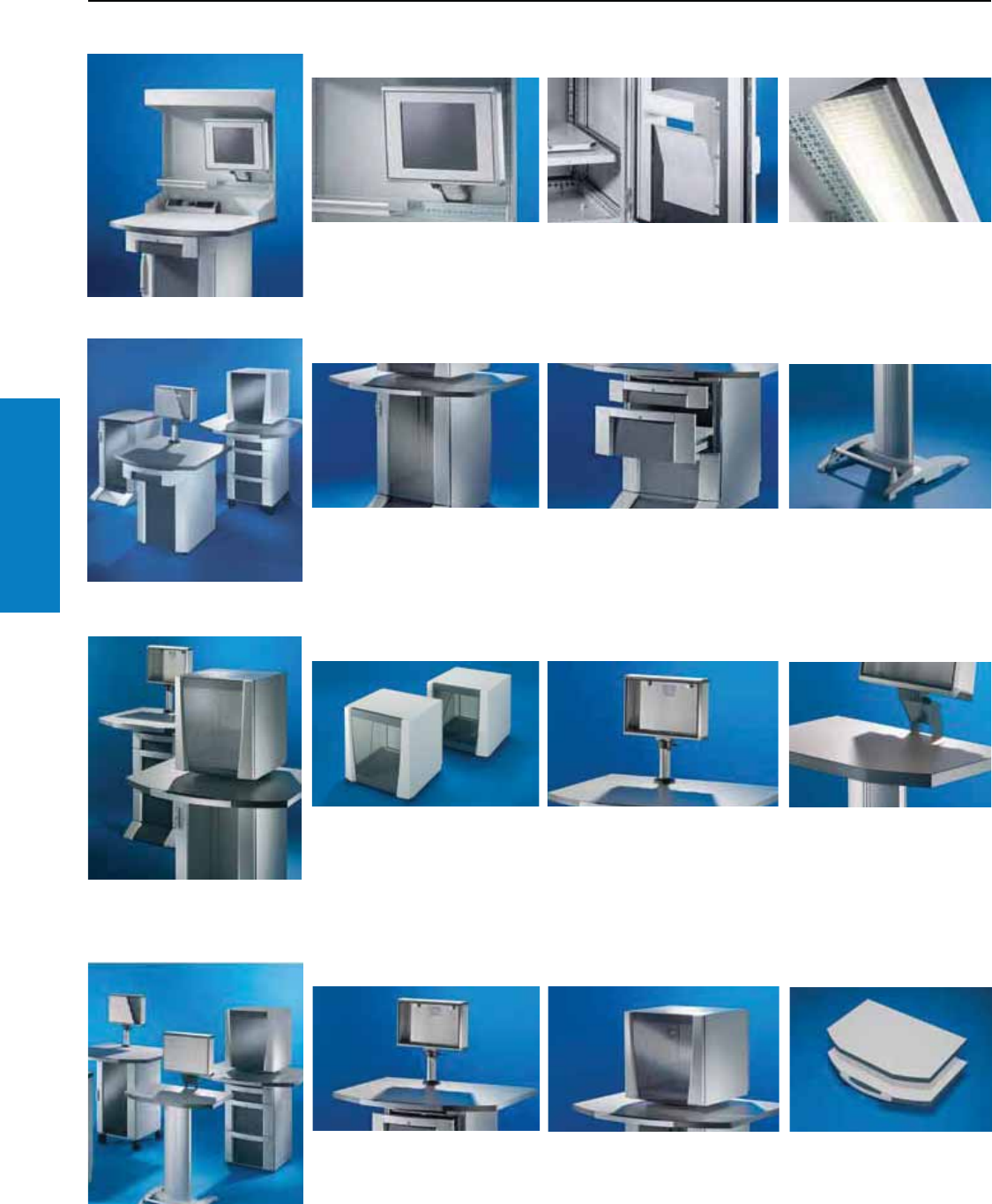
Operator Interface
182 Industrial Buyer’s Guide
Industrial
Workstations
Industrial Workstations
Features
IW Quality Point/IW Logistic Point
The integration of a TFT monitor
creates space on the work surface.
The rotatable printer shelf and the
paper tray are a perfect duo for the
secure accommodation of printers
in an industrial environment.
Optimum glare-free illumination
of the workplace with the
integral workstation light.
IW enclosure
In two standard heights, optionally
with designer door or glazed door.
Offers plenty of storage space.
With drawer front for an orderly
filing system. A pull-out lock which
prevents the simultaneous opening
of several drawers is integrated to
increase operational safety.
If no enclosure is needed to
accommodate documents or
equipment, the IW pedestal
may be used instead. By
combining with a worktop, a
large work surface is created.
IW monitor housing
In two sizes for monitors up to
17 and 21" (screen diagonal).
In conjunction with a turntable,
the monitor can be viewed from
all angles.
TFT monitors are increasingly being
used in industrial environments.
Thanks to the large number of
standardized system components.
TFT's may be easily integrated into
the workstation.
Mounting of a TFT monitor
without reducing the work
space. With the aid of the
enclosure attachment, the
angle of the display is ideally
adapted to suit the user.
IW worktops
14 different worktops in 7
different sizes accommodate
virtually all requirements.
Monitor housings may be mounted
either rigidly or swivel-mounted on
worktops prepared for a turntable.
Worktops available with or
without a handle.
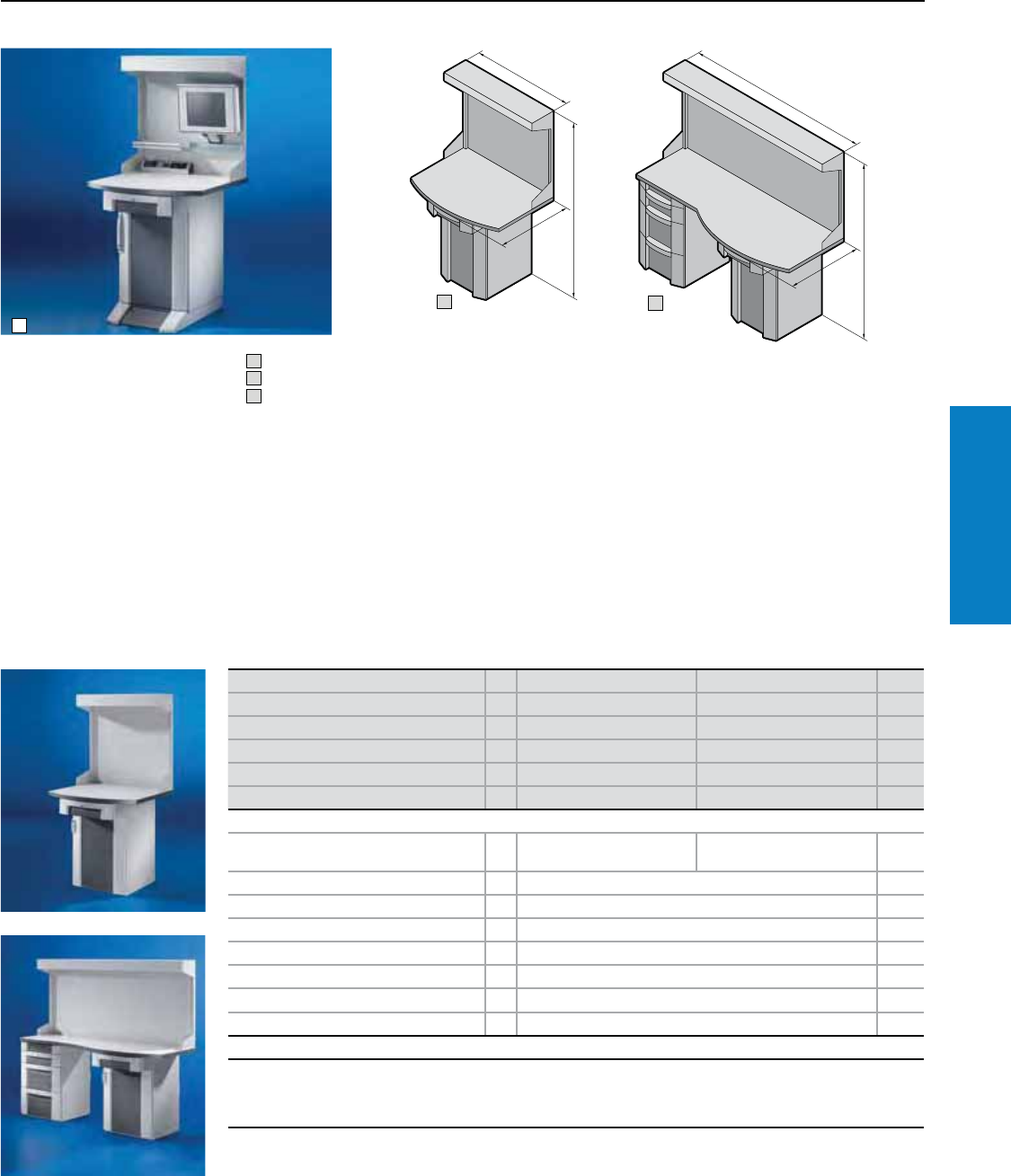
Operator Interface
Industrial Buyer’s Guide 183
Industrial
Workstations
Inspection Station
Depth: 35" (895 mm), Height: 79" (2000 mm)
1
3
2
T
H
B
T
H
B
The complete system for use
as a testing station in industrial
environments (e.g., directly at the
machine) where it is necessary to
perform testing and process the
data electronically. An individual PC
system is integrated to perfection.
Benets:
• Plenty of space to accommodate
test equipment
• Easy integration of PC's, monitors,
printers, etc.
• Theft protection
1 Assembly example
2 Single Inspection Station
3 Double Inspection Station
Color:
RAL 7015 (slate gray)/7035 (light
gray)/9006 (white aluminium)
Protection Ratings:
NEMA 12 (IP 54 to EN 60 529)
Single Inspection Station
Conguration:
Enclosure with keyboard drawer
section 6900.410, see page
186, worktop 1.5 x 39 x 35" (38
x 1000 x 895 mm) H x W x D,
Inspection Station attachment
with side system punchings
on a 1" (25 mm) pitch pattern
for the attachment of system
accessories (such as punched
sections with mounting flanges),
workstation light, 2 x 36 W,
230 V, 50 Hz.
Double Inspection Station
Conguration:
Enclosure with drawer front
(left), 6900.600, see page 187,
enclosure with keyboard drawer
section (right), 6900.410, see
page 186, worktop 1.5 x 79 x 35"
(38 x 2000 x 895 mm) H x W x
D, Inspection Station attachment
with side system punchings
on a 1" (25 mm) pitch pattern
for the attachment of system
accessories (such as punched
sections with mounting flanges),
workstation light, 2 x 36 W,
230 V, 50 Hz.
Version PU Single Inspection Station Double Inspection Station Page
Height (H) inches (mm) 79 (2000) 79 (2000)
Width (B) inches (mm) 39 (1000) 79 (2000)
Depth (T) inches (mm) 35 (895) 35 (895)
Part No. 16920.100 6920.200
Weight lb (kg) 306 (139) 607 (276)
Accessories
Punched sections with mounting flanges
3 x 0.6" (73 x 17 mm) 8612.090 – 234
Bracket, locatable for shelves 6902.690 –
Paper removal flap 6903.200 –
Paper tray 6903.000 –
Mounting panel 8614.675 231
Component shelf, static installation 8800.900 –
Component shelf, pull-out 6902.960 –
Drawer tray 6902.700 –
Lock systems
Standard double-bit lock insert may be exchanged for type F lock inserts, see page 220, type B lock cylinder inserts, see
page 219, or comfort handle, see page 217, for front designer door only in conjunction with handle adaptor 8611.300,
see page 211.
Drawer with lock no. 3524 E. Other versions available upon request.
Inch and pound measurements are rounded to the nearest whole number.
For additional technical
information, please visit
www.rittal-corp.com
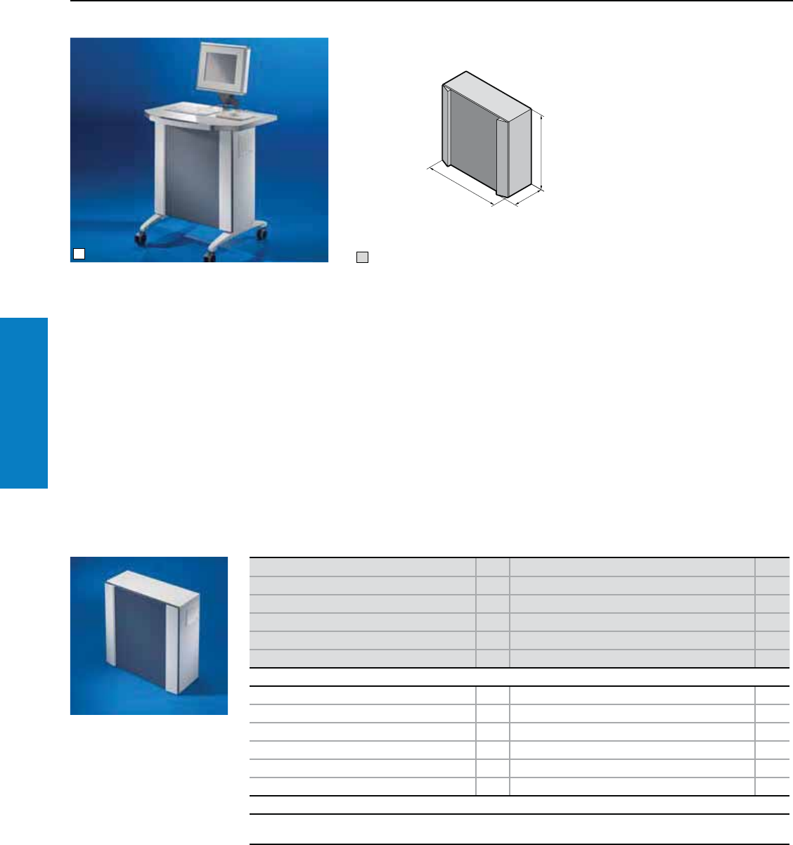
Operator Interface
184 Industrial Buyer’s Guide
Industrial
Workstations
Enclosure for Tower PC
Depth: 12" (300 mm), Height: 30" (760 mm)
For additional technical information,
please visit www.rittal-corp.com
11 Assembly example
H
T
B
Compact enclosure, ready to connect. Standard
commercially available tower PC's, up to 21
x 10 x 24" (530 x 250 x 600 mm) H x W x D
(max. 44 lb [20 kg]) may be attached securely
to the base, screw fastened to the door using
the retaining strap (supplied loose). The rear
interfaces of the PC are readily accessible with
the door open. Because the socket strip and
fan-and-filter unit are already pre-installed, the
enclosure is ready for immediate use.
Roof prepared for mounting
• worktop 6902.310
• beneath surfaces
Base prepared for mounting
• cast feet 6902.920
• on surfaces
Material:
Enclosure:
Sheet steel, powder coated in textured RAL 7035
(light gray)
Door:
Sheet steel, spray-finished in RAL 7015 (slate gray)
with fitted design strips of aluminum in RAL 7035
(light gray)
Protection Ratings:
NEMA 12 (IP 54 to EN 60 529)
(in conjunction with connector gland 2400.300/.500,
supplied loose)
Conguration:
Enclosure sealed all round, right hand door hinge,
with screw-fastened base on the inside of the tubular
door frame to accommodate a tower PC, locked at
the side with a fitted cam lock.
Rear panel with two cut-outs for
use of the connector gland
2400.300 and 2400.500, supplied
loose. Connector for power supply,
retaining strap to secure the
tower PC to the base,
left-hand side panel with fitted
outlet filter 3322.200.
Side panel, right, fitted with:
• Fan-and-filter unit 3322.107,
see page 267
• Supply socket for 230 V
power supply
• Socket strip with 3 sockets
and over voltage protection
PU Enclosure for tower PC Page
Height (H) inches (mm) 30 (760)
Width (B) inches (mm) 30 (760)
Depth (T) inches (mm) 12 (300)
Part No. 16900.300
Weight lb (kg) 121 (55)
Accessories
Cast feet 2 6902.920 –
Twin castors 1 set 4634.500 168
Worktop without handle 1 6902.310 188
Enclosure attachment, tilting, base mounting 1 6902.640 139
TFT monitor 17" with safety glass screen 1 6450.020 –
Desktop keyboard IP 65 1 6446.000 –
Lock systems
Standard double-bit lock insert may be exchanged for 2" (47 mm) lock inserts, type D, or plastic handles, type G, see
www.rittal-corp.com.
Inch and pound measurements are rounded to the nearest whole number.
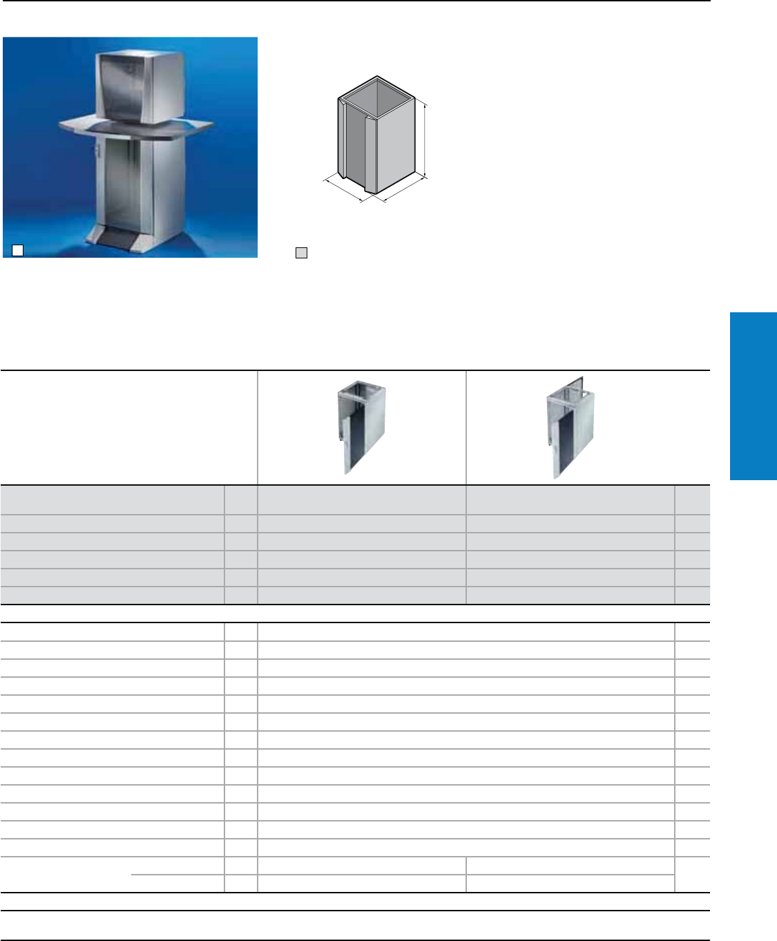
Operator Interface
Industrial Buyer’s Guide 185
Industrial
Workstations
Enclosure With Doors
Depth: 24" (600 mm), Height: 35" (900 mm)
For additional technical information,
please visit www.rittal-corp.com
11 Assembly example
H
T
B
Material:
Enclosure, designer door, rear panel, rear
door: Sheet steel, RAL 7035 (light gray)
Glazed door:
Plastic to UL 94-V0, RAL 7035 (light gray),
toughened safety glass 0.15" (4.0 mm)
Protection Ratings:
NEMA 12 (IP 55 to EN 60 529)
Property rights:
German patent no. 100 13 034
German registered design
no. 400 02 325
US patent no. 6,538,876
US design patent no. D 487, 730
UK reg. design no. 2 094 499
Japan reg. design no. 113 95 92
IR reg. design no. DM/053 554
with validity for FR, IT
Version PU Designer door, rear panel screw-fastened
from the inside Deisgner door, rear door Page
Height (H) inches (mm) 35 (900) 35 (900)
Width (B) inches (mm) 24 (600) 24 (600)
Depth (T) inches (mm) 24 (600) 24 (600)
Part No. 16900.000 6900.100
Weight lb (kg) 121 (54.9) 132 (59.9)
Accessories
Base/plinth, stationary 1 8800.920 –
Cross member, adjustable 2 8601.680 199
Twin castors 1 set 4634.500 168
Paper tray 1 6903.000 –
Paper removal flap 1 6903.200 –
Handle adaptor for comfort handle 1 8611.300 211
Mounting panel for enclosure width 24" (600 mm) 1 8614.675 231
Component shelf, static installation 1 8800.900 –
Component shelf, pull-out 1 6902.960 –
Drawer tray 11 6902.700 –
Drawer extension lock 1 6902.730 –
Mobile workstations 1 4641.000 –
Adaptor section 19" (482.6 mm) 8613.070 245
Gland Plate Size 2 2
Qty. 1 1
Lock systems
Standard double-bit lock insert may be exchanged for type F lock inserts, type B lock cylinder inserts, or comfort handle, see from page 217,
for designer door and glazed door only in conjunction with handle adaptor 8611.300, see page 211.
Note:
• Other enclosure depths or
heights, variable on a 1" (25 mm)
pitch pattern
• All IW components as well as
system accessories fully assembled,
available upon request.
Inch and pound measurements are rounded to the nearest whole number.
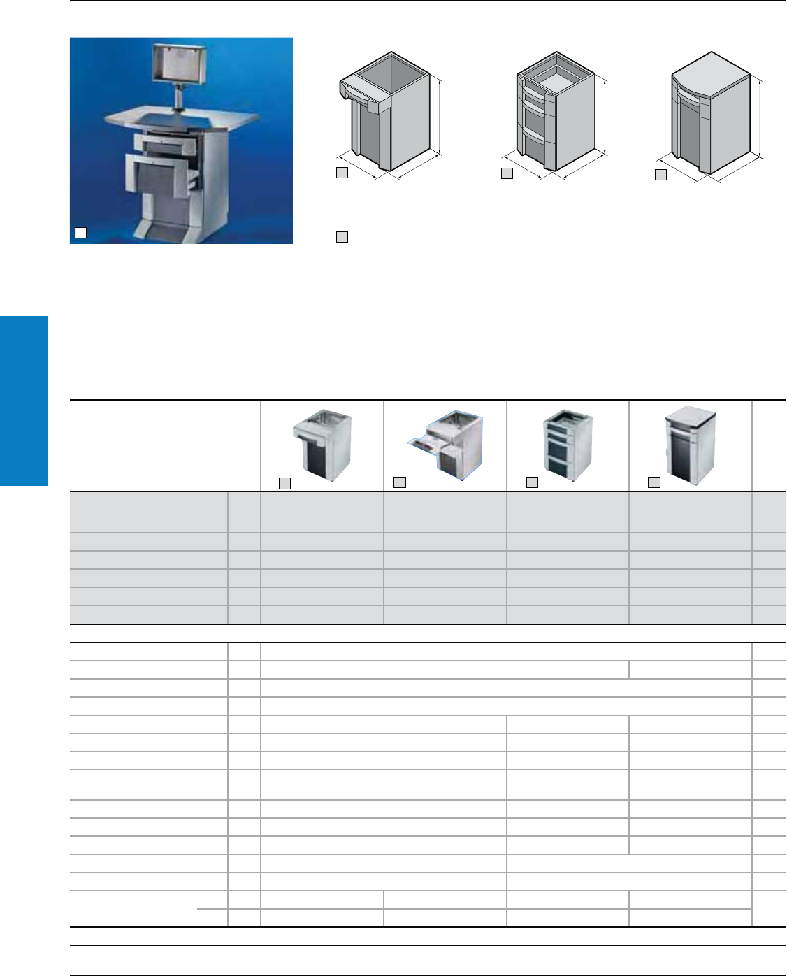
Operator Interface
186 Industrial Buyer’s Guide
Industrial
Workstations
Enclosure With Drawers or Worktop
Depth: 24 - 25" (600 - 645 mm), Height: 35 - 40" (900 - 1000 mm)
For additional technical information,
please visit www.rittal-corp.com
11 Assembly example
Material:
Enclosure, roof, drawer tray, designer door and rear
door: Sheet steel, RAL 7035 (light gray)
Worktop:
Chipboard, plastic-laminated on both sides, similar
to RAL 7035 (light gray), with tough plastic
edging, similar to RAL 7015 (slate gray)
Drawer trim panel:
Plastic, RAL 7015 (slate gray)/7035 (light
gray)/9006 (white aluminium)
Protection Ratings:
NEMA 12 (IP 54 to EN 60 529)
Note:
• Other enclosure depths or heights,
variable on a 1" (25 mm) pitch pattern
• All IW components as well as system
accessories fully assembled
• Other drawer combinations
• Fitted version 6901.100 (with worktop)
also with other worktops, see page 188,
available upon request
H
T
B
H
T
B
H
T
B
4
3
2
Version PU
Drawer section for
documents, designer
door, rear door
Drawer section for
keyboard and mouse,
designer door, rear door
Drawer front, rear panel Enclosure with worktop,
keyboard drawer Page
Height (H) inches (mm) 35 (900) 35 (900) 35 (900) 40 (1000)
Width (B) inches (mm) 24 (600) 24 (600) 24 (600) 24 (600)
Depth (T) inches (mm) 24 (600) 24 (600) 24 (600) 25 (645)
Part No. 16900.400 6900.410 6900.600 6901.100
Weight lb (kg) 161 (73) 161 (73) 172 (78) 200 (91)
Accessories
Base/plinth, stationary 1 8800.920 –
Cross member, adjustable 2 8601.680 – 199
Twin castors 1 set 4634.500 168
Paper removal flap 1 6903.200 –
Paper tray 1 6903.000 – 6903.000 –
Cable gland 1 6902.770 – 6902.770 190
Mounting panel 1 8614.675 – 8614.675 231
Component shelf, static
installation 1 8800.900 – 8800.900 –
Component shelf, pull-out 1 6902.960 – 6902.960 –
Drawer tray 1 6902.700 – 6902.700 –
Drawer extension lock 1 6902.730 included – –
Mobile workstations 1 4641.000 – –
Adaptor section 19" (482.6 mm) 1 8613.070 – 245
Gland plate Size 2222
Qty.1111
Lock systems
Standard double-bit lock insert may be exchanged for type F lock inserts, type B lock cylinder inserts, or comfort handle, see from page 217-220,
for designer door only in conjunction with handle adaptor 8611.300, see page 211. Drawer with lock no. 3524 E. Other versions available upon request.
2
23 4
Inch and pound measurements are rounded to the nearest whole number.
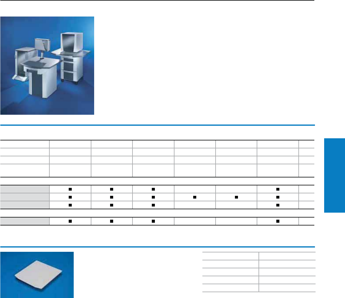
Operator Interface
Industrial Buyer’s Guide 187
Industrial
Workstations
Roof and Worktop
Depth: 24" (600 mm), Height 35" (900 mm)
For additional technical information,
please visit www.rittal-corp.com
Note:
• Keyboard and front panels for keys integrated into
the worktop
• Worktops in modified sizes
• All IW components as well as system accessories
fully assembled, available upon request.
Combination options for enclosures/worktops
Height inches (mm) 35 (900) 35 (900) 35 (900) 35 (900) 35 (900) 35 (900) Page
Width inches (mm) 24 (600) 24 (600) 24 (600) 24 (600) 24 (600) 24 (600)
Depth inches (mm) 24 (600) 24 (600) 24 (600) 24 (600) 24 (600) 24 (600)
Enclosures
Part No. 6900.000 6900.100 6900.200 6900.400 6900.410 6900.600
Worktop
6902.000 –– 188
6902.100 188
6902.300 –– 188
Roof
6902.400 –– 187
To order worktops in the ESD version, please add the extension .XX8 to the Part No.
Roof
Folded all-round, with brackets for screw-
fastening to the enclosure from the inside.
Material:
Sheet steel 16 ga (1.5 mm)
Finish:
Spray-finished in textured RAL 7035 (light gray)
Height (H) inches (mm) 0.5 (13)
Width (B) inches (mm) 24 (600)
Depth (T) inches (mm) 25 (640)
Weight lb (kg) 16 (7.4)
Part No. 6902.400
Inch and pound measurements are rounded to the nearest whole number.
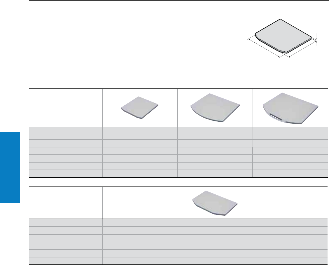
Operator Interface
188 Industrial Buyer’s Guide
Industrial
Workstations
Worktops
Depth: 25 - 37" (645 - 950 mm), Height: 2" (38 mm)
Worktops
Material/Finish:
Chipboard, plastic-laminated on both sides,
similar to RAL 7035 (light gray), with tough
plastic edging, similar to RAL 7015 (slate
gray). Handle made from aluminum, powder
coated in RAL 9006 (white aluminium).
H
T
B
Solid
Version Without handle
for enclosure
Without handle
for enclosure/worktop base
With handle
for enclosure
Height (H) inches (mm) 2 (38) 2 (38) 2 (38)
Width (B) inches (mm) 24 (610) 39 (1000) 47 (1200)
Depth (T) inches (mm) 25 (645) 35 (895) 37 (950)
Part No. 6902.300 6902.100 6902.000
Weight lb (kg) 26 (11.6) 53 (24) 75 (34)
Prepared for mounting on
– Pedestal IW
– Enclosure for tower PC
– Worktop attachment
Version Without handle
Height (H) inches (mm) 2 (38)
Width (B) inches (mm) 37 (950)
Depth (T) inches (mm) 24 (600)
Part No. 6902.310
Weight lb (kg) 35 (16)
Inch and pound measurements are rounded to the nearest whole number.
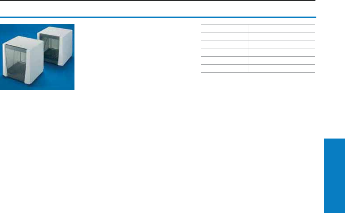
Operator Interface
Industrial Buyer’s Guide 189
Industrial
Workstations
Monitor Housing
Depth: 24" (600 mm), Height: 24" (600 mm)
Monitor housing
For protected accommodation of 17" monitors.
Material:
Enclosure, rear door and component shelf:
0.6" (1.5 mm) sheet steel
Designer door: Vertical plastic decorative trim
panels to UL 94-V0
Pane: Toughened safety glass 0.16" (4 mm)
Finish:
Enclosure and rear door: Textured RAL 7035
(light gray)
Designer door: Decorative trim panels RAL 7035
(light gray),
screen-printed mask on glass pane RAL 7015
(slate gray)
Component shelf: RAL 7015 (slate gray)
Protection Ratings:
NEMA 12 (IP 55 to EN 60 529/09.2000)
Conguration:
Front designer door with internal lock,
unlatched behind the rear door via a lever
with Bowden cable. Rear door with standard
double-bit lock insert, may be exchanged for
1" (27 mm) lock inserts, type A, or lock cylinder
inserts, type B, and for Ergoform-S lock system,
see pages 217-220.
Enclosure with cut-out at the bottom and
reinforcement for mounting
Base prepared for the mounting of feet for desktop.
Fitted component shelf, slotted, height-adjustable
on a 25 mm pitch pattern, prepared for mounting
fan expansion kit 7980.000, and a socket strip, 19"
(482.6 mm) long, see www.rittal-corp.com.
For additional technical information,
please visit www.rittal-corp.com
Housing for 21" monitors
Height inches (mm) 24 (600)
Width inches (mm) 24 (600)
Depth inches (mm) 24 (600)
Part No. 6902.500
Weight lb (kg) 94 (42.5)
Delivery times available upon request.
Inch and pound measurements are rounded to the nearest whole number.
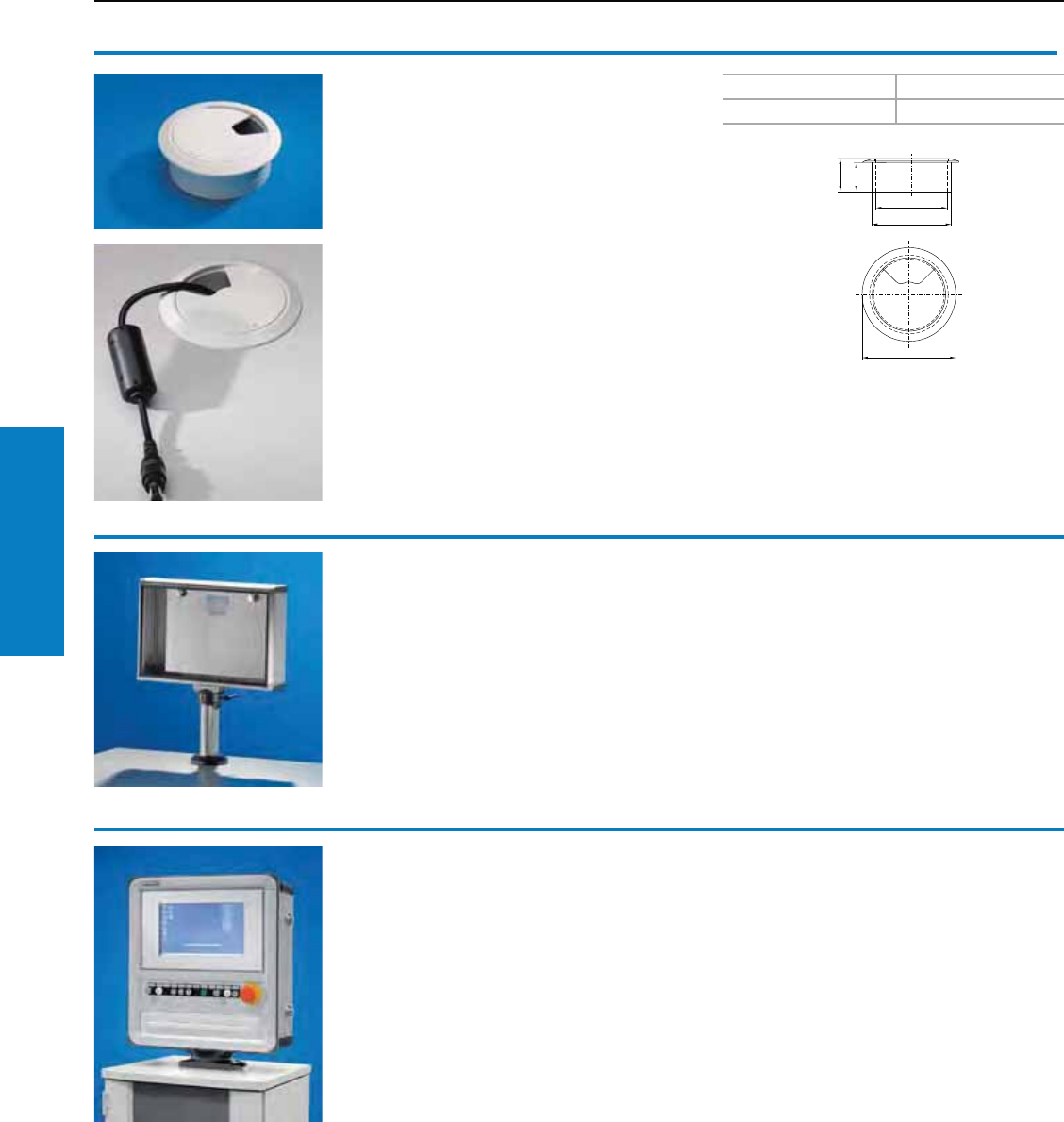
Operator Interface
190 Industrial Buyer’s Guide
Industrial
Workstations
Workstation Accessories
Cable gland
for Industrial Workstation worktops
To fit drilled 2.4" (60 mm) drilled holes. For the
entry of cables with pre-assembled connectors,
the rotating flap and cover are easily removed.
Material:
Plastic
Color:
RAL 7035 (light gray)
1
PU Part No.
16902.770
Optipanel
A stylish enclosure of extruded aluminium section.
In installation depths 2, 4 and 6" (50, 100 and
150 mm), the width and height are sized to your
specified panels.
Standard sizes are available off the shelf for
TFT monitors 15 and 17" with safety glass or
touchscreen, and also for conventional desktop
TFT s up to 20.1", see page 94.
Full information on the Optipanel, see page 93.
Support arm system CP-L
Using support section CP-L, Operator housings
may be positioned in a rotatable and swivelling
configuration depending on the respective
ergonomic conditions, see page 132.
Comfort Panel
Choose from 11 installation depths in a number of
different variants. Whether screw-fastened or with
a flat front frame, hinged, the Comfort Panel will
always adapt to suit your requirements. An allround
soft profile reduces the risk of injury. Simply
compile your individual Comfort Panel or use the
standard sizes, available off the shelf for TFT monitors
15” and 17”.
Full information on the Comfort Panel from page 83.
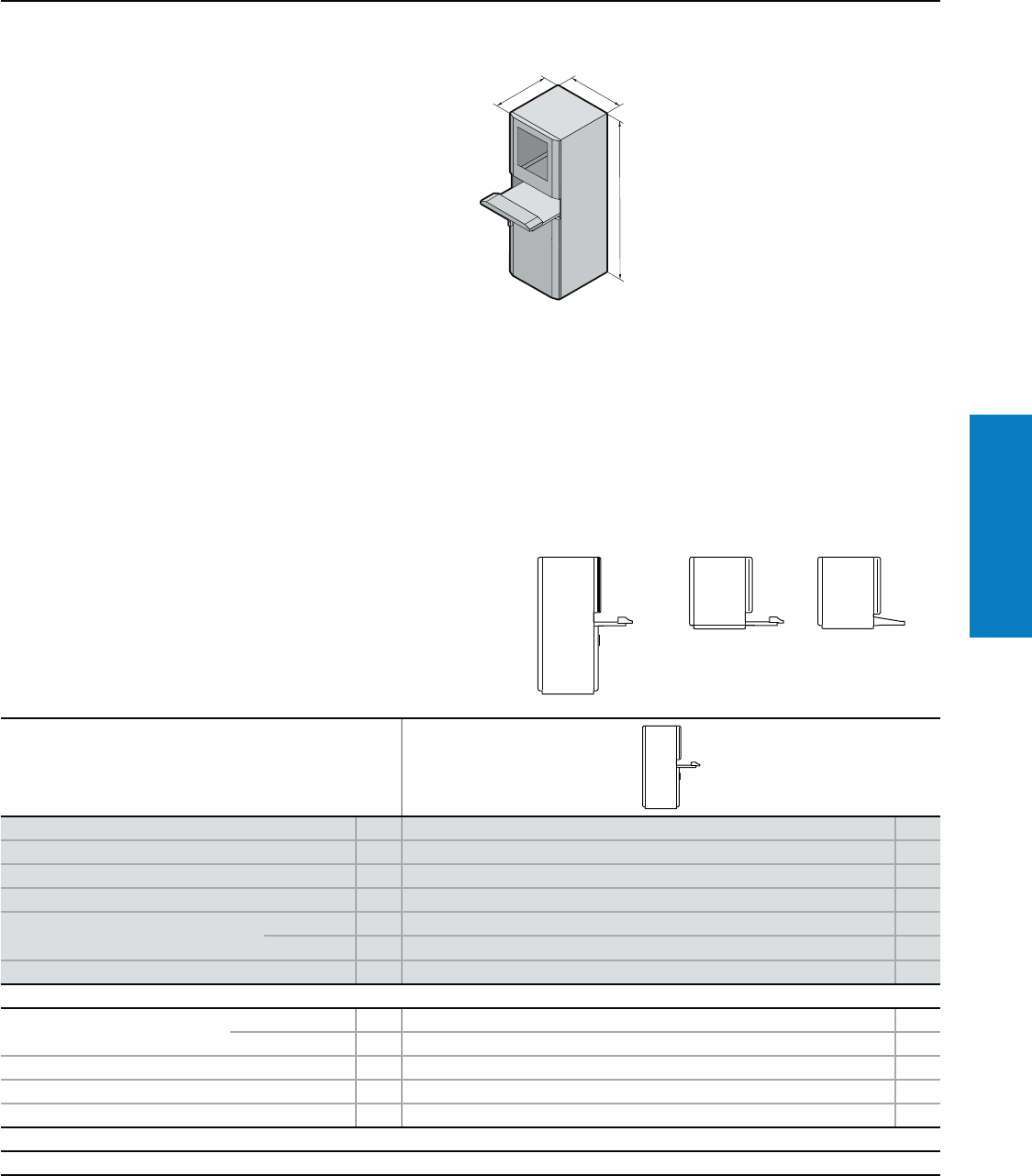
Operator Interface
Industrial Buyer’s Guide 191
PC Enclosure
Workstations
PC Enclosure System
Depth: 24" (620 mm), Height: 63" (1600 mm)
T
H
B
Conguration:
with keyboard drawer
• Lock insert, lock no. 3524 E
• Swing-down front for handrest
• Mouse pad support (also suitable
for IP 67 mouse), may optionally
be used on the left or right
• Hinged cable support
Material:
Stainless steel
Enclosure:
10-fold profiled, 16+ ga (1.8 mm)
Rear door: 14 ga (2.0 mm)
Gland plates: 16 ga (1.5 mm)
Monitor field with single-pane
safety glass for screen diagonal
19" (482.6 mm).
Finish:
Brushed, grain 240
Protection Ratings:
NEMA 12
(IP 55 to EN 60 529/09.2000)
Available on request:
• Enclosure system PC with
mounting compartment, large
and drawer
• PC enclosure system with desk
section
• PC enclosure system with drawer
• PC enclosure system with desk
section
For additional technical
information, please visit
www.rittal-corp.com
Version PU With keyboard drawer Page
Height (H) inches (mm) 63 (1600)
Width (B1) inches (mm) 24 (600)
Depth (T) inches (mm) 24 (620)
Part No. Type 304 14650.000
Type 316L 14650.500
Weight lb (kg) 253 (115)
Accessories
Base/plinth Height 4" (100 mm) 1 2855.000 196
Height 8" (200 mm) 1 2877.000 196
Levelling feet, 4" (100 mm) high 1 set 2859.000 201
Base/plinth trim, modular 4 2913.000 –
Adaptor pieces, 19" (482.6 mm) 8 4547.000 –
Lock systems
Standard double-bit lock insert may be exchanged for 27 mm lock inserts, type A, see page 219 or lock cylinder inserts, type B, see page 217.
Inch and pound measurements are rounded to the nearest whole number.

Notes
192 Industrial Buyer’s Guide
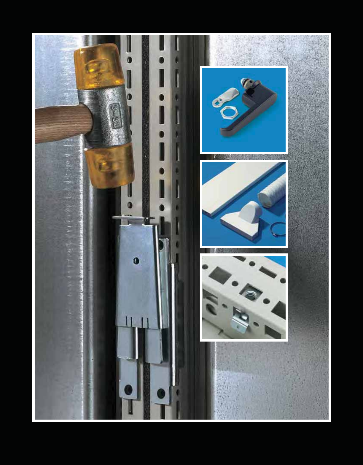
Accessories
193
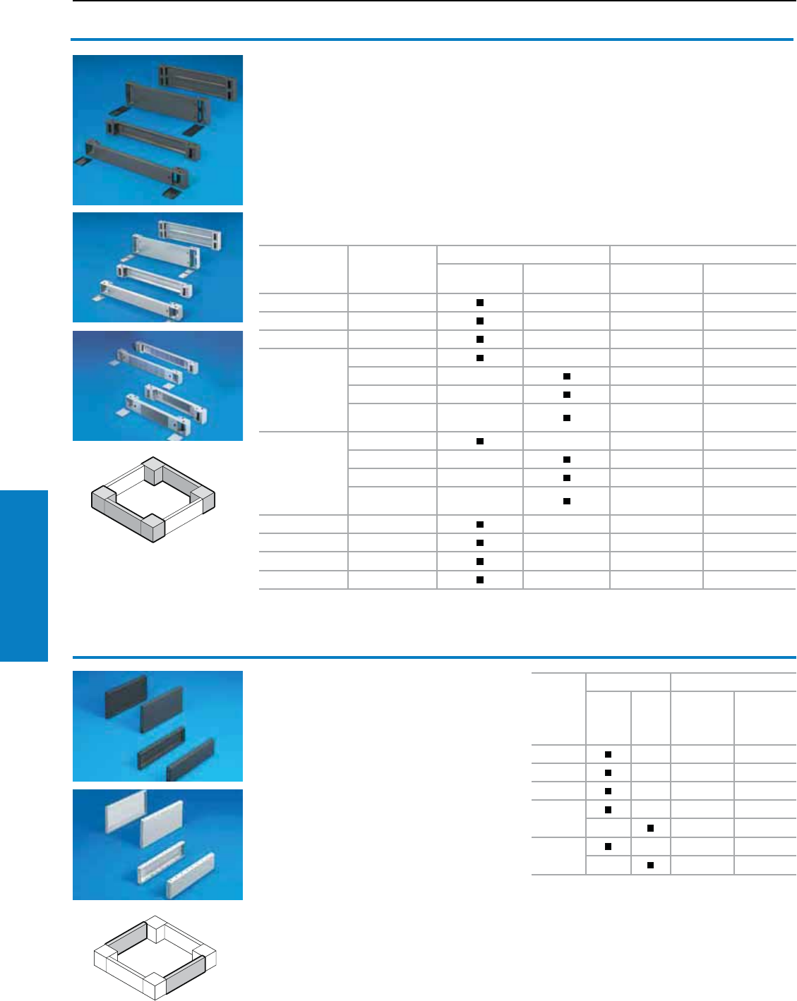
194 Industrial Buyer’s Guide
Accessories Bases
Base/plinth components
front and rear
Sheet steel
For TS, CM, PC-TS, TP, IW
Base/plinth component consisting of one trim panel
and two pre-configured corner pieces. In 8" (200
mm) high base/plinth components, one trim panel
is divided into two for cable entry.
Material:
Sheet steel, painted
Cover caps plastic RAL 9005 (jet black)/
RAL 7035 (light gray)
Conguration:
1 set = 2 base/plinth components, 4 cover caps,
4 screws and captive nuts M12 for mounting on
the enclosure
Accessories:
Base assembly plate 2817.000
Filter mat for trim panel, vented
German patent no. 198 60 408
Base/plinth trim, side
Sheet steel
For TS, CM, PC-TS, TP, IW
For mounting between the base/plinth
components. At 8" (200 mm) height, two 4"
(100 mm) base/plinth trims may be used. Base/
plinth trim panels (4" [100 mm] high) may be
installed rotated 90° in order to stabilize bayed
base/plinth components.
Material:
Sheet steel, painted
Conguration:
1 set = 2 base/plinth trim panels, including parts
for attaching to the base/plinth components
Additional parts needed:
Base/plinth baying bracket 8601.100,
when base/plinth components are installed
by turning 90°
Accessories:
Assembly bolts for base/plinth
For enclosure
width inches
(mm)
Version
Color Part No.
RAL 7022
(umbra gray)
RAL 7035
(light gray) 4" (100 mm) high 8" (200 mm) high
12 (300) solid –8601.915 –
16 (400) solid –8601.400 8602.400
20 (500) solid –8601.500 8602.500
24 (600)
solid –8601.600 8602.600
solid – 8601.6051) 8602.605
vented – 7825.6012) –
vented with
designer cover –7825.603 –
32 (800)
solid –8601.800 8602.800
solid – 8601.805 8602.805
vented – 7825.801 –
vented with
designer cover –7825.803 –
39 (1000) solid –8601.000 8602.000
47 (1200) solid –8601.200 8602.200
63 (1600) solid –8601.920 8602.920
71 (1800) solid –8901.920 8901.930
1) Version in RAL 9005 (jet black): 8601.602
2) Version in RAL 9005 (jet black): 7825.605
For
enclosure
depth
inches
(mm)
Color Part No.
RAL
7022
(umbra
gray)
RAL
7035
(light
gray)
4"
(100 mm)
high
8"
(200 mm)
high
12 (300) –8601.030 8602.030
16 (400) –8601.040 8602.040
20 (500) –8601.050 8602.050
24 (600) –8601.060 8602.060
–8601.065 8602.065
32 (800)
–8601.080 8602.080
–8601.085 8602.085
Bases
Base/Plinth Components and Trim
Inch and pound measurements are rounded to the nearest whole number.
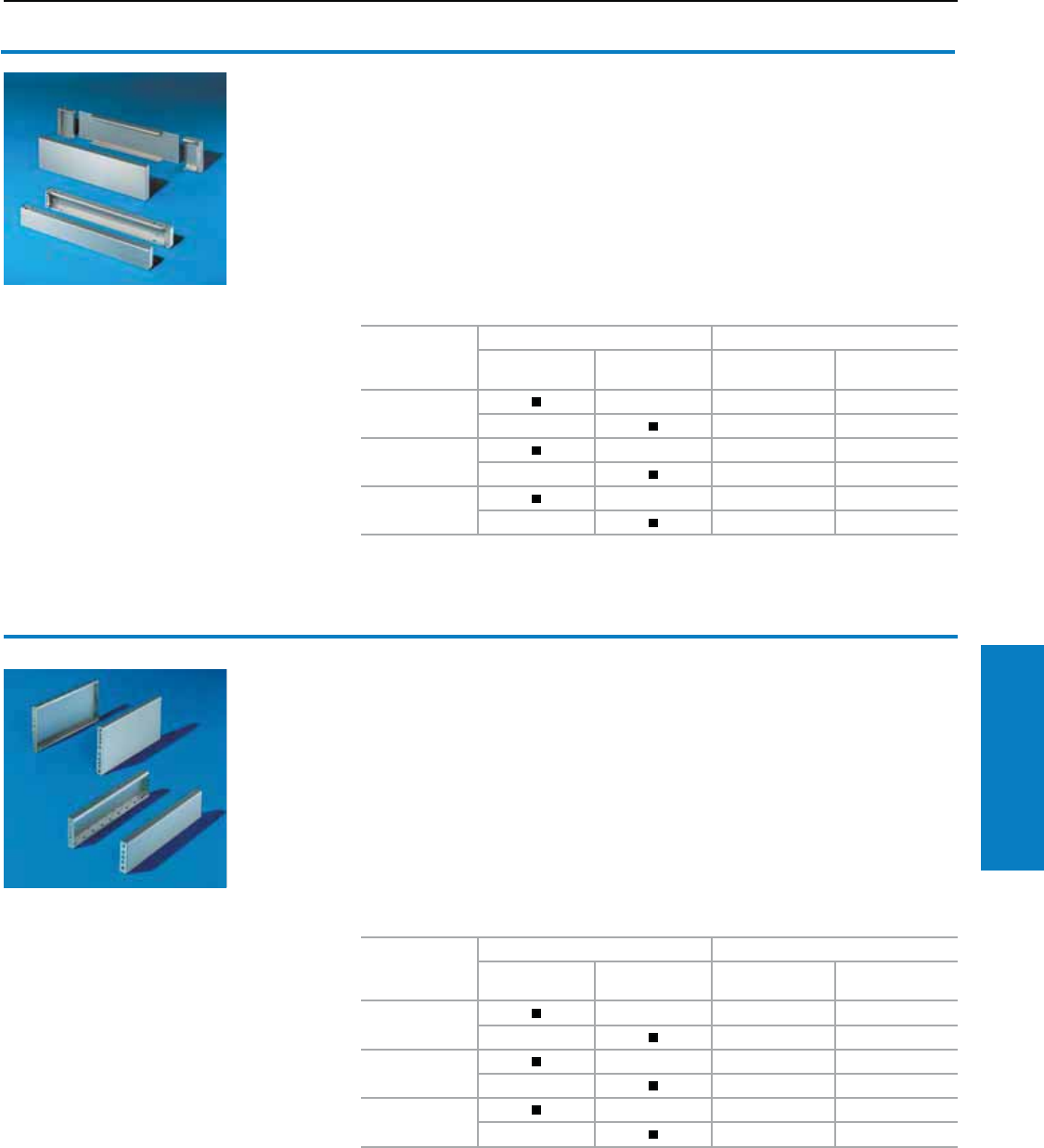
Industrial Buyer’s Guide 195
Accessories Bases
Base/plinth components
front and rear
Stainless steel
For TS, CM
Material:
Type 304 and 316L stainless steel
Finish:
Brushed, grain 400
Conguration:
Assembly parts including
4 screws and captive nuts M12 for mounting on
the enclosure
4" (100 mm) high:
2 trim panels front/rear
8" (200 mm) high:
2 corner pieces with removable trim panel,1 trim
panel front/rear
Base/plinth trim, side
Stainless steel
For TS, CM
For mounting between the base/plinth
components. At 8" (200 mm) height, two 4" (100
mm) base/plinth trims may be used. Base/plinth
trim panels (4" [100 mm] high) may be installed
rotated 90° in order to stabilize bayed base/plinth
components.
Material:
Type 304 and 316L stainless steel
Bases
Base/Plinth Components and Trim
For enclosure
width inches
(mm)
Material Part No.
Type 304
stainless steel
Type 316L
stainless steel 4" (100 mm) high 8" (200 mm) high
24 (600) –8701.600 8702.600
–8701.605 8702.605
32 (800) –8701.800 8702.800
–8701.805 8702.805
47 (1200) –8701.200 8702.200
–8701.205 8702.205
Finish:
Brushed, grain 400
Conguration:
1 set = 2 base/plinth trim panels, including parts for
attaching to the base/plinth components
Additional parts needed:
Base/plinth baying bracket 8601.100,
when base/plinth components are installed
by turning 90°
Accessories:
Assembly bolts for base/plinth
For enclosure
width inches
(mm)
Material Part No.
Type 304
stainless steel
Type 316L
stainless steel 4" (100 mm) high 8" (200 mm) high
16 (400) –8701.040 8702.040
–8701.045 8702.045
20 (500) –8701.050 8702.050
–8701.055 8702.055
24 (600)
–8701.060 8702.060
–8701.065 8702.065
Inch and pound measurements are rounded to the nearest whole number.
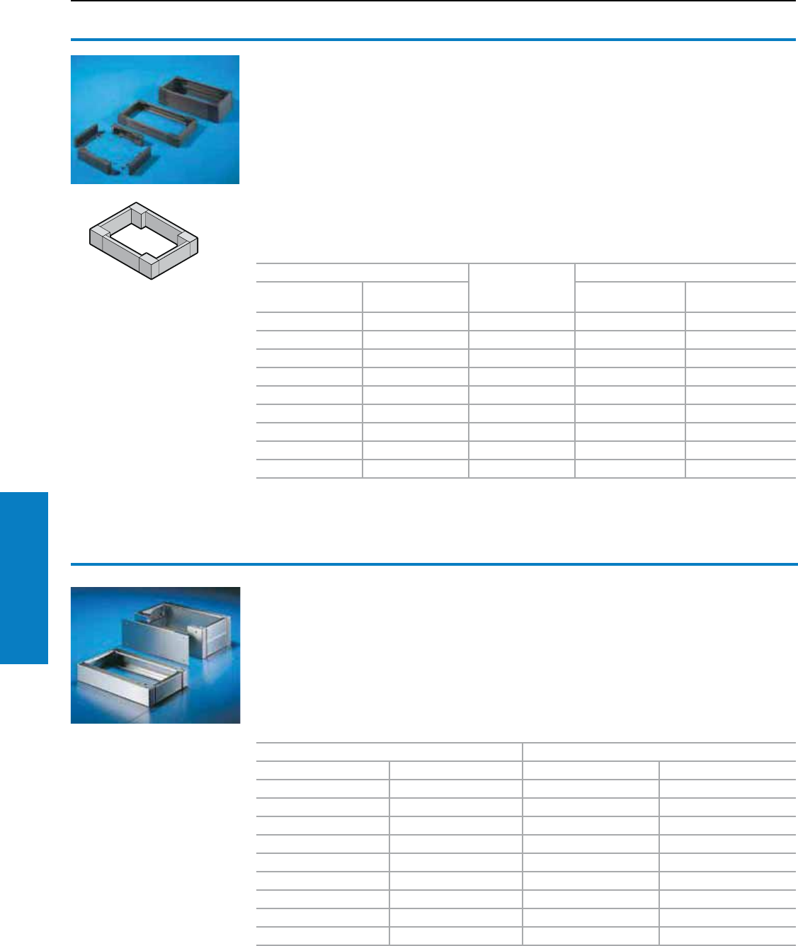
196 Industrial Buyer’s Guide
Accessories Bases
For enclosures/consoles Base/plinth depth (T)
inches (mm)
Part No.
Width (b)
inches (mm) Depth inches (mm) 4" (100 mm) 8" (200 mm)
24 (600) 16 (400) 14 (350) 2804.200 2805.200
24 (600) 20 (500) 18 (450) 2807.200 2808.200
32 (800) 16 (400) 14 (350) 2823.200 2824.200
32 (800) 20 (500) 18 (450) 2829.200 2830.200
39 (1000) 16 (400) 14 (350) 2909.200 2910.200
47 (1200) 16 (400) 14 (350) 2836.200 2837.200
47 (1200) 20 (500) 18 (450) 2839.200 2840.200
63 (1600) 16 (400) 14 (350) 2905.200 2906.200
71 (1800) 20 (500) 18 (450) 2903.200 2904.200
Base/plinth, complete
Sheet steel
for AE, AP, ES, PC-ES
consisting of:
Trim panels at the front and rear with fitted corner
pieces and side trim panels.
Material:
Sheet steel, spray-finished
Color:
RAL 7022
Conguration:
Assembly parts including 4 screws and captive
nuts M12 for mounting on the enclosure.
4" (100 mm) high:
4 corner pieces,
2 trim panels front/rear,
2 trim panels side.
8" (200 mm) high:
4 corner pieces,
1 trim panel front/rear x 8" (200 mm),
2 trim panels front/rear x 4" (100 mm),
4 trim panels side.
Bases
Base/Plinth Complete Kits
For enclosures/consoles Part No.
Width inches (mm) Depth inches (mm) 4" (100 mm) 8" (200 mm)
24 (600) 16 (400) 2865.000 2875.000
24 (600) 20 (500) 2868.000 2876.000
24 (600) 20 (500) 2855.000 2877.000
32 (800) 16 (400) 2869.000 2878.000
32 (800) 20 (500) 2866.000 2879.000
32 (800) 24 (600) 2856.000 2880.000
39 (1000) 16 (400) 2867.000 2885.000
47 (1200) 16 (400) 2870.000 2886.000
47 (1200) 20 (500) 2860.000 2887.000
To order enclosures in stainless steel Type 316L, use Part No. XXXX.500
Base/plinth, complete
Stainless steel
for ES, PC-ES, AP one-piece console
Material:
Stainless steel Type 304
Surface nish:
Brushed
Conguration:
Assembly parts including 4 screws and captive
nuts M12 for mounting on the enclosure.
4" (100 mm) high:
2 trim panels front/rear,
2 trim panels side.
8" (200 mm) high:
2 corner pieces with removable trim panel,
1 trim panel front/rear, 4 trim panels side.
Inch and pound measurements are rounded to the nearest whole number.
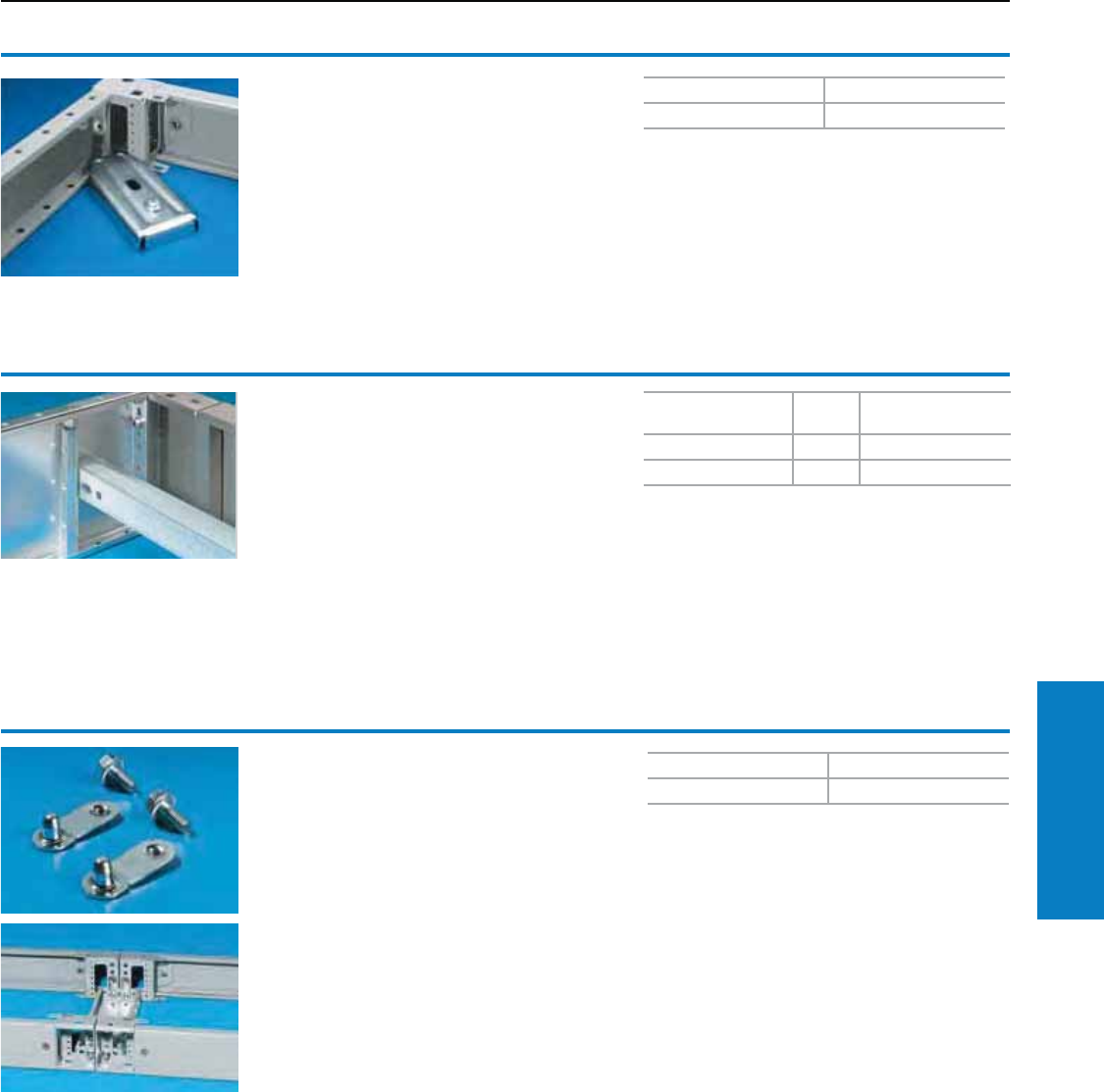
Industrial Buyer’s Guide 197
Accessories Bases
Base assembly plate
For base/plinth TS and base/plinth, complete
For fastening the plinth to the floor without
moving the enclosure or the bayed enclosure
suite. For assembly screws up to 0.5" (12 mm) Ø.
Material:
Sheet steel, zinc-plated, passivated
Bases
Base/Plinth Brackets and Bolts
PU Part No.
10 2817.000
PU Part No.
20 8601.100
Fastening bolts
For
• Base/plinth TS
• Base/plinth, complete
• Base/plinth, stationary
For mounting on base/plinth trim panels, side. The
lockable assembly bolt allows the installation of
cable clamp rails and standard C rails.
Material:
Hexagon steel, zinc-plated, passivated, width
across flats 0.8" (19 mm)
Base/plinth trim panel
inches (mm) high
PU Part No.
4 (100) 10 2819.000
8 (200) 10 2819.200
Base/plinth baying brackets
For base/plinth TS
Essential if the trim panels are mounted rotated
through 90° for additional stabilization during the
transportation of bayed enclosures.
Additionally required for each trim panel: 2 units.
Material:
Sheet steel, zinc-plated, passivated
Conguration:
Screws M8 x 0.6" (16 mm)
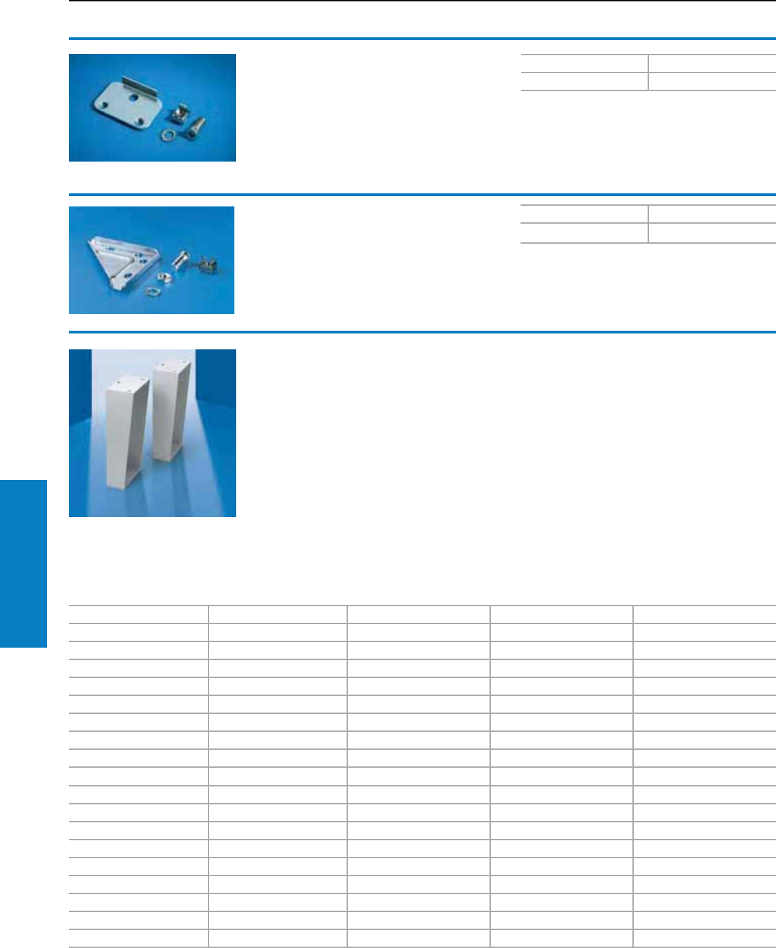
198 Industrial Buyer’s Guide
Accessories Bases
Bases
Base/Plinth Adaptors
Floor stand kits
For AE, WM
For mounting wallmount
enclosures to the floor, in
accordance with floormount
standards. Easy installation
- just drill holes in the bottom
of enclosure and bolt to the
enclosure. Includes sealing
washers.
Material/Finish:
Carbon Steel: 12 ga, RAL 7035
(light gray)
Stainless Steel: 12 ga
Type 304, 316L
Conguration:
2 stands
Mounting hardware
Height inches (mm) Depth inches (mm) Part No. Carbon steel Part No. Stainless 304 Part No. Stainless 316L
12 (305) 6 (152) FSK1206C FSK12064 FSK12066
18 (457) 6 (152) FSK1806C FSK18064 FSK18066
24 (610) 6 (152) FSK2406C FSK24064 FSK24066
12 (305) 8 (203) FSK1208C FSK12084 FSK12086
18 (457) 8 (203) FSK1808C FSK18084 FSK18086
24 (610) 8 (203) FSK2408C FSK24084 FSK24086
12 (305) 10 (254) FSK1210C FSK12104 FSK12106
18 (457) 10 (254) FSK1810C FSK18104 FSK18106
24 (610) 10 (254) FSK2410C FSK24104 FSK24106
12 (305) 12 (305) FSK1212C FSK12124 FSK12126
18 (457) 12 (305) FSK1812C FSK18124 FSK18126
24 (610) 12 (305) FSK2412C FSK24124 FSK24126
12 (305) 16 (406) FSK1216C FSK12164 FSK12166
18 (457) 16 (406) FSK1816C FSK18164 FSK18166
24 (610) 16 (406) FSK2416C FSK24164 FSK24166
12 (305) 20 (508) FSK1220C FSK12204 FSK12206
18 (457) 20 (508) FSK1820C FSK18204 FSK18206
24 (610) 20 (508) FSK2420C FSK24204 FSK24206
Base/plinth adaptor
For leveling feet
Connection component for fastening M12 leveling
feet 4612.000 to the TS base/plinth.
Material:
Sheet steel, zinc-plated, passivated
Base/plinth adaptor
For twin castors
Connection component for mounting twin castors
to the TS base/plinth.
Material:
Sheet steel, zinc-plated, passivated
Additional parts needed:
Leveling feet, 4612.000,
see page 201.
PU Part No.
48800.220
PU Part No.
48800.290
Additional parts needed:
Base/plinth side trim, see pages 194-195,
whenever a twin castor is installed.
Inch and pound measurements are rounded to the nearest whole number.
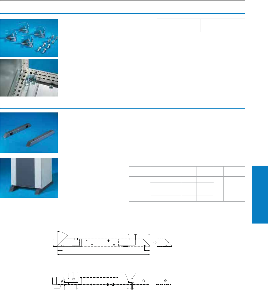
Industrial Buyer’s Guide 199
Accessories Bases
Bases
Base/Plinth Brackets and Cross Members
Reinforcement bracket
For TS, ES, AP universal console
For use in addition to clamping straps for
stabilization when populated enclosures are
screw-fastened through the base tray to the
base/plinth or pallet for transportation purposes.
Material:
Sheet steel, zinc-plated, passivated
Conguration:
Assembly hardware
PU Part No.
48800.830
Cross-member
For TS, CM, TP, PC, IW, ES, AP adjustable
To increase stability, the cross-member is
positioned 5.4" (138 mm) above the base frame
of the enclosure at the front and rear. For deeper
enclosures, the rear part may be extended and
screw-fastened again. For screw-fastening to
the floor and enclosure with mounting hole at the
sides, front and rear. The castors and leveling feet
may be secured to the welded nuts M12.
For Enclosure depth
inches (mm) L1 L2 PU Part No.
TS, CM,
TP, PC,
IW, ES, AP
Universal
Console
16 (400) 644 275 28601.450
20 (500) 744 375
24 (600) 844 475 28601.680
32 (800) 1044 675
Material:
Sheet steel, spray-finished
Color:
RAL 7015 (slate gray)
Note:
For mobile use, the cross-member must be screw-
fastened in the corners of the enclosure.
1
1
1
11
111
8601.450, 8601.680
Inch and pound measurements are rounded to the nearest whole number.
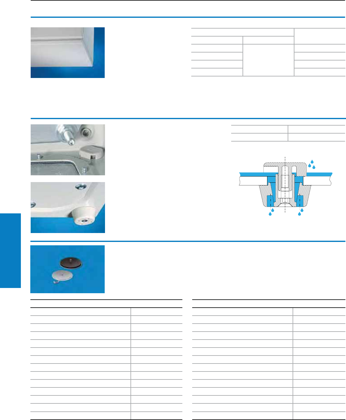
200 Industrial Buyer’s Guide
Accessories Bases
Oiltight Hole Seals - Carbon Steel
Description Part No.
Miniature Oiltight Pushbutton Hole 22.5 mm (IEC) OHSMPBC
0.50" Conduit Hole OHS050C
0.75" Conduit Hole OHS075C
Standard Oiltight Pushbutton Hole 30.5 mm (NEMA) OHSSPBC
1.00" Conduit Hole OHS100C
1.25" Conduit Hole OHS125C
1.50" Conduit Hole OHS150C
1.75" Conduit Hole OHS175C
2.00" Conduit Hole OHS200C
2.50" Conduit Hole OHS250C
3.00" Conduit Hole OHS300C
3.50" Conduit Hole OHS350C
4.00" Conduit Hole OHS400C
Bases
Base/Plinth Drains and Seals
Oiltight hole seals
Oiltight hole seals are used to
seal unused or empty pushbutton
holes, conduit openings, and
knockout openings from the entry
of dirt, dust, oil and water.
Material:
Carbon Steel:
RAL 7035 (light gray)
Type 304 stainless steel
Hole Seals:
• 12 sizes
• Covers holes with a 0.19"
diameter
• Can be used on material
thickness up to 0.31"
• Oil-resistant gasket
• UL/cUL Type 12, 4/4X and 13
Oiltight Hole Seals - Stainless Steel 304
Description Part No.
Miniature Oiltight Pushbutton Hole 22.5 mm (IEC) OHSMPB6
0.50" Conduit Hole OHS0506
0.75" Conduit Hole OHS0756
Standard Oiltight Pushbutton Hole 30.5 mm (NEMA) OHSSPB6
1.00" Conduit Hole OHS1006
1.25" Conduit Hole OHS1256
1.50" Conduit Hole OHS1506
1.75" Conduit Hole OHS1756
2.00" Conduit Hole OHS2006
2.50" Conduit Hole OHS2506
3.00" Conduit Hole OHS3006
3.50" Conduit Hole OHS3506
4.00" Conduit Hole OHS4006
See pages 72-76 for Pushbutton Enclosures
Condensate drain
For reliable discharge from the inside and
protection against splashes from the outside
(labyrinth effect).
A hole diameter of 0.6" (16 mm) is required.
(With AE/WM sheet steel, the holes are already
provided in the base).
Material:
Polyamide
Color:
Similar to RAL 7035 (light gray)
PU Part No.
62459.000
Cover plate
For CM
To conceal the entire base
opening or as a lid with a fitted
enclosure rotated by 180°.
Material:
Sheet steel
Color:
Textured RAL 7035 (light gray)
Conguration:
Assembly hardware
For enclosure Part No.
B (W) inches (mm) T (D) inches (mm)
24 (600)
16 (400)
5001.130
32 (800) 5001.140
39 (1000) 5001.150
47 (1200) 5001.160
Inch and pound measurements are rounded to the nearest whole number.
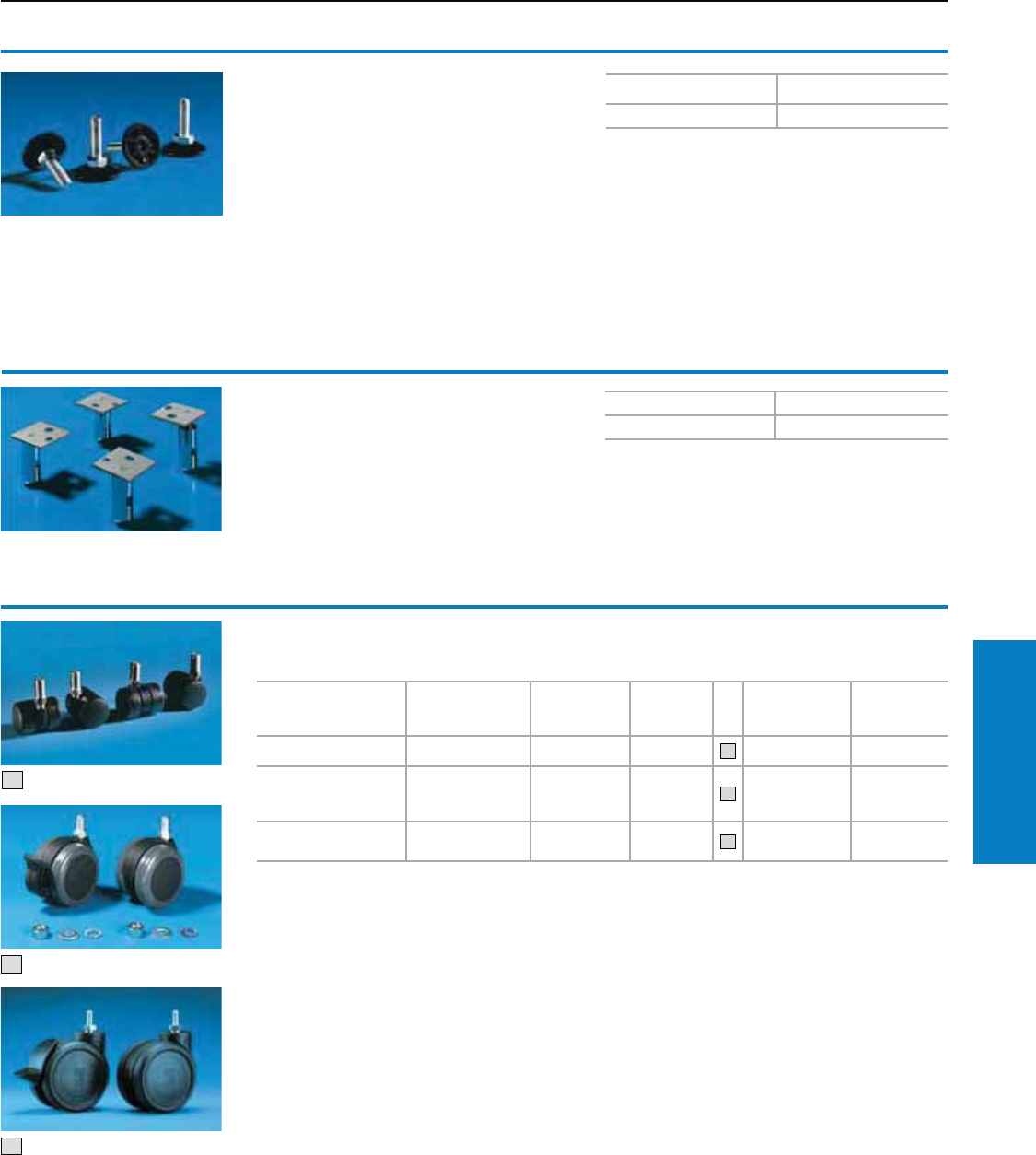
Industrial Buyer’s Guide 201
Accessories Bases
Bases
Base/Plinth Feet and Castors
For:
• TS8 modular enclosure system
• PC enclosure system
• Pedestal base plate
6137.035 – 6137.535
• Pedestal 6141.XXX
• Industrial workstations
• Data rack
Leveling feet
1 – 2" (18 – 43 mm) high
To compensate for uneven floors. Thread length
2" (40 mm). Assembly thread M12.
Maximum static load:
Approximately 661 lb (300 kg) per leveling foot.
For:
• TS8 modular enclosure system
• PC enclosure system
• Pedestal base plate 6137.035 – 6137.535
• Pedestal 6141.XXX
• Industrial workstations
Leveling feet
3 – 5" (85 – 115 mm) high
For mounting on TS, ES and PC enclosures,
for easier floor cleaning and to compensate for
uneven floors.
Height: 4" (100 mm).
Maximum static load:
772 lb (350 kg) per leveling foot.
Additional parts needed:
For mounting on the TS base/plinth:
Base/plinth adaptor 8800.220,
see page 198.
PU Part No.
44612.000
PU Part No.
42859.000
Material:
Feet: Brass, nickel-plated Threaded bolts
Mounting panels: Type 304 stainless steel
Conguration:
Assembly hardware to the enclosure.
Additional parts needed:
For mounting on the TS base/plinth:
Base/plinth adaptor for twin castors 8800.290,
see page 198.
Maximum permissible
static load (per castor)
lb (kg)
Ground
clearance
inches (mm)
Lock PU Color Part No.
88 (40) 2 (50) 4 without 1 set 1black 4611.000
165 (75) 3 (85) 2 with,
2 without 1 set 2
black
with gray
wheels
6148.000
265 (120) 5 (125) 2 with,
2 without 1 set 3black 7495.000
Twin castors
Mounting thread 1" (M12 x 20)
1
Inch and pound measurements are rounded to the nearest whole number.
2
3
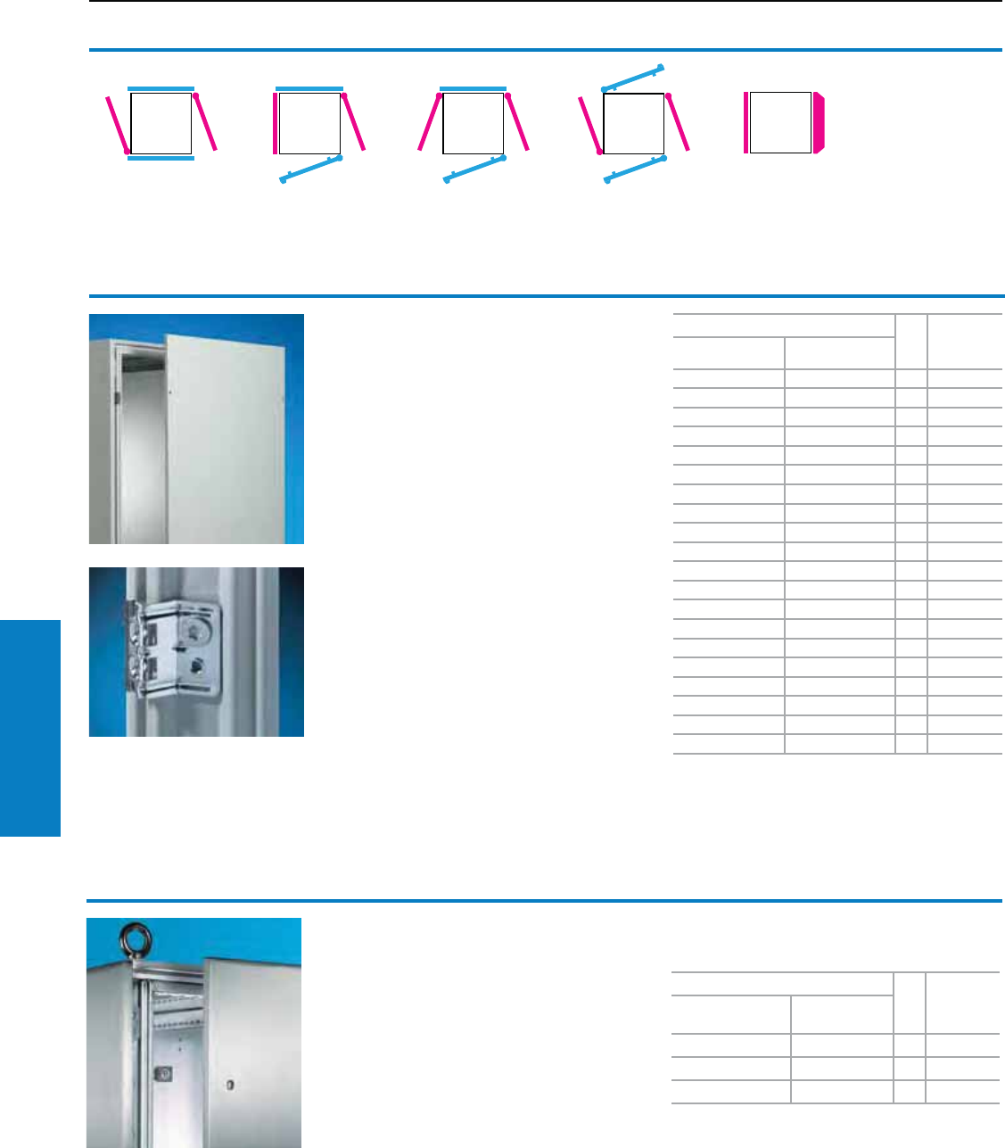
202 Industrial Buyer’s Guide
Accessories Walls
The TS sidewall provides new
dimensions in convenient access
to the TS interior, due to the option
of hinging.
Important:
Sidewalls, hinged and unhinged,
must always be opposite of one
another. Doors and rear walls must
always be opposite of one another.
Only one surface on each vertical
enclosure section may be hinged.
Note:
Climate control sidewalls with
integrated cooling module may
be retrofitted instead of an
enclosure sidewall.
Walls
Side Panels
Sidewalls, screw-fastened,
sheet steel
For TS
Easy positioning on the frame with the location aid.
Six or eight enclosure panel holders with grounding
insert ensure automatic potential equalization
and higher EMC protection. Grounding bolts with
contact surface are pre-integrated.
Material:
16 ga (1.5 mm) sheet steel
Finish:
Dipcoat-primed, powder coated in textured
RAL 7035 (light gray) on the outside.
Protection Ratings:
UL Type 12 (IP 55 to EN 60 529/10.91)
Conguration:
Assembly hardware
Note:
Enclosure panel holders may be fitted from the
inside or outside of the enclosure.
Area available for population:
External dimension – 4" (100 mm).
Accessories:
Ground straps, see page 243.
German patent no. 198 01 720
Sidewalls, screw-fastened,
stainless steel
For TS
To finish a complete enclosure. Easy attachment
on the inside vertical enclosure frame upright.
Grounding inserts ensure automatic potential
equalization and a higher degree of EMC protection.
Ground studs with contact surfaces are included.
Material:
Type 304 stainless steel, 16 ga (1.5 mm)
Finish:
Brushed, grain 240
Protection Ratings:
UL Type 12 (IP 55 to EN 60 529/10.91)
Conguration:
Assembly hardware
For enclosures
PU Part No.
Height inches
(mm)
Depth inches
(mm)
32 (800) 24 (600) 2 8173.235
39 (1000) 24 (600) 2 8174.235
47 (1200) 24 (600) 2 8170.235
47 (1200) 32 (800) 2 8175.235
55 (1400) 20 (500) 2 8145.235
55 (1400) 24 (600) 2 8146.235
55 (1400) 32 (800) 2 8148.235
63 (1600) 20 (500) 2 8165.235
63 (1600) 24 (600) 2 8166.235
63 (1600) 32 (800) 2 8168.235
71 (1800) 16 (400) 2 8184.235
71 (1800) 20 (500) 2 8185.235
71 (1800) 24 (600) 2 8186.235
71 (1800) 32 (800) 2 8188.235
79 (2000) 16 (400) 2 8104.235
79 (2000) 20 (500) 2 8105.235
79 (2000) 24 (600) 2 8106.235
79 (2000) 32 (800) 2 8108.235
87 (2200) 24 (600) 2 8126.235
87 (2200) 32 (800) 2 8128.235
To order primed version, use Part no. XXXX.300.
For enclosures
PU Part No.
Height inches
(mm)
Depth inches
(mm)
71 (1800) 16 (400) 2 8700.840
71 (1800) 20 (500) 2 8700.850
79 (2000) 24 (600) 2 8700.060
To order enclosures in Type 316 stainless steel, use
Part no. 8705.XXX.
Inch and pound measurements are rounded to the nearest whole number.
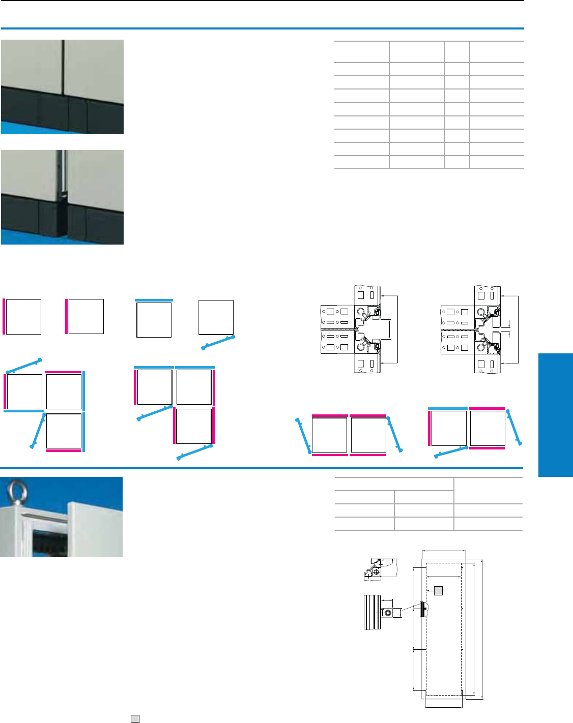
Industrial Buyer’s Guide 203
Accessories Walls
Sidewalls, asymmetrical
For TS
The alternative to the standard sidewall for
improved visual appearance in the event of
back-to-back, back-to-side or corner baying. The
gap (A) which occurs with standard sidewalls
is reduced to a standard dimension (B), see
technical drawing.
In the case of the TS8 corner enclosure, an
asymmetrical sidewall is included in the supply.
The number of additionally required asymmetrical
sidewalls depends on the baying version which
is selected.
Material:
Sheet steel, 16 ga (1.5 mm)
Color:
RAL 7035 (light gray)
Protection Ratings:
UL Type 12 (IP 55 to EN 60 529/10.91)
Conguration:
Assembly hardware
Asymmetrical
sidewall
B
Sidewall Rear wall Door
Corner baying
Back-to-back baying Side-to-back baying
Sidewall
Standard
Sidewall
asymmetrical
Height
inches (mm)
Depth
inches (mm) PU Part No.
71 (1800) 16 (400) 2 8184.500
71 (1800) 20 (500) 2 8185.500
71 (1800) 24 (600) 2 8186.500
79 (2000) 16 (400) 2 8104.500
79 (2000) 20 (500) 2 8105.500
79 (2000) 24 (600) 2 8106.500
79 (2000) 32 (800) 2 8108.500
87 (2200) 24 (600) 2 8126.500
Walls
Side Panels
Sidewalls for
modular front design
For TS
Attachment on the inside vertical enclosure
frame member. The 8106.235 sidewall retainers
(see page 202) could conflict with the partial
door fasteners.
Material:
14 ga (2 mm) sheet steel
Finish:
Dip-coat primed, powder coated on the outside
RAL 7035 (light gray), textured
Protection Ratings:
UL Type 12 (IP 55 to EN 60 529/10.91)
Conguration:
2 sidewalls,
16 retainers with automatic potential equalization
Note:
Can also be used in enclosures without modular
front design.
1 Usable interior area
For enclosure inches (mm) Part No.
Height Depth
79 (2000) 24 (600) 8106.512
79 (2000) 32 (800) 8108.512
11
11
1
Inch and pound measurements are rounded to the nearest whole number.
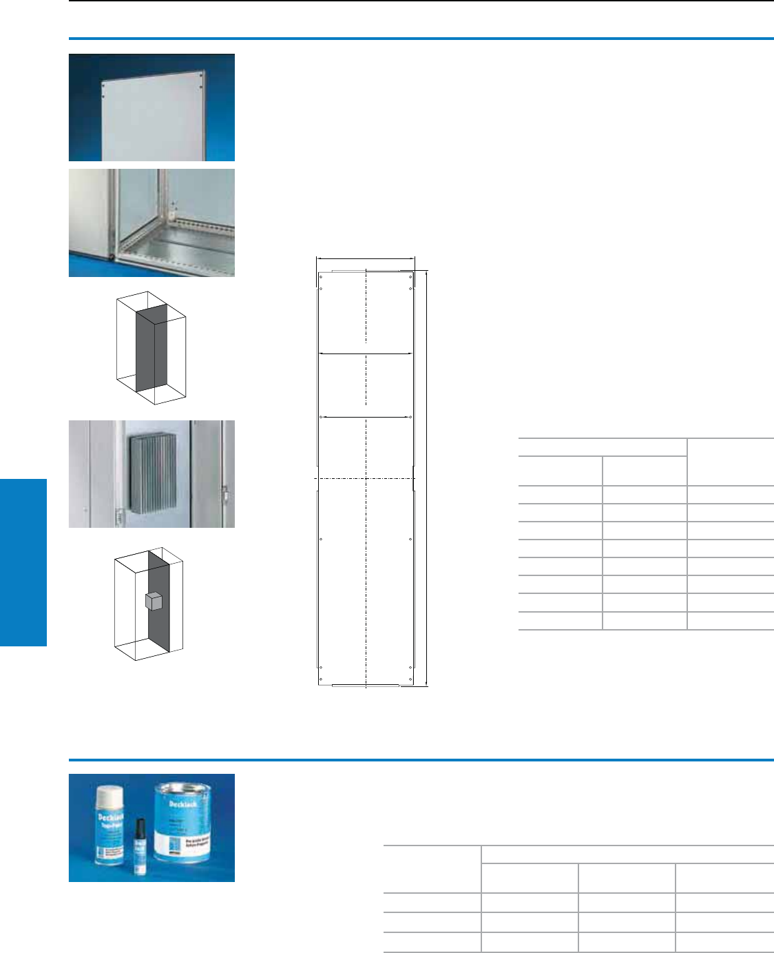
204 Industrial Buyer’s Guide
Accessories Walls
Divider panel
For TS
For separating individual enclosure cells. Due
to the symmetry of the frame system, the divider
panel can also be used at the rear. Around the
perimeter, double fold for stability and to hold
the gasket. Notches in the corners and halfway
up the sides permit the use of interconnecting
brackets and baying brackets, even with a divider
panel installed for mounting on the outer mounting
level. This leaves the inner level free for additional
population.
Material:
Sheet steel, 14 ga (2 mm), zinc-plated, passivated
Protection Ratings:
UL Type 12 (IP 54 to EN 60 529/10.91)
Conguration:
Assembly hardware
Accessories:
Cover with door.
Baying bracket 8800.470 for
enclosures with installed divider panel,
see page 251.
Note:
The divider panel may also be fitted to the rear. This
allows, for example frequency converters for heat
dissipation to be installed in a divider panel with
the air conditioners facing outwards and protected/
finished off with a cover.
For enclosures
Part No.
Height
inches (mm)
Depth
inches (mm)
71 (1800) 16 (400) 8609.840
71 (1800) 20 (500) 8609.850
71 (1800) 24 (600) 8609.860
79 (2000) 16 (400) 8609.040
79 (2000) 20 (500) 8609.050
79 (2000) 24 (600) 8609.060
79 (2000) 32 (800) 8609.080
87 (2200) 24 (600) 8609.260
1111 1
Walls
Divider Panels/Paint
Primer/paint
For touching up and repairing powder coated and
wet-painted surfaces, air-drying.
Color RAL
Part No.
0.6 oz touch-up
pen Spray Can Quart can
7022 (umbra gray) 9095.008 9093.008 9094.008
7032 (pebble gray) 9095.002 9093.002 9094.002
7035 (light gray) 9095.006 9093.006 9094.006
Inch and pound measurements are rounded to the nearest whole number.
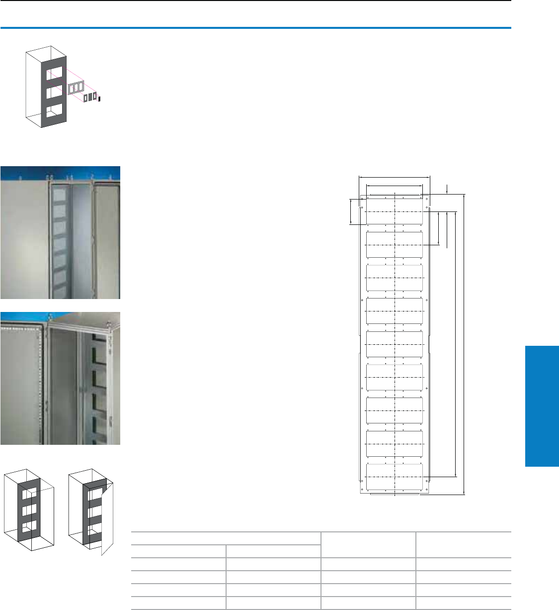
Industrial Buyer’s Guide 205
Accessories Walls
The divider panel and module
plate system
More options:
The cut-outs of a divider panel are individually
equipped with module plates for 16-pole or 24-
pole connectors, with module plates for cable entry
and with solid module plates.
Faster assembly:
Usually only part of the total number of connector
cut-outs are used. Due to the new divider panel
technique, the cut-outs do not need to be covered
individually. The solid module plate is used instead.
The benefits: Less plates, less screws, less
assembly work.
Divider panel
For module plates TS
With cut-outs for the installation of module plates
for connectors or for cable entry, and also for
the entry of busbar systems and other installed
equipment. There is a double fold around the
perimeter for stability and to hold the seal. The
symmetry of the enclosure frame allows divider
panels to be fitted at the rear, dimensions
permitting.
For mounting on the outer mounting level. This
leaves the inner level free for further population.
Material:
Sheet steel, 14 ga (2 mm), zinc-plated, passivated
Conguration:
Assembly hardware and self-tapping socket
screws, M5 x 1" (12 mm) for mounting the
module plates.
Note:
Notches in the corners and half-way up the sides
permit the use of interconnecting brackets and
baying brackets, even with a fitted divider panel.
Accessories:
Module plates, see page 206.
Cover with door.
Baying bracket 8800.470 for enclosures with
divider panel installed, see page 251.
1
1
1
1111
1 111 11 11
11 1
For enclosures Number of cut-outs Part No.
Height inches (mm) Depth inches (mm)
71 (1800) 20 (500) 9 8609.100
71 (1800) 24 (600) 9 8609.110
79 (2000) 20 (500) 10 8609.120
79 (2000) 24 (600) 10 8609.130
Walls
Divider Panels
Inch and pound measurements are rounded to the nearest whole number.
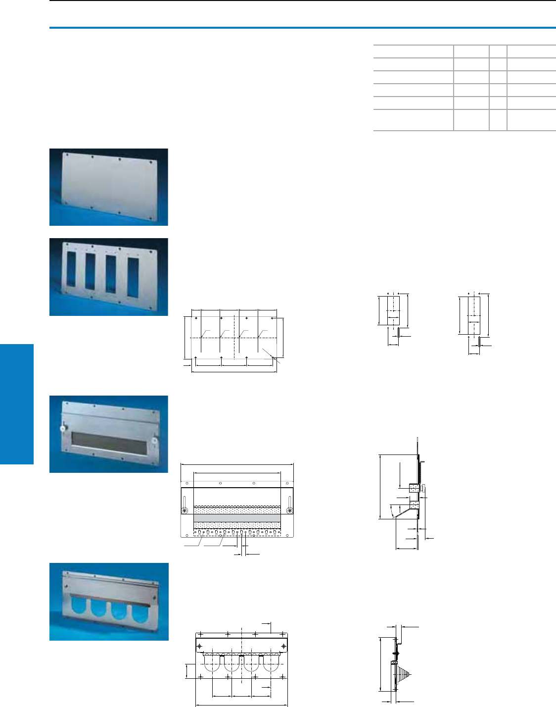
206 Industrial Buyer’s Guide
Accessories Walls
For cable entry grommets
For mounting on the divider panel for TS module
plates. Slide the grommets into the cut-outs, slide
the clamp plate with seal down over them, and
screw-fasten.
Additional parts needed:
Cable entry grommets or
connector grommets
B
B
1
1
1
For cable entry
For the entry using pre-assembled cables.
Sealed, routing is achieved using adjustable
angle brackets with inserted foam cable
clamp strip. Attachment bracket, punched,
for cable clamping.
Accessories:
Cable tie for quick assembly 2597.000
1
1
1
1
1
Walls
Module Plates
Module plates
Material:
Sheet steel, 14 ga (2 mm), zinc-plated, passivated
Conguration:
Gasket included
Solid
For sealing unused cut-outs. Easily machined
for individual cut-outs.
For 16/24-pole connectors
With cut-outs to accommodate connectors. In
addition to mounting on divider panels, module
plates may also be attached to the 1" (25 mm)
system hole pattern of the enclosure and to the
rails of the TS/PS system.
Accessories:
Adaptor, cover plate (see page 207)
Cable gland for connector cut-outs
Version Cut-outs PU Part No.
Solid – 1 8609.160
For 16-pole connectors 4 1 8609.150
For 24-pole connectors 4 1 8609.140
For cable entry 1 1 8609.170
For cable entry
grommets 418609.190
1
1
1 11
1
1
11
1
Accessories:
Adaptor, cover
Cable gland for connector cut-outs
X 16-pole X 24-pole
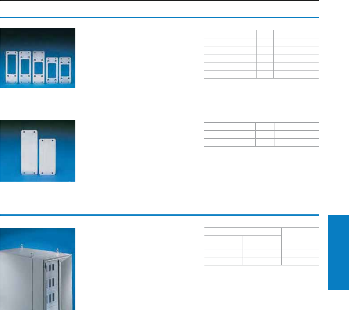
Industrial Buyer’s Guide 207
Accessories Walls
Walls
Module Plates
Adaptor
For connector cut-outs
For using connectors with varying numbers of
poles.
Material:
Sheet steel, zinc-plated, passivated
Conguration:
Seal for adaptor and assembly parts.
For reduction PU Part No.
From 24 to 16 poles 5 2479.000
From 24 to 10 poles 5 2480.000
From 24 to 6 poles 5 2481.000
From 16 to 10 poles 5 2401.000
From 16 to 6 poles 5 2402.000
Cover plate
For connector cut-outs
For unused cut-outs.
Material:
Sheet steel, zinc-plated, passivated
Conguration:
Seal and assembly parts.
For PU Part No.
24-pole cut-outs 20 2477.000
16-pole cut-outs 20 2478.000
Cover with door
For TS
To protect and finish off connectors or other
installed equipment. 8” (200 mm) wide cover, with
opening at the top or bottom for cable entry
including a cover plate for unused openings.
Material:
Sheet steel
Cover: 16 ga (1.5 mm)
Door: 14 ga (2.0 mm)
Color:
7035 textured
Conguration:
Cover, door with locking rod and double-bit lock
insert, 1 cover plate for the top or bottom.
Note:
May also be fitted at the rear to extend the
enclosure depth. To cover the resultant gap,
we recommend asymmetrical side panels
(see page 203). In this way, for example,
frequency converters to dissipate heat may be
installed in a divider panel (see page 205) with
the heat sinks facing outwards and protected/
concealed with a cover.
For enclosures
Part No.
Height inches
(mm)
Depth inches
(mm)
79 (2000) 20 (500) 8609.020
79 (2000) 24 (600) 8609.030
For primed version, use Part No. 8609.0X1
Accessories:
Lock inserts, version F
see page 220.
Comfort handle,
see page 217.
180° hinge,
see page 214.
Inch and pound measurements are rounded to the nearest whole number.
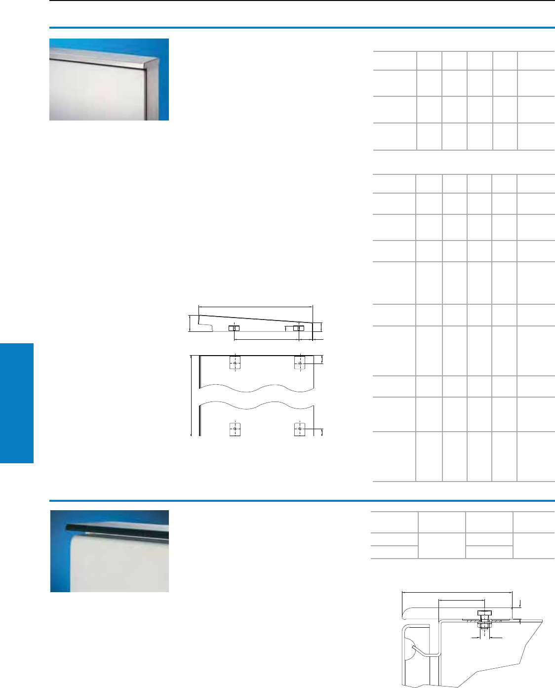
208 Industrial Buyer’s Guide
Accessories Roof
For
enclosure
Length
inches (mm)
A inches
(mm) Part No.
AE/WM 47 (1200) 1.0 (25) 2426.500
KL/EB/JB 0.8 (20.5)
Dust guard trim
For KL, EB, JB, AE, WM
To protect against deposits on the upper edge of
the door and between the enclosure and the door/
lid. Cut the door protection strip to length
according to the enclosure width. Drill the
enclosure and mount the strip using the adhesive
strips and screws.
Material:
Plastic, UV-resistant
Color:
Similar to RAL 7024 (graphite gray)
Rain canopies
For AE
Reliable protection for outside installations – with
water run-off to the rear. Easily retrofitted.
Conguration:
Assembly hardware
Note:
For outdoor installations, we generally
recommend a rain canopy above the enclosure or
the gap between the door or screw-fastened rear
wall and the enclosure, in order to protect against
water and UV radiation.
The tests of IP protection categories for water
protection (2nd code number to EN 60 529)
cannot be compared with an enclosure sited
outdoors or under similar conditions.
Upon request, rain canopies of sheet steel,
stainless steel or aluminum can also be produced
for other enclosures.
Accessories:
Condensate drain, see page 200.
Sheet steel version
For AE en-
closures B1 B2 T1 T2 Part No.
1031.500
1038.500
1380.500
15
(391)
13
(340)
9
(235)
5
(120) 2501.500
1039.500
1060.500
1076.500
24
(611)
22
(560)
9
(235)
4
(95) 2502.500
1339.500
1360.500
1376.500
24
(611)
22
(560)
15
(375)
9
(235) 2511.500
Stainless steel version
For AE
enclosures B1 B2 T1 T2 Part No.
1002.600
1035.500
8
(211)
6
(160)
7
(180)
3
(65) 2470.000
1005.600
1033.500
1034.500
12
(311)
10
(260)
9
(235)
5
(120) 2361.000
1004.600
1030.500
15
(391)
13
(340)
7
(180)
2
(65) 2471.000
1006.600
1008.600
1031.500
1038.500
1380.500
15
(391)
13
(340)
9
(235)
5
(120) 2472.000
1007.600
1050.500
20
(511)
18
(460)
9
(235)
5
(120) 2362.000
1009.600
1010.600
1012.600
1039.500
1060.500
1076.500
24
(611)
22
(560)
9
(235)
4
(95) 2473.000
1014.600
1073.500
30
(771)
28
(720)
13
(325)
7
(185) 2474.000
1016.600
1017.600
1180.500
1280.500
32
(811)
30
(760)
13
(325)
7
(185) 2475.000
1018.600
1019.600
1110.500
1114.500
1130.500
1213.500
40
(1011)
38
(960)
13
(325)
7
(185) 2363.000
T1
T1
1
B1
B = Width
T = Depth
Roof
Rain Canopies/Dust Guards
Inch and pound measurements are rounded to the nearest whole number.
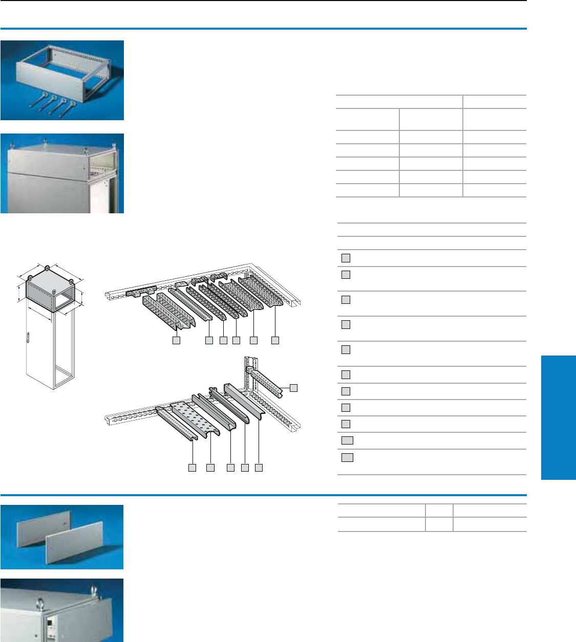
Industrial Buyer’s Guide 209
Accessories Roof
Top-mounting module
For TS
As a cable chamber for cable feed from above or
for power distribution with busbar systems across
bayed enclosures. The TS cover plate is used as
standard to finish at the top. The enclosure height
is increased by 8" (200 mm) with the top mounting
module installed. The top baying cover cannot be
fitted. Installation accessories for top and bottom,
see diagram and explanations below.
Material:
Sheet steel, 14 ga (2 mm)
Finish:
Painted in textured
RAL 7035 (light gray)/RAL 7032 (pebble gray)
Protection ratings:
UL Type 12 (IP 55 to EN 60 529/10.91)
(in conjunction with sidewall for
top-mounting module)
Conguration:
1 frame module,
2 trim panels (front and rear),
8 holders with automatic potential equalization,
4 tapped rods with eyebolts.
For enclosures Part No.
Width (B)
inches (mm)
Depth
inches (mm)
RAL 7035
(light gray)
16 (400) 24 (600) 8801.725
24 (600) 24 (600) 8801.735
32 (800) 24 (600) 8801.745
39 (1000) 24 (600) 8801.755
47 (1200) 24 (600) 8801.765
B
1
B
1
1
1
2 311
1
Accessories
Description
1 TS system bar 0.7 x 1.5" (18 x 38 mm)
2 PS system bar 0.9 x 0.9" (23 x 23 mm)
with angle bracket
3 PS system bar 0.9 x 0.9" (23 x 23 mm)
with support bracket PS
4 PS system chassis without mounting flange,
0.9 x 2.9" (23 x 73 mm) with support bracket PS
5 PS system chassis with mounting flange 0.9 x 2.9"
(23 x 73 mm)
6 Support rail
7 System support rails
8 C rail 30/15 with support bracket or spacer
9 Cable clamp rail
10 TS system bar 0.9 x 1.5" (25 x 38 mm)
11 TS system chassis without mounting flanges,
1.8 x 3.5" (45 x 88 mm)
Sidewall
For top-mounting module
To finish off the side of a top-mounting module or
bayed suite.
Material:
Sheet steel, 14 ga (2 mm)
Finish:
Painted in textured
RAL 7035 (light gray)
Conguration:
2 sidewalls,
8 holders with automatic potential equalization
Version PU Part No.
RAL 7035 (light gray) 2 8801.775
Roof
Top Module
Inch and pound measurements are rounded to the nearest whole number.
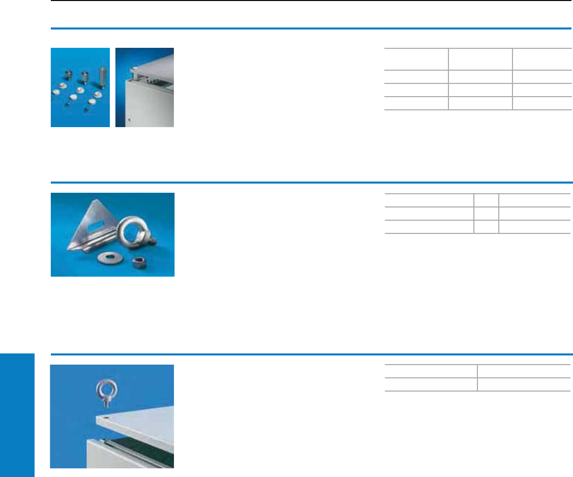
210 Industrial Buyer’s Guide
Accessories Roof
Eyebolts
For AE, CM
For crane transportation of enclosures, with
reinforcement plate to be inserted underneath.
Thread: M12
Conguration:
Eyebolts, reinforcement plates
For PU Part No.
AE 4 2509.000
CM 2 2590.500
Spacers
For roof plate, TS
To raise the TS8 roof for ventilation purposes,
in three different heights. Not suitable for crane
transportation.
Height
inches (mm) PU Part No.
0.5 (10) 4 2422.000
1.0 (20) 4 2423.000
2.0 (50) 4 7967.000
Roof
Spacers/Eyebolts
Inch and pound measurements are rounded to the nearest whole number.
Eyebolts
for TS, ES
For crane transportation of enclosures,
may already be included in the supply.
Thread: M12
Packs of Part No.
44568.000
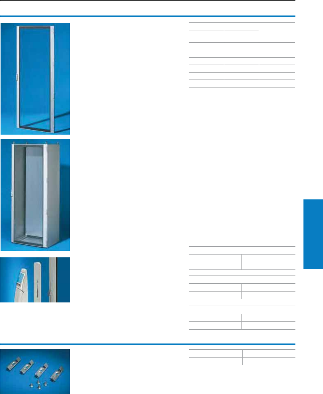
Industrial Buyer’s Guide 211
Accessories Doors/Locks
Doors/Locks
Viewing Doors
Viewing door
For TS
Instead of a sheet steel door or rear wall.
Version:
Frame:
Extruded aluminum section, die-cast zinc corner
pieces, powder coated in RAL 7035 (light gray)
Single-pane safety glass, 0.1" (3 mm) thick,
printed mask on the inside
RAL 7015 (slate gray)
Locking rod with double-bit insert
180° hinges (4)
Visible area:
H – 6" (160 mm),
W – 6" (140 mm).
Protection Ratings:
UL Type 12 (IP 55 to EN 60 529/10.91)
US design patent no. 418 608
German registered design No. M 98 03 844
IR reg. design no. DM/045 440 with validity for BE,
FR, NL, HU, LU
UK reg. design no. 2 076 673
South Korean reg. design no. 0 240 621
Russian reg. design no. 46 300
Japanese reg. design no. 1 056 165
Additional parts needed:
When mounting in place of the rear wall:
Lock components for frame 8800.040.
Accessories:
Lock inserts, see pages 218-220.
Comfort handle, see page 217.
For enclosures
Part No.
Height
inches (mm)
Width
inches (mm)
71 (1800) 24 (600) 8610.680
71 (1800) 32 (800) 8610.880
79 (2000) 24 (600) 8610.600
79 (2000) 32 (800) 8610.800
87 (2200) 24 (600) 8610.620
87 (2200) 32 (800) 8610.820
Handle adaptor
The handle adaptor compensates for the design
slant in the door profile to enable installation of
the comfort handle.
Material:
Plastic
Conguration:
1 adaptor plate,
1 extension for drive,
2 assembly screws
Lock components
For frame TS
For retrofitting a viewing door or sheet steel
door in place of a rear wall.
Material:
Die-cast zinc
For viewing door TS, PC, IW
Color Part No.
RAL 7035 (light gray) 8611.080
PU Part No.
48800.040
For designer door IW and PC-TS bottom door
Color Part No.
RAL 7035 (light gray) 8611.300
For viewing door IW
Color Part No.
RAL 7035 (light gray) 6903.170
Conguration:
Assembly hardware
Inch and pound measurements are rounded to the nearest whole number.
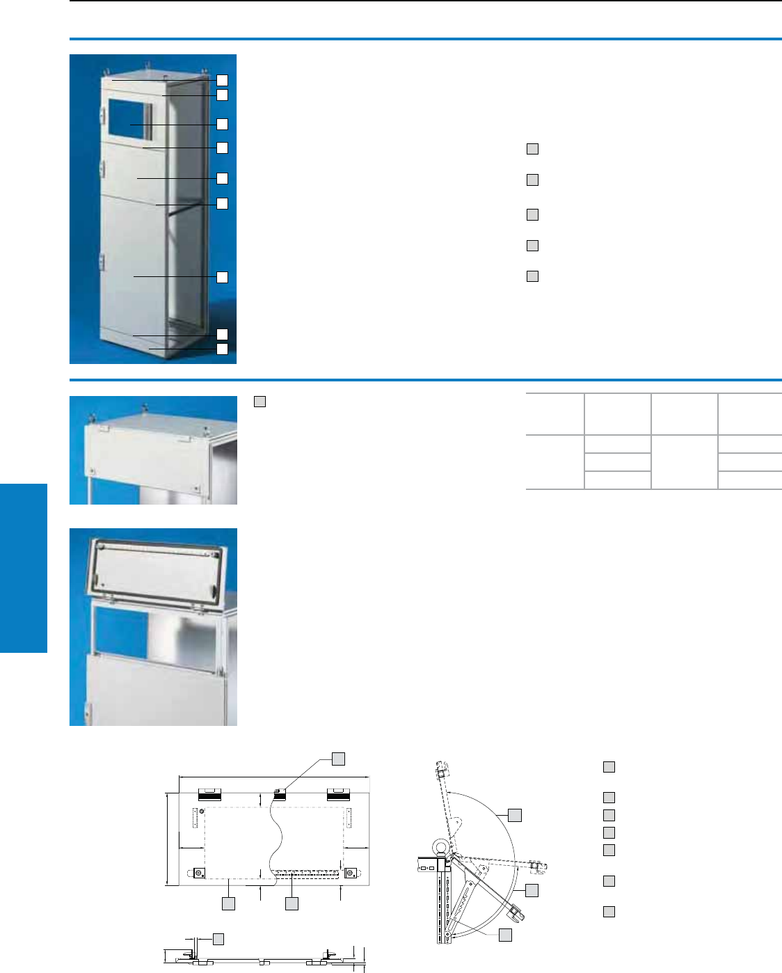
212 Industrial Buyer’s Guide
Accessories Doors/Locks
Doors/Locks
Modular Doors
1 Trim piece, hinged at the top
For TS
For the installation of control and display
components.
Material:
Sheet steel, 14 ga (2 mm)
Conguration:
Hinges, cam locks with double-bit insert and
assembly hardware
Note:
Not in combination with top-mounted module
for TS (see page 209).
Accessories:
Door stop for trim piece, hinged at the top
see page 216.
Lock inserts, version A,
see page 219.
Rittal Service:
Combination with shortened door, enclosure
with mounted trim instead of door, cut-outs for
operator and display components on request.
Additional parts needed:
Cross member: see page 213
11 2
1
3
1
Height
inches
(mm)
Width
inches
(mm)
Color RAL Part No.
12 (300)
24 (600)
7035
(light gray)
8801.230
32 (800) 8801.240
47 (1200) 8801.250
1 Only for width 32 and 47" (800
and 1200 mm)
2 Only for width 47" (1200 mm)
3 Usable interior area
4 Optional: Door stop 8801.260
5 Maximum opening with
support stay approximately 85°
6 Maximum opening without stay
approximately 190°
7 Grounding bolt M8
1
2
3
4
5
1
2
2
2
Modular front design
For TS
All 24 and 32" (600 and 800 mm) wide TS8
enclosures instead of a door or rear wall, as long
as the modular front enclosure is positioned
in a suite between two enclosures with normal
doors. If positioned as a freestanding enclosure
or at the end of an enclosure suite, special
side panels such as 8106.512 (see www.rittal-
corp.com) are required. The partial doors with
and without viewing panels can be arbitrarily
combined with cross members. A trim panel and
a cross member are each required at the top and
bottom. The requirements for your individual front
design and the considerations which must be
taken into account are illustrated on the sample
configuration opposite page.
Protection Ratings:
UL Type 12 (IP 55 to EN 60 529/10.91)
(with a completed enclosure)
Additional parts needed:
1 Trim panels, height 4" (100 mm) or trim panel,
hinged at the top, height
2 Cross member
Accessories:
3 Partial door with viewing window,
height 16" (400 mm)
4 Partial door without viewing window,
height 16" (400 mm)
5 Partial door without viewing window,
height 39" (1000 mm)
Inch and pound measurements are rounded to the nearest whole number.
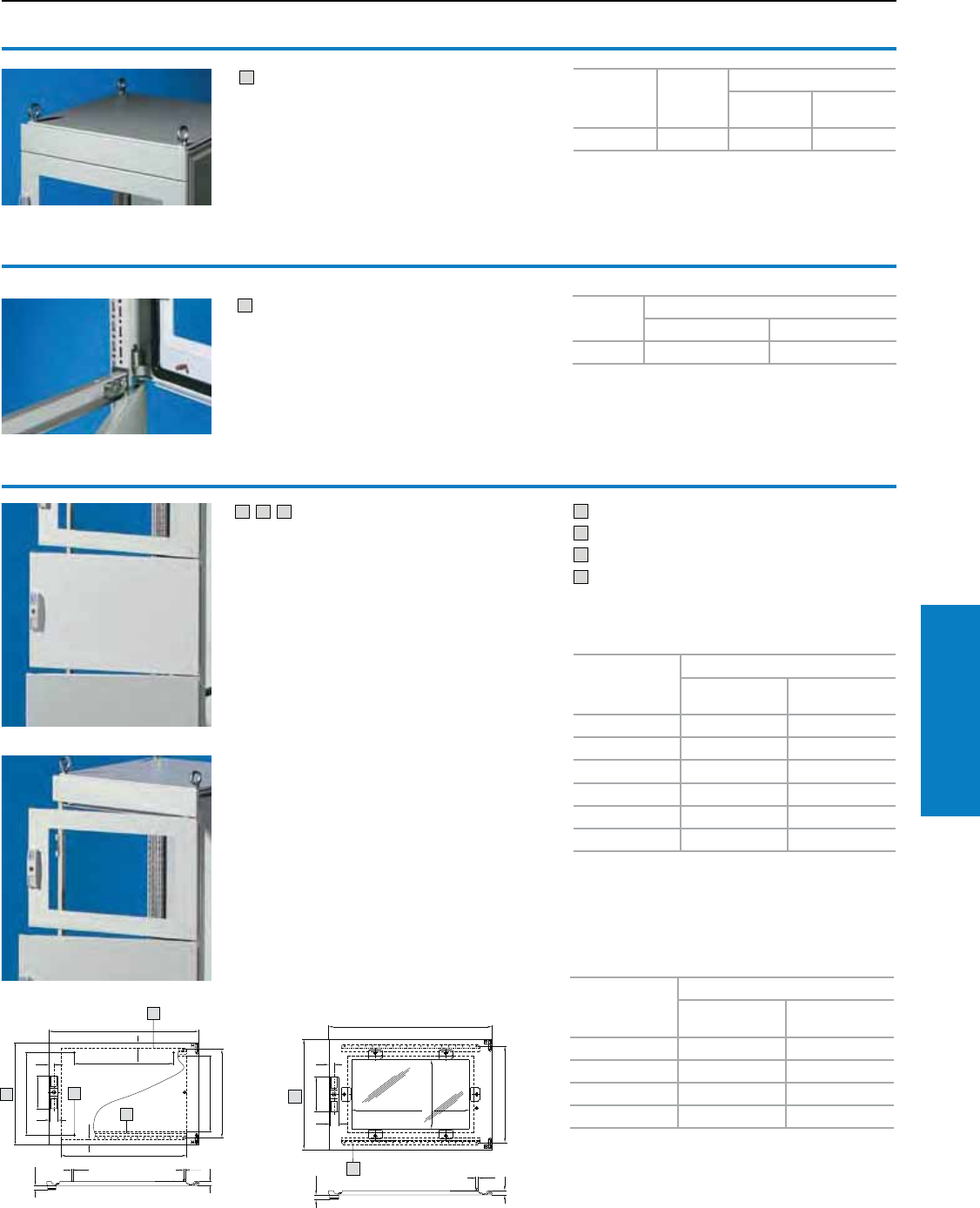
Industrial Buyer’s Guide 213
Accessories Doors/Locks
1 Trim panels
For TS
Required as upper and lower height trim.
Material:
Sheet steel, 14 ga (2 mm), textured
Conguration:
2 trim panels, assembly hardware
Additional parts needed:
Cross member, see below.
2 Cross member
For TS
As sealing member between:
• Trim panels
• Partial doors
• Trim piece, hinged at the top
Material:
Sheet steel
Color:
RAL 7035 (light gray)
Conguration:
Assembly hardware
3 4 5 Partial doors
For TS
Door can be optionally hinged on the right or left
side. In the case of doors without viewing panel
(height 24 – 39" [600 – 1000 mm]) the installation
of monitor frame 2305.000 is possible.
Standard double-bit lock insert may be
exchanged for TS lock inserts, and from
24" (600 mm) height, for comfort handle.
Material:
Sheet steel, 14 ga (2 mm)
Conguration:
Door, hinges and lock
Additional parts needed:
Cross member, see above.
Accessories:
Monitor frame 2305.000, see
www.rittal-corp.com.
TS lock inserts, see page 219.
Comfort handle, see page 217.
1 Height – 0.1" (2 mm)
2 Usable interior area
3 M6 bolt only for width 24" (600 mm)
4 Perforated strip only for width 32" (800 mm)
Height
inches
(mm)
Color RAL
Part No.
Width 24"
(600 mm)
Width 32"
(800 mm)
4 (100) 7035 8801.510 8801.110
PU Part No.
Width 24" (600 mm) Width 32" (800 mm)
58801.630 8801.830
Solid
Height inches
(mm)
Part No.
Width 24"
(600 mm)
Width 32"
(800 mm)
RAL 7035 RAL 7035
8 (200) 8801.520 8801.120
16 (400) 8801.540 8801.140
24 (600) 8801.560 8801.160
32 (800) 8801.580 8801.180
39 (1000) 8801.500 8801.100
With 0.1" (3 mm) single-pane safety glass
Height inches
(mm)
Part No.
Width 24"
(600 mm)
Width 32"
(800 mm)
RAL 7035 RAL 7035
16 (400) 8801.550 -
24 (600) 8801.570 8801.170
32 (800) 8801.590 -
RAL 7035 (light gray)
1
1
1
11
1
1
2
13
1
1
1
1
111111
11111
Doors/Locks
Modular Doors
Inch and pound measurements are rounded to the nearest whole number.
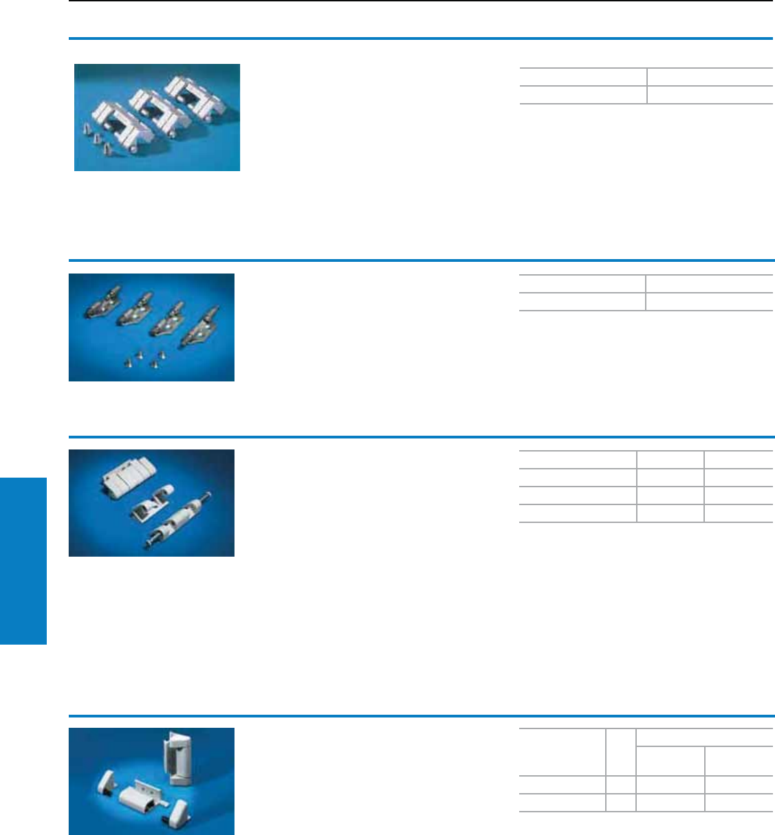
214 Industrial Buyer’s Guide
Accessories Doors/Locks
Doors/Locks
Hinges
Hinges 130°
For ES
For retrofitting a sheet steel door instead
of the rear wall.
Material:
Die-cast zinc
Conguration:
Assembly hardware
Note:
Lock components for frame should be
ordered separately:
Hinges 130°
For TS
For retrofitting a sheet steel door instead
of the rear wall.
Material:
Die-cast zinc
Conguration:
Assembly hardware
Additional parts needed:
Lock components for frame 8800.040,
see page 211.
Hinges 180°
For TS
For on-site conversion of sheet steel doors with
130° hinges
Easy assembly:
• Exchange the hinge parts on the frame side
for 180° hinges (4 screws)
• Drill the door at the pre-marked points
• Screw-fasten the hinge parts onto the door
• Install the door
• Press in the captive hinge pins
Material:
Die-cast zinc
Conguration:
Assembly hardware
Note:
Door assemblies such as the comfort handle may
restrict the door opening angle. The hinge pins may
only be actuated and the door removed with the
door open.
The hinge cannot be dismantled from the outside
with the door closed (access protection).
PU Part No.
64190.000
PU Part No.
48800.020
Version PU Part No.
RAL 7035 (light gray) 4 8800.190
RAL 8019 (gray brown) 4 8800.230
Matt nickel-plated 4 8701.180
Hinges 180°
For TS modular bayed enclosure suites with
comfort handle
In TS modular bayed enclosure suites with
comfort handle for semi-cylinder, the following
door opening angles may be achieved:
Sheet steel door: Maximum 180°
Viewing door: Maximum 140°
Material:
Die-cast zinc
Color:
RAL 7035 (light gray)/RAL 9005 (white gray)
Conguration:
Assembly hardware
Note:
• The protection ratings of the enclosure
may be reduced
• Not for divided doors
• Door hinge remains the same within a bayed
modular enclosure suite
• Not suitable for use with TS designer
viewing doors
Version
for PU
Part No.
RAL 7035
(light gray)
RAL 9005
(gray white)
Sheet Steel door 4 7824.520 7824.522
Viewing door 4 7824.525 –
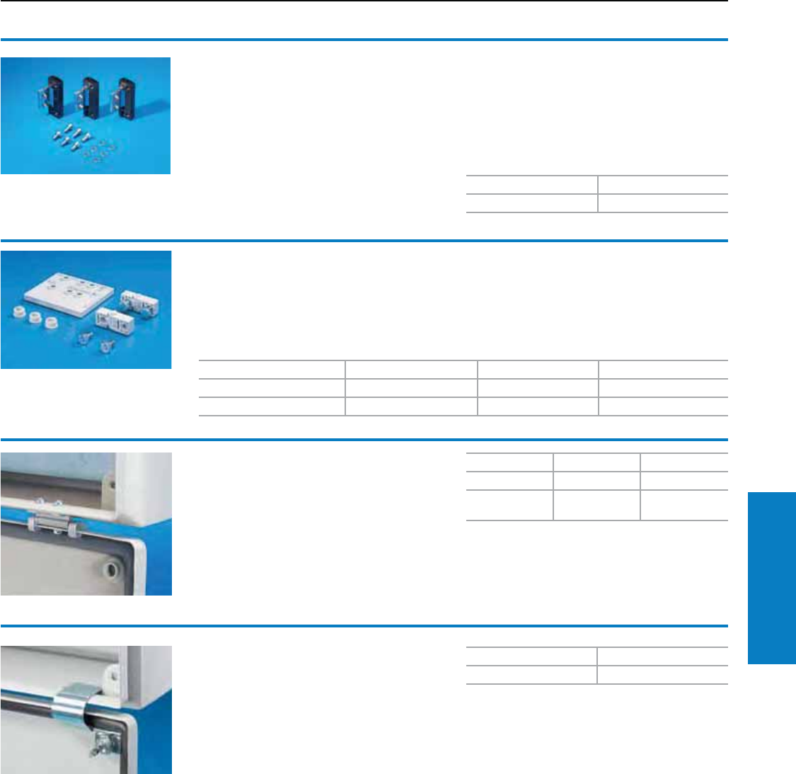
Industrial Buyer’s Guide 215
Accessories Doors/Locks
Doors/Locks
Hinges
Hinges, 180°
For CM
For retroactive conversion of standard doors
with 130° hinges. One pack is sufficient for one
door – i.e., with two-door enclosures, two packs
will be required.
Material:
Die-cast zinc PU Part No.
35001.000
Color:
RAL 9011 (pebble black)/9006 (white aluminum)
Conguration:
Assembly parts
Note:
When baying two CM enclosures, position the
hinges on the outside
For enclosure Material PU Part No.
9500.000 – 9513.000 Polycarbonate 10 sets 9580.000
9514.000 – 9524.000 Polystyrene 10 sets 9581.000
Hinges
For PK
For hinged attachment of lids.
The supplied drilling template ensures
problem-free assembly.
Conguration:
1 set = 2 hinges,
4 assembly screws,
3 polyethylene sealing plugs,
1 drilling template.
Cover hinge
For KL
The cover hinge is simply screwed to the enclosure
protection channel and to the edge fold.
Conguration:
Assembly parts
Material PU Part No.
Die-cast zinc 6 1592.000
Stainless steel
Type 316L 21592.010
Cover retainer
For KL
The cover retainer is easily fitted without
drilling, and allows the covers to be
opened upwards, even when the terminal
box below is bayed.
PU Part No.
3 pairs 1591.000
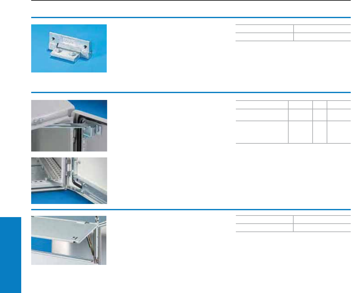
216 Industrial Buyer’s Guide
Accessories Doors/Locks
Door stop
To secure the door in the open position.
• Only single door WMs H x W <900 x 900 mm
• Double door WMs ≤900 mm
• No Stainless Steel WMs
For Assembly PU Part No.
TS, ES, PC, AP
universal console Bottom 54583.000
AE (except 1032.500
and 1035.500), WM and
all AE stainless steel
enclosures1)
Top 52519.000
1) With AE stainless steel, only in conjunction with
perforated mounting strip.
Door stop
For trim panel, hinged at the top
5 system hole pattern positions up to a maximum
opening of approximately 85°.
Material:
Sheet steel, zinc-plated, passivated
PU Part No.
28801.260
Doors/Locks
Hinges/Door Stops
Hinges 180°
For AE
For retrospective conversion of standard doors
with 130° hinges.
Material:
Die-cast zinc
Conguration:
Assembly hardware
PU Part No.
22449.000
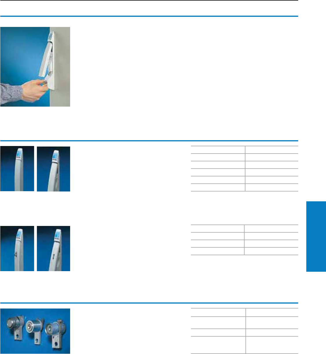
Industrial Buyer’s Guide 217
Accessories Doors/Locks
The Rittal Comfort handle
For TS, PC, IW
The entire door area can be maximized for
installing equipment, because the handle does
not take up any of the swivel area, due to its
folding action.
Material:
Die-cast zinc
Finish:
Powder coated
US design patent no. 428,322
German patent no. 198 01 720
German registered design no. M98 00 539
IR reg. design no. DM/045 065
with validity for BE, CH, ES, FR, IT, NL, HU, LU
Austrian design no. 32290
Czech design no. 28278
UK reg. design no. 2 075 910
Swedish design no. 64 750
South Korean design no. 241,505
Israel. design no. 30 123
Slovenian design no. 98 500 73
Russian design no. 46307
South African design no. 98/0865
Finnish design no. 20461
Chinese design no. 983 03439
Australian design no. 13887
Brazilian design no. DI 5801235-4
Jap. design no. 1 081 561
Taiwanese design no. 68683
European patent no. 1 049 842
with validity for FR, GB, IT
Jap. patent no. 3 485 892
US patent no. 6,418,762
Doors/Locks
Handles/Inserts
Lock and push-button inserts
For installation in the comfort handle
for lock inserts.
Version Part No.
Security lock insert no.
3524 E 8611.1801)
Push-button insert 8611.190
Push-button and lock
inserts Lock no. 12321;
No other lock is possible
8611.2001)
1) With 2 keys
Comfort handle
For lock inserts
Prepared for the installation of lock inserts,
safety and push-button inserts, see below.
Length: 12" (295 mm).
Additional parts needed:
Handle adaptor for mounting on a TS viewing
door, PC-TS bottom door, IW designer door.
Comfort handle
For padlock and lock inserts
Prepared for the installation of lock inserts, safety
and push-button inserts, and with additional
shackle (hole diameter 0.3" [8 mm]) for a padlock.
Length: 12" (295 mm).
Additional parts needed:
Handle adaptor for mounting on a TS viewing
door, PC-TS bottom door, IW designer door
(see pages 211).
Design Part No.
RAL 7032 (pebble gray) 8611.010
RAL 7035 (light gray) 8611.020
RAL 8019 (gray brown) 8611.250
RAL 9005 (jet black) 8611.350
Matte, nickel-plated 8611.330
Version Part No.
RAL 7032 (pebble gray) 8611.030
RAL 7035 (light gray) 8611.290
RAL 8019 (gray brown) 8611.260
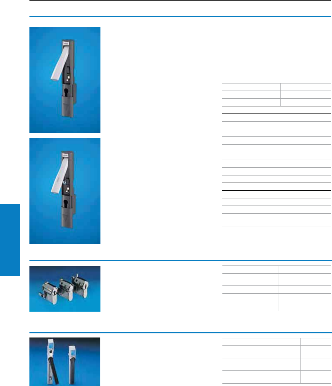
218 Industrial Buyer’s Guide
Accessories Doors/Locks
Lock and push-button inserts
For installation in:
• Ergoform-S standard
• CM hinged handle
Version Part No.
Security lock insert no.
3524 E 2467.0001)
Push-button insert 2468.000
Lock and push-button
inserts, Lock no. 2123 E;
No other lock is possible
2469.0001)
1) With 2 keys
Doors/Locks
Handles/Inserts
Folding lever handle
For CM
Because the handle does not
take up any swing space, due to
its folding mechanism, the door
surface area may be maximized
for installed equipment.
Color:
Handle body: Similar to RAL 9005
(jet black)
Lever: Similar to RAL 9006 (white
aluminum)
Prepared for the installation of:
– Semi-cylinders with overall
length of 1.6 or 1.8"
(40 or 45 mm) (to DIN 18 254)
– All lock inserts
– As well as lock and
push-button inserts
Handle version PU Part No.
Basic 1 5001.060
Padlock 1 5001.062
Accessories
Lock inserts
Version Part No.
7 mm square 8611.100
8 mm square 8611.110
6.5 mm triangular 8611.220
7 mm triangular 8611.120
8 mm triangular 8611.130
Screwdriver 8611.140
3 mm double-bit 8611.160
Lock and push-button inserts
Design Part No.
Lock insert lock no. 3524 E 2467.0001)
Push-button insert 2468.000
Lock and push-button insert, lock no.
2123 E; No other lock is possible 2469.0001)
1) With 2 keys
Conguration:
Assembly hardware
Folding lever handle
with padlock hasp
For CM
Ergoform lock system
For AE/KS/TP Enclosures
Prepared for the installation of semi-cylinders with
a total length of 1.6" (40 mm) (to DIN 18 254), all
1.1" (27 mm) lock inserts, version A, and lock and
push-button inserts, see above.
Version Part No.
RAL 7035 (light gray)
For AE (carbon > 40" H)/TP 2435.000
Nickel-plated
For AE (SS > 40" H)/TP 2452.000
RAL 7035 (light gray)
With brown handle (for KS > 24" H) 1490.010
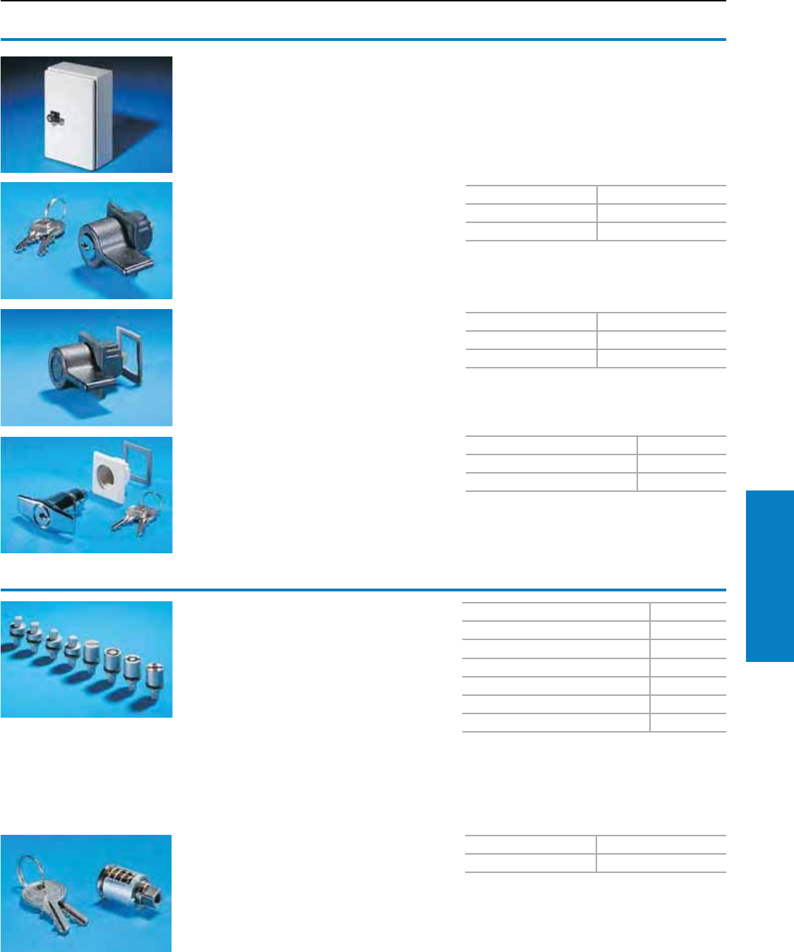
Industrial Buyer’s Guide 219
Accessories Doors/Locks
Plastic handles
For AE, WM, EB, JB
With cylinder insert.
Lock no. 3524 E including assembly hardware,
seal and 2 keys. For carbon steel enclosures only.
Doors/Locks
Handles/Inserts
T handles
Material:
Die-cast zinc, chrome-plated
Conguration:
Seal and 2 keys
Version B
Note:
Universal lock systems allow the installation of
a handle to suit almost any application or customer
specification. Please check the product ordering
page which shows the handles that can be fitted
into each particular enclosure assembly.
Color Part No.
RAL 9011 (graphite black) 2576.000
RAL 7030 (stone gray) 2439.000
Version Part No.
With lock insert, lock no. 3524 E 2575.000
Without lock insert 2572.000
Color Part No.
RAL 9011 (graphite black) 2533.000
Type 316L stainless steel WMQTPLS6*
* Padlockable handle
Version B,
without key locking insert
Version B
Lock inserts
Universal lock systems allow the installation of a
handle to suit almost any application or customer
specification.
Version A
Material:
Die-cast zinc
Note:
Key sold separately
See page 220 for key options
Length 27 mm Part No.
7 mm square 2460.000
8 mm square 2461.000
7 mm triangular 2462.000
8 mm triangular 2463.000
Screwdriver 2464.000
3 mm double-bit 2466.000
PU Part No.
12571.000
Cylinder inserts
For AE, EB, WM (carbon steel only),
JB (carbon steel only)
Material:
Die-cast zinc
Version B
Lock no. 3524 E with 2 keys
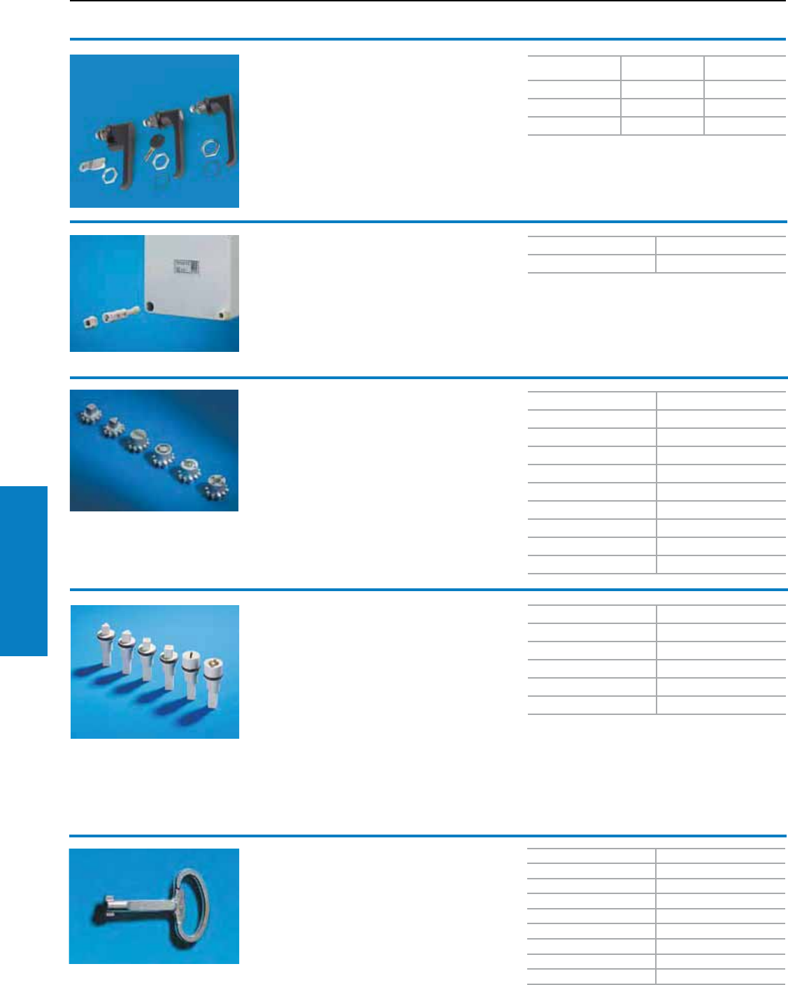
220 Industrial Buyer’s Guide
Accessories Doors/Locks
Carbon Steel
Part No.
Stainless Steel
Part No.
L-Handle WMLHNL WMLHNLS6
L-Handle Padlock WMLHPL WMLHPLS6
L-Handle Keylock WMLHKL WMLHKLS6
Doors/Locks
Handles/Inserts
Turn-lock fastener
For PK
A quick, convenient screw fastening aid is
obtained by clipping into the head of the lid screw.
Material:
Polyamide
Conguration:
1 pack
PU Part No.
100 9582.000
Lock inserts
Material: Die cast zinc.
For comfort handles and standard TS lock (in
exchange for the standard double-bit lock insert).
Version F
Version Part No.
7 mm square 8611.100
8 mm square 8611.110
6.5 mm triangular 8611.220
7 mm triangular 8611.120
8 mm triangular 8611.130
Screwdriver 8611.140
Daimler 8611.150
3 mm double-bit 8611.160
Fiat 8611.170
Enclosure key
For lock inserts (one double-bit key is supplied
with every enclosure).
Version Part No.
Double-bit key no. 5 2531.000
Security key no. 3524 E 2532.000
7 mm triangular 2545.000
8 mm triangular 2546.000
7 mm square 2547.000
8 mm square 2548.000
Daimler key 2521.000
Fiat key 2308.000
L-Handle
For WM
A lock for 3 point latch wallmount enclosures.
Material:
Die-cast zinc, powder coated black or stainless
steel
Lock inserts
Material: Plastic.
Version E
Version Part No.
7 mm triangular 1485.000
8 mm triangular 1486.000
8 mm square 1488.000
Screwdriver 1489.000
Double-bit 1492.000
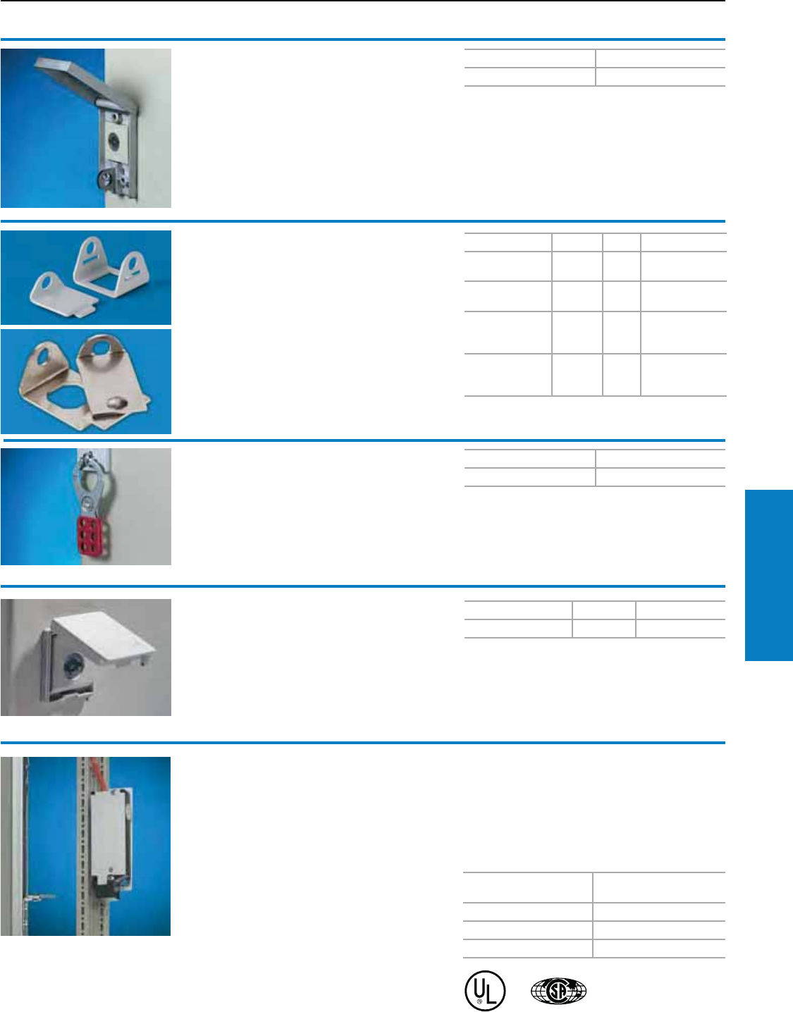
Industrial Buyer’s Guide 221
Accessories Doors/Locks
Doors/Locks
Lock Covers
Padlock cover
For AE, WM, EB, JB
For use with padlocks or multiple locks for on-site
mounting on all AE/WM enclosures of sheet steel
and with cam lock.
Material:
Die-cast zinc, nickel-plated, passivated
Color PU Part No.
RAL 7035 (light gray) 2 2476.000
PU Part No.
22493.500
PU Part No.
12493.000
Lock cover
For AE, WM, EB, JB
Prepared for lead seal. For all enclosure types with
Rittal-specific locks, such as AE, WM, EB and JB.
For carbon steel enclosures only.
Material:
Polyamide
German registered design no. M 92 07 062
Multiple lock
For use with padlock lock cover
The ideal solution in cases where individual
access for several persons is required for
maintenance and repair purposes. Accommodates
up to six padlocks.
Material:
Sheet steel, zinc-plated, passivated
Electrical interlock
Fitted to doors, to protect against contact with live
electrical equipment while the main switch is ON.
Function:
• Locks the door when the main switch is ON
• Mains power (voltage) is only enabled while the
door is closed
• Monitoring of the lock magnet via an additional
closing contact
Conguration:
Lock, actuator, angle bracket, assembly hardware.
Additional parts needed:
For double door enclosures part no. 4127.000
should also be ordered (see www.rittal-corp.com).
Connection voltage
for lock magnet Part No.
230 V AC 11 VA 2416.000
24 V DC 8 W 2418.000
120 V AC 8 VA 2419.000
Padlock lockout
For AE, WM, EB, JB
For use with padlocks or multiple lock for on site
mounting on all EB/JB or AE/WM enclosures
Material:
RAL 7035 (light gray) or
Type 316L stainless steel
Material For PU Part No.
RAL 7035
(light gray)
carbon
steel 1WMPADCS
Type 316L
stainless steel
stainless
steel 1WMPADS6
Type 316L
stainless steel
(riveted)
carbon
steel 1WMPADRCS
Type 316L
stainless steel
(riveted)
stainless
steel 1WMPADRS6
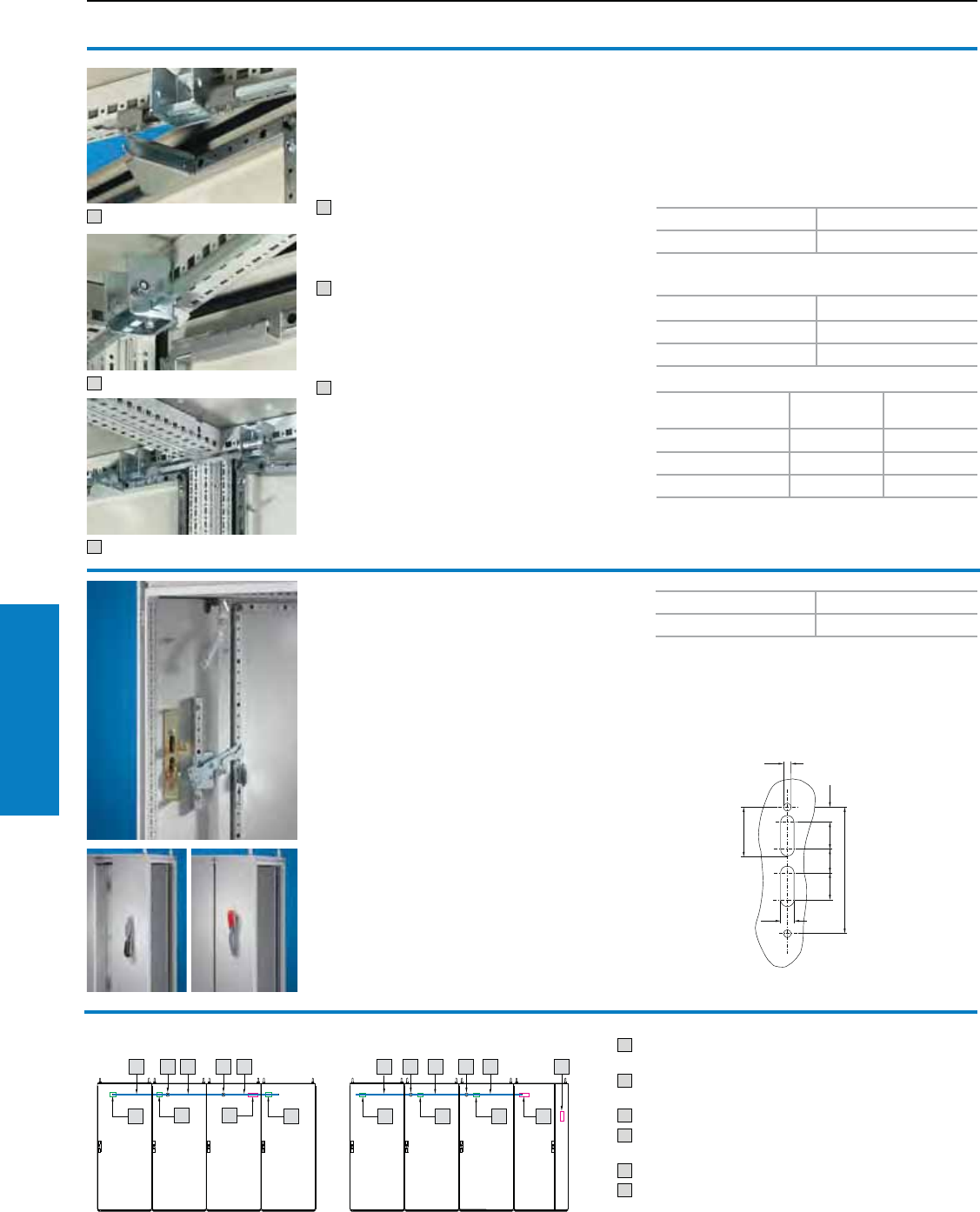
222 Industrial Buyer’s Guide
Accessories Doors/Locks
Door interlocking for
bayed suites
For extending the door lock of commercially
available main switches to TS bayed suites.
Adjacent door cannot be opened until the main
door has been opened.
1 Interlock activator
(Fitted in the enclosure with main switch and
additionally in every fourth adjacent enclosure)
2 Adjacent door locking
(Installation in adjacent enclosure)
3 Interconnecting rods
To extend locking from the main enclosure to
the adjacent enclosures of a bayed suite.
An interconnecting rod corresponding to the
width of the enclosure is required for each
adjacent enclosure.
The main switch can be positioned anywhere in
the suite; its function is independent from the door
hinge position. Subsequent locking of the adjacent
doors in the suite is possible: They are thus
automatically included in locking operation.
Flange mount
disconnect locking
For safety locking of enclosures and bayed
suites in conjunction with up to 200A disconnect
switches and up to 400A circuit breaker operating
mechanisms.1)
• ABB DSFHN, K5FCH, OHF1C, K3FHD, K6FHD
• Allen Bradley 1494V, 1494C, 1494RC, 140U
• Cutler Hammer C361, C371, Flex Shaft
• General Electric STDA, SCH SpectraFlex
• Siemens VBF, VBNF, FHO, Max-Flex
• Square D 9422
To complete the assembly you must order
4911.000 (see above) and the required
interconnecting rods for bayed suites.
Note:
8611.310 includes interlock activator
(4912.000 [see above]).
1 Interlock activator, installation in enclosure
with main switch
2 Adjacent door locking, installation in
adjacent enclosure
3 Interconnecting rod
4 Connection component (included in the supply of
interconnecting rod)
5 FMD main door lock
6 Interlock activator, installation in the main enclosure
(included in the supply of the FMD main door lock
position 5).
1
11 1
1
1
1
2 1 2
333
2
33 3
2
22
Part No.
Interlock activator 4912.000
Adjacent door locking Part No.
1 Door 4911.000
2 Door 4911.100
For enclosure width
inches (mm) PU Part No.
24 (600) 10 4916.000
32 (800) 10 4918.000
47 (1200) 10 4920.000
Main door locking Part No.
For TS 8611.310
Non-FMD door locking FMD door locking
Doors/Locks
Interlocking Hardware
Note:
Included with master flange mount
disconnect cabinet.
1
2
3
Inch and pound measurements are rounded to the nearest whole number.
1) May work with some circuit braker operating mechanisms greater than 400A.
Cut-out for main switch
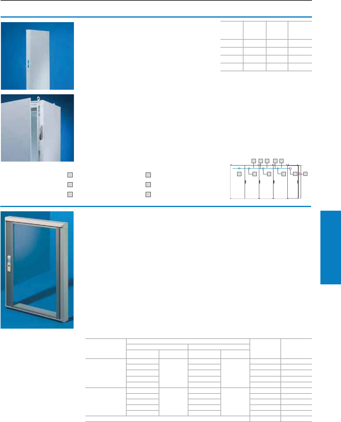
Industrial Buyer’s Guide 223
Accessories Doors/Locks
System windows
Covers display and operating instruments or cut-
outs to protect against dirt and liquids as well as
unauthorized access.
Consisting of the following components:
1. Base frame:
• Easily screw-fastened to the door due to
modified dimensions (tubular door frame may
be used as a drilling template)
• Readily height-adjustable
• Stabilizes the door cut-out
• Conceals the cut edge
• The rain canopy:
− Prevents dirt from landing on the seal
− Protects the glass from being lifted out
− Prevents the ingress of dirt and moisture
when opening the window
2. Viewing window:
• Hinge with 180° opening angle, easily inserted
• Made from single-pane safety glass:
− High level of resistance to Anti-static solvents
and scratches
− Reduced risk of injury if broken
• Integrated cam lock with double-bit insert, easily
exchanged for all standard lock inserts and semi-
cylinders in the Ergoform-S lock system (not with
2735.500 and .560)
Material:
System windows:
Extruded aluminum sections with die-cast zinc
corner pieces and single-pane safety glass
Finish:
Base frame:
Powder coated in RAL 7035 (light gray).
Hinge and lock section:
Natural anodized.
Protection Ratings:
NEMA Type 12 (IP 54 to EN 60 529/10.91)
To fit TS, ES, IW
with width inches
(mm)
Window size inches (mm)
Part No.
30 section
Part No.
60 section
Exterior Internal
H B (W) H B (W)
24 (600)
11 (270)
20 (500)
8 (200)
17 (430)
2735.500 –
15 (370) 12 (300) 2735.510 2735.510
19 (470) 16 (400) 2735.520 2735.520
22 (570) 20 (500) 2735.530 2735.530
26 (670) 24 (600) 2736.540 2736.540
32 (800)
11 (270)
27 (700)
8 (200)
25 (630)
2735.560 –
15 (370) 12 (300) 2735.570 –
19 (470) 16 (400) 2735.580 2735.580
22 (570) 20 (500) 2735.590 2735.590
26 (670) 24 (600) 2735.250 2735.250
Other sizes1) 2735.509 2735.509
1) Please also specify the external dimensions of the viewing window.
Doors/Locks
Disconnect Module/Windows
Inch and pound measurements are rounded to the nearest whole number.
1
TS disconnect module
The TS disconnect module easily converts a standard TS
modular enclosure into a flange-mount disconnect enclosure.
Compatible with the following disconnects:
• Allen Bradley 1494 V-H1
• Square D 9422 A1
• ITE Siemens Max-Flex series/FHOH
(only available in the USA)
• General Electric TDA Type 1 and 2
• Moeller NZM-XSHGVR 12-NA
Benets:
• Compact desgin width of 3.9” (100 mm)
• Mounted in place of a standard side wall on a TS enclosure
• May be mounted on the left or right side of a TS enclosure
• The TS mounting panel infill (part number 4590.700/
4591.700) may be used to increase the internal mounting
panel surface by approximatly 14%.
Material:
Sheet steel
Surface nish:
Powder-coated, RAL 7035
Protection category:
UL Type 12 / IP 55 to EN 60 529
Supply includes:
Disconnect module with assembly
hardware, main door interlock hardware.
Accessories:
Mounting panel infill
Also required:
Interlock activator, 4912.000, for
enclosure with TS disconnect module
and additionally every fourth adjacent
enclosure. Adjacent door locking,
4911.000, 4911.100, for every adjacent
enclosure. Interconnecting rods, for every
adjacent enclosure in the appropriate
enclosure width.
Width
inches
(mm)
Height
inches
(mm)
Depth
inches
(mm)
Part No.
4 (100) 71 (1800) 16 (400) 8900.840
4 (100) 71 (1800) 20 (500) 8900.850
4 (100) 79 (2000) 20 (500) 8900.050
4 (100) 79 (2000) 24 (600) 8900.060
1 Interlock activator 4 Connection component
2 Adjacent door locking (single door) 5 Main door latch
3 Interlocking rod 6 Adjacent door locking (two door)
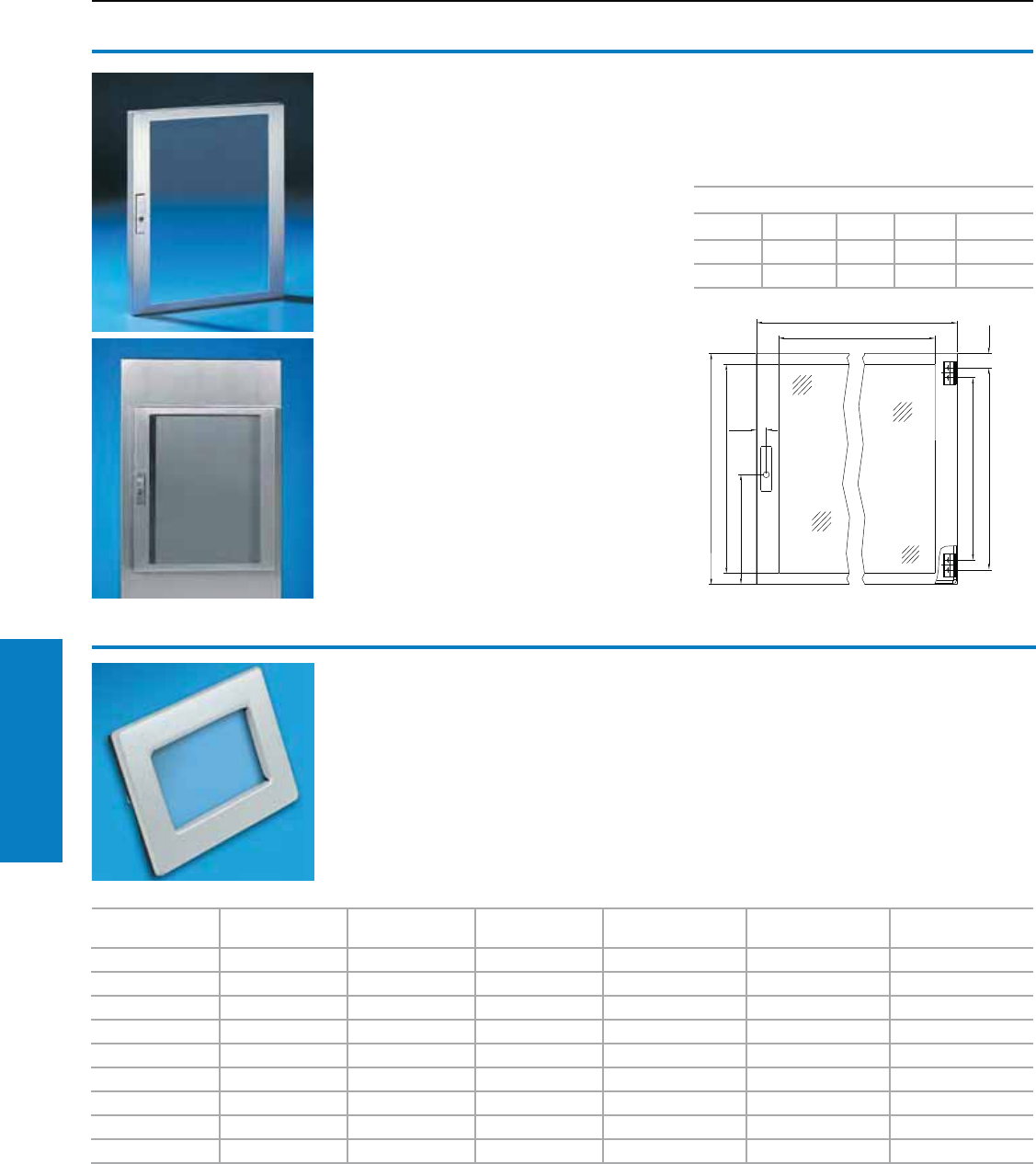
224 Industrial Buyer’s Guide
Accessories Doors/Locks
Doors/Locks
Windows
Viewing panel
Stainless steel
Fitted as standard with internal 130° hinges
and seal around the perimeter.
Standard double-bit lock insert may be
exchanged for 1" (27 mm) lock inserts,
type A and Ergoform-S handle 2452.000.
Material:
Type 304 stainless steel
Single-pane safety glass
Protection Ratings:
NEMA Type 12 (IP 54 to EN 60 529/10.91)
Conguration:
Assembly hardware
Note:
Other sizes available on request.
Accessories:
Lock inserts 1" (27 mm), version A,
see page 219.
Ergoform-S handle 2452.000,
see www.rittal-corp.com.
Inches (mm)
Height Width (B) Depth B1 Part No.
24 (600) 21 (522) 2 (38) 16 (408) 2793.560
24 (600) 29 (722) 2 (38) 24 (608) 2793.760
B
B1
Window Kits
Rittal window kits can be installed
in most Rittal enclosures of
suitable size. Window kits include
all necessary hardware. Oil-
resistant gaskets ensure a tight
seal around the entire window.
Material/Finish:
Carbon Steel: 14 ga, painted
RAL 7035 (light gray)
Stainless Steel 304: 14 ga
Stainless Steel 316L: 14 ga
Note:
Allow for clearance of gaskets,
gasket retainers, door stiffeners,
print pockets, door handles, lock
rods, and other parts attached
to the door or cover when you
determine the size of the window
kit you require.
Protection Ratings:
NEMA Type 4 Carbon,
NEMA Type 4X Stainless
Window Height
inches (mm)
Window Width
inches (mm)
Frame Height
inches (mm)
Frame Width
inches (mm)
Carbon Steel
Part No.
Type 304 Stainless
Steel Part No.
Type 316L Stainless
Steel Part No.
5 (127) 3 (76) 8 (191) 6 (140) WK0503C WK05034 WK05036
9 (229) 6 (140) 12 (292) 8 (203) WK0905C WK09054 WK09056
13 (330) 3 (76) 16 (394) 6 (140) WK1303C WK13034 WK13036
13 (330) 8 (203) 16 (394) 11 (267) WK1308C WK13084 WK13086
17 (432) 6 (140) 20 (495) 8 (203) WK1705C WK17054 WK17056
17 (432) 11 (279) 20 (495) 14 (343) WK1711C WK17114 WK17116
23 (584) 15 (381) 26 (648) 18 (445) WK2315C WK23154 WK23156
29 (737) 19 (483) 32 (800) 22 (546) WK2919C WK29194 WK29196
35 (889) 23 (584) 38 (953) 26 (648) WK3523C WK35234 WK35236
Inch and pound measurements are rounded to the nearest whole number.
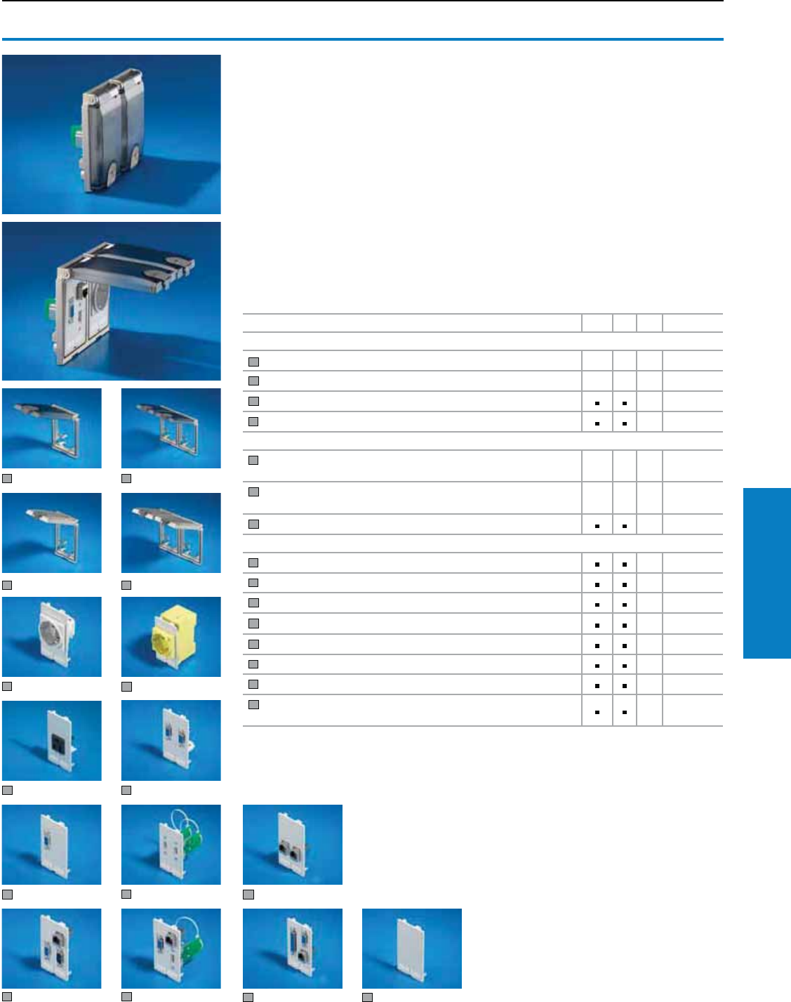
Industrial Buyer’s Guide 225
Accessories Doors/Locks
Doors/Locks
Interface Flaps
Interface aps, modular
For universal use in all situations where rapid
access to interfaces and sockets is needed.
The enclosure remains closed and protected
from the external environment and unauthorized
access. Space-saving installation:
• in small enclosures and compact enclosures
as a programming interface for controllers
• in IT and industrial enclosures as
maintenance access for networks
• in PC enclosures and console systems
for the temporary connection of additional
equipment in mobile Industrial Workstations
for rapid connection to existing network
structures
• in Command Panel systems for
programming and maintenance of
integral components
The mounting frame has a flap which snaps
into position at opening angles of 90° to
180°. A snap fastener ensures a reliable
seal. This may be locked if required.
Material:
Mounting frame and metal flap:
Fine die-cast zinc, matte nickel-plated
Plastic flap: Polycarbonate
(semi-transparent)
Lock: Polycarbonate,
RAL 7024 (graphite gray)
Protection Ratings:
NEMA 12 (IP 65) with sealed flap
and proper assembly
Detailed drawings:
visit www.rittal-corp.com
Description cUL UL PU Part No.
Mounting frame1)
1 Single, with plastic flap (semi-transparent) 12482.300
2 Double, with plastic flap (semi-transparent) 12482.310
3 Single, with metal flap 12482.320
4 Double, with metal flap 12482.330
Socket modules
5 Germany (VDE), spring-action terminals max. 2 x 2.5 mm2, connection
at rear 12482.4003)
6 Germany (VDE), screw terminals max. 6 mm2, connection at rear,
color: yellow (RAL 1016), for installation in front of main switch 12482.4103)
7 USA NEMA 5-15, plug-in solder connection 4.8 x 0.8 mm 12482.4204)
Interface inserts
8 2 x SUB-D9 (jack/pin) 12482.500
9 SUB-D9 (jack/jack) 12482.510
10 2 x USB A (jack/jack) 12482.5402)
11 2 x RJ 45 (jack/jack, Cat. 5e) 12482.550
12 RJ 45 (jack/jack, Cat. 5e), SUB-D9 (jack/jack), SUB-D9 (pin/pin) 12482.5602)
13 USB A (jack/jack), RJ 45 (jack/jack, Cat. 5e), SUB-D9 (jack/pin) 12482.5702)
14 RJ 45 (jack/jack, Cat. 5e), SUB-D9 (jack/pin), SUB-D25 (jack/pin) 12482.580
15 Blanking plate (slimline), for individual population, usable area: 1.8 x 3.0"
(45 x 75 mm) 12482.590
1) Electrically conductive. 2) Conductively linked to mounting frame. 3) Rated voltage: 250 V AC, rated
current: 10 – 16 A
4) Rated voltage: 125 V AC, rated current: 15 A (2482.420)
All SUB-D interfaces may be rotated while in operation. Other socket modules and interface inserts
available on request.
2
1
34
56
78
910 11
12 13 14 15
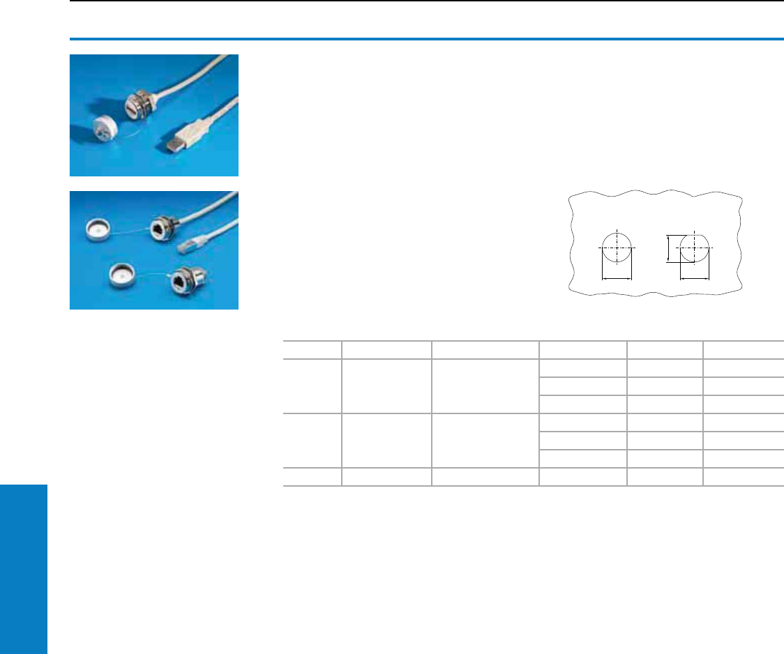
226 Industrial Buyer’s Guide
Accessories Doors/Locks
Doors/Locks
Interface Extension
Interface extension with wall
connection and built-in
RJ 45 module
For extending the internal enclosure interfaces –
e.g., from industrial PCs and switches – to the
outside of the enclosure. The wall connection only
needs the same space as a switch.
Benets:
Rapid access for maintenance work
The protection ratings of the enclosure is
preserved
The lock nut cuts into the spray-finish creating a
conductive connection
Screw-on protective cap
Material:
Enclosure: Brass, nickel-plated
Cover: Aluminium, anodized
Seal: Polyamide
Protection Ratings:
NEMA 4X (IP 66) with the protective cap closed
Anti-twist guard
Material thickness: 1 – 6 mm
Version Wall Connection Inside Length meters Packs of Part No.
USB Type A Jack Type A connector
0.5 1 2482.210
1.0 1 2482.220
2.0 1 2482.230
RJ 45 Jack Connector
0.5 1 2482.700
1.0 1 2482.710
2.0 1 2482.720
RJ 45 Jack Jack – 1 2482.730
Other versions and lengths available upon request.
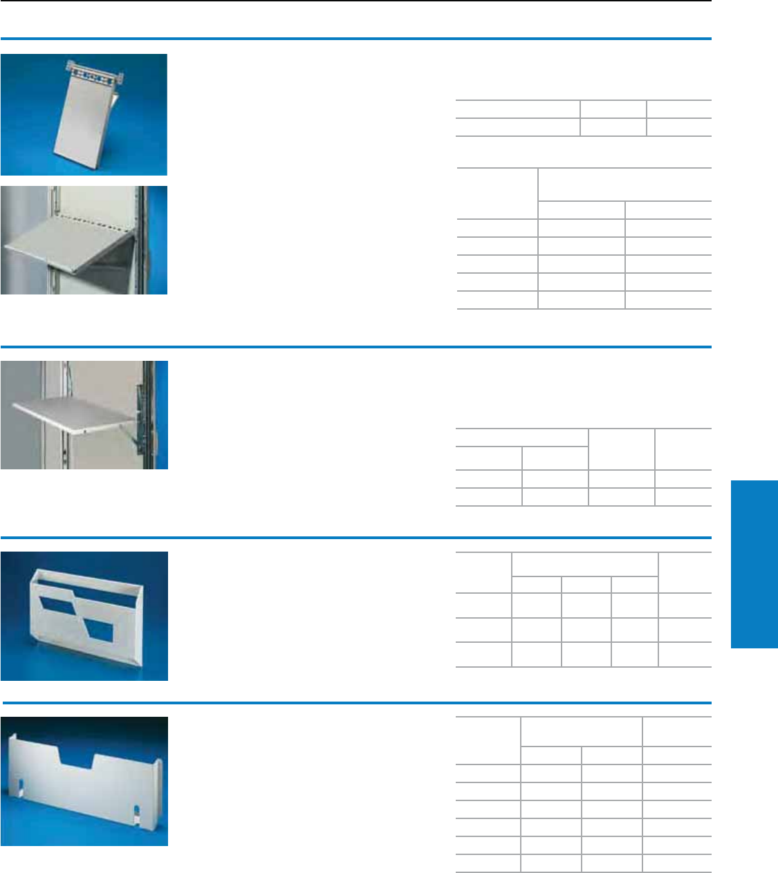
Industrial Buyer’s Guide 227
Accessories Doors/Locks
Utility shelf
For programming units, etc. Prepared for mounting
on the tubular door frame of TS, CM, ES, PC or on
any sufficiently large surface. When required for
servicing, it folds down quickly with a maximum
support area, and after use is stowed between the
tubular door frames in a space-saving design.
Load capacity: Maximum 66 lb (30 kg)
Material:
Sheet steel
Color:
RAL 7035 (light gray)
Writing board
Holds prints during trouble shooting and
maintenance work. The writing board can be
bayed according to the door width.
For mounting on the tubular door frame.
Material:
Utility board: Polypropylene
Mounting bracket: Die-cast zinc
Color:
Similar to RAL 7035 (light gray)
Conguration:
Writing board (width 8" [210 mm])
Assembly hardware
Support area inches (mm) For door
width inches
(mm)
Part No.
Width Depth
16 (400) 16 (400) 24 (600) 4638.600
24 (600) 16 (400) 32 (800) 4638.800
For enclosures PU Part No.
For TS, CM, TP, ES, PC 1 4120.000
For door width
inches (mm)
Required/possible number
of writing boards
Minimum Maximum
16 (400) 1 1
20 (500) 1 1
24 (600) 2 2
32 (800) 2 3
39 (1000) 3 3
Doors/Locks
Shelves/Pockets
For Format
Clearance opening
inches (mm) Part No.
HWD
A3
landscape 11 (290) 17 (440) 2 (45) 2513.000
A4
portrait 10 (260) 9 (230) 1 (20) 2514.000
A5
landscape 7 (180) 9 (230) 1 (20) 2515.000
Plastic print pockets
For mounting to the inside of doors.
Material:
Polystyrene with self-adhesive fastening strips
Color:
Similar to RAL 7035 (light gray)
To fit door
width
inches (mm)
Clearance opening
inches (mm) Part No.
W H D 4" (90 mm)
16 (400) 10 (255) 10 (260) 4114.000
20 (500) 14 (355) 10 (260) 4115.000
24 (600) 18 (455) 10 (260) 4116.000
32 (800) 26 (655) 10 (260) 4118.000
35 (900) 30 (755) 10 (260) 4123.000
39 (1000) 34 (855) 10 (260) 4124.000
Wiring plan pockets of sheet
steel
For TS, CM, ES, PC, TP
For mounting to tubular door frames at any height.
Color:
RAL 7035 (light gray)
Conguration:
Assembly hardware
Inch and pound measurements are rounded to the nearest whole number.
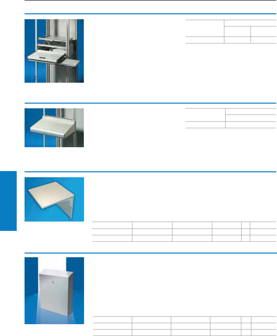
228 Industrial Buyer’s Guide
Accessories Doors/Locks
Drawer
For TS
Height 8" (200 mm).
For mouse and keyboard with a maximum width
of 20/28" (500/700 mm).
A high level of protection is retained, even with
the door open. Standard double-bit lock insert may
be exchanged for 1" (27 mm) lock inserts, version A,
plastic handles, type B and T handles, type B.
Material:
Sheet steel
Conguration:
Door and assembly hardware
Additional parts needed:
Cross member, use 8801.510 for 24" (600 mm)
width, 8801.110 for 32" (800 mm) width.
Accessories:
1" (27 mm) lock inserts, type A, see page 219.
Plastic handles, type B, see page 219.
T handles, type B, see page 219.
Color
Part No.
Width 24"
(600 mm)
Width 32"
(800 mm)
RAL 7035 (light gray) 8801.715 8801.915
Doors/Locks
Drawers/Shelves/Pockets
Fold-down shelf
Collapsible shelf designed to support
programming and monitoring equipment.
Locks in raised position and folds down
when not in use.
Material:
Sheet steel, 14 ga (2.0 mm)
Finish:
Dipcoat-primed, powder coated in textured RAL
7035 (light gray)
Conguration:
Continuous hinge
Mounting hardware included
Height inches (mm) Width inches (mm) Depth inches (mm) Weight lb (kg) PU Part No.
12 (305) 12 (305) 2 (51) 7.5 (16.5) 1 FDS1212C
18 (457) 18 (457) 2 (51) 14 (30.8) 1 FDS1818C
External data pocket
Based on the popular AE wallmount enclosure,
this data pocket is designed to hold system-
related documents.
Material:
Sheet steel, 16 ga (1.5 mm)
Finish:
Pocket and cover: Dipcoat-primed, powder coated
in textured RAL 7035 (light gray)
Conguration:
Slotted head insert
Foamed in place gasket
Mounting hardware included
Protection Rating:
NEMA 4
Height inches (mm) Width inches (mm) Depth inches (mm) Weight lb (kg) PU Part No.
16 (409) 14 (356) 3 (76) 14 (29.7) 1 EDP1614C
14 (356) 19 (487) 3 (76) 15 (33.0) 1 EDP1419C
Desk section
For TS
Height 8" (200 mm).
For installing:
• Keyboard, IP 67 mouse and mousepad
• Display and control elements
With screw-fastened cover plates top and bottom.
Material:
Sheet steel
Conguration:
Assembly hardware
Additional parts needed:
Cross member, use 8801.510 for 24" (600 mm)
width, 8801.110 for 32" (800 mm) width.
Color
Part No.
Width 24" (600 mm)
RAL 7035 (light gray) 8801.705
Inch and pound measurements are rounded to the nearest whole number.
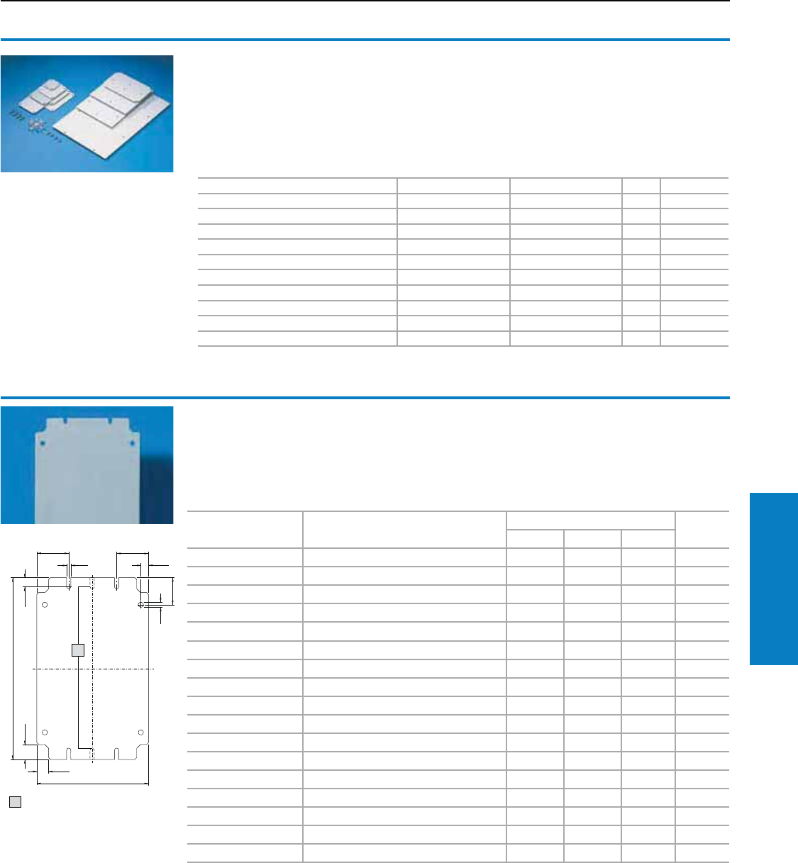
Industrial Buyer’s Guide 229
Accessories Interior Installation
Mounting panels
For KL (or as a replacement panel for EB):
For component installation outside of the
enclosure. Assembly hardware included as
accessories with the enclosure.
For enclosure size
inches (mm) W x H For Part No. Dimensions inches (mm) Part No.
G1 F1 F2
6 x 6 (150 x 150) 1500.510, 1514.510, 1521.010 5 (135) 5 (125) – 1560.700
8 x 6 (200 x 150) 1528.510, 1529.510 7 (185) 5 (125) – 1575.700
8 x 8 (200 x 200) 1502.510, 1516.510, 1523.010 7 (185) 7 (175) 2.0 (50) 1562.700
12 x 6 (300 x 150) 1501.510, 1515.510, 1522.010, 1530.510 11 (285) 5 (125) – 1561.700
12 x 8 (300 x 200) 1503.510, 1517.510, 1524.010, 1531.510 11 (285) 7 (175) 2.0 (50) 1563.700
12 x 12 (300 x 300) 1507.510, 1526.010, 1535.510 11 (285) 11 (275) 2.0 (50) 1567.700
16 x 6 (400 x 150) 1589.510 15 (385) 5 (125) – 1576.700
16 x 8 (400 x 200) 1504.510, 1518.510, 1525.010, 1532.510 15 (385) 7 (175) 2.0 (50) 1564.700
16 x 12 (400 x 300) 1508.510, 1536.510 15 (385) 11 (275) 2.0 (50) 1568.700
16 x 16 (400 x 400) 1511.510, 1539.510 15 (385) 15 (375) 2.5 (62.5) 1571.700
20 x 8 (500 x 200) 1505.510, 1533.510 19.1 (485) 7 (175) 2.0 (50) 1565.700
20 x 12 (500 x 300) 1509.510, 1537.510 19.1 (485) 11 (275) 2.0 (50) 1569.700
24 x 8 (600 x 200) 1506.510, 1519.510, 1534.510 23 (585) 7 (175) 2.0 (50) 1566.700
24 x 12 (600 x 300) 1510.510, 1538.510 23 (585) 11 (275) 2.0 (50) 1570.700
24 x 16 (600 x 400) 1512.510, 1540.510 23 (585) 15 (375) 2.5 (62.5) 1572.700
32 x 8 (800 x 200) 1527.510, 1542.510 31 (785) 7 (175) 2.0 (50) 1574.700
32 x 16 (800 x 400) 1513.510, 1541.510 31 (785) 15 (375) 2.5 (62.5) 1573.700
Material:
Sheet steel, 14 ga (2.0 mm), zinc-plated, passivated
Accessories:
Self-tapping screws 2487.000, see page 240.
As an alternative, can be used:
Support rails
1
F1
1
F
G1
F
1
1
Mounting panel
For PK
For individual configuration of the enclosure interior,
the mounting panel offers a stable, secure and
flexible design option.
Version:
Melamine phenol-coated laminated paper,
12 ga (2.5 mm) thick.
Color:
RAL 7035 (light gray)
Conguration:
Self-tapping assembly screws
To fit Height inches (mm) Width inches (mm) PU Part No.
9502.000/9503.000 2 (45) 3 (74) 12 9541.0001)
9504.000/9505.000 3 (74) 3 (74) 12 9542.0001)
9506.000/9507.000 4 (90) 4 (90) 12 9543.0001)
9508.000/9509.000 3 (74) 4 (110) 12 9544.0001)
9510.000/9511.000 4 (110) 4 (110) 10 9545.000
9512.000/9513.000 3 (74) 6 (160) 10 9546.000
9514.000/9515.000/9516.000 4 (90) 6 (150) 10 9547.000
9517.000/9518.000/9519.000 6 (150) 6 (150) 10 9548.000
9520.000/9521.000/9522.000 6 (150) 9 (220) 8 9549.000
9523.000/9524.000 9 (220) 13 (331) 4 9550.000
1) With spacers
Interior Installation
Mounting Panels
1 Panels 5" (125 mm) wide
are notched only in the center
(represented by the dashed
lines).
Inch and pound measurements are rounded to the nearest whole number.
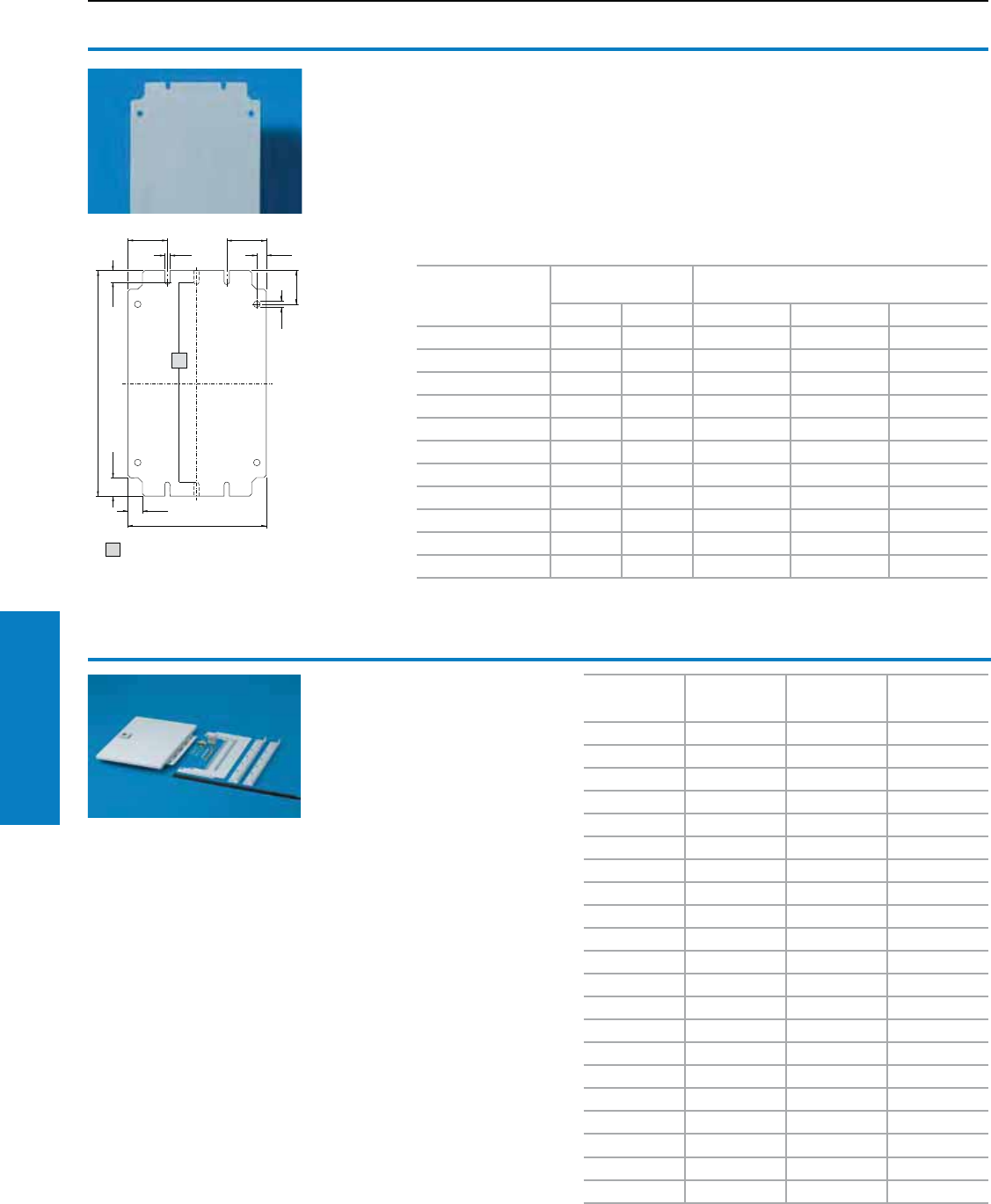
230 Industrial Buyer’s Guide
Accessories Interior Installation
For enclosure size
inches (mm)
H x W
Dimensions
inches (mm) Part No.
G1 F1 Zinc-Plated White Stainless
6 x 4 (150 x 100) 5 (135) 3 (75) JBMP0604 JBMP0604W JBMP0604S6
6 x 6 (150 x 150) 5 (135) 5 (125) JBMP0606 JBMP0606W JBMP0606S6
8 x 6 (200 x 150) 7 (185) 5 (125) JBMP0806 JBMP0806W JBMP0806S6
8 x 8 (200 x 200) 7 (185) 7 (175) JBMP0808 JBMP0808W JBMP0808S6
10 x 8 (250 x 200) 9 (235) 7 (175) JBMP1008 JBMP1008W JBMP1008S6
10 x 10 (250 x 250) 9 (235) 9 (225) JBMP1010 JBMP1010W JBMP1010S6
12 x 6 (300 x 150) 11 (285) 5 (125) JBMP1206 JBMP1206W JBMP1206S6
12 x 10 (300 x 250) 11 (285) 9 (225) JBMP1210 JBMP1210W JBMP1210S6
12 x 12 (300 x 300) 11 (285) 11 (275) JBMP1212 JBMP1212W JBMP1212S6
14 x 12 (350 x 300) 13 (335) 11 (275) JBMP1412 JBMP1412W JBMP1412S6
16 x 14 (400 x 350) 15 (385) 13 (325) JBMP1614 JBMP1614W JBMP1614S6
1
F1
1
F
G1
F
1
1
Interior Installation
Mounting Panels
1 Panels 3" (75 mm) and
5" (125 mm) wide are notched
only in the center (represented
by the dashed lines).
Enclosure
Height
inches (mm)
Enclosure
Width
inches (mm)
Part No.
Carbon Steel
Part No.
Aluminum
12 (305) 12 (305) DFK1212C DFK1212A
16 (406) 12 (305) DFK1612C DFK1612A
16 (406) 16 (406) DFK1616C DFK1616A
16 (406) 20 (508) DFK1620C DFK1620A
20 (508) 16 (406) DFK2016C DFK2016A
20 (508) 20 (508) DFK2020C DFK2020A
20 (508) 24 (610) DFK2024C DFK2024A
24 (610) 16 (406) DFK2416C DFK2416A
24 (610) 20 (508) DFK2420C DFK2420A
24 (610) 24 (610) DFK2424C DFK2424A
24 (610) 30 (762) DFK2430C DFK2430A
30 (762) 20 (508) DFK3020C DFK3020A
30 (762) 24 (610) DFK3024C DFK3024A
30 (762) 30 (762) DFK3030C DFK3030A
36 (914) 24 (610) DFK3624C DFK3624A
36 (914) 30 (762) DFK3630C DFK3630A
36 (914) 36 (914) DFK3636C DFK3636A
42 (1067) 30 (762) DFK4230C DFK4230A
42 (1067) 36 (914) DFK4236C DFK4236A
48 (1219) 36 (914) DFK4836C DFK4836A
60 (1524) 36 (914) DFK6036C DFK6036A
Dead Front Kits
For AE, WM
Provides a UL 1 safety barrier and
mounting surface towards the front
of WM and AE wallmount enclosures.
Easy installation and can be
retrofitted to existing enclosures.
Material:
Carbon Steel, RAL 7035 (light gray);
aluminum
Conguration:
Mounting brackets, panel,
and hardware
Inch and pound measurements are rounded to the nearest whole number.
Finish:
Zinc-plated, passivated
White, painted smooth
Stainless, brushed
Accessories:
Self-tapping screws 2487.000, see page 240.
As an alternative, can be used:
Support rails
Mounting Panels
For JB
For component installation inside of the
enclosure. Assembly hardware included
as accessories with the enclosure.
Material:
Sheet steel or 316L stainless steel
14 ga (2.0 mm)
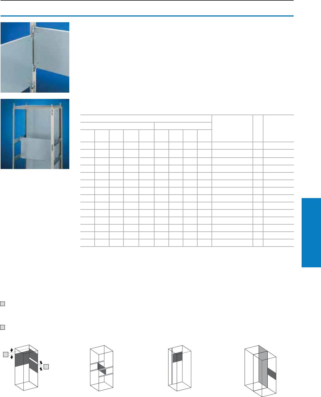
Industrial Buyer’s Guide 231
Accessories Interior Installation
Partial mounting panels
For TS
• Universal interior installation, also in conjunction
with system chassis with mounting flanges and
support bars. Defective assemblies are quickly
and easily replaced
• Additional mounting levels
Partial mounting panels are fastened directly
onto the vertical enclosure sections with the inner
mounting level using the assembly hardware
supplied loose. In this mounting position (in both
the width and the depth) they form one level with
TS system chassis with mounting flanges 0.7 x 2.9"
(17 x 73 mm) and TS support bars for the inner
mounting level.
Material:
Sheet steel, 11 ga (3.0 mm), zinc-plated, passivated
Conguration:
Assembly hardware
Accessories:
TS system chassis with mounting flange
0.7 x 2.9" (17 x 73 mm) for the outer mounting
level, see page 234.
TS support bar, see page 236.
Hinge attachment.
Self-tapping screws, 2487.000, see page 240.
1
2
For installation in enclosures with
Size inches (mm) PU Part No.
Width inches (mm) Depth (side) inches (mm)
16
(400)
24
(600)
32
(800)
39
(1000)
47
(1200)
16
(400)
20
(500)
24
(600)
32
(800)
• • • • 20 x 12 (500 x 300) 1 8614.640
• • • 20 x 16 (500 x 400) 1 8614.650
• • 20 x 20 (500 x 500) 1 8614.660
• • • • 20 x 27 (500 x 700) 1 8614.680
• • 20 x 31 (500 x 775) 1 8614.6751)
• • • • 27 x 12 (700 x 300) 1 8614.840
• • • 27 x 16 (700 x 400) 1 8614.850
• • 27 x 27 (700 x 700) 1 8614.880
• • • 35 x 12 (900 x 300) 1 8614.040
• • 35 x 16 (900 x 400) 1 8614.050
• • • 35 x 20 (900 x 500) 1 8614.060
• • • 43 x 12 (1100 x 300) 1 8614.240
• • 43 x 16 (1100 x 400) 1 8614.250
• • • 43 x 20 (1100 x 500) 1 8614.260
When installing around
corners due to collision
between the assembly
components
1 At least 3" (75 mm)
(adjustable on a 1" [25 mm]
system hole pattern).
Maximum space utilization
2 0.04" (1 mm)
(adjustable on a
1" [25 mm] pattern).
Forward set installation
position
Quickly and easily
achieved with four TS
system chassis with
mounting flanges 0.7 x 2.9"
(17 x 73 mm) for the outer
mounting level,
see page 234.
Partial installation
Partial utilization of the
enclosure depth or width
is also possible.
Continuously ush
In bayed enclosures,
the partial mounting
panel is in the rear most
position flush with the
standard mounting panel.
This facilitates continuous
component mounting.
Interior Installation
Mounting Panels
1) Also suitable for installing in:
• PC enclosures based on TS behind the lower front door
• IW enclosures, height 35 and 39" (900 and 1000 mm)
Inch and pound measurements are rounded to the nearest whole number.
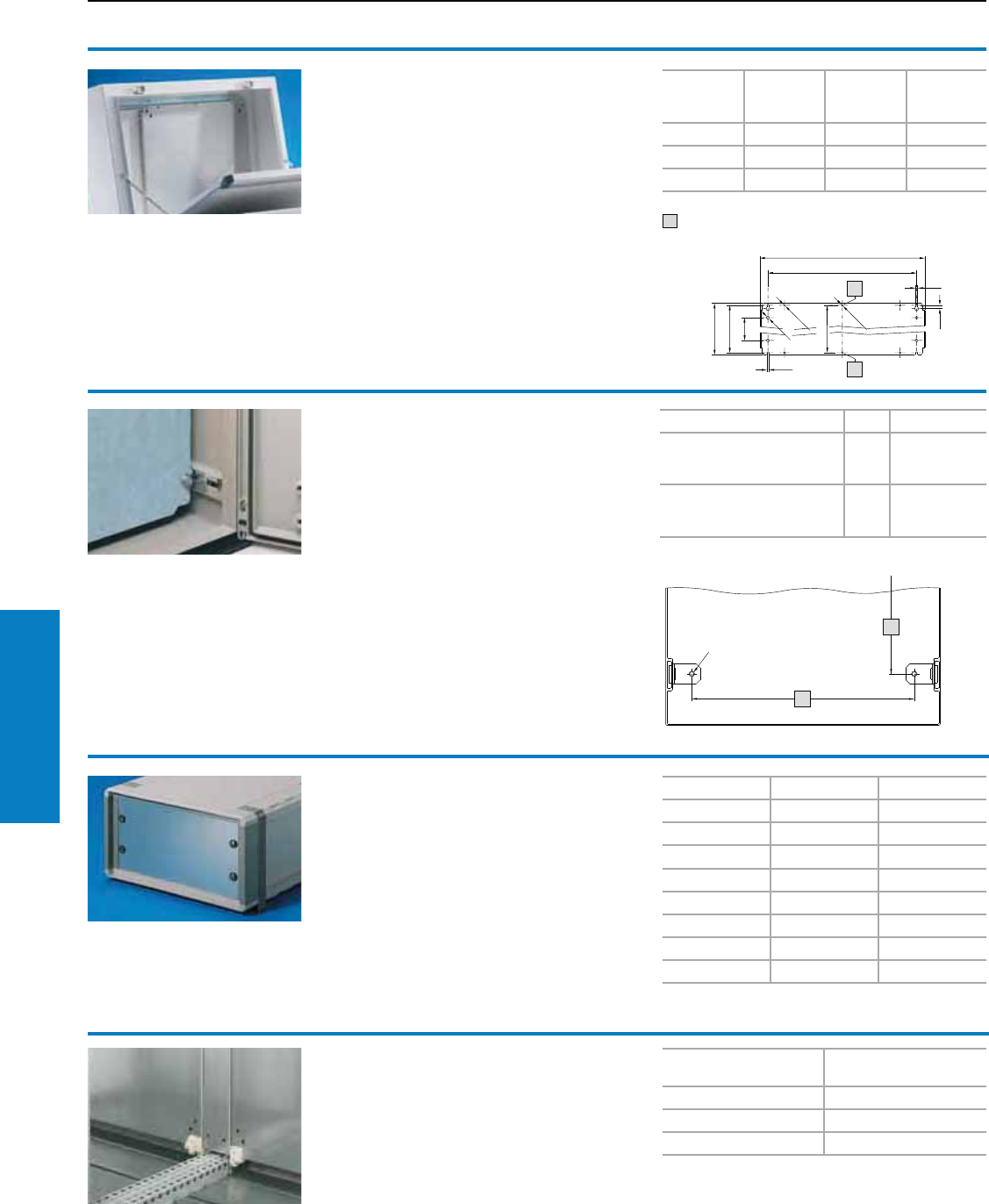
232 Industrial Buyer’s Guide
Accessories Interior Installation
Interior Installation
Mounting/ Blanking Panels
Mounting panel
adjustment bracket
For KS
Infinitely adjustable.
Other equipment can also be installed to the
brackets, instead of the mounting panel.
Material:
Sheet steel, zinc-plated, passivated
Conguration:
Assembly hardware
Enclosure width:
– 3.0" (76 mm) (1481.000)
– 4.1" (104 mm) (1491.000)
Enclosure height:
– 5.9" (150 mm)
For enclosures PU Part No.
1423.600, 1432.600, 1434.600,
1444.600, 1446.600, 1448.600,
1449.600, 1466.600, 1467.600
41481.000
1453.600, 1454.600, 1468.600,
1469.600, 1479.600, 1480.600,
1400.600
41491.000
1
Partial mounting panels
For TP
For installation in:
• Console and desk unit on the interior installation
system rails
• Punched sections with mounting flanges or
support strips fitted to the side of the pedestal
in the depth
• Other enclosures mounted on rails with 25 mm
pitch pattern punchings
For easy mounting on pre-fitted assembly screws.
Can be bayed using the side screws.
Material:
Sheet steel, zinc-plated, passivated
Conguration:
Assembly hardware
1
1
1
1
1
Width
inches
(mm)
Height
inches
(mm)
PU Part No.
8 (200) 17 (437) 1 6730.310
20 (500) 17 (437) 1 6730.330
28 (700) 17 (437) 1 6730.340
1 From width 20" (500 mm)
Blanking panel, 19" (482.6 mm)
For the installation in electronic enclosures or
housings.
Material:
Aluminium, natural-anodized
UPUPart No.
131931.200
231932.200
331933.200
431934.200
631936.200
731935.200
931939.200
12 3 1937.200
Mounting panel inll
For TS
For a continuous mounting surface in bayed suites
where the mounting panel is set forward.
Material:
Sheet steel, zinc-plated, passivated
Conguration:
Assembly hardware
For enclosure height
inches (mm) Part No.
71 (1800) 4590.700
79 (2000) 4591.700
87 (2200) 4592.700
Inch and pound measurements are rounded to the nearest whole number.
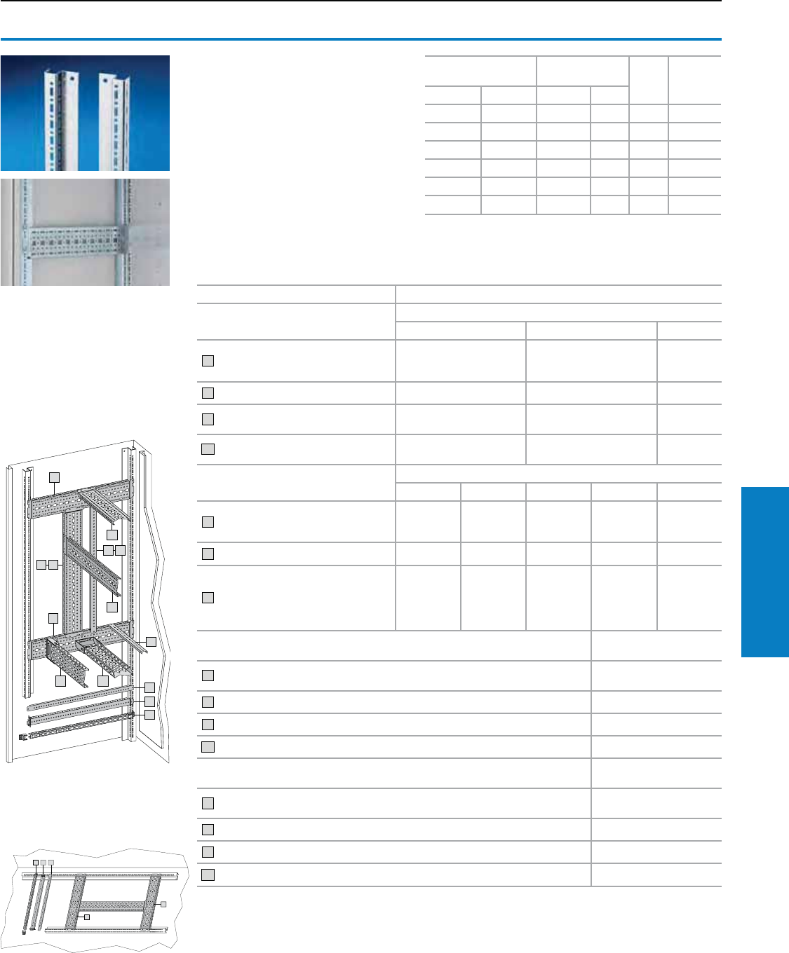
Industrial Buyer’s Guide 233
Accessories Interior Installation
Interior Installation
Rail Systems
1
2
1
1
2
3
2
Rails for interior
installation
For CM, TP
For mounting on the existing threaded
bolts. With TS system punchings on
three sides.
Material:
Sheet steel, zinc-plated, passivated
Conguration:
Assembly parts
Width
inches (mm)
Height
inches (mm) PU Part No.
CM TP1) CM TP2)
24 (600) 24 (600) 24 (600) 675 4 5001.050
32 (800) 32 (800) 32 (800) – 4 5001.051
39 (1000) – 39 (1000) – 4 5001.052
47 (1200) 47 (1200) 47 (1200) – 4 5001.053
– – 55 (1400) – 4 5001.054
– 63 (1600) – – 4 5001.055
1) Only with TP console and desk unit (cover or rear panel/base).
2) Only with TP pedestal.
Installation accessories Part No.
For CM and TP pedestal For depth inches (mm)
12 (300) 16 (400) 20 (500)
1
TS punched section with mounting
flange 0.7 x 2.9" (17 x 73 mm)
for the outer level
8612.130 8612.140 8612.150
2TS support strip for the outer level 8800.125 4694.000 4695.000
3TS punched rail 0.7 x 1.5"
(18 x 38 mm) – 8612.240 8612.250
20 PS punched rail 0.9 x 0.9" (23 x 23
mm) with support bracket 8800.370 – 4169.000 4170.000
For CM and TP pedestal For width inches (mm)
24 (600) 32 (800) 39 (1000) 47 (1200) 63 (1600)
4
TS punched section with mounting
flange 0.7 x 2.9" (17 x 73 mm) for the
inner level
8612.060 8612.080 8612.000 8612.020 –
5TS support strip for the inner level 8800.130 4579.000 – – –
7
PS punched section without mounting
flange 0.9 x 2.9" (23 x 73 mm) with
support bracket TS (alternatively with
one or two punched rails 0.9 x 0.9"
[23 x 23 mm])
4376.000 4377.000 4382.000 4378.000 –
For TP console and desk unit (except cover for height 650 mm) May be installed in
depth or height
1TS punched section with mounting flange 0.7 x 2.9" (17 x 73 mm) for the outer
level 8612.150
2TS support strip for the outer level 4695.000
3TS punched rail 0.7 x 1.5" (18 x 38 mm) 8612.250
20 PS punched rail 0.9 x 0.9" (23 x 23 mm) with support bracket 8800.370 4170.000
For TP console (only cover for height 26" [650 mm]) May be installed in
the height
1TS punched section with mounting flange 0.7 x 2.9" (17 x 73 mm) for the outer
level 8612.140
2TS support strip for the outer level 4694.000
3TS punched rail 0.7 x 1.5" (18 x 38 mm) 8612.240
20 PS punched rail 0.9 x 0.9" (23 x 23 mm) with support bracket 8800.370 4169.000
2
1
1
32
Compact system enclosures
CM/TP pedestal
TP console and desk unit
(cover or rear panel/base)
Inch and pound measurements are rounded to the nearest whole number.
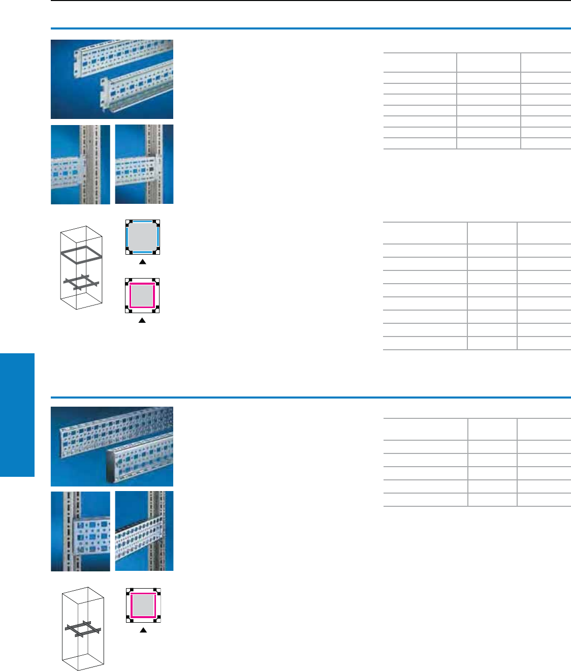
234 Industrial Buyer’s Guide
Accessories Interior Installation
Interior Installation
Rail Systems
TS system chassis with
mounting ange,
0.9 x 2.9" (23 x 73 mm)
The alternative to the TS system chassis with
mounting flange 0.7 x 2.9" (17 x 73 mm), with
system holes for captive nuts/threaded blocks
instead of the slotted holes top and bottom.
Simply mount and secure.
Installation options:
• On the vertical TS enclosure section
Material:
Sheet steel, zinc-plated, passivated
Conguration:
Assembly hardware
Accessories:
Screws, see page 240.
Threaded blocks, captive nuts, see page 246.
TS system chassis with
mounting ange,
0.7 x 2.9" (17 x 73 mm)
Variable, with 5 rows of holes for open assembly
structures or partial assembly. Simply mount into
the TS system holes and secure.
Installation options:
• On the vertical TS enclosure section:
− On the outer mounting level, around the
perimeter, at the same height
− On the inner mounting level, around the
perimeter, height-offset
• In CM, TP via rail for interior installation:
− In the depth, for outer mounting level
− In the width, for inner mounting level
Material:
Sheet steel, zinc-plated, passivated
Conguration:
Assembly hardware
German patent no. 196 47 802
Additional parts needed:
For installation in CM, TP:
Rail for interior installation.
Accessories:
Screws, see page 240.
Cable tie for quick assembly 2597.000.
For the outer mounting level1)
For enclosure width/
depth inches (mm) PU Part No.
12 (300) 4 8612.130
16 (400) 4 8612.140
20 (500) 4 8612.150
24 (600) 4 8612.160
32 (800) 4 8612.180
40 (1000) 4 8612.100
48 (1200) 4 8612.120
1) Note:
In conjunction with plug-in-sidewalls, notched
system chassis are required.
For enclosure width/
depth inches (mm) PU Part No.
20 (500) 4 8612.550
24 (600) 4 8612.560
32 (800) 4 8612.580
40 (1000) 4 8612.500
48 (1200) 4 8612.520
For enclosure width/
depth inches (mm) PU Part No.
12 (300) 4 8612.030
16 (400) 4 8612.040
20 (500) 4 8612.050
24 (600) 4 8612.060
32 (800) 4 8612.080
36 (900) 4 8612.090
40 (1000) 4 8612.000
48 (1200) 4 8612.020
For the inner mounting level
For the inner mounting level
Inch and pound measurements are rounded to the nearest whole number.
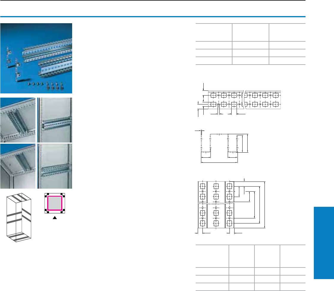
Industrial Buyer’s Guide 235
Accessories Interior Installation
Interior Installation
Rail Systems
TS punched section without
mounting ange 1.8 x 3.5"
(45 x 88 mm)
Heavy top-mounted equipment mounted directly
on the internal surfaces (e. g. roof) is supported.
Mounted on the side or rear, the enclosure can
then be screw-fastened securely to the machine.
The twin profile with 11 rows of holes offers
numerous additional opportunities for interior
installation.
Installation options:
• On the vertical and horizontal TS enclosure
section
Material:
Sheet steel, zinc-plated, passivated
Conguration:
Assembly parts
For enclosure
width/depth
inches (mm)
PU Part No.
20 (500) 2 8612.650
24 (600) 2 8612.660
32 (800) 2 8612.680
11
1
1
11
Side punchings
1
1
11 11
B
11
For
enclosure
width/depth
inches (mm)
ABC
20 (500) 16 (398) 15 (375) 14 (350)
24 (600) 20 (498) 19 (475) 18 (450)
32 (800) 28 (698) 27 (675) 26 (650)
Inch and pound measurements are rounded to the nearest whole number.

236 Industrial Buyer’s Guide
Accessories Interior Installation
Interior Installation
Rail Systems
TS system bars
1.0 x 1.5" (25 x 38 mm)
For heavy installations, with attachment holes.
Installation options:
• On the vertical TS enclosure section
With 0.4" (9 mm) round holes all around on a
1.0" (25 mm) system hole pattern, for the
configuration of:
• Support rails
• System support rails
• C rails 30/15
• Cable clamp rails (right angle section)
• Your own assemblies
Material:
Sheet steel 11 ga (3.0 mm), zinc-plated,
passivated
Conguration:
Assembly hardware
Additional parts needed:
Snap-on nut M8, 8800.808, see pg. 238.
Note:
In conjunction with the snap-on nut, particularly
well-suited for moveable connections.
For enclosure width/
depth inches (mm) PU Part No.
20 (500) 2 8612.750
24 (600) 2 8612.760
32 (800) 2 8612.780
TS support bars
Installation options:
• On the vertical and horizontal TS
enclosure section:
− On the outer mounting level, around the
perimeter, at the same height
− On the inner mounting level, around the
perimeter, height-offset
• On the tubular door frame TS, ES
• On the perforated door strip CM
• On the ES system holes, in the enclosure depth
Material:
Sheet steel, zinc-plated, passivated
Conguration:
Assembly hardware
Accessories:
Screws, see page 240.
Cable tie for quick assembly 2597.000.
For the outer mounting level
For enclosure
width/depth
inches (mm)
Length inches
(mm) PU Part No.
12 (300) 9 (240) 20 8800.125
16 (400) 14 (340) 20 4694.000
20 (500) 17 (440) 20 4695.000
24 (600) 21 (540) 20 4696.000
32 (800) 29 (740) 20 4697.000
For the inner mounting level and for mounting on doors
For enclosure width/
depth inches (mm)
For door width
inches (mm) Length inches (mm) PU Part No.
- 16 (400) 11 (290) 20 4594.000
16 (400) 20 (500) 15 (390) 20 4309.000
20 (500) 24 (600) 19 (490) 20 4596.000
24 (600) - 23 (590) 20 8800.130
- 32 (800) 27 (690) 20 4598.000
32 (800) 35 (900) 31 (790) 20 4579.000
- 39 (1000) 35 (890) 20 4599.000
Inch and pound measurements are rounded to the nearest whole number.
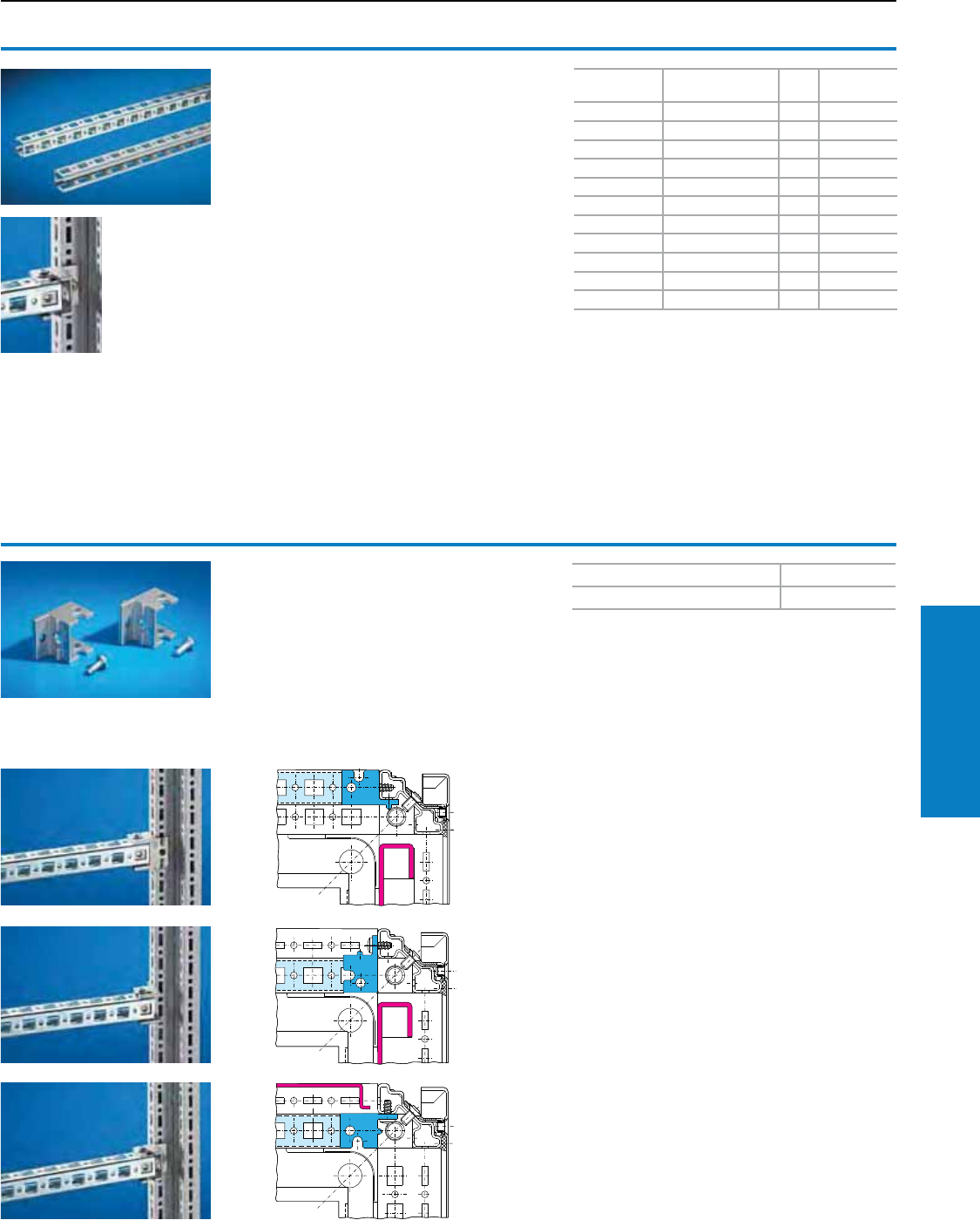
Industrial Buyer’s Guide 237
Accessories Interior Installation
Interior Installation
Rail Systems
TS system bars
0.9 x 0.9" (23 x 23 mm)
Installation options:
• On the vertical enclosure section:
− Directly with support brackets TS
− With adaptor rail for PS compatibility in
conjunction with angle brackets, mounting
brackets or support brackets PS
• On the horizontal enclosure section:
− Directly with angle brackets, mounting
brackets or support brackets PS
Material:
Sheet steel, zinc-plated, passivated
Additional parts needed:
U nuts, see page 239.
Mounting brackets TS/PS, see below. Accessories:
Screws, see page 240.
Cable tie for quick assembly 2597.000.
Length
inches (mm)
For H, W, or D
inches (mm) PU Part No.
12 (295) 16 (400) 12 4169.000
16 (395) 20 (500) 12 4170.000
20 (495) 24 (600) 12 4171.000
28 (695) 32 (800) 12 4172.000
35 (895) 40 (1000) 12 4173.000
43 (1095) 48 (1200) 6 4174.000
51 (1295) 55 (1400) 6 4393.000
59 (1495) 63 (1600) 6 4175.000
67 (1695) 71 (1800) 6 4176.000
75 (1895) 79 (2000) 6 4177.000
83 (2095) 87 (2200) 6 4178.000
Mounting bracket TS
Offers variable mounting opportunities for the
system bar 0.9 x 0.9" (23 x 23 mm).
For example for supporting external surfaces or
creating an additional internal level.
Material:
Die-cast zinc
Conguration:
24 metal screws BZ 5.5 x 0.5" (13 mm)
Accessories:
U nuts for system bars (recommended: M6),
see page 239.
PU Part No.
24 8800.370
Installation options:
• On the vertical TS enclosure section:
- Flush with the outer edge of the enclosure or
- Flush with the enclosure clearance width.
3. With a divider panel installed, with or without
mounting panel in a set forward position.
Two installation options for the inner mounting level:
2. If there is no divider panel installed.
1. Support of the external surfaces with two
mounting options:
• Without mounting panel (photo)
• With mounting panel (drawing)
3.
2.
1.
Inch and pound measurements are rounded to the nearest whole number.
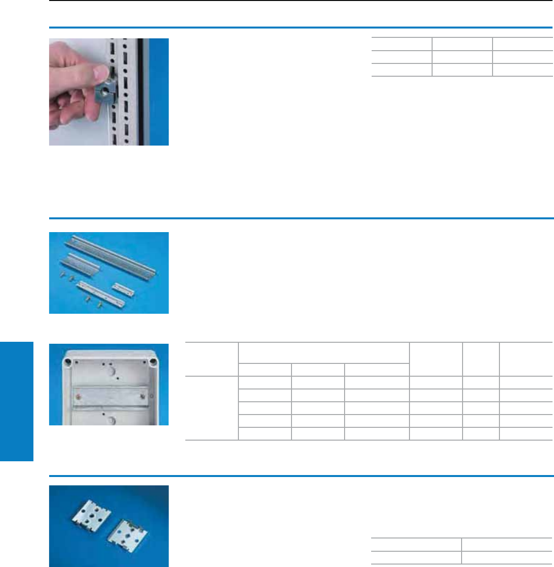
238 Industrial Buyer’s Guide
Accessories Interior Installation
Interior Installation
Rail Systems/Mounting Clips
Support rail
For PK
The two support rail sections provide flexibility
for accommodating terminal blocks and installed
components.
Material:
The support rails are designed in accordance with
EN 50 022 (TS 35/7.5); the Finish is zinc-plated.
Conguration:
Two self-tapping assembly screws
Rail
Maximum number of terminals
with the following terminal sizes Bar length
inches (mm) PU Part No.
2.5 mm24 mm210 mm2
TS 35/7.5
12 9 5 3 (81) 12 9564.000
17 13 8 4 (106) 12 9565.000
24 20 11 6 (144) 12 9566.000
38 32 19 9 (216) 12 9567.000
61 50 30 13 (336) 12 9568.000
Calculation of the maximum number of terminals is based on two end holders and a cover.
Mounting clip
for support rails
For fast, secure attachment of:
• Cable trunking
• Mounting panels
• Mounting angles on support rail TS 35/7.5
and TS 35/15 to EN 50 022.
PU Part No.
30 2309.000
Simply pre-assemble the mounting clip on the
part to be installed, then snap into position on the
support rail.
Inch and pound measurements are rounded to the nearest whole number.
Snap-on nut
For TS
Metric thread for vertical TS enclosure section.
To install, insert into slot and clip into position.
The snap-on nut is then secure. By tightening the
screw, it is securely tightened against the section,
and potential equalization is automatically created.
Installation options:
• On the vertical TS enclosure section
− with metric thread M6 or M8
− the alternative to metal screws
− particularly well-suited for dynamically loaded
connections
Material:
Precision-cast stainless steel
Thread PU Part No.
M6 20 8800.806
M8 20 8800.808
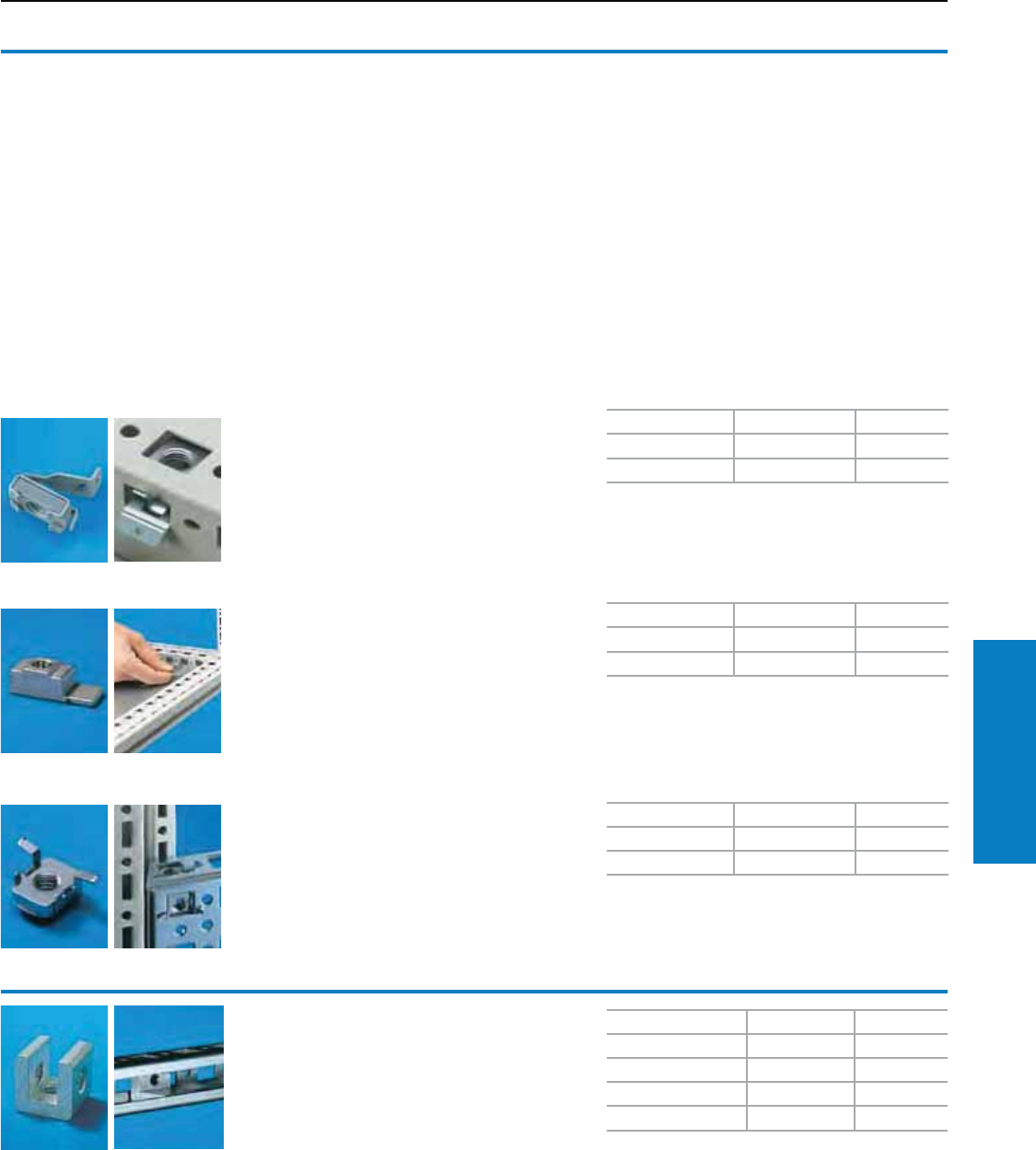
Industrial Buyer’s Guide 239
Accessories Interior Installation
Interior Installation
Assembly Components
Cage nuts/threaded blocks
Installation options:
On enclosures and rails with square system
punches 0.5 x 0.4" (12.5 x 10.5 mm),
for example on:
• TS enclosure section:
− Vertical, with adaptor rail for PS compatibility
− Horizontal, direct
• ES enclosure body, unibody construction
• System bars 0.9 x 0.9" (23 x 23 mm)
• System chassis without mounting flanges,
0.9 x 2.9" (23 x 73 mm)
• System chassis without mounting flanges,
1.8 x 3.5" (45 x 88 mm)
• System chassis with mounting flanges,
0.9 x 2.9" (23 x 73 mm)
Cage nuts
The compression spring designed as an insertion
aid ensures reliable, mechanical and electrical
connection in the system holes.
Threaded blocks
With snap-off insertion aid, die-cast zinc.
Cage nuts
The nuts are inserted from the same side as
screw-fastening takes place. Consequently,
attachment points in the same height or width
may also be used around corners.
The spring cage also ensures electrical
connection in the system holes.
Thread PU Part No.
M6 50 4164.000
M8 50 4165.000
Thread PU Part No.
M6 50 4162.000
M8 50 4163.000
Thread PU Part No.
M6 50 8800.340
M8 50 8800.350
As an alternative, can be used:
On the vertical TS enclosure section TS snap-on
nut, see page 238.
U nuts
Installation options:
• System bar 0.9 x 0.9" (23 x 23 mm)
• System chassis without mounting flange,
0.9 x 3" (23 x 73 mm)
• System chassis without mounting flange,
1.8 x 4" (45 x 88 mm)
• System chassis with mounting flange,
0.9 x 3" (23 x 73 mm)
For mounting system bars and system chassis
without mounting flanges on angle brackets,
mounting brackets and support brackets, we
recommend U nuts with M6 thread (4179.000).
Thread PU Part No.
M4 20 4119.000
M5 20 4157.000
M6 20 4179.000
M8 20 4180.000
Accessories:
Multi-tooth screws M6 x 0.5" (12 mm),
(for 4179.000), see page 240.
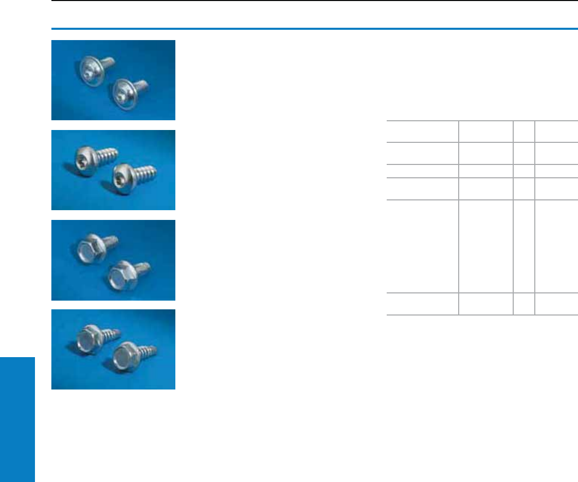
240 Industrial Buyer’s Guide
Accessories Interior Installation
Interior Installation
Assembly Components
Multi-tooth screws
Torx T-25 Head
M6 x 0.5" (12 mm) to fit:
• Snap-on nut (8800.806)
• U nuts for system bars (4179.000)
• Cage nuts (4164.000)
• Threaded blocks (4162.000)
M8 x 0.5" (12 mm) to fit:
• Snap-on nut (8800.808)
Multi-tooth screws
Torx T-25 Head
For the round holes 0.2" (4.5 mm) diameter in the
enclosure section, system bars and system
chassis without mounting flanges.
Self-tapping screws
For the round holes 0.2" (4.5 mm) diameter in the
enclosure section, system bars and system
chassis without mounting flanges.
Self-tapping screws
Mark, drill and tighten in a single operation using
electric or pneumatic tools.
For metal thickness: 22 – 11 ga (0.8 – 3 mm)
Length: 0.6" (16 mm)
Type of screw Dimensions
inches (mm) PU Part No.
Multi-tooth screws M6 x 0.5 (12)
M8 x 0.5 (12)
300
300
2504.500
2504.800
Multi-tooth screws BZ 5.5 x 0.5 (13) 300 2486.500
Multi-tooth screws
for stainless steel BZ 5.5 x 0.5 (13) 300 2486.300
Self-tapping
screws:
• Hex screws
• Posidrive raised
countersunk
screws
• Pan head screws,
posidrive
• Pan-head screws,
multi-tooth
M5 x 0.4 (10)
M5 x 0.5 (12)
M5 x 0.5 (12)
M5 x 0.5 (12)
500
500
500
500
2504.000
2488.000
2489.000
2489.500
Self-tapping
screws
ST 4.8 x 0.6
(16) 300 2487.000
Usable length: 0.4" (9.5 mm)
Width across flats: 0.3" (8 mm)
Multi-tooth drive for optimum transmission of
torque, an extended tool life and increased safety
and reliability when tightening and loosening screw
connections.
Industrial Buyer’s Guide 241
Accessories Interior Installation
Universal light with integrated motion sensor
Cable options UL Length
inches (mm) PU Color Part No.
Power cable for Universal Light 4155.500
(with outlet and strain relief, without plug) Yes 118 (3000) 1 Gray 4315.150
Through-wiring for Universal Light 4155.500
(with outlet and plug) Yes 24 (600) 1 Gray 4315.450
Technical
Specifications Socket H
inches (mm)
W
inches (mm)
D
inches (mm) Part No. Protection
Ratings
26 W. 110-240 V,
50-60 Hz No 4 (95) 14 (345) 2 (55) 4155.500 UL/CE
With compact fluorescent lamp, TC-DEL 26 W, base G24q-3, length 7” (174 mm)
Additional parts needed: connection cable power supply part no. 4315.150 (see below)
Connection cables
The following components can be used for
time-saving and simple installation of the lights:
Enclosure lights
Rittal’s fluorescent enclosure lights are designed
for quick and easy installation. The external
terminal block means no need to disassemble the
light to make electrical connections. Available
in 15 or 18 watt rating, they can be used with or
without the Rittal 4127.000 door switch. Equipped
with interference suppression capacitor or a RFI
filter they also come with or without a lamp shade
or 115 V U.S. style receptacle.
Technical specications:
Rating: 120 V, 60 Hz
Color: RAL 7044 (silky gray)
Light medium: cool white
Includes installation hardware
Connection terminals: L1 N. GND
On/off rocker switch
Part No.
With
interference
suppression
capacitor
and no
receptacle
With RFI
filter, U.S.
receptacle
and lamp
shade
Installation
length A
Technical
data
inches
(mm) 120 V 60 Hz
9968.108 9968.111 18 (467) 15 W
9968.109 9968.112 24 (620) 18W
Interior Installation
Lights
UL recognized for Canadian and U.S.
requirements.
Inch and pound measurements are rounded to the nearest whole number.
Door operated switch
For use with enclosure lights 9968.108/.109/.111/.112
as well as climate control devices such as air
conditioners, heat exchangers, fans and heaters.
PU Part No.
14127.010
242 Industrial Buyer’s Guide
Accessories Interior Installation
Compact light
Narrower – Faster – Brighter
• Narrower: Around 50% less height and depth
and also around 75% less volume than
conventional lights.
• Faster: Universal fast attachment via clips,
screws, or powerful magnets (optional). Simply
slide in at the side or rear, fit the light, and
it’s done!
• Brighter: Up to 75% greater luminous efficiency
from the lamp at the same output helps
to cut electricity costs.
• Door-operated switch can also be connected
via a 2-pole connection.
• Cable routing on the back of the light enables
deflection, e. g., when mounted vertically
in a TS8.
Material:
Body:
PC-ABS (halogen-free)
Light cover:
Polycarbonate (halogen-free)
Color:
Similar to RAL 7035 (light gray)
Protection Ratings:
IP 20
Conguration:
Compact light with clip and screw mounting kits
Accessories:
Mounting kit magnet,
see below.
Door-operated switch with connection cable,
see below.
Part No. 4140.210 4140.220 4140.110 4140.120
Rated voltage 100 – 240 V AC ± 10 % at 50 – 60 Hz 24 V DC ± 10 %
Wattage 8 14 8 14
Protection ratings II (all-insulated)
Width (B1) inches (mm) 18 (455) 28 (705) 18 (455) 28 (705)
Mounting distance (B2)
inches (mm) clip/magnet 16 (400) 26 (650) 16 (400) 26 (650)
Mounting distance (B3)
inches (mm) 19 (475) 29 (725) 19 (475) 29 (725)
Connection cable 3 m (open end)
Cover color Gray Yellow
Rated current (A)
– at 230 V AC
– at 110 V AC
– at 24 V DC
0.045 – 0.088
0.083 – 0.149
–
0.073 – 0.127
0.149 – 0.216
–
–
–
0.35
–
–
0.57
Light Fluorescent lamp T5
Operating unit Wide-range electronic ballast Electronic ballast
Switches Integral, on/off/door-operated switch mode
Light cover Transparent, grooved on the inside
cURus
A Side attachment
B Rear attachment
B1
BB
Clip/magnet
attachment
Screw attachment
Mounting kit magnet
For reliable adhesion on all sheet steel surfaces.
PU Part No.
24140.000
Door operated switch
Color: Gray
Length
inches (mm) PU Part No.
24 (600) 1 4315.720
Interior Installation
Lights
Industrial Buyer’s Guide 243
Accessories Interior Installation
Interior Installation
Grounding
Ground rail, horizontal
Potential equalization rail
Current carrying capacity approximately 200 A.
Conguration:
Ground rail made from E-Cu 57 to DIN 1759,
DIN 40 500, 15 x 0.2" (5 mm),
20 connection points with M5 screws,
2 ground connections 25 mm2,
2 isolators, including assembly hardware.
Length inches (mm) PU Part No.
18 (450) 1 7113.000
For Door/lid Enclosures
KL, EB, JB
AE 1032.XXX,
AE 1035.XXX
M6 M6
AE, TP, WM M6 M6
TS, ES, PC,
AP universal console M8 M8
Connection
Cross
Section
mm²
Length
inches
(mm)
PU Part No.
M8 – M8 4 7 (170) 5 2564.000
M8 – M8 16 7 (170) 5 2565.000
M8 – M8 25 7 (170) 5 2566.000
M6 – M6 10 8 (200) 5 2565.100
M8 – M8 4 12 (300) 5 2567.000
M6 – M8 10 12 (300) 5 2565.110
M8 – M8 10 12 (300) 5 2565.120
M8 – M8 16 12 (300) 5 2568.000
M8 – M8 25 12 (300) 5 2569.000
Ground straps
For configuring a reliable grounding connection
with perfect contact.
• With ring terminals in M6 and M8 to match the
grounding screw
• Length-optimized and ready to install
Connection
Cross
Section
mm²
Length
inches
(mm)
PU Part No.
M6 10 8 (200) 10 2412.210
M8 16 8 (200) 10 2412.216
M8 25 8 (200) 10 2412.225
M6 10 12 (300) 10 2412.310
M8 16 12 (300) 10 2412.316
M8 25 12 (300) 10 2412.325
Ground strap
Tin-plated copper, in various lengths and cross
sections with press-fitted contact rings.
Grounding straps counteract the current
displacement effect at high frequencies,
while at the same time offering highly
flexible connection opportunities.
Assembly hardware
For fastening the ground straps and grounding
braids to:
• Horizontal TS enclosure sections
• ES system punchings
Additional parts needed:
For mounting on the horizontal TS
enclosure section:
Captive nut, see page 246.
Size PU Part No.
M6 10 sets 2570.000
M8 10 sets 2559.000
Inch and pound measurements are rounded to the nearest whole number.
244 Industrial Buyer’s Guide
Accessories Interior Installation
Interior Installation
Grounding
Contact washers
Toothed contact washers facilitate secure ground
conductor connection. As a result, there is no
need to manually strip paint in the connection area.
Central grounding point
For connecting:
• Ground straps
• Grounding braids
to the vertical and horizontal enclosure profile.
The connection bracket is mounted to the
enclosure frame with 2 screws and is
securely contacted. Ground connection is carried
out via the threaded bolt M8 x 0.8" (20 mm).
Material:
Sheet steel, zinc-plated, passivated
Conguration:
1 connection bracket,
2 screws BZ 5.5 x 0.5" (13 mm),
2 serrated washers,
1 nut M8,
1 contact washer M8,
1 washer
Grounding plate
For installation in:
• Command Panel
• VIP 6000
• Optipanel
• TS
One grounding cable can be screw-fastened to
the threaded bolt and can be distributed to up to
8 components via 0.2" (6.3 mm) flat-pin
connectors.
Conguration:
Assembly hardware
Size PU Part No.
M5 100 2343.000
M6 100 2334.000
M6 100 2335.000
PU Part No.
17829.200
PU Part No.
12570.500
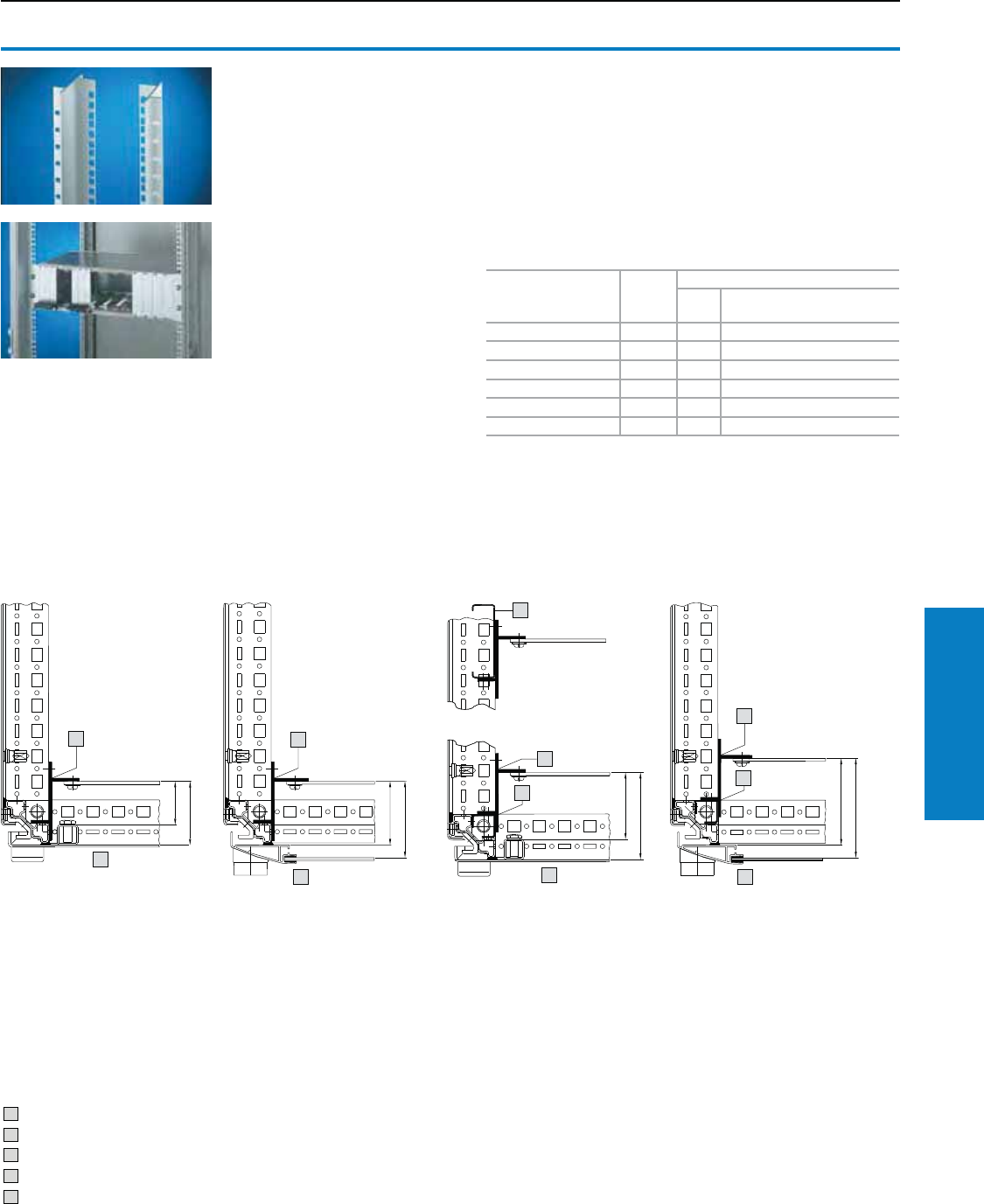
Industrial Buyer’s Guide 245
Accessories Interior Installation
Interior Installation
19" Rail Systems
Mounting rails, 19" (482.6 mm)
For the installation of subracks and
other equipment.
Mounting angles are easily shortened
for partial assemblies.
Finish:
Conductive, corrosion-protected coating.
Conguration:
Assembly parts
For
enclosure height
inches (mm)
PU
For enclosure system TS1)
UAluminum
Extruded section
Part No.
63 (1600) 4 33 8613.060
71 (1800) 4 38 8613.080
79 (2000) 4 42 8613.000
87 (2200) 4 47 8613.020
For PC enclosure2) 417 8613.070
1) For the rear of electronic enclosures, see page 30.
2) Behind bottom door.
1
3
1
3
1
2
1
2
Accessories:
Infill panels.
Captive nuts, see page 246.
Assembly screws, see page 240.
Slide rails with one-sided mounting.
Slide rails with two-sided mounting.
Drawing 1 and 2:
Mounting angle or adaptor piece fitted in
the foremost installation position, directly
on the vertical section. When installing
slide rails with two-sided mounting, the
same mounting angles or adaptor pieces
must also be mounted on the vertical
section at the rear.
Drawing 4 and 5:
Greater distance from the door is
achieved by mounting on adaptor
rails for PS compatibility. In this position,
the slide rails can be fitted with one-
sided mounting.
Drawing 3:
Mounting on two vertically installed PS
punched sections permits fully flexible use
of the enclosure depths.
1 Mounting angles/piece
2 Adaptor rail
3 TS sheet steel door
4 TS glazed door
5 Punched section without mounting flange
Assembly examples of TS:
Drawing 1 Drawing 2 Drawing 3 Drawing 5
Drawing 4
Inch and pound measurements are rounded to the nearest whole number.
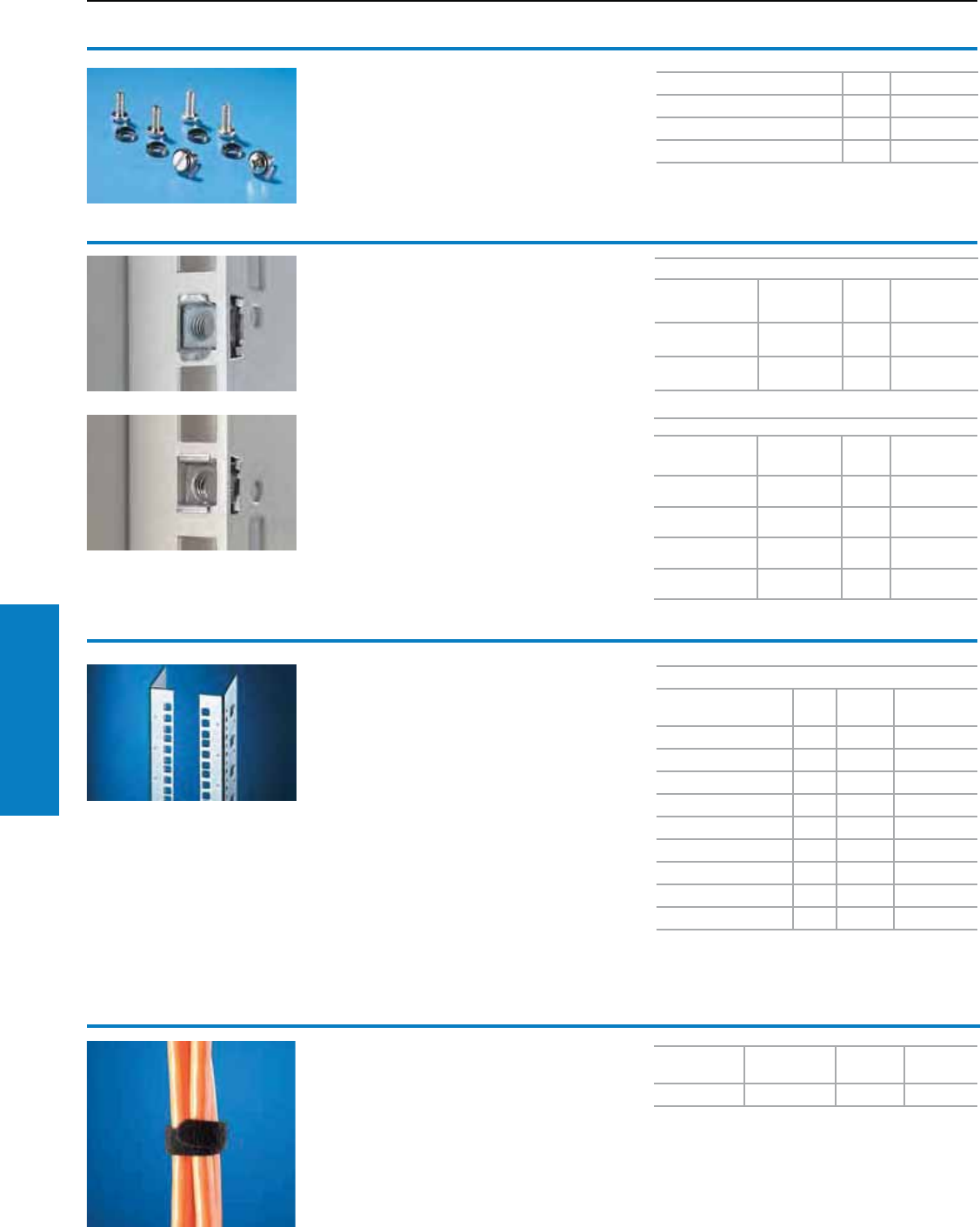
246 Industrial Buyer’s Guide
Accessories Interior Installation
Assembly screws
M5 x 0.6" (16 mm)/M6 x 0.6" (16 mm)
For electronic equipment, 19" (482.6 mm)
installed components and blanking plates.
Conguration:
Plastic washers
Version PU Part No.
Phillips-head screw M5 100 2099.500
Cheese-head screw M6 100 2093.200
Phillips-head screw M6 100 2089.000
Captive nuts M5/M6
For the attachment of rack-mounted electronic
equipment, 19" (482.6 mm) installed equipment
and blanking plates to mounting angles,19"
(482.6 mm).
For use with metal thickness from 22 – 14 ga
(0.8 – 2.0 mm).
In areas of narrow tolerance, captive nuts for
metal thicknesses of 18 – 16 ga (1.2 – 1.5 mm)
should be used. Optionally with or without contact
of the installed equipment to the 19" (482.6 mm)
section/ enclosure.
Captive nut M5
Version
For metal
thicknesses
ga (mm)
PU Part No.
With contact 22 - 14
(0.8 - 2.0) 50 2094.500
Without contact 22 - 14
(0.8 - 2.0) 50 2092.500
Captive nut M6
Design
For metal
thicknesses
ga (mm)
PU Part No.
With contact 22 - 14
(0.8 - 2.0) 50 2094.200
Without contact 22 - 14
(0.8 - 2.0) 50 2092.200
With contact 18 - 16
(1.2 - 1.5) 50 2094.300
Without contact 18 - 16
(1.2 - 1.5) 50 2092.300
Interior Installation
19" Rail Systems
Full installation
Rack height inches
(mm) UPU Part No.
24 (600) 11 2 7827.061
32 (800) 15 2 7827.081
40 (1000) 20 2 7827.101
47 (1200) 24 2 7827.121
55 (1400) 29 2 7827.141
63 (1600) 33 2 7827.161
71 (1800) 38 2 7827.181
79 (2000) 42 2 7827.201
87 (2200) 47 2 7827.221
Mounting angles,
19" (482.6 mm)
The L-shaped mounting angles accommodate
the installation kits of 19" (482.6 mm) systems.
The integral U markings in the front facilitate
systematic assembly within the 19" (482.6 mm)
attachment level.
Technical specications:
2 mm sheet steel, with integral 19" (482.6 mm)
punchings and side round and square holes.
Zinc-plated, passivated for conductive connection
of the 19" (482.6 mm) installed equipment.
Conguration:
Assembly parts
Note:
The mounting angles can also be used to
accommodate 21, 23 and 24" attachment
dimensions.
Nylon loop
Ensures orderly cable routing.
Supplied on a reel for cutting to the
required length.
• Protects the cable sheathing
• Easily reopened
• Reusable
Length
inches (mm)
Width
inches (mm) PU Part No.
197 (5000) 0.6 (16) 1 2203.400
Inch and pound measurements are rounded to the nearest whole number.
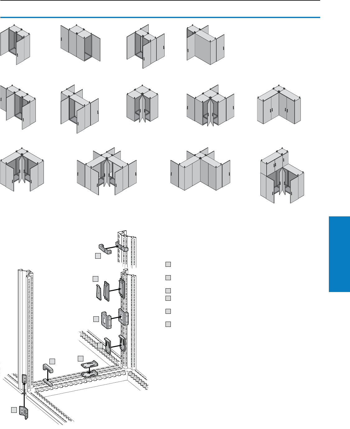
Industrial Buyer’s Guide 247
Accessories Baying Systems
Baying Systems
Baying at Installation Site
Bayable on all sides
Whether around corners,
forwards, backwards, to the
left or right or even upwards if
required, the baying possibilities
are unlimited.
For baying at the installation site
or for provisional siting in the workshop
1 Quick-fit baying clamps,
one-piece
2 Quick-fit baying clamps,
three-piece
3 Baying clamp, horizontal
4 Baying clamp, vertical
for TS/TS
5 Baying clamp, vertical
for TS/PS
6 Baying connector, external
Notes on the transport of bayed enclosures, see page 248.
1
1
3
2
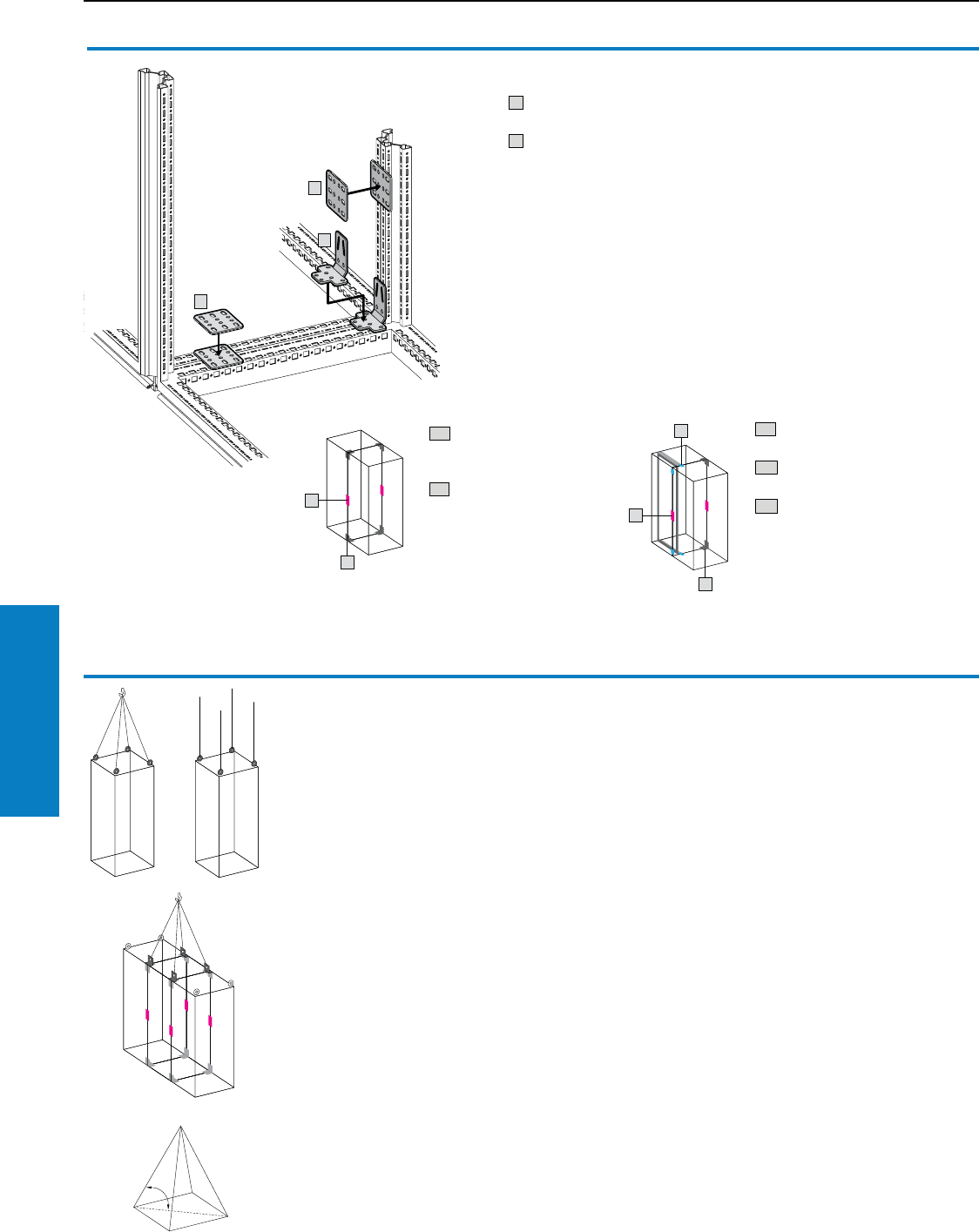
248 Industrial Buyer’s Guide
Accessories Baying Systems
Individual enclosures are securely transported
using the eyebolts included with the supply.
For symmetrical loads, the following maximum
loads apply:
At 45° sling angle 4800 N (1079 lbf),
At 60° sling angle 6400 N (1439 lbf),
At 90° sling angle 13,600 N (3057 lbf).
For the enclosure combination with interconnecting
(angular baying) brackets, quick-connect wedge
and combination angles shown here, the load
capacity with a sling angle of 60° is as follows:
For the left enclosure: 7000 N (1574 lbf),
For middle enclosure: 14,000 N (3147 lbf),
For right enclosure: 7000 N (1579 lbf).
The sling angle between the roof plate and the
sling has a significant influence on the total
permissible load.
The sling angle must not be less than 45°,
but must be less than 60° whenever possible.
Note:
For larger baying combinations,
we recommend the use of a transport base/plinth.
Baying Systems
Baying for Transport
Notes on the transport of bayed enclosures
A 2 quick-connect wedges
8800.500 (see page 249).
B 2 corner baying brackets
8800.430 (see page 250).
C 4 flat baying brackets
4582.500 (see page 250).
If the corner baying brackets
cannot be fitted in the foremost
installation position due to
installed equipment such as
large swing frames.
When transporting bayed enclosures
7 Corner baying bracket
for TS/TS
8 Flat baying bracket for TS/TS
and for TS/PS
Note:
• In addition, the outer baying
connector (see page 250),
can be used
• When transporting large,
heavy enclosure combinations
by crane, we also recommend
the use of combination angles
4540.000.
Additional parts needed:
For protection ratings UL Type 12
(IP 55): One connector/clamp is
required half-way up the enclosure
height, see page 249. Baying
clamp, see pages 249-250.
For additional technical
information, visit
www.rittal-corp.com
A 2 quick-connect wedges
8800.500
(see page 249).
B 4 corner baying brackets
8800.430
(see page 250).
Industrial Buyer’s Guide 249
Accessories Baying Systems
1 Quick-t baying clamps,
one-piece
For TS/TS
Simply attach the screws, insert the quick-fit
baying clamp, tap in with a hammer and lock.
Material:
Sheet steel, zinc-plated, passivated
Conguration:
Assembly hardware
2 Quick-t baying clamps,
three-piece
For TS/TS
Simply locate, connect with the lock plate,
and secure.
Material:
Sheet steel, zinc-plated, passivated
Conguration:
Assembly hardware
3 Baying clamp, horizontal
For TS/TS, TS/PS
For mounting on the horizontal enclosure sections.
Material:
Sheet steel, zinc-plated, passivated
Conguration:
Assembly hardware
German patent no. 197 35 251
French patent no. 98 104 58
Jap. patent no. 2 965 975
4 Baying clamp, vertical
For TS/TS
For mounting on the vertical enclosure sections.
Material:
Sheet steel, zinc-plated, passivated
Conguration:
Assembly hardware
German patent no. 197 35 251
French patent no. 98 104 58
Jap. patent no. 2 965 975
PU Part No.
68800.590
PU Part No.
48800.400
PU Part No.
68800.410
PU Part No.
68800.500
Baying Systems
Clamps
Note:
Should not be used in conjunction with TS divider
panel
250 Industrial Buyer’s Guide
Accessories Baying Systems
7 Corner baying brackets
For TS/TS
The strong connection when transporting
bayed enclosure suites. Screw-fastening may
be optionally:
• Horizontally and vertically with 8 screws
• Horizontally with 2 screws and M8 threaded
blocks, vertically with 4 screws
Material:
Sheet steel, zinc-plated, passivated
Conguration:
Assembly hardware
8 Flat baying brackets
For TS/TS and TS/PS
For additional stabilization, or in cases where:
• Mounting panel brackets
• Swing frames
• Busbar supports
Prevent the installation of angular baying brackets.
Material:
Sheet steel, zinc-plated, passivated
Conguration:
Assembly hardware
PU Part No.
48800.430
PU Part No.
44582.500
Baying Systems
Clamps/Brackets
Accessories:
For mounting on the vertical TS enclosure section:
Snap-on nut M8, 8800.808.
5 Baying clamp, vertical
For TS/PS
For mounting on the vertical enclosure sections.
Material:
Sheet steel, zinc-plated, passivated
Conguration:
Assembly hardware
US patent no. 6,435,759
German patent no. 198 01 185
European patent no. 104 8098
with validity for FR, GB, IT
6 Baying connector, external
For TS/TS
For mounting on the vertical enclosure sections.
Simply position on the outside and screw-fasten
either from the inside or outside.
Material:
Sheet steel, zinc-plated, passivated or Type 304
stainless steel
Conguration:
Assembly hardware
German patent no. 197 37 668
PU Part No.
68800.420
Version PU Part No.
Sheet steel 6 8800.490
Stainless steel 6 8700.000
Industrial Buyer’s Guide 251
Accessories Baying Systems
Interconnecting brackets
The alternative to baying bracket 4582.500 and for
individual interior installations.
Material:
Sheet steel, zinc-plated, passivated
Conguration:
Angular baying bracket, M8 screws and M8
threaded blocks
Additional parts needed:
For mounting on:
Horizontal TS enclosure section
Captive nut/threaded block M8.
Snap-on nut M8, 8800.808.
Eyebolt interconnecting bracket
For optimum distribution of tensile forces during
transportation of bayed enclosures by crane.
Material:
Sheet steel, zinc-plated, passivated
Conguration:
Assembly hardware
Combination bracket, Transport bracket, Crane
Accessories:
Baying cover, see page 252.
Notes on the transport of bayed enclosures,
see page 248.
Baying attachment, vertical
For TS/TS with divider panel
Only suitable for mounting in conjunction with the
angle brackets of the divider panel (included with
the supply).
Material:
Sheet steel, zinc-plated, passivated
Conguration:
Assembly hardware
Note:
May also be used for side or wall attachment/
fastening of enclosures. In such cases, additional
holes must be drilled in the side or rear wall.
Baying clamp, horizontal
For back-to-back mounting
Two-piece, for on-site assembly of
enclosures with mounting panel in the
rear most installation position.
Material:
Sheet steel, zinc-plated, passivated
Conguration:
Assembly hardware
German patent no. 10 157 979
Baying attachment, vertical
For TS/TS
For baying two populated enclosures on the
vertical enclosure section. Simply mount into the
vertical TS system holes, secure and connect both
brackets by using the hex screws (supplied loose).
Using the fastening bolts, the enclosure is pulled
into a defined end position, with a height or side
offset of up to ± 2 mm.
Material:
Sheet steel 11 ga (3 mm), zinc-plated, passivated.
Conguration:
Assembly hardware
PU Part No.
44582.000
PU Part No.
44540.000
PU Part No.
88800.470
PU Part No.
68800.670
PU Part No.
48800.170
Baying Systems
Brackets
252 Industrial Buyer’s Guide
Accessories Baying Systems
Baying cover, top
A cover with two end caps may be clipped over
the gap between the two enclosures in addition to
the sealing gasket. This prevents dirt and liquid
from collecting on the baying seal.
Material:
Cover section: Sheet steel, painted or Type 304
stainless steel
End caps: Plastic
US patent no. 6,312,068
German patent no. 197 37 667
European patent no. 10 12,935
with validity for FR, IT
Note:
May also be fitted in the width with enclosure suites
bayed back-to-back.
For enclosure
depth
inches (mm)
PU
Part No.
RAL 7035
(light gray)
Stainless
steel
16 (400) 1 8800.840 8700.140
20 (500) 1 8800.850 8700.150
24 (600) 1 8800.860 8700.160
32 (800) 1 8800.880 –
40 (1000) 1 8800.892 –
Baying Systems
Baying Cover
Inch and pound measurements are rounded to the nearest whole number.
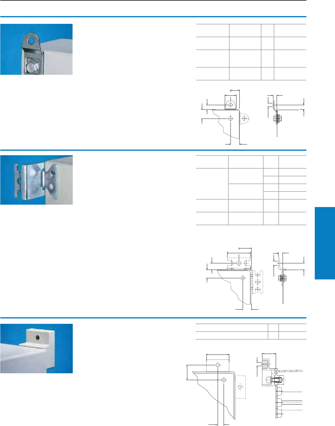
Industrial Buyer’s Guide 253
Accessories Enclosure Mounting Hardware
1
1
1
1
1
11
Enclosure Mounting Hardware
Wallmounting
Wallmounting bracket
For KL, EB, JB, BG and EL
Conguration:
Assembly hardware for mounting on the enclosure
Note:
For hygiene reasons, and to ensure the protection
category, the stainless steel enclosures do not
have any drilled holes for the wallmounting
brackets.
Wallmounting bracket
For KL, EB, JB, BG, AE, WM, CM, TP
Conguration:
Assembly hardware for mounting on the enclosure.
Note:
For hygiene reasons, and to ensure the protection
category, the stainless steel enclosures do not
have any drilled holes for the wallmounting
brackets.
Material Wall distance
inches (mm) PU Part No.
Brass nickel-
plated 0.3 (8) 4 1580.000
Sheet steel
zinc-plated,
passivated
0.3 (8) 4 1590.000
Type 304
stainless steel 0.3 (8) 4 1594.000
Wallmounting bracket
For KS
For attachment to the wall, only possible from
the outside of the enclosure.
Material:
Fiberglass-reinforced polyamide
Conguration:
Assembly hardware for mounting
on the enclosure
Color PU Part No.
Similar to RAL 7035 (light gray) 4 1483.010
Material Wall distance
(A) inches (mm) PU Part No.
Sheet steel
zinc-plated,
passivated
1.6 (40) 12503.0001)
42503.200
0.4 (10) 12508.0001)
42508.200
Type 304
stainless steel 0.4 (10) 4 2433.000
Type 316L
stainless steel 0.4 (10) 4 2433.500
1) Without assembly hardware.
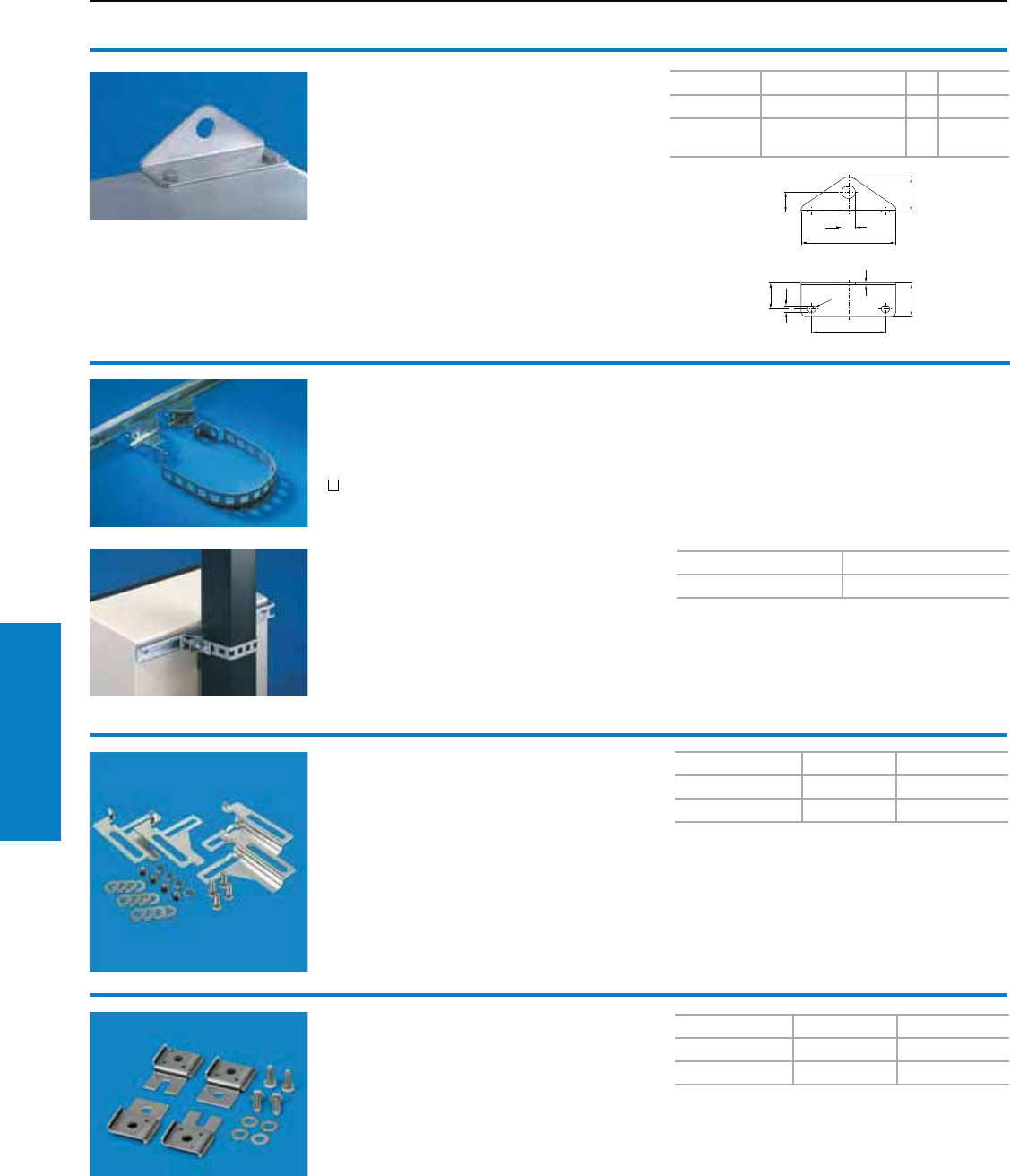
254 Industrial Buyer’s Guide
Accessories EnclosureMounting Hardware
Enclosure Mounting Hardware
Wall/Pole Mounting
Wall xing angle
For compact enclosures (additional holes
required in the enclosure).
Material Color PU Part No.
Sheet steel RAL 7035 (light gray) 1 2505.500
Type 304
stainless steel –12583.000
PU Part No.
1 set 2584.000
For KL, EB, JB, AE, WM, KS
Conguration:
2 mounting rails, 24" (600 mm) long,
4 clamping sections,
2 clamping straps,
4 clamping brackets,
4 screws and nuts M8
for attachment to the enclosure.
Pole clamp
For reliable, convenient fastening to round or
square poles.
For pole diameter/size:
Ø from 1.6 to 7.5" (40 to 190 mm)
from 2.0 to 6" (50 to 150 mm)
Material:
Mounting rails, clamping section:
Sheet steel, zinc-plated, passivated
Clamping strap: Type 304 stainless
1
Universal wallmounting bracket
For AE, WM, EB, JB
Used to install wallmounted enclosures using
traditional NEMA hole patterns.
Material:
Sheet Steel, zinc-plated, passivated
Type 316L stainless steel
Material PU Part No.
Zinc-plated 4 WMUMB
Stainless Steel 4 WMUMB6
Slotted wallmount bracket
For AE, WM
Designed to mimic a standard NEMA style
flange where the slots on the lower brackets
accommodate drop-on and lift-off mounting.
Material:
Sheet Steel, zinc-plated, passivated
Type 316L stainless steel
Material PU Part No.
Zinc-plated 1 set WMSMB
Stainless Steel 1 set WMSMB6
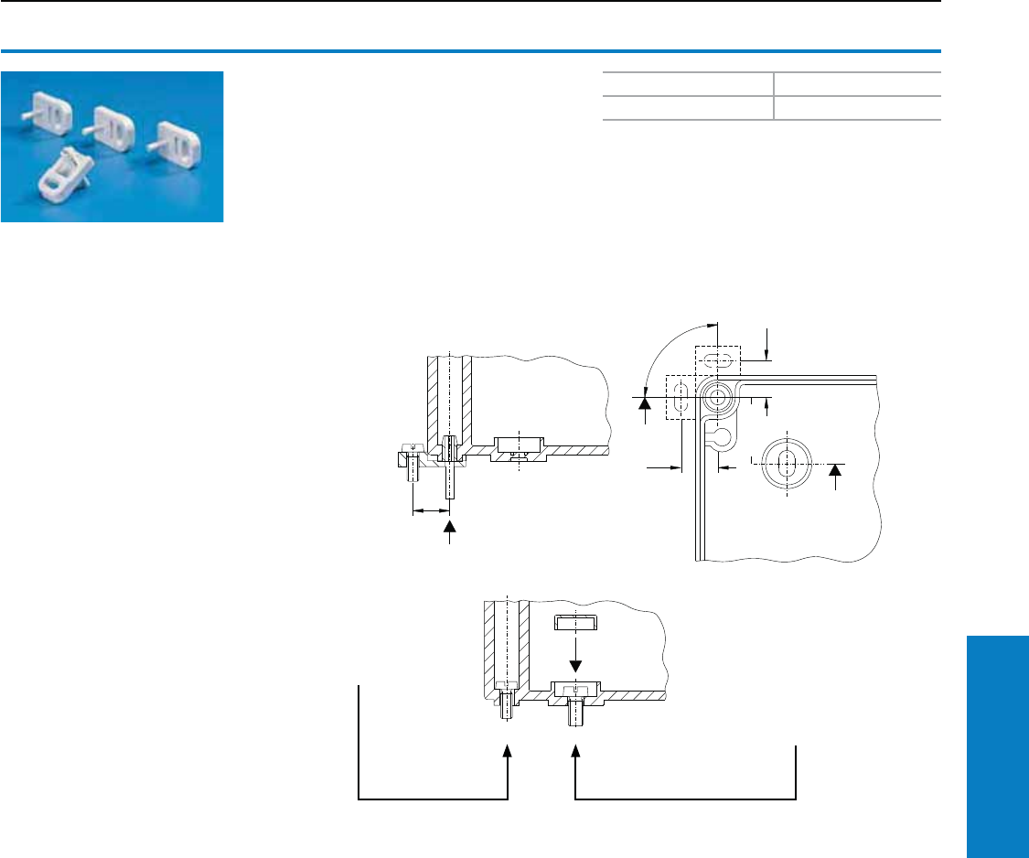
Industrial Buyer’s Guide 255
Accessories Enclosure Mounting Hardware
1
1
1
Enclosure Mounting Hardware
Wallmounting
Wallmounting brackets
For PK
The enclosure can be screwed to the wall using
four wallmounting brackets. Each bracket is
attached to the enclosure by retaining pins.
Material:
Polyamide, gray
Conguration:
1 pack
The assembly screw is located in
the wallmounting bracket, making it
accessible at all times.
The wallmounting bracket may be
fitted to the side or top.
Wall attachment can also be made
without the bracket
Option 1:
Wall attachment in the cover
screw channel is a simple,
secure means of attachment.
Option 2:
By drilling the hole in the rear of the
enclosure, mounting in the enclosure
interior is also possible. The screws
must be concealed using the sealing
plugs supplied with the enclosure.
The spacing between the attachment
holes is marked on the rear wall of the
enclosure.
PU Part No.
40 9583.000
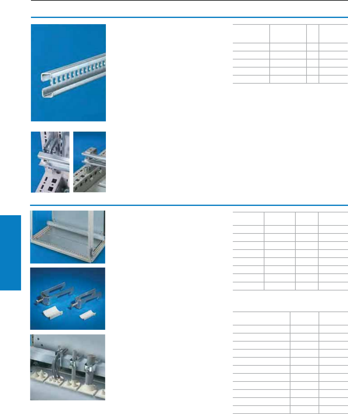
256 Industrial Buyer’s Guide
Accessories Cable Management
C rails 30/15
to EN 60 715
For TS, ES
Installation options:
• On the vertical TS enclosure section
− Via snap-on nut 8800.808 (Fig. left)
− Via adaptor rail for PS compatibility
• On the horizontal TS enclosure section
(Fig. right)
• On the ES system punchings
Material:
Sheet steel, zinc-plated, passivated
For enclosure
width/depth
inches (mm)
Length inches
(mm) PU Part No.
20 (500) 18 (455) 6 4943.000
24 (600) 22 (555) 6 4944.000
32 (800) 30 (755) 6 4945.000
39 (1000) 38 (955) 6 4946.000
47 (1200) 45 (1155) 6 4947.000
Accessories:
Cable clamps,
see below
Support bracket or spacer,
Quick-assembly block, 4133.000,
Snap-on nut M8, 8800.808,
Adaptor rail, 8800.300, 8800.320, 8800.380
see www.rittal-corp.com
Cable clamp rails
Right angle section
For TS, ES, PC, AP universal console,
base/plinths
For strain relief with cable entry. Depth-variable
mounting on a 1.0" (25 mm) pitch pattern on the
horizontal enclosure section or in side base/plinth
trim panels with assembly bolts.
Material:
Sheet steel, zinc-plated, passivated
Conguration:
Assembly parts
Enclosure
width mm Length mm PU Part No.
16 (400) 15 (385) 2 4193.000
24 (600) 23 (585) 2 4191.000
32 (800) 31 (785) 2 4192.000
34 (850) 33 (835) 2 4195.000
39 (1000) 39 (985) 2 4336.000
47 (1200) 47 (1185) 2 4196.000
63 (1600) 62 (1585) 2 4338.000
71 (1800) 70 (1785) 2 4339.000
(may also be used for AP and AE base/plinths)
For cable diameter inches
(mm) PU Part No.
0.2 – 0.5 (6 – 12) 25 2350.000
0.5 – 0.6 (12 – 16) 25 2351.000
0.6 – 0.7 (14 – 18) 25 2352.000
0.7 – 0.9 (18 – 22) 25 2353.000
0.9 – 1.0 (22 – 26) 25 2354.000
1.0 – 1.2 (26 – 30) 25 2355.000
1.2 – 1.3 (30 – 34) 25 2356.000
1.3 – 1.5 (34 – 38) 25 2357.000
1.5 – 1.7 (38 – 42) 25 2358.000
1.7 – 1.8 (42 – 46) 25 2359.000
1.8 – 2.0 (46 – 50) 25 2360.000
Cable Management
Cable Entry
Inch and pound measurements are rounded to the nearest whole number.
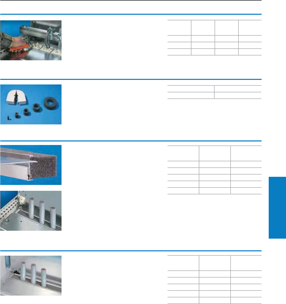
Industrial Buyer’s Guide 257
Accessories Cable Management
Cable Management
Cable Entry
Cable entry grommets
In conjunction with the cable entry plate, simple
and fast sealing of cables inserted in the base
area of enclosures.
Material:
Body: Polypropylene
Cover: Thermoplastic elastomer
Protection ratings:
IP 55 subject to correct mounting
Cables per
grommet
Max. Ø
inches
(mm)
PU Part No.
8 0.5 (13) 25 4316.000
3 0.8 (21) 25 4317.000
1 1.9 (47) 25 4318.000
Connector grommets
Suitable for cable diameters from 8 to 36 mm.
Material:
Outer cover: Polypropylene covered with
thermoplastic elastomer
Seal: Cellular rubber
Protection Ratings:
IP 55 subject to correct mounting
PU Part No.
10 4311.000
Section for cable entry, center
For TS, CM, TP
For top-mounting on gland plates. A superior
alternative to the foam rubber cable clamp strip,
thanks to:
• Easier mounting
• Full-surface support
• High level of sealing of cables inserted
into the enclosure
Material:
Extruded aluminium section, seal PU foam,
cross-section: 1 x 1" (30 x 25 mm)
Protection Ratings:
IP 55 subject to correct mounting
For enclosure
width inches
(mm)
PU Part No.
24 (600) 1 set 8802.060
32 (800) 1 set 8802.080
39 (1000) 2 sets 8802.100
47 (1200) 2 sets 8802.120
63 (1600) 2 sets 8802.160
Section for cable entry, rear
For TS, CM, TP
Unlike the section for cable entry, center, the rear
section is mounted directly onto the base opening.
In this way, when installing the mounting panel
in the rear most position (TS) or with CM, the
cables may be routed directly on a cable clamping
rail with no large radii. In conjunction with the
cable clamp rail, optimum adjustment between
the cable entry and mounting panel can
be achieved.
Material:
Extruded aluminium section, seal PU foam,
cross-section: 1 x 1" (30 x 25 mm)
Protection Ratings:
IP 55 subject to correct mounting
Note:
1 set is sufficient for one base opening up to an
enclosure width of 31" (800 mm).
From an enclosure width of 39" (1000 mm), two
base openings are provided. 2 sets per enclosure
may be fitted.
For enclosure
width inches
(mm)
PU Part No.
24 (600) 1 set 8802.065
32 (800) 1 set 8802.085
39 (1000) 2 sets 8802.105
47 (1200) 2 sets 8802.125
63 (1600) 2 sets 8802.165
Note:
1 set is sufficient for one base opening up to an
enclosure width of 31" (800 mm). From an
enclosure width of 39" (1000 mm), two base
openings are provided. 2 sets per enclosure may
be fitted.
Inch and pound measurements are rounded to the nearest whole number.
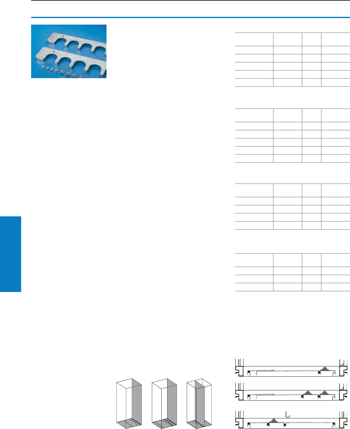
258 Industrial Buyer’s Guide
Accessories Cable Management
Cable Management
Cable Entry
Cable entry plates
For TS, CM, TP, AP
• Cable entry grommets
• Connector grommets
instead of segments of the standard divided
gland plates.
Material:
Sheet steel, zinc-plated, passivated
Type 304 stainless steel, for TS stainless steel
Conguration:
Assembly parts
For installation in TS and PC enclosures based on TS
Enclosure width
inches (mm)
Cut-outs
per plate PU Part No.
24 (600) 5 2 8800.060
32 (800) 8 2 8800.080
33 (850) 9 2 8800.085
39 (1000) 4 4 8800.100
47 (1200) 6 4 8800.120
For installation in CM enclosures and
TP TopConsole system
Enclosure width
inches (mm)
Cut-outs
per plate PU Part No.
24 (600) 5 1 5001.226
32 (800) 8 1 5001.227
39 (1000) 4 1 5001.228
47 (1200) 6 1 5001.229
63 (1600) 6 1 5001.237
For installation in ES, PC enclosures based on ES
and in AP universal consoles
Enclosure width
inches (mm)
Cut-outs
per plate PU1) Part No.
24 (600) 5 2 4320.700
32 (800) 8 2 4321.700
39 (1000) 10 2 4323.700
47 (1200) 6 4 4325.700
1) Including compensating plate
For installation in TS, stainless steel
Enclosure width
inches (mm)
Cut-outs
per plate PU Part No.
24 (600) 5 2 8700.600
32 (800) 8 2 8700.800
47 (1200) 6 4 8700.120
Three examples from a wide range
of possibilities
The diagrams show three TS examples for
the positioning of cable entry plates instead of
segments of the three-piece gland plates supplied
as standard. This facilitates positioning to fit the
mounting panel.
Thanks to the enclosure symmetry, where
dimensions permit, cable entry plates may also
be inserted in the enclosure depth, right and left,
analogous to the gland plates.
Inch and pound measurements are rounded to the nearest whole number.
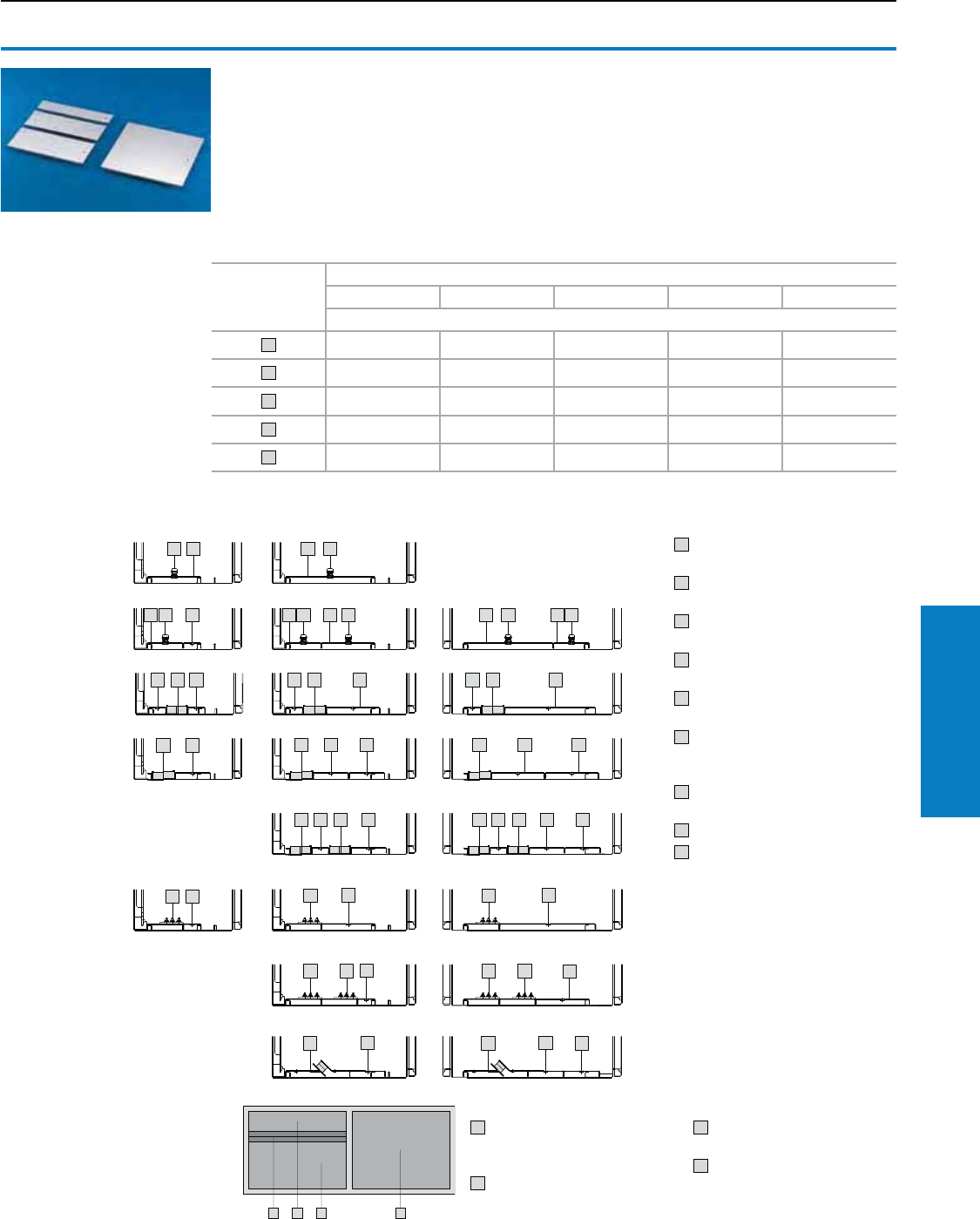
Industrial Buyer’s Guide 259
Accessories Cable Management
Cable Management
Gland Plates
Gland plates
For CM, TP
Select suitable gland plates depending on the
application. The following examples illustrate
how individually cable entry may be structured.
Potential equalization is provided by assembly
components and grounding points.
1 3
Option
For enclosure width inches (mm)
24 (600) 32 (800) 39 (1000) 47 (1200) 63 (1600)
Part No.
15001.210 5001.211 5001.212 5001.213 5001.233
25001.214 5001.215 5001.216 5001.217 5001.234
35001.218 5001.219 5001.220 5001.221 5001.235
45001.222 5001.223 5001.224 5001.225 5001.236
65001.2261) 5001.2271) 5001.2281) 5001.2291) 5001.2371)
1) Cable entry grommets, see page 257.
Inch and pound measurements are rounded to the nearest whole number.
5 2 sections for cable entry,
center, 8802.100, see
page 257 (PU 4)
1 1 gland plate, depth 2"
(50 mm), Part no. 5001.212
3 1 gland plate, depth 6"
(150 mm), Part no. 5001.220
4 1 gland plate, depth 10"
(250 mm), Part no. 5001.224
Material:
Sheet steel, zinc-plated
Conguration:
1 gland plate, including
assembly hardware.
Note:
For greater stability and universal cable entry, the
base opening is divided in the width for 39 and
47" (1000 and 1200 mm) wide enclosures and
can be equipped individually.
Key:
1 Gland plate, depth 2.0"
(50 mm)
2 Gland plate, depth 3.9"
(100 mm)
3 Gland plate, depth 6"
(150 mm)
4 Gland plate, depth 10"
(250 mm)
5 Section for cable entry, center,
see page 257.
6 Cable entry plates, depth
3.9" (100 mm) see above,
grommets, see page 258.
7 EMC gland plate, see
page 257.
8 Cable glands, see page 261.
9 Section for cable entry, rear,
see page 257.
Possible Combinations:
D=300 mm D=400 mm D=500 mm
3
2 1
11
2
1
1
2 3
3
22
1 2
2
3
1
1
1 2 2
2
4
6
66
84 2 8
3
3
3
2
One-piece/
cable gland
Divided/
cable gland
Divided/
cable clamp strip,
center
Divided/
cable clamp strip,
rear
Divided/
cable clamp strip,
center and rear
Divided/
1 x grommets
Divided/
2 x grommets
EMC
Order example:
5120.500 (H x W x D: 47 x 39 x 16"
[1200 x 1000 x 400 mm])
• On the left, divided gland plates
with cable clamp strip
• On the right, one-piece
gland plate
You will need:
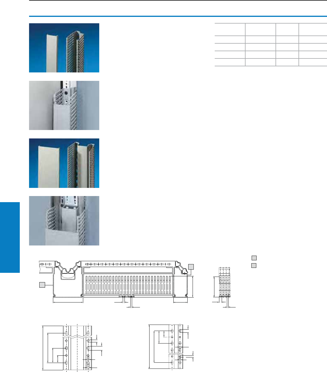
260 Industrial Buyer’s Guide
Accessories Cable Management
Cable Management
Cable Routing
Inch and pound measurements are rounded to the nearest whole number.
Cable duct
for vertical TS section
For direct mounting on the vertical enclosure
section.
Width 2" (50 mm)
For assembly on a vertical enclosure section in
the area of the side panel.
Width 4" (100 mm)
For assembly on two bayed enclosure profiles
in the baying area. Baying brackets and baying
clamps which have already been fitted can be
covered over with the cable duct.
The nominal break points of the members are
also oriented towards combination with the
cable ducts for mounting plates; in addition
a further nominal break at the level of the
mounting plate enables direct insertion into the
cable duct.
The cable duct fastening points are
co-ordinated with the TS system hole pattern;
elaborate drilling, as in the case of DIN ducts,
is dispensed with.
Width
inches (mm)
Height
inches (mm) PU Part No.
2 (50) 63 (1600) 8 sets 8800.570
2 (50) 71 (1800) 8 sets 8800.520
4 (100) 63 (1600) 4 sets 8800.540
4 (100) 71 (1800) 4 sets 8800.510
Technical specications:
Depth: 3" (80 mm)
Length:
• 63" (1600 mm) for enclosure height 71" (1800 mm)
• 71" (1800 mm) for enclosure height 79" (2000 mm)
can be shortened for other enclosure sizes.
Member width: 0.21" (5.5 mm)
Slot width: 0.18" (4.5 mm)
Material:
Hard PVC, flame-resistant, self-extinguishing,
temperature-resistant to 140° F (+60° C)
Color:
Similar to RAL 7030
Supply includes:
1 set = 1 cable duct with cover
1
2
1
1
1
11
11
11
11
1
1
2
8800.570/8800.520
8800.540/8800.510
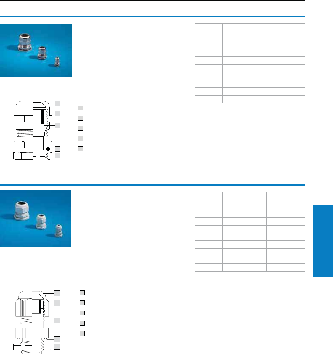
Industrial Buyer’s Guide 261
Accessories Cable Management
Cable gland, brass
Benets:
• Because the gland and lock nut are sold together
in a single pack, this saves additional ordering
and storage space
• Clamping membranes for even tightening and
strain relief which protects the cables
• Insulation because of plastic insert
• Optimum seal on the connection thread,
due to O-ring
• The lock nut cuts automatically into the paint,
thereby creating a conductive connection
Material:
Nickel-plated brass, neoprene seal
Protection Ratings:
IP 68 (5 bar, 30 min.) to EN 60 529/10.91
Approval:
VDE tested to EN 50 262
1 Top-hat nut
2 Neoprene seal
3 Plastic insert
4 O-ring
5 Lock nut
Size
Cable
diameter
inches (mm)
PU Part No.
M12 x 1.5 0.1 – 0.3 (3 – 6.5) 15 2411.800
M16 x 1.5 0.2 – 0.4 (4.5 – 10) 15 2411.810
M20 x 1.5 0.2 – 0.5 (6 – 12) 10 2411.820
M25 x 1.5 0.4 – 0.7 (11 – 17) 10 2411.830
M32 x 1.5 0.6 – 0.8 (15 – 21) 5 2411.840
M40 x 1.5 0.7 – 1.1 (19 – 28) 4 2411.850
M50 x 1.5 1.0 – 1.5 (27 – 38) 2 2411.860
M63 x 1.5 1.3 – 1.7 (34 – 44) 1 2411.870
Cable gland, polyamide
Benets:
• Because the gland and lock nut are sold
together in a single pack, this saves additional
ordering and storage space
• Clamping membranes for even tightening and
strain relief which protects the cables
• Spray-moulded sealing lip ensures an optimum
seal against the enclosure
• Trapezoid thread for secure screw-fastening of
the top-hat nut
Material:
Polyamide 6, neoprene seal
Color:
RAL 7035 (light gray)
Protection Ratings:
IP 68 (5 bar, 30 min.) to EN 60 529/10.91
Approval:
VDE tested to EN 50 262
Size
Cable
diameter
inches (mm)
PU Part No.
M12 x 1.5 0.1 – 0.3 (3 – 6.5) 50 2411.600
M16 x 1.5 0.2 – 0.4 (4.5 – 10) 50 2411.610
M20 x 1.5 0.2 – 0.5 (6 – 12) 50 2411.620
M25 x 1.5 0.4 – 0.7 (11 – 17) 25 2411.630
M32 x 1.5 0.6 – 0.8 (15 – 21) 15 2411.640
M40 x 1.5 0.7 – 1.1 (19 – 28) 5 2411.650
M50 x 1.5 1.0 – 1.5 (27 – 38) 5 2411.660
M63 x 1.5 1.3 – 1.7 (34 – 44) 3 2411.670
3
2
1
3
2
1
1 Top-hat nut
2 Neoprene seal
3 Plastic insert
4 O-ring
5 Lock nut
Cable Management
Cable Glands
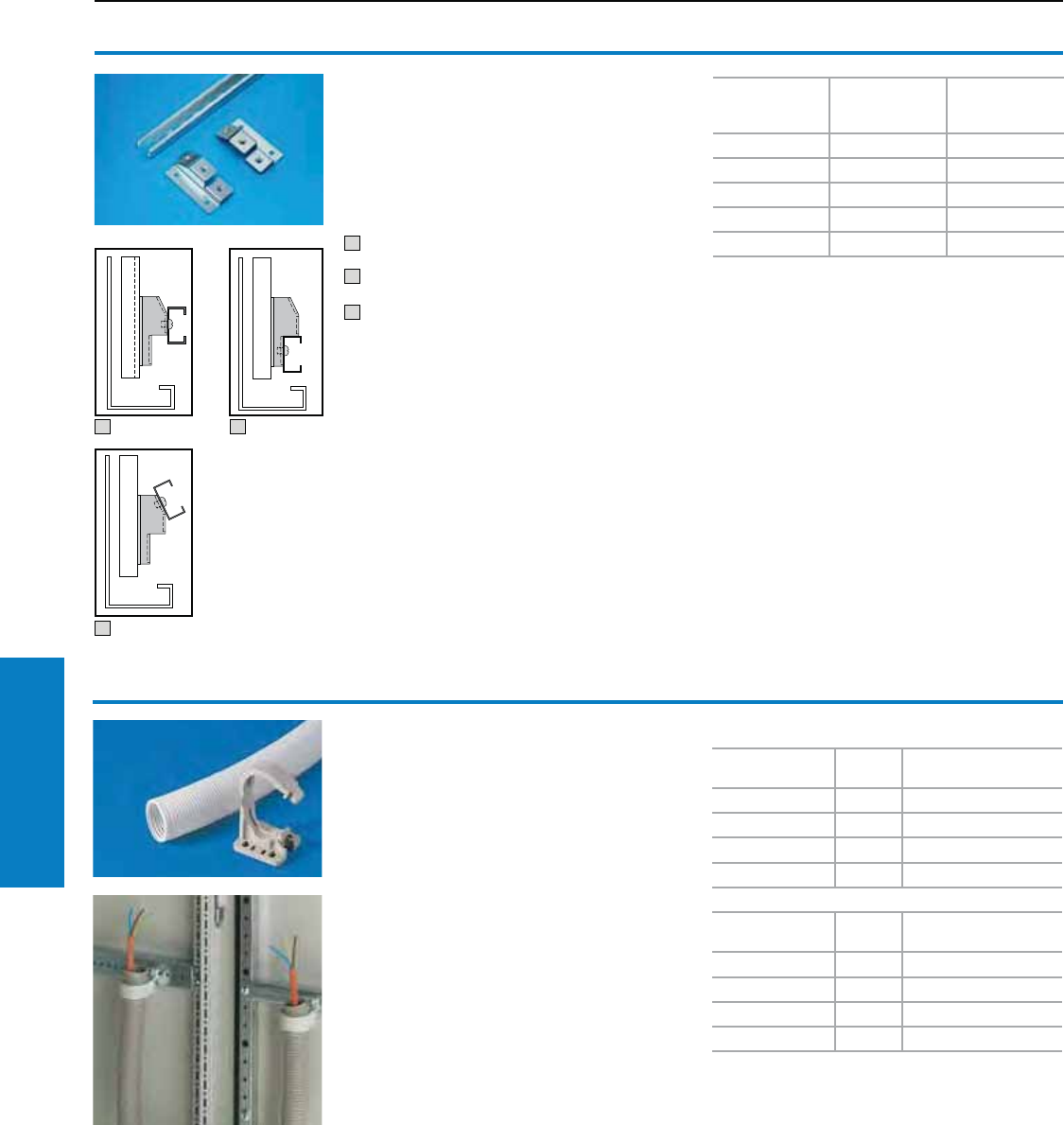
262 Industrial Buyer’s Guide
Accessories Cable Management
Cable clamp rails
C section
For TS, CM, TP
For strain relief with cable entry. The length of the
cable clamp rail is tailored to the width of the
mounting panel. The mounting bracket included
with the supply supports three different installation
situations on the mounting panel:
1 straight, at a distance of 0.9" (23 mm) from the
mounting panel
2 straight, at a distance of 0.4" (10 mm) from the
mounting panel
3 tilted, towards the mounting panel
Material:
Sheet steel
Finish:
Zinc-plated, passivated
Conguration:
Two mounting brackets and assembly screws
Cable Management
Cable Routing
1 2
3
For enclosure
width inches
(mm)
Length inches
(mm ) Part No.
24 (600) 20 (499) 5001.080
32 (800) 28 (699) 5001.081
39 (1000) 35 (899) 5001.082
48 (1200) 43 (1099) 5001.083
63 (1600) 59 (1499) 5001.0841)
1) Including 3 mounting brackets.
Cable conduit and cable
conduit holder
For secure cable routing, e.g., from the enclosure
or mounting panel to the door. Attachment facility
for standard commercially available cable ties
is provided on the cable conduit holder, so that
cables may be attached upon entry to/exit from
the cable conduit.
Material:
Cable conduit: Polyethylene
Cable conduit holder: Polyamide
Cable conduit
Internal Ø inches
(mm) PU Part No.
0.6 (16) 25 m 2595.000
1.1 (29) 25 m 2589.000
1.4 (36) 25 m 2596.000
1.9 (48) 25 m 2590.000
Cable conduit holder
For cable conduit
Ø mm PU Part No.
0.6 (16) 20 2593.0001)
1.1 (29) 20 2591.0001)
1.4 (36) 20 2594.000
1.9 (48) 20 2592.000
1) Installation in compact enclosures AE with universal
bracket 2373.000
Inch and pound measurements are rounded to the nearest whole number.
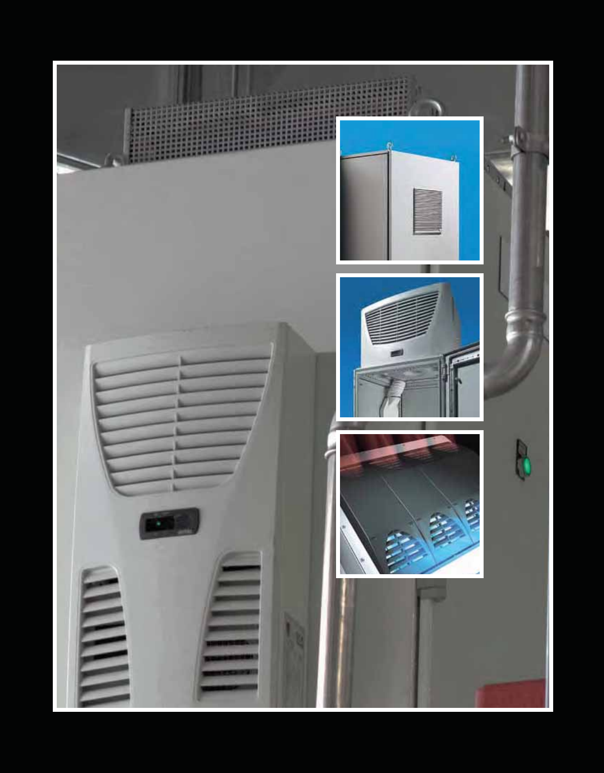
Climate Control
263
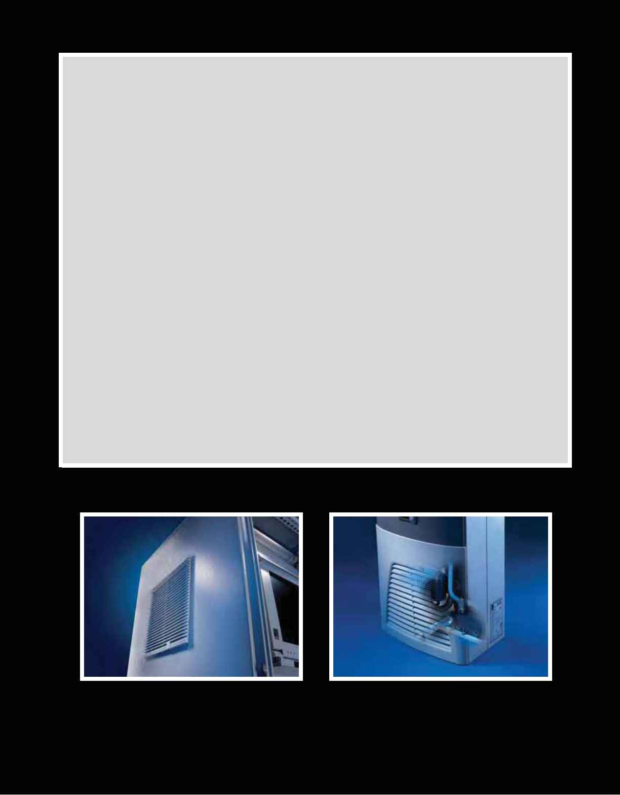
Climate Control
Filter Fans and Roofmount Fans .....................................................From page 266
Air Conditioners ...............................................................................From page 274
Roofmount ................................................................................................................................................277 – 281
Wallmount .................................................................................................................................................282 – 290
Thermoelectric Coolers....................................................................From page 291
Vortex Coolers ..................................................................................From page 293
Heat Exchangers ...............................................................................From page 296
Wallmount – Air/Air Heat Exchangers.......................................................................................................297 – 299
Wallmount – Air/Water Heat Exchangers ..................................................................................................300 – 306
Roofmount – Air/Water Heat Exchangers .................................................................................................307 – 308
Chiller Systems .................................................................................From page 309
Heaters ..............................................................................................From page 317
Accessories ......................................................................................From page 319
264
Industrial Buyer’s Guide 265
Climate Control Software/Service
Software and Service
Features
Rittal Therm
Sizing Software
Let Rittal take the guess work out of selecting the proper climate control for your
application. Rittal Therm software is a complimentary, step by step guide to
choosing the optimal climate control based on your specific environment. This
software can be downloaded at www.rittal-corp.com/software.
Rittal Services — Tailored to Meet Your Business Needs
Installation and Start–Up Services
Rittal offers installation and start–up services for all of our product lines. With our
installation and start up services you are assured that the proper parameters are set and
the equipment operates according to factory specifications.
Repair and Field Services
Our focus is on minimizing equipment downtime and maintaining optimum performance
levels. Rittal field service extends from emergency interventions to customized preventive
maintenance programs designed to meet your specific needs.
• Comprehensive product support • Factory trained • Globally located
technicians staff
• Prompt, efficient service • In-house repair
Spare Parts Services
As the leading manufacturer of Industrial and IT enclosures and climate control products, Rittal is able to support the performance of your
equipment by offering genuine spare parts. The utilization of global warehouses and parts centers provides fast off–the–shelf delivery to any
location, ensuring maximum uptime and reduced customer inventory.
Service and Maintenance Agreements
Rittal offers preventative maintenance programs to maximize your uptime:
Rittal Service Packages
Program Name Basic Comfort Advanced Full
Availability
Hours Of Business
24 / 7 / 365
Response Time
Next Working Day
Next Day
8 Hours
Availability of Spare Parts
Standard
24 Hours
Expedited
Maintenance
1 / Year
2 / Year
Individual
(At Least 2 / Year)
Extended Warranty
No
Yes
Custom agreements tailored to your specific needs are available – please contact the Rittal Service Group at 800-477-4000 (option 3) to
learn more.
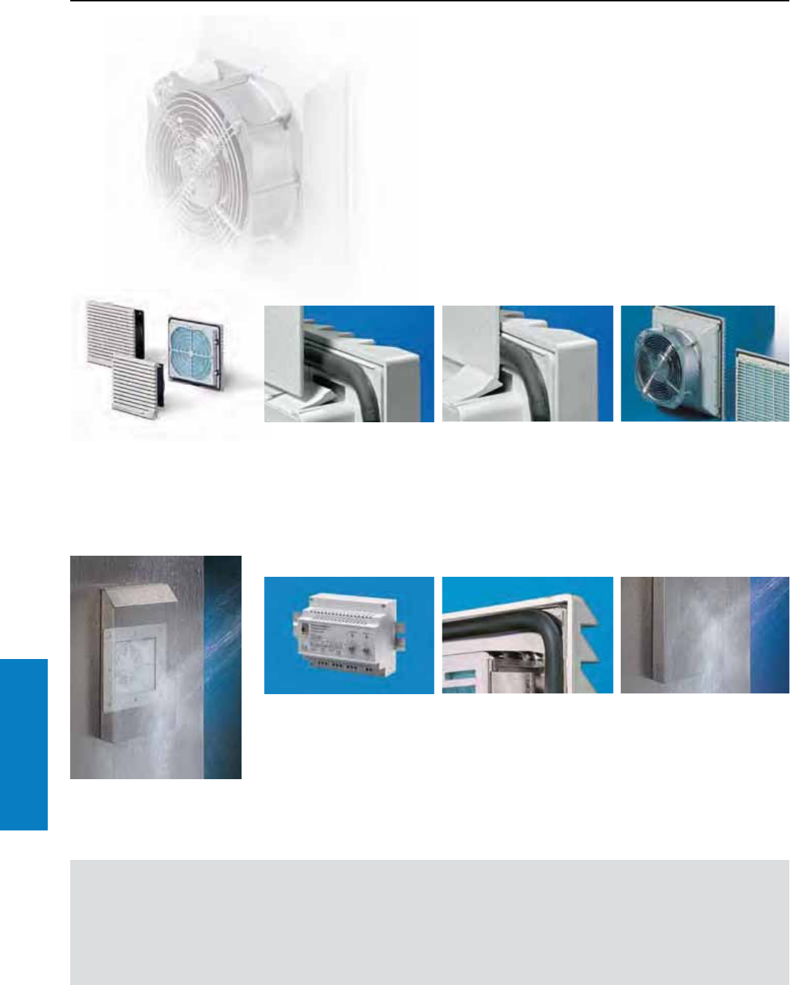
266 Industrial Buyer’s Guide
Climate Control Filter Fans
Filter Fan
Features
Benets:
• Air displacement of 12 to
412 cfm (20 m3/h to 700 m3/h)
• Air flow direction may be
reversed from blowing
(standard setting) to extracting
• Quick assembly
• UL type 12 (IP 54) as standard
• All fans are also available with
EMC shielding
• Made in USA
Important:
• The prescribed heat loss and
the maximum anticipated
ambient temperature define the
required volumetric flow
• Always use the filter fan units
and outlet filters together
For calculations and to
download Therm software,
refer to our website:
www.rittal-corp.com
Filter fan units are ideal for dissipating heat loads cost
effectively. The prerequisite is that the ambient air must
be relatively clean with a temperature below the desired
enclosure internal temperature. The entire range of filter fan
units is now available with EMC shielding and all required
rated voltages.
Fast assembly
Quick clip-on mounting
This guarantees quick,
completely secure attachment
of the filter fan unit. The
prerequisites for ratings UL 12
(IP 54) are met as standard.
Changing the filter mat is quick
and easy. The louvered grille
is attached without screws
providing quick access to the
filter mat.
Inlet or outlet
The air direction may be quickly
reversed from blowing (standard
setting) to extracting. Simply
rotate the fan by 180°.
Application diversity and functions
Not always full power
Air displacement may be reduced
at lower ambient temperatures.
Noise generation is reduced
by adapting the filter fan speed
to match the temperature using
a controller.
Also available with EMC shielding
All filter fan units and outlet filters
are available with EMC shielding.
The required conductive
connection is achieved by a
metallic coating on the filter fan
unit housing and a special
sealing frame.
Hosed water protection
Particularly for applications in
the food industry, the hose-proof
hood prevents the ingress of
moisture. The ratings of UL 3R
(IP 56) is achieved in conjunction
with the filter mats.
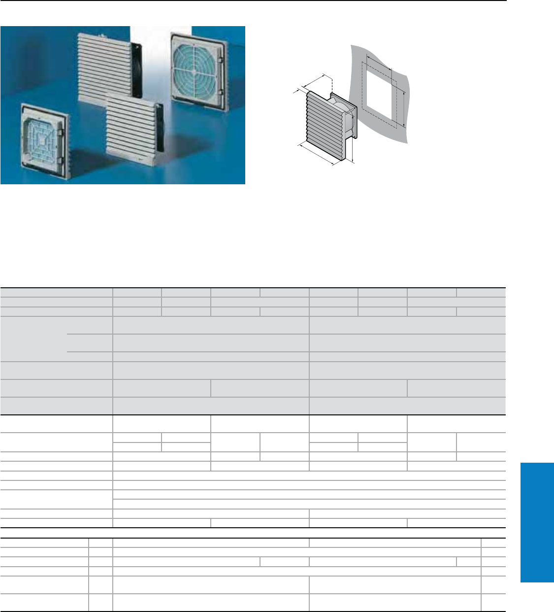
Industrial Buyer’s Guide 267
Climate Control Filter Fans
Filter Fan
Air Displacement: 12 - 39 cfm
Protection Ratings:
UL, cUL recognized, CE, CSA
UL file: E76083
Conguration:
Filter fan unit ready for installation,
including filter mats.
Property Rights:
German Registered Design
No. M 93 04 846
For additional technical
information, please visit
www.rittal-corp.com
H
B
T
B1
T
1
H1
Part No. RAL 7035 3321.107 3321.117 3321.027 3321.047 3322.107 3322.117 3322.027 3322.047
Part No. RAL 90051) 9963.647 9963.648 – 9963.649 9963.650 –
Voltage V, Hz 230, 50/60 115, 50/60 24 (DC) 48 (DC) 230, 50/60 115, 50/60 24 (DC) 48 (DC)
Dimensions inches
(mm)
Height (H1)/
Width (B1) 5 (116) 6 (148)
Height (H2)/
Width (B2) 4 + 0.03 (92 + 0.8)1) 5 (124)1)
Depth (T1) 0.4 (10) 0.4 (10)
Max. installation
depth inches (mm) Depth (T2) 2 (42) 2 (57)
Air displacement,
unimpeded air flow 12/15 cfm (20/25 m3/h) 12 cfm (20 m3/h) 32/39 cfm (55/66 m3/h) 32 cfm (55 m3/h)
Air displacement with outlet filter
including standard filter mat 1 x 3321.207: 9/11 cfm (15/18 m3/h) 1 x 3322.207: 25/29 cfm (43/50 m3/h)
Axial fan Self-starting shaded pole
motor DC motor Self-starting shaded pole
motor DC motor
Rated current maximum 69 mA 138 mA 125 mA 90 mA 0.12 A 0.24 A 0.35 A 90 mA
58 mA 115 mA 0.11 A 0.23 A
Power 12.5/10.3 W 3.0 W 4.1 W 19.0/18.0 W 7.7 W 4.4 W
Noise level 41/46 dB (A) 41 dB (A) 46/49 dB (A) 46 dB (A)
Temperature range 13 to 131° F (–10 to +55° C)
Color RAL 7035 (light gray)/ RAL 9005 (black)
Environmental ratings UL Type 12 (IP 54) standard
UL Type 3R (IP 56) when using a hose-proof hood
Part No. outlet filter RAL 7035 3321.207 3322.207
Part No. outlet filter RAL 9005 9963.661 – 9963.662 –
Accessories PU Page
Spare filter mats 5 3321.700 3322.700 326
Thermostat 1 3110.000 322
Temperature indicator 1 3114.200 – 3114.200 – 321
Speed control 1 3120.200 322
Stainless steel hose-proof
hood 1 3321.800 3322.800 328
RAL 7035 hose-proof
hood 1 3321.835 3322.835 328
1) For metal thickness > 13 ga (2.5 mm), the cut-out H2/B2 (W) must be 0.04" (1 mm) larger.
Special voltages available by request. We reserve the right to make technical modifications.
B = Width
T = Depth
Inch and pound measurements are rounded to the nearest whole number.
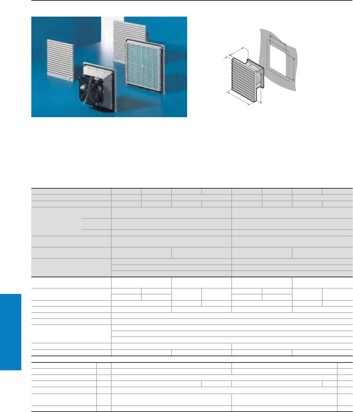
268 Industrial Buyer’s Guide
Climate Control Filter Fans
Filter Fan
Air Displacement: 62 - 106 cfm
Protection Ratings:
UL, cUL recognized, CE, CSA
UL file: E76083
Conguration:
Filter fan unit ready for installation,
including filter mats.
Property Rights:
German Registered Design
No. M 93 04 846
For additional technical
information, please visit
www.rittal-corp.com
Part No. RAL 7035 3323.107 3323.117 3323.027 3323.047 3324.107 3324.117 3324.027 3324.047
Part No. RAL 9005 9963.651 9963.652 – 9963.653 9963.654 –
Voltage V, Hz 230, 50/60 115, 50/60 24 (DC) 48 (DC) 230, 50/60 115, 50/60 24 (DC) 48 (DC)
Dimensions inches
(mm)
Height (H1)/
Width (B1) 8 (204) 10 (255)
Height (H2)/
Width (B2) 7 (177)1) 9 (224)1)
Depth (T1) 1 (12) 1 (12)
Max. installation depth
inches (mm) Depth (T2) 3 (82) 4 (105)
Air displacement,
unimpeded air flow 62/71 cfm (105/120 m3/h) 62 cfm (105 m3/h) 106/94 cfm (180/160 m3/h)2) 106 cfm (180 m3/h)
Air displacement with outlet filter
including standard filter mat
1 x 3323.207: 42/48 cfm (71/82 m3/h) 1 x 3325.207: 68/56 cfm (115/95 m3/h)
2 x 3323.207: 50/58 cfm (85/98 m3/h) 2 x 3325.207: 97/82 cfm (165/140 m3/h)
1 x 3325.207: 46/53 cfm (78/90 m3/h) 1 x 3326.207: 91/78 cfm (155/130 m3/h)
Axial fan Self-starting shaded pole
motor DC motor Self-starting shaded pole
motor DC motor
Rated current maximum 0.12 A 0.24 A 0.35 A 90 mA 0.19 A 0.38 A 0.3 A 0.34 A
0.11 A 0.23 A 0.20 A 0.40 A
Power 19.0 W/18.0 W 8.0 W 4.3 W 30.0 W/35.0 W 7.2 W 14.0 W
Noise level 46/49 dB (A) 46 dB (A) 52/48 dB (A) 52 dB (A)
Temperature range 13 to 131° F (–10 to +55° C)
Color RAL 7035 (light gray)/ RAL 9005 (black)
Environmental ratings
UL Type 12 (IP 54) standard
IP 55 when using an additional fine filter mat
UL Type 3R (IP 56) when using a hose-proof hood
Part No. outlet filter RAL 7035 3323.207 3325.207
Part No. outlet filter RAL 9005 9963.663 – 9963.664 –
Accessories PU Page
Spare filter mats 5 3171.100 3172.100 326
Fine filter mats 5 3181.100 3182.100 326
Thermostat 1 3110.000 322
Temperature indicator 1 3114.200 – 3114.200 – 321
Speed control 1 3120.200 322
Stainless steel hose-proof
hood 1 3323.800 3324.800 328
RAL 7035 hose-proof hood 1 3323.835 3324.835 328
1) For metal thickness > 13 ga (2.5 mm), the cut-out H2/B2 (W) must be 0.04" (1 mm) larger.
2) In order to reduce the noise level of the fan, the shaded pole motor was modified so that the electrical and torque characteristics at 60 Hz
would be decreased (as compared to 50 Hz).
Special voltages available by request. We reserve the right to make technical modifications.
Inch and pound measurements are rounded to the nearest whole number.
H
B
T
B1
T1
H1
B = Width
T = Depth
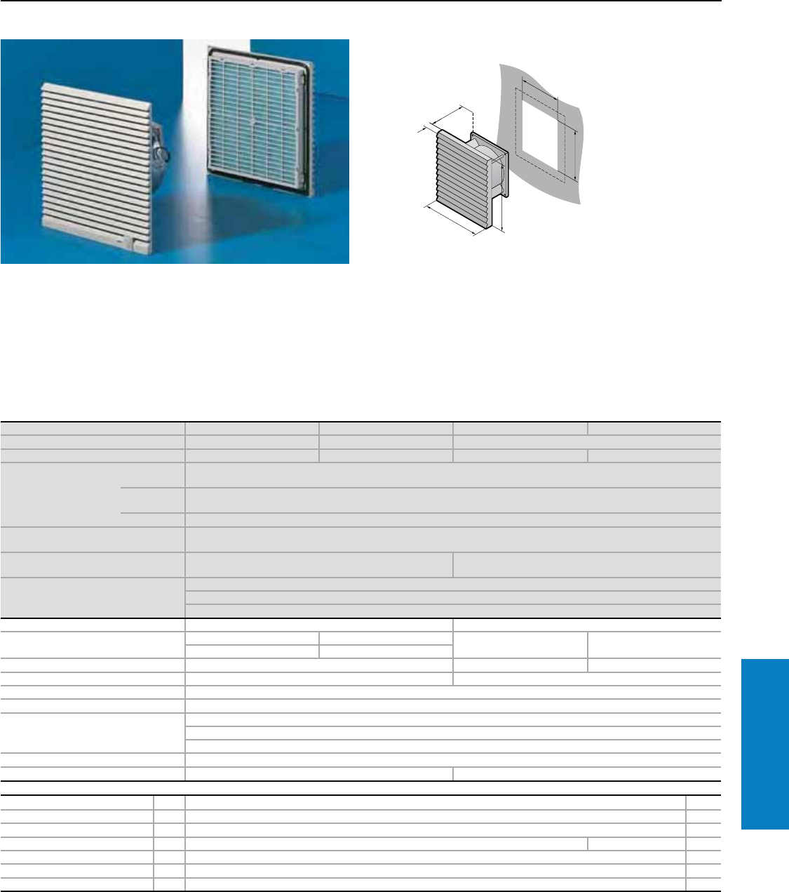
Industrial Buyer’s Guide 269
Climate Control Filter Fans
Filter Fan
Air Displacement: 135 - 156 cfm
Protection Ratings:
UL, cUL recognized, CE, CSA
UL file: E76083
Conguration:
Filter fan unit ready for installation,
including filter mats.
Property Rights:
German Registered Design
No. M 93 04 846
For additional technical
information, please visit
www.rittal-corp.com
Part No. RAL 7035 3325.107 3325.117 3325.027 3325.047
Part No. RAL 9005 9963.655 9963.656 –
Voltage V, Hz 230, 50/60 115, 50/60 24 (DC) 48 (DC)
Dimensions inches (mm)
Height (H1)/
Width (B1) 10 (255)
Height (H2)/
Width (B2) 9 (224)1)
Depth (T1) 1 (12)
Max. installation depth
inches (mm) Depth (T2) 4 (105)
Air displacement, unimpeded
air flow 135/156 cfm (230/265 m3/h) 135 cfm (230 m3/h)
Air displacement with outlet filter
including standard filter mat
1 x 3325.207: 100/121 cfm (170/205 m3/h)
2 x 3325.207: 118/135 cfm (200/230 m3/h)
1 x 3326.207: 112/127 cfm (190/215 m3/h)
Axial fan Self-starting shaded pole motor DC motor
Rated current maximum 0.28 A 0.53 A 0.59 A 0.31 A
0.24 A 0.49 A
Power 41.0/38.0 W 14.0 W 15.0 W
Noise level 54/56 dB (A) 54 dB (A)
Temperature range 13 to 131° F (–10 to +55° C)
Color RAL 7035 (light gray)/ RAL 9005 (black)
Environmental ratings
UL Type 12 (IP 54) standard
IP 55 when using an additional fine filter mat
UL Type 3R (IP 56) when using a hose-proof hood
Part No. outlet filter RAL 7035 3325.207
Part No. outlet filter RAL 9005 9963.664 –
Accessories PU Page
Spare filter mats 5 3172.100 326
Fine filter mats 5 3182.100 326
Thermostat 1 3110.000 322
Temperature indicator 1 3114.200 – 321
Speed control 1 3120.200 322
Stainless steel hose-proof hood 1 3324.800 328
RAL 7035 hose-proof hood 1 3324.835 328
1) For metal thickness > 13 ga (2.5 mm), the cut-out H2/B2 (W) must be 0.04" (1 mm) larger.
Special voltages available by request. We reserve the right to make technical modifications.
Inch and pound measurements are rounded to the nearest whole number.
H
B
T
B1
T
1
H1
B = Width
T = Depth
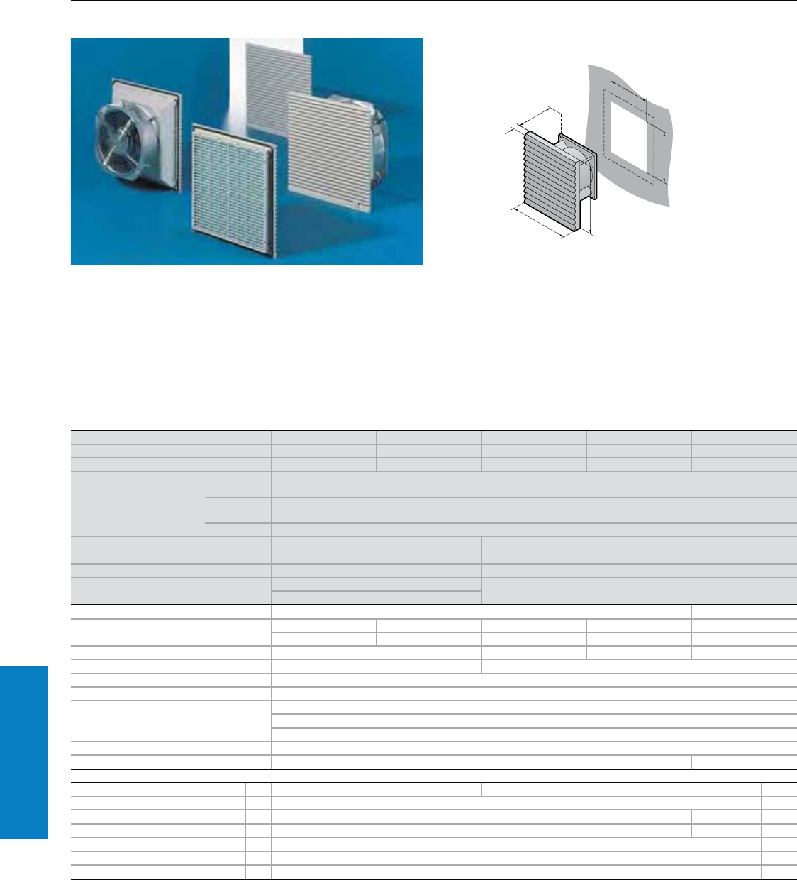
270 Industrial Buyer’s Guide
Climate Control Filter Fans
Filter Fan
Air Displacement: 323 - 424 cfm
Protection Ratings:
UL, cUL recognized, CE, CSA
UL file: E76083
Conguration:
Filter fan unit ready for
installation, including filter mats.
Property Rights:
German Registered Design
No. M 93 04 846
For additional technical
information, please visit
www.rittal-corp.com
Part No. RAL 7035 3326.107 3326.117 3327.107 3327.117 3327.147
Part No. RAL 9005 9963.657 9963.658 9963.659 9963.660 –
Voltage V, Hz 230, 50/60 115, 50/60 230, 50/60 115, 50/60 400/460, 3~, 50/60
Dimensions inches (mm)
Height (H1)/
Width (W1) 13 (323)
Height (H2)/
Width (W2) 12 (292)1)
Depth (D1) 1 (12)
Max. installation depth
inches (mm) Depth (D2) 5 (125) 6 (145)
Air displacement, unimpeded air flow 323/353 cfm (550/600 m3/h) 412/424 cfm (700/720 m3/h)
Air displacement with outlet filter
including standard filter mat
1 x 3326.207: 212/230 cfm (360/390 m3/h) 1 x 3326.207: 309/338 cfm (525/575 m3/h)
2 x 3326.207: 259/291 cfm (440/495 m3/h)
Axial fan Capacity motor Rotary current motor
Rated current maximum 0.29 A 0.58 A 0.65 A 1.5 A 0.27 A
0.35 A 0.70 A 0.95 A 2.0 A 0.37 A
Power 64.0/80.0 W 115.0/212.0 W 167.0/230.0 W 146.0/220.0 W
Noise level 59/61 dB (A) 75/76 dB (A)
Temperature range 13 to 131° F (–10 to +55° C)
Color RAL 7035 (light gray)/ RAL 9005 (black)
Environmental ratings
UL Type 12 (IP 54) standard
IP 55 when using an additional fine filter mat
UL Type 3R (IP 56) when using a hose-proof hood
Part No. outlet filter RAL 7035 3326.207
Part No. outlet filter RAL 9005 9963.583 –
Accessories PU Page
Spare filter mats 5 3173.100 3327.700 326
Fine filter mats 5 3183.100 326
Thermostat 1 3110.000 – 322
Temperature indicator 1 3114.200 – 321
Speed control 1 3120.200 322
Stainless steel hose-proof hood 1 3326.800 328
RAL 7035 hose-proof hood 1 3326.835 328
1) For metal thickness > 13 ga (2.5 mm), the cut-out H2/B2 (W) must be 0.04" (1 mm) larger.
Special voltages available by request. We reserve the right to make technical modifications.
Inch and pound measurements are rounded to the nearest whole number.
H
B
T
B1
T1
H1
B = Width
T = Depth
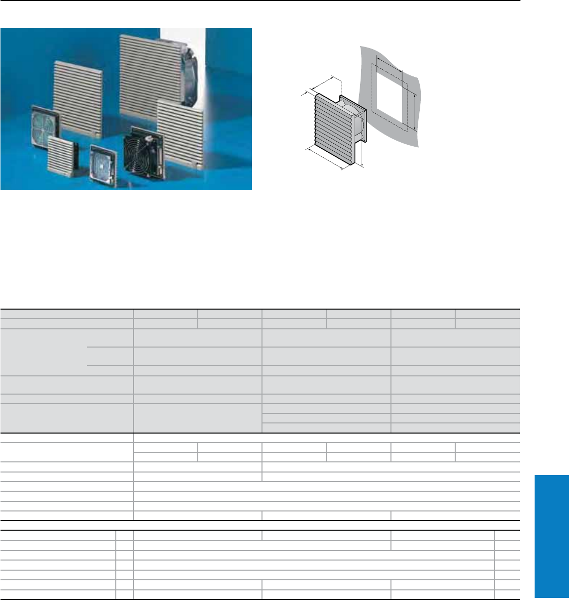
Industrial Buyer’s Guide 271
Climate Control Filter Fans
Filter Fan - EMC Shielded
Air Displacement: 12 - 71 cfm
Conguration:
Filter fan unit ready for installation,
including drilling template, filter
mat and assembly parts.
Protection Ratings:
UL, cUL recognized, CE, CSA
UL file: E76083
For additional technical
information, please visit
www.rittal-corp.com
Part No. 3321.607 3321.617 3322.607 3322.617 3323.607 3323.617
Voltage V, Hz 230, 50/60 115, 50/60 230, 50/60 115, 50/60 230, 50/60 115, 50/60
Dimensions inches (mm)
Height (H1)/
Width (W1) 5 (116) 6 (148) 8 (204)
Height (H2)/
Width (W2) 4 + 0.03 (92 + 0.8)1) 5 (124)1) 7 (177)1)
Depth (D1) 0.4 (10) 1 (10.5) 1 (12.5)
Max. installation depth
inches (mm) Depth (D2) 2 (42) 2 (57) 3 (82)
Air displacement, unimpeded air flow 12/15 cfm (20/25 m3/h) 32/39 cfm (55/66 m3/h) 62/71 cfm (105/120 m3/h)
Air displacement with outlet
filter including standard filter mat 1 x 3321.267: 9/11 cfm (15/18 m3/h)
1 x 3322.267: 25/29 cfm (43/50 m3/h) 1 x 3323.267: 42/48 cfm (71/82 m3/h)
2 x 3322.267: 28/32 (48/55 m3/h) 2 x 3323.267: 50/58 cfm (85/98 m3/h)
1 x 3323.267: 28/32 (48/55 m3/h) 1 x 3325.267: 46/53 cfm (78/90 m3/h)
Axial fan Self-starting shaded pole motor
Rated current maximum 69 mA/ 138 mA/ 0.12 A/ 0.24 A/ 0.12 A/ 0.24 A/
58 mA 115 mA 0.11 A 0.23 A 0.11 A 0.23 A
Power 12.5/10.3 W 19.0/18.0 W
Noise level 41/46 dB (A) 46/49 dB (A)
Temperature range 13 to 131° F (–10 to +55° C)
Color RAL 7035 (light gray)2)
Environmental ratings UL Type 12 (IP 54) standard
Part No. outlet filter - EMC 3321.267 3322.267 3323.267
Accessories PU Page
Spare filter mats 5 3321.700 3322.700 3171.100 326
Fine filter mats 5 – 3181.100 326
Thermostat 1 3110.000 322
Temperature indicator 1 3114.200 321
Speed control 1 3120.200 322
Stainless steel hose-proof hood 1 3321.800 3322.800 3323.800 328
RAL 7035 hose-proof hood 1 3321.835 3322.835 3323.835 328
1) For metal thickness > 13 ga (2.5 mm), the cut-out H2/B2 (W) must be 0.04" (1 mm) larger.
2) RAL 9005 (black) by request.
Special voltages available by request. We reserve the right to make technical modifications.
Inch and pound measurements are rounded to the nearest whole number.
H
B
T
B1
T
1
H1
B = Width
T = Depth
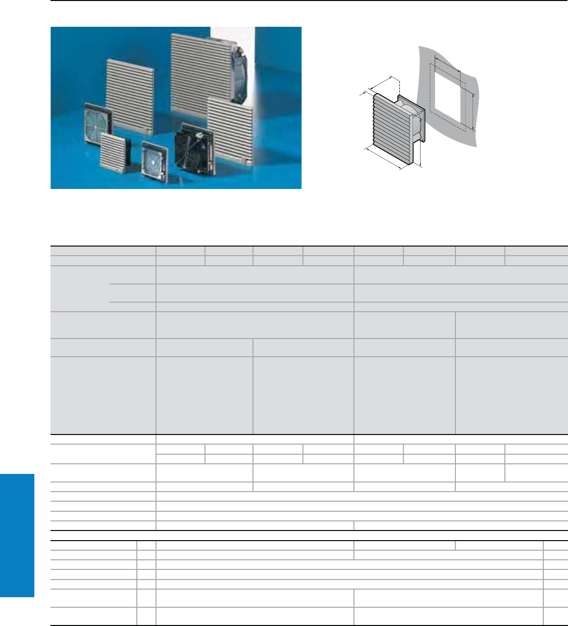
272 Industrial Buyer’s Guide
Climate Control Filter Fans
Filter Fan - EMC Shielded
Air Displacement: 94 - 423 cfm
Conguration:
Filter fan unit ready for installation,
including drilling template, filter
mat and assembly parts.
Protection Ratings:
UL, cUL recognized, CE, CSA
UL file: E76083
For additional technical
information, please visit
www.rittal-corp.com
Part No. 3324.607 3324.617 3325.607 3325.617 3326.607 3326.617 3327.607 3327.617
Voltage V, Hz 230, 50/60 115, 50/60 230, 50/60 115, 50/60 230, 50/60 115, 50/60 230, 50/60 115, 50/60
Dimensions
inches (mm)
Height (H1)/
Width (W1) 10 (255) 13 (323)
Height (H2)/
Width (W2) 9 (224)1) 12 (292)1)
Depth (D1) 1 (12) 1 (12)
Max. installation
depth inches
(mm)
Depth (D2) 4 (105) 5 (129) 6 (145)
Air displacement,
unimpeded air flow 106/94 cfm (180/160 m3/h)3) 156/ 135 cfm
(265/230 m3/h)
353/324 cfm
(600/550 m3/h) 423/412 cfm (720/700 m3/h)
Air displacement with
outlet filter including standard
filter mat
1 x 3325.267:
68/56 cfm (115/95 m3/h)
2 x 3325.267:
97/82 cfm (165/140 m3/h)
1 x 3326.267:
91/77 cfm (155/130 m3/h)
1 x 3325.267:
100/120 cfm
(170/205 m3/h)
2 x 3325.267:
118/135 cfm
(200/230 m3/h)
1 x 3326.267:
111/127 cfm
(190/215 m3/h)
1 x 3325.267:
100/120 cfm
(170/205 m3/h)
2 x 3325.267:
118/135 cfm
(200/230 m3/h)
1 x 3326.267:
212/230 cfm
(360/390 m3/h)
1 x 3326.267: 309/338 cfm
(525/575 m3/h)
Axial fan Self-starting shaded pole motor Capacity motor
Rated current maximum 0.19 A/ 0.38 A/ 0.28 A/ 0.53 A/ 0.29 A/ 0.58 A/ 0.65 A/ 1.50 A/
0.20 A 0.40 A 0.24 A 0.49 A 0.35 A 0.70 A 0.95 A 2.00 A
Power 30.0/35.0 W 41.0/38.0 W 64.0/80.0 W 155.0/212.0
W167.0/230.0 W
Noise level 52/48 dB (A) 54/56 dB (A) 59/61 dB (A) 75/76 dB (A)
Temperature range 13 to 131° F (–10 to +55° C)
Color RAL 7035 (light gray)2)
Environmental ratings UL Type 12 (IP 54) standard
Part No. outlet filter - EMC 3325.267 3326.267
Accessories PU Page
Spare filter mats 5 3172.100 3173.100 3327.700 326
Fine filter mats 5 3182.100 3183.100 326
Thermostat 1 3110.000 322
Temperature indicator 1 3114.200 321
Speed control 1 3120.200 322
Stainless steel hose-
proof hood 1 3324.800 3326.800 328
RAL 7035 hose-proof
hood 1 3324.835 3326.835 328
1) For metal thickness > 13 ga (2.5 mm), the cut-out H2/B2 (W) must be 0.04" (1 mm) larger.
2) RAL 9005 (black) by request.
3) In order to reduce the noise level of the fan, the shaded pole motor was modified so that the electrical and torque characteristics at 60 Hz
would be decreased (as compared to 50 Hz).
Special voltages available by request. We reserve the right to make technical modifications.
Inch and pound measurements are rounded to the nearest whole number.
H
B
T
B1
T1
H1
B = Width
T = Depth
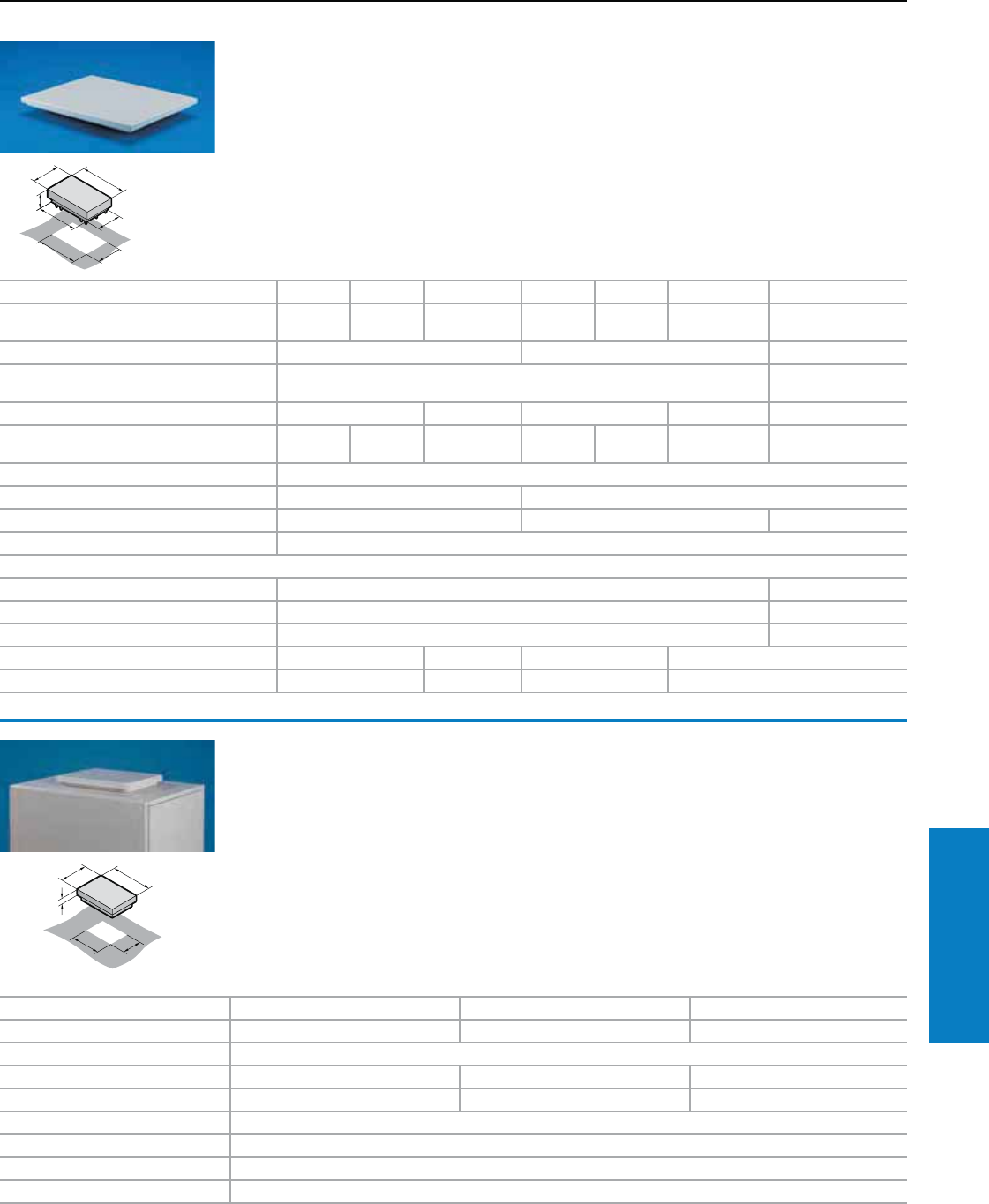
Industrial Buyer’s Guide 273
Climate Control Roof-Mounted Fans and Vent Attachment
Roof-Mounted Fans and Vent Attachment
Air Displacement: 212 - 471 cfm
Inch and pound measurements are rounded to the nearest whole number.
Roof-mounted fan and
vent attachment
for TS
The active roof-mounted fan and the passive
vent attachment (TS 8801.380) integrate
perfectly into the system-wide mounting
concept of the Rittal TopTherm platform. They
fit precisely onto the cutouts of the small and
medium performance category of TopTherm
roof-mounted cooling units. Of course, they may
also be mounted on any sufficiently large roof
surface.
TS roof plates with prepared mounting cut-outs
are additionally available.
Roof-mounted fan supply includes:
Unit ready to connect with built-in radial fan,
sealing material and assembly parts.
Vent attachment:
see page 324.
Protection category:
IP 43 to EN 60 529
Protection rating:
CSA Type 12, CE
T
B
290
500
370
550
125
B = Width
T = Depth
For additional technical
information, please visit
www.rittal-corp.com
Part No. 3149.410 3149.420 3149.4401) 3149.810 3149.820 3149.8401) 8801.380
Rated operating voltage V/Hz 115, 50/60 230, 50/60 400, 3~, 50/60
460, 3~, 60 115, 50/60 230, 50/60 400, 3~, 50/60
460, 3~, 60 Roof vent
Air throughput, unimpeded air flow 235 cfm (400 m3/h) 471 cfm (800 m3/h) Without motor
Required mounting cut-out W x D inches (mm) 18.7 x 10.2 (475 x 260) 19.3 x 15.4
(490 x 390)
Power consumption of fan 120 W/170 W 95 W/140 W 170 W/225 W 180 W/310 W
Rated current of fan 1.1/1.6 A 0.55/0.88
A
0.35/0.35 A 1.5/2.2 A 0.75/1.1 A 0.35/0.55 A
Temperature range 13 to 131° F (–10 to +60° C)
Noise level 68/69 dB (A) 69/70 dB (A)
Weight lb (kg) 22 (10) 24 (11) 13 (6)
Color RAL 7035 (light gray)
Accessories
Roof plate 600 x 600 mm for TS 8 with cut-out 8801.300 8801.310
Roof plate 600 x 800 mm for TS 8 with cut-out 8801.320 8801.330
Roof plate 1200 x 600 mm for TS 8 with cut-out – 8801.350
Temperature indicator 3114.200 – 3114.200 –
Speed control 3120.200 – 3120.200 –
Roof-mounted fan
• The roof-mounted fan is easily installed using
6 screws. The sealing tape supplied can be
used to seal it against the enclosure.
• The attachment screws are invisible from the
outside.
• The roof-mounted fan casing has a large air
outlet surface and labyrinth air ducting.
Protection category:
IP 43 to EN 60 529. By additionally installing the
filter holder with filter mat 3175.000, with roof
vent 3148.007 a protection category of IP 44 is
achieved.
Protection rating:
CSA Type 12, CE
Fully wired unit ready for connection with built-in
radial fan, sealing material and assembly parts,
connection cable (3 m), drilling template.
Accessory:
Filter holder, see page 325.
For additional technical
information, please visit
www.rittal-corp.com
50
265
345
340
420
Part No. 3149.0071) 3169.007 3148.0071)
Rated operating voltage V/Hz 230, 50/60 115, 50/60 Without fan motor
Air throughput 212 cfm (360 m3/h)
Rated current max. 0.2 A 0.55 A
Power consumption 42 W 65 W
Temperature range 13 to 131° F (–10 to +60° C)
Noise level 53 dB (A)
Weight lb (kg) 1.7 (7.8)
Color RAL 7035 (light gray), textured enamel
1) CSA pending
Special voltages available on request. We reserve the right to make technical modifications.
1) CSA pending
274 Industrial Buyer’s Guide
Climate Control Air Conditioners
Air Conditioners
Features
As the footprint for electronics continue to decrease and
internal and external temperatures continue to increase, proper
cooling becomes essential to prolong the life of your electronics
and prevent costly downtime. No matter the application or the
cooling requirements, Rittal has solutions to meet your needs.
Rittal's TopTherm air conditioners are the cost-effective, energy-
efficient solution for protecting sensitive electronics from heat,
dust and other significant risk factors.
Comfort Controller:
• Switching hysteresis: 2 – 10 C
preset to 5 C
• System alarm, individually
configurable for 2 floating fault
signal contacts
• Visualization of the current
enclosure internal temperature and
all system messages on the display
• System information available via
download for diagnostics using
3159.100 RiDiag II software
• Optional extension card for
integration into monitoring
systems (CMC)
• Master slave operation possible
for up to 10 air conditioners
Selection criteria
Rittal Efficiency Label
The new Rittal Efficiency Label,
created in accordance with
DIN EN ISO 14021, is affixed
to all of our cooling systems
that have been proven to be
environmentally friendly for
your application and for your
surroundings as well.
Roofmount air conditioners
Up to four cold air outlet openings
and the optional use of ducts
allow the user to control cold air
routing through the enclosure.
Heated air is expelled to the rear,
left, right and optionally upwards
which allows enclosures to be
bayed together or to be installed
close to the wall.
Wallmount air conditioners
You can choose from internal
mounting, partial internal mounting
and external mounting based on
your space requirements. Cold
air effectively flows throughout
the enclosure due to the large
distances between the air intake
and outlet openings.
Intelligent control
Choose from basic and comfort
control versions. Both versions
offer a comprehensive range
of functions. Essential control
electronics are well protected
and cooled in the inner circuit.
Both versions have the
following properties:
• Three voltage options: 115 V,
230 V, 400/460 V 3~
• Integrated start-up delay and
door limit switch function
• Icing protection function
• Monitoring of all motors
• Phase monitoring for
three phase units
Basic Controller:
• Visualization of the operating
status by a LED display
• Switching hysteresis: 5 C
• Floating fault signal contact
in case of over temperature
• Set-point adjustable from the
outside by a potentiometer
(setting range 68 – 131° F
[20 – 55° C])
Industrial Buyer’s Guide 275
Climate Control Air Conditioners
Air Conditioners
Features
Wallmount air conditioners
Wallmount UL Type 4X air conditioners
Roofmount air conditioners
Exterior shroud for
component protection
in harsh environments
Vents allow for effective airflow
through the air conditioner
while maintaining the protection
provided by the shroud.
Monitoring made easy
Rittal air conditioners can be
ordered with either basic or comfort
controllers, even in UL Type 4X
versions.
Flexible performance
Only 3 mounting cut-outs for 6
different output categories in 28
design versions.
Targeted air routing in
the enclosure
The internal air circulation is
targeted and effective: The heated
air is extracted centrally. Air exhaust
occurs in the four corners, based on
your specific requirements.
Wallmount air conditioners –
Practical and stylish
The mounting cut-out is selected
depending on the mounting
type: External, internal or partial
internal mount.
Effective air routing inside
the enclosure
The large distance between the
air intake and outlet in the internal
circuit makes wallmount air
conditioners particularly effective.
This ensures optimum air
dissipation inside the enclosure,
and air short-circuits are avoided.
Benets:
• Useful cooling capacity from 1000 to
18400 BTU (300 to 5400 W)
• Extensive control and monitoring
features, even with the basic version
• Three-phase air conditioners support
multiple voltages as standard
• Uniform, output-related, cross-
system mounting cut-outs, to match
TopTherm air/air heat exchangers
• Targeted, individual air routing
• Made in USA
Important:
• Avoid overloading the roofplate by using
supports (see TS8 system accessories)
• Air intake and outlet openings in
the internal and external circuit must
not be blocked (allow a minimum
distance of 8")
276 Industrial Buyer’s Guide
Climate Control Air Conditioners
Air Conditioners
Features
Standard Rittal TopTherm Plus air conditioners are
available off the shelf with RiNano coating of the condenser
coils and an integrated condensate evaporator utilizing PTC
resistance technology.
TopTherm Plus and RiNano
An innovative nish for long
lasting cooling performance
Layers of dust on the outer air
circuit surfaces of air conditioners
can diminish effectiveness by
30 to 50% due to an insulating
effect. A revolutionary RiNano-
finish helps prevent this because
of its water, dirt and oil repelling
properties; it will help provide
long lasting, consistent cooling
performance. Service and
maintenance can be scheduled
less frequently and cleaning will
be much easier.
RiNano coatings were tested
at the Volkswagen gear-box
manufacturing center in
Kassel, Germany.
RiNano coating makes it
harder for particles to stick
to the condenser coil and
consequently the condenser
coil remains clean longer than
untreated material.
Without RiNano, the oily
ambient air leaves noticeable
contamination.
TopTherm Plus units come
standard with an electronic
condensate evaporator which
prevents the collection of
condensation on sensitive
electronics. This eliminates the
need to collect and dissipate
condensation. (Applies to all
TopTherm Plus and Integrated Condensate Evaporator
roofmount air conditioners and
all wallmount air conditioners
with more than 3400 BTU.)
The integrated condensate
evaporator provided in all
TopTherm Plus air conditioners
with more than 3400 BTU's
adjusts its thermal output
automatically, using PTC
(Positive Temperature Coefficient)
technology. The PTC technology
is energy efficient and can
evaporate up to 3.4 oz. of
condensate per hour, eliminating
the need for drain hoses or
collection bottles.
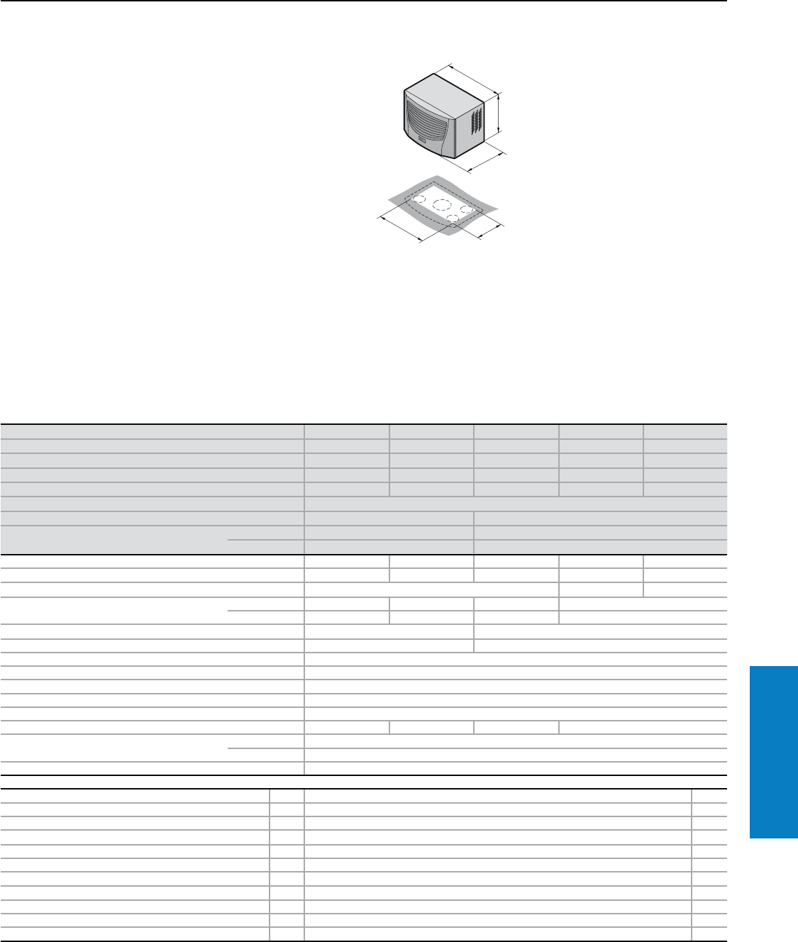
Industrial Buyer’s Guide 277
Climate Control Air Conditioners
Air Conditioner - Roofmount
Useful Cooling Capacity: 1581 - 3081 BTU (463 - 903 W)
Conguration:
Fully wired ready for connection,
including drilling template and
assembly parts.
With nano-coated condenser
and integrated condensate
evaporator.
Note:
Air conditioners with comfort
controller may be integrated
into a monitoring system with an
optional interface card 3124.200
(RS 232, RS 485, RS 422 and
PLC interface). See page 323
Protection Ratings:
UL and cUL recognized, CSA
UL file: SA8250
For additional technical
information, please visit
www.rittal-corp.com
Part No. with basic controller, RAL 7035 (light gray) 3382.100 3382.110 3359.100 3359.110 3359.140
Part No. with comfort controller, RAL 7035 (light gray) 3382.500 3382.510 3359.500 3359.510 3359.540
Part No. with basic controller, Type 304 stainless steel 3382.200 3382.210 3359.200 3359.210 3359.240
Part No. with comfort controller, Type 304 stainless steel 3382.600 3382.610 3359.600 3359.610 3359.640
Voltage V, Hz 230, 50/60 115, 50/60 230, 50/60 115, 50/60 400, 2~, 50/60
Dimensions inches (mm) H x W x D 16 x 24 x 15 (417 x 597 x 380)
Useful cooling capacity QK BTU (W) Ti 131 Ta 131 1581 (463) 3081 (903)
Useful cooling capacity QK to DIN 3168 BTU (W) Ti 95 Ta 95 1708/1742 (500/510) 2561/2766 (750/810)
Ti 95 Ta 122 922/1264 (270/370) 1861/2015 (545/590)
Rated current maximum 3.3 A/3.5 A 6.7 A/7.2 A 3.6 A/4.5 A 7.2 A/9.0 A 2.1 A/2.4 A
Starting current 9.2 A/10.2 A 18.4 A/18.4 A 10.0 A/10.7 A 20.0 A/21.4 A 5.8 A/6.2 A
Pre-fuse T 10.0 A 16.0 A 10.0 A
Power consumption Pel to DIN 3168 Ti 95 Ta 95 550 W/550 W 510 W/560 W 550 W/660 W 560 W/675 W
Ti 95 Ta 122 550 W/590 W 560 W/610 W 630 W/740 W 640 W/750 W
Cooling coefficient j = QK/Pel Ti 95 Ta 95 1.0 1.4
Refrigerant R134a, 8.8 oz (250 g) R134a, 10.6 oz (300 g)
Maximum allowable operating pressure 363 psi (25 bar)
Temperature and setting range 68 to 131° F (+20 to +55° C)
Environmental rating UL Type 12 (IP 54)
Duty cycle 100%
Type of connection Plug-in terminal strip
Weight lb (kg) 66.1 (30) 77.1 (35) 70.5 (32) 81.5 (37)
Air displacement of fans (unimpeded air flow) External circuit 536 cfm (910 m3/h)
Internal circuit 259 cfm (440 m3/h)
Temperature control Basic or comfort controller (factory setting 95° F [+35° C])
Accessories PU Page
Filter mats 3 3286.500 328
Metal filters 1 3286.510 327
Quick-change frame 1 3286.700 –
Door-operated switch 1 4127.000 –
Master/slave cable for comfort controller 1 3124.100 323
RiDiag II including cables for comfort controller 1 3159.100 323
Interface card for comfort controller 1 3124.200 323
Air ducting system 1 3286.870 319
Shallow air ducting system 1 3286.850 319
Plugs for interior air outlet 2 3286.780 320
Condensate hose 1 3301.612 324
Special voltages available by request. We reserve the right to make technical modifications.
1
Property rights:
German registered design
no. 402 02 324
German registered design
no. 402 02 325
Inch and pound measurements are rounded to the nearest whole number.
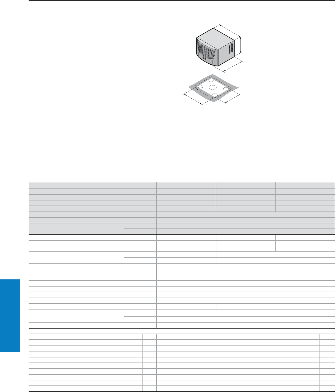
278 Industrial Buyer’s Guide
Climate Control Air Conditioners
Air Conditioner - Roofmount
Useful Cooling Capacity: 4462 BTU (1307 W)
Conguration:
Fully wired ready for connection,
including drilling template and
assembly parts.
With nano-coated condenser
and integrated condensate
evaporator.
Note:
Integration of the air conditioners
with comfort controller into
a monitoring system can be
achieved with an optional
interface card 3124.200
(RS 232, RS 485, RS 422 and
PLC interface). See page 323
Protection Ratings:
UL and cUL recognized, CSA
UL file: SA8250
For additional technical
information, please visit
www.rittal-corp.com
Property Rights:
German registered design
no. 402 02 324
German registered design
no. 402 02 325
1
Part No. with basic controller, RAL 7035 (light gray) 3383.100 3383.110 3383.140
Part No. with comfort controller, RAL 7035 (light gray) 3383.500 3383.510 3383.540
Part No. with basic controller, Type 304 stainless steel 3383.200 3383.210 3383.240
Part No. with comfort controller, Type 304 stainless steel 3383.600 3383.610 3383.640
Voltage V, Hz 230, 50/60 115, 50/60 400, 2~, 50/60
Dimensions inches (mm) H x W x D 16 x 24 x 19 (417 x 597 x 475)
Useful cooling capacity QK BTU (W) Ti 131 Ta 131 4462 (1307)
Useful cooling capacity QK to DIN 3168 BTU (W) Ti 95 Ta 95 3415/3688 (1000/1080)
Ti 95 Ta 122 2596/2800 (760/820)
Rated current maximum 4.9 A/5.1 A 9.5 A/10.0 A 2.8 A/2.8 A
Starting current 15.5 A/15.5 A 25.3 A/24.3 A 8.0 A/8.8 A
Pre-fuse T 10.0 A 16.0 A 10.0 A
Power consumption Pel to DIN 3168 Ti 95 Ta 95 690 W/790 W 720 W/800 W
Ti 95 Ta 122 800 W/890 W 810 W/900 W
Cooling coefficient j = QK/Pel Ti 95 Ta 95 1.4
Refrigerant R134a, 17.6 oz (500 g)
Maximum allowable operating pressure 363 psi (25 bar)
Temperature and setting range 68 to 131° F (+20 to +55° C)
Environmental rating UL Type 12 (IP 54)
Duty cycle 100%
Type of connection Plug-in terminal strip
Weight lb (kg) 88.2 (40) 101.4 (46)
Air displacement of fans External circuit 1036 cfm (1760 m3/h)
Internal circuit 259 cfm (440 m3/h)
Temperature control Basic or comfort controller (factory setting 95° F [+35° C])
Accessories PU Page
Filter mats 3 3286.500 328
Metal filters 1 3286.510 327
Door-operated switch 1 4127.000 –
Master/slave cable for comfort controller 1 3124.100 323
RiDiag II including cables for comfort controller 1 3159.100 323
Interface card for comfort controller 1 3124.200 323
Air ducting system 1 3286.870 319
Shallow air ducting system 1 3286.850 319
Plugs for interior air outlet 2 3286.880 320
Condensate hose 1 3301.612 324
Special voltages available by request. We reserve the right to make technical modifications.
Inch and pound measurements are rounded to the nearest whole number.
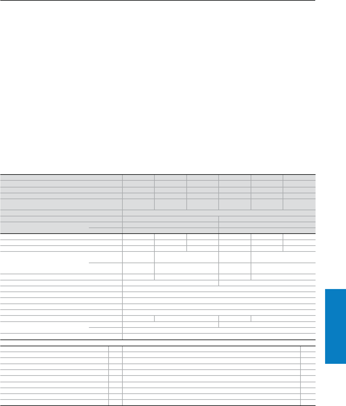
Industrial Buyer’s Guide 279
Climate Control Air Conditioners
Air Conditioner - Roofmount
Useful Cooling Capacity: 6009 - 8272 BTU (1760 - 2423 W)
Protection Ratings:
UL and cUL recognized, CSA
UL file: SA8250
Conguration:
Fully wired ready for connection,
including drilling template and
assembly parts.
With nano-coated condenser
and integrated condensate
evaporator.
Note:
Air conditioners with comfort
controller may be integrated
into a monitoring system with an
optional interface card 3124.200
(RS 232, RS 485, RS 422 and
PLC interface). See page 323 For additional technical
information, please visit
www.rittal-corp.com
Property Rights:
German registered design
no. 402 02 324
German registered design
no. 402 02 325
Part No. with basic controller, RAL 7035 (light gray) 3384.100 3384.110 3384.140 3385.100 3385.110 3385.140
Part No. with comfort controller, RAL 7035 (light gray) 3384.500 3384.510 3384.540 3385.500 3385.510 3385.540
Part No. with basic controller, Type 304 stainless steel 3384.200 3384.210 3384.240 3385.200 3385.210 3385.240
Part No. with comfort controller, Type 304 stainless steel 3384.600 3384.610 3384.640 3385.600 3385.610 3385.640
Voltage V, Hz 230, 50/60 115, 50/60 400, 2~,
50/60 230, 50/60 115, 50/60 400, 2~,
50/60
Dimensions inches (mm) H x W x D 16 x 24 x 19 (417 x 597 x 475)
Useful cooling capacity QK BTU (W) Ti 131 Ta 131 6009 (1760) 8272 (2423)
Useful cooling capacity QK to DIN 3168
BTU (W)
Ti 95 Ta 95 5123/5191 (1500/1520) 6830/7274 (2000/2130)
Ti 95 Ta 122 3757/4132 (1100/1210) 5362/5703 (1570/1670)
Rated current maximum 6.3 A/7.4 A 13.7 A/15.3 A 3.8 A/4.4 A 6.3 A/7.2 A 14.2 A/15.4 A 3.7 A/4.2 A
Starting current 16.6 A/17.1 A 30.7 A/29.1 A 9.8 A/9.6 A 16.8 A/18.4 A 36.0 A/32.0 A 10.0 A/12.0 A
Pre-fuse T 10.0 A 20.0 A 10.0 A 10.0 A 20.0 A 10.0 A
Power consumption Pel to DIN 3168
Ti 95 Ta 95 955 W/1070
W990 W/1090 W 1140 W/1310
W1190 W/1390 W
Ti 95 Ta 122 1090 W/1290
W1140 W/1290 W 1240 W/1450
W1300 W/1520 W
Cooling coefficient j = QK/Pel Ti 95 Ta 95 1.6 1.5 1.8 1.7
Refrigerant R134a, 17.6 oz (500 g) R134a, 33.4 oz (950 g)
Maximum allowable operating pressure 363 psi (25 bar)
Temperature and setting range 68 to 131° F (+20 to +55° C)
Environmental ratings UL Type 12 (IP 54)
Duty cycle 100%
Type of connection Plug-in terminal strip
Weight lb (kg) 90.3 (41) 103.6 (47) 92.6 (42) 105.8 (48)
Air displacement of fans External circuit 1036 cfm (1760 m3/h) 1071 cfm (1820 m3/h)
Internal circuit 277 cfm (470 m3/h)
Temperature control Basic or comfort controller (factory setting 95° F [+35° C])
Accessories PU Page
Filter mats 3 3286.500 328
Metal filters 1 3286.510 327
Door-operated switch 1 4127.000 –
Master/slave cable for comfort controller 1 3124.100 323
RiDiag II including cables for comfort controller 1 3159.100 323
Interface card for comfort controller 1 3124.200 323
Air ducting system 1 3286.870 319
Shallow air ducting system 1 3286.850 319
Plugs for interior air outlet 2 3286.880 320
Condensate hose 1 3301.612 324
Special voltages available on request. We reserve the right to make technical modifications.
Inch and pound measurements are rounded to the nearest whole number.
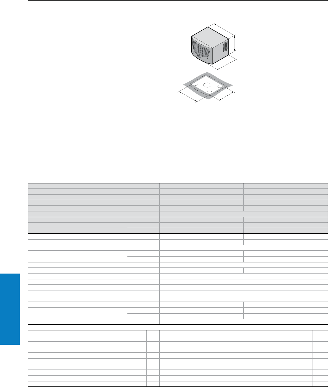
280 Industrial Buyer’s Guide
Climate Control Air Conditioners
Air Conditioner - Roofmount
Useful Cooling Capacity: 12632 - 18436 BTU (3700 - 5400 W)
Protection Ratings:
UL and cUL recognized, CSA
UL file: SA8250
Conguration:
Fully wired ready for connection,
including drilling template,
eyebolt and assembly parts.
With nano-coated condenser
and integrated condensate
evaporator.
Note:
Air conditioners with comfort
controller may be integrated
into a monitoring system with an
optional interface card 3124.200
(RS 232, RS 485, RS 422 and
PLC interface). See page 323
For additional technical
information, please visit
www.rittal-corp.com
Property Rights:
German registered design
no. 402 02 324
German registered design
no. 402 02 325
Part No. with basic controller, RAL 7035 (light gray) 3386.140 3387.140
Part No. with comfort controller, RAL 7035 (light gray) 3386.540 3387.540
Part No. with basic controller, Type 304 stainless steel 3386.240 3387.240
Part No. with comfort controller, Type 304 stainless steel 3386.640 3387.640
Voltage V, Hz 400, 50/460, 60, 3~ 400, 50/460, 60, 3~
Dimensions inches (mm) H x W x D 19 x 31 x 23 (470 x 796 x 580)
Useful cooling capacity QK BTU (W) Ti 131 Ta 131 12632 (3700) 18436 (5400)
Useful cooling capacity QK to DIN 3168 BTU (W) Ti 95 Ta 95 10246/11270 (3000/3300) 13661/14344 (4000/4200)
Ti 95 Ta 122 8401/9392 (2460/2750) 11099/11919 (3250/3490)
Rated current maximum 3.4 A/3.4 A 3.9 A/3.9 A
Starting current 8.0 A/9.0 A 17.0 A/19.0 A
Pre-fuse T Motor circuit breaker 6.3 A/10.0 A
Power consumption Pel to DIN 3168 Ti 95 Ta 95 1320 W/1630 W 1760 W/2200 W
Ti 95 Ta 122 1570 W/1910 W 2010 W/2480 W
Cooling coefficient j = QK/Pel Ti 95 Ta 95 2.3
Refrigerant R134a, 56.4 oz (1600 g) R134a, 63.5 oz (1800 g)
Maximum allowable operating pressure 363 psi (25 bar)
Temperature and setting range 68 to 131° F (+20 to +55° C)
Environmental ratings UL Type 12 (IP 54)
Duty cycle 100%
Type of connection Plug-in terminal strip
Weight lb (kg) 154.3 (70) 169.8 (77)
Air displacement of fans External circuit 2031 cfm (3450 m3/h) 2278 cfm (3870 m3/h)
Internal circuit 753.4 cfm (1280 m3/h) 836 cfm (1420 m3/h)
Temperature control Basic or comfort controller (factory setting 95° F [+35° C])
Accessories PU Page
Filter mats 3 3286.600 328
Metal filters 1 3286.610 327
Door-operated switch 1 4127.000 –
Master/slave cable for comfort controller 1 3124.100 323
RiDiag II including cables for comfort controller 1 3159.100 323
Interface card for comfort controller 1 3124.200 323
Air ducting system 1 3286.970 319
Shallow air ducting system 1 3286.850 319
Plugs for interior air outlet 2 3286.980 320
Condensate hose 1 3301.612 324
Special voltages available on request. We reserve the right to make technical modifications.
Inch and pound measurements are rounded to the nearest whole number.
Industrial Buyer’s Guide 281
Climate Control Air Conditioners
Air Conditioner - Roofmount
Useful Cooling Capacity: 4687 BTU (1373 W)
Designed For
Office Applications.
Low noise level (considerably
quieter than air conditioners
for industrial applications).
With nano-coated condenser
and integrated condensate
evaporator.
Conguration:
Fully wired ready for connection,
including automatic condensate
evaporation, drilling template and
assembly parts.
With nano-coated condenser
and integrated condensate
evaporator.
Note:
Air conditioners with comfort
controller may be integrated
into a monitoring system with an
optional interface card 3124.200
(RS 232, RS 485, RS 422 and
PLC interface). See page 323 For additional technical
information, please visit
www.rittal-corp.com
Property Rights:
German registered design
no. 402 02 324
German registered design
no. 402 02 325
Part No. with comfort controller 3273.500 3273.515
Voltage V, Hz 230, 50/60 115, 50/60
Dimensions inches (mm) H x W x D 16 x 24 x 19 (417 x 597 x 475)
Useful cooling capacity QK BTU (W) Ti 131 Ta 131 4687 (1373)
Useful cooling capacity QK to DIN 3168 BTU (W) Ti 95 Ta 95 3756/4098 (1100/1200)
Ti 95 Ta 122 2903/2971 (850/870)
Rated current maximum 5.2 A/5.4 A 11.0 A/11.5 A
Starting current 15.5 A/16.5 A 32.0 A/35.0 A
Pre-fuse T 10.0 A 20.0 A
Power consumption Pel to DIN 3168 Ti 95 Ta 95 890 W/910 W 920 W/940 W
Ti 95 Ta 122 960 W/1100 W 990 W/1140 W
Cooling coefficient j = QK/Pel Ti 95 Ta 95 1.2
Refrigerant R134a, 24.7 oz (700 g)
Maximum allowable operating pressure 363 psi (25 bar)
Temperature and setting range 68 to 131° F (+20 to +55° C)
Environmental ratings UL Type 12 (IP 54)2)
Duty cycle 100%
Type of connection Plug-in terminal strip
Weight lb (kg) 92.6 (42) 103.6 (47)
Color RAL 7035 (light gray)
Air displacement of fans External circuit 1036 cfm (1760 m3/h)
Internal circuit 259 cfm (440 m3/h)
Temperature control Basic or comfort controller (factory setting 95° F [+35° C])
Accessories PU Page
Filter mats 3 3286.100 328
Metal filters 1 3286.210 327
Door-operated switch 1 4127.000 –
Master/slave cable for comfort controller 1 3124.100 323
RiDiag II including cables for comfort controller 1 3159.100 323
Interface card for comfort controller 1 3124.200 323
Air ducting system 1 3286.870 319
Shallow air ducting system 1 3286.850 319
Plugs for interior air outlet 2 3286.980 320
Condensate hose 1 3301.612 324
Special voltages available on request. We reserve the right to make technical modifications.
Inch and pound measurements are rounded to the nearest whole number.
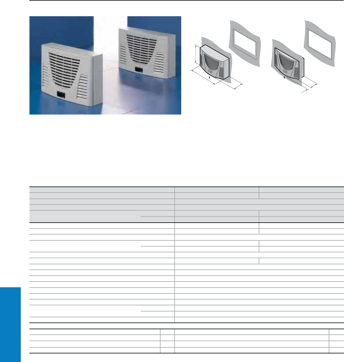
282 Industrial Buyer’s Guide
Climate Control Air Conditioners
Air Conditioner - Wallmount
Useful Cooling Capacity: 809 BTU (237 W)
Mini air conditioners for horizontal
mounting, ideal for cooling
small equipment and operating
housings with optimum space
utilization.
Protection Ratings:
UL and cUL recognized, CSA
UL file: SA8250
Conguration:
Fully wired ready for connection,
including drilling template and
assembly parts.
With nano-coated condenser.
For additional technical
information, please visit
www.rittal-corp.com
1
Part No. 3302.300 3302.310
Voltage V, Hz 230, 50/60 115, 60
Dimensions inches (mm) H x W x D 13 x 21 x 6 (340 x 525 x 153)
Useful cooling capacity QK BTU (W) Ti 131 Ta 131 809 (237)
Useful cooling capacity QK to DIN 3168 BTU (W) Ti 95 Ta 95 1025/1093 (300/320) 1025 (300)
Ti 95 Ta 122 512/546 (150/160) 512 (150)
Rated current maximum 1.6 A/1.7 A 4.0 A
Starting current 4.3 A/5.3 A 12.0 A
Pre-fuse T 10 A
Power consumption Pel to DIN 3168 Ti 95 Ta 95 285 W/300 W 290 W
Ti 95 Ta 122 320 W/340 W 340 W
Cooling coefficient j = QK/Pel Ti 95 Ta 95 1.1
Refrigerant R134a, 3.5 oz (100 g) R134a, 3.4 oz (95 g)
Maximum allowable operating pressure 363 psi (25 bar)
Temperature and setting range 68 to 131° F (+20 to +55° C)
Environmental ratings UL Type 12 (IP 54)
Duty cycle 100%
Type of connection Plug-in terminal strip
Weight lb (kg) 28.7 (13)
Color RAL 7035 (light gray)
Air displacement of fans External circuit 203 cfm (345 m3/h)
Internal circuit 182 cfm (310 m3/h)
Temperature control Basic controller
Accessories PU Page
Temperature indicator 1 3114.200 321
Condensate hose 1 3301.608 324
Filter mats 3 3286.110 328
Metal filters 1 3286.120 327
Special voltages available upon request. We reserve the right to make technical modifications.
Inch and pound measurements are rounded to the nearest whole number.
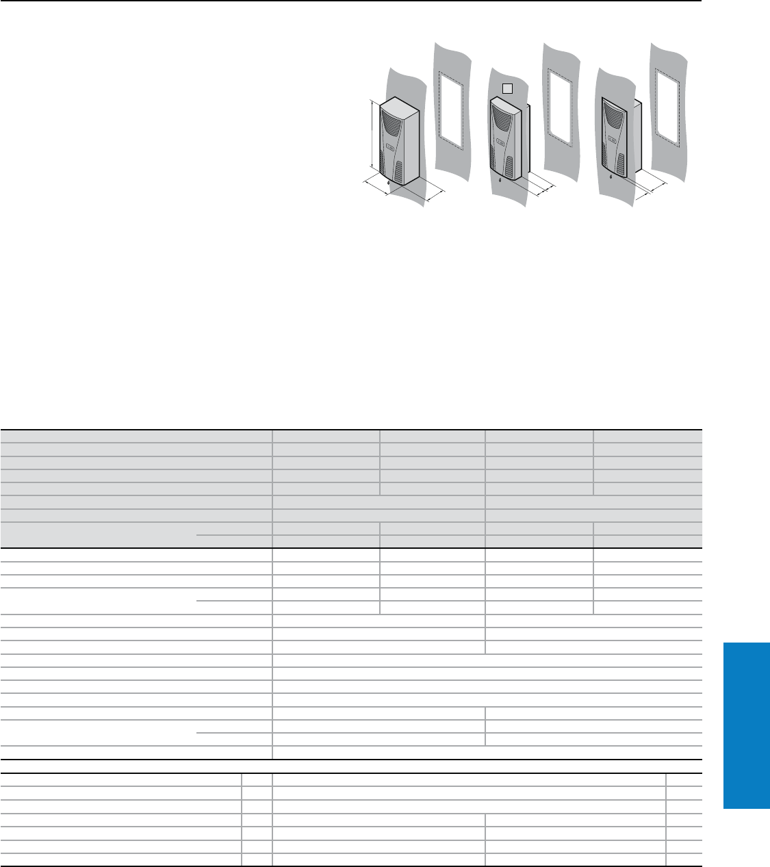
Industrial Buyer’s Guide 283
Climate Control Air Conditioners
Air Conditioner - Wallmount
Useful Cooling Capacity: 864 - 2400 BTU (253 - 703 W)
Protection Ratings:
UL and cUL recognized, CSA
UL file: SA8250
Conguration:
Fully wired ready for connection,
including drilling template and
assembly parts.
With nano-coated condenser.
Note:
Air conditioners with comfort
controller may be integrated
into a monitoring system with an
optional interface card 3124.200
(RS 232, RS 485, RS 422 and
PLC interface). See page 323
Partial Internal Mounting
Possible With 3303.XXX Only.
For additional technical
information, please visit
www.rittal-corp.com
Property Rights:
US design patent no. D 488,480
IR reg. design no. DM/061 967
with validity for FR, IT, ES
German registered designs
no. 402 02 324 and no. 402 02 325
Japanese registered design
no. 1 187 896
Indian registered design
no. 189 953
T
T
1
1
1
Part No. with basic controller, RAL 7035 (light gray) 3302.100 3302.110 3303.100 3303.110
Part No. with comfort controller, RAL 7035 (light gray) – – 3303.500 3303.510
Part No. with basic controller, Type 304 stainless steel 3302.200 3302.210 3303.200 3303.210
Part No. with comfort controller, Type 304 stainless steel – – 3303.600 3303.610
Voltage V, Hz 230, 50/60 115, 60 230, 50/60 115, 60
Dimensions inches (mm) H x B x T x T2 22 x 11 x 6 x 4 (550 x 280 x 140 x 98) 22 x 11 x 8 x 7 (550 x 280 x 200 x 164)
Useful cooling capacity QK BTU (W) Ti 131 Ta 131 864 (253) 2400 (703)
Useful cooling capacity QK to DIN 3168
BTU (W)
Ti 95 Ta 95 1025/1093 (300/320) 1025 (300) 1708/2083 (500/610) 1708 (500)
Ti 95 Ta 122 512/581 (150/170) 512 (150) 957/1195 (280/350) 957 (280)
Rated current maximum 1.6 A/1.7 A 3.3 A 2.6 A/2.6 A 5.7 A
Starting current 3.0 A/3.4 A 8.0 A 5.1 A/6.4 A 11.5 A
Pre-fuse T 10.0 A 10.0 A 10.0 A 10.0 A
Power consumption Pel to DIN 3168 Ti 95 Ta 95 245 W/255 W 290 W 360 W/380 W 470 W
Ti 95 Ta 122 255 W/275 W 340 W 420 W/390 W 500 W
Cooling coefficient j = QK/Pel Ti 95 Ta 95 1.2 1.4
Refrigerant R134a, 3.5 oz (100 g) R134a, 6.0 oz (170 g)
Maximum allowable operating pressure 263 psi (25 bar) 406 psi (28 bar)
Temperature and setting range 68 to 131° F (+20 to +55° C)
Environmental ratings UL Type 12 (IP 54)
Duty cycle 100%
Type of connection Plug-in terminal strip
Weight lb (kg) 28.7 (13) 37.5 (17)
Air displacement of fans External circuit 182 cfm (310 m3/h) 203 cfm (345 m3/h)
Internal circuit 203 cfm (345 m3/h) 182 cfm (310 m3/h)
Temperature control Basic or comfort controller (factory setting 95° F [+35° C])
Accessories PU Page
Filter mats 3 3286.300 328
Metal filters 1 3286.310 327
Door-operated switch 1 4127.000 –
Master/slave cable for comfort controller 1 – 3124.100 323
RiDiag II including cables for comfort controller 1 – 3159.100 323
Interface card for comfort controller 1 – 3124.200 323
Condensate hose 1 3301.608 3301.610 324
Special voltages available by request. We reserve the right to make technical modifications.
Inch and pound measurements are rounded to the nearest whole number.
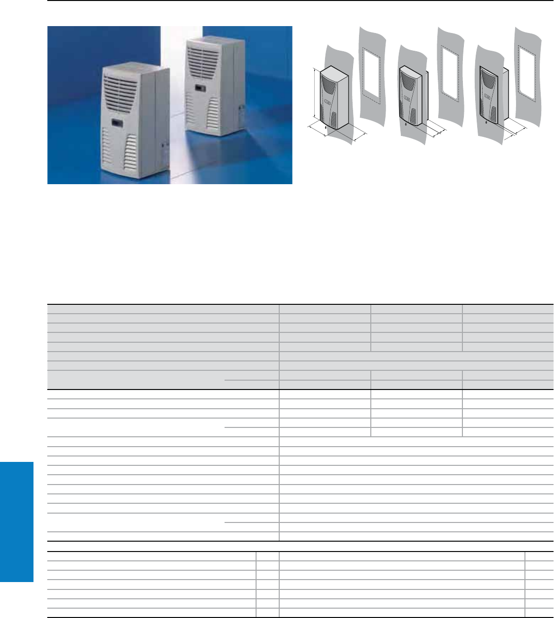
284 Industrial Buyer’s Guide
Climate Control Air Conditioners
Air Conditioner - Wallmount
Useful Cooling Capacity: 2663 BTU (780 W)
Protection Ratings:
UL and cUL recognized, CSA
UL file: SA8250
Conguration:
Fully wired ready for connection,
including drilling template and
assembly parts.
With nano-coated condenser.
Note:
Air conditioners with comfort
controller may be integrated
into a monitoring system with an
optional interface card 3124.200
(RS 232, RS 485, RS 422 and
PLC interface). See page 323.
Property Rights:
US design patent no. D 488,480
IR reg. design no. DM/061 967
with validity for FR, IT, ES
German registered designs
no. 402 02 324 and no. 402 02 325
Japanese registered design
no. 1 187 896
Indian registered design
no. 189 953
For additional technical
information, please visit
www.rittal-corp.com
1
1
Part No. with basic controller, RAL 7035 (light gray) 3361.100 3361.110 3361.1401)
Part No. with comfort controller, RAL 7035 (light gray) 3361.500 3361.510 3361.5401)
Part No. with basic controller, Type 304 stainless steel 3361.200 3361.210 3361.2401)
Part No. with comfort controller, Type 304 stainless steel 3361.600 3361.610 3361.6401)
Voltage V, Hz 230, 50/602) 115, 602) 400, 2~, 50/602)
Dimensions inches (mm) H x W x D 22 x 11 x 11 (550 x 280 x 280)
Useful cooling capacity QK BTU (W) Ti 131 Ta 131 2663 (780)
Useful cooling capacity QK to DIN 3168 BTU (W) Ti 95 Ta 95 2561/2664 (750/780) 2561 (750) 2561/2664 (750/780)
Ti 95 Ta 122 1742/1844 (510/540) 1742 (510) 1742/1844 (510/540)
Rated current maximum 2.3 A/2.4 A 5.3 A 1.2 A/1.4 A
Starting current 5.6 A/5.6 A 12.0 A 3.1 A/3.3 A
Pre-fuse T 10 A 10 A 10 A
Power consumption Pel to DIN 3168 Ti 95 Ta 95 480 W/555 W 570 W 480 W/550 W
Ti 95 Ta 122 530 W/640 W 670 W 530 W/640 W
Cooling coefficient j = QK/Pel Ti 95 Ta 95 1.5
Refrigerant R134a, 9.9 oz (280 g)
Maximum allowable operating pressure 406 psi (28 bar)
Temperature and setting range 68 to 131° F (+20 to +55° C)
Environmental ratings UL Type 12 (IP 54)
Duty cycle 100%
Type of connection Plug-in terminal strip
Weight lb (kg) 48.5 (22)
Air displacement of fans (unimpeded air flow) External circuit 283 cfm (480 m3/h)
Internal circuit 353 cfm (600 m3/h)
Temperature control Basic or comfort controller (factory setting 95° F [+35° C])
Accessories PU Page
Filter mats 3 3286.300 328
Metal filters 1 3286.310 327
Door-operated switch 1 4127.000 –
Master/slave cable for comfort controller 1 3124.100 323
RiDiag II including cables for comfort controller 1 3159.100 323
Interface card for comfort controller 1 3124.200 323
Condensate hose 1 3301.608 324
1) External transformer Ø 5 x 3" (126 x 65 mm) deep which must be mounted by the end customer.
2) Ta maximum = 125° F (52° C)/60 Hz.
Special voltages available upon request. We reserve the right to make technical modifications.
Inch and pound measurements are rounded to the nearest whole number.
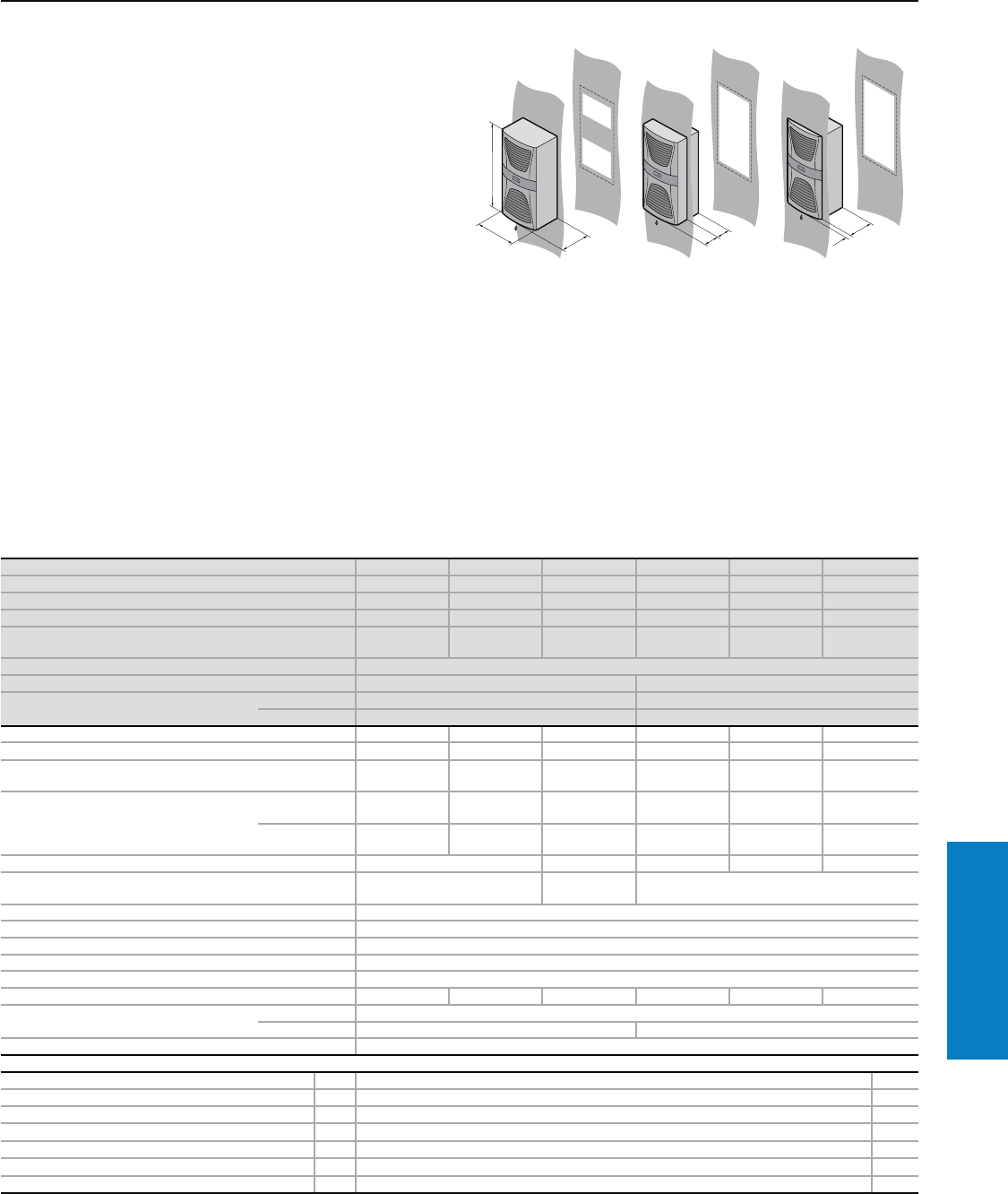
Industrial Buyer’s Guide 285
Climate Control Air Conditioners
Air Conditioner - Wallmount
Useful Cooling Capacity: 3916 - 5794 BTU (1147 - 1697 W)
Protection Ratings:
UL and cUL recognized, CSA
UL file: SA8250
Conguration:
Fully wired ready for connection,
including drilling template and
assembly parts.
With nano-coated condenser
and integrated condensate
evaporator.
Note:
Air conditioner with comfort
controller may be integrated
into a monitoring system with an
optional interface card 3124.200
(RS 232, RS 485, RS 422 and
PLC interface). See page 323
Property Rights:
German registered design
no. 402 02 325
IR reg. design no. DM/062 557
with validity for FR, IT, ES
Indian registered design
no. 190 269
Japanese registered design
no. 1 187 905
For additional technical
information, please visit
www.rittal-corp.com
1
1
1
Part No. with basic controller, RAL 7035 (light gray) 3304.100 3304.110 3304.140 3305.100 3305.110 3305.140
Part No. with comfort controller, RAL 7035 (light gray) 3304.500 3304.510 3304.540 3305.500 3305.510 3305.540
Part No. with basic controller, Type 304 stainless steel 3304.200 3304.210 3304.240 3305.200 3305.210 3305.240
Part No. with comfort controller, Type 304 stainless steel 3304.600 3304.610 3304.640 3305.600 3305.610 3305.640
Voltage V, Hz 230, 50/60 115, 50/60 400, 50/460,
60, 3~ 230, 50/60 115, 50/60 400, 50/460,
60, 3~
Dimensions inches (mm) H x W x D 37 x 16 x 10 (950 x 400 x 260)
Useful cooling capacity QK BTU (W) Ti 131 Ta 131 3916 (1147) 5794 (1697)
Useful cooling capacity QK to DIN 3168
BTU (W)
Ti 95 Ta 95 3415/3620 (1000/1060) 5123/5157 (1500/1510)
Ti 95 Ta 122 2698/2869 (790/840) 4201/4269 (1230/1250)
Rated current maximum 4.8 A/4.4 A 9.5 A/10.0 A 2.5 A/2.6 A 5.4 A/6.0 A 11.0 A/12.5 A 2.3 A/2.6 A
Starting current 12.0 A/14.0 A 26.0 A/28.0 A 11.5 A/12.7 A 22.0 A/24.0 A 42.0 A/46.0 A 12.2 A/11.3 A
Pre-fuse T 10.0 A/10.0 A 16.0 A/16.0 A 10.0 A/10.0
A1) 16.0 A/16.0 A 20.0 A/20.0 A 10.0 A/10.0
A1)
Power consumption Pel to DIN 3168
Ti 95 Ta 95 700 W/650 W 725 W/680 W 580 W/550 W 850 W/
1000 W
880 W/
1050 W 800 W/980 W
Ti 95 Ta 122 750 W/710 W 780 W/750 W 660 W/680 W 1000 W/
1160 W
1040 W/
1200 W 960 W/1150 W
Cooling coefficient j = QK/Pel Ti 95 Ta 95 1.4 1.7 1.8 1.7 1.9
Refrigerant R134a, 11.4 oz (325g) R134a, 17.6
oz (500 g) R134a, 21.2 oz (600 g)
Maximum allowable operating pressure 363 psi (25 bar)
Temperature and setting range 68 to 131° F (+20 to +55° C)
Environmental ratings UL Type 12 (IP 54)
Duty cycle 100%
Type of connection Plug-in terminal strip
Weight lb (kg) 86.0 (39) 97.0 (44) 88.2 (40) 90.3 (41) 101.4 (46) 92.6 (42)
Air displacement of fans External circuit 530 cfm (900 m3/h)
Internal circuit 353 cfm (600 m3/h) 471 cfm (600 m3/h)
Temperature control Basic or comfort controller (factory setting +95° F [35° C])
Accessories PU Page
Filter mats 3 3286.400 328
Metal filters 1 3286.410 327
Door-operated switch 1 4127.000 –
Master/slave cable for comfort controller 1 3124.100 323
RiDiag II including cables for comfort controller 1 3159.100 323
Interface card for comfort controller 1 3124.200 323
Condensate hose 1 3301.612 324
1) Motor circuit-breaker.
Special voltages available by request. We reserve the right to make technical modifications.
Inch and pound measurements are rounded to the nearest whole number.
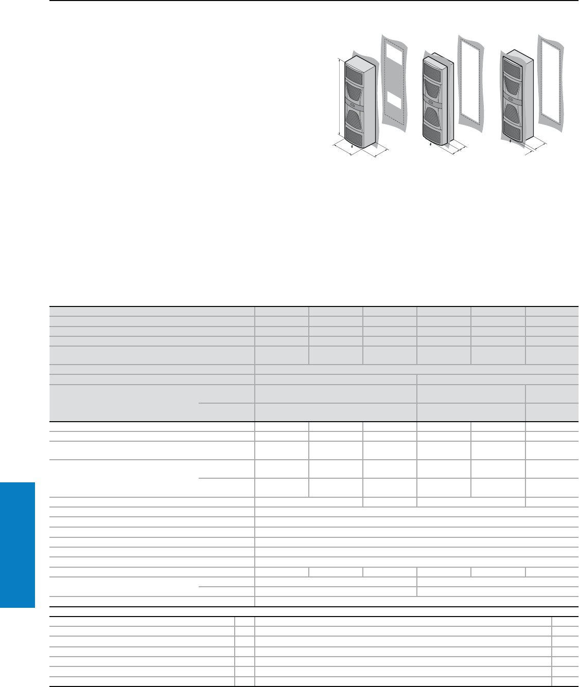
286 Industrial Buyer’s Guide
Climate Control Air Conditioners
Air Conditioner - Wallmount
Useful Cooling Capacity: 8706 - 10525 BTU (2550 - 3083 W)
Protection Ratings:
UL and cUL recognized, CSA
UL file: SA8250
Conguration:
Fully wired ready for connection,
including drilling template,
eyebolt and assembly parts.
With nano-coated condenser
and integrated condensate
evaporator.
Note:
Air conditioners with comfort
controller may be integrated
into a monitoring system with an
optional interface card 3124.200
(RS 232, RS 485, RS 422 and
PLC interface). See page 323
1
1
1
Part No. with basic controller, RAL 7035 (light gray) 3328.100 3328.110 3328.140 3329.100 3329.110 3329.140
Part No. with comfort controller, RAL 7035 (light gray) 3328.500 3328.510 3328.540 3329.500 3329.510 3329.540
Part No. with basic controller, Type 304 stainless steel 3328.200 3328.210 3328.240 3329.200 3329.210 3329.240
Part No. with comfort controller, Type 304 stainless steel 3328.600 3328.610 3328.640 3329.600 3329.610 3329.640
Voltage V, Hz 230, 50/60 115, 50/60 400, 50/460,
60, 3~ 230, 50/60 115, 50/60 400, 50/460,
60, 3~
Dimensions inches (mm) H x W x D 62 x 16 x 11 (1580 x 400 x 295)
Useful cooling capacity QK BTU (W) Ti 131 Ta 131 8706 (2550) 10525 (3083)
Useful cooling capacity QK to DIN 3168
BTU (W)
Ti 95 Ta 95 6830/8026 (2000/2350) 8537/9392 (2500/2750) 8537/9392
(2500/2700)
Ti 95 Ta 122 4952/6771 (1450/1690) 5464/5977 (1600/1750) 6489/6660
(1900/1950)
Rated current maximum 7.5 A/9.1 A 14.7 A/17.3 A 2.8 A/3.3 A 8.6 A/10.6 A 17.0 A/22.0 A 3.7 A/3.8 A
Starting current 22.0 A/26.0 A 36.0 A/39.0 A 6.8 A/7.8 A 21.0 A/21.0 A 44.0 A/42.0 A 6.8 A/7.6 A
Pre-fuse T 16.0 A 25.0 A 10.0 A/10.0
A1) 16.0 A 25.0 A 10.0 A/10.0
A1)
Power consumption Pel to DIN 3168
Ti 95 Ta 95 1025 W/
1200 W
1085 W/
1250 W
930 W/
1150 W
1320 W/
1550 W
1380 W/
1600 W
1300 W/
1500 W
Ti 95 Ta 122 1130 W/
1220 W
1170 W/
1290 W
1150 W/
1400 W
1500 W/
1880 W
1550 W/
1940 W
1550 W/
1850 W
Cooling coefficient j = QK/Pel Ti 95 Ta 95 1.7 2.3 1.9 2.0
Refrigerant R134a, 33.5 oz (950 g)
Maximum allowable operating pressure 406 psi (28 bar)
Temperature and setting range 68 to 131° F (+20 to +55° C)
Environmental ratings UL Type 12 (IP 54)
Duty cycle 100%
Type of connection Plug-in terminal strip
Weight lb (kg) 145.5 (66) 160.9 (73) 147.7 (67) 152.1 (69) 167.6 (76) 154.3 (70)
Air displacement of fans External circuit 377 cfm (640 m3/h) 418 cfm (710 m3/h)
Internal circuit 324 cfm (550 m3/h) 377 cfm (640 m3/h)
Temperature control Basic or comfort controller (factory setting 95° F [+35° C])
Accessories PU Page
Filter mats 3 3286.400 328
Metal filters 1 3286.410 327
Door-operated switch 1 4127.000 –
Master/slave cable for comfort controller 1 3124.100 323
RiDiag II including cables for comfort controller 1 3159.100 323
Interface card for comfort controller 1 3124.200 323
Condensate hose 1 3301.612 324
1) Motor circuit-breaker.
Special voltages available by request. We reserve the right to make technical modifications.
Additional Parts Needed:
For installation in the door, the
use of a door alignment roller
(4538.000) is recommended.
For additional technical
information, please visit
www.rittal-corp.com
Inch and pound measurements are rounded to the nearest whole number.
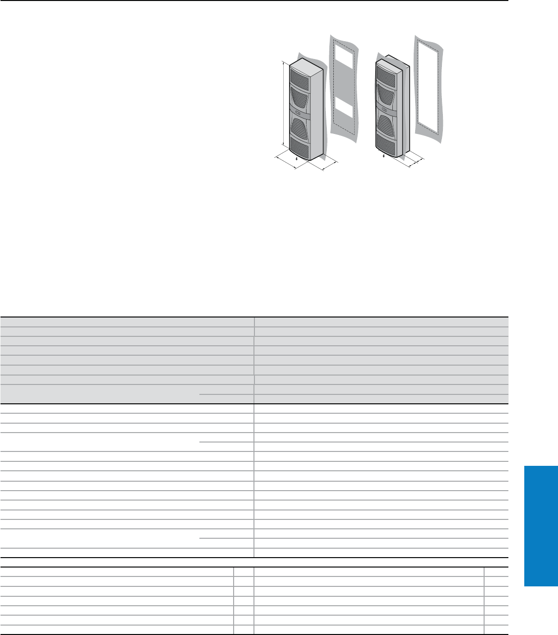
Industrial Buyer’s Guide 287
Climate Control Air Conditioners
Air Conditioner - Wallmount
Useful Cooling Capacity: 16841 BTU (4933 W)
Protection Ratings:
UL and cUL recognized, CSA
UL file: SA8250
Conguration:
Fully wired ready for connection,
including drilling template,
eyebolt and assembly parts.
With nano-coated condenser
and integrated condensate
evaporator.
Note:
Air conditioners with comfort
controller may be integrated
into a monitoring system with an
optional interface card 3124.200
(RS 232, RS 485, RS 422 and
PLC interface). See page 323
Additional Parts Needed:
For installation in the door, the
use of a door alignment roller
(4538.000) is recommended.
For additional technical
information, please visit
www.rittal-corp.com
1
1
1
Part No. with basic controller, RAL 7035 (light gray) 3332.140
Part No. with comfort controller, RAL 7035 (light gray) 3332.540
Part No. with basic controller, Type 304 stainless steel 3332.240
Part No. with comfort controller, Type 304 stainless steel 3332.640
Voltage V, Hz 400, 50/460, 60, 3~
Dimensions inches (mm) H x W x D 62 x 20 x 13 (1580 x 500 x 340)
Useful cooling capacity QK BTU (W) Ti 131 Ta 131 16841 (4933)
Useful cooling capacity QK to DIN 3168 BTU (W) Ti 95 Ta 95 13661/15027 (4000/4400)
Ti 95 Ta 122 10485/12192 (3070/3570)
Rated current maximum 4.2 A/4.2 A
Starting current 9.2 A/11.0 A
Pre-fuse T Motor circuit breaker 10.0 A/10.0 A
Power consumption Pel to DIN 3168 Ti 95 Ta 95 1710 W/2110 W
Ti 95 Ta 122 1980 W/2450 W
Cooling coefficient j = QK/Pel Ti 95 Ta 95 2.3
Refrigerant R134a, 105.8 oz (3000 g)
Maximum allowable operating pressure 406 psi (28 bar)
Temperature and setting range 68 to 131° F (+20 to +55° C)
Environmental ratings UL Type 12 (IP 54)
Duty cycle 100%
Type of connection Plug-in terminal strip
Weight lb (kg) 200.6 (91)
Air displacement of fans External circuit 1177 cfm (2000 m3/h)
Internal circuit 883 cfm (1500 m3/h)
Temperature control Basic or comfort controller (factory setting 95° F [+35° C])
Accessories PU Page
Filter mats 3 3286.400 328
Metal filters 1 3286.410 327
Door-operated switch 14127.000 –
Master/slave cable for comfort controller 1 3124.100 323
RiDiag II including cables for comfort controller 1 3159.100 323
Interface card for comfort controller 1 3124.200 323
Condensate hose 1 3301.612 324
Special voltages available by request. We reserve the right to make technical modifications.
Inch and pound measurements are rounded to the nearest whole number.
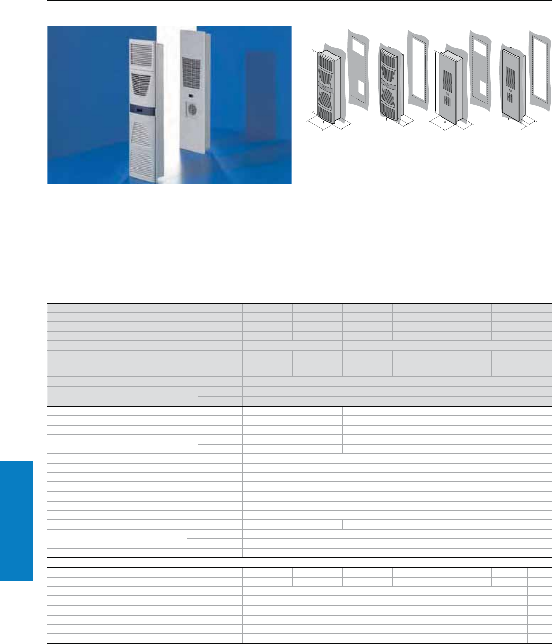
288 Industrial Buyer’s Guide
Climate Control Air Conditioners
Air Conditioner - Wallmount
Slimline, Useful Cooling Capacity: 5804 BTU (1700 W)
The super slimline design
permits system adaptation for
applications where high heat
loads are accommodated in a
confined space.
Protection Ratings:
UL and cUL recognized, CSA
UL file: SA8250
Conguration:
Fully wired ready for connection,
including drilling template and
assembly parts.
With nano-coated condenser
and integrated condensate
evaporator.
Note:
Air conditioner with comfort
controller may be integrated
into a monitoring system with an
optional interface card 3124.200
(RS 232, RS 485, RS 422 and
PLC interface). See page 323 For additional technical
information, please visit
www.rittal-corp.com
1
1
1
1
1
Part No. with basic controller, RAL 7035 (light gray) 3366.100 3377.100 3366.110 3377.110 3366.140 3377.140
Part No. with comfort controller, RAL 7035 (light gray) 3366.500 3377.500 3366.510 3377.510 3366.540 3377.540
Part No. with basic controller, Type 304 stainless steel 3366.200 3377.200 3366.210 3377.210 3366.240 3377.240
Part No. with comfort controller, Type 304 stainless steel 3366.600 3377.600 3366.610 3377.610 3366.640 3377.640
Voltage V, Hz 230, 50/60 115, 50/60 400, 50/460, 60, 3~
Dimensions inches (mm) H x W x D
62 x 18 x 8
(1590 x 435 x
205)
62 x 18 x 7
(1590 x 435 x
165)
62 x 18 x 8
(1590 x 435 x
205)
62 x 18 x 7
(1590 x 435
x 165)
62 x 18 x 8
(1590 x 435
x 205)
62 x 18 x 7
(1590 x 435 x
165)
Useful cooling capacity QK BTU (W) Ti 131 Ta 131 5804 (1700)
Useful cooling capacity QK to DIN 3168
BTU (W)
Ti 95 Ta 95 3415/5123 (1500/1500)
Ti 95 Ta 122 3586/3757 (1050/1100)
Rated current maximum 7.1 A/7.3 A 14.2 A/14.7 A 3.0 A/3.1 A
Starting current 22.0 A/24.0 A 43.0 A/47.0 A 8.0 A/8.8 A
Pre-fuse T 10.0 A 20.0 A 10.0 A
Power consumption Pel to DIN 3168 Ti 95 Ta 95 1045 W/1175 W 1075 W/1200 W 1090 W/1240 W
Ti 95 Ta 122 1220 W/1335 W 1265 W/1250 W 1120 W/1290 W
Cooling coefficient j = QK/Pel Ti 95 Ta 95 1.4 1.3
Refrigerant R134a, 24.7 oz (700 g)
Maximum allowable operating pressure 406 psi (28 bar)
Temperature and setting range 68 to 131° F (+20 to +55° C)
Environmental ratings UL Type 12 (IP 54)
Duty cycle 100%
Type of connection Plug-in terminal strip
Weight lb (kg) 99.2 (45) 110.2 (50) 101.4 (46)
Air displacement of fans (unimpeded air
flow)
External circuit 536 cfm (910 m3/h)
Internal circuit 506 cfm (860 m3/h)
Temperature control Basic or comfort controller (factory setting 95° F [+35° C])
Accessories PU Page
Filter mats 3 3286.400 3253.010 3286.400 3253.010 3286.400 3253.010 328
Metal filters 1 3286.410 3253.220 3286.410 3253.220 3286.410 3253.220 327
Trim frame for external mounting 1 3377.000 324
Door-operated switch 1 4127.000 –
Master/slave cable for comfort controller 1 3124.100 323
RiDiag II including cables for comfort controller 1 3159.100 323
Interface card for comfort controller 1 3124.200 323
Condensate hose 1 3301.612 324
Special voltages available by request. We reserve the right to make technical modifications.
Inch and pound measurements are rounded to the nearest whole number.
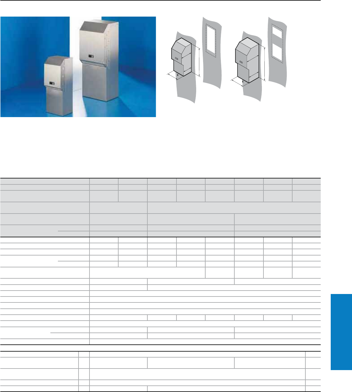
Industrial Buyer’s Guide 289
Climate Control Air Conditioners
UL Type 4X Air Conditioner - Wallmount
Useful Cooling Capacity: 2400 - 5794 BTU (703 - 1697 W)
Material:
Type 304 stainless steel
Protection Ratings:
UL and cUL recognized, CSA
UL file: SA8250
Conguration:
Fully wired ready for connection,
including drilling template and
assembly parts.
With nano-coated condenser and
integrated condensate evaporator.
Note:
Air conditioner with comfort
controller may be integrated
into a monitoring system with an
optional interface card 3124.20
(RS 232, RS 485, RS 422 and
PLC interface). See page 323
Now made in the USA.
1
Part No. with basic controller 3303.1042) 3303.1142) 3304.104 3304.114 3304.144 3305.104 3305.114 3305.144
Part No. with comfort controller 3303.5042) 3303.5142) 3304.504 3304.514 3304.544 3305.504 3305.514 3305.544
Voltage V, Hz 230, 50/60 115, 60 230, 50/60 115, 60 400, 50/
460, 60, 3~ 230, 50/60 115, 60 400, 50/
460, 60, 3~
Dimensions inches (mm) H x W x D 24 x 11 x 12
(620 x 285 x 298) 40 x 16 x 14 (1020 x 405 x 358)
Useful cooling capacity QK
BTU (W) Ti 131 Ta 131 2400 (703) 3916 (1147) 5794 (1697)
Useful cooling capacity QK
to DIN 3168 BTU (W)
Ti 95 Ta 95 1708/2083 (500/610) 3415/3620 (1000/1060) 5123/5157 (1500/1510)
Ti 95 Ta 122 956/1195 (280/350) 2698/2869 (790/840) 4201/4269 (1230/1250)
Rated current maximum 2.6/2.6 A 5.7 A 5.4/5.0 A 10.6/11.1 A 2.8/2.9 A 6.0/6.5 A 12.1/13.6 A 2.6/2.9 A
Starting current 5.1/6.4 A 11.5 A 12.0/14.0 A 26.0/28.0 A 11.5/12.7 A 22.0/24.0 A 42.0/46.0 A 12.2/11.3 A
Pre-fuse T 10.0 A 10.0 A 10.0 A 16.0 A 10.0 A1) 16.0 A 20.0 A 10.0 A1)
Power consumption Pel to
DIN 3168
Ti 95 Ta 95 360/380 W 470 W 700/650 W 725/680 W 580/550 W 850/1000 W 880/1050 W 800/980 W
Ti 95 Ta 122 420/390 W 500 W 750/710 W 780/750 W 660/680 W 1000/1160 W 1040/1200 W 960/1150 W
Cooling coefficient j =
QK/Pel Ti 95 Ta 95 1.4 1.7 1.8 1.7 1.9
Refrigerant R134a, 6.0 oz (170 g) R134a, 17.6 oz (500 g) R134a, 21.1 oz (600 g)
Maximum allowable operating pressure 406 psi (28 bar) 363 psi (25 bar)
Temperature and setting range 68 to 131° F (+20 to +55° C)
Environmental ratings UL Type 4X (IP 66)
Duty cycle 100%
Type of connection Plug-in terminal strip
Weight lb (kg) 55.1 (25) 108.2 (49) 119.0 (54) 110.2 (50) 112.4 (51) 123.5 (56) 114.6 (52)
Material Type 304 stainless steel
Air displacement of
fans
External circuit 203 cfm (345 m3/h) 530 cfm (900 m3/h) 530 cfm (900 m3/h)
Internal circuit 182 cfm (310 m3/h) 353 cfm (600 m3/h) 471 cfm (800 m3/h)
Temperature control Basic or comfort controller (factory setting 95° F [+35° C])
Accessories PU Page
Door-operated switch 1 4127.000 –
Master/slave cable for comfort
controller 1 3124.100 – 3124.100 323
RiDiag II including cables for comfort
controller 1 3159.100 323
Interface card for comfort controller 1 3124.200 323
Condensate hose 1 3301.610 3301.612 324
1) Motor circuit breaker.
2) Internal condensate evaporator not included.
Special voltages and technical modifications available by request.
For additional technical
information, please visit
www.rittal-corp.com
Inch and pound measurements are rounded to the nearest whole number.
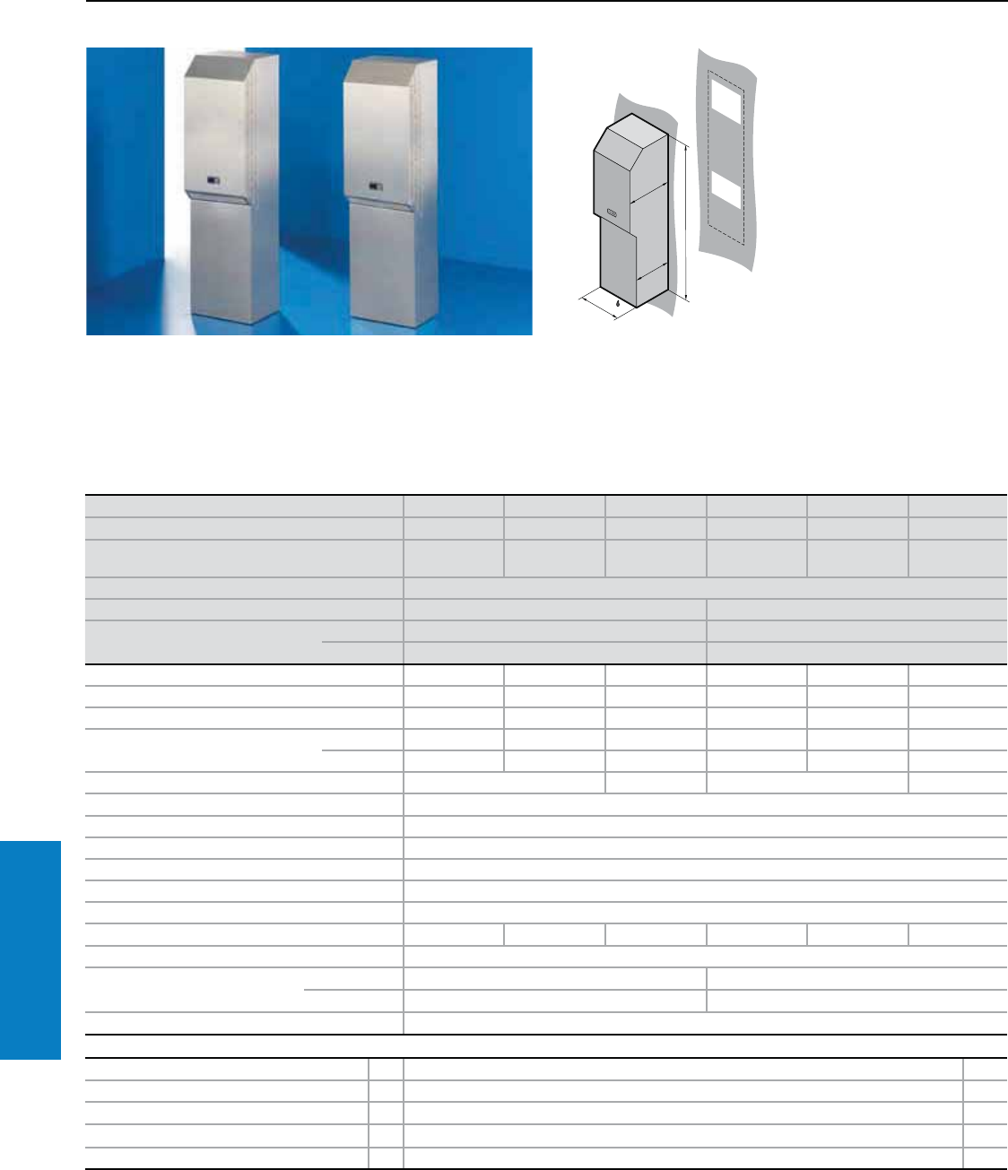
290 Industrial Buyer’s Guide
Climate Control Air Conditioners
UL Type 4X Air Conditioner - Wallmount
Useful Cooling Capacity: 8706 - 10525 BTU (2550 - 3083 W)
Material:
Type 304 stainless steel
Protection Ratings:
UL and cUL recognized
UL file: SA8250
Conguration:
Fully wired ready for connection,
including drilling template and
assembly parts.
With nano-coated condenser
and integrated condensate
evaporator.
Note:
Air conditioner with comfort
controller may be integrated
into a monitoring system with an
optional interface card 3124.200
(RS 232, RS 485, RS 422 and
PLC interface). See page 323
1
Now made in the USA.
For additional technical
information, please visit
www.rittal-corp.com
Part No. with basic controller 3328.104 3328.114 3328.144 3329.104 3329.114 3329.144
Part No. with comfort controller 3328.504 3328.514 3328.544 3329.504 3329.514 3329.544
Rated operating voltage V, Hz 230, 50/60 115, 50/60 400, 50/460,
60, 3~ 230, 50/60 115, 50/60 400, 50/460,
60, 3~
Dimensions inches (mm) H x W x D 65 x 16 x 15 (1650 x 405 x 388)
Useful cooling capacity QK BTU (W) Ti 131 Ta 131 8706 (2550) 10525 (3083)
Useful cooling capacity QK to DIN 3168
BTU (W)
Ti 95 Ta 95 6860/8025 (2000/2350) 8538/9392 (2500/2750)
Ti 95 Ta 122 4952/5772 (1450/1690) 5464/5977 (1600/1750)
Rated current max. 7.5 A/9.1 A 14.7 A/17.3 A 2.8 A/3.3 A 8.6 A/10.6 A 17.0 A/22.0 A 3.7 A/3.8 A
Start-up current 22.0 A/26.0 A 36.0 A/39.0 A 6.8 A/7.8 A 21.0 A/21.0 A 44.0 A/42.0 A 6.8 A/7.6 A
Pre-fuse T 16.0 A 25.0 A 10.0A/10.0 A1) 16.0 A 25.0 A 10.0 A/10.0 A1)
Power consumption Pel to DIN 3168 Ti 95 Ta 95 1025/1200 W 1085/1250 W 1050/1275 W 1450/1675 W 1500/1725 W 1425/1625 W
Ti 95 Ta 122 1250/1350 W 1300/1410 W 1275/1525 W 1625/2000 W 1675/2065 W 1675/1975 W
Cooling coefficient j = QK/Pel Ti 95 Ta 95 1.7 2.3 1.9 2.0
Refrigerant R134a, 31.7 oz (900 g)
Maximum allowable operating pressure 406 psi (28 bar)
Temperature and setting range 68 to 122° F (+20 to +55° C)
Protection rating UL Type 4X (IP 66)
Duty cycle 100%
Type of connection Plug-in terminal strip
Weight lb (kg) 176.4 (80) 191.8 (87) 176.4 (80) 183.0 (83) 198.4 (90) 183.0 (83)
Material Type 304 stainless steel
Air displacement of fans External circuit 377 cfm (640 m3/h) 418 cfm (710 m3/h)
Internal circuit 324 cfm (550 m3/h) 377 cfm (640 m3/h)
Temperature control Basic or comfort controller (factory setting 95° F [+35° C])
Accessories PU Page
Door-operated switch 1 4127.000 –
Master/slave cable for comfort controller 1 3124.100 323
RiDiag II including cables for comfort controller 1 3159.100 323
Interface card for comfort controller 1 3124.200 323
Condensate hose 1 3301.612 324
1) Motor circuit breaker.
Special voltages available on request. We reserve the right to make technical modifications.
Inch and pound measurements are rounded to the nearest whole number.
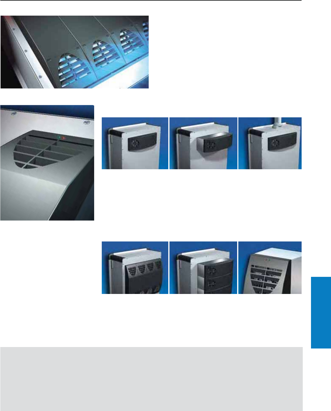
Industrial Buyer’s Guide 291
Climate Control Thermoelectric Coolers
Thermoelectric Cooler
Small, Lightweight, Efficient
The powerful thermoelectric cooling unit in a lightweight
design. The energy efficient climate-control solution for
command panels and small enclosures – an energy
savings of more than 60% compared to conventional
industry systems.
Internal mounting
When installed in the
enclosure, the unit only
protrudes by a few
inches, and therefore does
not interrupt either
the aesthetic appearance
or freedom of movement
on support arm systems.
External mounting
Its low weight also allows it
to be externally mounted on
simple aluminium rear panels
or blanking panels.
Support arm systems
Thanks to its low-vibration
operation and minimal weight,
the thermoelectric cooler from
Rittal is the ideal partner on
support arm systems.
Mounting
Modular
Scalable output
The modular designs
allows simple scaling of the
cooling output depending
on your requirements,
both horizontally . . .
. . . and vertically. Controller
Energy-efficient control with
pulse width modulation and
innovative soft start function
ensures a constant enclosure
temperature and a long
service life of the Peltier
elements.
Benets
• Cooling output 341 BTU,
thanks to state-of-the-art
Peltier technology.
• Low-maintenance
thanks to an efficient
design.
• High operating ratio
(Coefficiency of
Performance >1) thanks
to optimum interplay
between all components.
• Maximum possible
protection for your
electronics, floating
change-over fault signal
contact in case of over
temperature.
• USB interface for unit
programming.
• Minimal build volume
and minimal weight
compared with other
industry systems.
• Large voltage range
from 100 – 240 V AC
and 24 V DC.
• RJ 45 interface for linking
to the Rittal CMC-TC
monitoring system.
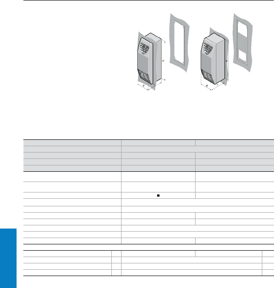
292 Industrial Buyer’s Guide
Climate Control Thermoelectric Coolers
Thermoelectric Cooler
Useful Cooling Capacity: 341 BTU (100 W)
Application:
• Ideal for cooling small enclosures
and operator interface panels
• Especially suitable for use on
support arm systems as well
• Optimum space utilization
• Targeted cooling of hot spots
Conguration:
Thermoelectric cooling unit,
wired ready for connection, with
multilingual documentation and
mounting accessories.
Part No. 3201.200 3201.300
Dimensions inches (mm) H x B x T 16 x 5 x 6 (400 x 125 x 155)
Rated operating voltage V/Hz 100 – 230 V AC / 50/60 Hz 24 V DC
Coefficiency of Performance/COP Ti 95 Ta 95 1.0 1.2
Useful cooling output QK to DIN 3168 Ti 95 Ta 95 341 BTU (100 W) 341 BTU (100 W)
Starting current 120 V: 9.2 A
230 V: 4.7 A 40 A
Max. running current 120 V: 1.2 A
230 V: 0.6 A 5.2 A
Power pack integrated –
Color of cover/unit RAL 7024/Anodized aluminium
Protection rating NEMA 12/IP 54
Weight lb (kg) 7.7 (3.5) 6.6 (3.0)
Temperature range +32 to +131° F (0 to +55° C) +32 to +131° F (0 to +55° C)
Air throughput, unimpeded air flow 29 cfm (50 m3/h)
Type of connection Plug-in spring connection terminal
Pre-fuse t 2 A 10 A
Accessories PU Page
Power pack 150 watts for 35 mm top-hat rail 1 – 3201.030 –
Filter mat 1 3201.050 –
Door-operated switch 1 4127.010 241
Digital temperature indicator 1 3114.200 321
We reserve the right to make technical modifications. Special voltages available by request.
Inch and pound measurements are rounded to the nearest whole number.
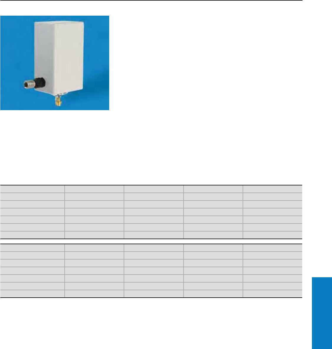
Industrial Buyer’s Guide 293
Climate Control Vortex Coolers
Low Noise Vortex Cooler
Useful Cooling Capacity: 400 - 5000 BTU (117 - 1465 W)
Vortex Coolers use compressed air to create a cool stream of air which is
distributed inside an enclosure using a flexible hose ducting kit. This low
noise version is housed in a UL94 V-O plastic cover with sound deadening
insulation for quieter operation.
These coolers are especially effective in small enclosures where air
conditioners will not fit, when an existing source of compressed air exists,
when heat loads are low to moderate, or when a NEMA 4/4X cooling
solution is required. Vortex Coolers are also effective in applications where
EMI/ RFI must be minimized.
Rittal can provide sizing assistance and, through Rittal’s modification
service center, mounting cut-outs for these coolers.
Maintains 80-95° F temperature
Operates in environments
up to 175° F
Material:
Stainless steel or aluminum
Color:
Satin finish
Protection Ratings:
UL type 12, 4/4X
UL listed
UL file #191061
Conguration:
Includes low noise Vortex Cooler,
ducting kit and mechanical
thermostat. No electrical wiring
required.
For additional technical
information, please visit
www.rittal-corp.com
Advantages
Easy quick top or side mounting
No wiring
No maintenance required
Very quiet, 62 dB(A) operation
Slight pressurization of enclosure
Integrated mechanical thermostat
Part No. 9963.957 9963.959 9963.961 9963.963
UL Type Rating 12 12 12 12
Cooling Capacity (BTU)1) 900 1500 2500 5000
Noise level at dBa at 100 psi 62 62 62 62
Air consumption SCFM 15 25 35 70
Pressure psi 100 100 100 100
Port size NPT inches 0.375 0.375 0.375 0.375
Part No. 9963.958 9963.960 9963.962 9963.964
UL Type Rating 4/4X 4/4X 4/4X 4/4X
Cooling Capacity (BTU)1) 900 1500 2500 5000
Noise level at dBa at 100 psi 62 66 62 62
Air consumption SCFM 15 25 35 70
Pressure range psi 100 100 100 100
Port size NPT inches 0.375 0.375 0.375 0.375
Inch and pound measurements are rounded to the nearest whole number.
1) Cooling capacity at 100 psig, 70° F inlet air, 90° F thermostat setting, -40° F pressure dew point.
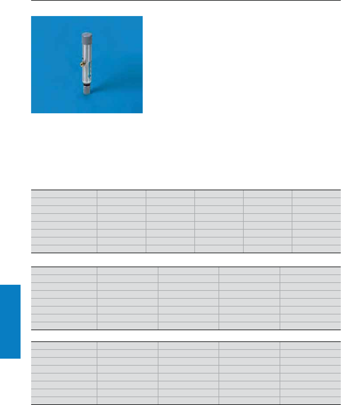
294 Industrial Buyer’s Guide
Climate Control Vortex Coolers
Vortex Cooler
Useful Cooling Capacity: 400 - 5000 BTU (117 - 1465 W)
Vortex Coolers use compressed air to create a cool stream of air which is
distributed inside an enclosure using a flexible hose ducting kit.
These coolers are especially effective in small enclosures where air
conditioners will not fit, when an existing source of compressed air exists,
when heat loads are low to moderate, or when a NEMA 4/4X cooling
solution is required. Vortex Coolers are also effective in applications where
EMI/ RFI must be minimized.
Rittal can provide sizing assistance and, through Rittal’s modification
service center, mounting cut-outs for these coolers.
Low maintenance
Maintain UL Type 12, 4 and
4X ratings
Material:
Stainless steel or aluminum
Color:
Satin finish
Protection Ratings:
CE, UL
UL listed
UL file: 191061
Advantages
Small physical size
No EMI/RFI created
Creates cooled air without
refrigerants (CFCs/HFCs)
Exceptionally reliable, no
moving parts to break
Part No. 9963.944 9963.945 9963.946 9963.947 9963.9483)
UL Type Rating 12 12 12 12 12
Voltage1) 115/50/60 115/50/60 115/50/60 115/50/60 115/50/60
Cooling Capacity (BTU)2) 400 900 1500 2500 5000
Noise level at dBa at 100 psi 69 80 83 90 90
Air consumption SCFM 8 15 25 35 70
Pressure range psi 70 – 150 70 – 150 70 – 150 70 – 150 70 – 150
Port size NPT inches 0.125 0.25 0.25 0.25 0.25
Part No. 9963.949 9963.950 9963.953 9963.9543)
UL Type Rating 4444
Voltage1) 115/50/60 115/50/60 115/50/60 115/50/60
Cooling Capacity (BTU)2) 900 1700 2500 5000
Noise level at dBa at 100 psi 83 86 90 90
Air consumption SCFM 15 25 35 70
Pressure range psi 70 – 150 70 – 150 70 – 150 70 – 150
Port size NPT inches 0.125 0.25 0.25 0.25
Part No. 9963.951 9963.955 9963.956 9963.9523)
UL Type Rating 4X 4X 4X 4X
Voltage1) 115/50/60 115/50/60 115/50/60 115/50/60
Cooling Capacity (BTU)2) 900 1700 2500 5000
Noise level at dBa at 100 psi 83 86 90 90
Air consumption SCFM 15 25 35 70
Pressure range psi 70 – 150 70 – 150 70 – 150 70 – 150
Port size NPT inches 0.125 0.25 0.25 0.25
1) 230 V available by substituting 230 V solenoid – see Accessories, 24 V DC and 480 V AC available by special order.
2) Cooling capacity at 100 psig, 70° F inlet air, 90° F thermostat setting, -40° F pressure dew point.
3) Ships with two 2500 BTU vortex tubes.
Inch and pound measurements are rounded to the nearest whole number.
Conguration:
Includes Vortex Cooler,
thermostat, solenoid, filter,
and ducting kit (230 V solenoid
available for 230 V operation)
For additional technical
information, please visit
www.rittal-corp.com
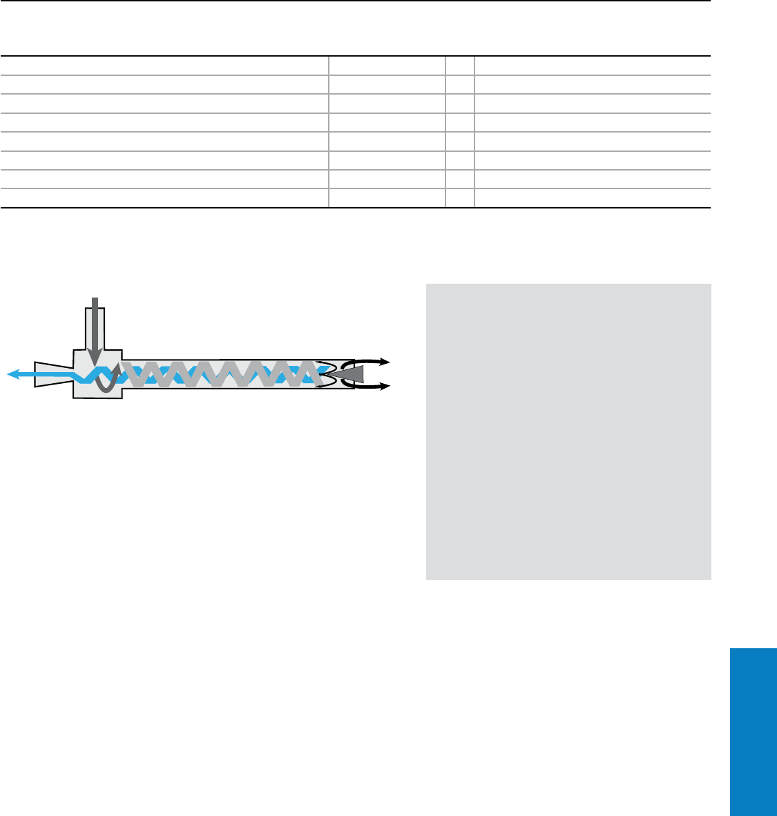
Industrial Buyer’s Guide 295
Climate Control Vortex Coolers
Vortex Cooler
Accessories
Accessories Port size NPT inches PU
5 micron filter for up to 1700 BTU capacity 0.375 1 9963.936
5 micron filter for up to 2500 BTU capacity 0.375 1 9963.937
5 micron filter for up to 5000 BTU capacity 0.75 1 9963.938
Oil filter for up to 1700 BTU capacity 0.375 1 9963.939
Oil filter for up to 5000 BTU capacity 0.375 1 9963.940
UL Type 12 230V solenoid for up to 1700 BTU capacity 0.25 1 9961.458
UL Type 4/4X 230V solenoid for up to 1700 BTU capacity 0.25 1 9961.459
UL Type 4/4X 230V solenoid for up to 2500 BTU capacity 0.375 1 9963.943
The Rittal Vortex Cooler - how it works
A Vortex Cooler uses the principle of vortex
cooling which occurs when air rotates around
an axis. The vortex tube creates a "mini tornado"
from compressed air, which is separated into hot
and cold airstreams. This compressed air enters
into the tube and passes through the generation
chamber to start the airflow rotating. As the air
spins down the tube towards the control valve a
small portion of the compressed air passes out
as hot exhaust. The remaining air is forced back
through the tube at a slower air speed. This cooled
return air exits through the cold air exhaust port
and into the enclosure.
The Rittal Vortex Cooler has no moving parts
and are commonly used for spot cooling when a
compressed air source is readily available.
Compressed Air (70° F, 21° C)
Vortex Tube Control Valve
Hot Air Outlet
Vortex Generation Chamber
Cold Air Outlet
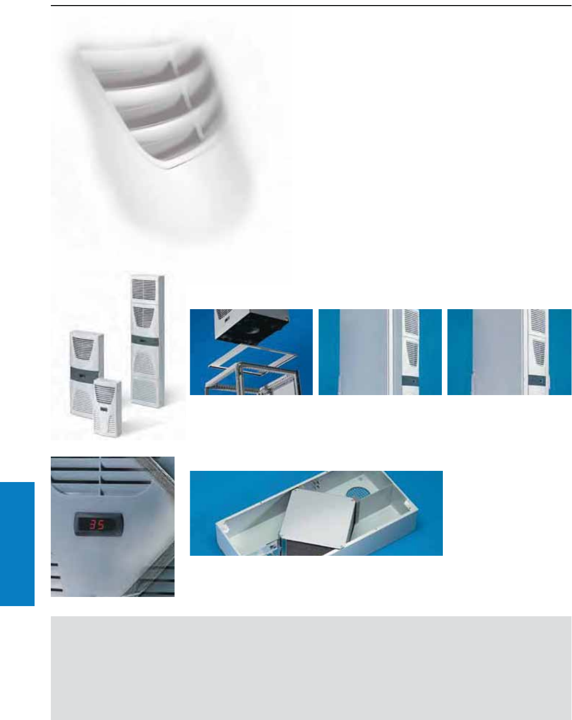
296 Industrial Buyer’s Guide
Climate Control Heat Exchangers
Heat Exchangers
Features of Air/Air Heat Exchangers
Rittal’s air/air heat exchangers are perfect for environments
where the ambient air temperature is at or below the desired
interior temperature of the enclosure. Two separate air circuits
prevent the ingress of dust and pollutants into the enclosure.
Benets:
• Specific thermal output from
17.5 to 90 W/C
• External and internal circuit may
be controlled separately
• Mounting cut-outs and enclosure
dimensions identical to TopTherm
wallmount air conditioners
• Most models suitable for
external and internal mounting
• Top design identical to
TopTherm wallmount air
conditioners
Important:
• The temperature difference
between the room temperature
and enclosure internal
temperature will have a
decisive effect on the heat
loss that may be dissipated.
For calculations
and to download
Therm software, refer
to our website:
www.rittal-corp.com
Platform concept/installation
Identical installation cut-outs
for various cooling capacities.
Easily retrotted
Due to the low weight, simple
assembly cut-outs and problem
free attachment of the heat
exchangers, a cabinet or
enclosure is easily retrofitted.
Servicing/security
Simple maintenance
The heat exchanger module
removes easily for cleaning.
The cleverly designed structure
enables fast, economical
maintenance.
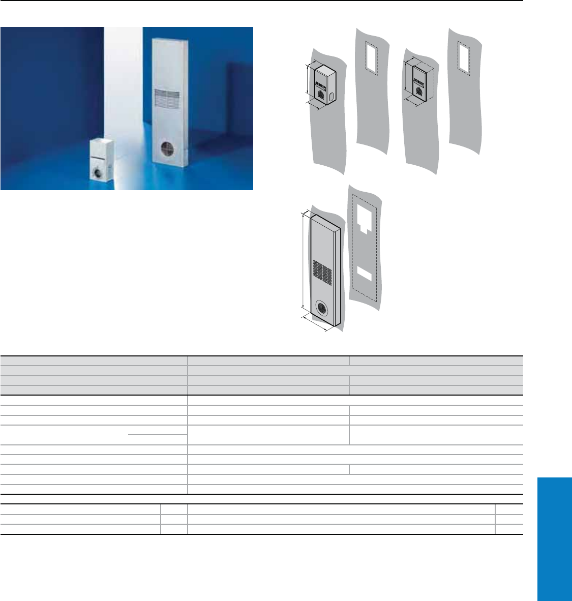
Industrial Buyer’s Guide 297
Climate Control Heat Exchangers
Air/Air Heat Exchanger - Wallmount
Specic Thermal Output: 12 – 62 W/C
Conguration:
Fully wired unit ready for
connection.
Protection Rating:
UL and cUL recognized, CE
UL file: E117603
For additional technical
information, please visit
www.rittal-corp.com
3125.800
Compact wall-mount air/air heat
exchanger. Ideal for small enclosures
and command panels. Suitable for
external and internal mounting.
3129.800
Super-slimline air/air heat exchangers.
Ideal for external/ internal door
mounting.
T
H
B
B
H
T
B
H
T
Part No. 3125.800 3129.8001)
Voltage V, Hz 230, 50/60
Dimensions inches (mm) H x B x T 16 x 8 x 6 (400 x 200 x 146) 54 x 16 x 4 (1360 x 400 x 110)
Specific thermal output 12 W/C 62 W/C
Fans 2 per heat exchanger
Maximum rated current per fan (230 V) 0.11 A/0.13 A 0.45 A/0.55 A
Power per fan (230 V) 25 W/30 W 100 W/130 W
Air displacement of fans External circuit 156/185 cfm
(265/315 m3/h)
506/530 cfm
(860/900 m3/h)
Internal circuit
Temperature range 23 to 131° F (–5 to +55° C)
Type of connection connection cable
Weight lb (kg) 18 (8) 66 (30)
Color RAL 7035 (light gray)
Environmental ratings Internal circuit UL Type 12 (IP 54)
Accessories PU Page
Thermostat 1 3110.000 322
Temperature indicator 1 3114.200 321
Speed control 1 3120.200 322
1) UL Pending
Special voltages available by request. We reserve the right to make technical modifications.
Inch and pound measurements are rounded to the nearest whole number.
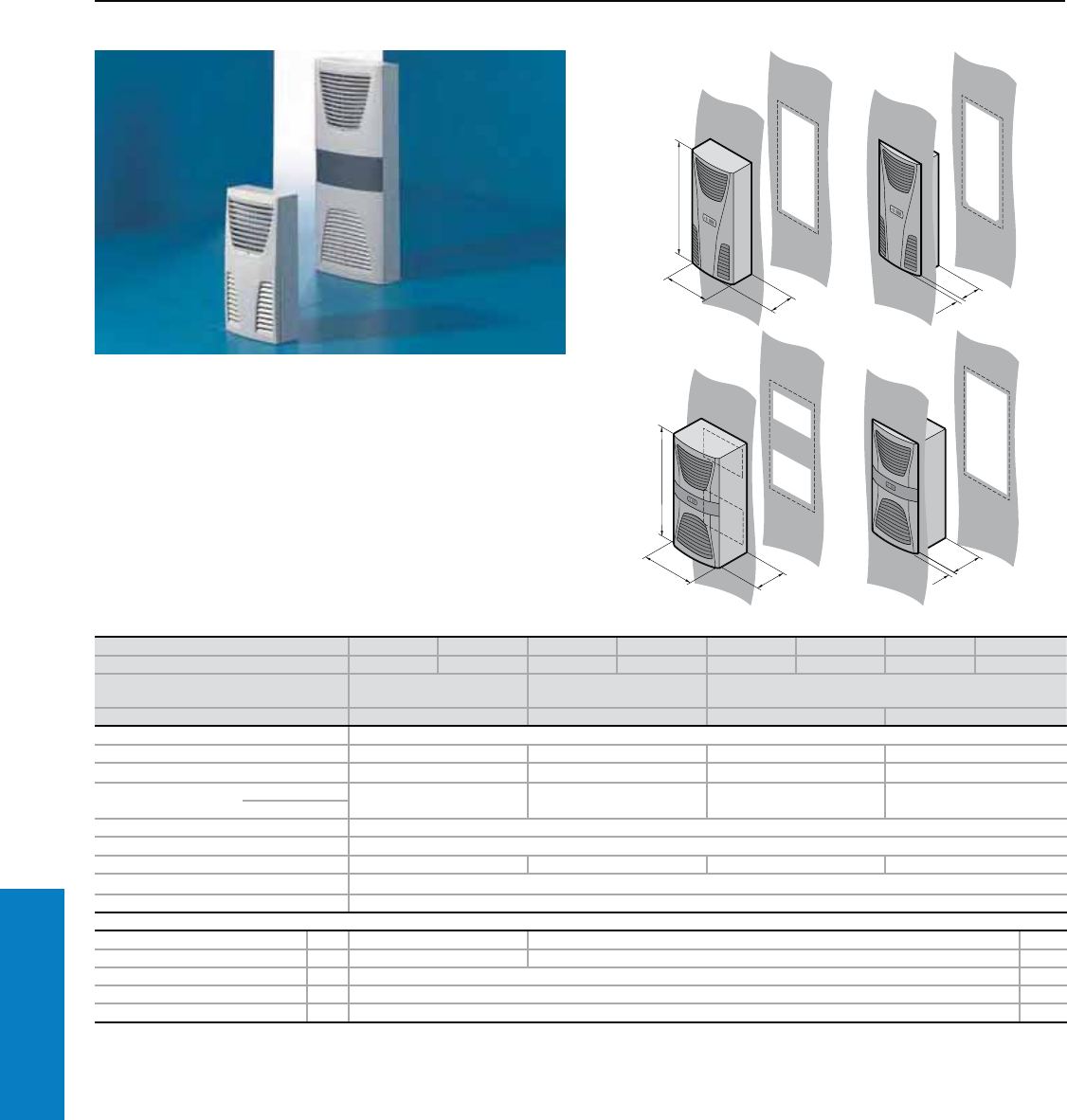
298 Industrial Buyer’s Guide
Climate Control Heat Exchangers
Air/Air Heat Exchanger - Wallmount
Specic Thermal Output: 17.5 – 60 W/C
Protection Ratings:
UL and cUL recognized, CE
UL file: E117603A
For additional technical
information, please visit
www.rittal-corp.com
Property Rights:
German registered designs
no. 402 02 324 and
no. 402 02 325
IR reg. design no. DM/061 967
and no. DM/062 557
Chinese registered design
no. ZL 0330 8461.1
Indian registered design
no. 190 269 and no. 189 953
Japanese registered design
no. 1 187 905 and no. 1 187 896
US design patent no. US D 488,480S
1
1
T
T1
Part No. 3126.100 3126.115 3127.100 3127.115 3128.100 3128.115 3129.100 3129.115
Voltage V, Hz 230, 50/60 115, 50/60 230, 50/60 115, 50/60 230, 50/60 115, 50/60 230, 50/60 115, 50/60
Dimensions inches
(mm) H x B x T1 x T2 22 x 11 x 6
(550 x 280 x 150)
37 x 16 x 8 x 6
(950 x 400 x 205 x 155)
37 x 16 x 9 x 7
(950 x 400 x 225 x 175)
Specific thermal output 17.5 W/C 30 W/C 45 W/C 60 W/C
Fans 2 per heat exchanger
Maximum rated current per fan (230 V) 0.11 A/0.13 A 0.28 A/0.34 A 0.3 A/0.4 A 0.38 A/0.4 A
Power per fan (230 V) 23 W/27 W 60 W/75 W 70 W/90 W 85 W/90 W
Air displacement of
fans
External circuit 156/185 cfm
(265/315 m3/h)
283/309 cfm
(480/525 m3/h)
353/368 cfm
(600/625 m3/h)
506/530 cfm
(860/900 m3/h)
Internal circuit
Temperature range 23 to 131° F (–5 to +55° C)
Type of connection Plug-in terminal strip
Weight lb (kg) 22 (10) 40 (18) 42 (19) 46 (21)
Color RAL 7035 (light gray)
Environmental ratings Internal circuit UL Type 12 (IP 54)
Accessories PU Page
Filter mats 3 3286.300 3286.400 328
Metal filters 1 3286.310 3286.410 327
Thermostat 1 3110.000 322
Temperature indicator 1 3114.200 321
Speed control 1 3120.200 322
Special voltages available by request. We reserve the right to make technical modifications.
Inch and pound measurements are rounded to the nearest whole number.
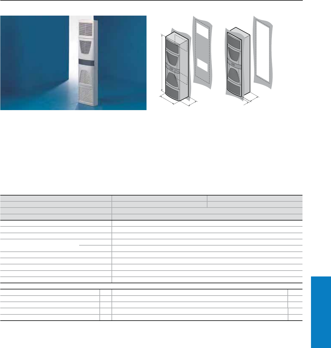
Industrial Buyer’s Guide 299
Climate Control Heat Exchangers
Air/Air Heat Exchanger - Wallmount
Specic Thermal Output: 90 W/C
Protection Ratings:
UL and cUL recognized, CE
UL file: E117603A
Conguration:
Fully wired unit ready for
connection.
• With comfort controller and
digital temperature indicator
• Floating fault signal contact in
case of overtemperature
• Separately controllable
air circuits
Property Rights:
German registered designs
no. 402 02 324 and no. 402 02 325
IR reg. design no. DM/061 967
and no. DM/062 557
Brazilian registered design
no. DI 6203240-2
Chinese registered design
no. ZL 0330 4386.8
Indian registered designs
nos. 190 270, 189 954,
189 955, 189 958
Japanese registered design
no. 1 187 906 and no. 1 187 897
US design patent
no. US D 492,319S and
US D 492,320S
1
1
1
For additional technical
information, please visit
www.rittal-corp.com
Part No. 3130.100 3130.115
Voltage V, Hz 230, 50/60 115, 50/60
Dimensions inches (mm) H x W x D 62 x 16 x 9 (1580 x 400 x 215)
Specific thermal output 90 W/C
Fans 2 per heat exchanger
Maximum rated current per fan (230 V) 0.67 A/0.88 A
Power per fan (230 V) 150 W/200 W
Air displacement of fans External circuit 500/556 cfm (850/945 m3/h)
Internal circuit 500/556 cfm (850/945 m3/h)
Temperature range 23 to 131° F (–5 to +55° C)
Type of connection Plug-in terminal strip
Weight lb (kg) 75 (34)
Color RAL 7035 (light gray)
Environmental ratings Internal circuit UL Type 12 (IP 54)
Accessories PU Page
Filter mats 3 3286.400 328
Metal filters 1 3286.410 327
Thermostat 1 3110.000 322
Temperature indicator 1 3114.200 321
Speed control 1 3120.200 322
Special voltages available by request. We reserve the right to make technical modifications.
Inch and pound measurements are rounded to the nearest whole number.
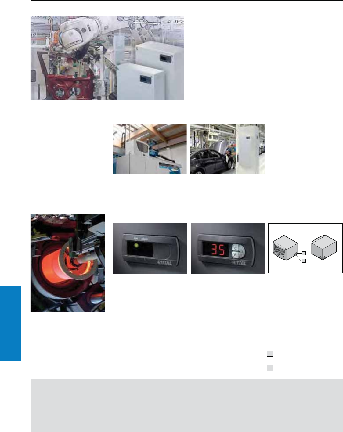
300 Industrial Buyer’s Guide
Climate Control Heat Exchangers
Heat Exchangers
Features of Air/Water Heat Exchangers
Benets:
• Useful cooling capacity from 1025
to 17076 BTU (300 to 5000 W)
• Suitable for use even in extreme
conditions and ambient
temperatures up to 158° F (+70° C)
• Also available with all water-
carrying parts made from
Type 316 stainless steel
Important:
• Air/water heat exchangers
should always be used
in conjunction with chiller
systems or a cooling
water circuit
For calculations
and to download
Therm software, refer
to our website:
www.rittal-corp.com
Versions
Roofmount
Especially for bayed enclosures,
where wallmount devices would
obstruct the door.
Wallmount
For mounting on the wall or any
sufficiently large vertical surface.
Controller
Basic Controller:
• Visualization of the operating
status by a LED display
• Switching hysteresis: 5 C
• Floating fault signal contact in
case of over temperature
• Setpoint adjustable from the
outside by a potentiometer
(setting range 68 – 131° F
[20 – 55° C])
Comfort Controller:
• Switching hysteresis: 2 – 10 C,
preset to 5 C
• System alarm, individually
configurable for 2 floating fault
signal contacts
• Visualization of the current
enclosure internal temperature
and all system messages on
the display
• Storage of all system states in
the log file
• Optional extension card for
integration into monitoring
systems such as CMC
Flexible water logistics and
condensate management
Any condensate is discharged by
one of the two tube connectors
(½") and a discharge hose, which
should be laid with a gradient to
ensure that there are no kinks.
In order to avoid increased
condensation, the cooling water
temperature should be adapted
to match the required cooling
capacity.
1 Condensate discharge
(flexible)
2 Cooling water connection
(flexible)
2
1
Suitable for use in extreme conditions
The air of the enclosure interior may also be cooled to below
the level of the external temperature by using air/water heat
exchangers with a central chiller system. Dust is unable to
penetrate the enclosure. The waste heat from the enclosure
does not raise the temperature of the ambient air, provided
the cold water supply system is spatially separated.
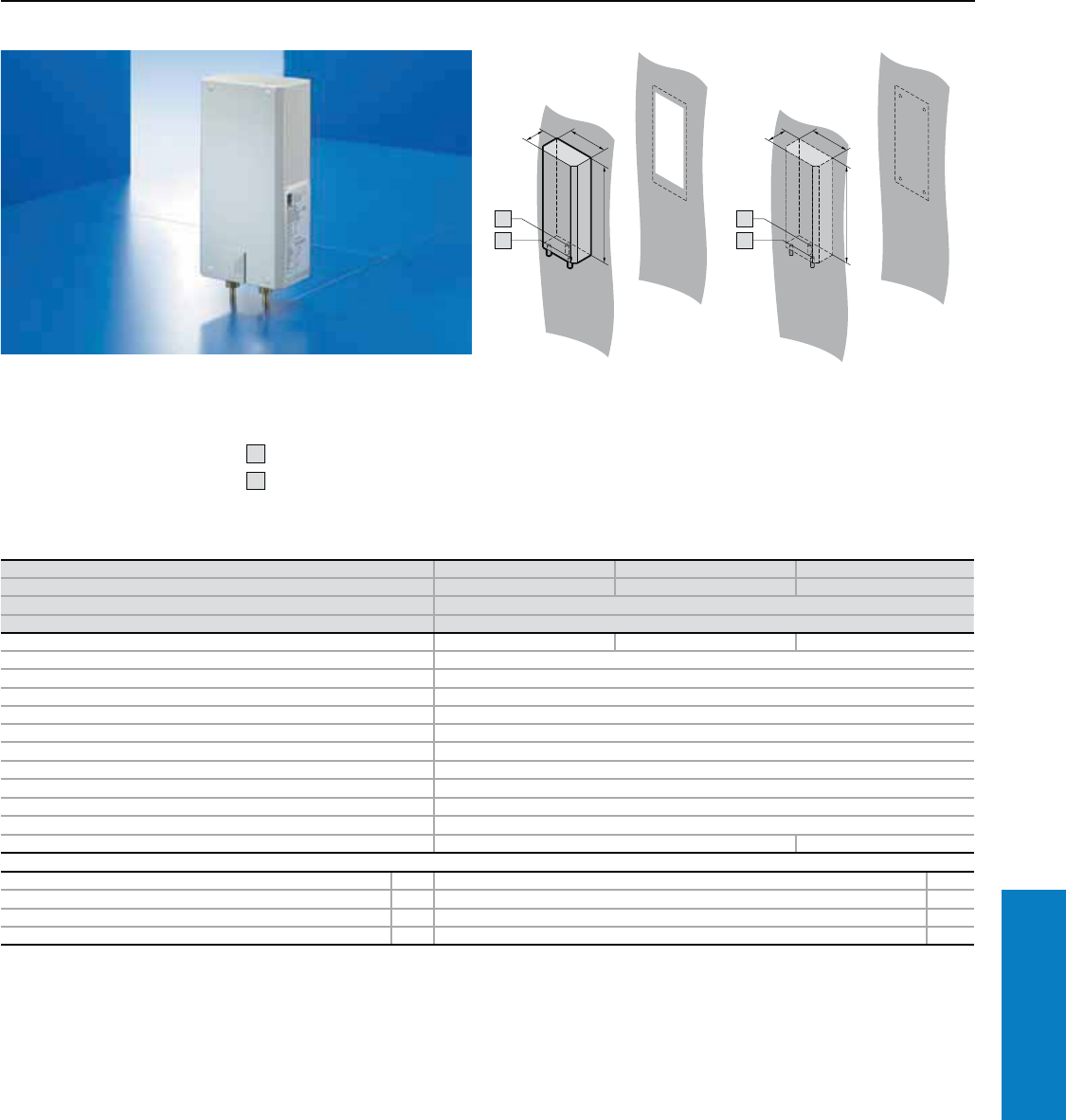
Industrial Buyer’s Guide 301
Climate Control Heat Exchangers
Air/Water Heat Exchanger - Wallmount
Useful Cooling Capacity: 1025 BTU (300 W)
Especially for selective cooling of
hot spots in small enclosures.
Conguration:
Fully wired ready for connection,
including drilling template and
assembly parts.
1 Condensate discharge
2 Cooling water connection
(quick-release fastener)
For additional technical
information, please visit
www.rittal-corp.com
1
1
2
1
1
2
Part No. 3212.230 3212.1151) 3212.0241)
Voltage V, Hz 230, 50/60 115, 50/60 24 V DC
Dimensions inches (mm) H x W x D 12 x 6 x 3 (300 x 150 x 85)
Useful cooling capacity BTU (W) Ti 95 Tw 50, 52.8 gal/h (200 l/h) 1025 (300)
Rated current maximum 0.11 A/0.13 A 0.23 A/0.24 A 1.20 A
Pre-fuse T 4.0 A
Cooling medium Water (refer to specifications and assembly instructions at www.rittal-corp.com)
Water inlet temperature > 34 to 86° F (+1 to +30° C)
Permissible operating pressure p. max. 15 to 145 psi (1 to 10 bar)
Temperature range 34 to 158° F (+1 to +70° C)
Environmental ratings UL Type 12 (IP 55)2)
Duty cycle 100%
Type of connection Connection clamp
Weight lb (kg) 6.6 (3)
Color RAL 7035 (light gray)
Air displacement of fans (unimpeded air flow) 165 cfm (280 m3/h) 147 cfm (250 m3/h)
Accessories PU Page
Temperature indicator 1 3114.200 321
Door-operated switch 1 4127.000, see www.rittal-corp.com –
Condensate hose 1 3301.612 324
Flow regulator valve 1 see www.rittal-corp.com –
1) Delivery times available upon request and UL pending.
2) IP 65 available by request.
Special voltages available by request. We reserve the right to make technical modifications.
Inch and pound measurements are rounded to the nearest whole number.
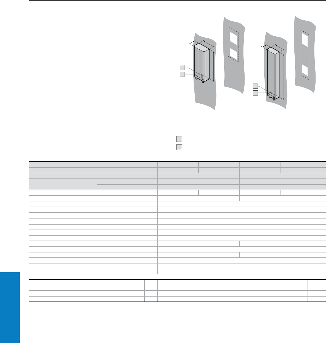
302 Industrial Buyer’s Guide
Climate Control Heat Exchangers
Air/Water Heat Exchanger - Wallmount
Useful Cooling Capacity: 2049 - 4440 BTU (600 - 1300 W)
Protection Ratings:
UL and cUL recognized, CE
UL file: E117603
Conguration:
Fully wired ready for connection
with terminal strip, including
drilling template, gasket and
assembly parts.
Additional Parts Needed:
Cooling water system such
as Rittal chiller systems,
see page 309
1 Condensate discharge ½"
2 Cooling water connection ½"
For additional technical
information, please visit
www.rittal-corp.com
1
1
2
Part No. 3214.100 3214.1151) 3215.100 3215.1151)
Voltage V, Hz 230, 50/60 115, 50/60 230, 50/60 115, 50/60
Dimensions inches (mm) H x W x D 20 x 8 x 4 (500 x 200 x 100) 37 x 8 x 4 (950 x 200 x 100)
Useful cooling capacity BTU (W) Ti 95 Tw 50, 52.8 gal/h (200 l/h) 2049 (600) 4269 (1250)
Ti 95 Tw 50, 105 gal/h (400 l/h) 2220 (650) 4440 (1300)
Rated current maximum 0.17 A/0.18 A 0.34 A/0.36 A 0.38 A/0.4 A 0.76 A/0.8 A
Pre-fuse T 2.0 A 4.0 A
Cooling medium Water (refer to specifications and assembly instructions at www.rittal-corp.com)
Water inlet temperature > 34 to 86° F (+1 to +30° C)
Permissible operating pressure pmax 14.5 to 145 psi (1 to 10 bar)
Temperature range 34 to 158° F (+1 to +70° C)
Environmental ratings UL Type 12 (IP 55)2)
Duty cycle 100%
Type of connection Terminal strip
Weight lb (kg) 15.4 (7) 20.9 (9.5)
Color RAL 7035 (light gray)
Air displacement of fans 71 cfm (120 m3/h) 118 cfm (200 m3/h)
Temperature control Thermostat-controlled magnetic valve
Temperature monitoring Internal thermostat, with change-over contact, switching load 16 A, setting range
68 to 140° F (+20 to +60° C) (factory setting 95° F [+35° C])
Accessories PU Page
Temperature indicator 1 3114.200 321
Door-operated switch 1 4127.000, see www.rittal-corp.com –
Condensate hose 1 3301.612 324
Flow regulator valve 1 see www.rittal-corp.com –
1) UL pending.
2) IP 65 available by request.
Special voltages available by request. We reserve the right to make technical modifications.
1
1
2
Inch and pound measurements are rounded to the nearest whole number.
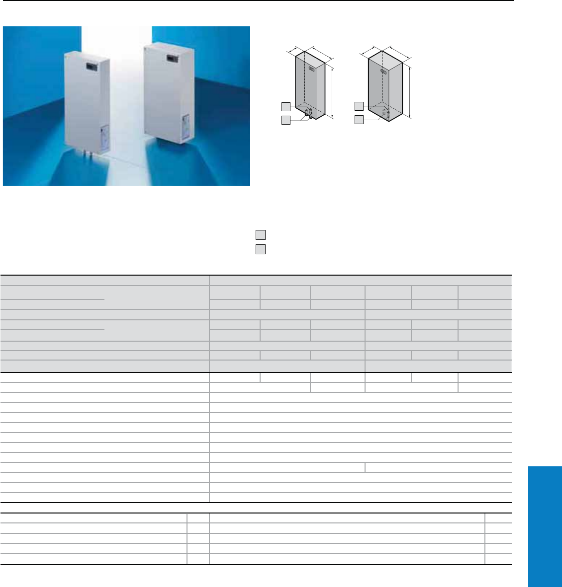
Industrial Buyer’s Guide 303
Climate Control Heat Exchangers
Air/Water Heat Exchanger - Wallmount
Useful Cooling Capacity: 1280 - 3412 BTU (375 - 1000 W)
Protection Ratings:
UL and cUL recognized, CE
UL file: E117603
Upon request: UL Type 3R
available
UL Type 3R file: SA33163
Conguration:
Fully wired ready for connection
with terminal strip, including
drilling template, gasket and
assembly parts.
Additional Parts Needed:
Cooling water system such
as Rittal chiller systems,
see page 309
1 Condensate discharge ½"
2 Cooling water connection ½"
2
1
1
2
1
For additional technical
information, please visit
www.rittal-corp.com
Water-carrying parts
Part No. basic controller CuAL 3363.100 3363.1101) 3363.1401) 3364.100 3364.1101) 3364.1401)
Part No. comfort controller 3363.500 3363.5101) 3363.5401) 3364.500 3364.5101) 2) 3364.5401)
Useful cooling output BTU (W) Ti 95 Tw 50, 105 gal/h (400 l/h) 1706 (500) 3412 (1000)
Part No. basic controller Type 316 stainless steel 3363.104 3363.114 3363.144 3364.1041) 3364.114 3364.144
Part No. comfort controller 3363.504 3363.514 3363.544 3364.5041) 3364.514 3364.544
Useful cooling output BTU (W) Ti 95 Tw 50, 105 gal/h (400 l/h) 1280 (375) 2559 (750)
Voltage V, Hz 230, 50/60 115, 50/60 400, 2~, 50/60 230, 50/60 115, 50/60 400, 2~, 50/60
Dimensions inches (mm) H x W x D 22 x 11 x 4 (550 x 280 x 92) 22 x 11 x 6 (550 x 280 x 142)
Rated current maximum 0.17A/ 0.18A 0.35A/ 0.40A 0.1A/0.12A 0.2A/0.19A 0.4A/0.38A 0.12A/0.11A
Pre-fuse T 4.0 A 4.0 A2) 4.0 A 4.0 A2)
Cooling medium Water (refer to specifications and assembly instructions at www.rittal-corp.com)
Water inlet temperature 34 to 86° F (+1 to +30° C)
Permissible operating pressure p. max. 14.5 to 145 psi (1 to 10 bar)
Temperature range 34 to 158° F (+1 to +70° C)
Environmental ratings UL Type 12 (IP 55)3)
Duty cycle 100%
Type of connection Plug-in terminal strip
Weight lb (kg) 26 (12) 33 (15)
Color RAL 7035 (light gray)
Air displacement of fans 159/188 cfm (270/320 m3/h)
Temperature control Basic or comfort controller (factory setting 95° F [+35° C])
Accessories PU Page
Door-operated switch 1 4127.000, see www.rittal-corp.com –
Master/slave 1 3124.100 323
Interface card for comfort controller 1 3124.200 323
Condensate hose 1 3301.612 324
Flow regulator valve 1 see www.rittal-corp.com –
1) Units include an additional external transformer which must be mounted by the end customer.
2) 2-pole miniature circuit breaker.
3) IP 65 available by request.
Special voltages available by request. We reserve the right to make technical modifications.
Inch and pound measurements are rounded to the nearest whole number.
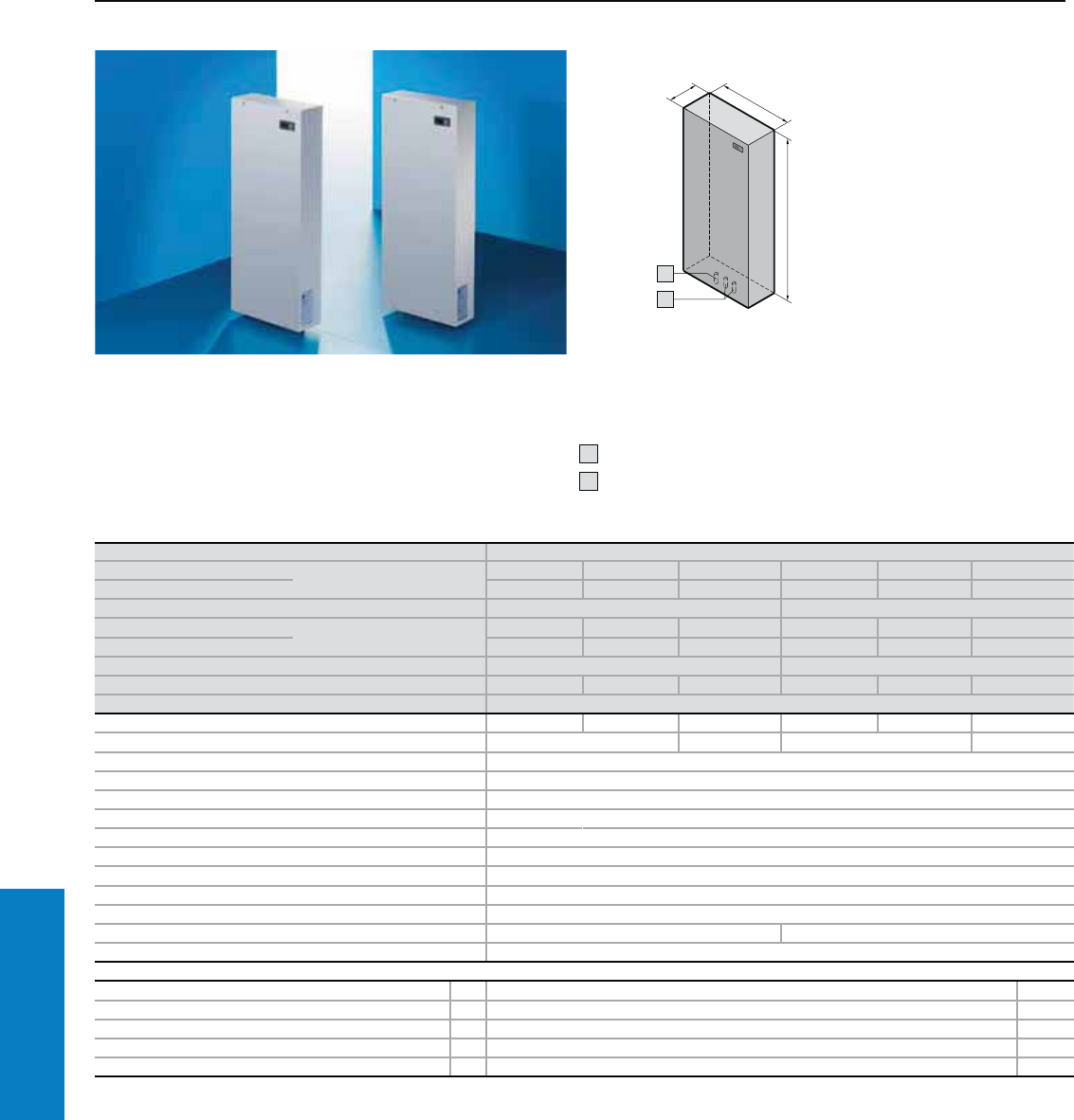
304 Industrial Buyer’s Guide
Climate Control Heat Exchangers
Air/Water Heat Exchanger - Wallmount
Useful Cooling Capacity: 5118 - 10236 BTU (1500 - 3000 W)
Protection Ratings:
UL and cUL recognized, CE
UL file: E117603
Upon request: UL Type 3R
available
UL Type 3R file: SA33163
Conguration:
Fully wired ready for connection
with terminal strip, including
drilling template, gasket and
assembly parts.
Additional Parts Needed:
Cooling water system such
as Rittal chiller systems,
see page 309
1 Condensate discharge ½"
2 Cooling water connection ½"
1
2
1
For additional technical
information, please visit
www.rittal-corp.com
Water-carrying parts
Part No. basic controller CuAL 3373.100 3373.110 3373.140 3374.100 3374.110 3374.140
Part No. comfort controller 3373.500 3373.510 3373.540 3374.500 3374.510 3374.540
Useful cooling output BTU (W) Ti 95 Tw 50, 105 gal/h (400 l/h) 6824 (2000) 10236 (3000)
Part No. basic controller Type 316 stainless steel 3373.104 3373.114 3373.144 3374.104 3374.114 3374.144
Part No. comfort controller 3373.504 3373.514 3373.544 3374.504 3374.514 3374.544
Useful cooling output BTU (W) Ti 95 Tw 50, 105 gal/h (400 l/h) 5118 (1500) 7677 (2250)
Voltage V, Hz 230, 50/60 115, 50/60 400, 2~, 50/60 230, 50/60 115, 50/60 400, 2~, 50/60
Dimensions inches (mm) H x W x D 37 x 16 x 6 (950 x 400 x 142)
Rated current maximum 0.38A/ 0.43A 0.75A/ 0.85A 0.22A/0.25A 0.57A/0.78A 1.15A/1.55A 0.35A/0.45A
Pre-fuse T 4.0 A 4.0 A2) 4.0 A 4.0 A2)
Cooling medium Water (refer to specifications and assembly instructions at www.rittal-corp.com)
Water inlet temperature 34 to 86° F (+1 to +30° C)
Permissible operating pressure p. max. 14.5 to 145 psi (1 to 10 bar)
Temperature range 34 to 158° F (+1 to +70° C)
Environmental ratings UL Type 12 (IP 55)1)
Duty cycle 100%
Type of connection Plug-in terminal strip
Weight lb (kg) 44 (20)
Color RAL 7035 (light gray)
Air displacement of fans 353/368 cfm (600/625 m3/h) 412/430 cfm (700/730 m3/h)
Temperature control Basic or comfort controller (factory setting 95° F [+35° C])
Accessories PU Page
Door-operated switch 1 4127.000, see www.rittal-corp.com –
Master/slave 1 3124.100 323
Interface card for comfort controller 1 3124.200 323
Condensate hose 1 3301.612 324
Flow regulator valve 1 see www.rittal-corp.com –
1) IP 65 available by request.
2) 2-pole miniature circuit breaker.
Special voltages available by request. We reserve the right to make technical modifications.
Inch and pound measurements are rounded to the nearest whole number.
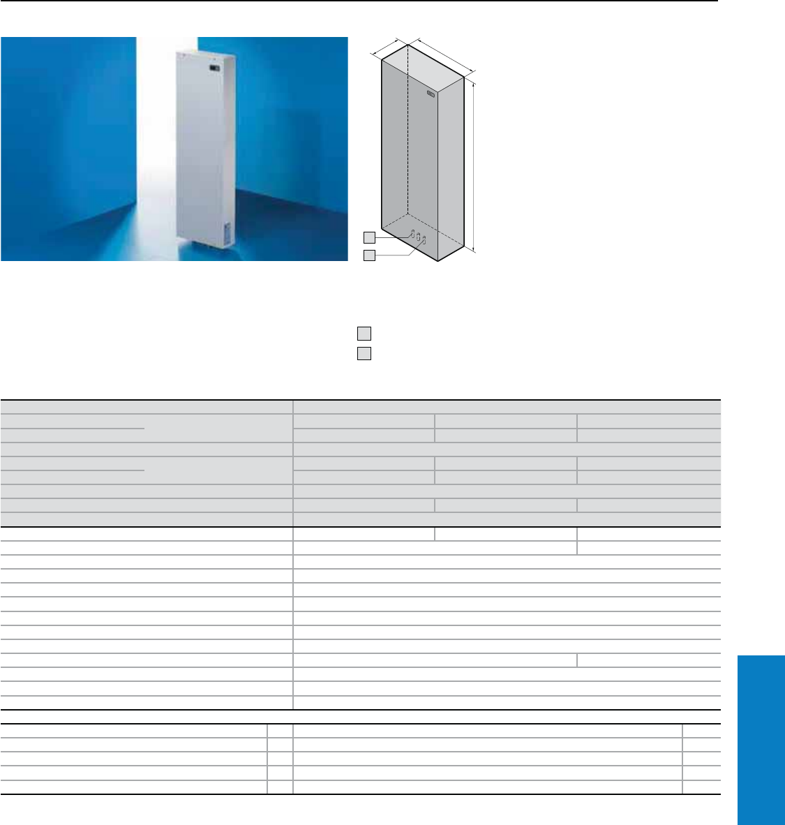
Industrial Buyer’s Guide 305
Climate Control Heat Exchangers
Air/Water Heat Exchanger - Wallmount
Useful Cooling Capacity: 12795 - 17060 BTU (3750 - 5000 W)
Protection Ratings:
UL and cUL recognized, CE
UL file: E117603
Upon request: UL Type 3R
available
UL Type 3R file: SA33163
Conguration:
Fully wired ready for connection
with terminal strip, including
drilling template, gasket and
assembly parts.
Additional Parts Needed:
Cooling water system such
as Rittal chiller systems,
see page 309
1 Condensate discharge ½"
2 Cooling water connection ½"
1
2
1
For additional technical
information, please visit
www.rittal-corp.com
Water-carrying parts
Part No. basic controller CuAL 3375.100 3375.110 3375.140
Part No. comfort controller 3375.500 3375.510 3375.540
Useful cooling output BTU (W) Ti 95 Tw 50, 105 gal/h (400 l/h) 17060 (5000)
Part No. basic controller Type 316 stainless steel 3375.104 3375.114 3375.144
Part No. comfort controller 3375.504 3375.514 3375.544
Useful cooling output BTU (W) Ti 95 Tw 50, 105 gal/h (400 l/h) 12796 (3750)
Voltage V, Hz 230, 50/60 115, 50/60 400, 2~, 50/60
Dimensions inches (mm) H x W x D 55 x 18 x 10 (1400 x 450 x 250)
Rated current maximum 0.57A/0.78A 1.15A/1.55A 0.35A/0.45A
Pre-fuse T 4.0 A 4.0 A1)
Cooling medium Water (refer to specifications and assembly instructions at www.rittal-corp.com)
Water inlet temperature 34 to 86° F (+1 to +30° C)
Permissible operating pressure Pmax. 14.5 to 145 psi (1 to 10 bar)
Temperature range 34 to 158° F (+1 to +70° C)
Environmental ratings UL Type 12 (IP 55)1)
Duty cycle 100%
Type of connection Plug-in terminal strip
Weight lb (kg) 123 (56) 130 (59)
Color RAL 7035 (light gray)
Air displacement of fans 1391/1618 cfm (2365/2750 m3/h)
Temperature control Basic or comfort controller (factory setting 95° F [+35° C])
Accessories PU Page
Door-operated switch 1 4127.000, see www.rittal-corp.com –
Master/slave 1 3124.100 323
Interface card for comfort controller 1 3124.200 323
Condensate hose 1 3301.612 324
Flow regulator valve 1 see www.rittal-corp.com –
1) IP 65 available by request.
2) 2-pole miniature circuit breaker.
Special voltages available by request. We reserve the right to make technical modifications.
Inch and pound measurements are rounded to the nearest whole number.
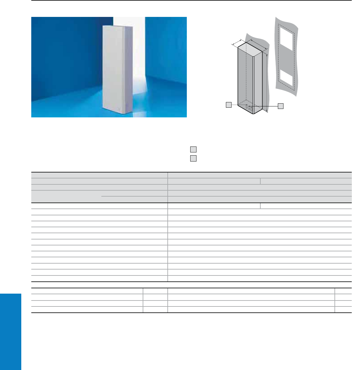
306 Industrial Buyer’s Guide
Climate Control Heat Exchangers
Air/Water Heat Exchanger - Wallmount
Useful Cooling Capacity: 17060 - 23885 BTU (5000 - 7000 W)
Protection Ratings:
CSA
Conguration:
Fully wired ready for connection
with terminal strip, including
drilling template, gasket and
assembly parts.
Additional Parts Needed:
Cooling water system such
as Rittal chiller systems,
see page 309
1 Condensate discharge ½"
2 Cooling water connection ½"
For additional technical
information, please visit
www.rittal-corp.com
Part No. 3216.480
Voltage V, Hz 400, 3~, 50/60 480, 3~, 60
Dimensions inches (mm) H x W x D 71 x 18 x 12 (1800 x 450 x 300)
Useful cooling capacity BTU (W) Ti 95 Tw 50, 105 gal/h (400 l/h) 17060 BTU (5000 W)
Ti 95 Tw 50, 132 gal/h (500 l/h) 23885 BTU (7000 W)
Rated current maximum 1.4 A/1.6 A 1.2 A
Pre-fuse T 4.0 A, 3-pole
Cooling medium Water (refer to specifications and assembly instructions at www.rittal-corp.com)
Water inlet temperature 34 to 86° F (+1 to +30° C)
Permissible operating pressure Pmax. 14.5 to 145 psi (1 to 10 bar)
Temperature range 34 to 158° F (+1 to +70° C)
Environmental ratings UL Type 12 (IP 55)1)
Duty cycle 100%
Type of connection Terminal strip
Weight lb (kg) 174.2 (79)
Color RAL 7035 (light gray)
Air displacement of fans 4078 cfm (2400 m3/h)
Temperature control Thermostat-controlled magnetic valve
Accessories PU Page
Temperature indicator 1 3114.200 321
Door-operated switch 1 4127.000, see www.rittal-corp.com –
Condensate hose 1 3301.612 324
Flow regulator valve 1 see www.rittal-corp.com –
1) IP 65 available by request.
UL pending, all water-carrying parts Type 316 stainless steel.
Special voltages available by request. We reserve the right to make technical modifications.
1
1
2
Inch and pound measurements are rounded to the nearest whole number.
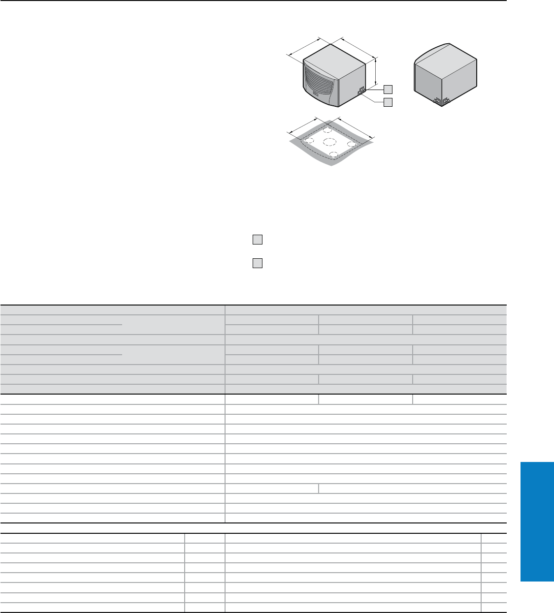
Industrial Buyer’s Guide 307
Climate Control Heat Exchangers
Air/Water Heat Exchanger - Roofmount
Useful Cooling Capacity: 6403 - 8538 BTU (1875 - 2500 W)
Protection Ratings:
cUL recognized, CE
UL file: E117603A
Conguration:
Fully wired ready for connection
with connector, including drilling
template, gasket and assembly
parts.
Additional Parts Needed:
Cooling water system such
as Rittal chiller systems,
see page 309
1 Condensate discharge
(flexible)
2 Cooling water connection
(flexible)
Property Rights:
German registered designs
no. 402 02 324 and
no. 402 02 325
US design patent
no. US D 492,319S
Indian registered design
no. 189 956
Chinese registered design
no. ZL 0330 6415.6
2
1
1
Water-carrying parts
Part No. basic controller CuAL 3209.100 3209.110 3209.140
Part No. comfort controller 3209.500 3209.510 3209.540
Useful cooling capacity BTU (W) Ti 95 Tw 50, 105 gal/h (400 l/h) 8538 (2500)
Part No. basic controller Type 316 stainless steel 3209.1041) 3209.1141) 3209.144
Part No. comfort controller 3209.5041) 3209.5141) 3209.544
Useful cooling capacity BTU (W) Ti 95 Tw 50, 105 gal/h (400 l/h) 6403 (1875)
Voltage V, Hz 230, 50/60 115, 50/60 400, 2~, 50/60
Dimensions inches (mm) H x W x D 16 x 24 x 19 (415 x 597 x 475)
Rated current maximum 0.40 A 0.85 A 0.25 A
Pre-fuse T 4.0 A
Cooling medium Water (refer to specifications and assembly instructions at www.rittal-corp.com)
Water inlet temperature > 34 to 86° F (+1 to +30° C)
Permissible operating pressure Pmax. 14.5 to 145 psi (1 to 10 bar)
Temperature range 34 to 158° F (+1 to +70° C)
Environmental ratings UL Type 12 (IP 55)1)
Duty cycle 100%
Type of connection Plug-in terminal strip
Weight lb (kg) 51.8 (23.5) 60.6 (27.5)
Color RAL 7035 (light gray)
Air displacement of fans (unimpeded air flow) 606 cfm (1030 m3/h)
Temperature control Basic or comfort controller (factory setting 95° F [+35° C])
Accessories PU Page
Door-operated switch 1 4127.000, see www.rittal-corp.com –
Master/slave cable for comfort controller 1 3124.100 323
Interface card for comfort controller 1 3124.200 323
Air ducting system 1 3286.870 319
Cover stoppers for interior air outlet 1 3286.880 320
Condensate hose 1 3301.612 324
Shallow duct systems 1 3286.850 319
Flow regulator valve 1 see www.rittal-corp.com –
2) IP 65 available by request.
Special voltages available by request. We reserve the right to make technical modifications.
For additional technical
information, please visit
www.rittal-corp.com
Inch and pound measurements are rounded to the nearest whole number.
308 Industrial Buyer’s Guide
Climate Control Heat Exchangers
Air/Water Heat Exchanger - Roofmount
Useful Cooling Capacity: 10246 - 13661 BTU (3000 - 4000 W)
Protection Ratings:
cUL recognized, CE
UL file: E117603A
Conguration:
Fully wired ready for connection
with connector, including drilling
template, gasket and assembly
parts.
Additional Parts Needed:
Cooling water system such as
Rittal chiller systems, see page 309
1 Condensate discharge (flexible)
2 Cooling water connection (flexible)
Property Rights:
German registered
designs
no. 402 02 324 and
no. 402 02 325
Water-carrying parts
Part No. basic controller CuAL 3210.100 3210.110 3210.140
Part No. comfort controller 3210.500 3210.510 3210.540
Useful cooling capacity BTU (W) Ti 95 Tw 50, 105 gal/h (400 l/h) 13661 (4000)
Part No. basic controller Type 316 stainless steel 3210.104 3210.114 3210.144
Part No. comfort controller 3210.504 3210.514 3210.544
Useful cooling capacity BTU (W) Ti 95 Tw 50, 105 gal/h (400 l/h) 10246 (3000)
Voltage V, Hz 230, 50/60 115, 50/60 400, 2~, 50/60
Dimensions inches (mm) H x W x D 16 x 24 x 19 (415 x 597 x 475)
Rated current maximum 0.44 A 0.9 A 0.25 A
Pre-fuse T 4.0 A
Cooling medium Water (refer to specifications and assembly instructions at www.rittal-corp.com)
Water inlet temperature > 34 to 86° F (+1 to +30° C)
Permissible operating pressure Pmax. 14.5 to 145 psi (1 to 10 bar)
Temperature range 34 to 158° F (+1 to +70° C)
Environmental ratings UL Type 12 (IP 55)1)
Duty cycle 100%
Type of connection Plug-in terminal strip
Weight lb (kg) 56.2 (25.5) 65 (29.5)
Color RAL 7035 (light gray)
Air displacement of fans (unimpeded air flow) 544 cfm (925 m3/h)
Temperature control Basic or comfort controller (factory setting 95° F [+35° C])
Accessories PU Page
Door-operated switch 1 4127.000, see www.rittal-corp.com –
Master/slave cable for comfort controller 1 3124.100 323
Interface card for comfort controller 1 3124.200 323
Air ducting system 1 3286.870 319
Cover stoppers for interior air outlet 1 3286.880 320
Condensate hose 1 3301.612 324
Shallow duct systems 1 3286.850 319
Flow regulator valve 1 see www.rittal-corp.com –
1) IP 65 available by request.
Special voltages available by request. We reserve the right to make technical modifications.
For additional technical
information, please visit
www.rittal-corp.com US design patent no. US D 492,319S
Indian registered design no. 189 956
Chinese registered design no. ZL 0330 6415.6
Inch and pound measurements are rounded to the nearest whole number.
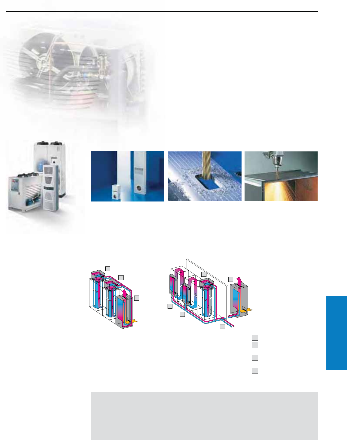
Industrial Buyer’s Guide 309
Climate Control Chiller Systems
Chiller Systems
Features
2
1
21
3
3
2
Chiller systems ensure centralized, efficient cooling and
provision of the cooling medium (generally water). For
example, all cooling tasks on a system or machine can
be solved by a single pipeline system. Spatial separation
between cooling production and process cooling can be
achieved with chiller systems.
Application diversity of centralized cooling technology
Enclosure cooling
In conjunction with air/water heat
exchangers, optimum dissipation
of high heat loads is guaranteed,
even under extreme ambient
temperatures and air pollution.
Installation conditions
Cooling of liquid media
Direct and indirect cooling of
liquids are the prerequisite for
ensuring essential machine
precision and speed.
Process cooling
High-quality material processing,
such as laser cutting, requires
high levels of temperature
precision with simultaneous
cooling of the peripheral
technology.
Unity with enclosures
For example, chiller systems
may be attached directly to a
bayed enclosure suite to provide
effective, centralized cooling of
all cases and enclosures on a
machine or plant floor.
Spatially separated
High heat loads can even be dissipated
in confined and awkward spaces, due
to the spatial separation of the chiller
system from the enclosure and machine.
In all cases, as well as enclosure cooling,
cooling water may also be produced
for process and machine cooling or for
cooling liquid media.
1) Chiller system
2) Air/water heat exchanger,
roofmount
3) Air/water heat exchanger,
wallmount
4) Further cooling options,
machine cooling
Benets:
• A single system for enclosure
cooling, process and machine
cooling, and the cooling of
liquid media.
• Integration into bayed
enclosure suites
• Individual project planning
• Commissioning and servicing
Important:
• Cooling capacity calculated at
an ambient temperature of 90° F
(32° C) and an inlet temperature
of 50° F (10° C) and 64° F (18° C)
(water) or 68° F (20° C) (oil)
Need IMAGE
3
1
2
4
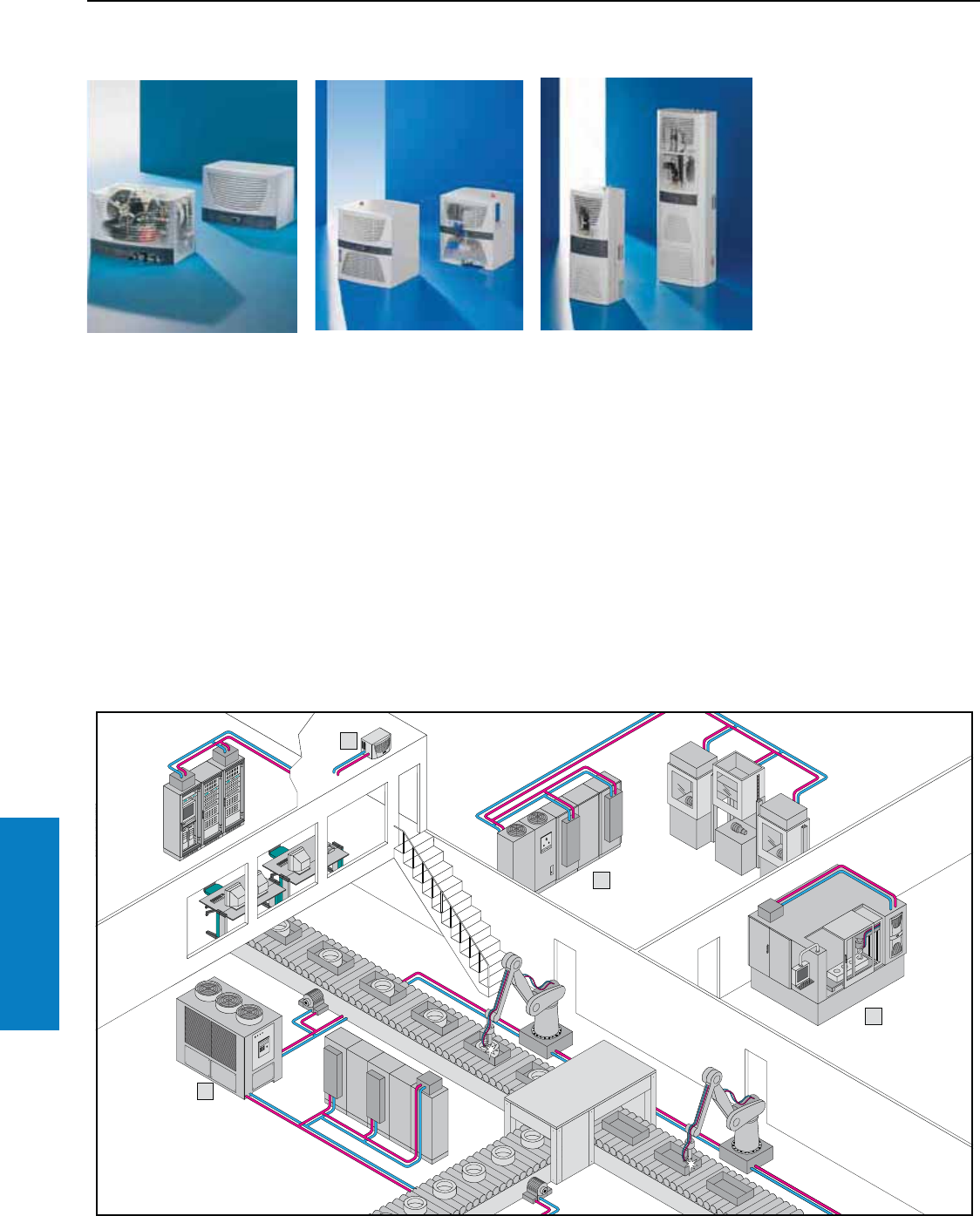
310 Industrial Buyer’s Guide
Climate Control Chiller Systems
Chiller Systems
Features
Project planning examples
Example 4
Tool production
The heat loss generated during
tool machining, (for example by
water-cooled motor spindles with
high-frequency drives), must
be dissipated efficiently. In this
case, the task is performed by
a wallmount mini chiller system
which at the same time ensures
cooling of the control unit, also
integrated into the machine.
Example 1
Production line
High-quality material processing
requires a high degree of
temperature precision with
simultaneous cooling of the
peripheral technology. The
cost-effective cooling of various
equipment in the production
line is performed centrally
by the chiller system in an
industrial enclosure. It supplies
the machine, process cooling
and control enclosure with the
required cooling water by an
air/water heat exchanger.
Example 3
Control room
In conjunction with air/water
heat exchangers, the server and
network enclosures installed in
the production control room are
cooled by a mini chiller system.
The mini chiller system is installed
outside of the production control
room to avoid contaminating the
room air, and to facilitate optimum
dissipation of the heat loss
generated by the chiller system.
1
2
3
4
Example 2
Test laboratory
Every single product is subjected
to in-depth functional and quality
testing at the in-house test
laboratory. To ensure that the
test process runs smoothly, the
control enclosures are cooled
by an air/water heat exchanger,
and the three test benches are
supplied with the required cooling
water per the test requirements.
These diverse cooling tasks are
performed by a chiller system
integrated into the TS8 modular
enclosure system. Visually, they
form a single unit with the TS8
control enclosure.
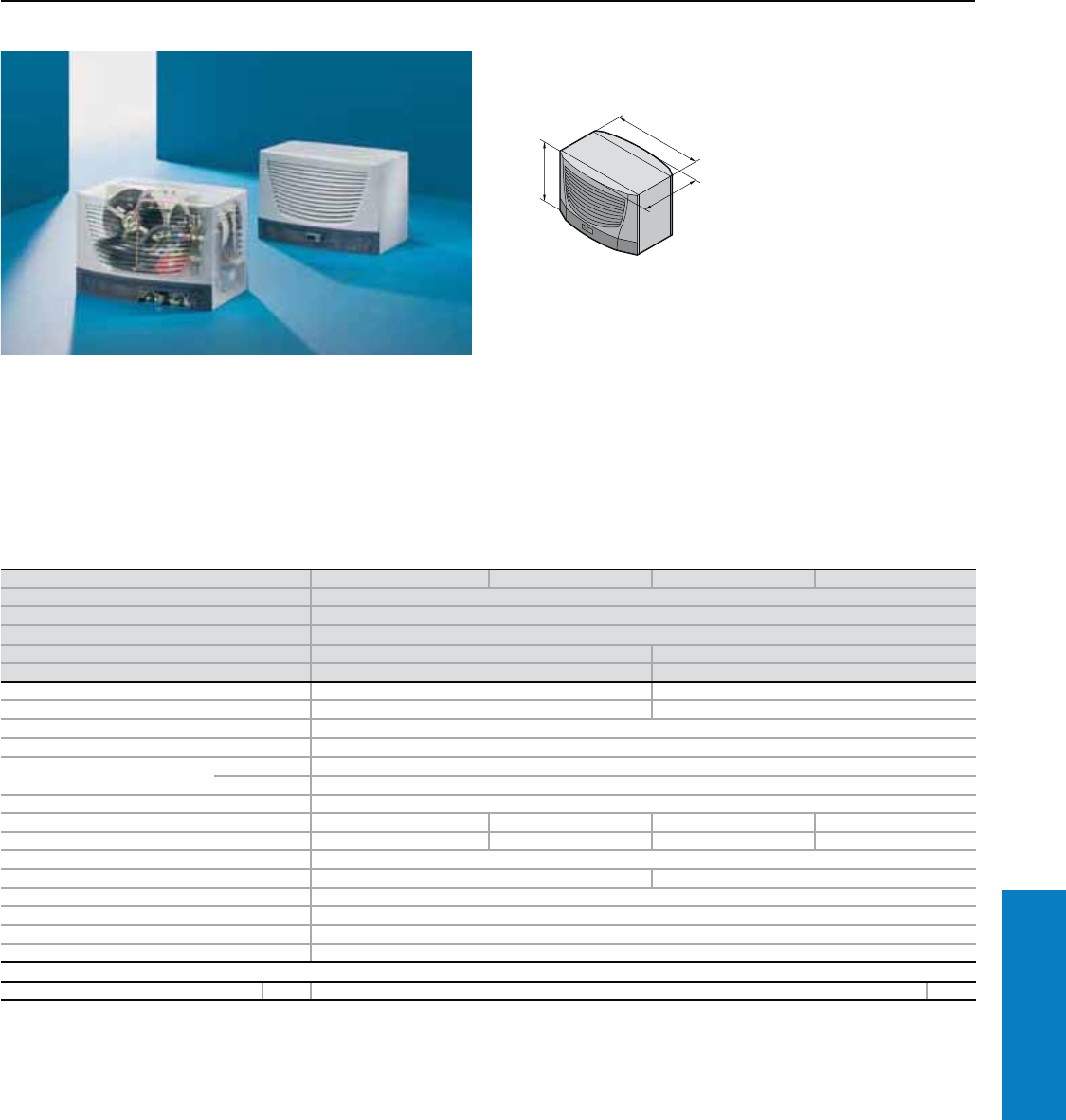
Industrial Buyer’s Guide 311
Climate Control Chiller Systems
Chiller System
Cooling Capacity: 2664 - 5669 BTU (780 - 1660 W)
Technical Design:
• Compact and modular layout of
the cooling components on a
base plate which functions as a
collecting tray
• Medium-conveying pumps
• Precise temperature control,
based on microprocessor
technology
Part No. 3318.600 3318.610 3319.600 3319.610
Voltage V, Hz 230, 50/60
Dimensions inches (mm) H x W x D 16 x 24 x 17 (400 x 600 x 430)
Cooling capacity at
Tw = 50° F (10° C)/Ta = 90° F (32° C) BTU (W) 2664/2971 (780/870) 4098/4542 (1200/1330)
Tw = 64° F (18° C)/Ta = 90° F (32° C) BTU (W) 3279/3654 (960/1070) 5089/5669 (1490/1660)
Power consumption 630/780 W 845/1050 W
Rated current maximum 4.2 A 5.4 A
Refrigerant R134a
Pmax. cooling circuit 363 psi (25 bar)
Temperature range Environment 59 to 109° F (+15 to +43° C)
Liquid media 59 to 77° F (+15 to +25° C)
Pump capacity See characteristic curve
Tank Pressure-sealed PP plastic Pressure-sealed PP plastic
Tank capacity gal (l) – 0.7 (2.5) – 0.7 (2.5)
Water connections 2 x ½" BSPP Internal Thread
Weight lb (kg) 105.8 (48) 112.4 (51)
Color RAL 7035 (light gray)
Ratings (electric) IP 44
Air displacement of fans 530 cfm (900 m3/h)
Temperature control Microcontroller control, setting range 50 to 77° F (+10 to +25° C) (factory setting 64° F [+18° C])
Accessories PU Page
Metal filter mat 1 3286.510 327
Customized solutions and technical modifications available upon request.
• Collective fault signal with
floating contact
• Application-specific equipment
available on request
• Pressure-sealed system
(XXXX.600) or open system
with tank (XXXX.610)
Conguration:
Chiller system wired and
plumbed ready for connection,
with multilingual documentation
including functional diagram and
wiring plans.
Note:
The illustration shows units with
customer-specific options.
For additional technical
information, please visit
www.rittal-corp.com
Inch and pound measurements are rounded to the nearest whole number.
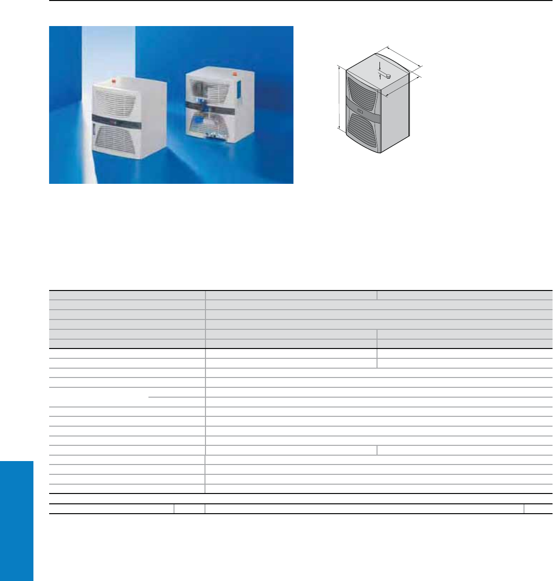
312 Industrial Buyer’s Guide
Climate Control Chiller Systems
Chiller System
Mini, Cooling Capacity: 9050 - 18442 BTU (2650 - 5400 W)
Technical Design:
• Compact, modular configuration
of the cooling components
with integrated water
tank. Operator display may be
optionally mounted on the
front or rear
• Integrated tank level display
• Medium-conveying pumps
• Precise temperature control,
based on microprocessor
technology
• Collective fault signal with
floating contact
• Application-specific equipment
available on request
Conguration:
Chiller system wired and
plumbed ready for connection,
with multilingual documentation
including functional diagram
and wiring plans.
Note:
The illustration shows units with
customer-specific options.
For additional technical
information, please visit
www.rittal-corp.com
Part No. 3320.600 3334.600
Voltage V, Hz 400, 3~, 50/60/460, 3~, 601)
Dimensions inches (mm) H x W x D 27 x 24 x 25 (676 x 602 x 645)
Cooling capacity at
Tw = 50° F (10° C)/Ta = 90° F (32° C) BTU (W) 9050/10246 (2650/3000) 13319/16051 (3900/4700)
Tw = 64° F (18° C)/Ta = 90° F (32° C) BTU (W) 10246/11612 (3000/3400) 15368/18442 (4500/5400)
Power consumption 1716/1953 W 2001/2505 W
Rated current maximum 3.8 A/3.9 A 4.9 A/5.0 A
Refrigerant R134a
Pmax. cooling circuit 363 psi (25 bar)
Temperature range Environment 59 to 109° F (+15 to +43° C)
Liquid media 59 to 77° F (+15 to +25° C)
Pump capacity See characteristic curve
Tank Type 304 stainless steel
Tank capacity gal (l) 7.9 (30)
Water connections 2 x ½" BSPP Internal Thread
Weight lb (kg) 194.0 (88) 207.2 (94)
Color RAL 7035 (light gray)
Ratings (electric) IP 44
Air displacement of fans 1051 cfm (1785 m3/h)
Temperature control Microcontroller control, setting range 50 to 77° F (+10 to +25° C) (factory setting 64° F [+18° C])
Accessories PU Page
Metal filter mat 1 3286.520 327
1) Supports multiple voltages without rewiring.
Special voltages and technical modifications available upon request.
Inch and pound measurements are rounded to the nearest whole number.
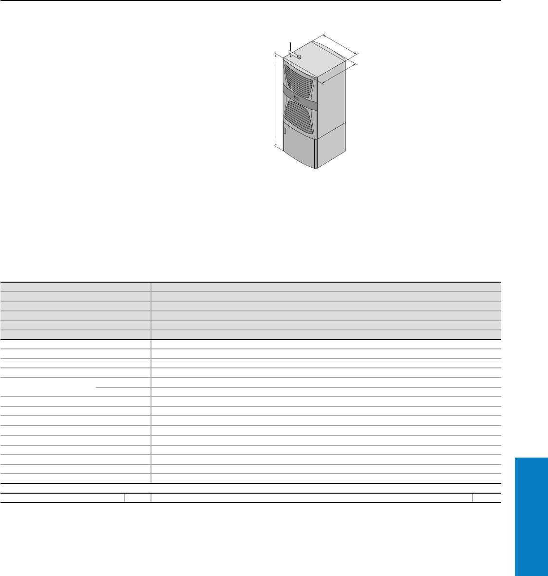
Industrial Buyer’s Guide 313
Climate Control Chiller Systems
Chiller System
Cooling Capacity: 16368 - 22506 BTU (4800 - 6600 W)
Technical Design:
• Compact, modular configuration
of the cooling components
with integrated water
tank. Operator display may be
optionally mounted on the
front or rear
• Integrated tank level display
• Medium-conveying pumps
• Precise temperature control,
based on microprocessor
technology
• Collective fault signal with
floating contact
• Application-specific equipment
available on request
Conguration:
Chiller system wired and
plumbed ready for connection,
with multilingual documentation
including functional diagram
and wiring plans.
Note:
The illustration shows units with
customer-specific options.
For additional technical
information, please visit
www.rittal-corp.com
Part No. 3334.660
Voltage V, Hz 400, 3~, 50/60/460, 3~, 601)
Dimensions inches (mm) H x W x D 41 x 24 x 25 (1050 x 602 x 645)
Cooling capacity at
Tw = 50° F (10° C)/Ta = 90° F (32° C) BTU (W) 16368/17562/17562 (4800/5150/5150)
Tw = 64° F (18° C)/Ta = 90° F (32° C) BTU (W) 20460/22506/22506 (6000/6600/6600)
Power consumption 4280/5140/5080 W
Rated current maximum 8.09 A/9.7 A/8.04 A
Refrigerant R134a
Pmax. cooling circuit 363 psi (25 bar)
Temperature range Environment 59 to 109° F (+15 to +43° C)
Liquid media 59 to 77° F (+15 to +25° C)
Pump capacity See characteristic curve
Tank Type 304 stainless steel
Tank capacity gal (l) 7.9 (30)
Water connections 2 x ½" BSPP Internal Thread
Weight lb (kg) 264 (120)
Color RAL 7035 (light gray)
Ratings (electric) IP 44
Air displacement of fans 1295/1471 cfm (2200/2500 m3/h)
Temperature control Microcontroller control, setting range 50 to 77° F (+10 to +25° C) (factory setting 64° F [+18° C])
Accessories PU Page
Metal filter mat 1 3286.520 327
1) Supports multiple voltages without rewiring.
Special voltages and technical modifications available upon request.
1
Inch and pound measurements are rounded to the nearest whole number.
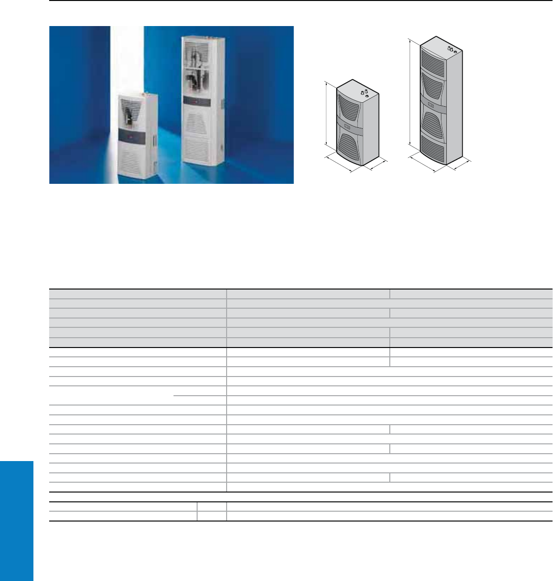
314 Industrial Buyer’s Guide
Climate Control Chiller Systems
Part No. 3360.100 3360.250
Voltage V, Hz 400, 3~, 50/60/460, 3~, 601)
Dimensions inches (mm) H x B x T 37 x 16 x 12 (950 x 400 x 310) 62 x 16 x 11 (1580 x 400 x 290)
Cooling capacity at
Tw = 50° F (10° C)/Ta = 90° F (32° C) BTU (W) 2835/3176 (830/930) 7172/8026 (2100/2350)
Tw = 64° F (18° C)/Ta = 90° F (32° C) BTU (W) 3415/3825 (1000/1120) 8538/9563 (2500/2800)
Power consumption 700/760 W 1550/2000 W
Rated current maximum 2.7 A/3.0 A 3.7 A/3.8 A
Refrigerant R134a
Pmax. cooling circuit 334 psi (23 bar)
Temperature range Environment 59 to 109° F (+15 to +43° C)
Liquid media 59 to 77° F (+15 to +25° C)
Pump capacity See characteristic curve
Tank PP plastic
Tank capacity gal (l) 1.3 (5) 2.6 (10)
Water connections Quick-release coupling (counterpart included in accessory bag)
Weight lb (kg) 103.6 (47) 172.0 (78)
Color RAL 7035 (light gray)
Ratings (electric) IP 44
Air displacement of fans 294 cfm (500 m3/h) 418 cfm (710 m3/h)
Temperature control Microcontroller control, setting range 50 to 77° F (+10 to +25° C) (factory setting 64° F [+18° C])
Accessories PU
Filter mat 1 3286.400
Metal filter mat 1 3286.410
1) Supports multiple voltages without rewiring.
Special voltages and technical modifications available upon request.
Chiller System - Wallmount
Cooling Capacity: 2835 - 9563 BTU (830 - 2800 W)
Technical Design:
• Compact, modular configuration
of the cooling components
with integrated water tank
• Application-specific equipment
available on request
• Open system with tank
T
H
B
T
H
B
Conguration:
Chiller system fully wired and
plumbed ready for connection,
with multilingual documentation
including functional diagram
and wiring plans.
Note:
The illustration shows units with
customer-specific options
For additional technical
information, please visit
www.rittal-corp.com
Inch and pound measurements are rounded to the nearest whole number.
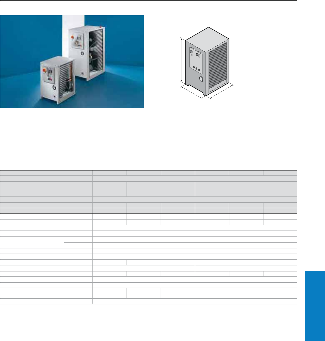
Industrial Buyer’s Guide 315
Climate Control Chiller Systems
Part No. 3336.100 3336.200 3336.300 3336.500 3336.600 3336.650
Voltage V, Hz 400, 3~, 50
Dimensions inches (mm) H x B x T
29 x 18 x 21
(725 x 470 x
540)
38 x 19 x 26 (965 x 485 x 650) 46 x 24 x 32 (1180 x 595 x 800)
Cooling capacity at
Tw = 50° F (10° C)/TU = 90° F (32° C) BTU (W) 5800 (1700) 7166 (2100) 7848 (2300) 12113 (3550) 16378 (4800) 17743 (5200)
Tw = 64° F (18° C)/TU = 90° F (32° C) BTU (W) 7166 (2100) 8803 (2580) 1165 (3360) 17197 (5040) 21019 (6160) 26274 (7700)
Power consumption 1.5 kW 1.7 kW 2.3 kW 2.9 kW 3.7 kW 3.9 kW
Rated current maximum 3.4 A 3.0 A 4.2 A 5.5 A 6.2 A 7.3 A
Refrigerant R134a
Pmax. cooling circuit 348 psi (24 bar)
Temperature range Environment 59 to 109° F (+15 to +43° C)
Liquid media 59 to 77° F (+15 to +25° C)
Pump capacity See characteristic curve
Tank Type 304 stainless steel
Tank capacity gal (l) 4.5 (17) 8.7 (33) 15.1 (57)
Water connections 3/4" BSPP Internal Thread 1" BSPP Internal Thread
Weight lb (kg) 165 (75) 213 (97) 218 (99) 310 (141) 314 (143) 323 (147)
Color RAL 7035 (light gray)
Ratings (electric) IP 54
Air displacement of fans 412 cfm
(700 m3/h)
736 cfm
(1250 m3/h)
1050 cfm
(1785 m3/h) 1848 cfm (3140 m3/h)
Temperature control Microcontroller control, setting range 50 to 77° F (+10 to +25° C) (factory setting 64° F [+18° C])
Special voltages available upon request. We reserve the right to make technical modifications.
Chiller System - Floorstanding
Cooling Capacity: 5800 - 26274 BTU (1700 - 7700 W)
Technical Design:
• Robust industrial standard in
3 enclosure sizes
• Identical basic enclosure for oil
and water chiller systems
• Variable air routing is possible
via the l/h or r/h side panel
T
H
B
• Floating contact for collective
fault signal
• Anti-frost sensor
• Multi-coil vaporizer in the tank
Conguration:
Chiller system wired ready for
connection, with multilingual
documentation including
functional diagram and
wiring plans.
For additional technical
information, please visit
www.rittal-corp.com
Inch and pound measurements are rounded to the nearest whole number.
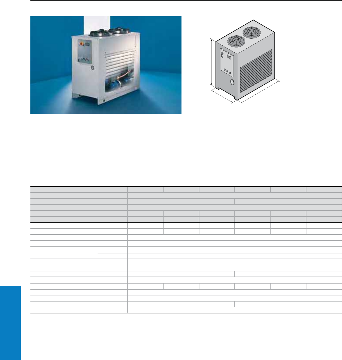
316 Industrial Buyer’s Guide
Climate Control Chiller Systems
Immersible Chiller System - Floorstanding
Cooling Capacity 28150 - 86986 BTU (8250 - 25200 W)
Technical Design:
Robust industrial standard in 2
enclosure sizes
• Identical basic enclosure for oil
and water chiller systems
• Variable air routing is possible
via the l/h or r/h side panel
T
H
B
• Floating contact for collective
fault signal
• Anti-frost sensor
• Multi-coil vaporizer in the tank
Conguration:
Chiller system wired ready for
connection, with multilingual
documentation including
functional diagram and
wiring plans.
For additional technical
information, please visit
www.rittal-corp.com
Part No. 3336.700 3336.710 3336.720 3336.730 3336.740 3336.750
Voltage V, Hz 400, 3~, 50
Dimensions inches (mm) H x B x T 46 x 24 x 46 (1178 x 615 x 1160) 46 x 28 x 54 (1178 x 715 x 1360)
Cooling capacity at
Tw = 50° F (10° C)/Tu = 90° F (32° C) BTU (W) 28150 (8250) 40605 (11900) 45893 (13450) 51182 (15000) 58006 (17000) 70290 (20600)
Tw = 64° F (18° C)/Tu = 90° F (32° C) BTU (W) 34121 (10000) 48964 (14350) 55618 (16300) 63124 (18500) 71313 (20900) 86986 (25200)
Power consumption 3800 W 4800 W 5300 W 6400 W 7100 W 13120 W
Rated current maximum 10.6 A 13.1 A 14.1 A 16.2 A 18.2 A 23.7 A
Refrigerant R407C
Pmax. cooling circuit 392 psi (27 bar)
Temperature range Environment 59 to 109° F (+15 to +43° C)
Liquid media 59 to 77° F (+15 to +25° C)
Pump capacity See characteristic curve
Tank Type 304 stainless steel
Tank capacity gal (l) 15.9 (60) 26.4 (100)
Water connections 1" BSPP Internal Thread
Weight lb (kg) 473 (215) 495 (225) 517 (235) 528 (240) 550 (250) 572 (260)
Color RAL 7035 (light gray)
Ratings (electric) IP 54
Air displacement of fans 3696 cfm (6280 m3/h) 6404 cfm (10880 m3/h)
Temperature control Microcontroller control, setting range 50 to 77° F (+10 to +25° C) (factory setting 64° F [+18° C])
Special voltages available upon request. We reserve the right to make technical modifications.
Inch and pound measurements are rounded to the nearest whole number.
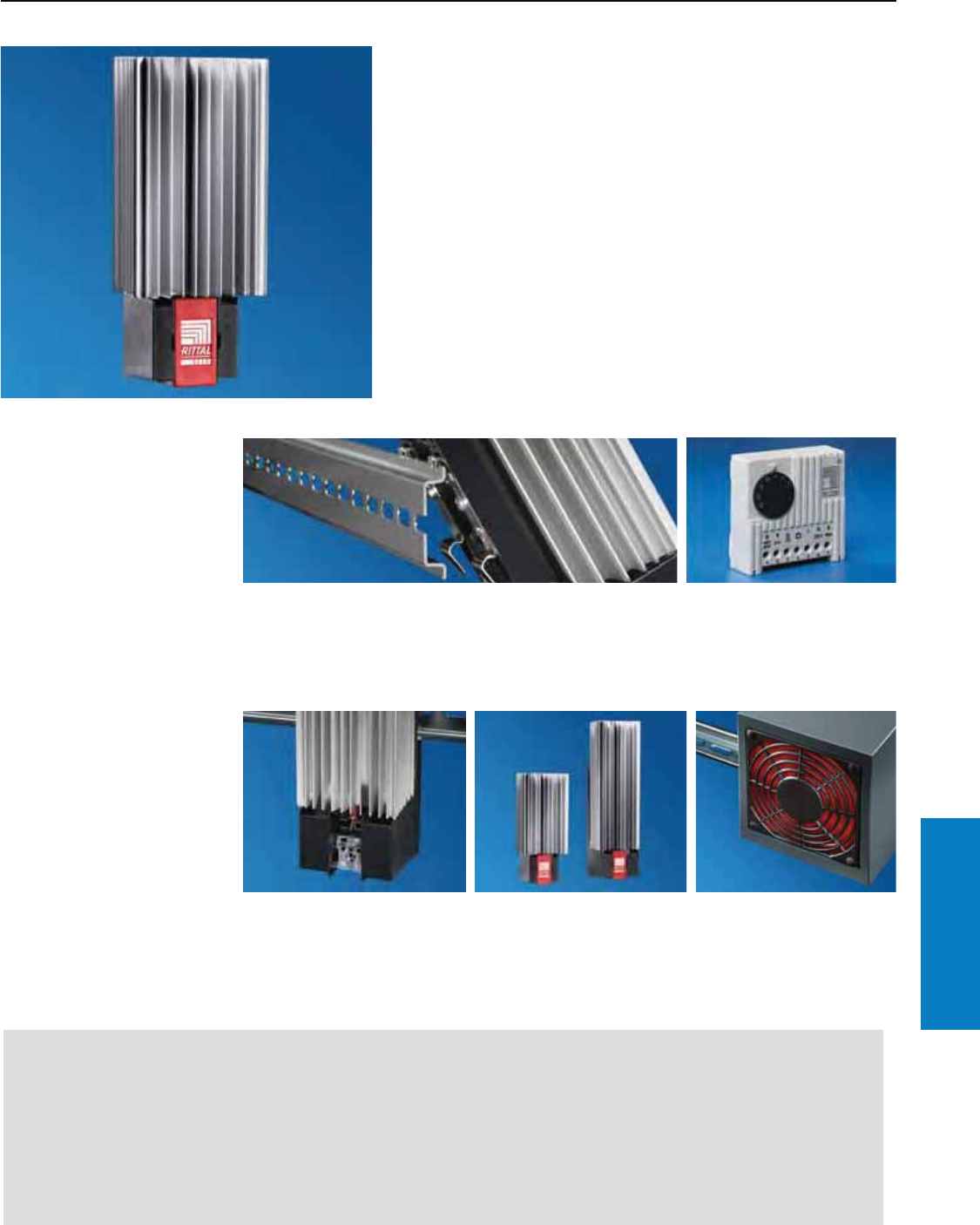
Industrial Buyer’s Guide 317
Climate Control Heaters
Heaters
Features
Condensation poses a high risk for control electronics in
outdoor and indoor locations. Various output ratings ensure
that the correct thermal output is always available. Therefore,
the total required thermal output can be distributed with
complete accuracy inside an enclosure.
Simple assembly and perfect control
Fast assembly
This is achieved with a snap
fastening on the mounting panel
or 1" (35 mm) EN 50 022 support
No condensation and always
the right temperature
The heater is controlled as
required by a hygrostat or
enclosure internal thermostat.
Fully wired unit ready for
connection
Clamp-type terminal connection
for simple, effective wiring.
Energy-optimised design
• Output without fan
10, 20, 30, 50, 130, 200 watts
• Output with fan
250, 400, 800 watts
Benets:
• Continuous thermal output of
10 to 800 W (34 to 2730 BTU)
• Energy efficienct due to self-
regulating PTC technology.
• Quick-assembly system
Important:
• For the correct temperature
and to avoid condensation,
use a thermostat or hygrostat,
see page 322
• The thermal output is
increased with fans
• Heaters should always be
installed in an upright position.
Leave a distance of 2" (50 mm)
at the top and bottom to allow
circulation
• Heat is distributed evenly in
large enclosures by using
several low-output heaters
General information,
Therm software and
calculation formulas can
be found on our website:
www.rittal-corp.com
rails or screw-fastening directly
onto a mounting panel.
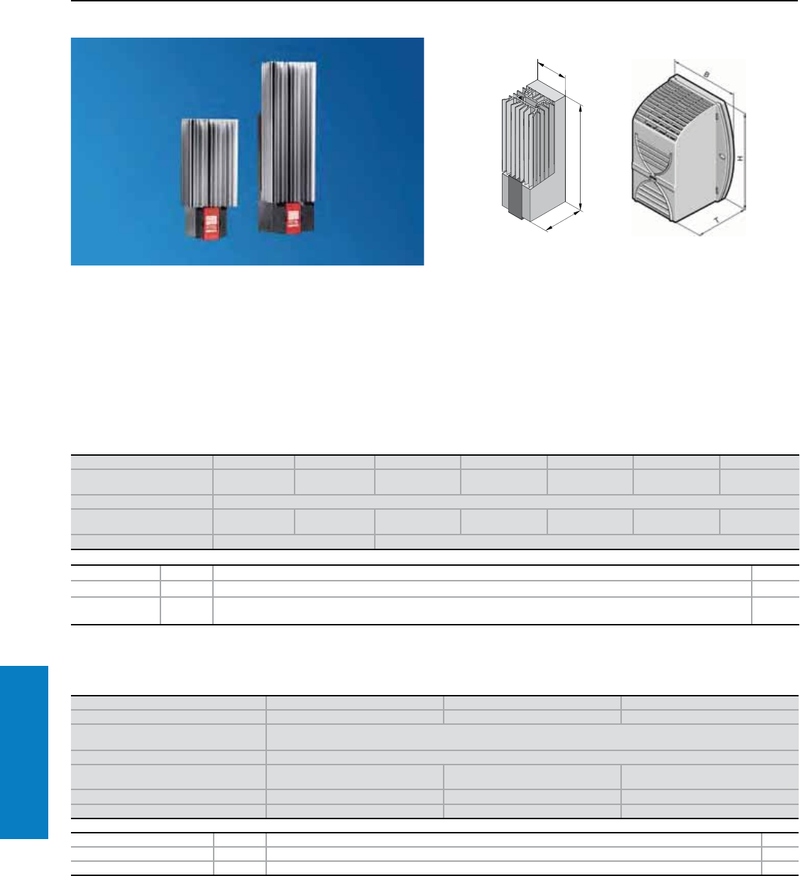
318 Industrial Buyer’s Guide
Climate Control Heaters
Panel Heaters
Continuous Thermal Output 34 - 2730 BTU (10 - 800 W)
Conguration:
PTC heater with quick-fit terminal
and assembly parts.
Protection Ratings:
UL recognized, CE
UL file: E76083
Note:
• Thermostat 3110.000 (see
page 322) is recommended for
precise temperature control in
the enclosure.
• In order to prevent
condensation on assemblies,
hygrostat 3118.000 (see page
322) is recommended to
regulate heating.
• In larger enclosures, even heat
distribution is best achieved
by installing several low-output
heaters.
• Installation in the enclosure is
generally advisable, even
when using heat exchangers
and air conditioners, in order
to prevent condensation.
For additional technical
information, please visit
www.rittal-corp.com
Part No. 110 V with fan 3105.210 3105.220 3105.230
Part No. 230 V with fan 3105.180 3105.190 3105.200
Dimensions inches (mm) H x B x T 7 x 6 x 4
(170 x 142 x 101)
Voltage V, Hz 110 – 240 V, 50/60 Hz
Continuous thermal output at
Ta = 50° F (10° C) BTU (W) 853 (250)1) 1365 (400)1) 2730 (800)1)
Pre-fuse gG for 110 V 4 A 6 A 10 A
Pre-fuse gG for 230 V 4 A 6 A 6 A
Accessories PU Page
Thermostat 1 3110.000 322
Hygrostat 1 3118.000 322
Temperature indicator 1 3114.200 321
1) Output with fan.
Special voltages available upon request. We reserve the right to make technical modifications.
Inch and pound measurements are rounded to the nearest whole number.
T
H
B
Part No. 3105.310 3105.320 3105.330 3105.340 3105.350 3105.360 3105.370
Dimensions
inches (mm) H x B x T 5 x 2 x 2
(120 x 45 x 46)
5 x 2 x 2
(120 x 45 x 46)
6 x 3 x 2
(155 x 64 x 56)
6 x 3 x 2
(155 x 64 x 56)
9 x 3 x 2
(230 x 64 x 56)
6 x 4 x 3
(165 x 90 x 75)
7 x 4 x 3
(180 x 90 x 75)
Voltage V, Hz 110 – 240 V, 50/60 Hz
Continuous thermal output at
Ta = 50° F (10° C) BTU (W)
27 – 34
(8 – 10)
61 – 68
(18 – 20)
78 – 102
(23 – 30)
167 – 170
(49 – 50)
215 – 256
(63 – 75)
293 – 341
(86 – 100)
444 – 512
(130 – 150)
Pre-fuse T 2 A 4 A
Accessories PU Page
Thermostat 1 3110.000 322
Hygrostat 1 3118.000 322
Temperature
indicator 1 3114.200 321
Special voltages available on request. We reserve the right to make technical modifications.
Without fan, continuous thermal output 34 – 512 BTU (10 – 150 W)
With fan, continuous thermal output 853 – 2730 BTU (250 – 800 W)
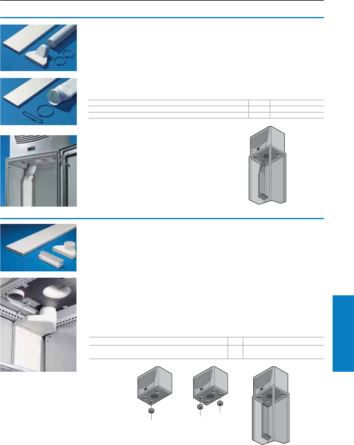
Accessories
Air Routing
For air conditioner PU Part No.
3382. . . ./3383. . . ./3384. . . ./3385. . . ./3273. . . . /3359. . . . 1 3286.870
3386. . . ./3387. . . . 1 3286.970
Air duct system
For TopTherm roofmount air conditioners
The air duct system for Rittal TopTherm roofmount
air conditioners makes it possible to route the cold
air directly to specific areas of the enclosure. The
risk of short cycles in the air circulation due to self-
ventilated installed devices is eliminated.
The length of the flat duct is 59" (1500 mm), and it
may be cut to the desired length.
Note:
Do not direct cold air straight at active
components. When using the duct system,
the performance of the air conditioner may
be reduced, depending on the application in
question.
Material:
Flame-resistant plastic to DIN 4102/B1
Conguration:
Flat duct, compensating hose
Accessories:
90° deflector, see page 320.
Plugs, see page 320.
Shallow air duct system
for TopTherm roofmount cooling units and
air/water heat exchangers, to t TS8 enclosures
from a width of 31" (800 mm)
It is possible to route the cold air directly to
specific areas of the enclosure using the air duct
system. The risk of "short circuits" in the air
circulation due to self-ventilated installed devices
is therefore eliminated. The length of the shallow
duct is 59" (1500 mm), and it may be cut to any
required length.
Material:
Flame-resistant plastic to DIN 4102/B1
Conguration:
Shallow duct, adaptor, compensating piece,
deflector 90°
Accessories:
90° Deflector, see page 320.
Plugs, see page 320.
Also required:
Shallow duct extension 3286.860 to compensate
for the enclosure width and height. TS support
strips for securing the shallow duct in a vertical
direction, see page 320.
Note:
Do not direct cold air straight at active
components. When using the ducting system, the
performance of the cooling unit may be reduced,
depending on the application in question.
For air conditioner PU Part No.
3209. . . ./3210. . . ./3273. . . ./3359. . . ./3382. . . ./
3383. . . ./3384. . . ./3385. . . . 13286.850
Note:
Max. number of
plugs per unit
varies by part
number
Max. 1 x:
3359. . . .
3382. . . .
3386. . . .
3387. . . .
Max. 2 x:
3383. . . .
3384. . . .
3385. . . .
Industrial Buyer’s Guide 319
Climate Control Accessories
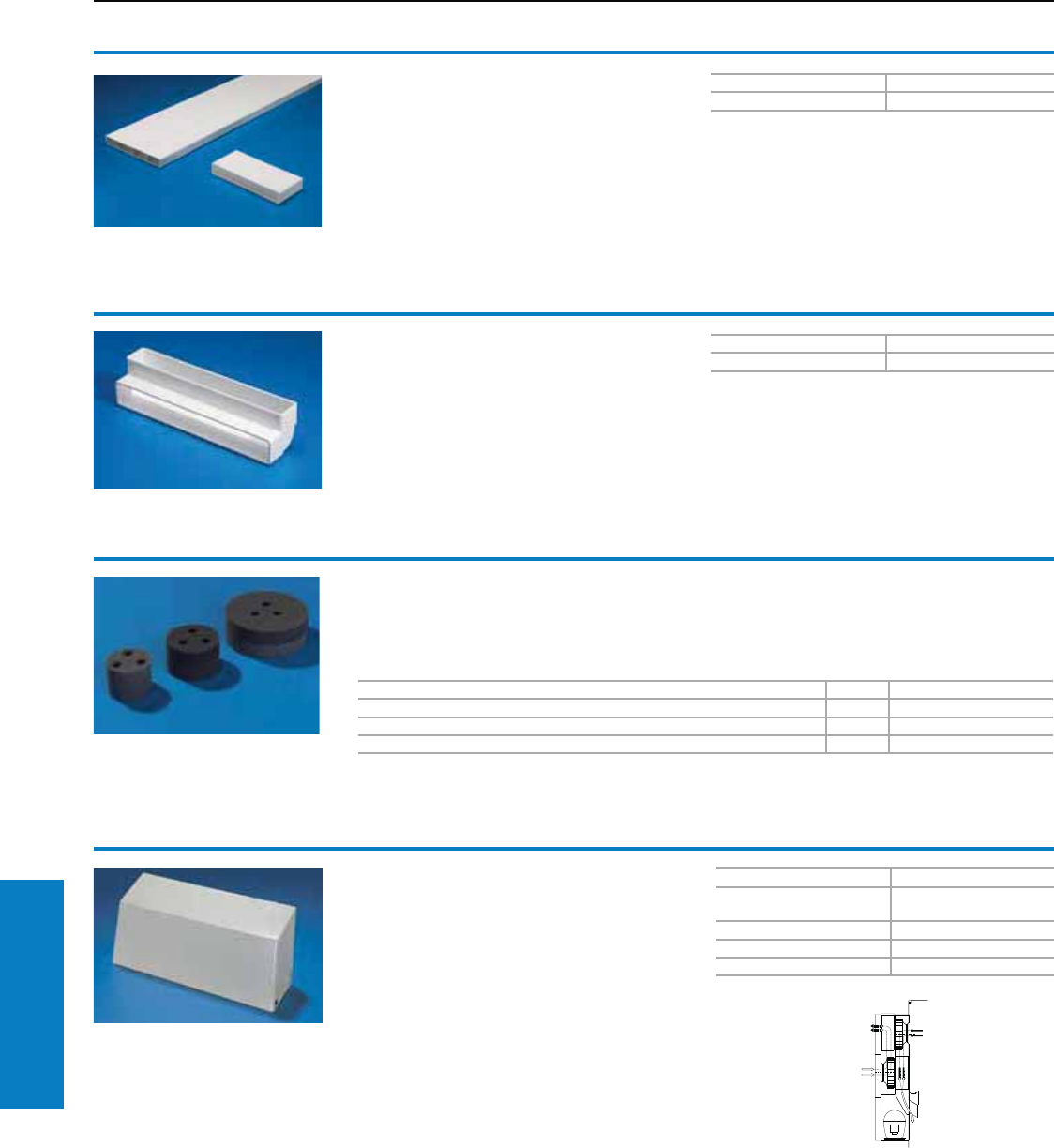
Accessories
Air Routing
For devices Part No.
8607. . . ./8687. . . ./3306. .
. ./3331. . . . 3213.300
3304. . . ./3305. . . . 3213.310
3328. . . ./3329. . . . 3213.320
3332. . . . 3213.3301)
Air diverter
For use in climate controlled enclosures, climate
control doors, climate control sidewalls and
TopTherm wallmount air conditioners.
For targeted routing of the cold air in a
downward direction.
Particularly well-suited for densely-packed
electrical components in the lower section of
the enclosure.
Material:
Carbon steel, painted RAL 7032 (pebble gray)
1
External
air circuit
Internal
air circuit
1) 5" (115 mm) for 3213.330
For air conditioner PU Part No.
3382. . . ./3359. . . . 2 3286.780
3383. . . ./3384. . . ./3385. . . ./3273. . . . 2 3286.880
3386. . . ./3387. . . . 2 3286.980
Plugs
For TopTherm roofmount air conditioners
To cover unneeded cold air outlets in TopTherm
roofmount air conditioners.
Material:
Polyurethane foam
PU Part No.
13286.990
90° deector
For air duct system
For targeted air deflection at the end of the
flat channel.
Material:
Flame-resistant plastic to DIN 4102/B1
Shallow duct extension
Extension kit for shallow air duct system
3286.850 for width, depth or height length
extensions in TS8 enclosures.
Material:
Flame-resistant plastic to DIN 4102/B1
Conguration:
59" (1500 mm) shallow duct, connection piece
PU Part No.
13286.860
320 Industrial Buyer’s Guide
Climate Control Accessories
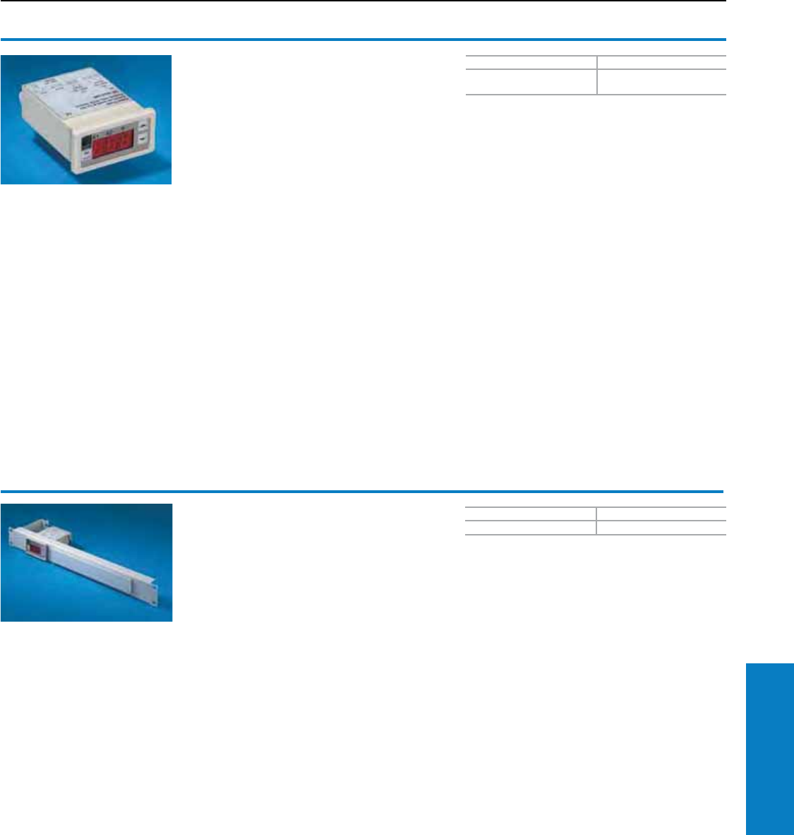
Accessories
Regulation/Control
Voltage Part No.
100 - 230 V AC 50/60 Hz
24-60 V DC 3114.200
Special requirements available on request.
Color Part No.
RAL 7035 (light gray) 7109.035
Digital enclosure internal
temperature display and
thermostat
For installing on the enclosure door or wall
and in an air conditioner, heat exchanger or
thermoelectric cooler.
Technical Specications:
• Small dimensions
• Depth: 4" (100 mm)
• The 3-digit 7-segment display is ½" (13 mm)
high and clearly legible
• Can be switched from °F/°C
• The display can be used in a temperature range
from 41 to 158° F (+5 to +70° C)
• With 59" (1500 mm) long NTC sensor
• Two relay outputs as change-over contact and
normally open contact (maximum contact load
230 V, 6 A)
• Freely selectable switching difference
• The freely adjustable setpoint values can be
adjusted by the membrane keyboard at the front.
• Setting range: 41 to 131° F (+5 to +55° C)
• Display and switching accuracy ± 2 K
• Mounting cut-out 3 x 1" (68 x 33 mm)
• Storage of the minimum and maximum recorded
temperature until the system is reset
Digital enclosure internal
temperature display and
thermostat
Integrated into a patch panel 1 U
Including cable attachment for connection cable
and label holder.
Voltage: 230 V AC
Special voltages available on request.
Technical Specications:
• Small dimensions
• Depth: 4" (100 mm)
• The 3-digit 7-segment display is 0.5" (13 mm)
high and clearly legible
• Can be switched from °F/°C
• The display can be used in a temperature range
from 41 to 158° F (+5 to +70° C)
• With 59" (1500 mm) long NTC sensor
• Two relay outputs as change-over contact and
normally open contact (maximum contact load
230 V, 6 A)
• Freely selectable switching difference
• The freely adjustable setpoint values can be
adjusted by the membrane keyboard at the front
• Setting range: 41 to 131° F (+5 to +55° C)
• Display and switching accuracy ± 2 K
• Mounting cut-out 3 x 1" (68 x 33 mm)
• Storage of the minimum and maximum recorded
temperature until the system is reset
Conguration:
Panel, temperature indicator and thermostat,
identification strip.
Industrial Buyer’s Guide 321
Climate Control Accessories
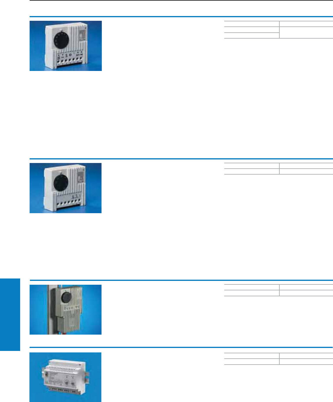
Accessories
Regulation/Control
Voltage Part No.
230/115/60/48/24 V AC 3110.000
60/48/24 V DC
Voltage Part No.
24 - 230 V (AC/DC) 3118.000
PU Part No.
13110.200
Enclosure internal thermostat
Ideal for controlling filter fan units, heaters and
heat exchangers, this thermostat can also be used
as a signal generator for monitoring the enclosure
internal temperature.
Technical Specications:
• Bi-metal sensor as a temperature-sensitive
element with thermal feedback
• Contact population: Single-pole change-over
contact as a quick-break contact
• Permissible contact load:
Category 5 – 3 (heating)
AC 10 (4)1) A,
DC = 30 W
Category 5 – 4 (cooling)
AC 5 (4)1) A,
DC = 30 W
1) = Inductive load at cos M= 0.6
• Setting range 41 to 140° F (+5 to +60° C)
• Weight approximately 4 oz (105 grams)
• Dimensions 3 x 3 x 1" (71 x 71 x 33 mm)
• Switching difference approximately 1 K ± 0.8 K
• A broad voltage spectrum, just one model covers
24 to 230 V.
• Time-saving connection technique using a
terminal strip with a screw connection from the
outside.
• Flexible mounting on a vertical or horizontal 1"
(35 mm) support rail to EN 50 022, and snap
fastening in the TS/ES enclosure section using
the supplied adaptor.
Protection Ratings:
UL, cUL recognized,CE,VDE
UL file: E174004
Hygrostat
The hygrostat switches on the heater and/or
fan when a preset relative humidity level in the
enclosure is exceeded. The relative humidity is
raised above the dew point, and condensation on
assemblies or electronic components is avoided.
Technical Specications:
• Contact population: Single-pole change-over
contact as a quick-break contact
• Permissible contact load:
AC ~ 5 (0.2)1) A
DC = maximum 20 W
1) = Inductive load at cos M = 0.6
• Setting range 50 – 100% relative humidity
• Weight approximately 4 oz (100 g)
• Dimensions 3 x 3 x 1" (71 x 71 x 33.5 mm)
Bottom mount adaptor
For enclosure internal thermostat 3110.000
and hygrostat 3118.000
Bottom mount adaptor with mounting option
for screwed cable glands, for targeted cable
infeed from appropriate equipment such as filter
fan units and enclosure heaters. In conjunction
with screwed cable glands, it is also suitable for
use as strain relief.
• Switching difference approximately 4%
• A broad voltage spectrum, just one
model covers 24 to 230 V.
• Time-saving connection technique using
a terminal strip with a screw connection
from the outside.
• Flexible mounting on a vertical or
horizontal 1" (35 mm) support rail to EN
50 022, and snap fastening in the TS/ES
enclosure section using the supplied
adaptor.
Speed control
Temperature-dependent speed control for Rittal fan
and filter units and air/air heat exchangers. Dual
rated 115/230 V, 50/60 Hz AC for noise reduction and
to save energy in part-load operation.
Technical Specications:
• For mounting on 35 mm support rail DIN EN 50 022
• Rated operating voltage: 230 V (AC)/115 V (AC)
• Setting range: +68 to +131° F (+20 to +55° C)
• Phase cross-over controller
PU Part No.
13120.200
• Maximum fan output: 300 W
• Dimensions inches (mm): 4.1 x 3.5 x 2.4
(105 x 91 x 60)
Protection Rating:
• UL file: E203342
322 Industrial Buyer’s Guide
Climate Control Accessories
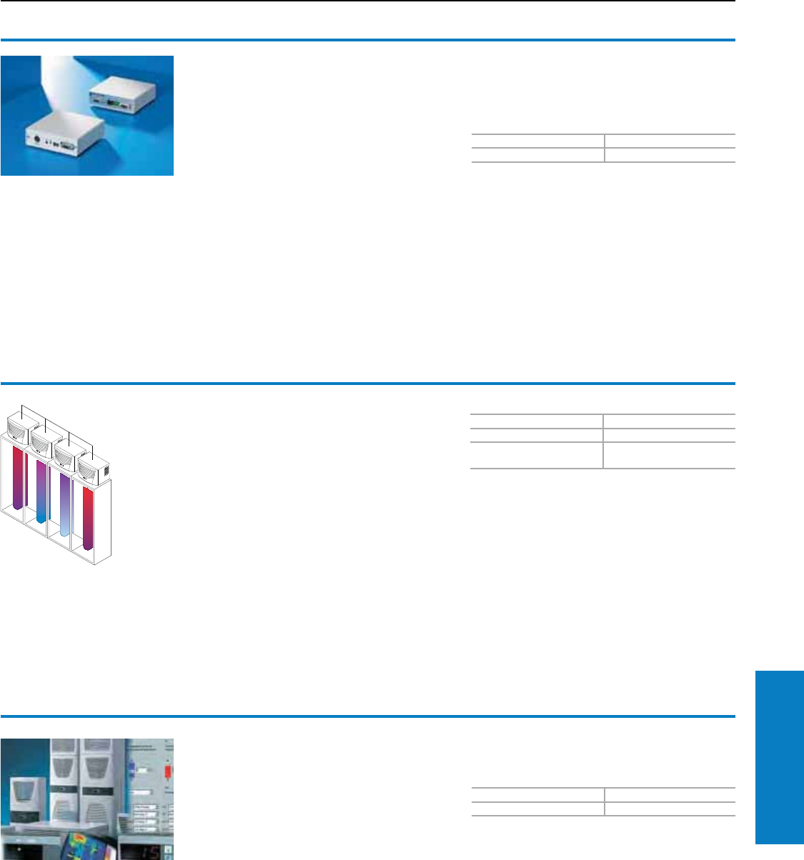
Accessories
Regulation/Control
PU Part No.
13124.200
Interface card
For TopTherm air conditioners with
comfort controller
The interface card is an extension for TopTherm
air conditioners with comfort controller. In this way
it is possible, to monitor a master/slave
combination of up to 10 air conditioners. Control is
achieved by standardized interfaces: RS232 (DB9)
or RS 485, one PLC interface (DB9).
RS 422 (RJ 45 jack) is the connection to the Rittal
CMC-TC. Remote monitoring by TCP-IP, graphical
interfaces for operation, evaluation and control,
documentation. Connection to additional sensors
for access control, monitoring is therefore
possible. The extension card is built into a 1 U
plastic housing. A voltage supply of 24 V DC
is needed. This may be supplied from the
CMC-TC by a wide-range power pack 7320.425
(100 to 240 V AC, 50/60 Hz) or externally by a
Kycon connector.
Conguration:
Interface card integrated into a plastic box
H x W x D inches (mm):
2 or 1 U x 5 x 5 (44 or 1 U x 136 x 129).
Serial SUB-D cable, 59" (1.5 mm).
For Part No.
TopTherm 3124.100
Climate controlled
enclosures 3124.000
SK master/slave cable
The SK master/slave cable facilitates
communications between several enclosure air
conditioners, TopTherm .500/.510/.540, production
date 05/02 or later, by a master/slave construction
such as that required in complex bayed enclosure
systems for optimum operating results.
Technical Specications:
The master/slave construction facilitates common
activation and deactivation by door limit switches,
parallel activation and deactivation by a
temperature set point, and common collective
fault signals and temperature logging, thereby
eliminating the need for intricate wiring.
Conguration:
118" (3 m) shielded interface cable, including
operating manual on programming the air
conditioners.
Note:
nB = nK – 1
nB: Number of order units (SK bus system)
nk: Number of air conditioners to be linked
Property Rights:
German patent no. 196 15 469
RiDiag II
RiDiag II is a tool for diagnosing the operating
behaviour of Comfort controller-regulated cooling
units. By connecting a PC, it is possible to retrieve
error messages, temperatures and capacity
utilization levels of the cooling units which are
stored in the Comfort controller.
The system includes integrated temperature
measurement from four sensors in the cooling unit,
and also features graphical representation of the
temperature development over time.
PU Part No.
13159.100
Supply includes:
CD-ROM (languages: German/English/Italian/
French), connection cable
Industrial Buyer’s Guide 323
Climate Control Accessories
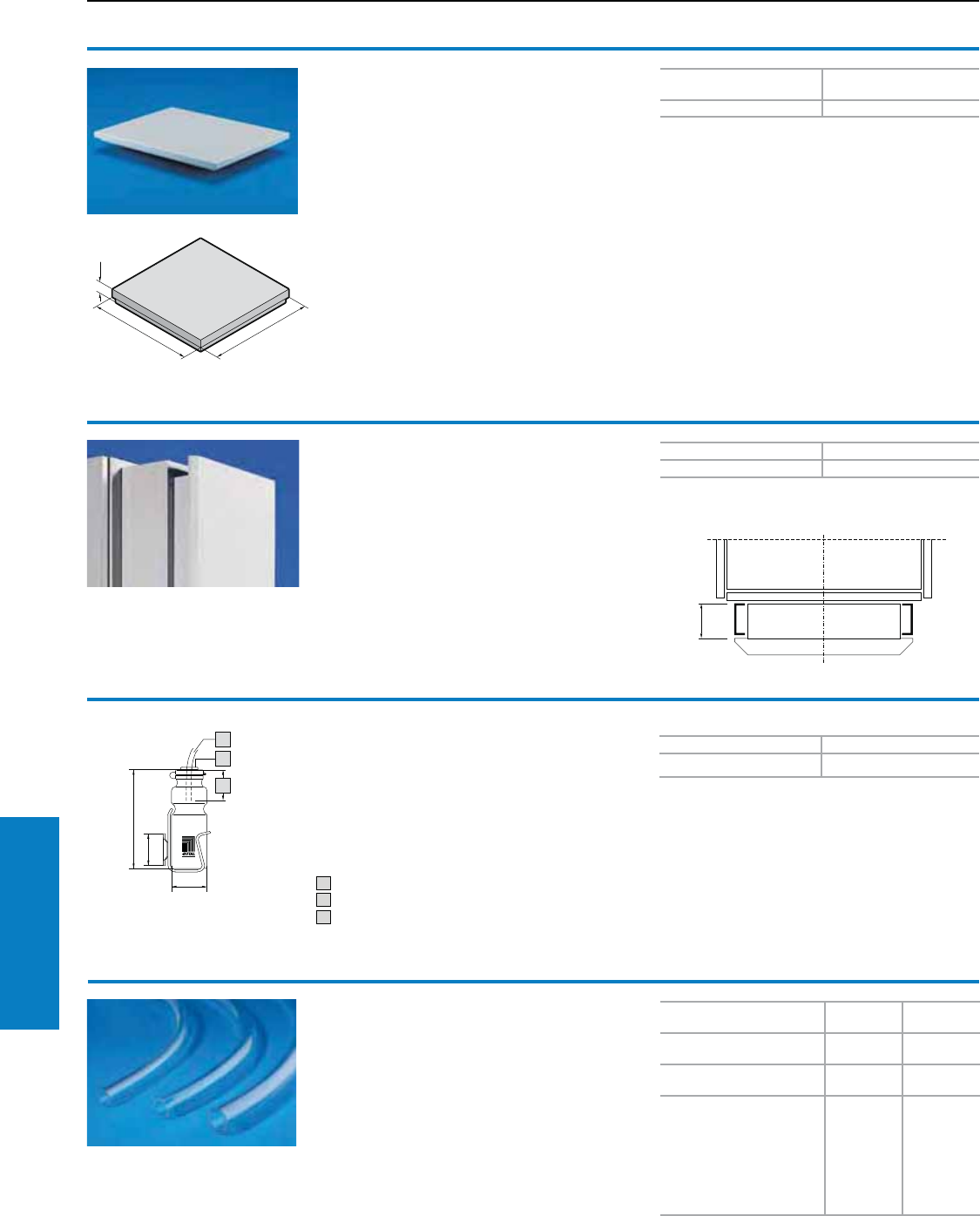
Accessories
General
For roof plates with cut-out
inches (mm) Part No.
19 x 15 (490 x 390) 8801.380
For air conditioner Part No.
3366. . . . /3377. . . . 3377.000
Vent attachment TS
For passive ventilation with labyrinthine air flow
routing, to match the roofs for TopTherm roofmount
air conditioners.
Color:
RAL 7035 (light gray)
Protection Ratings:
IP 43
Conguration:
Assembly parts
Trim frame
For slimline air conditioners
Slimline air conditioners can be internally or
externally mounted on an enclosure door or wall.
The trim frame presents a closed front for the air
conditioner.
Material:
Sheet steel
Color:
RAL 7035 (light gray)
1
For devices Material
thickness Ø Part No.
3302 . . . 8 x 1"
(1.5 mm) 3301.608
3303. . . ./3361. . . . 10 x 1"
(1.5 mm) 3301.610
3273. . . ./3304. . . ./
3305. . . ./3328. . . ./
3329. . . ./3332. . . ./
3366. . . ./3359. . . ./
3382. . . ./3383. . . ./
3384. . . ./3385. . . ./
3386. . . ./3387. . . ./
3377. . .
12 x 1"
(2 mm) 3301.612
Condensate hose
For removing and forwarding condensate.
For connecting to enclosure air conditioners.
Material:
PVC, transparent
Conguration:
394" (10 m) hose
PU Part No.
13301.600
1
2
3
Condensate collecting bottle
For mounting on the enclosure. For use with
all enclosure air conditioners and air/water
heat exchangers.
Safety overflow at the side.
Capacity approximately 0.2 gal (0.75 l).
1 Condensate discharge tube
2 Membrane grommet
3 Maximum 3" (70 mm)
Conguration:
Condensate collecting bottle, bottle holder
including assembly parts.
324 Industrial Buyer’s Guide
Climate Control Accessories
Inch and pound measurements are rounded to the nearest whole number.
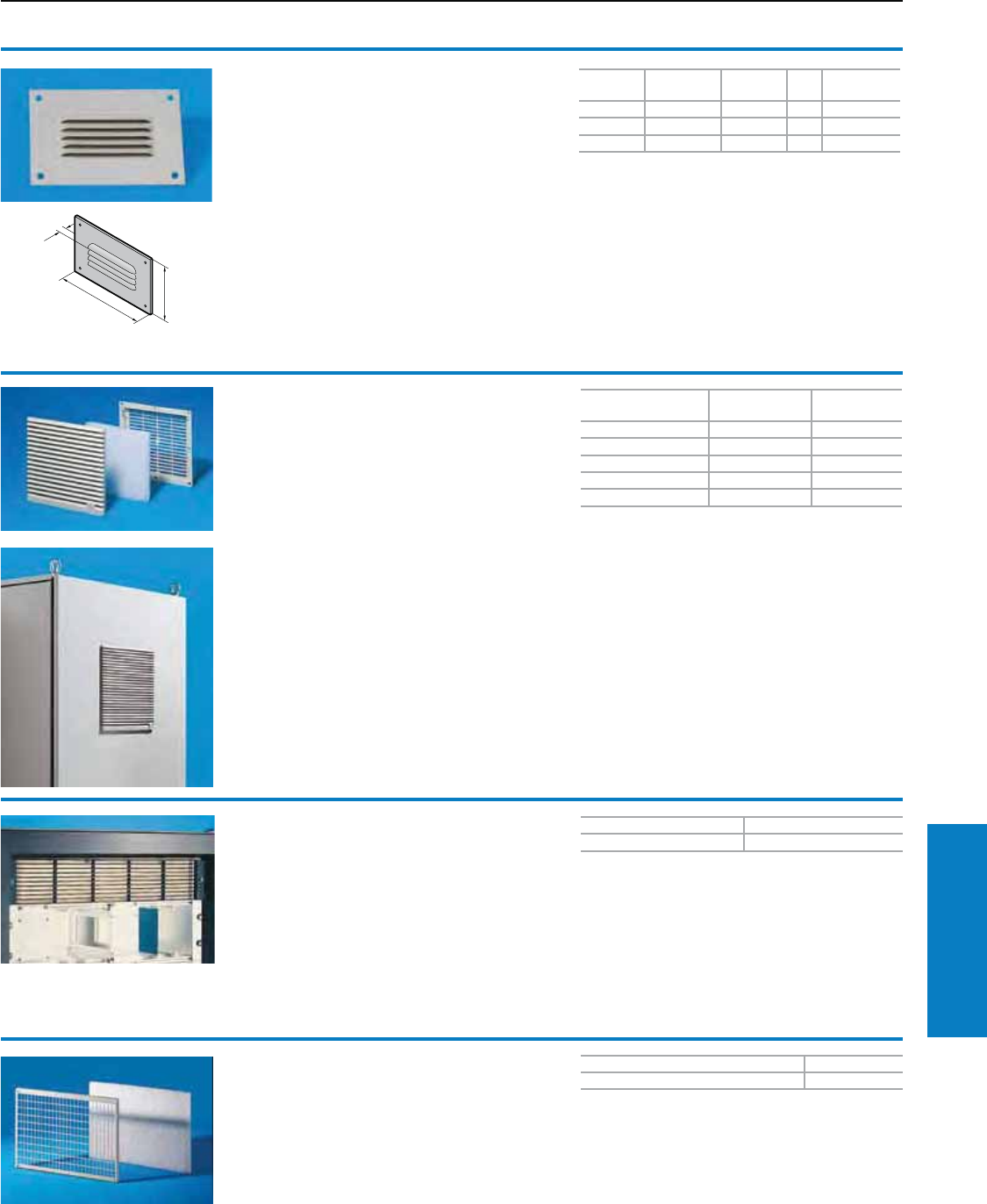
H x W x D inches (mm) Part No.
10 x 13 x 0.6 (244 x 340 x 15) 3175.000
Filter holder
For roof ventilation
The use of a filter mat is required in order to
increase the ratings of the roof vent (3148.000).
Ratings IP 43 to EN 60 529/10.91 is achieved.
Material:
Sheet steel
PU Part No.
13176.000
Front outlet grill 2U
For centrifugal fans
This front outlet grill is required if a 19"
(482.6 mm) cross-flow blower (3144.000/3145.000)
is used in the lower section of the electronic
enclosure and the hot air is to be expelled to the
outside from the upper section of the enclosure.
The design of the grill matches that of the intake
grill in the cross-flow blower. These grills can also
be used as simple inflow and outflow grills with
natural convection.
Accessories
General
Dimensions
inches (mm)
Part No.
RAL 7035
Part No.
RAL 9005
5 x 1 (116 x 22) 3321.207 9963.661
6 x 1 (148 x 24.5) 3322.207 9963.662
8 x 1 (204 x 30) 3323.207 9963.663
10 x 1 (255 x 30) 3325.207 9963.664
13 x 1 (323 x 30) 3326.207 9963.583
For RAL 7032 (pebble gray), use Part No. XXXX.200.
Outlet lter
For ventilation by convection, an outlet filter can
be installed in the upper and lower sections of the
modular enclosure.
Material:
ABS, material resistance to UL 94-V0
Color:
RAL 7035 (light gray)
Note:
EMC version, please visit wwww.rittal-corp.com
Accessories:
Spare filter mats, see page 326
Fine filter mats, see page 326
H inches
(mm)
W inches
(mm)
D inches
(mm) PU Part No.
4 (110) 6 (160) 0.3 (8) 4 2541.235
4 (100) 8 (210) 0.3 (8) 4 2542.235
4 (110) 13 (330) 0.3 (8) 4 2543.235
For RAL 7032 (pebble gray), use Part No XXXX.200;
For primed version, use Part No. XXXX.300.
B
H
T
Integrated louvers
For ventilation by convection; easily retrofitted
using 4 screws.
Material:
Sheet steel
Color:
RAL 7035 (light gray)
B = Width
T = Depth
Accessories:
Filter mat, see page 326
Conguration:
Filter holder including filter mat
Accessories:
Spare filter mat, see page 326
For additional technical
information, please visit
www.rittal-corp.com
Protection Ratings:
UL, cUL recognized
UL file: E76084
Conguration:
Outlet filter including filter mat.
Industrial Buyer’s Guide 325
Climate Control Accessories
Inch and pound measurements are rounded to the nearest whole number.
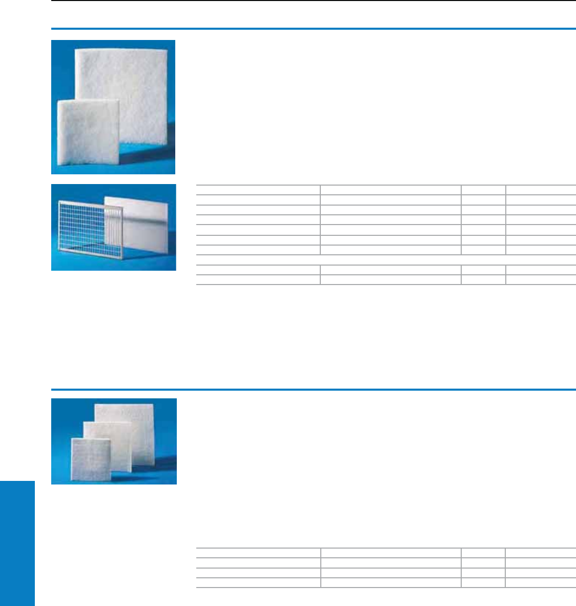
Accessories
Filter Mats
For filter fan units H x W x D inches (mm) PU Part No.
3321. . . . 4 x 4 x 0.4 (89 x 89 x 10) 5 3321.700
3322. . . . 5 x 5 x 0.5 (120 x 120 x 12) 5 3322.700
3323. . . . 7 x 7 x 0.7 (173 x 173 x 17) 5 3171.100
3324. . . ./3325. . . . 9 x 9 x 0.7 (221 x 221 x 17) 5 3172.100
3326. . . . 11 x 11 x 0.7 (289 x 289 x 17) 5 3173.100
3327. . . . 11 x 11 x 0.4 (289 x 289 x 10) 5 3327.700
For filter holders H x W x D inches (mm) PU Part No.
3175.000 10 x 13 x 0.8 (242 x 338 x 20) 3 3174.000
Spare lter mats
Made of chopped-fiber mat with a
progressive structure.
Temperature resistant to 212° F (100° C), self-
extinguishing category F1 to DIN 53 438.
Dust-laden air side: Open structure.
Clean air end: Closed structure.
Reliable filtering of virtually all types of dust from
a particle size of 10 μm and larger.
Material:
Chemical fiber
For filter fan units/outlet filters H x W x D inches (mm) PU Part No.
3323 . . . . 7 x 7 x 0.5 (173 x 173 x 12) 5 3181.100
3324 . . . ./3325 . . . . 9 x 9 x 0.5 (221 x 221 x 12) 5 3182.100
3326. . . ./3327. . . . 11 x 11 x 0.5 (289 x 289 x 12) 5 3183.100
Fine lter mats
Made of chopped-fiber mat with a
progressive structure.
Temperature-resistant to 212° F (100° C),
self-extinguishing category F1 to DIN 53 438.
Dust-laden air side: Open structure.
Clean air end: Closed structure.
Reliable filtering of virtually all types of dust
from a particle size of 10 μm and smaller.
Material:
Chemical fiber
326 Industrial Buyer’s Guide
Climate Control Accessories
Inch and pound measurements are rounded to the nearest whole number.
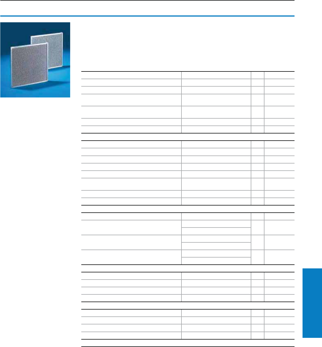
Metal lter
When air conditioners are used in dusty and
damp environments, it is advisable to use washable
metal filters. If air or steam condenses on the
metal surfaces, any particles that may be present
will adhere to the metal and are easily washed out
with water or grease-dissolving detergents.
For TopTherm air conditioners H x W x D inches (mm) PU Part No.
3302.300/3302.310 4 x 8 x 0.4 (95 x 190 x 10) 1 3286.120
3302.100/3302.110/3303. . . ./3361. . . . 8 x 10 x 0.4 (200 x 265 x 10) 1 3286.310
3304. . . ./3305. . . ./3328. . . ./3329. . . ./3332. . .
./3366. . . . 11 x 14 x 0.4 (268 x 344 x 10) 1 3286.410
3273. . . ./3382. . . ./3383. . . ./3384. . . ./3385. . .
./3359. . . . 10 x 21 x 0.4 (255 x 530 x 10) 1 3286.510
3386. . . ./3387. . . . 12 x 28 x 0.4 (300 x 720 x 10) 1 3286.610
3377. . . . 8 x 8 x 0.4 (210 x 205 x 10) 1 3253.220
For discontinued air conditioners H x W x D inches (mm) PU Part No.
3296. . . ./3272.100/3290. . . ./3280.100 11 x 21 x 0.4 (290 x 520 x 10) 1 3286.210
3299. . . ./3261. . . . 12 x 21 x 0.4 (315 x 520 x 10) 1 3286.200
3265.100/3266.100 13 x 10 x 0.4 (320 x 265 x 10) 1 3267.200
3256. . . . 14 x 12 x 0.4 (365 x 315 x 10) 1 3254.200
3293. . . ./3281.100/3298. . . ./3279.100/3260. . .
./3269. . . ./3262.100/3393. . ./3381.100/3391. . . . 12 x 13 x 0.4 (300 x 328 x 10) 1 3294.200
3255. . . ./3395. . . . 9 x 14 x 0.4 (210 x 348 x 10) 1 3253.200
3394. . . . 16 x 15 x 0.4 (415 x 375 x 10) 1 3285.200
For UL Type 4X stainless steel air conditioners H x W x D inches (mm) PU Part No.
3303. . . . 9 x 11 x 0.4 (231 x 275 x 10) 29961.868
3 x 11 x 0.4 (81.5 x 280 x 10)
3304. . . ./3305. . . . 12 x 16 x 0.4 (291 x 395 x 10) 29961.869
3 x 16 x 0.4 (82 x 401 x 10)
3328. . . ./3329. . . . 13 X 16 X 0.4 (321 X 395 x 10 29961.870
3 x 16 x 0.4 (82 x 401 x 10)
For climate control doors H x W x D inches (mm) PU Part No.
3306. . . ./3307. . . ./3309. . . ./3310. . . . 4 x 17 x 0.4 (100 x 424 x 10) 1 3284.200
3308. . . . 4 x 25 x 0.4 (100 x 624 x 10) 1 3288.200
3331. . . . 6 x 15 x 0.4 (150 x 380 x 10) 1 3289.200
For mini chiller systems H x W x D inches (mm) PU Part No.
3318.600/3318.610/3319.600/3319.610 10 x 21 x 0.4 (255 x 530 x 10) 1 3286.510
3320.600/3334.600 22 x 20 x 0.3 (558 x 500 x 8) 1 3286.520
3360. . . . 11 x 14 x 0.4 (268 x 344 x 10) 1 3286.410
Note: Each UL Type 4X air conditioner require 2 filters a top and bottom. Each part number is a complete set.
Accessories
Filter Mats
Material:
Aluminum
Thickness: 0.4" (10 mm)
Inch and pound measurements are rounded to the nearest whole number.
Industrial Buyer’s Guide 327
Climate Control Accessories
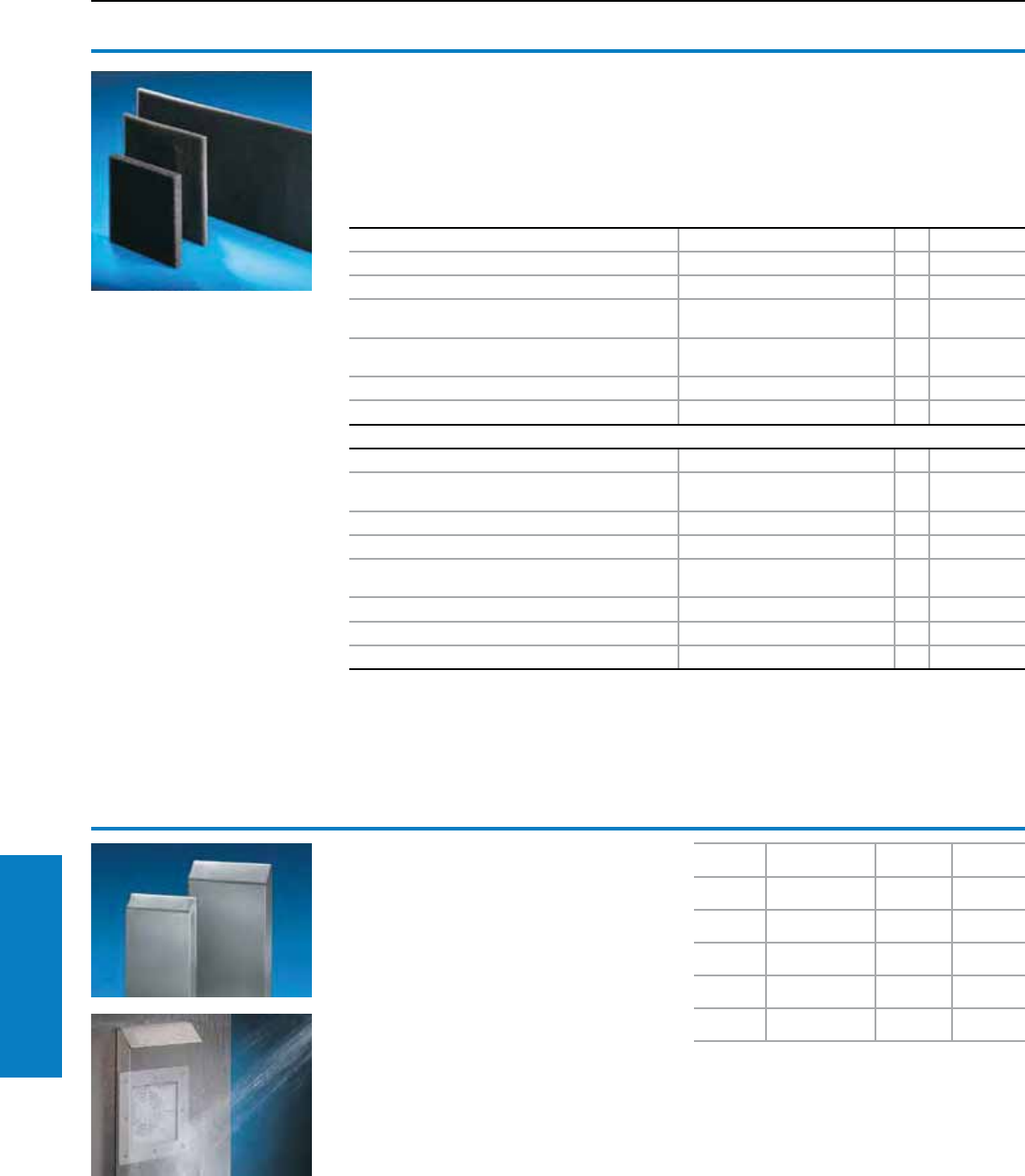
Filter mats for cooling units
Rittal cooling units are low-maintenance and are
supplied without filter mats. Filter mats may be
used for extreme conditions.
Material:
Open-celled polyurethane foamed plastic with
excellent physical and mechanical properties.
Temperature-resistant from -40 to 176° F
(-40 to +80° C).Thickness: 0.4" (10 mm)
For TopTherm air conditioners H x W x D inches (mm) PU Part No.
3302.300/3302.310 4 x 8 x 0.4 (95 x 190 x 10) 3 3286.110
3302. . . ./3303. . . ./3361. . . . 8 x 10 x 0.4 (200 x 265 x 10) 3 3286.300
3304. . . ./3305. . . ./3328. . . ./3329. . . ./3332. . . ./
3366. . . . 11 x 14 x 0.4 (268 x 344 x 10) 3 3286.400
3273. . . ./3382. . . ./3383. . . ./3384. . . ./3385. . . ./
3359. . . . 10 x 21 x 0.4 (255 x 530 x 10) 3 3286.500
3386. . . ./3387. . . . 12 x 28 x 0.4 (300 x 720 x 10) 3 3286.600
3377. . . . 8 x 8 x 0.4 (210 x 205 x 10) 3 3253.010
For discontinued air conditioners H x W x D inches (mm) PU Part No.
3296. . . ./3272.100/3290. . . ./3280.100/3299. . . ./
3261. . . . 13 x 21 x 0.4 (332 x 539 x 10) 3 3286.100
3265.100/3266.100 13 x 11 x 0.4 (332 x 270 x 10) 3 3267.100
3256. . . . 12 x 16 x 0.4 (300 x 395 x 10) 3 3254.000
3293. . . ./3281.100/3298. . . ./3279.100/3260. . . ./
3269. . . ./3262.100/3393. . . ./3381.100/3391. . . . 12 x 13 x 0.4 (313 x 334 x 10) 3 3294.100
3255. . . ./3395. . . . 10 x 14 x 0.4 (245 x 350 x 10) 3 3253.000
3394. . . . 8 x 12 x 0.4 (200 x 315 x 10) 3 3285.000
3292.134/3278.134 10 x 13 x 0.4 (250 x 325 x 10) 3 3286.000
Accessories
Filter Mats
For Dimensions
inches (mm)
Part No.
Stainless
Part No.
RAL 7035
3321. . . 10 x 6 x 2
(260 x 150 x 40) 3321.800 3321.835
3322. . . 11 x 7 x 2
(270 x 176 x 55) 3322.800 3322.835
3323. . . 16 x 9 x 2
(410 x 233 x 55) 3323.800 3323.835
3324. . .
3325. . .
20 x 11 x 3
(500 x 282 x 85) 3324.800 3324.835
3326. . .
3327. . .
22 x 14 x 4
(560 x 350 x 110) 3326.800 3326.835
Hose-proof hoods
For lter fan units/outlet lters
When the hose-proof hood is mounted above the
filter fan unit and outlet filter a rating of IP 56 (UL
3R) to EN 60 529/10.91 is achieved. Particularly
suitable for use in the food industry.
Material:
Stainless steel
Painted steel RAL 7035 (light gray)
Protection Ratings:
In conjunction with the filter fan units/outlet filters,
UL 3R + 12 is met.
UL and cUL recognized
UL file: E76083
Inch and pound measurements are rounded to the nearest whole number.
328 Industrial Buyer’s Guide
Climate Control Accessories
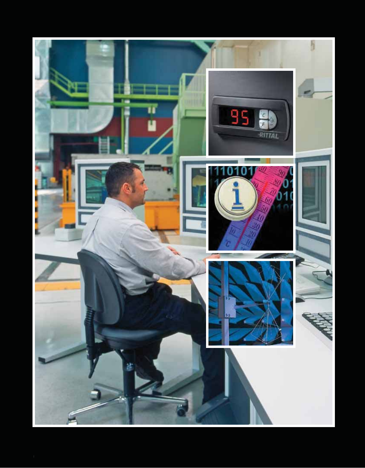
c 329
c
329
Technical Appendix
329
Grounding
The grounding must be
designed by the manufacturer of
switchgear in accordance with
the relevant VDE provisions or
local regulations.
The enclosure packs generally
contain grounding materials
(screws, nuts, washers). The
assembly instructions contain
recommendations on installing a
protective ground.
The pre-assembled ground
straps available in various
cross sections and lengths, are
intended to make assembly of a
ground conductor easier.
Further information can be
found in our technical
documentation "PE ground
conductor connection, current
carrying capacity".
Protection Ratings
and approvals
Product Protection Ratings and
approvals are key requirements
for the global acceptance of
industrial products.
Rittal products meet the highest
internationally recognized
quality standards. All components
are subjected to the most
stringent testing in accordance
with international standards
and regulations.
The consistently high product quality
is ensured by a comprehensive
quality management system.
Regular production inspections
by external test institutes also
guarantee compliance with
global standards.
A precise allocation of products
to marks of conformity can be
found on our product and
service pages on the Internet:
www.rittal-corp.com
Enclosure designs
guaranteeing
hygiene and effective
cleaning
Special applications require
special solutions – in terms of
materials, design and security.
This is also true for applications in
the food and hygiene sector and
in sensitive fields such as medical
technology and pharmaceuticals.
Consequently, Rittal has
reviewed the quality standards
in those branches and has
subjected its products to
stringent testing.
Color RAL Designation Color Sample
3001 signal red
5002 ultramarine
5005 signal blue
5018 turquoise blue
7015 slate gray
7022 umbra gray
7024 graphite gray
7030 stone gray
7032 pebble gray
RAL Colors
Color RAL Designation Color Sample
7033 cement gray
7035 light gray
7044 silky gray
8019 gray brown
9005 jet black
9006 white aluminum
9011 graphite black
9017 traffic black
Technical Appendix
Protection Ratings/Grounding/ RAL Colors/Universal Cut-Outs
Universal Cut-Outs
For safety locking of enclosures and bayed suites in conjunction with up to 200A disconnect switches
and up to 400A circuit breaker operating mechanisms.1)
• ABB DSFHN, K5FCH, OHF1C, K3FHD, K6FHD
• Allen Bradley 1494V, 1494C, 1494RC, 140U
• Cutler Hammer C361, C371, Flex Shaft
• General Electric STDA, SCH SpectraFlex
• Siemens VBF, VBNF, FHO, Max-Flex
• Square D 9422
1)May work with some circuit braker operating mechanisms greater than 400A.
Color samples shown are for reference only and may be different from the finished product
330 Industrial Buyer’s Guide
Tech Appendix Ratings/Grounding/Colors/Cut-Outs
Technical Appendix
Surface Protection
Surface protection
The triple treatment of outer
surfaces – Nano coating,
electrophoretic dipcoat-priming
and textured powder-coating
– provides optimum corrosion
protection for enclosures such
as TS, AE and KL. To ensure
optimum corrosion protection
in extreme climates, aluminium
or zinc-plated metal with
subsequent zinc phosphating
and powder-coating are used for
outdoor enclosures.
Priming or powder
coating suitable for
over-painting
After careful cleaning of the
surface, the standard coating
may be over-painted with:
• DD gloss paints
• Single and dual-component
gloss paints
• Car repair paints
• Powder paints
• Water-based paints
If in doubt, perform a compatibility
test. Always follow the paint
manufacturer’s instructions.
When over-painting, take care not
to exceed 356° F (180° C) and a
baking time of 15 minutes.
Prior to painting, the surface
needs to be prepared by physical
scuffing or the use of a chemical
etching agent.
Physical scuffing would be like
a 300 grit 3M pad; chemical
etching agents would be Xylene
or Toulene.
Special coatings
Tropical coating:
For high corrosion resistance in warm,
damp climates, also suitable for
outdoor and long-term use.
Chemical paint:
For the best possible resistance
to organic and inorganic
substances that can be achieved
with paint.
Outdoor use of
enclosures
In order to guarantee satisfactory
long-term function of enclosures
in outdoor environments, relevant
environmental factors need to be
taken into account.
These include:
• UV radiation, the corrosive
action of air pollution, rain, ice,
snow, wind and other factors in
special climate conditions.
Inuence of weather conditions
on the outer coating
It is necessary to ensure the
UV and corrosion resistance
of components exposed to the
weather. A special 3-phase
paint finish is suitable for
outdoor installations. For outdoor
installation of an enclosure, a rain
canopy should be provided to
protect the seal against
permanent humidity and exposure
to prolonged UV radiation.
Condensation inside
the enclosure
Condensation needs to be
prevented with special measures,
for example by venting or heating
the enclosure.
Protection ratings
The enclosure is exposed to
extreme weather conditions
during outdoor use.
Long periods of rain, snow, ice,
high winds and temperature
fluctuations place high demands
on the enclosure’s sealing
gaskets. Often, the protection
ratings for outdoor weather
exposure described in DIN VDE
0100, part 737, point 5.2, IP X3 is
insufficient to provide permanent
protection for electrical installations.
Standard IEC 60 529 offers
the option of labeling with
the supplementary letter “W”.
Enclosures labeled this way
are suitable for use in weather
conditions agreed between the
manufacturer and the user, and
are equipped with additional
protective features or techniques
(rain canopy, special paints,
special color shades).
The standard coating is resistant to:
• Mineral oils
• Lubricants
• Machining emulsions
• Solvent (briefly as for cleaning)
• Weak acids and alkalines
This has been tested and confirmed
by various independent test
institutes.
Quality is ensured by continuous
process monitoring.
Coating procedures Technical properties Technical specications
Degreasing, Nano
coating, rinsing
Neutralizes electric resistance, provides temporary
corrosion protection and better adhesion of paint.
Anodic dipcoat priming Uniform coating on all surfaces, edges and recesses
provides superior corrosion protection.
Coat thickness Approximately 20 μm
Erichsen cupping DIN EN ISO 20 482 > 0.2" (4 mm)
Bucholz hardness DIN EN ISO 2815 > 80
Cross cutting DIN EN ISO 2409 Gt 0
The primer is readily over-painted and free from heavy metals, chromate and silicone.
Oven Heating
Textured powder coating
The special merits of powder-coating are high durability,
good corrosion protection, good resistance to chemicals,
temperature, and outdoor environment, and can be
easily cleaned.
Outer coating thickness 60 μm . . . 110 μm
Erichsen cupping DIN EN ISO 20 482 > 0.2" (4 mm)
Bucholz hardness DIN EN ISO 2815 > 80
Cross cutting DIN EN ISO 2409 Gt 0
The powder coating is readily over-painted and is free from heavy metals, chromate and silicone.
Oven Heating Overall outer coating thickness Ø 80 μm . . . 135 μm
The three-phase coating process for enclosures
Industrial Buyer’s Guide 331
Tech Appendix Surface Protection
Technical Appendix
Protection Categories
Protection categories to IEC 60 529
The IP protection ratings is characterized by 2 numbers.
Example of protection ratings: IP 43:
Code Letters IP
First characteristic numeral
4
Second characteristic numeral
3
Degrees of protection for protection against contact and foreign bodies:
First characteristic numeral
Degrees of protection for protection against water:
Second characteristic numeral
First
characteristic
numeral
Degree of protection Second
characteristic
numeral
Degree of protection
Description Definition Description Definition
1
Protected against solid foreign
objects with a diameter of
2.0" (50 mm) and greater
The object probe, a sphere
2.0" (50 mm) in diameter,
must not penetrate fully1).
1Protected against vertically
falling water drops
Vertically falling drops shall
have no harmful effects.
2
Protected against solid foreign
objects with a diameter of
0.5" (12.5 mm) and greater
The object probe, a sphere
0.5" (12.5 mm) in diameter,
must not penetrate fully1).
The articulated test finger
may penetrate up to its length
of 3" (80 mm), but adequate
distance must
be adhered to.
2
Protected against vertically
falling water drops when the
enclosure is tilted up to 15°
Vertically falling drops must
not have any harmful effects
when the enclosure is tilted
up to 15° in both directions
from the vertical.
3
Protected against solid foreign
objects with a diameter of
0.1" (2.5 mm) and greater
The object probe, a sphere
0.1" (2.5 mm) in diameter,
must not penetrate at all1).
3Protected against
spraying water
Water sprayed at an angle of
up to 60° on either side of the
vertical must have no harmful
effects.
4
Protected against solid foreign
objects with a diameter of
0.04" (1.0 mm) and greater
The object probe, a sphere
0.04" (1.0 mm) in diameter,
must no penetrate at all1).
4Protected against
splashing water
Water splashed on the
enclosure from every
direction must not have any
adverse effects.
5 Dust-protected
The ingress of dust is not fully
prevented, but dust may not
enter to such an extent as to
impair satisfactory operation
of the device
or safety.
5 Protected against water jets
Water splashed on the
enclosure from every
direction must not have any
adverse effects.
6 Dust-tight
No ingress of dust at a partial
vacuum of 20 mbar inside the
enclosure.
6Protected against powerful
water jets
Water splashed on the
enclosure from every direction
in a powerful jet must not
have any adverse effects.
7
Protected against the effects
of temporary immersion
in water
Water must not ingress to
such an extent as to cause
harmful effects when the
enclosure is temporarily
immersed in water under
standardized pressure and
time conditions.
9K Water with high-pressure/
stream-jet cleaning2)
Water directed at the
enclosure from every
direction under greatly
increased pressure must not
have any adverse effects.
1) The full diameter of the object probe must not pass through an opening of the enclosure.
2) This test is not regulated by EN 60 529, but by DIN EN 40 050, part 9.
Extracts from BS EN 60 259: 1991 are reproduced with the permission of BSI. Complete editions of the standards can be obtained by post from BSI
Customer Services, 889 Chiswick High Road, London W4 4AL
The CE symbol
All Rittal products subject to an
EU Directive which envisages
labeling are labeled CE.
Up-to-date manufacturer
declarations for the respective
products are available on the
Internet at: www.rittal-corp.com
Note:
The CE symbol is not a
quality symbol. Conformity is
certified by the manufacturer
on an independent basis. This
distinguishes CE labeling from
approvals, which are issued by
independent bodies.
332 Industrial Buyer’s Guide
Tech Appendix Protection Categories

Technical Appendix
Protection Categories
NEMA
The National Electrical
Manufacturers Association
(NEMA) is a standards
organization in Washington, D.C.,
USA, which publishes a number
of technical standards but does
not test or certify products itself.
The following NEMA classification
outlines the protection of
individuals from unintentional
contact with equipment and the
protection of an enclosure from
external factors.
Further information on protection
categories may be found on the
Internet at: www.rittal-corp.com
NEMA, UL, and CSA Standards
Enclosure rating NEMA UL CSA
National Electrical Manufacturers Association
(NEMA 250)
Underwriters Laboratories, Inc.
(UL 50 and 508)*
Canadian Standards Association
(C22.2 No. 94-M91)
Type 1
Enclosures are intended for indoor use
primarily to provide a degree of
protection against the contact with the
enclosed equipment.
Indoor use primarily to provide protection
against contact with the enclosed
equipment and against a limited amount of
falling dirt.
General purpose enclosure. Protects against
accidental contact with live parts.
Type 2
Enclosures are intended for indoor use
primarily to provide a degree of
protection against the contact with the
enclosed equipment.
Indoor use to provide a degree of protection
against contact with the enclosed
equipment and against a limited amount of
falling dirt.
Indoor use to provide a degree of protection
against dripping and light splashing of
noncorrosive liquids, and falling dirt.
Type 3
Enclosures are intended for outdoor use
primarily to provide a degree of protection
against rain, sleet, windblown dust, and
damage from external ice formation.
Outdoor use to provide a degree of
protection against windblown rain;
undamaged by the
formation of ice on the enclosure.
Indoor or outdoor use to provide a degree
of protection against rain, snow, and
windblown dust; undamaged by the
external formation of ice on the enclosure.
Type 3R
Enclosures are intended for outdoor use
primarily to provide a degree of protection
against rain, sleet, and damage from
external ice formation.
Outdoor use to provide a degree of
protection against windblown dust and
windblown rain; undamaged by the
formation of ice on the enclosure.
Indoor or outdoor use to provide a degree
of protection against rain, snow;
undamaged by the external formation of ice
on the enclosure.
Type 4
Enclosures are intended for indoor and
outdoor use primarily to provide a degree of
protection against rain, sleet, and damage
from external ice formation.
Indoor or outdoor use to provide a degree
of protection against falling rain, splashing
water, and hose-directed water; undamaged
by the formation of ice on the enclosure.
Indoor or outdoor use to provide a degree
of protection against rain, snow, and
windblown dust, splashing and
hose-directed water; undamaged by the
external formation of ice on the enclosure.
Type 4X
Enclosures are intended for indoor and
outdoor use primarily to provide a degree of
protection against corrosion, windblown dust
and rain, splashing water,
hose-directed water, and damage from
external ice formation.
Indoor or outdoor use to provide a degree
of protection against falling rain, splashing
water, and hose-directed water; undamaged
by the formation of ice on the enclosure;
resists corrosion.
Indoor or outdoor use to provide a degree
of protection against rain, snow, and
windblown dust, splashing and
hose-directed water; undamaged by the
external formation of ice on the enclosure;
resists corrosion.
Type 6
Enclosures are intended for indoor and
outdoor use primarily to provide a degree of
protection against hose-directed water, the
entry of water during occasional temporary
submersion at a limited depth, and damage
from external ice formation.
Indoor or outdoor use to provide a degree
of protection against entry of water during
temporary submersion at a limited depth;
undamaged by the formation of ice on
the enclosure.
Indoor or outdoor use to provide a degree
of protection against entry of water during
temporary submersion at a limited depth;
undamaged by the formation of ice on
the enclosure.
Type 12
Enclosures are intended for indoor use
primarily to provide a degree of protection
against circulating dust, falling dirt and
non-corrosive liquids.
Indoor use to provide a degree of protection
against dust, dirt, fiber flyings, dripping
water, and external condensation of
non-corrosive liquids.
Indoor use primarily to provide a degree
of protection against circulating dust, lint,
fibers, and flyings; dripping and light
splashing of non-corrosive liquids; not
provided with knockouts.
Type 13
Enclosures are intended for indoor use
primarily to provide a degree of protection
against circulating dust, falling dirt and
non-corrosive liquids.
Indoor use to provide a degree of
protection against lint, dust, seepage,
external condensation and spraying of water,
oil, non-corrosive liquids.
Indoor use primarily to provide a degree
of protection against circulating dust, lint,
fibers, and flyings; seepage and spraying
of non-corrosive liquids including oils
and coolants.
Reprinted with permission from National Electrical Manufacturers Association, Underwriters Laboratories, Inc., and Canadian Standards Association.
* UL shall not be responsible to anyone for the use of or reliance upon a UL Standard material by anyone. UL shall not incur any obligation or liability for
damages, including consequential damages, arising out of or in connection with the use, interpretation of, or reliance upon a UL Standard Material.
UL
UL is a source for product
compliance based in Northbrook,
IL, U.S.A. UL has developed
more than 800 safety standards,
for which it does product testing,
and serves customers in more
than 35 countries around the
world, from manufacturers and
retailers to consumers and
regulating bodies.
CSA
The Canadian Standards
Association is a not-for-profit
membership-based association
serving business, industry,
government and consumers
in Canada and the global
marketplace. CSA develops
standards for public health
and safety and offers training
materials, workshops, and
seminars for education in those
standards.
Industrial Buyer’s Guide 333
Tech Appendix Protection Categories

Conversion of NEMA Enclosure Type Ratings
(NEMA 250-2003)
Example Of Table Use
An IEC IP 45 Enclosure Rating is specified. What NEMA Type
Enclosures meet and exceed the IP 45 rating?
Referencing the first character, 4, in the IP rating and the row
designated "IP4_" in the left most column in the table; the blocks in
Column "A" for NEMA Types 3, 3X, 3S, 3SX, 4, 4X, 5, 6, 6P, 12, 12K,
and 13 are shaded. These NEMA ratings meet and exceed the IEC
protection requirements against access to hazardous parts and solid
foreign objects.
Referencing the second character, 5, in the IP rating and the row
designated "IP_5" in the right most column in the table; the blocks
in Column "B" for NEMA Types 3, 3X, 3S, 3SX, 4, 4X, 6 and 6P are
shaded. These NEMA ratings meet and exceed the IEC requirements
for protection against the ingress of water. The absence of shading
in Column "B" beneath the "NEMA Enclosure Type 5" indicates that
Type 5 does not meet the IP 45 protection requirements against
the ingress of water. Likewise the absence of shading in Column
"B" for NEMA Type 12, 12K and 13 enclosures indicates that these
enclosures do not meet the IP 45 requirements for protection against
the ingress of water. Only Types 3, 3X, 3S, 3SX, 4, 4X, 6, and 6P have
both Column "A" in the "IP4_" row and Column "B" in the "IP_5" row
shaded and could be used in an IP45 application.
The NEMA Enclosure Type 3 not only meets the IP 45 Enclosure
Rating, but also exceeds the IEC requirements because the NEMA
IP
First
Character
NEMA Enclosure Type
IP Second
Character
12
3, 3X,
3S, 3SX 3R, 3RX 4, 4X 5 6 6P 12, 12K, 13
IP0_ IP_0
IP1_ IP_1
IP2_ IP_2
IP3_ IP_3
IP4_ IP_4
IP5_ IP_5
IP6_ IP_6
IP_7
IP_8
ABABABABABABABABAB
To IEC 60529 Enclosure Classication Designations (IP)
(Cannot be Used to Convert IEC Classification Designations to NEMA Type Ratings)
Type requires an outdoor corrosion test; a gasket aging test; a dust
test; an external icing test; and no water penetration in the rain test.
Slight differences exist between the IEC and NEMA test methods,
but the IEC rating permits the penetration of water if "it does not
deposit on insulation parts, or reach live parts." The IEC rating does
not require a corrosion test; gasket aging test; dust test or external
icing test. Because the NEMA ratings include additional test
requirements, this table cannot be used to select IP Designations
for NEMA rated enclosure specifications.
IEC 60529 specifies that an enclosure shall not only be
designated with a stated degree of protection indicated by the first
characteristic numeral if it also complies with all lower degrees of
protection. Furthermore IEC 60529 states that an enclosure shall
only be designated with a degree of protection indicated by the
second characteristic numeral if it also complies with all lower
degrees of protection up to and including the second characteristic
numeral 6. An enclosure designated with a second characteristic
numeral 7 or 8 only is considered unsuitable for exposure to water
jets (designated by second characteristic numeral 5 or 6) and
need not comply with requirements for numeral 5 or 6 unless it is
dual coded. Since the IEC protection requirements become more
stringent with increasing IP character value up through 6, once a
NEMA Type rating meets the requirements for an IP designation
up through 6, it will also meet the requirements for all lower IP
designations. This is apparent from the shaded areas shown in the
table.
A = A shaded block in the "A" column indicates that the NEMA
Enclosure Type exceeds the requirements for the respective
IEC 60529 IP First Character Designation. The IP First Character
Designation is the protection against access to hazardous parts and
solid foreign objects.
B = A shaded block in the "B" column indicates that the NEMA
Enclosure Type exceeds the requirements for the respective IEC
60529 IP Second Character Designation. The IP Second Character
Designation is the protection against the ingress of water.
Note
Reprinted with permission from National Electrical Manufacturers
Association, exert from NEMA 250-2003 pages 28 – 29.
334 Industrial Buyer’s Guide
Tech Appendix NEMA to IEC Conversion

Part Number Index
1001.600 - 2471.000
Industrial Buyers Guide 335
Part No. Page
No.
1001.600 50
1002.600 50
1003.600 50
1004.600 50
1005.600 50
1006.600 50
1007.600 50
1008.600 50
1009.600 50
1010.600 50
1011.600 50
1012.600 50
1013.600 50
1014.600 51
1015.600 50
1016.600 51
1017.600 51
1018.600 51
1019.600 51
1030.500 13
1031.500 13
1032.500 13
1033.500 13
1034.500 13
1035.500 13
1038.500 13
1039.500 13
1045.500 13
1050.500 13
1053.500 39
1058.500 14
1060.500 13
1063.500 39
1074.500 39
1075.500 39
1076.500 13
1077.500 13
1078.500 39
1090.500 14
1097.800 39
1097.810 39
1097.820 39
1097.830 39
1097.850 39
1097.870 39
1100.500 14
1110.500 14
1115.500 39
1130.500 14
1180.500 14
1183.500 39
1213.500 14
Part No. Page
No.
1260.500 14
1280.500 14
1283.500 39
1338.500 14
1339.500 14
1353.500 39
1360.500 14
1363.500 39
1375.500 39
1376.500 14
1380.500 13
1400.500 65
1423.500 64
1432.500 64
1434.500 64
1444.500 64
1446.500 64
1448.500 64
1449.500 64
1453.500 65
1454.500 65
1466.500 65
1467.500 65
1468.500 65
1469.500 65
1479.500 65
1480.500 65
1481.000 232
1483.010 253
1485.000 220
1486.000 220
1488.000 220
1489.000 220
1490.010 218
1491.000 232
1492.000 220
1500.510 4
1501.510 4
1502.510 4
1503.510 4
1504.510 4
1505.510 4
1506.510 4
1507.510 5
1508.510 5
1509.510 5
1510.510 5
1511.510 5
1512.510 5
1513.510 5
1514.510 4
1515.510 4
Part No. Page
No.
1516.510 4
1517.510 4
1518.510 4
1519.510 4
1521.010 43
1522.010 43
1523.010 43
1524.010 43
1525.010 43
1526.010 43
1527.510 5
1528.510 4
1529.510 4
1530.510 5
1531.510 5
1532.510 5
1533.510 5
1534.510 5
1535.510 5
1536.510 5
1537.510 5
1538.510 5
1539.510 5
1540.510 5
1541.510 5
1542.510 5
1545.500 7
1546.500 7
1547.500 7
1548.500 7
1549.500 7
1550.500 8
1551.500 7
1552.500 7
1553.500 7
1554.500 7
1555.500 8
1556.500 8
1557.500 8
1560.700 229
1561.700 229
1562.700 229
1563.700 229
1564.700 229
1565.700 229
1566.700 229
1567.700 229
1568.700 229
1569.700 229
1570.700 229
1571.700 229
1572.700 229
Part No. Page
No.
1573.700 229
1574.700 229
1575.700 229
1576.700 229
1577.500 8
1578.500 8
1579.500 8
1580.000 253
1589.510 4
1590.000 253
1591.000 215
1592.000 215
1592.010 215
1594.000 253
1751.500 7
1752.500 8
1753.500 8
1754.500 8
1755.500 8
1931.200 232
1932.200 232
1933.200 232
1934.200 232
1935.200 232
1936.200 232
1937.200 232
1939.200 232
2089.000 246
2092.200 246
2092.300 246
2092.500 246
2093.200 246
2094.200 246
2094.300 246
2094.500 246
2099.500 246
2203.400 246
2308.000 220
2309.000 238
2334.000 244
2335.000 244
2343.000 244
2350.000 256
2351.000 256
2352.000 256
2353.000 256
2354.000 256
2355.000 256
2356.000 256
2357.000 256
2358.000 256
2359.000 256
Part No. Page
No.
2360.000 256
2361.000 208
2362.000 208
2363.000 208
2401.000 207
2402.000 207
2411.600 261
2411.610 261
2411.620 261
2411.630 261
2411.640 261
2411.650 261
2411.660 261
2411.670 261
2411.800 261
2411.810 261
2411.820 261
2411.830 261
2411.840 261
2411.850 261
2411.860 261
2411.870 261
2412.210 243
2412.216 243
2412.225 243
2412.310 243
2412.316 243
2412.325 243
2416.000 221
2418.000 221
2419.000 221
2422.000 210
2423.000 210
2426.500 208
2433.000 253
2433.500 253
2435.000 218
2439.000 219
2449.000 216
2452.000 218
2459.000 200
2460.000 219
2461.000 219
2462.000 219
2463.000 219
2464.000 219
2466.000 219
2467.000 218
2468.000 218
2469.000 218
2470.000 208
2471.000 208

Part Number Index
2472.000 - 3285.200
336 Industrial Buyer’s Guide
Part No. Page
No.
2472.000 208
2473.000 208
2474.000 208
2475.000 208
2476.000 221
2477.000 207
2478.000 207
2479.000 207
2480.000 207
2481.000 207
2482.210 226
2482.220 226
2482.230 226
2482.300 225
2482.310 225
2482.320 225
2482.330 225
2482.400 225
2482.410 225
2482.420 225
2482.500 225
2482.510 225
2482.540 225
2482.550 225
2482.560 225
2482.570 225
2482.580 225
2482.590 225
2482.700 226
2482.710 226
2482.720 226
2482.730 226
2486.300 240
2486.500 240
2487.000 240
2488.000 240
2489.000 240
2489.500 240
2493.000 221
2493.500 221
2501.500 208
2502.500 208
2503.000 253
2503.200 253
2504.000 240
2504.500 240
2504.800 240
2505.500 254
2508.000 253
2508.200 253
2509.000 210
2511.500 208
Part No. Page
No.
2513.000 227
2514.000 227
2515.000 227
2519.000 216
2521.000 220
2531.000 220
2532.000 220
2533.000 219
2541.235 325
2542.235 325
2543.235 325
2545.000 220
2546.000 220
2547.000 220
2548.000 220
2559.000 243
2564.000 243
2565.000 243
2565.100 243
2565.110 243
2565.120 243
2566.000 243
2567.000 243
2568.000 243
2569.000 243
2570.000 243
2570.500 244
2571.000 219
2572.000 219
2575.000 219
2576.000 219
2583.000 254
2584.000 254
2589.000 262
2590.000 262
2590.500 210
2591.000 262
2592.000 262
2593.000 262
2594.000 262
2595.000 262
2596.000 262
2683.500 178
2683.600 178
2684.500 178
2684.600 178
2685.500 178
2685.600 178
2686.500 178
2686.600 178
2694.500 177
2695.500 177
Part No. Page
No.
2735.250 223
2735.500 223
2735.509 223
2735.510 223
2735.520 223
2735.530 223
2735.560 223
2735.570 223
2735.580 223
2735.590 223
2736.540 223
2793.560 224
2793.760 224
2804.200 196
2805.200 196
2807.200 196
2808.200 196
2817.000 197
2819.000 197
2819.200 197
2823.200 196
2824.200 196
2829.200 196
2830.200 196
2836.200 196
2837.200 196
2839.200 196
2840.200 196
2855.000 196
2856.000 196
2859.000 201
2860.000 196
2865.000 196
2866.000 196
2867.000 196
2868.000 196
2869.000 196
2870.000 196
2875.000 196
2876.000 196
2877.000 196
2878.000 196
2879.000 196
2880.000 196
2885.000 196
2886.000 196
2887.000 196
2903.200 196
2904.200 196
2905.200 196
2906.200 196
2909.200 196
Part No. Page
No.
2910.200 196
3105.180 318
3105.190 318
3105.200 318
3105.210 318
3105.220 318
3105.230 318
3105.310 318
3105.320 318
3105.330 318
3105.340 318
3105.350 318
3105.360 318
3105.370 318
3110.000 322
3110.200 322
3114.200 321
3118.000 322
3120.200 322
3124.000 323
3124.100 323
3124.200 323
3125.800 297
3126.100 298
3126.115 298
3127.100 298
3127.115 298
3128.100 298
3128.115 298
3129.100 298
3129.115 298
3129.800 297
3130.100 299
3130.115 299
3148.007 273
3149.007 273
3149.410 273
3149.420 273
3149.440 273
3149.810 273
3149.820 273
3149.840 273
3159.100 323
3169.007 273
3171.100 326
3172.100 326
3173.100 326
3174.000 326
3175.000 325
3176.000 325
3181.100 326
3182.100 326
Part No. Page
No.
3183.100 326
3201.200 292
3201.300 292
3209.100 307
3209.104 307
3209.110 307
3209.114 307
3209.140 307
3209.144 307
3209.500 307
3209.504 307
3209.510 307
3209.514 307
3209.540 307
3209.544 307
3210.100 308
3210.104 308
3210.110 308
3210.114 308
3210.140 308
3210.144 308
3210.500 308
3210.504 308
3210.510 308
3210.514 308
3210.540 308
3210.544 308
3212.024 301
3212.115 301
3212.230 301
3213.300 320
3213.310 320
3213.320 320
3213.330 320
3214.100 302
3214.115 302
3215.100 302
3215.115 302
3216.480 306
3253.000 328
3253.010 328
3253.200 327
3253.220 327
3254.000 328
3254.200 327
3267.100 328
3267.200 327
3273.500 281
3273.515 281
3284.200 327
3285.000 328
3285.200 327

Part Number Index
3286.000 - 3366.200
Industrial Buyers Guide 337
Part No. Page
No.
3286.000 328
3286.100 328
3286.110 328
3286.120 327
3286.200 327
3286.210 327
3286.300 328
3286.310 327
3286.400 328
3286.410 327
3286.500 328
3286.510 327
3286.520 327
3286.600 328
3286.610 327
3286.780 320
3286.850 319
3286.860 320
3286.870 319
3286.880 320
3286.970 319
3286.980 320
3286.990 320
3288.200 327
3289.200 327
3294.100 328
3294.200 327
3301.600 324
3301.608 324
3301.610 324
3301.612 324
3302.100 283
3302.110 283
3302.200 283
3302.210 283
3302.300 282
3302.310 282
3303.100 283
3303.104 289
3303.110 283
3303.114 289
3303.200 283
3303.210 283
3303.500 283
3303.504 289
3303.510 283
3303.514 289
3303.600 283
3303.610 283
3304.100 285
3304.104 289
3304.110 285
Part No. Page
No.
3304.114 289
3304.140 285
3304.144 289
3304.200 285
3304.210 285
3304.240 285
3304.500 285
3304.504 289
3304.510 285
3304.514 289
3304.540 285
3304.600 285
3304.544 289
3304.610 285
3304.640 285
3305.100 285
3305.104 289
3305.110 285
3305.114 289
3305.140 285
3305.144 289
3305.200 285
3305.210 285
3305.240 285
3305.500 285
3305.504 289
3305.510 285
3305.514 289
3305.540 285
3305.544 289
3305.600 285
3305.610 285
3305.640 285
3318.600 311
3318.610 311
3319.600 311
3319.610 311
3320.600 312
3321.027 267
3321.047 267
3321.107 267
3321.117 267
3321.207 325
3321.267 271
3321.607 271
3321.617 271
3321.700 326
3321.800 328
3321.835 328
3322.027 267
3322.047 267
3322.107 267
Part No. Page
No.
3322.117 267
3322.207 325
3322.267 271
3322.607 271
3322.617 271
3322.700 326
3322.800 328
3322.835 328
3323.027 268
3323.047 268
3323.107 268
3323.117 268
3323.207 325
3323.267 271
3323.607 271
3323.617 271
3323.800 328
3323.835 328
3324.027 268
3324.047 268
3324.107 268
3324.117 268
3324.607 272
3324.617 272
3324.800 328
3324.835 328
3325.027 269
3325.047 269
3325.107 269
3325.117 269
3325.207 325
3325.267 272
3325.607 272
3325.617 272
3326.107 270
3326.117 270
3326.207 325
3326.267 272
3326.607 272
3326.617 272
3326.800 328
3326.835 328
3327.107 270
3327.117 270
3327.147 270
3327.607 272
3327.617 272
3327.700 326
3328.100 286
3328.104 290
3328.110 286
3328.114 290
Part No. Page
No.
3328.140 286
3328.144 290
3328.200 286
3328.210 286
3328.240 286
3328.500 286
3328.504 290
3328.510 286
3328.514 290
3328.540 286
3328.544 290
3328.600 286
3328.610 286
3328.640 286
3329.100 286
3329.104 290
3329.110 286
3329.114 290
3329.140 286
3329.144 290
3329.200 286
3329.210 286
3329.240 286
3329.500 286
3329.504 290
3329.510 286
3329.514 290
3329.540 286
3329.544 290
3329.600 286
3329.610 286
3329.640 286
3332.140 287
3332.240 287
3332.540 287
3332.640 287
3334.600 312
3334.660 313
3336.100 315
3336.200 315
3336.300 315
3336.500 315
3336.600 315
3336.650 315
3336.700 316
3336.710 316
3336.720 316
3336.730 316
3336.740 316
3336.750 316
3359.100 277
3359.110 277
Part No. Page
No.
3359.140 277
3359.200 277
3359.210 277
3359.240 277
3359.500 277
3359.510 277
3359.540 277
3359.600 277
3359.610 277
3359.640 277
3360.100 314
3360.250 314
3361.100 284
3361.110 284
3361.140 284
3361.200 284
3361.210 284
3361.240 284
3361.500 284
3361.510 284
3361.540 284
3361.600 284
3361.610 284
3361.640 284
3363.100 303
3363.104 303
3363.110 303
3363.114 303
3363.140 303
3363.144 303
3363.500 303
3363.504 303
3363.510 303
3363.514 303
3363.540 303
3363.544 303
3364.100 303
3364.104 303
3364.110 303
3364.114 303
3364.140 303
3364.144 303
3364.500 303
3364.504 303
3364.510 303
3364.514 303
3364.540 303
3364.544 303
3366.100 288
3366.110 288
3366.140 288
3366.200 288

Part Number Index
3366.210 - 5284.500
338 Industrial Buyer’s Guide
Part No. Page
No.
3366.210 288
3366.240 288
3366.500 288
3366.510 288
3366.540 288
3366.600 288
3366.610 288
3366.640 288
3373.100 304
3373.104 304
3373.110 304
3373.114 304
3373.140 304
3373.144 304
3373.500 304
3373.504 304
3373.510 304
3373.514 304
3373.540 304
3373.544 304
3374.100 304
3374.104 304
3374.110 304
3374.114 304
3374.140 304
3374.144 304
3374.500 304
3374.504 304
3374.510 304
3374.514 304
3374.540 304
3374.544 304
3375.100 305
3375.104 305
3375.110 305
3375.114 305
3375.140 305
3375.144 305
3375.500 305
3375.504 305
3375.510 305
3375.514 305
3375.540 305
3375.544 305
3377.000 324
3377.100 288
3377.110 288
3377.140 288
3377.200 288
3377.210 288
3377.240 288
3377.500 288
Part No. Page
No.
3377.510 288
3377.540 288
3377.600 288
3377.610 288
3377.640 288
3382.100 277
3382.110 277
3382.200 277
3382.210 277
3382.500 277
3382.510 277
3382.600 277
3382.610 277
3383.100 278
3383.110 278
3383.140 278
3383.200 278
3383.210 278
3383.240 278
3383.500 278
3383.510 278
3383.540 278
3383.600 278
3383.610 278
3383.640 278
3384.100 279
3384.110 279
3384.140 279
3384.200 279
3384.210 279
3384.240 279
3384.500 279
3384.510 279
3384.540 279
3384.600 279
3384.610 279
3384.640 279
3385.100 279
3385.110 279
3385.140 279
3385.200 279
3385.210 279
3385.240 279
3385.500 279
3385.510 279
3385.540 279
3385.600 279
3385.610 279
3385.640 279
3386.140 280
3386.240 280
3386.540 280
Part No. Page
No.
3386.640 280
3387.140 280
3387.240 280
3387.540 280
3387.640 280
4114.000 227
4115.000 227
4116.000 227
4118.000 227
4119.000 239
4120.000 227
4123.000 227
4124.000 227
4127.010 241
4140.000 242
4140.110 242
4140.120 242
4140.210 242
4140.220 242
4155.500 241
4157.000 239
4162.000 239
4163.000 239
4164.000 239
4165.000 239
4169.000 237
4170.000 237
4171.000 237
4172.000 237
4173.000 237
4174.000 237
4175.000 237
4176.000 237
4177.000 237
4178.000 237
4179.000 239
4180.000 239
4190.000 214
4191.000 256
4192.000 256
4193.000 256
4195.000 256
4196.000 256
4309.000 236
4311.000 257
4315.150 241
4315.450 241
4315.720 242
4316.000 257
4317.000 257
4318.000 257
4320.700 258
Part No. Page
No.
4321.700 258
4323.700 258
4325.700 258
4336.000 256
4338.000 256
4339.000 256
4393.000 237
4540.000 251
4568.000 210
4579.000 236
4582.000 251
4582.500 250
4583.000 216
4590.700 232
4591.700 232
4592.700 232
4594.000 236
4596.000 236
4598.000 236
4599.000 236
4611.000 201
4612.000 201
4634.500 168
4638.600 227
4638.800 227
4650.000 191
4650.500 191
4694.000 236
4695.000 236
4696.000 236
4697.000 236
4911.000 222
4911.100 222
4912.000 222
4916.000 222
4918.000 222
4920.000 222
4943.000 256
4944.000 256
4945.000 256
4946.000 256
4947.000 256
5001.000 215
5001.050 233
5001.051 233
5001.052 233
5001.053 233
5001.054 233
5001.055 233
5001.060 218
5001.062 218
5001.080 262
Part No. Page
No.
5001.081 262
5001.082 262
5001.083 262
5001.084 262
5001.130 200
5001.140 200
5001.150 200
5001.160 200
5001.210 259
5001.211 259
5001.212 259
5001.213 259
5001.214 259
5001.215 259
5001.216 259
5001.217 259
5001.218 259
5001.219 259
5001.220 259
5001.221 259
5001.222 259
5001.223 259
5001.224 259
5001.225 259
5001.226 259
5001.227 259
5001.228 259
5001.229 259
5001.233 259
5001.234 259
5001.235 259
5001.236 259
5001.237 259
5080.500 34
5084.500 34
5110.500 15
5111.500 16
5112.500 15
5113.500 16
5114.500 15
5115.500 16
5116.500 15
5117.500 16
5118.500 15
5119.500 15
5120.500 16
5121.500 15
5122.500 16
5123.500 16
5205.500 35
5265.500 34
5284.500 34

Part Number Index
5450.500 - 8106.500
Industrial Buyers Guide 339
Part No. Page
No.
5450.500 54
5450.600 54
5451.500 54
5451.600 54
5452.500 54
5452.600 54
5453.500 54
5453.600 54
5454.500 54
5454.600 54
5455.500 54
5455.600 54
5605.500 35
5665.500 34
5684.500 34
5784.500 34
5805.500 35
5865.500 34
5884.500 34
5905.500 35
6023.010 155
6040.010 156
6050.000 152
6050.500 152
6100.000 152
6100.500 152
6110.010 158
6110.100 158
6120.010 157
6130.010 154
6130.510 154
6130.610 153
6136.000 160
6136.500 160
6137.035 160
6137.535 160
6140.010 157
6141.100 161
6141.200 161
6142.100 163
6143.200 160
6143.210 165
6143.310 165
6144.100 163
6145.100 163
6147.000 163
6148.000 201
6160.010 159
6170.010 159
6180.010 157
6200.000 152
6200.500 152
Part No. Page
No.
6205.000 153
6214.500 164
6215.000 164
6215.100 164
6380.000 94
6380.020 94
6380.040 94
6380.050 94
6380.100 94
6442.500 80
6462.500 80
6501.010 121
6501.030 121
6501.050 123
6501.070 122
6501.090 146
6501.110 126
6501.120 124
6501.130 123
6501.140 125
6501.150 127
6501.160 126
6501.340 121
6503.000 165
6508.010 143
6509.000 136
6510.320 134
6510.330 134
6510.340 134
6511.000 136
6513.000 136
6515.000 136
6519.000 136
6520.010 148
6520.510 147
6521.010 149
6522.010 148
6523.010 147
6524.010 145
6524.210 146
6525.010 144
6525.110 144
6525.210 142
6525.510 138
6525.610 139
6526.010 145
6527.010 137
6527.110 138
6528.010 140
6528.210 141
6528.510 140
6529.010 137
Part No. Page
No.
6530.200 79
6531.200 79
6532.200 79
6533.200 79
6535.010 82
6535.510 82
6536.010 82
6536.510 82
6538.010 82
6538.510 82
6539.010 82
6539.510 82
6540.200 79
6541.009 81
6552.500 80
6660.000 128
6660.010 128
6660.020 128
6660.050 128
6660.100 128
6660.110 128
6660.120 128
6660.200 128
6660.210 128
6660.220 128
6660.230 128
6660.240 128
6660.250 128
6662.500 80
6663.000 130
6663.400 130
6663.500 130
6664.000 129
6664.100 129
6664.500 129
6665.000 131
6665.500 131
6700.500 173
6701.500 173
6702.500 173
6703.500 173
6704.500 173
6705.500 173
6706.500 173
6707.500 173
6710.500 172
6711.500 172
6712.500 172
6713.500 172
6714.500 172
6715.500 172
6716.500 172
Part No. Page
No.
6717.500 172
6720.100 171
6720.200 170
6720.500 169
6721.100 171
6721.200 170
6721.500 169
6722.100 171
6722.200 170
6722.500 169
6723.100 171
6723.200 170
6723.500 169
6724.500 169
6725.500 169
6726.500 169
6727.500 169
6730.000 174
6730.010 174
6730.020 174
6730.030 174
6730.100 174
6730.110 174
6730.120 174
6730.130 174
6730.200 174
6730.210 174
6730.220 174
6730.230 174
6730.310 232
6730.330 232
6730.340 232
6730.500 175
6730.510 175
6740.500 176
6742.500 176
6746.500 176
6748.500 176
6900.000 185
6900.100 185
6900.300 184
6900.400 186
6900.410 186
6900.600 186
6901.100 186
6902.000 188
6902.100 188
6902.300 188
6902.310 188
6902.400 187
6902.500 189
6902.640 139
Part No. Page
No.
6902.670 121
6902.770 190
6903.170 211
6920.100 183
6920.200 183
7109.035 321
7113.000 243
7495.000 201
7824.520 214
7824.522 214
7824.525 214
7825.601 194
7825.603 194
7825.801 194
7825.803 194
7827.061 246
7827.081 246
7827.101 246
7827.121 246
7827.141 246
7827.161 246
7827.181 246
7827.201 246
7827.221 246
7829.200 244
7967.000 210
8005.500 26
8006.500 26
8006.530 27
8006.547 32
8006.548 32
8008.530 27
8008.547 32
8008.548 32
8025.500 28
8026.500 29
8026.547 33
8026.548 33
8028.500 29
8028.547 33
8028.548 33
8080.500 21
8084.500 21
8085.500 22
8086.500 23
8088.500 24
8104.235 202
8104.500 203
8105.235 202
8105.500 203
8106.235 202
8106.500 203

Part Number Index
8106.512 - 8702.205
340 Industrial Buyer’s Guide
Part No. Page
No.
8611.180 217
8611.190 217
8611.200 217
8611.220 220
8611.250 217
8611.260 217
8611.290 217
8611.300 211
8611.310 222
8611.330 217
8611.350 217
8612.000 234
8612.020 234
8612.030 234
8612.040 234
8612.050 234
8612.060 234
8612.080 234
8612.090 234
8612.100 234
8612.120 234
8612.130 234
8612.140 234
8612.150 234
8612.160 234
8612.180 234
8612.500 234
8612.520 234
8612.550 234
8612.560 234
8612.580 234
8612.650 235
8612.660 235
8612.680 235
8612.750 236
8612.760 236
8612.780 236
8613.000 245
8613.020 245
8613.060 245
8613.070 245
8613.080 245
8614.040 231
8614.050 231
8614.060 231
8614.240 231
8614.250 231
8614.260 231
8614.640 231
8614.650 231
8614.660 231
8614.675 231
Part No. Page
No.
8106.512 203
8108.235 202
8108.500 203
8108.512 203
8126.235 202
8126.500 203
8128.235 202
8145.235 202
8146.235 202
8148.235 202
8165.235 202
8166.235 202
8168.235 202
8170.235 202
8173.235 202
8174.235 202
8175.235 202
8184.235 202
8184.500 203
8185.235 202
8185.500 203
8186.235 202
8186.500 203
8188.235 202
8204.500 25
8205.500 26
8206.500 27
8208.500 27
8225.500 28
8226.500 29
8228.500 29
8245.500 17
8246.500 18
8248.500 18
8265.500 19
8266.500 20
8268.500 20
8284.500 21
8285.500 22
8286.500 23
8288.500 24
8366.000 179
8366.100 180
8366.200 180
8366.300 179
8366.400 179
8368.000 179
8368.100 180
8405.500 25
8405.510 25
8406.510 26
8410.510 30
Part No. Page
No.
8418.510 30
8426.500 28
8430.510 30
8438.510 30
8450.500 52
8450.600 52
8450.680 53
8451.500 52
8451.600 52
8452.500 52
8452.600 52
8453.500 52
8453.600 52
8454.500 52
8454.600 52
8455.500 52
8455.600 52
8456.500 52
8456.600 52
8457.500 52
8457.600 52
8485.510 22
8486.510 23
8601.000 194
8601.030 194
8601.040 194
8601.050 194
8601.060 194
8601.065 194
8601.080 194
8601.085 194
8601.100 197
8601.200 194
8601.400 194
8601.450 199
8601.500 194
8601.600 194
8601.605 194
8601.680 199
8601.800 194
8601.805 194
8601.915 194
8601.920 194
8602.000 194
8602.030 194
8602.040 194
8602.050 194
8602.060 194
8602.065 194
8602.080 194
8602.085 194
8602.200 194
Part No. Page
No.
8602.400 194
8602.500 194
8602.600 194
8602.605 194
8602.800 194
8602.805 194
8602.920 194
8604.500 25
8605.500 26
8606.500 26
8606.547 32
8606.548 32
8608.500 27
8608.547 32
8608.548 32
8609.020 207
8609.030 207
8609.040 204
8609.050 204
8609.060 204
8609.080 204
8609.100 205
8609.110 205
8609.120 205
8609.130 205
8609.140 206
8609.150 206
8609.160 206
8609.170 206
8609.190 206
8609.260 204
8609.840 204
8609.850 204
8609.860 204
8610.600 211
8610.620 211
8610.680 211
8610.800 211
8610.820 211
8610.880 211
8611.010 217
8611.020 217
8611.030 217
8611.080 211
8611.100 220
8611.110 220
8611.120 220
8611.130 220
8611.140 220
8611.150 220
8611.160 220
8611.170 220
Part No. Page
No.
8614.680 231
8614.840 231
8614.850 231
8614.880 231
8625.500 28
8626.500 29
8626.547 33
8626.548 33
8628.500 29
8628.547 33
8628.548 33
8645.500 17
8646.500 17
8648.500 18
8665.500 19
8666.500 19
8668.500 20
8684.500 21
8685.500 22
8686.500 23
8688.500 23
8700.000 250
8700.060 202
8700.120 258
8700.140 252
8700.150 252
8700.160 252
8700.600 258
8700.800 258
8700.840 202
8700.850 202
8701.040 195
8701.045 195
8701.050 195
8701.055 195
8701.060 195
8701.065 195
8701.180 214
8701.200 195
8701.205 195
8701.600 195
8701.605 195
8701.800 195
8701.805 195
8702.040 195
8702.045 195
8702.050 195
8702.055 195
8702.060 195
8702.065 195
8702.200 195
8702.205 195

Part Number Index
8702.600 - 9963.654
Industrial Buyers Guide 341
Part No. Page
No.
8702.600 195
8702.605 195
8702.800 195
8702.805 195
8800.020 214
8800.040 211
8800.060 258
8800.080 258
8800.085 258
8800.100 258
8800.120 258
8800.125 236
8800.130 236
8800.170 251
8800.190 214
8800.220 198
8800.230 214
8800.290 198
8800.340 239
8800.350 239
8800.370 237
8800.400 249
8800.410 249
8800.420 250
8800.430 250
8800.470 251
8800.490 250
8800.500 249
8800.510 260
8800.520 260
8800.540 260
8800.570 260
8800.590 249
8800.670 251
8800.806 238
8800.808 238
8800.830 199
8800.840 252
8800.850 252
8800.860 252
8800.880 252
8800.892 252
8801.100 213
8801.110 213
8801.120 213
8801.140 213
8801.160 213
8801.170 213
8801.180 213
8801.230 212
8801.240 212
8801.250 212
Part No. Page
No.
8801.260 216
8801.380 273,
324
8801.500 213
8801.510 213
8801.520 213
8801.540 213
8801.550 213
8801.560 213
8801.570 213
8801.580 213
8801.590 213
8801.630 213
8801.705 228
8801.715 228
8801.725 209
8801.735 209
8801.745 209
8801.755 209
8801.765 209
8801.775 209
8801.830 213
8801.915 228
8802.060 257
8802.065 257
8802.080 257
8802.085 257
8802.100 257
8802.105 257
8802.120 257
8802.125 257
8802.160 257
8802.165 257
8804.500 25
8805.500 26
8806.500 26
8806.547 32
8806.548 32
8806.580 31
8808.500 27
8808.547 32
8808.548 32
8825.500 28
8826.500 29
8826.547 33
8826.548 33
8828.500 29
8828.547 33
8828.548 33
8845.500 17
8846.500 17
8848.500 18
8865.500 19
Part No. Page
No.
8866.500 19
8868.500 20
8880.500 22
8881.500 23
8884.500 21
8885.500 22
8886.500 23
8888.500 23
8900.050 223
8900.060 223
8900.840 223
8900.850 223
8901.210 22
8901.220 22
8901.230 23
8901.240 24
8901.250 22
8901.260 22
8901.270 23
8901.280 24
8901.290 26
8901.400 27
8901.410 27
8901.420 26
8901.430 27
8901.440 27
8901.600 40
8901.610 41
8901.620 40
8901.630 41
8901.640 41
8901.650 41
8901.660 41
8901.670 41
8901.680 41
8901.690 41
8901.920 194
8901.930 194
8905.500 41
8906.500 41
8908.500 41
8926.500 41
8945.500 40
8945.580 40
8958.500 41
8965.500 40
8966.500 40
8980.500 41
8984.500 40
8985.500 40
8995.500 41
8996.500 41
Part No. Page
No.
9093.002 204
9093.006 204
9093.008 204
9094.002 204
9094.006 204
9094.008 204
9095.002 204
9095.006 204
9095.008 204
9100.210 58
9101.210 58
9102.210 58
9103.210 58
9104.210 58
9105.210 58
9106.210 58
9107.210 58
9108.210 58
9110.210 58
9111.210 58
9112.210 58
9113.210 58
9114.210 58
9116.210 58
9117.210 58
9118.210 58
9119.210 58
9500.000 56
9501.000 56
9502.000 56
9503.000 56
9504.000 56
9505.000 56
9506.000 56
9507.000 56
9508.000 56
9508.100 56
9509.000 56
9509.100 56
9510.000 56
9510.100 56
9511.000 56
9511.100 56
9512.000 56
9512.100 56
9513.000 56
9513.100 56
9514.000 57
9514.100 57
9515.000 57
9515.100 57
9516.000 57
Part No. Page
No.
9516.100 57
9517.000 57
9517.100 57
9518.000 57
9518.100 57
9519.000 57
9519.100 57
9520.000 57
9520.100 57
9521.000 57
9521.100 57
9522.000 57
9522.100 57
9523.000 57
9523.100 57
9524.000 57
9524.100 57
9530.000 56
9531.000 56
9541.000 229
9542.000 229
9543.000 229
9544.000 229
9545.000 229
9546.000 229
9547.000 229
9548.000 229
9549.000 229
9550.000 229
9564.000 238
9565.000 238
9566.000 238
9567.000 238
9568.000 238
9580.000 215
9581.000 215
9582.000 220
9583.000 255
9961.458 295
9961.459 295
9961.868 327
9961.869 327
9961.870 327
9963.583 325
9963.647 267
9963.648 267
9963.649 267
9963.650 267
9963.651 268
9963.652 268
9963.653 268
9963.654 268

Part Number Index
9963.655 - JBMP1212
342 Industrial Buyer’s Guide
Part No. Page
No.
9963.655 269
9963.656 269
9963.657 270
9963.658 270
9963.659 270
9963.660 270
9963.661 325
9963.662 325
9963.663 325
9963.664 325
9963.936 295
9963.937 295
9963.938 295
9963.939 295
9963.940 295
9963.943 295
9963.944 294
9963.945 294
9963.946 294
9963.947 294
9963.948 294
9963.949 294
9963.950 294
9963.951 294
9963.952 294
9963.953 294
9963.954 294
9963.955 294
9963.956 294
9963.957 293
9963.958 293
9963.959 293
9963.960 293
9963.961 293
9963.962 293
9963.963 293
9963.964 293
9968.108 241
9968.109 241
9968.111 241
9968.112 241
C
C080807H4 78
C080807HC 77
C081207H4 78
C081207HC 77
C081607H4 78
C081607HC 77
C082007H4 78
C082007HC 77
C121209H4 78
C121209HC 77
Part No. Page
No.
C121609H4 78
C121609HC 77
C122009H4 78
C122009HC 77
C122409H4 78
C122409HC 77
C161611H4 78
C161611HC 77
C162011H4 78
C162011HC 77
C162411H4 78
C162411HC 77
C163011H4 78
C163011HC 77
C163611H4 78
C163611HC 77
C202013H4 78
C202013HC 77
C202413H4 78
C202413HC 77
C203013H4 78
C203013HC 77
D
DFK1212A 230
DFK1212C 230
DFK1612A 230
DFK1612C 230
DFK1616A 230
DFK1616C 230
DFK1620A 230
DFK1620C 230
DFK2016A 230
DFK2016C 230
DFK2020A 230
DFK2020C 230
DFK2024A 230
DFK2024C 230
DFK2416A 230
DFK2416C 230
DFK2420A 230
DFK2420C 230
DFK2424A 230
DFK2424C 230
DFK2430A 230
DFK2430C 230
DFK3020A 230
DFK3020C 230
DFK3024A 230
DFK3024C 230
DFK3030A 230
DFK3030C 230
DFK3624A 230
Part No. Page
No.
DFK3624C 230
DFK3630A 230
DFK3630C 230
DFK3636A 230
DFK3636C 230
DFK4230A 230
DFK4230C 230
DFK4236A 230
DFK4236C 230
DFK4836A 230
DFK4836C 230
DFK6036A 230
DFK6036C 230
E
EDP1419C 228
EDP1614C 228
F
FDS1212C 228
FDS1818C 228
FSK1206C 198
FSK1208C 198
FSK1210C 198
FSK1212C 198
FSK1216C 198
FSK1220C 198
FSK1806C 198
FSK1808C 198
FSK1810C 198
FSK1812C 198
FSK1816C 198
FSK1820C 198
FSK2406C 198
FSK2408C 198
FSK2410C 198
FSK2412C 198
FSK2416C 198
FSK2420C 198
FSK12064 198
FSK12066 198
FSK12084 198
FSK12086 198
FSK12104 198
FSK12106 198
FSK12124 198
FSK12126 198
FSK12164 198
FSK12166 198
FSK12204 198
FSK12206 198
FSK18064 198
FSK18066 198
FSK18084 198
Part No. Page
No.
FSK18086 198
FSK18104 198
FSK18106 198
FSK18124 198
FSK18126 198
FSK18164 198
FSK18166 198
FSK18204 198
FSK18206 198
FSK24064 198
FSK24066 198
FSK24084 198
FSK24086 198
FSK24104 198
FSK24106 198
FSK24124 198
FSK24126 198
FSK24164 198
FSK24166 198
FSK24204 198
FSK24206 198
J
JB040403H4 44
JB040403H6 44
JB040403HC 6
JB060403H4 44
JB060403H6 44
JB060403HC 6
JB060404H4 44
JB060404H6 44
JB060404HC 6
JB060604H4 44
JB060604H6 44
JB060604HC 6
JB080604H4 44
JB080604H6 44
JB080604HC 6
JB080606H4 44
JB080606H6 44
JB080606HC 6
JB080804H4 44
JB080804H6 44
JB080804HC 6
JB100804H4 44
JB100804H6 44
JB100804HC 6
JB100806H4 44
JB100806H6 44
JB100806HC 6
JB101006H4 44
JB101006H6 44
JB101006HC 6
Part No. Page
No.
JB120604H4 44
JB120604H6 44
JB120604HC 6
JB121005H4 44
JB121005H6 44
JB121005HC 6
JB121006H4 45
JB121006H6 45
JB121006HC 6
JB121008H4 45
JB121008H6 45
JB121008HC 6
JB121206H4 45
JB121206H6 45
JB121206HC 6
JB141206H4 45
JB141206H6 45
JB141206HC 6
JB161406H4 45
JB161406H6 45
JB161406HC 6
JB161408H4 45
JB161408H6 45
JB161408HC 6
JB161410H4 45
JB161410H6 45
JB161410HC 6
JBMP0604 230
JBMP0604S6 230
JBMP0604W 230
JBMP0606 230
JBMP0606S6 230
JBMP0606W 230
JBMP0806 230
JBMP0806S6 230
JBMP0806W 230
JBMP0808 230
JBMP0808S6 230
JBMP0808W 230
JBMP1008 230
JBMP1008S6 230
JBMP1008W 230
JBMP1010 230
JBMP1010S6 230
JBMP1010W 230
JBMP1206 230
JBMP1206S6 230
JBMP1206W 230
JBMP1210 230
JBMP1210S6 230
JBMP1210W 230
JBMP1212 230

Part Number Index
JBMP1212S6 - PB30305T5C
Industrial Buyers Guide 343
Part No. Page
No.
JBMP1212S6 230
JBMP1212W 230
JBMP1412 230
JBMP1412S6 230
JBMP1412W 230
JBMP1614 230
JBMP1614S6 230
JBMP1614W 230
L
L-F1PB 76
L-F1PBGM 76
L-F2PB 76
L-F2PBGM 76
L-F3PB 76
L-F3PBGM 76
L-F4PB 76
L-F4PBGM 76
L-F5PB 76
L-F5PBGM 76
L-F16HS10 70
L-F20HS16 70
L-F24HS24 70
L-F30HS24 70
L-F36HS30 70
L-F60H3612 68
L-F60H3616 68
L-F72H2525FS 69
L-F72H4925FSDD 69
L-FJ332HB 60
L-FJ532HB 60
L-FJ604CHNFQ 62
L-FJ604CHNFQX 62
L-FJ604CHNFSC 61
L-FJ604CHNFSCX 61
L-FJ604NFSC 59
L-FJ606CHNFQ 62
L-FJ606CHNFQX 62
L-FJ606CHNFSC 61
L-FJ606CHNFSCX 61
L-FJ606NFSC 59
L-FJ644HB 60
L-FJ806CHNFQ 62
L-FJ806CHNFQW 63
L-FJ806CHNFQX 62
L-FJ806CHNFSC 61
L-FJ806CHNFSCX 61
L-FJ806NFSC 59
L-FJ844HB 60
L-FJ1008CHNFQ 62
L-FJ1008CHNFQW 63
L-FJ1008CHNFQX 62
L-FJ1008CHNFSC 61
Part No. Page
No.
L-FJ1008CHNFSCX 61
L-FJ1008NFSC 59
L-FJ1144HB 60
L-FJ1210CHNFQ 62
L-FJ1210CHNFQW 63
L-FJ1210CHNFQX 62
L-FJ1210CHNFSC 61
L-FJ1210CHNFSCX 61
L-FJ1210NFSC 59
L-FJ1412CHNFQ 62
L-FJ1412CHNFQW 63
L-FJ1412CHNFQX 62
L-FJ1412CHNFSC 61
L-FJ1412CHNFSCX 61
L-FJ1412NFSC 59
L-FJ1614CHNFQ 62
L-FJ1614CHNFQW 63
L-FJ1614CHNFQX 62
L-FJ1614CHNFSC 61
L-FJ1614CHNFSCX 61
L-FJ1614NFSC 59
L-FJ1816CHNFQ 62
L-FJ1816CHNFQW 63
L-FJ1816CHNFQX 62
L-FJ1816CHNFSC 61
L-FJ1816CHNFSCX 61
L-FJ1816NFSC 59
L-FJ2016CHNFQ 62
L-FJ2016CHNFQW 63
L-FJ2016CHNFQX 62
L-FJ2016CHNFSC 61
L-FJ2016CHNFSCX 61
L-FJ2016NFSC 59
L-FW20H1612 66
L-FW20R1612HCR 67
L-FW24H2008 66
L-FW24H2410 66
L-FW24H2412 66
L-FW24R2008HCR 67
L-FW24R2410HCR 67
L-FW30H2008 66
L-FW30H2407 66
L-FW30H2410 66
L-FW30R2410HCR 67
L-FW30R2412HCR 67
L-FW36H3010 66
L-FW36H3012 66
L-FW36R3010HCR 67
L-FW36R3012HCR 67
L-FW48H3612 66
L-FW48H3616 66
L-FW48R3612HCR 67
Part No. Page
No.
L-FW48R3616HCR 67
O
OHS050C 200
OHS075C 200
OHS100C 200
OHS125C 200
OHS150C 200
OHS175C 200
OHS200C 200
OHS250C 200
OHS300C 200
OHS350C 200
OHS400C 200
OHS0506 200
OHS0756 200
OHS1006 200
OHS1256 200
OHS1506 200
OHS1756 200
OHS2006 200
OHS2506 200
OHS3006 200
OHS3506 200
OHS4006 200
OHSMPB6 200
OHSMPBC 200
OHSSPB6 200
OHSSPBC 200
P
PB01225M1C 72
PB01225M14 74
PB01225M16 75
PB01305L1C 72
PB01305L14 74
PB01305S1C 72
PB01305S14 74
PB01305S16 75
PB01305T1C 73
PB01305X1C 73
PB01305X14 74
PB01305X16 75
PB02225M1C 72
PB02225M14 74
PB02225M16 75
PB02305L1C 72
PB02305L14 74
PB02305S1C 72
PB02305S14 74
PB02305S16 75
PB02305T2C 73
PB02305X1C 73
PB02305X14 74
Part No. Page
No.
PB02305X16 75
PB03225M1C 72
PB03225M14 74
PB03225M16 75
PB03305L1C 72
PB03305S1C 72
PB03305S14 74
PB03305S16 75
PB03305T3C 73
PB03305X1C 73
PB03305X14 74
PB03305X16 75
PB04225E2C 73
PB04225M1C 72
PB04225M14 74
PB04225M16 75
PB04305L1C 72
PB04305S1C 72
PB04305S2C 72
PB04305S14 74
PB04305S16 75
PB04305S24 74
PB04305S26 75
PB04305T2C 73
PB04305T4C 73
PB04305X1C 73
PB04305X2C 73
PB04305X14 74
PB04305X16 75
PB04305X24 74
PB04305X26 75
PB05305L1C 72
PB05305S1C 72
PB05305S14 74
PB05305S16 75
PB06225E2C 73
PB06225M2C 72
PB06225M24 74
PB06225M26 75
PB06305L1C 72
PB06305S1C 72
PB06305S2C 72
PB06305S24 74
PB06305S26 75
PB06305T3C 73
PB06305X2C 73
PB06305X24 74
PB06305X26 75
PB08305S1C 72
PB08305T4C 73
PB09225E3C 73
PB09225M3C 72
Part No. Page
No.
PB09225M34 74
PB09225M36 75
PB09305S3C 72
PB09305S34 74
PB09305S36 75
PB09305T3C 73
PB09305X3C 73
PB09305X34 74
PB09305X36 75
PB10305S1C 72
PB10305T5C 73
PB10305X2C 73
PB10305X24 74
PB10305X26 75
PB12225E3C 73
PB12225M3C 73
PB12225M34 74
PB12225M36 75
PB12305S3C 72
PB12305S34 74
PB12305S36 75
PB12305T3C 73
PB12305T6C 73
PB12305X3C 73
PB12305X34 74
PB12305X36 75
PB16225E4C 73
PB16225M4C 73
PB16305S4C 72
PB16305T4C 73
PB16305T8C 73
PB16305X2C 73
PB16305X4C 73
PB16305X24 75
PB16305X26 75
PB16305X44 75
PB16305X46 75
PB20225E4C 73
PB20225M5C 73
PB20305T5C 73
PB20305X4C 73
PB20305X44 75
PB20305X46 75
PB25225E5C 73
PB25225M5C 73
PB25305T5C 73
PB25305X5C 73
PB25305X54 75
PB25305X56 75
PB30225E5C 73
PB30225M5C 73
PB30305T5C 73

Part Number Index
PB36225E6C - WMUMB6
344 Industrial Buyer’s Guide
Part No. Page
No.
PB36225E6C 73
PB42225E6C 73
T
TSFM634712NC 36
TSFM634716NC 36
TSFM634716XC 42
TSFM634720NC 36
TSFM634720XC 42
TSFM634724NC 36
TSFM634724XC 42
TSFM636312NC 36
TSFM636316NC 36
TSFM636316XC 42
TSFM636320XC 42
TSFM636324NC 36
TSFM636324XC 42
TSFM716312NC 36
TSFM716316NC 36
TSFM716316XC 42
TSFM716320NC 37
TSFM716320XC 42
TSFM716324NC 37
TSFM717112NC 36
TSFM717116NC 37
TSFM717116XC 42
TSFM717120NC 37
TSFM717120XC 42
TSFM717124NC 37
TSFM717124XC 42
W
WK0503C 224
WK0905C 224
WK1303C 224
WK1308C 224
WK1705C 224
WK1711C 224
WK2315C 224
WK2919C 224
WK3523C 224
WK05034 224
WK05036 224
WK09054 224
WK09056 224
WK13034 224
WK13036 224
WK13084 224
WK13086 224
WK17054 224
WK17056 224
WK17114 224
WK17116 224
WK23154 224
Part No. Page
No.
WK23156 224
WK29194 224
WK29196 224
WK35234 224
WK35236 224
WM121206N4 46
WM121206N6 46
WM121206NC 9
WM161206N4 46
WM161206N6 46
WM161206NC 9
WM161208N4 46
WM161208N6 46
WM161208NC 9
WM161606N4 46
WM161606N6 46
WM161606NC 9
WM161608NC 9
WM162006NC 9
WM162008NC 10
WM201606N4 46
WM201606N6 46
WM201606NC 9
WM201608N4 46
WM201608N6 46
WM201608NC 10
WM202006N4 46
WM202006N6 46
WM202006NC 9
WM202008N4 46
WM202008N6 46
WM202008NC 10
WM202010NC 11
WM202012NC 11
WM202408NC 10
WM241606NC 9
WM241608N4 46
WM241608N6 46
WM241608NC 10
WM242006NC 9
WM242008N4 46
WM242008N6 46
WM242008NC 10
WM242010N4 47
WM242010N6 47
WM242010NC 11
WM242012NC 11
WM242406NC 9
WM242408N4 46
WM242408N6 46
WM242408NC 10
WM242410NC 11
Part No. Page
No.
WM242412N4 47
WM242412N6 47
WM242412NC 11
WM242608X4 55
WM242608X6 55
WM242608XC 38
WM243008NC 10
WM244208NC 10
WM302008NC 10
WM302406NC 9
WM302408N4 46
WM302408N6 46
WM302408NC 10
WM302410N4 47
WM302410N6 47
WM302410NC 11
WM302412N4 47
WM302412N6 47
WM302412NC 11
WM302420NC 12
WM303008N4 47
WM303008N6 47
WM303008NC 10
WM303010N4 47
WM303010N6 47
WM303010NC 11
WM303012NC 11
WM304210NC 11
WM304810NC 11
WM362408N4 47
WM362408N6 47
WM362408NC 10
WM362410NC 11
WM362412NC 11
WM363008N4 47
WM363008N6 47
WM363008NC 10
WM363010N4 47
WM363010N6 47
WM363010NC 11
WM363012N4 47
WM363012N6 47
WM363012NC 12
WM363016N4 47
WM363016N6 47
WM363016NC 12
WM363208X4 55
WM363208X6 55
WM363208XC 38
WM363210X4 55
WM363210X6 55
WM363210XC 38
Part No. Page
No.
WM363212X4 55
WM363212X6 55
WM363212XC 38
WM363608NC 10
WM363612N4 47
WM363612N6 47
WM363612NC 12
WM364212NC 12
WM364812NC 12
WM366012NC 12
WM423008NC 10
WM423212X4 55
WM423212X6 55
WM423212XC 38
WM423608NC 10
WM423610NC 11
WM423612N4 47
WM423612N6 47
WM423612NC 12
WM426012NC 12
WM483608NC 10
WM483610N4 47
WM483610N6 47
WM483610NC 11
WM483612N4 47
WM483612N6 47
WM483612NC 12
WM483616N4 47
WM483616N6 47
WM483616NC 12
WM483620NC 12
WM483812X4 55
WM483812X6 55
WM483812XC 38
WM483816X4 55
WM483816X6 55
WM483816XC 38
WM484812NC 12
WM603610NC 11
WM603612N4 47
WM603612N6 47
WM603612NC 12
WM603616N4 47
WM603616N6 47
WM603616NC 12
WM603810X4 55
WM603810X6 55
WM603810XC 38
WM603812X4 55
WM603812X6 55
WM603812XC 38
WMLHKL 220
Part No. Page
No.
WMLHKLS6 220
WMLHNL 220
WMLHNLS6 220
WMLHPL 220
WMLHPLS6 220
WMPADCS 221
WMPADRCS 221
WMPADRS6 221
WMPADS6 221
WMQTPLS6 219
WMS161208N4 48
WMS161208N6 48
WMS161608N4 48
WMS161608N6 48
WMS201608N4 48
WMS201608N6 48
WMS201612N4 48
WMS201612N6 48
WMS202008N4 48
WMS202008N6 48
WMS202012N4 48
WMS202012N6 48
WMS242008N4 48
WMS242008N6 48
WMS242408N4 48
WMS242408N6 48
WMS242412N4 48
WMS242412N6 48
WMS302408N4 48
WMS302408N6 48
WMS302412N4 49
WMS302412N6 49
WMS303008N4 48
WMS303008N6 48
WMS363008N4 48
WMS363008N6 48
WMS363012N4 49
WMS363012N6 49
WMS363016N4 49
WMS363016N6 49
WMS363612N4 49
WMS363612N6 49
WMS483616N4 49
WMS483616N6 49
WMS603616N4 49
WMS603616N6 49
WMSMB 254
WMSMB6 254
WMUMB 254
WMUMB6 254

Rittal –The System.
Faster – Better – Worldwide.
Whether your projects take you around the corner or
around the world, Rittal product, service, and support
systems are available to deliver quality, flexible solutions
that provide exceptional value for the money. Rittal has
everything you need for simple jobs requiring single
enclosures or complex applications that demand
climate control, power management, and even
networking capabilities—inside or out. And, we can
get it to you on time, on budget, and fully backed
by comprehensive support and service packages
that can be tailored to fit your specific areas of
concern.
Visit www.rittal-thesystem.com to learn more.
INDUSTRIAL ENCLOSURES POWER DISTRIBUTION ELECTRONIC PACKAGING SYSTEM CLIMATE CONTROL IT SYSTEMS
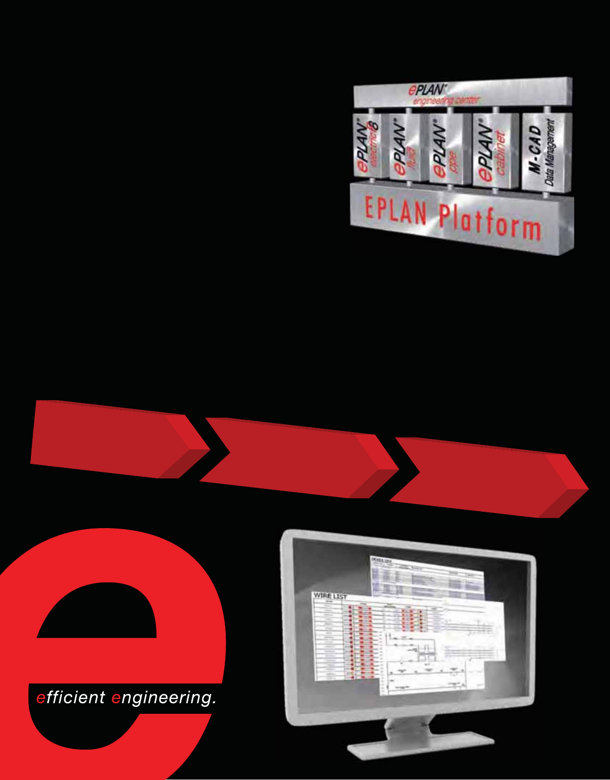
EPLAN Software & Services
EPLAN Software & Services, a fast growing subsidiary
of Rittal, provides fully integrated CAE software products
for the efficient design and documentation of electrical,
fluid power, instrumentation and process control, and
2D/3D enclosure systems. EPLAN’s customer-centric
services range from technical support and training
to integration with third-party enterprise systems and
overall engineering process consulting. This ensures
successful software implementation and continued
optimization of engineering processes as proven by over
18,000 customers with more than 60,000 installations.
The EPLAN Platform
EPLAN products are based on a unique data management technology enabling them to directly and
seamlessly share design data and core functionalities across the EPLAN Platform. This effectively
allows the electrical, fluid power, instrumentation and process control, and enclosure designers to
have one universal tool to achieve maximum efficiency and accuracy levels—both individually and
collaboratively.
Schematics, Layouts,
Wiring Diagrams
EPLAN Platform
Concept
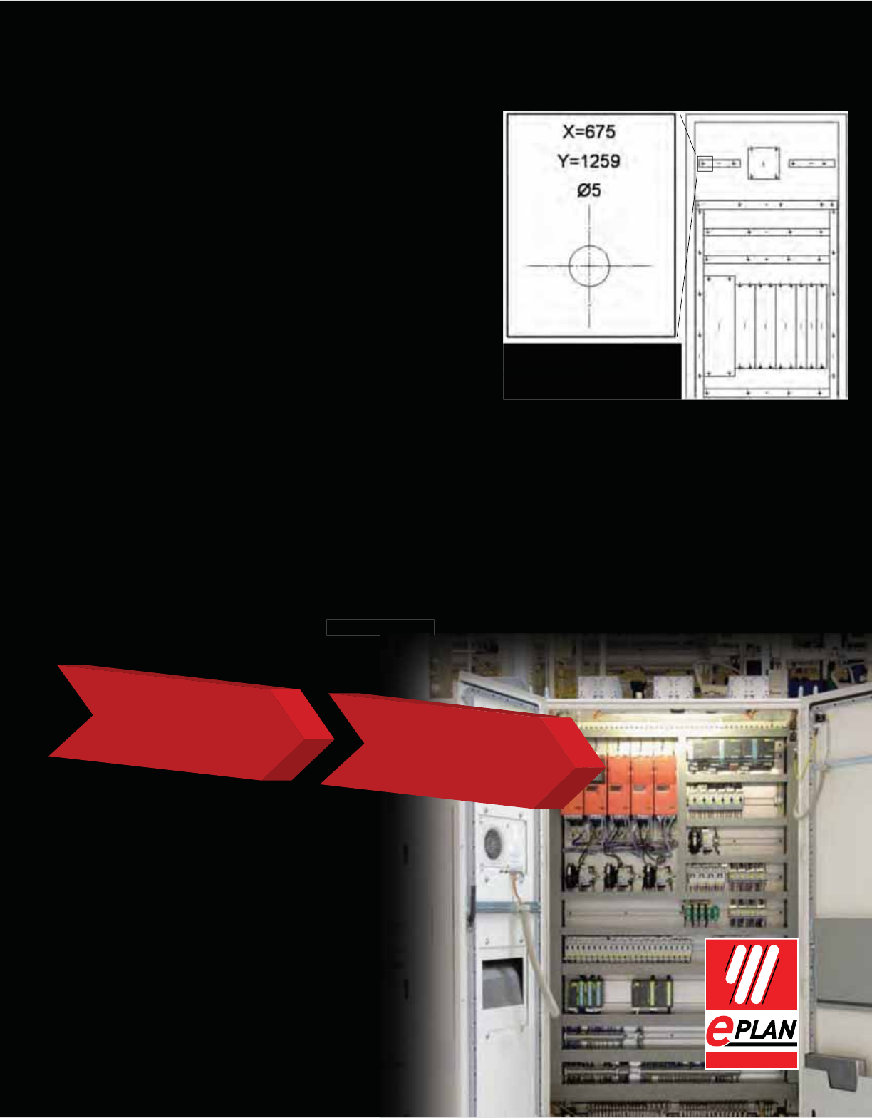
EPLAN products can also connect
into a company’s processes and
enterprise environment. The benefit for
the customer is the ability to recognize
substantial efficiency gains across the
entire design, build, commissioning and
maintenance cycle. This measurably
reduces overall engineering costs and
improves quality.
For more information and to request a
free trial, call 888-375-2668 or visit
www.eplanusa.com.
EPLAN Electric P8: Design your power distribution,
control and PLC schematics and generate your BOM,
wire lists, and cable and terminal diagrams.
EPLAN Fluid: Design your hydraulic, pneumatic,
cooling and lubrication systems.
EPLAN PPE: Create your P&IDs, instrumentation data
sheets and process BOM.
EPLAN Cabinet: Prototype, validate and build your
enclosure in 3D environment, preventing collisions and maximizing build
surface.
EPLAN Engineering Center: Configure your machine and generate your documentation for all
mechatronic disciplines.
Additionally, EPLAN Cabinet automates optimal wire routing, calculates shortest wire lengths
and controls cable duct fill levels. EPLAN Cabinet also computes drill holes data to automatically
generate drilling templates. For more advanced processes this data can be directly transferred
to NC and wire processing machines. The result is enclosures accurately prepared for build in
dramatically shorter times. Direct access to Rittal’s RiCAD 3D catalog ensures accuracy and
efficiency both in the design and manufacturing of enclosures.
m
ax
i
m
i
z
i
n
g
build
g
g
Manufacturing
Documentation Control Panel
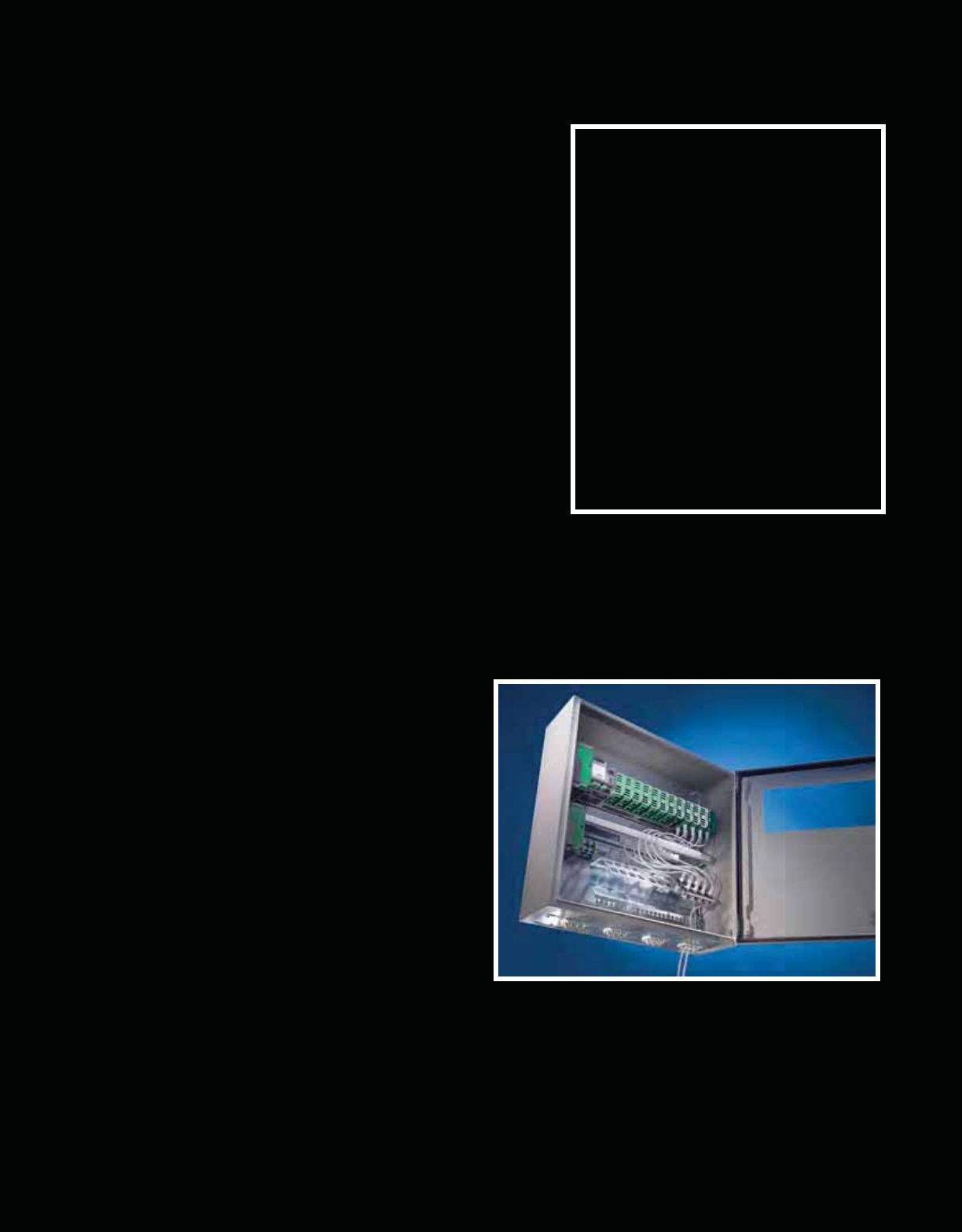
Electronic Packaging
Need an electronic packaging solution for your application? Stick with Rittal.
Rittal offers far more than just enclosures. Choose from a
variety of subracks, chassis and piece parts that comply
with industry standard platforms including CPCI, VME
and uTCA.
From basic builds to complex EMC shielding
requirements, panel-mounted components, custom or
mobile applications—Rittal has everything you need.
All of our components (including power supplies, fan
units and panels) are factory tested for reliability and
performance to ensure your project’s success.
Plant Floor Networking
Ongoing technological advances in manufacturing operations and other modern industrial
applications are increasingly integrating IT-dependent processes, making the use of IT
equipment outside of the data center more
and more prevalent. This requires enclosure
solutions that can meet the demands of
both IT performance and industrial-grade
protection. Even though IT equipment is
placed at greater risk out on the plant floor,
uptime is still a primary concern and a non-
negotiable requirement.
Rittal offers UL Type 12 and NEMA 12 rated
TS8 enclosures that incorporate the best of
both worlds—the protection of our industrial
enclosures and the flexibility and performance
of our IT enclosures. Rittal’s plant floor networking enclosures are compatible with a wide range
of both industrial and IT accessories including Rittal industrial cooling products such as filter
fans and air conditioners that can remove the heat necessary to keep installed IT equipment up
and running while maintaining critical protection ratings.
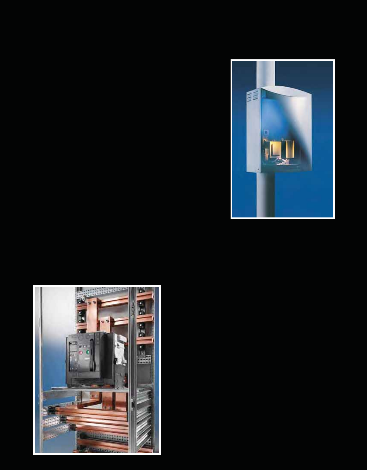
Outdoor Enclosure Solutions
Rittal offers a wide variety of enclosure systems and climate control components engineered
specifically for outdoor and commercial applications that can be ordered off-the-shelf or
custom-configured to provide superior protection in
challenging environments.
Installed equipment is kept safe from day-to-day
temperature fluctuations, humidity and sunlight as well as
severe weather conditions, exposure to seawater and even
earthquakes by industry-leading, modular freestanding
and wall-mounted enclosures constructed of either rugged
carbon or stainless steel. In addition, integral physical
security and design features protect against unauthorized
access and vandalism so you can rest assured that you’re
installation is protected from the worst that both “Mother” or
human nature have to offer.
Power Distribution
Rittal understands how important reliable, safe power distribution is to our customers, which is
why our modular busbar systems are engineered to keep your applications running and your
personnel out of harm’s way.
Flexible, touch-safe designs allow users to
customize their solution to meet their precise
specifications while a modular architecture
provides the freedom to easily reconfigure
the system to change along with their needs.
Supported by Rittal’s knowledgeable applications
experts, Rittal industrial power distribution
systems deliver industry-leading technology to
the controls and switchgear equipment that drive
today’s business.

Rittal –The System.
Faster – better – worldwide.
07/10 • US173
Enclosures
Power Distribution
Climate Control
IT Infrastructure
Software & Services
Rittal Corporation
1 Rittal Place • Urbana Ohio 43078 • USA
Phone: 937-399-0500 • Fax: 800-477-4003 • Toll-free: 800-477-4000
Email: rittal@rittal-corp.com • Online: www.rittal-corp.com
