Installation Directions
71590-Installationsheet 71590-InstallationSheet 71590-InstallationSheet 640181 Batch2_1 unilog cesco-content
2016-09-04
: Pdf 169773-Installationsheet 169773-InstallationSheet B4 unilog
Open the PDF directly: View PDF ![]() .
.
Page Count: 2
™ Fluorescent High Bay Occupancy Sensor
Installation Instructions
Hubbell Building Automation
9601 Dessau Road Building One Suite 100
Austin, TX 78754
Toll Free: 888-698-3242
Fax: 512-450-1215
www.hubbell-automation.com
PRODUCT CONFIGURATIONS
FHB141NPUNV – Fluorescent High Bay PIR Sensor with 1.4 Area Lens, 1-SPST Output
FHB142NPUNV – Fluorescent High Bay PIR Sensor with 1.4 Area Lens, 2-SPST Outputs
FHBADAPTOR – Fluorescent High Bay Mounting Extension Adaptor
SPECIFICATIONS
Timer Timeouts
oPrimary (8 second test mode, 4, 8 16, 30 minutes)
oSecondary (Disabled, 30, 60, 90 minutes) – Available on dual output version only
Coverage
o360 Degree (masking kit included)
oLens: 1.4 – 42 foot radius; mounted at 30 feet
Load Ratings (for each output)
o120V: 0 – 800W ballast or tungsten
o277V: 0 – 1200W ballast
o347V: 0 – 1500W ballast
o¼ HP motor load
Power Requirements: 120/277/347VAC, 60Hz
Operating Environment: Indoor Use Only; 32o – 104o F (0o – 40o C); Relative Humidity (non-condensing):
0% - 95%.
PRECAUTIONS
Read and understand all instructions before beginning installation.
NOTICE: For installation by a licensed electrician in accordance with National and/or local Electrical
Codes and the following instructions.
NOTICE: For use in Pollution Degree 2 Environment - Indoor Use Only.
CAUTION: RISK OF ELECTRICAL SHOCK. Turn power off at service panel before beginning
installation. Never wire energized electrical components.
CAUTION: USE COPPER CONDUCTOR ONLY.
Confirm that device ratings are suitable for application prior to installation.
Use only approved materials and components (i.e. wire nuts, electrical box, etc.) as appropriate for
installation.
NOTICE: Do not install if any damage to product is noticed.
SENSOR INSTALLATION
The installation instructions contained in this document are provided as a guide for proper and reliable
installation. The mounting location should be selected and prepared based on the lighting system application
and facility layout requirements. All electrical wiring and mounting hardware (i.e. extension adaptor (p/n
FHBADAPTOR, electrical mounting box, conduit, etc.) should be prepared with consideration of the
requirements outlined in the wiring and mounting diagrams below.
1. Turn power off at the service panel before installing sensor.
2. Insert the sensor’s wires and threaded nipple into a ½” knockout on the fixture body.
3. Thread the sensor’s wires through the lock-nut.
4. Verify that the sensor is positioned correctly (i.e. lens facing downward).
5. Screw lock-nut onto the sensor’s threaded nipple and tighten to secure sensor to fixture.
6. Electrically connect the sensor to the lighting system per the applicable wiring diagram below.
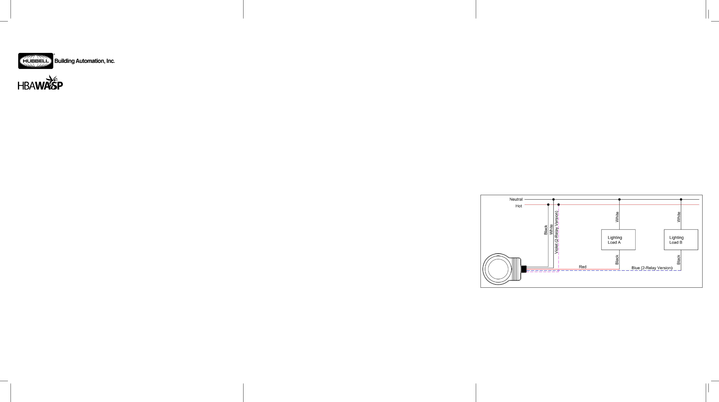
a. Single Relay Sensor: See Wiring Diagram A. Black lead to Line (Hot); Red lead to Load; White
lead to Line (Neutral).
b. Dual Relay Sensor: See Wiring Diagram A. Black lead to Line (Hot); Red lead to Load (A); White
lead to Line (Neutral), Violet lead to Line (Hot), Blue lead to Load (B).
c. Dual Relay Sensor connected to a switching ballast: See Wiring Diagram B. Black lead to Line
(Hot); Red lead to Gray wire from ballast; White lead to Line (Neutral), Violet lead to Line (Hot),
Blue lead to Load (B). NOTE: Disable Smart Cycling for this configuration.
7. Adjust sensor operation by setting Bank A and Bank B DIP switches as described below.
8. Turn power on and allow sensor 2 minutes minimum to stabilize.
9. Verify sensor is functioning by waving hand under lens and observing that the sensor’s red light (located
under the lens) flashes.
SENSOR WITH ADAPTOR INSTALLATION
1. Turn power off at the service panel before installing sensor.
2. Remove the first adaptor cover by slightly pressing down on the top seam, in the middle, while pulling apart
(See Figure 1).
3. Using a threaded nipple connector, insert one end of the connector into the adaptor knockout and the other
end of the connector into a ½” knockout on the fixture body.
4. Secure adaptor to the fixture by screwing a lock-nut onto both ends of the connector.
5. Remove the second adaptor cover by slightly pressing down on the bottom seam, in the middle, while
pulling apart
6. From the outside of the adaptor, insert the sensor’s wires and threaded nipple into the second adaptor
knockout (See Figure 2).
7. Thread the sensor’s wires through the lock-nut provided with the sensor.
8. Screw lock-nut onto the sensor’s threaded nipple.
9. Feed the sensor wires up through the adaptor and into the threaded nipple connector attached to the fixture.
10. Verify sensor is correctly positioned (lens facing down), and then tighten all (3) lock-nuts.
11. Re-attach both adaptor covers.
12. Electrically connect the sensor to the lighting system per the applicable wiring diagram below.
a. Single Relay Sensor: See Wiring Diagram A. Black lead to Line (Hot); Red lead to Load; White
lead to Line (Neutral).
b. Dual Relay Sensor: See Wiring Diagram A. Black lead to Line (Hot); Red lead to Load (A); White
lead to Line (Neutral), Violet lead to Line (Hot), Blue lead to Load (B).
c. Dual Relay Sensor connected to a switching ballast: See Wiring Diagram B. Black lead to Line
(Hot); Red lead to Gray wire from ballast; White lead to Line (Neutral), Violet lead to Line (Hot),
Blue lead to Load (B). NOTE: Disable Smart Cycling for this configuration.
13. Adjust sensor operation by setting Bank A and Bank B DIP switches as described below.
14. Turn power on and allow sensor 2 minutes minimum to stabilize.
15. Verify sensor is functioning by waving hand under lens and observing that the sensor’s red light (located
under the lens) flashes.
RANGE TEST
Range testing provides a means to confirm that the sensor’s coverage pattern (see Figures 3 & 4) is aligned
properly in the lighted space as well as verifying basic functionality of the sensor.
1. Remove PIR lens assembly from sensor (see Adjustments section below).
2. Place sensor in Test Mode (8 seconds) by adjusting Bank A DIP switches as described below.
3. Re-install PIR lens assembly.
4. Vacate the sensor detection pattern area. Remove obstructions (i.e. ladder or lift) from the sensor detection
pattern area as necessary. Light(s) will turn off approximately 8 seconds after vacating detection pattern
area.
5. Wait for at least 4 seconds, then re-enter sensor detection pattern area and observe that lights turn on.
6. Step out of sensor detection pattern area and observe that lights turn off approximately 8 seconds after
vacating detection area.
7. Repeat steps 5 and 6 from different entry points on the detection pattern area as necessary to verify proper
detection pattern area coverage.
8. If necessary, modify sensor detection pattern area by adjusting sensor sensitivity (see DIP Switch settings
below), adding or modifying PIR lens masking, and/or adjusting sensor orientation/mounting.
9. After completing testing, repeat steps 1 through 3 to take sensor out of Test Mode by readjusting Bank A
DIP switch settings as described below. NOTE: Sensor will automatically exit Test Mode after 1 hour.
WIRING DIAGRAMS
Wiring Diagram A – 120-347VAC Line voltage wiring diagram for single and dual relay sensors (Single
Phase Only)
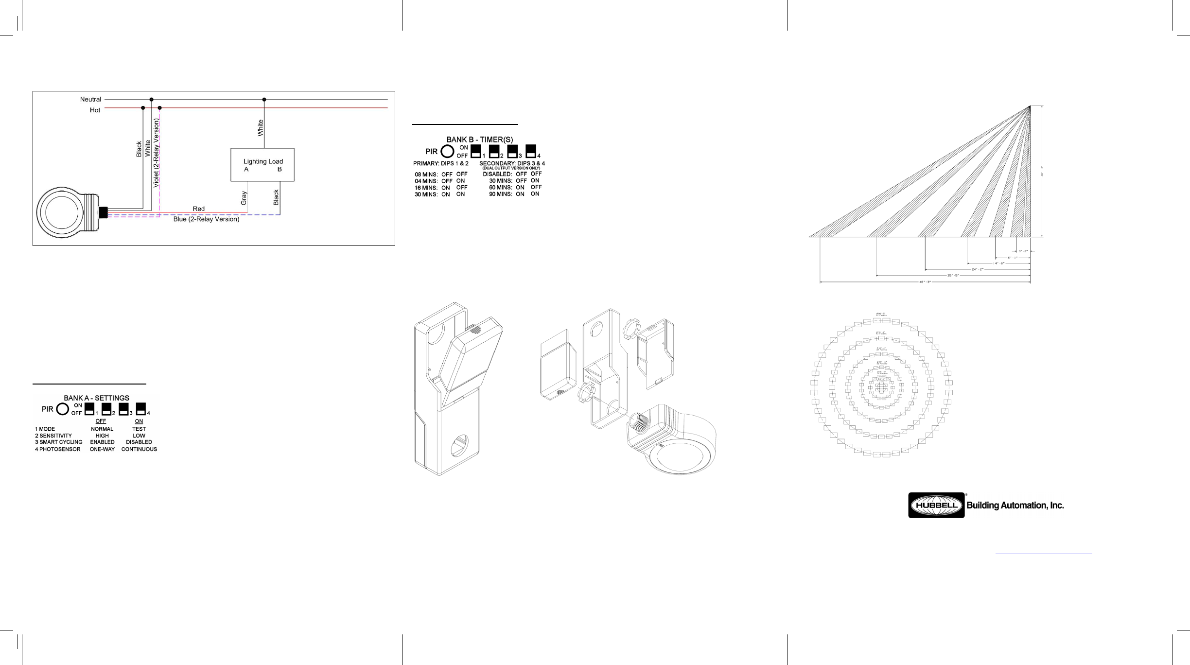
Wiring Diagram B – 120-347VAC Line voltage wiring diagram for connecting a dual relay sensor to a
switching ballast
ADJUSTMENTS
Remove PIR lens assembly from sensor by inserting a small blade screwdriver into the catch at the bottom of
the lens retainer ring (closest to the chase nipple) and gently lift up. Pinch the sides of the lens retainer ring
together to release the two retainer catches. Remove PIR lens and set the adjustment switches as desired (see
DIP Switch Settings below). To re-install PIR lens assembly, place PIR lens back on sensor – making sure that
ALL lens tabs are inserted and that the lens is flush against the sensor housing. Pinch the sides of lens retainer
ring together and insert retainer catches into recesses in sensor housing. Press down on bottom catch to secure
retainer ring to housing.
DIP SWITCH SETTINGS
BANK A – SENSOR SETTINGS
Switch 1 – Mode: Controls the operational mode of the sensor. When placed in Test Mode (ON Position), the
sensor will timeout after 8 seconds of no occupancy. Sensor will automatically exit test mode after 1 hour.
Switch 2 – Sensitivity: Controls PIR motion detection level. Use high sensitivity unless light(s) appear to turn
on due to air currents, heat sources, etc. when area is unoccupied.
Switch 3 – Smart Cycling: Controls Smart Cycling operation of dual relay sensors. This feature extends lamp
life by balancing the cumulative operating times of the different output loads.
Switch 4 – Photosensor: Available on photosensor models only. Controls selection between One-Way Mode
and Continuous Mode. In One-Way Mode, the sensor turns lights on in response to occupancy when light levels
are below the photosensor set point. Sensor then maintains them in the on condition regardless of the light level.
In Continuous Mode, the sensor functions the same way as One-Way Mode, except that during periods of
occupancy it will turn the lights off if ambient light levels increase sufficiently to illuminate the space.
BANK B – SENSOR TIMERS
Primary Timer (DIPs 1 & 2): Controls time interval to turn off light(s) controlled by Primary Timer after the
lighted space becomes unoccupied. Available settings are 8 (Default), 4, 16, and 30 minutes.
Secondary Timer (DIPs 3 & 4): Used on dual relay sensors only. Controls time interval to turn off light(s)
controlled by Secondary Timer after the lighted space becomes unoccupied. Available settings are DISABLED
(Default), 30, 60, and 90 minutes.
ADAPTOR MOUNTING DIAGRAMS
Figure1 Figure2
SENSOR RANGE DIAGRAM – 1.4 AREA LENS PATTERN
Figure 3 - Side View of 1.4 Area Lens
Figure 4 - Top View of 1.4 Area Lens
Hubbell Building Automation
9601 Dessau Road �Building One � Suite 100 � Austin, TX 78754
888-698-3242 �512-450-1215 Fax �www.hubbell-automation.com
72-00386
