00180_2 Codan Obsolete CD/data/bulletins/17 17 00180 2
User Manual: Pdf Codan Obsolete CD/data/bulletins/17-00180_2
Open the PDF directly: View PDF ![]() .
.
Page Count: 4
Head Office Page 1 of 4
Codan Pty Ltd
ACN 007 590 605
81 Graves Street
Newton
South Australia 5074
Telephone +61 8 8305 0311
Facsimile +61 8 8305 0411
Email:
radcom@codan.com.au
Worldwide web:
http://www.codan.com.au
Codan (UK) Ltd
Gostrey House
Union Road
Farnham, Surrey GU9 7PT
United Kingdom
Telephone +44 1252 717 272
Facsimile +44 1252 717 337
Telex 858355
Codan Pty Ltd
Suite 11A, 2 Hardy Street
South Perth
Western Australia 6151
Telephone +61 8 9368 5282
Facsimile +61 8 9368 5283
Service Bulletin
DOCUMENT NUMBER: 17-00180
ISSUE NUMBER: 2
ISSUE DATE: March, ‘98
RELATED DOCUMENTS:
C/R 25315
17-00175
Transceiver fails to power up normally
1. Scope
This Service Bulletin refers to front control transceivers and control heads dispatched since
December 1997. This is the second issue of this Service Bulletin in which the range of
acceptable regulators has been extended.
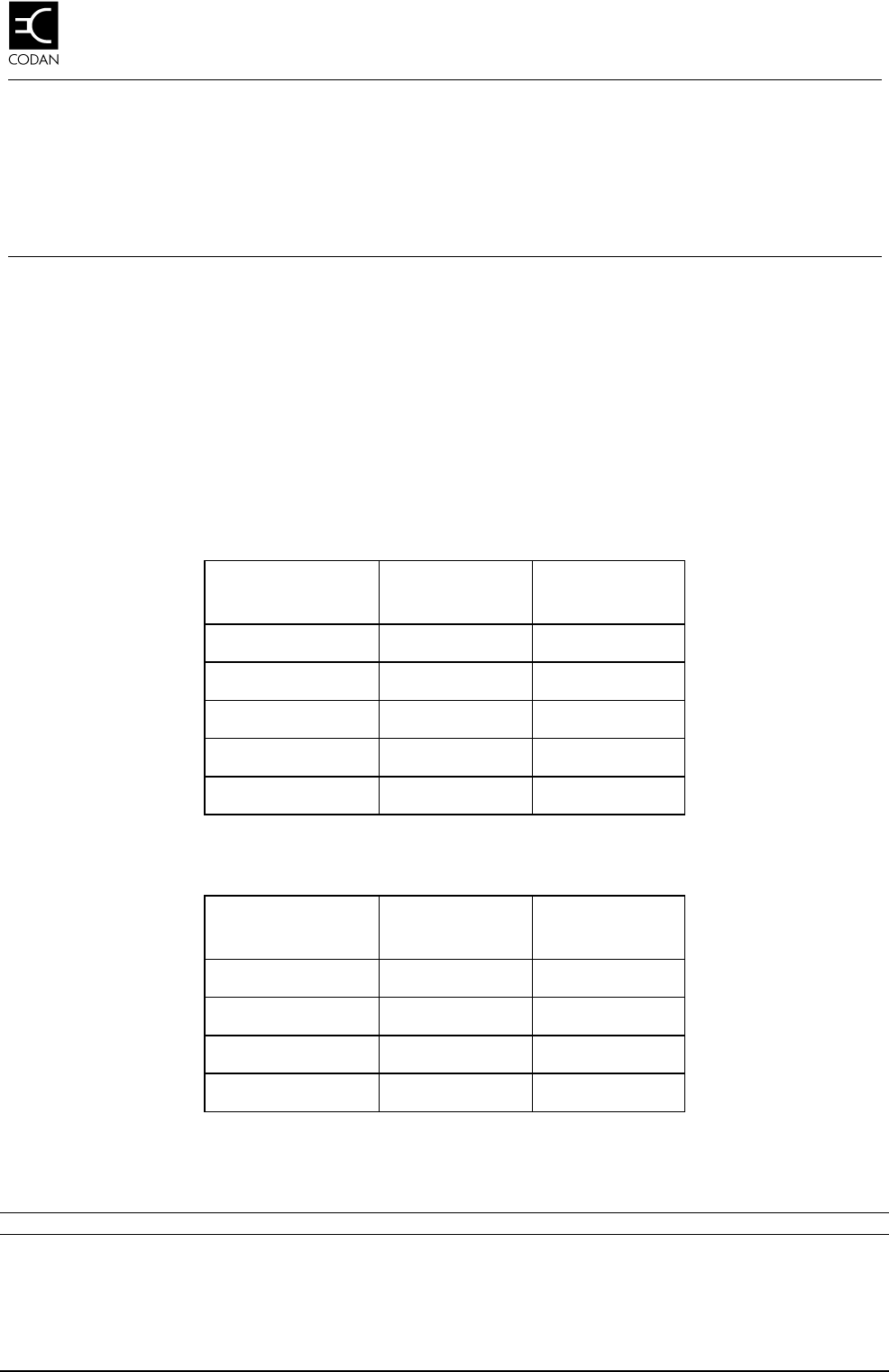
The tables below identify the range of equipment and serial numbers likely to be affected.
Table 1: Range of affected transceiver serial numbers
Transceiver type From Serial
Number To Serial
Number
9360F E1426 E1634
9360-VF A0269 A0270
9390F E0274 E0296
9680 E0300 E0349
9780F B0556 B0632
Table 2: Range of affected control head serial numbers
Control head type From Serial
Number To Serial
Number
9330 D1284 D1312
9366 D1464 D1654
9391 D0155 D0158
9782 A0334 A0395
Any transceiver or control head modified in accordance with Service Bulletin 17-00175 may
also be affected.

Transceiver fails to power up normally
Page 2 of 4 17-00180 Issue 2
2. Symptoms
Previously observed symptoms include:
• transceiver display back lights are on but there are no characters on the display and no
functionality
• transceiver functions normally but takes significantly longer than usual to power up
Symptoms may only occur under certain conditions such as extremes of temperature.
3. Cause
The problems are caused by the use of non brand-name, generic voltage regulators.
A recent change to the microprocessor reset circuit (refer Service Bulletin 17-00175), has
made the use of non brand-name generic regulator types unacceptable.
4. Corrective action
If the symptoms exist in equipment identified in Tables 1 and 2, or in equipment that has
been modified retrospectively in accordance with Service Bulletin 17-00175, the voltage
regulator should be suspected and changed if necessary.
4.1 Procedure
q Remove the transceiver/control head from the installation.
q If you want to modify a front panel, continue at Procedure: front panel.
Otherwise, continue at Procedure: control head.
Procedure: front panel
q Remove the two screws securing the bottom cover and remove the cover.
q Disconnect the cable connecting the front panel to the Microprocessor and Audio PCB.
q Remove the four screws securing the front panel to the chassis.
q Withdraw the entire front panel from the chassis.
q Remove the two screws securing the shield covering the front panel PCB.
q Remove the shield.
q Continue at Procedure: identifying the regulator.
Procedure: control head
q Remove the two screws securing the back panel and remove the panel.
q Carefully disconnect the control interface cable (P4) and the extension speaker plug (if
fitted).
Transceiver fails to power up normally
17-00180 Issue 1 Page 3 of 4
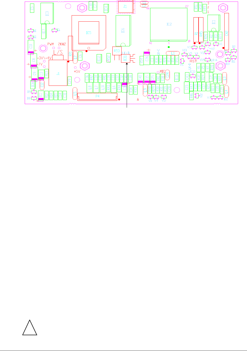
Procedure: identifying the regulator
q Locate IC11. Refer to Figure 1.
IC 11
Figure 1: Location of IC11
q Carefully lift IC11 up off the board so that the identifying markings on its flat side may
be read.
q Check that the regulator has a manufacturer’s marking such as a trademark or a
name.
q If IC11 does not have a manufacturer’s trademark or name it will need replacing.
Continue at Procedure: changing the regulator.
Otherwise, continue at Reassembly.
Procedure: changing the regulator
Parts required
• 1 x LM340LAZ-5.0 voltage regulator, Codan part number XB-07805-501
Tools required
• Desoldering tool (or desoldering wick)
• 60/40 Tin/Lead resin core solder
• Soldering iron
• Side cutters
• Small pliers
Note. Since the display module prevents access to Side 1 of the display board, the regulator
must be removed and reinstalled from Side 2. This is the uppermost side. It is therefore not
necessary to remove the display board from the front panel/control head.
!
Warning. During the following steps, take great care not to damage the through
hole plating.

Transceiver fails to power up normally
Page 4 of 4 17-00180 Issue 2
q Cut each of the three leads of the regulator as close as possible to the body of the
regulator.
q Using the soldering iron and the pliers, heat each joint and remove the leads from the
board.
q Using the desoldering tool or the desoldering wick, clear the solder from the three
holes.
q Form and trim the leads of the replacement regulator. Refer to Figure 2.
Regulator
Flat side down ≈ 4 mm
≈ 4 mm
Figure 2: Formation of regulator leads
q Insert the regulator into the three holes. Flat side down. Refer to Figure 1.
q Solder the three leads into the display board.
Reassembly
q Reassembly of the front panel is the reverse of the steps in Procedure: front panel.
q Reassembly of the control head is the reverse of the steps in Procedure: control head.
q Reinstall the transceiver/control head to the installation.
