Modicon M580 Automation Platform 170522 Catalog
1000479433-Catalog 1000479433-Catalog 1000479433-Catalog B5 unilog cesco-content
144219-Catalog 144219-Catalog 144219-Catalog B5 unilog cesco-content
97205-Catalog 97205-Catalog 97205-Catalog B5 unilog cesco-content
97206-Catalog 97206-Catalog 97206-Catalog B5 unilog cesco-content
2016-09-04
: Pdf 170522-Catalog 170522-Catalog B4 unilog
Open the PDF directly: View PDF ![]() .
.
Page Count: 152 [warning: Documents this large are best viewed by clicking the View PDF Link!]
Modicon M580
automation platform
Catalog
January 2014
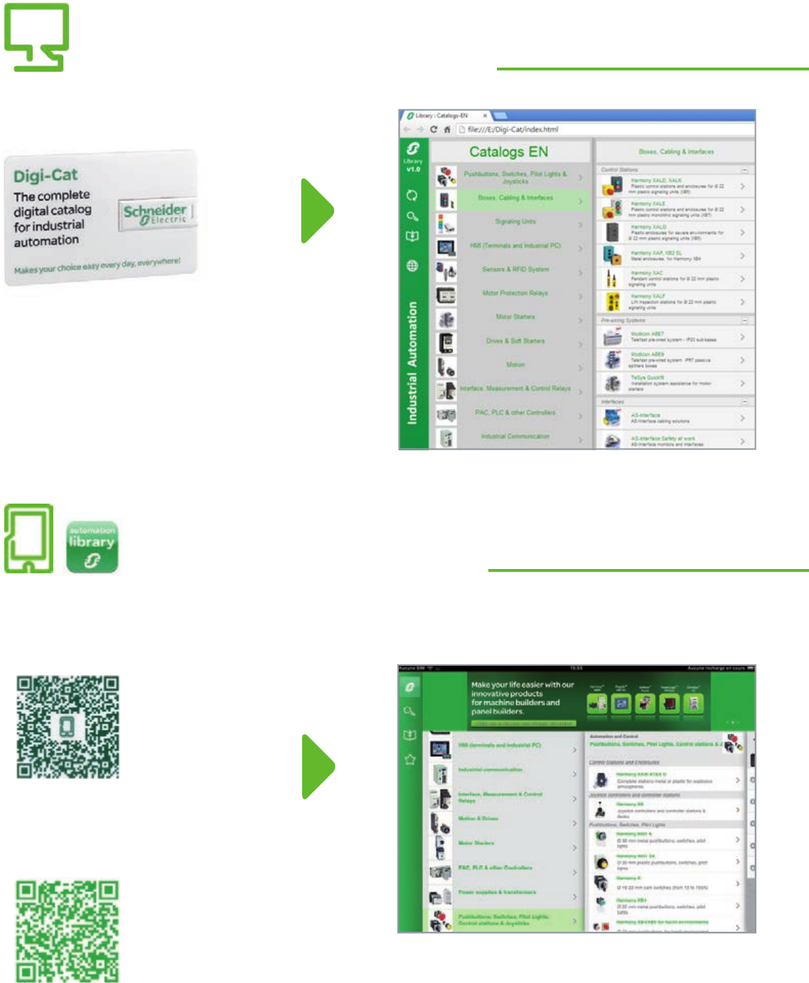
Digi-Cat, a handy USB key for PC
Contact your local representative to get your own Digi-Cat
How can you fit a 6000-page catalog in your pocket ?
Schneider Electric provides you with the complete set of industrial automation catalogs all on a handy
USB key for PC or in an application for tablets
e-Library, the app for tablets
>Convenient to carry
>Always up-to-date
>Environmentally friendly
>Easy-to-share format
>Go to the App Store and search for e-Library
>or scan the QR code
If you have an iPad®:
>Go to the Google Play StoreTM and search for eLibrary
>or scan the QR code
If you have an Android tablet:

1
General contents
Presentation . ..............................
I/O architectures . ..........................
Communication . ..........................
Software . ..................................
Ruggedized Modicon M580 modules . .....
Standards and certifications . .............
Services . ..................................
Technical information, index . ..............
2
1
3
4
5
6
7
8
9
10
2
1
3
4
5
6
7
8
9
10

1/0
2
1
3
4
5
6
7
8
9
10
2
1
3
4
5
6
7
8
9
10

1/1
Contents
Presentation
b General presentation.............................................................................page 1/2
b Composition ......................................................................................... page 1/8
b Compatibility........................................................................................page 1/14
Processor modules
Selection guide ............................................page 1/18
b Presentation.........................................................................................page 1/20
b Description...........................................................................................page 1/21
b Memory structure ................................................................................page 1/22
v Memory cards........................................................................................ page 1/22
v Protecting the application ...................................................................... page 1/22
v Modifying the program in online mode ................................................... page 1/22
b References ...........................................................................................page 1/23
Single-rack conguration
b Presentation, description, functions ................................................. page 1/24
b References ...........................................................................................page 1/25
Multi-rack conguration
b Presentation, description ................................................................... page 1/26
b References ...........................................................................................page 1/28
1 - Presentation, processor
modules, single-rack and multi-
rack congurations
2
1
3
4
5
6
7
8
9
10
2
1
3
4
5
6
7
8
9
10
1/2
The Modicon M580 ePAC (Programmable Automation Controllers) feature
openness, exibility, robustness and sustainability. The M580 are designed with an
Ethernet backbone to optimize connectivity and communications. They support X80
common I/O modules which can be easily integrated into its architecture. The
powerful processors offer high levels of computation for complex networked
communication, display and control applications.
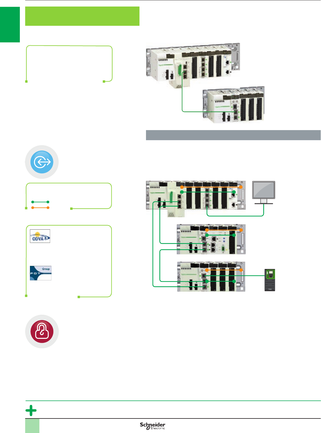
Innovative
ePAC concept
>Top-to-bottom standard Ethernet network
>Open architecture with direct Ethernet connection on backplane
SCADA
Modicon X80 drop on Ethernet RIO
Variable
speed
drive
Modicon M580
Cybersecurity ready
> Cybersecurity ready with Achilles Level 2 certication and advanced built-in cyber
security features
>Embedded security features as dened by standard IEC 62443
>M580 hardware platform:
>Unused services can be disabled
>Remote access to PLC can be controlled
>M580 programming software with integrity check of Unity Pro executable les
Modicon M580 ePAC
Control at the heart of PlantStruXure
Modicon M580 combines Unity
PAC’s existing features with
innovative technologies to
deliver Schneider Electric’s
complete Ethernet based PAC
3.0
General presentation Modicon M580 automation
platform
Innovative
Open and secure solution based on standards
Ethernet
X-bus
Direct Ethernet connection
backplane
ODVA organization:
supports network
technologies built on
EtherNet/IP
FDT Technology: an
international standard
with broad acceptance
in the automation
industry
Modicon M580
Modicon X80
drop on Ethernet RIO
O
p
e
r
a
t
i
o
n
a
l
I
n
t
e
l
l
i
g
e
n
c
e
S
e
c
u
r
i
t
y
Ethernet
Ethernet
11
2
1
3
4
5
6
7
8
9
10
2
1
3
4
5
6
7
8
9
10
No program required with
time-stamping solution mode
1/3
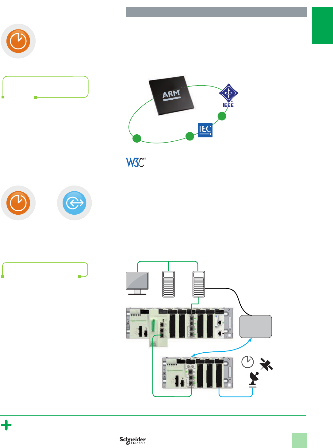
Innovative (continued)
Advanced technologies
>Based on high-speed dual-core processor (ARM® type)
>High-speed communication, application and execution
>Innovative mechanical and electronic design for high EMC immunity and
ruggedness that is superior to the required IEC standards
>Supports extended temperature range from −25°C to +70°C
High precision
>Native deterministic Ethernet network
>Ability to deliver 1 ms I/O resolution through native time-stamping at source with
specic time-stamping modules via OPC server
>Applications include functions such as:
>sequence of events recording (SER)
>utility substation automation
>protective relay trip history
>alarm/event logs
>time-stamping of power monitoring data logs
SCADA OPC
Server
IRIG-B/DCF77
External
synchronization
Modicon M580
Modicon X80 drop on Ethernet RIO
Ethernet
General presentation
(continued)
Modicon M580 automation
platform
Innovative
Modify your process and architecture during runtime
Ethernet
& Web
Modicon M580 design is
compliant with automation
standards
O
p
e
r
a
t
i
o
n
a
l
I
n
t
e
l
l
i
g
e
n
c
e
T
i
m
e
-
t
o
-
m
a
r
k
e
t
T
i
m
e
-
t
o
-
m
a
r
k
e
t
Routing
function via
external router
11
2
1
3
4
5
6
7
8
9
10
2
1
3
4
5
6
7
8
9
10
1/4
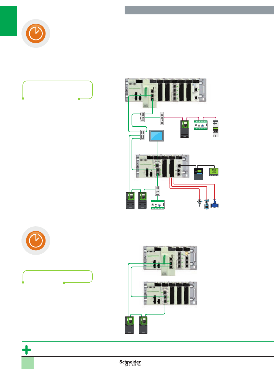
Simple and exible
Flexibility in design
>Flexible topology allows simple integration of devices
> Ability to mix remote equipment, distributed equipment and other devices on the
same Ethernet eld network with complete software integration
>Transparent access to data through Ethernet backbone
>Simple HMI integration via third port on remote I/O head
> Interface to other popular eldbus and device networks including AS-Interface,
Modbus, Probus, and HART
HMI
Distributed devices
HART
Modbus
Probus
Modicon M580
Ethernet.
Variable
speed
drive Motor
protection
Motor
starter
Modicon X80
drop on Ethernet RIO
Optimized architecture
>Simple daisy chain loop
Modicon M580
Modicon X80 drop on Ethernet RIO
Ethernet.
Extend your process or
application easily with exible
Modicon M580 topology
No switches required for
simple main loop
Design your architecture without constraints
General presentation
(continued)
Modicon M580 automation
platform
Simple and exible
T
i
m
e
-
t
o
-
m
a
r
k
e
t
T
i
m
e
-
t
o
-
m
a
r
k
e
t
Variable
speed
drive
2
1
3
4
5
6
7
8
9
10
2
1
3
4
5
6
7
8
9
10
11
1/5
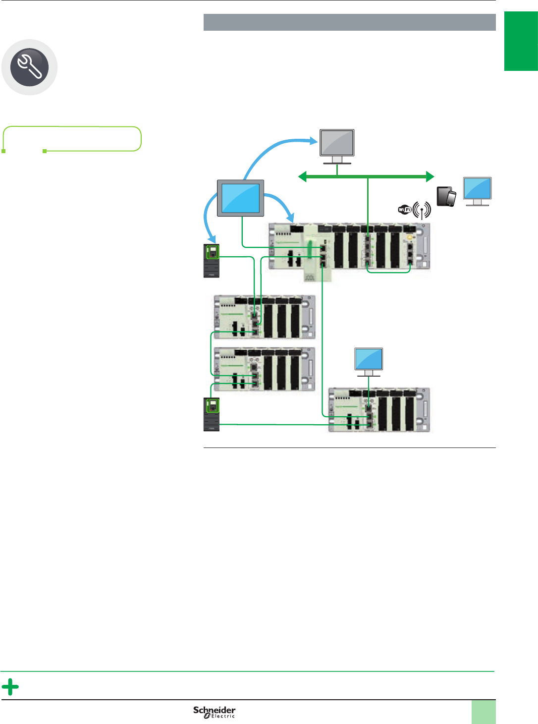
Simple and exible (continued)
Easy diagnostics
>Ethernet delivers information everywhere
>Simple remote and mobile diagnostics (smartphone, tablet, etc.)
>Embedded web server for web access
>Manage SCADA screens on HMI and access HMI screens
>Built-in Vijeo Citect objects for advanced integrated diagnostics
(1) This schematic diagram will operate with the new BMENOC03●1 modules (available second
quarter 2014 to replace the existing BMXNOC0402) with complete Ethernet transparency via
connection to the Ethernet backplane.
Diagnose remotely
General presentation
(continued)
Modicon M580 automation
platform
Simple and exible
Data at your ngertips wherever
you are SCADA
HMI HMI
HMI
HMI
Modicon M580
Ethernet
(1)
Modicon X80 drop on Ethernet RIO
M
a
i
n
t
e
n
a
n
c
e
E
x
c
e
l
l
e
n
c
e
Variable speed drive
Smartphone,
tablet
2
1
3
4
5
6
7
8
9
10
2
1
3
4
5
6
7
8
9
10
11
1/6
1.0
General presentation
(continued)
Modicon M580 automation
platform
Simple and exible, sustainable
Protect existing and future investments
R
e
n
e
w
P
l
a
n
O
p
t
i
m
i
z
e
O
p
e
r
a
t
e
I
n
s
t
a
l
l
How do I
renew my
solution?
What are
my options?
How do I
install and
commission?
How do I
optimize?
How do I
operate and
maintain?
Life Cycle
Services
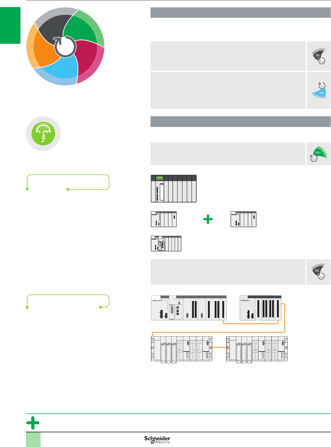
Simple and exible (continued)
Change conguration on the y without stopping
the process
bAdd or remove discrete and analog I/O modules on RIO drop
(not time-stamped)
bAdd a new RIO drop
bModify channel conguration parameters
bAutomatic reconguration of modules on hotswap
bOnline application changes during process runtime including adding
new variables shared with HMI (Human/Machine Interfaces)
Sustainable
Protect investments
bStandardize on the Modicon family with common X80 modules and
reduce training and maintenance costs
Modicon Quantum Ethernet I/O
Modicon M340
Modicon M580 Modicon X80 I/O
bKeep your existing Modicon Premium I/O and wiring
bSmooth migration paths for both hardware (quick wiring adapter)
and software (SW converters)
Modicon M580 Modicon X80 expansion rack
Premium racks
X-bus
Installed base migration: keep
your existing I/O and wiring
Modicon family with common
X80 modules
I
n
v
e
s
t
m
e
n
t
P
r
o
t
e
c
t
i
o
n
11
2
1
3
4
5
6
7
8
9
10
2
1
3
4
5
6
7
8
9
10

1/7
Winning associations in PlantStruXure architecture
Modicon M580 Ethernet PACs have strong associations with:
Partners
>Able to develop X80 modules on Ethernet backplane with Ethernet tool kit
backplane
>For specic applications or communication modules: weighing, Wi-Fi, etc.
Vijeo Citect SCADA
>To manage time-stamped events through OPC server in a system approach
>To display Unity Pro diagnostic buffers
>To integrate objects quickly and easily to provide advanced diagnostic
information
Altivar variable speed drives
>Simple integration of Altivar variable speed drive range on Ethernet network
through FDT/DTM
>Dual-port connection is possible for high availability
HMI MagelisTM range
>Connection through X80 Wi-Fi, Web server access, multiple screens on
Ethernet backbone, diagnostic buffers supported by Vijeo Designer, export of
Unity Pro data to Vijeo Designer
Services on installed base
> Schneider Electric provides smooth migration paths to migrate existing wired
legacy I/O to M580. Contact our Customer Care Center for more details.
General presentation
(continued)
Modicon M580 automation
platform
Winning associations in PlantStruXure
architecture
Integration of M580 ePAC in your full PlantStruXure architecture
O
p
e
r
a
t
i
o
n
a
l
I
n
t
e
l
l
i
g
e
n
c
e
11
2
1
3
4
5
6
7
8
9
10
2
1
3
4
5
6
7
8
9
10
1/8
Presentation Modicon M580 automation
platform
Presentation
The Modicon M580 automation platform is composed of the following devices:
bA BMEP58pppp processor
bA Modicon X80 I/O platform
bDedicated modules (HART, weighing, etc.)
bEthernet backplane
bUnity
The Modicon M580 automation platform meets the needs of specialist applications
such as:
bManufacturing and large infrastructures
bWater and Waste Water (WWW)
bFood & Beverage (F&B)
bMining, Minerals, Metals (MMM)
bOil & Gas (O&G)
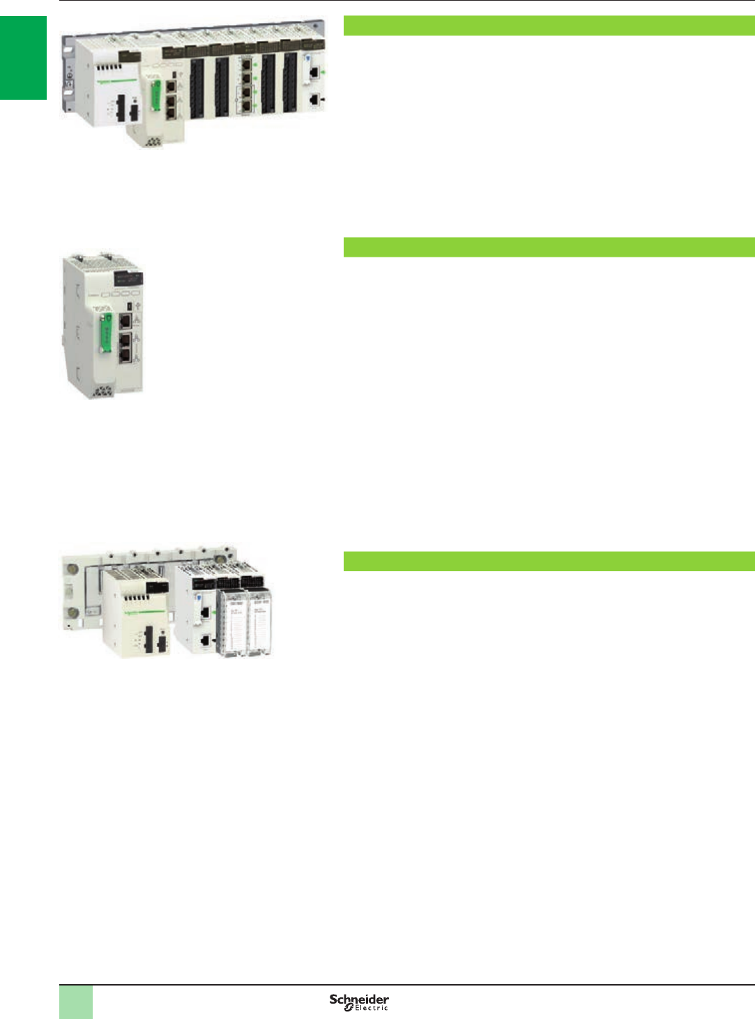
Processor modules
The BMEP58pppp processor range constitutes the core of a complete control
solution based on Modicon M580 specic and compatible modules and racks.
The standalone BMEP58pppp processor is a modular automation processor that
physically occupies two module slots on a backplane.
BMEP58pppp processors can be installed on BMEXBPpppp Ethernet + X-bus
racks and BMXXBPpppp (PV02 or later) X-bus racks.
The processors can manage the Modicon X80 I/O platform in a single-rack or
multi-rack Ethernet PAC station. Their slots can be equipped with:
bDiscrete I/O modules
bAnalog I/O modules
bCounter modules
bCommunication modules:
vEthernet Modbus/TCP network, EtherNet/IP network
vAS-Interface actuator/sensor buses and RTU (Remote Terminal Unit) serial link
vModbus serial link
bExpert modules
The seven processors in this range have different memory capacities, processing
speeds, number of I/O, number of supported local racks, and embedded Ethernet
port functions (see page 1/23).
Modicon X80 I/O platform
The Modicon X80 I/O platform serves as the common base for automation platforms
by simply adding a dedicated processor such as the M580 or M340.
It may also:
bForm part of a Quantum Ethernet I/O architecture as an Ethernet RIO (EIO) drop
with a CRA bus terminal module
bForm an Ethernet Modbus/TCP DIO drop with a PRA module
The Modicon X80 I/O platform is available in single-rack or multi-rack conguration.
This platform may also accept automation platform-dedicated modules
(communication, application, etc.).
One Modicon X80 drop may support two racks separated by a distance of up to
30 meters/98.425 feet.
This platform, common to several automation platforms, can reduce maintenance
and training costs as it comprises:
bA single range of spare parts in stock
bTraining common to several PLCs
Based on the latest I/O technology, the Modicon X80 I/O platform offers:
bHigh-quality ruggedness and compactness
bCompliance with international certications (ATEX, IEC, etc.)
bA wide selection of modules: Discrete or analog I/O, expert modules,
communication modules, etc
Note: For further information, please consult the “Modicon X80 I/O platform” catalog available
on our website www.schneider-electric.com.
BMEP582020 processor
Modicon X80 I/O platform
Modicon M580 automation platform
2
1
3
4
5
6
7
8
9
10
2
1
3
4
5
6
7
8
9
10
1/9
Presentation (continued) Modicon M580 automation
platform
Unity Pro
Dedicated modules
HART integrated analog I/O modules
The Highway Addressable Remote Transducer (HART) protocol is the global
standard for sending and receiving digital information across analog wires between
smart devices and a control or monitoring system. The standard is controlled by the
HART Communications Foundation.
HART integrated analog I/O modules can be added on the backplane of the
Modicon M580 processor.
These HART modules offer 8 channels per input module and 4 channels per output
module. HART integrated analog I/O modules allow the integration of HART-
enabled instruments to the network architecture.
Each M580 main rack can support up to 6 HART I/O modules and each X80 RIO
drop can support up to 7 HART I/O modules. These devices are congured via the
Unity Pro DTM.
HART analog I/O modules are only supported by Ethernet + X-bus backplanes
(main rack or RIO drop).
Note: For further information, please consult the “Modicon X80 I/O platform” catalog available
on our website www.schneider-electric.com.
Scaime partner weighing module
The Scaime integrated partner weighing module is a solution for integrated and
distributed weighing systems.
The weighing module is only supported by Ethernet + X-bus backplanes (main rack
or RIO drop).
This Scaime Ethernet system weighing transmitter offers 1 weighing channel and
can take up to 100 measurements per second in order to provide a better weighing
resolution.
Weighing data is easily provided to the PLC via the Ethernet backbone.
The ofine conguration can be done via Unity and the online calibrations and
settings can be done via FDT/DTM.
Note: For further information, please consult the “Modicon X80 I/O platform” catalog available
on our website www.schneider-electric.com.
Two rack types
M580 processors can work in either an X-bus rack or a dual (Ethernet + X-bus) rack.
Ethernet backplanes are available with 4, 8, and 12 slots.
The M580 Ethernet backplanes provide the X-bus connection and Ethernet
connectivity.
A single conguration can support up to 7 standard BMX racks used as expansion
racks in addition to the local rack, separated by a cumulative distance of up to
30 meters/98.425 feet.
An Ethernet RIO (EIO) drop is composed of one or two racks that can be either a
BMX X-bus rack or a BME Ethernet rack. The expansion rack can only be a BMX
X-bus rack. All the Ethernet racks are available in a version suitable for use in harsh
environments.
An Ethernet switch is embedded in the Ethernet backplane. This switch is connected
to several slots on the backplane. In the case of 12-slot backplanes, not all slots
have Ethernet connectivity. Only 8 slots are available for Ethernet, but they are
placed in several locations along the rack for maximum exibility of use
(see page 1/25).
M580 application design and installation
The Modicon M580 automation platform is programmed and congured using Unity
Pro software version u 8.0. Bit forcing simplies simulation and structured data
simplies diagnostics (see page 4/18).
bUse of these M580 processors requires Unity Pro Large or Extra Large
programming software. This software is also compatible with the Modicon X80 I/O,
Quantum, Premium, and M340 platforms
bOptionally, as required:
vUnity EFB toolkit software for developing EF and EFB function block libraries in
C language
vUnity Dif software for comparing Unity Pro applications
vUnity Loader software for updating Unity Pro projects and rmware
HART integrated analog
input module
8-slot Ethernet + X-bus rack
Scaime partner weighing
module
2
1
3
4
5
6
7
8
9
10
2
1
3
4
5
6
7
8
9
10
1/10
Presentation (continued) Modicon M580 automation
platform
(1) The BMXNOC0402 communication module will be replaced by the BMENOC03p1 modules
during the 2nd quarter of 2014.
Cybersecurity ready
The Modicon M580 is Schneider Electric’s most cyber-secure platform thanks to the
Achilles Level 2 certication and its advanced built-in cybersecurity features.
The Achilles L2 cybersecurity certication demonstrates the robustness of the
Modicon M580 platform under both extreme and common Ethernet conditions. The
Modicon M580 automation platform also offers the following features:
bProtection against unauthorized remote connections via an online editable
Access Control List
bProtection against remote programming changes via a password
bOption to enable or disable HTTP or FTP services
bOption to enable or disable remote run/stop commands
bOption to enable or disable remote write commands
bAuthentication and integrety of the rmware
bIntegrity of Unity Pro executable les
bUnnecessary services disabled by default
bSecurity features enabled by default
Note: For further information, please consult our website www.schneider-electric.com.
Processor performance
The M580 processor supports 4 to 8 local racks (depending on the CPU
performance level), using existing X80 I/O modules and accessories. The M580
processor must be installed in the main rack, which can be a dual (Ethernet + X-bus)
bus rack. M580 PLCs can support up to 8 expansion racks of 4, 6, 8, or 12 slots.
These standalone processors physically occupy two module slots on a backplane.
The processors can manage Modicon X80 I/O platform in a single-rack or multi-rack
Ethernet PAC station. Their slots can be equipped with:
bDiscrete I/O modules
bAnalog I/O modules
bCounter modules
bCommunication modules: Ethernet Modbus/TCP network, EtherNet/IP network,
Modbus SL
bAS-Interface actuator/sensor buses and RTU (Remote Terminal Unit) serial link
bExpert modules
The seven processors available have different memory capacities, processing
speeds, number of I/O, number of supported local racks, and embedded Ethernet
port functions (see page 1/23).
The M580 processor range offers the choice between 4 memory levels:
b4 MB for BMEP581020 processors
b8 MB for BMEP5820pp processors
b12 MB for BMEP5830pp processors
b16 MB for BMEP5840pp processors
It also offers the choice between 2 types of Ethernet device network port:
bFor BMEP58pp20 processors: distributed I/O ports (DIO) to connect distributed
equipment
bFor BMEP58pp40 processors: distributed I/O ports (DIO) to connect distributed
equipment or remote I/O ports (RIO) to connect remote equipment
This range also offers different performance levels: BMEP5840pp processors are
twice as fast as BMEP5830pp processors, which are themselves twice as fast as
BMEP5810pp and BMEP5820pp processors.
An optional 4 GB SD memory card is supplied with M580 processors for application
and data storage.
In addition, depending on the model, the processors offer:
b1,024 to 4,096 discrete I/O
b256 to 1,024 analog I/O
b64 application-specic channels such as process counters, motion control, serial
link, RTU, etc
Applications can be downloaded to the M580 processor when:
bUnity is connected via a local communication module such as the
BMXNOC0402 Ethernet module (1)
bUnity is connected directly to the processor through USB or Ethernet, or to the
Ethernet ports of BMECRA31210 Ethernet drop adapters and ConneXium DRS
(Dual Ring Switch) switches
BMEP582040 processor
Achiles Level 2 certication
PF122547
2
1
3
4
5
6
7
8
9
10
2
1
3
4
5
6
7
8
9
10
1/11
Presentation (continued) Modicon M580 automation
platform
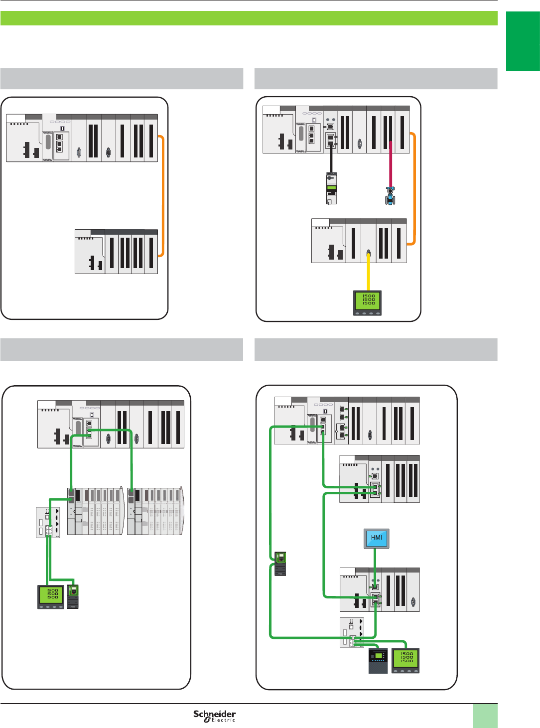
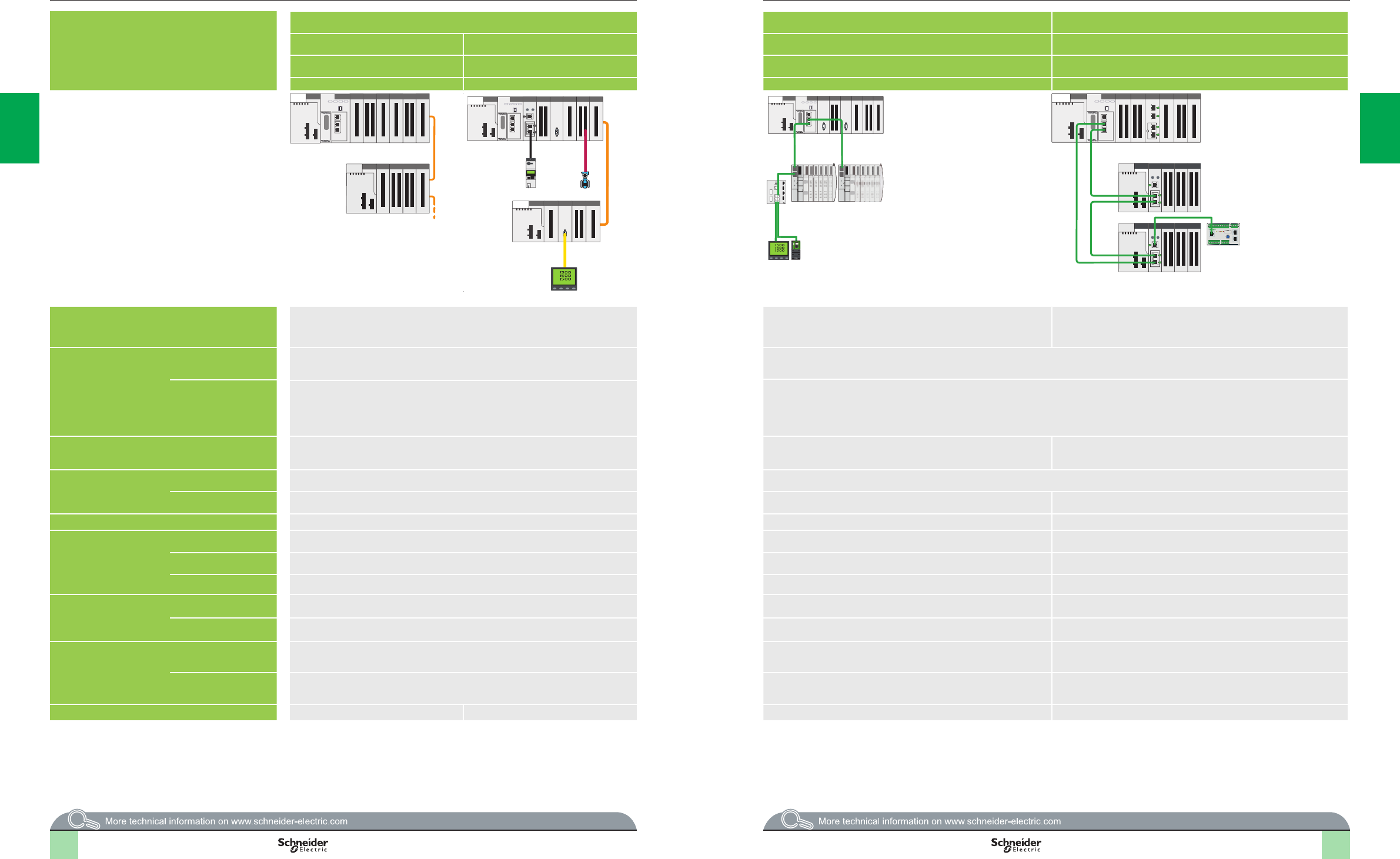
Various architectures
The Modicon M580 ePAC offers different embedded networks to meet various architecture needs:
bStandard Ethernet DIO ports on BMEP58pp20 processors for architectures A,B and C
bDual Ethernet RIO ports on BMEP58pp40 processors for architecture D
Architecture A: Composed of hard-wired I/O; mainly compact
topology
Architecture B: Composed of devices distributed over
eldbuses; mainly compact topology
Architecture C: Composed of devices distributed over
Ethernet; ideal for mainly distributed topologies
Architecture D: Uses Ethernet racks. Composed of remote
devices and features remote functions, such as eldbus master
Modicon M580 main rack
Modicon X80 expansion rack
X-bus
Modicon M580 main rack
X-bus
Energy
supervision
Motor
starter
Modbus SL HART
HART
device
AS-Interface
Modicon X80 expansion rack
Ethernet
Modicon M580 main rack
Modicon STB I/O Modicon STB I/O
Energy
supervision
Variable speed drive
ConneXium
DRS switch
HMI
Modicon M580 main rack
Energy
supervision
Ethernet
Variable
speed
drive
ConneXium
DRS switch
Modicon X80 drop
Modicon X80 drop
2
1
3
4
5
6
7
8
9
10
2
1
3
4
5
6
7
8
9
10
1/12
Modicon M580 PLC
Premium racks
Modicon X80 expansion rack
X-bus
Presentation (continued) Modicon M580 automation
platform
Ethernet backplane
The M580 dual backplanes provide X-bus connection and Ethernet connectivity.
One Ethernet switch is embedded in the backplane with connectivity to some slots
on the backplane. Not all slots have Ethernet connectivity in the case of 12-slot
backplanes.
Using such connectivity, Ethernet-based modules (both Schneider Electric and
third-party) can communicate with any other module or device that is reachable via
the Ethernet and IP networks.
An additional connector is added to some slots of the backplane, next to the X-bus
connector.
The Ethernet backplane provides multiple communication buses compared with the
X-bus backplane to improve connectivity on the backplane. These buses can be
connected to Ethernet modules and used to communicate different types of data for
different purposes (see page 1/25).
The following communication buses are present in Ethernet backplanes:
bX-bus
bEthernet
Expanded backplanes
To expand the conguration using additional racks, users must use a bus expansion
module (BMXXBE1000) and X-bus cables (see page 1/26). An expanded
backplane can only be an X-bus rack.
Each backplane has to include a power supply module and will support up to 12
modules.
It is also possible to expand a drop’s backplane.
Each rack will be assigned a physical address using 4 micro switches located in the
bus expansion module:
bThe main rack containing the processor will be assigned address 0.
bThe other racks will be assigned addresses 1 to 7.
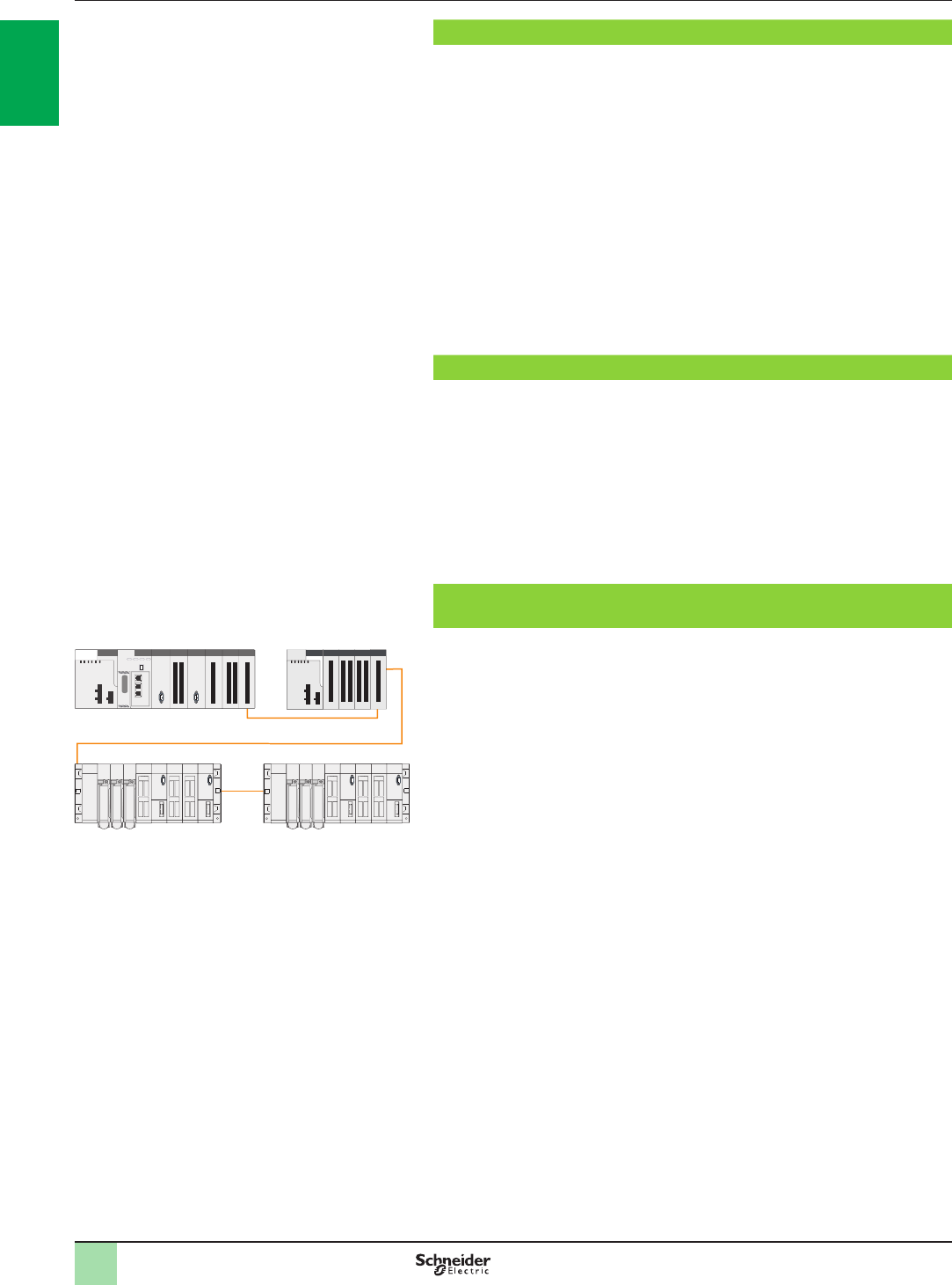
Premium X-bus expansion - making migration as simple as
possible
An M580 system allows TSXRKYpEX Premium expanded local racks to be added
to the conguration. The use of Premium racks in a M580 conguration means the
existing cabling can be retained.
This smooth migration path means that Premium devices, such as discrete and
analog I/O, and counter modules, can be retained.
Indeed, the M580 processor is able to manage the I/O and application-specic
modules on Premium local racks. For further information, see page 1/26.
It is also possible to replace a Premium local rack with an M580 rack if necessary.
Unity V8.0 offers the option to retain the I/O topology in the Premium expansion rack
when revamping a Premium application.
Premium X-bus expansion example
2
1
3
4
5
6
7
8
9
10
2
1
3
4
5
6
7
8
9
10

1/13
Presentation (continued) Modicon M580 automation
platform
Unity Pro
Design and setup of Modicon M580 applications
Unity Pro programming software u V8.0 is required to set up the Modicon M580
automation platform (see page 4/18).The Unity Pro function block software libraries
make it possible to meet the needs of specialist applications in various elds of
application, such as:
bWater and Waste Water (WWW)
bFood & Beverage (F&B)
bMining, Minerals, Metals (MMM)
bOil & Gas (O&G)
To set up Modicon M580 automation platform processors, you need Unity Pro Large
or Extra Large programming software identical to the one used to set up Modicon
M340, Modicon Premium, and Modicon Quantum automation platforms.
Unity Pro V8.0 is compatible with Windows® XP, Windows 7, Windows 8, and
Windows Server 2008.
Depending on requirements, you may also need:
bUnity EFB toolkit software for developing EF and EFB libraries in C language
Unity SFC View software for viewing and diagnostics of applications written in
Sequential Function Chart (SFC) or Grafcet language
bGraphical Unity Diff matching software for comparing two applications
congured with Unity Pro
The function block software libraries provide Modicon M580 processors with the
processing capability required to meet the needs of specialist applications in the
following area:
bProcess control via programmable control loops (EF and EFB libraries)
This software also offers the following features:
bReferences
bImplicit type conversion, IEC 1131-3 proposition
bSecurity Editor on server
bImproved log le
bA trending tool that is synchronized on each PLC scan
bDFB providing information on users logged on to the PLC
bData le (dtx) backup with application backup (sta/stu or zef)
bPassword protection for the application running on the PLC
bMacro function
Treatment for harsh environments
If the Modicon M580 automation platform needs to be used in a very harsh
environment, the ruggedized offer provides processors, power supply modules, and
I/O modules on X-bus and racks with a protective coating applied to their electronic
cards (see page 5/2).
This treatment improves the cards’ insulation qualities and their resistance to:
bCondensation
bDusty atmospheres (conducting foreign particles)
bChemical corrosion, in particular when used in sulphurous atmospheres (oil
renery, purication plant, etc.) or atmospheres containing halogens (chlorine, etc.)
This protection, combined with appropriate installation and maintenance, enables
Modicon M580 products to be used in harsh chemical environments such as types
3C2 and 3C3 as described in standard IEC/EN 60721-3-3.
The functional and electrical characteristics of the coated modules are identical to
those of the non-coated versions.
With coated modules, the Modicon M580 automation platform may be used in harsh
environments or within a range of operating temperatures from - 25 °C to +70 °C/
- 13 °F to + 158 °F.
Some Modicon M580 modules are also ATEX-certied.
2
1
3
4
5
6
7
8
9
10
2
1
3
4
5
6
7
8
9
10
1/14 1/141/15
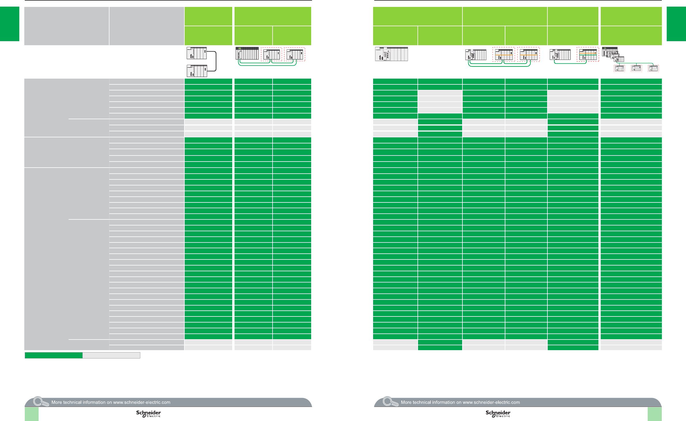
Compatibility Modicon X80 I/O platform
Product compatibility according to the network
architecture
Product type Reference Local rack Modicon
M340
EIO Quantum drop with Modicon X80
EIO drop with CRA drop adaptor type
Local rack Modicon M580 M580 EIO drop with X-bus BMXXBP
backplane and CRA drop adaptor type
M580 EIO drop with
Ethernet + X-bus
BMEXBP backplane and
CRA drop adaptor
Ethernet Modbus TCP DIO
drop with PRA connected to a
Quantum/Premium/M580/
M340 platform
Single-rack or
multi-rack
“standard”
BMXCRA31200
“performance”
BMXCRA31210
X-bus BMXXBP rack Ethernet + X-bus
BMEXBP rack
“standard”
BMXCRA31200
“performance”
BMXCRA31210
BMECRA31210 BMXPRA0100
Racks X-bus BMXXBE1000/BMXXBE1000H (1)
BMXXBE2005 (1)
BMXXBP0400/BMXXBP0400H
BMXXBP0600/BMXXBP0600H
BMXXBP0800/BMXXBP0800H
BMXXBP1200
BMXXEM010
Ethernet +
X-bus
BMEXBP0400/BMEXBP0400H
BMEXBP0800/BMEXBP0800H
BMEXBP1200/BMEXBP1200H
Power supply
modules
BMXCPS2000
BMXCPS2010
BMXCPS3020/BMXCPS3020H
BMXCPS3500/BMXCPS3500H
BMXCPS3540T
I/Os Analog BMXAMI0410/BMXAMI0410H
BMXAMI0800
BMXAMI0810/BMXAMI0810H
BMXAMM0600/BMXAMM0600H
BMXAMO0210/BMXAMO0210H
BMXAMO0410/BMXAMO0410H
BMXAMO0802
BMXART0414/BMXART0414H
BMXART0814/BMXART0814H
Discrete BMXDAI0805
BMXDAI1602/BMXDAI1602H
BMXDAI1603/BMXDAI1603H
BMXDAI1604/BMXDAI1604H
BMXDAI0814
BMXDAO1605/BMXDAO1605H
BMXDDI1602/BMXDDI1602H
BMXDDI1603/BMXDDI1603H
BMXDDI1604T
BMXDDI3202K
BMXDDI6402K
BMXDDM16022/BMXDDM16022H
BMXDDM16025/BMXDDM16025H
BMXDDM3202K
BMXDDO1602/BMXDDO1602H
BMXDDO1612/BMXDDO1612H
BMXDDO3202K
BMXDDO6402K
BMXDRA0804T
BMXDRA0805/BMXDRA0805H
BMXDRA1605/BMXDRA1605H
HART BMEAHI0812
BMEAHO0412
Compatible Not compatible
(1) Supports only one X-bus rack extension.
1/14
1 1
2 2
3 3
4 4
5 5
6 6
7 7
8 8
9 9
10 10
1/15 1/15
Product type Reference Local rack Modicon
M340
EIO Quantum drop with Modicon X80
EIO drop with CRA drop adaptor type
Local rack Modicon M580 M580 EIO drop with X-bus BMXXBP
backplane and CRA drop adaptor type
M580 EIO drop with
Ethernet + X-bus
BMEXBP backplane and
CRA drop adaptor
Ethernet Modbus TCP DIO
drop with PRA connected to a
Quantum/Premium/M580/
M340 platform
Single-rack or
multi-rack
“standard”
BMXCRA31200
“performance”
BMXCRA31210
X-bus BMXXBP rack Ethernet + X-bus
BMEXBP rack
“standard”
BMXCRA31200
“performance”
BMXCRA31210
BMECRA31210 BMXPRA0100
Application-specic
modules
SSI encoder BMXEAE0300/BMXEAE0300H
Counter BMXEHC0200/BMXEHC0200H
BMXEHC0800/BMXEHC0800H
Time stamping BMXERT1604T
PTO (Pulse Train Output) BMXMSP0200
Weighing PMESWT0100
Communication
modules
Ethernet BMXNOC0401
BMXNOC0402 (1)
BMXNOE0100/BMXNOE0100H
BMXNOE0110/BMXNOE0110H
Serial link BMXNOM0200/BMXNOM0200H
RTU BMXNOR0200H
AS-Interface BMXEIA0100
Optical bre BMXNRP0200
BMXNRP0201
Wi-Fi PMXNOW0300
Communication
heads
BMXCRA31200
BMXCRA31210/BMXCRA31210C
BMECRA31210/BMECRA31210C
BMXPRA0100
CPUs M340 BMXP341000/BMXP341000H
BMXP342000
BMXP342010
BMXP3420102
BMXP342020H
BMXP3420302/BMXP3420302H
M580 BMEP581020/BMEP581020H
BMEP582020/BMEP582020H
BMEP582040/BMEP582040H
BMEP583020
BMEP583040
BMEP584020
BMEP584040
Compatible Not compatible
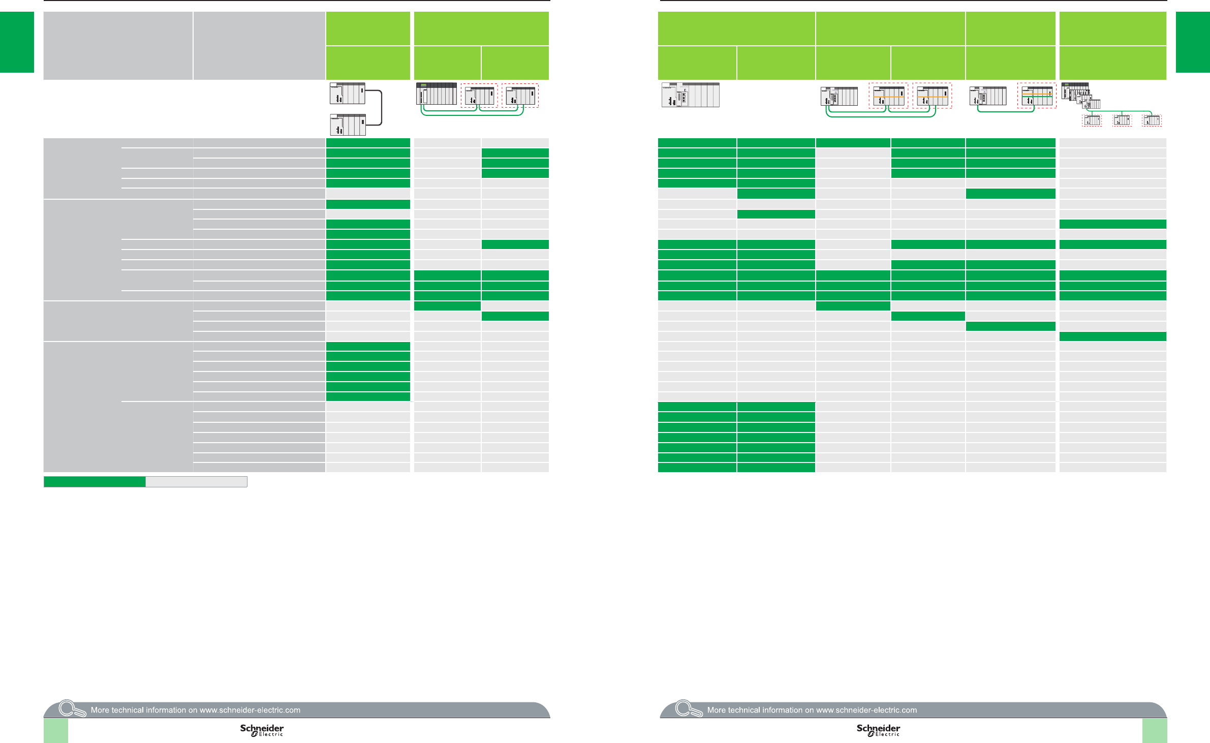
Compatibility (continued) Modicon X80 I/O platform
Product compatibility according to the network
architecture
(1) The BMXNOC0402 communication module will be replaced by the BMENOC03●1 modules during the 2nd quarter of 2014. See our Modicon M580 catalog on
our website www.schneider-electric.com.
1/16 1/151/17
1 1
2 2
3 3
4 4
5 5
6 6
7 7
8 8
9 9
10 10
1/19
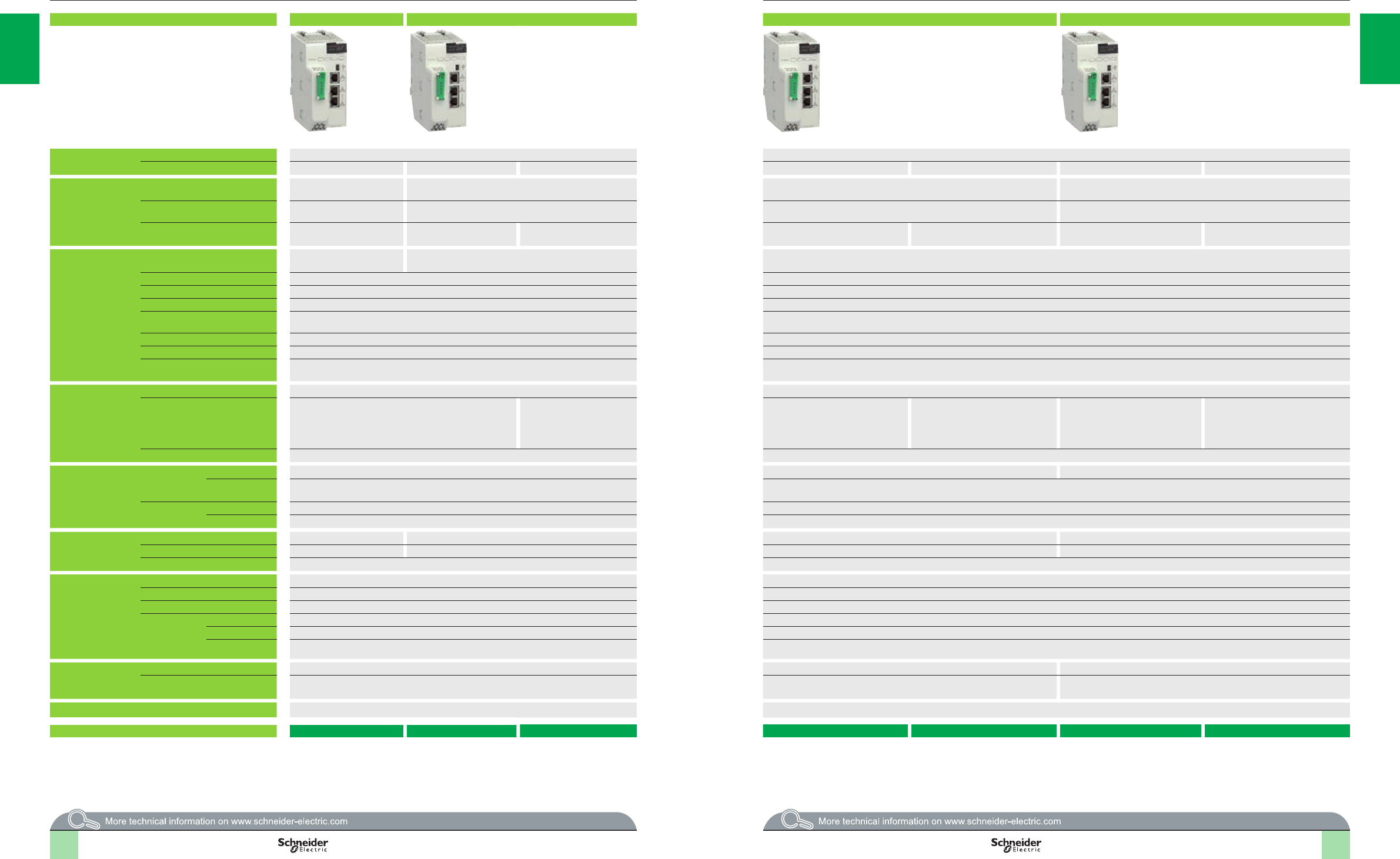
Modicon M580 platform for Unity Pro software offer BMEP5810 model BMEP5820 models BMEP5830 models BMEP5840 models
Racks Maximum number of local racks 4 8
Remote I/O drop of 2 racks – – 8 – 16 –16
I/O Maximum number of discrete I/O
channels (1)
1,024 2,048 3,072 4,096
Maximum number of analog I/O
channels (1)
256 512 768 1,024
Maximum number of Ethernet DIO
devices
64 128 64 128 64 128 64
In-rack application-
specic channels
Maximum number of application-
specic channels
24 32 64
Counter (1) BMXEHC0200 2-channel (60 kHz) or BMXEHC0800 8-channel (10 kHz) modules BMXEHC0200 2-channel (60 kHz) or BMXEHC0800 8-channel (10 kHz) modules
Motion control (1) BMXMSP0200 2-channel PTO (Pulse Train Output) module for servo drives BMXMSP0200 2-channel PTO (Pulse Train Output) modules for servo drives
Serial link (process or RTU) (1) BMXNOM0200 2-channel module or BMXNOR0200H module with 1 RTU serial channel BMXNOM0200 2-channel module or BMXNOR0200H module with 1 RTU serial channel
HART(1) BMEAHI0812 8-channel HART analog input (4–20 mA) module or BMEAHO0412 4-channel
HART analog output (4–20 mA) module
BMEAHI0812 8-channel HART analog input (4–20 mA) or BMEAHO0412 4-channel HART analog output (4–20 mA) module
SSI encoder (1) BMXEAE0300 3-channel module (SSI) BMXEAE0300 3-channel module (SSI)
Time stamping (1) BMXERT1604T 16-channel discrete input (with 1 ms resolution) module BMXERT1604T 16-channel discrete output (with 1 ms resolution) module
Process control, programmable
loops
Process control EFB library Process control EFB library
Integrated
communication ports
Ethernet Service port (RJ45) 1 port for DIO devices, Unity, CNM, HMI, SCADA, diagnosis & external tools 1 port for DIO devices, Unity, CNM, HMI, SCADA, diagnosis & external tools -
Ethernet Device Network dual ports
(RJ45)
2 ports support DIO mode to connect devices using DIO
scanner
2 ports support both RIO and
DIO mode to connect Modicon
X80 drops using deterministic
RIO scanner and devices
using DIO scanner
2 ports support DIO mode to connect
devices using DIO scanner
2 ports support both RIO and DIO
mode to connect Modicon X80 drops
using deterministic RIO scanner and
devices using DIO scanner
2 ports support DIO mode to connect
devices using DIO scanner
2 ports support both RIO and DIO
mode to connect Modicon X80 drops
using deterministic RIO scanner and
devices using DIO scanner
USB port 1 programming port (PC terminal) 1 programming port (PC terminal)
Communication
modules
(1)
Ethernet network Maximum number 23 4
Type of module BMXNOC0402 (2) network modules with 1 EtherNet/IP channel or Modbus TCP
communication protocol
BMXNOC0402 (2) network modules with 1 EtherNet/IP channel or Modbus TCP communication protocol
AS-Interface Maximum number 8 8
Type of module BMXEIA0100 master module BMXEIA0100 master module
Internal memory
capacity
Program (MB) 48 12 16
Data (KB) 384 768 1,024 2,048
Data storage (GB) 4 4
Application structure Master task 2 processing modes (cyclic, periodic) 2 processing modes (cyclic, periodic)
Fast task 1 processing mode (periodic) 1 processing mode (periodic)
Auxiliary tasks (AUX 0, AUX 1) 1 processing mode (periodic) 1 processing mode (periodic)
Event tasks I/O event 64 128
Timer event 16 32
Total I/O and Timer
event
64 128
No. of K instructions
executed per ms
100% Boolean (Kinstr/ms) 10 20 40
65% Boolean + 35% xed arithmetic
(Kinstr/ms)
7.5 15 30
Rack power supply 24 V c isolated, 24…48 V c isolated, or 100…240 V a power supply module 24 V c isolated, 24…48 V c isolated, or 100…240 V a power supply module
Modicon M580 processor BMEP581020 BMEP582020 BMEP582040 BMEP583020 BMEP583040 BMEP584020 BMEP584040
(1) The maximum values for the number of I/O, application-specic channels, and the number of networks are not cumulative (they are limited by the maximum
number of slots in the conguration, 1 rack: 11, 2 racks: 23, 3 racks: 35 and 4 racks: 47.)
(2) The BMXNOC0402 communication module will be replaced by the BMENOC03p1 modules during the 2nd quarter of 2014.
Selection guide Modicon M580 automation
platform
Modicon M580 processors
1/18
2
1
3
4
5
6
7
8
9
10
2
1
3
4
5
6
7
8
9
10
2
1
3
4
5
6
7
8
9
10
2
1
3
4
5
6
7
8
9
10

1/20
Presentation Modicon M580 automation
platform
Processor modules
Modicon M580 conguration
Presentation
The Modicon M580 BMEP58 modular processors form the core of a complete
control solution based on Modicon M580 specic and compatible modules and
racks. These standalone processors physically occupy two module slots (0 and 1)
on a backplane.
The processors can manage the Modicon X80 I/O platform in a single-rack or
multi-rack Ethernet PAC station. Their slots can be equipped with:
b Discrete I/O modules
b Analog I/O modules
b Counter modules
b Communication modules: Ethernet Modbus/TCP network, EtherNet/IP network,
Modbus serial link, AS-Interface actuator/sensor buses and RTU (Remote Terminal
Unit) serial link
b Expert modules
The seven processors available in this range have different memory capacities,
processing speeds, number of I/O, number of supported local racks, and embedded
Ethernet port functions.
An optional 4 GB SD memory card is supplied with M580 processors for application
and data storage. Each processor has a USB terminal port for connecting to a
programming terminal. A temporary connection to an HMI is possible via the USB
port (1).
In addition, depending on the model, these processors offer a maximum (non-
cumulative) of:
b 1,024 to 4,096 discrete I/O
b 256 to 1,024 analog I/O
b 64 application-specic channels (2) (process counter, motion control, and serial
link, or RTU)
b 1 Ethernet service port
b 2 Ethernet device network ports
vDIO ports (distributed equipment) for all processors
vRIO ports (remote equipment) for BMEP58pp40 processors
b 4 “Full extended master” AS-Interface V3 actuator/sensor buses, prole M4.0
Applications can be downloaded to the M580 processor when:
b Unity is connected via a local BMXNOC0402 communication module (Ethernet
module) (3)
b Unity is connected directly to M580 through USB or Ethernet. For a faster
transfer, users can select FTP protocol.
(1) Please refer to HMI catalogs on www.schneider-electric.com.
(2) Maximum number of application-specic channels per station. Only the application-specic
channels actually congured in the Unity application are considered.
(3) The BMXNOC0402 communication module will be replaced by the BMENOC03p1 modules
during the 2nd quarter of 2014.
2
1
3
4
5
6
7
8
9
10
2
1
3
4
5
6
7
8
9
10
1/21
Presentation Modicon M580 automation
platform
Processor modules
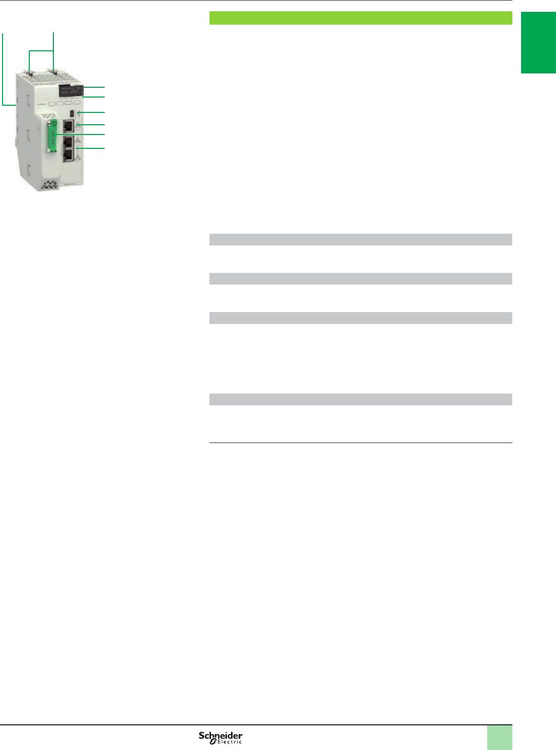
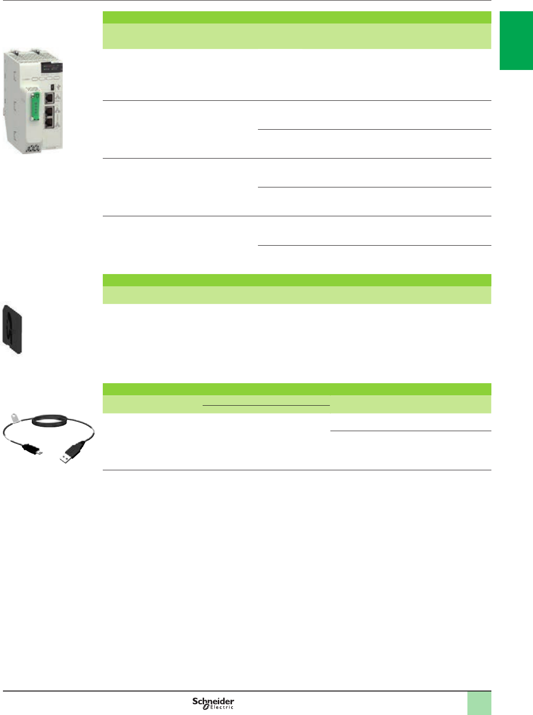
Description of BMEP58pppp processors
BMEP58pppp processors include :
1A display block comprising 7 LEDs whose varying combinations provide a quick
diagnostic status of the processor:
b RUN LED (green): processor in operation (program execution)
b ERR LED (red): processor or system detected error
b I/O LED (red): detected I/O module fault
b DL LED (green): rmware download is in progress
b BACKUP LED (red): backup memory (internal or card)
b ETH MS LED (bi-color green/red): indicates the Ethernet port conguration status
b ETH NS LED (bi-color green/red): indicates the Ethernet connection status
2A mini-B USB port for connecting to a programming terminal
3An RJ45 Ethernet port that allows diagnosis of Ethernet ports and provides
access to external tools, devices, and distributed I/O devices
5A slot equipped with a optional SD memory card for application and data storage
(an LED, located behind the door, indicates access to the memory card)
6A MAC address printed on the front panel of the processor (the last two bytes of
the MAC address are used to calculate the default processor IP address)
7Two hooks and two screws for mechanical attachment and earthing connection
to backplane
8 Two connectors for electrical connection to a M580 backplane (X-bus only or
Ethernet backplane)
Description of BMEP58pp20 processors
4BMEP58pp20 processors have dual RJ45 Ethernet ports for connection to the
distributed equipment (DIO).
Description of BMEP58pp40 processors
4BMEP58pp40 processors have dual RJ45 Ethernet ports for connection to the
remote I/O drops (EIO) and distributed equipment (through DRS) (1).
USB terminal port
The USB port 2,offering a useful data rate of 480 Mbps, is compatible with Unity Pro
programming software, OPC Factory Server (OFS), and Magelis HMI terminals (2).
BMEP58 processors can be connected to a USB bus comprising several peripheral
devices. However:
b Only one processor can be connected to the USB bus
b No device on the USB bus can be controlled by the PLC (modem, printer)
Ethernet backplanes
The new range of Ethernet backplanes feature embedded Ethernet and X-bus
connectivity. With 4, 8, and 12 slots, these two connectors allow the existing M580/
X80 modules to be incorporated into an M580 architecture (see page 3/10).
(1) DRS: Dual Ring Switches. Supported ConneXium switches TCSESM083F23F1/063F2CU1/
063F2CS1.
(2) Please refer to HMI catalogs on www.schneider-electric.com.
BMEP58pppp
1
2
3
4
5
6
7
8
2
1
3
4
5
6
7
8
9
10
2
1
3
4
5
6
7
8
9
10
1/22
Memory structure Modicon M580 automation
platform
Processor modules
Write-protect switch
Program
Data
Application
program
%MW backup
Saved data
Persistent memory
M580 processor
Internal application RAM
Modicon M580 application storage
Optional memory card
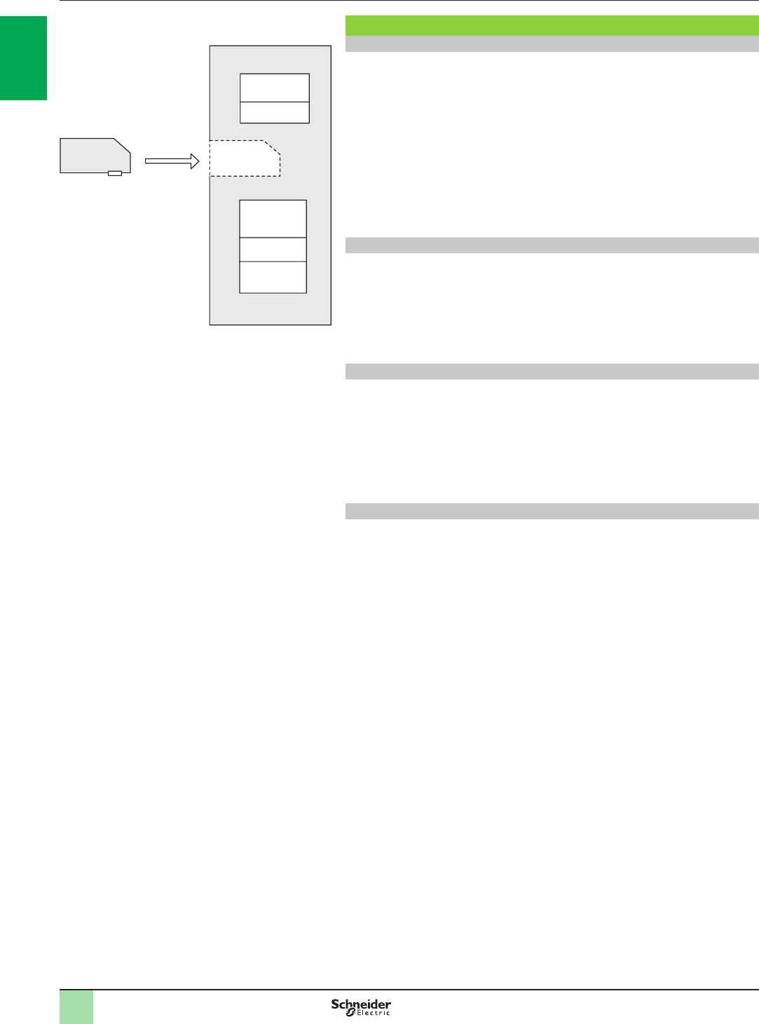
Memory structure
Internal memory capacity
The internal application RAM of Modicon M580 processors stores and executes the
application program. This RAM has no battery backup, which means data could be
lost in the event of a power brake. To avoid data loss, the application can be backed
up in the persistent memory. The internal memory provides a maximum capacity of
16 MB for memory program, 2,048 KB for data, and 4 GB for data storage.
The internal persistent memory is used by the rmware to register:
b the value of application variables
b the system state
b application backup
b a copy of %MW values
An optional memory card, BMXRMS004GPF, is used for application backup and
data storage. It is formatted by Schneider Electric.
BMXRMS004GPF SD memory card
Modicon M580 processors support an optional 4 GB memory card
BMXRMS004GPF. The SD memory card is of ‘‘industrial grade’’ and formatted for
use with Modicon M580 only. The Modicon M580 does not support memory cards
from Modicon M340. This card withstands operating temperatures of - 40 to 85 ºC/
- 40 to 185 °F and has 10 years of le retention capacity.
Unity Pro programming software helps the application designer manage the
structure and memory space of the Modicon M580 automation platform.
Protecting the application
If necessary, it is possible to limit access to the application (in terms of reading and
modifying the program) by only loading the executable code in the PLC.
Additionally, a memory protection bit, set in conguration mode, is also available to
help prevent any program modication (via the programming terminal or
downloading).
The user has function blocks for protecting know-how by means of a signature that
can be loaded and stored in the M580 processor module’s Flash memory card
(code not executed if the signature is not present).
Modifying the program in online mode
As with the Modicon Premium and Quantum platforms (with Unity Pro software), the
online program modication function is available on the Modicon M580 automation
platform. It has the option of adding or modifying the program code and data in
different places in the application in a single modication session (thus helping to
ensure that modication is homogenous and consistent with the controlled
process). A dedicated memory area of the application internal RAM authorizes
these program modication or addition sessions while complying with the
recommendation to structure the application program in several, reasonably-sized
sections.
The CCOTF (Change Conguration On The Fly) function is used to add or remove
discrete or analog I/O modules to/from a Modicon M580 CPU in a remote I/O drop in
RUN mode. It enables Ethernet RIO drops to be added in RUN mode. The addition
of a complete M580 Ethernet RIO drop in RUN mode requires Unity Pro V8.0 or
higher on BMEP581020,BMEP582020,BMEP582040,BMEP583020,
BMEP583040,BMEP584020, and BMEP584040 processors.
The CCOTF function avoids interrupting processes and helps to reduce production
costs. It also enables the conguration parameters of pre-existing and new Modicon
M580 analog and discrete I/O modules to be modied online in a remote I/O drop.
2
1
3
4
5
6
7
8
9
10
2
1
3
4
5
6
7
8
9
10
1/23
References Modicon M580 automation
platform
Processor modules
BMEP58pppp
BMXRMS004GPF
BMXXCAUSBH0pp
PF122552
PF106120PF106185
Modicon M580 processors
I/O capacity Maximum
number of
networks
Device ports Service port Reference Weight
kg/lb
1,024 discrete I/O
256 analog I/O
24 application-specic
channels
4 MB integrated
(memory program)
2 Ethernet
networks
2 DIO 1BMEP581020 0.849/
1.872
2,048 discrete I/O
512 analog I/O
32 application-specic
channels
8 MB integrated
(memory program)
2 Ethernet
networks
2 DIO 1BMEP582020 0.849/
1.872
2 RIO/DIO 1BMEP582040 0.849/
1.872
3,072 discrete I/O
768 analog I/O
64 application-specic
channels
12 MB integrated
(memory program)
3 Ethernet
networks
2 DIO 1BMEP583020 0.849/
1.872
2 RIO/DIO 1BMEP583040 0.849/
1.872
4,096 discrete I/O
1,024 analog I/O
64 application-specic
channels
16 MB integrated
(memory program)
4 Ethernet
networks
2 DIO 1BMEP584020 0.849/
1.872
2 RIO/DIO 1BMEP584040 0.849/
1.872
SD Memory card
Description Processor compatibility Capacity Reference Weight
kg/lb
SD memory card
(optional) (1)
All processors 4 GB (for application
backup and data
storage)
BMXRMS004GPF 0.002/
0.004
Separate parts
Description Use Length
m/ft.
Reference Weight
kg/lb
From To
Terminal port/
USB cordsets
Mini-B USB port
on Modicon M580
processor
Type A USB port on:
- PC terminal
- Magelis HMI graphic
terminal
1.8/5.905 BMXXCAUSBH018 0.065/
0.143
4.5 /14.764 BMXXCAUSBH045 0.110/
0.243
(1) Memory card, used for:
- Backing up the program, constants, symbols and data
- File storage
2
1
3
4
5
6
7
8
9
10
2
1
3
4
5
6
7
8
9
10
1/24
Presentation,
description
Modicon M580 automation
platform
M580 backplanes
Presentation
The M580 PAC is complatible with two types of backplane: dual Ethernet and X-bus
backplanes or X-bus only backplanes (1)(2). One Ethernet switch is embedded in
the backplane with connectivity to some slots on the backplane (not all slots have
Ethernet connectivity).
X-bus functionality is preserved and conforms to the legacy implementation and
specication. The X-bus will be used in a subset of modules on the Ethernet
backplane.
The M580 backplanes provide power supply for all modules in the rack.
Function
The Ethernet backplane provides the following services to X-bus slots:
bprovide rack number
bprovide interconnection to all slots in main and expanded backplanes
The Ethernet interface is the main communication medium in the Ethernet
backplane. All Ethernet modules on the Ethernet backplane are attached to one of
several ports. The modules lead to the Ethernet switch chip embedded inside the
Ethernet backplane.
The Ethernet backplane provides the following services to ETH slots:
bprovide ETH connection to ETH slots
bprovide point-to-point lane connection
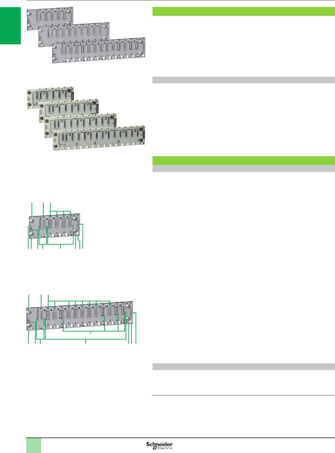
Description
Dual Ethernet and X-bus backplanes
The quantity of X-bus and Ethernet slots found on a backplane depends on the
backplane size.
BMEXBP0400/BMEXBP0800 are 4/8-slot dual Ethernet and X-bus backplanes
with:
1CPS slot for power supply
24 slots (BMEXBP0400)/8 slots (BMEXBP0800) with:
2a 4/8 Ethernet and X-bus connectors for mixed modules
3 Expansion: 1 connector for an X-bus backplane expansion
4 2 xing points for the shielding connection bar
5 Protective earth screw
6 Slots for anchoring the module pin
7Tapped holes for the locking screw on each module
84 holes for M4, M5, M6 or UNC #6-32 screws (4.32 to 6.35 mm/0.170 to 0.250 in.)
9 Rack is fastened to 35 mm/1.38 in. wide and 15 mm/0.59 in. deep DIN rails.
Mounting on a 35 mm/1.38 in. wide and 7.5 mm/0.295 in. deep DIN rail is possible
(in this case, the product withstands less mechanical stress)
BMEXBP1200 is a 12-slot dual Ethernet and X-bus backplane with:
1CPS slot for power supply
212 slots with:
2a 8 Ethernet and X-bus connectors for mixed modules
2b 4 X-bus connectors for X-bus modules
3 Expansion: 1 connector for an X-bus backplane expansion
4 2 xing points for the shielding connection bar
5 Protective earth screw
6 Slots for anchoring the module pin
7Tapped holes for the locking screw on each module
84 holes for M4, M5, M6 or UNC #6-32 screws (4.32 mm to 6.35 mm/0.170 to
0.250 in.)
X-bus backplanes (1)(2)
Available with 4, 6, 8, and 12 slots with BMXXBP0400/0600/0800/1200 for X-bus
modules.
For more information, please refer to the “Modicon X80 I/O platform” catalog
available on our website www.schneider-electric.com.
(1) For more information on rack, see page 1/26
(2) Mandatory PV02 version or later.
BMEXBP0400/0800 backplanes
8 2a
2b
3642154
BMEXBP1200 backplane
7
8 2a7
9 4 5 1 2 4 6 3
Dual Ethernet and X-bus backplanes
X-bus backplanes (1)(2)
2
1
3
4
5
6
7
8
9
10
2
1
3
4
5
6
7
8
9
10
1/25
Description,
references
Modicon M580 automation
platform
M580 backplanes
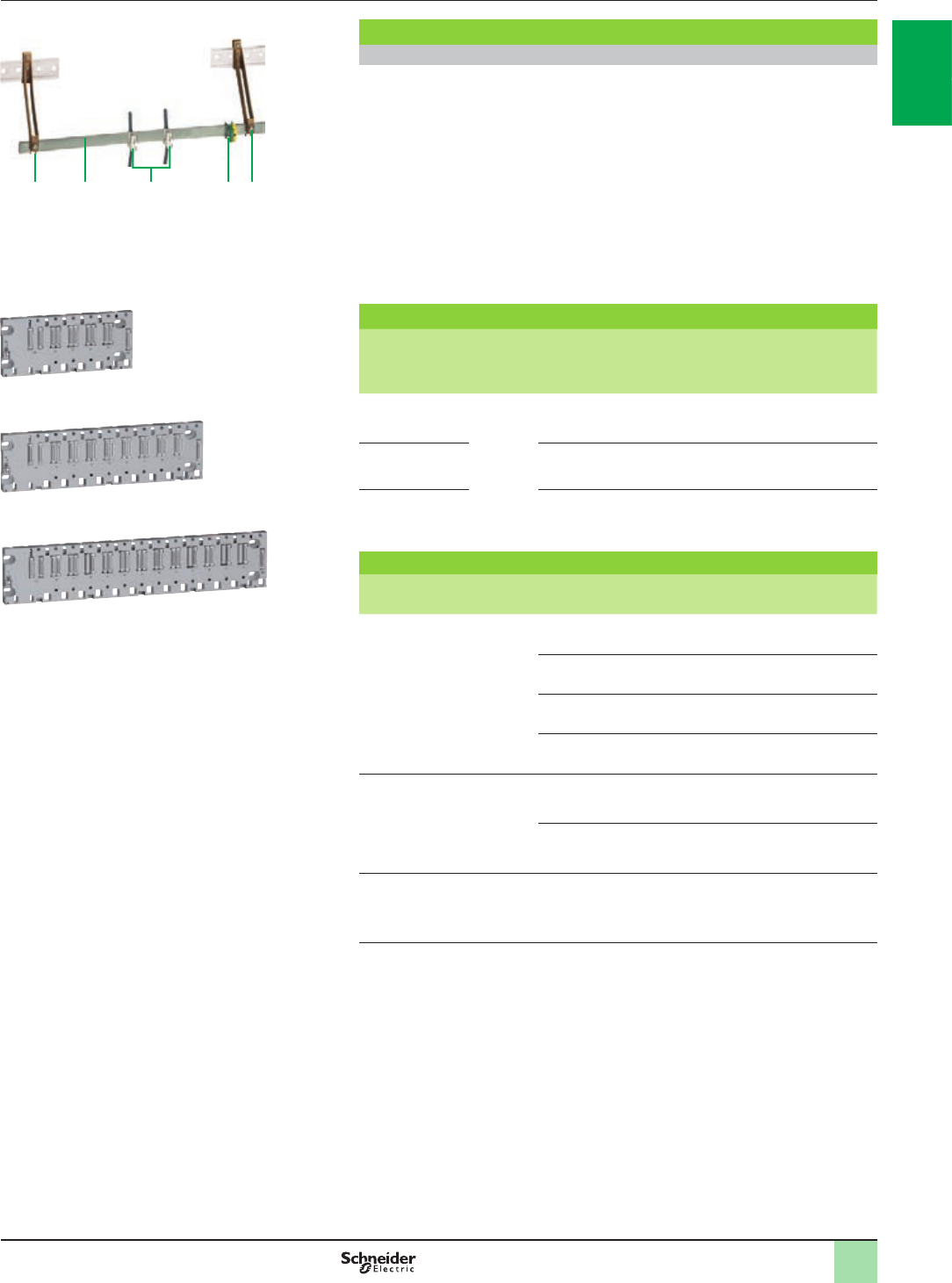
Description (continued)
Cable shielding connection kit
To be ordered separately:
A BMXXSPpp00 cable shielding connection kit, used to help protect against
electrostatic discharge when connecting the shielding on cordsets for connecting:
b Analog, counter, and motion control modules
b Some Magelis HMI terminals (1) to the processor (via BMXXCAUSBH0pp
shielded USB cable)
The BMXXSPpp00 shielding connection kit comprises:
9 A metal bar that takes the clamping rings and the earthing terminal
10 Two sub-bases to be mounted on the rack
11 An earthing terminal
12 Not included in the shielding connection kit, the STBXSP30p0 clamping rings
(sold in lots of 10, cross-section 1.5…6 mm2/AWG 16...10 or 5…11 mm2/AWG 10...8)
Racks (2)(3)
Description (4) Type of
module
to be
inserted
Ethernet
conn-
ectors
X-bus
conn-
ectors
Power
consump-
tion
(5)
Reference (2) Weight
kg/lb
4-slot Ethernet +
X-bus backplane
BMEP58
processors,
Modicon
X80 I/O
modules (6)
4 4 2.8 W
BMEXBP0400
0.705/
1.554
8-slot Ethernet +
X-bus backplane
8 8 3.9 W
BMEXBP0800
1.060/
2.337
12-slot backplane
(8 Ethernet +
X-bus/4 X-bus)
8 12 3.9 W
BMEXBP1200
1.377/
3.036
Accessories
Description For use with Reference Weight
kg/lb
Shielding connection kits
comprising:
-1 metal bar
-2 support sub-bases
-1 earthing terminal
BMEXBP0400, BMXXBP0400
rack
BMXXSP0400
0.280/
0.617
BMXXBP0600 rack
BMXXSP0600
0.310/
0.683
BMEXBP0800, BMXXBP0800
rack
BMXXSP0800
0.340/
0.750
BMEXBP1200, BMXXBP1200
rack
BMXXSP1200
0.400/
0.882
Spring clamping rings
Sold in lots of 10
Cables, cross-section 1.5...6 mm2/
AWG 16...10
STBXSP3010 0.050/
0.110
Cables, cross-section 5...11 mm2/
AWG 10...8
STBXSP3020 0.070/
0.154
Protective covers
(replacement parts)
Sold in lots of 5
Unoccupied slots on
BMXXBPpp00 rack
BMXXEM010 0.005/
0.011
(1) Please refer to HMI catalogs on www.schneider-electric.com
(2) In an M580 architecture, Ethernet backplanes can be used for RIO drop Ethernet (EIO) but
not as expansion racks anywhere. For expansion rack, it is necessary to use
BMXXBP0400/0600/0800/1200 racks (see page 1/26).
(3) For multi-rack conguration, see page 1/26.
(4) Number of slots including all modules except for power supply rack expansion modules.
(5) Power consumption of anti-condensation resistor(s).
(6) Please refer to the “Modicon X80 I/O platform” catalog on www.schneider-electric.com
10 9 12 11 10
BMXXSPpp00 cable shielding connection kit
BMEXBP1200
PF122508
BMEXBP0800
PF122507
BMEXBP0400
PF122506
2
1
3
4
5
6
7
8
9
10
2
1
3
4
5
6
7
8
9
10
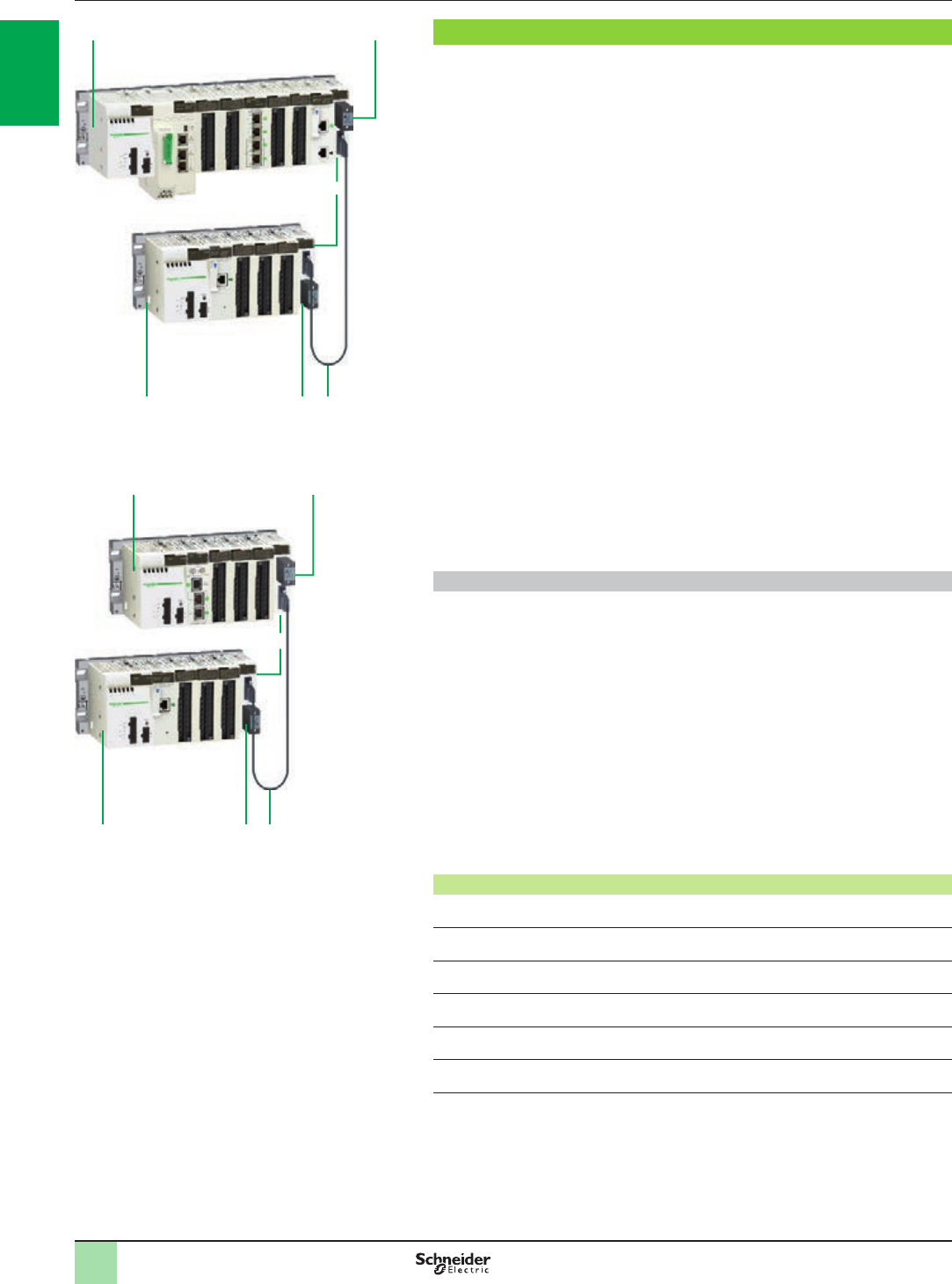
1/26
Presentation Modicon M580 automation
platform
Multi-rack conguration
14
2
4 31
Modicon X80 drop + expansion rack
Composition of an expansion backplane conguration
M580 CPU supports 4 to 8 local racks (depending upon the CPU performance
level), using existing X80 I/O modules and accessories. A Modicon M580 CPU must
be installed in the rst rack (#0) and this can be a dual bus rack. A Modicon M580
PLC will support up to 7 BMXXBPpppp PV02 or higher backplanes (racks) of 4, 6,
8, or 12 slots. The main backplane (rack #0) will support the CPU.
To expand the conguration using additional racks, users must use a bus expansion
module (BMXXBE1000) and X-bus cables. The backplane expander will be
plugged in the dedicated connector on the right side of the backplane. It will not
occupy any module slot. The XBE expansion module will not be hot-swappable in
accordance with Modicon X80. Each backplane has to include a power supply
module and will support up to 12 modules.
An expansion rack can be connected to the main backplane and the X80 drop
(EIO).
The rack address is assigned as follows:
b Each rack will be assigned a physical address using 4 micro switches located in
the bus expansion module.
b The main rack containing the CPU will be assigned address 0.
b The other racks will be assigned addresses 1 to 7.
Each rack is equipped with:
1 A BMXCPSppppp power supply
2 A BMXXBE1000 rack expansion module. This module, inserted in the right-hand
end of the rack (XBE slot) does not occupy rack slots 00…11 (4, 6, 8, or 12 slots are
still available).
3 The BMXXBE1000 rack expansion modules are connected to each other by
X-bus cordsets.
4Line terminators: Both expansion modules at the ends of the daisy chain must
have a line terminator TSXTLYEX on the unused 9-way SUB-D connector.
Ethernet racks
The Modicon M580 CPU supports dual bus backplanes (Ethernet and X-bus), all
the processors support Ethernet ring or star architectures on their Ethernet port.
BMXP58pp2p processors support Ethernet star or ring architectures (RSTP loop is
supported on ports 2 and 3). The embedded scanner allows scanning of distributed
equipment. The CPU drives these devices directly (“NOC” embedded function).
BMXP58pp4pprocessors support an embedded scanner that allows scanning of
X80 drops on Ethernet RIO (EIO) in addition to distributed equipment.
M580 CPUs have an additional third Ethernet port dedicated to the connection of a
service tool such as a PC, HMI, or network analyzer. This port is labeled “ETH 1”. It
does not support RSTP.
M580 CPU will be able to communicate on the main Ethernet backplane. The
Modicon M580 CPU cannot be installed in an expansion rack.
It is necessary to use an Ethernet backplane
Reference Description
BMEXBP0400 Standard 4-slot backplane
BMEXBP0800 Standard 8-slot backplane
BMEXBP1200 Standard 12-slot backplane
BMEXBP0400H Ruggedized 4-slot backplane
BMEXBP0800H Ruggedized 8-slot backplane
BMEXBP1200H Ruggedized 12-slot backplane
1
1
4
4 3
2
Modicon M580 + expansion rack
2
1
3
4
5
6
7
8
9
10
2
1
3
4
5
6
7
8
9
10
1/27
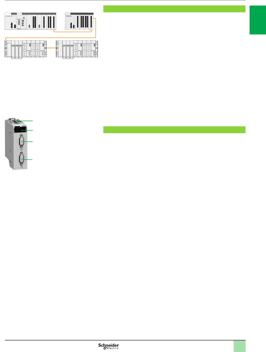
Description Modicon M580 automation
platform
Multi-rack conguration
Modicon M580 Modicon X80 expansion rack
Premium racks
Premium X-bus expansion example
Premium X-bus expansion - making migration as simple as possible
Modicon M580 CPU supports revamping of an existing Premium installation by
replacing the Premium rack 0 (CPU and communication modules) with an M580 rack. It
is also possible to associate TSXRKY4EX/6EX/8EX/12EX Premium racks with X80 I/O
based on an X-bus rack. Most existing congurations are supported. The number of
expansion racks allowed depends on the CPU that is being used:
b BMEP581020,BMEP582020, and BMEP582040 CPUs support a main local rack
and up to 3 expansion racks. If you are using 4, 6, or 8-slot Premium expansion racks,
you may install 2 physical racks at each assigned rack address, allowing up to 6
Premium expansion racks (up to 6 backplanes and 100 m/328.083 ft. between 2
drops).
BMEP583020,BMEP583040,BMEP584020, and BMEP584040 CPUs support a
main local rack with up to 7 expansion racks. If you are using 4, 6, or 8-slot Premium
expansion racks, you may install 2 physical racks at each assigned rack address,
allowing up to 14 Premium expansion racks.
The maximum number of supported X-bus racks is as follows:
b 4 for BMEP581020/20p0
b 8 for BMEP58030p0/40p0
The maximum number of X-bus drops is calculated as follows:
Max number = 1 (CPU rack: BMXXBPpp00 or BMEXBPpp00)
+ ½ number of TSXRKY4/6/8EX racks
+ number of TSXRKY12EX racks
+ number of BMXXBPpp00 racks
Description
The front panel of the BMXXBE1000 rack expansion module comprises:
5 Retaining screw for locking the module in its slot (at the far right-hand end of the
rack)
6 A display block with 5 LEDs:
bRUN LED (green): module in operation
bCOL LED (red): several racks have the same address, or rack address 0 does
not contain the BMEP58ppp0 processor module
bLEDs 0, 1, 2, and 3 (green): rack address 0, 1, 2, or 3
7 A 9-way female SUB-D connector, marked X-bus, for the incoming X-bus cordset
3 connected to the upstream rack, or if it is the rst rack, for the A/ line terminator
included in the TSXTLYEX 4 pack (see page 1/26)
8 A 9-way female SUB-D connector, marked X-bus, for the outgoing X-bus cordset
3 to the downstream rack, or if it is the last rack, for the /B line terminator included
in the TSXTLYEX 4 pack (see page 1/26)
On the right-hand side panel
A ap for accessing the 3 rack addressing micro-switches: 0…3.
Installation rules for BMXXBPppp0 racks: For the rules on how to install racks in
enclosures, see our website www.schneider-electric.com.
5
6
7
8
X-bus
2
1
3
4
5
6
7
8
9
10
2
1
3
4
5
6
7
8
9
10
1/28
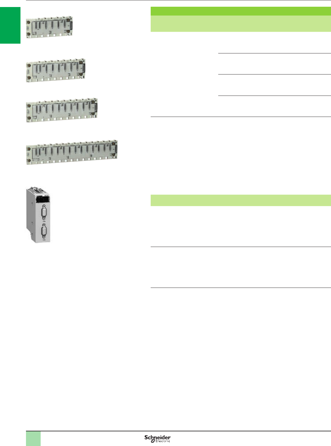
References Modicon M580 automation
platform
Multi-rack conguration
Expansion racks
Description Type of module
to be inserted
No. of
slots
(1)
Power
consumption
(2)
Reference Weight
kg/lb
X-bus
backplanes
for expansion
racks
(3)
Modicon X80 I/O
modules (3)
BMEP58
processors
41 W BMXXBP0400 0.630/
1.389
61.5 W BMXXBP0600 0.790/
1.742
82 W BMXXBP0800 0.950/
2.094
12 0 W BMXXBP1200 1.270/
2.800
Description Use Reference Weight
kg/lb
Modicon X80 I/O
rack expansion
module
(3)
Standard module for mounting in each
rack (XBE slot) and used to interconnect:
-Up to 3 racks with
BMEP581020/20pppp processor module
-Up to 7 racks with BMEP5830pp/40pp
processor module
-1 rack with X80 drop (EIO)
BMXXBE1000
0.178/
0.392
Modicon X80 I/O
rack expansion
kit
(3)
Complete kit for 2-rack conguration
comprising:
- 2 BMXXBE1000 rack expansion
modules
- 1 BMXXBC008K extension cordset,
length 0.8 m/2.625 ft.
- 1 TSXTLYEX line terminator (set of 2)
BMXXBE2005 0.700/
1.543
(1) Number of slots taking all modules except for power supply and rack expansion modules
(2) Power consumption of anti-condensation resistor(s)
(3) Please refer to the “Modicon X80 I/O platform” catalog on www.schneider-electric.com.
BMXXBP0400
PF106104
BMXXBP0600
PF106105
BMXXBP0800
PF106106
BMXXBP1200
PF106107
BMXXBE1000
PF108119
2
1
3
4
5
6
7
8
9
10
2
1
3
4
5
6
7
8
9
10
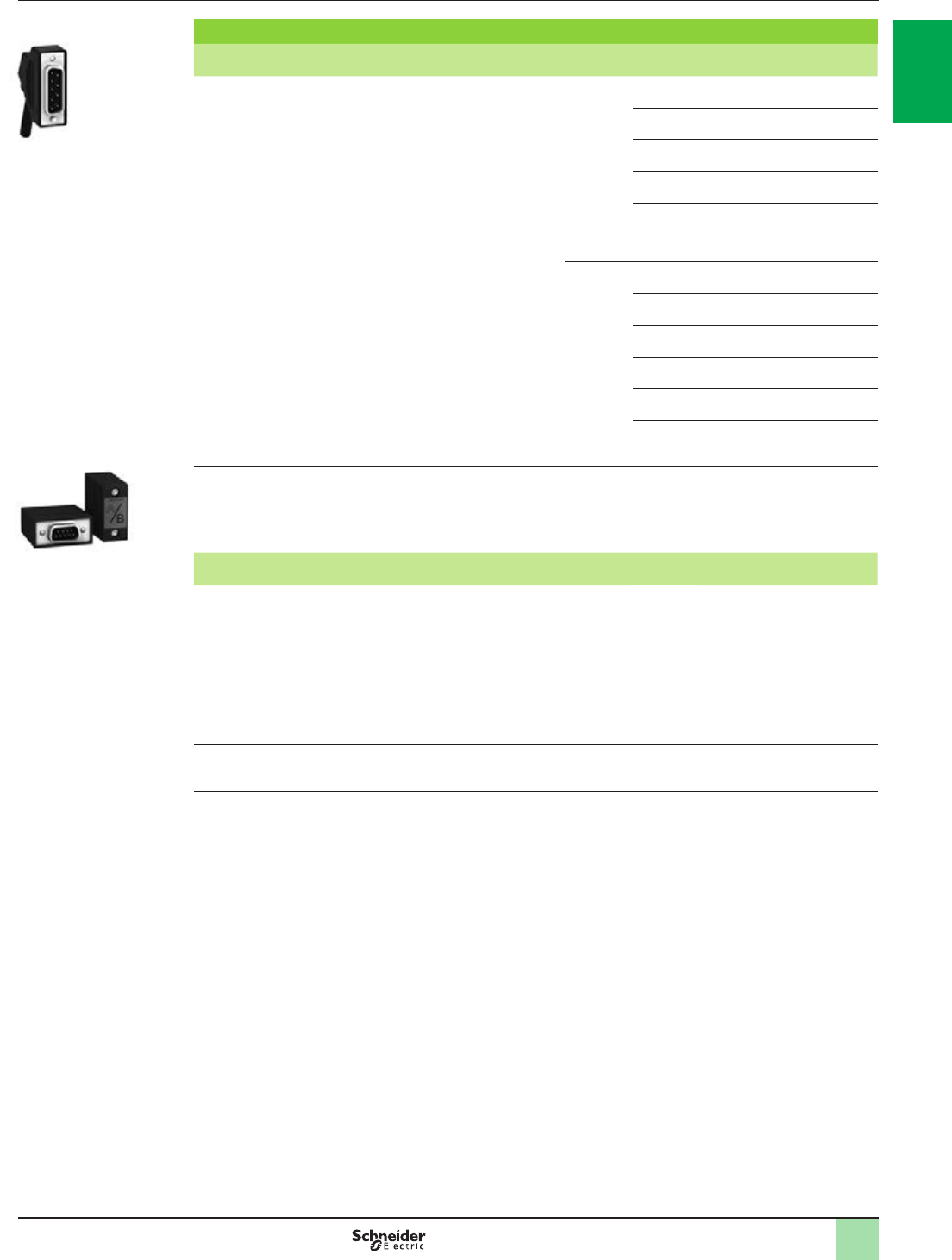
1/29
References Modicon M580 automation
platform
Multi-rack conguration
Cordsets and connection accessories
Description Use Composition Type of
connector
Length
m/ft.
Reference Weight
kg/lb
X-bus extension
cordsets
total length
30 m/98.425 ft. max.
Between 2
BMXXBE1000 rack
expansion modules
2 x 9-way SUB-D
connectors
Angled 0.8/2.625 BMXXBC008K 0.165/
0.364
1.5/4.921 BMXXBC015K 0.250/
0.551
3/9.842 BMXXBC030K 0.420/
0.926
5/16.404 BMXXBC050K 0.650/
1.433
12/39.37 BMXXBC120K 1.440/
3.175
Straight 1/3.281 TSXCBY010K 0.160/
0.353
3/9.842 TSXCBY030K 0.260/
0.573
5/16.404 TSXCBY050K 0.360/
0.794
12/39.37 TSXCBY120K 1.260/
2.778
18/59.05 TSXCBY180K 1.860/
4.101
28/91.86 TSXCBY280KT
(1)
2.860/
6.305
Cable reel Length of cable to be
equipped with
TSXCBYK9
connectors
Cable with
ends with ying
leads, 2 line testers
– 100/328.08 TSXCBY1000 12.320/
27.161
Description Use Composition Type of
connector
Sold in
lots of
Unit reference Weight
kg/lb
Line terminators Required on the 2
BMXXBPppp0
modules located at
either end of the daisy
chain
2 x 9-way SUB-D
connectors marked A/ and /B
2TSXTLYEX 0.050/
0.110
X-bus straight
connectors
For TSXCBY1000
cables
2 x 9-way SUB-D
straight connectors
2TSXCBYK9 0.080/
0.176
Connector assembly
kit
For attaching
TSXCBYK9
connectors
2 crimping pliers,
1 pen (2)
–TSXCBYACC10 –
(1) Cable supplied with a set of 2 TSXTVSY100 electrical transient suppressors.
(2)To t the connectors on the cable, you also need a wire stripper, a pair of scissors, and a digital ohmmeter.
TSXTLYEX
PF108138
BMXXBCpppK
PF108142
2
1
3
4
5
6
7
8
9
10
2
1
3
4
5
6
7
8
9
10

2/0
2
1
3
4
5
6
7
8
9
10
2
1
3
4
5
6
7
8
9
10

2/1
Contents
Architectures
Overview of I/O architectures……………………………….…………. .... page 2/2
b Presentation …………………………………..….…………………... ........page 2/4
b Architecture A………………….……………..….…………………............page 2/5
b Architecture B………………….……………..….…………………............page 2/6
b Architecture C………………….……………..….……….…………...........page 2/7
b Architecture D………………….……………..….…………………............page 2/8
b Modicon X80 performance EIO adapter……................. ….…………... page 2/9
b Modbus/TCP and EtherNet/IP network module.…….................... .... page 2/10
b Modicon X80 NRP EIO drop optical repeaters ……....................…... page 2/11
b ConneXium managed switches………………………….......... ….…... page 2/11
b Example of a complex architecture……………………….…........…... page 2/12
b Examples of architectures………………………………… .......….…... page 2/13
v Food and beverage examples..…………………….… ............ …………. page 2/13
v Water example ….……………….…………………………………........ … page 2/14
v Hydro power example ………..………………………… .......... …………. page 2/15
v Cement example .……….……………………………………………......... page 2/16
b References and requirements………………………............. ………... page 2/17
Modicon distributed I/O solutions
Selection guide ............................................page 2/20
b Presentation.........................................................................................page 2/22
b Description, references.......................................................................page 2/23
b Composition ........................................................................................page 2/24
b Conguration.......................................................................................page 2/25
2 - I/O architectures
2
1
3
4
5
6
7
8
9
10
2
1
3
4
5
6
7
8
9
10
2
1
3
4
5
6
7
8
9
10
2
1
3
4
5
6
7
8
9
10
2
1
3
4
5
6
7
8
9
10
2
1
3
4
5
6
7
8
9
10
2/2 2/2
Overview Modicon M580 automation
platform
I/O architectures
Modicon M580 type of architecture
Note: These architectures can be combined with each other
Architectures with local racks (main rack and expansion racks) Architecture with local racks (main rack and expansion racks) Architecture with racks in remote drops
Hardwired Distributed peripherals over eldbuses Distributed peripherals and I/O over Ethernet Remote over Ethernet
Compact topology with devices hardwired
on local I/O
Compact topology with devices distributed
over eldbuses
Distributed devices and I/O topology over Ethernet Remote I/O + Remote functions (including eldbus master)
Architecture A Architecture B Architecture C Architecture D
Expanded rack (with X-bus rack expansion module) Main local rack with up to 7 local expansion racks on X-bus (Modicon Premium or Modicon X80
racks)
Main local rack with up to 7 local expansion racks on X-bus (Modicon Premium
or Modicon X80 racks)
Main local rack with up to 7 local expansion racks on X-bus (Modicon Premium or
Modicon X80 racks), RIO drop with up to 1 remote expanded rack on X-bus (only
Modicon X80 racks)
Backplane compatibility BMEXBPpp00 Ethernet +
X-bus racks
Compatible for main racks (local or remote) Compatible for main racks (local or remote)
Mandatory for expansion racks (main or remote)
Compatible with any rack if Modicon X80 I/O Ethernet modules are not used in the racks, such as: weighing, HART and BMECRA31210 modules
BMXXBPpp00 X-bus racks
PV02 (or later)
Mandatory for expansion racks (main or remote)
Compatible with any rack if Modicon X80 I/O Ethernet modules are not used in the racks, such
as: weighing, HART and BMECRA31210 modules
Compatible CPU types All CPUs are compatible (1) All CPUs are compatible (1) BMEP58pp40 CPUs are required to manage RIO
CPU Ethernet ports SERVICE port One SERVICE port for HMI, Unity, control network, variable speed drive, etc. One SERVICE port for HMI, Unity, control network, variable speed drive, etc.
Dual port Dual ports are not used Dual ports are used for distributed equipment (DIO scanner) Dual ports are used for remote equipment (RIO scanner), BMECRA31210
Ethernet drop adapter is mandatory in RIO drop (2).
RIO drops – – A maximum of 16 RIO drops can be supported in an M580 network
Communication AS-Interface and serial link
modules
Yes Yes Yes, in a local rack or in a RIO drop
BMXNOR0200H RTU
module
Yes Yes Yes, only in a local rack
Ethernet modules Yes Yes Yes, only in a local rack
Expert functions PTO (Pulse Train Output)
modules
Yes Yes Yes, only in a local rack
Other expert modules:
counting, SSI encoder, etc.
Yes Yes Yes, in a local rack or in a RIO drop
Time stamping 1 ms max. BMXERT1604T
module integrated in the ERT
module
Yes Yes Yes, in a local rack or in a RIO drop
10 ms with BMECRA31210
combined with discrete I/O
modules in the RIO drop
– – Yes, only in the RIO drop, system mode with OFS (2)
Pages
(1) BMEP58pp40 CPUs are not mandatory for architectures A, B and C.
(2) BMXCRA31210 modules are also compatible.
X-bus
HART
Ethernet
Ethernet
AS-I
Modbus
X-bus
2/2 2/3
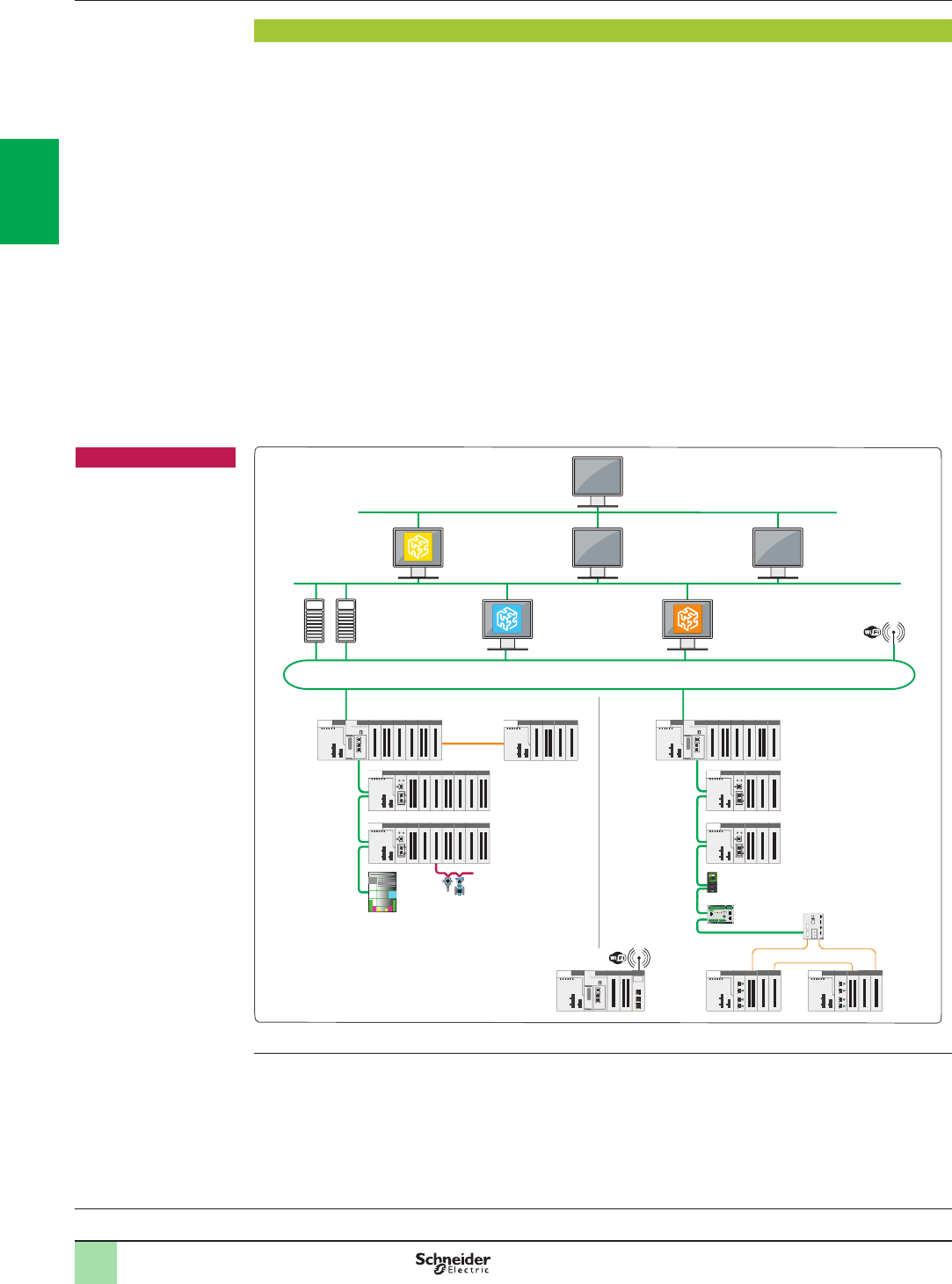
2/4
Presentation Modicon M580 automation
platform
I/O architectures
Processors:
page 1/18
Software:
page 4/2
Ruggedized Modicon M580
modules: page 5/2
Presentation
The Modicon M580 automation platform offers four different types of architectures with local racks or with racks in
remote drops. These four options are presented on the following pages as architectures A, B, C and D.
The Modicon M580 automation platform offers an I/O architecture solution over local racks, eldbuses and
Ethernet, connecting the M580 main rack to remote I/O (RIO) drops, installed on a Modicon X80 rack (1), and
distributed I/O (DIO) devices.
This Modicon M580 solution comprises:
bRIO drops on a Modicon X80 drop
bEthernet DIO devices
bA choice of three CRA Ethernet drop adapters (standard or high performance) in each Modicon X80 RIO drop
bTwo optical repeaters, for single mode or multimode optical ber, on Modicon X80 RIO drop
bA choice of three types of managed dual ring switches (DRS) from the ConneXium offer (2), congurable by
means of predened conguration les for immediate setup
Different architectures are therefore possible, such as:
bEthernet RIO architectures with or without ConneXium managed switches (2)
bArchitectures with separate or combined Ethernet RIO and Ethernet DIO devices on the same physical
medium
This solution also includes numerous options and functions as standard, providing:
bHigh process availability, with the option of connecting Ethernet RIO and Ethernet DIO in a daisy chain loop
bDeterministic data exchanges between the PLC and the Ethernet RIO
bRemote service, with a SERVICE port available on the M580 CPU or Modicon X80 CRA Ethernet drop
adapters
Historian
Ethernet ring
Redundant
system
servers
Unity Pro
MES
(Manufacturing
Execution
System)
ERP system
Vijeo Citec
SCADA
Enterprise
Factory
Process
Field
Modicon M580 main rack Modicon M580 main rack
Modicon X80 drop
Modicon X80 drop
Modicon
X80 drop
Modicon
X80 drop
Variable speed drive
Motor
protection
Optical ber
ConneXium managed
switch (DRS)
X-bus
Expansion rack
Modicon X80 drop
Modicon X80 drop
HART devices
iMCC
Remote
site
Wi-Fi
Typical architecture (3)
(1) The Modicon X80 range offers common I/O modules which can be used both in Ethernet RIO drops connected in
Modicon M580 automation platforms.
(2) Supported ConneXium switches: TCSESM083F23F1/063F2CU1/063F2CS1 (see page 2/11).
(3) This typical architecture representation is a conceptual network diagram and does not represent the actual wiring
specications.
Note
bThe validated and tested
architectures are shown in
the technical documentation
available on our website
www.schneider-electric.com.
bThe use of switches other
than those detailed in these
architecture I/O pages
(pages 2/4 to 2/19) is not
supported (2).
2
1
3
4
5
6
7
8
9
10
2
1
3
4
5
6
7
8
9
10
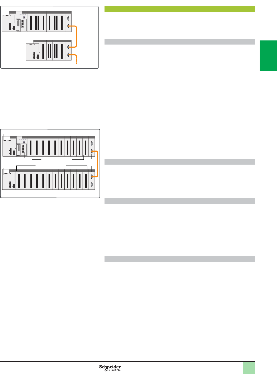
2/5
Processors:
page 1/18
Software:
page 4/2
Ruggedized Modicon M580
modules: page 5/2
Presentation
(continued)
Modicon M580 automation
platform
Architectures with local racks
Architecture A
Presentation
Architecture A is used for control systems that reside in the main control cabinet.
The M580 platform provides interrupt services for this type of application.
Up to 94 slots are possible for I/O modules in a conguration comprising a main rack
and 7 expansion racks, connected by BMXXBEp00p rack expansion modules.
Description
The Modicon M580 automation platform provides local I/O management for control
systems that are wired to the main control cabinet.
Architecture A can comprise a maximum of 10 I/O modules in the main rack, in
addition to the CPU module 2 and the power supply module 1.
These local I/O can be extended on an expansion rack by using a BMXXBEp00p
rack expansion module 3.
Ethernet slots are available only in the main rack because rack expansion cables
only support X-bus.
The choice of appropriate rack depends on the required number of modules for the
system. Main racks are available in the following formats: 4, 8 and 12 slots.
As well as discrete and analog I/O modules, the following modules are available:
bApplication-specic modules:
vSSI encoder
vCounter
vPulse train output
vWeighing
Some application-specic modules (weighing, etc.) require use of an Ethernet
backplane.
If necessary, communication and network modules can be installed in the local rack.
The majority of communication and network modules need to be in the local rack.
Architecture A conguration rules
When conguring an architecture A system, the following four parameters should be
considered:
bNumber of slots available in the 8 local racks (main and expansion racks)
bSlots available for optional modules
bPower consumed by the installed modules
bAddressing words available for conguring the modules
Available slots and power consumption
Architecture A can have a maximum of 94 available slots (with eight 12-slot racks)
for I/O modules, application-specic modules and communication modules.
These modules are powered from the power supply included in the rack.
For a valid conguration, simply add together the consumption (in mA) of the
modules in the rack and check that the total current is less than that provided by the
selected power supply.
This power consumption calculation can easily be performed using Unity Pro
software.
Empty BMXXEM010 modules are also available to occupy unused slots.
Module addressing (1)
With Unity Pro, the I/O addressing is unlimited (physical limitation: 94 slots).
(1) Requires Unity Pro software V8.0.
Architecture A: devices on local I/O
Expansion rack
Main rack
X-bus
For rack accessory references, see page 1/25
3
Main rack
Expansion rack
10 slots max. available
12 slots max. available
2
1
1
2
1
3
4
5
6
7
8
9
10
2
1
3
4
5
6
7
8
9
10
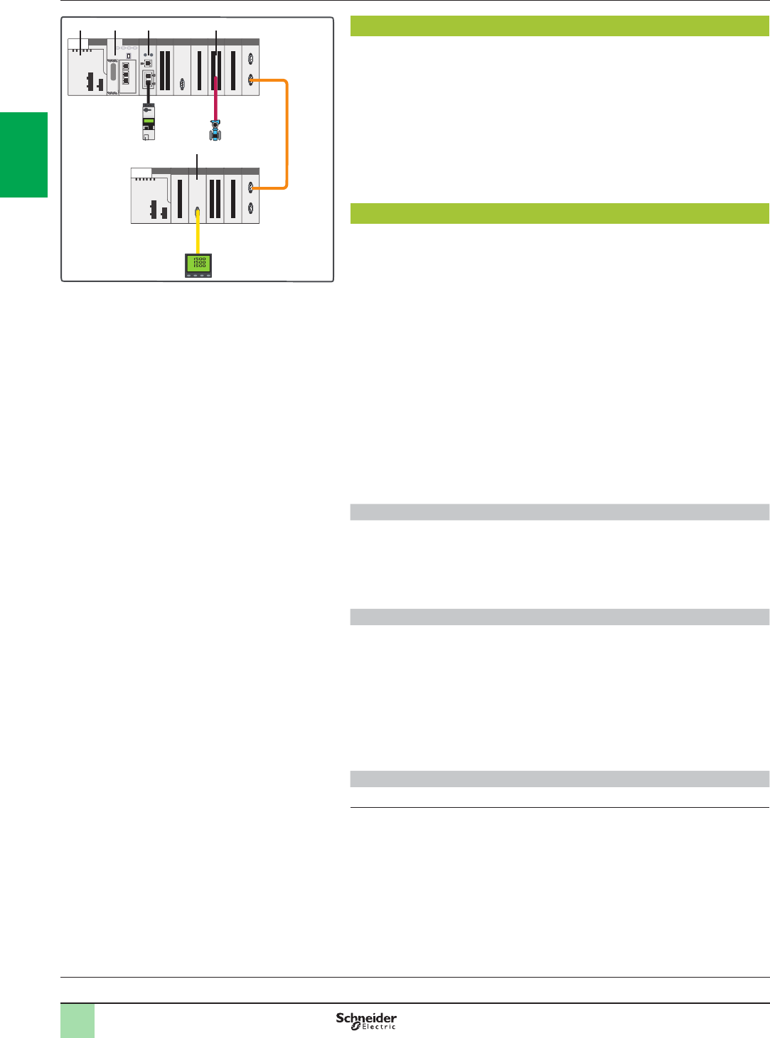
2/6
Presentation,
description
Modicon M580 automation
platform
Architectures with local racks
Architecture B
Presentation
Architecture B is based on architecture A with the possibility of adding eldbuses
such as AS-Interface, Modbus SL, HART, etc.
Architecture B is used for control systems that are wired to the main control cabinet.
It consists of a mainly local topology with several peripherals distributed over
eldbuses.
The Modicon M580 automation platform provides interrupt services for this type of
application.
Up to 94 slots are possible for I/O and communication modules in a conguration
comprising a main rack and 7 expansion racks, connected by BMXXBEp00p rack
expansion modules.
Description
The Modicon M580 automation platform provides local I/O management for control
systems that are wired to the main control cabinet.
Architecture B can comprise a maximum of 10 I/O and communication modules in
the main BMEXBPpp00 rack, in addition to the CPU module 2 and the power supply
module 1. These local I/O and communication modules can be extended on
expansion racks by using a BMXXBEp00p rack expansion module.
The choice of appropriate racks depends on the required number of modules for the
system. Main racks are available in the following formats: 4, 8 and 12 slots.
If necessary, communication and network modules can be installed in the main
rack. The majority of communication and network modules need to be in the main
rack.
As well as discrete and analog I/O modules, the following modules are available:
bCommunication modules:
vSerial link 3
vAS-Interface 4
vHART 5
Some communication modules (Modbus/TCP and EtherNet/IP network module,
HART analog I/O modules, etc.) require use of an Ethernet backplane.
Architecture B conguration rules
When conguring an architecture B system, the following four parameters should
be considered:
bNumber of slots available in the 8 local racks
bSlots available for optional modules
bPower consumed by the installed modules
bAddressing words available for conguring the modules
Available slots and power consumption
Architecture B can have a maximum of 94 available slots (with eight 12-slot racks)
for I/O modules, application-specic modules and communication modules.
These modules are powered from the power supply included in the rack.
For a valid conguration, simply add together the consumption (in mA) of the
modules in the rack and check that the total current is less than that provided by the
selected power supply.
This power consumption calculation can easily be performed using Unity Pro
software.
Empty BMXXEM010 modules are also available to occupy unused slots.
Module addressing
With Unity Pro (1), the I/O addressing is unlimited (physical limitation: 94 slots).
(1) Requires Unity Pro version ≥ 8.0 software.
Processors:
page 1/18
Software:
page 4/2
Ruggedized Modicon M580
modules: page 5/2
Architecture B: devices distributed over eldbuses
1 2 3 5
4
Main rack
Expansion rack
X-bus
2
1
3
4
5
6
7
8
9
10
2
1
3
4
5
6
7
8
9
10
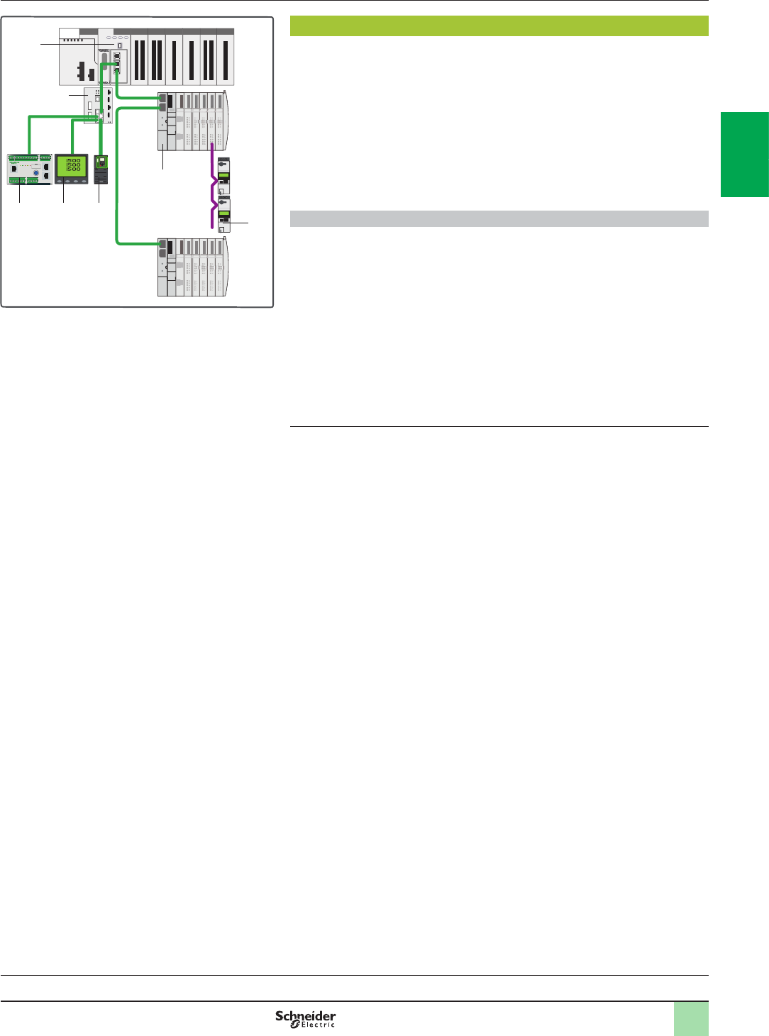
2/7
Presentation,
description
(continued)
Modicon M580 automation
platform
Architectures with local racks
Architecture C
Presentation
Architecture C consists of I/O and devices distributed over Ethernet (DIO).
The Ethernet DIO devices can be connected to Ethernet ports of the BMEP58p0p0
CPU 1 or of a ConneXium DRS (Dual Ring Switch) switch.
The available Ethernet DIO devices are:
bModicon STB distributed I/O 2
bVariable speed drives 3
bEnergy supervision 4 and HMI
bTesys U 5 connected via CANopen to a Modicon STB I/O island and Tesys T 6
motor protection, etc.
Modbus serial link devices can be integrated in architecture C via the
BMXNOM0200 serial link module.
High availability and expanded integration capacity
Architecture C can integrate ConneXium DRS (Dual Ring Switch) switches 7(1). 15
predened congurations which can be loaded into the switches simplify their
implementation.
The use of these switches provides enhanced capacity for the integration of
devices:
bDIO sub-rings
bDIO clouds
The advantages of this architecture are:
bHigh availability of the Ethernet DIO devices
Maximum distance between each ConneXium managed switch:
b100 m/328.084 ft with copper medium
b2 km/1.243 mi with multimode optical ber
b16 km/9.942 mi with single mode optical ber medium
(1) Supported ConneXium switches: TCSESM083F23F1, TCSESM063F2CU1,
TCSESM063F2CS1.
Processors:
page 1/18
Software:
page 4/2
Ruggedized Modicon M580
modules: page 5/2
Architecture C: devices distributed over Ethernet
1
2
3
5
46
7
Main rack
Distributed
I/O
Distributed
I/O
Ethernet
2
1
3
4
5
6
7
8
9
10
2
1
3
4
5
6
7
8
9
10
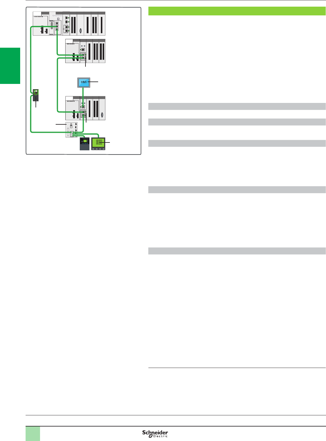
2/8
Presentation,
description
(continued)
Modicon M580 automation
platform
Architectures with remote racks
Architecture D
Presentation
Architecture D consists of remote I/O and remote functions (including eldbus
masters).
Architecture D is fully compatible with the references in the Modicon M580
automation platform and Modicon X80 I/O platform offers. The capacity of Modicon
X80 I/O drops depends on the CRA Ethernet drop adapter used. A maximum of
16 RIO drops 1 can be supported in an architecture D system.
The available Ethernet devices are:
bVariable speed drives 2
bEnergy supervision 3 and HMI 4
bTesys T motor protection, etc.
It is possible to include DIO devices in architecture D via the SERVICE port of the
CPU or of the BMECRA31210 drop adapter 1 or via ConneXium DRS (Dual Ring
Switch) switches 5.
Rack Viewer function r
The Rack Viewer function provides access to Ethernet RIO data via a web browser.
Predened congurations for ConneXium managed switches
The use of ConneXium managed switches specically for Modicon M580
architectures is simplied using 15 predened conguration les.
Standard architecture D
This is composed of a daisy chain loop consisting of a Modicon M580 main rack and
several Modicon X80 I/O drops containing an Ethernet drop adapter:
bBMECRA31210 Modicon X80 performance EIO adapter, with SERVICE port
bBMXCRA31210 Modicon X80 RIO Ethernet drop adapter, with SERVICE port
bBMXCRA31200 Modicon X80 RIO Ethernet drop adapter, without SERVICE
port
Long distance architecture D
Similar to the standard architecture D, this variant comprises of one or more
remotely located Modicon X80 I/O drops connected via integrated NRP optical ber
repeaters.
There are two types of NRP repeater:
bBMXNRP0200: multimode optical ber repeater (remote location up to 2 km)
bBMXNRP0201: single mode optical ber repeater (remote location up to 16 km)
The NRP repeaters are linked to CRA drop adapters by means of Ethernet Interlink
cables.
High availability and expanded integration capacity
Architecture D can integrate ConneXium DRS (Dual Ring Switch) switches 5(1).
15 predened congurations which can be loaded into the switches simplify their
implementation.
The use of these switches provides enhanced capacity for the integration of
devices:
bRIO sub-rings
bOptical ber media for long distance remote location, etc.
bEnable DIO integration to architecture D
The advantages of this architecture are:
bReduced wiring costs
bDeterministic data exchanges between the PLC and the EIO devices
bSecondary rings can be linked to the main ring by two DRS switches, which
improve availability
Maximum distance between each ConneXium managed switch:
b100 m/328.084 ft with copper (twisted pair) cables
b2 km/1.243 mi with multimode optical ber
b16 km/9.942 mi with single mode optical ber media
(1) Supported ConneXium switches: TCSESM083F23F1, TCSESM063F2CU1,
TCSESM063F2CS1.
Processors:
page 1/18
Software:
page 4/2
Ruggedized Modicon M580
modules: page 5/2
HMI
Architecture D: remote I/O
1
1
2
5
4
3
Main rack Remote
drop
Remote
drop
Ethernet
r Available 2nd quarter 2014.
2
1
3
4
5
6
7
8
9
10
2
1
3
4
5
6
7
8
9
10
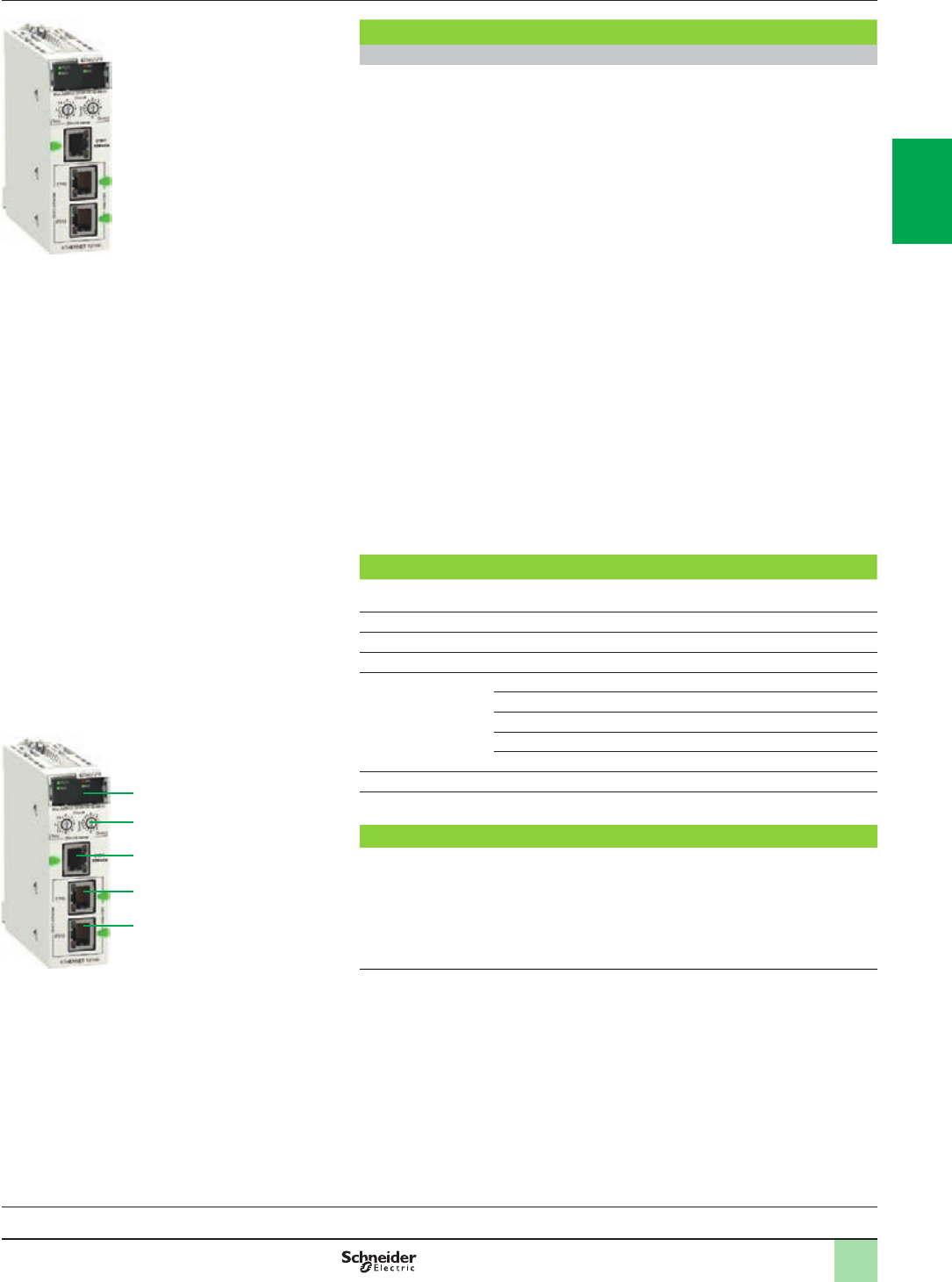
2/9
Presentation,
description
(continued)
Modicon M580 automation
platform
Modicon X80 performance EIO adapter
Modicon X80 performance EIO adapter
Presentation
An M580 Ethernet RIO (EIO) architecture with Modicon X80 I/O drops requires the
use of a dedicated adapter in each Modicon X80 drop.
The BMECRA31210 adapter supports Ethernet and X-bus communications across
the remote backplane.
This EIO adapter module supports several expert modules such as counting and
weighing modules and CCOTF (Change Conguration On The Fly).
For Modicon X80 RIO drops on an Ethernet backplane, time stamping can be
managed with a resolution of 10 ms when using a BMECRA31210 performance
EIO adapter.
Only one BMECRA31210 module can be installed per Modicon X80 RIO drop.
This module can also support a BMXXBPpp00 expansion rack.
The BMECRA31210 adapter is designed to be installed on an Ethernet backplane
in the main remote rack. The adapter supports the Modicon X80 I/O and partner
modules with both Ethernet and X-bus connections (1).
The keying pin on the rear side of the module means the BMECRA31210 adapter
cannot be installed on unsupported backplanes.
These adapters are connected by Ethernet cordsets tted with RJ45 connectors.
The dual Ethernet connection port on each adapter allows Daisy Chain Loop
connections using the RSTP protocol (Rapid Spanning Tree Protocol).
The BMECRA31210 adapter is also available in a conformal coating version for
harsh environments.
It also complies with several standards and certications such as C-Tick, GOST,
merchant navy, CSA C22.2 No. 142 and 213 and IEC/EN 61131-2.
Capacity of the Modicon BMECRA31210 adapter
Maximum number of
racks per drop
Up to 2
SERVICE port 1
Discrete I/O modules Up to 1024
Analog I/O module Up to 256
Expert modules
supported:
bserial link BMXNOM0200
btime and date stamping at 1 ms BMXERT1604T
bcounting BMXEHC0200/BMXEHC0800
bweighing PMESWT0100
bHART integrated analog I/O modules BMEAHI0812/BMEAHO0412
CCOTF function Yes
Time and date stamping 10 ms
Description
1 LED display block indicating the module status
2 Rotary switches for setting the address of an EIO drop (00…159)
3 Dedicated RJ45 service port (ETH 1) for remote service tools such as a PC, an
HMI terminal module or Ethernet DIO devices
4 RJ45 device network port (ETH 2) for connection to the Ethernet network
5 RJ45 device network port (ETH 3) for connection to the Ethernet network
(1) This module is also compatible with X-bus backplanes. In this case it has the same
functionality as a BMXCRA31210 performance Ethernet drop adapter.
BMECRA31210
BMECRA31210
1
2
3
4
5
Processors:
page 1/18
Software:
page 4/2
Ruggedized Modicon M580
modules: page 5/2
2
1
3
4
5
6
7
8
9
10
2
1
3
4
5
6
7
8
9
10
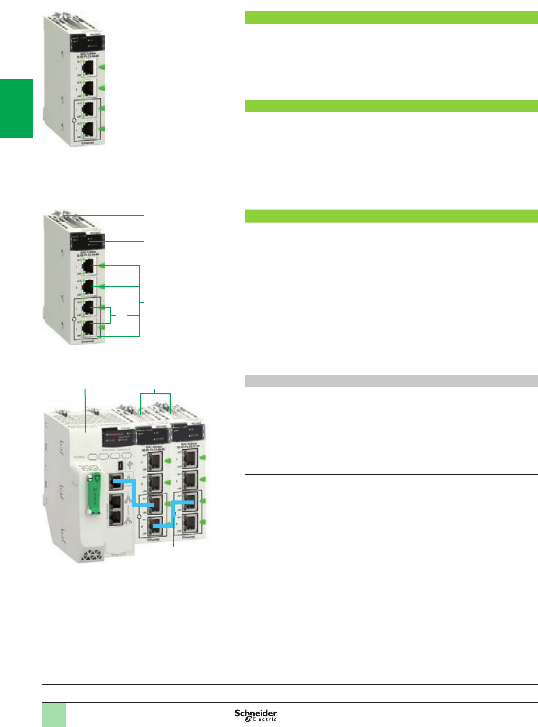
2/10
Presentation,
functions, description
Modicon M580 automation
platform
Modbus/TCP and EtherNet/IP network module
Presentation
The BMXNOC0402 (1) network module acts as an interface between the M580 PLC
and other Ethernet network devices via the Modbus/TCP and EtherNet/IP
communication protocols.
The standard format BMXNOC0402 network module occupies a single slot in the
rack of the Modicon M580 platform. This module should be installed in the main
Ethernet backplane rack.
Functions
The BMXNOC0402 module offers the following functions:
bModbus/TCP and EtherNet/IP protocols operating simultaneously
bRing topologies on 2 Ethernet ports using RSTP (Rapid Spanning Tree Protocol)
bPriority of Ethernet packets using QoS (Quality of Service) service
bAutomatic module conguration recovery using FDR (Fast Device Replacement)
service
bEmbedded Web server for application monitoring and module diagnostics
bSharing data between PLCs
bNetwork management using SNMP (Simple Network Management Protocol)
Description
The front panel of the BMXNOC0402 module features:
1 A screw for locking the module in a slot in the rack.
2 A display block with 5 LEDs:
vRUN LED (green): Operating status
vERR LED (red): Error detected
vMS LED (green/red): Module status
vNS LED (green/red): Network connection status
vETH STS LED (amber): Ethernet link status
3 Four RJ45 connectors for connection to the Ethernet network. The two bottom
connectors 3a support ring topologies (RSTP protocol).
Each RJ45 connector has two associated LEDs:
vLNK LED (yellow): Ethernet link established
vACT LED (green): Transmission/reception activity
Combination of Ethernet modules and BMEP58 CPU
It is possible to combine Ethernet modules with the Modicon M580 CPU in order to
increase its connectivity.
In this example, the two NOC EtherNet/IP, Modbus/TCP network modules 5 are
linked to the BMEP58●0●0 CPU module 4 by means of Ethernet Interlink cables 6.
Multiple combinations are possible:
4 BMEP581020 CPU
5 BMXNOC0402 EtherNet/IP, Modbus/TCP network module
6 Ethernet Interlink cable TCSECN3M3M1S4/1S4U
(1) The BMXNOC0402 communication module will be replaced by the BMENOC03●1 modules
during the 2nd quarter of 2014.
BMXNOC0402
Example of BMEP58 and NOC module combination:
BMEP581020/BMXNOC0402/BMXNOC0402
6
45
BMXNOC0402
1
2
3
3a
Processors:
page 1/18
Software:
page 4/2
Ruggedized Modicon M580
modules: page 5/2
6
2
1
3
4
5
6
7
8
9
10
2
1
3
4
5
6
7
8
9
10
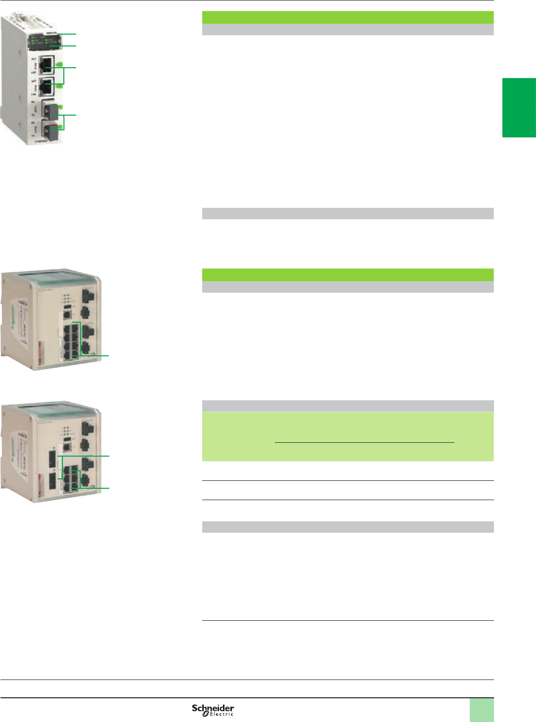
2/11
Presentation,
description
Modicon M580 automation
platform
Modicon X80 NRP EIO drop optical repeaters,
ConneXium managed switches
Modicon X80 EIO drop optical repeaters (1)(2)
Presentation
BMXNRP0200/0201 optical ber repeaters are an alternative to the use of
ConneXium managed dual ring switches (DRS), for optical ber communications
over long distances, in Ethernet I/O (EIO) systems.
When inserted in Modicon X80 RIO drops, BMXNRP0200/0201 optical ber
repeaters make it possible to:
bExtend the total distance of the EIO network, when EIO drops are located in
areas of the factory more than 100 m/328.084 ft away
bEnhance immunity to noise
bResolve difference of potential between distant sites
bNRP repeaters can be installed on the primary ring or on secondary rings. These
modules cannot, however, be used to connect secondary rings to the primary ring
bThe BMXNRP0200 repeater for multimode optical ber allows remote location up
to 2 km/1.243 mi.
The BMXNRP0201 repeater or single mode optical ber allows remote location up to
16 km/9.942 mi.
Depending on the conguration, the NRP repeater may be linked to the CRA adapter
of the drop where it is installed, via one or two Ethernet Interlink cables.
Description
1 Module reference
2 Display block indicating the module status
3 RJ45 Ethernet ports. Two LEDs, LNK and ACT, indicate the status of each port
4 Optical ber ports with SFP transceiver for LC type connector
ConneXium managed switches (3)
Presentation
There are three ConneXium managed DRS (Dual Ring Switch) models available
specically for EIO architectures. They are used in the following situations:
bFor remote racks located at a distance of more than 100 m/328.084 ft
bUse of optical ber media:
vFor remote racks located over long distances: 2 km/1.243 mi (multimode optical
ber) or 16 km/9.942 mi (single mode optical ber)
vIn environments subject to interference
vBetween sites with different earth equipotentiality
bArchitectures with combined EIO and Ethernet DIO devices
bImplementation of a secondary ring
ConneXium managed switches specic to the medium
ConneXium
managed switch
Copper port Multimode
optical ber port
Single mode
optical ber port
Distance
between
switches
RJ45 shielded
connectors
Duplex SC connectors
TCSESM083F23F1 1 : 8 x 10/100
BASE-TX ports
––100 m/
328.084 ft
TCSESM063F2CU1 3 : 6 x 10/100
BASE-TX ports
2 : 2 x 10/100
BASE-FX ports
–2 km/
1.243 mi
TCSESM063F2CS1 3 : 6 x 10/100
BASE-TX ports
–2 : 2 x 10/100
BASE-FX ports
16 km/
9.942 mi
Predened conguration les
For ease of implementation of the 3 switches described above, 15 predened
conguration les are available for building validated and tested architectures.
These conguration les are included, as standard, on the Unity Pro V8.0 DVD.
The parameters of the switch(es) present on the Ethernet network can then easily
be easily set with the chosen conguration using a PC equipped with a web browser
or Ethernet Switch Congurator software. The switch is congured immediately.
Ethernet Switch Congurator software is also available on the ConneXium
Resource CD-ROM.
(1) For additional characteristics, see our website www.schneider-electric.com.
(2) Requires Unity Pro Extra Large software u V8.0.
(3) The functions described are only available for the three ConneXium managed switches
mentioned on this page: (TCSESM083F23F1/063F2CU1/063F2CS1).
3
2
TCSESM063F2CU1
TCSESM063F2CS1
1
TCSESM083F23F1
BMXNRP020p
2
3
4
1
Processors:
page 1/18
Software:
page 4/2
Ruggedized Modicon M580
modules: page 5/2
2
1
3
4
5
6
7
8
9
10
2
1
3
4
5
6
7
8
9
10
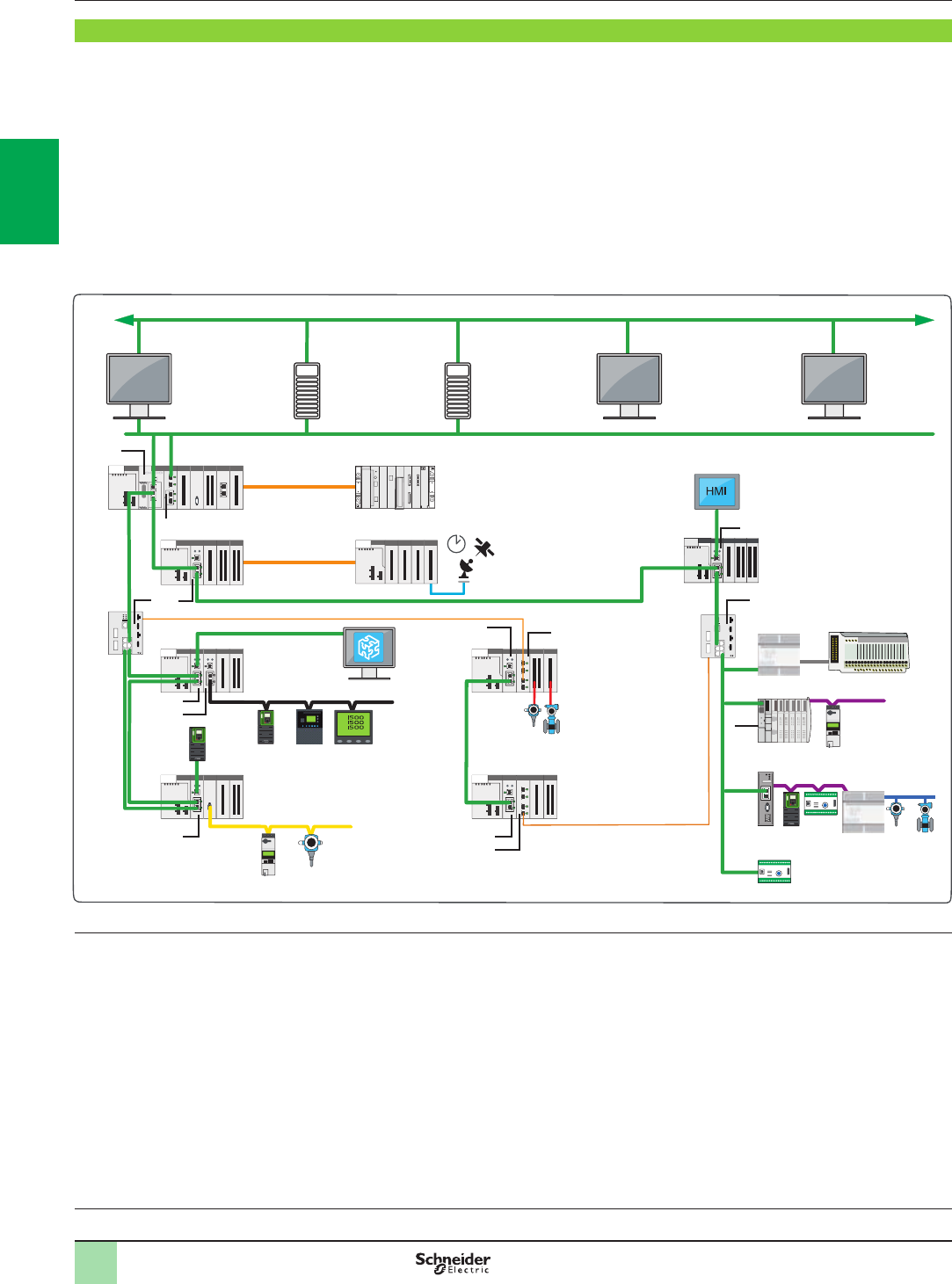
2/12
Architectures Modicon M580 automation
platform
I/O architectures
Example of a complex architecture
Example of a complex architecture
The complex architecture below illustrates the extensive possibilities of the Modicon M580 offer:
bA choice between 7 BMEP58p0p0 CPUs 1
bEasy integration of the I/O network with supervisors in the control network, due to the BMXNOC0402 Ethernet module 2(1)
bOptimized wiring with RIO and DIO control via a single medium: the DIO are controlled via the CPU
bHigh availability of secondary rings with ConneXium managed switches 3
bLong distance optimized by the optical ber converter 4,directly in the Modicon X80 rack
bSimplied integration of devices via a serial link 5 (for example: measuring center, variable speed drive, motor starters, protection relays,
etc.). FTD/DTM technology makes it possible to congure and debug devices transparently via the Ethernet network, from any supervisor
bGreat exibility due to integration of DIO devices 6or other diagnostic/conguration tools on any drop SERVICE port or on the DIO port of a
managed switch
bEasy integration of Modicon X80 I/O drops on Ethernet with BMECRA31210 drop adapters 7
(1) The BMXNOC0402 communication module will be replaced by the BMENOC03●1 modules during the 2nd quarter of 2014.
Processors:
page 1/18
Software:
page 4/2
Ruggedized Modicon M580
modules: page 5/2
Example of a complex architecture
HMI
MES
(Manufacturing
Execution
System)
Modicon M580 main rack
Modicon X80 drop
Modicon X80
drop
Modicon X80
drop
Modicon X80
drop
Variable
speed
drive
Variable
speed drive
Energy
supervision
Supervision
Motor
starter
Instrumentation on
AS-I bus
HART
instrumentation
AS-Interface
Modicon X80 drop
Modicon X80 drop
Modicon X80
drop
Telefast ABE7
Motor starter
Motor protection
STB I/O island
Probus remote master
CANopen
Probus DP
Probus PA
ConneXium
managed
switch
(DRS)
ConneXium managed switch
(DRS)
Optical ber
IRIG-B/DCF77
Modicon Premium rack expansion
Redundant
system
servers
Unity Pro
X-bus
X-bus
1
2
3
5
7
77
7
4
3
4
6
Ethernet
7
7
2
1
3
4
5
6
7
8
9
10
2
1
3
4
5
6
7
8
9
10
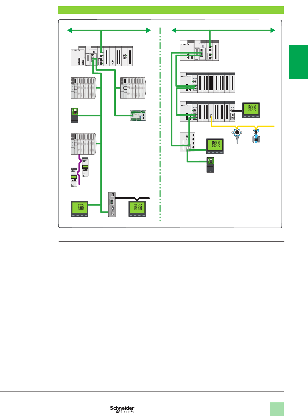
2/13
Architectures Modicon M580 automation
platform
I/O architectures
Example of an architecture
Processors:
page 1/18
Software:
page 4/2
Ruggedized Modicon M580
modules: page 5/2
Example of an architecture for Food & Beverage applications
Control network
Modicon M580
main rack
Modicon M580
main rack
STB I/O island
Motor
protection
ConneXium
managed
switch (DRS)
Motor starter
on CANopen
Power meter
Power meter
Power meter for
energy management
on Modbus SL
Power meter for
energy management
on Modbus SL
Instrumentation on AS-I bus
connected on AS-I master
module embedded in
Modicon X80 Ethernet remote
drop
STB I/O
island
STB I/O island
Variable speed
drive
Variable
speed
drive
Control network
Modicon X80 remote drop
Modicon X80 remote drop
Ethernet
Ethernet
Example of an architecture: Food & Beverage application
Note: These architecture representations are conceptual network diagrams and do not represent actual wiring specications.
Probus
Remote
Master
Architecture with distributed equipment Architecture with remote equipment
2
1
3
4
5
6
7
8
9
10
2
1
3
4
5
6
7
8
9
10
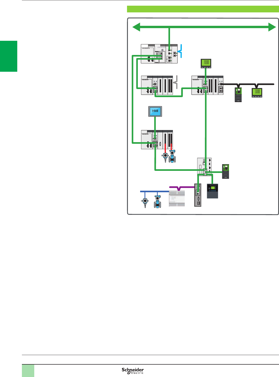
2/14
Architectures Modicon M580 automation
platform
I/O architectures
Example of an architecture
Example of an architecture for a Water application
HMI
Modicon M580
main rack
Remote
Terminal Unit
ConneXium
managed
switch (DRS)
HART
instrumentation
managed by HART
analog I/O modules
embedded
in the rack
Local HMI on Ethernet
SERVICE port of
BMECRA31210 module
Modbus SL
Power meter on Ethernet
SERVICE port of the
BMECRA31210 module
Variable
speed drive
Variable speed drive
Energy
supervision
Supervision
Control network
Modicon
X80 drop
Modicon X80
drop
Modicon
X80 drop
Ethernet
Probus Remote Master
Probus equipment
Hardwired
equipment
Probus PA
Probus DP
Example of an architecture: Water application
Processors:
page 1/18
Software:
page 4/2
Ruggedized Modicon M580
modules: page 5/2
2
1
3
4
5
6
7
8
9
10
2
1
3
4
5
6
7
8
9
10
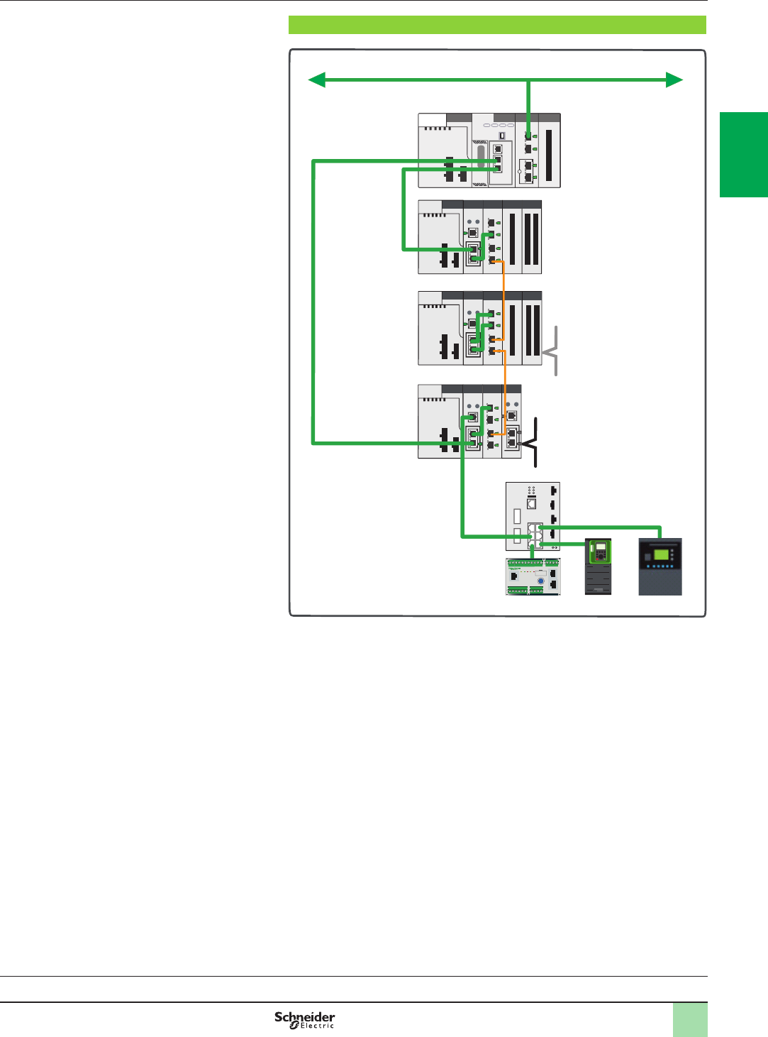
2/15
Example of an architecture: Water application
Architectures Modicon M580 automation
platform
I/O architectures
Example of an architecture
Example of an architecture for a Hydro power application
Distributed equipment
connected to a ConneXium
managed switch (DRS)
mixed on Ethernet RIO main
ring
Modbus SL
Hardwired
equipment
Control network
Modicon M580
main rack
Modicon X80
remote drop
Modicon X80
long distance
remote drop on
optical ber
with embedded
NRP optical
ber modules
Ethernet
Example of an architecture: Hydro power application
Processors:
page 1/18
Software:
page 4/2
Ruggedized Modicon M580
modules: page 5/2
2
1
3
4
5
6
7
8
9
10
2
1
3
4
5
6
7
8
9
10
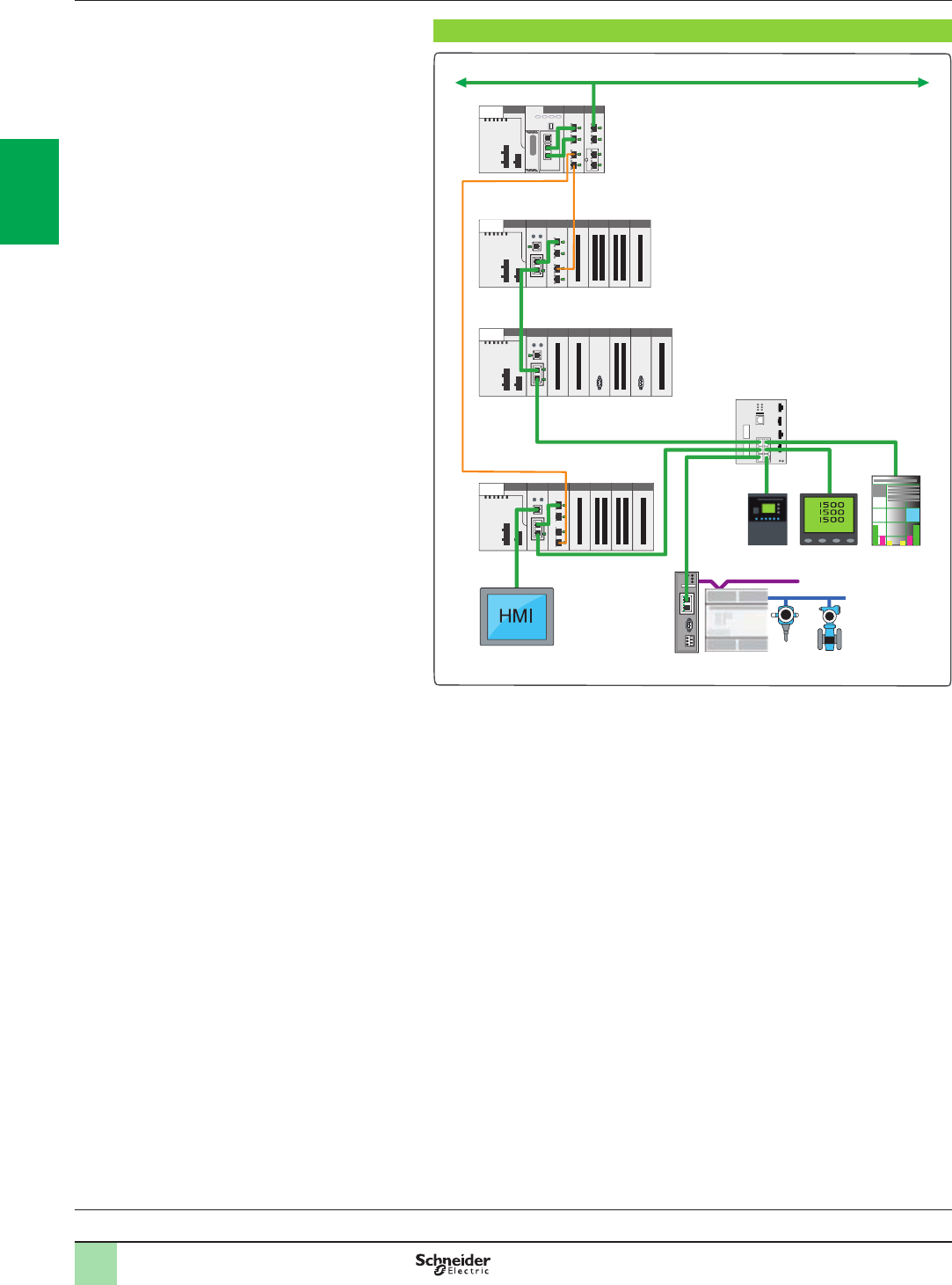
2/16
Architectures Modicon M580 automation
platform
I/O architectures
Example of an architecture
Example of an architecture for a Cement application
HMI
Distributed equipments on Ethernet
Probus equipment
Probus DP
Probus PA
iMCC
Ethernet
Control network
Modicon M580 main rack
Modicon X80 drop
Modicon X80 drop
Modicon X80 drop
Probus
Remote
Master
Local HMI on Ethernet
SERVICE port of BMECRA31210 module
Optical ber
Example of an architecture: Cement application
Processors:
page 1/18
Software:
page 4/2
Ruggedized Modicon M580
modules: page 5/2
2
1
3
4
5
6
7
8
9
10
2
1
3
4
5
6
7
8
9
10
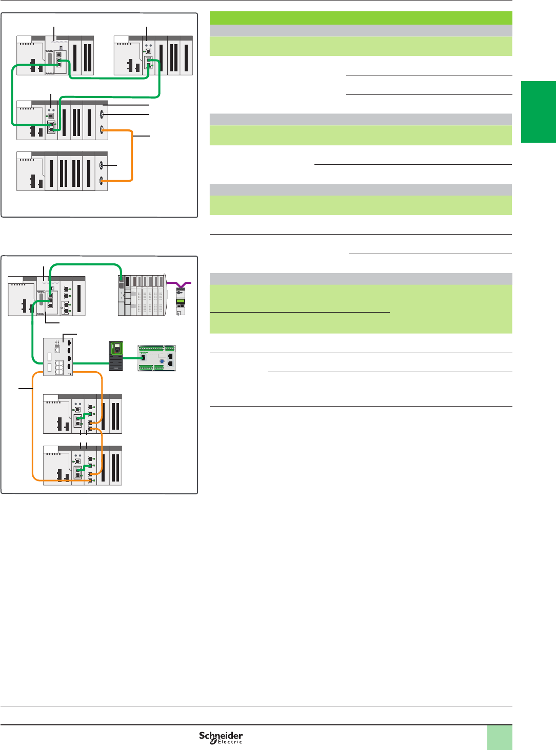
2/17
References Modicon M580 automation
platform
I/O architectures
References (1)
Ethernet head and drop adapters (2)
Description SERVICE
port
Item
(3)
Reference Weight
kg/lb
Modicon X80 EIO drop adapter
Provide 1 module per Modicon X80 EIO
drop
–1BMXCRA31200 0.200/
0.441
11BMXCRA31210 (4) 0.234/
0.516
11BMECRA31210 (4) 0.234/
0.516
Modicon X80 Ethernet RIO drop optical repeaters (2)
Description Optical ber Item
(3)
Reference Weight
kg/lb
Modicon X80 Ethernet RIO
drop optical repeaters
multimode 2BMXNRP0200 0.203/
0.448
single mode 2BMXNRP0201 0.203/
0.448
Ethernet communication modules and cordsets (2)
Description Item
(3)
Reference Weight
kg/lb
Modbus/TCP and EtherNet/IP
network module
3BMXNOC0402 (5) 0.200/
0.441
Ethernet Interlink cables
Length 1 m/3.281 ft
Standard
version
–TCSECN3M3M1S4 –
UL version –TCSECN3M3M1S4U –
Dedicated ConneXium managed switches (5)(6)
Copper port Multimode
optical ber
port
Single mode
optical ber
port
Item
(3)
Reference
(4)
Weight
kg/lb
RJ45 shielded
connectors
Duplex SC connectors
8 x 10/100
BASE-TX ports
–––TCSESM083F23F1 1.000/
2.205
6 x 10/100
BASE-TX ports
2 x 10/100
BASE-FX ports
–4TCSESM063F2CU1 1.000/
2.205
–2 x 10/100
BASE-FX ports
4TCSESM063F2CS1 1.000/
2.205
(1) For additional characteristics, see our website www.schneider-electric.com.
(2) Requires Unity Pro Extra Large software u V8.0 (see page 2/19).
(3) For items 5to 9, see pages 2/18 and 2/19.
(4) Conformal coating version for harsh environments. In this case, add the letter “C” to the end
of the reference.
(5) The BMXNOC0402 communication module will be replaced by the BMENOC03●1 modules
during the 2nd quarter of 2014.
(6) ConneXium managed switches validated for Modicon M580 architectures.
Architecture A + architecture D
Ethernet
X-bus
5 1
1
7
9
8
9
EthernetOptical ber
CANopen
Architecture C + architecture D
6
5
3
4
1 2
Processors:
page 1/18
Software:
page 4/2
Ruggedized Modicon M580
modules: page 5/2
2
1
3
4
5
6
7
8
9
10
2
1
3
4
5
6
7
8
9
10
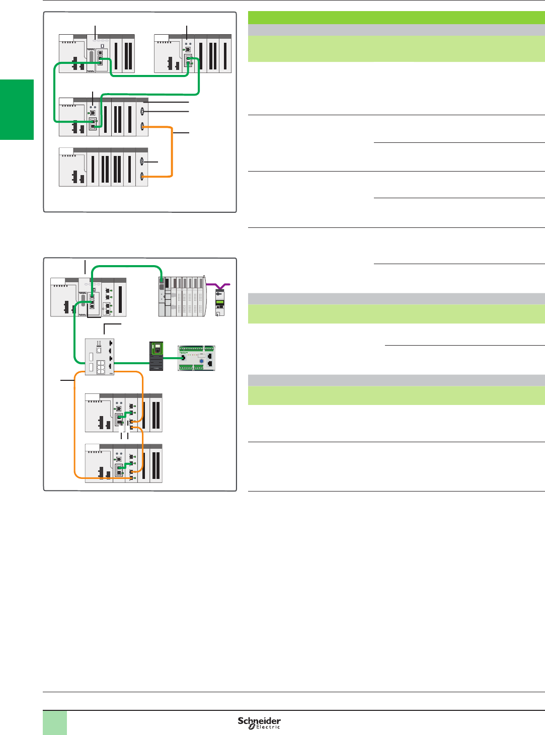
2/18
References
(continued)
Modicon M580 automation
platform
I/O architectures
References (continued) (1)
Modicon M580 processors
I/O capacity Maximum
number of
networks
Device
ports
SERVICE
port
Item
(2)
Reference Weight
kg/lb
1,024 discrete I/O
256 analog I/O
24 application-specic
channels
4 MB integrated
(memory program)
2 Ethernet
networks
2 DIO 15BMEP581020 –
2,048 discrete I/O
512 analog I/O
32 application-specic
channels
8 MB integrated
(memory program)
2 Ethernet
networks
2 DIO 15BMEP582020 –
2 RIO/DIO 15BMEP582040 –
3,072 discrete I/O
768 analog I/O
64 application-specic
channels
12 MB integrated
(memory program)
3 Ethernet
networks
2 DIO 15BMEP583020 –
2 RIO/DIO 15BMEP583040 –
4,096 discrete I/O
1,024 analog I/O
64 application-specic
channels
16 MB integrated
(memory program)
4 Ethernet
networks
2 DIO 15BMEP584020 –
2 RIO/DIO 15BMEP584040 –
Optical ber cable
Description Length
m/ft
Item
(2)
Reference Weight
kg/lb
62.5/125 μm multimode optical ber
cables
equipped with MT-RJ connectors
For interconnection of the Ethernet port on
the CPU or BMECRA adapter 1
3/9.843 6490NOR00003 –
5/16.404 6490NOR00005 –
Rack extension for Modicon X80 drop
Description Item
(2)
Reference Weight
kg/lb
Modicon X80 rack expansion module
Standard module for mounting in each rack
(XBE slot) and allowing the interconnection
of 2 racks max.
7
BMXXBE1000
0.178/
0.392
Modicon X80 rack expansion kit
Complete kit for 2-rack conguration comprising:
- 2 BMXXBE1000 rack expansion modules
- 1 BMXXBC008K extension cordset, length 0.8 m/2.625 ft
- 1 TSXTLYEX line terminator (pack of 2)
7
8
9
BMXXBE2005
0.700/
1.543
(1) For additional characteristics, see our website www.schneider-electric.com.
(2) For items 1 to 4, see page 2/17.
EthernetOptical ber
CANopen
Architecture C + architecture D
6
4
5
3
1 2
Architecture A + architecture D
Ethernet
X-bus
5 1
1
7
9
8
9
Processors:
page 1/18
Software:
page 4/2
Ruggedized Modicon M580
modules: page 5/2
2
1
3
4
5
6
7
8
9
10
2
1
3
4
5
6
7
8
9
10

2/19
References
(continued)
Modicon M580 automation
platform
I/O architectures
References (continued) (1)
Description Type of connector Length
m/ft
Item
(2)
Reference Weight
kg/lb
X-bus preformed extension
cordsets with two 9-pin SUB-D
connectors
Elbowed 0.8/2.625 8
BMXXBC008K
0.165/
0.364
1.5/4.921 8
BMXXBC015K
0.250/
0.551
3/9.843 8
BMXXBC030K
0.420/
0.926
5/16.404 8
BMXXBC050K
0.650/
1.433
12/39.370 8
BMXXBC120K
1.440/
3.175
Straight 1/3.281 8
TSXCBY010K
0.160/
0.353
3/9.843 8
TSXCBY030K
0.260/
0.573
5/16.404 8
TSXCBY050K
0.360/
0.794
12/39.370 8
TSXCBY120K
1,260/
2.778
18/59.055 8
TSXCBY180K
1,860/
4.101
28/91.864 8
TSXCBY280KT
(3)
2.860/
6.305
Description Use Length
m/ft
Item
(2)
Reference Weight
kg/lb
Cable on reel
Cable with free ends, 2 line testers
To be tted with 2 TSXCBYK9
connectors
100/328.084 –
TSXCBY1000
12,320/
27.161
Description Use Sold in
lots of
Item
(2)
Reference Weight
kg/lb
Line terminator
2 x 9-way SUB-D connectors
marked
A/ and /B
Required on the
2 BMpXBPppp0 modules
located at either end of the
daisy chain
29
TSXTLYEX
0.050/
0.110
Bus X straight connectors
2 x 9-way SUB-D connectors
For TSXCBY1000 cable ends 2–
TSXCBYK9
0.080/
0.176
Connector installation kit
2 crimping pliers,
1 pen (4)
Fitting TSXCBYK9
connectors
– –
TSXCBYACC10
–
Requirements for a Modicon M580 Ethernet I/O architecture (1)
The table below gives the minimum hardware and software requirements for setting up a Modicon M580 I/O
architecture.
Description of the hardware or software required Reference Version Item
(2)
Unity Pro Extra Large software UNISPUEFpCD80 u 8.0 –
Modicon X80 RIO drop adapter BMECRA31210 u 2.0 1
BMXCRA31200 u 2.0 1
BMXCRA31210 u 2.0 1
Modicon X80 NRP EIO drop optical repeaters BMXNRP0200 –2
BMXNRP0201 –2
ConneXium managed switches TCSESM083F23F1 Firmware u 6.0 4
TCSESM063F2CU1 Firmware u 6.0 4
TCSESM063F2CS1 Firmware u 6.0 4
M580 CPUs BMEP581020 Firmware u 1.0 5
BMEP582020 Firmware u 1.0 5
BMEP582040 Firmware u 1.0 5
BMEP583020 Firmware u 1.0 5
BMEP583040 Firmware u 1.0 5
BMEP584020 Firmware u 1.0 5
BMEP584040 Firmware u 1.0 5
(1) For additional characteristics, see our website www.schneider-electric.com.
(2) For items 1 to 4, see page 2/17; 5 to 7, see page 2/18.
(3) Cable supplied with a set of 2 TSXTVSY100 electrical transient suppressors.
(4) Installation of connectors on the cable also requires a wire stripper, a pair of scissors and a digital ohmmeter.
Processors:
page 1/18
Software:
page 4/2
Ruggedized Modicon M580
modules: page 5/2
2
1
3
4
5
6
7
8
9
10
2
1
3
4
5
6
7
8
9
10
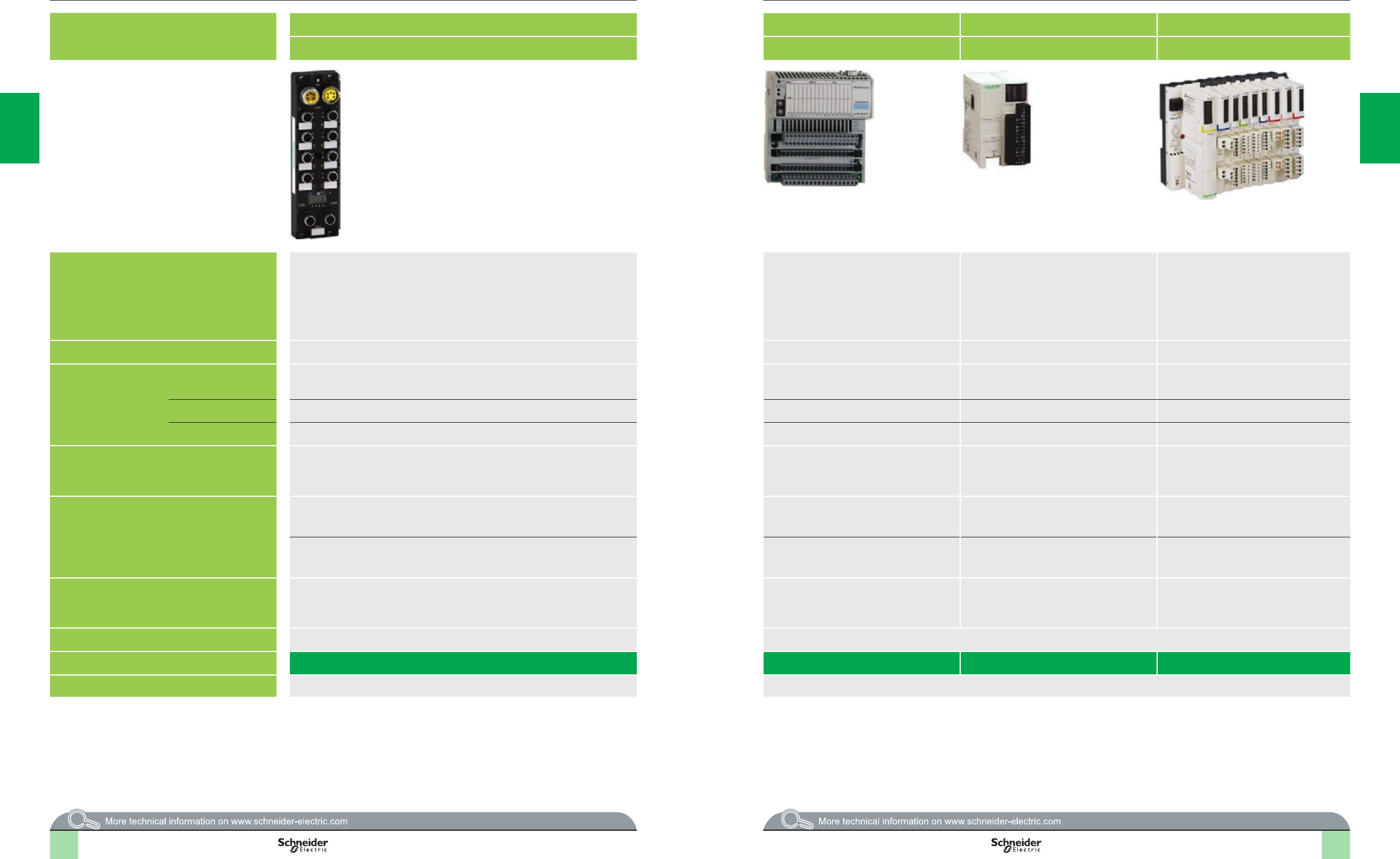
2
1
3
4
5
6
7
8
9
10
2
1
3
4
5
6
7
8
9
10
2
1
3
4
5
6
7
8
9
10
2
1
3
4
5
6
7
8
9
10
2/20 2/20
Type of splitter box and module Monobloc IP 67 I/O splitter boxes Monobloc IP 20 distributed I/O Optimum IP 20 distributed I/O Modular IP 20 distributed I/O
Modicon ETB Modicon Momentum Modicon OTB Modicon STB
Available buses and
networks
Ethernet Modbus TCP/IP
EtherNet/IP
Ethernet Modbus TCP/IP
Modbus Plus
Fipio
InterBus
Probus DP
DeviceNet
Ethernet Modbus TCP/IP
CANopen
Modbus (RS 485)
Ethernet Modbus TCP/IP
EtherNet/IP
CANopen
Modbus Plus
Fipio
InterBus
Probus DP
DeviceNet
Max. number per connection point 1 I/O base with 1 CPU or 1 communication module 1 interface module + 7 Twido expansion modules 1 NIM (Network Interface Module) + 32 I/O modules
Discrete I/O Modularity Splitter box with 16 congurable I/O, 16 I, 12 I + 4 O, or 8 I + 8 O I/O base with 16 I, 32 I, 8 O, 16 O, 32 O, 10 I/8 O,
16 I/8 O, 16 I/12 O and 16 I/16 O
12 I/8 O (interface module)
8 I, 16 I, 32 I, 8 O, 16 O, 32 O, 4 I/4 O and 16 I/8 O
(expansion modules)
Module with 2 I, 4 I, 6 I, 16 I, 2 O, 4 O, 6 O or 16 O
Input voltage 24 V c24 V c, 120 V a and 230 V a24 V c24 V c, 115 V a and 230 V a
Output voltage 24 V c24 V c V, 120 V a and 230 V a and relay 24 V c and relay 24 V c, 115/230 V a and relay
Analog I/O –8 I, 16 I or 4 O voltage/current I/O bases
I/O base with 4 thermocouple or probe inputs
2 I, 4 I, 8 I, 1 O, 2 O, 2 I/1 O and 4 I/2 O
(expansion modules)
voltage/current, thermocouple or
temperature probe
Modules with 2, 4 or 8 inputs and 1 or 2 outputs
(voltage/current)
Module with 2 thermocouple or probe inputs
Application-specic I/O –10 kHz/200 kHz 2-channel counter sub-base Integrated in interface module:
- Two 5 kHz/20 kHz channels
- 2 PWM function channels
Counter module with one 40 kHz channel
HART multiplexer module
- 4 HART channels per HART multiplexer module
- Up to 8 HART multiplexer modules per island
–6 I/3 O 120 V a sub-base with 1 Modbus port –Parallel interface modules for TeSys Quickt and
TeSys U motor starters, integrated connection for
third-party CANopen products
I/O connection M12 connectors Screw or spring-type removable terminal blocks Removable screw terminal block (interface module)
Removable screw terminal block, non-removable
spring-type terminal block and HE 10 connector
(expansion modules)
Removable screw or spring-type connectors,
Telefast connectors
Type of housing Plastic Plastic
Type of module ETB1Eppp 170ApOTB1p0DM9LP STBppp
Pages Please consult the catalog pages on our website www.schneider-electric.com Please consult the catalog pages on our website www.schneider-electric.com
Modicon distributed I/O solutions
Selection guide
2/20 2/21
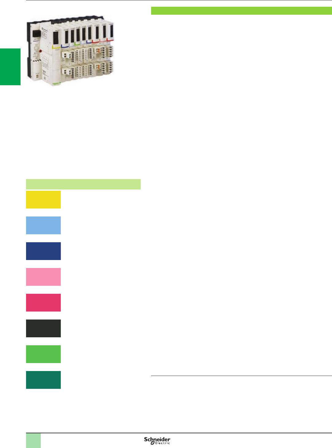
2/22
Presentation (1)
To meet the needs of machine manufacturers and users, automation architectures
have been decentralized while delivering performance close to that of centralized
systems.
Architectures based around islands installed as close to the machine as possible
reduce the time and cost of wiring for sensors and actuators, while increasing
system availability.
The Modicon STB distributed I/O solution is an open, modular input/output system
that makes it possible to design automation islands managed by a master controller
via a bus or communication network.
These islands can be used to connect:
bTeSys U or TeSys T starter-controllers
bAltivar variable speed drives
bFTB IP 67 distributed I/O
bOsiSense rotary encoders
bMagelis operator dialog terminals
bApproved third-party products via the CANopen bus: Bosch, Festo, Parker
solenoid valves, Balluff linear encoders, etc. (1)
Advantys software guides users through the design phase, start-up, and even
maintenance of the system. This single software package covers the Modicon STB,
OTB, FTB, and FTM ranges.
The island components are electronic modules mounted on one or more DIN rails.
These clusters of modules, known as segments, carry a bus from beginning to end of
each island. The island bus provides power distribution, signal sensing, and power
management to compatible modules, in the form of a wiring management system.
The Modicon STB I/O family is divided into 2 groups of modules:
bBasic modules: A complete set of low-cost modules, with simplied operating
modes
bStandard modules: An expanded offer of I/O modules, with additional functions:
Congurable parameters, expanded operating modes
The basic range comprises:
bPDM power distribution modules (24 V c and 115/230 V a)
bI/O modules:
vDiscrete I/O (24 V c)
vAnalog I/O (10-bit resolution)
The standard range comprises:
bNIM modules: network interfaces
bPDM power distribution modules (24 V c and 115/230 V a)
bI/O modules:
vDiscrete I/O (24 V c and 115/230 V a)
vAnalog I/O (10, 12 and 16-bit resolution)
vRelay outputs (24 V c coil and 24 V c contact or 115/230 V a)
bApplication module: Counter module, HART multiplexer module
bDedicated module: For TeSys U and TeSys Quickt applications
bEOS end of segment and BOS beginning of segment modules
bExternal equipment support module on CANopen expansion module
Standard and basic modules can be combined on the same island. Combining them
in this way allows a wide range of functions (1).
The sensors and actuators are connected to the I/O modules via removable screw or
spring-type terminals (2).
Standard Modicon STB I/O modules are hot-swappable, provided the network
interface modules are also standard type.
Modicon STB distributed I/O islands have a protection rating of IP 20. For
installations in production workshops, they must be housed in enclosures providing
at least IP 54 (complying to IEC 60950 or NEMA 250) (1).
(1) For further information, please consult our “Modicon STB IP 20 distributed I/O” catalog
available on our website www.schneider-electric.com.
(2) For much easier wiring and to free up space in the electrical cabinet, Modicon STB
16-channel discrete I/O modules can be combined with Modicon Telefast ABE 7 pre-wired or
adapter blocks.
Presentation Modicon STB distributed I/O
solution
Open and modular system
Color code Type of module
NIM network interface
EOS/BOS island expansion
CANopen expansion
24 V c discrete inputs
24 V c supply distribution
24 V c discrete outputs
115 V a or 230 V a discrete current inputs
115/230 V a supply distribution
115/230 V a discrete current outputs
Discrete relay outputs
TeSys U and TeSys Quickt interface,
counter module
Analog inputs
Analog outputs
2
1
3
4
5
6
7
8
9
10
2
1
3
4
5
6
7
8
9
10
2
1
3
4
5
6
10
2
1
3
4
5
6
10
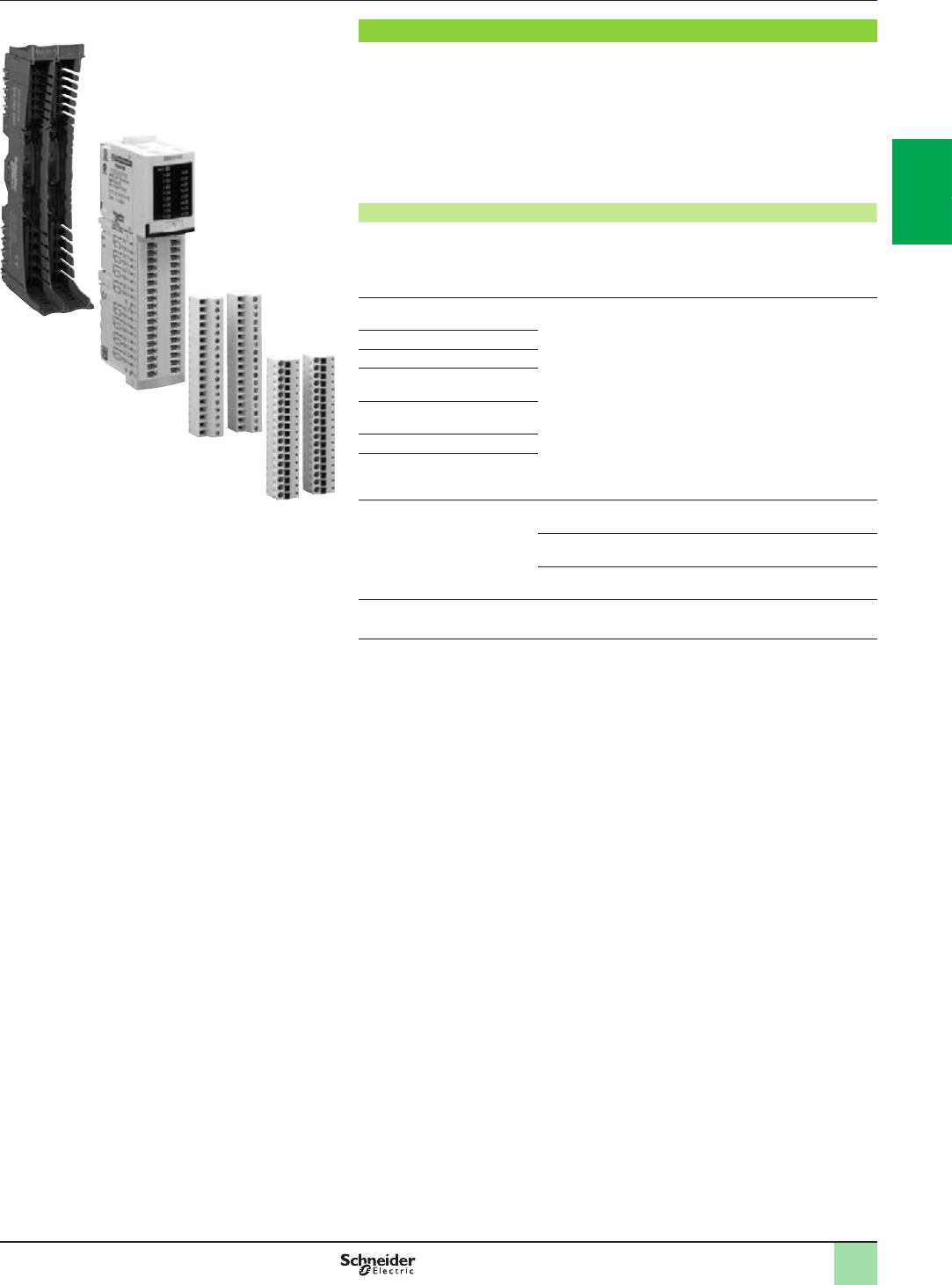
2/23
Description Modicon STB distributed I/O
solution
Open and modular system
Modicon STB modules (1)
The Modicon STB module references allow you to acquire the following items under
a single reference:
bA module
bIts base
bThe appropriate screw-type and/or spring-type connectors
The following table gives the contents of the Modicon STB modules and the
general form of their references (1).
Module Contents Reference (1)
NIM network interface Module, screw-type and spring-type
connectors (base not required), bus
terminator, documentation on mini
CD-ROM (2) (3)
STBNpppppp
Power distribution module
(PDM)
Base, module,
screw-type and spring-type connectors
STBpppppppK
Discrete I/O (except 16-channel)
Analog I/O
EOS and BOS island bus
expansion module
CANopen bus expansion
module
Auxiliary power supply
TeSys U and TeSys Quickt
interface
Discrete I/O 16-channel Base, module, screw-type connectors STBDDp37p5KS
Base, module, spring-type connectors STBDDp37p5KC
Module (4) STBDDp37p5
Counting Base, module, spring-type connectors STBEHC3020KC
(1) For further information, please consult our “Modicon STB IP 20 distributed I/O” catalog
available on our website www.schneider-electric.com.
(2) DeviceNet STBNDNpppp NIM network interface module: order the 5-way screw and
spring-type removable terminals (eldbus connection) separately (1).
(3) An English language mini-CD-ROM containing the user documentation, a label template and
one exchange le per network type. The user documentation is also available on our website
www.schneider-electric.com.
(4) For use with the Modicon Telefast ABE 7 pre-wired or adapter system:
- STBXBA3000 base to be ordered separately (1)
- Telefast ABE 7 base and connection accessories to be ordered separately (1)
Base
Module
Screw-type
connectors
Spring-type
connectors
2
1
3
4
5
6
7
8
9
10
2
1
3
4
5
6
7
8
9
10
2
1
3
4
5
6
7
8
9
10
2
1
3
4
5
6
7
8
9
10

2/24
Composition Modicon STB distributed I/O
solution
Open and modular system
Composition of a Modicon STB island (1)
A Modicon STB island is made up of one or more segments comprising PDMs
(Power Distribution Modules) and I/O modules.
The island begins with a NIM network interface module and ends with a bus
terminator supplied with the NIM.
An island can be made up of a single segment or a primary segment and up to
6 expansion segments.
The island’s segments are chained by EOS (End Of Segment) and BOS (Beginning
Of Segment) internal bus expansion modules.
On each segment:
bPlace the PDMs immediately to the right of the network interface modules or
expansion modules.
bPlace the I/O modules to the right of the PDM module supplying them
with power.
bEach module (with the exception of the NIM network interface module), is held
in a xing base on the DIN rail.
Three module and base widths are possible. On the DIN rail, the overall width
needed for a segment is the sum of widths of the network interface module, the
bases and any bus terminator.
The bases provide continuity of the internal bus, auto-addressing of the modules,
and separated and isolated distribution of the internal power supplies, actuators
(outputs) and sensors (inputs).
The advantages of this arrangement are:
bUnplugging modules:
vWhen switched off (cold swap), modules can be unplugged very quickly
vWhen switched on (hot swap), I/O modules can be unplugged provided the
network interface module is the standard type
bOutput power supply independent of inputs: For example, if an output power
supply is cut by a Preventa module, the inputs are still managed.
bImmunity of inputs: For example, the closing of power contactors (controlled by
outputs) does not disturb analog input measurements.
Network Interface Module (NIM):
This module manages communications on the island bus. It acts as a gateway for
exchanges with the eldbus or network master.
Various NIM network interface modules (only standard type) are available
for the following major eldbuses or industrial networks:
bEthernet Modbus TCP/IP: Single or double port Network Interface Modules
bEtherNet/IP, Modbus Plus and Fipio: Only standard type NIM network
interface modules
bCANopen, InterBus, Modbus Plus, Fipio, Probus DP and DeviceNet
(1) For further information, please consult our “Modicon STB IP 20 distributed I/O” catalog
available on our website www.schneider-electric.com.
2
1
3
4
5
6
7
8
9
10
2
1
3
4
5
6
7
8
9
10
2
1
3
4
5
6
10
2
1
3
4
5
6
10
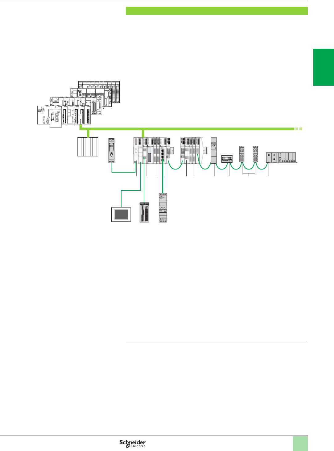
2/25
Congurations Modicon STB distributed I/O
solution
Open and modular system
Control system conguration example (1)
NIM network interface modules STBNpp2p1p, located at the beginning of each
island, are gateways for exchanging data between the network or bus master PLC
and the Modicon STB automation island.
Standard NIM network interface modules STBNpp2p1p can be used to congure
and address the installation external devices. These settings are stored in the
module’s internal RAM or Flash memory. Optionally, they can be saved to the 32 KB
removable SIM card STBXMP4440 (except for the address of the network
connection point) to duplicate the conguration from one island to another.
The control system conguration in the above example comprises:
1 Modicon M580/M340/Premium/Quantum automation platform
2 24 V c external power supply
3 HMI terminal with Magelis XBT, XBT G, XBT GT, etc, type Modbus link (1)
4 Network Interface Module (NIM)
5 Power Distribution Module (PDM)
6 I/O modules
7 Second STB segment
8 Another control system
9 Parallel interface module for TeSys U and TeSys Quickt starter-controllers
10 Congurable Preventa XPS MC safety controller connected on the power supply
to the outputs of power distribution module STBPDTp100K
11 ATV 32 variable speed drive
12 Festo solenoid valves
13 Modicon FTB IP 67 I/O
14 Parker solenoid valves
15 TeSys U starter-controller
(1) For further information, please consult our “Modicon STB IP 20 distributed I/O” catalog
available on our website www.schneider-electric.com.
1
8
14911
6124
3
2
135
7
6
10
5
15
(1)
2
1
3
4
5
6
7
8
9
10
2
1
3
4
5
6
7
8
9
10
2
1
3
4
5
6
7
8
9
10
2
1
3
4
5
6
7
8
9
10

3/0
2
1
3
4
5
6
7
8
9
10
2
1
3
4
5
6
7
8
9
10

3/1
Contents
Communication selection guide................................page 3/2
PlantStruxure Ethernet architectures
b Architecture ...........................................................................................page 3/6
b Industrial Ethernet communication services ......................................page 3/8
v Presentation ............................................................................................ page 3/8
v Functions................................................................................................. page 3/9
b Performance ........................................................................................page 3/14
b Embedded web pages .........................................................................page 3/20
b Modbus/TCP and EtherNet/IP network module.................................page 3/24
v Presentation, functions, description....................................................... page 3/24
v References ............................................................................................ page 3/25
Web servers and gateways selection guide .....................page 3/26
Other buses and networks
b Modbus Plus Proxy module................................................................page 3/28
v Presentation .......................................................................................... page 3/28
v References ............................................................................................ page 3/29
b Probus Remote Master module........................................................page 3/30
v Presentation .......................................................................................... page 3/30
v References ............................................................................................page 3/31
3 - Communication
2
1
3
4
5
6
7
8
9
10
2
1
3
4
5
6
7
8
9
10
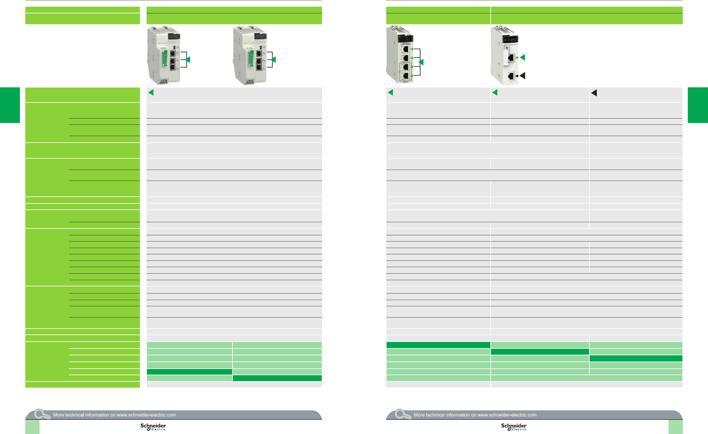
Selection guide Modicon M580 automation
platform
Communication, integrated ports and modules
Applications Ethernet communication Ethernet communication RTU communication
Type of device Processors with integrated
Modbus/TCP port
Ethernet modules RTU module
Network protocols EtherNet/IP and Modbus/TCP EtherNet/IP and Modbus/TCP Modbus/TCP, IEC 60870-5-104,
DNP3 (subset level 3)
Serial link, external modem link,
IEC 60870-5-101, DNP3 (subset level 3)
Structure Physical interface 10BASE-T/100BASE-TX 10BASE-T/100BASE-TX 10BASE-T/100BASE-TX (Modbus/TCP),
PPPoE (Point-to-Point Protocol over Ethernet) for
ADSL external modem link
Non-isolated RS 232/485 (serial link),
Non-isolated RS 232 (Radio, PSTN, GSM,
GPRS/3G external modem link)
Type of connector RJ45 Four RJ45 connectors (2 connectors for a ring topology) One RJ45 connector One RJ45 connector
Access method CSMA-CD CSMA-CD CSMA-CD (Modbus/TCP),
Master/slave (IEC 104/DNP3)
Master/slave (IEC 101/DNP3)
Data rate 10/100 Mbps 10/100 Mbps 10/100 Mbps (Modbus/TCP) 0.3…38.4 Kbps (serial link)
Medium Double twisted pair copper cable, category CAT 5E
Optical ber via ConneXium cabling system
Double twisted pair copper cable, category CAT 5E, optical ber via ConneXium cabling system Double shielded twisted pair copper cable,
Crossover serial cable (serial link),
Direct serial cable (external modem link)
Conguration Maximum number of devices –128 (EtherNet/IP or Modbus/TCP) 128 (Modbus/TCP),
64 slaves/servers (IEC 104/DNP3)
32 max.
Max. length
100 m/328.08 ft (copper cable), 4,000 m/13,123.32 ft (multimode optical ber),
32,500 m/106,627 ft (singlemode optical ber) (1)
100 m/328.08 ft (copper cable), 4,000 m/13,123.32 ft (multimode optical ber),
32,500 m/106,627 ft (singlemode optical ber)
1,000 m/3,280.83 ft (serial link with insulating
case)
Number of modules of the same type
per station
1Up to 4 Ethernet modules per station depending on
processor
2 RTU modules per station with any BMEP58
processor
Depending on application-specic channels
(20/36 application-specic channels with
BMEP58p0p0)
Standard services Modbus/TCP messaging and EtherNet/IP services EtherNet/IP and Modbus/TCP messaging Modbus/TCP messaging Reading/writing discrete and analog I/O, counters
Transparent Ready conformity class – – C30 –
Embedded Web
server services
Standard services Status Summary, Performance, Port Statistics, I/O Scanner, Quality of Service (QoS),
Messaging, Network Time Service, Redundancy, and Alarm Viewer
Status Summary, Performance, Port Statistics, I/O Scanner, Quality of Service (QoS), Network Time Service,
Messaging
–
Advanced services – – Hosting and display of user Web pages –
Transparent Ready
communication
services
I/O Scanning service –Yes –
Global Data service – – –
NTP time synchronization Yes –Yes
FDR service Yes (server) Yes (server) Yes (client) –
SMTP e-mail notication service – – Ye s –
SOAP/XML Web service – – Server –
SNMP network management service Yes Yes Yes (agent) –
RSTP redundancy service Yes Yes –
QoS (Quality of Service) service Yes Yes –
RTU communication
services
IEC 60870-5-104,
DNP3 IP or
IEC 60870-5-101,
DNP3 serial
Master or Slave conguration – – Yes, IEC101/104 and DNP3
Time and date stamped data exchange – – Interrogation via polling and exchanges on change of status (RBE), unsolicited messaging
RTU time synchronization – – Yes, IEC101/104 and DNP3
Management and buffering of time
and date stamped events
– – Yes, IEC101/104 and DNP3
Automatic transfer of time and date
stamped events to the Master/SCADA
– – Yes, IEC101/104 and DNP3
Buffer holding 10,000 events (per connected client, 4 clients max.)
Data Logging service – – Yes, on SD 128 MB memory card, in CSV les, access via FTP or sent by e-mail
Compatibility with processor –All Modicon M580 processors
Processor or module
references depending
on other type of
integrated port (2)
None BMXNOC0402
Serial link BMXNOR0200H
Ethernet Modbus/TCP BMXNOR0200H
CANopen
DIO service BMEP58p020
DIO and RIO services BMEP58p040
Page 1/23 3/25 Please consult the “Modicon X80 I/O platform” catalog available on our website www.schneider-electric.com
(1) Fiber requires use of other products (for example, an Ethernet switch or the BMXNRP020p module) to convert from the twisted pair connectors (RJ45) that these
products have.
(2) CANopen can be used, but it is necessary to use Modicon STB I/Os. Please consult the “IP 20 distributed inputs/outputs - Modicon STB” catalog available on our
website www.schneider-electric.com.
3 33 3
3/2 3/23/2 3/3
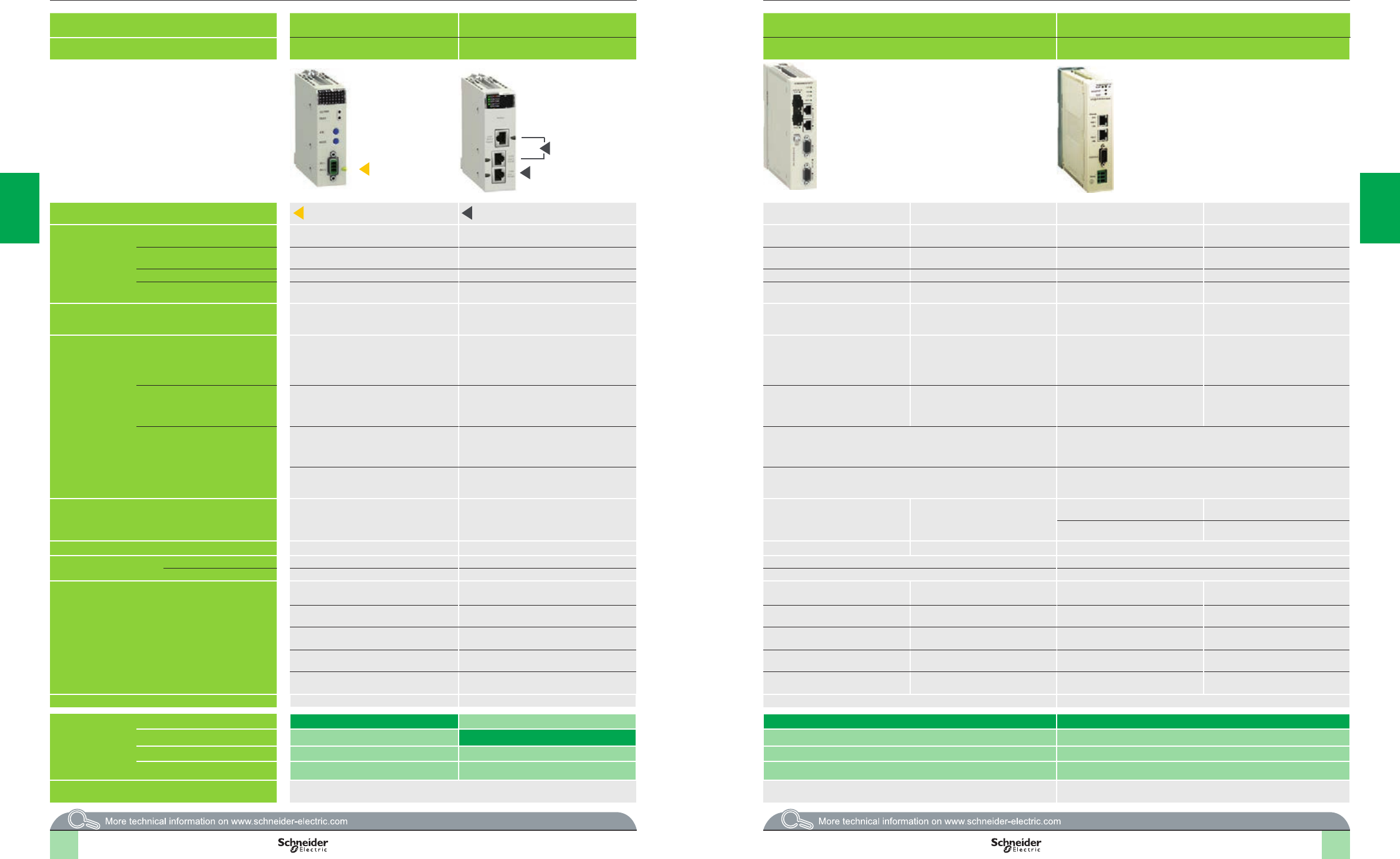
Selection guide (continued) Modicon M580 automation
platform
Communication, integrated ports and modules
Applications AS-Interface
communication
Serial link communication Modbus Plus communication Probus DP and Probus PA communication
Type of device AS-Interface
actuator/sensor bus module
2-channel serial link
module
Modbus Plus proxy module (external) Probus Remote Master (PRM) module (external)
Network protocols AS-Interface Modbus and Character mode Ethernet Modbus/TCP Modbus Plus Ethernet Modbus/TCP Probus DP V1
Probus PA (via gateway)
Structure Physical interface AS-Interface V3 standard Non-isolated RS 232, 8-wire
Isolated RS 485, 2-wire
10/100BASE-T Modbus Plus standard 10BASE-T/100BASE-TX Isolated RS 485
Type of connector 3-way SUB-D 2 RJ45 and 1 RJ45 Two RJ45 connectors Two 9-way female SUB-D connectors Two RJ45 connectors (supporting
daisy chain topology)
One 9-way female SUB-D connector
Access method Master/slave CSMA-CD Token ring CSMA-CD Master/slave
Data rate 167 Kbps 0.3...115.2 Kbps in RS 232
0.3...57.6 Kbps in RS 485
10/100 Mbps 1 Mbps 10/100 Mbps 9.6 Kbps...12 Mbps
Medium Two-wire AS-Interface cable Shielded twisted pair copper cable Double shielded twisted pair copper
cable, category CAT 5E (direct or
crossover)
Twisted pair copper cable Double shielded twisted pair copper
cable, category CAT 5E (direct or
crossover)
Shielded twisted pair copper cable
Conguration Maximum number of devices 62 slaves 2 per drop, 16 per Ethernet remote I/O (RIO)
network max.
128 32 per segment
64 for all segments
Several PRMs can be connected to the
Ethernet port on the M580, M340,
Premium or Quantum PLC, as long as
the I/O Scanner capacity is not
exceeded
125 slaves
Max. length 100 m/328.08 ft,
500 m/1,640.42 ft max. with 2 repeaters
15 m/48.21 ft with non-isolated RS 232,
1,000 m/3,280.83 ft with non-isolated RS 485
100 m/328.08 ft 450 m/1,476.37 ft per segment
1,800 m/5,905.49 ft with 3 repeaters
100 m/328.08 ft (copper) 1,200 m/3,936.99 ft (9.6 Kbps),
4,800 m/15,747 ft with 3 repeaters,
100 m/328.08 ft (12 Mbps),
400 m/1,312.33 ft with 3 repeaters
Number of links of the same type per
station
All M580 processors:
4 AS-Interface modules
All M580 processors:
36 application-specic channels
(1 application-specic channel = 1 counter,
motion control module or serial link channel)
1 max. –
BMECRA31210 Ethernet drop adapter:
2 AS-Interface modules
36 application specic channels max.
2BMXNOM0200 modules per BMECRA31210
Ethernet drop adapter
– –
Standard services Transparent exchanges with the sensors/
actuators
Read/write bits and words, diagnostics in
Modbus mode
Send and receive character string in Character
mode
Modbus/TCP messaging Modbus Plus messaging Modbus/TCP messaging Cyclic and acyclic data exchange with
slaves
Transparent Ready Class A20 Class 1 and Class 2
Conformity class M4 prole – – – –
Embedded Web server
service
Standard service – – Conguration, diagnostics –
Advanced services – – – –
Communication services – – Modbus Plus server (scanned by the
PLC)
Reading/writing variables Modbus server (scanned by the PLC) Master/slave communication
– – FDR service Global database FDR service Global Control service
– – SNMP agent network management
service
Peer Cop service SNMP agent network management
service
Acyclic communication (read/write) in
Class 1 and Class 2
– – –––Support for extended diagnostics
– – –––Auto-scanning service of slaves on the
bus
24 V c external power supply – – 19.2…31.2 V 18…30 V
Type of processor or
module depending
on other integrated
port
None BMXEIA0100 TCSEGDB23F24FA TCSEGPA23F14F
Serial link BMXNOM0200
Ethernet Modbus/TCP
CANopen
Page Please consult the “Modicon X80 I/O platform” catalog available on our website
www.schneider-electric.com
3/29 3/31
3 33 3
3/3 3/33/4 3/5
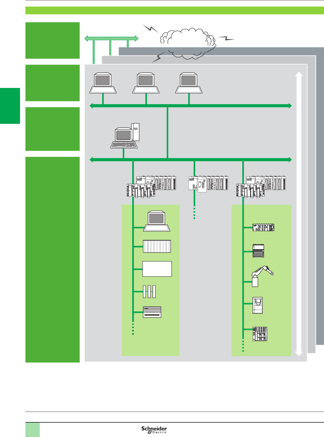
3/6
Premium
Architecture Modicon M580 automation
platform 0
PlantStruxure Ethernet architectures
Logical communication architecture
Logical communication architecture
Company
Enterprise
Factory
Workshop
MES: Manufacturing Execution System (production management system)
ERP: Enterprise Resource Planning (integrated management software packages)
IHM/SCADA: Human/Machine Interface and Supervision Control And Data Acquisition
Gateway: Gateway to sensor/actuator bus, to installed base network, eldbus, etc.
INPUT
OUTPUT
+
–
INPUT
OUTPUT
+
–
A
B
A
B
Collaborative
Automation
Partner Program
Internet
Site 1
Site 2
Site 3
MES ERP
Unix Windows Linux
HMI + SCADA
Industrial PC
M580 M580
Modicon M340
M580
Momentum M1E
Robot
Variable speed
drive
Modicon STB I/O
Workshop 2
Workshop 1
Distributed I/O
Gateway
PLC
HMI
Premium
Intranet
Ethernet Modbus/TCP and EtherNet/IP
Processors:
page 1/18
I/O architectures:
page 2/2
Software:
page 4/2
Ruggedized Modicon M580
modules: page 5/2
Premium
2
1
3
4
5
6
7
8
9
10
2
1
3
4
5
6
7
8
9
10
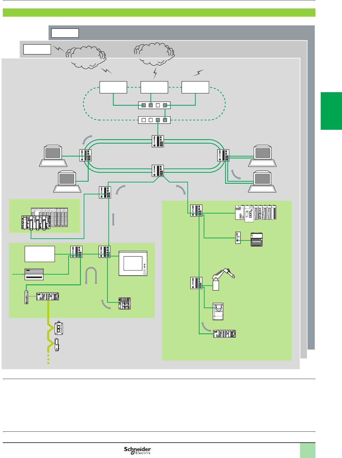
3/7
Architecture (continued) Modicon M580 automation
platform 0
PlantStruxure Ethernet architectures
Physical communication architecture
Processors:
page 1/18
I/O architectures:
page 2/2
Software:
page 4/2
Ruggedized Modicon M580
modules: page 5/2
Physical communication architecture
(1) As a general rule, dening several collision domains can increase the size of the architecture and improve performance (see pages 8/2 to 8/7).
INPUT
OUTPUT
+
–
INPUT
OUTPUT
+
–
A
B
A
B
Collaborative
Automation
Partner Program
Public telecommunications
network, ADSL
Site 1
210 m/
688.97 ft
max.
Switch
100 m/
328.08 ft
max.
Switch Redundant ber optic ring ERP
MES
Specialized link
Frame Relay
ATM
Switches (VLAN)
or routers
Switch
100 m/
328.08 ft
max.
3,100 m/
10,170.57 ft
max.
Collision domain 2
Switch
Switch
Site 3
Router
Site 2
Router
WAN
Provider
Router Firewall
Quantum Modicon M580
Premium
Modicon M340
Modicon M340
Switch Switch
Collision domain 3 (1)
AS-Interface bus
Altivar 71
Momentum
M1E
Transceiver
Magelis iPC
Vijeo Designer
Third-party device
Gateway
Modicon STB
Switch
Switch
RAS
100BASE-FX
Collision domain 1
Full Duplex Half Duplex
100BASE-TX
Optical
bers
Internet
Provider
Robot
100 m/
328.08 ft
max.
100 m/
328.08 ft
max.
100 m/
328.08 ft max.
2
1
3
4
5
6
7
8
9
10
2
1
3
4
5
6
7
8
9
10

3/8
Presentation
Presentation
PlantStruxure Ethernet architectures provide transparent communication services to
the entire operation through the implementation of standard, unmodied Ethernet
protocols and services.
Transport
Network
Data link
physical
Modbus
Modbus/TCP
HTTP
Web pages
TCP
IGRP
QoS
SMTP
E-mail
CIP
EtherNet/IP
SNMP
Diagnostoics
UDP
IGMP
RSTP
ICMP
IEEE 802.3 AND Ethernet
IP
TFTP
DHCP
FDR
In addition to the typical Ethernet services (HTTP, BOOTP, DHCP, etc.) Ethernet
communication modules are equipped with automation-specic services, such as:
b Device scanning using Modbus TCP and EtherNet/IP
b Messaging using Modbus TCP and EtherNet/IP
b Automatic replacement device conguration using FDR (Fast Device replacement)
b Extensive diagnostics through SNMP
b Clock synchronization using NTP
b E-mail alarm notication via SMTP
b Packet prioritization using QoS
b Ring topology redundancy through RSTP
Note: The above services may not be offered in all devices. Please refer to the Selection Guide
and Reference pages for a comprehensive list of the services offered by each device.
Modicon M580 automation
platform
PlantStruxure Ethernet architectures
Industrial Ethernet communication services
Processors:
page 1/18
I/O architectures:
page 2/2
Software:
page 4/2
Ruggedized Modicon M580
modules: page 5/2
2
1
3
4
5
6
7
8
9
10
2
1
3
4
5
6
7
8
9
10

3/9
Functions
Functions
Ethernet basic services
HTTP (RFC 1945)
HTTP (HyperText Transfer Protocol) is used to transmit Web pages between a
server and a browser. HTTP has been used on the Web since 1990. Web servers
embedded in Schneider Electric automation products provide easy access to
information and diagnostics from anywhere in the network.
BOOTP/DHCP (RFC1531)
BOOTP/DHCP is used to provide devices with IP parameters automatically. This
avoids having to manage each device address individually by transferring this
management to a dedicated IP address server.
The DHCP protocol (Dynamic Host Conguration Protocol) is used to assign
conguration parameters to devices automatically. DHCP is an extension of BOOTP.
Schneider Electric devices can be:
bBOOTP clients, allowing the IP address to be retrieved automatically from a
server, or
bBOOTP servers, allowing the device to distribute IP addresses to the network
stations.
FTP (File Transfer Protocol) & TFTP (Trivial File Transfer Protocol) (RFCs 959, 2228, and
2640)
File Transfer Protocols such as FTP and TFTP provide the basic elements for le
sharing. In an automation device, FTP or TFTP are often used to deliver rmware
updates.
NTP (Network Time Protocol) (RFC 1305)
NTP (Network Time Protocol) is used to synchronize the time of a client device from
a time server.
SMTP (Simple Mail Transfer Protocol) (RFC 0821)
SMTP (Simple Mail Transfer Protocol) is an e-mail transmission service. It is used to
send e-mail between a sender and a recipient via an SMTP email server.
SNMP (Simple Network Management Protocol) (RFCs 1155, 1156, and 1157)
Simple Network Management Protocol (SNMP) is an Internet protocol used to
manage IP based network devices. SNMP is used to:
Monitor network components, such as computer workstations, routers, switches,
bridges, and end devices to view their status.
Obtain statistics about the network, such as bandwidth utilization and detected
errors on the network.
Change information in the device SNMP database, such as when to report a high
temperature condition.
SNMP is comprised of a network manager (usually running on a computer) and
agents (running on the network devices). Network Management Systems (NMS) are
software applications used to manage SNMP managed devices.
QoS (Quality of Service) (RFC 2474)
QoS provides the ability to mark, or “tag”, packets of a specic type or origin so that
in a congested network, the switches will give higher priority to the most important
packets.
RSTP (Rapid Spanning Tree Protocol)
RSTP has been implemented in Schneider Electric automation products to allow
multi-port devices to be connected in ring congurations. It helps prevent the
formation of broadcast storms and monitors the state of the ring.
Should a link in the ring become disconnected, the protocol routes packets in a
different direction to help ensure continuity of service.
Schneider Electric offers a Network Management software application tailored for
the industrial control environment. ConneXium Network Manager has been
developed with Automation and Controls professionals in mind. ConneXium
Network Manager provides a window in network equipment operation to help
improve plant productivity. The software can be used to:
bDiscover network devices and generate a network map
bSet network performance thresholds and alerts for detected errors to help avoid
downtime
bManage ports (multiple ports at once)
bBaseline network performance
bDocument the network
bGenerate a report to send to technical support
bInterface to SCADA via the built-in OPC server
The software is compatible with third-party as well as Schneider Electric network
devices.
Modicon M580 automation
platform
PlantStruxure Ethernet architectures
Industrial Ethernet communication services
Processors:
page 1/18
I/O architectures:
page 2/2
Software:
page 4/2
Ruggedized Modicon M580
modules: page 5/2
2
1
3
4
5
6
7
8
9
10
2
1
3
4
5
6
7
8
9
10

3/10
Modicon M580 automation
platform
PlantStruxure Ethernet architectures
Industrial Ethernet communication services
Functions (continued)
Modbus standard communication protocol
Modbus, the industry communication standard since 1979, has been combined with
Ethernet Modbus/TCP, the medium for the Internet revolution, to form Modbus/TCP,
a completely open Ethernet protocol. The development of a connection to Modbus/
TCP does not require any proprietary component, nor purchase of a license.
This protocol can easily be combined with any product supporting a standard TCP/IP
communication stack. The specications can be obtained free of charge from the
following website: www.modbus.org.
Modbus/TCP, simple and open
The Modbus application layer is very simple and universally familiar with its 9 million
installed connections. Thousands of manufacturers have already implemented this
protocol. Many have already developed a Modbus/TCP connection and numerous
products are presently available.
The simplicity of Modbus/TCP enables any eld device, such as an I/O module, to
communicate on Ethernet without the need for a powerful microprocessor or a lot of
internal memory.
Modbus/TCP, high-performance
Due to the simplicity of its protocol and the fast speed of 100 Mbps Ethernet,
Modbus/TCP performance is excellent. This allows this type of network to be used in
real-time applications such as I/O scanning.
Modbus/TCP, a standard
The application protocol is identical on Modbus serial link, Modbus Plus, or Modbus/
TCP. This means that messages can be routed from one network to the other without
converting protocol.
Since Modbus is implemented on top of the TCP/IP layer, users can also benet from
IP routing, enabling devices located anywhere in the world to communicate without
worrying about the distance between them.
Schneider Electric offers a complete range of gateways for interconnecting a
Modbus/TCP network to existing Modbus Plus or Modbus serial link networks.
The IANA organization (Internet Assigned Numbers Authority) has allocated the
xed, well-known port 502 to the Modbus protocol. Thus Modbus has become an
Internet standard.
Modbus and Modbus/TCP are recognized by the IEC/EN 61158 international
standard as a eldbus. They are also compliant with the “Chinese National Standard”
managed by ITEI.
Interfacing CANopen with Modbus/TCP
CiA DSP 309-2 provides standardized mapping of CANopen data for transport on
Ethernet Modbus/TCP networks. The specication reserves Modbus function code
43/13 for this purpose. This function code is reserved exclusively for CANopen.
Modbus TCP/IP characteristics
Maximum size of data:
b Read: 125 words or registers
b Write: 100 words or registers
Functions (continued)
Modbus/TCP function codes dec hex
Bit
access
Read n input bits 02 02
Read n output bits 01 01
Read exception status 07 07
Write 1 output bit 05 05
Write n output bits 15 0F
Read 1 input word 04 04
Read n input words 03 03
Write 1 output word 06 06
Write n output words 16 10
Read device ID 43/14 2B/0E
Examples of Modbus/TCP function codes for accessing data
and diagnostics
Processors:
page 1/18
I/O architectures:
page 2/2
Software:
page 4/2
Ruggedized Modicon M580
modules: page 5/2
2
1
3
4
5
6
7
8
9
10
2
1
3
4
5
6
7
8
9
10

3/11
Functions (continued) Modicon M580 automation
platform
PlantStruxure Ethernet architectures
Industrial Ethernet communication services
Functions (continued)
EtherNet/IP standard communication protocol
EtherNet/IP is an industrial communications protocol based on the Common
Industrial Protocol (CIP) which is owned and managed by the ODVA, an
international, independent standards organization (www.odva.org).
Standard, unmodied Ethernet
Schneider Electric added EtherNet/IP as a core network in 2007. EtherNet/IP is very
similar to Modbus TCP in many aspects. In particular, it shares the same principles
of standardization and interoperability. EtherNet/IP operates on the same equipment
and infrastructure as Modbus TCP, and both protocols can operate simultaneously
on the network at any time.
Advanced services and high performance
EtherNet/IP is built on an object-based model. Data in each EtherNet/IP device is
grouped in objects, and each device may have different types of object, depending
on the purpose of the device.
EtherNet/IP objects
The Ethernet modules implement the standard set of objects prescribed by the
ODVA. The most common objects are listed below:
Communication Identity Object (01hex)
Message Router Object (02hex)
Assembly Object (04hex)
Connection Object (05hex)
Connection Conguration Object (F3hex)
Connection Manager Object (06hex)
Modbus Object (44hex)
EtherNet/IP Network QoS Object (48hex)
Port Object (F4hex)
TCP/IP Interface Object (F5hex)
Ethernet Link Object (F6hex)
Diagnostics EtherNet/IP Interface Diagnostic Object (350hex)
EtherNet/IP IO Scanner Diagnostic Object (351hex)
IO Connection Diagnostic Object (352hex)
EtherNet/IP Explicit Connection Diagnostic Object (353hex)
Processors:
page 1/18
I/O architectures:
page 2/2
Software:
page 4/2
Ruggedized Modicon M580
modules: page 5/2
2
1
3
4
5
6
7
8
9
10
2
1
3
4
5
6
7
8
9
10
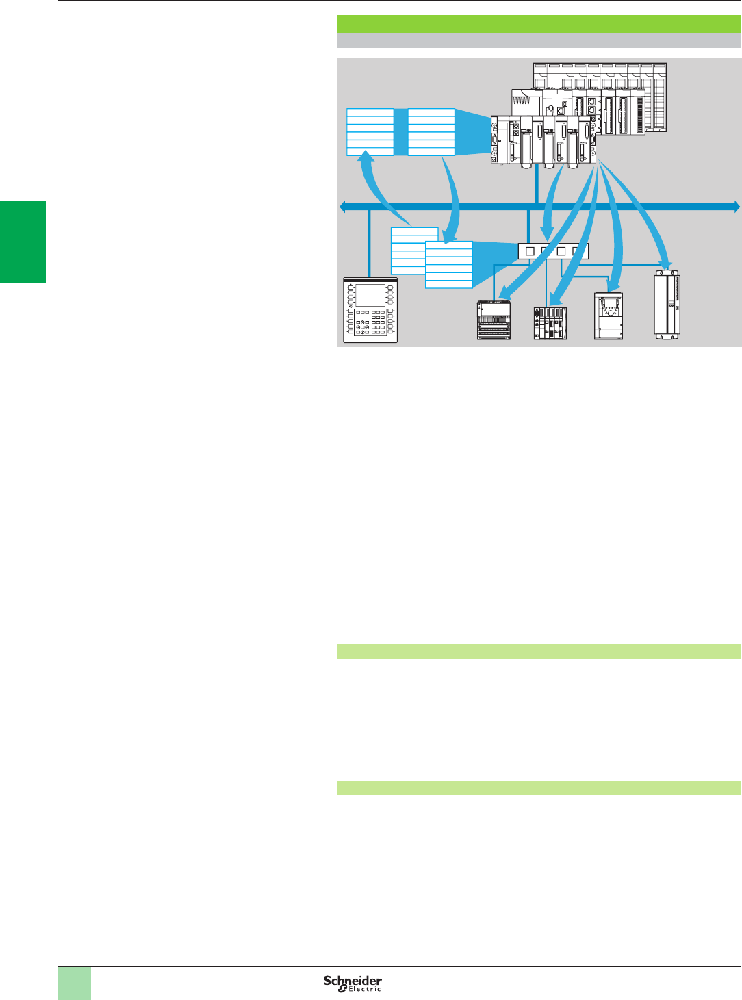
3/12
Functions (continued)
I/O Scanning service
The I/O Scanning Service is used to manage the exchange of remote I/O states on
the Ethernet network after simple conguration, without the need for any special
programming.
I/O scanning is performed transparently by means of read/write requests according
to the Modbus client/server protocol on the TCP/IP prole.
This principle of scanning via a standard protocol enables communication with any
device supporting Modbus TCP messaging in server mode.
This service can be used to dene:
bA %MW word zone reserved for reading inputs
bA %MW word zone reserved for writing outputs
bRefresh periods independent of the PLC scan
During operation, the module:
bManages TCP/IP connections with each remote device
bScans devices and copies the I/O to the congured %MW word zone
bFeeds back status words used to check that the service is working correctly from
the PLC application.
bApplies pre-congured fallback values if a communication error is detected
A range of hardware and software products is available enabling the I/O Scanning
protocol to be implemented on any type of device that can be connected to the
Ethernet network.
Characteristics
bUnder Unity Pro software, each station can exchange a maximum of:
v120 write words
v125 read words
bMaximum size in the PLC managing the service:
v1 Kword %MW in inputs and 1 Kword %MW in outputs with manager PLC limited
to 64 stations
v2 or 4 Kwords %MW in inputs and 2 or 4 Kwords %MW in outputs with manager
PLC limited to 128 stations
I/O Scanning service diagnostics
I/O Scanning service diagnostics can be performed in one of ve ways:
bVia the application program from a specic PLC data zone
bFrom the setup software debug screen
bFrom the PLC system diagnostic function displayed by means of an Internet
browser on a PC station
bUsing standard SNMP network management software
INPUT
OUTPUT
+
–
INPUT
OUTPUT
+
–
A
B
A
B
Word table
Read Write
Ethernet
Modbus/TCP
Device
input words/
output words
Modicon M580 automation
platform
PlantStruxure Ethernet architectures
Ethernet Modbus/TCP communication services
Functions (continued)
Modicon Premium,
M580 or Quantum
platform with
I/O Scanner
function
(Transparent
Ready class p30)
Device with
Modbus/TCP
messaging in
server mode
2
1
3
4
5
6
7
8
9
10
2
1
3
4
5
6
7
8
9
10

3/13
Modicon M580 automation
platform
PlantStruxure Ethernet architectures
Ethernet Modbus/TCP communication services
Functions (continued)
Functions (continued)
FDR (Fast Device Replacement) service
The Fast Device Replacement service uses standard address management
technologies (BOOTP, DHCP) and the TFTP (Trivial File Transfer Protocol) le
management service, with the aim of simplifying maintenance of Ethernet devices.
It is used to replace a device with a new device that will be detected, recongured,
and automatically restarted by the system.
The main steps in replacement are:
1 The device to be replaced is identied.
2 Another similar device is taken from the maintenance store, precongured with
the Device name for the existing device, then reinstalled on the network.
Depending on the device, addressing can be performed using rotary selector
switches (as for Modicon STB distributed I/O or Modicon OTB for example) or can
be given using the keypad integrated in the device (as for Altivar variable speed
drives for example).
3The FDR server detects the new device, allocates it an IP address, and transfers
the conguration parameters to it.
4The replacement device checks that all these parameters are indeed compatible
with its own characteristics and switches to operational mode.
The FDR server can be:
v A Modicon M340 Ethernet network module, BMXNOC0401
v A Modicon M580 Ethernet network module, BMXNOC0402 (1)
v A Modicon Premium Ethernet module, TSXETC101
v A Modicon Quantum PLC Ethernet module, 140NOC77101, 140NOC78000,
140NOC78100
v A Modicon Premium CPU with integrated Ethernet port, TSXP57ppppM
v A Modicon Quantum CPU with integrated Ethernet port, 140CPU65150/60,
140CPU65260
(1) The BMXNOC0402 communication module will be replaced by the BMENOC03p1 modules
during the 2nd quarter of 2014.
FDR client device example
Processors:
page 1/18
I/O architectures:
page 2/2
Software:
page 4/2
Ruggedized Modicon M580
modules: page 5/2
2
1
3
4
5
6
7
8
9
10
2
1
3
4
5
6
7
8
9
10

3/14
Modicon M580 automation
platform
Ethernet Modbus/TCP network
Performance
Selecting the communication architecture
When selecting an architecture, performance needs to be taken into account at the
earliest possible stage. To do this, developers need to:
1Determine the precise requirements:
v quantity and type of devices to be interconnected
v volume and type of exchanges
v expected response times
v environment
2Compare the requirements with the characteristics of the offers available and be
aware that the actual performance level between any 2 points in an architecture
depends on the weakest link in the chain, which can be:
v dependent on the hardware
v but also dependent on the applications (size, architecture, operating system,
machine power rating, etc.), which are often only vaguely dened at this stage of the
project
3Decide which is the most suitable architecture
The purpose of the next few pages is to provide the main information and
instructions needed to answer the second point. Given that the performance of an
Ethernet architecture is linked to several parameters, these pages do not supply all
the information needed to calculate the network performance. Their aim is to focus
on the following main aspects:
b Guidelines for calculating the network load so as to design an Ethernet
network that meets the application requirements
b Application response time to be obtained depending on the conguration used
(see pages 3/15 to 3/17)
b Processing capability of Modicon M340, Modicon M580, Modicon Premium,
and Modicon Quantum platforms so as to be able to select the CPU and dene the
number of Ethernet connections required on the PLC depending on the application
(see pages 3/18 and 3/19)
Calculating the network load
Introduction
When calculating the load on an Ethernet network, all the communication services of
all the peripheral devices connected to the network need to be calculated.
Because of the outstanding performance of the Ethernet network, the load is often
less than the Ethernet network limits and does not signicantly affect the application
response time. This phenomenon is explained by the high speed of the Ethernet
network: the network transaction time is 10% less than the application response
time. In order to keep the network load low and avoid large theoretical calculations,
it is highly advisable to separate the collision domain so as to limit the network load,
using only the switched network (tree, star, or daisy-chain topology).
Performance
Processors:
page 1/18
I/O architectures:
page 2/2
Software:
page 4/2
Ruggedized Modicon M580
modules: page 5/2
2
1
3
4
5
6
7
8
9
10
2
1
3
4
5
6
7
8
9
10
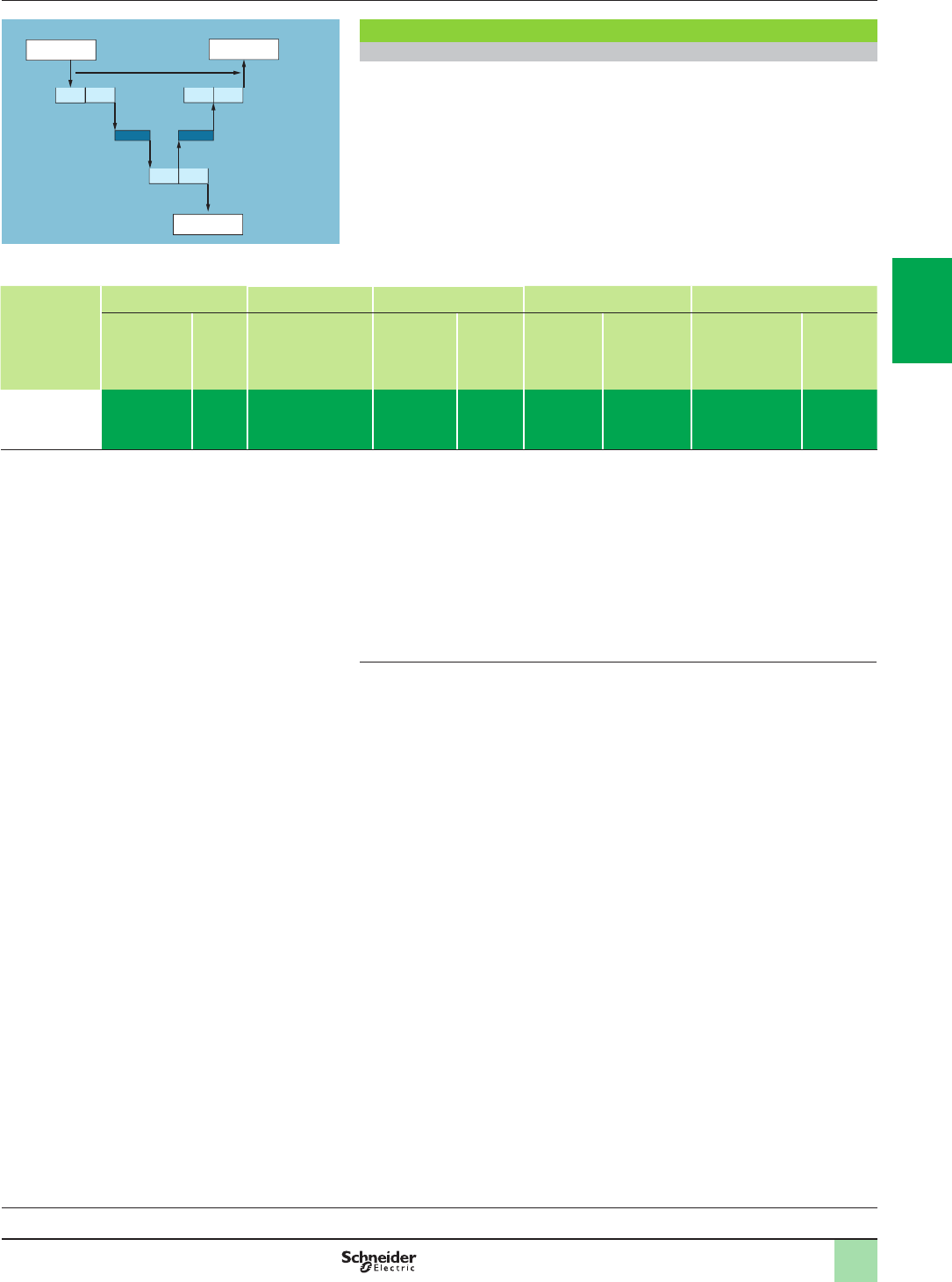
3/15
Modicon M580 automation
platform
Ethernet Modbus/TCP network
Performance
Application response time
Modbus (or Uni-TE) messaging service response time
Exchanges between the PLC CPU and the Ethernet module are synchronous with
the PLC scan cycle time (CT), just like the I/O exchanges. When an event occurs
(such as an input being set to 1 for example), a message can be transmitted only
after this input has been taken into account (start of the next cycle) and the PLC
(Modicon M340, Modicon Premium, or Modicon Quantum) program has been
executed, i.e. on average approximately 1.5 cycles after the event occurred.
The network access time (NAT) shown in the table below in ms is a total of the
module transit time and the delay before the message can be transmitted on the
network.
Processing
Modbus TCP/IP
message
requests
Modicon M580 BMEP58 Modicon M580 BMX Modicon M340 BMX Modicon Premium TSX Modicon Quantum 140
1020
2020
2040
3020
3040
4020
4040
NOC0402 (1) NOC0401 P342020
P342030
ETY210
ETY110WS
ETC101
WMY100
P5710...57 60
NOC77101/78ppp
CPU113/311pp
CPU434/5341p
CPU65ppp
CPU67ppp
NOC77101
NOC78p00
Network
access time
(NAT)
< 10 ms < 10 ms < 10 ms < 10 ms < 10 ms < 25 ms < 10 ms < 10 ms < 10 ms
The transaction time TT includes the delay between the transmission of a message
from a client (station 1), its reception by the server (station 2), processing the
request, sending back the response, and it being taken into account by the station 1
(updating an output for example).
As the block diagram above shows:
b The transaction time TT will be between:
2x CT1 + 2 x NAT < TT < 4 x CT1 + CT2 + 2 x NAT
b The average duration TTav is equivalent to:
TTav = 3 x CT1 + 0.5 x CT2 + 2 x NAT
(1) The BMXNOC0402 communication module will be replaced by the BMENOC03p1 modules
during the 2nd quarter of 2014.
Performance (continued)
Modbus messaging service response time
Station 1
Event
CT1
NAT NAT
CT2 CT2 Station 2
Report
TT
CT1 CT1 CT1
Action
Processors:
page 1/18
I/O architectures:
page 2/2
Software:
page 4/2
Ruggedized Modicon M580
modules: page 5/2
2
1
3
4
5
6
7
8
9
10
2
1
3
4
5
6
7
8
9
10
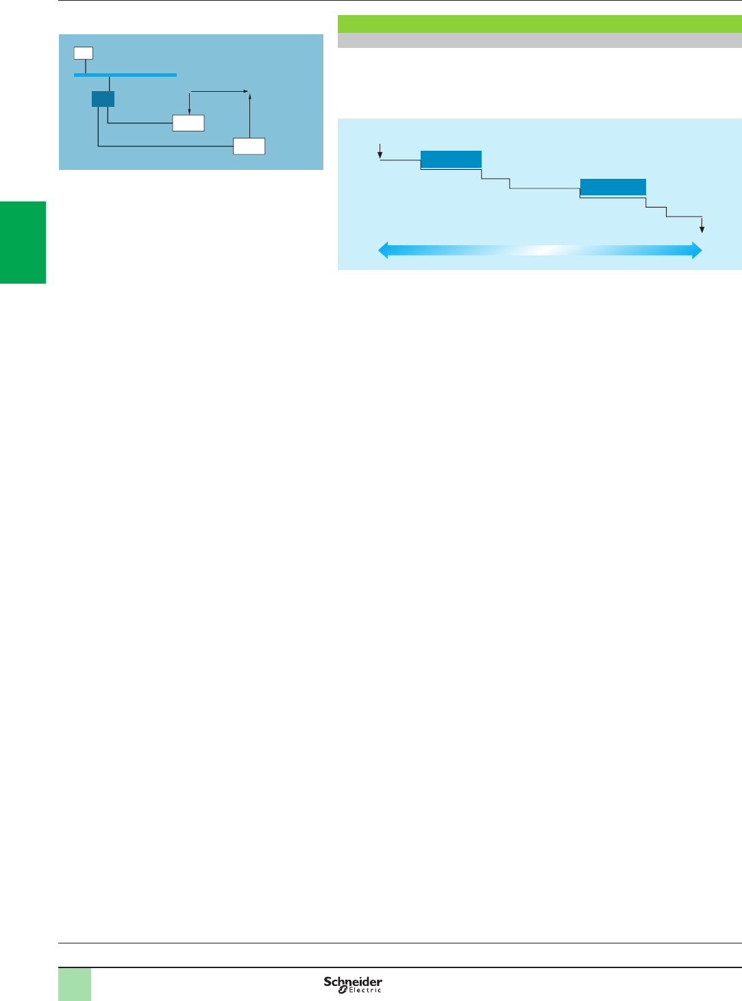
3/16
Modicon M580 automation
platform
Ethernet Modbus/TCP network
Performance
Application response time (continued)
I/O Scanning service response time
The response time RT includes the time between taking account of information from
a remote input and updating the state of a remote output. It includes the processing
time in the PLC.
This response time RT consists of the following parameters:
v TMod In and TMod Out: Response time of the read/written device, excluding the
electrical transition time at the input/output (TMod depends on the device, usually
between 1 and 8 ms)
v TIOS In and TIOS Out: Time between 2 read/write operations on the same device
(0.3 ms x number of devices scanned), at least equivalent to the congured scan
time
As TIOS is executed in parallel with the PLC cycle, it can be hidden from the
viewpoint of the response time RT.
v Cycle T: PLC scan cycle time
v TNet: Propagation time on the network (depends on the application, but usually
TNet = 0.05 ms at 10 Mbps and 0.005 ms at 100 Mbps)
The response time RT can be estimated using the following 3 formulae:
b RTmin, minimum response time with TIOS hidden and 1 PLC scan cycle:
b RTtypic, typical response time with 0.5 TIOS hidden:
b RTmax, maximum response time with TIOS not hidden:
RTmin = (TMod In + 0) x TIOS In + (Tnet + N) x cycle T + (0 x TIOS Out) + Tnet + TMod Out
RTtypic =
(TMod In + 0.5) x TIOS In + (Tnet + N) x cycle T + (0.5 x TIOS Out) + Tnet + TMod Out
RTmax = TMod In + TIOS In + (Tnet + N) x T cycle + TIOS Out + Tnet + TMod Out
Performance (continued)
I/O Scanning service response time
Device 1
Device 2
Manager
Hub
Input
Output
CT
RT
Ethernet Modbus/TCP
Response time (RT)
Input
Output
TMod In
TMod Out
TIOS In
TNet
N x Cycle T TIOS Out
TNet
Processors:
page 1/18
I/O architectures:
page 2/2
Software:
page 4/2
Ruggedized Modicon M580
modules: page 5/2
2
1
3
4
5
6
7
8
9
10
2
1
3
4
5
6
7
8
9
10
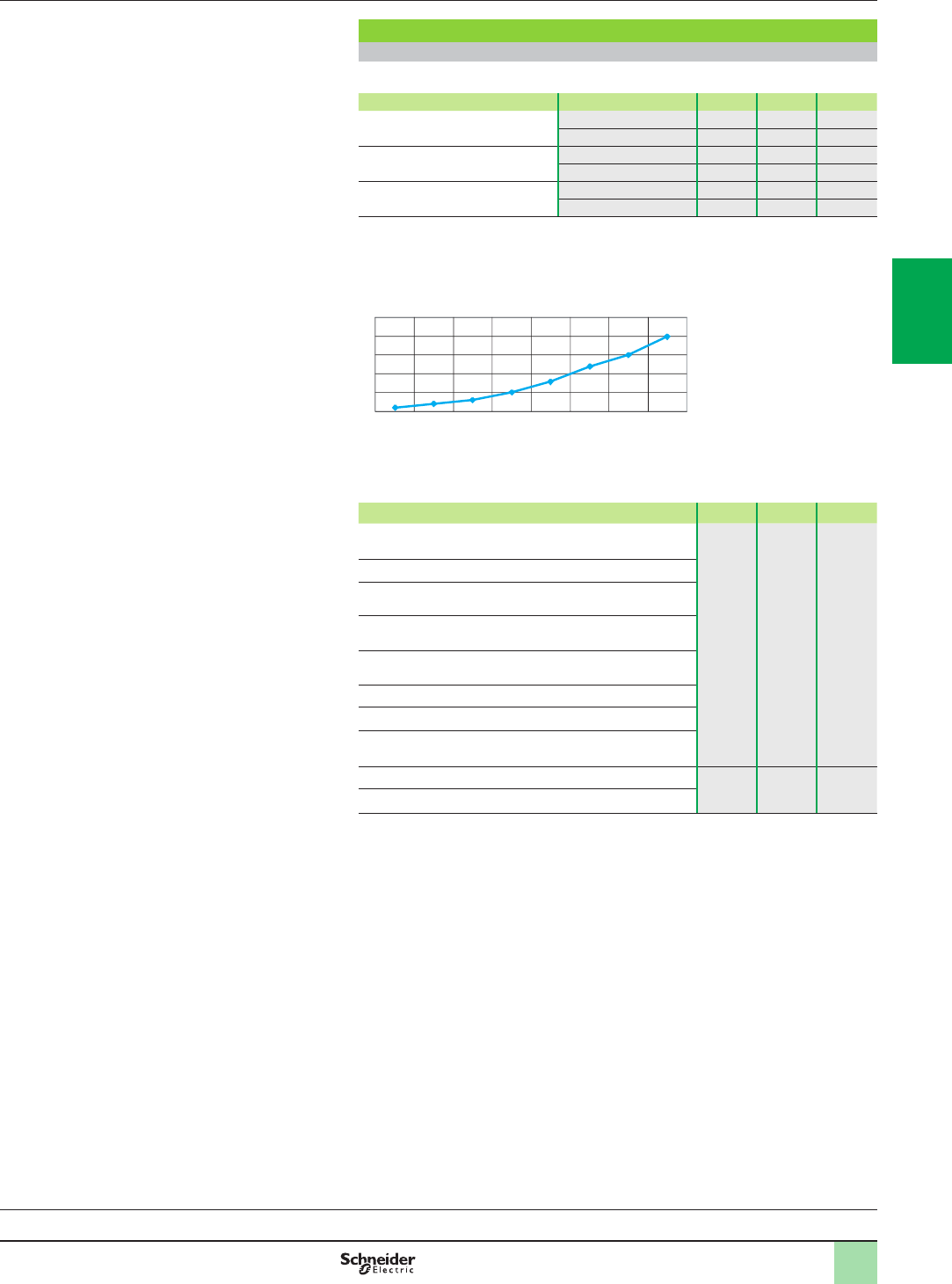
3/17
Modicon M580 automation
platform
Ethernet Modbus/TCP network
Performance
Application response time (continued)
I/O Scanning service response time (continued)
Below are the TMod In and TMod Out response times:
Type of distributed I/O Response time Min. Typical Max.
Momentum 170ENT11002 TMod In 1 ms 1 ms 1 ms
TMod Out 5 ms 5 ms 5 ms
Momentum 170ENT11001 TMod In 4 ms 6 ms 8 ms
TMod Out 4 ms 6 ms 8 ms
Advantys STB STBNIP2212 TMod In 2 ms 3 ms 4 ms
TMod Out 2 ms 3 ms 4 ms
The TIOS In/TIOS Out times measured between 2 scan cycles (Ethernet network
with switches) are shown below:
The number N of CPU scan cycles is shown below:
Number of CPU cycles N Min. Typical Max.
Modicon M340 platform with BMXNOC0401 module 2 2.5 3
Modicon M580 platform with BMXNOC0402 module (1)
Premium platform with TSXETY4103 and TSXETY5103
modules
Quantum platform with 140NOE77101 and 140NOE77111
modules
Quantum platform with 140NOC77101 and 140NOC78p00
modules
Modicon M580 platform with BMEP58pppp modules
Modicon M340 BMXP342020/2030 CPUs
Premium TSXP5726/3634M,TSXP5726/2823M and
TSXP5736/4823AM CPUs
Premium TSXP5746/56/6634M CPUs 112
Quantum 140CPU65150/60 CPUs
(1) The BMXNOC0402 communication module will be replaced by the BMENOC03p1 modules
during the 2nd quarter of 2014.
Performance (continued)
0
5
10
15
20
25
1 5 10 20 30 40 50 60
Number of devices scanned
Time (ms)
Processors:
page 1/18
I/O architectures:
page 2/2
Software:
page 4/2
Ruggedized Modicon M580
modules: page 5/2
2
1
3
4
5
6
7
8
9
10
2
1
3
4
5
6
7
8
9
10
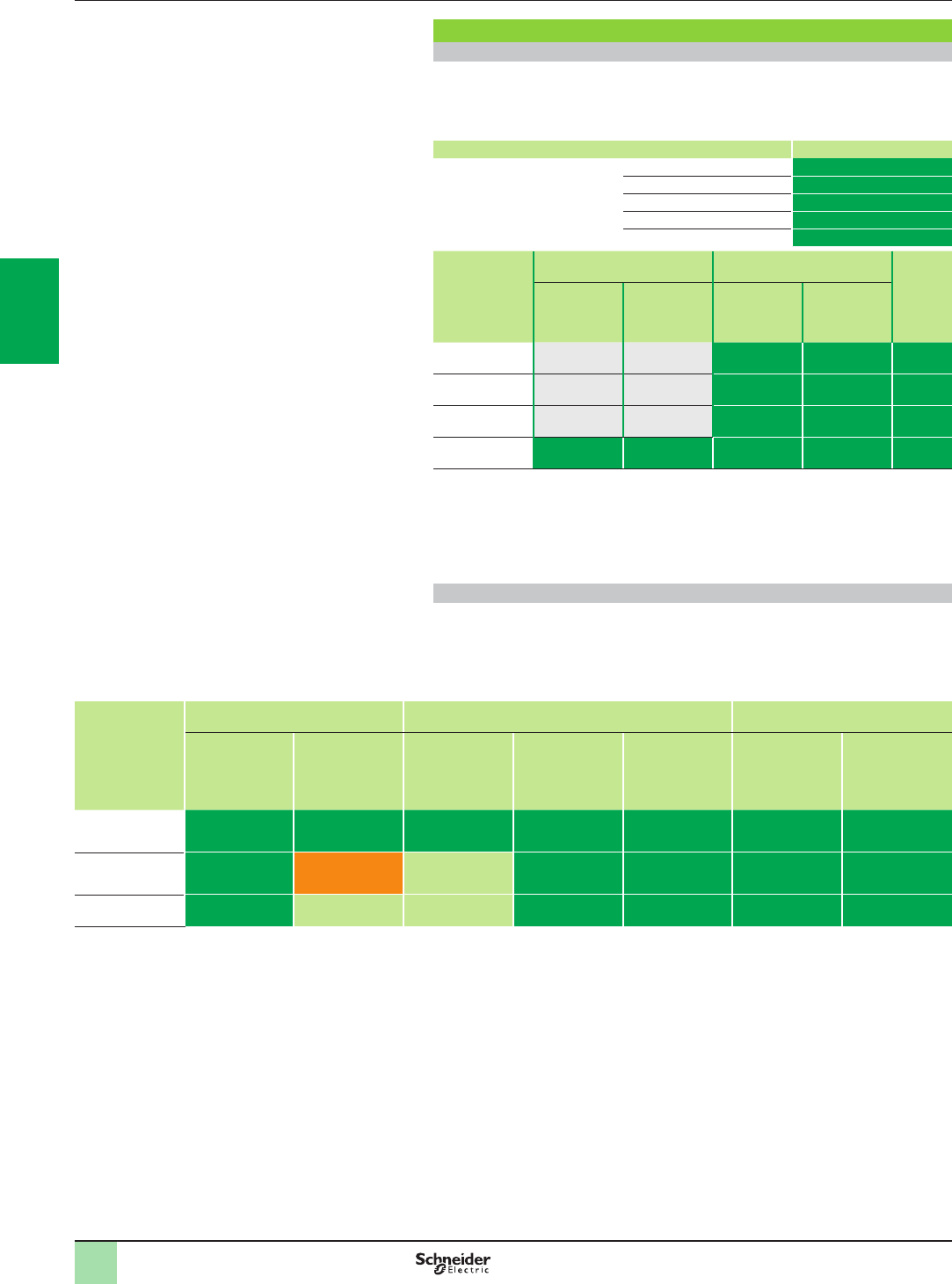
3/18
Modicon M580 automation
platform
Ethernet Modbus/TCP network
Performance
Processing capacities of Modicon platforms
Processing capacity
Use the table below to compare, for each station, the total number of messages
received via the Modbus (or Uni-TE) messaging service if used (value R1, R2, or Ri)
with the capacity of the station CPU.
Processing of Modbus requests per PLC scan cycle:
Modicon M340, Modicon Premium/Atrium platforms Messages received
Total messages received by the
PLC from all the communication
modules (1)
TSX5710 4 messages/cycle
BMXP3420/TSX5720 8 messages/cycle
TSX5730 12 messages/cycle
TSX5740 16 messages/cycle
TSX5750/60 (2) 16/20 messages/cycle
Modicon
Quantum
platform
Integrated port limitations Communication module
limitations
Ethernet
modules
per PLC
All types of
communica-
tion request
Additional
read/write 4x
registers
All types of
communica-
tion request
Additional
read/write 4x
registers
140CPU113 (3) ––1 message/
cycle
4 messages/
cycle
Up to 2
140CPU311 ––1 message/
cycle
4 messages/
cycle
Up to 2
140CPU434/534 ––4 messages/
cycle
8 messages/
cycle
Up to 6
140CPU651 16 messages/
cycle
16 messages/
cycle
4 messages/
cycle
8 messages/
cycle
Up to 6
Messages/cycle: number of messages received per cycle from the PLC master task (typical
cycle of 50 to 100 ms)
Example:
Quantum 140CPU43412p CPU with 4 Ethernet 140NOE771p1 modules:
- 20 messages/cycle for all types of communication request, and
- 32 messages/cycle for the read/write 4x registers
Ethernet transaction processing capacity
For each station, compare the total number of messages received S[values Ri, Rj]
and the total number of messages transmitted S [values Ei, Ej] (for station N, for
example) with the Ethernet transaction processing capacity shown below.
Use the elements below for the Ethernet connection per PLC, rather than the
number of transactions required by the application.
Ethernet
transaction
processing
capacity
Modicon M340 BMX Modicon Premium TSX Modicon Quantum 140
NOC0401 P342020
P342030
ETY210
ETY110WS
ETC101
WMY100
P5710/20/30/40
P5750
P5760
NOC77101
/78ppp
NWM10000
CPU65ppp
CPU67ppp
Modbus
messaging
500 transactions/s 500 transactions/s 60 transactions/s 450
transactions/s
500
transactions/s
350
transactions/s
350
transactions/s
I/O Scanning
service
2000
transactions/s
Server mode (5) Service not
available
2000
transactions/s (6)
2000
transactions/s
2000
transactions/s (6)
2000
transactions/s
Global Data
subscription
800 Service not
available
Service not
available
800
(6)
800 800
(6)
800
__________________________________________________________________
(1) A temporary overload, due for example to an adjustment terminal or the temporary
connection of an Internet browser, lasting for a few PLC scans, is permitted.
(2) Only with Unity Pro software.
(3) Only with Concept/ProWORX software.
(4) The BMXNOC0402 communication module will be replaced by the BMENOC03p1 modules
during the 2nd quarter of 2014.
(5) BMXP3420p0 CPUs with Modbus TCP messaging in server mode can be scanned by a
device with the I/O Scanning service.
(6) TSXWMY100 and 140NWM10000 modules do not have I/O Scanning and Global Data
services.
Performance (continued)
2
1
3
4
5
6
7
8
9
10
2
1
3
4
5
6
7
8
9
10
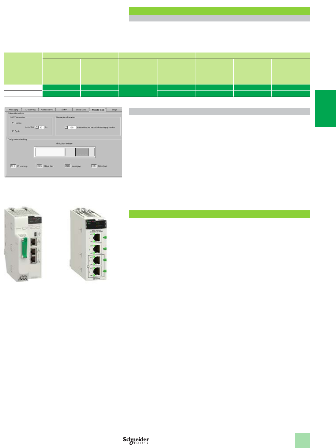
3/19
Modicon M580 automation
platform
Ethernet Modbus/TCP network
Performance
Processing capacities of Modicon platforms (continued)
Number of simultaneous TCP/IP connections
The number of simultaneous TCP/IP connections depends on the platform as well as
the type of connection to the Ethernet network:
b 10/100BASE-TX port in network modules
b 10/100BASE-TX port integrated in CPUs
Number of
simultaneous
TCP/IP
connections
Modicon M340 BMX Modicon Premium TSX Modicon Quantum 140
NOC0401
NOE0110
P342020
P342030
ETY210
ETY110WS
ETC101
WMY100
P5710...5760
NOC77101/78ppp
CPU113/311pp
CPU434/53414B
CPU65ppp
CPU67ppp NOC77101
NOC78p00
Client 16 16 32 16 (1)16 (1)16 (1)16
Server 32 32 64 (1)64 (1)64 (1)32
Bandwidth management for Ethernet Modbus/TCP modules
The bandwidth management service indicates the load level of the Ethernet network
module. This allows the user to monitor resource consumption and help ensure a
good module performance.
The Ethernet module load is indicated in one of three ways:
b Expected load in the Unity Pro conguration screen
b Actual load in the Unity Pro diagnostics/debug screen
b In the SNMP interface for access by the SNMP network manager
The bandwidth is shown as a percentage for each of the following services:
b Modbus (and Uni-TE) messaging
b I/O Scanning
b Others
Ethernet solutions with Modicon M580 platforms
Modicon M580 platforms feature two types of connection to the Ethernet network:
b The 10/100BASE-TX port integrated in the CPUs, which also process the
application and exchange data with the other modules supported by the rack and
other communication ports (CANopen bus, Modbus serial link, etc.)
b The multiple 10/100BASE-TX port in dedicated Ethernet modules on which, unlike
the CPU with integrated Ethernet port, all the resources are allocated to Ethernet
Modbus/TCP and EtherNet/IP communication
These fundamentally different hardware characteristics result in equally different
capacities in terms of services and performance:
b The integrated port is a low-cost way of satisfying applications that are not too
demanding in terms of communication (y 500 user messages/s).
b Where there are a large number of exchanges, use of a dedicated Ethernet
network module is strongly recommended to help improve performance.
(1) With 64 TCP/IP connections maximum (cumulative total of client and server connections).
(2) The BMXNOC0402 communication module will be replaced by the BMENOC03p1 modules
during the 2nd quarter of 2014.
Performance (continued),
selection
Bandwidth management
Ethernet port integrated in
the CPU (for example with
BMEP584040 Modicon
M580 CPU)
Dedicated Ethernet
module (for example with
BMXNOC0402 Modicon
M580 module) (2)
or
Processors:
page 1/18
I/O architectures:
page 2/2
Software:
page 4/2
Ruggedized Modicon M580
modules: page 5/2
2
1
3
4
5
6
7
8
9
10
2
1
3
4
5
6
7
8
9
10
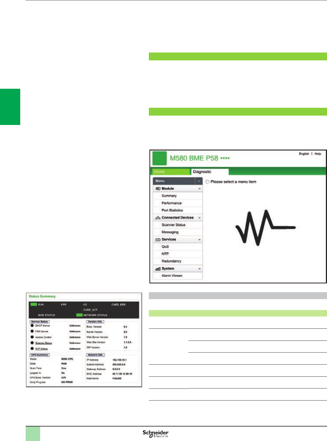
3/20
Presentation Modicon M580 automation
platform
Embedded web pages
The M580 CPU includes a Hypertext Transfer Protocol (HTTP) server. The server
transmits web pages for the purpose of monitoring, diagnosing, and controlling
remote access to the communication module. The server provides easy access to
the CPU from standard internet browsers.
The embedded web server pages are used to display real-time diagnostic data for
the M580 CPU.
Requirements
The embedded web server in M580 CPUs displays data in standard HTML web
pages. The embedded web pages can be accessed on a PC, iPad®, or Android®
tablet with the following browsers:
bInternet Explorer® (V8 or later)
bGoogle Chrome® (V11 or later)
bMozilla Firefox® (V4 or later)
bSafari® (V5.1.7 or later)
Diagnostic web pages
The M580 CPU Diagnostic web pages provide information on Status Summary,
Performance, Port Statistics, I/O Scanner, Messaging, QoS (quality of service),
Network Time Service, Redundancy and Alarm Viewer. All these pages are updated
every 5 seconds to get the latest information.
Status Summary page
The objects on this page provide status information.
Parameters Description
LEDs The black eld contains LED indicators (RUN, ERR, etc.)
Service Status Green The available service is operational and running
Red An error is detected in an available service
Black The available service is not present or not congured
Version Info. This eld describes the software versions that are running on the CPU
CPU Summary This eld describes the CPU hardware and the applications that are
running on the CPU
Network Info. This eld contains network and hardware address information and
connectivity that corresponds to the CPU
Status summary
2
1
3
4
5
6
7
8
9
10
2
1
3
4
5
6
7
8
9
10
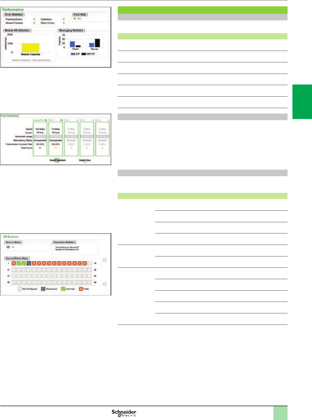
3/21
Modicon M580 automation
platform
Embedded web pages
Presentation (continued)
Performance
Port Statistics
I/O Scanner
Diagnostic web pages (continued)
Performance page
The objects on this page provide information on performance statistics.
Field Description
Error Statistics This area contains the detected errors in the diagnostics data for the CPU
(these counters can be reset to 0 with the Reset Counters button)
Error Rate This percentage represents the total number of packets divided by the
number of packets that are not associated with detected errors
Total Bandwidth
Utilization
This value indicates the percentage of the available bandwidth that the
CPU is using
Module I/O
Utilization
This graph shows the total number of packets (per second) the CPU can
handle at once (1)
Processor
Utilization
This graph shows the number of Modbus/TCP or EtherNet/IP messages
per second for the client or server (1)
System Bandwidth
Monitor
These graphs show the percentage of bandwidth consumed by the
Modbus messaging and I/O Scanning services (1)
Port Statistics page
This page shows the statistics for each port on the CPU.
This information is associated with the conguration of the Ethernet ports and the
conguration of the service/extended port.
The names of active ports are green. The names of inactive ports are gray.
The information is reset or expanded with these buttons:
bReset Counters: Resets all dynamic counters to 0.
bDetail View: Expands the list of port statistics.
I/O Scanner page
The objects on this page provide information on the scanner status and connection
statistics.
Field Description
Scanner Status Enabled The I/O scanner is enabled
Disabled The I/O scanner is disabled
Idle The I/O scanner is enabled but not running
Unknown The I/O scanner returns unexpected values from the
device
Connection
Statistics
Transactions per second
Number of connections
Scanned Device
Status
Colors that appear in each block indicate these states for specic remote
devices
Gray There is an uncongured device
Black The scanning of the specic device has been
intentionally disabled
Green A device is being scanned successfully
Red A device that is being scanned is returning detected
errors
(1) Move the mouse over the dynamic graphs to see the current numeric values.
2
1
3
4
5
6
7
8
9
10
2
1
3
4
5
6
7
8
9
10
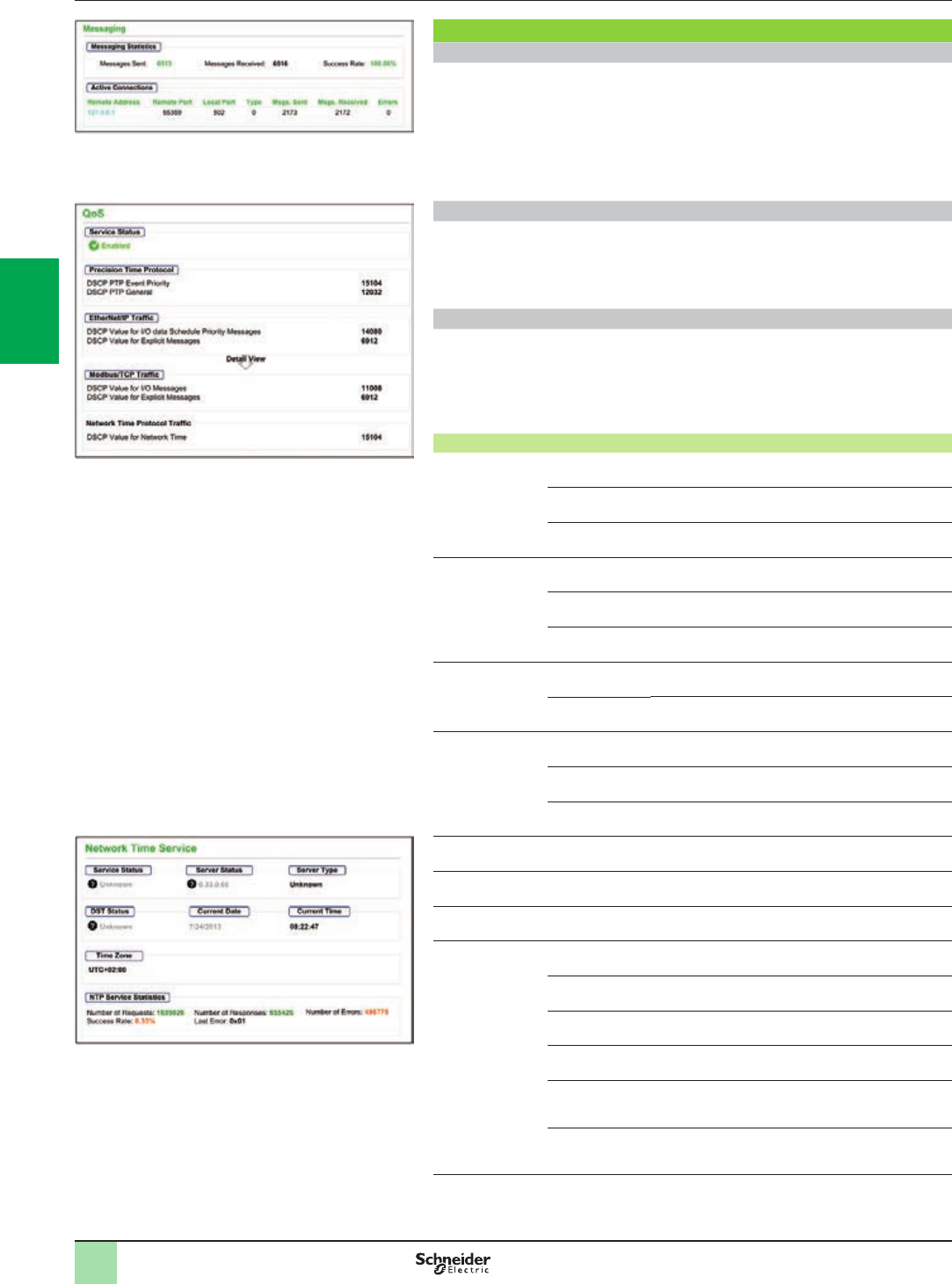
3/22
Modicon M580 automation
platform
Embedded web pages
Presentation (continued)
Diagnostic web pages (continued)
Messaging page
This page shows current information for open TCP connections on port 502:
bMessaging Statistics: This eld contains the total number of sent and received
messages on port 502. These values are not reset when the port 502 connection is
closed. Therefore, the values indicate the number of messages that have been sent
or received since the module was started.
bActive Connections: This eld shows the connections that are active when the
Messaging page is refreshed.
QoS (quality of service) page
This page displays information about the QoS service. This service is congured in
Unity Pro. When QoS is enabled, the module adds a differentiated services code
point (DSCP) tag to each Ethernet packet it transmits, thereby indicating the priority
of that packet.
Network Time Service page
This page displays information about the NTP service. This service is congured in
Unity Pro. The Network Time Service synchronizes computer clocks over the
Internet for the purposes of event recording (sequencing events), event
synchronization (triggering simultaneous events), or alarm and I/O synchronization
(timestamping alarms).
Field Description
Service Status Running The NTP service is correctly congured and running
Disabled The NTP service is disabled
Unknown The NTP service status is unknown
Server Status Green The server is connected and running
Red A bad server connection is detected
Gray The server status is unknown
Server Type Primary A primary server polls a master time server for the
current time
Secondary A secondary server requests the current time only from
a primary server
DST Status Running DST (daylight saving time) is congured and running
Disabled DST (daylight saving time) is disabled
Unknown The DST status is unknown
Current Date This is the current date in the selected time zone
Current Time This is the current time in the selected time zone
Time Zone This eld shows the time zone in terms of plus or minus Universal Time
Coordinated (UTC)
NTP Service
Statistics
These elds show the current values for service statistics
Number of
Requests
This eld shows the total number of requests sent to
the NTP server
Success Rate This eld shows the percentage of successful requests
out of the total number of requests
Number of
Responses
This eld shows the total number of responses
received from the NTP server
Last Error This eld contains the code of the last error that was
detected during the transmission of an email message
to the network
Number of
Errors
This eld contains the total number of email messages
that could not be sent to the network or that have been
sent but not acknowledged by the server
Messaging
QoS
Network time service
2
1
3
4
5
6
7
8
9
10
2
1
3
4
5
6
7
8
9
10
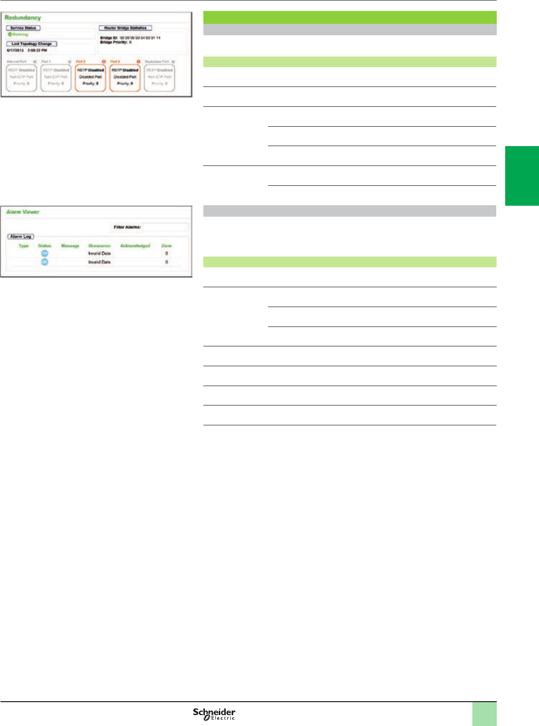
3/23
Modicon M580 automation
platform
Embedded web pages
Presentation (continued)
Diagnostic web pages (continued)
Redundancy page
This page displays values from the RSTP conguration in Unity Pro.
Parameters Description
Service Status This is the status (Enabled or Disabled) of the RSTP bridge on the
corresponding CPU
Last Topology
Change
These values represent the date and time that the last topology change
was received for the corresponding Bridge ID
Redundancy Status Green The designated Ethernet port is learning or formatting
information
Yellow The designated Ethernet port is discarding information
Gray RSTP is disabled for the designated Ethernet port
Router Bridge
Statistics
Bridge ID This unique bridge identier is the concatenation of the
bridge RSTP priority and the MAC address
Bridge Priority In Unity Pro, congure the RSTP operating state of the
Bridge ID
Alarm Viewer page
The Alarm Viewer page reports detected errors in the application. Information about
alarm objects can be read, ltered, and sorted on this page. The type of information
displayed by the Alarm Viewer is adjusted in the Filter Alarms box.
Field Description
Type This column describes the alarm type
Status STOP You need to acknowledge the alarm
ACK An alarm has been acknowledged
OK An alarm does not require acknowledgment
Message This column contains the text of the alarm message
Occurance This column contains the date and time that the alarm occurred
Acknowledged This column reports the acknowledged status of the alarm
Zone This column contains the area or geographical zone from which the alarm
comes (0: common area)
Alarm Viewer
Redundancy 2
1
3
4
5
6
7
8
9
10
2
1
3
4
5
6
7
8
9
10
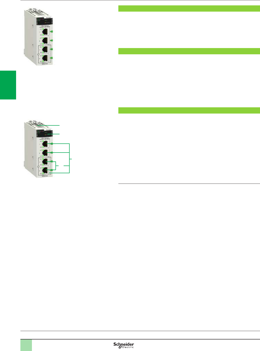
3/24
Presentation,
functions,
description
Modicon M580 automation
platform
Modbus/TCP and EtherNet/IP network module
Processors:
page 1/18
I/O architectures:
page 2/2
Software:
page 4/2
Ruggedized Modicon M580 modules:
page 5/2
Presentation
The BMXNOC0402 (1) network module acts as an interface between the M580 PLC
and other Ethernet network devices via the Modbus/TCP and EtherNet/IP
communication protocols.
The standard format BMXNOC0402 (1) network module occupies a single slot in the
rack of the Modicon M580 platform. This module has to be installed in the main
Ethernet + X-bus backplane rack.
Functions
The BMXNOC0402 (1) module offers the following functions:
bModbus/TCP and EtherNet/IP protocols operating simultaneously
bRing topologies on 2 Ethernet ports using RSTP (Rapid Spanning Tree Protocol)
bPriority of Ethernet packets using QoS (Quality of Service) service
bAutomatic module conguration recovery using FDR (Fast Device Replacement)
service
bEmbedded Web server for application monitoring and module diagnostics
bSharing data between PLCs
bNetwork management using SNMP (Simple Network Management Protocol)
Description
The front panel of the BMXNOC0402 (1) module features:
1 A screw for locking the module in a slot in the rack.
2 A display block with 5 LEDs:
vRUN LED (green): Operating status
vERR LED (red): Error detected
vMS LED (green/red): Module status
vNS LED (green/red): Network connection status
vETH STS LED (amber): Ethernet link status
3 Four RJ45 connectors for connection to the Ethernet network. The two bottom
connectors 3a support ring topologies (RSTP protocol).
Each RJ45 connector has two associated LEDs:
vLNK LED (yellow): Ethernet link established
vACT LED (green): Transmission/reception activity
(1) The BMXNOC0402 communication module will be replaced by the BMENOC03p1 modules
during the 2nd quarter of 2014.
BMXNOC0402
1
2
3
3a
BMXNOC0402
2
1
3
4
5
6
7
8
9
10
2
1
3
4
5
6
7
8
9
10

3/25
References Modicon M580 automation
platform
Modbus/TCP and EtherNet/IP network module
References
Description Data rate Reference Weight
kg/lb
EtherNet/IP, Modbus/TCP
network module
10/100 Mbps BMXNOC0402 (1)(2) 0.345/
0.761
(1) The Unity Pro conguration tool is supplied on CD-ROM with the module. This software is
used to update the Unity Pro hardware catalog (addition of the new module DTMs).
(2) The BMXNOC0402 communication module will be replaced by the BMENOC03p1 modules
during the 2nd quarter of 2014.
Processors:
page 1/18
I/O architectures:
page 2/2
Software:
page 4/2
Ruggedized Modicon M580 modules:
page 5/2
BMXNOC0402
2
1
3
4
5
6
7
8
9
10
2
1
3
4
5
6
7
8
9
10
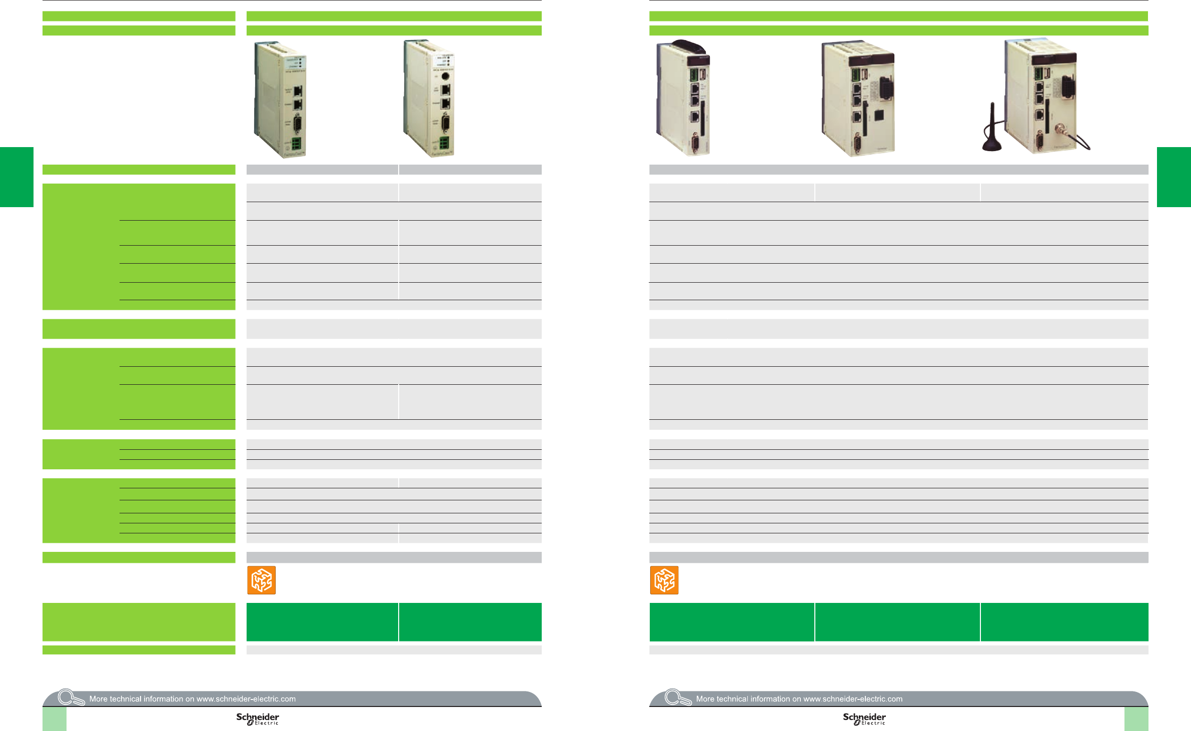
2
1
3
4
5
6
7
8
9
10
2
1
3
4
5
6
7
8
9
10
2
1
3
4
5
6
7
8
9
10
2
1
3
4
5
6
7
8
9
10
3/26 3/26
Web Designer
Selection guide Modicon M580 automation
platform
Web servers and gateways
Applications Standalone Web Gateway/Server module for remote access Standalone Web Gateway/Server modules for remote access
Type FactoryCast Gateway ETG10p0FactoryCast HMI Gateway ETG30pp
Target products Type Any device supporting Modbus Any device supporting Uni-Telway Any Modicon PLC or third-party device supporting Modbus
Network/Remote
access services
Remote access Intranet or via external modem and integrated
RAS function
Intranet or modem, external modem and
integrated RAS function
Intranet or modem, external modem and integrated
RAS function
Intranet or modem
RTC modem and integrated RAS function
Intranet or modem
GSM modem and integrated RAS function
Remote programming, downloading via FTP, access to Web server via web browser Remote programming, downloading via FTP, access to Web server via web browser
Gateway function Ethernet to Modbus serial
Modem to Modbus serial and Ethernet
Ethernet to Uni-Telway serial
Modem to Uni-Telway and Ethernet
Ethernet to Uni-Telway serial, modem to Modbus serial and Ethernet
Serial protocols Modbus master Uni-Telway slave Modbus master
Ethernet protocols Modbus/TCP Modbus/TCP
Uni-TE (Premium, Micro)
Modbus/TCP
TCP/IP protocols BootP/DHCP, DNS, SNMP agent, SMTP
client, NTP client (1), FTP
BootP/DHCP, DNS, SNMP agent, SMTP
client, NTP client (1), FTP
DHCP, DNS, SNMP agent, SMTP client, NTP client (1), FTP
Security Protection by IP address ltering and passwords Protection by IP address ltering and passwords
Web server Characteristics HTTP and FTP server, 8 MB memory available for user, hosting of user Web pages and
documents (doc, pdf, Excel)
HTTP and FTP server, 32 MB memory available for user Web pages, memory expansion using Compact Flash cards 1 GB max., hosting of user Web pages and
documents (doc, pdf, Excel)
Predened services Conguration Via Web Designer software or predened Web pages Via Web Designer software or predened Web pages
Diagnostics Serial device diagnostics via predened Web pages Network diagnostics, serial and Ethernet device diagnostics via predened Web pages
Monitoring Monitoring via animation tables
Display of PLC Unity program in a Web page
Monitoring of devices and application via
animation tables (read/write variables)
Display of PLC Unity program in a Web page
Monitoring of devices and application via animation tables (read/write variables)
Display of PLC Unity program in a Web page
Alarm management – –
Customizable
services
Graphic views Graphic monitoring via animated views (integrated graphic editor) Graphic monitoring via animated views (integrated graphic editor)
Unity Pro operator screen – –
User Web pages Graphic monitoring via animated Web pages created by the user Graphic monitoring via animated Web pages created by the user
Advanced and HMI
services
Calculation scripts –Arithmetic and logical scripts
E-mail service Alarm notication by e-mail Alarm notication by e-mail/SMS
Data logging –Data recorded in the module with date and time stamping (CSV les)
Database connection –Direct recording in an SQL, Oracle, or MySQL server
Report service –Dynamic HTML report management
Recipe service –Management of “Recipe” data (storage and review locally or in remote database)
Application development software Web Designer (supplied with each module) Web Designer (supplied with each module)
References TSXETG1000 TSXETG1010 TSXETG3000 TSXETG3010 (PSTN modem) TSXETG3021
(GSM900/1800 MHz band)
TSXETG3022 function
(GSM850/1900 MHz band)
Catalog or website www.schneider-electric.com www.schneider-electric.com
(1) Except with TSXP57103M/153M Modicon Premium processors, which do not have the NTP service.
Web Designer
3/26 3/27
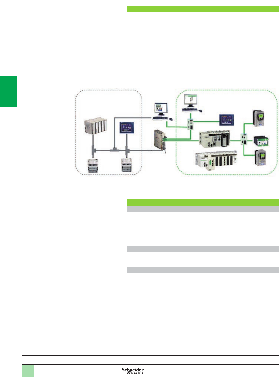
3/28
Presentation Modicon M580 automation
platform
Modbus Plus Proxy module
Presentation
The TCSEGDB23F24FA Modbus Plus Proxy module is a network gateway that
allows Modicon M340 and M580 PLCs to communicate with existing Modbus Plus
devices.
It is not necessary to modify the applications for these devices to communicate with
the Modicon M340 and M580 PLCs, since the module automatically addresses the
platforms and the various communication functions between the M340/M580 and
other PLC platforms (especially 984LL).
The Modbus Plus Proxy offers Modbus Plus PLC users the chance to integrate the
M340 and M580 PLCs easily into their Modbus Plus network and thus to access
advanced communications via Ethernet, or to migrate gradually from other PLC
models to Modicon M340/M580 and Unity.
Key benets
Reduced startup time
bOnline conguration of the proxy via a simple Web browser
bSetup Web pages similar to the screens of the Modbus Plus Peer Cop utility,
accessible under Concept/Unity for the Global Data transaction
bSimpler data exchange with Global Data transactions performed on all network
nodes
bPoint-to-point communication without programming with Peer Cop
Increased network reliability and maintainability
bStandard diagnostics provide data on all network nodes for easy troubleshooting
bDual Modbus Plus ports provide Modbus Plus network redundancy
Reduced total cost of ownership
bHelps protect your investment in Modbus Plus while migrating to Ethernet
bDual Ethernet ports allow connection of both the M340 or M580 PLC and the
conguration PC to the proxy, without any additional switches
Processors:
page 1/18
I/O architectures:
page 2/2
Software:
page 4/2
Ruggedized Modicon M580 modules:
page 5/2
Compact 984
Distributed I/O
Modbus Plus
SCADA
Modbus Plus
Proxy
Web
conguration
interface
Modicon M340
Modicon M580
Ethernet
2
1
3
4
5
6
7
8
9
10
2
1
3
4
5
6
7
8
9
10
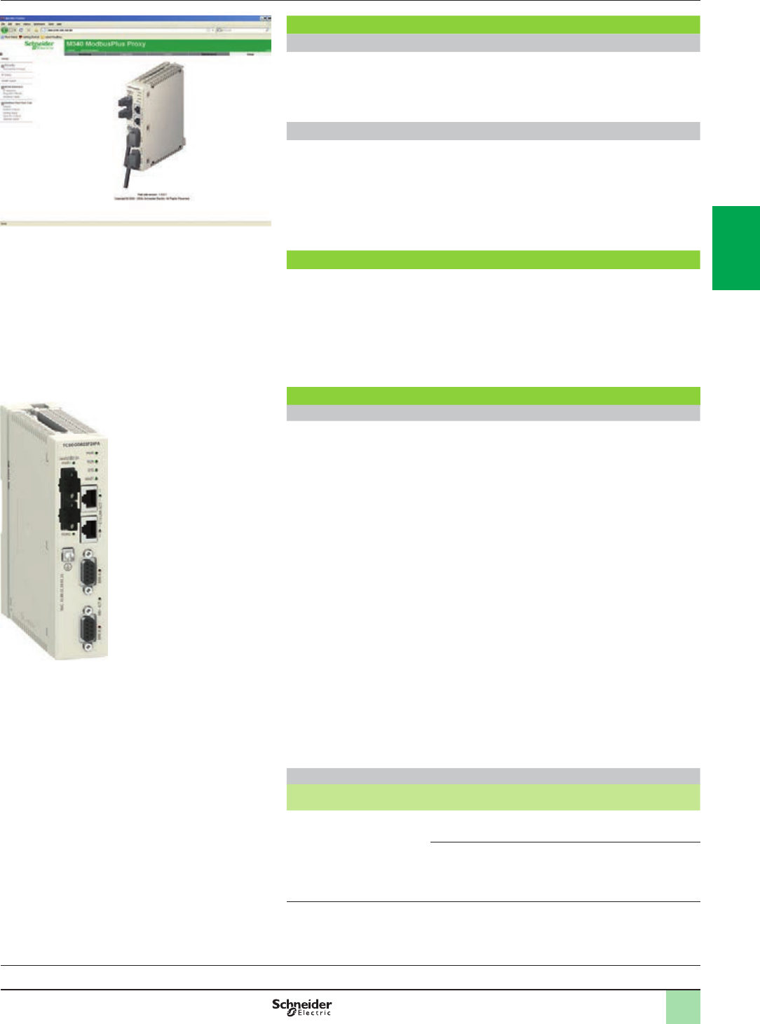
3/29
Modicon M580 automation
platform
Modbus Plus Proxy module
References
TCSEGDB23F24FA
Embedded Web server
Web server functions
The Modbus Plus Proxy module includes an embedded Web server that can be used
to perform diagnostics and congure the module connection. All data is presented in
the form of standard Web pages in HTML format. To access a Web page, you need
Internet Explorer (version 6.0 or later) and Java (version 1.5 or later).
Embedded Web server functions
1 - Setup: The Setup pages allow you to dene the parameters for several different
module services, including security, IP, SNMP, Global Data, Peer Cop and Ethernet
ports.
2 - Diagnostics: These network diagnostic pages contain Ethernet, TCP, and SNMP
statistics, as well as a log of the diagnostics performed.
Complementary characteristics
The following characteristics complement those introduced in the communication
selection guide on page 3/5:
bExternal power supply voltage: 19.2...31.2 V c
bConsumption: 300 mA max.
bDissipated power: 6.2 W
bConformity with standards: UL 508, CSA 22.2 No. 142 (cUL), EMI EN 55011,
EN 61131-2, C-Tick
References
System and network requirements
Unity Pro XL programming software (version 3.x or later) (1)
Internet Explorer (version 6.0 or later)
Java (version 1.5 or later)
Microsoft Windows XP or Vista
Modicon M340 processors:
bBMXP342020 (Modbus and Ethernet version)
bBMXP3420302 (CANopen and Ethernet version)
bBMXP3420302CL (CANopen and Ethernet version) (2)
Modicon M580 processors:
bBMEP581020
bBMEP582020
bBMEP582040
bBMEP583020
bBMEP583040
bBMEP584020
bBMEP584040
Ethernet Modicon M340 communication modules:
bBMXNOE0100
bBMXNOE0110
bBMXNOC0401
Modicon M580:
bBMXNOC0402 (3)
Modicon Modbus Plus Proxy module
Description Type Reference Weight
kg
Modbus Plus Proxy module
for Modicon M340 and M580
PLCs
supplied with 2 front-mounted
power supply connectors
(2 positions)
Standard TCSEGDB23F24FA –
Conformal coating TCSEGDB23F24FK –
(1) Unity V8.0 or later with M580
(2) Memory card to be ordered separately for the BMXP3420302CL processor (see our website
www.schneider-electric.com).
(3) The BMXNOC0402 communication module will be replaced by the BMENOC03p1 modules
during the 2nd quarter of 2014..
Processors:
page 1/18
I/O architectures:
page 2/2
Software:
page 4/2
Ruggedized Modicon M580 modules:
page 5/2
2
1
3
4
5
6
7
8
9
10
2
1
3
4
5
6
7
8
9
10
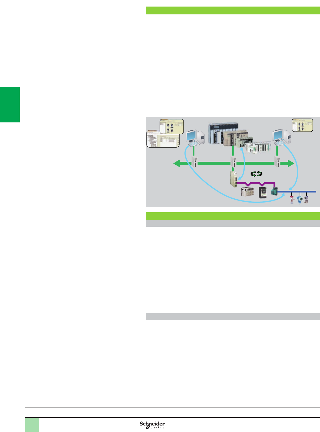
3/30
Presentation Modicon M580 automation
platform
Probus DP V1 and Probus PA buses
Probus Remote Master module
Probus DP eldbus
Probus DP is one of the most widely used eldbuses in industry. Based on a
master/slave protocol, only master stations, sometimes called active stations, have
the right to access the bus, with slave, or passive, stations being limited to
responding to interrogations.
Version V0 of Probus only allows cyclic exchanges with I/O, whereas version V1
offers an acyclic message handling channel that can be used for device adjustment
or diagnostics during operation.
The physical link is a single shielded twisted pair, but numerous interfaces are
available for creating all sorts of topologies - tree, star, or ring - including those using
optical ber or a non-physical link.
Gateways can be used to communicate transparently with Probus PA, one of the
most commonly used standards in process applications for connecting
instrumentation. Probus PA can be used to supply devices across the network and
also to install sensors in potentially explosive zones (ATEX).
Unity Pro
PRM master
PRM Com DTM
Ethernet
Probus PA
PRM Probus DP
DP Class 1
Probus Remote Master (PRM) module
Presentation
The Probus Remote Master (PRM) module is connected to the Ethernet Modbus
TCP/IP network via its integrated 2-port switch, as close as possible to the process
and the instrumentation.
The PRM module can be used to connect Modicon Quantum, Premium, M580, and
M340 PLCs to Probus DP V1 via the I/O scanner function.
Irrespective of the type of PLC, only one product reference is required and setup is
identical, thus reducing training and maintenance costs.
Two versions are available, standard and tropicalized, so as to adapt to any type of
environment.
The PRM module is open to Asset Management tools. A dedicated communication
DTM is supplied with the product, thus allowing any compatible FDT standard tool to
remotely adjust devices on Probus using Ethernet.
Conguration
From a single Unity tool, the user can create the Probus conguration, the PLC
application, and congure or calibrate devices.
The latter are integrated in the Unity catalog via their DTMs if they exist, or their gsd
les.
The I/O scanner conguration is created implicitly in Unity Pro using the Probus
conguration. The parameters assigned by default help optimize performance, as well
as the consistency of I/O data in the PLC application, irrespective of the PLC
platform.
Similarly, the I/O variables dened and presymbolized in the DTMs can be used
directly in the application. Finally, the screens integrated in Unity Pro, together with
the diagnostic functions integrated in the device DTMs simplify application
maintenance.
Processors:
page 1/18
I/O architectures:
page 2/2
Software:
page 4/2
Ruggedized Modicon M580 modules:
page 5/2
2
1
3
4
5
6
7
8
9
10
2
1
3
4
5
6
7
8
9
10
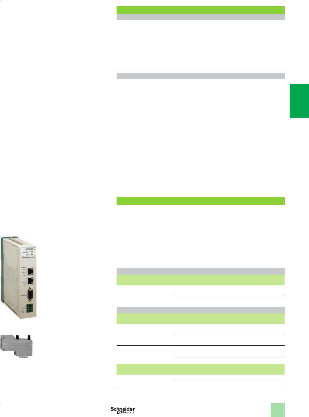
3/31
Modicon M580 automation
platform
Probus DP V1 and Probus PA buses
Probus Remote Master module
Presentation (continued),
references
Probus Remote Master (PRM) module (continued)
Connectable devices
The following Schneider Electric devices can be connected to this bus:
bTeSys U and TeSys T starter-controllers
bMomentum and Modicon STB distributed I/O
bAltivar 312/61/71 variable speed drives for asynchronous motors
bLexium 05 and 32 servo drives for brushless motors
bAltistart ATS 48 soft start-soft stop units
bLMC Packdrive 3
bOsicoder
bAny third-party device compatible with Probus DP and PA standard proles
Limitations
Once saved, the Unity project incorporates all the Probus parameters as well as
those of the slaves connected to the bus. Modicon Quantum, Premium, M580, and
M340 PLCs are capable of embedding all this data so that an empty Unity terminal
without any applications is able, after a simple transfer from the PLC, to locate the
whole application, including the slave parameters. This function is called ETS
(Empty Terminal Service).
In certain cases, it may be that the memory size required to save the device
parameters exceeds the PLC memory capacity (signaled by a “memory full”
message during the build). This is particularly likely on devices which have DTM (the
most common instrumentation on PA). Typically, each device of this type takes up
around 20 KB of the PLC memory.
It is therefore essential to create a memory map according to the type of conguration
used and possibly adapt it accordingly, either by increasing the amount of memory
dedicated to the application (by reducing the zone allocated to data), or by
increasing the overall memory via cartridges available in the catalog.
If the ETS function is not required, Unity Pro can also be congured in such a way as
to reduce the size of the embedded data by disabling comments and animation tables,
or by disabling the upload function so that the application does not include data
relating to DTMs. In this case, the upload from an empty terminal function is no
longer available.
References
The Probus Remote Master module is supplied with a CD-ROM, which includes:
bThe PRM master DTM for operating the PRM on Quantum, Premium, or M340
starting from Unity V5.0
bThe PRM Gateway DTM for operating the PRM on M580 starting from Unity V8.0
bThe generic Probus DTM for managing devices not provided with DTM but just
with gsd les
bThe PRM communication DTM providing total communication transparency from
any FDT tool (out of Unity) up to the Probus devices
bA library of DFBs for PRM management or support of explicit DP V1
communication with Probus slaves
bPRM technical documentation
Probus Remote Master modules
Description Type Reference Weight
kg/lb
Probus Remote Master
modules
Standard TCSEGPA23F14F 0.620/
1.367
Ruggedized (1) TCSEGPA23F14FK 0.620/
1.367
Probus DP bus connection components
Description Type Reference Weight
kg/lb
Distributed I/O
on Probus DP bus
Modicon STB
network interface module
STBNDP2212 0.140/
0.309
Momentum communication
module
170DNT11000 0.070/
0.154
Connectors for remote I/O
communication module
Line terminators 490NAD91103 –
In-line connector 490NAD91104 –
In-line connector 490NAD91105 –
Description Length Reference Weight
kg/lb
Probus DP
connection cables
100 m/328.08 ft TSXPBSCA100 –
400 m/1,312.33 ft TSXPBSCA400 –
(1) Conformal coating and extended operating temperatures between - 25 and + 70 °C/
- 13 and 158°F (see ruggedized module characteristics, page 5/2)
490NAD91103
TCSEGPA23F14F
2
1
3
4
5
6
7
8
9
10
2
1
3
4
5
6
7
8
9
10

4/0
2
1
3
4
5
6
7
8
9
10
2
1
3
4
5
6
7
8
9
10

4/1
Contents
Unity Pro software
Selection guide .............................................page 4/2
b Presentation...........................................................................................page 4/4
b FDT/DTM.................................................................................................page 4/4
b Programming languages ...................................................................... page 4/5
b Functions ...............................................................................................page 4/6
b Communication drivers ...................................................................... page 4/16
b Windows OS compatibility.................................................................. page 4/16
b Unity Pro update ..................................................................................page 4/17
b References ...........................................................................................page 4/18
Unity EFB Toolkit software
b Presentation, setup .............................................................................page 4/22
b References ...........................................................................................page 4/23
Unity DIF software
b Presentation, setup .............................................................................page 4/24
b References ...........................................................................................page 4/25
Unity Loader software
b Presentation.........................................................................................page 4/26
b References ...........................................................................................page 4/27
Unity Specic libraries
b Presentation.........................................................................................page 4/28
b References ...........................................................................................page 4/29
OPC data server software
b Presentation.........................................................................................page 4/30
b Architectures .......................................................................................page 4/31
b Setup ....................................................................................................page 4/33
b Functions .............................................................................................page 4/34
b References ...........................................................................................page 4/35
b Time stamping system ........................................................................page 4/36
v Presentation .......................................................................................... page 4/36
v Architectures ......................................................................................... page 4/36
v Performance.......................................................................................... page 4/37
4 - Software
2
1
3
4
5
6
7
8
9
10
2
1
3
4
5
6
7
8
9
10
2
1
3
4
5
6
7
8
9
10
2
1
3
4
5
6
7
8
9
10
2
1
3
4
5
6
7
8
9
10
2
1
3
4
5
6
7
8
9
10
4/2 4/2
Unity Pro programming software for Modicon M340 M, Modicon M580 M5, Premium P, Quantum Q, Safety Sand Modicon distributed I/O D platforms Unity Pro programming software for Modicon M340 M, Modicon M580 M5, Premium P, Quantum Q, Safety Sand Modicon distributed I/O D platforms
IEC 61131-3
languages
Instruction List (IL) M - D M - M5 - P - Q - D M - M5 - P - Q - D M - P - Q - D
Ladder (LD) M - D M - M5 - P - Q - D M - M5 - P - Q - D M - P - Q - S - D
Structured Text (ST) M - D M - M5 - P - Q - D M - M5 - P - Q - D M - P - Q - D
Function Block Diagram (FBD) M - D M - M5 - P - Q - D M - M5 - P - Q - D M - P - Q - S - D
Sequential Function Chart (SFC)/Grafcet M - D M - M5 - P - Q - D M - M5 - P - Q - D M - P - Q - D
Ladder Logic Language LL984 MM - Q M - QM - Q
Programming
services
Multitask programming (Master, fast and
event-triggered)
M - D M - M5 - P - Q - D M - M5 - P - Q - D M - P - Q - D
Multitask programming (Master, fast, auxiliary
and event-triggered)
M5 M5 - P (TSXP575p) - Q (140CPU651/671) - D P (TSXP575p) - Q (140CPU651/671) - D
Functional view and function modules M - D M - M5 - P - Q - D M - M5 - P - Q - D M - P - Q - S - D
DFB editor and instances M - D M - M5 - P - Q - D M - M5 - P - Q - D M - P - Q - S - D
DDT compound data editors M - D M - M5 - P - Q - D M - M5 - P - Q - D M - P - Q - D
Data structure instances and tables M - D M - M5 - P - Q - D M - M5 - P - Q - D M - P - Q - D
EF and EFB libraries M - D M - M5 - P - Q - D M - M5 - P - Q - D M - P - Q - D
User-denable control loops P (TSXP572p/3p/4p)- D P (TSXP572p/3p/4p/5p)- D P (TSXP572p/3p/4p/5p)- D
Programmable control loops (with process
control FB library)
M - D M - M5 - P - Q - D M - M5 - P - Q - D M - P - Q - D
Safety function block libraries S - D
Motion function block (MFB) libraries M - D M - M5 - P - Q - D M - M5 - P - D M - P - D
Hot Standby PLC redundancy system P (TSXH5724M/44M) - D P (TSXH5724M/44M) - Q (140CPU67160) - D P (TSXH5724M/44M) - Q (140CPU67160) - S - D
System and Application diagnostics M - D M - M5 - P - Q - D M - M5 - P - Q - D M - P - Q - S - D
Bus and network conguration to slave devices
(Modicon distributed I/O, etc.)
M - D M - M5 - P - Q - D M - M5 - P - Q - D M - P - Q - D
Debugging
and display
services
PLC simulator M - D M - M5 - P - Q - D M - M5 - P - Q - D M - P - Q - S - D
Hypertext link animations in graphic languages M - D M - M5 - P - Q - D M - M5 - P - Q - D M - P - Q - S - D
Step by step execution, Breakpoint,
Watchpoint
M - D M - M5 - P - Q - D M - M5 - P - Q - D M - P - Q - S - D
Trending tool M - D M - M5 - P - Q - D M - M5 - P - Q - D M - P - Q - S - D
Operator screens, Animation tables M - D M - M5 - P - Q - D M - M5 - P - Q - D M - P - Q - S - D
Diagnostics viewer M - D M - M5 - P - Q - D M - M5 - P - Q - D M - P - Q - S - D
Other
services
Creation of hyperlinks M - D M - M5 - P - Q - D M - M5 - P - Q - D M - P - Q - S - D
XML/XVM import/export M - D M - M5 - P - Q - D M - M5 - P - Q - D M - P - Q - S - D
Application converters (Modsoft, Concept,
ProWORX, PL7)
MM - M5 - P - Q - D M - M5 - P - Q - D M - P - Q - D
Utilities for updating PLCs and Advantys
operating system
M - D M - M5 - P - Q - D M - M5 - P - Q - D M - P - Q - D
Communication drivers for Modicon platforms M - D M - M5 - P - Q - D M - M5 - P - Q - D M - P - Q - S - D
Unity Pro servers - Openness (OFS,
3rd party tools)
M - D M - M5 - P - Q - D M - M5 - P - Q - D M - P - Q - S - D
Online modication of the conguration M5 - Q M5 - Q
Online modication of the program M - P - Q M - M5 - P - Q M - M5 - P - Q
Importing of applications (Modsoft, Concept,
ProWORX) written in LL984 language
MM - Q M - Q M - Q
Data dictionary, Dynamic exchange with
SCADA through OFS
M - M5 - P - Q - D M - P - Q - S - D
Static exchange via XML/XVM export les M - D M - M5 - P - Q - D M - M5 - P - Q - D M - P - Q - S - D
Compatible
Modicon
platforms
Modicon M340 CPUs MAll models All models All models All models
Modicon M580 CPUs M5 BMEP5810/5820/5830 All models –
Premium CPUs P–TSXP57104M/1634M/154M
TSXP57204M/2634M/254M
TSXP57304M/3634M/354M
TSXP574634/454M
TSXH5724/44M
TSXP57104M/1634M/154M
TSXP57204M/2634M/254M
TSXP57304M/3634M/354M
TSXP574634M/454M
TSXP575634M/554M
TSXP576634M
TSXH5724M/44M
TSXP57104M/1634M/154M
TSXP57204M/2634M/254M
TSXP57304M/3634M/354M
TSXP574634M/454M
TSXP575634M/554M
TSXP576634M
TSXH5724M/44M
Quantum CPUs Q–140CPU31110
140CPU43412U
140CPU53414U
140CPU31110
140CPU43412U
140CPU53414U
140CPU65150/60
140CPU65260
140CPU67160
140CPU67260/61
140CPU31110
140CPU43412U
140CPU53414U
140CPU65150/60
140CPU65260
140CPU67160
140CPU67260/61
Safety CPUs S– – – 140CPU65160S
140CPU67160S
Compatible Modicon distributed I/O DSTB, OTB, TM7, ETB, Momentum STB, OTB, TM7, ETB, Momentum STB, OTB, TM7, ETB, Momentum STB, OTB, TM7, ETB, Momentum
Software name Unity Pro Small Unity Pro Large Unity Pro Extra Large Unity Pro XL Safety
Unity Pro package UNYPROSP80 UNYPROLP80 UNYPROXLP80 UNYSPUXF●CD70
License, see page 4/18 4/19 4/20 www.schneider-electric.com
Selection guide Software
Unity Pro software
4/2 4/3
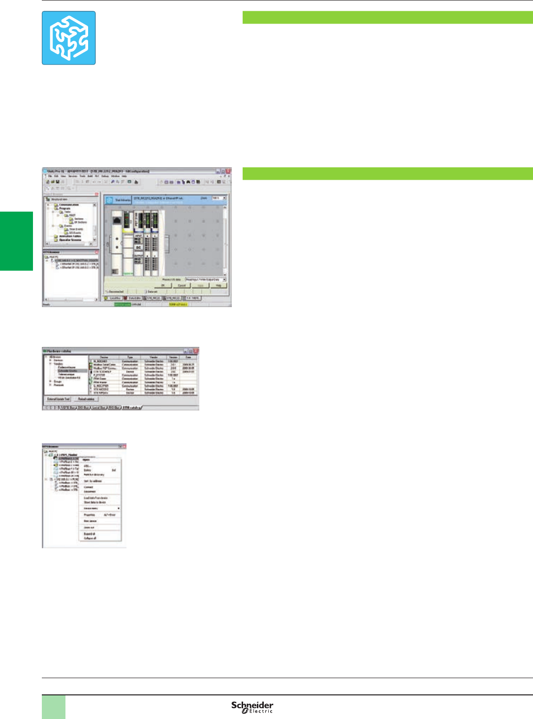
4/4
Software
Unity Pro software
Small/Large/Extra Large
Presentation,
functions
Presentation
Unity Pro is the common programming, debugging and operating software for the
Modicon M340, M580, Premium and Quantum PLC ranges.
Unity Pro is multitasking software offering the following features:
bAll-in-one software
bFive IEC 61131-3 programming languages
bLL 984 programming language
bIntegrated, customizable DFB library
bPLC simulator on PC for program validation prior to installation
bBuilt-in tests and diagnostics
bWide range of online services
FDT/DTM function
Unity Pro facilitates integration of eldbus architectures into engineering control
systems using FDT/DTM technology:
bFDT (Field Device Tool) is the container which supports the device DTMs.
bDTM (Device Type Manager) is the conguration tool for devices with integrated
graphic interfaces. It contains the properties specic to each device.
In addition to the FDT/DTM standard, Unity Pro uses specic information from the
Master DTM created for the Probus Remote Master (PRM) module and the
Modbus/TCP and EtherNet/IP network module BMXNOC0401.
Use of the Master DTM allows Unity Pro to perform the following actions:
bManage the PLC I/O scan
bCreate the application variables based on the description of the process objects
available from the connected DTM devices
bManage synchronization with the PLC conguration
bCreate a generic DTM from the description les (GSD or EDS)
The DTM conguration is stored in the PLC memory so that the application can be
downloaded in its entirety. It is also saved in the PLC project le (STU), the archive
le (STA), and the full application exchange le (ZEF).
A third-party DTM can be installed in the DTM hardware catalog.
The DTM hardware catalog can be used to sort or lter the DTMs according to
various criteria such as Device, Vendor, Groups or Protocols.
The DTM Browser in Unity Pro:
bDisplays the eldbus topologies in a tree structure
bAllows the user to congure the DTM devices:
vAdd and delete DTMs
vConnect and disconnect DTMs to/from their physical devices
vDisplay and print the properties of a DTM
vTransfer DTM conguration data to and from the physical device
vFunctions specic to the DTM, via the Device menu
Selection guide:
page 4/2
Unity Pro
DTM editor (Modicon STB island)
DTM hardware catalog
DTM browser and DTM context menu
2
1
3
4
5
6
7
8
9
10
2
1
3
4
5
6
7
8
9
10
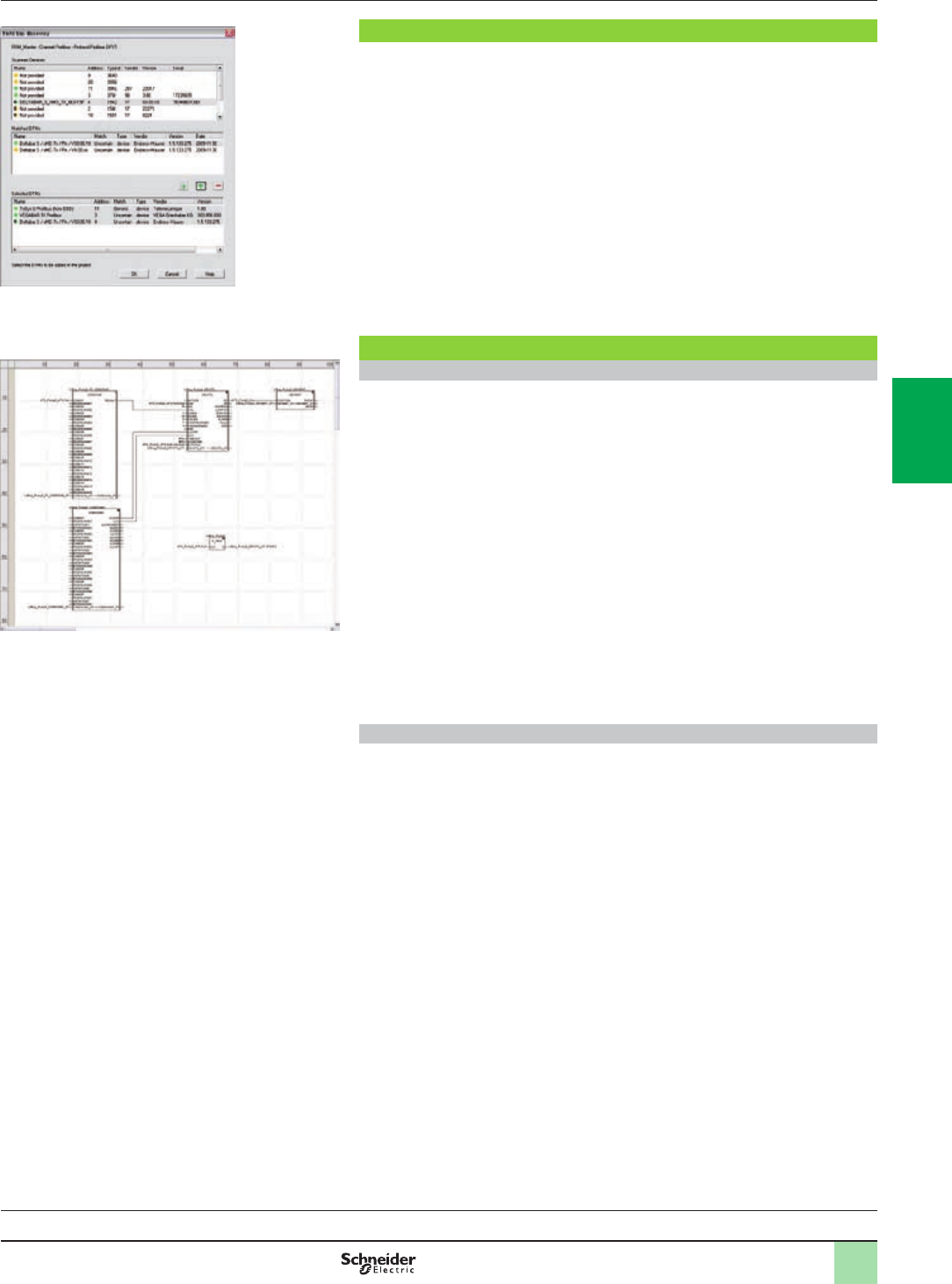
4/5
FDT/DTM function (continued)
The eldbus lookup function scans the physical devices in a eldbus network and
adds the selected devices to the DTM Browser.
Programming languages
The ve IEC 61131-3 compliant languages
The ve graphical or textual languages available in Unity Pro are used for
programming Modicon M340, Modicon M580, Premium and Quantum automation
platforms.
The three graphical languages are:
bLadder (LD) language
bFunction Block Diagram (FBD)
bSequential Function Chart (SFC) or Grafcet
The two textual languages are:
bStructured Text (ST)
bInstruction List (IL)
For these ve languages, you can use the standard set of instructions compliant with
IEC standard 61131-3 to create applications which can be transferred from one
platform to another. Unity Pro software also provides extensions to this standard set
of instructions. As they are specic to Modicon M340, Modicon M580, Premium and
Quantum PLCs, these extensions support the development of more complex
applications in order to maximize the potential of the specic features of each of
these platforms.
LL984 language
LL984 (Ladder Logic 984) language enables migration from legacy Modicon ranges.
It is used to program Modicon M340 and Quantum automation platforms.
Software
Unity Pro software
Small/Large/Extra Large
Functions (continued)
Selection guide:
page 4/2
Fieldbus lookup screen
FBD language editor
2
1
3
4
5
6
7
8
9
10
2
1
3
4
5
6
7
8
9
10
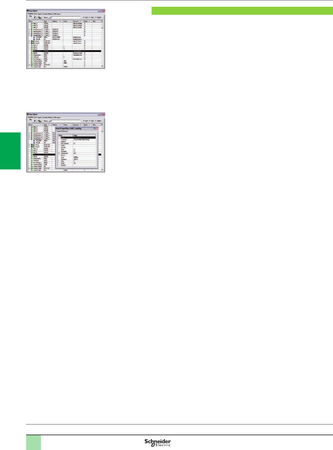
4/6
Software
Unity Pro software
Small/Large/Extra Large
Data editor
The data editor provides a single tool for performing the following editing tasks:
bDeclaration of data including variables and function blocks (declaration of their
type, instances and attributes).
bUse and archiving of function block data types in different libraries.
bHierarchical view of data structures.
bSearching, sorting and ltering of data.
bCreation of a hyperlink to access a description from any variable comment.
The data is displayed in four tabs:
b“Variables” tab for the creation and management of the following data instances:
Bits, words, double words, inputs/outputs, tables and structures.
b“DDT Types” tab for the creation of derived data types (tables and structures).
b“Function Blocks” tab for the declaration of EFBs and DFBs.
b“DFB Types” tab for the creation of DFB user function block data types.
Each data element has several attributes, of which:
bThe variable name and type are mandatory.
bThe comment, physical address in the memory and initial values are optional.
The data editor columns can be congured (number of columns, order). The
attributes associated with a variable can be displayed in a properties window.
This editor can be accessed at any time during programming by selecting variables
for data modication or creation.
Functions (continued)
Selection guide:
page 4/2
Data editor
Data properties
2
1
3
4
5
6
7
8
9
10
2
1
3
4
5
6
7
8
9
10
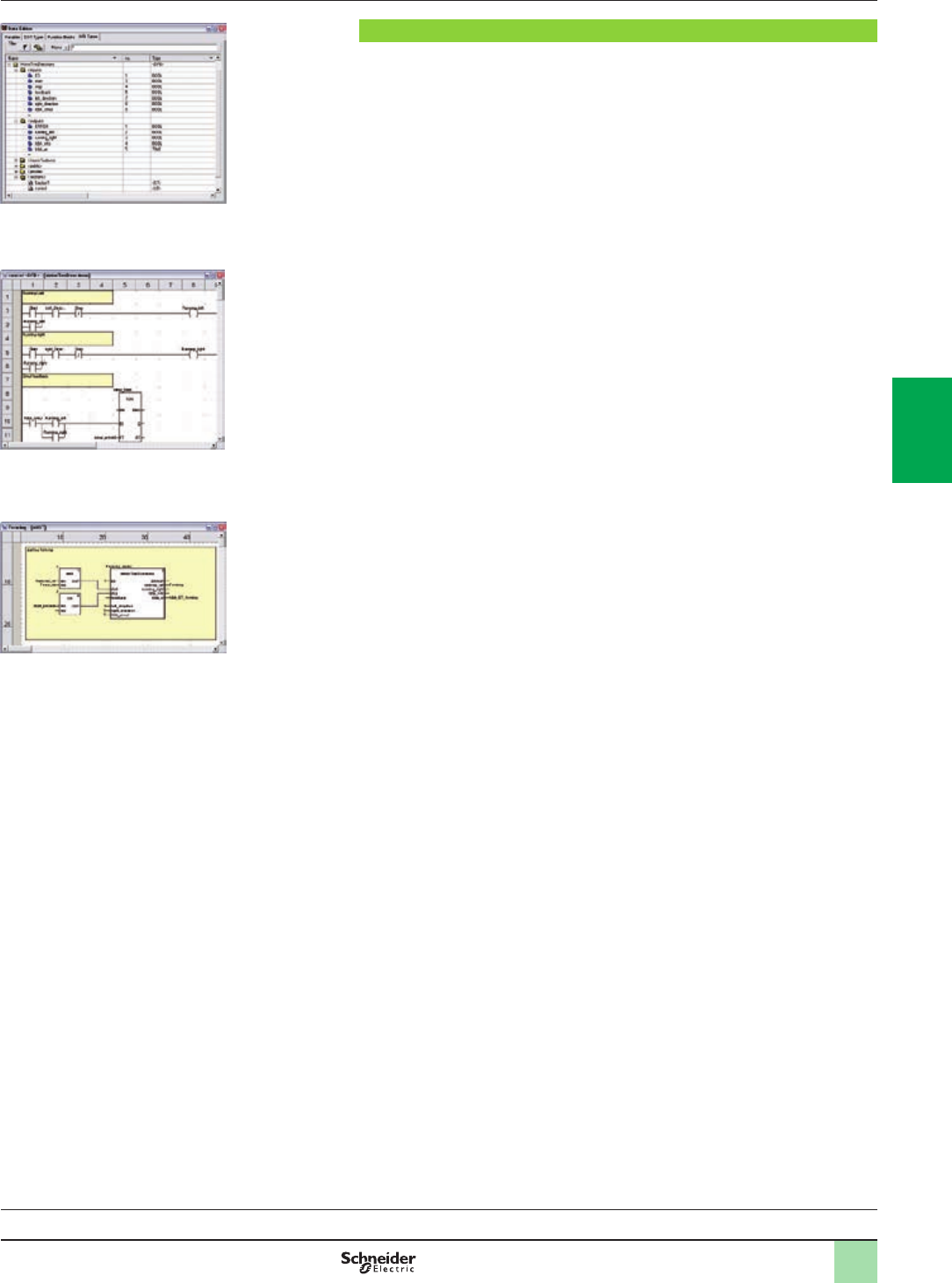
4/7
Software
Unity Pro software
Small/Large/Extra Large
DFB user function blocks
With Unity Pro software, users can create their own function blocks for specic
application requirements on Modicon M340, Modicon M580, Premium and Quantum
platforms.
Once created and saved in the library, these user function blocks can be reused as
easily as EFBs (Elementary Function Blocks).
The user function blocks can be used to structure an application. They are used
when a program sequence is repeated several times in the application or for freezing
a standard programming routine. They can be read-only or read/write. They can be
exported to all other Unity Pro applications.
Using a DFB in one or more applications:
bSimplies program design and entry.
bImproves program readability and understanding.
bFacilitates program debugging (variables handled by the DFB are identied in the
data editor).
bEnables the use of private variables specic to the DFBs, which are independent
of the application.
A DFB is set up in several stages:
bThe DFB is designed by assigning a name, a set of parameters (inputs, outputs,
public and private internal variables) and a comment to it via the data editor.
bThe code is created in one or more sections of the program, with the following
languages selected according to requirements: Structured Text, Instruction List,
Ladder or Function Block Diagram (ST, IL, LD or FBD).
bThe DFB can be stored in a library with an associated version number.
bA DFB instance is created in the data editor or when the function is called in the
program editor.
bThis instance is used in the program in the same way as an EFB (the instance can
be created from within the program).
Functions (continued)
Selection guide:
page 4/2
Design
Creating the code
Use within the program
2
1
3
4
5
6
7
8
9
10
2
1
3
4
5
6
7
8
9
10
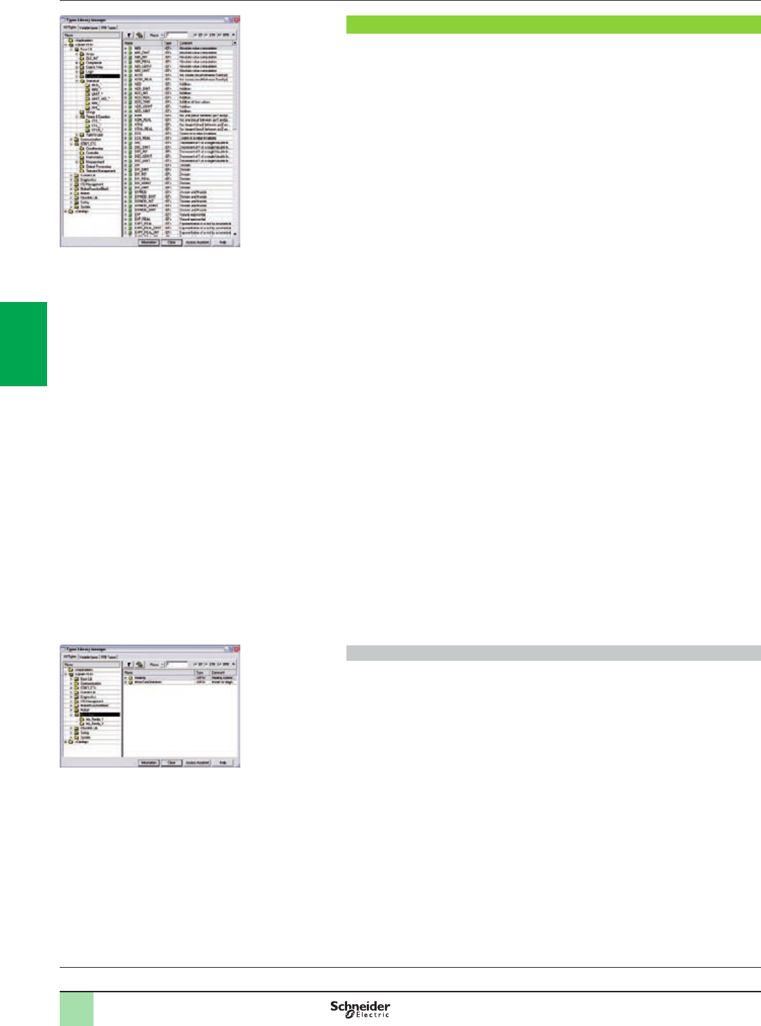
4/8
Software
Unity Pro software
Small/Large/Extra Large
Function block libraries
The function and function block libraries manager contains the elements provided
with Unity Pro software. Functions and function blocks are organized into libraries,
which themselves consist of families. Depending on the type of PLC selected and
the processor model, users will have a subset of these libraries available to write
their applications. However, the “Base Lib” library contains a set of functions and
function blocks, for the majority of which compatibility is independent of the
platforms. In particular, it contains the blocks compliant with IEC 61131-3.
The “Base Lib” library is structured into families:
bTimers and counters
bProcess control on integers
bTable management
bComparison
bDate and time management
bLogic processing
bMathematical processing
bStatistical processing
bCharacter string processing
bType-to-type data conversion
The “Base Lib” library, which covers standard automation functions, is supplemented
by other, more application-specic libraries and platform-specic functions:
bCommunication library, providing an easy means of integrating communication
programs from PLCs with those used by HMIs from the PLC application program.
Like other function blocks, these EFBs can be used in any language to exchange
data among PLCs or to deliver data to be displayed on an HMI.
bProcess control library. The CONT_CTL library can be used to set up process-
specic control loops. It offers controller, derivative and integral control functions and
additional algorithms, such as EFBs for calculating mean values, selecting a
maximum value, detecting edges or assigning a hysteresis to process values, etc.
bDiagnostics library, which can be used to monitor actuators and contains EFBs
for active diagnostics, reactive diagnostics, interlocking diagnostics, permanent
process condition diagnostics, dynamic diagnostics, monitoring of signal groups, etc.
bI/O management library, providing services to handle information exchanged
with hardware modules (formatting data, scaling, etc.).
bMotion Function Blocks library, containing a set of predened functions and
structures to manage motion controlled by drives and servo drives connected on
CANopen.
bMotion library for motion control and fast counting.
bSystem library, which provides EFBs for the execution of system functions,
including: evaluation of scan time, availability of several different system clocks, SFC
section monitoring, display of system state, management of les on the memory
cartridge of the Modicon M340 processor, M580 processor, etc.
bFinally, a library named “obsolete”, containing all function blocks used by legacy
programming software needed to perform application conversions.
Management of user standards
Users can create libraries and families in order to store their own DFBs and DDTs.
This enhancement allows users to take advantage of programming standards
adapted to their needs, along with version management. This means that it is
possible to:
bCheck the version of the elements used in an application program against those
stored in the library
bPerform an upgrade, if necessary
Functions (continued)
Selection guide:
page 4/2
Standard function block libraries
User libraries
2
1
3
4
5
6
7
8
9
10
2
1
3
4
5
6
7
8
9
10
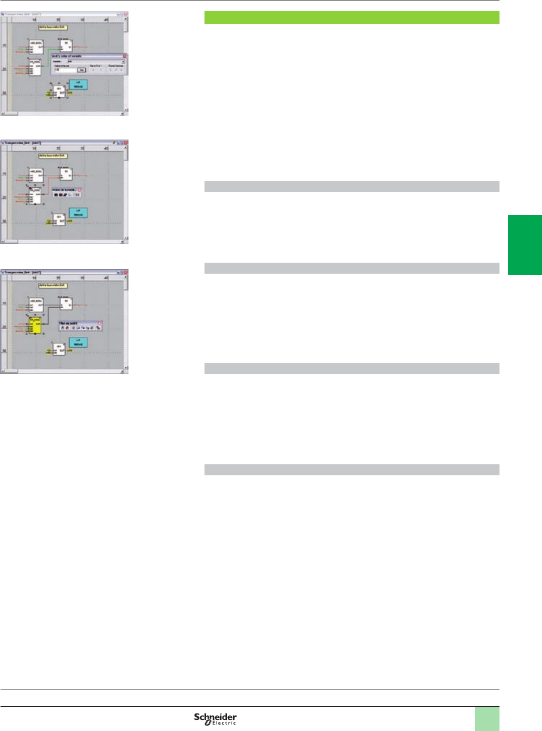
4/9
Software
Unity Pro software
Small/Large/Extra Large
Debugging tools
Unity Pro software offers a complete set of tools for debugging Modicon M340,
M580, Premium or Quantum applications. A tool palette provides direct access to the
main functions:
bDynamic program animation.
bSetting of watchpoints or breakpoints (not authorized in event-triggered tasks).
bStep-by-step program execution. A function in this mode enables section-by-
section execution. Instruction-by-instruction execution can be launched from the
previous breakpoint. Three execution commands are therefore possible when the
element to be processed is a subroutine (SR) or DFB user block instance:
vStep Into: this command is used to move to the rst element of the SR or DFB
vStep Over: this command is used to execute the entire SR or DFB
vStep Out: this command is used to move to the next instruction after the SR or
DFB element
bIndependent execution of the master (MAST), fast (FAST), auxiliary (AUX) and
event-triggered (EVTi) tasks.
Animation of program elements
Dynamic animation is managed section-by-section. A button on the toolbar is used to
activate or deactivate animation for each section.
When the PLC is in RUN, this mode can be used to view simultaneously:
bThe animation of a program section, regardless of the language used.
bThe variables window containing the application objects created automatically
from the section viewed.
Animation table
Tables containing the variables of the application to be monitored or modied can be
created by data entry or initialized automatically from the selected program section.
The tables can be stored in the application and retrieved from there at a later date.
Unity Pro can be used to save, import and export Animation tables with predened
set values. As it allows population of set values along with current values and vice
versa in the PLC, the Animation tables can be used as templates to make the
application easier to tune.
Debugging DFB user function blocks
The parameters and public variables of these blocks are displayed and animated in
real time using animation tables, with the possibility of modifying and forcing the
required objects.
In exactly the same way as with other program elements, the watchpoint, breakpoint,
step-by-step execution and program code diagnostics functions can be used to
analyze the behavior of DFBs. Setting a breakpoint in a DFB user function block
instance stops execution of the task containing this block.
Debugging in Sequential Function Chart (SFC) language
The various debugging tools are also available in SFC language. However, unlike
other sections (IL, ST, LD or FBD) an SFC section executed step-by-step does not
stop execution of the task but instead freezes the SFC chart. Several breakpoints
can be declared simultaneously within a single SFC section.
Functions (continued)
Selection guide:
page 4/2
Dynamic animation/adjustment
Watchpoint
Breakpoint/step-by-step
2
1
3
4
5
6
7
8
9
10
2
1
3
4
5
6
7
8
9
10
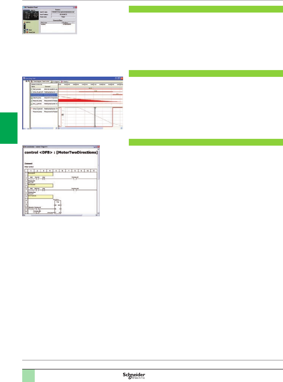
4/10
Software
Unity Pro software
Small/Large/Extra Large
PLC simulator
Unity Pro’s integrated simulator can be used to test the application program for
Modicon M340, M580, Premium or Quantum PLCs from the PC terminal without
having to connect to the PLC processor. The functions provided by the debugging
tools are available for debugging the master, fast and auxiliary tasks.
As the simulator does not manage the PLC I/O, animation tables can be used to
simulate the state of inputs by forcing them to 0 or 1.
The simulator can be connected to third-party applications via an OPC server with
OFS (OPC Factory Server) software.
Trending tool
The trending tool allows easy monitoring of variables by detecting operating
problems or improving process performance. You can select any variable in your
application and start acquisition, save records, and analyze records with integrated
tools or Excel. The PLC mast scan can scan up to 16 variables.
Documentation editor
The documentation editor is based on the Documentation Browser, which shows the
le structure in tree form.
It allows all or part of the application le to be printed on any graphics printer
accessible under Windows and using True Type technology, in A4 or US letter print
format.
The documentation editor supports the creation of user-specic les using the
following headings:
bTitle page
bContents
bGeneral information
bFooter
bConguration
bEF, EFB and DFB type function blocks
bUser variables
bCommunication
bProject structure
bProgram
bAnimation tables and cross-references
bRuntime screens
Functions (continued)
Selection guide:
page 4/2
Simulator control panel
Accessing the documentation editor
Trending tool control panel
2
1
3
4
5
6
7
8
9
10
2
1
3
4
5
6
7
8
9
10
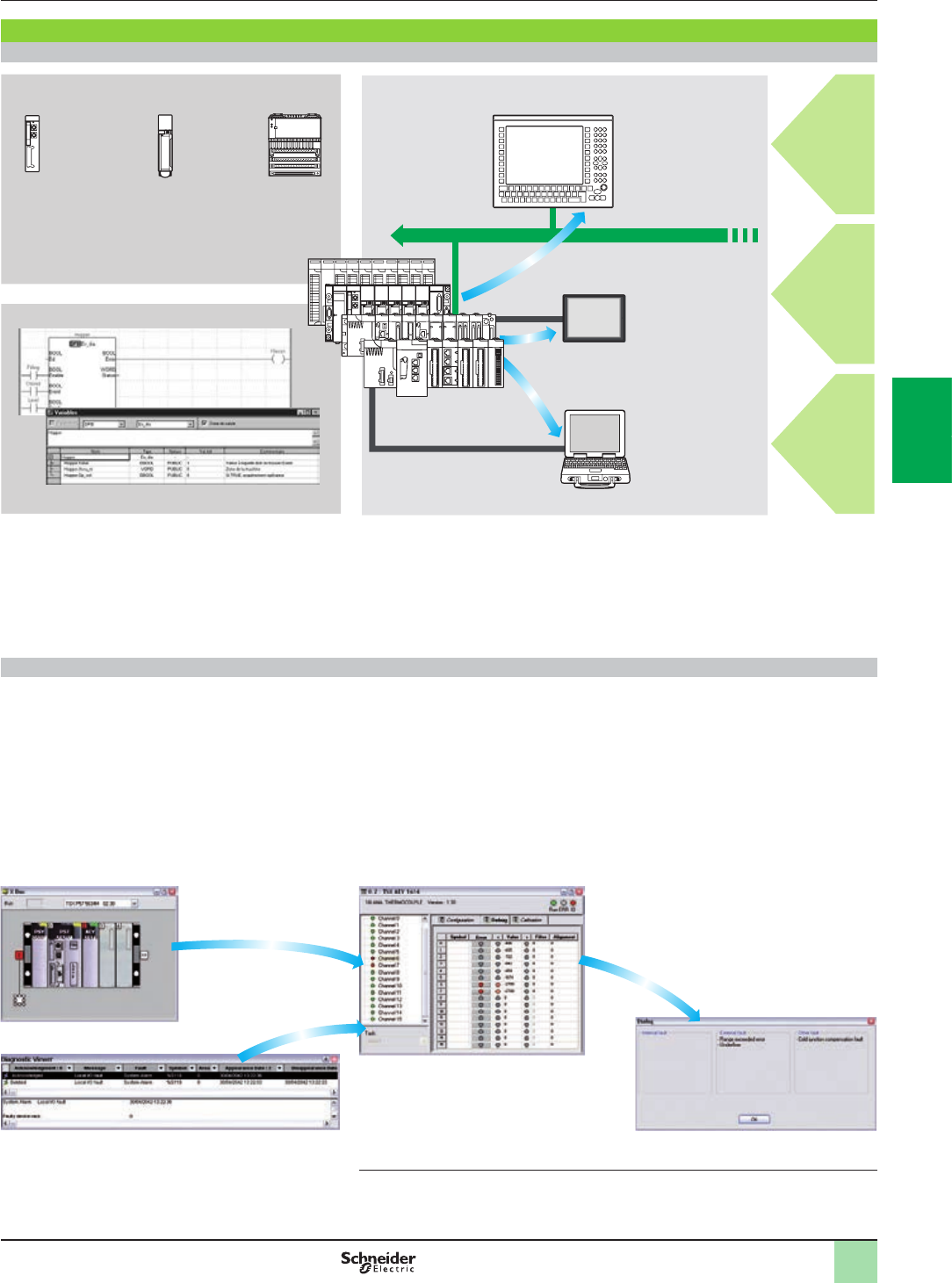
4/11
Diagnostics integrated in Modicon M340, Modicon M580, Premium and Quantum automation platforms
Presentation
The diagnostics offer for Modicon M340, M580, Premium and Quantum platforms is
based on the following three components:
bSystem diagnostics
bDFB and EFB diagnostic function blocks (for system and application diagnostics)
bError message display system, called viewers, supplied as a standard component
of Magelis XBT terminals, Vijeo Citect supervisory software and Unity Pro setup
software
System diagnostics
The system diagnostics for the Modicon M340, M580, Premium and Quantum
platforms support the monitoring of system bits/words, I/O modules and activity times
(minimum/maximum) of SFC steps. By simply choosing the relevant option during
application conguration, any event will generate time-stamped messages logged in
the diagnostic buffer of the PLC.
These events are displayed automatically in a diagnostics viewer (1) without requiring
any additional programming.
With Unity Pro integrated diagnostics, this function can be used to perform rst level
diagnostics of the elements in the conguration, up to and including each I/O module
channel.
Conguration level
Viewer window (example with Unity Pro software)
Module level
Channel level
(1) Diagnostics viewers are tools for displaying and acknowledging diagnostic error messages.
They are supplied as a standard component of Unity Pro and Vijeo Designer software, with
Magelis terminals and with the PLC Web server that can be accessed via a thin client
Magelis iPC.
Processor
for system
bits and
words
In-rack I/O
modules
Remote I/O
modules on
Fipio
or CANopen
Higher-level
M.E.S.
Cell level
Machine level
Unity Pro
Diagnostics viewersSystem diagnostics
Application diagnostics
Ethernet TCP/IP
Magelis XBT
PC
Vijeo Citect
Thin client Magelis iPC
Quantum,
Premium,
M340,
M580
Vijeo Designer
Software
Unity Pro software
Small/Large/Extra Large
Integrated diagnostics
Functions (continued)
2
1
3
4
5
6
7
8
9
10
2
1
3
4
5
6
7
8
9
10
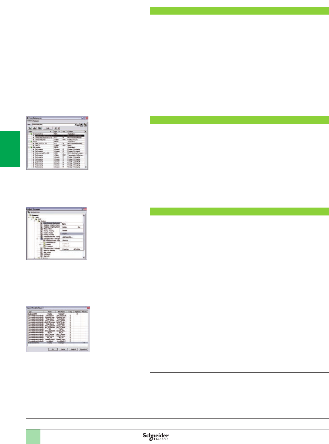
4/12
Software
Unity Pro software
Small/Large/Extra Large
Modifying the program with the PLC in RUN mode
With Unity Pro, changes can be made to the program when the PLC connected to
the programming terminal is in RUN mode. These modications are performed with
the following operations:
bThe application contained in the PLC is transferred to the PC terminal running
Unity Pro, if necessary.
bProgram changes are prepared. These program modications can be of any type
and in any language (IL, ST, LD, FBD and SFC), for example, addition or deletion of
SFC steps or actions. The code of a DFB user function block can also be modied
(however, modication of its interface is not permitted).
bThese program changes are updated in the PLC (in RUN mode).
This function makes it possible to add or modify program code and data in different
parts of the application during a single modication session (thus resulting in a
uniform, consistent modication with respect to the controlled process). This
increased exibility comes at a cost in terms of the amount of program memory
required.
Cross-references function
Unity Pro's cross-references function, which is available in standalone mode (ofine)
and when connected to the PLC in Run (online), allows users to view all the
elements of a PLC application when searching for any type of variable. This view
indicates where the declared variable is used, as well as how it is used (for writing,
reading, etc.).
This function also provides access to the Search/Replace function for variable
names.
The variable search can be initialized from any editor (language, data, runtime
screen, animation table, etc.).
Import/export function
The import/export function available in Unity Pro supports the following operations
from the structural and functional project views:
bVia the import function, reuse all or part of a previously created project in the
current project.
bVia the export function, copying of all or part of the current project to a le for
subsequent reuse.
The les generated during export are generally in XML format (1). However, in
addition to XML, variables can be exported and imported in the following formats:
b.xvm format compatible with OFS data server software.
bSource format, in an .scy le compatible with PL7 development software.
bText format with separator (TAB) in a .txt le for compatibility with any other
system.
During an import, a wizard can be used to reassign data to new instances of:
bDFB function blocks
bDDT data structures
bSimple data
In addition, when a functional module is imported, the data associated with
animation tables and runtime screens is also reassigned.
The XML import function also supports the transfer of a Modicon M340,
Modicon M580, Premium or Quantum PLC conguration prepared in the SIS Pro
costing and conguration tool for use in the creation of a project in Unity Pro.
This import function spares the user from having to redene the PLC conguration
when the PLC has already been congured with the SIS Pro tool.
(1) XML language is an open, text-based language that provides structural and semantic
information.
Functions (continued)
Selection guide:
page 4/2
Cross-references table
Data export shortcut menu
Data import wizard
2
1
3
4
5
6
7
8
9
10
2
1
3
4
5
6
7
8
9
10
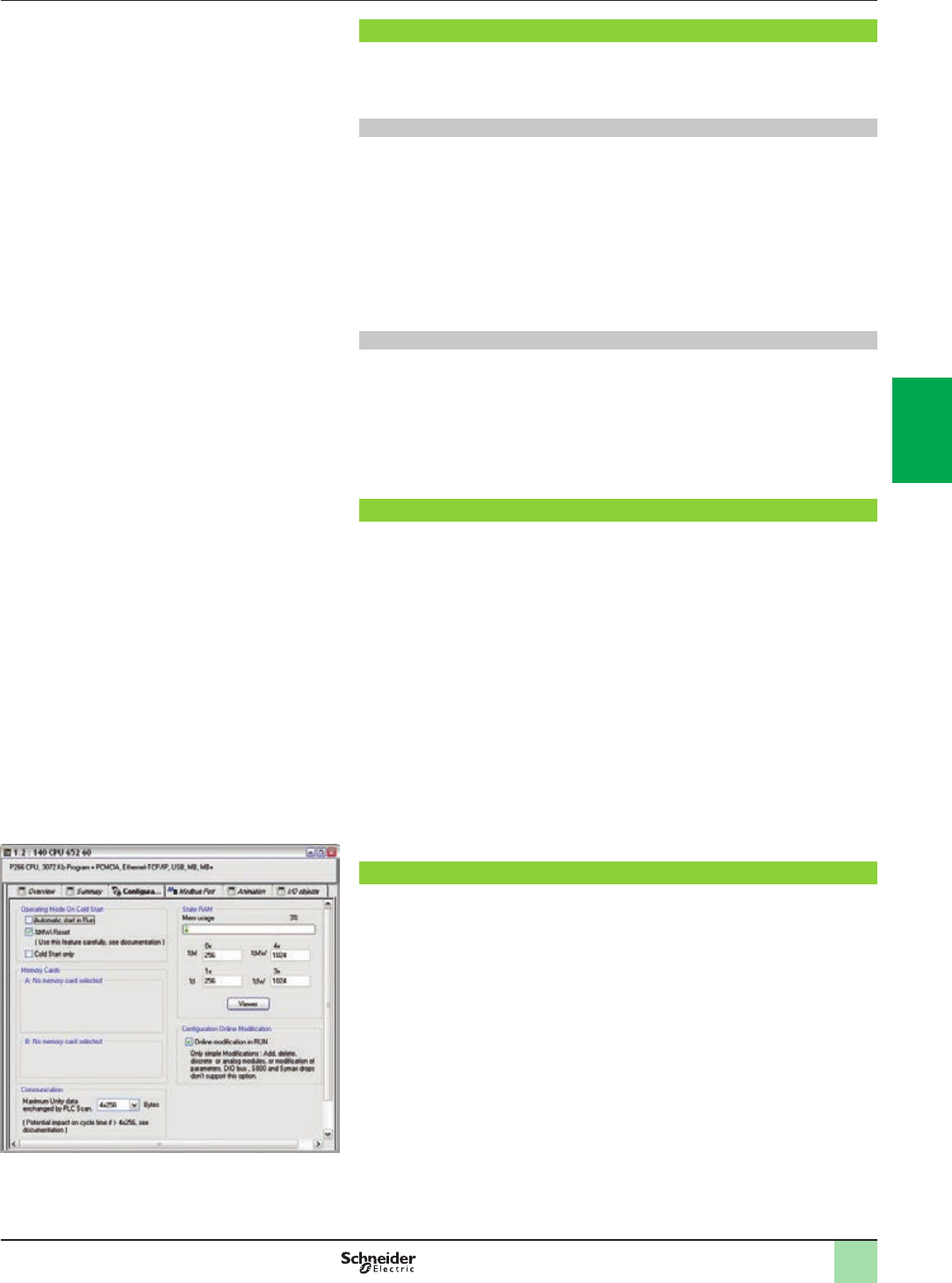
4/13
Software
Unity Pro software
Small/Large/Extra Large
Application converters
Unity Pro’s integrated conversion tools can be used to convert PLC applications
created with ModSoft, ProWorX, Concept and PL7 programming software to Unity
Pro applications.
Concept/Unity Pro converter (Quantum PLC)
This conversion is performed with a Concept application V2.5 or later (it can also be
performed in V2.11 or later, but only after an update to V2.5). In order to perform the
conversion, the application must be exported to an ASCII le in Concept.
The export le is converted to a Unity Pro source le automatically. This le is then
analyzed by Unity Pro. At the end of the procedure, a conversion report is generated
and an output window displays any conversion errors and provides direct access to
the part of the program to be modied.
The Concept application converter converts the application to Unity Pro, but does
not guarantee that it will operate correctly in real time. It is therefore essential to test
or debug all converted applications.
PL7/Unity Pro converter (Premium PLC and Atrium slot PLC)
This conversion is performed with a PL7 application V4 or later (Premium PLC or
Atrium slot PLC). In order to perform the conversion, the source le (complete
application or user function block) must be exported in PL7.
The conversion procedure is similar to that of the Concept conversion described
above.
Note: Applications created with Concept, Modsoft and ProWORX can be converted to LL984.
Please contact our Customer Care Center.
Operating system update utilities
The OS-Loader software is designed for updating operating systems on Premium
and Quantum platforms. It is supplied with Unity Pro software.
It is used to upgrade Unity processors and modules as well as to upgrade PL7 or
Concept processors and modules to make them compatible with Unity Pro.
OS-Loader software supports:
bPremium processors
bQuantum processors
bEthernet communication modules
bEtherNet/IP communication modules
The operating system updates are performed as follows:
bUni-Telway RS 485 terminal link for Premium processors
bModbus or Modbus Plus terminal link for Quantum processors
bEthernet TCP/IP network for integrated Ethernet port on Premium processors and
Premium and Quantum Ethernet modules
Note: For Modicon M340 and M580 this service is provided by Unity Loader (see page 4/26).
Online modication of the Quantum conguration
This function, also called Change Conguration On The Fly (CCOTF), is used to modify
the Quantum conguration online (application in RUN mode):
bAddition or removal of discrete or analog I/O modules
bModication of conguration parameters of discrete or analog I/O modules
(already present or newly installed)
The CCOTF function is supported by standalone processors for all three types of I/O
architecture (local, RIO, DIO) using version 5 of Unity Pro, and for Hot Standby
processors using version 4.1 or higher of Unity Pro.
The CCOTF function must rst be validated in the Unity Pro conguration screen.
A conrmation screen appears when the conguration has been modied online.
Functions (continued)
Conguration screen
2
1
3
4
5
6
7
8
9
10
2
1
3
4
5
6
7
8
9
10
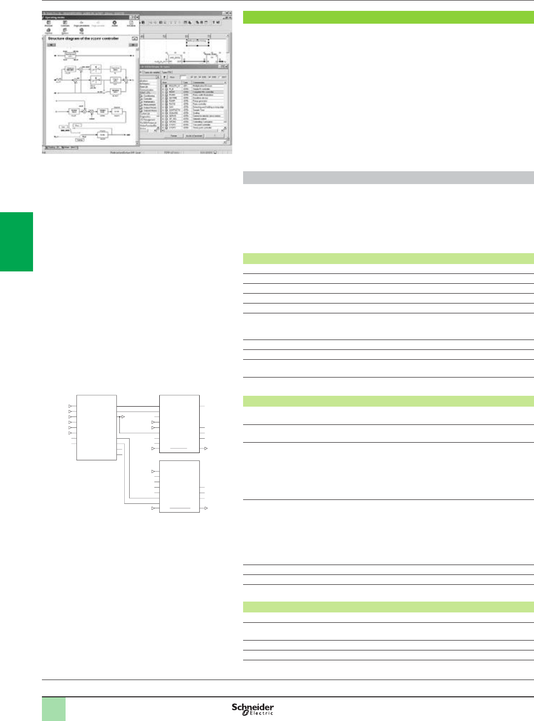
4/14
Functions (continued) Software
Unity Pro software
Small/Large/Extra Large
Programmable process control
Process control in machines
Unity Pro contains CONT_CTL, a library of 36 function blocks used to create control
loops for machine control.
The requirements for closed loop control functions in machines are adequately met
by Modicon M340, Modicon M580, Premium and Quantum platforms thanks to the
wealth of functions in the library and the exibility with which function blocks can be
linked together through programming. This solution therefore avoids the need for
external controllers and simplies the overall control architecture of the machine, as
well as its design, roll-out and operation.
The EFs or EFBs can be used in any of the Unity Pro languages (LD, ST, IL and
FBD). FBD is particularly suitable for accessing control processing operations in
Unity Pro through its wizard for entering and viewing parameters and function block
variables.
CONT_CTL library functions
The library consists of ve function families:
bInput data conditioning
bControllers
bMathematical functions
bProcess value processing
bOutput value processing
Input data conditioning
DTIME Pure time delay
INTEGRATOR Integrator with limiting
LAG_FILTER First order time lag
LDLG Lead/lag function with smoothing
LEAD Lead function with smoothing
MFLOW Mass ow calculation based on the measurement of differential
pressure or ow speed with pressure and temperature
compensation
QDTIME Dead time term
SCALING Scaling
TOTALIZER Integrator (typically of ow) until a limit (typically a volume) is
reached, with automatic reset
VEL_LIM Velocity limiter, with manipulated variable limiting
Controllers
PI_B Basic PI controller: PI algorithm with a mixed structure
(series/parallel)
PIDFF Complete PID controller: PID algorithm with a parallel or mixed
structure (series/parallel)
AUTOTUNE Automatic tuner setting for the PIDFF (complete PID) controller or
the PI_B (simple PI) controller
v Identication using Ziegler Nichols type method
v Modeling based on rst-order process
v Building of control parameters with criterion for prioritizing
either the reaction time to disturbance (dynamic) or the stability
of the process
IMC Model-based controller. The model is a rst-order model with
delay. This corrector is useful:
v When there are serious delays compared with the main time
constant of the process; this scenario cannot be satisfactorily
resolved by standard PID process control
v For regulating a non-linear process IMC can handle any stable
aperiodic process of any order.
SAMPLETM Control of controller startup and sampling
STEP2 Simple two-position controller
STEP3 Three-position controller for temperature regulation
Mathematical functions
COMP_DB Comparison of two values, with dead zone and hysteresis
K_SQRT Square root, with weighting and threshold, useful for linearization
of ow measurements
MULDIV_W Weighted multiplication/division of 3 numerical values
SUM_W Weighted summing of 3 numerical values
CONT_CTL, programmable process control integrated in
Unity Pro
AUTOTUNE
PV
SP
RCPY
START
PREV
PARA
TR_I
TR_S
PV_O
SP_O
PARA_C
TRI
TRS
INFO
STATUS
TT18_PV
TT18_SP
TC18_OUT
TC18_START
TC18_PREV
TC_PARA
TC18_PARA
TC18_OUT
1
TC2_OUT
TC2_OUT
TC18_OUT
PV
SP
PARA
TR_I
TR_S
PIDFF
FF
RCPY
MAN_AUTO
OUT OUT
OUTD
MA_O
INFO
STATUT
TC2_OUT
MS
TC18_OUT
IN
PARA
TR_I
TR_S
FORC
MA_FORC
MAN_AUTO
OUT OUT
OUTD
MA_O
STATUT
Example: PID controller with MS manual control
Selection guide:
page 4/2
2
1
3
4
5
6
7
8
9
10
2
1
3
4
5
6
7
8
9
10
4/15
Functions (continued),Software
Unity Pro software
Small/Large/Extra Large
Programmable process control
Process control in machines (continued)
CONT_CTL library functions (continued)
Process value processing
AVGMV Moving average with xed number of samples (50 max.)
AVGMV_K Moving average with constant correction factor, 10,000 samples
max.
DEAD_ZONE Dead zone
LOOKUP_TABLE1 Linearization of characteristic curves using rst-order interpolation
SAH Detection of a rising edge
HYST_XXX Detection of high threshold with hysteresis (1)
INDLIM_XXX Detection of high and low thresholds with hysteresis (1)
Output value processing
MS Manual control of an output
MS_DB Manual control of an output with dead zone
PWM1 Control via pulse width modulation
SERVO Control for servo motors
SPLRG Control of two Split Range actuators
Setpoint management
RAMP Ramp generator, with separate ascending and descending ramps
RATIO Ratio controller
SP_SEL Selection of setpoint value: local (operator) or remote (processing)
Setting up process control function blocks
Based on the sequencing of function blocks, the FBD language integrated in Unity
Pro is a programming language particularly suitable for building control loops.
Designers can use FBD to easily associate blocks from the CONT_CTL library with
their own DFBs written in Unity Pro’s ST, IL or LD language, or in C language.
Debugging, operation
All Unity Pro’s standard debugging services (see page 4/9) are available. In
particular, the PLC simulator can be used to check correct execution of processing
ofine.
Compatibility
The CONT_CTL control function block library is available in all versions of Unity Pro.
It is compatible with processors in the Modicon M340, Modicon M580, Premium and
Quantum ranges.
Optional specialized libraries
The CONT_CTL control function block library can be supplemented with optional
specialized libraries, to meet specic needs such as predictive control, fuzzy logic
controller, HVAC and mass ow calculation (see page 4/28).
Resources
The technical documentation provides many examples of how to set up
programmable process control function blocks in FBD, LD, IL and ST languages.
The techniques for adjusting process control loops are described in the document
“Process control, Unity V3.0” available online at www.schneider-electric.com.
(1) XXX according to the type of variable: DINT, INT, UINT, UDINT, REAL.
Programming in Unity Pro in ofine mode
Programming in online mode
Selection guide:
page 4/2
2
1
3
4
5
6
7
8
9
10
2
1
3
4
5
6
7
8
9
10
4/16
Software
Unity Pro software
Small/Large/Extra Large
Communication drivers
The most commonly used communication drivers for Modicon M340, M580,
Premium and Quantum platforms are installed at the same time as the Unity Pro
software.
Unity Pro also includes the following drivers, which can be installed as required (1):
Protocol - Hardware Windows®XP
Professional
Windows® 7
32-bit and 64-bit
editions
Windows®8
32-bit and 64-bit
editions
Ethway - Ethernet
Fip - FPC10 ISA card
Fip - FPC20 PCMCIA card
Fip adaptor - CUSBFIP
ISAway - PCX57 ISA card
Modbus Serial - COM port
PCIway - Atrium TPCI57 PCI card
Uni-Telway - COM port
Uni-Telway - SCP114 PCMCIA card
USB for high end PLC
XIP - XWay on TCP/IP
Driver available Driver not available
Upgrade kits for Concept, PL7 Pro and ProWORX software
The Concept, PL7 Pro and ProWORX upgrade kits allow users who already have
one of these programs from the installed base, and who have a current subscription,
to obtain Unity Pro version V4.1 software at a reduced price.
These upgrades are only available for licenses of the same type (e.g. from Concept
XL group license to Unity Pro Extra Large group license).
Composition and Windows® OS compatibility
Unity Pro multilingual software packages are compatible with Windows XP (32-bit),
Windows 7 (32-bit and 64-bit) and Windows 8 (32-bit and 64-bit) (2) operating
systems.
They include:
bDocumentation in electronic format in six languages (English, French, German,
Italian, Spanish and Chinese)
bConverters for converting applications created with Concept and PL7 Pro
programming software
bPLC simulator
Cables for connecting the processor to the programming PC must be ordered
separately.
(1) Also available separately under reference TLXCDDRV20M.
(2) Windows 8 can be used only in Windows 7 compatibility mode.
Functions (continued)
Selection guide:
page 4/2
2
1
3
4
5
6
7
8
9
10
2
1
3
4
5
6
7
8
9
10
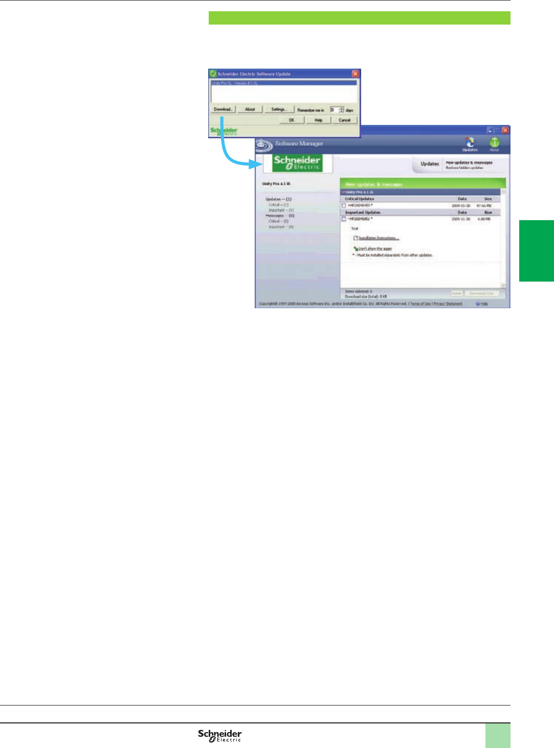
4/17
Unity Pro update
Customers are notied automatically when a new Unity Pro update becomes
available.
They can then access the software updates manager directly, download the update
and install it locally on their workstation.
Note: The latest rmware versions can be downloaded from our website
www.schneider-electric.com.
Functions (continued) Software
Unity Pro software
Small/Large/Extra Large
Selection guide:
page 4/2
2
1
3
4
5
6
7
8
9
10
2
1
3
4
5
6
7
8
9
10

4/18
References
Unity Pro software packages
These software packages are for programming and setting up Unity automation
platforms. The software is available in three versions:
bUnity Pro Small UNYPROSP80 (see page 4/18).
bUnity Pro Large UNYPROLP80 (see page 4/19).
bUnity Pro Extra Large UNYPROXLP80 (see page 4/20).
Upgrade kits for Concept, PL7 Pro and ProWORX software
These upgrade kits allow users who already have these software programs from the
installed base and who have a current subscription to obtain Unity Pro version
V8.0 software at a reduced price. These upgrades are only available for licenses of
the same type (e.g. from Concept XL group license to Unity Pro Extra Large group
license). See page 4/20.
Subscription renewal of Unity Pro software packages
If the user renews the subscription support before the end of renewal date:
bThe new subscription period starts automatically at the end of the previous one.
bNew versions of the software are sent to the customer during the subscription
period.
Expired subscription renewal of Unity Pro software packages (1)
If the user renews the subscription after the end of the renewal date:
bThe latest version of the software is sent to the customer.
bThe customer must register within three months for the new subscription period.
bThe new subscription period starts at the time of registration.
bNew versions of the software are sent to the customer during the subscription
period.
bThere is no subscription support during the time elapsed between the two
periods.
Composition and Windows OS compatibility
Unity Pro multilingual software packages are compatible with Windows XP (32-bit),
Windows Vista Business Edition (32-bit) and Windows 7 (32-bit and 64-bit)
operating systems. The packages comprise:
bA Unity Pro V8.0 DVD in six languages (English, French, German, Italian,
Spanish and Chinese).
bA Unity Loader V8.0 CD.
bAn Advantys V8.0 conguration software CD.
bA DVD containing the documentation in electronic format in six languages
(English, French, German, Italian, Spanish and Chinese).
bA one-year service subscription.
Unity Pro Small version 8.0 software
For Modicon M340: All models
For distributed I/O: Modicon ETB, TM7, OTB, STB, Momentum
Unity Pro Small version 8.0 software packages (1) (2)
Description License type Reference Weight
kg/lb
Unity Pro Small
software packages
Single (1 station) UNYSPUSFUCD80 –
Group (3 stations) UNYSPUSFGCD80 –
Team (10 stations) UNYSPUSFTCD80 –
Software upgrades from:
- Concept S
- PL7 Micro
- ProWORX NxT/32 Lite
Single (1 station) UNYSPUSZUCD80 –
Group (3 stations) UNYSPUSZGCD80 –
Team (10 stations) UNYSPUSZTCD80 –
License type extensions for Unity Pro Small version 8.0
From To Reference Weight
kg/lb
Single (1 station) Group (3 stations) UNYSPUSZUGCD80 –
Group (3 stations) Team (10 stations) UNYSPUSZGTCD80 –
(1) Automatic renewals for Unity Pro new versions are possible during 1st year of subscription.
Please contact our Customer Care Center for more information.
(2) For compatibility of Unity software/automation platforms and distributed I/O, refer to the
selection guide on page 4/2.
Unity Pro
Selection guide:
page 4/2
References Software
Unity Pro software
Small/Large/Extra Large
2
1
3
4
5
6
7
8
9
10
2
1
3
4
5
6
7
8
9
10

4/19
References (continued) Software
Unity Pro software
Small/Large/Extra Large
Unity Pro Large version 8.0 software
For Modicon M340: All models
For Modicon M580: BMEP5810/5820/5830
For Modicon Premium: TSX571p…4p
For Modicon Quantum: 140CPU31110/43412U/53414U
For distributed I/O: Modicon ETB, TM7, OTB, STB, Momentum
Unity Pro Large version 8.0 software packages (1) (2)
Description License type Reference Weight
kg/lb
Unity Pro Large
software packages
Single (1 station) UNYSPULFUCD80 –
Group (3 stations) UNYSPULFGCD80 –
Team (10 stations) UNYSPULFTCD80 –
Facility (y 100 stations) UNYSPULFFCD80 –
Software upgrades from:
- Concept S, M
- PL7 Micro, Junior, Pro
- ProWORX NxT/32 Lite
Single (1 station) UNYSPULZUCD80 –
Group (3 stations) UNYSPULZGCD80 –
Team (10 stations) UNYSPULZTCD80 –
Facility (y 100 stations) UNYSPULZFCD80 –
License type extensions for Unity Pro Large version 8.0
From To Reference Weight
kg/lb
Single (1 station) Group (3 stations) UNYSPULZUGCD80 –
Group (3 stations) Team (10 stations) UNYSPULZGTCD80 –
Upgrade to Unity Pro Large from Unity Pro Small
Type of upgrade
The number of stations is unchanged
Reference Weight
kg/lb
Small to Large Single (1 station) UNYSPULZSUCD80 –
Small to Large Group (3 stations) UNYSPULZSGCD80 –
Small to Large Team (10 stations) UNYSPULZSTCD80 –
Upgrade to Unity Pro Large from Unity Pro Medium
Type of upgrade
The number of stations is unchanged
Reference Weight
kg/lb
Small to Large Single (1 station) UNYSPULZMUCD80 –
Small to Large Group (3 stations) UNYSPULZMGCD80 –
Small to Large Team (10 stations) UNYSPULZMTCD80 –
(1) For compatibility of Unity software/automation platforms and distributed I/O, refer to the
selection guide on page 4/2.
(2) Automatic renewals for Unity Pro new versions are possible during 1st year of subscription.
Please contact our Customer Care Center for more information.
2
1
3
4
5
6
7
8
9
10
2
1
3
4
5
6
7
8
9
10

4/20
Unity Pro
Selection guide:
page 4/2
References (continued) Software
Unity Pro software
Small/Large/Extra Large
Unity Pro Extra Large version 8.0 software
For Modicon M340: All models
For Modicon M580: All models
For Modicon Premium: TSX571p...6p
For Modicon Quantum: 140CPU31110/43412U/53414U/65150/65160/65260/67160/67260/67261
For distributed I/O: Modicon ETB, TM7, OTB, STB, Momentum
Unity Pro Extra Large version 8.0 software packages (1) (2)
Description License type Reference Weight
kg/lb
Unity Pro Extra Large
software packages
Single (1 station) UNYSPUEFUCD80 –
Group (3 stations) UNYSPUEFGCD80 –
Team (10 stations) UNYSPUEFTCD80 –
Facility (y 100 stations) UNYSPUEFFCD80 –
Software upgrades from:
- Concept S, XL
- PL7 Micro, Junior, Pro
- ProWORX NxT Lite, Full
- ProWORX 32 Lite, Full
Single (1 station) UNYSPUEZUCD80 –
Group (3 stations) UNYSPUEZGCD80 –
Team (10 stations) UNYSPUEZTCD80 –
Facility (y 100 stations) UNYSPUEZFCD80 –
License type extensions for Unity Pro Extra Large
From To Reference Weight
kg/lb
Single (1 station) Group (3 stations) UNYSPUEZUGCD80 –
Group (3 stations) Team (10 stations) UNYSPUEZGTCD80 –
Upgrade to Unity Pro Extra Large from Unity Pro Large
Type of upgrade
The number of stations is unchanged
Reference Weight
kg/lb
Large to Pro Extra Large Single (1 station) UNYSPUEZLUCD80 –
Large to Pro Extra Large Group (3 stations) UNYSPUEZLGCD80 –
Large to Pro Extra Large Team (10 stations) UNYSPUEZLTCD80 –
Unity Pro Extra Large Educational version 8.0 software packages (1) (2)
Description License type Reference Weight
kg/lb
Unity Pro Educational
software package
Facility (y 100 stations) UNYSPUEEFCD80 –
(1) For compatibility of Unity software/automation platforms and distributed I/O, refer to Unity Pro
Extra Large in the selection guide on page 4/3.
(2) Automatic renewals for Unity Pro new versions are possible during 1st year of subscription.
Please contact our Customer Care Center for more information.
2
1
3
4
5
6
7
8
9
10
2
1
3
4
5
6
7
8
9
10

4/21
References (continued) Software
Unity Pro software
Small/Large/Extra Large
Accessories for connecting to the PC programming terminal
Description Use Length
m/ft
Reference Weight
kg/lb
From processor port To PC port
PC terminal
connection
cables
(PC to PLC)
(1)
USB mini B port
BMXP341000/20p0/20p02
BMEP58pppp
USB port 1.8/
5.91
BMXXCAUSBH018 0.065/
0.143
4.5/
14.8
BMXXCAUSBH045 0.110/
0.243
Mini-DIN port
Premium TSX571p/2p/3p/4pRS 232D
(9-way
SUB-D
connector)
2.5/
8.20
TSXPCX1031 0.170/
0.375
USB port
(USB/
RS 485
converter)
0.4/
1.31
TSXCUSB485
(2)
0.144/
0.318
USB port
(mini-DIN/
RJ45
cordset)
2.5/
8.20
TSXCRJMD25
(2)
0.150/
0.331
Modbus port
15-way SUB-D Quantum
140CPU31110
140CPU43412A
140CPU53414B
RS 232D
(9-way
SUB-D
connector)
3.7/
12.1
990NAA26320 0.300/
0.661
15/
49.2
990NAA26350 0.180/
0.397
USB port
Premium TSX575p/6p
Quantum 140CPU6p1
USB port 3.3/
10.8
UNYXCAUSB033 –
Modbus port, RJ45 connector
Quantum 140CPU6p1
RJ 45
connector
1/
3.28
110XCA28201 –
3/
9.84
110XCA28202 –
6/
19.7
110XCA28203 –
PC terminal
connection
cables
(PC SUB-D
to
Modicon STB
I/O)
HE13 connector Modicon
STB I/O network interface
module (NIM)
RS 232D
(3)
(9-way
SUB-D
connector)
2/
6.56
STBXCA4002 0.210/
0.463
USB/SUB-D
adaptor
(PC USB to
Modicon STB
I/O)
HE13 connector Modicon
STB I/O network interface
module (NIM) with
STBXCA4002 cable (4)
USB port
(4)
–SR2CBL06 0.185/
0.408
Description Use Reference Weight
kg/lb
Universal
Bluetooth®
interface
(UBI)
Provides Bluetooth® connectivity for products
such as the Modicon M340/Premium platforms
and Altivar/Lexium servo drives, via their serial port
(RS 485).
Used for setting-up and maintenance of products.
Designed for permanent installation and can be
tted on the inside or outside of electrical
enclosures.
bProtocols supported: Modbus and Uni-Telway
bPowered via the product’s RS 485 serial port
bMax. range in direct line of sight: 20 m/65.6 ft
The kit comprises:
bA Universal Bluetooth® interface (UBI)
bAn RJ45/mini-DIN cable (length 1 m/3.28 ft)
bAn RJ45/RJ45 cable (length 1 m/3.28 ft)
bA xing clamp for installation inside the electrical
enclosure
bA CD with conguration software and user
manual
TCSWAAC13FB 0.320/
0.705
(1) The 490NTW00002 and 490NTW00002U RJ45 ConneXium cables (2 m/6.56 ft) can be used
to connect the PC to the SERVICE port of M580 CPUs or X80 drop. Please consult our
website www.schneider-electric.com.
(2) The TSXCUSB485 converter requires use of the TSXCRJMD25 mini-DIN/RJ45 cordset.
(3) Use the SR2CBL06 cable for connection on a USB port (4).
(4) Adaptor equipped with a USB connector (PC side) and a 9-way SUB-D connector
(STBXCA4002 cable side); requires the STBXCA4002 cable (9-way SUB-D/HE 13) for
connection to the HE13 connector on the Modicon STB NIM.
TSXPCX1031
BMXXCAUSBH0pp
TSXCUSB485
TCSWAAC13FB
2
1
3
4
5
6
7
8
9
10
2
1
3
4
5
6
7
8
9
10
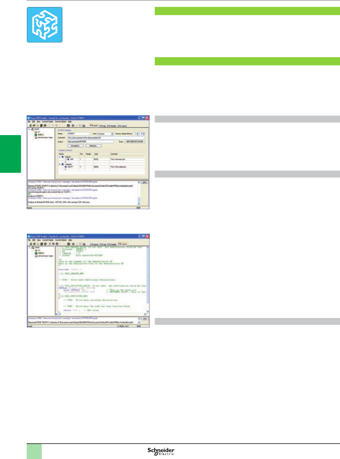
4/22
Presentation
Unity EFB Toolkit is the software for developing EFs and EFBs in “C” programming
language. As an option with Unity Pro, it can be used to extend the standard Unity
Pro function blocks in order to increase functionality. This software comes with
Microsoft Visual Studio, which can be used to debug the function blocks developed
in the Unity Pro PLC simulator. Unity EFB Toolkit also includes a service for creating
and managing families of function blocks and integrating them in Unity Pro.
Setup
Unity EFB Toolkit manages the whole process of developing Unity Pro function
blocks:
bUser-friendly graphical user interface with automatic le organization
bPowerful tools for testing and debugging
bManagement of compatibilities and software versions of created functions
bGeneration of executable les for subsequent installation of functions on different
Unity Pro stations
Managing function block families
The software can be used to create function block families. The function blocks
developed, also known as EFs/EFBs, are stored in families. This makes it possible to
create an organized library of functions written in “C” language. Once created, these
function block families are installed on the Unity Pro stations for the purpose of
extending the standard Unity Pro libraries. Integration in Unity Pro can be executed
from Unity EFB Toolkit or via the tool for updating Unity Pro libraries, which allows
these families to be distributed without the use of any other software.
Developing function blocks
The EFB Toolkit software allows the user to create a function block as follows:
bDeclaration of the function block interface in the same way as for the DFBs in
Unity Pro
bDenition of all data types needed (elementary, structures, tables)
bSupport of public and private variables
bGeneration of all les and the block “C” coding frame (the user only adds
functionality to this frame)
bGranting access to numerous internal PLC services, such as the real-time clock,
PLC variables and data, system words and math functions, including high-precision
numerical processing in “double” format
bStructure of the function block family (compilation/link for all Unity Pro automation
platforms)
bProvision of a debugging environment: the function blocks created can easily be
debugged in Microsoft Visual Studio by downloading a Unity Pro application
containing the function developed in the Unity Pro PLC simulator. The debugging
functions in Microsoft Visual Studio, especially breakpoints, step-by-step operations,
display of the code/data and manipulation of the data, can be accessed without
restriction.
bSupport for managing Unity Pro versions, important during the function block
maintenance phase
Note: GNU compiler is used to generate the code for a Modicon M340, M580 and Momentum
platform. It is supplied with the Unity EFB Toolkit.
Compatibility
Unity EFB Toolkit is compatible with Unity Pro Small, Large and Extra Large. EFs
and EFBs can be developed for Modicon Premium, Quantum, M340, M580 and
Momentum platforms.
The latest available EFB Toolkit version is V8.0:
bOS compatibility Windows®7(32-bit, 64-bit) and Windows® X P.
bMinimum supported version of Unity Pro is V6.0 and above if installation is on the
same system.
bThe generated libraries can be installed on lower Unity Pro versions with different
systems.
Presentation,
setup
Software
Unity Pro software
Unity EFB Toolkit software
Unity EFB Toolkit
EFB Toolkit: Managing function block families
EFB Toolkit: Editor
2
1
3
4
5
6
7
8
9
10
2
1
3
4
5
6
7
8
9
10

4/23
References
Unity EFB Toolkit and its documentation are supplied in electronic format on
DVD-ROM in English.
EFB Toolkit package includes:
bUnity EFB Toolkit DVD
bGNU Compiler CD
bMS Visual Studio DVD
Description Type Language Reference Weight
kg/lb
Unity EFB Toolkit
software
Single license
(1 station)
English (software and
electronic documentation)
UNYSPUZFUCD80 –
Software
Unity Pro software
Unity EFB Toolkit software
References
2
1
3
4
5
6
7
8
9
10
2
1
3
4
5
6
7
8
9
10
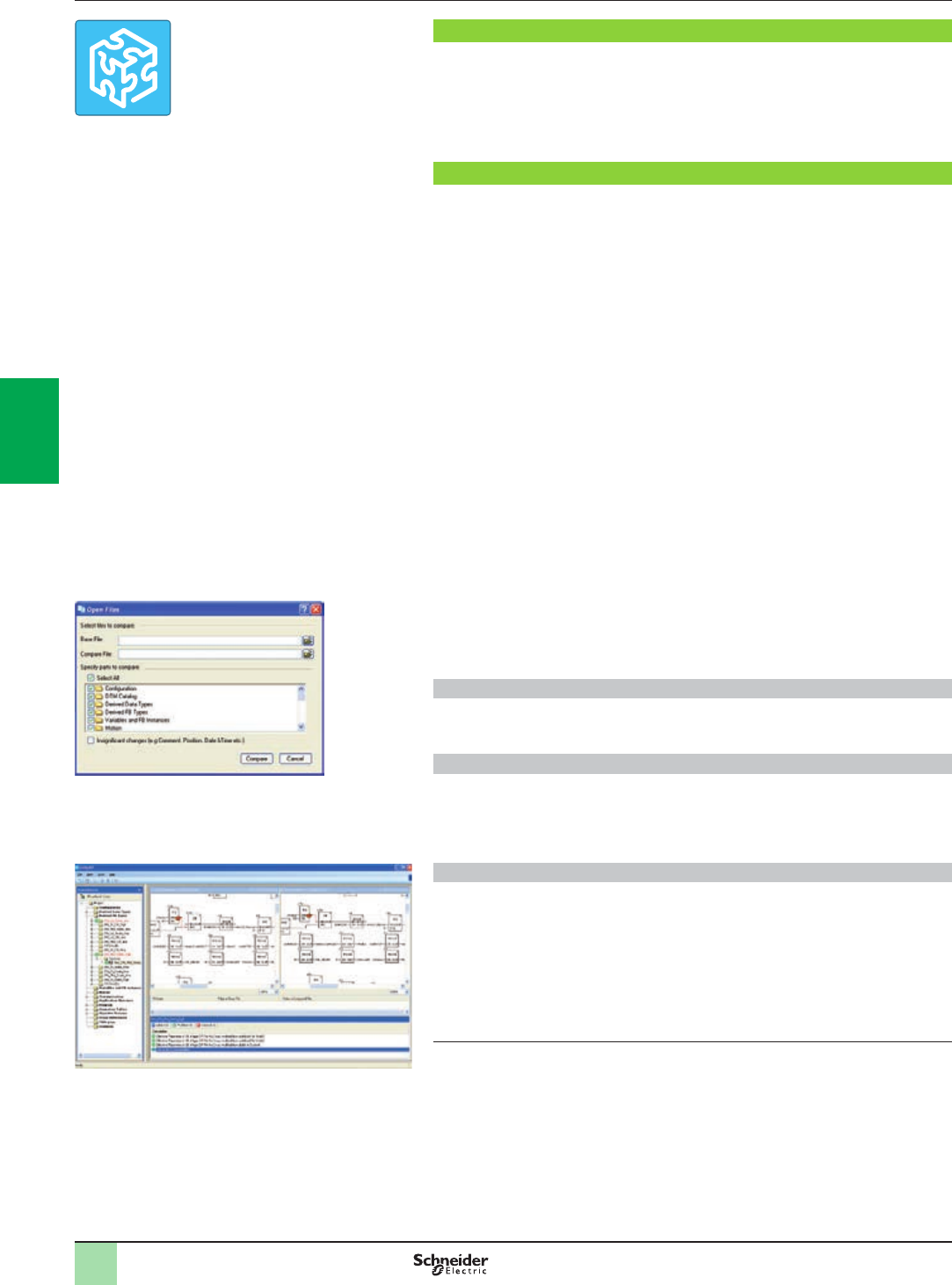
4/24
Presentation
Unity DIF is a companion software for Unity Pro. It compares two Unity Pro
applications and displays an exhaustive list of the differences. The differences are
displayed graphically and textually based on the type of program/section chosen.
Unity DIF improves productivity during the main life stages of a control system,
mainly during development and debugging of applications and commissioning,
operation and maintenance of the installation.
Software setup
Unity DIF compares two Unity Pro application les (XEF, ZEF, STU and STA) and
detects anything ADDED, DELETED and MODIFIED. The user interface and
graphical representation of differences are similar to Unity Pro for consistency and
ease of understanding the differences.
Unity DIF can be launched in several ways:
bFrom Unity Pro
bFrom the Windows Start menu
bFrom a command line interface
The user interface and graphical representation of differences are similar to
Unity Pro graphics for consistency and ease of detecting the differences.
Unity DIF can provide differences for the following sections:
bPLC Conguration (Hardware and Network)
bDerived Data Types
bDerived FB Types
bVariables and FB Instance
bMotion
bCommunication
bPrograms
bAnimation Table
bOperator Screen
bDTM Catalog
bProject Settings
The result of the comparison can be displayed in the user interface, printed or saved
in .pdf and .txt le format.
Windows® OS Compatibility
Unity DIF V8.0 is compatible with Windows XP (32-bit), Windows 7 (32-bit and
64-bit), Windows 8 (32-bit and 64-bit) and Windows Server 2008 R2 (64-bit).
Comparison (1)
The base and compared les should be selected by the user, and the comparison
results will be displayed with respect to the base le as reference.
Before initiating comparison, the user can select his preference of required section
for comparison.
Displaying results
Upon comparison, the section summary will be loaded with the complete list. The user can
navigate through the browser tree or using the F7 and F8 keys.
The differences will be highlighted in three different colors signifying Added, Deleted or
Modied types. Colors can be customized as per the user’s preference. The detailed report
can be generated through Print or can be Saved for later reference.
Unity DIF also supports command line processing and .txt report generation for interfacing
with Partner software.
(1) Comparison of STU and STA requires Unity Pro to be available.
Software
Unity Pro software
Unity DIF software
Presentation,
setup
Unity DIF
Selection of elements to compare
Displaying results
2
1
3
4
5
6
7
8
9
10
2
1
3
4
5
6
7
8
9
10

4/25
References
This Unity DIF software is used to compare two Unity applications generated by
Unity Pro software version V2.1 or later.
Compatibility: All Unity Pro packages and platforms are supported.
Description Language Type Reference Weight
kg/lb
Unity DIF software English (software
and electronic
documentation)
Single
license
(1 station)
UNYDFFXZZSPA80
(1)
–
(1) Available on our website www.schneider-electric.com.
Software
Unity Pro software
Unity DIF software
References
2
1
3
4
5
6
7
8
9
10
2
1
3
4
5
6
7
8
9
10
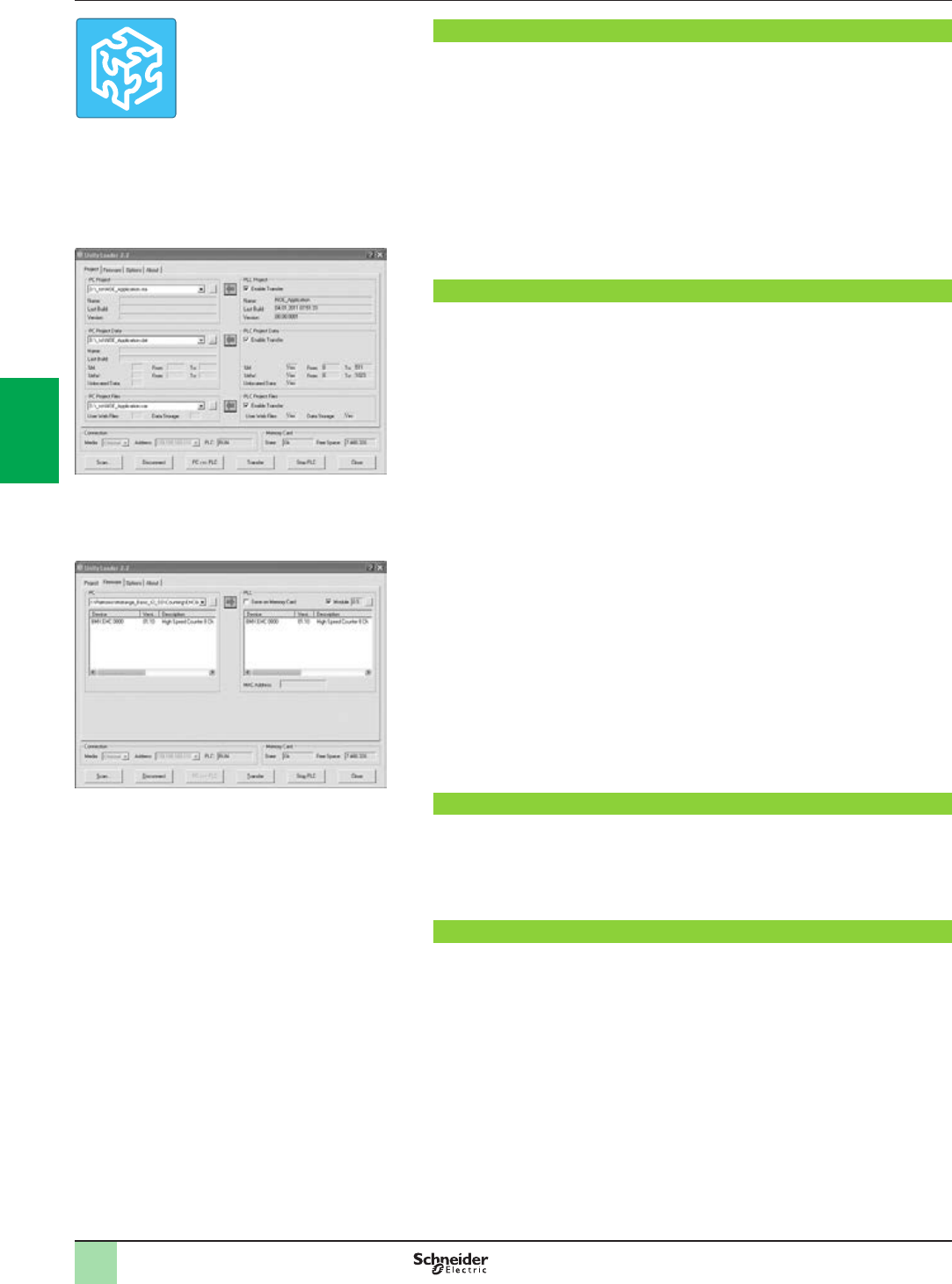
4/26
Software
Unity Pro software
Unity Loader software
Presentation
Unity Loader is companion software to Unity Pro and is used to perform maintenance
operations on automation applications. Its easy setup and the small size of its
executable make it a vital tool for updating Unity Pro projects without needing to use
Unity Pro. It can also be used for updating the embedded software on Modicon
M340, M580 or Momentum Unity PLCs or on Modicon X80 I/O modules. It performs
the following main functions:
bTransferring automation project components, such as the program and data, from
the PC to the PLC or the PLC to the PC
bTransferring les and user Web pages stored in the memory card of Modicon
M340 PLCs
bTransferring the rmware from the PC to Modicon M340, M580 or Momentum
Unity PLCs or to Modicon X80 I/O modules
Software graphic interface
The interface is easy to use and has four tabs for access to different operations:
bThe “Project” tab manages the transfer of projects (program and data) between
the PC and the PLC CPU. The software transfers the program (application le
format: .stu; archive le format: .sta) and data (located and unlocated; data le
format: .dat) of a Unity Pro project in both directions. The program and data les
created by Unity Loader are compatible with Unity Pro. When it is connected to the
PLC, Unity Loader displays the information associated with the data read in the PLC.
This information is displayed on the PC for the selected les. The user decides which
project elements will be transferred by a single command after validation of the
required transfers.
vModicon M340 PLCs and BMXRMSpp8MFP memory card only: the les and user
Web pages can be transferred from the memory card to the PC and vice versa.
vBMXNOE0110 with ash memory card only: Web pages stored in the ash
memory can be transferred from the module to the PC and vice versa.
bThe “Firmware” tab can be used to update the rmware in the Modicon M340,
M580 or Momentum Unity PLCs or on Modicon X80 I/O modules. The screen
displays the detailed content of the rmware versions existing in the module and on
the PC. Firmware updating works in the same way as project transfers.
bThe “Options” tabs is used to congure the working environment, especially the
location of les on the PC and the selection of one of the six languages supported
(English, French, German, Italian, Spanish and Chinese) for the user interface and
online help.
bThe “About…” tab displays information about the software.
Note: Regardless of which tab is selected, the connection status with the PLC is continuously
displayed, together with commands for connection/disconnection and changing the PLC
operating mode.
Modicon M340 PLC and BMXRMSpp8MFP memory card only
The Unity Loader software can download the project les and the rmware (PLC or
module) onto a ash memory card (BMXRMSpp8MFP only) plugged into the PLC
CPU.
This rmware download can then be used to update a remote Modicon M340 PLC.
Automation of Unity Loader commands
Projects can be downloaded/uploaded between a PLC and a supervisory station
equipped with Unity Loader software by means of a command le included in the
supervisory application.
Presentation
Unity Loader
Unity Loader: Project tab
Unity Loader: Firmware tab
2
1
3
4
5
6
7
8
9
10
2
1
3
4
5
6
7
8
9
10
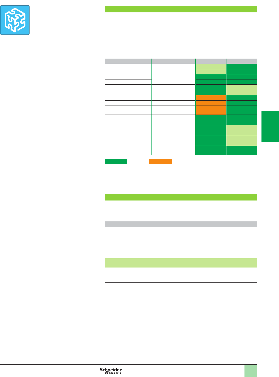
4/27
Software
Unity Pro software
Unity Loader software
Communication between the PC and the PLC
Unity Loader supports the following PC-to-PLC communication:
bModicon Quantum Unity Pro PLCs: Modbus communication, transfer of project
components only
bModicon Premium Unity Pro PLCs: Unitelway communication, transfer of project
components only
bModicon M340, M580 or Momentum Unity PLCs or Modicon X80 I/O modules:
communication via Ethernet and USB ports, transfer of project components and
rmware. See the table below:
Reference Type of module Ethernet port USB port
BMXP342000 M340 CPU with Modbus
BMXP342010/20103 M340 CPU with CANopen
BMXP342020 M340 CPU with integrated
Ethernet port
BMXP342030/20302
BMXNOE0100/0110 X80 module Ethernet
Modbus/TCP
BMXAMI/ART/AMO/AMM X80 module Analog I/O
BMXEHC0200/0800 X80 module Counter
BMXMSP0200 X80 module Motion
control
BMEP58
10XX/20XX/30XX/40XX
M580 CPUs
BMXNOC0402 (1) M580 local
communication module
171CBU78090 Momentum Unity CPU
with integrated port
171CBU98090/
171CBU98091
Momentum Unity CPU
with integrated port
Supported Supported if CPU has integrated Ethernet port
For Ethernet networks, Unity Loader contains a network scanner which can be used
to scan a range of network addresses. Once a recognized Modicon M340, M580 or
Momentum Unity PLC has been selected, data transfer operations can be
performed.
References
Unity Loader is supplied with Unity Pro Small, Large and Extra Large.
It can also be downloaded free of charge from our website
www.schneider-electric.com, download section.
Compatibility:
Unity Loader is independent of Unity Pro and compatible with Modicon M340, M580
or Momentum Unity PLCs, Unity Pro Quantum PLCs via Modbus and Unity Pro
Premium PLC via Unitelway. The program les and PLC data les are compatible
between Unity Pro and Unity Loader.
Description Type Reference Weight
kg/lb
Unity Loader software Single license
(1 station)
Software can be downloaded
free of charge from our website
www.schneider-electric.com
–
(1) The BMXNOC0402 communication module will be replaced by the BMENOC03p1 modules
during the 2nd quarter of 2014.
Presentation (continued),
references
Unity Loader
2
1
3
4
5
6
7
8
9
10
2
1
3
4
5
6
7
8
9
10

4/28
Software
Unity Pro software
Specic libraries
Presentation
Presentation
The CONT_CTL process control function block library supplied with Unity Pro
software can be supplemented with optional specialized libraries so as to meet
specic needs such as:
bPredictive control
bFuzzy logic controller
bHVAC
bMass ow calculation
Fuzzy Control Library
This library is used in particular in the water treatment eld, for example for
controlling chlorine levels in fresh water pools or controlling water levels in high-level
reservoirs.
Flow Calculation Library
This library is used in the vertical Oil & Gas eld, for measuring the gas ow in
compliance with the American Gas Association (AGA) standard. This version of the
library includes the AGA3, AGA7 and AGA8 function blocks.
TeSys Library
This library provides function blocks for TeSys T and TeSys U starter-controllers for
M340 and Premium platforms.
It includes function blocks and a help function for Unity Pro.
PCR Library for Unity Pro and Concept
This library is used for predictive control of process applications.
Originally developed for reactors, predictive control can be used in other industrial
sectors.
Schneider Electric’s Companion Unity & Libraries team works in partnership with the
French company Sherpa Engineering, who specialize in predictive control
consultancy services.
Heating Ventilation & Air Conditioning Library
This library is used in the HVAC eld and deals with repetitive temperature control
and humidity problems using ventilation equipment.
System Library for Unity Pro
This library offers functional blocks that are derived from Devices and Process
Library but only has Unity Pro components (DFBs).
The Devices and Process Library supports several Schneider Electric devices
including TeSys T and TeSys U starters-controllers, Modicon STB distributed inputs/
outputs, power meters, Altivar variable speed drives, Icla and Lexium integrated
drives, SEPAM digital protection relays, various eldbus communications and other
standard objects for motors.
There are approximately 100 objects in the library.
Unity specific Libraries
2
1
3
4
5
6
7
8
9
10
2
1
3
4
5
6
7
8
9
10

4/29
Software
Unity Pro software
Specic libraries
Specic libraries depending on the software used
Specic libraries depending on the software used (see below) can be ordered
separately.
Control libraries
Description Target
software
Type Reference Weight
kg/lb
PCR Library Unity Pro
and
Concept
Single
license
(1 station)
UNYLPCZAUWB –
Fuzzy Control Library Unity Pro Single
license
(1 station)
UNYLFZZAUWB12 –
TeSys Library UNYLTSZAUWB10 –
Heating Ventilation & Air
Conditioning Library
UNYLHVZAUWB10 –
Flow Calculation Library UNYLAGZAUWB20 –
System Library UNYLSYSFU –
System libraries for Unity Pro
Description Target
software
Type Reference Weight
kg/lb
Enhanced Process Library (1) UAG Single
license
(1 station)
UAGSBTCFUCD10 –
Devices and Process Library (1) UAGSBTDFUWB13 –
(1) Compatible with Unity Pro V5.0 max. For Unity Pro u V6.0, please consult our Customer Care
Center.
References
Unity specific Libraries
2
1
3
4
5
6
7
8
9
10
2
1
3
4
5
6
7
8
9
10

4/30
Presentation
Based on the OLE for Process Control (OPC) standard, Schneider Electric's OPC
Factory Server (OFS) software allows “client” software applications, such as
supervisors/SCADA and customized interfaces, to access the data of Schneider
Electric automation system and electrical distribution devices connected to networks
or eldbuses in real time.
It also allows communication with third-party devices supporting Modbus and
Modbus/TCP protocols.
OFS enables simpler, more open and transparent communication between your
software applications and your devices. These are just some of the advantages that
result in a complete interoperability solution that is central to your process.
In version V3.5, the OFS data server integrates the following specications:
bOPC-DA (OPC Data Access)
b.NET API interface
bOPC XML-DA V1.0 (OPC XML Data Access)
bOPC-UA (OPC Unied Architecture)
There are two versions of the OFS V3.5 offer:
bOFS Small: Data server for 1000 items (1) supporting the OPC-DA and OPC-UA
protocols (OPC XML-DA protocol not supported).
bOFS Large: Data server with an unlimited number of items (1) supporting the
OPC-DA, OPC XML-DA and OPC-UA protocols.
Devices and protocols supported
OFS software is a multi-device data server: it allows simultaneous use of several
communication protocols, and it provides client applications with a set of services for
accessing control system items that may be local or remote, via physical address or
via symbol.
Devices supported:
bModicon Quantum, Premium, M340, M580, Micro, Compact and Momentum
PLCs
bSchneider Electric TSX Series 7 and April Series 1000 PLCs
bModbus serial devices connected via Schneider Electric gateways: TSXETG10pp,
EGXppp ranges, etc.
bUni-Telway serial devices connected via Schneider Electric gateways
(TSXETG1010)
Networks and protocols supported:
bModbus: Modbus serial, Modbus Plus, Modbus/TCP
bX-Way/Uni-TE: Uni-Telway, Fipway, ISAway, PCIway
Openness
The development of specialized interfaces is simpler with OFS V3.5 software, which
is aimed at two types of user in particular:
bEnd users who want either to interface their supervision or human/machine
interface applications with Schneider Electric equipment, or to develop applications
on a PC (supervisory control screens, Excel spreadsheets etc.) requiring access to
control system data.
bSuppliers of control system or industrial data processing software
(supervision, human/machine interfaces, etc.) seeking to develop, within their
standard products, an OPC Client interface capable of accessing data in Schneider
Electric equipment via the OFS server.
(1) “item”: variable, structure, table etc. in the Unity Pro application.
OPC Factory Server
Software 3
OPC data server software
OPC Factory Server
Architectures:
page 4/31
Setup:
page 4/33
Functions:
page 4/34
References:
page 4/35
Time stamping system:
page 4/36
Presentation
3
2
1
3
4
5
6
7
8
9
10
2
1
3
4
5
6
7
8
9
10
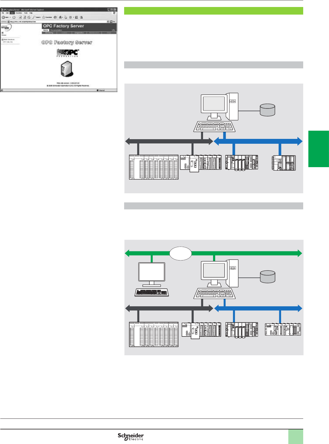
4/31
Supported architectures
The OFS server allows four access modes:
bA purely local mode
bRemote access from an OPC-DA client
bRemote access from an OPC.NET client
bRemote access from an OPC XML-DA or OPC UA clients
bRemote access from an OPC-UA client
Local access
The client application and the OFS server are on the same PC.
Remote access from an OPC-DA client
The client application and the OFS data server are on remote stations.
Communication between the client station and the OFS server is conducted through
the DCOM layer (Microsoft) via the OPC-DA protocol.
OPC Factory Server: Home page
Software 3
OPC data server software
OPC Factory Server
Architectures
0
Presentation:
page 4/30
Setup:
page 4/33
Functions:
page 4/34
References:
page 4/35
Time stamping system:
page 4/36
OFS station
Symbol data
(Unity Pro ,
Concept
or PL7)
Modbus network X-Way network
Premium M340
M580
Quantum
Remote client
application
program
DCOM
Ethernet Modbus/TCP network
Local client
applic. prog
M340Premium
M580
Quantum
Modbus network
OFS station
Local client
applic. prog Symbol data
(Unity Pro,
Concept
or PL7)
2
1
3
4
5
6
7
8
9
10
2
1
3
4
5
6
7
8
9
10
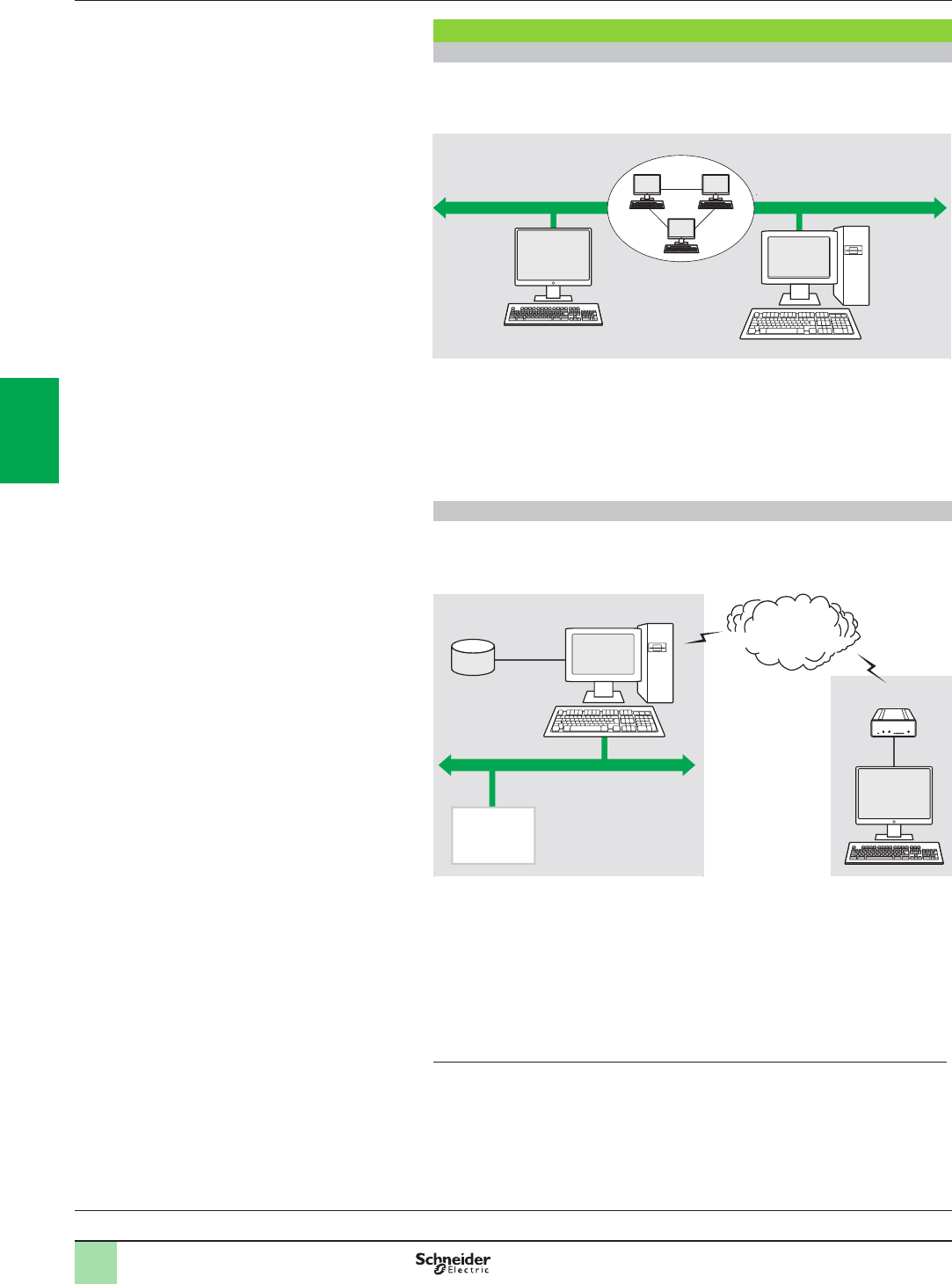
4/32
Software 3
OPC data server software
OPC Factory Server
Architectures (continued)
0
Architectures supported (continued)
Remote access from an OPC .NET client
The .NET client application program and the OFS data server are on remote
stations. Communication between the client station and the OFS server is
conducted through the DCOM layer (Microsoft) via the OPC-DA protocol.
The .NET Microsoft compatibility of the OFS server has been developed to allow an
OPC .NET client to access OFS server items on an Intranet network via the OPC
.NET API interface.
This interface provides interoperability between existing OPC applications and
applications developed in the standard .NET environment.
Remote access from an OPC XML-DA client via HTTP
The client application program and the OFS server are on remote stations, using the
SOAP protocol to communicate via the Internet in conformity with the OPC XML-DA
or OPC UA specication of the OPC Foundation.
These two protocols are designed to overcome the limitations of COM/DCOM, thus
providing:
bA standardized interface for Windows and non-Windows client applications
bBeyond the Intranet perimeter, remote access via the Internet through rewalls
The OPC XML-DA specication is based on Web Services standards such as SOAP,
XML and WSDL (1). A SOAP client can access data on the OFS server via Intranet or
Internet using the SOAP protocol in conformity with the OPC XML-DA or OPC UA
specication of the OPC Foundation.
(1) SOAP: Simple Object Access Protocol
XML: Extensible Markup Language
WSDL: Web Services Description Language
Server
OFS station
Intranet
.NET client
Ethernet Modbus/TCP networkDCOM
Site server
and OFS
station
Symbol data
(Unity Pro,
Concept or PL7)
Industrial network IIS
Internet
Industrial
PLCs
Remote client
application
program
Firewall
Presentation:
page 4/30
Setup:
page 4/33
Functions:
page 4/34
References:
page 4/35
Time stamping system:
page 4/36
2
1
3
4
5
6
7
8
9
10
2
1
3
4
5
6
7
8
9
10
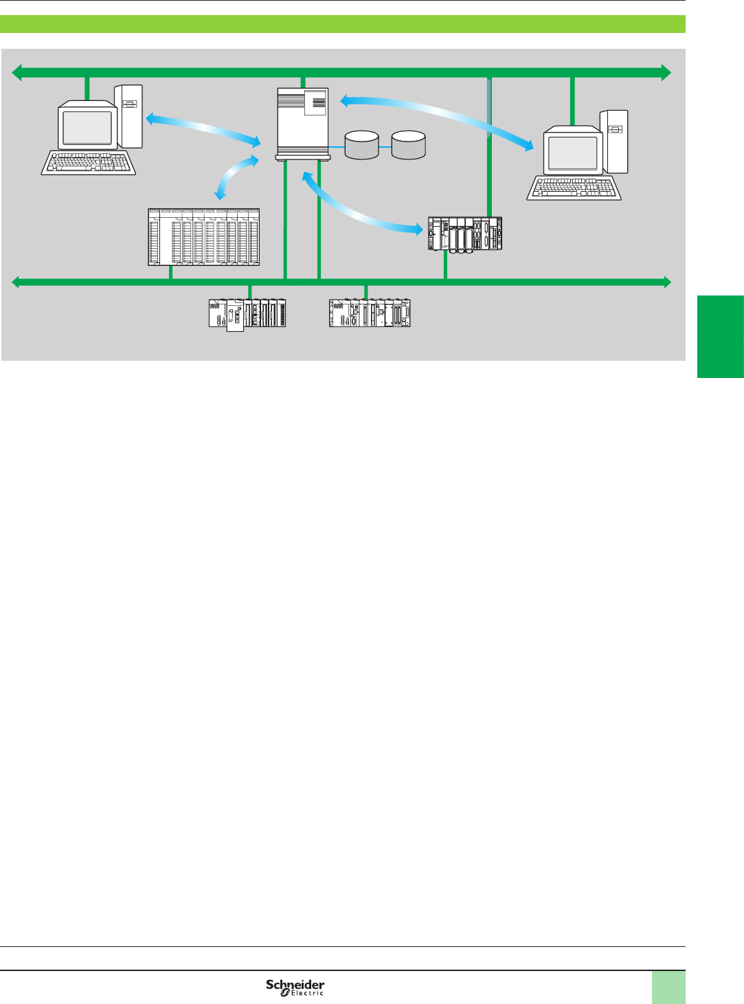
4/33
Setup
3
Setup
The OFS server 1is at the center of the data exchanges. It makes variables
exchanged between the OPC client 2 and the PLC 3,consistent in one of three
ways, using a symbol (or variables) database:
bThe variables database is either the Unity Pro project 4, or the Concept project.
In both these cases, Unity Pro or Concept needs to be installed on the OFS server
station.
bOr the variables database is an export le (SCY for PL7, XVM for Unity Pro). PL7
and Unity Pro are not required in either of these cases.
bOr the variables database is the PLC itself. In this case neither Unity Pro nor an
export le is needed. This does not apply to Momentum and TSX Micro PLCs.
If an inconsistency is detected (following online modication of the PLC program for
example), OFS resynchronizes itself automatically as a background task, without
breaking communication between the PLC and the OPC client.
For this function the following minimum versions are required:
vOFS V3.35
vUnity Pro V6.0
vModicon M340 V2.3, M580 V1.0, Premium V2.9 and Quantum V3.0 PLCs
1
Ethernet Modbus/TCP
OFS server
(V3.0)
Database
Symbols.xvm (Unity Pro)
Symbols.prj (Concept)
Symbols.scy (PL7)
3Premium
3M340
3M580
3Quantum
Ethernet Modbus/TCP
4
Unity Pro
project
station
2OPC client
Presentation:
page 4/30
Architectures:
page 4/31
Functions:
page 4/34
References:
page 4/35
Time stamping system:
page 4/36
Software 3
OPC data server software
OPC Factory Server
2
1
3
4
5
6
7
8
9
10
2
1
3
4
5
6
7
8
9
10

4/34
Software 3
OPC data server software
OPC Factory Server
Functions
3
Function
Development of client applications
OFS software has 4 types of interface:
bOLE Automation interface (OPC-DA)
Particularly suitable for end users, this enables the development of OPC client
applications in Visual Basic, in Visual Basic for Excel, and in C++.
bOLE Custom interface (OPC-DA)
Used primarily by suppliers of automated control system or industrial IT products,
this interface enables the development of applications in C++ in order to access the
OFS software OPC server. It is aimed at software development experts in particular,
so that they can integrate the client application into their standard products. It is the
interface with the highest performance, in terms of access time to data stored in the
OPC server. It requires extensive knowledge of C++ programming to set up.
bOPC .NET API wrapper interface
The .NET Microsoft compatibility of the OFS data server gives an OPC .NET client
standard access to OFS server items via an Intranet network, thus providing greater
interoperability with standard .NET environments.
Note: In this case, communication between the OPC .NET client and the OFS server is
conducted through the DCOM layer (or COM layer in a local conguration) via the OPC-DA
protocol.
bOPC XML-DA interface (1)
The OPC XML-DA V1.0 specications are designed to overcome the limitations of
the OPC-DA specication and COM/DCOM by providing:
vAn interface for Windows and non-Windows client applications
vRemote access via the Internet through rewalls (beyond the Intranet perimeter)
The OPC XML-DA specication is based on Web Services standards such as SOAP,
XML, WSDL. A SOAP client can access data on the OFS server via Intranet or
Internet using the SOAP protocol in conformity with the OPC XML-DA V1.01
specication of the OPC Foundation.
bThe OPC-UA interface
This interface is aimed at users with software that includes an OPC-UA client
interface. This interface is based on the same communication standards as the OPC
XML-DA interface and offers the same advantages as it, which are:
vAn interface with Windows and non-Windows applications
vRemote access, via the Internet, through a rewall
(1) Available only with the Large version of OPC Factory Server.
Presentation:
page 4/30
Architectures:
page 4/31
Setup:
page 4/33
References:
page 4/35
Time stamping system:
page 4/36
2
1
3
4
5
6
7
8
9
10
2
1
3
4
5
6
7
8
9
10

4/35
Software 3
OPC data server software
OPC Factory Server
References
3
OPC Factory Server
References
OFS V3.5 software for PC compatible stations (minimum conguration: Pentium
566 MHz processor, 128 Mb of RAM) running Windows® 7 (32-bit or 64-bit) or
Windows 8 (32-bit or 64-bit).
The OFS V3.5 offer comprises:
bOPC server software
bOPC server simulator (for debugging the application when no PLCs are present)
bOFS server conguration software
bAn example of OPC client for setting up applications
bThe setup documentation on DVD-ROM
bA reference document on “time stamping system” solutions
bA tool to help with sizing and conguring “time stamping system” solutions
Supplied on DVD-ROM, the software operates independently on a PC. It interfaces
with the variable export les generated by PL7, ProWORX, Concept, and Unity Pro
software.
It also provides a direct dynamic link to the Unity Pro and Concept applications.
OFS V3.5 software is available in two versions:
bSmall Version TLXCDSpOFS35
vMaximum of 1000 items (1)
vProtocols supported: OPC-DA and OPC-UA
vSingle station and 10-station site licenses
bLarge Version TLXCDLpOFS35
vUnlimited number of items (1)
vProtocols supported: OPC-DA, OPC XML-DA and OPC-UA
vSingle station, 10-station and 200-station site licenses
OPC Factory Server V3.5 Small
Description License type Reference Weight
kg/lb
OPC Factory Server
V3.5 Small software
bMaximum of 1000
items (1)
bProtocols supported:
OPC-DA and OPC-UA
Single station TLXCDSUOFS35 –
10 stations TLXCDSTOFS35 –
OPC Factory Server V3.5 Large
Description License type Reference Weight
kg/lb
OPC Factory Server
V3.5 Large software
bUnlimited number of
items (1)
bProtocols supported:
OPC-DA, OPC XML-DA
and OPC-UA
Single station TLXCDLUOFS35 –
10 stations TLXCDLTOFS35 –
200 stations TLXCDLFOFS35 –
(1) “item”: variable, structure, table etc. in the Unity Pro application.
Presentation:
page 4/30
Architectures:
page 4/31
Setup:
page 4/33
Functions:
page 4/34
Time stamping system:
page 4/36
2
1
3
4
5
6
7
8
9
10
2
1
3
4
5
6
7
8
9
10
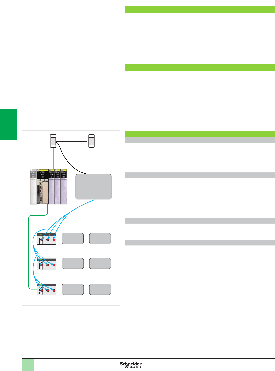
4/36
Presentation
The time stamping system is a complete solution providing a SCADA with a
sequence of events that are time-stamped at source, enabling the user to analyze
the source of any abnormal behavior in an automated system.
The SOE (sequence of events) is displayed in the alarm log or in the list of events for
a client such as a SCADA.
Each event in the SOE is a change of value (transition) of a discrete I/O detected by
a time stamping module.
Advantages
Using the time stamping system has the following advantages:
bNo PLC programming
bDirect communication between the time stamping modules and the client. If the
time stamping modules are in a Quantum Ethernet I/O drop, the bandwidth of the
PLC communication is not used
bConsistency of the I/O values between the process (time stamping modules) and
the client
bConsistency is maintained irrespective of the operating mode
bNo loss of events under normal operating conditions
bManagement of Hot Standby congurations on the PLC and/or SCADA
redundancy
Composition of a time stamping architecture
BMXCRA31210 and BMECRA31210 modules
This time stamping module can be at the source of any discrete I/O signal located in
the drop with a resolution of 10 ms.
To avoid losing any events, all events are stored and kept in a buffer located in the
product until OFS takes them.
Synchronization of the CRA module uses the NTP protocol.
BMXERT1604T module
This module has 16 discrete inputs which carry out the time stamping at source
outputs with a resolution of 1 ms.
To avoid losing any events, all events are stored and kept in a buffer located in the
product until OFS takes them.
This module can be placed either in an RIO drop, or in a local rack equipped with a
BM●CRA31210 module.
The CRA module is synchronized via the DCF 77 or IRIG-B standards.
OFS V3.50
OFS V3.50 is used to access events stored in the various buffers in the architecture
and to notify the SCADA of them via the standard OPC DA protocol.
Vijeo Citect V7.30
Vijeo Citect V7.30 receives events transmitted by OFS and displays them in the SOE
or in the list of alarms.
Presentation:
page 4/30
Architectures:
page 4/31
Setup:
page 4/33
Functions:
page 4/34
References:
page 4/35
Software 3
OPC data server software
Time stamping system
Presentation
Routing function via
Quantum NOC control
head 140 NOC 78 100
or external router
Modicon
Quantum drops
Modicon
Quantum drops
Modicon
Quantum drops
OFS server
Vijeo Citect
alarm
terminal
Quantum CPU
Ethernet
Ethernet
BMX-CRA1
event
memory
BMX-CRA2
event
memory
BMX-CRA3
event
memory
BMX-ERT1
event
memory
BMX-ERT
event
memory
BMX-ERT
event
memory
Example of a Time stamping architecture
2
1
3
4
5
6
7
8
9
10
2
1
3
4
5
6
7
8
9
10

4/37
Presentation:
page 4/30
Architectures:
page 4/31
Setup:
page 4/33
Functions:
page 4/34
References :
page 4/35
Performance
Performance Event source
module
Value
Between two identical source modules in
the same rack
BMXERT1604T 1.6 < resolution < 3.3 ms
BM●CRA31210 10 ms
Between two different inputs in the same
source module
BMXERT1604T 1 ms
BM●CRA31210 1 scan
Maximum number of events scanned BMXERT1604T 400 events (1)
BM●CRA31210 2048 events (1)
Maximum number of I/O and memory
available
BMXERT1604T 16 discrete inputs on module
512 events in internal buffer
BM●CRA31210 256 discrete I/O congured
4000 events in internal buffer
Maximum number of source modules in an
Ethernet remote drop
BM●CRA31210 1 per drop
BMXERTpppp 9 per drop
Maximum number of event sources
controlled
BMXERTpppp 500 sources per second (1)
(1) This maximum value is not an absolute value. It depends on the overall system dynamics
(total number of scanned items and number of events generated by the system).
Software 3
OPC data server software
Time stamping system
Performance
2
1
3
4
5
6
7
8
9
10
2
1
3
4
5
6
7
8
9
10

5/0
2
1
3
4
5
6
7
8
9
10
2
1
3
4
5
6
7
8
9
10

5/1
Contents
Treatment for severe environnements
b Presentation...........................................................................................page 5/2
b Harsh chemical environnements .........................................................page 5/2
b Extreme climatic environnements ....................................................... page 5/2
Ruggedized processor modules
b References .............................................................................................page 5/3
Ruggedized racks and rack expansion module
b References .............................................................................................page 5/4
Ruggedized communication module and network gateway
b References .............................................................................................page 5/5
5 - Ruggedized Modicon M580
modules
2
1
3
4
5
6
7
8
9
10
2
1
3
4
5
6
7
8
9
10

5/2
Presentation Modicon M580 automation platform
Treatment for severe environments
Ruggedized modules
Presentation
Protective treatment of Modicon M580 automation platform
The Modicon M580 automation platform complies with “TC” treatment requirements
(Treatment for all Climates). it is designed as standard to operate in temperatures of
0 to + 60°C/32 to 140°F.
For installations in industrial production workshops or environments corresponding
to “TH” (Treatment for Hot and humid environments), devices should be housed in
enclosures providing at least IP 54 protection as specied by standard
IEC/EN 60529, or an equivalent level of protection according to NEMA 250.
The Modicon M580 automation platform offers IP 20 degree of protection (1). It can
therefore be installed without an enclosure in restricted access areas that do not
exceed pollution level 2 (control room with no dust-producing machinery or
activity). Pollution level 2 does not take account of harsher environments, such as
those where the air is polluted with dust, fumes, corrosive or radioactive particles,
vapors or salts, molds, insects, etc.
Treatment for more severe environments
If the Modicon M580 automation platform has to be used in more severe
environments or is required to start and operate in an extended temperature range,
from - 25°C to + 70°C/- 13°F to 158°F, the “ruggedized” offer features industrially
hardened processor modules, X-bus and X-bus + Ethernet racks, rack expansion
modules and communication modules that have a protective coating on their circuit
boards.
Note: Capable of starting within an extended temperature range (from - 25°C to + 70°C/
- 13°F to 158°F, a single-rack conguration is also able to operate at extremely low
temperatures (to - 40°C/-40 °F) if placed in an appropriate enclosure. Please consult our
Customer Care Center.
This treatment increases the isolation capability of the circuit boards and their
resistance to:
bCondensation
bDusty atmospheres (conducting foreign particles)
bChemical corrosion, in particular during use in sulphurous atmospheres (oil
renery, purication plant, etc.) or atmospheres containing halogens (chlorine, etc.)
This protection, combined with appropriate installation and maintenance, enables
Modicon M580 automation products to be used in the following environments:
Harsh chemical environments:
vIEC/EN 60721-3-3 class 3C3:
-14 days; 25°C/77°F relative humidity 75%
-Concentrations (mm3/m3): H2S: 2100/SO2: 1850/Cl2: 100
vISA S71.04 classes G1 to G3:
-14 days; 25°C/77°F relative humidity 75%
-Concentrations (mm3/m3): H2S: 50/SO2: 300/Cl2: 10/NO2: 1250
vIEC/EN 60068-2-52 salt mist, Kb test severity level 2:
-3 x 24-hour cycles
-5% NaCI
-40°C/104°F relative humidity 93%
Extreme climatic environments:
vTemperatures from - 25 to + 70°C/- 13 to 158°F
vRelative humidity levels:
-up to 93% from - 25°C/- 13°F to + 60°C/140°F
-up to 95% from - 25°C/- 13°F to + 55°C/131°F
vFormation of ice
vAltitudes from 0 to 5,000 m/0 to 16,404 ft
(1) Each slot in a BMXXBP0p00H, BMEXBP0p00H or BMXXBE1000H rack is equipped as
standard with a protective cover that should only be removed when inserting a module. If any
covers are subsequently misplaced, replacements can be ordered under reference
BMXXEM010 (sold in lots of 5).
Compatibility:
page 1/14
Communication:
page 3/2
2
1
3
4
5
6
7
8
9
10
2
1
3
4
5
6
7
8
9
10
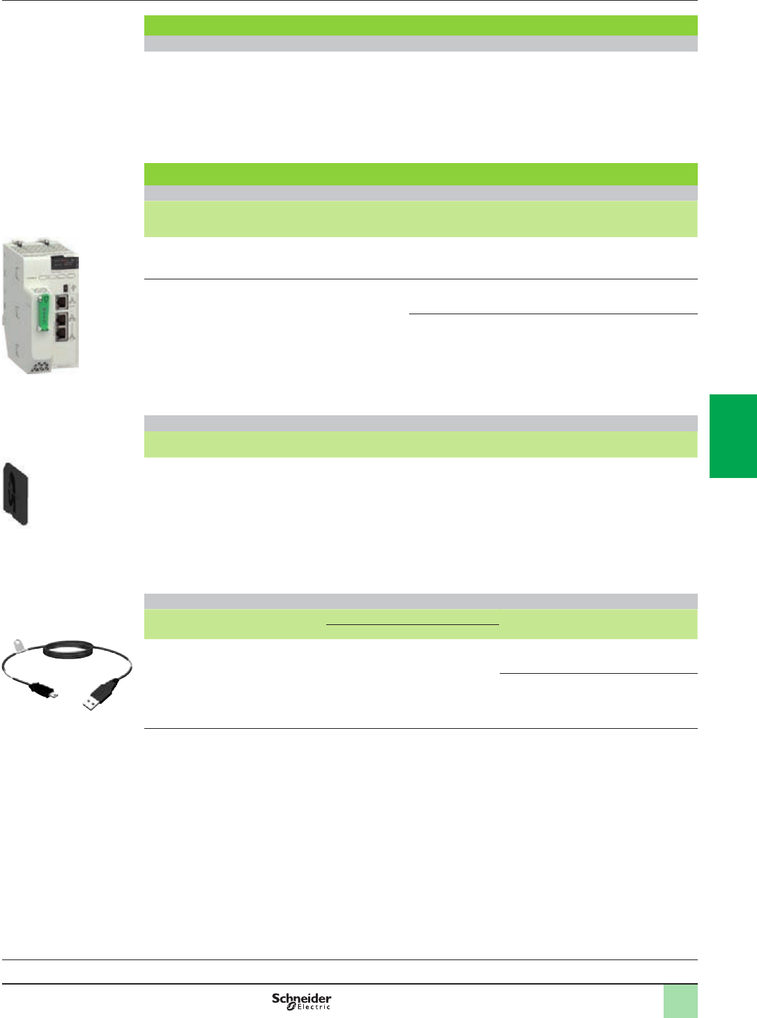
5/3
Presentation (continued),
references
Modicon M580 automation platform
Dedicated parts for severe environments
Ruggedized processor modules
Composition
References and characteristics
To order ruggedized modules and racks, see the reference pages 5/3 to 5/5 (the references of the ruggedized
products available include the sufx “H”).
The standard separate parts (cordsets, cables, sub-bases, etc.) that are compatible with the ruggedized modules
offer are listed in the reference pages (see pages 5/3 to 5/5).
The majority of operating and electrical characteristics of ruggedized modules are identical to those of their
equivalent standard versions. However, some characteristics are subject to either derating or limitation. Please
consult our website www.schneider-electric.com.
Ruggedized Modicon M580 processors
Ruggedized Modicon M580 processors
I/O capacity Maximum number
of networks
Device ports Service port Reference Weight
kg/lb
1,024 discrete I/O, 256 analog I/O
24 application-specic channels
4 MB integrated (memory program)
2 Ethernet
networks
2 DIO 1BMEP581020H –
2,048 discrete I/O, 512 analog I/O
32 application-specic channels
8 MB integrated (memory program)
2 Ethernet
networks
2 DIO 1BMEP582020H –
2 RIO/DIO 1BMEP582040H –
Standard SD Memory card
Description Processor compatibility Capacity Reference Weight
kg/lb
SD memory card (optional) Any processor 4 GB (for
application
backup and
data storage)
BMXRMS004GPF 0.002/
0.004
Standard separate parts
Description Use Length
m/ft.
Reference Weight
kg/lb
From To
Terminal port/ USB cordsets Mini-B USB port
on the Modicon
M580 processor
Type A USB port on:
PC terminal,
Magelis HMI graphic
terminal
1.8/5.905 BMXXCAUSBH018 0.065/
0.143
4.5/14.764 BMXXCAUSBH045 0.110/
0.243
BMEP58ppppH
PF122552
BMXRMS004GPF
PF106120
BMXXCAUSBH0pp
PF106185
Compatibility:
page 1/14
Communication:
page 3/2
2
1
3
4
5
6
7
8
9
10
2
1
3
4
5
6
7
8
9
10
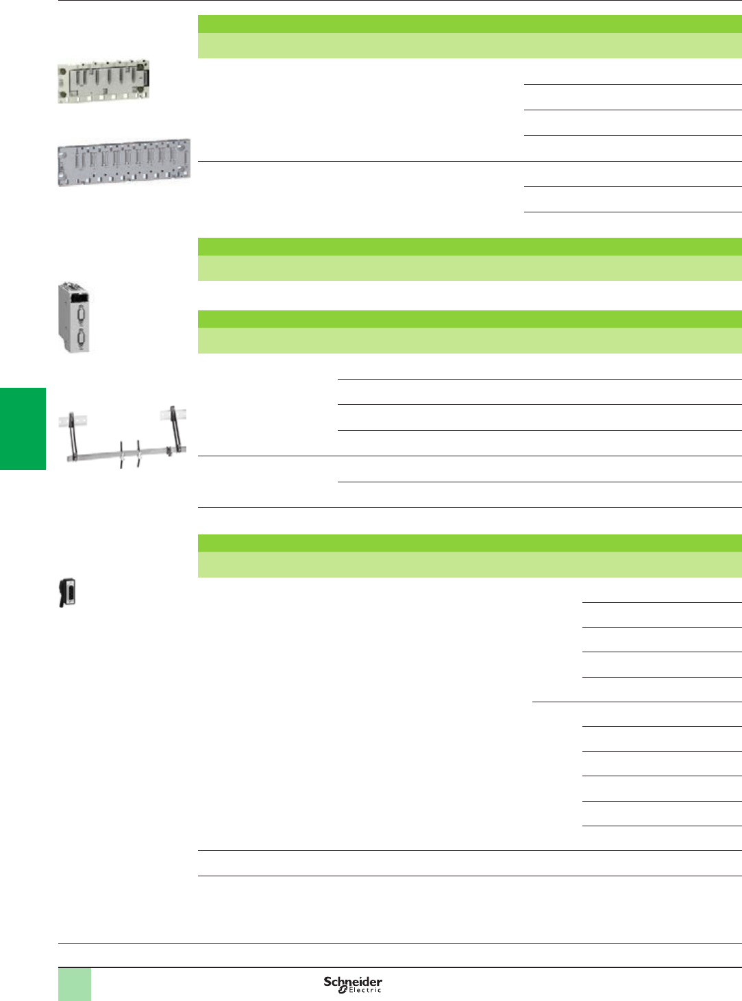
5/4
References Modicon M580 automation platform
Dedicated parts for severe environments
Ruggedized racks and rack expansion module
Ruggedized racks
Description Type of module to be inserted No. of
slots (1)
Power
consumption (2)
Reference Weight
kg/lb
Ruggedized X-bus racks BMEP58 processor, BMXCPS power supply,
I/O modules and application-specic
(counter and communication) modules
4 1 W BMXXBP0400H 0.630/
1.389
6 1.5 W BMXXBP0600H 0.790/
1.742
8 2 W BMXXBP0800H 0.950/
2.094
12 –BMXXBP1200H 1.270/
2.800
Ruggedized Ethernet + X-bus
racks
BMEP58 processor, BMXCPS power supply,
I/O modules and application-specic
(counter and communication) modules
4 2.8 W BMEXBP0400H 0.715/
1.576
83.9 W BMEXBP0800H 1.070/
2.359
12 3.9 W BMEXBP1200H 1.387/
3.058
Ruggedized expansion module
Description Use Reference Weight
kg/lb
Ruggedized expansion
module for ruggedized rack
(3)
Standard module to be installed in each rack (XBE slot)
Used to daisy-chain up to 4 racks
BMXXBE1000H 0.178/
0.392
Standard accessories for racks
Description For use with Sold in
lots of
Reference Weight
kg/lb
Shielding connection kits
comprising:
-a metal bar
-2 support bases
BMpXBP0400H rack –BMXXSP0400 0.280/
0.617
BMXXBP0600H rack –BMXXSP0600 0.310/
0.683
BMpXBP0800H rack –BMXXSP0800 0.340/
0.750
BMpXBP1200H rack –BMXXSP1200 0.400/
0.882
Spring clamping rings Cables, cross-section 1.5...6 mm2/AWG 16...9 10 STBXSP3010 0.050/
0.110
Cables, cross-section 5...11 mm2/AWG 10...7 10 STBXSP3020 0.070/
0.154
Protective covers
(replacement parts)
Unoccupied slots on BMpXBPpp00H rack 5BMXXEM010 0.005/
0.011
Standard cordsets and connection accessories
Description Use Composition Type of
connector
Length Reference Weight
kg/lb
X-bus extension cordsets
total length 30 m/
98.425 ft max. (3)
Between two
BMXXBE1000H rack
expansion modules
2 x 9-way
SUB-D
connectors
Angled 0.8 m/
2.625 ft
BMXXBC008K
0.165/
0.364
1.5 m/
4.921 ft
BMXXBC015K
0.250/
0.551
3 m/
9.843 ft
BMXXBC030K
0.420/
0.926
5 m/
16.404 ft
BMXXBC050K
0.650/
1.433
12 m/
39.370 ft
BMXXBC120K
1.440/
3.175
Straight 1 m/
3.281 ft
TSXCBY010K
0.160/
0.353
3 m/
9.843 ft
TSXCBY030K
0.260/
0.573
5 m/
16.404 ft
TSXCBY050K
0.360/
0.794
12 m/
39.370 ft
TSXCBY120K
1.260/
2.778
18 m/
59.055 ft
TSXCBY180K
1.860/
4.101
28 m/
91.864 ft
TSXCBY280KT
(4)
2.860/
6.305
Cable reel (3) Length of cable to be tted
with TSXCBYK9 connectors
Ends with ying leads,
2 line testers
100 m/
328.084 ft
TSXCBY1000
12.320/
27.161
Nota: For other ruggedized modules in the Modicon X80 range, please consult the “Modicon X80 I/O platform” catalogue.
(1) Number of slots taking the processor module, I/O modules and application-specic modules (excluding power supply module).
(2) Power consumption of anti-condensation resistor(s).
(3) Module and cordsets do not operate properly at temperatures lower than - 25°C/- 13°F.
(4) Cable supplied with a set of 2 TSXTVSY100 electrical transient suppressors.
Compatibility:
page 1/14
Communication:
page 3/2
BMXXBP0400H
PF106104
BMEXBP0800H
PF122507B
BMXXBE1000H
PF108119
BMXXSP0p00
+ BMXXSP30p0
PF516134
Angled connector on
extension cordsets
PF108142
2
1
3
4
5
6
7
8
9
10
2
1
3
4
5
6
7
8
9
10
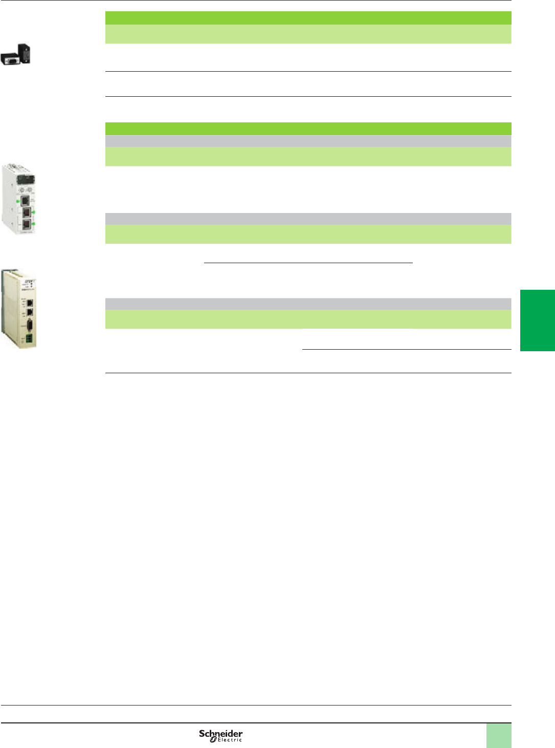
5/5
References (continued) Modicon M580 automation platform
Dedicated parts for severe environments
Connection accessories, ruggedized communication
module and network gateway
Compatibility:
page 1/14
Communication:
page 3/2
TCSEGPA23F14FK
PF516164
BMECRA31210C
PF122504B
TSXTLYEX
PF108138
Connection accessories
Description Use Composition Reference Weight
kg/lb
Line terminator
(Sold in lots of 2)
Required on both BMEXBP/
BMXXBPppp0H modules at
each end of the daisy chain
2 x 9-way SUB-D
connectors marked A/ and /B
TSXTLYEX
0.050/
0.110
X-bus straight connectors
(Sold in lots of 2)
For ends of TSXCBY1000
cables
2 x 9-way SUB-D straight
connectors
TSXCBYK9
0.080/
0.176
Connector assembly kit Fitting TSXCBYK9 connectors 2 crimping pliers, 1 pen (1)
TSXCBYACC10
–
Communication
“Conformal Coating” EIO drop adapter
Description SERVICE port Reference Weight
kg/lb
Modicon X80 EIO drop
adapter for
Ethernet + X-bus racks
1BMECRA31210C –
Ruggedized Probus DP network gateway
Description Protocols Physical
layer
Reference Weight
kg/lb
Probus Remote Master
(PRM) module
Modbus TCP 1 Ethernet switch,
2 x 10BASE-T/100BASE-TX ports
TCSEGPA23F14FK –
Probus DP V1 and Probus
PA (via gateway)
1 isolated RS 485 Probus DP port
Standard connection accessory
Description Details RS 232 interface Reference Weight
kg/lb
Cordset for DCE terminal
(modem, etc.)
Equipped with 1 x RJ45
connector and 1 x 9-way male
SUB-D connector
Length 3 m/9.843 ft
Simplied 4-wire (RX, TX, RTS
and CTS)
TCSMCN3M4M3S2 0.150/
0.331
Full 8-wire (except RI signal) TCSXCN3M4F3S4 0.165/
0.364
(1) To t the connectors on the cable, you also need a wire stripper, a pair of scissors and a digital ohmmeter.
2
1
3
4
5
6
7
8
9
10
2
1
3
4
5
6
7
8
9
10

6/0
2
1
3
4
5
6
7
8
9
10
2
1
3
4
5
6
7
8
9
10

6/1
Contents
Technical appendices
b Standards, certications and environmental conditions ...................page 6/2
b Certications for automation products and EC regulations ..............page 6/6
6 - Standards and certications
2
1
3
4
5
6
7
8
9
10
2
1
3
4
5
6
7
8
9
10
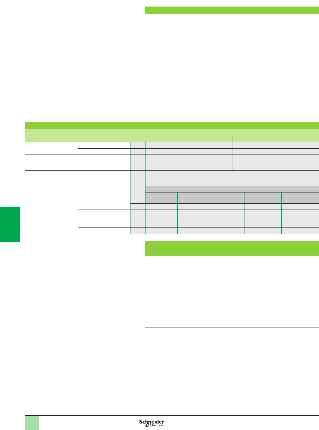
6/2
Standards and certications
The Modicon M580 automation platform has been developed to comply with the
principal national and international standards concerning electronic equipment for
industrial automation systems.
bRequirements specic to programmable controllers: functional characteristics,
immunity, resistance, safety, etc.: IEC/EN 61131-2, UL and CSA standards for
industry (UL 508, CSA E61131-2).
bRequirements specic to power utility automation systems: IEC/EN 61850-3.
bMerchant navy requirements of the major international organizations: unied in
IACS (International Association of Classication Societies).
bCompliance with European Directives for e marking:
bLow Voltage: 2006/95/EC
bElectromagnetic Compatibility: 2004/108/EC
bEx areas:
vFor USA and Canada: Hazardous location class I, division 2, groups A,B,C and D
vFor other countries: e ATEX (directive 94/9/EC) or IECEx in dened atmosphere
Zone 2 (gas) and/or Zone 22 (dust).
vUp-to-date information on which certications have been obtained is available on
our website.
Protective treatment of the Modicon M580 automation
platform
The Modicon M580 platform meets the requirements of “TC” treatment (Treatment
for all Climates).
For installations in industrial production workshops or environments corresponding
to “TH” treatment (treatment for hot and humid environments), Modicon M580 must
be embedded in enclosures with minimum IP 54 protection.
The Modicon M580 automation platform offers protection to IP 20 level and
protection against pins (enclosed equipment) (1). They can therefore be installed
without an enclosure in reserved-access areas which do not exceed pollution level
2 (control room with no dust-producing machine or activity). Pollution level 2 does
not take account of more severe environmental conditions: air pollution by dust,
smoke, corrosive or radioactive particles, vapors or salts, attack by fungi, insects,
etc.
(1) In cases where a position is not occupied by a module, a BMXXEM010 protective cover must
be installed.
(e): tests required by European directives (e)and based on IEC/EN 61131-2 standards.
Characteristics
Service conditions and recommendations relating to the environment
Standards and
certications Modicon M580 automation
platform
Standards, certications and environment
conditions
Modicon M580 automation platform Modicon M580 harsh automation platform
Temperature Operation °C 0...+ 60 - 25...+ 70
Storage °C - 40...+ 85 - 40...+ 85
Relative humidity
(without condensation)
Cyclical humidity %+ 5 ... + 95 up to 55°C + 5 ... + 95 up to 55°C
Continuous humidity %+ 5 ... + 93 up to 55°C + 5 ... + 93 up to 60°C
Altitude Operation m0…2000 (full specication: temperature and isolation)
2000 ... 5000 (temperature derating: 1°C/400 m, isolation lost: 150 V c/1000 m)
Supply voltage Modicon X80 I/O power supply modules
BMXCPS2010 BMXCPS3020
BMXCPS3020H
BMXCPS3540T BMXCPS2000 BMXCPS3500
BMXCPS3500H
Nominal voltage V24 c24...48 c125 c100...240 a100...240 a
Limit voltages V18...31.2 c18...62.4 c100…150 c85...264 a85...264 a
Nominal frequencies Hz ––– 50/60 50/60
Limit frequencies Hz ––– 47/63 47/63
2
1
3
4
5
6
7
8
9
10
2
1
3
4
5
6
7
8
9
10

6/3
Environment tests Modicon M580 automation
platform
Standards, certications and environment
conditions
Environment tests
Name of test Standards Levels
Immunity to LF interference (e)(1)
Voltage and frequency variations IEC/EN 61131-2; IEC/EN 61000-6-2; IEC 61000-4-11 0.85...1.10 Un - 0.94...1.04 Fn; 4 steps t = 30 min
IACS E10; IEC 61000-4-11 0.80 Un...0.90 Fn; 1.20 Un...1.10 Fn; t = 1.5 s/5 s
Direct voltage variations IEC/EN 61131-2; IEC 61000-4-29;
IACS E10 (PLC not connected to charging battery)
0.85...1.2 Un + ripple: 5% peak; 2 steps t = 30 min
Third Harmonic IEC/EN 61131-2 H3 (10% Un), 0°/180°; 2 steps t = 5 min
Immunity to conducted low frequency (only IACS) IACS E10 For a:
bH2…H15 (10% Un), H15…H100 (10%...1% Un),
H100…H200 (1% Un)
For c:
bH2…H200 (10% Un)
Voltage interruptions IEC/EN 61131-2; IEC/EN 61000-6-2;
IEC 61000-4-11; IEC 61000-4-29; IACS E10
Power supply immunity:
b1 ms for c PS1/10 ms for a PS2
bCheck operating mode for longer interruptions
For IACS:
b30 s for a or c
IEC/EN 61131-2; IEC/EN 61000-6-2;
IEC 61000-4-11
For a PS2:
b20% Un, t0: ½ period
b40% Un, cycle 10/12
b70% Un, cycle: 25/30
b0% Un, cycle 250/300
Voltage shut-down and start-up IEC/EN 61131-2 bUn…0…Un; t = Un/60 s
bUmin…0…Umin; t = Umin/5 s
bUmin…0.9 Udl…Umin; t = Umin/60 s
Magnetic eld IEC/EN 61131-2; IEC/TS 61000-6-5; IEC 61000-4-8
(for MV power stations: IEC 61850-3)
Power frequency: 50/60 Hz, 100 A/m continuous
...1000 A/m; t = 3 s; 3 axes
IEC 61000-4-10
(for MV power stations: IEC 61850-3)
Oscillatory: 100 kHz...1 MHz, 100 A/m; t = 9 s; 3 axes
Conducted common mode
disturbances range 0 Hz …150 kHz
IEC 61000-4-16
(for MV power stations: IEC 61850-3)
For remote systems:
b 50/60 Hz and c, 300 V, t = 1s
b 50/60 Hz and c, 30 V, t = 1 min
b 5 Hz…150 kHz, sweep 3 V…30 V
Where:
bPS1 applies to PLC supplied by battery, PS2 applies to PLC energized from a or c supplies
bUn: nominal voltage, Fn: nominal frequency, Udl: detection level when powered
Name of test Standards Levels
Immunity to LF interference (e)(1)
Electrostatic discharges IEC/EN 61131-2; IEC/EN 61000-6-2;
IEC 61000-4-2; IACS E10
6 kV contact; 8 kV air; 6 kV indirect contact
Radiated radio frequency electromagnetic eld IEC/EN 61131-2; IEC/EN 61000-6-2;
IEC 61000-4-3; IACS E10
15 V/m, 80 MHz … 3 GHz
Sinus amplitude modulated 80%,1 kHz + internal
clock frequencies
Electrical fast transient bursts IEC/EN 61131-2; IEC/EN 61000-6-2;
IEC 61000-4-4; IACS E10
For a or c main supplies:
b2kVin common mode/2 kV in wire mode
For a or c auxiliary supplies, a unshielded I/O:
b2kVin common mode
For analog, c unshielded I/O, communication and
shielded lines:
b1kVin common mode
Surge IEC/EN 61131-2; IEC/EN 61000-6-2; IEC 61000-4-5;
IACS E10
For a/c main and auxiliary supplies, a unshielded
I/O:
b2kVin common mode/1 kV in differential mode
For analog, c unshielded I/O:
b0.5 kV in common mode/0.5 kV in differential
mode
For communication and shielded lines:
b1kVin common mode
Conducted disturbances induced by radiated
electromagnetic elds
IEC/EN 61131-2; IEC/EN 61000-6-2; IEC 61000-4-6;
IACS E10
10 V; 0.15 MHz...80 MHz
Sinus amplitude 80%, 1 kHz + spot frequencies
Damped oscillatory wave IEC/EN 61131-2; IEC 61000-4-18;
IACS E10
For a/c main supplies and a auxiliary supplies,
a unshielded I/O:
b2.5 kV in common mode/1 kV in differential mode
For c auxiliary supplies, analog, c unshielded I/O:
b1kVin common mode/0.5 kV in differential mode
For communication and shielded lines:
b0.5 kV in common mode
(1) Devices must be installed, wired and maintained in accordance with the instructions provided in the manual “Grounding and Electromagnetic Compatibility of PLC Systems”.
(2) These tests are performed without an enclosure, with devices xed on a metal grid and wired as per the recommendations in the manual “Grounding and Electromagnetic Compatibility of
PLC systems”.
(e): tests required by European e directives and based on IEC/EN 61131-2.
2
1
3
4
5
6
7
8
9
10
2
1
3
4
5
6
7
8
9
10
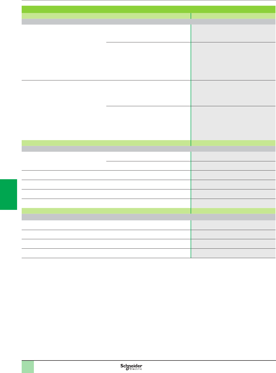
6/4
Environment tests
(continued)
Modicon M580 automation
platform
Standards, certications and environment
conditions
Environment tests (continued)
Name of test Standards Levels
Electromagnetic emissions (e)(1)
Conducted emission IEC/EN 61131-2; FCC part 15; IEC/EN 61000-6-4;
CISPR 11 & 22, Class A, Group 1
150 kHz … 500 kHz: quasi-peak 79 dB (µV/m);
average 66 dB (µV/m)
500 kHz … 30 MHz: quasi-peak 73 dB (µV/m);
average 60 dB (µV/m)
IACS E10 b a/c power (general power distribution zone):
10 kHz … 150 kHz: quasi-peak 120...69 dB (µV/m);
150 kHz … 0.5 MHz: quasi-peak 79 dB (µV/m)
0.5 MHz … 30 MHz: quasi-peak 73 dB (µV/m)
b a/c power (bridge and deck zone for evaluation):
10 kHz … 150 kHz: quasi-peak 96…50 dB (µV/m)
150 kHz … 0.35 MHz: quasi-peak 60…50 dB (µV/m)
0.35 MHz … 30 MHz: quasi-peak 50 dB (µV/m)
Radiated emission IEC/EN 61131-2; FCC part 15; IEC/EN 61000-6-4;
CISPR 11 & 22, Class A, Group 1
30 MHz ... 230 MHz: quasi-peak 40 dB (µV/m) (at
10 m);
50 dB (µV/m) (at 3 m)
230 MHz ... 1 GHz: quasi-peak 47 dB (µV/m) (at
10 m);
57 dB (µV/m) (at 3 m)
IACS E10 bFor general power distribution zone
0.15 MHz … 30 Mhz: quasi-peak 80…50 dB (µV/m)
(at 3 m)
30 MHz-100 MHz: quasi-peak 60…54 dB (µV/m) (at
3 m)
100 MHz - 2 GHz: quasi-peak 54 dB (µV/m) (at 3 m)
156 … 165 MHz: quasi-peak 24 dB (µV/m) (at 3 m)
Name of test Standards Levels
Immunity to climatic variations (1) (power on)
Dry heat IEC 60068-2-2 (Bb & Bd) 60°C, t = 16 hrs [for ruggedized range: 70°C,
t = 16 hrs] (2)
IACS E10 60°C, t = 16 hrs + 70°C, t = 2 hrs
[for ruggedized range: 70°C, t = 18 hrs] (2)
Cold IEC 60068-2-1 (Ab & Ad)
IACS E10
0°C … - 25°C, t = 16 hrs + power on at 0°C
[for ruggedized range: power on at -25°C] (2)
Damp heat, steady state (continuous humidity) IEC 60068-2-78 (Cab);
IACS E10
55°C, 93% relative humidity, t = 96 hrs
[for ruggedized range: 60°C] (2)
Damp heat, cyclic
(cyclical humidity)
IEC 60068-2-30 (Db);
IACS E10
55°C … 25°C, 93…95% relative humidity, 2 cycles
t = 12 hrs +12 hrs
Change of temperature IEC 60068-2-14 (Na & Nb) 0°C … 60°C, 5 cycles t = 6 hrs + 6 hrs
[for ruggedized range: - 25 … 70°C] (2)
Name of test Standards Levels
Withstand to climatic variations (1) (power off)
Dry heat IEC/EN 61131-2; IEC 60068-2-2 (Bb & Bd)
IEC/EN 60945
85°C, t = 96 hrs
Cold IEC/EN 61131-2; IEC 60068-2-1 (Ab & Ad);
IACS E10
- 40°C, t = 96 hrs
Damp heat, cyclic
(cyclical humidity)
IEC/EN 61131-2; IEC 60068-2-30 (Db) 55°C … 25°C, 93…95% relative humidity, 2 cycles
t = 12 hrs + 12 hrs
Change of temperature
(thermal shocks)
IEC/EN 61131-2; IEC 60068-2-14 (Na & Nb) - 40°C ... 85°C, 5 cycles t = 3 hrs + 3 hrs
(1) Devices must be installed, wired and maintained in accordance with the instructions provided in the manual “Grounding and Electromagnetic Compatibility of
PLC Systems”.
(2) Refer also to the chapter “Treatment for severe environments”.
(e): tests required by European e directives and based on IEC/EN 61131-2 standards.
2
1
3
4
5
6
7
8
9
10
2
1
3
4
5
6
7
8
9
10

6/5
Environment tests
(continued)
Modicon M580 automation
platform
Standards, certications and environment
conditions
Environment tests (continued)
Name of test Standards Levels
Immunity to mechanical constraints (1) (power on)
Sinusoidal vibrations IEC/EN 61131-2;
IEC 60068-2-6 (Fc)
Basic IEC/EN 61131-2: 5 Hz ... 150 Hz, ± 3.5 mm
amplitude (5 Hz …. 8.4 Hz), 1 g (8.4 Hz …. 150 Hz)
Specic prole: 5 Hz ... 150 Hz, ± 10.4 mm
amplitude (5 Hz …. 8.4 Hz), 3 g (8.4 Hz …. 150 Hz)
For basic and specic: endurance: 10 sweep cycles
for each axis
IACS E10 3 Hz ... 100 Hz, 1 mm amplitude (3 Hz …. 13.2 Hz),
0.7 g (13.2 Hz …. 100 Hz)
Endurance at each resonance frequency: 90 min for
each axis, amplication coefcient < 10
IEC 60068-2-6 Seismic analysis: 3 Hz ... 35 Hz, 22.5 mm amplitude
(3 Hz …. 8.1 Hz), 6 g (8.1 Hz …. 35 Hz)
Shocks IEC/EN 61131-2;
IEC 60068-2-27 (Ea)
30 g, 11 ms; 3 shocks/direction/axis (2)
25 g, 6 ms; 100 bumps/direction/axis (bumps) (3)
Free fall during operation IEC/EN 61131-2;
IEC 60068-2-32 (Ed Method 1)
1 m, 2 falls
Name of test Standards Levels
Withstand to mechanical constraints (power off)
Random free fall with packaging IEC/EN 61131-2;
IEC 60068-2-32 (Method 1)
1 m, 5 falls
Flat free fall IEC/EN 61131-2;
IEC 60068-2-32 (Ed Method 1)
10 cm, 2 falls
Controlled free fall IEC/EN 61131-2;
IEC 60068-2-31 (Ec)
30° or 10 cm, 2 falls
Plugging/Unplugging IEC/EN 61131-2 For modules and connectors:
Operations: 50 for permanent connections, 500 for
non-permanent connections
Name of test Standards Levels
Equipment and personnel safety (1) (e)
Dielectric strength and insulation
resistance
IEC/EN 61131-2;
IEC 61010-2-201; UL; CSA
Dielectric: 2 Un + 1000 V; t = 1 min
Insulation: Un y 50 V: 10 MΩ, 50 V y Un y 250 V :
100 MΩ
Continuity of earth IEC/EN 61131-2;
IEC 61010-2-201; UL; CSA
30A, R y 0,1Ω; t = 2 min
Leakage current UL; CSA y 3.5 mA after disconnecting
Protection offered by enclosures IEC/EN 61131-2;
IEC61010-2-201;
IP20 and protection against standardized pins
Impact withstand IEC/EN 61131-2;
IEC 61010-2-201; UL; CSA
Sphere of 500 g, fall from 1.30 m (energy 6.8 J
minimum)
Stored energy injury risk IEC/EN 61131-2;
IEC 61010-2-201
Transient connection: 37% Un after 1 s
Permanent connection: 37% Un after 10 s
Overload IEC/EN 61131-2;
IEC 61010-2-201; UL; CSA
50 cycles, Un, 1.5 In; t = 1 s ON + 9 s OFF
Endurance IEC/EN 61131-2;
IEC 61010-2-201; UL; CSA
In, Un; 12 cycles: t=100 ms ON + 100 ms OFF, 988
cycles : t = 1 s ON + 1 s OFF, 5000 cycles : t = 1 s ON
+ 9 s OFF
Temperature rise IEC/EN 61131-2; UL; CSA; ATEX; IECEx Ambient temperature 60°C [for ruggedized range:
70°C] (4)
Name of test Standards Levels
Specic Environment (1)
Corrosion areas - gas, salt, dust ISA S71.4 Mixed owing gases: class G3, 25°C, 75% relative
humidity, t = 14 days (4)
IEC 60721-3-3 Mixed owing gases: class 3C3, 25°C, 75% relative
humidity, t = 14 days (4)
IEC 60068-2-52 Salt spray: test Kb, severity 2 (4)
(1) Devices must be installed, wired and maintained in accordance with the instructions provided in the manual “Grounding and Electromagnetic Compatibility of
PLC Systems”.
(2) When using fast actuators (response time y 5 ms) driven by relay outputs: 15 g, 11 ms; 3 shocks/direction/axis.
(3) When using fast actuators (response time y 15 ms) driven by relay outputs: 15 g, 6 ms; 100 bumps/direction/axis.
(4) Refer also to the chapter “Treatment for severe environments”.
(e): tests required by European e directives and based on IEC/EN 61131-2 standards.
2
1
3
4
5
6
7
8
9
10
2
1
3
4
5
6
7
8
9
10
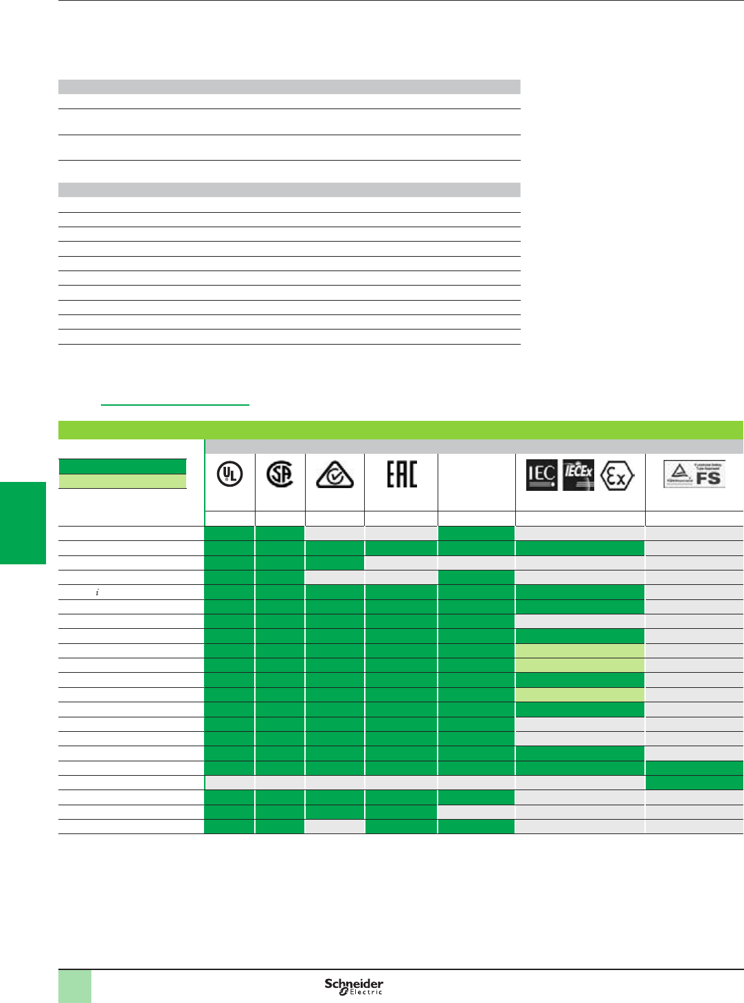
6/6
Technical appendices
Automation product certications
EC regulations
Some countries require certain electrical components to undergo certication by law. This certication takes the form of a certicate of
conformity to the relevant standards and is issued by the ofcial body in question. Where applicable, certied devices must be labelled
accordingly. Use of electrical equipment on board merchant vessels generally implies that it has gained prior approval (i.e. certication) by
certain shipping classication societies.
Abbreviation Certication body Country
CSA Canadian Standards Association Canada
RCM
(formerly C-Tick)
Australian Communications and Media Authority Australia, New Zealand
EAC
(formerly GOST)
Eurasian conformity Russia and customs union
UL Underwriters Laboratories USA
Abbreviation Classication authority Country
IACS International Association of Classication Societies International
ABS American Bureau of Shipping USA
BV Bureau Veritas France
DNV Det Norske Veritas Norway
GL Germanischer Lloyd Germany
LR Lloyd’s Register UK
RINA Registro Italiano Navale Italy
RMRS Russian Maritime Register of Shipping Russia
RRR Russian River Register Russia
CCS China Classication Society China
The tables below provide an overview of the situation as at 9th January 2014 in terms of which certications (listed next to their respective
bodies) have been granted or are pending for our automation products.
Up-to-date information on which certications have been obtained by products bearing the Schneider Electric brand can be viewed on our
website: www.schneider-electric.com
Product certications
Certications
Hazardous
locations (1)
Class I, div 2
Certied
Certication pending
UL CSA RCM EAC (9) (6) TÜV Rheinland
USA Canada Australia Russia USA, Canada
Modicon OTB
Modicon STB FM Zone 2 (2)(5)
Modicon Telefast ABE 7
ConneXium (2)
Magelis PC/GTW (3) (2) (3) Zone 2/22 (2)
Magelis XBT GT (3) (2) (2) (3) Zone 2/22 (2)(5)
Magelis XBT GK (3) (3)
Magelis XBT N/R/RT CSA Zone 2/22 (2)(5)
Magelis HMI GTO (3) (2) (3) (2)
Magelis HMI STO/STU (3) (2) (2)(3) (2)
Modicon M340 CSA Zone 2/22 (2)(8)
Modicon M580
Modicon X80 I/O CSA Zone 2/22 (2)(8)
Modicon Momentum FM
Modicon Premium (2) CSA
Modicon Quantum (2) CSA, FM (2) Zone 2/22 (2)
Modicon Quantum Safety (2) CSA Zone 2/22 (2) SIL 2, SIL 3 (7)
Preventa XPSMF SIL 3 (7)
Modicon TSX Micro CSA
Phaseo (3)
Twido (4) (4) CSA/UL (4)
(1) Hazardous locations: According to ANSI/ISA 12.12.01, CSA 22.2 No. 213 and FM 3611, certied products are only approved for use in hazardous
locations categorized as Class I, division 2, groups A, B, C and D, or in non-classied locations.
(2) Depends on product; please visit our website: www.schneider-electric.com.
(3) North American certication cULus (Canada and USA).
(4) Except for AS-Interface module TWD NOI 10M3, e only.
(5) For zones not covered by this specication, Schneider Electric offers a solution as part of the CAPP (Collaborative Automation Partner Program). Please consult
our Customer Care Centre.
(6) Refer to the instructions supplied with each ATEX and/or IECEx certied product.
(7) According to IEC 61508. Certied by TÜV Rheinland for integration into a safety function of up to SIL 2 or SIL 3.
(8) Can be used in gassy mines under certain conditions.
(9) Formerly GOST. GOST will be replaced by EAC after certicates are renewed.
2
1
3
4
5
6
7
8
9
10
2
1
3
4
5
6
7
8
9
10
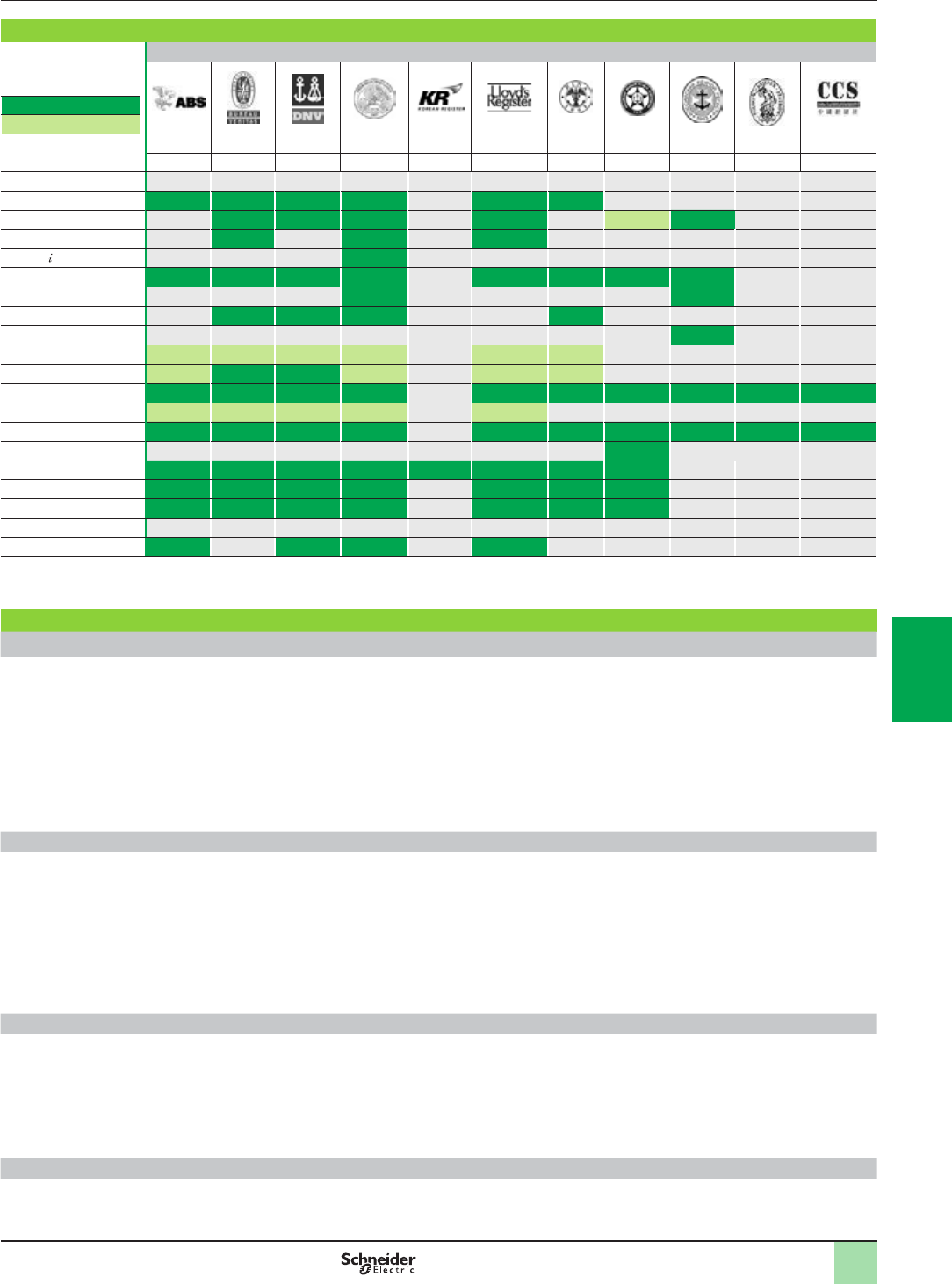
6/7
Technical appendices
Automation product certications
EC regulations
Merchant navy certications
Shipping classication societies
Certied
Certication pending
ABS BV DNV GL KRS LR RINA RMRS RRR PRS CCS
USA France Norway Germany Korea Great Britain Italy Russia Russia Poland China
Modicon OTB
Modicon STB (1) (2) (2) (2) (2) (2) (2)
Modicon Telefast ABE 7
ConneXium
Magelis PC/GTW Bridge (2)
Magelis XBT GT (2) (2) (2) (2) (2) (2) (2) (2)
Magelis XBT GK
Magelis XBT N/R
Magelis XBT RT
Magelis HMI GTO
Magelis HMI STO/STU (2) (2)
Modicon M340 (2) (2)
Modicon M580
Modicon X80 I/O (2) (2)
Modicon Momentum
Modicon Premium
Modicon Quantum
Modicon TSX Micro
Phaseo
Twido
(1) Also covers US Navy requirements ABS-NRV part 4.
(2) Depends on product; please visit our website: www.schneider-electric.com.
EC regulations
European Directives
The open nature of the European markets assumes harmonization between the regulations set by the member states of the European Union.
European Directives are texts whose aim is to remove restrictions on free circulation of goods and which must be applied within all European
Union states.
Member states are obligated to incorporate each Directive into their national legislation, and to simultaneously withdraw any regulations that
contradict it.
Directives - and particularly those of a technical nature with which we are concerned - merely set out the objectives to be fullled (referred to as
“essential requirements”). Manufacturers are responsible for taking the necessary measures to establish that their products conform to the
requirements of each Directive applicable to their equipment.
As a general rule, manufacturers certify compliance with the essential requirements of the Directive(s) that apply to their products by applying a
e mark. The e mark is afxed to our products where applicable.
Signicance of the e mark
The e mark on a product indicates the manufacturer's certication that the product conforms to the relevant European Directives; this is a
prerequisite for placing a product which is subject to the requirements of one or more Directives on the market and allowing its free circulation
within European Union countries. The e mark is intended for use by those responsible for regulating national markets.
Where electrical equipment is concerned, conformity to standards indicates that the product is t for use. Only a warranty by a well-known
manufacturer can provide reassurance of a high level of quality.
As far as our products are concerned, one or more Directives are likely to apply in each case; in particular:
bThe Low Voltage Directive (2006/95/EC)
bThe Electromagnetic Compatibility Directive (2004/108/EC)
bThe ATEX e Directive (94/9/EC)
Hazardous substances
These products are compatible with:
bThe WEEE Directive (2002/96/EC)
bThe RoHS Directive ((2011/65/EU)
bThe China RoHS Directive (Standard SJ/T 11363-2006)
bThe REACH regulations Directive (EC 1907/2006)
Note: Documentation on sustainable development is available on our website www.schneider-electric.com (product environmental profiles and instructions for use,
ROHS and REACH directives) .
End of life (WEEE)
End of life products containing electronic cards must be dealt with by specic treatment processes.
When products containing backup batteries are unusable or at end of life they must be collected and treated separately. Batteries do not contain
a percentage by weight of heavy metals above the limit specied by European Directive 2006/66/EC.
2
1
3
4
5
6
7
8
9
10
2
1
3
4
5
6
7
8
9
10

7/0
2
1
3
4
5
6
7
8
9
10
2
1
3
4
5
6
7
8
9
10

7/1
Contents
A dedicated services offer for your installed base
b Maintenance and support services ......................................................page 7/2
b Consultancy services............................................................................page 7/3
b Modernization solutions .......................................................................page 7/3
b Customization services ........................................................................page 7/3
7 - Services
2
1
3
4
5
6
7
8
9
10
2
1
3
4
5
6
7
8
9
10
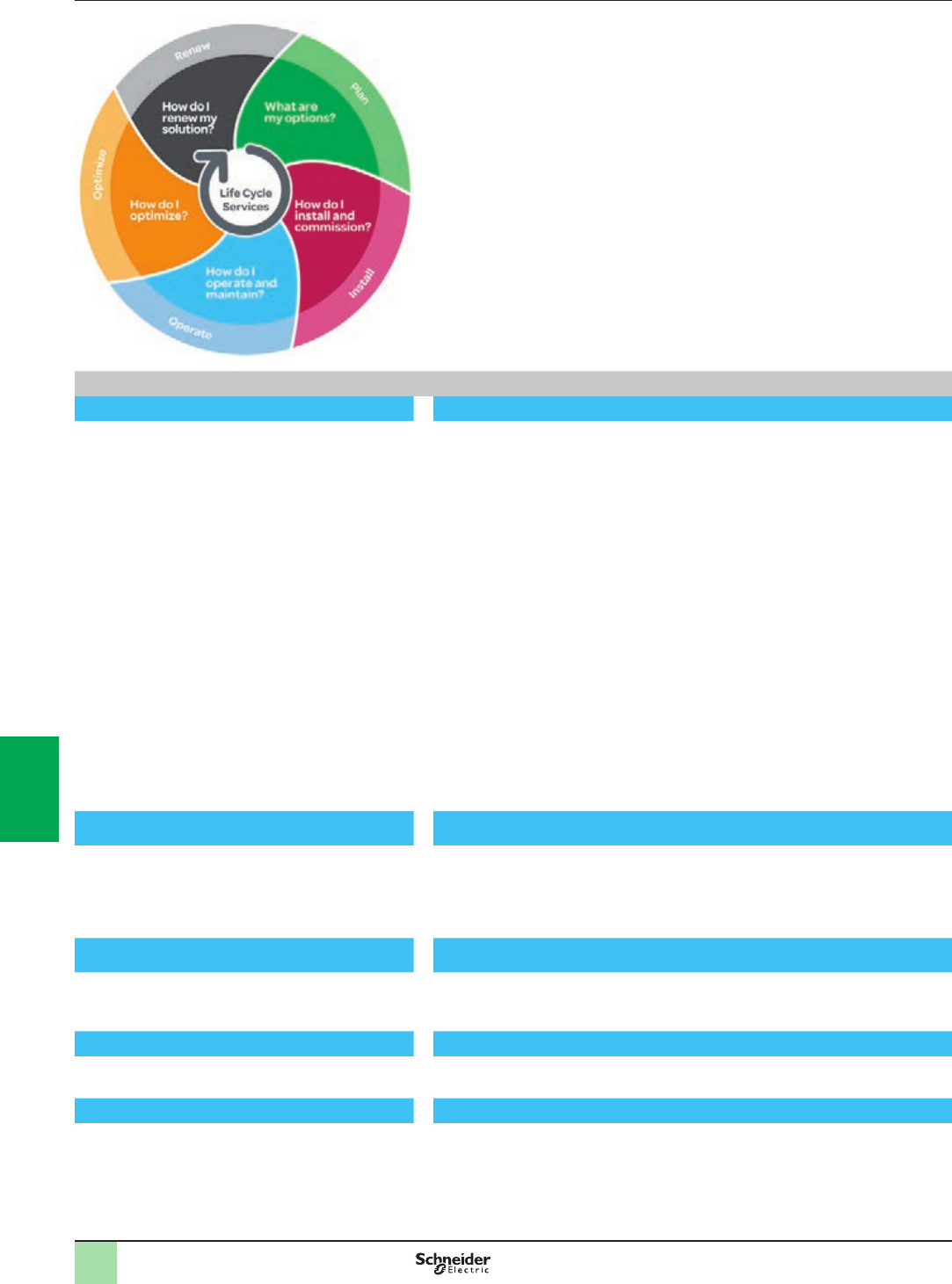
7/2
Presentation A dedicated services offer for your
installed base
Schneider Electric, with its experts, products and dedicated tools, provides services
such as system design, consultancy, maintenance contracts, modernisation of
facilities or delivering projects.
The Schneider Electric services offer is structured around several key areas:
bMaintenance and support services:
vA set of services to help maintain reliability and availability of automated control
systems. These services may be the subject of a bespoke maintenance contract to
meet your requirements more closely.
bConsultancy services:
vDiagnostics of the installed base
bModernization solutions:
vMigration solutions including consultancy, expertise, tools and technical support
to help ensure a smooth transition to newer technology while keeping the wiring and
the encoding in most cases.
Customization services are also available to accommodate specic requirements.
For more information, please consult the specic pages on our website
www.schneider-electric.com/automationservices
Maintenance and support services
Spare parts, exchanges and repairs Everything you need to get equipment working again as quickly as possible
Solutions to respond very quickly to requests for spare parts, exchanges and repairs
to your installed automation equipment (automation platforms, Human Machine
Interfaces, drives, distributed I/O):
bSpare parts management:
vIdentication of critical parts
vStock of spare parts: a Schneider Electric owned stock of spare parts, on your
site or in one of our warehouses, with immediate availability on site or a contractually
agreed delivery time if stored off site
vTesting of spare parts stored on site
vAutomatic stock lling
bRepairs:
vBroken down products are repaired in a network of worldwide repair centres. For
each repaired product, our experts provide a detailed report.
bOn-site repair:
vOur experts’ knowledge and expertise
vMonitoring of specic repair procedures
vAvailability of our teams to respond 24/7
bExchanges:
vWith standard replacements, receive a new or reconditioned product before the
broken down product has even been sent back
vFast exchanges offer the option to receive the replacement product within
24 hours (in Europe)
Preventive maintenance Improving and guaranteeing the long-term reliability and performance of your
installations
Schneider Electric’s preventive maintenance expert assesses your site, the
equipment to be managed and sets up a maintenance program to accommodate
specic requirements. A list is provided of the tasks to be performed and their
frequency, including site-specic tasks, describing how preventive maintenance is to
be managed.
Extended warranty An additional manufacturer warranty covering replacement or repair of the
equipment
The extended warranty offers the option to take out a 3-year warranty. The warranty
period can vary according to the geographical area, consult your Customer Care
Centre.
Online support Access to dedicated experts
Priority access to experts who can answer technical questions promptly concerning
equipment and software both on sale and no longer commercially available.
Software subscription Access to software upgrades and new features
By subscribing to software updates, users are able to:
bPurchase licences
bReceive updates, upgrades, software migrations and transitions
bDownload software from Schneider Electric’s software library
2
1
3
4
5
6
7
8
9
10
2
1
3
4
5
6
7
8
9
10
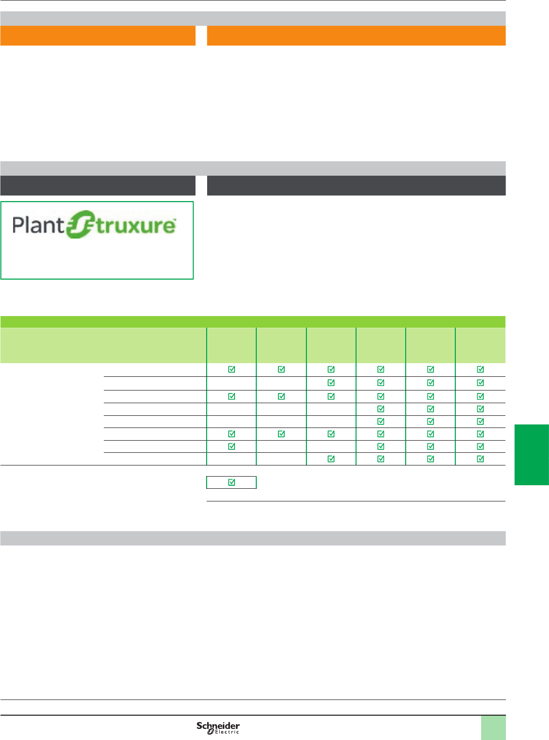
7/3
Presentation (continued) A dedicated services offer for your
installed base
Consultancy services
M2C (Maintenance and Modernization
Consultancy) Professional tools and methods, proven experience of managing obsolescence and
updating installed bases, to reduce downtimes and improve performance
With our maintenance and modernization consultancy offer, Schneider Electric will
help you check the state of your installed base by:
bDening the scope and depth of the analysis in collaboration with you
bCollecting the technical data without shutting down production
bAnalyzing and identifying avenues for improvement
bProducing a recommendation plan
Customer benets:
bLearning about the components that make up the installed base and how
up-to-date they are
bBetter downtime anticipation
bExpert advice designed to improve performance
Modernization solutions
Migration to PlantStruxure Proven expertise, tools and methods to give you a clear vision of the improvement
opportunities and guide you toward a successful modernization project
To nd out more about PlantStruxure
architectures, please visit our website
www.schneider-electric.com/PlantStruxure
Schneider Electric offers a gradual program of modernization through a series of
products, tools and services that allow you to upgrade to newer technology. There
are several stages in this gradual modernization program:
bPartial program: replacement of an old component with a new one
bStaggered program: gradual incorporation of new offers in the system
bTotal program: total renovation of the system
The table below lists our various migration offers:
Wide range of migration offers
Solution Change the
CPU
Keep the
I/O racks &
wiring
Change the
I/O racks &
keep the
wiring
Migrate your
application
Manage your
project
Execute your
project
Platform (1) TSX47 to TSX107
April series 1000
Modicon p84, Compact
April SMC
Merlin Gerin PB
AEG
Symax
Rockwell SLC500
Service available
(1) Our migration service offer also includes SCADA, Human Machine Interfaces, drives,
communication networks and distributed I/O.
Customization services
Schneider Electric is able to meet your specic requirements and provide you with
adapted products:
bProtective coating for Human Machine Interfaces, automation platforms and
distributed I/O modules for use in harsh environments
bCustomized cable lengths to match your specic needs
bCustomized front panels for Human Machine Interfaces
Note: To check availability of services required, please contact our Customer Care Centre.
2
1
3
4
5
6
7
8
9
10
2
1
3
4
5
6
7
8
9
10

8/0
2
1
3
4
5
6
7
8
9
10
2
1
3
4
5
6
7
8
9
10

8/1
Contents
Technical appendices
b Ethernet network infrastructure ...........................................................page 8/2
Index
b Product reference index........................................................................page 8/8
8 - Technical information, index
2
1
3
4
5
6
7
8
9
10
2
1
3
4
5
6
7
8
9
10

8/2
Presentation Technical information
Ethernet network
Infrastructure
Presentation
The ConneXium Industrial Ethernet offer comprises a complete family of products
and tools (including the ConneXium Network Manager (CNM) software tool) required
to build the infrastructure of an Industrial Ethernet network. The following pages
provide information on network design and component selection.
Ofce Ethernet versus Industrial Ethernet
There are three main areas of differentiation between Ethernet applications in an
ofce environment and those in an industrial environment:
bEnvironment
bLayout (not physical layer specication)
bPerformance
Contrary to the ofce environment and even though ISO/IEC is working on it, as yet
there are no clearly dened specications for Ethernet devices intended for
industrial applications. The specications of what it is called Industrial Ethernet are
dened by different agencies or entities based upon its nature and what the
automation market has traditionally used.
The environmental specications of Industrial Ethernet devices are dened by the
traditional agencies that dene the environmental specications for standard
industrial devices (UL, CSA, e, etc.).
IEEE 802.3 denes the physical layer specications of the Ethernet network (types
of connector, distance between devices, number of devices, etc.) while standard
11801 (similar to TIAEIA 568B and CENELEC EN 50173) provides layout guidelines
for installers.
The performance specications are currently being drawn up by ISO/IEC.
Ethernet 802.3 principles
The Ethernet 802.3 Link Layer is based on a collision detection mechanism
(CSMA CD) whereby every node whose information has collided on the network
detects the collision and re-sends the information.
The process of re-sending information causes delays in its propagation and could
affect the application.
A collision domain is a group of Ethernet end devices interconnected by hubs or
repeaters (devices that receive information and send it out to all their other ports, no
matter where the destination device is connected). This means that all devices will
be affected by collisions.
With full duplex switches (devices that receive information and only send it out through
the port to which the destination device is connected), there are no collision domains.
Therefore, for industrial automation applications it is highly advisable to use full
duplex switches to interconnect devices. This will help eliminate collision domains.
2
1
3
4
5
6
7
8
9
10
2
1
3
4
5
6
7
8
9
10
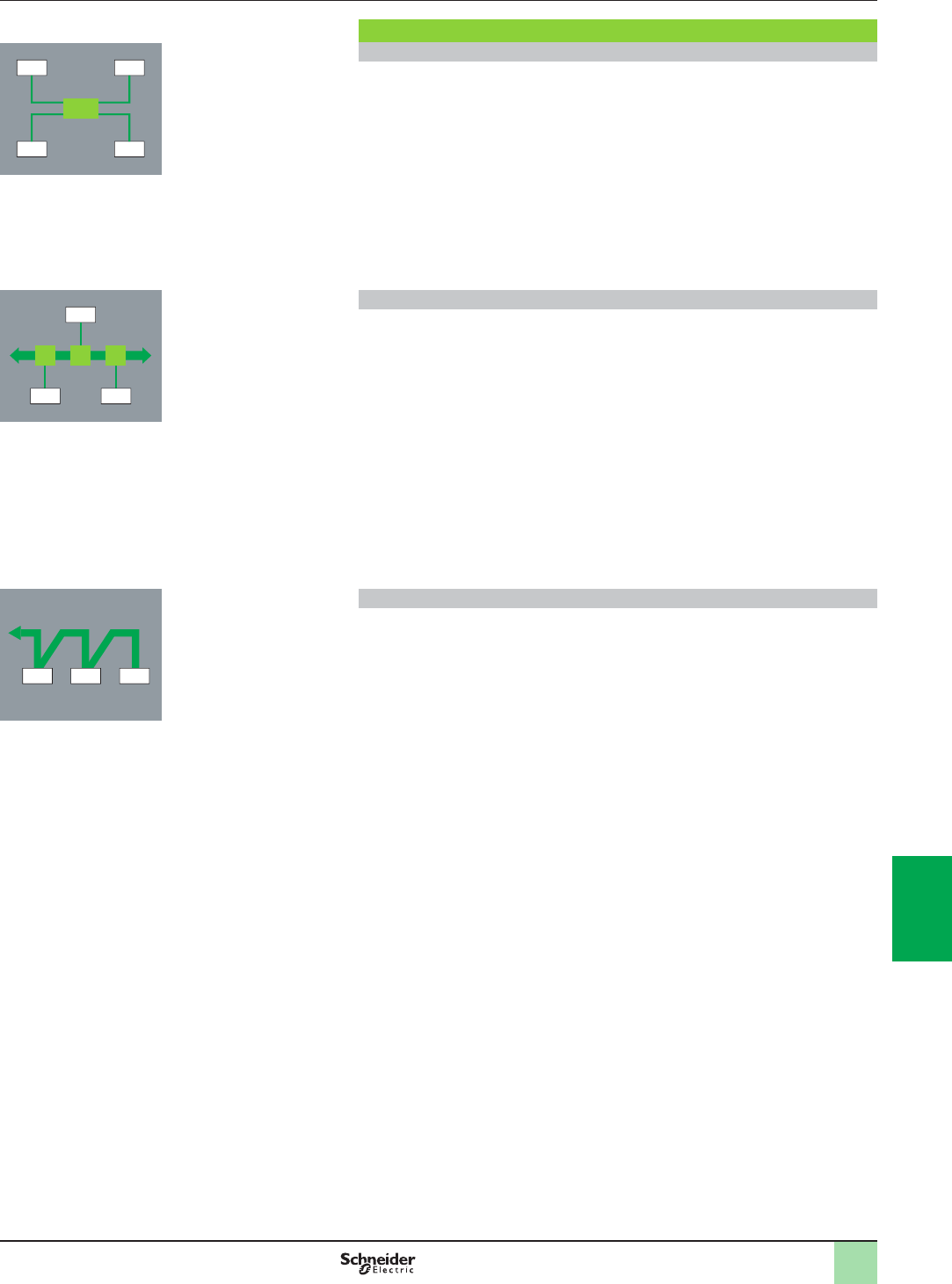
8/3
Topologies Technical information
Ethernet network
Infrastructure
Different network topologies
Star topology
In a star topology, all devices and Data Terminal Equipment (DTE) are connected
though an intermediate device.
Ethernet star
In an Ethernet star the intermediate device may be a switch. The star is the most
commonly used topology in corporate networks and is currently adopted in almost
every automation application. As mentioned previously, for industrial Ethernet
applications the use of full duplex switches as the central device rather than hubs is
highly recommended.
Deploying star topologies with ConneXium
Star topologies can be implemented with any of the switches in the ConneXium offer.
Bus topology
The bus is one of the most common topologies in traditional industrial automation
networks. A single trunk cable connects all devices on the network usually via
passive or active T-connectors, or directly chained (daisy chain). Devices can
usually be installed anywhere along the bus.
Ethernet bus
An Ethernet bus can be deployed by interconnecting switches in line and
considering every one of them as the connection for a drop device. An unlimited
number of switches can be interconnected to achieve this purpose.
Deploying bus topologies with ConneXium
Bus topologies can be implemented with any of the switches in the ConneXium offer.
Switches with 1 or 2 ber optic ports are particularly suitable for this purpose:
bSwitches with 2 ber optic ports can be used to connect in-line devices.
bSwitches with 1 ber optic port can be used to connect end-of-line devices.
Daisy chain topology
Daisy chain - along the bus - is the other most common topology in traditional
industrial automation networks. Cable segments interconnect multiple devices,
being the devices “part” of the network cable.
Ethernet daisy chain
Daisy chain is currently not a particularly common Ethernet topology, but it is likely to
rise in popularity as more devices become available.
Ethernet daisy chain devices have:
b2 Ethernet ports and
b1 embedded switch.
Schneider Electric is launching Industrial Ethernet devices on the industrial market
for connection in daisy chain architectures.
Deploying daisy chain topologies
No switches are required for daisy chain topologies. All devices have an embedded
switch.
Dual port Ethernet at device level is an absolute integral component for daisy chain
topologies.
One port on the device connects to one port on each of the two neighboring devices.
These neighboring connections make up the daisy chain.
Ethernet switches can be employed in a daisy chain topology when multiple scan
chains are in use by the controlling device. It is expected that the Ethernet switch will
be located near the controlling device with the different scan chains emanating from
the switch.
DTE
DTEDTE
DTE DTEDTE
DTE DTE
DTE DTE
2
1
3
4
5
6
7
8
9
10
2
1
3
4
5
6
7
8
9
10
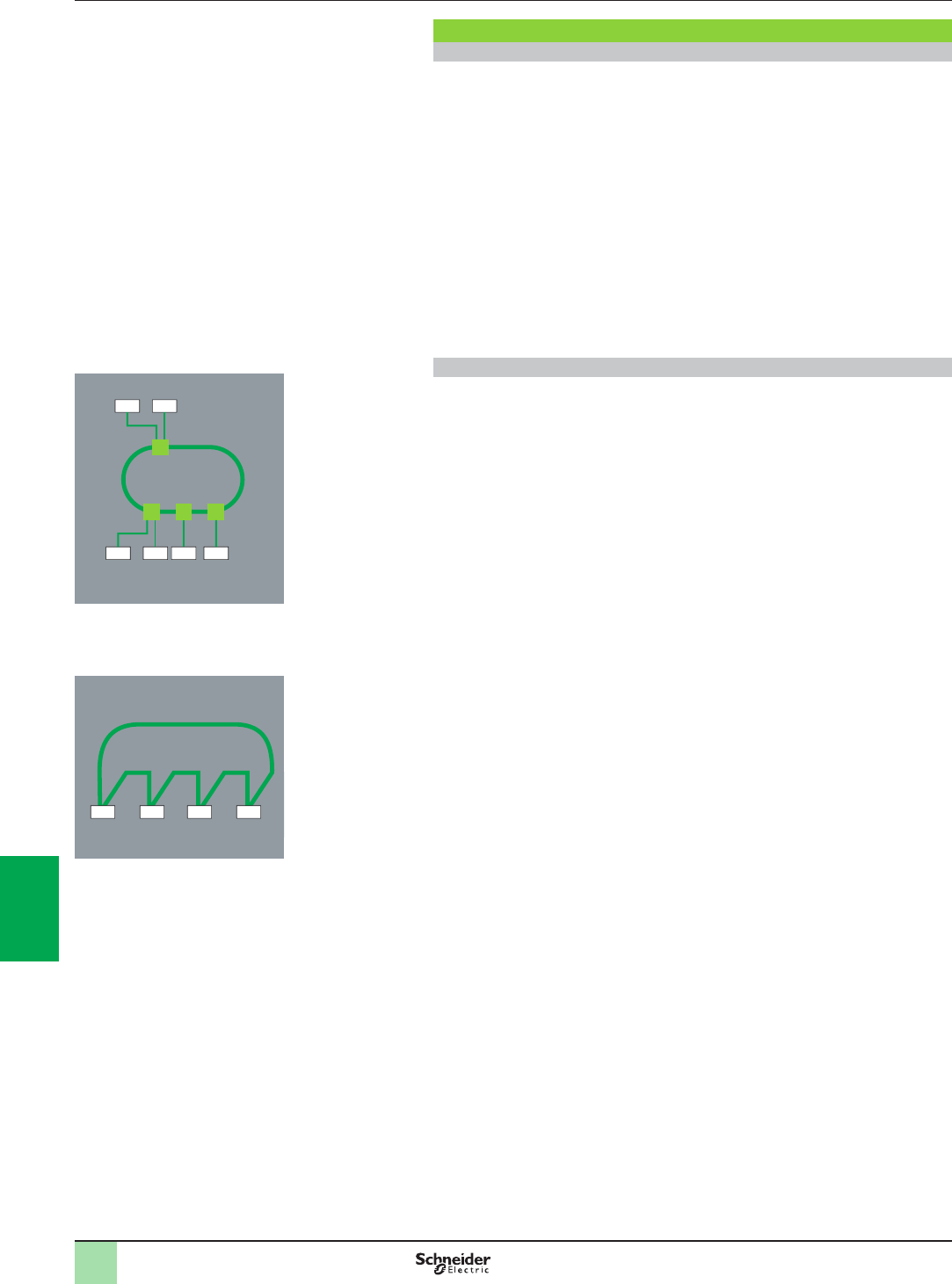
8/4
Topologies (continued) Technical information
Ethernet network
Infrastructure
Different network topologies (continued)
Daisy chain topology (continued)
Limitations of the daisy chain:
Limitations of the daisy chain topology in terms of operational integrity of the network
and performance metrics are as follows:
bDual port Ethernet devices only support 10 Mbps and/or 100 Mbps operational
speeds and must use one or the other.
bThe network will operate only as fast as the slowest device that is connected to the
network.
bIn order to improve network trafc latency, the number of devices in a single scan
chain is limited to 32 devices. This means that the time for a round trip of a packet
through the daisy chain is likely to be less than 5 milliseconds.
The maximum latency of a packet passing through any device in a scan chain is no
more than 10 µs.
Ring topology
In a ring topology, all devices or network infrastructure components are connected in
a loop. Through this type of topology, a type of network redundancy is achieved.
Ring topologies also help improve the availability of the network and its
communication to devices.
Ethernet ring
Ethernet rings are usually the backbones of applications in which high availability is
required. If ring topology is required then switches that support this feature should be
ordered.
Deploying ring topologies using ConneXium
ConneXium offers switches that allow the deployment of single and coupled
self-healing rings (see page 2/11 for more information).
Daisy chain loop
A daisy chain loop consists of several daisy chain devices that are placed in a ring
topology.
When an Ethernet network forms a loop, all the devices in that loop must use the
same protocol (RSTP, MRP, or HIPER-Ring).
DTEDTE
DTEDTE DTE DTE
DTE DTE DTE DTE
2
1
3
4
5
6
7
8
9
10
2
1
3
4
5
6
7
8
9
10
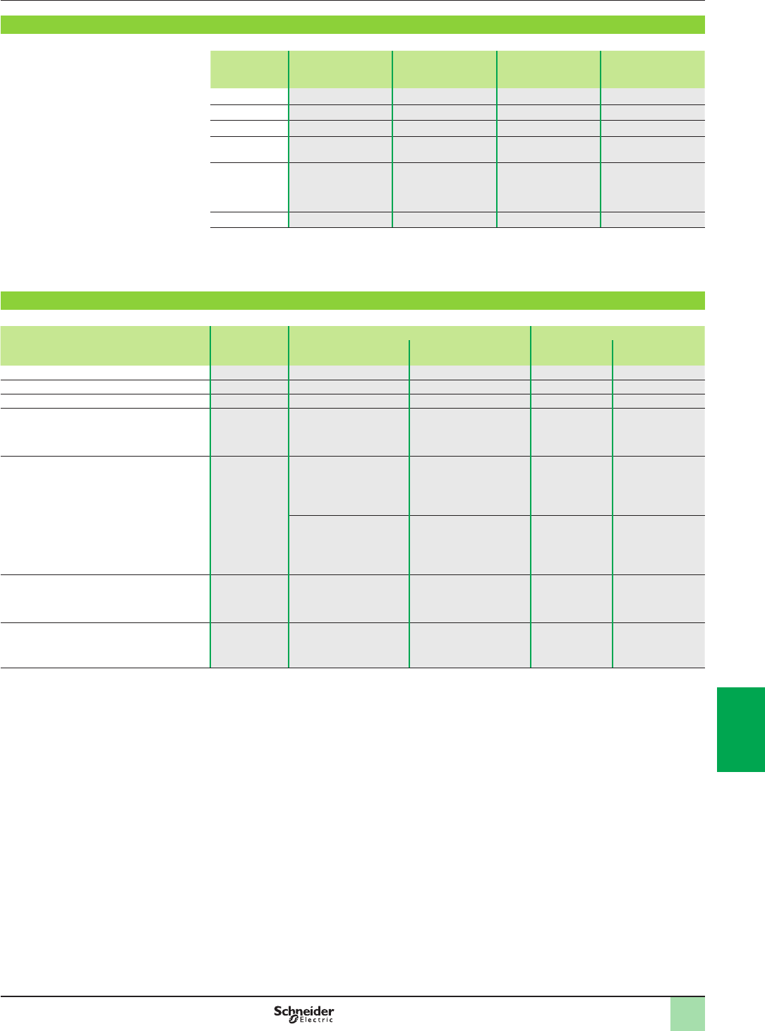
8/5
Characteristics Technical information
Ethernet network
Infrastructure
Distance limitations and number of devices per segment
Based on standard 802.3, the distance limits and number of devices in cascade are as follows:
Type Maximum segment
length (1)
Maximum segment
length (offered by
ConneXium devices)
Maximum number of
hubs in cascade
Maximum number of
switches in cascade
10BASE-T 100 m/328.08 ft 100 m/328.08 ft 4Unlimited
100BASE-TX 100 m/328.08 ft 100 m/328.08 ft 2 Unlimited
1000BASE-T 100 m/328.08 ft 100 m/328.08 ft – Unlimited
10BASE-FL 2,000 m/6,561.66 ft 3,100 m/10,170.57 ft
(2)
11 (ber ring) –
100BASE-FX 412 m/1,351.70 ft
2,000 m/6,561.66 ft
4,000 m/13,123.32 ft
with multimode ber,
32,500 m/106,627 ft
with singlemode ber (3)
– Unlimited
1000BASE-SX 275 m/902.23 ft – – Unlimited
(1) Based on 802.3, full duplex/half duplex.
(2) Depends on the optical ber budget and ber attenuation.
(3) Depends on the optical ber budget and ber attenuation, typical specication is
2,000 m/6,561.66 ft for multimode and 15,000 m/49,212.45 ft for singlemode.
Physical media
The Ethernet 802.3 standard denes the Physical Layer. A summary of the most common media is given below:
Type Data rate Cable type Connector type
Dened by 802.3 Recommended by
Schneider Electric
Dened
by 802.3
Recommended by
Schneider Electric
10BASE-T 10 Mbps CAT 3 - UTP CAT 5E - STP RJ45 RJ45
100BASE-TX 100 Mbps CAT 5 - UTP CAT 5E - STP RJ45 RJ45
1000BASE-T 1 Gbps CAT 5 - UTP CAT 5E - STP RJ45 RJ45
10BASE-FL 10 Mbps Two multimode optical
ber cables typically
62.5/125 µm ber,
850 nm light wavelength
Two multimode optical
ber cables typically
62.5/125 µm ber,
850 nm light wavelength
ST ST
100BASE-FX 100 Mbps Two multimode optical
bers typically
62.5/125 µm multimode
ber,
1,300 nm light wavelength
Two multimode optical
bers typically
62.5/125 µm multimode
ber,
1,300 nm light wavelength
ST SC
–Two monomode optical
bers typically 9/125 µm
multimode ber,
1,300 nm light wavelength
– SC
1000BASE-SX 1 Gbps Two 62.5/125 or 50/125
multimode optical bers,
770 to 860 nm light
wavelength
Two 62.5/125 µm or
50/125 m multimode
optical bers,
1,300 nm light wavelength
SC LC
1000BASE-LX 1 Gbps –Two 9/125 µm singlemode
optical bers,
1,300 nm light wavelength
– LC
Note: These specications are dened by IEEE 802.3. However, some of the cables are no
longer being developed. For instance, for 10BASE-T and 100BASE-TX, a CAT-5E cable is used.
2
1
3
4
5
6
7
8
9
10
2
1
3
4
5
6
7
8
9
10

8/6
Management Technical information
Ethernet network
Infrastructure
Management
Ethernet devices in general (end-of-line devices and cabling devices) can be divided
into two categories: unmanaged and managed devices.
bUnmanaged devices are those devices for which there is no option to congure or
control any of the device parameters.
bManaged devices are those devices whose parameters can be congured or
controlled (managed) and their internal data can be accessed.
The ConneXium product line offers both types of device.
There is also a third, unspecied category of device, which is normally classed as a
managed device. However, there is one major difference: although this device allows
access to its internal data, it cannot be controlled and/or congured.
Managed devices
Managed devices offer the following features:
bTrafc optimization and ltering - The aim is to increase the bandwidth, or the
trafc capacity in a network (some of the features in this area are message and port
priority, ow control, multicast ltering, broadcast limiting, IGMP snooping, Vlan, etc.).
bVLAN - A virtual LAN (VLAN) consists of a group of network participants in one or
more network segments who can communicate with each other as if they belonged
to the same LAN.
VLANs are based on logical (instead of physical) links. The biggest advantage of
VLANs is their possibility of forming user groups based on the participant function
and not on their physical location or medium.
Since broad/multicast data packets are transmitted exclusively within a virtual LAN,
the remaining data network is unaffected. VLAN can also serve as a security
mechanism to block unwanted Unicast messages.
bSecurity - This feature helps the user protect the switch from unauthorized access
that could result in changes in its conguration and impact the trafc going through
the switch (some of the features in this area are port security, read/write community
name, etc.).
Users can also set up the switch so that it blocks messages coming from
unauthorized “device” source addresses connected to the switch.
bTime synchronization - This feature allows all devices in a network to be
synchronized according to the time.
bNetwork redundancy - This helps to develop high availability applications.
bDual ring switch (DRS) - These switches are provided with predened settings to
optimize communication performance and help save time in Ethernet RIO
architectures with Modicon Quantum and Modicon M580 automation platforms.
DRS switches are mandatory to build Ethernet RIO architectures in which sub-rings
have to be connected to the main Ethernet ring.
2
1
3
4
5
6
7
8
9
10
2
1
3
4
5
6
7
8
9
10

8/7
Redundancy Technical information
Ethernet network
Infrastructure
Redundancy
To develop high availability applications, “redundancy” in the networking
infrastructure is the answer. Developers can help avoid losing network segments by
implementing a single ring or a coupled ring architecture.
Single ring
The rst level of redundancy is achieved by implementing a single ring. ConneXium
switches allow the set up of backbone ring congurations.
ConneXium switches support three redundancy protocols: HIPER-Ring, MRP, and
RSTP.
The ring is constructed using HIPER-Ring ports. If an error is detected in one section
of the line, a ring structure of up to 50 switches transforms back to a line-type
conguration within 0.5 seconds.
With a Modicon Quantum or a Modicon M580 Ethernet RIO architecture, the
recovery loop can be optimized to less than 50 ms thanks to the RSTP protocol
implemented in the different devices.
Dual ring
The second level of redundancy is achieved by implementing a dual ring. The control
intelligence built into ConneXium switches allows the redundant coupling of
HIPER-Rings and network segments.
As for a single ring, the recovery time can be optimized to less than 50 ms for 16
switches or 32 RIO drop adapters thanks to the RSTP protocol.
Mesh topology using the rapid “Spanning Tree” protocol
A third level of redundancy can be achieved by implementing a mesh topology.
In simple terms,“Spaning Tree” is a protocol that provides a single path for the
signal, when multiple paths exist. If the active path is broken, the “Spanning Tree”
protocol enables one of the alternative paths.
ConneXium switches offer this possibility.
Security
ConneXium rewalls help improve security for industrial networks while meeting the
needs for cybersecurity.
Firewall rules can be dened to control access levels at the host, protocol, and port
levels.
Further rules can be dened for other purposes, such as protecting access to
Modbus/TCP function codes and register levels, or EtherNet/IP CIP objects and
service codes.
ConneXium rewalls can also offer layer 3 routing, network address translation
(NAT), and virtual private networks (VPN) for advanced security zoning of critical
industrial networks.
DTEDTE
DTEDTE DTE DTE
DTEDTE
DTEDTE DTE DTE
DTE
DTE
DTE DTE
DTE
DTE
2
1
3
4
5
6
7
8
9
10
2
1
3
4
5
6
7
8
9
10

8/8
Product reference index
Index
1
110XCA28201 4/21
110XCA28202 4/21
110XCA28203 4/21
170DNT11000 3/31
4
490NAD91103 3/31
490NAD91104 3/31
490NAD91105 3/31
490NOR00003 2/18
490NOR00005 2/18
9
990NAA26320 4/21
990NAA26350 4/21
B
BMECRA31210 2/17
BMECRA31210C 5/5
BMEP581020 1/23
2/18
2/19
BMEP581020H 5/3
BMEP582020 1/23
2/18
2/19
BMEP582020H 5/3
BMEP582040 1/23
2/18
2/19
BMEP582040H 5/3
BMEP583020 1/23
2/18
2/19
BMEP583040 1/23
2/18
2/19
BMEP584020 1/23
2/18
2/19
BMEP584040 1/23
2/18
2/19
BMEXBP0400 1/25
BMEXBP0400H 5/4
BMEXBP0800 1/25
BMEXBP0800H 5/4
BMEXBP1200 1/25
BMEXBP1200H 5/4
BMXCRA31200 2/17
BMXCRA31210 2/17
BMXERT1604T 4/37
BMXNOC0402 2/17
3/25
BMXNRP0200 2/17
BMXNRP0201 2/17
BMXRMS004GPF 1/23
5/3
BMXXBC008K 1/29
2/19
5/4
BMXXBC015K 1/29
2/19
5/4
BMXXBC030K 1/29
2/19
5/4
BMXXBC050K 1/29
2/19
5/4
BMXXBC120K 1/29
2/19
5/4
BMXXBE1000 1/28
2/18
BMXXBE1000H 5/4
BMXXBE2005 1/28
2/18
BMXXBP0400 1/28
BMXXBP0400H 5/4
BMXXBP0600 1/28
BMXXBP0600H 5/4
BMXXBP0800 1/28
BMXXBP0800H 5/4
BMXXBP1200 1/28
BMXXBP1200H 5/4
BMXXCAUSBH018 1/23
4/21
5/3
BMXXCAUSBH045 1/23
4/21
5/3
BMXXEM010 1/25
5/4
BMXXSP0400 1/25
5/4
BMXXSP0600 1/25
5/4
BMXXSP0800 1/25
5/4
BMXXSP1200 1/25
5/4
S
SR2CBL06 4/21
STBEHC3020KC 2/23
STBNDP2212 3/31
STBXCA4002 4/21
STBXSP3010 1/25
5/4
STBXSP3020 1/25
5/4
T
TCSECN3M3M1S4 2/17
TCSECN3M3M1S4U 2/17
TCSEGDB23F24FA 3/29
TCSEGDB23F24FK 3/29
TCSEGPA23F14F 3/31
TCSEGPA23F14FK 3/31
5/5
TCSESM083F23F1 2/17
TCSMCN3M4M3S2 5/5
TCSWAAC13FB 4/21
TCSXCN3M4F3S4 5/5
TSXPBSCA100 3/31
TSXPBSCA400 3/31
TLXCDLFOFS35 4/35
TLXCDLTOFS35 4/35
TLXCDLUOFS35 4/35
TLXCDSTOFS35 4/35
TLXCDSUOFS35 4/35
TSXCBY010K 1/29
2/19
5/4
TSXCBY030K 1/29
2/19
5/4
TSXCBY050K 1/29
2/19
5/4
TSXCBY120K 1/29
2/19
5/4
TSXCBY180K 1/29
2/19
5/4
TSXCBY280KT 1/29
2/19
5/4
TSXCBY1000 1/29
2/19
5/4
TSXCBYACC10 1/29
2/19
5/5
TSXCBYK9 1/29
2/19
5/5
TSXCRJMD25 4/21
TSXCUSB485 4/21
TSXPCX1031 4/21
TSXTLYEX 1/29
2/19
5/5
U
UAGSBTCFUCD10 4/29
UAGSBTDFUWB13 4/29
UNYDFFXZZSPA80 4/25
UNYLAGZAUWB20 4/29
UNYLFZZAUWB12 4/29
UNYLHVZAUWB10 4/29
UNYLPCZAUWB 4/29
UNYLSYSFU 4/29
UNYLTSZAUWB10 4/29
UNYSPUEEFCD80 4/20
UNYSPUEFFCD80 4/20
UNYSPUEFGCD80 4/20
UNYSPUEFTCD80 4/20
UNYSPUEFUCD80 4/20
UNYSPUEZFCD80 4/20
UNYSPUEZGCD80 4/20
UNYSPUEZGTCD80 4/20
UNYSPUEZLGCD80 4/20
UNYSPUEZLTCD80 4/20
UNYSPUEZLUCD80 4/20
UNYSPUEZTCD80 4/20
UNYSPUEZUCD80 4/20
UNYSPUEZUGCD80 4/20
UNYSPULFFCD80 4/19
UNYSPULFGCD80 4/19
UNYSPULFTCD80 4/19
UNYSPULFUCD80 4/19
UNYSPULZFCD80 4/19
UNYSPULZGCD80 4/19
UNYSPULZGTCD80 4/19
UNYSPULZMGCD80 4/19
UNYSPULZMTCD80 4/19
UNYSPULZMUCD80 4/19
UNYSPULZSGCD80 4/19
UNYSPULZSTCD80 4/19
UNYSPULZSUCD80 4/19
UNYSPULZTCD80 4/19
UNYSPULZUCD80 4/19
UNYSPULZUGCD80 4/19
UNYSPUSFGCD80 4/18
UNYSPUSFTCD80 4/18
UNYSPUSFUCD80 4/18
UNYSPUSZGCD80 4/18
UNYSPUSZGTCD80 4/18
UNYSPUSZTCD80 4/18
UNYSPUSZUCD80 4/18
UNYSPUSZUGCD80 4/18
UNYSPUZFUCD80 4/23
UNYXCAUSB033 4/21
2
1
3
4
5
6
7
8
9
10
2
1
3
4
5
6
7
8
9
10
DIA6ED2131202EN
Januar y 2014 - V1.0
The information provided in this documentation contains general descriptions and/or technical
characteristics of the performance of the products contained herein. This documentation is not
intended as a substitute for and is not to be used for determining suitability or reliability of these
products for specic user applications. It is the duty of any such user or integrator to perform the
appropriate and complete risk analysis, evaluation and testing of the products with respect to the
relevant specic application or use thereof. Neither Schneider Electric nor any of its afliates or
subsidiaries shall be responsible or liable for misuse of the information contained herein.
Design: Schneider Electric
Photos: Schneider Electric
Printed by:
Head O f ce
35, rue Joseph Monier
F-92500 Rueil-Malmaison
France
Schneider Electric Industries SAS www.schneider-electric.com

Schneider Electric Modicon M580 automation platform
14
