172844 EMC Certification Castles
2016-04-05
: Pdf 172844 Emc Certification Castles 172844_EMC_certification_Castles CertsReports 172844 ProductFiles
Open the PDF directly: View PDF ![]() .
.
Page Count: 71

REPORT NO. : E920229
Page 1 of 69
EMC TEST REPORT
According to
1) EN 55022: 1998+A1: 2000
2) EN 61000-3-2: 2000
3) EN 61000-3-3: 1995
4) EN 55024: 1998+A1: 2001
EN 61000-4-2: 1995+A1: 1998 / EN 61000-4-3: 1996+A1: 1998
EN 61000-4-4: 1995 / EN61000-4-5: 1995
EN 61000-4-6: 1996 / EN 61000-4-8: 1993
EN 61000-4-11: 1994
EUT Name Smart Card Reader
Model No. EZ-100PU-C, EZ-100PU-P
Applicant CASTLES TECHNOLOGY CO., LTD.
6F-1, NO. 190, CHUNG-HSIN RD., SEC. 2, HSIN-TIEN, TAIPEI
HSIEN, TAIWAN, R. O. C.
Test Engineer ΚDENNY HUANG
Reviewed by ΚJASON KUNG
Issued Date: ΚJUN. 03, 2003
ΘThe test report shall not be reproduced except in full, without the written approval of the
laboratory.
ΘThe report can’t be used by the client to claim product endorsement by PEP Testing
Laboratory.
ΘThis report is only for the equipment which described in page 6.

REPORT NO. : E920229
Page 2 of 69
TABLE OF CONTENTS
1. General 4
1.1 General Information
1.2 Place of Measurement
1.3 Test Standards
2. Product Information/Product Technical Judgement 6
3. EUT Description 7
4. Modification 8
5. Test Software Used 8
6. Support Equipment Used 9
7. EN 55022 Conducted Disturbance Test 11
7.1 Test Limits
7.2 Test Setup Photos
7.3 Test Data
8. EN 55022 Radiated Disturbance Test 16
8.1 Test Description
8.2 Test Limits
8.3 Test Setup photos
8.4 Test Data
9. EN 61000-4-2 Electrostatic Discharge Test 22
9.1 Test Description
9.2 Test Limits
9.3 Test Setup Drawing
9.4 Test Data

REPORT NO. : E920229
Page 3 of 69
10. EN 61000-4-3 Radio-Frequency Electromagnetic Field Test 32
10.1 Test Description
10.2 Test Limits
10.3 Test Setup Photo
11. EN 61000-4-4 Fast Transient Burst Test 38
11.1 Test Description
11.2 Test Limits
11.3 Test Setup Photo
11.4 Test Data
12. EN 61000-4-5 Surge Immunity Test 44
12.1 Test Description
12.2 Test Limits
12.3 Test Setup Photo
12.4 Test Data
13. EN 61000-4-6 Conducted Disturbances, Induced By Radio Frequency Test 50
13.1 Test Description
13.2 Test Limits
13.3 Test Setup Photo
13.4 Test Data
14. EN 61000-4-8 Power Frequency Magnetic Field Immunity Test 57
14.1 Test Description
14.2 Test Setup
14.3 Test Limits
14.4 Test Setup Photo
15. Labeling Requirement, Warning 62
16. The List of Test Instruments 63
17. EUT Photos 65

REPORT NO. : E920229
Page 4 of 69
1. General
1.1 General Information :
Applicant : CASTLES TECHNOLOGY CO., LTD.
6F-1, NO. 190, CHUNG-HSIN RD., SEC. 2, HSIN-TIEN,
TAIPEI HSIEN, TAIWAN, R. O. C.
Manufacturer : CASTLES TECHNOLOGY CO., LTD.
6F-1, NO. 190, CHUNG-HSIN RD., SEC. 2, HSIN-TIEN,
TAIPEI HSIEN, TAIWAN, R. O. C.
Measurement Procedure : EN55022
1.2 Place of Measurement
PEP TESTING LABORATORY
12-3Fl, No. 27-1, Lane 169, Kang-Ning St., Hsi-Chih,
Taipei Hsien, Taiwan, R. O. C.
TEL : 8862-26922097 FAX : 8862-26956236
NVLAP LAB CODE 200097-0
FCC Registration No. : 90868
NEMKO Aut. No. : ELA133
BSMI Aut. No. : SL2-IN-E-11
VCCI Registration No. : C-493/R-477

REPORT NO. : E920229
Page 5 of 69
1.3 Test Standards
Tested for compliance with:
EN 55022:1998 - Information Technology Equipment – Radio disturbance
+A1: 2000 characteristics - Limits and methods of measurement
EN 61000-3-2: 2000 - Electromagnetic compatibility (EMC) Part 3-2: Limits –
Limits for harmonic current emissions (equipment input
Current up to and including 16A per phase
EN 61000-3-3:1995 - Electromagnetic compatibility (EMC) Part 3-2: Limits –
Limitation of voltage fluctuations and flicker in low-voltage
supply systems for equipment with rated current up to 16A
EN 55024:1998 - Information technology equipment – Immunity characteristics
+A1: 2001 Limits and methods of measurement
EN 61000-4-2:1995 - Electromagnetic compatibility (EMC) Part 4: Testing and
+A1: 1998 measurement techniques, Section 2: Electrostatic discharge
immunity test Basic EMC Publication
EN 61000-4-3:1996 - Electromagnetic compatibility (EMC) Part 4: Testing and
+A1: 1998 measurement techniques, Section 3: Radiated, radio-
Frequency, electromagnetic field immunity test
EN 61000-4-4:1995 - Electromagnetic compatibility (EMC) Part 4: Testing and
measurement techniques, Section 4: Electrical fast transient
/ Burst immunity test Basic EMC publication
EN 61000-4-5: 1995 - Electromagnetic compatibility (EMC) Part 4: Testing and
measurement techniques, Section 5: Surge immunity test (includes
corrigendum: 1995)
EN 61000-4-6: 1996 - Electromagnetic compatibility (EMC) Part 4: Testing and
measurement techniques, Section 6: Immunity to conducted
disturbances, induced by radio-frequency fields
EN 61000-4-8: 1993 - Electromagnetic compatibility (EMC) Part 4: Testing and
measurement techniques, Section 8: Power frequency
magnetic field immunity test Basic EMC publication
EN 61000-4-11: 1994 - Electromagnetic compatibility (EMC) Part 4: Testing and
measurement techniques, Section 11: Voltage dips, short
interruptions and voltage variations immunity tests

REPORT NO. : E920229
Page 6 of 69
2. Product Information
a. EUT Name: Smart Card Reader
b. Model No. EZ-100PU-C
c. CPU Type EZU0030
d. CPU Frequency 6MHz
e. Crystal/Oscillator(s) 6MHz
f. Chassis Used ABS
g. Port/Connector(s) USB Port × 1
h. Power Rating DC 5V ------- From PC
i. Condition of the EUT : ϭ Prototype Sample Engineering Sample
ʳϭ
Production Sample
j. Test Item Receipt Date : MAY 26, 2003
2a. Product Technical Judgement
Based on the major electrical and mechanical constrictions of the EUT, We hereby declare
that the subject product does fully comply with the following EMC requirements
without additional test required :
1) EN 61000-3-2 : 2000
2) EN 61000-3-3 : 1995
3) EN 61000-4-11 : 1994
These test standards will be applicable to both of PEP EMC verification and declaration
of conformity for technical reference.

REPORT NO. : E920229
Page 7 of 69
3. EUT Description
The equipment under test (EUT) is Smart Card Reader model EZ-100PU-C and
EZ-100PU-P. These two models have identical electrical design and construction except
that model EZ-100PU-C uses COB (Chip On Board) IC and model EZ-100PU-P uses
LQPF IC. After verifying these two models, we took the worst-case model: EZ-100PU-C
for test. The EUT that compatible with USB interface to PC comes with the function to
read data from smart card. DC5V from PC via PC USB port is required to operate EUT.
For more detail specification about EUT, please refer to the user’s manual.
Test method: The EUT was configured to PC USB port and all corresponding peripherals
to PC I/O ports and EUT were setup to proceed with test. The test was
carried out on the operating condition of EUT for the maximum disturbance.
The worst-case test result was recorded and provided in this report.
As pre-scan, we took radiated emission first. EUT configuration including peripheral
devices placement and data cables coupling was compliant with EN 55022 requirement.
Test engineer tried to find the worst data cables coupling in order to perform the final test
that conducted emission and radiated emission would keep the same configuration under
test.
Conducted emission test:
The system was setup with the EMI diagnostic software running. The power line
conducted EMI tests were run on the line and neutral conductors of the power cord and the
results were recorded. The effect of varying the position of the interface cables has been
investigated to find the worst-case configuration that produces maximum emission.
At the frequencies where the peak values of the emission exceeded the applicable limit, the
emissions were also measured with the quasi-peak detectors. The average detector also
measured the emission either (A) quasi-peak values were under quasi-peak limit but
exceeded average limit, or (B) peak values were under quasi-peak limit.
Radiated emission test:
The maximum readings were found by varying the height of antenna and then rotating the
turntable. Both polarization of antenna, horizontal and vertical, are measured. The effect
of varying the position of the interface cables has been investigated to find the
configuration that produces maximum emission.
The highest emissions were also analyzed in details by operating the spectrum analyzer in
fixed tuned quasi-peak mode to determine the precise amplitude of the emissions. While
doing so, the antenna height was varied between one and four meters, and the turntable
was slowly rotated, to maximize the emission.

REPORT NO. : E920229
Page 8 of 69
4. Modification(s):
N/A
5. Test Software Used
(A) Castles EMI program was the software used to operate EUT during the test.
(B) EMITEST program was the software used to detect PC peripherals and EUT during
the test.

REPORT NO. : E920229
Page 9 of 69
6. Support Equipment Used
1. Personal Computer (PC3) CPU : Intel P4 Socket 478 1.6GHz
FCC ID Declaration of Conformity(DoC)
Manufacturer LEMEL
Model Number LMIH1A2
Power Supply Switching
Power Cord Non-Shielded, Detachable, 1.8m
Data Cable N/A
2. Keyboard (KBS1 PS/2) FCC ID E5XKB5121WTH0110
Manufacturer BTC
Model Number 5121W
Power Supply +5Vdc from PS2 of PC
Power Cord N/A
Data Cable 1 > Shielded , Non-detachable,1.6m
2 > Back Shell : Metal
3. Monitor (MON1 15”) FCC ID Declaration of Conformity(DoC)
Manufacturer SAMSUNG
Model Number 550S
Power Supply Switching
Power Cord Non-Shielded, Detachable, 1.8m
Data Cable 1 > Shielded , Non-detachable,1.2m
2 > Back Shell : Metal
4. Printer (PRN1) FCC ID B94C2642X
Manufacturer Hewlett-Packard
Model Number C2642E
Power Supply Linear, 30Vdc O/P
Power Cable Non-Shielded , Detachable,1.8m
Data Cable 1 > Shielded , Detachable,1.2m
2 > Back Shell : Metal

REPORT NO. : E920229
Page 10 of 69
5. Modem (MOD1) FCC ID IFAXDM1414
Manufacturer ACEEX
Model Number 1414
Power Supply Linear, 9Vac O/P
Power Cable Non-Shielded , Detachable,1.7m
Data Cable 1 > Shielded , Detachable,1m
2 > Back Shell : Metal
6. Mouse (MOUS/1 PS/2) FCC ID DZL211106
Manufacturer LOGITECH
Model Number M-S43
Power Supply +5Vdc from PS2 of PC
Power Cord N/A
Data Cable 1 > Shielded , Non-detachable,1.8m
2 > Back Shell : Metal

REPORT NO. : E920229
Page 11 of 69
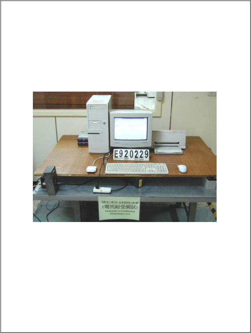
7. EN 55022 Conducted Disturbance Test
Test Standard Model No. Result
EN 55022:1998 EZ-100PU-C Passed
7.1 Conducted Disturbance Test Limits at Main Ports
Frequency Rang Limits dB(uV)
Class A ITE Class B ITE
MHz Quasi-peak Average Quasi-peak Average
0.15 - 0.50 79 66 66-56 56-46
0.50 - 5.0 73 60 56 46
5.0 - 30 73 60 60 50
Remarks: - If the average limit is met when a quasi-peak detector is used, the EUT shall
be deemed to meet both limits and measurement with the average detector is
unnecessary.
- The lower limit shall apply at the transition frequency
- The limit decreases linearly with the logarithm of the frequency in the range
0.15MHz to 0.50 MHz.
REPORT NO. : E920229
Page 12 of 69
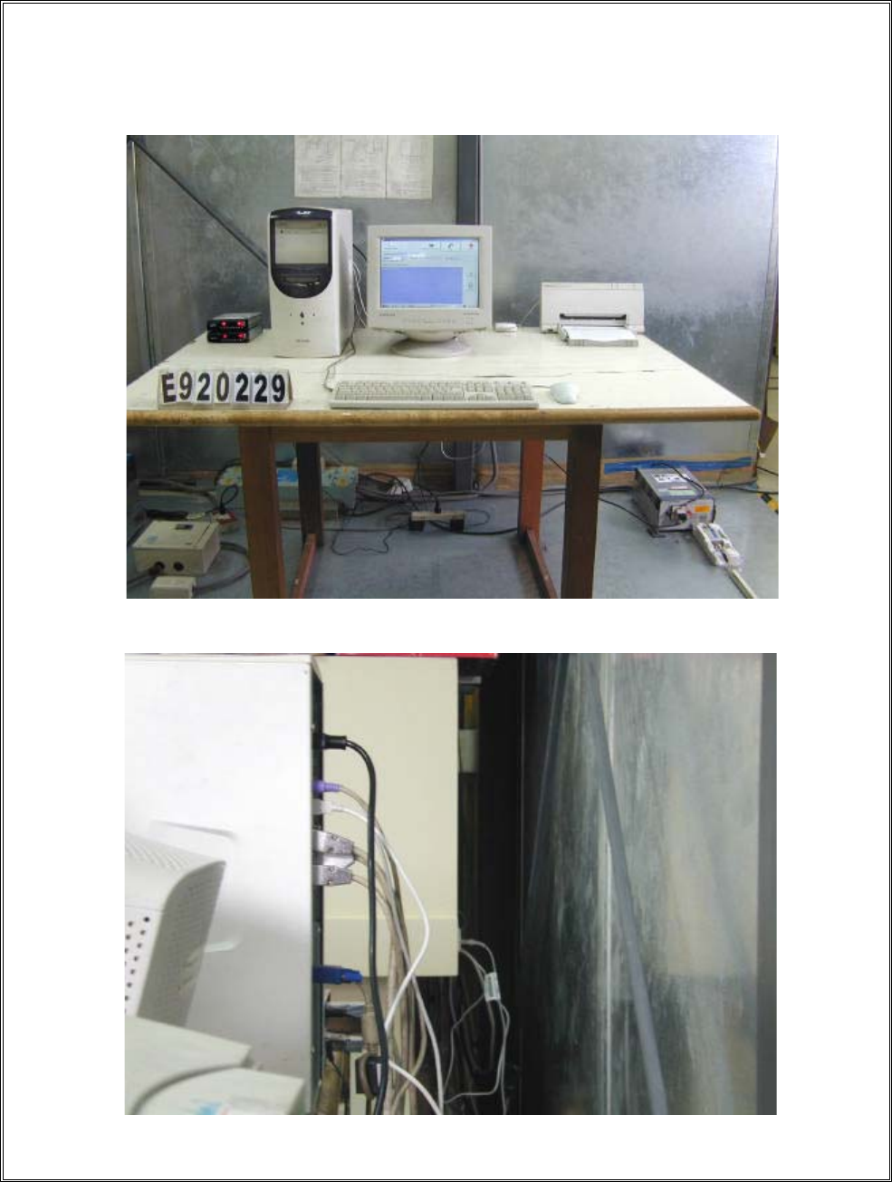
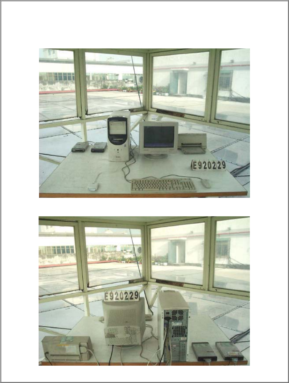
7.2 Conducted Disturbance Test Setup Photo.
< FRONT VIEW >
< REAR VIEW >

REPORT NO. : E920229
Page 13 of 69
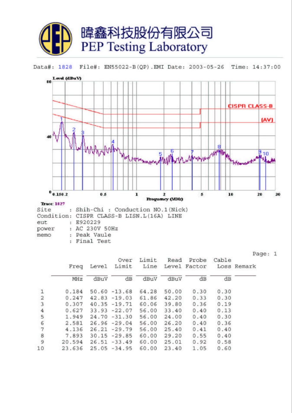
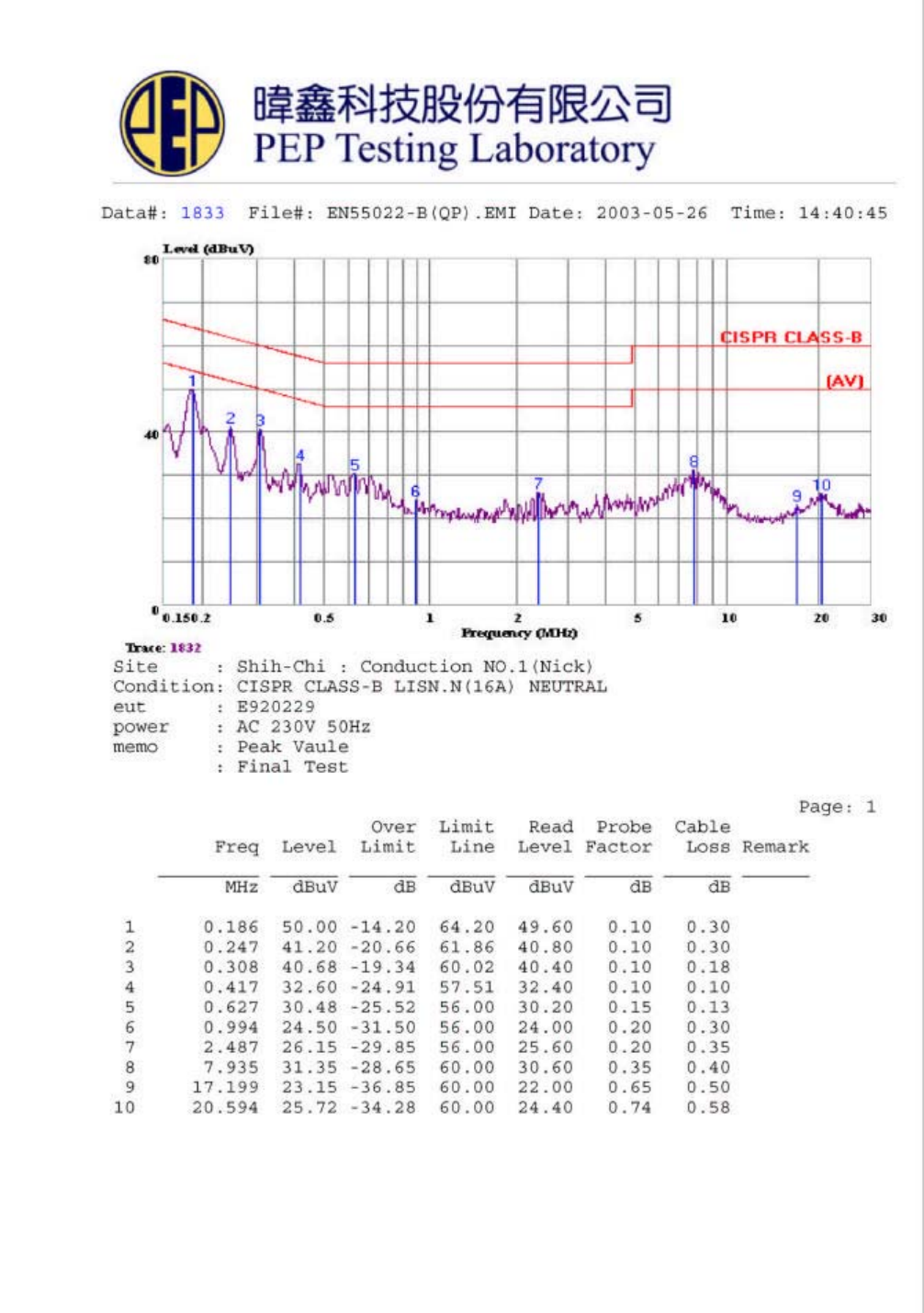
7.3 Conducted Disturbance Test Data at Main Ports (LISN)
Model No. : EZ-100PU-C
Frequency range : 150KHz to 30MHz
Detector : Peak Value
Temperature : 23
Humidity : 52 %
Test Data : #1828 ˟˜ˡ˘ʳ
#1833 ˡ˘˨˧˥˔˟ʳ
Note 1. Level = Read Level + Probe (LISN) Factor + Cable Loss
2. Over Limit = Level – Limit Line = Margin
Page 14 of 69
Page 15 of 69

REPORT NO. : E920229
Page 16 of 69
8. EN 55022 Radiated Disturbance Test
Test Standard Model No. Result
EN 55022 EZ-100PU-C Passed
8.1 Radiated Disturbance Test Description
Preliminary measurements were made indoors chamber at 3 meter using broadband
antennas, broadband amplifier, and spectrum analyzer to determine the frequency
producing the maximum EME. Appropriate precaution was taken to ensure that all
EME from the EUT were maximized and investigated. The system configuration,
clock speed, mode of operation or video resolution, turntable azimuth with respect to
the antenna were noted for each frequency found. The spectrum was scanned from 30
to 1000 MHz using logbicon antenna. Above 1GHz, linearly polarized double ridge
horn antenna were used.
Final measurements were made outdoors at 10-meter test range using biconical,
dipole antenna or horn antenna. The test equipment was placed on a wooden bench
situated on a 1.5x1 meter area adjacent to the measurement area. Sufficient time for
the EUT, support equipment, and test equipment was allowed in order for them to
warm up to their normal operating condition. Each frequency found during pre-scan
measurements was re-examined and investigated using Quasi-Peak Adapter. The
detector function was set to CISPR quasi-peak mode and the bandwidth of the
receiver was set to 120kHz.
The half-wave dipole antenna was tuned to the frequency found during preliminary
radiated measurements. The EUT, support equipment and interconnecting cables
were re-configured to the set-up producing the maximum emission for the frequency
and were placed on top of a 0.8-meter high non-metallic 1 x 1.5 meter table. The
EUT, support equipment, and interconnecting cables were re-arranged and
manipulated to maximize each EME emission. The turntable containing the system
was rotated; the antenna height was varied 1 to 4 meters and stopped at the azimuth
or height producing the maximum emission.
REPORT NO. : E920229
Page 17 of 69
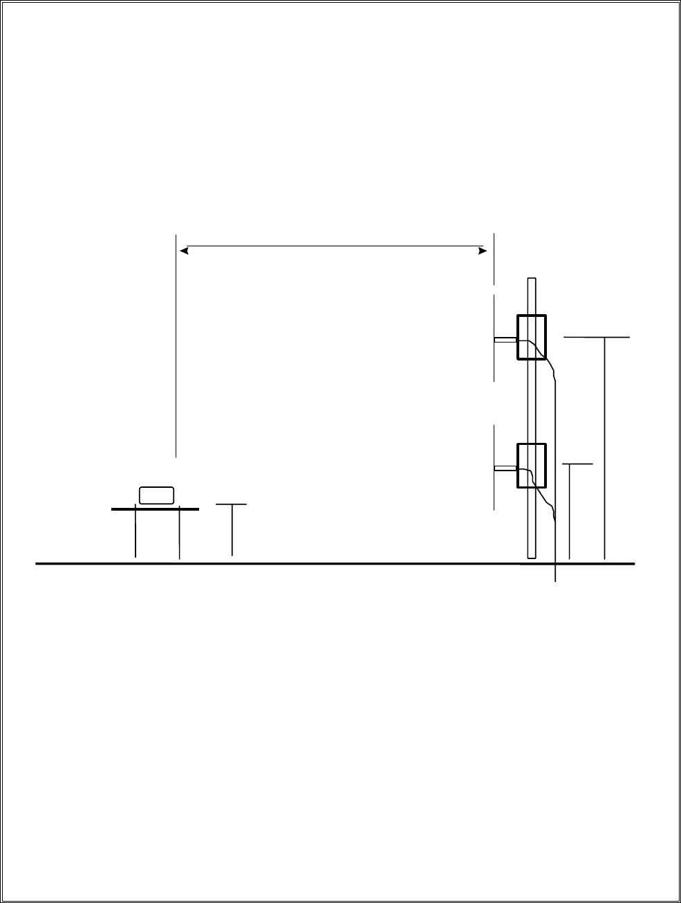
8.2 Radiated Disturbance Test Setup
(EUT)
10m
4m
1m
0.8m
GROUND
PLANE TURN TABLE TO RECEIVE
R
EUT = Equipment Under Test
REPORT NO. : E920229
Page 18 of 69
8.3 Radiated Disturbance Test Limits
Limits for radiated disturbance of Class A ITE at
a measuring distance of 10 m
Frequency Field Strength
MHz dB(ӴV/m)
30 to 230 40
230 to 1 000 47
NOTES
1 The lower limit shall apply at the transition frequency.
2 Additional provisions may be required for cases where interference
occurs.
Limits for radiated disturbance of Class B ITE at
a measuring distance of 10 m
Frequency Field Strength
MHz dB(ӴV/m)
30 to 230 30
230 to 1 000 37
NOTES
1 The lower limit shall apply at the transition frequency.
2 Additional provisions may be required for cases where interference
occurs.
REPORT NO. : E920229
Page 19 of 69
8.4 Radiated Disturbance Test Setup Photos.
< FRONT VIEW >
< REAR VIEW >

REPORT NO. : E920229
Page 20 of 69
8.5 Radiated Disturbance Test Data
Model No. : EZ-100PU-C
Frequency range : 30MHz to 1GHz Detector : Quasi-Peak Value
Frequency range : above 1GHz Detector : Quasi-Peak/Average Value
Temperature : 23o C Humidity : 52 %
Antenna polarization : HORIZONTAL ; Test distance : 10m ;
Over Limit Read Antenna Cable Preamp
Freq. Level Limit Line Level Factor Loss Factor Azimuth Antenna
(MHz) (dBuV/m) (dB) (dBuV/m) (dBuV) (dB) (dB) (dB) (̓angle) High(m)
!
!!!!52/3:8!!!29/9:!!.22/22!!!41/11!!41/14!!!:/4:!!!1/21!!!31/74!!!221/1!!!!5/1!!!
!!!222/823!!!31/8:!!.!:/32!!!41/11!!44/99!!!7/78!!!1/41!!!31/17!!!!71/1!!!!5/1!!!
!!!227/858!!!33/21!!.!8/:1!!!41/11!!46/39!!!7/67!!!1/41!!!31/15!!!!:1/1!!!!5/1!!!
!!!311/362!!!38/26!!.!3/96!!!41/11!!47/86!!!:/81!!!1/81!!!31/11!!!261/1!!!!5/1!!!
!!!8:8/581!!!42/54!!.!6/68!!!48/11!!35/:6!!34/15!!!3/49!!!29/:5!!!321/1!!!!4/6!!!
!!!935/6:6!!!38/34!!.!:/88!!!48/11!!32/11!!34/31!!!3/46!!!2:/43!!!431/1!!!!4/6!!!
!
!
!
!
!
!
!
!
!
!
Note :
1. Level = Read Level + Antenna Factor + Cable Loss – Preamp Factor
2. Over Limit = Level – Limit Line

REPORT NO. : E920229
Page 21 of 69
Model No. : EZ-100PU-C
Frequency range : 30MHz to 1GHz Detector : Quasi-Peak Value
Frequency range : above 1GHz Detector : Quasi-Peak/Average Value
Temperature : 23o C Humidity : 52 %
Antenna polarization : VERTICAL ; Test distance : 10m ;
Over Limit Read Antenna Cable Preamp
Freq. Level Limit Line Level Factor Loss Factor Azimuth Antenna
(MHz) (dBuV/m) (dB) (dBuV/m) (dBuV) (dB) (dB) (dB) (̓angle) High(m)
!
!!!!82/952!!!33/64!!.!8/58!!!41/11!!48/95!!!5/72!!!1/35!!!31/27!!!!:1/1!!!!2/1!!!
!!!236/625!!!35/75!!.!6/47!!!41/11!!49/36!!!6/::!!!1/51!!!31/11!!!2:6/1!!!!2/1!!!
!!!2::/:6:!!!33/76!!.!8/46!!!41/11!!43/36!!!:/81!!!1/81!!!31/11!!!361/1!!!!2/1!!!
!!!8:8/375!!!35/28!!.23/94!!!48/11!!28/7:!!34/15!!!3/49!!!29/:5!!!346/1!!!!2/6!!!
!!!938/714!!!37/15!!.21/:7!!!48/11!!2:/82!!34/3:!!!3/46!!!2:/42!!!421/1!!!!2/6!!!
!!!:47/9:1!!!39/:2!!.!9/1:!!!48/11!!2:/64!!36/51!!!3/4:!!!29/52!!!451/1!!!!2/6!!!
!
!
!
!
!
!
!
!
!
!
!
Note :
1. Level = Read Level + Antenna Factor + Cable Loss – Preamp Factor
2. Over Limit = Level – Limit Line

REPORT NO. : E920229
Page 22 of 69
9. EN 61000-4-2 Electrostatic Discharge Test
Test standard Model No. Result
EN 61000-4-2 EZ-100PU-C, EZ-100PU-P A
The test results shall be classified on the basis of the operating conditions and the
functional specifications of the equipment under test , as in the following , unless
different specifications are given by product committees or product specifications :
Performance Criterion :
A) normal performance within the specification limits ;
B) temporary degradation or loss of function or performance which is self-recoverable ;
C) temporary degradation or loss of function or performance which requires operator
intervention or system reset ;

REPORT NO. : E920229
Page 23 of 69
9.1 Electrostatic Discharge Test Description
This standard relates to equipment, systems, sub-systems and peripherals which may be
involved in static electricity discharges owing to environmental and installation conditions.
such as low relative humidity, use of low-conductivity (artificial-fibre) carpets, vinyl
garments, etc., which may exist in allocations classified in standards relevant to electrical
and electronic equipment.
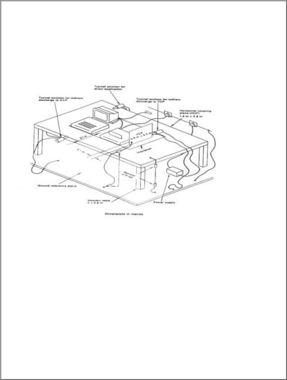
The test set-up shall consist of a wooden able, 0.8 m high standing on the ground reference
plane. A horizontal coupling plane(HCP), 1.6 m x 0.8 m, shall be placed on the table. The
EUT and cables shall be isolated from the coupling plane by an insulating support 0.5 mm
thick .
A ground reference plane shall be provided on floor of the laboratory. It shall be metallic
sheet of 0.25 mm minimum thickness. The minimum size of the reference plane is 1 m, the
exact size depending on the dimensions of the EUT .
It shall project beyond the EUT or coupling plant by at least 0.5 m on all sides. and shall be
connected to the protective grounding system.
In order to minimize the impact of environmental parameters on test results, the tests shall be
carried out in climatic and electromagnetic reference conditions.
Climatic conditions
- ambient temperature: 15 кʳ to 35к;
- relative humidity: 30 % to 60%
- atmospheric pressure: 86 KPa (860 mbar) to 106 KPa (1 060 mbar).
NOTE – Any other values are specified in the product specification.
Electromagnetic conditions
The electromagnetic environment of the laboratory shall not influence the test results.
REPORT NO. : E920229
Page 24 of 69
9.2 Electrostatic Discharge Test Setup
- Example of test set-up for table-top equipment,
laboratory tests

REPORT NO. : E920229
Page 25 of 69
9.3 Electrostatic Discharge Test Limits
Test levels
Contact discharge Air discharge
Level Test voltage Level Test voltage
kv
12 12
24 24
36 38
48 415
x1) Special x1) Special
1) “x” is an open level . The level has to be specified in the dedicated
equipment specification .
If higher voltages than those shown are specified , special test equipment may be
needed .
REPORT NO. : E920229
Page 26 of 69
9.4 Direct Discharge Test Drawing
Model No. EZ-100PU-C
REPORT NO. : E920229
Page 27 of 69
Indirect Discharge Test Drawing
REPORT NO. : E920229
Page 28 of 69
Direct Discharge Test Drawing
Model No. EZ-100PU-P
REPORT NO. : E920229
Page 29 of 69
Indirect Discharge Test Drawing

REPORT NO. : E920229
Page 30 of 69
9.5 Electrostatic Discharge Test Data (Direct Discharge)
Model No. : EZ-100PU-C, EZ-100PU-P
Test Item : Direct Discharge Instrument : NoiseKen ESS-100L
Temperature : 24 к Relative Humidity : 47 %RH
Storage Capacitor : 150 pf Discharge Resistor : 330 Ohm
Discharge Rate : < 1 / Sec
Contact Discharge Air Discharge
2 KV 4 KV 6 KV 8 KV 2 KV 4 KV 6 KV 8 KV
+-+-+-+-+-+-+-+-
1////////PPPPPPPP
2////////PPPPPPPP
3////////PPPPPPPP
4////////PPPPPPPP
5////////PPPPPPPP
6////////PPPPPPPP
7////////PPPPPPPP
8////////PPPPPPPP
9////////PPPPPPPP
10////////PPPPPPPP
1.“ P ”---- means the EUT function is correct during the test .
2.“ / ”----no test.
REPORT NO. : E920229
Page 31 of 69
Electrostatic Discharge Test Data (Indirect Discharge)
Model No. : EZ-100PU-C, EZ-100PU-P
Test Item : Indirect Discharge Instrument : NoiseKen ESS-100L
Temperature : 24 к Relative Humidity : 47 %RH
Storage Capacitor : 150 pf Discharge Resistor : 330 Ohm
Discharge Rate : < 1 / Sec
Contact Discharge Air Discharge
2 KV 4 KV 6 KV 8 KV 2 KV 4 KV 6 KV 8 KV
+-+-+-+-+-+-+-+-
1PPPP////////////
2PPPP////////////
3////////////////
4////////////////
5////////////////
6////////////////
7////////////////
8////////////////
9////////////////
10////////////////
1.“ P ”---- means the EUT function is correct during the test .
2.“ / ”----no test.

REPORT NO. : E920229
Page 32 of 69
10. EN 61000-4-3 Radio-Frequency Electromagnetic
Field Test
Test standard Model No. Result
EN 61000-4-3 EZ-100PU-C, EZ-100PU-P A
Field Strength : 3 V/M , Level 2 .
Modulation : AM 80 % , 1KHz . ON ( YES ) . OFF ( )
Start : 80 MHz , Stop : 1000 MHz . AC Power : 230 Vac
DC Power : N/A Vdc
The test results shall be classified on the basis of the operating conditions and the
functional specifications of the equipment under test , as in the following , unless
different specifications are given by product committees or product specifications :
Performance Criterion :
A) normal performance within the specification limits ;
B) temporary degradation or loss of function or performance which is self-recoverable ;
C) temporary degradation or loss of function or performance which requires operator
intervention or system reset ;

REPORT NO. : E920229
Page 33 of 69
10.1 Radio-Frequency Electromagnetic Field Test Description
Most electronic equipment is, in some manner, affected by electromagnetic radiation.
This radiation is frequently generated by such sources as the small hand-held radio
transceivers that are used by operating, maintenance and security personnel, fixed-station
radio and television transmitters, vehicle radio transmitters, and various industrial
electromagnetic sources.
In addition to electromagnetic energy deliberately generated, there is also spurious radiation
caused by devices such as welders, thyristors, fluorescent lights, switches operating inductive
loads, etc. For the most part, this interference manifests itself as conducted electrical
interference and, as such, is dealt with in other parts of this standard. Methods employed to
prevent effects from electromagnetic fields will normally also reduce the effects from these
sources.
The electromagnetic environment is determined by the strength of the electromagnetic field
(field strength in volts per metre). The field strength is not easily measured without
sophisticated instrumentation nor is it easily calculated by classical equations and formulae
because of the effect of surrounding structures or the proximity of other equipment that will
distort and/or reflect the electromagnetic waves.
All testing of equipment shall be performed in a configuration as close as possible to the
installed case. Wiring shall be consistent with the manufacturer’s recommended procedures,
and the equipment shall be in its housing with all covers and access panels in place, unless
otherwise stated.
If the equipment is designed to be mounted in a panel, rack or cabinet, it shall be tested in
this configuration.
REPORT NO. : E920229
Page 34 of 69
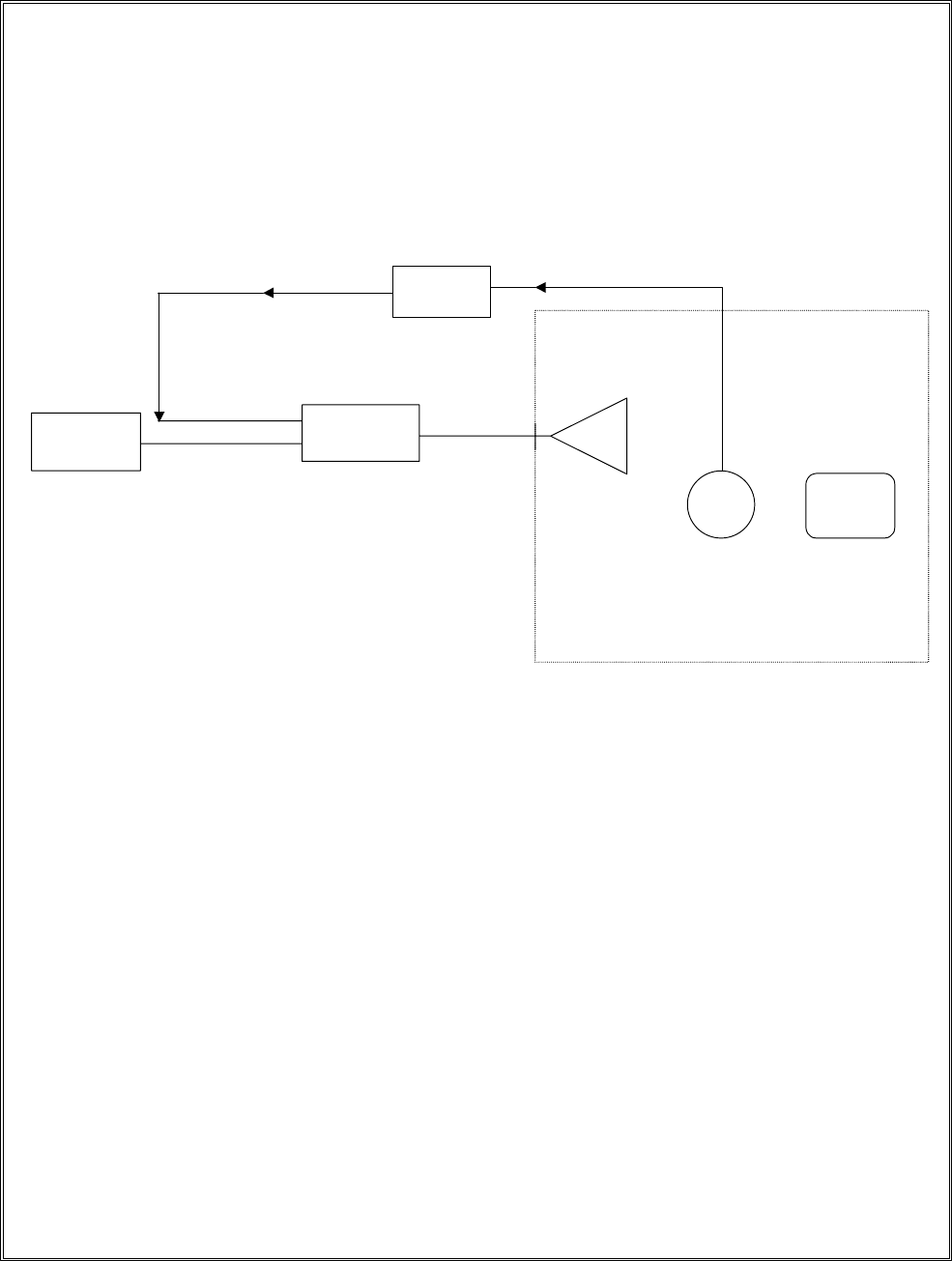
10.2 Radio-Frequency Electromagnetic Field Test Block Diagram
RF Source Power Amplifier Antenna
Field Monitor
Field
Probe EUT
RF Input
Anechoic Chamber
Detector
Input
Field Leveling
Signal
Bulkhead
Feedthrough
Fiber
Optic
Cable

REPORT NO. : E920229
Page 35 of 69
10.3 Radio-Frequency Electromagnetic Field Test Limits
Table 1 - Test levels
Level Test field strength
V/m
11
23
310
x Special
NOTE – x is an open test level. This level nay be given in the
Product specification.
Table 1 gives details of the field strength of the unmodulated signal. For testing of equipment,
this signal is 80 % amplitude modulate with a 1 KHz sinewave to simulate actual threats.
REPORT NO. : E920229
Page 36 of 69
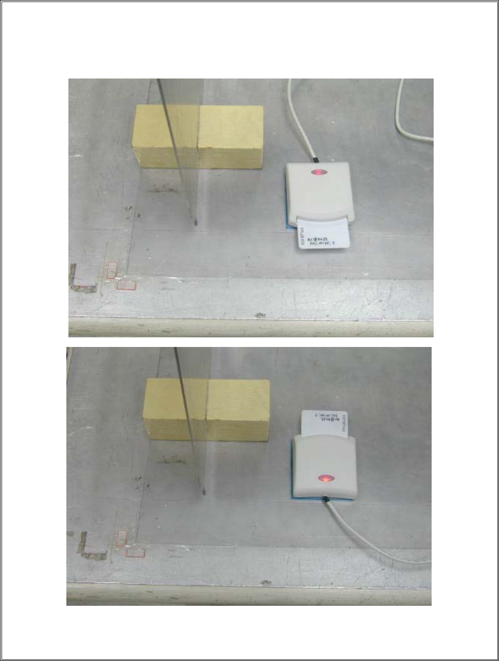
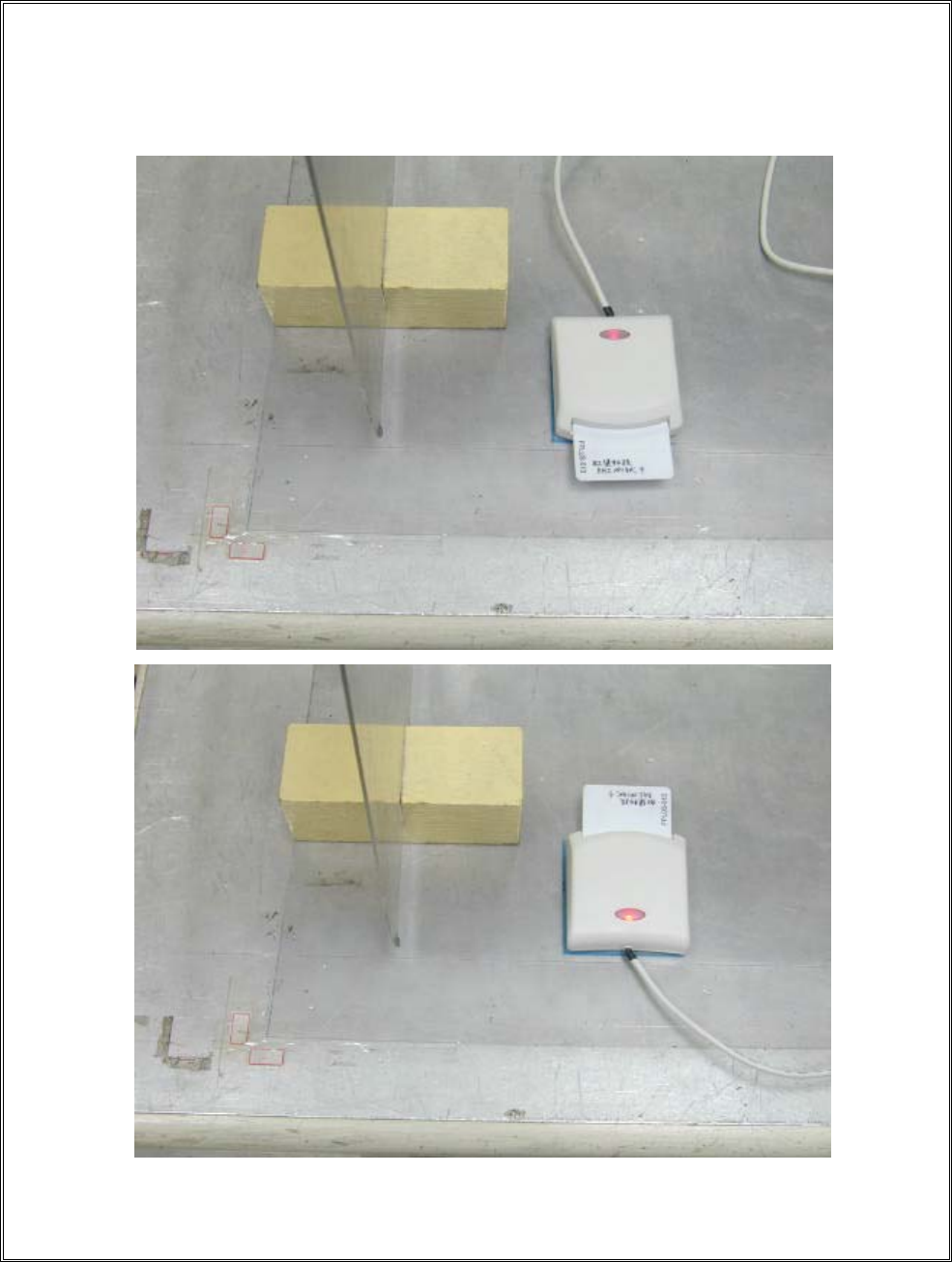
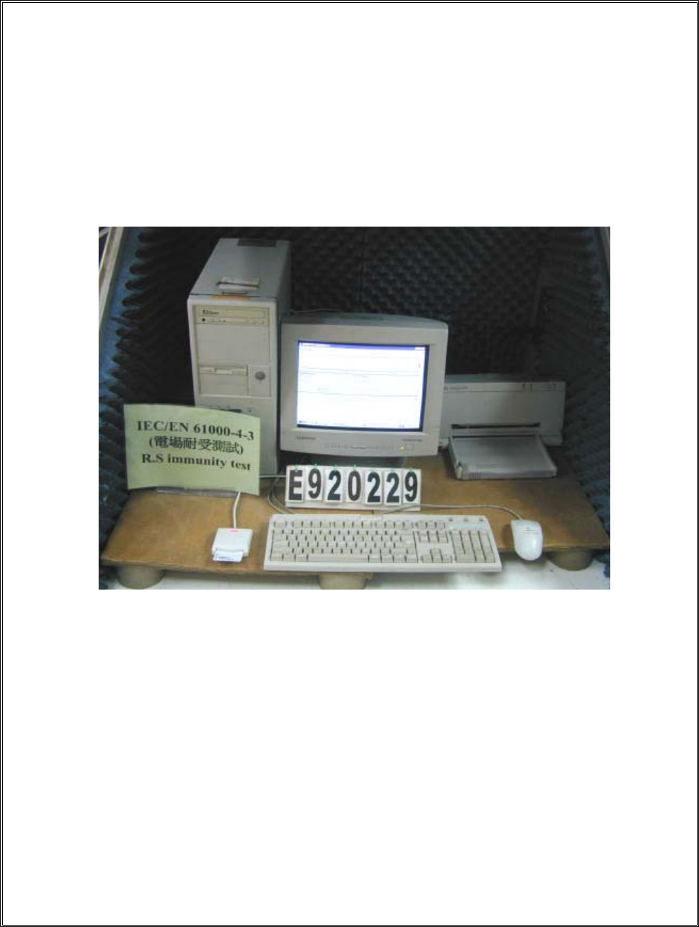
10.4 Radio-Frequency Electromagnetic Field Test Setup Photo
Model No. EZ-100PU-C
< FRONT VIEW >
REPORT NO. : E920229
Page 37 of 69
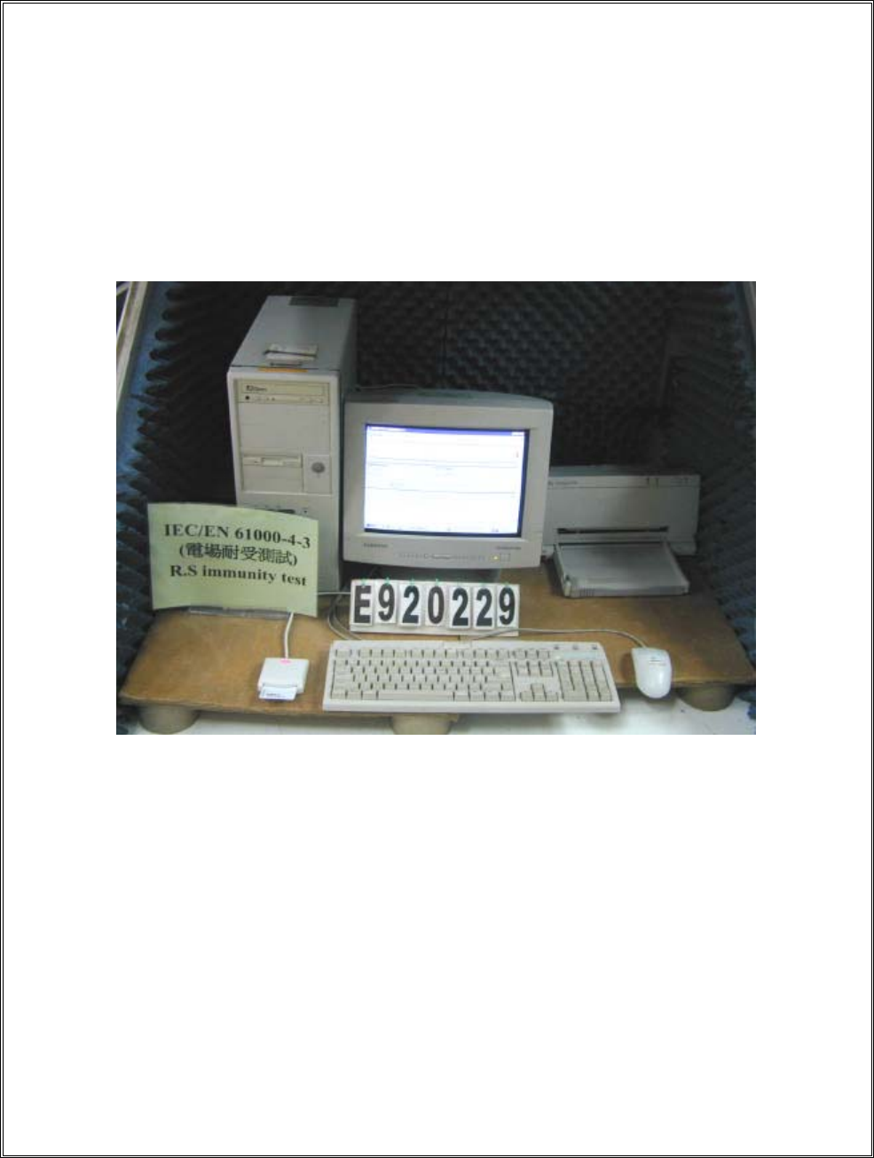
Model No. EZ-100PU-P
< FRONT VIEW >
REPORT NO. : E920229
Page 38 of 69
11. EN 61000-4-4 Fast Transient Burst Test
Test standard Model No. Result
EN 61000-4-4 EZ-100PU-C B
The test results shall be classified on the basis of the operating conditions and the
functional specifications of the equipment under test , as in the following , unless
different specifications are given by product committees or product specifications :
Performance Criterion :
A) normal performance within the specification limits ;
B) temporary degradation or loss of function or performance which is self-recoverable ;
C) temporary degradation or loss of function or performance which requires operator
intervention or system reset ;

REPORT NO. : E920229
Page 39 of 69
11.1 Fast Transient Bursts Test Description
The repetitive fast transient test is a test with bursts consisting of a number of fast transients,
coupled into power supply, control and signal ports of electrical and electronic equipment.
Significant for the test are the short rise time, the repetition rate and the low energy of the
transients.
The test shall be carried out on the basis of a test plan including verification of the
performances of the EUT as defined in the technical specification.
Climatic conditions
The tests shall be carried out in standard climatic conditions in accordance with IEC 68-1:
- ambient temperature: 15к to 35к
- relative humidity: 25% to 75%
- atmospheric pressure: 86kPa (860 mbar) to 106Kpa (1 060 mbar)
NOTE – Any other values are specified in the product specification.
Electromagnetic conditions
The electromagnetic conditions of the laboratory shall be such to guarantee the correct
operation of the EUT in order not to influence the test results.
REPORT NO. : E920229
Page 40 of 69
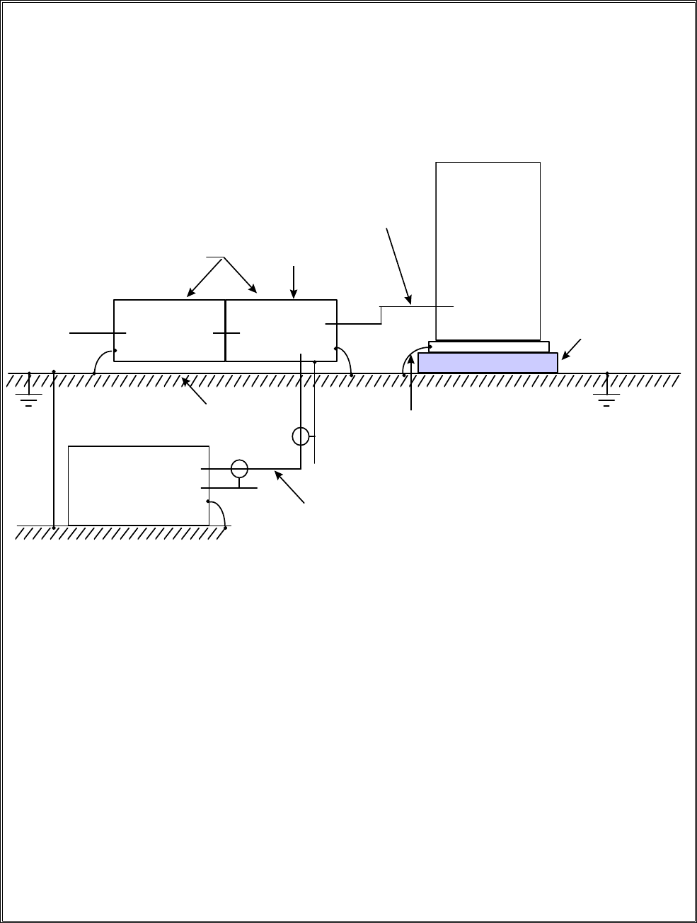
11.2 Fast Transient Burst Test Setup
Couping/decupling sections
shall be mounted directly on
the reference ground plane.
Bonding connections shall be
as short as possibke.
Capacitor
or clamp
Decoupling
network
Coupling
device
Lines
Lines/terminals
to be tested
lnsulating
support
EUT
Reference plane
Electrical fast
transievt/burst
generator This length should
be < 1 m
Grounding conection according
to the manufacturer’s specification.
Length to be specified in the test plan.
Block-diagram for electrical fast transient/burst immunity test
REPORT NO. : E920229
Page 41 of 69
11.3 Fast Transient Burst Test Limits
Test levels
Open-circuit output test voltage (̈́10 %) and repetition rate of the impulses (̈́20 %)
On power supply port, PE On I/O (Input/Output) signal,
data and control ports
Level
Voltage peak Repetition rate Voltage peak Repetition rate
kV kHz kV kHz
1 0.5 5 0.25 5
2 1 5 0.5 5
32 51 5
4 4 2.5 2 5
x1) Special Special Special Special
1) “x” is an open level. The level has to be specified in the dedicated equipment specification.
REPORT NO. : E920229
Page 42 of 69
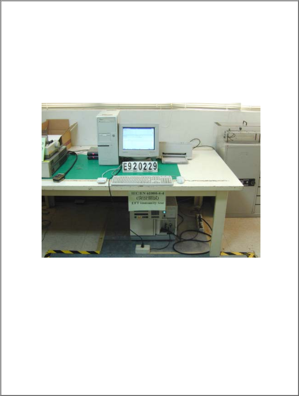
11.4 Fast Transient Burst Test Setup Photo
< FRONT VIEW >
REPORT NO. : E920229
Page 43 of 69
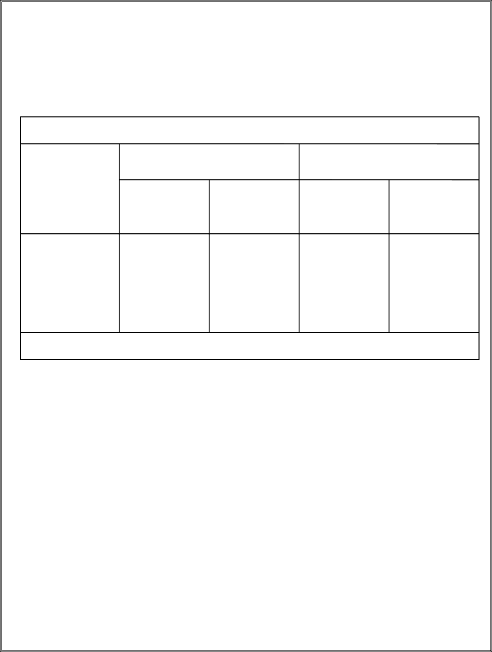
11.5 Fast Transient Burst Test Data
MODEL NO. : EZ-100PU-C
REGULATION : According to EN 61000-4-4 ( 1995 ) Spec .
TEST RESULT
Temperature : 24 degree . Duration of tests : 1 min .
Relative Humidity : 47 % RH . Time between test : 60 second .
Pulse : 5 / 50 ns . AC Power : 230 Vac .
Burst : 15 ms / 300 ms . DC Power : N/A Vdc .
0.5 KV 1KV KV
Voltage \ Polarity
\ Test Point \ Mode \ Result +- +- +-
L//PP//
N//PP//
Power Line
G//PP//
Signal Line Clamp Test
//////
Note : 1. “ P “ mean the EUT function is correct during the test .
2. “ F “ ---- Fail
3. “ / ” ---- no test
REPORT NO. : E920229
Page 44 of 69
12. EN 61000-4-5 Surge Immunity Test
Test standard Model No. Result
EN 61000-4-5 EZ-100PU-C A
The test results shall be classified on the basis of the operating conditions and the
functional specifications of the equipment under test , as in the following , unless
different specifications are given by product committees or product specifications :
Performance Criterion :
A) normal performance within the specification limits ;
B) temporary degradation or loss of function or performance which is self-recoverable ;
C) temporary degradation or loss of function or performance which requires operator
intervention or system reset ;

REPORT NO. : E920229
Page 45 of 69
12.1 Surge Immunity Test Description
The task of the described laboratory test is to find the reaction of the EUT under specified
operational conditions caused by surge voltages from switching and lightning effects at certain
threat levels.
The following equipment is part of the test set-up :
- equipment under test (EUT);
- auxiliary equipment (AE);
- cables (of specified type and lengeh);
- coupling device (capacitive or arrestors);
- test generator (combination wave generator, 1.2/50 µs generator);
- decoupling network/protection devices;
- additional resistors, 10 ohm and 40 ohm
The surge is to be applied to the EUT power supply terminals via the capacitive coupling
network. Decoupling networks are required in order to avoid possible adverse effects on
equipment not under test that may be powered by the same lines and to provide sufficient
decoupling impedance to the surge wave so that the specified wave may be developed on the
lines under test .
REPORT NO. : E920229
Page 46 of 69
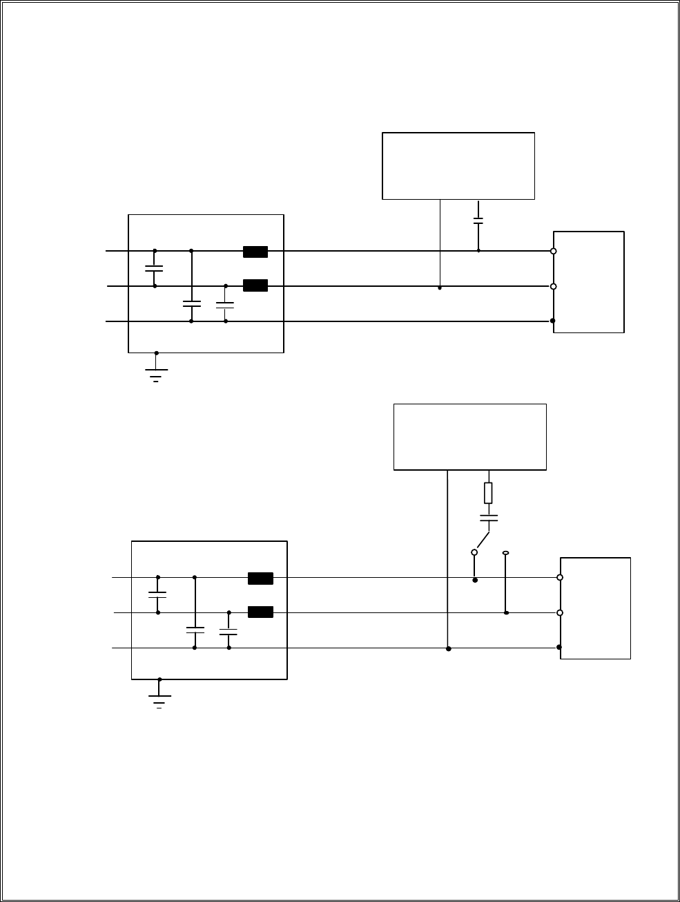
12.2 Surge Immunity Test Setup
AC(DC)
power supply
network
Exa
m
p
le of test set-
u
p
fo
r
ca
p
acltive co
u
p
li
n
go
n
a
.c./d.c.
k
i
n
es;
li
n
e-to-ea
r
t
h
co
u
p
li
n
g(ac
c
o
r
di
n
gto7.2)
Decoupling network
Combination wave
generator
C=18
µ
F
L
N
PE
EUT
Earth reference
L
Example of test set- up for capacltive coupling on a.c./d.c. kines;
line-to-line coupling (according to 7.2)
N
L
PE
EUT
Earth reference
AC(DC)
power supply
network
Deco
u
p
li
n
g
n
et
w
o
r
k
L
Co
m
b
i
n
atio
n
w
ave
ge
n
e
r
at
o
r
C=9
µ
F
R=10o
h
m

REPORT NO. : E920229
Page 47 of 69
12.3 Surge Immunity Test Limits
The preferential range of test levels is given in table 1.
Table 1-Test levels
Open-circuit test voltage
Level +10 %
-
kV
1 0.5
2 1.0
3 2.0
4 4.0
x Special
NOTE - x is an open class . The level can be specified in the product
specification .
REPORT NO. : E920229
Page 48 of 69
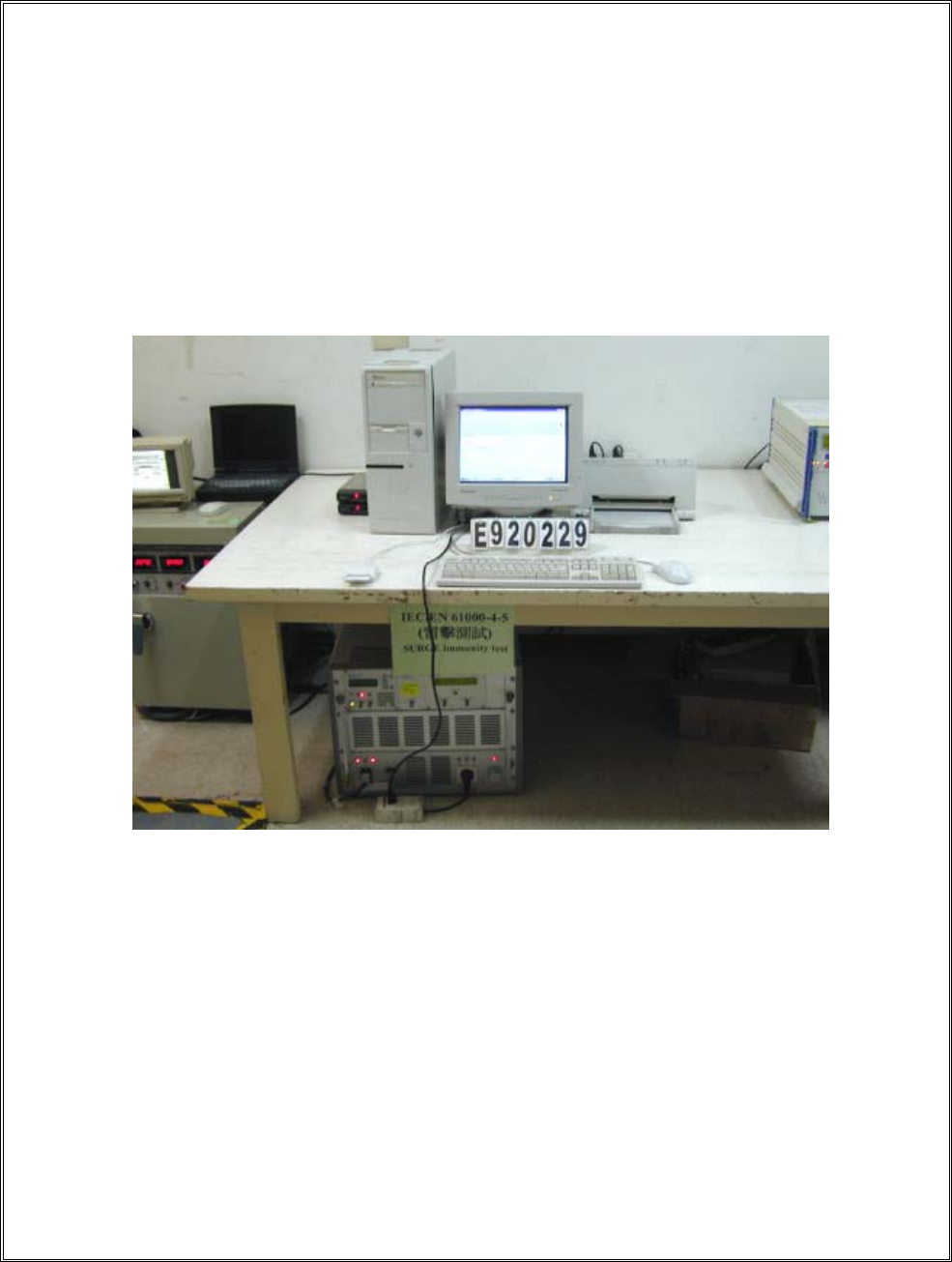
12.4 Surge Immunity Test Setup Photo
< FRONT VIEW >
REPORT NO. : E920229
Page 49 of 69
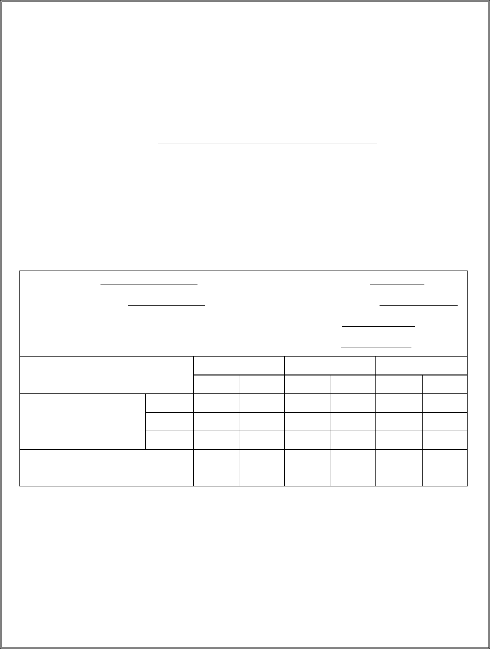
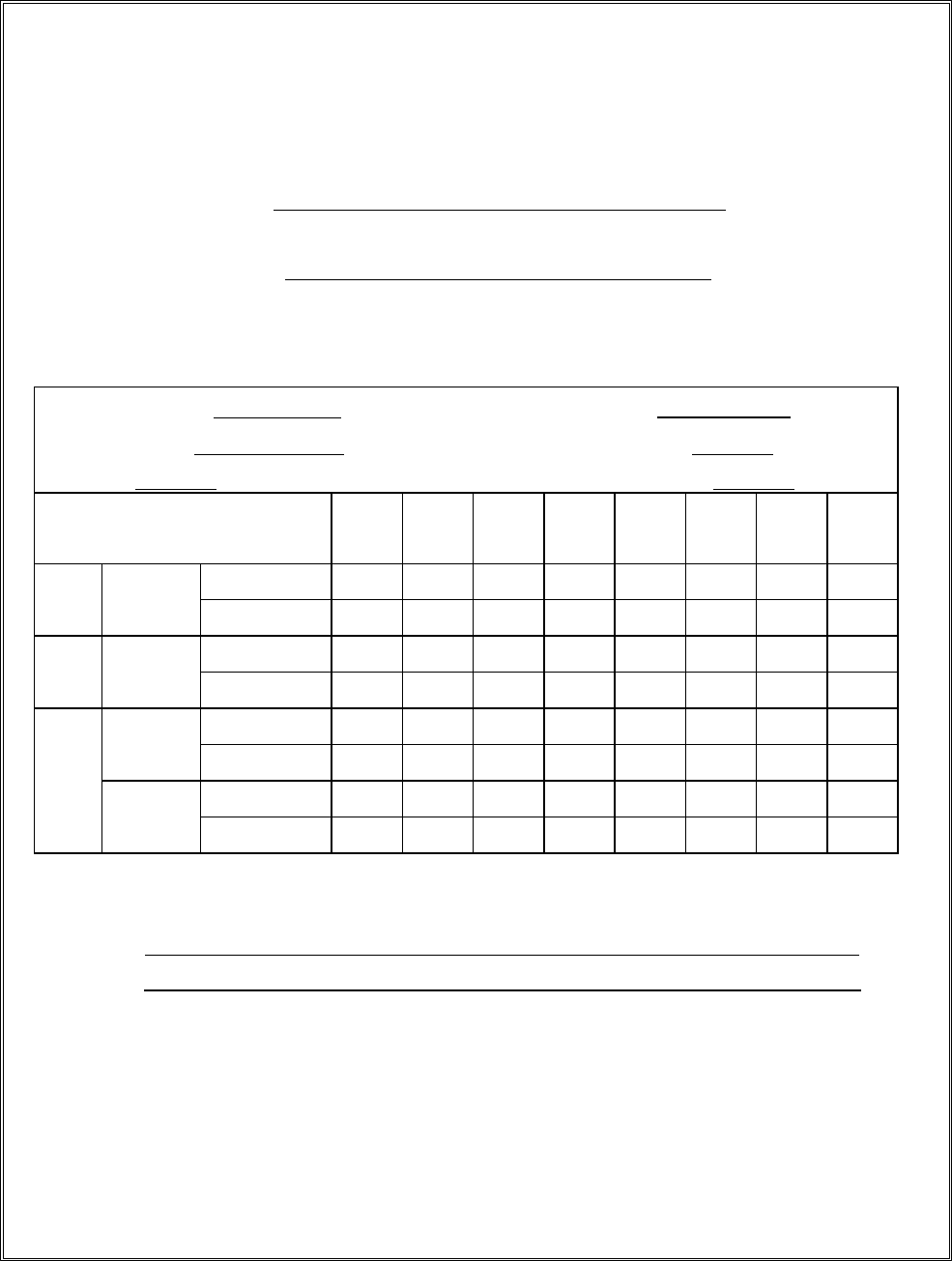
12.5 Surge Immunity Test Data
MODEL NO : EZ-100PU-C
TEST SETUP : According to EN 61000-4-5 (1995)
TEST RESULT
Temperature : 24 к Relative Humidity 47 %RH
Waveform : 1,2 x 50 µs Test rate : 15 sec
Times 1 times / each condition AC power 230 VAC
\Phase
\Voltage\Mode\Polarity\Result
0 45 90 135 180 215 270 315
+ PPPPPPPP
1KV Line
Neutral - PPPPPPPP
+ ////////
2KV Line
Neutral - ////////
+ ////////Line
Ground - ////////
+ ////////
2KV
Neutral
Ground - ////////
Note : 1. “P” means the EUT function is correct during the test
2. “ / ” no test
REPORT NO. : E920229
Page 50 of 69
13. EN 61000-4-6 Immunity To Conducted
Disturbances, Induced By Radio-
Frequency Fields
Test standard Model No. Result
EN 61000-4-6 EZ-100PU-C, EZ-100PU-P A
The test results shall be classified on the basis of the operating conditions and the
functional specifications of the equipment under test , as in the following , unless
different specifications are given by product committees or product specifications :
Performance Criterion :
A) normal performance within the specification limits ;
B) temporary degradation or loss of function or performance which is self-recoverable ;
C) temporary degradation or loss of function or performance which requires operator
intervention or system reset ;

REPORT NO. : E920229
Page 51 of 69
13.1 Immunity To Conducted Disturbances, Induced By Radio-
Frequency Fields Description
The EUT shall be placed on an insulating support, 0.1 m above the ground reference plane.
For table-top equipment, the ground reference plane may be placed on a table (see figure) .
On all cables to be tested, coupling and decoupling devices shall be inserted. The coupling
and decoupling devices shall be placed on the ground reference plane, making direct contact
with it at about 0.1 m to 0.3 m from the EUT. The cables between the coupling and
decoupling devices and the EUT shall be as short as possible and shall not be bundled nor
wrapped. height above the ground reference plane shall be between 30 mm and 50 mm.
If the EUT is provided with other earth terminals, they shall, when allowed, be connected to
the ground reference plane through the coupling and decoupling network CDN-M1, (i.e. the
AE port of the CDN-M1 is then connected to the ground reference).
If the EUT is provided with a keyboard or hand-held accessory, then the artificial hand shall
be placed on this keyboard or wrapped around the accessory and connected to the ground
reference plane.
Auxiliary equipment (AE) required for the defined operation of the EUT according to the
specifications of the product committee, e.g. communication equipment, modem, printer,
sensor, etc., as well as auxiliary equipment necessary for ensuring any data transfer and
assessment of the functions, shall be connected to the EUT through coupling and decoupling
devices. However, as far as possible the number of cables to be tested should be limited by
restricting attention to the representative functions.
REPORT NO. : E920229
Page 52 of 69
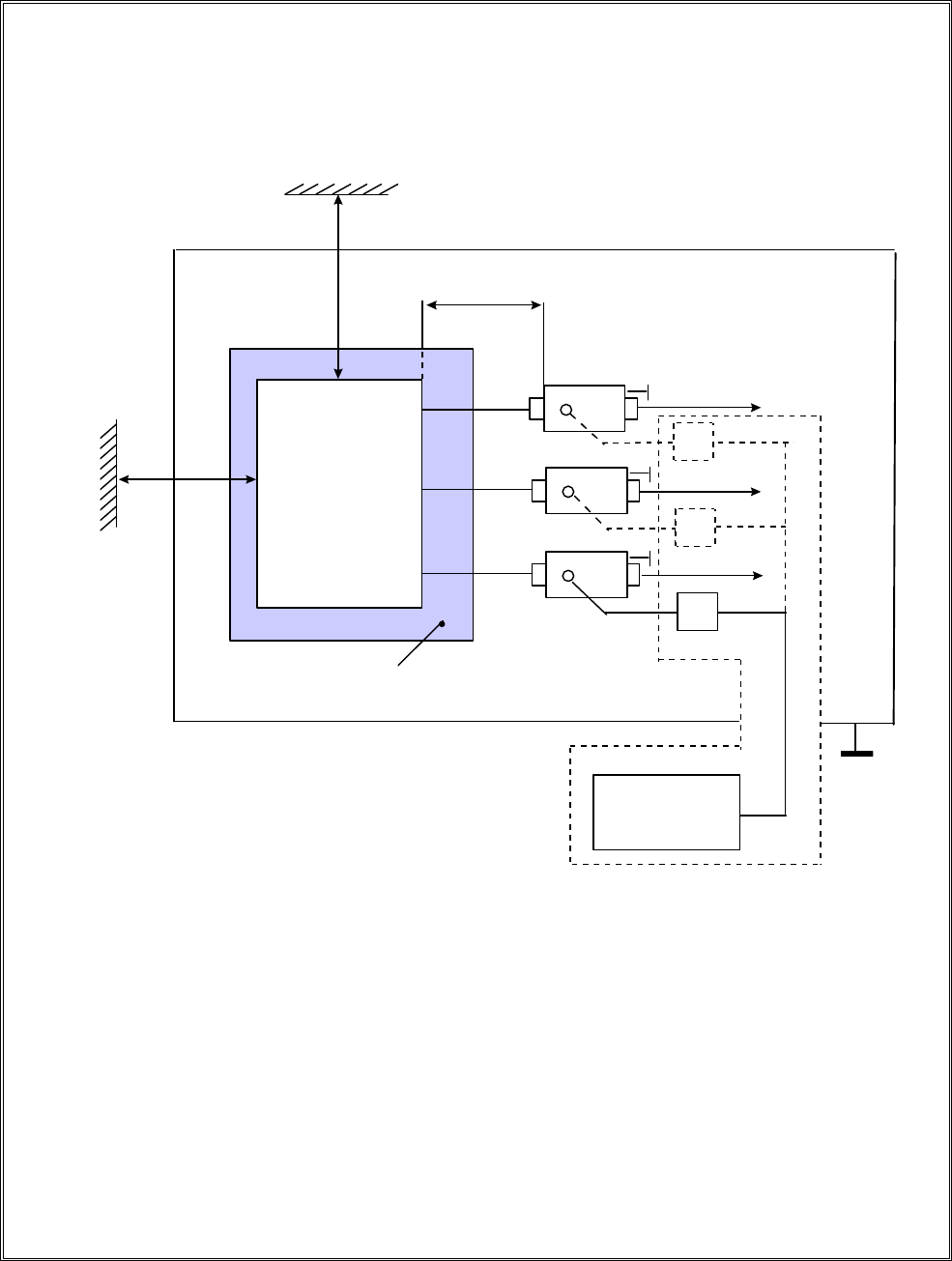
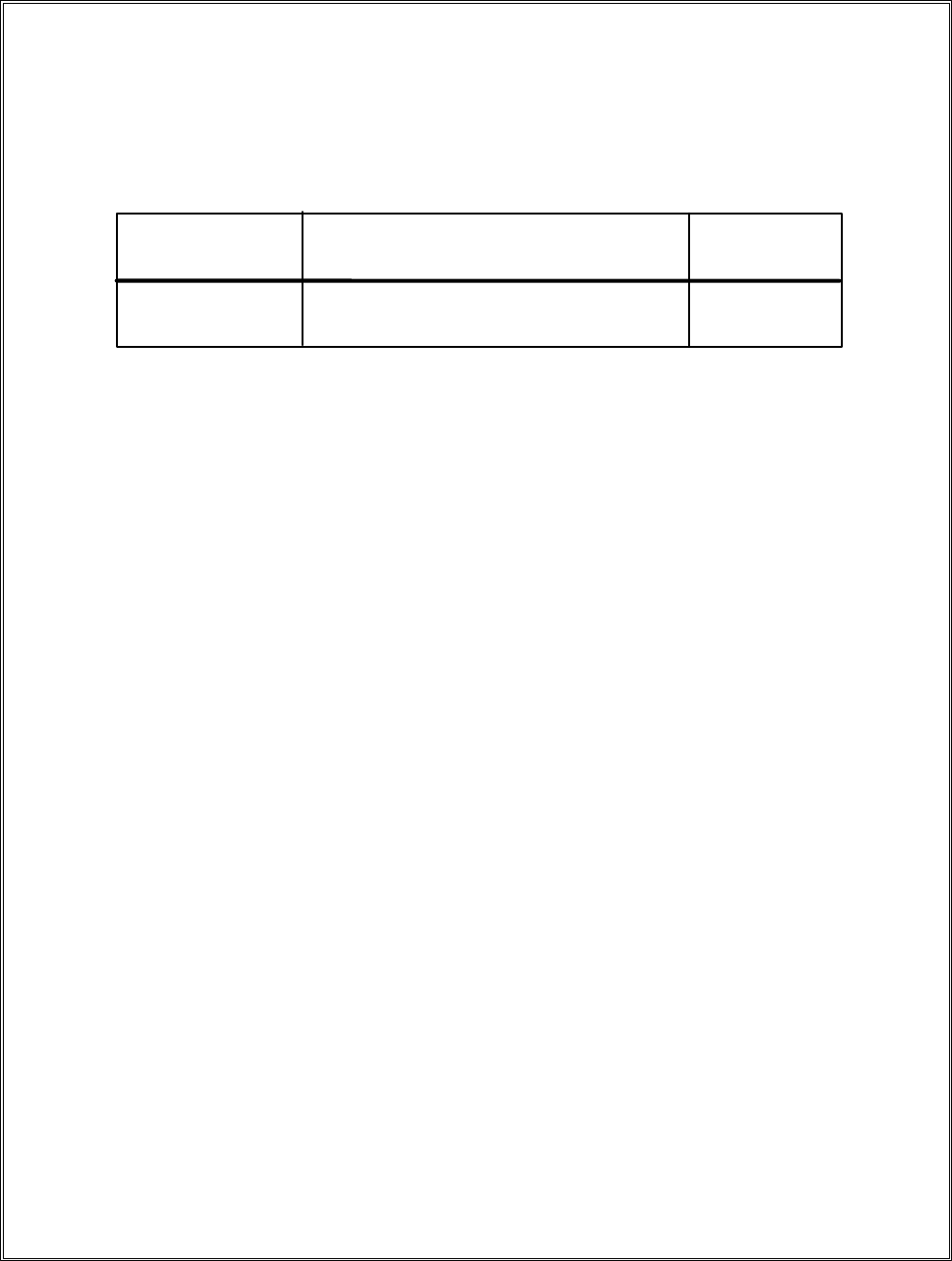
13.2 Immunity To Conducted Disturbances, Induced By Radio-
Frequency Fields Setup
NOTE - The EUT clearance from any metallic obstacles shall be at least 0.5 m .
All non-excited input ports of the CDNs shall be terminated by 50 ohm loads .
Example of test set-up with a single-unit system
for class II safety equipment (see IEC 536)
Balanced pair
Mains
Unscreened
non-balanced
cable
EUT
Insulating support
h = 0.1 m
Test generator
0.1 m < L <0.3m
To AE or
telecommunication lines
CDN-T2
T2
AE
CDN-AF2
T2
Mains
CDN-M2
T2
0.5 m
0.5 m
Reference ground plane
REPORT NO. : E920229
Page 53 of 69
13.3 Immunity To Conducted Disturbances, Induced By Radio-
Frequency Fields Test Limits
No tests are required for induced disturbances caused by electromagnetic fields coming from
intentional RF transmitters in the frequency range 9 kHz to 150 kHz,
The open-circuit test levels (e.m.f.) of the unmodulated disturbing signal, expressed in r.m.s.,
are given in table 1. The test levels are set at the EUT port of the coupling and decoupling
devices. For testing of equipment, this signal is 80% amplitude modulated with a 1 kHz sine
wave to simulate actual threats.
Table1 – Test levels
Frequency range 150 kHz – 80MHz
Level Voltage level (e.m.t.)
Uo [dB(ӴV)] Uo[V]
1
2
X1)
120 1
130 3
140 10
special
1) X is an open level.
REPORT NO. : E920229
Page 54 of 69
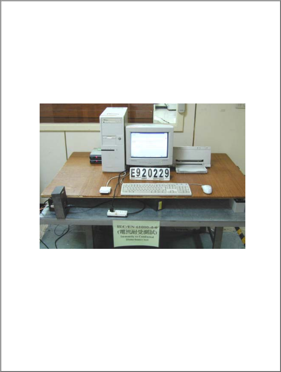
13.4 Immunity To Conducted Disturbances, Induced By Radio-
Frequency Fields Test Setup Photo
Model No. EZ-100PU-C
< FRONT VIEW >
REPORT NO. : E920229
Page 55 of 69
Model No. EZ-100PU-P
< FRONT VIEW >

REPORT NO. : E920229
Page 56 of 69
13.5 Immunity To Conducted Disturbances, Induced By Radio-
Frequency Fields Test Data
MODEL NO. : EZ-100PU-C, EZ-100PU-P
REGULATION : EN 61000-4-6 (1995)
TEST RESULT
Temperature : 24 degree , Relative Humidity : 47 % RH
Start : 0.15 MHz , Stop : 80 MHz , Power : AC 230V
Modulation : AM 80 % , 1kHz. ON (YES ) , OFF ( )
Output impedance : 50 ohm , Source impedance : 150 ohm
Performance criterion : A
Test Ports Frequency(MHz)
Range
EUT Condition 1V(rms)
Field strength
3V(rms)
Field strength
Input / Output
a. c. power
0.15 ------ 80 NORMAL / P
Input / Output
d. c.
0.15 ------ 80 NORMAL / /
Signal lines
Control lines
0.15 ------ 80 NORMAL / /
Note : 1. “ P ” mean the EUT function is correct during the test.
2. “ / ” no test.
REPORT NO. : E920229
Page 57 of 69
14. EN 61000-4-8 Power Frequency Magnetic Field
Immunity Test
Test standard Model No. Result
EN 61000-4-8 EZ-100PU-C A
(A) Test instruments :
Θʳ HAEFELY&TRENCH magnetic field tester MAG100.1
Θʳ HAEFELY&TRENCH coil with clamp 1m x 1m
Θʳ HAEFELY&TRENCH support with castors height 2m
ʳ
ʻ˕ʼʳ˟˴˵̂̅˴̇̂̅̌ʳ̅˸˹˸̅˸́˶˸ʳ˶̂́˷˼̇˼̂́̆ʳˍʳ
ʳ
Θʳ ˧˸̀̃˸̅˴̇̈̅˸ʳˍʳ кʳ
Θʳ ̅˸˿˴̇˼̉˸ʳ˻̈̀˼˷˼̇̌ʳˍʳ ʳʸʳ
Θʳ ˴̇̀̂̆̃˻˸̅˼˶ʳ̃̅˸̆̆̈̅˸ʳˍʳˌˈʳ˾ˣ˴ʳ
Θʳ ˸˿˸˶̇̅̂̀˴˺́˸̇˼˶ʳ ʳ ˍʳ ʳ ˄˃ʳ˷˕ʳ˵˸˿̂̊ʳ̇˻˸ʳ̆˸˿˸˶̇ʳ̇˸̆̇ʳ˿˸̉˸˿
(C) ˧˸̆̇ʳ˿˸̉˸˿ʳˍʳ ˿˸̉˸˿ʳ˄ʳ˔˂̀
The test results shall be classified on the basis of the operating conditions and the
functional specifications of the equipment under test , as in the following , unless
different specifications are given by product committees or product specifications :
Performance Criterion :
A) normal performance within the specification limits ;
B) temporary degradation or loss of function or performance which is self-recoverable ;
C) temporary degradation or loss of function or performance which requires operator
intervention or system reset ;

REPORT NO. : E920229
Page 58 of 69
14.1 Power Frequency Magnetic Field Immunity Test Description
The magnetic fields to which equipment is subjected may influence the reliable operation
of equipment and systems.
The following tests are intended to demonstrate the immunity of equipment when subjected
to power frequency magnetic fields related to the specific location and installation
condition of the equipment (e.g. proximity of equipment to the disturbance source).
The power frequency magnetic field is generated by power frequency current in conductors
or, more seldom, from other devices (e.q. leakage of transformers) in the proximity of
equipment.
As for the influence of nearby conductors, one should differentiate between:
- the current under normal operating conditions, which produces a steady magnetic field,
with a comparatively small magnitude;
- the current under fault conditions which can produce comparatively high magnetic fields
but of short duration, until the protection devices operate (a few milliseconds with fuses, a
few seconds for protection relays).
The test with a steady magnetic field may apply to all types of equipment intended for
public or industrial low voltage distribution networks or for electrical plants.
The test with short duration magnetic field related to fault conditions, requires test levels
that differ from those for steady state conditions; the highest values apply mainly to
equipment to be installed in exposed places of electrical plants.
The test field waveform is that of power frequency.
In many cases (household areas, sub-stations and power plant under normal conditions),
the magnetic field produced by harmonics is negligible. However, in very special cases like
heavy industrial areas (large power convectors, etc.) they occur, and eill be considered in a
future revision of this standard.
REPORT NO. : E920229
Page 59 of 69
14.2 Power Frequency Magnetic Field Immunity Test Setup
ΘVertical magnetic field drawing
Θ˛̂̅˼̍̂́̇˴˿ʳ̀˴˺́˸̇˼˶ʳ˹˼˸˿˷ʳ˷̅˴̊˼́˺ʳ
MAG100
AC power
source
EUT
AC power
source
MAG100
EUT

REPORT NO. : E920229
Page 60 of 69
14.3 Power Frequency Magnetic Field Immunity Test Limits
Table 1-Test levels for continuous field
Level Magnetic field strength
A/m
11
23
310
430
5 100
x1) special
NOTES
1 – “x” is an open level. This level can be given in the product specification.
Table 2 – Test levels for short duration: 1 s to 3 s
Level Magnetic field strength
A/m
1 n.a.2)
2 n.a.2)
3 n.a.2)
4 300
5 1000
x1) special
NOTES
1 – “x” is an open level. This level, as well the duration of the test, can be
given in the product specification.
2 – “n.a.” = not applicable
REPORT NO. : E920229
Page 61 of 69
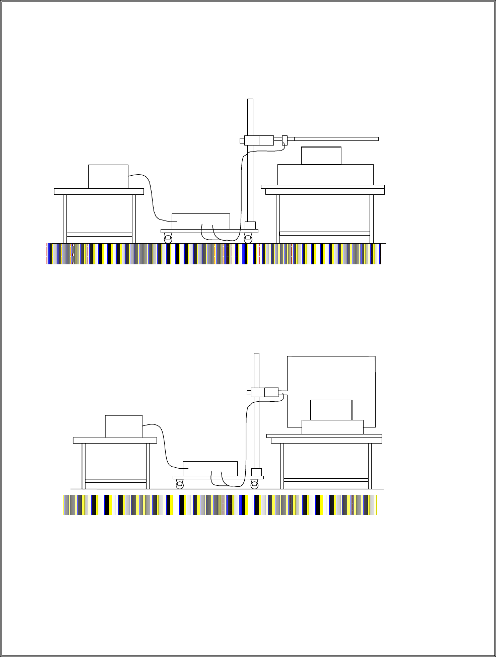
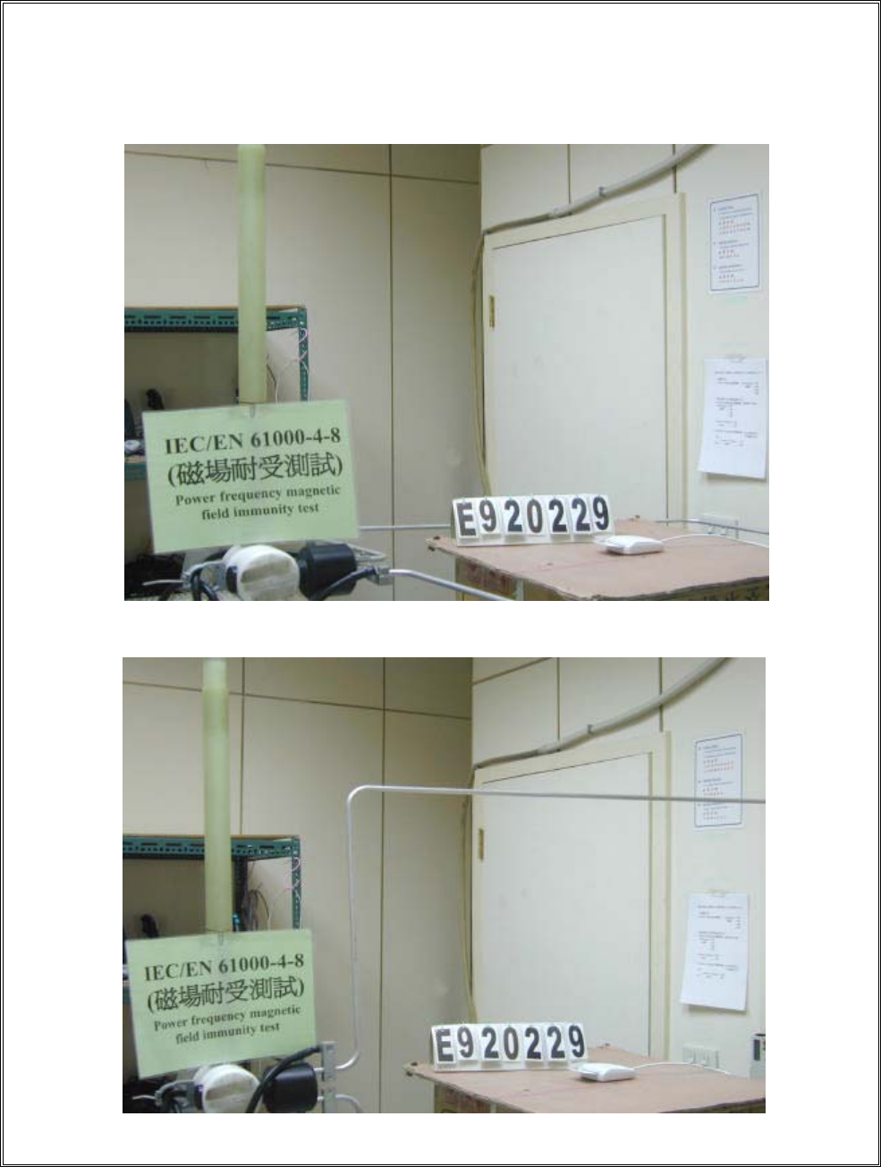
14.4 Power Frequency Magnetic Field Immunity Test Setup Photos
< VERTICAL VIEW >
< HORIZONTAL VIEW >
REPORT NO. : E920229
Page 62 of 69
15. Labeling Requirement, WARNING
1. The vertical size is 5mm.
2. The mark will be placed in a visible spot on the outside of the equipment, but in cases
where that is impractical, it may be included on the packaging and/or documentation.
ITE is subdivided into two categories denoted class A ITE and class B ITE.
Class A ITE
Class A ITE is a category of all other ITE which satisfies the Class A ITE limits but not the
Class B ITE limits. Such equipment should not be restricted in its sale but the following
warning shall be included in the instructions for use :
Warning
This is a Class A product. In a domestic environment this product may
cause radio interference in which case the user may be required to take
adequate measures.
Class B ITE
Class B ITE is a category of apparatus which satisfies the class B ITE disturbance limits.
Class B ITE is intended primarily for use in the domestic environment and may include:
- equipment with no fixed place of use; for example, portable equipment powered by
built-in batteries;
- telecommunication terminal equipment powered by a telecommunication network;
- personal computers and auxiliary connected equipment.

REPORT NO. : E920229
Page 63 of 69
16. The List of Test Instruments
Test Mode Instrument Model No. Serial No. Next Cal. Date Cal. Interval
R & S
Receiver ESHS10 830223/008 May 22, 2004 1Year
Rolf Heine
LISN NNB-4/63TL 98008 May 01, 2004 1Year
R & S
LISN ESH3-Z5 844982/039 Aug. 07, 2003 1Year
Spectrum
Analyzer R3261A 91720076 Jun. 09, 2003 1Year
RF Cable Rg400 N/A May 12, 2004 1Year
Conduction
( No.1)
Schaffner
ISN T411 N/A Jun. 30, 2003 1Year
R & S
Receiver ESVS30 863342/012 May 20, 2004 1Year
Schaffner
Pre-amplifier CPA9232 1028 May 12, 2004 1Year
COM-Power
Horn Ant.
AH-118
(1GHz~18GHz) 10095 May 21, 2004 2Year
Schwarzbeck
Precision Dipole
Ant
VHAP
(30MHz~1GHz)
970 + 971
953 + 954 Jun. 27, 2003 3Year
R &S Signal
Generator SMY01 841104/037 Apr. 28, 2004 1Year
RF Cable No. 1 N/A May 11, 2004 1Year
Radiation
(OP No.1)
EMCO
Antenna
3142B
(26MHz~2GHz) 9904-1370 Aug. 25, 2003 1Year

REPORT NO. : E920229
Page 64 of 69
Test
Mode
Test
item Instrument Model No. Serial No. Next Cal. Date Cal.
Interval
4-2 ESD Test
System
ESS-100L
(A)TC-815D 4099C01970 July 15, 2003 1Year
4-3 Comtest
G-Strip G-320 CC112-0008 Oct. 01, 2003 2Year
4-4 KeyTek EFT
Noise Generator CE-40 9508266 Jan. 27, 2005 2Year
4-5 HAEFELY
Surge Tester PSURGE 4 083665-17 Dec. 18, 2004 2Year
4-8 HAEFELY
Magnetic Field MAG 100.1 083858-04 Dec. 26, 2004 2Year
4-11
HAEFELY
Line Interference
Tester
PLINE 1610 083732-01 Dec. 19, 2004 2Year
4-3
4-6
HP Signal
Generator 8648A 3619U00426 Sep. 15, 2003 1Year
EMS
(NO.1)
3-2
3-3
HP Harmonic/
Flicker Test
System
6842A 3531A-00141 Dec. 19, 2004 2Year
REPORT NO. : E920229
Page 65 of 69
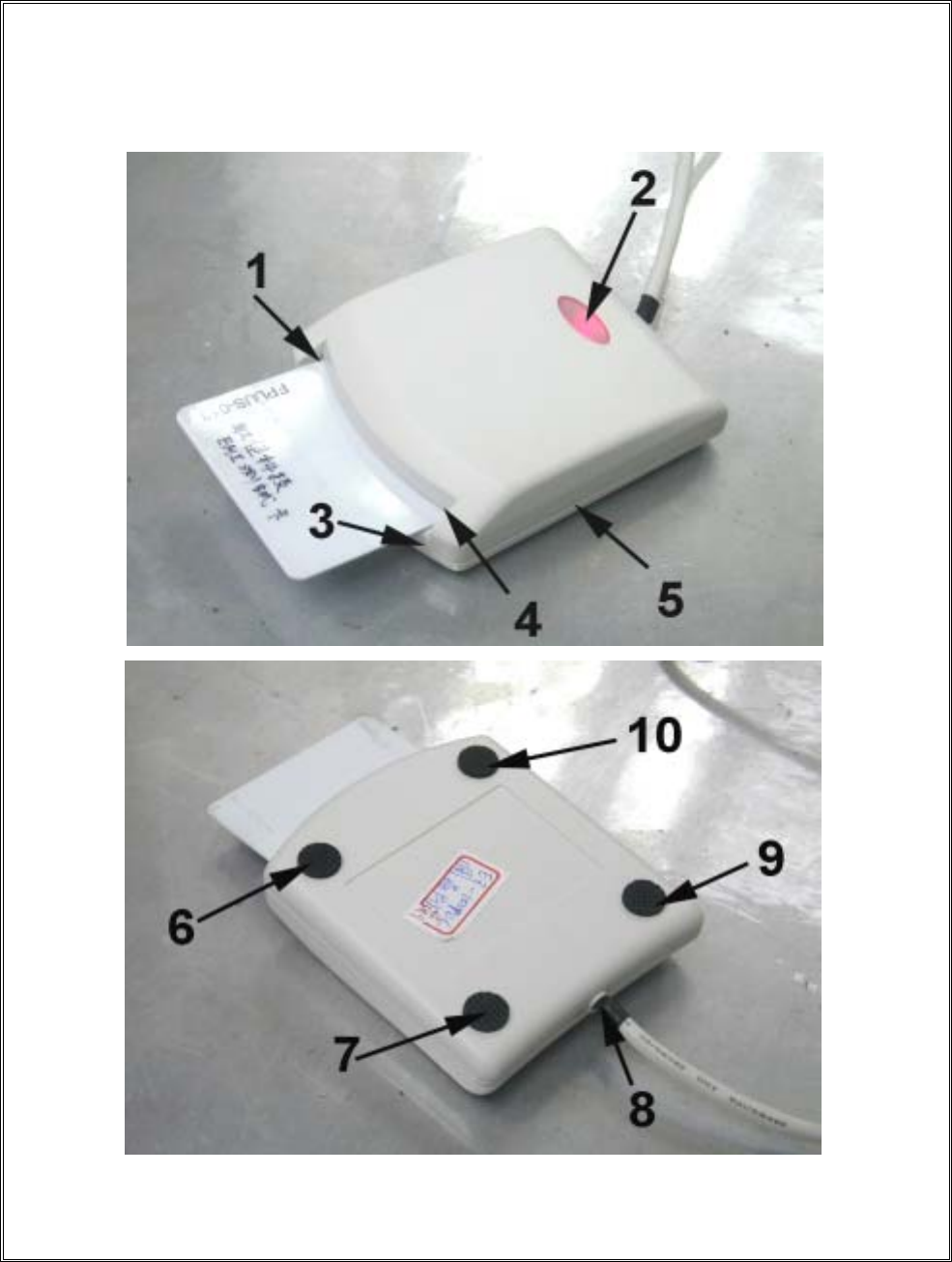
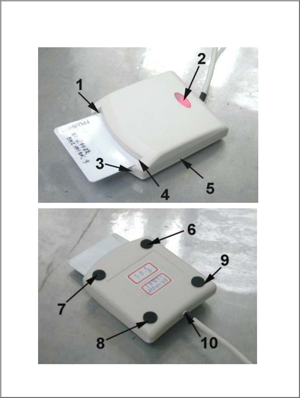
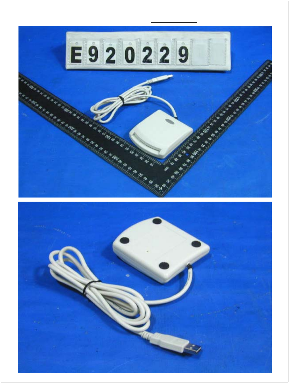
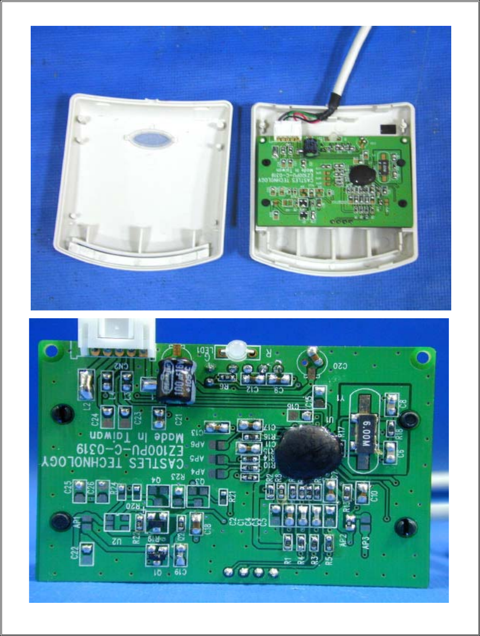
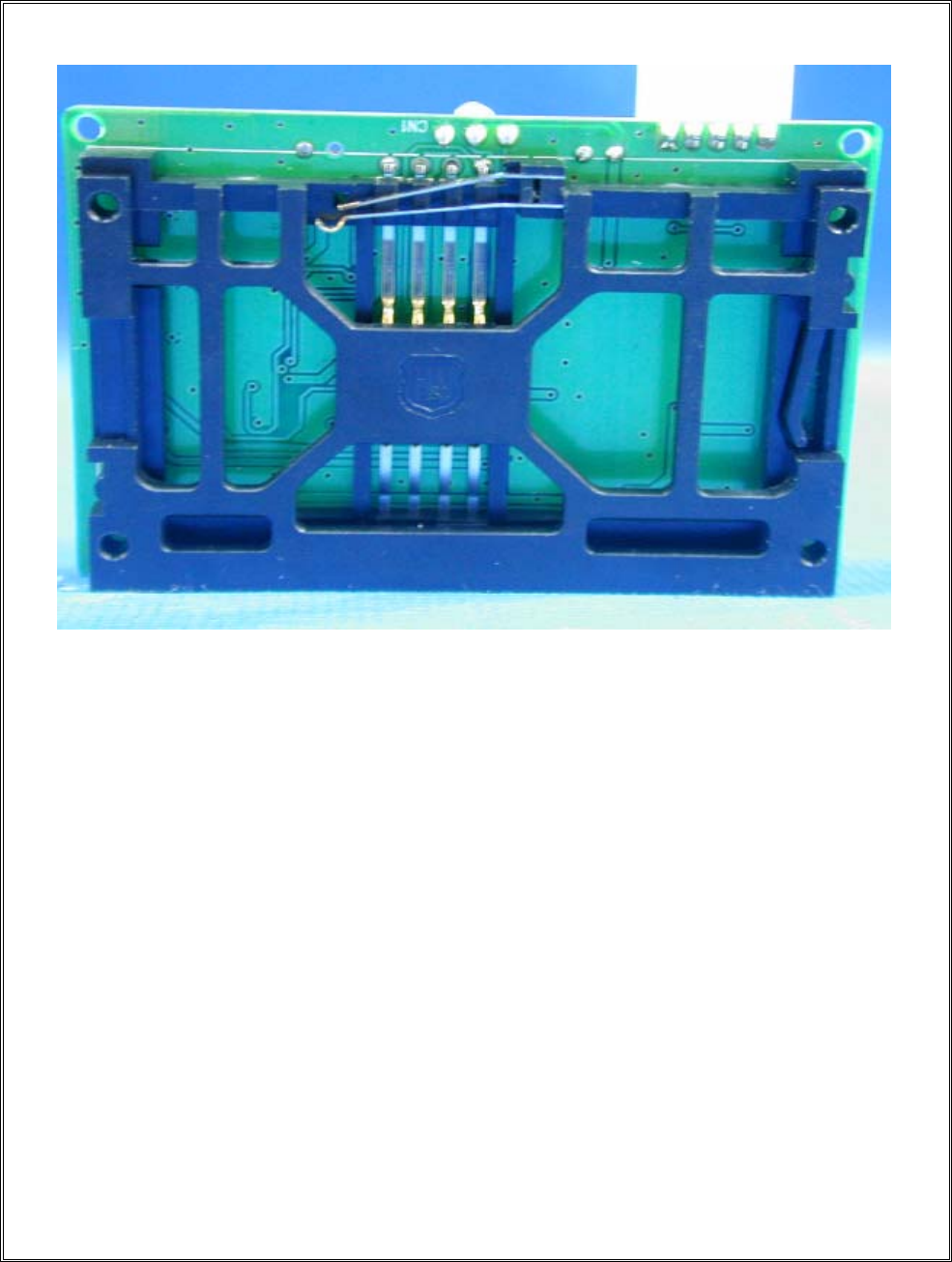
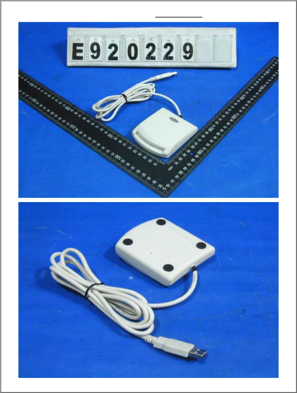
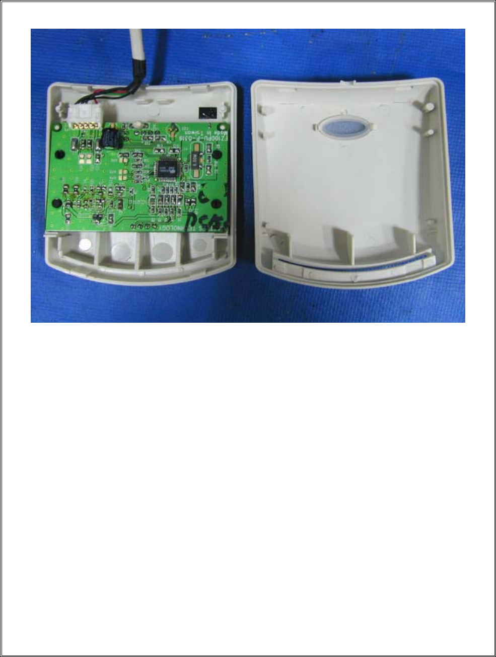
17. EUT Photos
MODEL NO. : EZ-100PU-C ;
REPORT NO. : E920229
Page 66 of 69
REPORT NO. : E920229
Page 67 of 69
REPORT NO. : E920229
Page 68 of 69
MODEL NO. : EZ-100PU-P ;
REPORT NO. : E920229
Page 69 of 69

VERIFICATION
of conformity with
European EMC Directive
No. E920229
Document holder
:CASTLES TECHNOLOGY CO., LTD.
Type of equipment:
Smart Card Reader
Type designation
:EZ-100PU-C, EZ-100PU-P
A sample of the equipment has been tested for CE-marking according to the EMC Directive, 89/336/EEC. &
92/31/EEC & 93/68/EEC
Standard(s) used for showing compliance with the essential requirements of the directive:
EMC Standard(s): Performance Criterion
EN 55022: 1998+A1: 2000 Class B
EN 61000-3-2: 2000
EN 61000-3-3: 1995
EN 55024: 1998+A1: 2001 EN 61000-4-2: 1995+A1: 1998 A
EN 61000-4-3: 1996+A1: 1998 A
EN 61000-4-4: 1995 B
EN 61000-4-5: 1995 A
EN 61000-4-6: 1996 A
EN 61000-4-8: 1993 A
EN 61000-4-11: 1994
The referred test report(s) show that the product fulfills the requirements in the EMC Directive for CE marking. On this
basis, together with the manufacturer’s own documented production control, the manufacturer (or his European authorized
representative) can in his EC Declaration of Conformity verify compliance with the EMC Directive.
Signed for and on behalf of
PEP Testing Laboratory
Date: JUN. 03, 2003 M. Y. Tsui / President

Declaration of Conformity
The following
Applicant : CASTLES TECHNOLOGY CO., LTD.
Equipment : Smart Card Reader
Model No. : EZ-100PU-C, EZ-100PU-P
Report No. : E920229
is herewith confirmed to comply with the requirements set out in the Council Directive on
the Approximation of the Laws of the Member States relating to Electromagnetic
Compatibility(89/336/EEC) and the amendments in the Council Directive 92/31/EEC,
93/68/EEC.
For the evaluation of above mentioned Directives, the following standards were applied:
1) EN 55022: 1998+A1 : 2000 Class B
2) EN 61000-3-2 : 2000
3) EN 61000-3-3 : 1995
4) EN 55024 : 1998+A1 : 2001
EN 61000-4-2 : 1995+A1: 1998
EN 61000-4-3 : 1996+A1: 1998
EN 61000-4-4 : 1995
EN 61000-4-5 : 1995
EN 61000-4-6 : 1996
EN 61000-4-8 : 1993
EN 61000-4-11 : 1994
The following manufacturer is responsible for this declaration:
CASTLES TECHNOLOGY CO., LTD.
6F-1, NO. 190, CHUNG-HSIN RD.,
SEC. 2, HSIN-TIEN, TAIPEI HSIEN,
TAIWAN, R. O. C.
Taiwan / Jun. 03, 2003
Place and Date Signature of responsible Person
