RSZ07082103 3 177221 LVD Report1
2016-04-05
: Pdf 177221 Lvd Report1 177221_LVD__Report1 CertsReports 177221 ProductFiles
Open the PDF directly: View PDF ![]() .
.
Page Count: 31

RSZ07082103-3
Page 1 of 31
TEST REPORT
EN 60950-1:2006
Safety of information technology equipment
Part 1-General requirements
Report reference No ........................: RSZ07082103-3
Compiled by (+ signature) ...............:
Approved by (+ signature) ...............:
Arly Zhao ..........................................
Safety Engineer:Jeanne Han ...........................................
Date of issue ....................................: 2007-08-31
Testing laboratory ............................: Bay Area Compliance Laboratory Corp. (Shenzhen)
Address ...........................................: 6/F, the 3rd Phase of WanLi Industrial Building, ShiHua Road,
FuTian Free Trade Zone, ShenZhen, Guangdong, P.R.China
Testing location ...............................: As above
Applicant1 ........................................: DynaPoint (Dong Guan) Inc.
Address ...........................................:
Applicant2 ........................................:
Address ...........................................:
The Sixth Industrial Park.Shangsha,South Area
ChangAn,DongGuan,GuangDong,China 523880
---
Standard ...........................................: EN 60950-1:2006
Test procedure ................................: LVD Scheme
Test sample(s) received...................: 2007-08-30
Test in period....................................: 2007-08-30 To 2007-08-31
Procedure deviation ........................: N.A.
Non-standard test method ...............: N.A.
This test report is for the customer shown above and their specific product only. It may not be duplicated or
used in part without prior written consent from Bay Area Compliance Laboratory Corp. (Shenzhen). This report
must not be used by the customer to claim product certification, approval, or endorsement by NVLAP, NIST, or
any agency of the Federal Government.
Type of test object ...........................: Wireless Mouse
Trademark .......................................: ---
Model/type reference .......................: H7AG5001
Manufacturer.................... ................: DynaPoint (Dong Guan) Inc.
RSZ07082103-3
Page 2 of 31
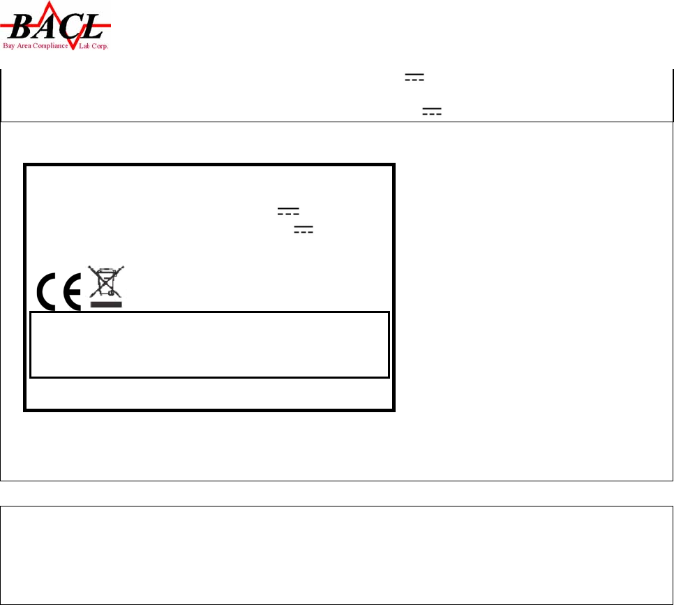
Wireless Mouse
Model : H7AG5001
Input rating: Transmitter unit : DC3.0V ≤0.036A
Receiver unit: USB DC+5.0V ≤0.015A;
Serial No.:xxxxxx
CAUTION
RISK OF EXPLOSION IF BATTERY IS REPLACE
BY AN INCORRECT TYPE.
DISPOSE OF USED BATTERIES ACCORDING TO THE INSTRUCTIONS
D
y
naPoint
(
Don
g
Guan
)
Inc. Made In
Rating ...............................................: Transmitter unit : DC3.0V ≤0.036A(built-in 2x1.5Vdc AA size
non-rechagrable batteries)
Receiver unit: USB DC+5.0V ≤0.015A;
Copy of marking plate:
Possible test case verdicts:
-test case does not apply to the test object................:N(.A.)
-test object does meet the requirement.......................P(ass)
-test object does not meet the requirement.................F(ail)

RSZ07082103-3
Page 3 of 31
General remarks:
”(see remark #)” refers to a remark appended to the report.
(see appended table)” refers to a table appended to the report.
Throughout this report a comma is used as the decimal separator.
The test results presented in this report relate only to the object tested.
This report shall not be reproduced except in full without the written approval of the testing laboratory.
GENERAL INFORMATION:
1. Factory information:
Factory: DynaPoint (Dong Guan) Inc.
Address: The Sixth Industrial Park.Shangsha,South Area ChangAn,DongGuan,GuangDong,China
523880.
2. Manufacturer’s name or trade-mark of identification mark:
Manufacturer’s name: DynaPoint (Dong Guan) Inc.
Trade-mark: ---

RSZ07082103-3
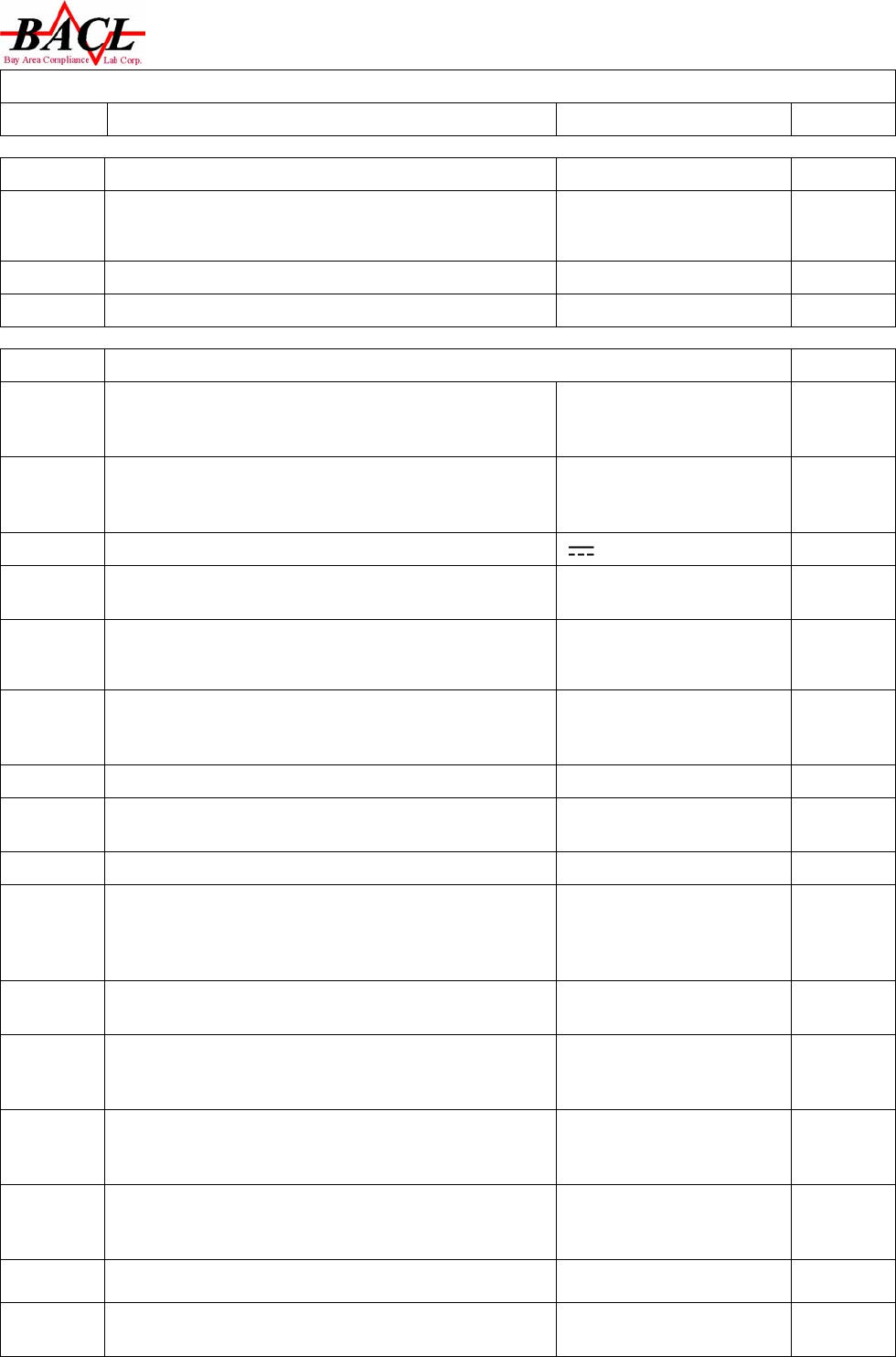
EN 60950-1
Clause Requirement – Test Result - Remark Verdict
Page 4 of 31
1 General P
1.5. Component P
1.5.1 General (see appended table
1.5.1) P
1.5.2 Evaluation and testing of components Certified components are
used in accordance with their
ratings, certifications and
they comply with applicable
parts of this Standard.
Components not certified are
used in accordance with their
ratings and they comply with
IEC60950 and the relevant
component Standard.
Components, for which no
relevant IEC Standard exist,
have been tested under the
condition occurring in the
equipment, using applicable
parts of IEC60950.
P
Dimension (mm) of main plug for direct plug-in: No main plug used. N
Torque and pull test of main plug for direct plug-in;
Torque (Nm), Pull (N):
N
1.5.3 Thermal controls No thermal controls. N
1.5.4 Transformers N
1.5.5 Interconnecting cables N
1.5.6 Capacitors in primary circuits N
1.5.7 Double insulation or reinforced insulation bridged by
components
N
1.5.7.1 General N
1.5.7.2 Bridging capacitors Not used. N
1.5.7.3 Bridging resistors Not used. N
1.5.7.4 Accessible parts N
1.5.8 Components in equipment for IT power distribution
systems
N
1.5.9 Surge suppressors N
1.5.9.1 General
N
1.5.9.2 Protection of VDRs N
1.5.9.3 Bridging of functional insulation by a VDR N
1.5.9.4 Bridging of basic insulation by a VDR N
1.5.9.5 Bridging of supplementary, double or reinforced
insulation by a VDR
N
1.6 POWER INTERFACE P
RSZ07082103-3
EN 60950-1
Clause Requirement – Test Result - Remark Verdict
Page 5 of 31
1.6.1 AC power distribution systems N
1.6.2 Input current Transmitter unit :≤0.036A
Receiver unit: ≤0.015A;
P
1.6.3 Voltage limit of hand-held equipment Not exceed 250V. P
1.6.4 Neutral conductor N
1.7 MARKINGS AND INSTRUCTIONS P
1.7.1 Power rating Power rating marking is
readily visible to
operator.See below.
P
-rated voltage or rated voltage range,in vlots Transmitter unit :DC3.0V
Receiver unit: USB
DC+5.0V
P
-symbol for nature of supply, for d.c. only P
-rated frequency of rated frequency range,in
hertz,unless the equipment is designed for d.c. only
N
-rated current, in milliamperes or amperes Transmitter unit :≤0.036A
Receiver unit: ≤0.015A;
P
-manufacturer’s name or trade-mark of identification
mark
Manufacturer’s name:
DynaPoint (Dong Guan)
Inc.
P
-manufacturer’s model or type reference H7AG5001 P
-symbol (60417-1-IEC-5172), for class II equipment
only
Class III equipment N
-certification mark CE mark P
1.7.2 Safety instructions User’s manual in English
explains safety
instructions,safe
operation, installation, etc.
P
- a warning that excessive sound pressure from
earphones and headphones can cause hearing loss.
N
-for permanently connected equipment, a readily
accessible disconnect device shall be incorporated in
the building installation wiring
N
-for pluggable equipment, the socket-outlet shall be
installed near the equipment and shall be easily
accessible
N
1.7.3 Marking of rated operating time, or rated operation
time and resting time
The equipment is
intended for continuous
operation.
N
1.7.4 Method of voltage adjustment is fully described No voltage
setting/frequency setting. N
1.7.5 Marking of maximum load be permitted to be
connected shall be placed in the vicinity of the outlet
No standard power outlets
are provided. N

RSZ07082103-3
EN 60950-1
Clause Requirement – Test Result - Remark Verdict
Page 6 of 31
1.7.6 Fuse identification N
1.7.7 Wiring terminals N
1.7.7.1 Right marking of protective and bonding terminals N
1.7.7.2 Terminals for a.c. mains supply conductors N
1.7.7.3 Terminals for d.c. mains supply conductors N
1.7.8 Controls and indicators See below. P
1.7.8.1 Identification, location and marking N
1.7.8.2 Colours N
1.7.8.3 Symbols N
1.7.8.4 Marking using figures N
1.7.9 Insulation of multiple sources N
1.7.10 IT power dixtribution systems N
1.7.11 Thermostats and other regulating devices Not used. N
1.7.12 Language English. P
1.7.13 Durability The label was rubbed with
cloth soaked with water
for 15s and then again for
15s with the cloth soaked
with petroleum spirit.After
test the label is legible
without any damage. The
marking on the label did
not fade. There was no
curling nor lifting of the
label edge.
P
1.7.14 Removable parts No hazard for removable
parts. P
1.7.15 Replaceable batteries Transimitter unit:built-in
2x1.5Vdc AA size non-
rechagrable replaveable
batteries.
P
1.7.16 Operator access with a tool N
1.7.17 Equipment for restricted access locations N
2. PROTECTION FROM HAZARDOUS P
2.1 Protection from electric shock and energy hazards P
2.1.1 Protection in operator access areas All circuits are SELV and
no energy hazards. P
2.1.1.1 Access to energized parts N
Test by inspection N
Test with test finger N
Test with test probe N

RSZ07082103-3
EN 60950-1
Clause Requirement – Test Result - Remark Verdict
Page 7 of 31
Test with test pin N
2.1.1.2 Battery compartments Transmitter unit have a
battery compartments. P
2.1.1.3 Access to ELV wiring N
Working voltage (V); distance (mm) through
insulation
N
2.1.1.4 Access to hazardous voltage circuit wiring N
2.1.1.5 Energy hazards N
2.1.1.6 Mannual controls N
2.1.1.7 Discharge of capacitors in equipment N
Time constant (s); measured voltage (V) ---
2.1.2 Protection in service access areas N
2.1.3 Protection in restricted access location N
2.2 SELV CIRCUITS P
2.2.1 General requirements P
2.2.2 Voltages under normal conditions All accessible voltages
are less than 42.4 Vp or
60 V dc and are classified
as SELV.
P
2.2.3 Voltages under fault conditions Not exceed 42.4 Vp or 60
V dc under fault condition. P
2.2.3.1 Separation by double insulation or reinforced
insulation(method 1)
N
2.2.3.2 Separation by earthed screen( method 2) N
2.2.3.3 Protection by earthing of the SELV circuits to other
circuit
N
2.2.4 Connection of SELV circuits to other circuits N
2.3 TNV circuits N
2.3.1 Limits N
Type of TNV circuits ---
2.3.2 Separation from other circuits and from accessible
parts
N
Insulation employed ---
2.3.3 Separation from hazardous voltage N
Insulation employed N
2.3.4 Connection of TNV circuits to other circuits N
Insulation employed N
2.3.5 Test for operating voltages generated externally N

RSZ07082103-3
EN 60950-1
Clause Requirement – Test Result - Remark Verdict
Page 8 of 31
2.4 Limited current circuits N
2.4.1 General requirements N
2.4.2 Limit values N
Frenquency (Hz) ---
Measured current (mA) ---
Measured voltage (V) ---
Measured capacitance (µF) ---
2.4.3 Connection of limited current circuits to other circuits N
2.5 Limited power source N
Inherently limited output N
Impedance limited output N
Overcurrent protective device limited output N
Regulating network limited output under normal
operating and single fault condition
N
Regulating network limited output under normal
operating condition and overcurrent protective device
limited output under single fault condition
N
Output voltage (v);output current (A); apparent power
(VA)
---
Current rating of overcurrent protective device (A) ---
2.6 Provisions for earthing and bonding N
2.6.1 Protective earthing N
2.6.2 Functional earthing N
2.6.3 Protective earthing and protective bonding
conductors
N
2.6.3.1 General requirements N
2.6.3.2 Size of protective earthing conductors N
Rated current (A); cross sectional area (mm2), AWG ---
2.6.3.3 Size of protective bonding conductors N
Rated current (A); cross sectional area (mm2), AWG ---
2.6.3.4 Rated current (A); type and nominal thread diameter
(mm);
N
Resistance (Ohm) of earthing conductor and their
terminations; test current (A)
N
2.6.3.5 Colour of insulation N
2.6.4 Terminals N
2.6.4.1 General N

RSZ07082103-3
EN 60950-1
Clause Requirement – Test Result - Remark Verdict
Page 9 of 31
2.6.4.2 Protective earthing and bonding terminals N
Rated current (A); type and nominal thread diameter
(mm);
---
2.6.4.3 Separation of the protective earthing conductor from
protective bonding conductors
N
2.6.5 Integrity of protective earthing N
2.6.5.1 Interconnection of equipment N
2.6.5.2 Components in protective earthing and protective
bonding conductors
N
2.6.5.3 Disconnection of protective earth N
2.6.5.4 Parts that can be removed by an operator N
2.6.5.5 Parts removed during servicing N
2.6.5.6 Corrosion resistance N
2.6.5.7 Screws for protective bonding N
2.6.5.8 Reliance on telecommunication network or cable
distribution system
N
2.7 Overcurrent and earth fault protection in primary circuits N
2.7.1 Basic requirements N
Instructions when protection relies on building
installation
N
2.7.2 Faults not covered in 5.3 N
2.7.3 Short-circuit backup protection N
2.7.4 Number and location of protective devices N
2.7.5 Protection by several devices N
2.7.6 Warning to service persons N
2.8 Safety interlocks N
2.8.1 General principles N
2.8.2 Protection requirements N
2.8.3 Inadvertent reactivation N
2.8.4 Fall-safe operation N
2.8.5 Moving parts N
2.8.6 Overriding N
2.8.7 Switches and relays N
2.8.7.1 Contact gaps N
2.8.7.2 Overload test N
2.8.7.3 Endurance test N
2.8.7.4 Electric strength test N

RSZ07082103-3
EN 60950-1
Clause Requirement – Test Result - Remark Verdict
Page 10 of 31
2.8.8 Mechanical actuators N
2.9 Electrical insulation P
2.9.1 Proterties of insulation materials Neither natural rubber,
materials containing
asbestos nor hygroscopic
materials are used as
insulation. No driving
belts or couplings used.
P
2.9.2 Humidity conditioning N
2.9.3 Requirements of insulation Insulation complies with
heating test,electric
strength,creepage and
clearance requirements.
See appended table
4.5,5.2
P
2.10 Clearances, creepage distances and distances through insulation N
2.10.1 General N
2.10.2 Determination of working voltage N
2.10.3 Clearance N
2.10.3.1 General N
2.10.3.2 Clearance in primary circuits N
2.10.3.3 Clearances in secondary circuits N
2.10.3.4 Measurement of transient voltage levels N
2.10.4 Creepage distance N
CTI tests ---
2.10.5 Solid insulation N
2.10.5.1 Minmum distance through insulation N
2.10.5.2 Thin sheet material N
Number of layers (pcs) ---
Electric strength test ---
2.10.5.3 Printed boards N
Distance through insulation N
Electric strength test for thin sheet insulation material ---
Number of layers (pcs)................................................. N
2.10.5.4 Wound components N
Number of layers N
Two wires in contact in side component; angle
between 45º and 90º
N
2.10.6 Coated printed boards N
2.10.6.1 General N

RSZ07082103-3
EN 60950-1
Clause Requirement – Test Result - Remark Verdict
Page 11 of 31
2.10.6.2 Sample preparation and preliminary inspection N
2.10.6.3 Thermal cycling N
2.10.6.4 Thermal ageing N
2.10.6.5 Electric strength test N
2.10.6.6 Abrasion resistance test N
Electric strength test ---
2.10.7 Enclosed and sealed parts N
Temperature T1=T2+Tma-Tamb+10K N
2.10.8 Spacings filled by insulating compound N
Electric strength N
2.10.9 Comonent external terminations N
2.10.10 Insultion with warying dimensions N
3 WIRING,CONNECTIONS AND SUPPLY P
3.1 General P
3.1.1 Current rating and overcurrent protection N
3.1.2 Protection against mechanical damage Smooth wireway and free
from edges. P
3.1.3 Securing of internal wiring P
3.1.4 Insulation of conductors N
3.1.5 Beads and ceramic insulators N
3.1.6 Screws for electrical contact pressure No screws for electric
contact. N
3.1.7 Insulation materials in electrical connections N
3.1.8 Self-tapping and spaced thread screws N
3.1.9 Termination of conductors N
3.1.10 Sleeving on wiring No sleeving on wiring. N
3.2 Connection to an a.c. mains supply or a d.c. mains supply N
3.2.1 Means of connection N
3.2.1.1 Connection to an a.c. mains supply N
3.2.1.2 Connection to a d.c. mains supply N
3.2.2 Multiple supply connections N
3.2.3 Permanently connected equipment N
Number of conductors, diameter (mm) of cable and
conduits ---
3.2.4 Appliance inlets N

RSZ07082103-3
EN 60950-1
Clause Requirement – Test Result - Remark Verdict
Page 12 of 31
3.2.5 Power supply cords N
Type ---
Rated current (A); cross-sectional area (mm2), AWG ---
3.2.6 Cord anchorages and strain relief N
Mass of the equipment (kg); pull (N) ---
Longitudinal displacement (mm) ---
3.2.7 Protection against mechanical damage N
3.2.8 Cord guards N
D (mm); test mass (g) ---
Radius of curvatureof cord (mm) ---
3.2.9 Supply wiring space N
3.3 Wiring terminals for connection of external conductors N
3.3.1 Wiring terminals N
3.3.2 Connection of non-detachable power supply cords N
3.3.3 Screw terminals N
3.3.4 Rated current (A), cord/cable type, cross-sectional
area (mm2)
N
3.3.5 Rated current (A), type and norminal thread diameter
(mm)
N
3.3.6 Wiring terminal design N
3.3.7 Grouping of wiring terminals N
3.3.8 Stranded wire N
3.4 Disconnection from the mains supply N
3.4.1 General requirement N
3.4.2 Disconnect devices N
3.4.3 Permanently connected equipment N
3.4.4 Parts which remain energized N
3.4.5 Switches in flexible cords N
3.4.6 Single-phase and d.c. equipment N
3.4.7 Three-phase equipment N
3.4.8 Switches as disconnect devices N
3.4.9 Plugs as disconnect devices N
3.4.10 Interconnected equipment N
3.4.11 Multiple power sources N

RSZ07082103-3
EN 60950-1
Clause Requirement – Test Result - Remark Verdict
Page 13 of 31
3.5 Interconnection of equipment N
3.5.1 General reqirements N
3.5.2 Types of interconnection circuits N
3.5.3 ELV circuits as interconnection circuits N
4 PHYSICAL REQIREMENTS P
4.1 Stability N
Angle of 10º N
Test: force (N)......................................................... N
4.2 Mechanical strength P
4.2.1 General P
4.2.2 Steady force test, 10N P
4.2.3 Steady force test, 30N N
4.2.4 Steady force test, 250N N
4.2.5 Impact test N
4.2.6 Drop test 1.0m,three times no
hazard. P
4.2.7 Stress relief test N
4.2.8 Cathode ray tubes N
Picture tube separately certified N
4.2.9 High pressure lamps N
4.2.10 Wall or ceiling mounted equipment; force (N) N
4.3. Design and construction P
4.3.1 Edges and corners All edges and corners are
rounded or smoothed. P
4.3.2 Handles and manual controls; force (N) N
4.3.3 Adjustable controls N
4.3.4 Securing of parts N
4.3.5 Connection of plugs and sockets N
4.3.6 Direct plug-in equipment N
Torque; (Nm) ---
4.3.7 Heating elements in earthed equipment N
4.3.8 Batteries Transmitter unit used
2x1.5Vdc AA size non-
rechagrable batteries.
P

RSZ07082103-3
EN 60950-1
Clause Requirement – Test Result - Remark Verdict
Page 14 of 31
4.3.9 Oil and grease N
4.3.10 Dust, pwders, liquids and gases N
4.3.11 Containers for liquids or gases N
4.3.12 Flammable liquids N
Quantity of liquid (l) ---
Flash point (℃) ---
4.3.13 Radiation,type of radiation N
Equipment using lasers N
4.4 Protection agains hazardous moving parts N
4.4.1 General No harzard moving parts. N
4.4.2 Protection in operator access areas N
4.4.3 Protection in restricted access locations N
4.4.4 Protection in service access areas N
4.5 Thermal requirements P
4.5.1 Temperatures rises (See appended table 4.5) P
Normal load condition per Annex L P
4.5.2 Resistance to abnormal heat N
4.6 Openings in enclosures N
4.6.1 Top and side openings N
Dimension ---
4.6.2 Bottoms of fire enclosures N
Construction of the bottom ---
4.6.3 Doors of covers in fire enclosures N
4.6.4 Openings in transportable equipment N
4.6.5 Adhesives for constructional purposes N
Conditioning of temperature/time N
4.7 Resistance to fire P
4.7.1 Reducing the risk of ignition and spread of flame P
4.7.2 Conditions for a fire enclosure P
4.7.2.1 Parts requiring a fire enclosure P
4.7.2.2 Parts not requiring a fire enclosure P
4.7.3 Materials P
4.7.3.1 General P

RSZ07082103-3
EN 60950-1
Clause Requirement – Test Result - Remark Verdict
Page 15 of 31
4.7.3.2 Materials for fire enclosures P
4.7.3.3 Materials for components and other parts outside fire
enclosures
N
4.7.3.4 Materials for components and other parts inside fire
enclosures
P
4.7.3.5 Materials for air filter assembiles N
4.7.3.6 Materials used in high-voltage components N
5 ELECTRICAL REQUIREMENTS AND SIMULATED ABNORMAL CONDITIONS P
5.1 Touch current and protective conductor current N
5.1.1 General N
5.1.2 Equipment under test N
5.1.3 Test circuit N
5.1.4 Application of measuring instrument N
5.1.5 Test procedure N
5.1.6 Test measurements N
Test voltage ---
Measured current(mA) ---
Max. Allowed current (mA) ---
5.1.7 Equipment with touch current exceeding 3.5mA N
5.1.8 Touch currents to telecommunication networks and
cabl distribution systems and from
telecommunication networks
N
5.1.8.1 Limitation of the touch currents to telecommunication
networks and cabl distribution systems and from
telecommunication networks
N
Test voltage ---
Measured current(mA) ---
Max. Allowed current (mA) ---
5.1.8.2 Summation of touch currents from
telecommunication network
N
5.2 Electric strength P
5.2.1 General P
5.2.2 Test procedure (See Appended table 5.2). P
5.3 Abnormal operating and fault conditions N
5.3.1 Protection against overload and abnormal operation N

RSZ07082103-3
EN 60950-1
Clause Requirement – Test Result - Remark Verdict
Page 16 of 31
5.3.2 Motors N
5.3.3 Transformers N
5.3.4 Functional insulation N
5.3.5 Electromechanical components N
5.3.6 Simulation of faults N
5.3.7 Unattended equipment N
5.3.8 Compliance criteria for abnormal operating and fault
conditions
N
6 CONNECTION TO TELECOMMUNICATION NETWORKS N
6.1 Protection of telecommunication network service persons, and users of other
equipment connected to the network,from hazards in the equipment N
6.1.1 Protection from hazardous voltages N
6.1.2 Separation of the telecommunicatio network from
earth ---
6.1.2.1 Requirements N
Test voltage (V) ---
Current in test circuit (mA) ---
6.1.2.2 Exclusions N
6.2 Protection of equipment users from over voltages on telecommunication networks N
6.2.1 Separation requirements N
6.2.2 Electric strength test procedure N
6.2.2.1 Impulse test N
6.2.2.2 Steady-state test N
6.2.2.3 Compliance criteria N
6.3 Protection of the telecommunication wiring system from overheating N
Max. output current (A) ---
Current limiting method ---
7 CONNECTION TO CABLE DISTRIBUTION SYSTEMS N
7.1 Protection of cable distribution system service
persons, and users of other equipment connected to
the system, from hazardous voltage in the equipment
N
7.2 Portection of equipment users from overvoltage on
the cable distribution system
N
7.3 Insulation between primary circuits and cable
distribution systems
N
7.3.1 General N
7.3.2 Voltage surge test N

RSZ07082103-3
EN 60950-1
Clause Requirement – Test Result - Remark Verdict
Page 17 of 31
Surge test voltage (V)/test time (s) ---
Electric test voltage (V) ---
7.3.3 Imulse test N
Test voltage (V)/time (s) ---
Electric test voltage (V) ---
A ANNEX A, TEST FOR RESITANCE TO HEAT AND FIRE N
A.1 Flammability test for fire enclosures of movable equipment havin a total mass
exceed N
A.1.1 Samples, materials ---
Wall thickness ---
A.1.2 Conditioning of samples N
A.1.3 Mounting of samples N
A.1.4 Test flame N
A.1.5 Test procedure N
A.1.6 Comliance criteria N
Sample 1 burning times ---
Sample 2 burning times ---
Sample 3 burning times ---
A.2 Flammability test for fire enclosures of movable equipment having a total mass not
exceeding 18kg, and for material and components located inside fire enclosure
(see 4.7.3.2 and 4.7.3.4)
N
A.2.1 Samples, materials N
Wall thickness N
A.2.2 Conditioning of samples N
A.2.3 Mounting of samples N
A.2.4 Test flame N
A.2.5 Test procedure N
A.2.6 Comliance criteria N
Sample 1 burning times ---
Sample 2 burning times ---
Sample 3 burning times ---
A.2.7 Alternative test acc. to IEC60695-2-2 cl. 4 and 8 N
Sample 1 burning times ---
Sample 2 burning times ---

RSZ07082103-3
EN 60950-1
Clause Requirement – Test Result - Remark Verdict
Page 18 of 31
Sample 3 burning times ---
A.3 Hot flaming oil test(see 4.6.2) N
B annex b motor tests under abnormal conditions N
B.1 General requirements N
Position ---
Manufacturer ---
Type ---
Rated values ---
B.2 Test conditions N
B.3 Maximum temperatures N
B.4 Running overload test N
B.5 Locked-rotor overload test . N
Test duration (days) ---
Electric strength test: test voltage (V) ---
B.6 Running overload test for d.c.motors in secondary
circuits
N
B.7 Locked-rotor overload test for d.c. motors in
secondary circuits
N
B.7.1 Test procedure N
B.7.2 Alternative test procedure, test time (h) N
B.7.3 Electric strength test N
B.8 Test for motors with capacitors N
B.9 Test for three-phase motors N
B.10 Test for series motors N
Opening voltage (V) N
C annex c transformer N
Position N
Manufacturer N
Type N
Rated values N
Method of protection N
C.1 Overload test N
C.2 Insulation N

RSZ07082103-3
EN 60950-1
Clause Requirement – Test Result - Remark Verdict
Page 19 of 31
Protection from displacement of windings N
G ANNEX G. ANTERNATIVE METHOD FOR DETERMINING MINIMUM CLEARANCES N
G.1 Summary of the procedure for determining minimum
clearances
N
G.2 Determination of mains transient voltage (V).......... N
G.3 Determination of telecommunication network
transient voltage(V).................................................
N
G.4 Determination of required withstand voltage(V)...... N
G.5 Measurement of transient voltage levels (V)........... N
G.6 Determination of minimum calearances................. N
H ANNEX H. IONIZING RADIATION (see 4.3.13) N
Ionizing radiation N
Measured radiation (mR/h) ---
Measured high-voltage (kV) ---
Measured focus voltage (kV) ---
CRT markings ---
J ANNEX J. TABLE OF ELECTROCHEMICAL POTENTIALS (see 2.6.5.6) N
Metal used.............................................................. ---
K ANNEX K. THERMAL CONTROLS (see 1.5.3 and 5.3.7)
N
K.1 Making and breaking capacity N
K.2 Thermostat reliability; operating voltage (V)............ N
K.3 Thermostat endurance test; operating voltage (V).. N
K.4 Temperature limiter endurance; operating voltage
(V)...........................................................................
N
K.5 Thermal cut-out reliability N
K.6 Stability of operation N
M ANNEX M,CRITERIA FOR TELEPHONE RINGING SIGNALS N
M.1 Instruction N
M.2 Method A N
M.3 Method B N
M.3.1 Ringing signal N
M.3.1.1 Frequency (Hz)........................................................ ---
M.3.1.2 Voltage (V).............................................................. ---
RSZ07082103-3
EN 60950-1
Clause Requirement – Test Result - Remark Verdict
Page 20 of 31
M.3.1.3 Cadence; time (s); voltage (V)................................ ---
M.3.1.4 Single fault current (A)............................................ ---
M.3.2 Tripping device and monitoring voltage.................. N
M.3.2.1 Conditions for use of a tripping device or a
monitoring voltage
N
M.3.2.2 Tripping device N
M.3.2.3 Monitoring voltage................................................... N
U ANNEX U, INSULATED WINDING WIRES FOR USE WITHOUT INTERLEAVED INSULATION N
Separate test report N
RSZ07082103-3
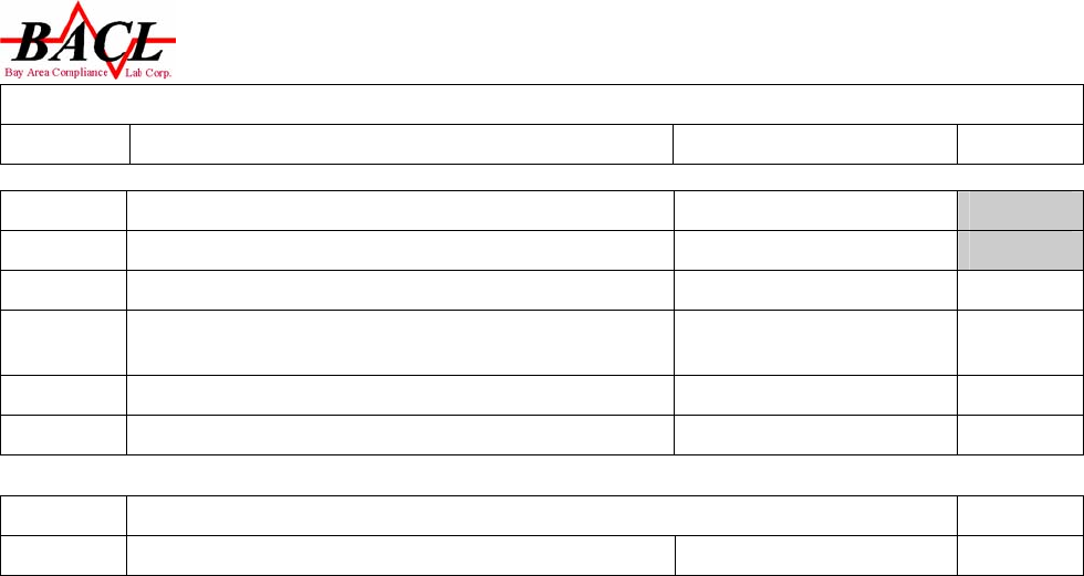
EN 60950-1
Clause Requirement – Test Result - Remark Verdict
Page 21 of 31
1.5.1 Table: list of critical component P
Object /Part
No
Manufacturer/
Trade Mark Type/ Model
T
echnical data
File
No./Licence
No.
P.W.B Various Various
V-1 or above, Min. 105 ℃ UL
Enclosure Various Various HB or above UL
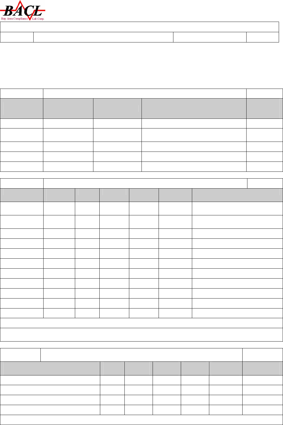
1.6.2 Table: Electrical data (in normal conditions) P
Fuse# I rated
(mA)
U (V) P (W) I (mA) I (fuse
mA)
Condition /status
Transmitter 36 DC
3.0V 0.062 20.8 --- Maximum Normal Operation
Receiver 15 DC
5.0V 0.048 9.6 --- Maximum Normal Operation
Supplementary information:
2.10.3 and
2.10.4
Table: clearances and creepage distance measurements N
Clearances cl and creepage
distance dcr at/of
Up
(V)
Ur.m.s
(V)
required
cl (mm)
cl
(mm)
required
dcr (mm)
dcr
(mm)
Supplementary information:
RSZ07082103-3
EN 60950-1
Clause Requirement – Test Result - Remark Verdict
Page 22 of 31
2.10.5 Table: distance through insulation measurements N
Distances through insulation di at/of U r.m.s
(V)
test voltage
(V)
required
di(mm)
di
(mm)
Supplementary information:
4.3.8 Table: Rechargeable battery N
Battery Position. Rated Max Charging
Current(mA)
Test Charging
Current(mA) Result
Supple mentary information:
4.5.1 Table: temperature rise measurements P
Test voltage(V)................................................ Transmitter unit:DC3.0V
/Receiver unit: DC5V ---
t1( )...............................................................℃ 25.4 ---
t2( )................................................................℃23.8 ---
Temperature of part/at:
T( ) ℃
condition
A
Required
(Tmax+Tamb-
Tma )℃
Ambient 23.8 ---
U4 of receiver 26.5 Ref.
PWB of receiver 26.1 88.8
Enclosure of receiver 25.8 58.8
U3 of transmitter 26.0 Ref.
PWB of transmitter 25.7 88.8
Enclosure of transmitter 24.3 58.8
Supplementary information: Tma is 40℃ in user manual. A:normal condition
4.5.2 Table: ball pressure test of thermoplastic N
Allowed impression diameter
(mm):................ 2mm
part Test
temperature
d impression diameter
(mm)
Supplementary information:
5.2 Table:electric strength tests and impulse tests P
test voltage applied between test voltage
(V)
breakdown
(Yes/No)
RSZ07082103-3
EN 60950-1
Clause Requirement – Test Result - Remark Verdict
Page 23 of 31
DC input to Enclosure transmitter unit 707VDC No
DC input to Enclosure receiver unit 707VDC No
Supplementary information:
5.3 Table: fault condition test N
ambient temperature ( )..................℃.................................: ---
model/type of power supply................................................: ---
manufacturer of power supply..........................................: ---
rated markings of power supply........................................: ---
Component
no. Fault Test
voltage
Test
time
Fuse
no.
Input
current
(mA)
Result
Supplementary information:
NHT: No High Temperature; NCD: No Component Damage;NFG no flamability gas.
A. 6.5 Table: flammability test for classifying material V-0,V-1or V-2 N
sample
No./ref. afterflame time (s) t1 or t2 Afterflame +afterglow (s) after 2nd flame
application t2+t3
Supplementary information:
A.6.6 Table: flammability re-test for classifying material V-0,V-1or V-2 N
sample
No./ref. afterflame time (s) t1 or t2 Afterflame +afterglow (s) after 2nd flame
application t2+t3
Supplementary information:
A.7.4
A.7.5
A.7.6 and
A.7.7
Table: flammability test for classifying foam material HF-0,HF1or HBF N
sample
No./ref. flame time (s) glow time (s) flaming /glowing distance
from the end (mm) comment
Supplementary information:
RSZ07082103-3
EN 60950-1
Clause Requirement – Test Result - Remark Verdict
Page 24 of 31
A.7.8 Table: flammability re-test for classifying foam material HF-0,HF-1 N
sample
No. flame time (s) glow time (s) flaming /glowing distance
from the end (mm) comment
Supplementary information:
A.7.9 Table: flammability re-test for classifying foam material HBF N
sample
No. flame time (s) glow time (s) flaming /glowing distance
from the end (mm) comment
Supplementary information:
A. 8.5 Table: flammability test for classifying materials HB N
sample
No.. flaming/glowing rate mm/min flaming/glowing distance from reference mark (mm)
Supplementary information:
A.9.6 Table: flammability test for classifying material 5V N
sample test bars test plaques
No. flaming+glowin
g time (s)
burning distance
(mm)
positio
n
flaming +glowing time
(s)
burning distance
(mm)
Supplementary information:

RSZ07082103-3
EN 60950-1
Clause Requirement – Test Result - Remark Verdict
Page 25 of 31
RSZ07082103-3
Page 26 of 31
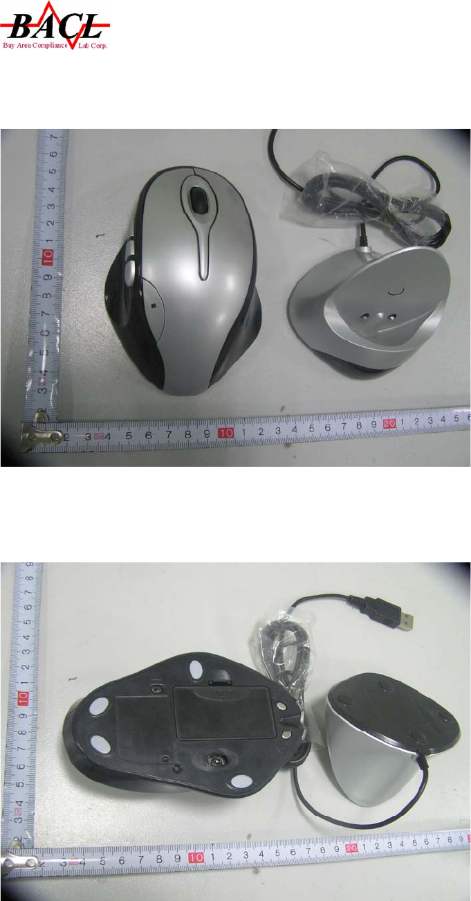
Appendix A - EUT Photos
A.1 EUT photo-Whole View 1 of Unit
A.2 EUT photo- Whole View 2 of Unit
RSZ07082103-3
Page 27 of 31
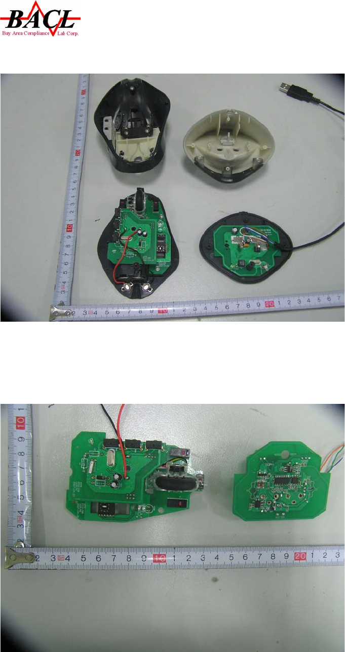
A.3 EUT photo-Inside View of Unit
A.4 EUT photo- PCB View 1 of unit
RSZ07082103-3
Page 28 of 31
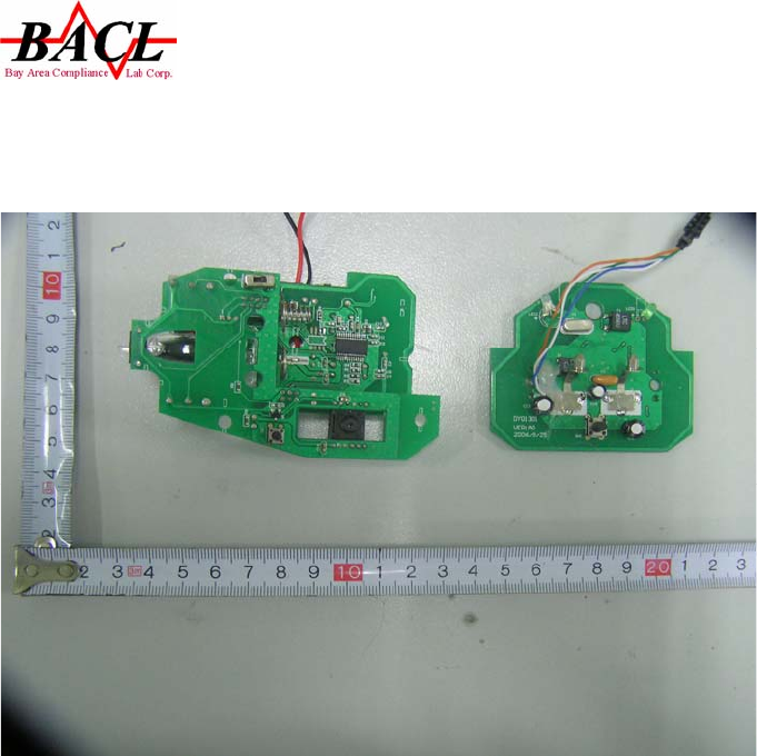
A.5 EUT photo- PCB view 2 of unit

RSZ07082103-3
Page 29 of 31
APPENDIX B – USER’S MANUAL

RSZ07082103-3
Page 30 of 31
APPENDIX C– CIRCUIT SCHEMATICS

RSZ07082103-3
Page 31 of 31
APPENDIX D -TEST EQUIPMENTS LIST
