Control Panel Design Guide 180448 Catalog
133078-Catalog 1 133078-Catalog_1 133078-Catalog_1 Batch9 unilog cesco-content
180448-Catalog 180448-Catalog 180448-Catalog 782116 Batch5 unilog cesco-content
2014-07-04
: Pdf 180448-Catalog 180448-Catalog 015082 Batch5 unilog
Open the PDF directly: View PDF ![]() .
.
Page Count: 37
UL 508A control panel design guide
The easy-to-design guide for selection of electrical control components
in control panels used in industrial machinery applications
This guide is provided to assist with the design of control
panels per UL
T 508A, specifically for use in industrial
machinery applications. This guide is designed to cover the
most common applications of electrical control products per
UL 508A, but is by no means an exhaustive guide, and does
not cover all uses and applications associated with UL 508A
regulations. This guide is not intended to be used in lieu of
UL 508A or other regulatory standards. Always consult all
pertinent actual regulatory standards and local standard
representatives to ensure full compliance.
Control panel design guide

Through continuing investments,
Eaton’s Electrical Sector has
grown into a world-class provider
of power protection and control
products. Meeting your specific
needs means offering a complete
line of motor protection, control
and logic devices—all the latest
in technology.
From contactors, starters and drives
to pushbuttons, relays and
programmable controllers, you’ll
have the edge when it comes to
application-specific solutions.
Trust Eaton to deliver the products
and solutions that will make your
process more efficient and effective.
The power of fusion.
A long history of innovation
in control and protection
EATON CORPORATION Control panel design guide
2Ready to buy? Go to www.eaton.com/controlpanel • Got a question? Call 877-ETN-CARE
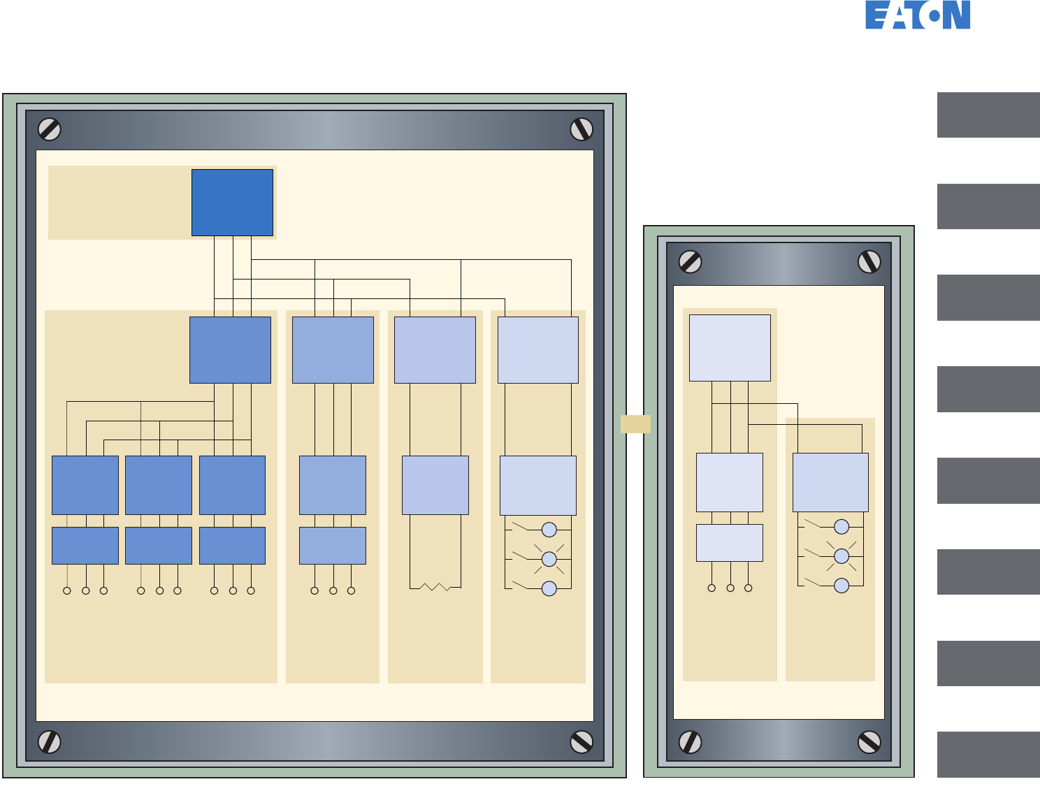
Designing the panel
Controller Controller Controller
Controller
Controller
Transformer
or Power
Supply
Overload
Protection
Overload
Protection
Overload
Protection
Overload
Protection
Branch
Protection
Branch
Protection
Controller
Overload
Protection
Branch
Protection
Branch
Protection
M
M
L
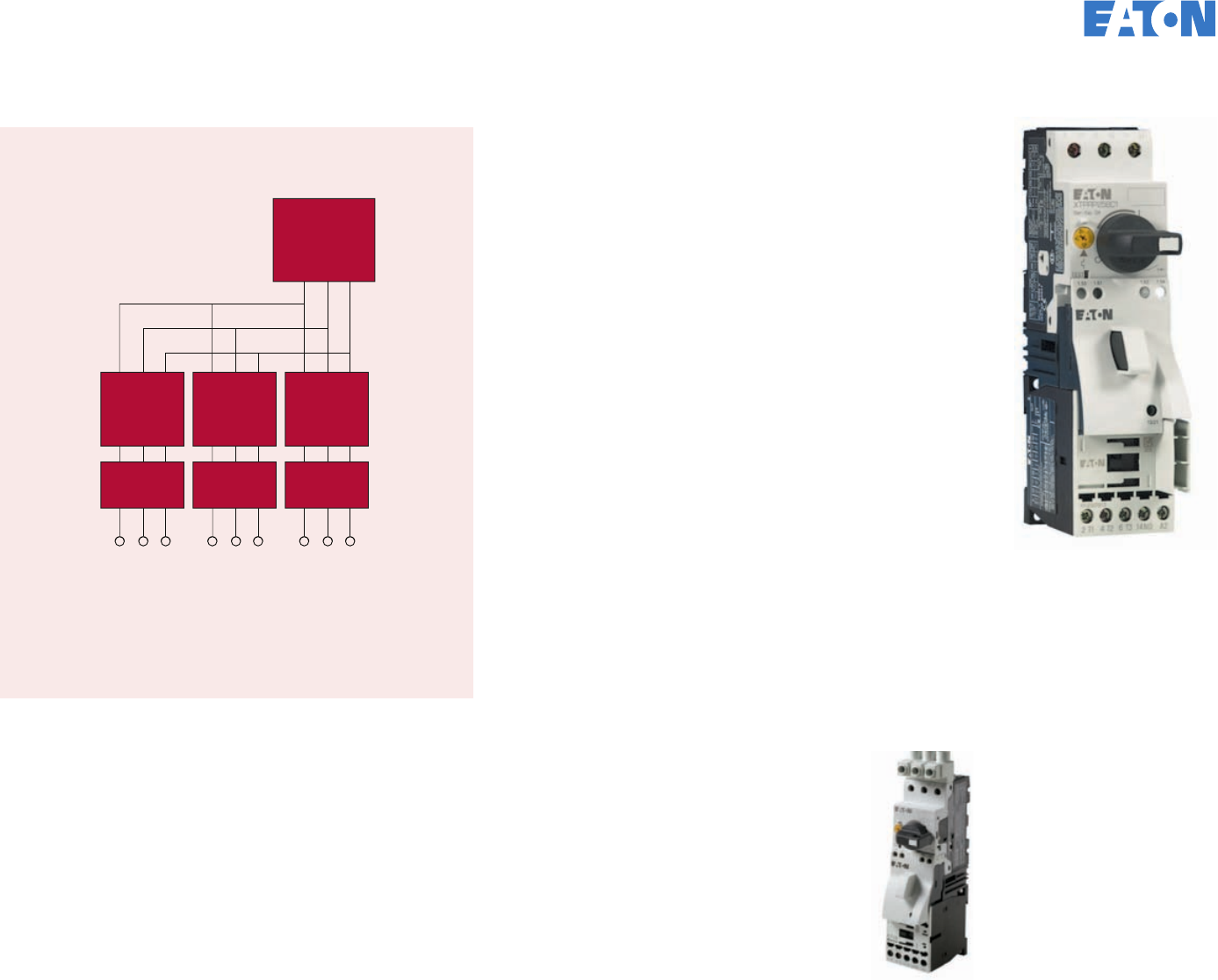
Group Motor—Multiple Motors Protected
by a Single Set of Fuses or Breaker
See Page 6
Individual Circuit
for Motor Load
See Page 8
Heater or
Lighting Load
See Page 14
Feeder Main
See Page 4
Control
Circuit
See Page 20
Single Motor
Load
See Page 31
Control
Circuit
See Page 20
Feeder
Main
Transformer
or Power
Supply
M
M
L
Branch
Protection
Controller Controller Controller
Controller
Controller
Transformer
or Power
Supply
Overload
Protection
Overload
Protection
Overload
Protection
Overload
Protection
Branch
Protection
Branch
Protection
Controller
Overload
Protection
Branch
Protection
Branch
Protection
M
M
L
Group Motor—Multiple Motors Protected
by a Single Set of Fuses or Breaker
See Page 6
Individual Circuit
for Motor Load
See Page 8
Heater or
Lighting Load
See Page 14
Feeder Main
See Page 4
Control
Circuit
See Page 20
Single Motor
Load
See Page 31
Control
Circuit
See Page 20
Feeder
Main
Transformer
or Power
Supply
M
M
L
Branch
Protection
Single Motor Panel
Multi-Load Panel
OR
Individual
Circuit for 8
Motor Load
Heater or
Lighting 14
Lead
Power
Circuit 16
Wiring
Group Motor 6
Feeder Main 4
Accessories 19
Control
Circuit 20
Single
Motorload 31
EATON CORPORATION Control panel design guide
3Ready to buy? Go to www.eaton.com/controlpanel • Got a question? Call 877-ETN-CARE
Sizing the feeder
M
M
L
Circuit Breaker
175A
Circuit Breaker
50A
Fuses
6A
Circuit Breaker
125A
Circuit Breaker
25A
Overload
Protection
Overload
Protection
Overload
Protection ControllerController
Transformer
or Power
Supply
Controller Controller Controller Overload
Protection
Motor Load Motor Load Motor Load Motor Load Heater Load
Transformer
Load
(Primary Side)
3.4 FLA 7.6 FLA 14 FLA 65 FLA 20A 1.95A
The feeder amp rating is sized
based on the sum of the amp
rating of the largest branch
protective device plus the full-
load currents of the other loads.
In this example, the 125A circuit
breaker is the largest short-circuit
protective device. This value is
added to the full load currents
of the other loads in the circuit
(motors, heater, and the primary
of the transformer).
The overcurrent feeder amp rating
should not exceed the conductor
ampacity rating on the loadside.
For conductor ampacity ratings,
see Table 28.1 on Page 18.
Example Multi-Load Panel
125A + 3.4A + 7.6A + 14A + 20A + 2A = 172A
Use closest size, 175A
Reference Section 32.3.1 a
EATON CORPORATION Control panel design guide
4Ready to buy? Go to www.eaton.com/controlpanel • Got a question? Call 877-ETN-CARE
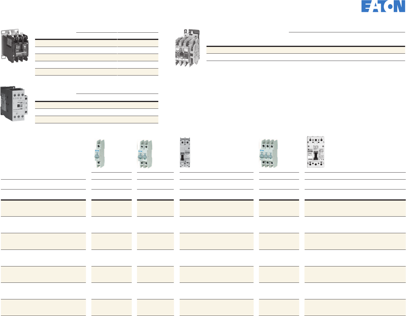
Breaker and Fused Disconnect Selection
Molded Case Circuit Breaker Rotary Fusible Disconnect (Fuses not Included)
Target
Ampacity Breaker
Frame 18 kA 480V
25 kA 240V 25 kA 480V
65 kA 240V 25 kA 480V
35 kA 240V 35 kA 480V
65 kA 240V 65 kA 480V
100 kA 240V 65 kA 480V
100 kA 240V 100 kA 480V
200 kA 240V 100 kA @ 600V
with Class J 200 kA 600V
with Class J
1 EG EGB3015FFG —EGE3015FFG —EGH3015FFG —EGC3015FFG Base R4H3030FJ
NEMA 1, 3R,
12 handle PHB1N12F
12" shaft SF320PH5X5
Fuse type Class J
Integrated lugs #14–#10
Base R9J3030FJ
NEMA 4X handle PHB1N4XF
12" shaft SF320PH10X10
Fuse type Class J
Terminal lugs #10–#6
3 EG EGB3015FFG —EGE3015FFG —EGH3015FFG —EGC3015FFG
6 EG EGB3015FFG —EGE3015FFG —EGH3015FFG —EGC3015FFG
10 EG EGB3015FFG —EGE3015FFG —EGH3015FFG —EGC3015FFG
15 EG EGB3015FFG —EGE3015FFG —EGH3015FFG —EGC3015FFG
20 EG EGB3020FFG —EGE3020FFG —EGH3020FFG —EGC3020FFG
25 EG EGB3025FFG —EGE3025FFG —EGH3025FFG —EGC3025FFG
30 EG EGB3030FFG —EGE3030FFG —EGH3030FFG —EGC3030FFG
35 EG EGB3035FFG —EGE3035FFG —EGH3035FFG —EGC3035FFG —Base R9K3060FJ
NEMA 4X handle PHB2N4XF
12" shaft SF320PH10X10
Fuse type Class J
Integrated lugs #10–#6
40 EG EGB3040FFG —EGE3040FFG —EGH3040FFG —EGC3040FFG
45 EG EGB3045FFG —EGE3045FFG —EGH3045FFG —EGC3045FFG
50 EG EGB3050FFG —EGE3050FFG —EGH3050FFG —EGC3050FFG
60 EG EGB3060FFG —EGE3060FFG —EGH3060FFG —EGC3060FFG
70 EG EGB3070FFG —EGE3070FFG —EGH3070FFG —EGC3070FFG —Base R9K3100FJ
NEMA 4X handle PHB2N4XF
12" shaft SF320PH10X10
Fuse type Class J
Terminal lugs #12–1
80 EG EGB3080FFG —EGE3080FFG —EGH3080FFG —EGC3080FFG
90 EG EGB3090FFG —EGE3090FFG —EGH3090FFG —EGC3090FFG
100 EG EGB3100FFG —EGE3100FFG —EGH3100FFG —EGC3100FFG
110 EG EGB3125FFG —EGE3125FFG —EGH3125FFG —EGC3125FFG —Base R9K3200FJ
NEMA 4X handle PHB2N4XF
12" shaft SF320PH10X10
Fuse type Class J
Terminal lugs #6–3/0
125 EG EGB3125FFG —EGE3125FFG —EGH3125FFG —EGC3125FFG
150 JG — JGE3150FAG —JGS3150FAG —JGH3150FAG JGC3150FAG
175 JG — JGE3175FAG —JGS3175FAG —JGH3175FAG JGC3175FAG
200 JG — JGE3200FAG —JGS3200FAG —JGH3200FAG JGC3200FAG
225 JG — JGE3225FAG —JGS3225FAG —JGH3225FAG JGC3225FAG —Base R9K3400FJ
NEMA 4X handle PHB2N4XF
12" shaft SF320PH10X10
Fuse type Class J
Terminal lugs #2–600 kcmil
250 JG — JGE3250FAG —JGS3250FAG —JGH3250FAG JGC3250FAG
300 LG — — — LGE3300FAG —LGH3300FAG LGU3300FAG
350 LG — — — LGE3350FAG —LGH3350FAG LGU3350FAG
400 LG — — — LGE3400FAG —LGH3400FAG LGU3400FAG
450 LG — — — LGE3500FAG —LGH3500FAG LGU3500FAG —Base R9K3600FJ
NEMA 4X handle PHB3N4XF
12" shaft SF320PH12X12
Fuse type Class J
Terminal lugs 2x #2–2x 600 kcmil
500 LG — — — LGE3500FAG —LGH3500FAG LGU3500FAG
600 LG — — — LGE3600FAG —LGH3600FAG LGU3600FAG
EG Frame LG FrameJG Frame
NEMA 1/12/3R
Rotary Handle
Mechanism,
12” Shaft for EG
EGHMVD12B
NNEMA 1/12/3R
Rotary Handle
Mechanism,
12” Shaft for LG
LGHMVD12B
EMA 1/12/3R
Rotary Handle
Mechanism,
12” Shaft for JG
JGHMVD12B
EATON CORPORATION Control panel design guide
5Ready to buy? Go to www.eaton.com/controlpanel • Got a question? Call 877-ETN-CARE
Controller Controller Controller
Overload
Protection
Overload
Protection
Overload
Protection
Branch
Protection
Group motor design Reference Section 31.4.1 c
Group Motor—Multiple Motors Protected by a Single Set of
Fuses or Breaker
The following rules apply to
manual motor controllers for motor loads only:
A single set of fuses or breaker can be used if the following
conditions are met:
1. All power circuit devices are rated for group motor use as
indicated on the component, heater tables or instruction
publication.
2. The following tap rule (31.4.3) is met:
a. The conductors to the individual loads are not less than
1/10 the ampacity of the branch circuit protection for each
circuit provided with a manual motor controller (MMC)
marked “Suitable as tap conductor protection in group
installations.” Also, the conductors on the load side of the
MMC shall not have an ampacity less than 125% of the
motor FLA.
3. The branch circuit protection is sized by the sum of the
following:
a. If the branch protection is a breaker, 250% of the largest
motor FLA, plus the sum of the remaining motor loads,
b. If the branch protection is a time delay fuse, 175% of
the largest motor FLA, plus the sum of the remaining
motor loads, or
c. If the branch protection is a CC fuse, 300% of the largest
motor FLA, plus the sum of the remaining motor loads.
4. The branch circuit protection must not exceed the amp rating
as specified in the group installation marking of the power
circuit components and the type specified.
ote:N UL 508 Type F combination
motor controllers (XTFC) are
self-protected and do not limit the
upstream protective devices.
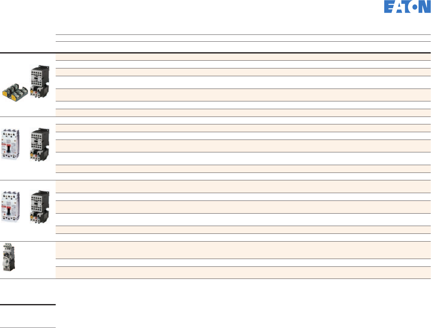
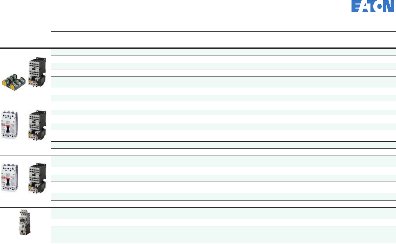
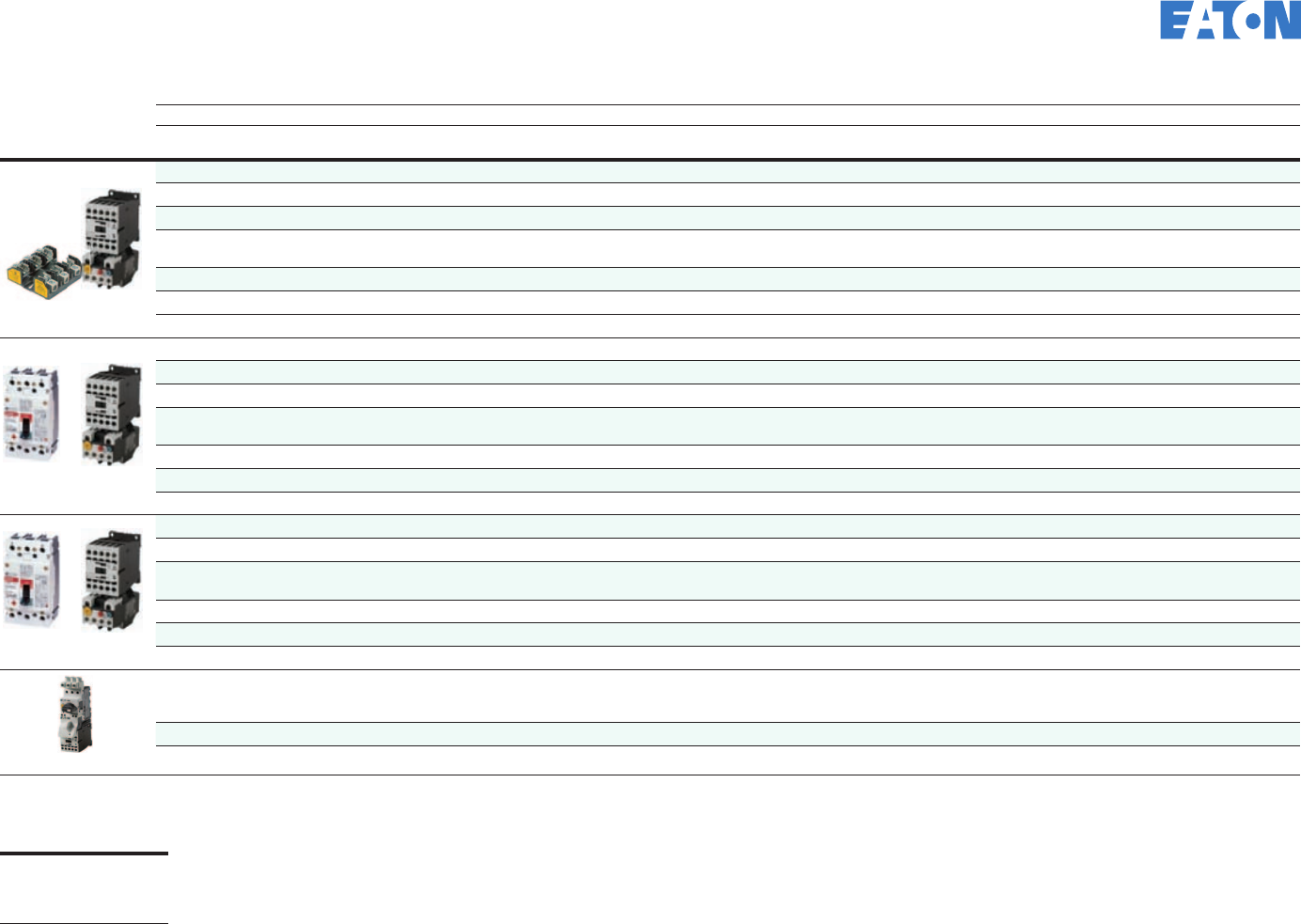
XT Manual Motor Controller (XTSC)
EATON CORPORATION Control panel design guide
6Ready to buy? Go to www.eaton.com/controlpanel • Got a question? Call 877-ETN-CARE

Refer to Page 5 for breaker part numbers and to Page 19 for fuse base part numbers.
Manual Motor Controllers Short-Circuit Ratings for UL/CSAT Group Installations
XTSC and XTSR Manual Motor Controllers (MMC) / Starter Combinations
Assembled Controller
FLA Adjustment
Range/Overload
Release—Ir
(Amps)
Group Installation, UL/CSA
Maximum rms Symmetrical Short-Circuit Ratings (kA) Maximum Upstream Protective Device (Amps)
Non-Reversing Reversing 240V 480V 600V Maximum Fuse
600V
Maximum
Circuit Breaker
600V
XTSC and XTSR Frame B MMP + Frame B Contactor
XTSCP16BBA XTSRP16BBA 0.1–0.16 50 50 50 600 600
XTSCP25BBA XTSRP16BBA 0.16–0.25 50 50 50 600 600
XTSCP40BBA XTSRP40BBA 0.25–0.4 50 50 50 600 600
XTSCP63BBA XTSRP63BBA 0.4–0.63 50 50 50 600 600
XTSC001BBA XTSR001BBA 0.63–1 50 50 50 600 600
XTSC1P6BBA XTSR1P6BBA 1–1.6 50 50 50 600 600
XTSCAP5BBA XTSR2P5BBA 1.6–2.5 50 50 50 600 600
XTSC004BBA XTSR004BBA 2.5–4 50 50 50 600 600
XTSC6P3BBA XTSR6P3BBA 4–6.3 50 50 50 600 600
XTSC010BBA XTSR010BBA 6.3–10 22 22 22 150 125
XTSC012BBA XTSR012BBA 8–12 10 10 10 150 125
XTSC016BBA — 10–16 10 10 10 150 125
XTSC and XTSR Frame B MMP + Frame C Contactor
XTSC016BCA XTSR016BCA 10–16 10 10 10 150 125
XTSC020BCA XTSR020BCA 16–20 10 10 10 150 125
XTSC025BCA XTSR025BCA 20-25 10 10 10 150 125
XTSC032BCA XTSR032BCA 25–32 5 5 5 150 125
XTSC and XTSR Frame D MMP + Frame C Contactor
XTSC016DCA XTSR016DCA 10–16 50 50 10 600 600
XTSC025DCA XTSR025DCA 16–25 50 50 10 600 600
XTSC032DCA XTSR032DCA 25–32 50 50 10 600 600
XTSC and XTSR Frame D MMP + Frame D Contactor
XTSC040DDA XTSR040DDA 32-40 50 50 10 600 600
XTSC050DDA XTSR050DDA 40–50 50 50 10 600 600
XTSC058DDA XTSR058DDA 50–58 50 50 — — —
XTSC063DDA XTSR063DDA 55–63 50 50 — — —
ote:N Products are shown with a 120 Vac coil. For other coil voltages, replace the "A" suffix with the corresponding letter from the following table.
Coil Voltage Suffix
120 Vac
24 Vdc
24 Vac
240 Vac
A
TD
T
B
EATON CORPORATION Control panel design guide
7Ready to buy? Go to www.eaton.com/controlpanel • Got a question? Call 877-ETN-CARE
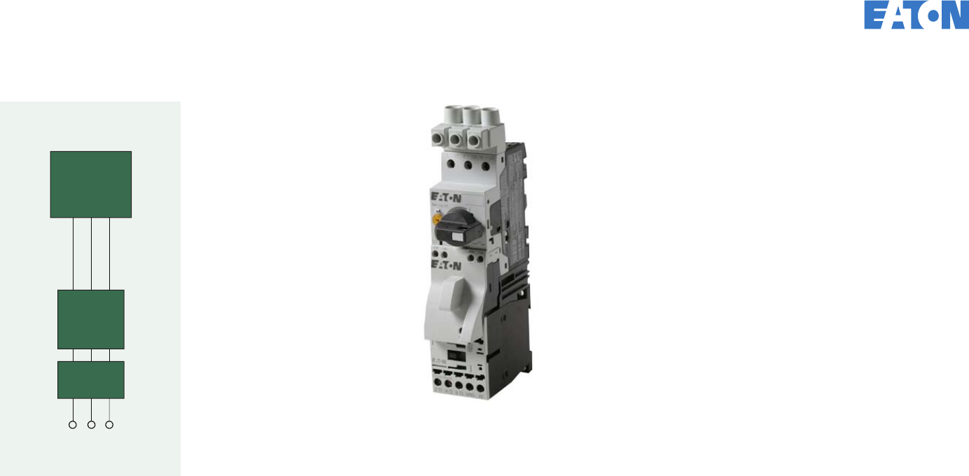
Individual circuit for motor load Reference Sections 31.3, 33.2, 34.2, 66.8
Controller
Overload
Protection
Branch
Protection
Individual Circuit for Motor Load
There are several ways to
build a branch circuit for a
motor load. Each method
provides short-circuit protection,
motor overload protection, and
the ability to start and stop the
motor. Some additionally
provide a means to disconnect
the branch circuit for mainte-
nance and safety purposes.
UL 508 Type F Combination
Motor Controllers (CMCs)
(manual motor protector +
contactor + line-side adapter)
provide the most efficient means
to build a branch circuit for a
motor. CMCs are designed for
motor loads such that they do not
need to be oversized (as breakers
and fuses are) to prevent tripping
during motor startup. CMCs not
only take up less space, but also
install more quickly.
For selection of motor branch
circuits for 240V, refer to
Pages 10 and 11.
For selection of motor branch
circuits for 480V, refer to
Pages 12 and 13.
EATON CORPORATION Control panel design guide
8Ready to buy? Go to www.eaton.com/controlpanel • Got a question? Call 877-ETN-CARE
Motor Branch Circuit Types
Motor Branch Devices Fuse and Starter Breaker and Starter Motor Circuit
Protector and Starter Combination Motor
Controller (Type F)
Fuses
Short-circuit protection
Contactor
Motor controller
Overload
relay
Motor overload
protection
Breaker
Motor
disconnect
Short-circuit
protection
Contactor
Motor controller
Overload
relay
Motor overload
protection
MCP
Motor
disconnect
Short-circuit
protection
Contactor
Motor controller
Overload
relay
Motor overload
protection
CMC
Motor disconnect
Short-circuit and
motor overload
protection
Motor controller
Branch circuit functions
Disconnect function Disconnect (separate) Breaker Motor circuit protector Manual motor protector
Short-circuit protection Fuse block/fuses Breaker Motor circuit protector Manual motor protector
Motor controller Contactor Contactor Contactor Contactor
Motor overload protection Overload relay Overload relay Overload relay Manual motor protector
Installation
Installation effort High Moderate Moderate Low
Line-side commoning links Not available Not available Not available Yes
Usability
Controller options Remote Remote Remote Manual or remote
Resetability after short circuit Replacement fuses necessary Reset breaker switch Reset MCP switch Reset CMC switch
Protection
Sizing protective devices Fuses are sized up to 300% of the FLA to
prevent nuisance tripping during startup.
Because the fuses are oversized for the motor
FLA, an overload relay is also needed.
Breakers are sized up to 250% of the FLA
to prevent nuisance tripping during startup.
Because the breaker is oversized for the motor
FLA, an overload relay is also needed.
MCPs are sized up to 800 to 1100% of the FLA
to prevent nuisance tripping during startup.
Because the MCP provides no thermal
protection, an overload relay is needed.
CMCs are sized according to the motor FLA to
provide overload protection. The CMC includes
short circuit that is designed to mimic the
motor inrush (14 times FLA).
Safety
Padlockable provision No, unless provided in a separate disconnect Yes, with breaker accessory Yes, with MCP accessory Included in MMP
Cost
Component price Low Moderate Moderate Low
Panel space (and cost) Moderate Moderate Moderate Low
Components used to build a reversing contactor
For reversing applications, the contactors should have mechanical
and electrical interlocks. For Frame B, use contactors with a
built-in NC auxiliary (ending in “B01A” instead of “B10A”).
Quantity Frame B C D F G
2 Contactor XTCE...B01 XTCE...C01 XTCE...D00 XTCE...F00 XTCE...G00
2 Auxiliary contact (front) XTCEXFAC20 XTCEXFAC20 XTCEXFBG11 XTCEXFBG11 XTCEXFBG11
1 Mechanical interlock XTCEXMLB XTCEXMLC XTCEXMLD XTCEXMLG XTCEXMLG
1 Reversing link kit XTCEXRLB XTCERLC XTCEXRLD XTCEXRLG XTCEXRLG
EATON CORPORATION Control panel design guide
9Ready to buy? Go to www.eaton.com/controlpanel • Got a question? Call 877-ETN-CARE
Branch Motor Selection for 230 Vac
HP (230V) 1/2 3/4 1 1-1/2 2 3 5 7-1/2
FLA 2.2 3.2 4.2 6 6.8 9.6 15.2 22
Minimum Wire
Size (AWG) 14 14 14 14 14 14 12 10
Fuse amperage 3 6 10 15 15 15 30 40
Fuse type CC CC CC CC CC CC J J
Contactor XTCE007B10A XTCE007B10A XTCE007B10A XTCE007B10A XTCE007B10A XTCE009B10A XTCE015B10A XTCE025C10A
Auxiliary contact 1NO aux built-in 1NO aux built-in 1NO aux built-in 1NO aux built-in 1NO aux built-in 1NO aux built-in 1NO aux built-in 1NO aux built-in
Thermal overload
relay
XTOB2P4BC1 XTOB004BC1 XTOB006BC1 XTOB010BC1 XTOB010BC1 XTOB010BC1 XTOB016BC1 XTOB024CC1
Overload range (A) 1.6 to 2.4 2.4 to 4.0 4 to 6 6 to 10 6 to 10 6 to 10 12 to 16 16 to 24
Fuse Starter SCCR (kA) 100 100 100 100 100 100 100 100
Breaker EGH015FFG EGH015FFG EGH015FFG EGH015FFG EGH015FFG EGH020FFG EGH030FFG EGH040FFG
Breaker size (A) 15 15 15 15 15 20 30 40
Contactor XTCE007B10A XTCE007B10A XTCE007B10A XTCE007B10A XTCE007B10A XTCE009B10A XTCE015B10A XTCE025C10A
Auxiliary contact 1NO aux built-in 1NO aux built-in 1NO aux built-in 1NO aux built-in 1NO aux built-in 1NO aux built-in 1NO aux built-in 1NO aux built-in
Thermal overload
relay
XTOB2P4BC1 XTOB004BC1 XTOB006BC1 XTOB010BC1 XTOB010BC1 XTOB010BC1 XTOB016BC1 XTOB024CC1
Overload range (A) 1.6 to 2.4 2.4 to 4.0 4 to 6 6 to 10 6 to 10 6 to 10 12 to 16 16 to 24
Breaker Starter SCCR (kA) — — — — — — — 50 kA A
Motor circuit
protector
HMCP003A0C HMCP007C0C HMCP007C0C HMCPE015E0C HMCPE015E0C HMCPE015E0C HMCPE030H1C HMCPE030H1C
Contactor XTCE007B10A XTCE007B10A XTCE007B10A XTCE007B10A XTCE007B10A XTCE009B10A XTCE015B10A XTCE025C10A
Auxiliary contact 1NO aux built-in 1NO aux built-in 1NO aux built-in 1NO aux built-in 1NO aux built-in 1NO aux built-in 1NO aux built-in 1NO aux built-in
Thermal overload
relay
XTOB2P4BC1 XTOB004BC1 XTOB006BC1 XTOB010BC1 XTOB010BC1 XTOB010BC1 XTOB016BC1 XTOB024CC1
Overload range 1.6 to 2.4 2.4 to 4.0 4 to 6 6 to 10 6 to 10 6 to 10 12 to 16 16 to 24
MCP-Starter SCCR (kA) 35 35 15 65 65 65 65 65
CMC
Combination motor
controller
XTFC2P5BBA XTFC004BBA XTFC6P3BBA XTFC6P3BBA XTFC010BBA XTFC010BBA XTFC016BBA XTFC025BCA
Overload range (A) 1.6 to 2.5 2.5 to 4.0 4 to 6.3 4 to 6.3 6.3 to 10 6.3 to 10 10 to 16 20 to 25
SCCR (kA) 65 65 65 65 65 65 50 18
A UL Pending.
EATON CORPORATION Control panel design guide
10 Ready to buy? Go to www.eaton.com/controlpanel • Got a question? Call 877-ETN-CARE
Branch Motor Selection for 230 Vac, continued
HP (230V) 10 15 20 25 30 40 50 60
FLA 28 42 54 68 80 104 130 154
Minimum Wire
Size (AWG) 8 6 4 4 3 1 2/0 3/0
Fuse amperage 50 80 100 125 150 200 225 300
Fuse type J J J J J J J J
Contactor XTCE032C10A XTCE050D00A XTCE065D00A XTCE065D00A XTCE080F00A XTCE150G00A XTCE150G00A XTCE150G00A
Auxiliary contact 1NO aux built-in 1NO/1NC side aux
XTCEXSBN11
1NO/1NC side aux
XTCEXSBN11
1NO/1NC side aux
XTCEXSBN11
1NO/1NC side aux
XTCEXSBN11
1NO/1NC side aux
XTCEXSBN11
1NO/1NC side aux
XTCEXSBN11
1NO/1NC side aux
XTCEXSBN11
Thermal overload
relay
XTOB032CC1 XTOB057DC1 XTOB065DC1 XTOB075DC1 XTOB100GC1 XTOB125GC1 XTOB150GC1 XTOB175GC1
Overload range (A) 24 to 32 40 to 57 50 to 65 65 to 75 70 to 100 95 to 125 120 to 150 145 to 175
Fuse Starter SCCR (kA) 100 100 100 — 100 100 100 100
Breaker EGH050FFG EGH080FFG EGH100FFG EGH125FFG JGE150FAG JGE200FAG JGE250FAG LGE3300FAG
Breaker size (A) 50 80 100 125 150 200 250 —
Contactor XTCE025C10A XTCE040D00A XTCE050D00A XTCE065D00A XTCE080F00A XTCE095F00A XTCE115G00A XTCE150G00A
Auxiliary contact 1NO aux built-in 1NO/1NC side aux
XTCEXSBN11
1NO/1NC side aux
XTCEXSBN11
1NO/1NC side aux
XTCEXSBN11
1NO/1NC side aux
XTCEXSBN11
1NO/1NC side aux
XTCEXSBN11
1NO/1NC side aux
XTCEXSBN11
1NO/1NC side aux
XTCEXSBN11
Thermal overload
relay
XTOB032CC1 XTOB057DC1 XTOB065DC1 XTOB075DC1 XTOB100GC1 XTOB125GC1 XTOB150GC1 XTOB175GC1
Overload range (A) 24 to 32 40 to 57 50 to 65 65 to 75 70 to 100 95 to 125 120 to 150 145 to 175
Breaker Starter SCCR (kA) 50 kA A50 kA A50 kA A50 kA A65 kA A65 kA A65 kA A42 kA A
Motor circuit
protector
HMCPE050K2C HMCPE100R3C HMCPE100T3C — — — — —
Contactor XTCE032C10A XTCE040D00A XTCE050D00A
Auxiliary contact 1NO aux built-in 1NO/1NC side aux
XTCEXSBN11
1NO/1NC side aux
XTCEXSBN11
1NO/1NC side aux
XTCEXSBN11
1NO/1NC side aux
XTCEXSBN11
1NO/1NC side aux
XTCEXSBN11
1NO/1NC side aux
XTCEXSBN11
1NO/1NC side aux
XTCEXSBN11
Thermal overload
relay
XTOB032CC1 XTOB057DC1 XTOB057DC1 — — — — —
Overload range (A) 24 to 32 40 to 57 40 to 57 — — — — —
MCP-Starter SCCR (kA) 65 65 65 — — — — —
CMC / MPCB + Contactor
Combination motor
controller or
MPCB + contactor
XTFC032BCA XTFC050DDA XTFC058DDA FDMP 3080L +
XTCE080F00A
FDMP 3100L +
XTCE080F00A
FDMP 3160L +
XTCE085F00A
FDMP 3160L +
XTCE115G00A
FDMP 3160L +
XTCE150G00A
Overload range (A) 25 to 32 40 to 50 50 to 58 40 to 80 80 to 100 100 to 160 100 to 160 100 to 160
SCCR (kA) 18 65 65 65 65 65 65 65
AUL Pending.
ote:N Contactors are shown with a 120 Vac coil. For other coil voltages, replace the "A" suffix with the corresponding letter from the following table.
Coil Voltage Suffix
120 Vac
24 Vdc
24 Vac
240 Vac
A
TD
T
B
EATON CORPORATION Control panel design guide
11 Ready to buy? Go to www.eaton.com/controlpanel • Got a question? Call 877-ETN-CARE
Branch Motor Selection for 460 Vac
HP (480V) 1/2 3/4 1 1-1/2 2 3 5 7-1/2
FLA 1.1 1.6 2.1 3.0 3.4 4.8 7.6 11
Minimum Wire
Size (AWG) 14 14 14 14 14 14 14 14
Fuse amperage 3 3 3 6 6 10 15 30
Fuse type CC CC CC CC CC CC CC CC
Contactor XTCE007B10A XTCE007B10A XTCE007B10A XTCE007B10A XTCE007B10A XTCE007B10A XTCE009B10A XTCE012B10A
Auxiliary contact 1NO aux built-in 1NO aux built-in 1NO aux built-in 1NO aux built-in 1NO aux built-in 1NO aux built-in 1NO aux built-in 1NO aux built-in
Thermal overload
relay
XTOB1P6BC1 XTOB2P4BC1 XTOB2P4BC1 XTOB004BC1 XTOB004BC1 XTOB006BC1 XTOB010BC1 XTOB012BC1
Overload range (A) 1.0 to 1.6 1.6 to 2.4 1.6 to 2.4 2.4 to 4 2.4 to 4 4 to 6 6 to 10 9 to 12
Fuse Starter High fault rating (kA) 100 100 100 100 100 100 100 100
Breaker EGE3015FFG EGE3015FFG EGE3015FFG EGE3015FFG EGE3015FFG EGE3015FFG EGE3015FFG EGE3025FFG
Breaker size (A) 15A EG frame 15A EG frame 15A EG frame 15A EG frame 15A EG frame 15A EG frame 15A EG frame 25A EG frame
Contactor XTCE007B10A XTCE007B10A XTCE007B10A XTCE007B10A XTCE007B10A XTCE007B10A XTCE009B10A XTCE012B10A
Auxiliary contact 1NO aux built-in 1NO aux built-in 1NO aux built-in 1NO aux built-in 1NO aux built-in 1NO aux built-in 1NO aux built-in 1NO aux built-in
Thermal overload
relay
XTOB1P6BC1 XTOB2P4BC1 XTOB2P4BC1 XTOB004BC1 XTOB004BC1 XTOB006BC1 XTOB010BC1 XTOB012BC1
Overload range (A) 1.0 to 1.6 1.6 to 2.4 1.6 to 2.4 2.4 to 4 2.4 to 4 4 to 6 6 to 10 9 to 12
Breaker Starter High fault rating — — — — — — — —
Motor circuit
protector
HMCP003A0C HMCP003A0C HMCP003A0C HMCP003A0C HMCP003A0C HMCPE015E0C HMCPE015E0C HMCPE015E0C
Contactor XTCE007B10A XTCE007B10A XTCE007B10A XTCE007B10A XTCE007B10A XTCE007B10A XTCE009B10A XTCE012B10A
Auxiliary contact 1NO aux built-in 1NO aux built-in 1NO aux built-in 1NO aux built-in 1NO aux built-in 1NO aux built-in 1NO aux built-in 1NO aux built-in
Thermal overload
relay
XTOB1P6BC1 XTOB2P4BC1 XTOB2P4BC1 XTOB004BC1 XTOB004BC1 XTOB006BC1 XTOB010BC1 XTOB012BC1
Overload range (A) 1.0 to 1.6 1.6 to 2.4 1.6 to 2.4 2.4 to 4 2.4 to 4 4 to 6 6 to 10 9 to 12
MCP-Starter High fault rating (kA) 35 35 35 35 35 65 65 65
CMC
Combination motor
controller
XTFC1P6BBA XTFC2P5BBA XTFC2P5BBA XTFC004BBA XTFC004BBA XTFC6P3BBA XTFC010BBA XTFC012BBA
Overload range (A) 1.0 to 1.6 1.6 to 2.5 1.6 to 2.5 2.5 to 4.0 2.5 to 4.0 4 to 6.3 6 to 10 8 to 12
SCCR (kA) (480/277V) 65 65 65 65 65 65 65 65
EATON CORPORATION Control panel design guide
12 Ready to buy? Go to www.eaton.com/controlpanel • Got a question? Call 877-ETN-CARE
Branch Motor Selection for 460 Vac, continued
HP (480V) 10 15 20 25 30 40 50 60
FLA 14 21 27 34 40 52 65 77
Minimum Wire Size
(AWG) 12 10 8 8 8 6 4 3
Fuse amperage 25 35 50 60 70 90 125 150
Fuse type J J J J J J J J
Contactor XTCE015B10A XTCE025C10A XTCE032C10A XTCE040D00A XTCE040D00A XTCE050D00A XTCE065D00A XTE080F00A
Auxiliary contact 1NO aux built-in 1NO aux built-in 1NO aux built-in 1NO-1NC side aux
XTCEXSBN11
1NO-1NC side aux
XTCEXSBN11
1NO-1NC side aux
XTCEXSBN11
1NO-1NC side aux
XTCEXSBN11
1NO-1NC side aux
XTCEXSBN11
Thermal overload relay XTOB016BC1 XTOB024CC1 XTOB032CC1 XTOB040DC1 XTOB057DC1 XTOB057DC1 XTOB065DC1 XTOB100GC1
Overload range (A) 12 to 16 16 to 24 24 to 32 24 to 40 40 to 57 40 to 57 50 to 65 70 to 100
Fuse Starter High fault rating (kA) 100 100 100 100 100 100 100 100
Breaker EGH3035FFG EGH3040FFG EGH3050FFG EGH3070FFG EGH3080FFG EGH3100FFG EGH3125FFG JGH3150FAG
Breaker size (A) 35A EG frame 40A EG frame 50A EG frame 70A EG frame 80A EG frame 100A EG frame 125A EG frame 150A JG frame
Contactor XTCE015B10A XTCE025C10A XTCE032C10A XTCE040D00A XTCE040D00A XTCE050D00A XTCE065D00A XTE080F00A
Auxiliary contact 1NO aux built-in 1NO aux built-in 1NO aux built-in 1NO-1NC side aux
XTCEXSBN11
1NO-1NC side aux
XTCEXSBN11
1NO-1NC side aux
XTCEXSBN11
1NO-1NC side aux
XTCEXSBN11
1NO-1NC side aux
XTCEXSBN11
Thermal overload relay XTOB016BC1 XTOB024CC1 XTOB032CC1 XTOB040DC1 XTOB057DC1 XTOB057DC1 XTOB075DC1 XTOB100GC1
Overload range (A) 12 to 16 16 to 24 24 to 32 24 to 40 40 to 57 40 to 57 65 to 75 70 to 100
Breaker Starter High fault rating — 65 kA A65 kA A65 kA A65 kA A65 kA A65 kA A65 kA A
Motor circuit protector HMCPE030H1C HMCPE030H1C HMCPE050K2C HMCPE050K2C HMCPE100R3C HMCPE100R3C HMCPE100R3C HMCPE100T3C
Contactor XTCE015B10A XTCE025C10A XTCE032C10A XTCE040D00A XTCE040D00A XTCE050D00A XTCE065D00A XTE080F00A
Auxiliary contact 1NO aux built-in 1NO aux built-in 1NO aux built-in 1NO-1NC side aux
XTCEXSBN11
1NO-1NC side aux
XTCEXSBN11
1NO-1NC side aux
XTCEXSBN11
1NO-1NC side aux
XTCEXSBN11
1NO-1NC side aux
XTCEXSBN11
Thermal overload relay XTOB016BC1 XTOB024CC1 XTOB032CC1 XTOB040DC1 XTOB057DC1 XTOB057DC1 XTOB065DC1 XTOB100GC1
Overload range (A) 12 to 16 16 to 24 24 to 32 24 to 40 40 to 57 40 to 57 50 to 65 70 to 100
MCP-Starter High fault rating (kA) 65 65 65 65 65 65 65 65
CMC
Combination motor
controller or
MPCB + contactor
XTFC016BBA XTFC025BCA XTFC032BCA XTFC040DDA XTFC050DDA XTFC058DDA XTFC063DDA FDMP 3080L +
XTCE080F00A
Overload range (A) 10 to 16 20 to 25 25 to 32 32 to 40 40 to 50 50 to 58 55 to 65 40 to 80
SCCR (kA) (480/277V) 50 18 18 65 65 65 65 65
AUL Pending.
ote:N Contactors are shown with a 120 Vac coil. For other coil voltages, replace the "A" suffix with the corresponding letter from the following table.
Coil Voltage Suffix
120 Vac
24 Vdc
24 Vac
240 Vac
A
TD
T
B
EATON CORPORATION Control panel design guide
13 Ready to buy? Go to www.eaton.com/controlpanel • Got a question? Call 877-ETN-CARE
Reference Sections 31.6, 31.8, 66.7.6
Controller
Branch
Protection
Heater and lighting load circuits
Heater or Lighting Load
Heater loads:
The branch circuit protection is
sized (see Section 31.6.1 excep-
tions for larger heater loads):
1. Not less than 125% of the
heater load,
2. Not more than 60A, and
3. Not larger than the
ampacity of the field
wiring to the heater load.
Controllers are sized to the
heater full-load rating using the
controller’s general-purpose amp
rating or resistive load rating.
Lighting loads:
The branch circuit protection for
standard-duty incandescent
lampholders or fluorescent
ballasts (see Section 31.8.2 for
larger lighting loads):
1. Shall not exceed
15A, and
2. Shall not exceed the
ampacity of the anticipated
field wiring
The controllers are sized to the
specific lighting ratings.
EATON CORPORATION Control panel design guide
14 Ready to buy? Go to www.eaton.com/controlpanel • Got a question? Call 877-ETN-CARE
Single-Pole Two-Pole Two-Pole Three-Pole
Heater application between… Miniature
Breaker Miniature
Breaker Molded Case Circuit Breaker Miniature
Breaker Molded Case Circuit Breaker
Breaker
Rating (A) Minimum Maximum 10 kA 277V
10 kA 120V 10 kA 480V
10 kA 240V 18 kA 480V
25 kA 240V 65 kA 480V
50 kA 240V 10 kA 480Y
10 kA 240V 18 kA 480V
25 kA 240V 35 kA 480V
43 kA 240V 65 kA 480V
50 kA 240V
0.5
1
1.5
-
0.4
0.8
0.4
0.8
1.2
WMZT1CX0
WMZT1C01
WMZT1CX1
WMZT2CX0
WMZT2C01
WMZT2CX1
EGB2015FFG
—
—
EGH2015FFG
—
—
WMZT3CX0
WMZT3C01
WMZT3CX1
EGB3015FFG
—
—
EGE3015FFG
—
—
EGH3015FFG
—
—
2
3
4
1.2
1.6
2.4
1.6
2.4
3.2
WMZT1C02
WMZT1C03
WMZT1C04
WMZT2C02
WMZT2C03
WMZT2C04
—
—
—
—
—
—
WMZT3C02
WMZT3C03
WMZT3C04
—
—
—
—
—
—
—
—
—
5
6
7
3.2
4.0
4.8
4
4.8
5.6
WMZT1C05
WMZT1C06
WMZT1C07
WMZT2C05
WMZT2C06
WMZT2C07
—
—
—
—
—
—
WMZT3C05
WMZT3C06
WMZT3C07
—
—
—
—
—
—
—
—
—
8
10
13
5.6
6.4
8.0
6.4
8
10.4
WMZT1C08
WMZT1C10
WMZT1C13
WMZT2C08
WMZT2C10
WMZT2C13
—
—
—
—
—
—
WMZT3C08
WMZT3C10
WMZT3C13
—
—
—
—
—
—
—
—
—
15
20
25
10.4
12.0
16.0
12
16
20
WMZT1C15
WMZT1C20
WMZT1C25
WMZT2C15
WMZT2C20
WMZT2C25
—
EGB2020FFG
EGB2025FFG
—
EGH2020FFG
EGH2025FFG
WMZT3C15
WMZT3C20
WMZT3C25
—
EGB3020FFG
EGB3025FFG
—
EGE3020FFG
EGE3025FFG
—
EGH3020FFG
EGH3025FFG
30
35
40
20.0
24.0
28.0
24
28
32
WMZT1C30
WMZT1C35
WMZT1C40
WMZT2C30
WMZT2C35
WMZT2C40
EGB2020FFG
EGB2035FFG
EGB2040FFG
EGH2020FFG
EGH2035FFG
EGH2040FFG
WMZT3C30
WMZT3C35
WMZT3C40
EGB3030FFG
EGB3035FFG
EGB3040FFG
EGE3030FFG
EGE3035FFG
EGE3040FFG
EGH3030FFG
EGH3035FFG
EGH3040FFG
45
50
60
32.0
36.0
40.0
36
40
48
—
—
—
—
—
—
EGB2045FFG
EGB2050FFG
EGB2060FFG
EGH2045FFG
EGH2050FFG
EGH2060FFG
—
—
—
EGB3045FFG
EGB3050FFG
EGB3060FFG
EGE3045FFG
EGE3050FFG
EGE3060FFG
EGH3045FFG
EGH3050FFG
EGH3060FFG
Contactors
Definite Purpose Contactor
Resistive Load (A) Two-Pole Three-Pole
20 C25DRF215A C25DRF315A
35 C25DRF225A C25DRF325A
40 C25DRF230A C25DRF330A
50 C25DRF240A C25DRF340A
65 C25DRJ250A C25DRJ350A
General Purpose
Amps
IEC Contactor
Three-Pole Four-Pole
20 XTCE015B10A XTCF020B00A
40 XTCE032C10A XTCF045C10A
63 XTCE040D00A XTCF063D00A
Electrically Held Lighting Contactor
Ballast or Mercury
Vapor Load
(at 600V) Tungsten Load
(at 480V) 2NO 3NO 4NO
10 10 CN35AN2AB CN35AN3AB CN35AN4AB
20 20 CN35BN2AB CN35BN3AB CN35BN4AB
EATON CORPORATION Control panel design guide
15 Ready to buy? Go to www.eaton.com/controlpanel • Got a question? Call 877-ETN-CARE

This section refers to the wiring in the feeder and branch circuits.
For information on wiring in the control circuit, see Page 26.
Internal wiring (Reference Section 29, 66.5):
• All internal wiring conductors shall be copper.
• All conductors in the power circuit should be labeled at the
termination point with letters or numbers corresponding with
the wiring diagram provided in the industrial control panel.
• Power circuit conductors should not be smaller than 14 AWG.
• For single loads, power circuit conductors for motors or heater
loads should be sized for an ampacity not less than 125% of the
full-load current.
• For multiple loads, such as multiple motors or a motor with other
loads, power circuit conductors shall be sized for an ampacity not
less than 125% of all heater loads plus 125% of the largest motor
load plus the full-load ampere ratings of all remaining motors and
other loads that are simultaneously operable.
• The wire size is selected from the table on Page 17 based on the
calculated wire ampacity. Conductors used in group motor applica-
tions should also comply with Table 66.2 (Reference Section 66.7.5).
Field wiring (Reference Section 28.3, 66.4):
• Not smaller than 14 AWG.
• For single loads, the field wiring conductors should be sized for an
ampacity of 125% of the full-load current.
• For multiple loads, such as multiple motors or a motor with other
loads, the field wiring is sized based on the sum of 125% of the
largest motor FLA, plus the sum of the other full-load currents of
the remaining loads.
• The wire size is selected from the table on Page 17 based on the
calculated wire ampacity.
Wire color designation (internal power circuit wiring)
Power circuit wiring
Exception: Insulated conductors sized 4 AWG (21.2 mm2) or larger and having insulation colored other than
as in Section 17.4 shall be identified at each termination point by a white marking, such as tape wrapped
around the conductor.
Black:
All ungrounded power circuit conductors regardless of voltage
White or gray or three continuous white stripes on other
than green, blue, orange or yellow:
Grounded AC current-carrying power circuit conductor regardless
of voltage
EATON CORPORATION Control panel design guide
16 Ready to buy? Go to www.eaton.com/controlpanel • Got a question? Call 877-ETN-CARE

To determine the wire size for
motor loads, add the full-load
current ratings found in Table
50.1 for all external loads being
carried by the conductor. Then
use Table 28.1 on the following
page to determine the wire size
for the calculated ampacity.
Full-Load Motor-running Currents in Amperes Corresponding to Various AC Horsepower Ratings—Reference Table 50.1
HP
110–120V 200V 208V 220–240V A 380–415V 440–480V 550–600V
Single-
Phase Single-
Phase Three-
Phase Single-
Phase Three-
Phase Single-
Phase Three-
Phase Single-
Phase Three-
Phase Single-
Phase Three-
Phase Single-
Phase Three-
Phase
1/10 3.0 — — — — 1.5 — 1.0 — — — — —
1/8 3.8 — — — — 1.9 — 1.2 — — — — —
1/6 4.4 2.5 — 2.4 — 2.2 — 1.4 — — — — —
1/4 5.8 3.3 — 3.2 — 2.9 — 1.8 — — — — —
1/3 7.2 4.1 — 4.0 — 3.6 — 2.3 — — — — —
1/2 9.8 5.6 2.5 5.4 2.4 4.9 2.2 3.2 1.3 2.5 1.1 2.0 0.9
3/4 13.8 7.9 3.7 7.6 3.5 6.9 3.2 4.5 1.8 3.5 1.6 2.8 1.3
1 16.0 9.2 4.8 8.8 4.6 8.0 4.2 5.1 2.3 4.0 2.1 3.2 1.7
1 1/2 20.0 11.5 6.9 11.0 6.6 10.0 6.0 6.4 3.3 5.0 3.0 4.0 2.4
2 24.0 13.8 7.8 13.2 7.5 12.0 6.8 7.7 4.3 6.0 3.4 4.8 2.7
3 34.0 19.6 11.0 18.7 10.6 17.0 9.6 10.9 6.1 8.5 4.8 6.8 3.9
5 56.0 32.2 17.5 30.8 16.7 28.0 15.2 17.9 9.7 14.0 7.6 11.2 6.1
7 1/2 80.0 46.0 25.3 44.0 24.2 40.0 22.0 27.0 14.0 21.0 11.0 16.0 9.0
10 100.0 57.5 32.2 55.0 30.8 50.0 28.0 33.0 18.0 26.0 14.0 20.0 11.0
15 135.0 — 48.3 — 46.2 68.0 42.0 44.0 27.0 34.0 21.0 27.0 17.0
20 — — 62.1 — 59.4 88.0 54.0 56.0 34.0 44.0 27.0 35.0 22.0
25 — — 78.2 — 74.8 110.0 68.0 70.0 44.0 55.0 34.0 44.0 27.0
30 — — 92.0 — 88.0 136.0 80.0 87.0 51.0 68.0 40.0 54.0 32.0
40 — — 120.0 — 114.0 176.0 104.0 112.0 66.0 88.0 52.0 70.0 41.0
50 — — 150.0 — 143.0 216.0 130.0 139.0 83.0 108.0 65.0 86.0 52.0
60 — — 177.0 — 169.0 — 154.0 — 103.0 — 77.0 — 62.0
75 — — 221.0 — 211.0 — 192.0 — 128.0 — 96.0 — 77.0
100 — — 285.0 — 273.0 — 248.0 — 165.0 — 124.0 — 99.0
125 — — 359.0 — 343.0 — 312.0 — 208.0 — 156.0 — 125.0
150 — — 414.0 — 396.0 — 360.0 — 240.0 — 180.0 — 144.0
200 — — 552.0 — 528.0 — 480.0 — 320.0 — 240.0 — 192.0
250 — — — — — — 604.0 — 403.0 — 302.0 — 242.0
300 — — — — — — 722.0 — 482.0 — 361.0 — 289.0
350 — — — — — — 828.0 — 560.0 — 414.0 — 336.0
400 — — — — — — 954.0 — 636.0 — 477.0 — 382.0
450 — — — — — — 1030.0 — — — 515.0 — 412.0
500 — — — — — — 1180.0 — 786.0 — 590.0 — 472.0
A To obtain full-load currents for 265 and 277 volt motors, decrease corresponding 220–240 volt ratings by 13 and 17 percent respectively.
EATON CORPORATION Control panel design guide
17 Ready to buy? Go to www.eaton.com/controlpanel • Got a question? Call 877-ETN-CARE

Relationship Between Conductor Size and Overcurrent Protection
Rating for Power Circuits—Reference Table 66.2
Conductor Size
Maximum Rating
of Non-Time Delay
Fuse or Inverse
Time Circuit
Breaker (Amps)
Time Delay or
Dual Element Fuse
(Amps)AWG mm2
14 2.1 60 30
12 3.3 80 40
10 5.3 100 50
8 8.4 150 80
6 13.3 200 100
4 21.2 250 125
3 26.7 300 150
2 33.6 350 175
1 42.4 400 200
1/0 53.6 500 250
2/0 67.4 600 300
3/0 85.0 700 350
4/0 107.2 800 400
Ampacities of Insulated Conductors—Reference Table 28.1
Wire Size
AWG mm2Copper
75°C (167°F)
14 2.1 15
12 3.3 20
10 5.3 30
8 8.4 50
6 13.3 65
4 21.2 85
3 26.7 100
2 33.6 115
1 42.4 130
1/0 53.5 150
2/0 67.4 175
3/0 85.0 200
4/0 107.2 230
250 kcmil 127 255
300 152 285
350 177 310
400 203 335
500 253 380
600 304 420
700 355 460
750 380 475
800 405 490
900 456 520
1000 506 545
1250 633 590
1500 760 625
1750 887 650
2000 1013 665
ote:N For multiple conductors of the same size (1/0 AWG or larger) at a
terminal, the ampacity is equal to the value in this table for that conductor mul-
tiplied by the number of conductors that the terminal is able to accommodate.
For group motor applications
where two or more motors are
protected by a single device,
wire sizes should comply
with the fuse/breaker size in
Table 66.2 at right.
EATON CORPORATION Control panel design guide
18 Ready to buy? Go to www.eaton.com/controlpanel • Got a question? Call 877-ETN-CARE
Contactor Auxiliary Contacts
Conventional Thermal
Current, Open at 60°C
lth=le, AC-1 in Amps Contact
Configuration Circuit Symbol Package
Quantity
Screw
Terminals
Catalog
Number
Frame B–C
Front (Top) Mount
For use with
XTCE... B
XTCE... C
16 4NO
54
63 73
64 74
53 83
8
4
5XTCEXFAC40
16 3NO-1NC
54
53 61
62
73
74
83
8
4
5XTCEXFAC31
16 2NO-2NC
54
53 61
62
71
72
83
8
4
5XTCEXFAC22
Frame C
Side Mount
For use with
XTCE... C
10 1NO-1NC
54
53 61
62
1 XTCEXSCC11
Frame D–G
For use with
XTCE... D
XTCE... F
XTCE... G
16 4NO-0NC
14
13 23
24
33
34
43
44
5XTCEXFBG40
16 3NO-1NC
14
13 21
22
33
34
43
44
5XTCEXFBG31
16 2NO-2NC
14
13 21
22
31
32
43
44
5XTCEXFBG22
Frame D–R
For use with
XTCE... D
XTCE... F
XTCE... G
10 1NO-1NC
13
44
14
43
21
32
31
22
1XTCEXSBN11
MMP Accessories
Description Catalog Number
Line-side adapter
For use with XTPR... BC1
XTPAXLSA
Tool-less connector kit
For use with
XTPR... BC1
XTCE... B
XTPAXTPCB
1NO-1NC
Front mount auxiliary
XTPAXFA11
Commoning link
For use with XTPR... BC1
XTPAXCLKA2
Commoning link
For use with XTPR... BC1
XTPAXCLKA3
Commoning link
For use with XTPR... BC1
XTPAXCLKA4
Commoning link
For use with XTPR... BC1
XTPAXCLKA5
Handle mechanism XTPAXRHMRY
EG Frame Multiwire Connectors Ordering Information
Maximum
Amps Wires per
Terminal Wire Size Range
AWG Cu Kit Catalog
Number
125 3 14–2 3TA125E3K
125 6 14–6 3TA125E6K
JG Frame Multiwire Connectors Ordering Information
Maximum
Amps Wires per
Terminal Wire Size Range
AWG Cu Kit Catalog
Number
250 3 14–2 3TA250FJ3
250 6 14–6 3TA250FJ6
Disconnect Fuse Holders Product Selection
Description Standard Pack Catalog Number
For Class CC Fuse
Single-pole fuse holder 12 C383FHCC
Accessories
EATON CORPORATION Control panel design guide
19 Ready to buy? Go to www.eaton.com/controlpanel • Got a question? Call 877-ETN-CARE

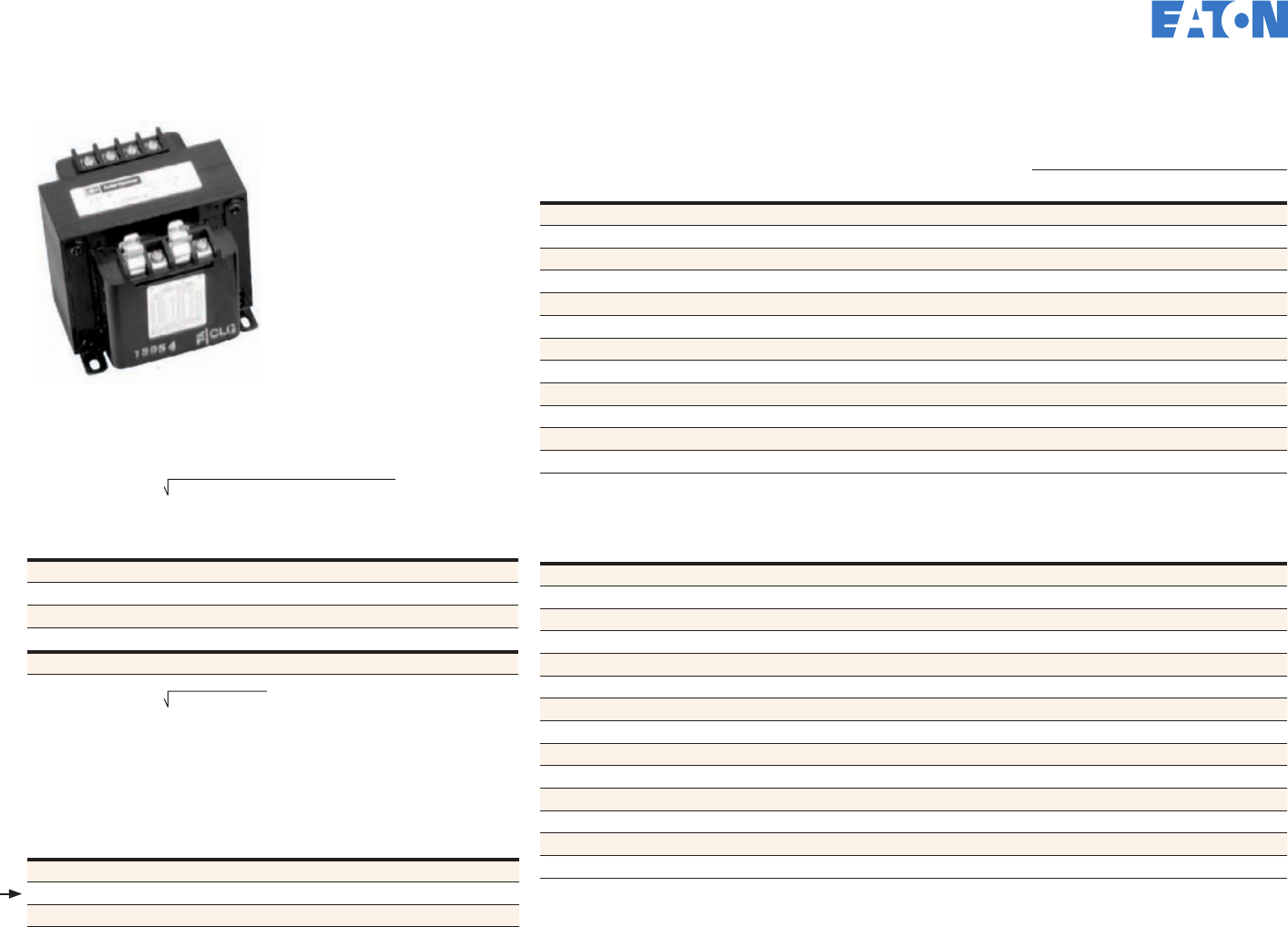
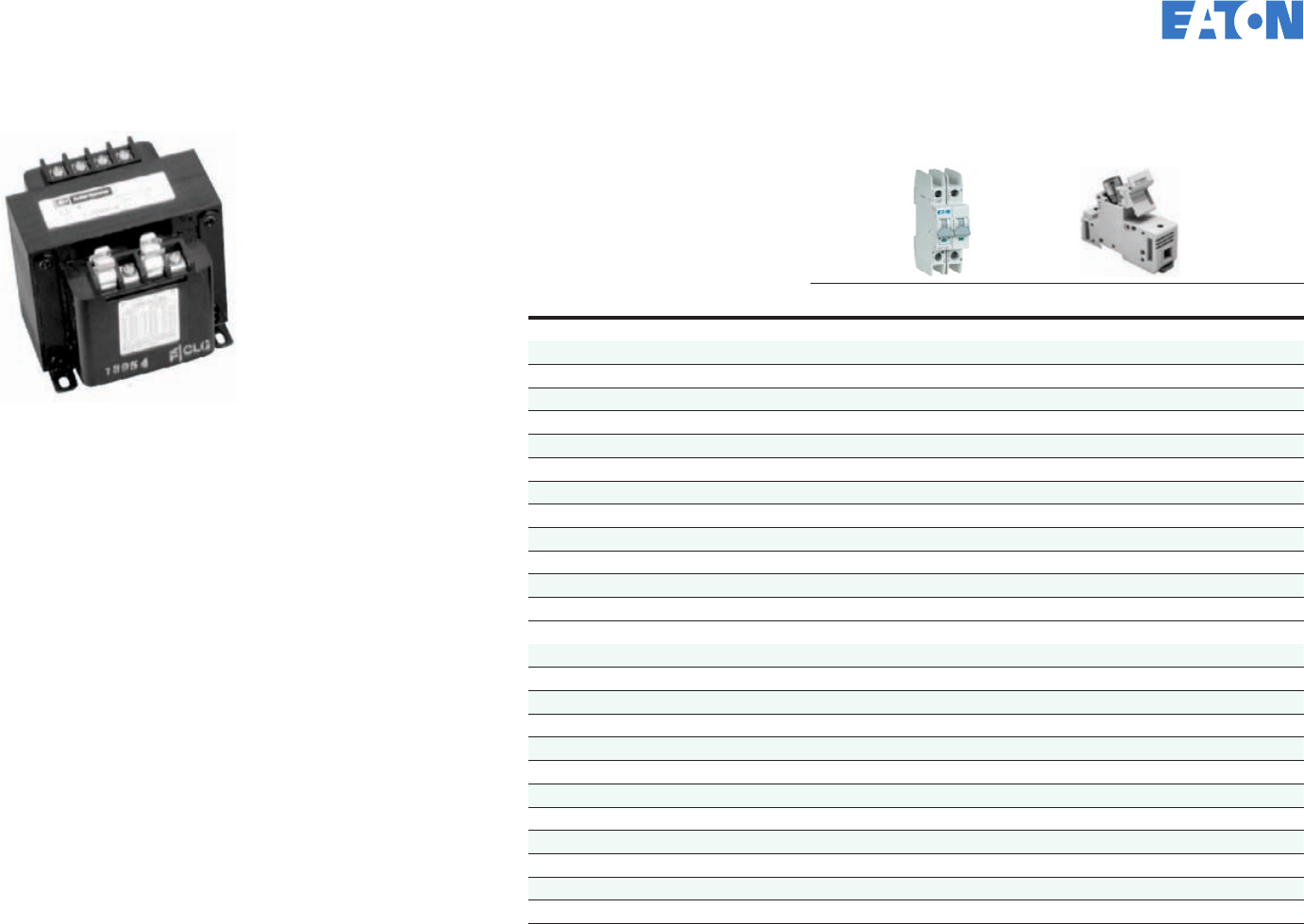
Designing the control circuit
Transformer
or Power
Supply
M
M
L
Branch
Protection
Control circuits provide the logic for the operation of the components
in the power circuit. Control circuits are typically a lower, safer voltage,
such as 120 Vac or 24 Vdc. Control power transformers (CPTs) and
power supplies are used to transform or convert the power circuit
voltage to the control circuit voltage.
Refer to Page 22 for selection of the CPT and protective devices.
Refer to Page 24 for selection of the power supply and protective
devices.
Refer to Page 26 for control circuit wiring.
Eaton also offers a variety of control devices commonly
used in control circuits.
Refer to Page 27 for pushbutton and pilot devices.
Refer to Page 28 for relays, timers, and terminal blocks.
Refer to Page 29 for programmable logic controllers and relays.
EATON CORPORATION Control panel design guide
20 Ready to buy? Go to www.eaton.com/controlpanel • Got a question? Call 877-ETN-CARE
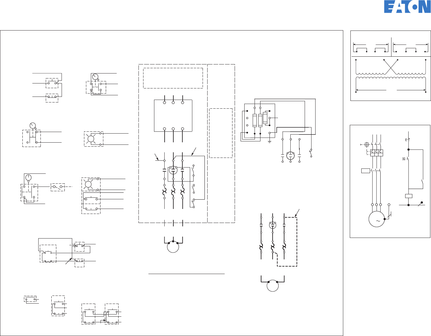
Figure 2
Fusible Control Transformer
Field Conversion to 1-Phase
Figure 1
Front View Diagram
Connections for StartersConnections for Control Stations
M
M
Add Dotted
Connection
OL
M
L3
L2
L1
OL
Motor
260878 D4
A1 A2 96
95
OL Reset
2/13
3/14
T1
24
T2 6
T3
6/
T1
2/
T2 T3
4/
95
Reset
96
97
98
1A1 A2
1 3 5
T1 T2 T3
“C”
T3
T1
4/
T2
L1
1
A1 A2
L2
3
T2
6/
L3
5
2/
T1
Motor
T1 T2
Separate Control
Remove Wire “C” if Supplied and
Connect Separate Control Lines to
the Number 1 Terminal on the Remote
Pilot Device and to the Number 96
Terminal on the Overload Relay
Omit Connector
Stop
Start
Remote
2 1
2/13
4 3
Local
1
3/14
Stop (OFF)
Start (ON)
Combined Remote and Local for Figures 1 and 2
Remote Control
Local Control
“A”
When More Than One
Pushbutton Station Is Used,
Omit Connector “A” and
Connect per Sketch Below
Stop
Start
Start
Stop
Start
3/14
2/13
1
2/13
1
3/14
2-Wire
Control
Not for
Use with
Auto Reset
OL Relays.
3-Wire
Control
1
3/14
Black / White
Black / White
Connect to Coil Terminals
”A1“ and ”A2“
X1
X2
1 2
Stop (OFF)
43
Start (ON)
3/14
2/13
1
Black
Red
Red 2 4
3
1
Hand
Auto
1
3/14
YellowYellow
Black
Red
Figure D
2-Position Selector Switch
Figure A
START/STOP Pushbuttons
Figure B
START/STOP Selector Switch
2
1
4
3Start (ON) 3/14
1
Black
Red
Figure E
Pilot Light (Motor RUN)
Connect to ”A1“
and ”A2“ Terminals
3
4
4
3
Figure C
3-Position Selector Switch
Hand 3/14
Yellow
Auto
1
Black
Remote
Switch
Red
To Coil
Terminal
”A1“
Figure F
START/STOP with Pilot Light
3
4
1
3/14
2/13
21
Stop (OFF)
Start (ON)
Black / White
Black / White
X1
X2
Local
Control
(Flange
Mounting
if Used)
See
Figures
A, B, C, D,
E and F
CPT
Fusible Control Transformer
(If Used)
See Figure 2
Omit This
Connector
if Figure 2
Is Used
Disconnecting
Means
D.S. or C.B.
L1 L2 L3
Fuse
Fuse
Fuse
3
Secondary
Connections
G
1
H3
1
X2
H2
4H4
XF 1
H1 X1
CPT
Primary
Connections
Connections for Dual
Voltage Rated Transformer –
See Transformer Nameplate
Remove Wire “C” (Figure 1) if Used
and Connect as Shown Below.
(All Other Starter Wires Remain
as Shown in Figure 1)
5
L2L1 L3
L1 L2 L3
135
1 3 5
2 4 6
2 4 6
UVW
M
-M1
3
PE N
-S11
21
22
13
14
-Q11
-Q11
-Q11
-Q1
14
13
A1
A2
O
240V
230V
220V
480V
460V
440V
110V
115V
120V
H1 H2H3 H4
H1 H3 H2 H4 H1 H3 H2 H4
H2 X2
240V x 480V Primary, 120V
Secondary CPT Wiring Diagram
Manual Motor Controller and
Combination Motor Controller
Wiring Diagram
Common control circuit wiring
EATON CORPORATION Control panel design guide
21 Ready to buy? Go to www.eaton.com/controlpanel • Got a question? Call 877-ETN-CARE
1. Use the following formula to determine the inrush power of
the control power transformer (CPT) needed to support the
components used in the application.
2. Select the CPT size based on the CPT inrush VA needed.
CPT Selection Chart
CPT Part
Number APrimary
Voltage (AC) Secondary
Voltage (AC) CPT VA
Inrush VA at 20% Power Factor
90% Secondary
Voltage 95% Secondary
Voltage
C0025E2A 240 x 480 120 25 130 100
C0050E2A 240 x 480 120 50 200 170
C0075E2A 240 x 480 120 75 410 310
C0100E2A 240 x 480 120 100 540 370
C0150E2A 240 x 480 120 150 930 780
C0200E2A 240 x 480 120 200 1150 810
C0250E2A 240 x 480 120 250 1900 1400
C0300E2A 240 x 480 120 300 2700 1900
C0350E2A 240 x 480 120 350 3650 3100
C0500E2A 240 x 480 120 500 5300 4000
C0750E2A 240 x 480 120 750 11000 8300
C1000E2A 240 x 480 120 1000 21000 15000
A Add "FB" to the end of the part number to include a double-pole primary fuse block for rejection type fuses. Not available for 25 VA.
Common Control Loads
Description Part Number Inrush VA Sealed VA
7 to 15A XT Contactor Coil XTCE…B… 25 3.3
18 to 32A XT Contactor Coil XTCE…C… 58 6.5
40 to 72A XT Contactor Coil XTCE…D… 154 14
80 to 95A XT Contactor Coil XTCE…F… 372 37.1
115 to 170A XT Contactor Coil XTCE…G… 170 3.1
Definite Purpose Contactor Coil C25DRF… 75 5.8
Definite Purpose Contactor Coil C25DRJ… 111 7.6
Lighting Contactor Coil C35A… 80 7.5
Lighting Contactor Coil C35B… 100 10
Mini XT Relay XTRM… 29 3.9
LED M22 Indicating Light M22-L... 0.4 0.4
Intelligent Relay EZ512... 5 5
Intelligent Relay EZ719... 10 10
EZ Expansion Module EZ618... 10 10
Example
Qty Description Inrush
VA Sealed
VA Total
Inrush Total
Sealed
1 XTCE007B10A coil 25 3.3 25 3.3
2 XTCE018C10A coil 58 6.5 116 13.0
2 Relays 29 3.3 58 6.6
6 Indicating lights 7.0 7.0 42 42.0
Total 241 65.0
Selection Using Data from Previous Example
Part Number Primary
Voltage Secondary
Voltage Transformer
VA
Inrush VA
(90% Sec.
Inrush Voltage)
C0050E2A 240 x 480 120 50 200
C0075E2A 240 x 480 120 75 410
C0100E2A 240 x 480 120 100 540
Sizing the control power transformer
CPT INRUSH VA = (INRUSH VA)2 + (SEALED VA)2
CPT INRUSH VA = (241)2 + (65)2
= 250 VA
C0075E2AFB has enough inrush VA capacity to handle the 250 VA inrush of the
components.
EATON CORPORATION Control panel design guide
22 Ready to buy? Go to www.eaton.com/controlpanel • Got a question? Call 877-ETN-CARE
Primary and Secondary Protection
C383FHCC
Single-Pole
Fuse Holder
(Type CC)
CPT Part Number ACPT VA Primary
Two-Pole Breaker Secondary
Two-Pole Breaker Primary
Fuse Size Secondary
Fuse Size
240V Primary: 120V Secondary
C0025E2A 25 WMZT2CX0 WMZT2CX0 1 1
C0050E2A 50 WMZT2C01 WMZT2C01 1 1
C0075E2A 75 WMZT2CX1 WMZT2C01 3 1
C0100E2A 100 WMZT2C02 WMZT2CX1 3 1
C0150E2A 150 WMZT2C03 WMZT2C02 3 3
C0200E2A 200 WMZT2C04 WMZT2C03 6 3
C0250E2A 250 WMZT2C05 WMZT2C04 6 3
C0300E2A 300 WMZT2C06 WMZT2C04 6 3
C0350E2A 350 WMZT2C07 WMZT2C05 10 3
C0500E2A 500 WMZT2C05 WMZT2C07 6 6
C0750E2A 750 WMZT2C08 WMZT2C10 10 6
C1000E2A 1000 WMZT2C10 WMZT2C15 10 10
480V Primary: 120V Secondary
C0025E2A 25 WMZT2CX0 WMZT2CX0 1 1
C0050E2A 50 WMZT2CX0 WMZT2C01 1 1
C0075E2A 75 WMZT2C01 WMZT2C01 1 1
C0100E2A 100 WMZT2C01 WMZT2CX1 1 1
C0150E2A 150 WMZT2CX1 WMZT2C02 1 3
C0200E2A 200 WMZT2C02 WMZT2C03 1 3
C0250E2A 250 WMZT2C03 WMZT2C04 1 3
C0300E2A 300 WMZT2C03 WMZT2C04 1 3
C0350E2A 350 WMZT2C04 WMZT2C05 1 3
C0500E2A 500 WMZT2C05 WMZT2C07 1 6
C0750E2A 750 WMZT2C08 WMZT2C10 3 6
C1000E2A 1000 WMZT2C05 WMZT2C15 3 10
A Add “FB” to the end of the CPT part number to include a two-pole primary fuse block for rejection type fuses.
Sizing protection for CPTs
Reference Accessories Section
on Page 19 for Fuse Holders.
Reference Section 42.1
EATON CORPORATION Control panel design guide
23 Ready to buy? Go to www.eaton.com/controlpanel • Got a question? Call 877-ETN-CARE
Common Control Loads
Description Part Number Inrush W Sealed W
7 to 9A XT Contactor Coil XTCE…B… 3 3
12 to 15A XT Contactor Coil XTCE…B… 4.5 4.5
18 to 32A XT Contactor Coil XTCE…C… 12 0.5
40 to 72A XT Contactor Coil XTCE…D… 24 0.5
80 to 95A XT Contactor Coil XTCE…F… 90 1.3
115 to 170A XT Contactor Coil XTCE…G… 149 2.1
Definite Purpose Contactor Coil C25D… 69 3.1
Lighting Contactor (10 and 20A) Coil C35… 77 3.4
Mini XT Relay XTRM… 2.6 2.6
LED M22 Indicating Light M22-L... 0.4 0.4
Intelligent Relay EZ512... 2 2
Intelligent Relay EZ719... 3.5 3.5
EZ Display EZD-80... 3 3
EZ Expansion Modules EZ618... 4 4
ELC Programmable Logic Controller ELC-PV... 5.3 5.3
ELC Expansion Modules ELC-EX..., -AN..., -TC... 2.2 2.2
Example: Select a 24 Vdc Power Supply with the Following Loads and a 240 Vac Input
Qty Description Inrush W Sealed W Surge
Current Nominal
Current Total Surge
Current Total Nominal
Current
8 XTCE007B10TD Coil 3 3 0.13 0.13 1.00 1.00
4 XTCE018C10TD Coil 12 0.5 0.50 0.02 2.00 0.08
2 Relay 2.6 2.6 0.11 0.11 0.22 0.22
5 Indicating light 1.2 1.2 0.05 0.05 0.25 0.25
Total 3.47 1.55
Derating for Extended Operation: Total Nominal Current = 1.55 x 120% = 1.86
Selection using data from previous table.
Part Number Capacity W Input Voltage Output Voltage Nominal Current Surge Current Surge Capacity
PSG60E 60 100–240 Vac 1-P 24 Vdc 2.5A 3.75A 1 second at
10 second intervals
PSG120E 120 100–240 Vac 1-P 24 Vdc 5A 7.5A 1 second at
10 second intervals
PSG240E 240 100–240 Vac 1-P 24 Vdc 10A 15A 1 second at
10 second intervals
PSG60E has enough nominal and surge current capacity for these components.
Control power selection
Selection Chart
Input Output
Part
Number Capacity Voltage Voltage Nominal
Current Surge
Current Surge
Capacity
PSG60E 60W 100–240 Vac
single-phase
24 Vdc
single-
phase
2.5A 3.75A 1 second at
10 second
intervals
PSG120E 120W 5A 7.5A
PSG240E 240W 10A 15A
PSG480E 480W 20A 30A
PSG60F 60W 400–500 Vac
three-phase
24 Vdc
single-
phase
2.5A 3.75A
PSG120F 120W 5A 7.5A
PSG240F 240W 10A 15A
PSG480F 480W 20A 30A
ote:N Above 55 degrees C, the PSG should be derated.
See catalog CA08102001E for additional information and other specifications.
1. Determine the output capacity needed to support the components used in the application.
First, calculate the total load at steady state (nominal load after inrush). This is done by
summing the sealed-in or nominal loads.
Nominal Load = Sealed Load1 + Sealed Load2 + .... + Sealed Loadn
For extended operational life of the power supply, increase the calculated nominal load by 20%.
2. Next, calculate the total inrush or surge loads of the components supported by the power supply.
Inrush Load = Inrush Load1 + Inrush Load2 + .... + Inrush Loadn
3. Select the power supply based on the available input voltage, nominal load and inrush (surge)
load requirements.
4. Verify that the application of the components on the load does not exceed the surge capacity
and other specifications of the selected power supply.
EATON CORPORATION Control panel design guide
24 Ready to buy? Go to www.eaton.com/controlpanel • Got a question? Call 877-ETN-CARE
Sizing protection for power supplies Reference Section 42.2
Power Supplies
Part
Number Capacity Input
Voltage Primary
Fusing Class CC
Fuse Holder (Qty) Suggested Power Supply
Primary Wire Size
PSG60E 60W 100–240 Vac
single-phase
6A or 10A C383FHCC (2) 14 AWG
PSG120E 120W 6A or 10A C383FHCC (2) 14 AWG
PSG240E 240W 10A or 16A C383FHCC (2) 14 AWG
PSG480E 480W 10A or 16A C383FHCC (2) 14 AWG
PSG60F 60W 400–500 Vac
three-phase
6A or 10A C383FHCC (3) 14 AWG
PSG120F 120W 6A or 10A C383FHCC (3) 14 AWG
PSG240F 240W 6A or 10A C383FHCC (3) 14 AWG
PSG480F 480W 6A or 10A C383FHCC (3) 14 AWG
ote:N If the sum of the loads on the secondary of the power supply exceeds the output ratings of the power supply,
then secondary overload protection is required.
EATON CORPORATION Control panel design guide
25 Ready to buy? Go to www.eaton.com/controlpanel • Got a question? Call 877-ETN-CARE
Wire size for control circuits must be no smaller than 18 AWG,
with exception of control circuits for PLC input/outputs. Wire
size is determined from Table 38.1 based on the amp rating of the
overcurrent protective device for the control circuit or the amp rating
of the secondary of the CPT or power supply.
Wire selection for control circuits
Wire color designation (internal power circuit wiring)
Black:
All ungrounded control circuit conductors operating at the
supply voltage
Red:
Ungrounded AC control circuits operating at a voltage less than
the supply voltage
Blue: Ungrounded DC control circuits
Yellow or orange:
Ungrounded control circuits or other wiring, such as for cabinet
lighting, that remain energized when the main disconnect is in the
OFF position
White or gray or three white stripes on other than green,
blue, orange, or yellow:
Grounded AC current-carrying control circuit conductor regardless
of voltage
White with blue stripe:
Grounded DC current-carrying control circuit conductor
White with yellow stripe or white with orange stripe:
Grounded AC control circuit current-carrying conductor that remains
energized when main disconnect switch is in the OFF position
Ampacity of Control Circuit Conductors—Reference Table 38.1
Ampacity, Amperes
Conductor Size
AWG mm2
10 16 1.3
7 18 0.82
5 20 0.52
3 22 0.32
2 24 0.20
1 26 0.13
0.8 28 A 0.08
0.5 30 A 0.05
A Where these conductors are contained in a jacketed multi-conductor cable assembly.
These sizes of conductors are only for connection of control circuits for electronics programmable
input/output and static control (having no moving parts).
Reference Section 38, 66.9
EATON CORPORATION Control panel design guide
26 Ready to buy? Go to www.eaton.com/controlpanel • Got a question? Call 877-ETN-CARE
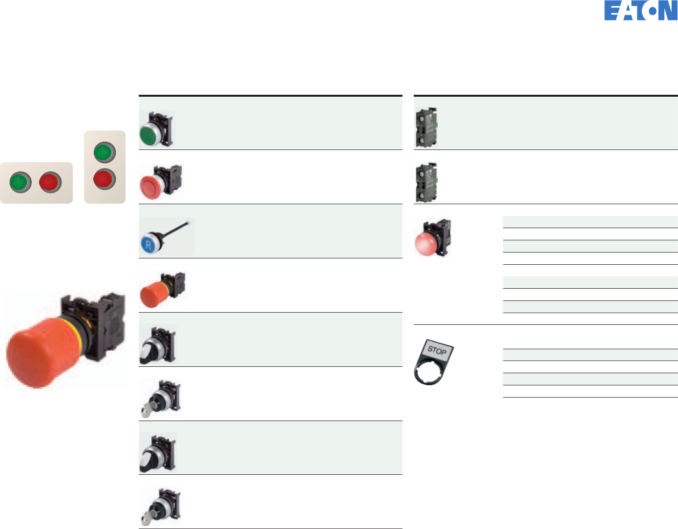
Choosing Operators and Lights
Type Catalog Number
Flush green momentary button M22-D-G
Extended red momentary button M22-DP-R
Blue RESET with push rod M22-DZ-B-GB14
Twist-to-release E-Stop with 1NO/2NC M22-PVT-K12
Two-position maintained selector switch M22-WKV
Two-position maintained keyed selector switch M22-WRS
Three-position maintained selector switch M22-WRK3
Three-position maintained keyed selector switch M22-WRS3
Type Description Catalog Number
NO contact block M22-K10
NC contact block M22-K01
LED indicating light 12–30 Vac/Vdc
Yellow M22-L-Y-W
Green M22-L-G-G
Red M22-L-R-R
Blue M22-L-B-B
85–264 Vac/Vdc
Yellow M22-L-Y-230W
Green M22-L-G-230G
Red M22-L-R-230R
Blue M22-L-B-230B
Legend plates “START” M22S-ST-GB1
“STOP” M22S-ST-GB0
“OFF ON” M22S-ST-GB10
“MAN. AUTO” M22S-ST-GB11
”HAND O AUTO” M22-ST-D12
“MAN. O AUTO” M22-ST-GB12
Logic control—pilot devices selection Reference Section 66.12
Rules for Operator Controls
1. Start buttons and switches
should be located either
above or to the left of the
associated stop button.
2. Every control panel
that includes operator
controls should include
an emergency stop. This
emergency stop should be
a mushroom or palm type
that is self-latching.
STOP START STOP
START
EATON CORPORATION Control panel design guide
27 Ready to buy? Go to www.eaton.com/controlpanel • Got a question? Call 877-ETN-CARE
Image Type Catalog Number
2NO-2NC 10A relay 120 Vac XTRM10A22A
2NO-2NC 10A relay 24 Vdc XTRM10A22TD
On-delay timer 0.05s to 60h XTMT6A60H11B
Single-pole terminal block relays XRU1D120U
XRU1D24U
Four-pole, 15A control relays D7PF4AA (120 Vac)
D7PF4AT1 (24 Vdc)
Four-pole control relay socket D7PAD
Multifunction universal timing relay TRL07
DIN rail XBANS3575P
Image Type Catalog Number
30A terminal blocks 6.2 mm wide XBUT4 (Grey)
XBUT4BU (Blue)
XBUT4BK (Black)
XBUT4WH (White)
XBUT4RD (Red)
Ground terminal block XBUT4PE
DIN rail end stop XBAES35C
Terminal block jumpers
XBAFBS26—2 pos.
XBAFBS36—3 pos.
XBAFBS56—5 pos.
XBAFBS106—10 pos.
Terminal block end cover XBACUT10
Blank marker strip (strip of 10) XBMZB6
Open three-pole power distribution block
175A
CHDB3213
Finger-safe power distribution block
380A
CHDB330F
Logic control—relays, timers, and terminal block selection
EATON CORPORATION Control panel design guide
28 Ready to buy? Go to www.eaton.com/controlpanel • Got a question? Call 877-ETN-CARE
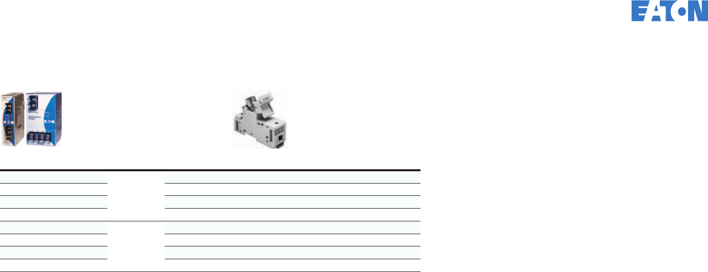
EZ500 with Display
ELC Logic Controller
EZ700 with Display
ELC Power Supply EZ80-B
ELC-GP04
PLCs and Intelligent Relays
Controller Expansion Module Options Power Supply
Options
Catalog
Number Description Digital
Input Analog
Input Relay
Outputs Catalog
Number Description
100–240
Vac Input
Catalog
Number
24 Vdc
Output
(Amps)
Basic (120 Vac Input)
EZ512-AC-RC Intelligent relay
with clock and
display
8 —4 — —
EZ400-POW 1.25
Basic (24 Vdc Input)
EZ512-DC-RC Intelligent relay
with clock and
display
824 — —
EZ400-POW 1.25
Expanded (120 Vac Input)
110–240 Vac
Inputs
Relay
Outputs
EZ719-AC-RC Intelligent relay
with clock and
display
12 — 6
EZ618-AC-RE
12 6
EZ400-POW 1.25
Expanded (24 Vdc Input)
24 Vdc
Inputs
Relay
Outputs
EZ719-DC-RC Intelligent relay
with clock and
display
12 4 6
EZ618-DC-RE
12 6
EZ400-POW 1.25
Advanced (24 Vdc Input)
Right Side
Module
24 Vdc
Inputs
Analog
In
Relay
Outputs
Analog
Out
Transistor
Out
ELC-PV28NNDR Programmable
logic controller
that has expand-
able features with
add-on modules
16 — 12
ELC-EX16NNDR
8 — 8 ——
ELC-PS01
1
ELC-EX16NNDT
8 — — —8
ELC-PS02
2
ELC-AN06AANN
— 4 —2 —
ELC-TC04ANNN Thermocouple J, K, R, S, T plus 4 analog in
ELC-MC01 Motion control, 1 axis module
Left Side Module
ELC-COENETM Ethernet Modbus TCP (master/slave)
EZ Accessories
EZSOFT—Programming software
EZ-PC-CAB—PC programming cable
EZD-80-B—External display
EZD-CP4-500—Display communication
module with cable
ELC Accessories
ELCSOFT—ELC programming software
ELC-GP04—External graphic panel display
ELC-CBPCELC1—PC/graphic panel cable
ELCSOFTGP—ELC-GP programming
software
Logic control—logic controllers and relays
EATON CORPORATION Control panel design guide
29 Ready to buy? Go to www.eaton.com/controlpanel • Got a question? Call 877-ETN-CARE
Controller
Overload
Protection
Branch
Protection
Sizing the branch protection for a single motor and a control circuit
Conductors of a control circuit
that are tapped from the load side
of a branch circuit device (and
where the power voltage is the
same as the control voltage—
no CPT) shall be protected by
overcurrent devices rated not
more than as specified in the
table at the right.
Branch Circuit Protection
Type Percent of FLA
Non-time delay fuse and Class CC fuse Up to 300%
Dual element fuse (time delay) except Class CC Up to 175%
Inverse-time circuit breaker Up to 250%
Self-protected combination motor controller 100%
Manual self-protected combination motor controller 100%
Reference Section 66.10
Overcurrent Device Ratings for Control Circuit Conductors Tapped from Load Side of Branch Circuit
Protective Device—Reference Table 66.4
Conductor
Size Control Circuit Overcurrent
Device (Amps) Branch Circuit Overcurrent
Device (Amps)
AWG mm2Control in Wire Panel Remote Control
Larger than 14 Larger than 2.1 Equal to wire capacity 400% of wire ampacity 300% of wire ampacity
14 2.1 20 80 60
16 1.3 20 40 20
18 0.82 20 25 20
ote:N See table on Page 6 for breaker and fused disconnect part numbers, and Page 19 for fuse holders.
Single Motor Load and Control
Circuit with Shared Branch
Protection
For single motor load control panel where the branch protective
device acts as the main for the panel and the control circuit is tapped
off the load side of the device, the branch protective device is sized
by the following:
1. Multiply the motor FLA (from Table 50.1 on Page 32) with the
following percentage based on the type of protective device
from the table at right:
2. Add the full-load current on the primary of the CPT from the
table below.
3. Select the closest standard protective device rating.
See Page 8 for selection of the controller and overload protection.
EATON CORPORATION Control panel design guide
30 Ready to buy? Go to www.eaton.com/controlpanel • Got a question? Call 877-ETN-CARE
Common Formulas and Conversions
Voltage Drop Calculations
VVoltage drop
ICurrent
LLength of cable/wire (ft)
DConductor cross section (circular mile)
KResistivity of conductor
• K = 12 for circuits loaded more than 50% of rating (copper)
• K = 11 for circuits loaded less than 50% of rating (copper)
Two-wire,
single-phase V =
Three-wire,
three-phase V =
2K x L x I
D
2K x L x I x 0.866
D
Conversions
1 inch 2.54 cm
3.28 feet 1 meter
1 yard 0.91 meters
1 mile 5,280 feet
1 mile 1.609 kilometers
144 square inches 1 square foot
9 square feet 1 square yard
640 acres 1 square mile
1 cubic foot 7.48 gallons
NEMA/UL/IEC Enclosure Type Cross-Reference—Approximate
NEMA
Enclosure
Rating IP10 IP20 IP21 IP22 IP23 IP30 IP31 IP32 IP33 IP40 IP41 IP42 IP43 IP50 IP51 IP52 IP53 IP54 IP55 IP56 IP60 IP61 IP62 IP63 IP64 IP65 IP66 IP67 IP68
1XXXXX
2XXXXX
3XXXXXXXXXXXXXXXXXXXXXXXXX
3R XXXXXXXX
3S XXXXXXXXXXXXXXXXXXXXXXXXX
4XXXXXXXXXXXXXXXXXXXXXXXXXXX
4X XXXXXXXXXXXXXXXXXXXXXXXXXXX
6XXXXXXXXXXXXXXXXXXXXXXXXXXXX
6P XXXXXXXXXXXXXXXXXXXXXXXXXXXXX
12 XXXXXXXXXXXXXXXXXXXXXXXXXX
13 XXXXXXXXXXXXXXXXXXXXXXXXXX
Direct Current Single-Phase (AC) Three-Phase (AC)
Current (I)
from HP I = I = I =
Current (I)
from kW I = I = I =
Current (I)
from kVA I = I =
Horsepower
(HP) HP = HP = HP =
HP x 746
V x %EFF
HP x 746
V x %EFF x PF
HP x 746
V x %EFF x PF x 1.73
kW x 1000
V
kW x 1000
V x PF
kW x 1000
V x PF x 1.73
kVA x 1000
V
kVA x 1000
V x 1.73
V x I x %EFF
746
V x I x %EFF x PF
746
V x I x %EFF x PF x 1.73
746
EATON CORPORATION Control panel design guide
31 Ready to buy? Go to www.eaton.com/controlpanel • Got a question? Call 877-ETN-CARE
Product Specifications
Tightening Torque (in-lb) Approximate Dimensions (mm)
Type Installation
Pub NumberProtective Devices Part Number Lineside Loadside Mounting Height Width Depth
Molded case
circuit breakers A
EGB…
EGE…
EGH…
EGC…
14–10 AWG… 35
8 AWG… 40
6–4 AWG… 45
3–3/0 AWG… 50
14–10 AWG… 35
8 AWG… 40
6–4 AWG… 45
3–3/0 AWG… 50
10 139.7
139.7
139.7
139.7
76.2
76.2
76.2
76.2
75.9
75.9
75.9
75.9
Three-pole
Three-pole
Three-pole
Three-pole
I.L. 29C515C
I.L. 29C515C
I.L. 29C515C
I.L. 29C515C
JGE…
JGS…
JGH…
JGC…
4–350 kcmil… 180 4–350 kcmil… 180 10 177.8
177.8
177.8
177.8
104.9
104.9
104.9
104.9
90.7
90.7
90.7
90.7
Three-pole
Three-pole
Three-pole
Three-pole
IL01204006E
IL01204006E
IL01204006E
IL01204006E
LGE…
LGH…
LGU…
2–500 kcmil (2)… 375 2–500 kcmil (2)… 375 25 257.3
257.3
257.3
139.2
139.2
139.2
103.9
103.9
103.9
Three-pole
Three-pole
Three-pole
IL01207006E
IL01207006E
IL01207006E
Multiwire terminals 3TA125E3K 70 in-lb 70 in-lb 35 48.0 Incremental IL01202001E
3TA125E6K 25 in-lb 25 in-lb 35 48.0 Incremental IL01202002E
3TA250FJ3 70 in-lb 70 in-lb 96 81.0 Incremental IC01204001E
3TA250FJ6 25 in-lb 25 in-lb 96 81.0 Incremental IC01204002E
Miniature circuit breakers WMZT…
Motor circuit protectors HMCP… 14–10 AWG… 35
8 AWG… 40
6–4 AWG… 45
3–3/0 AWG… 50
14–10 AWG… 35
8 AWG… 40
6–4 AWG… 45
3–3/0 AWG… 50
28 152.4 105.0 86 Three-pole IL01211006E
HMCPE… 14-10 AWG... 35
8 AWG... 40
6-4 AWG... 45
3-3/0 AWG... 50
14-10 AWG... 35
8 AWG... 40
6-4 AWG... 45
3-3/0 AWG... 50
10 139.7 76.2 75.9 Three-pole IL29C130D
Motor protective
circuit breaker
FDMP… 14–10 AWG… 35
8 AWG… 40
6–4 AWG… 45
3–4/0 AWG… 50
14–10 AWG… 35
8 AWG… 40
6–4 AWG… 45
3–4/0 AWG… 50
35 152.4 105.0 86.0 Three-pole IL29C115C
Fusible disconnects R4H3030FJ 27 in-lb 27 in-lb 20 ? 116.0 105.0 99.0 N/A
R4H3030FCC 27 in-lb 27 in-lb 20 ? 116.0 96.0 83.5 N/A
R9J3030FJ and R9J3060FJ 31 in-lb 31 in-lb 20 ? 136.0 149.5 123.0 N/A
R9K3100FJ 35.4 in-lb 35.4 in-lb 20 ? 186.0 149.5 123.0 N/A
R9L3200FJ 200 in-lb 200 in-lb 20 ? 291.0 195.0 130.0 N/A
R9M3400FJ 500 in-lb 500 in-lb 20 ? 390.0 276.0 141.5 N/A
R9N3600FJ 500 in-lb 500 in-lb 20 ? 471.0 364.0 250.0 N/A
Fuse holders C383FHCC 18–12 AWG… 20
10–8 AWG… 25
18–10 AWG (2)… 25
18–12 AWG… 20
10–8 AWG… 25
18–10 AWG (2)… 25
81.2 17.8 61.0 Single-pole
A Tightening torques are for standard terminal provided with breaker. For alternative lugs, see the installation publication.
Dimensional Orientation
Depth
Face Height
Width
EATON CORPORATION Control panel design guide
32 Ready to buy? Go to www.eaton.com/controlpanel • Got a question? Call 877-ETN-CARE

Product Specifications (continued)
Tightening Torque (in-lb) Approximate Dimensions (mm)
Type Installation
Pub NumberControllers Part Number Line Load Coil Auxiliary
Contacts Height Width Depth
Motor control XTSC…BB… 15.0 10.6 10.6 10.6 178.5 45.0 95.7 Pub51176
XTSC…BC… 15.0 26.6 10.6 10.6 228.8 45.0 124.3 Pub51228
XTSC…DD… 26.6 29.2 10.6 10.6 284.0 55.0 196.0 Pub51190
XTFC…BB… 36 10.6 10.6 10.6 209.0 45.0 95.7 Pub51176
XTFC…BC… 36 26.6 10.6 10.6 266.7 45.0 124.3 Pub51228
XTFC…DD… 36 29.2 10.6 10.6 312.1 55.0 196.0 Pub51190
XTCE…B… 10.6 10.6 10.6 10.6 68.0 45.0 75.0 Pub51210
XTCE…C… 26.6 26.6 10.6 10.6 85.0 45.0 97.4 Pub51211
XTCE…D… 29.2 29.2 10.6 10.6 104.0 55.0 132.1 Pub51216
XTCE…F… 123.9 123.9 10.6 10.6 170.0 90.0 160.0 Pub51188
XTCE…G… 123.9 123.9 10.6 10.6 170.0 90.0 160.0 Pub51188
XTOB…BC1 — 16.0 — 7–10.6 49.8 incremental 45.0 88.4 Pub51210
XTOB…CC1 — 16.0 — 7–10.6 51.4 incremental 45.0 105.3 Pub51211
XTOB…DC1 — 31.0 — 7–10.6 70 incremental 60.0 93.6 Pub51216
XTOB…GC1 — 88.5 — 7–10.6 107 incremental 118.0 134 Pub51188
XTCEXF… — — — 10.6 — — 41.2 incremental Pub51211 or Pub51216
XTCEXS… — — — 10.6 — 10.5 incremental — Pub51216 or Pub51188
XTPAXF… — — — 10.6 — — — Pub51198
XTPAXTPCB Not required — — — — — Pub51176
XTPAXLSA 36 — — — 30.5 incremental — — —
Definite purpose C25DR… 12–14 AWG 15 in-lb
10 AWG 25 in-lb
8 AWG 40 in-lb
4–6 AWG 45 in-lb
EATON CORPORATION Control panel design guide
33 Ready to buy? Go to www.eaton.com/controlpanel • Got a question? Call 877-ETN-CARE

Product Specifications (continued)
Tightening Torque (in-lb) Approximate Dimensions (mm)
Type Installation
Pub NumberPower Conversion Part Number Primary Secondary Height Width Depth
Control power
transformers
C0025E2A 16 16 65.0 76.0 64.0 —
C0050E2A 16 16 65.0 76.0 76.0 —
C0075E2A 16 16 65.0 76.0 89.0 —
C0100E2A 16 16 73.0 86.0 86.0 —
C0150E2A 16 16 81.0 95.0 102.0 —
C0200E2A 16 16 97.0 114.0 102.0 —
C0250E2A 16 16 97.0 114.0 111.0 —
C0300E2A 16 16 97.0 114.0 121.0 —
C0350E2A 16 16 97.0 114.0 133.0 —
C0500E2A 30 30 121.0 133.0 140.0 —
C0750E2A 30 30 121.0 133.0 178.0 —
C1000E2A 30 30 144.0 171.0 164.0 —
Power supplies PSG60E 6.94–8.68 6.94–8.68 125.0 32.0 120.5 — IL00912001E
PSG60F 10.41–13.89 10.41–13.89 126.5 70.0 111.4 — IL00912005E
PSG120E 6.94–8.68 6.94–8.68 126.5 50.0 115.0 — IL00912002E
PSG120F 10.41–13.89 10.41–13.89 126.5 70.0 111.3 — IL00912006E
PSG240E 6.94–8.68 6.94–8.68 126.5 85.0 118.5 — IL00912003E
PSG240F 10.41–13.89 10.41–13.89 126.5 85.0 120.5 — IL00912007E
PSG480E 10.41–13.89 10.41–13.89 126.5 160.0 111.4 — IL00912004E
PSG480F 10.41–13.89 10.41–13.89 126.5 160.0 111.4 — IL00912008E
Tightening Torque (in-lb) Approximate Dimensions (mm)
Type Installation
Pub NumberType Part Number Lineside Loadside Mounting Height Width Depth
Logic controllers EZ512… 5.3 5.3 — 110.0 71.5 58.0 — MN05013003E
EZ719… 5.3 5.3 — 110.0 107.5 58.0 — MN05013003E
EZ618… 5–7 5–7 — 110.0 107.5 58.0 — IL05013009E
EZ400… 5–7 5–7 — 110.0 71.5 56.5 — IL05013008E
ELC-PV… 22–16 AWG… 1.7 22–16 AWG… 1.7 — 96.0 70.0 60.0 — IL05001004E
ELC-EX16NNDR 22–16 AWG… 1.7 22–16 AWG… 1.7 — 96.0 25.2 60.0 — IL05003004E
ELC-EX16NNDT 22–16 AWG… 1.7 22–16 AWG… 1.7 — 96.0 25.2 60.0 — IL05003004E
ELC-AN06AANN 22–16 AWG… 1.7 22–16 AWG… 1.7 — 96.0 25.2 60.0 — IL05003003E
ELC-TC04ANNN 1.7 1.7 — 96.0 25.2 60.0 — IL05003009E
ELC-MC01 22–16 AWG… 1.7 22–16 AWG… 1.7 — 96.0 25.2 60.0 — IL05003023E
ELC-COENETM — — — 96.0 33.0 60.0 — MN05006001E
ELC-PS01 4.3–6.9 4.3–6.9 — 96.0 36.5 60.0 — IL05003007E
ELC-PS02 4.3–6.9 4.3–6.9 — 96.0 55.0 60.0 — IL05003007E
EATON CORPORATION Control panel design guide
34 Ready to buy? Go to www.eaton.com/controlpanel • Got a question? Call 877-ETN-CARE

Product Specifications (continued)
Tightening Torque (in-lb) Approximate Dimensions (mm)
Type Installation
Pub Number
Logic Circuit
Components Part Number Line Load Mounting Coil Height Width Depth
Pushbuttons, switches
pilot lights
M22… 7.1 — 17.7 — — — — — IL04716001E
M22… 7.1 — 17.7 — — — — — —
Relays XTRM… 10.6 — — 10.6 58.0 45.0 54.0 — Pub51219
XTMT… 10.6 — — 10.6 58.0 45.0 54.0 — Pub51245
TRL07 8.8 — — 8.8 87.0 17.5 60.0 — IL04910002E
D7… 7–8 — — 7–8 79.7 49.9 70.0 — —
Terminal blocks XBUT4… 5.3–7.1 — — — 47.5 6.2 46.9 — Pub51473
XBAE… 5.3–7.1 — — — 47.5 6.2 46.9 — Pub51473
XBAF… Not required — — — — Pub51473
CHDB3213 2/0–8 AWG… 120 4–6 AWG… 35
8 AWG… 25
10–14… 20
— — 101.6 131.8 84.3 — —
CHDB330F 500–6 AWG… 500 2–3 AWG… 50
4–6 AWG… 45
8 AWG… 40
10–14 AWG…35
— — 118.4 39.1 72.9 — —
With the permission of Underwriters Laboratories, Inc., material is reproduced from UL Standard 508A,
Industrial Control Panels, which is copyrighted by Underwriters Laboratories, Inc., Northbrook, Illinois.
While use of this material has been authorized, UL shall not be responsible for the manner in which
the information is presented, nor for any interpretations thereof. UL’s approval to use this information
does not imply or warrant that any associated products or materials in this publication are UL Listed.
For more information on UL or to purchase standards, please visit our Standards website
at www.comm-2000.com or call 1-888-853-3503.
EATON CORPORATION Control panel design guide
35 Ready to buy? Go to www.eaton.com/controlpanel • Got a question? Call 877-ETN-CARE

EATON CORPORATION Control panel design guide
36 Ready to buy? Go to www.eaton.com/controlpanel • Got a question? Call 877-ETN-CARE

Eaton Corporation
Electrical Sector
1111 Superior Ave.
Cleveland, OH 44114
United States
877-ETN-CARE (877-386-2273)
Eaton.com
© 2010 Eaton Corporation
All Rights Reserved
Printed in USA
Publication No. SA08302002E / Z9647
May 2010
PowerChain Management is a registered
trademark of Eaton Corporation.
All other trademarks are property of their
respective owners.
