18872 Catalog
236765-Catalog 236765-Catalog 236765-Catalog 008699 Batch5 unilog cesco-content
2014-09-08
: Pdf 18872-Catalog 18872-Catalog 008699 Batch5 unilog
Open the PDF directly: View PDF ![]() .
.
Page Count: 92
- AFL Fiber Inside Plant Catalog
- About AFL
- FAST Connectors
- Table of Contents
- Components
- Cable Assemblies – Indoor
- Couplers and Modules
- Wideband Couplers
- Ruggedized Wideband Couplers
- Planar Couplers
- Optical Coupler Modules
- LGX® FTTx Splitter Modules
- Optical Splitter Shelf
- Optical FTTx Coupler Module
- Wavelength Division Multiplexer Couplers
- Optical FTTx WDM Module
- LGX® FTTx WDM Modules
- RFoG WDM Module
- CWDM Single-channel OADM
- Coarse WDM Modules (CWDM)
- Thin Film Filter (TFF) Compact Series CWDM
- Dense WDM (DWDM) Modules
- Fiber Management
- LightLink LANSystem Rack Mount Patch Panels
- LightLink LANSystem 1RU Fiber Termination Patch/Splice Panel
- LightLink LANSystem 2RU Fiber Termination Patch/Splice Panel
- LightLink LANSystem CON048P Fiber Termination Patch Panel
- LightLink LANSystem CON072P Fiber Termination Patch Panel
- LightLink LANSystem CON096P Fiber Termination Patch Panel
- LightLink LANSystem CON144P Fiber Termination Patch Panel
- LightLink LANSystem Rack Mount Patch and Splice Panels
- LightLink LANSystem CNS048P – 48 Fiber Patch and Splice Panel
- LightLink LANSystem CNS072P – 72 Fiber Patch and Splice Panel
- LightLink LANSystem CNS096P – 96 Fiber Patch and Splice Panel
- LightLink LANSystem CNS144P – 144 Fiber Patch and Splice Panel
- LightLink LANSystem SPL3RU and SPL4RU – Optical Splice Shelf
- LightLink LANSystem Rack Mount Patch Panels
- Panel Accessories
- Optical Interconnect Modules
- Xpress Fiber Management® (XFM) MPO Optical Cassettes
- Xpress Fiber Management® High Density Products (XFM®-HD)
- Xpress Fiber Management® High Density (XFM®-HD) Patch Panels
- Xpress Fiber Management® High Density (XFM®-HD) Optical Cassettes
- Xpress Fiber Management® High Density (XFM®-HD) Trunk Cable Assemblies
- Xpress Fiber Management® High Density (XFM®-HD) Patch Cord Assemblies
- Xpress Fiber Management® (XFM) 1RU Patch Panel
- Xpress Fiber Management® (XFM) 2RU Patch Panel
- Xpress Fiber Management® (XFM) 4RU Patch Panel
- Wall Mount Interconnect Enclosure (WME) with Two LGX® Mounting Positions
- Wall Mount Interconnect Enclosure (WME) with Four LGX® Mounting Positions
- Training from the Light Brigade, AFL's Training Division
FIBER INSIDE PLANT
Rack Mount Panels
|
Optical Modules
|
Cable Assemblies
|
Components

Founded in 1984, AFL is a global leader providing ber optic
products, equipment, and engineering services to the
electric utility, broadband, communications, OEM, enterprise,
wireless and transit rail markets. AFL also serves a diverse
mix of industry segments that include service providers,
military and defense, mining, oil and gas, and biomedical.
AFL brings years of experience in developing solutions for
customers, fostering a creative culture to drive and deploy
innovative technologies that will improve communications for
years to come. Our product line consists of ber optic cable,
transmission and substation accessories, outside plant equipment,
connectors, fusion splicers, test equipment and training.
AFL has operations in the U.S., Mexico, Europe and Asia.
AFL is dedicated to bringing our customers a quality
product as well as delivering superior value.

1
Fiber Inside Plant
www.AFLglobal.com or (800)235-3423 3Q13
Table of Contents
Components
FAST Connectors .....................................3
FAST Connector Universal Tool Kit .........................5
Field Master® Connectors ..............................6
FuseConnect Fusion Spliced Field Installable Connectors ........7
FuseConnect MPO Fusion Spliced Field-Terminated Connectors ...8
SpliceConnect with Tool Kit .............................10
Adapters ..........................................11
Buildout Attenuators .................................14
Optical Terminators and Fanout Kits ......................15
Connector Specications ..............................16
Cable Assemblies – Indoor
Simplex Cable Assemblies ..............................17
Two-Fiber Cable Assemblies ............................18
LC Uniboot Cable Assemblies ...........................19
Quad Cable Assemblies ...............................20
Circular Premise Cable (CPC) Assemblies ...................21
Sub-Unitized MicroCore® Trunk Cable Assemblies ............22
Bend Insensitive Cable Assemblies .......................24
SC Angled Pigtail Assemblies ...........................25
Couplers and Modules
Wideband Couplers ..................................26
Ruggedized Wideband Couplers .........................27
Planar Couplers .....................................28
Optical Coupler Modules ..............................29
LGX® FTTx Splitter Modules ............................31
Optical Splitter Shelf ..................................32
Optical FTTx Coupler Module ...........................33
Wavelength Division Multiplexer Couplers ..................34
Optical FTTx WDM Module .............................35
LGX® FTTx WDM Modules .............................36
RFoG WDM Module ..................................37
CWDM Single-channel OADM ..........................38
Coarse WDM Modules (CWDM) .........................39
Thin Film Filter (TFF) Compact Series CWDM ................40
Dense WDM (DWDM) Modules ..........................41
Fiber Management
LightLink LANSystem Rack Mount Patch Panels
1RU Fiber Termination Patch/Splice Panel .................43
2RU Fiber Termination Patch/Splice Panel .................45
CON048P Fiber Termination Patch Panel .................47
CON072P Fiber Termination Patch Panel .................49
CON096P Fiber Termination Patch Panel .................51
CON144P Fiber Termination Patch Panel .................53
LightLink LANSystem Rack Mount Patch and Splice Panels
1RU Fiber Termination Patch/Splice Panel .................43
2RU Fiber Termination Patch/Splice Panel .................45
CNS048P – 48 Fiber Patch and Splice Panel ...............55
CNS072P – 72 Fiber Patch and Splice Panel ...............57
CNS096P – 96 Fiber Patch and Splice Panel ..............59
CNS144P – 144 Fiber Patch and Splice Panel .............61
SPL3RU and SPL4RU – Optical Splice Shelf ...............63
Panel Accessories
LightLink Adapter Plates ...............................65
Poli-MOD® Patch and Splice Module .....................67
Pigtail Assemblies for Patch and Splice Panels ..............69
Optical Interconnect Modules
Xpress Fiber Management® (XFM) MPO Optical Cassettes ......70
Xpress Fiber Management® High Density Products (XFM®-HD) ...72
XFM®-HD Patch Panels ..............................73
XFM®-HD Optical Cassettes ..........................75
XFM®-HD Trunk Cable Assemblies ......................76
XFM®-HD Patch Cord Assemblies ......................78
Xpress Fiber Management® (XFM)
1RU Patch Panel ...................................79
2RU Patch Panel ...................................80
4RU Patch Panel ...................................81
Wall Mount Interconnect Enclosure (WME)
with Two LGX® Mounting Positions .....................82
with Four LGX® Mounting Positions .....................84

2
Fiber Inside Plant
www.AFLglobal.com or (800)235-3423
3
© 2005 AFL, all rights reserved. PP-2-00052, Revision 7, 7.25.13
Specications are subject to change without notice.
FAST Connectors
FAST Connectors are factory pre-polished, eld-installable connectors that completely
eliminate the need for hand polishing in the eld. Proven mechanical splice technology
ensuring precision ber alignment, a factory pre-cleaved ber stub and a proprietary
index-matching gel combine to offer an immediate low loss termination to either
single-mode or multimode optical bers. FAST Connectors are compatible with
250 µm and 900 µm optical bers, as well as 900 µm, 2 mm and 3 mm cordage.
All primary ber types are supported, and each connector is color coded per
industry standard requirements to aide in identication during and after installation.
A factory-installed wedge clip (included with each connector) is removed and discarded
upon completion of the termination. Incorporated into this device is an innovative,
translucent wedge enabling the use of a common VFI to provide a "pass/fail"
signal once physical contact is achieved.
Features
• No Epoxy, No Polish
• Low Insertion Loss
• Fiber Can Be Reinserted
up to Three Times
• 3.0 mm, 2.0 mm and 900 μm
Cordage Compatibility
• VFI Accessory to Conrm
Proper Installation
Applications
• Premise/Enterprise Networks
• LAN/WAN Connections
• Patch Panels
• Equipment Termination
• FTTx Applications
• Field Repair/Replacement
• Equipment Test Leads
U.S. Patents: 5,963,699 / 5,984,532 / 6,179,482 / 7,003,208 / 7,258,496
Ordering Information
FIBER TYPE HOUSING
COLOR
CABLE
SIZE
AFL NO.
PACKAGE OF 6 PACKAGE OF 100
FAST SC CONNECTOR
Multimode 62.5/125 µm, OM1 Beige
900 µm
FAST-SC-MM62.5-6 FAST-SC-MM62.5-100
Multimode 50/125 µm, OM2 Black FAST-SC-MM50-6 FAST-SC-MM50-100
Multimode 50/125 µm, OM3/OM4 compatible Aqua FAST-SC-MM50L-6 FAST-SC-MM50L-100
Single-mode, UPC Blue FAST-SC-SM-6 FAST-SC-SM-100
Single-mode, APC-AU Green FAST-SC-SMAU-6 FAST-SC-SMAU-100
Single-mode, APC-AA Green FAST-SC-SMAA-6* FAST-SC-SMAA-100*
FAST ST CONNECTOR
Multimode 62.5/125 µm, OM1 Beige
900 µm
FAST-ST-MM62.5-6 FAST-ST-MM62.5-100
Multimode 50/125 µm, OM2 Black FAST-ST-MM50-6 FAST-ST-MM50-100
Multimode 50/125 µm, OM3/OM4 compatible Aqua FAST-ST-MM50L-6 FAST-ST-MM50L-100
Single-mode, UPC Blue FAST-ST-SM-6 FAST-ST-SM-100
FAST LC CONNECTOR
Multimode 62.5/125 µm, OM1 Beige
900 µm
FAST-LC-MM62.5-6 FAST-LC-MM62.5-100
Multimode 50/125 µm, OM2 Black FAST-LC-MM50-6 FAST-LC-MM50-100
Multimode 50/125 µm, OM3/OM4 compatible Aqua FAST-LC-MM50L-6 FAST-LC-MM50L-100
Single-mode, UPC Blue FAST-LC-SM-6 FAST-LC-SM-100
* Requires FAST APC Tool Kit for installation
Specifications
PARAMETER VALUE
Insertion Loss:
Singlemode - UPC
Singlemode - APC
Multimode - PC
Average: 0.2 dB, Maximum: 0.5 dB
Average: 0.3 dB, Maximum: 0.6 dB
Average: 0.1 dB, Maximum: 0.5 dB
Return Loss at Room Temperature:
Singlemode - UPC
Singlemode - APC-AU*
Singlemode - APC-AA**
Multimode
Average: -55 dB, Maximum: -45 dB
Average: -55 dB, Maximum: -50 dB
Average: -65 dB, Maximum: -60 dB
Average: -25 dB, Maximum: -20 dB
Operating Temperature -40°C to +75°C
*Angle/Flat Cleaves
**Angle/Angle Cleaves
TIA/EIA-568-C.3 Compliant
TIA/EIA-604 (FOCIS) Compliant
4
© 2005 AFL, all rights reserved. PP-2-00052, Revision 7, 7.25.13
Specications are subject to change without notice.
Accessories
DESCRIPTION AFL NO. AFL NO.
BOOT KITS FOR 2MM AND 3MM CORDAGE COLOR CABLE SIZE PACK OF 6 PACK OF 100
2 mm Boot Kit, SC/LC/ST Black 2 mm FAST-BOOT-2MM-6 FAST-BOOT-2MM-100
3 mm Boot Kit, SC/LC/ST Black 3 mm FAST-BOOT-3MM-6 FAST-BOOT-3MM-100
DUPLEX CLIPS
LC Duplex Clip (LC only) Transparent CS010437-06 CS010437-100
TOOL KITS AFL NO.
FAST UPC Tool Kit For all UPC style connectors and SC/ APC-AU (CT-30A Cleaver) CS001201
FAST UPC Tool Kit For all UPC style connectors and SC/APC-AU (CT-05A Cleaver) CS010975
FAST APC Tool Kit For SC/APC-AA connectors (CT-11A Cleaver) CS012290
VISUAL FAULT IDENTIFIERS AFL NO.
AFL NOYES® VFI 2 VFI2-00-0900
AFL NOYES HiLite VFI3-00-0900
1.25 mm Universal Adapter (LC Connectors) 2900-50-0010MR
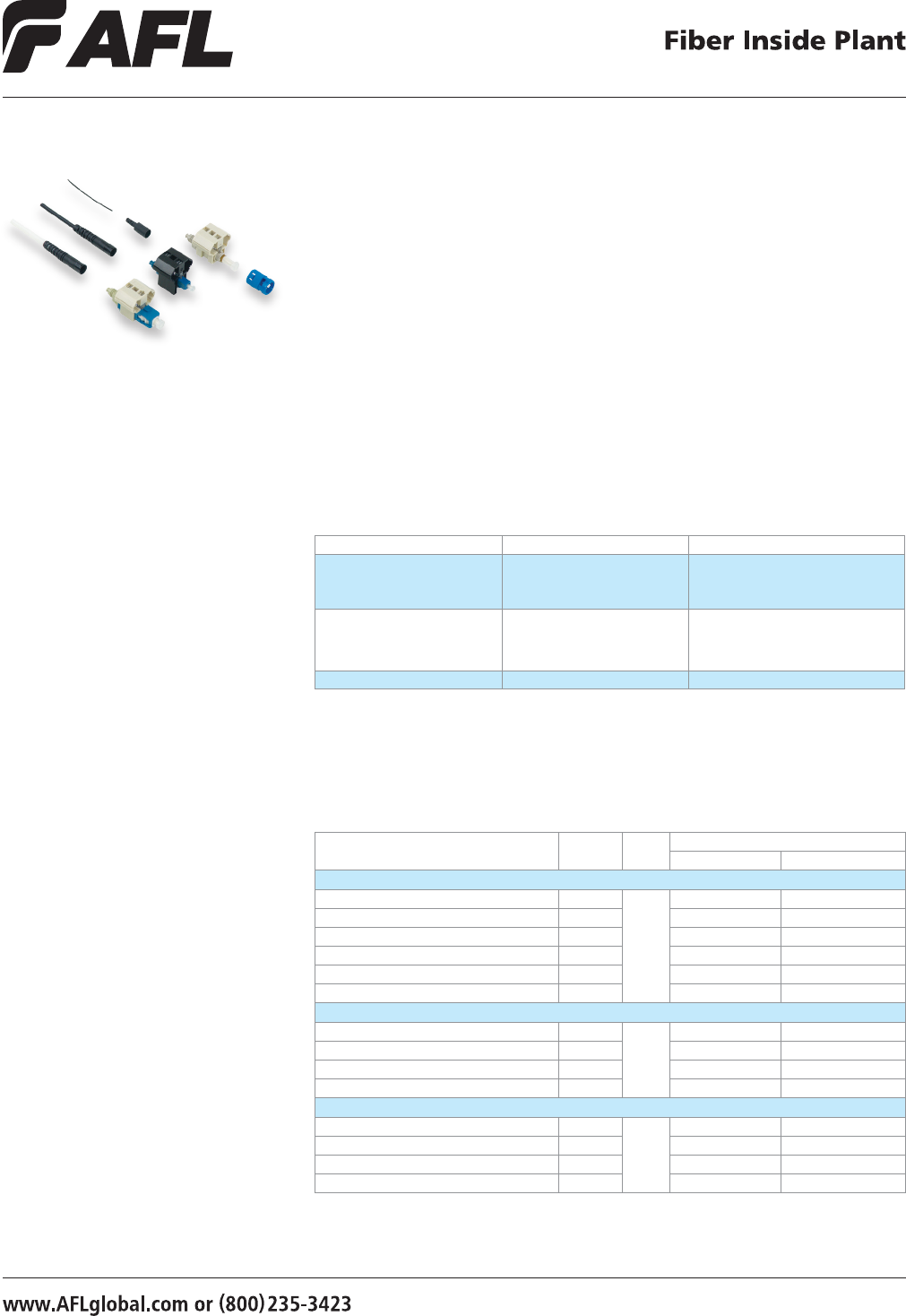
FAST Connectors
Testing
Before Fiber Insertion
After Fiber Insertion
>POM<
12
>POM<
12
HOLD
1 sec
HOLD
1 sec
5
© 2005, AFL, all rights reserved. PP-2-00053, Revision 5, 5.2.13
Specications are subject to change without notice.
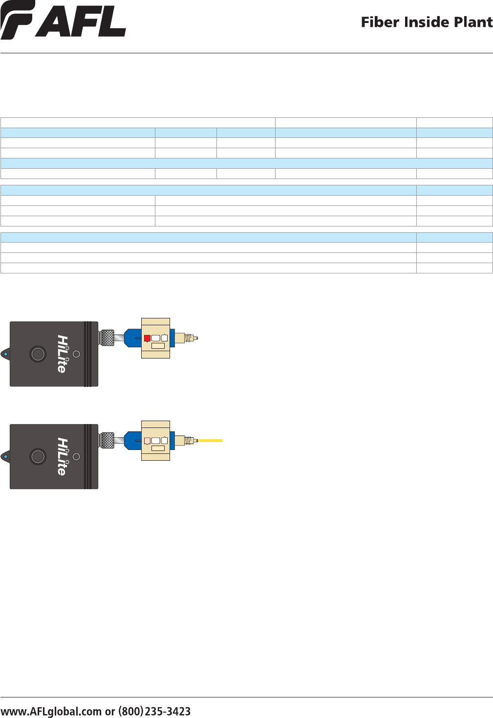
FAST Connector Universal Tool Kit
The FAST Connector Universal Tool Kits provide all the necessary installation tools
required for ber preparation of 250 μm or 900 μm bers, or 900 μm, 2 mm or 3 mm
cordage for AFL’s pre-polished FAST connectors. Featuring either the CT-30A or CT-05
ber cleaver, the FAST Connector Universal Tool Kit contains all the industry standard
termination tools required for ber preparation. Additionally, the carrying case has
adequate storage for extra FAST connectors for on-site convenience.
Features
• Industry standard ber preparation tools
• Compact design, exible yet rugged case
• Complete instructions provided
Applications
• Premise environments
• LAN Fiber to the Desk environments
• Patch panel/wiring closets
• FTTx applications
• Quick repair/replacement areas
Tool Kit Contents
Ordering Information
DESCRIPTION AFL NO.
FAST Connector High Precision UPC/PC Tool Kit with CT-30A Cleaver CS001201
FAST Connector High Precision UPC/PC Tool Kit with CT-05 Cleaver CS010975
FAST Connector APC (Angle/Angle Connector) Tool Kit with CT-11A Cleaver CS012290
Tool Kits include: Cleaver, FAST SC Assembly Tool, FAST LC Assembly Tool, 3 mm Cable Clamp, 2 mm Cable
Clamp, 0.25/0.9 mm Cable Clamp, Fiber Stripper, Kevlar Scissors, Fiber Preperation Fluid, Lint-free Cloth Wipes,
Marker Pen, Installation Instructions, Strip Length Template, Assembly Video (CD) and a Carrying Case.
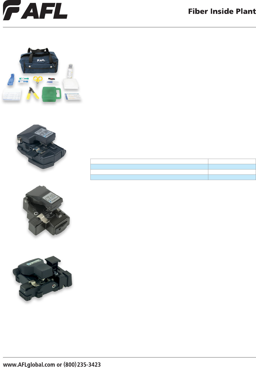
CT-05 Cleaver
CT-30A Cleaver
CT-11A Cleaver
6
© 2002, AFL, all rights reserved. PP-2-00054, Revision 2.1, 5.17.11
Specications are subject to change without notice.
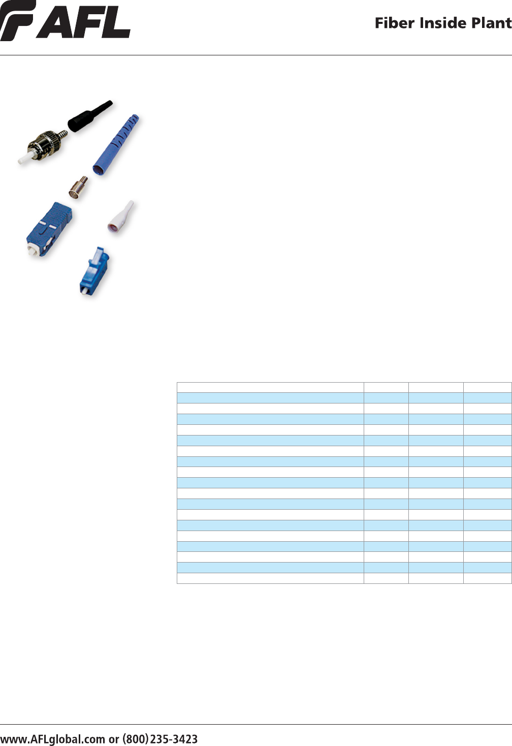
Field Master® Connectors
Field Master Connectors for eld termination of ber optics feature high precision, high
reliability and low applied connector cost. Durable metal components, industry-standard
connector designs, and proven crimp technology give the customer peace-of-mind that
their installed network is steady and reliable. Field Master Tool Kits come complete with all
necessary tools and consumables for the professional installation of Field Master Connectors.
Features
• High precision ceramic ferrules
ensure ber alignment and
repeatable performance
• Rugged metal connector bodies provide
sturdy cable terminations
• Industry standard interfaces allow
interoperability with media equipment
• Meets EIA/TIA 568B
performance requirements
• Field proven crimp technology improves
connector/cable tensile performance
Applications
• Premise environments
• Desk for LAN environments
• Patch panels
• Direct equipment termination
• Fiber to the Subscriber
(FTTx) applications
• Repair / replacement requirements
© 2002, AFL, all rights reserved. PP-2-00054, Revision 2.1, 5.17.11
Specications are subject to change without notice.
Ordering Information
CONNECTOR FIBER TYPE BOOT COLOR AFL NO.*
SC Field Master Connector (900 µm boot) Multimode Black CS000308
SC Field Master Connector (3.0 mm boot) Multimode Beige CS000309
SC Field Master Connector (900 µm & 3.0 mm boot) Multimode Black /Beige CS005144
SC Field Master Connector (900 µm boot) Single-mode Blue CS000310
SC Field Master Connector (3.0 mm boot) Single-mode Blue CS000311
SC Field Master Connector (900 µm & 3.0 mm boot) Single-mode Blue CS005145
ST Field Master Connector (900 µm boot) Multimode Black CS000316
ST Field Master Connector (3.0 mm boot) Multimode Black CS000317
ST Field Master Connector (900 µm & 3.0 mm boot) Multimode Black CS005147
ST Field Master Connector (900 µm boot) Single-mode Blue CS000318
ST Field Master Connector (3.0 mm boot) Single-mode Blue CS000319
ST Field Master Connector (900 µm & 3.0 mm boot) Single-mode Blue CS005148
LC Field Master Connector (900 µm boot) Multimode White CS000320
LC Field Master Connector (2.0 mm boot) Multimode White CS000321
LC Field Master Connector (900 µm boot) Single-mode Blue CS000322
LC Field Master Connector (2.0 mm boot) Single-mode Blue CS000323
LC Duplex Field Master Connector (2.0 mm boot) Multimode White CS000467
LC Duplex Field Master Connector (2.0 mm boot) Single-mode Blue CS000466
* Packaged 100 pieces per bag.
7
© 2007, AFL, all rights reserved. PP-2-00056, Revision 3, 7.10.13
Specications are subject to change without notice.
Ordering Information
CONN.
TYPE
BOOT
TYPE
AFL NO.*
UPC SM
(Blue)
APC SM
(Green)
PC 62.5 µm MM
(Beige)
PC 50 µm MM
(Black)
PC 50 µm LOMMF
(AQUA) **
SC 900 µm FUSE-SC9SMU-6 FUSE-SC9SMA-6 FUSE-SC9M62-6 FUSE-SC9M50-6 FUSE-SC9M50L-6
3 mm FUSE-SC3SMU-6 FUSE-SC3SMA-6 FUSE-SC3M62-6 FUSE-SC3M50-6 FUSE-SC3M50L-6
LC 900 µm FUSE-LC9SMU-6 FUSE-LC9SMA-6 FUSE-LC9M62-6 FUSE-LC9M50-6 FUSE-LC9M50L-6
2 mm FUSE-LC2SMU-6 FUSE-LC2SMA-6 FUSE-LC2M62-6 FUSE-LC2M50-6 FUSE-LC2M50L-6
FC 900 µm FUSE-FC9SMU-6 —FUSE-FC9M62-6 FUSE-FC9M50-6 FUSE-FC9M50L-6
2 mm FUSE-FC2SMU-6 —FUSE-FC2M62-6 FUSE-FC2M50-6 FUSE-FC2M50L-6
3 mm FUSE-FC3SMU-6 —FUSE-FC3M62-6 FUSE-FC3M50-6 FUSE-FC3M50L-6
ST 900 µm FUSE-ST9SMU-6 —FUSE-ST9M62-6 FUSE-ST9M50-6 FUSE-ST9M50L-6
2 mm FUSE-ST2SMU-6 —FUSE-ST2M62-6 FUSE-ST2M50-6 FUSE-ST2M50L-6
3 mm FUSE-ST3SMU-6 —FUSE-ST3M62-6 FUSE-ST3M50-6 FUSE-ST3M50L-6
FuseConnect Fusion Spliced
Field Installable Connectors
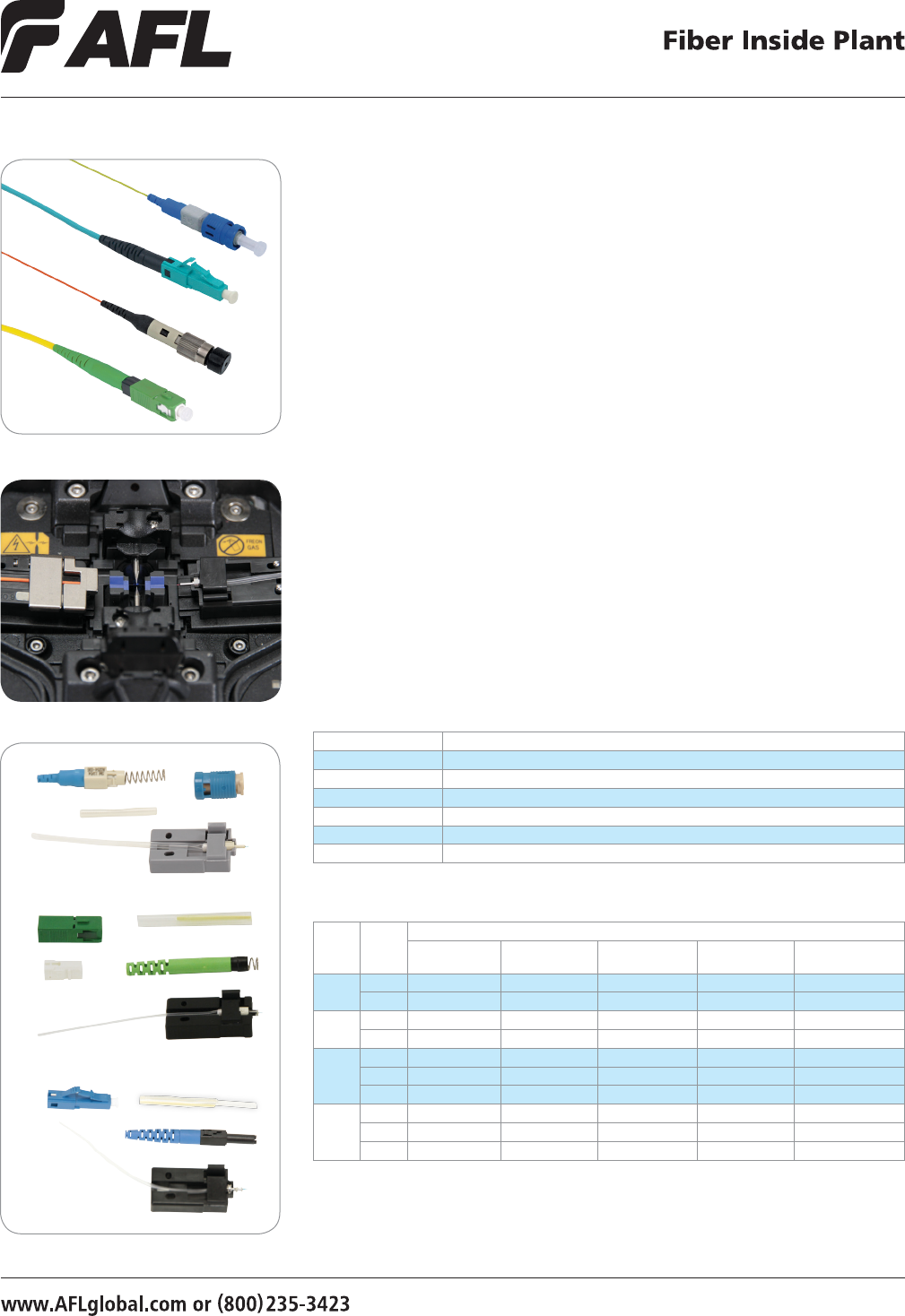
FuseConnect Fusion Spliced Field Installable Connectors
AFL’s FuseConnect fusion spliced, eld installable connectors are uniquely designed and
feature only four to ve components. The factory pre-polished ferrule eliminates the
need for polishing, adhesives, and crimping in the eld, which minimizes the potential
for operator error and expensive connector scrap.
FuseConnect utilizes a fusion splicer to terminate the connector in the eld, addressing
return loss concerns present in analog optical networks. This advanced process yields
true APC performance for SC/APC and LC/APC congurations, and is compliant to
GR-326-CORE. FuseConnect is compatible with Fujikura fusion splicers and most other
ber holder-based fusion splicing platforms.
Features
• Field installable
• No adhesives, crimping or polishing
• True APC performance
• MM compliant to TIA/EIA568C.3
• Compatible with most fusion splicers
Applications
• Connectorization in:
- RF-overlay FTTP networks
- Cable TV backbone networks
- Outside plant
- FTTD
- MDU FTTP Cabling
• Central ofce connector replacement
• Data center installation
Specifications
PARAMETER VALUE
Connector Type SC, LC, FC, ST
Cable Type 900 µm, 2 mm, 3 mm
Polish APC, UPC, PC
Insertion Loss SM: 0.15 dB (average), 0.3 dB (maximum) / MM: 0.10 dB (average), 0.3 dB (maximum)
Return loss SM: ≤ -65 dB (APC), ≤ -55 dB (UPC) / MM: ≤ -30 dB (PC)
Operating Temperature -40°C to +75°C
*
AFL NO. is for one pack of 6 pieces
**
Laser Optimized MM Fiber (LOMMF) compatible with OM3 and OM4 bers
FuseConnect Connectors (SC, FC, LC, ST)
FuseConnect in Fusion Splicer
FuseConnect Kits—ST (aqua), SC (green), LC (blue)
Fiber Inside Plant
www.AFLglobal.com or (800)235-3423
8
© 2011, AFL, all rights reserved. PP-2-00059, Revision 0, 8.29.11
Specications are subject to change without notice.
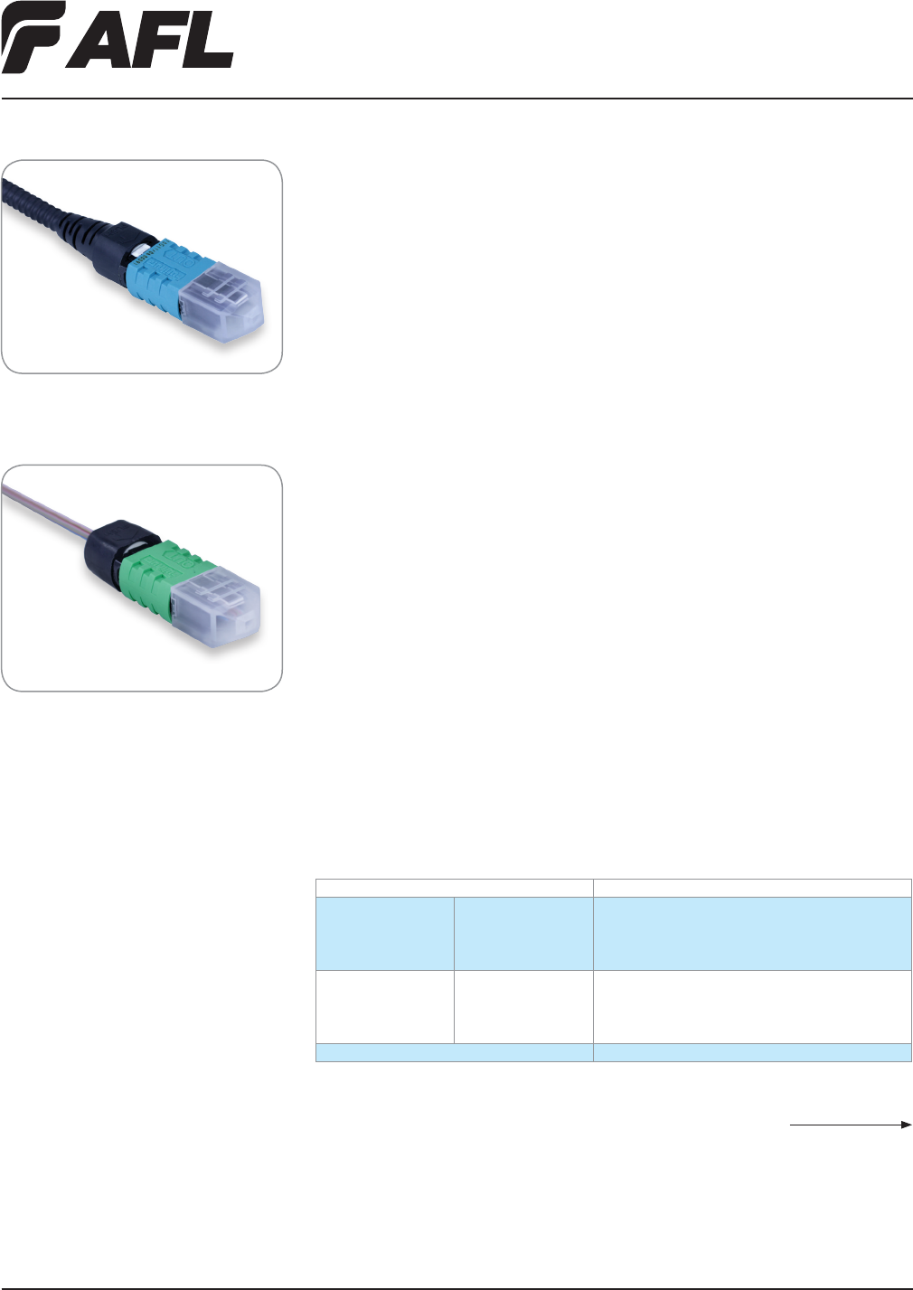
FuseConnect MPO Fusion Spliced
Field-Terminated Connectors
AFL’s FuseConnect MPO fusion-spliced, eld-terminated connectors are uniquely
designed and feature just six components. With a factory pre-polished ferrule, its
innovative eld-termination process eliminates polishing, adhesives and crimping
in the eld minimizing the potential for operator error and expensive connector scrap.
Designed to Fiber Optic Connector Intermateability Standard (FOCIS), Type MPO, FOCIS-5,
TIA-604-5-C, AFL’s FuseConnect MPO performs as an equivalent to the standard factory
terminated MPO/MTP® assemblies. Designed to utilize either ribbon or loose tube cable,
this connector helps to minimize the complexity involved in the termination of a multi-ber
connection, allowing for a reliable and repeatable termination in eld applications.
FuseConnect MPO is part of the FuseConnect series splice-on connector which includes
the SC, LC, ST and FC that require a fusion splicer and accessories for installations. The
AFL FuseConnect MPO Termination Kit specically provides all the necessary accessories
required for eld termination of the FuseConnect MPO.
Features
• Field installable splice-on connector
• Only six components
• No adhesives, crimping or polishing
• TIA-568-C.3, IEC-61754-7, and
TIA/EIA-604-5 FOCIS 5 Compliant
• Field MPO polarity customization
• Include 3.0 mm round and optical ber
ribbon at boots in each pack
Applications
• Connectorization in:
- RF-overlay FTTP networks
- Cable TV backbone networks
- Outside plant
- MDU FTTP Cabling
• Connector restoration in the eld
• Data center installation
• Patch cord customization in the eld
Specifications
PARAMETER VALUE
Insertion Loss Single-mode (OS1)
62.5/125 (OM1)
50/125 (OM2)
50/125 LO (OM3)
Average: 0.25 dB; Max: 0.75 dB
Average: 0.10 dB; Max: 0.35 dB
Average: 0.10 dB; Max: 0.35 dB
Average: 0.10 dB; Max: 0.35 dB
Return Loss Single-mode (OS1)
62.5/125 (OM1)
50/125 (OM2)
50/125 LO (OM3)
> 65 dB
> 30 dB
> 30 dB
> 30 dB
Operating Temperature -40°C to +75°C
FuseConnect MPO Connectors, Cable
FuseConnect MPO Connectors, Ribbon
continued on next page
Fiber Inside Plant
www.AFLglobal.com or (800)235-3423
9
© 2011, AFL, all rights reserved. PP-2-00059, Revision 0, 8.29.11
Specications are subject to change without notice.
FuseConnect MPO Fusion Spliced
Field-Terminated Connectors
Ordering Information
AFL NO.* CONNECTOR TYPE FIBER TYPE POLISH
CABLE SIZE
ROUND FLAT HOUSING COLOR
FUSEMPO-SMA-3-M-6 MPO, Male (guide pins) Single-mode (OS1) APC 3.0 mm 250 µm Green
FUSEMPO-SMA-3-F-6 MPO, Female (No Guide Pins) Single-mode (OS1) APC 3.0 mm 250 µm Green
FUSEMPO-MM6-3-M-6 MPO, Male (guide pins) Multimode 62.5 µm (OM1) PC 3.0 mm 250 µm Beige
FUSEMPO-MM6-3-F-6 MPO, Female (no guide pins) Multimode 62.5 µm (OM1) PC 3.0 mm 250 µm Beige
FUSEMPO-MM5-3-M-6 MPO, Male (guide pins) Multimode 50 µm (OM2) PC 3.0 mm 250 µm Black
FUSEMPO-MM5-3-F-6 MPO, Female (no guide pins) Multimode 50 µm (OM2) PC 3.0 mm 250 µm Black
FUSEMPO-MM5L-3-M-6 MPO, Male (guide pins) Multimode 50 µm 10Gig (OM3) PC 3.0 mm 250 µm Aqua
FUSEMPO-MM5L-3-F-6 MPO, Female (no guide pins) Multimode 50 µm 10Gig (OM3) PC 3.0 mm 250 µm Aqua
*Pack of 6 pieces
Ordering Information – Accessories
DESCRIPTION AFL NO.
TOOL KIT
FuseConnect MPO Tool Kit FUSEMPO-TL-KT
ACCESSORIES
FuseConnect Ribbonize Tool FUSE-RB-TL
FuseConnect Stripping Tool (3.0 mm, 2.8 mm, 2.0 mm, and 1.6 mm) FUSE-ST-TL
FuseConnect MPO Assembly Tool FUSE-AS-TL
10
Fiber Inside Plant
www.AFLglobal.com or (800)235-3423 © 2007, AFL, all rights reserved. PP-2-00104, Revision 2, 10.9.12
Specications are subject to change without notice.
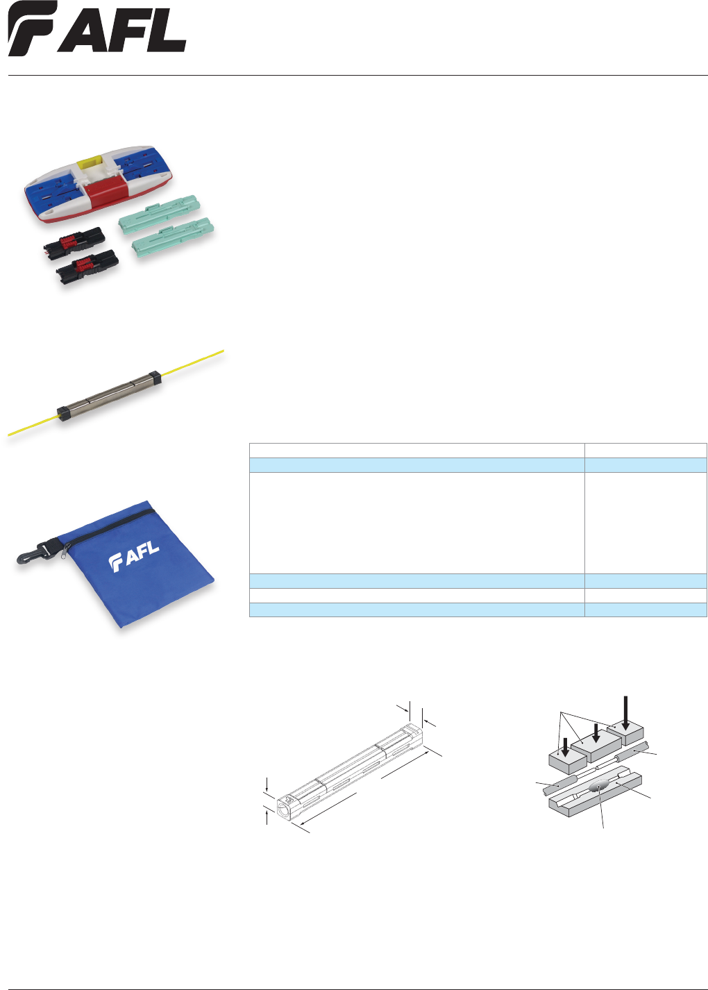
SpliceConnect with Tool Kit
AFL’s SpliceConnect is a mechanical splice that provides an inexpensive, quick alterna-
tive to mating bers. Using V-groove technology, this splice maintains physical contact
between the bers. An assembly tool is used to ensure the bers are mated correctly,
resulting in <0.1 dB insertion loss (typical for single-mode). The SpliceConnect secures
both ber and coating independently with the U-shaped sleeve, enhancing the strength
against ber twist.
Features
• Quick splicing time
• Minimal tools
• 250 µm and/or 900 µm ber capabilities
• Both ber and coating are secured
independently
Dimensions and Structure
Ordering Information
DESCRIPTION AFL NO.
SpliceConnect Mechanical Splices (Bag of 6) CS004154
SpliceConnect Mechanical Splice Tool Kit
Kit Includes:
SpliceConnect Mechanical Splicing Tool
Fiber Holder, 250 µm
Fiber Holder, 900 µm
Instruction Manual
Instruction Video
Carrying Case
CS004162
CS004155
CS004442
CS004443
CS004159
CS004160
CS004161
SpliceConnect Mechanical Splicing Tool CS004155
Fiber Holder, 250 µm CS004442
Fiber Holder, 900 µm CS004443
Applications
• Restoration
• Premise environments
•
Fiber-to-the-Subscriber (FTTx) applications
Clamping
V-groove Plate
Fiber
Fiber
Clamping Force
from U-Shaped Crimp
Index Mating Gel
4 mm
4 mm
40 mm
Fiber Inside Plant
www.AFLglobal.com or (800)235-3423
11
© 2002, AFL, all rights reserved. PP-2-00042, Revision 3, 5.7.13
Specications are subject to change without notice
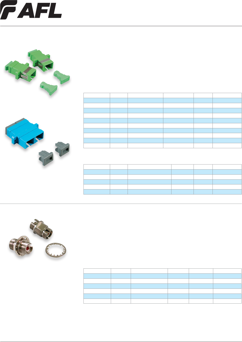
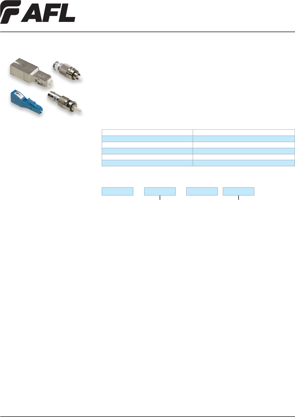
SC Adapters
SC adapters are used to mate industry standard SC connectors. Adapters are available with
metal and ceramic alignment sleeves, and are color coded for easy identication. The duplex
adapters accept two simplex connectors or one duplex connection. Hybrids are available for
special applications.
SC Duplex Adapters
TYPE MODE DESCRIPTION SLEEVE COLOR AFL NO.
SC Duplex MM Long Flange Metallic Beige C209383
SC Duplex MM Long Flange Ceramic Beige C209081
SC Duplex SM No Clip / Screw Mount Ceramic Blue C094862
SC Duplex SM Long Flange Ceramic Blue C092258
SC Duplex SM Long Flange Metallic Blue C092266
SC Simplex Adapters
TYPE MODE DESCRIPTION SLEEVE COLOR AFL NO.
SC Simplex MM SC-A Type Ceramic Beige C209560
SC Simplex MM SC-A Type Metallic Beige C209563
SC Simplex SM SC-A Type Ceramic Blue C028851
SC Simplex SM Short Flange Ceramic Blue C058475
SC Simplex SM SC-A Type Ceramic Plated C002766
SC Simplex SM SC-A Type Metallic Blue C033235
SC Simplex SM Short Flange Metallic Blue C057037
SC Simplex SM SC-A Type Metallic Plated C002507
SC Simplex SM / AP SC-A Type Ceramic Green C080810
SC Simplex SM / AP Short Flange Ceramic Green C147880
SC Simplex Adapters
SC Duplex Adapters
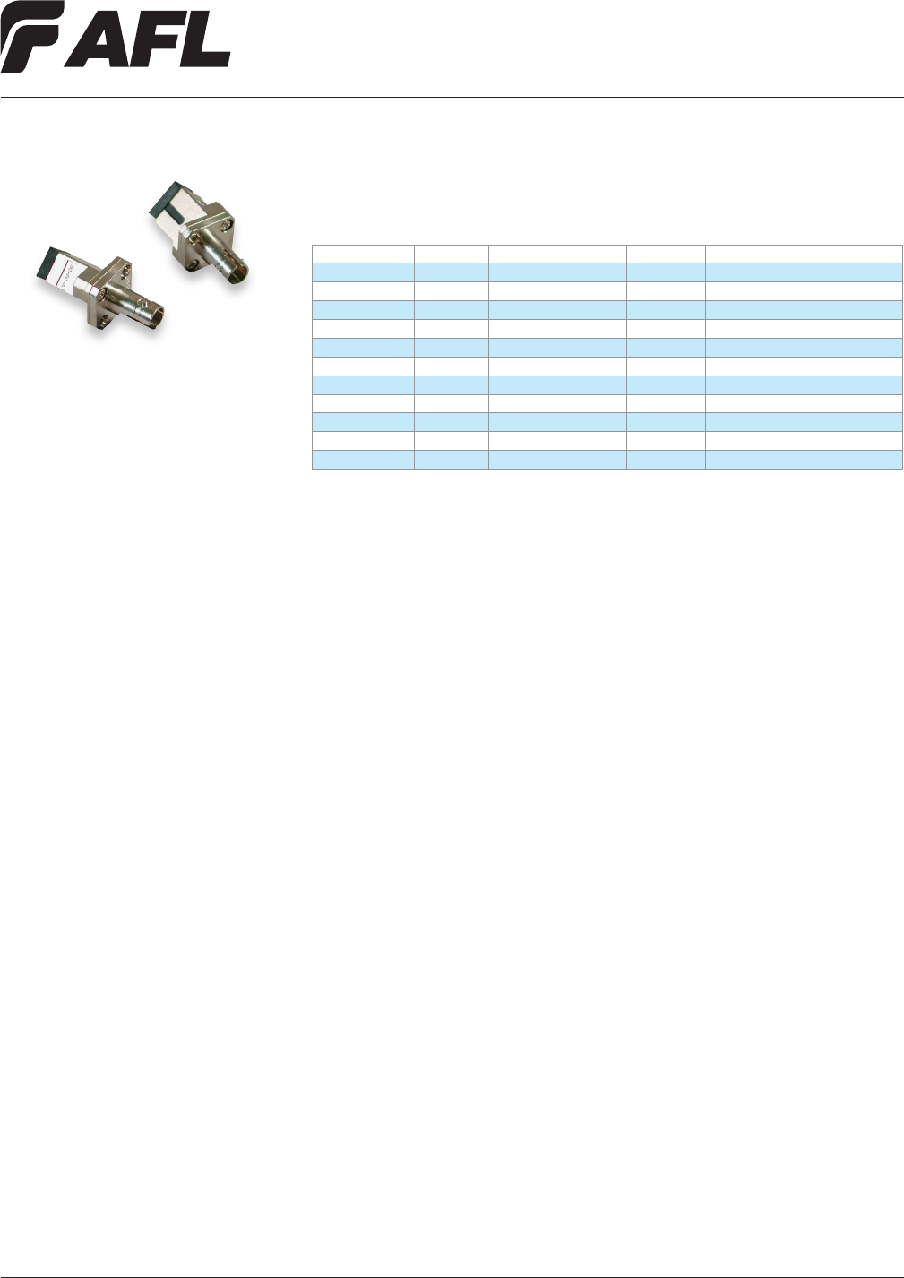
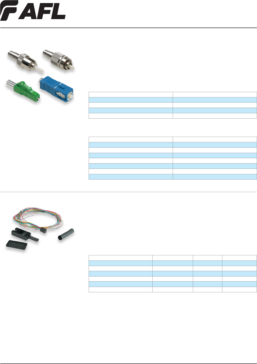
FC Adapters
FC adapters connect industry standard FC connectors and are available in Square-Mount,
D-Mount and Flange-Mount versions. Our FC adapters feature a metal body for long life
and are available with either ceramic or metallic sleeves. The FC D-Mount adapter easily
installs into panel mount applications and conforms to JIS C5970. FC Square-Mount meets
Bellcore GA326 and the angle polish versions meet the industry standard 2.0 mm key
width. An assortment of hybrid congurations is available.
TYPE MODE DESCRIPTION INSERT COLOR AFL NO.
FC Simplex SM / AP Square Mount Ceramic Metal C143346
FC Simplex SM Square Mount Ceramic Metal C146558R
FC Simplex SM D Mount Metallic Metal C143680
FC Simplex SM / AP D Mount Ceramic Metal C146566
FC Simplex SM D Mount Ceramic Metal C145357
FC Simplex SM Square Mount Die Cast Metallic Metal C066443
Adapters
Fiber Inside Plant
www.AFLglobal.com or (800)235-3423
12
© 2002, AFL, all rights reserved. PP-2-00042, Revision 3, 5.7.13
Specications are subject to change without notice
LC Adapters
LC style adapters are used in high density applications and feature a quick plug in instal-
lation. Adapters are available in both simplex and duplex designs and utilize high quality
zirconia and phosphorous bronze sleeves. The LC duplex adapter uses the same cutout as
the copper RJ-45, resulting in less redesign work when retrotting existing panels.
TYPE MODE INSERT COLOR AFL NO.
LC Duplex SM Ceramic Blue C178298
LC Duplex SM/AP Ceramic Green C203962
LC Duplex MM Metallic Beige C203956
LC Simplex SM Ceramic Blue C207202
LC Simplex MM Ceramic Beige C207205
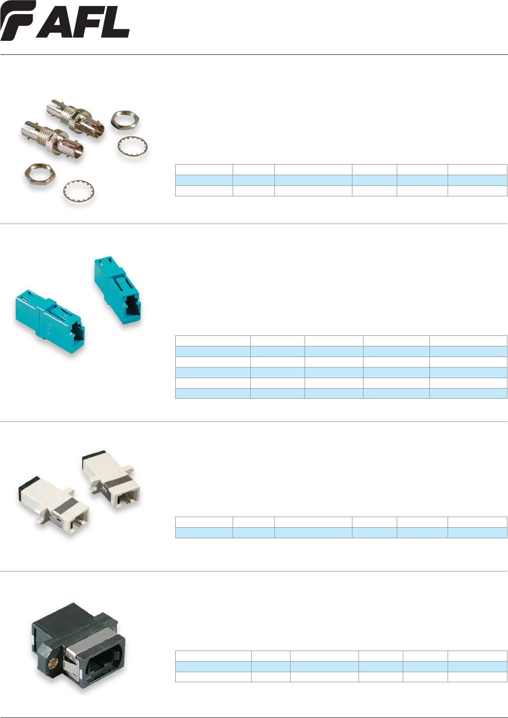
ST adapters connect industry standard ST connectors and are available in D-Mount
and Flange-Mount versions. ST adapters are available with ceramic or metallic sleeves,
feature a metal body for long life, and easily install in panel mount applications.
TYPE MODE DESCRIPTION INSERT COLOR AFL NO.
ST Simplex SM Only D Mount Ceramic Metal C094994
ST Simplex MM Only D Mount Metallic Metal C096377
ST Adapters
MT-RJ adapters connect industry standard MT-RJ connectors in high-density applications.
MT-RJ adapters are keyed for proper alignment and conform to RJ-45 modular plates.
Mounting hardware is not included.
TYPE MODE DESCRIPTION INSERT COLOR AFL NO.
MT-RJ Duplex MM Flange Mount — Beige C196855
TYPE MODE DESCRIPTION INSERT COLOR AFL NO.
MTP SM/MM Flange Mount — Black C057010
MTP (aligned keyway) SM/MM Flange Mount — Grey CS000211
The MTP adapter connects two industry standard MTP connectors. The compact MTP
adapter measures 25 mm x 10 mm and is found in high density applications.
MTP Adapters
MT-RJ Adapters
Fiber Inside Plant
www.AFLglobal.com or (800)235-3423
13
© 2002, AFL, all rights reserved. PP-2-00042, Revision 3, 5.7.13
Specications are subject to change without notice
TYPE MODE DESCRIPTION INSERT COLOR AFL NO.
FC - SC Simplex SM / AP Angled Adapter Ceramic Stainless Steel C130082
FC - SC Simplex SM Square Mount Metallic Stainless Steel C004127
FC - ST Simplex SM Square Mount Metallic Stainless Steel C002401
FC - ST Simplex SM Square Mount Ceramic Stainless Steel C032980
SC - FC Simplex SM Flat Mount Metallic Stainless Steel C033022
SC - FC Simplex SM Square Mount Ceramic Stainless Steel C002453
SC - FC Simplex SM Flat Mount Ceramic Stainless Steel C033030
SC - ST Simplex SM Flat Mount Metallic Blue C002499
SC - ST Simplex SM Square Mount Metallic Stainless Steel C004133
SC - ST Simplex SM Flat Mount Ceramic Blue C024392
SC - ST Simplex SM Flat Mount Ceramic Stainless Steel C038733
Hybrid FC, SC and ST adapters are available to t specic application needs.
Hybrid Adapters
Fiber Inside Plant
www.AFLglobal.com or (800)235-3423
14
© 2002, AFL, all rights reserved. PP-2-00044, Revision 3, 12.03.12
Specications are subject to change without notice.
Buildout Attenuators
Buildout attenuators provide superior performance for all single-mode in-line attenua-
tion requirements. Standard attenuation values are 5, 10, 15, and 20 dB, available in SC,
FC, ST, and LC connector styles. Using no air gap, lters, or light path discontinuities,
attenuation is achieved by controlled absorption of light energy. This results in a
polarization insensitive device with high power handling capability, environmentally
stable, and exceptionally responsive, across a wide bandpass range.
01DB
02DB
03DB
04DB
05DB
06DB
07DB
08DB
09DB
10DB
11DB
12DB
13DB
14DB
15DB
16DB
17DB
18DB
19DB
20DB
21DB
22DB
23DB
24DB
25DB
26DB
27DB
28DB
29DB
30DB
OFA
Ordering Information
BO
Connector
SCA = SC/APC
SCU = SC/UPC
LCA = LC/APC
LCU = LC/UPC
STU = ST/UPC
FCA = FC/APC
FCU = FC/UPC
— —
Features
• SC, FC, ST, and LC connector styles
(Ultra & Angled Polish)
• Long-term reliability
• Low ripple, wavelength independent
attenuation
• Certied to >125 mW continuous
power handling capability with no
performance degradation
• Polarization insensitive
• Telcordia approved
Application
• Broadband Network
• Fiber in the Loop
• Local Area Networks (LAN)
• Long Haul Telecommunications
(CLEC, CAPS)
• Network Testing
• Passive Optical Networks
• Telco
Specifications
PARAMETER VALUE
Standard Attenuation Values 5, 10, 15 and 20 dB
Attenuation Tolerance Standard at 10%
Vibration resistance <0.1X attenuation value
Operating Temperature Range: -40°C to +75°C
Storage Temperature Range: -40°C to +85°C
Fiber Inside Plant
www.AFLglobal.com or (800)235-3423
15
© 2002, AFL, all rights reserved. PP-2-00095, Revision 3.0, 5.19.11
Specications are subject to change without notice.
Optical Terminators
Specifications
PARAMETER VALUE
Reectance <-55 dB (ultra polish)
Reectance <-60 dB (angle polish)
Operating Temperature -40°C to +85°C
Operating Wavelength 1260 nm to 1580 nm
Optical terminators are used to terminate unused connector ports in ber optic systems
so that unwanted reections are not introduced back into the system. All AFL optical
terminators feature zirconia ferrules for long life and durability.
Ordering Information
DESCRIPTION AFL NO.
SC/UP Terminator C067393
SC/AP Terminator C148828
FC/UP Terminator C067407
FC/AP Terminator C082562
ST/UP Terminator C167083
LC/UP Terminator CS000637
LC/AP Terminator CS000638
Fanout Kits
Fanout kits route 250 µm ber into 900 µm tubes ready for connectorization. Easily installed
in minutes, these kits require no special tools. Color-coded tubing allows easy identication.
The furcation unit snaps together, eliminating epoxy. Loose tube fanout kits are available in
6 and 12 ber congurations.
Ordering Information
CABLE TYPE FIBER COUNT LENGTH AFL NO.
Loose Tube Fanout Kit (for 3.0 mm tube) 6 Fibers 24 inches C189826
Loose Tube Fanout Kit (for 3.0 mm tube) 12 Fibers 24 inches C189818
Ribbon-Link® Fanout Kit 6 Fibers 36 inches C189842
Ribbon-Link Fanout Kit 12 Fibers 36 inches C189834
Uni-Tube Fanout Kit 6 Fibers 36 inches C193114
Uni-Tube Fanout Kit 12 Fibers 36 inches C193122
Optical Terminators and Fanout Kits
16
Fiber Inside Plant
www.AFLglobal.com or (800)235-3423 © 2005, AFL, all rights reserved. PP-2-00047, Revision 2, 5.19.11
Specications are subject to change without notice.
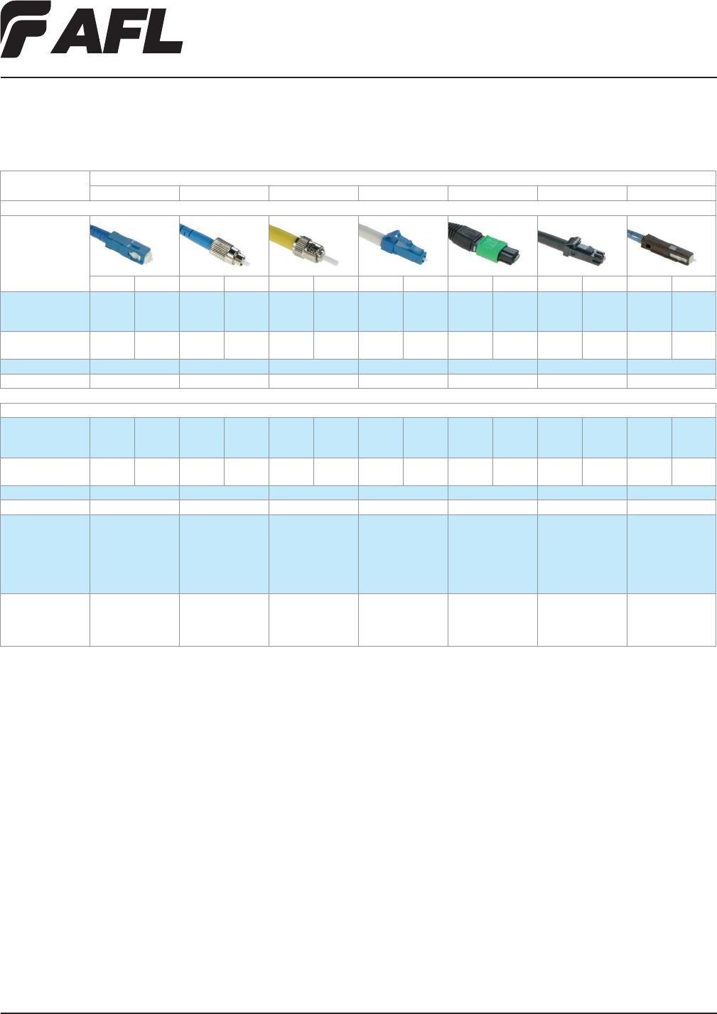
Connector Specications
PARAMETER CONNECTOR
SC FC ST LC MTP MT-RJ MU
Single-mode Assemblies
Image
Ultra Angle Ultra Angle Ultra Angle Ultra Angle Flat Angle Ultra Angle Ultra Angle
Insertion loss (dB)
Maximum
Typical
0.2
0.15
0.25
0.2
0.2
0.25
0.25
0.2
0.2
0.15
—
—
0.2
0.15
0.25
0.15
—
—
0.75
0.35
0.5
0.25
—
—
0.25
0.2
—
—
Return Loss (dB)
Minimum -55 dB -65 dB -55 dB -65 dB -55 dB — -55 dB -65 dB — -55 dB -35 dB — -55 dB —
Temp Range (°C) -40 to +85 -40 to +85 -40 to +85 -40 to +85 -40 to +75 -40 to +75 -40 to +85
Durability Cycles 500 500 500 500 200 200 500
Multimode Assemblies
Insertion loss (dB)
Maximum
Typical
0.5
0.25
—
—
0.5
0.25
—
—
0.5
0.25
—
—
0.5
0.25
—
—
0.75
0.35
—
—
0.5
0.25
—
—
0.5
0.25
—
—
Return Loss (dB)
Minimum -30 dB — -30 dB — -30 dB — -30 dB — -30 dB — -20 dB — -20 dB —
Temp Range (°C) -40 to +85 -40 to +85 -40 to +85 -40 to +85 -40 to +75 -40 to +75 -40 to +85
Durability Cycles 500 500 500 500 200 200 500
Cable Options Simplex/Duplex
900 µm
1.6 mm
2.0 mm
2.4 mm
3.0 mm
Simplex/Duplex
900 µm
1.6 mm
2.0 mm
2.4 mm
3.0 mm
Simplex/Duplex
900 µm
1.6 mm
2.0 mm
2.4 mm
3.0 mm
Simplex/Duplex
900 µm
1.6 mm
2.0 mm
Bare Ribbon
Jacketed Ribbon
8-12 Fiber Count
Bare Ribbon
Jacketed Ribbon
Dual Link
Zipcord
900 µm
2.0 mm
Applications Telephony
CATV/Broadband
Telco Backplanes
LAN/WAN
Telephony
CATV/Broadband
Telco Backplanes
LAN/WAN
Telephony
CATV/Broadband
Telco Backplanes
LAN/WAN
Telephony
CATV/Broadband
Telco Backplanes
LAN/WAN
Telephony
CATV/Broadband
Telco Backplanes
LAN/WAN
Telephony
CATV/Broadband
Telco Backplanes
LAN/WAN
Telephony
CATV/Broadband
Telco Backplanes
LAN/WAN
Fiber Inside Plant
www.AFLglobal.com or (800)235-3423
17
© 2002, AFL, all rights reserved. PP-2-00102, Revision 2, 5.19.11
Specications are subject to change without notice.
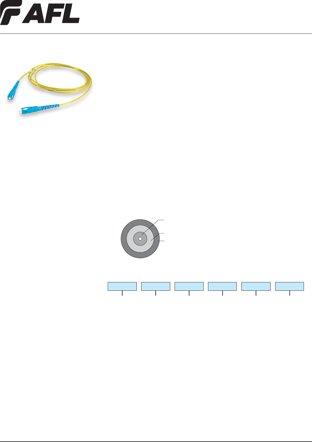
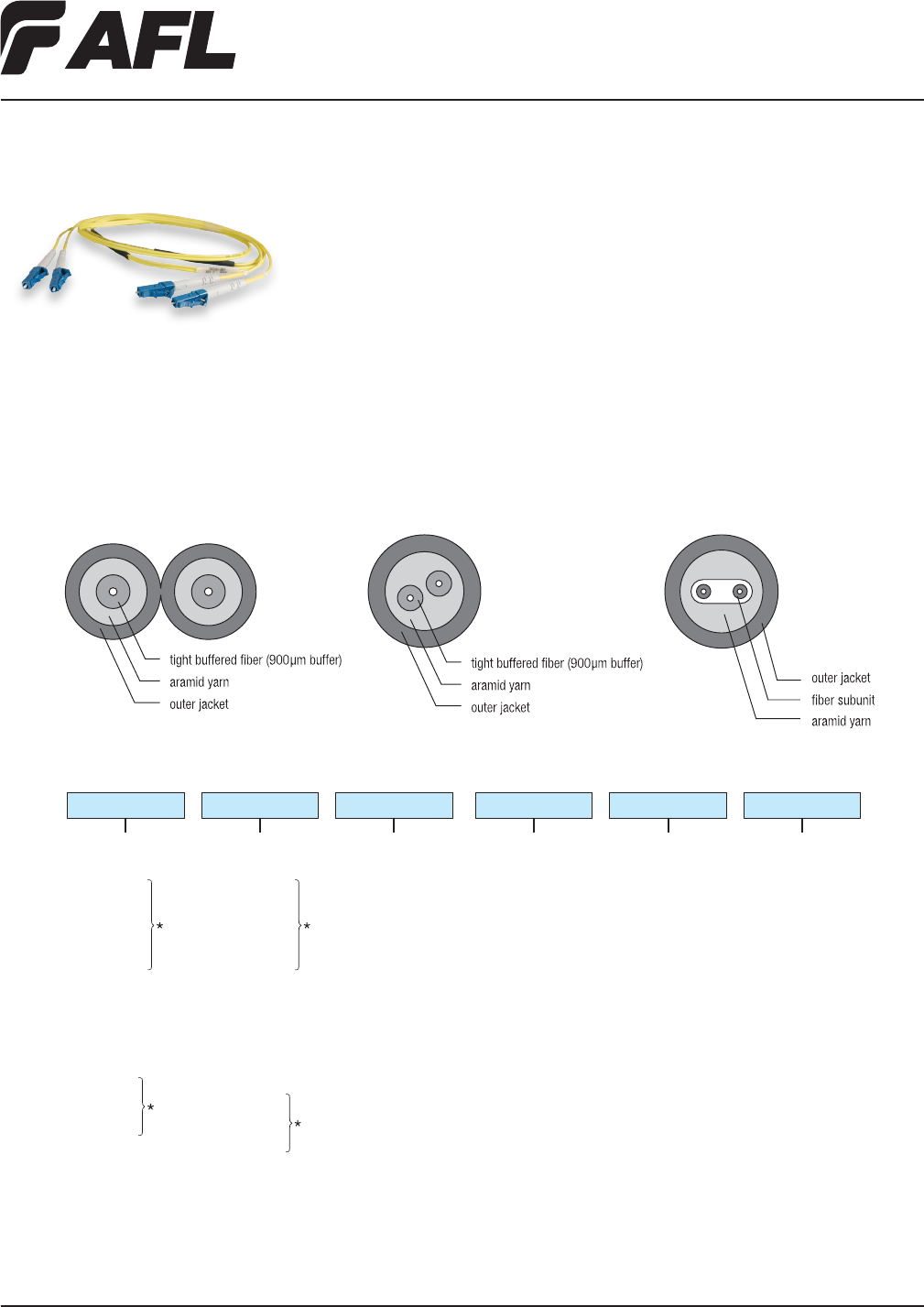
Simplex cable assemblies are offered with a variety of combinations. Connectors include
SC, FC, ST, LC and MU. 3.0 mm, 2.0 mm, 1.6 mm, and 900 μm simplex cables in riser
and plenum are available.
Features
• 3.0 mm, 2.0 mm, 1.6 mm, and 900 μm cable diameter available
• RoHS compliant – Riser, Plenum, and LSZH rated cables available
• Cable compliant with Telcordia® GR-409
• Connectors compliant with Telcordia GR-326
Simplex Cable Assemblies
Ordering Information
Connector End A
Single-mode
ASC = Angle SC
AFC = Angle FC
ALC = Angle LC
USC = Ultra SC
UFC = Ultra FC
UST = Ultra ST
ULC = Ultra LC
UMA = Ultra MU
UMJ = Ultra MU-J
Multimode
PSC = SC MM
PFC = FC MM
PLC = LC MM
PST = ST MM
Cable Type
RS = 3.0 mm Riser
PS = 3.0 mm Plenum
RM = 1.6 m Riser
PM = 1.6 mm Plenum
RT = 2.0 mm Riser
PT = 2.0 mm Plenum
JH = 900 µm
Fiber Count
001 = 1
Fiber Type
Q = Single-mode
R = Multimode 50/125
2 = Multimode 62.5/125
L = 10G Laser Link 300
Cable Length (meters)
0010 = 10 meters
(specify length)
ASC ASC RS 001 Q0010
Connector End B
Single-mode
ASC = Angle SC
AFC = Angle FC
ALC = Angle LC
USC = Ultra SC
UFC = Ultra FC
UST = Ultra ST
ULC = Ultra LC
UMA = Ultra MU
UMJ = Ultra MU-J
XXX = No connector
Multimode
PSC = SC MM
PFC = FC MM
PLC = LC MM
PST = ST MM
XXX = No connector
Applications
• Building interconnections (campus LAN)
• Trunking lines direct to telecommunications closet
• Fiber patch panels within communications closets
• Links between electronic equipment and ber patch panels
Cable Components
tight buffered fiber
(900 µm buffer)
aramid yarn
outer jacket
Telcordia is a registered trademark of Telcordia Technologies, Inc.
Fiber Inside Plant
www.AFLglobal.com or (800)235-3423
18
© 2002, AFL, all rights reserved. PP-2-00106, Revision 2, 5.19.11
Specications are subject to change without notice.
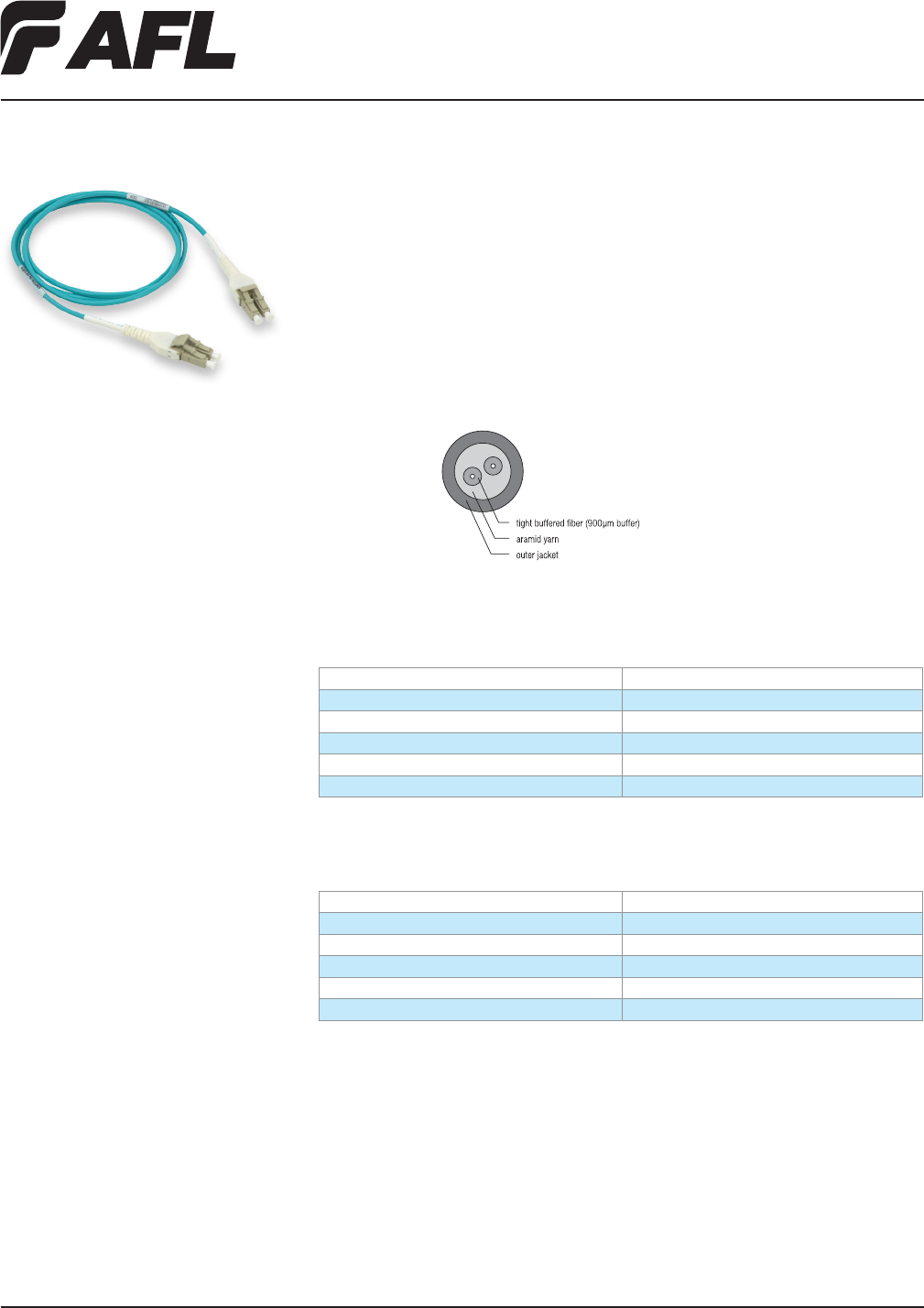
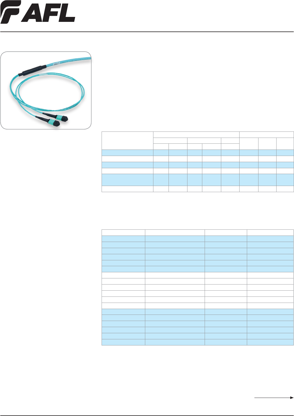
Two-Fiber Cable Assemblies
Zipcord, Dual-Link and Ribbon cables are used to meet the requirements for two-ber
cable assemblies, utilizing SC, FC, ST, LC, MU and MT-RJ connectors.
Ordering Information
Connector End A
Single-mode
ASC = Angle SC
AFC = Angle FC
USC = Ultra SC
UFC = Ultra FC
UST = Ultra ST
ULC = Ultra LC
USF = Ultra SC Duplex
UDL = Ultra LC Duplex
SJF = MT-RJ Female
SJM = MT-RJ Male
Multimode
PSC = SC MM
PFC = FC MM
PLC = LC MM
PST = ST MM
PSF = SC Duplex MM
PDL = LC Duplex MM
PJF = MT-RJ Female MM
PJM = MT-RJ Male MM
Cable Type
RZ = 3.0 mm Riser Zipcord
PZ = 3.0 mm Plenum Zipcord
R20Z = 2.0 mm Riser Zipcord
P20Z = 2.0 mm Plenum Zipcord
R16Z = 1.6 mm Riser Zipcord
P16Z = 1.6 mm Plenum Zipcord
RD = Riser Dual Link
PD = Plenum Dual Link
Fiber Count
002 = 2
Fiber Type
Q = Single-mode
ITU-T G.652D
X = Single-mode
ITU-T G.657A BIF
2 = Multimode
62.5/125 µm OM1
R = Multimode
50/125 µm OM2
L = Multimode
50/125 µm OM3/10G
Cable Length (meters)
XXXX (specify length)
0010 = 10 meters
UST UST RD 002 Q0010
Connector End B
Single-mode
ASC = Angle SC
AFC = Angle FC
USC = Ultra SC
UFC = Ultra FC
UST = Ultra ST
ULC = Ultra LC
USF = Ultra SC Duplex
UDL = Ultra LC Duplex
SJF = MT-RJ Female
SJM = MT-RJ Male
XXX = No connector
Multimode
PSC = SC MM
PFC = FC MM
PLC = LC MM
PST = ST MM
PSF = SC Duplex MM
PDL = LC Duplex MM
PJF = MT-RJ Female MM
PJM = MT-RJ Male MM
XXX = No connector
Features
• Flexible, 2-ber design
• RoHS compliant – Riser, Plenum and
LSZH rated cables available
• Cable compliant with Telcordia® GR-409
• Connectors compliant with Telcordia
GR-326
Applications
• FDDI, 10 Gigabit Ethernet, ATM and
Fiber Channel protocols
• Communications closet to wall outlet
• Wall outlet to desk
• Interconnect and cross-connect
applications
Cable Components
Zipcord Dual-link Ribbon-link
NOTES: 1. Refer to Connector Specications page.
* Single connector options, quantity two per end.
Duplex connectors are assembled with
removable clip.
Telcordia is a registered trademark of Telcordia Technologies, Inc.
Fiber Inside Plant
www.AFLglobal.com or (800)235-3423 © 2009, AFL, all rights reserved. PP-2-00082, Revision 1, 5.19.11
Specications are subject to change without notice.
19
LC Uniboot Cable Assemblies
AFL’s LC Uniboot terminated cable assemblies offer a more compact design when
compared to traditional duplex zipcord assemblies. These assemblies contain two LC
connectors encased in a common housing with one boot, terminated on a single, round,
two-ber cable. Utilizing AFL’s DUAL-Link 2.8 mm premise cable, LC Uniboot assemblies
condenses the cable management to half the space used by regular zipcord assemblies.
AFL’s LC Uniboot cable assemblies offer the best solution for high-density applications.
Features
• LC duplex connector uses a single
housing and single boot
• 2.8 mm DUAL-Link cable; Riser, Plenum,
and LSZH rated cables available
• RoHS compliant
• Connectors compliant with Telcordia®
GR-326, TIA/EIA-604-10A(FOCIS 10)
• Cable compliant with Telcordia GR-409 Specifications
PARAMETER VALUE
Insertion Loss (typical) 0.15 dB (SM/MM)
Return Loss (typical) -55 dB (SM), -30 dB (MM)
Durability 500 cycles
Operating Temperature -40°C to +85°C
Ferrule Zirconia
Ordering Information:
LC Uniboot to LC Uniboot, 2.8 mm Riser DUAL-Link Cable
FIBER TYPE AFL NO.
62.5/125 µm (OM1) CS007814-XXXX
50/125 µm (OM2) CS008116-XXXX
50/125 µm 10gig 300 (OM3) CS007783-XXXX
50/125 µm 10gig 550 (OM4) CS009233-XXXX
Single-mode CS009234-XXXX
XXXX = Length (meters)
Example: 0010 = 10
Contact AFL Customer Service for information regarding plenum and LSZH rated assemblies.
Applications
• Private networks
• Data centers
• High density applications
• Interconnect and cross-connect
• Premise installations
Cable Components
Zipcord
DUAL-Link
Micro-Dual Ruggedized Duplex
Telcordia is a registered trademark of Telcordia Technologies, Inc.
Fiber Inside Plant
www.AFLglobal.com or (800)235-3423
20
© 2002, AFL, all rights reserved. PP-2-00098, Revision 2, 5.19.11
Specications are subject to change without notice.
Leg Diameter
NN = Non-furcated, both
ends 900µm
FF = Furcated both ends
NF = 900µm end A,
Furcated end B
NF
Features
• 4.8mm cable diameter allows exibility and easy routing
• RoHS compliant - Riser, Plenum, and LSZH rated cables available
• 900um tight buffered bers allow direct termination (no furcation needed)
• Cable tested to meet or exceed EIA/TIA 568-A/GR-409-CORE
• Connectors compliant with Telcordia GR-326
Applications
• Loaded Panels
• Communications cables with both send-
and-receive in a single unit
• Routing between communications
closets and equipment rooms
• Intrabuilding backbones
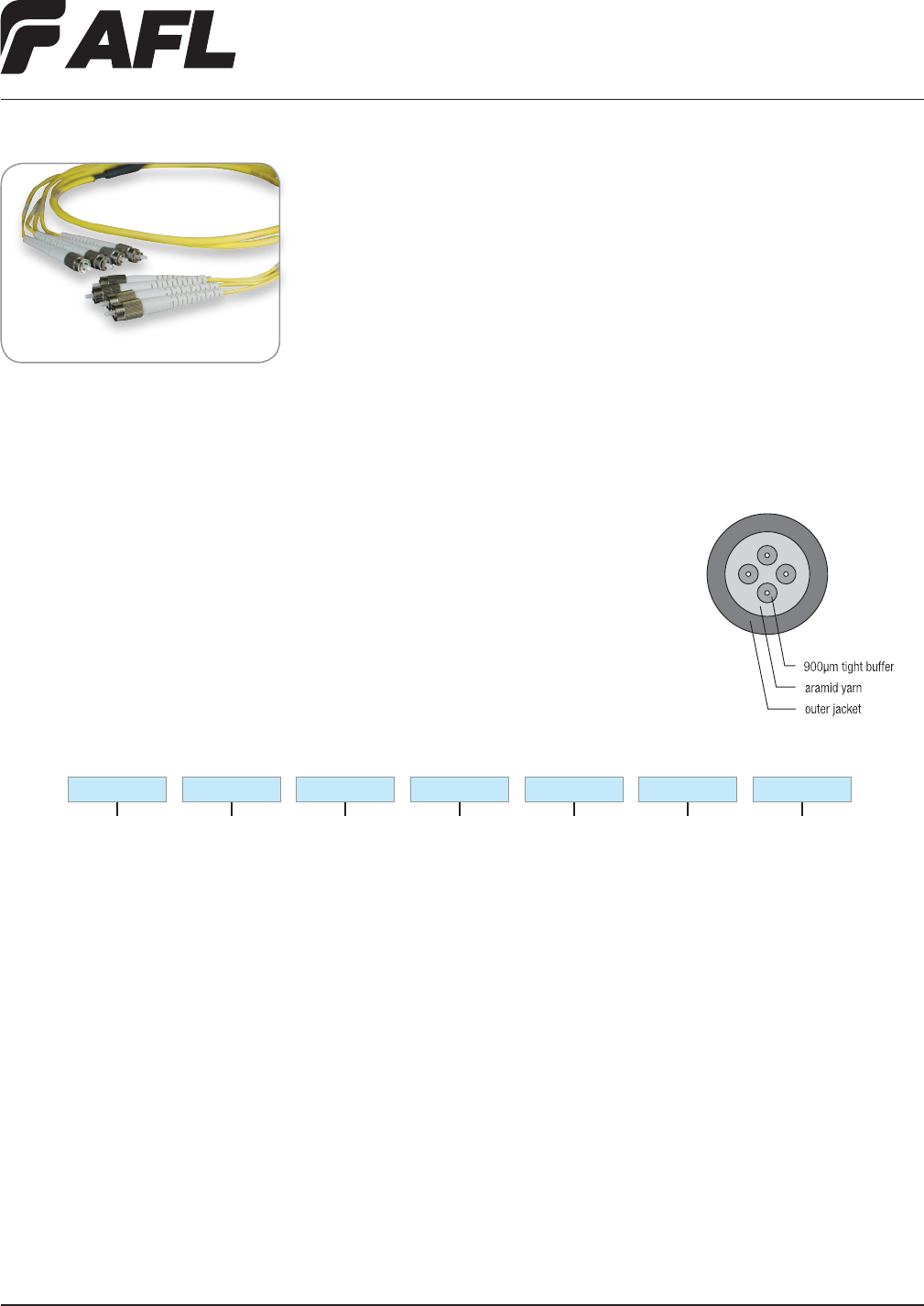
Quad Cable Assemblies
Quad cable assemblies are available in a wide variety of congurations, to t exact
application needs. These assemblies are offered using four 900um coated bers in one
circular cable, featuring a 4.8mm outer diameter.
Connector End A
Single-mode
ASC = Angle SC
AFC = Angle FC
USC = Ultra SC
UFC = Ultra FC
UST = Ultra ST
ULC = Ultra LC
USF = Ultra SC Duplex
UDL = Ultra LC Duplex
SJF = MT-RJ Female
SJM = MT-RJ Male
Multimode
PSC = SC MM
PFC = FC MM
PLC = LC MM
PST = ST MM
PSF = SC Duplex MM
PDL = LC Duplex MM
PJF = MT-RJ Female MM
PJM = MT-RJ Male MM
Cable Type
RQ = Quad Riser
PQ = Quad Plenum
Fiber Count
004 = 4
Fiber Type
Q = Single-mode
ITU-T G.652D
X = Single-mode
ITU-T G.657A BIF
2 = Multimode
62.5/125µm OM1
R = Multimode
50/125µm OM2
L = Multimode
50/125µm OM3/10G
Cable Length
(meters)
XXXX (specify length)
0010 = 10 meters
ASC
Ordering Information
ASC RQ 004 Q0010
Connector End B
Single-mode
ASC = Angle SC
AFC = Angle FC
USC = Ultra SC
UFC = Ultra FC
UST = Ultra ST
ULC = Ultra LC
USF = Ultra SC Duplex
UDL = Ultra LC Duplex
SJF = MT-RJ Female
SJM = MT-RJ Male
XXX = No connector
Multimode
PSC = SC MM
PFC = FC MM
PLC = LC MM
PST = ST MM
PSF = SC Duplex MM
PDL = LC Duplex MM
PJF = MT-RJ Female MM
PJM = MT-RJ Male MM
XXX = No connector
Cable Components
NOTES: 1. Refer to Connector Specications page.
2. Duplex connectors are assembled with
removable clip.
Fiber Inside Plant
www.AFLglobal.com or (800)235-3423
21
© 2002, AFL, all rights reserved. PP-2-00045, Revision 2, 5.19.11
Specications are subject to change without notice.
Circular Premise Cable (CPC) Assemblies
Features
• 6-144 bers with aramid yarn reinforce-
ment for rugged protection
• Highly exible for ease of routing
• RoHS compliant - Riser, Plenum and
LSZH rated cables available
• Pre-installed pulling eye kits available
on certain products
• 1 meter standard breakout (other
lengths are custom)
• 900 µm tight buffered bers allows
direct termination; 2.0 mm furcation
available
• Cable tested to meet or exceed EIA/TIA
568-A/GR-409-CORE
• Telcordia GR-326 compliant connectors
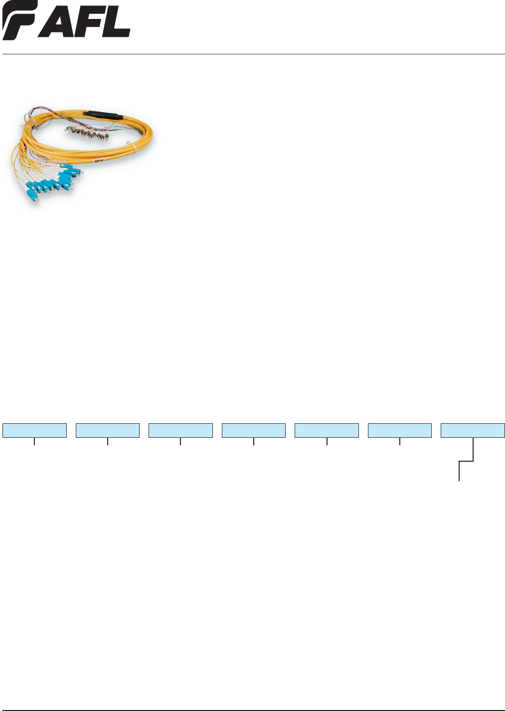
High-ber count Circular Premise Cable (CPC) assemblies provide safe and cost effective
installation for many applications. These assemblies help eliminate labor-intensive eld
termination, yet guarantee reliable performance. Featuring a unied construction for
easy ber identication and rapid installation, these assemblies are built to exceed all
TIA and Telcordia® requirements.
Connector End A
Single-mode
ASC = Angle SC
AFC = Angle FC
USC = Ultra SC
UFC = Ultra FC
UST = Ultra ST
ULC = Ultra LC
Multimode
PSC = SC MM
PFC = FC MM
PLC = LC MM
PST = ST MM
Cable Type
RC = Riser (CPC)
PC = Plenum (CPC)
Fiber Count
006 = 6
012 = 12
024 = 24
036 = 36
048 = 48
072 = 72
096 = 96
144 = 144
Fiber Type
Q = Single-mode
ITU-T G.652D
X = Single-mode
ITU-T G.657A BIF
2 = Multimode
62.5/125 µm OM1
R = Multimode
50/125 µm OM2
L = Multimode
50/125 µm OM3/10G
Cable Length (meters)
XXXX (specify length)
0010 = 10 meters
Leg Diameter
N = 900 µm End A / XXX End B
NN = 900 µm End A and B
F = Furcated End A / XXX End B
FF = Furcated Ends A and B
FN = Furcated Ends A / 900 µm End B
NF = 900 µm End A / Furcated Ends B
ASC
Ordering Information
ASC RC 012 Q0010 NN
Connector End B
Single-mode
ASC = Angle SC
AFC = Angle FC
USC = Ultra SC
UFC = Ultra FC
UST = Ultra ST
ULC = Ultra LC
XXX = No connector
Multimode
PSC = SC MM
PFC = FC MM
PLC = LC MM
PST = ST MM
XXX = No connector
Applications
• Head-end termination to a ber
"backbone"
• Termination of ber rack systems
• Multi-oor deployment where select
bers are used at each oor
• Intrabuilding "backbones"
NOTES: 1. Refer to Connector Specications page.
2. Duplex SC and LC available
Telcordia is a registered trademark of Telcordia Technologies, Inc.
Fiber Inside Plant
www.AFLglobal.com or (800)235-3423
22
© 2010, AFL, all rights reserved. PP-2-00105, Revision 4, 6.13.13
Specications are subject to change without notice.
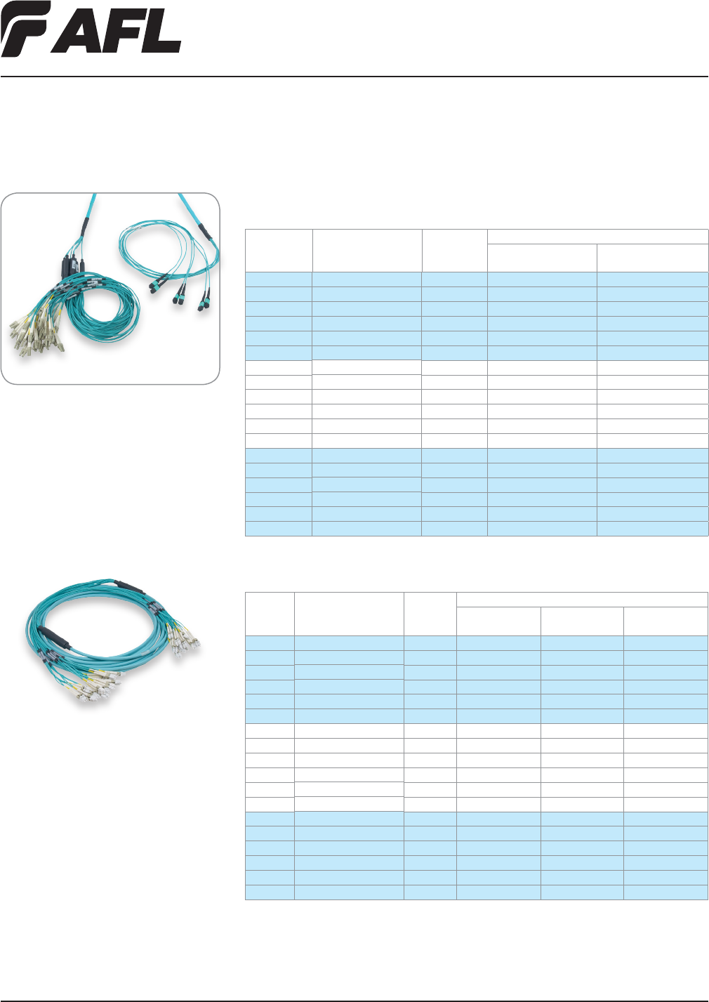
Sub-Unitized MicroCore®
Trunk Cable Assemblies
Features
• Sub-unitized design, with (12) 250 µm
colored bers per tube
• 12, 24, and 72 ber counts (SM or 50
µm LOMMF) with active part numbers
• Small diameter provides superior bend
performance
• Standard 2.0 mm zipcord furcation for
single ber connectors
• One meter standard breakout
• Cable jackets & connector housings
color-coded for easy identication
• Sub-unit legs identied for ease of
channel routing/traceability
• Cable tested to meet or exceed EIA/TIA
568-A/GR-409-CORE
• Telcordia® GR-326 compliant connectors
Sub-unitized MicroCore trunk cable assemblies provide high performance for premise
installations where space is a premium. The small diameter, sub-unitized design offers
twelve 250 µm colored bers per tube, with aramid strength members enclosed by a
PVC jacket, enabling high density architecture. The cable allows quick and efcient
termination of MTP connectors, as well as, breakout capability to single ber connectors.
Applications
• Data center systems wiring
• MTP-MTP or MTP-Fanouts, and Single
Fiber Connector Terminations
• Head-end termination to a ber
"backbone"
• Termination of ber rack systems
• Multi-oor deployment where select
bers are used at each oor
• Intrabuilding "backbones"
Ordering Information – MTP-MTP Assemblies
(Female MTPs on both ends – no pins)
(Polarity: Key Up/Key Up, Straight Through)
FIBER COUNT FIBER PULLING EYE AFL NO.
12 Single-mode No CS009980-XXXX
12 Single-mode Yes CS009981-XXXX
24 Single-mode No CS009984-XXXX
24 Single-mode Yes CS009985-XXXX
72 Single-mode No CS009996-XXXX
72 Single-mode Yes CS009997-XXXX
12 50 µm 10gig 300 (OM3) No CS010649-XXXX
12 50 µm 10gig 300 (OM3) Yes CS010650-XXXX
24 50 µm 10gig 300 (OM3) No CS003700-XXXX
24 50 µm 10gig 300 (OM3) Yes CS009912-XXXX
72 50 µm 10gig 300 (OM3) No CS003720-XXXX
72 50 µm 10gig 300 (OM3) Yes CS010016-XXXX
12 50 µm 10gig 550 (OM4) No CS008420-XXXX
12 50 µm 10gig 550 (OM4) Yes CS010065-XXXX
24 50 µm 10gig 550 (OM4) No CS010100-XXXX
24 50 µm 10gig 550 (OM4) Yes CS010066-XXXX
72 50 µm 10gig 550 (OM4) No CS010101-XXXX
72 50 µm 10gig 550 (OM4) Yes CS010067-XXXX
NOTE: XXXX is length in meters
.
Contact AFL Customer Service for additional polarity schemes available.
Specifications
PARAMETER
SINGLE-MODE ASSEMBLIES MULTIMODE ASSEMBLIES
LC SC MTP LC SC MTP
(LOW LOSS)
ULTRA ANGLED ULTRA ANGLED ANGLED
Insertion Loss (Typical dB)*** 0.15 0.15 0.15 0.15 0.35 0.15 0.15 0.15
Insertion Loss (Maximum dB) 0.3 0.3 0.3 0.3 0.75 0.5 0.5 0.2
Return Loss (Typical dB)*** -60 -70 -60 -70 -65 -35 -35 -30
Return Loss (Minimum dB) -55 -65 -55 -65 -55 -30 -30 -20
Temperature Range (°C) -40 to
+85
-40 to
+85
-40 to
+85
-40 to
+85
-40 to
+75
-40 to
+85
-40 to
+85
-40 to
+75
Durability Cycles 500 500 500 500 200 500 500 200
***
Typical values based on equal quality connectors
.
Telcordia is a registered trademark of Telcordia Technologies, Inc.
continued on next page
Fiber Inside Plant
www.AFLglobal.com or (800)235-3423
23
© 2010, AFL, all rights reserved. PP-2-00105, Revision 4, 6.13.13
Specications are subject to change without notice.
Ordering Information – MTP Fanout Assemblies
(Male MTPs — Duplex Connectors)
FIBER
COUNT FIBER
PULLING
EYE
AFL NO.
MALE MTP-LC
DUPLEX MALE MTP-SC DUPLEX
12 Single-mode No CS009521-XXXX CS010020-XXXX
12 Single-mode Yes CS0010017-XXXX CS010021-XXXX
24 Single-mode No CS003796-XXXX CS010022-XXXX
24 Single-mode Yes CS010018-XXXX CS010023-XXXX
72 Single-mode No CS003811-XXXX CS010024-XXXX
72 Single-mode Yes CS010019-XXXX CS010025-XXXX
12 50 µm 10gig 300 (OM3) No CS011510-XXXX CS010030-XXXX
12 50 µm 10gig 300 (OM3) Yes CS010027-XXXX CS010031-XXXX
24 50 µm 10gig 300 (OM3) No CS003795-XXXX CS010032-XXXX
24 50 µm 10gig 300 (OM3) Yes CS010028-XXXX CS010033-XXXX
72 50 µm 10gig 300 (OM3) No CS003810-XXXX CS010034-XXXX
72 50 µm 10gig 300 (OM3) Yes CS010029-XXXX CS010035-XXXX
12 50 µm 10gig 550 (OM4) No CS009519-XXXX CS010073-XXXX
12 50 µm 10gig 550 (OM4) Yes CS010068-XXXX CS010074-XXXX
24 50 µm 10gig 550 (OM4) No CS010069-XXXX CS010075-XXXX
24 50 µm 10gig 550 (OM4) Yes CS010070-XXXX CS010076-XXXX
72 50 µm 10gig 550 (OM4) No CS010071-XXXX CS010077-XXXX
72 50 µm 10gig 550 (OM4) Yes CS010072-XXXX CS010078-XXXX
Ordering Information – LC and SC Trunk Assemblies
(Duplex LC and SC Connectors)
FIBER
COUNT FIBER
PULLING
EYE
AFL NO.
LC DUPLEX-
LC DUPLEX
LC DUPLEX-
SC DUPLEX
SC DUPLEX-
SC DUPLEX
12 Single-mode No CS010036-XXXX CS010038-XXXX CS010042-XXXX
12 Single-mode Yes CS010037-XXXX CS010039-XXXX CS010043-XXXX
24 Single-mode No CS004602-XXXX CS007203-XXXX CS007201-XXXX
24 Single-mode Yes CS004603-XXXX CS007204-XXXX CS007202-XXXX
72 Single-mode No CS004618-XXXX CS010040-XXXX CS010044-XXXX
72 Single-mode Yes CS004619-XXXX CS010041-XXXX CS010045-XXXX
12 50 µm 10gig 300 (OM3) No CS010046-XXXX CS010048-XXXX CS010052-XXXX
12 50 µm 10gig 300 (OM3) Yes CS010047-XXXX CS010049-XXXX CS010053-XXXX
24 50 µm 10gig 300 (OM3) No CS004608-XXXX CS007221-XXXX CS007219-XXXX
24 50 µm 10gig 300 (OM3) Yes CS004609-XXXX CS007222-XXXX CS007220-XXXX
72 50 µm 10gig 300 (OM3) No CS004624-XXXX CS010050-XXXX CS010054-XXXX
72 50 µm 10gig 300 (OM3) Yes CS004625-XXXX CS010051-XXXX CS010055-XXXX
12 50 µm 10gig 550 (OM4) No CS010079-XXXX CS010085-XXXX CS010091-XXXX
12 50 µm 10gig 550 (OM4) Yes CS010080-XXXX CS010086-XXXX CS010092-XXXX
24 50 µm 10gig 550 (OM4) No CS010081-XXXX CS010087-XXXX CS010093-XXXX
24 50 µm 10gig 550 (OM4) Yes CS010082-XXXX CS010088-XXXX CS010094-XXXX
72 50 µm 10gig 550 (OM4) No CS010083-XXXX CS010089-XXXX CS010095-XXXX
72 50 µm 10gig 550 (OM4) Yes CS010084-XXXX CS010090-XXXX CS010096-XXXX
NOTE: XXXX is length in meters
.
Sub-Unitized MicroCore®
Trunk Cable Assemblies
Fiber Inside Plant
www.AFLglobal.com or (800)235-3423 © 2005, AFL, all rights reserved. PP-2-00043, Revision 5, 5.19.11
Specications are subject to change without notice.
24
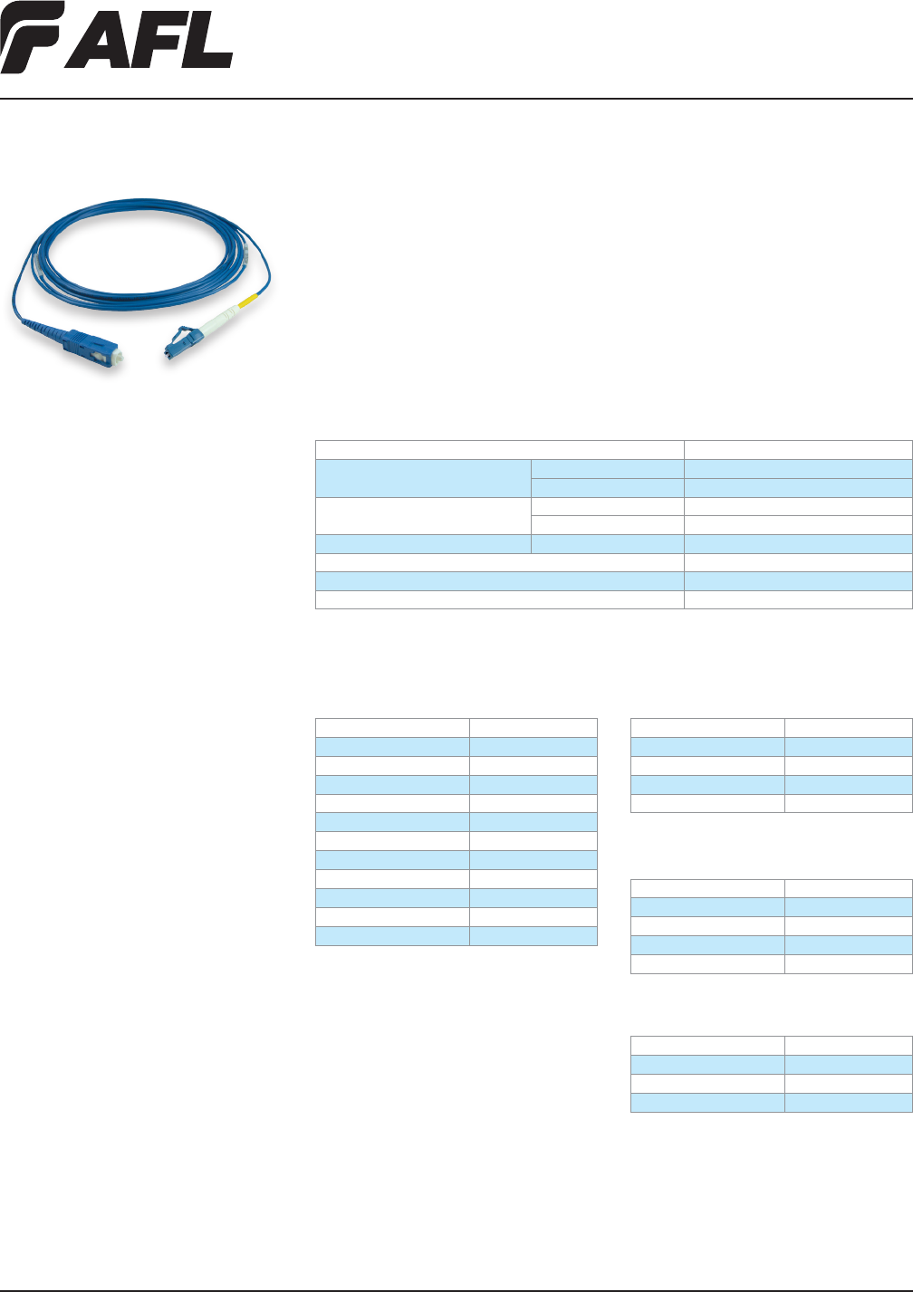
Bend Insensitive Cable Assemblies
AFL’s single-mode bend insensitive cable assemblies enable tight bend radii and routing
to minimize signal loss due to high trafc and/or densely packed patch panel routing
installations. Available in simplex, duplex, quad (4 ber) and octo (8 ber) cable congu-
rations, either ultra or angled polished interfaces can be requested, thereby meeting low
insertion loss and high return loss system requirements.
Various standard connector interface options are available and meet Telcordia® GR-326
performance requirements.
Applications
• Service provider networks
• Central ofce and equipment buildings
• CATV carrier video systems
Features
CONNECTORS
• Ceramic ferrule utilized for precision
ber alignment
• Ribbed boot design on SC insures
protected cable bending
• 40 degree LC boot option allows guided
cable routing in DMX and DMXtend
system applications
• Meets connector interface specications
of EIA.TIA-455 (FOCIS)
• All component materials are compliant
to UL94 V-0
• Premium performance at standard
grade prices
• Color-coded blue cable jacket identies
enhanced performance
• Tested in accordance with
Telcordia GR-326, issue 3 specications
CABLE
• Fujikura ber enables tight bend radius
control and low loss
• Long term performance at a
bend radius <15 mm
• Simplex, Duplex Dual-link, Quad and
8-ber cable constructions are RoHS
compliant
• Cable constructions meet or exceed
Telcordia GR-409
Specifications
PARAMETER VALUE
Insertion Loss max 0.25 dB
typical 0.15 dB
Return Loss max -65 dB (APC), -55 dB (UPC)
typical -68 dB (APC), -58 dB (UPC)
Cable Bend Radius minimum < 15 mm
Durability 200 cycles
Operating Temperature -40°C to +85°C
Storage Temperature -40°C to +85°C
Ordering Information
SIMPLEX CABLE ASSEMBLIES,
2 MM JACKET DIAMETER
DESCRIPTION AFL NO.
USC-USC C063770B-XXXX
ULC-ULC C213707B-XXXX
ASC-ASC C202687B-XXXX
UFC-UFC C185200B-XXXX
AFC-AFC C202691B-XXXX
USC-ULC C213712B-XXXX
USC-ASC C202702B-XXXX
USC-UFC C167091B-XXXX
USC-AFC C202705B-XXXX
ASC-AFC C202696B-XXXX
USC-ULC (40° LC boot) CS001104B-XXXX
DUPLEX DUAL-LINK CABLE ASSEMBLIES,
3.2 MM JACKET DIAMETER
DESCRIPTION AFL NO.
USC-USC C141246B-X
ULC-ULC CS000813B-XXXX
USC-ULC CS000812B-XXXX
USC-UFC C124414B-XXXX
QUAD 4-FIBER CABLE ASSEMBLIES,
4.7 MM JACKET DIAMETER
DESCRIPTION AFL NO.
USC-USC C183518B-XXXX
ULC-ULC CS000818B-XXXX
USC-ULC CS000661B-XXXX
USC-UFC C178379B-XXXX
OCTO 8-FIBER CABLE ASSEMBLIES,
5.2 MM JACKET DIAMETER
DESCRIPTION AFL NO.
USC-USC CS000619B-XXXX
ULC-ULC CS00815B-XXXX
USC-ULC CS000814B-XXXX
XXXX = Length (meters)
Example: 0010 = 10
Telcordia is a registered trademark of Telcordia Technologies, Inc.
Fiber Inside Plant
www.AFLglobal.com or (800)235-3423
25
© 2005, AFL, all rights reserved. PP-2-00101, Revision 2, 5.19.11
Specications are subject to change without notice.
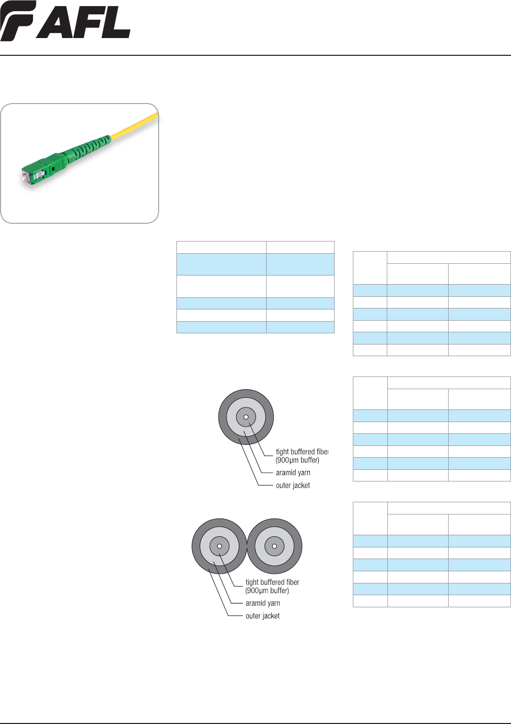
AFL single-mode SC Angled Pigtail Assemblies are designed to meet stringient perfor-
mance requirements of the latest FTTH (Fiber to the Home) applications. Available in
either simplex (one ber) or duplex zipcord (two ber) construction, the SC angled con-
nector guarantees the high performance return loss required of video signals. Assemblies
are tested and qualied to Telcordia® GR-326, Issue 3 requirements and meet all
EIA.TIA 455-3 (FOCIS 3) interface standards for SC connectors. The assemblies are pro-
vided in easy-to-install disposable packaging reels up to 300 feet, in 50-foot increments.
Applications
• Multi-Dwelling Unit (MDU) drop cables
for FTTH systems
• CATV Video systems
• LAN Networks
Features
CONNECTORS:
• Tested in accordance with Telcordia
GR-326, issue 3 specications
• Meets SC interface specications of
EIA.TIA-455-3 (FOCIS 3)
• All component materials are compliant
to UL94 V-0
• Ceramic ferrule utilized for precision
ber alignment
• Keyed push-pull latching mechanism
• Connector housings are color coded
(Green) for APC identication and
-65 dB return loss
CABLE:
• Cable constructions meet or exceed
Telcordia GR-409
• 3.0 mm cable diameter available in
Riser and Plenum grade
• Simplex and Duplex zipcord cable
construction, RoHS compliant
• Cable manufactured using Corning
SMF-28e single-mode ber
SC Angled Pigtail Assemblies
Specification
PARAMETER VALUE
Insertion loss maximum
typical
0.25 dB
0.15 dB
Return Loss maximum
typical
-65 dB
-68 dB
Durability 200 cycles
Operating Temperature -40°C to + 85°C
Storage Temperature -40°C to + 85°C
Duplex Zipcord
Simplex
Duplex Single-Jacket
Cable Components
Ordering Information
RISER GRADE, SINGLE-ENDED, 3 MM
LENGTH
(FEET)
AFL NO.
SIMPLEX
DUPLEX
ZIPCORD
50 CS000686-0050 CS000688-0050
100 CS000686-0100 CS000688-0100
150 CS000686-0150 CS000688-0150
200 CS000686-0200 CS000688-0200
250 CS000686-0250 CS000688-0250
300 CS000686-0300 CS000688-0300
PLENUM GRADE, SINGLE-ENDED, 3 MM
LENGTH
(FEET)
AFL NO.
SIMPLEX
DUPLEX
ZIPCORD
50 CS000698-0050 CS000700-0050
100 CS000698-0100 CS000700-0100
150 CS000698-0150 CS000700-0150
200 CS000698-0200 CS000700-0200
250 CS000698-0250 CS000700-0250
300 CS000698-0300 CS000700-0300
PLENUM-RISER GRADE, SINGLE-ENDED, 3MM
LENGTH
(FEET)
AFL NO.
SIMPLEX
DUPLEX
ZIPCORD
50 CS000704-0050 CS000706-0050
100 CS000704-0100 CS000706-0100
150 CS000704-0150 CS000706-0150
200 CS000704-0200 CS000706-0200
250 CS000704-0250 CS000706-0250
300 CS000704-0300 CS000706-0300
Telcordia is a registered trademark of Telcordia Technologies, Inc.
Fiber Inside Plant
www.AFLglobal.com or (800)235-3423
26
© 2002, AFL, all rights reserved. PP-2-00110, Revision 2, 5.24.11
Specications are subject to change without notice.
Features
• Dual window wideband operation
• Low insertion loss over entire band-
width and temperature (typical IL
change <±0.1 dB)
•
Ultra-low PDL and temperature sensitivity
• High directivity
• Compact design
• Environmentally stable, over 10 years of
proven eld reliability
• Standard operating temperature range
-4O°C to +85°C
• Fully tested to Telcordia 1209 and 1221
criteria
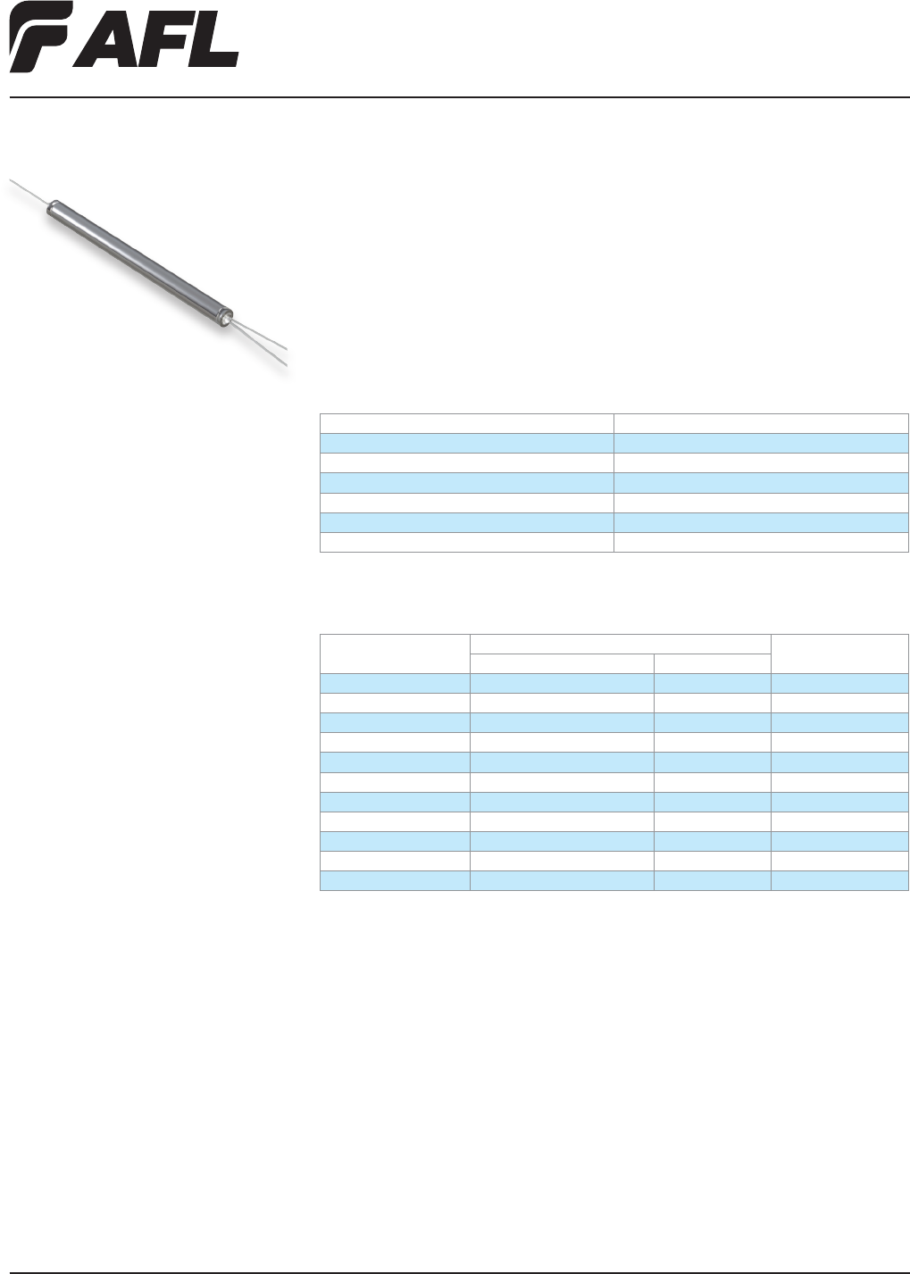
Wideband Couplers
The dual window Wideband Couplers (WBC) split or couple optical power in two wave-
length regions while maintaining a very broad operating bandwidth. Split and coupling
ratios are available from 5% to 50%. WBCs are widely considered one of the most
cost-effective solutions to optical power management. The WBC is an all-ber device,
based on AFL’s fused biconic technology, and is designed and manufactured to meet
military and Telcordia® requirements.
Applications
• Telecommunications
• CATV
• LAN
• Monitoring of Networks
Ordering Information
SINGLE-MODE PREMIUM GRADE SPECIFICATIONS (MAX. INSERTION LOSS AND MAX. PDL)
RATIO SPECIFICATIONS (DB) AFL NO.
PRIMARY/SECONDARY PORT PDL (DB)
50/50 3.6/3.6 0.15 C198364-P
55/45 3.2/4.1 0.15 C198358-P
60/40 2.7/4.7 0.14 C198353-P
65/35 2.3/5.3 0.14 C198349-P
67/33 2.2/5.7 0.14 C198904-P
70/30 2.0/6.0 0.13 C198346-P
75/25 1.8/6.8 0.13 C198340-P
80/20 1.3/7.8 0.10 C198335-P
85/15 1.0/9.2 0.10 C198331-P
90/10 0.8/11.2 0.10 C198328-P
95/5 0.5/14.4 0.10 C198322-P
Specifications
STANDARD AND PREMIUM GRADES
PARAMETER VALUE
Operating Wavelength 1310 nm + 50 and 1550 nm + 50
Return Loss 55 dB
Directivity 55 dB
Package Dimension 3.2 mm (dia.) x 55 mm (L)
Operating Temperature -40° to +85°C
Storage Temperature -40° to +85°C
Telcordia is a registered trademark of Telcordia Technologies, Inc.
Fiber Inside Plant
www.AFLglobal.com or (800)235-3423
27
© 2002, AFL, all rights reserved. PP-2-00100, Revision 1, 5.24.11
Specications are subject to change without notice.
Features
• Dual window wideband operation
• Low insertion loss
• Low PDL
• High Directivity
• Long term eld application
• Environmentally stable over range of
-40°C to +85°C
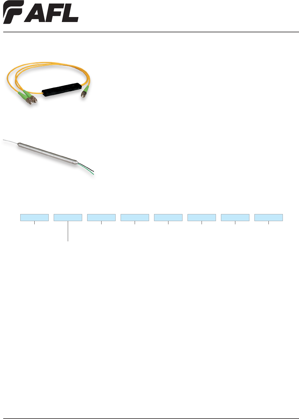
Ruggedized Wideband Couplers
Enhancing AFL’s wideband coupler offering are two package styles for ruggedized
versions of these reliable, standardized couplers – 3 mm and 900 µm furcated pigtail
options and a variety of connector styles are offered in both single-mode and multimode
applications. All AFL couplers conform to stringent environmental and mechanical stan-
dards to provide high reliablity in a variety of customer applications.
Ordering Information
Applications
• Telecommunications
• CATV
• LAN
• Fiber in the Loop
• Network monitoring
Output Connector/
Adapter
ASC = Angle SC
AFC = Angle FC
USC = Ultra SC
UFC = Ultra FC
SST = Super ST
ULC = Ultra LC
000 = Non-connectorized
Output Pigtail
Length (M)
(Examples)
01 = 1 meter
02 = 2 meters
Input Connector
Options
ASC = Angle SC
AFC = Angle FC
USC = Ultra SC
UFC = Ultra FC
SST = Super ST
ULC = Ultra LC
000 = Non-connectorized
Conguration
S = Single-mode
M = Multimode
Input Pigtail
Length (M)
(Examples)
01 = 1 meter
02 = 2 meters
Output Leads
0102 = 1 x 2
Split Ratio
50 = 50/50%
45 = 45/55%
40 = 40/60%
35 = 35/65%
30 = 30/70%
25 = 25/75%
20 = 20/80%
15 = 15/85%
10 = 10/90%
5 = 5/95%
T0102 50 SASC 01 ASC 01
Package Type
T = 900 µm Diameter Leads
3 = 3 mm Diameter Leads
Fiber Inside Plant
www.AFLglobal.com or (800)235-3423
28
© 2005, AFL, all rights reserved. PP-2-00097, Revision 1, 5.24.11
Specications are subject to change without notice.
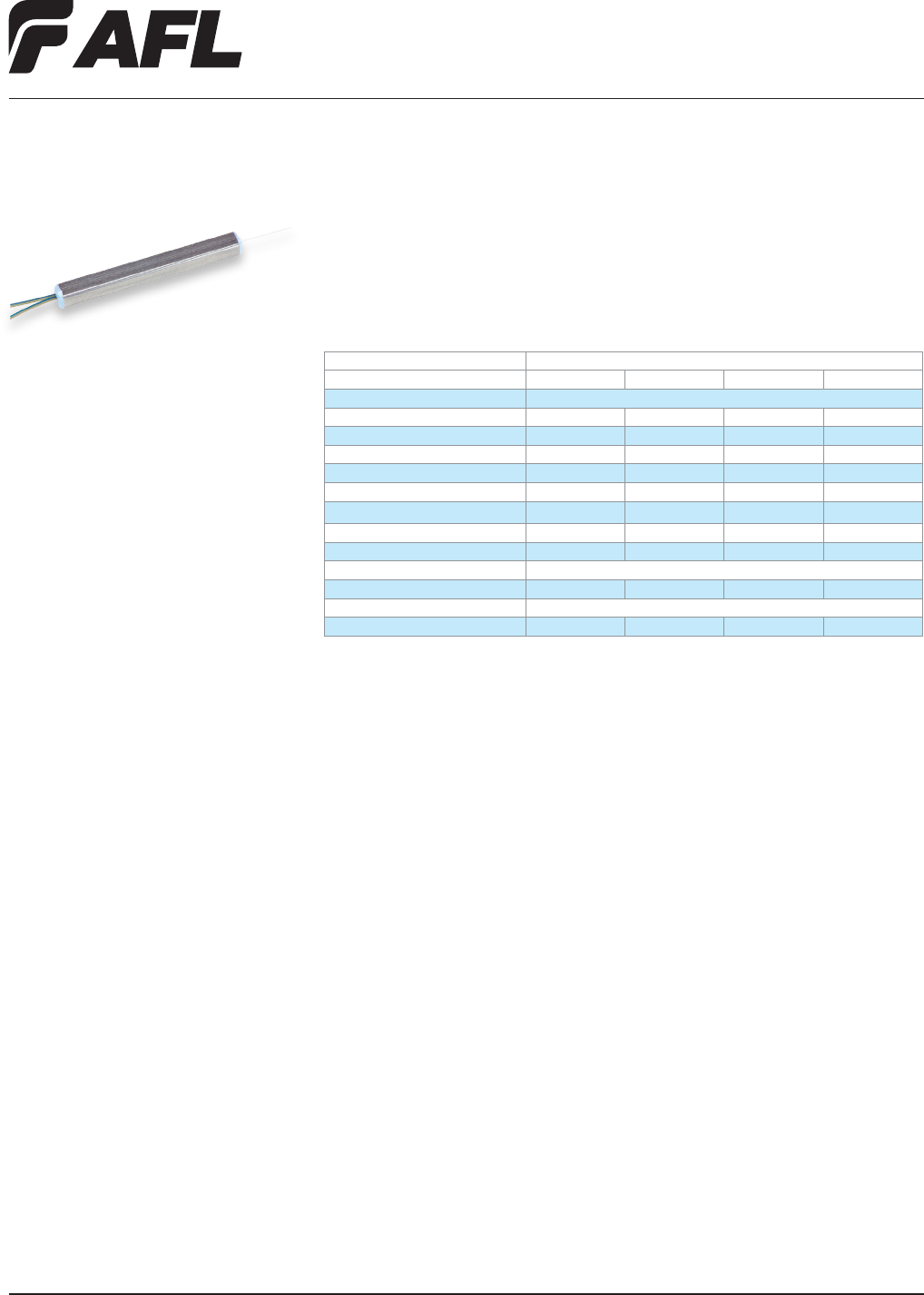
Planar Couplers
The Planar Coupler provides the uniform division of an optical signal by having one
input port and multiple output ports. Compact packaging and stable optical parameters
allow these couplers to be integrated into Telecommunications, Local Area Network
(LAN), and Cable Television (CATV) networks.
Features
• Low insertion loss
• Compact design
• Stable optical performance
• Dual Window (1310 & 1550 nm)
• Low insertion loss
• Low back reection
• High output uniformity
• Telecordia® GR-1029 and GR-1221
qualied
Applications
• Telecommunications Networks
• Datacom
• LAN & CATV Networks
• FTTH, FTTB, & FTTC
Specifications
PARAMETER VALUE
AFL NO. CM000034 CM000033 C198299 CS001470
Operating Wavelength (Grade) 1260-1360 nm and 1480-1580 nm (Standard)
Optical Split Ratio 1 x 4 1 x 8 1 x 16 1 x 32
Maximum Insertion Loss (dB) 7.5 11.0 14.2 17.8
Typical Insertion Loss (dB) 7.3 10.8 13.9 17.5
Maximum Uniformity (dB) 1.0 1.0 1.5 2.0
Typical Uniformity (dB) 0.8 0.8 1.3 1.8
PDL (dB) <0.3 <0.3 <0.4 <0.4
Return Loss (dB) >55 >55 >55 >55
Directivity (dB) >55 >55 >55 >55
Fiber Type SMF28e 250 µm equivalent
Input/Output Fiber Length 1 meter 1.5 meters 1.5 meters 1.5 meters
Operating Temperature -40° to +85°C
Package Dimensions (LxWxH) (mm) 40 x 4 x 4 40 x 4 x 4 40 x 4 x 4 50 x 6.5 x 4
Telcordia is a registered trademark of Telcordia Technologies, Inc.
Fiber Inside Plant
www.AFLglobal.com or (800)235-3423
29
© 2002, AFL, all rights reserved. PP-2-00091, Revision 4, 5.24.11
Specications are subject to change without notice.
Features
• Telcordia GR-1209 & GR-1221 compliant
• Telcordia GR-326 compliant connectors
and adapters
• Telcordia GR-20 compliant singlemode
optical ber
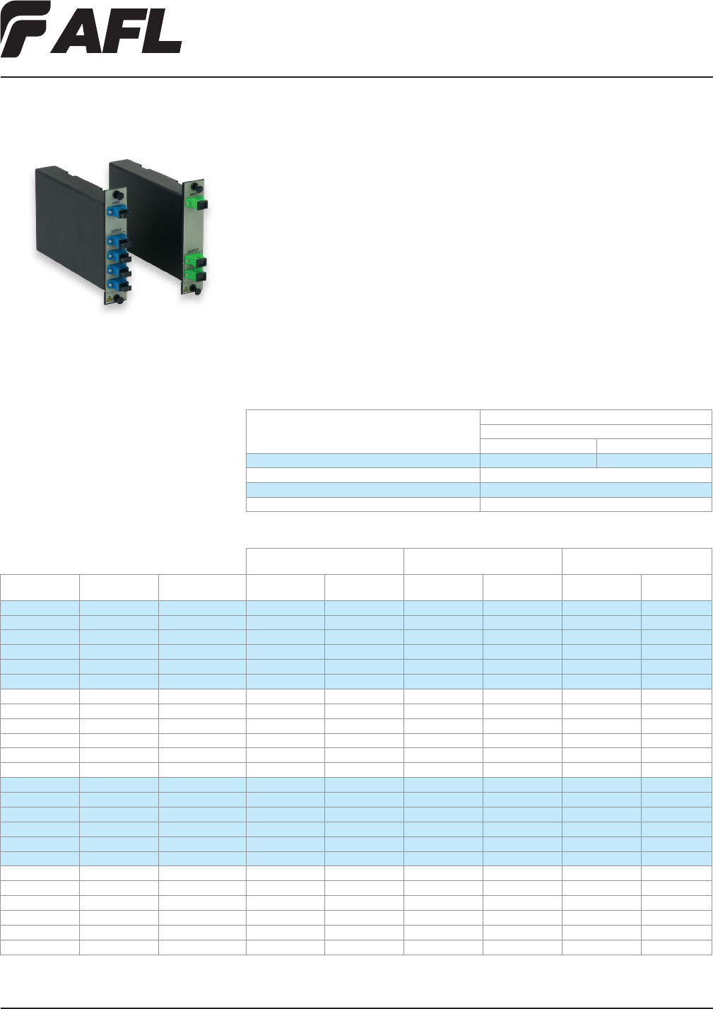
Optical Coupler Modules
The optical coupler module offers management of optical power and wavelength, pack-
aged in the LGX® desgin. Each module is comprised of Telcordia®-compliant
PLC or concatenated fused biconic components. Once assembled and terminated,
the module is fully tested for environmental, mechanical, and optical integrity.
Applications
• CATV
• Telco
• Wide Area Networks
• Fiber Monitoring Systems
• Military systems
Ordering Information
LGX is a registered trademark of Furukawa Electric North America, Inc.
Telcordia is a registered trademark of Telcordia Technologies, Inc.
Specifications
PARAMETER
VALUE
Single-mode
Ultra Angled
Return Loss (Minimum dB) > -45 > -50
Directivity > -55
Operating Temperature/ Relative Humidity -40 to +85°C / 90%
Storage Temperature/ Relative Humidity -40 to +85°C / 90%
OUTPUT PORT
COUPLING RATIO (PORT)
INSERTION LOSS
(IL) PORT 01
INSERTION LOSS
(IL) PORT 02
I/O PORTS I/O CONN AFL NO. 01 02 TYP MAX TYP MAX
1 x 2 USC CM000165 50 50 3.3 4.0 3.3 4.0
1 x 2 USC CM000166 40 60 4.3 5.2 2.5 3.3
1 x 2 USC CM000167 30 70 5.5 6.4 1.5 2.4
1 x 2 USC CM000168 20 80 7.3 8.3 1.3 1.8
1 x 2 USC CM000169 10 90 10.3 11.5 0.8 1.1
1 x 2 USC CM000170 5 95 13.3 14.6 0.5 0.8
1 x 2 ASC CM000171 50 50 3.3 4.0 3.3 4.0
1 x 2 ASC CM000172 40 60 4.3 5.2 2.5 3.3
1 x 2 ASC CM000173 30 70 5.5 6.4 1.5 2.4
1 x 2 ASC CM000174 20 80 7.3 8.3 1.3 1.8
1 x 2 ASC CM000175 10 90 10.3 11.5 0.8 1.1
1 x 2 ASC CM000176 5 95 13.3 14.6 0.5 0.8
1 x 2 ULC CM000315 50 50 3.3 4.0 3.3 4.0
1 x 2 ULC CM000325 40 60 4.3 5.2 2.5 3.3
1 x 2 ULC CM000323 30 70 5.5 6.4 1.5 2.4
1 x 2 ULC CM000321 20 80 7.3 8.3 1.3 1.8
1 x 2 ULC CM000319 10 90 10.3 11.5 0.8 1.1
1 x 2 ULC CM000317 5 95 13.3 14.6 0.5 0.8
1 x 2 ALC CM000310 50 50 3.3 4.0 3.3 4.0
1 x 2 ALC CM000324 40 60 4.3 5.2 2.5 3.3
1 x 2 ALC CM000322 30 70 5.5 6.4 1.5 2.4
1 x 2 ALC CM000320 20 80 7.3 8.3 1.3 1.8
1 x 2 ALC CM000318 10 90 10.3 11.5 0.8 1.1
1 x 2 ALC CM000316 5 95 13.3 14.6 0.5 0.8
• Optical bandpass: 1310 ± 40 nm /
1550 ± 40 nm
• RoHS compliant
• Packaged individually / tamper-proof seal
Fiber Inside Plant
www.AFLglobal.com or (800)235-3423
30
© 2002, AFL, all rights reserved. PP-2-00091, Revision 4, 5.24.11
Specications are subject to change without notice.
Optical Coupler Modules
Ordering Information (cont.)
OUTPUT PORT
COUPLING RATIO (PORT)
INSERTION LOSS
PORT 01 PORT 02 PORT 03
I/O PORTS I/O CONN AFL NO. 01 02 03 TYP MAX TYP MAX TYP MAX
1 x 3 USC CM000177 33.0 33.0 33.0 5.1 6.2 5.1 6.2 5.1 6.2
1 x 3 ASC CM000178 33.0 33.0 33.0 5.1 6.2 5.1 6.2 5.1 6.2
1 x 3 ULC CM000326 33.0 33.0 33.0 5.1 6.2 5.1 6.2 5.1 6.2
1 x 3 ALC CM000311 33.0 33.0 33.0 5.1 6.2 5.1 6.2 5.1 6.2
OUTPUT PORT
COUPLING RATIO (PORT)
INSERTION LOSS
PORT 01 PORT 02 PORT 03 PORT 04
I/O PORTS I/O CONN AFL NO. 01 02 03 04 TYP MAX TYP MAX TYP MAX TYP MAX
1 x 4 USC CM000179 25.0 25.0 25.0 25.0 6.3 7.7 6.3 7.7 6.3 7.7 6.3 7.7
1 x 4 ASC CM000180 25.0 25.0 25.0 25.0 6.3 7.7 6.3 7.7 6.3 7.7 6.3 7.7
1 x 4 ULC CM000327 25.0 25.0 25.0 25.0 6.3 7.7 6.3 7.7 6.3 7.7 6.3 7.7
1 x 4 ALC CM000312 25.0 25.0 25.0 25.0 6.3 7.7 6.3 7.7 6.3 7.7 6.3 7.7
OUTPUT PORT
COUPLING RATIO (PORT)
INSERTION LOSS
PORT 01 PORT 02 PORT 03 PORT 04
I/O
PORTS
I/O
CONN AFL NO. 01 02 03 04 05 06 07 08 TYP MAX TYP MAX TYP MAX TYP MAX
1 x 8 USC CM000181 12.5 12.5 12.5 12.5 12.5 12.5 12.5 12.5 9.3 11.4 9.3 11.4 9.3 11.4 9.3 11.4
1 x 8 ASC CM000182 12.5 12.5 12.5 12.5 12.5 12.5 12.5 12.5 9.3 11.4 9.3 11.4 9.3 11.4 9.3 11.4
1 x 8 ULC CM000346 12.5 12.5 12.5 12.5 12.5 12.5 12.5 12.5 9.3 11.4 9.3 11.4 9.3 11.4 9.3 11.4
1 x 8 ALC CM000347 12.5 12.5 12.5 12.5 12.5 12.5 12.5 12.5 9.3 11.4 9.3 11.4 9.3 11.4 9.3 11.4
OUTPUT PORT
COUPLING RATIO (PORT)
INSERTION LOSS
PORT 05 PORT 06 PORT 07 PORT 08
I/O
PORTS
I/O
CONN AFL NO. 01 02 03 04 05 06 07 08 TYP MAX TYP MAX TYP MAX TYP MAX
1 x 8 USC CM000181 12.5 12.5 12.5 12.5 12.5 12.5 12.5 12.5 9.3 11.4 9.3 11.4 9.3 11.4 9.3 11.4
1 x 8 ASC CM000182 12.5 12.5 12.5 12.5 12.5 12.5 12.5 12.5 9.3 11.4 9.3 11.4 9.3 11.4 9.3 11.4
1 x 8 ULC CM000346 12.5 12.5 12.5 12.5 12.5 12.5 12.5 12.5 9.3 11.4 9.3 11.4 9.3 11.4 9.3 11.4
1 x 8 ALC CM000347 12.5 12.5 12.5 12.5 12.5 12.5 12.5 12.5 9.3 11.4 9.3 11.4 9.3 11.4 9.3 11.4
Insertion loss (IL) includes connector loss and Polarization Dependent Loss (PDL) across operating temperature over the Optical Bandpass.
*** Additional split ratios available upon request.
Fiber Inside Plant
www.AFLglobal.com or (800)235-3423 © 2011, AFL, all rights reserved. PP-2-00083, Revision 0, 3.15.11
Specications are subject to change without notice.
3131
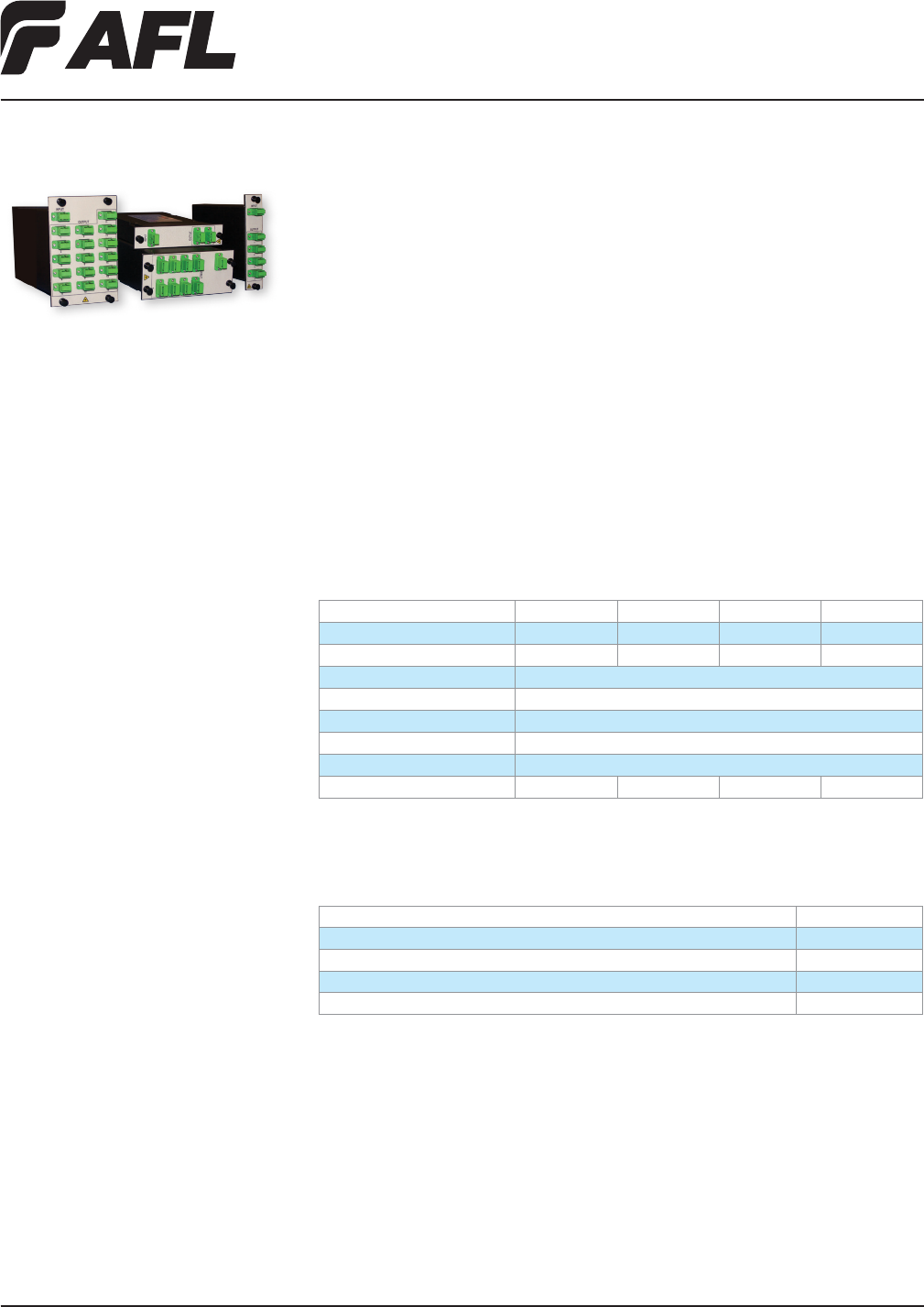
LGX® FTTx Splitter Modules
The PON / FTTx splitters provide a convenient in-rack solution to combine or split optical
signals in an optical network. Based on PLC technology, these modules offer the network
operator high port-to-port uniformity and low insertion loss, as well as a wide operating
wavelength range to accommodate future growth needs with new and emerging optical
technologies. These products are available in LGX compatible modules.
Features
• Low excess loss
• Low polarization dependent loss
• Flexible LGX packaging options
(* see ordering information below
for product size information)
• Telcordia® GR-1209 or GR-1221 compliant
• SC/APC Connectors
Applications
• PON - FTTx Networks
• Access Networks
• CATV Links
• Wide Area Networks
LGX is a registered trademark of Furukawa Electric North America, Inc.
Telcordia is a registered trademark of Telcordia Technologies, Inc.
Ordering Information
DESCRIPTION AFL NO.
1x4 Optical Splitter Module, 1260~1650 nm, Single slot LGX, Black, SC/APC CM000474
1x8 Optical Splitter Module, 1260~1650 nm, Dual slot LGX, Black, SC/APC CM000475
1x16 Optical Splitter Module, 1260~1650 nm, Triple slot LGX, Black, SC/APC CM000476
1x32 Optical Splitter Module, 1260~1650 nm, Triple slot LGX, Black, SC/APC CM000477
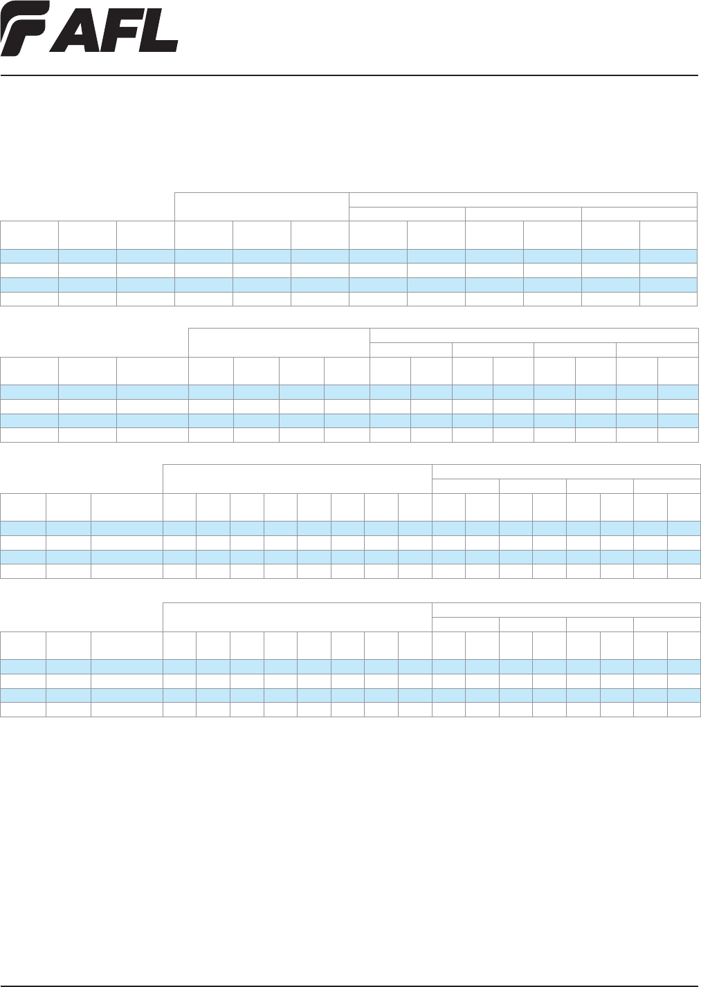
Performance Specifications
PARAMETER 1X4 1X8 1X16 1X32
Insertion Loss (dB) * <7.4 <10.5 <13.9 <17.2
Uniformity (dB) *, ** <0.5 <0.8 <1.1 <1.5
PDL (dB) *, ** <0.3
Return Loss (dB) >55
Directivity (dB) >55
Operating Temperature (°C) -40 to +85
Storage Temperature (°C) -40 to +85
Package LGX, 1 Slot LGX, 2 Slot LGX, 3 Slot LGX, 3 Slot
*Operating wavelength range (1260-1650 nm) guaranteed by design. Test report provided at 1310 and 1550 nm.
** Value does not include connector loss.
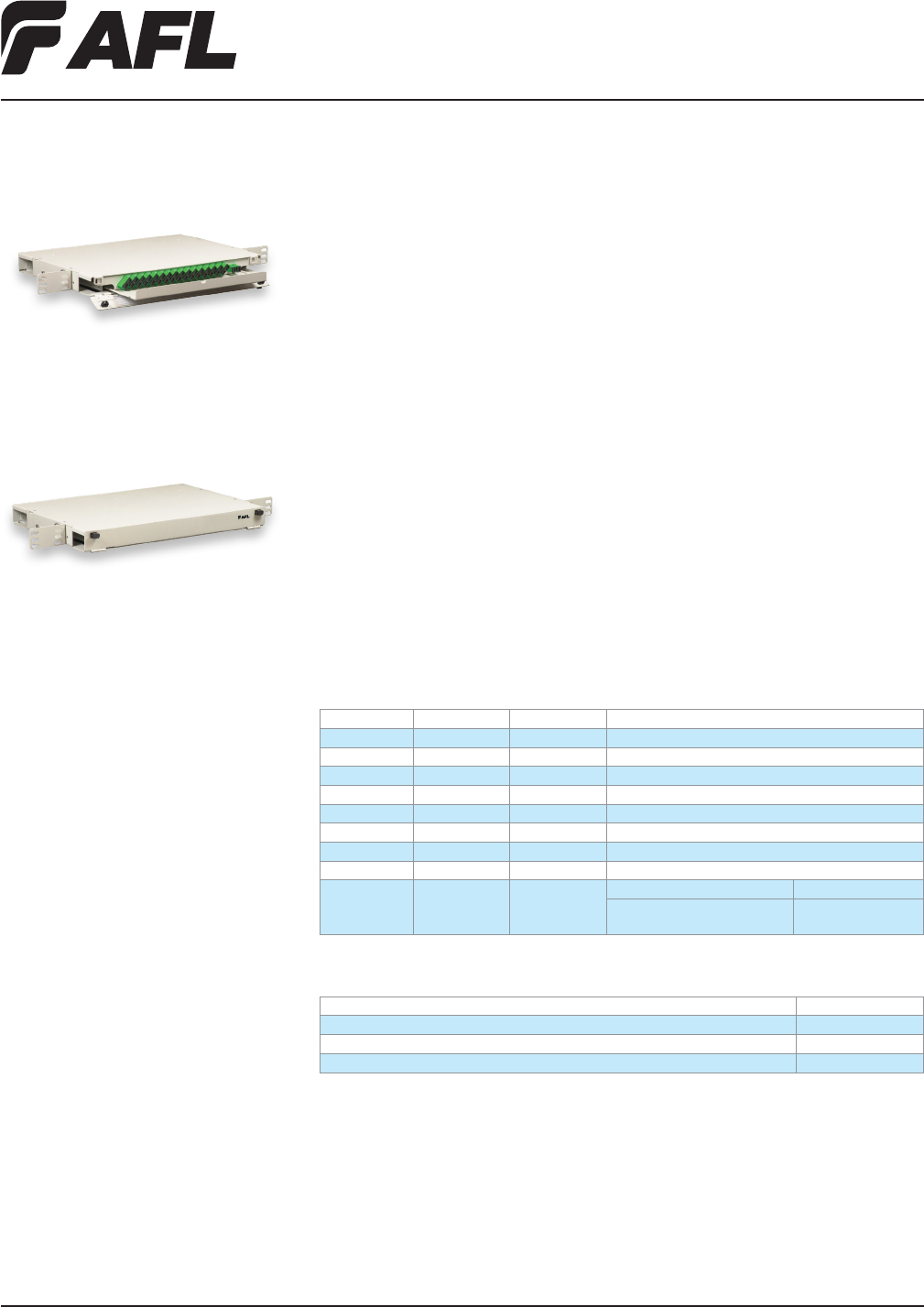
Fiber Inside Plant
www.AFLglobal.com or (800)235-3423
32
© 2006, AFL, all rights reserved. PP-2-00094, Revision 4, 10.10.12
Specications are subject to change without notice.
Ordering Information
DESCRIPTION AFL NO.
1x16 Optical Splitter Shelf, ASC inputs/outputs, 1U, textured White FM001000
1x32 Optical Splitter Shelf, ASC inputs/outputs, 1U, textured White FM000775
2x32 Optical Splitter Shelf, ASC inputs/outputs, 1U, textured White FM000622
The LightLink LanSystem™ Optical Splitter Shelf provides a convenient in-rack solu-
tion to combine/split optical signals in a passive optical network. With 1x16, 1x32 and
2x32 options available, the splitter shelf also features a Planar Lightwave Circuit (PLC)
allowing a signal to be split into either 16 or 32 channels in a 1U rack-mountable
housing. The 2x32 option provides a lter WDM concatenated to a PLC, which allows
1310/1490/1550 nm signal management evenly across 32 channels.
Optical Splitter Shelf
Features
• Telcordia® GR-63 NEBS tested housing
• Aluminum Material per ASTMB209
• Universal Mounting Bracket WECO, EIA
• 19" and 23" Rack Mountable
• Rugged construction, ensuring environ-
mental, mechanical, and optical integrity
• WDM and PLC fully compliant to
Telcordia GR-1209 and GR-1221
• Low Excess loss
• Low Polarization Dependent Loss
Applications
• PON-FTTx Networks
• CATV links
• DWDM & CWDM systems
• Wide area networks
• Outside plant requirements
Specifications
PARAMETER 1x16 1x32 2x32
Insertion Loss 13.5 ~ 14.3 dB 17.5 - 18.5 dB 17.5 - 19 dB
Uniformity 1.5 dB Typical 1.8 dB Typical 1.8 dB Typical
PDL ≤ 0.3 dB <0.45 dB <0.45 dB
Return Loss ≥ 55 dB ≥ 55 dB ≥ 40 dB
Directivity ≥ 55 dB ≥ 55 dB ≥ 50 dB
Fiber Type SMF-28e SMF-28e SMF-28e
Operating Temp -40°C to +85°C -40°C to +85°C -40°C to +70°C
Storage Temp -40°C to +85°C -40°C to +85°C -40°C to +85°C
Operating
Bandwidth
1260 ~ 1650 1260 ~ 1650 1550 nm Band - Port 1 (Pass) 1550 - 1560 nm
1310 + 1490 nm - Port 2 (Reect) 1260-1360 nm &
1480-1500 nm
Telcordia is a registered trademark of Telcordia Technologies, Inc.
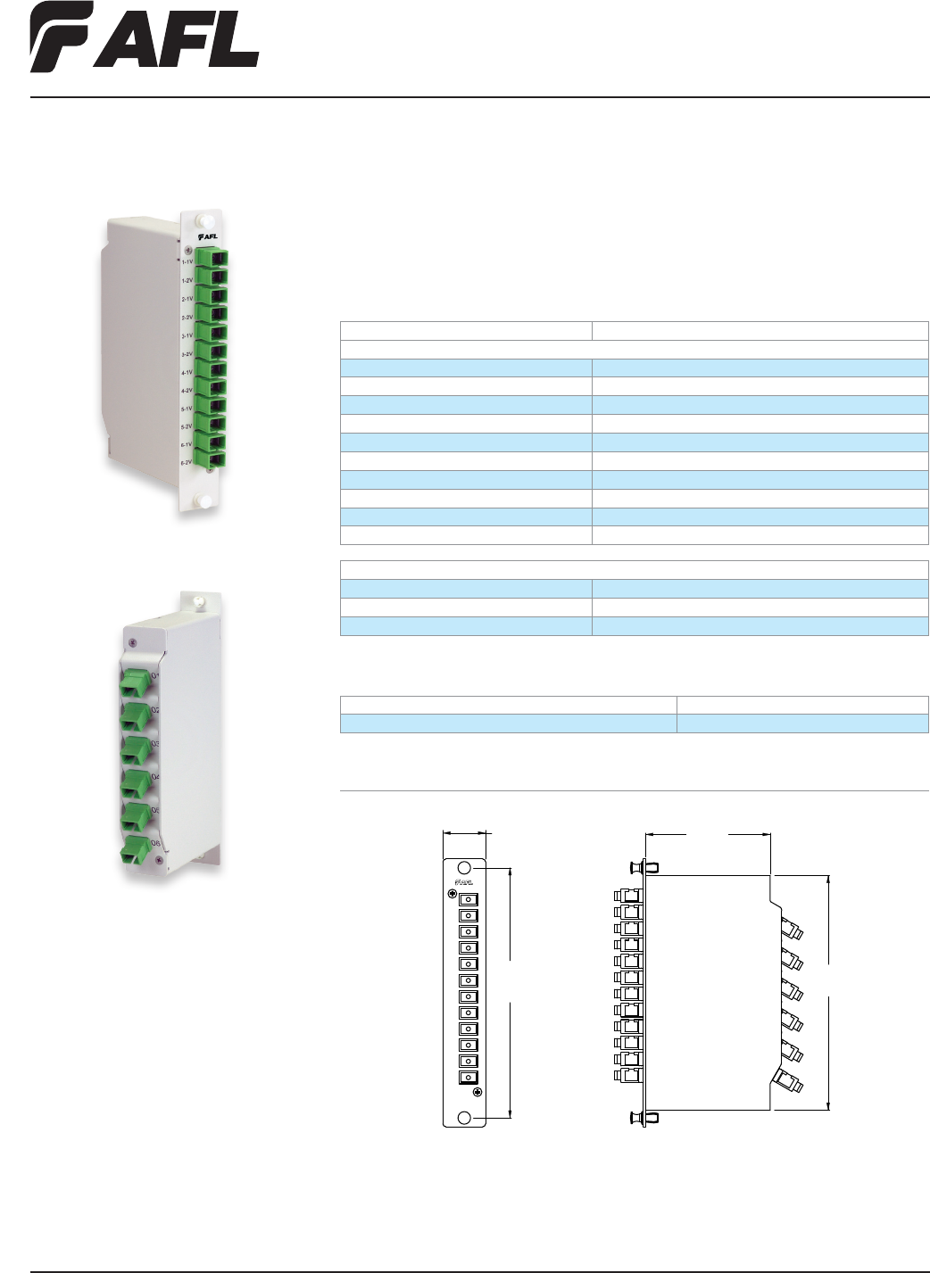
Fiber Inside Plant
www.AFLglobal.com or (800)235-3423
33
© 2004, AFL, all rights reserved. PP-2-00092, Revision 2, 5.24.11
Specications are subject to change without notice.
Optical FTTx Coupler Module
AFL’s Optical FTTx Coupler Module is designed to satisfy requirements utilizing 1550 nm
bandwidths in FTTx applications and is specied for FTTx video install-ations. The module
features a compact footprint with adapter ports consisting of SC/APC adapter outputs.
Specifications
PARAMETER VALUE
Performance
Wavelength 1540-1560 nm
Insertion Loss 1550 < 3.9 dB
PDL <0.2 dB
PMD < 0.05 ps
Return Loss > 55 dB
Directivity > 55 dB
Operating Temperature -40 to +75°C
Storage Temperature -40 to +85 °C
Relative Humidity 0 to 90%
Optical Power 500 mW
Dimensions
Ordering Information
DESCRIPTION AFL NO.
Optical FTTx Coupler Module CM000072
84.60 mm
3.33"
155.60 mm
6.13"
29.00 mm
1.14"
171.00 mm
6.73"
LGX is a registered trademark of Furukawa Electric North America, Inc.
PACKAGING
Packaging Size Standard Single Width LGX® Rack Module
Fiber Type Low-Water-Peak Non-Dispersion Shifted SMF-28e
Connector Type All ports – SC/APC, Green
Fiber Inside Plant
www.AFLglobal.com or (800)235-3423
34
© 2002, AFL, all rights reserved. PP-2-00109, Revision 1, 5.24.11
Specications are subject to change without notice.
Wavelength Division Multiplexer Couplers
The WDM separates or combines wavelengths in the 1310 and 1550 nm bands over
an ultra-wide bandwidth (+ 20 nm) and temperature range while maintaining excellent
stability and optical performance. The device, which is fabricated using an advanced fused
biconical taper technology, is designed to meet Telcordia® 1209 and 1221 requirements.
Features
• Low insertion loss
• Ultra-wide bandwidth
• Wide operating temperature
• Low PDL
• Highly stable and reliable
• Epoxy-free optical path
Applications
• Telecommunications
• CATV
• Fiber Optic Sensors and Instruments
• Subscriber Loops
• Military Systems, Fiber Optic Gyros
• FTTH
Specifications (Single-Mode Premium)
PARAMETER VALUE
Model Number S004794
Conguration 1 x 2
Wavelength 1310 / 1550 nm
Directivity <-65 dB
Operating Temperature -40º to +85ºC
Typical Temperature Stability <0.1 dB
Typical Polarization Stability (passband) <0.1 dB
Isolation 20 dB
*Isolation of 32 dB and higher not available in 63 mm L or 69 mm L x 3 mm OD
Telcordia is a registered trademark of Telcordia Technologies, Inc.
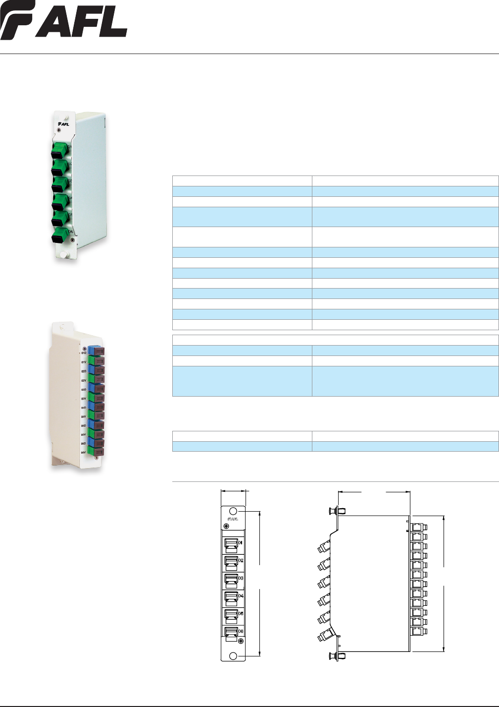
Fiber Inside Plant
www.AFLglobal.com or (800)235-3423
35
© 2004, AFL, all rights reserved. PP-2-00093, Revision 2, 5.24.11
Specications are subject to change without notice.
Specifications
PARAMETER VALUE
1550 Band – Port 1 (Pass) 1550-1560 nm
1310 + 1490 Band – Port 2 (Reect) 1260-1360 & 1480-1500 nm
Insertion Loss 1550 < 1.2 dB
1310 + 1490 < 1.2 dB
Isolation 1550 > 25 dB
1310 + 1490 > 20 dB
PDL <0.2 dB
PMD < 0.2 ps
Return Loss > 50 dB
Directivity > 50 dB
Operating Temperature -40 to +75°C
Storage Temperature -40 to +85°C
Relative Humidity 0 to 90%
Optical Power 500 mW
PACKAGING
Packaging Size Standard Single Width LGX® Rack Module
Fiber Type Low-Water-Peak Non-Dispersion Shifted SMF-28e
Connector Type Port 3 (Common) – SC/APC
Port 1 (Data) – SC/UPC
Port 2 (Video) – SC/APC
Ordering Information
AFL NO. DESCRIPTION
CM000043 Optical FTTx WDM Module
84.60 mm
3.33"
155.60 mm
6.13"
29.00 mm
1.14"
171.00 mm
6.73"
Optical FTTx WDM Module
The Optical FTTx WDM Module is designed to satisfy requirements utilizing 1310, 1490
and 1550 nm bandwidths in FTTx applications. The module features a compact footprint
with adapter ports consisting of SC (UPC or APC) outputs.
Dimensions
LGX is a registered trademark of Furukawa Electric North America, Inc.
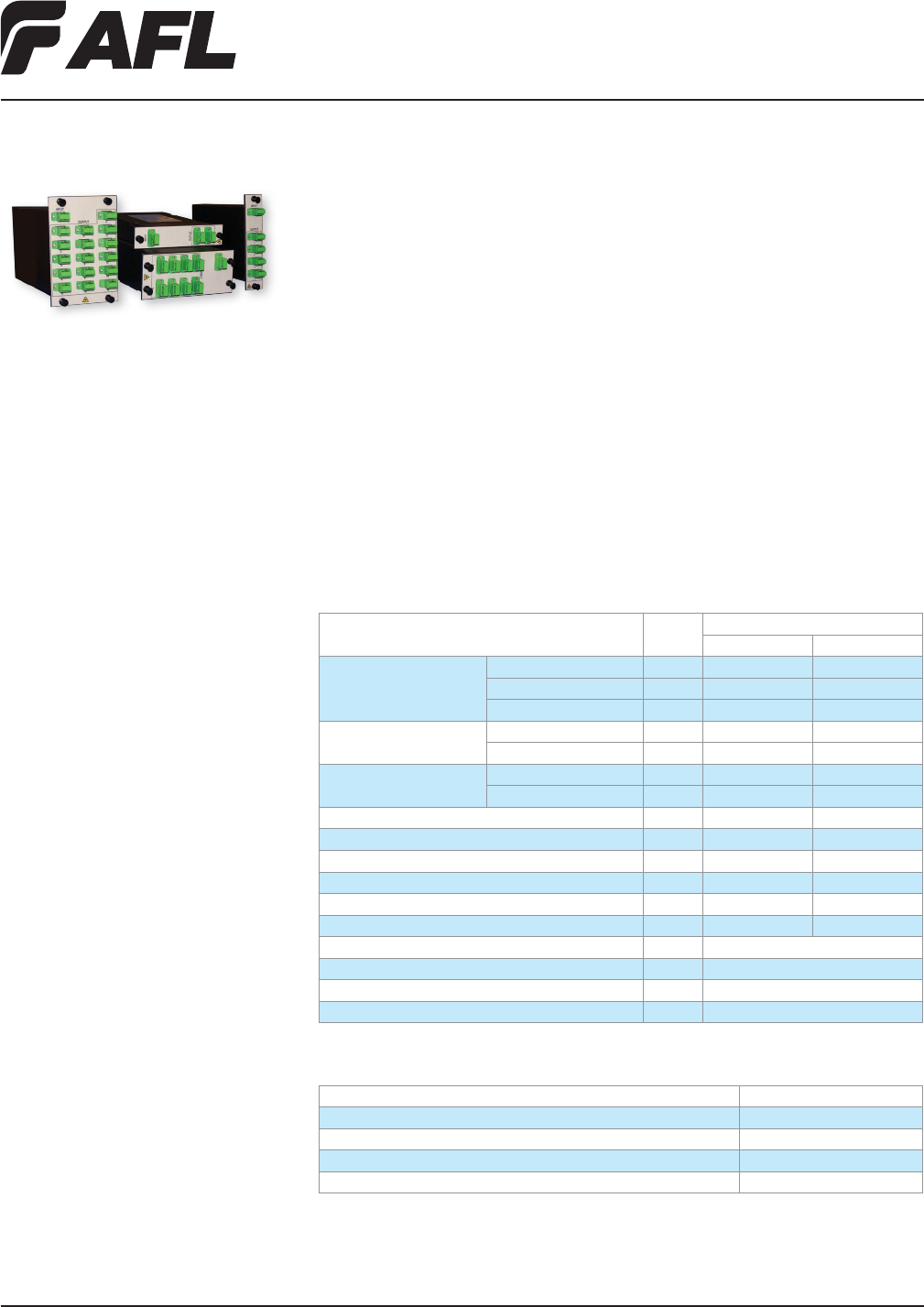
Fiber Inside Plant
www.AFLglobal.com or (800)235-3423 © 2011, AFL, all rights reserved. PP-2-00084, Revision 1, 5.26.11
Specications are subject to change without notice.
3636
LGX is a registered trademark of Furukawa Electric North America, Inc.
Telcordia is a registered trademark of Telcordia Technologies, Inc.
Ordering Information
DESCRIPTION AFL NO.
PON WDM Module, 1X, 1310/1490+1550, Single slot LGX, Black, SC/APC CM000478
PON WDM Module, 2X, 1310/1490+1550, Single slot LGX, Black, SC/APC CM000479
PON WDM Module, 4X, 1310/1490+1550, Dual slot LGX, Black, SC/APC CM000480
PON WDM Module, 6X, 1310/1490+1550, Triple slot LGX, Black, SC/APC CM000481
Performance Specifications
PARAMETER UNIT SPECIFICATION
MINIMUM MAXIMUM
Wavelength Range
1310 Band nm 1260 1360
1490 Band nm 1480 1500
1550 Band nm 1550 1560
Insertion Loss 1310+1490 Port dB 1.2
1550 Port dB 1.4
Band Isolation 1310/1490 Port @ 1550 dB 40
1550 @ 1310/1490 Port dB 30
Wavelength Thermal Stability nm/°C 0.002
Directivity dB 50
PDL dB 0.15
PMD ps 0.1
Return Loss dB 45
Optical Power Level mW 300
Operation Temperature °C -5 to 70
Operation Humidity %RH 5 to 90
Storage Temperature °C 40 to 85
Storage Humidity %RH 0 to 95
LGX® FTTx WDM Modules
The FTTx WDM Modules are designed to satisfy 1310, 1490 and 1550 nm wavelength
management requirements in FTTx passive optical networks. Based on proven thin-lm
lter technology, these modules offer low overall insertions loss, high wavelength thermal
stability and high band isolation, all of which add to network reliability. These products are
available in LGX compatible modules of scaling density to meet varying density objectives.
Features
• Low excess loss
• Low polarization dependent loss
• Flexible LGX packaging options
(* see ordering information below for
product size and density information)
• Telcordia® GR-1209 or GR-1221 compliant
• SC/APC Connectors
Applications
• PON - FTTx Networks
• Access Networks
• CATV Links
• Wide Area Networks
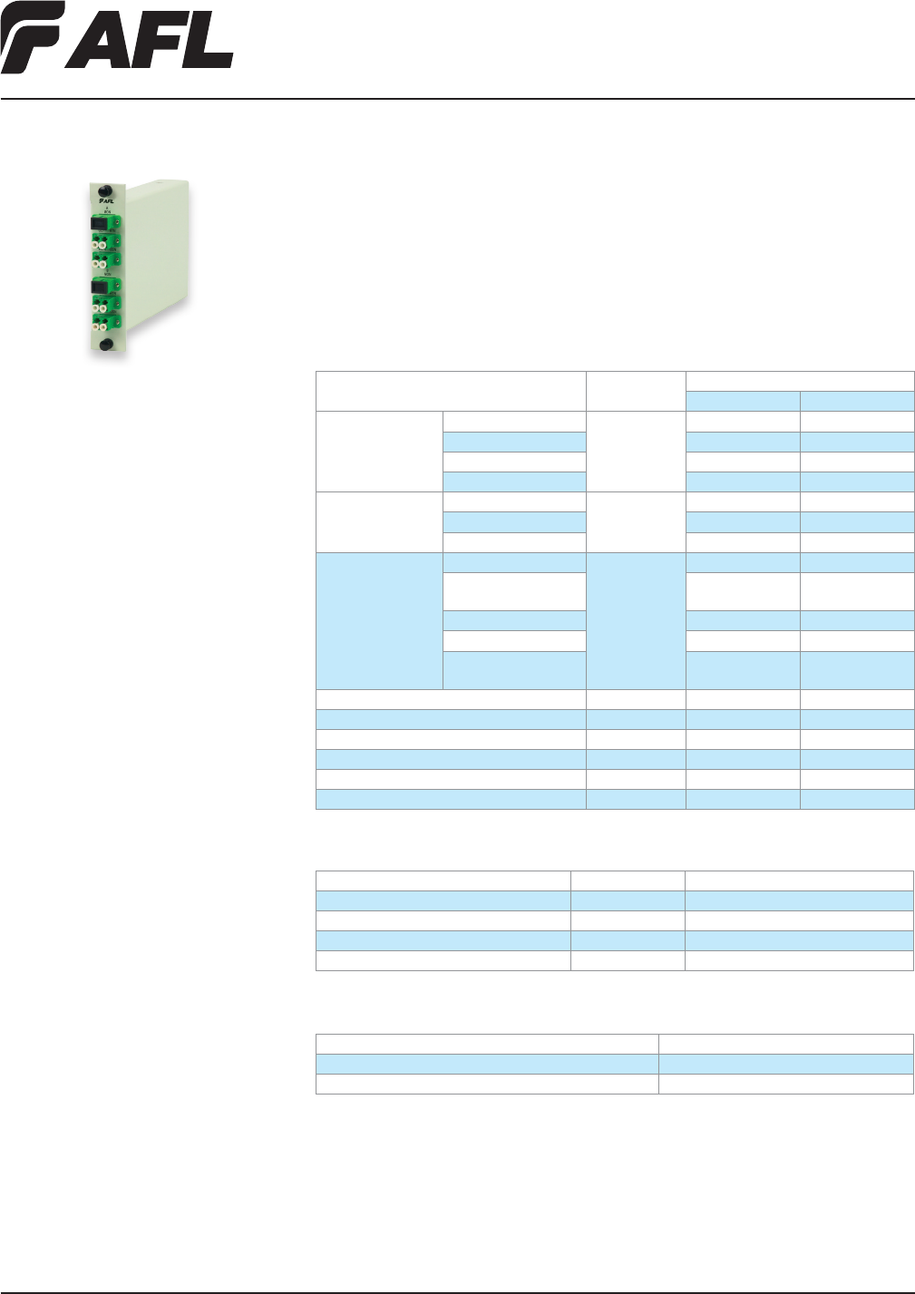
Fiber Inside Plant
www.AFLglobal.com or (800)235-3423 © 2010, AFL, all rights reserved. PP-2-00099, Revision 1, 5.24.11
Specications are subject to change without notice.
37
RFoG WDM Module
The RFOG WDM module is designed to satisfy wavelength management requirements where
1310, 1490, 1550, 1590 / 1610 nm wavelengths are used in passive optical network appli-
cations. This unit is available in traditional LGX® module packaging with virtually all connec-
tor options supported. Also available is a high density platform delivering unsurpassed ports
per rack unit for applications requiring the most efcient use of available rack space.
Features
• Flexible packaging options
• Low Excess Loss
• Low PDL
• Monitoring / Tap ports available
• RoHS compliant
Applications
• PON - FTTx Networks
• Access Networks
• CATV Links
Specifications
PARAMETER UNIT SPECIFICATION
MIN MAX
Wavelength Range 1310 Band nm 1270 1350
1490 Band 1480 1500
1550 Band 1540 1570
1590/1610 Band 1584.5 1620
Insertion Loss 1310+1490 Port dB - 1.2
1550 Port 1.4
1590/1610 Port 1.5
Band Isolation 1310/1490 Port @ 1550 dB 40
1310/1490 Port @
1590/1610
40
1550 Port @ 1310/1490 30
1550 Port @ 1590 15
1590/1610 Port @
1310/1490/1550
35
Wavelength Thermal Stability nm/°C 0.002
Directivity dB 50
PDL dB 0.15
PMD ps 0.10
Return Loss dB 45
Optical Power Handling mW 300
Environmental Specifications
PARAMETER UNIT SPECIFICATION
Operation Temperature °C -5 ~ +70
Operation Humidity %RH 5 ~ 95 not condensed
Storage Temperature °C -40 ~ +85
Storage Humidity %RH 0 ~ 95 not condensed
Ordering Information
DESCRIPTION AFL NO.
FILTER WDM,1310+1490/1550+1590/1610,SC/APC CM000150
DUAL FILTER WDM,1310+1490/1550+1590/1610,LC/APC CM000151
* Additional conguration available upon request. Contact AFL Customer Service.
LGX is a registered trademark of Furukawa Electric North America, Inc.
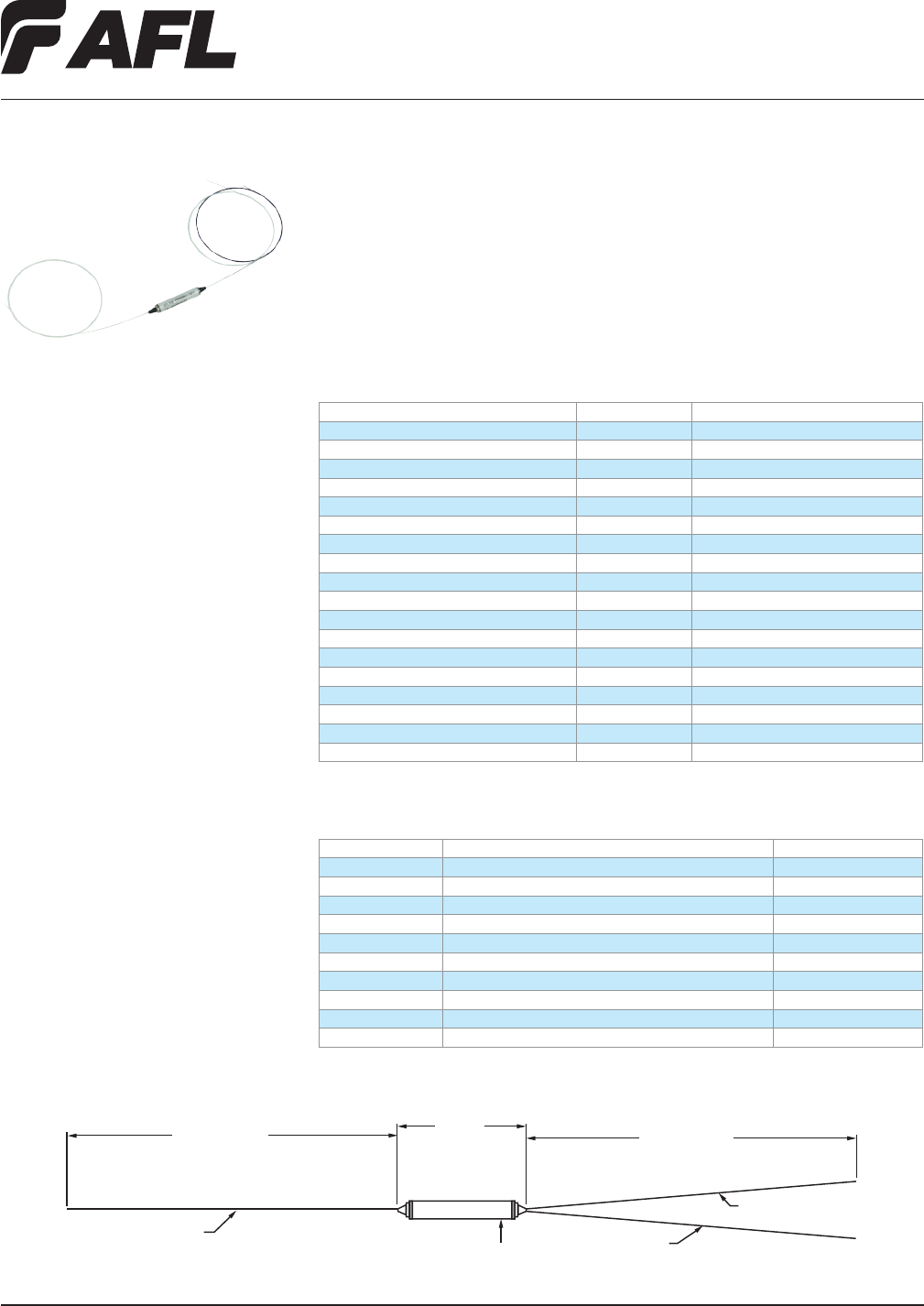
Fiber Inside Plant
www.AFLglobal.com or (800)235-3423 © 2010, AFL, all rights reserved. PP-2-00046, Revision 1, 10.30.12
Specications are subject to change without notice.
38
CWDM Single-channel OADM
The CWDM Single-channel OADM is designed to add/drop a single CWDM channel from
an optical ber. This product is hardened and designed to perform in OSP applications
from -40° to +85° C, but can also be used in splice trays or similar structures in Inside
Plant or similar environments. While 250um leads are most commonly desired, these
products can also be supplied with color-coded 900um leads and terminated with virtu-
ally any common single-ber optical connector.
Applications
• Metro Ethernet / Cellular Backhaul
• Access Networks
• CWDM Systems
• CATV Links
Features
• Hardened for OSP use
• Low Excess Loss
• Low PDL
• Color coded 900um leads available
• RoHS Compliant
Specifications
PARAMETER UNIT VALUE
Center Wavelength nm ITU-T Grid
Channel Passband nm ITU-T Grid ± 6.5
Passband Flatness dB < 0.5
Bandwidth (@ -5dB) nm >14
Insertion Loss (Pass Channel) dB < 1.0
Insertion Loss (Reect Channel) dB < 0.6
Adjacent Channel Isolation dB > 30
Non-Adjacent Channel Isolation dB > 45
Isolation (Reect Channel) dB > 13
Return Loss dB > 45
PDL dB < 0.1
Directivity dB > 50
IL Thermal Stability dB/°C < 0.005
Wavelength Thermal Stability nm/°C < 0.002
Operation Temperature °C -40 to +85
Operation Humidity % RH 5 to 95 not condensed
Storage Temperature °C -40 to +85
Storage Humidity % RH 0 to 95 not condensed
Part Numbers
ITEM NUMBER MODEL CODE PASSBAND
CW000311-1431 CWDM TFF, 3-Port, 1431nm, 250um leads, NC, OSP 1431
CW000311-1451 CWDM TFF, 3-Port, 1451nm, 250um leads, NC, OSP 1451
CW000311-1471 CWDM TFF, 3-Port, 1471nm, 250um leads, NC, OSP 1471
CW000311-1491 CWDM TFF, 3-Port, 1491nm, 250um leads, NC, OSP 1491
CW000311-1511 CWDM TFF, 3-Port, 1511nm, 250um leads, NC, OSP 1511
CW000311-1531 CWDM TFF, 3-Port, 1531nm, 250um leads, NC, OSP 1531
CW000311-1551 CWDM TFF, 3-Port, 1551nm, 250um leads, NC, OSP 1551
CW000311-1571 CWDM TFF, 3-Port, 1571nm, 250um leads, NC, OSP 1571
CW000311-1591 CWDM TFF, 3-Port, 1591nm, 250um leads, NC, OSP 1591
CW000311-1611 CWDM TFF, 3-Port, 1611nm, 250um leads, NC, OSP 1611
* Additional conguration available upon request. Contact AFL Customer Service.
1 METER (Standard) 1 METER (Standard)
PASS (CLEAR)
39±1mm
Ø5.5
COMMON (BLACK)
REFLECT (CLEAR)
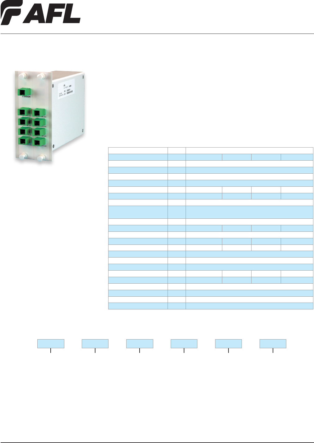
Fiber Inside Plant
www.AFLglobal.com or (800)235-3423
39
© 2005, AFL, all rights reserved. PP-2-00049, Revision 2, 5.24.11
Specications are subject to change without notice.
Coarse WDM Modules (CWDM)
AFL’s Coarse WDM modules are designed using proven thin-lm lter technology providing
high isolation, 20nm channel separation and a high level of thermal stability. CWDM mod-
ules are available in 2, 4, 8, and 16 channel congurations and are factory assembled in
a thin cassette or rugged LGX® cassette with industry standard connector options to meet
varying system requirements. An optional 1310 nm Mux/Demux Upgrade Port is available
to allow seamless integration of legacy voice, video, and data services.
Applications
• CATV Systems
• Sensor Systems
• 10G Ethernet Systems
• Metro Optical Networks
• Metro Access Networks
Features
• Telcordia® qualied components
• 20 nm channel spacing
• 2, 4, 8, and 16 channel congurations
• Most industry standard connectors
• Low insertion loss
• High isolation
• Custom congurations upon request
Ordering Information
Package/Pigtail
1 = Thin Cassette,
1 Meter Pigtail
3 = Thin Cassette,
3 Meter Pigtail
5 = Thin Cassette,
5 Meter Pigtail
L = LGX 118
End Wavelength (nm)
1291
1311
1331
1351
1371
1391
1411
1431
1451
1471
1491
1511
1531
1551
1571
1591
1611
Connectors
ASC = SC/APC
USC = SC/UPC
ALC = LC/APC
ULC = LC/UPC
X = No connectors
Start Wavelength (nm)
1271
1291
1311
1331
1351
1371
1391
1411
1431
1451
1471
1491
1511
1531
1551
1571
1591
Options
U = 1310 Upgrade Port
T = 2% Tap Port
X = No Option
B = 1310 Upgrade Port
and 2% Tap Port
Channel Count
02 = 2 Channel
04 = 4 Channel
08 = 8 Channel
16 = 16 Channel
04 51271 B1331 ASC
— — —— ——
CWDM —ISP
LGX is a registered trademark of Furukawa Electric North America, Inc.
Telcordia is a registered trademark of Telcordia Technologies, Inc.
Specifications
PARAMETER UNIT VALUE
Ports 2 4 8 16
Center Wavelength nm 1271-1611
Passband @ 0.5 dB nm > 14
Passband nm ± 6.5
Passband Flatness dB < 0.5
Insertion Loss (Typ.) dB 1.4 1.6 1.8 4.3
Insertion Loss (Max.) dB 1.8 2.0 2.5 5.0
Adjacent Channel Isolation dB > 30
Non-Adjacent Channel Isola-
tion
dB > 45
Wavelength Thermal Stability nm/°C < 0.002
IL Thermal Stability db/°C < 0.005 < 0.005 < 0.007 < 0.008
Return Loss dB > 45
PMD ps < 0.10 < 0.10 < 0.15 < 0.15
PDL dB < 0.10 < 0.15 < 0.20 < 0.25
Directivity dB > 50
Operation Temperature °C -5 to +65
Storage Temperature °C -40 to +85
LGX 118 Package Single-width Single-width Double-width Triple-width
Thin Cassette Package mm 88.9 x 50.8 x 8.3 120 x 80 x 13 130 x 87 x 13 150 x 115 x 13
Options 2% Tap, 1310 Upgrade
1310 Channel Wavelength nm 1260-1360
1310 Channel Isolation dB 40 minimum
1310 Channel Insertion Loss dB 1.3 maximum
* Includes Connectors
Double-width LGX 118 package shown
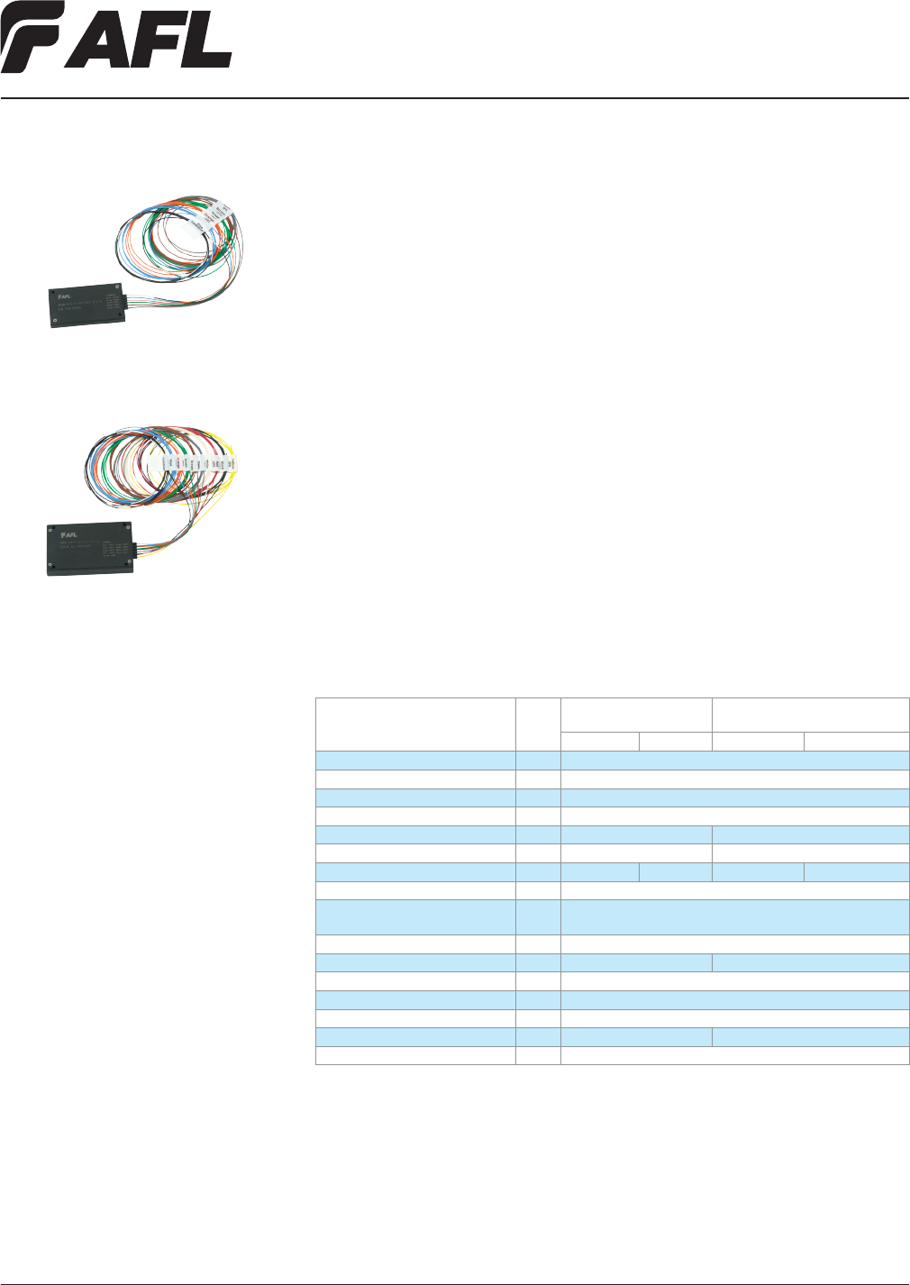
Fiber Inside Plant
www.AFLglobal.com or (800)235-3423
40
© 2010, AFL, all rights reserved. PP-2-00048, Revision 1, 10.30.12
Specications are subject to change without notice.
Thin Film Filter (TFF) Compact Series CWDM
AFL’s TFF compact series CWDM modules deliver reliable performance and exibility in
every network application – from cellular backhaul and metro Ethernet to access and
security. With its reduced package size, this new outside plant CWDM module has added
exibility, making deployment options more convenient.
This CWDM series is based on proven Thin Film Filter technology, offering low insertion
loss and high thermal stability over the entire outside plant operating temperature
range. Numerous congurations are available to meet unique needs and support new or
existing network architectures. Typical options include a variety of congurations (mux,
demux, and balanced), upgrade ports (1310, C-Band, and others), test / monitoring
ports and multiple termination options.
Applications
• CWDM systems
• Metro ethernet / access networks
• Cellular backhaul networks
Features
• Low insertion loss
• Compact size
• High thermal stability
• Telcordia GR-1221-CORE compliant
• RoHS 6/6 compliant
LGX is a registered trademark of Furukawa Electric North America, Inc.
Specifications
PARAMETER UNIT
WITHOUT UPGRADE
PORT WITH 1310NM UPGRADE PORT
4 Channel 8 Channel 4 Channel 8 Channel
Operating Wavelength nm 1471~1611
Channel Spacing nm 20
Center Wavelength nm Customer specied
Pass Band nm ± 6.5
1310 Upgrade Port Pass Band nm — 1270~1350
1310 Upgrade Port Insertion Loss dB — 1.0
CWDM Channel Insertion Loss dB ≤ 2.0 ≤ 2.5 ≤ 2.6 ≤ 3.4
CWDM Adjacent Channel Isolation dB ≥ 30
CWDM Non-adjacent Channel
Isolation
dB ≥ 45
PDL dB ≤ 0.2
PMD ps ≤ 0.1 ≤ 0.25
Return Loss dB ≥ 45
Directivity dB ≥ 50
Maximum Input Power mW ≤ 300
Package Size Mm 60 (l) x 35 (w) x 6(d) 70(l) x 45(w) x 9(d)
Operating Temperature °C -40 ~ +85
* Actual optical specications will vary based on product conguration
1. Higher and lower channel counts available
CWDM 4-Channel Mini Module
CWDM 8-Channel Mini Module
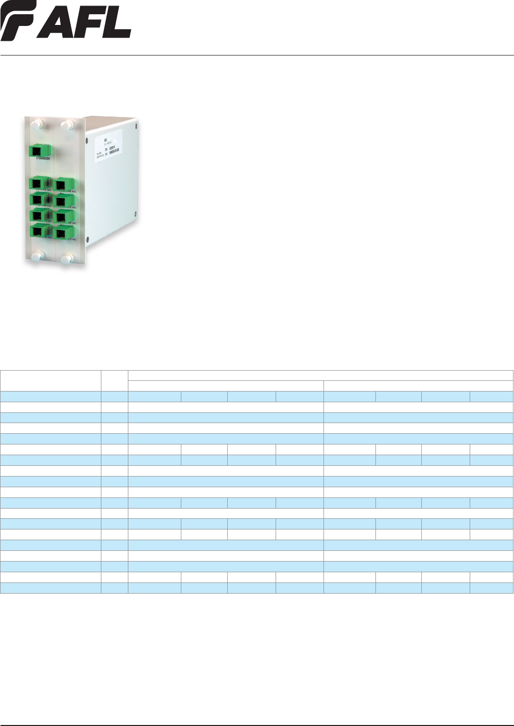
Fiber Inside Plant
www.AFLglobal.com or (800)235-3423
41
© 2008, AFL, all rights reserved. PP-2-00050, Revision 1, 5.24.11
Specications are subject to change without notice.
Dense WDM (DWDM) Modules
AFL’s Dense WDM modules (DWDM) are designed using proven thin-lm lter technology
featuring low insertion loss, high isolation, and superior environmental stability. DWDM
modules are available in 2, 4, 8, and 16 channel congurations, with 100 GHz and 200 GHz
spaced central wavelength options on the ITU-T Grid in the C-Band (1528 nm-1568 nm)
and L-Band (1568 nm-1610 nm). All DWDM modules are factory assembled in a thin cas-
sette package or a rugged LGX® cassette with most common industry standard connector
options to meet varying system requirements.
Applications
• CATV Systems
• Sensor Systems
• 10G Ethernet Systems
• Metro Optical Networks
• Metro Access Networks
Features
• Telcordia® qualied components
• 100 GHz & 200 GHz ITU-T channel spacing
• 2, 4, 8 and 16 channel congurations
• Most industry standard connectors
• Low insertion loss
• High isolation
• Epoxy-free optical path
LGX is a registered trademark of Furukawa Electric North America, Inc.
Telcordia is a registered trademark of Telcordia Technologies, Inc.
Double-width LGX 118 package shown
Specifications
PARAMETER UNIT
VALUE
100 GHZ DWDM 200 GHZ DWDM
Ports 2 4 8 16 2 4 8 16
Center Wavelength nm 1531-1561 (CH. 20-58) 1530-1560 (CH. 21-59)
Passband @ 0.5 dB nm >0.25 >0.6
Passband nm ±0.11 ±0.25
Passband Flatness dB <0.5 <0.5
Insertion Loss (Typ.) dB 1.4 1.6 2.6 3.8 1.4 1.6 2.6 3.8
Insertion Loss (Max.) dB 1.8 2.0 3.2 4.5 1.8 2.0 3.2 4.5
Adjacent Channel Isolation dB >25 >25
Non-Adjacent Channel Isolation dB >45 >45
Wavelength Thermal Stability nm/°C <0.001 <0.002
IL Thermal Stability db/°C <0.005 <0.005 <0.007 <0.007 <0.005 <0.005 <0.007 <0.007
Return Loss dB >45 >45
PMD ps <0.10 <0.10 <0.10 <0.15 <0.10 <0.10 <0.10 <0.15
PDL dB <0.10 <0.20 <0.20 <0.25 <0.10 <0.20 <0.20 <0.25
Directivity dB >50 >50
Operation Temperature °C -5 to +65 -5 to +65
Storage Temperature °C -40 to +85 -40 to +85
LGX 118 Package Single-width Single-width Double-width Triple-width Single-width Single-width Double-width Triple-width
Thin Cassette Package mm 88.9x50.8x8.3 120x80x13 130x87x13 150x115x13 88.9x50.8x8.3 120x80x13 130x87x13 150x115x13

Fiber Inside Plant
www.AFLglobal.com or (800)235-3423
42
© 2008, AFL, all rights reserved. PP-2-00050, Revision 1, 5.24.11
Specications are subject to change without notice.
Dense WDM (DWDM) Modules
Ordering Information
Package/Pigtail
1 = Thin Cassette,
1 Meter Pigtail
3 = Thin Cassette,
3 Meter Pigtail
5 = Thin Cassette,
5 Meter Pigtail
L = LGX 118
End Channel
21
22
23
24
25
26
27
28
29
30
31
32
33
34
35
36
37
38
39
40
41
42
43
44
45
46
47
48
49
50
51
52
53
54
55
56
57
58
59
Connectors
ASC = SC/APC
USC = SC/UPC
ALC = LC/APC
ULC = LC/UPC
X = No connectors
Start Channel
20
21
22
23
24
25
26
27
28
29
30
31
32
33
34
35
36
37
38
39
40
41
42
43
44
45
46
47
48
49
50
51
52
53
54
55
56
57
58
Channel Count
02 = 2 Channel
04 = 4 Channel
08 = 8 Channel
16 = 16 Channel
04 520 24 ASC
— —— ——
DWDM —ISP
Spacing
1 = 100 GHz
2 = 200 GHz
1—
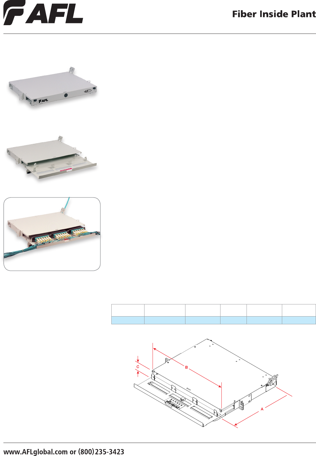
43
© 2008, AFL, all rights reserved. PP-2-00069, Revision 4, 5.13.13
Specications are subject to change without notice.
The AFL’s 1RU Fiber Termination Patch/Splice Panel is designed for use as a rack mount
interconnect point where termination and connectivity of up to 36 bers is desired.
The panel design is based on a 1 rack unit height and is provisioned with three LGX®
118 compatible mounting positions that can accommodate adapter plates, XFM optical
cassettes, passive optical modules or any combination therein. Standard panels are
available empty for complete eld conguration, half-loaded with adapter plates for
eld termination and cable assembly installation, or stubbed with a factory-installed
cable assembly of a user specied length.
Features
• Fits comfortably into new and existing
interconnect, cross-connect, customer
premise, and co-location environments
• Most common connector styles and
types available
• Compatible with industry standard
equipment frames
• Modular design
• Slide-out tray with relief cut-outs
for simplied connector access
• Optional splice tray kit for on site
con-version to patch and splice panel
• Optional front door key lock
for heightened protection of
internal components
LGX is a registered trademark of Furukawa Electric North America, Inc.
LightLink LANSystem
1RU Fiber Termination Patch/Splice Panel
Dimensions
DEPTH (A)
IN INCHES
WIDTH (B)
IN INCHES
HEIGHT (C)
IN INCHES
RACK
UNITS CAPACITY
UNLOADED
WEIGHT
13.51 17.00 1.75 1 18 / 36 4 lbs.
Applications
• Telecommunications closets
• Data Centers
• Customer Premise
• LAN / WAN Networks
• Central Ofces / Headends
• Hubs / Cabinets / Remote Terminals
• FTTH / FTTB Networks
Specifications
• Aluminum Construction per ASTMB209
• Durable textured powder coat nish
available in black or white
•
Universal 19/23" EIA/TIA rack compatibility
• Standard density: up to 18-ber,
High density: up to 36-ber
• LGX 118 compatible
• Standard cable stub location is right
rear exiting upward
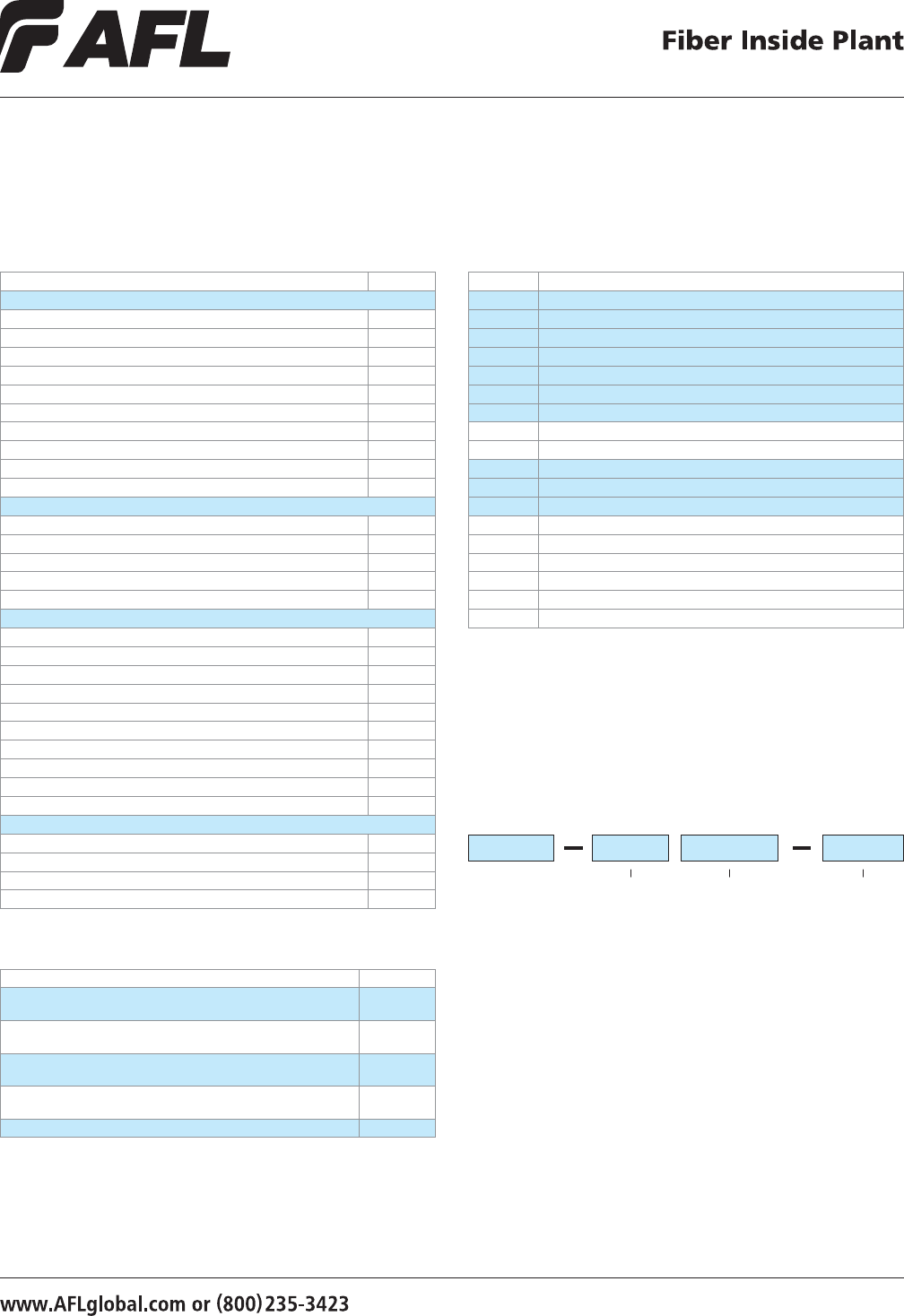
44
© 2008, AFL, all rights reserved. PP-2-00069, Revision 4, 5.13.13
Specications are subject to change without notice.
LightLink LANSystem
1RU Fiber Termination Patch/Splice Panel
Accessories
DESCRIPTION AFL NO.
Splice Tray Kit: Single Fusion, 12 ber, 1RU Patch Panel, Standard Density
(1 splice tray)
FM002826-1
Splice Tray Kit: Single Fusion, 12 ber, 1RU Patch Panel, High Density
(2 splice trays)
FM002826-2
Splice Tray Kit: Single Fusion, 12 ber, 1RU Patch Panel, Standard Density,
Ribbon (1 splice tray)
FM002826-1R
Splice Tray Kit: Single Fusion, 12 ber, 1RU Patch Panel, High Density, Ribbon
(2 splice trays)
FM002826-2R
Kit, Lock, for CON / CNS Panels FM001318
Ordering Information
Select the seven digit AFL number of the panel you need, specify
black or C.O. white, and choose the loading character desired.
When ordering stubbed (S), enter the cable stub length required
in meters. Standard stub is Circular Premise Cable (CPC).
FM001344
B S 0010
AFL NO. Color
Loading
Charactor
E = Empty
H = Half-loaded with adapters
L = Loaded with adapters and
pigtails (N/A on Patch)
S = Preterminated with tight
buffered CPC cable stub
(Riser) (N/A on Patch &
Splice)
R = Preterminated with an OSP
loose tube cable stub (N/A
on Patch & Splice)
W = C.O. White
B = Black
0002 = 2 meters
0004 = 4 meters
etc.
Cable Stub
Length (M)
Example: Order number for a panel Black in color, loaded with 12 PSC adapters
(2 six packs), connectors and a cable stub 10 meters in length.
Configuration Part Numbers
CONFIGURATION AFL NO.
1 RU PATCH PANELS - 12 FIBERS
CON012P – EMPTY FM001038
CON012P w/ 12 PSC adapters (2 Six Packs) 118 LGX (Beige) FM001344
CON012P w/ 12 UST adapters (2 Six Packs) 118 LGX FM001346
CON012P w/ 12 PST adapters (2 Six Packs) 118 LGX FM001347
CON012P w/ 6 UDL (dup) adapters (2 Three Packs) 118 LGX (Blue) FM001353
CON012P w/ 6 PDL (dup) adapters (2 Three Packs) 118 LGX (Beige) FM001354
CON012P w/ 12 ASC adapters (2 Six Packs) 118 LGX (Green) FM001352
CON012P w/ 12 UFC adapters (2 Six Packs) 118 LGX FM001349
CON012P w/ 12 USC (ZR) adapters (2 Six Packs) 118 LGX (Blue) FM001351
CON012P w/ 12 AFC adapters (2 Six Packs) 118 LGX FM001350
1 RU HIGH DENSITY PATCH PANELS - 24 FIBERS
CON024HD w/ 24 UST adapters (2 Twelve Packs) 118 LGX 24 Fibers FM001355
CON024HD w/ 24 PST adapters (2 Twelve Packs) 118 LGX 24 Fibers FM001356
CON024HD w/ 12 PDL (dup) adapters (2 Six Packs) 118 LGX 24 Fibers FM001348
CON024HD w/ 12 USF (dup) adapters (2 Six Packs) 118 LGX 24 Fibers FM001357
CON024HD w/ 12 ASF (dup) adapters (2 Six Packs) 118 LGX 24 Fibers FM001358
1U PATCH AND SPLICE PANELS - 12 FIBERS
CNS012P – EMPTY FM001328
CNS012P w/ 12 PSC adapters (2 Six Packs)118 LGX, Splice Tray FM001323
CNS012P w/ 12 UST adapters (2 Six Packs)118 LGX, Splice Tray FM001329
CNS012P w/ 12 PST adapters (2 Six Packs)118 LGX, Splice Tray FM001325
CNS012P w/ 6 UDL (dup) adapters (2 Three Packs) 118 LGX, Splice Tray (Blue) FM001334
CNS012P w/ 6 PDL (dup) adapters (2 Three Packs) 118 LGX, Splice Tray (Beige) FM001335
CNS012P w/ 12 ASC adapters (2 Six Packs)118 LGX, Splice Tray FM001333
CNS012P w/ 12 UFC adapters (2 Six Packs)118 LGX, Splice Tray FM001330
CNS012P w/ 12 USC (ZR) adapters (2 Six Packs)118 LGX, Splice Tray FM001332
CNS012P w/ AFC adapters (2 Six Packs) 118 LGX, Splice Tray FM001331
1U HIGH DENSITY PATCH AND SPLICE PANELS - 24 FIBERS
CNS024HD w/ 24 UST adapters (2 Twelve Packs)118 LGX, Splice Tray FM001336
CNS024HD w/ 24 PST adapters (2 Twelve Packs)118 LGX, Splice Tray FM001337
CNS024HD w/ 12 USF (dup) adapters (2 Six Packs)118 LGX, Splice Tray FM001338
CNS024HD w/ 12 ASF (dup) adapters (2 Six Packs)118 LGX, Splice Tray FM001339
Connector/Adapter Key
TYPE DESCRIPTION
ASC Angle Polish SC (ZR) sleeve-SM
ASF Angle Polish SC Duplex (ZR) sleeve-SM
PSC Physical Polish SC (PB) sleeve-MM
PSF Physical Polish SC Duplex (PB) sleeve-MM
USC (PB) Ultra Polish SC wih (PB) sleeve-SM
USC (ZR) Ultra Polish SC with (ZR) sleeve-SM
USF Ultra Polish SC Duplex (ZR) sleeve-SM
PST Physical Polish ST (PB) sleeve-MM
UST Ultra Polish ST (ZR) sleeve-SM
AFC Angle Polish FC (ZR) sleeve-SM
PFC Physical Polish FC (PB) sleeve-MM
UFC Ultra Polish FC (ZR) sleeve-SM
ADL Angle Polish LC Duplex (ZR) sleeve-SM
PDL Physical Polish LC Duplex (PB) sleeve-MM
PLC Physical Polish LC (PB) sleeve-MM
UDL (ZR) Ultra Polish LC Duplex (ZR) sleeve-SM
UDL (PB) Ultra Polish LC Duplex (PB) sleeve-SM
ULC Ultra Polish LC (ZR) sleeve-SM
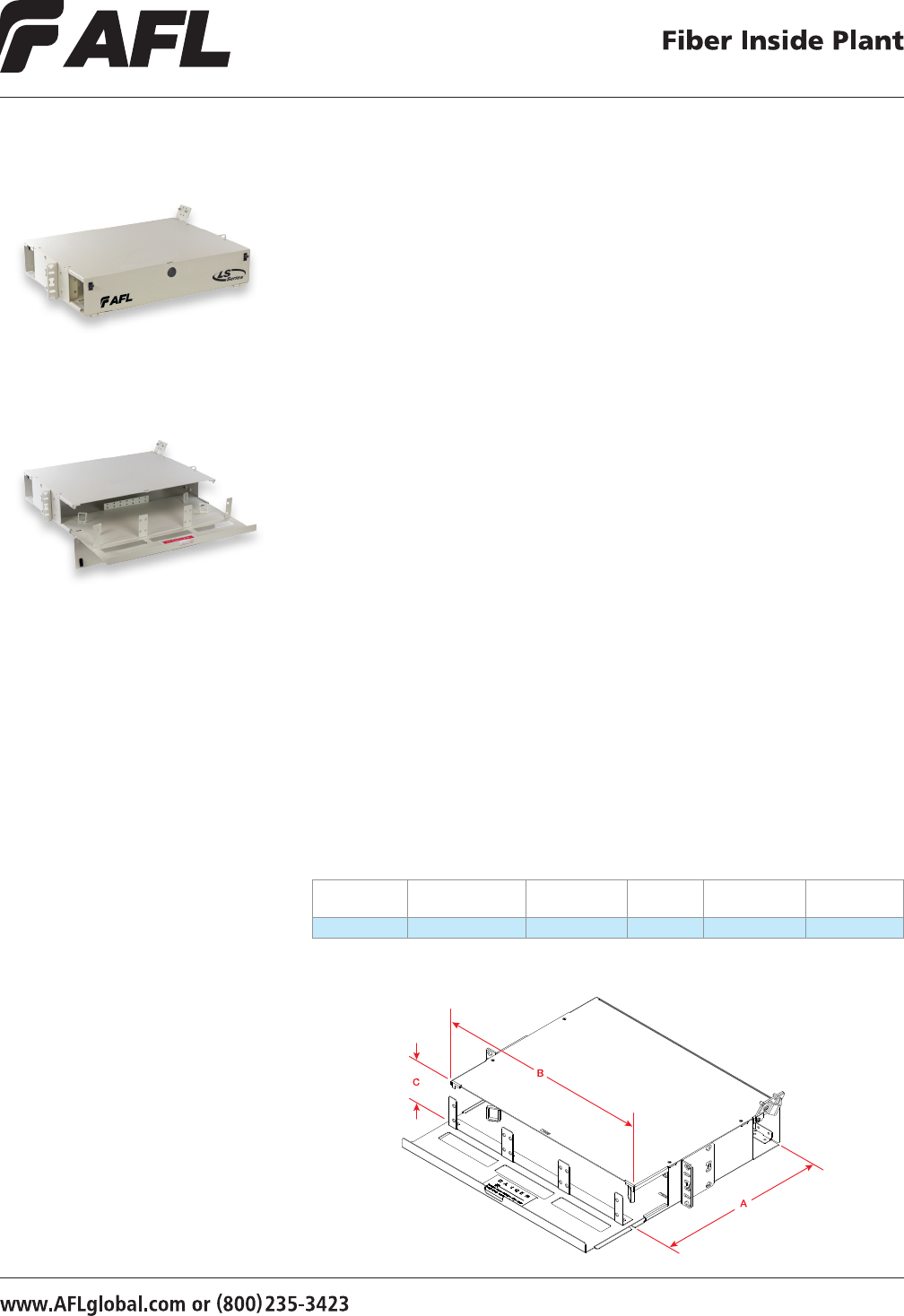
45
© 2008, AFL, all rights reserved. PP-2-00070, Revision 4, 5.13.13
Specications are subject to change without notice.
The AFL 2RU Fiber Termination Patch/Splice Panel is designed for use as a rack mount
interconnect point where termination and connectivity of up to 72 bers is desired.
The panel design is based on a 2 rack unit height and is provisioned with six
LGX® 118 compatible mounting positions that can accommodate adapter plates,
XFM optical cassettes, passive optical modules or any combination of these. Standard
panels are available empty for complete eld conguration, half-loaded with adapter
plates for eld termination and cable assembly installation, or stubbed with a
factory-installed cable assembly of a user specied length.
Features
• Fits comfortably into new and existing
interconnect, cross-connect, customer
premise, and co-location environments
• Most common connector styles and
types available
• Compatible with industry standard
equipment frames
• Modular design
• Slide-out tray with relief cut-outs for
simplied connector access
• Optional splice tray kit for on site
conversion to patch and splice panel
• Optional front door key lock
for heightened protection of
internal components
LGX is a registered trademark of Furukawa Electric North America, Inc.
LightLink LANSystem
2RU Fiber Termination Patch/Splice Panel
Dimensions
DEPTH (A)
IN INCHES
WIDTH (B)
IN INCHES
HEIGHT(C)
IN INCHES
RACK
UNITS CAPACITY
UNLOADED
WEIGHT
13.51 17.00 3.5 2 36 / 72* 5 lbs.
* 72 ber capacity not available in Patch and Splice conguration.
Applications
• Telecommunications closets
• Data Centers
• Customer Premise
• LAN / WAN Networks
• Central Ofces / Headends
• Hubs / Cabinets / Remote Terminals
• FTTH / FTTB Networks
Specifications
• Aluminum construction per ASTMB209
• Durable textured powder coat nish
available in black or white
• Universal 19/23" EIA/TIA rack compatibility
• Standard density: up to 36 ber,
High density: up to 72 ber
• LGX 118 compatible
• Standard cable stub location is right
rear exiting upward
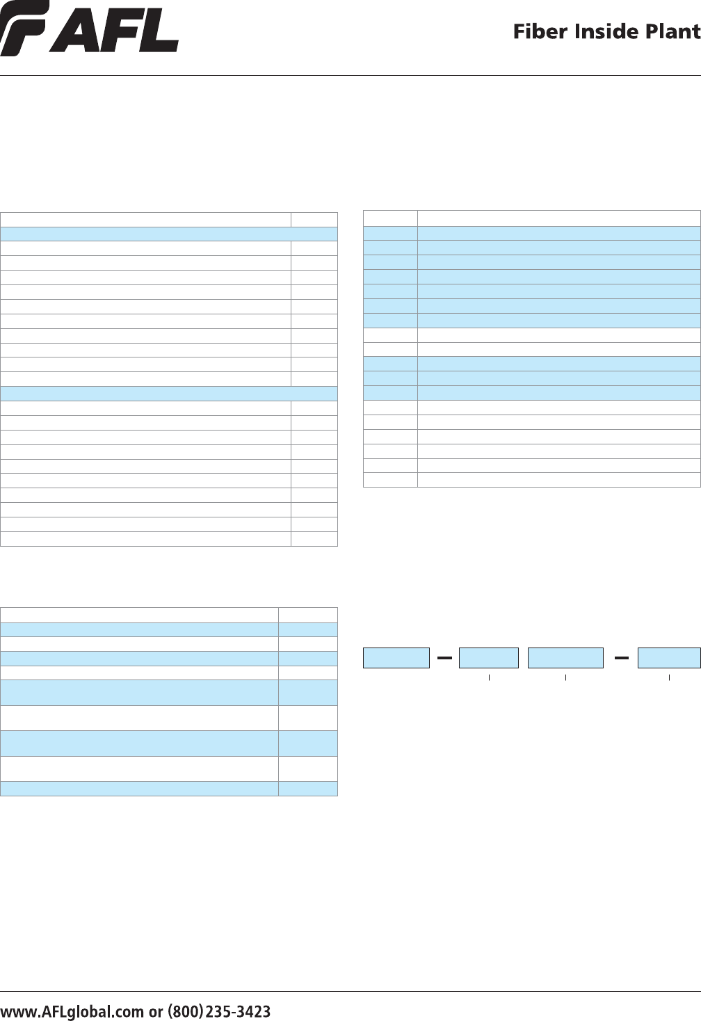
46
© 2008, AFL, all rights reserved. PP-2-00070, Revision 4, 5.13.13
Specications are subject to change without notice.
LightLink LANSystem
2RU Fiber Termination Patch/Splice Panel
Accessories
DESCRIPTION AFL NO.
Splice Tray Kit: Single Fusion, 12 ber, 2RU, WME02, WME04 (1 splice tray) FM002827-1
Splice Tray Kit: Single Fusion, 12 ber, 2RU, WME02, WME04 (2 splice trays) FM002827-2
Splice Tray Kit: Single Fusion, 12 ber, 2RU, WME02, WME04 (3 splice trays) FM002827-3
Splice Tray Kit: Single Fusion, 12 ber, 2RU, WME02, WME04 (4 splice trays) FM002827-4
Splice Tray Kit: Single Fusion, 12 ber, 2RU, WME02, WME04, Ribbon
(1 splice tray)
FM002827-1R
Splice Tray Kit: Single Fusion, 12 ber, 2RU, WME02, WME04, Ribbon
(2 splice trays)
FM002827-2R
Splice Tray Kit: Single Fusion, 12 ber, 2RU, WME02, WME04, Ribbon
(3 splice trays)
FM002827-3R
Splice Tray Kit: Single Fusion, 12 ber, 2RU, WME02, WME04, Ribbon
(4 splice trays)
FM002827-4R
Kit, Lock, for CON / CNS Panels FM001318
Configuration Part Numbers
CONFIGURATION AFL NO.
2 RU PATCH PANELS - 24 FIBERS
CON024P – EMPTY FM001029
CON024P with 24 PSC adapters (4 Six Packs) 118 LGX (Beige) FM001433
CON024P with 24 UST adapters (4 Six Packs) 118 LGX FM001434
CON024P with 24 PST adapters (4 Six Packs) 118 LGX FM001435
CON024P with12 UDL (dup) adapters (4 Three Packs) 118 LGX (Blue) FM001441
CON024P with 12 PDL (dup) adapters (4 Three Packs) 118 LGX (Beige) FM001442
CON024P with 24 ASC adapters (4 Six Packs) 118 LGX (Green) FM001439
CON024P with 24 UFC adapters (4 Six Packs) 118 LGX FM001436
CON024P with 24 USC (ZR) adapters (4 Six Packs) 118 LGX (Blue) FM001438
CON024P with 24 AFC adapters (4 Six Packs) 118 LGX FM001437
2U PATCH AND SPLICE PANELS - 24 FIBERS
CNS024P – EMPTY FM001414
CNS024P with 24 PSC adapters (4 Six Packs) 118 LGX, Splice tray FM001411
CNS024P with 24 UST adapters (4 Six Packs) 118 LGX, Splice tray FM001412
CNS024P with 24 PST adapters (4 Six Packs) 118 LGX, Splice tray FM001413
CNS024P with 12 UDL (dup) adapters (4 three Packs)118 LGX , Splice tray FM001419
CNS024P with 12 PDL (dup) adapters (4 three Packs)118 LGX , Splice tray FM001420
CNS024P with 24 ASC adapters (4 Six Packs) 118 LGX, Splice tray FM001418
CNS024P with 24 UFC adapters (4 Six Packs) 118 LGX, Splice tray FM001415
CNS024P with 24 USC (ZR) adapters (4 Six Packs) 118 LGX, Splice tray FM001417
CNS024P with 24 AFC adapters (4 Six Packs) 118 LGX, Splice tray FM001416
Connector/Adapter Key
TYPE DESCRIPTION
ASC Angle Polish SC (ZR) sleeve-SM
ASF Angle Polish SC Duplex (ZR) sleeve-SM
PSC Physical Polish SC (PB) sleeve-MM
PSF Physical Polish SC Duplex (PB) sleeve-MM
USC (PB) Ultra Polish SC wih (PB) sleeve-SM
USC (ZR) Ultra Polish SC with (ZR) sleeve-SM
USF Ultra Polish SC Duplex (ZR) sleeve-SM
PST Physical Polish ST (PB) sleeve-MM
UST Ultra Polish ST (ZR) sleeve-SM
AFC Angle Polish FC (ZR) sleeve-SM
PFC Physical Polish FC (PB) sleeve-MM
UFC Ultra Polish FC (ZR) sleeve-SM
ADL Angle Polish LC Duplex (ZR) sleeve-SM
PDL Physical Polish LC Duplex (PB) sleeve-MM
PLC Physical Polish LC (PB) sleeve-MM
UDL (ZR) Ultra Polish LC Duplex (ZR) sleeve-SM
UDL (PB) Ultra Polish LC Duplex (PB) sleeve-SM
ULC Ultra Polish LC (ZR) sleeve-SM
Note: All MM cable is 62.5 µm unless otherwise specied.
Ordering Information
Select the seven digit AFL number of the panel you need, specify
black or C.O. white, and choose the loading character desired.
When ordering stubbed (S), enter the cable stub length required
in meters.
FM001411
B S 0010
AFL NO. Color
Loading
Charactor
E = Empty
H = Half-loaded with adapters
L = Loaded with adapters and
pigtails (N/A on Patch)
S = Preterminated with tight
buffered CPC cable stub
(Riser) (N/A on Patch &
Splice)
R = Preterminated with an OSP
loose tube cable stub (N/A
on Patch & Splice)
W = C.O. White
B = Black
0002 = 2 meters
0004 = 4 meters
etc.
Cable Stub
Length (M)
Example: Order number for a panel Black in color, loaded with 24 PSC adapters
(4 six packs), connectors and a cable stub 10 meters in length.
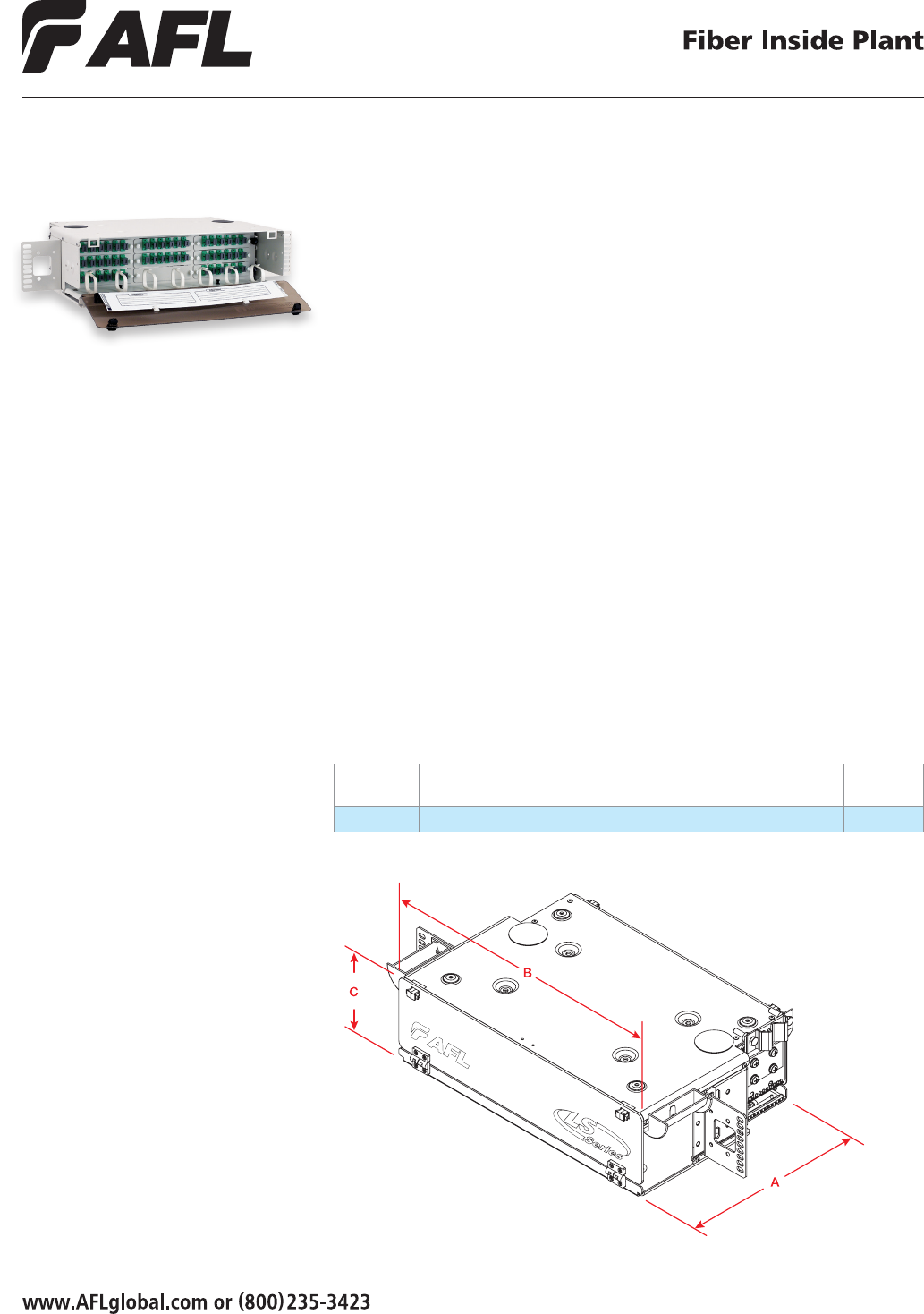
47
© 2002, AFL, all rights reserved. PP-2-00077, Revision 3, 10.10.12
Specications are subject to change without notice.
Features
• Fits comfortably into new and existing
interconnect, cross-connect, customer
premise, and co-location environments
• Various connector styles and
types available
• Compatible with industry standard
equipment frames
• LGX compatible master plate (118 mm)
• Modular design
• Provides maximum protection
of optical components
The CON048P Fiber Termination Panel is used where termination and connectivity
of up to 48 bers (standard density) or 96 bers (high density) is desired. The panel
design is based on a 3 rack unit height with a master plate to accommodate nine
LGX® compatible adapter plates or modules. Standard panels are available in empty,
loaded and preterminated versions. Loaded panels include adapters and adapter plates.
Preterminated panels include adapters, adapter plates and standard 48 ber OFNR cable.
The ber stub for preterminated panels exits the right rear of the unit facing up.
Applications
• Telecommunication Closets
• Data Centers
• Customer Premise
• Local Area Networks
• Wide Area Networks
• Central Ofces
• Hubs
• Cabinets
• Remote Terminals
Specifications
• Telcordia® GR-63 NEBS Tested
• Aluminum material per ASTMB209
• Black or white texture powder coated
• Universal mounting bracket WECO, EIA
• 19"and 23" rack compatible
LightLink LANSystem
CON048P Fiber Termination Patch Panel
Dimensions
DEPTH (A)
IN INCHES
WIDTH (B)
IN INCHES
HEIGHT (C)
IN INCHES
RACK
UNITS
FIBER
CAPACITY
UNLOADED
WEIGHT
MATERIAL
GAUGE
11 17 5.25 3 54/108 8.4 lbs. 2.03 mm
LGX is a registered trademark of Furukawa Electric North America, Inc.
Telcordia is a registered trademark of Telcordia Technologies, Inc.
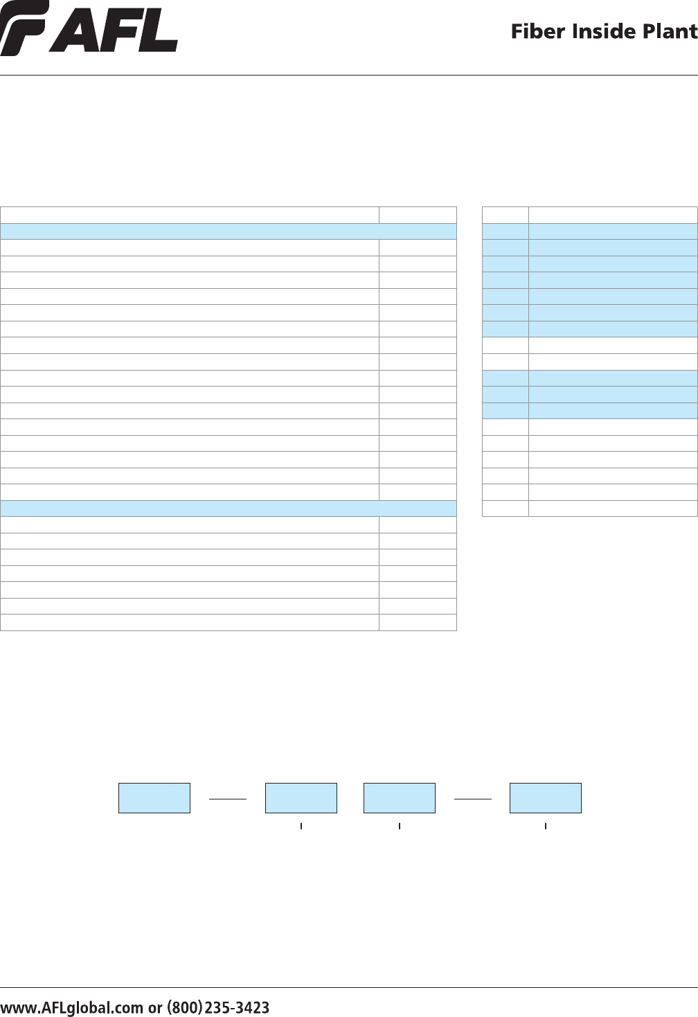
48
© 2002, AFL, all rights reserved. PP-2-00077, Revision 3, 10.10.12
Specications are subject to change without notice.
LightLink LANSystem
CON048P Fiber Termination Patch Panel
Ordering Information
Select the seven digit AFL number of the panel you need, specify black or C.O. white, and choose the loading character desired.
When ordering stubbed (S), enter the cable stub length required in meters.
C211291 B
AFL No. Color Loading Charactor
E = Empty
H = Half-loaded with adapters
S = Preterminated with tight
buffered CPC cable stub (Riser)
R = Preterminated with an OSP
loose tube cable stub
W = C.O. White
B = Black
S
0002 = 2 meters
0004 = 4 meters
etc.
0010
Cable Stub Length (M)
Example: Order number for a panel Black in color, loaded with 48 USC adapters (8 six packs), connectors and a cable stub 10 meters in length.
Ordering Information
CONFIGURATION AFL NO.
3 RU PATCH PATCH PANELS
CON048P – EMPTY C211291
CON048P with 48 USC (PB) adapters (8 Six Packs) 118 LGX (Blue) C211300
CON048P with 48 PSC adapters (8 Six Packs) 118 LGX (Beige) C211309
CON048P with 48 UST adapters (8 Six Packs) 118 LGX C211336
CON048P with 48 PST adapters (8 Six Packs) 118 LGX C211345
CON048P with 24 UDL (dup) adapters (8 Three Packs) 118 LGX (Blue) FM000181
CON048P with 24 PDL (dup) adapters (8 Three Packs) 118 LGX (Beige) FM000182
CON048P with 48 ASC adapters (8 Six Packs) 118 LGX (Green) C213928
CON048P with 48 UFC adapters (8 Six Packs) 118 LGX C213916
CON048P with 48 USC (ZR) adapters (8 Six Packs) 118 LGX (Blue) C213923
CON048P with 48 AFC adapters (8 Six Packs) 118 LGX C213919
CON048P with 48 ULC adapters (8 Six Packs) 118 LGX C213934
CON048P with 24 PSF (dup) adapters (8 Three Packs) 118 LGX (Beige) FM000183
CON048P with 24 USF (dup) adapters (8 Three Packs) 118 LGX (Blue) FM000184
CON048P with 24 ASF (dup) adapters (8 Three Packs) 118 LGX (Green) FM000185
CON048P with 48 MTRJ adapters (8 Six Packs) 118 LGX (Blue) FM000186
3 RU HIGH DENSITY PATCH PANELS
CON096HD with 96 UST adapters (8 Twelve Packs) 118 LGX 96 Fibers FM000187
CON096HD with 96 PST adapters (8 Twelve Packs) 118 LGX 96 Fibers FM000188
CON096HD with 48 UDL (dup) adapters (8 Six Packs) 118 LGX 96 Fibers C211349
CON096HD with 48 PSF (dup) adapters (8 Six Packs) 118 LGX 96 Fibers C211313
CON096HD with 48 PDL (dup) adapters (8 Six Packs) 118 LGX 96 Fibers C211360
CON096HD with 48 USF (dup) adapters (8 Six Packs) 118 LGX 96 Fibers FM000189
CON096HD with 48 ASF (dup) adapters (8 Six Packs) 118 LGX 96 Fibers FM000190
Note: All MM cable is 62.5 µm unless otherwise specied.
Connector/Adapter Key
TYPE DESCRIPTION
ASC Angle Polish SC (ZR) sleeve-SM
ASF Angle Polish SC Duplex (ZR) sleeve-SM
PSC Physical Polish SC (PB) sleeve-MM
PSF Physical Polish SC Duplex (PB) sleeve-MM
USC (PB) Ultra Polish SC wih (PB) sleeve-SM
USC (ZR) Ultra Polish SC with (ZR) sleeve-SM
USF Ultra Polish SC Duplex (ZR) sleeve-SM
PST Physical Polish ST (PB) sleeve-MM
UST Ultra Polish ST (ZR) sleeve-SM
AFC Angle Polish FC (ZR) sleeve-SM
PFC Physical Polish FC (PB) sleeve-MM
UFC Ultra Polish FC (ZR) sleeve-SM
ADL Angle Polish LC Duplex (ZR) sleeve-SM
PDL Physical Polish LC Duplex (PB) sleeve-MM
PLC Physical Polish LC (PB) sleeve-MM
UDL (ZR) Ultra Polish LC Duplex (ZR) sleeve-SM
UDL (PB) Ultra Polish LC Duplex (PB) sleeve-SM
ULC Ultra Polish LC (ZR) sleeve-SM
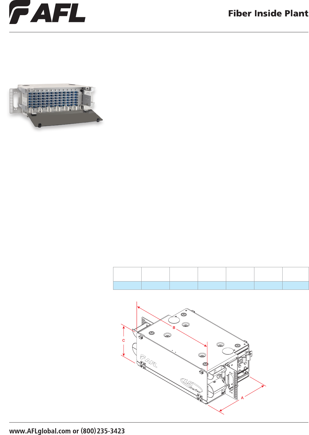
49
© 2002, AFL, all rights reserved. PP-2-00071, Revision 4, 5.13.13
Specications are subject to change without notice.
Features
• Fits comfortably into new and existing
interconnect, cross-connect, customer
premise, and co-location environments
• Various connector styles
and types available
• Compatible with industry standard
equipment frames
• LGX compatible master plate and
footprint (118 mm)
• Modular design
• Provides maximum protection
of optical components
• Available with I/O loose tube stub
The CON072P Fiber Termination Panel is used where termination and connectivity of
up to 72 bers (standard density) or 144 bers (high density) is desired. The panel
design is based on a 4 rack unit height with a master plate to accommodate 12 LGX®
compatible adapter plates or modules. Standard panels are available in empty, loaded
and preterminated versions. Loaded panels include adapters and adapter plates.
Preterminated panels include adapters, adapter plates and standard 72 ber OFNR
cable. The ber stub for preterminated panels exits the right rear of the unit facing up.
Specifications
• Telcordia® GR-63 NEBS Tested
• Aluminum material per ASTMB209
• White or black texture powder coated
• Universal mounting bracket WECO, EIA
• 19"and 23" rack compatible
• 144 ber (high density) version
Applications
• Telecommunication Closets
• Data Centers
• Customer Premise
• Local Area Networks
• Wide Area Networks
• Central Ofces
• Hubs
• Cabinets
• Remote Terminals
LightLink LANSystem
CON072P Fiber Termination Patch Panel
Dimensions
DEPTH (A)
IN INCHES
WIDTH (B)
IN INCHES
HEIGHT (C)
IN INCHES
RACK
UNITS
FIBER
CAPACITY
UNLOADED
WEIGHT
MATERIAL
GAUGE
11 17 7 4 72/144 9 lbs. 2.03 mm
LGX is a registered trademark of Furukawa Electric North America, Inc.
Telcordia is a registered trademark of Telcordia Technologies, Inc.

50
© 2002, AFL, all rights reserved. PP-2-00071, Revision 4, 5.13.13
Specications are subject to change without notice.
LightLink LANSystem
CON072P Fiber Termination Patch Panel
Ordering Information
CONFIGURATION AFL NO.
4 RU PATCH PANELS
CON072P – EMPTY 118 LGX C211372
CON144HD – EMPTY 118 LGX FM000344
CON072P with 72 USC (PB) adapters (12 Six Packs) 118 LGX (Blue) C211381
CON072P with 72 PSC adapters (12 Six Packs) 118 LGX (Beige) C211390
CON072P with 72 UST adapters (12 Six Packs) 118 LGX C211417
CON072P with 72 PST adapters (12 Six Packs) 118 LGX C211426
CON072P with 36 UDL (dup) adapters (12 Three Packs) 118 LGX (Blue) FM000191
CON072P with 36 PDL (dup) adapters (12 Three Packs) 118 LGX (Beige) FM000192
CON072P with 72 ASC adapters (12 Six Packs) 118 LGX (Green) C213955
CON072P with 72 UFC adapters (12 Six Packs) 118 LGX C213941
CON072P with 72 USC (ZR) adapters (12 Six Packs) 118 LGX (Blue) C213952
CON072P with 72 AFC adapters (12 Six Packs) 118 LGX C213946
CON072P with 72 ULC adapters (12 Six Packs) 118 LGX C213959
CON072P with 36 PSF (dup) adapters (12 Three Packs) 118 LGX (Beige) FM000193
CON072P with 36 USF (dup) adapters (12 Three Packs) 118 LGX (Blue) FM000136
CON072P with 36 ASF (dup) adapters (12 Three Packs) 118 LGX (Green) FM000194
CON072P with 72 MTRJ adapters (12 Six Packs) 118 LGX FM000195
4 RU HIGH DENSITY PATCH PANELS
CON144HD with 72 UDL (dup) adapters (12 Six Packs) 118 LGX 144 Fibers C211432
CON144HD with 72 ADL (dup) adapters (12 Six Packs) 118 LGX 144 Fibers FM000345
CON144HD with 72 PSF (dup) adapters (12 Six Packs) 118 LGX 144 Fibers C211396
CON144HD with 72 PDL (dup) adapters (12 Six Packs) 118 LGX 144 Fibers C211439
CON144HD with 72 USF (dup) adapters (12 Six Packs) 118 LGX 144 Fibers FM000196
CON144HD with 72 ASF (dup) adapters (12 Six Packs) 118 LGX 144 Fibers FM000197
CON144HD with 144 UST adapters (12 Twelve Packs) 118 LGX 144 Fibers FM000198
CON144HD with 144 PST adapters (12 Twelve Packs) 118 LGX 144 Fibers FM000199
CON144HD with 144 UFC adapters (12 Twelve Packs) 118 LGX 144 Fibers FM000200
CON144HD with 144 USC (PB) adapters (12 Twelve Packs) 118 LGX 144 Fibers FM000133
CON144HD with 144 ASC adapters (12 Twelve Packs) 118 LGX 144 Fibers FM000201
Ordering Information
Select the seven digit AFL number of the panel you need, specify black or C.O. white, and choose the loading character desired.
When ordering stubbed (S), enter the cable stub length required in meters.
C211381 B
AFL NO. Color Loading Charactor
W = C.O. White
B = Black
S
0002 = 2 meters
0004 = 4 meters
etc.
0010
Cable Stub Length (M)
Example: Order number for a panel Black in color, loaded with 72 USC adapters (12 six packs), connectors and a cable stub 10 meters in length.
Note: All MM cable is 62.5 µm unless otherwise specied.
Connector/Adapter Key
TYPE DESCRIPTION
ASC Angle Polish SC (ZR) sleeve-SM
ASF Angle Polish SC Duplex (ZR) sleeve-SM
PSC Physical Polish SC (PB) sleeve-MM
PSF Physical Polish SC Duplex (PB) sleeve-MM
USC (PB) Ultra Polish SC wih (PB) sleeve-SM
USC (ZR) Ultra Polish SC with (ZR) sleeve-SM
USF Ultra Polish SC Duplex (ZR) sleeve-SM
PST Physical Polish ST (PB) sleeve-MM
UST Ultra Polish ST (ZR) sleeve-SM
AFC Angle Polish FC (ZR) sleeve-SM
PFC Physical Polish FC (PB) sleeve-MM
UFC Ultra Polish FC (ZR) sleeve-SM
ADL Angle Polish LC Duplex (ZR) sleeve-SM
PDL Physical Polish LC Duplex (PB) sleeve-MM
PLC Physical Polish LC (PB) sleeve-MM
UDL (ZR) Ultra Polish LC Duplex (ZR) sleeve-SM
UDL (PB) Ultra Polish LC Duplex (PB) sleeve-SM
ULC Ultra Polish LC (ZR) sleeve-SM
E = Empty
H = Half-loaded with adapters
S = Preterminated with tight
buffered CPC cable stub (Riser)
R = Preterminated with an OSP
loose tube cable stub
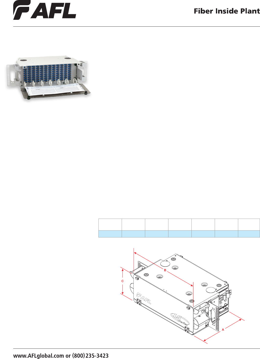
51
© 2002, AFL, all rights reserved. PP-2-00079, Revision 3, 10.10.12
Specications are subject to change without notice.
Features
• Fits comfortably into new and existing
interconnect, cross-connect, customer
premise, and co-location environments
• Various connector styles
and types available
• Compatible with industry standard
equipment frames
• LGX compatible master plate and
footprint (130 mm)
• Modular design
• Provides maximum protection
of optical components
• Utilizes (12) 8-packs
• Available with I/O loose tube stub
The CON096P Fiber Termination Panel is used where termination and connectivity of up to
96 bers is desired. The panel design is based on a 4 rack unit height with a master plate
to accommodate 12 LGX® compatible adapter plates or modules. Standard panels are
available in empty, loaded and preterminated versions. Loaded panels include adapters and
adapter plates. Preterminated panels include adapters, adapter plates and standard 96 ber
OFNR cable. The ber stub for preterminated panels exits the right rear of the unit facing up.
Specifications
• Telcordia® GR-63 NEBS Tested
• Aluminum Material per ASTMB209
• White or Black Texture Powder Coated
• Universal Mounting Bracket WECO, EIA
• 19"and 23" Rack Compatible
Applications
• Telecommunication Closets
• Data Centers
• Customer Premise
• Local Area Networks
• Wide Area Networks
• Central Ofces
• Hubs
• Cabinets
• Remote Terminals
LightLink LANSystem
CON096P Fiber Termination Patch Panel
Dimensions
DEPTH (A)
IN INCHES
WIDTH (B)
IN INCHES
HEIGHT (C)
IN INCHES
RACK
UNITS
FIBER
CAPACITY
UNLOADED
WEIGHT
MATERIAL
GAUGE
11 17 7 4 96 9 lbs. 2.03 mm
LGX is a registered trademark of Furukawa Electric North America, Inc.
Telcordia is a registered trademark of Telcordia Technologies, Inc.
52
© 2002, AFL, all rights reserved. PP-2-00079, Revision 3, 10.10.12
Specications are subject to change without notice.
LightLink LANSystem
CON096P Fiber Termination Patch Panel
Ordering Information
CONFIGURATION AFL NO
4 RU PATCH PANELS
CON072/96P – EMPTY 130 LGX FM000344
CON096P with 96 USC (PB) adapters (12 Eight Packs) 4U Housing 130 LGX FM000202
CON096P with 96 PSC adapters (12 Eight Packs) 4U Housing 130 LGX FM000203
CON096P with 96 UST adapters (12 Eight Packs) 4U Housing 130 LGX C213964
CON096P with 96 PST adapters (12 Eight Packs) 4U Housing 130 LGX FM000204
CON096P with 96 ASC adapters (12 Eight Packs) 4U Housing 130 LGX C213982
CON096P with 96 UFC adapters (12 Eight Packs) 4U Housing 130 LGX C213970
CON096P with 96 USC (ZR) adapters (12 Eight Packs) 4U Housing 130 LGX C213977
CON096P with 96 AFC adapters (12 Eight Packs) 4U Housing 130 LGX C213973
CON096P with 96 MTRJ adapters (12 Eight Packs) 4U Housing 130 LGX FM000205
Ordering Information
Select the seven digit AFL number of the panel you need, specify black or C.O. white, and choose the loading character desired.
When ordering stubbed (S), enter the cable stub length required in meters.
C211381 B
AFL No. Color Loading Charactor
W = C.O. White
B = Black
S
0002 = 2 meters
0004 = 4 meters
etc.
0010
Cable Stub Length (M)
Example: Order number for a panel Black in color, loaded with 72 USC adapters (12 six packs), connectors and a cable stub 10 meters in length.
Note: All MM cable is 62.5 µm unless otherwise specied.
Connector/Adapter Key
TYPE DESCRIPTION
ASC Angle Polish SC (ZR) sleeve-SM
ASF Angle Polish SC Duplex (ZR) sleeve-SM
PSC Physical Polish SC (PB) sleeve-MM
PSF Physical Polish SC Duplex (PB) sleeve-MM
USC (PB) Ultra Polish SC wih (PB) sleeve-SM
USC (ZR) Ultra Polish SC with (ZR) sleeve-SM
USF Ultra Polish SC Duplex (ZR) sleeve-SM
PST Physical Polish ST (PB) sleeve-MM
UST Ultra Polish ST (ZR) sleeve-SM
AFC Angle Polish FC (ZR) sleeve-SM
PFC Physical Polish FC (PB) sleeve-MM
UFC Ultra Polish FC (ZR) sleeve-SM
ADL Angle Polish LC Duplex (ZR) sleeve-SM
PDL Physical Polish LC Duplex (PB) sleeve-MM
PLC Physical Polish LC (PB) sleeve-MM
UDL (ZR) Ultra Polish LC Duplex (ZR) sleeve-SM
UDL (PB) Ultra Polish LC Duplex (PB) sleeve-SM
ULC Ultra Polish LC (ZR) sleeve-SM
E = Empty
H = Half-loaded with adapters
S = Preterminated with tight
buffered CPC cable stub (Riser)
R = Preterminated with an OSP
loose tube cable stub
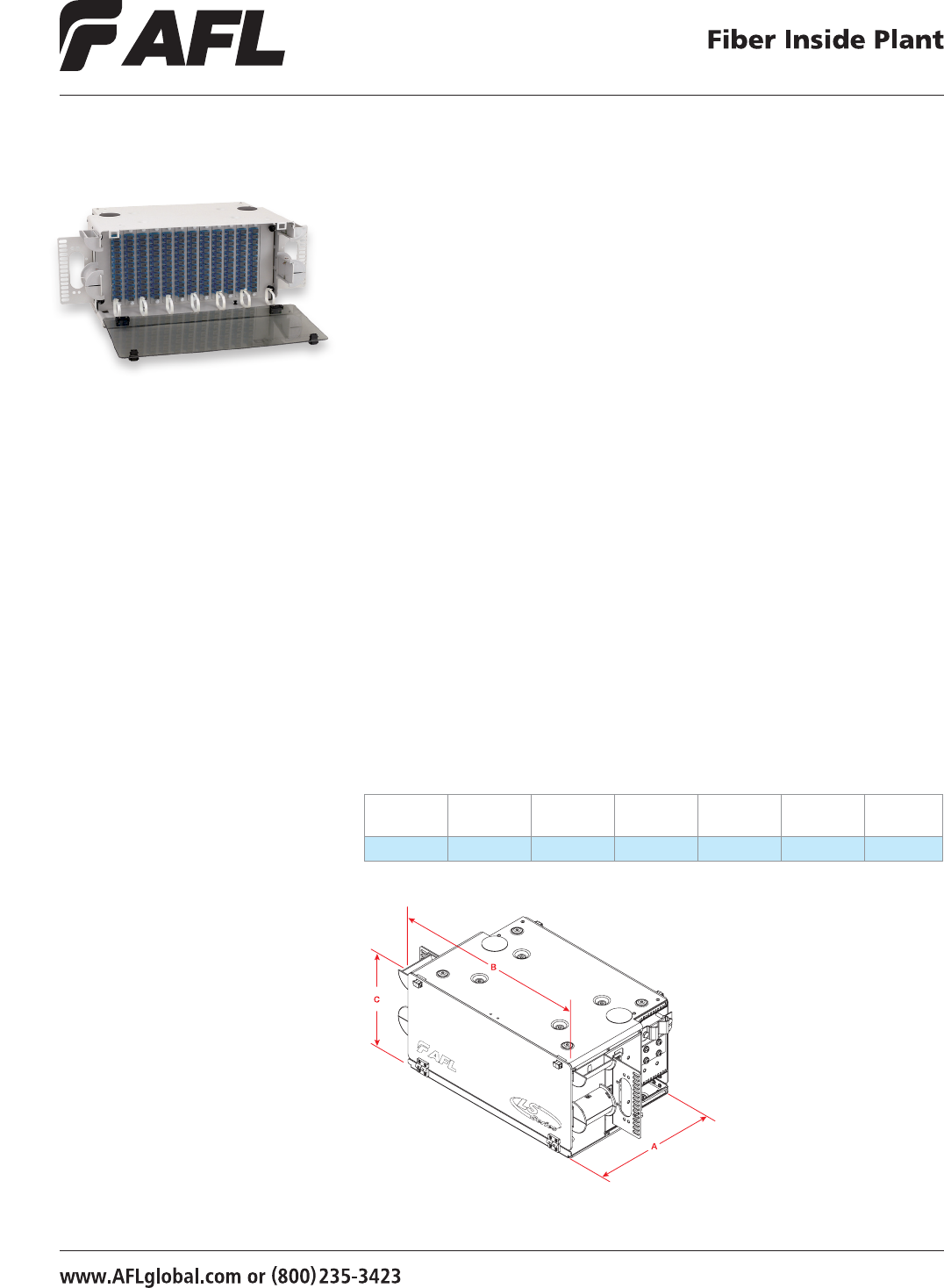
53
© 2002, AFL, all rights reserved. PP-2-00080, Revision 4, 10.10.12
Specications are subject to change without notice.
Features
• Fits comfortably into new and existing
interconnect, cross-connect, customer
premise, and co-location environments
• Various connector styles
and types available
• Compatible with industry standard
equipment frames
• LGX compatible master plate (170 mm)
• Modular design
• Provides maximum protection
of optical components
• Available with I/O loose tube stub
The CON144P Fiber Termination Panel is used where termination and connectivity of up to
144 bers (standard density) or 288 (high density) is desired. The panel design is based on
a 5 rack unit height with a master plate to accommodate 12 LGX® (170 mm) compatible
adapter plates. Standard panels are available in empty, loaded and preterminated versions.
Loaded panels include adapters and adapter plates. Preterminated panels include adapters,
adapter plates and standard 144 ber OFNR cable. The ber stub for preterminated panels
exits the right rear of the unit facing up. High density panels use two 144 ber stubs for
288 terminations.
Specifications
• Telcordia® GR-63 NEBS Tested
• Aluminum material per ASTMB209,
standard front cover lexan
• Central ofce white, black, texture
powder coated
• Universal mounting bracket WECO, EIA
• 19"and 23" rack compatable
Applications
• Telecommunication Closets
• Data Centers
• Customer Premise
• Local Area Networks
• Wide Area Networks
• Central Ofces
• Hubs
• Cabinets
• Remote Terminals
LightLink LANSystem
CON144P Fiber Termination Patch Panel
Dimensions
DEPTH (A)
IN INCHES
WIDTH (B)
IN INCHES
HEIGHT (C)
IN INCHES
RACK
UNITS
FIBER
CAPACITY
UNLOADED
WEIGHT
MATERIAL
GAUGE
11 17 8.75 5 144/288 9 lbs. 2.03 mm
LGX is a registered trademark of Furukawa Electric North America, Inc.
Telcordia is a registered trademark of Telcordia Technologies, Inc.

54
© 2002, AFL, all rights reserved. PP-2-00080, Revision 4, 10.10.12
Specications are subject to change without notice.
Ordering Information
Select the seven digit AFL number of the panel you need, specify black or C.O. white, and choose the loading character desired.
When ordering stubbed (S), enter the cable stub length required in meters.
C211462 B
AFL No. Color Loading Charactor
W = C.O. White
B = Black
S
0002 = 2 meters
0004 = 4 meters
etc.
0010
Cable Stub Length (M)
Example: Order number for a panel Black in color, loaded with 144 USC adapters (12 twelve packs), connectors and a cable stub 10 meters in length.
LightLink LANSystem
CON144P Fiber Termination Patch Panel
Ordering Information
CONFIGURATION AFL NO.
5 RU PATCH PANELS
CON144P – EMPTY 170 LGX C211453
CON144P with 144 USC (PB) adapters (12 Twelve Packs) 170 LGX (Blue) C211462
CON144P with 144 PSC adapters (12 Twelve Packs) 170 LGX (Beige) C211471
CON144P with 144 UST adapters (12 Twelve Packs) 170 LGX C211498
CON144P with 144 PST adapters (12 Twelve Packs) 170 LGX C211507
CON144P with 72 UDL (dup) adapters (12 Six Packs) 170 LGX (Blue) FM000206
CON144P with 72 PDL (dup) adapters (12 Six Packs) 170 LGX (Beige) FM000207
CON144P with 144 ASC adapters (12 Twelve Packs) 170 LGX (Green) C214009
CON144P with 144 UFC adapters (12 Twelve Packs) 170 LGX C213995
CON144P with 144 USC (ZR) adapters (12 Twelve Packs) 170 LGX (Blue) C214006
CON144P with 72 PSF (dup) adapters (12 Six Packs) 170 LGX (Beige) FM000208
CON144P with 72 USF (dup) adapters (12 Six Packs) 170 LGX (Blue) FM000209
CON144P with 72 ASF (dup) adapters (12 Six Packs) 170 LGX (Green) FM000210
CON144P with 144 MTRJ adapters (12 Twelve Packs) 170 LGX FM000211
5 RU HIGH DENSITY PATCH PANELS (USES TWO 144 STUBS)
CON288HD with 144 UDL (dup) adapters (12 Twelve Packs) 170 LGX 288 Fibers C211511
CON288HD with 144 ADL (dup) adapters (12 Twelve Packs) 170 LGX 288 Fibers FM000346
CON288HD with 144 PDL (dup) adapters (12 Twelve Packs) 170 LGX 288 Fibers C211522
CON288HD with 144 PSF (dup) adapters (12 Twelve Packs) 170 LGX 288 Fibers C211475
CON288HD with 144 USF (dup) adapters (12 Twelve Packs) 170 LGX 288 Fibers FM000212
CON288HD with 144 ASF (dup) adapters (12 Twelve Packs) 170 LGX 288 Fibers FM000213
Note: All MM cable is 62.5 µm unless otherwise specied.
Connector/Adapter Key
TYPE DESCRIPTION
ASC Angle Polish SC (ZR) sleeve-SM
ASF Angle Polish SC Duplex (ZR) sleeve-SM
PSC Physical Polish SC (PB) sleeve-MM
PSF Physical Polish SC Duplex (PB) sleeve-MM
USC (PB) Ultra Polish SC wih (PB) sleeve-SM
USC (ZR) Ultra Polish SC with (ZR) sleeve-SM
USF Ultra Polish SC Duplex (ZR) sleeve-SM
PST Physical Polish ST (PB) sleeve-MM
UST Ultra Polish ST (ZR) sleeve-SM
AFC Angle Polish FC (ZR) sleeve-SM
PFC Physical Polish FC (PB) sleeve-MM
UFC Ultra Polish FC (ZR) sleeve-SM
ADL Angle Polish LC Duplex (ZR) sleeve-SM
PDL Physical Polish LC Duplex (PB) sleeve-MM
PLC Physical Polish LC (PB) sleeve-MM
UDL (ZR) Ultra Polish LC Duplex (ZR) sleeve-SM
UDL (PB) Ultra Polish LC Duplex (PB) sleeve-SM
ULC Ultra Polish LC (ZR) sleeve-SM
E = Empty
H = Half-loaded with adapters
S = Preterminated with tight
buffered CPC cable stub (Riser)
R = Preterminated with an OSP
loose tube cable stub
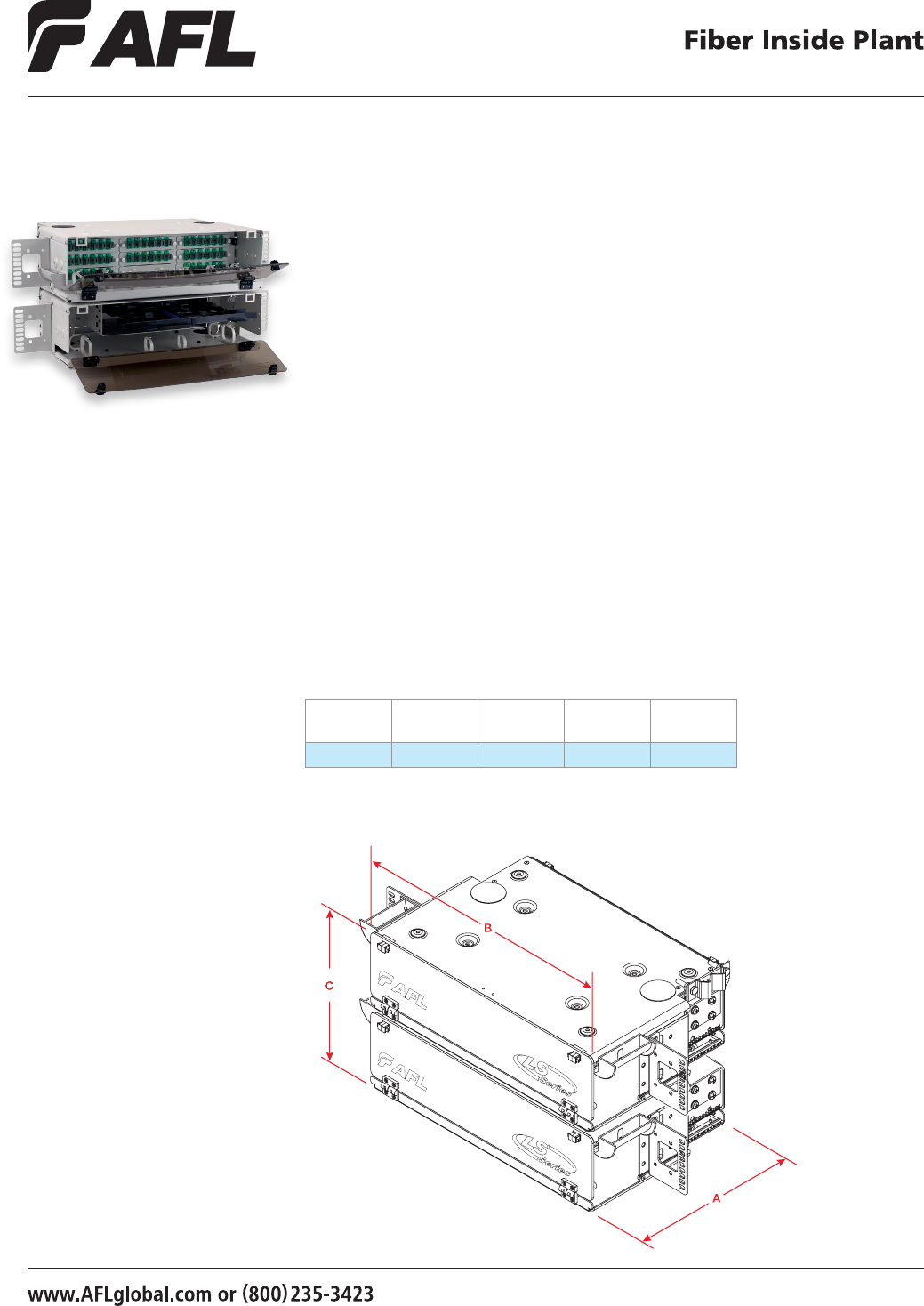
55
© 2002, AFL, all rights reserved. PP-2-00073, Revision 3, 10.8.12
Specications are subject to change without notice.
Specifications
• Telcordia® GR-63 NEBS tested
• Aluminum material per ASTMB209
• Central ofce white, black, texture powder coated
• Universal mounting bracket - WECO, EIA
• 19" and 23" rack compatible
• Fiber storage capacity - one meter per spliced ber (3 mm jacket)
• Uses two STF-48 splice drawers
• Two panel package - 3U patch, 3U splice
• Nine 118 mm LGX® positions
The CNS048P is a rack mountable ber patch and splice panel designed to accommodate
up to 48 ber terminations (standard density) or 96 ber terminations (high density) and
up to 144 single fusion splices with optional STF-48 splice drawer. The CNS048P provides
a compact and versatile method of splicing and connectivity. Standard panels are available
in empty, loaded and unloaded versions. Unloaded panels include six packs, adapters and
splice drawers. Loaded panels also include pigtails (<3 meters).
LightLink LANSystem
CNS048P – 48 Fiber Patch and Splice Panel
Applications
• Telecommunication Closets
• Data Centers
• Customer Premise
• Local Area Networks
• Wide Area Networks
• Central Ofces
• Hubs
• Cabinets
• Remote Terminals Dimensions
DEPTH (A)
IN INCHES
WIDTH (B)
IN INCHES
HEIGHT (C)
IN INCHES
RACK
UNITS
FIBER
CAPACITY
11 17 10.5 6 48/96
LGX is a registered trademark of Furukawa Electric North America, Inc.
Telcordia is a registered trademark of Telcordia Technologies, Inc.

56
© 2002, AFL, all rights reserved. PP-2-00073, Revision 3, 10.8.12
Specications are subject to change without notice.
Empty - Includes master plate, mounting hardware, cable clamp.
Unloaded - Includes master plate, adapter plates, adapters, splice drawer (48 & up), hardware, cable clamp.
Loaded - Includes master plate, adapter plates, adapters, splice drawer (48 & up), pigtails with connectors, hardware, cable clamp.
Ordering Information
LightLink LANSystem
CNS048P – 48 Fiber Patch and Splice Panel
C211543 B
AFL NO. Color Loading Charactor
W = C.O. White
B = Black
L
Example: Order number for a panel Black in color, loaded
with, master plate, adapter plates, 48 USC
adapters (8 six packs), splice drawer (48 & up),
pigtails with connectors, hardware, cable clamp.
Ordering Information
Select the seven digit AFL number of the panel you need, specify black or C.O. white, and choose the loading character desired.
CONFIGURATION AFL NO.
6U PATCH AND SPLICE PANELS (1 - 3U PATCH, 1 - 3U SPLICE)
CNS048P – EMPTY C211534
CNS048P with 48 USC (PB) adapters (8 Six Packs) Splice Drawer (2 - 48 position) 118 LGX C211543
CNS048P with 48 PSC adapters (8 Six Packs) Splice Drawer (2 - 48 position) 118 LGX C211552
CNS048P with 48 UST adapters (8 Six Packs) Splice Drawer (2 - 48 position) 118 LGX C211579
CNS048P with 48 PST adapters (8 Six Packs) Splice Drawer (2 - 48 position) 118 LGX C211588
CNS048P with 24 UDL (dup) adapters (8 Three Packs) Splice Drawer (2 - 48 position) 118 LGX FM000234
CNS048P with 24 PDL (dup) adapters (8 Three Packs) Splice Drawer (2 - 48 position) 118 LGX FM000235
CNS048P with 48 ASC adapters (8 Six Packs) Splice Drawer (2 - 48 position) 118 LGX C210928
CNS048P with 48 UFC adapters (8 Six Packs) Splice Drawer (2 - 48 position) 118 LGX C210913
CNS048P with 48 USC (ZR) adapters (8 Six Packs) Splice Drawer (2 - 48 position) 118 LGX C210922
CNS048P with AFC adapters (8 Six Packs) Splice Drawer (2 - 48 position) 118 LGX C210917
CNS048P with ULC adapters (8 Six Packs) Splice Drawer (2 - 48 position) 118 LGX C210931
CNS048P with 24 PSF (dup) adapters (8 Three Packs) Splice Drawer (2 - 48 position) 118 LGX FM000236
CNS048P with 24 USF (dup) adapters (8 Three Packs) Splice Drawer (2 - 48 position) 118 LGX FM000237
CNS048P with 24 ASF (dup) adapters (8 Three Packs) Splice Drawer (2 - 48 position) 118 LGX FM000238
CNS048P with 48 MTRJ adapters (8 Six Packs) Splice Drawer (2 - 48 position) 118 LGX FM000239
6U HIGH DENSITY PATCH AND SPLICE PANELS
CNS096HD with 96 UST adapters (8 Twelve Packs) Splice Drawer 2 - 48 position) 118 LGX FM000240
CNS096HD with 96 PST adapters (8 Twelve Packs) Splice Drawer (2 - 48 position) 118 LGX FM000241
CNS096HD with 48 UDL (dup) adapters (8 Six Packs) Splice Drawer (2 - 48 position) 118 LGX C211594
CNS096HD with 48 PSF (dup) adapters (8 Six Packs) Splice Drawer (2 - 48 position) 118 LGX C211558
CNS096HD with 48 PDL (dup) adapters (8 Six Packs) Splice Drawer (2 - 48 position) 118 LGX C211601
CNS096HD with 48 USF (dup) adapters (8 Six Packs) Splice Drawer (2 - 48 position) 118 LGX FM000242
CNS096HD with 48 ASF (dup) adapters (8 Six Packs) Splice Drawer (2 - 48 position) 118 LGX FM000243
DESCRIPTION AFL NO.
Telescoping Splice Drawer 911442-00-00
Accessories
Note: All MM cable is 62.5 µm unless otherwise specied.
Connector/Adapter Key
TYPE DESCRIPTION
ASC Angle Polish SC (ZR) sleeve-SM
ASF Angle Polish SC Duplex (ZR) sleeve-SM
PSC Physical Polish SC (PB) sleeve-MM
PSF Physical Polish SC Duplex (PB) sleeve-MM
USC (PB) Ultra Polish SC wih (PB) sleeve-SM
USC (ZR) Ultra Polish SC with (ZR) sleeve-SM
USF Ultra Polish SC Duplex (ZR) sleeve-SM
PST Physical Polish ST (PB) sleeve-MM
UST Ultra Polish ST (ZR) sleeve-SM
AFC Angle Polish FC (ZR) sleeve-SM
PFC Physical Polish FC (PB) sleeve-MM
UFC Ultra Polish FC (ZR) sleeve-SM
ADL Angle Polish LC Duplex (ZR) sleeve-SM
PDL Physical Polish LC Duplex (PB) sleeve-MM
PLC Physical Polish LC (PB) sleeve-MM
UDL (ZR) Ultra Polish LC Duplex (ZR) sleeve-SM
UDL (PB) Ultra Polish LC Duplex (PB) sleeve-SM
ULC Ultra Polish LC (ZR) sleeve-SM
E = Empty
H = Half-loaded with adapters
L = Loaded with adapters and pigtails
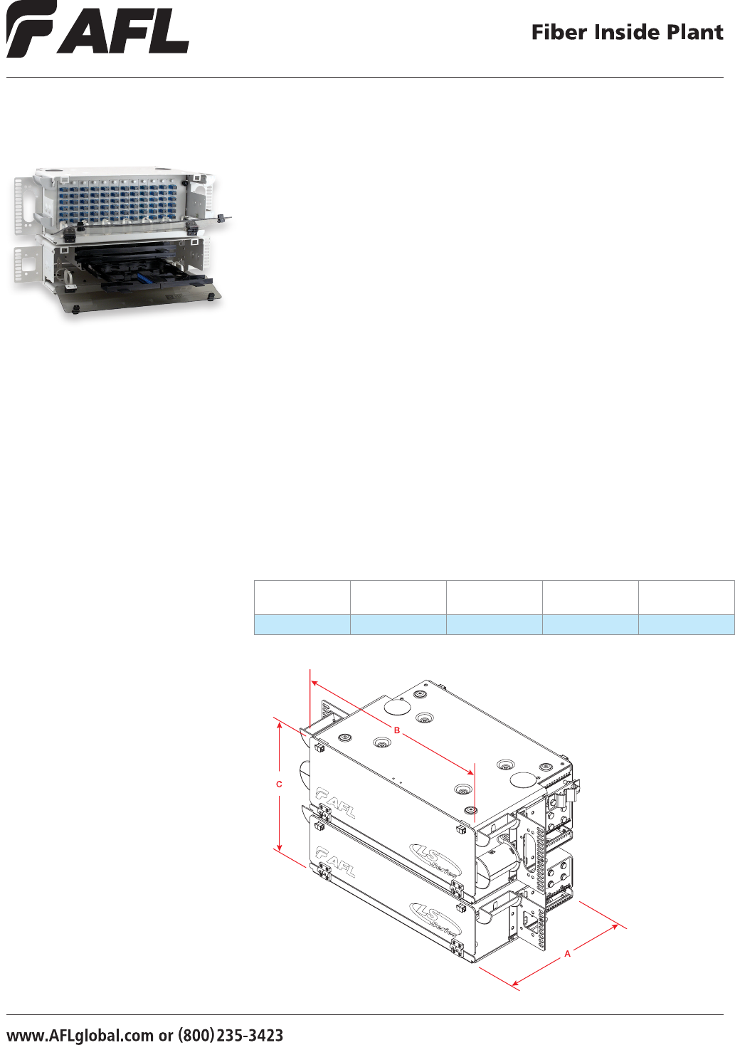
57
© 2002, AFL, all rights reserved. PP-2-00074, Revision 4, 5.13.13
Specications are subject to change without notice.
Specifications
• Telcordia® GR-63 NEBS tested
• Aluminum material per ASTMB209
• Central ofce white, black, texture powder coated
• Universal mounting bracket - WECO, EIA
• 19" and 23" rack compatible
• Fiber storage capacity - one meter per spliced ber (3 mm jacket)
• Uses three STF-48 splice drawers
• Two panel package - 4U patch, 3U splice
• Twelve 118 mm LGX® positions
• 144 ber (high density) version uses
The CNS072P is a rack mountable ber patch and splice panel designed to accommodate
up to 72 ber terminations (standard density) or 144 ber terminations (high density)
and up to 144 single fusion splices. The CNS072P provides a compact and versatile
method of splicing and connectivity. Standard panels are available in empty, loaded
and unloaded versions. Unloaded panels include adapter plates, adapters and splice
drawers. Loaded panels also include pigtails (<3 meters).
LightLink LANSystem
CNS072P – 72 Fiber Patch and Splice Panel
Dimensions
DEPTH (A)
IN INCHES
WIDTH (B)
IN INCHES
HEIGHT (C)
IN INCHES RACK UNITS FIBER CAPACITY
11 17 12.25 7 72/144
Applications
• Telecommunication Closets
• Data Centers
• Customer Premise
• Local Area Networks
• Wide Area Networks
• Central Ofces
• Hubs
• Cabinets
• Remote Terminals
LGX is a registered trademark of Furukawa Electric North America, Inc.
Telcordia is a registered trademark of Telcordia Technologies, Inc.
58
© 2002, AFL, all rights reserved. PP-2-00074, Revision 4, 5.13.13
Specications are subject to change without notice.
Empty - Includes master plate, mounting hardware, cable clamp.
Unloaded - Includes master plate, adapter plates, adapters, splice drawer (48 & up), hardware, cable clamp.
Loaded - Includes master plate, adapter plates, adapters, splice drawer (48 & up), pigtails with connectors, hardware, cable clamp.
Example: Order number for a panel Black in color, loaded
with, master plate, adapter plates, 72 USC adapters
(12 six packs), splice drawer (48 & up), pigtails
with connectors, hardware, cable clamp.
LightLink LANSystem
CNS072P – 72 Fiber Patch and Splice Panel
Standard Panel Ordering Information
C211624 B
AFL NO. Color Loading Charactor
W = C.O. White
B = Black
L
Ordering Information
Select the seven digit AFL number of the panel you need, specify black or C.O. white, and choose the loading character desired.
CONFIGURATION AFL NO.
7U PATCH AND SPLICE PANELS (1 - 4U PATCH, 1 - 3U SPLICE)
CNS072P – EMPTY 118 LGX C211615
CNS096P – EMPTY 118 LGX C210967
CNS072P with 72 USC (PB) adapters (12 Six Packs) Splice Drawers (3 - 48 position) 118 LGX C211624
CNS072P with 72 PSC adapters (12 Six Packs) Splice Drawers (3 - 48 position) 118 LGX C211633
CNS072P with 72 UST adapters (12 Six Packs) Splice Drawers (3 - 48 position) 118 LGX C211660
CNS072P with 72 PST adapters (12 Six Packs) Splice Drawers (3 - 48 position) 118 LGX C211669
CNS072P with 36 UDL (dup) adapters (12 Three Packs) Splice Drawers (3 - 48 position) 118 LGX FM000244
CNS072P with 36 PDL (dup) adapters (12 Three Packs) Splice Drawers (3 - 48 position) 118 LGX FM000245
CNS072P with 72 ASC adapters (12 Six Packs) Splice Drawers (3 - 48 position) 118 LGX C210958
CNS072P with 72 UFC adapters (12 Six Packs) Splice Drawers (3 - 48 position) 118 LGX C210946
CNS072P with 72 USC (ZR) adapters (12 Six Packs) Splice Drawers (3 - 48 position) 118 LGX C210953
CNS072P with 72 AFC adapters (12 Six Packs) Splice Drawers (3 - 48 position) 118 LGX C210949
CNS072P with 72 ULC adapters (12 Six Packs) Splice Drawers (3 - 48 position) 118 LGX C210964
CNS072P with 36 PSF (dup) adapters (12 Three Packs) Splice Drawers (3 - 48 position) 118 LGX FM000246
CNS072P with 36 USF (dup) adapters (12 Three Packs) Splice Drawers (3 - 48 position) 118 LGX FM000247
CNS072P with 36 ASF (dup) adapters (12 Three Packs) Splice Drawers (3 - 48 position) 118 LGX FM000248
CNS072P with 72 MTRJ adapters (12 Six Packs) Splice Drawers (3 - 48 position) 118 LGX FM000249
7U HIGH DENSITY PATCH AND SPLICE PANELS (1 - 4U PATCH, 1 - 3U SPLICE)
CNS144HD with 72 UDL (dup) adapters (12 Six Packs) Splice Drawers (3 - 48 position) 118 LGX C211673
CNS144HD with 72 PSF (dup) adapters (12 Six Packs) Splice Drawers (3 - 48 position) 118 LGX C211637
CNS144HD with 72 PDL (dup) adapters (12 Six Packs) Splice Drawers (3 - 48 position) 118 LGX C211684
CNS144HD with 72 USF (dup) adapters (12 Six Packs) Splice Drawers (3 - 48 position) 118 LGX FM000250
CNS144HD with 72 ASF (dup) adapters (12 Six Packs) Splice Drawers (3 - 48 position) 118 LGX FM000251
CNS144HD with 144 UST adapters (12 Twelve Packs) Splice Drawers (3 - 48 position) 118 LGX FM000252
CNS144HD with 144 PST adapters (12 Twelve Packs) Splice Drawers (3 - 48 position) 118 LGX FM000253
CNS144HD with 144 UFC adapters (12 Twelve Packs) Splice Drawers (3 - 48 position) 118 LGX FM000254
CNS144HD with 144 USC adapters (12 Twelve Packs) Splice Drawers (3 - 48 position) 118 LGX FM000255
CNS144HD with 144 ASC adapters (12 Twelve Packs) Splice Drawers (3 - 48 position) 118 LGX FM000256
Accessories
DESCRIPTION AFL NO.
Telescoping Splice Drawer 911442-00-00
Note: All MM cable is 62.5 µm unless otherwise specied.
Connector/Adapter Key
TYPE DESCRIPTION
ASC Angle Polish SC (ZR) sleeve-SM
ASF Angle Polish SC Duplex (ZR) sleeve-SM
PSC Physical Polish SC (PB) sleeve-MM
PSF Physical Polish SC Duplex (PB) sleeve-MM
USC (PB) Ultra Polish SC wih (PB) sleeve-SM
USC (ZR) Ultra Polish SC with (ZR) sleeve-SM
USF Ultra Polish SC Duplex (ZR) sleeve-SM
PST Physical Polish ST (PB) sleeve-MM
UST Ultra Polish ST (ZR) sleeve-SM
AFC Angle Polish FC (ZR) sleeve-SM
PFC Physical Polish FC (PB) sleeve-MM
UFC Ultra Polish FC (ZR) sleeve-SM
ADL Angle Polish LC Duplex (ZR) sleeve-SM
PDL Physical Polish LC Duplex (PB) sleeve-MM
PLC Physical Polish LC (PB) sleeve-MM
UDL (ZR) Ultra Polish LC Duplex (ZR) sleeve-SM
UDL (PB) Ultra Polish LC Duplex (PB) sleeve-SM
ULC Ultra Polish LC (ZR) sleeve-SM
E = Empty
H = Half-loaded with adapters
L = Loaded with adapters and pigtails
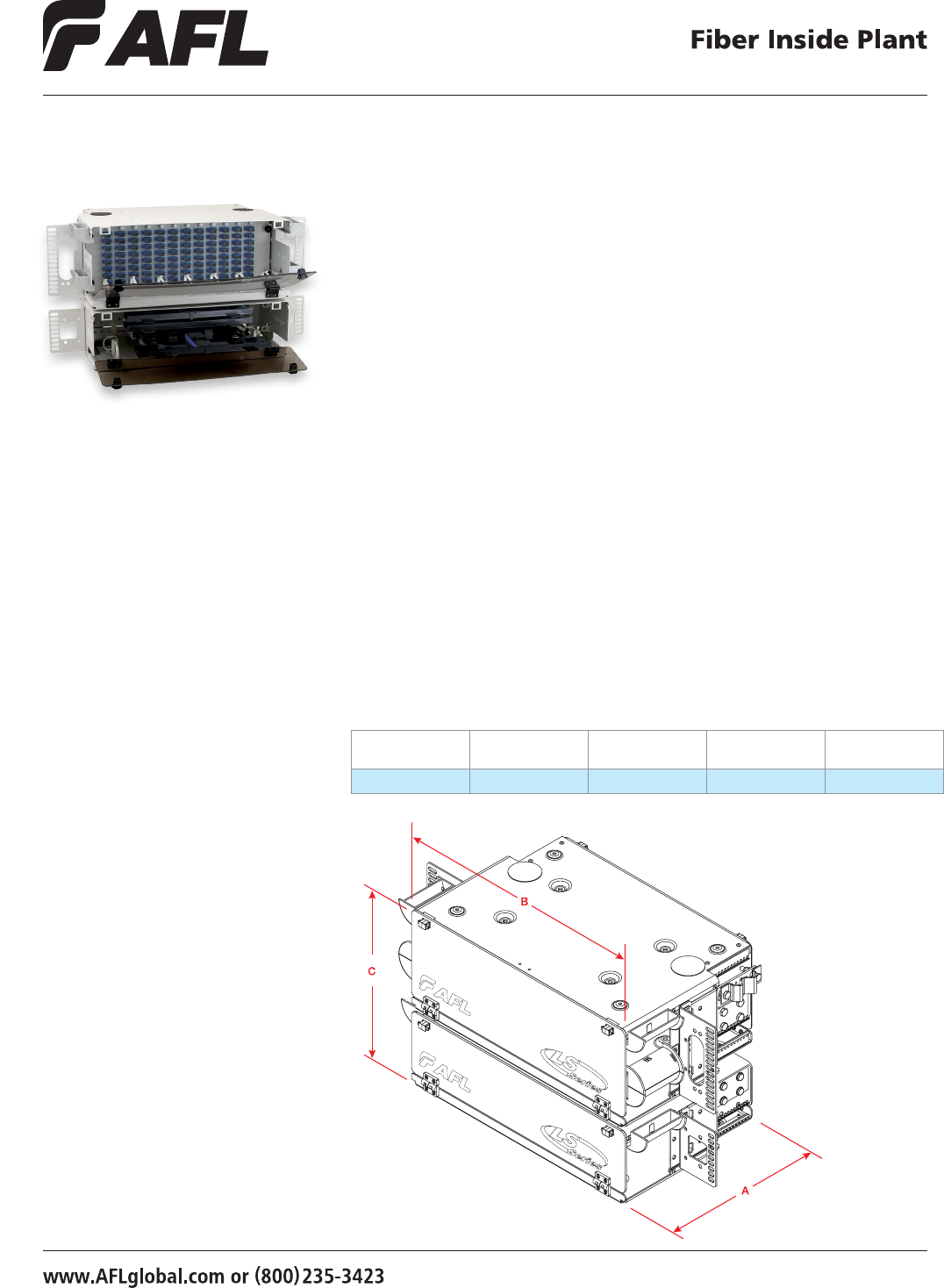
59
© 2002, AFL, all rights reserved. PP-2-00075, Revision 3, 10.8.12
Specications are subject to change without notice.
The CNS096P is a rack mountable ber patch and splice panel designed to accomodate
up to 96 ber terminations (standard density) or 144 ber terminations (high density)
and up to 144 single fusion splices. The CNS096P provides a compact and versatile
method of splicing and connectivity. Standard panels are available in empty, loaded
and unloaded versions. Unloaded panels include adapter plates, adapters and splice
drawers. Loaded panels also include pigtails (<3 meters).
LightLink LANSystem
CNS096P – 96 Fiber Patch and Splice Panel
Specifications
• Telcordia® GR-63 NEBS tested
• Aluminum material per ASTMB209
• Central ofce white, black, texture powder coated
• Universal mounting bracket - WECO, EIA
• 19" and 23" rack compatible
• Fiber storage capacity - one meter per spliced ber (3 mm jacket)
• Uses two STF-48 splice drawers
• Two panel package - 4U patch, 3U splice
• Twelve 130 mm LGX® positions
• Twelve 8-packs
Dimensions
DEPTH (A)
IN INCHES
WIDTH (B)
IN INCHES
HEIGHT (C)
IN INCHES RACK UNITS FIBER CAPACITY
11 17 12.25 7 96
Applications
• Telecommunication Closets
• Data Centers
• Customer Premise
• Local Area Networks
• Wide Area Networks
• Central Ofces
• Hubs
• Cabinets
• Remote Terminals
LGX is a registered trademark of Furukawa Electric North America, Inc.
Telcordia is a registered trademark of Telcordia Technologies, Inc.
60
© 2002, AFL, all rights reserved. PP-2-00075, Revision 3, 10.8.12
Specications are subject to change without notice.
LightLink LANSystem
CNS096P – 96 Fiber Patch and Splice Panel
Standard Panel Ordering Information
C210989 B
AFL NO. Color Loading Charactor
W = C.O. White
B = Black
L
Ordering Information
Select the seven digit AFL number of the panel you need, specify black or C.O. white, and choose the loading character desired.
CONFIGURATION AFL NO.
7U PATCH AND SPLICE PANELS (1 - 4U PATCH, 1 - 3U SPLICE)
CNS072/96P – EMPTY 130 LGX C210967
CNS096P with 96 UST adapters (12 Eight Packs) Splice Drawers (2 - 48 position) 130 LGX C210971
CNS096P with 96 UFC adapters (12 Eight Packs) Splice Drawers (2 - 48 position) 130 LGX C210976
CNS096P with 96 AFC adapters (12 Eight Packs) Splice Drawers (2 - 48 position) 130 LGX C210982
CNS096P with 96 USC (ZR) adapters (12 Eight Packs) Splice Drawers (2 - 48 position) 130 LGX C210985
CNS096P with 96 ASC adapters (12 Eight Packs) Splice Drawers (2 - 48 position) 130 LGX C210989
CNS096P with 96 MTRJ adapters (12 Eight Packs) Splice Drawers (2 - 48 position) 130 LGX FM000257
Accessories
DESCRIPTION AFL NO.
Telescoping Splice Drawer 911442-00-00
Note: All MM cable is 62.5 µm unless otherwise specied.
Empty - Includes master plate, mounting hardware, cable clamp.
Unloaded - Includes master plate, adapter plates, adapters, splice drawer (48 & up), hardware, cable clamp.
Loaded - Includes master plate, adapter plates, adapters, splice drawer (48 & up), pigtails with connectors, hardware, cable clamp.
Example: Order number for a panel Black in color, loaded
with, master plate, adapter plates, 96 ASC adapters
(12 eight packs), splice drawer (48 & up), pigtails
with connectors, hardware, cable clamp.
Connector/Adapter Key
TYPE DESCRIPTION
ASC Angle Polish SC (ZR) sleeve-SM
ASF Angle Polish SC Duplex (ZR) sleeve-SM
PSC Physical Polish SC (PB) sleeve-MM
PSF Physical Polish SC Duplex (PB) sleeve-MM
USC (PB) Ultra Polish SC wih (PB) sleeve-SM
USC (ZR) Ultra Polish SC with (ZR) sleeve-SM
USF Ultra Polish SC Duplex (ZR) sleeve-SM
PST Physical Polish ST (PB) sleeve-MM
UST Ultra Polish ST (ZR) sleeve-SM
AFC Angle Polish FC (ZR) sleeve-SM
PFC Physical Polish FC (PB) sleeve-MM
UFC Ultra Polish FC (ZR) sleeve-SM
ADL Angle Polish LC Duplex (ZR) sleeve-SM
PDL Physical Polish LC Duplex (PB) sleeve-MM
PLC Physical Polish LC (PB) sleeve-MM
UDL (ZR) Ultra Polish LC Duplex (ZR) sleeve-SM
UDL (PB) Ultra Polish LC Duplex (PB) sleeve-SM
ULC Ultra Polish LC (ZR) sleeve-SM
E = Empty
H = Half-loaded with adapters
L = Loaded with adapters and pigtails
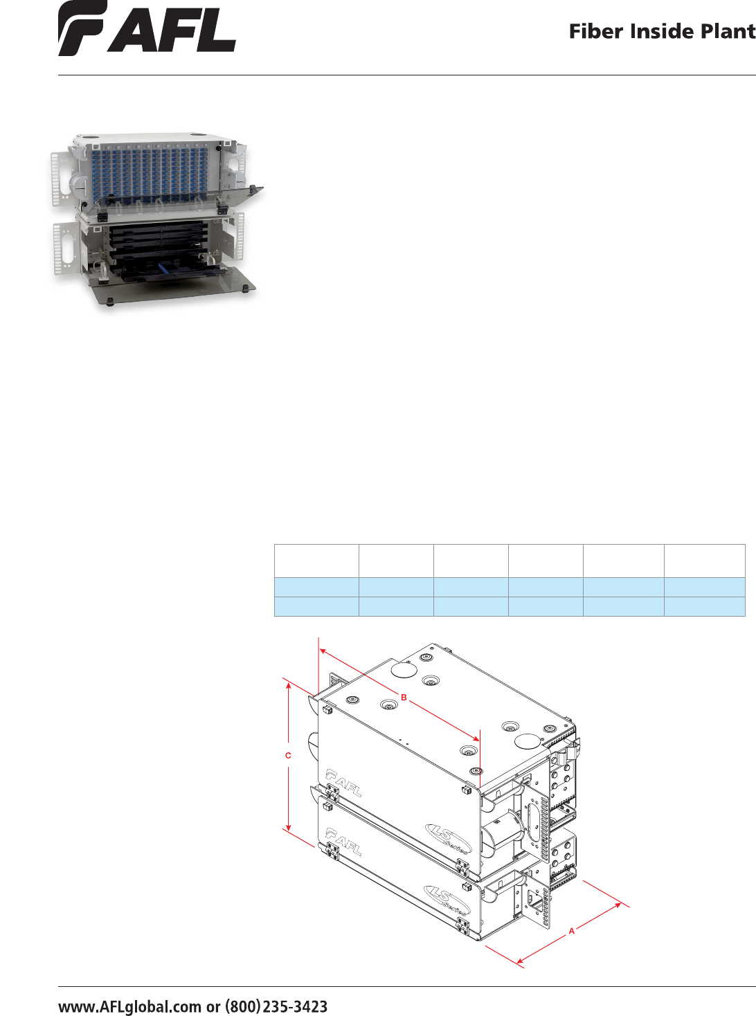
61
© 2002, AFL, all rights reserved. PP-2-00076, Revision 3, 10.8.12
Specications are subject to change without notice.
The CNS144P is a rack mountable ber patch and splice panel designed to accommodate
up to 144 ber terminations (standard density) or 288 ber terminations (high density) and
up to 288 single fusion splices using double density splice trays. The CNS144P provides a
compact and versatile method of splicing and connectivity. Standard panels are available in
empty, loaded and unloaded versions. Unloaded panels include adapter plates, adapters and
splice drawers. Loaded panels also include pigtails (<3 meters).
LightLink LANSystem
CNS144P – 144 Fiber Patch and Splice Panel
Specifications
• Telcordia® GR-63 NEBS tested
• Aluminum material per ASTMB209, standard front cover lexan
• Central ofce white, black, texture powder coated
• Universal mounting bracket - WECO, EIA
• 19" and 23" rack compatible
• Fiber storage capacity - one meter per spliced ber (3 mm jacket)
• Uses six STF-48 splice drawers
• Two pane package - 5U patch, 3U splice (4U splice panel with High Density version)
• Twelve 170 mm LGX® positions
Dimensions
PANEL VERSION
DEPTH (A)
IN INCHES
WIDTH (B)
IN INCHES
HEIGHT (C)
IN INCHES RACK UNITS
FIBER CAPACITY
Standard 11 17 14 8 144
High Density 11 17 15.75 9 288
Applications
• Telecommunication Closets
• Data Centers
• Customer Premise
• Local Area Networks
• Wide Area Networks
• Central Ofces
• Hubs
• Cabinets
• Remote Terminals
LGX is a registered trademark of Furukawa Electric North America, Inc.
Telcordia is a registered trademark of Telcordia Technologies, Inc.

62
© 2002, AFL, all rights reserved. PP-2-00076, Revision 3, 10.8.12
Specications are subject to change without notice.
Empty - Includes master plate, mounting hardware, cable clamp.
Unloaded - Includes master plate, adapter plates, adapters, splice tray (12, 24) / drawer (48 & up), hardware, cable clamp.
Loaded - Includes master plate, adapter plates, adapters, splice drawer (48 & up), pigtails with connectors, hardware, cable clamp.
C211705 B
AFL NO. Color Loading Charactor
W = C.O. White
B = Black
L
Example: Order number for a panel Black in color, loaded
with, master plate, adapter plates, 144 USC adapters
(12 twelve packs), splice drawer (48 & up), pigtails
with connectors, hardware, cable clamp.
Ordering Information
Select the seven digit AFL number of the panel you need, specify black or C.O. white, and choose the loading character desired.
LightLink LANSystem
CNS144P – 144 Fiber Patch and Splice Panel
Accessories
DESCRIPTION AFL NO.
Telescoping Splice Drawer 911442-00-00
Note: All MM cable is 62.5 µm unless otherwise specied.
Connector/Adapter Key
TYPE DESCRIPTION
ASC Angle Polish SC (ZR) sleeve-SM
ASF Angle Polish SC Duplex (ZR) sleeve-SM
PSC Physical Polish SC (PB) sleeve-MM
PSF Physical Polish SC Duplex (PB) sleeve-MM
USC (PB) Ultra Polish SC wih (PB) sleeve-SM
USC (ZR) Ultra Polish SC with (ZR) sleeve-SM
USF Ultra Polish SC Duplex (ZR) sleeve-SM
PST Physical Polish ST (PB) sleeve-MM
UST Ultra Polish ST (ZR) sleeve-SM
AFC Angle Polish FC (ZR) sleeve-SM
PFC Physical Polish FC (PB) sleeve-MM
UFC Ultra Polish FC (ZR) sleeve-SM
ADL Angle Polish LC Duplex (ZR) sleeve-SM
PDL Physical Polish LC Duplex (PB) sleeve-MM
PLC Physical Polish LC (PB) sleeve-MM
UDL (ZR) Ultra Polish LC Duplex (ZR) sleeve-SM
UDL (PB) Ultra Polish LC Duplex (PB) sleeve-SM
ULC Ultra Polish LC (ZR) sleeve-SM
Standard Panel Ordering Information
CONFIGURATION AFL NO.
8U PATCH AND SPLICE PANELS (1 - 5U PATCH, 1 - 3U SPLICE)
CNS144P – EMPTY C211696
CNS144P with 144 USC (PB) adapters (12 Twelve Packs) Splice Drawers (3 - 48 position) 170 LGX C211705
CNS144P with 144 PSC adapters (12 Twelve Packs) Splice Drawers (3 - 48 position) 170 LGX C211714
CNS144P with 144 UST adapters (12 Twelve Packs) Splice Drawers (3 - 48 position) 170 LGX C211741
CNS144P with 144 PST adapters (12 Twelve Packs) Splice Drawers (3 - 48 position) 170 LGX C211750
CNS144P with 72 UDL (dup) adapters (12 Six Packs) Splice Drawers (3 - 48 position) 170 LGX FM000258
CNS144P with 72 PDL (dup) adapters (12 Six Packs) Splice Drawers (3 - 48 position) 170 LGX FM000259
CNS144P with 144 ASC adapters (12 Twelve Packs) Splice Drawers (3 - 48 position) 170 LGX C211021
CNS144P with 144 UFC adapters (12 Twelve Packs) Splice Drawers (3 - 48 position) 170 LGX C211007
CNS144P with 144 USC (ZR) adapters (12 Twelve Packs) Splice Drawers (3 - 48 position) 170 LGX FM000260
CNS144P with 72 PSF (dup) adapters (12 Six Packs) Splice Drawers (3 - 48 position) 170 LGX FM000261
CNS144P with 72 USF (dup) adapters (12 Six Packs) Splice Drawers (3 - 48 position) 170 LGX FM000262
CNS144P with 72 ASF (dup) adapters (12 Six Packs) Splice Drawers (3 - 48 position) 170 LGX FM000263
CNS144P with 144 MTRJ adapters (12 Twelve Packs) Splice Drawers (3 - 48 position) 170 LGX FM000264
9U HIGH DENSITY PATCH AND SPLICE PANELS (1 - 5U PATCH, 1 - 4U SPLICE)
CNS288HD with 144 UDL (dup) adapters (12 Twelve Packs) Splice Drawers (6 - 48 position) 170 LGX C211756
CNS288HD with 144 PDL (dup) adapters (12 Twelve Packs) Splice Drawers (6 - 48 position) 170 LGX C211763
CNS288HD with 144 PSF (dup) adapters (12 Twelve Packs) Splice Drawers (6 - 48 position) 170 LGX C211720
CNS288HD with 144 USF (dup) adapters (12 Twelve Packs) Splice Drawers (6 - 48 position) 170 LGX FM000265
CNS288HD with 144 ASF (dup) adapters (12 Twelve Packs) Splice Drawers (6 - 48 position) 170 LGX FM000266
E = Empty
H = Half-loaded with adapters
L = Loaded with adapters and pigtails

63
© 2002, AFL, all rights reserved. PP-2-00081, Revision 4, 5.13.13
Specications are subject to change without notice.
The LightLink LANSystem Optical Splice Shelf is designed to provide a convenient in-rack
splicing and interconnection point for Outside Plant (OSP) cable entering a Central Ofce
(CO), Controlled Environmental Vault (CEV), Headend (HE) or customer location. Units
are available with three or six sliding, telescoping drawer assemblies. Each drawer is
capable of handling up to 48 individual single-fused or up to 144 mass-fused bers,
with minimum bend radius routing and protection.
LightLink LANSystem
SPL3RU and SPL4RU – Optical Splice Shelf
Features
• Fits comfortably into new and existing
interconnect, cross-connect, customer
premise, and co-location environments
• Compatible with industry standard
equipment frames
• For in-rack splicing of outside plant cable
to connectorized pigtails or riser cable
• Drawers handle up to 48 single-fused or
144 mass-fused bers
• Cable entry/exit grommet seals
• Durable and scratch resistant power
coated antique white nish
• Hinged plexiglass front and rear door
• Spring loaded latches
SPL3RU
SPL4RU
Specifications
• Telcordia® GR-63 NEBS tested
• Aluminum material per ASTMB209
• Central ofce white, black, texture
powder coated
• Universal mounting bracket - WECO, EIA
• 19" and 23" rack compatible
Applications
• Telecommunication Closets
• Data Centers
• Customer Premise
• Local Area Networks
• Wide Area Networks
• Central Ofces
• Hubs
• Cabinets
• Remote Terminals
LGX is a registered trademark of Furukawa Electric North America, Inc.
Telcordia is a registered trademark of Telcordia Technologies, Inc.
continued on next page
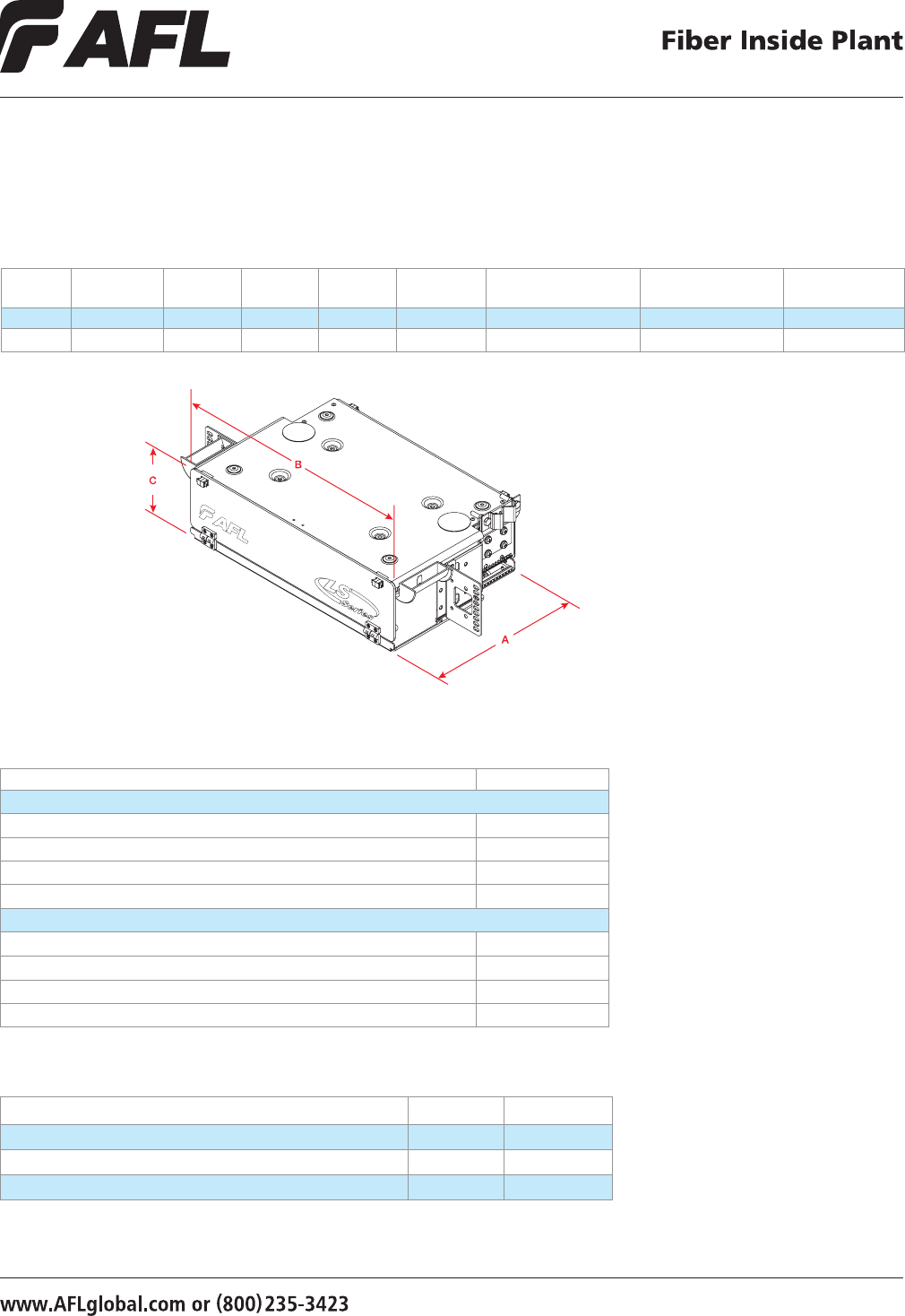
64
© 2002, AFL, all rights reserved. PP-2-00081, Revision 4, 5.13.13
Specications are subject to change without notice.
Ordering Information
DESCRIPTION AFL NO.
SPL3RU
CO White, 3RU (5.25") Optical Splice Shelf - Empty C211777 - W
Black, 3RU (5.25") Optical Splice Shelf - Empty C211777 - B
CO White, 3RU (5.25") Optical Splice Shelf - with 3 telescoping splice drawers C211781 - W
Black, 3RU (5.25") Optical Splice Shelf - with 3 telescoping splice drawers C211781 - B
SPL4RU
CO White, 4RU (7.00") Optical Splice Shelf - Empty C211795 - W
Black, 4RU (7.00") Optical Splice Shelf - Empty C211795 - B
CO White, 4RU (7.00") Optical Splice Shelf - with 6 telescoping splice drawers C211799 - W
Black, 4RU (7.00") Optical Splice Shelf - with 6 telescoping splice drawers C211799 - B
Accessories
DESCRIPTION MODEL AFL NO.
Telescoping Splice Drawer, up to 48 single fused or 144 mass fused splices STF-48 911442-00-00
1x8 Universal Core Tube Fiber Routing Kit 1x8-UCT-FR-Kit FC000008
1x6 Universal Ribbon or Loose Tube Fiber Routing Kit 1x6-URL-FR-Kit FC000070
LightLink LANSystem
SPL3RU and SPL4RU – Optical Splice Shelf
Dimensions
MODEL NO. OF TRAYS DEPTH (A)
(INCHES)
WIDTH (B)
(INCHES)
HEIGHT (C)
(INCHES) RACK UNITS SPLICE CAPACITY UNLOADED WEIGHT MATERIAL GAUGE
SPL3RU 3 11 17 5.25 3 144 single, 432 mass 8.4 lbs. 2.03 mm
SPL4RU 6 11 17 7.00 4 288 single, 864 mass 9.0 lbs. 2.03 mm
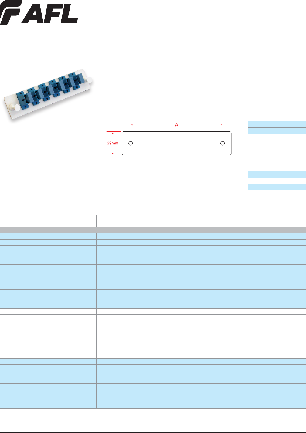
65
Fiber Inside Plant
www.AFLglobal.com or (800)235-3423 © 2010, AFL, all rights reserved. PP-2-00169, Revision 2, 5.13.13
Specications are subject to change without notice.
Features
• Metal Plate with Nylatches
• Polyurethane powder coated
(CO white or Black)
• LGX® compatible
LightLink Adapter Plates
LightLink Adapter Plates add versatility to the AFL’s panel product line. Adapter plates
are compatible with industry standard platforms allowing for easy upgrades of existing
panels. Adapter Plates come preloaded and are available in 6, 8, and 12 pack versions.
DIMENSION A
118 mm LGX®
170 mm LGX®
Specifications
MULTIPLE UNIT ORDERING OPTION
To order multiple units of the same part, select the base number from the
ordering charts and add the quantity extension.
Example: FM000086 – 12Z
ORDERING MULTIPLE UNITS
1 = 1 6 = 6
2 = 2 8 = 8
3 = 3 12 = 12
4 = 4 XX = Specify
LGX is a registered trademark of Furukawa Electric North America, Inc.
Ordering Information
AFL NO.
PLATE
CAPACITY / STYLE PLATE COLOR
SLEEVE
MATERIAL FOOTPRINT
ADAPTER
ORIENTATION
ADAPTER
TYPE
ADAPTER
COLOR
SC
C215503 Blank White N/A LGX 118 N/A N/A N/A
C215507 Blank Black N/A LGX 118 N/A N/A N/A
FM002271 6 SC Duplex White Ceramic LGX 118 Vertical SC SM Blue
FM002274 6 SC Duplex Black Ceramic LGX 118 Vertical SC SM Blue
FM002273 6 SC Duplex White Metal LGX 118 Vertical SC MM Beige
FM002276 6 SC Duplex Black Metal LGX 118 Vertical SC MM Beige
FM002272 6 SC Duplex White Ceramic LGX 118 Vertical SC MM Aqua
FM002275 6 SC Duplex Black Ceramic LGX 118 Vertical SC MM Aqua
FM002634 6 SC Duplex White Ceramic LGX 118 Vertical SC MM Green
FM002633 6 SC Duplex Black Ceramic LGX 118 Vertical SC MM Green
FM002632-TB 6 SC Duplex Black N/A LGX 118 Vertical Empty Empty
FM002632-TW 6 SC Duplex White N/A LGX 118 Vertical Empty Empty
C215512 3 SC Duplex White Ceramic LGX 118 Vertical SC SM Blue
C215521 3 SC Duplex Black Ceramic LGX 118 Vertical SC SM Blue
C215536 3 SC Duplex White Metal LGX 118 Vertical SC MM Beige
C215543 3 SC Duplex Black Metal LGX 118 Vertical SC MM Beige
FM000115 3 SC Duplex White Ceramic LGX 118 Vertical SC MM Green
FM000114 3 SC Duplex White Ceramic LGX 118 Vertical SC MM Green
C215548 3 SC Duplex Black N/A LGX 118 Vertical Empty Empty
C215554 3 SC Duplex White N/A LGX 118 Vertical Empty Empty
C215602 6 SC Simplex White Ceramic LGX 118 Straight SC SM Blue
C215611 6 SC Simplex Black Ceramic LGX 118 Straight SC SM Blue
C215626 6 SC Simplex White Metal LGX 118 Straight SC MM Beige
C215633 6 SC Simplex Black Metal LGX 118 Straight SC MM Beige
C215638 6 SC Simplex White Ceramic LGX 118 Straight SC SM AP Green
C215644 6 SC Simplex Black Ceramic LGX 118 Straight SC SM AP Green
C215647 6 SC Simplex Black N/A LGX 118 Straight Empty Empty
C215651 6 SC Simplex White N/A LGX 118 Straight Empty Empty
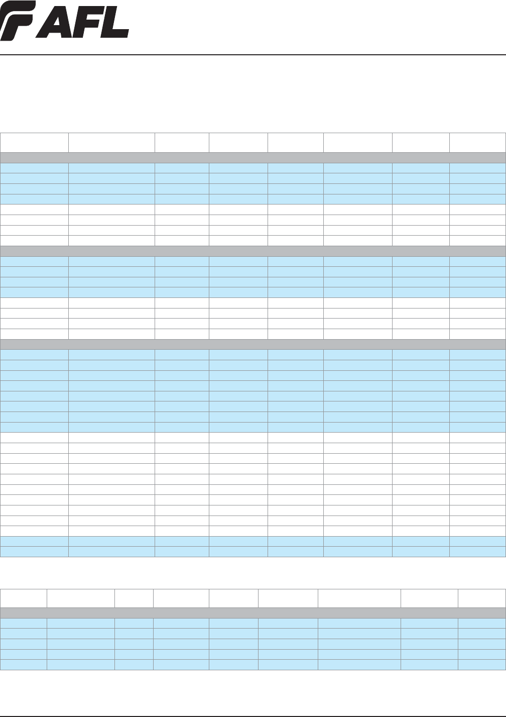
66
Fiber Inside Plant
www.AFLglobal.com or (800)235-3423 © 2010, AFL, all rights reserved. PP-2-00169, Revision 2, 5.13.13
Specications are subject to change without notice.
LightLink Adapter Plates
Ordering Information (cont.)
AFL NO.
PLATE
CAPACITY / STYLE PLATE COLOR
SLEEVE
MATERIAL FOOTPRINT
ADAPTER
ORIENTATION
ADAPTER
TYPE
ADAPTER
COLOR
FC
C215926 6 FC Simplex White Ceramic LGX 118 Straight FC SM D Mount Plated metal
C215935 6 FC Simplex Black Ceramic LGX 118 Straight FC SM D Mount Plated metal
C215953 6 FC Simplex White N/A LGX 118 Straight Empty Empty
C215957 6 FC Simplex Black N/A LGX 118 Straight Empty Empty
C223765 12 FC Simplex White Ceramic LGX 118 Staggered FC SM D Mount Plated metal
C223774 12 FC Simplex Black Ceramic LGX 118 Staggered FC SM D Mount Plated metal
C223672-TW 12 FC Simplex White N/A LGX 118 Staggered Empty Empty
C223672-TB 12 FC Simplex Black N/A LGX 118 Staggered Empty Empty
ST
C215962 6 ST Simplex White Ceramic LGX 118 Straight ST SM D Mount Plated metal
C215975 6 ST Simplex Black Ceramic LGX 118 Straight ST MM D Mount Plated metal
C215980 6 ST Simplex White N/A LGX 118 Straight Empty Empty
C215986 6 ST Simplex Black N/A LGX 118 Straight Empty Empty
C223564 12 ST Simplex White Ceramic LGX 118 Staggered ST SM D Mount Plated metal
C223567 12 ST Simplex White Ceramic LGX 118 Staggered ST MM D Mount Plated metal
C223571 12 ST Simplex Black Ceramic LGX 118 Staggered ST SM D Mount Plated metal
C223576 12 ST Simplex Black Ceramic LGX 118 Staggered ST MM D Mount Plated metal
LC
FM000289 3 LC Duplex White Ceramic LGX 118 Straight LC SM Blue
FM000290 3 LC Duplex Black Ceramic LGX 118 Straight LC SM Blue
FM000291 3 LC Duplex White Metal LGX 118 Straight LC MM Beige
FM000292 3 LC Duplex Black Metal LGX 118 Straight LC MM Beige
FM000293 3 LC Duplex White Ceramic LGX 118 Straight LC SM AP Green
FM000294 3 LC Duplex Black Ceramic LGX 118 Straight LC SM AP Green
FM000295 3 LC Duplex White N/A LGX 118 Straight Empty Empty
FM000296 3 LC Duplex Black N/A LGX 118 Straight Empty Empty
C215989 6 LC Duplex White Ceramic LGX 118 Straight LC SM Blue
C215993 6 LC Duplex Black Ceramic LGX 118 Straight LC SM Blue
C215998 6 LC Duplex White Metal LGX 118 Straight LC MM Beige
C216004 6 LC Duplex Black Metal LGX 118 Straight LC MM Beige
FM001303 6 LC Duplex White Ceramic LGX 118 Straight LC MM 10G Aqua
FM001302 6 LC Duplex Black Ceramic LGX 118 Straight LC MM 10G Aqua
FM001004 6 LC Duplex White Ceramic LGX 118 Straight LC SM AP Green
FM001005 6 LC Duplex Black Ceramic LGX 118 Straight LC SM AP Green
C216007 6 LC Duplex White N/A LGX 118 Straight Empty Empty
C216011 6 LC Duplex Black N/A LGX 118 Straight Empty Empty
FM000853 12 LC Duplex White Ceramic LGX 118 Straight Dual Column LC MM 10G Aqua
FM000852 12 LC Duplex Black Ceramic LGX 118 Straight Dual Column LC MM 10G Aqua
AFL NO.
PLATE
CAPACITY / STYLE
PLATE
COLOR
SLEEVE
MATERIAL FOOTPRINT
ADAPTER
ORIENTATION
ADAPTER
STYLE
ADAPTER
TYPE
ADAPTER
COLOR
MTP
C216043 3 MTP White Polymer LGX 118 Straight MTP (key up / key down) MTP SM/MM Black
C216047 3 MTP Black Polymer LGX 118 Straight MTP (key up / key down) MTP SM/MM Black
C216052 3 MTP White N/A LGX 118 Straight Empty N/A Empty
C216058 3 MTP Black N/A LGX 118 Straight Empty N/A Empty
FM001606 6 MTP Black Polymer LGX 118 Straight MTP (key up / key down) MTP SM/MM Black
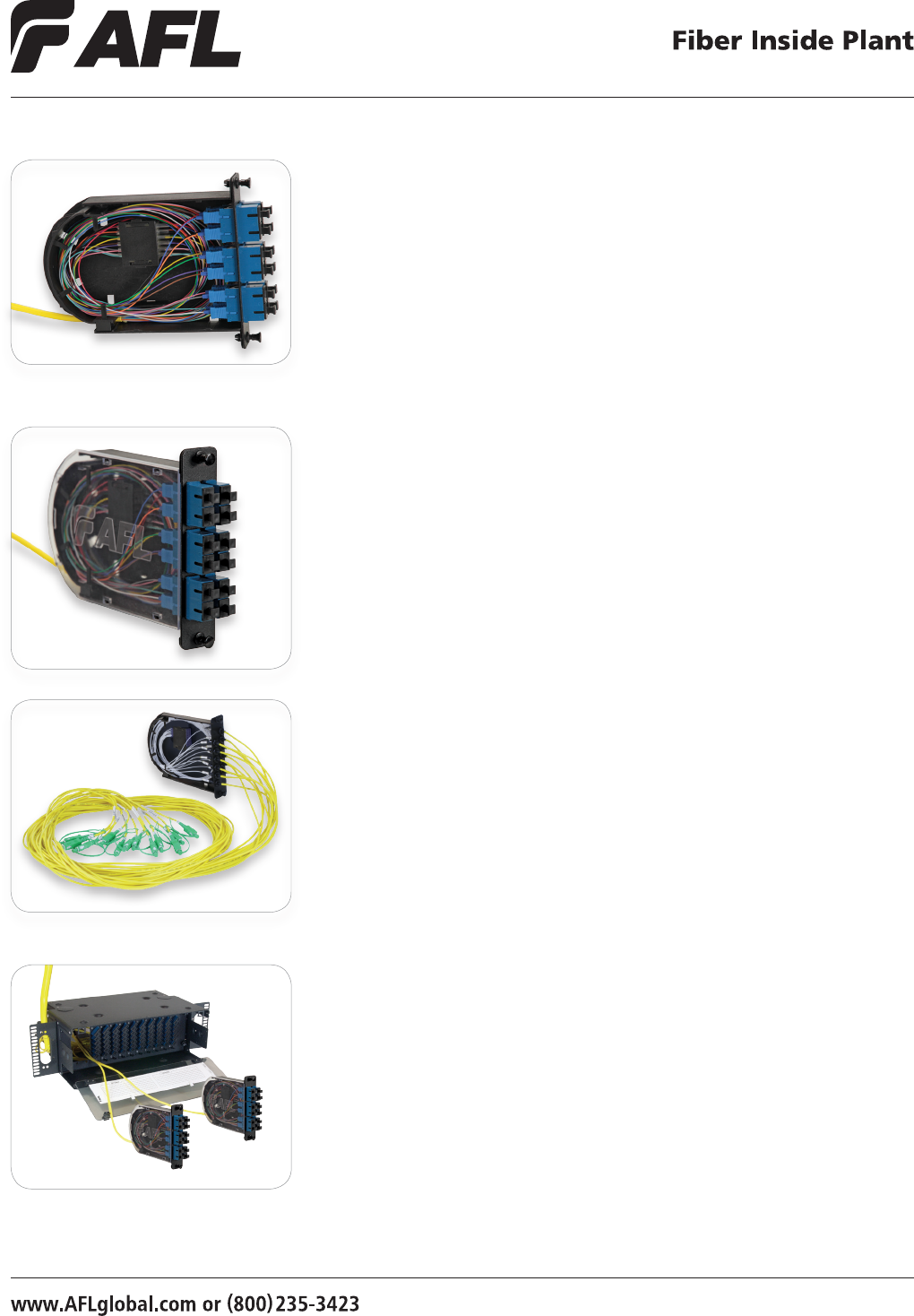
67
© 2013, AFL, all rights reserved. PP-2-00089, Revision 1, 8.28.13
Specications are subject to change without notice.
LGX is a registered trademark of Furukawa Electric North America, Inc.
AFL's new Poli-MOD is an innovative patch and splice module, which offers an
inventive and effective means to accommodate up to 24 ber interconnections in an
industry-standard, single-slot LGX®118 footprint. The new Poli-MOD offers a unique and
robust way to secure cable without the need for time-wasting, tie-wrap alternatives.
Additionally, the module leverages a creative snap-in splice sleeve cradle to securely
manage both single and ribbon ber arrangements. These features provide the capacity
to outt a standard 4RU rack-mount panel with up to 288-ber interconnections.
The Poli-MOD is also offered in an arrangement that supports the low loss budget
requirements of Distributed Antenna System (DAS) networks. This is accomplished
through the elimination of an interconnection point while providing a robust splicing
environment for rack and wall-mount panel applications.
Poli-MOD® Patch and Splice Module
Features
• 24-ber interconnection capacity
• LGX 118 compatibility (single-slot module)
• Effective and time-saving cable mounting mechanism (no tie-wraps necessary)
• Inventive splice sleeve cradle
• Available in SC, LC, ST and FC connector arrangements
• Organized ber routing
• Fixed solution, no moving parts
• Multi-directional cable entry access
Applications
• Telecommunications Closets
• Data Centers
• Customer Premise
• Local Area Networks
• Wide Area Networks
• Central Ofces
• Hub Sites
• Cabinets
• Remote Terminals
• Distributed Antenna Systems (DAS)
12-Fiber SC/UPC Conguration
DAS Poli-MOD
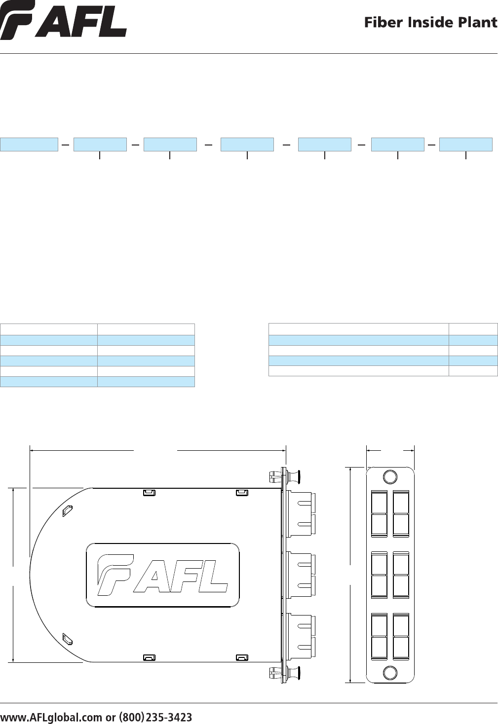
68
© 2013, AFL, all rights reserved. PP-2-00089, Revision 1, 8.28.13
Specications are subject to change without notice.
Poli-MOD® Patch and Splice Module
Example: PM-L-12-ASC-0-S-01
Ordering Information
Dimensions
Conguration
E = Empty (Splicing Only)
H = Half Loaded
(Adapter Plate only)
L = Loaded
(Adapter Plate & Pigtails)
D = DAS Poli-MOD*
LPM
Fiber Type
0 = Single-mode
(G.657.A1 BIF)
1 = 62.5 μm (OM1)
2 = 50 μm (OM2)
3 = 50 μm (OM3)
4 = 50 μm (OM4)
X = Empty
0
Fiber Arrangement
S = Single/Standard
R = Ribbon
3 = 3 mm, 3 meter DAS
X = No Fiber
(Half Loaded or Empty)
S12
Fiber/Connector Count
06 = 6 Fibers/Connectors
12 = 12 Fibers/Connectors
24 = 24 Fibers/Connectors
XX = Empty
ASC
Connector Type
ASC = Angle-Polished SC
USC = Ultra-Polished SC
PSC = Multimode SC
ALC = Angle-Polished LC
ULC = Ultra-Polished LC
PLC = Multimode LC
UST = Ultra-Polished ST
PST = Multimode ST
AFC = Angle-Polished FC
UFC = Ultra-Polished FC
PFC = Multimode FC
XXX = Empty
Connector Color Codes
CONNECTOR COLOR
APC Green
UPC Blue
PC-OM1 Beige
PC-OM2 Black
PC-OM3 / PC-OM4 Aqua
6.07 in. (154 mm) 1.14 in.
(29 mm)
4.14 in.
(105 mm)
5.12 in.
(130 mm)
Poli-MOD Kits/Accessories
DESCRIPTION AFL NO.
Poli-MOD Cable Mounting Clip Kit FM003053
Fusion Splice Sleeve, FP-03, 40 mm S000206
Adapter Bracket for Mounting Single Poli-MOD FM000948-B
Corning CCH and PCH 145 mm Adapter Bracket FM001636
Packaging
01 = 1 Poli-MOD per box*
06 = 6 Poli-MODs per box
12 = 12 Poli-MODs per box
01
* DAS Poli-MOD requires specialty packaging and is packaged as "1 Poli-MOD per box" ONLY.
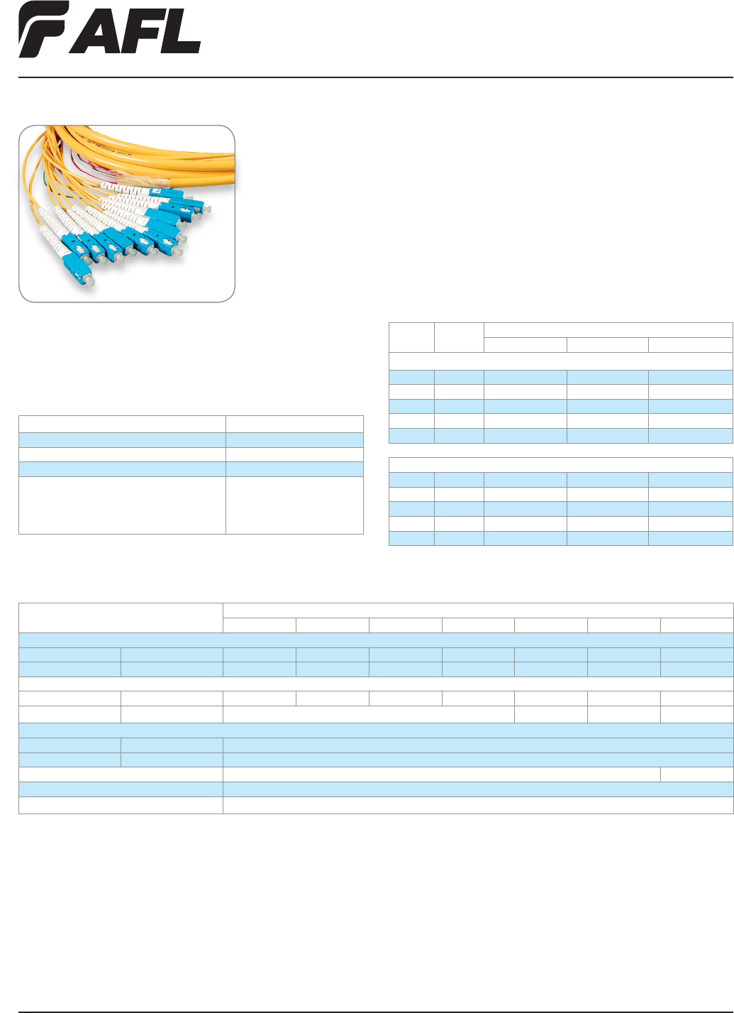
Fiber Inside Plant
www.AFLglobal.com or (800)235-3423
69
© 2002, AFL, all rights reserved. PP-2-00096, Revision 3, 5.24.11
Specications are subject to change without notice.
Pigtail Assemblies
for Patch and Splice Panels
AFL’s pigtail assemblies help eliminate labor-intensive eld termination, yet guarantee reli-
able performance. Featuring a unied construction allowing for easy ber identication and
rapid installation, these assemblies are built to exceed all TIA and Telcordia requirements.
Ordering Information
POLISH
FIBER
TYPE
CONNECTOR INTERFACE AFL NO.
SC ST LC
CPC PIGTAIL KITS, 3 METER, 12-FIBER
APC SMF C152906-0003 — CS007719-0003
UPC SMF C165943-0003 C152671-0003 C223369-0003
PC 62.5 µm C165463-0003 C223366-0003 C223373-0003
PC 50 µm CS007672-0003 CS007674-0003 CS007676-0003
PC 50 µm LO CS007673-0003 CS007675-0003 CS007677-0003
900 M TIGHT-BUFFERED PIGTAIL KITS, 3 METER, 12-FIBER
APC SMF C223312-0003 — CS003981-0003
UPC SMF C223492-0003 CS003979-0003 CS001037-0003
PC 62.5 µm CS000386-0003 CS002150-0003 CS002067-0003
PC 50 µm CS001373-0003 CS002136-0003 CS002081-0003
PC 50 µm LO CS003056-0003 CS003980-0003 CS003058-0003
Splicer Connector Specifications
PARAMETER VALUE
Cable Type 250 µm, 900 µm
Insertion Loss < 0.15 dB
Return Loss > 40 dB
Operating Temperature (900 µm Fiber Coating)
PVC
Nylon
TPEE
-40ºC to 75ºC
0ºC to 75ºC
-25ºC to 75ºC
Jumper Specifications
PARAMETER
VALUE
LC SC ST FC LC-APC SC-APC MT
Insertion Loss
SM max 0.3 0.3 0.5 0.3 0.3 0.5 0.75
MM max 0.5 0.5 0.5 0.5 0.6
Return Loss
SM max -55.0 dB -55.0 dB -55.0 dB -55.0 dB -65.0 dB -65.0 dB -55.0 dB
MM max -20.0 dB -20.0 dB
Cable Bend Radius
Standard min <30 mm
Bend Insensitive min <15 mm
Durability 200 cycles 500 cycles
Operating Temperature -40ºC to +85ºC
Storage Temperature -40ºC to +85ºC
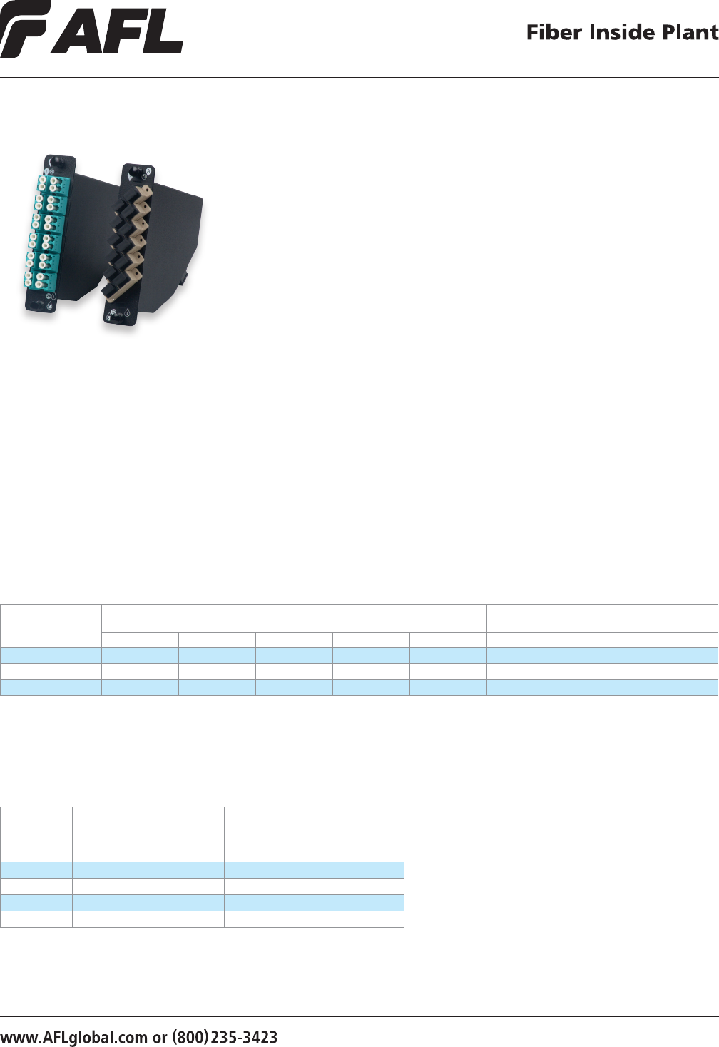
70
© 2003, AFL, all rights reserved. PP-2-00117, Revision 4, 8.5.13
Specications are subject to change without notice.
Features
• 12- and 24- port congurations
• ANSI/TIA/EIA-568-B.3 compliant
• Single-slot LGX packages
• Compatible with LANSystem
and WME hardware
Xpress Fiber Management® (XFM)
MPO Optical Cassettes
AFL’s Xpress Fiber Management Optical Cassette product line is a family of preterminated
fanout modules that streamline the deployment of optical network infrastructure. The
primary function of these products is to break out multi-ber ribbon connectors to simplex
or duplex style connectors for connection to adjacent network elements.
The Xpress Fiber Management Optical Cassette solution features low-loss MPO style
trunk cable assemblies. These cassettes are available in the industry standard LGX®
footprint as well as a selection of Corning Cable Systems™ footprints to support
embedded base installations. All modules feature a durable powder coat nish, and are
compatible with all 1U-4U LANSystem platforms. All modules are clearly labeled with a
silk-screened "A" and "B" positioning reference to ensure proper polarity is maintained
in the network, referenced to the polarity convention being deployed.
Applications
• Data centers
• LAN, WAN and SAN
• Interofce cross-connects
• Campus environments
Ordering Information
FIBER COUNT,
CONNECTOR
OPTION
SINGLE-MODE MULTIMODE
UPC - MPO
(MALE, APC)
APC - MPO
(Male, APC)
50 µm LOMMF OM4
PC - MPO
(Male, PC)
62.5 µm OM1
PC - MPO
(Male, PC)
12F, LC FM000090-B FM001437-B FM000273-B FM000092-B
24F, LC FM000691-B FM001653-B FM000692-B FM000663-B
12F, SC FM000087-B FM001465-B FM000272-B FM000089-B
12F, ST FM000093-B N/A FM000274-B FM000095-B
Optical Performance Data
PARAMETER Single-mode Fiber (OS1) Multimode Fiber
(OM1, OM2 and 50 µm Laser Optimized)
LC - MPO LCAPC - MPO SC - MPO SCAPC - MPO ST - MPO LC - MPO SC - MPO ST - MPO
Max IL (dB) 1.15 1.15 1.3 1.3 1.3 1.15 1.3 1.3
Typical IL (dB) 0.6 0.6 0.6 0.6 0.6 0.6 0.6 0.6
Reectance (dB) -55 -65 -55 -65 -55 -30 -30 -30
Notes:
1. Single-mode IL test wavelengths 1310 nm and 155 0nm
2. Multimode IL test wavelengths 850 nm and 1300 nm
3. Single-mode RL test wavelengths 1310 nm and 1550 nm
4. Multimode RL test wavelengths 850 nm and 1300 nm
Technical Specications:
1. ANSI/TIA/EIA-568-B.3
2. Telcordia® GR-326-CORE compliant single ber connectors
3. Telcordia GR-1435-CORE compliant multi-ber connectors
• Available in black with rear
MPO connection(s)
• SMF, 62.5 µm MMF and
50 µm MMF supported
• SC- and LC-MPO standard congurations
• ST- and FC-MPO congurations available
on special order
LGX is a registered trademark of Furukawa Electric North America, Inc.
Telcordia is a registered trademark of Telcordia Technologies, Inc.
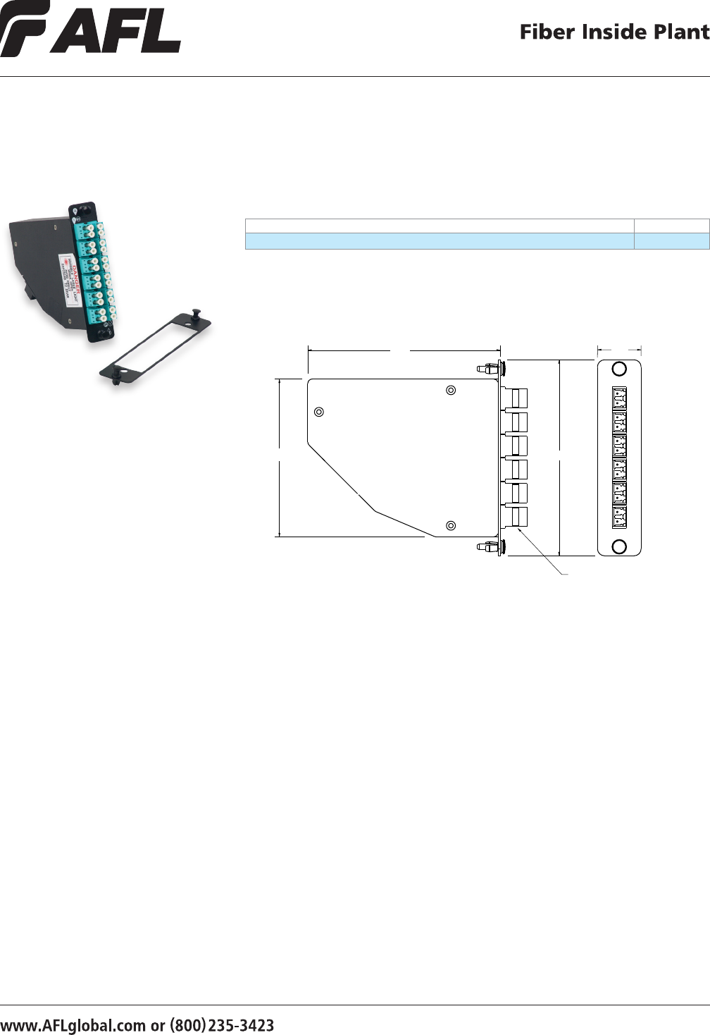
71
© 2003, AFL, all rights reserved. PP-2-00117, Revision 4, 8.5.13
Specications are subject to change without notice.
Xpress Fiber Management® (XFM)
MPO Optical Cassettes
Ordering Information – Accessories
DESCRIPTION AFL NO.
145 mm Adapter Bracket FM001636
LGX is a registered trademark of Furukawa Electric North America, Inc.
Dimensions
128.0
ADAPTERS SHOWN
FOR REFERENCE ONLY
28.9
130.0
104.6
NOTE: Allows standard LGX modules, such as AFL’s Poli-Mod Interconnect Module and the XFM Optical Cassette, to be mounted
into existing Corning Cable Systems™ CCH series and PCH series racks and wall mount products.
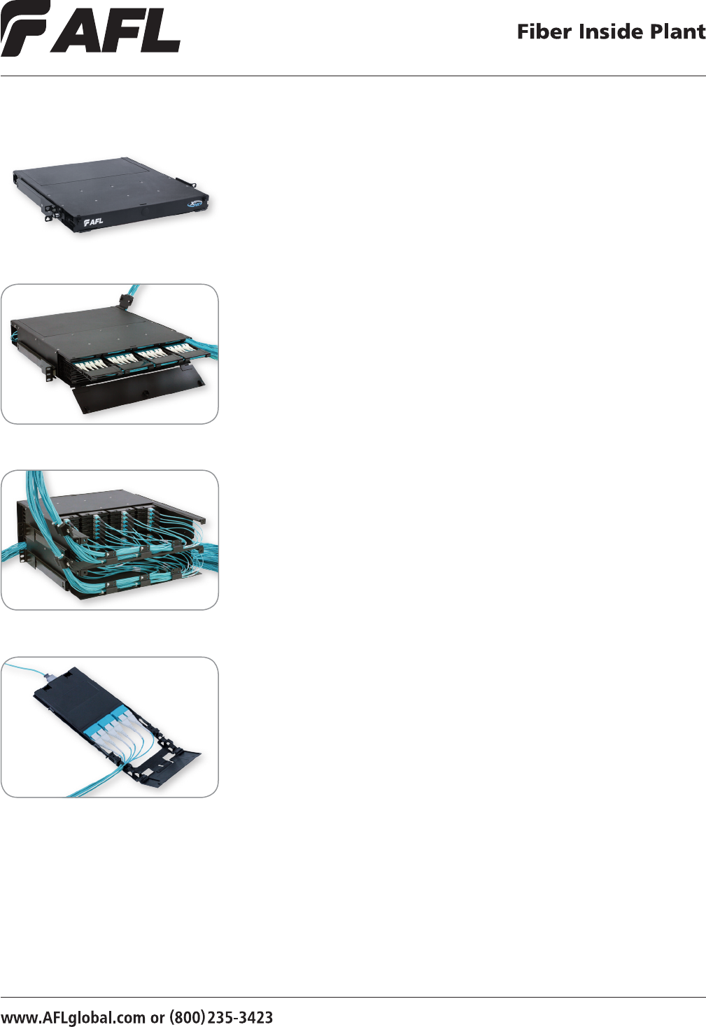
7272
XFM-HD Optical Cassette
The XFM-HD family of products is designed to offer intuitive ber management and
unmatched ber port accessibility in both the front and rear of the panel to extreme
density applications in an optical interconnect environment. Readily supporting the
management of densities up to 576 bers in a traditional 4 rack-unit (4RU) space,
the XFM-HD solution easily matches the highest port densities available in the market.
The completely modular solution features low-loss MPO style trunk cable assemblies,
Optical Fan-out cassettes with integrated ber management and Uniboot 2.0 mm LC
jumper assemblies. This combination of products cohesively equates to efcient moves,
adds and changes and more accurate cost budgeting as there are no other products or
accessories required to complete or modify an installation. A unique Uniboot LC connector
allows for reversal of polarity in the eld without requiring the use of any tools, easing
assimilation into existing installations. Microcore trunk cables offer operators a reduced
cable diameter which eases congestion in busy raceways, and feature an innovative
protective pulling eye solution designed to add efciency and security to moving the
trunks through densely-packed ducts and conduits.
Components
• Cassettes
• Panels
• Trunk cable assemblies
• Patch cord assemblies
Xpress Fiber Management®
High Density Products (XFM®-HD)
XFM-HD 1RU front view
XFM-HD 2RU front view with trays pulled out
XFM-HD 4RU rear view Features
• Self contained ber management
• Low loss MPO connectors
• High Density: 1RU/144F, 2RU/288F and 4RU/576F
• Uniboot LC assemblies with eld-reversable polarity
• Reduced O.D. Microcore Trunk cable assemblies with enhanced pulling eye option
• Unsurpassed port density
• Simplied front and rear port access by design
© 2010, AFL, all rights reserved. PP-2-00116, Revision 3, 1.12.12
Specications are subject to change without notice.
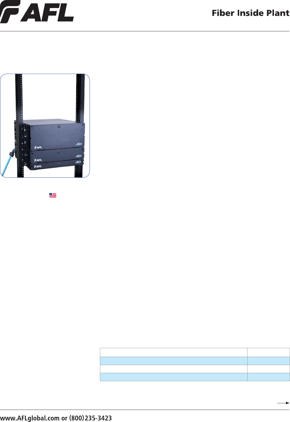
7373
Xpress Fiber Management® High Density
(XFM®-HD) Patch Panels
AFL's XFM-HD patch panels are available in 1RU, 2RU and 4RU sizes with fully-loaded
densities of 144 ber, 288 ber and 576 ber, respectively. Designed to support
incremental growth or a full-scale deployment in a self-contained manner, the XFM-
HD panels consist of the XFM High Density Optical Cassette as a building block, which
ensures that both front-side and back-side cabling is secured, protected and well
managed.
All panels are 19/23" rack mountable and constructed using a heavy gauge steel with a
durable black powder coat nish for an extended service life. The front doors consist of
optional locks, are removable without tools, and hinge on the bottom of the panel. The
unique sliding rail system locks into a standard rack mounting position yet also allows
the user to place the panel into a service position allowing simplied access to “behind-
the-wall” components. In tandem with the sliding rail system, the rear door and rear half
of the panel lid are joined. When the rear door is removed for service, the rear section of
the lid is also removed, enabling unobstructed access from the rear of the panel all the
way to the MPO connector interfaces on the module plane.
The trunk cable management area (rear of the panel) features multiple tie-points and
lances that are positioned to work well with a predened trunk breakout length to
securely manage slack sub-units while still allowing the modules to slide in/out for
installation and service. The 4RU panel features a dual plane design which separates
the back-side cabling into two separate 288 ber groups to aid in installation and ease
post-installation maintenance activities.
Features
• Self contained ber management
• Low loss MPO connectors
• High Density: 1RU/144F, 2RU/288F and 4RU/576F
• Uniboot LC assemblies with eld-reversable polarity
• Reduced O.D. Microcore Trunk cable assemblies with enhanced pulling eye option
• Unsurpassed port density
• Simplied front and rear port access by design
XFM-HD Patch Panels in Rack
Continued
Made in USA
DESCRIPTION AFL NO.
XFM-HD Panel, 1RU, Empty, 12 Cassette / 144F Capacity, Black XFM-HD-1U
XFM-HD Panel, 2RU, Empty, 24 Cassette / 288F Capacity, Black XFM-HD-2U
XFM-HD Panel, 4RU, Empty, 48 Cassette / 576F Capacity, Black XFM-HD-4U
Ordering Information
© 2010, AFL, all rights reserved. PP-2-00116, Revision 4, 8.28.13
Specications are subject to change without notice.
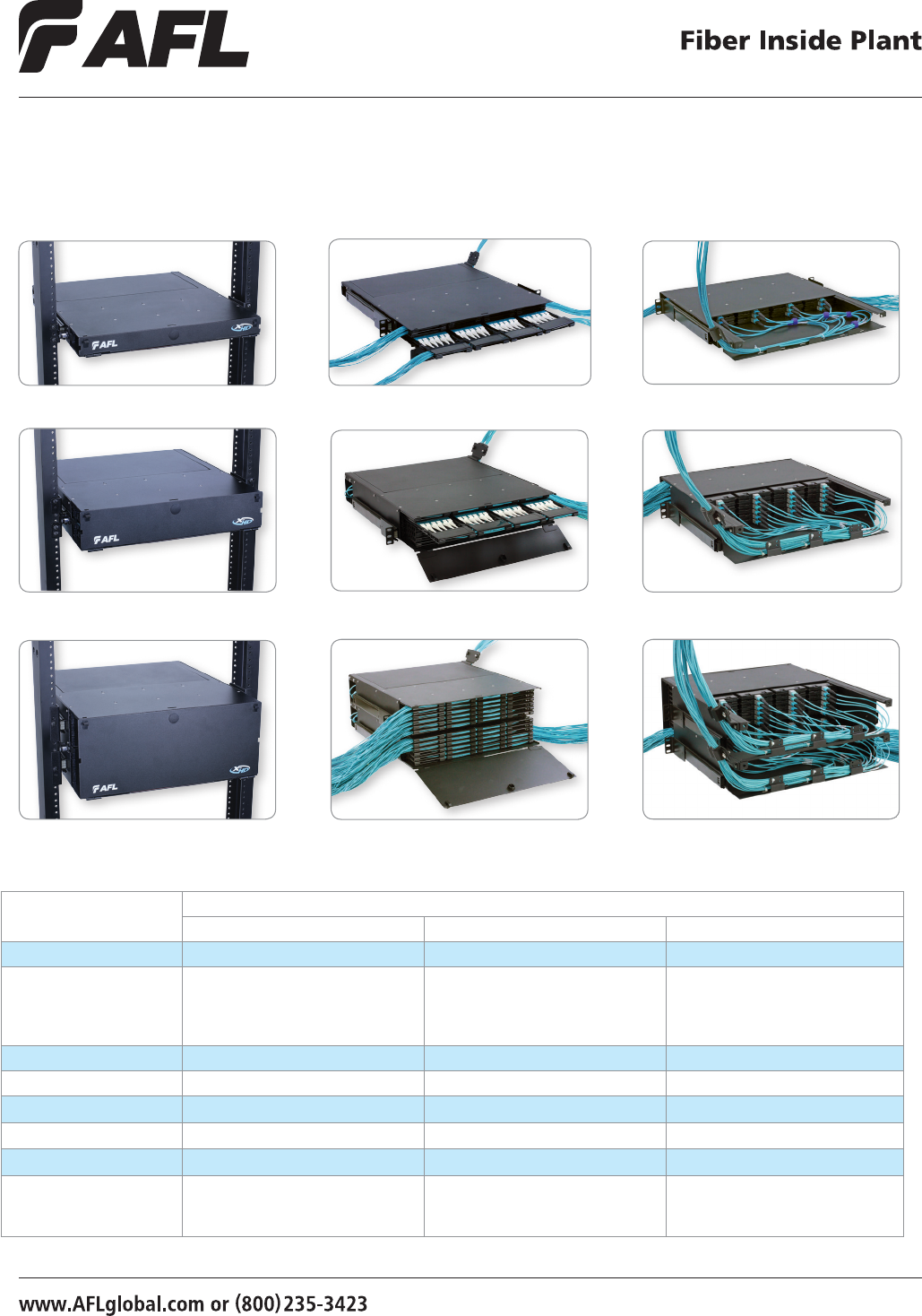
7474
Xpress Fiber Management® High Density (XFM®-HD)
Patch Panels (cont.)
XFM-HD 1RU front XFM-HD 1RU rear
Specifications
PARAMETER MODEL
XFM-HD 1U XFM-HD 2U XFM-HD 4U
Rack Space Requirement 1 RU (1.75 in) 2 RU (3.50 in) 4 RU (7.00 in)
Managed Density 144F
Front Side - 72 Micro-Dual 2F Assemblies
Back Side - 12 x 12F trunk – 1 x 144F
(any increment of 12F)
288F
Front Side - 144 Micro-Dual 2F Assemblies
Back Side - 24 x 12F trunk – 2 x 144F
(any increment of 12F)
576F
Front Side - 288 Dual-Link 2F Assemblies
Back Side - 48 x 12F trunk – 4 x 144F
(any increment of 12F)
Module Capacity 12 x 12 ber 24 x 12 ber 48 x 12 ber
Dimensions* (HxWxD) 1.72 x 16.25 x 18.66 in 3.47 x 16.25 x 18.66 in 6.97 x 16.25 x 18.66 in
Shipping Dimensions (HxWxD) 24.5 x 21 x 5 in 24.5 x 21 x 6.8 in 24.5 x 21 x 10.3 in
Weight 18 lbs. 21 lbs. 34 lbs.
Color Black Black Black
Material Metal Components: 16 GA Steel per ASTM
A366
Plastic Components: UL 94 V0 rated PBT
Metal Components: 16 GA Steel per ASTM
A366
Plastic Components: UL 94 V0 rated PBT
Metal Components: 16 GA Steel per ASTM
A366
Plastic Components: UL 94 V0 rated PBT
* Not including mounting ears
XFM-HD 1RU
XFM-HD 2RU front XFM-HD 2RU rearXFM-HD 2RU
XFM-HD 4RU front XFM-HD 4RU rearXFM-HD 4RU
© 2010, AFL, all rights reserved. PP-2-00116, Revision 4, 8.28.13
Specications are subject to change without notice.
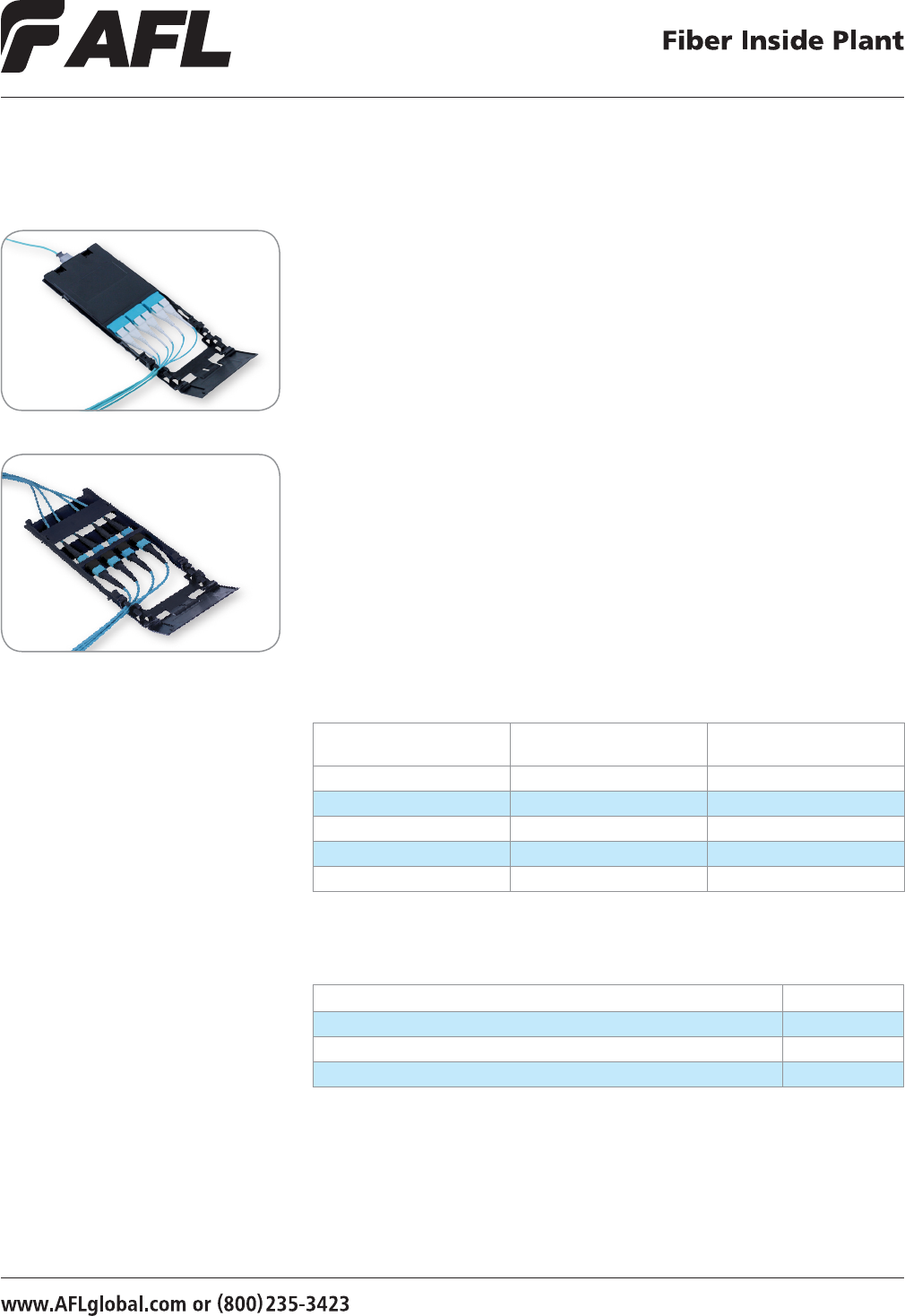
7575
XFM-HD LC Module
Features
• Self contained ber management
• Low loss MPO connectors
Xpress Fiber Management® High Density
(XFM®-HD) Optical Cassettes
Specifications
PARAMETER SINGLE-MODE FIBER (OS1)
LC/UPC - MTP
MULTIMODE FIBER (OM4)
LC/PC - MTP
Max IL 1.15 dB 1.15 dB
Typical IL 0.6 dB 0.6 dB
Reectance -55 dB -30 dB
Shipping Dimensions 12 x 6 x 2 in. 12 x 6 x 2 in.
Weight 1.6 lbs. 1.6 lbs.
AFL’s XFM-HD Optical Cassettes are the building-blocks of the XFM-HD system. Optical
Cassettes can be installed into all three XFM-HD panels from the front or rear and
mount independently on an integral card guide rail system. This mounting system
features a mechanical stop at the position where the connector / adapter mating point
extends beyond the leading edge of the patch panel, preventing inadvertent removal
of the module from the front side once installed. A self-contained ber manager is
incorporated into each cassette ensuring that the exiting cables are well-managed
and organized, regardless of ber exit direction. The ber manager is reversible in the
eld to support both an Alpha and Beta module position, depending on the polarity
management practice being employed.
Each cassette ships with a eld-installable clip which links multiple cassettes together
within a patch panel to form a shelf. This shelf slides inwards and outwards allowing
access to each individual ber connection while not disturbing any ber connection in
that shelf. These clips are eld-removable at any time should the need arise to remove a
module for service, to move a link, or to upgrade to a new ber type.
XFM-HD Optical Cassettes are designed to function exclusively within the XFM-HD
product line, and are compatible with all patch panels in the line.
XFM-HD MTP Module
Ordering Information
DESCRIPTION AFL NO.
XFM-HD High Density Optical Cassette, 4 Position MPO HDOC-MPO-4A
XFM-HD High Density Optical Cassette,12F Single-mode, LC/UPC - MPO Connectors HDOC-SM-ULC
XFM-HD High Density Optical Cassette,12F 10G 50 µm MM, LC/PC - MPO Connector HDOC-50-PLC
© 2010, AFL, all rights reserved. PP-2-00116, Revision 3, 1.12.12
Specications are subject to change without notice.
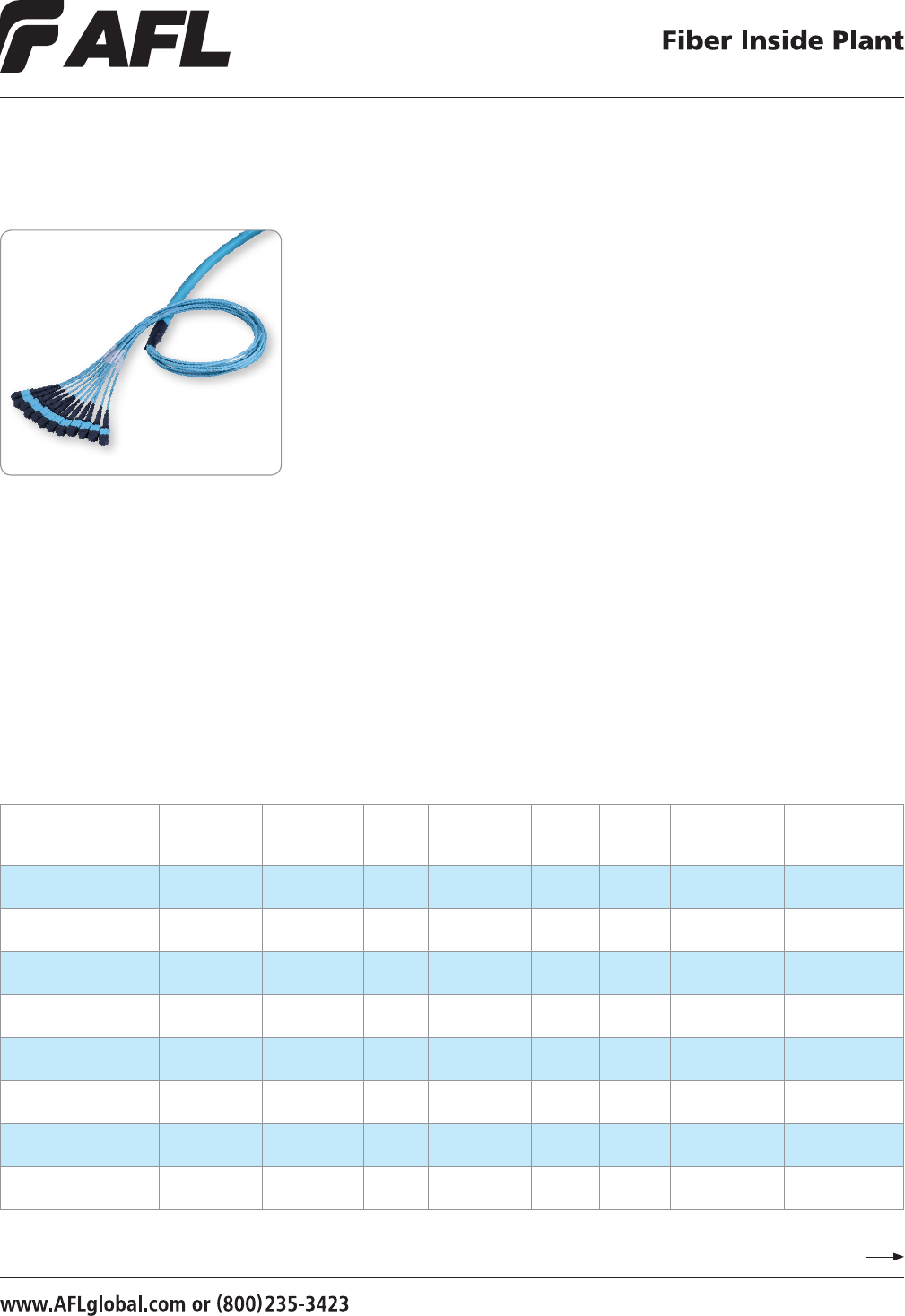
7676
Xpress Fiber Management® High Density
(XFM®-HD) Trunk Cable Assemblies
Features
• Self contained ber management
• Low loss MPO connectors
• Uniboot LC assemblies with eld-revers-
able polarity
• Reduced O.D. Microcore Trunk cable
assemblies with enhanced pulling eye
option
• Unsurpassed port density
Continued
Specifications
CONNECTOR
CONNECTOR
ORDERING
CODE
CONNECTOR
HOUSING
COLOR
BOOT
COLOR
FIBER
TYPE
CABLE
JACKET
COLOR
FLAME
RATING
IL
(TYPICAL dB)***
RL
(TYPICAL dB)***
LC/UPC UDL Blue White Single-mode
G.657.A1 (BIF)
Yellow Plenum 0.15 -60
LC/PC PDL Beige White 50 µm OM3,
OM4
Aqua Plenum 0.15 -35
Angled MTP (unpinned) ATF Green Black Single-mode
G.657.A1 (BIF)
Yellow Plenum 0.35 -65
Angled MTP (pinned) ATM Green Black Single-mode
G.657.A1 (BIF)
Yellow Plenum 0.35 -65
Angled MTP (unpinned),
Low Loss
ETF Green Black Single-mode
G.657.A1 (BIF)
Yellow Plenum 0.15 -65
Angled MTP (pinned),
Low Loss
ETM Green Black Single-mode
G.657.A1 (BIF)
Yellow Plenum 0.15 -65
MTP (unpinned),
Low Loss
FTF Aqua Black 50 µm OM3,
OM4
Aqua Plenum 0.15 -30
MTP (pinned),
Low Loss
FTM Aqua Black 50 µm OM3,
OM4
Aqua Plenum 0.15 -30
NOTES: Typical values based on equal quality connectors
XFM-HD trunk cable assemblies consist of sub-unitized MicroCore® ber optic cable
in ber counts ranging from 12-144. This reduced diameter, high performance cable is
comprised of multiple 12-ber sub-unit tubes, each containing twelve 250 µm colored
bers enclosed by a high performance PVC jacket. The reduced diameter offers the installer
many advantages over traditional tight-buffered cable options – higher tolerance to
bends during and after installation; requires less space in cable trays, raceways, ducts and
conduits; and enables more efcient airow in congested,
high density cabling applications.
Trunk cables are available in a variety of congurations to align with customer needs.
High-precision MPO ferrules ensure that optical performance specications are met
without requiring components to be paired, offering customers the utmost in exibility
when consuming inventory or ordering new product. No transition is required on MPO-
terminated trunk cables due to cable design. An epoxy-lled, reduced OD transition piece
is standard on trunk cables terminated with single-ber connectors. MPO-terminated trunk
cable ends have a single, predened breakout length, regardless of ber count, which
functions in perfect harmony with any XFM-HD patch panel, eliminating guesswork and
virtually guaranteeing a clean and well-organized installation.
© 2010, AFL, all rights reserved. PP-2-00116, Revision 3, 1.12.12
Specications are subject to change without notice.
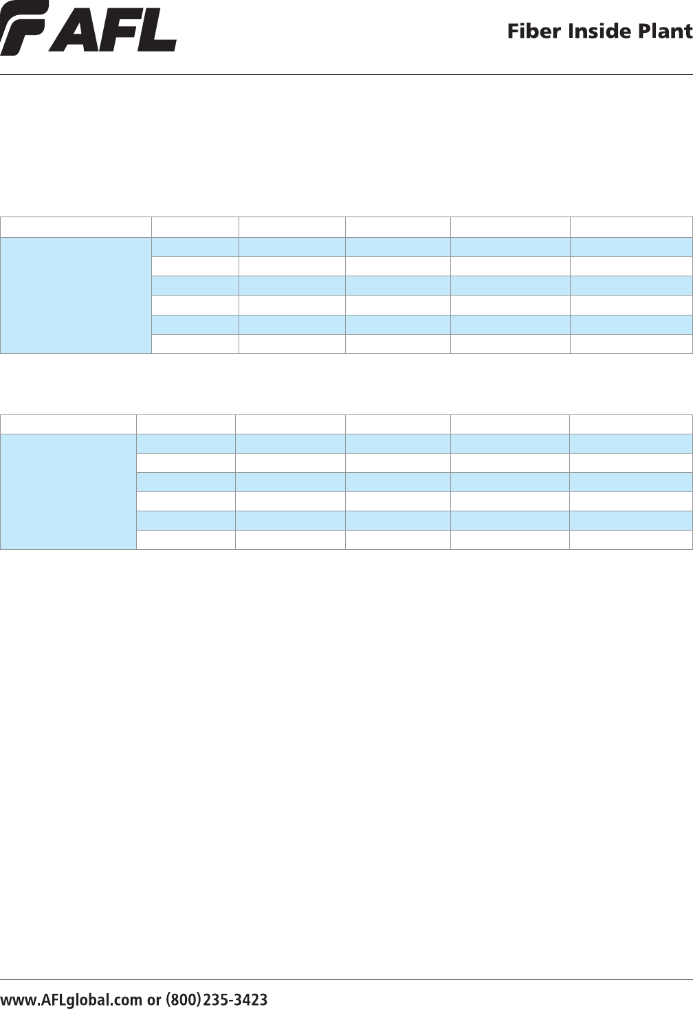
7777
Xpress Fiber Management® High Density (XFM®-HD)
Trunk Cable Assemblies (cont.)
XFM-HD MTP Trunks
CONNECTOR FIBER COUNT APC SM APC SM - ELITE PC MM 50 µm OM3 PC MM 50 µm OM4
MTP (No Pins) - MTP (No Pins)
12 XFM000057-XXXX XFM000071-XXXX XFM000085-XXXX XFM000099-XXXX
24 XFM000058-XXXX XFM000072-XXXX XFM000086-XXXX XFM000100-XXXX
48 XFM000060-XXXX XFM000074-XXXX XFM000088-XXXX XFM000102-XXXX
72 XFM000061-XXXX XFM000075-XXXX XFM000089-XXXX XFM000103-XXXX
96 XFM000062-XXXX XFM000076-XXXX XFM000090-XXXX XFM000104-XXXX
144 XFM000063-XXXX XFM000077-XXXX XFM000091-XXXX XFM000105-XXXX
XXXX = length in meters and XXXXFT = length in feet
XFM-HD MTP Extender Trunks
CONNECTOR FIBER COUNT APC SM APC SM - ELITE PC MM 50 µm OM3 PC MM 50 µm OM4
MTP (No Pins) - MTP (Pins)
12 XFM000064-XXXX XFM000078-XXXX XFM000092-XXXX XFM000106-XXXX
24 XFM000065-XXXX XFM000079-XXXX XFM000093-XXXX XFM000107-XXXX
48 XFM000067-XXXX XFM000081-XXXX XFM000095-XXXX XFM000109-XXXX
72 XFM000068-XXXX XFM000082-XXXX XFM000096-XXXX XFM000110-XXXX
96 XFM000069-XXXX XFM000083-XXXX XFM000097-XXXX XFM000111-XXXX
144 XFM000070-XXXX XFM000084-XXXX XFM000098-XXXX XFM000112-XXXX
XXXX = length in meters and XXXXFT = length in feet
XXXX = length in meters and XXXXFT = length in feet
Ordering Information
© 2010, AFL, all rights reserved. PP-2-00116, Revision 3, 1.12.12
Specications are subject to change without notice.
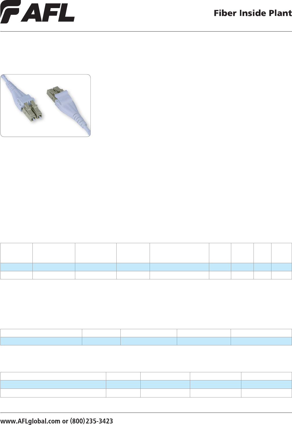
7878
Xpress Fiber Management® High Density
(XFM®-HD) Patch Cord Assemblies
Features
• Self contained ber management
• Low loss MPO connectors
• Uniboot LC assemblies with eld-reversable polarity
• Reduced O.D. Microcore Trunk cable assemblies with enhanced pulling eye option
• Unsurpassed port density
XFM-HD patch cords are assembled with AFL’s Micro-Dual (2-ber) cable and are
terminated with a unique, eld-reversible LC Uniboot connector. This round cable design
coupled with the Uniboot LC connector minimizes the front-side cabling footprint and
reduces the impact on airow up and down the rack, and between racks. A 2.0 mm and
2.4 mm OD option is available, enabling both 250 µm and 900 µm ber coating options
within the cable. Riser- and plenum-rated jackets are available and all major ber types
are supported.
In addition to being eld-reversible, the Uniboot LC connector also supports both the SFP
and Mini-SFP transceiver footprints. Virtually all polarity management methods and active
component connections are supported, enabling the end user to utilize a single product
across new, existing and acquired network installations.
Specifications
CONNECTOR
CONNECTOR
ORDERING CODE
CONNECTOR
HOUSING COLOR BOOT COLOR FIBER TYPE
CABLE
JACKET
COLOR
FLAME
RATING IL RL
LC/UPC ULU¹ Blue White Single-mode G.657.A1 (BIF) Yellow Plenum 0.3 dB >55 dB
LC/PC PLU² Beige White 50 µm OM3, OM4 Aqua Plenum 0.5 dB >30 dB
1 - Single-mode only
2 - Multimode only
MTP-LC Fanouts
CONNECTOR FIBER COUNT APC SM PC MM 50 µm OM3 PC MM 50 µm OM4
MTP (Pins) - LC Duplex 12 CS009521-XXXX CS011510-XXXX CS009519-XXXX
XXXX = length in meters and XXXXFT = length in feet
LC Uniboot Assemblies
CONNECTOR FIBER COUNT UPC SM PC MM 50 µm OM3 PC MM 50 µm OM4
LC Uniboot - LC Uniboot Assembly, 2.0 mm Plenum 2 CS011378-XXXX CS010640-XXXX CS011386-XXXX
LC Uniboot - LC Uniboot Assembly, 2.4 mm Plenum 2 CS011389-XXXX CS011397-XXXX CS011400-XXXX
XXXX = length in meters and XXXXFT = length in feet
Ordering Information
© 2010, AFL, all rights reserved. PP-2-00116, Revision 3, 1.12.12
Specications are subject to change without notice.
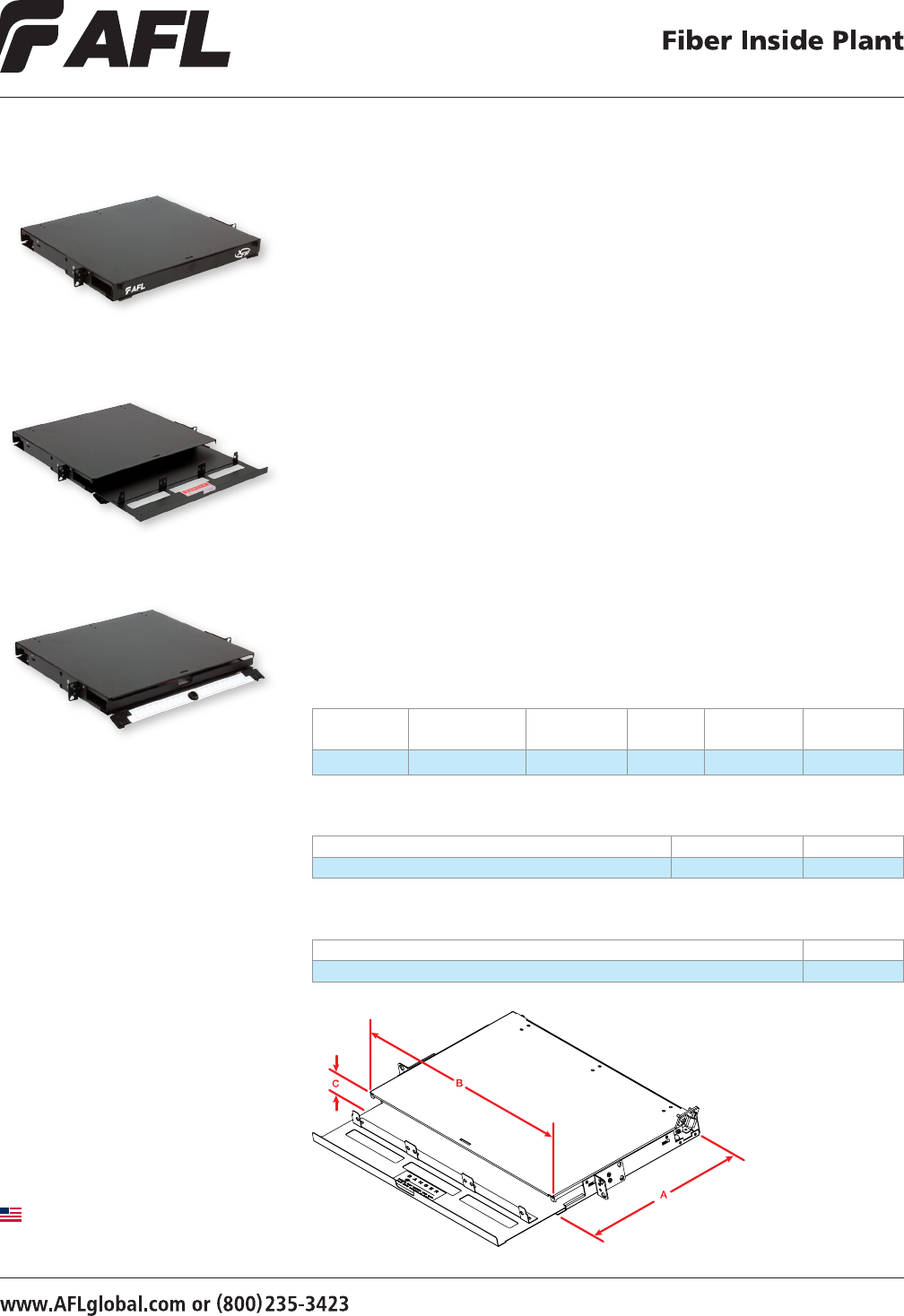
79
© 2008, AFL, all rights reserved. PP-2-00164, Revision 1, 11.14.12
Specications are subject to change without notice.
79
The Xpress Fiber Management (XFM) 1U patch panel is a rack mountable interconnect
point specically designed to manage dense ber applications. Based on the LGX®
intermateability platform, the panel is fully compatible with AFL’s XFM Optical Cassette,
Passive Optical Coupler Modules, and Poli-MOD solutions. This panel offers enhanced
management of densities up to 72 bers using MTP-LC XFM Optical Cassettes (24 bers).
Features
• Steel construction
• Textured black powder coat nish
• Universal WECO/TIA 19"/23"
rack compatibility
• (3) LGX 118 adapter plate / module
mounting positions
• Slide-out tray with relief cut-outs
for simplied connector access
• Optional front door key lock
for heightened protection
of internal components
LGX is a registered trademark of Furukawa Electric North America, Inc.
Xpress Fiber Management® (XFM)
1RU Patch Panel
Ordering Information
DESCRIPTION MODEL NUMBER AFL NO.
Xpress® Fiber Management 1U Patch Panel, Black, Empty XFM-1-U-B-0 FM002711-BE
Accessories
DESCRIPTION AFL NO.
Kit, Lock, for CON/CNS Panels FM001318
Specifications
DEPTH
(A) (inches)
WIDTH
(B) (inches)
HEIGHT
(C) (inches)
RACK
UNITS CAPACITY
UNLOADED
WEIGHT
15.5 17 1.7 1 (3) LGX 118 13 lbs.
Applications
• Data Centers
• Enterprise Networks
• Telecommunications Closets
• Central Ofces / Headends
Made in USA
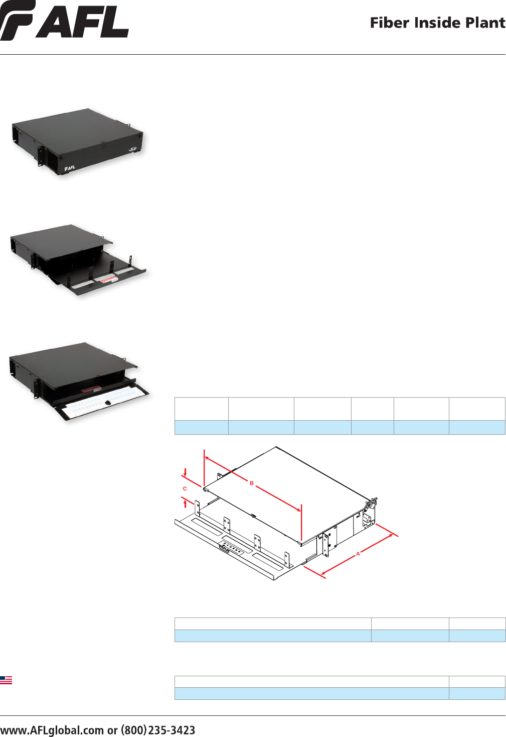
80
© 2008, AFL, all rights reserved. PP-2-00165, Revision 0, 1.26.11
Specications are subject to change without notice.
The Xpress Fiber Management (XFM) 2U patch panel is a rack mountable interconnect
point specically designed to manage dense ber applications. Based on the LGX®
intermateability platform, the panel is fully compatible with AFL’s XFM Optical Cassette,
Passive Optical Coupler Modules, and Poli-MOD solutions. This panel offers enhanced
management of densities up to 144 bers using MTP-LC XFM Optical Cassettes (24 bers).
Features
• Steel construction
• Textured black powder coat nish
• Universal WECO/TIA 19"/23"
rack compatibility
• (6) LGX 118 adapter plate / module
mounting positions
• Slide-out tray with relief cut-outs
for simplied connector access
• Optional front door key lock
for heightened protection
of internal components
© 2008, AFL, all rights reserved. PP-2-00165, Revision 0, 1.26.11
Specications are subject to change without notice.
LGX is a registered trademark of Furukawa Electric North America, Inc.
Xpress Fiber Management® (XFM)
2RU Patch Panel
Ordering Information
DESCRIPTION MODEL NUMBER AFL NO.
Xpress™ Fiber Management 2U Patch Panel, Black, Empty XFM-2-U-B-0 FM002712-BE
Accessories
DESCRIPTION AFL NO.
Kit, Lock, for CON/CNS Panels FM001318
Specifications
DEPTH (A)
IN INCHES
WIDTH (B)
IN INCHES
HEIGHT (C)
IN INCHES
RACK
UNITS CAPACITY
UNLOADED
WEIGHT
15.5 17 3.5 2 (6) LGX 118 15 lbs.
Applications
• Data Centers
• Enterprise Networks
• Telecommunications Closets
• Central Ofces / Headends
Made in USA
FM002712-BE
FM001318
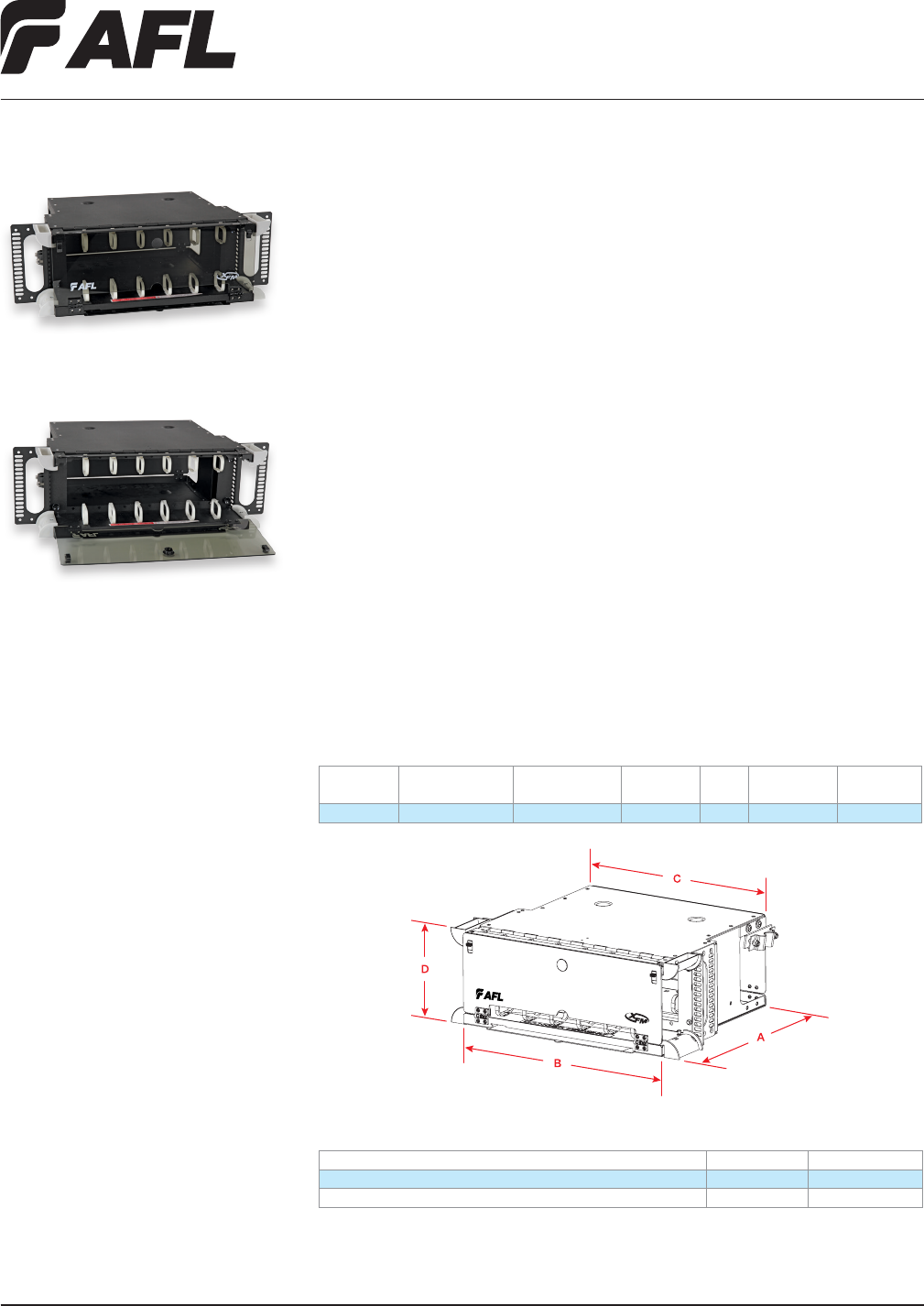
Fiber Inside Plant
www.AFLglobal.com or (800)235-3423
81
© 2008, AFL, all rights reserved. PP-2-00115, Revision 2, 5.13.13
Specications are subject to change without notice.
The Xpress Fiber Management (XFM) 4U patch panel is a rack mountable interconnect
point specically designed to manage dense ber applications. Based on the LGX®
intermateability platform, the panel is fully compatible with AFL’s XFM Optical Cassette
and Poli-MOD solutions, offering enhanced management of densities up to 288F using
MTP/MPO, single ber, or patch and splice methodologies. A hinged ber management
panel can be secured in an upright or lowered position, which provides enhanced cable
routing exiting the panel to the left or right, and also allows cable assemblies to be
routed up and across the front of the panel for extreme density management. This
panel can be provisioned with a key lock at the time of order for secure environments.
Features
• Aluminum construction
• Textured black powder coat nish
• Universal WECO/TIA 19"/23" rack
compatibility
• (12) LGX 118 adapter plate / module
mounting positions
• Mounting depth adjustable from ush
to 8" in 1" increments
Ordering Information
DESCRIPTION MODEL NO. AFL NO.
Xpress Fiber Management 4U Patch Panel, Black, Empty XFM-4U-B-0 FM001090-B
Xpress Fiber Management 4U Patch Panel, Black, Empty, Key Lock XFM-4U-B-K FM001218-B
LGX is a registered trademark of Furukawa Electric North America, Inc.
Xpress Fiber Management® (XFM)
4RU Patch Panel
Specifications
DEPTH (A)
IN INCHES
FRONT WIDTH (B)
IN INCHES
REAR WIDTH (C)
IN INCHES
HEIGHT (D)
IN INCHES
RACK
UNITS CAPACITY
UNLOADED
WEIGHT
15.5 17 15 7 4 (12) LGX 118 9 lbs.
Applications
• Data Centers
• Enterprise Networks
• Telecommunications Closets
• Central Ofces / Headends
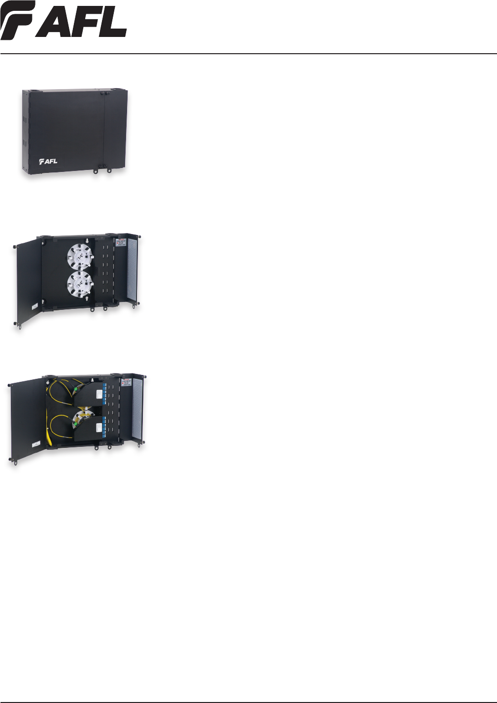
Fiber Inside Plant
www.AFLglobal.com or (800)235-3423
82
© 2010, AFL, all rights reserved. PP-2-00107, Revision 2, 9.30.11
Specications are subject to change without notice.
Features
• Fits comfortably into new and existing interconnect, cross-connect and co-location
environments
• U-shaped cable entry eliminates the need to feed preconnectorized cables through an
inconvenient access port
• Modular design fully compatible with PoliMOD™ products and XFM optical cassettes
• Dual doors with separate locking options for exibility and security
• Available empty, with adapters, or with adapters, splice trays and pigtails pre-installed
• LGX 118 compatible
• Optional splice tray and holder (ordered separately)
• All major connector types are supported
Wall Mount Interconnect Enclosure (WME)
with Two LGX® Mounting Positions
AFL’s wall mount interconnect enclosure (WME-02) provides a convenient convergence
point for interconnecting and/or splicing in wall mount applications. Provisioned for
up to two LGX compatible adapter plates or optical modules, the enclosure features a
well-engineered solution for ber and cable management on both the ingress and egress
openings of the enclosure. Robust steel construction ensures the highest level of protection
for sensitive components while integrated roll-formed hinges eliminate possible ber pinch
points while deploying or servicing components within. All WME series enclosures feature
discrete access doors for provider and customer access which are independently lockable
with a common pad-lock or tube-style keyed lock.
Applications
• Co-Location sites
• Customer premise
• Hub/OTN sites
• Telecommunication closets
• Campus/enterprise environments
Specifications
• Solid steel construction
• Powder coat black textured nish
• Top or bottom cable entry with dust resistant grommets
• Dual-hasp locking/security system
• 12 to 24 ber patch and splice density
• Two LGX mounting positions
• Physical dimensions: 12.0"H x 14.0"W x 2.5"D
• Empty version weight: 10.65 lbs.
LGX is a registered trademark of Furukawa Electric North America, Inc.
WME-02
WME-02 shown empty
WME-02 shown fully loaded
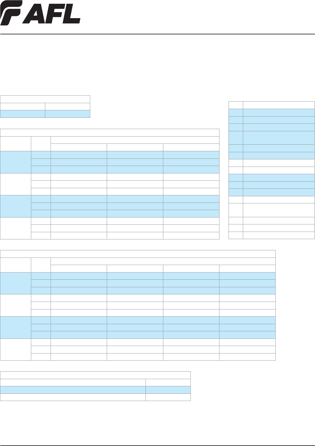
Fiber Inside Plant
www.AFLglobal.com or (800)235-3423
83
© 2010, AFL, all rights reserved. PP-2-00107, Revision 2, 9.30.11
Specications are subject to change without notice.
Wall Mount Interconnect Enclosure (WME)
with Two LGX® Mounting Positions
LGX is a registered trademark of Furukawa Electric North America, Inc.
Ordering Information
EMPTY
DESCRIPTION AFL NO.
WME02 Empty WME02E
LOADED: WME WITH ADPATER PLATES/ADAPTERS/SPLICE TRAYS/PIGTAIL (900 µm TIGHT BUFFERED FIBERS 3 METERS IN LENGTH)
CONNECTOR
TYPE
FIBER
COUNT
AFL NO.
UPC SM (BLUE)
APC SM (GREEN)
PC MM 62.5 µm (BEIGE) PC MM 50 µm (BLACK)
SC 6 WME02FS-USCSM-006110 WME02FS-ASCSM-006110 WME02FS-PSCM6-006110 WME02FS-PSCM5-006110
12 WME02FS-USCSM-012110 WME02FS-ASCSM-012110 WME02FS-PSCM6-012110 WME02FS-PSCM5-012110
24 WME02FH-USFSM-024120 WME02FH-ASFSM-024120 WME02FH-PSFM6-024120 WME02FH-PSFM5-024120
LC 6 WME02FS-UDLSM-006110 WME02FS-ADLSM-006110 WME02FS-PDLM6-006110 WME02FS-PDLM5-006110
12 WME02FS-UDLSM-012110 WME02FS-ADLSM-012110 WME02FS-PDLM6-012110 WME02FS-PDLM5-012110
24 WME02FH-UDLSM-024120 WME02FH-ADLSM-024120 WME02FH-PDLM6-024120 WME02FH-PDLM5-024120
ST 6 WME02FS-USTSM-006110 — WME02FS-PSTM6-006110 WME02FS-PSTM5-006110
12 WME02FS-USTSM-012110 — WME02FS-PSTM6-012110 WME02FS-PSTM5-012110
24 WME02FH-USTSM-024120 — WME02FH-PSTM6-024120 WME02FH-PSTM5-024120
FC 6 WME02FS-UFCSM-006110 WME02FS-AFCSM-006110 WME02FS-PFCM6-006110 WME02FS-PFCM5-006110
12 WME02FS-UFCSM-012110 WME02FS-AFCSM-012110 WME02FS-PFCM6-012110 WME02FS-PFCM5-012110
24 WME02FH-UFCSM-024120 WME02FH-AFCSM-024120 WME02FH-PFCM6-024120 WME02FH-PFCM5-024120
HALF LOADED: WME WITH ADAPTER PLATES AND ADAPTERS ONLY
CONNECTOR
TYPE
FIBER
COUNT
AFL NO.
UPC SM (BLUE)
APC SM (GREEN)
PC MM (BEIGE)
SC 6 WME02AS-USCSM-006000 WME02AS-ASCSM-006000 WME02AS-PSCM6-006000
12 WME02AS-USCSM-012000 WME02AS-ASCSM-012000 WME02AS-PSCM6-012000
24 WME02AH-USFSM-024000 WME02AH-ASFSM-024000 WME02AH-PSFM6-024000
LC 6 WME02AS-UDLSM-006000 WME02AS-ADLSM-006000 WME02AS-PDLM6-006000
12 WME02AS-UDLSM-012000 WME02AS-ADLSM-012000 WME02AS-PDLM6-012000
24 WME02AH-UDLSM-024000 WME02AH-ADLSM-024000 WME02AH-PDLM6-024000
ST 6 WME02AS-USTSM-006000 — WME02AS-PSTM6-006000
12 WME02AS-USTSM-012000 — WME02AS-PSTM6-012000
24 WME02AH-USTSM-024000 — WME02AH-PSTM6-024000
FC 6 WME02AS-UFCSM-006000 WME02AS-AFCSM-006000 WME02AS-PFCM5-006000
12 WME02AS-UFCSM-012000 WME02AS-AFCSM-012000 WME02AS-PFCM5-012000
24 WME02AH-UFCSM-024000 WME02AH-AFCSM-024000 WME02AH-PFCM5-024000
ACCESSORIES
DESCRIPTION AFL NO.
Splice Tray Kit: Single Fusion 12F, 2RU, WME02, WME04, 1 Splice Tray FM002827-1
Splice Tray Kit: Single Fusion 12F, 2RU, WME02, WME04, 2 Splice Trays FM002827-2
Connector/Adapter Key
TYPE DESCRIPTION
ASC Angle Polish SC (ZR) sleeve-SM
ASF Angle Polish SC Duplex (ZR) sleeve-SM
PSC Physical Polish SC (PB) sleeve-MM
PSF Physical Polish SC Duplex (PB) sleeve-
MM
USC Ultra Polish SC with (ZR) sleeve-SM
USF Ultra Polish SC Duplex (ZR) sleeve-SM
PST Physical Polish ST (PB) sleeve-MM
UST Ultra Polish ST (ZR) sleeve-SM
AFC Angle Polish FC (ZR) sleeve-SM
PFC Physical Polish FC (PB) sleeve-MM
UFC Ultra Polish FC (ZR) sleeve-SM
ADL Angle Polish LC Duplex (ZR) sleeve-SM
PDL Physical Polish LC Duplex (PB) sleeve-
MM
PLC Physical Polish LC (PB) sleeve-MM
UDL Ultra Polish LC Duplex (ZR) sleeve-SM
ULC Ultra Polish LC (ZR) sleeve-SM
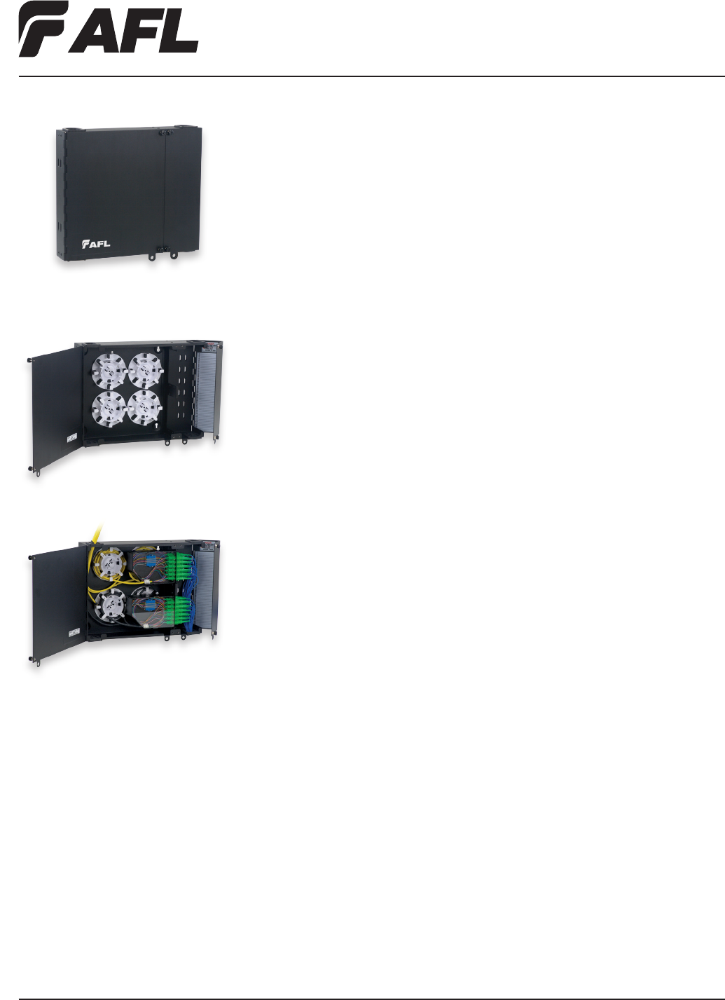
Fiber Inside Plant
www.AFLglobal.com or (800)235-3423
84
© 2010, AFL, all rights reserved. PP-2-00108, Revision 1, 5.24.11
Specications are subject to change without notice.
Features
• Fits comfortably into new and existing interconnect, cross-connect and co-location
environments
• U-shaped cable entry eliminates the need to feed preconnectorized cables through an
inconvenient access port
• Modular design fully compatible with PoliMOD™ products and XFM optical cassettes
• Dual doors with separate locking options for exibility and security
• Available empty, with adapters, or with adapters, splice trays and pigtails pre-installed
• LGX 118 compatible
• Optional splice tray and holder (ordered separately)
• All major connector types are supported
Wall Mount Interconnect Enclosure (WME)
with Four LGX® Mounting Positions
AFL’s wall mount interconnect enclosure (WME-04) provides a convenient convergence
point for interconnecting and/or splicing in wall mount applications. Provisioned for
up to four LGX compatible adapter plates or optical modules, the enclosure features a
well-engineered solution for ber and cable management on both the ingress and egress
openings of the enclosure. Robust steel construction ensures the highest level of protection
for sensitive components while integrated roll-formed hinges eliminate possible ber pinch
points while deploying or servicing components within. All WME series enclosures feature
discrete access doors for provider and customer access which are independently lockable
with a common pad-lock or tube-style keyed lock.
Applications
• Co-Location sites
• Customer premise
• Hub/OTN sites
• Telecommunication closets
• Campus/enterprise environments
Specifications
• Solid steel construction
• Powder coat black textured nish
• Top or bottom cable entry with dust resistant grommets
• Dual-hasp locking/security system
• 24 to 48 ber patch and splice density
• Four LGX mounting positions
• Physical dimensions: 12.0"H x 16.0"W x 3.63"D
LGX is a registered trademark of Furukawa Electric North America, Inc.
WME-04
WME-04 shown empty
WME-04 shown fully loaded
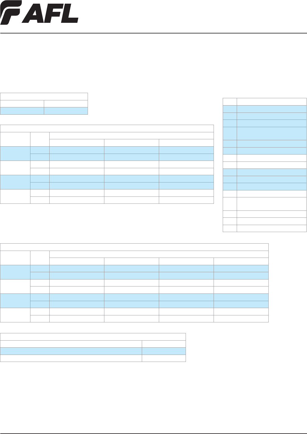
Fiber Inside Plant
www.AFLglobal.com or (800)235-3423
85
© 2010, AFL, all rights reserved. PP-2-00108, Revision 1, 5.24.11
Specications are subject to change without notice.
Wall Mount Interconnect Enclosure (WME)
with Four LGX® Mounting Positions
LGX is a registered trademark of Furukawa Electric North America, Inc.
Ordering Information
EMPTY
DESCRIPTION AFL NO.
WME04 Empty WME04E
LOADED: WME WITH ADPATER PLATES/ADAPTERS/SPLICE TRAYS/PIGTAIL (900 µm TIGHT BUFFERED FIBERS 3 METERS IN LENGTH)
CONNECTOR
TYPE
FIBER
COUNT
AFL NO.
UPC SM (BLUE)
APC SM (GREEN)
PC MM 62.5 µm (BEIGE) PC MM 50 µm (BLACK)
SC 24 WME04FS-USCSM-024120 WME04FS-ASCSM-024120 WME04FS-PSCM6-024120 WME04FS-PSCM5-024120
48 WME04FH-USFSM-048140 WME04FH-ASFSM-048140 WME04FH-PSFM6-048140 WME04FH-PSFM5-048140
LC 24 WME04FS-UDLSM-024120 WME04FS-ADLSM-024120 WME04FS-PDLM6-024120 WME04FS-PDLM5-024120
48 WME04FH-UDLSM-048140 WME04FH-ADLSM-048140 WME04FH-PDLM6-048140 WME04FH-PDLM5-048140
ST 24 WME04FS-USTSM-024120 — WME04FS-PSTM6-024120 WME04FS-PSTM5-024120
48 WME04FH-USTSM-048140 — WME04FH-PSTM6-048140 WME04FH-PSTM5-048140
FC 24 WME04FS-UFCSM-024120 WME04FS-AFCSM-024120 WME04FS-PFCM6-024120 WME04FS-PFCM5-024120
48 WME04FH-UFCSM-048140 WME04FH-AFCSM-048140 WME04FH-PFCM6-048140 WME04FH-PFCM5-048140
HALF LOADED: WME WITH ADAPTER PLATES AND ADAPTERS ONLY
CONNECTOR
TYPE
FIBER
COUNT
AFL NO.
UPC SM (BLUE)
APC SM (GREEN)
PC MM (BEIGE)
SC 24 WME04AS-USCSM-024000 WME04AS-ASCSM-024000 WME04AS-PSCM6-024000
48 WME04AH-USFSM-048000 WME04AH-ASFSM-048000 WME04AH-PSFM6-048000
LC 24 WME04AS-UDLSM-024000 WME04AS-ADLSM-024000 WME04AS-PDLM6-024000
48 WME04AH-UDLSM-048000 WME04AH-ADLSM-048000 WME04AH-PDLM6-048000
ST 24 WME04AS-USTSM-024000 — WME04AS-PSTM6-024000
48 WME04AH-USTSM-048000 — WME04AH-PSTM6-048000
FC 24 WME04AS-UFCSM-024000 WME04AS-AFCSM-024000 WME04AS-PFCM5-024000
48 WME04AH-UFCSM-048000 WME04AH-AFCSM-048000 WME04AH-PFCM5-048000
ACCESSORIES
DESCRIPTION AFL NO.
Splice Tray Kit: Single Fusion 12F, 2RU, WME02, WME04, 3 Splice Trays FM002827-3
Splice Tray Kit: Single Fusion 12F, 2RU, WME02, WME04, 4 Splice Trays FM002827-4
Connector/Adapter Key
TYPE DESCRIPTION
ASC Angle Polish SC (ZR) sleeve-SM
ASF Angle Polish SC Duplex (ZR) sleeve-SM
PSC Physical Polish SC (PB) sleeve-MM
PSF Physical Polish SC Duplex (PB) sleeve-
MM
USC Ultra Polish SC with (ZR) sleeve-SM
USF Ultra Polish SC Duplex (ZR) sleeve-SM
PST Physical Polish ST (PB) sleeve-MM
UST Ultra Polish ST (ZR) sleeve-SM
AFC Angle Polish FC (ZR) sleeve-SM
PFC Physical Polish FC (PB) sleeve-MM
UFC Ultra Polish FC (ZR) sleeve-SM
ADL Angle Polish LC Duplex (ZR) sleeve-SM
PDL Physical Polish LC Duplex (PB) sleeve-
MM
PLC Physical Polish LC (PB) sleeve-MM
UDL Ultra Polish LC Duplex (ZR) sleeve-SM
ULC Ultra Polish LC (ZR) sleeve-SM

206.575.0404 • 800.451.7128 • www.lightbrigade.com
86
© 2012, The Light Brigade, all rights reserved.
Specications are subject to change without notice
Since 1987, the Light Brigade, AFL’s training division, has trained more than 45,000 technicians, installers, engineers, and designers from a wide
variety of industries: telephony, broadband cable, utilities, media broadcast, industrial, manufacturing, mining, government, aerospace, along
with various branches of the military.
Whether your application is voice, video, and/or data, or you are a service provider, contractor, or end user, The Light Brigade can
provide critical training for your personnel to lower operating costs and improve installation efciency.
Instructors
Our professional instructors and technicians are technically skilled and have a variety of real world practical experience in all aspects
of ber optics. With experience in applications such as communications, signaling, security, and network control, our instructors
provide valuable insight into the design, installation, and operation of state-of-the-art ber optic systems.
Hands-on Training
Extensive hands-on training sessions help our attendees to learn ber optics by doing rather than watching. Attendees spend
class time building, testing, and troubleshooting an actual ber optic system. In each of our courses, the ratio of students to instructors
during the hands-on sessions assures that there is direct personal interaction and attention to each student.
Technology-based
In our training classes, you receive an objective viewpoint, not a sales pitch. We teach ber techniques that are applicable to any
product, and select the best available equipment and supplies from many different manufacturers. You can choose to develop your
skills using our state-of-the-art equipment and accessories, or bring your own to learn how to use it more effectively.
Relevant
Our course materials are constantly updated to stay in step with current and emerging technologies. All of our materials
and techniques are written and taught based on the latest standards, recommendations, and codes from ANSI, ITU, TIA/EIA,
IEEE, IEC, Telcordia, MSHA, NEC, NESC, and others.
Continuing Support
To assure continued long-term support, we offer technical assistance to our class attendees. If you have a question or need
help after the class is over, our staff is there to help.
The Leader in Fiber Optic Training
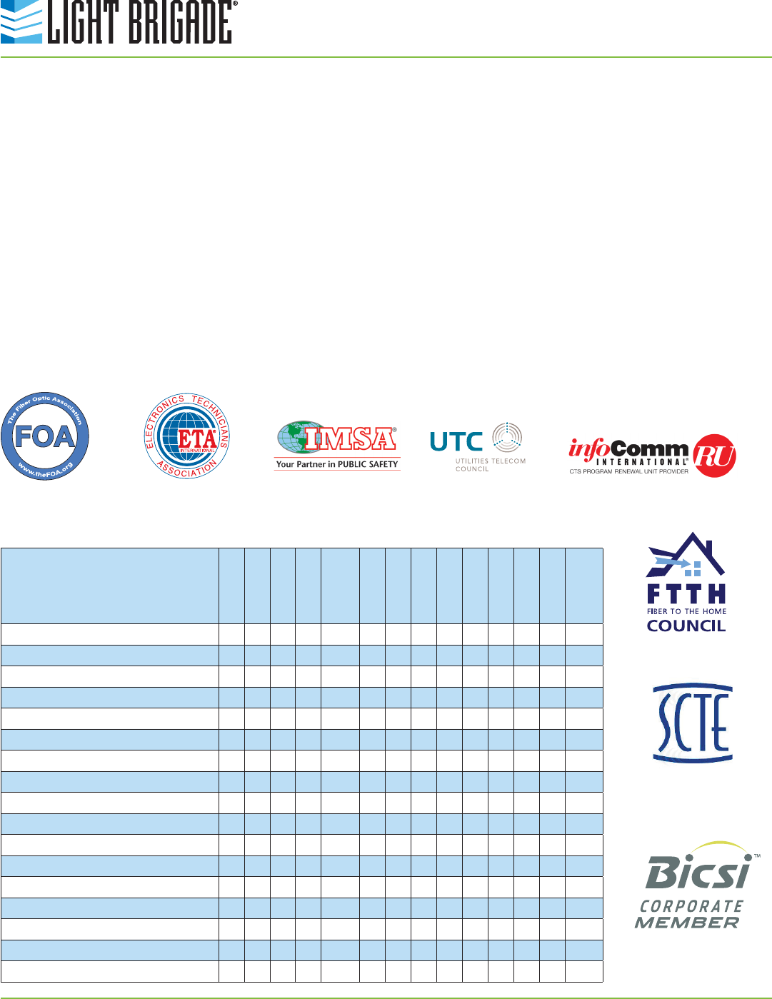
206.575.0404 • 800.451.7128 • www.lightbrigade.com
87
© 2012, The Light Brigade, all rights reserved.
Specications are subject to change without notice
Light Brigade Certicate of Completion
Everyone who completes one of our courses will receive a Light Brigade Certicate of Completion, signed by the course instructor. This certicate
species the content and total number of instructional hours for both the classroom and hands-on portion and is traceable to the class attended.
Third-party Credits and Certication
Many of our classes are eligible for independent certications through third-party industry organizations and groups. These certications are typically
progressive levels and show competency in hands-on skills and technical knowledge. See individual course for more information.
In addition, many of our courses are eligible for BICSI Continuing Education Credits (CECs), SCTE Recertication Units (RUs), IMSA Technical
Advancement Recognition Points (TARPs), and Infocomm Recertication Units (RUs).
Certication Options
Certication Options
Electronics
Technicians
Association (ETA)
Fiber Optic
Association
(FOA)
Building Industry Consulting
Service International, Inc.
(BICSI)
FTTH Council
Society of Cable
Telecommunications
Engineers (SCTE)
Page
ETA FOI
ETA FOT-OSP
FOA CFOT
FTTH Council
CFHP
IMSA Level I
IMSA Level II
IMSA Level III
UTC Level 1
UTC Level 2
UTC Level 3
BICSI CECs
SCTE RUs
Infocomm
RUs
Fiber Optics 1-2-3 10 • • •
Advanced Hands-on Modules 11 • • •
Certied Fiber to the Home Professional 12 • •
FTTx for Installers and Technicians 13 • • •
Fiber Characterization 14 •
Emergency Restoration 15 •
Fiber Optics for Utilities Level 1 16 •
Fiber Optics for Utilities Level 2 17 •
Fiber Optics for Utilities Level 3 (Custom) – •
Fiber Optics for Trafc Systems Level I 18 •
Fiber Optics for Trafc Systems Level II 18 •
Fiber Optics for Trafc Systems Level III 18 •
Fiber Optics for Oil/Gas 19 •
Fiber Optics for Mining Applications 20 •
Fiber Optics for Pro-AV 21 •
Premises/LAN Installation & Maintenance 22 • •
Staff Development DVDs 26 • •
Infocomm
International Municipal
Signal Association
(IMSA)
Utilities Telecom
Council (UTC)

88
Fiber Inside Plant
www.AFLglobal.com or (800)235-3423
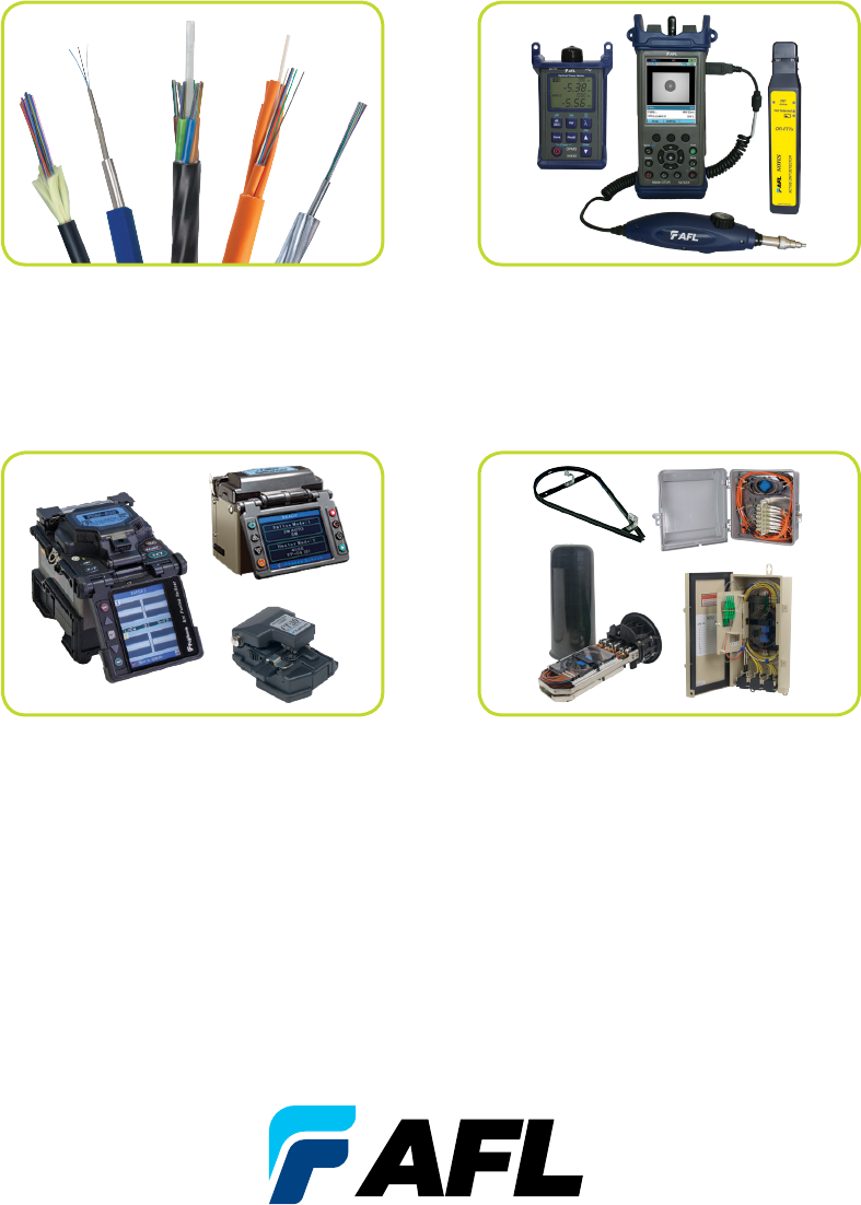
Please contact your AFL Sales Representative for
information about our other products or services.
FIBER OUTSIDE PLANT
EQUIPMENT
FUSION SPLICING
SYSTEMS AND ACCESSORIES
FIBER OPTIC CABLE
(OPGW, ADSS, Loose Tube)
TEST AND INSPECTION
EQUIPMENT
Along with a broad range of products, we also offer professional training through
The Light Brigade®. Over 45,000 people have completed a Light Brigade training
course making us the leading ber optic training provider in the world.
Visit www.lightbrigade for more information.
www.AFLglobal.com
CAT-01006 9.24.2013
