TSQ8000_AutoSRM 1R120587 0005 TSQ Duo Auto SRM User Guide
2016-05-17
: Pdf 1R120587-0005 Tsq Duo Autosrm User Guide 1R120587-0005 TSQ Duo AutoSRM User Guide TSQ Duo Manuals User ation
Open the PDF directly: View PDF ![]() .
.
Page Count: 50

TSQ Series
AutoSRM User Guide
with Chromeleon 7.2 support
1R120587-0005 Revision C December 2015
© 2014 Thermo Fisher Scientific Inc. All rights reserved.
Dionex and TSQ are trademarks, and Chromeleon is a registered trademark of Thermo Fisher Scientific in the
United States.
The following are registered trademarks in the United States and other countries: Microsoft, Windows, and
Excel are registered trademarks of Microsoft. Adobe and Acrobat are registered trademarks of Adobe Systems
Incorporated.
All other trademarks are the property of Thermo Fisher Scientific and its subsidiaries.
Thermo Fisher Scientific Inc. provides this document to its customers with a product purchase to use in the
product operation. This document is copyright protected and any reproduction of the whole or any part of this
document is strictly prohibited, except with the written authorization of Thermo Fisher Scientific Inc.
The contents of this document are subject to change without notice. All technical information in this
document is for reference purposes only. System configurations and specifications in this document supersede
all previous information received by the purchaser.
Thermo Fisher Scientific Inc. makes no representations that this document is complete, accurate or error-
free and assumes no responsibility and will not be liable for any errors, omissions, damage or loss that might
result from any use of this document, even if the information in the document is followed properly.
This document is not part of any sales contract between Thermo Fisher Scientific Inc. and a purchaser. This
document shall in no way govern or modify any Terms and Conditions of Sale, which Terms and Conditions of
Sale shall govern all conflicting information between the two documents.
Release history: Revision A, July 2014; Revision B, March 2015; Revision C, December 2015.
Software version: Thermo Foundation 3.1 SP1; Thermo Scientific Dionex Chromeleon 7 (release 7.2 SR3
MUa or later)
For research use only: Not for use in diagnostic procedures.

Thermo Scientific TSQ Series AutoSRM User Guide iii
C
Preface . . . . . . . . . . . . . . . . . . . . . . . . . . . . . . . . . . . . . . . . . . . . . . . . . . . . . . . . . . . . . . ix
About Your System. . . . . . . . . . . . . . . . . . . . . . . . . . . . . . . . . . . . . . . . . . . . . . .ix
Related Documentation . . . . . . . . . . . . . . . . . . . . . . . . . . . . . . . . . . . . . . . . . . . x
System Requirements . . . . . . . . . . . . . . . . . . . . . . . . . . . . . . . . . . . . . . . . . . . . . x
Chromeleon User Management Set Up . . . . . . . . . . . . . . . . . . . . . . . . . . . . . . .xi
Safety and Special Notices . . . . . . . . . . . . . . . . . . . . . . . . . . . . . . . . . . . . . . . . xii
Special Notices . . . . . . . . . . . . . . . . . . . . . . . . . . . . . . . . . . . . . . . . . . . . . . . xii
Safety Symbols and Signal Words . . . . . . . . . . . . . . . . . . . . . . . . . . . . . . . . . xii
Hydrogen Safety Precautions . . . . . . . . . . . . . . . . . . . . . . . . . . . . . . . . . . . . . .xiv
Using Hydrogen with the Mass Spectrometer . . . . . . . . . . . . . . . . . . . . . . . . xv
Hydrogen Connection Guidelines . . . . . . . . . . . . . . . . . . . . . . . . . . . . . . . . .xvi
Purchasing Hydrogen . . . . . . . . . . . . . . . . . . . . . . . . . . . . . . . . . . . . . . . . . xvii
Properly Storing Hydrogen . . . . . . . . . . . . . . . . . . . . . . . . . . . . . . . . . . . . .xviii
Hydrogen Safety Codes, Standards and References . . . . . . . . . . . . . . . . . . . .xix
Hazardous Substances Precautions . . . . . . . . . . . . . . . . . . . . . . . . . . . . . . . . . . xx
Biological Hazard Warning Note. . . . . . . . . . . . . . . . . . . . . . . . . . . . . . . . . . xx
Venting Toxic Gases . . . . . . . . . . . . . . . . . . . . . . . . . . . . . . . . . . . . . . . . . . .xxi
Contacting Us . . . . . . . . . . . . . . . . . . . . . . . . . . . . . . . . . . . . . . . . . . . . . . . . .xxi
Chapter 1 Using AutoSRM . . . . . . . . . . . . . . . . . . . . . . . . . . . . . . . . . . . . . . . . . . . . . . . . . . . . . . . .1
Determining Precursor Ions . . . . . . . . . . . . . . . . . . . . . . . . . . . . . . . . . . . . . . . . 1
Conducting the Product Ion Study . . . . . . . . . . . . . . . . . . . . . . . . . . . . . . . . . . 15
Developing the SRM Optimization Study. . . . . . . . . . . . . . . . . . . . . . . . . . . . . 20
Importing Transitions into the Method Editor . . . . . . . . . . . . . . . . . . . . . . . . . 24
Contents

Declaration
Manufacturer: Thermo Fisher Scientific
Thermo Fisher Scientific is the manufacturer of the instrument described in this manual and, as such, is responsible for
the instrument safety, reliability and performance only if:
• installation,
•recalibration, and
•changes and repairs
have been carried out by authorized personnel and if:
• the local installation complies with local law regulations,
• the instrument is used according to the instructions provided, and
• if its operation is only entrusted to qualified trained personnel.
Thermo Fisher Scientific is not liable for any damages derived from the non-compliance with the aforementioned
recommendations.
Regulatory Compliance
Thermo Fisher Scientific performs complete testing and evaluation of its products to ensure full compliance with
applicable domestic and international regulations. When the system is delivered to you, it meets all pertinent
electromagnetic compatibility (EMC) and safety standards as described in the next section or sections by product name.
Changes that you make to your system may void compliance with one or more of these EMC and safety standards.
Changes to your system include replacing a part or adding components, options, or peripherals not specifically
authorized and qualified by Thermo Fisher Scientific. To ensure continued compliance with EMC and safety standards,
replacement parts and additional components, options, and peripherals must be ordered from Thermo Fisher Scientific
or one of its authorized representatives.
EMC and Safety Standards
• ITQ, and Ion Trap Series standards: EMC: EN 61326-1:2006. Safety: IEC 61010-1:2001, IEC 61010-2-081:2001
• Direct Probe Controller (DPC) standards: EMC: EN 61326-1:2013. Safety: IEC 61010-1:2001,
IEC 61010-2-081:2001
• ISQ Series standards: EMC: EN 61326-1:2013. Safety: IEC 61010-1:2010 (ed. 3); IEC 61010-2-081:2015 (ed.
2); IEC 61010-2-010:2014 (ed. 3); IECEE CB SCHEME CERT NO. DE 3-30000
• TSQ 8000 Evo and TSQ Duo standards: EMC: EN 61326-1:2013. Safety: IEC 61010-1:2010 (ed. 3); IEC
61010-2-081:2015 (ed. 2); IEC 61010-2-010:2014 (ed. 3); IECEE CB SCHEME CERT NO. DE 3-30034
Low Voltage Safety Compliance
This device complies with Low Voltage Directive 2011/95/EC.
FCC Compliance Statement
Notice on Lifting and Handling of
Thermo Scientific Instruments
For your safety, and in compliance with international regulations, the physical handling of this Thermo Fisher Scientific
instrument requires a team effort to lift and/or move the instrument. This instrument is too heavy and/or bulky for one
person alone to handle safely.
Notice on the Proper Use of
Thermo Scientific Instruments
In compliance with international regulations: Use of this instrument in a manner not specified by Thermo Fisher
Scientific could impair any protection provided by the instrument.
Notice on the Susceptibility
to Electromagnetic Transmissions
Your instrument is designed to work in a controlled electromagnetic environment. Do not use radio frequency
transmitters, such as mobile phones, in close proximity to the instrument.
THIS DEVICE COMPLIES WITH PART 15 OF THE FCC RULES. OPERATION IS SUBJECT TO
THE FOLLOWING TWO CONDITIONS: (1) THIS DEVICE MAY NOT CAUSE HARMFUL
INTERFERENCE, AND (2) THIS DEVICE MUST ACCEPT ANY INTERFERENCE RECEIVED,
INCLUDING INTERFERENCE THAT MAY CAUSE UNDESIRED OPERATION.
CAUTION Read and understand the various precautionary notes, signs, and symbols
contained inside this manual pertaining to the safe use and operation of this product before
using the device.

For manufacturing location, see the label on the instrument.
WEEE Compliance
This product is required to comply with the European Union’s Waste Electrical & Electronic Equipment (WEEE)
Directive 2002/96/EC. It is marked with the following symbol:
Thermo Fisher Scientific has contracted with one or more recycling or disposal companies in each European Union
(EU) Member State, and these companies should dispose of or recycle this product. See www.thermoscientific.com/
rohsweee for further information on Thermo Fisher Scientific’s compliance with these Directives and the recyclers in
your country.
WEEE Konformität
Dieses Produkt muss die EU Waste Electrical & Electronic Equipment (WEEE) Richtlinie 2002/96/EC erfüllen.
Das Produkt ist durch folgendes Symbol gekennzeichnet:
Thermo Fisher Scientific hat Vereinbarungen mit Verwertungs-/Entsorgungsfirmen in allen EU-Mitgliedsstaaten
getroffen, damit dieses Produkt durch diese Firmen wiederverwertet oder entsorgt werden kann. Mehr Information
über die Einhaltung dieser Anweisungen durch Thermo Fisher Scientific, über die Verwerter, und weitere Hinweise,
die nützlich sind, um die Produkte zu identifizieren, die unter diese RoHS Anweisung fallen, finden sie unter
www.thermoscientific.com/rohsweee.

Conformité DEEE
Ce produit doit être conforme à la directive européenne (2002/96/EC) des Déchets d'Equipements Electriques et
Electroniques (DEEE). Il est marqué par le symbole suivant:
Thermo Fisher Scientific s'est associé avec une ou plusieurs compagnies de recyclage dans chaque état membre de
l’union européenne et ce produit devrait être collecté ou recyclé par celles-ci. Davantage d'informations sur la
conformité de Thermo Fisher Scientific à ces directives, les recycleurs dans votre pays et les informations sur les
produits Thermo Fisher Scientific qui peuvent aider la détection des substances sujettes à la directive RoHS sont
disponibles sur www.thermoscientific.com/rohsweee.

Thermo Scientific TSQ Series AutoSRM User Guide ix
P
Preface
This guide contains detailed information about how to use the Thermo Scientific AutoSRM
software application for the Thermo Scientific triple-quadrupole mass spectrometers. These
systems provide the selectivity and sensitivity of triple-quadrupole GC/MS systems while also
functioning as high-performance single quadrupole instruments. AutoSRM helps users new
to triple-quadrupole GC/MS/MS systems develop selected reaction monitoring (SRM)
methods.
AutoSRM software allows automated creation and optimization of selected reaction
monitoring (SRM) methods and greatly simplifies your workflow. Use AutoSRM to develop
SRM methods from existing SIM methods and previous MS/MS methods, or use the software
to create brand-new SRM methods that you can then export to the TSQ Series method editor
and use for your routine needs.
About Your System
Thermo Scientific systems provide the highest caliber gas chromatography/mass spectrometry
(GC/MS) instrumentation available on today’s market.
Contents
•About Your System
•Related Documentation
•System Requirements
•Chromeleon User Management Set Up
•Safety and Special Notices
•Hydrogen Safety Precautions
•Hazardous Substances Precautions
•Contacting Us

Preface
Related Documentation
xTSQ Series AutoSRM User Guide Thermo Scientific
GC/MS represents a combination of two powerful analytical techniques: GC, which acts as a
separation technique, and MS, which acts as a detection technique. Complex mixtures of
individual compounds can be injected into the GC, either manually or by an autosampler and
then separated for presentation to the MS. The MS will generate a mass spectrum of the GC
eluate and its components. The mass spectrum can then be used for qualitative identification
as well as accurate and precise quantification of the individual compounds present in the
sample.
A triple-quadrupole GC/MS/MS system provides the extra selectivity required for trace
analysis of compounds in complex matrices.
Related Documentation
The GC-MS system includes Help and product manuals as PDF files.
To view product manuals
Open the Manuals folder on your computer desktop or go to Start > All Programs >
Thermo Instruments > Manuals > TSQ Series > AutoSRM.
To open Help
• On the AutoSRM window, click the Help icon in the upper right corner of the
window or press the F1 key.
• For information about setting parameters for a specific window or dialog box, click
Help (if available) or press the F1 key.
For more information, visit www.thermoscientific.com.
System Requirements
Your chromatography data system must meet these minimum requirements.
WARNING Thermo Scientific systems operate safely and reliably under carefully
controlled environmental conditions. If the equipment is used in a manner not specified
by the manufacturer, the protections provided by the equipment might be impaired. If
you maintain a system outside the specifications listed in this guide, failures of many
types, including personal injury or death, might occur. The repair of instrument failures
caused by operation in a manner not specified by the manufacturer is specifically excluded
from the standard warranty and service contract coverage.

Preface
Chromeleon User Management Set Up
Thermo Scientific TSQ Series AutoSRM User Guide xi
Chromeleon User Management Set Up
If user management is enabled in Chromeleon, AutoSRM users must log into Chromeleon
when they start AutoSRM. To run AutoSRM, logged in users must have the following
Chromeleon access and user privileges assigned to them by the Chromeleon Administrator:
Required Access Privileges:
• Access to the instruments
• Access to the data vault and the folder or sequence in which the template instrument
method is located
Required User Privileges:
•Create Instrument Method
• Modify Instrument Method
• Copy Instrument Method
• Control Instrument
• Take Over Instrument Control
• Control Queue
• Control Instrument While Queue Is Running*
• Create Folder
• Create Sequence
• Modify Sequence
•Copy Injection
• Add New Injection
System Requirements
PC Hardware • 4.6 GHz processor with 16GB RAM
•DVD/CD-ROM drive
• Video card and monitor capable of 1680 ×1050 resolution
• 1000 GB hard drive
• Quad core processor
Software • Microsoft™ Windows™ 7 SP1 Operating System (64-bit)
• Thermo Foundation1
• Thermo Scientific™ Dionex™ Chromeleon™ 7 (release 7.2 SR3 MUa
or later)2
Preface
Safety and Special Notices
xii TSQ Series AutoSRM User Guide Thermo Scientific
• Delete Finished Or Interrupted Injection**
* Necessary if an autosampler is not configured and a system message asks for a confirmation
in order to continue after a manual injection.
** Necessary in order to allow the user to run the same study multiple times. If this privilege is
not granted, users can run a study only one time.
Safety and Special Notices
Make sure you follow the precautionary statements presented in this guide. The safety and
other special notices appear in boxes.
Special Notices
Special notices include the following:
Safety Symbols and Signal Words
All safety symbols are followed by WARNING or CAUTION, which indicates the degree of risk
for personal injury, instrument damage, or both. Cautions and warnings are following by a
descriptor. A WARNING is intended to prevent improper actions that could cause personal
injury. A CAUTION is intended to prevent improper actions that might cause personal injury
or instrument damage. You can find the following safety symbols on your instrument or in
this guide.
IMPORTANT Highlights information necessary to prevent damage to software, loss of
data, or invalid test results; or might contain information that is critical for optimal
performance of the system.
Note Highlights information of general interest.
Tip Highlights helpful information that can make a task easier.
Symbol Descriptor
BIOHAZARD: Indicates that a biohazard will, could, or might occur.
BURN HAZARD: Alerts you to the presence of a hot surface that could or
might cause burn injuries.

Preface
Safety and Special Notices
Thermo Scientific TSQ Series AutoSRM User Guide xiii
ELECTRICAL SHOCK HAZARD: Indicates that an electrical shock could or
might occur.
FIRE HAZARD: Indicates a risk of fire or flammability could or might occur.
FLAMMABLE GAS HAZARD: Alerts you to gases that are compressed,
liquefied or dissolved under pressure and can ignite on contact with an
ignition source. This symbol indicates this risk could or might cause physical
injury.
GLOVES REQUIRED: Indicates that you must wear gloves when performing
a task or physical injury could or might occur.
HAND AND CHEMICAL HAZARD: Indicates that chemical damage or
physical injury could or might occur.
INSTRUMENT DAMAGE: Indicates that damage to the instrument or
component might occur. This damage might not be covered under the
standard warranty.
LIFTING HAZARD: Indicates that a physical injury could or might occur if
two or more people do not lift an object.
MATERIAL AND EYE HAZARD: Indicates that eye damage could or might
occur.
RADIOACTIVE HAZARD: Indicates that exposure to radioactive material
could or might occur.
READ MANUAL: Alerts you to carefully read your instrument’s
documentation to ensure your safety and the instrument’s operational
ability. Failing to carefully read the documentation could or might put you at
risk for a physical injury.
Symbol Descriptor
Preface
Hydrogen Safety Precautions
xiv TSQ Series AutoSRM User Guide Thermo Scientific
Hydrogen Safety Precautions
Hydrogen is a colorless, odorless, highly flammable gas with the molecular formula H2 and an
atomic weight of 1.00794, making it the lightest element. Hydrogen gas presents a hazard as
it is combustible over a wide range of concentrations: at ambient temperature and pressure,
this ranges from about 4% to 74.2% by volume.
Hydrogen has a flash point of - 423 °F (- 253 °C) and an auto-ignition temperature of
1,040 °F (560 °C). It has a very low ignition energy and the highest burning velocity of any
gas. If hydrogen is allowed to expand rapidly from high pressure, it can self-ignite. Hydrogen
burns with a flame that can be invisible in bright light.
Before you begin using hydrogen, you should conduct a risk assessment based on the quantity
of hydrogen to be used and the conditions of your laboratory. You should ask yourself:
“What hydrogen hazards associated with this project are most likely to occur?”
“What hydrogen hazards associated with this project have the potential to result in the
worst consequences?”
• Try to reduce or eliminate the higher risks by using the proper ventilation to remove
hydrogen gas before an ignitable concentration can accumulate. You should also consider
purging the hydrogen to further reduce hazards and ensure anyone who will be working
with hydrogen has basic hydrogen safety training.
TOXIC SUBSTANCES HAZARD: Indicates that exposure to a toxic substance
could occur and that exposure could or might cause personal injury or death.
For the prevention of personal injury, this general warning symbol precedes
the WARNING safety alert word and meets the ISO 3864-2 standard. In the
vocabulary of ANSI Z535 signs, this symbol indicates a possible personal
injury hazard exists if the instrument is improperly used or if unsafe actions
occur. This symbol and another appropriate safety symbol alerts you to an
imminent or potential hazard that could cause personal injury.
Symbol Descriptor
WARNING FIRE HAZARD: The use of hydrogen as a carrier gas is dangerous. Hydrogen is
potentially explosive and must be used with extreme care. Any use of hydrogen gas must
be reviewed by appropriate health and safety staff and all installations of hydrogen systems
must be performed to applicable codes and standards. Thermo Fisher Scientific assumes
no liability for the improper use of hydrogen as a carrier gas.
Preface
Hydrogen Safety Precautions
Thermo Scientific TSQ Series AutoSRM User Guide xv
• As with laboratory safety in general, be sure to wear safety glasses, laboratory coats,
gloves, etc. Typically there are no specific requirements for gaseous hydrogen, other than
eye protection when working with a compressed gas. If working with liquid (cryogenic)
hydrogen, insulated gloves and protective shoes should be worn in addition to eye
protection.
• You should post “No Smoking” and “No Open Flames” signs to identify hydrogen
sources and cylinders. Maintain, inspect and leak-test all hydrogen sources regularly.
• All hydrogen shutoff valves should be clearly marked and permanent hydrogen piping
should be labeled as such at the supply or discharge point and at regular intervals along its
length. Where hydrogen gas piping passes through a wall, the piping should be labeled on
both sides of the wall.
• There should also be contingency plans in place should an incident occur.
• The site emergency response team, as well as the local fire department, should know the
location of all hydrogen storage tanks.
Using Hydrogen with the Mass Spectrometer
To use hydrogen with the MS, you must always shut off the GC carrier gas before venting or
turning off the MS. There are three hydrogen safety screws on the MS that must be in place.
These are attached to your instrument at the factory.
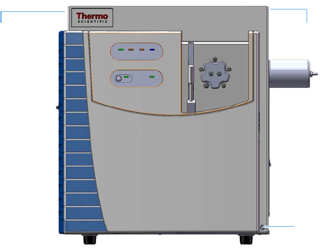
Figure 1. Hydrogen Safety Screws on the Mass Spectrometer
Left Top
Cover Screw
Right Top
Cover Screw
Front Panel
Screw
Preface
Hydrogen Safety Precautions
xvi TSQ Series AutoSRM User Guide Thermo Scientific
Before powering on the MS system, ensure that:
• All the covers and panels of the MS system are firmly attached.
• The vent valve is tightly closed if you vented the system.
• All fittings, ferrules, and o-rings are sealed.
Hydrogen Connection Guidelines
Use the following guidelines to safely connect hydrogen to your system:
•Piping—Hydrogen must be delivered to equipment using appropriate piping and be
done in such a way as to pose essentially no hazard to end-users. Piping systems for the
delivery of hydrogen should be designed and installed by a person qualified by specific
training and experience with hydrogen piping systems.
Stainless steel is usually recommended because it is a safe, cost-effective material. Piping
of black iron or copper must not be used, as the pipe can become brittle with age.
Elastomeric/plastic tubing of various plastics and polymers should not be used, unless the
tubing is approved for use with hydrogen. If elastomeric/plastic tubing is used for
hydrogen gas delivery, the tubing should be tested for hydrogen permeability to minimize
leakage.
The hydrogen piping system must be flexible enough to endure routine thermal
expansion and contraction. The system should also include considerations for the most
severe condition of temperature and pressure expected during service. Piping and
supports must be able to withstand static loading introduced by such things as ice and
snow; and dynamic loading from high wind and earthquake.
Caution should be used if burying hydrogen piping. Proper controls should be used to
protect against damage and corrosion, and also to prevent Hydrogen from entering a
building if there is any leakage.
•Fittings—All fittings must be of the proper type approved or designed for use with
hydrogen gas. Use as few fittings as possible to minimize the potential for leaks. After
installation, ensure that leak testing is carried out prior to system use, and on a regular
basis.
There must be no PTFE tape or other things like plumber's putty used to enhance a seal, as
this actually is a detriment to a good seal. Ideally the best installation would use stainless
steel tubing with appropriate gas-tight fittings.
Welding is usually preferred for joints in hydrogen piping systems since welding provides
a better connection and reduces the potential for leaks compared to mechanical fittings.
Soft solder joints are not permitted for hydrogen systems (due to the low melting point of
soft solder and its potential for brittle failure at cryogenic temperatures). Brazed joints are
permitted, but such joints should be protected against the possibility of external fire.
Preface
Hydrogen Safety Precautions
Thermo Scientific TSQ Series AutoSRM User Guide xvii
Tubing connections should be clamped to barbed or press-fit type connections. Hose
clamps or jubilee clamps must not be used.
•Valves—All valves must be suitable for hydrogen service and for the specific operating
conditions. Valves, including regulators, must not be used for hydrogen, unless they are
designed and identified for such a use. Ball valves are often chosen because of their
superior leak tightness through the valve seat. Pneumatic operators are usually chosen for
remotely operated valves so that potential ignition sources (electricity) are remote from
the valve.
Manual shutoff valves should be provided near each point of use, within immediate reach.
If a hydrogen cylinder or hydrogen generation system is located within immediate reach,
a separate point-of-use shutoff valve is usually not necessary.
Line regulators that have their source away from the point of use should have a manual
shutoff valve near the point of use.
An emergency gas shutoff device in an accessible location outside the use area should be
provided in addition to the manual point-of-use valve in each educational and
instructional laboratory space that has a piped gas supply system.
If necessary, the piping system should have uninterruptible pressure relief. The pressure
relief system should be designed to provide a discharge rate sufficient to avoid further
pressure increase and should vent to a safe location outside or to a ventilation system
exhaust.
Purchasing Hydrogen
Use the following guidelines when purchasing hydrogen:
•Hydrogen Generator—Because it minimizes the amount of hydrogen present and
reduces the degree of hazard, a hydrogen generator (also called an electrolyzer) is the safest
way to purchase hydrogen in the quantity used in GC/MS.
However, to minimize the degree of hazard, the hydrogen generator must only be
operated in a non-explosive environment because hydrogen buildup can be ignitable.
This means that your ventilation system for the room or lab hood must maintain an air
exchange rate that is at least two orders of magnitude greater than the maximum
hydrogen production rate of the hydrogen generator. Be sure to follow the manufacturers'
directions about proper use and maintenance of the regulator.
To prevent the possibility of releasing hydrogen, the hydrogen generator should be set to
shut down if:
– There is a loss of flow to the ventilation system
– A hydrogen detector alarms at 25% of the lower flammable limit of hydrogen in air.
The oxygen exhausted by the electrolyzer should be vented to the outside as well.
Preface
Hydrogen Safety Precautions
xviii TSQ Series AutoSRM User Guide Thermo Scientific
•Hydrogen Cylinder—Hydrogen can be delivered in standard laboratory gas bottles or
cylinders. These cylinders have a limited amount of hydrogen in them and are a safe way
to transport and store hydrogen. However, compressed hydrogen gas cylinders, like all
compressed gas cylinders, must be secured in an upright position, ideally with a
non-combustible chain or cable. If the cylinder falls over, the valve can be knocked off
and the pressurized cylinder can take off like a rocket, which leads to the release of
hydrogen and possibly an explosion, severe injury, or death. Never crack a hydrogen
cylinder valve to remove dust or dirt from fittings prior to attaching a regulator, as there is
a risk of self-ignition.
Properly Storing Hydrogen
Storing and handling compressed hydrogen gas and cryogenic liquid hydrogen present
potential health and safety hazards. Using proper storage and handling techniques is essential
to maintaining a safe work environment.
Use the following guidelines when storing hydrogen:
• Store spare hydrogen gas cylinders outside and away from doors, windows, building air
intake vents, structures, and vehicle routes. This precaution applies when the hydrogen is
or is not in use. Indoor storage of spare hydrogen cylinders has special requirements,
which is beyond the scope of this document. Documentation for each vessel should
include a description of the vessel, a list of available drawings or other documents, the
most recent inspection results, and the responsible person's name.
• Prevent spare cylinders from toppling by wrapping them with chains. The chains should
also be protected against corrosion and excessive heat.
• Separate spare hydrogen cylinders from oxidizing gases (such as oxygen) with a 5 ft
(1.5 m) tall fire barrier with a half-hour fire rating or place the cylinders at least 20 ft
(6 m) apart.
• When moving hydrogen cylinders:
– Remove the regulator and replace the cylinder valve cap before moving.
– Move cylinders on cylinder carts or with other appropriate transport devices.
– Never roll or drop a cylinder and never lift a cylinder by its protective cap.
• Bulk hydrogen systems include either gaseous or liquid hydrogen in fixed installations; in
some gas systems a semi-permanent trailer (tube trailer) can be used. Storage vessels for
compressed hydrogen gas or liquid hydrogen should be designed, constructed, tested, and
maintained in accordance with applicable codes and standards. Bulk hydrogen systems
represent a level of complexity again which is beyond the scope of this document;
however some general guidelines are provided.
Preface
Hydrogen Safety Precautions
Thermo Scientific TSQ Series AutoSRM User Guide xix
• The bulk hydrogen storage system should not be located beneath electric power lines,
close to other flammable gases/liquids, or close to public areas. It should be readily
accessible to authorized personnel and delivery equipment, but protected from physical
damage or tampering.
• As liquid hydrogen systems also have a cryogenic hazard, additional safety considerations
for the use of cryogenic liquids might be necessary.
Hydrogen Safety Codes, Standards and References
The following list of safety codes, standards and references is in no way an exhaustive list. In
fact, there might be federal, state or local codes that apply to your specific location. Check
with all appropriate agencies with jurisdiction before installing or using a hydrogen system.
• Air Products Safetygram #4 Gaseous Hydrogen
• ANSI/AIAA standard for hydrogen safety guidelines is AIAA G-095-2004, Guide to
Safety of Hydrogen and Hydrogen Systems
• ASME B31.1, Power Piping Code
• ASME B31.3, Process Piping Code
• ASME B31.8, Gas Transmission and Distribution Systems
• BCGA Code Of Practice CP4 Industrial Gas Cylinder Manifolds and Gas Distribution
Pipework
• BCGA Code Of Practice CP33 The Bulk Storage of Gaseous Hydrogen at Users'
Premises
• CGA G-5, Hydrogen
• CGA G-5.4, Standard for Hydrogen Piping Systems at Consumer Locations
• CGA G-5.5, Hydrogen Vent Systems
• CGA G-5.6, Hydrogen Pipeline Systems
• CGA G-5.8, High Pressure Hydrogen Piping Systems at Consumer Locations.
• FM Global Property Loss Prevention Data Sheets 7-50: Compressed Gases in Cylinders
• FM Global Property Loss Prevention Data Sheets 7-91: Hydrogen
• IGC Doc 121/04/E, Hydrogen Transportation Pipelines System Design Features
• NASA
• NSS 1740.16 Safety Standard For Hydrogen And Hydrogen Systems Guidelines for
Hydrogen System Design, Materials Selection, Operations, Storage, and Transportation
• NFPA 52, Vehicular Fuel Systems Code

Preface
Hazardous Substances Precautions
xx TSQ Series AutoSRM User Guide Thermo Scientific
• NFPA 55, Standard for the Storage, Use, and Handling of Compressed Gases and
Cryogenic Fluids in Portable and Stationary Containers, Cylinders, and Tanks, 2005
Edition
• NFPA 68, Standard on Explosion Protection by Deflagration Venting
• NFPA 70, National Electrical Code
• NFPA 497, Recommended Practice for the Classification of Flammable Liquids, Gases,
or Vapors and of Hazardous (Classified) Locations for Electrical Installations in Chemical
Process Areas
• NFPA 13, Standard for the Installation of Sprinkler Systems
• NFPA 45, Standard on Fire Protection for Laboratories Using Chemicals
• NFPA 55, Standard for the Storage, Use, and Handling of Compressed Gases and
Cryogenic Fluids in Portable and Stationary Containers, Cylinders, and Tanks
• NFPA 68, 2007 Standard on Explosion Protection by Deflagration Venting
• NFPA 69, Standard on Explosion Prevention Systems
• NFPA 91, Standard for Exhaust Systems for Air Conveying of Vapors
• NFPA 255, Standard Method of Test of Surface Burning Characteristics of Building
Materials
• OSHA 29CFR1910.103 1910.103 Hydrogen
Hazardous Substances Precautions
Biological Hazard Warning Note
In laboratories where samples with potential biological hazards are handled, the user must
label any equipment or parts which might become contaminated with biohazardous material.
The appropriate warning labels are included with the shipment of the instrument. It is the
user’s responsibility to label the relevant parts of the equipment.
WARNING Before using hazardous substances (toxic, harmful, and so on), please read the
hazard indications and information reported in the applicable Material Safety Data Sheet
(MSDS). Use personal protective equipment according to the safety requirements.

Preface
Contacting Us
Thermo Scientific TSQ Series AutoSRM User Guide xxi
When working with biohazardous materials, you are responsible for fulfilling the following
mandatory requirements:
• Providing instructions on how to safely handle biohazardous material.
• Training operators to be aware of potential hazards.
• Providing personal protective equipment.
• Providing instructions for what to do if operators are exposed to aerosols or vapors during
normal operation (within the intended use of the equipment) or in case of single fault
situations such as a broken vial. The protective measures must consider potential contact
with the skin, mouth, nose (respiratory organs), and eyes.
• Providing instructions for decontamination and safe disposal of relevant parts.
Venting Toxic Gases
When analyzing toxic compounds, be aware that during the normal operation of the GC
some of the sample might be vented outside the instrument through the split and purge flow
vents; therefore, be sure to vent the exhaust gases to a fume hood. Consult local
environmental and safety regulations for instructions in exhausting fumes from your system.
Contacting Us
There are several ways to contact Thermo Fisher Scientific for the information you need.
To find out more about our products
Go to www.thermo.com/ms for information about our products.
To get local contact information for sales or service
Go to www.thermoscientific.com/wps/portal/ts/contactus.
To suggest changes to documentation or to Help
• Fill out a reader survey online at www.surveymonkey.com/s/PQM6P62.
• Send an e-mail message to the Technical Publications Editor at
techpubs-austin@thermofisher.com.
WARNING The user or operator is responsible for the safe handling of hazardous
chemicals or biological compounds including (but not limited to) bacterial or viral
samples and the associated waste, according to international and local regulations.
Thermo Scientific TSQ Series AutoSRM User Guide 1
Using AutoSRM
This chapter tells you how to set up and run an AutoSRM discovery study. AutoSRM
discovery studies have three sections:
• The precursor ion study
• The product ion study
• SRM optimization
As well as instructions for setting up and running each study, this user guide gives you the
steps for importing the resulting transitions into the TSQ Series instrument method and
accessing them for routine use.
Determining Precursor Ions
The purpose of the first study is to select your precursor ions. During this study, after you
name your compounds and enter your vial numbers and retention times, AutoSRM instructs
your TSQ Series system to run a full-scan analysis on the compounds.
For precursor ion studies, along with the resulting chromatographic peaks and full-scan
spectra, AutoSRM presents you with a table of the most intense product ion masses that you
may select. If you wish, however, AutoSRM can automatically pick the product ion masses.
Note Set up your GC and autosampler methods through the Instrument Method Editor
in Chromeleon before developing your AutoSRM study.
Contents
•Determining Precursor Ions
•Conducting the Product Ion Study
•Developing the SRM Optimization Study
•Importing Transitions into the Method Editor
1 Using AutoSRM
Determining Precursor Ions
2TSQ Series AutoSRM User Guide Thermo Scientific
The user interface presents the full-scan peaks and attempts to identify your compounds
based on the largest peak at the approximate retention time you provided. You may extract a
single ion or perform a baseline subtraction to help you identify potential precursor ions.
To determine your precursor ions in AutoSRM
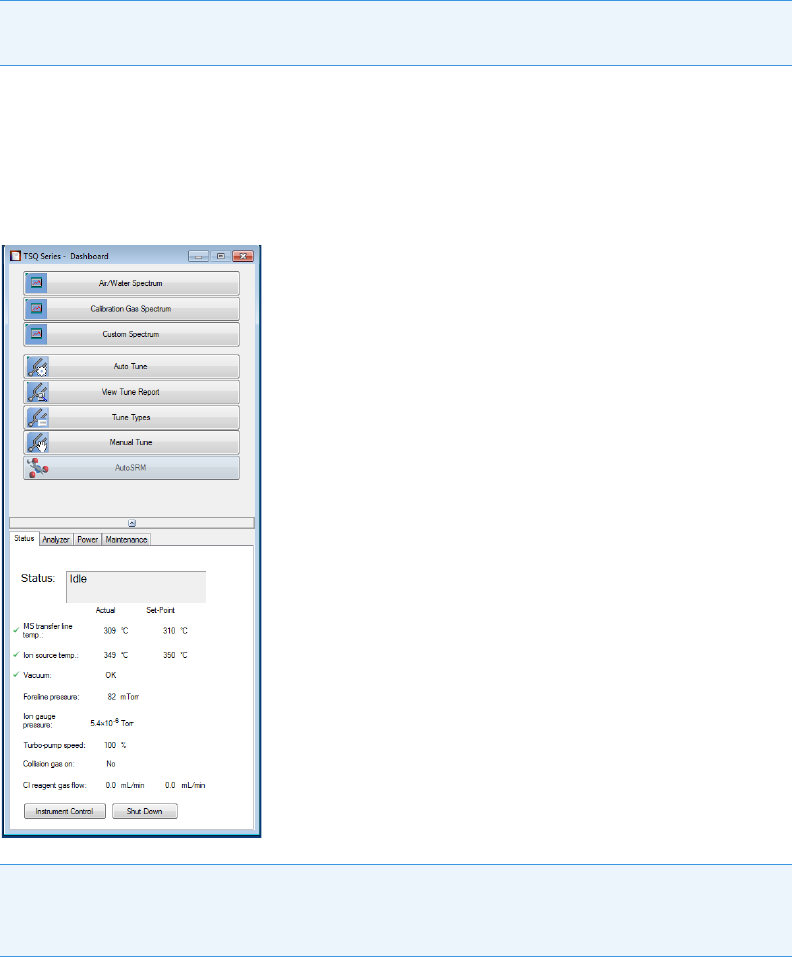
1. Open the TSQ Series Dashboard.
2. Click AutoSRM.
Figure 1. Accessing AutoSRM from the TSQ Series Dashboard
Note You will need mid-range concentration standards (500 pg/uL–10 ng/uL) before
setting up your AutoSRM method.
Note If User Management is enabled in Chromeleon, the Chromeleon log on dialog box
opens when you start AutoSRM. Enter your Chromeleon User Name and Password to
continue.
1 Using AutoSRM
Determining Precursor Ions
Thermo Scientific TSQ Series AutoSRM User Guide 3
3. Click the Create a New Study icon on the left to create a new study. See Figure 2.
Figure 2. New AutoSRM Study
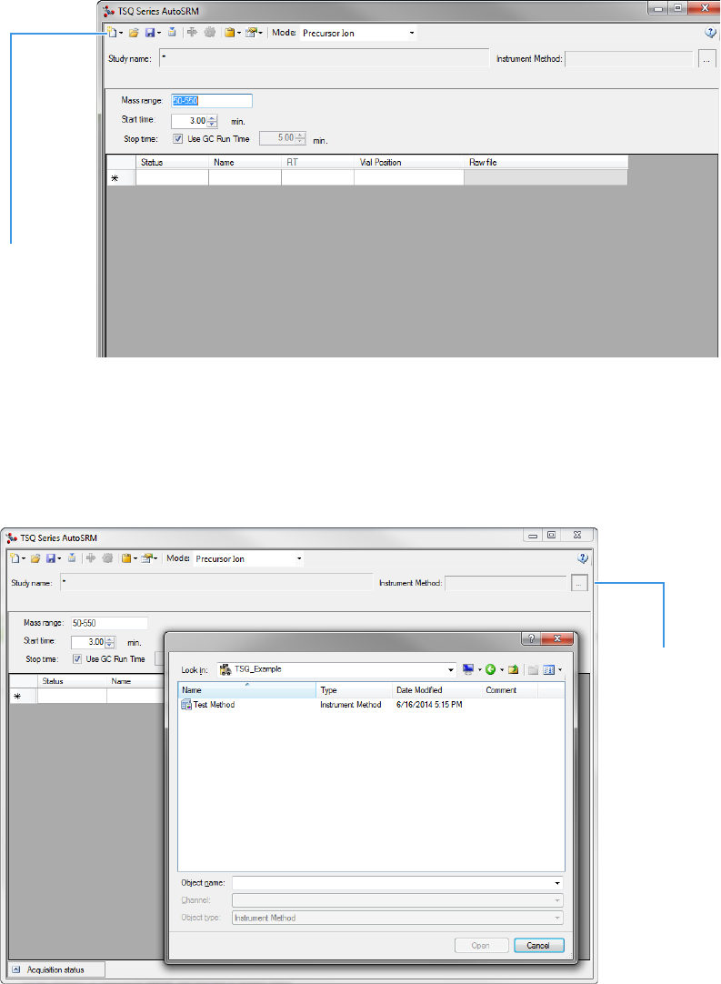
4. A new study window opens.
5. Link to an instrument method file that you created using the Chromeleon Instrument
Method Editor by clicking on the ellipsis icon next to the Instrument Method window.
See Figure 3.
Figure 3. Retrieving an Instrument Method
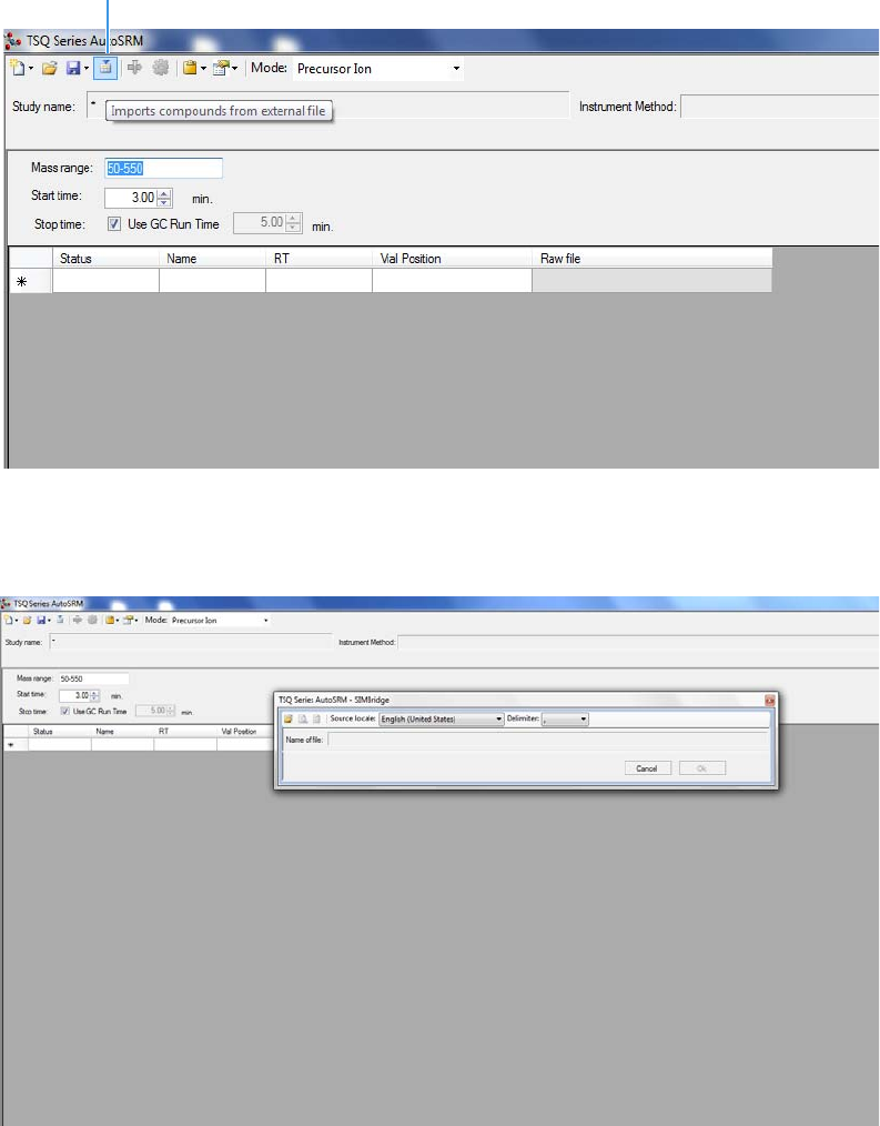
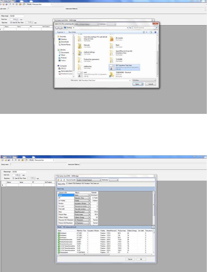
6. If you are importing a file created on another system, click the import icon. See Figure 4.
Create a New
Study Icon
Link to an
Instrument
Method
1 Using AutoSRM
Determining Precursor Ions
4TSQ Series AutoSRM User Guide Thermo Scientific
Figure 4. Importing Compounds from an External File
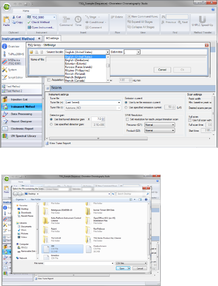
7. The SIMBridge dialog box opens. Choose the language of your method file from the
Source Locale drop-down menu. See Figure 5.
Figure 5. Setting the Source Language of Method Files using SIMBridge
8. Click the File icon. The Select the File Containing the Scans dialog box opens. Browse
to your file. See Figure 6.
Import Icon
1 Using AutoSRM
Determining Precursor Ions
Thermo Scientific TSQ Series AutoSRM User Guide 5
Figure 6. Linking to an External File using SIM Bridge
9. Click Open to open the method in SIMBridge.
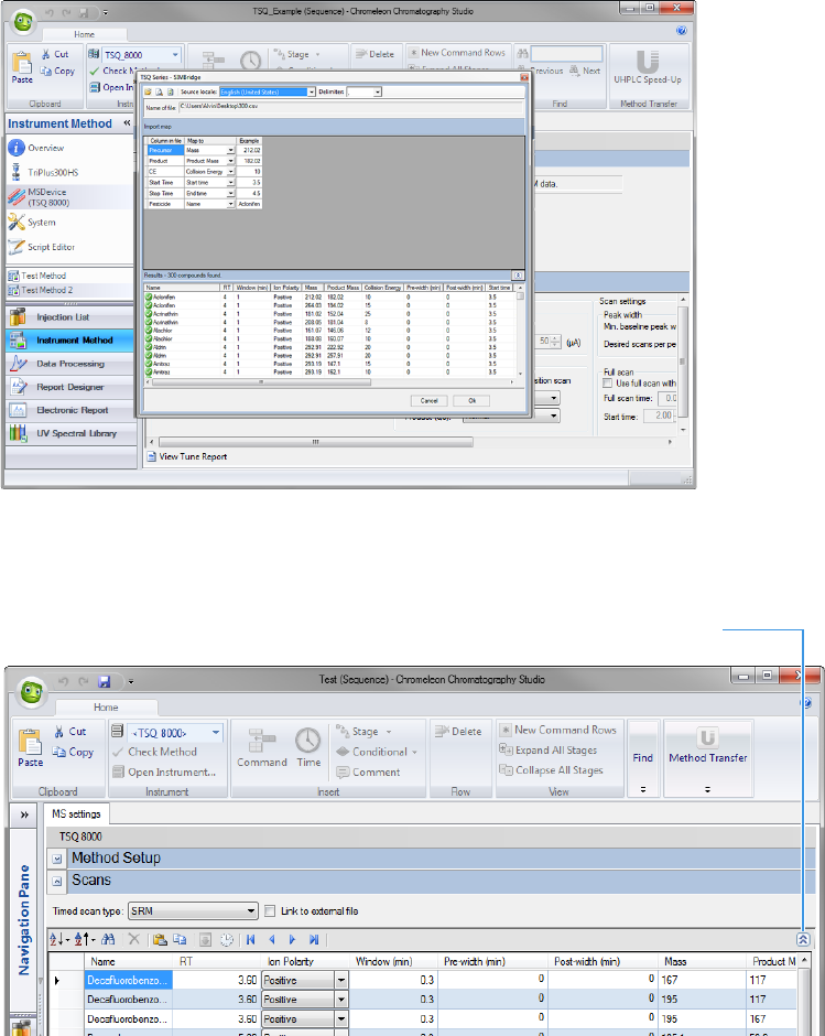
10. If necessary, change the method headings in your original file to match those in the
method editor. A green check mark appears when your method is validated. See Figure 7.
Figure 7. Changing Method Headings in SIMBridge
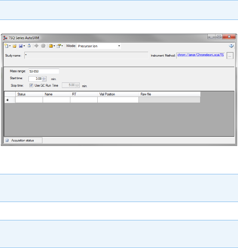
11. Your method opens in AutoSRM. AutoSRM will use the GC and autosampler parameters
from this method file. You may set the Mass Range, Start Time, and Stop Time. See
Figure 8.
Any changes you make to your MS method here will override the method editor settings.
1 Using AutoSRM
Determining Precursor Ions
6TSQ Series AutoSRM User Guide Thermo Scientific
Figure 8. Adjusting the Settings
12. Enter the compound name, approximate retention time, and vial number for each
compound you wish to optimize.
13. Click the Save the Study icon.
Note If the method’s start time is reduced, you risk scanning over the solvent front. This
might contaminate the source.
Tip You can import the compound information from another source by clicking the
Import icon. The import file must be in the same .csv format that the TSQ Series
instrument method exports through its Export Timed Scans function
Tip To simplify your workflow, create a folder for your study. Files that AutoSRM
generates, including raw data files, will be saved into the same folder in which you save the
study file.
1 Using AutoSRM
Determining Precursor Ions
Thermo Scientific TSQ Series AutoSRM User Guide 7
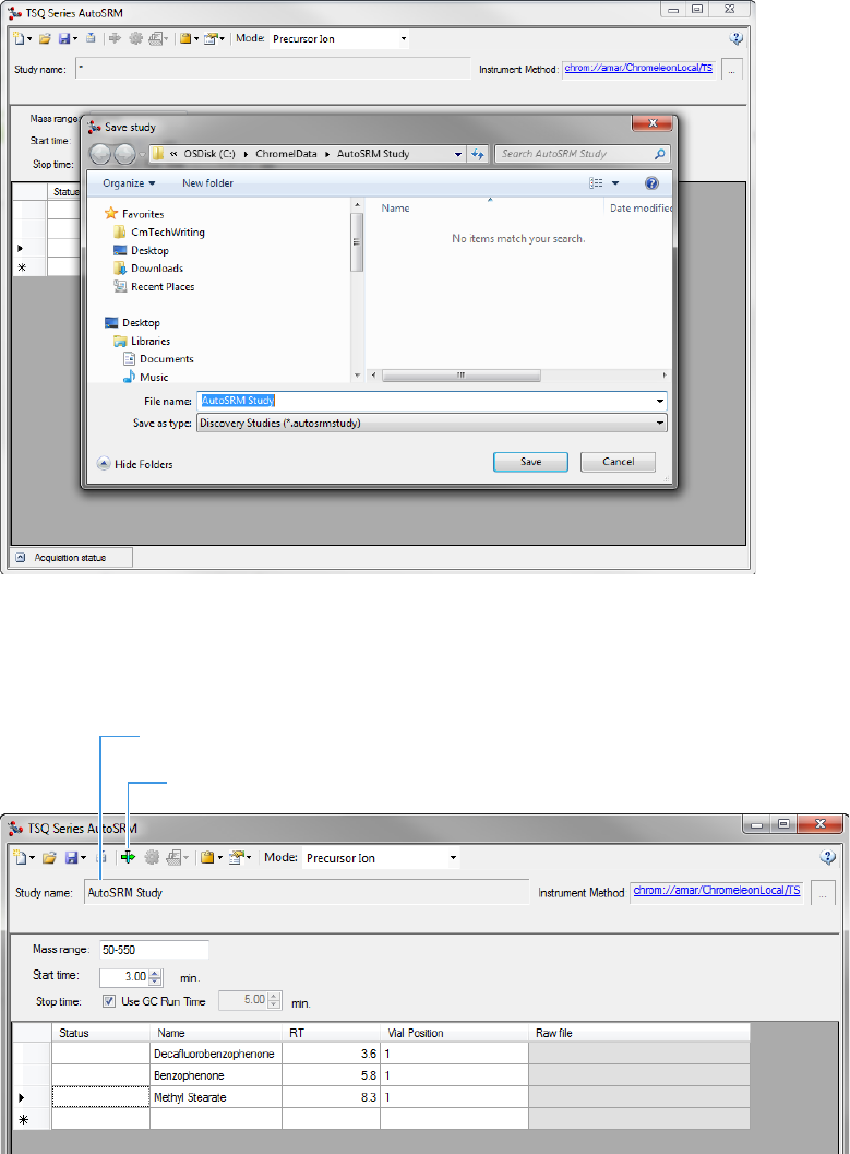
14. Give your study a name and save it in the study folder. See Figure 9.
Figure 9. Saving an AutoSRM Study
15. The Windows Explorer window closes.
16. The Study Name is the name you assigned. See Figure 10.
Figure 10. Acquiring Acquisition Data
New Study Name
Acquire Data Icon
1 Using AutoSRM
Determining Precursor Ions
8TSQ Series AutoSRM User Guide Thermo Scientific
17. (CI Only) If you are running a chemical ionization (CI) study, select Positive or Negative
from the Ion Polarity pull-down menu. See Figure 11.
Figure 11. Setting Ion Polarity in a CI Method
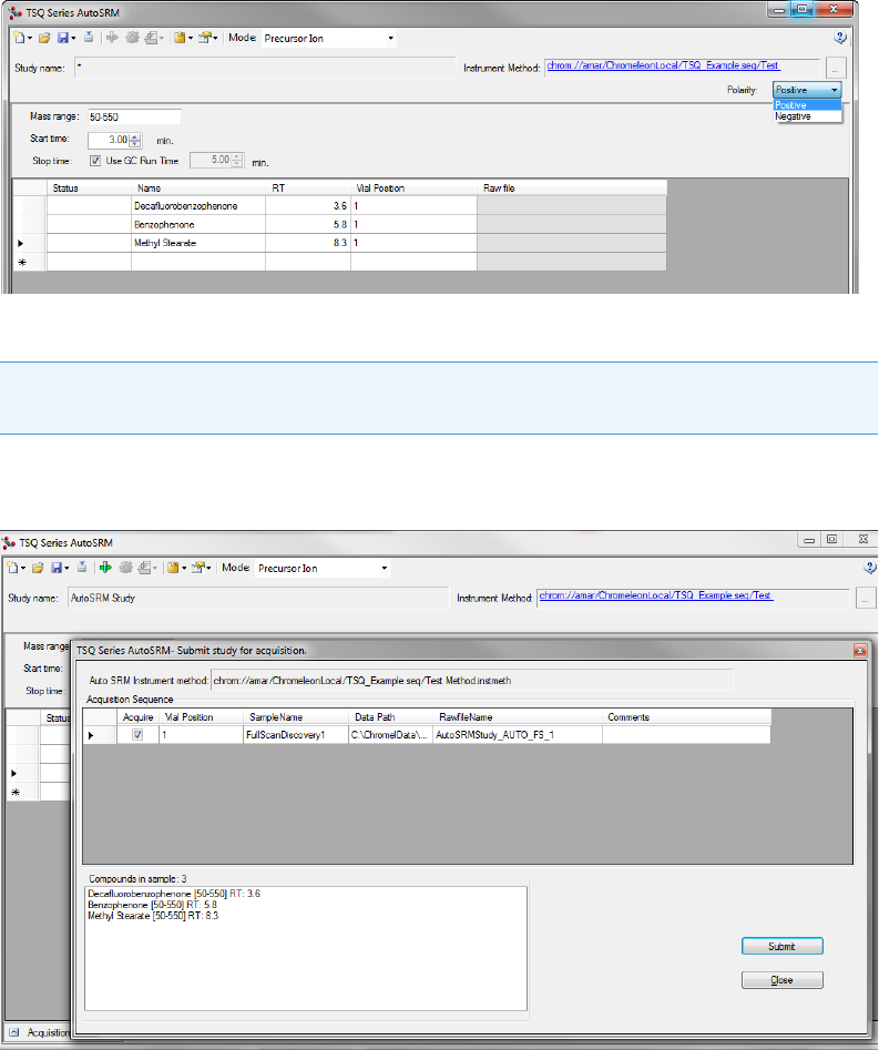
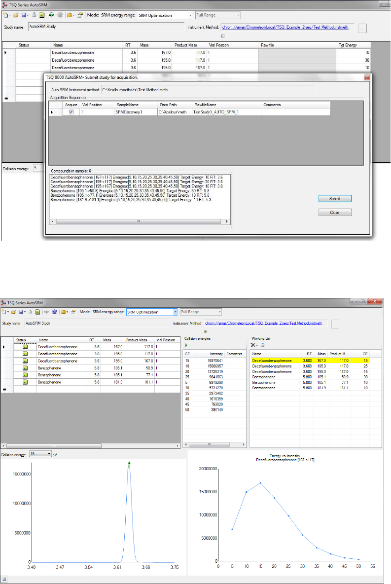
18. Click the Acquire Data icon to run your samples. See Figure 10.
The Submit Study for Acquisition window opens. See Figure 12.
Figure 12. Submitting a Study for Acquisition
19. Click Submit to submit the samples to the instrument.
The AutoSRM study is added to the Chromeleon sequence queue. Chromeleon performs
a Ready Check to verify that the instrument is ready for operation and the instrument
method is error-free. If the Ready Check passes, the run starts.
Note AutoSRM calculates the number of injections needed based on the compound list
and vial positions you assigned.

1 Using AutoSRM
Determining Precursor Ions
Thermo Scientific TSQ Series AutoSRM User Guide 9
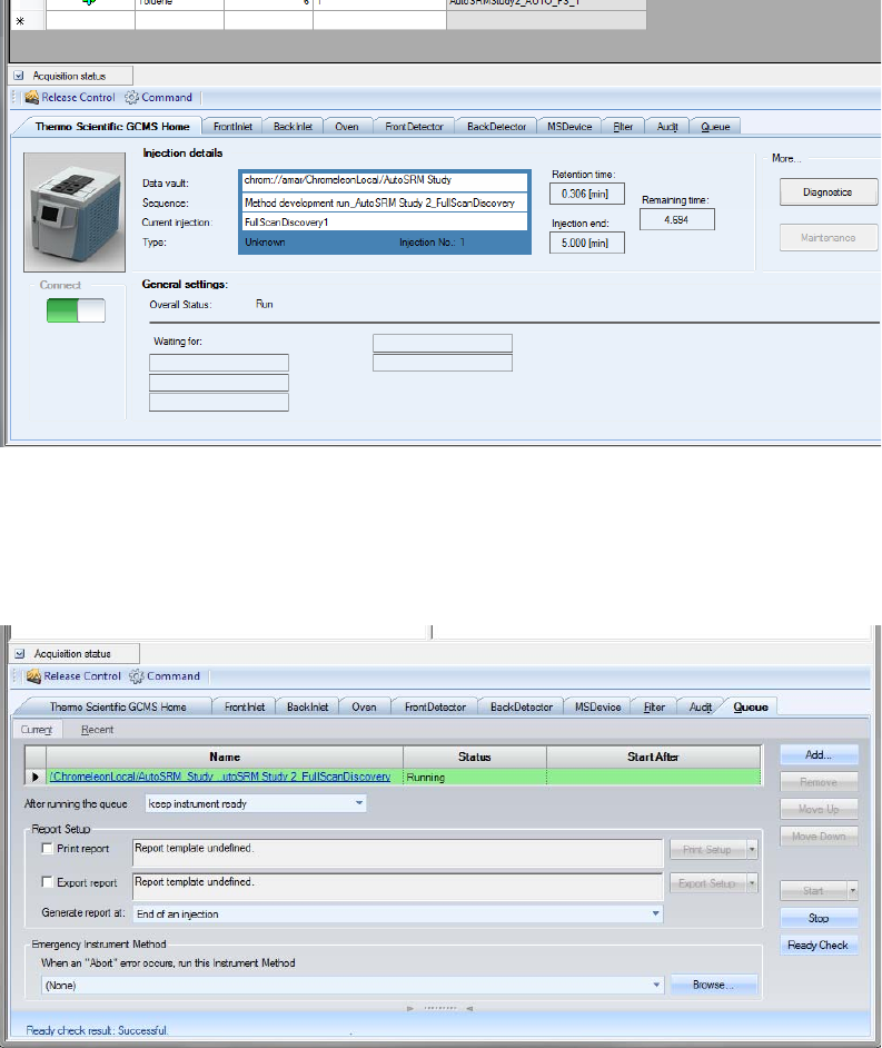
20. The Acquisition Status pane displays status information about the running instrument. If
the pane is not currently visible, click the Acquisition Status button. See Figure 13.
Figure 13. Displaying the Acquisition Status Pane
The pane contains a Chromeleon ePanel Set that you can use to monitor the status of
AutoSRM injections. See Figure 14. You can also use the ePanel Set to monitor the
devices configured in the instrument and to see the status of the Chromeleon sequence
queue. For details about Chromeleon ePanel Sets, refer to the Chromeleon Help.
Note If the run does not start automatically after you click Submit, review the
Chromeleon Ready Check messages listed in the Acquisition summary pane on the
Submit dialog box. Close the Submit dialog box, correct the errors, and then resubmit
the study.
If the following Ready Check message appears: “The instrument is currently in ‘Hold’
condition,” follow these steps to release the Hold:
• On the Acquisition Status pane (described below), click the Command button.
• On the Command window, click the System icon. In the Properties list, select
HoldMode Off and press ENTER.
Acquisition Status Button
1 Using AutoSRM
Determining Precursor Ions
10 TSQ Series AutoSRM User Guide Thermo Scientific
Figure 14. Viewing Instrument Status on the Home ePanel
21. For an overview of the status of the run, click the Home tab. To monitor or control a
configured device (mass spectrometer, detector, oven, etc.) click the tab for the device.
22. To view the queue status or to stop or start the queue, click the Queue tab. See Figure 15.
Figure 15. Viewing Queue Status on the Queue ePanel
Once the samples have finished running, the software analyzes the data.
1 Using AutoSRM
Determining Precursor Ions
Thermo Scientific TSQ Series AutoSRM User Guide 11
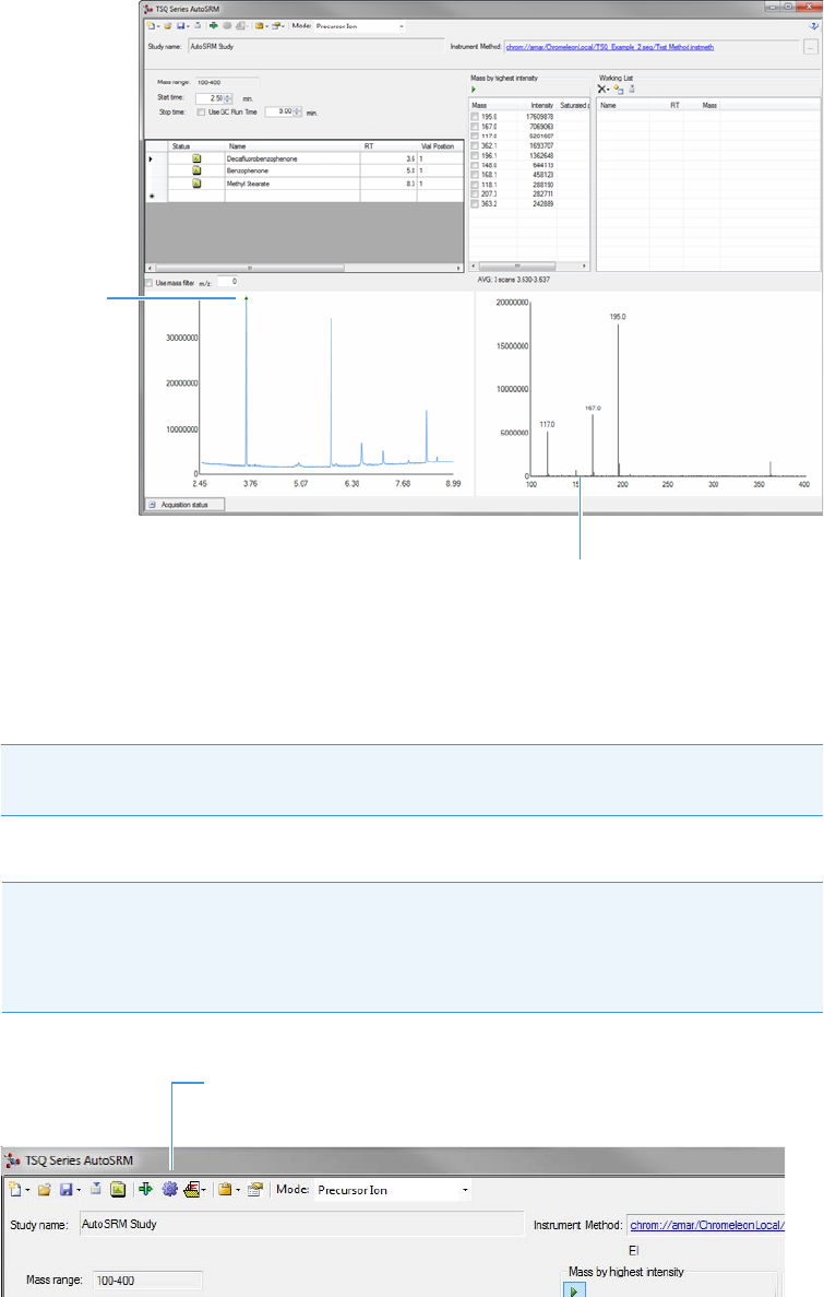
23. The results appear in the AutoSRM window. See Figure 16.
Figure 16. Study Results in AutoSRM
The results displayed correspond to the peak topped by the green triangle. The Mass by
Highest Intensity pane contains a list of the highest intensity ions at the indicated
retention time.
You are now ready to select the precursor ions you want to send to the working list.
Figure 17. Automatically Selecting Precursor Ions
Note Background subtraction updates the ions in the Mass by Highest Intensity
pane.
Tip To have AutoSRM select the precursor ions for you, click the purple Auto
Process icon (see Figure 17). AutoSRM selects the highest intensity ions for each
compound. The number of ions chosen for each compound can be set in the options
window.
Peak
Associated
with Displayed
Results
Full-Scan
Spectrum
Auto Process
Icon
1 Using AutoSRM
Determining Precursor Ions
12 TSQ Series AutoSRM User Guide Thermo Scientific
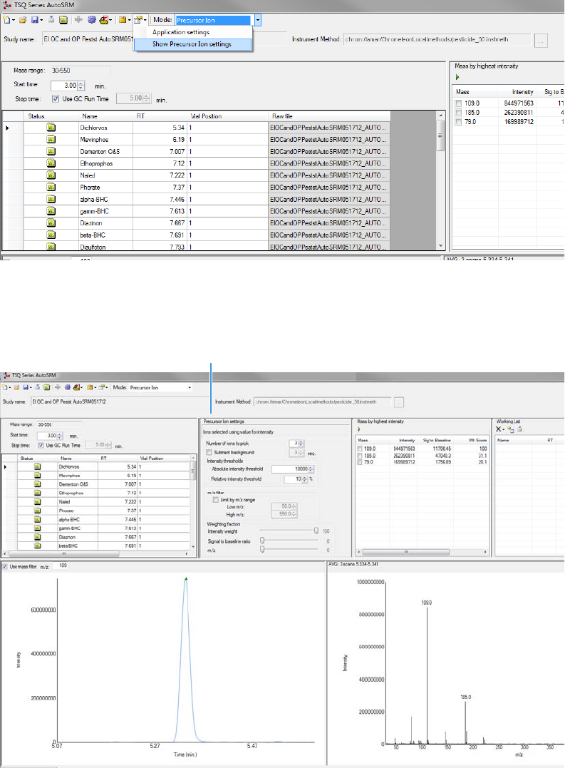
24. Select the check box next to the precursor ions you want to send to the working list,
double-click on the ions in the spectra window, or click the Settings icon and choose
Show Precursor Ion Settings to access additional settings for selecting precursor ions.
See Figure 18.
Figure 18. Accessing the Precursor Ion Settings
25. The Precursor Ion Settings pane opens. See Figure 19.
Figure 19. Precursor Ion Settings
Precursor Ion
Settings

1 Using AutoSRM
Determining Precursor Ions
Thermo Scientific TSQ Series AutoSRM User Guide 13
26. By default, precursor ions are sorted by highest intensity. In the Precursor Ion Settings
box, you may select precursor ions according to the following criteria.
a. Number of Ions to Pick: Selects the number of precursor ions picked for each
compound.
b. Subtract Background: Checking this box subtracts background from the spectrum.
Subtracting the background may reduce baseline noise automatically away from the
selected peak. This will help identify your target compounds, clarify intensities, and
may reduce the effects of column bleed. If the automatic background subtraction is
not ideal (e.g., due to co-eluting peaks), you may select to manually subtract
background for individual compounds by right clicking on the chromatogram and
then highlighting the scan or scans to use for subtraction.
c. Intensity Thresholds: Allows you to select precursor ion candidates based on
intensity levels.
i. Absolute Intensity Threshold: Sets the minimum intensity level such that all
ions must be greater than this intensity to be selected as precursor ion candidates.
ii. Relative Intensity Threshold: Sets the minimum intensity of an ion relative to
the highest intensity ion to be a candidate for the precursor ion list. Ions must
have a relative abundance greater than or equal to this percentage to be selected
as precursor ion candidates.
d. Limit by m/z Range: Check this box and set the low m/z and high m/z to limit your
precursor ion selection list to certain masses within the set scan range.
e. Weighting Factors: Use the sliding bars and check boxes to set the values you want
to give each precursor ion study setting. The available factors are Intensity Weight
(peak height), Signal to Baseline Ratio (peak height/baseline height), and m/z. Set
the weights of each from 0 to 100, with a total weight of 100.
Tip When selecting precursor ions, you often get better results by weighting m/z
higher than intensity weight.
1 Using AutoSRM
Determining Precursor Ions
14 TSQ Series AutoSRM User Guide Thermo Scientific
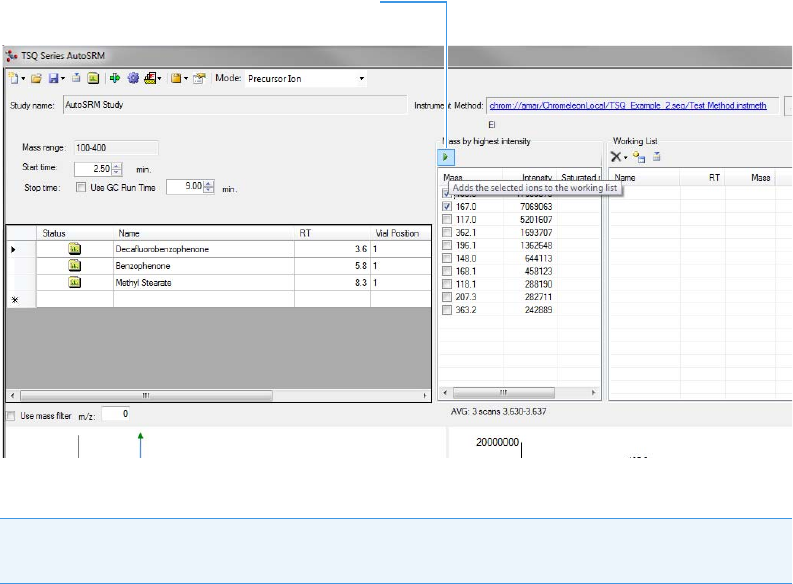
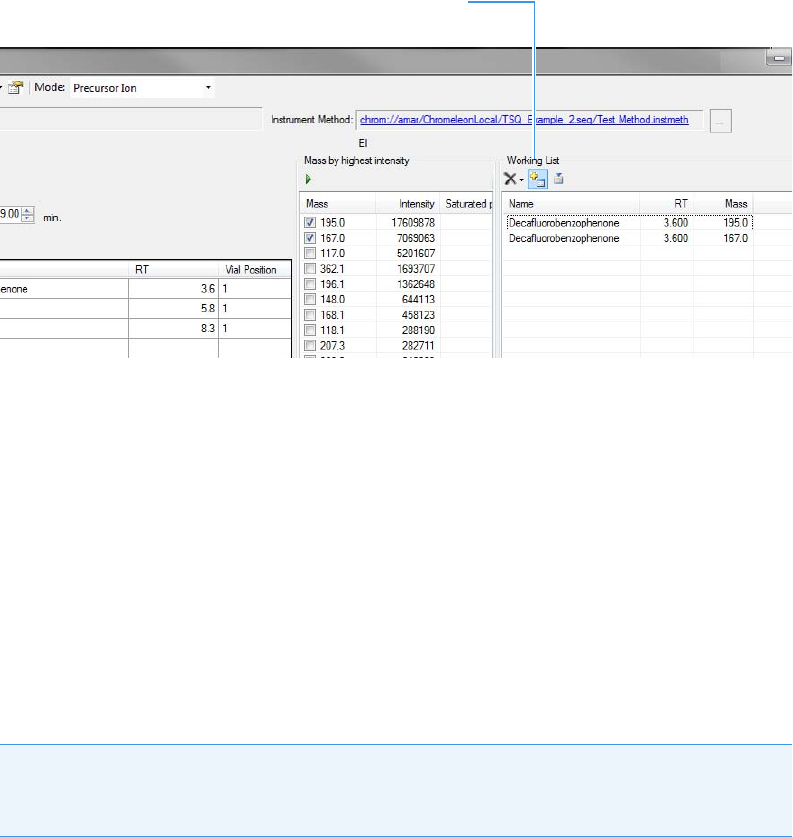
27. Click the green arrow icon to push the precursor ions you selected to the working list. See
Figure 20.
Figure 20. Selecting Precursor Ions for Product Ion Study
28. Repeat this process for all of your compounds.
You have obtained your list of precursor ions and are now ready to conduct the product
ion study.
Note You can select precursor ions by checking them in the mass list or double-clicking
on the ion in the spectra window.
Add Ions to Working List
1 Using AutoSRM
Conducting the Product Ion Study
Thermo Scientific TSQ Series AutoSRM User Guide 15
29. When you have reviewed all the compounds and selected the precursor ions, click the
Push icon in the working list to push the transitions in the working list to the Product
Ion Study. See Figure 21.
Figure 21. Pushing Compounds in Working List to Product Ion Study
Conducting the Product Ion Study
Now that you have selected your precursor masses, you can find the product masses.
AutoSRM instructs the TSQ Series system to acquire product ion scans of your precursor
masses at three collision energies. You do not have to set up any methods or sequences;
AutoSRM automatically does these for you. Also, the software instructs the autosampler to
make multiple injections if compound retention times are too close or if multiple precursor
ions are selected for a single compound.
Along with your chromatographic peak and your product ion spectra, AutoSRM presents you
with a table of the most intense product ion masses from which to choose. If you prefer,
AutoSRM can select the product ion masses for you.
Push Icon
Tip You can import a SIM method directly into this step by clicking the Import icon. The
import file must be in the same .csv format that the TSQ Series instrument method
exports through its Export Timed Scans function.
1 Using AutoSRM
Conducting the Product Ion Study
16 TSQ Series AutoSRM User Guide Thermo Scientific
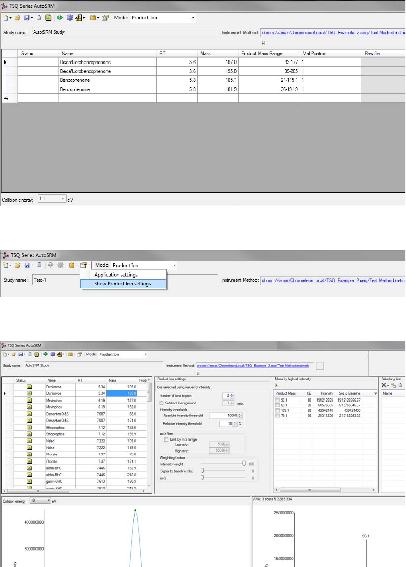
To conduct a product ion study
1. The AutoSRM window displays the list of precursor ions you selected for the Product Ion
study. See Figure 22.
Figure 22. Precursor Ions Selected for Product Ion Study
2. Click the Settings icon to access the product ion settings. See Figure 23.
Figure 23. Accessing Product Ion Settings
3. The Product Ion Settings box opens. See Figure 24.
Figure 24. Product Ion Settings

1 Using AutoSRM
Conducting the Product Ion Study
Thermo Scientific TSQ Series AutoSRM User Guide 17
4. By default, product ions are sorted by highest intensity. In the Product Ion Settings box,
you may select product ions according to the following criteria.
a. Number of Ions to Pick: Selects the number of product ions picked for each
compound.
b. Subtract Background: Checking this box subtracts background from the spectrum.
Subtracting the background may reduce baseline noise automatically away from the
selected peak. This will help identify your target compounds, clarify intensities, and
reduce the effects of column bleed. If the automatic background subtraction is not
ideal (e.g., due to co-eluting peaks), you may select to manually subtract background
for individual compounds by right clicking on the chromatogram and then
highlighting the scan or scans to use for subtraction.
c. Intensity Thresholds: Allows you to use intensity levels.
i. Absolute Intensity Threshold: Sets the minimum intensity level such that all
ions must be greater than this intensity to be selected as precursor ion candidates.
ii. Relative Intensity Threshold: Sets the minimum intensity of an ion relative to
the highest intensity ion to be a candidate for the precursor ion list. Ions must
have a relative abundance greater than or equal to this percentage to be selected
as precursor ion candidates.
d. Limit by m/z Range: Check this box and set the low m/z and high m/z to limit your
product ion selection list to certain masses within the set scan range.
e. Weighting Factors: Use the sliding bars and check boxes to set the values you want
to give each product ion study setting. The available factors are Intensity Weight
(peak height), Signal to Baseline Ratio (peak height/baseline height), and m/z. Set
the weights of each from 0 to 100, with a total weight of 100.
5. Review the product ion list and update the vial numbers if necessary.
6. Save the study by clicking the Save icon.
7. Click the green Acquire Data icon to submit the study for acquisition.
Tip When selecting product ions, you often get better results by weighting
intensity weight higher than m/z.
1 Using AutoSRM
Conducting the Product Ion Study
18 TSQ Series AutoSRM User Guide Thermo Scientific
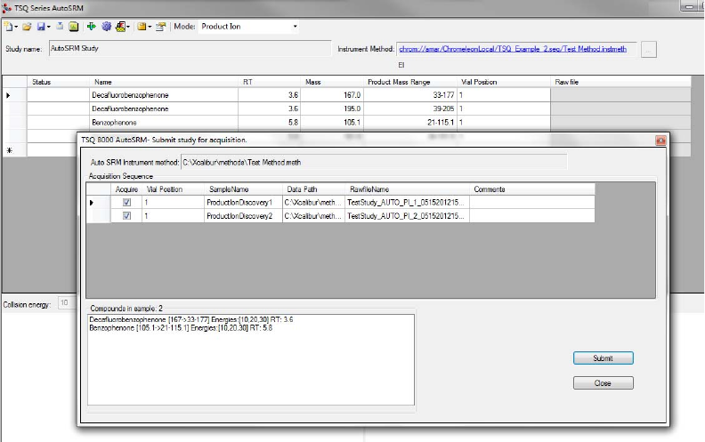
8. Click Submit. See Figure 25.
Figure 25. Submitting Precursor Ions to Product Ion Study
AutoSRM calculates the number of injections needed based on the compound list and
vial positions you assigned.
During the Product Ion study, each product ion scans at 10, 20, and 30 eV collision
energies to get a good collision energy range over which to search for the best product
ions.
1 Using AutoSRM
Conducting the Product Ion Study
Thermo Scientific TSQ Series AutoSRM User Guide 19
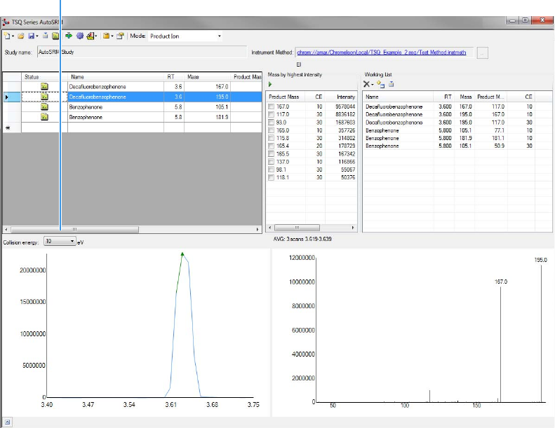
9. Select the different collision energies from the drop-down box to view the product ions
produced at different collision energies. See Figure 26.
Figure 26. Selecting Collision Energies
Collision Energy
Drop-down Box

1 Using AutoSRM
Developing the SRM Optimization Study
20 TSQ Series AutoSRM User Guide Thermo Scientific
10. Choose the product ions and collision energies you want for SRM optimization and push
them to the working list. See Figure 27.
Figure 27. Pushing Product Ions to Working List for SRM Optimization
From this point you may export your transition list to your instrument method, or you may
send your selected transitions to an SRM optimization study for further optimization.
Developing the SRM Optimization Study
The final step in SRM development is the SRM optimization step. Now that you have
selected precursor and product masses, AutoSRM acquires those transitions at multiple
collision energies. Because of its fast scanning capabilities, the TSQ Series GC-MS system has
the ability to analyze three transitions per compound, each at 10 unique collision energies, in
a single injection.
Note AutoSRM lists product ions in order of highest energy intensity and at the optimal
collision energy for each product ion.
Tip AutoSRM automatically processes the data for you and suggests transitions if you
click the purple Auto Process icon.

1 Using AutoSRM
Developing the SRM Optimization Study
Thermo Scientific TSQ Series AutoSRM User Guide 21
To develop an SRM optimization study
1. Push the working list of precursor ions to the SRM optimization study.
2. Select Targeted or Full Range study in the SRM Energy Range drop-down box. See
Figure 28.
Targeted optimizations use a collision energy range that is 10 eV on either side of the
target energy in 2 eV steps. Full Range optimizations use collision energies from 5 to
50 eV in 5 eV steps.
Figure 28. Selecting SRM Energy Range
Tip You can import an SRM method directly into this step by clicking the Import icon.
The import file must be in the same .csv format that the TSQ Series instrument method
exports through its Export Timed Scans function.
Note A single study cannot perform both Full Range and Targeted studies. If you want to
do both, you must create a separate study. This can be accomplished through the Create
New Study from Existing Study function.
1 Using AutoSRM
Developing the SRM Optimization Study
22 TSQ Series AutoSRM User Guide Thermo Scientific
3. Save the study and submit the samples for analysis. See Figure 29.
Figure 29. Submitting SRM Optimization Study for Analysis
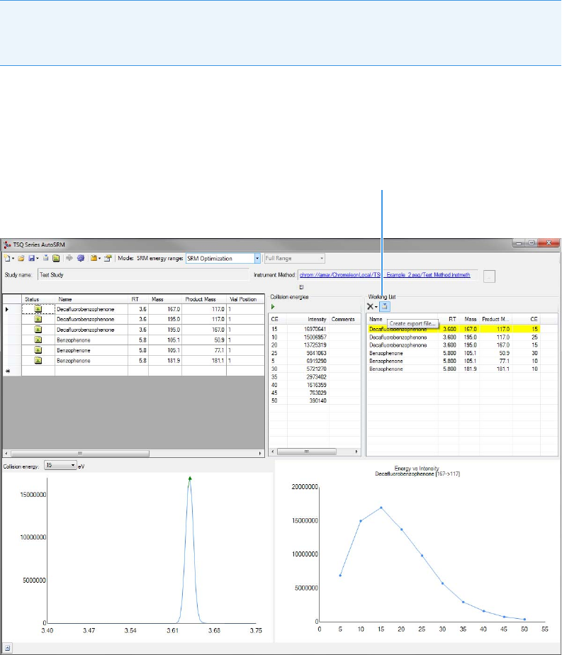
4. Once the analysis is complete, the software displays the data for you to perform a final
review. See Figure 30.
Figure 30. Reviewing your SRM Optimization Data
1 Using AutoSRM
Developing the SRM Optimization Study
Thermo Scientific TSQ Series AutoSRM User Guide 23
5. Review each transition and push the best collision energy to the working list.
6. Once you have reviewed the data and chosen the transitions you want to use, save the
study and create a .csv file to transfer the transitions to your instrument method. See
Figure 31.
Figure 31. Creating File to Transfer Transitions
Once complete, AutoSRM allows the simple creation of a TSQ Series instrument method
to be ready for routine analysis.
Note The software will choose the peak with the highest intensity. If compounds with
similar retention times share transitions, you might need to select the appropriate peak
using the green triangle.
Create .csv File
1 Using AutoSRM
Importing Transitions into the Method Editor
24 TSQ Series AutoSRM User Guide Thermo Scientific
Importing Transitions into the Method Editor
To import the list of transitions you created in AutoSRM
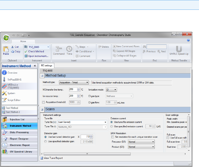
1. Open your instrument method in Chromeleon.
2. Click the mass spectrometer icon in the method editor side pane. See Figure 32.
Figure 32. Viewing Instrument Method in Chromeleon
3. From the Method Type drop-down menu, select Acquisition-Timed.
Tip Click the link in the Instrument Method box in AutoSRM to open Chromeleon.
1 Using AutoSRM
Importing Transitions into the Method Editor
Thermo Scientific TSQ Series AutoSRM User Guide 25
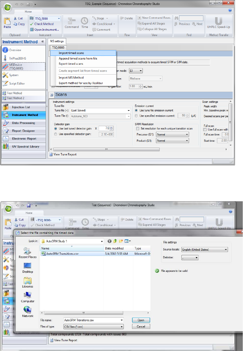
4. Under the MS Settings tab, click TSQ 8000 and select Import timed scans. See
Figure 33.
Figure 33. Selecting Import Timed Scans
5. Browse to the location where you saved the .csv file you created in AutoSRM. The
software informs you if your .csv file is valid. See Figure 34. Click Open.
Figure 34. Linking to an External .csv File
1 Using AutoSRM
Importing Transitions into the Method Editor
26 TSQ Series AutoSRM User Guide Thermo Scientific
6. Browse to the location where you saved the .csv file you created in AutoSRM. The
SIMBridge dialog box opens. Choose the language of your method file from the Source
Locale drop-down menu. See Figure 35.
Figure 35. Setting the Source Language of Method Files using SIMBridge
7. Browse to your file. See Figure 36.
Figure 36. Linking to an External File using SIM Bridge
8. Click Open to open the method in SIMBridge.
9. If necessary, change the method headings in your original file to match those in the
method editor. A green check mark appears when your method is validated. See
Figure 37.
1 Using AutoSRM
Importing Transitions into the Method Editor
Thermo Scientific TSQ Series AutoSRM User Guide 27
Figure 37. Changing Method Headings in SIMBridge
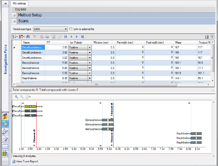
10. Click Show Analysis (see Figure 38) and review the imported list of compounds. See
Figure 39.
Figure 38. Selecting Show Analysis
Show Analysis
1 Using AutoSRM
Importing Transitions into the Method Editor
28 TSQ Series AutoSRM User Guide Thermo Scientific
Figure 39. Reviewing the Imported List
11. Adjust your scan settings as necessary. See the user guide for your instrument for more
information.
12. Once you are satisfied with your method, save it.
13. Run a set of samples to verify that the method meets your needs.
