20424_5TM_Manual_Web 20424 5TM Manual Web
User Manual: Pdf 20424_5TM_Manual_Web
Open the PDF directly: View PDF ![]() .
.
Page Count: 24

5TM
i
TABLE OF CONTENTS
1. Introduction .............................................................................................. 1
2. Operation ...................................................................................................2
2.1 Installation ................................................................................................2
2.2 Removing the Sensor .................................................................................4
2.3 Connecting .................................................................................................4
2.3.1 Connect to METER Data Logger ........................................................ 5
2.3.2 Connect to a Non-METER Data Logger ............................................. 5
2.4 Communication .........................................................................................6
3. System .........................................................................................................7
3.1 Specifications ............................................................................................7
3.2 About 5TM................................................................................................ 10
3.3 Theory ...................................................................................................... 10
3.3.1 Volumetric Water Content .............................................................. 10
3.3.2 Temperature .................................................................................. 11
4. Service ....................................................................................................... 12
4.1 Calibration ............................................................................................... 12
4.1.1 Dielectric Permittivity .................................................................... 12
4.1.2 Mineral Soil Calibration ................................................................. 12
4.1.3 Calibration in Nonsoil Media ..........................................................13
4.2 Troubleshooting ....................................................................................... 13
4.3 Customer Support....................................................................................14
4.4 Terms and Conditions .............................................................................. 15
13441-01
4.9.2018
iii
1
5TE
1. INTRODUCTION
Thank you for choosing the ECH2O 5TM Volumetric Water Content (VWC) and Temperature
sensor from METERGroup.
This manual guides the customer through the sensor features and describes how to use the
sensor successfully. METER hopes the contents of this manual are useful in understanding
the instrument and maximizing its benefit.
Prior to use, verify the 5TM arrived in good condition.

2
OPERATION
2. OPERATION
Please read all instructions before operating the 5TM to ensure it performs to its full
potential.
PRECAUTIONS
METER sensors are built to the highest standards, but misuse, improper protection, or
improper installation may damage the sensor and possibly void the manufacturer’s warranty.
Before integrating 5TM into a system, make sure to follow the recommended installation
instructions and have the proper protections in place to safeguard sensors from damage.
2.1 INSTALLATION
When selecting a site for installation, remember that the soil adjacent to the sensor surface
has the strongest influence on the sensor reading and that the sensor measures the VWC
of the soil. Therefore, any air gaps or excessive soil compaction around the sensor and in
between the sensor prongs can profoundly influence the readings.
• If installing sensors in a lightning-prone area with a grounded data logger, please read
Lightning surge and grounding practices.
• Test the sensors with the data logging device and software before going to the field.
Do not install the sensor adjacent to large metal objects such as metal poles or stakes. This
can attenuate the sensor's electromagnetic field and adversely affect readings. In addition,
the 5TM sensor should not be installed within 5 cm of the soil surface, or the sensing volume
of the electromagnetic field can extend out of the soil and reduce accuracy.
Because the 5TM has gaps between its prongs, it is also important to consider the particle
size of the medium. It is possible to get sticks, bark, roots or other material stuck between
the sensor prongs, which will adversely affect readings. Finally, be careful when inserting the
sensors into dense soil, as the prongs can break if excessive sideways force is used when
pushing them in.
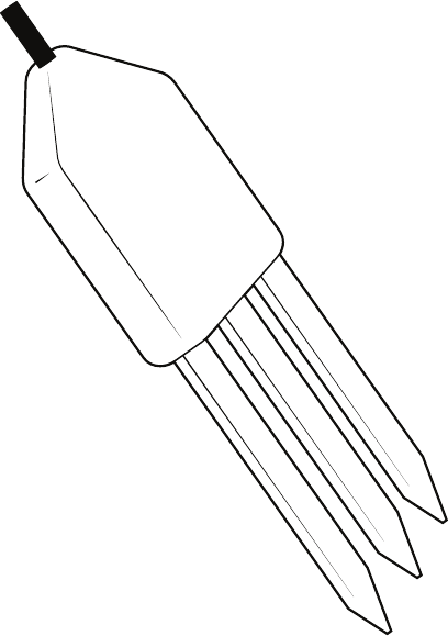
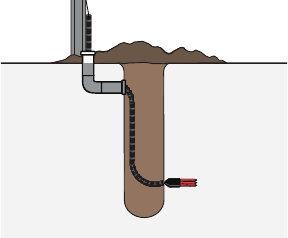
When installing the 5TM, it is imperative to maximize contact between the sensor and soil.
The sensor needs to be completely covered by soil (Figure1).
3
5TE
ERROR
OK
TEST
(–)
(+)
(–)
(+)
(–)
(+)
(+)
(–)
(+)
(–)
P1 P2 P3 P4 P5 P6
Figure1 Example of 5TE proper installation
For most accurate results, the sensor should be inserted into undisturbed soil. There are two
basic methods to accomplish a high-quality installation.
With either of these methods, the sensor may still be difficult to insert into extremely
compact or dry soil.
NOTE: Never pound the sensor into the soil! If there is difficulty inserting the sensor, loosen or wet the soil. This will
result in inaccurate VWC measurements until the water added during installing redistributes into the surrounding soil
METHOD 1. HORIZONTAL INSTALLATION
1. Excavate a hole or trench a few centimeters deeper than the depth at which the sensor
is to be installed.
2. At the installation depth, shave off some soil from the vertical soil face exposing
undisturbed soil.
3. Insert the sensor into the undisturbed soil face until the entire sensor is inserted. The tip
of each prong has been sharpened to make it easier to push the sensor into the soil. Be
careful with the sharp tips!
4. Backfill the trench taking care to pack the soil back to natural bulk density around the
sensor body of the 5TM.
METHOD 2. VERTICAL INSTALLATION
1. Auger a 3-in hole to the depth at which the sensor is to be installed.
2. Insert the sensor into the undisturbed soil at the bottom of the auger hole using a hand
or any other implement that will guide the sensor into the soil at the bottom of the hole.
Many people have used a simple piece of PVC pipe with a notch cut in the end for the
sensor to sit in, with the sensor cable routed inside the pipe.
3. After inserting the sensor, remove the installation device and backfill the hole taking
care to pack the soil back to natural bulk density while not damaging the black
overmolding of the sensor and the sensor cable in the process.
4
OPERATION
View a visual demonstration on proper installation of the sensor in How to install soil
moisture sensors.
The sensor can be oriented in any direction. However, orienting the flat side perpendicular
to the surface of the soil will minimize effects on downward water movement. The sensor
measures the average VWC along its length, so a vertical installation will integrate VWC over
a 10-cm depth while a horizontal orientation will measure VWC at a more discrete depth.
This problem occurs regardless of which logging system is being used if the ground wires
are connected at all times. If sensors must be close together (e.g., column experiments),
consider a multiplexing option that would isolate the ground wires.
If installing sensors vertically at short depth intervals, do not bury them directly over the top
of each other. Although at times the vertical distance may be less than 20 cm, the sensors
can be staggered horizontally so they are not directly above each other, thus meeting the
distance requirement.
2.2 REMOVING THE SENSOR
When removing the sensor from the soil, do not pull it out of the soil by the cable! Doing so
may break internal connections and make the sensor unusable.
2.3 CONNECTING
The 5TM works most efficiently with METER ZENTRA, EM60, or Em50 data loggers, and it
can also be used with other data loggers, such as those from Campbell Scientific, Inc.
5TM sensors require an excitation voltage in the range of 3 to 15 VDC.
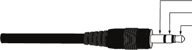
The 5TM sensors come with a 3.5-mm stereo plug connector (Figure2) to facilitate easy
connection with METER loggers. 5TM sensors may be ordered with stripped and tinned
wires to facilitate connecting to some third-party loggers (Section2.3.2).
Ground
Data
Power
Figure2 Stereo plug connector
The 5TM sensor comes standard with a 5-m cable. It may be purchased with custom cable
lengths for an additional fee (on a per-meter basis). This option eliminates the need for splicing
the cable (a possible failure point). However, the maximum recommended length is 75 m.
5
5TE
2.3.1 CONNECT TO METER DATA LOGGER
The 5TM sensor works seamlessly with METER ZENTRA, EM60, or Em50 data loggers.
Check the METER download webpage for the most recent data logger firmware. Logger
configuration may be done using either ZENTRA Utility (desktop and mobile application) or
ZENTRA Cloud (web-based application for cell-enabled ZENTRA data loggers).
1. Plug the 3.5-mm stereo plug connector into one of the sensor ports on the logger.
2. Using the appropriate software application, configure the chosen logger port for 5TM.
3. Set the measurement interval.
2.3.2 CONNECT TO A NONMETER DATA LOGGER
The 5TM sensor can be used with non-METER (third-party) data loggers. Refer to the third-
party logger manual for details on logger communications, power supply, and ground ports.
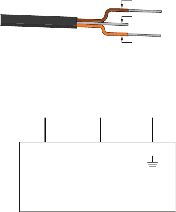
5TM sensors can be ordered with stripped and tinned (pigtail) connecting wires for use with
screw terminals. Connect the 5TM wires to the data logger as illustrated in Figure3 and
Figure4, with the power supply wire (brown) connected to the excitation, the digital out wire
(orange) to a digital input, and the bare ground wire to ground.
Ground (bare)
Data (orange)
Power (brown)
Figure3 Pigtail wiring
NOTE: Some 5TM sensors may have the older Decagon wiring scheme where the power supply is white, the digital out
is red, and the bare wire is ground.
Switched
3.6–15 VDC
Digital
In
Data Logger
G
Data
(orange)
Ground
(bare)
Power
(brown)
Figure4 Wiring diagram
NOTE: The acceptable range of excitation voltages is from 3 to 15 VDC. To read 5TM sensors with Campbell Scientific
data loggers, power the sensor from a switched 12-V port or a 12-V port if using a multiplexer.
If the 5TM cable has a standard 3.5-mm stereo plug connector and will be connected to a
non-METER data logger, please use one of the following two options.
6
OPERATION
Option 1
1. Clip off the 3.5-mm stereo plug connector on the sensor cable.
2. Strip and tin the wires.
3. Wire it directly into the data logger.
This option has the advantage of creating a direct connection with no chance of the sensor
becoming unplugged. However, it then cannot be easily used in the future with a METER
readout unit or data logger.
Option 2
Obtain an adapter cable from METER.
The adapter cable has a connector for the female stereo plug connector on one end and
three wires (or pigtail adapter) for connection to a data logger on the other end. The stripped
and tinned adapter cable wires have the same termination as seen in Figure4: the brown
wire is excitation, the orange is output, and the bare wire is ground.
NOTE: Secure the stereo plug connector to the pigtail adapter connections to ensure the sensor does not become
disconnected during use.
Because 5TM sensors use digital communication, they require special considerations
when connecting to an SDI-12 data logger. Read SDI-12 example programs to view sample
Campbell Scientific programs.
2.4 COMMUNICATION
The 5TM sensor communicates using two different methods, DDI serial and SDI-12. Please
see the 5TM Integrator Guide for detailed instructions.

7
5TE
3. SYSTEM
This section describes the 5TM sensor.
3.1 SPECIFICATIONS
MEASUREMENT SPECIFICATIONS
Volumetric Water Content (VWC)
Range
Mineral soil
calibration
0.0–1.0 m3/m3
Soilless media
calibration
0.0–1.0 m3/m3
Apparent dielectric
permittivity (εa)
1 (air) to 80 (water)
Resolution 0.0008 m3/m3 from 0%–50% VWC
Accuracy
Generic calibration ± 0.03 m3/m3 typical
Medium-specific
calibration
±0.02 m3/m3
Apparent dielectric
permittivity (εa)
1–40 (soil range), ±1 εa (unitless)
40–80, 15% measurement
Temperature
Range –40 to +60 °C
Resolution 0.1 °C
Accuracy ±1 °C
COMMUNICATION SPECIFICATIONS
Output
DDI serial or SDI-12 communication protocol
Data Logger Compatibility
Data acquisition systems capable of 3.6- to 15.0-VDC power and serial or
SDI-12communication

8
SYSTEM
PHYSICAL SPECIFICATIONS
Dimensions
Length 10.9 cm (4.3 in)
Width 3.4 cm (1.3 in)
Height 1.0 cm (0.4 in)
Prong Length
5.0 cm (1.9 in)
Operating Temperature Range
Minimum –40 °C
Typical NA
Maximum +60 °C
NOTE: Sensors may be used at higher temperatures under certain conditions; contactCustomer Support for
assistance.
Cable Length
5 m (standard)
75 m (maximum custom cable length)
NOTE: Contact Customer Support if a nonstandard cable length is needed.
Connector Types
3.5-mm stereo plug connector or stripped and tinnedwires
ELECTRICAL AND TIMING CHARACTERISTICS
Supply Voltage (VCC to GND)
Minimum 3.6 VDC
Typical NA
Maximum 15.0 VDC
Digital Input Voltage (logic high)
Minimum 2.8 V
Typical 3.0 V
Maximum 3.9 V

9
5TE
Digital Input Voltage (logic low)
Minimum –0.3 V
Typical 0.0 V
Maximum 0.8 V
Power Line Slew Rate
Minimum 1.0 V/ms
Typical NA
Maximum NA
Current Drain (during measurement)
Minimum 0.5 mA
Typical 3.0 mA
Maximum 10.0 mA
Current Drain (while asleep)
Minimum NA
Typical 0.03 mA
Maximum NA
Power-Up Time (DDI serial)
Minimum NA
Typical NA
Maximum 100 ms
Power-Up Time (SDI-12)
Minimum 100 ms
Typical 150 ms
Maximum 200 ms
Measurement Duration
Minimum NA
Typical 150 ms
Maximum 200 ms
10
SYSTEM
COMPLIANCE
Manufactured under ISO 9001:2015
EM ISO/IEC 17050:2010 (CE Mark)
3.2 ABOUT 5TM
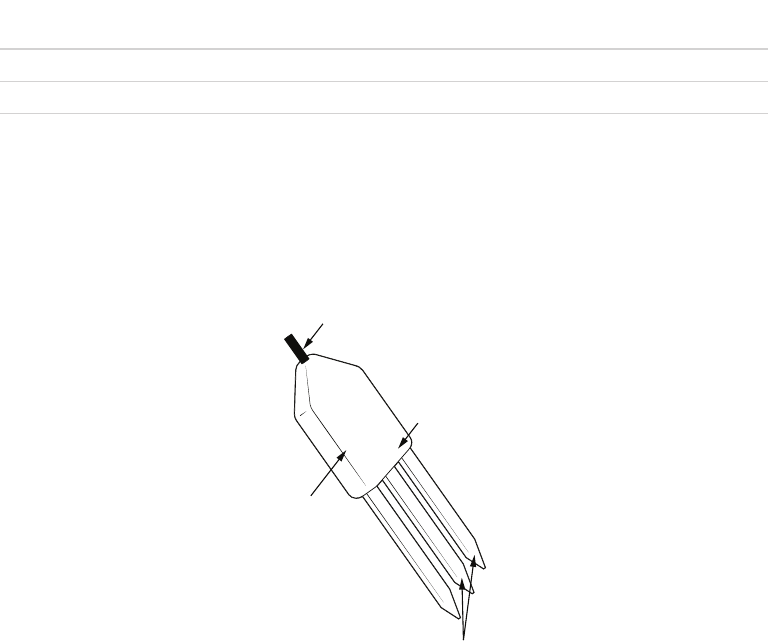
The 5TM is designed to measure the water content and temperature of soil (Figure5). The
5TM uses an oscillator running at 70 MHz to measure the dielectric permittivity of soil
to determine the water content. A thermistor in thermal contact with the sensor prongs
provides the soil temperature. The polyurethane coating on the 5TM circuit board protects
the components from water damage and gives the sensor a longer life span.
Connection cable
Thermal sensor
(thermistor)
Dielectric
VWC sensor
Polyurethane
overmolding
Figure5 5TM components
3.3 THEORY
The following sections explain the theory of VWC and temperature measured by 5TM.
3.3.1 VOLUMETRIC WATER CONTENT
The 5TM sensor uses an electromagnetic field to measure the dielectric permittivity of the
surrounding medium. The sensor supplies a 70 MHz oscillating wave to the sensor prongs
that charges according to the dielectric of the material. The stored charge is proportional
to soil dielectric and soil VWC. The 5TM microprocessor measures the charge and outputs a
value of dielectric permittivity from the sensor.
11
5TE
3.3.2 TEMPERATURE
The 5TM uses a surface-mounted thermistor to take temperature readings. The thermistor is
underneath the sensor overmold, next to one of the prongs, and it reads the temperature of
the prong surface. The 5TM outputs temperature in degrees Celsius unless otherwise stated
in the software preferences file.
If the black polyurethane overmold of the sensor body is in direct sunshine, the temperature
measurement may read high. Do not install the sensor with the overmold in the sun.
12
SERVICE
4. SERVICE
This section contains calibration and recalibration information, calibration frequencies,
cleaning and maintenance guidelines, troubleshooting guidelines, customer support contact
information, and terms and conditions.
4.1 CALIBRATION
METER software tools automatically apply factory calibrations to the sensor output data.
However, this general calibration may not be applicable for all soil types. For added accuracy
METER encourages customers to perform soil-specific calibrations.
4.1.1 DIELECTRIC PERMITTIVITY
METER factory calibrates each 5TM sensor to measure dielectric permittivity (εa) accurately
in the range of 1 (air) to 80 (water). The unprocessed raw values reported by the 5TM in
standard serial communication have units of 50εa. When used in SDI-12 communication
mode, the unprocessed values have units of εa (for 5TM board versions R2.04 and older, units
are 100εa ).
4.1.2 MINERAL SOIL CALIBRATION
Numerous researchers have studied the relationship between dielectric permittivity and
VWC in soil. As a result, numerous transfer equations that predict VWC from measured
dielectric permittivity. Use any of these various transfer equations to convert raw dielectric
permittivity data from the 5TM into VWC. If using the mineral soil calibration option in METER
ProCheck reader, DataTrac 3, or ECH2O Utility, they convert raw dielectric permittivity values
with the Topp equation (Topp et al. 1980).
Equation 1
VWC4.3 10 5.5 10 2.92 10 5.3 10
aa a
63 42 22
εε ε
=× −× +× −×
−− −−
METER tests show that in a properly installed 5TM sensor in a normal mineral soil
with saturation extract electrical conductivity <10 dS/m, the Topp equation results in
measurements within 3% VWC of the actual soil VWC. If a more accurate VWC is required,
such as working in a soil with very high EC or nonnormal mineralogy, then it may be
necessary to conduct a soil-specific calibration for the 5TM sensor to improve the accuracy
to 1% to 2% for any soil.
There are two options for soil-specific calibration.
• Follow the step-by-step instructions for calibrating soil moisture sensors in the application
note Calibrating ECH2O soil moisture probes.
• METER offers a service providing soil specific calibrations.
This calibration service also applies to soilless materials, such as compost or potting
materials. Contact Customer Support for more information.

13
5TE
4.1.3 CALIBRATION IN NONSOIL MEDIA
METER has performed calibrations with the 5TM in several nonsoil growth media. The
following are suggested calibration equations for some common materials.
Potting Soil
Equation 2
VWC2.25 10 2.06 10 7.24 10 0.247
aaa
53 32 2
εεε
=× −× +× −
−−−
Rockwool
Equation 3
VWC1.68 10 6.56 10 0.0266
aa
32 2
εε
=× +× +
−−
Perlite
Equation 4
VWC1.07 10 5.25 10 0.0685
aa
32 2
εε
=− ×+×−
−−
METER continually develops additional calibration equations for various other growth media
as opportunities arise. Contact Customer Support for the status of this ongoing research.
The 5TM can accurately read VWC in virtually any porous medium if a custom calibration is
performed (Section4.1.2). Contact Customer Support for more information.
4.2 TROUBLESHOOTING
If problems with the 5TM are encountered, they most likely manifest themselves in the form
of incorrect or erroneous readings. Review the information in Table 1 and the Troubleshooting
METER soil moisture sensors video to identify the problem. Contact Customer Support for
more information.
Table 1 Troubleshooting the 5TM
Problem Possible Solution
Sensor not responding
Check power to the sensor.
Check sensor cable and stereo plug connector integrity.
Check data logger wiring to ensure brown is power supply, orange is
digital out, and bare is ground.
NOTE: Some 5TM sensors may have the older Decagon wiring scheme where the
power supply is white, the digital out is red, and the bare wire is ground.
Sensor reading too low
(orslightly negative)
Check for air gaps around sensor needles. These could be produced
below the surface of the substrate when the needle contacts a large
piece of material and pushes it out of the way, or if the sensor is not
inserted perfectly linearly.
Ensure the calibration equation being used is appropriate for the
media type. There are significant differences between substrate
calibrations, so be sure to use the one specific to the substrate.

14
SERVICE
Table 1 Troubleshooting the 5TM (continued)
Problem Possible Solution
Sensor reading too high
Check to make sure that the media was not packed excessively or
insufficiently during sensor installation. Higher density can cause
sensor reading to be elevated.
Ensure the calibration equation being used is appropriate for the media
type. There are significant differences between calibrations, so be sure
to use the one most suitable to the substrate, or consider developing a
substrate-specific calibration for the particular medium.
Some substrates have an inherently high dielectric permittivity (soils
of volcanic origin or high titanium, for instance). If the substrate has a
dry dielectric permittivity above 6, a custom calibration may need to
be performed. Soils with a bulk EC >10 dS/m require substrate-specific
calibrations (Section4.1).
Cable or stereo plug
connectorfailure
If a stereo plug connector is damaged or needs to be replaced, contact
Customer Support for a replacement connector and splice kit.
If a cable is damaged, follow these guidelines for wire splicing and
sealing techniques.
4.3 CUSTOMER SUPPORT
Customer service representatives are available for questions, problems, or feedback Monday
through Friday, 7 am–5 pm Pacific time.
Email: support.environment@metergroup.com
sales.environment@metergroup.com
Phone: +1.509.332.5600
Fax: +1.509.332.5158
Website: metergroup.com
If contacting METER by email, please include the following information:
Name
Address
Phone
Email address
Instrument serial number
Description of the problem
NOTE: For 5TM sensors purchased through a distributor, please contact the distributor directly forassistance.
15
5TE
4.4 TERMS AND CONDITIONS
CONTRACT FORMATION. All requests for goods and/or services by METER Group, Inc. USA
(METER) are subject to the customer’s acceptance of these Terms and Conditions. The
Buyer will be deemed to have irrevocably accepted these Terms and Conditions of Sale
upon the first to occur of the Buyer’s issuance of a purchase order or request for goods or
services. Unless expressly assented to in writing by METER, terms and conditions different
are expressly rejected. No course of dealing between the parties hereto shall be deemed to
affect or to modify, amend, or discharge any provisions of this agreement.
PRICES AND PAYMENT. Invoice prices will be based upon METER prices as quoted or at
METER list price in effect at the time an order is received by the Seller. Prices do not include
any state or federal taxes, duties, fees, or charges now or hereafter enacted applicable to the
goods or to this transaction, all of which are the responsibility of the Buyer. Unless otherwise
specified on the invoice, all accounts are due and payable 30 days from the date of invoice.
Unpaid accounts extending beyond 30 days will be subject to a service charge of 2% per
month (24% per annum). Should Seller initiate any legal action or proceeding to collect on
any unpaid invoice, Seller shall be entitled to recover from Buyer all costs and expenses
incurred in connection therewith, including court costs and reasonable attorney’s fees.
RISK OF LOSS AND DELIVERY TITLE. Liability for loss or damage passes to the Buyer when
the Seller delivers the goods on the Seller’s dock or to the transporting agent, whichever
occurs first. The Seller has the right to deliver the goods in installments. Shipping and
delivery dates communicated by the Seller to the Buyer are approximate only.
SHIPMENT. In the absence of specific shipping instructions, the Seller, if and as requested
by the Buyer, will ship the goods by the method the Seller deems most advantageous. Where
the Seller ships the goods, the Buyer will pay all transportation charges that are payable on
delivery or, if transportation charges are prepaid by the Seller, the Buyer will reimburse the
Seller upon receipt of an invoice from the Seller. The Buyer is obligated to obtain insurance
against damage to the goods being shipped. Unless otherwise specified, the goods will be
shipped in the standard Seller commercial packaging. When special packing is required or, in
the opinion of the Seller, required under the circumstances, the cost of the special packaging
shall be the responsibility of the Buyer.
INSPECTION AND ACCEPTANCE. Goods will be conclusively deemed accepted by the
Buyer unless a written notice setting out the rejected goods and the reason for the
rejection is sent by the Buyer to the Seller within 10 days of delivery of the goods. The
Buyer will place rejected goods in safe storage at a reasonably accessible location for
inspection by the Seller.
CUSTOM GOODS. There is no refund or return for custom or nonstandard goods.
WARRANTIES. The Seller warrants all equipment manufactured by it to be free from
defects in parts and labor for a period of one year from the date of shipment from factory.
The liability of the Seller applies solely to repairing, replacing, or issuing credit (at the
Seller’s sole discretion) for any equipment manufactured by the Seller and returned by the
Buyer during the warranty period. SELLER MAKES NO SEPARATE OR OTHER WARRANTY
16
SERVICE
OF ANY NATURE WHATSOEVER, EXPRESS OR IMPLIED, INCLUDING THE WARRANTY OF
MERCHANTABILITY OR FOR A PARTICULAR PURPOSE. There shall be no other obligations
either expressed or implied.
LIMITATION OF LIABILITY. Seller will not be liable to the Buyer or any other person or entity
for indirect special, incidental, consequential, punitive, or exemplary damages in connection
with this transaction or any acts or omissions associated therewith or relating to the sale
or use of any goods, whether such claim is based on breach of warranty, contract, tort, or
other legal theory and regardless of the causes of such loss or damages or whether any other
remedy provided herein fails. In no event will the Seller’s total liability under this contract
exceed an amount equal to the total amount paid for the goods purchased hereunder.
WAIVER. In the event of any default under or breach of the contract by the Buyer, the Seller
has the right to refuse to make further shipments. The Seller’s failure to enforce at any time
or for any period of time the provisions of this contract will not constitute a waiver of such
provisions or the right of the Seller to enforce each and every provision.
GOVERNING LAW. The validity, construction, and performance of the contract and the
transactions to which it relates will be governed by the laws of the United States of America.
All actions, claims, or legal proceedings in any way pertaining to this contract will be
commenced and maintained in the courts of Whitman County, State of Washington, and the
parties hereto each agree to submit themselves to the jurisdiction of such court.
SEVERABILITY. If any of the Terms and Conditions set out in this contact are declared
to be invalid by a court, agency, commission, or other entity having jurisdiction over the
interpretation and enforcement of this contract, the applications of such provisions to
parties or circumstances other than those as to which it is held invalid or unenforceable
will not be affected. Each term not so declared invalid or unenforceable will be valid
and enforced to the fullest extent permitted by law and the rights and obligations of the
parties will be construed and enforced as though a valid commercially reasonable term
consistent with the undertaking of the parties under the order has been substituted in
place of the invalid provision.
SET-OFF. The Buyer may not set-off any amount owing from the Seller to the Buyer against
any amount payable by the Buyer to the Seller whether or not related to this contract
17
5TE
REFERENCES
Hilhorst MA. 2000. A pore water conductivity sensor. Soil Sci Soc Am J. 64(6): 19221925.
Topp GC, David JL, and Annan AP. 1980. Electromagnetic, Determination of Soil Water
Content: Measurement in Coaxial Transmission Lines. Water Resour Res 16(3): 574582.
INDEX
18
INDEX
A
accuracy 7
C
cable length 8
calibration 12–13
cleaning 13
communication 6, 7
compliance 10
connecting
METER data logger 5
non-METER logger 5–6
connector types 8
customer support 14
D
data logger 4–6, 7
dielectric permittivity 7, 10, 12
E
email 14
I
installation 2
horizontal 3–4
vertical 3
integrator's guide 6
M
measurements 7–9
mineral soil calibration 12
O
orientation 4
P
particle size 2
power requirements 8
R
range 7
references 17
S
specifications 7–10
communication 7
data logger compatibility 7
electrical and timing 8–9
measurement 7
physical 8
T
temperature 7, 8, 11
terms and conditions 15–17
theory 10–13
troubleshooting 13
V
volumetric water content 7, 10
W
wiring 5–6
Z
ZENTRA
ZENTRA Cloud 5
ZENTRA Utility 5
14563-01
4.9.2018
METER Group, Inc. USA
2365 NE Hopkins Court
Pullman, WA 99163
T: +1.509.332.5600 F: +1.509.332.5158
E: info@metergroup.com
W: metergroup.com
© 2013, 2018 All Rights Reserved.

