Product Detail Manual
549745-Attachment 549745-Attachment 549745-Attachment 078275 Batch5 unilog cesco-content
107036-Attachment 1 107036-Attachment_1 107036-Attachment_1 Batch9 unilog cesco-content
2014-06-02
: Pdf 221736-Attachment 221736-Attachment 078275 Batch4 unilog
Open the PDF directly: View PDF ![]() .
.
Page Count: 4
Project:
Location:
Product Type:
Contact/Phone:
Model #:
Energy Controls
FF Series
FF Series
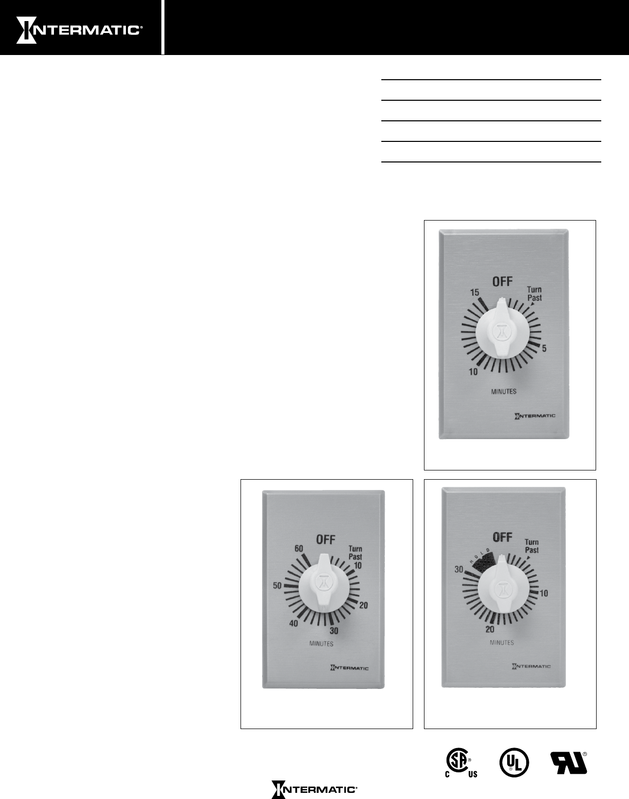
Commercial Series
The FF Series Commercial Auto-Off Timers are designed to replace
any standard wall switch - single or multi-gang. This series of
energy-efcient mechanical timers do not require electricity to
operate. In addition, they automatically limit the ON times for fans,
lighting, motors, heaters, and other energy consuming loads.
Features
• Hold feature enables the user to override the automatic
shut-off function
• Rugged time dial plate easily withstands the abuse encountered in
commercial environments
• Commercial “brushed metal” (plastic construction) look meets
NEC requirements
• Time saving up front terminal connection with teeter-type terminals
• Press-on knob design ensures quick and easy installation
• CFL compatible
Not for use with sunlamps, saunas, or loads that could cause
personal injury if timed incorrectly.
Ratings
Resistive: 20 Amp, 125 VAC, 50/60 Hz
10 Amp, 250 VAC, 50/60 Hz
10 Amp, 277 VAC, 50/60 Hz
Tungsten: 7 Amp, 125 VAC
Motor: 1 HP, 120 VAC, 50/60 Hz
2 HP, 240 VAC, 50/60 Hz
Dimensions: 2.79" H x 1.6" W x 1.19" D
FF15MC
FF30MH
FF60MC
Auto-Off Timers

www.intermatic.com
Energy Controls
FF Series
Model Number Time Cycle Switch Hold Color
FF5M 5 Minutes SPST No Brushed Metal Finish
FF5MH 5 Minutes SPST Yes Brushed Metal Finish
FF15MC 15 Minutes SPST No Brushed Metal Finish
FF15MH 15 Minutes SPST Yes Brushed Metal Finish
FF30MC 30 Minutes SPST No Brushed Metal Finish
FF30MH 30 Minutes SPST Yes Brushed Metal Finish
FF60MC 60 Minutes SPST No Brushed Metal Finish
FF60MHC 60 Minutes SPST Yes Brushed Metal Finish
FF2H 2 Hours SPST No Brushed Metal Finish
FF4H 4 Hours SPST No Brushed Metal Finish
FF6H 6 Hours SPST No Brushed Metal Finish
FF6HH 6 Hours SPST Yes Brushed Metal Finish
FF12HC 12 Hours SPST No Brushed Metal Finish
FF12HHC 12 Hours SPST Yes Brushed Metal Finish
FF315M 15 Minutes SPDT No Brushed Metal Finish
FF330M 30 Minutes SPDT No Brushed Metal Finish
FF360M 60 Minutes SPDT No Brushed Metal Finish
FF32H 2 Hours SPDT No Brushed Metal Finish
FF32HH 2 Hours SPDT Yes Brushed Metal Finish
FF34H 4 Hours SPDT No Brushed Metal Finish
FF34HH 4 Hours SPDT Yes Brushed Metal Finish
FF36H 6 Hours SPDT No Brushed Metal Finish
FF312H 12 Hours SPDT No Brushed Metal Finish
FF312HH 12 Hours SPDT Yes Brushed Metal Finish
FF415M 15 Minutes DPST No Brushed Metal Finish
FF430M 30 Minutes DPST No Brushed Metal Finish
FF460M 60 Minutes DPST No Brushed Metal Finish
FF46H 6 Hours DPST No Brushed Metal Finish
FF412H 12 Hours DPST No Brushed Metal Finish
Specification
The timer shall be of the appropriate dimensions and design to provide for direct replacement of a standard wall switch
in a single gang 2 ½" deep junction box. The timer shall include a spiral time scale to provide easy selection of a desired
time setting. Molded white knob and brushed metal nish wall plate shall be a press-on type requiring no screw or other
hardware to secure. The polymeric time dial shall replace a standard switch plate without modications. The timer shall
have a UL listed rating of:
• 1 HP at 125 VAC, 50/60 Hz
• 2 HP at 250 VAC, 50/60 Hz
• 20 Amp, 120 VAC, 50/60 Hz
• 10 Amp, 250 VAC, 50/60 Hz
• 10 Amp, 277 VAC, 50/60 Hz
• 7 Amp, 125 VAC, Tungsten
The timer eld wiring connections shall be secured by means of a teeter-type terminal screw to provide secure
connections for appropriate wire sizes. The timer shall be ___________ (SPST)(DPST)(SPDT). The timer __________ (Shall)
(Shall Not) have a Hold feature and shall have a time cycle of ___________(See Time Cycles Listed). The timer shall be
Intermatic model _______________(See Model Numbers Listed).
Energy Controls
FF Series
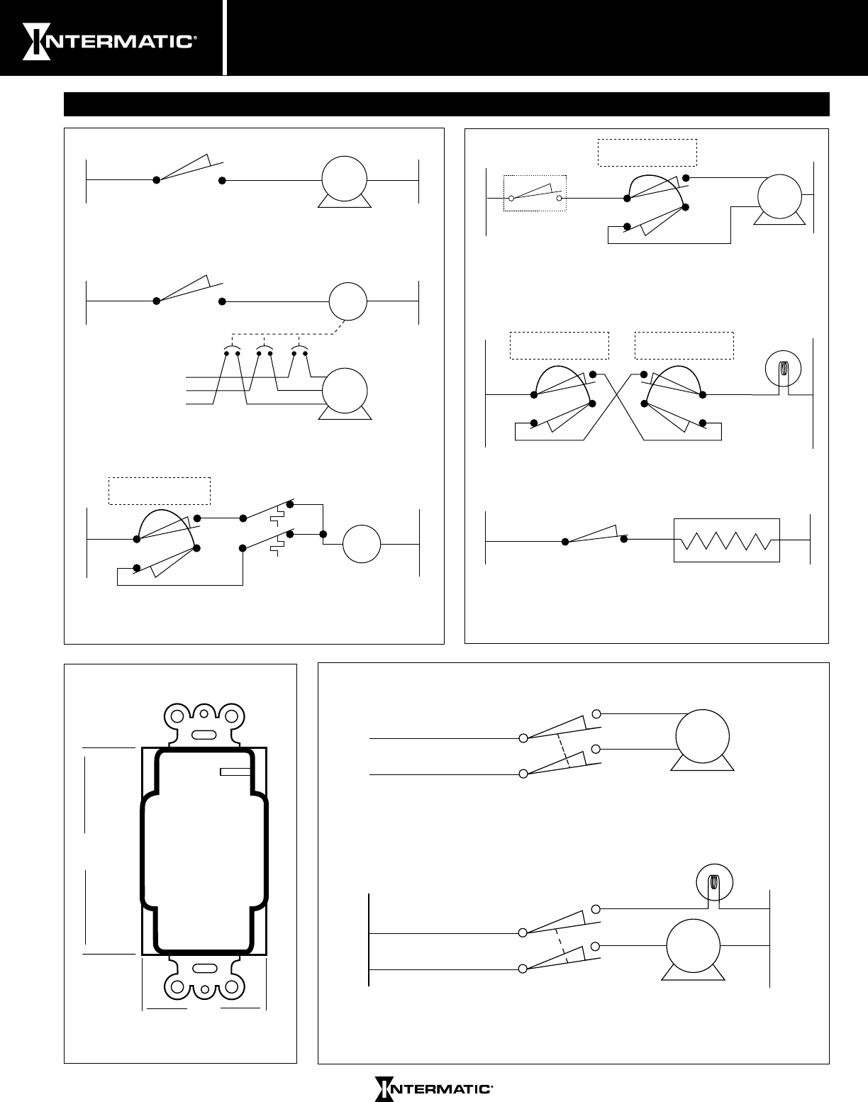
Diagrams
Example for SPST motor load control.
Example for SPST large motor load control
using a 3-pole contactor or motor starter.
Example for control of low voltage set-back
set-up thermostats using SPDT timer.
LOAD
LOAD
CR1
CR1
24
VAC
Hot Neutral
Load 1Line 1
Load 1Line 1
Load 1
Jumper From
Line 2 To Line 1
Load 2
Line 1
Line 2
Hot Neutral
Hot Neutral
Load
Supply
55º
72º
STRIP
GAUGE
2.79"
1.60"
[7.09cm]
[4.06cm]
Example for 3-way load control providing
timed override from more than one location.
Example for reverse action control. The load
is switched off when timer is operated for a
limited time then switches back on.
Example for timed selection of low or high
speed motor with optional timer to limit
operation time regardless of speed selected.
Load 1
Load 2
Line 1
Optional Line 2
High
Low
Neutral
Hot
Load 2
Line 2
No Connections Required
For Line 1 and Load 1
Hot
Load 1
Load 2
Line 1
Line 2
Line 2
Hot Neutral
Neutral
Load 2
Line 1
Solder Pot
Jumper From
Line 2 To Line 1 Jumper From
Line 2 To Line 1
Jumper From
Line 2 To Line 1
LOAD
Example for controlling two loads
simultaneously by using DPST contacts.
Example for breaking both sides of a 240 volt
load using DPST contacts.
240 VAC
120 VAC
120 VAC
Line 1
Load 1
Load 2
Line 2
Hot Neutral
Line 1
Load 1
Load 2
Line 2 LOAD
LOAD

www.intermatic.com
Energy Controls
Notes
FF Series
