232144 Catalog
102156-Catalog 102156-Catalog 102156-Catalog 016843 Batch8 unilog cesco-content
108596-Attachment 108596-Attachment 108596-Attachment 016843 Batch8 unilog cesco-content
2014-09-05
: Pdf 232144-Catalog 232144-Catalog 016843 Batch7 unilog
Open the PDF directly: View PDF ![]() .
.
Page Count: 250 [warning: Documents this large are best viewed by clicking the View PDF Link!]
- 01-026-38
- 01-026-40
- 01-028-38
- 01-028-40
- 01-031-38
- 01-031-40
- 01-034-38
- 01-034-40
- 01-038-38
- 01-038-40
- 01-057-38
- 01-057-40
- 01-059-38
- 01-059-40
- 01-062-38
- 01-062-40
- 01-065-38
- 01-065-40
- 01-069-38
- 01-069-40
- 01-073-38
- 01-073-40
- 01-075-40
- 01-077-40
- 01-081-40
- 01-083-40
- 01-085-40
- 01-092-38
- 01-092-40
- 01-094-38
- 01-094-40
- 01-097-38
- 01-097-40
- 01-100-38
- 01-100-40
- 01-104-38
- 01-104-40
- 01-108-38
- 01-108-40
- 01-110-38
- 01-110-40
- 01-112-40
- 01-116-40
- 01-118-40
- 01-120-40
- 01-121-40
- 01-124-40
- 01-125-40
- 01-126-40
- 1A006xx01
- 1A006xxM1
- 1A012xx01
- 1A012xxM1
- 1A024xx01
- 1A024xxM1
- 1A036xx01
- 1A036xxM1
- 1A048xx01
- 1A048xxM1
- 1A072xx01
- 1A072xxM1
- 1A096xx01
- 1A096xxM1
- 1A120xxM1
- 1A144xx01
- 1A216xx01
- 1A288xx01
- 1C006xx01
- 1C012xx01
- 1C024xx01
- 1C036xx01
- 1C048xx01
- 1C072xx01
- 1C096xx01
- 1C144xx01
- 1C216xx01
- 1D006xx01
- 1D012xx01
- 1D024xx01
- 1D036xx01
- 1D048xx01
- 1D072xx01
- 1D096xx01
- 1D144xx01
- 1D216xx01
- 1F006x111
- 1F006x121
- 1F006x141
- 1F012x111
- 1F012x121
- 1F012x141
- 1F024x111
- 1F024x121
- 1F024x141
- 1F048x111
- 1F048x121
- 1F048x141
- 1F096x111
- 1F096x121
- 1F096x141
- 1F144x111
- 1F144x121
- 1F144x141
- 1F288x111
- 1F288x121
- 1F288x141
- 1G006xx01
- 1G006xxM1
- 1G012xx01
- 1G012xxM1
- 1G024xx01
- 1G024xxM1
- 1G036xx01
- 1G036xxM1
- 1G048xx01
- 1G048xxM1
- 1G072xx01
- 1G072xxM1
- 1G096xx01
- 1G096xxM1
- 1G120xxM1
- 1G144xx01
- 1G216xx01
- 1G288xx01
- 1H006xx01
- 1H012xx01
- 1H024xx01
- 1H036xx01
- 1H048xx01
- 1H072xx01
- 1H096xx01
- 1H144xx01
- 1H216xx01
- 1N012xx01
- 1N024xx01
- 1N036xx01
- 1N048xx01
- 02-001-13
- 02-002-13
- 02-004-13
- 02-005-13
- 02-006-13
- 02-006-13
- 02-006-23
- 02-010-23
- 02-011-23
- 02-020-23
- 02-021-23
- 02-022-23
- 02-024-23
- 02-031-23
- 02-032-13
- 02-032-23
- 02-033-23
- 02-041-13
- 02-050-13
- 02-050-23
- 02-051-13
- 02-052-13
- 02-053-13
- 02-054-13
- 02-062-03
- 02-065-03
- 02-069-03
- 02-073-03
- 02-075-03
- 02-077-03
- 02-081-03
- 02-097-03
- 02-097-61
- 02-098-61
- 02-100-03
- 02-100-61
- 02-102-13
- 02-104-03
- 02-104-61
- 02-106-03
- 02-108-03
- 02-110-03
- 02-110-23
- 02-111-13
- 02-111-23
- 02-112-03
- 02-113-13
- 02-113-23
- 02-114-13
- 02-116-03
- 02-118-03
- 02-120-03
- 02-120-13
- 02-121-03
- 02-124-03
- 02-125-03
- 02-126-03
- 02-131-23
- 02-132-23
- 02-201-61
- 02-203-61
- 02-211-23
- 02-221-13
- 02-222-13
- 02-223-13
- 02-224-13
- 02-311-23
- 02-350-23
- 02-360-23
- 02-361-23
- 02-362-23
- 02-401-13
- 02-409-13
- 02-431-10
- 02-450-13
- 02-513-13*
- 02-514-13*
- 02-702-13*
- 02-706-13*
- 02-810-10
- 02-811-10
- 02-813-10
- 02-815-10
- 02-820-10
- 02-832-10
- 02-840-10
- 02-841-10
- 02-D02-13
- 02-D06-13
- 02-D30-13
- 02-E02-13
- 02-G11-13
- 02-G16-13
- 02-G50-13
- 02-H13-13
- 03-H12-13
- 04-001-54
- 04-001-55
- 04-001-58
- 04-001-64
- 04-001-65
- 04-001-68
- 04-002-54
- 04-002-55
- 04-002-58
- 04-002-64
- 04-002-65
- 04-002-68
- 04-003-54
- 04-003-55
- 04-003-58
- 04-003-64
- 04-003-65
- 04-003-68
- 04-022-16*
- 04-023-85
- 04-025-16*
- 04-025-85
- 04-026-04
- 04-026-21
- 04-026-27
- 04-026-94
- 04-028-04
- 04-028-21
- 04-028-27
- 04-028-94
- 04-031-04
- 04-031-21
- 04-031-27
- 04-031-94
- 04-034-04
- 04-034-21
- 04-034-27
- 04-034-94
- 04-038-04
- 04-038-21
- 04-038-27
- 04-038-94
- 04-052-17
- 04-052-84
- 04-053-17
- 04-053-84
- 04-055-17
- 04-055-84
- 04-056-17
- 04-056-84
- 04-057-04
- 04-057-16*
- 04-057-17
- 04-057-21
- 04-057-27
- 04-057-85
- 04-057-94
- 04-058-17
- 04-058-84
- 04-058-85
- 04-059-04
- 04-059-21
- 04-059-27
- 04-059-94
- 04-061-85
- 04-062-04
- 04-062-16*
- 04-062-21
- 04-062-27
- 04-062-84
- 04-062-94
- 04-065-04
- 04-065-21
- 04-065-27
- 04-065-94
- 04-067-16*
- 04-069-04
- 04-069-21
- 04-069-27
- 04-069-94
- 04-073-04
- 04-073-21
- 04-073-27
- 04-073-94
- 04-075-04
- 04-075-21
- 04-075-27
- 04-077-04
- 04-077-21
- 04-077-27
- 04-081-04
- 04-081-21
- 04-081-27
- 04-083-04
- 04-083-21
- 04-083-27
- 04-091-16
- 04-092-04
- 04-092-21
- 04-092-27
- 04-092-94
- 04-094-04
- 04-094-16
- 04-094-21
- 04-094-27
- 04-094-94
- 04-097-04
- 04-097-21
- 04-097-27
- 04-097-31
- 04-097-37
- 04-097-85
- 04-097-94
- 04-098-85
- 04-100-04
- 04-100-21
- 04-100-27
- 04-100-94
- 04-101-85
- 04-104-04
- 04-104-21
- 04-104-27
- 04-104-31
- 04-104-37
- 04-104-94
- 04-108-04
- 04-108-21
- 04-108-27
- 04-108-94
- 04-110-04
- 04-110-21
- 04-110-27
- 04-110-94
- 04-112-04
- 04-112-21
- 04-112-27
- 04-112-94
- 04-116-04
- 04-116-21
- 04-116-27
- 04-116-94
- 04-118-04
- 04-118-21
- 04-118-27
- 04-118-94
- 04-120-04
- 04-120-21
- 04-120-27
- 04-121-04
- 04-121-21
- 04-121-27
- 04-124-04
- 04-124-21
- 04-124-27
- 04-601-54
- 04-601-55
- 04-601-58
- 04-601-64
- 04-601-65
- 04-601-68
- 5F-220-x5
- 5F-220-x8
- 5V0063061
- 5V0063121
- 5V0123121
- 5V0123251
- 5V0183181
- 5V0243251
- 5W002301Q
- 5W002302Q
- 5W002303Q
- 5W004301Q
- 6A-272-xA
- 6A-272-xB
- 6F-272-xA
- 6F-272-xB
- 6H-272-xA
- 6H-272-xB
- 6S-220-xA
- 6S-220-xB
- 6T-272-xA
- 6T-272-xB
- 07-021-51
- 07-021-52
- 07-021-53
- 07-021-54
- 07-021-55
- 07-021-56
- 07-021-57
- 07-021-58
- 07-021-59
- 07-021-68
- 07-021-69
- 07-021-70
- 07-021-71
- 07-021-72
- 07-021-73
- 07-021-74
- 07-021-75
- 07-021-76
- 07-021-77
- 07-021-90
- 07-021-98
- 07-021-99
- 07-022-08
- 07-022-11
- 07-022-12
- 07-024-74
- 7A-421-03
- 7A-621-03
- 09-026-02
- 09-026-92
- 09-028-02
- 09-028-92
- 09-031-02
- 09-031-77
- 09-031-92
- 09-034-02
- 09-034-05
- 09-034-77
- 09-034-92
- 09-038-02
- 09-038-77
- 09-038-92
- 09-057-02
- 09-057-05
- 09-057-92
- 09-059-02
- 09-059-05
- 09-059-92
- 09-062-02
- 09-062-05
- 09-062-77
- 09-062-92
- 09-065-02
- 09-065-05
- 09-065-77
- 09-065-92
- 09-069-02
- 09-069-77
- 09-069-92
- 09-073-02
- 09-073-77
- 09-073-92
- 09-075-02
- 09-075-77
- 09-075-92
- 09-077-02
- 09-077-77
- 09-077-92
- 09-081-02
- 09-081-77
- 09-081-92
- 09-083-02
- 09-083-77
- 09-083-92
- 09-085-02
- 09-085-77
- 09-085-92
- 09-087-02
- 09-092-02
- 09-092-05
- 09-092-92
- 09-094-02
- 09-094-05
- 09-094-92
- 09-097-02
- 09-097-05
- 09-097-77
- 09-097-92
- 09-100-02
- 09-100-05
- 09-100-77
- 09-100-92
- 09-104-02
- 09-104-05
- 09-104-77
- 09-104-92
- 09-108-02
- 09-108-05
- 09-108-77
- 09-108-92
- 09-110-02
- 09-110-05
- 09-110-77
- 09-110-92
- 09-112-02
- 09-112-77
- 09-112-92
- 09-116-02
- 09-116-77
- 09-116-92
- 09-118-02
- 09-118-77
- 09-118-92
- 09-120-02
- 09-120-77
- 09-120-92
- 09-121-02
- 09-121-77
- 09-121-92
- 09-124-02
- 09-124-77
- 09-124-92
- 09-125-02
- 09-125-77
- 09-125-92
- 09-126-02
- 09-126-92
- 09-132-02
- 09-132-77
- 09-135-02
- 09-135-77
- 09-139-02
- 09-139-77
- 09-143-02
- 09-143-77
- 09-145-02
- 09-145-77
- 09-147-02
- 09-147-77
- 09-151-02
- 09-151-77
- 09-153-02
- 09-153-77
- 09-155-02
- 09-155-77
- 09-156-02
- 09-156-77
- 09-157-02
- 09-157-77
- 09-158-77
- 09-159-02
- 09-159-77
- 09-164-02
- 10-001-15
- 10-002-15
- 10-002-17
- 10-002-34
- 10-002-34
- 10-003-15
- 10-003-17
- 10-004-17
- 10-006-15
- 10-006-17
- 10-006-19
- 10-006-34
- 10-012-15
- 10-012-17
- 10-012-19
- 10-012-35
- 10-012-35
- 10-016-06
- 10-018-17
- 10-026-06
- 10-040-29
- 10-061-29
- 10-096-06
- 10-102-34
- 10-102-34
- 10-102-35
- 10-102-35
- 10-106-34
- 10-106-34
- 10-116-06
- 10-206-34
- 10-206-34
- 10-212-35
- 10-212-35
- 10-261-38
- 10-261-38
- 10-262-38
- 10-262-38
- 10-265-38
- 10-265-38
- 10-281-38
- 10-281-38
- 10-284-38
- 10-284-38
- 10-285-38
- 10-285-38
- 10-306-34
- 10-306-34
- 10-503-34
- 10-503-34
- 10-921-38
- 10-921-38
- 10-923-38
- 10-923-38
- 11-001-02
- 11-001-03
- 11-002-87
- 11-002-88
- 11-002-89
- 11-003-12
- 11-003-13
- 11-003-30
- 11-003-45
- 11-003-46
- 11-003-47*
- 11-003-53
- 11-003-55*
- 11-003-65
- 11-003-66
- 11-003-91
- 11-003-92
- 11-005-90
- 12-001-04
- 12-001-11
- 12-001-12
- 12-001-13
- 12-002-11
- 12-003-11
- 12-003-12
- 12-003-13
- 12-004-08
- 12-004-11
- 12-004-12
- 12-005-12
- 12-005-13
- 12-006-08
- 12-007-08
- 12-008-08
- 12-009-08
- 12-010-08
- 12-011-04
- 12-013-08
- 12-014-08
- 12-015-08
- 12-016-04
- 12-018-04
- 12-019-08
- 12-021-09
- 12-022-08
- 12-022-09
- 12-023-08
- 12-023-09
- 12-024-08
- 12-025-08
- 12-026-08
- 12-031-08
- 12-031-12
- 12-032-08
- 12-032-13
- 12-033-13
- 12-034-13
- 12-035-13
- 12-041-09
- 12-042-09
- 12-043-09
- 12-101-04
- 12-101-13
- 12-102-04
- 12-102-13
- 12-103-13
- 12-104-04
- 12-104-13
- 12-105-04
- 12-105-13
- 12-106-04
- 12-106-13
- 12-107-04
- 12-107-13
- 12-108-13
- 12-109-13
- 12-111-04
- 12-112-04
- 12-112-13
- 12-121-04
- 12-122-04
- 12-123-04
- 12-140-03
- 12-201-15
- 12-202-15
- 12-202-37
- 12-203-13
- 12-203-15
- 12-203-37
- 12-204-15
- 12-204-37
- 12-205-15
- 12-206-15
- 12-206-32
- 12-207-15
- 12-208-15
- 12-209-15
- 12-210-15
- 12-211-15
- 12-212-32
- 12-212-T5
- 12-213-32
- 12-213-T5
- 12-214-37
- 12-214-T5
- 12-215-T5
- 12-216-15
- 12-220-03
- 12-262-01
- 12-301-07
- 12-301-15
- 12-302-07
- 12-303-07
- 12-303-13
- 12-303-62*
- 12-304-07
- 12-304-13
- 12-305-07
- 12-305-13
- 12-311-13
- 12-311-36
- 12-313-13
- 12-318-13
- 12-322-36
- 12-326-11
- 12-331-36
- 12-401-15
- 12-402-15
- 12-402-37
- 12-403-13
- 12-403-15
- 12-403-37
- 12-404-37
- 12-406-13
- 12-412-32
- 12-414-32
- 12-414-52
- 12-415-52
- 12-416-52
- 12-417-52
- 12-501-07
- 12-501-13
- 12-519-08
- 12-642-01
- 12-801-08
- 12-802-08
- 12-805-62*
- 12-825-62*
- 12-842-01
- 12-901-04
- 12-902-04
- 12-903-04
- 12-904-04
- 12-905-04
- 12-907-04
- 18-041-36
- 18-042-13
- 18-042-33
- 18-141-13
- 18-141-33
- 18-141-36
- 18-241-13
- 18-241-23
- 18-241-26
- 18-241-33
- 18-241-36
- 18-241-43
- 18-241-46
- 18-241-56
- 18-341-13
- 18-341-33
- 18-341-36
- 18-341-46
- 18-475-13
- 18-475-33
- 18-475-36
- 18-475-46
- 18-499-13
- 18-499-33
- 18-499-36
- 18-499-46
- 18-579-13
- 18-579-33
- 18-579-36
- 18-599-13
- 18-599-33
- 18-599-36
- 18-789-13
- 18-789-33
- 18-799-36
- 18-799-46
- 18-872-13
- 18-872-33
- 18-872-46
- 18-A99-33
- 18-A99-36
- 18-B99-33
- 18-B99-36
- 18-B99-46
- 18-C99-33
- 18-C99-36
- 18-D99-33
- 19-083-01
- 19-085-01
- 19-116-01
- 19-116-01
- 19-118-01
- 19-120-01
- 19-121-01
- 19-124-01
- 19-125-01
- 19-126-01
- 19-151-01
- 19-153-01
- 19-155-01
- 19-156-01
- 19-157-01
- 19-158-01
- 19-159-01
- 19-161-01
- 19-162-01
- 19-164-01
- 19-167-01
- 20-031-05
- 20-031-42
- 20-034-05
- 20-034-42
- 20-038-05
- 20-038-42
- 20-042-42
- 20-044-42
- 20-046-42
- 20-062-05
- 20-062-20
- 20-062-42
- 20-062-43
- 20-065-05
- 20-065-20
- 20-065-42
- 20-065-43
- 20-069-05
- 20-069-20
- 20-069-42
- 20-069-43
- 20-073-05
- 20-073-42
- 20-075-05
- 20-075-42
- 20-077-05
- 20-077-42
- 20-081-05
- 20-081-42
- 20-083-05
- 20-083-42
- 20-097-05
- 20-097-20
- 20-097-42
- 20-097-43
- 20-100-05
- 20-100-20
- 20-100-42
- 20-100-43
- 20-104-05
- 20-104-20
- 20-104-42
- 20-104-43
- 20-108-05
- 20-108-20
- 20-108-42
- 20-108-43
- 20-110-05
- 20-110-42
- 20-112-05
- 20-112-42
- 20-116-05
- 20-116-42
- 20-118-05
- 20-118-42
- 20-120-05
- 20-120-42
- 20-121-05
- 20-121-42
- 20-124-05
- 20-124-42
- 20-145-05
- 20-145-20
- 20-145-42
- 20-147-05
- 20-147-42
- 20-151-05
- 20-151-42
- 20-153-05
- 20-153-42
- 20-155-05
- 20-155-42
- 20-156-05
- 20-156-42
- 20-157-05
- 20-157-42
- 20-158-05
- 20-158-42
- 20-159-05
- 20-161-05
- 20-161-42
- 20-162-42
- 21-062-48
- 21-065-48
- 21-069-48
- 21-073-48
- 21-075-48
- 22-031-83
- 22-034-83
- 22-038-83
- 22-042-83
- 22-044-83
- 22-062-83
- 22-065-83
- 22-069-83
- 22-073-83
- 22-075-83
- 22-077-83
- 22-081-83
- 22-083-83
- 22-085-83
- 22-097-83
- 22-100-83
- 22-104-83
- 22-108-83
- 22-110-83
- 22-112-83
- 22-116-83
- 22-118-83
- 22-120-83
- 22-121-83
- 22-124-83
- 22-125-83
- 22-132-83
- 22-135-83
- 22-139-83
- 22-143-83
- 22-145-83
- 22-147-83
- 22-151-83
- 22-153-83
- 22-155-83
- 22-156-83
- 22-157-83
- 22-158-83
- 22-159-83
- 22-161-83
- 22-162-83
- 24-417-83
- 24-440-05
- 24-440-83
- 24-456-05
- 24-456-83
- 24-472-05
- 24-472-83
- 24-493-05
- 24-493-83
- 24-564-05
- 24-586-05
- 24-586-83
- 24-618-83
- 24-642-83
- 24-657-83
- 25-020-79
- 25-021-79
- 25-061-80
- 25-062-80
- 25-063-79
- 25-063-80
- 25-064-79
- 25-064-80
- 25-069-80
- 25-078-80
- 25-154-80
- 25-262-19
- 25-263-19
- 25-351-79
- 25-351-80
- 25-353-80
- 25-354-79
- 25-355-79
- 25-358-80
- 25-360-79
- 25-360-80
- 25-361-79
- 25-525-80
- 25-526-80
- 25-527-19
- 25-527-80
- 25-530-80
- 25-547-79
- 25-549-80
- 25-551-19
- 25-552-79
- 25-553-79
- 25-555-79
- 25-565-80
- 25-653-79
- 25-654-79
- 25-654-80
- 25-658-79
- 25-658-80
- 25-662-79
- 25-663-79
- 25-667-80
- 25-680-80
- 25-681-79
- 25-681-80
- 25-682-80
- 25-684-80
- 25-685-80
- 25-722-80
- 25-759-80
- 27-118-19
- 27-145-19
- 27-151-19
- 27-153-19
- 27-155-19
- 27-157-19
- 27-159-19
- 27-162-19
- 27-164-19
- 51-240-E1
- 51-240-x1
- 51-240-x5
- 51-240-xG
- 51-241-x8
- 51-243-x5
- 51-243-x8
- 51-347-x5
- 51-372-x5
- 51-478-x5
- 51-478-x8
- 51-499-EL
- 52-200-x5
- 52-200-x8
- 52-200-xD
- 52-240-x5
- 52-241-x8
- 52-272-xD
- 54-246-xA
- 54-246-xB
- 54-272-xA
- 54-272-xB
- 55-021-23
- 55-041-23
- 55-141-23
- 55-241-23
- 55-275-26
- 55-299-20
- 55-299-21
- 55-299-38
- 55-341-23
- 55-399-20
- 55-399-21
- 55-399-25
- 55-399-26
- 55-399-38
- 55-399-43
- 55-399-46
- 55-499-20
- 55-499-21
- 55-499-23
- 55-499-25
- 55-499-38
- 55-499-43
- 55-599-20
- 55-599-21
- 55-599-23
- 55-599-25
- 55-599-26
- 55-599-38
- 55-599-43
- 55-599-47
- 55-699-20
- 55-699-21
- 55-699-23
- 55-699-26
- 55-699-38
- 55-699-43
- 55-699-46
- 55-779-19
- 55-789-19
- 55-799-19
- 55-799-20
- 55-799-21
- 55-799-23
- 55-799-24
- 55-799-25
- 55-799-26
- 55-799-38
- 55-799-43
- 55-899-20
- 55-899-21
- 55-899-23
- 55-899-25
- 55-899-38
- 55-899-43
- 55-999-20
- 55-999-21
- 55-999-25
- 55-999-38
- 55-999-43
- 55-A99-20
- 55-A99-21
- 55-A99-23
- 55-A99-25
- 55-A99-26
- 55-A99-38
- 55-A99-43
- 55-A99-47
- 55-B99-20
- 55-B99-21
- 55-B99-23
- 55-B99-24
- 55-B99-25
- 55-B99-26
- 55-B99-38
- 55-C99-25
- 55-C99-38
- 55-D99-23
- 55-D99-25
- 55-E12-47
- 55-E99-20
- 55-E99-21
- 55-E99-23
- 55-E99-24
- 55-E99-25
- 55-E99-26
- 55-E99-46
- 55-E99-47
- 55-F31-23
- 55-F99-21
- 55-F99-26
- 55-F99-43
- 55-G99-23
- 55-G99-26
- 55-G99-46
- 55-H99-26
- 55-H99-47
- 55-K99-26
- 55-L99-21
- 55-L99-26
- 55-M99-23
- 55-N99-23
- 55-N99-46
- 55-N99-47
- 55-P99-23
- 55-P99-26
- 55-P99-46
- 55-Q99-23
- 55-Q99-26
- 55-R99-26
- 55-R99-47
- 55-S99-23
- 55-U99-23
- 55-V99-24
- 55-W99-24
- 55-Y99-47
- 56-201-5A
- 56-201-5B
- 56-201-6A
- 56-201-6B
- 56-201-7A
- 56-201-7B
- 56-201-55
- 56-201-58
- 56-201-65
- 56-201-68
- 56-201-75
- 56-201-78
- 56-202-2A
- 56-202-2B
- 56-202-3A
- 56-202-3B
- 56-202-4A
- 56-202-4B
- 56-202-25
- 56-202-28
- 56-202-35
- 56-202-38
- 56-202-45
- 56-202-48
- 66-240-xA
- 66-240-xB
- 66-246-xA
- 66-246-xB
- 66-272-xA
- 66-272-xB
- 70-065-24
- 70-065-48
- 70-067-36
- 70-067-72
- 70-069-48
- 70-069-72
- 70-071-72
- 70-071-96
- 70-073-96
- 70-425-18
- 70-425-36
- 71-055-02
- 71-202-12
- 71-402-02
- 72-312-01
- 72-421-03
- 72-512-01
- 72-621-03
- 77-240-xA
- 77-240-xB
- 77-246-xA
- 77-246-xB
- 77-272-xA
- 77-272-xB
- 78-11A-9R
- 78-107-9P
- 78-107-91
- 78-147-9P
- 78-147-91
- 78-148-91
- 79-11A-9R
- 79-107-9P
- 79-107-91
- 79-147-9P
- 79-147-91
- 79-148-91
- 85-018-25
- 85-019-25
- 85-026-01
- 85-026-13
- 85-028-01
- 85-028-13
- 85-031-01
- 85-031-13
- 85-031-41
- 85-034-01
- 85-034-13
- 85-034-41
- 85-038-01
- 85-038-13
- 85-038-41
- 85-042-01
- 85-042-13
- 85-042-41
- 85-057-01
- 85-057-13
- 85-059-01
- 85-059-13
- 85-061-13
- 85-062-01
- 85-062-13
- 85-062-41
- 85-065-01
- 85-065-13
- 85-065-41
- 85-069-01
- 85-069-13
- 85-069-41
- 85-073-01
- 85-073-13
- 85-073-41
- 85-075-01
- 85-075-13
- 85-077-01
- 85-077-13
- 85-077-41
- 85-081-01
- 85-081-13
- 85-081-41
- 85-083-01
- 85-083-13
- 85-085-13
- 85-092-01
- 85-092-13
- 85-094-01
- 85-094-13
- 85-097-01
- 85-097-13
- 85-100-01
- 85-100-13
- 85-100-41
- 85-104-01
- 85-104-13
- 85-104-41
- 85-108-01
- 85-108-13
- 85-108-41
- 85-110-01
- 85-110-13
- 85-110-41
- 85-112-01
- 85-112-13
- 85-112-41
- 85-116-01
- 85-116-13
- 85-116-41
- 85-118-01
- 85-118-13
- 85-118-41
- 85-120-01
- 85-120-13
- 85-120-41
- 85-121-13
- 85-124-13
- 85-132-01
- 85-132-13
- 85-135-01
- 85-135-13
- 85-135-41
- 85-139-01
- 85-139-13
- 85-139-41
- 85-143-01
- 85-143-13
- 85-143-41
- 85-145-01
- 85-145-13
- 85-147-01
- 85-147-13
- 85-147-41
- 85-151-01
- 85-151-13
- 85-151-41
- 85-153-01
- 85-153-13
- 85-153-41
- 85-155-01
- 85-155-13
- 85-155-41
- 85-156-01
- 85-156-13
- 85-157-01
- 85-157-13
- 85-158-13
- 85-159-13
- 85-161-13
- 85-233-06
- 85-234-06
- 85-235-06
- 11006xN01
- 11006xx01
- 11006xxM1
- 11012xN01
- 11012xx01
- 11012xxM1
- 11024C02Q
- 11024D01Q
- 11024xN01
- 11024xx01
- 11024xxM1
- 11036xN01
- 11036xx01
- 11036xxM1
- 11048xN01
- 11048xx01
- 11048xxM1
- 11072xN01
- 11072xx01
- 11072xxM1
- 11096xN01
- 11096xx01
- 11096xxM1
- 11120xxM1
- 11144xN01
- 11144xx01
- 11216xN01
- 11216xx01
- 11288xN01
- 11288xx01
- 12006xx01
- 12006xxM1
- 12012xx01
- 12012xxM1
- 12024D01Q
- 12024D02Q
- 12024xx01
- 12024xxM1
- 12036xx01
- 12036xxM1
- 12048xx01
- 12048xxM1
- 12072xx01
- 12072xxM1
- 12096xx01
- 12096xxM1
- 12120xxM1
- 12144xx01
- 12216xx01
- 12288xx01
- 13006xx01
- 13012xx01
- 13024xx01
- 13036xx01
- 13048xx01
- 13072xx01
- 13096xx01
- 13144xx01
- 13216xx01
- 13288xx01
- 24002xx01
- 24002xxBB
- 24004xx01
- 24004xxBB
- 24006xx01
- 24006xxBB
- 24008xx01
- 24008xxBB
- 24012xx01
- 24012xxBB
- 24018xx01
- 24024xx01
- 24030xx01
- 24036xx01
- 24048xx01
- 24060xx01
- 24072xx01
- 33001x101
- 33001yG01
- 33002x101
- 33002xxBB
- 33002yG01
- 33004x101
- 33004xxBB
- 33004yG01
- 34001x101
- 34001yG01
- 34002x101
- 34002xxBB
- 34002yG01
- 34004x101
- 34004xxBB
- 34004yG01
- 43006x101
- 43006xxBB
- 43006yG01
- 43008HGA1
- 43008x101
- 43008xxBB
- 43008yG01
- 43012HGA1
- 43012HGC1
- 43012x101
- 43012xxBB
- 43012yG01
- 43018HGA1
- 43018x101
- 43018xK01
- 43018yG01
- 43018yK01
- 43024HGA1
- 43024HGB1
- 43024HK1Q
- 43024HKB1
- 43024x101
- 43024xK01
- 43024yG01
- 43024yK01
- 43030x101
- 43030yG01
- 43036HG01
- 43036HGB1
- 43036HGC1
- 43036x101
- 43036yG01
- 43048HGB1
- 43048HGC1
- 43048HGD1
- 43048x101
- 43048yG01
- 43060HGA1
- 43060HGC1
- 43060x101
- 43060yG01
- 43072HGA1
- 43072HGC1
- 43072x101
- 43072yG01
- 43084x101
- 43084yG01
- 43096HGA1
- 43096x101
- 43096yG01
- 43144x101
- 43144yG01
- 44006x101
- 44006xxBB
- 44006yG01
- 44008HGA1
- 44008HGB1
- 44008x101
- 44008xxBB
- 44008yG01
- 44012HGA1
- 44012HGC1
- 44012HKA1
- 44012x101
- 44012xxBB
- 44012yG01
- 44018HGA1
- 44018x101
- 44018xK01
- 44018yG01
- 44018yK01
- 44024HGC1
- 44024HGD1
- 44024HGG1
- 44024HKA1
- 44024x101
- 44024xK01
- 44024yG01
- 44024yK01
- 44030x101
- 44030yG01
- 44036HGA1
- 44036HGC1
- 44036x101
- 44036yG01
- 44048HGA1
- 44048HGC1
- 44048x101
- 44048yG01
- 44060HGA1
- 44060HGC1
- 44060x101
- 44060yG01
- 44072HGA1
- 44072HGC1
- 44072x101
- 44072yG01
- 44096x101
- 44096yG01
- 44144x101
- 44144yG01
- 51002xx01
- 51004xx01
- 51006xx01
- 51006xx01
- 51008xx01
- 51012xx01
- 51012xx01
- 51024xx01
- 51036xx01
- 51048xx01
- 51072xx01
- 51096xx01
- 52002xx01
- 52002xx01
- 52004xx01
- 52004xx01
- 52006xx01
- 52006xx01
- 52006xx01
- 52008xx01
- 52008xx01
- 52012xx01
- 52012xx01
- 52012xx01
- 52024xx01
- 52036xx01
- 52048xx01
- 52072xx01
- 52096xx01
- 53006xx01
- 53012xx01
- 53024xx01
- 53036xx01
- 53048xx01
- 53072xx01
- 53096xx01
- 57001x23Q
- 57002x0BQ
- 57002x0CQ
- 57002x1BQ
- 57002x1CQ
- 57002x01Q
- 57002x02Q
- 57002x11Q
- 57002x12Q
- 57002x23Q
- 57004x0BQ
- 57004x0CQ
- 57004x1BQ
- 57004x1CQ
- 57004x01Q
- 57004x02Q
- 57004x11Q
- 57004x12Q
- 57004x23Q
- 57006x0BQ
- 57006x1BQ
- 57006x01Q
- 57006x11Q
- 57006x23Q
- 57008x23Q
- 57012x0CQ
- 57012x1BQ
- 57012x1CQ
- 57012x01Q
- 57012x02Q
- 57012x11Q
- 57012x12Q
- 57012x23Q
- 72002xx2S
- 72002xx6S
- 72002xx21
- 72002xx61
- 72004xx2S
- 72004xx6S
- 72004xx21
- 72004xx61
- 72006xx2S
- 72006xx6S
- 72006xx21
- 72006xx61
- 72012xx6S
- 72012xx61
- A3001x101
- A3001yG01
- A4001x101
- A4001yG01
- B3002x101
- B3002yG01
- B4002x101
- B4002yG01
- C3002x101
- C3002yG01
- C4002x101
- C4002yG01
- D1-2009S5
- D1-3169S5
- D1-5009S5
- D1-6169S5
- D1-A009S5
- D1-B169S5
- D1-D009S5
- D1-E169S5
- D1-J009S5
- D1-K169S5
- D1-M009S5
- D1-N169S5
- D1-S009S5
- D1-T169S5
- D1-V009S5
- D1-W169S5
- D3-2009SA
- D3-5009SA
- D3-A009SA
- D3-B169SA
- D3-D009SA
- D3-E169SA
- D3-J009SA
- D3-K169SA
- D3-M009SA
- D3-N169SA
- D3-S009SA
- D3-T169SA
- D3-V009SA
- F1006xx01
- F1012xx01
- F1024xx01
- F1036xx01
- F1048xx01
- F1072xx01
- F1096xx01
- F2006xxS1
- F2012xxS1
- F2024xxS1
- F2036xxS1
- F2048xxS1
- F2072xxS1
- F2096xxS1
- FM006x1S1
- FM012x1S1
- FM024x1S1
- FM036x1S1
- FM048x1S1
- FM072x1S1
- FM096x1S1
- K2-199-x5
- K2-299-y5
- K4-199-xA
- K4-299-yA
- K8-A99-33
- KC-919-45
- KC-919-E5
- KC-919-x5
- L2-199-x5
- L2-299-y5
- L4-199-xA
- L4-299-yA
- L3002x301
- L3002xW01
- L3004x301
- L3004xW01
- L3006x101
- L3006x401
- L3006xW01
- L3008x401
- L3012x101
- L3012x401
- L3012xW01
- L3018x401
- L3018xK1Q
- L3018xW01
- L3024x101
- L3024x401
- L3024xK1Q
- L3024xW01
- L3036x401
- L3036xW01
- L3048x101
- L3048x401
- L3048xW01
- L3072x101
- L3072x401
- L3072xW01
- L3096x101
- L3096x401
- L3096xW01
- L3144x101
- L3144x401
- L3144xW01
- L4002x201
- L4002x301
- L4004x201
- L4004x301
- L4006x201
- L4006x401
- L4012x201
- L4012x401
- L4018x201
- L4018x401
- L4018xK1Q
- L4024x201
- L4024x401
- L4024xK1Q
- L4036x201
- L4036x401
- L4048x201
- L4048x401
- L4072x201
- L4072x401
- MR0723011
- P3012xx01
- P4012xx01
- P4072xG01
- R1012x101
- R1012xD01
- R1024xD01
- R1048x101
- R1048xD01
- R1072x101
- R1072xD01
- R1096x101
- R1096xD01
- R1144x101
- R1144xD01
- R1192x101
- R1192xD01
- R1216x101
- R1216xD01
- R1288x101
- R1288xD01
- R1360x101
- R1360xD01
- R1432x101
- R1432xD01
- R2012x1S1
- R2012xDS1
- R2024x1S1
- R2024xDS1
- R2036x1S1
- R2048x1S1
- R2048xDS1
- R2072x1S1
- R2072xDS1
- R2096x1S1
- R2096xDS1
- R2144x1S1
- R2144xDS1
- R2192x1S1
- R2192xDS1
- R2216x1S1
- R2216xDS1
- R2288x1S1
- R2288xDS1
- R2360x1S1
- R2360xDS1
- R2432x1S1
- R2432xDS1
- RM060x1S1
- RM072x1S1
- RM096x1S1
- RM144x1S1
- RM192x1S1
- RM216x1S1
- S2A08x101
- S2360x101
- S2432x101
- S2576x101
- S2864x101
- W3002xx01
- W3002xxBB
- W3004xx01
- W3004xxBB
- W3006xx01
- W3006xxBB
- W3008xx01
- W3008xxBB
- W3012HGB1
- W3012HGD1
- W3012xx01
- W3012xxBB
- W3018HGA1
- W3018xx01
- W3024HGA1
- W3024HGC1
- W3024HGE1
- W3024xx01
- W3030xx01
- W3036HGA1
- W3036HGC1
- W3036HGE1
- W3036xx01
- W3048HGB1
- W3048HGC1
- W3048HGE1
- W3048xx01
- W3060HGA1
- W3060xx01
- W3072HGA1
- W3072HGC1
- W3072xx01
- W3084xx01
- W3096HGA1
- W3096HGB1
- W3096xx01
- W3144HGC1
- W3144xx01
- W4006xx01
- W4008xx01
- W4012xx01
- W7001K101
- W7001KU01
COMMUNICATIONS WIRE and CABLE
COPPER | FIBER | COMPOSITES
SEARCH
NOTE: When searching for a specific
part number, enter only the
first 5 letters/numbers and
include dashes.
Table of Contents
Part Number Index
SECTIONS
PREMISES COPPER
PREMISES FIBER
OSP FIBER
OSP COMPOSITE
CENTRAL OFFICE COPPER
RDUP/RUS OSP COPPER
BELL OSP COPPER
OSP COPPER WIRE
CANADIAN OSP COPPER
TECHNICAL INFO
WARRANTIES
UPDATED: November 22, 2010
QUICK LINKS
SuperiorEssex.com/Comm
Receive catalog updates via RSS
PREMISES COPPER PREMISES FIBER OSP FIBER OSP COMPOSITE CENTRAL OFFICE COPPER RDUP/RUS OSP COPPER BELL OSP COPPER OSP COPPER WIRE CANADIAN OSP COPPER TECHNICAL INFO
Toll Free 800.551.8948 | Fax 770.657.6807 | SuperiorEssex.com/Comm
Our Ongoing Commitment
to Quality, Value and On-Time Delivery
Superior Essex, a global leader in the design, manufacture and supply communications
and data cable products, has cultivated one of the broadest offerings of high performance
optical fiber and copper cables in the industry and built a reputation for delivering quality
products to the market. For this reason, Superior Essex has become the preferred supplier
for many of the major communications service providers, leading enterprises, universities,
hospitals, military facilities and businesses around the globe for more than 50 years.
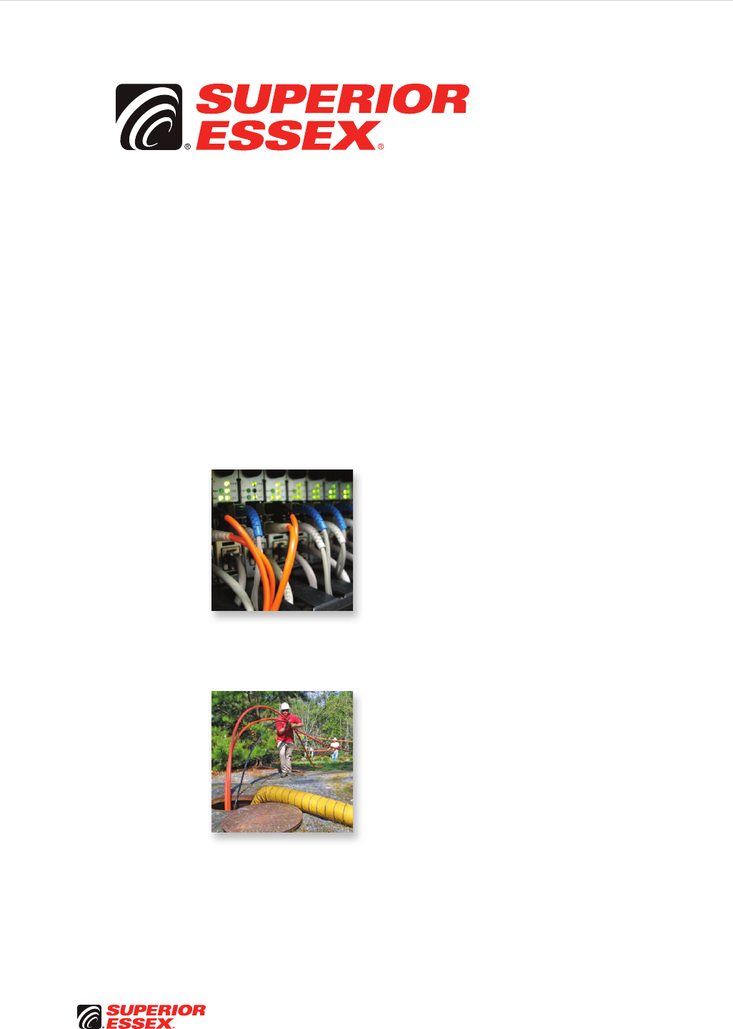
PREMISES CABLE
Our premises wire and cable products provide a total user
experience that is unequaled in the industry. For years,
Superior Essex cables have offered more useful features
that save time and money, better performance, higher
quality and better overall value than our competition.
Ultimately, these subtle advantages combined with our
broad portfolio of fiber and copper cable offerings make
Superior Essex premises products the preferred choice for
architects, engineers, consultants and contractors alike.
OUTSIDE PLANT WIRE AND CABLE
Superior Essex is the world’s largest producer of Outside
Plant (OSP) copper communications cables and a leader
in the OSP optical fiber cable market. With more than 4,000
different optical fiber, copper and wire designs available,
our products serve virtually every application demanded for
OSP installations. Our strong market position was built from
an endless pursuit of perfection in our products and service.
It’s the difference that has kept customers loyal for decades
and has earned Superior Essex customer quality awards
year after year.
PREMISES COPPERPREMISES FIBEROSP FIBEROSP COMPOSITECENTRAL OFFICE COPPERRDUP/RUS OSP COPPERBELL OSP COPPEROSP COPPER WIRECANADIAN OSP COPPERTECHNICAL INFO
Toll Free 800.551.8948 | Fax 770.657.6807 | SuperiorEssex.com/Comm
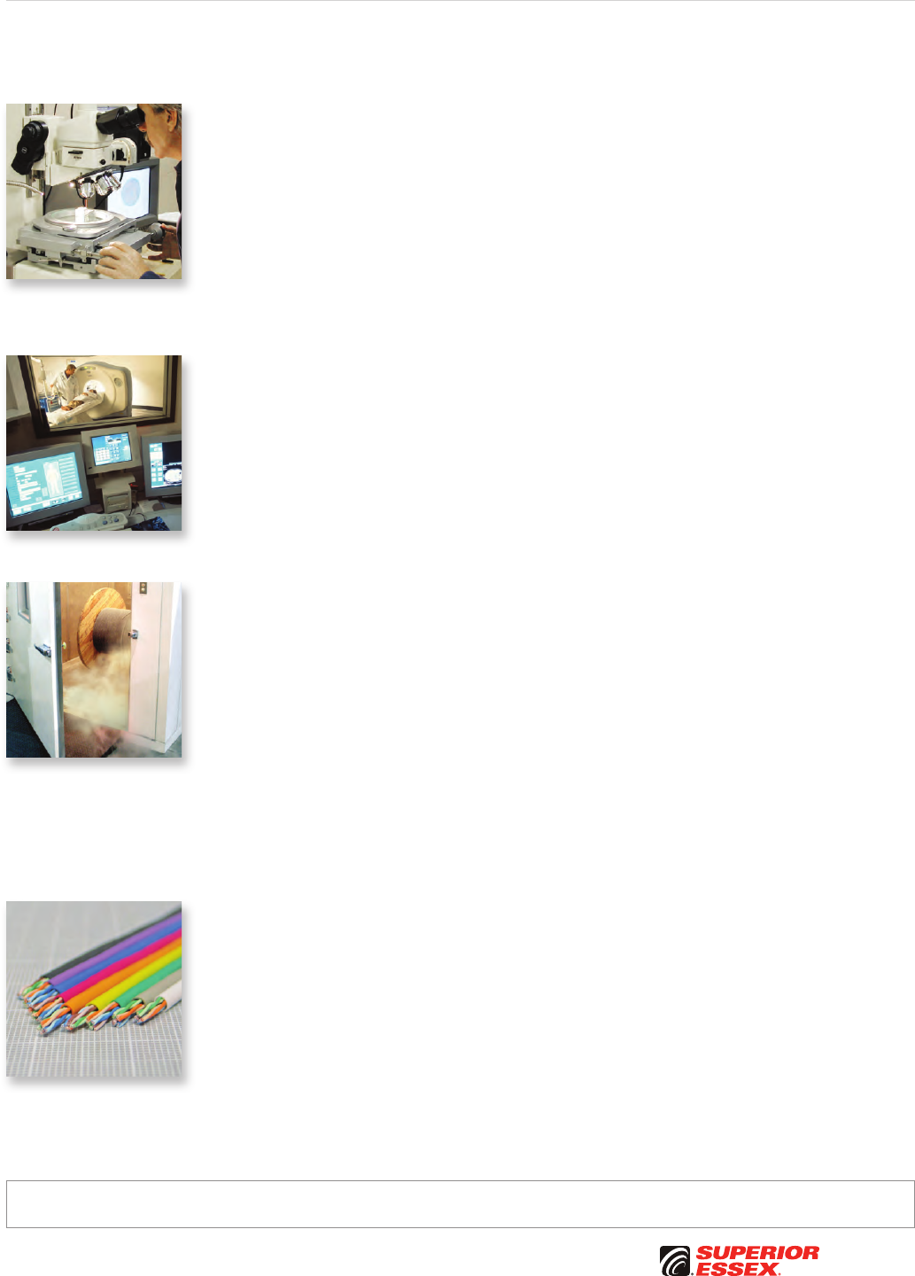
DEFINING QUALITY
Superior Essex has TL 9000 and ISO 9001:2001 certification
in every communications production facility, assuring a
level of quality and consistency of the company’s products
and service. And, there is much more to this commitment.
Beyond quality assurance of our products is our dedication
to bring value added elements and superior customer
service to our products. At Superior Essex quality is simple
– providing the customer what is expected every time.
CONSISTENCY MATTERS
Any cable manufacturer can design a high-performance
cable, but very few have the ability or inclination to ensure
that every cable produced is high-performance. Superior
Essex does. Superior Essex has firmly established a long-
standing reputation for providing quality products, on-time
delivery and expert technical support. Consistency matters;
get it right the first time with Superior Essex.
PRODUCT PERFORMANCE
When it comes to product performance, we guarantee
that when you install any of our communications cables
that you’ll get more than you ask for – you’ll get what you
want. Superior Essex has engineered some of the highest
performance copper and fiber optic cable products available
anywhere. In independent tests, Superior Essex Category
5e, 6 and 6A cables regularly surpass the performance
of competitors who claim performance to be their sole
distinction. This same attention to engineering excellence
is also extended to our fiber cable products and our voice-
grade cables.
FLEXIBILITY
The Superior Essex cable and wire catalog is extensive,
but we also manufacture custom products with special
requirements. Our Product Management team can quote and
deliver unique designs that are tailored for your application.
Superior Essex makes every effort to ensure the accuracy of the information contained in this catalogue at the time of publication. Specifications, packaging and part numbers detailed
within are subject to change. For the most up to date information, please contact Superior Essex at 770.657.6000 or visit SuperiorEssex.com/Comm. © 2010 Superior Essex, Inc.

PREMISES COPPER PREMISES FIBER OSP FIBER OSP COMPOSITE CENTRAL OFFICE COPPER RDUP/RUS OSP COPPER BELL OSP COPPER OSP COPPER WIRE CANADIAN OSP COPPER TECHNICAL INFO
Toll Free 800.551.8948 | Fax 770.657.6807 | SuperiorEssex.com/Comm
Table of Contents
PREMISES COPPER A-1
10Gain® XP Category 6A CMR/CMP . . . . . . . . . . . . . . . . . . . . . . . . . . A-2
10Gain® Category 6A CMR/CMP ............................. A-4
Category 6A STP (U/FTP) CMR/CMP. . . . . . . . . . . . . . . . . . . . . . . . . . A-6
Category 6A ScTP (F/UTP) CMR/CMP. . . . . . . . . . . . . . . . . . . . . . . . . A-8
Category 6+ ScTP (F/UTP) CMR/CMP . . . . . . . . . . . . . . . . . . . . . . . . . A-9
NextGain® Category 6eX CMR/CMP . . . . . . . . . . . . . . . . . . . . . . . . . A-10
DataGain® Category 6+ CMR/CMP . . . . . . . . . . . . . . . . . . . . . . . . . . A-12
Category 6 CMR/CMP ..................................... A-14
Cobra Category 5e+ CMR/CMP . . . . . . . . . . . . . . . . . . . . . . . . . . . . . A-16
Cobra Category 5e+ Limited Combustible . . . . . . . . . . . . . . . . . . . . A-18
Category 5e+ ScTP (F/UTP) CMR/CMP. . . . . . . . . . . . . . . . . . . . . . . A-20
Marathon LAN® Category 5e CMR/CMP. . . . . . . . . . . . . . . . . . . . . . A-22
Category 5e CMR/CMX Outdoor Sunlight Resistant. . . . . . . . . . . . A-24
Category 5e CMR/CMX Outdoor . . . . . . . . . . . . . . . . . . . . . . . . . . . . A-25
Category 5e CM........................................... A-26
6-Pair Category 5e CMR ................................... A-27
25-Pair Power Sum Category 5e CMR/CMP . . . . . . . . . . . . . . . . . . A-28
25-Pair Category 5e Indoor/Outdoor . . . . . . . . . . . . . . . . . . . . . . . . . A-29
OSP Broadband Category 6 ................................ A-30
OSP Broadband Category 5e . . . . . . . . . . . . . . . . . . . . . . . . . . . . . . . A-31
MEGAPIC™ OSP Broadband Backbone Category 5 . . . . . . . . . . . . A-32
Interlock Armored Premises Copper CMR ...................... A-33
Category 3 CMR/CMP 2-Pair – 400-Pair........................ A-34
AR Series Riser ARAM/ARMM ............................... A-36
Category 3 Station Wire CMR/CMX Outdoor. . . . . . . . . . . . . . . . . . A-37
Bundled Category 6 ....................................... A-38
Bundled Category 5e ...................................... A-39
Bundled Composite Category 6 CMR . . . . . . . . . . . . . . . . . . . . . . . . A-40
Bundled Composite Category 5e CMR . . . . . . . . . . . . . . . . . . . . . . . A-41
Residential Broadband Riser
Coax Series 6 Quad Shield, Category 6 and Optical Fiber ............ A-42
Residential Broadband Riser
Coax Series 6 Quad Shield, Category 5e and Optical Fiber ........... A-43
Coax Series 6 Quad Shield
CM/CATV, CMR/CATVR and Aluminum Interlock Armored CMR . . . . . . . A-44
Coax Series 6 60% Shield CM. . . . . . . . . . . . . . . . . . . . . . . . . . . . . . . A-46
Coax Series 6 Tri-Shield 70% CM. . . . . . . . . . . . . . . . . . . . . . . . . . . . A-47
PREMISES FIBER B-1
Simplex, Duplex and Quad Interconnect OFNR/OFNP ............ B-2
Microarray Data Center Interconnect OFNR/OFNP .............. B-4
Microarray Breakout OFNP .................................. B-5
Single Unit Distribution OFNR/OFNP ........................... B-6
Premises Fiber BrakeBox® with QuickCount® Marking System . . . . . . B-7
Multi-Unit Distribution OFNR/OFNP ............................ B-8
Indoor/Outdoor Sunlight Resistant OFNP ..................... B-10
Dry Block/Sunlight Resistant Indoor/Outdoor OFNR ............ B-11
Dry Block/Sunlight Resistant Indoor/Outdoor OFNP ............ B-12
Hybrid Premises Fiber OFNR/OFNP ............................B-14
Interlock Armored Premises Fiber OFCR/OFCP .................. B-16
OSP FIBER C-1
Loose Tube Single Jacket All Dielectric Series 11............... C-2
Loose Tube Double Jacket Non-Armor Series 1G ............... C-3
Loose Tube Single Jacket Single Armor Series 12............... C-4
Loose Tube Double Jacket Single Armor Series 1A.............. C-5
Loose Tube Double Jacket Double Armor Series 1D ............. C-6
Loose Tube Triple Jacket Double Armor Series 1C .............. C-7
Loose Tube Single Jacket Self Support Series 11M.............. C-8
Loose Tube Double Jacket Self Support Series 1GM ............ C-9
Loose Tube Single Jacket Single Armor Self Support Series 12M . . C-10
Loose Tube Double Jacket Single Armor Self Support Series 1AM. C-11
Loose Tube Single Jacket All Dielectric Nylon Series 1NY . . . . . . C-12
ADSS 100 Series 1F100...................................... C-13
ADSS 200 Series 1F200...................................... C-14
ADSS 400 Series 1F400...................................... C-15
Single Loose Tube All Dielectric Series 51 .................... C-16
Single Loose Tube Single Armor Series 52 .................... C-17
Single Flex Tube All Dielectric Series F1 ...................... C-18
Single Flex Tube Single Armor Series F2 ...................... C-19
Flex Tube Locate Series FM ................................. C-20
Ribbon Locate Series RM ................................... C-21
Loose Tube Indoor/Outdoor OFNR Series 13 ................... C-22
Interlock Armored OSP Fiber OFCR Series 13I ................. C-23
Single Loose Tube Indoor/Outdoor OFNR Series 53............. C-24
Heavy Duty Loose Tube OFNR Series 1H ...................... C-25
Loose Tube 12 AWG Composite Series 1N..................... C-26
UG FTTP Series 513 ........................................ C-27
Buried FTTP Steel Armor Series 52S.......................... C-28
Buried FTTP Aluminum Armor Series 523 ..................... C-29
Buried Drop Composite Aluminum Armor Series 72 ............ C-30
Buried Drop Composite Steel Armor Series 72S................ C-31
Toneable Drop FTTP Series 571Q ............................. C-32
Universal Drop FTTP Series 570Q ............................ C-33
Universal FTTP OFNR Series 57R ............................. C-34
Toneable FTTP OFCR Series 57CR ............................ C-35
Figure 8 FTTP Series 573Q ................................... C-36
FTTP Tight Buffered Indoor/Outdoor Drop Series W7 ........... C-37
Dri-Lite® Ribbon Series R1D ................................. C-38
Dri-Lite® Ribbon Single Armor Series R2D ..................... C-39
Stranded Tube Ribbon Single Armor Series S2................. C-41
Single Tube Ribbon Series R1................................ C-42
Single Tube Ribbon Single Armor Series R2 ................... C-43
OSP COMPOSITE D-1
Composite Right of Way Series MR ........................... D-2
Composite Category 5e Drop Series 5F ........................ D-3
Composite Drop Web Series 71 W............................. D-4
Composite Drop Overjacket Series 71 OJ....................... D-5
Composite OSP Web Series 5V ...............................D-6
Composite OSP Overjacket Series 70 OJ ....................... D-7
Composite Round CF Series L ................................ D-8

PREMISES COPPERPREMISES FIBEROSP FIBEROSP COMPOSITECENTRAL OFFICE COPPERRDUP/RUS OSP COPPERBELL OSP COPPEROSP COPPER WIRECANADIAN OSP COPPERTECHNICAL INFO
Toll Free 800.551.8948 | Fax 770.657.6807 | SuperiorEssex.com/Comm
CENTRAL OFFICE COPPER E-1
ABAM (600B) and ABMM Series Central Office. . . . . . . . . . . . . . . . .E-2
1249C Series Central Office ..................................E-3
1161A Series Category 3 Central Office . . . . . . . . . . . . . . . . . . . . . . . .E-4
600C Series Central Office ...................................E-5
25-Pair Category 5e Shielded CMR . . . . . . . . . . . . . . . . . . . . . . . . . . . .E-6
Switchboard 100 Ohm Central Office . . . . . . . . . . . . . . . . . . . . . . . . . .E-8
Switchboard 100 Ohm Central Office
200A/800A Series (Canadian Color Code)..........................E-10
T100 Series Central Office...................................E-11
Switchboard 85 and Shielded Switchboard 85 . . . . . . . . . . . . . . . . .E-12
Distribution Frame Wire DFW ................................E-13
Heavy Duty Distribution Frame Wire HD-DFW ..................E-14
Tight Twist Distribution Frame Wire DFW ......................E-15
RDUP/RUS OSP COPPER F-1
SEALPIC® ..................................................F-2
SEALPIC®–84 ...............................................F-4
SEALPIC®–FSF-84 ...........................................F-6
SEALPIC®–FSF (RDUP PE-89) .................................F-8
CASPIC®–FSF (RDUP PE-89).................................F-10
SEALPIC®–F (RDUP PE-39) ..................................F-12
CUPIC®–F (RDUP PE-39).....................................F-14
GOPIC®–F (RDUP PE-39) ....................................F-16
CASPIC®–F (RDUP PE-39) ...................................F-18
BELL OSP COPPER G-1
ALPETH BHBA, BHAA, BKMA and BKTA ......................... G-2
PASP BHBH, BHAH, BKMH and BKTH ........................... G-4
Self-Support BHAS and BKMS ................................ G-6
Reinforced Self-Support BHAP, BKMP and BKTP................. G-8
Bonded STALPETH DCAZ, DCMZ and DCTZ..................... G-10
STEAMPETH DKMN and DKTN ............................... G-12
Power Station High Potential Filled ASP CMAW ............... G-13
Filled ALPETH ANBA, ANAA, ANMA and ANTA .................. G-14
Filled ASP ANBW, ANAW, ANMW and ANTW ................... G-16
Tight Twist 200-Pair ANMW ................................. G-18
T-SCREEN® Filled ASP KNAW and KNMW ..................... G-19
OSP COPPER WIRE H-1
C-Rural Wire .............................................. H-2
IMRDW................................................... H-3
IMRDWS.................................................. H-4
ADP NMS................................................. H-5
ADP NMS (6x24) Compact Design. . . . . . . . . . . . . . . . . . . . . . . . . . . . H-6
ADP S .................................................... H-7
Integrated Messenger Wire IM/F, IM/H and IM/G ................ H-8
BDW A ................................................... H-9
BDW G .................................................. H-10
BW CF................................................... H-11
BW GDJ ................................................. H-12
BW NS Buried Wire Non-Shielded . . . . . . . . . . . . . . . . . . . . . . . . . . H-13
Non-Jacketed Tight Twist Cable Core . . . . . . . . . . . . . . . . . . . . . . . H-14
OSP COPPER WIRE continued H-1
Air Pipe.................................................. H-14
Bridle Wire............................................... H-15
Temporary Drop Wire TDW ................................. H-15
E-Block Wire ............................................. H-16
Ground Wire Bare or Jacketed ............................... H-16
Cross-Connect Category 5 Wire XCW ........................ H-17
Indoor/Outdoor Cross-Connect Wire XCW .................... H-18
CANADIAN OSP COPPER I-1
CELFIL BJBB, BJAB, BJMB and BJTB............................I-2
Canadian ALPETH BHBB, BHAB, BKMB and BKTB .................I-4
SEALPAP BHBF, BHAF, BKMF and BKTF ..........................I-6
Canadian Bonded STALPETH DCAZ, DCMZ and DCTZ..............I-8
Canadian Self Support BHBS-BC, BHAS-BC and BKMS-BC.........I-10
Aerial Drop Wire ADW . . . . . . . . . . . . . . . . . . . . . . . . . . . . . . . . . . . . . . I-11
Canadian Integrated Messenger Wire IM/F, IM/H and IM/G .......I-12
Canadian ADP NMS with QuickCount® in Meters .................I-13
Buried Distribution Wire BCBD ...............................I-14
TECHNICAL INFO J-1
Metric Measurement Conversions . . . . . . . . . . . . . . . . . . . . . . . . . . . .J-2
American Wire Gauge (AWG) Sizes . . . . . . . . . . . . . . . . . . . . . . . . . . .J-2
Optical Fiber Types..........................................J-3
Optical Fiber Selection Chart . . . . . . . . . . . . . . . . . . . . . . . . . . . . . . . . .J-4
Single Mode
Multimode
Optical Fiber Cable..........................................J-6
ANSI/TIA/EIA-598-B Standard Colors
Standard Jacket Colors
OSP Flooding Compound and Jacket Marking Options
OSP Central Members/Strength Members Options
Additional OSP Options
Canadian Central Office Copper Cable . . . . . . . . . . . . . . . . . . . . . . . . .J-6
Insulation Color Codes
Spare Pair Insulation Color Codes
Spare Single Insulation Color Codes
OSP Copper Cable ..........................................J-7
Pair Identification Colors
Groups of Pairs Binder Identification Colors
Super-units Binder Identification Colors
Copper Wire and Cable......................................J-8
NEC Fire Resistance Ratings
Balanced Twisted Pair Transmission Categories
Premises Cable Conduit Fill Quick Reference . . . . . . . . . . . . . . . . . . .J-9
Packaging.................................................J-10
Glossary of Terms..........................................J-16
Standard Warranty.........................................J-21
PerformaLink® Warranty ....................................J-22
Campus Warranty..........................................J-24
Part Number Index.........................................J-28
Table of Contents


A-1
PREMISES COPPERPREMISES FIBEROSP FIBEROSP COMPOSITECENTRAL OFFICE COPPERRDUP/RUS OSP COPPERBELL OSP COPPEROSP COPPER WIRECANADIAN OSP COPPERTECHNICAL INFO
Toll Free 800.551.8948 | Fax 770.657.6807 | SuperiorEssex.com/Comm
PREMISES COPPER
Table of Contents
10Gain® XP Category 6A CMR/CMP . . . . . . . . . . . . . . . . . . . . . . . . . . A-2
10Gain® Category 6A CMR/CMP ............................. A-4
Category 6A STP (U/FTP) CMR/CMP. . . . . . . . . . . . . . . . . . . . . . . . . . A-6
Category 6A ScTP (F/UTP) CMR/CMP. . . . . . . . . . . . . . . . . . . . . . . . . A-8
Category 6+ ScTP (F/UTP) CMR/CMP . . . . . . . . . . . . . . . . . . . . . . . . . A-9
NextGain® Category 6eX CMR/CMP . . . . . . . . . . . . . . . . . . . . . . . . . A-10
DataGain® Category 6+ CMR/CMP . . . . . . . . . . . . . . . . . . . . . . . . . . A-12
Category 6 CMR/CMP ..................................... A-14
Cobra Category 5e+ CMR/CMP . . . . . . . . . . . . . . . . . . . . . . . . . . . . . A-16
Cobra Category 5e+ Limited Combustible . . . . . . . . . . . . . . . . . . . . A-18
Category 5e+ ScTP (F/UTP) CMR/CMP. . . . . . . . . . . . . . . . . . . . . . . A-20
Marathon LAN® Category 5e CMR/CMP. . . . . . . . . . . . . . . . . . . . . . A-22
Category 5e CMR/CMX Outdoor Sunlight Resistant. . . . . . . . . . . . A-24
Category 5e CMR/CMX Outdoor . . . . . . . . . . . . . . . . . . . . . . . . . . . . A-25
Category 5e CM........................................... A-26
6-Pair Category 5e CMR ................................... A-27
25-Pair Power Sum Category 5e CMR/CMP . . . . . . . . . . . . . . . . . . A-28
25-Pair Category 5e Indoor/Outdoor . . . . . . . . . . . . . . . . . . . . . . . . . A-29
OSP Broadband Category 6 ................................ A-30
OSP Broadband Category 5e . . . . . . . . . . . . . . . . . . . . . . . . . . . . . . . A-31
MEGAPIC™ OSP Broadband Backbone Category 5 . . . . . . . . . . . . A-32
Interlock Armored Premises Copper CMR ...................... A-33
Category 3 CMR/CMP 2-Pair – 400-Pair........................ A-34
AR Series Riser ARAM/ARMM ............................... A-36
Category 3 Station Wire CMR/CMX Outdoor. . . . . . . . . . . . . . . . . . A-37
Bundled Category 6 ....................................... A-38
Bundled Category 5e ...................................... A-39
Bundled Composite Category 6 CMR . . . . . . . . . . . . . . . . . . . . . . . . A-40
Bundled Composite Category 5e CMR . . . . . . . . . . . . . . . . . . . . . . . A-41
Residential Broadband Riser
Coax Series 6 Quad Shield, Category 6 and Optical Fiber ............ A-42
Residential Broadband Riser
Coax Series 6 Quad Shield, Category 5e and Optical Fiber ........... A-43
Coax Series 6 Quad Shield
CM/CATV, CMR/CATVR and Aluminum Interlock Armored CMR . . . . . . . A-44
Coax Series 6 60% Shield CM. . . . . . . . . . . . . . . . . . . . . . . . . . . . . . . A-46
Coax Series 6 Tri-Shield 70% CM. . . . . . . . . . . . . . . . . . . . . . . . . . . . A-47
A-2
PREMISES COPPER PREMISES FIBER OSP FIBER OSP COMPOSITE CENTRAL OFFICE COPPER RDUP/RUS OSP COPPER BELL OSP COPPER OSP COPPER WIRE CANADIAN OSP COPPER TECHNICAL INFO
Rev 10/10 Ed 10.2Toll Free 800.551.8948 | Fax 770.657.6807 | SuperiorEssex.com/Comm
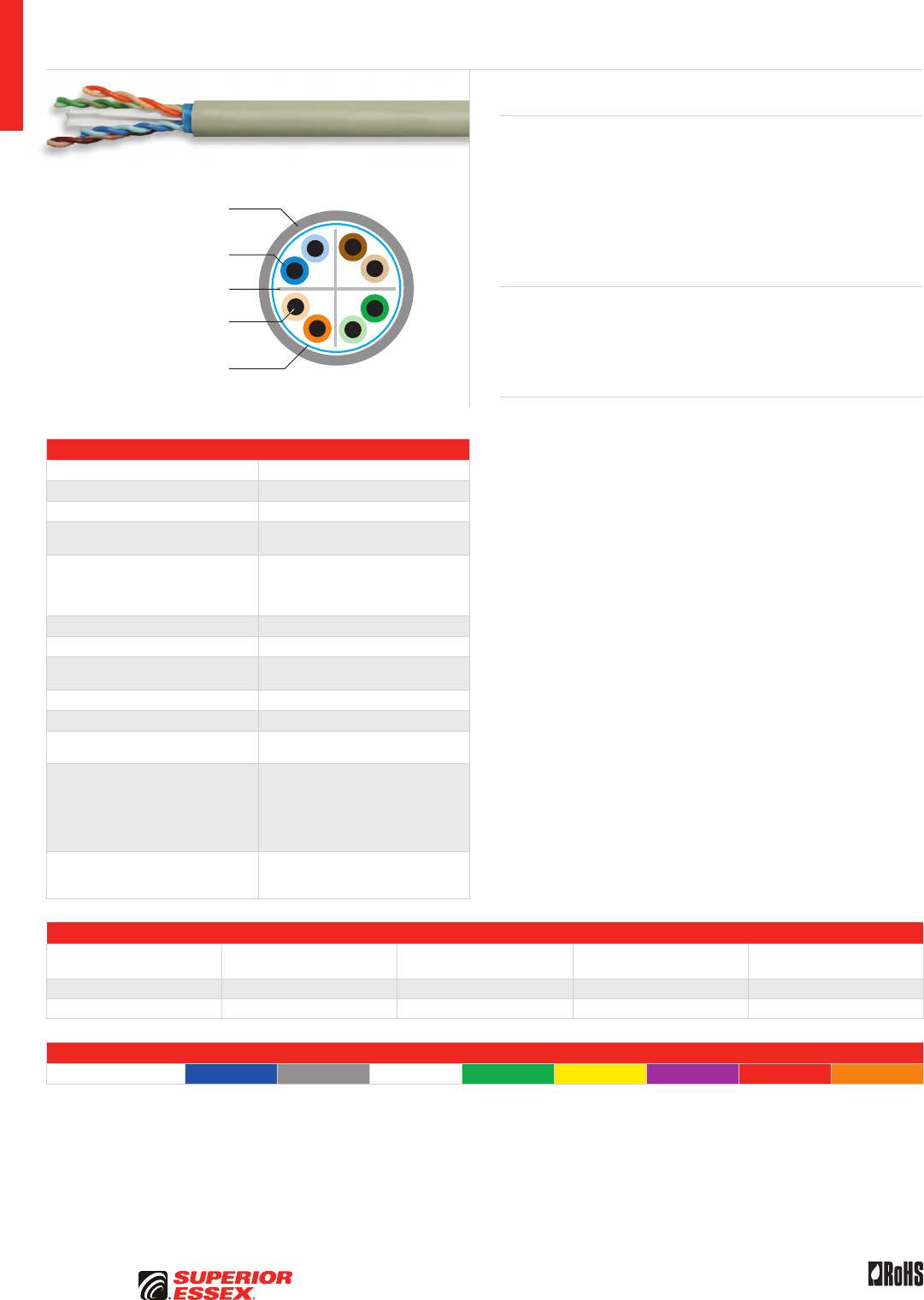
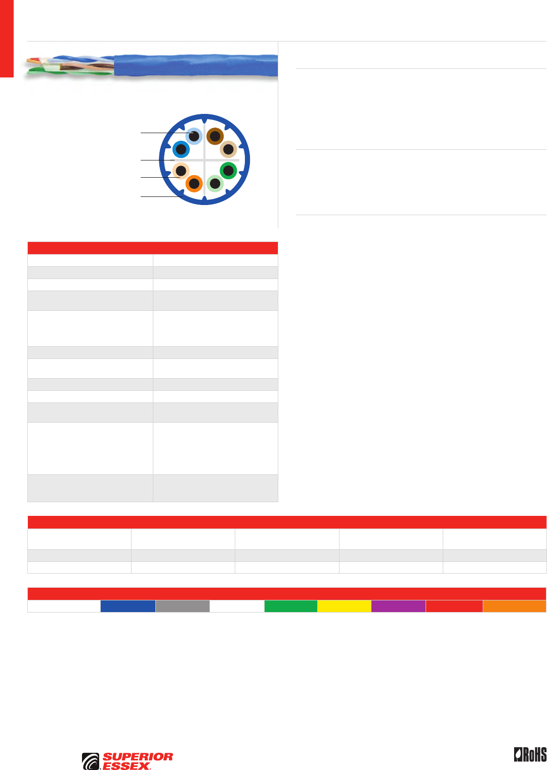
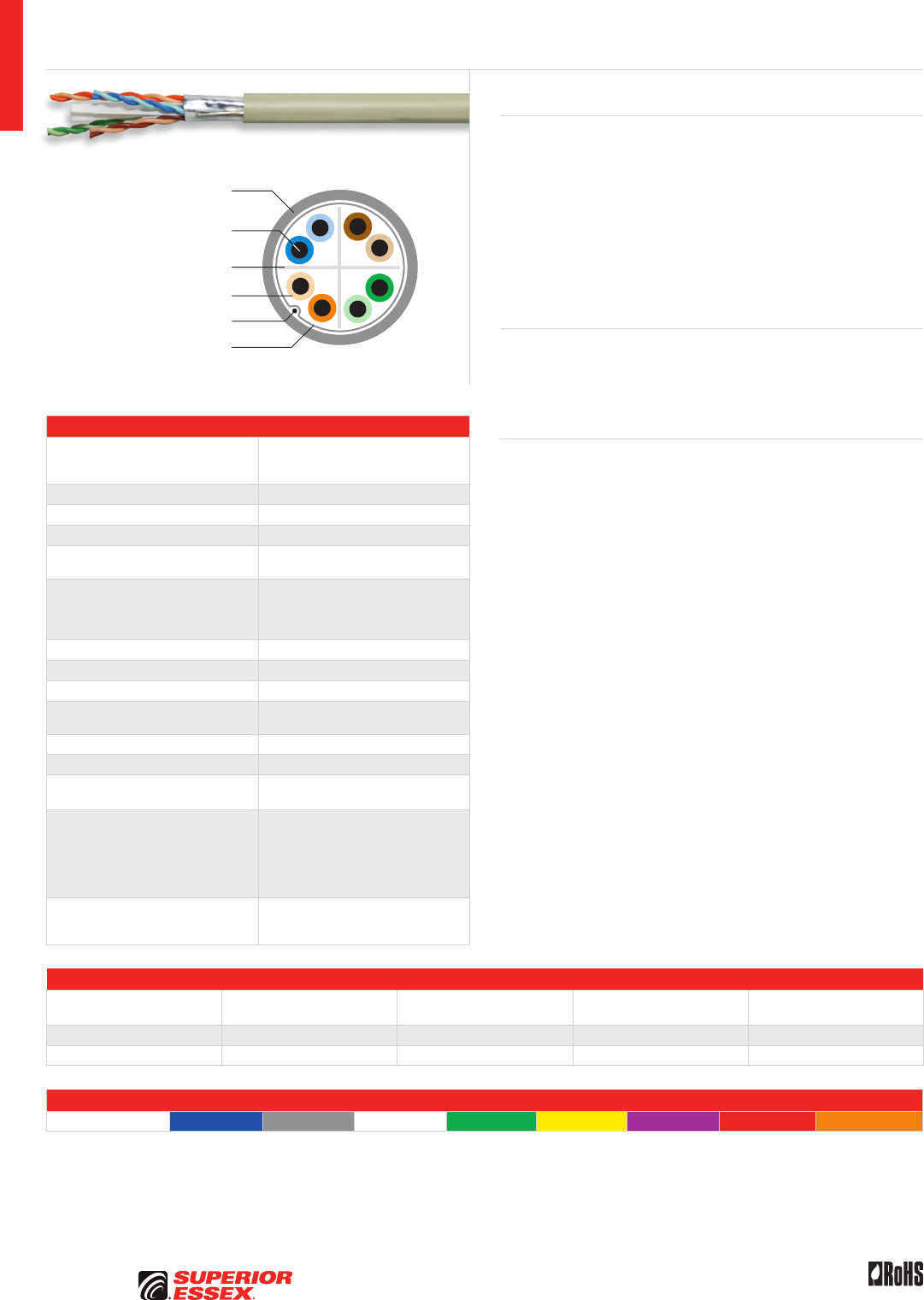
Flame Retardant
PVC Jacket
Solid Annealed
Copper Conductor
Thermoplastic Insulation
Isolation Wrap
Cross-web Separator
Specifications
Pair Count 4
Conductor Solid annealed copper
AWG (mm) 23 (0.57)
Insulation CMR: Thermoplastic
CMP: FEP
Insulation Colors
Pair 1: ColorTip™ Light Blue, Blue
Pair 2: ColorTip Light Orange, Orange
Pair 3: ColorTip Light Green, Green
Pair 4: ColorTip Light Brown, Brown
Separator Cross-web
Isolation Wrap Proprietary construction
Jacket CMR: Flame retardant (FR) PVC
CMP: FR, low smoke PVC
Package 1,000’ plywood reel
Characteristic Impedance (Ohms) 100 ± 15
Velocity of Propagation (%) CMR: 65
CMP: 69
Performance Compliance
UL 444
CSA C22.2 No. 214-08
UL 1666
NFPA 262
ANSI/TIA-568-C.2
RoHS-compliant
NRTL Programs
UL Verified CAT 6A
UL, c(UL) Listed CMR
UL, c(UL) Listed CMP
Part Numbers and Physical Characteristics
Listing Part Number¹
Nominal Diameter
in (mm)
Approx. Weight
lbs/kft (kg/km) Packages Per Pallet
CMR 6H-272-xA 0.295 (7.49) 47 (70) 12
CMP 6H-272-xB 0.295 (7.49) 45 (67) 12
Jacket Colors
¹Replace “x” with: Blue = 2 Gray = 3 White = 4 Green = 5 Yellow = 6 Purple = 7 Red = 9 Orange = D
10Gain® XP Category 6A CMR/CMP
Product Description
10Gain® XP, with its non-conductive Isolation Wrap, is the first Category 6A
cable without a continuous shield to offer 3 dB margin over Alien Crosstalk
(AXT) performance requirements in ANSI/TIA-568-C.2. The uniquely
designed Isolation Wrap contains discontinuous sections of metallized
material, held in place by a polymeric layer. 10Gain XP has a nominal 0.295
inch diameter which allows for higher cable density than other CAT 6A
cable products. 10Gain XP fully complies with UL 444 requirements for an
unshielded twisted pair product.
Applications
• 10GBASE-T and legacy applications 10BASE-T through
1000BASE-T ethernet
• ATM and token ring
• Backward compatible to legacy protocols and applications
Features Benefits
• Guaranteed 3 dB AXT margin • Guaranteed AXT performance
in virtually any installation
environment
• UL Verified CAT 6A • Assures consistent, worry free
performance
• Tested to 650 MHz • Assures ample bandwidth
headroom
• Non-conductive Isolation Wrap • Provides substantially more
AXT protection without grounding
or bonding
• Nominal 0.295 inch diameter • Allows higher cable density
and smaller bend radius
• 1.2 inch bending radius • Flexible for use in tight spaces
• CableID™ alpha numeric code
printed every 2 feet
• Allows both ends of a cable run
to be easily identifiable without
the need to seperately label or
tone the cable
• QuickCount® marking system
in feet and meters
• Provides remaining length
of cable on reel
• ColorTip™ circuit
identification system
• Easily identifiable conductor
mates even in low light
environments
A-3
PREMISES COPPERPREMISES FIBEROSP FIBEROSP COMPOSITECENTRAL OFFICE COPPERRDUP/RUS OSP COPPERBELL OSP COPPEROSP COPPER WIRECANADIAN OSP COPPERTECHNICAL INFO
Rev 10/10 Ed 10.2 Toll Free 800.551.8948 | Fax 770.657.6807 | SuperiorEssex.com/Comm
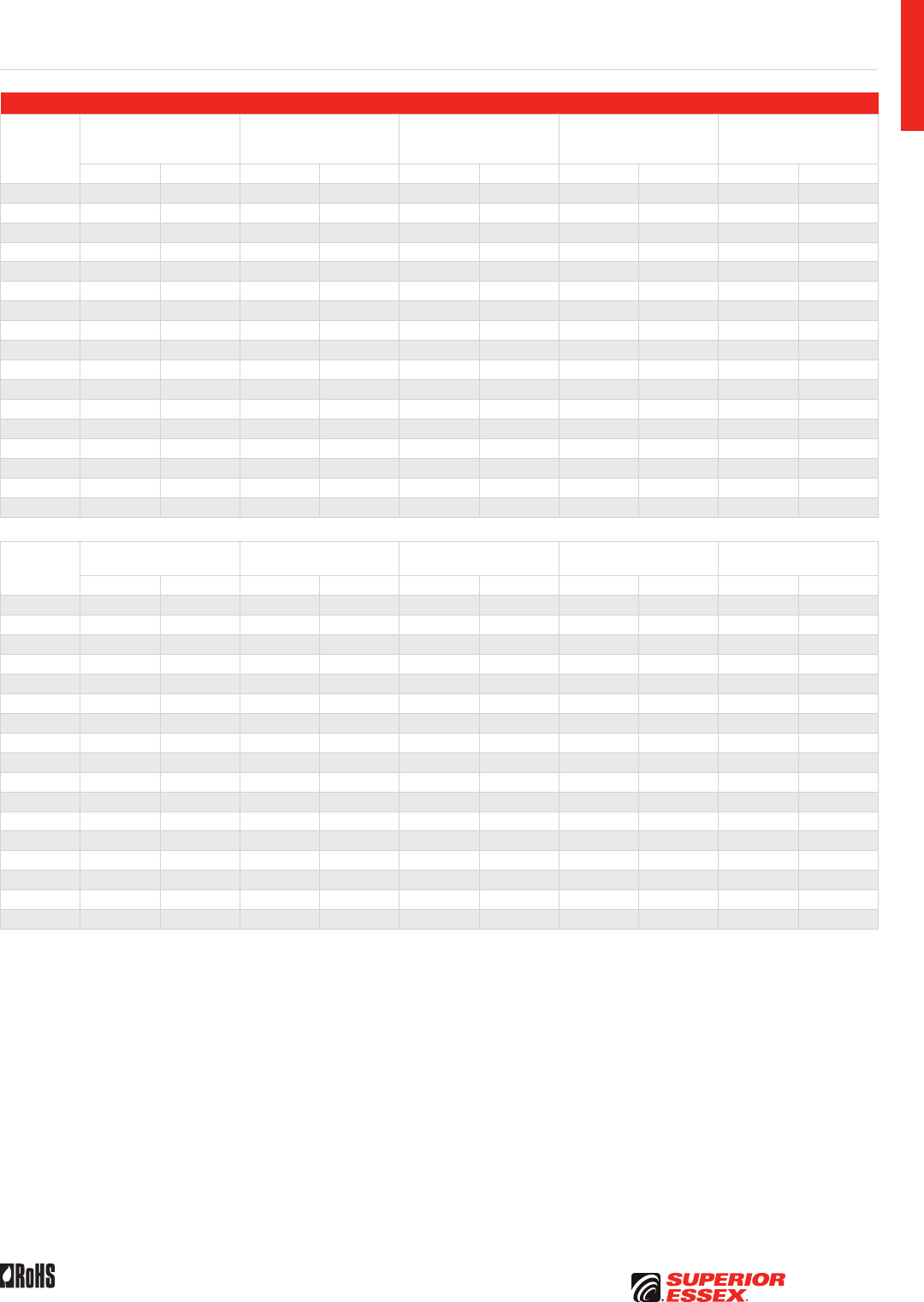
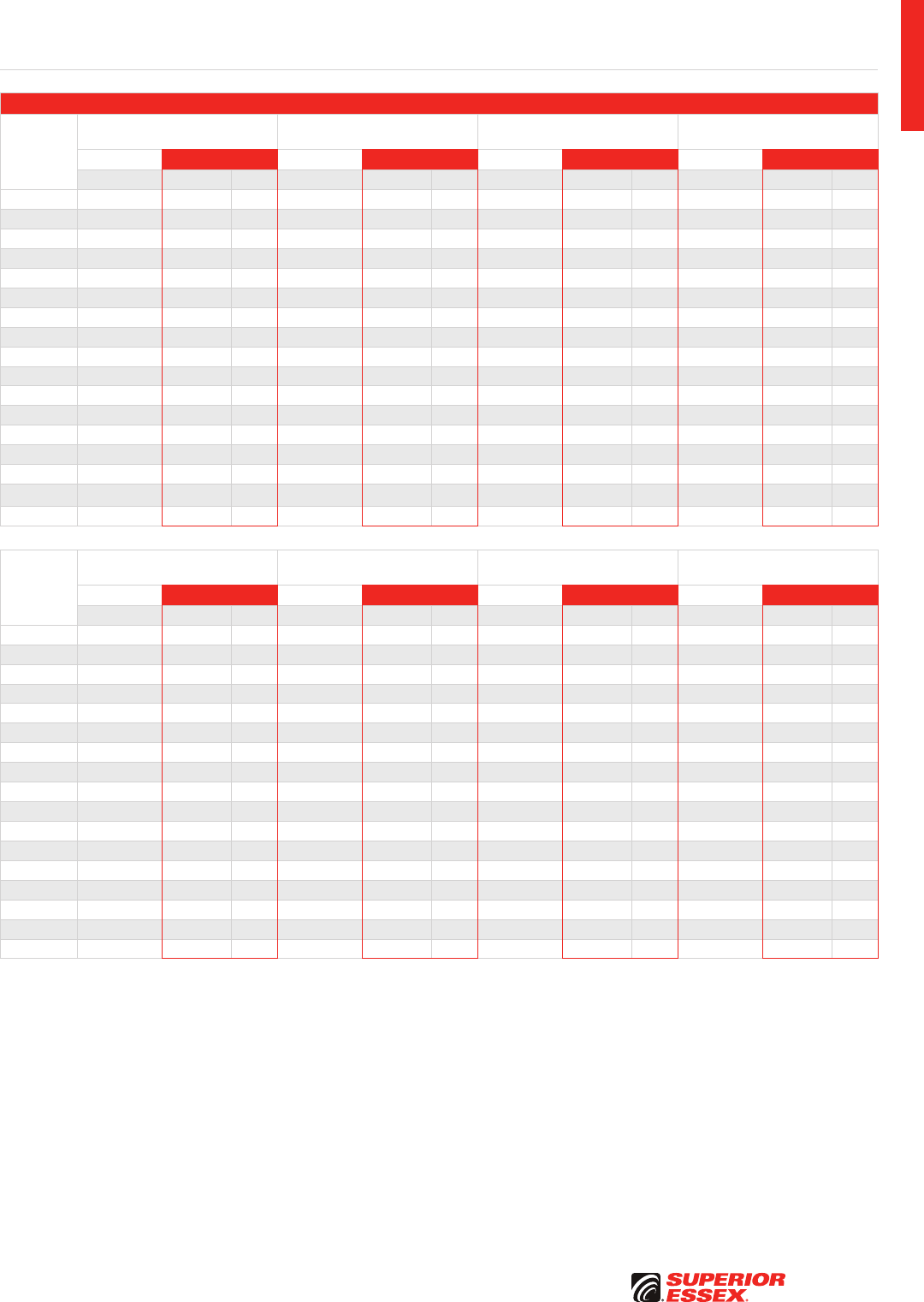
Electrical Specifications
Frequency
MHz
Insertion Loss @ 20°C
Maximum
dB/100 m
NEXT Minimum
dB/100 m
ACR Minimum
dB/100 m
PSNEXT Minimum
dB/100 m
PSACR Minimum
dB/100 m
Guaranteed Typical Guaranteed Typical Guaranteed Typical Guaranteed Typical Guaranteed Typical
1 2.1 2.0 74.3 78.3 72.2 77.3 72.3 77.3 70.2 76.3
4 3.8 3.7 65.3 69.3 61.5 66.6 63.3 68.3 59.5 65.6
8 5.3 5.1 60.8 64.8 55.4 60.6 58.8 63.8 53.4 59.6
10 5.9 5.7 59.3 63.3 53.4 58.6 57.3 62.3 51.4 57.6
16 7.5 7.3 56.2 60.2 48.8 54.0 54.2 59.2 46.8 53.0
20 8.4 8.1 54.8 58.8 46.4 51.7 52.8 57.8 44.4 51.2
25 9.4 9.1 53.3 57.3 44.0 49.7 51.3 56.3 42.0 49.0
31.25 10.5 10.2 51.9 55.9 41.4 47.2 49.9 54.9 39.4 46.7
62.5 15.0 14.4 47.4 51.4 32.4 39.0 45.4 50.4 30.4 38.4
100 19.1 18.4 44.3 48.3 25.2 32.4 42.3 47.3 23.2 31.7
200 27.6 26.5 39.8 43.8 12.2 20.1 37.8 42.8 10.2 19.5
250 31.1 29.8 38.3 42.3 7.3 15.5 36.3 41.3 5.3 15.1
300 34.3 32.9 37.1 41.1 2.9 11.4 35.1 40.1 0.9 10.8
400 40.1 38.3 35.3 39.3 4.6 33.3 38.3 3.6
500 45.3 43.0 33.8 37.8 31.8 36.8
600 47.5 36.4 35.6
650 49.7 35.9 35.1
Frequency
MHz
Return Loss Minimum
dB/100 m
ACRF Minimum
dB/100 m
PSACRF Minimum
dB/100 m
PSANEXT Minimum
dB/100 m
PSAACRF Minimum
dB/100 m
Guaranteed Typical Guaranteed Typical Guaranteed Typical Guaranteed Typical Guaranteed Typical
1 20.0 22.0 67.8 73.8 64.8 70.8 70.0 96.5 70.0 72.0
4 23.0 25.0 55.8 61.8 52.8 58.8 70.0 87.5 69.2 71.2
8 24.5 26.5 49.7 55.7 46.7 52.7 70.0 83.0 63.1 65.1
10 25.0 27.0 47.8 53.8 44.8 50.8 70.0 81.5 61.2 63.2
16 25.0 27.0 43.7 49.7 40.7 46.7 70.0 78.4 57.1 59.1
20 25.0 27.0 41.8 47.8 38.8 44.8 70.0 77.0 55.2 57.2
25 24.3 26.3 39.8 45.8 36.8 42.8 70.0 75.5 53.2 55.2
31.25 23.6 25.6 37.9 43.9 34.9 40.9 70.0 74.1 51.3 53.3
62.5 21.5 23.5 31.9 37.9 28.9 34.9 68.6 69.6 45.3 47.3
100 20.1 22.1 27.8 33.8 24.8 30.8 65.5 66.5 41.2 43.2
200 18.0 20.0 21.8 27.8 18.8 24.8 61.0 62.0 35.2 37.2
250 17.3 19.3 19.8 25.8 16.8 22.8 59.5 60.5 33.2 35.2
300 16.8 18.8 18.3 24.3 15.3 21.3 58.3 59.3 31.7 33.7
400 15.9 17.9 15.8 21.8 12.8 18.8 56.5 57.5 29.2 31.2
500 15.2 17.2 13.8 19.8 10.8 16.8 55.0 56.0 27.2 29.2
600 16.7 18.2 15.2 54.8 27.6
650 16.4 17.5 14.5 54.3 26.9
10Gain XP Category 6A CMR/CMP
A-4
PREMISES COPPER PREMISES FIBER OSP FIBER OSP COMPOSITE CENTRAL OFFICE COPPER RDUP/RUS OSP COPPER BELL OSP COPPER OSP COPPER WIRE CANADIAN OSP COPPER TECHNICAL INFO
Rev 10/10 Ed 10.2Toll Free 800.551.8948 | Fax 770.657.6807 | SuperiorEssex.com/Comm
Solid Annealed
Copper Conductor
Thermoplastic Insulation
Flame Retardant PVC Jacket
Cross-web Separator
Specifications
Pair Count 4
Conductor Solid annealed copper
AWG (mm) 23 (0.57)
Insulation CMR: Polyolefin
CMP: FEP
Insulation Colors
Pair 1: ColorTip™ Light Blue, Blue
Pair 2: ColorTip Light Orange, Orange
Pair 3: ColorTip Light Green, Green
Pair 4: ColorTip Light Brown, Brown
Separator Cross-web
Jacket CMR: Flame retardant (FR) PVC
CMP: FR, low smoke PVC
Package 1,000’ plywood reel
Characteristic Impedance (Ohms) 100 ± 15
Velocity of Propagation (%) CMR: 65
CMP: 69
Performance Compliance
UL 444
CSA C22.2 No. 214-08
UL 1666
NFPA 262
ANSI/TIA-568-C.2
RoHS-compliant
NRTL Programs
UL Verified CAT 6A
UL, c(UL) Listed CMR
UL, c(UL) Listed CMP
Part Numbers and Physical Characteristics
Listing Part Number¹
Nominal Diameter
in (mm)
Approx. Weight
lbs/kft (kg/km) Packages Per Pallet
CMR 6A-272-xA 0.35 (8.9) 51 (76) 12
CMP 6A-272-xB 0.32 (8.1) 49 (73) 12
Jacket Colors
¹Replace “x” with: Blue = 2 Gray = 3 White = 4 Green = 5 Yellow = 6 Purple = 7 Red = 9 Orange = D
10Gain® Category 6A CMR/CMP
Product Description
10Gain® cable brings Category 6A UTP performance to a new level. This
cable meets the internal and alien cross-talk performance requirements of
ANSI/TIA-568-C.2 as tested in a 6 around 1 configuration. With guaranteed
performance out to 500 MHz and independently verified and monitored by UL,
10Gain CAT 6A cable demonstrates superior capability for 10 Gigabit Ethernet
and all other bandwidth intensive and legacy applications.
Applications
• 10GBASE-T and legacy applications 10BASE-T through
1000BASE-T ethernet
• ATM and token ring
• Backward compatible to legacy protocols and applications
Features Benefits
• UL Verified CAT 6A • Assures consistent, worry-free
performance
• Tested to 650 MHz • Assures ample bandwidth
headroom
• Exceptional PSACR and PSAACRF
(PSAELFEXT) performance
• Performance assurance for
10 Gigabit Ethernet and multiple
high-bandwidth applications
• CableID™ alpha numeric code
printed every 2 feet
• Allows both ends of a cable run
to be easily identifiable without
the need to seperately label or
tone the cable
• QuickCount® marking system
in feet and meters
• Provides remaining length
of cable on reel
• ColorTip™ circuit
identification system
• Easily identifiable conductor
mates even in low light
environments
A-5
PREMISES COPPERPREMISES FIBEROSP FIBEROSP COMPOSITECENTRAL OFFICE COPPERRDUP/RUS OSP COPPERBELL OSP COPPEROSP COPPER WIRECANADIAN OSP COPPERTECHNICAL INFO
Rev 10/10 Ed 10.2 Toll Free 800.551.8948 | Fax 770.657.6807 | SuperiorEssex.com/Comm
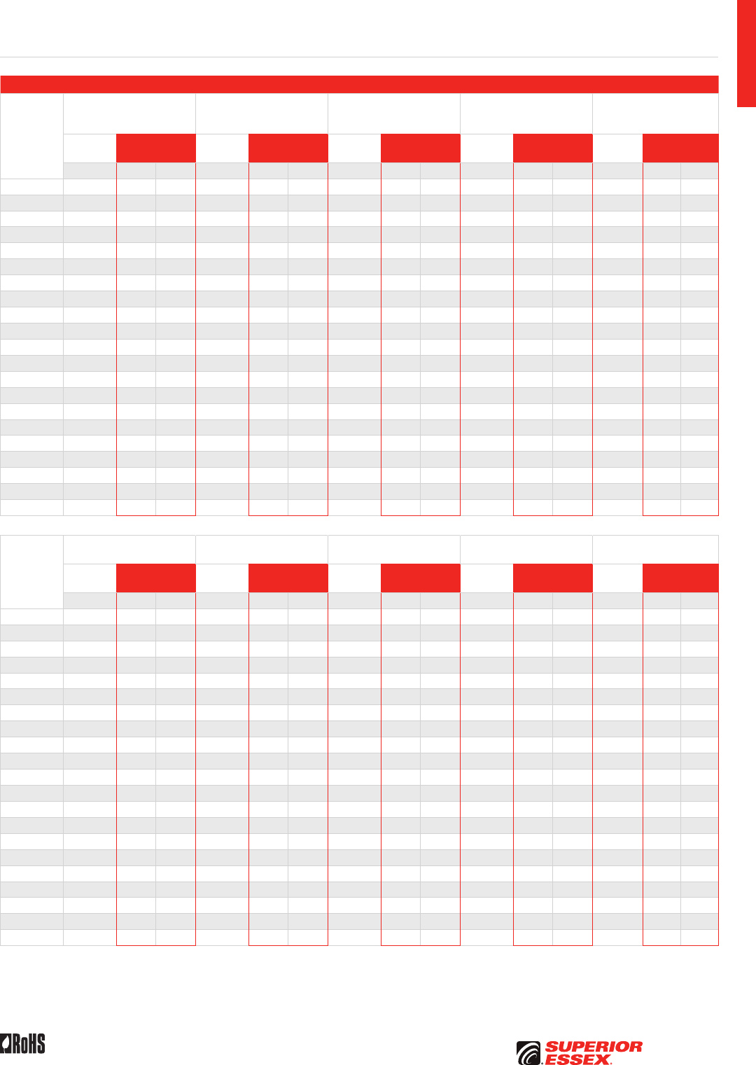
Electrical Specifications
Frequency
MHz
Insertion Loss @ 20°C
Maximum
dB/100 m
NEXT Minimum
dB/100 m
ACR Minimum
dB/100 m
PSNEXT Minimum
dB/100 m
PSACR Minimum
dB/100 m
TIA-
568-C.2 Superior Essex TIA-
568-C.2 Superior Essex TIA-
568-C.2 Superior Essex TIA-
568-C.2 Superior Essex TIA-
568-C.2
Superior
Essex
Specified Guar. Typical Specified Guar. Typical Specified Guar. Typical Specified Guar. Typical Specified Guar. Typical
1 2.0 2.0 1.7 74.3 75.3 92.4 72.3 74.3 90.7 72.3 74.3 90.3 70.3 72.3 88.7
4 3.7 3.6 3.4 65.3 66.3 82.2 61.5 63.5 78.9 63.3 65.3 80.5 59.5 61.5 77.2
8 5.2 5.1 4.7 60.8 61.8 78.0 55.5 57.5 73.3 58.8 60.8 76.4 53.5 55.5 71.7
10 5.9 5.7 5.3 59.3 60.3 76.5 53.4 55.4 71.2 57.3 59.3 74.8 51.4 53.4 69.6
16 7.4 7.2 6.7 56.2 57.2 73.8 48.8 50.8 67.2 54.2 56.2 72.0 46.8 48.8 65.4
20 8.3 8.1 7.6 54.8 55.8 71.1 46.5 48.5 63.6 52.8 54.8 69.7 44.5 46.5 62.2
25 9.3 9.1 8.5 53.3 54.3 68.9 44.0 46.0 60.5 51.3 53.3 67.4 42.0 44.0 59.1
31.25 10.4 10.2 9.5 51.9 52.9 68.3 41.5 43.5 58.9 49.9 51.9 67.0 39.5 41.5 57.6
62.5 14.9 14.5 13.6 47.4 48.4 64.3 32.5 34.5 50.8 45.4 47.4 62.3 30.5 32.5 49.0
100 19.0 18.5 17.4 44.3 45.3 61.2 25.3 27.3 44.0 42.3 44.3 59.2 23.3 25.3 42.2
155 24.0 23.4 21.9 41.4 42.4 57.3 17.5 19.5 35.7 39.4 41.4 55.9 15.5 17.5 34.4
200 27.5 26.8 25.1 39.8 40.8 57.1 12.3 14.3 32.4 37.8 39.8 54.9 10.3 12.3 30.3
250 31.0 30.2 28.2 38.3 39.3 55.9 7.4 9.4 27.6 36.3 38.3 53.3 5.4 7.4 25.4
300 34.2 33.3 31.1 37.1 38.1 53.7 3.0 5.0 22.8 35.1 37.1 51.5 1.0 3.0 20.9
350 37.2 36.3 33.8 36.1 37.1 52.7 1.0 19.1 34.1 36.1 50.1 16.9
400 40.0 39.0 36.3 35.3 37.3 52.4 15.3 33.3 36.3 49.3 13.5
450 42.7 41.6 38.7 34.5 36.5 50.2 11.6 32.5 35.5 47.8 9.7
500 45.3 44.1 41.0 33.8 35.8 48.7 7.7 31.8 34.8 46.2 5.8
550 43.2 45.6 2.3 43.7 1.0
600 45.3 44.0 42.2
650 47.5 42.0 40.2
Frequency
MHz
Return Loss Minimum
dB/100 m
ACRF Minimum
dB/100 m
PSACRF Minimum
dB/100 m
PSANEXT Minimum
dB/100 m
PSAACRF Minimum
dB/100 m
TIA-
568-C.2 Superior Essex TIA-
568-C.2 Superior Essex TIA-
568-C.2 Superior Essex TIA-
568-C.2 Superior Essex TIA-
568-C.2
Superior
Essex
Specified Guar. Typical Specified Guar. Typical Specified Guar. Typical Specified Guar. Typical Specified Guar. Typical
1 20.0 20.0 27.3 67.8 72.8 83.6 64.8 69.8 81.2 67.0 67.0 94.8 67.0 67.0 71.2
4 23.0 23.0 33.1 55.8 60.8 72.0 52.8 57.8 69.6 67.0 67.0 85.7 66.2 66.2 70.3
8 24.5 24.5 35.3 49.7 54.7 66.2 46.7 51.7 63.7 67.0 67.0 81.2 60.1 60.1 64.3
10 25.0 25.0 36.0 47.8 52.8 64.4 44.8 49.8 61.8 67.0 67.0 79.8 58.2 58.2 62.4
16 25.0 25.0 36.5 43.7 48.7 60.3 40.7 45.7 57.8 67.0 67.0 76.7 54.1 54.1 58.3
20 25.0 25.0 38.4 41.8 46.8 58.4 38.8 43.8 56.0 67.0 67.0 75.3 52.2 52.2 56.4
25 24.3 24.3 37.6 39.8 44.8 56.3 36.8 41.8 54.1 67.0 67.0 73.8 50.2 50.2 54.4
31.25 23.6 23.6 37.8 37.9 42.9 54.3 34.9 39.9 52.1 67.0 67.0 72.4 48.3 48.3 52.5
62.5 21.5 21.5 36.6 31.9 36.9 48.3 28.9 33.9 46.1 65.6 65.6 67.8 42.3 42.3 46.5
100 20.1 20.1 33.5 27.8 32.8 44.5 24.8 29.8 42.3 62.5 62.5 64.8 38.2 38.2 42.4
155 18.8 18.8 33.0 24.0 29.0 40.6 21.0 26.0 38.5 59.6 59.6 61.9 34.4 34.4 38.6
200 18.0 18.0 30.7 21.8 26.8 38.4 18.8 23.8 36.2 58.0 58.0 60.3 32.2 32.2 36.4
250 17.3 17.3 30.3 19.8 24.8 35.0 16.8 21.8 33.4 56.5 56.5 58.8 30.2 30.2 34.4
300 16.8 16.8 26.9 18.3 23.3 33.8 15.3 20.3 31.6 55.3 55.3 57.6 28.7 28.7 32.8
350 16.3 16.3 27.0 16.9 21.9 32.5 13.9 18.9 30.4 54.3 54.3 56.6 27.3 27.3 31.5
400 15.9 15.9 26.9 15.8 19.8 31.8 12.8 17.8 29.8 53.5 53.5 55.7 26.2 26.2 30.3
450 15.5 15.5 26.0 14.7 18.7 30.8 11.7 16.7 28.8 52.7 52.7 55.0 25.1 25.1 29.3
500 15.2 15.2 24.8 13.8 17.8 29.8 10.8 15.8 28.1 52.0 52.0 54.3 24.2 24.2 28.4
550 24.2 28.8 26.9 53.7 27.6
600 22.7 28.6 26.4 53.1 26.8
650 19.6 27.2 25.3 52.6 26.1
10Gain Category 6A CMR/CMP
A-6
PREMISES COPPER PREMISES FIBER OSP FIBER OSP COMPOSITE CENTRAL OFFICE COPPER RDUP/RUS OSP COPPER BELL OSP COPPER OSP COPPER WIRE CANADIAN OSP COPPER TECHNICAL INFO
Rev 10/10 Ed 10.2Toll Free 800.551.8948 | Fax 770.657.6807 | SuperiorEssex.com/Comm
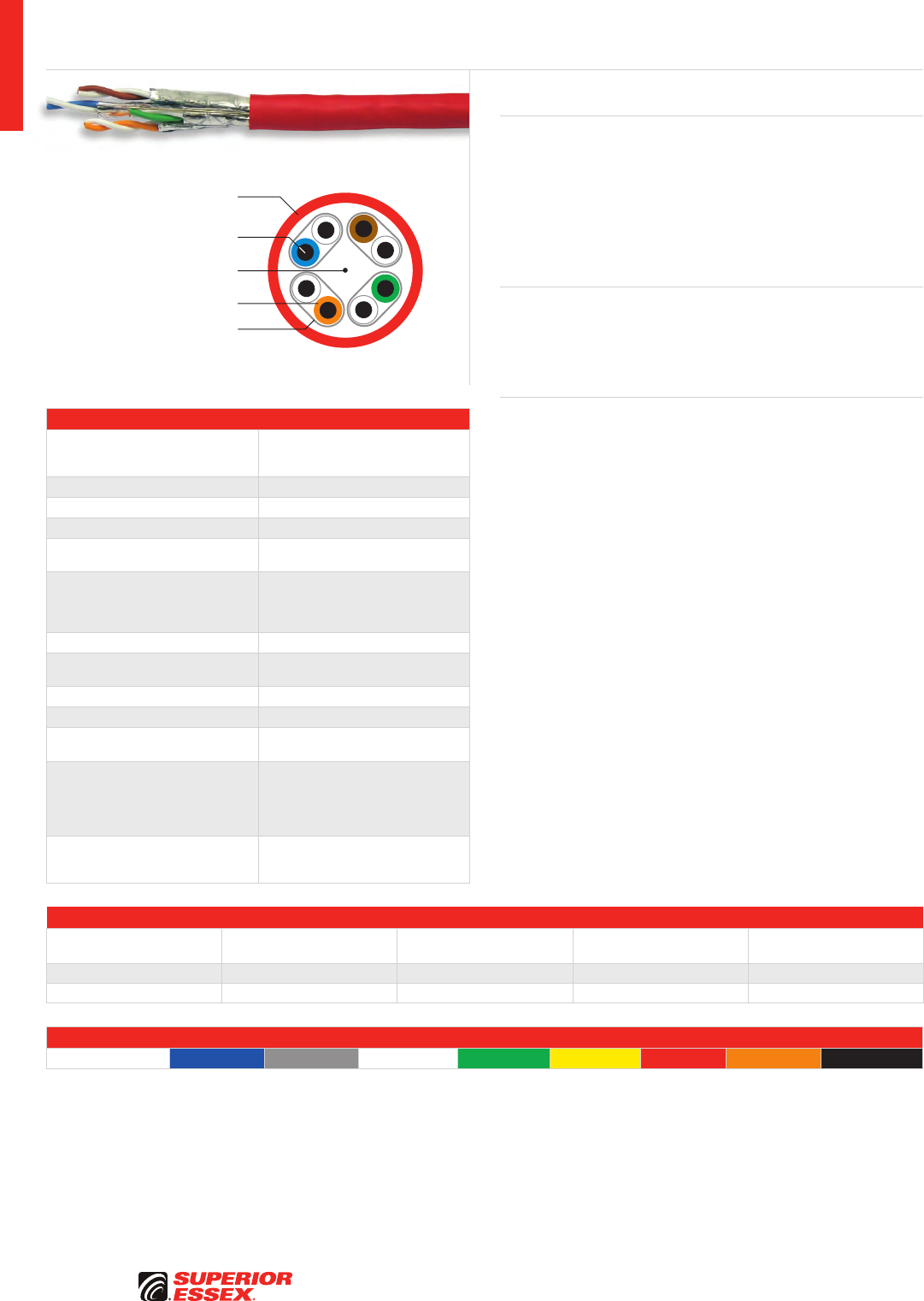
Flame Retardant PVC Jacket
Solid Annealed
Copper Conductor
Thermoplastic Insulation
Tin Coated Drain Wire
Aluminum Foil Tape Shield
Specifications
Configuration
Copper pairs each surrounded by
aluminum/Mylar® foil with center
drain wire and jacket
Pair Count 4
Conductor Solid annealed copper
AWG (mm) 23 (0.57)
Insulation CMR: Polyolefin
CMP: FEP
Insulation Colors
Pair 1: White/Blue
Pair 2: White/Orange
Pair 3: White/Green
Pair 4: White/Brown
Drain Wire Tinned copper
Jacket CMR: Flame retardant (FR) PVC
CMP: FR, low smoke PVC
Package 1,000’ plywood reel
Characteristic Impedance (Ohms) 100 ± 15
Nominal Velocity
of Propagation (%)
CMR: 73
CMP: 77
Performance Compliance
UL 444
CSA C22.2 No. 214-08
UL 1666
NFPA 262
ANSI/TIA-568-C.2
NRTL Programs
UL Verified CAT 6A
UL, c(UL) or ETL, c(ETL) Listed CMR
UL, c(UL) or ETL, c(ETL) Listed CMP
Part Numbers and Physical Characteristics
Listing Part Number¹
Nominal Diameter
in (mm)
Approx. Weight
lbs/kft (kg/km) Packages Per Pallet
CMR 6S-220-xA 0.31 (7.9) 50 (74) 15
CMP 6S-220-xB 0.29 (7.4) 52 (77) 15
Jacket Colors
¹Replace “x” with: Blue = 2 Gray = 3 White = 4 Green = 5 Yellow = 6 Red = 9 Orange = D Black = E
Category 6A STP (U/FTP) CMR/CMP
Product Description
Superior Essex offers Shielded Twisted Pair (STP) Category 6A cables in
both plenum and riser versions. The cable has guaranteed performance to
600 MHz and meets or exceeds ANSI/TIA-568-C.2 for CAT 6A cables required
for 10GBASE-T applications. The cable consists of four (4) balanced 23 AWG
copper pairs. Each pair is wrapped with a Mylar® backed aluminum foil with
the drain wire in the center of all 4 copper pairs. The wrapped pairs are
then jacketed with an appropriate flexible PVC jacket for either plenum or
riser applications.
Applications
• 10GBASE-T and legacy applications 10BASE-T through
1000BASE-T ethernet
• ATM and token ring
• Backward compatible to legacy protocols and applications
Features Benefits
• Individually foil shielded pairs • Protects against EMI/RFI
and provides exceptional NEXT,
PSNEXT, ELFEXT, and Electrical
Performance performance
• Exceeds specification
ANSI/TIA-568-C.2 for CAT 6A
cable performance
• Meets 10GBASE-T application
requirements for both Insertion
Loss and Return Loss and
exceeds requirements for
alien and internal crosstalk
performance
• Riser and plenum rated designs • UL 1666 and NFPA 262 fire rating
options help to reduce additional
expensive materials required to
meet building safety codes
• QuickCount® marking system
in feet and meters
• Provides remaining length
of cable on reel
A-7
PREMISES COPPERPREMISES FIBEROSP FIBEROSP COMPOSITECENTRAL OFFICE COPPERRDUP/RUS OSP COPPERBELL OSP COPPEROSP COPPER WIRECANADIAN OSP COPPERTECHNICAL INFO
Rev 10/10 Ed 10.2 Toll Free 800.551.8948 | Fax 770.657.6807 | SuperiorEssex.com/Comm
Electrical Specifications
Frequency
MHz
Insertion Loss @ 20°C Maximum
dB/100 m
NEXT Minimum
dB/100 m
ACR Minimum
dB/100 m
PSNEXT Minimum
dB/100 m
TIA-568-C.2 Superior Essex TIA-568-C.2 Superior Essex TIA-568-C.2 Superior Essex TIA-568-C.2 Superior Essex
Specified Guaranteed Typical Specified Guaranteed Typical Calculated Guaranteed Typical Specified Guaranteed Typical
1 2.1 2.1 2.1 65.0 74.2 74.2 62.9 76.2 78.2 72.2 76.2 78.2
4 3.8 3.8 3.7 65.0 69.2 74.2 61.2 65.4 70.5 63.2 67.2 72.2
8 5.3 5.3 5.2 60.7 64.7 74.2 55.4 59.4 69.0 58.7 62.7 72.2
10 5.9 5.9 5.8 59.2 63.2 74.2 53.3 57.3 68.4 57.2 61.2 72.2
16 7.4 7.4 7.4 56.2 60.2 74.2 48.7 52.7 66.8 54.2 58.2 71.2
20 8.3 8.3 8.2 54.7 58.7 72.7 46.4 50.4 64.4 52.7 56.7 69.7
25 9.3 9.3 9.2 53.3 57.3 71.3 43.9 47.9 62.0 51.3 55.3 68.3
31.25 10.5 10.5 10.4 51.8 55.8 69.8 41.3 45.3 59.4 49.8 53.8 66.8
62.5 14.9 14.9 14.8 47.3 51.3 65.3 32.3 36.3 50.5 45.3 49.3 62.3
100 19.1 19.1 18.9 44.2 48.2 62.2 25.1 29.1 43.3 42.2 46.2 59.2
200 27.5 27.5 27.3 39.7 43.7 57.7 12.2 16.2 30.4 37.7 41.7 54.7
250 31.1 31.1 30.7 38.3 42.3 56.3 7.2 11.2 25.5 36.3 40.3 53.3
300 34.2 34.2 33.9 37.1 41.1 55.1 2.8 6.8 21.2 35.1 39.1 52.1
350 37.2 37.2 36.8 36.1 40.1 54.1 2.9 17.2 34.1 38.1 51.1
400 40.1 40.1 39.6 35.2 39.2 53.2 13.6 33.2 37.2 50.2
500 45.2 45.2 44.8 33.8 37.8 51.8 7.0 31.8 35.8 48.8
600 50.1 49.5 36.6 50.6 1.1 34.6 47.6
Frequency
MHz
PSACR Minimum
dB/100 m
Return Loss Minimum
dB/100 m
ELFEXT (ACRF) Minimum
dB/100 m
PSELFEXT (PSACRF) Minimum
dB/100 m
TIA-568-C.2 Superior Essex TIA-568-C.2 Superior Essex TIA-568-C.2 Superior Essex TIA-568-C.2 Superior Essex
Calculated Guaranteed Typical Specified Guaranteed Typical Specified Guaranteed Typical Specified Guaranteed Typical
1 70.2 74.2 76.2 20.0 20.0 20.6 67.7 69.7 73.7 64.7 66.7 70.7
4 59.4 63.4 68.5 23.0 23.0 23.7 55.7 57.7 61.7 52.7 54.7 58.7
8 53.4 57.4 67.0 24.5 24.5 25.3 49.7 51.7 55.7 46.7 48.7 52.7
10 51.3 55.3 66.4 25.0 25.0 25.8 47.7 49.7 53.7 44.7 46.7 50.7
16 46.7 50.7 63.8 25.0 25.0 25.8 43.7 45.7 49.7 40.7 42.7 46.7
20 44.4 48.4 61.4 25.0 25.0 25.8 41.7 43.7 47.7 38.7 40.7 44.7
25 41.9 45.9 59.0 24.3 24.3 25.1 39.8 41.8 45.8 36.8 38.8 42.8
31.25 39.3 43.3 56.4 23.6 23.6 24.3 37.8 39.8 43.8 34.8 36.8 40.8
62.5 30.3 34.3 47.5 21.5 21.5 22.2 31.8 33.8 37.8 28.8 30.8 34.8
100 23.1 27.1 40.3 20.1 20.1 20.7 27.8 29.8 33.7 24.8 26.8 30.8
200 10.2 14.2 27.4 18.0 18.0 18.5 21.7 23.7 27.7 18.7 20.7 24.7
250 5.2 9.2 22.5 17.3 17.3 17.8 19.8 21.8 25.8 16.8 18.8 22.8
300 0.8 4.8 18.2 16.8 16.8 17.3 18.2 20.2 24.2 15.2 17.2 21.2
350 0.9 14.2 16.3 16.3 16.8 16.9 18.9 22.9 13.9 15.9 19.9
400 10.6 15.9 15.9 16.4 15.7 17.7 21.7 12.7 14.7 18.7
500 4.0 15.2 15.7 13.8 15.8 19.8 10.8 12.8 16.8
600 -1.9 15.1 14.2 18.2 11.2 15.2
Category 6A STP (U/FTP) CMR/CMP
A-8
PREMISES COPPER PREMISES FIBER OSP FIBER OSP COMPOSITE CENTRAL OFFICE COPPER RDUP/RUS OSP COPPER BELL OSP COPPER OSP COPPER WIRE CANADIAN OSP COPPER TECHNICAL INFO
Rev 10/10 Ed 10.2Toll Free 800.551.8948 | Fax 770.657.6807 | SuperiorEssex.com/Comm
Category 6A ScTP (F/UTP) CMR/CMP
Flame Retardant
PVC Jacket
Solid Annealed
Copper Conductor
Thermoplastic Insulation
Tin Coated Drain Wire
Aluminum Foil Tape Shield
Cross-web Separator
Specifications
Configuration
Copper pairs surrounded by aluminum
PET foil with an outer drain wire
and jacket
Pair Count 4
Conductor Solid annealed copper
AWG (mm) 23 (0.57)
Insulation CMR: Thermoplastic
CMP: FEP
Insulation Colors
Pair 1: ColorTip™ Light Blue, Blue
Pair 2: ColorTip Light Orange, Orange
Pair 3: ColorTip Light Green, Green
Pair 4: ColorTip Light Brown, Brown
Separator Cross-web
Shield Aluminum/PET
Drain Wire Tinned copper
Jacket CMR: Flame retardant (FR) PVC
CMP: FR, low smoke PVC
Package 1,000’ plywood reel
Characteristic Impedance (Ohms) 100 ± 15
Nominal Velocity
of Propagation (%)
CMR: 65
CMP: 69
Performance Compliance
UL 444
CSA C22.2 No. 214-08
UL 1666
NFPA 262
ANSI/TIA-568-C.2
RoHS-compliant
NRTL Programs
UL Verified CAT 6A
UL, c(UL) Listed CMR
UL, c(UL) Listed CMP
Part Numbers and Physical Characteristics
Listing Part Number¹
Nominal Diameter
in (mm)
Approx. Weight
lbs/kft (kg/km) Packages Per Pallet
CMR 6F-272-xA 0.29 (7.3) 40 (59) 12
CMP 6F-272-xB 0.30 (7.7) 46 (69) 12
Jacket Colors
¹Replace “x” with: Blue = 2 Gray = 3 White = 4 Green = 5 Yellow = 6 Purple = 7 Red = 9 Orange = D
Product Description
Category 6A ScTP (F/UTP) cable, swept out to 650 MHz, meets or exceeds
ANSI/TIA-568-C.2 for CAT 6A cables, a requirement for 10GBASE-T
applications. The cable is UL Verified CAT 6A and has a typical Alien
Crosstalk margin of 18 dB.
The cable consists of four (4) balanced 23 AWG copper pairs around a flame
retardant cross-web. The core is wrapped with a Mylar backed aluminum
foil. A drain wire is applied longitudinally against the tape. The cable is then
protected with a flexible riser or plenum rated PVC jacket. Standard features
include ColorTip™ circuit identification system and QuickCount® length
marking system measured in both feet and meters.
Applications
• 10GBASE-T and legacy applications 10BASE-T through
1000BASE-T ethernet
• ATM and token ring
• Backward compatible to legacy protocols and applications
Features Benefits
• Overall shielded core • Protects against EMI/RFI
• 18 dB typical margin Alien
Crosstalk performance
• Exceeds ANSI/TIA-568-C.2
specification for CAT 6A cable
performance
• Meets all 10GBASE-T application
requirements
• Exceeds requirements for Alien
Crosstalk performance
• UL Verified CAT 6A • Assures CAT 6A performance by
a nationally recognized test lab
• Riser and plenum rated designs • Meets all fire safety requirements
for either backbone or horizontal
applications
• CableID™ alpha numeric code
printed every 2 feet
• Allows both ends of a cable run
to be easily identifiable without
the need to seperately label or
tone the cable
• QuickCount® marking system
in feet and meters
• Provides remaining length
of cable on reel
• ColorTip™ circuit
identification system
• Easily identifiable conductor
mates even in low light
environments
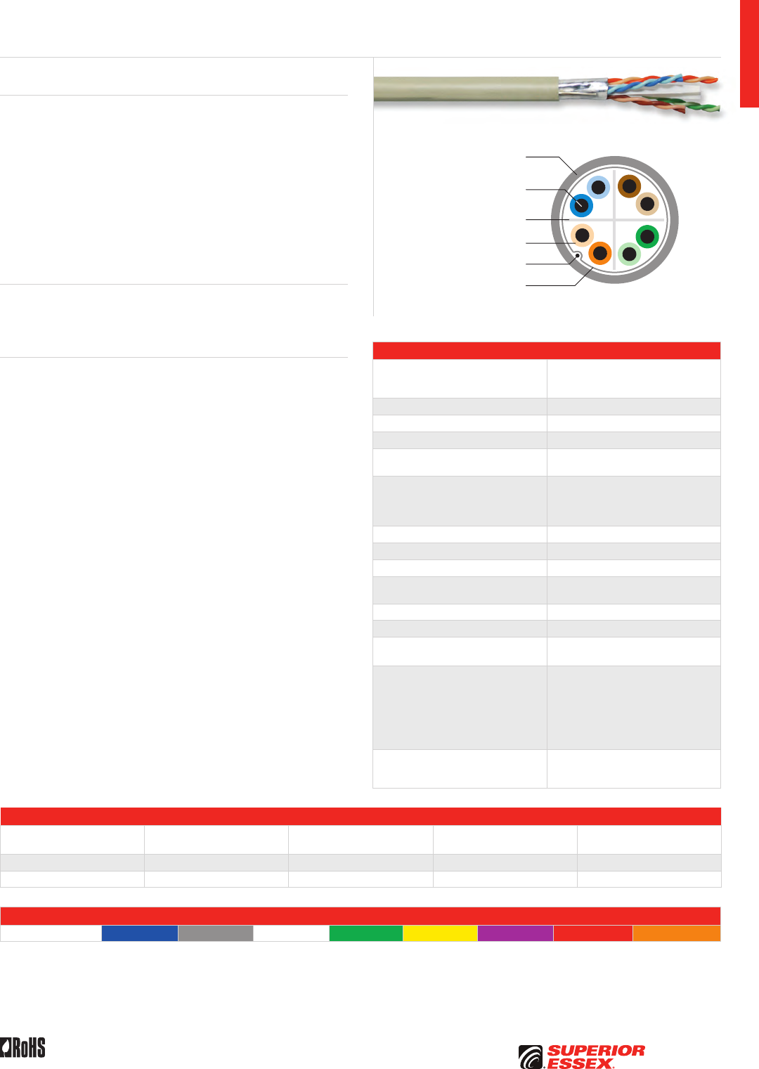
A-9
PREMISES COPPERPREMISES FIBEROSP FIBEROSP COMPOSITECENTRAL OFFICE COPPERRDUP/RUS OSP COPPERBELL OSP COPPEROSP COPPER WIRECANADIAN OSP COPPERTECHNICAL INFO
Rev 10/10 Ed 10.2 Toll Free 800.551.8948 | Fax 770.657.6807 | SuperiorEssex.com/Comm
Flame Retardant
PVC Jacket
Solid Annealed
Copper Conductor
Thermoplastic Insulation
Tin Coated Drain Wire
Aluminum Foil Tape Shield
Cross-web Separator
Specifications
Configuration
Copper pairs surrounded by aluminum
PET foil with an outer drain wire
and jacket
Pair Count 4
Conductor Solid annealed copper
AWG (mm) 23 (0.57)
Insulation CMR: Thermoplastic
CMP: FEP
Insulation Colors
Pair 1: ColorTip™ Light Blue, Blue
Pair 2: ColorTip Light Orange, Orange
Pair 3: ColorTip Light Green, Green
Pair 4: ColorTip Light Brown, Brown
Separator Cross-web
Shield Aluminum/PET with 10% overlap
Drain Wire Tinned copper
Jacket CMR: Flame retardant (FR) PVC
CMP: FR, low smoke PVC
Package 1,000’ Plywood reel
Characteristic Impedance (Ohms) 100 ± 15
Nominal Velocity
of Propagation (%)
CMR: 65
CMP: 69
Performance Compliance
UL 444
CSA C22.2 No. 214-08
UL 1666
NFPA 262
ANSI/TIA-568-C.2
ANSI/TIA/EIA-TSB-155
RoHS-compliant
NRTL Programs
UL Verified CAT 6
UL, c(UL) Listed CMR
UL, c(UL) Listed CMP
Part Numbers and Physical Characteristics
Listing Part Number¹
Nominal Diameter
in (mm)
Approx. Weight
lbs/kft (kg/km) Packages Per Pallet
CMR 6T-272-xA 0.29 (7.3) 40 (59) 12
CMP 6T-272-xB 0.30 (7.7) 46 (69) 12
Jacket Colors
¹Replace “x” with: Blue = 2 Gray = 3 White = 4 Green = 5 Yellow = 6 Purple = 7 Red = 9 Orange = D
Product Description
Category 6+ ScTP (F/UTP) cable, with guaranteed performance out to
500 MHz, exceeds ANSI/TIA-568-C.2 for CAT 6 cables. The cable is UL
Verified CAT 6 and has a typical Alien Crosstalk margin of 18 dB. The
cable can be used for 10GBASE-T applications for up to 55 meters per
ANSI/TIA/EIA-TSB-155.
The cable consists of four (4) balanced 23 AWG copper pairs around a flame
retardant cross-web. The core is wrapped with a Mylar backed aluminum
foil. A drain wire is applied longitudinally against the tape. The cable is then
protected with a flexible riser or plenum rated PVC jacket. Standard features
include ColorTip™ circuit identification system and QuickCount® length
marking system measured in both feet and meters.
Applications
• 10GBASE-T (up to 55 meters), 1000BASE-T, 100BASE-T
and legacy ethernet applications
• ATM and token ring
Features Benefits
• Overall shielded core • Protects against EMI/RFI
• 18 dB typical margin Alien
Crosstalk performance
• Guaranteed performance
to 500 MHz
• Assures ample headroom
for existing and future high
bandwidth applications
• Exceeds ANSI/TIA-568-C.2
specification for CAT 6
cable performance
• Allows for 10GBASE-T
applications up to 55 meters
• UL Verified CAT 6 • Assures CAT 6 performance by
a nationally recognized test lab
• Riser and plenum rated designs • Meets all fire safety requirements
for either backbone or horizontal
applications
• CableID™ alpha numeric code
printed every 2 feet
• Allows both ends of a cable run
to be easily identifiable without
the need to seperately label or
tone the cable
• QuickCount® marking system
in feet and meters
• Provides remaining length
of cable on reel
• ColorTip™ circuit
identification system
• Easily identifiable conductor
mates even in low light
environments
Category 6+ ScTP (F/UTP) CMR/CMP
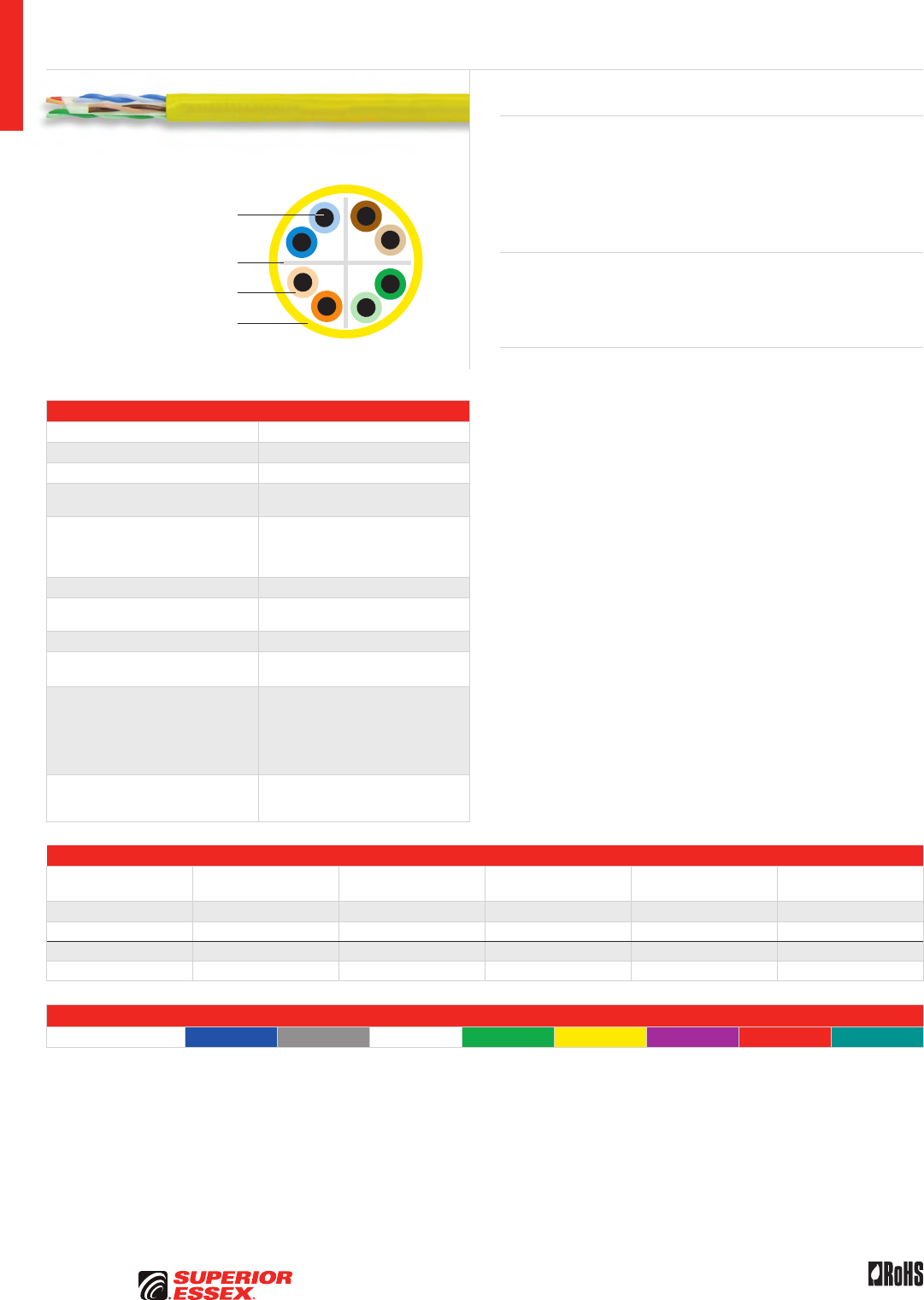
A-10
PREMISES COPPER PREMISES FIBER OSP FIBER OSP COMPOSITE CENTRAL OFFICE COPPER RDUP/RUS OSP COPPER BELL OSP COPPER OSP COPPER WIRE CANADIAN OSP COPPER TECHNICAL INFO
Rev 10/10 Ed 10.2Toll Free 800.551.8948 | Fax 770.657.6807 | SuperiorEssex.com/Comm
Solid Annealed
Copper Conductor
Thermoplastic Insulation
Flame Retardant PVC Jacket
Cross-web Separator
Specifications
Pair Count 4
Conductor Solid annealed copper
AWG (mm) 23 (0.57)
Insulation CMR: Polyolefin
CMP: FEP
Insulation Colors
Pair 1: ColorTip™ Light Blue, Blue
Pair 2: ColorTip Light Orange, Orange
Pair 3: ColorTip Light Green, Green
Pair 4: ColorTip Light Brown, Brown
Separator Cross-web
Jacket CMR: Flame retardant (FR) PVC
CMP: FR, low smoke PVC
Characteristic Impedance (Ohms) 100 ± 15
Nominal Velocity
of Propagation (%)
CMR: 70
CMP: 75
Performance Compliance
UL 444
CSA C22.2 No. 214-08
UL 1666
NFPA 262
ANSI/TIA-568-C.2
RoHS-compliant
NRTL Programs
UL Verified CAT 6
UL, c(UL) Listed CMR
UL, c(UL) Listed CMP
Part Numbers and Physical Characteristics
Listing Part Number¹
Nominal Diameter
in (mm)
Approx. Weight
lbs/kft (kg/km) Package Packages Per Pallet
CMR 54-246-xA 0.23 (5.8) 24 (36) 1,000’ BrakeBox®12
CMR 54-272-xA 0.23 (5.8) 24 (36) 1,000’ Plywood Reel 16
CMP 54-246-xB 0.24 (6.1) 28 (42) 1,000’ BrakeBox®12
CMP 54-272-xB 0.24 (6.1) 28 (42) 1,000’ Plywood Reel 16
Jacket Colors
¹Replace “x” with: Blue = 2 Gray = 3 White = 4 Green = 5 Yellow = 6 Purple = 7 Red = 9 Teal = F
NextGain® Category 6eX CMR/CMP
Product Description
NextGain® Category 6eX cable brings UTP performance to a new level.
Guaranteed for 6 dB of margin (headroom) over base requirements of
CAT 6 NEXT standards, this cable maximizes bandwidth for today’s leading
edge applications and those of the future. With positive ACR verified beyond
300 MHz, NextGain CAT 6eX cable demonstrates superior capability for
ATM, Gigabit Ethernet and other bandwidth intensive applications.
Applications
• 10BASE-T through 1000BASE-T ethernet
• ATM and token ring
• Supports legacy protocols and applications
Features Benefits
• Guaranteed NEXT of 6 dB greater
than CAT 6 requirements
• “Future-proofing”
the cable installation
• Guaranteed ACR of 30 dB at
100 MHz and 11.7 dB at 250 MHz
• Performance assurance
for multiple high-bandwidth
applications (e.g., fast ethernet,
ATM, Gigabit Ethernet)
• Exceptional performance over
CAT 6 requirements
• Reduces BER, improving
network efficiency
• BrakeBox® payout
control system
• Adjustable tension control
on reel prevents over spin
and entangling of cable
• Warranted with numerous
connectivity manufacturers
• Offers flexibility in selection
of connectivity solutions
• CableID™ alpha numeric code
printed every 2 feet
• Allows both ends of a cable run
to be easily identifiable without
the need to seperately label or
tone the cable
• QuickCount® marking system
in feet and meters
• Provides remaining length
of cable on reel
• ColorTip™ circuit
identification system
• Easily identifiable conductor
mates even in low light
environments
• Color coded box labels • Easily identifies jacket colors
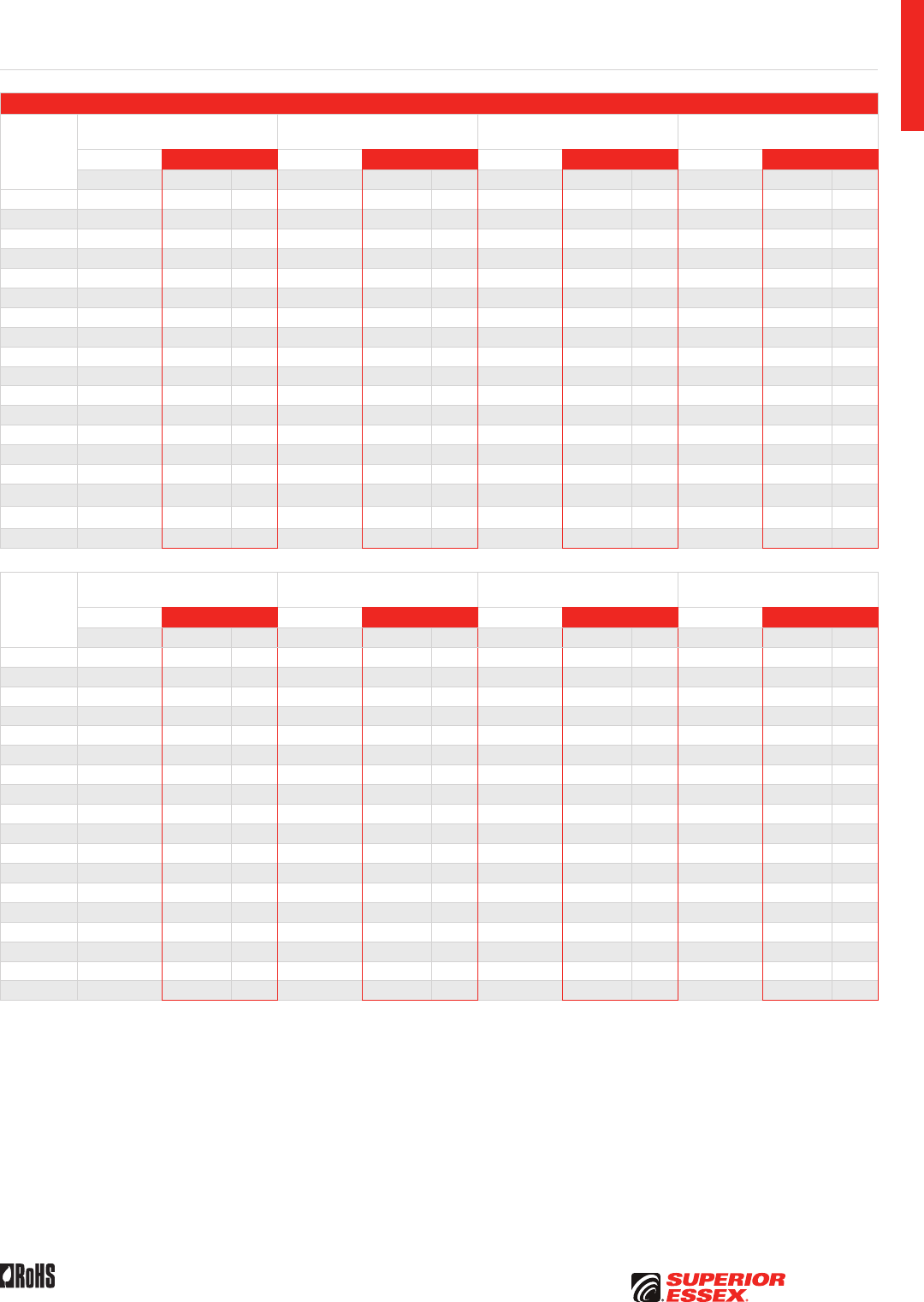
A-11
PREMISES COPPERPREMISES FIBEROSP FIBEROSP COMPOSITECENTRAL OFFICE COPPERRDUP/RUS OSP COPPERBELL OSP COPPEROSP COPPER WIRECANADIAN OSP COPPERTECHNICAL INFO
Rev 10/10 Ed 10.2 Toll Free 800.551.8948 | Fax 770.657.6807 | SuperiorEssex.com/Comm
Electrical Specifications
Frequency
MHz
Insertion Loss @ 20°C Maximum
dB/100 m
NEXT Minimum
dB/100 m
ACR Minimum
dB/100 m
PSNEXT Minimum
dB/100 m
TIA-568-C.2 Superior Essex TIA-568-C.2 Superior Essex TIA-568-C.2 Superior Essex TIA-568-C.2 Superior Essex
Specified Guaranteed Typical Specified Guaranteed Typical Calculated Guaranteed Typical Specified Guaranteed Typical
1 2.0 2.0 1.7 74.3 80.3 92.7 72.3 78.3 90.9 72.3 78.3 90.4
4 3.8 3.8 3.4 65.3 71.3 83.5 61.5 67.5 80.1 63.3 69.3 81.4
10 6.0 5.9 5.4 59.3 65.3 76.9 53.3 59.4 71.6 57.3 63.3 74.9
16 7.6 7.5 6.9 56.3 62.3 74.2 48.6 54.7 67.3 54.3 60.3 72.0
20 8.5 8.4 7.7 54.8 60.8 72.7 46.3 52.4 64.9 52.8 58.8 70.6
25 9.5 9.4 8.7 53.3 59.3 71.2 43.8 49.9 62.5 51.3 57.3 69.1
31.25 10.7 10.6 9.8 51.9 57.9 69.1 41.2 47.3 59.3 49.9 55.9 67.2
62.5 15.4 15.3 14.1 47.4 53.4 64.6 32.0 38.1 50.6 45.4 51.4 62.6
100 19.8 19.7 18.1 44.3 50.3 62.4 24.5 30.6 44.3 42.3 48.3 60.3
200 29.0 28.8 26.3 39.8 45.8 57.0 10.8 17.0 30.9 37.8 43.8 55.0
250 32.8 32.6 29.8 38.3 44.3 56.0 5.5 11.7 26.0 36.3 42.3 53.8
300 36.2 33.0 40.2 54.5 4.0 21.5 38.2 52.3
350 39.5 35.9 39.2 53.1 17.1 37.2 50.8
400 43.0 38.5 38.3 50.9 12.2 36.3 48.6
450 46.0 41.3 37.5 48.3 7.0 35.5 46.3
500 48.9 44.0 36.8 48.80 4.9 34.8 46.8
550 51.8 46.6 36.2 48.1 1.6 34.2 46.0
650 51.1 45.0 43.1
Frequency
MHz
PSACR Minimum
dB/100 m
Return Loss Minimum
dB/100 m
ELFEXT (ACRF) Minimum
dB/100 m
PSELFEXT (PSACRF) Minimum
dB/100 m
TIA-568-C.2 Superior Essex TIA-568-C.2 Superior Essex TIA-568-C.2 Superior Essex TIA-568-C.2 Superior Essex
Calculated Guaranteed Typical Specified Guaranteed Typical Specified Guaranteed Typical Specified Guaranteed Typical
1 70.3 76.3 88.7 20.0 20.0 26.8 67.8 73.8 84.7 64.8 70.8 82.8
4 59.5 65.5 78.1 23.0 23.6 31.2 55.7 61.7 72.8 52.7 58.7 71.0
10 51.3 57.3 69.6 25.0 26.0 33.2 47.8 53.8 65.1 44.8 50.8 63.1
16 46.6 52.7 65.2 25.0 26.0 32.8 43.7 49.7 61.2 40.7 46.7 59.2
20 44.3 50.3 63.0 25.0 26.0 33.0 41.7 47.7 59.3 38.7 44.7 57.3
25 41.8 47.8 60.5 24.3 25.5 34.6 39.8 45.8 57.4 36.8 42.8 55.4
31.25 39.2 45.2 57.6 23.6 25.0 34.6 37.9 43.9 55.6 34.9 40.9 53.5
62.5 30.0 35.9 48.7 21.5 23.5 34.0 31.8 37.8 49.8 28.8 34.8 47.7
100 22.5 28.4 42.4 20.1 22.5 33.0 27.8 33.8 46.0 24.8 30.8 43.7
200 8.8 14.6 29.0 18.0 21.0 30.6 21.7 27.7 40.1 18.7 24.7 37.8
250 3.5 9.3 24.3 17.3 20.5 29.8 19.8 25.8 38.1 16.8 22.8 35.8
300 1.5 19.8 20.1 28.7 24.2 36.3 21.2 34.0
350 -2.8 15.3 19.8 27.3 22.9 35.0 19.9 32.7
400 -7.4 10.6 15.9 26.7 21.7 33.6 18.7 31.1
450 -11.3 5.5 15.5 25.8 32.4 30.1
500 -14.9 3.3 15.2 24.7 30.9 28.6
550 -17.7 0.0 14.9 23.1 29.5 27.2
650 18.4 26.2 24.0
NextGain Category 6eX CMR/CMP
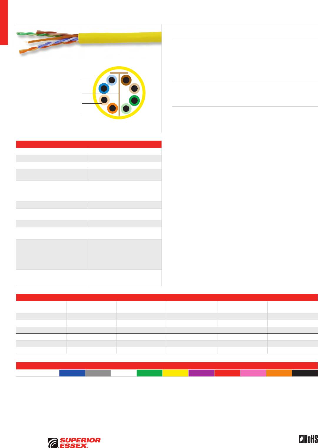
A-12
PREMISES COPPER PREMISES FIBER OSP FIBER OSP COMPOSITE CENTRAL OFFICE COPPER RDUP/RUS OSP COPPER BELL OSP COPPER OSP COPPER WIRE CANADIAN OSP COPPER TECHNICAL INFO
Rev 10/10 Ed 10.2Toll Free 800.551.8948 | Fax 770.657.6807 | SuperiorEssex.com/Comm
Specifications
Pair Count 4
Conductor Solid annealed copper
AWG (mm) 23 (0.57)
Insulation CMR: Polyolefin
CMP: FEP
Insulation Colors
Pair 1: ColorTip™ Light Blue, Blue
Pair 2: ColorTip Light Orange, Orange
Pair 3: ColorTip Light Green, Green
Pair 4: ColorTip Light Brown, Brown
Separator T-Filler
Jacket CMR: Flame retardant (FR) PVC
CMP: FR, low smoke PVC
Characteristic Impedance (Ohms) 100 ± 15
Nominal Velocity
of Propagation (%)
CMR: 71
CMP: 74
Performance Compliance
UL 444
CSA C22.2 No. 214-08
UL 1666
NFPA 262
ANSI/TIA-568-C.2
RoHS-compliant
NRTL Programs
UL Verified CAT 6
UL, c(UL) Listed CMR
UL, c(UL) Listed CMP
Part Numbers and Physical Characteristics
Listing Part Number¹
Nominal Diameter
in (mm)
Approx. Weight
lbs/kft (kg/km) Package Packages Per Pallet
CMR 66-246-xA 0.22 (5.5) 24 (36) 1,000’ BrakeBox®27
CMR 66-272-xA 0.22 (5.5) 24 (36) 1,000’ Plywood Reel 16
CMR 66-240-xA 0.22 (5.5) 24 (36) 1,000’ POP™ Box 20
CMP 66-246-xB 0.22 (5.5) 26 (39) 1,000’ BrakeBox®27
CMP 66-272-xB 0.22 (5.5) 26 (39) 1,000’ Plywood Reel 16
CMP 66-240-xB 0.22 (5.5) 26 (39) 1,000’ POP™ Box 20
Jacket Colors
¹Replace “x” with: Blue = 2 Gray = 3 White = 4 Green = 5 Yellow = 6 Purple = 7 Red = 9 Pink = C Orange = D Black = E
DataGain® Category 6+ CMR/CMP
Product Description
DataGain® cable provides the best value in Category 6+ cables on the
market today. The innovative design, which utilizes a T-Filler separator,
yields exceptional performance that exceeds TIA/EIA CAT 6 specifications.
DataGain easily surpasses the performance of other cost-competitive
CAT 6 cables.
Applications
• 10BASE-T through 1000BASE-T ethernet
• ATM and token ring
Features Benefits
• Guaranteed electrical
performance to 400 MHz
• Greater assurance of exceptional
overall channel performance at
a great value
• Guaranteed 3 dB margin
in ACR and PSACR
• “Future-proofs”
the cable installation
• Tested to 550 MHz • Assures ample
bandwidth headroom
• Round design with
T-Filler separator
• Reduces installation time
• Warranted with numerous
connectivity manufacturers
• Offers flexibility in selection
of connectivity solutions
• BrakeBox® payout
control system
• Adjustable tension control
on reel prevents over spin
and entangling of cable
• CableID™ alpha numeric code
printed every 2 feet
• Allows both ends of a cable run
to be easily identifiable without
the need to seperately label or
tone the cable
• QuickCount® marking system
in feet and meters
• Provides remaining length
of cable on reel
• ColorTip™ circuit
identification system
• Easily identifiable conductor
mates even in low light
environments
• Color coded box labels • Easily identifies jacket colors
Solid Annealed
Copper Conductor
Thermoplastic Insulation
Flame Retardant PVC Jacket
T-Filler Separator

A-13
PREMISES COPPERPREMISES FIBEROSP FIBEROSP COMPOSITECENTRAL OFFICE COPPERRDUP/RUS OSP COPPERBELL OSP COPPEROSP COPPER WIRECANADIAN OSP COPPERTECHNICAL INFO
Rev 10/10 Ed 10.2 Toll Free 800.551.8948 | Fax 770.657.6807 | SuperiorEssex.com/Comm
Electrical Specifications
Frequency
MHz
Insertion Loss @ 20°C Maximum
dB/100 m
NEXT Minimum
dB/100 m
ACR Minimum
dB/100 m
PSNEXT Minimum
dB/100 m
TIA-568-C.2 Superior Essex TIA-568-C.2 Superior Essex TIA-568-C.2 Superior Essex TIA-568-C.2 Superior Essex
Specified Guaranteed Typical Specified Guaranteed Typical Calculated Guaranteed Typical Specified Guaranteed Typical
1 2.0 2.0 1.7 74.3 77.3 87.6 72.3 75.3 85.9 72.3 75.3 85.2
4 3.8 3.8 3.4 65.3 68.3 77.9 61.5 64.5 74.5 63.3 66.3 75.6
10 6.0 5.9 5.4 59.3 62.3 71.4 53.3 56.4 66.0 57.3 60.3 69.1
16 7.6 7.5 6.9 56.3 59.2 68.4 48.6 51.7 61.5 54.2 57.2 66.1
20 8.5 8.4 7.8 54.8 57.8 67.1 46.3 49.4 59.4 52.8 55.8 64.8
25 9.5 9.4 8.7 53.3 56.3 65.4 43.8 46.9 56.7 51.3 54.3 63.1
31.25 10.7 10.6 9.8 51.9 54.9 64.2 41.2 44.3 54.3 49.9 52.9 61.8
62.5 15.4 15.3 14.1 47.4 50.4 59.5 32.0 35.1 45.4 45.4 48.4 57.3
100 19.8 19.7 18.1 44.3 47.3 56.7 24.5 27.6 38.5 42.3 45.3 54.3
200 29.0 28.8 26.4 39.8 42.8 51.5 10.8 14.0 25.3 37.8 40.8 49.3
250 32.8 32.6 29.8 38.3 41.3 50.5 5.5 8.7 20.5 36.3 39.3 47.8
300 36.2 33.0 37.1 48.2 0.7 15.2 35.1 45.7
400 42.7 38.9 35.3 45.2 6.2 33.3 42.6
500 44.2 42.4 40.0
550 47.2 41.0 39.1
Frequency
MHz
PSACR Minimum
dB/100 m
Return Loss Minimum
dB/100 m
ELFEXT (ACRF) Minimum
dB/100 m
PSELFEXT (PSACRF) Minimum
dB/100 m
TIA-568-C.2 Superior Essex TIA-568-C.2 Superior Essex TIA-568-C.2 Superior Essex TIA-568-C.2 Superior Essex
Calculated Guaranteed Typical Specified Guaranteed Typical Specified Guaranteed Typical Specified Guaranteed Typical
1 70.3 73.3 83.6 20.0 20.2 27.5 67.8 70.7 80.6 64.8 68.3 78.6
4 59.5 62.5 72.3 23.0 23.2 32.8 55.8 58.7 68.7 52.8 56.3 66.8
10 51.3 54.5 63.7 25.0 25.5 35.1 47.8 50.7 60.9 44.8 48.3 58.9
16 46.6 49.7 59.3 25.0 25.5 35.2 43.7 46.6 56.9 40.7 44.2 54.9
20 44.3 47.4 57.2 25.0 25.5 34.9 41.8 44.7 55.0 38.8 42.3 52.9
25 41.8 44.9 54.5 24.3 24.8 35.0 39.8 42.7 53.2 36.8 40.3 51.0
31.25 39.2 42.3 52.2 23.6 24.1 34.7 37.9 40.8 51.3 34.9 38.4 49.1
62.5 30.0 33.1 43.3 21.5 22.0 32.2 31.9 34.8 45.5 28.9 32.4 43.2
100 22.5 25.6 36.5 20.1 20.6 31.2 27.8 30.7 41.6 24.8 28.3 39.3
200 8.8 12.0 23.2 18.0 18.5 29.2 21.8 24.7 35.7 18.8 22.3 33.4
250 3.5 6.7 18.4 17.3 17.8 29.1 19.8 22.7 33.7 16.8 20.3 31.4
300 13.1 16.8 27.4 18.3 32.0 15.3 29.7
400 4.2 15.9 26.0 15.8 29.2 12.8 26.8
500 24.5 26.2 23.9
550 23.6 24.6 22.5
DataGain Category 6+ CMR/CMP
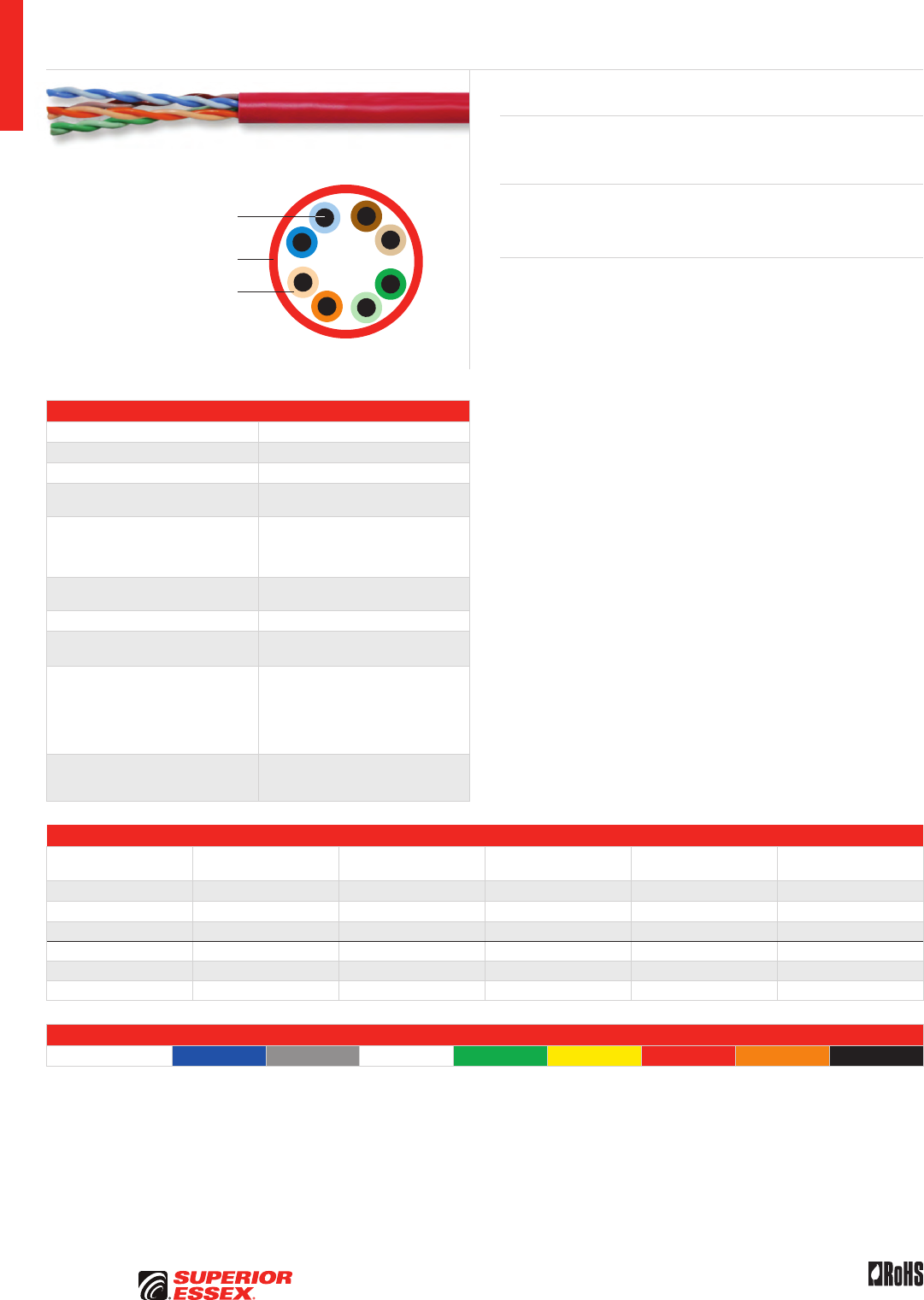
A-14
PREMISES COPPER PREMISES FIBER OSP FIBER OSP COMPOSITE CENTRAL OFFICE COPPER RDUP/RUS OSP COPPER BELL OSP COPPER OSP COPPER WIRE CANADIAN OSP COPPER TECHNICAL INFO
Rev 10/10 Ed 10.2Toll Free 800.551.8948 | Fax 770.657.6807 | SuperiorEssex.com/Comm
Solid Annealed
Copper Conductor
Thermoplastic Insulation
Flame Retardant PVC Jacket
Specifications
Pair Count 4
Conductor Solid annealed copper
AWG (mm) 23 (0.57)
Insulation CMR: Polyolefin
CMP: FEP
Insulation Colors
Pair 1: ColorTip™ Light Blue, Blue
Pair 2: ColorTip Light Orange, Orange
Pair 3: ColorTip Light Green, Green
Pair 4: ColorTip Light Brown, Brown
Jacket CMR: Flame retardant (FR) PVC
CMP: FR, low smoke PVC
Characteristic Impedance (Ohms) 100 ± 15
Nominal Velocity
of Propagation (%)
CMR: 71
CMP: 74
Performance Compliance
UL 444
CSA C22.2 No. 214-08
UL 1666
NFPA 262
ANSI/TIA-568-C.2
RoHS-compliant
NRTL Programs
UL Verified CAT 6
UL, c(UL) Listed CMR
UL, c(UL) Listed CMP
Part Numbers and Physical Characteristics
Listing Part Number¹
Nominal Diameter
in (mm)
Approx. Weight
lbs/kft (kg/km) Package Packages Per Pallet
CMR 77-246-xA 0.22 (5.5) 24 (36) 1,000’ BrakeBox®27
CMR 77-272-xA 0.22 (5.5) 24 (36) 1,000’ Plywood Reel 16
CMR 77-240-xA 0.22 (5.5) 24 (36) 1,000’ POP™ Box 20
CMP 77-246-xB 0.22 (5.5) 25 (37) 1,000’ BrakeBox®27
CMP 77-272-xB 0.22 (5.5) 25 (37) 1,000’ Plywood Reel 16
CMP 77-240-xB 0.22 (5.5) 25 (37) 1,000’ POP™ Box 20
Jacket Colors
¹Replace “x” with: Blue = 2 Gray = 3 White = 4 Green = 5 Yellow = 6 Red = 9 Orange = D Black = E
Category 6 CMR/CMP
Product Description
Superior Essex Series 77 product line provides exceptional value for jobs
that require standards compliant Category 6 cable at a cost-effective price.
Applications
• 10BASE-T through 1000BASE-T ethernet
• ATM and token ring
Features Benefits
• Meets ANSI/TIA-568-C.2
specification
• Provides cost effective solution
• BrakeBox® payout
control system
• Adjustable tension control on reel
prevents over spin and entangling
of cable
• CableID™ alpha numeric code
printed every 2 feet
• Allows both ends of a cable run
to be easily identifiable without
the need to seperately label or
tone the cable
• QuickCount® marking system
in feet and meters
• Provides remaining length
of cable on reel
• ColorTip™ circuit
identification system
• Easily identifiable conductor
mates even in low light
environments
• Color coded box labels • Easily identifies jacket colors
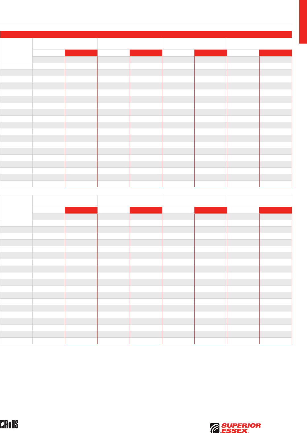
A-15
PREMISES COPPERPREMISES FIBEROSP FIBEROSP COMPOSITECENTRAL OFFICE COPPERRDUP/RUS OSP COPPERBELL OSP COPPEROSP COPPER WIRECANADIAN OSP COPPERTECHNICAL INFO
Rev 10/10 Ed 10.2 Toll Free 800.551.8948 | Fax 770.657.6807 | SuperiorEssex.com/Comm
Electrical Specifications
Frequency
MHz
Insertion Loss @ 20°C Maximum
dB/100 m
NEXT Minimum
dB/100 m
ACR Minimum
dB/100 m
PSNEXT Minimum
dB/100 m
TIA-568-C.2 Superior Essex TIA-568-C.2 Superior Essex TIA-568-C.2 Superior Essex TIA-568-C.2 Superior Essex
Specified Typical Specified Typical Calculated Typical Specified Typical
1 2.0 1.7 74.3 82.9 72.3 82.2 72.3 81.9
4 3.8 3.4 65.3 77.6 61.5 74.2 63.3 75.0
8 5.3 4.8 60.8 74.4 55.4 68.9 58.8 71.9
10 6.0 5.4 59.3 70.1 53.3 64.7 57.3 68.3
16 7.6 6.9 56.2 69.6 48.7 62.5 54.2 67.1
20 8.5 7.8 54.8 68.7 46.3 60.7 52.8 65.7
25 9.5 8.8 53.3 66.1 43.8 58.7 51.3 64.7
31.25 10.7 9.8 51.9 67.8 41.2 56.2 49.9 63.4
62.5 15.4 14.2 47.4 64.0 32.0 47.8 45.4 59.1
100 19.8 18.2 44.3 58.0 24.5 38.7 42.3 55.0
155 25.2 23.0 41.4 54.5 16.3 31.6 39.4 52.1
200 29.0 26.6 39.8 53.8 10.8 26.5 37.8 50.6
250 32.8 30.1 38.3 51.0 5.5 21.1 36.3 48.7
300 33.4 53.8 19.4 49.1
350 36.5 50.1 14.3 47.5
400 39.5 49.1 8.0 44.5
450 42.3 44.6 3.3 43.4
500 45.1 42.9 41.7
550 47.7 41.6 39.1
Frequency
MHz
PSACR Minimum
dB/100 m
Return Loss Minimum
dB/100 m
ELFEXT Minimum
dB/100 m
PSELFEXT Minimum
dB/100 m
TIA-568-C.2 Superior Essex TIA-568-C.2 Superior Essex TIA-568-C.2 Superior Essex TIA-568-C.2 Superior Essex
Calculated Typical Specified Typical Specified Typical Specified Typical
1 70.3 80.2 20.0 26.0 67.8 78.7 64.8 76.6
4 59.5 71.6 23.0 31.1 55.8 65.9 52.8 64.2
8 53.4 67.1 24.5 34.5 49.7 60.1 46.7 58.4
10 51.3 62.9 25.0 36.3 47.8 58.1 44.8 56.4
16 46.7 60.2 25.0 37.7 43.7 54.0 40.7 52.2
20 44.3 58.1 25.0 36.0 41.8 52.1 38.8 50.3
25 41.8 56.1 24.3 38.6 39.8 50.2 36.8 48.4
31.25 39.2 53.6 23.6 38.3 37.9 48.1 34.9 46.4
62.5 30.0 45.0 21.5 32.8 31.9 41.4 28.9 40.3
100 22.5 37.0 20.1 30.7 27.8 36.8 24.8 35.2
155 14.3 29.1 18.8 28.8 24.0 33.3 21.0 31.9
200 8.8 24.0 18.0 27.6 21.8 32.6 18.8 31.8
250 3.5 18.8 17.3 28.5 19.8 32.5 16.8 31.3
300 15.8 28.6 30.8 28.9
350 11.6 29.0 26.8 25.4
400 5.0 24.9 24.7 23.5
450 1.2 23.9 23.2 21.9
500 25.0 22.5 21.5
550 24.2 22.4 22.0
Category 6 CMR/CMP
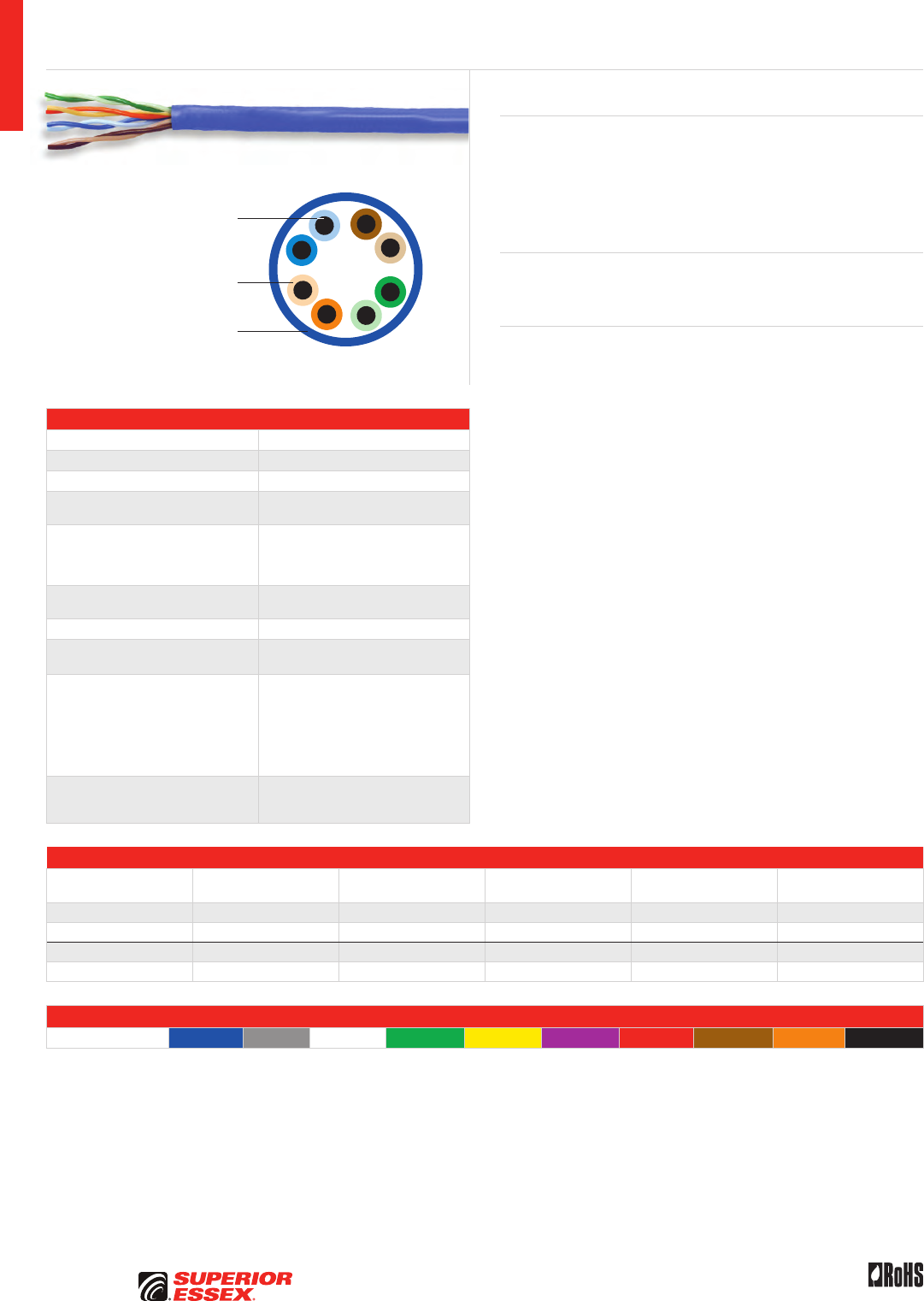
A-16
PREMISES COPPER PREMISES FIBER OSP FIBER OSP COMPOSITE CENTRAL OFFICE COPPER RDUP/RUS OSP COPPER BELL OSP COPPER OSP COPPER WIRE CANADIAN OSP COPPER TECHNICAL INFO
Rev 10/10 Ed 10.2Toll Free 800.551.8948 | Fax 770.657.6807 | SuperiorEssex.com/Comm
Specifications
Pair Count 4
Conductor Solid annealed copper
AWG (mm) 24 (0.51)
Insulation CMR: Polyolefin
CMP: FEP
Insulation Colors
Pair 1: ColorTip™ Light Blue, Blue
Pair 2: ColorTip Light Orange, Orange
Pair 3: ColorTip Light Green, Green
Pair 4: ColorTip Light Brown, Brown
Jacket CMR: Flame retardant (FR) PVC
CMP: FR, low smoke PVC
Characteristic Impedance (Ohms) 100 ± 15
Nominal Velocity
of Propagation (%)
CMR: 70
CMP: 74
Performance Compliance
UL 444
CSA C22.2 No. 214-08
UL 1666
NFPA 262
ANSI/TIA-568-C.2
ANSI/ICEA S-90-661-2008
RoHS-compliant
NRTL Programs
UL Verified CAT 5e
UL, c(UL) Listed CMR
UL, c(UL) Listed CMP
Part Numbers and Physical Characteristics
Listing Part Number¹
Nominal Diameter
in (mm)
Approx. Weight
lbs/kft (kg/km) Package Packages Per Pallet
CMR 52-200-x5 0.19 (4.8) 19 (28) 1,000’ Reel-in-a-Box 45
CMR 52-240-x5 0.19 (4.8) 19 (28) 1,000’ POP™ Box 36
CMP 52-200-x8 0.19 (4.8) 21 (31) 1,000’ Reel-in-a-Box 45
CMP 52-241-x8 0.19 (4.8) 21 (31) 1,000’ POP™ Box 45
Jacket Colors
¹Replace “x” with: Blue = 2 Gray = 3 White = 4 Green = 5 Yellow = 6 Purple = 7 Red = 9 Brown = B Orange = D Black = E
Cobra Category 5e+ CMR/CMP
Product Description
Cobra Category 5e+ cable is the performance leader in its class. Cobra
cable is ideal for installations that require true “future proofing” in channel
performance. By design, Cobra cables are manufactured to the highest
quality standards, design requirements and materials to ensure that every
box provides significant margin over ANSI/TIA-568-C.2 specifications for
NEXT, Power Sum NEXT and Insertion Loss.
Applications
• 10BASE-T through 1000BASE-T ethernet
• ATM and token ring
Features Benefits
• Guaranteed NEXT of 3 dB
greater than ANSI/TIA-568-C.2
specification across
frequency range
• Greater assurance of exceptional
overall channel performance
• Guaranteed ACR of 19.5 dB
at 100 MHz
• Performance assurance
for multiple high-bandwidth
applications
• Exceptional PSNEXT, PSELFEXT
and PSACR over CAT 5e
• Reduces BER, improving
network efficiency
• “WideMouth” POP™ Box design • Reduces tension on wire
to ensure proper electrical
performance after installation
• CableID™ alpha numeric code
printed every 2 feet
• Allows both ends of a cable run
to be easily identifiable without
the need to seperately label or
tone the cable
• QuickCount® marking system
in feet and meters
• Provides remaining length
of cable on reel
• ColorTip™ circuit
identification system
• Easily identifiable conductor
mates even in low light
environments
• Color coded box labels • Easily identifies jacket colors
Solid Annealed
Copper Conductor
Thermoplastic Insulation
Flame Retardant PVC Jacket
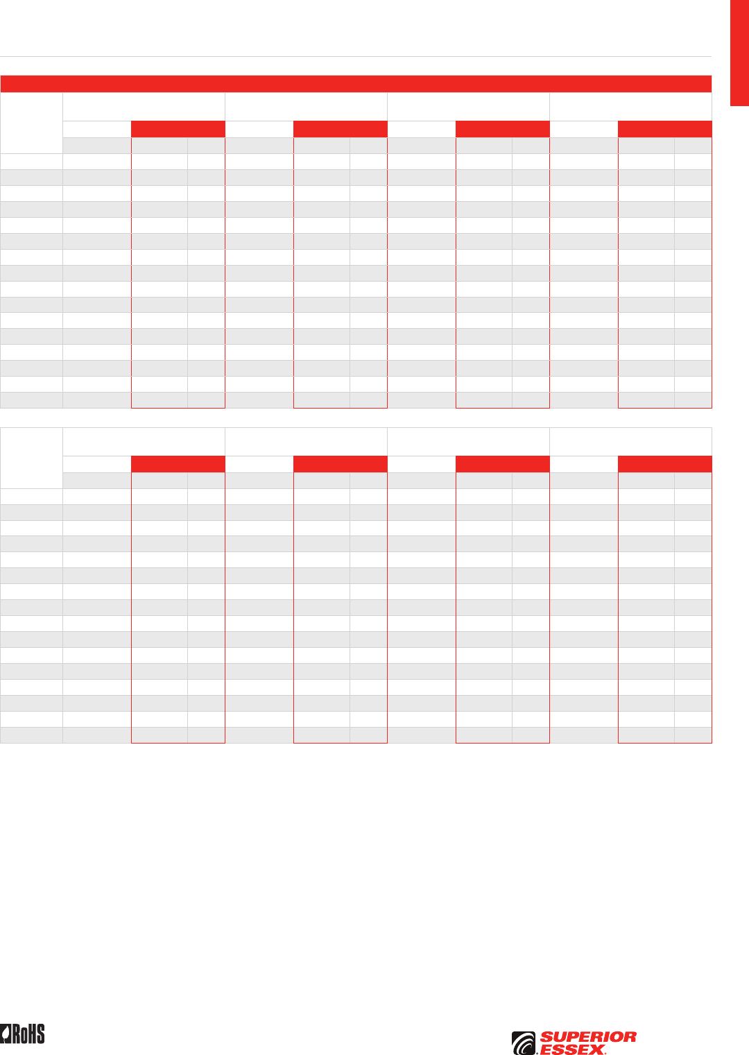
A-17
PREMISES COPPERPREMISES FIBEROSP FIBEROSP COMPOSITECENTRAL OFFICE COPPERRDUP/RUS OSP COPPERBELL OSP COPPEROSP COPPER WIRECANADIAN OSP COPPERTECHNICAL INFO
Rev 10/10 Ed 10.2 Toll Free 800.551.8948 | Fax 770.657.6807 | SuperiorEssex.com/Comm
Electrical Specifications
Frequency
MHz
Insertion Loss @ 20°C Maximum
dB/100 m
NEXT Minimum
dB/100 m
ACR Minimum
dB/100 m
PSNEXT Minimum
dB/100 m
TIA-568-C.2 Superior Essex TIA-568-C.2 Superior Essex TIA-568-C.2 Superior Essex TIA-568-C.2 Superior Essex
Specified Guaranteed Typical Specified Guaranteed Typical Calculated Guaranteed Typical Specified Guaranteed Typical
0.772 1.8 1.8 1.6 67.0 70.0 81.1 65.2 69.3 84.0 64.0 68.0 78.7
1 2.0 2.0 1.8 65.3 68.3 79.5 63.3 67.4 77.7 62.3 66.3 77.2
4 4.1 4.0 3.6 56.3 59.3 69.9 52.2 56.4 66.4 53.3 57.3 67.5
8 5.8 5.7 5.1 51.8 54.8 65.1 46.0 50.3 60.0 48.8 52.8 62.7
10 6.5 6.4 5.8 50.3 53.3 63.6 43.8 48.2 57.9 47.3 51.3 61.2
16 8.2 8.1 7.4 47.2 50.3 60.4 39.0 43.4 53.1 44.2 48.3 58.0
20 9.3 9.2 8.3 45.8 48.8 59.0 36.5 41.0 50.9 42.8 46.8 56.6
25 10.4 10.3 9.3 44.3 47.3 57.5 33.9 38.5 48.3 41.3 45.3 55.1
31.25 11.7 11.6 10.4 42.9 45.9 56.0 31.2 35.8 45.7 39.9 43.9 53.5
62.5 17.0 16.8 14.9 38.4 41.4 51.7 21.4 26.2 36.8 35.4 39.4 49.2
100 22.0 21.7 19.1 35.3 38.3 48.5 13.3 21.0 29.5 32.3 36.3 46.0
155 27.7 24.2 35.5 45.7 9.3 21.6 33.5 43.1
200 32.1 27.8 29.8 43.6 3.5 16.0 27.8 41.0
250 36.5 31.4 28.3 42.0 10.7 26.3 39.4
300 40.5 34.7 27.2 40.4 5.9 25.2 37.9
350 44.4 37.7 26.2 39.3 1.7 24.2 36.8
Frequency
MHz
PSACR Minimum
dB/100 m
Return Loss Minimum
dB/100 m
ELFEXT Minimum
dB/100 m
PSELFEXT Minimum
dB/100 m
TIA-568-C.2 Superior Essex TIA-568-C.2 Superior Essex TIA-568-C.2 Superior Essex TIA-568-C.2 Superior Essex
Calculated Guaranteed Typical Specified Guaranteed Typical Specified Guaranteed Typical Specified Guaranteed Typical
0.772 62.2 66.3 86.0 19.4 19.4 26.0 66.0 66.0 77.4 63.0 63.0 79.2
1 60.3 64.4 75.4 20.0 20.0 28.5 63.8 63.8 72.6 60.8 60.8 70.8
4 49.2 53.4 64.0 23.0 23.0 35.6 51.8 51.7 60.7 48.7 48.7 59.0
8 43.0 47.3 57.7 24.5 24.5 35.7 45.7 45.7 54.8 42.7 42.7 53.1
10 40.8 45.2 55.6 25.0 25.0 35.9 43.8 43.8 52.9 40.8 40.8 51.1
16 36.0 40.4 50.8 25.0 25.0 35.2 39.7 39.7 48.9 36.7 36.7 47.1
20 33.5 38.0 48.6 25.0 25.0 34.9 37.8 37.7 47.0 34.7 34.7 45.2
25 30.9 35.5 46.0 24.3 24.3 35.3 35.8 35.8 45.1 32.8 32.8 43.3
31.25 28.2 32.8 43.4 23.6 23.6 34.8 33.9 33.9 43.2 30.9 30.9 41.3
62.5 18.4 23.2 34.6 21.5 21.5 31.8 27.9 27.8 37.2 24.8 24.8 35.2
100 10.3 18.0 27.3 20.1 20.1 30.1 23.8 23.8 33.2 20.8 20.8 31.1
155 6.3 19.4 18.8 28.4 19.9 29.3 16.9 27.2
200 0.5 13.9 18.0 27.3 11.7 27.1 10.7 25.0
250 8.6 17.3 26.1 9.8 25.1 8.8 23.1
300 3.8 16.8 25.1 8.2 23.7 7.2 21.5
350 16.3 24.0 6.9 22.5 5.9 20.3
Cobra Category 5e+ CMR/CMP
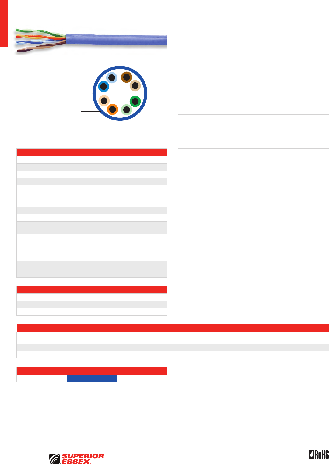
A-18
PREMISES COPPER PREMISES FIBER OSP FIBER OSP COMPOSITE CENTRAL OFFICE COPPER RDUP/RUS OSP COPPER BELL OSP COPPER OSP COPPER WIRE CANADIAN OSP COPPER TECHNICAL INFO
Rev 10/10 Ed 10.2Toll Free 800.551.8948 | Fax 770.657.6807 | SuperiorEssex.com/Comm
Specifications
Pair Count 4
Conductor Solid annealed copper
AWG (mm) 24 (0.51)
Insulation FEP
Insulation Colors
Pair 1: ColorTip™ Light Blue, Blue
Pair 2: ColorTip Light Orange, Orange
Pair 3: ColorTip Light Green, Green
Pair 4: ColorTip Light Brown, Brown
Jacket Low smoke flouropolymer
Characteristic Impedance (Ohms) 100 ± 15
Nominal Velocity
of Propagation (%) 74
Performance Compliance
UL 2424
NFPA 255, 259 and 262
ANSI/TIA-568-C.2
ANSI/ICEA S-90-661-2008
RoHS-compliant
NRTL Programs
UL Verified CAT 5e
UL, c(UL) Limited Combustible FHC 25/50
UL, c(UL) Listed CMP
Environmental Specifications
Operation -40°C to +200°C
Storage/Shipping -40°C to +200°C
Installation -40°C to +200°C
Part Numbers and Physical Characteristics
Part Number¹
Nominal Diameter
in (mm)
Approx. Weight
lbs/kft (kg/km) Package Packages Per Pallet
52-200-xD 0.19 (4.8) 21 (31) 1,000’ BrakeBox™27
52-272-xD 0.19 (4.8) 21 (31) 1,000’ Plywood Reel 16
Jacket Colors
¹Replace “x” with: Blue = 2 White = 4
Cobra Category 5e+ Limited Combustible
Product Description
Limited Combustible Cobra is an enhanced Category 5e cable that has the
highest fire safety rating possible for data cables. Limited Combustible
Cobra is designed for high-risk applications where the exceptionally low
smoke and low fire spread values are required. Employing the latest polymer
technology, Limited Combustible Cobra is constructed entirely of chemical,
oil, heat, and moisture resistant fluoropolymer. The cable is ideally suited
for industrial UTP applications where severe environmental stresses
would compromise standard PVC plenum or riser cables. In addition, the
cable’s printing process ensures a more durable print legend on the cable
compared with other limited combustible cables.
Applications
• 10BASE-T through 1000BASE-T ethernet, ATM and token ring
• ATM and token ring
• High risk, high liability installations
Features Benefits
• UL Listed: Limited Combustible
FHC 25/50
• Exceptional low smoke and low
flame Spread Performance
• Lower fuel load than plenum PVC • Higher safety rating for
high-risk applications
• All fluoropolymer construction • Resistant to chemical, moisture
and heat exposure
• RoHS-compliant • No heavy metals;
and no toxic components
• Exceeds CAT 5e requirements • Insures compatibility with
new protocols
• Durable cable print • Print legend does not rub
off cable like other limited
combustible cables
• BrakeBox® payout
control system
• Adjustable tension control on reel
prevents over spin and entangling
of cable
• QuickCount® marking system
in feet and meters
• Provides remaining length
of cable on reel
• ColorTip™ circuit
identification system
• Easily identifiable conductor
mates even in low light
environments
• Color coded box labels • Easily identifies jacket colors
Solid Annealed
Copper Conductor
Thermoplastic Insulation
Low Smoke
Fluoropolymer Jacket

A-19
PREMISES COPPERPREMISES FIBEROSP FIBEROSP COMPOSITECENTRAL OFFICE COPPERRDUP/RUS OSP COPPERBELL OSP COPPEROSP COPPER WIRECANADIAN OSP COPPERTECHNICAL INFO
Rev 10/10 Ed 10.2 Toll Free 800.551.8948 | Fax 770.657.6807 | SuperiorEssex.com/Comm
Electrical Specifications
Frequency
MHz
Insertion Loss @ 20°C Maximum
dB/100 m
NEXT Minimum
dB/100 m
ACR Minimum
dB/100 m
PSNEXT Minimum
dB/100 m
TIA-568-C.2 Superior Essex TIA-568-C.2 Superior Essex TIA-568-C.2 Superior Essex TIA-568-C.2 Superior Essex
Specified Guaranteed Typical Specified Guaranteed Typical Calculated Guaranteed Typical Specified Guaranteed Typical
1 2.0 2.0 1.8 65.3 68.3 79.4 63.3 65.9 77.7 62.3 66.3 77.2
4 4.1 4.0 3.6 56.3 59.3 69.9 52.2 54.9 66.4 53.3 57.3 67.4
8 5.8 5.7 5.1 51.8 54.8 65.1 46.0 48.8 60.0 48.8 52.8 62.7
10 6.5 6.4 5.8 50.3 53.3 63.6 43.8 46.7 57.9 47.3 51.3 61.2
16 8.2 8.2 7.4 47.3 50.3 60.4 39.1 41.9 53.1 44.3 48.3 58.0
20 9.3 9.2 8.2 45.8 48.8 59.0 36.5 39.5 50.9 42.8 46.8 56.6
25 10.4 10.3 9.3 44.3 47.3 57.5 33.9 37.0 48.3 41.3 45.3 55.1
31.25 11.7 11.6 10.5 42.9 45.9 56.0 31.2 34.3 45.7 39.9 43.9 53.5
62.5 17.0 16.8 14.9 38.4 41.4 51.7 21.4 24.7 36.8 35.4 39.4 49.2
100 22.0 21.7 19.2 35.3 38.3 48.5 13.3 19.5 29.5 32.3 36.3 46.0
155 27.8 24.2 35.5 45.7 9.3 21.6 33.5 43.1
200 32.1 27.8 29.8 43.6 3.5 16.0 27.8 41.0
250 36.5 31.4 28.3 42.0 10.7 26.3 39.4
300 40.5 34.7 27.2 40.4 5.9 25.2 37.7
350 44.4 37.8 26.2 39.3 1.7 24.2 36.8
Frequency
MHz
PSACR Minimum
dB/100 m
Return Loss Minimum
dB/100 m
ELFEXT Minimum
dB/100 m
PSELFEXT Minimum
dB/100 m
TIA-568-C.2 Superior Essex TIA-568-C.2 Superior Essex TIA-568-C.2 Superior Essex TIA-568-C.2 Superior Essex
Calculated Guaranteed Typical Specified Guaranteed Typical Specified Guaranteed Typical Specified Guaranteed Typical
1 60.3 64.4 75.4 20.0 20.0 28.5 63.8 63.8 72.6 60.8 60.8 70.6
4 49.2 53.4 64.0 23.0 23.0 35.6 51.7 51.7 60.7 48.7 48.7 59.0
8 43.0 47.3 57.7 24.5 24.5 35.7 45.7 45.7 54.8 42.7 42.7 53.1
10 40.8 45.2 55.6 25.0 25.0 35.9 43.8 43.8 52.9 40.8 40.8 51.1
16 36.1 40.4 50.8 25.0 25.0 35.2 39.7 39.7 48.9 36.7 36.7 47.1
20 33.5 38.0 48.6 25.0 25.0 34.9 37.7 37.7 47.0 34.7 34.7 45.2
25 30.9 35.5 46.0 24.3 24.3 35.2 35.8 35.8 45.1 32.8 32.8 43.3
31.25 28.2 32.8 43.4 23.6 23.6 34.8 33.9 33.9 43.2 30.9 30.9 41.3
62.5 18.4 23.2 34.6 21.5 21.5 31.8 27.8 27.8 37.2 24.8 24.8 35.2
100 10.3 18.0 27.3 20.1 20.1 30.1 23.8 23.8 33.2 20.8 20.8 31.1
155 6.8 19.4 18.8 28.4 19.9 29.3 16.9 27.2
200 1.0 13.9 18.0 27.3 11.7 27.1 10.7 25.0
250 8.6 17.3 26.1 9.8 25.1 8.8 23.1
300 3.8 16.8 25.1 8.2 23.7 7.2 21.5
350 16.3 24.0 6.9 22.5 5.9 20.3
Cobra Category 5e+ Limited Combustible
A-20
PREMISES COPPER PREMISES FIBER OSP FIBER OSP COMPOSITE CENTRAL OFFICE COPPER RDUP/RUS OSP COPPER BELL OSP COPPER OSP COPPER WIRE CANADIAN OSP COPPER TECHNICAL INFO
Rev 10/10 Ed 10.2Toll Free 800.551.8948 | Fax 770.657.6807 | SuperiorEssex.com/Comm
Specifications
Pair Count 4
Conductor Solid annealed copper
AWG (mm) 24 (0.51)
Insulation CMR: Polyolefin
CMP: FEP
Insulation Colors
Pair 1: ColorTip™ Light Blue, Blue
Pair 2: ColorTip Light Orange, Orange
Pair 3: ColorTip Light Green, Green
Pair 4: ColorTip Light Brown, Brown
Shield Aluminum foil tape
Drain Wire 24 AWG tinned copper
Jacket CMR: Flame retardant (FR) PVC
CMP: FR, low smoke PVC
Package 1,000’ plywood reel
Characteristic Impedance (Ohms) 100 ± 15
Nominal Velocity
of Propagation (%)
CMR: 67
CMP: 70
Performance Compliance
UL 444
CSA C22.2 No. 214-08
UL 1666
NFPA 262
ANSI/TIA-568-C.2
RoHS-compliant
NRTL Programs
UL Verified CAT 5e
UL, c(UL) Listed CMR
UL, c(UL) Listed CMP
Part Numbers and Physical Characteristics
Listing Part Number¹
Nominal Diameter
in (mm)
Approx. Weight
lbs/kft (kg/km) Packages Per Pallet
CMR 5F-220-x5 0.28 (7.1) 31 (46) 12
CMP 5F-220-x8 0.25 (6.4) 30 (45) 12
Jacket Colors
¹Replace “x” with: Blue = 2 Gray = 3 White = 4 Green = 5 Yellow = 6 Red = 9 Orange = D Black = E
Category 5e+ ScTP (F/UTP) CMR/CMP
Product Description
Superior Essex offers Screen Twisted Pair (ScTP) shielded Category
5e+ cables in both plenum and riser versions. The cable has guaranteed
performance out to 350MHz and meets all applicable ANSI/TIA-568-C.2
requirements. The cable consists of four balanced 24 AWG copper pairs.
The core is wrapped with an aluminum foil tape and has a tin coated drain
wire. The tape wrapped core is jacketed with the appropriate flexible PVC
jacket for plenum or riser applications.
Applications
• ATM and token ring configurations
• 10BASE-T through 1000BASE-T ethernet
• Applications requiring secure networks or protection from EMI/RFI
Features Benefits
• Aluminum foil tape covers
all 4-pair
• Protects against EMI/RFI
and provides greater security
• Exceeds ANSI/TIA-568-C.2
for CAT 5e cable performance
• Assures compliance for all
current networking applications
(up to 1000BASE-T)
• Guaranteed performance
to 350 MHz
• Assures ample bandwidth
headroom
• CableID™ alpha numeric code
printed every 2 feet
• Allows both ends of a cable run
to be easily identifiable without
the need to seperately label or
tone the cable
• QuickCount® marking system
in feet and meters
• Provides remaining length
of cable on reel
• ColorTip™ circuit
identification system
• Easily identifiable conductor
mates even in low light
environments
• Color coded box labels • Easily identifies jacket colors
Flame Retardant
PVC Jacket
Solid Annealed
Copper Conductor
Thermoplastic Insulation
Tin Coated Drain Wire
Aluminum Foil Tape Shield
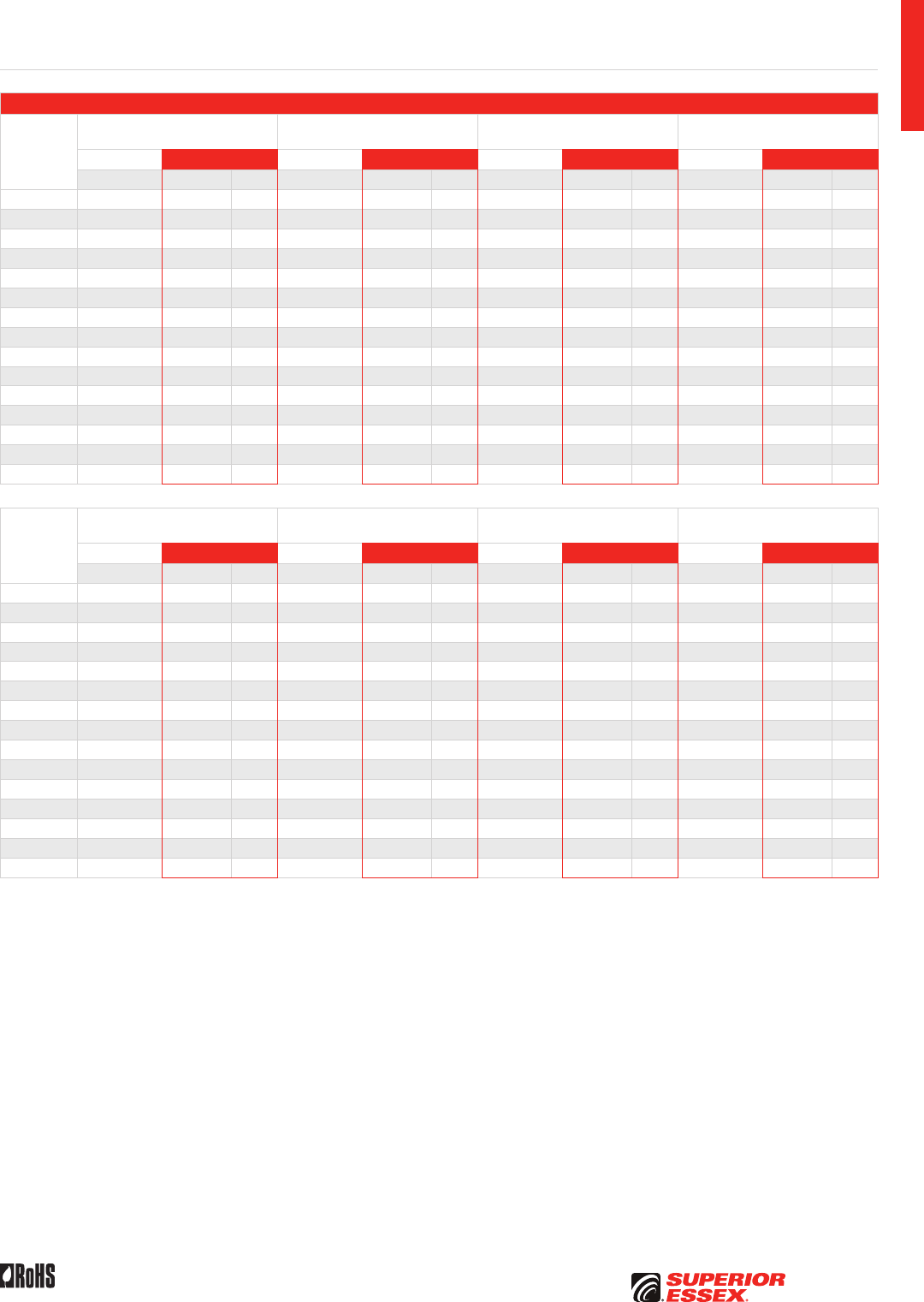
A-21
PREMISES COPPERPREMISES FIBEROSP FIBEROSP COMPOSITECENTRAL OFFICE COPPERRDUP/RUS OSP COPPERBELL OSP COPPEROSP COPPER WIRECANADIAN OSP COPPERTECHNICAL INFO
Rev 10/10 Ed 10.2 Toll Free 800.551.8948 | Fax 770.657.6807 | SuperiorEssex.com/Comm
Electrical Specifications
Frequency
MHz
Insertion Loss @ 20°C Maximum
dB/100 m
NEXT Minimum
dB/100 m
ACR Minimum
dB/100 m
PSNEXT Minimum
dB/100 m
TIA-568-C.2 Superior Essex TIA-568-C.2 Superior Essex TIA-568-C.2 Superior Essex TIA-568-C.2 Superior Essex
Specified Guaranteed Typical Specified Guaranteed Typical Calculated Guaranteed Typical Specified Guaranteed Typical
1 2.0 2.0 1.8 65.3 68.3 79.4 63.3 65.9 77.7 62.3 66.3 77.2
4 4.1 4.0 3.6 56.3 59.3 69.9 52.2 54.9 66.4 53.3 57.3 67.4
8 5.8 5.7 5.1 51.8 54.8 65.1 46.0 48.8 60.0 48.8 52.8 62.7
10 6.5 6.4 5.8 50.3 53.3 63.6 43.8 46.7 57.9 47.3 51.3 61.2
16 8.2 8.2 7.4 47.3 50.3 60.4 39.1 41.9 53.1 44.3 48.3 58.0
20 9.3 9.2 8.2 45.8 48.8 59.0 36.5 39.5 50.9 42.8 46.8 56.6
25 10.4 10.3 9.3 44.3 47.3 57.5 33.9 37.0 48.3 41.3 45.3 55.1
31.25 11.7 11.6 10.5 42.9 45.9 56.0 31.2 34.3 45.7 39.9 43.9 53.5
62.5 17.0 16.8 14.9 38.4 41.4 51.7 21.4 24.7 36.8 35.4 39.4 49.2
100 22.0 21.7 19.2 35.3 38.3 48.5 13.3 19.5 29.5 32.3 36.3 46.0
155 27.8 24.2 35.5 45.7 9.3 21.6 33.5 43.1
200 32.1 27.8 29.8 43.6 3.5 16.0 27.8 41.0
250 36.5 31.4 28.3 42.0 10.7 26.3 39.4
300 40.5 34.7 27.2 40.4 5.9 25.2 37.7
350 44.4 37.8 26.2 39.3 1.7 24.2 36.8
Frequency
MHz
PSACR Minimum
dB/100 m
Return Loss Minimum
dB/100 m
ELFEXT Minimum
dB/100 m
PSELFEXT Minimum
dB/100 m
TIA-568-C.2 Superior Essex TIA-568-C.2 Superior Essex TIA-568-C.2 Superior Essex TIA-568-C.2 Superior Essex
Calculated Guaranteed Typical Specified Guaranteed Typical Specified Guaranteed Typical Specified Guaranteed Typical
1 60.3 64.4 75.4 20.0 20.0 28.5 63.8 63.8 72.6 60.8 60.8 70.6
4 49.2 53.4 64.0 23.0 23.0 35.6 51.7 51.7 60.7 48.7 48.7 59.0
8 43.0 47.3 57.7 24.5 24.5 35.7 45.7 45.7 54.8 42.7 42.7 53.1
10 40.8 45.2 55.6 25.0 25.0 35.9 43.8 43.8 52.9 40.8 40.8 51.1
16 36.1 40.4 50.8 25.0 25.0 35.2 39.7 39.7 48.9 36.7 36.7 47.1
20 33.5 38.0 48.6 25.0 25.0 34.9 37.7 37.7 47.0 34.7 34.7 45.2
25 30.9 35.5 46.0 24.3 24.3 35.2 35.8 35.8 45.1 32.8 32.8 43.3
31.25 28.2 32.8 43.4 23.6 23.6 34.8 33.9 33.9 43.2 30.9 30.9 41.3
62.5 18.4 23.2 34.6 21.5 21.5 31.8 27.8 27.8 37.2 24.8 24.8 35.2
100 10.3 18.0 27.3 20.1 20.1 30.1 23.8 23.8 33.2 20.0 20.8 31.1
155 6.8 19.4 18.8 28.4 19.9 29.3 16.9 27.2
200 1.0 13.9 18.0 27.3 11.7 27.1 10.7 25.0
250 8.6 17.3 26.1 9.8 25.1 8.8 23.1
300 3.8 16.8 25.1 8.2 23.7 7.2 21.5
350 16.3 24.0 6.9 22.5 5.9 20.3
Category 5e+ ScTP (F/UTP) CMR/CMP
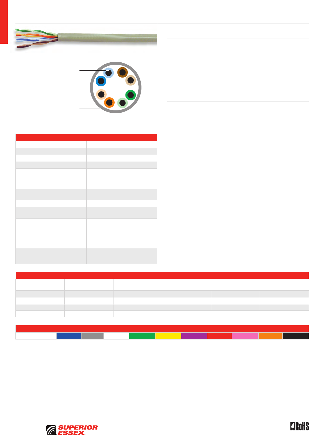
A-22
PREMISES COPPER PREMISES FIBER OSP FIBER OSP COMPOSITE CENTRAL OFFICE COPPER RDUP/RUS OSP COPPER BELL OSP COPPER OSP COPPER WIRE CANADIAN OSP COPPER TECHNICAL INFO
Rev 10/10 Ed 10.2Toll Free 800.551.8948 | Fax 770.657.6807 | SuperiorEssex.com/Comm
Solid Annealed
Copper Conductor
Thermoplastic Insulation
Flame Retardant PVC Jacket
Specifications
Pair Count 4
Conductor Solid annealed copper
AWG (mm) 24 (0.51)
Insulation Thermoplastic
Insulation Colors
Pair 1: ColorTip™ Light Blue, Blue
Pair 2: ColorTip Light Orange, Orange
Pair 3: ColorTip Light Green, Green
Pair 4: ColorTip Light Brown, Brown
Jacket CMR: Flame retardant (FR) PVC
CMP: FR, low smoke PVC
Characteristic Impedance (Ohms) 100 ± 15
Nominal Velocity
of Propagation (%)
CMR: 71
CMP: 74
Performance Compliance
UL 444
CSA C22.2 No. 214-08
UL 1666
NFPA 262
ANSI/TIA-568-C.2
RoHS-compliant
NRTL Programs
UL Verified CAT 5e
UL, c(UL) Listed CMR
UL, c(UL) Listed CMP
Part Numbers and Physical Characteristics
Listing Part Number¹
Nominal Diameter
in (mm)
Approx. Weight
lbs/kft (kg/km) Package Packages Per Pallet
CMR 51-243-x5 0.18 (4.6) 17 (25) 1,000’ Reel-in-a-Box 45
CMR 51-240-x5 0.18 (4.6) 17 (25) 1,000’ POP™ Box 45
CMP 51-243-x8 0.19 (4.8) 20 (30) 1,000’ Reel-in-a-Box 45
CMP 51-241-x8 0.19 (4.8) 20 (30) 1,000’ POP™ Box 45
Jacket Colors
¹Replace “x” with: Blue = 2 Gray = 3 White = 4 Green = 5 Yellow = 6 Purple = 7 Red = 9 Pink = C Orange = D Black = E
Marathon LAN® Category 5e CMR/CMP
Product Description
Marathon LAN Category 5e cable offers an exceptional value for jobs that
require standards compliance at a cost-effective price. While Marathon
LAN cable meets all of the ANSI/TIA-568-C.2 specifications, it also offers
other features that make it easier to use, save on installation time and
expense and ensure product quality during the installation. From the
QuickCount® feature, which marks the exact cable remaining in the box, to
the WideMouth payout design, which reduces tension on the wire as it is
pulled during installation, Marathon LAN cable provides more overall value
than any other CAT 5e product available today.
Applications
• 10BASE-T through 1000BASE-T ethernet, ATM and token ring
Features Benefits
• Meets ANSI/TIA-568-C.2
specification
• Provides cost-effective solution
• Tested to 350 MHz • Assures ample bandwidth
headroom
• “WideMouth” POP® Box design • Reduces tension on wire
to ensure proper electrical
performance after installation
• CableID™ alpha numeric code
printed every 2 feet
• Allows both ends of a cable run
to be easily identifiable without
the need to seperately label or
tone the cable
• QuickCount® marking system
in feet and meters
• Provides remaining length
of cable on reel
• ColorTip™ circuit
identification system
• Easily identifiable conductor
mates even in low light
environments
• Color coded box labels • Easily identifies jacket colors
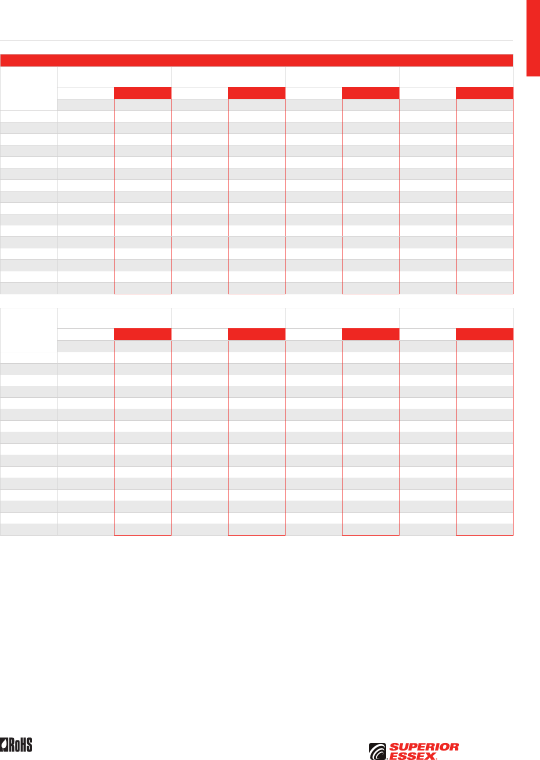
A-23
PREMISES COPPERPREMISES FIBEROSP FIBEROSP COMPOSITECENTRAL OFFICE COPPERRDUP/RUS OSP COPPERBELL OSP COPPEROSP COPPER WIRECANADIAN OSP COPPERTECHNICAL INFO
Rev 10/10 Ed 10.2 Toll Free 800.551.8948 | Fax 770.657.6807 | SuperiorEssex.com/Comm
Electrical Specifications
Frequency
MHz
Insertion Loss @ 20°C Maximum
dB/100 m
NEXT Minimum
dB/100 m
ACR Minimum
dB/100 m
PSNEXT Minimum
dB/100 m
TIA-568-C.2 Superior Essex TIA-568-C.2 Superior Essex TIA-568-C.2 Superior Essex TIA-568-C.2 Superior Essex
Specified Typical Specified Typical Calculated Typical Specified Typical
0.772 1.8 1.5 67.0 78.5 65.2 83.0 64.0 77.0
1 2.0 1.8 65.3 76.8 63.3 81.0 62.3 75.3
4 4.1 3.7 56.3 67.8 52.2 70.1 53.3 66.3
8 5.8 5.4 51.8 63.3 46.0 63.9 48.8 61.8
10 6.5 6.0 50.3 61.8 43.8 61.8 47.3 60.3
16 8.2 7.7 47.2 58.7 39.0 57.0 44.3 57.2
20 9.3 8.6 45.8 57.3 36.5 54.7 42.8 55.8
25 10.4 9.6 44.3 55.8 33.9 52.2 41.3 54.3
31.25 11.7 10.8 42.9 54.4 31.2 49.6 39.9 52.9
62.5 17.0 15.5 38.4 49.9 21.4 40.4 35.4 48.4
100 22.0 19.8 35.3 46.8 13.3 33.0 32.3 45.3
155 24.8 43.9 25.1 42.4
200 28.2 42.3 20.1 40.8
250 31.8 40.8 15.0 39.3
300 35.0 39.6 10.6 38.1
350 38.3 38.6 6.3 37.1
Frequency
MHz
PSACR Minimum
dB/100 m
Return Loss Minimum
dB/100 m
ELFEXT Minimum
dB/100 m
PSELFEXT Minimum
dB/100 m
TIA-568-C.2 Superior Essex TIA-568-C.2 Superior Essex TIA-568-C.2 Superior Essex TIA-568-C.2 Superior Essex
Calculated Typical Specified Typical Specified Typical Specified Typical
0.772 62.2 80.3 19.4 32.4 66.0 76.8 63.0 71.5
1 60.3 78.3 20.0 33.0 63.8 74.6 60.8 69.3
4 49.2 67.4 23.0 36.0 51.8 62.6 48.8 57.3
8 43.0 61.2 24.5 37.5 45.7 56.5 42.7 51.2
10 40.8 59.1 25.0 38.0 43.8 54.6 40.8 49.3
16 36.1 54.3 25.0 38.0 39.7 50.5 36.7 45.2
20 33.5 52.0 25.0 38.0 37.8 48.6 34.8 43.3
25 30.9 49.5 24.3 37.3 35.8 46.6 32.8 41.3
31.25 28.2 46.9 23.6 36.6 33.9 44.7 30.9 39.4
62.5 18.4 37.7 21.5 34.5 27.9 38.7 24.9 33.4
100 10.3 30.3 20.1 33.1 23.8 34.6 20.8 29.3
155 22.4 31.8 30.8 25.5
200 17.4 31.0 28.6 23.3
250 12.3 30.3 26.6 21.3
300 7.9 29.8 25.1 19.8
350 3.6 29.3 23.7 18.4
Marathon LAN Category 5e CMR/CMP
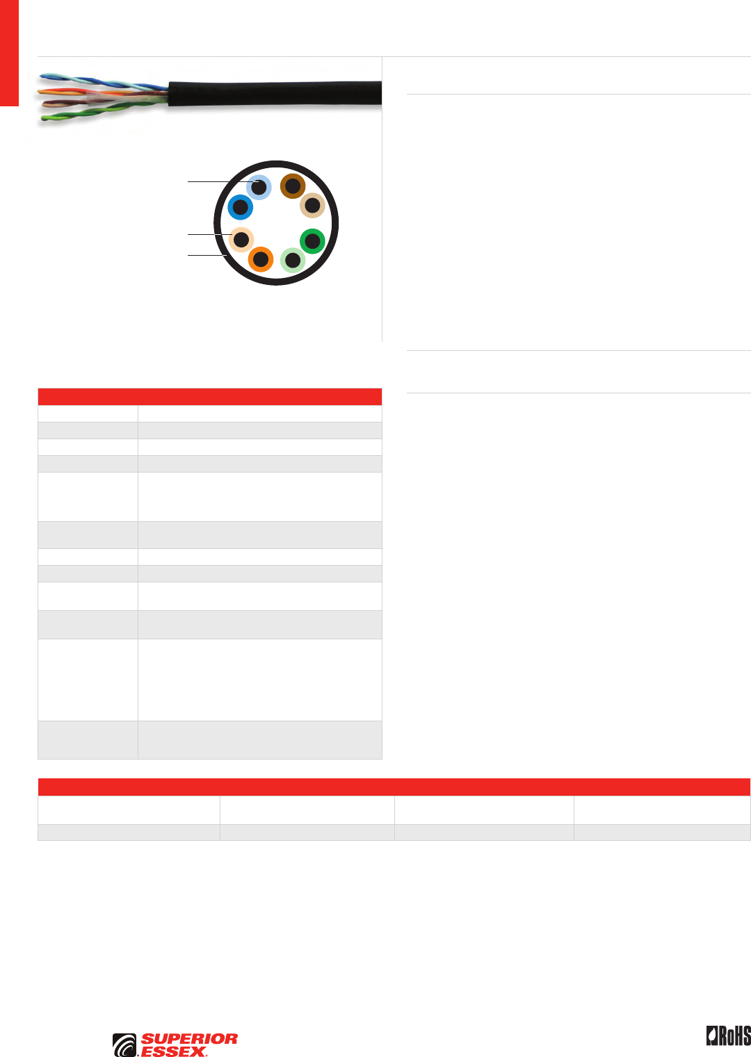
A-24
PREMISES COPPER PREMISES FIBER OSP FIBER OSP COMPOSITE CENTRAL OFFICE COPPER RDUP/RUS OSP COPPER BELL OSP COPPER OSP COPPER WIRE CANADIAN OSP COPPER TECHNICAL INFO
Rev 10/10 Ed 10.2Toll Free 800.551.8948 | Fax 770.657.6807 | SuperiorEssex.com/Comm
Specifications
Pair Count 4
Conductor Solid annealed copper
AWG (mm) 24 (0.51)
Insulation Polyolefin
Insulation Colors
Pair 1: ColorTip™ Light Blue, Blue
Pair 2: ColorTip Light Orange, Orange
Pair 3: ColorTip Light Green, Green
Pair 4: ColorTip Light Brown, Brown
Jacket Tough, flame retardant, weather, sunlight and abrasion
resistant riser PVC
Jacket Color Black
Package 1,000’ POP™ Box
Characteristic
Impedance (Ohms) 100 ± 15
Nominal Velocity
of Propagation (%) 69
Performance
Compliance
UL 444
CSA C22.2 No. 214-08
UL 1581
UL 1666
ANSI/TIA-568-C.2
ANSI/TIA/EIA-570-B
2002/95/EC RoHS-compliant
NRTL Programs
UL Verified CAT 5e
UL, c(UL) Listed CMR
UL, c(UL) Listed CMX-Outdoor Sunlight Resistant
Part Numbers and Physical Characteristics
Part Number
Nominal Diameter
in (mm)
Approx. Weight
lbs/kft (kg/km) Packages Per Pallet
51-240-E1 0.21 (5.3) 21 (31) 36
Category 5e CMR/CMX Outdoor Sunlight Resistant
Product Description
The Superior Essex Category 5e CMR/CMX Outdoor Sunlight Resistant cable
is specifically designed for extreme sunlight and temperature applications.
The cable’s specially formulated black jacket is designed to resist both
temperatures down to -20°C (-4°F) and up to +60°C (+140°F). The level of
UV blocking compounds is the same as in traditional Outside Plant (OSP)
cable products, with the black color preventing damage from long-term
UV sunlight exposure. Applications include ethernet interconnect cable for
WiMAX or retrofit cable installations that employ exterior runs, having long
term outdoor exposure between two environmentally protected points.
Superior Essex CAT 5e CMR/CMX Outdoor Sunlight Resistant black premises
cable has been tested and listed as UL 444 Sunlight Resistant compliant.
This designation requires the cable to resist 720 hours of harsh UV and heat
and is more than twice the exposure time of the standard 300 hours required
in the CMX Outdoor test. In addition, the CMR listing allows the cable to be
used in riser spaces per UL 1666, eliminating the need to transition to fire
resistant cables.
Applications
• 10BASE-T through 1000BASE-T ethernet, WiMAX
Features Benefits
• Combines indoor/outdoor
applications into one product
with the added feature of Sunlight
Resistant black color jacket
• Provides cost-effective solution
• Exceeds UL 444 • 720 hour sunlight resistant
specification
• Meets ANSI/TIA-568-C.2
specification
• CAT 5e performance
• CableID™ alpha numeric code
printed every 2 feet
• Allows both ends of a cable run
to be easily identifiable without
the need to seperately label or
tone the cable
• QuickCount® marking system
in feet and meters
• Provides remaining length
of cable on reel
• ColorTip™ Circuit
Identification System
• Easily identifiable conductor
mates even in low light
environments
• Rip cord applied under jacket • Facilitates easy opening
• RoHS-compliant • No heavy metals;
and no toxic components
• Combined indoor/outdoor rating • Reduces inventory by eliminating
multiple cable types
• UL 444/UL 1581 Sunlight
Resistant Listed
• Increased life in direct,
long term sunlight
Solid Annealed
Copper Conductor
Thermoplastic Insulation
Flame, Weather, Abrasion
and Sunlight Resistant
Black PVC Jacket
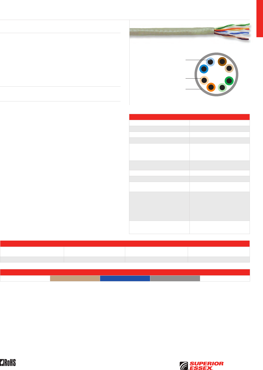
A-25
PREMISES COPPERPREMISES FIBEROSP FIBEROSP COMPOSITECENTRAL OFFICE COPPERRDUP/RUS OSP COPPERBELL OSP COPPEROSP COPPER WIRECANADIAN OSP COPPERTECHNICAL INFO
Rev 10/10 Ed 10.2 Toll Free 800.551.8948 | Fax 770.657.6807 | SuperiorEssex.com/Comm
Solid Annealed
Copper Conductor
Thermoplastic Insulation
Flame Retardant, Weather and
Abrasion Resistant PVC Jacket
Specifications
Pair Count 4
Conductor Solid annealed copper
AWG (mm) 24 (0.51)
Insulation Polyolefin
Insulation Colors
Pair 1: ColorTip™ Light Blue, Blue
Pair 2: ColorTip Light Orange, Orange
Pair 3: ColorTip Light Green, Green
Pair 4: ColorTip Light Brown, Brown
Jacket Tough, flame retardant, weather
and abrasion resistant PVC
Package 1,000’ POP™ Box
Characteristic Impedance (Ohms) 100 ± 15
Nominal Velocity
of Propagation (%) 69
Performance Compliance
UL 444
CSA C22.2 No. 214-08
UL 1581
UL 1666
ANSI/TIA-568-C.2
ANSI/TIA/EIA-570-B
2002/95/EC RoHS-compliant
NRTL Programs
UL Verified CAT 5e
UL, c(UL) Listed CMR
UL, c(UL) Listed CMX-Outdoor
Part Numbers and Physical Characteristics
Part Number¹
Nominal Diameter
in (mm)
Approx. Weight
lbs/kft (kg/km) Packages Per Pallet
51-240-x1 0.21 (5.3) 21 (31) 36
Jacket Colors
¹Replace “x” with: Beige = 1 Blue = 2 Gray = 3 White = 4
Category 5e CMR/CMX Outdoor
Product Description
Superior Essex Category 5e CMR/CMX Outdoor Cable is designed for
residential indoor/outdoor LAN applications. CAT 5e compliance ensures
this cable will support 1000BASE-T Gigabit Ethernet. This cable easily
surpasses the Grade 2 requirements specified in the ANSI/TIA/EIA-570-B
Residential Telecommunications Standard. The CAT 5e CMR/CMX-Outdoor
cable is resistant to cracking after long-term UV exposure, making it ideal
for installation runs that require the cable to be exposed to the elements.
This cable has been tested and is listed as compliant to the 300 hour
weatherometer test and -20°C cold bend test.
Applications
• 10BASE-T through 1000BASE-T ethernet, ATM and token ring
Features Benefits
• Tough, weather resistant
PVC jacket
• Increases life of cable by
providing low temperature
handling and sunlight resistance;
cable jacket resists cracking
over time
• Combined indoor/outdoor rating • Reduces inventory by eliminating
multiple cable types
• Meets ANSI/TIA-568-C.2
specification
• CAT 5e compliance
• CableID™ alpha numeric code
printed every 2 feet
• Allows both ends of a cable run
to be easily identifiable without
the need to seperately label or
tone the cable
• QuickCount® marking system
in feet and meters
• Provides remaining length
of cable on reel
• ColorTip™ Circuit
Identification System
• Easily identifiable
conductor mates even in low
light environments
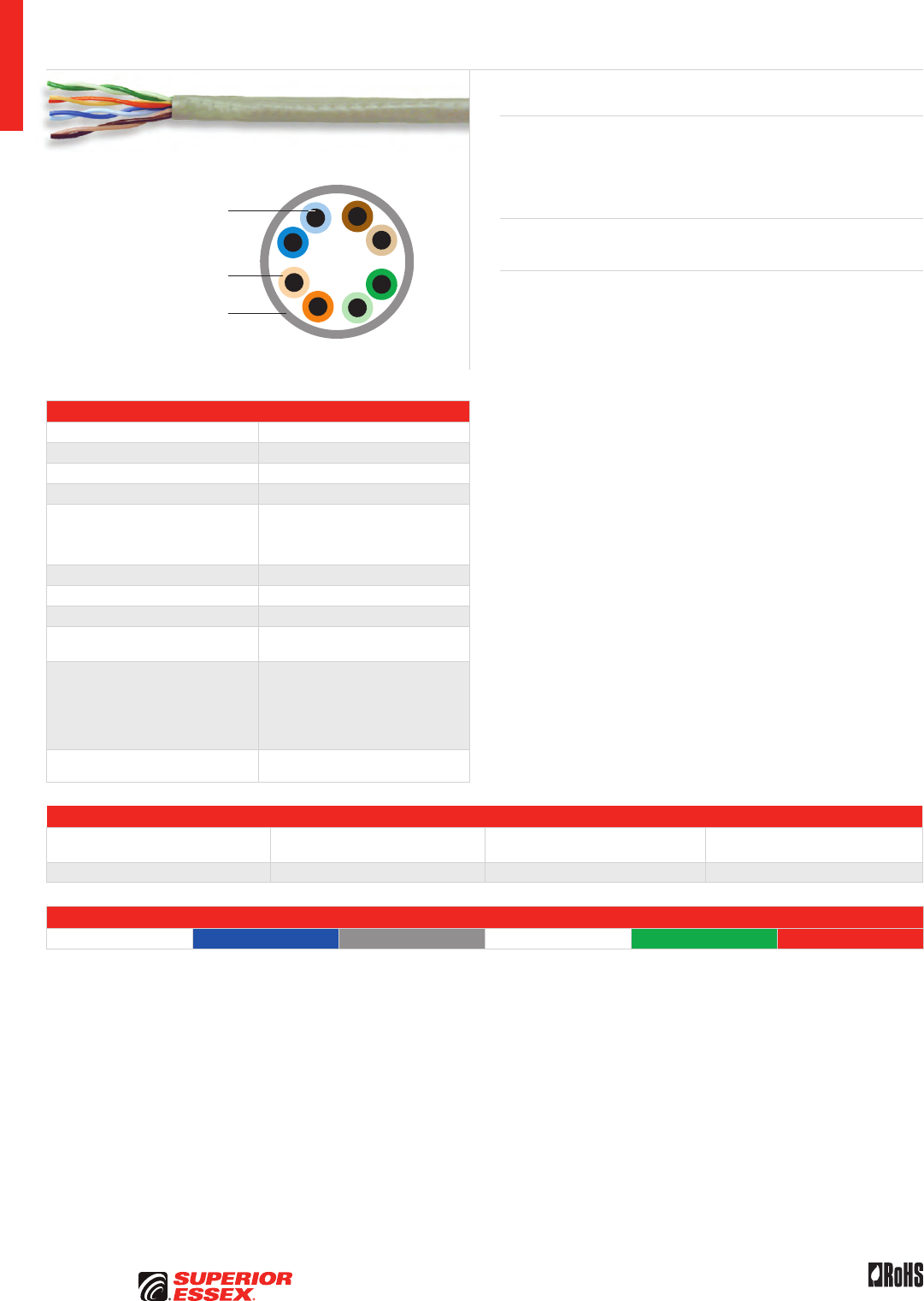
A-26
PREMISES COPPER PREMISES FIBER OSP FIBER OSP COMPOSITE CENTRAL OFFICE COPPER RDUP/RUS OSP COPPER BELL OSP COPPER OSP COPPER WIRE CANADIAN OSP COPPER TECHNICAL INFO
Rev 10/10 Ed 10.2Toll Free 800.551.8948 | Fax 770.657.6807 | SuperiorEssex.com/Comm
Product Description
Superior Essex Category 5e CM cable is designed for residential LAN
applications. CAT 5e compliance ensures this cable will support 1000BASE-T
Gigabit Ethernet. This cable easily surpasses the Grade 2 requirements
specified in the ANSI/TIA/EIA-570-B Residential Telecommunications standard.
Applications
• 10BASE-T through 1000BASE-T ethernet, ATM and token ring
Features Benefits
• Meets ANSI/TIA-568-C.2
specification
• CAT 5e compliance
• CableID™ alpha numeric code
printed every 2 feet
• Allows both ends of a cable run
to be easily identifiable without
the need to seperately label or
tone the cable
• QuickCount® marking system
in feet and meters
• Provides remaining length
of cable on reel
• ColorTip™ Circuit
Identification System
• Easily identifiable
conductor mates even in low
light environments
Solid Annealed
Copper Conductor
Thermoplastic Insulation
Flame Retardant
PVC Jacket
Specifications
Pair Count 4
Conductor Solid annealed copper
AWG (mm) 24 (0.51)
Insulation Polyolefin
Insulation Colors
Pair 1: ColorTip™ Light Blue, Blue
Pair 2: ColorTip Light Orange, Orange
Pair 3: ColorTip Light Green, Green
Pair 4: ColorTip Light Brown, Brown
Jacket Flame retardant PVC
Package 1,000’ POP™ Box
Characteristic Impedance (Ohms) 100 ± 15
Nominal Velocity
of Propagation (%) 69
Performance Compliance
UL 444
CSA C22.2 No. 214-08
UL 1685
ANSI/TIA-568-C.2
ANSI/TIA/EIA-570-B
RoHS-compliant
NRTL Programs UL Verified CAT 5e
UL, c(UL) Listed CM
Part Numbers and Physical Characteristics
Part Number¹
Nominal Diameter
in (mm)
Approx. Weight
lbs/kft (kg/km) Packages Per Pallet
51-240-xG 0.18 (4.6) 16 (24) 45
Jacket Colors
¹Replace “x” with: Blue = 2 Gray = 3 White = 4 Green = 5 Red = 9
Category 5e CM
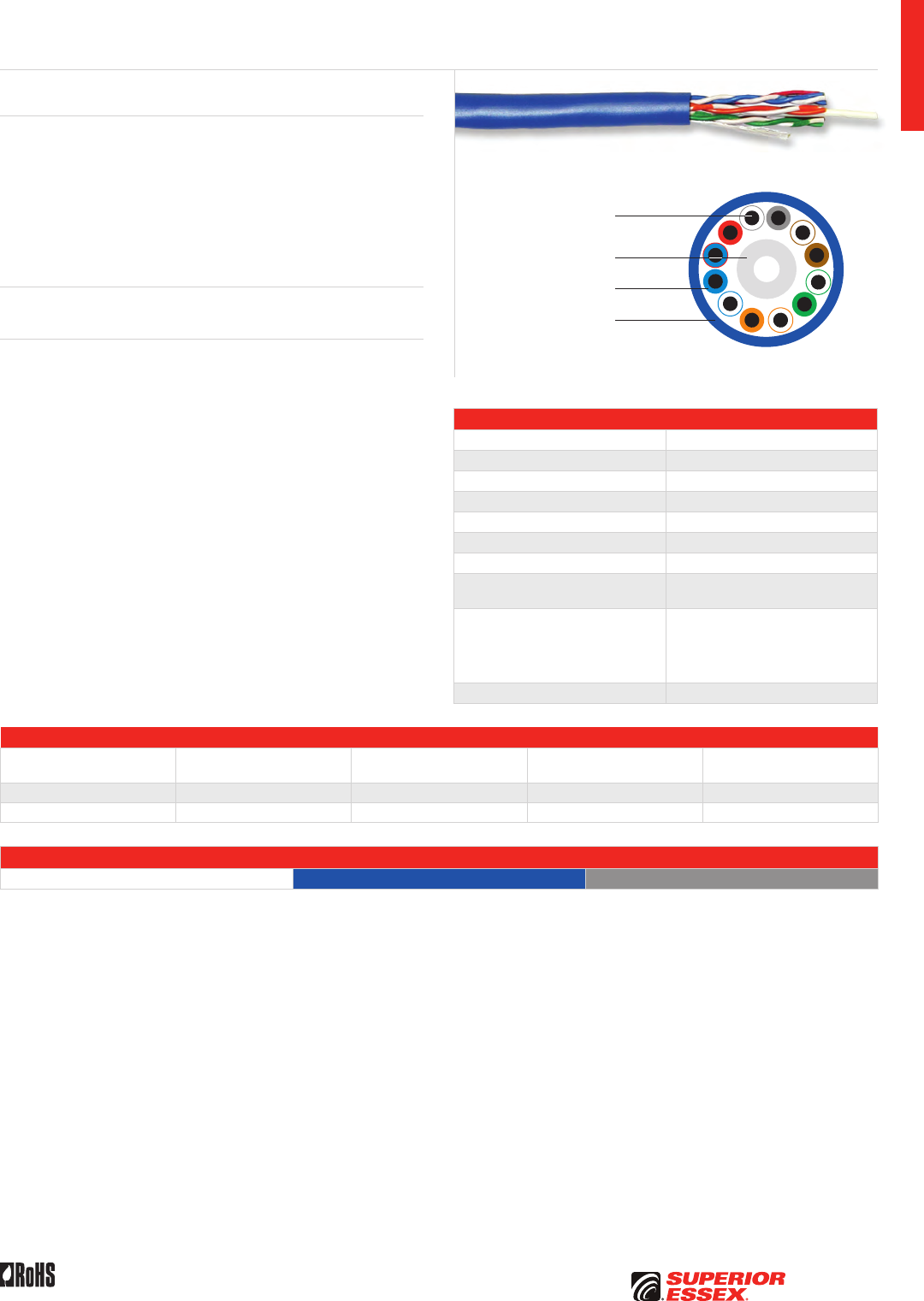
A-27
PREMISES COPPERPREMISES FIBEROSP FIBEROSP COMPOSITECENTRAL OFFICE COPPERRDUP/RUS OSP COPPERBELL OSP COPPEROSP COPPER WIRECANADIAN OSP COPPERTECHNICAL INFO
Rev 10/10 Ed 10.2 Toll Free 800.551.8948 | Fax 770.657.6807 | SuperiorEssex.com/Comm
Specifications
Pair Count 6
Conductor Solid annealed copper
AWG (mm) 24 (0.51)
Insulation Polyolefin
Separator Round filler
Jacket Flame retardant PVC
Characteristic Impedance (Ohms) 100 ± 15
Nominal Velocity
of Propagation (%) 69
Performance Compliance
UL 444
CSA C22.2 No. 214-08
UL 1666
ANSI/TIA-568-C.2
RoHS-compliant
NRTL Programs UL, c(UL) Listed CMR
Part Numbers and Physical Characteristics
Part Number¹
Nominal Diameter
in (mm)
Approx. Weight
lbs/kft (kg/km) Package Packages Per Pallet
51-347-x5 0.26 (6.6) 32 (48) 1,000’ Reel-in-a-Box 27
51-372-x5 0.26 (6.6) 32 (48) 1,000’ Plywood Reel 16
Jacket Colors
¹Replace “x” with: Blue = 2 Gray = 3
6-Pair Category 5e CMR
Product Description
6-pair UTP cable, with Category 5e (ANSI/TIA-568-C.2) performance, is the
solution to a growing number of special installation needs. More customers
are demanding two additional pairs above the standard 4-pair cable for high-
bandwidth applications. Two additional pairs provide the flexibility for utility
metering and other telemetry needs without the expense of adding a separate
cable and without additional space. The Superior Essex 6-pair CAT 5e cable
delivers the performance expected, while offering the many features and user
advantages of all our high performance premises products.
Applications
• 10BASE-T through 1000BASE-T ethernet, ATM and token ring
Features Benefits
• Two additional pairs in excess of
the standard 4-pair construction
• Eliminates expense of
additional cable when 6-pair
are required, reduces cabling
space requirements; speeds
installation time
• ANSI/TIA-568-C.2 compliance • Any of the 6-pair can be used
for CAT 5e applications
• CableID™ alpha numeric code
printed every 2 feet
• Allows both ends of a cable run
to be easily identifiable without
the need to seperately label or
tone the cable
• QuickCount® marking system
in feet and meters
• Eliminates guesswork of footage
on reel and reduces scrap
• Warranted with all leading
connectivity manufacturers
• Offers flexibility in selection
of connectivity solutions
Solid Annealed
Copper Conductor
Thermoplastic Insulation
Flame Retardant
PVC Jacket
Cylindrical Separator
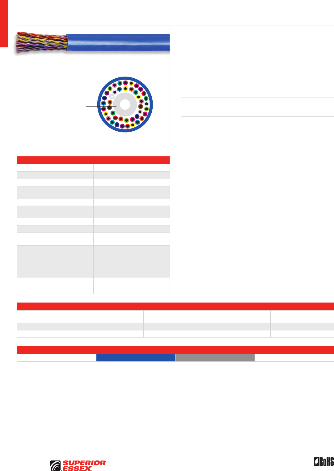
A-28
PREMISES COPPER PREMISES FIBER OSP FIBER OSP COMPOSITE CENTRAL OFFICE COPPER RDUP/RUS OSP COPPER BELL OSP COPPER OSP COPPER WIRE CANADIAN OSP COPPER TECHNICAL INFO
Rev 10/10 Ed 10.2Toll Free 800.551.8948 | Fax 770.657.6807 | SuperiorEssex.com/Comm
Solid Annealed
Copper Conductor
Thermoplastic Insulation
Flame Retardant PVC Jacket
Cylindrical Separator
Cylindrical Separator
Specifications
Pair Count 25
Conductor Solid annealed copper
AWG (mm) 24 (0.51)
Insulation CMR: Thermoplastic
CMP: FEP
Separator Cylindrical
Jacket CMR: Flame retardant PVC
CMP: Fluoropolymer
Package 1,000’ plywood reel
Characteristic Impedance (Ohms) 100 ± 15
Nominal Velocity
of Propagation (%)
CMR: 69
CMP: 72
Performance Compliance
UL 444
CSA C22.2 No. 214-08
UL 1666
NFPA 262
ANSI/TIA-568-C.2
RoHS-compliant
NRTL Programs
UL Verified CAT 5e
UL, c(UL) Listed CMR
UL, c(UL) Listed CMP
Part Numbers and Physical Characteristics
Listing Part Number¹
Nominal Diameter
in (mm)
Approx. Weight
lbs/kft (kg/km) Packages Per Pallet
CMR 51-478-x5 0.57 (14.5) 144 (214) 4
CMP 51-478-x8 0.48 (12.2) 148 (220) 4
Jacket Colors
¹Replace “x” with: Blue = 2 Gray = 3 White = 4
25-Pair Power Sum Category 5e CMR/CMP
Product Description
25-Pair Power Sum Category 5e UTP cables are designed to provide support
for both backbone and horizontal applications. These applications include
inter-closet backbone links, equipment cabling between cross-connect
and hub equipment and zone distribution horizontal cabling between wiring
closets and multiple work area transition points. The cable is available
in CMP and CMR ratings and is UL verified to meet all requirements
of ANSI/TIA-568-C.2.
Applications
• 10BASE-T through 1000BASE-T ethernet, ATM and token ring
Features Benefits
• Small outside diameter • Handles tight installations
• Vibrant insulation colors • Easier identification of conductors
• Flexible jacket material • Ease of use during installation
• Marked in feet and meters • Dual length marking complies
with government, military and
international requirements
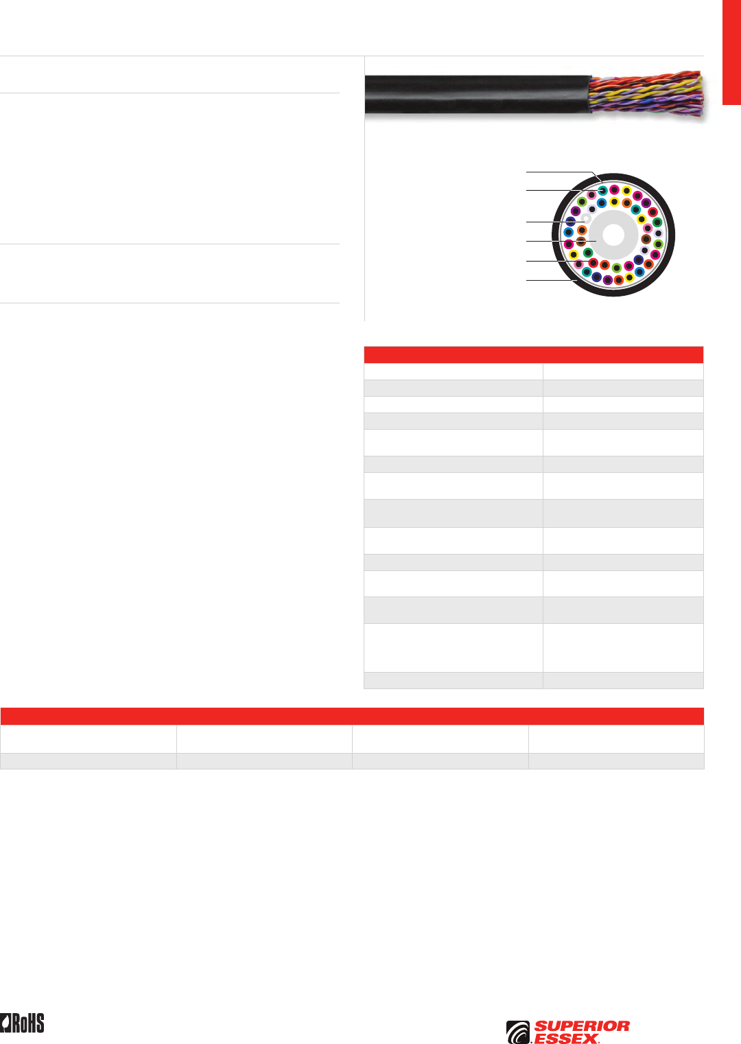
A-29
PREMISES COPPERPREMISES FIBEROSP FIBEROSP COMPOSITECENTRAL OFFICE COPPERRDUP/RUS OSP COPPERBELL OSP COPPEROSP COPPER WIRECANADIAN OSP COPPERTECHNICAL INFO
Rev 10/10 Ed 10.2 Toll Free 800.551.8948 | Fax 770.657.6807 | SuperiorEssex.com/Comm
Solid Annealed
Copper Conductor
PET Tape Core Wrap
Thermoplastic Insulation
Black, Low Smoke Zero Halogen,
OSP Grade Jacket
Cylindrical Separator
Cylindrical Separator
Specifications
Pair Count 25
Conductor Solid annealed copper
AWG (mm) 24 (0.51)
Insulation Thermoplastic
Separators Cylindrical, flame retardant
thermoplastic
Core Wrap PET Tape
Jacket Black, CM rated, non-halogen
OSP grade
Input Impedance (Ohms) Guaranteed
@ 1-100 MHz 100 ± 15
Delay Skew (ns/100 m) Maximum: 45
Typical: 30
Nominal Velocity of Propagation (%) 69
DC Resistance (Ohms/100 m) Maximum: 9.38
Typical: 9.0
Resistance Unbalance (%) Maximum: 5.0
Typical: 0.7
Performance Compliance
UL 444
CSA C22.2 No. 214-08
ANSI/TIA-568-C.2
RoHS-compliant
NRTL Programs UL, c(UL) Listed CM
Part Numbers and Physical Characteristics
Part Number
Nominal Diameter
in (mm)
Approx. Weight
lbs/kft (kg/km) Package
51-499-EL 0.59 (15) 148 (221) 1,000' Plywood Reel
Product Description
With its CM fire rating and UV resistant black jacket, this 25-pair, 24 gauge,
Category 5e tight twisted copper conductor cable can be installed in both
premises and outside plant (OSP) environments. The CAT 5e tight twist lays
provide superior crosstalk performance, supporting digital subscriber line
(xDSL) and IPTV broadband technologies in both the OSP pedestal and
customer premises. In addition, the cable jacket is fungus resistant which
is important in OSP pedestal environments. The cable meets or exceeds
ANSI/TIA-568-C.2 for CAT 5e backbone cables and is able to support up to
1000BASE-T Ethernet technologies.
Applications
• ADSL, VDSL, VDSL+ and VDSL+2
• 10BASE-T through 1000BASE-T Ethernet, ATM and token ring
Features Benefits
• Small outside diameter • Handles tight installations
• Vibrant insulation colors • Easy identification of conductors
• Black, CM rated, non-haolgen,
OSP grade jacket material
• Provides full sunlight
resistance and fire protection
in a flexible jacket
• Fungus resistance • Non-nutritive to fungus and
ideal for installation in humid
environments
• Compliant to ANSI/TIA-568-C.2
for CAT 5e
• Capable of 1000BASE-T
• Specially designed tight twist lays • Provides superior Alien Crosstalk
performance for xDSL applications
• Low temperature
bend performance
• Allows installation
at -20°C temperatures
25-Pair Category 5e Indoor/Outdoor
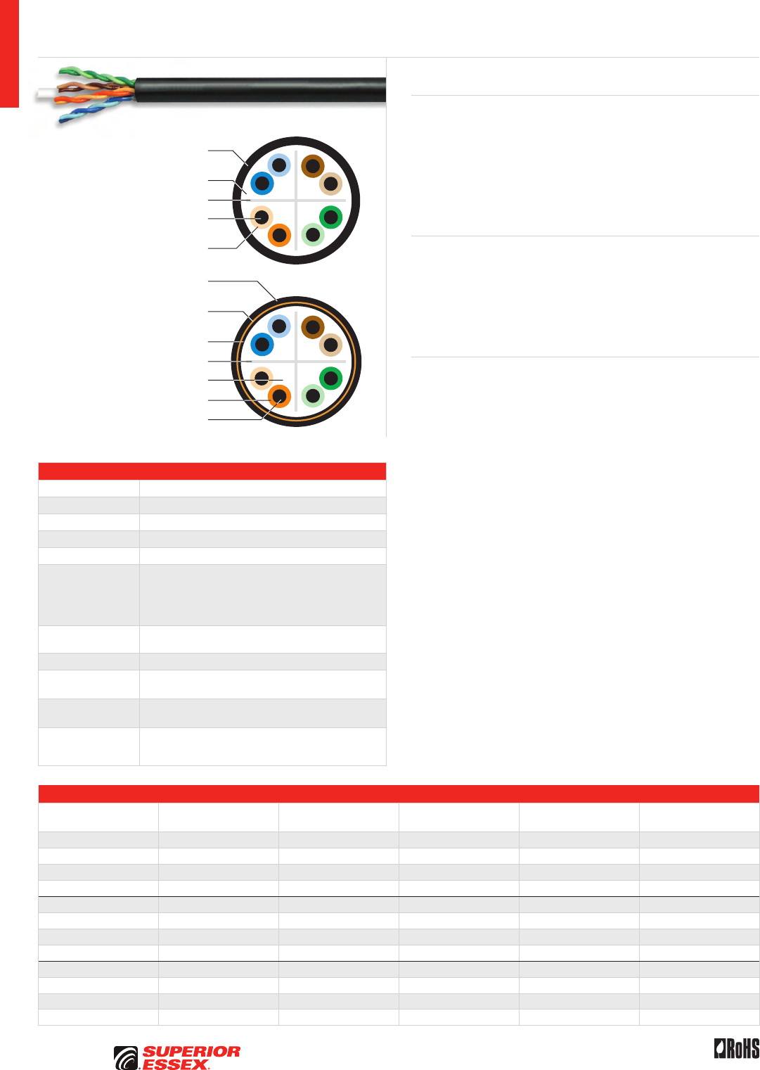
A-30
PREMISES COPPER PREMISES FIBER OSP FIBER OSP COMPOSITE CENTRAL OFFICE COPPER RDUP/RUS OSP COPPER BELL OSP COPPER OSP COPPER WIRE CANADIAN OSP COPPER TECHNICAL INFO
Rev 10/10 Ed 10.2Toll Free 800.551.8948 | Fax 770.657.6807 | SuperiorEssex.com/Comm
Specifications
Pair Count 4
Conductor Solid annealed copper
AWG (mm) 23 (0.57)
Insulation Polyolefin
Separator Polyolefin cross-web
Shield
BBD6: Unshielded
BBDN6: Electrically continuous 0.008 inch (0.20 mm) polymer
coated smooth aluminum tape, applied with an overlap
BBDG6: Electrically continuous 0.005 inch (0.13 mm)
corrugated copper-clad armor, applied with an overlap
Dry Water Block BBDN6: SAP powder
BBDG6: SAP yarn
Jacket Black, sunlight and weather resistant polyethylene
Characteristic
Impedance (Ohms) 100 ± 15
Nominal Velocity
of Propagation (%) 57
Performance
Compliance
ANSI/TIA-568-C.2
ANSI/ICEA S-107-704-2006
RoHS-compliant
Part Numbers and Physical Characteristics
Part Number Product Code Shield
Nominal Diameter
in (mm)
Approx. Weight
lbs/kft (kg/km) Package
04-001-68 BBD6 None 0.30 (7.6) 39 (58) 1,000’ Plywood Reel
04-002-68 BBD6 None 0.30 (7.6) 39 (58) 2,500’ Plywood Reel
04-003-68 BBD6 None 0.30 (7.6) 39 (58) 5,000’ Plywood Reel
04-601-68 BBD6 None 0.30 (7.6) 39 (58) Cut to Length
04-001-64 BBDN6 Coated Aluminum 0.40 (10.0) 67 (100) 1,000’ Plywood Reel
04-002-64 BBDN6 Coated Aluminum 0.40 (10.0) 67 (100) 2,500’ Plywood Reel
04-003-64 BBDN6 Coated Aluminum 0.40 (10.0) 67 (100) 5,000’ Plywood Reel
04-601-64 BBDN6 Coated Aluminum 0.40 (10.0) 67 (100) Cut to Length
04-001-65 BBDG6 Copper Clad 0.40 (10.0) 80 (119) 1,000’ Plywood Reel
04-002-65 BBDG6 Copper Clad 0.40 (10.0) 80 (119) 2,500’ Plywood Reel
04-003-65 BBDG6 Copper Clad 0.40 (10.0) 80 (119) 5,000’ Plywood Reel
04-601-65 BBDG6 Copper Clad 0.40 (10.0) 80 (119) Cut to Length
OSP Broadband Category 6
Sunlight and Weather Resistant
Polyethylene Jacket
Sunlight and Weather Resistant
Polyethylene Outer Jacket
Polyethylene Inner Jacket
Fully Filled Water Repellent Core
Solid Annealed
Copper Conductor
Thermoplastic Insulation
Fully Filled Water Repellent Core
Solid Annealed Copper Conductor
Thermoplastic Insulation
Aluminum Tape Shield (BBDN6) or
Copper-clad Armor Shield (BBDG6)
Cross-web Separator
Cross-web Separator
Product Description
BBD6 is an Outside Plant (OSP) unshielded Broadband Category 6 cable.
BBD6 has guaranteed transmission performance out to 250 MHz. The
cable consists of a core of four balanced twisted pairs held in place by
a cross-web separator and surrounded by a filling compound to prevent
water ingress. The core is jacketed with a sunlight and abrasion resistant
black polyethylene outer jacket. Shielded designs feature dry water block
between the shield and the core jacket to prevent water ingress. All designs
are suitable for buried applications.
Applications
• 10BASE-T through 1000BASE-T ethernet
• ATM and token ring
• BBDN6: Lashed aerial, underground conduit
or low-risk direct burial
• BBDG6: Direct burial where additional
mechanical protection is required
Features Benefits
• Filled core • Prevents water ingress that
can affect electrical performance
• CAT 6 transmission performance
characterized to 500 MHz
• OSP rated cable provides
connections for work area and
extension of the LAN
• Black polyethylene outer jacket • Sunlight and weather resistant
• BBD6: Unshielded • Small, robust design for
unshielded applications
• BBDN6: Aluminum tape shield • Protection against EMI/RFI
• BBDG6: Copper-clad armor shield • Protection against EMI/RFI
and provides rodent resistance
• ColorTip™ circuit
identification system
• Easily identifiable conductor
mates even in low light
environments
• Dry water block between
shield and core
• Prevents water ingress,
yet easy to clean
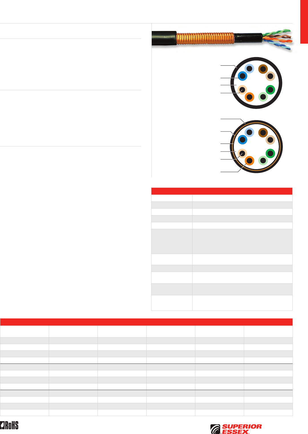
A-31
PREMISES COPPERPREMISES FIBEROSP FIBEROSP COMPOSITECENTRAL OFFICE COPPERRDUP/RUS OSP COPPERBELL OSP COPPEROSP COPPER WIRECANADIAN OSP COPPERTECHNICAL INFO
Toll Free 800.551.8948 | Fax 770.657.6807 | SuperiorEssex.com/CommRev 6/10 Ed 10.1
Specifications
Pair Count 4
Conductor Solid annealed copper
AWG (mm) 24 (0.51)
Filling Compound PFM™ thixotropic gel
Insulation Solid polyolefin
Shield
BBDe: Unshielded
BBDNe: Electrically continuous 0.008 in (0.20 mm) polymer
coated smooth aluminum tape, applied with an overlap
BBDGe: Electrically continuous 0.005 in (0.13 mm)
corrugated copper-clad armor, applied with an overlap
Dry Water Block BBDNe: SAP powder
BBDGe: SAP yarn
Jacket Black, sunlight and weather resistant polyethylene
Characteristic
Impedance (Ohms) 100 ± 15
Nominal Velocity
of Propagation (%) 62
Performance
Compliance
ANSI/TIA-568-C.2
ANSI/ICEA S-107-704-2006
RoHS-compliant
Part Numbers and Physical Characteristics
Part Number Product Code Shield
Nominal Diameter
in (mm)
Approx. Weight
lbs/kft (kg/km) Package
04-001-58 BBDe None 0.26 (6.6) 30 (45) 1,000’ Plywood Reel
04-002-58 BBDe None 0.26 (6.6) 30 (45) 2,500’ Plywood Reel
04-003-58 BBDe None 0.26 (6.6) 30 (45) 5,000’ Plywood Reel
04-601-58 BBDe None 0.26 (6.6) 30 (45) Cut to Length
04-001-54 BBDNe Coated Aluminum 0.36 (9.1) 55 (82) 1,000’ Plywood Reel
04-002-54 BBDNe Coated Aluminum 0.36 (9.1) 55 (82) 2,500’ Plywood Reel
04-003-54 BBDNe Coated Aluminum 0.36 (9.1) 55 (82) 5,000’ Plywood Reel
04-601-54 BBDNe Coated Aluminum 0.36 (9.1) 55 (82) Cut to Length
04-001-55 BBDGe Copper Clad 0.36 (9.1) 64 (95) 1,000’ Plywood Reel
04-002-55 BBDGe Copper Clad 0.36 (9.1) 64 (95) 2,500’ Plywood Reel
04-003-55 BBDGe Copper Clad 0.36 (9.1) 64 (95) 5,000’ Plywood Reel
04-601-55 BBDGe Copper Clad 0.36 (9.1) 64 (95) Cut to Length
OSP Broadband Category 5e
Sunlight and Weather Resistant
Polyethylene Jacket
Sunlight and Weather Resistant
Polyethylene Outer Jacket
Polyethylene Inner Jacket
Fully Filled Water Repellent Core
Solid Annealed
Copper Conductor
Thermoplastic Insulation
Fully Filled Water Repellent Core
Solid Annealed
Copper Conductor
Thermoplastic Insulation
Aluminum Tape Shield (BBDNe) or
Copper-clad Armor Shield (BBDGe)
Product Description
BBD Category 5e Outside Plant (OSP) cables are designed to provide
extension of the LAN beyond the premises. The core is filled wih PFM™
thixotropic filling compund to prevent water ingress. PFM™ gel will not
drip even in cell tower applications at elevated temperatures. A variety of
constructions are available to suit multiple environmental needs. Shielded
designs feature dry water block between the shield and the core jacket to
prevent water ingress. All designs are suitable for buried applications.
Applications
• 10BASE-T through 1000BASE-T ethernet
• ATM and token ring
• WiMAX cell towers
• BBDNe: Lashed aerial, underground conduit
or low-risk direct burial
• BBDGe: Direct burial where additional
mechanical protection is required
Features Benefits
• CAT 5e transmission performance
characterized to 350 MHz
• OSP rated cable connections
for work area and backbone LAN
• Metallic shield tapes (Aluminum
for BBDNe and Copper-clad
armor for BBDGe)
• Provides additional protection
against EMI/RFI and rodents
• Fully filled with PFM™
thixotropic gel
• Prevents intrusion of
moisture that can degrade
transmission quality
• Easy to clean and non-dripping
• UV/Sunlight resistant
black jacket
• Confidence that cable will last
even with long-term exposure
to direct sunlight
• BBDe: Unshielded • Small, robust design for
unshielded applications
• BBDNe: Aluminum tape shield • Protection against EMI/RFI
• BBDGe: Copper-clad armor shield • Protection against EMI/RFI
and provides rodent resistance
• ColorTip™ circuit
identification system
• Easily identifiable conductor
mates even in low light
environments
• Dry water block between
shield and core
• Prevents water ingress,
yet easy to clean
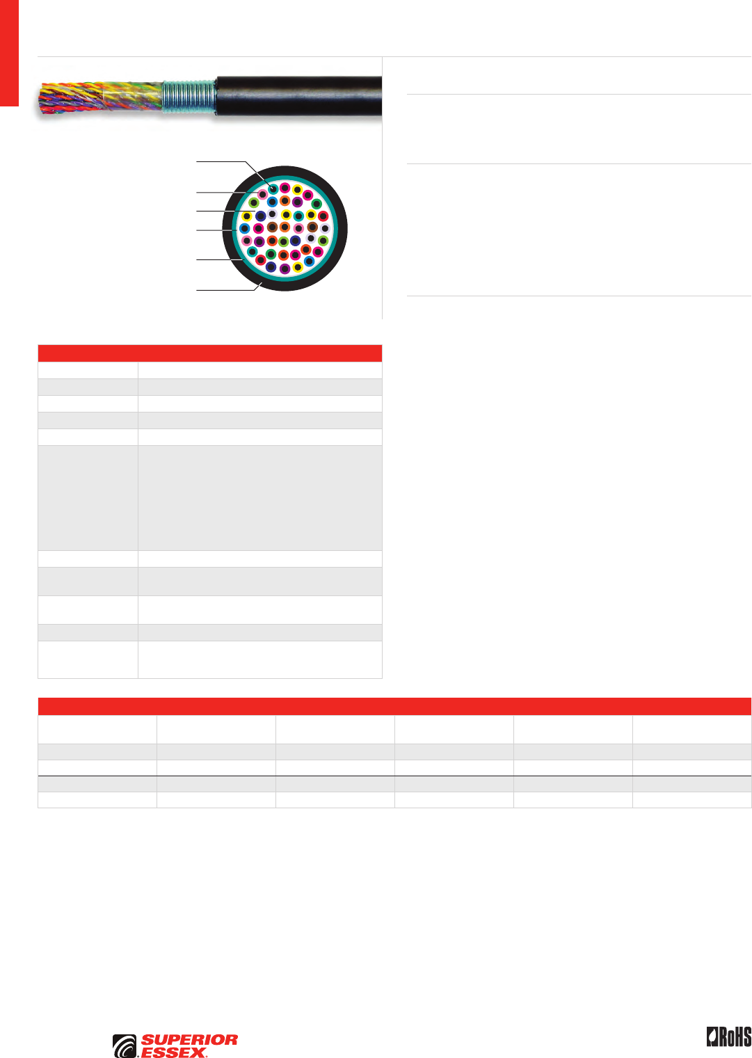
A-32
PREMISES COPPER PREMISES FIBER OSP FIBER OSP COMPOSITE CENTRAL OFFICE COPPER RDUP/RUS OSP COPPER BELL OSP COPPER OSP COPPER WIRE CANADIAN OSP COPPER TECHNICAL INFO
Toll Free 800.551.8948 | Fax 770.657.6807 | SuperiorEssex.com/Comm Rev 6/10 Ed 10.1
Specifications
Pair Count Available in 25-pair and 100-pair
Conductor Solid annealed copper
AWG (mm) 24 (0.51)
Filling Compound 80°C ETPR (extended thermoplastic rubber)
Core Wrap Non-hygroscopic dielectric tape
Shield
MEGAPIC-NF: Electrically continuous 0.008 in (0.20 mm)
polymer coated corrugated aluminum tape, applied with
an overlap and shield interface is flooded
MEGAPIC-GF: ASP sheath consisting of an inner electrically
continuous 0.008 in (0.20 mm) polymer coated corrugated
aluminum tape applied with a gap and covered with an
outer electrically continuous 0.006 in (0.15 mm) polymer
coated corrugated steel tape applied with an overlap;
interfaces of both tapes are flooded
Jacket Black, sunlight and weather resistant polyethylene
Characteristic
Impedance (Ohms) 100 ± 15
Nominal Velocity
of Propagation (%) 62
Package Wood reel
Performance
Compliance
ANSI/TIA-568-C.2
ANSI/ICEA S-99-689-2006
RoHS-compliant
Part Numbers and Physical Characteristics
Part Number Name Pair Count
Nominal Diameter
in (mm)
Approx. Weight
lbs/kft (kg/km)
Standard Length
ft (m)
04-097-31 MEGAPIC-NF 25 0.68 (17.3) 208 (310) 5,000 (1524)
04-104-31 MEGAPIC-NF 100 1.22 (31.0) 696 (1,037) 1,000 (305)
04-097-37 MEGAPIC-GF 25 0.71 (18.0) 258 (385) 5,000 (1524)
04-104-37 MEGAPIC-GF 100 1.26 (32.0) 801 (1,195) 1,000 (305)
MEGAPIC™ OSP Broadband Backbone Category 5
Solid Annealed
Copper Conductor
ETPR Filling Compound
Polymer Coated Corrugated
Aluminum Tape Shield
Non-hygroscopic
Dielectric Tape
Solid Polyolefin Insulation
Black, Sunlight and Weather
Resistant Polyethylene Jacket
Product Description
MEGAPIC™ Category 5 cables provide an extension of the LAN beyond the
premises. These cables are ideal for direct burial, underground and lashed
aerial applications.
Applications
• 10BASE-T
• ATM and token ring
• MEGAPIC-NF: Higher pair count shielded distribution cable for use
in lashed aerial, direct burial and duct installations
• MEGAPIC-GF: Higher pair count shielded distribution cable for use
in lashed aerial, direct burial and installations in high risk areas where
additional mechanical protection is required
Features Benefits
• Transmission performance
characterized to 100 MHz
• Extends the LAN
to the entire campus
• Metallic shield tapes • Facilitates grounding according
to NEC requirements
• Fully filled constructions • Helps prevent intrusion
of moisture
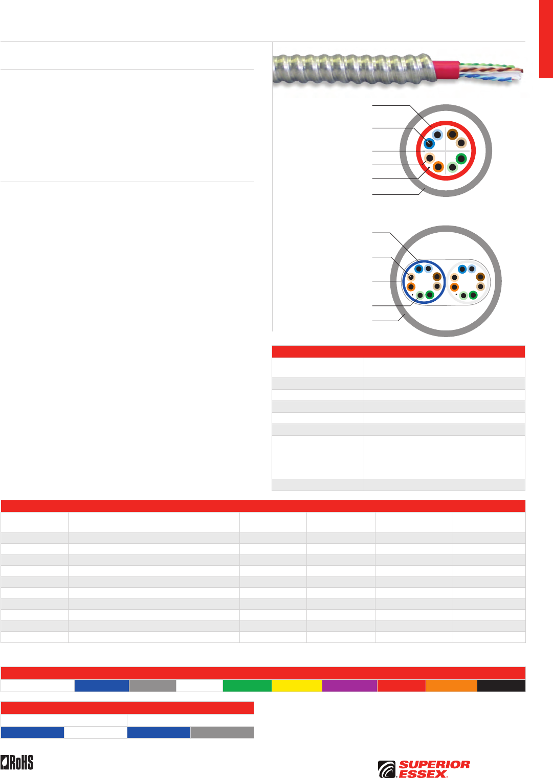
A-33
PREMISES COPPERPREMISES FIBEROSP FIBEROSP COMPOSITECENTRAL OFFICE COPPERRDUP/RUS OSP COPPERBELL OSP COPPEROSP COPPER WIRECANADIAN OSP COPPERTECHNICAL INFO
Toll Free 800.551.8948 | Fax 770.657.6807 | SuperiorEssex.com/CommRev 11/10 Ed 10.4
Interlock Armored
Premises Copper CMR
Specifications
Overall Cable
Configuration
Single to multiple component riser cables surrounded
by aluminum or steel interlock armored
Armor Interlocked aluminum or interlocked steel
Armor Jacket Options Unjacketed or jacketed (matches component color)
Armor/Component Jacket Riser grade PVC
Component Fire Listings UL 1666, UL CMR, c(UL) CMR
Package 1,000’ wood reel
Performance
Compliance
UL 444
CSA C22.2 No. 214-08
UL 1569
ANSI/TIA-568-C.2
RoHS-compliant
NRTL Programs UL, c(UL) Listed CMR
Part Numbers and Physical Characteristics
Part Number¹ Configuration Component
Number of
Components
Nominal Diameter
in (mm)
Approx. Weight
lbs/kft (kg/km)
K4-199-xA Aluminum interlock armored, no outer jacket 4-pair CAT 6 1 0.49 (12.5) 67 (100)
L4-199-xA Aluminum interlock armored, with outer jacket* 4-pair CAT 6 1 0.55 (14.0) 104 (155)
K4-299-yA Aluminum interlock armored, no outer jacket 4-pair CAT 6 2 0.80 (20.2) 117 (174)
L4-299-yA Aluminum interlock armored, with outer jacket* 4-pair CAT 6 2 0.87 (22.2) 196 (292)
K2-199-x5 Aluminum interlock armored, no outer jacket 4-pair CAT 5e 1 0.44 (11.1) 55 (82)
L2-199-x5 Aluminum interlock armored, with outer jacket* 4-pair CAT 5e 1 0.50 (12.6) 88 (132)
K2-299-y5 Aluminum interlock armored, no outer jacket 4-pair CAT 5e 2 0.80 (20.2) 105 (156)
L2-299-y5 Aluminum interlock armored, with outer jacket* 4-pair CAT 5e 2 0.88 (22.2) 184 (274)
KC-919-x5 Aluminum interlock armored, no outer jacket RG6 Quad** 1 0.53 (13.5) 73 (109)
K8-A99-33 Aluminum interlock armored, no outer jacket 25-pair CAT 3 1 0.79 (20.2) 159 (237)
*For single unit cables, the outer jacket color matches the internal component jacket color. For multi-unit cables, the outer jacket standard color is blue.
Additional cable combinations are available. **Coaxial available with component jacket color in black or white.
Single Component Jacket Colors
¹Replace “x” with: Blue = 2 Gray = 3 White = 4 Green = 5 Yellow = 6 Purple = 7 Red = 9 Orange = D Black = E
Dual Component Jacket Colors
¹Replace “y” with “S” ¹Replace “y” with “T”
Blue White Blue Gray
Other color sequences are available upon request.
Product Description
Interlock Armored Category 6, Category 5e, Category 3 and/or RG6 Quad
Coax Riser cables provide significant mechanical protection. Interlock
armored cables with two or more components of the same type can have
either different colored components or uniquely labeled components with
the same color. Multiple cables can be constructed in either aluminum
or steel interlock armored; and the final cable is available in bare metal
or with an overall jacket. Each component cable is tested after interlock
armoring to ensure that it meets all applicable industry requirements. Cable
configurations that include optical fiber distribution cables are also available.
Features Benefits
• Aluminum or steel
interlock armored
• Protects against mechanical
stresses
• Protects against EMI/RFI
for reliable performance
• Provides additional fire protection
over riser rating
• Installs faster and easier
than EMT conduit and
conventional wire
• Category components meets
ANSI/TIA-568-C.2 for CAT 3,
CAT 5e and CAT 6
• Supports applications
up to 1000BASE-T
• CMR rated components • Maintains the fire rating with
interlock armored removed
Flame Retardant
PVC Jacket
Solid Annealed
Copper Conductor
Thermoplastic Insulation
Rip Cord
Aluminum or Steel
Interlocked Armor
Flame Retardant
PVC Jacket
Solid Annealed
Copper Conductor
Thermoplastic Insulation
Contra-Helically
Applied Binder Yarns
Aluminum or Steel
Interlocked Armor
Cross-web Separator
Single Component
Dual Component
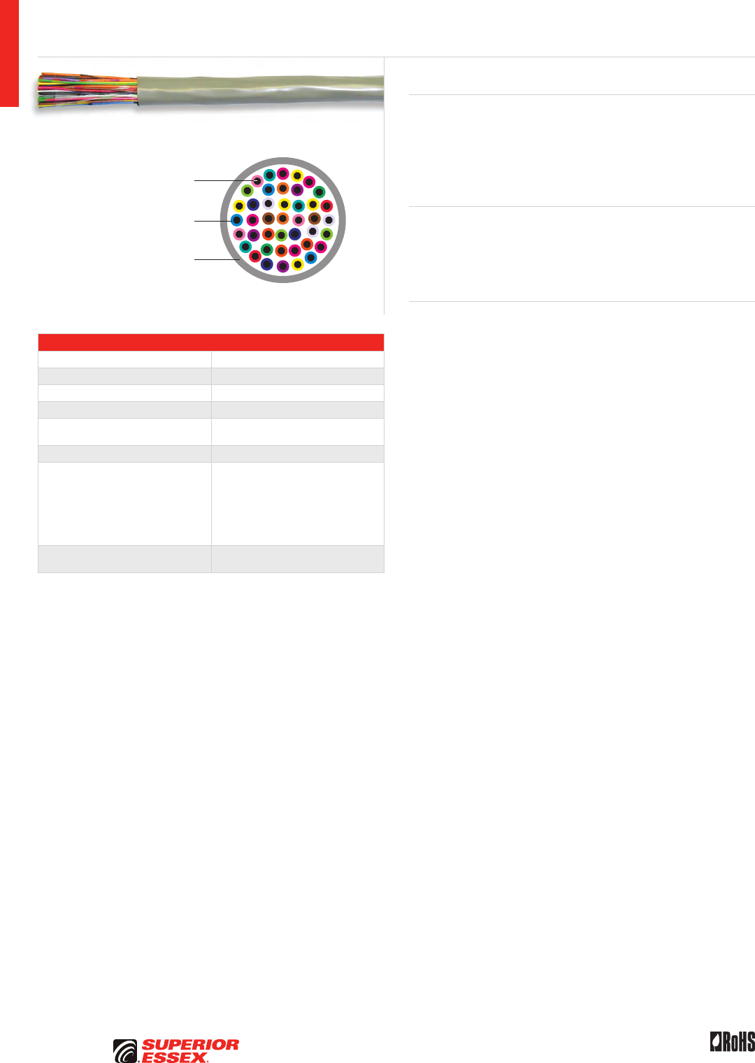
A-34
PREMISES COPPER PREMISES FIBER OSP FIBER OSP COMPOSITE CENTRAL OFFICE COPPER RDUP/RUS OSP COPPER BELL OSP COPPER OSP COPPER WIRE CANADIAN OSP COPPER TECHNICAL INFO
Rev 10/10 Ed 10.2Toll Free 800.551.8948 | Fax 770.657.6807 | SuperiorEssex.com/Comm
Specifications
Pair Count Available in 2-pair up to 400-pair
Conductor Solid annealed copper
AWG (mm) 24 (0.51)
Insulation Thermoplastic
Jacket CMR: Flame retardant (FR) PVC
CMP: FR, low smoke PVC
Characteristic Impedance (Ohms) 100 ± 15
Performance Compliance
UL 444
CSA C22.2 No. 214-08
UL 1666
NFPA 262
ANSI/TIA-568-C.2
ANSI/ICEA S-90-661-2008
RoHS-compliant
NRTL Programs UL, c(UL) Listed CMR
UL, c(UL) Listed CMP
Category 3 CMR/CMP
2-Pair – 400-Pair
Solid Annealed
Copper Conductor
Thermoplastic Insulation
Flame Retardant PVC Jacket
Product Description
The ideal choice for LAN transmission with specified bandwidth up to
16 MHz. These cables are used for voice and data communications and
can handle application bandwidths up to 16 MHz. Other uses for these
cables include indoor use on customer premises for the interconnection of
telephone key systems, PBX and intercom systems. Product is offered for
both plenum (CMP) and riser (CMR) applications.
Applications
• 4 Mbps token ring (IEEE 802.5)
• Analog voice
• 10 Mbps 10BASE-T ethernet (IEEE 802.3)
• Telecommunications closet wiring
Features Benefits
• CMR and CMP constructions use
extremely flexible, FR-PVC jacket
• Easier and less time-consuming
installations, no kinking of
outer jacket
• Jacket color options • Improves backbone sub-system
identification, reduces labor
and mistakes
• Band marked or striped
insulated conductors
• Reduces termination time and
improves circuit identification
A-35
PREMISES COPPERPREMISES FIBEROSP FIBEROSP COMPOSITECENTRAL OFFICE COPPERRDUP/RUS OSP COPPERBELL OSP COPPEROSP COPPER WIRECANADIAN OSP COPPERTECHNICAL INFO
Rev 10/10 Ed 10.2 Toll Free 800.551.8948 | Fax 770.657.6807 | SuperiorEssex.com/Comm
Part Numbers and Physical Characteristics
Listing Part Number Pair Count Jacket Color
Nominal Diameter
in (mm)
Approx. Weight
lbs/kft (kg/km) Package
Packages
Per Pallet
CMR 18-042-13 2 Beige 0.12 (3.1) 9 (13) 1,000’ POP™ Box 45
CMR 18-042-33 2 Gray 0.12 (3.1) 9 (13) 1,000’ POP™ Box 45
CMR 18-141-13 3 Beige 0.14 (3.5) 12 (18) 1,000’ POP™ Box 45
CMR 18-141-33 3 Gray 0.14 (3.5) 12 (18) 1,000’ POP™ Box 45
CMR 18-241-13 4 Beige 0.16 (3.9) 15 (22) 1,000’ POP™ Box 45
CMR 18-241-23 4 Blue 0.16 (3.9) 15 (22) 1,000’ POP™ Box 45
CMR 18-241-33 4 Gray 0.16 (3.9) 15 (22) 1,000’ POP™ Box 45
CMR 18-241-43 4 White 0.16 (3.9) 15 (22) 1,000’ POP™ Box 45
CMR 18-341-13 6 Beige 0.19 (4.8) 22 (32) 1,000’ POP™ Box 45
CMR 18-341-33 6 Gray 0.19 (4.8) 22 (32) 1,000’ POP™ Box 45
CMR 18-872-13 12 Beige 0.27 (6.9) 47 (71) 1,000’ Plywood Reel 16
CMR 18-872-33 12 Gray 0.27 (6.9) 47 (71) 1,000’ Plywood Reel 16
CMR 18-475-13 25 Beige 0.38 (9.6) 92 (137) 1,000’ Plywood Reel 12
CMR 18-499-13 25 Beige 0.38 (9.6) 92 (137) Cut to Length 1
CMR 18-475-33 25 Gray 0.38 (9.6) 92 (137) 1,000’ Plywood Reel 12
CMR 18-499-33 25 Gray 0.38 (9.6) 92 (137) Cut to Length 1
CMR 18-579-13 50 Beige 0.56 (14.2) 187 (279) 1,000’ Plywood Reel 4
CMR 18-599-13 50 Beige 0.56 (14.2) 187 (279) Cut to Length 1
CMR 18-579-33 50 Gray 0.56 (14.2) 187 (279) 1,000’ Plywood Reel 4
CMR 18-599-33 50 Gray 0.56 (14.2) 187 (279) Cut to Length 1
CMR 18-789-13 100 Beige 0.74 (18.7) 361 (538) Cut to Length 1
CMR 18-789-33 100 Gray 0.74 (18.7) 361 (538) Cut to Length 1
CMR 18-D99-33 150 Gray 0.92 (23.4) 541 (807) Cut to Length 1
CMR 18-A99-33 200 Gray 1.05 (26.6) 711 (1,060) Cut to Length 1
CMR 18-B99-33 300 Gray 1.27 (32.2) 1,049 (1,564) Cut to Length 1
CMR 18-C99-33 400 Gray 1.45 (36.9) 1,386 (2,067) Cut to Length 1
CMP 18-041-36 2 Gray 0.13 (3.3) 10 (15) 1,000’ POP™ Box 45
CMP 18-141-36 3 Gray 0.15 (3.7) 14 (20) 1,000’ POP™ Box 45
CMP 18-241-26 4 Blue 0.16 (4.2) 17 (26) 1,000’ POP™ Box 45
CMP 18-241-36 4 Gray 0.16 (4.2) 17 (26) 1,000’ POP™ Box 45
CMP 18-241-46 4 White 0.16 (4.2) 17 (26) 1,000’ POP™ Box 45
CMP 18-241-56 4 Green 0.16 (4.2) 17 (26) 1,000’ POP™ Box 45
CMP 18-341-36 6 Gray 0.20 (5.0) 24 (37) 1,000’ POP™ Box 45
CMP 18-341-46 6 White 0.20 (5.0) 24 (37) 1,000’ POP™ Box 45
CMP 18-872-46 12 White 0.30 (7.6) 49 (73) 1,000’ Plywood Reel 16
CMP 18-475-36 25 Gray 0.43 (10.9) 114 (171) 1,000’ Plywood Reel 12
CMP 18-499-36 25 Gray 0.43 (10.9) 114 (171) Cut to Length 1
CMP 18-475-46 25 White 0.43 (10.9) 114 (171) 1,000’ Plywood Reel 12
CMP 18-499-46 25 White 0.43 (10.9) 114 (171) Cut to Length 1
CMP 18-579-36 50 Gray 0.60 (15.3) 227 (339) 1,000’ Plywood Reel 4
CMP 18-599-36 50 Gray 0.60 (15.3) 227 (339) Cut to Length 1
CMP 18-799-36 100 Gray 0.84 (21.3) 446 (665) Cut to Length 1
CMP 18-799-46 100 White 0.84 (21.3) 446 (666) Cut to Length 1
CMP 18-A99-36 200 Gray 1.16 (29.4) 850 (1,268) Cut to Length 1
CMP 18-B99-36 300 Gray 1.44 (36.7) 1,315 (1,960) Cut to Length 1
CMP 18-B99-46 300 White 1.44 (36.7) 1,315 (1,961) Cut to Length 1
CMP 18-C99-36 400 Gray 1.64 (41.7) 1,720 (2,565) Cut to Length 1
Category 3 CMR/CMP 2-Pair – 400-Pair
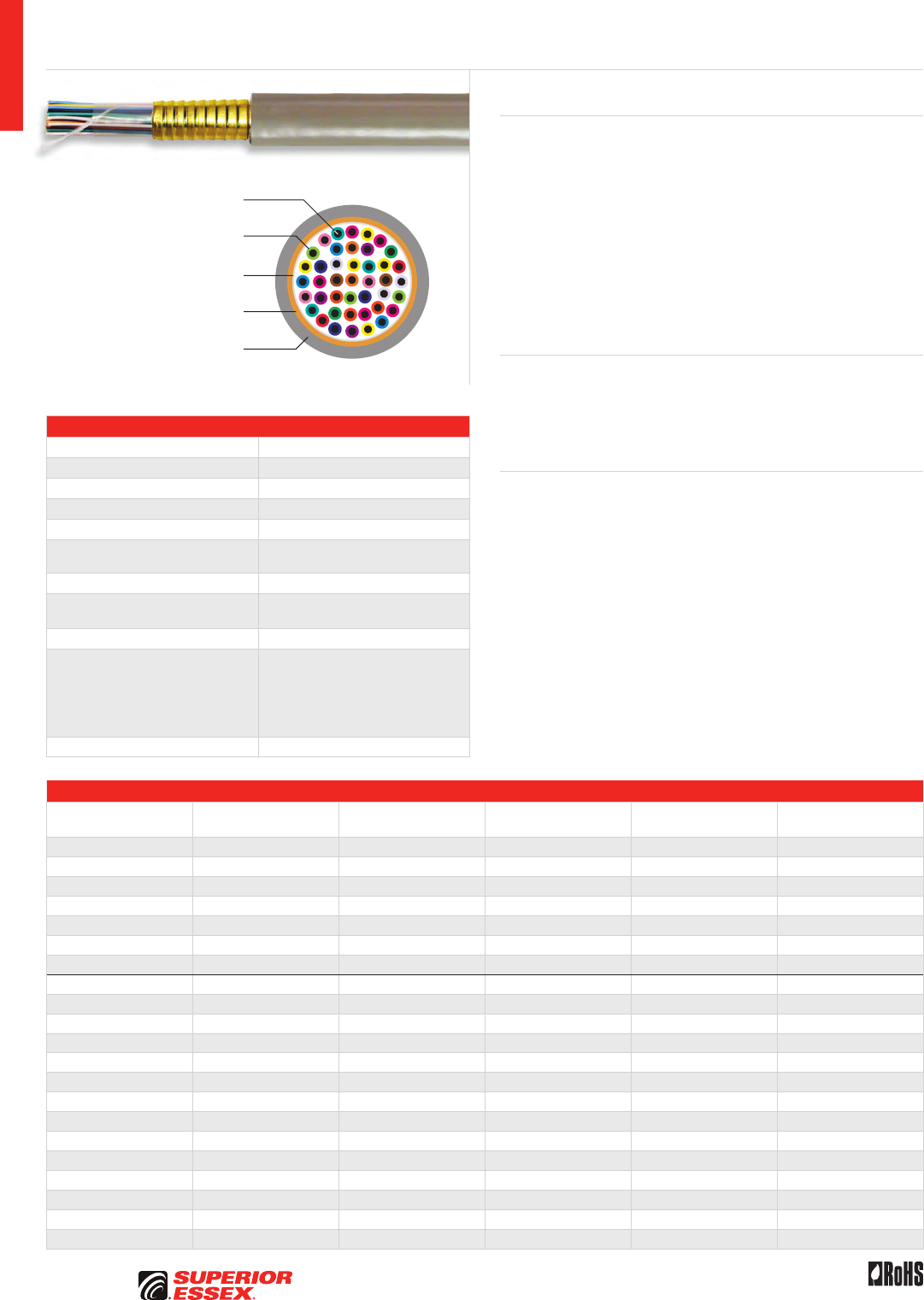
A-36
PREMISES COPPER PREMISES FIBER OSP FIBER OSP COMPOSITE CENTRAL OFFICE COPPER RDUP/RUS OSP COPPER BELL OSP COPPER OSP COPPER WIRE CANADIAN OSP COPPER TECHNICAL INFO
Toll Free 800.551.8948 | Fax 770.657.6807 | SuperiorEssex.com/Comm Rev 10/10 Ed 10.3
Specifications
Pair Count Available in 25-pair up to 2,400-pair
Conductor Solid annealed copper
AWG (mm) Available in 22 (0.64) and 24 (0.51)
Insulation Polyethylene foam with PVC skin
Shield Corrugated 8 mil aluminum tape
Jacket Gray, flame retardant and abrasion
resistant PVC
Characteristic Impedance (Ohms) 100 ± 15
Nominal Velocity
of Propagation (%) 60
Package Cut to length
Performance Compliance
UL 444
CSA C22.2 No. 214-08
UL 1666
Telcordia GR-111
ANSI/TIA-568-C.2
RoHS-compliant
NRTL Programs UL, c(UL) Listed CMR
Part Numbers and Physical Characteristics
Part Number Product Code Pair Count AWG (mm)
Nominal Diameter
in (mm)
Approx. Weight
lbs/kft (kg/km)
02-062-03 ARAM 25 22 (0.64) 0.61 (15) 203 (303)
02-065-03 ARAM 50 22 (0.64) 0.77 (20) 347 (517)
02-069-03 ARAM 100 22 (0.64) 1.05 (27) 644 (960)
02-073-03 ARAM 200 22 (0.64) 1.41 (36) 1,184 (1,766)
02-075-03 ARAM 300 22 (0.64) 1.68 (43) 1,699 (2,533)
02-077-03 ARAM 400 22 (0.64) 1.94 (49) 2,200 (3,280)
02-081-03 ARAM 600 22 (0.64) 2.30 (58) 3,196 (4,766)
02-097-03 ARMM 25 24 (0.51) 0.51 (13) 146 (218)
02-100-03 ARMM 50 24 (0.51) 0.64 (16) 241 (360)
02-104-03 ARMM 100 24 (0.51) 0.89 (23) 447 (667)
02-106-03 ARMM 150 24 (0.51) 1.02 (26) 618 (922)
02-108-03 ARMM 200 24 (0.51) 1.14 (29) 788 (1,175)
02-110-03 ARMM 300 24 (0.51) 1.35 (34) 1,129 (1,684)
02-112-03 ARMM 400 24 (0.51) 1.53 (39) 1,427 (2,128)
02-116-03 ARMM 600 24 (0.51) 1.85 (47) 2,106 (3,140)
02-118-03 ARMM 900 24 (0.51) 2.20 (56) 3,060 (4,563)
02-120-03 ARMM 1,200 24 (0.51) 2.50 (63) 4,008 (5,977)
02-121-03 ARMM 1,500 24 (0.51) 2.80 (71) 5,013 (7,476)
02-124-03 ARMM 1,800 24 (0.51) 3.05 (77) 5,958 (8,884)
02-125-03 ARMM 2,100 24 (0.51) 3.30 (84) 6,908 (10,302)
02-126-03 ARMM 2,400 24 (0.51) 3.52 (89) 7,852 (11,709)
AR Series Riser
ARAM/ARMM
Solid Annealed
Copper Conductor
Corrugated Aluminum
Tape Shield
Non-hygroscopic
Dielectric Tape
Polyethylene Foam with
PVC Skin Insulation
Flame Retardant and
Abrasion Resistant PVC Jacket
Product Description
The AR Series Riser Cables are intended for vertical and horizontal distribution
in commercial buildings and meet Category 3 electrical specifications. This
includes all applications except those in plenums. These cables have a fire-
retardant PVC jacket and have been listed as CMR rated, in accordance with
the National Electrical Code. AR cables are color coded to match standard
Outside Plant (OSP) cable designs. The cable consists of solid soft bare
copper that’s insulated with foam polyethylene and a skin of PVC. Cores
through 900-pair are color coded to match the standard PIC color code. Cables
1,200-pair and larger have a “Mirror Image” color code. Spare pairs are
offered in cables of 1,200-pair and larger. An alvyn sheath is applied overall.
The alvyn sheath consists of a 8 mil aluminum tape applied longitudinally
and bonded to a gray PVC outer jacket.
Applications
• Riser shafts without using conduits
• 4 Mbps token ring
• Analog voice
• 10BASE-T ethernet
Features Benefits
• CMR rating • Meets NFPA code
for riser applications
• Shielded design • Provides EMI/RFI shielding
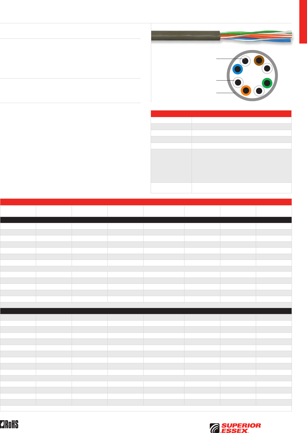
A-37
PREMISES COPPERPREMISES FIBEROSP FIBEROSP COMPOSITECENTRAL OFFICE COPPERRDUP/RUS OSP COPPERBELL OSP COPPEROSP COPPER WIRECANADIAN OSP COPPERTECHNICAL INFO
Rev 10/10 Ed 10.2 Toll Free 800.551.8948 | Fax 770.657.6807 | SuperiorEssex.com/Comm
Specifications
Pair Count Available in 2-pair, 3-pair, 4-pair, 6-pair and 12-pair
Conductor Solid annealed copper
AWG (mm) Available in 22 (0.64) and 24 (0.51)
Insulation Thermoplastic
Jacket Tough, flame retardant, weather and abrasion resistant PVC
Performance
Compliance
UL 444
CSA C22.2 No. 214-08
UL 1666
Extreme CMR/CMX Outdoor Includes ICEA -40°C Anvil Test
ANSI/TIA-568-C.2
ANSI/ICEA S-100-685
2002/95/EC RoHS-compliant
NRTL Programs UL, c(UL) Listed CMR
UL, c(UL) Listed CMX-Outdoor
Part Numbers and Physical Characteristics
Part Number Pair Count AWG (mm) Jacket Color
Nominal Diameter
in (mm)
Approx. Weight
lbs/kft (kg/km) Package
Packages
Per Pallet
CMR/CMX Outdoor
12-202-37 2 22 (0.64) Beige 0.18 (4.7) 17 (26) 1,000’ POP™ Box 45
12-203-37 3 22 (0.64) Beige 0.22 (5.5) 24 (36) 1,000’ POP™ Box 45
12-204-37 4 22 (0.64) Beige 0.22 (5.6) 29 (43) 1,000’ POP™ Box 36
12-214-37 4 22 (0.64) Gray 0.22 (5.6) 29 (43) 1,000’ POP™ Box 36
12-402-37 2 24 (0.51) Beige 0.15 (3.7) 12 (18) 1,000’ POP™ Box 45
12-403-37 3 24 (0.51) Beige 0.17 (4.3) 16 (24) 1,000’ POP™ Box 45
12-404-37 4 24 (0.51) Beige 0.20 (5.0) 20 (30) 1,000’ POP™ Box 45
The above products use a tubed jacket design with the following color code: Blue/White, Orange/White, Green/White, Brown/White.
12-212-32 2 22 (0.64) Beige 0.18 (4.7) 17 (26) 1,000’ POP™ Box 45
12-213-32 3 22 (0.64) Beige 0.22 (5.5) 24 (36) 1,000’ POP™ Box 45
12-206-32 4 22 (0.64) Beige 0.22 (5.6) 29 (43) 500’ POP™ Box 45
12-412-32 2 24 (0.51) Beige 0.15 (3.7) 12 (18) 1,000’ POP™ Box 45
12-414-32 4 24 (0.51) Beige 0.20 (5.0) 20 (30) 1,000’ POP™ Box 45
The above products use a tubed jacket design with the following color code: Red/Green, Yellow/Black, Blue/White, Orange/Brown.
Extreme CMR/CMX Outdoor
11-002-89 2 22 (0.64) Gray 0.17 (4.3) 19 (29) 125’ Coil Pack 128
11-002-88 2 22 (0.64) Ivory 0.17 (4.3) 19 (29) 125’ Coil Pack 256
11-002-87 2 22 (0.64) Ivory 0.17 (4.3) 19 (29) 1,000’ POP™ Box 45
11-003-12 2 24 (0.51) Ivory 0.15 (3.7) 12 (18) 1,000’ POP™ Box 45
11-003-13 2 24 (0.51) Gray 0.15 (3.7) 12 (18) 1,000’ POP™ Box 45
11-003-91 4 24 (0.51) White 0.20 (5.0) 20 (30) 1,000’ POP™ Box 45
11-003-92 4 24 (0.51) Ivory 0.20 (5.0) 20 (30) 1,000’ POP™ Box 45
12-303-62* 6 24 (0.51) Gray 0.21 (5.3) 27 (41) 1,000’ POP™ Box 36
12-805-62* 12 24 (0.51) Gray 0.28 (7.2) 49 (74) 1,000’ Plywood Reel 16
12-825-62* 12 24 (0.51) Ivory 0.28 (7.2) 49 (74) 1,000’ Plywood Reel 16
The above products use a tubed jacket design with the following color code: Blue/White, Orange/White, Green/White and Brown/White. 2-pair 22 AWG products are a pressure extruded design.
12-414-52 3 22 (0.64) Beige 0.22 (5.5) 24 (36) 1,000’ POP™ Box 45
12-415-52 2 24 (0.51) Beige 0.15 (3.7) 12 (18) 1,000’ POP™ Box 45
12-416-52 3 24 (0.51) Beige 0.17 (4.3) 16 (24) 1,000’ POP™ Box 45
12-417-52 4 24 (0.51) Beige 0.20 (5.0) 20 (30) 1,000’ POP™ Box 45
The above products use a tubed jacket design with the following color code: Red/Green, Yellow/Black, Blue/White, Orange/Brown.
*Copper conductors are PVC insulated.
Category 3 Station Wire CMR/CMX Outdoor
Solid Annealed
Copper Conductor
Thermoplastic Insulation
Flame Retardant, Weather and
Abrasion Resistant Jacket
Product Description
Station Wire Category 3 CMR/CMX Outdoor Wires are small, light-weight,
twisted pair cables designed for use in protected outdoor locations, indoor
areas or a combination. Two levels of Outdoor Protection are available CMR/
CMX Outdoor and Extreme CMR/CMX Outdoor. The Extreme Series meets
the -40°C anvil test.
Applications
• CMR/CMX Outdoor
• Extreme CMR/CMX Outdoor
Features Benefits
• CMR/CMX Outdoor combination • Indoor/outdoor use
• Extreme CMR/CMX Outdoor
combination
• Indoor/outdoor use with extreme
cold temperature feature
• Beige, gray and ivory
jacket colors
• Enhances appearance
on outdoor siding
• Various conductor colors • Customer preference
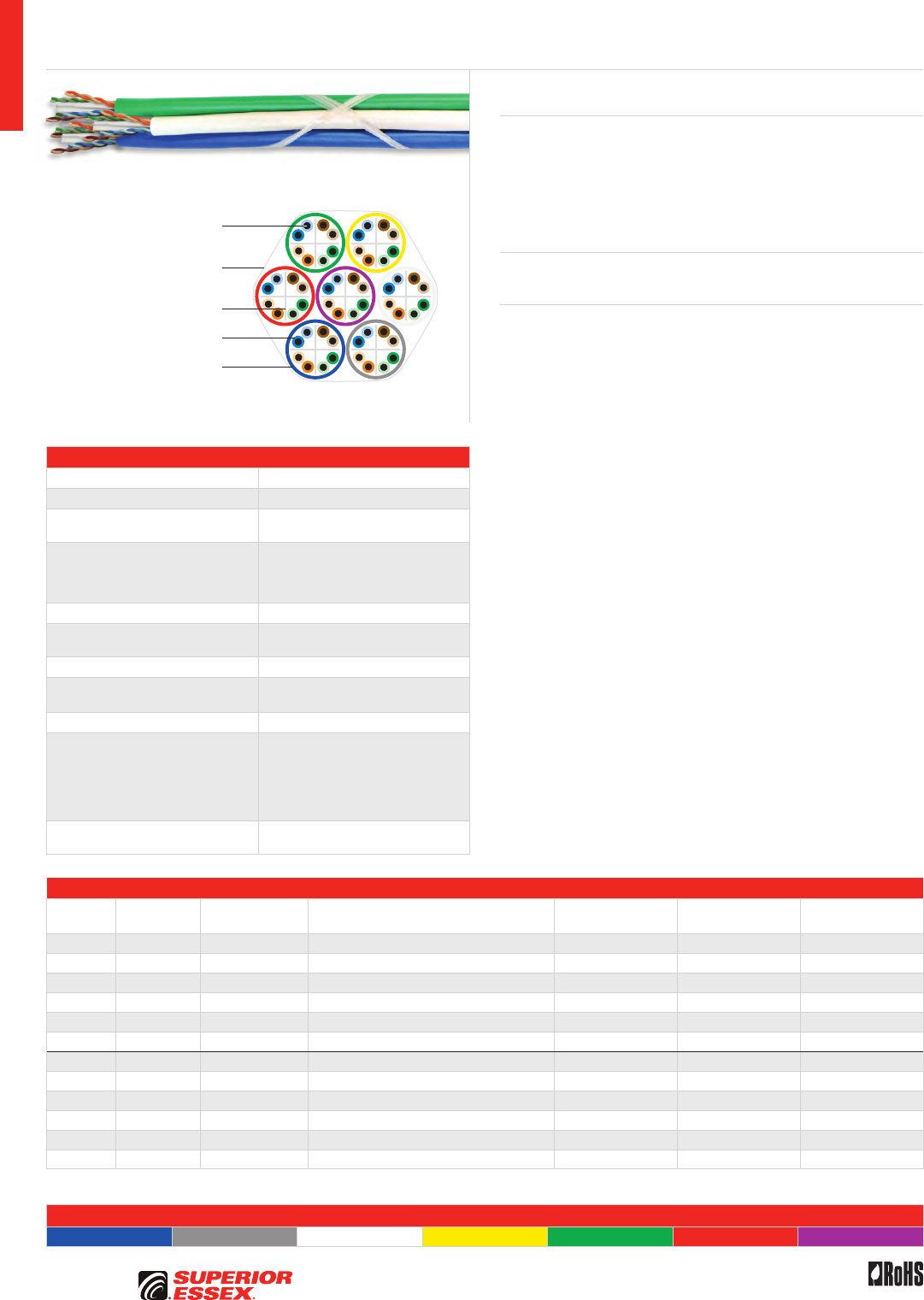
A-38
PREMISES COPPER PREMISES FIBER OSP FIBER OSP COMPOSITE CENTRAL OFFICE COPPER RDUP/RUS OSP COPPER BELL OSP COPPER OSP COPPER WIRE CANADIAN OSP COPPER TECHNICAL INFO
Rev 10/10 Ed 10.2Toll Free 800.551.8948 | Fax 770.657.6807 | SuperiorEssex.com/Comm
Specifications
Conductor Solid annealed copper
AWG (mm) 23 (0.57)
Insulation CMR: Thermoplastic
CMP: FEP
Insulation Colors
Pair 1: ColorTip™ Light Blue, Blue
Pair 2: ColorTip Light Orange, Orange
Pair 3: ColorTip Light Green, Green
Pair 4: ColorTip Light Brown, Brown
Separator Cross-web
Jacket CMR: Flame retardant (FR) PVC
CMP: FR, low smoke PVC
Characteristic Impedance (Ohms) 100 ± 15
Nominal Velocity
of Propagation (%)
CMR: 68
CMP: 71
Package F x T x D (in) 30 x 18 x 12 plywood reel
Component Performance
Compliance
UL 444
CSA C22.2 No. 214-08
UL 1666
NFPA 262
ANSI/TIA-568-C.2
RoHS-compliant
Component NRTL Programs UL, c(UL) Listed CMR
UL, c(UL) Listed CMP
Part Numbers and Physical Characteristics
Listing Part Number Cable Sub-units Jacket Colors*
Nominal Diameter
in (mm)
Approx. Weight
lbs/kft (kg/km)
Standard Length
ft (m)
CMR 56-202-2A 2 Blue, Gray 0.44 (11.2) 48 (106) 2,500 (762)
CMR 56-202-3A 3 Blue, Gray, White 0.48 (12.1) 72 (159) 2,500 (762)
CMR 56-202-4A 4 Blue, Gray, White, Yellow 0.53 (13.6) 97 (213) 2,500 (762)
CMR 56-201-5A 5 Blue, Gray, White, Yellow, Green 0.61 (15.5) 121 (266) 2,500 (762)
CMR 56-201-6A 6 Blue, Gray, White, Yellow, Green, Red 0.70 (17.8) 145 (319) 2,500 (762)
CMR 56-201-7A 7 Blue, Gray, White, Yellow, Green, Red, Purple 0.70 (17.8) 176 (387) 1,000 (305)
CMP 56-202-2B 2 Blue, Gray 0.48 (12.1) 57 (126) 2,500 (762)
CMP 56-202-3B 3 Blue, Gray, White 0.51 (13.0) 86 (189) 2,500 (762)
CMP 56-202-4B 4 Blue, Gray, White, Yellow 0.57 (14.6) 115 (252) 2,500 (762)
CMP 56-201-5B 5 Blue, Gray, White, Yellow, Green 0.64 (16.3) 143 (315) 2,500 (762)
CMP 56-201-6B 6 Blue, Gray, White, Yellow, Green, Red 0.71 (18.1) 172 (378) 2,500 (762)
CMP 56-201-7B 7 Blue, Gray, White, Yellow, Green, Red, Purple 0.71 (18.1) 201 (441) 1,000 (305)
*Other jacket color combinations available.
Jacket Colors
Blue Gray White Yellow Green Red Purple
Bundled Category 6
Product Description
Superior Essex Bundled UTP cables reduce the amount of cable pulls in an
installation and simplify cable management. These bundled cables consist
of multiple Category 6 compliant cables bundled together and bound by
contra-helically applied binder yarns. The binder configuration allows for
easy breakout and offers greater flexibility compared to an overjacket design.
Contrasting jacket colors allow for easy identification.
Applications
• 10BASE-T through 1000BASE-T ethernet, ATM and token ring
Features Benefits
• Binding of multiple UTP cables • Reduces installation time
• Multiple construction options
(2 to 7 cable sub-units)
• Improves cable management
• Warranted with numerous
connectivity manufacturers
• Sizes available for small
and large projects
• ColorTip™ circuit
identification system
• Easily identifiable conductor
mates, even in low
light environment
• Flexible, dual binder yarns,
contra-helically applied
• Maintains maximum flexibility
and allows for easy breakout
Contra-Helically
Applied Binder Yarns
Solid Annealed
Copper Conductor
Thermoplastic Insulation
Flame Retardant PVC Jacket
Cross-web Separator
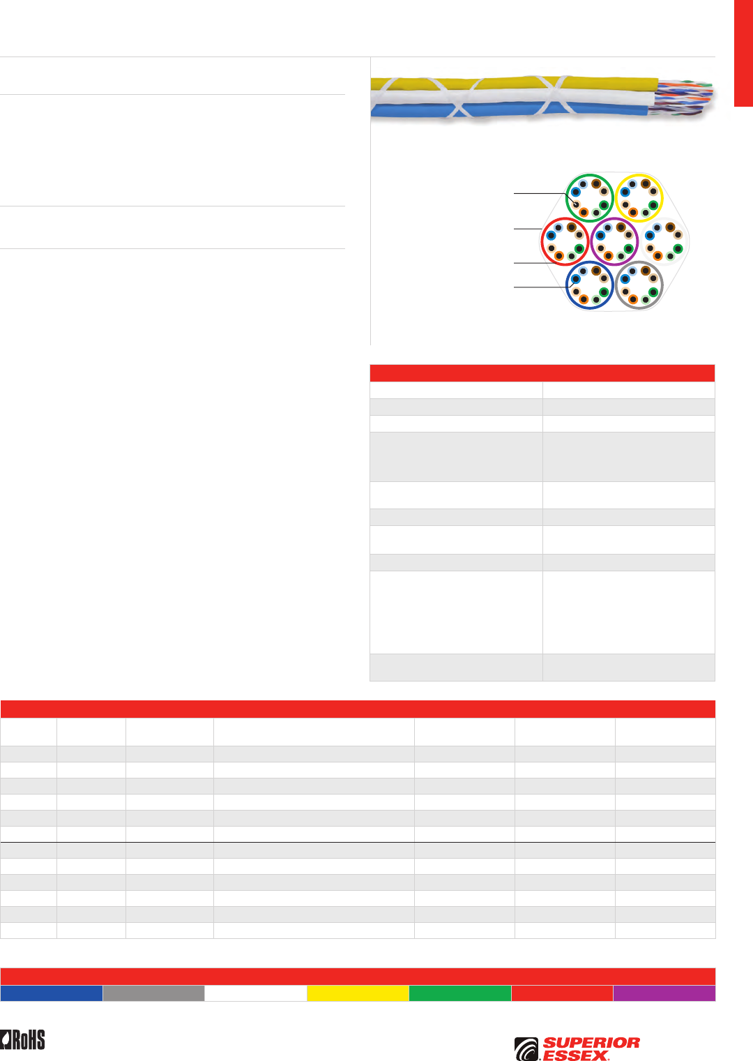
A-39
PREMISES COPPERPREMISES FIBEROSP FIBEROSP COMPOSITECENTRAL OFFICE COPPERRDUP/RUS OSP COPPERBELL OSP COPPEROSP COPPER WIRECANADIAN OSP COPPERTECHNICAL INFO
Rev 10/10 Ed 10.2 Toll Free 800.551.8948 | Fax 770.657.6807 | SuperiorEssex.com/Comm
Specifications
Conductor Solid annealed copper
AWG (mm) 24 (0.51)
Insulation Thermoplastic
Insulation Colors
Pair 1: ColorTip™ Light Blue, Blue
Pair 2: ColorTip Light Orange, Orange
Pair 3: ColorTip Light Green, Green
Pair 4: ColorTip Light Brown, Brown
Jacket CMR: Flame retardant (FR) PVC
CMP: FR, low smoke PVC
Characteristic Impedance (Ohms) 100 ± 15
Nominal Velocity
of Propagation (%)
CMR: 69
CMP: 72
Package F x T x D (in) 30 x 18 x 12 plywood reel
Component Performance
Compliance
UL 444
CSA C22.2 No. 214-08
UL 1666
NFPA 262
ANSI/TIA-568-C.2
ANSI/ICEA S-90-661-2008
RoHS-compliant
Component NRTL Programs UL, c(UL) Listed CMP
UL, c(UL) Listed CMR
Part Numbers and Physical Characteristics
Listing Part Number Cable Sub-units Jacket Colors*
Nominal Diameter
in (mm)
Approx. Weight
lbs/kft (kg/km)
Standard Length
ft (m)
CMR 56-202-25 2 Blue, Gray 0.38 (9.7) 38 (083) 2,500 (762)
CMR 56-202-35 3 Blue, Gray, White 0.41 (10.4) 57 (125) 2,500 (762)
CMR 56-202-45 4 Blue, Gray, White, Yellow 0.46 (11.7) 76 (167) 2,500 (762)
CMR 56-201-55 5 Blue, Gray, White, Yellow, Green 0.51 (13.0) 95 (208) 2,500 (762)
CMR 56-201-65 6 Blue, Gray, White, Yellow, Green, Red 0.56 (14.2) 114 (250) 2,500 (762)
CMR 56-201-75 7 Blue, Gray, White, Yellow, Green, Red, Purple 0.56 (14.2) 133 (292) 1,000 (305)
CMP 56-202-28 2 Blue, Gray 0.35 (8.9) 39 (085) 2,500 (762)
CMP 56-202-38 3 Blue, Gray, White 0.38 (9.6) 58 (127) 2,500 (762)
CMP 56-202-48 4 Blue, Gray, White, Yellow 0.42 (10.8) 77 (170) 2,500 (762)
CMP 56-201-58 5 Blue, Gray, White, Yellow, Green 0.48 (12.1) 96 (212) 2,500 (762)
CMP 56-201-68 6 Blue, Gray, White, Yellow, Green, Red 0.53 (13.4) 116 (254) 2,500 (762)
CMP 56-201-78 7 Blue, Gray, White, Yellow, Green, Red, Purple 0.53 (13.4) 135 (297) 1,000 (305)
*Other jacket color combinations available.
Jacket Colors
Blue Gray White Yellow Green Red Purple
Bundled Category 5e
Product Description
Superior Essex Bundled UTP cables reduce the amount of cable pulls in an
installation and simplify cable management. These bundled cables consist
of multiple Category 5e compliant cables bundled together and bound by
contra-helically applied binder yarns. The binder configuration allows for easy
breakout and offers greater flexibility compared to a composite overjacket
design. Contrasting jacket colors allow easy identification.
Applications
• 10BASE-T through 1000BASE-T ethernet, ATM and token ring
Features Benefits
• Binding of multiple UTP cables • Reduces installation time
• Multiple construction options
(2 to 7 cable sub-units)
• Improves cable management
• Warranted with numerous
connectivity manufacturers
• Sizes available for small
and large projects
• ColorTip™ circuit
identification system
• Easily identifiable conductor
mates, even in low
light environment
• Flexible, dual binder yarns,
contra-helically applied
• Maintains maximum flexibility
and allows for easy breakout
Contra-Helically
Applied Binder Yarns
Solid Annealed
Copper Conductor
Thermoplastic Insulation
Flame Retardant PVC Jacket
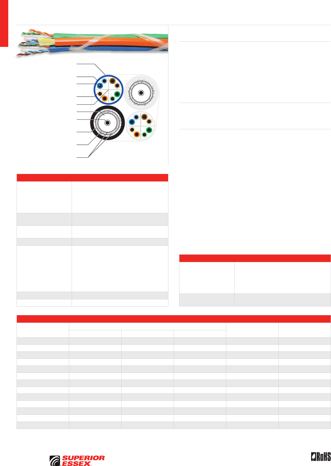
A-40
PREMISES COPPER PREMISES FIBER OSP FIBER OSP COMPOSITE CENTRAL OFFICE COPPER RDUP/RUS OSP COPPER BELL OSP COPPER OSP COPPER WIRE CANADIAN OSP COPPER TECHNICAL INFO
Rev 10/10 Ed 10.2Toll Free 800.551.8948 | Fax 770.657.6807 | SuperiorEssex.com/Comm
23 AWG Solid Annealed
Copper Conductor
Thermoplastic Insulation
Cross-web Separator
Flame Retardant PVC Jacket
Contra-Helically
Applied Binder Yarns
18 AWG Copper Clad
Steel Conductor
34 AWG Aluminum
Inner Braid (60%)
34 AWG Aluminum
Outer Braid (40%)
Aluminum Tape
Inner/Outer Shields (x2)
Insulation PE Foam
Bundled Composite Category 6 CMR
Specifications
CAT 6 UTP Component
Pair Count: 4
Conductor: Solid annealed copper
AWG (mm): 23 (0.57)
Insulation: Thermoplastic
Separator: Cross-web
Jacket: Flame retardant PVC
Characteristic
Impedance (Ohms) 100 ± 15
Nominal Velocity
of Propagation (%) 68
Fiber Component* 62.5/125 µm duplex, 5 mm round, 900 µm tight buffered
Coax Series 6 Quad
Shield Component
Conductor: Copper clad steel
AWG (mm): 18 (1.02)
Insulation: Polyethylene
Inner Shield: 2.8 mil aluminum foil
Inner Braid: 34 AWG aluminum (60%)
Outer Shield: 1.8 mil aluminum foil
Outer Braid: 34 AWG aluminum (40%)
Jacket: PVC
Electrical: See "Coax Series 6 Quad Shield" on page A-45
Binder Yarn Flexible, dual binder yarns, contra-helically applied
Package Cut to length on plywood reel
Part Numbers and Physical Characteristics
Part Number
Number of Cable Components Nominal Diameter
in (mm)
Nominal Weight
lbs/kft (kg/km)CAT 6 RG 6 Quad 62.5 2-fiber*
D3-2009SA 1 1 - 0.53 (14) 56 (124)
D3-5009SA 1 2 - 0.56 (14) 88 (195)
D3-A009SA 2 1 - 0.51 (13) 81 (178)
D3-D009SA 2 2 - 0.67 (17) 113 (248)
D3-J009SA 3 1 - 0.67 (17) 105 (232)
D3-M009SA 3 2 - 0.81 (21) 137 (302)
D3-S009SA 4 1 - 0.82 (21) 130 (286)
D3-V009SA 4 2 - 0.85 (22) 162 (356)
D3-B169SA 2 1 1 0.56 (14) 95 (210)
D3-E169SA 2 2 1 0.51 (13) 127 (280)
D3-K169SA 3 1 1 0.67 (17) 120 (263)
D3-N169SA 3 2 1 0.67 (17) 152 (334)
D3-T169SA 4 1 1 0.81 (21) 144 (317)
*Other fiber types and fiber counts available upon request.
Product Description
Superior Essex offers multiple configurations of skip-wrapped or bundled
riser-rated (CMR) composite cables to support common drop configurations
used in residential structured wiring installations. These composite cables
improve installation time and reduce the chance of violating minimum bend
radius of the cable. The individual components support many technologies,
including extended bandwidth satellite service, 1000BASE-T and 100BASE-TX
ethernet and high-definition TV signals. This product is also available with an
optical fiber cable.
Applications
• 10BASE-T through 1000BASE-T ethernet, ATM and token ring
• HDTV, CATV, CCTV and DBS
Features Benefits
• All-in-one cable design • Reduces installation time,
provides additional protection
to the individual cables
• Series 6 Quad Shield coaxial
cable with typical bandwidth
that exceeds 3 GHz
• “Future-Proofing” the installation.
Supports extended bandwidth
satellite service and high-
definition TV signals
• Multiple constructions available • Customized flexibility
for the application
• Optional optical fiber
premises cable
• Integrated fiber reduces the need
to install separate cables for
home interior optical networks
• Flexible, dual binder yarns,
contra-helically applied
• Maintains maximum flexibility
and allows for easy breakout
Specifications (continued)
Component
Performance
Compliance
UL 444
CSA C22.2 No. 214-08
UL 1666
ANSI/TIA-568-C.2
ANSI/ICEA S-83-596-2001
RoHS-compliant
Component
NRTL Programs UL, c(UL) Listed CMR
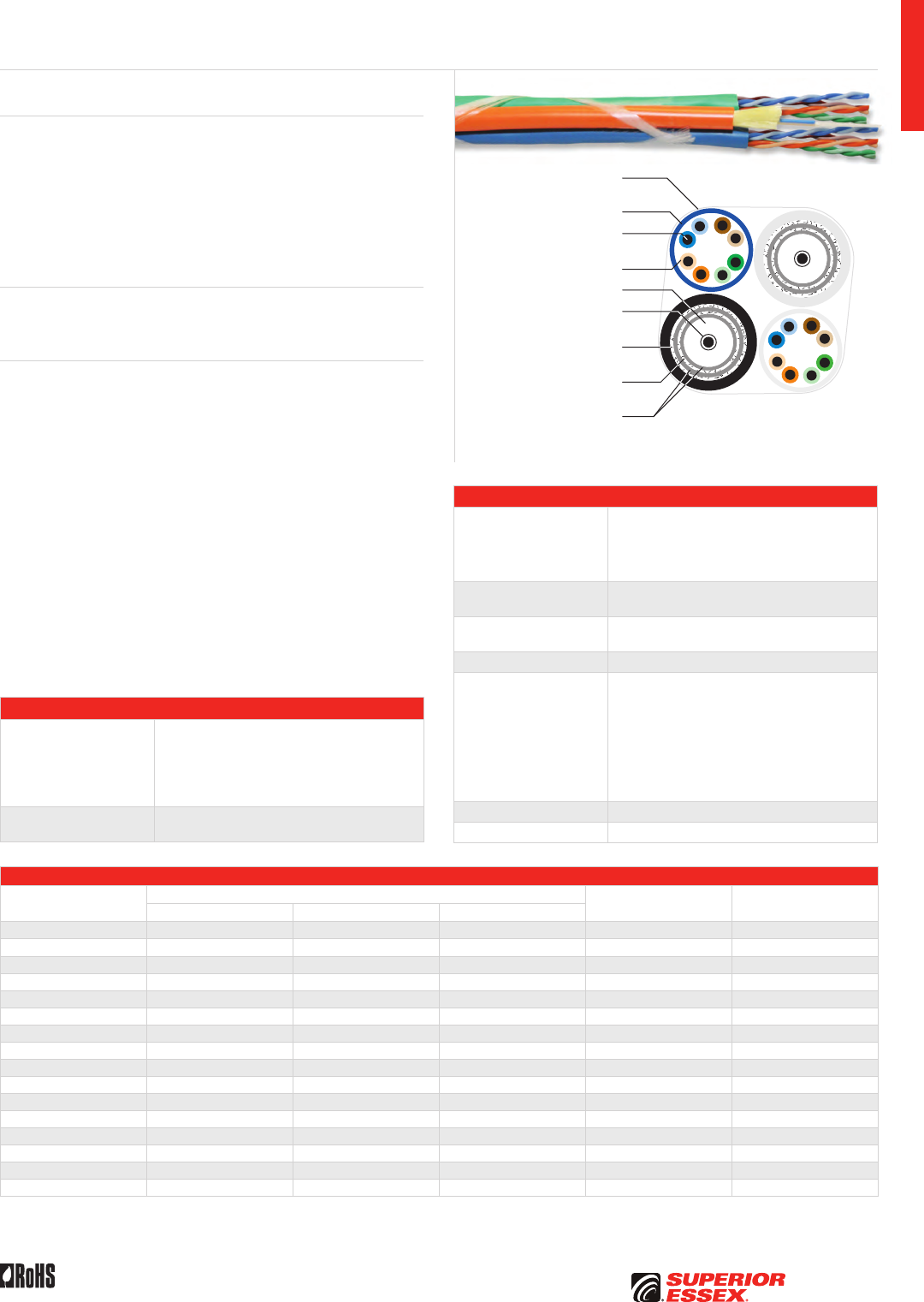
A-41
PREMISES COPPERPREMISES FIBEROSP FIBEROSP COMPOSITECENTRAL OFFICE COPPERRDUP/RUS OSP COPPERBELL OSP COPPEROSP COPPER WIRECANADIAN OSP COPPERTECHNICAL INFO
Rev 10/10 Ed 10.2 Toll Free 800.551.8948 | Fax 770.657.6807 | SuperiorEssex.com/Comm
24 AWG Solid Annealed
Copper Conductor
Thermoplastic Insulation
Flame Retardant PVC Jacket
Contra-Helically
Applied Binder Yarns
18 AWG Copper Clad
Steel Conductor
34 AWG Aluminum
Inner Braid (60%)
34 AWG Aluminum
Outer Braid (40%)
Aluminum Tape
Inner/Outer Shields (x2)
Insulation PE Foam
Bundled Composite Category 5e CMR
Specifications
CAT 5e UTP Component
Pair Count: 4
Conductor: Solid annealed copper
AWG (mm): 24 (0.51)
Insulation: Thermoplastic
Jacket: Flame retardant PVC
Characteristic
Impedance (Ohms) 100 ± 15
Nominal Velocity
of Propagation (%) 69
Fiber Component* 62.5/125 µm duplex, 5 mm round, 900 µm tight buffered
Coax Series 6 Quad
Shield Component
Conductor: Copper clad steel
AWG (mm): 18 (1.02)
Insulation: Polyethylene
Inner Shield: 2.8 mil aluminum foil
Inner Braid: 34 AWG aluminum (60%)
Outer Shield: 1.8 mil aluminum foil
Outer Braid: 34 AWG aluminum (40%)
Jacket: PVC
Electrical: See "Coax Series 6 Quad Shield" on page A-45
Binder Yarn Flexible, dual binder yarns, contra-helically applied
Package Cut to length on plywood reel
Part Numbers and Physical Characteristics
Part Number
Number of Cable Components Nominal Diameter
in (mm)
Nominal Weight
lbs/kft (kg/km)CAT 5e RG 6 Quad 62.5 2-fiber*
D1-2009S5 1 1 - 0.49 (12) 51 (113)
D1-5009S5 1 2 - 0.53 (13) 83 (183)
D1-A009S5 2 1 - 0.45 (12) 71 (156)
D1-D009S5 2 2 - 0.61 (16) 103 (226)
D1-J009S5 3 1 - 0.58 (15) 90 (198)
D1-M009S5 3 2 - 0.73 (19) 122 (269)
D1-S009S5 4 1 - 0.71 (18) 110 (241)
D1-V009S5 4 2 - 0.85 (22) 142 (311)
D1-3169S5 1 1 1 0.53 (13) 66 (145)
D1-6169S5 1 2 1 0.45 (12) 98 (215)
D1-B169S5 2 1 1 0.61 (16) 85 (187)
D1-E169S5 2 2 1 0.58 (15) 117 (258)
D1-K169S5 3 1 1 0.73 (19) 105 (230)
D1-N169S5 3 2 1 0.71 (18) 137 (300)
D1-T169S5 4 1 1 0.85 (22) 124 (273)
D1-W169S5 4 2 1 0.85 (22) 156 (343)
*Other fiber types and fiber counts available upon request.
Product Description
Superior Essex offers multiple configurations of skip-wrapped or bundled
riser-rated (CMR) composite cables to support common drop configurations
used in residential structured wiring installations. These composite cables
improve installation time and reduce the chance of violating minimum bend
radius of the cable. The individual components support many technologies,
including extended bandwidth satellite service, 1000BASE-T and 100BASE-TX
ethernet and high definition TV signals. This product is also available with an
optical fiber cable.
Applications
• 10BASE-T through 1000BASE-T ethernet, ATM and token ring
• HDTV, CATV, CCTV and DBS
Features Benefits
• All-in-one cable design • Reduces installation time,
provides additional protection
to the individual cables
• Series 6 Quad Shield coaxial
cable with typical bandwidth
that exceeds 3 GHz
• “Future-Proofing” the installation.
Supports extended bandwidth
satellite service and high-
definition TV signals
• Multiple constructions available • Customized flexibility
for the application
• Optional optical fiber
premises cable
• Integrated fiber reduces the need
to install separate cables for
home interior optical networks
• Flexible, dual binder yarns,
contra-helically applied
• Maintains maximum flexibility
and allows for easy breakout
Specifications (continued)
Component
Performance
Compliance
UL 444
CSA C22.2 No. 214-08
UL 1666
ANSI/TIA-568-C.2
ANSI/ICEA S-83-596-2001
RoHS-compliant
Component
NRTL Programs UL, c(UL) Listed CMR
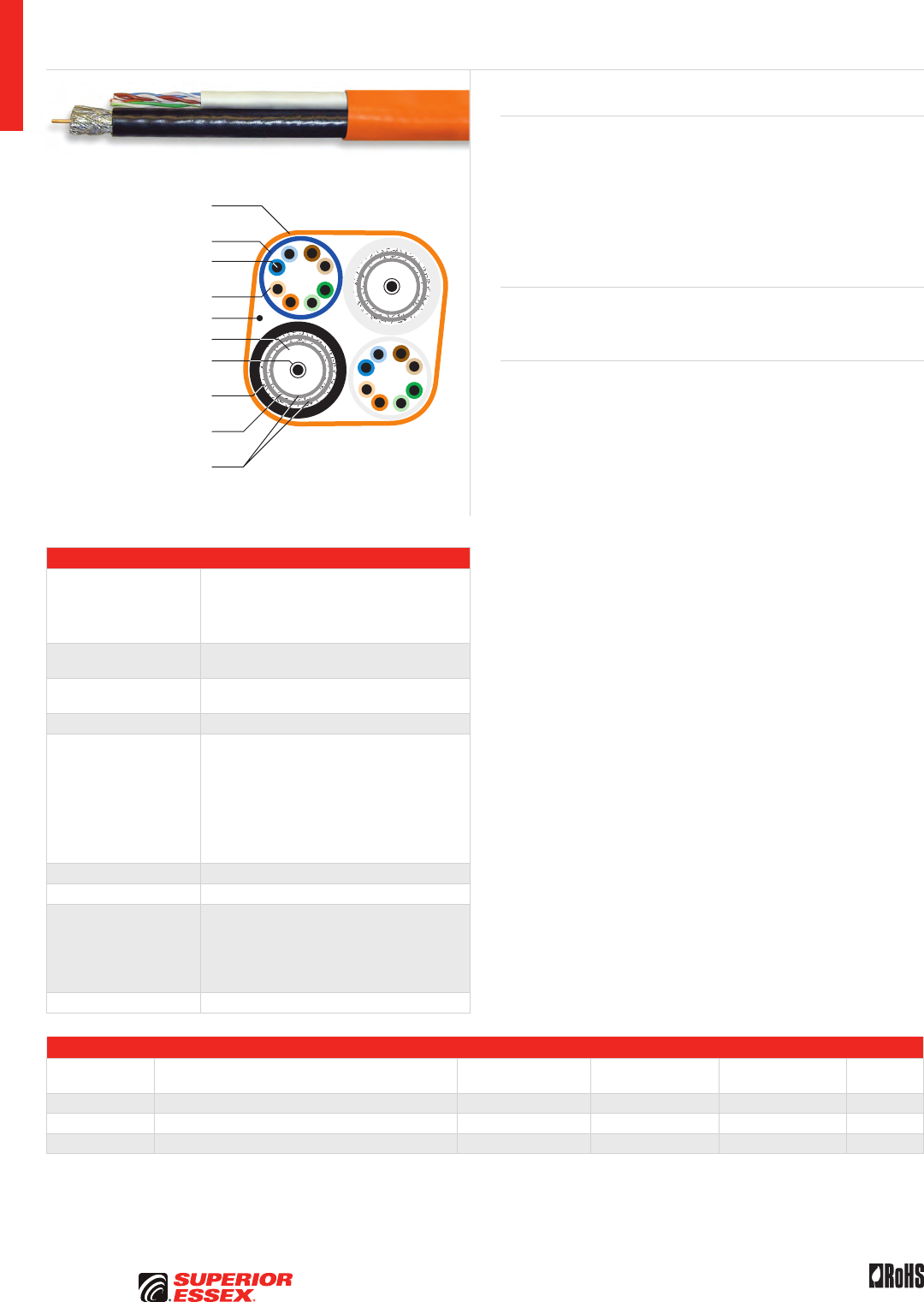
A-42
PREMISES COPPER PREMISES FIBER OSP FIBER OSP COMPOSITE CENTRAL OFFICE COPPER RDUP/RUS OSP COPPER BELL OSP COPPER OSP COPPER WIRE CANADIAN OSP COPPER TECHNICAL INFO
Rev 10/10 Ed 10.2Toll Free 800.551.8948 | Fax 770.657.6807 | SuperiorEssex.com/Comm
Specifications
CAT 6 UTP Component
Pair Count: 4
Conductor: Solid annealed copper
AWG (mm): 23 (0.57)
Insulation: Thermoplastic
Jacket: Flame retardant PVC
Characteristic
Impedance (Ohms) 100 ± 15
Nominal Velocity
of Propagation (%) 68
Fiber Component 62.5/125 µm duplex, 5 mm round, 900 µm tight buffered
Coax Series 6 Quad
Shield Component
Conductor: Copper clad steel
AWG (mm): 18 (1.02)
Insulation: Polyethylene
Inner Shield: 2.8 mil aluminum foil
Inner Braid: 34 AWG aluminum (60%)
Outer Shield: 1.8 mil aluminum foil
Outer Braid: 34 AWG aluminum (40%)
Jacket: PVC
Electrical: See "Coax Series 6 Quad Shield" on page A-45
Overall Jacket Orange, flame retardant PVC
Package Plywood reel
Performance
Compliance
UL 444
CSA C22.2 No. 214-08
UL 1666
ANSI/TIA-568-C.2
ANSI/ICEA S-83-596-2001
RoHS-compliant
NRTL Programs UL, c(UL) Listed CMR
Part Numbers and Physical Characteristics
Part Number Description
Nominal Diameter
in (mm)
Approx. Weight
lbs/kft (kg/km)
Standard Length
ft (m)
Packages
Per Pallet
72-512-01 1 Series 6 Quad x 1 CAT 6 0.37 x 0.54 (9.27 x 13.59) 70 (104) 1,000 (305) 4
72-621-03 2 Series 6 Quad x 2 CAT 6 0.62 x 0.54 (15.7 x 13.5) 130 (193) 500 (152) 4
7A-621-03 2 Series 6 Quad x 2 CAT 6 x 1 Duplex 62.5/125 MMF 0.62 x 0.54 (15.7 x 13.6) 144 (214) 500 (152) 4
Residential Broadband Riser
Coax Series 6 Quad Shield, Category 6 and Optical Fiber
Product Description
Superior Essex offers multiple configurations of Residential Broadband
riser-rated (CMR) composite cables to support the three common drop
configurations used in residential structured wiring installations. These
composite cables improve installation time and reduce the chance of
violating minimum bend radius of the cable. The individual components
support many technologies, including extended bandwidth satellite service,
1000BASE-T and 100BASE-TX ethernet and high-definition TV signals. This
product is also available with a 62.5 µm duplex multimode fiber.
Applications
• 10BASE-T through 1000BASE-T ethernet, ATM and token ring
• HDTV, CATV, CCTV and DBS
Features Benefits
• All-in-one cable design • Reduces installation time,
provides additional protection
to the individual cables
• Series 6 Quad Shield coaxial
cable with typical bandwidth
that exceeds 3 GHz
• “Future-Proofing” the installation.
Supports extended bandwidth
satellite service and high-
definition TV signals
• Multiple constructions available • Customized flexibility
for the application
• TeraGain® multimode optical
fiber (optional)
• Integrated fiber reduces the need
to install separate cables for
home interior optical networks
23 AWG Solid Annealed
Copper Conductor
Thermoplastic Insulation
Flame Retardant PVC Jacket
Flame Retardant
Overall PVC Jacket
18 AWG Copper Clad
Steel Conductor
34 AWG Aluminum
Inner Braid (60%)
34 AWG Aluminum
Outer Braid (40%)
Aluminum Tape
Inner/Outer Shields (x2)
Insulation PE Foam
Rip Cord
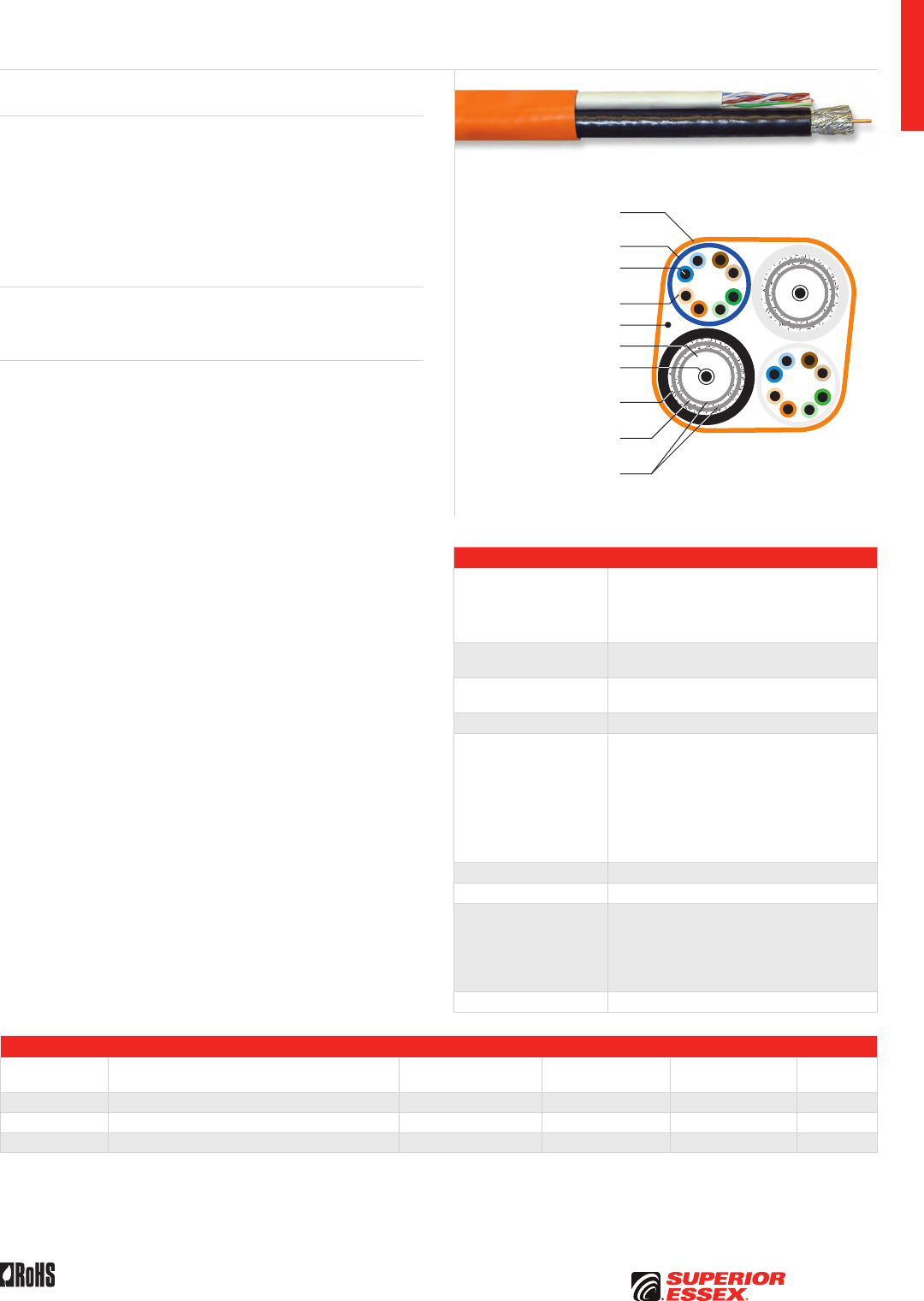
A-43
PREMISES COPPERPREMISES FIBEROSP FIBEROSP COMPOSITECENTRAL OFFICE COPPERRDUP/RUS OSP COPPERBELL OSP COPPEROSP COPPER WIRECANADIAN OSP COPPERTECHNICAL INFO
Rev 10/10 Ed 10.2 Toll Free 800.551.8948 | Fax 770.657.6807 | SuperiorEssex.com/Comm
24 AWG Solid Annealed
Copper Conductor
Thermoplastic Insulation
Flame Retardant PVC Jacket
Flame Retardant
Overall PVC Jacket
18 AWG Copper Clad
Steel Conductor
34 AWG Aluminum
Inner Braid (60%)
34 AWG Aluminum
Outer Braid (40%)
Aluminum Tape
Inner/Outer Shields (x2)
Insulation PE Foam
Rip Cord
Specifications
CAT 5e UTP Component
Pair Count: 4
Conductor: Solid annealed copper
AWG (mm): 24 (0.51)
Insulation: Thermoplastic
Jacket: Flame retardant PVC
Characteristic
Impedance (Ohms) 100 ± 15
Nominal Velocity
of Propagation (%) 69
Fiber Component 62.5/125 µm duplex, 5 mm round, 900 µm tight buffered
Coax Series 6 Quad
Shield Component
Conductor: Copper clad steel
AWG (mm): 18 (1.02)
Insulation: Polyethylene
Inner Shield: 2.8 mil aluminum foil
Inner Braid: 34 AWG aluminum (60%)
Outer Shield: 1.8 mil aluminum foil
Outer Braid: 34 AWG aluminum (40%)
Jacket: PVC
Electrical: See "Coax Series 6 Quad Shield" on page A-45
Overall Jacket Orange, flame retardant PVC
Package Plywood reel
Performance
Compliance
UL 444
CSA C22.2 No. 214-08
UL 1666
ANSI/TIA-568-C.2
ANSI/ICEA S-83-596-2001
RoHS-compliant
NRTL Programs UL, c(UL) Listed CMR
Part Numbers and Physical Characteristics
Part Number Description
Nominal Diameter
in (mm)
Approx. Weight
lbs/kft (kg/km)
Standard Length
ft (m)
Packages
Per Pallet
72-312-01 1 Series 6 Quad x 1 CAT 5e 0.365 x 0.535 (9.27 x 13.59) 73 (109) 1,000 (305) 4
72-421-03 2 Series 6 Quad x 2 CAT 5e 0.640 x 0.535 (16.00 x 13.59) 135 (201) 500 (152) 4
7A-421-03 2 Series 6 Quad x 2 CAT 5e x 1 Duplex 62.5/125 MMF 0.660 x 0.537 (16.80 x 13.64) 149 (222) 500 (152) 4
Residential Broadband Riser
Coax Series 6 Quad Shield, Category 5e and Optical Fiber
Product Description
Superior Essex offers multiple configurations of Residential Broadband
riser-rated (CMR) composite cables to support the three common drop
configurations used in residential structured wiring installations. These
composite cables improve installation time and reduce the chance of
violating minimum bend radius of the cable. The individual components
support many technologies, including extended bandwidth satellite service,
1000BASE-T and 100BASE-TX ethernet and high definition TV signals. This
product is also available with a 62.5 µm duplex multimode fiber.
Applications
• 10BASE-T through 1000BASE-T ethernet, ATM and token ring
• HDTV, CATV, CCTV and DBS
Features Benefits
• All-in-one cable design • Reduces installation time,
provides additional protection
to the individual cables
• Series 6 Quad Shield coaxial
cable with typical bandwidth
that exceeds 3 GHz
• “Future-Proofing” the installation.
Supports extended bandwidth
satellite service and high-
definition TV signals
• Multiple constructions available • Customized flexibility
for the application
• TeraGain® multimode optical
fiber (optional)
• Integrated fiber reduces the need
to install separate cables for
home interior optical networks
• CAT 5e, 4-pair • For high bandwidth applications
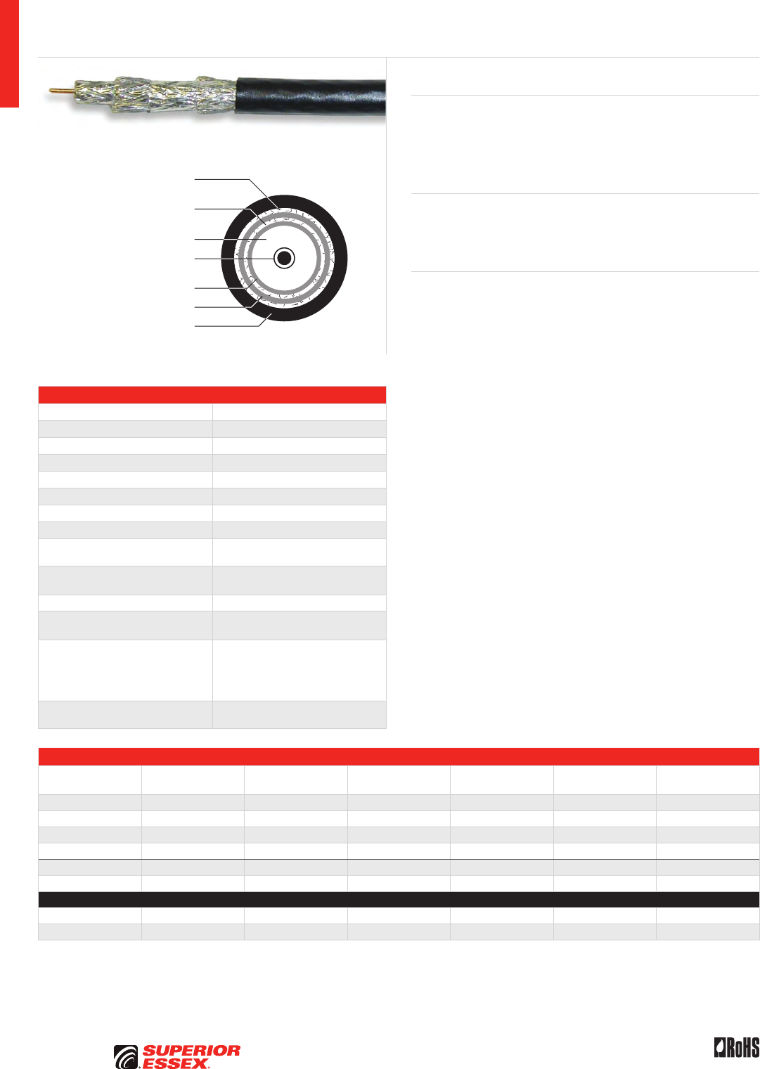
A-44
PREMISES COPPER PREMISES FIBER OSP FIBER OSP COMPOSITE CENTRAL OFFICE COPPER RDUP/RUS OSP COPPER BELL OSP COPPER OSP COPPER WIRE CANADIAN OSP COPPER TECHNICAL INFO
Toll Free 800.551.8948 | Fax 770.657.6807 | SuperiorEssex.com/Comm Rev 11/10 Ed 10.3
Specifications
Conductor Copper clad steel
AWG (mm) 18 (1.02)
Inner Shield 2.8 mil aluminum foil
Inner Braid 34 AWG aluminum (60%)
Outer Shield 1.8 mil aluminum foil
Outer Braid 34 AWG aluminum (40%)
Insulation Polyethylene
Jacket PVC (polyvinylchloride)
Nominal Diameter in (mm) Dielectric: 0.18 (4.57)
Shield: 0.19 (4.82)
Nominal Jacket Wall Thickness
in (mm) 0.03 (0.76)
Nominal Impedance (Ohms) 75
Nominal Velocity
of Propagation (%) 85
Performance Compliance
UL 444
CSA C22.2 No. 214-08
UL 1685
UL 1666
RoHS-compliant
NRTL Programs UL, c(UL) Listed CM
UL, c(UL) Listed CMR
Part Numbers and Physical Characteristics
Listing Part Number
Component
Jacket Color
Nominal Diameter
in (mm)
Approx. Weight
lbs/kft (kg/km) Package
Packages Per
Pallet
CM/CATV 78-147-91 White 0.30 (7.5) 29 (43) 1,000’ Plywood Reel 27
CM/CATV 79-147-91 Black 0.30 (7.5) 29 (43) 1,000’ Plywood Reel 27
CM/CATV 78-147-9P White 0.30 (7.5) 29 (43) 1,000’ POP™ Box 20
CM/CATV 79-147-9P Black 0.30 (7.5) 29 (43) 1,000’ POP™ Box 20
CMR/CATVR 78-148-91 White 0.30 (7.5) 30 (45) 1,000’ Plywood Reel 27
CMR/CATVR 79-148-91 Black 0.30 (7.5) 30 (45) 1,000’ Plywood Reel 27
Aluminum Interlock Armored (no outer jacket)
CMR KC-919-45 White 0.53 (13.5) 73 (109) 1,000’ Plywood Reel 1
CMR KC-919-E5 Black 0.53 (13.5) 73 (109) 1,000’ Plywood Reel 1
Coax Series 6 Quad Shield
CM/CATV, CMR/CATVR and Aluminum Interlock Armored CMR
18 AWG Copper Clad
Steel Conductor
34 AWG Aluminum
Inner Braid (60%)
34 AWG Aluminum
Outer Braid (40%)
Aluminum Foil Inner Shield
Aluminum Foil Outer Shield
Flame Retardant PVC Jacket
Insulation PE Foam
Product Description
Superior Essex Series 6 quad shield coaxial cables are designed to support
technologies such as extended bandwidth satellite service, high definition
TV signals, CATV and two-way cable modems. Superior Essex maintains
tight tolerances to cable diameter requirements of leading connector
manufacturers. Also available as interlock armored coax.
Applications
• HDTV, CATV and CCTV
• Two-way cable modems
• Extended bandwidth satellite service
Features Benefits
• Series 6 Quad Shield Coaxial
cable with bandwidth that
exceeds 3 GHz
• Future-proofing” the installation.
Supports extended bandwidth
satellite service and high-
definition TV signals
• Tight foamed polyethylene
insulating skin bonds around
center conductor
• Exhibits better transmission
characteristics
• Black and White jacket
colors available
• Helps differentiate incoming
service versus internal cabling
infrastructure
• Interlock armored version • Provides additional mechanical
and fire safety protection
A-45
PREMISES COPPERPREMISES FIBEROSP FIBEROSP COMPOSITECENTRAL OFFICE COPPERRDUP/RUS OSP COPPERBELL OSP COPPEROSP COPPER WIRECANADIAN OSP COPPERTECHNICAL INFO
Toll Free 800.551.8948 | Fax 770.657.6807 | SuperiorEssex.com/CommRev 11/10 Ed 10.3
Electrical Specifications
Frequency
MHz
Attenuation Maximum
SRL, Typical
dB
Specification
dB/100 m
Typical
dB/100 m
55 5.3 4.8 20
211 10.1 9.0 20
270 11.5 10.3 20
300 12.1 11.0 20
330 12.8 11.7 20
400 14.1 13.1 20
450 15.0 13.6 20
550 16.7 15.3 20
750 19.7 17.1 20
870 21.3 19.7 20
1000 23.0 21.2 20
1200 23.7 18
1450 26.1 18
1800 29.0 18
2200 32.1 18
2600 35.2 15
3000 38.3 15
Coax Series 6 Quad Shield
CM/CATV, CMR/CATVR and Aluminum Interlock Armored CMR
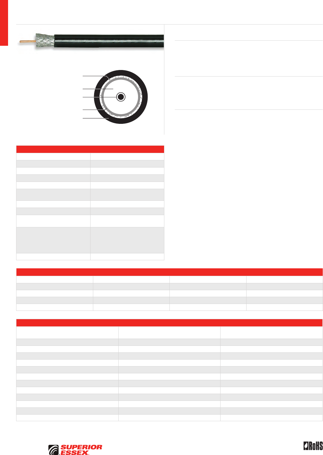
A-46
PREMISES COPPER PREMISES FIBER OSP FIBER OSP COMPOSITE CENTRAL OFFICE COPPER RDUP/RUS OSP COPPER BELL OSP COPPER OSP COPPER WIRE CANADIAN OSP COPPER TECHNICAL INFO
Rev 10/10 Ed 10.2Toll Free 800.551.8948 | Fax 770.657.6807 | SuperiorEssex.com/Comm
Specifications
Conductor Copper clad steel
AWG (mm) 18 (1.0)
Inner Braid 34 AWG aluminum (60%)
Inner Shield 2.8 mil aluminum foil
Jacket PVC (polyvinylchloride)
Nominal Diameter in (mm) Inner Shield: 0.18 (4.6)
Overall: 0.28 (7.1)
Approx. Weight lbs/kft (kg/km) 21 (13.5)
Nominal Impedance (Ohms) 75
Nominal Velocity
of Propagation (%) 85
Performance Compliance
UL 444
CSA C22.2 No. 214-08
UL 1685
ANSI/SCTE 74-2003
RoHS-compliant
NRTL Programs UL, c(UL) Listed CM
Part Numbers and Physical Characteristics
Part Number Jacket Color Package Packages Per Pallet
78-107-9P White 1,000’ POP™ Box 20
79-107-9P Black 1,000’ POP™ Box 20
78-107-91 White 1,000’ Plywood Reel 27
79-107-91 Black 1,000’ Plywood Reel 27
Electrical Specifications
Frequency
MHz
Attenuation Maximum, Specification
dB/100 m
SRL, Typical
dB
55 5.3 20
211 10.1 20
270 11.5 20
330 12.8 20
350 14.1 20
450 15.0 20
500 15.9 20
550 16.7 20
600 17.5 20
750 19.7 20
870 21.3 20
1000 23.0 20
Coax Series 6 60% Shield CM
18 AWG Copper Clad
Steel Conductor
34 AWG Aluminum
Inner Braid (60%)
Aluminum Foil Inner Shield
Flame Retardant PVC Jacket
Insulation PE Foam
Product Description
Superior Essex Series 6 60% shield coaxial cables are designed to support
analog, digital and high-bandwidth technologies. Superior Essex maintains
tight tolerances to cable diameter requirements of leading connector
manufacturers.
Applications
• HDTV, CATV and CCTV
• Two-way cable modems
• Extended bandwidth satellite service
Features Benefits
• Series 6 60% Shield Coaxial
cable with bandwidth that
exceeds 2.2 GHz
• “Future-proofing” the installation
• Tight foamed polyethylene
insulating skin bonds around
center conductor
• Exhibits better transmission
characteristics
• Black and white jacket
colors available
• Helps differentiate incoming
service versus internal cabling
infrastructure
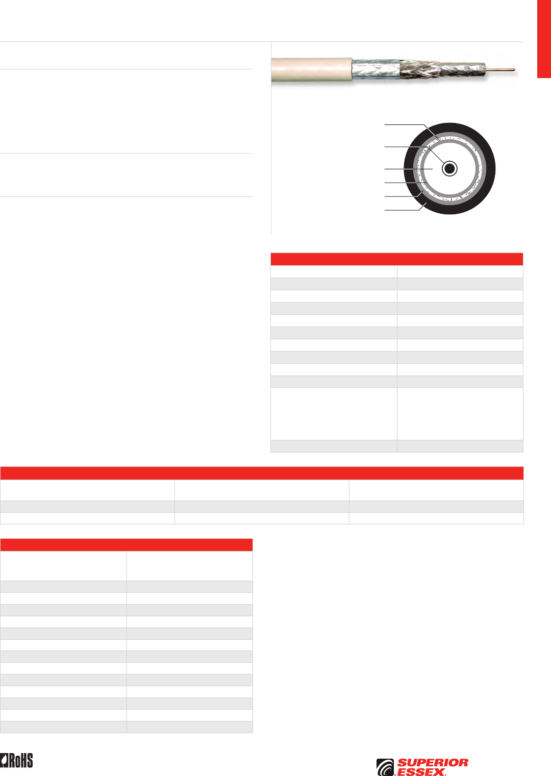
A-47
PREMISES COPPERPREMISES FIBEROSP FIBEROSP COMPOSITECENTRAL OFFICE COPPERRDUP/RUS OSP COPPERBELL OSP COPPEROSP COPPER WIRECANADIAN OSP COPPERTECHNICAL INFO
Rev 10/10 Ed 10.2 Toll Free 800.551.8948 | Fax 770.657.6807 | SuperiorEssex.com/Comm
Specifications
Conductor Copper clad steel
AWG (mm) 18 (1.0)
Inner Shield Aluminum/polyester foil (100%)
Center Shield 34 AWG aluminum braid (70%)
Outer Shield Aluminum/polyester foil (100%)
Overall Nominal Diameter in (mm) 0.28 (7.1)
Nominal Impedance (Ohms) 75
Jacket Flame retardant PVC
Package 1,000’ Reel-in-a-Box
Packages Per Pallet 27
Performance Compliance
UL 444
CSA C22.2 No. 214-08
UL 1685
ANSI/SCTE 74-2003
Appropriate ASTM standards
RoHS-compliant
NRTL Programs UL, c(UL) Listed CM
Part Numbers and Physical Characteristics
Part Number Jacket Color
Approx. Weight
lbs/kft kg/km)
78-11A-9R White 32 (48)
79-11A-9R Black 32 (48)
Electrical Specifications
Frequency
MHz
Maximum Attenuation
@ 68°F (20°C)
dB/100 m
55 5.2
211 10.0
250 10.8
270 11.0
330 12.2
350 12.6
450 14.4
500 15.3
550 16.1
600 16.7
750 18.5
870 20.0
1000 21.5
Coax Series 6 Tri-Shield 70% CM
Product Description
Superior Essex Series 6 Tri-Shield 70% braided coaxial cables exceed the
requirements specified in ANSI/SCTE 74-2003. The shielding consists of an
inner aluminum/polyester foil bonded to the insulation, an aluminum 34 AWG
braid, and an outer aluminum/polyester foil. This Series 6 Tri-Shield will
support such technologies as extended bandwidth satellite service, high
definition TV signals, CATV and two-way cable modems.
Applications
• HDTV
• Extended bandwidth satellite service
Features Benefits
• Series 6 (18 AWG copper
clad steel center conductor)
• Standard and popular size
• Available in CM Outdoor
(60°C rated jacket)
• Indoor/outdoor use
• Tri-Shield consists of inner
aluminum/polyester foil,
aluminum braid, outer
aluminum/polyester foil
• Added shielding for higher
service levels
• Bonded inner foil • Stops moisture
• 100% coverage over the 70%
(34 AWG aluminum) braiding
• Offers better shielding protection
and stops interference
• Reel-in-a-Box design • Water resistant package is easy
to carry and store
• White or black outer jacket
(UV rated for exterior use)
• Jacket color helps differentiate
incoming versus internal cabling
18 AWG Copper Clad
Steel Conductor
34 AWG Aluminum
Braid (70%)
Aluminum Foil Inner Shield
Aluminum Foil Outer Shield
Flame Retardant PVC Jacket
Insulation PE Foam


B-1
PREMISES COPPERPREMISES FIBEROSP FIBEROSP COMPOSITECENTRAL OFFICE COPPERRDUP/RUS OSP COPPERBELL OSP COPPEROSP COPPER WIRECANADIAN OSP COPPERTECHNICAL INFO
Toll Free 800.551.8948 | Fax 770.657.6807 | SuperiorEssex.com/Comm
PREMISES FIBER
Table of Contents
Simplex, Duplex and Quad Interconnect OFNR/OFNP ............ B-2
Microarray Data Center Interconnect OFNR/OFNP .............. B-4
Microarray Breakout OFNP .................................. B-5
Single Unit Distribution OFNR/OFNP ........................... B-6
Premises Fiber BrakeBox® with QuickCount® Marking System . . . . . . B-7
Multi-Unit Distribution OFNR/OFNP ............................ B-8
Indoor/Outdoor Sunlight Resistant OFNP ..................... B-10
Dry Block/Sunlight Resistant Indoor/Outdoor OFNR ............ B-11
Dry Block/Sunlight Resistant Indoor/Outdoor OFNP ............ B-12
Hybrid Premises Fiber OFNR/OFNP ............................B-14
Interlock Armored Premises Fiber OFCR/OFCP .................. B-16
B-2
PREMISES COPPER PREMISES FIBER OSP FIBER OSP COMPOSITE CENTRAL OFFICE COPPER RDUP/RUS OSP COPPER BELL OSP COPPER OSP COPPER WIRE CANADIAN OSP COPPER TECHNICAL INFO
Rev 10/10 Ed 10.3Toll Free 800.551.8948 | Fax 770.657.6807 | SuperiorEssex.com/Comm
Simplex, Duplex and Quad Interconnect
OFNR/OFNP
Flame Retardant PVC Jacket
Buffered Optical Fiber
Zip Cord Configuration
Round Configuration
Dielectric Aramid
Strength Members
Flame Retardant PVC Jacket
Buffered Optical Fiber
Dielectric Aramid
Strength Members
Specifications
Configuration Flexible tight buffered optical fibers surrounded by aramid
yarns and covered by a flame retardant jacket
Fiber Count Available in 1, 2 and 4-fiber
Strength Elements Dielectric aramid yarns
Jacket OFNR: Flame retardant (FR) PVC
OFNP: FR, low smoke PVC
Package Plywood reel
Performance
Compliance
UL 1651
CSA C22.2 No. 232
UL 1666
NFPA 262
Telcordia GR-409-CORE, Issue 2
ANSI/ICEA S-83-596
ANSI/TIA-568-C.3
RoHS-compliant
NRTL Programs UL, c(UL) Listed OFNR
UL, c(UL) Listed OFNP
Environmental Specifications
Riser Plenum
Operation -40°C to +75°C -40°C to +75°C
Storage/Shipping -40°C to +75°C -40°C to +75°C
Installation -20°C to +65°C -20°C to +65°C
Product Description
Simplex, Duplex and Quad Optical Fiber Interconnect Cables are typically
used for patch cords and intrabuilding installations. Superior Essex designed
these cables for environments where small size, flexible construction and
flame resistance are required. These cables are available in both riser and
plenum versions. Higher performance optical fibers are offered as standard;
including Reduced Water Peak (RWP) single mode, 220/600 62.5 µm multimode
and 10G/150 laser optimized 50 µm multimode.
The design consists of flexible tight buffer material extruded over the fiber
to a diameter of 900 µm for use with standard connectors. Dielectric yarns
are applied for additional strength and a flame retardant PVC jacket covers
the strength members. Appropriate materials are used to achieve an OFNR
(riser) or OFNP (plenum) rating. Standard 2.9 mm and small form factor 2 mm
diameters are available for simplex and duplex designs.
Applications
• Cross-connects and patch applications
• Communication closets to wall outlets
• Drop ceiling applications (plenum)
• Fiber to the work area
Features Benefits
• Simplex and duplex zip cord
designs in 2 mm and 2.9 mm
diameters
• Meets all the requirements
for both standard and small form
factor connectors for “in-front-
of-the-shelf” applications
• Round duplex and quad designs • Perfect for in-wall and “behind-
the-shelf” applications
• Marked in feet and meters • Meets commercial, government
and international requirements
for length markings
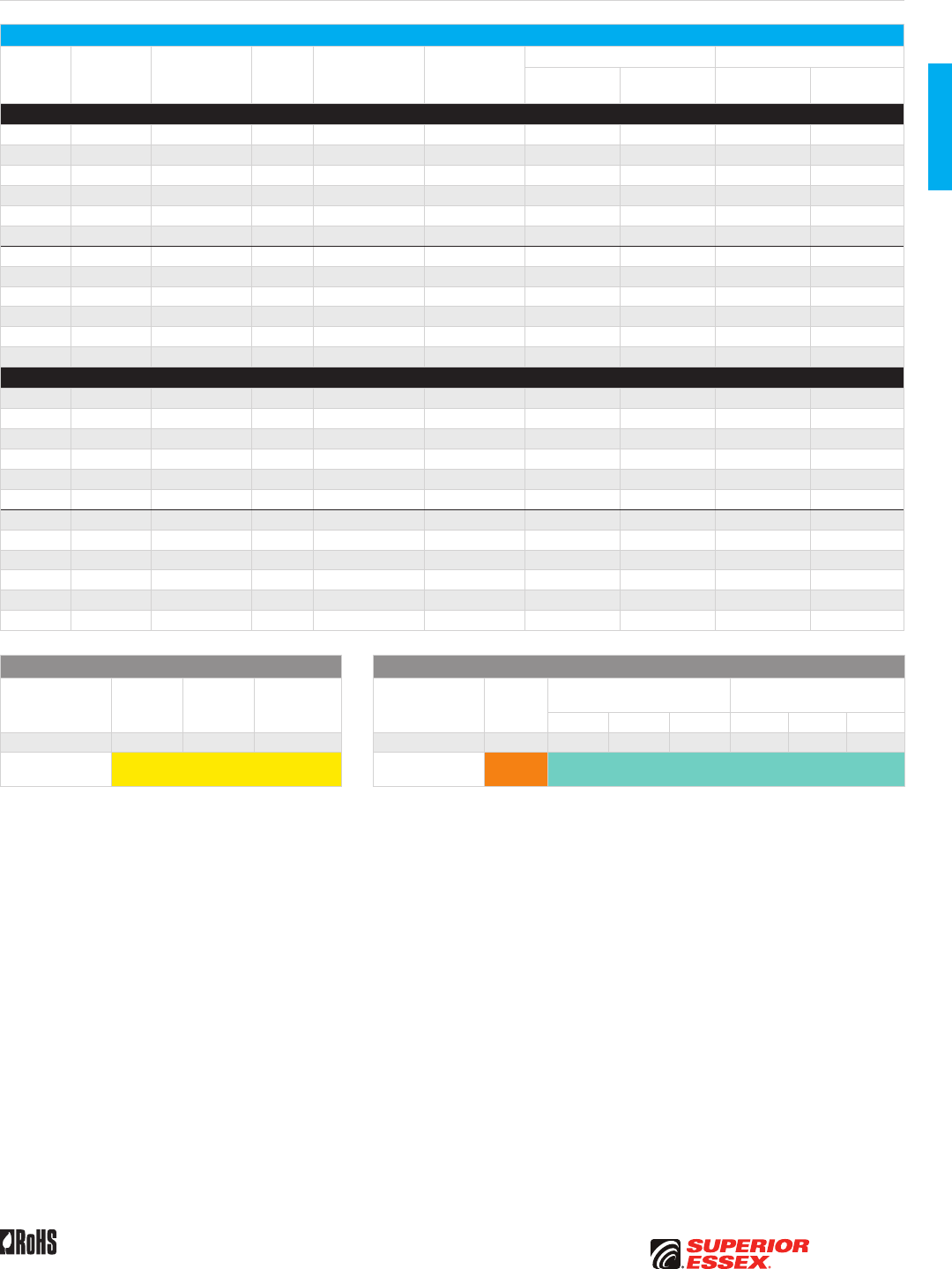
B-3
PREMISES COPPERPREMISES FIBEROSP FIBEROSP COMPOSITECENTRAL OFFICE COPPERRDUP/RUS OSP COPPERBELL OSP COPPEROSP COPPER WIRECANADIAN OSP COPPERTECHNICAL INFO
Rev 10/10 Ed 10.3 Toll Free 800.551.8948 | Fax 770.657.6807 | SuperiorEssex.com/Comm
Simplex, Duplex and Quad Interconnect OFNR/OFNP
Part Numbers and Physical Characteristics
Listing
Part
Number¹ Configuration
Fiber
Count
Nominal
Diameter
in (mm)
Nominal
Weight
lbs/kft (kg/km)
Maximum Tensile Loading Minimum Bend Radius
Install
lbs (N)
Long Term
lbs (N)
Install
in (mm)
Long Term
in (mm)
Single Mode
OFNR 33001x101 Round 1 0.11 (2.9) 6 (8) 50 (220) 15 (70) 1.7 (44) 1.1 (29)
OFNR A3001x101 Round 1 0.08 (2.0) 3 (4) 50 (220) 15 (70) 1.2 (30) 0.8 (20)
OFNR B3002x101 Zip 2 0.11 x 0.24 (2.9 x 6.2) 8 (12) 100 (440) 30 (130) 1.7 (44) 1.1 (29)
OFNR C3002x101 Zip 2 0.08 x 0.17 (2.0 x 4.2) 6 (9) 50 (220) 15 (70) 1.2 (30) 0.8 (20)
OFNR 33002x101 Round 2 0.20 (5.0) 14 (21) 100 (440) 30 (130) 3.0 (75) 2.0 (50)
OFNR 33004x101 Round 4 0.20 (5.0) 15 (23) 100 (440) 30 (130) 3.0 (75) 2.0 (50)
OFNP 34001x101 Round 1 0.11 (2.9) 6 (9) 50 (220) 15 (70) 1.7 (44) 1.1 (29)
OFNP A4001x101 Round 1 0.08 (2.0) 3 (4) 50 (220) 15 (70) 1.2 (30) 0.8 (20)
OFNP B4002x101 Zip 2 0.11 x 0.24 (2.9 x 6.2) 8 (11) 100 (440) 30 (130) 1.7 (44) 1.1 (29)
OFNP C4002x101 Zip 2 0.08 x 0.17 (2.0 x 4.2) 6 (9) 50 (220) 15 (70) 1.2 (30) 0.8 (20)
OFNP 34002x101 Round 2 0.17 (4.2) 12 (18) 100 (440) 30 (130) 2.5 (63) 1.7 (42)
OFNP 34004x101 Round 4 0.17 (4.2) 13 (20) 100 (440) 30 (130) 2.5 (63) 1.7 (42)
Multimode
OFNR 33001yG01 Round 1 0.11 (2.9) 6 (8) 50 (220) 15 (70) 1.7 (44) 1.1 (29)
OFNR A3001yG01 Round 1 0.08 (2.0) 3 (4) 50 (220) 15 (70) 1.2 (30) 0.8 (20)
OFNR B3002yG01 Zip 2 0.11 x 0.24 (2.9 x 6.2) 8 (12) 100 (440) 30 (130) 1.7 (44) 1.1 (29)
OFNR C3002yG01 Zip 2 0.08 x 0.17 (2.0 x 4.2) 6 (9) 50 (220) 15 (70) 1.2 (30) 0.8 (20)
OFNR 33002yG01 Round 2 0.20 (5.0) 14 (21) 100 (440) 30 (130) 3.0 (75) 2.0 (50)
OFNR 33004yG01 Round 4 0.20 (5.0) 15 (23) 100 (440) 30 (130) 3.0 (75) 2.0 (50)
OFNP 34001yG01 Round 1 0.11 (2.9) 6 (9) 50 (220) 15 (70) 1.7 (44) 1.1 (29)
OFNP A4001yG01 Round 1 0.08 (2.0) 3 (4) 50 (220) 15 (70) 1.2 (30) 0.8 (20)
OFNP B4002yG01 Zip 2 0.11 x 0.24 (2.9 x 6.2) 8 (11) 100 (440) 30 (130) 1.7 (44) 1.1 (29)
OFNP C4002yG01 Zip 2 0.08 x 0.17 (2.0 x 4.2) 6 (9) 50 (220) 15 (70) 1.2 (30) 0.8 (20)
OFNP 34002yG01 Round 2 0.17 (4.2) 12 (18) 100 (440) 30 (130) 2.5 (63) 1.7 (42)
OFNP 34004yG01 Round 4 0.17 (4.2) 13 (20) 100 (440) 30 (130) 2.5 (63) 1.7 (42)
Single Mode Optical Fiber Multimode Optical Fiber
Reduced
Water Peak
Zero
Water Peak
TeraFlex®
Bend Resistant
TeraGain®
62.5/125
TeraGain Laser Optimized 50/125
TeraFlex Bend Resistant
Laser Optimized 50/125
10G/150 10G/300 10G/550 10G/150 10G/300 10G/550
¹Replace “x” with: 3 2 K ¹Replace “y” with: 6 A B F M N P
Standard
Jacket Colors* Yellow Standard
Jacket Colors* Orange Aqua
*Other jacket colors available.
See the "Optical Fiber Selection Chart" in the "TECHNICAL INFO" section for detailed fiber type specifications.
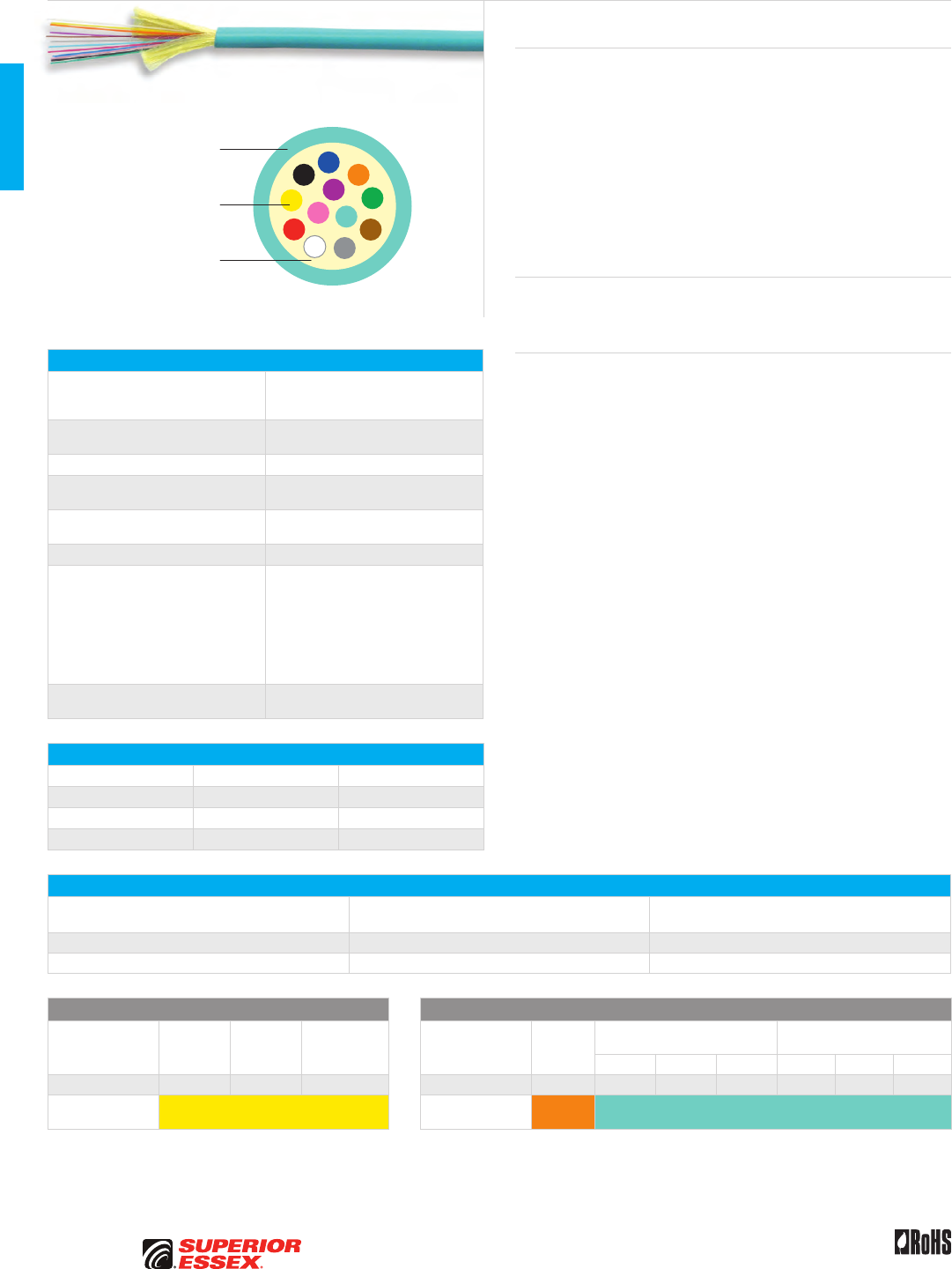
B-4
PREMISES COPPER PREMISES FIBER OSP FIBER OSP COMPOSITE CENTRAL OFFICE COPPER RDUP/RUS OSP COPPER BELL OSP COPPER OSP COPPER WIRE CANADIAN OSP COPPER TECHNICAL INFO
Rev 10/10 Ed 10.3Toll Free 800.551.8948 | Fax 770.657.6807 | SuperiorEssex.com/Comm
Microarray Data Center Interconnect
OFNR/OFNP
Flame Retardant
PVC Jacket
250 micron
Optical Fiber
Dielectric Aramid
Strength Members
Specifications
Configuration
Twelve 250 micron optical fibers
surrounded by dielectric aramid yarns
in a 3.0 mm loose tube
Jacket OFNR: Flame retardant (FR) PVC
OFNP: FR, low smoke PVC
Nominal Outer Diameter in (mm) 0.12 (3.0)
Maximum Tensile Loading lbs (N) Install: 80 (370)
Long Term: 25 (110)
Minimum Bend Radius in (mm) Install: 1.8 (45)
Long Term: 1.2 (30)
Package Plywood reel
Performance Compliance
UL 1651
CSA C22.2 No. 232
UL 1666
NFPA 262
Telcordia GR-409-CORE, Issue 2
ANSI/ICEA S-83-596
ANSI/TIA-568-C.3
RoHS-compliant
NRTL Programs UL, c(UL) Listed OFNR
UL, c(UL) Listed OFNP
Environmental Specifications
Riser Plenum
Operation -20°C to +70°C -10°C to +70°C
Storage/Shipping -40°C to +75°C -40°C to +75°C
Installation 10°C to +60°C 10°C to +60°C
Part Numbers and Physical Characteristics
Listing Part Number¹
Nominal Weight
lbs/kft (kg/km)
OFNR P3012xx01 5 (8)
OFNP P4012xx01 6 (9)
Single Mode Optical Fiber Multimode Optical Fiber
Reduced
Water Peak
Zero
Water Peak
TeraFlex®
Bend Resistant
TeraGain®
62.5/125
TeraGain Laser Optimized 50/125
TeraFlex Bend Resistant
Laser Optimized 50/125
10G/150 10G/300 10G/550 10G/150 10G/300 10G/550
¹Replace “xx” with: 31 21 K1 ¹Replace “xx” with: 6G AG BG FG MG NG PG
Standard
Jacket Colors Yellow Standard
Jacket Colors Orange Aqua
See the "Optical Fiber Selection Chart" in the "TECHNICAL INFO" section for detailed fiber type specifications.
Product Description
The Microarray Data Center Interconnect Cable from Superior Essex is
designed for high performance in a small package. Having a nominal outer
diameter of only 3.0 mm, the microarray data center cable has twelve 250
micron fibers. The cable can then be fusion spliced, connectorized to a
high density 12-fiber MTP/MPO mechanical array connector or attached
to standard single ferrule mechanical connectors (LC, SC, ST, etc.) via a
furcation kit. The loose fibers are surrounded by aramid yarns and a low
smoke PVC (LSPVC) plenum or riser-rated jacket. Its small size allows for
denser fiber routing than traditional tight buffered cables; its round shape
and loose-tube construction give it superior performance and installation
ease compared to ribbon interconnect cable.
Applications
• Data center plug and play cable installations
• Outside Plant (OSP)-premises transitions
Features Benefits
• Twelve 250 micron fibers
in 3.0 mm package
• Allows for higher fiber density
in data center applications
• Meets or exceeds
ANSI/ICEA S-83-596
and GR-409-CORE requirements
for interconnect cable
• Worry-free installation
and performance
• Plenum (OFNP) and riser (OFNR)
rated designs
• Fire-listed cables allow
placement in plenum
and riser spaces
• Available in all single mode
and multimode fiber types
• Build your network with the fiber
type that you need now or for
the future
• Marked in feet and meters • Meets commercial and
government requirements
for length markings
• Designed for MTP/MPO
connectors
• Economical plug
and play solution
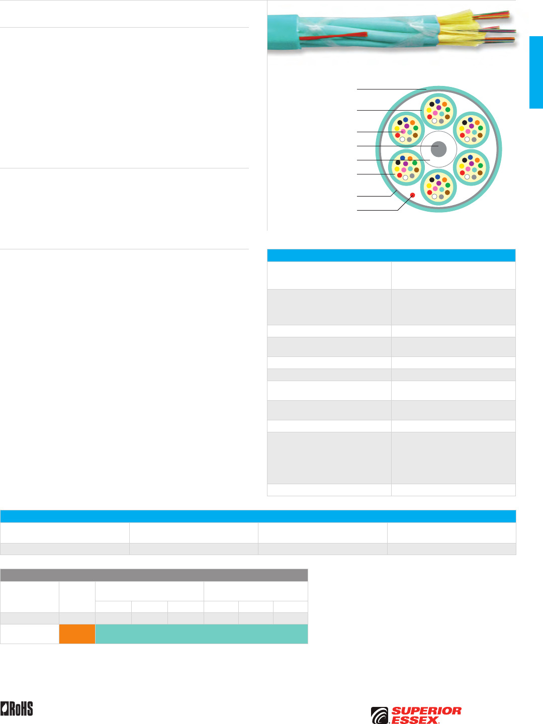
B-5
PREMISES COPPERPREMISES FIBEROSP FIBEROSP COMPOSITECENTRAL OFFICE COPPERRDUP/RUS OSP COPPERBELL OSP COPPEROSP COPPER WIRECANADIAN OSP COPPERTECHNICAL INFO
Rev 10/10 Ed 10.3 Toll Free 800.551.8948 | Fax 770.657.6807 | SuperiorEssex.com/Comm
Flame Retardant
Outer Jacket
Flame Retardant
LS PVC Jacket
Central Strength Member
PVC Jacket
Dielectric Aramid
Strength Members
250 micron Optical Fiber
Polyester Yarns
Rip Cord
Specifications
Cable Configuration
Six 3 mm subunits around a central
strength member and surrounded by
polyester yarns and an outer jacket
Subunit Configuration
3 mm Simplex cable with twelve 250
micron multimode optical fibers
surrounded by dielectric aramid
strength members
Subunit Marking Unit 1, Unit 2, Unit 3, Unit 4, Unit 5, Unit 6
Central Strength Element Glass Reinforced Plastic (GRP) covered
with a PVC jacket
Subunit Jacket Material Flame retardant, LS PVC
Outer Jacket Material Fluoropolymer
Maximum Tensile Loading lbs (N) Install: 150 (710)
Long Term: 45 (198)
Minimum Bend Radius in (mm) Install: 8.8 (224)
Long Term: 4.4 (112)
Package Plywood reel
Performance Compliance
UL 1651
CSA C22.2 No. 232
NFPA 262
Telcordia GR-409-CORE, Issue 2
ANSI/ICEA S-83-596
RoHS-compliant
NRTL Programs UL, c(UL) Listed OFNP
Part Numbers and Physical Characteristics
Part Number¹ Fiber Count
Nominal Diameter
in (mm)
Nominal Weight
lbs/kft (kg/km)
P4072xG01 72 0.44 (11.2) 89 (133)
Multimode Optical Fiber
TeraGain®
62.5/125
TeraGain Laser Optimized 50/125
TeraFlex® Bend Resistant
Laser Optimized 50/125
10G/150 10G/300 10G/550 10G/150 10G/300 10G/550
¹Replace “x” with: 6 A B F M N P
Standard Jacket/
Subunit Colors Orange Aqua
See the "Optical Fiber Selection Chart" in the "TECHNICAL INFO" section for detailed fiber type specifications.
Product Description
The Microarray Breakout cable from Superior Essex is designed for high
performance in a small package. The design consists of six 12-fiber 3 mm
microarray interconnect cable subunits, each of which contain twelve
250 micron multimode fibers. The 3 mm subunits are stranded around a
central strength element that is both flexible and robust enough to pass
backbone installation requirements. The stranded subunits are held to the
strength element core by polyester yarns ensuring excellent temperature
performance. Finally, a RoHS compliant flexible fluoropolymer jacket
protects the core from the rigors of installation while providing plenum fire
protection. The cable is available in 62.5/125 micron multimode and laser-
optimized 50/125 micron 10G/150 (OM2+), 10G/300 (OM3) and 10G/550 (OM4)
multimode fibers.
Applications
• 10GB Ethernet and legacy speeds
• Data centers
• Trunk applications
• High density installations
• MTP/MPO array connectors
Features Benefits
• 12-fiber 3 mm
interconnect subunits
• Connects directly to MTP/MPO
12-fiber array connectors
• Meets or exceeds
ICEA 83-596-2001 and
GR-409-CORE requirements
for interconnect subunits
and trunk cable
• Worry-free installation
and performance
• Plenum (OFNP) rated design • Fire-listed cables allow
placement in plenum spaces
• Available in 62.5/125 micron
and laser-optimized 50/125 micron
multimode fiber types
• Build your network with the
fiber type that you need now
or for the future
Microarray Breakout
OFNP
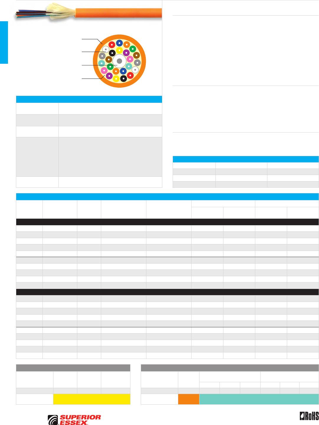
B-6
PREMISES COPPER PREMISES FIBER OSP FIBER OSP COMPOSITE CENTRAL OFFICE COPPER RDUP/RUS OSP COPPER BELL OSP COPPER OSP COPPER WIRE CANADIAN OSP COPPER TECHNICAL INFO
Rev 10/10 Ed 10.3Toll Free 800.551.8948 | Fax 770.657.6807 | SuperiorEssex.com/Comm
Specifications
6-12 Fiber
Configuration
Flexible 900 µm tight buffered fibers, dielectric aramid yarns
and overall jacket
18-24 Fiber
Configuration
Band marked flexible 900 µm tight buffered fibers, dielectric
aramid yarns, overall jacket and central strength element
Jacket OFNR: Flame retardant (FR) PVC
OFNP: FR, low smoke PVC
Performance
Compliance
UL 1651
CSA C22.2 No. 232
UL 1666
NFPA 262
Telcordia GR-409, Issue 2
ANSI/ICEA S-83-596
ANSI/TIA-568-C.3
RoHS-compliant
NRTL Programs UL, c(UL) Listed OFNR
UL, c(UL) Listed OFNP
Part Numbers and Physical Characteristics
Listing Part Number¹
Fiber
Count
Nominal Diameter
in (mm)
Nominal Weight
lbs/kft (kg/km)
Maximum Tensile Loading Minimum Bend Radius
Install
lbs (N)
Long Term
lbs (N)
Install
in (mm)
Long Term
in (mm)
Single Mode
OFNR 43006x101 6 0.20 (5.0) 17 (25) 150 (660) 45 (200) 3.0 (75) 2.0 (50)
OFNR 43008x101 8 0.24 (6.0) 20 (30) 150 (660) 45 (200) 3.5 (90) 2.4 (60)
OFNR 43012x101 12 0.26 (6.5) 25 (37) 150 (660) 45 (200) 3.8 (98) 2.6 (65)
OFNR 43018xK01 18 0.30 (7.5) 35 (51) 300 (1,320) 90 (400) 4.4 (113) 3.0 (75)
OFNR 43024xK01 24 0.33 (8.5) 44 (66) 300 (1,320) 90 (400) 5.0 (128) 3.3 (85)
OFNP 44006x101 6 0.20 (5.0) 17 (25) 100 (440) 30 (130) 3.0 (75) 2.0 (50)
OFNP 44008x101 8 0.21 (5.4) 19 (28) 100 (440) 30 (130) 3.2 (81) 2.1 (54)
OFNP 44012x101 12 0.24 (6.2) 24 (35) 100 (440) 30 (130) 3.7 (93) 2.4 (62)
OFNP 44018xK01 18 0.28 (7.0) 33 (49) 150 (660) 45 (200) 4.1 (105) 2.8 (70)
OFNP 44024xK01 24 0.31 (7.8) 42 (62) 150 (660) 45 (200) 4.6 (117) 3.1 (78)
Multimode
OFNR 43006yG01 6 0.20 (5.0) 17 (25) 150 (660) 45 (200) 3.0 (75) 2.0 (50)
OFNR 43008yG01 8 0.24 (6.0) 20 (30) 150 (660) 45 (200) 3.5 (90) 2.4 (60)
OFNR 43012yG01 12 0.26 (6.5) 25 (37) 150 (660) 45 (200) 3.8 (98) 2.6 (65)
OFNR 43018yK01 18 0.30 (7.5) 35 (51) 300 (1,320) 90 (400) 4.4 (113) 3.0 (75)
OFNR 43024yK01 24 0.33 (8.5) 44 (66) 300 (1,320) 90 (400) 5.0 (128) 3.3 (85)
OFNP 44006yG01 6 0.20 (5.0) 17 (25) 100 (440) 30 (130) 3.0 (75) 2.0 (50)
OFNP 44008yG01 8 0.21 (5.4) 19 (28) 100 (440) 30 (130) 3.2 (81) 2.1 (54)
OFNP 44012yG01 12 0.24 (6.2) 24 (35) 100 (440) 30 (130) 3.7 (93) 2.4 (62)
OFNP 44018yK01 18 0.28 (7.0) 33 (49) 150 (660) 45 (200) 4.1 (105) 2.8 (70)
OFNP 44024yK01 24 0.31 (7.8) 42 (62) 150 (660) 45 (200) 4.6 (117) 3.1 (78)
Single Mode Optical Fiber Multimode Optical Fiber
Reduced
Water Peak
Zero
Water Peak
TeraFlex®
Bend Resistant
TeraGain®
62.5/125
TeraGain Laser Optimized 50/125
TeraFlex Bend Resistant
Laser Optimized 50/125
10G/150 10G/300 10G/550 10G/150 10G/300 10G/550
¹Replace “x” with: 3 2 K ¹Replace “y” with: 6 A B F M N P
Standard
Jacket Colors Yellow Standard
Jacket Colors Orange Aqua
See the "Optical Fiber Selection Chart" in the "TECHNICAL INFO" section for detailed fiber type specifications.
Single Unit Distribution
OFNR/OFNP
Flame Retardant PVC Jacket
Buffered Optical Fiber
Dielectric Aramid
Strength Members
Central Strength Member
Product Description
These Superior Essex premises distribution optical fiber cables are
constructed using a single unit – single jacket RoHS-compliant design with
fiber counts from 6 through 24. The design consists of flexible 900 µm tight
buffered industry standard 250 µm fibers (900/250/125 µm) and is suitable for
use with standard connectors, like the SC, ST, and FC, and small-form-factor
connectors like the LC. Dielectric aramid yarns are applied for strength while
maintaining flexibility. The 18 and 24-fiber cable designs have a flexible glass
reinforced central strength element for added durability and performance.
A durable, flame resistant outer jacket is applied over the cable core using
appropriate OFNR or OFNP rated materials.
Applications
• Intrabuilding backbones
• Intrabuilding backbone (in conduit)
• Conduit pathways
• Service entrance to communication closets
• “Behind-the-shelf” connections
Features Benefits
• Marked in feet and meters • Meets commercial, government
and international requirements
for length markings
Environmental Specifications
Riser Plenum
Operation -40°C to +75°C -20°C to +75°C
Storage/Shipping -40°C to +75°C -40°C to +75°C
Installation -20°C to +65°C -20°C to +65°C
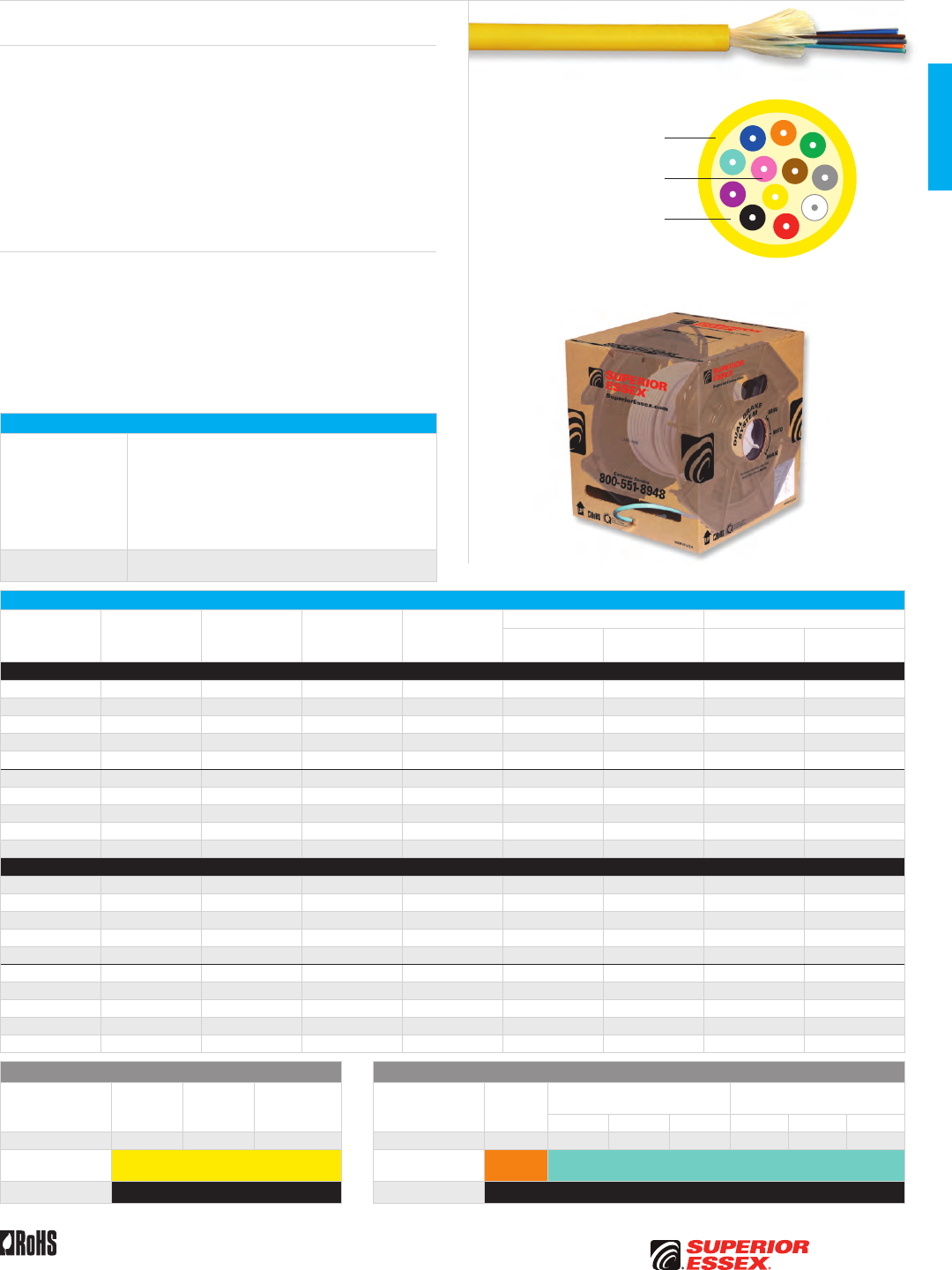
B-7
PREMISES COPPERPREMISES FIBEROSP FIBEROSP COMPOSITECENTRAL OFFICE COPPERRDUP/RUS OSP COPPERBELL OSP COPPEROSP COPPER WIRECANADIAN OSP COPPERTECHNICAL INFO
Rev 10/10 Ed 10.3 Toll Free 800.551.8948 | Fax 770.657.6807 | SuperiorEssex.com/Comm
Premises Fiber BrakeBox®
with QuickCount® Marking System
Product Description
Superior Essex offers premises fiber cable products packaged in a BrakeBox®
design, which includes the innovative QuickCount® footage marking and
a variable resistance system that virtually eliminates reel over-spin and
tangling. The BrakeBox packaging is a true advantage for installers who are
pulling fiber cable in multiple locations. It not only stacks and travels better,
it also protects the fiber cable better than an open reel. The box features two
resistance mechanisms on both sides of the reel, each of which has three
resistance settings. The variable brakes control back-tension preventing
over-spin and tangling. The QuickCount feature provides footage marking on
the cable jacket counting down from 1,000 feet.
Features Benefits
• QuickCount countdown
footage markings
• Allows installer an immediate,
exact view of unused cable
• Heavy-duty package design • Protects the cable more than open
reels; avoids damage to material
• 1,000’ packages • Reduces cable waste due to left
over short lengths
• Resistance brakes • Prevents over-spin and tangling
• Available for fiber counts 2-12 • Most commonly used fiber counts
Specifications
Performance
Compliance
UL 1651
CSA C22.2 No. 232
UL 1666
NFPA 262
Telcordia GR-409-CORE, Issue 2
ANSI/ICEA S-83-596
ANSI/TIA-568-C.3
RoHS-compliant
NRTL Programs UL, c(UL) Listed OFNR
UL, c(UL) Listed OFNP
Part Numbers and Physical Characteristics
Listing Part Number¹ Fiber Count
Nominal
Diameter
in (mm)
Nominal
Weight
lbs/kft (kg/km)
Maximum Tensile Loading Minimum Bend Radius
Install
lbs (N)
Long Term
lbs (N)
Install
in (mm)
Long Term
in (mm)
Premises
OFNR 33002xxBB 2 0.20 (5.0) 14 (21) 100 (440) 30 (130) 3.0 (75) 2.0 (50)
OFNR 33004xxBB 4 0.20 (5.0) 15 (23) 100 (440) 30 (130) 3.0 (75) 2.0 (50)
OFNR 43006xxBB 6 0.20 (5.0) 17 (25) 150 (660) 45 (200) 3.0 (75) 2.0 (50)
OFNR 43008xxBB 8 0.24 (6.0) 20 (30) 150 (660) 45 (200) 3.5 (90) 2.4 (60)
OFNR 43012xxBB 12 0.26 (6.5) 25 (37) 150 (660) 45 (200) 3.8 (98) 2.6 (65)
OFNP 34002xxBB 2 0.17 (4.2) 12 (18) 100 (440) 30 (130) 2.5 (63) 1.7 (42)
OFNP 34004xxBB 4 0.17 (4.2) 13 (20) 100 (440) 30 (130) 2.5 (63) 1.7 (42)
OFNP 44006xxBB 6 0.20 (5.0) 17 (25) 100 (440) 30 (130) 3.0 (75) 2.0 (50)
OFNP 44008xxBB 8 0.21 (5.4) 19 (28) 100 (440) 30 (130) 3.2 (81) 2.1 (54)
OFNP 44012xxBB 12 0.24 (6.2) 24 (35) 100 (440) 30 (130) 3.7 (93) 2.4 (62)
Indoor/Outdoor
OFNR W3002xxBB 2 0.20 (5.0) 15 (22) 300 (1,320) 90 (400) 3.0 (75) 2.0 (50)
OFNR W3004xxBB 4 0.20 (5.0) 15 (23) 300 (1,320) 90 (400) 3.0 (75) 2.0 (50)
OFNR W3006xxBB 6 0.20 (5.0) 17 (25) 300 (1,320) 90 (400) 3.0 (75) 2.0 (50)
OFNR W3008xxBB 8 0.24 (6.0) 21 (31) 300 (1,320) 90 (400) 3.5 (90) 2.4 (60)
OFNR W3012xxBB 12 0.26 (6.5) 25 (38) 300 (1,320) 90 (400) 3.8 (97) 2.6 (65)
OFNP 24002xxBB 2 0.17 (4.2) 11 (17) 150 (660) 45 (200) 2.5 (63) 1.7 (42)
OFNP 24004xxBB 4 0.17 (4.2) 14 (20) 150 (660) 45 (200) 2.5 (63) 1.7 (42)
OFNP 24006xxBB 6 0.20 (5.0) 17 (25) 150 (660) 45 (200) 3.0 (75) 2.0 (50)
OFNP 24008xxBB 8 0.21 (5.4) 19 (28) 150 (660) 45 (200) 3.2 (81) 2.1 (54)
OFNP 24012xxBB 12 0.24 (6.2) 24 (35) 150 (660) 45 (200) 3.7 (93) 2.4 (62)
Single Mode Optical Fiber Multimode Optical Fiber
Reduced
Water Peak
Zero
Water Peak
TeraFlex®
Bend Resistant
TeraGain®
62.5/125
TeraGain Laser Optimized 50/125
TeraFlex Bend Resistant
Laser Optimized 50/125
10G/150 10G/300 10G/550 10G/150 10G/300 10G/550
¹Replace “xx” with: 31 21 K1 ¹Replace “xx” with: 6G AG BG FG MG NG PG
Premises
Jacket Colors Yellow Premises
Jacket Colors Orange Aqua
I/O Jacket Color Black I/O Jacket Color Black
See the "Optical Fiber Selection Chart" in the "TECHNICAL INFO" section for detailed fiber type specifications.
Flame Retardant PVC Jacket
Buffered Optical Fiber
Dielectric Aramid
Strength Members
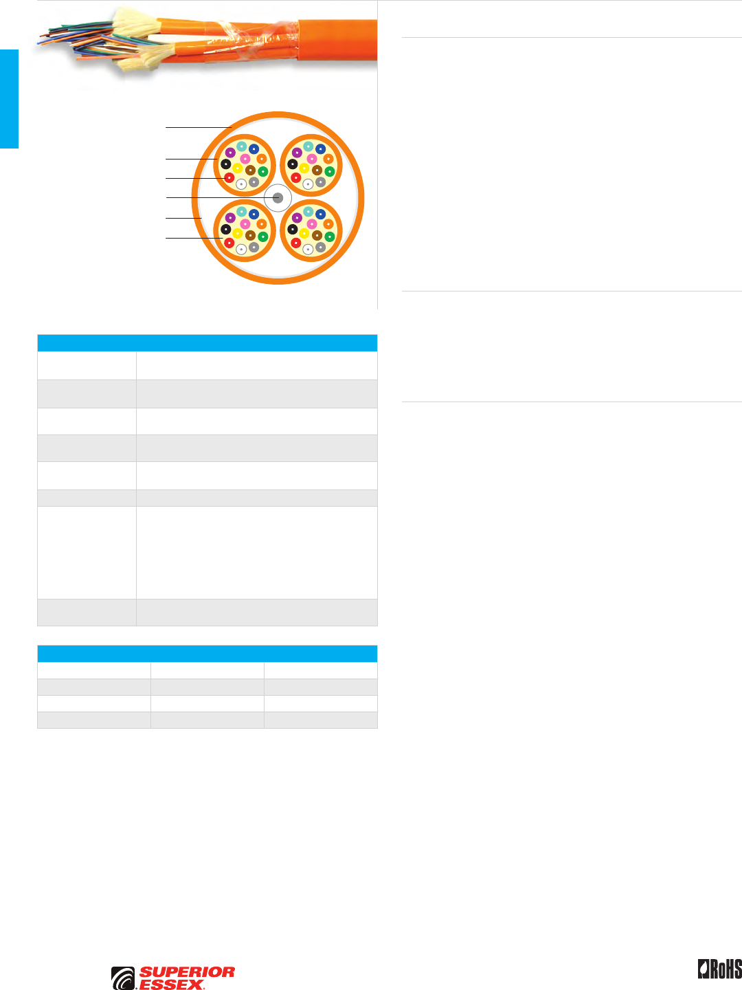
B-8
PREMISES COPPER PREMISES FIBER OSP FIBER OSP COMPOSITE CENTRAL OFFICE COPPER RDUP/RUS OSP COPPER BELL OSP COPPER OSP COPPER WIRE CANADIAN OSP COPPER TECHNICAL INFO
Rev 10/10 Ed 10.3Toll Free 800.551.8948 | Fax 770.657.6807 | SuperiorEssex.com/Comm
Flame Retardant PVC Jacket
Flame Retardant
PVC Outer Jacket
Buffered Optical Fiber
Dielectric Aramid
Strength Members
Polyester Tape
Central Strength Member
Multi-Unit Distribution
OFNR/OFNP
Specifications
18-36 Fiber
Configuration
6-fiber subunits, reverse oscillating lay (ROL) stranded
around flexible high-strength glass reinforced rod
48-144 Fiber
Configuration
12-fiber subunits, ROL stranded around flexible high-
strength glass reinforced rod
Subunit Jacket OFNR: Flame retardant (FR) PVC
OFNP: FR, low smoke PVC
Jacket OFNR: FR PVC
OFNP: FR PVDF
Maximum Tensile
Loading lbs (N)
Install: 600 (2,640)
Long Term: 180 (800)
Package Reel
Performance
Compliance
UL 1651
CSA C22.2 No. 232
UL 1666
NFPA 262
Telcordia GR-409-CORE, Issue 2
ANSI/ICEA S-83-596
ANSI/TIA-568-C.3
RoHS-compliant
NRTL Programs UL, c(UL) Listed OFNR
UL, c(UL) Listed OFNP
Environmental Specifications
Riser Plenum
Operation -20°C to +75°C -20°C to +75°C
Storage/Shipping -40°C to +75°C -40°C to +75°C
Installation 0°C to +65°C 0°C to +65°C
Product Description
Premises Multi-unit Distribution Optical Fiber Cables are constructed using
6 or 12-fiber subunits stranded around a central strength member in a RoHS-
compliant design for fiber counts from 18 through 144. Standard fibers for
these cables include Reduced Water Peak (RWP) single mode, TeraGain®
220/600 62.5 µm multimode and TeraGain 10G/150 – laser optimized 50 µm
multimode fiber. All fibers exceed industry requirements.
The design consists of flexible 900 µm tight buffered industry standard
250 µm fibers (900/250/125 µm) and is suitable for use with standard
connectors, like the SC, ST, and FC, and small-form-factor connectors like
the LC. Subunits are constructed using dielectric aramid yarns for strength
while maintaining flexibility and are jacketed using the color appropriate
to the type of fiber in the cable. The subunits are then reverse oscillating
lay (ROL) stranded around a flexible high-strength glass reinforced rod
which provides exceptional resistance to dimensional changes due to
temperature. A durable, flame resistant outer jacket is applied over the
cable core using appropriate OFNR or OFNP rated materials.
Applications
• Intrabuilding backbones
• Interbuilding backbone (in conduit)
• Conduit pathways
• Service entrance to communication closets
• “Behind-the-shelf” connections
Features Benefits
• Subunits are color coded
according to fiber type
• Easily identify fiber type
• Numbered subunits • Easily identifies correct
subunit on each end
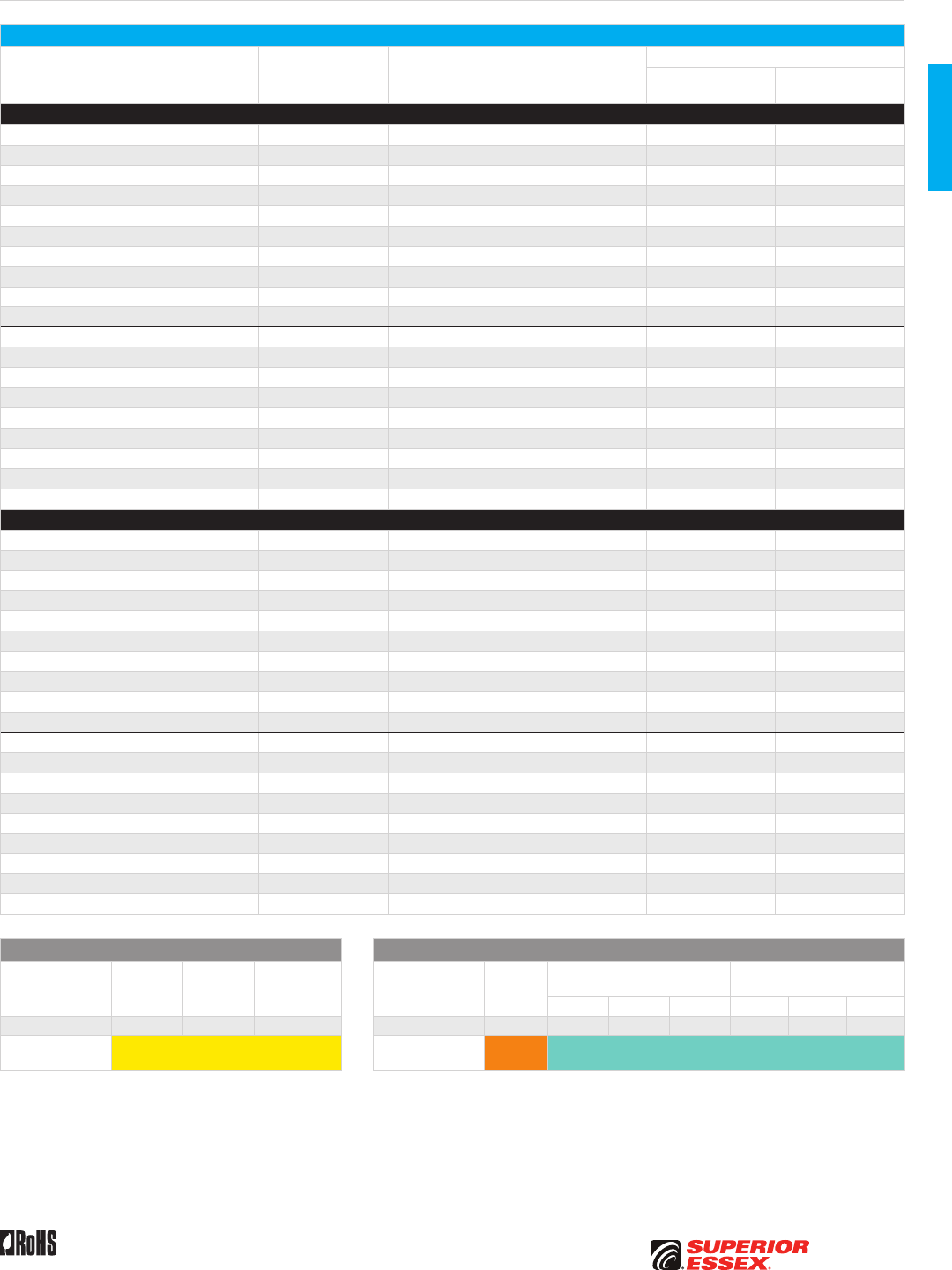
B-9
PREMISES COPPERPREMISES FIBEROSP FIBEROSP COMPOSITECENTRAL OFFICE COPPERRDUP/RUS OSP COPPERBELL OSP COPPEROSP COPPER WIRECANADIAN OSP COPPERTECHNICAL INFO
Rev 10/10 Ed 10.3 Toll Free 800.551.8948 | Fax 770.657.6807 | SuperiorEssex.com/Comm
Multi-Unit Distribution OFNR/OFNP
Part Numbers and Physical Characteristics
Listing Part Number¹ Fiber Count
Nominal Diameter
in (mm)
Nominal Weight
lbs/kft (kg/km)
Minimum Bend Radius
Install
in (mm)
Long Term
in (mm)
Single Mode
OFNR 43018x101 18 0.54 (13.7) 96 (143) 8.1 (206) 5.4 (137)
OFNR 43024x101 24 0.57 (14.6) 117 (174) 8.6 (218) 5.7 (146)
OFNR 43030x101 30 0.62 (15.8) 140 (210) 9.3 (236) 6.2 (158)
OFNR 43036x101 36 0.68 (17.4) 171 (255) 10.2 (260) 6.8 (174)
OFNR 43048x101 48 0.69 (17.5) 155 (232) 10.3 (262) 6.9 (175)
OFNR 43060x101 60 0.77 (19.5) 195 (291) 11.5 (292) 7.7 (195)
OFNR 43072x101 72 0.82 (21.0) 233 (348) 12.4 (314) 8.2 (210)
OFNR 43084x101 84 0.92 (23.3) 289 (431) 13.7 (349) 9.2 (233)
OFNR 43096x101 96 0.97 (24.7) 337 (503) 14.6 (370) 9.7 (247)
OFNR 43144x101 144 1.11 (28.3) 362 (540) 16.7 (425) 11.1 (283)
OFNP 44018x101 18 0.54 (13.8) 117 (175) 8.1 (206) 5.4 (138)
OFNP 44024x101 24 0.57 (14.6) 141 (211) 8.6 (219) 5.7 (146)
OFNP 44030x101 30 0.62 (15.8) 176 (262) 9.3 (237) 6.2 (158)
OFNP 44036x101 36 0.69 (17.4) 206 (307) 10.3 (261) 6.9 (174)
OFNP 44048x101 48 0.67 (17.1) 184 (275) 10.1 (257) 6.7 (171)
OFNP 44060x101 60 0.74 (18.9) 229 (341) 11.2 (284) 7.4 (189)
OFNP 44072x101 72 0.81 (20.6) 276 (412) 12.2 (309) 8.1 (206)
OFNP 44096x101 96 0.87 (22.0) 313 (467) 13.0 (330) 8.7 (220)
OFNP 44144x101 144 0.92 (23.4) 318 (474) 13.8 (351) 9.2 (234)
Multimode
OFNR 43018yG01 18 0.54 (13.7) 96 (143) 8.1 (206) 5.4 (137)
OFNR 43024yG01 24 0.57 (14.6) 117 (174) 8.6 (218) 5.7 (146)
OFNR 43030yG01 30 0.62 (15.8) 140 (210) 9.3 (236) 6.2 (158)
OFNR 43036yG01 36 0.68 (17.4) 171 (255) 10.2 (260) 6.8 (174)
OFNR 43048yG01 48 0.69 (17.5) 155 (232) 10.3 (262) 6.9 (175)
OFNR 43060yG01 60 0.77 (19.5) 195 (291) 11.5 (292) 7.7 (195)
OFNR 43072yG01 72 0.82 (21.0) 233 (348) 12.4 (314) 8.2 (210)
OFNR 43084yG01 84 0.92 (23.3) 289 (431) 13.7 (349) 9.2 (233)
OFNR 43096yG01 96 0.97 (24.7) 337 (503) 14.6 (370) 9.7 (247)
OFNR 43144yG01 144 1.11 (28.3) 362 (540) 16.7 (425) 11.1 (283)
OFNP 44018yG01 18 0.54 (13.8) 117 (175) 8.1 (206) 5.4 (138)
OFNP 44024yG01 24 0.57 (14.6) 141 (211) 8.6 (219) 5.7 (146)
OFNP 44030yG01 30 0.62 (15.8) 176 (262) 9.3 (237) 6.2 (158)
OFNP 44036yG01 36 0.69 (17.4) 206 (307) 10.3 (261) 6.9 (174)
OFNP 44048yG01 48 0.67 (17.1) 184 (275) 10.1 (257) 6.7 (171)
OFNP 44060yG01 60 0.74 (18.9) 229 (341) 11.2 (284) 7.4 (189)
OFNP 44072yG01 72 0.81 (20.6) 276 (412) 12.2 (309) 8.1 (206)
OFNP 44096yG01 96 0.87 (22.0) 313 (467) 13.0 (330) 8.7 (220)
OFNP 44144yG01 144 0.92 (23.4) 318 (474) 13.8 (351) 9.2 (234)
Single Mode Optical Fiber Multimode Optical Fiber
Reduced
Water Peak
Zero
Water Peak
TeraFlex®
Bend Resistant
TeraGain®
62.5/125
TeraGain Laser Optimized 50/125
TeraFlex Bend Resistant
Laser Optimized 50/125
10G/150 10G/300 10G/550 10G/150 10G/300 10G/550
¹Replace “x” with: 3 2 K ¹Replace “y” with: 6 A B F M N P
Standard
Jacket Colors Yellow Standard
Jacket Colors Orange Aqua
See the "Optical Fiber Selection Chart" in the "TECHNICAL INFO" section for detailed fiber type specifications.
B-10
PREMISES COPPER PREMISES FIBER OSP FIBER OSP COMPOSITE CENTRAL OFFICE COPPER RDUP/RUS OSP COPPER BELL OSP COPPER OSP COPPER WIRE CANADIAN OSP COPPER TECHNICAL INFO
Toll Free 800.551.8948 | Fax 770.657.6807 | SuperiorEssex.com/Comm Rev 11/10 Ed 10.4
Flame Retardant and
Sunlight Resistant PVC Jacket
Buffered Optical Fiber
Dielectric Aramid
Strength Members
Indoor/Outdoor Sunlight Resistant
OFNP
Specifications
2-12 Fiber
Single Unit Design
Configuration
Flexible tight buffer material extruded over fiber to 900 µm
diameter; color coded fibers are combined with dielectic
aramid yarns for strength and water blocking
18-36 Fiber
Multi-Unit Design
Configuration
Dry water-blocked 6-fiber sub-units are grouped to form
cable core; core consits of sub-units cabled with
additional strength members and water blocking elements
48-72 Fiber
Multi-Unit Design
Configuration
Dry water-blocked 12-fiber sub-units are grouped to form
cable core; core consists of sub-units cabled with
additional strength members and water blocking elements
Jacket Single unit: Black, flame retardant (FR), sunlight resistant PVC
Multi-unit: Black, FR, sunlight resistant PVDF
Package Plywood reel
Performance
Compliance
UL 1651
CSA C22.2 No. 232
NFPA 262
Telcordia GR-409-CORE, Issue 2
ANSI/TIA-568-C.3
RoHS-compliant
NRTL Programs UL, c(UL) Listed OFNP
UL, c(UL) Listed Sunlight Resistant
Environmental Specifications
Operation -20°C to +75°C
Storage/Shipping -40°C to +75°C
Installation -20°C to +65°C
Part Numbers and Physical Characteristics
Part Number¹ Fiber Count
Nominal
Diameter
in (mm)
Nominal Weight
lbs/kft (kg/km)
Maximum Tensile Loading Minimum Bend Radius
Install
lbs (N)
Long Term
lbs (N)
Install
in (mm)
Long Term
in (mm)
24002xx01 2 0.17 (4.2) 13 (19) 150 (670) 45 (200) 2.5 (63) 1.7 (42)
24004xx01 4 0.17 (4.2) 14 (21) 150 (670) 45 (200) 2.5 (63) 1.7 (42)
24006xx01 6 0.19 (4.9) 17 (25) 150 (670) 45 (200) 2.9 (73) 1.9 (49)
24008xx01 8 0.21 (5.4) 19 (28) 150 (670) 45 (200) 3.2 (81) 2.1 (54)
24012xx01 12 0.25 (6.2) 24 (35) 150 (670) 45 (200) 3.7 (93) 2.5 (62)
24018xx01 18 0.54 (13.8) 117 (175) 600 (2,700) 180 (800) 8.1 (206) 5.4 (138)
24024xx01 24 0.57 (14.6) 141 (211) 600 (2,700) 180 (800) 8.6 (219) 5.7 (146)
24030xx01 30 0.63 (16.0) 174 (259) 600 (2,700) 180 (800) 9.4 (240) 6.3 (160)
24036xx01 36 0.69 (17.4) 206 (307) 600 (2,700) 180 (800) 10.3 (261) 6.9 (174)
24048xx01 48 0.67 (17.1) 184 (275) 600 (2,700) 180 (800) 10.1 (257) 6.7 (171)
24060xx01 60 0.74 (18.9) 231 (344) 600 (2,700) 180 (800) 11.1 (283) 7.4 (189)
24072xx01 72 0.81 (20.6) 277 (413) 600 (2,700) 180 (800) 12.2 (309) 8.1 (206)
Single Mode Optical Fiber Multimode Optical Fiber
Reduced
Water Peak
Zero
Water Peak
TeraFlex®
Bend Resistant
TeraGain®
62.5/125
TeraGain Laser Optimized 50/125
TeraFlex Bend Resistant
Laser Optimized 50/125
10G/150 10G/300 10G/550 10G/150 10G/300 10G/550
¹Replace “xx” with: 31 21 K1 ¹Replace “xx” with: 6G AG BG FG MG NG PG
See the "Optical Fiber Selection Chart" in the "TECHNICAL INFO" section for detailed fiber type specifications.
Product Description
Indoor/Outdoor Sunlight Resistant Tight Buffer Plenum Optical Fiber Cables
are ideally suited for installations that require partial or complete routing of
pathways outside the building. These cables can be installed in conduits,
inner-ducts and steam tunnels, as well as within building riser and plenum
locations. The tight buffer feature of these indoor/outdoor cables eliminates
the need for breakout kits and or other special termination equipment
associated with loose tube Outside Plant (OSP) cables. The outer jacket is
comprised of a rugged UL Listed sunlight resistant polymer that allows for
the cable to be exposed to direct sunlight without the concern of material
degradation and greatly reduces moisture migration.
Applications
• Intrabuilding backbones
• Interbuilding backbone (in conduit)
• Conduit pathways
• Service entrance to communication closets
Features Benefits
• Tested and qualified
to Telcordia GR-409-CORE
• Assurance that cable investment
will last
• Exceeds ANSI/TIA-568-C.3
optical performance
• Future-proof fiber performance
for current and future networking
applications
• 900 µm tight buffered fibers • Connect directly
to mechanical connectors
• Black, UL Listed sunlight
resistant outer jacket
• Long periods of direct sunlight
exposure will not damage cable
• OFNP water resistant,
indoor/outdoor design
• Eliminates the need to
purchase separate cables
for plenum indoor/outdoor
applications
• All dielectric • No additional grounding materials
need to be purchased
• Jacket rip cord • Saves time in cable preparation
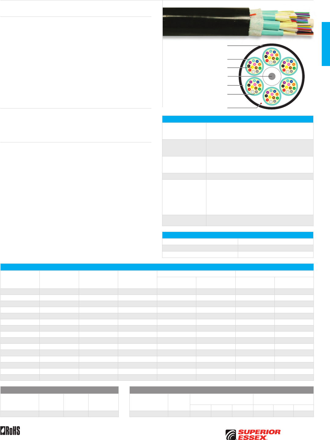
B-11
PREMISES COPPERPREMISES FIBEROSP FIBEROSP COMPOSITECENTRAL OFFICE COPPERRDUP/RUS OSP COPPERBELL OSP COPPEROSP COPPER WIRECANADIAN OSP COPPERTECHNICAL INFO
Toll Free 800.551.8948 | Fax 770.657.6807 | SuperiorEssex.com/CommRev 11/10 Ed 10.4
Dry Block/Sunlight Resistant Indoor/Outdoor
OFNR
Specifications
2-12 Fiber
Single Unit Design
Configuration
Flexible tight buffer material extruded over fiber to 900 µm
diameter; color coded fibers are combined with dielectic
aramid yarns for strength and water blocking
18-36 Fiber
Multi-Unit Design
Configuration
Dry water-blocked 6-fiber sub-units are grouped to form cable
core; core consits of sub-units cabled with additional
strength members and water blocking elements
48-144 Fiber
Multi-Unit Design
Configuration
Dry water-blocked 12-fiber sub-units are grouped to form
cable core; core consists of sub-units cabled with
additional strength members and water blocking elements
Jacket Black, flame retardant, chemical and sunlight resistant PVC
Performance
Compliance
UL 1651
CSA C22.2 No. 232
UL 1666
Telcordia GR-20-CORE, Issue 3
ANSI/ICEA S-104-696-2001
ANSI/TIA-568-C.3
RoHS-compliant
NRTL Programs UL, c(UL) Listed OFNR
UL, c(UL) Listed Sunlight Resistant
Environmental Specifications
Operation -40°C to +75°C
Storage/Shipping -40°C to +75°C
Installation -20°C to +65°C
Part Numbers and Physical Characteristics
Part Number¹ Fiber Count
Nominal
Diameter
in (mm)
Nominal Weight
lbs/kft (kg/km)
Maximum Tensile Loading Minimum Bend Radius
Install
lbs (N)
Long Term
lbs (N)
Install
in (mm)
Long Term
in (mm)
W3002xx01 2 0.20 (5.0) 14 (21) 300 (1,340) 90 (400) 3.0 (75) 2.0 (50)
W3004xx01 4 0.20 (5.0) 15 (23) 300 (1,340) 90 (400) 3.0 (75) 2.0 (50)
W3006xx01 6 0.20 (5.0) 16 (23) 300 (1,340) 90 (400) 3.0 (75) 2.0 (50)
W3008xx01 8 0.24 (6.0) 21 (31) 300 (1,340) 90 (400) 3.5 (90) 2.4 (60)
W3012xx01 12 0.26 (6.5) 25 (38) 300 (1,340) 90 (400) 3.8 (97) 2.6 (65)
W3018xx01 18 0.55 (14.1) 100 (149) 600 (2,700) 180 (800) 8.3 (211) 5.5 (141)
W3024xx01 24 0.59 (14.9) 122 (182) 600 (2,700) 180 (800) 8.8 (224) 5.9 (149)
W3030xx01 30 0.63 (16.1) 147 (220) 600 (2,700) 180 (800) 9.5 (242) 6.3 (161)
W3036xx01 36 0.70 (17.7) 179 (267) 600 (2,700) 180 (800) 10.5 (266) 7.0 (177)
W3048xx01 48 0.70 (17.8) 161 (241) 600 (2,700) 180 (800) 10.5 (267) 7.0 (178)
W3060xx01 60 0.78 (19.8) 204 (304) 600 (2,700) 180 (800) 11.7 (297) 7.8 (198)
W3072xx01 72 0.84 (21.3) 243 (362) 600 (2,700) 180 (800) 12.6 (320) 8.4 (213)
W3084xx01 84 0.91 (23.2) 294 (439) 600 (2,700) 180 (800) 13.7 (347) 9.1 (232)
W3096xx01 96 0.98 (25.0) 345 (515) 600 (2,700) 180 (800) 14.8 (375) 9.8 (250)
W3144xx01 144 1.11 (28.3) 375 (559) 600 (2,700) 180 (800) 16.7 (425) 11.1 (283)
Single Mode Optical Fiber Multimode Optical Fiber
Reduced
Water Peak
Zero
Water Peak
TeraFlex®
Bend Resistant
TeraGain®
62.5/125
TeraGain Laser Optimized 50/125
TeraFlex Bend Resistant
Laser Optimized 50/125
10G/150 10G/300 10G/550 10G/150 10G/300 10G/550
¹Replace “xx” with: 31 21 K1 ¹Replace “xx” with: 6G AG BG FG MG NG PG
See the "Optical Fiber Selection Chart" in the "TECHNICAL INFO" section for detailed fiber type specifications.
Product Description
The Dry Block, Sunlight Resistant Indoor/Outdoor Tight Buffer Riser Rated
Cable line offers the system designer the ultimate in premises optical fiber
cable utility. These cables can be installed in open spaces, trays, conduits,
inner-ducts, trenches, steam tunnels and building riser locations. These
cables incorporate the latest in dry water blocking technology. This system
of water blocking eliminates the need to clean off the traditional gel-based
water blocking compounds found in loose-tube cables. In addition, breakout
kits and or other special termination equipment associated with loose tube
Outside Plant (OSP) cables are not required. The outer jacket is comprised
of a rugged UL Listed, sunlight resistant, black polymer that allows for the
cable to be exposed to long-term direct sunlight without the concern of
material degradation. All fiber types are available, including 50/125 µm,
62.5/125 µm and single mode.
Applications
• Intra/inter-building backbones
• Trench/conduit/duct/tray pathways
• Dry or wet locations
Features Benefits
• Exceeds ANSI/TIA-568-C.3
optical performance
• Future-proof fiber performance
for current and future multi-
gigabit applications
• Dry-block design meets
Telcordia GR-20-CORE water
block requirements
• Cable integrity maintained
even if damage occurs to
protective layers
• 900 µm tight-buffered fibers • Attaches directly
to mechanical connectors
• UL/NEC Listed OFNR • Eliminates the need to purchase
separate cables for OSP and
indoor/riser applications
• All dielectric • No additional grounding materials
need to be purchased
• Jacket rip cord • Saves time in cable preparation
• Black, UL Listed sunlight
resistant outer jacket
• Long periods of direct sunlight
exposure will not damage cable
Flame Retardant PVC Jacket
Flame Retardant, Chemical and
Sunlight Resistant PVC Jacket
Buffered Optical Fiber
Water Blocking Dielectric
Aramid Strength Members
Water Blocking Tape
Rip Cord
Central Strength Member
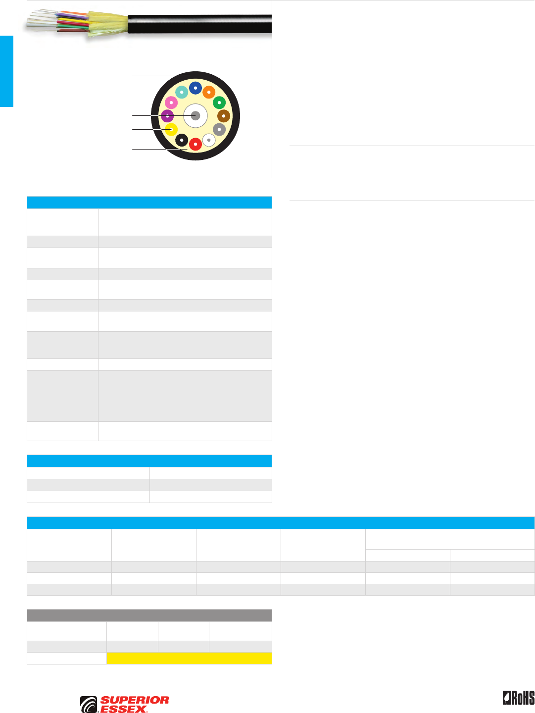
B-12
PREMISES COPPER PREMISES FIBER OSP FIBER OSP COMPOSITE CENTRAL OFFICE COPPER RDUP/RUS OSP COPPER BELL OSP COPPER OSP COPPER WIRE CANADIAN OSP COPPER TECHNICAL INFO
Toll Free 800.551.8948 | Fax 770.657.6807 | SuperiorEssex.com/Comm Rev 11/10 Ed 10.7
Dry Block/Sunlight Resistant Indoor/Outdoor
OFNP
Oil, Abrasion, Chemical
and Sunlight Resistant
Thermoplastic Jacket
Buffered Optical Fiber
Central Strength Element
Dielectric Aramid
Strength Members
Specifications
Configuration
6, 8 or 12 optical fibers surrounding dielectric strength
elements with
an overall jacket
Fiber Type 900 micron tight buffered 250 micron optical fiber
Dielectric
Strength Elements
Glass Reinforced Plastic (GRP)
and aramid yarns
Water-Blocking SAP Dry Block
Jacket Material Oil, chemical, abrasion and UV resistant plenum grade
thermoplastic
Jacket Color Standard OSP black
Maximum Tensile
Loading lbs (N)
Install: 300 (1,340)
Long Term: 90 (400)
Maximum
Attenuation dB/km
@ 1300 nm: 0.7
@ 1380 nm: 0.7
@ 1550 nm: 0.7
Package Plywood reel
Performance
Compliance
UL 1651
CSA C22.2 No. 232
NFPA 262
ANSI/ICEA S-104-696-2001
ANSI/TIA-568-C.3
RoHS-compliant
NRTL Programs UL, c(UL) Listed OFNP
UL, c(UL) Listed Sunlight Resistant
Environmental Specifications
Operation -40°C to +70°C
Storage/Shipping -40°C to +70°C
Installation 0°C to +60°C
Part Numbers and Physical Characteristics
Part Number¹ Fiber Count
Nominal Diameter
in (mm)
Nominal Weight
lbs/kft (kg/km)
Minimum Bend Radius
in (mm)
Install Long Term
W4006xx01 6 0.23 (5.9) 26 (39) 9.3 (236) 4.6 (118)
W4008xx01 8 0.26 (6.7) 32 (47) 10.6 (268) 5.3 (134)
W4012xx01 12 0.30 (7.5) 41 (62) 11.8 (300) 5.9 (150)
Single Mode Optical Fiber
Reduced
Water Peak
Zero
Water Peak
TeraFlex®
Bend Resistant
¹Replace “xx” with: 31 21 K1
Standard Jacket Colors Yellow
See the "Optical Fiber Selection Chart" in the "TECHNICAL INFO" section for detailed fiber type specifications.
Product Description
The Superior Essex Indoor/Outdoor Plenum Single Mode Fiber cable is
designed to survive the toughest installation and environmental conditions.
Not only does the cable exceed the rigorous Indoor/Outdoor plenum cable
performance requirements of ICEA 696, but its proprietary thermoplastic
jacket makes the cable resistant to mechanical abrasion, chemicals, oil and
sunlight. The cable core consists of 6, 8 or 12 single mode fibers. GRP and
aramid yarn dielectric strength elements give the cable both strength and
flexibility and the core is fully water-blocking using dry SAP technology. The
cable is available in all single mode fiber types, including Zero Water Peak
single mode and Non-Zero Dispersion Shifted single mode fibers.
Applications
• Intra/inter-building backbones
• Conduit/duct/tray pathways
• Dry or wet locations
Features Benefits
• 900 micron tight buffered
optical fibers
• Allows for either fusion
or mechanical connectors
• Full water blocking
with SAP DryBlock
• Prevents water ingress
from OSP splice enclosures
• Tough, thermoplastic jacket • Abrasion, chemical,
oil and sunlight resistant
• Meets or exceeds
ANSI/ICEA S-104-696-2001
• Worry-free installation
and performance
• Plenum (OFNP) rated designs • Plenum listing allows for cable
placement in both plenum and
riser spaces
• Available in all single mode
optical fiber types
• Choose the single mode fiber you
need for long distance and short-
haul FTTx applications

Toll Free 800.551.8948 | Fax 770.657.6807 | SuperiorEssex.com/Comm
QuickCount® Feet/Meters Marking
• Jacket marking in feet and meters
• Provides remaining length of cable on reel removing
the guesswork for cable installers
• Saves installation time and money
ColorTip™ Circuit Identification
• Circumferentially colors 100% of the conductor for easily
identifiable tip and ring mates
• Distinct colors reduces termination time and errors,
even in low light environments
• Permanent, environmentally friendly color that doesn’t
rub or wear off
CableID™ Alpha Numeric Coding
• Unique 4-character printed code, every 2 feet, on the cable
jacket for each 1000-foot box and reel of copper data cable
• Both ends of each cable run are easily identifiable without
the need to separately label or tone the cable
• Reduces installation time and cost for initial installations
and for moves, adds and changes
Standard Jacket Colors
• Extensive, in-stock jacket color offering in many
of the premises copper products
• Most colors available with no minimum quantity and
custom colors available upon request with minimum
order quantities
BrakeBox® Payout Control
The BrakeBox packaging is a true advantage for installers
who are pulling cable in multiple locations.
• Stacks, travels and protects cable better than an open reel
• Two resistance mechanisms on both sides of the box,
each with three variable resistance settings
• Controls back-tension preventing over-spin and tangling
Product Features
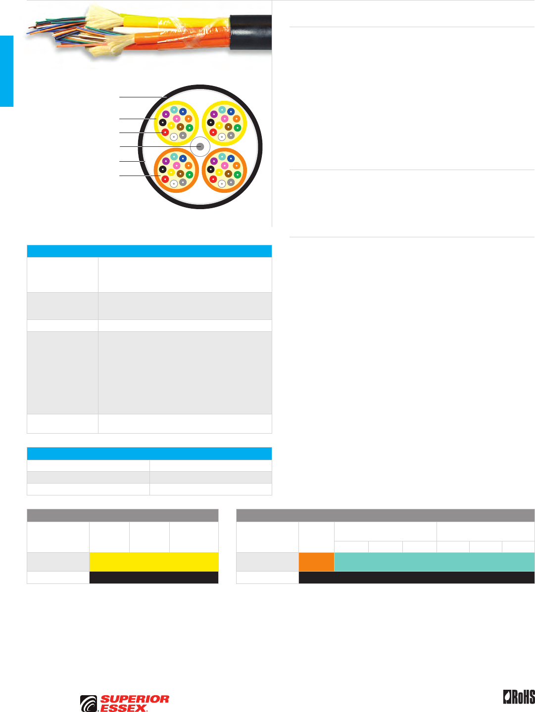
B-14
PREMISES COPPER PREMISES FIBER OSP FIBER OSP COMPOSITE CENTRAL OFFICE COPPER RDUP/RUS OSP COPPER BELL OSP COPPER OSP COPPER WIRE CANADIAN OSP COPPER TECHNICAL INFO
Rev 10/10 Ed 10.3Toll Free 800.551.8948 | Fax 770.657.6807 | SuperiorEssex.com/Comm
Flame Retardant PVC Jacket
Flame Retardant
PVC Outer Jacket
Buffered Optical Fiber
Dielectric Aramid
Strength Members
Water Blocking Tape
Central Strength Member
Hybrid
Premises Fiber OFNR/OFNP
Specifications
Tight Buffer
Configuration
Flexible tight buffer material extruded over the fiber to a
diameter of 900 µm for use with standard connectors;
dielectric aramid yarns are applied for additional
strength and covered with a flame retardant PVC jacket
Outer Jacket
Premises: Flame retardant (FR), chemical resistant PVC
Indoor/Outdoor: Black, FR, chemical resistant and
sunlight resistant PVC
Package Reel
Performance
Compliance
UL 1651
CSA C22.2 No. 232
UL 1666
NFPA 262
Premises: Telcordia GR-409-CORE, Issue 2
and ANSI/ICEA S-83-596
Indoor/Outdoor: Telcordia GR-20-CORE, Issue 3
and ANSI/ICEA S-104-696
ANSI/TIA-568-C.3
RoHS-compliant
NRTL Programs UL, c(UL) Listed OFNR
UL, c(UL) Listed OFNP
Environmental Specifications
Operation -40°C to +75°C
Storage/Shipping -40°C to +75°C
Installation -20°C to +65°C
Single Mode Optical Fiber Multimode Optical Fiber
Reduced
Water Peak
Zero
Water Peak
TeraFlex®
Bend Resistant
TeraGain®
62.5/125
TeraGain Laser Optimized 50/125
TeraFlex Bend Resistant
Laser Optimized 50/125
10G/150 10G/300 10G/550 10G/150 10G/300 10G/550
Premises
Jacket Colors Yellow Premises
Jacket Colors Orange Aqua
I/O Jacket Color Black I/O Jacket Color Black
See the "Optical Fiber Selection Chart" in the "TECHNICAL INFO" section for detailed fiber type specifications.
Product Description
Superior Essex offers a broad line of products including multimode and
single mode fibers within the same optical fiber cable. The use of hybrid
fiber designs have proven useful to network systems designers because they
offer the flexibility to run diverse applications upgrades without the need to
install new cables. Superior Essex hybrid optical fiber cables are available in
stranded tight buffer premises distribution cables, as well as all other loose
tube cable product designs. Hybrid cables are used for standard campus
networking applications and can be manufactured with a wide variety of fiber
type combinations. They will save the designer and the customer significant
costs over the lifetime of the physical cable plant.
Single mode fibers are assigned first in the color and/or sub-unit scheme.
Multimode fibers are assigned remaining colors and/or sub-units.
Applications
• Intrabuilding backbones
• Interbuilding backbone (in conduit)
• Conduit pathways
• Service entrance to communication closets
Features Benefits
• Telcordia GR-409-CORE and
GR-20-CORE qualified designs
• Most cost-effective cables
for the varied applications
• TeraGain® multimode and
single mode under one jacket
• Eliminates the need for additional
pathway space for different
cable types
• Compliant with ANSI/TIA-568-C.3 • Assures compliance for all
current networking applications
• Design options include: interlock
armored, indoor/outdoor, tight
buffered riser and plenum
• Cable designs available
for every application
• Subunits are color coded
according to fiber type
• Easily identify fiber type
B-15
PREMISES COPPERPREMISES FIBEROSP FIBEROSP COMPOSITECENTRAL OFFICE COPPERRDUP/RUS OSP COPPERBELL OSP COPPEROSP COPPER WIRECANADIAN OSP COPPERTECHNICAL INFO
Rev 10/10 Ed 10.3 Toll Free 800.551.8948 | Fax 770.657.6807 | SuperiorEssex.com/Comm
Hybrid Premises Fiber OFNR/OFNP
Part Numbers and Physical Characteristics
Listing
Part
Number
Fiber Count Nominal
Diameter
in (mm)
Nominal
Weight
lbs/kft (kg/km)
Maximum Tensile Loading Minimum Bend Radius
RWP SMF
TeraGain®
62.5/125
TeraGain®
10G/300
Install
lbs (N)
Long Term
lbs (N)
Install
in (mm)
Long Term
in (mm)
Single Unit Premises Distribution
OFNR 43008HGA1 4 - 4 0.24 (6.0) 20 (30) 150 (660) 45 (200) 3.5 (90) 2.4 (60)
OFNR 43012HGA1 6 6 - 0.26 (6.5) 25 (37) 150 (660) 45 (200) 3.8 (98) 2.6 (65)
OFNR 43012HGC1 6 - 6 0.26 (6.5) 25 (37) 150 (660) 45 (200) 3.8 (98) 2.6 (65)
OFNR 43024HK1Q 12 12 - 0.33 (8.5) 44 (66) 300 (1,320) 90 (400) 5.0 (128) 3.3 (85)
OFNR 43024HKB1 12 - 12 0.33 (8.5) 44 (66) 300 (1,320) 90 (400) 5.0 (128) 3.3 (85)
OFNP 44008HGA1 2 6 - 0.21 (5.4) 19 (28) 100 (440) 30 (130) 3.2 (81) 2.1 (54)
OFNP 44008HGB1 4 - 4 0.21 (5.4) 19 (28) 100 (440) 30 (130) 3.2 (81) 2.1 (54)
OFNP 44012HGA1 6 6 - 0.24 (6.2) 24 (35) 100 (440) 30 (130) 3.7 (93) 2.4 (62)
OFNP 44012HGC1 6 - 6 0.24 (6.2) 24 (35) 100 (440) 30 (130) 3.7 (93) 2.4 (62)
OFNP 44012HKA1 6 - 6 0.24 (6.2) 24 (35) 100 (440) 30 (130) 3.7 (93) 2.4 (62)
OFNP 44024HKA1 12 12 - 0.31 (7.8) 42 (62) 300 (1,320) 90 (400) 4.6 (117) 3.1 (78)
Multi-Unit Premises Distribution
OFNR 43018HGA1 6 12 - 0.54 (13.7) 96 (143) 300 (1,320) 90 (400) 8.1 (206) 5.4 (137)
OFNR 43024HGA1 12 12 - 0.57 (14.6) 117 (174) 300 (1,320) 90 (400) 8.6 (218) 5.7 (146)
OFNR 43024HGB1 6 18 - 0.57 (14.6) 117 (174) 300 (1,320) 90 (400) 8.6 (218) 5.7 (146)
OFNR 43036HG01 12 24 - 0.68 (17.4) 171 (255) 300 (1,320) 90 (400) 10.2 (260) 6.8 (174)
OFNR 43036HGB1 24 12 - 0.68 (17.4) 171 (255) 300 (1,320) 90 (400) 10.2 (260) 6.8 (174)
OFNR 43036HGC1 18 18 - 0.68 (17.4) 171 (255) 300 (1,320) 90 (400) 10.2 (260) 6.8 (174)
OFNR 43048HGB1 24 24 - 0.69 (17.5) 155 (232) 300 (1,320) 90 (400) 10.3 (262) 6.9 (175)
OFNR 43048HGD1 12 36 - 0.69 (17.5) 155 (232) 300 (1,320) 90 (400) 10.3 (262) 6.9 (175)
OFNR 43048HGC1 24 - 24 0.69 (17.5) 155 (232) 300 (1,320) 90 (400) 10.3 (262) 6.9 (175)
OFNR 43060HGA1 12 48 - 0.77 (19.5) 195 (291) 300 (1,320) 90 (400) 11.5 (292) 7.7 (195)
OFNR 43060HGC1 24 36 - 0.77 (19.5) 195 (291) 300 (1,320) 90 (400) 11.5 (292) 7.7 (195)
OFNR 43072HGA1 24 48 - 0.82 (21.0) 233 (348) 300 (1,320) 90 (400) 12.4 (314) 8.2 (210)
OFNR 43072HGC1 36 36 - 0.82 (21.0) 233 (348) 300 (1,320) 90 (400) 12.4 (314) 8.2 (210)
OFNR 43096HGA1 48 - 48 0.97 (24.7) 337 (503) 300 (1,320) 90 (400) 14.6 (370) 9.7 (247)
OFNP 44018HGA1 6 12 - 0.54 (13.8) 117 (175) 150 (660) 45 (200) 8.1 (206) 5.4 (138)
OFNP 44024HGC1 12 12 - 0.57 (14.6) 141 (211) 150 (660) 45 (200) 8.6 (219) 5.7 (146)
OFNP 44024HGD1 6 18 - 0.57 (14.6) 141 (211) 150 (660) 45 (200) 8.6 (219) 5.7 (146)
OFNP 44024HGG1 12 - 12 0.57 (14.6) 141 (211) 150 (660) 45 (200) 8.6 (219) 5.7 (146)
OFNP 44036HGA1 12 24 - 0.69 (17.4) 206 (307) 150 (660) 45 (200) 10.3 (261) 6.9 (174)
OFNP 44036HGC1 18 18 - 0.69 (17.4) 206 (307) 150 (660) 45 (200) 10.3 (261) 6.9 (174)
OFNP 44048HGA1 12 36 - 0.67 (17.1) 184 (275) 150 (660) 45 (200) 10.1 (257) 6.7 (171)
OFNP 44048HGC1 24 24 - 0.67 (17.1) 184 (275) 150 (660) 45 (200) 10.1 (257) 6.7 (171)
OFNP 44060HGA1 12 48 - 0.74 (18.9) 229 (341) 150 (660) 45 (200) 11.2 (284) 7.4 (189)
OFNP 44060HGC1 24 36 - 0.74 (18.9) 229 (341) 150 (660) 45 (200) 11.2 (284) 7.4 (189)
OFNP 44072HGA1 24 48 - 0.81 (20.6) 276 (412) 150 (660) 45 (200) 12.2 (309) 8.1 (206)
OFNP 44072HGC1 36 36 - 0.81 (20.6) 276 (412) 150 (660) 45 (200) 12.2 (309) 8.1 (206)
Single Unit Indoor/Outdoor Tight Buffer
OFNR W3012HGB1 6 6 - 0.26 (6.5) 25 (38) 300 (1,335) 90 (400) 3.8 (97) 2.6 (65)
OFNR W3012HGD1 6 - 6 0.26 (6.5) 25 (38) 300 (1,335) 90 (400) 3.8 (97) 2.6 (65)
Multi-Unit Indoor/Outdoor Tight Buffer
OFNR W3018HGA1 6 12 - 0.55 (14.1) 102 (152) 600 (2,640) 180 (800) 8.3 (211) 5.5 (141)
OFNR W3024HGA1 6 18 - 0.59 (14.9) 123 (184) 600 (2,640) 180 (800) 8.8 (224) 5.9 (149)
OFNR W3024HGC1 12 12 - 0.59 (14.9) 123 (184) 600 (2,640) 180 (800) 8.8 (224) 5.9 (149)
OFNR W3024HGE1 12 - 12 0.59 (14.9) 123 (184) 600 (2,640) 180 (800) 8.8 (224) 5.9 (149)
OFNR W3036HGA1 12 24 - 0.70 (17.7) 179 (267) 600 (2,640) 180 (800) 10.5 (266) 7.0 (177)
OFNR W3036HGC1 18 18 - 0.70 (17.7) 179 (267) 600 (2,640) 180 (800) 10.5 (266) 7.0 (177)
OFNR W3036HGE1 24 12 - 0.70 (17.7) 179 (267) 600 (2,640) 180 (800) 10.5 (266) 7.0 (177)
OFNR W3048HGE1 12 36 - 0.70 (17.8) 162 (242) 600 (2,640) 180 (800) 10.5 (267) 7.0 (178)
OFNR W3048HGC1 24 24 - 0.70 (17.8) 162 (242) 600 (2,640) 180 (800) 10.5 (267) 7.0 (178)
OFNR W3048HGB1 24 - 24 0.70 (17.8) 162 (242) 600 (2,640) 180 (800) 10.5 (267) 7.0 (178)
OFNR W3060HGA1 12 48 - 0.78 (19.8) 204 (304) 600 (2,640) 180 (800) 11.7 (297) 7.8 (198)
OFNR W3072HGA1 24 48 - 0.84 (21.3) 243 (362) 600 (2,640) 180 (800) 12.6 (320) 8.4 (213)
OFNR W3072HGC1 36 36 - 0.84 (21.3) 243 (362) 600 (2,640) 180 (800) 12.6 (320) 8.4 (213)
OFNR W3096HGA1 48 48 - 0.98 (25.0) 345 (515) 600 (2,640) 180 (800) 14.8 (375) 9.8 (250)
OFNR W3096HGB1 48 - 48 0.98 (25.0) 345 (515) 600 (2,640) 180 (800) 14.8 (375) 9.8 (250)
OFNR W3144HGC1 72 72 - 1.11 (28.3) 375 (559) 600 (2,640) 180 (800) 16.7 (425) 11.1 (283)
Other configurations available upon request. See the "Optical Fiber Selection Chart" in the "TECHNICAL INFO" section for detailed fiber type specifications.
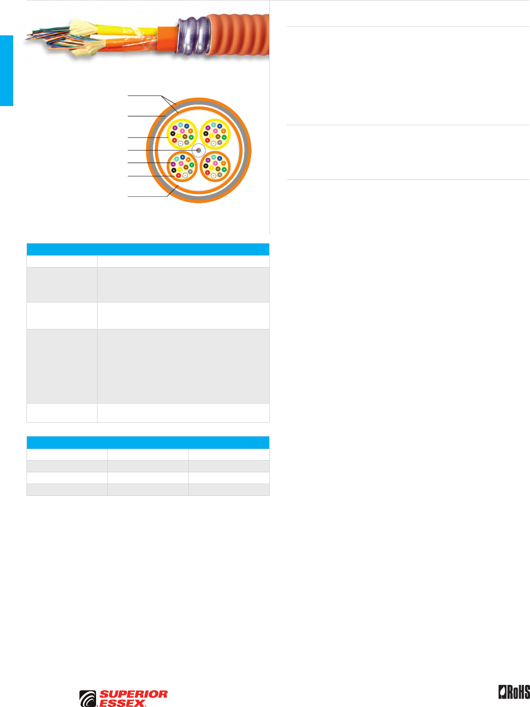
B-16
PREMISES COPPER PREMISES FIBER OSP FIBER OSP COMPOSITE CENTRAL OFFICE COPPER RDUP/RUS OSP COPPER BELL OSP COPPER OSP COPPER WIRE CANADIAN OSP COPPER TECHNICAL INFO
Toll Free 800.551.8948 | Fax 770.657.6807 | SuperiorEssex.com/Comm Rev 11/10 Ed 10.6
Flame Retardant PVC Jacket
Flame Retardant
PVC Outer Jackets
Aluminum or Steel
Interlocked Armor
Buffered Optical Fiber
Dielectric Aramid
Strength Members
Polyester Tape (Premises) or
Water Blocking Tape (I/O)
Central Strength Member
Interlock Armored
Premises Fiber OFCR/OFCP
Specifications
Core Configuration Available using 33, 34, 43, 44 and W3 series products
Interlock Armored
Flexible, heavy duty interlocking aluminum or steel tape
helically applied over the inner cable core; further
protection is provided by an optional flame retardant
outer jacket
Outer Jacket
Premises: Flame retardant (FR), chemical resistant PVC
Indoor/Outdoor: Black, FR, chemical resistant and
sunlight resistant PVC
Performance
Compliance
UL 1651
CSA C22.2 No. 232
UL 1666
NFPA 262
Telcordia GR-409-CORE, Issue 2
ANSI/ICEA S-83-596
ANSI/ICEA S-104-696
ANSI/TIA-568-C.3
RoHS-compliant
NRTL Programs UL, c(UL) Listed OFCR
UL, c(UL) Listed OFCP
Environmental Specifications
Riser Plenum
Operation -40°C to +75°C -40°C to +75°C
Storage/Shipping -40°C to +75°C -40°C to +75°C
Installation -20°C to +65°C -20°C to +65°C
Product Description
Interlock Armored Optical Fiber Cables provide for an extremely well
protected cable package ideally suited for harsh environments. The armor
is available in aluminum or steel and comes with either an OFCR (riser) or
OFCP (plenum) rating. This design offers the system designer a product that
can be installed in high traffic areas where added mechanical protection
and security are required. The flexible interlock armored cable design is
also popular for retrofit applications and eliminates the need to install rigid
conduit while still meeting building code guidelines.
Applications
• Intrabuilding backbones
• Conduit pathways
• Service entrance to communication closets
Features Benefits
• Thick, flexible metallic armor • Reduce incidences of circuit
disruption due to rodents or
mechanically abusive applications
• Flame retardant,
UL Listed designs
• Eliminates the need for multiple
cables for installation
• Full line of Superior Essex
cables available
• Customized designs reduces
cable inventory requirements
B-17
PREMISES COPPERPREMISES FIBEROSP FIBEROSP COMPOSITECENTRAL OFFICE COPPERRDUP/RUS OSP COPPERBELL OSP COPPEROSP COPPER WIRECANADIAN OSP COPPERTECHNICAL INFO
Toll Free 800.551.8948 | Fax 770.657.6807 | SuperiorEssex.com/CommRev 11/10 Ed 10.6
Interlock Armored Premises Fiber OFCR/OFCP
Part Numbers and Physical Characteristics
Listing Part Number¹
Fiber
Count
Nominal
Diameter
in (mm)
Nominal Weight
lbs/kft (kg/km)
Maximum
Compression
lbf/in (N/cm)
Maximum Tensile Loading Minimum Bend Radius
Install
lbs (N)
Long Term
lbs (N)
Install
in (mm)
Long Term
in (mm)
Single Unit Tight Buffer
OFCR L3002x301 2 0.54 (13.8) 89 (133) 286 (500) 150 (670) 45 (200) 8 (207) 5 (138)
OFCR L3004x301 4 0.54 (13.8) 90 (135) 286 (500) 150 (670) 45 (200) 8 (207) 5 (138)
OFCR L3006x401 6 0.54 (13.8) 92 (137) 286 (500) 150 (670) 45 (200) 8 (207) 5 (138)
OFCR L3008x401 8 0.54 (13.8) 94 (140) 287 (500) 150 (670) 45 (200) 8 (207) 5 (138)
OFCR L3012x401 12 0.62 (15.7) 112 (167) 286 (500) 150 (670) 45 (200) 9 (236) 6 (157)
OFCR L3018xK1Q 18 0.66 (16.8) 135 (201) 228 (400) 300 (1,340) 90 (400) 10 (251) 7 (168)
OFCR L3024xK1Q 24 0.70 (17.8) 158 (236) 228 (400) 300 (1,340) 90 (400) 11 (267) 7 (178)
OFCP L4002x301 2 0.50 (12.7) 82 (123) 286 (500) 150 (670) 45 (200) 8 (191) 5 (127)
OFCP L4004x301 4 0.50 (12.7) 84 (125) 286 (500) 150 (670) 45 (200) 8 (191) 5 (127)
OFCP L4006x401 6 0.50 (12.7) 87 (130) 286 (500) 150 (670) 45 (200) 8 (191) 5 (127)
OFCP L4012x401 12 0.55 (13.9) 104 (155) 286 (500) 150 (670) 45 (200) 8 (209) 5 (139)
OFCP L4018xK1Q 18 0.59 (15.1) 96 (143) 228 (400) 150 (670) 45 (200) 9 (227) 6 (151)
OFCP L4024xK1Q 24 0.59 (15.1) 88 (132) 228 (400) 150 (670) 45 (200) 9 (227) 6 (151)
Multi-Unit Tight Buffer
OFCR L3018x401 18 0.95 (24.1) 240 (358) 228 (400) 300 (1,340) 90 (400) 14 (362) 9 (241)
OFCR L3024x401 24 0.95 (24.1) 283 (422) 228 (400) 300 (1,340) 90 (400) 14 (362) 9 (241)
OFCR L3036x401 36 1.05 (26.7) 352 (525) 171 (300) 300 (1,340) 90 (400) 16 (400) 10 (267)
OFCR L3048x401 48 1.05 (26.8) 341 (508) 171 (300) 300 (1,340) 90 (400) 16 (401) 11 (268)
OFCR L3072x401 72 1.23 (31.2) 468 (699) 171 (300) 600 (2,700) 180 (800) 18 (468) 12 (312)
OFCR L3096x401 96 1.38 (35.1) 611 (912) 171 (300) 600 (2,700) 180 (800) 21 (527) 14 (351)
OFCR L3144x401 144 1.48 (37.6) 651 (971) 171 (300) 600 (2,700) 180 (800) 22 (564) 15 (376)
OFCP L4018x401 18 0.85 (21.7) 249 (372) 228 (400) 300 (1,340) 90 (400) 13 (325) 9 (217)
OFCP L4024x401 24 0.90 (22.8) 278 (414) 228 (400) 300 (1,340) 90 (400) 13 (343) 9 (228)
OFCP L4036x401 36 1.02 (25.8) 376 (561) 171 (300) 300 (1,340) 90 (400) 15 (387) 10 (258)
OFCP L4048x401 48 1.02 (25.8) 353 (526) 171 (300) 300 (1,340) 90 (400) 15 (387) 10 (258)
OFCP L4072x401 72 1.19 (30.3) 494 (736) 171 (300) 600 (2,700) 180 (800) 18 (455) 12 (303)
Single Unit Indoor/Outdoor Tight Buffer
OFCR L3002xW01 2 0.54 (13.8) 89 (133) 286 (500) 150 (670) 45 (200) 8 (207) 5 (138)
OFCR L3004xW01 4 0.54 (13.8) 90 (135) 286 (500) 150 (670) 45 (200) 8 (207) 5 (138)
OFCR L3006xW01 6 0.54 (13.8) 92 (137) 286 (500) 150 (670) 45 (200) 8 (207) 5 (138)
OFCR L3012xW01 12 0.62 (15.7) 112 (167) 286 (500) 150 (670) 45 (200) 9 (236) 6 (157)
OFCP L4002x201 2 0.50 (12.7) 82 (123) 286 (500) 150 (670) 45 (200) 8 (191) 5 (127)
OFCP L4004x201 4 0.50 (12.7) 84 (125) 286 (500) 150 (670) 45 (200) 8 (191) 5 (127)
OFCP L4006x201 6 0.50 (12.7) 87 (130) 286 (500) 150 (670) 45 (200) 8 (191) 5 (127)
OFCP L4012x201 12 0.55 (13.9) 104 (155) 286 (500) 150 (670) 45 (200) 8 (209) 5 (139)
Multi-Unit Indoor/Outdoor Tight Buffer
OFCR L3018xW01 18 0.95 (24.1) 248 (370) 228 (400) 300 (1,340) 90 (400) 14 (362) 9 (241)
OFCR L3024xW01 24 0.95 (24.1) 283 (422) 228 (400) 300 (1,340) 90 (400) 14 (362) 9 (241)
OFCR L3036xW01 36 1.05 (26.7) 352 (525) 171 (300) 300 (1,340) 90 (400) 16 (400) 10 (267)
OFCR L3048xW01 48 1.05 (26.8) 341 (508) 171 (300) 300 (1,340) 90 (400) 16 (401) 11 (268)
OFCR L3072xW01 72 1.23 (31.2) 468 (699) 171 (300) 600 (2,700) 180 (800) 18 (468) 12 (312)
OFCR L3096xW01 96 1.38 (35.1) 611 (912) 171 (300) 600 (2,700) 180 (800) 21 (527) 14 (351)
OFCR L3144xW01 144 1.48 (37.6) 651 (971) 171 (300) 600 (2,700) 180 (800) 22 (564) 15 (376)
OFCP L4018x201 18 0.85 (21.7) 249 (372) 228 (400) 300 (1,340) 90 (400) 13 (325) 9 (217)
OFCP L4024x201 24 0.90 (22.8) 278 (414) 228 (400) 300 (1,340) 90 (400) 13 (343) 9 (228)
OFCP L4036x201 36 1.02 (25.8) 376 (561) 171 (300) 300 (1,340) 90 (400) 15 (387) 10 (258)
OFCP L4048x201 48 1.02 (25.8) 353 (526) 171 (300) 300 (1,340) 90 (400) 15 (387) 10 (258)
OFCP L4072x201 72 1.19 (30.3) 494 (736) 171 (300) 300 (1,340) 90 (400) 18 (455) 12 (303)
Single Mode Optical Fiber Multimode Optical Fiber
Reduced
Water Peak
Zero
Water Peak
TeraFlex®
Bend Resistant
TeraGain®
62.5/125
TeraGain Laser Optimized 50/125
TeraFlex Bend Resistant
Laser Optimized 50/125
10G/150 10G/300 10G/550 10G/150 10G/300 10G/550
¹Replace “x” with: 3 2 K ¹Replace “x” with: 6 A B F M N P
Premises
Jacket Colors Yellow Premises
Jacket Colors Orange Aqua
I/O Jacket Color Black I/O Jacket Color Black
¹Part numbers listed above include aluminum interlock armored. Steel interlock armored available upon request.
See the "Optical Fiber Selection Chart" in the "TECHNICAL INFO" section for detailed fiber type specifications.


C-1
PREMISES COPPERPREMISES FIBEROSP FIBEROSP COMPOSITECENTRAL OFFICE COPPERRDUP/RUS OSP COPPERBELL OSP COPPEROSP COPPER WIRECANADIAN OSP COPPERTECHNICAL INFO
Toll Free 800.551.8948 | Fax 770.657.6807 | SuperiorEssex.com/Comm
OSP FIBER
Table of Contents
Loose Tube Single Jacket All Dielectric Series 11............... C-2
Loose Tube Double Jacket Non-Armor Series 1G ............... C-3
Loose Tube Single Jacket Single Armor Series 12............... C-4
Loose Tube Double Jacket Single Armor Series 1A.............. C-5
Loose Tube Double Jacket Double Armor Series 1D ............. C-6
Loose Tube Triple Jacket Double Armor Series 1C .............. C-7
Loose Tube Single Jacket Self Support Series 11M.............. C-8
Loose Tube Double Jacket Self Support Series 1GM ............ C-9
Loose Tube Single Jacket Single Armor Self Support Series 12M . . C-10
Loose Tube Double Jacket Single Armor Self Support Series 1AM. C-11
Loose Tube Single Jacket All Dielectric Nylon Series 1NY . . . . . . C-12
ADSS 100 Series 1F100...................................... C-13
ADSS 200 Series 1F200...................................... C-14
ADSS 400 Series 1F400...................................... C-15
Single Loose Tube All Dielectric Series 51 .................... C-16
Single Loose Tube Single Armor Series 52 .................... C-17
Single Flex Tube All Dielectric Series F1 ...................... C-18
Single Flex Tube Single Armor Series F2 ...................... C-19
Flex Tube Locate Series FM ................................. C-20
Ribbon Locate Series RM ................................... C-21
Loose Tube Indoor/Outdoor OFNR Series 13 ................... C-22
Interlock Armored OSP Fiber OFCR Series 13I ................. C-23
Single Loose Tube Indoor/Outdoor OFNR Series 53............. C-24
Heavy Duty Loose Tube OFNR Series 1H ...................... C-25
Loose Tube 12 AWG Composite Series 1N..................... C-26
UG FTTP Series 513 ........................................ C-27
Buried FTTP Steel Armor Series 52S.......................... C-28
Buried FTTP Aluminum Armor Series 523 ..................... C-29
Buried Drop Composite Aluminum Armor Series 72 ............ C-30
Buried Drop Composite Steel Armor Series 72S................ C-31
Toneable Drop FTTP Series 571Q ............................. C-32
Universal Drop FTTP Series 570Q ............................ C-33
Universal FTTP OFNR Series 57R ............................. C-34
Toneable FTTP OFCR Series 57CR ............................ C-35
Figure 8 FTTP Series 573Q ................................... C-36
FTTP Tight Buffered Indoor/Outdoor Drop Series W7 ........... C-37
Dri-Lite® Ribbon Series R1D ................................. C-38
Dri-Lite® Ribbon Single Armor Series R2D ..................... C-39
Stranded Tube Ribbon Single Armor Series S2................. C-41
Single Tube Ribbon Series R1................................ C-42
Single Tube Ribbon Single Armor Series R2 ................... C-43
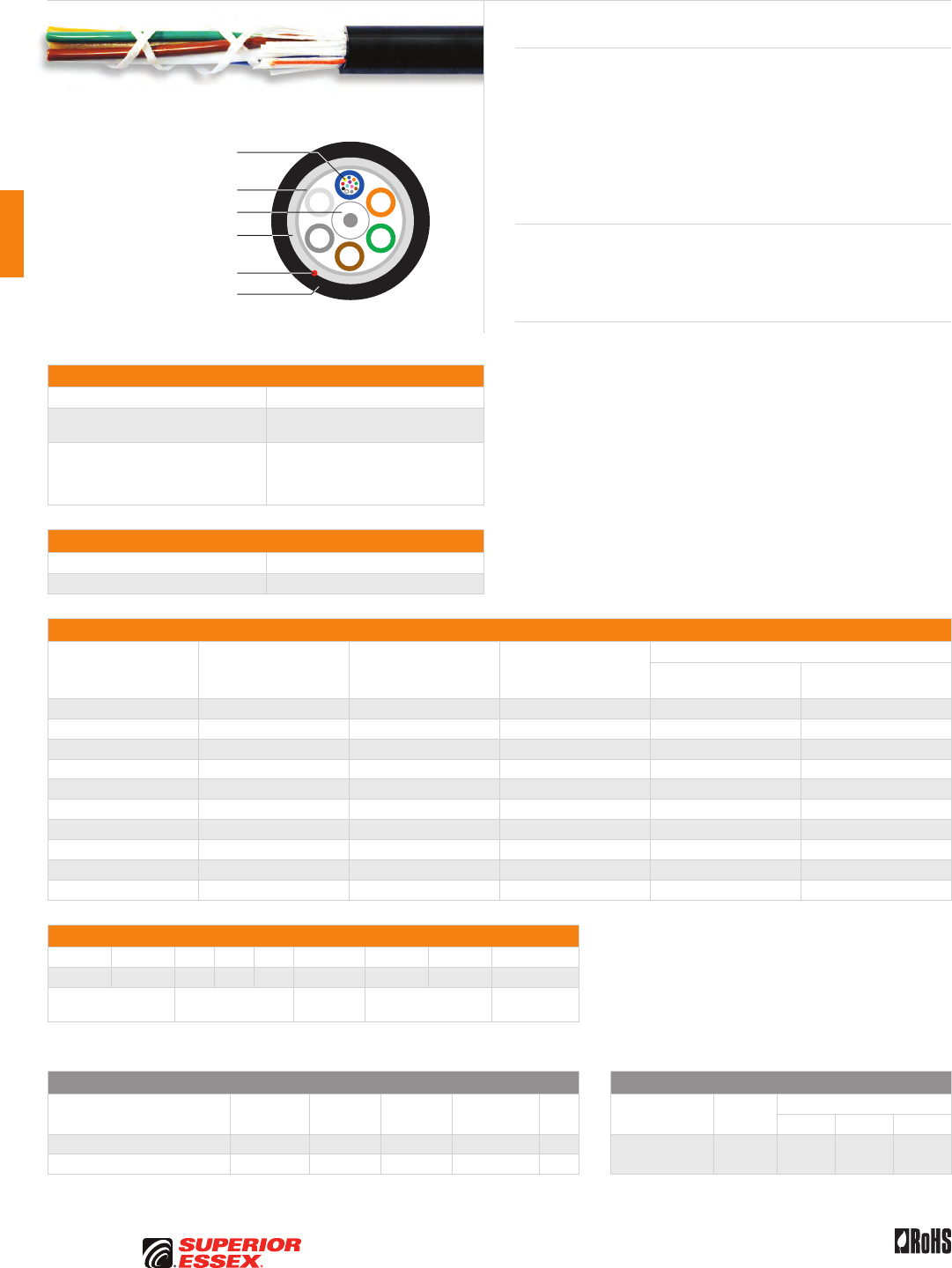
C-2
PREMISES COPPER PREMISES FIBER OSP FIBER OSP COMPOSITE CENTRAL OFFICE COPPER RDUP/RUS OSP COPPER BELL OSP COPPER OSP COPPER WIRE CANADIAN OSP COPPER TECHNICAL INFO
Rev 7/10 Ed 10.2Toll Free 800.551.8948 | Fax 770.657.6807 | SuperiorEssex.com/Comm
Specifications
Fiber Count Available in 6-fiber up to 288-fiber
Maximum Tensile Loading lbs (N) Install: 600 (2,700)
Long Term: 200 (890)
Standards Compliance
Telcordia GR-20-CORE
RDUP PE-90 Designation MLT
ICEA S-87-640-2006
RoHS-compliant
Environmental Specifications
Operation/Storage -40°C to +70°C
Installation -30°C to +75°C
Part Numbers and Physical Characteristics
Part Number¹ Fiber Count
Nominal Diameter
in (mm)
Approx. Weight
lbs/kft (kg/km)
Minimum Bend Radius
Install
in (mm)
Long Term
in (mm)
11006xx01 6 0.43 (10.9) 50 (75) 8.6 (218) 4.3 (109)
11012xx01 12 0.43 (10.9) 50 (75) 8.6 (218) 4.3 (109)
11024xx01 24 0.43 (10.9) 50 (75) 8.6 (218) 4.3 (109)
11036xx01 36 0.43 (10.9) 50 (75) 8.6 (218) 4.3 (109)
11048xx01 48 0.43 (10.9) 50 (75) 8.6 (218) 4.3 (109)
11072xx01 72 0.47 (12.0) 66 (99) 9.4 (239) 4.7 (119)
11096xx01 96 0.55 (13.9) 87 (130) 11.0 (279) 5.5 (140)
11144xx01 144 0.69 (17.5) 142 (211) 13.8 (351) 6.9 (175)
11216xx01 216 0.72 (18.3) 141 (209) 14.4 (366) 7.2 (183)
11288xx01 288 0.81 (20.5) 183 (272) 16.2 (411) 8.1 (206)
Part Number Designators
1 1 _ _ _ x x 0 _
1 2 3 4 5 6 7 8 9
product family fiber count (006-288) fiber type internal designator water block/
marking (1-8)
Contact Customer Service for availability of non-standard offerings.
See "Optical Fiber Cable" options in the "TECHNICAL INFO" section for flooding and jacket marking options.
Single Mode Optical Fiber Multimode Optical Fiber
Conventional
Reduced
Water Peak
Zero
Water Peak
TeraFlex®
Bend Resistant NZDS
TeraGain®
62.5/125
TeraGain Laser Optimized 50/125
10G/150 10G/300 10G/550
¹For ≤ 36 fibers replace “xx” with: 9T 3T 2T KT 8T ¹Replace “xx” with: 6G AG BG FG
¹For > 36 fibers replace “xx” with: 91 31 21 K1 81
See the "Optical Fiber Selection Chart" in the "TECHNICAL INFO" section for detailed fiber type specifications.
Loose Tube Single Jacket All Dielectric
Series 11
Product Description
Loose tube cables are the product of choice as the backbone in Outside
Plant (OSP) environments. The rugged loose tube design offers reliable
transmission performance over a broad temperature range. Optical fibers
are placed inside filled buffer tubes containing PFM™ gel. The core is
constructed by stranding the buffer tubes around a central member using
a reverse oscillating lay (ROL). The core is wrapped with flexible strength
members covered with a water blocking tape, then encased with a black
jacket. A rip cord is included under the jacket for ease of entry.
Applications
• Underground duct and lashed aerial
• Trunk, distribution and feeder cable
• Local loop, metro, long-haul and broadband network
Features Benefits
• Available with up to 288-fiber • High fiber density
• Multiple fiber types
including hybrids
• Multiple network applications
• Central strength members
available in metallic or dielectric
• Metallic option offers ease
of location, dielectric design
eliminates grounding issues
• Dry (SAP) core standard • Reduces cable prep
and installation time
• Standard tube size
for all fiber counts
• Reduces the number
of tools required
• PFM™ gel • Non-sticky gel speeds fiber
access and cleanup
Central Strength Member
Dielectric Water Blocking
Strength Members
Water Blocking Tape
Optical Fiber in PFM™ Gel
Filled Buffer Tube
Rip Cord
UV Resistant Jacket
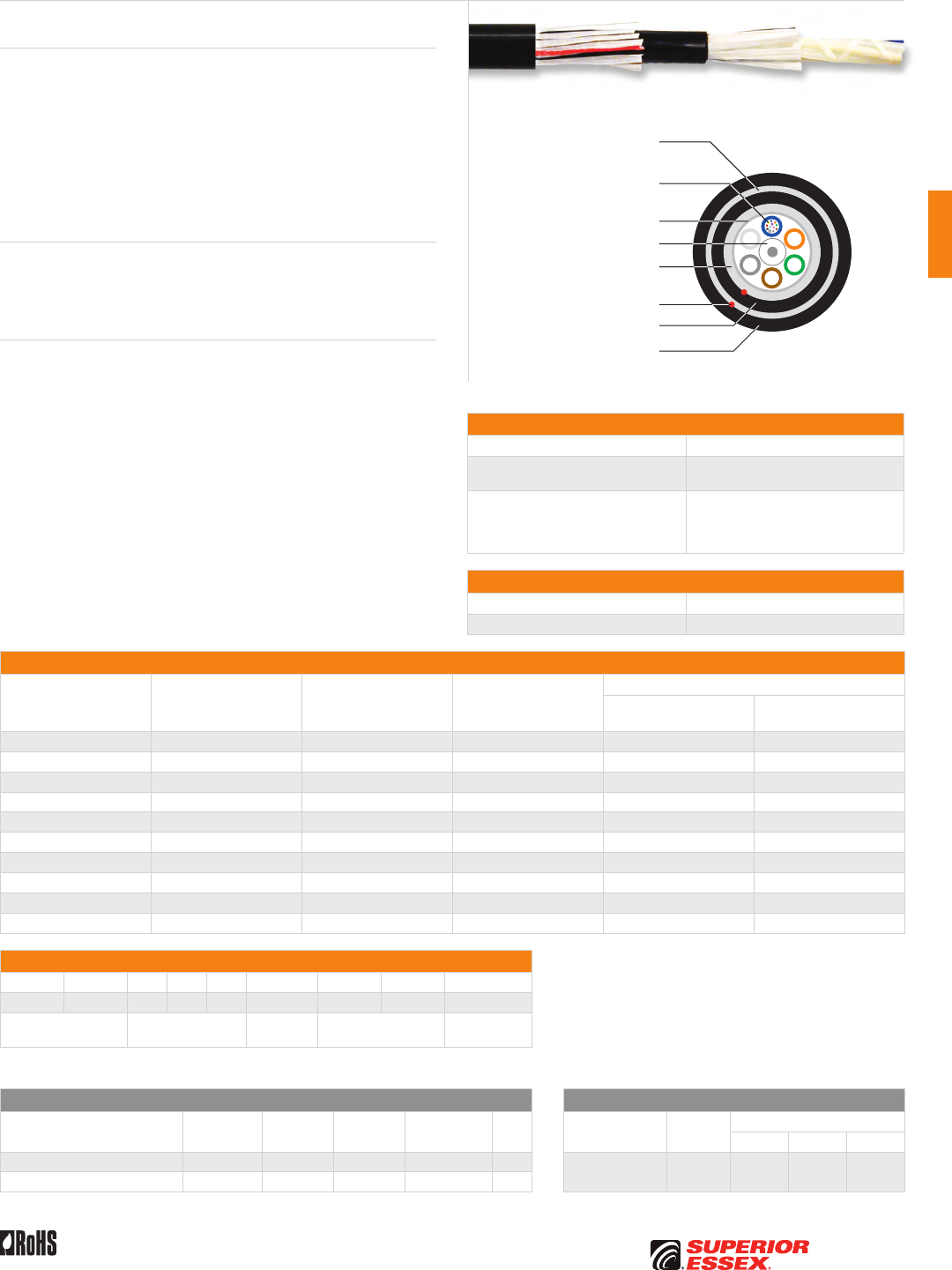
C-3
PREMISES COPPERPREMISES FIBEROSP FIBEROSP COMPOSITECENTRAL OFFICE COPPERRDUP/RUS OSP COPPERBELL OSP COPPEROSP COPPER WIRECANADIAN OSP COPPERTECHNICAL INFO
Rev 7/10 Ed 10.2 Toll Free 800.551.8948 | Fax 770.657.6807 | SuperiorEssex.com/Comm
Specifications
Fiber Count Available in 6-fiber up to 288-fiber
Maximum Tensile Loading lbs (N) Install: 600 (2,700)
Long Term: 200 (890)
Standards Compliance
Telcordia GR-20-CORE
RDUP PE-90 Designation MLT
ICEA S-87-640-2006
RoHS-compliant
Environmental Specifications
Operation/Storage -40°C to +70°C
Installation -30°C to +75°C
Part Numbers and Physical Characteristics
Part Number¹ Fiber Count
Nominal Diameter
in (mm)
Approx. Weight
lbs/kft (kg/km)
Minimum Bend Radius
Install
in (mm)
Long Term
in (mm)
1G006xx01 6 0.53 (13.5) 84 (124) 10.6 (269) 5.3 (135)
1G012xx01 12 0.53 (13.5) 84 (124) 10.6 (269) 5.3 (135)
1G024xx01 24 0.53 (13.5) 84 (124) 10.6 (269) 5.3 (135)
1G036xx01 36 0.53 (13.5) 84 (124) 10.6 (269) 5.3 (135)
1G048xx01 48 0.53 (13.5) 84 (124) 10.6 (269) 5.3 (135)
1G072xx01 72 0.57 (14.6) 99 (147) 11.4 (290) 5.7 (145)
1G096xx01 96 0.64 (16.3) 121 (181) 12.8 (325) 6.4 (163)
1G144xx01 144 0.78 (19.9) 185 (275) 15.6 (396) 7.8 (198)
1G216xx01 216 0.81 (20.7) 216 (321) 16.2 (411) 8.1 (206)
1G288xx01 288 0.90 (22.9) 283 (421) 18.0 (457) 9.0 (229)
Part Number Designators
1 G _ _ _ x x 0 _
1 2 3 4 5 6 7 8 9
product family fiber count (006-288) fiber type internal designator water block/
marking (1-8)
Contact Customer Service for availability of non-standard offerings.
See "Optical Fiber Cable" options in the "TECHNICAL INFO" section for flooding and jacket marking options.
Single Mode Optical Fiber Multimode Optical Fiber
Conventional
Reduced
Water Peak
Zero
Water Peak
TeraFlex®
Bend Resistant NZDS
TeraGain®
62.5/125
TeraGain Laser Optimized 50/125
10G/150 10G/300 10G/550
¹For ≤ 36 fibers replace “xx” with: 9T 3T 2T KT 8T ¹Replace “xx” with: 6G AG BG FG
¹For > 36 fibers replace “xx” with: 91 31 21 K1 81
See the "Optical Fiber Selection Chart" in the "TECHNICAL INFO" section for detailed fiber type specifications.
Loose Tube Double Jacket Non-Armor
Series 1G
Product Description
Loose tube cables are the product of choice as the backbone in Outside
Plant (OSP) environments. The rugged loose tube design offers reliable
transmission performance over a broad temperature range. Optical fibers
are placed inside filled buffer tubes containing PFM™ gel. The core is
constructed by stranding the buffer tubes around a central member using
a reverse oscillating lay (ROL). The core is wrapped with flexible strength
members covered with a water blocking tape, then encased with a black
inner jacket. Water blocking yarns and a black outer jacket are applied. Rip
cords are included under each jacket for ease of entry.
Applications
• Underground duct and lashed aerial
• Trunk, distribution and feeder cables
• Local loop, metro, long-haul and broadband network
Features Benefits
• Available with up to 288-fiber • High fiber density
• Multiple fiber types
including hybrids
• Multiple network applications
• Central strength members
available in metallic or dielectric
• Metallic option offers ease
of location, dielectric design
eliminates grounding issues
• Dry (SAP) core standard • Reduces cable prep
and installation time
• Standard tube size
for all fiber counts
• Reduces the number
of tools required
• PFM™ gel • Non-sticky gel speeds fiber
access and clean-up
Central Strength Member
Dielectric Water Blocking
Strength Members
Dielectric Water Blocking
Strength Members
Water Blocking Tape
Optical Fiber in PFM™ Gel
Filled Buffer Tube
Rip Cords
UV Resistant Inner Jacket
UV Resistant Outer Jacket
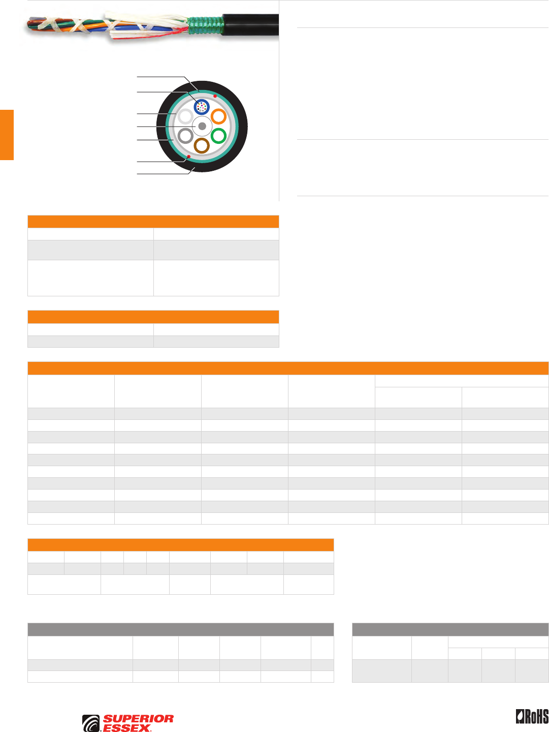
C-4
PREMISES COPPER PREMISES FIBER OSP FIBER OSP COMPOSITE CENTRAL OFFICE COPPER RDUP/RUS OSP COPPER BELL OSP COPPER OSP COPPER WIRE CANADIAN OSP COPPER TECHNICAL INFO
Rev 7/10 Ed 10.2Toll Free 800.551.8948 | Fax 770.657.6807 | SuperiorEssex.com/Comm
Specifications
Fiber Count Available in 6-fiber up to 288-fiber
Maximum Tensile Loading lbs (N) Install: 600 (2,700)
Long Term: 200 (890)
Standards Compliance
Telcordia GR-20-CORE
RDUP PE-90 Designation MLT
ICEA S-87-640-2006
RoHS-compliant
Environmental Specifications
Operation/Storage -40°C to +70°C
Installation -30°C to +75°C
Part Numbers and Physical Characteristics
Part Number¹ Fiber Count
Nominal Diameter
in (mm)
Approx. Weight
lbs/kft (kg/km)
Minimum Bend Radius
Install
in (mm)
Long Term
in (mm)
12006xx01 6 0.48 (12.2) 91 (136) 9.6 (244) 4.8 (122)
12012xx01 12 0.48 (12.2) 91 (136) 9.6 (244) 4.8 (122)
12024xx01 24 0.48 (12.2) 91 (136) 9.6 (244) 4.8 (122)
12036xx01 36 0.48 (12.2) 91 (136) 9.6 (244) 4.8 (122)
12048xx01 48 0.48 (12.2) 91 (136) 9.6 (244) 4.8 (122)
12072xx01 72 0.53 (13.3) 108 (161) 10.6 (269) 5.3 (135)
12096xx01 96 0.63 (16.0) 148 (220) 12.6 (320) 6.3 (160)
12144xx01 144 0.77 (19.7) 220 (328) 15.4 (391) 7.7 (196)
12216xx01 216 0.81 (20.5) 228 (339) 16.2 (411) 8.1 (206)
12288xx01 288 0.89 (22.7) 274 (408) 17.0 (452) 8.9 (226)
Part Number Designators
1 2 _ _ _ x x 0 _
1 2 3 4 5 6 7 8 9
product family fiber count (006-288) fiber type internal designator water block/
marking (1-8)
Contact Customer Service for availability of non-standard offerings.
See "Optical Fiber Cable" options in the "TECHNICAL INFO" section for flooding and jacket marking options.
Single Mode Optical Fiber Multimode Optical Fiber
Conventional
Reduced
Water Peak
Zero
Water Peak
TeraFlex®
Bend Resistant NZDS
TeraGain®
62.5/125
TeraGain Laser Optimized 50/125
10G/150 10G/300 10G/550
¹For ≤ 36 fibers replace “xx” with: 9T 3T 2T KT 8T ¹Replace “xx” with: 6G AG BG FG
¹For > 36 fibers replace “xx” with: 91 31 21 K1 81
See the "Optical Fiber Selection Chart" in the "TECHNICAL INFO" section for detailed fiber type specifications.
Loose Tube Single Jacket Single Armor
Series 12
Product Description
Loose tube cables are the product of choice as the backbone in Outside
Plant (OSP) environments. The rugged loose tube design offers reliable
transmission performance over a broad temperature range. Optical fibers
are placed inside filled buffer tubes containing PFM™ gel. The core is
constructed by stranding the buffer tubes around a central member using
a reverse oscillating lay (ROL). The core is wrapped with flexible strength
members covered with a water blocking tape. A corrugated steel armor is
applied and then encased with a black jacket. Rip cords are included under
the armor for ease of entry.
Applications
• Direct bury, underground duct and lashed aerial
• Trunk, distribution and feeder cable
• Local loop, metro, long-haul and broadband network
Features Benefits
• Available with up to 288-fiber • High fiber density
• Multiple fiber types
including hybrids
• Multiple network applications
• Dry (SAP) core standard • Reduces cable prep
and installation time
• Standard tube size
for all fiber counts
• Reduces the number
of tools required
• Corrugated steel armor • Improves compressive strength
and rodent protection
• PFM™ gel • Non-sticky gel speeds fiber
access and clean-up
Central Strength Member
Dielectric Water Blocking
Strength Members
Water Blocking Tape
Corrugated Steel Armor
Optical Fiber in PFM™ Gel
Filled Buffer Tube
Rip Cords
UV Resistant Jacket
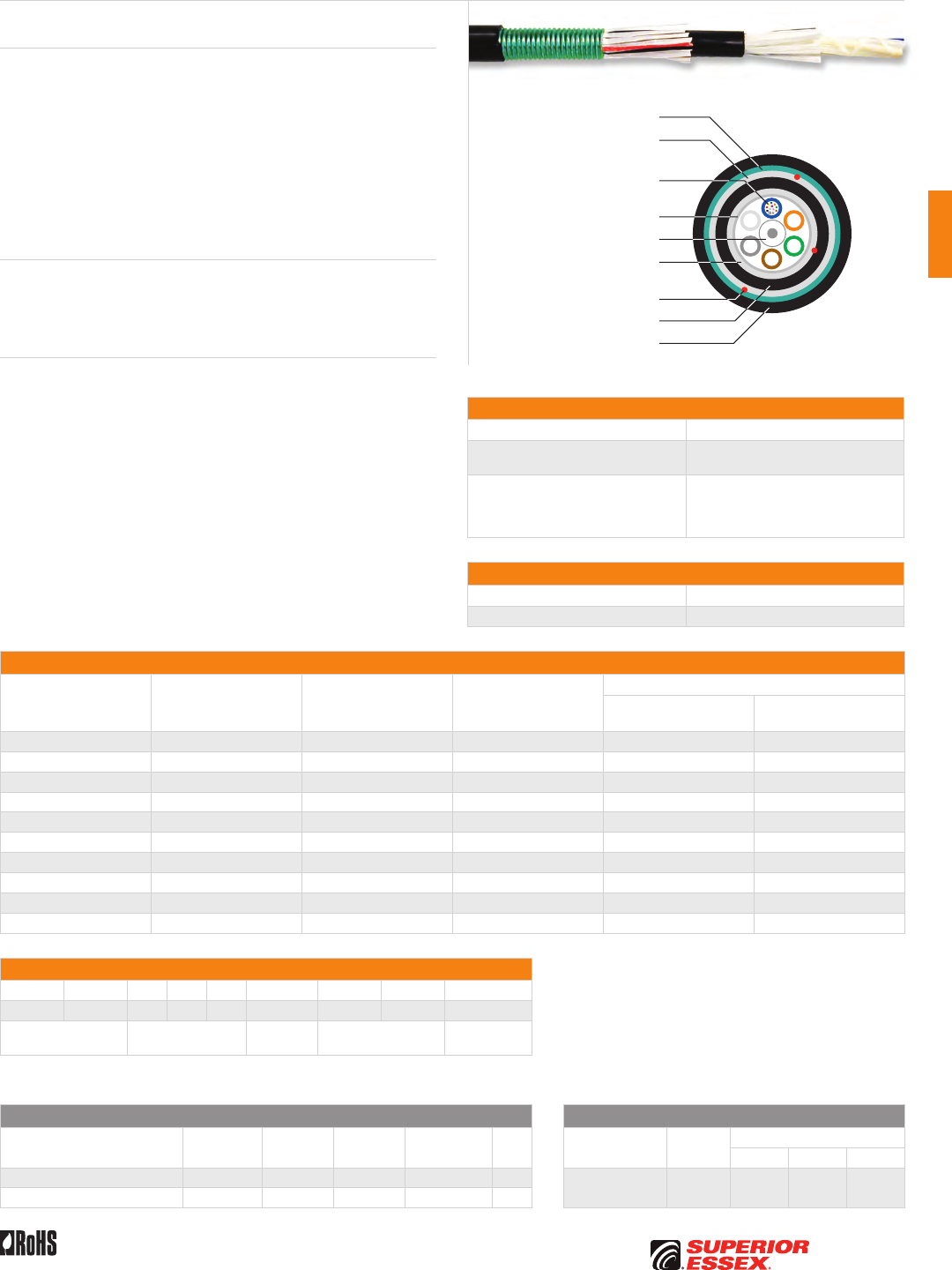
C-5
PREMISES COPPERPREMISES FIBEROSP FIBEROSP COMPOSITECENTRAL OFFICE COPPERRDUP/RUS OSP COPPERBELL OSP COPPEROSP COPPER WIRECANADIAN OSP COPPERTECHNICAL INFO
Rev 7/10 Ed 10.2 Toll Free 800.551.8948 | Fax 770.657.6807 | SuperiorEssex.com/Comm
Specifications
Fiber Count Available in 6-fiber up to 288-fiber
Maximum Tensile Loading lbs (N) Install: 600 (2,700)
Long Term: 200 (890)
Standards Compliance
Telcordia GR-20-CORE
RDUP PE-90 Designation MLT
ICEA S-87-640-2006
RoHS-compliant
Environmental Specifications
Operation/Storage -40°C to +70°C
Installation -30°C to +75°C
Part Numbers and Physical Characteristics
Part Number¹ Fiber Count
Nominal Diameter
in (mm)
Approx. Weight
lbs/kft (kg/km)
Minimum Bend Radius
Install
in (mm)
Long Term
in (mm)
1A006xx01 6 0.57 (14.5) 129 (192) 11.4 (290) 5.7 (145)
1A012xx01 12 0.57 (14.5) 129 (192) 11.4 (290) 5.7 (145)
1A024xx01 24 0.57 (14.5) 129 (192) 11.4 (290) 5.7 (145)
1A036xx01 36 0.57 (14.5) 129 (192) 11.4 (290) 5.7 (145)
1A048xx01 48 0.57 (14.5) 129 (192) 11.4 (290) 5.7 (145)
1A072xx01 72 0.66 (16.7) 164 (245) 13.2 (335) 6.6 (168)
1A096xx01 96 0.72 (18.4) 196 (291) 14.4 (365) 7.2 (183)
1A144xx01 144 0.87 (22.0) 274 (408) 17.4 (442) 8.7 (221)
1A216xx01 216 0.87 (22.0) 267 (397) 17.4 (442) 8.7 (221)
1A288xx01 288 0.98 (25.0) 334 (497) 19.6 (498) 9.8 (249)
Part Number Designators
1 A _ _ _ x x 0 _
1 2 3 4 5 6 7 8 9
product family fiber count (006-288) fiber type internal designator water block/
marking (1-8)
Contact Customer Service for availability of non-standard offerings.
See "Optical Fiber Cable" options in the "TECHNICAL INFO" section for flooding and jacket marking options.
Single Mode Optical Fiber Multimode Optical Fiber
Conventional
Reduced
Water Peak
Zero
Water Peak
TeraFlex®
Bend Resistant NZDS
TeraGain®
62.5/125
TeraGain Laser Optimized 50/125
10G/150 10G/300 10G/550
¹For ≤ 36 fibers replace “xx” with: 9T 3T 2T KT 8T ¹Replace “xx” with: 6G AG BG FG
¹For > 36 fibers replace “xx” with: 91 31 21 K1 81
See the "Optical Fiber Selection Chart" in the "TECHNICAL INFO" section for detailed fiber type specifications.
Loose Tube Double Jacket Single Armor
Series 1A
Product Description
Loose tube cables are the product of choice as the backbone in Outside
Plant (OSP) environments. The rugged loose tube design offers reliable
transmission performance over a broad temperature range. Optical fibers
are placed inside filled buffer tubes containing PFM™ gel. The core is
constructed by stranding the buffer tubes around a central member using
a reverse oscillating lay (ROL). The core is wrapped with flexible strength
members covered with a water blocking tape then encased with a black
inner jacket. Water blocking yarns and a corrugated steel armor are applied
and a black outer jacket completes the cable construction. Rip cords are
included under the inner jacket and armor for ease of entry.
Applications
• Direct bury, underground duct and lashed aerial
• Trunk, distribution and feeder cables
• Local loop, metro, long-haul and broadband network
Features Benefits
• Available with up to 288-fiber • High fiber density
• Multiple fiber types
including hybrids
• Multiple network applications
• Dry (SAP) core standard • Reduces cable prep
and installation time
• Standard tube size
for all fiber counts
• Reduces the number
of tools required
• Corrugated steel armor • Improves compressive strength
and rodent protection
• PFM™ gel • Non-sticky gel speeds fiber
access and clean-up
Corrugated Steel Armor
Central Strength Member
Dielectric Water Blocking
Strength Members
Dielectric Water Blocking
Strength Members
Water Blocking Tape
Optical Fiber in PFM™ Gel
Filled Buffer Tube
Rip Cords
UV Resistant Inner Jacket
UV Resistant Outer Jacket
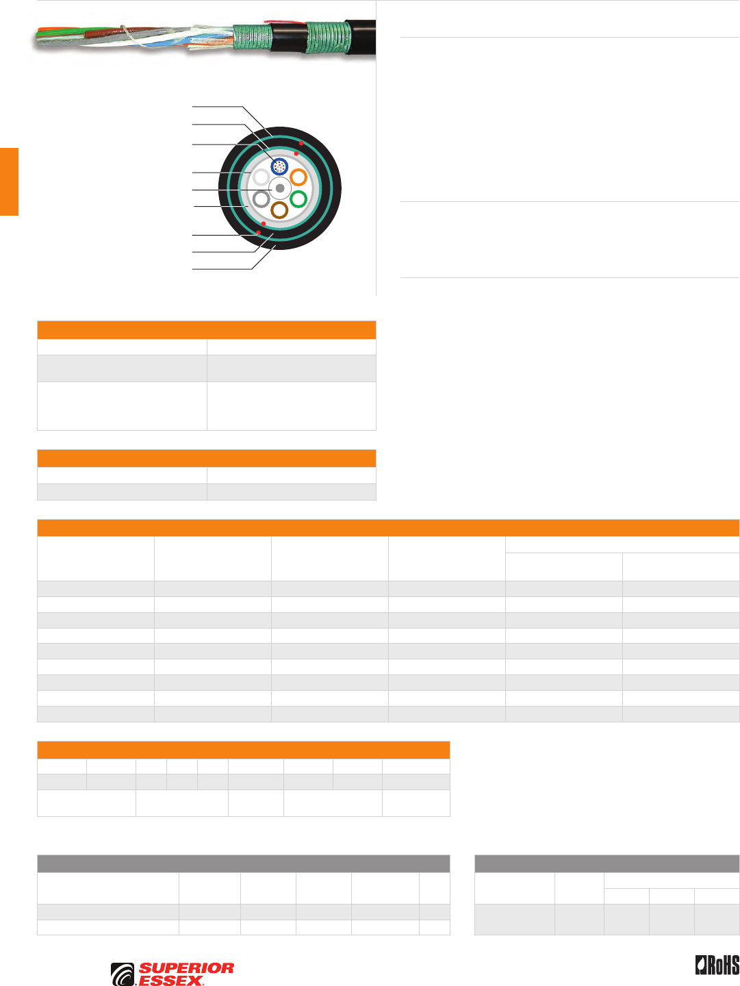
C-6
PREMISES COPPER PREMISES FIBER OSP FIBER OSP COMPOSITE CENTRAL OFFICE COPPER RDUP/RUS OSP COPPER BELL OSP COPPER OSP COPPER WIRE CANADIAN OSP COPPER TECHNICAL INFO
Rev 7/10 Ed 10.2Toll Free 800.551.8948 | Fax 770.657.6807 | SuperiorEssex.com/Comm
Specifications
Fiber Count Available in 6-fiber up to 216-fiber
Maximum Tensile Loading lbs (N) Install: 600 (2,700)
Long Term: 200 (890)
Standards Compliance
Telcordia GR-20-CORE
RDUP PE-90 Designation MLT
ICEA S-87-640-2006
RoHS-compliant
Environmental Specifications
Operation/Storage -40°C to +70°C
Installation -30°C to +75°C
Part Numbers and Physical Characteristics
Part Number¹ Fiber Count
Nominal Diameter
in (mm)
Approx. Weight
lbs/kft (kg/km)
Minimum Bend Radius
Install
in (mm)
Long Term
in (mm)
1D006xx01 6 0.70 (17.5) 207 (308) 14.0 (356) 7.0 (178)
1D012xx01 12 0.70 (17.5) 207 (308) 14.0 (356) 7.0 (178)
1D024xx01 24 0.70 (17.5) 207 (308) 14.0 (356) 7.0 (178)
1D036xx01 36 0.70 (17.5) 207 (308) 14.0 (356) 7.0 (178)
1D048xx01 48 0.70 (17.5) 207 (308) 14.0 (356) 7.0 (178)
1D072xx01 72 0.73 (18.6) 227 (339) 14.6 (371) 7.3 (185)
1D096xx01 96 0.80 (20.3) 270 (402) 16.0 (406) 8.0 (203)
1D144xx01 144 0.94 (24.0) 360 (535) 18.8 (477) 9.4 (239)
1D216xx01 216 1.01 (25.6) 403 (600) 20.2 (512) 10.1 (256)
Part Number Designators
1 D _ _ _ x x 0 _
1 2 3 4 5 6 7 8 9
product family fiber count (006-216) fiber type internal designator water block/
marking (1-8)
Contact Customer Service for availability of non-standard offerings.
See "Optical Fiber Cable" options in the "TECHNICAL INFO" section for flooding and jacket marking options.
Single Mode Optical Fiber Multimode Optical Fiber
Conventional
Reduced
Water Peak
Zero
Water Peak
TeraFlex®
Bend Resistant NZDS
TeraGain®
62.5/125
TeraGain Laser Optimized 50/125
10G/150 10G/300 10G/550
¹For ≤ 36 fibers replace “xx” with: 9T 3T 2T KT 8T ¹Replace “xx” with: 6G AG BG FG
¹For > 36 fibers replace “xx” with: 91 31 21 K1 81
See the "Optical Fiber Selection Chart" in the "TECHNICAL INFO" section for detailed fiber type specifications.
Loose Tube Double Jacket Double Armor
Series 1D
Product Description
Loose tube cables are the product of choice as the backbone in Outside
Plant (OSP) environments. The rugged loose tube design offers reliable
transmission performance over a broad temperature range. Optical fibers
are placed inside filled buffer tubes containing PFM™ gel. The core is
constructed by stranding the buffer tubes around a central member using
a reverse oscillating lay (ROL). The core is wrapped with flexible strength
members and covered with a water blocking tape. A corrugated steel armor
is applied and encased with a black inner jacket. More water blocking
yarns, a corrugated steel armor and a black outer jacket complete the cable
construction. Rip cords are included under each armor for ease of entry.
Applications
• Direct bury, underground duct and lashed aerial
• Trunk, distribution and feeder cable
• Local loop, metro, long-haul and broadband network
Features Benefits
• Available with up to 216-fiber • High fiber density
• Multiple fiber types
including Hybrids
• Multiple network applications
• Dry (SAP) core standard • Reduces cable prep
and installation time
• Standard tube size
for all fiber counts
• Reduces the number
of tools required
• Corrugated steel armor • Improves compressive strength
and rodent protection
• PFM™ gel • Non-sticky gel speeds fiber
access and clean-up
Corrugated Steel Inner Armor
Corrugated Steel Outer Armor
Central Strength Member
Dielectric Water Blocking
Strength Members
Water Blocking Tape
Optical Fiber in PFM™ Gel
Filled Buffer Tube
Rip Cords
UV Resistant Inner Jacket
UV Resistant Outer Jacket
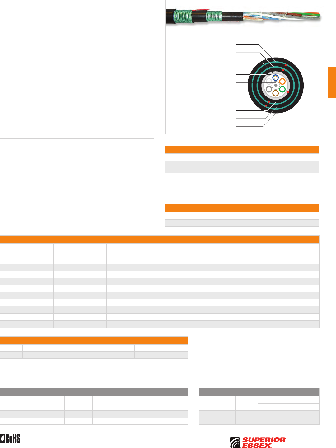
C-7
PREMISES COPPERPREMISES FIBEROSP FIBEROSP COMPOSITECENTRAL OFFICE COPPERRDUP/RUS OSP COPPERBELL OSP COPPEROSP COPPER WIRECANADIAN OSP COPPERTECHNICAL INFO
Rev 7/10 Ed 10.2 Toll Free 800.551.8948 | Fax 770.657.6807 | SuperiorEssex.com/Comm
Specifications
Fiber Count Available in 6-fiber up to 216-fiber
Maximum Tensile Loading lbs (N) Install: 600 (2,700)
Long Term: 200 (890)
Standards Compliance
Telcordia GR-20-CORE
RDUP PE-90 Designation MLT
ICEA S-87-640-2006
RoHS-compliant
Environmental Specifications
Operation/Storage -40°C to +70°C
Installation -30°C to +75°C
Part Numbers and Physical Characteristics
Part Number¹ Fiber Count
Nominal Diameter
in (mm)
Approx. Weight
lbs/kft (kg/km)
Minimum Bend Radius
Install
in (mm)
Long Term
in (mm)
1C006xx01 6 0.80 (20.3) 265 (394) 16.0 (406) 8.0 (203)
1C012xx01 12 0.80 (20.3) 265 (394) 16.0 (406) 8.0 (203)
1C024xx01 24 0.80 (20.3) 265 (394) 16.0 (406) 8.0 (203)
1C036xx01 36 0.80 (20.3) 265 (394) 16.0 (406) 8.0 (203)
1C048xx01 48 0.80 (20.3) 265 (394) 16.0 (406) 8.0 (203)
1C072xx01 72 0.84 (21.4) 293 (436) 16.8 (427) 8.4 (213)
1C096xx01 96 0.96 (24.4) 339 (505) 19.2 (488) 9.6 (244)
1C144xx01 144 1.05 (26.7) 432 (643) 21.0 (533) 10.5 (267)
1C216xx01 216 1.06 (27.0) 439 (655) 21.2 (540) 10.6 (270)
Part Number Designators
1 C _ _ _ x x 0 _
1 2 3 4 5 6 7 8 9
product family fiber count (006-216) fiber type internal designator water block/
marking (1-8)
Contact Customer Service for availability of non-standard offerings.
See "Optical Fiber Cable" options in the "TECHNICAL INFO" section for flooding and jacket marking options.
Single Mode Optical Fiber Multimode Optical Fiber
Conventional
Reduced
Water Peak
Zero
Water Peak
TeraFlex®
Bend Resistant NZDS
TeraGain®
62.5/125
TeraGain Laser Optimized 50/125
10G/150 10G/300 10G/550
¹For ≤ 36 fibers replace “xx” with: 9T 3T 2T KT 8T ¹Replace “xx” with: 6G AG BG FG
¹For > 36 fibers replace “xx” with: 91 31 21 K1 81
See the "Optical Fiber Selection Chart" in the "TECHNICAL INFO" section for detailed fiber type specifications.
Loose Tube Triple Jacket Double Armor
Series 1C
Product Description
Loose tube cables are the product of choice as the backbone in Outside
Plant (OSP) environments. The rugged loose tube design offers reliable
transmission performance over a broad temperature range. Optical fibers
are placed inside filled buffer tubes containing PFM™ gel. The core is
constructed by stranding the buffer tubes around a central member using
a reverse oscillating lay (ROL). The core is wrapped with flexible strength
members covered with a water blocking tape, then encased in a black inner
jacket. Flexible strength members are applied with a corrugated steel armor
and an intermediate black jacket. Another layer of flexible strength members
with a corrugated steel armor and a black outer jacket completes the cable
construction. Rip cords are included under the inner jacket and each armor
for ease of entry.
Applications
• Direct bury, underground duct and lashed aerial
• Trunk, distribution and feeder cables
• Local loop, metro, long-haul and broadband network
Features Benefits
• Available with up to 216-fiber • High fiber density
• Multiple fiber types
including hybrids
• Multiple network applications
• Dry (SAP) core standard • Reduces cable prep
and installation time
• Standard tube size
for all fiber counts
• Reduces the number
of tools required
• Corrugated steel armor • Improves compressive strength
and rodent protection
• PFM™ gel • Non-sticky gel speeds fiber
access and clean-up
Corrugated Steel Inner Armor
Corrugated Steel Outer Armor
Central Strength Member
Dielectric Water Blocking
Strength Members
Water Blocking Tape
Optical Fiber in PFM™ Gel
Filled Buffer Tube
Rip Cords
UV Resistant Inner Jacket
UV Resistant Central Jacket
UV Resistant Outer Jacket
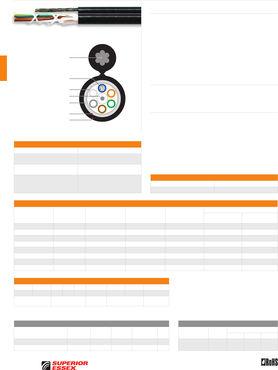
C-8
PREMISES COPPER PREMISES FIBER OSP FIBER OSP COMPOSITE CENTRAL OFFICE COPPER RDUP/RUS OSP COPPER BELL OSP COPPER OSP COPPER WIRE CANADIAN OSP COPPER TECHNICAL INFO
Rev 7/10 Ed 10.2Toll Free 800.551.8948 | Fax 770.657.6807 | SuperiorEssex.com/Comm
Specifications
Fiber Count Available in 6-fiber up to 120-fiber
Fiber Cable Component
Maximum Tensile Loading lbs (N)
Install: 600 (2,700)
Long Term: 200 (890)
Support Messenger
Breaking Strength lbs 6,650
Standards Compliance
Telcordia GR-20-CORE
RDUP PE-90 Designation MLT-8
ICEA S-87-640-2006
RoHS-compliant
Part Numbers and Physical Characteristics
Part Number¹ Fiber Count
Minor Dimension
in (mm)
Major Dimension
in (mm)
Nominal Weight
lbs/kft (kg/km)
Minimum Bend Radius
Install
in (mm)
Long Term
in (mm)
11006xxM1 6 0.43 (10.9) 0.89 (23.0) 208 (310) 8.6 (218) 4.3 (109)
11012xxM1 12 0.43 (10.9) 0.89 (23.0) 208 (310) 8.6 (218) 4.3 (109)
11024xxM1 24 0.43 (10.9) 0.89 (23.0) 208 (310) 8.6 (218) 4.3 (109)
11036xxM1 36 0.43 (10.9) 0.89 (23.0) 208 (310) 8.6 (218) 4.3 (109)
11048xxM1 48 0.43 (10.9) 0.89 (23.0) 208 (310) 8.6 (218) 4.3 (109)
11072xxM1 72 0.47 (12.0) 0.93 (24.0) 224 (333) 9.4 (239) 4.7 (119)
11096xxM1 96 0.55 (13.9) 1.01 (26.0) 245 (365) 11.0 (279) 5.5 (140)
11120xxM1 120 0.69 (17.5) 1.15 (29.0) 300 (446) 13.8 (351) 6.9 (175)
Part Number Designators
1 1 _ _ _ x x M _
1 2 3 4 5 6 7 8 9
product family fiber count (006-120) fiber type internal designator water block/
marking (1-8)
Contact Customer Service for availability of non-standard offerings.
See "Optical Fiber Cable" options in the "TECHNICAL INFO" section for flooding and jacket marking options.
Single Mode Optical Fiber Multimode Optical Fiber
Conventional
Reduced
Water Peak
Zero
Water Peak
TeraFlex®
Bend Resistant NZDS
TeraGain®
62.5/125
TeraGain Laser Optimized 50/125
10G/150 10G/300 10G/550
¹For ≤ 36 fibers replace “xx” with: 9T 3T 2T KT 8T ¹Replace “xx” with: 6G AG BG FG
¹For > 36 fibers replace “xx” with: 91 31 21 K1 81
See the "Optical Fiber Selection Chart" in the "TECHNICAL INFO" section for detailed fiber type specifications.
Loose Tube Single Jacket Self Support
Series 11M
Product Description
Loose tube cables are the product of choice as the backbone in Outside
Plant (OSP) applications. Loose tube self support cables are designed for
use in aerial applications as an alternative to lashing. These cables reduce
installation time and costs. Superior Essex offers self support cables for
spans up to 700 feet. The loose tube design offers reliable transmission
performance over a broad temperature range. The rugged loose tube design
features optical fibers placed inside PFM™ gel filled buffer tubes. The core
is constructed by stranding the buffer tubes around a central member using
a reverse oscillating lay (ROL). The core is wrapped with flexible strength
members, a water blocking tape and then encased with a black jacket and
an integrated EHS steel messenger. A rip cord is included under the jacket
for ease of entry.
Applications
• Aerial self support
• Trunk, distribution and feeder cable
• Local loop, metro, long-haul and broadband network
Features Benefits
• Available with up to 120-fiber • High fiber density
• Multiple fiber types
including hybrids
• Multiple network applications
• Dry (SAP) core standard • Reduces cable prep
and installation time
• Standard tube size
for all fiber counts
• Reduces the number
of tools required
• Conforms to standard pole
attachment hardware
• Standard installation practices
• PFM™ gel • Non-sticky gel speeds fiber
access and clean-up
Central Strength Member
Dielectric Water Blocking
Strength Members
Water Blocking Tape
Optical Fiber in PFM™ Gel
Filled Buffer Tube
Rip Cord
7-Strand EHS
Steel Messenger
UV Resistant Jacket
Environmental Specifications
Operation/Storage -40°C to +70°C
Installation -30°C to +75°C
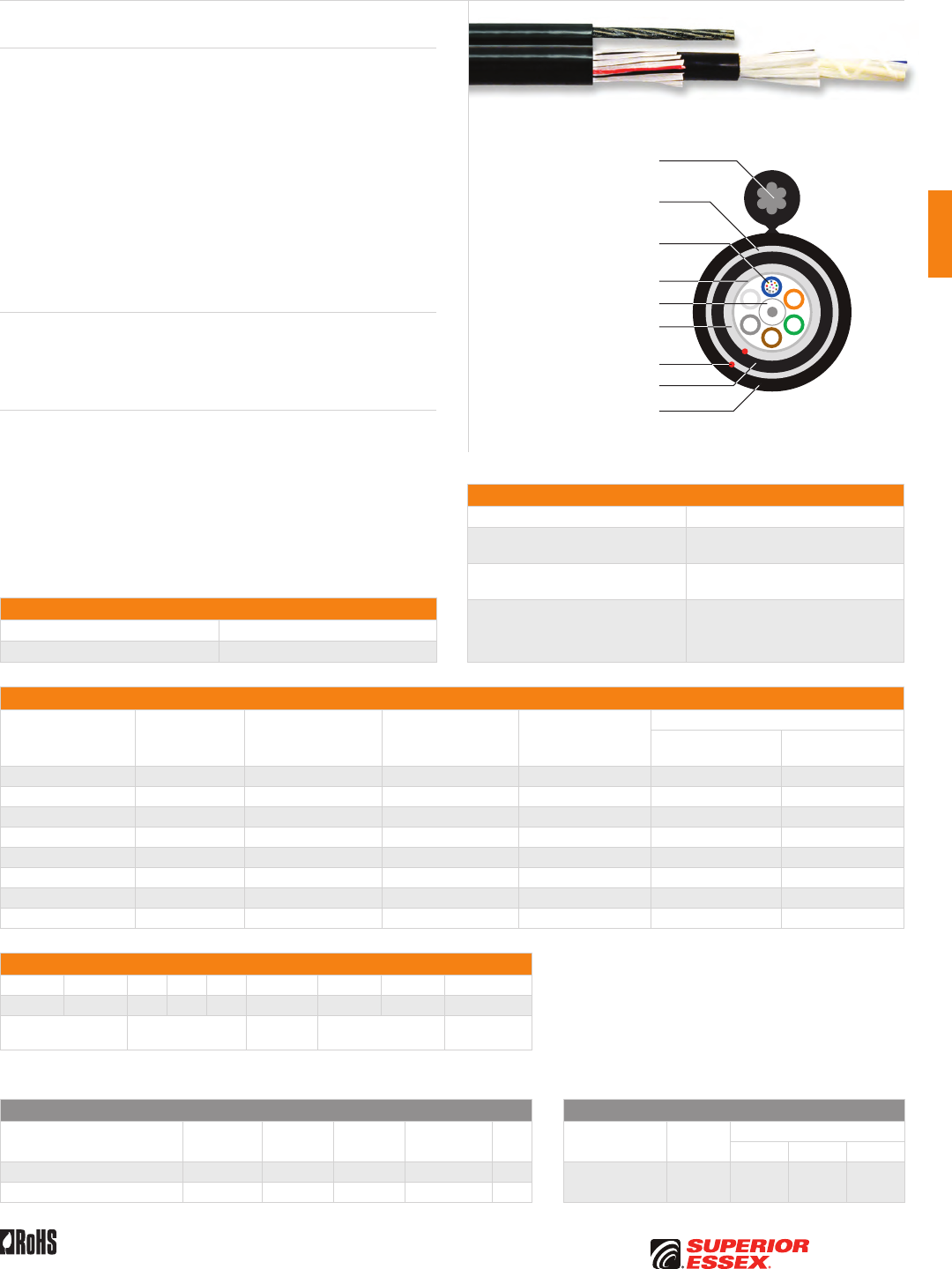
C-9
PREMISES COPPERPREMISES FIBEROSP FIBEROSP COMPOSITECENTRAL OFFICE COPPERRDUP/RUS OSP COPPERBELL OSP COPPEROSP COPPER WIRECANADIAN OSP COPPERTECHNICAL INFO
Rev 7/10 Ed 10.2 Toll Free 800.551.8948 | Fax 770.657.6807 | SuperiorEssex.com/Comm
Specifications
Fiber Count Available in 6-fiber up to 120-fiber
Fiber Cable Component
Maximum Tensile Loading lbs (N)
Install: 600 (2,700)
Long Term: 200 (890)
Support Messenger
Breaking Strength lbs 6,650
Standards Compliance
Telcordia GR-20-CORE
RDUP PE-90 Designation MLT-8
ICEA S-87-640-2006
RoHS-compliant
Part Numbers and Physical Characteristics
Part Number¹ Fiber Count
Minor Dimension
in (mm)
Major Dimension
in (mm)
Nominal Weight
lbs/kft (kg/km)
Minimum Bend Radius
Install
in (mm)
Long Term
in (mm)
1G006xxM1 6 0.53 (13.5) 0.99 (25.0) 242 (360) 10.6 (269) 5.3 (135)
1G012xxM1 12 0.53 (13.5) 0.99 (25.0) 242 (360) 10.6 (269) 5.3 (135)
1G024xxM1 24 0.53 (13.5) 0.99 (25.0) 242 (360) 10.6 (269) 5.3 (135)
1G036xxM1 36 0.53 (13.5) 0.99 (25.0) 242 (360) 10.6 (269) 5.3 (135)
1G048xxM1 48 0.53 (13.5) 0.99 (25.0) 242 (360) 10.6 (269) 5.3 (135)
1G072xxM1 72 0.57 (14.6) 1.03 (26.0) 257 (382) 11.4 (290) 5.7 (145)
1G096xxM1 96 0.64 (16.3) 1.10 (28.0) 279 (415) 12.8 (325) 6.4 (163)
1G120xxM1 120 0.78 (19.9) 1.26 (32.0) 343 (510) 15.6 (396) 7.8 (198)
Part Number Designators
1 G _ _ _ x x M _
1 2 3 4 5 6 7 8 9
product family fiber count (006-120) fiber type internal designator water block/
marking (1-8)
Contact Customer Service for availability of non-standard offerings.
See "Optical Fiber Cable" options in the "TECHNICAL INFO" section for flooding and jacket marking options.
Single Mode Optical Fiber Multimode Optical Fiber
Conventional
Reduced
Water Peak
Zero
Water Peak
TeraFlex®
Bend Resistant NZDS
TeraGain®
62.5/125
TeraGain Laser Optimized 50/125
10G/150 10G/300 10G/550
¹For ≤ 36 fibers replace “xx” with: 9T 3T 2T KT 8T ¹Replace “xx” with: 6G AG BG FG
¹For > 36 fibers replace “xx” with: 91 31 21 K1 81
See the "Optical Fiber Selection Chart" in the "TECHNICAL INFO" section for detailed fiber type specifications.
Loose Tube Double Jacket Self Support
Series 1GM
Product Description
Loose tube cables are the product of choice as the backbone in Outside
Plant (OSP) applications. Loose tube self support cables are designed for
use in aerial applications as an alternative to lashing. These cables reduce
installation time and costs. Superior Essex offers self support cables for
spans up to 700 feet. The loose tube design offers reliable transmission
performance over a broad temperature range. Optical fibers are placed
inside filled buffer tubes containing PFM™ gel. The core is constructed
by stranding the buffer tubes around a central member using a reverse
oscillating lay (ROL) and wrapped with flexible strength members, a water
blocking tape and then encased with a black inner jacket. Flexible strength
members are applied and a black outer jacket with integrated EHS steel
messenger completes the cable construction. Rip cords are included under
each jacket for ease of entry.
Applications
• Aerial self support
• Trunk, distribution and feeder cable
• Local loop, metro, long-haul and broadband network
Features Benefits
• Available with up to 120-fiber • High fiber density
• Multiple fiber types
including hybrids
• Multiple network applications
• Dry (SAP) core standard • Reduces cable prep
and installation time
• Conforms to standard pole
attachment hardware
• Standard installation practices
• PFM™ gel • Non-sticky gel speeds fiber
access and clean-up
Central Strength Member
Dielectric Water Blocking
Strength Members
Dielectric Water Blocking
Strength Members
Water Blocking Tape
Optical Fiber in PFM™ Gel
Filled Buffer Tube
Rip Cords
UV Resistant Inner Jacket
UV Resistant Outer Jacket
7-Strand EHS
Steel Messenger
Environmental Specifications
Operation/Storage -40°C to +70°C
Installation -30°C to +75°C
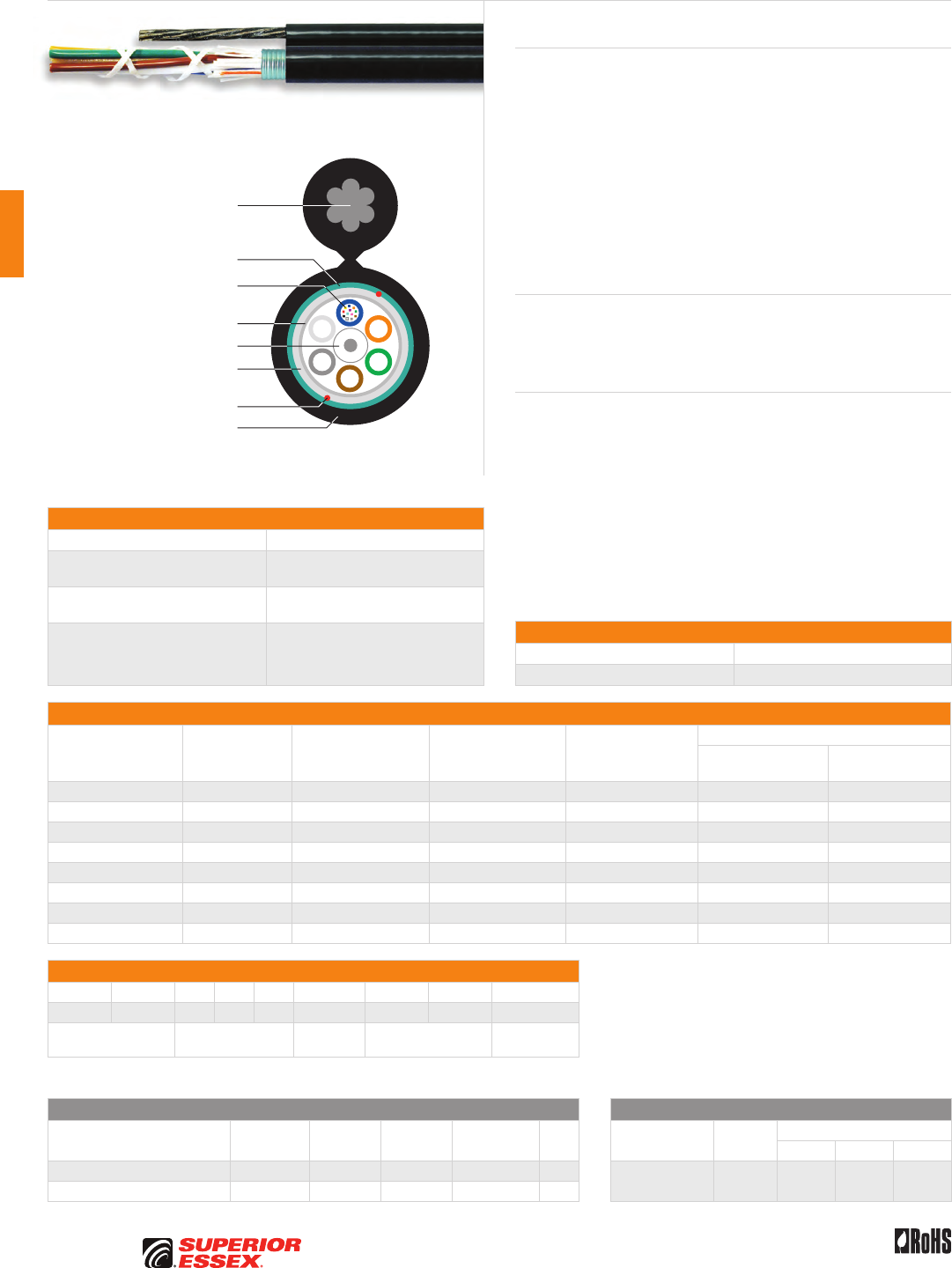
C-10
PREMISES COPPER PREMISES FIBER OSP FIBER OSP COMPOSITE CENTRAL OFFICE COPPER RDUP/RUS OSP COPPER BELL OSP COPPER OSP COPPER WIRE CANADIAN OSP COPPER TECHNICAL INFO
Rev 7/10 Ed 10.2Toll Free 800.551.8948 | Fax 770.657.6807 | SuperiorEssex.com/Comm
Specifications
Fiber Count Available in 6-fiber up to 120-fiber
Fiber Cable Component
Maximum Tensile Loading lbs (N)
Install: 600 (2,700)
Long Term: 200 (890)
Support Messenger
Breaking Strength lbs 6,650
Standards Compliance
Telcordia GR-20-CORE
RDUP PE-90 Designation MLT-8
ICEA S-87-640-2006
RoHS-compliant
Part Numbers and Physical Characteristics
Part Number¹ Fiber Count
Minor Dimension
in (mm)
Major Dimension
in (mm)
Nominal Weight
lbs/kft (kg/km)
Minimum Bend Radius
Install
in (mm)
Long Term
in (mm)
12006xxM1 6 0.48 (12.2) 0.94 (24.0) 249 (371) 9.6 (244) 4.8 (122)
12012xxM1 12 0.48 (12.2) 0.94 (24.0) 249 (371) 9.6 (244) 4.8 (122)
12024xxM1 24 0.48 (12.2) 0.94 (24.0) 249 (371) 9.6 (244) 4.8 (122)
12036xxM1 36 0.48 (12.2) 0.94 (24.0) 249 (371) 9.6 (244) 4.8 (122)
12048xxM1 48 0.48 (12.2) 0.94 (24.0) 249 (371) 9.6 (244) 4.8 (122)
12072xxM1 72 0.53 (13.3) 0.99 (25.0) 266 (396) 10.6 (269) 5.3 (135)
12096xxM1 96 0.63 (16.0) 1.09 (28.0) 306 (455) 12.6 (320) 6.3 (160)
12120xxM1 120 0.77 (19.7) 1.23 (31.0) 378 (562) 15.4 (391) 7.7 (196)
Part Number Designators
1 2 _ _ _ x x M _
1 2 3 4 5 6 7 8 9
product family fiber count (006-120) fiber type internal designator water block/
marking (1-8)
Contact Customer Service for availability of non-standard offerings.
See "Optical Fiber Cable" options in the "TECHNICAL INFO" section for flooding and jacket marking options.
Single Mode Optical Fiber Multimode Optical Fiber
Conventional
Reduced
Water Peak
Zero
Water Peak
TeraFlex®
Bend Resistant NZDS
TeraGain®
62.5/125
TeraGain Laser Optimized 50/125
10G/150 10G/300 10G/550
¹For ≤ 36 fibers replace “xx” with: 9T 3T 2T KT 8T ¹Replace “xx” with: 6G AG BG FG
¹For > 36 fibers replace “xx” with: 91 31 21 K1 81
See the "Optical Fiber Selection Chart" in the "TECHNICAL INFO" section for detailed fiber type specifications.
Loose Tube Single Jacket Single Armor Self Support
Series 12M
Product Description
Loose tube cables are the product of choice as the backbone in Outside
Plant (OSP) applications. Loose tube self support cables are designed for
use in aerial applications as an alternative to lashing. These cables reduce
installation time and costs. Superior Essex offers self support cables for
spans up to 700 feet. The loose tube design offers reliable transmission
performance over a broad temperature range. The rugged loose tube design
features optical fibers placed inside PFM™ gel filled buffer tubes. The core
is constructed by stranding the buffer tubes around a central member using
a reverse oscillating lay (ROL) and wrapped with flexible strength members
covered with a water blocking tape. A corrugated steel armor is applied and
then encased in a black jacket with an integrated EHS steel messenger. Rip
cords are included under the armor for ease of entry.
Applications
• Aerial self support
• Trunk, distribution and feeder cable
• Local loop, metro, long-haul and broadband network
Features Benefits
• Available with up to 120-fiber • High fiber density
• Multiple fiber types
including hybrids
• Multiple network applications
• Dry (SAP) core standard • Reduces cable prep
and installation time
• Corrugated steel armor • Improves compressive strength
and rodent protection
• Utilizes standard pole
attachment hardware
• Standard installation practices
• PFM™ gel • Non-sticky gel speeds fiber
access and clean-up
Central Strength Member
Dielectric Water Blocking
Strength Members
Water Blocking Tape
Corrugated Steel Armor
Optical Fiber in PFM™ Gel
Filled Buffer Tube
Rip Cords
UV Resistant Jacket
7-Strand EHS
Steel Messenger
Environmental Specifications
Operation/Storage -40°C to +70°C
Installation -30°C to +75°C
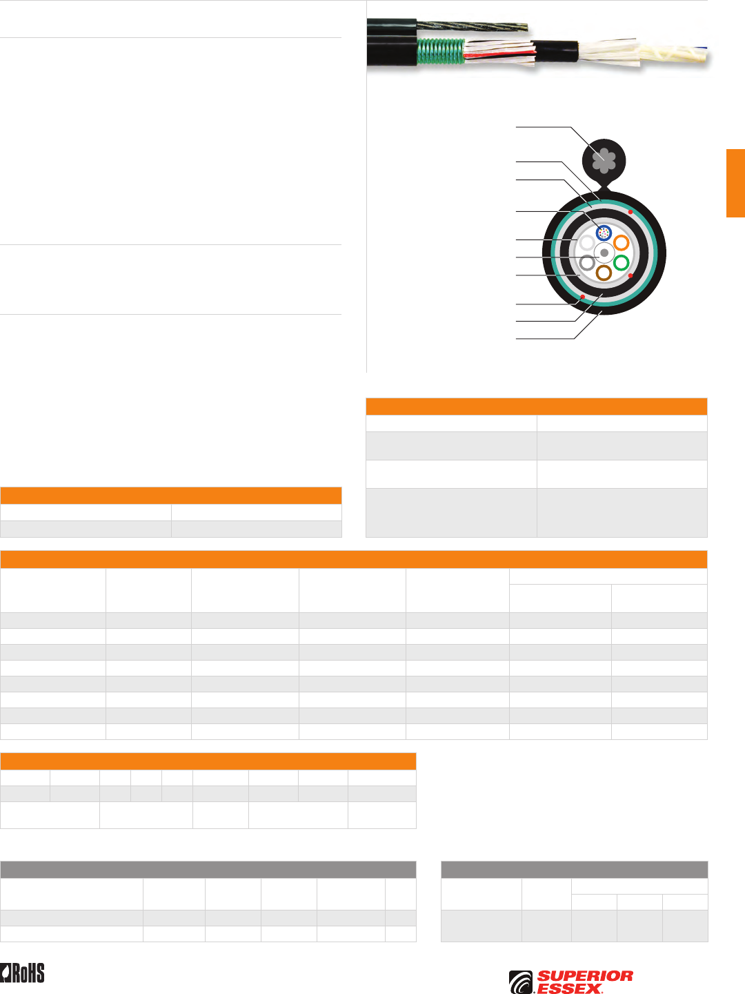
C-11
PREMISES COPPERPREMISES FIBEROSP FIBEROSP COMPOSITECENTRAL OFFICE COPPERRDUP/RUS OSP COPPERBELL OSP COPPEROSP COPPER WIRECANADIAN OSP COPPERTECHNICAL INFO
Rev 7/10 Ed 10.2 Toll Free 800.551.8948 | Fax 770.657.6807 | SuperiorEssex.com/Comm
Specifications
Fiber Count Available in 6-fiber up to 120-fiber
Fiber Cable Component
Maximum Tensile Loading lbs (N)
Install: 600 (2,700)
Long Term: 200 (890)
Support Messenger
Breaking Strength lbs 6,650
Standards Compliance
Telcordia GR-20-CORE
RDUP PE-90 Designation MLT-8
ICEA S-87-640-2006
RoHS-compliant
Part Numbers and Physical Characteristics
Part Number¹ Fiber Count
Minor Dimension
in (mm)
Major Dimension
in (mm)
Nominal Weight
lbs/kft (kg/km)
Minimum Bend Radius
Install
in (mm)
Long Term
in (mm)
1A006xxM1 6 0.57 (14.5) 1.03 (26.0) 287 (427) 11.4 (290) 5.7 (145)
1A012xxM1 12 0.57 (14.5) 1.03 (26.0) 287 (427) 11.4 (290) 5.7 (145)
1A024xxM1 24 0.57 (14.5) 1.03 (26.0) 287 (427) 11.4 (290) 5.7 (145)
1A036xxM1 36 0.57 (14.5) 1.03 (26.0) 287 (427) 11.4 (290) 5.7 (145)
1A048xxM1 48 0.57 (14.5) 1.03 (26.0) 287 (427) 11.4 (290) 5.7 (145)
1A072xxM1 72 0.66 (16.7) 1.12 (28.0) 322 (479) 13.2 (335) 6.6 (168)
1A096xxM1 96 0.72 (18.4) 1.18 (30.0) 354 (527) 14.4 (365) 7.2 (183)
1A120xxM1 120 0.89 (22.0) 1.35 (34.0) 432 (643) 17.4 (442) 8.7 (221)
Part Number Designators
1 A _ _ _ x x M _
1 2 3 4 5 6 7 8 9
product family fiber count (006-120) fiber type internal designator water block/
marking (1-8)
Contact Customer Service for availability of non-standard offerings.
See "Optical Fiber Cable" options in the "TECHNICAL INFO" section for flooding and jacket marking options.
Single Mode Optical Fiber Multimode Optical Fiber
Conventional
Reduced
Water Peak
Zero
Water Peak
TeraFlex®
Bend Resistant NZDS
TeraGain®
62.5/125
TeraGain Laser Optimized 50/125
10G/150 10G/300 10G/550
¹For ≤ 36 fibers replace “xx” with: 9T 3T 2T KT 8T ¹Replace “xx” with: 6G AG BG FG
¹For > 36 fibers replace “xx” with: 91 31 21 K1 81
See the "Optical Fiber Selection Chart" in the "TECHNICAL INFO" section for detailed fiber type specifications.
Loose Tube Double Jacket Single Armor Self Support
Series 1AM
Product Description
Loose tube cables are the product of choice as the backbone in Outside
Plant (OSP) applications. Loose tube self support cables are designed for
use in aerial applications as an alternative to lashing. These cables reduce
installation time and costs. Superior Essex offers self support cables for spans
up to 700 feet. The loose tube design offers reliable transmission performance
over a broad temperature range. Optical fibers are placed inside filled buffer
tubes containing PFM™ gel. The core is constructed by stranding the buffer
tubes around a central member using a reverse oscillating lay (ROL). The core
is wrapped with flexible strength members covered with a water blocking
tape then encased with a black polyethylene inner jacket. Water blocking
yarns and a corrugated steel armor are applied and a black outer jacket with
an integrated EHS steel messenger completes the cable construction. Rip
cords are included under the armor and inner jacket for ease of entry.
Applications
• Aerial self support
• Trunk, distribution and feeder cable
• Local loop, metro, long-haul and broadband network
Features Benefits
• Available with up to 120-fiber • High fiber density
• Multiple fiber types
including hybrids
• Multiple network applications
• Dry (SAP) core standard • Reduces cable prep
and installation time
• Corrugated steel armor • Improves compressive strength
and rodent protection
• Utilizes standard pole
attachment hardware
• Standard installation practices
• PFM™ gel • Non-sticky gel speeds fiber
access and clean-up
Corrugated Steel Armor
Central Strength Member
Dielectric Water Blocking
Strength Members
Dielectric Water Blocking
Strength Members
Water Blocking Tape
Optical Fiber in PFM™ Gel
Filled Buffer Tube
Rip Cords
UV Resistant Inner Jacket
UV Resistant Outer Jacket
7-Strand EHS
Steel Messenger
Environmental Specifications
Operation/Storage -40°C to +70°C
Installation -30°C to +75°C
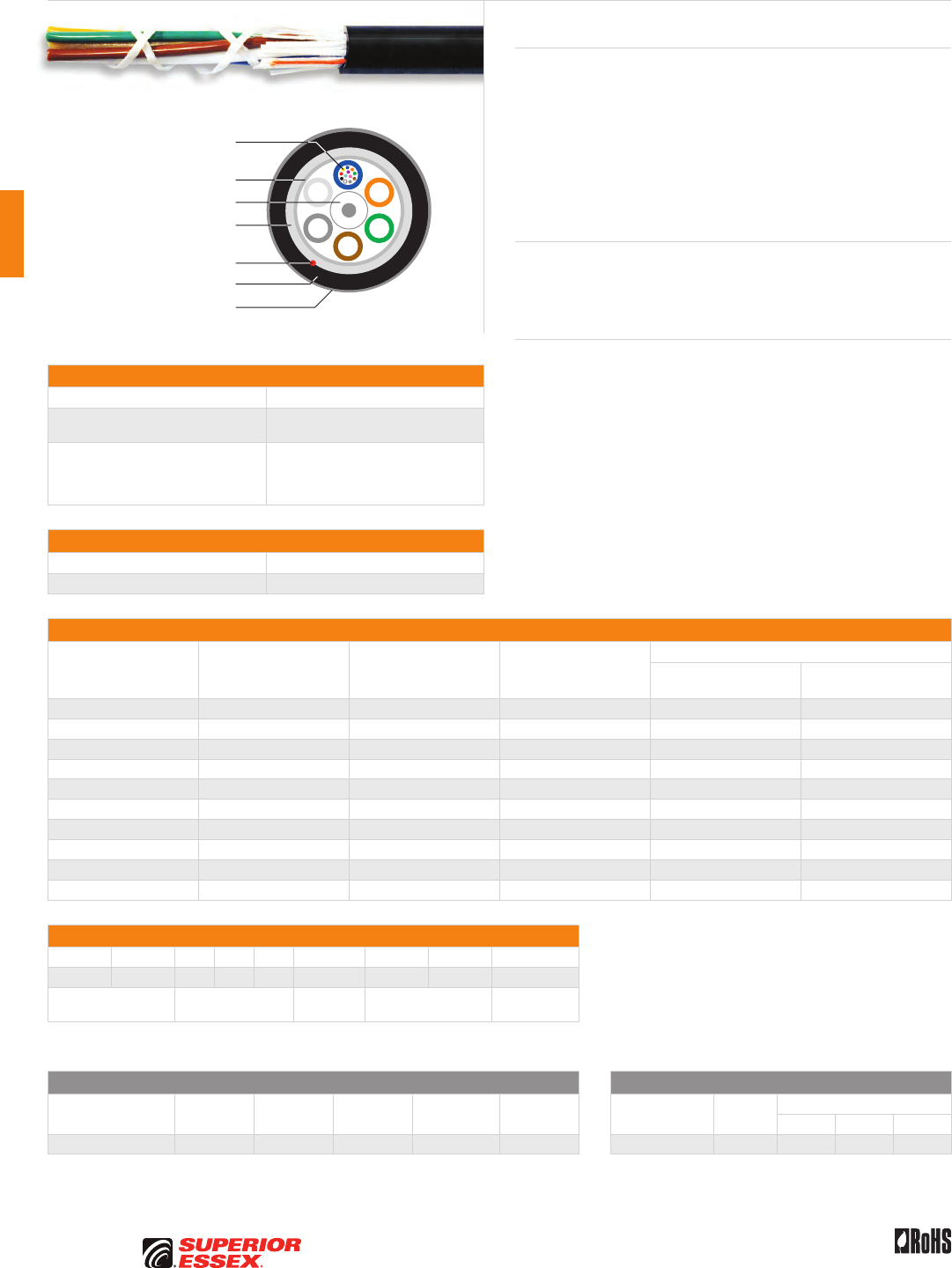
C-12
PREMISES COPPER PREMISES FIBER OSP FIBER OSP COMPOSITE CENTRAL OFFICE COPPER RDUP/RUS OSP COPPER BELL OSP COPPER OSP COPPER WIRE CANADIAN OSP COPPER TECHNICAL INFO
Rev 7/10 Ed 10.2Toll Free 800.551.8948 | Fax 770.657.6807 | SuperiorEssex.com/Comm
Loose Tube Single Jacket All Dielectric Nylon
Series 1NY
Specifications
Fiber Count Available in 2-fiber up to 288-fiber
Maximum Tensile Loading lbs (N) Install: 600 (2,700)
Long Term: 200 (890)
Standards Compliance
Telcordia GR-20-CORE
RDUP PE-90 Designation MLT
ICEA S-87-640-2006
RoHS-compliant
Environmental Specifications
Operation/Storage -40°C to +70°C
Installation -30°C to +75°C
Part Numbers and Physical Characteristics
Part Number¹ Fiber Count
Nominal Diameter
in (mm)
Approx. Weight
lbs/kft (kg/km)
Minimum Bend Radius
Install
in (mm)
Long Term
in (mm)
11006xN01 6 0.49 (12.4) 70 (105) 9.8 (248) 4.9 (124)
11012xN01 12 0.49 (12.4) 70 (105) 9.8 (248) 4.9 (124)
11024xN01 24 0.49 (12.4) 70 (105) 9.8 (248) 4.9 (124)
11036xN01 36 0.49 (12.4) 70 (105) 9.8 (248) 4.9 (124)
11048xN01 48 0.49 (12.4) 70 (105) 9.8 (248) 4.9 (124)
11072xN01 72 0.53 (13.5) 86 (129) 10.6 (270) 5.3 (135)
11096xN01 96 0.61 (15.4) 107 (160) 12.2 (308) 6.1 (154)
11144xN01 144 0.75 (19.0) 162 (241) 15.0 (380) 7.5 (190)
11216xN01 216 0.78 (19.8) 161 (239) 15.6 (396) 7.8 (198)
11288xN01 288 0.87 (22.0) 203 (302) 17.4 (440) 8.7 (220)
Part Number Designators
1 1 _ _ _ x N 0 _
1 2 3 4 5 6 7 8 9
product family fiber count (006-288) fiber type internal designator water block/
marking (1-8)
Contact Customer Service for availability of non-standard offerings.
See "Optical Fiber Cable" options in the "TECHNICAL INFO" section for flooding and jacket marking options.
Single Mode Optical Fiber Multimode Optical Fiber
Conventional
Reduced
Water Peak
Zero
Water Peak
TeraFlex®
Bend Resistant NZDS
TeraGain®
62.5/125
TeraGain Laser Optimized 50/125
10G/150 10G/300 10G/550
¹Replace “x” with: 9 3 2 K 8 ¹Replace “x” with: 6 A B F
See the "Optical Fiber Selection Chart" in the "TECHNICAL INFO" section for detailed fiber type specifications.
Product Description
Loose tube cables are the product of choice as the backbone in Outside
Plant (OSP) environments. The rugged loose tube design offers reliable
transmission performance over a broad temperature range. Optical fibers
are placed inside filled buffer tubes containing PFM™ gel. The core is
constructed by stranding the buffer tubes around a central member using
a reverse oscillating lay (ROL). The core is wrapped with flexible strength
members covered with a water blocking tape, then encased with a black
jacket. A rip cord is included under the jacket for ease of entry. The nylon
overjacket completes the cable.
Applications
• Underground duct and lashed aerial
• Trunk, distribution and feeder cable
• Local loop, metro, long-haul and broadband network
Features Benefits
• Available with up to 288-fiber • High fiber density
• Multiple fiber types
including hybrids
• Multiple network applications
• Central strength members
available in metallic or dielectric
• Metallic option offers ease
of location, dielectric design
eliminates grounding issues
• Dry (SAP) core standard • Reduces cable prep
and installation time
• Standard tube size
for all fiber counts
• Reduces the number
of tools required
• PFM™ gel • Non-sticky gel speeds fiber
access and cleanup
• Nylon overjacket • Rodent and chemical resistant
Central Strength Member
Dielectric Water Blocking
Strength Members
Water Blocking Tape
Optical Fiber in PFM™ Gel
Filled Buffer Tube
Rip Cord
UV Resistant Jacket
Nylon Overjacket
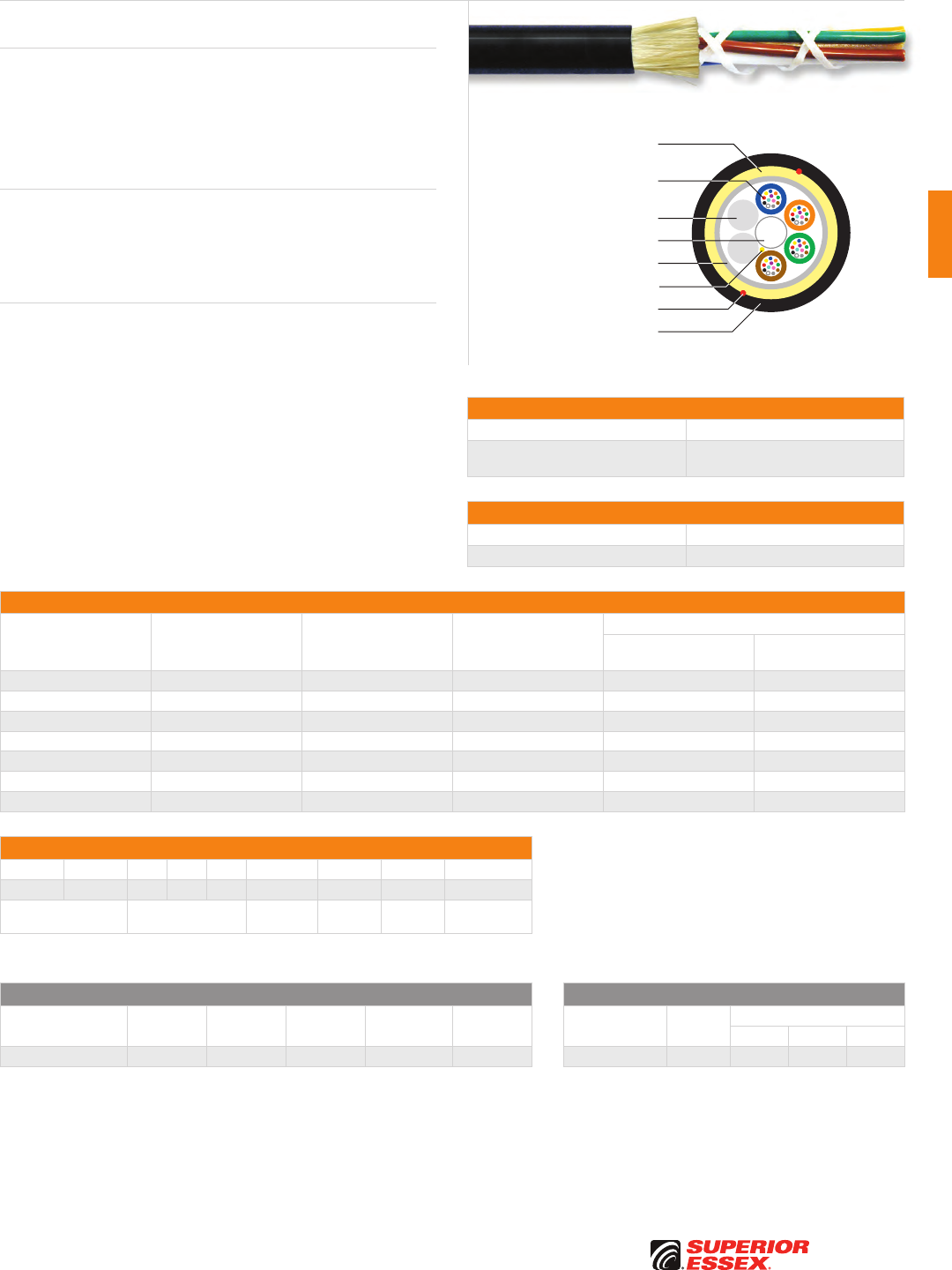
C-13
PREMISES COPPERPREMISES FIBEROSP FIBEROSP COMPOSITECENTRAL OFFICE COPPERRDUP/RUS OSP COPPERBELL OSP COPPEROSP COPPER WIRECANADIAN OSP COPPERTECHNICAL INFO
Rev 7/10 Ed 10.2 Toll Free 800.551.8948 | Fax 770.657.6807 | SuperiorEssex.com/Comm
ADSS 100
Series 1F100
Specifications
Fiber Count Available in 6-fiber up to 288-fiber
Compressive Strength
lbs/in (N/cm)
Install: 125 (220)
Long Term: 63 (110)
Environmental Specifications
Operation/Storage -40°C to +70°C
Installation -30°C to +70°C
Part Numbers and Physical Characteristics
Part Number¹ Fiber Count
Nominal Diameter
in (mm)
Nominal Weight
lbs/kft (kg/km)
Minimum Bend Radius
Install
in (mm)
Long Term
in (mm)
1F006x111 6 0.44 (11.3) 64 (96) 8.8 (226) 4.4 (113)
1F012x111 12 0.44 (11.3) 64 (96) 8.8 (226) 4.4 (113)
1F024x111 24 0.44 (11.3) 64 (96) 8.8 (226) 4.4 (113)
1F048x111 48 0.47 (12.0) 70 (105) 9.4 (240) 4.7 (120)
1F096x111 96 0.55 (13.9) 91 (136) 11.0 (278) 5.5 (139)
1F144x111 144 0.69 (17.5) 146 (217) 13.8 (350) 6.9 (175)
1F288x111 288 0.81 (20.5) 187 (278) 16.2 (410) 8.1 (205)
Part Number Designators
1 F _ _ _ x 1 1 _
1 2 3 4 5 6 7 8 9
product family fiber count (006-288) fiber type internal
designator
100 meter
span
water block/
marking (1-8)
Contact Customer Service for availability of non-standard offerings.
See "Optical Fiber Cable" options in the "TECHNICAL INFO" section for flooding and jacket marking options.
Single Mode Optical Fiber Multimode Optical Fiber
Conventional
Reduced
Water Peak
Zero
Water Peak
TeraFlex®
Bend Resistant NZDS
TeraGain®
62.5/125
TeraGain Laser Optimized 50/125
10G/150 10G/300 10G/550
¹Replace “x” with: 9 3 2 K 8 ¹Replace “x” with: 6 A B F
See the "Optical Fiber Selection Chart" in the "TECHNICAL INFO" section for detailed fiber type specifications.
Product Description
All Dielectric Self Supporting (ADSS) cables are suitable for aerial applications
with a maximum span of 100 meters. This black, PE jacketed cable is
UV-stabilized and water blocked for outdoor aerial applications. The loose
tube design provides stable and highly reliable transmission parameters for
a variety of voice, data, video and imaging applications. The high modulus
aramid yarns provide high tensile strength and long term reliability.
Applications
• Low-voltage transmission and distribution system
(space potential ≤12 kV)
• Railways and telecommunications pole route
• Suitable for all type of aerial lines
Features Benefits
• Available with up to 288-fiber • High fiber density
• Dry core standard • Reduces cable prep time
• Lower cost than Figure 8 • Reduced network cost
• Energized installation • No system turn off
PE Fillers
Central Strength Member
Water Swellable Yarn
Dielectric Water Blocking
Strength Members
Water Blocking Tape
Optical Fiber in
Gel Filled Buffer Tube
Rip Cords
PE Jacket
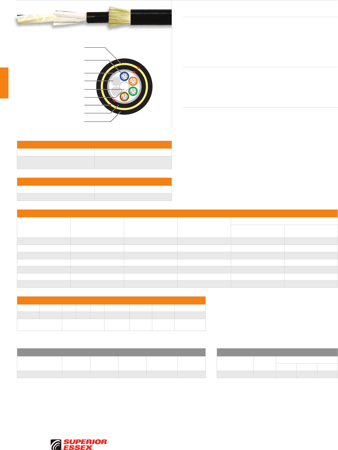
C-14
PREMISES COPPER PREMISES FIBER OSP FIBER OSP COMPOSITE CENTRAL OFFICE COPPER RDUP/RUS OSP COPPER BELL OSP COPPER OSP COPPER WIRE CANADIAN OSP COPPER TECHNICAL INFO
Rev 7/10 Ed 10.2Toll Free 800.551.8948 | Fax 770.657.6807 | SuperiorEssex.com/Comm
ADSS 200
Series 1F200
Specifications
Fiber Count Available in 6-fiber up to 288-fiber
Compressive Strength
lbs/in (N/cm)
Install: 125 (220)
Long Term: 63 (110)
Environmental Specifications
Operation/Storage -40°C to +70°C
Installation -30°C to +70°C
Part Numbers and Physical Characteristics
Part Number¹ Fiber Count
Nominal Diameter
in (mm)
Nominal Weight
lbs/kft (kg/km)
Minimum Bend Radius
Install
in (mm)
Long Term
in (mm)
1F006x121 6 0.50 (12.8) 84 (125) 10.0 (256) 5.0 (128)
1F012x121 12 0.50 (12.8) 84 (125) 10.0 (256) 5.0 (128)
1F024x121 24 0.50 (12.8) 84 (125) 10.0 (256) 5.0 (128)
1F048x121 48 0.52 (13.3) 91 (135) 10.4 (266) 5.2 (133)
1F096x121 96 0.57 (14.6) 107 (160) 11.4 (292) 5.7 (146)
1F144x121 144 0.69 (17.5) 154 (230) 13.8 (350) 6.9 (175)
1F288x121 288 0.80 (20.4) 201 (300) 16.0 (408) 8.0 (204)
Part Number Designators
1 F _ _ _ x 1 2 _
1 2 3 4 5 6 7 8 9
product family fiber count (006-288) fiber type internal
designator
200 meter
span
water block/
marking (1-8)
Contact Customer Service for availability of non-standard offerings.
See "Optical Fiber Cable" options in the "TECHNICAL INFO" section for flooding and jacket marking options.
Single Mode Optical Fiber Multimode Optical Fiber
Conventional
Reduced
Water Peak
Zero
Water Peak
TeraFlex®
Bend Resistant NZDS
TeraGain®
62.5/125
TeraGain Laser Optimized 50/125
10G/150 10G/300 10G/550
¹Replace “x” with: 9 3 2 K 8 ¹Replace “x” with: 6 A B F
See the "Optical Fiber Selection Chart" in the "TECHNICAL INFO" section for detailed fiber type specifications.
Product Description
All Dielectric Self Supporting (ADSS) cables are suitable for aerial applications
with a maximum span of 200 meters. This black, PE jacketed cable is
UV-stabilized and water blocked for outdoor aerial applications. The loose
tube design provides stable and highly reliable transmission parameters for
a variety of voice, data, video and imaging applications. The high modulus
aramid yarns provide high tensile strength and long term reliability.
Applications
• Low-voltage transmission and distribution system
(space potential ≤12 kV)
• Railways and telecommunications pole route
• Suitable for all type of aerial lines
Features Benefits
• Available with up to 288-fiber • High fiber density
• Dry core standard • Reduces cable prep time
• Lower cost than Figure 8 • Reduced network cost
• Energized installation • No system turn off
PE Fillers
Central Strength Member
Water Swellable Yarn
Dielectric Water Blocking
Strength Members
Water Blocking Tape
Optical Fiber in
Gel Filled Buffer Tube
Rip Cords
PE Inner Jacket
PE Outer Jacket
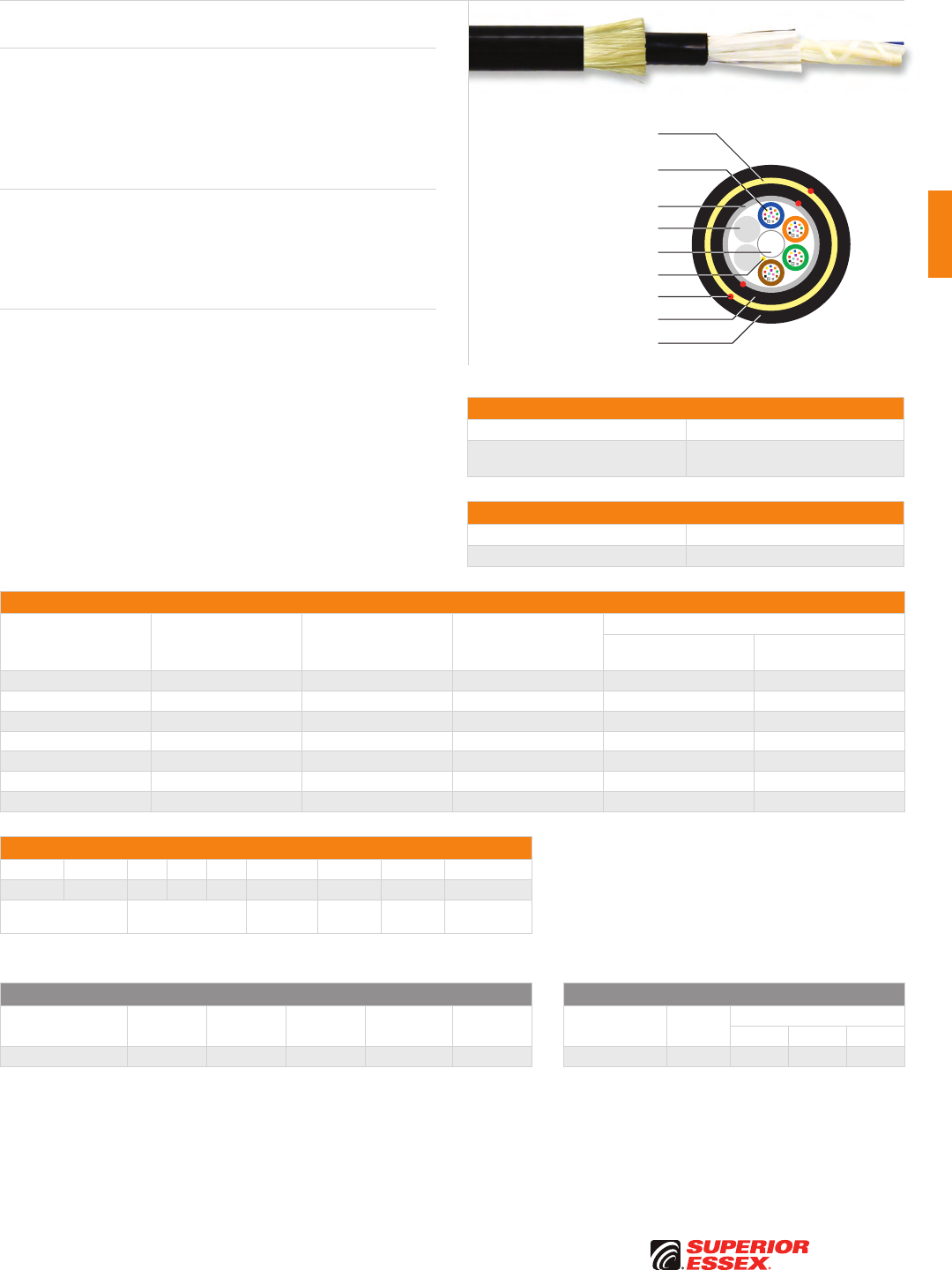
C-15
PREMISES COPPERPREMISES FIBEROSP FIBEROSP COMPOSITECENTRAL OFFICE COPPERRDUP/RUS OSP COPPERBELL OSP COPPEROSP COPPER WIRECANADIAN OSP COPPERTECHNICAL INFO
Rev 7/10 Ed 10.2 Toll Free 800.551.8948 | Fax 770.657.6807 | SuperiorEssex.com/Comm
ADSS 400
Series 1F400
Specifications
Fiber Count Available in 6-fiber up to 288-fiber
Compressive Strength
lbs/in (N/cm)
Install: 125 (220)
Long Term: 63 (110)
Environmental Specifications
Operation/Storage -40°C to +70°C
Installation -30°C to +70°C
Part Numbers and Physical Characteristics
Part Number¹ Fiber Count
Nominal Diameter
in (mm)
Nominal Weight
lbs/kft (kg/km)
Minimum Bend Radius
Install
in (mm)
Long Term
in (mm)
1F006x141 6 0.55 (14.0) 101 (150) 11.0 (280) 5.5 (140)
1F012x141 12 0.55 (14.0) 101 (150) 11.0 (280) 5.5 (140)
1F024x141 24 0.55 (14.0) 101 (150) 11.0 (280) 5.5 (140)
1F048x141 48 0.55 (14.0) 101 (150) 11.0 (280) 5.5 (140)
1F096x141 96 0.61 (15.4) 121 (180) 12.2 (308) 6.1 (154)
1F144x141 144 0.74 (18.7) 171 (255) 14.8 (374) 7.4 (187)
1F288x141 288 0.85 (21.6) 218 (325) 17.0 (432) 8.5 (216)
Part Number Designators
1 F _ _ _ x 1 4 _
1 2 3 4 5 6 7 8 9
product family fiber count (006-288) fiber type internal
designator
400 meter
span
water block/
marking (1-8)
Contact Customer Service for availability of non-standard offerings.
See "Optical Fiber Cable" options in the "TECHNICAL INFO" section for flooding and jacket marking options.
Single Mode Optical Fiber Multimode Optical Fiber
Conventional
Reduced
Water Peak
Zero
Water Peak
TeraFlex®
Bend Resistant NZDS
TeraGain®
62.5/125
TeraGain Laser Optimized 50/125
10G/150 10G/300 10G/550
¹Replace “x” with: 9 3 2 K 8 ¹Replace “x” with: 6 A B F
See the "Optical Fiber Selection Chart" in the "TECHNICAL INFO" section for detailed fiber type specifications.
Product Description
All Dielectric Self Supporting (ADSS) cables are suitable for aerial applications
with a maximum span of 400 meters. This black, PE jacketed cable is
UV-stabilized and water blocked for outdoor aerial applications. The loose
tube design provides stable and highly reliable transmission parameters for
a variety of voice, data, video and imaging applications. The high modulus
aramid yarns provide high tensile strength and long term reliability.
Applications
• Low-voltage transmission and distribution system
• Space potential ≤12 kV with PE jacket
• Railways and telecommunications pole route
• Suitable for all type of aerial lines
Features Benefits
• Available with up to 288-fiber • High fiber density
• Dry core standard • Reduces cable prep time
• Lower cost than Figure 8 • Reduced network cost
• Energized installation • No system turn off
PE Fillers
Central Strength Member
Water Swellable Yarn
Dielectric Water Blocking
Strength Members
Water Blocking Tape
Optical Fiber in
Gel Filled Buffer Tube
Rip Cords
PE Inner Jacket
PE Outer Jacket
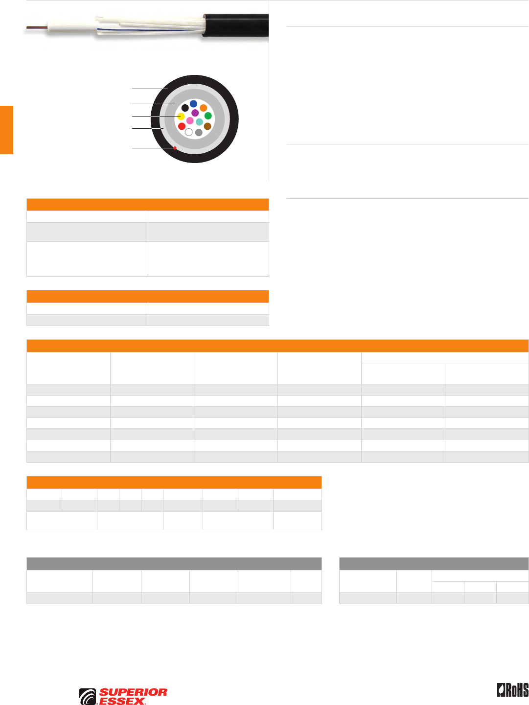
C-16
PREMISES COPPER PREMISES FIBER OSP FIBER OSP COMPOSITE CENTRAL OFFICE COPPER RDUP/RUS OSP COPPER BELL OSP COPPER OSP COPPER WIRE CANADIAN OSP COPPER TECHNICAL INFO
Rev 7/10 Ed 10.2Toll Free 800.551.8948 | Fax 770.657.6807 | SuperiorEssex.com/Comm
Specifications
Fiber Count Available in 6-fiber up to 96-fiber
Maximum Tensile Loading lbs (N) Install: 600 (2,700)
Long Term: 200 (890)
Standards Compliance
Telcordia GR-20-CORE
RDUP PE-90 Designation SLT
ICEA S-87-640-2006
RoHS-compliant
Environmental Specifications
Operation/Storage -40°C to +70°C
Installation -30°C to +75°C
Part Numbers and Physical Characteristics
Part Number¹ Fiber Count
Nominal Diameter
in (mm)
Approx. Weight
lbs/kft (kg/km)
Minimum Bend Radius
Install
in (mm)
Long Term
in (mm)
51006xx01 6 0.31 (7.9) 36 (54) 6.2 (158) 3.1 (79)
51012xx01 12 0.31 (7.9) 36 (54) 6.2 (158) 3.1 (79)
51024xx01 24 0.39 (9.8) 51 (75) 7.8 (196) 3.9 (98)
51036xx01 36 0.39 (9.8) 51 (75) 7.8 (196) 3.9 (98)
51048xx01 48 0.39 (9.8) 51 (75) 7.8 (196) 3.9 (98)
51072xx01 72 0.46 (11.6) 68 (102) 9.2 (232) 4.6 (116)
51096xx01 96 0.46 (11.6) 68 (102) 9.2 (232) 4.6 (116)
Part Number Designators
5 1 _ _ _ x x 0 _
1 2 3 4 5 6 7 8 9
product family fiber count (006-096) fiber type internal designator water block/
marking (1-8)
Contact Customer Service for availability of non-standard offerings.
See "Optical Fiber Cable" options in the "TECHNICAL INFO" section for flooding and jacket marking options.
Single Mode Optical Fiber Multimode Optical Fiber
Conventional
Reduced
Water Peak
Zero
Water Peak
TeraFlex®
Bend Resistant NZDS
TeraGain®
62.5/125
TeraGain Laser Optimized 50/125
10G/150 10G/300 10G/550
¹Replace “xx” with: 91 31 21 K1 81 ¹Replace “xx” with: 6G AG BG FG
See the "Optical Fiber Selection Chart" in the "TECHNICAL INFO" section for detailed fiber type specifications.
Single Loose Tube All Dielectric
Series 51
Product Description
Loose tube cables are the product of choice as the backbone in Outside
Plant (OSP) applications. Single Loose tube cables offer a low cost
alternative to traditional stranded loose tube cables. The loose tube design
offers reliable transmission performance over a broad temperature range.
The rugged single loose tube design features optical fibers placed inside
a single PFM™ gel filled tube. The core tube includes up to 8-fiber bundles,
each containing up to 12 optical fibers bound within a color coded binder.
The core tube is then helically wrapped with water blocking strength
members, then encased with a black jacket. A rip cord is included under the
jacket to provide ease of access to the core tube.
Applications
• Underground duct and lashed aerial
• Trunk, distribution and feeder cable
• Local loop, metro, long-haul and broadband network
Features Benefits
• Available with up to 96-fiber • High fiber density
• Multiple fiber types • Multiple network applications
• Dielectric outer
strength members
• Eliminates grounding
or bonding problems
• Dry (SAP) core standard • Reduces cable prep
and installation time
• Highly flexible • Easy handling
• Small cable diameter • Installation of more
fibers in less space
• Fewer cable components • Reduces cost
• PFM™ gel • Non-sticky gel speeds fiber
access and clean-up
Optical Fiber
Dielectric Water Blocking
Strength Members
PFM™ Gel Filled Tube
Rip Cord
UV Resistant Jacket
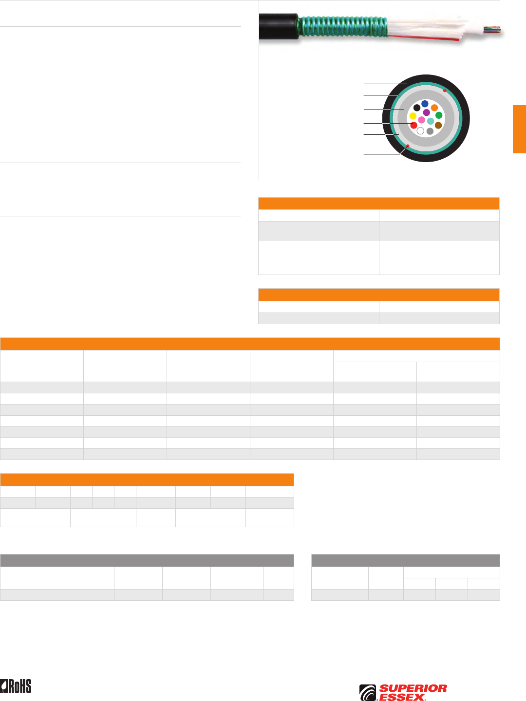
C-17
PREMISES COPPERPREMISES FIBEROSP FIBEROSP COMPOSITECENTRAL OFFICE COPPERRDUP/RUS OSP COPPERBELL OSP COPPEROSP COPPER WIRECANADIAN OSP COPPERTECHNICAL INFO
Rev 7/10 Ed 10.2 Toll Free 800.551.8948 | Fax 770.657.6807 | SuperiorEssex.com/Comm
Specifications
Fiber Count Available in 6-fiber up to 96-fiber
Maximum Tensile Loading lbs (N) Install: 600 (2,700)
Long Term: 200 (890)
Standards Compliance
Telcordia GR-20-CORE
RDUP PE-90 Designation SLT
ICEA S-87-640-2006
RoHS-compliant
Environmental Specifications
Operation/Storage -40°C to +70°C
Installation -30°C to +75°C
Part Numbers and Physical Characteristics
Part Number¹ Fiber Count
Nominal Diameter
in (mm)
Approx. Weight
lbs/kft (kg/km)
Minimum Bend Radius
Install
in (mm)
Long Term
in (mm)
52006xx01 6 0.36 (9.1) 62 (92) 7.2 (183) 3.6 (91)
52012xx01 12 0.36 (9.1) 62 (92) 7.2 (183) 3.6 (91)
52024xx01 24 0.44 (11.0) 83 (124) 8.8 (224) 4.4 (112)
52036xx01 36 0.44 (11.0) 83 (124) 8.8 (224) 4.4 (112)
52048xx01 48 0.44 (11.0) 83 (124) 8.8 (224) 4.4 (112)
52072xx01 72 0.50 (12.8) 111 (165) 10.0 (254) 5.0 (127)
52096xx01 96 0.50 (12.8) 111 (165) 10.0 (254) 5.0 (127)
Part Number Designators
5 2 _ _ _ x x 0 _
1 2 3 4 5 6 7 8 9
product family fiber count (006-096) fiber type internal designator water block/
marking (1-8)
Contact Customer Service for availability of non-standard offerings.
See "Optical Fiber Cable" options in the "TECHNICAL INFO" section for flooding and jacket marking options.
Single Mode Optical Fiber Multimode Optical Fiber
Conventional
Reduced
Water Peak
Zero
Water Peak
TeraFlex®
Bend Resistant NZDS
TeraGain®
62.5/125
TeraGain Laser Optimized 50/125
10G/150 10G/300 10G/550
¹Replace “xx” with: 91 31 21 K1 81 ¹Replace “xx” with: 6G AG BG FG
See the "Optical Fiber Selection Chart" in the "TECHNICAL INFO" section for detailed fiber type specifications.
Single Loose Tube Single Armor
Series 52
Product Description
Loose tube cables are the product of choice as the backbone in Outside Plant
(OSP) applications. Single Loose tube cables offer a low cost alternative to
traditional stranded loose tube cables. Armored cables are designed for
improved mechanical and rodent protection in direct bury applications. The
loose tube design offers reliable transmission performance over a broad
temperature range. The rugged single loose tube design features optical
fibers placed inside a single PFM™ gel filled tube. The core tube includes
up to 8-fiber bundles, each containing up to 12 optical fibers bound with a
color coded binder. The core is wrapped with flexible strength members and
covered with a water blocking tape. A corrugated steel armor is applied and
then encased with a black jacket. Rip cords are included under the armor for
ease of access to the core tube.
Applications
• Direct bury
• Trunk, distribution and feeder cable
• Local loop, metro, long-haul and broadband network
Features Benefits
• Available with up to 96-fiber • High fiber density
• Multiple fiber types • Multiple network applications
• Dry (SAP) core standard • Reduces cable prep
and installation time
• Highly flexible • Easy handling
• Fewer cable components • Reduces cost
• Corrugated Armor • Improves compressive strength
and rodent protection
• PFM™ gel • Non-sticky gel speeds fiber
access and clean-up
Optical Fiber
Dielectric Water Blocking
Strength Members
PFM™ Gel Filled Tube
Rip Cords
UV Resistant Jacket
Corrugated Steel Armor
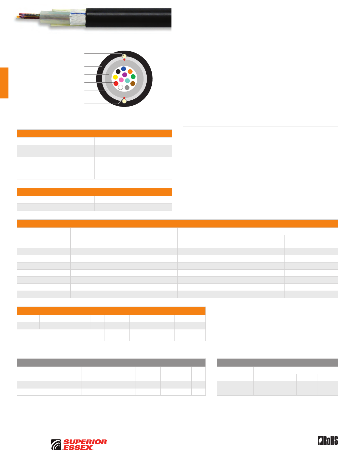
C-18
PREMISES COPPER PREMISES FIBER OSP FIBER OSP COMPOSITE CENTRAL OFFICE COPPER RDUP/RUS OSP COPPER BELL OSP COPPER OSP COPPER WIRE CANADIAN OSP COPPER TECHNICAL INFO
Rev 7/10 Ed 10.2Toll Free 800.551.8948 | Fax 770.657.6807 | SuperiorEssex.com/Comm
Specifications
Fiber Count Available in 6-fiber up to 96-fiber
Maximum Tensile Loading lbs (N) Install: 600 (2,700)
Long Term: 200 (890)
Standards Compliance
Telcordia GR-20-CORE
RDUP PE-90 Designation SLT
ICEA S-87-640-2006
RoHS-compliant
Environmental Specifications
Operation/Storage -40°C to +70°C
Installation -30°C to +75°C
Part Numbers and Physical Characteristics
Part Number¹ Fiber Count
Nominal Diameter
in (mm)
Approx. Weight
lbs/kft (kg/km)
Minimum Bend Radius
Install
in (mm)
Long Term
in (mm)
F1006xx01 6 0.47 (11.9) 75 (112) 9.4 (238) 4.7 (119)
F1012xx01 12 0.47 (11.9) 75 (112) 9.4 (238) 4.7 (119)
F1024xx01 24 0.47 (11.9) 75 (112) 9.4 (238) 4.7 (119)
F1036xx01 36 0.47 (11.9) 75 (112) 9.4 (238) 4.7 (119)
F1048xx01 48 0.47 (11.9) 75 (112) 9.4 (238) 4.7 (119)
F1072xx01 72 0.55 (14.0) 101 (150) 11.0 (279) 5.5 (139)
F1096xx01 96 0.55 (14.0) 101 (150) 11.0 (279) 5.5 (139)
Part Number Designators
F 1 _ _ _ x x 0 _
1 2 3 4 5 6 7 8 9
product family fiber count (006-096) fiber type internal designator water block/
marking (1-8)
Contact Customer Service for availability of non-standard offerings.
See "Optical Fiber Cable" options in the "TECHNICAL INFO" section for flooding and jacket marking options.
Single Mode Optical Fiber Multimode Optical Fiber
Conventional
Reduced
Water Peak
Zero
Water Peak
TeraFlex®
Bend Resistant NZDS
TeraGain®
62.5/125
TeraGain Laser Optimized 50/125
10G/150 10G/300 10G/550
¹For ≤ 12 fibers replace “xx” with: 96 36 26 K6 86 ¹Replace “xx” with: 6G AG BG FG
¹For > 12 fibers replace “xx” with: 91 31 21 K1 81
See the "Optical Fiber Selection Chart" in the "TECHNICAL INFO" section for detailed fiber type specifications.
Single Flex Tube All Dielectric
Series F1
Product Description
Loose tube cables are the product of choice as the backbone in Outside Plant
(OSP) applications. Single Loose tube cables offer a low cost alternative to
traditional stranded loose tube cables. The highly flexible single tube reduces
installation problems. The loose tube design offers reliable transmission
performance over a broad temperature range. The single flex tube design
features optical fibers placed inside a single PFM™ gel filled tube. The core
tube includes up to 8-fiber bundles, each containing up to 12 optical fibers
bound with a color coded binder. The core is wrapped with water blocking
tape and then encased with a black jacket containing rigid strength rods.
A rip cord is included under the jacket for ease of access to the core tube.
Applications
• Underground duct and lashed aerial
• Trunk, distribution and feeder cable
• Local loop, metro, long-haul and broadband network
Features Benefits
• Available with up to 96-fiber • High fiber density
• Multiple fiber types • Multiple network applications
• Dielectric outer
strength members
• Eliminates grounding
or bonding problems
• Dry (SAP) core standard • Reduces cable prep
and installation time
• Highly flexible • Easy handling
• Small cable diameter • Installation of more fibers
in less space
• Fewer cable components • Reduces cost
• PFM™ gel • Non-sticky gel speeds fiber
access and clean-up
Optical Fiber
Dielectric Water Blocking
Strength Members
PFM™ Gel Filled Tube
Rip Cords
UV Resistant Jacket
Rigid Dielectric Outer
Strength Members
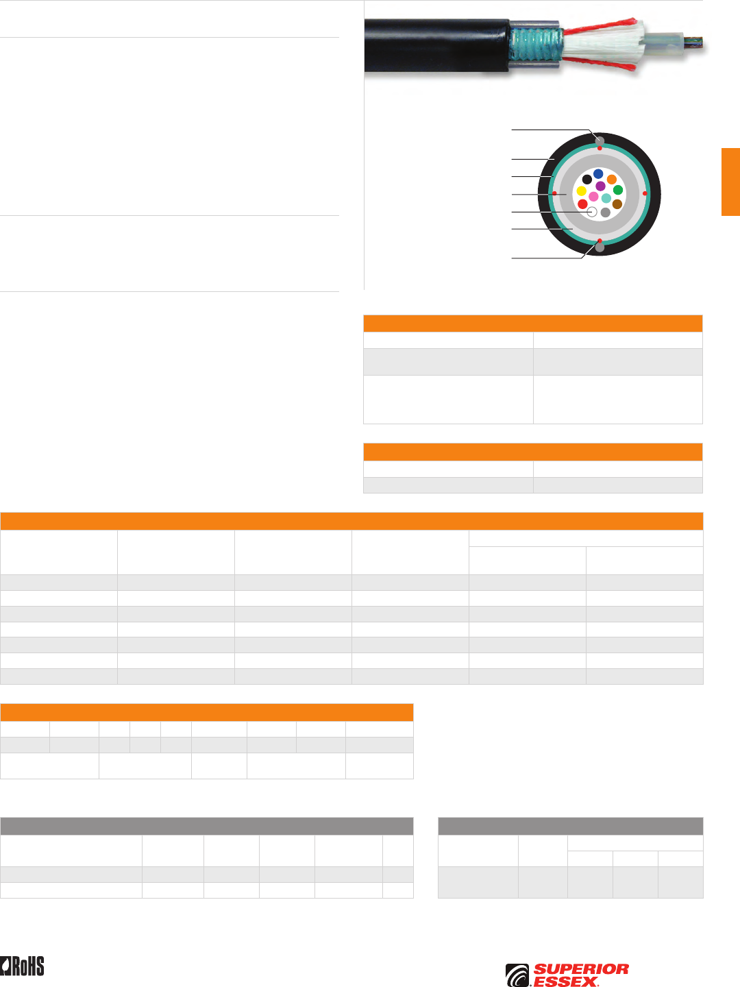
C-19
PREMISES COPPERPREMISES FIBEROSP FIBEROSP COMPOSITECENTRAL OFFICE COPPERRDUP/RUS OSP COPPERBELL OSP COPPEROSP COPPER WIRECANADIAN OSP COPPERTECHNICAL INFO
Rev 7/10 Ed 10.2 Toll Free 800.551.8948 | Fax 770.657.6807 | SuperiorEssex.com/Comm
Specifications
Fiber Count Available in 6-fiber up to 96-fiber
Maximum Tensile Loading lbs (N) Install: 600 (2,700)
Long Term: 200 (890)
Standards Compliance
Telcordia GR-20-CORE
RDUP PE-90 Designation SLT
ICEA S-87-640-2006
RoHS-compliant
Environmental Specifications
Operation/Storage -40°C to +70°C
Installation -30°C to +75°C
Part Numbers and Physical Characteristics
Part Number¹ Fiber Count
Nominal Diameter
in (mm)
Approx. Weight
lbs/kft (kg/km)
Minimum Bend Radius
Install
in (mm)
Long Term
in (mm)
F2006xxS1 6 0.51 (13.0) 117 (174) 10.2 (259) 5.1 (129)
F2012xxS1 12 0.51 (13.0) 117 (174) 10.2 (259) 5.1 (129)
F2024xxS1 24 0.51 (13.0) 117 (174) 10.2 (259) 5.1 (129)
F2036xxS1 36 0.51 (13.0) 117 (174) 10.2 (259) 5.1 (129)
F2048xxS1 48 0.51 (13.0) 117 (174) 10.2 (259) 5.1 (129)
F2072xxS1 72 0.58 (15.0) 150 (223) 11.6 (295) 5.8 (147)
F2096xxS1 96 0.58 (15.0) 150 (223) 11.6 (295) 5.8 (147)
Part Number Designators
F 2 _ _ _ x x S _
1 2 3 4 5 6 7 8 9
product family fiber count (006-096) fiber type internal designator water block/
marking (1-8)
Contact Customer Service for availability of non-standard offerings.
See "Optical Fiber Cable" options in the "TECHNICAL INFO" section for flooding and jacket marking options.
Single Mode Optical Fiber Multimode Optical Fiber
Conventional
Reduced
Water Peak
Zero
Water Peak
TeraFlex®
Bend Resistant NZDS
TeraGain®
62.5/125
TeraGain Laser Optimized 50/125
10G/150 10G/300 10G/550
¹For ≤ 12 fibers replace “xx” with: 96 36 26 K6 86 ¹Replace “xx” with: 6G AG BG FG
¹For > 12 fibers replace “xx” with: 91 31 21 K1 81
See the "Optical Fiber Selection Chart" in the "TECHNICAL INFO" section for detailed fiber type specifications.
Single Flex Tube Single Armor
Series F2
Product Description
Single loose tube cables offer a low cost alternative to traditional stranded
loose tube cables and armoring provides additional protection for certain
environments. The highly flexible single tube reduces installation problems.
The loose tube design offers reliable transmission performance over a broad
temperature range. The single flex tube design features optical fibers placed
inside a single PFM™ gel filled tube. The core tube includes up to 8-fiber
bundles, each containing up to 12 optical fibers bound with a color coded
binder. The core is wrapped with flexible strength members covered with a
water blocking tape, a corrugated steel armor is applied and then encased
with a black jacket containing rigid steel rods. Rip cords are included under
the armor for ease of access to the core tube.
Applications
• Direct bury, underground duct and lashed aerial
• Trunk, distribution and feeder cable
• Local loop, metro, long-haul and broadband network
Features Benefits
• Available with up to 96-fiber • High fiber density
• Multiple fiber types • Multiple network applications
• Metallic outer strength members • Offers ease of location
• Dry (SAP) core standard • Reduces cable prep
and installation time
• Highly flexible • Easy handling
• Small cable diameter • Installation of more fibers
in less space
• Fewer cable components • Reduces cost
• Corrugated Armor • Improves compressive strength
and rodent protection
• PFM™ gel • Non-sticky gel speeds fiber
access and clean-up
Optical Fiber
Dielectric Water Blocking
Strength Members
PFM™ Gel Filled Tube
Rip Cords
UV Resistant Jacket
Rigid Steel Outer
Strength Members
Corrugated Steel Armor
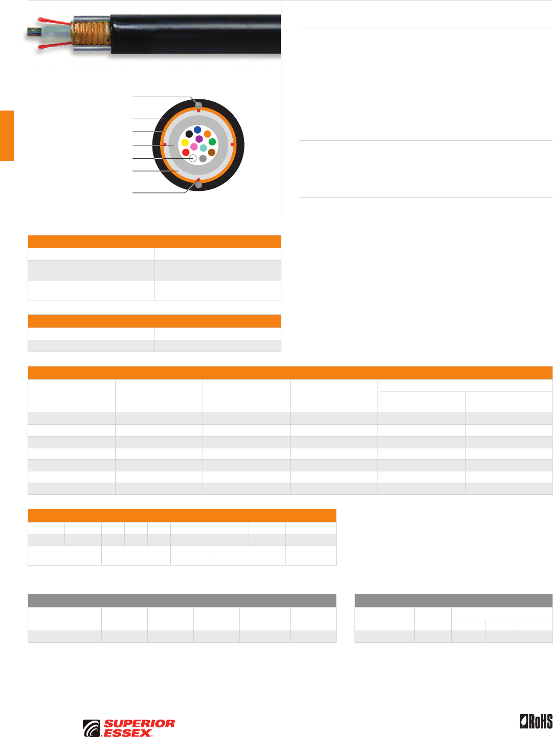
C-20
PREMISES COPPER PREMISES FIBER OSP FIBER OSP COMPOSITE CENTRAL OFFICE COPPER RDUP/RUS OSP COPPER BELL OSP COPPER OSP COPPER WIRE CANADIAN OSP COPPER TECHNICAL INFO
Rev 7/10 Ed 10.2Toll Free 800.551.8948 | Fax 770.657.6807 | SuperiorEssex.com/Comm
Flex Tube Locate
Series FM
Specifications
Fiber Count Available in 6-fiber up to 96-fiber
Maximum Tensile Loading lbs (N) Install: 600 (2,700)
Long Term: 200 (890)
Standards Compliance Telcordia GR-20-CORE
RoHS-compliant
Environmental Specifications
Operation/Storage -40°C to +70°C
Installation -30°C to +70°C
Part Numbers and Physical Characteristics
Part Number¹ Fiber Count
Nominal Diameter
in (mm)
Approx. Weight
lbs/kft (kg/km)
Minimum Bend Radius
Install
in (mm)
Long Term
in (mm)
FM006x1S1 6 0.59 (15.0) 117 (174) 11.8 (300) 5.9 (150)
FM012x1S1 12 0.59 (15.0) 117 (174) 11.8 (300) 5.9 (150)
FM024x1S1 24 0.59 (15.0) 117 (174) 11.8 (300) 5.9 (150)
FM036x1S1 36 0.59 (15.0) 117 (174) 11.8 (300) 5.9 (150)
FM048x1S1 48 0.59 (15.0) 117 (174) 11.8 (300) 5.9 (150)
FM072x1S1 72 0.59 (15.0) 143 (212) 11.8 (300) 5.9 (150)
FM096x1S1 96 0.59 (15.0) 143 (212) 11.8 (300) 5.9 (150)
Part Number Designators
F M _ _ _ x 1 S _
1 2 3 4 5 6 7 8 9
product family fiber count (006-096) fiber type internal designator water block/
marking (1-8)
Contact Customer Service for availability of non-standard offerings.
See "Optical Fiber Cable" options in the "TECHNICAL INFO" section for flooding and jacket marking options.
Single Mode Optical Fiber Multimode Optical Fiber
Conventional
Reduced
Water Peak
Zero
Water Peak
TeraFlex®
Bend Resistant NZDS
TeraGain®
62.5/125
TeraGain Laser Optimized 50/125
10G/150 10G/300 10G/550
¹Replace “x” with: 9 3 2 K 8 ¹Replace “x” with: 6 A B F
See the "Optical Fiber Selection Chart" in the "TECHNICAL INFO" section for detailed fiber type specifications.
Product Description
Flex Tube Locate cables are designed to offer low resistivity (less than 10
Ohms per mile) and are for use in long distance remote location systems.
These cables make use of a highly flexible tube that contains up to 8 loose
optical fiber bundles, each containing 12 optical fibers. PFM™ gel is used
inside the tube to reduce the time needed to access the fibers. The core
is wrapped with a water swellable tape to block water flow. A metallic
locatable tape is applied and then encased in a black, UV resistant outer
jacket of HDPE. Ripcords are included under the tape for ease of access
to the core tube.
Applications
• Direct bury, underground duct and lashed aerial
• Trunk, distribution and feeder cable
• Local loop, metro, long-haul and broadband network
Features Benefits
• Available with up to 96-fiber • High fiber density
• Multiple fiber types • Multiple network applications
• Metallic outer strength members • Offers ease of location
• Dry (SAP) core standard • Reduces cable prep
and installation time
• Highly flexible • Easy handling
• Small cable diameter • Installation of more fibers
in less space
• Fewer cable components • Reduces cost
• Less than 10 Ohms/mile resistivity • Remote locate system
• PFM™ gel • Non-sticky gel speeds fiber
access and clean-up
Optical Fiber
Water Swellable Tape
PFM™ Gel Filled Tube
Rip Cords
UV Resistant Jacket
Rigid Steel Outer
Strength Members
Locate Tape
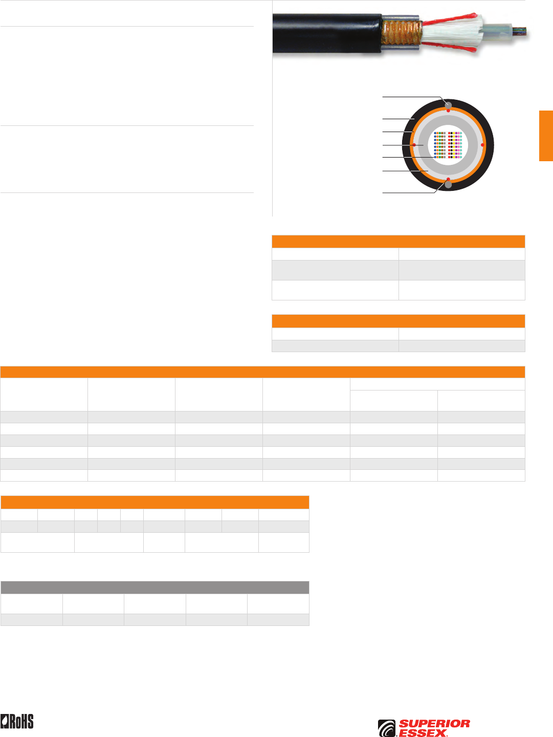
C-21
PREMISES COPPERPREMISES FIBEROSP FIBEROSP COMPOSITECENTRAL OFFICE COPPERRDUP/RUS OSP COPPERBELL OSP COPPEROSP COPPER WIRECANADIAN OSP COPPERTECHNICAL INFO
Rev 7/10 Ed 10.2 Toll Free 800.551.8948 | Fax 770.657.6807 | SuperiorEssex.com/Comm
Ribbon Locate
Series RM
Product Description
Ribbon Locate cables are designed to offer low resistivity (less than 10 Ohms
per mile) and are for use in long distance remote location systems. These
cables make use of a highly flexible tube that contains up to 18 ribbons, each
containing 12 optical fibers. PFM™ gel is used in the tube to reduce the time
needed to access the fibers. The core is wrapped with a water swellable
yarns to block water flow. A metallic locatable tape is applied and then
encased in a black UV resistant outer jacket of HDPE. Ripcords are included
under the tape for ease of access to the core tube.
Applications
• Direct bury
• Broadband network
• Local loop
• Trunk, distribution and feeder cables
Features Benefits
• Available with up to 216-fiber • High fiber density
• Multiple fiber types available • Multiple network applications
• Metallic outer strength members • Metallic design offers
easy location
• Highly flexible tube • Easy handling and easy
tube access
• Less than 10 Ohms/mile resistivity • Remote locate system
• Ribbon fiber • Saves labor cost by offering
mass fusion splicing
• Meets or exceeds Telcordia
specifications
• Industry approved
• PFM™ gel • Non-sticky gel allows for easier
and faster clean up
Specifications
Fiber Count Available in 60-fiber up to 216-fiber
Maximum Tensile Loading lbs (N) Install: 600 (2,700)
Long Term: 200 (890)
Standards Compliance Telcordia GR-20-CORE
RoHS-compliant
Environmental Specifications
Operation/Storage -40°C to +70°C
Installation -30°C to +70°C
Part Numbers and Physical Characteristics
Part Number¹ Fiber Count
Nominal Diameter
in (mm)
Nominal Weight
lbs/kft (kg/km)
Minimum Bend Radius
Install
in (mm)
Long Term
in (mm)
RM060x1S1 60 0.58 (15.0) 150 (223) 11.6 (295) 5.8 (147)
RM072x1S1 72 0.58 (15.0) 150 (223) 11.6 (295) 5.8 (147)
RM096x1S1 96 0.58 (15.0) 150 (223) 11.6 (295) 5.8 (147)
RM144x1S1 144 0.66 (17.0) 187 (279) 13.2 (335) 6.0 (152)
RM192x1S1 192 0.66 (17.0) 195 (290) 13.6 (345) 6.8 (173)
RM216x1S1 216 0.66 (17.0) 195 (290) 13.6 (345) 6.8 (173)
Part Number Designators
R M _ _ _ x 1 S _
1 2 3 4 5 6 7 8 9
product family fiber count (060-216) fiber type internal designator water block/
marking (1-8)
Contact Customer Service for availability of non-standard offerings.
See "Optical Fiber Cable" options in the "TECHNICAL INFO" section for flooding and jacket marking options.
Single Mode Optical Fiber
Reduced
Water Peak
Zero
Water Peak
TeraFlex®
Bend Resistant NZDS
¹Replace “x” with: 3 2 K 8
See the "Optical Fiber Selection Chart" in the "TECHNICAL INFO" section for detailed fiber type specifications.
Optical Fiber Ribbons
Dielectric Water Blocking
Strength Members
PFM™ Gel Filled Tube
Rip Cords
UV Resistant Jacket
Rigid Steel Outer
Strength Members
Locate Tape
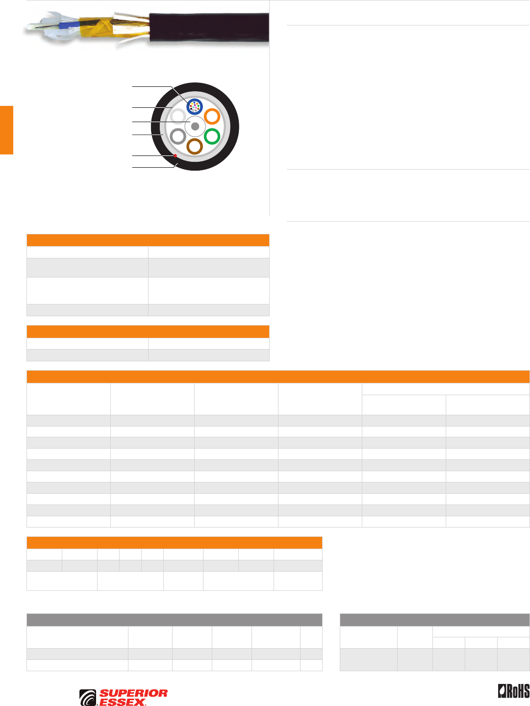
C-22
PREMISES COPPER PREMISES FIBER OSP FIBER OSP COMPOSITE CENTRAL OFFICE COPPER RDUP/RUS OSP COPPER BELL OSP COPPER OSP COPPER WIRE CANADIAN OSP COPPER TECHNICAL INFO
Toll Free 800.551.8948 | Fax 770.657.6807 | SuperiorEssex.com/Comm Rev 10/10 Ed 10.3
Specifications
Fiber Count Available in 6-fiber up to 288-fiber
Maximum Tensile Loading lbs (N) Install: 600 (2,700)
Long Term: 200 (890)
Performance Compliance
Telcordia GR-20-CORE
UL 1666
RoHS-compliant
NRTL Programs UL, c(UL) Listed OFNR
Environmental Specifications
Operation/Storage -40°C to +70°C
Installation -10°C to +65°C
Part Numbers and Physical Characteristics
Part Number¹ Fiber Count
Nominal Diameter
in (mm)
Nominal Weight
lbs/kft (kg/km)
Minimum Bend Radius
Install
in (mm)
Long Term
in (mm)
13006xx01 6 0.48 (12.2) 93 (138) 9.6 (244) 4.8 (122)
13012xx01 12 0.48 (12.2) 93 (138) 9.6 (244) 4.8 (122)
13024xx01 24 0.48 (12.2) 93 (138) 9.6 (244) 4.8 (122)
13036xx01 36 0.48 (12.2) 93 (138) 9.6 (244) 4.8 (122)
13048xx01 48 0.48 (12.2) 93 (138) 9.6 (244) 4.8 (122)
13072xx01 72 0.53 (13.0) 109 (163) 10.6 (269) 5.3 (135)
13096xx01 96 0.59 (15.0) 139 (206) 11.8 (300) 5.9 (150)
13144xx01 144 0.74 (18.7) 215 (320) 14.8 (316) 7.4 (188)
13216xx01 216 0.75 (19.1) 199 (297) 15.0 (381) 7.5 (191)
13288xx01 288 0.84 (21.0) 257 (382) 16.8 (427) 8.4 (213)
Part Number Designators
1 3 _ _ _ x x 0 _
1 2 3 4 5 6 7 8 9
product family fiber count (006-288) fiber type internal designator water block/
marking (1-8)
Contact Customer Service for availability of non-standard offerings.
See "Optical Fiber Cable" options in the "TECHNICAL INFO" section for flooding and jacket marking options.
Single Mode Optical Fiber Multimode Optical Fiber
Conventional
Reduced
Water Peak
Zero
Water Peak
TeraFlex®
Bend Resistant NZDS
TeraGain®
62.5/125
TeraGain Laser Optimized 50/125
10G/150 10G/300 10G/550
¹For ≤ 36 fibers replace “xx” with: 9T 3T 2T KT 8T ¹Replace “xx” with: 6G AG BG FG
¹For > 36 fibers replace “xx” with: 91 31 21 K1 81
See the "Optical Fiber Selection Chart" in the "TECHNICAL INFO" section for detailed fiber type specifications.
Loose Tube Indoor/Outdoor OFNR
Series 13
Product Description
Loose tube riser cables are ideal for campus environments, private networks
and local area networks. These dual purpose cables save money and
installation time by allowing a direct transition from indoor to outdoor
applications with a single cable. Because these cables are fully water blocked
with dry elements, stripping and termination is faster. These cables comply
with the standards for both Outside Plant (OSP) and indoor riser applications.
The loose tube design offers reliable transmission performance over a broad
temperature range. The rugged loose tube design features optical fibers placed
inside PFM™ gel filled buffer tubes. The core is constructed by stranding the
buffer tubes around a central member using a reverse oscillating lay (ROL). It is
wrapped with flexible strength members, covered with a heat resistant, water
blocking tape and then encased with a black, flame and sunlight resistant
jacket. A rip cord is included under the jacket for ease of entry.
Applications
• Underground duct and lashed aerial
• Trunk, distribution and feeder cable
• Local loop, metro, long-haul and broadband network
Features Benefits
• Available with up to 288-fiber • High fiber density
• Multiple fiber types
including hybrids
• Multiple network applications
• UL Listed, sunlight resistant • Longer cable life
• Dielectric outer
strength members
• Eliminates grounding
or bonding problems
• Dry (SAP) core standard • Reduces cable prep
and installation time
• Standard tube size
for all fiber counts
• Reduces the number
of tools required
• Transitions from indoor to outdoor
to indoor with no termination
• Reduces labor cost
• PFM™ gel • Non-sticky gel speeds fiber
access and clean-up
Central Strength Member
Dielectric Water Blocking
Strength Members
Heat Resistant Tape
Optical Fiber in PFM™ Gel
Filled Buffer Tube
Rip Cord
Flame and Sunlight
Resistant Jacket
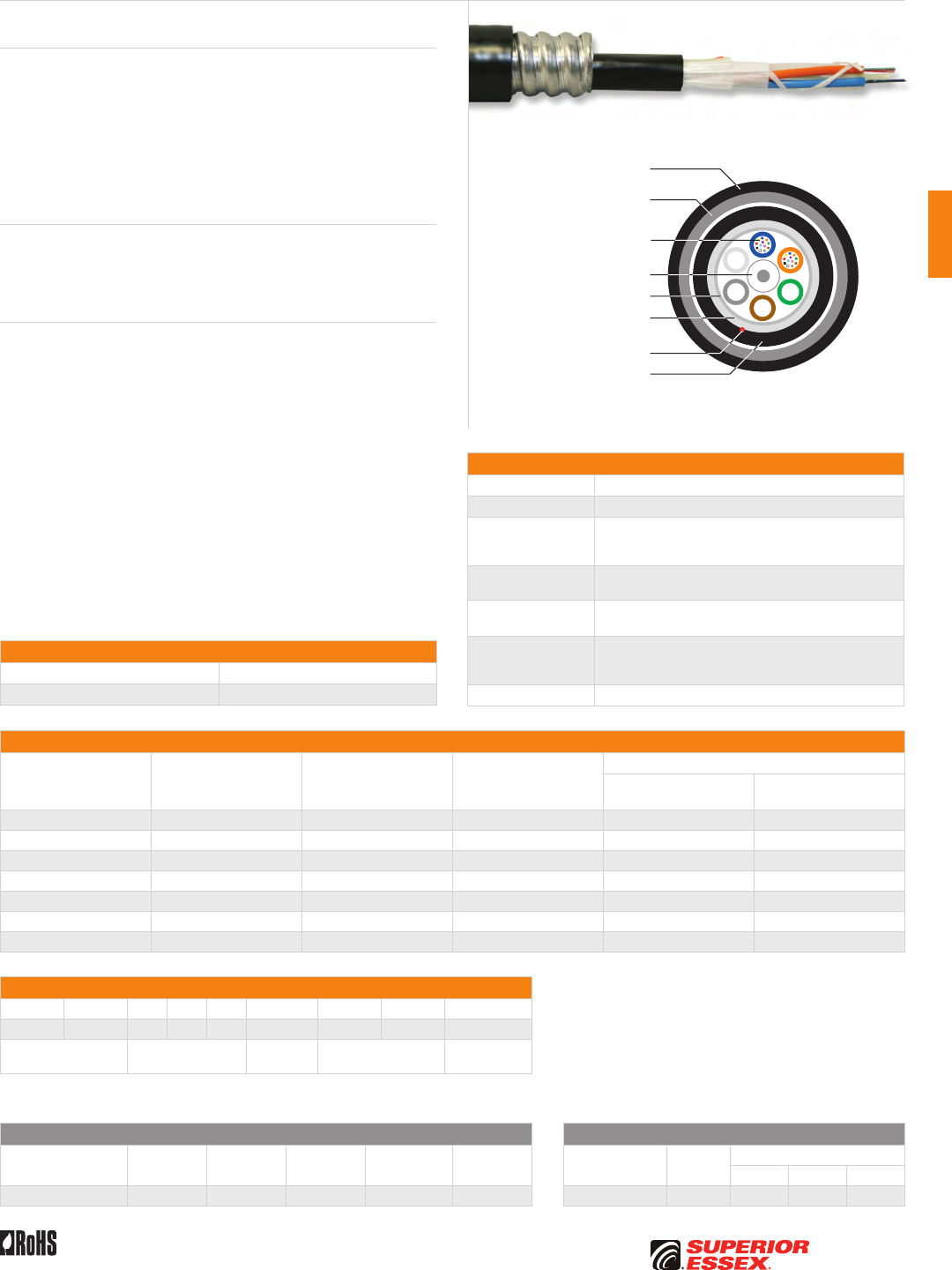
C-23
PREMISES COPPERPREMISES FIBEROSP FIBEROSP COMPOSITECENTRAL OFFICE COPPERRDUP/RUS OSP COPPERBELL OSP COPPEROSP COPPER WIRECANADIAN OSP COPPERTECHNICAL INFO
Toll Free 800.551.8948 | Fax 770.657.6807 | SuperiorEssex.com/Comm
Specifications
Fiber Count Available in 6-fiber up to 144-fiber
Core Configuration Loose Tube Indoor/Outdoor OFNR Series 13 cable
Interlock Armored
Flexible, heavy duty interlocking aluminum or steel tape
helically applied over the inner cable core; further
protection is provided by an optional outer jacket
Outer Jacket Black, flame retardant, chemical resistant and sunlight
resistant PVC
Maximum Tensile
Loading lbs (N)
Install: 600 (2,700)
Long Term: 200 (890)
Performance
Compliance
Telcordia GR-20-CORE
UL 1666
RoHS-compliant
NRTL Programs UL, c(UL) Listed OFCR
Part Numbers and Physical Characteristics
Part Number¹ Fiber Count
Nominal Diameter
in (mm)
Nominal Weight
lbs/kft (kg/km)
Minimum Bend Radius
Install
in (mm)
Long Term
in (mm)
L3006x101 6 0.96 (24.3) 301 (448) 14.5 (367) 9.6 (243)
L3012x101 12 0.96 (24.3) 301 (448) 14.5 (367) 9.6 (243)
L3024x101 24 0.96 (24.3) 301 (448) 14.5 (367) 9.6 (243)
L3048x101 48 0.96 (24.3) 301 (448) 14.5 (367) 9.6 (243)
L3072x101 72 1.01 (25.5) 316 (470) 15.2 (383) 10.1 (255)
L3096x101 96 1.07 (27.1) 346 (515) 16.1 (406) 10.7 (271)
L3144x101 144 1.20 (30.8) 424 (631) 18.3 (463) 12.2 (308)
Part Number Designators
L 3 _ _ _ x 1 0 _
1 2 3 4 5 6 7 8 9
product family fiber count (006-144) fiber type internal designator water block/
marking (1-8)
Contact Customer Service for availability of non-standard offerings.
See "Optical Fiber Cable" options in the "TECHNICAL INFO" section for flooding and jacket marking options.
Single Mode Optical Fiber Multimode Optical Fiber
Conventional
Reduced
Water Peak
Zero
Water Peak
TeraFlex®
Bend Resistant NZDS
TeraGain®
62.5/125
TeraGain Laser Optimized 50/125
10G/150 10G/300 10G/550
¹Replace “x” with: 9 3 2 K 8 ¹Replace “x” with: 6 A B F
See the "Optical Fiber Selection Chart" in the "TECHNICAL INFO" section for detailed fiber type specifications.
Rev 11/10 Ed 10.4
Central Strength Member
Dielectric Water Blocking
Strength Members
Heat Resistant Tape
Optical Fiber in PFM™ Gel
Filled Buffer Tube
Rip Cord
Flame and Sunlight
Resistant Inner Jacket
Flame and Sunlight
Resistant Outer Jacket
Aluminum or Steel
Interlocked Armor
Interlock Armored OSP Fiber OFCR
Series 13I
Product Description
Interlock Armored Optical Fiber Cables provide for an extremely well
protected cable package ideally suited for harsh environments. The armor
is available in aluminum or steel and comes with an OFCR (riser) rating.
This design offers the system designer a product that can be installed in
high traffic areas where added mechanical protection and security are
required. The flexible interlock armored cable design is also popular for
retrofit applications and eliminates the need to install rigid conduit while still
meeting building code guidelines.
Applications
• Intrabuilding backbones
• Conduit pathways
• Service entrance to communication closets
Features Benefits
• Thick, flexible metallic armor • Reduce incidences of circuit
disruption due to rodents or
mechanically abusive applications
• Flame retardant,
UL Listed designs
• Eliminates the need for multiple
cables for installation
• Full line of Superior Essex
cables available
• Customized designs reduces
cable inventory requirements
Environmental Specifications
Operation/Storage -40°C to +75°C
Installation -10°C to +65°C
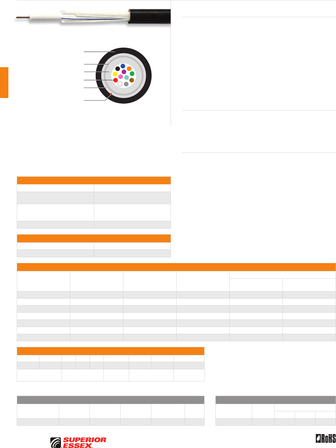
C-24
PREMISES COPPER PREMISES FIBER OSP FIBER OSP COMPOSITE CENTRAL OFFICE COPPER RDUP/RUS OSP COPPER BELL OSP COPPER OSP COPPER WIRE CANADIAN OSP COPPER TECHNICAL INFO
Toll Free 800.551.8948 | Fax 770.657.6807 | SuperiorEssex.com/Comm Rev 10/10 Ed 10.3
Specifications
Fiber Count Available in 6-fiber up to 96-fiber
Maximum Tensile Loading lbs (N) Install: 600 (2,700)
Long Term: 200 (890)
Performance Compliance
Telcordia GR-20-CORE
UL 1666
RoHS-compliant
NRTL Programs UL, c(UL) Listed OFNR
Environmental Specifications
Operation/Storage -40°C to +70°C
Installation -10°C to +65°C
Part Numbers and Physical Characteristics
Part Number¹ Fiber Count
Nominal Diameter
in (mm)
Nominal Weight
lbs/kft (kg/km)
Minimum Bend Radius
Install
in (mm)
Long Term
in (mm)
53006xx01 6 0.30 (7.0) 39 (57) 6.0 (152) 3.0 (75)
53012xx01 12 0.30 (7.0) 39 (57) 6.0 (152) 3.0 (75)
53024xx01 24 0.37 (10.0) 57 (85) 7.4 (188) 3.7 (94)
53036xx01 36 0.37 (10.0) 57 (85) 7.4 (188) 3.7 (94)
53048xx01 48 0.37 (10.0) 57 (85) 7.4 (188) 3.7 (94)
53072xx01 72 0.50 (13.0) 106 (157) 10.0 (254) 5.0 (127)
53096xx01 96 0.50 (13.0) 106 (157) 10.0 (254) 5.0 (127)
Part Number Designators
5 3 _ _ _ x x 0 _
1 2 3 4 5 6 7 8 9
product family fiber count (006-096) fiber type internal designator water block/
marking (1-8)
Contact Customer Service for availability of non-standard offerings.
See "Optical Fiber Cable" options in the "TECHNICAL INFO" section for flooding and jacket marking options.
Single Mode Optical Fiber Multimode Optical Fiber
Conventional
Reduced
Water Peak
Zero
Water Peak
TeraFlex®
Bend Resistant NZDS
TeraGain®
62.5/125
TeraGain Laser Optimized 50/125
10G/150 10G/300 10G/550
¹Replace “xx” with: 91 31 21 K1 81 ¹Replace “xx” with: 6G AG BG FG
See the "Optical Fiber Selection Chart" in the "TECHNICAL INFO" section for detailed fiber type specifications.
Single Loose Tube Indoor/Outdoor OFNR
Series 53
Product Description
Loose tube riser cables are ideal for campus environments, private networks
and local area networks. These dual purpose cables save money and
installation time by allowing a direct transition from indoor to outdoor
applications with a single cable. Loose tube cables are the product of choice
as the backbone in Outside Plant (OSP) applications. Single Loose tube
cables offer a low cost alternative to traditional stranded loose tube cables.
The loose tube design offers reliable transmission performance over a broad
temperature range. The rugged single loose tube design features optical
fibers placed inside a single PFM™ gel filled tube. The core tube includes up
to 8-fiber bundles, each containing up to 12 optical fibers bound with a color
coded binder. The core tube is then helically wrapped with water blocking
strength members, then encased with a black, flame resistant jacket. A rip
cord is included under the jacket to provide ease of access to the core tube.
Applications
• UL Listed sunlight resistant indoor/outdoor
• Lashed aerial, duct or riser
• Inter-building connection
• Campus environments
Features Benefits
• Available with up to 96-fiber • High fiber density
• Multiple fiber types • Multiple network applications
• UL Listed, sunlight resistant • Longer cable life
• Dielectric outer
strength members
• Eliminates grounding
or bonding problems
• Dry (SAP) core standard • Reduces cable prep
and installation time
• Highly flexible • Easy handling
• Small cable diameter • Installation of more fibers in
less space
• Fewer cable components • Reduces cost
• Transitions from indoor to outdoor
to indoor with no termination
• Reduces labor cost
• PFM™ gel • Non-sticky gel speeds fiber
access and clean-up
Optical Fiber
Heat Resistant Tape
Dielectric Water Blocking
Strength Members
PFM™ Gel Filled Tube
Rip Cord
Flame and Sunlight
Resistant Jacket
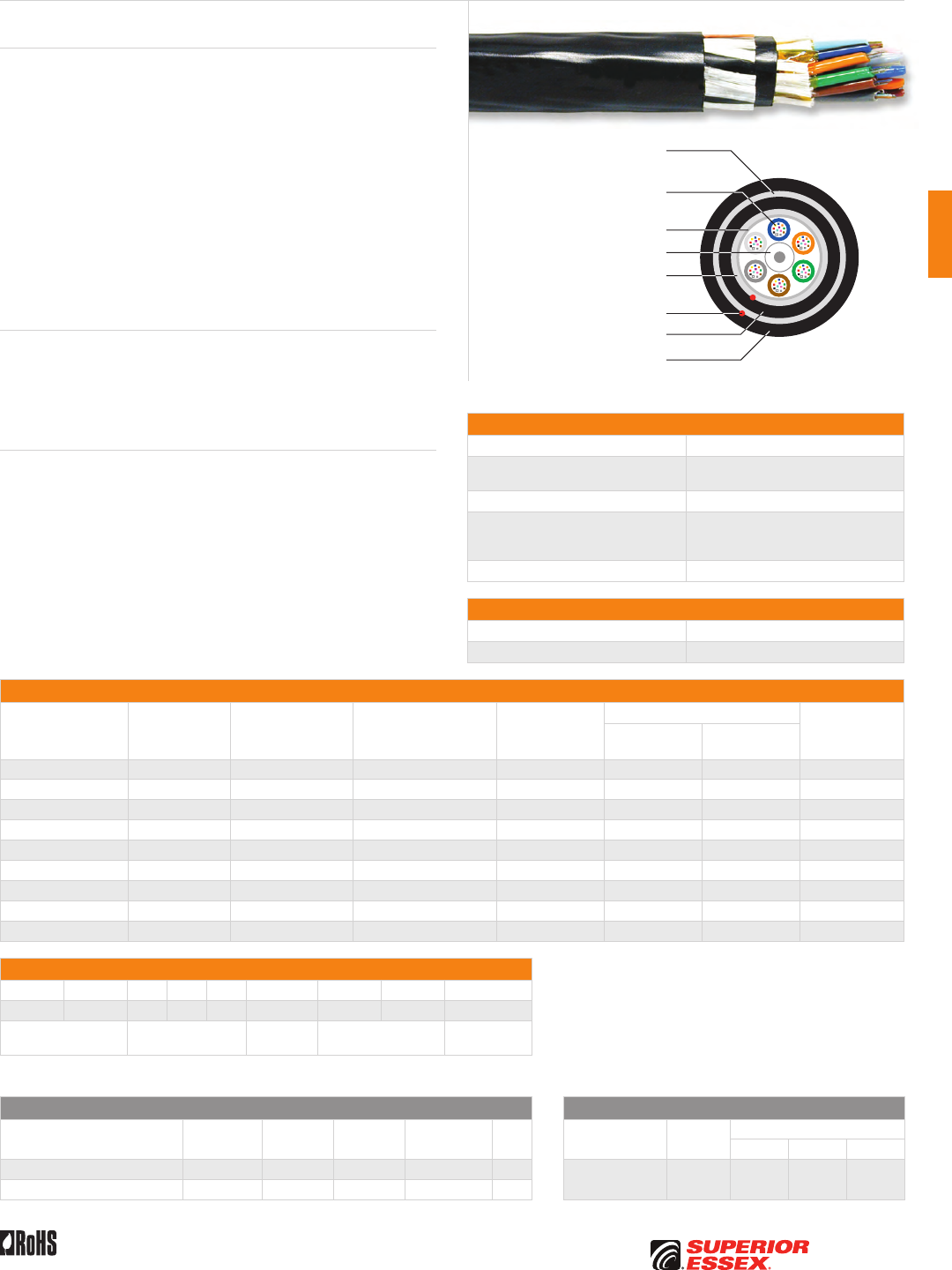
C-25
PREMISES COPPERPREMISES FIBEROSP FIBEROSP COMPOSITECENTRAL OFFICE COPPERRDUP/RUS OSP COPPERBELL OSP COPPEROSP COPPER WIRECANADIAN OSP COPPERTECHNICAL INFO
Toll Free 800.551.8948 | Fax 770.657.6807 | SuperiorEssex.com/CommRev 10/10 Ed 10.3
Specifications
Fiber Count Available in 6-fiber up to 216-fiber
Maximum Tensile Loading lbs (N) Install: 600 (2,700)
Long Term: 200 (890)
Crush lbs/in (N/cm) 260 (450)
Performance Compliance
Telcordia GR-20-CORE
UL 1666
RoHS-compliant
NRTL Programs UL, c(UL) Listed OFNR
Environmental Specifications
Operation/Storage -40°C to +70°C
Installation -10°C to +65°C
Part Numbers and Physical Characteristics
Part Number¹ Fiber Count
Nominal Diameter
in (mm)
Nominal Weight
lbs/kft (kg/km)
Impact
n*m
Minimum Bend Radius
Vertical Rise
ft (m)
Install
in (mm)
Long Term
in (mm)
1H006xx01 6 0.53 (13.4) 119 (176) 4.41 10.6 (269) 5.3 (135) 2,200 (671)
1H012xx01 12 0.53 (13.4) 119 (176) 4.41 10.6 (269) 5.3 (135) 2,200 (671)
1H024xx01 24 0.53 (13.4) 119 (176) 4.41 10.6 (269) 5.3 (135) 2,200 (671)
1H036xx01 36 0.53 (13.4) 119 (176) 4.41 10.6 (269) 5.3 (135) 2,200 (671)
1H048xx01 48 0.53 (13.4) 119 (176) 4.41 10.6 (269) 5.3 (135) 2,200 (671)
1H072xx01 72 0.57 (14.6) 137 (205) 5.15 11.4 (289) 5.7 (145) 1,840 (560)
1H096xx01 96 0.64 (16.3) 168 (250) 5.88 12.8 (326) 6.4 (163) 1,450 (443)
1H144xx01 144 0.78 (19.9) 250 (372) 6.62 15.6 (396) 7.8 (198) 1,050 (320)
1H216xx01 216 0.79 (20.3) 256 (383) 6.62 15.8 (406) 7.9 (203) 1,050 (320)
Part Number Designators
1 H _ _ _ x x 0 _
1 2 3 4 5 6 7 8 9
product family fiber count (006-216) fiber type internal designator water block/
marking (1-8)
Contact Customer Service for availability of non-standard offerings.
See "Optical Fiber Cable" options in the "TECHNICAL INFO" section for flooding and jacket marking options.
Single Mode Optical Fiber Multimode Optical Fiber
Conventional
Reduced
Water Peak
Zero
Water Peak
TeraFlex®
Bend Resistant NZDS
TeraGain®
62.5/125
TeraGain Laser Optimized 50/125
10G/150 10G/300 10G/550
¹For ≤ 36 fibers replace “xx” with: 9T 3T 2T KT 8T ¹Replace “xx” with: 6G AG BG FG
¹For > 36 fibers replace “xx” with: 91 31 21 K1 81
See the "Optical Fiber Selection Chart" in the "TECHNICAL INFO" section for detailed fiber type specifications.
Heavy Duty Loose Tube OFNR
Series 1H
Product Description
Heavy Duty Loose Tube OFNR Cables are ideally suited for harsh environment
applications including mining, steel mills, refineries, lumber mills and many
other situations requiring a rugged cable construction. These cables have
been specifically designed to have greater tensile, crush and impact ratings.
With a dual layer of flexible strength members and a double layer of rugged
flame retardant and sunlight resistant jackets, this cable design possesses
features ideal for environmentally demanding applications. The heavy duty
loose tube design features optical fibers placed inside PFM™ gel filled
buffer tubes. The core is constructed by stranding the buffer tubes around
a central member using reverse oscillating lay (ROL). The core is wrapped
with flexible strength members and covered by a water blocking tape,
then encased in a black flame resistant jacket. A second layer of flexible
strength members is applied and then encased in a black, flame and sunlight
resistant jacket. Rip cords are included under each jacket for ease of entry.
Applications
• IEEE networks from 10 Mbps to 10 Gbps
• Long vertical runs
• Cable trays
• Outdoor/indoor pathways
Features Benefits
• Multiple fiber types
including hybrids
• Multiple network applications
• UL Listed, sunlight resistant • Longer cable life
• Transitions from indoor
to outdoor
• Reduces labor costs
• Heavy duty design • Allows for harsh
environment application
• PFM™ gel • Non-sticky gel speeds fiber
access and clean-up
Central Strength Member
Dielectric Water Blocking
Strength Members
Dielectric Water Blocking
Strength Members
Heat Resistant Tape
Optical Fiber in PFM™ Gel
Filled Buffer Tube
Rip Cords
Flame Resistant Inner Jacket
Flame and Sunlight
Resistant Outer Jacket
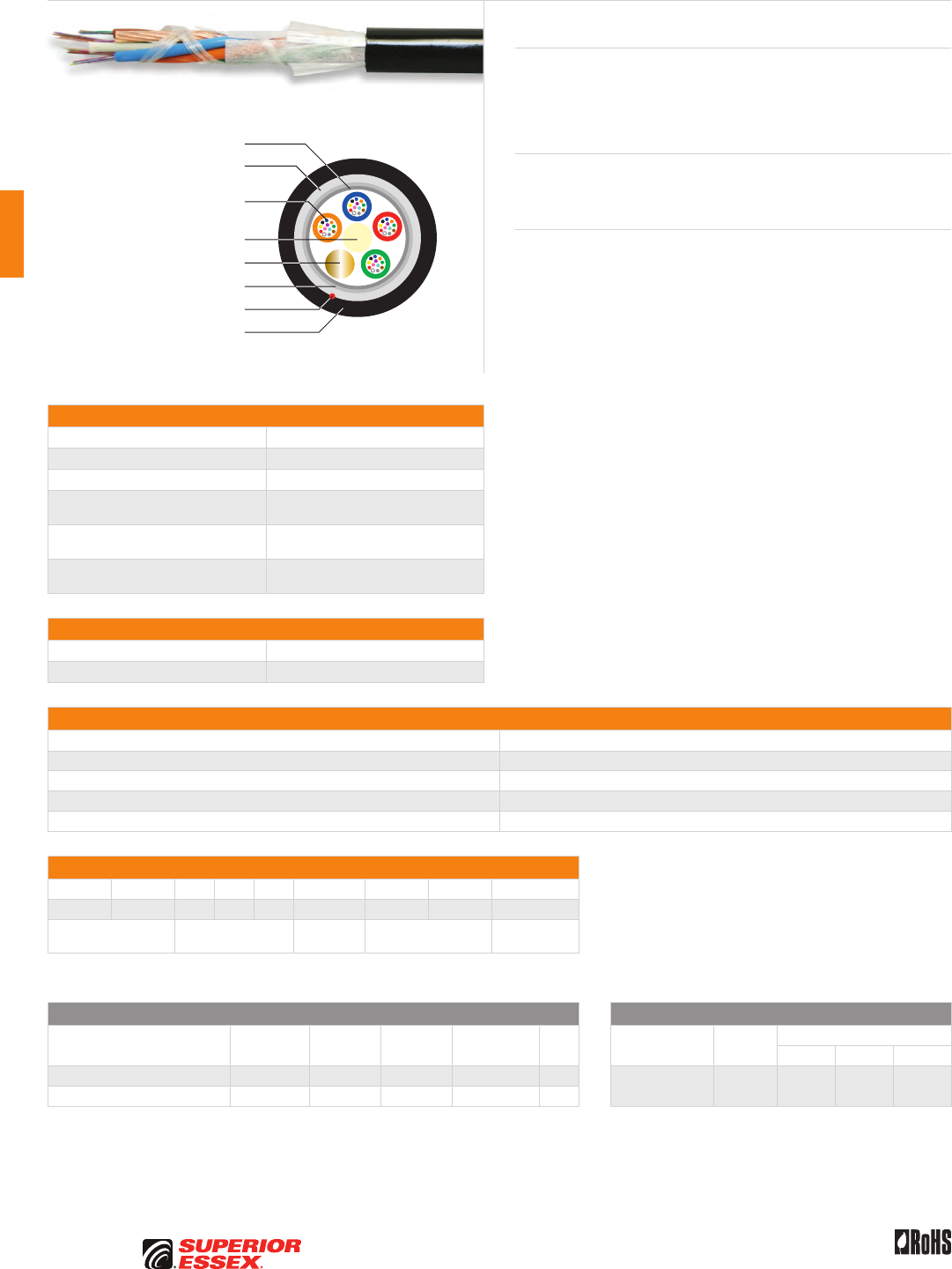
C-26
PREMISES COPPER PREMISES FIBER OSP FIBER OSP COMPOSITE CENTRAL OFFICE COPPER RDUP/RUS OSP COPPER BELL OSP COPPER OSP COPPER WIRE CANADIAN OSP COPPER TECHNICAL INFO
Rev 7/10 Ed 10.2Toll Free 800.551.8948 | Fax 770.657.6807 | SuperiorEssex.com/Comm
Specifications
Fiber Count Available in 12-fiber up to 48-fiber
Nominal Diameter in (mm) 0.43 (10.8)
Approx. Weight lbs/kft (kg/km) 76 (113)
Maximum Tensile Loading lbs (N) Install: 600 (2,700)
Long Term: 200 (890)
Minimum Bend Radius in (mm) Install: 8.6 (216)
Long Term: 4.3 (108)
Standards Compliance Telcordia GR-20-CORE
RoHS-compliant
Environmental Specifications
Operation/Storage -40°C to +70°C
Installation -30°C to +75°C
Part Numbers and Physical Characteristics
Part Number¹ Fiber Count
1N012xx01 12
1N024xx01 24
1N036xx01 36
1N048xx01 48
Part Number Designators
1 N _ _ _ x x 0 _
1 2 3 4 5 6 7 8 9
product family fiber count (012-048) fiber type internal designator water block/
marking (1-8)
Contact Customer Service for availability of non-standard offerings.
See "Optical Fiber Cable" options in the "TECHNICAL INFO" section for flooding and jacket marking options.
Single Mode Optical Fiber Multimode Optical Fiber
Conventional
Reduced
Water Peak
Zero
Water Peak
TeraFlex®
Bend Resistant NZDS
TeraGain®
62.5/125
TeraGain Laser Optimized 50/125
10G/150 10G/300 10G/550
¹For ≤ 36 fibers replace “xx” with: 9T 3T 2T KT 8T ¹Replace “xx” with: 6G AG BG FG
¹For > 36 fibers replace “xx” with: 91 31 21 K1 81
See the "Optical Fiber Selection Chart" in the "TECHNICAL INFO" section for detailed fiber type specifications.
Loose Tube 12 AWG Composite
Series 1N
Product Description
Loose Tube 12 AWG Composite Cable is a stranded, single jacket, non-
armored, gel-filled loose tube cable containing a 12 AWG stranded conductor,
which provides long distance tone for location. A rip cord is included under
the jacket to provide ease of entry.
Applications
• Underground duct and lashed aerial
• Broadband network
Features Benefits
• Available with up to 48-fiber • High fiber density
• Multiple fiber types • Multiple network applications
• PFM™ gel • Non-sticky gel speeds fiber
access and clean-up
• Dry (SAP) core standard • Reduces cable prep
and installation time
• Multiple fiber vendors • Meets customer preferences
• 12 AWG stranded conductor • Meets 10 Ohms/mile standard
Dielectric Water Blocking
Strength Members
Dielectric Strength Member
Water Blocking Tape
Water Blocking Tape
Optical Fiber in PFM™ Gel
Filled Buffer Tube
12 AWG Stranded Conductor
Rip Cord
UV Resistant Jacket
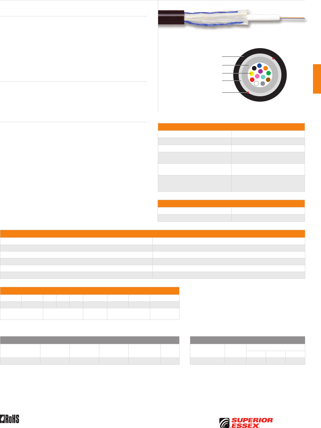
C-27
PREMISES COPPERPREMISES FIBEROSP FIBEROSP COMPOSITECENTRAL OFFICE COPPERRDUP/RUS OSP COPPERBELL OSP COPPEROSP COPPER WIRECANADIAN OSP COPPERTECHNICAL INFO
Rev 7/10 Ed 10.2 Toll Free 800.551.8948 | Fax 770.657.6807 | SuperiorEssex.com/Comm
Specifications
Fiber Count Available in 2-fiber up to 12-fiber
Nominal Diameter in (mm) 0.26 (6.7)
Nominal Weight lbs/kft (kg/km) 26 (38)
Maximum Tensile Loading lbs (N) Install: 300 (1,335)
Long Term: 100 (445)
Minimum Bend Radius in (mm) Install: 5.2 (132)
Long Term: 2.6 (66)
Standards Compliance
Telcordia GR-20-CORE
RDUP PE-90 Designation 513
RoHS-compliant
Environmental Specifications
Operation/Storage -40°C to +70°C
Installation -30°C to +75°C
Part Numbers and Physical Characteristics
Part Number¹ Fiber Count
51002xx01 2
51004xx01 4
51006xx01 6
51008xx01 8
51012xx01 12
Part Number Designators
5 1 _ _ _ x x 0 _
1 2 3 4 5 6 7 8 9
product family fiber count (002-012) fiber type internal designator water block/
marking (1-8)
Contact Customer Service for availability of non-standard offerings.
See "Optical Fiber Cable" options in the "TECHNICAL INFO" section for flooding and jacket marking options.
Single Mode Optical Fiber Multimode Optical Fiber
Conventional
Reduced
Water Peak
Zero
Water Peak
TeraFlex®
Bend Resistant NZDS
TeraGain®
62.5/125
TeraGain Laser Optimized 50/125
10G/150 10G/300 10G/550
¹Replace “xx” with: 93 33 23 K3 83 ¹Replace “xx” with: 6G AG BG FG
See the "Optical Fiber Selection Chart" in the "TECHNICAL INFO" section for detailed fiber type specifications.
UG FTTP
Series 513
Product Description
UG FTTP are all dielectric cables designed for Outside Plant (OSP)
applications, specifically as a drop cable. The reduced diameter maximizes
duct space and offers the lowest installed cost. The loose tube design
offers reliable transmission performance over a broad temperature range.
The single loose tube design features optical fibers placed inside a single
PFM™ gel filled tube. The core tube contains up to 12 optical fibers. The core
tube is then helically wrapped with water blocking strength members and
encased with a black jacket. A rip cord is included to provide ease of access
to the cable core.
Applications
• Drop cables
• Broadband network
• Local loop
• Fiber to the premise
Features Benefits
• Available with up to 12-fiber • High fiber density
• Multiple fiber types including
TeraFlex® bend resistant
• Multiple network applications
• Dielectric outer
strength members
• Eliminates grounding
or bonding problems
• Highly flexible • Easy handling
• Small cable diameter • Installation of more fibers
in less space, reduced cost
• Dry (SAP) core design • Reduces cable prep
and installation time
• PFM™ gel • Non-sticky gel allows for easier
and faster clean up
Optical Fiber
Dielectric Water Blocking
Strength Members
PFM™ Gel Filled Tube
Rip Cords
UV Resistant Jacket
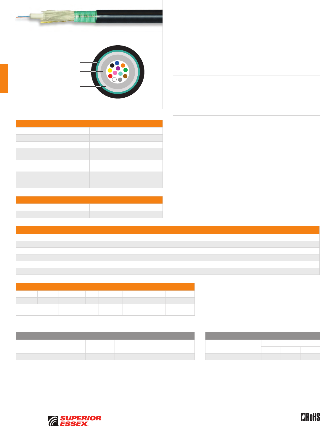
C-28
PREMISES COPPER PREMISES FIBER OSP FIBER OSP COMPOSITE CENTRAL OFFICE COPPER RDUP/RUS OSP COPPER BELL OSP COPPER OSP COPPER WIRE CANADIAN OSP COPPER TECHNICAL INFO
Rev 7/10 Ed 10.2Toll Free 800.551.8948 | Fax 770.657.6807 | SuperiorEssex.com/Comm
Specifications
Fiber Count Available in 2-fiber up to 12-fiber
Nominal Diameter in (mm) 0.32 (8.2)
Nominal Weight lbs/kft (kg/km) 51 (77)
Maximum Tensile Loading lbs (N) Install: 300 (1,335)
Long Term: 100 (445)
Minimum Bend Radius in (mm) Install: 6.4 (163)
Long Term: 3.2 (82)
Standards Compliance
Telcordia GR-20-CORE
RDUP PE-90 Designation 52S
RoHS-compliant
Environmental Specifications
Operation/Storage -40°C to +70°C
Installation -30°C to +75°C
Part Numbers and Physical Characteristics
Part Number¹ Fiber Count
52002xx01 2
52004xx01 4
52006xx01 6
52008xx01 8
52012xx01 12
Part Number Designators
5 2 _ _ _ x x 0 _
1 2 3 4 5 6 7 8 9
product family fiber count (002-012) fiber type internal designator water block/
marking (1-8)
Contact Customer Service for availability of non-standard offerings.
See "Optical Fiber Cable" options in the "TECHNICAL INFO" section for flooding and jacket marking options.
Single Mode Optical Fiber Multimode Optical Fiber
Conventional
Reduced
Water Peak
Zero
Water Peak
TeraFlex®
Bend Resistant NZDS
TeraGain®
62.5/125
TeraGain Laser Optimized 50/125
10G/150 10G/300 10G/550
¹Replace “xx” with: 9S 3S 2S KS 8S ¹Replace “xx” with: 6G AG BG FG
See the "Optical Fiber Selection Chart" in the "TECHNICAL INFO" section for detailed fiber type specifications.
Buried FTTP Steel Armor
Series 52S
Product Description
Buried FTTP cables are designed for Outside Plant (OSP) applications,
specifically as a drop cable. The reduced diameter maximizes duct space
and offers additional armoring protection. The loose tube design offers
reliable transmission performance over a broad temperature range. The
rugged single loose tube design features optical fibers placed inside a single
PFM™ gel filled tube. The core tube contains up to 12 optical fibers. The core
tube is then helically wrapped with water blocking strength members. A
corrugated steel armor is applied and encased with a black jacket.
Applications
• Drop cables
• Broadband network
• Local loop
• Fiber to the premise
Features Benefits
• Corrugated steel armor • Additional compressive strength
and rodent protection
• Multiple fiber types including
TeraFlex® bend resistant
• Multiple network applications
• Dielectric outer
strength members
• Eliminates grounding
or bonding problems
• Highly flexible • Easy handling
• Small cable diameter • Installation of more fibers
in less space, reduced cost
• Color coded fibers • Easy identification
during installation
• Dry (SAP) core design • Reduces cable prep
and installation time
• PFM™ gel • Non-sticky gel allows for easier
and faster clean up
Optical Fiber
Dielectric Water Blocking
Strength Members
PFM™ Gel Filled Tube
UV Resistant Jacket
Corrugated Steel Armor
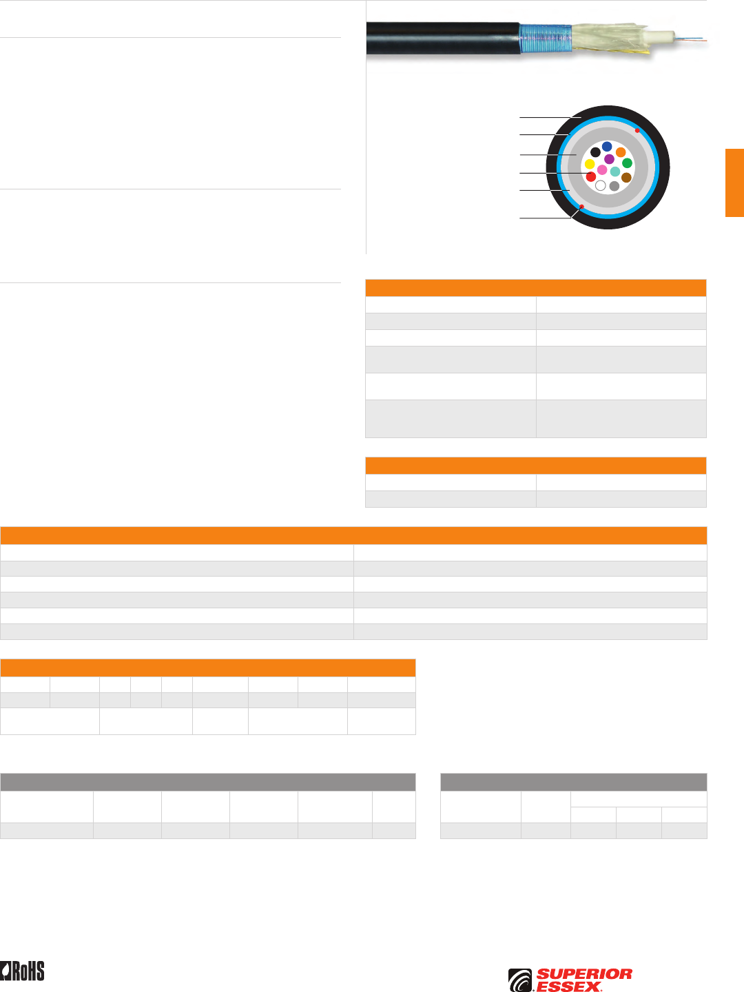
C-29
PREMISES COPPERPREMISES FIBEROSP FIBEROSP COMPOSITECENTRAL OFFICE COPPERRDUP/RUS OSP COPPERBELL OSP COPPEROSP COPPER WIRECANADIAN OSP COPPERTECHNICAL INFO
Rev 7/10 Ed 10.2 Toll Free 800.551.8948 | Fax 770.657.6807 | SuperiorEssex.com/Comm
Specifications
Fiber Count Available in 2-fiber up to 12-fiber
Nominal Diameter in (mm) 0.33 (8.4)
Nominal Weight lbs/kft (kg/km) 42 (62)
Maximum Tensile Loading lbs (N) Install: 300 (1,335)
Long Term: 100 (445)
Minimum Bend Radius in (mm) Install: 6.6 (168)
Long Term: 3.3 (84)
Standards Compliance
Telcordia GR-20-CORE
RDUP PE-90 Designation 523
RoHS-compliant
Environmental Specifications
Operation/Storage -40°C to +70°C
Installation -30°C to +75°C
Part Numbers and Physical Characteristics
Part Number¹ Fiber Count
52002xx01 2
52004xx01 4
52006xx01 6
52008xx01 8
52012xx01 12
Part Number Designators
5 2 _ _ _ x x 0 _
1 2 3 4 5 6 7 8 9
product family fiber count (002-012) fiber type internal designator water block/
marking (1-8)
Contact Customer Service for availability of non-standard offerings.
See "Optical Fiber Cable" options in the "TECHNICAL INFO" section for flooding and jacket marking options.
Single Mode Optical Fiber Multimode Optical Fiber
Conventional
Reduced
Water Peak
Zero
Water Peak
TeraFlex®
Bend Resistant NZDS
TeraGain®
62.5/125
TeraGain Laser Optimized 50/125
10G/150 10G/300 10G/550
¹Replace “xx” with: 93 33 23 K3 83 ¹Replace “xx” with: 6G AG BG FG
See the "Optical Fiber Selection Chart" in the "TECHNICAL INFO" section for detailed fiber type specifications.
Product Description
Buried FTTP cables are designed for Outside Plant (OSP) applications,
specifically as a drop cable. The reduced diameter maximizes duct space and
offers additional armoring protection. The loose tube design offers reliable
transmission performance over a broad temperature range. The rugged
single loose tube design features optical fibers placed inside a single PFM™
gel filled tube. The core tube contains up to 12 optical fibers. The core tube is
then helically wrapped with water blocking strength members. A corrugated
aluminum armor is applied and encased with a black jacket. Rip cords are
included under the armor for ease of access to the core tube.
Applications
• Drop cables
• Broadband network
• Local loop
• Fiber to the premise
Features Benefits
• Corrugated aluminum armor • Additional compressive strength
and rodent protection
• Multiple fiber types including
TeraFlex® bend resistant
• Multiple network applications
• Dielectric outer
strength members
• Eliminates grounding
or bonding problems
• Highly flexible • Easy handling
• Small cable diameter • Installation of more fibers
in less space, reduced cost
• Color coded fibers • Easy identification
during installation
• Dry (SAP) core design • Reduces cable prep
and installation time
• PFM™ gel • Non-sticky gel allows for easier
and faster clean up
Buried FTTP Aluminum Armor
Series 523
Optical Fiber
Dielectric Water Blocking
Strength Members
PFM™ Gel Filled Tube
Rip Cords
UV Resistant Jacket
Corrugated Aluminum Armor
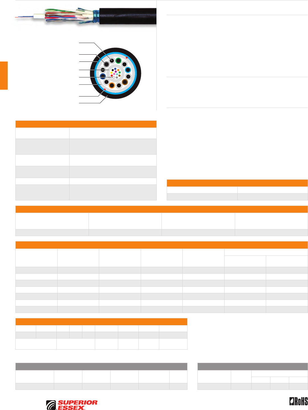
C-30
PREMISES COPPER PREMISES FIBER OSP FIBER OSP COMPOSITE CENTRAL OFFICE COPPER RDUP/RUS OSP COPPER BELL OSP COPPER OSP COPPER WIRE CANADIAN OSP COPPER TECHNICAL INFO
Rev 7/10 Ed 10.2Toll Free 800.551.8948 | Fax 770.657.6807 | SuperiorEssex.com/Comm
Specifications
Fiber Components Available in 2-fiber up to 12-fiber loose inside a
PFM™ gel filled buffer tube
Copper Components
Available with 2, 3 or 6-pair 22 AWG solid annealed
copper conductors each insulated with solid
polyolefin in distinctive colors
Maximum Tensile Loading
lbs (N)
Install: 300 (1,335)
Long Term: 100 (445)
Copper Maximum
Amperage and Voltage
Amperage: 1.0 A
Voltage: 150 vDC
Package Reel
Standards Compliance
Telcordia GR-20-CORE
RDUP PE-90 Designation 72
RoHS-compliant
Electrical Specifications
Conductor
AWG (mm)
Conductor DC Resistance @ 68°F
Maximum Individual
Ohms/mile (Ohms/km)
Resistance Unbalance Maximum
Individual Pair %
Minimum Dielectric Strength
DC Potential Volts
Conductor to Conductor
22 (0.64) 91.0 (56.4) 5.0 7,200
Part Numbers and Physical Characteristics
Part Number¹ Copper Pair Count Fiber Count
Nominal Diameter
in (mm)
Nominal Weight
lbs/kft (kg/km)
Minimum Bend Radius
Install
in (mm)
Long Term
in (mm)
72002xx21 2 2 0.39 (9.8) 61 (91) 7.8 (198) 3.9 (99)
72004xx21 2 4 0.39 (9.8) 61 (91) 7.8 (198) 3.9 (99)
72006xx21 2 6 0.39 (9.8) 61 (91) 7.8 (198) 3.9 (99)
72002xx61 6 2 0.43 (10.8) 338 (504) 8.6 (218) 4.3 (109)
72004xx61 6 4 0.43 (10.8) 338 (504) 8.6 (218) 4.3 (109)
72006xx61 6 6 0.43 (10.8) 338 (504) 8.6 (218) 4.3 (109)
72012xx61 6 12 0.43 (10.8) 338 (504) 8.6 (218) 4.3 (109)
Part Number Designators
7 2 _ _ _ x x 2, 3 or 6 _
1 2 3 4 5 6 7 8 9
product family fiber count (002-012) fiber type internal
designator
copper
pairs
water block/
marking (1-8)
Contact Customer Service for availability of non-standard offerings.
See "Optical Fiber Cable" options in the "TECHNICAL INFO" section for flooding and jacket marking options.
Single Mode Optical Fiber Multimode Optical Fiber
Conventional
Reduced
Water Peak
Zero
Water Peak
TeraFlex®
Bend Resistant NZDS
TeraGain®
62.5/125
TeraGain Laser Optimized 50/125
10G/150 10G/300 10G/550
¹Replace “xx” with: 93 33 23 K3 83 ¹Replace “xx” with: 6G AG BG FG
See the "Optical Fiber Selection Chart" in the "TECHNICAL INFO" section for detailed fiber type specifications.
Buried Drop Composite Aluminum Armor
Series 72
Product Description
Series 72 is the underground cable solution for the situation that requires
both optical fiber and twisted pairs. This product is available in fiber counts
up to 12 with 2-pair, 3-pair or 6-pair 22 AWG copper pairs. Series 72 serves
the need for communications or power over copper pairs with optical
fiber available for the future. The core is constructed with a single tube
containing up to 12 optical fibers and up to 6 copper pairs. A corrugated
aluminum armor and longitudinal strength elements are applied over the
core tube and encased within a black, weather resistant jacket. Rip cords
are included under the armor for ease of access to the core.
Applications
• Fiber to the premise
• Broadband network
• Buried, underground
Features Benefits
• Composite fiber/copper design • Multiple Network applications
• Round shape • Conforms to standard practices
and hardware
• Corrugated aluminum armor • Improves flexibility
• Dry (SAP) core standard • Reduces cable prep
and installation time
• PFM™ gel • Non-sticky gel allows for easier
and faster clean up
• Insulation of tip conductors are
marked with a stripe of the mating
ring’s insulation color
• Reduces the possibility of splitting
pairs during installation
Optical Fiber
Dielectric Water Blocking
Strength Members
PFM™ Gel Filled Tube
Rip Cords
UV Resistant Jacket
Corrugated Aluminum Armor
22 AWG Solid Annealed
Copper Conductor
Insulation
Environmental Specifications
Operation/Storage -40°C to +70°C
Installation -30°C to +75°C
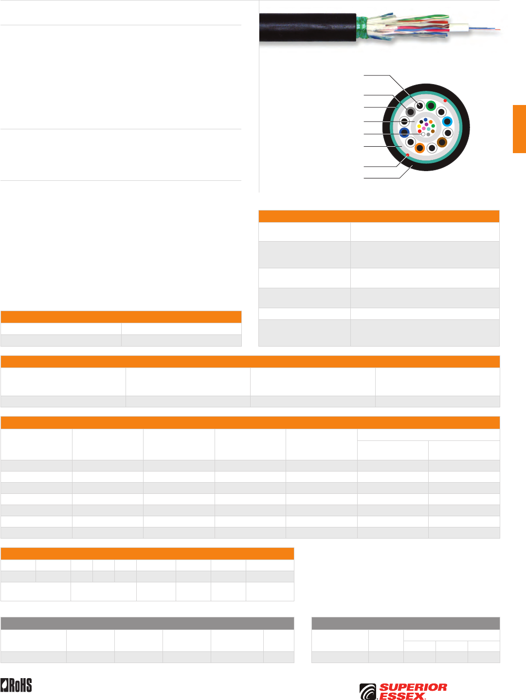
C-31
PREMISES COPPERPREMISES FIBEROSP FIBEROSP COMPOSITECENTRAL OFFICE COPPERRDUP/RUS OSP COPPERBELL OSP COPPEROSP COPPER WIRECANADIAN OSP COPPERTECHNICAL INFO
Rev 7/10 Ed 10.2 Toll Free 800.551.8948 | Fax 770.657.6807 | SuperiorEssex.com/Comm
Specifications
Fiber Components Available in 2-fiber up to 12-fiber loose inside a
PFM™ gel filled buffer tube
Copper Components
Available with 2, 3 or 6-pair 22 AWG solid annealed
copper conductors each insulated with solid
polyolefin in distinctive colors
Maximum Tensile Loading
lbs (N)
Install: 300 (1,335)
Long Term: 100 (445)
Copper Maximum
Amperage and Voltage
Amperage: 1.0 A
Voltage: 150 vDC
Package Reel
Standards Compliance
Telcordia GR-20-CORE
RDUP PE-90 Designation 72S
RoHS-compliant
Electrical Specifications
Conductor
AWG (mm)
Conductor DC Resistance @ 68°F
Maximum Individual
Ohms/mile (Ohms/km)
Resistance Unbalance Maximum
Individual Pair %
Minimum Dielectric Strength
DC Potential Volts
Conductor to Conductor
22 (0.64) 91.0 (56.4) 5.0 7,200
Part Numbers and Physical Characteristics
Part Number¹ Copper Pair Count Fiber Count
Nominal Diameter
in (mm)
Nominal Weight
lbs/kft (kg/km)
Minimum Bend Radius
Install
in (mm)
Long Term
in (mm)
72002xx2S 2 2 0.39 (9.8) 61 (91) 7.8 (198) 3.9 (99)
72004xx2S 2 4 0.39 (9.8) 61 (91) 7.8 (198) 3.9 (99)
72006xx2S 2 6 0.39 (9.8) 61 (91) 7.8 (198) 3.9 (99)
72002xx6S 6 2 0.43 (10.8) 338 (504) 8.6 (218) 4.3 (109)
72004xx6S 6 4 0.43 (10.8) 338 (504) 8.6 (218) 4.3 (109)
72006xx6S 6 6 0.43 (10.8) 338 (504) 8.6 (218) 4.3 (109)
72012xx6S 6 12 0.43 (10.8) 338 (504) 8.6 (218) 4.3 (109)
Part Number Designators
7 2 _ _ _ x x 2, 3 or 6 S
1 2 3 4 5 6 7 8 9
product family fiber count (002-012) fiber type internal
designator
copper
pairs steel armor
Contact Customer Service for availability of non-standard offerings.
Single Mode Optical Fiber Multimode Optical Fiber
Conventional
Reduced
Water Peak
Zero
Water Peak
TeraFlex®
Bend Resistant NZDS
TeraGain®
62.5/125
TeraGain Laser Optimized 50/125
10G/150 10G/300 10G/550
¹Replace “xx” with: 9S 3S 2S KS 8S ¹Replace “xx” with: 6G AG BG FG
See the "Optical Fiber Selection Chart" in the "TECHNICAL INFO" section for detailed fiber type specifications.
Buried Drop Composite Steel Armor
Series 72S
Product Description
Series 72S is the underground cable solution for the situation that requires
both optical fiber and twisted pairs. This product is available in fiber counts
up to 12 with 2-pair, 3-pair or 6-pair 22 AWG copper pairs. Series 72S serves
the need for communications or power over copper pairs with optical fiber
available for the future. The core is constructed with a single tube containing
up to 12 optical fibers and up to 6 copper pairs. A corrugated steel armor and
longitudinal strength elements are applied over the core tube and encased
within a black, weather resistant jacket. Rip cords are included under the
armor for ease of access to the core.
Applications
• Fiber to the premise
• Broadband network
• Buried, underground
Features Benefits
• Composite fiber/copper design • Multiple Network applications
• Round shape • Conforms to standard practices
and hardware
• Corrugated steel armor • Improves compressive strength
and rodent protection
• Dry (SAP) core standard • Reduces cable prep
and installation time
• PFM™ gel • Non-sticky gel allows for easier
and faster clean up
• Insulation of tip conductors
are marked with a stripe of the
mating ring’s insulation color
• Reduces the possibility of splitting
pairs during installation
Optical Fiber
Dielectric Water Blocking
Strength Members
PFM™ Gel Filled Tube
Rip Cords
UV Resistant Jacket
Corrugated Steel Armor
22 AWG Solid Annealed
Copper Conductor
Insulation
Environmental Specifications
Operation/Storage -40°C to +70°C
Installation -30°C to +75°C
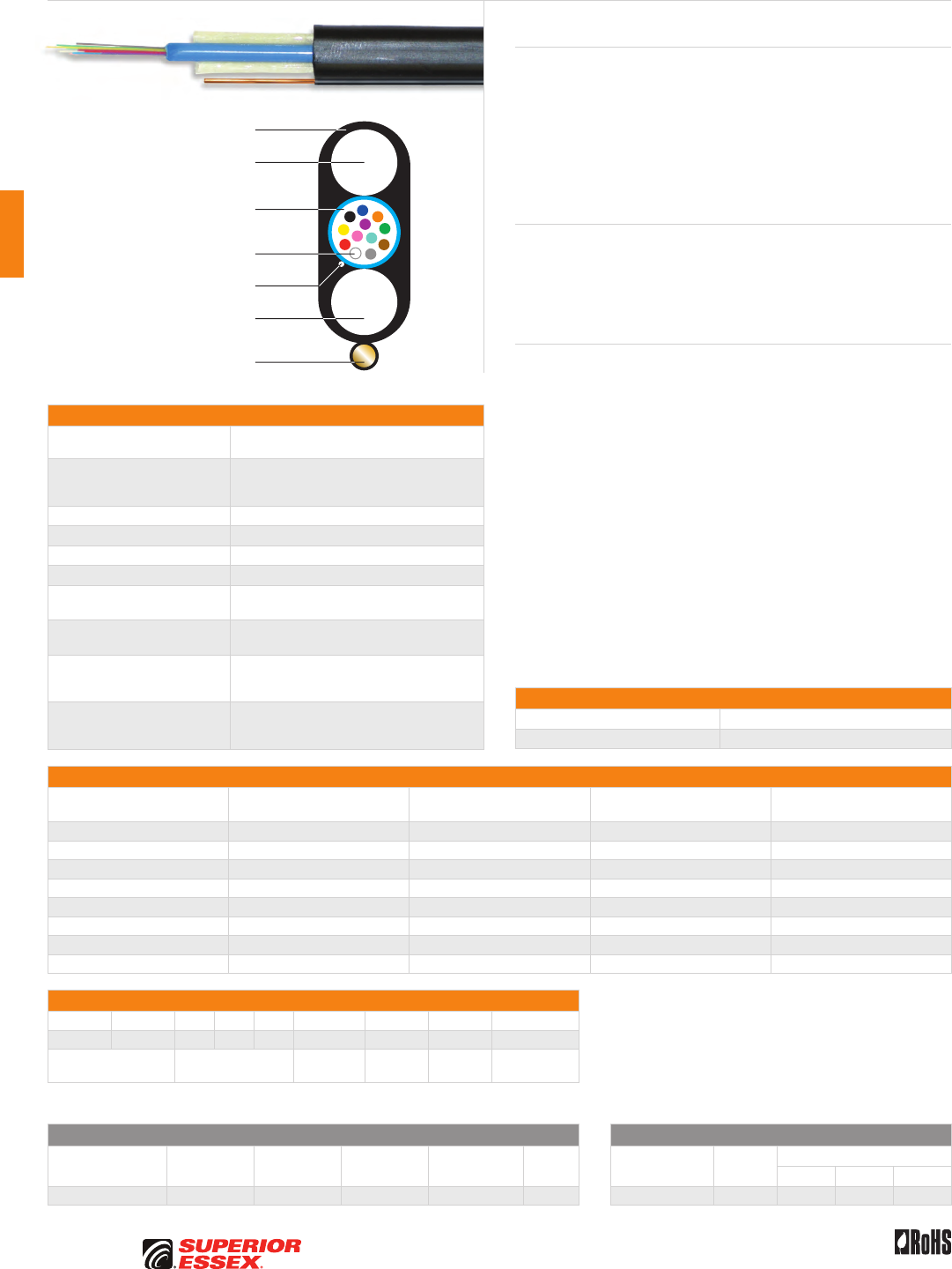
C-32
PREMISES COPPER PREMISES FIBER OSP FIBER OSP COMPOSITE CENTRAL OFFICE COPPER RDUP/RUS OSP COPPER BELL OSP COPPER OSP COPPER WIRE CANADIAN OSP COPPER TECHNICAL INFO
Rev 7/10 Ed 10.2Toll Free 800.551.8948 | Fax 770.657.6807 | SuperiorEssex.com/Comm
Specifications
Fiber Count Available with up to 12-fiber inside a PFM™ gel
filled loose buffer tube
Strength Members
Water blocking dielectric strength members
placed parallel to single loose tube, to provide
necessary longitudinal strength
Toneable Element 24 AWG copper wire encased in jacket
Jacket Black, UV resistant jacket
Nominal Dimensions in (mm) 0.40 (10.2) x 0.18 (4.5)
Weight lbs/kft 28
Minor Dimension
Bend Radius in (mm) 3.15 (76)
Maximum Tensile Loading
lbs (N)
Install: 300 (1,335)
Long Term: 90 (405)
Maximum Span Length
at 1% Sag ft (m)
Light Loading: 330 (101)
Medium Loading: 225 (69)
Heavy Loading: 150 (46)
Standards Compliance
Telcordia GR-20-CORE
RDUP PE-90 Designation 571Q
RoHS-compliant
Part Numbers and Physical Characteristics
Part Number¹ Fiber Count
Standard Length
ft (m)
Approx. Shipping Weight
lbs (kg) Package
57002x11Q 2 2,500 (762) 138 (304) 2,500’ Reel
57002x1BQ 2 1,000 (305) 37 (81) 1,000’ Reel-in-a-Box
57004x11Q 4 2,500 (762) 138 (304) 2,500’ Reel
57004x1BQ 4 1,000 (305) 37 (81) 1,000’ Reel-in-a-Box
57006x11Q 6 2,500 (762) 138 (304) 2,500’ Reel
57006x1BQ 6 1,000 (305) 37 (81) 1,000’ Reel-in-a-Box
57012x11Q 12 2,500 (762) 138 (304) 2,500’ Reel
57012x1BQ 12 1,000 (305) 37 (81) 1,000’ Reel-in-a-Box
Part Number Designators
5 7 _ _ _ x 1 1 or B Q
1 2 3 4 5 6 7 8 9
product family fiber count (001-012) fiber type internal
designator
package
type
internal
designator
Contact Customer Service for availability of non-standard offerings.
See "Optical Fiber Cable" options in the "TECHNICAL INFO" section for flooding and jacket marking options.
Single Mode Optical Fiber Multimode Optical Fiber
Conventional
Reduced
Water Peak
Zero
Water Peak
TeraFlex®
Bend Resistant NZDS
TeraGain®
62.5/125
TeraGain Laser Optimized 50/125
10G/150 10G/300 10G/550
¹Replace “x” with: 9 3 2 K 8 ¹Replace “x” with: 6 A B F
See the "Optical Fiber Selection Chart" in the "TECHNICAL INFO" section for detailed fiber type specifications.
Product Description
Toneable Drop FTTP offers the most flexible solution for fiber to the premise
applications. The toneable unit allows for easy location after installation.
The small profile reduces cost and increases both ease of use and access to
small conduits. This product is the low cost solution to the network’s last 100
meters. The durable design incorporates two dielectric rigid rods for tensile
and crush protection, bracketing a single enhanced loose tube containing
up to 12 optical fibers and PFM™ gel. This is a water-blocked design, using a
“dry” water absorbing thread to prevent the migration of moisture.
Applications
• Drop cables
• Broadband network
• Local loop
• Fiber to the premise
Features Benefits
• Available with up to 12-fiber • Maximum bandwidth
• Universal design • Aerial or direct bury
• Toneable element • Ease of location
• PFM™ gel • Non-sticky gel reduces installation
time and labor cost
• Dielectric rods • Excellent crush resistance
• Dry (SAP) core standard • Reduces cable prep
and installation time
• Multiple fiber types including
TeraFlex® bend resistant
• Multiple network applications
Toneable Drop FTTP
Series 571Q
UV Resistant Jacket
PFM™ Gel Filled
Loose Buffer Tube
Optical Fiber
Water Blocking Dielectric
Strength Member
Water Blocking Dielectric
Strength Member
24 AWG Copper Wire
Water Blocking Thread
Environmental Specifications
Operation/Storage -40°C to +70°C
Installation -30°C to +70°C
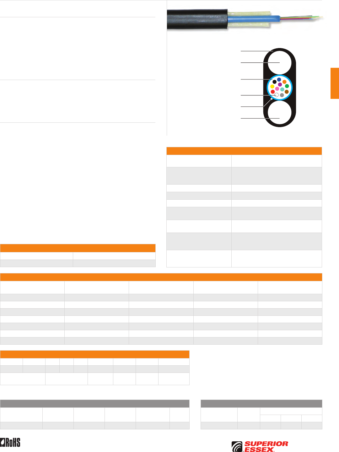
C-33
PREMISES COPPERPREMISES FIBEROSP FIBEROSP COMPOSITECENTRAL OFFICE COPPERRDUP/RUS OSP COPPERBELL OSP COPPEROSP COPPER WIRECANADIAN OSP COPPERTECHNICAL INFO
Rev 7/10 Ed 10.2 Toll Free 800.551.8948 | Fax 770.657.6807 | SuperiorEssex.com/Comm
Specifications
Fiber Count Available with up to 12-fiber inside a PFM™ gel
filled loose buffer tube
Strength Members
Water blocking dielectric strength members placed
parallel to single loose tube, one on each side,
to provide necessary longitudinal strength
Jacket Black, UV resistant jacket
Nominal Dimensions in (mm) 0.33 (8.2) x 0.18 (4.5)
Weight lbs/kft 24
Minor Dimension
Bend Radius in (mm) 3.15 (76)
Maximum Tensile Loading
lbs (N)
Install: 300 (1,335)
Long Term: 90 (405)
Maximum Span Length
at 1% Sag ft (m)
Light Loading: 330 (101)
Medium Loading: 225 (69)
Heavy Loading: 150 (46)
Standards Compliance
Telcordia GR-20-CORE
RDUP PE-90 Designation 570Q
RoHS-compliant
Part Numbers and Physical Characteristics
Part Number¹ Fiber Count
Standard Length
ft (m)
Approx. Shipping Weight
lbs (kg) Package
57002x01Q 2 2,500 (762) 128 (282) 2,500’ Reel
57002x0BQ 2 1,000 (305) 33 (73) 1,000’ Reel-in-a-Box
57004x01Q 4 2,500 (762) 128 (282) 2,500’ Reel
57004x0BQ 4 1,000 (305) 33 (73) 1,000’ Reel-in-a-Box
57006x01Q 6 2,500 (762) 128 (282) 2,500’ Reel
57006x0BQ 6 1,000 (305) 33 (73) 1,000’ Reel-in-a-Box
57012x01Q 12 2,500 (762) 128 (282) 2,500’ Reel
Part Number Designators
5 7 _ _ _ x 0 1 or B Q
1 2 3 4 5 6 7 8 9
product family fiber count (001-012) fiber type internal
designator
package
type
internal
designator
Contact Customer Service for availability of non-standard offerings.
See "Optical Fiber Cable" options in the "TECHNICAL INFO" section for flooding and jacket marking options.
Single Mode Optical Fiber Multimode Optical Fiber
Conventional
Reduced
Water Peak
Zero
Water Peak
TeraFlex®
Bend Resistant NZDS
TeraGain®
62.5/125
TeraGain Laser Optimized 50/125
10G/150 10G/300 10G/550
¹Replace “x” with: 9 3 2 K 8 ¹Replace “x” with: 6 A B F
See the "Optical Fiber Selection Chart" in the "TECHNICAL INFO" section for detailed fiber type specifications.
Universal Drop FTTP
Series 570Q
Product Description
Universal Drop FTTP offers the most flexible solution for fiber to the premise
applications. This all dielectric cable requires no grounding or bonding. The
small profile reduces cost and increases both ease of use and access to small
conduits. This durable design incorporates two dielectric rigid rods for tensile
and crush protection, bracketing a single enhanced loose tube containing up
to 12 optical fibers and PFM™ gel. This is a water-blocked design, using a “dry”
water absorbing thread to prevent the migration of moisture. A black, weather
resistant jacket completes the cable construction.
Applications
• Drop cables
• Broadband network
• Local loop
• Fiber to the premise
Features Benefits
• Available with up to 12-fiber • Offers the maximum bandwidth
for FTTP business, etc.
• Universal design • Aerial or direct bury
• Dielectric • Eliminates bonding and grounding
• PFM™ gel • Non-sticky gel reduces installation
time and labor cost
• Dielectric Rods • Excellent crush resistance
• Multiple fiber types including
TeraFlex® bend resistant
• Multiple network applications
UV Resistant Jacket
PFM™ Gel Filled
Loose Buffer Tube
Optical Fiber
Water Blocking Dielectric
Strength Member
Water Blocking Dielectric
Strength Member
Water Blocking Thread
Environmental Specifications
Operation/Storage -40°C to +70°C
Installation -30°C to +70°C
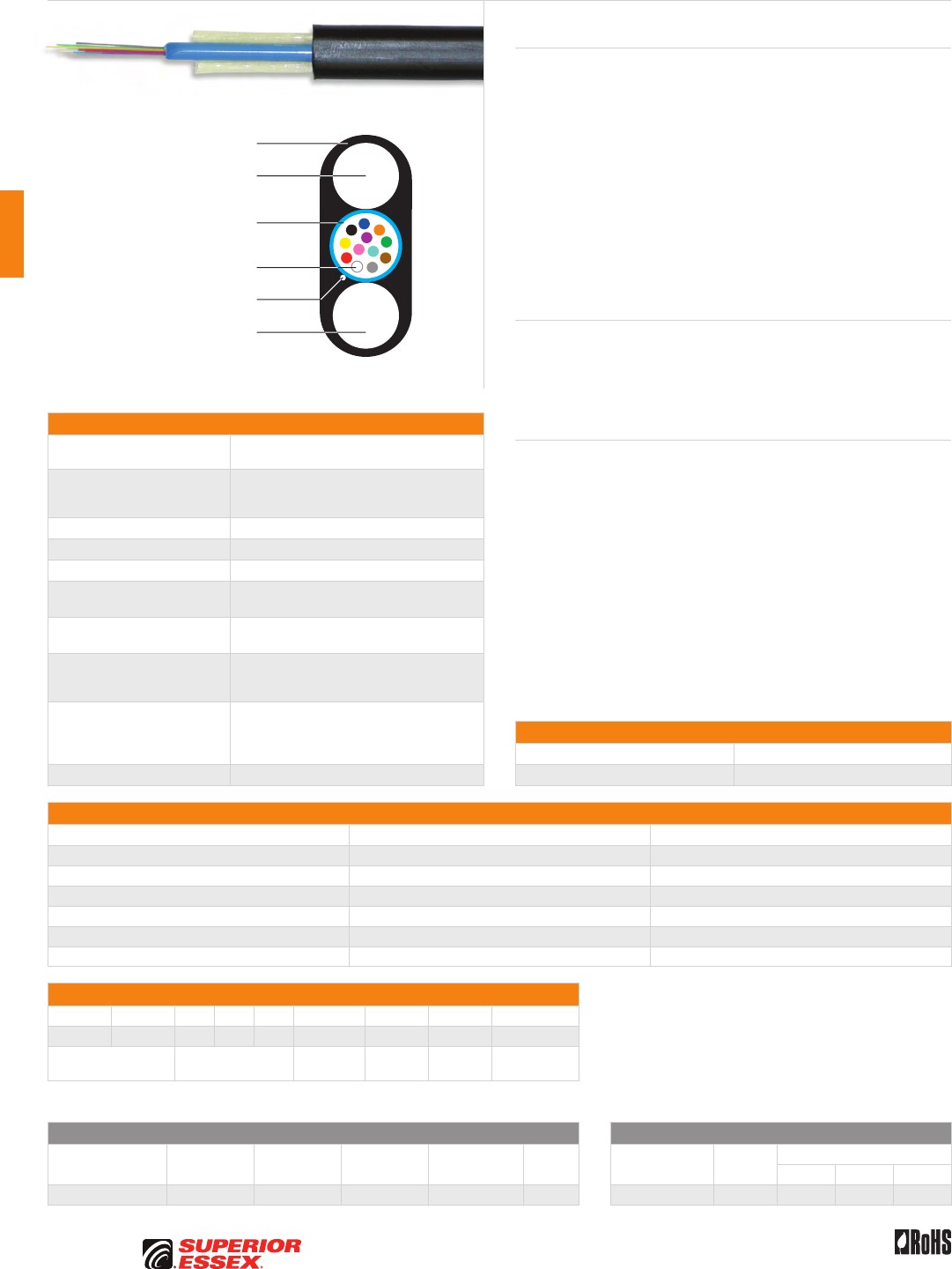
C-34
PREMISES COPPER PREMISES FIBER OSP FIBER OSP COMPOSITE CENTRAL OFFICE COPPER RDUP/RUS OSP COPPER BELL OSP COPPER OSP COPPER WIRE CANADIAN OSP COPPER TECHNICAL INFO
Toll Free 800.551.8948 | Fax 770.657.6807 | SuperiorEssex.com/Comm Rev 10/10 Ed 10.3
Specifications
Fiber Count Available with up to 12-fiber inside a PFM™ gel
filled loose buffer tube
Strength Members
Water blocking dielectric strength members placed
parallel to single loose tube, one on each side,
to provide necessary longitudinal strength
Jacket Black, UV resistant PVC jacket
Nominal Dimensions in (mm) 0.33 (8.2) x 0.18 (4.5)
Weight lbs/kft 24
Minor Dimension
Bend Radius in (mm) 3.19 (81)
Maximum Tensile Loading
lbs (N)
Install: 300 (1,335)
Long Term: 90 (405)
Maximum Span Length
at 1% Sag ft (m)
Light Loading: 330 (101)
Medium Loading: 225 (69)
Heavy Loading: 150 (46)
Performance Compliance
Telcordia GR-20-CORE
RDUP PE-90
UL 1666
RoHS-compliant
NRTL Programs UL, c(UL) Listed OFNR
Part Numbers and Physical Characteristics
Part Number¹ Fiber Count Package
57002x02Q 2 2,500’ Reel
57002x0CQ 2 1,000’ Reel-in-a-Box
57004x02Q 4 2,500’ Reel
57004x0CQ 4 1,000’ Reel-in-a-Box
57012x02Q 12 2,500’ Reel
57012x0CQ 12 1,000’ Reel-in-a-Box
Part Number Designators
5 7 _ _ _ x 0 2 or C Q
1 2 3 4 5 6 7 8 9
product family fiber count (001-012) fiber type internal
designator
package
type
internal
designator
Contact Customer Service for availability of non-standard offerings.
See "Optical Fiber Cable" options in the "TECHNICAL INFO" section for flooding and jacket marking options.
Single Mode Optical Fiber Multimode Optical Fiber
Conventional
Reduced
Water Peak
Zero
Water Peak
TeraFlex®
Bend Resistant NZDS
TeraGain®
62.5/125
TeraGain Laser Optimized 50/125
10G/150 10G/300 10G/550
¹Replace “x” with: 9 3 2 K 8 ¹Replace “x” with: 6 A B F
See the "Optical Fiber Selection Chart" in the "TECHNICAL INFO" section for detailed fiber type specifications.
Product Description
Universal FTTP OFNR offers the most complete solution for the fiber to the
premise application. This compact cable is RoHS-compliant and OFNR rated
making this cable universal in application. The cable is designed for use
in duct, aerial, direct bury and riser environments. The product is RoHS-
compliant meaning no heavy metals. The single tube contains PFM™ gel
which provides ease of clean up. The OFNR rating allows use of the cable
inside buildings removing the need for termination. This product is available
with TeraFlex® optical fiber which complies with ITU G.652D and provides
increased bend performance.
Universal FTTP OFNR is offered as a bulk reel with a standard length of 2,500’
or in a Reel-in-a-Box (weather resistant package containing 1,000 ft and
weighing only 35 lbs). QuickCount® print is standard on the Reel-in-a-Box and
reduces scrap by identifying the length of cable remaining in the box.
Applications
• Drop cables
• Broadband network
• Local loop
• Fiber to the premise
Features Benefits
• Available with up to 12-fiber • Offers the maximum bandwidth
for FTTP business, etc.
• Multiple fiber types including
TeraFlex® bend resistant
• Multiple network applications
• Universal design • Aerial, direct bury,
conduit, indoor riser
• PFM™ gel • Non-sticky gel reduces installation
time and labor cost
• OFNR rating • Indoor/outdoor use
• UL Listed, sunlight resistant • Longer cable life
• Reel-in-a-Box package option • QuickCount® countdown footage
marking feature reduces scrap
• Easy to carry and store
Universal FTTP OFNR
Series 57R
UV Resistant OFNR Jacket
PFM™ Gel Filled
Loose Buffer Tube
Optical Fiber
Water Blocking Dielectric
Strength Member
Water Blocking Dielectric
Strength Member
Water Blocking Thread
Environmental Specifications
Operation/Storage -40°C to +70°C
Installation -10°C to +70°C
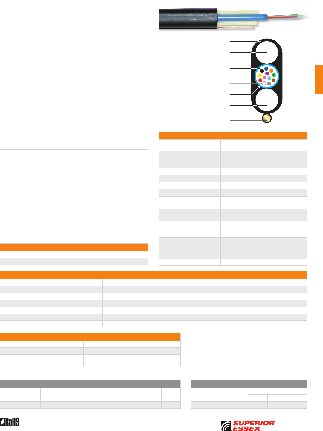
C-35
PREMISES COPPERPREMISES FIBEROSP FIBEROSP COMPOSITECENTRAL OFFICE COPPERRDUP/RUS OSP COPPERBELL OSP COPPEROSP COPPER WIRECANADIAN OSP COPPERTECHNICAL INFO
Toll Free 800.551.8948 | Fax 770.657.6807 | SuperiorEssex.com/CommRev 10/10 Ed 10.3
Specifications
Fiber Count Available with up to 12-fiber inside a PFM™ gel
filled loose buffer tube
Strength Members
Water blocking dielectric strength members placed
parallel to single loose tube, one on each side,
to provide necessary longitudinal strength
Toneable Element 24 AWG copper wire encased in a jacket
Jacket Black, UV resistant PVC jacket
Nominal Dimensions in (mm) 0.40 (10.2) x 0.18 (4.5)
Weight lbs/kft 35
Minor Dimension
Bend Radius in (mm) 3.19 (81)
Maximum Tensile Loading
lbs (N)
Install: 300 (1,335)
Long Term: 90 (405)
Maximum Span Length
at 1% Sag ft (m)
Light Loading: 330 (101)
Medium Loading: 225 (69)
Heavy Loading: 150 (46)
Performance Compliance
Telcordia GR-20-CORE
RDUP PE-90
UL 1666
RoHS-compliant
NRTL Programs UL, c(UL) Listed OFCR
Part Numbers and Physical Characteristics
Part Number¹ Fiber Count Package
57002x12Q 2 2,500’ Reel
57002x1CQ 2 1,000’ Reel-in-a-Box
57004x12Q 4 2,500’ Reel
57004x1CQ 4 1,000’ Reel-in-a-Box
57012x12Q 12 2,500’ Reel
57012x1CQ 12 1,000’ Reel-in-a-Box
Part Number Designators
5 7 _ _ _ x 1 2 or C Q
1 2 3 4 5 6 7 8 9
product family fiber count (001-012) fiber type internal
designator
package
type
internal
designator
Contact Customer Service for availability of non-standard offerings.
See "Optical Fiber Cable" options in the "TECHNICAL INFO" section for flooding and jacket marking options.
Single Mode Optical Fiber Multimode Optical Fiber
Conventional
Reduced
Water Peak
Zero
Water Peak
TeraFlex®
Bend Resistant NZDS
TeraGain®
62.5/125
TeraGain Laser Optimized 50/125
10G/150 10G/300 10G/550
¹Replace “x” with: 9 3 2 K 8 ¹Replace “x” with: 6 A B F
See the "Optical Fiber Selection Chart" in the "TECHNICAL INFO" section for detailed fiber type specifications.
Toneable FTTP OFCR
Series 57CR
Product Description
Toneable FTTP OFCR offers the most complete solution for the fiber to the
premise application. This compact cable is RoHS-compliant and OFCR rated
making this cable universal in application. The cable is designed for use in
duct, aerial, direct bury and riser environments. Cable location is made simple
with the toneable copper wire. The product is RoHS-compliant meaning no
heavy metals. The single tube contains PFM™ gel, which provides ease of
clean up. The OFCR rating allows use of the cable inside buildings removing
the need for termination. This product is standard with TeraFlex™ optical fiber
which complies with ITU G.652D and provides increased bend performance.
Toneable FTTP OFCR is offered as a bulk reel with a standard length of 2,500’
or in a Reel-in-a-Box (weather resistant package containing 1,000 ft and
weighing only 35 lbs). QuickCount® print is standard on the Reel-in-a-Box
and reduces scrap by identifying the length of cable remaining in the box.
Applications
• Drop cables
• Broadband network
• Local loop
• Fiber to the premise
Features Benefits
• Available with up to 12-fiber • Offers the maximum bandwidth
for FTTP business, etc.
• Multiple fiber types including
TeraFlex® bend resistant
• Multiple network applications
• Universal design • Aerial, direct bury,
conduit, indoor riser
• PFM™ gel • Non-sticky gel reduces installation
time and labor cost
• OFCR rating • Indoor/outdoor use
• Reel-in-a-Box package option • QuickCount® countdown footage
marking feature reduces scrap
• Easy to carry and store
• Toneable element • Ease of location
UV Resistant OFCR Jacket
PFM™ Gel Filled
Loose Buffer Tube
Optical Fiber
Water Blocking Dielectric
Strength Member
Water Blocking Dielectric
Strength Member
24 AWG Copper Wire
Water Blocking Thread
Environmental Specifications
Operation/Storage -40°C to +70°C
Installation -10°C to +70°C

C-36
PREMISES COPPER PREMISES FIBER OSP FIBER OSP COMPOSITE CENTRAL OFFICE COPPER RDUP/RUS OSP COPPER BELL OSP COPPER OSP COPPER WIRE CANADIAN OSP COPPER TECHNICAL INFO
Toll Free 800.551.8948 | Fax 770.657.6807 | SuperiorEssex.com/Comm Rev 11/10 Ed 10.3
Specifications
Fiber Count Available in 1-fiber up to 12-fiber inside
a PFM™ gel filled loose buffer tube
Strength Members 2.1 mm solid steel strand
Jacket Black, weather resistant PVC jacket
Nominal Diameter in (mm) 0.18 (4.5)
Major Dimension in (mm) 0.35 (8.9)
Nominal Weight lbs/kft (kg/km) 34 (50)
Maximum Tensile Loading lbs (N) Install: 300 (1,334)
Long Term: 90 (400)
Minimum Bend Radius in (mm) Install: 3.6 (91)
Long Term: 1.8 (46)
Standards Compliance
Telcordia GR-20-CORE
RDUP PE-90 Designation 573Q
RoHS-compliant
Part Numbers and Physical Characteristics
Part Number¹ Fiber Count
57001x23Q 1
57002x23Q 2
57004x23Q 4
57006x23Q 6
57008x23Q 8
57012x23Q 12
Part Number Designators
5 7 _ _ _ x 2 3 Q
1 2 3 4 5 6 7 8 9
product family fiber count (001-012) fiber type internal designator internal
designator
Contact Customer Service for availability of non-standard offerings.
See "Optical Fiber Cable" options in the "TECHNICAL INFO" section for flooding and jacket marking options.
Single Mode Optical Fiber Multimode Optical Fiber
Conventional
Reduced
Water Peak
Zero
Water Peak
TeraFlex®
Bend Resistant NZDS
TeraGain®
62.5/125
TeraGain Laser Optimized 50/125
10G/150 10G/300 10G/550
¹Replace “x” with: 9 3 2 K 8 ¹Replace “x” with: 6 A B F
See the "Optical Fiber Selection Chart" in the "TECHNICAL INFO" section for detailed fiber type specifications.
Product Description
Figure 8 FTTP offers an aerial solution for fiber to the premise applications.
This small profile aerial cable incorporates a 2.1 mm solid steel strand
supporting a single enhanced loose tube containing up to 12 optical fibers
and PFM™ gel. The small profile reduces cost and problems associated
with wind or ice load. This is a water-blocked design, using a “dry” water
absorbing thread to prevent the migration of moisture. A black, weather
resistant jacket of PVC completes the cable construction.
Applications
• Aerial self support drop cables
• Broadband network
• Local loop
• Fiber to the premise
Features Benefits
• Available with1-fiber
up to 12-fiber
• Offers the maximum bandwidth
for FTTP business, etc.
• Multiple fiber types including
TeraFlex® bend resistant
• Multiple network applications
• PFM™ gel • Non-sticky gel reduces
installation time and labor cost
• Dry (SAP) core standard • Reduces cable prep
and installation time
• PVC jacket • Improves flexibility
• Steel messenger • Allows use of standard hardware
Figure 8 FTTP
Series 573Q
Optical Fiber
Dielectric Water Blocking
Strength Members
PFM™ Gel Filled Tube
Rip Cord
UV Resistant Jacket
EHS Steel Messenger
Environmental Specifications
Operation/Storage -40°C to +70°C
Installation -10°C to +60°C
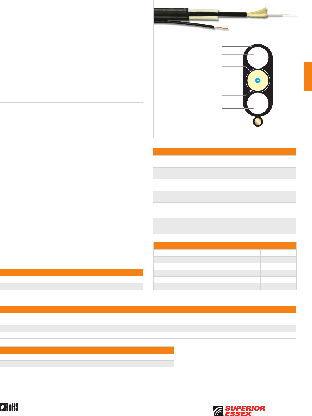
C-37
PREMISES COPPERPREMISES FIBEROSP FIBEROSP COMPOSITECENTRAL OFFICE COPPERRDUP/RUS OSP COPPERBELL OSP COPPEROSP COPPER WIRECANADIAN OSP COPPERTECHNICAL INFO
Toll Free 800.551.8948 | Fax 770.657.6807 | SuperiorEssex.com/CommRev 6/10 Ed 10.1
FTTP Tight Buffered Indoor/Outdoor Drop
Series W7
UV Resistant OFNR Jacket
Aramid Yarns
900 µm Tight Buffered
Optical Fiber
Water Blocking Dielectric
Strength Member
Water Blocking Dielectric
Strength Member
Optional Toneable
Copper Element
OFNR Jacket
Water Blocking
Thread
Specifications
Simplex OFNR Nominal Diameter
in (mm) 0.11 (2.9)
Simplex OFNR Bend Radius
in (mm)
Install: 2.2 (56)
Long Term: 1.1 (28)
Cable Bend Radius
in (mm)
Install: 3.6 (91)
Long Term: 1.8 (46)
Cable Tensile Load lbs (N) Install: 300 (1,350)
Long Term: 90 (405)
Maximum Span Length at 1% Sag
ft (m)
Light Loading: 350 (101)
Medium Loading: 275 (84)
Heavy Loading: 150 (46)
Standards Compliance
Telcordia GR-20-CORE
Telcordia GR-409-CORE
RoHS-compliant
Macro Bending Performance
10 Turns on 15 mm Radius Mandrel ITU G 657 A TeraFlex®
Macro bending loss @ 1550 nm 0.25 dB Max. ≤ 0.20 dB
Macro bending loss @ 1625 nm 1.00 dB Max. ≤ 0.50 dB
1 Turn on 10 mm Radius Mandrel ITU G 657 A TeraFlex®
Macro bending loss @ 1550 nm 0.75 dB Max. ≤ 0.20 dB
Macro bending loss @ 1625 nm 1.50 dB Max. ≤ 0.20 dB
TeraFlex® is an ITU G 657 A optical fiber that is completely compatible with ITU G 652 D
optical fibers. TeraFlex exceeds the performance standards of ITU G 657 A as listed above.
Part Numbers and Physical Characteristics
Part Number¹ Description
Nominal Dimensions
in (mm)
Weight
lbs/kft (kg/km)
W7001KU01 Universal Indoor/Outdoor FTTP 0.33 (8.2) x 0.18 (4.5) 29 (44)
W7001K101 Toneable Indoor/Outdoor FTTP 0.40 (10.2) x 0.18 (4.5) 31 (47)
Part Number Designators
W 7 0 0 1 K 1 or U 0 _
1 2 3 4 5 6 7 8 9
product family fiber count (001) fiber type internal designator water block/
marking (1-8)
Contact Customer Service for availability of non-standard offerings.
See "Optical Fiber Cable" options in the "TECHNICAL INFO" section for flooding and jacket marking options.
Product Description
Series W7 FTTP is the first indoor/outdoor drop cable that is rugged
enough for outdoor environments and flexible enough for tight bends
within residences. The patent-pending design utilizes a fully functional
2.9 mm OFNR rated simplex tight buffer cable as the core of a GR-20 OSP
rated FTTP small flat cable. The key benefit of this cable is that it can be
installed from the pedestal to the indoor ONT (Optical Network Terminal)
with no intermediate termination. Significant installation savings can be
realized by avoiding splicing or termination on the outside or inside wall
of the residence. Further savings are realized by using an indoor ONT that
does not require an electrician to install. This completely dry, flat drop
cable is available in universal and toneable designs that are suitable for
aerial, direct bury or conduit installation. A water blocking thread is used
to prevent water penetration.
Applications
• Drop cables for aerial, direct bury or conduit installations
• Fiber to the premise for single family residences
Features Benefits
• Universal design • Aerial, direct bury or conduit,
all dielectric
• Toneable design • Copper element allows
for toneable location
• Dielectric rods • Excellent crush resistance
• Indoor/outdoor design • Tight Buffered cable can be
placed in a riser environment
and is UL listed
• Meets GR-20 specifications • Industry accepted standard
for OSP installations
• Cable in a cable • Eliminates splice at premises wall
• TeraFlex® fiber in a flexible tight
buffer cable design
• Inner cable can be wrapped
around corners and stapled
with no attenuation issues
Environmental Specifications
Operation/Storage -40°C to +70°C
Installation -10°C to +70°C
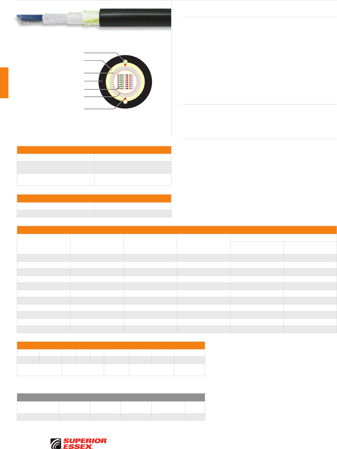
C-38
PREMISES COPPER PREMISES FIBER OSP FIBER OSP COMPOSITE CENTRAL OFFICE COPPER RDUP/RUS OSP COPPER BELL OSP COPPER OSP COPPER WIRE CANADIAN OSP COPPER TECHNICAL INFO
Rev 7/10 Ed 10.2Toll Free 800.551.8948 | Fax 770.657.6807 | SuperiorEssex.com/Comm
Specifications
Fiber Count Available in 12-fiber up to 432-fiber
Maximum Tensile Loading lbs (N) Install: 600 (2,700)
Long Term: 200 (890)
Standards Compliance Telcordia GR-20-CORE
RDUP PE-90 Designation R1D
Environmental Specifications
Operation/Storage -40°C to +70°C
Installation -30°C to +60°C
Part Numbers and Physical Characteristics
Part Number¹ Fiber Count
Nominal Diameter
in (mm)
Approx. Weight
lbs/kft (kg/km)
Minimum Bend Radius
Install
in (mm)
Long Term
in (mm)
R1012xD01 12 0.51 (13.0) 69 (103) 10.2 (260) 5.1 (130)
R1024xD01 24 0.51 (13.0) 69 (103) 10.2 (260) 5.1 (130)
R1048xD01 48 0.59 (15.0) 91 (136) 11.8 (300) 5.9 (150)
R1072xD01 72 0.59 (15.0) 91 (136) 11.8 (300) 5.9 (150)
R1096xD01 96 0.67 (17.0) 115 (171) 13.4 (340) 6.7 (170)
R1144xD01 144 0.67 (17.0) 115 (171) 13.4 (340) 6.7 (170)
R1192xD01 192 0.71 (18.0) 147 (219) 14.2 (360) 7.1 (180)
R1216xD01 216 0.71 (18.0) 147 (219) 14.2 (360) 7.1 (180)
R1288xD01 288 0.78 (19.8) 173 (258) 15.6 (396) 7.8 (198)
R1360xD01 360 0.78 (19.8) 173 (258) 15.6 (396) 7.8 (198)
R1432xD01 432 0.78 (19.8) 173 (258) 15.6 (396) 7.8 (198)
Part Number Designators
R 1 _ _ _ x D 0 _
1 2 3 4 5 6 7 8 9
product family fiber count (012-432) fiber type internal designator water block/
marking (1-8)
Contact Customer Service for availability of non-standard offerings.
See "Optical Fiber Cable" options in the "TECHNICAL INFO" section for flooding and jacket marking options.
Single Mode Optical Fiber
Conventional
Reduced
Water Peak
Zero
Water Peak
TeraFlex®
Bend Resistant NZDS
¹Replace “x” with: 9 3 2 K 8
See the "Optical Fiber Selection Chart" in the "TECHNICAL INFO" section for detailed fiber type specifications.
Dri-Lite® Ribbon
Series R1D
Product Description
Dri-Lite® Ribbon Cable is a totally gel free cable. The cable is designed for
Outside Plant (OSP) application, specifically lashed aerial and underground
duct applications. Our industry leading optical ribbons are manufactured
with high dimensional precision and low planarity, which equates to low
losses during mass fusion splicing. The Dri-Lite Ribbon cable features
optical ribbons inside a gel free tube which contains dry water blocking
elements. The core tube contains up to eighteen 12-fiber or 24-fiber ribbons.
Each ribbon unit is discretely identified and captured in an easy peel matrix
for ease of ribbon breakout and management. The core tube is wrapped with
a water blocking tape. Longitudinal strength elements are applied over the
core tube and encased within a black jacket. A rip cord is included under
the jacket for easy access to the core tube.
Applications
• Lashed aerial
• Underground duct
• Broadband network
Features Benefits
• Gel free water blocking
technology
• Reduces preparation time
and labor cost
• Available in 12-fiber
up to 432-fiber
• High fiber density
• Multiple fiber types available • Multiple network applications
• Highly flexible tube • Easier handling and reduced loss
• Meets or exceeds Telcordia
and RDUP specifications
• Industry approved
• Small outer diameter • Up to 432 optical fibers in less
than a 1 inch nominal diameter
• Industry leading planarity • Excellent mass splicing results
UV Resistant Jacket
Dielectric Water Blocking
Strength Members
Central Buffer Tube
Optical Fiber Ribbons
Dry Water Blocking
Elements
Dielectric Rods
Rip Cords
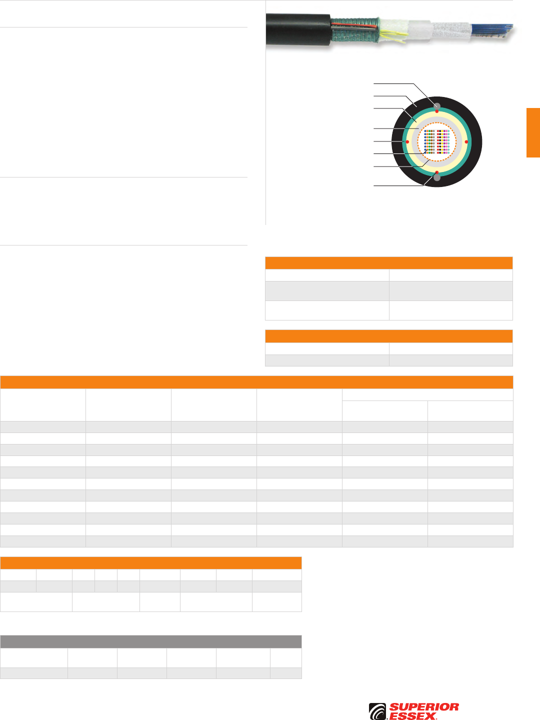
C-39
PREMISES COPPERPREMISES FIBEROSP FIBEROSP COMPOSITECENTRAL OFFICE COPPERRDUP/RUS OSP COPPERBELL OSP COPPEROSP COPPER WIRECANADIAN OSP COPPERTECHNICAL INFO
Rev 7/10 Ed 10.2 Toll Free 800.551.8948 | Fax 770.657.6807 | SuperiorEssex.com/Comm
Specifications
Fiber Count Available in 12-fiber up to 432-fiber
Maximum Tensile Loading lbs (N) Install: 600 (2,700)
Long Term: 200 (890)
Standards Compliance Telcordia GR-20-CORE
RDUP PE-90 Designation R2D
Environmental Specifications
Operation/Storage -40°C to +70°C
Installation -30°C to +60°C
Part Numbers and Physical Characteristics
Part Number¹ Fiber Count
Nominal Diameter
in (mm)
Approx. Weight
lbs/kft (kg/km)
Minimum Bend Radius
Install
in (mm)
Long Term
in (mm)
R2012xDS1 12 0.51 (13.0) 110 (164) 10.2 (260) 5.1 (130)
R2024xDS1 24 0.51 (13.0) 110 (164) 10.2 (260) 5.1 (130)
R2048xDS1 48 0.58 (15.0) 135 (201) 11.6 (295) 5.8 (147)
R2072xDS1 72 0.58 (15.0) 137 (203) 11.6 (295) 5.8 (147)
R2096xDS1 96 0.66 (17.0) 163 (242) 13.2 (340) 6.6 (170)
R2144xDS1 144 0.66 (17.0) 166 (247) 13.2 (340) 6.6 (170)
R2192xDS1 192 0.71 (18.0) 172 (256) 14.2 (360) 7.1 (180)
R2216xDS1 216 0.71 (18.0) 172 (256) 14.2 (360) 7.1 (180)
R2288xDS1 288 0.84 (21.3) 226 (337) 16.8 (437) 8.4 (219)
R2360xDS1 360 0.84 (21.3) 226 (337) 16.8 (437) 8.4 (219)
R2432xDS1 432 0.84 (21.3) 226 (337) 16.8 (437) 8.4 (219)
Part Number Designators
R 2 _ _ _ x D S _
1 2 3 4 5 6 7 8 9
product family fiber count (012-432) fiber type internal designator water block/
marking (1-8)
Contact Customer Service for availability of non-standard offerings.
See "Optical Fiber Cable" options in the "TECHNICAL INFO" section for flooding and jacket marking options.
Single Mode Optical Fiber
Conventional
Reduced
Water Peak
Zero
Water Peak
TeraFlex®
Bend Resistant NZDS
¹Replace “x” with: 9 3 2 K 8
See the "Optical Fiber Selection Chart" in the "TECHNICAL INFO" section for detailed fiber type specifications.
Dri-Lite® Ribbon Single Armor
Series R2D
UV Resistant Jacket
Corrugated Steel Armor
Dielectric Water Blocking
Strength Members
Central Buffer Tube
Optical Fiber Ribbons
Dry Water
Blocking Elements
Steel Rods
Rip Cords
Product Description
Dri-Lite® Ribbon Single Armor Cable is a totally gel free cable. The cable
is designed for Outside Plant (OSP) application, specifically direct buried,
lashed aerial and underground duct applications. Our industry leading
optical ribbons are manufactured with high dimensional precision and low
planarity, which equates to low losses during mass fusion splicing. The
Dri-Lite Ribbon Single Armor cable features optical ribbons inside a gel free
tube which contains dry water blocking elements. The core tube contains
up to eighteen 12-fiber or 24-fiber ribbons. Each ribbon unit is discretely
identified and captured in an easy peel matrix for ease of ribbon breakout
and management. The core tube is wrapped with a water blocking tape. A
corrugated steel armor and longitudinal strength elements are applied over
the core tube and encased within a black jacket. Rip cords are included
under the armor for easy access to the core tube.
Applications
• Direct bury
• Lashed aerial
• Underground duct
• Broadband network
Features Benefits
• Gel free water blocking
technology
• Reduces preparation time
and labor cost
• Available in 12-fiber
up to 432-fiber
• High fiber density
• Multiple fiber types available • Multiple network applications
• Highly flexible tube • Easier handling and reduced loss
• Meets or exceeds Telcordia
and RDUP specifications
• Industry approved
• Small outer diameter • Up to 432 optical fibers in less
than a 1 inch nominal diameter
• Industry leading planarity • Excellent mass splicing results

Toll Free 800.551.8948 | Fax 770.657.6807 | SuperiorEssex.com/Comm
We’re not just talking about being green.
We’re doing things that make a real difference.
Our actions, to date, have resulted in
substantial reductions in energy, CO
2
emissions, landfill
and other waste. And now our progress on recycling
and conservation is leading the industry.
To get the details for our real progress, visit spsx.com/green.aspx.
Being Green
Less Talk, More Action
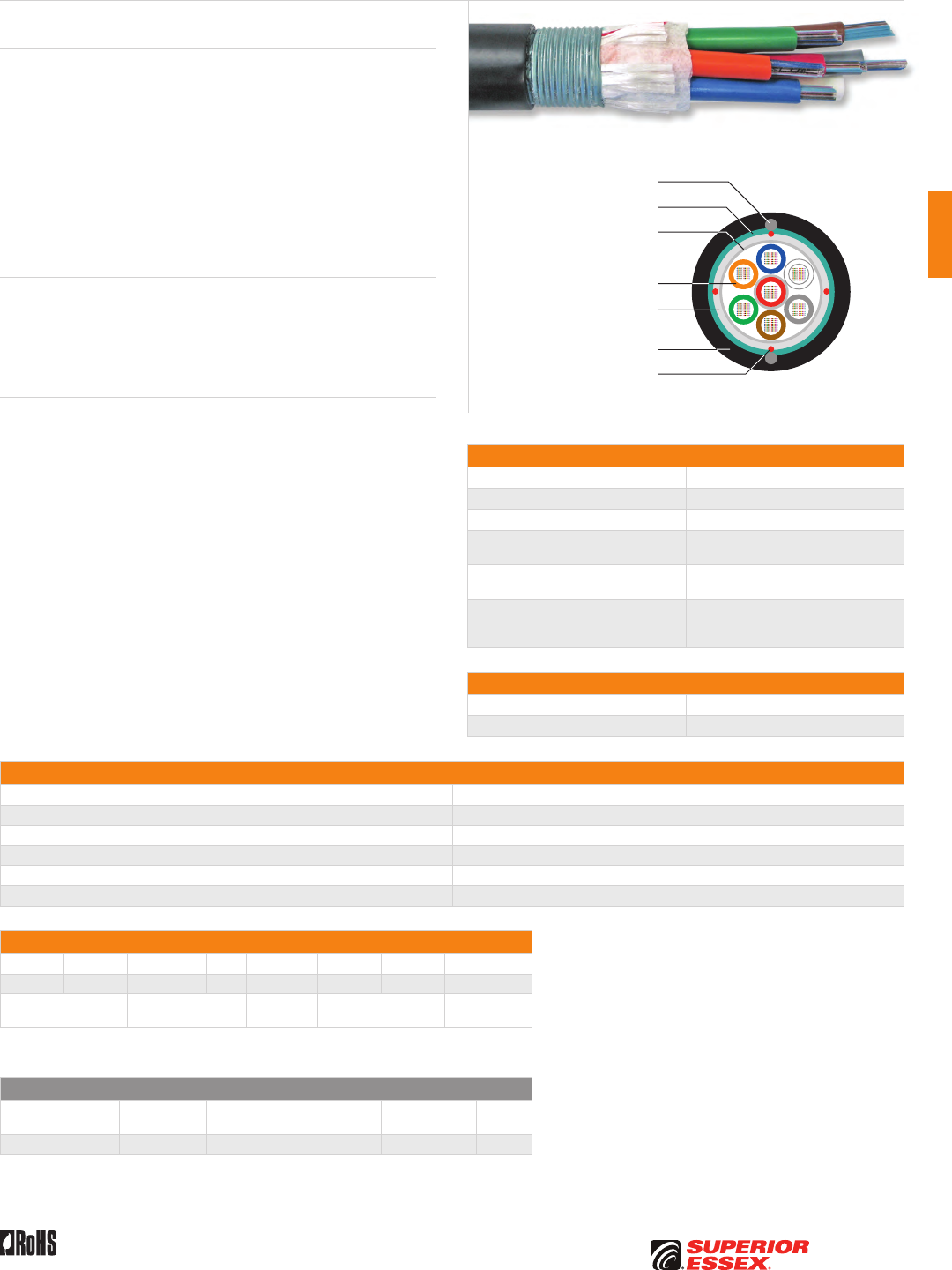
C-41
PREMISES COPPERPREMISES FIBEROSP FIBEROSP COMPOSITECENTRAL OFFICE COPPERRDUP/RUS OSP COPPERBELL OSP COPPEROSP COPPER WIRECANADIAN OSP COPPERTECHNICAL INFO
Rev 7/10 Ed 10.2 Toll Free 800.551.8948 | Fax 770.657.6807 | SuperiorEssex.com/Comm
Product Description
Stranded Tube Ribbon Single Armor Cable is designed for Outside Plant
(OSP) applications specifically direct bury installations. Our industry leading
optical fiber ribbons are manufactured with high dimensional precision and
low planarity which equates to low losses during mass fusion splicing. The
stranded tube design features optical fibers ribbons placed inside gel filled
tubes. Each tube contains up to 12 discretely identified, 12-fiber ribbons for
maximum design load capacity of 1,008 optical fibers. The core is helically
wrapped with water blocking strength members. A corrugated steel armor
is applied over the stranded core. Rigid steel rods encased in a outer jacket
completes the construction. Rip cords are included under the armor for
ease of entry.
Applications
• Direct bury
• Broadband network
• Local loop
• Trunk, distribution and feeder cables
Features Benefits
• Available with up to 1,008-fiber • High fiber density
• Multiple fiber types available • Multiple network applications
• Multiple stranded tubes • Individual tube access
• Corrugated steel armor • Compressive strength, rodent
protection and ease of location
• Ribbon fiber • Saves labor cost by offering
mass fusion splicing
Specifications
Fiber Count Available in 360-fiber up to 1,008-fiber
Nominal Diameter in (mm) 1.25 (31.8)
Nominal Weight lbs/kft (kg/km) 552 (821)
Maximum Tensile Loading lbs (N) Install: 600 (2,700)
Long Term: 180 (800)
Minimum Bend Radius in (mm) Install: 25.0 (635)
Long Term: 12.5 (318)
Standards Compliance
Telcordia GR-20-CORE
RDUP PE-90 Designtaion S2
RoHS-compliant
Environmental Specifications
Operation/Storage -40°C to +70°C
Installation -30°C to +60°C
Part Numbers and Physical Characteristics
Part Number¹ Fiber Count
S2360x101 360
S2432x101 432
S2576x101 576
S2864x101 864
S2A08x101 1,008
Part Number Designators
S 2 _ _ _ x 1 0 _
1 2 3 4 5 6 7 8 9
product family fiber count (360-A08) fiber type internal designator water block/
marking (1-8)
Contact Customer Service for availability of non-standard offerings.
See "Optical Fiber Cable" options in the "TECHNICAL INFO" section for flooding and jacket marking options.
Single Mode Optical Fiber
Conventional
Reduced
Water Peak
Zero
Water Peak
TeraFlex®
Bend Resistant NZDS
¹Replace “x” with: 9 3 2 K 8
See the "Optical Fiber Selection Chart" in the "TECHNICAL INFO" section for detailed fiber type specifications.
Stranded Tube Ribbon Single Armor
Series S2
Dielectric Water Blocking
Strength Members
Water Blocking Tape
Corrugated Steel Armor
Steel Rods
Optical Fiber Ribbons
Rip Cords
UV Resistant Jacket
PFM™ Gel Filled Tube
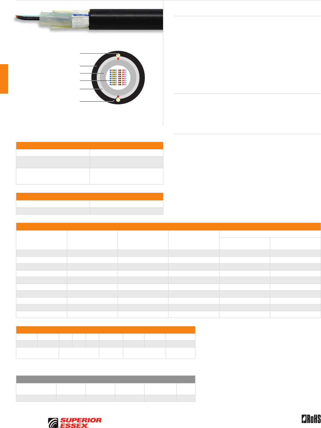
C-42
PREMISES COPPER PREMISES FIBER OSP FIBER OSP COMPOSITE CENTRAL OFFICE COPPER RDUP/RUS OSP COPPER BELL OSP COPPER OSP COPPER WIRE CANADIAN OSP COPPER TECHNICAL INFO
Rev 7/10 Ed 10.2Toll Free 800.551.8948 | Fax 770.657.6807 | SuperiorEssex.com/Comm
Specifications
Fiber Count Available in 12-fiber up to 432-fiber
Maximum Tensile Loading lbs (N) Install: 600 (2,700)
Long Term: 200 (890)
Standards Compliance
Telcordia GR-20-CORE
RDUP PE-90 Designation SLT-R
RoHS-compliant
Environmental Specifications
Operation/Storage -40°C to +70°C
Installation -30°C to +60°C
Part Numbers and Physical Characteristics
Part Number¹ Fiber Count
Nominal Diameter
in (mm)
Nominal Weight
lbs/kft (kg/km)
Minimum Bend Radius
Install
in (mm)
Long Term
in (mm)
R1012x101 12 0.47 (12.0) 76 (113) 9.4 (239) 4.7 (119)
R1048x101 48 0.47 (11.9) 76 (113) 9.4 (239) 4.7 (119)
R1072x101 72 0.55 (13.9) 101 (149) 11.0 (279) 5.5 (140)
R1096x101 96 0.55 (13.9) 101 (149) 11.0 (279) 5.5 (140)
R1144x101 144 0.63 (15.9) 131 (195) 12.6 (320) 6.3 (160)
R1192x101 192 0.67 (17.0) 150 (223) 13.4 (340) 6.7 (170)
R1216x101 216 0.67 (17.0) 150 (223) 13.4 (340) 6.7 (170)
R1288x101 288 0.79 (20.0) 188 (280) 15.8 (401) 7.9 (201)
R1360x101 360 0.79 (20.0) 188 (280) 15.8 (401) 7.9 (201)
R1432x101 432 0.79 (20.0) 188 (280) 15.8 (401) 7.9 (201)
Part Number Designators
R 1 _ _ _ x 1 0 _
1 2 3 4 5 6 7 8 9
product family fiber count (012-432) fiber type internal designator water block/
marking (1-8)
Contact Customer Service for availability of non-standard offerings.
See "Optical Fiber Cable" options in the "TECHNICAL INFO" section for flooding and jacket marking options.
Single Mode Optical Fiber
Conventional
Reduced
Water Peak
Zero
Water Peak
TeraFlex®
Bend Resistant NZDS
¹Replace “x” with: 9 3 2 K 8
See the "Optical Fiber Selection Chart" in the "TECHNICAL INFO" section for detailed fiber type specifications.
Single Tube Ribbon
Series R1
Product Description
Single Tube Ribbon Cable is designed for Outside Plant (OSP) applications,
specifically lashed aerial and underground duct installations. Our industry
leading optical ribbons are manufactured with high dimensional precision
and low planarity, which equates to low losses during mass fusion spicing.
The Single Tube Ribbon Cable features optical ribbons inside a single PFM™
gel filled tube. The core tube includes up to eighteen 12-fiber or 24-fiber
ribbons. Each 12-fiber ribbon unit is discretely identified and captured in an
easy peel matrix for ease of ribbon breakout and management. The core tube
is wrapped with a water blocking tape. Longitudinal strength elements are
applied over the core tube and encased within a black jacket. A rip cord is
included under the jacket for easy access to the core tube.
Applications
• Lashed aerial, underground duct
• Broadband network
• Local loop
• Trunk, distribution and feeder cables
Features Benefits
• Available with up to 432-fiber • High fiber density
• Multiple fiber types available • Multiple network applications
• Dielectric strength members • Dielectric design eliminates
grounding issues
• Highly flexible tube • Easy handling and easy
tube access
• Ribbon fiber • Saves labor cost by offering
mass fusion splicing
• Meets or exceeds Bellcore
and RDUP specifications
• Industry approved
• PFM™ gel • Non-sticky gel allows for easier
and faster clean up
Optical Fiber Ribbons
Dielectric Water Blocking
Strength Members
PFM™ Gel Filled Tube
Rip Cords
UV Resistant Jacket
Dielectric Outer
Strength Members
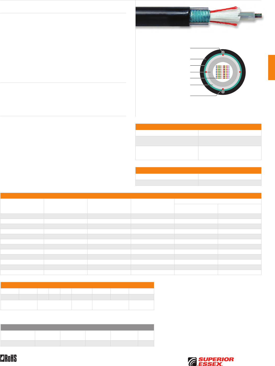
C-43
PREMISES COPPERPREMISES FIBEROSP FIBEROSP COMPOSITECENTRAL OFFICE COPPERRDUP/RUS OSP COPPERBELL OSP COPPEROSP COPPER WIRECANADIAN OSP COPPERTECHNICAL INFO
Rev 7/10 Ed 10.2 Toll Free 800.551.8948 | Fax 770.657.6807 | SuperiorEssex.com/Comm
Product Description
Single Tube Ribbon Single Armor Cable is designed for Outside Plant (OSP)
applications, specifically lashed aerial and underground duct installations.
Our industry leading optical ribbons are manufactured with high dimensional
precision and low planarity, which equates to low losses during mass
fusion spicing. The Single Tube Ribbon Single Armor cable features optical
ribbons inside a single PFM™ gel filled tube. The core tube includes up to
eighteen 12-fiber or 24-fiber ribbons. Each 12-fiber ribbon unit is discretely
identified and captured in an easy peel matrix for ease of ribbon breakout
and management. The core tube is wrapped with a water blocking tape. A
corrugated steel armor and longitudinal strength elements are applied over
the core tube and encased within a black jacket. Rip cords are included
under the armor for easy access to the core tube.
Applications
• Direct bury
• Broadband network
• Local loop
• Trunk, distribution and feeder cables
Features Benefits
• Available with up to 432-fiber • High fiber density
• Multiple fiber types available • Multiple network applications
• Metallic outer strength members • Metallic design offers
easy location
• Highly flexible tube • Easy handling and easy
tube access
• Corrugated steel armor • Compressive strength, rodent
protection and ease of location
• Ribbon fiber • Saves labor cost by offering
mass fusion splicing
• Meets or exceeds Bellcore
and RDUP specifications
• Industry approved
• PFM™ gel • Non-sticky gel allows for easier
and faster clean up
Specifications
Fiber Count Available in 12-fiber up to 432-fiber
Maximum Tensile Loading lbs (N) Install: 600 (2,700)
Long Term: 200 (890)
Standards Compliance
Telcordia GR-20-CORE
RDUP PE-90 Designation SLT-R
RoHS-compliant
Environmental Specifications
Operation/Storage -40°C to +70°C
Installation -30°C to +60°C
Part Numbers and Physical Characteristics
Part Number¹ Fiber Count
Nominal Diameter
in (mm)
Nominal Weight
lbs/kft (kg/km)
Minimum Bend Radius
Install
in (mm)
Long Term
in (mm)
R2012x1S1 12 0.51 (13.0) 118 (175) 10.2 (259) 5.1 (130)
R2024x1S1 24 0.51 (13.0) 118 (175) 10.2 (259) 5.1 (130)
R2036x1S1 36 0.51 (13.0) 118 (175) 10.2 (259) 5.1 (130)
R2048x1S1 48 0.51 (13.0) 118 (175) 10.2 (259) 5.1 (130)
R2072x1S1 72 0.58 (15.0) 150 (223) 11.6 (295) 5.8 (147)
R2096x1S1 96 0.58 (15.0) 150 (223) 11.6 (295) 5.8 (147)
R2144x1S1 144 0.66 (17.0) 187 (279) 13.2 (335) 6.0 (152)
R2192x1S1 192 0.66 (17.0) 195 (290) 13.6 (345) 6.8 (173)
R2216x1S1 216 0.66 (17.0) 195 (290) 13.6 (345) 6.8 (173)
R2288x1S1 288 0.84 (21.0) 256 (381) 16.8 (420) 8.4 (210)
R2360x1S1 360 0.84 (21.0) 256 (381) 16.8 (420) 8.4 (210)
R2432x1S1 432 0.84 (21.0) 256 (381) 16.8 (420) 8.4 (210)
Part Number Designators
R 2 _ _ _ x 1 S _
1 2 3 4 5 6 7 8 9
product family fiber count (012-432) fiber type internal designator water block/
marking (1-8)
Contact Customer Service for availability of non-standard offerings.
See "Optical Fiber Cable" options in the "TECHNICAL INFO" section for flooding and jacket marking options.
Single Mode Optical Fiber
Conventional
Reduced
Water Peak
Zero
Water Peak
TeraFlex®
Bend Resistant NZDS
¹Replace “x” with: 9 3 2 K 8
See the "Optical Fiber Selection Chart" in the "TECHNICAL INFO" section for detailed fiber type specifications.
Single Tube Ribbon Single Armor
Series R2
Optical Fiber Ribbons
Dielectric Water Blocking
Strength Members
PFM™ Gel Filled Tube
Rip Cords
UV Resistant Jacket
Rigid Steel Outer
Strength Members
Corrugated Steel Armor


D-1
PREMISES COPPERPREMISES FIBEROSP FIBEROSP COMPOSITECENTRAL OFFICE COPPERRDUP/RUS OSP COPPERBELL OSP COPPEROSP COPPER WIRECANADIAN OSP COPPERTECHNICAL INFO
Toll Free 800.551.8948 | Fax 770.657.6807 | SuperiorEssex.com/Comm
OSP COMPOSITE
Table of Contents
Composite Right of Way Series MR ........................... D-2
Composite Category 5e Drop Series 5F ........................ D-3
Composite Drop Web Series 71 W............................. D-4
Composite Drop Overjacket Series 71 OJ....................... D-5
Composite OSP Web Series 5V ...............................D-6
Composite OSP Overjacket Series 70 OJ ....................... D-7
Composite Round CF Series L ................................ D-8
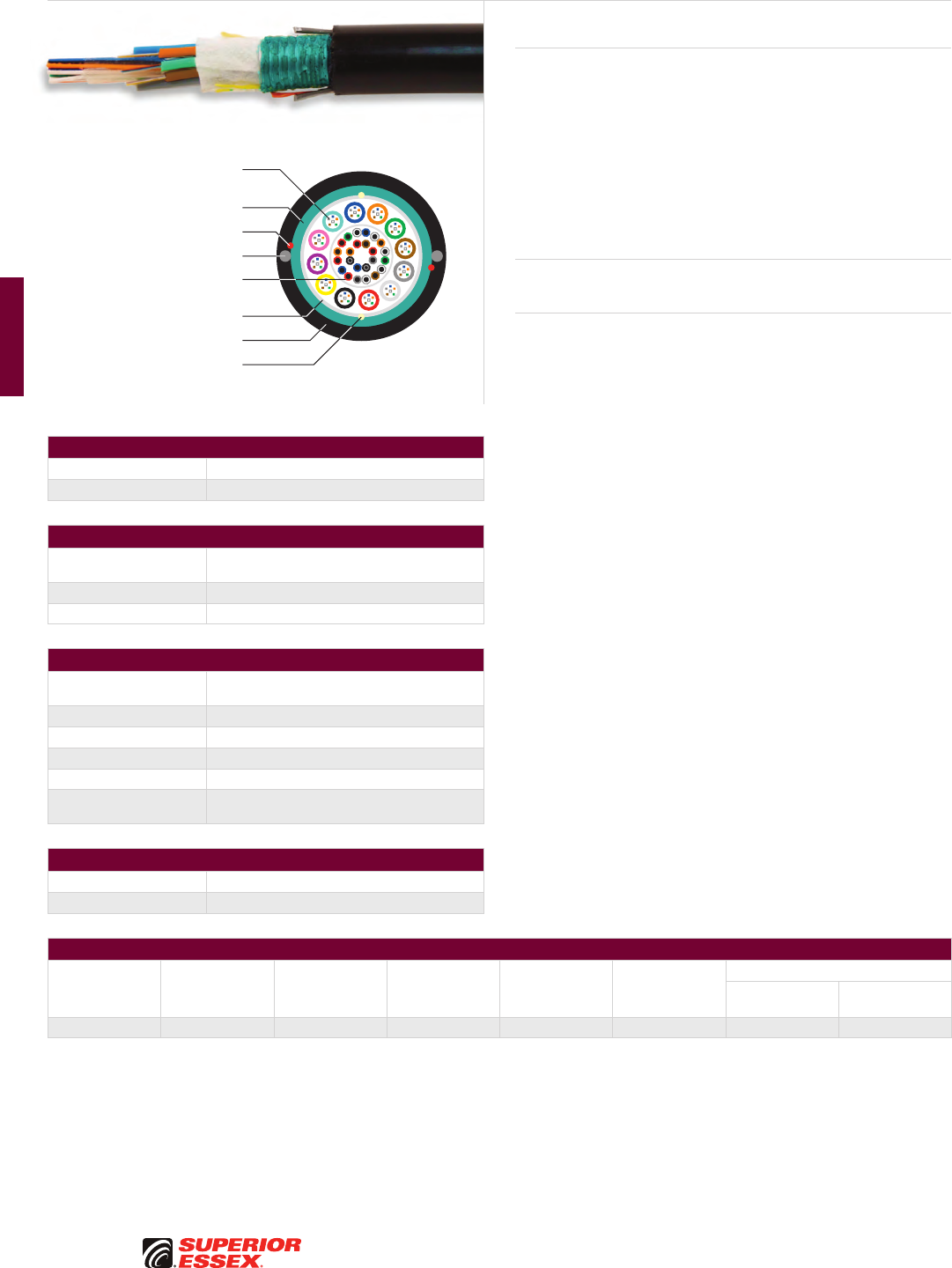
D-2
PREMISES COPPER PREMISES FIBER OSP FIBER OSP COMPOSITE CENTRAL OFFICE COPPER RDUP/RUS OSP COPPER BELL OSP COPPER OSP COPPER WIRE CANADIAN OSP COPPER TECHNICAL INFO
Toll Free 800.551.8948 | Fax 770.657.6807 | SuperiorEssex.com/Comm Rev 8/10 Ed 10.1
Composite Right of Way
Series MR
Product Description
The Composite Right of Way Series MR cable is designed to meet the
network requirements for both twisted copper pair and optical fiber. The
small 0.65 inch (16.6 mm) profile of this design easily fits into a 1-inch
conduit. The cable operates within a temperature range of -40˚C to +70˚C,
provides a maximum tensile strength of 600 lbs, and incorporates 12,
24 AWG twisted copper pairs and up to 72 strands of optical fiber. The core,
12 pairs of 24 AWG gel-filled copper, is surrounded by 12 gel-filled tubes
each containing 6 optical fibers. The core is water-blocked with super
absorbant polymers and then encased in a steel armor. Two steel rods for
anti-buckling are included in the outer jacket.
Applications
• Small conduits
Features Benefits
• Fiber and twisted copper pair • Offers the maximum bandwidth
for FTTP business, etc.
• Single unit construction • Lower installation costs
• Available with up to 72-fiber • High capacity
• Small nominal diameter • Suitable for small (1 inch) conduit
applications
OSP Copper Specifications
Conductor 12-pair 24 AWG (0.51 mm) solid annealed copper
Core Filling Thixotropic gel
Stranded Loose Tube Optical Fiber Specifications
Construction Loose tubes design features optical fibers placed
inside a PFM™ gel filled tube
Fiber Type RWP SMF (other fiber types available)
Fiber Count Up to 72 optical fibers
Composite Specifications
Construction Copper pairs at center of cable surrounded by
stranded loose tubes of optical fiber
Water Block Super absorbent polymer tape
Shield Corrugated steel armor
Strength Members Two steel strength members embedded in jacket
Jacket MDPE
Standards Compliance Telcordia GR-20-CORE
ICEA S-84-608-2007
Environmental Specifications
Operation/Storage -40°C to +70°C
Installation -10°C to +70°C
Part Numbers and Physical Characteristics
Part Number Fiber Count Fiber Type
Nominal
Diameter
in (mm)
Approx. Weight
lbs/kft (kg/km)
Install Bend
Radius
in (mm)
Maximum Tensile Load
Install
lbs (N)
Long Term
lbs (N)
MR0723011 72 RWP SMF 0.65 (16.6) 160 (237) 13 (332) 600 (2700) 200 (890)
Part number listed are RWP single mode optical fiber only. Other fiber types are available.
See the "Optical Fiber Selection Chart" in the "TECHNICAL INFO" section for detailed fiber type specifications.
Optical Fiber in PFM™ Gel
Filled Buffer Tube
Steel Strength Members
Ripcords (outside shield)
Ripcords (inside shield)
12 x 24 AWG Foam Skin
Copper Pairs in Gel Filled Core
Water Swellable Tape
MDPE Outer Jacket
Corrugated Steel Armor
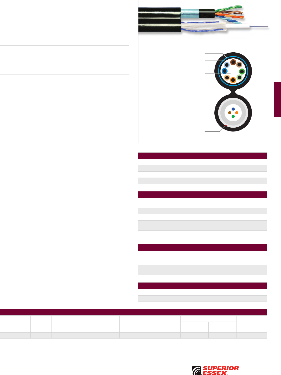
D-3
PREMISES COPPERPREMISES FIBEROSP FIBEROSP COMPOSITECENTRAL OFFICE COPPERRDUP/RUS OSP COPPERBELL OSP COPPEROSP COPPER WIRECANADIAN OSP COPPERTECHNICAL INFO
Rev 6/10 Ed 10.1 Toll Free 800.551.8948 | Fax 770.657.6807 | SuperiorEssex.com/Comm
Composite Category 5e Drop
Series 5F
Product Description
Series 5F combines the broadband performance of CAT 5e with the unlimited
capacity of optical fiber. A BBDNE CAT 5e Outside Plant (OSP) cable and a
Series 513 optical fiber cable are overjacketed into one cable in order to
offer flexibility and ease of installation.
Applications
• Drop cables
• Broadband network
• Fiber to the premise
Features Benefits
• Fiber and CAT 5e • Offers the maximum bandwidth
for FTTP business, etc.
• Overjacket design • Ease of use
• Single unit construction • Lower installation costs
• Available with 1-fiber
up to 12-fiber
• High capacity
• PFM™ gel • Non-sticky gel reduces
installation time and labor cost
CAT 5e OSP Copper Specifications
Conductor 4-pair 24 AWG solid annealed copper
Core Filling Thixotropic gel
Shield Coated smooth aluminum tape
Water Block Super absorbent polymer
Series 513 Optical Fiber Specifications
Construction Single loose tube design features optical fibers
placed inside a PFM™ gel filled tube
Fiber Type RWP SMF (other fiber types available)
Fiber Count Up to 12 optical fibers
Strength Members Core is helically wrapped with dielectric water
blocking strength members
Water Block Super absorbent polymer
Composite Specifications
Single Jacket Design
Copper and fiber independent cables are jacketed
into one cable in order to offer flexibility and ease
of installation
Standards Compliance Copper and fiber cables meet applicable
Telcordia and TIA standards
Environmental Specifications
Operation/Storage -40°C to +70°C
Installation -10°C to +70°C
Part Numbers and Physical Characteristics
Part Number
Fiber
Count Fiber Type
Nominal Diameter
in (mm)
Approx. Weight
lbs/kft (kg/km)
Bend Radius
in (mm)
Maximum Tensile Load Standard
Quantity
ft (m)
Install
lbs (N)
Long Term
lbs (N)
11-003-30 4 RWP SMF 0.63 (16) x 0.43 (10.9) 100 (148.8) 5.5 (139.7) 300 (136) 100 (45) 5,000 (1,524)
Part number listed are RWP single mode optical fiber only. Other fiber types are available.
See the "Optical Fiber Selection Chart" in the "TECHNICAL INFO" section for detailed fiber type specifications.
Optical Fiber
Dielectric Water Blocking
Strength Members
PFM™ Gel Filled Tube
Rip Cords
Sunlight and Weather Resistant
Outer Jacket with Web Separator
Inner Jacket
Fully Filled Water Repellent Core
24 AWG Copper Conductor
Polyolefin Insulation
Aluminum Tape Shield
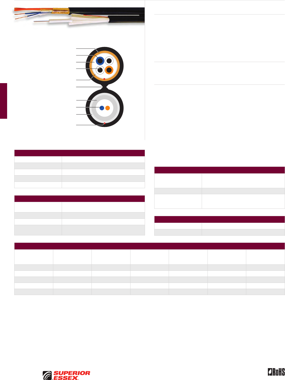
D-4
PREMISES COPPER PREMISES FIBER OSP FIBER OSP COMPOSITE CENTRAL OFFICE COPPER RDUP/RUS OSP COPPER BELL OSP COPPER OSP COPPER WIRE CANADIAN OSP COPPER TECHNICAL INFO
Toll Free 800.551.8948 | Fax 770.657.6807 | SuperiorEssex.com/Comm Rev 11/10 Ed 10.2
BSW OSP Copper Specifications
Conductor Solid annealed copper
Insulation Solid polyolefin
Core Wrap Non-hygroscopic
Filling Compound 80°C ETPR compound for water blocking protection
Shield Corrugated armor
Series 513 Optical Fiber Specifications
Construction Single loose tube design features optical fibers
placed inside a PFM™ gel filled tube
Fiber Type RWP SMF (other fiber types available)
Fiber Count Up to 12 optical fibers
Strength Members Core is helically wrapped with dielectric water
blocking strength members
Part Numbers and Physical Characteristics
Part Number
Copper Pair Count
x AWG Fiber Count Fiber Type
Copper Component
Nominal Diameter
in (mm)
Fiber Component
Nominal Diameter
in (mm)
Approx. Weight
lbs/kft (kg/km)
5W002302Q 2 x 19 2 RWP SMF 0.31 (7.9) 0.26 (6.7) 131 (195)
71-202-12 5 x 19 2 RWP SMF 0.36 (9.1) 0.26 (6.7) 179 (266)
5W002301Q 2 x 22 2 RWP SMF 0.27 (6.9) 0.26 (6.7) 114 (170)
5W002303Q 5 x 22 2 RWP SMF 0.32 (8.1) 0.26 (6.7) 136 (202)
5W004301Q 6 x 22 4 RWP SMF 0.36 (9.1) 0.26 (6.7) 149 (222)
Part numbers listed are RWP single mode optical fiber only. Other fiber types are available.
See the "Optical Fiber Selection Chart" in the "TECHNICAL INFO" section for detailed fiber type specifications.
Composite Drop Web
Series 71 W
Product Description
Series 71 W Composite Drop Cables combine fiber and copper technologies
in a web design. The composite design provides a cost benefit compared
to installing separate fiber and copper cables. The independent Series
513 optical fiber cable and the BSW Outside Plant (OSP) copper cable are
combined in a single jacket design utilizing a web separator. This lightweight
design is easy to access since the cables are easily separated at the web. In
addition, each independent cable also contains a rip cord.
Applications
• Network power and FTTP
• Drop cables
Features Benefits
• Independent fiber and copper
cables combined in a web design
• Reduces cost of cable and labor
• Web design • Easy separation of technologies
• Combined transport technologies
in one cable
• Cost-effective installation
• Optical/electrical technology • Ideal for multiple projects,
voice, video, data and powering
• Multiple fiber types available • Multiple applications
• PFM™ gel • Non-sticky gel reduces
installation time and labor cost
Composite Specifications
Single Jacket Design
Copper and fiber jackets joined by a web
separator that can be split to direct the cables
to separate locations
Standard Package 8,000’ Reel
Standards Compliance
Copper and fiber cables meet applicable Telcordia,
RDUP and ICEA specifications
RoHS-compliant
Environmental Specifications
Operation/Storage -40°C to +70°C
Installation -20°C to +70°C
Optical Fiber
Dielectric Water Blocking
Strength Members
PFM™ Gel Filled Tube
Rip Cords
Corrugated Armor
UV Resistant Jacket
with Web Separator
Polyolefin Insulation
Solid Annealed
Copper Conductor
Core Wrap
ETPR Filling Compound
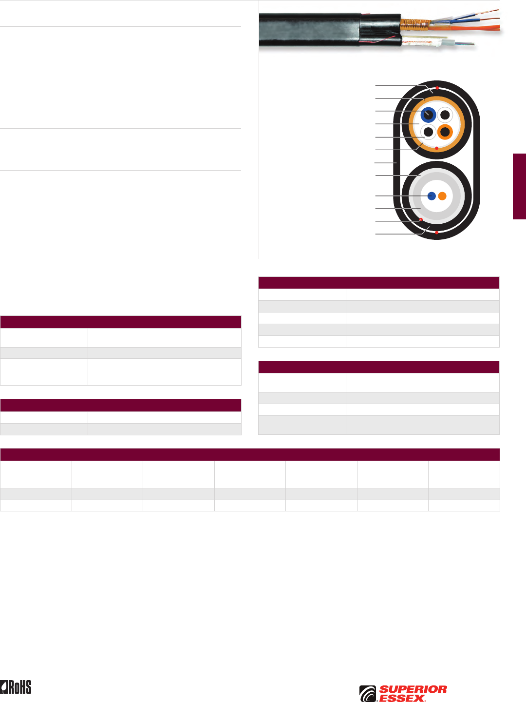
D-5
PREMISES COPPERPREMISES FIBEROSP FIBEROSP COMPOSITECENTRAL OFFICE COPPERRDUP/RUS OSP COPPERBELL OSP COPPEROSP COPPER WIRECANADIAN OSP COPPERTECHNICAL INFO
Toll Free 800.551.8948 | Fax 770.657.6807 | SuperiorEssex.com/CommRev 11/10 Ed 10.2
Optical Fiber
Dielectric Water Blocking
Strength Members
PFM™ Gel Filled Tube
Rip Cords
UV Resistant Overjacket
UV Resistant Jacket
Corrugated Armor
Solid Annealed Copper Conductor
Core Wrap
Polyolefin Insulation
UV Resistant Jacket
ETPR Filling Compound
BSW OSP Copper Specifications
Conductor Solid annealed copper
Insulation Solid polyolefin
Core Wrap Non-hygroscopic
Filling Compound 80°C ETPR compound for water blocking protection
Shield Corrugated armor
Series 513 Optical Fiber Specifications
Construction Single loose tube design features optical fibers
placed inside a PFM™ gel filled tube
Fiber Type RWP SMF (other fiber types available)
Fiber Count Up to 12 optical fibers
Strength Members Core is helically wrapped with dielectric water
blocking strength members
Part Numbers and Physical Characteristics
Part Number
Copper Pair Count
x AWG Fiber Count Fiber Type
Copper Component
Nominal Diameter
in (mm)
Fiber Component
Nominal Diameter
in (mm)
Approx. Weight
lbs/kft (kg/km)
71-055-02 2 x 22 2 RWP SMF 0.27 (6.9) 0.26 (6.7) 114 (170)
71-402-02 5 x 22 2 RWP SMF 0.32 (8.1) 0.26 (6.7) 136 (202)
Part numbers listed are RWP single mode optical fiber only. Other fiber types are available.
See the "Optical Fiber Selection Chart" in the "TECHNICAL INFO" section for detailed fiber type specifications.
Composite Drop Overjacket
Series 71 OJ
Product Description
Series 71 OJ Composite Drop Cables combine fiber and copper technologies
in an overjacket design. The independent Series 513 optical fiber cable
and the BSW Outside Plant (OSP) copper cable are combined into one
overjacketed cable. The composite design provides a cost benefit compared
to installing separate fiber and copper cables.
This design allows great flexibility regarding the independent cables used in
the overall construction. These independent cables are encased in an outer
jacket with a rip cord included for ease of entry.
Applications
• Network power and FTTP
• Drop cables
Features Benefits
• Independent fiber and
copper cables combined
in a overjacket design
• Lightweight, flexible construction
• Overjacket design • Easy separation of technologies
• Combined transport technologies
in one cable
• Cost-effective installation
• Various combinations and
multiple fiber types available
• Ideal for multiple projects
• PFM™ gel • Non-sticky gel reduces
installation time and labor cost
Composite Specifications
Single Jacket Design Independent copper and fiber cables are encased
in a outer jacket with a rip cord
Standard Package 8,000’ Reel
Standards Compliance
Copper and fiber cables meet applicable Telcordia,
RDUP and ICEA specifications
RoHS-compliant
Environmental Specifications
Operation/Storage -40°C to +70°C
Installation -20°C to +70°C
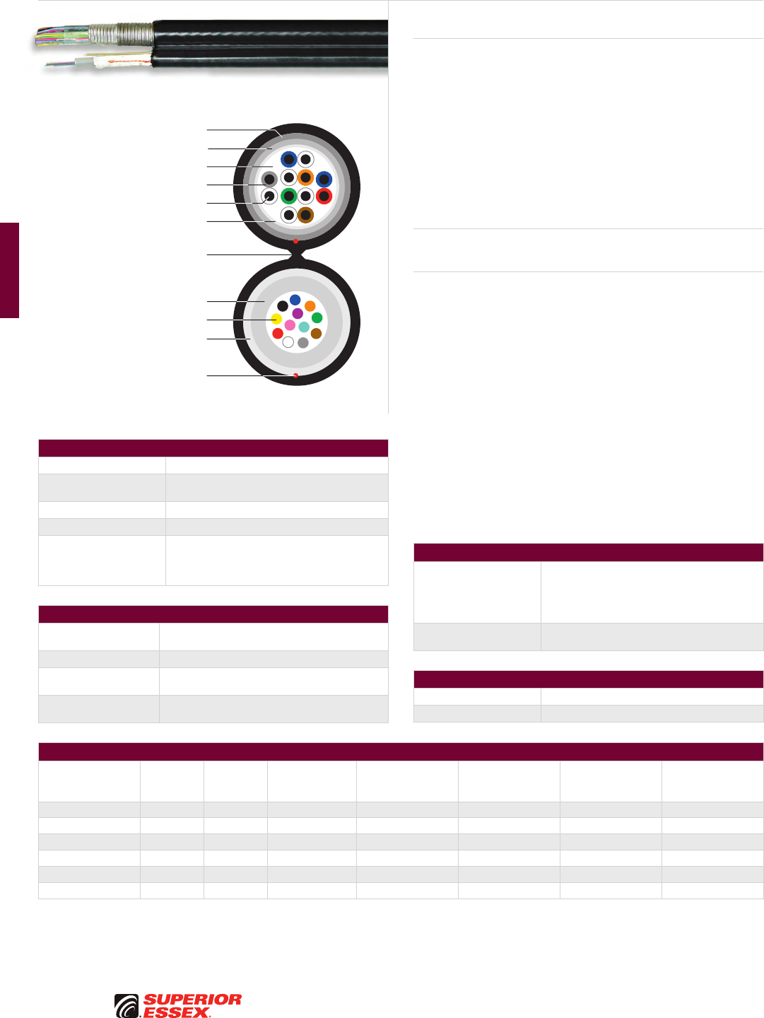
D-6
PREMISES COPPER PREMISES FIBER OSP FIBER OSP COMPOSITE CENTRAL OFFICE COPPER RDUP/RUS OSP COPPER BELL OSP COPPER OSP COPPER WIRE CANADIAN OSP COPPER TECHNICAL INFO
Rev 6/10 Ed 10.1Toll Free 800.551.8948 | Fax 770.657.6807 | SuperiorEssex.com/Comm
Composite OSP Web
Series 5V
Product Description
Series 5V Cables are designed for Outside Plant (OSP) broadband
applications. These cables combine copper and optical fiber technologies
into one composite cable and are suitable for voice, video and data
communications. The copper cable offers the option of providing network
power to eliminate the cost of local powering. The wide range of copper and
fiber counts make this cable ideal for most projects.
The construction of this product combines an ANAW OSP copper cable and
a Series 51 optical fiber cable. These independent cables are simultaneously
jacketed in a polyethylene outer jacket with a rip cord included for ease of
entry. The web connects the cables and can be easily split to direct the
cables to different locations.
Applications
• Direct bury, conduit, lashed aerial
Features Benefits
• Independent fiber and copper
cables under one jacket
• Reduces labor cost
• Web design • Easy separation
to different locations
• Optical/electrical technology • Ideal for voice, video and data
• Web design • Lower cost
• PFM™ gel • Non-sticky gel reduces
installation time and labor cost
ANAW OSP Copper Specifications
Conductor 22 AWG solid annealed copper
Insulation Inner layer of foamed, natural polyolefin covered
by an outer layer of solid, colored polyolefin
Core Wrap Non-hygroscopic
Filling Compound 80°C ETPR compound for water blocking protection
Shield
Corrugated 8 mil aluminum tape covered by a
corrugated bare 6 mil steel tape; both inner and
outer surfaces of the tapes are flooded to provide
a moisture barrier and inhibit corrosion
Series 51 Optical Fiber Specifications
Construction Single loose tube design features optical fibers placed
inside a PFM™ gel filled tube
Fiber Type RWP SMF (other fiber types available)
Fiber Count Up to 8 optical fiber bundles, each containing up to
12-fiber within a color coded binder
Strength Members Core is helically wrapped with dielectric water
blocking strength members
Part Numbers and Physical Characteristics
Part Number
Copper
Pair Count Fiber Count Fiber Type
Copper Component
Nominal Diameter
in (mm)
Fiber Component
Nominal Diameter
in (mm)
Approx. Weight
lbs/kft (kg/km)
Standard Quantity
ft
5V0063061 6 6 RWP SMF 0.45 (11) 0.37 (9) 176 (262) 14,800’ Reel
5V0063121 12 6 RWP SMF 0.56 (14) 0.37 (9) 234 (348) 14,800’ Reel
5V0123121 12 12 RWP SMF 0.56 (14) 0.37 (9) 234 (348) 14,800’ Reel
5V0183181 18 18 RWP SMF 0.61 (15) 0.37 (9) 285 (425) 14,800’ Reel
5V0123251 25 12 RWP SMF 0.72 (18) 0.37 (9) 355 (528) 12,700’ Reel
5V0243251 25 24 RWP SMF 0.72 (18) 0.37 (9) 355 (528) 12,700’ Reel
Part numbers listed are RWP single mode optical fiber only. Other fiber types are available.
See the "Optical Fiber Selection Chart" in the "TECHNICAL INFO" section for detailed fiber type specifications.
Composite Specifications
Single Jacket Design
Copper and fiber independent cables are
simultaneously jacketed in a polyethylene outer
jacket with a rip cord included for ease of entry
Web connects the cables and can be easily split to
direct the cables to different locations
Standards Compliance Copper and fiber cables meet applicable Telcordia
Specifications (GR-421-Core, GR-20 Core)
Environmental Specifications
Operation/Storage -40°C to +70°C
Installation -20°C to +70°C
Optical Fiber
Dielectric Water Blocking
Strength Members
PFM™ Gel Filled Tube
Rip Cords
Corrugated Aluminum Tape
UV Resistant Jacket
with Web Separator
ETPR Filling Compound
Corrugated Steel Tape
Solid Annealed Copper Conductor
Core Wrap
Polyolefin Insulation
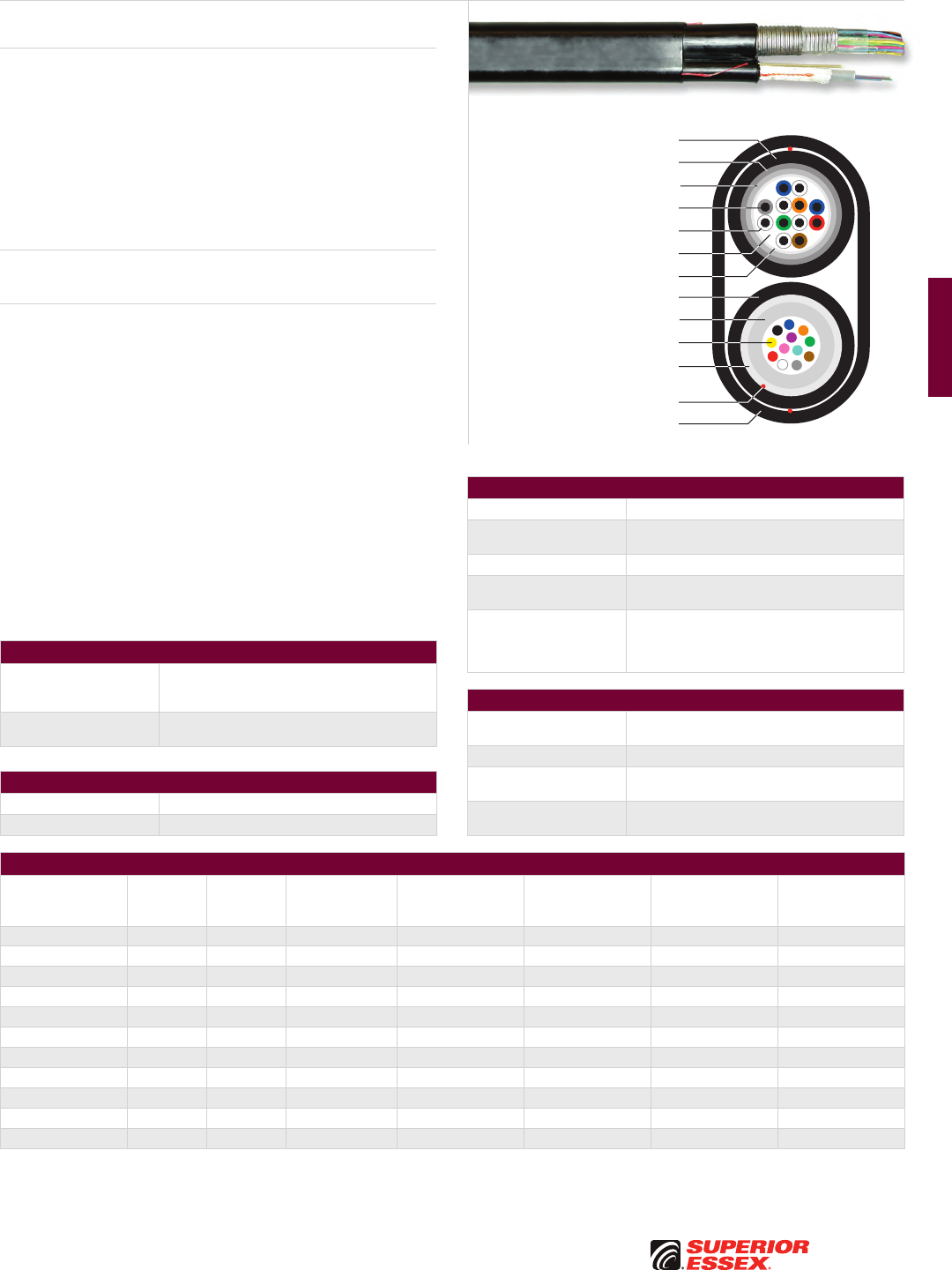
D-7
PREMISES COPPERPREMISES FIBEROSP FIBEROSP COMPOSITECENTRAL OFFICE COPPERRDUP/RUS OSP COPPERBELL OSP COPPEROSP COPPER WIRECANADIAN OSP COPPERTECHNICAL INFO
Rev 6/10 Ed 10.1 Toll Free 800.551.8948 | Fax 770.657.6807 | SuperiorEssex.com/Comm
Composite OSP Overjacket
Series 70 OJ
Product Description
Series 70 OJ Cables are designed for Outside Plant (OSP) broadband
applications. These cables combine copper and optical fiber technologies
into one composite cable and are suitable for voice, video and data
communications. The copper cable offers the option of providing network
power to eliminate the cost of local powering. The wide range of copper and
fiber counts make this cable ideal for most projects.
The construction of this product combines an ANAW OSP copper cable and
a Series 51 optical fiber cable. These independent cables are encased in an
outer jacket with a rip cord included for ease of use.
Applications
• Direct bury, conduit, lashed aerial
Features Benefits
• Independent fiber and copper
cables under one jacket
• Reduces labor cost
• Overjacket design • Easy separation
to different locations
• Optical/Electrical Technology • Ideal for voice, video and data
• PFM™ gel • Non-sticky gel reduces
installation time and labor cost
ANAW OSP Copper Specifications
Conductor 22 AWG solid annealed copper
Insulation Inner layer of foamed, natural polyolefin covered
by an outer layer of solid, colored polyolefin
Core Wrap Non-hygroscopic
Filling Compound 80°C ETPR compound provides water blocking
protection
Shield
Corrugated 8 mil aluminum tape covered by a
corrugated bare 6 mil steel tape; both inner
and outer surfaces of the tapes are flooded to
provide a moisture barrier and inhibit corrosion
Series 51 Optical Fiber Specifications
Construction Single loose tube design features optical fibers
placed inside a PFM™ gel filled tube
Fiber Type RWP SMF (other fiber types available)
Fiber Count Up to 8 optical fiber bundles, each containing up to
12-fiber within a color coded binder
Strength Members Core is helically wrapped with dielectric water
blocking strength members
Part Numbers and Physical Characteristics
Part Number
Copper
Pair Count Fiber Count Fiber Type
Copper Component
Nominal Diameter
in (mm)
Fiber Component
Nominal Diameter
in (mm)
Approx. Weight
lbs/kft (kg/km)
Standard Quantity
ft
70-425-18 36 18 RWP SMF 0.76 (19) 0.37 (9) 443 (658) 11,100’ Reel
70-425-36 36 36 RWP SMF 0.76 (19) 0.37 (9) 443 (658) 11,100’ Reel
70-065-24 50 24 RWP SMF 0.88 (22) 0.37 (9) 546 (811) 8,900’ Reel
70-065-48 50 48 RWP SMF 0.88 (22) 0.37 (9) 546 (811) 8,900’ Reel
70-067-36 75 36 RWP SMF 1.00 (25) 0.37 (9) 724 (1,077) 6,000’ Reel
70-067-72 75 72 RWP SMF 1.00 (25) 0.51 (13) 734 (1,092) 6,000’ Reel
70-069-48 100 48 RWP SMF 1.15 (29) 0.37 (9) 895 (1,331) 6,000’ Reel
70-069-72 100 72 RWP SMF 1.15 (29) 0.51 (13) 924 (1,374) 6,000’ Reel
70-071-72 150 72 RWP SMF 1.34 (34) 0.51 (13) 1,260 (1,874) 3,000’ Reel
70-071-96 150 96 RWP SMF 1.34 (34) 0.51 (13) 1,260 (1,874) 3,000’ Reel
70-073-96 200 96 RWP SMF 1.50 (38) 0.51 (13) 1,615 (2,403) 2,500’ Reel
Part numbers listed are RWP single mode optical fiber only. Other fiber types are available.
See the "Optical Fiber Selection Chart" in the "TECHNICAL INFO" section for detailed fiber type specifications.
Composite Specifications
Single Jacket Design
Copper and fiber independent cables are encased
in an overjacket with a rip cord included for ease
of use
Standards Compliance Copper and fiber cables meet applicable Telcordia
Specifications (GR-421-Core, GR-20 Core)
Environmental Specifications
Operation/Storage -40°C to +70°C
Installation -20°C to +70°C
Optical Fiber
Dielectric Water Blocking
Strength Members
PFM™ Gel Filled Tube
Rip Cords
UV Resistant Jacket
Corrugated Aluminum Tape
UV Resistant Overjacket
Solid Annealed Copper Conductor
Corrugated Steel Tape
UV Resistant Jacket
ETPR Filling Compound
Core Wrap
Polyolefin Insulation
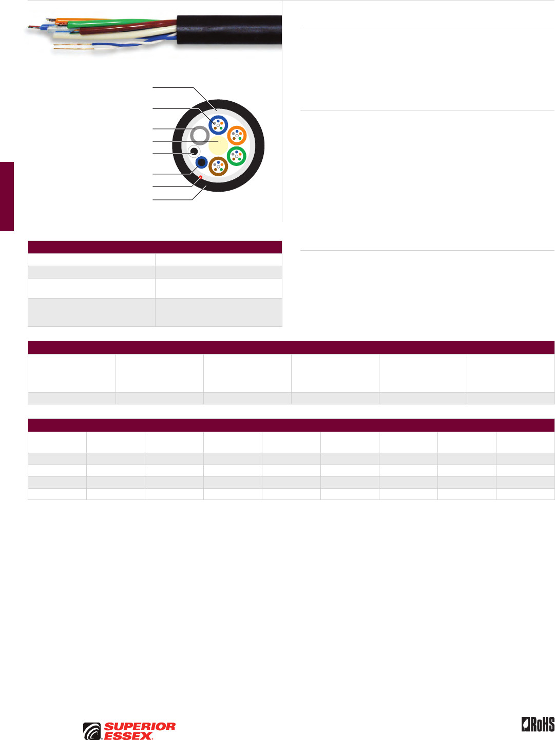
D-8
PREMISES COPPER PREMISES FIBER OSP FIBER OSP COMPOSITE CENTRAL OFFICE COPPER RDUP/RUS OSP COPPER BELL OSP COPPER OSP COPPER WIRE CANADIAN OSP COPPER TECHNICAL INFO
Rev 6/10 Ed 10.1Toll Free 800.551.8948 | Fax 770.657.6807 | SuperiorEssex.com/Comm
Composite Round CF
Series L
Product Description
Series L Cables combine the attributes of optical fiber and copper
technologies in a single cable. Designed for Outside Plant (OSP) applications,
these cables improve network flexibility by addressing the need to transmit
electrical power while providing virtually unlimited bandwidth to the
subscriber. Labor savings are also realized making this product ideal for
various projects.
Features Benefits
• Fiber tubes and copper pairs
in one jacket
• Reduced material cost and
significant installation savings
• Wide range of copper
and fiber counts
• Sizes available for large
and small projects
• Single mode, multimode
and hybrid designs
• Multiple network applications
• Copper twisted pairs • Capable of voice transmission,
cable location and site powering
• Various cable designs • Multiple applications
• PFM™ gel • Non-sticky gel reduces
installation time and labor cost
Note
• Special cable lengths are available upon request
• Please contact your Superior Essex sales professional
with your application requirements
Specifications
Construction Loose tube, single jacket
Fiber Type RWP SMF (other fiber types available)
Maximum Tensile Load lbs (N) Install: 600 (2,700)
Long Term: 200 (890)
Standards Compliance
Copper and fiber cables meet applicable
Telcordia and RDUP specifications
RoHS-compliant
Electrical Specifications
Conductor Size
AWG (mm)
Conductor DC
Resistance @ 68°F
Maximum Individual
Ohms/mile (Ohms/km)
Resistance Unbalance
Maximum
Individual Pair %
Dielectric Strength DC
Potential – Volts
Minimum
Conductor to Conductor Maximum Voltage
Maximum Amperage/
Conductor
22 (0.64) 91.0 (56.6) 5.0 5,000 150 vDC 1.0 A
Part Numbers and Physical Characteristics
Part Number
Copper
Pair Count Fiber Count Fiber Type
Optional
Shield
Filling
Compound
Length
Marking
Nominal O.D.
in (mm)
Appox. Weight
lbs/kft (kg/km)
11024C02Q 1 24 RWP SMF - dry feet 0.43 (10.85) 58 (86)
11024D01Q 2 24 RWP SMF - flood meters 0.43 (10.85) 69 (103)
12024D01Q 6 24 RWP SMF Single Armor dry feet 0.60 (16.05) 156 (232)
12024D02Q 2 24 RWP SMF Single Armor flood meters 0.48 (12.20) 107 (160)
Part number listed are RWP single mode optical fiber only. Other fiber types are available.
See the "Optical Fiber Selection Chart" in the "TECHNICAL INFO" section for detailed fiber type specifications.
Dielectric Water Blocking
Strength Members
Dielectric Central Strength Member
Polyolefin Insulation
Filler Rod
Solid Annealed
Copper Conductor
Optical Fiber in PFM™ Gel
Filled Buffer Tube
Rip Cord
UV Resistant Jacket
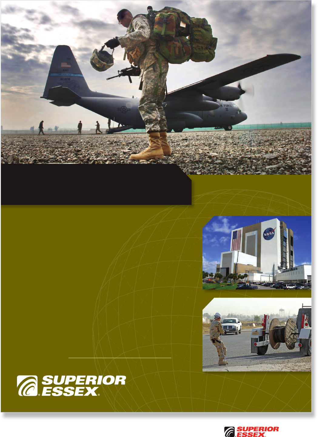
Toll Free 800.551.8948 | Fax 770.657.6807 | SuperiorEssex.com/Comm
Photos courtesy of U.S. Department of Defense
Where is the mission taking you?
Superior Essex will meet you there.
Superior Essex has a long, reputable track record
for providing comprehensive OSP and Premises
Optical Fiber and Copper solutions to government
agencies. Our products are trusted and installed
in applications around the world that vary from
the Pentagon to NASA to Bagram.
Our online Government Resource Center is dedicated
to helping cabling contractors, cabling consultants
and government users find information and tools
needed to help them specify Superior Essex products
in government related installations.
Wherever the mission takes you, we’ll be there.
Discover how at SuperiorEssex.com/Govt.aspx.

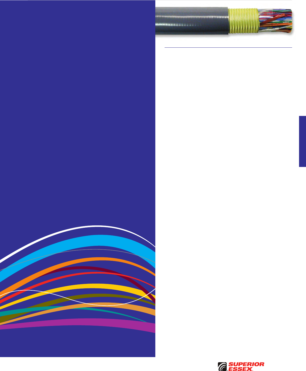
E-1
PREMISES COPPERPREMISES FIBEROSP FIBEROSP COMPOSITECENTRAL OFFICE COPPERRDUP/RUS OSP COPPERBELL OSP COPPEROSP COPPER WIRECANADIAN OSP COPPERTECHNICAL INFO
Toll Free 800.551.8948 | Fax 770.657.6807 | SuperiorEssex.com/Comm
CENTRAL OFFICE COPPER
Table of Contents
ABAM (600B) and ABMM Series Central Office. . . . . . . . . . . . . . . . .E-2
1249C Series Central Office ..................................E-3
1161A Series Category 3 Central Office . . . . . . . . . . . . . . . . . . . . . . . .E-4
600C Series Central Office ...................................E-5
25-Pair Category 5e Shielded CMR . . . . . . . . . . . . . . . . . . . . . . . . . . . .E-6
Switchboard 100 Ohm Central Office . . . . . . . . . . . . . . . . . . . . . . . . . .E-8
Switchboard 100 Ohm Central Office
200A/800A Series (Canadian Color Code)..........................E-10
T100 Series Central Office...................................E-11
Switchboard 85 and Shielded Switchboard 85 . . . . . . . . . . . . . . . . .E-12
Distribution Frame Wire DFW ................................E-13
Heavy Duty Distribution Frame Wire HD-DFW ..................E-14
Tight Twist Distribution Frame Wire DFW ......................E-15
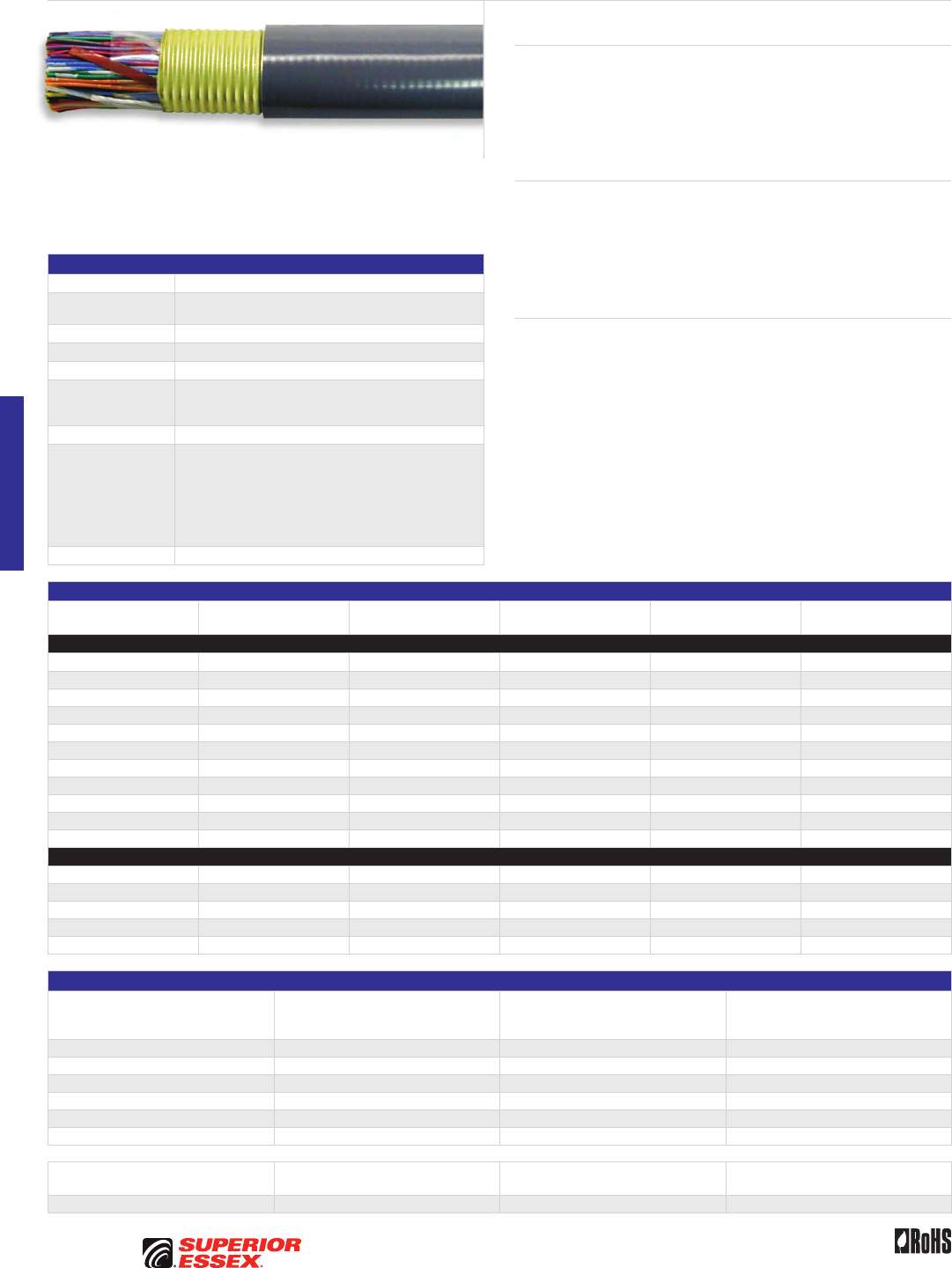
E-2
PREMISES COPPER PREMISES FIBER OSP FIBER OSP COMPOSITE CENTRAL OFFICE COPPER RDUP/RUS OSP COPPER BELL OSP COPPER OSP COPPER WIRE CANADIAN OSP COPPER TECHNICAL INFO
Toll Free 800.551.8948 | Fax 770.657.6807 | SuperiorEssex.com/Comm Rev 10/10 Ed 10.2
ABAM (600B) and ABMM Series Central Office
Product Description
The ABAM (600B) and ABMM Series Central Office (CO) Cables are designed
for use between switching and transmission equipment for distances up to
650 feet. The ABAM (600B) series offers low attenuation by using 22 AWG
conductors. Both ABAM (600B) and ABMM series (24 AWG) are manufactured
with a dark gray smooth PVC jacket and a 0.008 inch corrugated aluminum
shield for additional Electromagnetic Interference (EMI) reduction.
Applications
• T1/DS1
• T1C/DS1C
• DS2
• 4 Mbps token ring (IEEE 802.5)
• 10 Mbps 10BASE-T ethernet (IEEE 802.3)
Features Benefits
• 22 and 24 AWG tinned
copper conductors
• Low attenuation, enabling
longer run length; tinned copper
conductors minimize change in
wire-wrap joint resistance
• 100 Ohm nominal Impedance • Impedance mismatch with Outside
Plant (OSP) cables is minimized
• 0.008 inch corrugated
aluminum shield
• Higher EMI isolation over foil
shields; great mechanical strength
• CMR listed • Suitable for horizontal
and vertical installations
• CAT 3 compliant • Suitable for network applications
• Band marked conductors • Easy identification of conductor
ring mates
• Rip cord • Added ease of jacket removal
Specifications
Conductor Tinned copper
AWG (mm) ABAM: 22 (0.6)
ABMM: 24 (0.5)
Insulation PE/PVC
Shield Corrugated 8 mil aluminum bonded to the outer jacket
Jacket Gray PVC
Jacket Marking
Printed at 2 foot intervals on the jacket; information includes
product identification, pair count, UL information and
sequential lengths in feet and meters
Package Reel
Performance
Compliance
Telcordia GR-137 (select sections)
Telcordia GR-111
UL 444
CSA C22.2 No. 214-08
UL 1666
ANSI/TIA-568-C.2
RoHS-compliant
NRTL Programs UL, c(UL) Listed CMR
Part Numbers and Physical Characteristics
Part Number Product Code Pair Count
Nominal Diameter
in (mm)
Approx. Weight
lbs/kft (kg/km)
Standard Length
ft (m)
ABAM
55-399-25 606B 6 0.42 (11) 87 (129) 10,000 (3,048)
55-499-25 607B 12 0.50 (13) 132 (196) 7,000 (2,135)
55-599-25 608B 16 0.55 (14) 159 (237) 7,000 (2,135)
55-799-25 609B 25 0.65 (17) 224 (333) 5,000 (1,524)
55-899-25 616B 28 0.68 (17) 244 (363) 7,500 (2,285)
55-999-25 613B 30 0.69 (18) 257 (382) 5,000 (1,524)
55-A99-25 615B 32 0.71 (18) 270 (402) 5,000 (1,524)
55-B99-25 610B 50 0.84 (21) 383 (570) 7,500 (2,285)
55-C99-25 618B 56 0.88 (22) 420 (625) 3,000 (915)
55-D99-25 612B 75 1.02 (26) 561 (835) 3,000 (915)
55-E99-25 611B 100 1.14 (29) 711 (1,058) 7,500 (2,285)
ABMM
55-799-24 - 25 0.57 (15) 164 (244) 10,000 (3,048)
55-B99-24 - 50 0.73 (19) 276 (411) 10,000 (3,048)
55-E99-24 - 100 0.99 (25) 505 (725) 10,000 (3,048)
55-V99-24 - 600 2.10 (53) 2,378 (3,539) 1,000 (305)
55-W99-24 - 900 2.51 (64) 3,456 (5,143) 1,000 (305)
Electrical Specifications
Frequency
MHz
Attenuation @ 68˚F (20˚C)
Maximum Guaranteed
dB/100 m
PSNEXT
Minimum Guaranteed
dB/100 m
Minimum SRL
dB/100 m
0.772 2.2 43 12
1 2.6 41 12
4 5.6 32 12
8 8.5 27 12
10 9.7 26 12
16 13.1 23 10
Characteristic Impedance
Ohms
Delay Skew Maximum
ns/100 m
DC Resistance Maximum
Ohms/100 m
Resistance Unbalance Maximum
%
100 ± 15 45 9.38 5
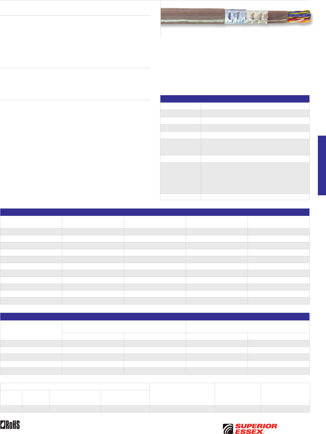
E-3
PREMISES COPPERPREMISES FIBEROSP FIBEROSP COMPOSITECENTRAL OFFICE COPPERRDUP/RUS OSP COPPERBELL OSP COPPEROSP COPPER WIRECANADIAN OSP COPPERTECHNICAL INFO
Toll Free 800.551.8948 | Fax 770.657.6807 | SuperiorEssex.com/CommRev 10/10 Ed 10.2
Product Description
The 1249C Series Central Office (CO) Cables are designed for use between
switching and transmission equipment for distances up to 450 feet. With
short twist lays, 1249C series offers superior crosstalk performance over
standard telephone cable. It is manufactured with a dual foil shield for
additional Electromagnetic Interference (EMI) reduction and is double
jacketed for protection of the twisted pairs. The 1249C series meets or
exceeds all applicable requirements of Telcordia GR-137 specifications.
Applications
• T1/DS1
• T1C/DS1C
• DS2
Features Benefits
• 26 AWG tinned
copper conductors
• Small diameter and light weight result in
smaller cable bundles and easier handling;
tinned copper conductors minimize change
in wire-wrap joint resistance
• Solid Polyolefin
insulation
• Greater crush resistance and improved
transmission characteristics
• 100 Ohm nominal
Impedance
• Impedance mismatch with Outside Plant
(OSP) cables is minimized
• Short pair
lays/tight twists
• Improved crosstalk performance
and pair identification
• Dual aluminum
foil shields
• Higher EMI isolation over a single foil shield
• Tinned copper
drain wire
• Easier termination and superior grounding
• CMR listed • Suitable for horizontal and riser installations
• Rip cord • Added ease of jacket removal
• Solid color insulation • Easy identification of conductor ring mates
Specifications
Conductor Tinned copper
AWG (mm) 26 (0.4)
Insulation Solid polyolefin
Shield Dual aluminum foil
Jacket Gray PVC
Jacket Marking
Printed at 2 foot intervals on the jacket; information includes
product identification, pair count, UL information and
sequential lengths in feet and meters
Package Reel
Performance
Compliance
Telcordia GR-137-CORE
Telcordia GR-499-CORE (Pulse shape compliance at 450 feet)
UL 444
CSA C22.2 No. 214-08
UL 1666
2002/95/EC RoHS-compliant
NRTL Programs UL, c(UL) Listed CMR
Part Numbers and Physical Characteristics
Part Number Pair Count
Nominal Diameter
in (mm)
Approx. Weight
lbs/kft (kg/km)
Standard Length
ft (m)
55-299-20 4 0.24 (6.1) 27 (40) 10,000 (3,048)
55-399-20 6 0.27 (6.9) 33 (49) 10,000 (3,048)
55-499-20 12 0.33 (8.4) 50 (74) 7,000 (2,133)
55-599-20 16 0.37 (9.4) 65 (97) 7,000 (2,133)
55-699-20 20 0.40 (10) 75 (112) 5,000 (1,524)
55-799-20 25 0.43 (11) 88 (131) 5,000 (1,524)
55-899-20 28 0.42 (11) 93 (138) 5,000 (1,524)
55-999-20 30 0.45 (11) 101 (150) 4,000 (1,219)
55-A99-20 32 0.46 (12) 105 (156) 4,000 (1,219)
55-B99-20 50 0.55 (14) 153 (228) 3,000 (914)
55-E99-20 100 0.73 (19) 277 (412) 3,000 (914)
Electrical Specificatons
Frequency
MHz
PSNEXT Mean
dB
PSNEXT Worst Pair
dB
Minimum Typical Minimum Typical
0.15 58 66 53 60
0.772 47 53 42 48
1.6 43 47 38 43
3.15 38 42 33 37
6.3 34 38 29 32
Attenuation @ 68˚F (20˚C) Conductor DC Resistance
@ 68˚F (20˚C)
Maximum Individual
Ohms/kft (Ohms/km)
Mutual Capacitance
Nominal
pF/ft (pF/m)
Characteristic
Impedance
@ 0.772 MHz
Ohms
Bit Rate
Mb/s
Frequency
MHz
Maximum Average*
dB/kft (dB/100 m)
Typical
dB/kft (dB/100 m)
1.544 0.772 7.8 (2.6) 6.4 (2.1) 46.1 (151) 16 (52) 102 ± 15.3
*For cables with 12-pair or less, the maximum average attenuation may be increased by 10% over the values shown.
1249C Series Central Office
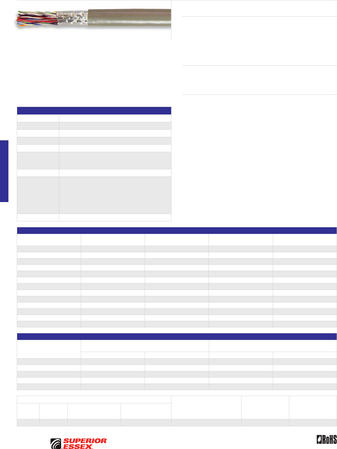
E-4
PREMISES COPPER PREMISES FIBER OSP FIBER OSP COMPOSITE CENTRAL OFFICE COPPER RDUP/RUS OSP COPPER BELL OSP COPPER OSP COPPER WIRE CANADIAN OSP COPPER TECHNICAL INFO
Toll Free 800.551.8948 | Fax 770.657.6807 | SuperiorEssex.com/Comm Rev 10/10 Ed 10.2
Product Description
The 1161A Series Central Office (CO) Cables are designed for use between
switching and transmission equipment, spanning distances up to 565 feet.
With short twist lays, 1161A series offers superior crosstalk performance
over standard telephone cable. It is manufactured with a foil shield for
Electromagnetic Interference (EMI) reduction. The 1161A series meets or
exceeds all applicable requirements of Telcordia GR-137 specifications.
Applications
• T1/DS1
• T1C/DS1C
• DS2
Features Benefits
• 24 AWG tinned copper
conductors
• Small diameter and light weight results
in smaller bundles of cables and
improved flexibility (compared with
600 series cables)
• Tinned copper conductors minimize
change in wire-wrap joint resistance
• Solid color Polyolefin
insulation
• Greater crush resistance and
improved transmission characteristics
• 100 Ohm nominal Impedance • Impedance mismatch with Outside
Plant (OSP) cables is minimized
• Short pair lays/tight twists • Improved crosstalk performance
and pair identification
• Aluminum foil shield • EMI isolation
• Tinned copper drain wire • Easier termination
and superior grounding
• CMR listed • Suitable for horizontal
and riser installations
• 75°C temperature rating • Wider operating
temperature range
• Rip cord • Added ease of jacket removal
Specifications
Conductor Tinned copper
AWG (mm) 24 (0.5)
Insulation Polyolefin
Shield Aluminum foil
Jacket Gray PVC
Jacket Marking
Printed at 2 foot intervals on the jacket; information includes
product identification, pair count, UL information and
sequential lengths in feet and meters
Package Reel
Performance
Compliance
Telcordia GR-137-CORE
Telcordia GR-499-CORE (Pulse shape compliance at 565 feet)
UL 444
CSA C22.2 No. 214-08
UL 1666
ANSI/TIA-568-C.2
2002/95/EC RoHS-compliant
NRTL Programs UL, c(UL) Listed CMR
Part Numbers and Physical Characteristics
Part Number Pair Count
Nominal Diameter
in (mm)
Approx. Weight
lbs/kft (kg/km)
Standard Length
ft (m)
55-299-21 4 0.26 (6.6) 27 (40) 10,000 (3,048)
55-399-21 6 0.27 (6.9) 35 (52) 10,000 (3,048)
55-F99-21 8 0.35 (8.9) 45 (67) 10,000 (3,048)
55-499-21 12 0.35 (8.9) 58 (86) 7,000 (2,133)
55-L99-21 14 0.38 (9.7) 70 (104) 7,000 (2,133)
55-599-21 16 0.41 (10) 77 (115) 7,000 (2,133)
55-699-21 20 0.44 (11) 93 (139) 20,000 (6,096)
55-799-21 25 0.48 (12) 112 (167) 5,000 (1,524)
55-899-21 28 0.51 (13) 123 (183) 5,000 (1,524)
55-999-21 30 0.53 (14) 135 (201) 5,000 (1,524)
55-A99-21 32 0.55 (14) 143 (213) 4,000 (1,219)
55-B99-21 50 0.66 (17) 210 (313) 3,000 (914)
55-E99-21 100 0.89 (23) 389 (579) 1,000 (305)
Electrical Specificatons
Frequency
MHz
PSNEXT Mean
dB
PSNEXT Worst Pair
dB
Minimum Typical Minimum Typical
0.15 58 66 53 60
0.772 47 53 42 48
1.6 43 47 38 43
3.15 38 42 33 37
6.3 34 38 29 32
Attenuation @ 68˚F (20˚C) Conductor DC Resistance
@ 68˚F (20˚C)
Maximum Individual
Ohms/kft (Ohms/km)
Mutual Capacitance
Nominal
pF/ft (pF/m)
Characteristic
Impedance
@ 0.772 MHz
Ohms
Bit Rate
Mb/s
Frequency
MHz
Maximum Average*
dB/kft (dB/100 m)
Typical
dB/kft (dB/100 m)
1.544 0.772 6.3 (2.1) 5.4 (1.8) 28.6 (93.8) 16 (52) 102 ± 15.3
*For cables with 12-pair or less, the maximum average attenuation may be increased by 10% over the values shown.
1161A Series Category 3 Central Office
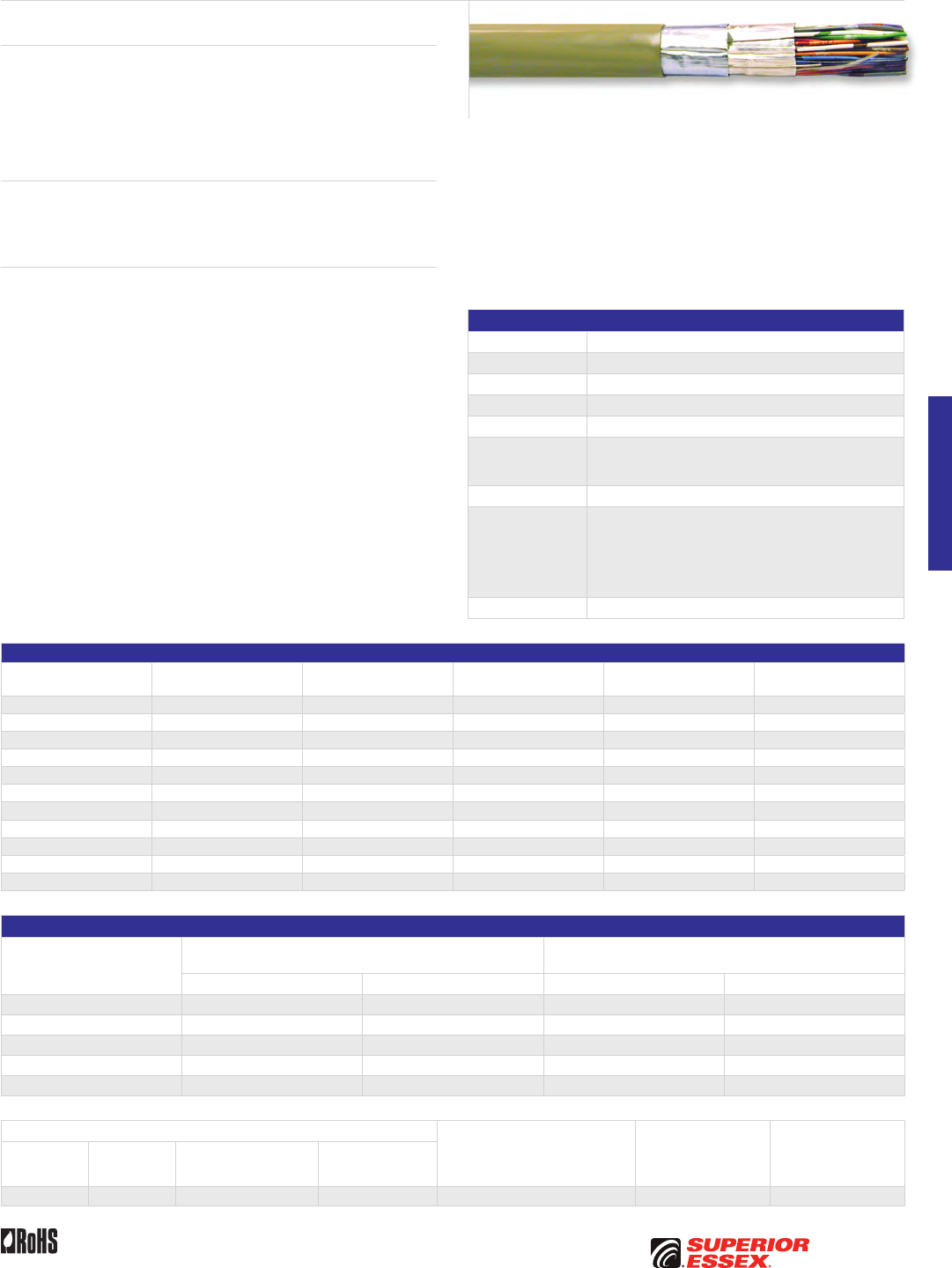
E-5
PREMISES COPPERPREMISES FIBEROSP FIBEROSP COMPOSITECENTRAL OFFICE COPPERRDUP/RUS OSP COPPERBELL OSP COPPEROSP COPPER WIRECANADIAN OSP COPPERTECHNICAL INFO
Toll Free 800.551.8948 | Fax 770.657.6807 | SuperiorEssex.com/CommRev 10/10 Ed 10.2
Product Description
The 600C Series Central Office (CO) Cables are designed for use between
switching and transmission equipment for distances up to 650 feet. This
series offers the lowest attenuation of all the CO cable products by using
22 AWG conductors. It is manufactured with a dual foil shield for additional
Electromagnetic Interference (EMI) reduction. The 600C series meets or
exceeds all applicable requirements of Telcordia GR-137 specifications.
Applications
• T1/DS1
• T1C/DS1C
• DS2
Features Benefits
• 22 AWG tinned
copper conductors
• Low attenuation, enabling
longer run length; tinned copper
conductors minimize change in
wire-wrap joint resistance
• Solid Polyolefin insulation • Greater crush resistance
and improved transmission
characteristics; smaller cable
over dual insulated type
• 100 Ohm nominal Impedance • Impedance mismatch with Outside
Plant (OSP) cables is minimized
• Dual aluminum foil shield • Higher EMI isolation over a single
foil shield; smaller cable diameter
than 600B Series cables
• Tinned copper drain wire • Easier termination and superior
grounding
• CMR listed • Suitable for horizontal and riser
installations
• Rip cord • Added ease of jacket removal
• Band marked • Easy identification of conductor
ring mates
Specifications
Conductor Tinned copper
AWG (mm) 22 (0.6)
Insulation Polyolefin
Shield Dual aluminum foil
Jacket Gray PVC
Jacket Marking
Printed at 2 foot intervals on the jacket; information includes
product identification, pair count, UL information and
sequential lengths in feet and meters
Package Reel
Performance
Compliance
Telcordia GR-137-CORE
Telcordia GR-499-CORE (Pulse shape compliance at 650 feet)
UL 444
CSA C22.2 No. 214-08
UL 1666
2002/95/EC RoHS-compliant
NRTL Programs UL, c(UL) Listed CMR
Part Numbers and Physical Characteristics
Part Number Product Code Pair Count
Nominal Diameter
in (mm)
Approx. Weight
lbs/kft (kg/km)
Standard Length
ft (m)
55-299-38 605C 4 0.29 (7.4) 40 (60) 10,000 (3,048)
55-399-38 606C 6 0.32 (8.1) 52 (77) 10,000 (3,048)
55-499-38 607C 12 0.41 (10) 89 (132) 7,000 (2,133)
55-599-38 608C 16 0.47 (12) 118 (176) 7,000 (2,133)
55-699-38 617C 20 0.50 (13) 141 (210) 5,000 (1,524)
55-799-38 609C 25 0.55 (14) 172 (256) 5,000 (1,524)
55-899-38 616C 28 0.58 (15) 189 (281) 5,000 (1,524)
55-999-38 613C 30 0.60 (15) 201 (299) 5,000 (1,524)
55-A99-38 615C 32 0.61 (16) 213 (317) 5,000 (1,524)
55-B99-38 610C 50 0.74 (19) 324 (482) 3,000 (914)
55-C99-38 618C 56 0.78 (20) 359 (534) 3,000 (914)
Electrical Specificatons
Frequency
MHz
PSNEXT Mean
dB
PSNEXT Worst Pair
dB
Minimum Typical Minimum Typical
0.15 58 66 53 60
0.772 47 53 42 48
1.6 43 47 38 43
3.15 38 42 33 37
6.3 34 38 29 32
Attenuation @ 68˚F (20˚C) Conductor DC Resistance
@ 68˚F (20˚C)
Maximum Individual
Ohms/kft (Ohms/km)
Mutual Capacitance
Nominal
pF/ft (pF/m)
Characteristic
Impedance
@ 0.772 MHz
Ohms
Bit Rate
Mb/s
Frequency
MHz
Maximum Average*
dB/kft (dB/100 m)
Typical
dB/kft (dB/100 m)
1.544 0.772 5.0 (1.6) 4.0 (1.3) 18 (59.1) 16 (52) 102 ± 15.3
*For cables with 12-pair or less, the maximum average attenuation may be increased by 10% over the values shown.
600C Series Central Office
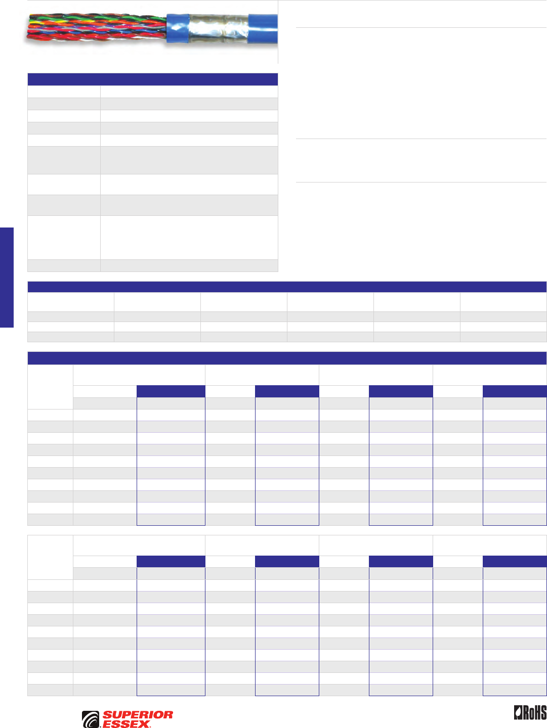
E-6
PREMISES COPPER PREMISES FIBER OSP FIBER OSP COMPOSITE CENTRAL OFFICE COPPER RDUP/RUS OSP COPPER BELL OSP COPPER OSP COPPER WIRE CANADIAN OSP COPPER TECHNICAL INFO
Toll Free 800.551.8948 | Fax 770.657.6807 | SuperiorEssex.com/Comm Rev 10/10 Ed 10.2
25-Pair Category 5e Shielded CMR
Product Description
This 25-pair, 24 AWG, Category 5e Tin Copper Shielded Cable is utilized to
connect equipment within a remote terminal cabinet or within a Central Office
(CO). Tight twist lays offer superior crosstalk performance for supporting
digital subscriber line (xDSL) technologies and higher IPTV data speeds.
Assembled with a cable connector on both ends, the combination facilitates
quick installation within the cabinet. The cable is manufactured with a blue
or gray colored double jacket separated by a single aluminum foil shield for
additional Electromagnetic Interference (EMI) reduction and added protection
for the twisted pairs.
Applications
• Remote terminal connecting cable
• Central Office cable
Features Benefits
• Small outside diameter • Facilitates routing within
a remote terminal
• Vibrant insulation colors • Easier identification
of conductors
• Performance compliance with
ANSI/TIA-568-C.2 specification
• Provides cost-effective solution
Specifications
Conductor Tinned copper
AWG (mm) 24 (0.5)
Insulation Polyolefin
Shield Aluminum foil
Jacket Flame retardant PVC
Jacket Marking
Printed at 2 foot intervals on the jacket; information includes
product identification, pair count, UL information and
sequential lengths in feet and meters
Input Impedance
(Ohms) 100 ± 15 @ 1-100 MHz
Nominal Velocity
of Propagation (%) 69
Performance
Compliance
UL 444
CSA C22.2 No. 214-08
UL 1666
ANSI/TIA-568-C.2
RoHS-compliant
NRTL Programs UL, c(UL) Listed CMR
Part Numbers and Physical Characteristics
Part Number Pair Count Jacket Color
Nominal Diameter
in (mm)
Approx. Weight
lbs/kft (kg/km) Package
55-779-19 25 Green 0.57 (15) 145 (216) 5,000' Reel
55-789-19 25 Gray 0.57 (15) 145 (216) 5,000' Reel
55-799-19 25 Blue 0.57 (15) 145 (216) 5,000' Reel
Electrical Specifications
Frequency
MHz
Attenuation @ 68°F (20°C) Maximum
dB/100 m
NEXT Minimum
dB/100 m
ACR Minimum
dB/100 m
PSNEXT Minimum
dB/100 m
TIA-568-C.2 Superior Essex TIA-568-C.2 Superior Essex TIA-568-C.2 Superior Essex TIA-568-C.2 Superior Essex
Specified Typical Specified Typical Calculated Typical Specified Typical
1 2.0 1.8 65.3 77.7 63.3 75.9 62.3 75.2
4 4.1 3.7 56.3 68.7 52.2 64.9 53.3 66.0
8 5.8 5.4 51.8 61.3 46.0 55.8 48.8 58.7
10 6.5 6.0 50.3 60.7 43.8 54.5 47.3 58.3
16 8.2 7.7 47.2 56.1 39.1 48.3 44.3 53.7
20 9.3 8.6 45.8 55.3 36.5 46.5 42.8 52.9
25 10.4 9.6 44.3 53.8 33.9 44.0 41.3 51.4
31.25 11.7 10.8 42.9 52.7 31.2 41.6 39.9 50.0
62.5 17.0 15.5 38.4 48.0 21.4 32.2 35.4 45.5
100 22.0 19.8 35.3 44.5 13.3 24.2 32.3 42.2
Frequency
MHz
PSACR Minimum
dB/100 m
Return Loss Minimum
dB/100 m
ELFEXT Minimum
dB/100 m
PSELFEXT Minimum
dB/100 m
TIA-568-C.2 Superior Essex TIA-568-C.2 Superior Essex TIA-568-C.2 Superior Essex TIA-568-C.2 Superior Essex
Calculated Typical Specified Typical Specified Typical Specified Typical
1 60.3 73.3 20.0 40.1 63.8 69.2 60.8 68.5
4 49.2 62.2 23.0 40.1 51.7 57.7 48.7 57.0
8 43.0 53.2 24.5 39.8 45.7 51.6 42.7 49.5
10 40.8 52.2 25.0 37.3 43.8 49.0 40.8 48.2
16 36.1 46.0 25.0 36.7 39.7 45.6 36.7 43.8
20 33.5 44.2 25.0 36.0 37.7 43.6 34.7 42.8
25 30.9 41.7 24.3 34.5 35.8 42.0 32.8 40.7
31.25 28.2 39.0 23.6 32.6 33.9 40.1 30.9 39.3
62.5 18.4 29.9 21.5 31.6 27.8 34.7 24.8 33.5
100 10.3 22.1 20.1 31.7 23.8 30.4 20.8 29.4

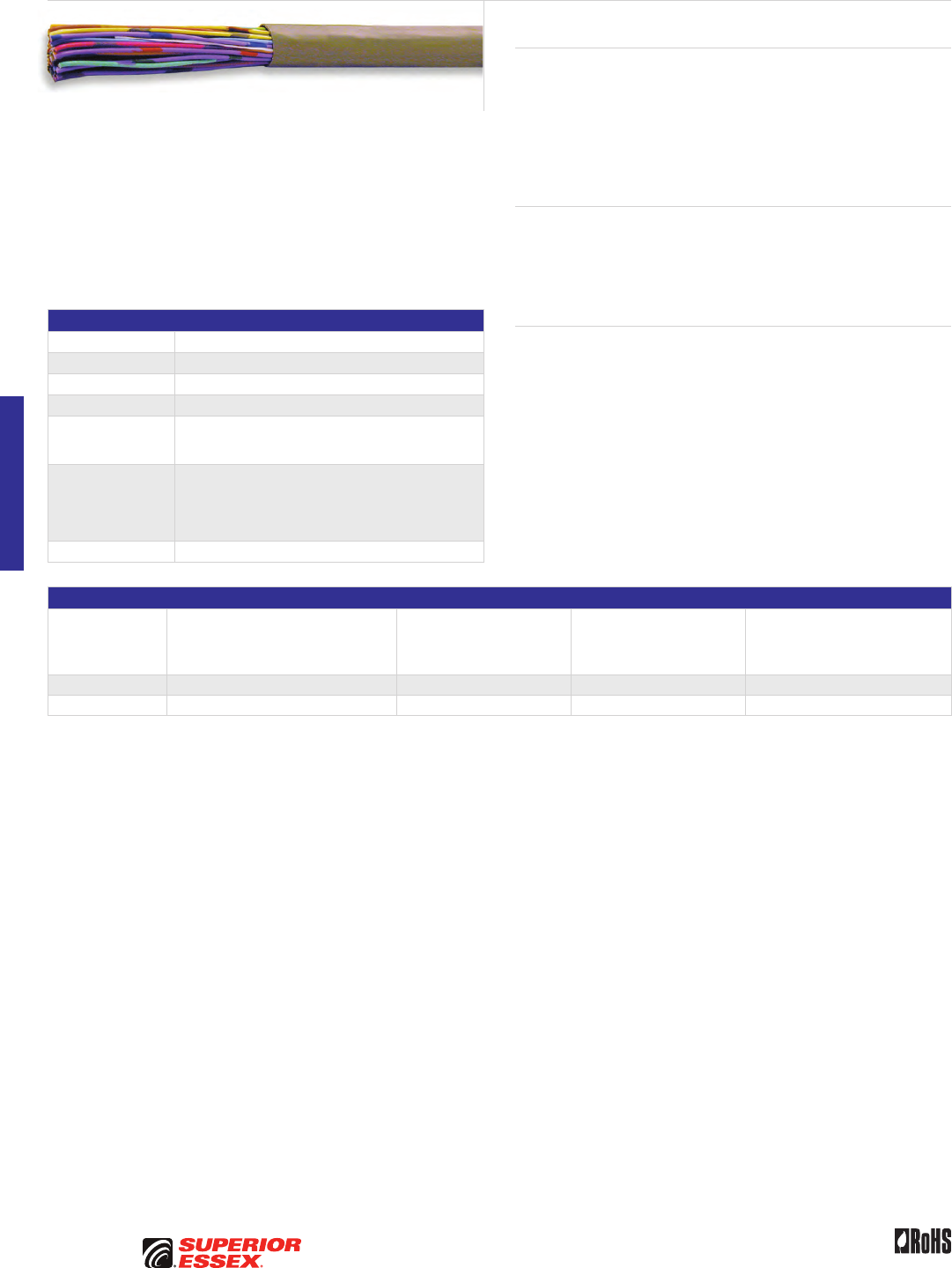
E-8
PREMISES COPPER PREMISES FIBER OSP FIBER OSP COMPOSITE CENTRAL OFFICE COPPER RDUP/RUS OSP COPPER BELL OSP COPPER OSP COPPER WIRE CANADIAN OSP COPPER TECHNICAL INFO
Toll Free 800.551.8948 | Fax 770.657.6807 | SuperiorEssex.com/Comm Rev 10/10 Ed 10.2
Product Description
Switchboard 100 Central Office (CO) Cables are designed for indoor use
in CO exchanges, or in premises telephone rooms. These cables are
used for interconnection of distribution frames and digital switching and
transmission equipment systems. Switchboard 100 provides 100 Ohm
characteristic impedance. The product line consists of 24 or 26 AWG tinned
insulated copper wires that are twisted into pairs. The pairs are stranded
together utilizing a standard color code scheme.
Applications
• T1/DS1
• T1C/DS1C
• 4 Mbps token ring (IEEE 802.5)
• 10 Mbps 10BASE-T ethernet (IEEE 802.3)
Features Benefits
• 100 Ohm nominal Impedance • Impedance mismatch with Outside
Plant (OSP) cables is minimized
• Tinned copper conductors • Minimize change in wire-wrap
joint resistance
• CMR listed • Suitable for horizontal and riser
installations
• Rip cord • Added ease of jacket removal
• Band marked • Easy identification of conductor
ring mates
Specifications
Conductor Tinned copper
AWG (mm) Available in 24 (0.5) and 26 (0.4)
Insulation PVC
Jacket Gray PVC
Jacket Marking
Printed at 2 foot intervals on the jacket; information includes
product identification, pair count, UL information and
sequential lengths in feet and meters
Performance
Compliance
UL 444
CSA C22.2 No. 214-08
UL 1666
Telcordia GR-137-CORE (select sections)
RoHS-compliant
NRTL Programs UL, c(UL) Listed CMR
Electrical Specifications
Conductor Size
AWG (mm)
Conductor DC Resistance
@ 68°F (20°C)
Maximum Individual
Ohms/kft (Ohms/km)
Mutual Capacitance
Nominal
pF/ft (pF/m)
Characteristic
Impedance @ 1 MHz
Ohms
Maximum Average Attenuation*
@ 0.772 MHz
@ 68°F (20°C)
dB/kft (dB/km)
24 (0.5) 28.6 (93.8) 20 (66) 100 ± 15 6.3 (20)
26 (0.4) 46.1 (151) 20 (66) 100 ± 15 7.8 (25)
*For cables with 12-pair or less, the maximum average attenuation may be increased by 10% over the values shown.
Switchboard 100 Ohm Central Office
E-9
PREMISES COPPERPREMISES FIBEROSP FIBEROSP COMPOSITECENTRAL OFFICE COPPERRDUP/RUS OSP COPPERBELL OSP COPPEROSP COPPER WIRECANADIAN OSP COPPERTECHNICAL INFO
Toll Free 800.551.8948 | Fax 770.657.6807 | SuperiorEssex.com/CommRev 10/10 Ed 10.2
Switchboard 100 Ohm Central Office
Part Numbers and Physical Characteristics
Part Number Product Code Pair Count AWG (mm)
Nominal Diameter
in (mm)
Approx. Weight
lbs/kft (kg/km)
Standard Length
ft (m) Package
55-041-23 TIW 2/24 2 24 (0.5) 0.14 (4) 10 (15) 1,000 (305) POP™ Box
55-021-23 TIW 2/24 2 24 (0.5) 0.14 (4) 10 (15) 5,000 (1,524) Reel
55-141-23 TIW 3/24 3 24 (0.5) 0.17 (4) 14 (21) 1,000 (305) POP™ Box
55-241-23 TIW 4/24 or 286A 4 24 (0.5) 0.18 (5) 18 (27) 1,000 (305) POP™ Box
55-341-23 TIW 6/24 or 252A 6 24 (0.5) 0.22 (6) 26 (39) 1,000 (305) POP™ Box
55-F31-23 294A 8 24 (0.5) 0.24 (7) 33 (49) 1,000 (305) Reel
55-G99-23 TIW 10/24 or 253A 10 24 (0.5) 0.25 (7) 40 (60) 7,000 (2,133) Reel
55-499-23 TIW 12/24 or 265A 12 24 (0.5) 0.28 (7) 49 (73) 7,000 (2,133) Reel
55-599-23 TIW 16/24 16 24 (0.5) 0.32 (8) 64 (95) 7,000 (2,133) Reel
55-699-23 255A 20 24 (0.5) 0.35 (9) 78 (116) 5,000 (1,524) Reel
55-N99-23 266A 24 24 (0.5) 0.38 (10) 92 (137) 5,000 (1,524) Reel
55-799-23 TIW 25/24 25 24 (0.5) 0.39 (10) 96 (143) 5,000 (1,524 Reel
55-899-23 TIW 28/24 28 24 (0.5) 0.41 (10) 107 (159) 5,000 (1,524) Reel
55-A99-23 TIW 32/24 32 24 (0.5) 0.43 (11) 121 (180) 5,000 (1,524) Reel
55-P99-23 269A 36 24 (0.5) 0.46 (12) 135 (201) 5,000 (1,524) Reel
55-Q99-23 257A 40 24 (0.5) 0.48 (12) 149 (222) 5,000 (1,524) Reel
55-B99-23 TIW 50/24 or 270A 50 24 (0.5) 0.53 (13) 184 (274) 3,000 (914) Reel
11-003-55* - 50 24 (0.5) 0.53 (13) 184 (274) 3,000 (914) Reel
55-S99-23 267A 72 24 (0.5) 0.65 (17) 276 (411) 3,000 (914) Reel
55-D99-23 TIW 75/24 75 24 (0.5) 0.67 (17) 286 (426) 2,000 (609) Reel
55-E99-23 TIW 100/24 or 262A 100 24 (0.5) 0.77 (20) 374 (557) 1,000 (305) Reel
11-003-47* - 100 24 (0.5) 0.77 (20) 374 (557) 1,000 (305) Reel
55-U99-23 287A 120 24 (0.5) 0.83 (21) 445 (662) 1,000 (305) Reel
55-M99-23 TIW 125/24 125 24 (0.5) 0.85 (22) 462 (688) 1,000 (305) Reel
55-275-26 812A 4 26 (0.4) 0.15 (4) 13 (19) 5,000 (1,524) Reel
55-399-26 816A 6 26 (0.4) 0.18 (5) 17 (25) 5,000 (1,524) Reel
55-F99-26 811A 8 26 (0.4) 0.19 (5) 22 (33) 5,000 (1,524) Reel
55-G99-26 820A 10 26 (0.4) 0.20 (6) 27 (40) 5,000 (1,524) Reel
55-599-26 807A 16 26 (0.4) 0.25 (7) 41 (61) 5,000 (1,524) Reel
55-699-26 800A 20 26 (0.4) 0.29 (7) 53 (79) 5,000 (1,524) Reel
55-799-26 824A 25 26 (0.4) 0.31 (8) 65 (97) 5,000 (1,524) Reel
55-A99-26 808A 32 26 (0.4) 0.35 (9) 81 (121) 5,000 (1,524) Reel
55-Q99-26 803A 40 26 (0.4) 0.39 (10) 100 (149) 5,000 (1,524) Reel
55-P99-26 822A 48 26 (0.4) 0.42 (11) 118 (176) 5,000 (1,524) Reel
55-B99-26 813A 50 26 (0.4) 0.43 (11) 123 (183) 5,000 (1,524) Reel
55-R99-26 809A 64 26 (0.4) 0.48 (12) 154 (229) 5,000 (1,524) Reel
55-K99-26 823A 96 26 (0.4) 0.58 (15) 228 (339) 5,000 (1,524) Reel
55-E99-26 806A 100 26 (0.4) 0.61 (16) 236 (351) 5,000 (1,524) Reel
55-H99-26 810A 128 26 (0.4) 0.69 (18) 316 (470) 5,000 (1,524) Reel
55-L99-26 814A 144 26 (0.4) 0.73 (19) 353 (525) 5,000 (1,524) Reel
*25-pair unit design
Note: Standard USA Color Code Scheme
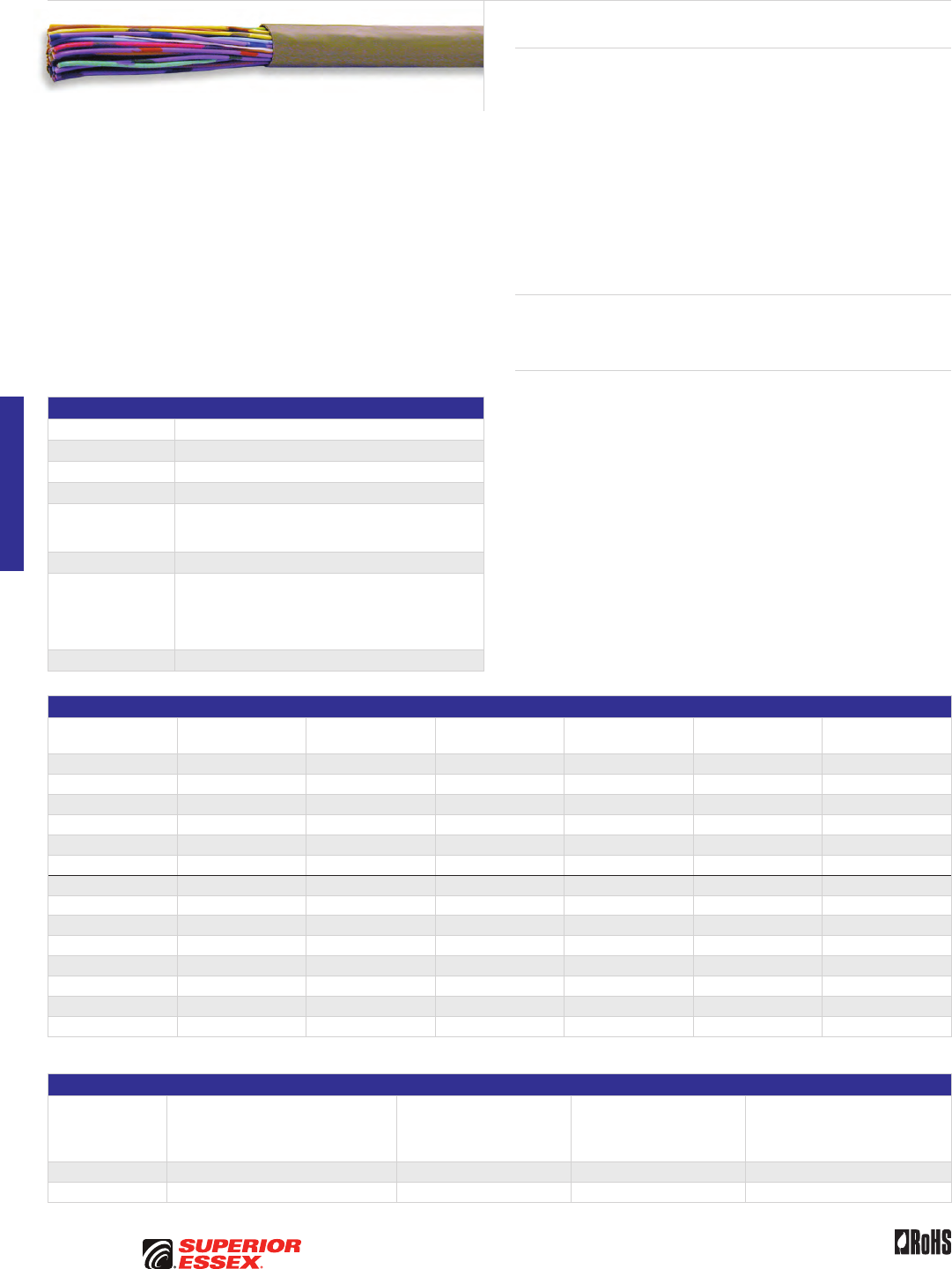
E-10
PREMISES COPPER PREMISES FIBER OSP FIBER OSP COMPOSITE CENTRAL OFFICE COPPER RDUP/RUS OSP COPPER BELL OSP COPPER OSP COPPER WIRE CANADIAN OSP COPPER TECHNICAL INFO
Toll Free 800.551.8948 | Fax 770.657.6807 | SuperiorEssex.com/Comm Rev 10/10 Ed 10.2
Product Description
The 200A and 800A Series Central Office (CO) Cables are designed for indoor
use in central offices or in premises telephone rooms, and are utilized
between a distribution frame and digital switching/transmission equipment.
This series offers 24 and 26 AWG tinned copper at 100 Ohm characteristic
impedance levels. Used primarily in Canada, the color code and lay-up
scheme has distinctively colored insulation in combination with single
dots and double dots or dashes of colored ink. Each wire within a unit is
readily distinguishable from all other wires within the same unit. Cables may
contain pairs or a combination of pairs and singles. The pairs and singles
are assembled together to form a core. Some cable sizes contain “spare
pairs.” The core is covered by a gray PVC jacket. The 200A and 800A series
meet or exceed all applicable requirements of Telcordia GR-137.
Applications
• T1/DS1
• T1C/DS1C
Features Benefits
• 24 and 26 AWG tinned
copper conductors
• Small diameter and light weight
result in smaller cable bundles
and easier handling; tinned
copper conductors minimize
change in wire-wrap joint
resistance
• Solid PVC insulation • Greater crush resistance
and improved transmission
characteristics
• 100 Ohm nominal impedance • Impedance mismatch with Outside
Plant (OSP) cables is minimized
• Standard pair lays • Improved crosstalk performance
and pair identification
• CMR listed • Suitable for horizontal and riser
installations
• Non-shielded design • Lower cost
• Rip cord • Added ease of jacket removal
Specifications
Conductor Tinned copper
AWG (mm) Available in 24 (0.5) and 26 (0.4)
Insulation PVC
Jacket Gray PVC
Jacket Marking
Printed at 2 foot intervals on the jacket; information includes
product identification, pair count, UL information and
sequential lengths in feet and meters
Package Reel
Performance
Compliance
Telcordia GR-137-CORE (select sections)
UL 444
CSA C22.2 No. 214-08
UL 1666
RoHS-compliant
NRTL Programs UL, c(UL) Listed CMR
Part Numbers and Physical Characteristics
Part Number Product Code Pair Count AWG (mm)
Nominal Diameter
in (mm)
Approx. Weight
lbs/kft (kg/km)
Standard Length
ft (m)
55-399-46 252A 6 24 (0.5) 0.22 (5.6) 26 (39) 3,000 (915)
55-699-46 255A 20 24 (0.5) 0.35 (8.9) 78 (116) 3,000 (915)
55-E99-46 262A 101.5 24 (0.5) 0.82 (21) 383 (570) 400 (120)
55-G99-46 253A 10 24 (0.5) 0.31 (7.9) 44 (65) 3,000 (915)
55-N99-46 266A 24 24 (0.5) 0.42 (11) 94 (140) 1,200 (365)
55-P99-46 269A 36 24 (0.5) 0.44 (11) 134 (199) 1,000 (305)
55-599-47 807A 17 26 (0.4) 0.26 (6.6) 47 (70) 3,000 (915)
55-A99-47 808A 33 26 (0.4) 0.37 (9.4) 86 (128) 2,000 (610)
55-E12-47 850A 100 26 (0.4) 0.65 (17) 265 (394) 2,000 (610)
55-R99-47 809A 66 26 (0.4) 0.51 (13) 164 (244) 1,325 (405)
55-H99-47 810A 132 26 (0.4) 0.67 (17) 330 (491) 700 (215)
55-Y99-47 821A 52 26 (0.4) 0.45 (11) 131 (195) 1,100 (335)
55-N99-47 824A 25 26 (0.4) 0.32 (8.1) 66 (98) 2,400 (730)
55-E99-47 806A 103 26 (0.4) 0.65 (17) 265 (394) 1,000 (305)
Note: Standard Canadian Color Scheme
Electrical Specifications
Conductor Size
AWG (mm)
Conductor DC Resistance
@ 68°F (20°C)
Maximum Individual
Ohms/kft (Ohms/km)
Mutual Capacitance
Nominal
pF/ft (pF/m)
Characteristic
Impedance @ 1 MHz
Ohms
Maximum Average Attenuation*
@ 0.772 MHz
@ 68°F (20°C)
dB/kft (dB/km)
24 (0.5) 28.6 (93.8) 20 (66) 100 ± 15 6.3 (20.7)
26 (0.4) 46.1 (151) 20 (66) 100 ± 15 7.8 (25.6)
*For cables with 12-pair or less, the maximum average attenuation may be increased by 10% over the values shown.
Switchboard 100 Ohm Central Office
200A/800A Series (Canadian Color Code)
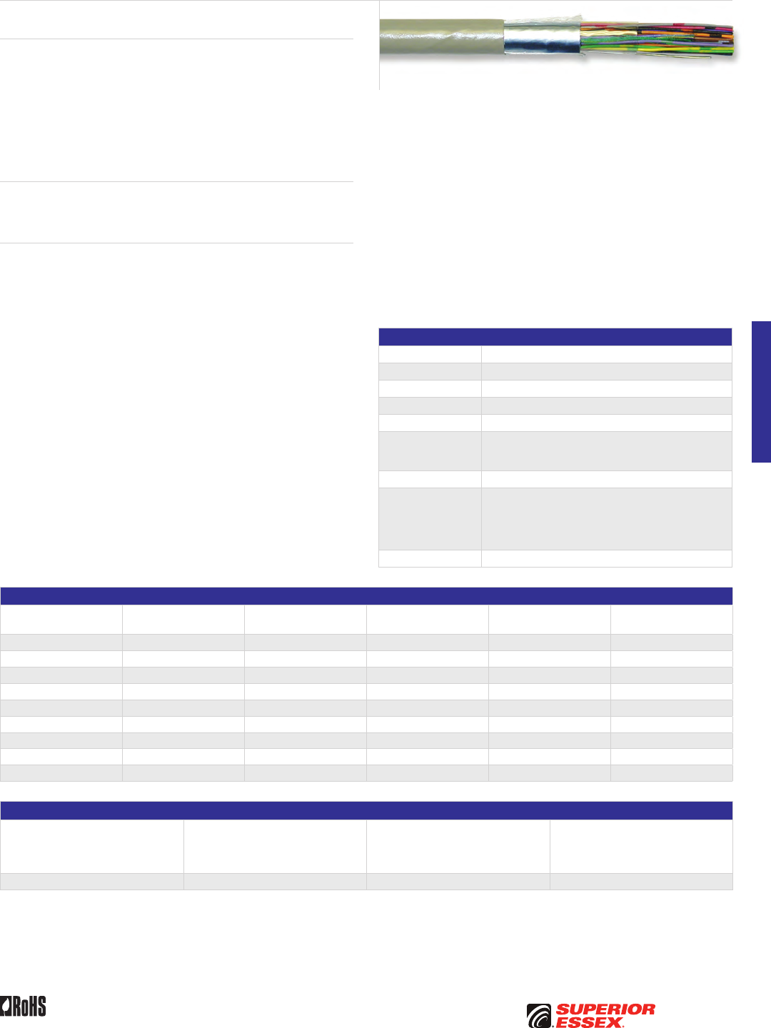
E-11
PREMISES COPPERPREMISES FIBEROSP FIBEROSP COMPOSITECENTRAL OFFICE COPPERRDUP/RUS OSP COPPERBELL OSP COPPEROSP COPPER WIRECANADIAN OSP COPPERTECHNICAL INFO
Toll Free 800.551.8948 | Fax 770.657.6807 | SuperiorEssex.com/CommRev 10/10 Ed 10.2
T100 Series Central Office
Product Description
The T100 Series Central Office (CO) Cables are designed for use between
switching and transmission equipment for distances up to 450 feet. They
are manufactured with a longitudinal aluminum-polyester foil shield with
aluminum facing the jacket for additional Electromagnetic Interference
(EMI) reduction. The pairs are stranded together utilizing distinctive colored
insulation in combination with markings of colored ink. The outer jacket is
a gray flame retardant PVC. T100 series meets or exceeds all applicable
requirements of Telcordia GR-137 specifications.
Applications
• T1/DS1
• T1C/DS1C
Features Benefits
• 24 AWG tinned
copper conductors
• Small diameter and light weight
result in smaller cable bundles
and easier handling; tinned
copper conductors minimize
change in wire-wrap joint
resistance
• CMR listed • Suitable for horizontal and riser
installations
• Solid PVC insulation • Greater crush resistance
and improved transmission
characteristics
• 100 Ohm nominal impedance • Impedance mismatch with Outside
Plant (OSP) cables is minimized
• Standard pair lays • Improved crosstalk performance
and pair identification
• Longitudinal aluminum/polyester
foil shield with aluminum facing
the jacket
• EMI isolation
• 24 AWG tinned copper drain wire • Easier termination and superior
grounding
• Rip cord • Added ease of jacket removal
• Band marked • Easy pair identification
Specifications
Conductor Tinned copper
AWG (mm) 24 (0.5)
Insulation PVC
Shield Aluminum/polyester foil
Jacket Gray PVC
Jacket Marking
Printed at 2 foot intervals on the jacket; information includes
product identification, pair count, UL information and
sequential lengths in feet and meters
Package Reel
Performance
Compliance
Telcordia GR-137-CORE (select sections)
UL 444 (pulse shape compliance at 450 feet)
CSA C22.2 No. 214-08
UL 1666
RoHS-compliant
NRTL Programs UL, c(UL) Listed CMR
Part Numbers and Physical Characteristics
Part Number Product Code Pair Count
Nominal Diameter
in (mm)
Approx. Weight
lbs/kft (kg/km)
Standard Length
ft (m)
55-399-43 T106 6 0.30 (7.6) 37 (55) 6,644 (2,025)
55-F99-43 T108 8 0.31 (7.9) 45 (67) 5,578 (1,700)
55-499-43 T112 12 0.34 (8.6) 59 (88) 6,644 (2,025)
55-599-43 T116 16 0.36 (9.1) 74 (110) 6,644 (2,025)
55-699-43 T120 20 0.41 (10) 91 (135) 5,315 (1,620)
55-799-43 T125 25 0.43 (11) 106 (158) 5,315 (1,620)
55-899-43 T128 28 0.44 (11) 114 (170) 5,000 (1,524)
55-999-43 T130 30 0.44 (11) 121 (180) 4,429 (1,350)
55-A99-43 T132 32 0.47 (12) 131 (195) 3,937 (1,200)
Electrical Specifications
Conductor DC Resistance
@ 68°F (20°C)
Maximum Individual
Ohms/kft (Ohms/km)
Mutual Capacitance
Nominal
pF/ft (pF/m)
Characteristic
Impedance @ 1 MHz
Ohms
Maximum Average Attenuation
@ 0.772 MHz
@ 68°F (20°C)
dB/kft (dB/km)
28.6 (93.8) 20 (66) 100 ± 15 7.2 (23.6)
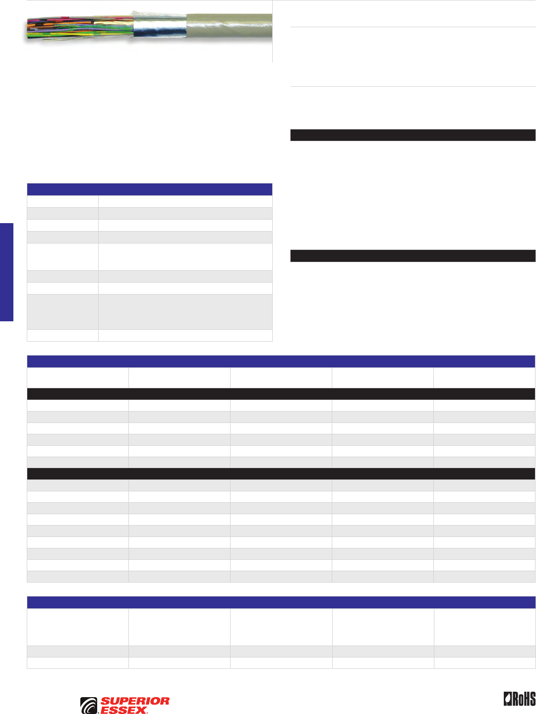
E-12
PREMISES COPPER PREMISES FIBER OSP FIBER OSP COMPOSITE CENTRAL OFFICE COPPER RDUP/RUS OSP COPPER BELL OSP COPPER OSP COPPER WIRE CANADIAN OSP COPPER TECHNICAL INFO
Toll Free 800.551.8948 | Fax 770.657.6807 | SuperiorEssex.com/Comm Rev 10/10 Ed 10.2
Product Description
Switchboard Cables are designed for indoor use in central exchanges, the
interconnection of distribution frames, and for switching and transmission
equipment systems. Switchboard cables are available in both shielded and
unshielded designs.
Applications
• T1/DS1
• T1C/DS1C
Features Benefits
Shielded Switchboard (SSWBD)
• Aluminum foil shield • EMI isolation
• Tinned copper drain wire • Easier termination
and superior grounding
• Tinned copper conductors • Minimize change in wire-wrap
joint resistance
• CMR listed • Suitable for horizontal
and riser installations
• Rip cord • Added ease of jacket removal
• Band marked • Easy identification of conductor
ring mates
Unshielded Switchboard (SWBD)
• Tinned copper conductors • Minimize change in wire-wrap
joint resistance
• CMR listed • Suitable for horizontal
and riser installations
• Rip cord • Added ease of jacket removal
• Band marked • Easy identification of conductor
ring mates
Specifications
Conductor Tinned copper
AWG (mm) 24 (0.5)
Insulation PVC
Jacket Gray PVC
Jacket Marking
Printed at 2 foot intervals on the jacket; information includes
product identification, pair count, UL information and
sequential lengths in feet and meters
Shield Aluminum/polyester (if appicable)
Package Reel
Performance
Compliance
UL 444
CSA C22.2 No. 214-08
UL 1666
RoHS-compliant
NRTL Programs UL, c(UL) Listed CMR
Part Numbers and Physical Characteristics
Part Number Pair Count
Nominal Diameter
in (mm)
Approx. Weight
lbs/kft (kg/km)
Standard Length
ft (m)
Shielded Switchboard (SSWBD)
02-201-61 25 0.35 (8.9) 88 (131) 1,000 (305)
02-097-61 25 0.35 (8.9) 88 (131) 5,000 (1,524)
02-203-61 25 0.35 (8.9) 88 (131) 2,000 (610)
02-098-61 32 0.41 (10) 113 (168) 5,000 (1,524)
02-100-61 50 0.48 (12) 167 (249) 5,000 (1,524)
02-104-61 100 0.63 (16) 314 (467) 5,000 (1,524)
Unshielded Switchboard (SWBD)
02-840-10 6 0.18 (4.6) 22 (33) 1,000 (305)
02-810-10 6 0.18 (4.6) 22 (33) 5,000 (1,524)
02-841-10 12 0.24 (6.1) 41 (61) 1,000 (305)
02-811-10 12 0.24 (6.1) 41 (61) 5,000 (1,524)
02-431-10 25 0.31 (7.9) 79 (118) 1,000 (305)
02-815-10 25 0.31 (7.9) 79 (118) 5,000 (1,524)
02-832-10 32 0.36 (9.1) 100 (149) 5,000 (1,524)
02-813-10 50 0.45 (11) 157 (234) 5,000 (1,524)
02-820-10 100 0.60 (15) 302 (449) 5,000 (1,524)
Electrical Specifications
Product
Conductor DC Resistance
@ 68°F (20°C)
Maximum Individual
Ohms/kft (Ohms/km)
Mutual Capacitance
Nominal
pF/ft (pF/m)
Characteristic
Impedance @ 1 MHz
Ohms
Attenuation Nominal
@ 0.772 MHz
@ 68°F (20°C)
dB/kft (dB/km)
SSWBD 28.6 (93.8) 20 (66) 85 ± 15 11 (36)
SWBD 28.6 (93.8) 20 (66) 85 ± 15 11 (36)
Switchboard 85 and Shielded Switchboard 85
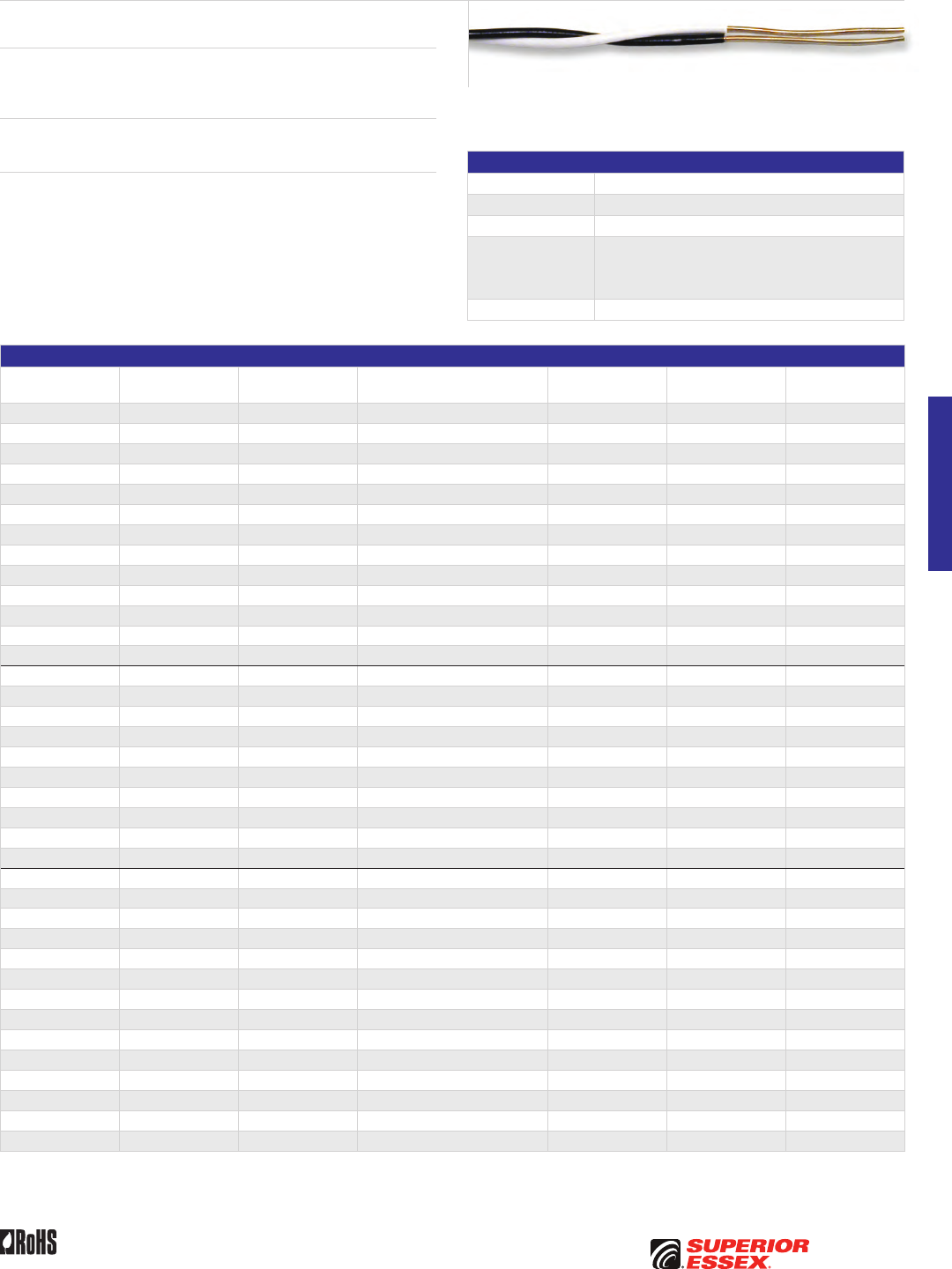
E-13
PREMISES COPPERPREMISES FIBEROSP FIBEROSP COMPOSITECENTRAL OFFICE COPPERRDUP/RUS OSP COPPERBELL OSP COPPEROSP COPPER WIRECANADIAN OSP COPPERTECHNICAL INFO
Toll Free 800.551.8948 | Fax 770.657.6807 | SuperiorEssex.com/CommRev 10/10 Ed 10.4
Distribution Frame Wire
DFW
Product Description
Distribution Frame Wires are designed for cross-connection of equipment
in telephone switch and equipment rooms requiring point-to-point hook ups.
Applications
• Normal use
Features Benefits
• Solid tinned copper conductors
in 22 AWG (0.6 mm) or 24 AWG
(0.5 mm) are insulated with semi-
rigid polyvinylchloride (PVC)
• Facilitates wire wrapping
and tight connections
• Each insulated conductor
is identified by a solid
insulation color
• Easy identification
Specifications
Conductor Tinned copper
AWG (mm) Available in 22 (0.6) and 24 (0.5)
Insulation Semi-rigid PVC
Performance
Compliance
UL 444
CSA C22.2 No. 214-08
GR 136 CORE (normal use)
RoHS-compliant
NRTL Programs UL, c(UL) Listed CM
Part Numbers and Physical Characteristics
Part Number
Number of
Conductors AWG (mm) Insulation Color
Nominal Diameter
in (mm)
Approx. Weight
lbs/kft (kg/km) Package
12-001-11 1 22 (0.6) Red 0.04 (1.0) 2 (3) 750 m Spool
12-002-11 1 22 (0.6) White 0.04 (1.0) 2 (3) 750 m Spool
12-003-11 1 22 (0.6) Green 0.04 (1.0) 2 (3) 750 m Spool
12-004-11 1 22 (0.6) Black 0.04 (1.0) 2 (3) 750 m Spool
12-303-13 1 22 (0.6) Green 0.04 (1.0) 2 (3) 1,000 m Spool
12-326-11 1 22 (0.6) Brown 0.04 (1.0) 2 (3) 3,000’ Spool
12-001-12 2 22 (0.6) Red/Green 0.08 (2.0) 5 (7) 500 m Spool
12-003-12 2 22 (0.6) Blue/White 0.08 (2.0) 5 (7) 500 m Spool
12-004-12 2 22 (0.6) Brown/Blue 0.08 (2.0) 5 (7) 500 m Spool
12-005-12 2 22 (0.6) Black/White 0.08 (2.0) 5 (7) 500 m Spool
12-001-13 2 22 (0.6) Red/White 0.08 (2.0) 5 (7) 305 m Spool
12-003-13 2 22 (0.6) Blue/White 0.08 (2.0) 5 (7) 1,000’ Spool
12-005-13 2 22 (0.6) Black/White 0.08 (2.0) 5 (7) 1,000’ Spool
12-101-13 2 24 (0.5) Red/White 0.08 (2.0) 4 (6) 1,000’ Spool
12-102-13 2 24 (0.5) Red/Yellow 0.08 (2.0) 4 (6) 1,000’ Spool
12-103-13 2 24 (0.5) White/Blue 0.08 (2.0) 4 (6) 1,000’ Spool
12-104-13 2 24 (0.5) Violet/Blue 0.08 (2.0) 4 (6) 305 m Spool
12-105-13 2 24 (0.5) Black/White 0.08 (2.0) 4 (6) 1,000’ Spool
12-106-13 2 24 (0.5) Red/White 0.08 (2.0) 4 (6) 6,000’ Spool
12-107-13 2 24 (0.5) Black/White 0.08 (2.0) 4 (6) 6,000’ Spool
12-108-13 2 24 (0.5) White/Blue 0.08 (2.0) 4 (6) 6,000’ Spool
12-109-13 2 24 (0.5) Yellow/Blue 0.08 (2.0) 4 (6) 6,000’ Spool
12-112-13 2 24 (0.5) Red/White 0.08 (2.0) 4 (6) 3,000’ Parallel Cone
12-203-13 2 22 (0.6) Blue/White 0.08 (2.0) 5 (7) 400’ Spool
12-304-13 2 22 (0.6) Brown/Blue 0.08 (2.0) 5 (7) 1,000 m Parallel Cone
12-305-13 2 22 (0.6) Black/White 0.08 (2.0) 5 (7) 1,000 m Parallel Cone
12-311-13 2 22 (0.6) Red/Green 0.08 (2.0) 5 (7) 3,000’ Spool
12-313-13 2 22 (0.6) Blue/White 0.08 (2.0) 5 (7) 3,280’ Parallel Cone
12-318-13 2 22 (0.6) White/Orange 0.08 (2.0) 5 (7) 3,000’ Spool
12-403-13 2 22 (0.6) White/Blue 0.08 (2.0) 5 (7) 3,000’ Spool
12-406-13 2 22 (0.6) Yellow/Violet 0.08 (2.0) 5 (7) 3,000’ Spool
12-501-13 2 22 (0.6) Red/White 0.08 (2.0) 5 (7) 2,300’ Spool
12-031-12 4 22 (0.6) Blue/White, Red/Green 0.12 (3.0) 9 (13) 1,640’ Parallel Cone
12-032-13 4 22 (0.6) Black/White, Black/White 0.12 (3.0) 9 (13) 1,640’ Parallel Cone
12-033-13 4 22 (0.6) Yellow/Blue, Orange/Brown 0.12 (3.0) 9 (13) 1,640’ Parallel Cone
12-034-13 5 22 (0.6) Yellow/Blue, Orange/Brown, Green 0.17 (4.3) 13 (20) 500 m Parallel Cone
12-035-13 5 22 (0.6) Black/White, Black/White, Green 0.17 (4.3) 13 (20) 500 m Parallel Cone
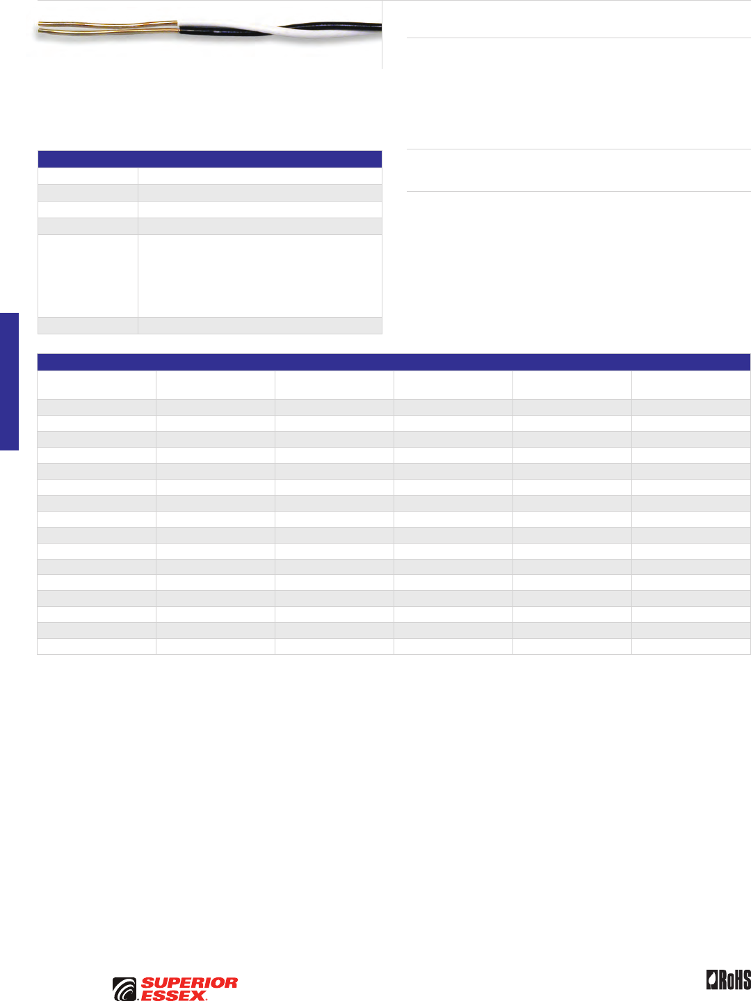
E-14
PREMISES COPPER PREMISES FIBER OSP FIBER OSP COMPOSITE CENTRAL OFFICE COPPER RDUP/RUS OSP COPPER BELL OSP COPPER OSP COPPER WIRE CANADIAN OSP COPPER TECHNICAL INFO
Toll Free 800.551.8948 | Fax 770.657.6807 | SuperiorEssex.com/Comm Rev 10/10 Ed 10.2
Product Description
Heavy Duty Distribution Frame Wire consists of 22 AWG tinned copper
conductors with a heavy duty, abrasion resistant, flame retardant PVC
insulation. HD-DFW is available in 2, 3 and 4 conductors, and is used for making
an interconnection between the incoming cable (tip termination) terminals and
the equipment on the main distribution frame in the Central Office (CO). HD-DFW
is suitable for use with either a solderless wrap or soldered terminals.
Applications
• High stress use
Features Benefits
• Solid tinned copper conductors
in 22 AWG (0.6 mm) are insulated
with PVC
• Facilitates solid connections
• Each insulated conductor
is identified by a solid
insulation color
• Easy identification
• Heavy duty insulation • Added protection for long runs
Specifications
Conductor Tinned copper
AWG (mm) 22 (0.6)
Insulation Heavy duty, abrasion resistant PVC
Package Parallel Cone
Performance
Compliance
UL 444
CSA C22.2 No. 214-08
UL 1666
GR-136-CORE (high stress use)
Applicable GR-136 Core requirements
for high stress applications
RoHS-compliant
NRTL Programs UL, c(UL) Listed CMR
Part Numbers and Physical Characteristics
Part Number Number of Conductors Insulation Color
Nominal Diameter
in (mm)
Approx. Weight
lbs/kft (kg/km)
Standard Length
ft (m)
12-201-15 2 White/Blue 0.08 (2.0) 5 (7) 3,000 (914)
12-202-15 2 White/Blue 0.08 (2.0) 5 (7) 574 (175)
12-203-15 2 White/Blue 0.08 (2.0) 5 (7) 3,281 (1,000)
12-204-15 2 White/Green 0.08 (2.0) 5 (7) 3,000 (914)
12-205-15 2 White/Orange 0.08 (2.0) 5 (7) 3,000 (914)
12-206-15 2 White/Red 0.08 (2.0) 5 (7) 3,000 (914)
12-207-15 2 Yellow/Black 0.08 (2.0) 5 (7) 3,000 (914)
12-208-15 2 Yellow/Green 0.08 (2.0) 5 (7) 3,000 (914)
12-209-15 2 Yellow/Orange 0.08 (2.0) 5 (7) 3,000 (914)
12-210-15 2 Black/Orange 0.08 (2.0) 5 (7) 3,000 (914)
12-211-15 2 Orange/Blue 0.08 (2.0) 5 (7) 3,000 (914)
12-216-15 2 Black/Green 0.08 (2.0) 5 (7) 3,000 (914)
12-301-15 3 White/Blue/Red 0.12 (3.0) 7 (10) 2,182 (665)
12-401-15 4 White/Blue, Red/Green 0.12 (3.0) 9 (13) 1,500 (457)
12-402-15 4 Yellow/Blue, Red/Green 0.12 (3.0) 9 (13) 1,500 (457)
12-403-15 4 Yellow/Blue, Red/Green 0.12 (3.0) 9 (13) 328 (100)
Heavy Duty Distribution Frame Wire
HD-DFW
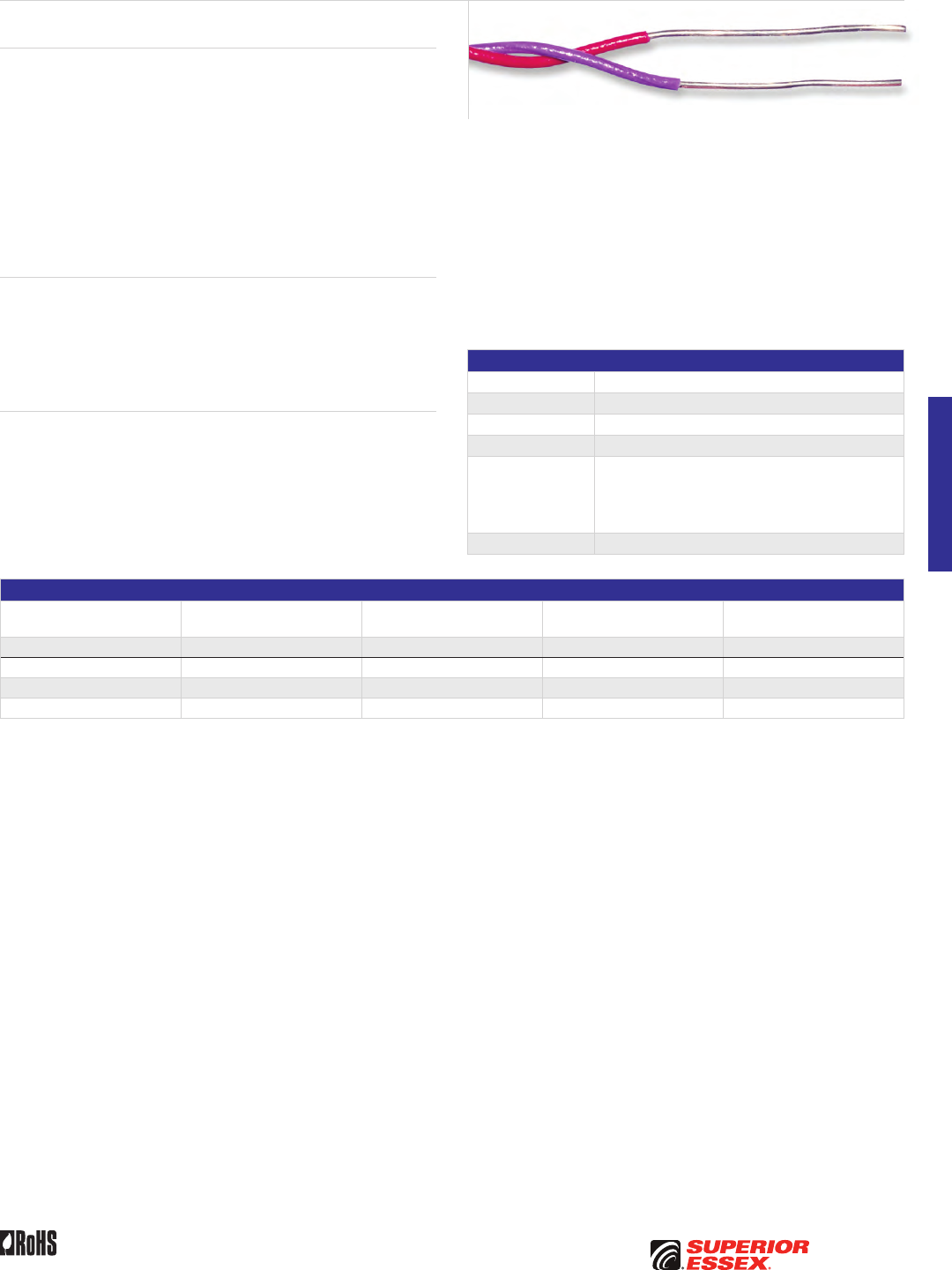
E-15
PREMISES COPPERPREMISES FIBEROSP FIBEROSP COMPOSITECENTRAL OFFICE COPPERRDUP/RUS OSP COPPERBELL OSP COPPEROSP COPPER WIRECANADIAN OSP COPPERTECHNICAL INFO
Toll Free 800.551.8948 | Fax 770.657.6807 | SuperiorEssex.com/CommRev 10/10 Ed 10.2
Tight Twist Distribution Frame Wire
DFW
Product Description
Tight Twist Distribution Frame Wire is necessary for the deployment of
both xDSL and HI-CAP (T-1/HDSL) circuits within the distribution frames of
central offices. This higher capacity frame wire is manufactured with a tight
twist to minimize the impacts of electromagnetic interferences within this
indoor environment. The Tight Twist Distribution Frame Wire is available in
both 22 and 24 gauge sizes with a heavy duty flame retardant PVC insulation.
Heavy duty in this application means a higher level of abrasion resistance,
higher cut through and a higher temperature rating. The 22 AWG product is
intended for use on main distribution frames (conventional type), while the
24 AWG is intended for use on COSMIC (Modular) distributing frames. The
product is available on spools.
Applications
• xDSL
• HI-CAP
• T-1/HDSL
• High stress use
Features Benefits
• 22 or 24 AWG solid tinned
annealed copper
• Facilitates solid connection
• Heavy duty, high temperature,
high stress insulation
• Added protection
for long wire runs
• Twisting sufficient to meet
xDSL requirements
• Twist pattern sufficient
for xDSL transmission level
Specifications
Conductor Tinned copper
AWG (mm) Available in 22 (0.6) and 24 (0.5)
Insulation Flame retardant PVC
Package Spool
Performance
Compliance
UL 444
CSA C22.2 No. 214-08
Applicable GR-136 Core requirement
for high stress applications
RoHS-compliant
NRTL Programs UL, c(UL) Listed CM
Part Numbers and Physical Characteristics
Part Number AWG (mm) Insulation Color
Nominal Diameter
in (mm)
Standard Length
ft (m)
12-212-T5 22 (0.6) White/Green 0.08 (2.0) 3,000 (915)
12-213-T5 24 (0.5) Violet/Red 0.07 (1.8) 3,000 (915)
12-214-T5 24 (0.5) Violet/Red 0.07 (1.8) 1,000 (305)
12-215-T5 24 (0.5) Green/Red 0.07 (1.8) 1,000 (305)


F-1
PREMISES COPPERPREMISES FIBEROSP FIBEROSP COMPOSITECENTRAL OFFICE COPPERRDUP/RUS OSP COPPERBELL OSP COPPEROSP COPPER WIRECANADIAN OSP COPPERTECHNICAL INFO
Toll Free 800.551.8948 | Fax 770.657.6807 | SuperiorEssex.com/Comm
RDUP/RUS OSP COPPER
Table of Contents
SEALPIC® ..................................................F-2
SEALPIC®–84 ...............................................F-4
SEALPIC®–FSF-84 ...........................................F-6
SEALPIC®–FSF (RDUP PE-89) .................................F-8
CASPIC®–FSF (RDUP PE-89).................................F-10
SEALPIC®–F (RDUP PE-39) ..................................F-12
CUPIC®–F (RDUP PE-39).....................................F-14
GOPIC®–F (RDUP PE-39) ....................................F-16
CASPIC®–F (RDUP PE-39) ...................................F-18
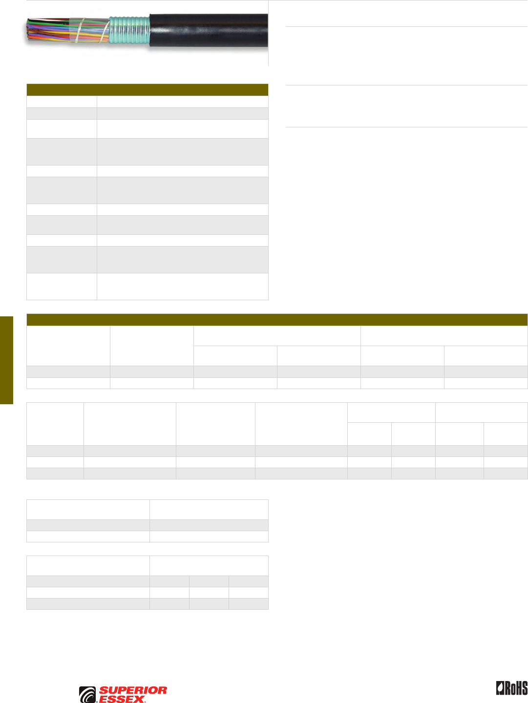
F-2
PREMISES COPPER PREMISES FIBER OSP FIBER OSP COMPOSITE CENTRAL OFFICE COPPER RDUP/RUS OSP COPPER BELL OSP COPPER OSP COPPER WIRE CANADIAN OSP COPPER TECHNICAL INFO
Rev 10/10 Ed 10.3Toll Free 800.551.8948 | Fax 770.657.6807 | SuperiorEssex.com/Comm
Specifications
Conductor Solid annealed copper
AWG (mm) Available in 19 (0.90), 22 (0.64) and 24 (0.51)
Insulation Solid polyolefin; color coded in accordance with
industry standards
Twisted Pairs
Individual insulated conductors are twisted into pairs with
varying lay lengths; specific color combinations provide
pair identification
≤ 25-Pair Core Pairs are assembled into a cylindrical core
> 25-Pair Core
Cables larger than 25-pair are assembled into units, which
are then used to assemble the core; units are identifiable
using color-coded binders
Core Wrap Non-hygroscopic, dielectric tape
Shield Corrugated, copolymer coated, 8 mil aluminum tape applied
longitudinally with an overlap
Jacket Black, polyethylene
Jacket Marking
Identifying information includes a telephone handset,
cable code, pair count, AWG, date of manufacture
and sequential length markings at 2 foot intervals
Standards
Compliance
ANSI/ICEA S-85-625-2007
Formerly PE-22
RoHS-compliant
Electrical Specifications
Number of Pairs
Average Mutual
Capacitance @ 1000 Hz
nF/mile (nF/km)
Capacitance Unbalance
Pair to Pair @ 1 kHz
Capacitance Unbalance
Pair to Ground @ 1 kHz
Maximum Individual
pF @ 1 kft (pF @ 1 km)
Maximum RMS
pF @ 1 kft (pF @ 1 km)
Maximum Individual
pF @ 1 kft (pF @ 1 km)
Maximum Average
pF @ 1 kft (pF @ 1 km)
12 or less 83 ± 7 (52 ± 4) 80 (145) - 800 (2,625) -
Over 12 83 ± 4 (52 ± 2) 80 (145) 25 (45) 800 (2,625) 175 (574)
Conductor Size
AWG (mm)
Minimum Insulation
Resistance @ 68°F (20°C)
gigohm-mile (gigohm-km)
Maximum Average
Attenuation*
772 kHz @ 68°F (20°C)
dB/kft (dB/km)
Maximum Conductor
Resistance @ 68°F (20°C)
Ohms/sheath
mile (km)
DC Resistance
Unbalance Maximum %
Dielectric Strength
DC Potential – Volts
Average
Individual
Pair
Conductor
to Conductor
Conductor
to Shield
19 (0.90) 1.0 (1.6) 3.3 (10.8) 45.0 (28.0) 1.5 5.0 5,000 10,000
22 (0.64) 1.0 (1.6) 4.7 (15.4) 91.0 (56.5) 1.5 5.0 4,000 10,000
24 (0.51) 1.0 (1.6) 5.9 (19.4) 144.0 (89.5) 1.5 5.0 3,000 10,000
*For cables with 12-pair or less, the maximum average attenuation may be increased by 10% over the values shown.
Minimum Near End Crosstalk
(NEXT) @ 772 kHz
PSWUNEXT Mean (dB) 47
PSWUNEXT Worst Pair (dB) 42
Minimum Far End Crosstalk
(FEXT) @ 772 kHz
Conductor Size (AWG) 19 22 24
PSELFEXT Mean (dB/kft) 51 49 49
PSELFEXT Worst Pair (dB/kft) 45 43 43
SEALPIC®
Product Description
SEALPIC® Cables have an air core design and are suited for lashed
aerial installations. If used in underground conduit, pressurization is
recommended. SEALPIC cables are not recommended for direct burial
installations.
Applications
• Lashed aerial
• Pressurized underground conduit
Features Benefits
• Twisted into pairs with varying
lay lengths
• Minimizes crosstalk
• Core wrap • Provides thermal protection
• Black, polyethylene jacket • Provides a tough protective
covering designed to withstand
exposure to direct sunlight,
atmospheric temperature
changes and stresses expected
in standard installations
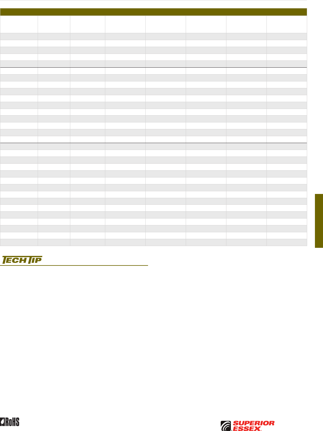
F-3
PREMISES COPPERPREMISES FIBEROSP FIBEROSP COMPOSITECENTRAL OFFICE COPPERRDUP/RUS OSP COPPERBELL OSP COPPEROSP COPPER WIRECANADIAN OSP COPPERTECHNICAL INFO
Rev 10/10 Ed 10.3 Toll Free 800.551.8948 | Fax 770.657.6807 | SuperiorEssex.com/Comm
Part Numbers and Physical Characteristics
Part Number Pair Count AWG (mm)
Nominal Diameter
in (mm)
Approx. Weight
lbs/kft (kg/km)
Standard Length
ft (m)
Approx.
Shipping Weight
lbs (kg)
Reel Size
F x T x D
in
01-026-40 6 19 (0.90) 0.48 (12) 105 (155) 5,000 (1,524) 635 (285) 44 x 18 x 20
01-028-40 12 19 (0.90) 0.57 (15) 170 (255) 5,000 (1,524) 1,015 (460) 46 x 25 x 20
01-031-40 25 19 (0.90) 0.76 (19) 310 (460) 5,000 (1,524) 1,755 (795) 52 x 25 x 20
01-034-40 50 19 (0.90) 1.00 (25) 575 (855) 5,000 (1,524) 3,165 (1,435) 62 x 30 x 24
01-038-40 100 19 (0.90) 1.34 (34) 1,075 (1,600) 5,000 (1,524) 6,075 (2,755) 78 x 40 x 39
01-057-40 6 22 (0.64) 0.39 (9.9) 65 (95) 5,000 (1,524) 390 (175) 36 x 18 x 14
01-059-40 12 22 (0.64) 0.46 (12) 100 (150) 5,000 (1,524) 610 (275) 44 x 18 x 20
01-062-40 25 22 (0.64) 0.60 (15) 180 (270) 5,000 (1,524) 1,065 (485) 46 x 25 x 20
01-065-40 50 22 (0.64) 0.77 (20) 315 (470) 5,000 (1,524) 1,780 (805) 52 x 25 x 20
01-069-40 100 22 (0.64) 1.02 (26) 580 (865) 5,000 (1,524) 3,190 (1,445) 62 x 30 x 24
01-073-40 200 22 (0.64) 1.38 (35) 1,095 (1,630) 5,000 (1,524) 6,175 (2,800) 78 x 40 x 39
01-075-40 300 22 (0.64) 1.66 (42) 1,605 (2,390) 2,500 (762) 4,625 (2,100) 72 x 35 x 36
01-077-40 400 22 (0.64) 1.89 (48) 2,115 (3,150) 2,500 (762) 5,,985 (2,715) 78 x 40 x 39
01-081-40 600 22 (0.64) 2.28 (58) 3,125 (4,650) 1,250 (381) 4,520 (2,050) 72 x 35 x 36
01-083-40 900 22 (0.64) 2.76 (70) 4,635 (6,900) 1,250 (381) 6,590 (2,990) 84 x 40 x 42
01-085-40 1,200 22 (0.64) 3.15 (80) 6,125 (9,115) 1,000 (305) 6,920 (3,140) 84 x 40 x 42
01-092-40 6 24 (0.51) 0.35 (8.9) 50 (75) 5,000 (1,524) 295 (135) 30 x 18 x 12
01-094-40 12 24 (0.51) 0.41 (10) 75 (110) 5,000 (1,524) 440 (200) 36 x 18 x 14
01-097-40 25 24 (0.51) 0.51 (13) 125 (185) 5,000 (1,524) 735 (330) 44 x 18 x 20
01-100-40 50 24 (0.51) 0.64 (16) 215 (320) 5,000 (1,524) 1,240 (560) 46 x 25 x 20
01-104-40 100 24 (0.51) 0.83 (21) 385 (575) 5,000 (1,524) 2,170 (985) 58 x 25 x 20
01-108-40 200 24 (0.51) 1.12 (28) 715 (1,065) 5,000 (1,524) 4,190 (1,900) 72 x 35 x 36
01-110-40 300 24 (0.51) 1.33 (34) 1,040 (1,550) 5,000 (1,524) 5,900 (2,675) 78 x 40 x 39
01-112-40 400 24 (0.51) 1.52 (39) 1,360 (2,025) 2,500 (762) 4,015 (1,820) 72 x 35 x 36
01-116-40 600 24 (0.51) 1.82 (46) 2,005 (2,985) 2,500 (762) 5,710 (2,590) 78 x 40 x 39
01-118-40 900 24 (0.51) 2.19 (56) 2,960 (4,405) 1,250 (381) 4,315 (1,955) 72 x 35 x 36
01-120-40 1,200 24 (0.51) 2.49 (63) 3,895 (5,795) 1,250 (381) 5,570 (2,525) 78 x 40 x 39
01-121-40 1,500 24 (0.51) 2.79 (71) 4,845 (7,210) 1,250 (381) 6,855 (3,110) 84 x 40 x 42
01-124-40 1,800 24 (0.51) 3.04 (77) 5,785 (8,610) 1,000 (305) 6,485 (2,940) 78 x 40 x 39
01-125-40 2,100 24 (0.51) 3.31 (84) 6,735 (10,025) 1,000 (305) 7,530 (3,415) 84 x 40 x 42
01-126-40 2,400 24 (0.51) 3.49 (89) 7,650 (11,385) 750 (229) 6,915 (3,135) 96 x 40 x 48
Product FAQs for OSP copper cables are available online:
www.SuperiorEssex.com/comm/productFAQs.aspx
SEALPIC
®
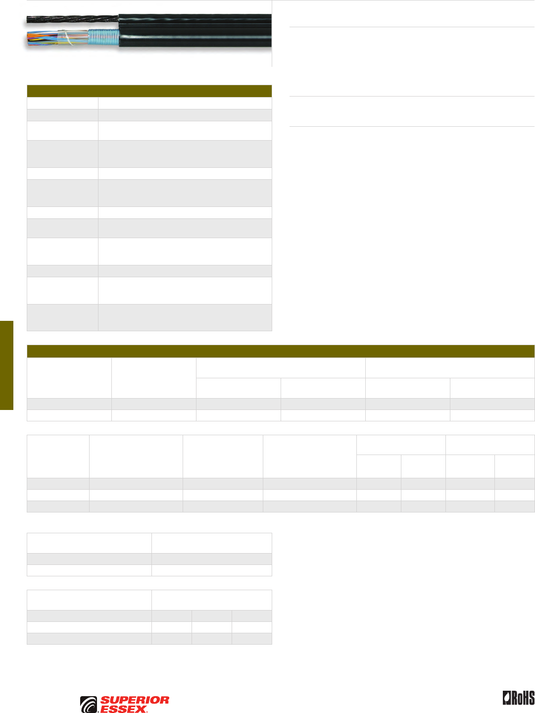
F-4
PREMISES COPPER PREMISES FIBER OSP FIBER OSP COMPOSITE CENTRAL OFFICE COPPER RDUP/RUS OSP COPPER BELL OSP COPPER OSP COPPER WIRE CANADIAN OSP COPPER TECHNICAL INFO
Rev 10/10 Ed 10.3Toll Free 800.551.8948 | Fax 770.657.6807 | SuperiorEssex.com/Comm
Specifications
Conductor Solid annealed copper
AWG (mm) Available in 19 (0.90), 22 (0.64) and 24 (0.51)
Insulation Solid polyolefin; color coded in accordance
with industry standards
Twisted Pairs
Individual insulated conductors are twisted into pairs with
varying lay lengths; specific color combinations provide
pair identification
≤ 25-Pair Core Pairs are assembled into a cylindrical core
> 25-Pair Core
Cables larger than 25-pair are assembled into units, which
are then used to assemble the core; units are identifiable
using color-coded binders
Core Wrap Non-hygroscopic, dielectric tape
Shield Corrugated, copolymer coated, 8 mil aluminum tape applied
longitudinally with an overlap
Support Member
0.25 inch, 7-strand Extra High Strength (EHS) galvanized
steel messenger serves as support member and integral
part of the sheath; messenger is flooded
Jacket Black, polyethylene
Jacket Marking
Identifying information includes a telephone handset,
cable code, pair count, AWG, date of manufacture
and sequential length markings at 2 foot intervals
Standards
Compliance
ANSI/ICEA S-85-625-2007
Formerly PE-38
RoHS-compliant
Electrical Specifications
Number of Pairs
Average Mutual
Capacitance @ 1000 Hz
nF/mile (nF/km)
Capacitance Unbalance
Pair to Pair @ 1 kHz
Capacitance Unbalance
Pair to Ground @ 1 kHz
Maximum Individual
pF @ 1 kft (pF @ 1 km)
Maximum RMS
pF @ 1 kft (pF @ 1 km)
Maximum Individual
pF @ 1 kft (pF @ 1 km)
Maximum Average
pF @ 1 kft (pF @ 1 km)
12 or less 83 ± 7 (52 ± 4) 80 (145) - 800 (2,625) -
Over 12 83 ± 4 (52 ± 2) 80 (145) 25 (45) 800 (2,625) 175 (574)
Conductor Size
AWG (mm)
Minimum Insulation
Resistance @ 68°F (20°C)
gigohm-mile (gigohm-km)
Maximum Average
Attenuation*
772 kHz @ 68°F (20°C)
dB/kft (dB/km)
Maximum Conductor
Resistance @ 68°F (20°C)
Ohms/sheath
mile (km)
DC Resistance
Unbalance Maximum %
Dielectric Strength
DC Potential – Volts
Average
Individual
Pair
Conductor
to Conductor
Conductor
to Shield
19 (0.90) 1.0 (1.6) 3.3 (10.8) 45.0 (28.0) 1.5 5.0 5,000 10,000
22 (0.64) 1.0 (1.6) 4.7 (15.4) 91.0 (56.5) 1.5 5.0 4,000 10,000
24 (0.51) 1.0 (1.6) 5.9 (19.4) 144.0 (89.5) 1.5 5.0 3,000 10,000
*For cables with 12-pair or less, the maximum average attenuation may be increased by 10% over the values shown.
Minimum Near End Crosstalk
(NEXT) @ 772 kHz
PSWUNEXT Mean (dB) 47
PSWUNEXT Worst Pair (dB) 42
Minimum Far End Crosstalk
(FEXT) @ 772 kHz
Conductor Size (AWG) 19 22 24
PSELFEXT Mean (dB/kft) 51 49 49
PSELFEXT Worst Pair (dB/kft) 45 43 43
SEALPIC®–84
Product Description
SEALPIC®-84 Cables have an air core design and are suited for aerial
installations. The core and support member (messenger) lay parallel to each
other forming a cross-sectional “figure 8.” The support messenger is an
integral part of the cable sheath, yet readily available for gripping, pulling
and tensioning.
Applications
• Aerial
Features Benefits
• Twisted into pairs with varying
lay lengths
• Minimizes crosstalk
• Core wrap • Provides thermal protection
• Fully flooded steel
support member
• Inhibits corrosion
• Black, polyethylene jacket • Provides a tough, protective
covering designed to withstand
exposure to direct sunlight,
atmospheric temperature
changes and stresses expected
in standard installations
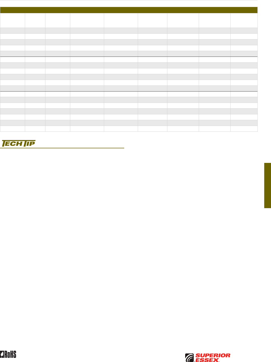
F-5
PREMISES COPPERPREMISES FIBEROSP FIBEROSP COMPOSITECENTRAL OFFICE COPPERRDUP/RUS OSP COPPERBELL OSP COPPEROSP COPPER WIRECANADIAN OSP COPPERTECHNICAL INFO
Rev 10/10 Ed 10.3 Toll Free 800.551.8948 | Fax 770.657.6807 | SuperiorEssex.com/Comm
Part Numbers and Physical Characteristics
Part Number
Pair
Count AWG (mm)
Nominal Diameter
(cable only)
in (mm)
Nominal Diameter
(with messenger)
in (mm)
Approx. Weight
lbs/kft (kg/km)
Standard Length
ft (m)
Approx.
Shipping Weight
lbs (kg)
Reel Size
F x T x D
in
01-026-38 6 19 (0.90) 0.47 (12) 0.96 (24) 240 (355) 5,000 (1,524) 1,850 (839) 72 x 36 x 36
01-028-38 12 19 (0.90) 0.56 (14) 1.05 (27) 305 (455) 5,000 (1,524) 1,795 (814) 58 x 25 x 20
01-031-38 25 19 (0.90) 0.74 (19) 1.24 (31) 445 (660) 5,000 (1,524) 2,975 (1,349) 78 x 40 x 39
01-034-38 50 19 (0.90) 1.01 (26) 1.48 (38) 715 (1,065) 5,000 (1,524) 4,395 (1,993) 84 x 40 x 42
01-038-38 100 19 (0.90) 1.36 (35) 1.82 (46) 1,235 (1,840) 2,500 (762) 3,685 (1,671) 72 x 36 x 36
01-057-38 6 22 (0.64) 0.38 (9.7) 0.87 (22) 200 (300) 5,000 (1,524) 1,270 (576) 58 x 25 x 20
01-059-38 12 22 (0.64) 0.45 (11) 0.94 (24) 235 (350) 5,000 (1,524) 1,515 (687) 62 x 30 x 24
01-062-38 25 22 (0.64) 0.59 (15) 1.08 (27) 315 (470) 5,000 (1,524) 2,225 (1,009) 72 x 36 x 36
01-065-38 50 22 (0.64) 0.75 (19) 1.25 (32) 450 (670) 5,000 (1,524) 3,000 (1,361) 78 x 40 x 39
01-069-38 100 22 (0.64) 1.03 (26) 1.50 (38) 725 (1,080) 2,500 (762) 2,100 (952) 62 x 30 x 24
01-073-38 200 22 (0.64) 1.40 (36) 1.86 (47) 1,255 (1,870) 2,500 (762) 3,725 (1,689) 72 x 36 x 36
01-092-38 6 24 (0.51) 0.34 (8.6) 0.83 (21) 185 (275) 5,000 (1,524) 1,115 (506) 46 x 25 x 20
01-094-38 12 24 (0.51) 0.40 (10) 0.89 (23) 210 (315) 5,000 (1,524) 1,280 (580) 52 x 25 x 20
01-097-38 25 24 (0.51) 0.50 (13) 0.99 (25) 260 (385) 5,000 (1,524) 1,595 (723) 58 x 25 x 20
01-100-38 50 24 (0.51) 0.63 (16) 1.12 (28) 350 (520) 5,000 (1,524) 2,065 (937) 62 x 30 x 24
01-104-38 100 24 (0.51) 0.81 (21) 1.31 (33) 515 (765) 5,000 (1,524) 3,275 (1,485) 72 x 36 x 36
01-108-38 200 24 (0.51) 1.14 (29) 1.60 (41) 875 (1,300) 2,500 (762) 2,440 (1,107) 62 x 30 x 24
01-110-38 300 24 (0.51) 1.36 (35) 1.81 (46) 1,200 (1,785) 2,500 (762) 3,585 (1,626) 72 x 36 x 36
Sag and Tension guidelines for these products are available online:
www.SuperiorEssex.com/techtip.aspx
SEALPIC
®
–84
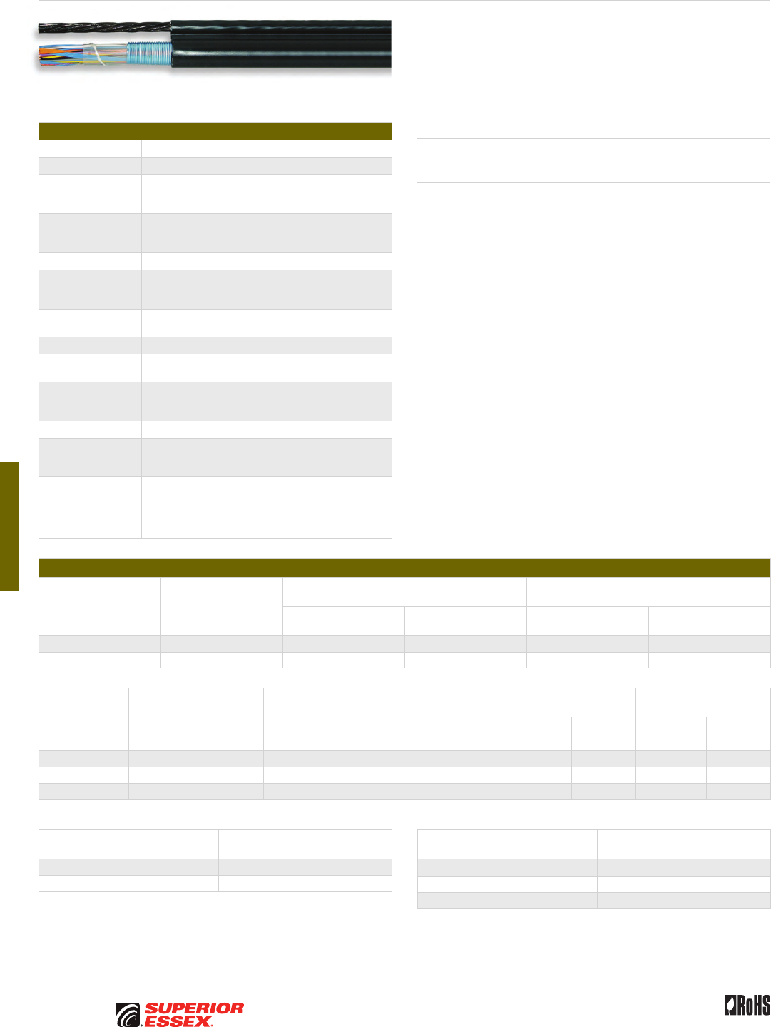
F-6
PREMISES COPPER PREMISES FIBER OSP FIBER OSP COMPOSITE CENTRAL OFFICE COPPER RDUP/RUS OSP COPPER BELL OSP COPPER OSP COPPER WIRE CANADIAN OSP COPPER TECHNICAL INFO
Rev 10/10 Ed 10.3Toll Free 800.551.8948 | Fax 770.657.6807 | SuperiorEssex.com/Comm
Specifications
Conductor Solid Annealed Copper
AWG (mm) 19 (0.90), 22 (0.64) and 24 (0.51)
Insulation
Dual insulation consisting of an inner layer of foamed, natural
polyolefin over which is applied a solid (skin) layer of
polyolefin colored in accordance with industry standards
Twisted Pairs
Individual insulated conductors; twisted into pairs with
varying lay lengths; specific color combinations provide
pair identification
≤ 25-Pair Core Pairs are assembled into a cylindrical core
> 25-Pair Core
Cables larger than 25-pair are assembled into units, which
are then used to assemble the core; units are identifiable
using color-coded binders
Filling Compound 80°C ETPR compound, completely filling the interstices
between the pairs and under the core wrap
Core Wrap Non-hygroscopic, dielectric tape
Shield Corrugated, copolymer coated, 8 mil aluminum tape applied
longitudinally with an overlap; flooded shield interfaces
Support Member
0.25 inch, 7-strand Extra High Strength (EHS) galvanized
steel messenger serves as support member and integral
part of the sheath; messenger is flooded
Jacket Black, polyethylene
Jacket Marking
Identifying information includes a telephone handset,
cable code, pair count, AWG, date of manufacture
and sequential length markings at 2 foot intervals
Standards
Compliance
SEALPIC-FSF-84 cables meet the physical and electrical
requirements of RDUP specification 7 CFR 1755.890
(PE-89), except that the figure-8 sheath shall meet
the requirements of ANSI/ICEA S-85-625-2007 Option A
RoHS-compliant
Electrical Specifications
Number of Pairs
Average Mutual
Capacitance @ 1000 Hz
nF/mile (nF/km)
Capacitance Unbalance
Pair to Pair @ 1 kHz
Capacitance Unbalance
Pair to Ground @ 1 kHz
Maximum Individual
pF @ 1 kft (pF @ 1 km)
Maximum RMS
pF @ 1 kft (pF @ 1 km)
Maximum Individual
pF @ 1 kft (pF @ 1 km)
Maximum Average
pF @ 1 kft (pF @ 1 km)
12 or less 83 ± 7 (52 ± 4) 80 (145) - 800 (2,625) -
Over 12 83 ± 4 (52 ± 2) 80 (145) 25 (45) 800 (2,625) 175 (574)
Conductor Size
AWG (mm)
Minimum Insulation
Resistance @ 68°F (20°C)
gigohm-mile (gigohm-km)
Maximum Average
Attenuation*
772 kHz @ 68°F (20°C)
dB/kft (dB/km)*
Maximum Conductor
Resistance @ 68°F (20°C)
Ohms/sheath
mile (km)
DC Resistance
Unbalance Maximum %
Dielectric Strength
DC Potential – Volts
Average
Individual
Pair
Conductor
to Conductor
Conductor
to Shield
19 (0.90) 1.0 (1.6) 3.2 (10.5) 45.0 (28.0) 1.5 5.0 4,500 10,000
22 (0.64) 1.0 (1.6) 4.5 (14.8) 91.0 (56.5) 1.5 5.0 3,600 10,000
24 (0.51) 1.0 (1.6) 5.6 (18.4) 144.0 (89.5) 1.5 5.0 3,000 10,000
*For cables with 12-pair or less, the maximum average attenuation may be increased by 10% over the values shown.
Minimum Near End Crosstalk
(NEXT) @ 772 kHz
PSWUNEXT Mean (dB) 47
PSWUNEXT Worst Pair (dB) 42
SEALPIC®–FSF-84
Product Description
SEALPIC®-FSF-84 Cables are suited for aerial applications where a filled
cable design is preferred. The core and support member (messenger) lay
parallel to each other forming a cross-sectional “figure 8.” The support
messenger is an integral part of the cable sheath, yet readily available for
gripping, pulling and tensioning.
Applications
• Aerial
Features Benefits
• Twisted into pairs with varying
lay lengths
• Minimizes crosstalk
• Core wrap • Provides thermal protection
• Filled core • Moisture resistant
• Fully flooded shield interfaces • Inhibits corrosion
and water migration
• Fully flooded steel
support member
• Inhibits corrosion
• Black, polyethylene jacket • Provides a tough, protective
covering designed to withstand
exposure to direct sunlight,
atmospheric temperature
changes and stresses expected
in standard installations
Minimum Far End Crosstalk
(FEXT) @ 772 kHz
Conductor Size (AWG) 19 22 24
PSELFEXT Mean (dB/kft) 51 49 49
PSELFEXT Worst Pair (dB/kft) 45 43 43
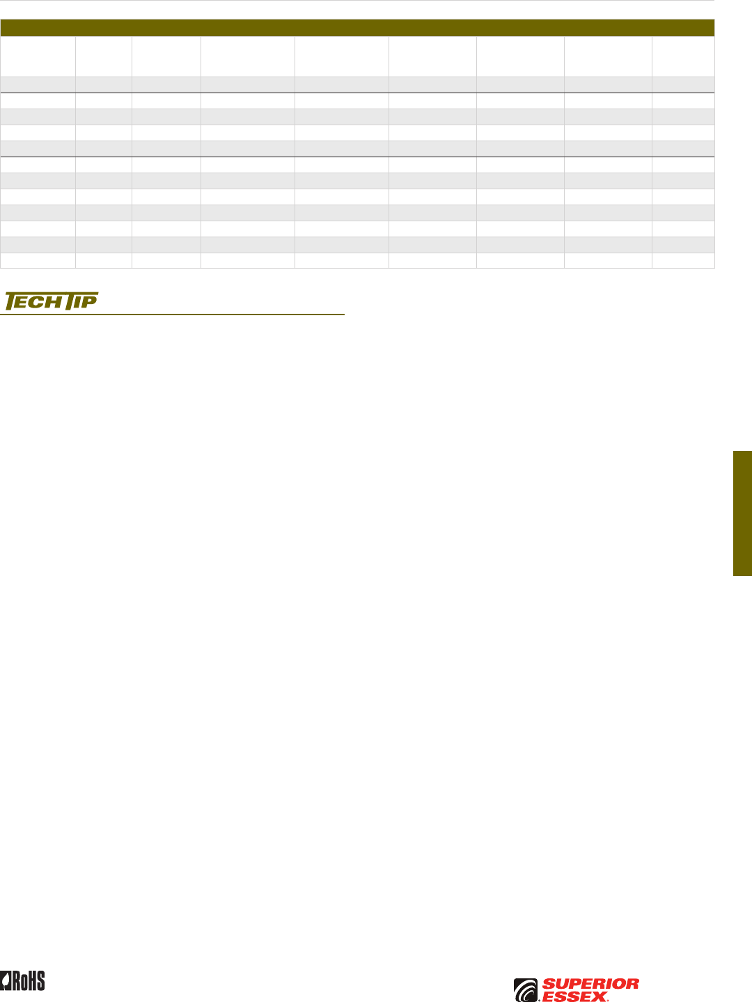
F-7
PREMISES COPPERPREMISES FIBEROSP FIBEROSP COMPOSITECENTRAL OFFICE COPPERRDUP/RUS OSP COPPERBELL OSP COPPEROSP COPPER WIRECANADIAN OSP COPPERTECHNICAL INFO
Rev 10/10 Ed 10.3 Toll Free 800.551.8948 | Fax 770.657.6807 | SuperiorEssex.com/Comm
Part Numbers and Physical Characteristics
Part Number
Pair
Count AWG (mm)
Nominal Diameter
(cable only)
in (mm)
Nominal Diameter
(with messenger)
in (mm)
Approx. Weight
lbs/kft (kg/km)
Standard Length
ft (m)
Approx.
Shipping Weight
lbs (kg)
Reel Size
F x T x D
in
09-034-05 50 19 (0.90) 1.04 (26) 1.51 (38) 800 (1,190) 2,500 (762) 2,270 (1,030) 60 x 30 x 30
09-057-05 6 22 (0.64) 0.37 (9.4) 0.84 (22) 205 (305) 5,000 (1,524) 1,255 (569) 52 x 25 x 20
09-059-05 12 22 (0.64) 0.46 (12) 0.93 (24) 250 (370) 5,000 (1,524) 1,513 (687) 52 x 25 x 20
09-062-05 25 22 (0.64) 0.59 (15) 1.06 (27) 330 (490) 5,000 (1,524) 1,945 (882) 58 x 25 x 20
09-065-05 50 22 (0.64) 0.75 (19) 1.22 (31) 485 (720) 5,000 (1,524) 2,765 (1,254) 62 x 30 x 24
09-092-05 6 24 (0.51) 0.34 (8.6) 0.83 (21) 185 (275) 5,000 (1,524) 1,115 (506) 46 x 25 x 20
09-094-05 12 24 (0.51) 0.40 (10) 0.89 (23) 210 (315) 5,000 (1,524) 1,280 (580) 52 x 25 x 20
09-097-05 25 24 (0.51) 0.50 (13) 0.99 (25) 260 (385) 5,000 (1,524) 1,595 (723) 58 x 25 x 20
09-100-05 50 24 (0.51) 0.63 (16) 1.12 (28) 350 (520) 5,000 (1,524) 2,065 (937) 62 x 30 x 24
09-104-05 100 24 (0.51) 0.81 (21) 1.31 (33) 515 (765) 5,000 (1,524) 3,275 (1,485) 72 x 36 x 36
09-108-05 200 24 (0.51) 1.14 (29) 1.60 (41) 875 (1,300) 2,500 (762) 2,440 (1,107) 62 x 30 x 24
09-110-05 300 24 (0.51) 1.36 (35) 1.81 (46) 1,200 (1,785) 2,500 (762) 3,585 (1,626) 72 x 36 x 36
Sag and Tension guidelines for these products are available online:
www.SuperiorEssex.com/techtip.aspx
SEALPIC
®
–FSF-84
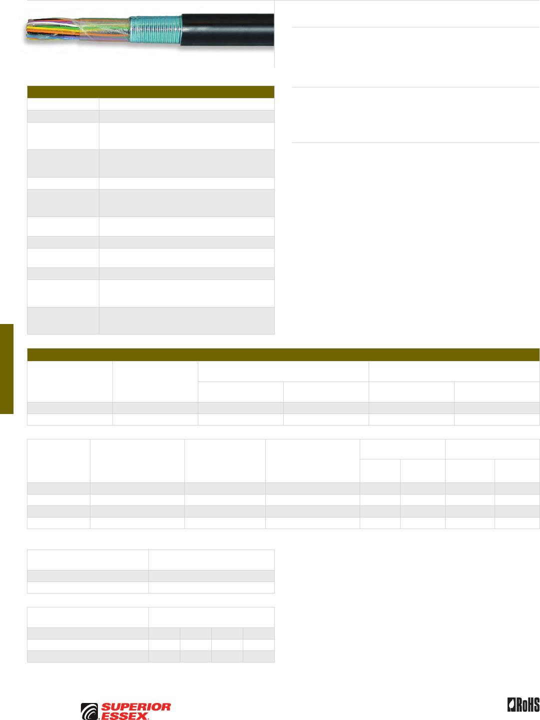
F-8
PREMISES COPPER PREMISES FIBER OSP FIBER OSP COMPOSITE CENTRAL OFFICE COPPER RDUP/RUS OSP COPPER BELL OSP COPPER OSP COPPER WIRE CANADIAN OSP COPPER TECHNICAL INFO
Rev 10/10 Ed 10.3Toll Free 800.551.8948 | Fax 770.657.6807 | SuperiorEssex.com/Comm
Specifications
Conductor Solid annealed copper
AWG (mm) Available in 19 (0.90), 22 (0.64), 24 (0.51) and 26 (0.40)
Insulation
Dual insulation consisting of an inner layer of foamed, natural
polyolefin over which is applied a solid (skin) layer of
polyolefin colored in accordance with industry standards
Twisted Pairs
Individual insulated conductors; twisted into pairs with
varying lay lengths; specific color combinations provide
pair identification
≤ 25-Pair Core Pairs are assembled into a cylindrical core
> 25-Pair Core
Cables larger than 25-pair are assembled into units, which
are then used to assemble the core; units are identifiable
using color-coded binders
Filling Compound 80°C ETPR compound, completely filling the interstices
between the pairs and under the core wrap
Core Wrap Non-hygroscopic, dielectric tape applied over the core
Shield Corrugated, copolymer coated, 8 mil aluminum tape applied
longitudinally with an overlap; flooded shield interfaces
Jacket Black, polyethylene
Jacket Marking
Identifying information includes a telephone handset,
cable code, pair count, AWG, date of manufacture
and sequential length markings at 2 foot intervals
Standards
Compliance
ANSI/ICEA S-84-608-2007
RDUP 7 CFR 1755.890 (PE-89)
RoHS-compliant
Electrical Specifications
Number of Pairs
Average Mutual
Capacitance @ 1000 Hz
nF/mile (nF/km)
Capacitance Unbalance
Pair to Pair @ 1 kHz
Capacitance Unbalance
Pair to Ground @ 1 kHz
Maximum Individual
pF @ 1 kft (pF @ 1 km)
Maximum RMS
pF @ 1 kft (pF @ 1 km)
Maximum Individual
pF @ 1 kft (pF @ 1 km)
Maximum Average
pF @ 1 kft (pF @ 1 km)
12 or less 83 ± 7 (52 ± 4) 80 (145) - 800 (2,625) -
Over 12 83 ± 4 (52 ± 2) 80 (145) 25 (45) 800 (2,625) 175 (574)
Conductor Size
AWG (mm)
Minimum Insulation
Resistance @ 68°F (20°C)
gigohm-mile (gigohm-km)
Maximum Average
Attenuation*
772 kHz @ 68°F (20°C)
dB/kft (dB/km)
Maximum Conductor
Resistance @ 68°F (20°C)
Ohms/sheath
mile (km)
DC Resistance
Unbalance Maximum %
Dielectric Strength
DC Potential – Volts
Average
Individual
Pair
Conductor
to Conductor
Conductor
to Shield
19 (0.90) 1.0 (1.6) 3.2 (10.5) 45.0 (28.0) 1.5 5.0 4,500 10,000
22 (0.64) 1.0 (1.6) 4.5 (14.8) 91.0 (56.5) 1.5 5.0 3,600 10,000
24 (0.51) 1.0 (1.6) 5.6 (18.4) 144.0 (89.5) 1.5 5.0 3,000 10,000
26 (0.40) 1.0 (1.6) 7.0 (23.3) 232.0 (144.0) 1.5 5.0 2,400 10,000
*For cables with 12-pair or less, the maximum average attenuation may be increased by 10% over the values shown.
Minimum Near End Crosstalk
(NEXT) @ 772 kHz
PSWUNEXT Mean (dB) 47
PSWUNEXT Worst Pair (dB) 42
Minimum Far End Crosstalk
(FEXT) @ 772 kHz
Conductor Size (AWG) 19 22 24 26
PSELFEXT Mean (dB/kft) 51 49 49 47
PSELFEXT Worst Pair (dB/kft) 45 43 43 43
SEALPIC®–FSF (RDUP PE-89)
Product Description
SEALPIC®-FSF Cables are designed for low risk direct burial or duct
applications where protection from moisture is required and aluminum
shielding is desired. SEALPIC-FSF may be used aerially, but must be
attached to a support strand.
Applications
• Low risk direct burial
• Underground conduit
• Lashed aerial
Features Benefits
• Twisted into pairs with varying
lay lengths
• Minimizes crosstalk
• Core wrap • Provides thermal protection
• Filled core • Moisture resistant
• Fully flooded shield interfaces • Inhibits corrosion
and water migration
• Black, polyethylene jacket • Provides a tough, protective
covering designed to withstand
exposure to direct sunlight,
atmospheric temperature
changes and stresses expected
in standard installations
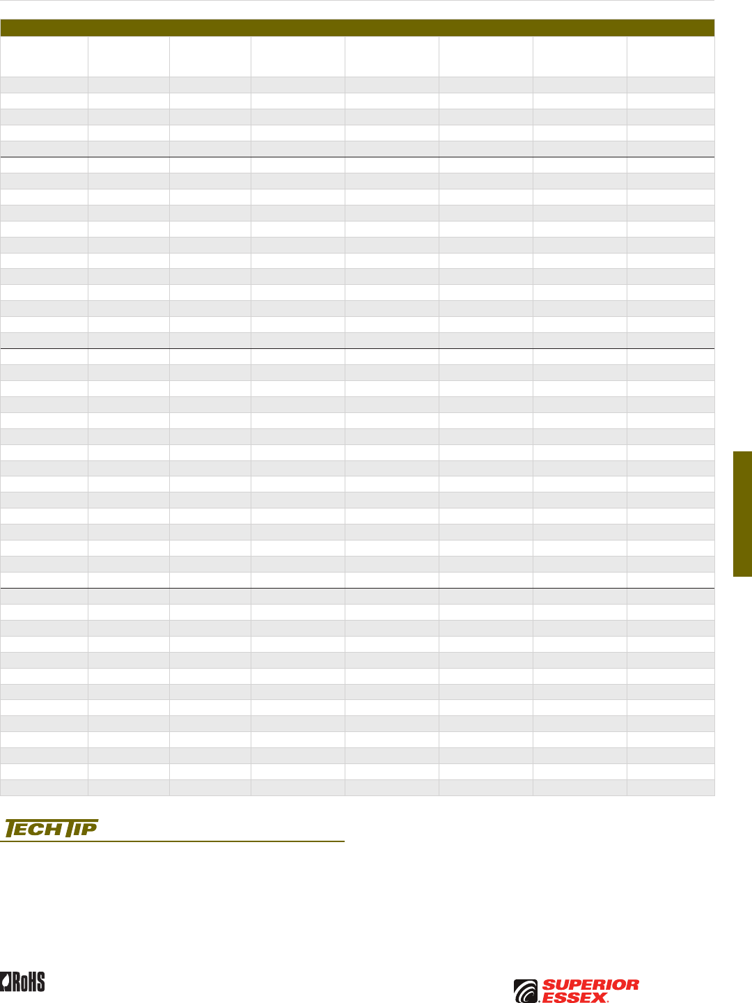
F-9
PREMISES COPPERPREMISES FIBEROSP FIBEROSP COMPOSITECENTRAL OFFICE COPPERRDUP/RUS OSP COPPERBELL OSP COPPEROSP COPPER WIRECANADIAN OSP COPPERTECHNICAL INFO
Rev 10/10 Ed 10.3 Toll Free 800.551.8948 | Fax 770.657.6807 | SuperiorEssex.com/Comm
SEALPIC
®
–FSF (RDUP PE-89)
Part Numbers and Physical Characteristics
Part Number Pair Count AWG (mm)
Nominal Diameter
in (mm)
Approx. Weight
lbs/kft (kg/km)
Standard Length
ft (m)
Approx.
Shipping Weight
lbs (kg)
Reel Size
F x T x D
in
09-026-02 6 19 (0.90) 0.49 (12) 120 (180) 5,000 (1,524) 710 (320) 44 x 18 x 20
09-028-02 12 19 (0.90) 0.59 (15) 190 (285) 5,000 (1,524) 1,115 (505) 46 x 25 x 20
09-031-02 25 19 (0.90) 0.78 (20) 355 (530) 5,000 (1,524) 1,980 (895) 52 x 25 x 20
09-034-02 50 19 (0.90) 1.03 (26) 655 (975) 5,000 (1,524) 3,565 (1,615) 62 x 30 x 24
09-038-02 100 19 (0.90) 1.37 (35) 1,225 (1,825) 2,500 (762) 3,430 (1,555) 65 x 30 x 32
09-057-02 6 22 (0.64) 0.39 (9.9) 70 (105) 5,000 (1,524) 415 (190) 36 x 18 x 14
09-059-02 12 22 (0.64) 0.47 (12) 115 (170) 5,000 (1,524) 685 (310) 44 x 18 x 20
09-062-02 25 22 (0.64) 0.60 (15) 200 (300) 5,000 (1,524) 1,165 (530) 46 x 25 x 20
09-065-02 50 22 (0.64) 0.77 (20) 350 (520) 5,000 (1,524) 1,955 (885) 52 x 25 x 20
09-069-02 100 22 (0.64) 1.02 (26) 650 (965) 5,000 (1,524) 3,540 (1,605) 62 x 30 x 24
09-073-02 200 22 (0.64) 1.38 (35) 1,225 (1,825) 2,500 (762) 3,350 (1,520) 62 x 30 x 24
09-075-02 300 22 (0.64) 1.65 (42) 1,800 (2,680) 1,250 (381) 2,495 (1,130) 58 x 25 x 20
09-077-02 400 22 (0.64) 1.88 (48) 2,365 (3,520) 1,250 (381) 3,245 (1,470) 62 x 30 x 24
09-081-02 600 22 (0.64) 2.28 (58) 3,505 (5,215) 1,250 (381) 4,995 (2,265) 72 x 35 x 36
09-083-02 900 22 (0.64) 2.76 (70) 5,195 (7,730) 1,250 (381) 7,290 (3,305) 84 x 40 x 42
09-085-02 1,200 22 (0.64) 3.14 (80) 6,845 (10,185) 1,250 (381) 9,730 (4,415) 96 x 40 x 48
09-087-02 1,500 22 (0.64) 3.51 (89) 8,520 (12,680) 1,000 (305) 9,695 (4,400) 96 x 40 x 48
09-092-02 6 24 (0.51) 0.36 (9.1) 55 (80) 5,000 (1,524) 320 (145) 36 x 18 x 14
09-094-02 12 24 (0.51) 0.42 (11) 85 (125) 5,000 (1,524) 490 (220) 36 x 18 x 14
09-097-02 25 24 (0.51) 0.52 (13) 140 (210) 5,000 (1,524) 810 (365) 44 x 18 x 20
09-100-02 50 24 (0.51) 0.66 (17) 240 (355) 5,000 (1,524) 1,365 (620) 46 x 25 x 20
09-104-02 100 24 (0.51) 0.85 (22) 430 (640) 5,000 (1,524) 2,395 (1,085) 58 x 25 x 20
09-108-02 200 24 (0.51) 1.14 (29) 810 (1,205) 5,000 (1,524) 4,665 (2,115) 72 x 35 x 36
09-110-02 300 24 (0.51) 1.37 (35) 1,180 (1,755) 2,500 (762) 3,320 (1,505) 65 x 30 x 32
09-112-02 400 24 (0.51) 1.55 (39) 1,545 (2,300) 2,500 (762) 4,475 (2,030) 72 x 35 x 36
09-116-02 600 24 (0.51) 1.88 (48) 2,285 (3,400) 1,250 (381) 3,145 (1,425) 62 x 30 x 24
09-118-02 900 24 (0.51) 2.25 (57) 3,350 (4,985) 1,250 (381) 4,800 (2,180) 72 x 35 x 36
09-120-02 1,200 24 (0.51) 2.57 (65) 4,420 (6,580) 1,250 (381) 6,225 (2,825) 78 x 40 x 39
09-121-02 1,500 24 (0.51) 2.86 (73) 5,490 (8,170) 1,000 (305) 6,190 (2,805) 78 x 40 x 39
09-124-02 1,800 24 (0.51) 3.12 (79) 6,560 (9,765) 1,000 (305) 7,355 (3,335) 84 x 40 x 42
09-125-02 2,100 24 (0.51) 3.40 (86) 7,690 (11,445) 1,000 (305) 8,865 (4,020) 96 x 40 x 48
09-126-02 2,400 24 (0.51) 3.59 (91) 8,695 (12,940) 1,000 (305) 9,870 (4,475) 96 x 40 x 48
09-132-02 25 26 (0.40) 0.44 (11) 100 (150) 5,000 (1,524) 565 (255) 36 x 18 x 14
09-135-02 50 26 (0.40) 0.55 (14) 165 (245) 5,000 (1,524) 990 (450) 46 x 25 x 20
09-139-02 100 26 (0.40) 0.71 (18) 290 (430) 5,000 (1,524) 1,655 (750) 52 x 25 x 20
09-143-02 200 26 (0.40) 0.94 (24) 535 (795) 5,000 (1,524) 2,965 (1,345) 62 x 30 x 24
09-145-02 300 26 (0.40) 1.09 (28) 755 (1,125) 5,000 (1,524) 4,390 (1,990) 72 x 35 x 36
09-147-02 400 26 (0.40) 1.25 (32) 995 (1,480) 2,500 (762) 2,735 (1,240) 58 x 25 x 20
09-151-02 600 26 (0.40) 1.49 (38) 1,455 (2,165) 2,500 (762) 4,250 (1,930) 72 x 35 x 36
09-153-02 900 26 (0.40) 1.78 (45) 2,120 (3,155) 1,250 (381) 3,020 (1,370) 65 x 30 x 32
09-155-02 1,200 26 (0.40) 2.03 (52) 2,785 (4,145) 1,250 (381) 4,095 (1,860) 72 x 35 x 36
09-156-02 1,500 26 (0.40) 2.28 (58) 3,480 (5,180) 1,250 (381) 4,965 (2,250) 72 x 35 x 36
09-157-02 1,800 26 (0.40) 2.48 (63) 4,150 (6,175) 1,250 (381) 5,885 (2,670) 78 x 40 x 39
09-159-02 2,400 26 (0.40) 2.86 (73) 5,515 (8,210) 1,250 (381) 8,070 (3,660) 96 x 40 x 48
09-164-02 3,600 26 (0.40) 3.45 (88) 8,165 (12,150) 1,000 (305) 9,340 (4,235) 96 x 40 x 48
Product FAQs for OSP copper cables are available online:
www.SuperiorEssex.com/comm/productFAQs.aspx

F-10
PREMISES COPPER PREMISES FIBER OSP FIBER OSP COMPOSITE CENTRAL OFFICE COPPER RDUP/RUS OSP COPPER BELL OSP COPPER OSP COPPER WIRE CANADIAN OSP COPPER TECHNICAL INFO
Rev 10/10 Ed 10.3Toll Free 800.551.8948 | Fax 770.657.6807 | SuperiorEssex.com/Comm
Specifications
Conductor Solid Annealed Copper
AWG (mm) Available in 19 (0.90), 22 (0.64) and 24 (0.51)
Insulation
Dual insulation consisting of an inner layer of foamed, natural
polyolefin over which is applied a solid (skin) layer of
polyolefin colored in accordance with industry standards
Twisted Pairs
Individual insulated conductors; twisted into pairs with
varying lay lengths; specific color combinations provide
pair identification
≤ 25-Pair Core Pairs are assembled into a cylindrical core
> 25-Pair Core
Cables larger than 25-pair are assembled into units, which
are then used to assemble the core; units are identifiable
using color-coded binders
Filling Compound 80°C ETPR compound, completely filling the interstices
between the pairs and under the core wrap
Core Wrap Non-hygroscopic, dielectric tape applied over the core
Inner Shield
Corrugated, copolymer coated, 8 mil aluminum tape applied
directly over the core wrap; does not butt or overlap at any
point along the length of the cable; flooded shield interface
Outer Shield
Rodent resistant, corrugated, copolymer coated, 6 mil steel
tape applied directly over the aluminum and overlaps;
flooded shield interface
Jacket Black, polyethylene
Jacket Marking
Identifying information includes a telephone handset,
cable code, pair count, AWG, date of manufacture
and sequential length markings at 2 foot intervals
Standards
Compliance
ANSI/ICEA S-84-608-2007
RDUP 7 CFR 1755.890 (PE-89)
RoHS-compliant
Electrical Specifications
Number of Pairs
Average Mutual
Capacitance @ 1000 Hz
nF/mile (nF/km)
Capacitance Unbalance
Pair to Pair @ 1 kHz
Capacitance Unbalance
Pair to Ground @ 1 kHz
Maximum Individual
pF @ 1 kft (pF @ 1 km)
Maximum RMS
pF @ 1 kft (pF @ 1 km)
Maximum Individual
pF @ 1 kft (pF @ 1 km)
Maximum Average
pF @ 1 kft (pF @ 1 km)
12 or less 83 ± 7 (52 ± 4) 80 (145) - 800 (2,625) -
Over 12 83 ± 4 (52 ± 2) 80 (145) 25 (45) 800 (2,625) 175 (574)
Conductor Size
AWG (mm)
Minimum Insulation
Resistance @ 68°F (20°C)
gigohm-mile (gigohm-km)
Maximum Average
Attenuation*
772 kHz @ 68°F (20°C)
dB/kft (dB/km)
Maximum Conductor
Resistance @ 68°F (20°C)
Ohms/sheath
mile (km)
DC Resistance
Unbalance Maximum %
Dielectric Strength
DC Potential – Volts
Average
Individual
Pair
Conductor
to Conductor
Conductor
to Shield
19 (0.90) 1.0 (1.6) 3.2 (10.5) 45.0 (28.0) 1.5 5.0 4,500 10,000
22 (0.64) 1.0 (1.6) 4.5 (14.8) 91.0 (56.5) 1.5 5.0 3,600 10,000
24 (0.51) 1.0 (1.6) 5.6 (18.4) 144.0 (89.5) 1.5 5.0 3,000 10,000
*For cables with 12-pair or less, the maximum average attenuation may be increased by 10% over the values shown.
Minimum Near End Crosstalk
(NEXT) @ 772 kHz
PSWUNEXT Mean (dB) 47
PSWUNEXT Worst Pair (dB) 42
Minimum Far End Crosstalk
(FEXT) @ 772 kHz
Conductor Size (AWG) 19 22 24
PSELFEXT Mean (dB/kft) 51 49 49
PSELFEXT Worst Pair (dB/kft) 45 43 43
CASPIC®–FSF (RDUP PE-89)
Product Description
CASPIC®-FSF Cables are designed for direct burial applications.
CASPIC-FSF cables are recommended for use in high-risk areas where
additional mechanical or rodent protection is required. CASPIC-FSF may be
used aerially, but must be attached to a support strand.
Applications
• Direct burial where additional mechanical protection
is requried or desired
• Lashed aerial where additional mechanical protection
is requried or desired
Features Benefits
• Twisted into pairs with varying
lay lengths
• Minimizes crosstalk
• Core wrap • Provides thermal protection
• Filled core • Moisture resistant
• Dual shield design • Rodent resistant
• Fully flooded shield interfaces • Inhibits corrosion
and water migration
• Black, polyethylene jacket • Provides a tough, protective
covering designed to withstand
exposure to direct sunlight,
atmospheric temperature
changes and stresses expected
in standard installations
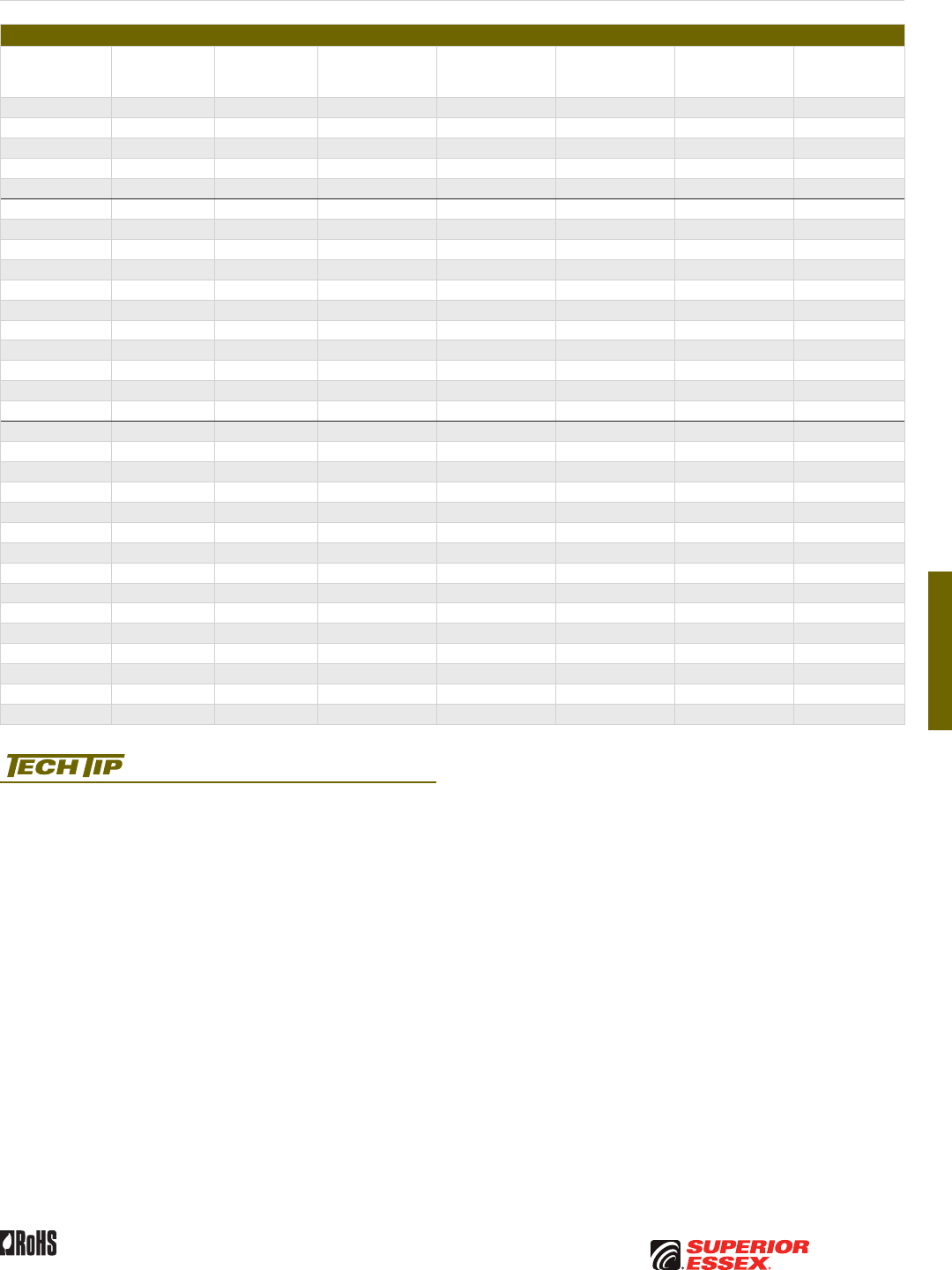
F-11
PREMISES COPPERPREMISES FIBEROSP FIBEROSP COMPOSITECENTRAL OFFICE COPPERRDUP/RUS OSP COPPERBELL OSP COPPEROSP COPPER WIRECANADIAN OSP COPPERTECHNICAL INFO
Rev 10/10 Ed 10.3 Toll Free 800.551.8948 | Fax 770.657.6807 | SuperiorEssex.com/Comm
CASPIC
®
–FSF (RDUP PE-89)
Part Numbers and Physical Characteristics
Part Number Pair Count AWG (mm)
Nominal Diameter
in (mm)
Approx. Weight
lbs/kft (kg/km)
Standard Length
ft (m)
Approx.
Shipping Weight
lbs (kg)
Reel Size
F x T x D
in
09-026-92 6 19 (0.90) 0.52 (13) 155 (230) 5,000 (1,524) 885 (400) 44 x 18 x 20
09-028-92 12 19 (0.90) 0.62 (16) 235 (350) 5,000 (1,524) 1,340 (610) 46 x 25 x 20
09-031-92 25 19 (0.90) 0.81 (21) 415 (620) 5,000 (1,524) 2,320 (1,050) 58 x 25 x 20
09-034-92 50 19 (0.90) 1.07 (27) 740 (1,100) 5,000 (1,524) 4,315 (1,955) 72 x 35 x 36
09-038-92 100 19 (0.90) 1.41 (36) 1,345 (2,000) 5,000 (1,524) 7,425 (3,370) 78 x 40 x 39
09-057-92 6 22 (0.64) 0.42 (11) 95 (140) 5,000 (1,524) 540 (245) 36 x 18 x 14
09-059-92 12 22 (0.64) 0.50 (13) 150 (225) 5,000 (1,524) 860 (390) 44 x 18 x 20
09-062-92 25 22 (0.64) 0.63 (16) 245 (365) 5,000 (1,524) 1,390 (630) 46 x 25 x 20
09-065-92 50 22 (0.64) 0.80 (20) 410 (610) 5,000 (1,524) 2,295 (1,040) 58 x 25 x 20
09-069-92 100 22 (0.64) 1.05 (27) 730 (1,085) 5,000 (1,524) 4,265 (1,935) 72 x 35 x 36
09-073-92 200 22 (0.64) 1.42 (36) 1,345 (2,000) 2,500 (762) 3,650 (1,655) 62 x 30 x 24
09-075-92 300 22 (0.64) 1.70 (43) 1,945 (2,895) 1,250 (381) 2,720 (1,235) 62 x 30 x 24
09-077-92 400 22 (0.64) 1.92 (49) 2,535 (3,775) 1,250 (381) 3,455 (1,570) 62 x 30 x 24
09-081-92 600 22 (0.64) 2.32 (59) 3,710 (5,520) 1,250 (381) 5,250 (2,380) 72 x 35 x 36
09-083-92 900 22 (0.64) 2.81 (71) 5,455 (8,120) 1,250 (381) 7,615 (3,455) 84 x 40 x 42
09-085-92 1,200 22 (0.64) 3.19 (81) 7,140 (10,625) 1,250 (381) 10,100 (4,580) 96 x 40 x 48
09-092-92 6 24 (0.51) 0.39 (9.9) 80 (120) 5,000 (1,524) 465 (210) 36 x 18 x 14
09-094-92 12 24 (0.51) 0.45 (11) 110 (165) 5,000 (1,524) 615 (280) 36 x 18 x 14
09-097-92 25 24 (0.51) 0.55 (14) 180 (270) 5,000 (1,524) 1,065 (485) 46 x 25 x 20
09-100-92 50 24 (0.51) 0.69 (18) 290 (430) 5,000 (1,524) 1,615 (735) 46 x 25 x 20
09-104-92 100 24 (0.51) 0.88 (22) 500 (745) 5,000 (1,524) 2,745 (1,245) 58 x 25 x 20
09-108-92 200 24 (0.51) 1.18 (30) 905 (1,345) 2,500 (762) 2,510 (1,135) 58 x 25 x 20
09-110-92 300 24 (0.51) 1.41 (36) 1,300 (1,935) 2,500 (762) 3,540 (1,605) 62 x 30 x 24
09-112-92 400 24 (0.51) 1.59 (40) 1,680 (2,500) 2,500 (762) 4,815 (2,185) 72 x 35 x 36
09-116-92 600 24 (0.51) 1.92 (49) 2,450 (3,645) 1,250 (381) 3,350 (1,520) 62 x 30 x 24
09-118-92 900 24 (0.51) 2.29 (58) 3,555 (5,290) 1,250 (381) 5,060 (2,295) 72 x 35 x 36
09-120-92 1,200 24 (0.51) 2.62 (67) 4,660 (6,935) 1,250 (381) 6,525 (2,960) 78 x 40 x 39
09-121-92 1,500 24 (0.51) 2.91 (74) 5,755 (8,565) 1,000 (305) 6,455 (2,930) 78 x 40 x 39
09-124-92 1,800 24 (0.51) 3.17 (81) 6,855 (10,200) 1,000 (305) 7,650 (3,470) 84 x 40 x 42
09-125-92 2,100 24 (0.51) 3.45 (88) 8,015 (11,930) 1,000 (305) 9,190 (4,170) 96 x 40 x 48
09-126-92 2,400 24 (0.51) 3.64 (93) 9,035 (13,445) 750 (229) 7,950 (3,605) 96 x 40 x 48
Product FAQs for OSP copper cables are available online:
www.SuperiorEssex.com/comm/productFAQs.aspx
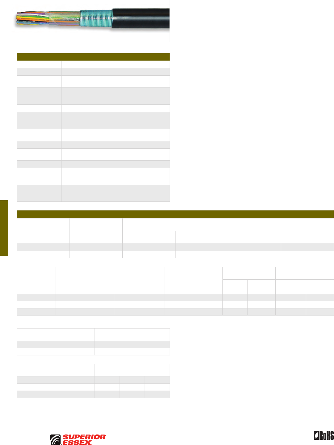
F-12
PREMISES COPPER PREMISES FIBER OSP FIBER OSP COMPOSITE CENTRAL OFFICE COPPER RDUP/RUS OSP COPPER BELL OSP COPPER OSP COPPER WIRE CANADIAN OSP COPPER TECHNICAL INFO
Rev 10/10 Ed 10.3Toll Free 800.551.8948 | Fax 770.657.6807 | SuperiorEssex.com/Comm
Specifications
Conductor Solid annealed copper
AWG (mm) Available in 19 (0.90), 22 (0.64) and 24 (0.51)
Insulation Solid polyolefin; color coded in accordance
with industry standards
Twisted Pairs
Individual insulated conductors; twisted into pairs with
varying lay lengths; specific color combinations provide
pair identification
≤ 25-Pair Core Pairs are assembled into a cylindrical core
> 25-Pair Core
Cables larger than 25-pair are assembled into units, which
are then used to assemble the core; units are identifiable
using color-coded binders
Filling Compound 80°C ETPR compound, completely filling the interstices
between the pairs and under the core wrap
Core Wrap Non-hygroscopic, dielectric tape applied over the core
Shield Corrugated, copolymer coated, 8 mil aluminum tape applied
longitudinally with an overlap; flooded shield interfaces
Jacket Black, polyethylene
Jacket Marking
Identifying information includes a telephone handset,
cable code, pair count, AWG, date of manufacture
and sequential length markings at 2 foot intervals
Standards
Compliance
ANSI/ICEA S-84-608-2007
RDUP 7 CFR 1755.390 (PE-39)
RoHS-compliant
Electrical Specifications
Number of Pairs
Average Mutual
Capacitance @ 1000 Hz
nF/mile (nF/km)
Capacitance Unbalance
Pair to Pair @ 1 kHz
Capacitance Unbalance
Pair to Ground @ 1 kHz
Maximum Individual
pF @ 1 kft (pF @ 1 km)
Maximum RMS
pF @ 1 kft (pF @ 1 km)
Maximum Individual
pF @ 1 kft (pF @ 1 km)
Maximum Average
pF @ 1 kft (pF @ 1 km)
12 or less 83 ± 7 (52 ± 4) 80 (145) - 800 (2,625) -
Over 12 83 ± 4 (52 ± 2) 80 (145) 25 (45) 800 (2,625) 175 (574)
Conductor Size
AWG (mm)
Minimum Insulation
Resistance @ 68°F (20°C)
gigohm-mile (gigohm-km)
Maximum Average
Attenuation*
772 kHz @ 68°F (20°C)
dB/kft (dB/km)
Maximum Conductor
Resistance @ 68°F (20°C)
Ohms/sheath
mile (km)
DC Resistance
Unbalance Maximum %
Dielectric Strength
DC Potential – Volts
Average
Individual
Pair
Conductor
to Conductor
Conductor
to Shield
19 (0.90) 1.0 (1.6) 2.8 (9.2) 45.0 (28.0) 1.5 5.0 7,000 15,000
22 (0.64) 1.0 (1.6) 4.0 (13.1) 91.0 (56.5) 1.5 5.0 5,000 15,000
24 (0.51) 1.0 (1.6) 5.0 (16.4) 144.0 (89.5) 1.5 5.0 4,000 15,000
*For cables of 12-pair or less, the maximum average attenuation may be increased by 10% over the values shown.
Minimum Near End Crosstalk
(NEXT) @ 772 kHz
PSWUNEXT Mean (dB) 47
PSWUNEXT Worst Pair (dB) 42
Minimum Far End Crosstalk
(FEXT) @ 772 kHz
Conductor Size (AWG) 19 22 24
PSELFEXT Mean (dB/kft) 51 49 49
PSELFEXT Worst Pair (dB/kft) 45 43 43
SEALPIC®–F (RDUP PE-39)
Product Description
SEALPIC-F Cables are designed for low risk direct burial or duct applications.
SEALPIC-F may be used aerially, but must be attached to a support strand.
Applications
• Low risk direct burial
• Underground conduit
• Lashed aerial
Features Benefits
• Twisted into pairs with varying
lay lengths
• Minimizes crosstalk
• Core wrap • Provides thermal protection
• Filled core • Moisture resistant
• Fully flooded shield interfaces • Inhibits corrosion
and water migration
• Black, polyethylene jacket • Provides a tough, protective
covering designed to withstand
exposure to direct sunlight,
atmospheric temperature
changes and stresses expected
in standard installations

F-13
PREMISES COPPERPREMISES FIBEROSP FIBEROSP COMPOSITECENTRAL OFFICE COPPERRDUP/RUS OSP COPPERBELL OSP COPPEROSP COPPER WIRECANADIAN OSP COPPERTECHNICAL INFO
Rev 10/10 Ed 10.3 Toll Free 800.551.8948 | Fax 770.657.6807 | SuperiorEssex.com/Comm
Part Numbers and Physical Characteristics
Part Number Pair Count AWG (mm)
Nominal Diameter
in (mm)
Approx. Weight
lbs/kft (kg/km)
Standard Length
ft (m)
Approx.
Shipping Weight
lbs (kg)
Reel Size
F x T x D
in
04-026-21 6 19 (0.90) 0.54 (14) 140 (210) 5,000 (1,524) 810 (365) 44 x 18 x 20
04-028-21 12 19 (0.90) 0.69 (18) 235 (350) 5,000 (1,524) 1,340 (610) 46 x 25 x 20
04-031-21 25 19 (0.90) 0.92 (23) 440 (655) 5,000 (1,524) 2,570 (1,165) 65 x 30 x 32
04-034-21 50 19 (0.90) 1.22 (31) 810 (1,205) 5,000 (1,524) 4,750 (2,155) 78 x 40 x 39
04-038-21 100 19 (0.90) 1.69 (43) 1,565 (2,330) 2,500 (762) 4,525 (2,055) 72 x 35 x 36
04-057-21 6 22 (0.64) 0.43 (11) 85 (125) 5,000 (1,524) 490 (220) 36 x 18 x 14
04-059-21 12 22 (0.64) 0.53 (14) 135 (200) 5,000 (1,524) 785 (355) 44 x 18 x 20
04-062-21 25 22 (0.64) 0.68 (17) 240 (355) 5,000 (1,524) 1,365 (620) 46 x 25 x 20
04-065-21 50 22 (0.64) 0.89 (23) 425 (630) 5,000 (1,524) 2,370 (1,075) 58 x 25 x 20
04-069-21 100 22 (0.64) 1.19 (30) 780 (1,160) 5,000 (1,524) 4,515 (2,050) 72 x 35 x 36
04-073-21 200 22 (0.64) 1.63 (41) 1,500 (2,230) 2,500 (762) 4,365 (1,980) 72 x 35 x 36
04-075-21 300 22 (0.64) 1.96 (50) 2,205 (3,280) 2,500 (762) 6,210 (2,820) 78 x 40 x 39
04-077-21 400 22 (0.64) 2.23 (57) 2,890 (4,300) 1,250 (381) 4,225 (1,915) 72 x 35 x 36
04-081-21 600 22 (0.64) 2.72 (69) 4,295 (6,390) 1,250 (381) 6,165 (2,795) 84 x 40 x 42
04-083-21 900 22 (0.64) 3.30 (84) 6,380 (9,495) 1,250 (381) 7,975 (3,615) 96 x 40 x 48
04-092-21 6 24 (0.51) 0.38 (9.7) 60 (90) 5,000 (1,524) 365 (165) 36 x 18 x 14
04-094-21 12 24 (0.51) 0.46 (12) 95 (140) 5,000 (1,524) 585 (265) 44 x 18 x 20
04-097-21 25 24 (0.51) 0.58 (15) 165 (245) 5,000 (1,524) 990 (450) 46 x 25 x 20
04-100-21 50 24 (0.51) 0.74 (19) 285 (425) 5,000 (1,524) 1,630 (740) 52 x 25 x 20
04-104-21 100 24 (0.51) 0.98 (25) 520 (775) 5,000 (1,524) 2,970 (1,345) 65 x 30 x 32
04-108-21 200 24 (0.51) 1.32 (34) 975 (1,450) 5,000 (1,524) 5,575 (2,530) 78 x 40 x 39
04-110-21 300 24 (0.51) 1.58 (40) 1,420 (2,115) 2,500 (762) 4,165 (1,890) 72 x 35 x 36
04-112-21 400 24 (0.51) 1.79 (46) 1,850 (2,755) 2,500 (762) 5,325 (2,415) 78 x 40 x 39
04-116-21 600 24 (0.51) 2.18 (55) 2,745 (4,085) 1,250 (381) 4,045 (1,835) 72 x 35 x 36
04-118-21 900 24 (0.51) 2.63 (67) 4,050 (6,025) 1,250 (381) 5,760 (2,615) 78 x 40 x 39
04-120-21 1,200 24 (0.51) 3.00 (76) 5,325 (7,925) 1,000 (305) 6,025 (2,730) 78 x 40 x 39
04-121-21 1,500 24 (0.51) 3.35 (85) 6,625 (9,860) 1,000 (305) 7,800 (3,540) 96 x 40 x 48
04-124-21 1,800 24 (0.51) 3.63 (92) 7,870 (11,710) 1,000 (305) 9,045 (4,105) 96 x 40 x 48
Product FAQs for OSP copper cables are available online:
www.SuperiorEssex.com/comm/productFAQs.aspx
SEALPIC
®
–F (RDUP PE-39)
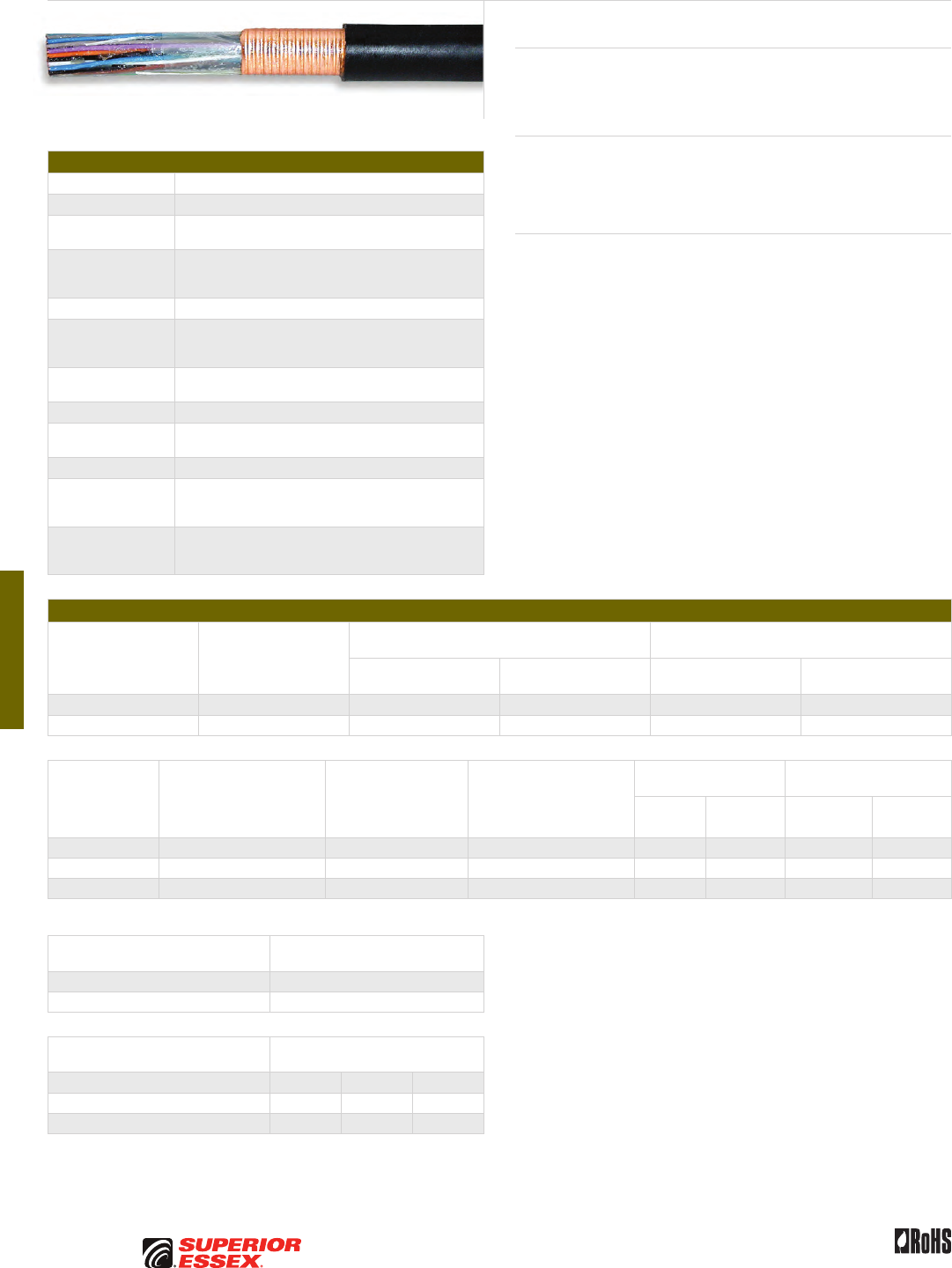
F-14
PREMISES COPPER PREMISES FIBER OSP FIBER OSP COMPOSITE CENTRAL OFFICE COPPER RDUP/RUS OSP COPPER BELL OSP COPPER OSP COPPER WIRE CANADIAN OSP COPPER TECHNICAL INFO
Rev 10/10 Ed 10.3Toll Free 800.551.8948 | Fax 770.657.6807 | SuperiorEssex.com/Comm
Specifications
Conductor Solid annealed copper
AWG (mm) Available in19 (0.90), 22 (0.64) and 24 (0.51)
Insulation Solid polyolefin; color coded in accordance
with industry standards
Twisted Pairs
Individual insulated conductors; twisted into pairs with
varying lay lengths; specific color combinations provide
pair identification
≤ 25-Pair Core Pairs are assembled into a cylindrical core
> 25-Pair Core
Cables larger than 25-pair are assembled into units, which
are then used to assemble the core; units are identifiable
using color-coded binders
Filling Compound 80°C ETPR compound, completely filling the interstices
between the pairs and under the core wrap
Core Wrap Non-hygroscopic, dielectric tape applied over the core
Shield Corrugated, 5 mil copper tape is applied longitudinally with
an overlap; shield interfaces are flooded
Jacket Black, polyethylene
Jacket Marking
Identifying information includes a telephone handset,
cable code, pair count, AWG, date of manufacture
and sequential length markings at 2 foot intervals
Standards
Compliance
ANSI/ICEA S-84-608-2007
RDUP 7 CFR 1755.390 (PE-39)
RoHS-compliant
Electrical Specifications
Number of Pairs
Average Mutual
Capacitance @ 1000 Hz
nF/mile (nF/km)
Capacitance Unbalance
Pair to Pair @ 1 kHz
Capacitance Unbalance
Pair to Ground @ 1 kHz
Maximum Individual
pF @ 1 kft (pF @ 1 km)
Maximum RMS
pF @ 1 kft (pF @ 1 km)
Maximum Individual
pF @ 1 kft (pF @ 1 km)
Maximum Average
pF @ 1 kft (pF @ 1 km)
12 or less 83 ± 7 (52 ± 4) 80 (145) - 800 (2,625) -
Over 12 83 ± 4 (52 ± 2) 80 (145) 25 (45) 800 (2,625) 175 (574)
Conductor Size
AWG (mm)
Minimum Insulation
Resistance @ 68°F (20°C)
gigohm-mile (gigohm-km)
Maximum Average
Attenuation*
772 kHz @ 68°F (20°C)
dB/kft (dB/km)
Maximum Conductor
Resistance @ 68°F (20°C)
Ohms/sheath
mile (km)
DC Resistance
Unbalance Maximum %
Dielectric Strength
DC Potential – Volts
Average
Individual
Pair
Conductor
to Conductor
Conductor
to Shield
19 (0.90) 1.0 (1.6) 2.8 (9.2) 45.0 (28.0) 1.5 5.0 7,000 15,000
22 (0.64) 1.0 (1.6) 4.0 (13.1) 91.0 (56.5) 1.5 5.0 5,000 15,000
24 (0.51) 1.0 (1.6) 5.0 (16.4) 144.0 (89.5) 1.5 5.0 4,000 15,000
*For cables of 12-pair or less, the maximum average attenuation may be increased by 10% over the values shown.
Minimum Near End Crosstalk
(NEXT) @ 772 kHz
PSWUNEXT Mean (dB) 47
PSWUNEXT Worst Pair (dB) 42
Minimum Far End Crosstalk
(FEXT) @ 772 kHz
Conductor Size (AWG) 19 22 24
PSELFEXT Mean (dB/kft) 51 49 49
PSELFEXT Worst Pair (dB/kft) 45 43 43
CUPIC®–F (RDUP PE-39)
Product Description
CUPIC®-F Cables are designed for use in low risk duct or direct burial
applications. CUPIC-F may be used aerially, but must be attached to a
support strand.
Applications
• Low risk direct burial
• Underground conduit
• Lashed aerial
Features Benefits
• Twisted into pairs with varying
lay lengths
• Minimizes crosstalk
• Core wrap • Provides thermal protection
• Filled core • Moisture resistant
• Fully flooded shield interfaces • Inhibits corrosion
and water migration
• Black, polyethylene jacket • Provides a tough, protective
covering designed to withstand
exposure to direct sunlight,
atmospheric temperature
changes and stresses expected
in standard installations
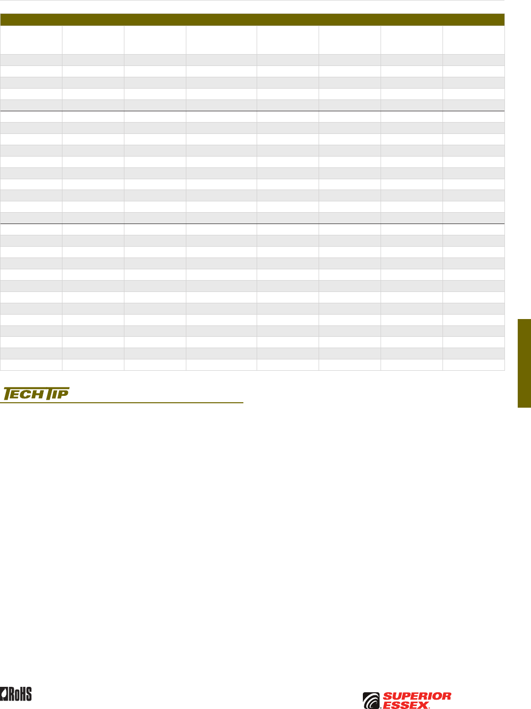
F-15
PREMISES COPPERPREMISES FIBEROSP FIBEROSP COMPOSITECENTRAL OFFICE COPPERRDUP/RUS OSP COPPERBELL OSP COPPEROSP COPPER WIRECANADIAN OSP COPPERTECHNICAL INFO
Rev 10/10 Ed 10.3 Toll Free 800.551.8948 | Fax 770.657.6807 | SuperiorEssex.com/Comm
Part Numbers and Physical Characteristics
Part Number Pair Count AWG (mm)
Nominal Diameter
in (mm)
Approx. Weight
lbs/kft (kg/km)
Standard Length
ft (m)
Approx.
Shipping Weight
lbs (kg)
Reel Size
F x T x D
in
04-026-04 6 19 (0.90) 0.54 (14) 150 (225) 5,000 (1,524) 860 (390) 44 x 18 x 20
04-028-04 12 19 (0.90) 0.69 (18) 255 (380) 5,000 (1,524) 1,440 (655) 46 x 25 x 20
04-031-04 25 19 (0.90) 0.92 (23) 470 (700) 5,000 (1,524) 2,720 (1,235) 65 x 30 x 32
04-034-04 50 19 (0.90) 1.22 (31) 845 (1,260) 5,000 (1,524) 4,925 (2,235) 78 x 40 x 39
04-038-04 100 19 (0.90) 1.69 (43) 1,620 (2,410) 2,500 (762) 4,750 (2,155) 78 x 40 x 39
04-057-04 6 22 (0.64) 0.43 (11) 95 (140) 5,000 (1,524) 540 (245) 36 x 18 x 14
04-059-04 12 22 (0.64) 0.53 (14) 145 (215) 5,000 (1,524) 835 (380) 44 x 18 x 20
04-062-04 25 22 (0.64) 0.68 (17) 255 (380) 5,000 (1,524) 1,440 (655) 46 x 25 x 20
04-065-04 50 22 (0.64) 0.89 (23) 450 (670) 5,000 (1,524) 2,495 (1,130) 58 x 25 x 20
04-069-04 100 22 (0.64) 1.19 (30) 815 (1,215) 5,000 (1,524) 4,690 (2,125) 72 x 35 x 36
04-073-04 200 22 (0.64) 1.63 (41) 1,550 (2,305) 2,500 (762) 4,490 (2,035) 72 x 35 x 36
04-075-04 300 22 (0.64) 1.97 (50) 2,270 (3,380) 2,500 (762) 6,375 (2,890) 78 x 40 x 39
04-077-04 400 22 (0.64) 2.23 (57) 2,960 (4,405) 1,250 (381) 4,315 (1,955) 72 x 35 x 36
04-081-04 600 22 (0.64) 2.72 (69) 4,385 (6,525) 1,250 (381) 6,280 (2,850) 84 x 40 x 42
04-083-04 900 22 (0.64) 3.30 (84) 6,490 (9,660) 1,250 (381) 9,290 (4,215) 96 x 40 x 48
04-092-04 6 24 (0.51) 0.38 (9.7) 70 (105) 5,000 (1,524) 415 (190) 36 x 18 x 14
04-094-04 12 24 (0.51) 0.46 (12) 110 (165) 5,000 (1,524) 660 (300) 44 x 18 x 20
04-097-04 25 24 (0.51) 0.58 (15) 180 (270) 5,000 (1,524) 1,065 (485) 46 x 25 x 20
04-100-04 50 24 (0.51) 0.74 (19) 305 (455) 5,000 (1,524) 1,730 (785) 52 x 25 x 20
04-104-04 100 24 (0.51) 0.98 (25) 550 (820) 5,000 (1,524) 3,120 (1,415) 65 x 30 x 32
04-108-04 200 24 (0.51) 1.32 (34) 1,015 (1,510) 5,000 (1,524) 5,775 (2,620) 78 x 40 x 39
04-110-04 300 24 (0.51) 1.59 (40) 1,470 (2,190) 2,500 (762) 4,290 (1,945) 72 x 35 x 36
04-112-04 400 24 (0.51) 1.79 (46) 1,905 (2,835) 2,500 (762) 5,460 (2,475) 78 x 40 x 39
04-116-04 600 24 (0.51) 2.18 (55) 2,815 (4,190) 1,250 (381) 4,135 (1,875) 72 x 35 x 36
04-118-04 900 24 (0.51) 2.63 (67) 4,135 (6,155) 1,250 (381) 5,870 (2,660) 78 x 40 x 39
04-120-04 1,200 24 (0.51) 3.00 (76) 5,420 (8,065) 1,000 (305) 6,120 (2,775) 78 x 40 x 39
04-121-04 1,500 24 (0.51) 3.35 (85) 6,730 (10,015) 1,000 (305) 7,905 (3,585) 96 x 40 x 48
04-124-04 1,800 24 (0.51) 3.63 (92) 7,990 (11,890) 1,000 (305) 9,165 (4,155) 96 x 40 x 48
Product FAQs for OSP copper cables are available online:
www.SuperiorEssex.com/comm/productFAQs.aspx
CUPIC
®
–F (RDUP PE-39)
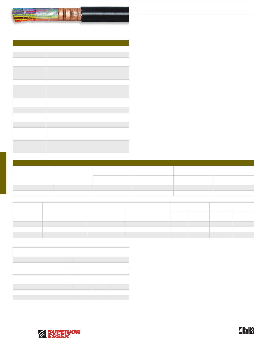
F-16
PREMISES COPPER PREMISES FIBER OSP FIBER OSP COMPOSITE CENTRAL OFFICE COPPER RDUP/RUS OSP COPPER BELL OSP COPPER OSP COPPER WIRE CANADIAN OSP COPPER TECHNICAL INFO
Rev 10/10 Ed 10.3Toll Free 800.551.8948 | Fax 770.657.6807 | SuperiorEssex.com/Comm
Specifications
Conductor Solid annealed copper
AWG (mm) Available in 19 (0.90), 22 (0.64) and 24 (0.51)
Insulation Solid polyolefin; color coded in accordance
with industry standards
Twisted Pairs
Individual insulated conductors; twisted into pairs with
varying lay lengths; specific color combinations provide
pair identification
≤ 25-Pair Core Pairs are assembled into a cylindrical core
> 25-Pair Core
Cables larger than 25-pair are assembled into units, which
are then used to assemble the core; units are identifiable
using color-coded binders
Filling Compound 80°C ETPR compound, completely filling the interstices
between the pairs and under the core wrap
Core Wrap Non-hygroscopic, dielectric tape applied over the core
Shield Corrugated, rodent resistant, copper bearing armor applied
longitudinally with an overlap; flooded shield interfaces
Jacket Black, polyethylene
Jacket Marking
Identifying information includes a telephone handset,
cable code, pair count, AWG, date of manufacture
and sequential length markings at 2 foot intervals
Standards
Compliance
ANSI/ICEA S-84-608-2007
RDUP 7 CFR 1755.390 (PE-39)
RoHS-compliant
Electrical Specifications
Number of Pairs
Average Mutual
Capacitance @ 1000 Hz
nF/mile (nF/km)
Capacitance Unbalance
Pair to Pair @ 1 kHz
Capacitance Unbalance
Pair to Ground @ 1 kHz
Maximum Individual
pF @ 1 kft (pF @ 1 km)
Maximum RMS
pF @ 1 kft (pF @ 1 km)
Maximum Individual
pF @ 1 kft (pF @ 1 km)
Maximum Average
pF @ 1 kft (pF @ 1 km)
12 or less 83 ± 7 (52 ± 4) 80 (145) - 800 (2,625) -
Over 12 83 ± 4 (52 ± 2) 80 (145) 25 (45) 800 (2,625) 175 (574)
Conductor Size
AWG (mm)
Minimum Insulation
Resistance @ 68°F (20°C)
gigohm-mile (gigohm-km)
Maximum Average
Attenuation*
772 kHz @ 68°F (20°C)
dB/kft (dB/km)
Maximum Conductor
Resistance @ 68°F (20°C)
Ohms/sheath
mile (km)
DC Resistance
Unbalance Maximum %
Dielectric Strength
DC Potential – Volts
Average
Individual
Pair
Conductor
to Conductor
Conductor
to Shield
19 (0.90) 1.0 (1.6) 2.8 (9.2) 45.0 (28.0) 1.5 5.0 7,000 15,000
22 (0.64) 1.0 (1.6) 4.0 (13.1) 91.0 (56.5) 1.5 5.0 5,000 15,000
24 (0.51) 1.0 (1.6) 5.0 (16.4) 144.0 (89.5) 1.5 5.0 4,000 15,000
*For cables of 12-pair or less, the maximum average attenuation may be increased by 10% over the values shown.
Minimum Near End Crosstalk
(NEXT) @ 772 kHz
PSWUNEXT Mean (dB) 47
PSWUNEXT Worst Pair (dB) 42
Minimum Far End Crosstalk
(FEXT) @ 772 kHz
Conductor Size (AWG) 19 22 24
PSELFEXT Mean (dB/kft) 51 49 49
PSELFEXT Worst Pair (dB/kft) 45 43 43
GOPIC®–F (RDUP PE-39)
Product Description
GOPIC®-F Cables are designed for use in direct burial applications where
additional mechanical or rodent protection is required. GOPIC-F may be
used aerially, but must be attached to a support strand.
Applications
• Direct burial where additional mechanical protection
is required or desired
• Lashed aerial where additional mechanical protection
is required or desired
Features Benefits
• Twisted into pairs
with varying lay lengths
• Minimizes crosstalk
• Core wrap • Provides thermal protection
• Filled core • Moisture resistant
• Corrugated, copper
bearing armor
• Rodent resistant
• Fully flooded shield interfaces • Inhibits corrosion
and water migration
• Black, polyethylene jacket • Provides a tough, protective
covering designed to withstand
exposure to direct sunlight,
atmospheric temperature
changes and stresses expected
in standard installations

F-17
PREMISES COPPERPREMISES FIBEROSP FIBEROSP COMPOSITECENTRAL OFFICE COPPERRDUP/RUS OSP COPPERBELL OSP COPPEROSP COPPER WIRECANADIAN OSP COPPERTECHNICAL INFO
Rev 10/10 Ed 10.3 Toll Free 800.551.8948 | Fax 770.657.6807 | SuperiorEssex.com/Comm
Part Numbers and Physical Characteristics
Part Number Pair Count AWG (mm)
Nominal Diameter
in (mm)
Approx. Weight
lbs/kft (kg/km)
Standard Length
ft (m)
Approx.
Shipping Weight
lbs (kg)
Reel Size
F x T x D
in
04-026-27 6 19 (0.90) 0.54 (14) 155 (230) 5,000 (1,524) 885 (400) 44 x 18 x 20
04-028-27 12 19 (0.90) 0.69 (18) 255 (380) 5,000 (1,524) 1,440 (655) 46 x 25 x 20
04-031-27 25 19 (0.90) 0.92 (23) 470 (700) 5,000 (1,524) 2,720 (1,235) 65 x 30 x 32
04-034-27 50 19 (0.90) 1.22 (31) 850 (1,265) 5,000 (1,524) 4,950 (2,245) 78 x 40 x 39
04-038-27 100 19 (0.90) 1.69 (43) 1,620 (2,410) 2,500 (762) 4,665 (2,115) 72 x 35 x 36
04-057-27 6 22 (0.64) 0.43 (11) 95 (140) 5,000 (1,524) 540 (245) 36 x 18 x 14
04-059-27 12 22 (0.64) 0.53 (14) 150 (225) 5,000 (1,524) 860 (390) 44 x 18 x 20
04-062-27 25 22 (0.64) 0.68 (17) 260 (385) 5,000 (1,524) 1,465 (665) 46 x 25 x 20
04-065-27 50 22 (0.64) 0.89 (23) 450 (670) 5,000 (1,524) 2,495 (1,130) 58 x 25 x 20
04-069-27 100 22 (0.64) 1.19 (30) 820 (1,220) 5,000 (1,524) 4,715 (2,140) 72 x 35 x 36
04-073-27 200 22 (0.64) 1.63 (41) 1,555 (2,315) 2,,500 (762) 4,500 (2,040) 72 x 35 x 36
04-075-27 300 22 (0.64) 1.96 (50) 2,275 (3,385) 2,500 (762) 6,385 (2,895) 78 x 40 x 39
04-077-27 400 22 (0.64) 2.23 (57) 2,965 (4,415) 1,250 (381) 4,320 (1,960) 72 x 35 x 36
04-081-27 600 22 (0.64) 2.72 (69) 4,395 (6,540) 1,250 (381) 6,290 (2,855) 84 x 40 x 42
04-083-27 900 22 (0.64) 3.30 (84) 6,505 (9,680) 1,250 (381) 8,130 (3,690) 96 x 40 x 48
04-092-27 6 24 (0.51) 0.38 (9.7) 70 (105) 5,000 (1,524) 415 (190) 36 x 18 x 14
04-094-27 12 24 (0.51) 0.46 (12) 110 (165) 5,000 (1,524) 660 (300) 44 x 18 x 20
04-097-27 25 24 (0.51) 0.58 (15) 180 (270) 5,000 (1,524) 1,065 (485) 46 x 25 x 20
04-100-27 50 24 (0.51) 0.74 (19) 310 (460) 5,000 (1,524) 1,755 (795) 52 x 25 x 20
04-104-27 100 24 (0.51) 0.98 (25) 550 (820) 5,000 (1,524) 3,120 (1,415) 65 x 30 x 32
04-108-27 200 24 (0.51) 1.32 (34) 1,020 (1,520) 5,000 (1,524) 5,800 (2,630) 78 x 40 x 39
04-110-27 300 24 (0.51) 1.58 (40) 1,475 (2,195) 2,500 (762) 4,300 (1,950) 72 x 35 x 36
04-112-27 400 24 (0.51) 1.79 (46) 1,910 (2,845) 2,500 (762) 5,475 (2,485) 78 x 40 x 39
04-116-27 600 24 (0.51) 2.18 (55) 2,825 (4,205) 1,250 (381) 4,145 (1,880) 72 x 35 x 36
04-118-27 900 24 (0.51) 2.63 (67) 4,145 (6,170) 1,250 (381) 5,880 (2,665) 78 x 40 x 39
04-120-27 1,200 24 (0.51) 3.00 (76) 5,435 (8,090) 1,000 (305) 6,135 (2,780) 78 x 40 x 39
04-121-27 1,500 24 (0.51) 3.35 (85) 6,745 (10,040) 1,000 (305) 7,920 (3,590) 96 x 40 x 48
04-124-27 1,800 24 (0.51) 3.63 (92) 8,005 (11,915) 1,000 (305) 9,180 (4,165) 96 x 40 x 48
Product FAQs for OSP copper cables are available online:
www.SuperiorEssex.com/comm/productFAQs.aspx
GOPIC
®
–F (RDUP PE-39)
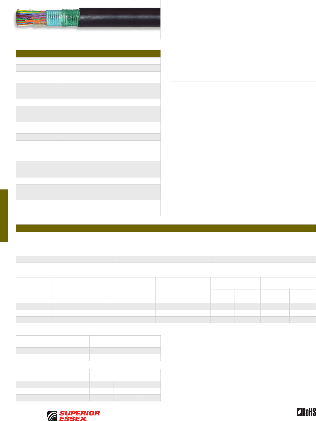
F-18
PREMISES COPPER PREMISES FIBER OSP FIBER OSP COMPOSITE CENTRAL OFFICE COPPER RDUP/RUS OSP COPPER BELL OSP COPPER OSP COPPER WIRE CANADIAN OSP COPPER TECHNICAL INFO
Rev 10/10 Ed 10.3Toll Free 800.551.8948 | Fax 770.657.6807 | SuperiorEssex.com/Comm
Specifications
Conductor Solid annealed copper
AWG (mm) Available in 19 (0.90), 22 (0.64) and 24 (0.51)
Insulation Solid polyolefin; color coded in accordance
with industry standards
Twisted Pairs
Individual insulated conductors; twisted into pairs with
varying lay lengths; specific color combinations provide
pair identification
≤ 25-Pair Core Pairs are assembled into a cylindrical core
> 25-Pair Core
Cables larger than 25-pair are assembled into units, which
are then used to assemble the core; units are identifiable
using color-coded binders
Filling Compound 80°C ETPR compound, completely filling the interstices
between the pairs and under the core wrap
Core Wrap Non-hygroscopic, dielectric tape applied over the core
Inner Shield
Corrugated, copolymer coated, 8 mil aluminum tape
applied directly over the core wrap that does not butt
or overlap at any point along the length of the cable;
flooded shield interfaces
Outer Shield
Rodent resistant, corrugated, copolymer coated, 6 mil steel
tape applied directly over the aluminum and overlaps;
flooded shield interfaces
Jacket Black, polyethylene
Jacket Marking
Identifying information includes a telephone handset,
cable code, pair count, AWG, date of manufacture
and sequential length markings at 2 foot intervals
Standards
Compliance
ANSI/ICEA S-84-608-2007
RDUP 7 CFR 1755.390 (PE-39)
RoHS-compliant
Electrical Specifications
Number of Pairs
Average Mutual
Capacitance @ 1000 Hz
nF/mile (nF/km)
Capacitance Unbalance
Pair to Pair @ 1 kHz
Capacitance Unbalance
Pair to Ground @ 1 kHz
Maximum Individual
pF @ 1 kft (pF @ 1 km)
Maximum RMS
pF @ 1 kft (pF @ 1 km)
Maximum Individual
pF @ 1 kft (pF @ 1 km)
Maximum Average
pF @ 1 kft (pF @ 1 km)
12 or less 83 ± 7 (52 ± 4) 80 (145) - 800 (2,625) -
Over 12 83 ± 4 (52 ± 2) 80 (145) 25 (45) 800 (2,625) 175 (574)
Conductor Size
AWG (mm)
Minimum Insulation
Resistance @ 68°F (20°C)
gigohm-mile (gigohm-km)
Maximum Average
Attenuation*
772 kHz @ 68°F (20°C)
dB/kft (dB/km)
Maximum Conductor
Resistance @ 68°F (20°C)
Ohms/sheath
mile (km)
DC Resistance
Unbalance Maximum %
Dielectric Strength
DC Potential – Volts
Average
Individual
Pair
Conductor
to Conductor
Conductor
to Shield
19 (0.90) 1.0 (1.6) 2.8 (9.2) 45.0 (28.0) 1.5 5.0 7,000 15,000
22 (0.64) 1.0 (1.6) 4.0 (13.1) 91.0 (56.5) 1.5 5.0 5,000 15,000
24 (0.51) 1.0 (1.6) 5.0 (16.4) 144.0 (89.5) 1.5 5.0 4,000 15,000
*For cables of 12-pair or less, the maximum average attenuation may be increased by 10% over the values shown.
Minimum Near End Crosstalk
(NEXT) @ 772 kHz
PSWUNEXT Mean (dB) 47
PSWUNEXT Worst Pair (dB) 42
Minimum Far End Crosstalk
(FEXT) @ 772 kHz
Conductor Size (AWG) 19 22 24
PSELFEXT Mean (dB/kft) 51 49 49
PSELFEXT Worst Pair (dB/kft) 45 43 43
CASPIC®–F (RDUP PE-39)
Product Description
CASPIC®-F Cables are designed for use in direct burial applications where
additional mechanical or rodent protection is required. CASPIC-F may be
used aerially, but must be attached to a support strand.
Applications
• Direct burial where additional mechanical protection
is required or desired
• Lashed aerial where additional mechanical protection
is required or desired
Features Benefits
• Twisted into pairs with varying
lay lengths
• Minimizes crosstalk
• Core wrap • Provides thermal protection
• Filled core • Moisture resistant
• Dual shield design • Rodent resistant
• Fully flooded shield interfaces • Inhibits corrosion
and water migration
• Black, polyethylene jacket • Provides a tough, protective
covering designed to withstand
exposure to direct sunlight,
atmospheric temperature
changes and stresses expected
in standard installations
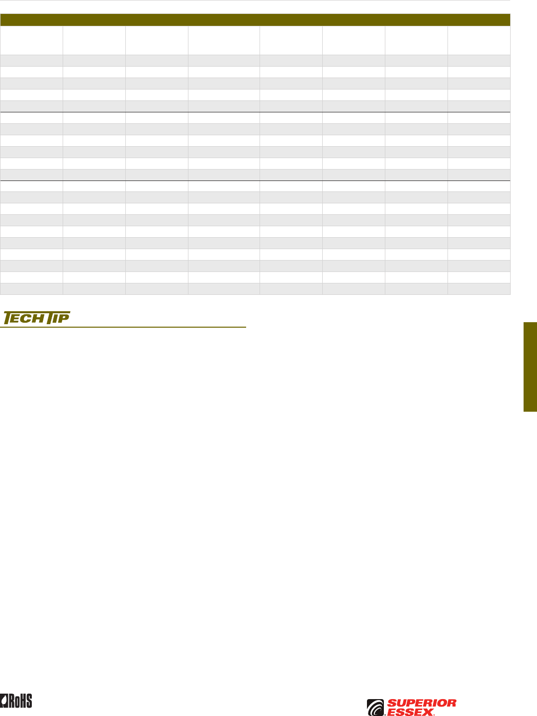
F-19
PREMISES COPPERPREMISES FIBEROSP FIBEROSP COMPOSITECENTRAL OFFICE COPPERRDUP/RUS OSP COPPERBELL OSP COPPEROSP COPPER WIRECANADIAN OSP COPPERTECHNICAL INFO
Rev 10/10 Ed 10.3 Toll Free 800.551.8948 | Fax 770.657.6807 | SuperiorEssex.com/Comm
Part Numbers and Physical Characteristics
Part Number Pair Count AWG (mm)
Nominal Diameter
in (mm)
Approx. Weight
lbs/kft (kg/km)
Standard Length
ft (m)
Approx.
Shipping Weight
lbs (kg)
Reel Size
F x T x D
in
04-026-94 6 19 (0.90) 0.57 (15) 175 (260) 5,000 (1,524) 1,040 (470) 46 x 25 x 20
04-028-94 12 19 (0.90) 0.72 (18) 285 (425) 5,000 (1,524) 1,630 (740) 52 x 25 x 20
04-031-94 25 19 (0.90) 0.95 (24) 515 (765) 5,000 (1,524) 2,865 (1,300) 62 x 30 x 24
04-034-94 50 19 (0.90) 1.26 (32) 915 (1,360) 5,000 (1,524) 5,275 (2,390) 78 x 40 x 39
04-038-94 100 19 (0.90) 1.73 (44) 1,715 (2,550) 2,500 (762) 4,985 (2,260) 78 x 40 x 39
04-057-94 6 22 (0.64) 0.46 (12) 110 (165) 5,000 (1,524) 660 (300) 44 x 18 x 20
04-059-94 12 22 (0.64) 0.56 (14) 170 (255) 5,000 (1,524) 1,015 (460) 46 x 25 x 20
04-062-94 25 22 (0.64) 0.71 (18) 290 (430) 5,000 (1,524) 1,655 (750) 52 x 25 x 20
04-065-94 50 22 (0.64) 0.93 (24) 495 (735) 5,000 (1,524) 2,845 (1,290) 65 x 30 x 32
04-069-94 100 22 (0.64) 1.22 (31) 880 (1,310) 5,000 (1,524) 5,100 (2,315) 78 x 40 x 39
04-073-94 200 22 (0.64) 1.67 (42) 1,645 (2,450) 2,500 (762) 4,725 (2,145) 72 x 35 x 36
04-092-94 6 24 (0.51) 0.41 (10) 90 (135) 5,000 (1,524) 515 (235) 36 x 18 x 14
04-094-94 12 24 (0.51) 0.49 (12) 130 (195) 5,000 (1,524) 760 (345) 44 x 18 x 20
04-097-94 25 24 (0.51) 0.61 (16) 205 (305) 5,000 (1,524) 1,190 (540) 46 x 25 x 20
04-100-94 50 24 (0.51) 0.77 (20) 340 (505) 5,000 (1,524) 1,905 (865) 52 x 25 x 20
04-104-94 100 24 (0.51) 1.01 (26) 600 (895) 5,000 (1,524) 3,290 (1,490) 62 x 30 x 24
04-108-94 200 24 (0.51) 1.36 (35) 1,090 (1,620) 5,000 (1,524) 6,150 (2,790) 78 x 40 x 39
04-110-94 300 24 (0.51) 1.63 (41) 1,560 (2,320) 2,500 (762) 4,515 (2,050) 72 x 35 x 36
04-112-94 400 24 (0.51) 1.84 (47) 2,015 (3,000) 2,500 (762) 5,735 (2,600) 78 x 40 x 39
04-116-94 600 24 (0.51) 2.22 (56) 2,945 (4,385) 1,250 (381) 4,295 (1,950) 72 x 35 x 36
04-118-94 900 24 (0.51) 2.68 (68) 4,300 (6,400) 1,250 (381) 6,170 (2,800) 84 x 40 x 42
Product FAQs for OSP copper cables are available online:
www.SuperiorEssex.com/comm/productFAQs.aspx
CASPIC
®
–F (RDUP PE-39)


G-1
PREMISES COPPERPREMISES FIBEROSP FIBEROSP COMPOSITECENTRAL OFFICE COPPERRDUP/RUS OSP COPPERBELL OSP COPPEROSP COPPER WIRECANADIAN OSP COPPERTECHNICAL INFO
Toll Free 800.551.8948 | Fax 770.657.6807 | SuperiorEssex.com/Comm
BELL OSP COPPER
Table of Contents
ALPETH BHBA, BHAA, BKMA and BKTA ......................... G-2
PASP BHBH, BHAH, BKMH and BKTH ........................... G-4
Self-Support BHAS and BKMS ................................ G-6
Reinforced Self-Support BHAP, BKMP and BKTP................. G-8
Bonded STALPETH DCAZ, DCMZ and DCTZ..................... G-10
STEAMPETH DKMN and DKTN ............................... G-12
Power Station High Potential Filled ASP CMAW ............... G-13
Filled ALPETH ANBA, ANAA, ANMA and ANTA .................. G-14
Filled ASP ANBW, ANAW, ANMW and ANTW ................... G-16
Tight Twist 200-Pair ANMW ................................. G-18
T-SCREEN® Filled ASP KNAW and KNMW ..................... G-19
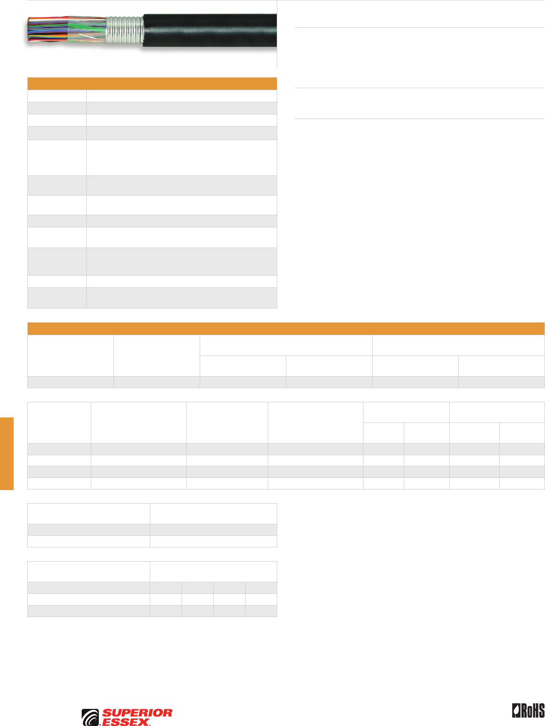
G-2
PREMISES COPPER PREMISES FIBER OSP FIBER OSP COMPOSITE CENTRAL OFFICE COPPER RDUP/RUS OSP COPPER BELL OSP COPPER OSP COPPER WIRE CANADIAN OSP COPPER TECHNICAL INFO
Rev 10/10 Ed 10.3Toll Free 800.551.8948 | Fax 770.657.6807 | SuperiorEssex.com/Comm
ALPETH
BHBA, BHAA, BKMA and BKTA
Specifications
Conductor Solid annealed copper
AWG (mm) Available in 19 (0.90), 22 (0.64), 24 (0.51) and 26 (0.40)
Insulation Solid polyolefin in distinctive colors to facilitate pair identification
≤ 25-Pair Core Pairs are combined into a cylindrical core
> 50-Pair Core
Multiples of 25-pair groups are assembled to form the final
cable core; each group is identified by color coded
non-hygroscopic binders; for 1,200-pair and larger,
the color code is a Mirror Image design
Core Wrap Non-hygroscopic dielectric material protects the core and helps
provide core-to-shield dielectric strength
Shield Corrugated bare 8 mil aluminum tape is applied longitudinally
over the core wrap
Jacket Black polyethylene
Shield/Jacket
Options
If extra mechanical protection is desired, an additional outer
steel armor and polyethylene jacket (UM) can be requested
Jacket
Marking
Manufacturer’s identification, pair count, AWG, product
identification, sequential footage and a telephone handset
printed at 2 foot intervals
Package 420 steel reel (F x T x D = 83 x 40 x 42 inches)
Standards
Compliance
Telcordia GR-421-CORE Issue 2
RoHS-compliant
Electrical Specifications
Number of Pairs
Average Mutual
Capacitance @ 1000 Hz
nF/mile (nF/km)
Capacitance Unbalance
Pair to Pair @ 1 kHz
Capacitance Unbalance
Pair to Ground @ 1 kHz
Maximum Individual
pF @ 1 kft (pF @ 1 km)
Maximum RMS
pF @ 1 kft (pF @ 1 km)
Maximum Individual
pF @ 1 kft (pF @ 1 km)
Maximum Average
pF @ 1 kft (pF @ 1 km)
Over 12 83 ± 4 (52 ± 2) 80 (145) 25 (45) 800 (2,625) 175 (574)
Conductor Size
AWG (mm)
Minimum Insulation
Resistance @ 68°F (20°C)
gigohm-mile (gigohm-km)
Maximum Average
Attenuation
772 kHz @ 68°F (20°C)
dB/kft (dB/km)
Maximum Conductor
Resistance @ 68°F (20°C)
Ohms/sheath
mile (km)
DC Resistance
Unbalance Maximum %
Dielectric Strength
DC Potential – Volts
Average
Individual
Pair
Conductor
to Conductor
Conductor
to Shield
19 (0.90) 1.0 (1.6) 3.3 (10.8) 45 (28.0) 1.5 5.0 5,000 10,000
22 (0.64) 1.0 (1.6) 4.7 (15.4) 91 (56.5) 1.5 5.0 4,000 10,000
24 (0.51) 1.0 (1.6) 5.9 (19.4) 144 (89.5) 1.5 5.0 3,000 10,000
26 (0.40) 1.0 (1.6) 7.4 (24.3) 232 (144.2) 1.5 5.0 2,400 10,000
Minimum Near End Crosstalk
(NEXT) @ 772 kHz
PSWUNEXT Mean (dB) 47
PSWUNEXT Worst Pair (dB) 42
Minimum Far End Crosstalk
(FEXT) @ 772 kHz
Conductor Size (AWG) 19 22 24 26
PSELFEXT Mean (dB/kft) 51 49 49 47
PSELFEXT Worst Pair (dB/kft) 45 43 43 43
Product Description
ALPETH Cable is a solid insulated, single jacket air core design intended
for aerial installations. In this application, the cable must be attached to
a support strand (messenger). ALPETH cable is not recommended for any
buried or duct application, with or without air pressure.
Applications
• Lashed aerial
Features Benefits
• Tightly controlled individual
conductor dimensions
• Limits resistance unbalance
of paired conductors
• Specially designed
pair twist lays
• Minimizes crosstalk and meets
the capacitance unbalance
requirements
• Core wrap • Protects core and provides
improved mechanical and
electrical characteristics
• Bare aluminum tape shield • Assures good electrical
contact with non-piercing
bonding clamps
• Polyethylene jacket • Provides a tough, flexible,
protective covering that
withstands exposure to sunlight,
atmospheric temperatures and
stresses expected in standard
installations
G-3
PREMISES COPPERPREMISES FIBEROSP FIBEROSP COMPOSITECENTRAL OFFICE COPPERRDUP/RUS OSP COPPERBELL OSP COPPEROSP COPPER WIRECANADIAN OSP COPPERTECHNICAL INFO
Rev 10/10 Ed 10.3 Toll Free 800.551.8948 | Fax 770.657.6807 | SuperiorEssex.com/Comm
Part Numbers and Physical Characteristics
Part Number Pair Count AWG (mm)
Nominal Diameter
in (mm)
Approx. Weight
lbs/kft (kg/km)
Standard Length
ft (m)
Approx.
Shipping Weight
lbs (kg)
BHBA
20-031-42 25 19 (0.90) 0.76 (19) 310 (460) 10,000 (3,048) 3,895 (1,765)
20-034-42 50 19 (0.90) 1.00 (25) 570 (850) 10,000 (3,048) 6,495 (2,945)
20-038-42 100 19 (0.90) 1.34 (34) 1,070 (1,590) 5,000 (1,524) 6,145 (2,785)
20-042-42 200 19 (0.90) 1.85 (47) 2,075 (3,090) 2,500 (762) 5,985 (2,715)
20-044-42 300 19 (0.90) 2.23 (57) 3,065 (4,560) 2,000 (610) 6,925 (3,140)
20-046-42 400 19 (0.90) 2.73 (69) 4,172 (6,215) 1,260 (384) 5,997 (2,723)
BHAA
20-062-42 25 22 (0.64) 0.60 (15) 180 (270) 15,000 (4,572) 3,495 (1,585)
20-065-42 50 22 (0.64) 0.77 (20) 315 (470) 15,000 (4,572) 5,520 (2,505)
20-069-42 100 22 (0.64) 1.02 (26) 580 (865) 10,000 (3,048) 6,595 (2,990)
20-073-42 200 22 (0.64) 1.38 (35) 1,090 (1,620) 5,000 (1,524) 6,245 (2,835)
20-075-42 300 22 (0.64) 1.66 (42) 1,600 (2,380) 3,300 (1,006) 6,075 (2,755)
20-077-42 400 22 (0.64) 1.89 (48) 2,110 (3,140) 2,500 (762) 6,070 (2,755)
20-081-42 600 22 (0.64) 2.28 (58) 3,115 (4,635) 2,000 (610) 7,025 (3,185)
20-083-42 900 22 (0.64) 2.76 (70) 4,625 (6,885) 1,100 (335) 5,885 (2,670)
BKMA
20-097-42 25 24 (0.51) 0.51 (13) 125 (185) 20,000 (6,096) 3,295 (1,495)
20-100-42 50 24 (0.51) 0.64 (16) 215 (320) 20,000 (6,096) 5,095 (2,310)
20-104-42 100 24 (0.51) 0.83 (21) 380 (565) 13,300 (4,054) 5,850 (2,655)
20-108-42 200 24 (0.51) 1.12 (28) 710 (1,055) 8,000 (2,438) 6,475 (2,935)
20-110-42 300 24 (0.51) 1.33 (34) 1,035 (1,540) 5,700 (1,737) 6,695 (3,035)
20-112-42 400 24 (0.51) 1.52 (39) 1,355 (2,015) 4,400 (1,341) 6,755 (3,065)
20-116-42 600 24 (0.51) 1.82 (46) 1,995 (2,970) 3,100 (945) 6,980 (3,165)
20-118-42 900 24 (0.51) 2.19 (56) 2,950 (4,390) 2,200 (671) 7,285 (3,305)
20-120-42 1,200 24 (0.51) 2.50 (64) 3,905 (5,810) 1,600 (488) 7,045 (3,195)
20-121-42 1,500 24 (0.51) 2.79 (71) 4,860 (7,235) 1,250 (381) 6,870 (3,115)
20-124-42 1,800 24 (0.51) 3.05 (78) 5,810 (8,645) 1,140 (347) 7,420 (3,365)
BKTA
20-145-42 300 26 (0.40) 1.07 (27) 675 (1,005) 8,000 (2,438) 6,195 (2,810)
20-147-42 400 26 (0.40) 1.23 (31) 875 (1,300) 6,600 (2,012) 6,570 (2,980)
20-151-42 600 26 (0.40) 1.47 (37) 1,290 (1,920) 5,000 (1,524) 7,245 (3,285)
20-153-42 900 26 (0.40) 1.75 (45) 1,890 (2,815) 3,300 (1,006) 7,030 (3,190)
20-155-42 1,200 26 (0.40) 2.00 (51) 2,495 (3,715) 2,200 (671) 6,285 (2,850)
20-156-42 1,500 26 (0.40) 2.25 (57) 3,100 (4,615) 2,000 (610) 6,995 (3,175)
20-157-42 1,800 26 (0.40) 2.45 (62) 3,695 (5,500) 1,600 (488) 6,705 (3,040)
20-158-42 2,100 26 (0.40) 2.65 (67) 4,305 (6,405) 1,140 (347) 5,705 (2,585)
20-161-42 2,700 26 (0.40) 2.97 (75) 5,495 (8,180) 1,050 (320) 6,565 (2,980)
20-162-42 3,000 26 (0.40) 3.13 (80) 6,090 (9,065) 800 (244) 5,665 (2,570)
ALPETH BHBA, BHAA, BKMA and BKTA
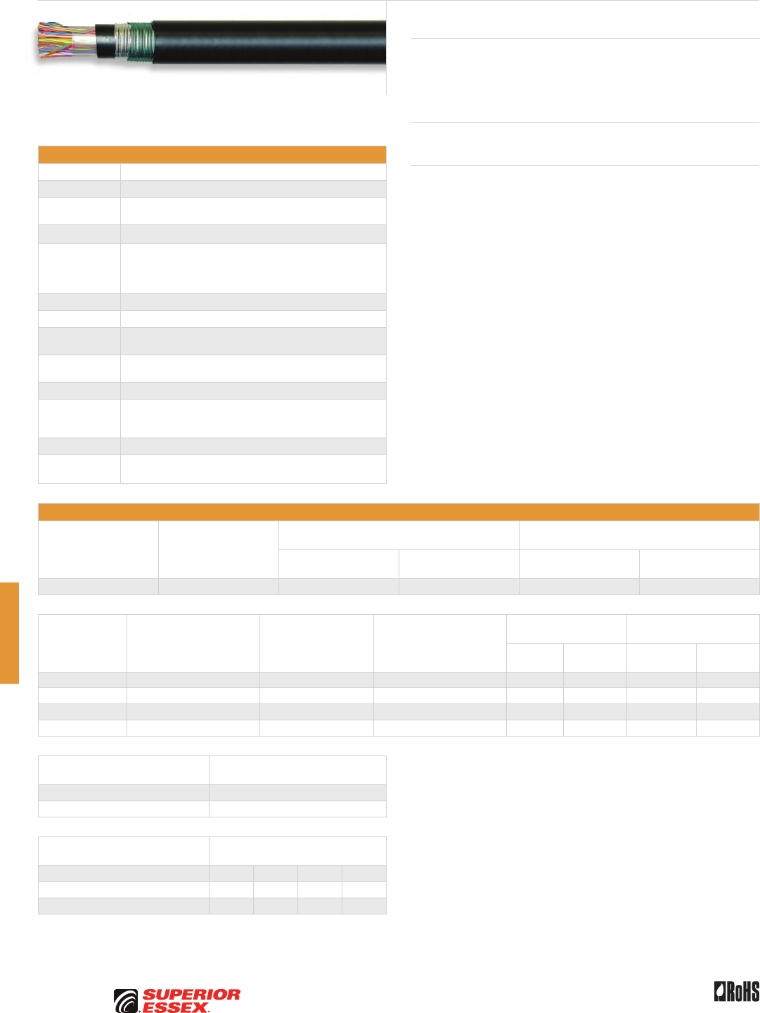
G-4
PREMISES COPPER PREMISES FIBER OSP FIBER OSP COMPOSITE CENTRAL OFFICE COPPER RDUP/RUS OSP COPPER BELL OSP COPPER OSP COPPER WIRE CANADIAN OSP COPPER TECHNICAL INFO
Rev 10/10 Ed 10.3Toll Free 800.551.8948 | Fax 770.657.6807 | SuperiorEssex.com/Comm
Specifications
Conductor Solid annealed copper
AWG (mm) Available in 19 (0.90), 22 (0.64), 24 (0.51) and 26 (0.40)
Insulation Conductors are insulated with solid polyolefin in distinctive
colors to facilitate pair identification
≤ 25-Pair Core Pairs are combined into a cylindrical core
> 50-Pair Core
Multiples of 25-pair groups are assembled to form the final
cable core; each group is identified by color coded
non-hygroscopic binders; for 1,200-pair and larger,
the color code is a Mirror Image design
Core Wrap Non-hygroscopic dielectric material
Inner Jacket Polyethylene
Shield Corrugated bare 8 mil aluminum tape applied longitudinally over
the inner jacket
Armor Corrugated, copolymer coated, 6 mil steel tape applied over the
aluminum shield; armor is bonded to the outer jacket
Outer Jacket Black polyethylene
Jacket
Marking
Manufacturer’s identification, pair count, AWG, product
identification, sequential footage and a telephone handset
printed at 2 foot intervals
Package 420 steel reel (F x T x D = 83 x 40 x 42 inches)
Standards
Compliance
Telcordia GR-421-CORE Issue 2
RoHS-compliant
Electrical Specifications
Number of Pairs
Average Mutual
Capacitance @ 1000 Hz
nF/mile (nF/km)
Capacitance Unbalance
Pair to Pair @ 1 kHz
Capacitance Unbalance
Pair to Ground @ 1 kHz
Maximum Individual
pF @ 1 kft (pF @ 1 km)
Maximum RMS
pF @ 1 kft (pF @ 1 km)
Maximum Individual
pF @ 1 kft (pF @ 1 km)
Maximum Average
pF @ 1 kft (pF @ 1 km)
Over 12 83 ± 4 (52 ± 2) 80 (145) 25 (45) 800 (2,625) 175 (574)
Conductor Size
AWG (mm)
Minimum Insulation
Resistance @ 68°F (20°C)
gigohm-mile (gigohm-km)
Maximum Average
Attenuation
772 kHz @ 68°F (20°C)
dB/kft (dB/km)
Maximum Conductor
Resistance @ 68°F (20°C)
Ohms/sheath
mile (km)
DC Resistance
Unbalance Maximum %
Dielectric Strength
DC Potential – Volts
Average
Individual
Pair
Conductor
to Conductor
Conductor
to Shield
19 (0.90) 1.0 (1.6) 3.3 (10.8) 45 (28.0) 1.5 5.0 5,000 20,000
22 (0.64) 1.0 (1.6) 4.7 (15.4) 91 (56.5) 1.5 5.0 4,000 20,000
24 (0.51) 1.0 (1.6) 5.9 (19.4) 144 (89.5) 1.5 5.0 3,000 20,000
26 (0.40) 1.0 (1.6) 7.4 (24.3) 232 (144.2) 1.5 5.0 2,400 20,000
Minimum Near End Crosstalk
(NEXT) @ 772 kHz
PSWUNEXT Mean (dB) 47
PSWUNEXT Worst Pair (dB) 42
Minimum Far End Crosstalk
(FEXT) @ 772 kHz
Conductor Size (AWG) 19 22 24 26
PSELFEXT Mean (dB/kft) 51 49 49 47
PSELFEXT Worst Pair (dB/kft) 45 43 43 43
Product Description
PASP Cable is a solid insulated, double jacket, armored air core design
intended for use in outside cable plant where a greater risk of physical
damage exists. The inner jacket provides protection to the cable core in the
event of severe damage to the outer protective sheath.
Applications
• Pressurized direct buried installations in harsh environments
Features Benefits
• Tightly controlled individual
conductor dimensions
• Limits resistance unbalance
of paired conductors
• Specially designed
pair twist lays
• Minimizes crosstalk and meets the
capacitance unbalance requirements
• Core wrap • Protects the core and provides
core-to-shield dielectric strength
• Inner polyethylene jacket • Provides additional protection
against mechanical damage and
prevents the ingress of moisture
• Aluminum tape shield • Assures good electrical contact
with non-piercing bonding clamps
• Steel tape armor bonded
to outer jacket
• Protects the core from mechanical
damage and reduces the possibility
of tape buckling during installation,
ingress of water to the aluminum
shield and of water along the cable
between the armor and outer jacket
• Polyethylene jacket • Provides a tough, flexible, protective
covering that withstands exposure to
sunlight, atmospheric temperatures,
ground chemicals and stresses
expected in standard installations
PASP
BHBH, BHAH, BKMH and BKTH
G-5
PREMISES COPPERPREMISES FIBEROSP FIBEROSP COMPOSITECENTRAL OFFICE COPPERRDUP/RUS OSP COPPERBELL OSP COPPEROSP COPPER WIRECANADIAN OSP COPPERTECHNICAL INFO
Rev 10/10 Ed 10.3 Toll Free 800.551.8948 | Fax 770.657.6807 | SuperiorEssex.com/Comm
Part Numbers and Physical Characteristics
Part Number Pair Count AWG (mm)
Nominal Diameter
in (mm)
Approx. Weight
lbs/kft (kg/km)
Standard Length
ft (m)
Approx.
Shipping Weight
lbs (kg)
BHBH
20-031-05 25 19 (0.90) 0.89 (23) 415 (620) 10,000 (3,048) 4,945 (2,245)
20-034-05 50 19 (0.90) 1.13 (29) 705 (1,050) 5,000 (1,524) 4,320 (1,960)
20-038-05 100 19 (0.90) 1.50 (38) 1,280 (1,905) 3,300 (1,006) 5,020 (2,275)
BHAH
20-062-05 25 22 (0.64) 0.72 (18) 260 (385) 15,000 (4,572) 4,695 (2,130)
20-065-05 50 22 (0.64) 0.90 (23) 425 (630) 10,000 (3,048) 5,045 (2,290)
20-069-05 100 22 (0.64) 1.15 (29) 715 (1,065) 7,500 (2,286) 6,160 (2,795)
20-073-05 200 22 (0.64) 1.54 (39) 1,300 (1,935) 3,750 (1,143) 5,670 (2,570)
20-075-05 300 22 (0.64) 1.83 (47) 1,865 (2,775) 3,300 (1,006) 6,950 (3,150)
20-077-05 400 22 (0.64) 2.05 (52) 2,405 (3,580) 2,000 (610) 5,605 (2,540)
20-081-05 600 22 (0.64) 2.48 (63) 3,515 (5,230) 1,250 (381) 5,190 (2,355)
20-083-05 900 22 (0.64) 2.96 (75) 5,110 (7,605) 1,100 (335) 6,415 (2,910)
BKMH
20-097-05 25 24 (0.51) 0.63 (16) 195 (290) 20,000 (6,096) 4,695 (2,130)
20-100-05 50 24 (0.51) 0.76 (19) 300 (445) 13,300 (4,054) 4,785 (2,170)
20-104-05 100 24 (0.51) 0.97 (25) 500 (745) 10,000 (3,048) 5,795 (2,630)
20-108-05 200 24 (0.51) 1.24 (32) 860 (1,280) 6,600 (2,012) 6,470 (2,935)
20-110-05 300 24 (0.51) 1.49 (38) 1,240 (1,845) 4,400 (1,341) 6,250 (2,835)
20-112-05 400 24 (0.51) 1.68 (43) 1,595 (2,375) 3,300 (1,006) 6,060 (2,750)
20-116-05 600 24 (0.51) 1.99 (51) 2,290 (3,410) 2,500 (762) 6,520 (2,955)
20-118-05 900 24 (0.51) 2.38 (61) 3,335 (4,965) 1,600 (488) 6,130 (2,780)
20-120-05 1,200 24 (0.51) 2.72 (69) 4,355 (6,480) 1,100 (335) 5,585 (2,535)
20-121-05 1,500 24 (0.51) 2.99 (76) 5,350 (7,960) 1,100 (335) 6,680 (3,030)
20-124-05 1,800 24 (0.51) 3.25 (83) 6,340 (9,435) 800 (244) 5,865 (2,660)
BKTH
20-145-05 300 26 (0.40) 1.20 (31) 820 (1,220) 6,600 (2,012) 6,205 (2,815)
20-147-05 400 26 (0.40) 1.40 (36) 1,075 (1,600) 5,000 (1,524) 6,170 (2,800)
20-151-05 600 26 (0.40) 1.64 (42) 1,520 (2,260) 3,300 (1,006) 5,810 (2,635)
20-153-05 900 26 (0.40) 1.93 (49) 2,175 (3,235) 2,600 (792) 6,450 (2,925)
20-155-05 1,200 26 (0.40) 2.20 (56) 2,845 (4,235) 2,200 (671) 7,055 (3,200)
20-156-05 1,500 26 (0.40) 2.45 (62) 3,490 (5,195) 1,600 (488) 6,380 (2,895)
20-157-05 1,800 26 (0.40) 2.66 (68) 4,135 (6,155) 1,300 (396) 6,170 (2,800)
20-158-05 2,100 26 (0.40) 2.85 (72) 4,770 (7,100) 1,140 (347) 6,235 (2,825)
20-159-05 2,400 26 (0.40) 3.05 (80) 5,465 (8,141) 1,100 (335) 7,012 (3,183)
20-161-05 2,700 26 (0.40) 3.18 (81) 6,015 (8,950) 1,140 (347) 7,650 (3,470)
PASP BHBH, BHAH, BKMH and BKTH
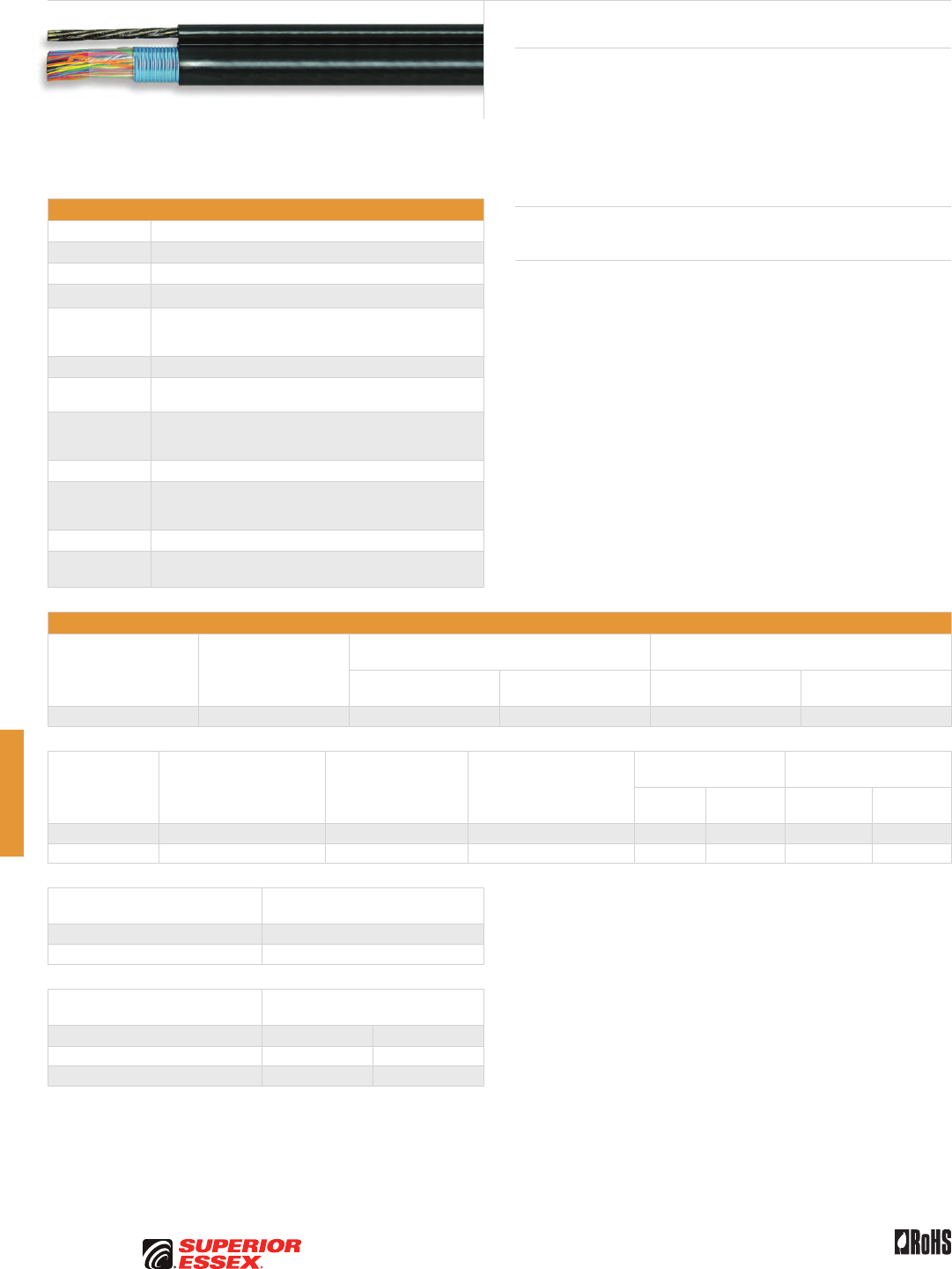
G-6
PREMISES COPPER PREMISES FIBER OSP FIBER OSP COMPOSITE CENTRAL OFFICE COPPER RDUP/RUS OSP COPPER BELL OSP COPPER OSP COPPER WIRE CANADIAN OSP COPPER TECHNICAL INFO
Rev 10/10 Ed 10.3Toll Free 800.551.8948 | Fax 770.657.6807 | SuperiorEssex.com/Comm
Self-Support
BHAS and BKMS
Specifications
Conductor Solid annealed copper
AWG (mm) Available in 22 (0.64) and 24 (0.51)
Insulation Solid polyolefin in distinctive colors to facilitate pair identification
≤ 25-Pair Core Pairs are combined into a cylindrical core
> 50-Pair Core
Multiples of 25-pair groups are assembled to form the final
cable core; each group is identified by color coded non-
hygroscopic binders
Core Wrap Non-hygroscopic dielectric material
Shield Corrugated, 8 mil coated aluminum tape applied longitudinally
over the core wrap
Support
Member
0.25 inch, 7-strand Extra High-Strength (EHS) galvanized steel
member, fully flooded, serves as the support member
and is an integral part of the sheath
Jacket Black polyethylene
Jacket
Marking
Manufacturer’s identification, pair count, AWG, product
identification, sequential footage and a telephone handset
printed at 2 foot intervals
Package 420 steel reel (F x T x D = 83 x 40 x 42 inches)
Standards
Compliance
Telcordia GR-421-CORE Issue 2
RoHS-compliant
Electrical Specifications
Number of Pairs
Average Mutual
Capacitance @ 1000 Hz
nF/mile (nF/km)
Capacitance Unbalance
Pair to Pair @ 1 kHz
Capacitance Unbalance
Pair to Ground @ 1 kHz
Maximum Individual
pF @ 1 kft (pF @ 1 km)
Maximum RMS
pF @ 1 kft (pF @ 1 km)
Maximum Individual
pF @ 1 kft (pF @ 1 km)
Maximum Average
pF @ 1 kft (pF @ 1 km)
Over 12 83 + 4, - 5 (52 + 2, - 3) 80 (145) 25 (45) 800 (2,625) 175 (574)
Conductor Size
AWG (mm)
Minimum Insulation
Resistance @ 68°F (20°C)
gigohm-mile (gigohm-km)
Maximum Average
Attenuation
772 kHz @ 68°F (20°C)
dB/kft (dB/km)
Maximum Conductor
Resistance @ 68°F (20°C)
Ohms/sheath
mile (km)
DC Resistance
Unbalance Maximum %
Dielectric Strength
DC Potential – Volts
Average
Individual
Pair
Conductor
to Conductor
Conductor
to Shield
22 (0.64) 1.0 (1.6) 4.7 (15.4) 91 (56.5) 1.5 5.0 4,000 10,000
24 (0.51) 1.0 (1.6) 5.9 (19.4) 144 (89.5) 1.5 5.0 3,000 10,000
Minimum Near End Crosstalk
(NEXT) @ 772 kHz
PSWUNEXT Mean (dB) 47
PSWUNEXT Worst Pair (dB) 42
Minimum Far End Crosstalk
(FEXT) @ 772 kHz
Conductor Size (AWG) 22 24
PSELFEXT Mean (dB/kft) 49 49
PSELFEXT Worst Pair (dB/kft) 43 43
Product Description
Self-Support Cable is a solid insulated, single jacket air core design with a
built-in support member intended specifically for aerial applications. The
undulated, shielded core is laid parallel to a flooded steel support member
and jacketed in an integral extrusion to form a “figure-8” configuration.
The supporting member is an integral part of the cable sheath yet readily
available for gripping, pulling and tensioning. Installation is fast and easy
using standard methods and hardware.
Applications
• Aerial
Features Benefits
• Tightly controlled individual
conductor dimensions
• Limits resistance unbalance
of paired conductors
• Specially designed
pair twist lays
• Minimizes crosstalk
and meets the capacitance
unbalance requirements
• Undulated core assembly • Eliminates strain on the
conductors and provides
sufficient slack during installation
• Core wrap • Protects the core and
helps provide core-to-shield
dielectric strength
• Fully flooded steel
support member
• Provides corrosion protection
• Polyethylene jacket • Provides tough, flexible, protective
covering that withstands
exposure to sunlight, atmospheric
temperatures and stresses
expected in standard installations
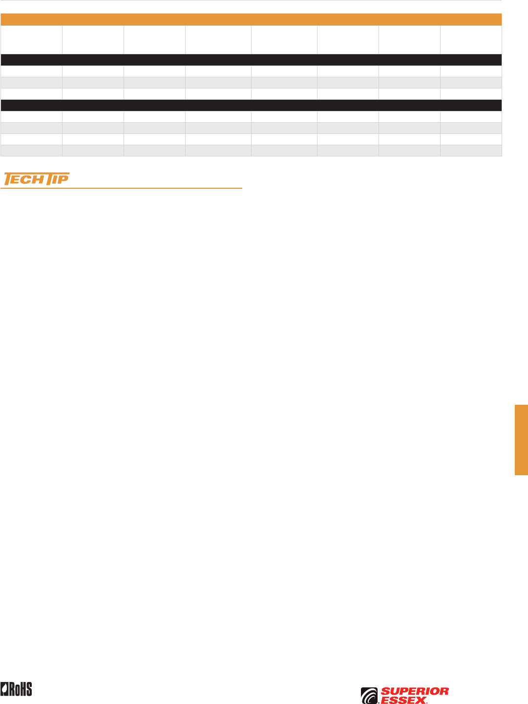
G-7
PREMISES COPPERPREMISES FIBEROSP FIBEROSP COMPOSITECENTRAL OFFICE COPPERRDUP/RUS OSP COPPERBELL OSP COPPEROSP COPPER WIRECANADIAN OSP COPPERTECHNICAL INFO
Rev 10/10 Ed 10.3 Toll Free 800.551.8948 | Fax 770.657.6807 | SuperiorEssex.com/Comm
Part Numbers and Physical Characteristics
Part Number Pair Count AWG (mm)
Nominal Diameter
(cable only)
in (mm)
Nominal Diameter
(with messenger)
in (mm)
Approx. Weight
lbs/kft (kg/km)
Standard Length
ft (m)
Approx.
Shipping Weight
lbs (kg)
BHAS
20-062-43 25 22 (0.64) 0.58 (15) 1.05 (27) 310 (461) 10,000 (3,048) 3,895 (1,766)
20-065-43 50 22 (0.64) 0.74 (19) 1.20 (31) 445 (662) 7,500 (2,286) 4,135 (1,875)
20-069-43 100 22 (0.64) 1.00 (25) 1.47 (37) 705 (1,049) 6,000 (1,829) 5,025 (2,279)
BKMS
20-097-43 25 24 (0.51) 0.49 (12) 0.96 (24) 260 (387) 13,300 (4,054) 4,255 (1,930)
20-100-43 50 24 (0.51) 0.62 (16) 1.09 (28) 345 (513) 13,300 (4,054) 5,385 (2,442)
20-104-43 100 24 (0.51) 0.80 (20) 1.27 (32) 515 (766) 8,000 (2,438) 4,915 (2,229)
20-108-43 200 24 (0.51) 1.09 (28) 1.56 (40) 840 (1,250) 5,000 (1,524) 4,995 (2,265)
Sag and Tension guidelines for these products are available online:
www.SuperiorEssex.com/techtip.aspx
Self-Support BHAS and BKMS
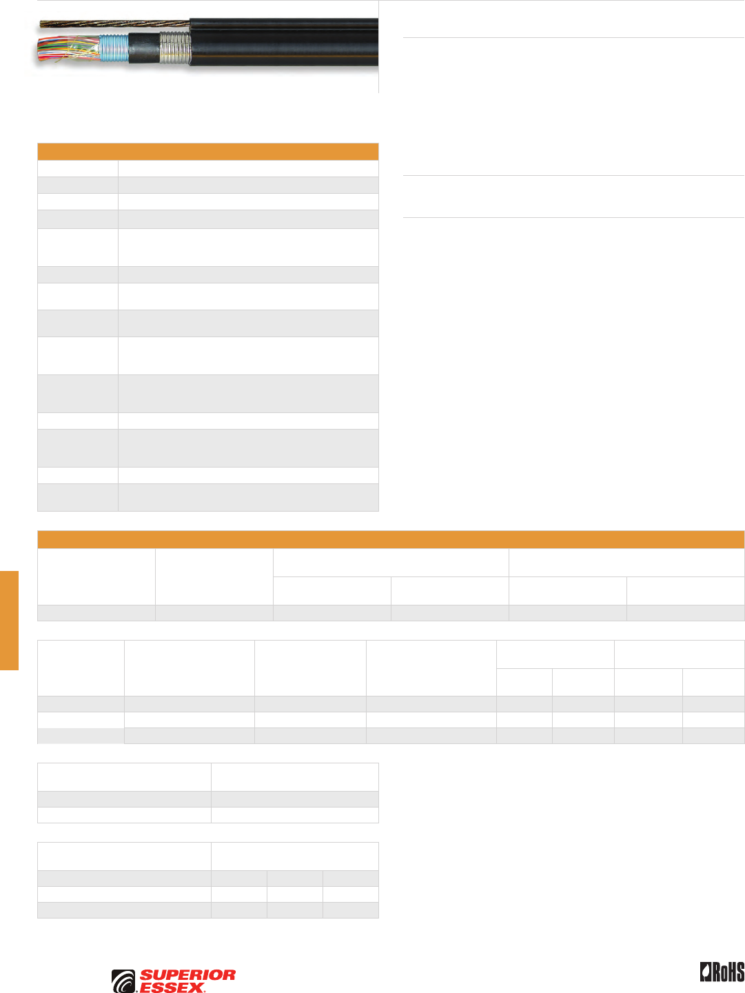
G-8
PREMISES COPPER PREMISES FIBER OSP FIBER OSP COMPOSITE CENTRAL OFFICE COPPER RDUP/RUS OSP COPPER BELL OSP COPPER OSP COPPER WIRE CANADIAN OSP COPPER TECHNICAL INFO
Rev 10/10 Ed 10.3Toll Free 800.551.8948 | Fax 770.657.6807 | SuperiorEssex.com/Comm
Specifications
Conductor Solid annealed copper
AWG (mm) Available in 22 (0.64), 24 (0.51) and 26 (0.40)
Insulation Solid polyolefin in distinctive colors to facilitate pair identification
≤ 25-Pair Core Pairs are combined into a cylindrical core
> 50-Pair Core
Multiples of 25-pair groups are assembled to form the final
cable core; each group is identified by color coded non-
hygroscopic binders
Core Wrap Non-hygroscopic dielectric material
Shield Corrugated, 8 mil aluminum tape is applied longitudinally over
the core wrap
Inner Jacket Polyethylene helps protect the core and shield against
mechanical damage and ingress of moisture
Armor
Corrugated bare 6 mil steel tape is applied longitudinally over
the inner jacket and the inner and outer surfaces of the steel
are flooded
Support
Member
0.25 inch, 7-strand Extra High-Strength (EHS) galvanized steel
member, fully flooded, serves as the support member and is
an integral part of the sheath
Outer Jacket Black polyethylene
Jacket
Marking
Manufacturer’s identification, pair count, AWG, product
identification, sequential footage and a telephone handset
printed at 2 foot intervals
Package 420 steel reel (F x T x D = 83 x 40 x 42 inches)
Standards
Compliance
Telcordia GR-421-CORE Issue 2
RoHS-compliant
Electrical Specifications
Number of Pairs
Average Mutual
Capacitance @ 1000 Hz
nF/mile (nF/km)
Capacitance Unbalance
Pair to Pair @ 1 kHz
Capacitance Unbalance
Pair to Ground @ 1 kHz
Maximum Individual
pF @ 1 kft (pF @ 1 km)
Maximum RMS
pF @ 1 kft (pF @ 1 km)
Maximum Individual
pF @ 1 kft (pF @ 1 km)
Maximum Average
pF @ 1 kft (pF @ 1 km)
Over 12 83 + 4, - 5 (52 ± 2, - 3) 80 (145) 25 (45) 800 (2,625) 175 (574)
Conductor Size
AWG (mm)
Minimum Insulation
Resistance @ 68°F (20°C)
gigohm-mile (gigohm-km)
Maximum Average
Attenuation
772 kHz @ 68°F (20°C)
dB/kft (dB/km)
Maximum Conductor
Resistance @ 68°F (20°C)
Ohms/sheath
mile (km)
DC Resistance
Unbalance Maximum %
Dielectric Strength
DC Potential – Volts
Average
Individual
Pair
Conductor
to Conductor
Conductor
to Shield
22 (0.64) 1.0 (1.6) 4.7 (15.4) 91 (56.5) 1.5 5.0 4,000 10,000
24 (0.51) 1.0 (1.6) 5.9 (19.4) 144 (89.5) 1.5 5.0 3,000 10,000
26 (0.40) 1.0 (1.6) 7.4 (24.3) 232 (144.2) 1.5 5.0 2,400 10,000
Minimum Near End Crosstalk
(NEXT) @ 772 kHz
PSWUNEXT Mean (dB) 47
PSWUNEXT Worst Pair (dB) 42
Minimum Far End Crosstalk
(FEXT) @ 772 kHz
Conductor Size (AWG) 22 24 26
PSELFEXT Mean (dB/kft) 49 49 47
PSELFEXT Worst Pair (dB/kft) 43 43 43
Product Description
Reinforced Self-Support Cable is a solid insulated, double jacket, armored,
self-supporting air core design intended for aerial installations where
hazards from squirrel attack, tree limb abrasion or lightning exist. The
undulated, shielded, jacketed core is covered with a flooded steel armor,
laid parallel to a flooded steel support member and jacketed in an integral
extrusion to form a “figure-8” configuration. The steel strand member is
readily available for gripping, pulling and tensioning using standard methods
and hardware.
Applications
• Aerial installations in harsh environments
Features Benefits
• Tightly controlled individual
conductor dimensions
• Limits resistance unbalance of
paired conductors
• Specially designed
pair twist lays
• Minimizes crosstalk and meets
the capacitance unbalance
requirements
• Undulated core assembly • Eliminates strain on the
conductors and provides
sufficient slack during installation
• Core wrap • Protects the core and helps
provide core-to-shield dielectric
strength
• Inner polyethylene jacket • Provides additional protection
against mechanic damage and
prevents the ingress of moisture
• Fully flooded steel
support member
• Provides corrosion protection
• Polyethylene jacket • Provides tough, flexible, protective
covering that withstands
exposure to sunlight, atmospheric
temperatures and stresses
expected in standard installations
Reinforced Self-Support
BHAP, BKMP and BKTP
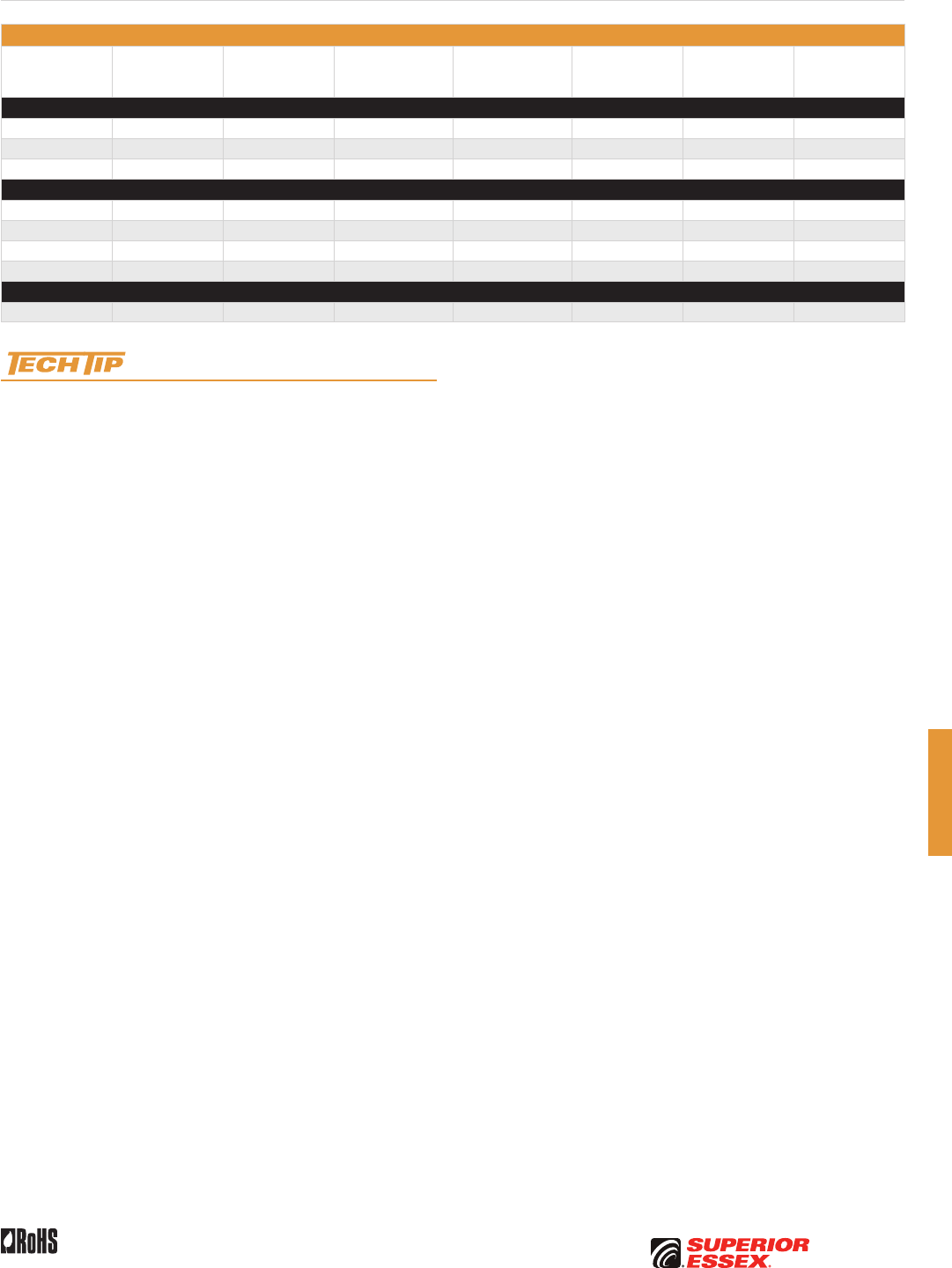
G-9
PREMISES COPPERPREMISES FIBEROSP FIBEROSP COMPOSITECENTRAL OFFICE COPPERRDUP/RUS OSP COPPERBELL OSP COPPEROSP COPPER WIRECANADIAN OSP COPPERTECHNICAL INFO
Rev 10/10 Ed 10.3 Toll Free 800.551.8948 | Fax 770.657.6807 | SuperiorEssex.com/Comm
Part Numbers and Physical Characteristics
Part Number Pair Count AWG (mm)
Nominal Diameter
(cable only)
in (mm)
Nominal Diameter
(with messenger)
in (mm)
Approx. Weight
lbs/kft (kg/km)
Standard Length
ft (m)
Approx.
Shipping Weight
lbs (kg)
BHAP
20-062-20 25 22 (0.64) 0.87 (22) 1.33 (34) 455 (675) 10,000 (3,048) 4,200 (1,905)
20-065-20 50 22 (0.64) 1.05 (27) 1.51 (38) 625 (930) 7,500 (2,286) 4,465 (2,025)
20-069-20 100 22 (0.64) 1.30 (33) 1.76 (45) 940 (1,400) 5,000 (1,524) 4,475 (2,029)
BKMP
20-097-20 25 24 (0.51) 0.83 (21) 1.29 (33) 400 (595) 10,000 (3,048) 4,345 (1,971)
20-100-20 50 24 (0.51) 0.94 (24) 1.40 (36) 510 (760) 10,000 (3,048) 5,445 (2,469)
20-104-20 100 24 (0.51) 1.13 (29) 1.59 (40) 715 (1,065) 5,000 (1,524) 4,145 (1,880)
20-108-20 200 24 (0.51) 1.42 (36) 1.88 (48) 1,120 (1,665) 4,000 (1,220) 4,995 (2,265)
BKTP
20-145-20 300 26 (0.40) 1.35 (34) 1.81 (46) 1,045 (1,555) 3,300 (1,010) 4,110 (1,864)
Sag and Tension guidelines for these products are available online:
www.SuperiorEssex.com/techtip.aspx
Reinforced Self-Support BHAP, BKMP and BKTP

G-10
PREMISES COPPER PREMISES FIBER OSP FIBER OSP COMPOSITE CENTRAL OFFICE COPPER RDUP/RUS OSP COPPER BELL OSP COPPER OSP COPPER WIRE CANADIAN OSP COPPER TECHNICAL INFO
Rev 10/10 Ed 10.3Toll Free 800.551.8948 | Fax 770.657.6807 | SuperiorEssex.com/Comm
Bonded STALPETH
DCAZ, DCMZ and DCTZ
Specifications
Conductor Solid annealed copper
AWG (mm) Available in 22 (0.64), 24 (0.51) and 26 (0.40)
Insulation
Conductors are dual insulated with an inner layer of foamed,
natural polyolefin covered by an outer layer of solid, colored
polyolefin; conductor insulation is color coded in accordance
with industry standard
≥ 50-Pair Core
Multiples of 25-pair groups are assembled to form the final
cable core; each group is identified by color coded
non-hygroscopic binders; for 1,200-pair and larger,
the color code is Mirror Image design
Core Wrap Non-hygroscopic dielectric material
Shield Corrugated bare 8 mil aluminum tape applied longitudinally over
the core wrap
Armor Corrugated, copolymer coated, 6 mil steel tape applied over the
aluminum shield and bonded to the outer jacket
Jacket Black polyethylene
Jacket
Marking
Manufacturer’s identification, pair count, AWG, product
identification and a telephone handset printed at 2 foot
intervals; sequential footage markings are printed at alternate
2 foot intervals
Package 420 steel reel (F x T x D = 83 x 40 x 42 inches)
Standards
Compliance
Telcordia GR-421-CORE Issue 2
RoHS-compliant
Electrical Specifications
Number of Pairs
Average Mutual
Capacitance @ 1000 Hz
nF/mile (nF/km)
Capacitance Unbalance
Pair to Pair @ 1 kHz
Capacitance Unbalance
Pair to Ground @ 1 kHz
Maximum Individual
pF @ 1 kft (pF @ 1 km)
Maximum RMS
pF @ 1 kft (pF @ 1 km)
Maximum Individual
pF @ 1 kft (pF @ 1 km)
Maximum Average
pF @ 1 kft (pF @ 1 km)
All pairs 83 ± 4 (52 ± 2) 80 (145) 25 (45) 800 (2,625) 175 (574)
Conductor Size
AWG (mm)
Minimum Insulation
Resistance @ 68°F (20°C)
gigohm-mile (gigohm-km)
Maximum Average
Attenuation
772 kHz @ 68°F (20°C)
dB/kft (dB/km)
Maximum Conductor
Resistance @ 68°F (20°C)
Ohms/sheath
mile (km)
DC Resistance
Unbalance Maximum %
Dielectric Strength
DC Potential – Volts
Average
Individual
Pair
Conductor
to Conductor
Conductor
to Shield
22 (0.64) 1.0 (1.6) 5.0 (16.4) 91 (56.5) 1.5 5.0 1,400 5,000
24 (0.51) 1.0 (1.6) 6.3 (20.7) 144 (89.5) 1.5 5.0 1,200 5,000
26 (0.40) 1.0 (1.6) 7.9 (25.9) 232 (144.2) 1.5 5.0 1,000 5,000
Minimum Near End Crosstalk
(NEXT) @ 772 kHz
PSWUNEXT Mean (dB) 47
PSWUNEXT Worst Pair (dB) 42
Minimum Far End Crosstalk
(FEXT) @ 772 kHz
Conductor Size (AWG) 22 24 26
PSELFEXT Mean (dB/kft) 49 49 47
PSELFEXT Worst Pair (dB/kft) 43 43 43
Product Description
Bonded STALPETH Cable is a foam skin insulated, single jacket, armored
air core design intended for use in ducts to provide more efficient duct
utilization than standard PIC designs.
Applications
• Congested underground duct systems
Features Benefits
• Tightly controlled individual
conductor dimensions
• Limits resistance unbalance
of paired conductors
• Specially designed
pair twist lays
• Minimizes crosstalk
and meets the capacitance
unbalance requirements
• Core wrap • Protects the core and
helps provide core-to-shield
dielectric strength
• Aluminum tape shield • Assures good electrical
contact with non-piercing
bonding clamps
• Steel tape armor bonded
to outer jacket
• Protects the core from
mechanical damage and reduces
the possibility of tape buckling
during installation, ingress of
water to the aluminum shield and
of water along the cable between
the armor and outer jacket
• Polyethylene jacket • Provides a tough, flexible,
protective covering that
withstands exposure to sunlight,
atmospheric temperatures,
ground chemicals and stresses
expected in standard installations
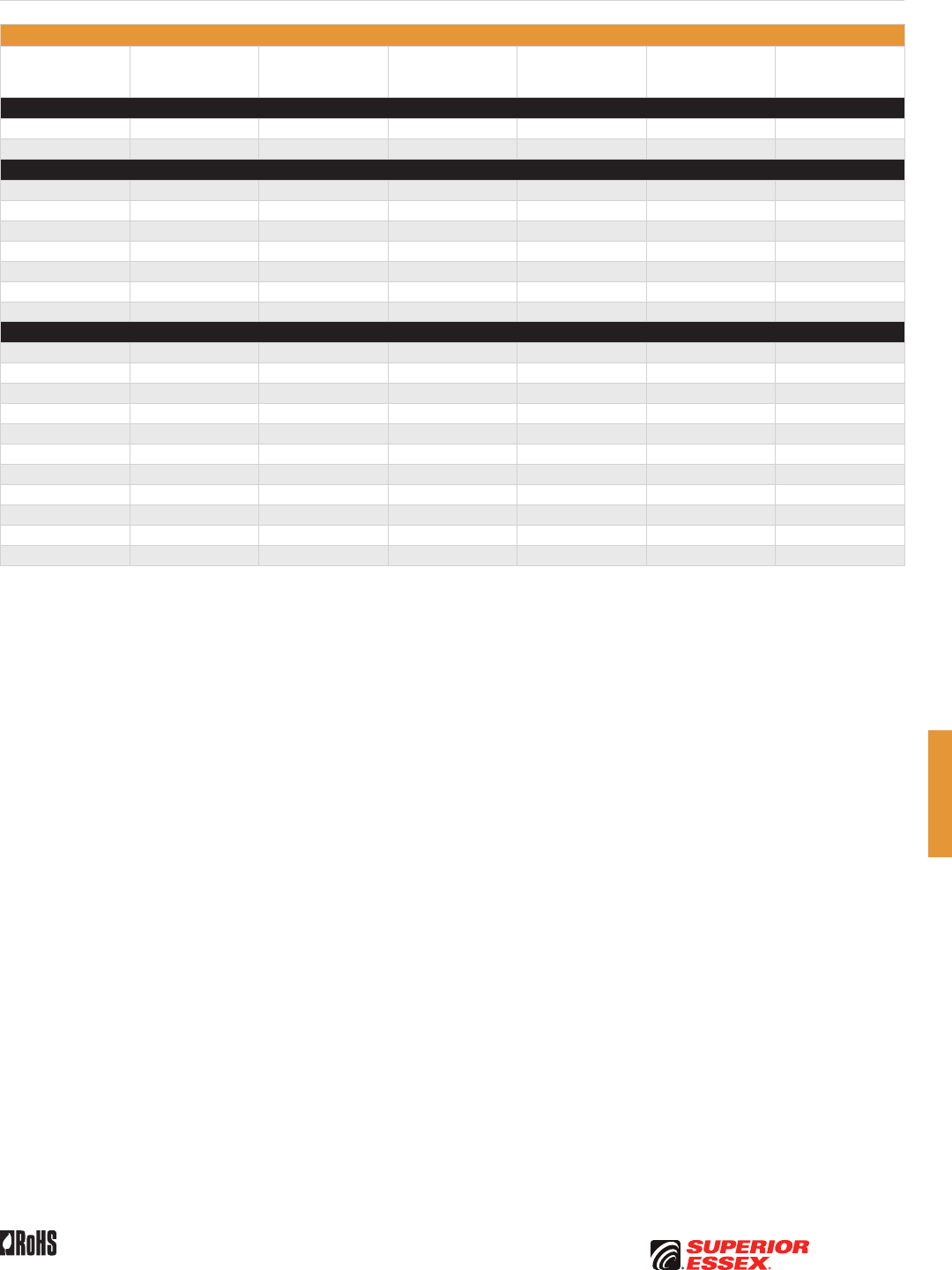
G-11
PREMISES COPPERPREMISES FIBEROSP FIBEROSP COMPOSITECENTRAL OFFICE COPPERRDUP/RUS OSP COPPERBELL OSP COPPEROSP COPPER WIRECANADIAN OSP COPPERTECHNICAL INFO
Rev 10/10 Ed 10.3 Toll Free 800.551.8948 | Fax 770.657.6807 | SuperiorEssex.com/Comm
Part Numbers and Physical Characteristics
Part Number Pair Count AWG (mm)
Nominal Diameter
in (mm)
Approx. Weight
lbs/kft (kg/km)
Standard Length
ft (m)
Approx.
Shipping Weight
lbs (kg)
DCAZ
19-083-01 900 22 (0.64) 2.49 (63) 4,375 (6,510) 1,600 (488) 7,795 (3,535)
19-085-01 1,200 22 (0.64) 2.85 (72) 5,770 (8,585) 1,200 (366) 7,720 (3,500)
DCMZ
19-116-01 600 24 (0.51) 1.70 (43) 1,960 (2,915) 3,900 (1,189) 8,440 (3,830)
19-118-01 900 24 (0.51) 2.02 (51) 2,860 (4,255) 2,616 (797) 8,275 (3,755)
19-120-01 1,200 24 (0.51) 2.30 (58) 3,755 (5,590) 2,000 (610) 8,305 (3,765)
19-121-01 1,500 24 (0.51) 2.57 (65) 4,660 (6,935) 1,600 (488) 8,250 (3,745)
19-124-01 1,800 24 (0.51) 2.81 (71) 5,545 (8,250) 1,250 (381) 7,725 (3,505)
19-125-01 2,100 24 (0.51) 3.04 (77) 6,440 (9,585) 1,150 (351) 8,200 (3,720)
19-126-01 2,400 24 (0.51) 3.22 (82) 7,320 (10,895) 876 (267) 7,205 (3,270)
DCTZ
19-151-01 600 26 (0.40) 1.38 (35) 1,285 (1,910) 5,700 (1,737) 8,120 (3,685)
19-153-01 900 26 (0.40) 1.62 (41) 1,850 (2,755) 3,900 (1,189) 8,010 (3,635)
19-155-01 1,200 26 (0.40) 1.84 (47) 2,420 (3,600) 3,200 (975) 8,540 (3,875)
19-156-01 1,500 26 (0.40) 2.08 (53) 2,995 (4,455) 2,500 (762) 8,285 (3,755)
19-157-01 1,800 26 (0.40) 2.26 (57) 3,560 (5,300) 2,080 (634) 8,200 (3,720)
19-158-01 2,100 26 (0.40) 2.41 (61) 4,115 (6,125) 1,250 (381) 5,940 (2,695)
19-159-01 2,400 26 (0.40) 2.58 (66) 4,685 (6,970) 1,600 (488) 8,290 (3,760)
19-161-01 2,700 26 (0.40) 2.71 (69) 5,240 (7,800) 1,250 (381) 7,345 (3,330)
19-162-01 3,000 26 (0.40) 2.86 (73) 5,800 (8,630) 1,200 (366) 7,755 (3,520)
19-164-01 3,600 26 (0.40) 3.03 (77) 6,885 (10,245) 1,150 (351) 8,715 (3,950)
19-167-01 4,200 26 (0.40) 3.26 (83) 7,995 (11,900) 900 (274) 7,990 (3,625)
Bonded STALPETH DCAZ, DCMZ and DCTZ
G-12
PREMISES COPPER PREMISES FIBER OSP FIBER OSP COMPOSITE CENTRAL OFFICE COPPER RDUP/RUS OSP COPPER BELL OSP COPPER OSP COPPER WIRE CANADIAN OSP COPPER TECHNICAL INFO
Rev 10/10 Ed 10.3Toll Free 800.551.8948 | Fax 770.657.6807 | SuperiorEssex.com/Comm
Specifications
Conductor Solid annealed copper
AWG (mm) Available in 24 (0.51) and 26 (0.40)
Insulation Solid polypropylene insulation; standard color codes are used
for pair identification
Core Assembly
Multiples of 25-pair groups are assembled to form the final cable
core; each group is identified by color coded non-hygroscopic
binders; for 1,200-pair and larger, color coding is Mirror Image
Core Wrap Non-hygroscopic dielectric material
Shield Corrugated bare 8 mil aluminum tape applied longitudinally
over the core wrap
Armor Corrugated, copolymer coated, 6 mil steel tape applied
over the aluminum shield and bonded to the outer jacket
Jacket Black, medium density polyethylene
Jacket Marking
Manufacturer’s identification, pair count, AWG, product
identification, a telephone handset and sequential footage
markings are printed at 2 foot intervals.
Package 420 steel reel (F x T x D = 83 x 40 x 42 inches)
Standards
Compliance Telcordia GR-110-CORE
Electrical Specifications
Number of Pairs
Average Mutual
Capacitance @ 1000 Hz
nF/mile (nF/km)
Capacitance Unbalance
Pair to Pair @ 1 kHz
Capacitance Unbalance
Pair to Ground @ 1 kHz
Maximum Individual
pF @ 1 kft (pF @ 1 km)
Maximum RMS
pF @ 1 kft (pF @ 1 km)
Maximum Individual
pF @ 1 kft (pF @ 1 km)
Maximum Average
pF @ 1 kft (pF @ 1 km)
All pairs 83 ± 4 (52 ± 2) 80 (145) 25 (45) 800 (2,625) 175 (574)
Conductor
Sizes
AWG (mm)
Minimum Insulation
Resistance @ 68°F (20°C)
gigohm-mile (gigohm-km)
Maximum Average
Attenuation
772 kHz @ 68°F (20°C)
dB/kft (dB/km)
Maximum Conductor
Resistance @ 68°F (20°C)
Ohms/sheath
mile (km)
DC Resistance Unbalance
Maximum %
Dielectric Strength
DC Potential – Volts
Average Individual Pair
Conductor
to Conductor
Conductor
to Shield
24 (0.51) 1.0 (1.6) 5.9 (16.4) 144 (89.5) 1.5 5.0 3,000 10,000
26 (0.40) 1.0 (1.6) 7.4 (24.3) 232 (144.2) 1.5 5.0 2,400 10,000
Minimum Near End Crosstalk (NEXT)
@ 150 kHz @ 772 kHz
PSWUNEXT Mean (dB) 58 47
PSWUNEXT Worst Pair (dB) 53 42
Part Numbers and Physical Characteristics
Part Number Pair Count AWG (mm)
Nominal Diameter
in (mm)
Approx. Weight
lbs/kft (kg/km)
Standard Length
ft (m)
Approx. Shipping Weight
lbs (kg)
DKMN
27-118-19 900 24 (0.51) 2.23 (57) 3,110 (4,630) 2,100 (640) 7,325 (3,325)
DKTN
27-145-19 300 26 (0.40) 1.11 (28) 750 (1,115) 8,600 (2,621) 7,245 (3,285)
27-151-19 600 26 (0.40) 1.51 (38) 1,395 (2,075) 4,800 (1,463) 7,490 (3,400)
27-153-19 900 26 (0.40) 1.79 (46) 2,015 (3,000) 3,300 (1,006) 7,445 (3,375)
27-155-19 1,200 26 (0.40) 2.04 (52) 2,635 (3,920) 2,120 (646) 6,380 (2,895)
27-157-19 1,800 26 (0.40) 2.50 (64) 3,885 (5,780) 1,650 (503) 7,205 (3,270)
27-159-19 2,400 26 (0.40) 2.87 (73) 5,110 (7,605) 1,250 (381) 7,185 (3,260)
27-162-19 3,000 26 (0.40) 3.18 (81) 6,325 (9,415) 1,150 (351) 8,070 (3,660)
27-164-19 3,600 26 (0.40) 3.36 (85) 7,495 (11,155) 850 (259) 7,165 (3,250)
Product Description
STEAMPETH Cable is a solid insulated, single jacket, armored air core
design intended for use in underground systems where a high incidence
of damage could occur if steam enters the duct. The cable is designed for
application in high temperature environments up to 230°F (110°C).
Applications
• Steam tunnels
Features Benefits
• Solid polypropylene insulation • Provides higher temperature rating
• Tightly controlled individual
conductor dimensions
• Limits resistance unbalance
of paired conductors
• Specially designed
pair twist lays
• Minimizes crosstalk and meets the
capacitance unbalance requirements
• Core wrap • Protects core and helps provide
core-to-shield dielectric strength
• Aluminum tape shield • Assures good electrical contact
with non-piercing bonding clamps
• Steel armor bonded
to the outer jacket
• Protects the core from mechanical
damage and reduces the possibility
of tape buckling during installation,
ingress of water to the shield and
seepage of water along the cable
between the armor and outer jacket
• Polyethylene jacket • Provides a tough, flexible, protective
covering that withstands exposure to
sunlight, above-normal temperatures,
ground chemicals and stresses
expected during installation
Minimum Far End Crosstalk
@ 150 kHz @ 772 kHz
Conductor Size (AWG) 24 26 24 26
PSELFEXT Mean (dB/kft) 63 61 49 47
PSELFEXT Worst Pair (dB/kft) 57 57 43 43
STEAMPETH
DKMN and DKTN
G-13
PREMISES COPPERPREMISES FIBEROSP FIBEROSP COMPOSITECENTRAL OFFICE COPPERRDUP/RUS OSP COPPERBELL OSP COPPEROSP COPPER WIRECANADIAN OSP COPPERTECHNICAL INFO
Rev 10/10 Ed 10.3 Toll Free 800.551.8948 | Fax 770.657.6807 | SuperiorEssex.com/Comm
Power Station High Potential Filled ASP
CMAW
Specifications
Conductor Solid annealed copper
AWG (mm) 22 (0.64)
Insulation Color coded solid high dielectric insulation; standard color codes
are used for pair identification.
25-Pair Core Pairs are combined into a cylindrical core
≥ 50-Pair Core
Multiples of 25-pair groups are assembled to form the final
cable core; each group is identified by color-coded non-
hygroscopic binders
Filling
Compound
Entire core assembly is filled with 80°C ETPR compound, filling
the air space between the insulated conductors
Core Wrap Dielectric tape applied over the core
Shields Corrugated bare 8 mil aluminum tape covered by a corrugated
bare 6 mil steel tape applied longitudinally over the core wrap
Jacket Black polyethylene
Jacket
Marking
Manufacturer’s ID, pair count, AWG, product ID and telephone
handset printed every 2 foot; sequential footage marking
printed at 2 foot intervals
Package 420 steel reel (F x T x D = 83 x 40 x 42 inches)
Standards
Compliance
Telcordia GR-421-CORE Issue 2
RoHS-compliant
Electrical Specifications
Number of Pairs
Average Mutual
Capacitance @ 1000 Hz
nF/mile (nF/km)
Capacitance Unbalance
Pair to Pair @ 1 kHz
Capacitance Unbalance
Pair to Ground @ 1 kHz
Maximum Individual
pF @ 1 kft (pF @ 1 km)
Maximum RMS
pF @ 1 kft (pF @ 1 km)
Maximum Individual
pF @ 1 kft (pF @ 1 km)
Maximum Average
pF @ 1 kft (pF @ 1 km)
All pairs 83 ± 4 (52 ± 2) 80 (145) 25 (45) 800 (2,625) 175 (574)
Conductor Size
AWG (mm)
Minimum Insulation
Resistance @ 68°F (20°C)
gigohm-mile (gigohm-km)
Maximum Average
Attenuation
772 kHz @ 68°F (20°C)
dB/kft (dB/km)
Maximum Conductor
Resistance @ 68°F (20°C)
Ohms/sheath
mile (km)
DC Resistance
Unbalance Maximum %
Dielectric Strength
DC Potential – Volts
Average
Individual
Pair
Conductor
to Conductor
Conductor
to Shield
22 (0.64) 1.0 (1.6) 4.0 (13.1) 91 (56.5) 1.5 5.0 5,000 20,000
Minimum Near End Crosstalk
(NEXT) @ 772 kHz
Minimum Far End Crosstalk
(FEXT) @ 772 kHz
PSWUNEXT Mean (dB) 47 PSELFEXT Mean (dB/kft) 49
PSWUNEXT Worst Pair (dB) 42 PSELFEXT Worst Pair (dB/kft) 43
Part Numbers and Physical Characteristics
Part Number Pair Count
Nominal Diameter
in (mm)
Approx. Weight
lbs/kft (kg/km)
Standard Length
ft (m)
Approx.
Shipping Weight
lbs (kg)
21-062-48 25 0.71 (18) 285 (425) 10,000 (3,048) 3,645 (1,655)
21-065-48 50 0.93 (24) 495 (735) 10,000 (3,048) 5,745 (2,605)
21-069-48 100 1.22 (31) 875 (1,300) 5,000 (1,524) 5,170 (2,345)
21-073-48 200 1.76 (45) 1,758 (2,619) 2,500 (762) 5,190 (2,360)
21-075-48 300 2.11 (54) 2,529 (3,767) 2,500 (762) 7,115 (3,235)
Product Description
High Potential Filled ASP Cable with solid insulation is a single jacket,
filled, armored design intended for applications associated with power
substations. This cable provides exceptional durability and resistance to
moisture. The finished cable meets all standard electrical requirements plus
a 20 kv high voltage test between the conductors and the shield.
Applications
• Power sub stations
Features Benefits
• Tightly controlled individual
conductor dimensions
• Limits resistance unbalance
of paired conductors
• Specially designed
pair twist lays
• Minimizes crosstalk and meets
the capacitance unbalance
requirements
• Core wrap • Protects core and provides
improved mechanical and
electrical characteristics
• Inner and outer surfaces of
both aluminum tape and steel
tape are flooded with an
adhesive compound
• Provides a moisture barrier
and inhibits corrosion
• Polyethylene jacket • Provides a tough, flexible,
protective covering that
withstands exposure to sunlight,
above-normal temperatures,
ground chemicals and stresses
expected during installation
G-14
PREMISES COPPER PREMISES FIBER OSP FIBER OSP COMPOSITE CENTRAL OFFICE COPPER RDUP/RUS OSP COPPER BELL OSP COPPER OSP COPPER WIRE CANADIAN OSP COPPER TECHNICAL INFO
Rev 10/10 Ed 10.3Toll Free 800.551.8948 | Fax 770.657.6807 | SuperiorEssex.com/Comm
Specifications
Conductor Solid annealed copper
AWG (mm) Available in 19 (0.90), 22 (0.64), 24 (0.51) and 26 (0.40)
Insulation
Conductors are dual insulated with an inner layer of foamed,
natural polyolefin covered by an outer layer of solid, colored
polyolefin; conductor insulation is color coded in accordance
with industry standard
25-Pair Core Pairs are combined into a cylindrical core
≥ 50-Pair Core
Multiples of 25-pair groups are assembled to form the final
cable core; each group is identified by color coded
non-hygroscopic binders; for 1,200-pair and larger,
the color code is a Mirror Image design
Filling
Compound
Entire core assembly is filled with an 80°C ETPR compound,
filling the air space between the insulated conductors
Core Wrap Dielectric tape applied over the core
Shield
Corrugated bare 8 mil aluminum tape is applied longitudinally
over the core wrap; inner and outer surfaces of the aluminum
shield are flooded
Jacket Black, polyethylene
Jacket
Marking
Manufacturer’s identification, pair count, AWG, product
identification, sequential footage and a telephone handset
printed at 2 foot intervals
Package 420 steel reel (F x T x D = 83 x 40 x 42 inches)
Standards
Compliance
Telcordia GR-421-CORE Issue 2
RoHS-compliant
Electrical Specifications
Number of Pairs
Average Mutual
Capacitance @ 1000 Hz
nF/mile (nF/km)
Capacitance Unbalance
Pair to Pair @ 1 kHz
Capacitance Unbalance
Pair to Ground @ 1 kHz
Maximum Individual
pF @ 1 kft (pF @ 1 km)
Maximum RMS
pF @ 1 kft (pF @ 1 km)
Maximum Individual
pF @ 1 kft (pF @ 1 km)
Maximum Average
pF @ 1 kft (pF @ 1 km)
Over 12 83 ± 4 (52 ± 2) 80 (145) 25 (45) 800 (2,625) 175 (574)
Conductor Size
AWG (mm)
Minimum Insulation
Resistance @ 68°F (20°C)
gigohm-mile (gigohm-km)
Maximum Average
Attenuation
772 kHz @ 68°F (20°C)
dB/kft (dB/km)
Maximum Conductor
Resistance @ 68°F (20°C)
Ohms/sheath
mile (km)
DC Resistance
Unbalance Maximum %
Dielectric Strength
DC Potential – Volts
Average
Individual
Pair
Conductor
to Conductor
Conductor
to Shield
19 (0.90) 1.0 (1.6) 3.2 (10.5) 45 (28.0) 1.5 5.0 4,500 10,000
22 (0.64) 1.0 (1.6) 4.5 (14.8) 91 (56.5) 1.5 5.0 3,600 10,000
24 (0.51) 1.0 (1.6) 5.6 (18.4) 144 (89.5) 1.5 5.0 3,000 10,000
26 (0.40) 1.0 (1.6) 7.0 (23.0) 232 (144.2) 1.5 5.0 2,400 10,000
Minimum Near End Crosstalk
(NEXT) @ 772 kHz
PSWUNEXT Mean (dB) 47
PSWUNEXT Worst Pair (dB) 42
Minimum Far End Crosstalk
(FEXT) @ 772 kHz
Conductor Size (AWG) 19 22 24 26
PSELFEXT Mean (dB/kft) 51 49 49 47
PSELFEXT Worst Pair (dB/kft) 45 43 43 43
Product Description
Filled ALPETH Cable with foam skin insulation is a single jacket, filled design
intended for direct burial application. An ETPR compound completely coats
each insulated conductor and fills the air space between conductors. The
shielding and jacketing combined with the filling and flooding compounds
throughout the cable provide exceptional durability and resistance to moisture.
Applications
• Direct burial and underground conduit
Features Benefits
• Tightly controlled individual
conductor dimensions
• Limits resistance unbalance
of paired conductors
• Specially designed
pair twist lays
• Minimizes crosstalk and meets
the capacitance unbalance
requirements
• Core wrap • Protects core and provides
improved mechanical and
electrical characteristics
• Polyethylene jacket • Provides a tough, flexible,
protective covering that
withstands exposure to sunlight,
atmospheric temperatures,
ground chemicals and stresses
expected in standard installation
Filled ALPETH
ANBA, ANAA, ANMA and ANTA
G-15
PREMISES COPPERPREMISES FIBEROSP FIBEROSP COMPOSITECENTRAL OFFICE COPPERRDUP/RUS OSP COPPERBELL OSP COPPEROSP COPPER WIRECANADIAN OSP COPPERTECHNICAL INFO
Rev 10/10 Ed 10.3 Toll Free 800.551.8948 | Fax 770.657.6807 | SuperiorEssex.com/Comm
Part Numbers and Physical Characteristics
Part Number Pair Count AWG (mm)
Nominal Diameter
in (mm)
Approx. Weight
lbs/kft (kg/km)
Standard Length
ft (m)
Approx.
Shipping Weight
lbs (kg)
ANBA
09-031-77 25 19 (0.90) 0.78 (20) 355 (530) 10,000 (3,048) 4,345 (1,970)
09-034-77 50 19 (0.90) 1.03 (26) 655 (975) 5,000 (1,524) 4,070 (1,845)
09-038-77 100 19 (0.90) 1.37 (35) 1,225 (1,825) 3,300 (1,006) 4,840 (2,195)
ANAA
09-062-77 25 22 (0.64) 0.60 (15) 200 (300) 15,000 (4,572) 3,795 (1,720)
09-065-77 50 22 (0.64) 0.77 (20) 350 (520) 15,000 (4,572) 6,045 (2,740)
09-069-77 100 22 (0.64) 1.02 (26) 645 (960) 7,500 (2,286) 5,635 (2,555)
09-073-77 200 22 (0.64) 1.38 (35) 1,225 (1,825) 5,000 (1,524) 6,920 (3,140)
09-075-77 300 22 (0.64) 1.65 (42) 1,800 (2,680) 3,300 (1,006) 6,735 (3,055)
09-077-77 400 22 (0.64) 1.88 (48) 2,365 (3,520) 2,500 (762) 6,710 (3,045)
09-081-77 600 22 (0.64) 2.28 (58) 3,500 (5,210) 1,650 (503) 6,570 (2,980)
09-083-77 900 22 (0.64) 2.76 (70) 5,190 (7,725) 1,000 (305) 5,985 (2,715)
09-085-77 1,200 22 (0.64) 3.15 (80) 6,870 (10,225) 834 (254) 6,525 (2,960)
ANMA
09-097-77 25 24 (0.51) 0.52 (13) 140 (210) 20,000 (6,096) 3,595 (1,630)
09-100-77 50 24 (0.51) 0.66 (17) 240 (355) 20,000 (6,096) 5,595 (2,540)
09-104-77 100 24 (0.51) 0.85 (22) 430 (640) 10,000 (3,048) 5,095 (2,310)
09-108-77 200 24 (0.51) 1.14 (29) 810 (1,205) 5,000 (1,524) 4,845 (2,200)
09-110-77 300 24 (0.51) 1.37 (35) 1,180 (1,755) 5,000 (1,524) 6,695 (3,035)
09-112-77 400 24 (0.51) 1.55 (39) 1,545 (2,300) 4,000 (1,219) 6,975 (3,165)
09-116-77 600 24 (0.51) 1.88 (48) 2,285 (3,400) 2,500 (762) 6,510 (2,950)
09-118-77 900 24 (0.51) 2.25 (57) 3,345 (4,980) 1,650 (503) 6,315 (2,865)
09-120-77 1,200 24 (0.51) 2.58 (66) 4,430 (6,595) 1,250 (381) 6,335 (2,870)
09-121-77 1,500 24 (0.51) 2.87 (73) 5,510 (8,200) 1,000 (305) 6,305 (2,860)
09-124-77 1,800 24 (0.51) 3.13 (80) 6,590 (9,805) 840 (256) 6,330 (2,870)
09-125-77 2,100 24 (0.51) 3.40 (86) 7,725 (11,495) 750 (229) 6,590 (2,990)
ANTA
09-132-77 25 26 (0.40) 0.44 (11) 100 (150) 20,000 (6,096) 2,795 (1,270)
09-135-77 50 26 (0.40) 0.55 (14) 165 (245) 20,000 (6,096) 4,095 (1,855)
09-139-77 100 26 (0.40) 0.71 (18) 290 (430) 15,000 (4,572) 5,145 (2,335)
09-143-77 200 26 (0.40) 0.94 (24) 535 (795) 10,000 (3,048) 6,145 (2,785)
09-145-77 300 26 (0.40) 1.09 (28) 755 (1,125) 6,000 (1,829) 5,325 (2,415)
09-147-77 400 26 (0.40) 1.25 (32) 995 (1,480) 5,000 (1,524) 5,770 (2,615)
09-151-77 600 26 (0.40) 1.49 (38) 1,450 (2,160) 3,300 (1,006) 5,580 (2,530)
09-153-77 900 26 (0.40) 1.78 (45) 2,120 (3,155) 2,500 (762) 6,095 (2,765)
09-155-77 1,200 26 (0.40) 2.03 (52) 2,790 (4,150) 2,000 (610) 6,375 (2,890)
09-156-77 1,500 26 (0.40) 2.28 (58) 3,490 (5,195) 1,300 (396) 5,330 (2,420)
09-157-77 1,800 26 (0.40) 2.49 (63) 4,165 (6,200) 1,250 (381) 6,000 (2,720)
09-158-77 2,100 26 (0.40) 2.69 (68) 4,870 (7,250) 1,200 (366) 6,640 (3,010)
09-159-77 2,400 26 (0.40) 2.86 (73) 5,535 (8,235) 1,000 (305) 6,330 (2,870)
Filled ALPETH ANBA, ANAA, ANMA and ANTA
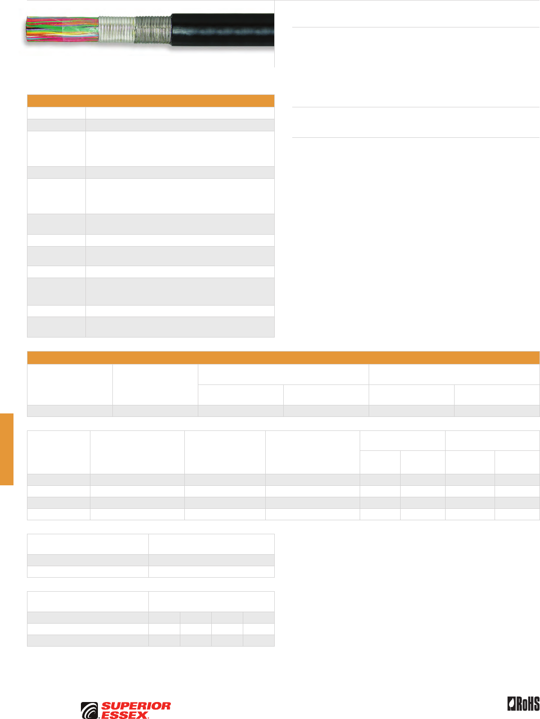
G-16
PREMISES COPPER PREMISES FIBER OSP FIBER OSP COMPOSITE CENTRAL OFFICE COPPER RDUP/RUS OSP COPPER BELL OSP COPPER OSP COPPER WIRE CANADIAN OSP COPPER TECHNICAL INFO
Rev 10/10 Ed 10.3Toll Free 800.551.8948 | Fax 770.657.6807 | SuperiorEssex.com/Comm
Specifications
Conductor Solid annealed copper
AWG (mm) Available in 19 (0.90), 22 (0.64), 24 (0.51) and 26 (0.40)
Insulation
Conductors are dual insulated with an inner layer of foamed,
natural polyolefin covered by an outer layer of solid, colored
polyolefin; conductor insulation is color coded in accordance
with industry standard
25-Pair Core Pairs are combined into a cylindrical core
≥ 50-Pair Core
Multiples of 25-pair groups are assembled to form the final
cable core; each group is identified by color coded
non-hygroscopic binders; for 1,200-pair and larger,
the color code is a Mirror Image design
Filling
Compound
Core assembly is completely filled with an 80°C ETPR compound,
filling the air space between the insulated conductors
Core Wrap Dielectric tape applied over the core
Shields Corrugated bare 8 mil aluminum tape covered by a corrugated
bare 6 mil steel tape applied longitudinally over the core wrap
Jacket Black, polyethylene
Jacket
Marking
Manufacturer’s identification, pair count, AWG, product
identification, sequential footage and a telephone handset
printed at 2 foot intervals
Package 420 steel reel (F x T x D = 83 x 40 x 42 inches)
Standards
Compliance
Telcordia GR-421-CORE Issue 2
RoHS-compliant
Electrical Specifications
Number of Pairs
Average Mutual
Capacitance @ 1000 Hz
nF/mile (nF/km)
Capacitance Unbalance
Pair to Pair @ 1 kHz
Capacitance Unbalance
Pair to Ground @ 1 kHz
Maximum Individual
pF @ 1 kft (pF @ 1 km)
Maximum RMS
pF @ 1 kft (pF @ 1 km)
Maximum Individual
pF @ 1 kft (pF @ 1 km)
Maximum Average
pF @ 1 kft (pF @ 1 km)
Over 12 83 ± 4 (52 ± 2) 80 (145) 25 (45) 800 (2,625) 175 (574)
Conductor Size
AWG (mm)
Minimum Insulation
Resistance @ 68°F (20°C)
gigohm-mile (gigohm-km)
Maximum Average
Attenuation
772 kHz @ 68°F (20°C)
dB/kft (dB/km)
Maximum Conductor
Resistance @ 68°F (20°C)
Ohms/sheath
mile (km)
DC Resistance
Unbalance Maximum %
Dielectric Strength
DC Potential – Volts
Average
Individual
Pair
Conductor
to Conductor
Conductor
to Shield
19 (0.90) 1.0 (1.6) 3.2 (10.5) 45 (28.0) 1.5 5.0 4,500 10,000
22 (0.64) 1.0 (1.6) 4.5 (14.8) 91 (56.5) 1.5 5.0 3,600 10,000
24 (0.51) 1.0 (1.6) 5.6 (18.4) 144 (89.5) 1.5 5.0 3,000 10,000
26 (0.40) 1.0 (1.6) 7.0 (23.0) 232 (144.2) 1.5 5.0 2,400 10,000
Minimum Near End Crosstalk
(NEXT) @ 772 kHz
PSWUNEXT Mean (dB) 47
PSWUNEXT Worst Pair (dB) 42
Minimum Far End Crosstalk
(FEXT) @ 772 kHz
Conductor Size (AWG) 19 22 24 26
PSELFEXT Mean (dB/kft) 51 49 49 47
PSELFEXT Worst Pair (dB/kft) 45 43 43 43
Product Description
FILLED ASP Cable with foam skin insulation is a single jacket, armored,
filled design intended for direct burial applications in high risk areas. An
ETPR compound completely coats each insulated conductor and fills the
air space between conductors. The shielding, armoring and jacketing
combined with the filling and flooding compounds throughout the cable,
provide exceptional durability and resistance to moisture.
Applications
• Direct burial
Features Benefits
• Tightly controlled individual
conductor dimensions
• Limits resistance unbalance
of paired conductors
• Specially designed
pair twist lays
• Minimizes crosstalk and meets
the capacitance unbalance
requirements
• Inner and outer surfaces of
both aluminum tape and steel
tape are flooded
• Provides a barrier to moisture
and inhibits corrosion
• Core wrap • Protects core and provides
improved mechanical and
electrical characteristics
• Polyethylene jacket • Provides a tough, flexible,
protective covering that
withstands exposure to sunlight,
atmospheric temperatures,
ground chemicals and stresses
expected in standard installation
Filled ASP
ANBW, ANAW, ANMW and ANTW

G-17
PREMISES COPPERPREMISES FIBEROSP FIBEROSP COMPOSITECENTRAL OFFICE COPPERRDUP/RUS OSP COPPERBELL OSP COPPEROSP COPPER WIRECANADIAN OSP COPPERTECHNICAL INFO
Rev 10/10 Ed 10.3 Toll Free 800.551.8948 | Fax 770.657.6807 | SuperiorEssex.com/Comm
Part Numbers and Physical Characteristics
Part Number Pair Count AWG (mm)
Nomnal Diameter
in (mm)
Approx. Weight
lbs/kft (kg/km)
Standard Length
ft (m)
Approx.
Shipping Weight
lbs (kg)
ANBW
22-031-83 25 19 (0.90) 0.81 (21) 410 (610) 10,000 (3,048) 4,895 (2,220)
22-034-83 50 19 (0.90) 1.07 (27) 735 (1,095) 5,000 (1,524) 4,470 (2,030)
22-038-83 100 19 (0.90) 1.41 (36) 1,340 (1,995) 5,000 (1,524) 7,495 (3,400)
22-042-83 200 19 (0.90) 1.96 (50) 2,570 (3,825) 2,000 (610) 5,935 (2,690)
22-044-83 300 19 (0.90) 2.35 (60) 3,740 (5,565) 1,650 (503) 6,965 (3,160)
ANAW
22-062-83 25 22 (0.64) 0.63 (16) 240 (355) 18,000 (5,486) 5,115 (2,320)
22-065-83 50 22 (0.64) 0.80 (20) 405 (605) 15,000 (4,572) 6,870 (3,115)
22-069-83 100 22 (0.64) 1.05 (27) 730 (1,085) 7,500 (2,286) 6,270 (2,845)
22-073-83 200 22 (0.64) 1.42 (36) 1,340 (1,995) 5,000 (1,524) 7,495 (3,400)
22-075-83 300 22 (0.64) 1.69 (43) 1,940 (2,885) 3,300 (1,006) 7,195 (3,265)
22-077-83 400 22 (0.64) 1.92 (49) 2,530 (3,765) 2,500 (762) 7,120 (3,230)
22-081-83 600 22 (0.64) 2.32 (59) 3,705 (5,515) 1,650 (503) 6,910 (3,135)
22-083-83 900 22 (0.64) 2.81 (71) 5,445 (8,105) 1,100 (335) 6,785 (3,075)
22-085-83 1,200 22 (0.64) 3.20 (81) 7,160 (10,655) 834 (254) 6,765 (3,070)
ANMW
22-097-83 25 24 (0.51) 0.55 (14) 175 (260) 20,000 (6,096) 4,295 (1,950)
22-100-83 50 24 (0.51) 0.69 (18) 290 (430) 20,000 (6,096) 6,595 (2,990)
22-104-83 100 24 (0.51) 0.88 (22) 500 (745) 13,300 (4,054) 7,445 (3,375)
22-108-83 200 24 (0.51) 1.18 (30) 900 (1,340) 6,600 (2,012) 6,735 (3,055)
22-110-83 300 24 (0.51) 1.41 (36) 1,295 (1,925) 5,000 (1,524) 7,270 (3,300)
22-112-83 400 24 (0.51) 1.59 (40) 1,680 (2,500) 4,000 (1,219) 7,515 (3,410)
22-116-83 600 24 (0.51) 1.92 (49) 2,445 (3,640) 2,500 (762) 6,910 (3,135)
22-118-83 900 24 (0.51) 2.29 (58) 3,545 (5,275) 2,000 (610) 7,885 (3,575)
22-120-83 1,200 24 (0.51) 2.63 (67) 4,670 (6,950) 1,250 (381) 6,635 (3,010)
22-121-83 1,500 24 (0.51) 2.92 (74) 5,775 (8,595) 1,000 (305) 6,570 (2,980)
22-124-83 1,800 24 (0.51) 3.18 (81) 6,880 (10,240) 950 (290) 7,330 (3,325)
22-125-83 2,100 24 (0.51) 3.45 (88) 8,045 (11,975) 940 (287) 8,960 (4,065)
ANTW
22-132-83 25 26 (0.40) 0.47 (12) 130 (195) 20,000 (6,096) 3,395 (1,540)
22-135-83 50 26 (0.40) 0.58 (15) 205 (305) 20,000 (6,096) 4,895 (2,220)
22-139-83 100 26 (0.40) 0.74 (19) 340 (505) 15,000 (4,572) 5,895 (2,675)
22-143-83 200 26 (0.40) 0.98 (25) 610 (910) 10,000 (3,048) 6,895 (3,130)
22-145-83 300 26 (0.40) 1.13 (29) 840 (1,250) 6,000 (1,829) 5,835 (2,645)
22-147-83 400 26 (0.40) 1.29 (33) 1,100 (1,635) 6,000 (1,829) 7,395 (3,355)
22-151-83 600 26 (0.40) 1.53 (39) 1,580 (2,350) 4,000 (1,219) 7,115 (3,225)
22-153-83 900 26 (0.40) 1.83 (47) 2,275 (3,385) 2,500 (762) 6,485 (2,940)
22-155-83 1,200 26 (0.40) 2.07 (53) 2,965 (4,415) 2,000 (610) 6,725 (3,050)
22-156-83 1,500 26 (0.40) 2.33 (59) 3,695 (5,500) 1,600 (488) 6,705 (3,040)
22-157-83 1,800 26 (0.40) 2.54 (65) 4,400 (6,550) 1,250 (381) 6,295 (2,855)
22-158-83 2,100 26 (0.40) 2.74 (70) 5,120 (7,620) 1,200 (366) 6,940 (3,150)
22-159-83 2,400 26 (0.40) 2.91 (74) 5,805 (8,640) 1,000 (305) 6,600 (2,995)
22-161-83 2,700 26 (0.40) 3.08 (78) 6,485 (9,650) 740 (226) 5,595 (2,535)
22-162-83 3,000 26 (0.40) 3.24 (82) 7,185 (10,695) 750 (229) 6,185 (2,805)
Filled ASP ANBW, ANAW, ANMW and ANTW
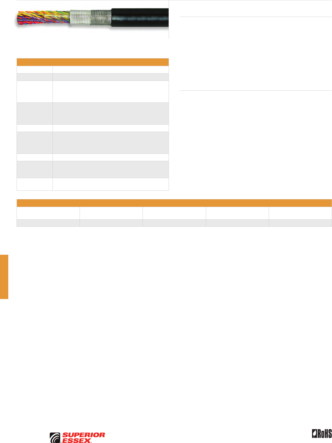
G-18
PREMISES COPPER PREMISES FIBER OSP FIBER OSP COMPOSITE CENTRAL OFFICE COPPER RDUP/RUS OSP COPPER BELL OSP COPPER OSP COPPER WIRE CANADIAN OSP COPPER TECHNICAL INFO
Toll Free 800.551.8948 | Fax 770.657.6807 | SuperiorEssex.com/Comm Rev 6/10 Ed 10.1
Specifications
Conductor Solid annealed copper
AWG (mm) 24 (0.51)
Insulation
Conductors are dual insulated with an inner layer of foamed,
natural polyolefin covered by an outer layer of solid, colored
polyolefin. The conductor insulation is color coded in
accordance with industry OSP standards.
Core Assembly
Groups of 25-pair are identified by appropriate binder strings
consistent with OSP standards. The entire core assembly is
completely filled with an 80°C ETPR compound, filling the air
spaces between the insulated conductors.
Core Wrap Non-hydroscopic
Shield
A corrugated bare 8-mil aluminum shield covered by a corrugated
bare 6-mil steel shield is applied longitudinally over the core
wrap. The inner and outer surfaces of the aluminum and steel
shields are flooded with an adhesive compound.
Jacket Black polyethylene
Jacket
Marking
Manufacturer’s identification, pair count, AWG, product
identification, sequential footage and a telephone handset
printed at 2 foot intervals
Standards
Compliance
GR-421-CORE, Issue 2 (selected physical sections)
RoHS-compliant
Part Numbers and Physical Characteristics
Part Number Pair Count
Nominal Diameter
in (mm)
Approx. Weight
lbs/kft (kg/km) Package
07-024-74 200 1.32 (33.5) 99 (148) Cut to Length
Tight Twist 200-Pair
ANMW
Product Description
The Tight Twist (TT) 200-pair ANMW is an Outside Plant (OSP) copper cable
designed with tightly twisted pairs to enhance the performance of xDSL
technologies such as ADSL2+, VDSL2 and IPTV. Deployed on the launch
circuits between the Remote Terminal (RT) cabinet and the (SAC) cross
connect cabinet, this cable significantly improves broadband services at
the customer premises. The xDSL and IPTV equipment within the RT are
organized in bays of 192-pair groupings. One 200-pair cable will facilitate
one bay and will be utilized for the 192 outgoing pairs. Large RT cabinets
can have multiple bays with each requiring a 200-pair cable. The TT 200-Pair
ANMW cable design is modeled after the traditional ANMW series.
Features Benefits
• Enhanced pair twist patterns • Improves NEXT Mean
performance by 10 dB
over GR-421-CORE
• Offers greater capabilities
for higher technologies
• Core wrap • Protects core and provides
improved mechanical and
electrical characteristics
• Flooded shield surfaces • Provides a moisture barrier
and inhibits corrosion
• Polyethylene jacket • Provides a tough, flexible,
protective covering that
withstands exposure to sunlight,
atmospheric temperatures,
ground chemicals and stresses
expected in standard installations
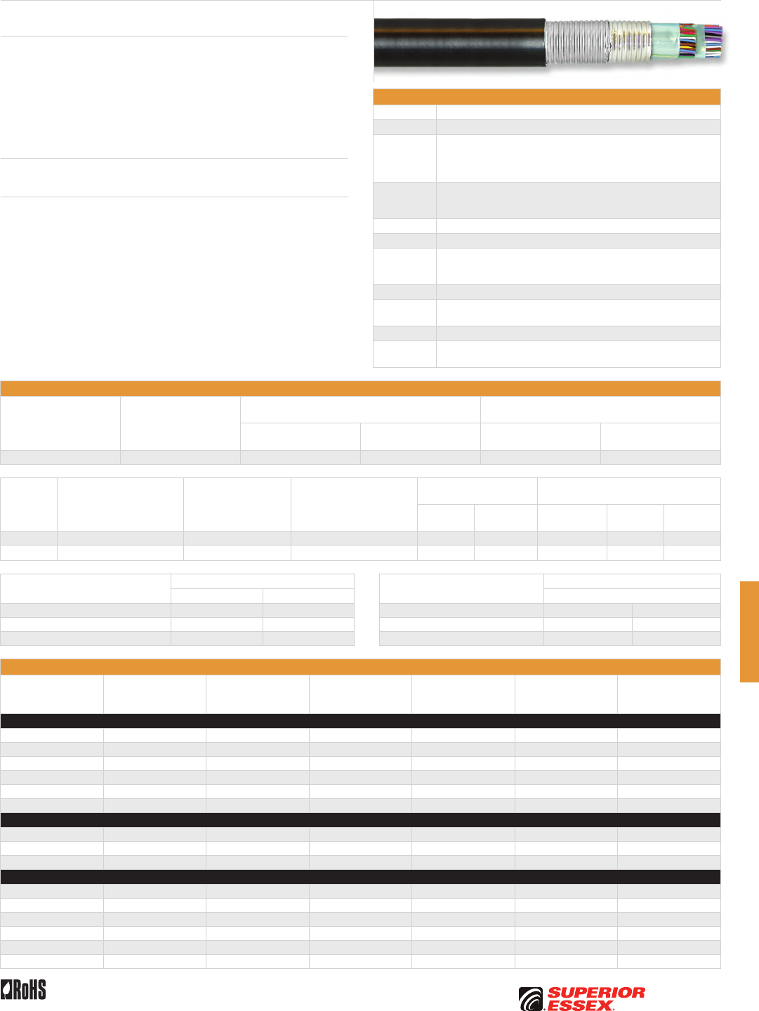
G-19
PREMISES COPPERPREMISES FIBEROSP FIBEROSP COMPOSITECENTRAL OFFICE COPPERRDUP/RUS OSP COPPERBELL OSP COPPEROSP COPPER WIRECANADIAN OSP COPPERTECHNICAL INFO
Rev 10/10 Ed 10.3 Toll Free 800.551.8948 | Fax 770.657.6807 | SuperiorEssex.com/Comm
Specifications
Conductor Solid annealed copper
AWG (mm) Available in 22 (0.64) and 24 (0.51)
Insulation
Conductors are dual insulated with an inner layer of foamed,
natural polyolefin covered by an outer coating of solid, colored
polyolefin; conductor insulation is color coded in accordance
with industry standard
Core
Assembly
Twisted pairs assembled and equally placed on either side
of the T-SCREEN®, dividing the core into two electrically
isolated compartments
Core Wrap Dielectric tape applied over the core
Screen Coated 4-mil aluminum tape to separate the cable into two halves
Shields
Corrugated bare 8-mil aluminum tape covered by a corrugated bare
6 mil steel tape applied longitudinally over the core wrap; inner
and outer surfaces of the aluminum shield and steel tape are flooded
Jacket Black polyethylene
Jacket
Marking
Manufacturer’s ID, pair count, AWG, product ID, sequential footage
and a telephone handset printed at 2-foot intervals
Package 420 steel reel (F x T x D = 83 x 40 x 42 inches)
Standards
Compliance
Telcordia GR-421-CORE Issue 2
RoHS-compliant
Electrical Specifications
Number of Pairs
Average Mutual
Capacitance @ 1000 Hz
nF/mile (nF/km)
Capacitance Unbalance
Pair to Pair @ 1 kHz
Capacitance Unbalance
Pair to Ground @ 1 kHz
Maximum Individual
pF @ 1 kft (pF @ 1 km)
Maximum RMS
pF @ 1 kft (pF @ 1 km)
Maximum Individual
pF @ 1 kft (pF @ 1 km)
Maximum Average
pF @ 1 kft (pF @ 1 km)
All pairs 83 ± 4 (52 ± 2) 80 (145) 25 (45) 800 (2,625) 175 (574)
Conductor
Size
AWG (mm)
Minimum Insulation
Resistance @ 68°F (20°C)
gigohm-mile
(gigohm-km)
Maximum Average
Attenuation
772 kHz @ 68°F (20°C)
dB/kft (dB/km)
Maximum Conductor
Resistance @ 68°F (20°C)
Ohms/sheath
mile (km)
DC Resistance
Unbalance Maximum %
Dielectric Strength
DC Potential – Volts
Average
Individual
Pair
Conductor to
Conductor
Conductor
to Shield
Conductor
to Screen
22 (0.64) 1.0 (1.6) 4.5 (14.8) 91 (56.5) 1.5 5.0 3,600 10,000 5,000
24 (0.51) 1.0 (1.6) 5.6 (18.4) 144 (89.5) 1.5 5.0 3,000 10,000 5,000
Minimum Near End Crosstalk (NEXT) Minimum Far End Crosstalk (FEXT)
@ 772 kHz @ 1600 kHz @ 772 kHz
PSWUNEXT Mean (dB) 47 - Conductor Size (AWG) 22 24
PSWUNEXT Worst Pair (dB) 42 - PSELFEXT Mean (dB/kft) 49 49
P.S.NEXT Between Compartments (dB) - 78 PSELFEXT Worst Pair (dB/kft) 43 43
Part Numbers and Physical Characteristics
Part Number Pair Count AWG (mm)
Nominal Diameter
in (mm)
Approx. Weight
lbs/kft (kg/km)
Standard Length
ft (m)
Approx.
Shipping Weight
lbs (kg)
KNAW
24-417-83 28 22 (0.64) 0.69 (18) 280 (415) 10,000 (3,048) 3,595 (1,630)
24-440-83 54 22 (0.64) 0.95 (24) 510 (760) 10,000 (3,048) 5,895 (2,675)
24-456-83 106 22 (0.64) 1.10 (28) 785 (1,170) 7,500 (2,286) 6,685 (3,030)
24-472-83 158 22 (0.64) 1.29 (33) 1,105 (1,645) 5,000 (1,524) 6,320 (2,865)
24-493-83 210 22 (0.64) 1.46 (37) 1,420 (2,115) 4,280 (1,305) 6,875 (3,115)
24-586-83 616 22 (0.64) 2.40 (61) 3,875 (5,765) 1,650 (503) 7,190 (3,260)
KNMW
24-618-83 28 24 (0.51) 0.63 (16) 220 (325) 10,000 (3,048) 2,995 (1,360)
24-642-83 54 24 (0.51) 0.79 (20) 350 (520) 10,000 (3,048) 4,295 (1,950)
24-657-83 106 24 (0.51) 0.92 (23) 540 (805) 5,000 (1,524) 3,495 (1,585)
KHAH* (T-SCREEN® Air Core Design)
24-440-05 54 22 (0.64) 0.98 (25) 475 (705) 7,500 (2,286) 4,360 (1,975)
24-456-05 106 22 (0.64) 1.20 (31) 780 (1,160) 5,000 (1,524) 4,695 (2,130)
24-472-05 158 22 (0.64) 1.44 (37) 1,095 (1,630) 4,250 (1,295) 5,450 (2,470)
24-493-05 210 22 (0.64) 1.60 (41) 1,395 (2,075) 3,300 (1,006) 5,400 (2,450)
24-564-05 418 22 (0.64) 2.12 (54) 2,550 (3,795) 2,000 (610) 5,895 (2,675)
24-586-05 616 22 (0.64) 2.54 (65) 3,660 (5,445) 1,250 (381) 5,370 (2,435)
Product Description
T-SCREEN® Filled ASP Cable with foam skin insulation is a single jacket, armored,
filled design intended for direct burial applications in high risk areas. An ETPR
compound completely coats each insulated conductor and fills the air space
between conductors. An internal separator screen is included that provides
two core compartments for use in T1C PCM applications. The shielding, armor
and jacketing combined with the filling and flooding compounds throughout the
cable, provides exceptional durability and resistance to moisture.
Applications
• Bi-directional, T Carrier digital systems in direct buried installations
Features Benefits
• Core wrap • Protects core and provides
improved mechanical and
electrical characteristics
• Internal screen • Separates bi-directional conductors
to transmit and receive T1 pairs
• Inner and outer surfaces of both
tape shields are flooded with an
adhesive compound
• Provides a moisture barrier
and inhibits corrosion
• Polyethylene jacket • Provides a tough, flexible,
protective covering that withstands
exposure to sunlight, atmospheric
temperatures, ground chemicals and
stresses of standard installations
T-SCREEN® Filled ASP
KNAW and KNMW


H-1
PREMISES COPPERPREMISES FIBEROSP FIBEROSP COMPOSITECENTRAL OFFICE COPPERRDUP/RUS OSP COPPERBELL OSP COPPEROSP COPPER WIRECANADIAN OSP COPPERTECHNICAL INFO
Toll Free 800.551.8948 | Fax 770.657.6807 | SuperiorEssex.com/Comm
OSP COPPER WIRE
Table of Contents
C-Rural Wire .............................................. H-2
IMRDW................................................... H-3
IMRDWS.................................................. H-4
ADP NMS................................................. H-5
ADP NMS (6x24) Compact Design. . . . . . . . . . . . . . . . . . . . . . . . . . . . H-6
ADP S .................................................... H-7
Integrated Messenger Wire IM/F, IM/H and IM/G ................ H-8
BDW A ................................................... H-9
BDW G .................................................. H-10
BW CF................................................... H-11
BW GDJ ................................................. H-12
BW NS Buried Wire Non-Shielded . . . . . . . . . . . . . . . . . . . . . . . . . . H-13
Non-Jacketed Tight Twist Cable Core . . . . . . . . . . . . . . . . . . . . . . . H-14
Air Pipe.................................................. H-14
Bridle Wire............................................... H-15
Temporary Drop Wire TDW ................................. H-15
E-Block Wire ............................................. H-16
Ground Wire Bare or Jacketed ............................... H-16
Cross-Connect Category 5 Wire XCW ........................ H-17
Indoor/Outdoor Cross-Connect Wire XCW .................... H-18
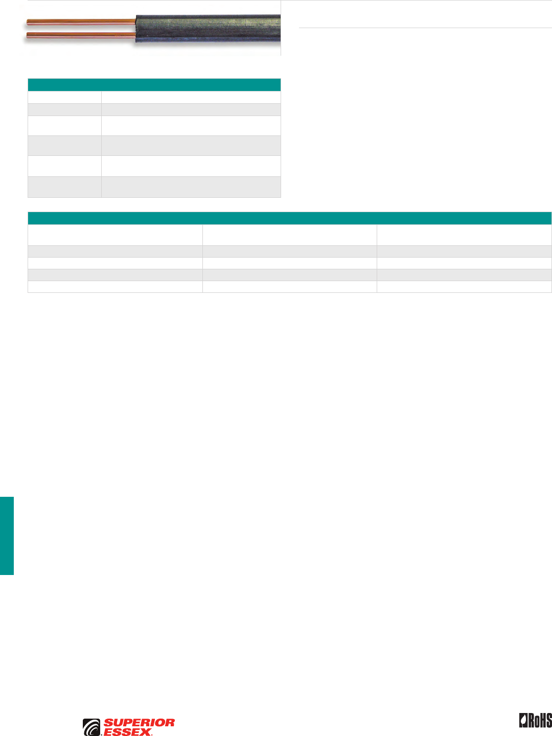
H-2
PREMISES COPPER PREMISES FIBER OSP FIBER OSP COMPOSITE CENTRAL OFFICE COPPER RDUP/RUS OSP COPPER BELL OSP COPPER OSP COPPER WIRE CANADIAN OSP COPPER TECHNICAL INFO
Rev 6/10 Ed 10.1Toll Free 800.551.8948 | Fax 770.657.6807 | SuperiorEssex.com/Comm
C-Rural Wire
Product Description
C-Rural Wire is quickly and easily installed, utilizing standard hardware and
installation procedures for single circuit aerial distribution rural networks.
Specifications
Conductor Solid 30% conductivity copper-covered steel
AWG (mm) 14 (1.63)
Insulation Black polyolefin compound extruded over the two conductors
in parallel to form an integrated oval configuration
Dimensions in (mm) Minor: 0.15 (3.8)
Major: 0.28 (7.1)
Approx. Weight
lbs/kft (kg/km) 36 (54)
Standards
Compliance
Telcordia TA-TSY-000125
RoHS-compliant
Part Numbers and Physical Characteristics
Part Number
Standard Length
ft (m) Package
10-026-06 1,000 (305) Coil
10-016-06 5,500 (1676) Wooden Reel
10-116-06 22,000 (6,705) Four 5,500’ Reels on a Pallet
10-096-06 19,000 (5791) Steel Reel
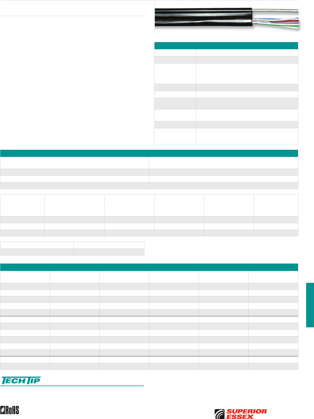
H-3
PREMISES COPPERPREMISES FIBEROSP FIBEROSP COMPOSITECENTRAL OFFICE COPPERRDUP/RUS OSP COPPERBELL OSP COPPEROSP COPPER WIRECANADIAN OSP COPPERTECHNICAL INFO
Toll Free 800.551.8948 | Fax 770.657.6807 | SuperiorEssex.com/CommRev 10/10 Ed 10.3
Specifications
Conductor Solid bare copper
Insulation Polyolefin
Core Assembly
Twisted into pairs to minimize resistance unbalance; in
multi-pair constructions, pair twist lays vary to minimize
crosstalk and meet capacitance unbalance requirements;
twisted pairs are formed into firm, round core
Core Wrap Non-hygroscopic, dielectric wrap
Jacket Black polyethylene
Support Wire Single 0.109 inch solid, extra-high strength steel, jacketed in
an integral extrusion with the core
Standard Length
ft (m) 5,000 (1,524)
Package Reel
Standards
Compliance
RDUP PE-27 and PE-28 deactivated by RDUP
ICEA S-89-648 as applicable
RoHS-compliant
Electrical Specifications
Number of Pairs
Average Mutual Capacitance @ 1000 Hz
nF/mile (nF/km)
Maximum Individual 94 (58)
12 or less 83 ± 7 (52 ± 4)
Over 12 83 ± 4 (52 ± 2)
Conductor Size
AWG (mm)
Minimum Insulation
Resistance
@ 68°F (20°C)
megohm-mile (megohm-km)
Maximum Average
Attenuation
772 kHz @ 68°F (20°C)
dB/kft (dB/km)
Maximum Conductor
Resistance
@ 68°F (20°C)
Ohms/mile (Ohms/km)
DC Resistance
Unbalance Maximum %
Individual Pair
Dielectric Strength
Minimum Volts DC
19 (0.90) 1,000 (1,600) 3.6 (11.8) 45 (28.0) 5.0 7,200
22 (0.64) 1,000 (1,600) 5.1 (16.7) 91 (56.4) 5.0 7,200
24 (0.51) 1,000 (1,600) 6.5 (21.3) 144 (89.5) 5.0 7,200
Capacitance Unbalance @ 1000 Hz pF @ 1 kft (pF @ 1 km)
Maximum Pair to Pair 80 (145)
Part Numbers and Physical Characteristics
Part Number Pair Count AWG (mm)
Minor Dimension
in (mm)
Major Dimension
in (mm)
Approx. Weight
lbs/kft (kg/km)
10-001-15 1 19 (0.90) 0.20 (5.1) 0.48 (12.2) 60 (90)
10-002-15 2 19 (0.90) 0.25 (6.4) 0.53 (13.5) 70 (105)
10-003-15 3 19 (0.90) 0.30 (7.6) 0.59 (15.0) 85 (125)
10-006-15 6 19 (0.90) 0.39 (9.9) 0.68 (17.2) 120 (180)
10-012-15 12 19 (0.90) 0.48 (12.2) 0.77 (19.5) 180 (270)
10-002-17 2 22 (0.64) 0.20 (5.1) 0.48 (12.2) 60 (90)
10-003-17 3 22 (0.64) 0.23 (5.8) 0.51 (12.9) 65 (95)
10-004-17 4 22 (0.64) 0.24 (6.0) 0.52 (13.2) 70 (104)
10-006-17 6 22 (0.64) 0.29 (7.5) 0.58 (14.8) 85 (125)
10-012-17 12 22 (0.64) 0.36 (9.2) 0.65 (16.5) 115 (170)
10-018-17 18 22 (0.64) 0.43 (11.0) 0.72 (18.3) 150 (225)
10-006-19 6 24 (0.51) 0.25 (6.4) 0.54 (13.7) 70 (105)
10-012-19 12 24 (0.51) 0.32 (8.2) 0.61 (15.4) 95 (140)
Sag and Tension guidelines for these products are available online:
www.SuperiorEssex.com/techtip.aspx
Product Description
Multi-pair, self-supporting IMRDW Wire is used for subscriber lines in
exchange plant; single-pair is often used for lateral runs from aerial plant.
In both single and multi-pair types, the wire core is laid parallel to a solid
steel support wire and jacketed in an integral extrusion to form a “figure-8”
configuration utilizing a 0.109 inch solid, extra-high strength steel support
member. The IM construction permits fast, economical installation and
facilitates removal and re-use of wire.
IMRDW
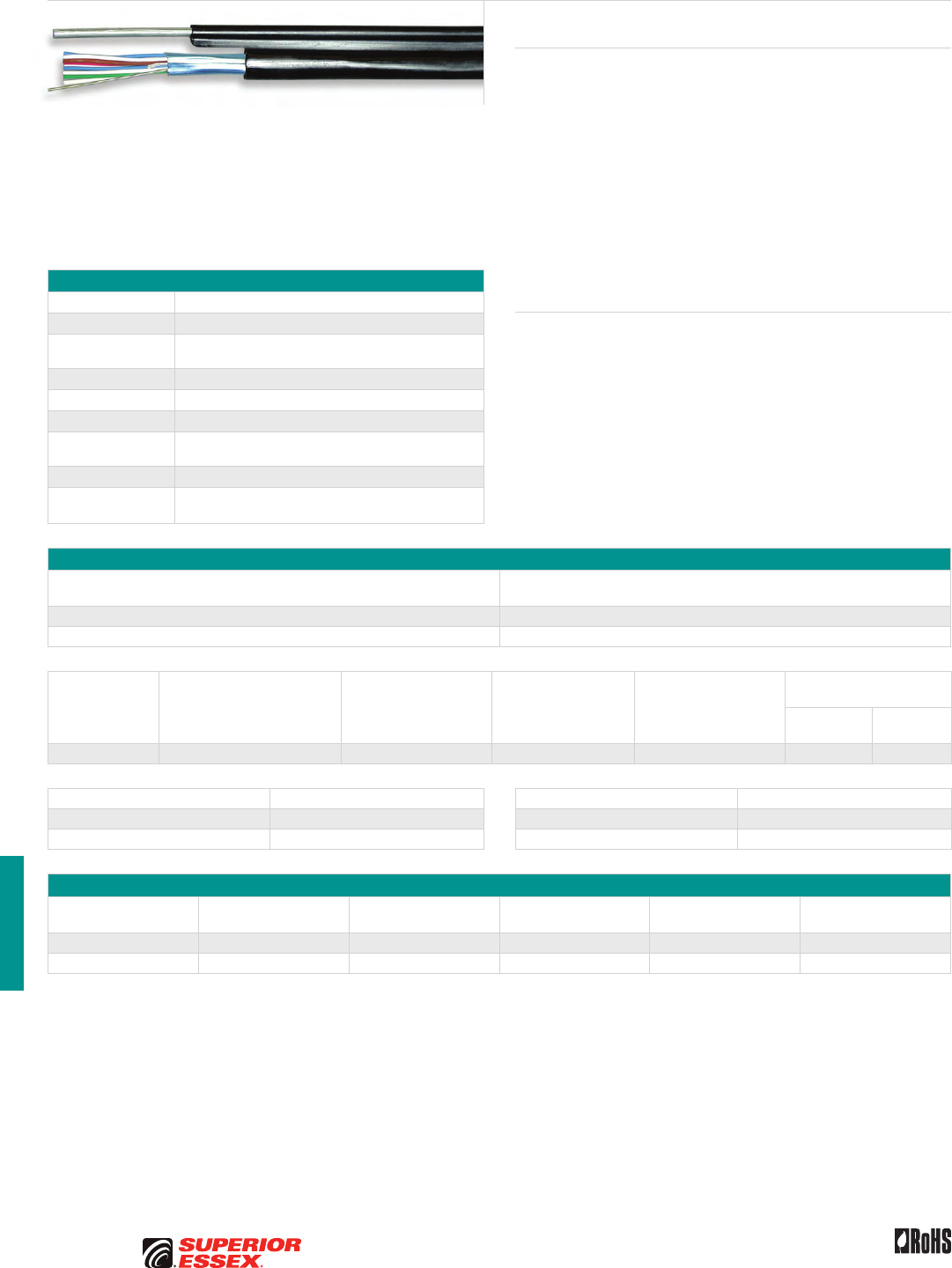
H-4
PREMISES COPPER PREMISES FIBER OSP FIBER OSP COMPOSITE CENTRAL OFFICE COPPER RDUP/RUS OSP COPPER BELL OSP COPPER OSP COPPER WIRE CANADIAN OSP COPPER TECHNICAL INFO
Toll Free 800.551.8948 | Fax 770.657.6807 | SuperiorEssex.com/Comm Rev 10/10 Ed 10.3
IMRDWS
Product Description
IMRDWS is an aerial wire designed for use in extending communications
service (voice, data, and/or video) to a subscriber premises from the
distribution point. This product has additional capabilities over the
standard IMRDW product because it contains a shielding screen. The
conductors are wrapped within a metallic aluminum shield to insulate them
from interference and thus provide high quality digital transmission. In
addition, a drain wire runs longitudinally the length of the wire to drain off
Electromagnetic Interference (EMI) and Radio Frequency Interference (RFI).
Without shielding and a drain wire, noise can be introduced into circuits
from high voltage AC power lines, machinery with motors, x-ray systems,
TV sets and AM radio stations. Shielding also lessens the chance that DSL
or other high frequency transmission protocols will interfere with other
signals on adjacent cables.
Features Benefits
• 3 mil foil shield with drain wire • Provides high quality digital
transmission medium for xDSL
technologies and, when properly
grounded, removes spectrum
interferences
• Black, polyethylene jacket • Provides tough, flexible
protective covering that
withstands exposure to sunlight,
atmospheric temperatures
and stresses encountered
in standard installations
• Rip cord • Facilitates jacket removal
Specifications
Conductor Solid bare copper
Insulation Polyolefin
Core Assembly Individual conductors carefully twisted into pairs to
minimize resistance unbalance and cross-talk
Shield 3 mil foil shield with drain wire
Jacket Black polyethylene
Rip cord Placed parallel to the core
Support Wire “Figure 8” configuration utilizing a 0.109 inch, solid, extra
high strength, steel support wire
Package Reel
Standards
Compliance
ICEA S-89-648 as applicable
RoHS-compliant
Electrical Specifications
All Pairs
Average Mutual Capacitance @ 1000 Hz
nF/mile (nF/km)
Maximum Individual 94 (58)
Wire Average 83 ± 7 (52 ± 4)
Conductor Size
AWG (mm)
Minimum Insulation
Resistance @ 68°F (20°C)
megohm-mile (megohm-km)
Maximum Average
Attenuation
772 kHz @ 68°F (20°C)
dB/kft (dB/km)
Maximum Conductor
Resistance
@ 68°F (20°C)
Ohms/mile (Ohms/km)
DC Resistance
Unbalance Maximum %
Individual Pair
Dielectric Strength
Minimum Volts DC
Conductor
to Conductor
Conductor
to Shield
22 (0.64) 1,000 (1,600) 5.1 (16.7) 91 (56.4) 5.0 7,200 3,600
Crosstalk Loss dB/kft (dB/km) Capacitance Unbalance @ 1000 Hz pF @ 1 kft (pF @ 1 km)
Minimum FEXT @ 150 kHz 63 (207) Maximum Individual Pair to Pair 80 (145)
Minimum NEXT @ 722 kHz 44 (144) Maximum Individual Pair to Ground 800 (2,625)
Part Numbers and Physical Characteristics
Part Number Pair Count
Minor Dimension
in (mm)
Major Dimension
in (mm)
Approx. Weight
lbs/kft (kg/km)
Standard Length
ft (m)
10-061-29 6 0.32 (8.1) 0.60 (15.3) 95 (142) 2,133 (650)
10-040-29 6 0.32 (8.1) 0.60 (15.3) 95 (142) 5,000 (1,524)
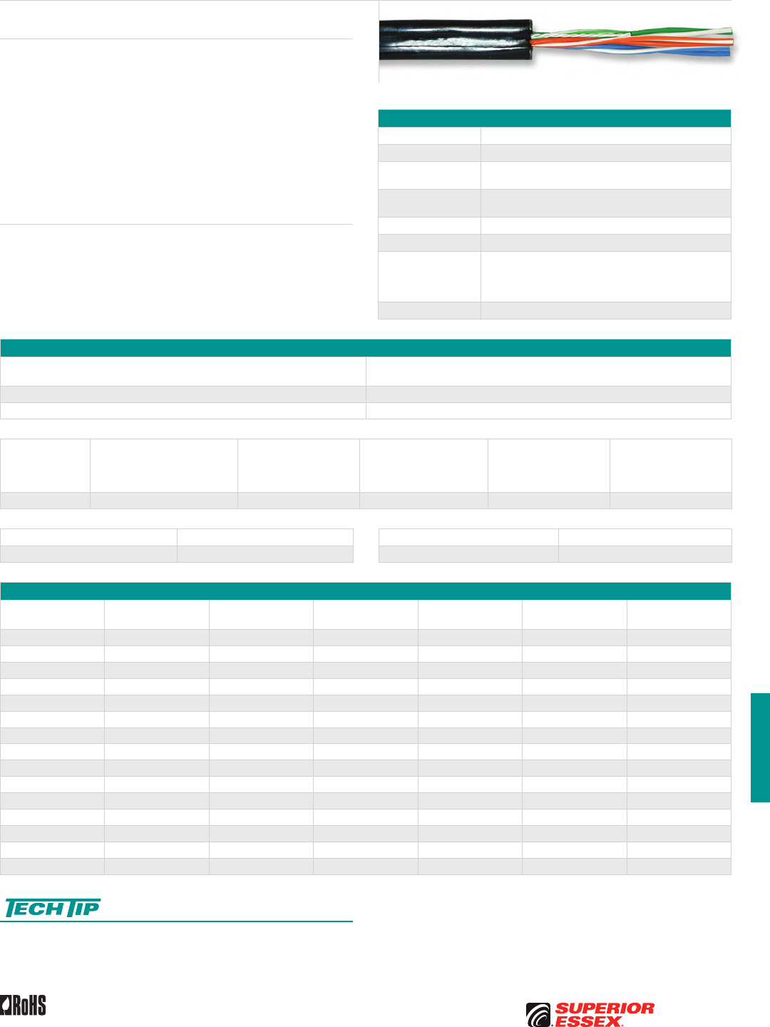
H-5
PREMISES COPPERPREMISES FIBEROSP FIBEROSP COMPOSITECENTRAL OFFICE COPPERRDUP/RUS OSP COPPERBELL OSP COPPEROSP COPPER WIRECANADIAN OSP COPPERTECHNICAL INFO
Toll Free 800.551.8948 | Fax 770.657.6807 | SuperiorEssex.com/CommRev 10/10 Ed 10.4
Specifications
Conductor Solid annealed copper
Insulation Polyolefin
Core Assembly Individual conductors are carefully twisted into pairs in a
manner designed to minimize resistance unbalance
Strength Members Non-metallic or fiberglass strength members placed in
jacket parallel to core assembly
Rip cord Placed parallel to the core
Jacket Weather-resistant PVC
Performance
Compliance
Telecordia GR-3163-CORE
RDUP PE 7
ANSI/ICEA S-89-648-2006
RoHS-compliant
NRTL Programs UL Listed
Electrical Specifications
Number of Pairs
Average Mutual Capacitance @ 1000 Hz
nF/mile (nF/km)
Maximum Pair 94 (58)
Maximum Average 90 (56)
Conductor Size
AWG (mm)
Minimum Insulation
Resistance @ 68°F (20°C)
megohm-mile (megohm-km)
Maximum Average
Attenuation
772 kHz @ 68°F (20°C)
dB/kft (dB/km)
Maximum Conductor
Resistance
@ 68°F (20°C)
Ohms/mile (Ohms/km)
DC Resistance
Unbalance Maximum %
Individual Pair
Conductor to Conductor
Dielectric Strength
Volts DC
3 secs, no breakdown
22 (0.64) 1,000 (1,600) 5.1 (17) 91 (56.5) 5.0 4,000
Crosstalk Loss dB/kft (dB/km) Capacitance Unbalance @ 1000 Hz pF @ 1 kft (pF @ 1 km)
Minimum NEXT @ 722 kHz 44 (144) Maximum Individual Pair 80 (145)
Part Numbers and Physical Characteristics
Part Number Pair Count
Minor Dimension
in (mm)
Major Dimension
in (mm)
Approx. Weight
lbs/kft (kg/km)
Standard Length
ft (m) Package
12-031-08 1 0.18 (4.8) 0.36 (9.1) 34 (51) 750 (229) POP™ Box
12-032-08 1 0.18 (4.8) 0.36 (9.1) 34 (51) 1,000 (305) Reel
12-004-08 2 0.18 (4.8) 0.36 (9.1) 39 (58) 750 (229) POP™ Box
12-010-08 2 0.18 (4.8) 0.36 (9.1) 39 (58) 1,000 (305) Coil
12-023-08 2 0.18 (4.8) 0.36 (9.1) 39 (58) 5,000 (1,524) Reel
12-019-08 3 0.21 (5.3) 0.39 (9.9) 45 (67) 600 (183) POP™ Box
12-022-08 3 0.21 (5.3) 0.39 (9.9) 45 (67) 750 (229) Coil
12-519-08 5 0.27 (7.0) 0.48 (12.0) 76 (113) 400 (122) POP™ Box
12-024-08 5 0.27 (7.0) 0.48 (12.0) 76 (113) 2,500 (762) Reel
12-025-08 5 0.27 (7.0) 0.48 (12.0) 76 (113) 1,000 (305) Reel
12-026-08 5 0.27 (7.0) 0.48 (12.0) 76 (113) 700 (213) IPL Coil
12-006-08 6 0.27 (7.0) 0.48 (12.0) 70 (104) 400 (122) Coil
12-007-08 6 0.27 (7.0) 0.48 (12.0) 70 (104) 2,500 (762) Reel
12-008-08 6 0.27 (7.0) 0.48 (12.0) 70 (104) 3,500 (1,068) Reel
12-009-08 6 0.27 (7.0) 0.48 (12.0) 70 (104) 1,000 (305) Reel
Sag and Tension guidelines for these products are available online:
www.SuperiorEssex.com/techtip.aspx
Product Description
ADP NMS is a PVC-jacketed Aerial Service Wire offered in 1, 2, 3, 5 or
6-pair. It is designed for use in extending telephone service to subscriber
premises from the distribution cable or cable terminal. Major features
include small size and light weight coupled with abrasion resistant jacket.
Standard hardware and installation procedures are directly applicable to
this product. The insulation of the tip conductor is marked with a stripe of the
mating ring insulation color to reduce the possibility of splitting pairs during
installation. A black, weather resistant, polyvinylchloride jacket is extruded
over the strength members and rip cord to protect the core from mechanical
damage, degradation by sunlight and ingress of moisture. The jacket bonds
to the strength members to provide the required strength characteristics.
Features Benefits
• Non-metallic or fiberglass
strength members
• Provide necessary
longitudinal strength
• Rip cord • Facilitates jacket removal
ADP NMS
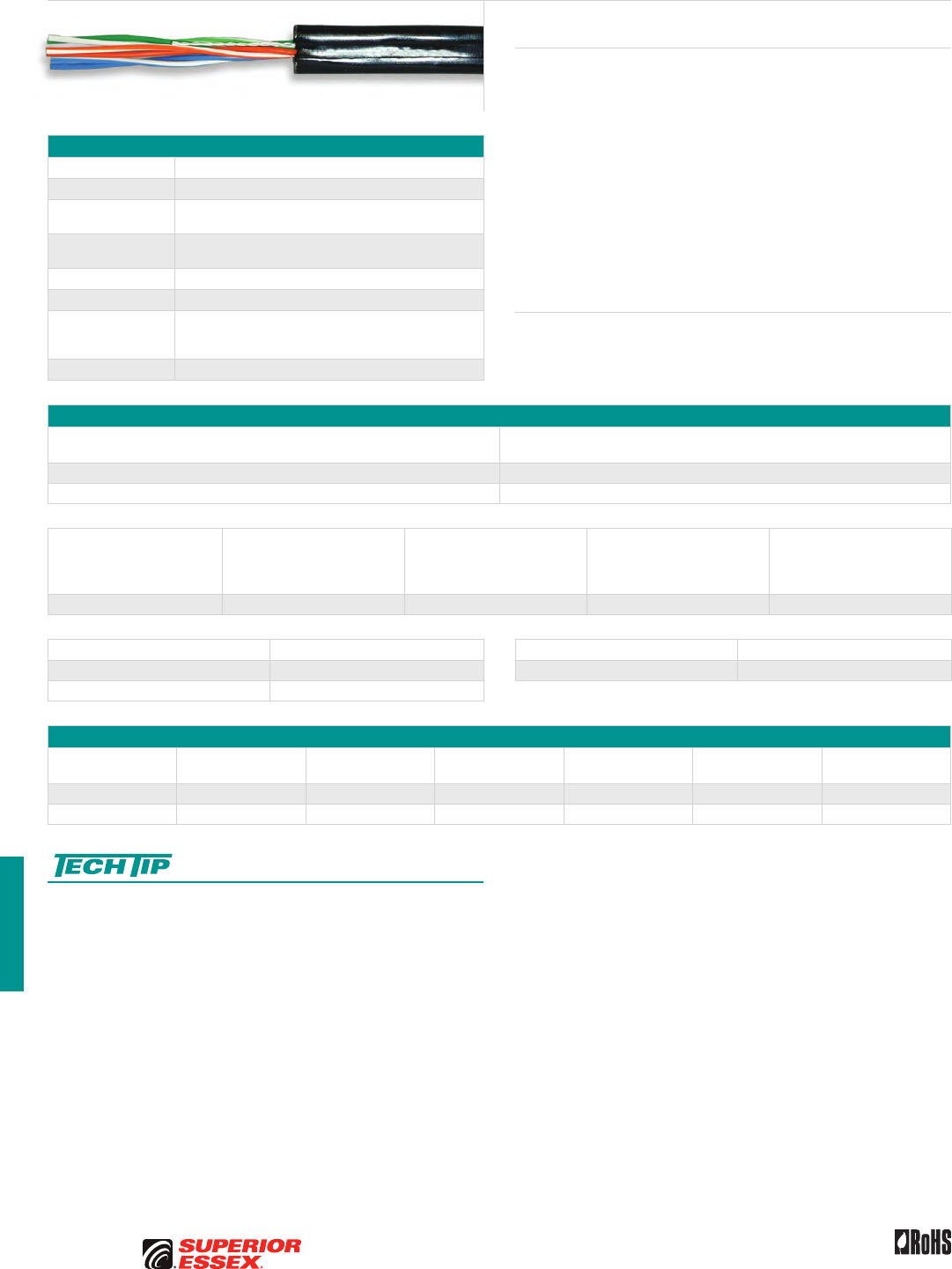
H-6
PREMISES COPPER PREMISES FIBER OSP FIBER OSP COMPOSITE CENTRAL OFFICE COPPER RDUP/RUS OSP COPPER BELL OSP COPPER OSP COPPER WIRE CANADIAN OSP COPPER TECHNICAL INFO
Toll Free 800.551.8948 | Fax 770.657.6807 | SuperiorEssex.com/Comm Rev 10/10 Ed 10.4
ADP NMS (6x24) Compact Design
Product Description
The ADP NMS 6x24 Compact Design features a black abrasion resistant
PVC-jacket and is used to extend telephone service to subscriber premises
from the distribution cable or cable terminal. The product features four
fiberglass yarns that provide all the longitudinal strength necessary. Simple
access procedures allow for quick and easy installation with the small
standard off the shelf industry hardware. This product offers 6-pair in the
size and shape of the traditional 3-pair product. Each conductor is insulated
with solid polyolefin in distinctive colors. The insulation of the tip conductor
is marked with a stripe of the mating ring insulation color to reduce the
possibility of splitting pairs during installation. A black, weather resistant,
polyvinylchloride jacket is extruded over the strength members and rip cord
to protect the core from mechanical damage. The jacket bonds to the fiber
glass strength members to provide the required strength characteristics.
Features Benefits
• Non-metallic or fiberglass
strength members
• Provide necessary
longitudinal strength
• Rip cord • Facilitates jacket removal
Specifications
Conductor Solid annealed copper
Insulation Polyolefin
Core Assembly Individual conductors are carefully twisted into pairs in a
manner designed to minimize resistance unbalance
Strength Members Non-metallic or fiberglass strength members placed in
jacket parallel to core assembly
Rip cord Placed parallel to the core
Jacket Weather-resistant PVC
Performance
Compliance
GR-3163-CORE as applicable
ANSI/ICEA S-89-648-2006
RoHS-compliant
NRTL Programs UL Listed
Electrical Specifications
Number of Pairs
Average Mutual Capacitance @ 1000 Hz
nF/mile (nF/km)
Maximum Individual 94 (58)
Wire Average 83 ± 7 (52 ± 4)
Conductor Size
AWG (mm)
Minimum Insulation
Resistance @ 68°F (20°C)
megohm-mile (megohm-km)
Maximum Average
Attenuation
772 kHz @ 68°F (20°C)
dB/kft (dB/km)
Maximum Conductor
Resistance
@ 68°F (20°C)
Ohms/mile (Ohms/km)
DC Resistance Unbalance
Maximum %
Individual Pair
24 (0.51) 1,000 (1,600) 5.8 (19.0) 144 (89.5) 5.0
Crosstalk Loss dB/kft (dB/km) Capacitance Unbalance @ 1000 Hz pF @ 1 kft (pF @ 1 km)
Minimum FEXT @ 150 kHz 63 (207) Maximum Individual Pair 80 (145)
Minimum NEXT @ 722 kHz 44 (144)
Part Numbers and Physical Characteristics
Part Number Pair Count
Minor Dimension
in (mm)
Major Dimension
in (mm)
Approx. Weight
lbs/kft (kg/km)
Standard Length
ft (m) Package
12-801-08 6 0.21 (5.3) 0.38 (9.7) 50 (74) 600 (183) POP™ Box
12-802-08 6 0.21 (5.3) 0.38 (9.7) 50 (74) 1,000 (305) Reel
Sag and Tension guidelines for these products are available online:
www.SuperiorEssex.com/techtip.aspx
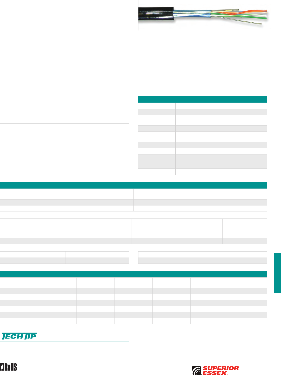
H-7
PREMISES COPPERPREMISES FIBEROSP FIBEROSP COMPOSITECENTRAL OFFICE COPPERRDUP/RUS OSP COPPERBELL OSP COPPEROSP COPPER WIRECANADIAN OSP COPPERTECHNICAL INFO
Toll Free 800.551.8948 | Fax 770.657.6807 | SuperiorEssex.com/CommRev 10/10 Ed 10.4
Specifications
Conductor Solid annealed copper
Insulation Polyolefin
Core Assembly Individual conductors are carefully twisted into pairs in a
manner designed to minimize resistance unbalance
Shield 3 mil metallic foil shield with drain wire
Strength Members Non-metallic or fiberglass strength members placed in
jacket parallel to core assembly
Rip cord Placed parallel to the core
Jacket Weather-resistant PVC
Performance
Compliance
Applicable sections of both GR-3163-CORE
and ANSI/ICEA S-89-648-2006
RoHS-compliant
NRTL Programs UL Listed
Electrical Specifications
Number of Pairs
Average Mutual Capacitance @ 1000 Hz
nF/mile (nF/km)
Maximum Pair 94 (58)
Maximum Average 90 (56)
Conductor Size
AWG (mm)
Minimum Insulation
Resistance @ 68°F (20°C)
megohm-mile (megohm-km)
Maximum Average
Attenuation
772 kHz @ 68°F (20°C)
dB/kft (dB/km)
Maximum Conductor
Resistance
@ 68°F (20°C)
Ohms/mile (Ohms/km)
DC Resistance
Unbalance Maximum %
Individual Pair
Conductor to Conductor
Dielectric Strength
Volts DC
3 secs, no breakdown
22 (0.64) 1,000 (1,600) 5.1 (17) 91 (56.5) 5.0 4,000
Crosstalk Loss dB/kft (dB/km) Capacitance Unbalance @ 1000 Hz pF @ 1 kft (pF @ 1 km)
Minimum NEXT @ 722 kHz 44 (144) Maximum Individual Pair 80 (145)
Part Numbers and Physical Characteristics
Part Number Pair Count
Minor Dimension
in (mm)
Major Dimension
in (mm)
Approx. Weight
lbs/kft (kg/km)
Standard Length
ft (m) Package
12-301-07 3 0.27 (6.8) 0.45 (11.4) 55 (82) 1,000 (305) Reel
12-302-07 3 0.27 (6.8) 0.45 (11.4) 55 (82) 400 (122) POP™ Box
12-303-07 3 0.27 (6.8) 0.45 (11.4) 55 (82) 750 (229) Reel
12-304-07 3 0.27 (6.8) 0.45 (11.4) 55 (82) 750 (229) Coil
12-305-07 3 0.27 (6.8) 0.45 (11.4) 55 (82) 500 (152) Reel-in-a-Box
12-501-07 5 0.28 (7.1) 0.49 (12.0) 78 (116) 1,000 (305) Reel
Sag and Tension guidelines for these products are available online:
www.SuperiorEssex.com/techtip.aspx
ADP S
Product Description
ADP S is a PVC-jacketed, aerial service wire designed for use in extending
communications service (voice, data and/or video) to a subscriber premises
from the distribution cable terminal. This product has additional capabilities
over the standard ADP NMS product because it contains a shielding
screen. The core is wrapped within a metallic foil to provide shielding from
interference and thus provide high quality digital transmission. In addition, a
drain wire runs longitudinally the length of the wire to drain off Electromagnetic
Interference (EMI) and Radio Frequency Interference (RFI). Without shielding
and a drain wire, noise can be introduced into circuits from high voltage AC
power lines, machinery with motors, x-ray systems, TV sets and AM radio
stations. Shielding also lessens the chance that DSL or other high frequency
transmission protocols will interfere with other signals on adjacent cables.
Each conductor is insulated with solid polyolefin in distinctive colors. The
insulation of the tip conductor is marked with a stripe of the mating ring
insulation color to reduce the possibility of splitting pairs during installation. A
black, weather resistant, polyvinylchloride jacket is extruded over the yarns
and rip cord to protect the core from mechanical damage, degradation by
sunlight and ingress of moisture. The jacket bonds to the fiberglass strength
members to provide the required strength characteristics.
Features Benefits
• 3 mil metallic foil shield
with drain wire
• Provides high quality digital
transmission medium for xDSL
technologies and, when properly
grounded, removes spectrum
interferences
• Non-metallic or fiberglass
strength members
• Provide necessary
longitudinal strength
• Rip cord • Facilitates jacket removal
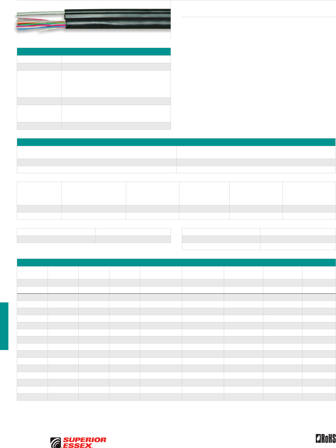
H-8
PREMISES COPPER PREMISES FIBER OSP FIBER OSP COMPOSITE CENTRAL OFFICE COPPER RDUP/RUS OSP COPPER BELL OSP COPPER OSP COPPER WIRE CANADIAN OSP COPPER TECHNICAL INFO
Toll Free 800.551.8948 | Fax 770.657.6807 | SuperiorEssex.com/Comm Rev 10/10 Ed 10.4
Integrated Messenger Wire
IM/F, IM/H and IM/G
Product Description
IM/F, IM/H and IM/G aerial service wire in 2, 3, 6 and 12-pair is self
supporting. The conductors are laid parallel to an (F) 0.083 inch,
(H) 0.109 inch, or (G) 0.095 inch solid extra-strength steel support wire. Both
the conductors and support wire are jacketed in an integral “figure-8”
configuration. This product permits fast, economical installation from aerial
distribution cable terminals to building entrance protectors or network
interface units on the subscriber’s premises. The fully color coded core
expedites splicing and terminating procedures. A black, fire retardant,
polyvinylchloride jacket provides a tough flexible protective covering that
withstands exposure to sunlight, atmospheric temperatures and stresses
encountered in standard installations. The steel support wire is jacketed in
an integral extrusion with the core.
Specifications
Conductor Solid annealed copper
Insulation Polyolefin
Core Assembly
Individual conductor dimensions are tightly controlled to
limit resistance unbalance of the twisted pairs; in multi-
pair constructions, pair twist lays are varied to minimize
crosstalk and meet capacitance limits; twisted pairs are
formed into a firm, round core
Jacket Fire retardant PVC
Performance
Compliance
Telcordia GR-3163-CORE
ANSI/ICEA S-89-648-2006
RoHS-compliant
NRTL Programs UL Listed
Electrical Specifications
Number of Pairs
Average Mutual Capacitance @ 1000 Hz
nF/mile (nF/km)
Maximum Pair 94 (58)
Maximum Average 90 (56)
Conductor Size
AWG (mm)
Minimum Insulation
Resistance @ 68°F (20°C)
megohm-mile (megohm-km)
Maximum Average
Attenuation
772 kHz @ 68°F (20°C)
dB/kft (dB/km)
Maximum Conductor
Resistance
@ 68°F (20°C)
Ohms/mile (Ohms/km)
DC Resistance
Unbalance Maximum %
Individual Pair
Conductor to Conductor
Dielectric Strength
Minimum Volts DC
3 secs, no breakdown
19 (0.90) 1,000 (1,600) 3.6 (11.8) 45 (28.0) 5.0 -
22 (0.64) 1,000 (1,600) 5.1 (17.0) 91 (56.5) 5.0 4,000
Crosstalk Loss dB/kft (dB/km) Capacitance Unbalance @ 1000 Hz pF @ 1 kft (pF @ 1 km)
Minimum NEXT @ 722 kHz 44 (144) Maximum Individual Pair to Pair 80 (145)
Maximum Individual Pair to Ground 800 (2,625)
Part Numbers and Physical Characteristics
Part Number Support Size Pair Count AWG (mm)
Minor Dimension
in (mm)
Major Dimension
in (mm)
Approx. Weight
lbs/kft (kg/km)
Standard Length
ft (m) Package
10-921-38 IM/G 0.095 2 19 (0.90) 0.27 (6.8) 0.51 (12.9) 73 (109) 656 (200) Coil
10-923-38 IM/G 0.095 2 19 (0.90) 0.27 (6.8) 0.51 (12.9) 73 (109) 4,921 (1,500) Reel
10-002-34 IM/F 0.083 2 22 (0.64) 0.22 (5.7) 0.46 (11.7) 55 (82) 600 (183) Coil
10-102-34 IM/F 0.083 2 22 (0.64) 0.22 (5.7) 0.46 (11.7) 55 (82) 5,000 (1,524) Reel
10-503-34 IM/F 0.083 3 22 (0.64) 0.24 (6.2) 0.48 (12.3) 72 (107) 1,000 (305) Coil
10-106-34 IM/F 0.083 6 22 (0.64) 0.30 (7.6) 0.53 (13.6) 80 (119) 3,500 (1,067) Reel
10-206-34 IM/F 0.083 6 22 (0.64) 0.30 (7.6) 0.53 (13.6) 80 (119) 1,000 (305) Reel
10-306-34 IM/F 0.083 6 22 (0.64) 0.30 (7.6) 0.53 (13.6) 80 (119) 400 (122) Coil
10-261-38 IM/G 0.095 6 22 (0.64) 0.30 (7.6) 0.55 (13.9) 80 (119) 492 (150) Coil
10-262-38 IM/G 0.095 6 22 (0.64) 0.30 (7.6) 0.55 (13.9) 80 (119) 2,461 (750) Reel
10-265-38 IM/G 0.095 6 22 (0.64) 0.30 (7.6) 0.55 (13.9) 80 (119) 5,000 (1,562) Reel
10-281-38 IM/G 0.095 12 22 (0.64) 0.38 (7.6) 0.65 (16.6) 114 (170) 410 (125) Coil
10-284-38 IM/G 0.095 12 22 (0.64) 0.38 (7.6) 0.65 (16.6) 114 (170) 2,460 (750) Reel
10-285-38 IM/G 0.095 12 22 (0.64) 0.38 (7.6) 0.65 (16.6) 114 (170) 8,202 (2,500) Reel
10-102-35 IM/H 0.109 12 22 (0.64) 0.38 (7.6) 0.66 (16.7) 130 (193) 1,000 (305) Reel
10-012-35 IM/H 0.109 12 22 (0.64) 0.38 (7.6) 0.66 (16.7) 130 (193) 250 (76) Coil
10-212-35 IM/H 0.109 12 22 (0.64) 0.38 (7.6) 0.66 (16.7) 130 (193) 5,000 (1,524) Reel
Contact Superior Essex for additional configurations and AWG sizes.
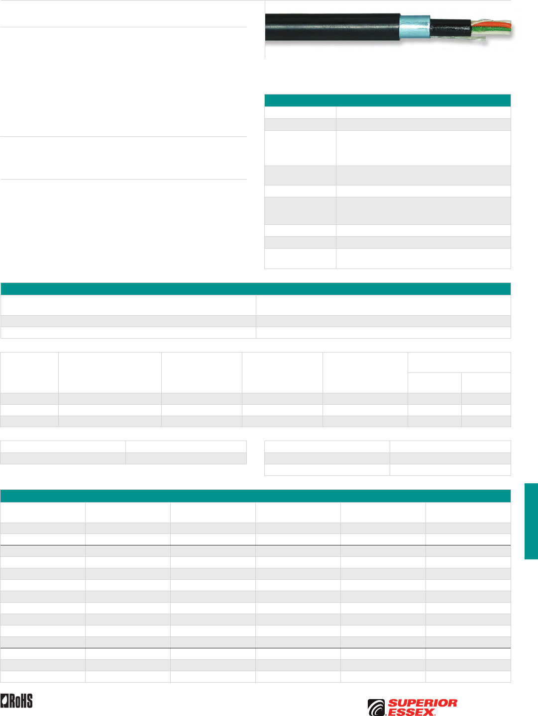
H-9
PREMISES COPPERPREMISES FIBEROSP FIBEROSP COMPOSITECENTRAL OFFICE COPPERRDUP/RUS OSP COPPERBELL OSP COPPEROSP COPPER WIRECANADIAN OSP COPPERTECHNICAL INFO
Toll Free 800.551.8948 | Fax 770.657.6807 | SuperiorEssex.com/CommRev 10/10 Ed 10.3
BDW A
Product Description
BDW A is a filled, double-jacketed buried wire intended for direct burial
applications. Applications include distribution circuits and service entrance
wires. BDW A is designed to withstand installation stresses. BDW A is filled
with an ETPR compound, which completely coats each insulated conductor
and fills the air space between conductors. BDW A is recommended for
non-gopher areas. Each conductor is insulated with solid polyolefin in
distinctive colors. The insulation of the tip conductor is marked with a stripe
of the mating ring insulation color to reduce the possibility of splitting pairs
during installation.
Applications
• Direct burial
• Distribution circuits and service entrance wires
Features Benefits
• Polyethylene inner jacket • Provides additional mechanical
and moisture protection
• Polyethylene outer jacket • Provides tough, flexible,
protective covering that
withstands exposure to sunlight,
atmospheric temperatures,
ground chemicals and stresses
expected in standard installations
• Dual rip cords • Facilitates jacket removal
Specifications
Conductor Solid annealed copper
Insulation Polyolefin
Core Assembly
Individual conductor dimensions are tightly controlled
to limit resistance unbalance of twisted pairs; pair
twist lays are varied to minimize crosstalk and meet
capacitance unbalance limits
Filling Compound Wire core is completely filled with 80°C ETPR compound,
filling the air spaces between insulated conductors
Inner Jacket Polyethylene
Shield
Smooth, copolymer-coated, 8 mil aluminum tape applied
longitudinally over inner jacket and bonded to outer jacket;
space under the tape is flooded to eliminate all air space
Outer Jacket Black, polyethylene
Package Reel
Standards
Compliance
ANSI/ICEA S-86-634-2004
RoHS-compliant
Electrical Specifications
All Pairs
Average Mutual Capacitance @ 1000 Hz
nF/mile (nF/km)
Maximum Individual 94 (58)
Wire Average 83 ± 7 (52 ± 4)
Conductor Size
AWG (mm)
Minimum Insulation
Resistance @ 68°F (20°C)
megohm-mile (megohm-km)
Maximum Average
Attenuation
772 kHz @ 68°F (20°C)
dB/kft (dB/km)
Maximum Conductor
Resistance
@ 68°F (20°C)
Ohms/mile (Ohms/km)
DC Resistance
Unbalance Maximum %
Individual Pair
Dielectric Strength
Minimum Volts DC
Conductor
to Conductor
Conductor
to Shield
19 (0.90) 1,000 (1,600) 3.1 (10.2) 45 (28.0) 5.0 7,000 20,000
22 (0.64) 1,000 (1,600) 4.4 (14.4) 91 (56.4) 5.0 5,000 20,000
24 (0.51) 1,000 (1,600) 5.5 (18.0) 144 (89.5) 5.0 4,000 20,000
Crosstalk Loss dB/kft (dB/km) Capacitance Unbalance @ 1000 Hz pF @ 1 kft (pF @ 1 km)
Minimum NEXT @ 722 kHz 44 (144) Maximum Individual Pair to Pair 80 (145)
Maximum Individual Pair to Ground 800 (2,625)
Part Numbers and Physical Characteristics
Part Number Pair Count AWG (mm)
Nominal Diameter
in (mm)
Approx. Weight
lbs/kft (kg/km)
Standard Length
ft (m)
04-023-85 2 19 (0.90) 0.38 (9.7) 65 (97) 5,000 (1,524)
04-025-85 3 19 (0.90) 0.42 (11) 85 (125) 5,000 (1,524)
04-052-84 2 22 (0.64) 0.32 (8.1) 45 (65) 1,000 (305)
04-053-84 2 22 (0.64) 0.32 (8.1) 45 (65) 2,500 (762)
04-055-84 2 22 (0.64) 0.32 (8.1) 45 (65) 5,000 (1,524)
04-056-84 3 22 (0.64) 0.33 (8.4) 50 (75) 1,000 (305)
04-062-84 3 22 (0.64) 0.33 (8.4) 50 (75) 2,500 (762)
04-058-84 3 22 (0.64) 0.33 (8.4) 50 (75) 5,000 (1,524)
04-061-85 6 22 (0.64) 0.41 (10) 80 (120) 1,000 (305)
04-058-85 6 22 (0.64) 0.41 (10) 80 (120) 2,500 (762)
04-057-85 6 22 (0.64) 0.41 (10) 80 (120) 5,000 (1,524)
04-098-85 2 24 (0.51) 0.27 (6.9) 30 (45) 5,000 (1,524)
04-101-85 3 24 (0.51) 0.29 (7.4) 40 (60) 5,000 (1,524)
04-097-85 6 24 (0.51) 0.35 (8.9) 55 (80) 5,000 (1,524)
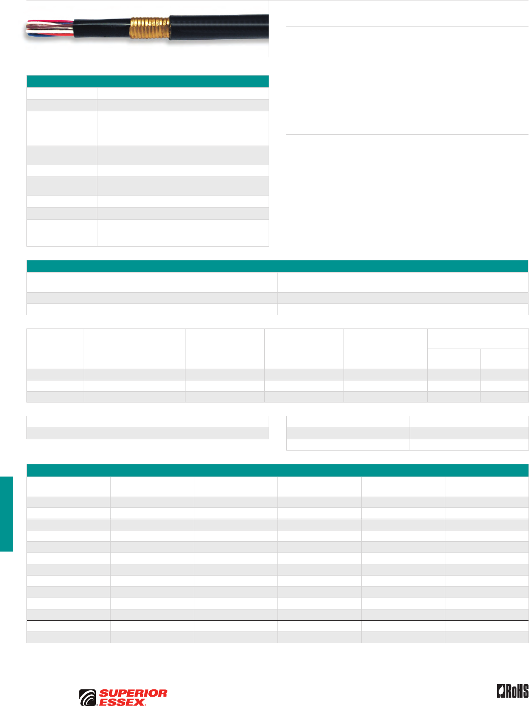
H-10
PREMISES COPPER PREMISES FIBER OSP FIBER OSP COMPOSITE CENTRAL OFFICE COPPER RDUP/RUS OSP COPPER BELL OSP COPPER OSP COPPER WIRE CANADIAN OSP COPPER TECHNICAL INFO
Toll Free 800.551.8948 | Fax 770.657.6807 | SuperiorEssex.com/Comm Rev 10/10 Ed 10.3
Specifications
Conductor Solid annealed copper
Insulation Polyolefin
Core Assembly
Individual conductor dimensions are tightly controlled
to limit resistance unbalance of twisted pairs; pair
twist lays are varied to minimize crosstalk and meet
capacitance unbalance limits
Filling Compound Wire core is completely filled with 80°C ETPR compound,
filling the air spaces between insulated conductors
Inner Jacket Polyethylene
Shield Corrugated, 5 mil gopher resistant armor applied
longitudinally over the inner jacket and flooded
Outer Jacket Black polyethylene
Package Reel
Standards
Compliance
*RDUP 7 CFR 1755.860 (PE-86)
ANSI/ICEA S-86-634-2004
RoHS-compliant
Electrical Specifications
All Pairs
Average Mutual Capacitance @ 1000 Hz
nF/mile (nF/km)
Maximum Individual 94 (58)
Wire Average 83 ± 7 (52 ± 4)
Conductor Size
AWG (mm)
Minimum Insulation
Resistance @ 68°F (20°C)
megohm-mile (megohm-km)
Maximum Average
Attenuation
772 kHz @ 68°F (20°C)
dB/kft (dB/km)
Maximum Conductor
Resistance
@ 68°F (20°C)
Ohms/mile (Ohms/km)
DC Resistance
Unbalance Maximum %
Individual Pair
Dielectric Strength
Minimum Volts DC
Conductor
to Conductor
Conductor
to Shield
19 (0.90) 1,000 (1,600) 3.1 (10.2) 45 (28.0) 5.0 7,000 20,000
22 (0.64) 1,000 (1,600) 4.4 (14.4) 91 (56.4) 5.0 5,000 20,000
24 (0.51) 1,000 (1,600) 5.5 (18.0) 144 (89.5) 5.0 4,000 20,000
Crosstalk Loss dB/kft (dB/km) Capacitance Unbalance @ 1000 Hz pF @ 1 kft (pF @ 1 km)
Minimum NEXT @ 722 kHz 44 (144) Maximum Individual Pair to Pair 80 (145)
Maximum Individual Pair to Ground 800 (2,625)
Part Numbers and Physical Characteristics
Part Number Pair Count AWG (mm)
Nominal Diameter
in (mm)
Approx. Weight
lbs/kft (kg/km)
Standard Length
ft (m)
04-022-16* 2 19 (0.90) 0.37 (9.4) 70 (105) 5,000 (1,524)
04-025-16* 3 19 (0.90) 0.41 (10) 90 (135) 5,000 (1,524)
04-052-17 2 22 (0.64) 0.32 (8.1) 55 (80) 1,000 (305)
04-053-17 2 22 (0.64) 0.32 (8.1) 55 (80) 2,500 (762)
04-055-17 2 22 (0.64) 0.32 (8.1) 55 (80) 5,000 (1,524)
04-056-17 3 22 (0.64) 0.33 (8.4) 60 (90) 1,000 (305)
04-057-17 3 22 (0.64) 0.33 (8.4) 60 (90) 2,500 (762)
04-058-17 3 22 (0.64) 0.33 (8.4) 60 (90) 5,000 (1,524)
04-067-16* 6 22 (0.64) 0.40 (10) 90 (135) 1,000 (305)
04-062-16* 6 22 (0.64) 0.40 (10) 90 (135) 2,500 (762)
04-057-16* 6 22 (0.64) 0.40 (10) 90 (135) 5,000 (1,524)
04-094-16 2 24 (0.51) 0.27 (6.9) 40 (60) 5,000 (1,524)
04-091-16 3 24 (0.51) 0.29 (7.4) 45 (65) 5,000 (1,524)
Product Description
BDW G is a filled, double-jacketed buried wire intended for direct burial
applications. Applications include distribution circuits and service entrance
wires. All types are designed to withstand installation stresses. They are
filled with an ETPR compound, which completely coats each insulated
conductor and fills the air space between conductors. BDW G also provides
protection from rodents or harsh environments. Each conductor is insulated
with solid polyolefin in distinctive colors. The insulation of the tip conductor
is marked with a stripe of the mating ring insulation color to reduce the
possibility of splitting pairs during installation.
Features Benefits
• Polyethylene inner jacket • Provides additional mechanical
and moisture protection
• Corrugated armor • Gopher resistant
• Provides excellent
mechanical protection
• Polyethylene outer jacket • Provides tough, flexible,
protective covering that
withstands exposure to sunlight,
atmospheric temperatures,
ground chemicals and stresses
expected in standard installations
BDW G
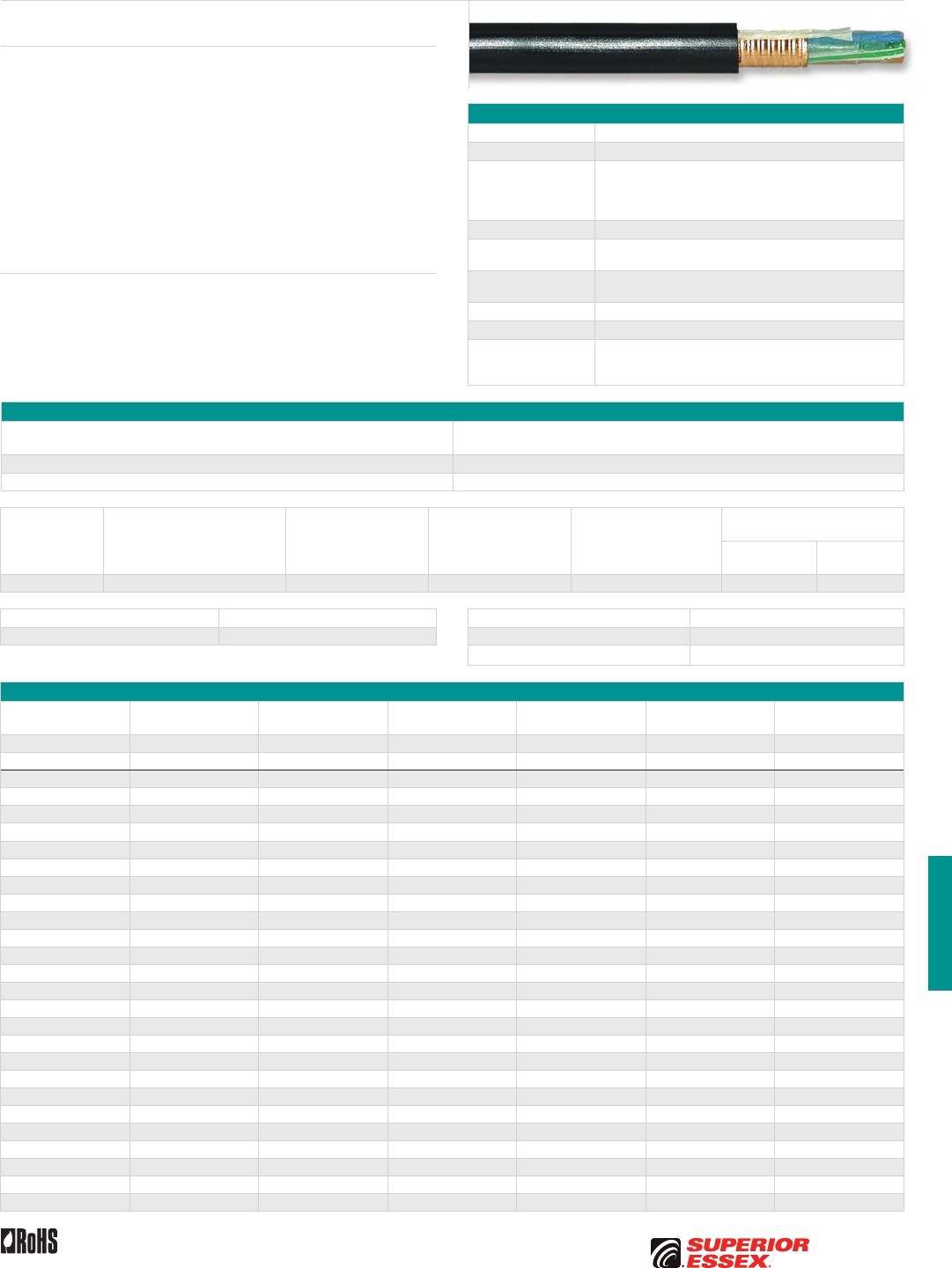
H-11
PREMISES COPPERPREMISES FIBEROSP FIBEROSP COMPOSITECENTRAL OFFICE COPPERRDUP/RUS OSP COPPERBELL OSP COPPEROSP COPPER WIRECANADIAN OSP COPPERTECHNICAL INFO
Toll Free 800.551.8948 | Fax 770.657.6807 | SuperiorEssex.com/CommRev 10/10 Ed 10.3
BW CF
Product Description
BW CF is designed for direct burial applications and is available in 2, 3, 5
and 6-pair sizes. It is filled with an ETPR compound which is chemically and
electrically compatible with all other materials in the wire. The compound
completely coats each insulated conductor and fills the air space between
conductors. BW CF can also be used for distribution circuits and service
entrance wires. Each conductor is insulated with solid polyolefin in distinctive
colors. The insulation of the tip conductor is marked with a stripe of the
mating ring insulation color to reduce the possibility of splitting pairs during
installation. black, weather-resistant polyvinylchloride jacket is extruded over
the shield and rip cord to protect the core from minor mechanical damage,
degradation by sunlight and ingress of moisture and water.
Features Benefits
• Non-hygroscopic core wrap • Protects the core and provides
improved mechanical and
electrical characteristics
• Adhesive compound floods
shield’s outer surface
• Provides a moisture barrier
and inhibits corrosion
• Rip cord • Facilitates jacket removal
Specifications
Conductor Solid annealed copper
Insulation Polyolefin
Core Assembly
Individual conductor dimensions are tightly controlled to
limit resistance unbalance of twisted pairs; pair twist lays
are varied to minimize crosstalk and meet capacitance
unbalance limits
Core Covering Non-hygroscopic core wrap
Filling Compound Wire core is completely filled with 80°C ETPR compound,
filling the air spaces between insulated conductors
Shield Corrugated copper clad steel or bronze tape longitudinally
applied over the core wrap
Rip cord Rip cord applied over shield and beneath jacket
Jacket Weather-resistant PVC
Standards
Compliance
Telcordia GR-3163-CORE
ANSI/ICEA S-86-634-2004
RoHS-compliant
Electrical Specifications
All Pairs
Average Mutual Capacitance @ 1000 Hz
nF/mile (nF/km)
Maximum Pair 94 (58)
Maximum Average 90 (56)
Conductor Size
AWG (mm)
Minimum Insulation
Resistance @ 68°F (20°C)
megohm-mile (megohm-km)
Maximum Average
Attenuation
772 kHz @ 68°F (20°C)
dB/kft (dB/km)
Maximum Conductor
Resistance
@ 68°F (20°C)
Ohms/mile (Ohms/km)
DC Resistance
Unbalance Maximum %
Individual Pair
Dielectric Strength
Minimum Volts DC
Conductor
to Conductor
Conductor
to Shield
22 (0.64) 1,000 (1,600) 4.4 (14) 91 (56.5) 5.0 5,000 15,000
Crosstalk Loss dB/kft (dB/km) Capacitance Unbalance @ 1000 Hz pF @ 1 kft (pF @ 1 km)
Minimum NEXT @ 722 kHz 44 (144) Maximum Individual Pair to Pair 80 (145)
Maximum Individual Pair to Ground 800 (2,625)
Part Numbers and Physical Characteristics
Part Number Pair Count AWG (mm)
Nominal Diameter
in (mm)
Approx. Weight
lbs/kft (kg/km)
Standard Length
ft (m) Package
25-722-80 2 19 (0.90) 0.32 (8.1) 62 (92) 1,600 (488) Reel
25-759-80 2 19 (0.90) 0.32 (8.1) 62 (92) 5,000 (1,524) Reel
25-063-80 2 22 (0.64) 0.27 (6.9) 43 (64) 250 (76) Coil
25-069-80 2 22 (0.64) 0.27 (6.9) 43 (64) 1,300 (396) Reel
25-078-80 2 22 (0.64) 0.27 (6.9) 43 (64) 8,250 (2,514) Reel
25-062-80 2 22 (0.64) 0.27 (6.9) 43 (64) 700 (214) Coil
25-061-80 2 22 (0.64) 0.27 (6.9) 43 (64) 1,500 (457) Reel
25-064-80 2 22 (0.64) 0.27 (6.9) 43 (64) 3,000 (915) Reel
25-351-80 3 22 (0.64) 0.30 (7.6) 53 (79) 500 (152) Coil
25-360-80 3 22 (0.64) 0.30 (7.6) 53 (79) 1,200 (366) Reel
25-353-80 3 22 (0.64) 0.30 (7.6) 53 (79) 3,000 (915) Reel
25-358-80 3 22 (0.64) 0.30 (7.6) 53 (79) 5,000 (1,524) Reel
25-530-80 5 22 (0.64) 0.33 (8.4) 67 (100) 300 (92) Reel
25-154-80 5 22 (0.64) 0.33 (8.4) 67 (100) 500 (152) Coil
25-527-80 5 22 (0.64) 0.33 (8.4) 67 (100) 900 (274) Reel
25-549-80 5 22 (0.64) 0.33 (8.4) 67 (100) 5,500 (1,676) Reel
25-525-80 5 22 (0.64) 0.33 (8.4) 67 (100) 925 (282) Reel
25-526-80 5 22 (0.64) 0.33 (8.4) 67 (100) 1,200 (366) Reel
25-565-80 5 22 (0.64) 0.33 (8.4) 67 (100) 2,500 (762) Reel
25-667-80 6 22 (0.64) 0.37 (9.4) 81 (121) 600 (183) Coil
25-680-80 6 22 (0.64) 0.37 (9.4) 81 (121) 700 (214) Reel
25-685-80 6 22 (0.64) 0.37 (9.4) 81 (121) 1,200 (366) Reel
25-654-80 6 22 (0.64) 0.37 (9.4) 81 (121) 2,500 (762) Reel
25-682-80 6 22 (0.64) 0.37 (9.4) 81 (121) 4,000 (1,219) Reel
25-681-80 6 22 (0.64) 0.37 (9.4) 81 (121) 800 (244) Reel
25-658-80 6 22 (0.64) 0.37 (9.4) 81 (121) 5,000 (1,524) Reel
25-684-80 6 22 (0.64) 0.37 (9.4) 81 (121) 12,000 (3,660) Reel
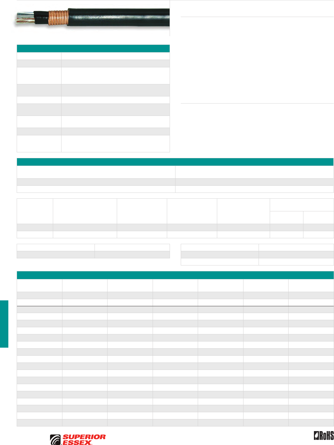
H-12
PREMISES COPPER PREMISES FIBER OSP FIBER OSP COMPOSITE CENTRAL OFFICE COPPER RDUP/RUS OSP COPPER BELL OSP COPPER OSP COPPER WIRE CANADIAN OSP COPPER TECHNICAL INFO
Toll Free 800.551.8948 | Fax 770.657.6807 | SuperiorEssex.com/Comm Rev 10/10 Ed 10.3
BW GDJ
Product Description
BW GDJ, available in 2, 3, 5 and 6-pair sizes, is intended for direct burial
applications and is well suited to withstand installation stresses. It is filled
with an ETPR compound, which is chemically and electrically compatible
with all other materials in the wire. The compound completely coats each
insulated conductor and fills the air space between conductors. BW GDJ
effectively combats attacks by rodents. It can be used for distribution
circuits and service entrance wires. Each conductor is insulated with solid
polyolefin distinctive colors. The insulation of the tip conductor is marked
with a stripe of the mating ring insulation color to reduce the possibility
of splitting pairs during installation. A black, polyvinylchloride jacket is
extruded over the armor to protect the core from minor mechanical damage,
degradation by sunlight and the ingress of moisture.
Features Benefits
• Polyethylene inner jacket • Provides additional mechanical
and moisture protection
• Corrugated armor • Gopher resistant
• Armor’s inner and outer surfaces
are flooded
• Prevents water flow between
the shield and outer jacket
• Rip cord • Facilitates jacket removal
Specifications
Conductor Solid annealed copper
Insulation Polyolefin
Core Assembly
Conductors are twisted into pairs in a manner designed to
minimize resistance unbalance; pair twist lays are varied
to minimize crosstalk.
Filling Compound Wire core is completely filled with 80°C ETPR compound,
filling the air spaces between insulated conductors
Inner Jacket Polyethylene inner jacket; outer surface flooded
Armor Corrugated armor applied longitudinally over the inner
jacket; inner and outer surfaces of the armor are flooded
Rip cord Rip cord is applied beneath the inner jacket; a second rip
cord can also be applied under the outer jacket
Jacket Weather resistant PVC
Standards
Compliance
Telcordia GR-3163-CORE
ANSI/ICEA S-86-634-2004
RoHS-compliant
Electrical Specifications
All Pairs
Average Mutual Capacitance @ 1000 Hz
nF/mile (nF/km)
Maximum Pair 94 (58)
Maximum Average 90 (56)
Conductor Size
AWG (mm)
Minimum Insulation
Resistance @ 68°F (20°C)
megohm-mile (megohm-km)
Maximum Average
Attenuation
772 kHz @ 68°F (20°C)
dB/kft (dB/km)
Maximum Conductor
Resistance
@ 68°F (20°C)
Ohms/mile (Ohms/km)
DC Resistance
Unbalance Maximum %
Individual Pair
Dielectric Strength
Minimum Volts DC
Conductor
to Conductor
Conductor
to Shield
19 (0.90) 1,000 (1,600) 3.1 (11) 45 (28.0) 5.0 7,000 20,000
22 (0.64) 1,000 (1,600) 4.4 (14) 91 (56.5) 5.0 5,000 20,000
Crosstalk Loss dB/kft (dB/km) Capacitance Unbalance @ 1000 Hz pF @ 1 kft (pF @ 1 km)
Minimum NEXT @ 722 kHz 44 (144) Maximum Individual Pair to Pair 80 (145)
Maximum Individual Pair to Ground 800 (2,625)
Part Numbers and Physical Characteristics
Part Number Pair Count AWG (mm)
Nominal Diameter
in (mm)
Approx. Weight
lbs/kft (kg/km)
Standard Length
ft (m) Package
25-020-79 2 19 (0.90) 0.37 (9.4) 80 (119) 900 (275) Reel
25-021-79 2 19 (0.90) 0.37 (9.4) 80 (119) 7,000 (2,135) Reel
25-063-79 2 22 (0.64) 0.37 (9.4) 80 (119) 600 (183) Coil
25-064-79 2 22 (0.64) 0.37 (9.4) 80 (119) 5,000 (1,524) Reel
25-351-79 3 22 (0.64) 0.33 (8.4) 70 (104) 500 (152) Coil
25-355-79 3 22 (0.64) 0.33 (8.4) 70 (104) 600 (183) Reel
25-360-79 3 22 (0.64) 0.33 (8.4) 70 (104) 1,200 (366) Reel
25-354-79 3 22 (0.64) 0.33 (8.4) 70 (104) 3,000 (915) Reel
25-361-79 3 22 (0.64) 0.33 (8.4) 70 (104) 8,000 (2,438) Reel
25-552-79 5 22 (0.64) 0.38 (9.0) 90 (134) 500 (152) Coil
25-555-79 5 22 (0.64) 0.38 (9.0) 90 (134) 1,000 (305) Reel
25-547-79 5 22 (0.64) 0.38 (9.0) 90 (134) 2,000 (610) Reel
25-553-79 5 22 (0.64) 0.38 (9.0) 90 (134) 5,000 (1,524) Reel
25-681-79 6 22 (0.64) 0.40 (10.0) 100 (149) 800 (244) Reel
25-654-79 6 22 (0.64) 0.40 (10.0) 100 (149) 350 (107) Coil
25-662-79 6 22 (0.64) 0.40 (10.0) 100 (149) 1,000 (305) Reel
25-663-79 6 22 (0.64) 0.40 (10.0) 100 (149) 2,000 (610) Reel
25-653-79 6 22 (0.64) 0.40 (10.0) 100 (149) 3,000 (915) Reel
25-658-79 6 22 (0.64) 0.40 (10.0) 100 (149) 5,000 (1,524) Reel
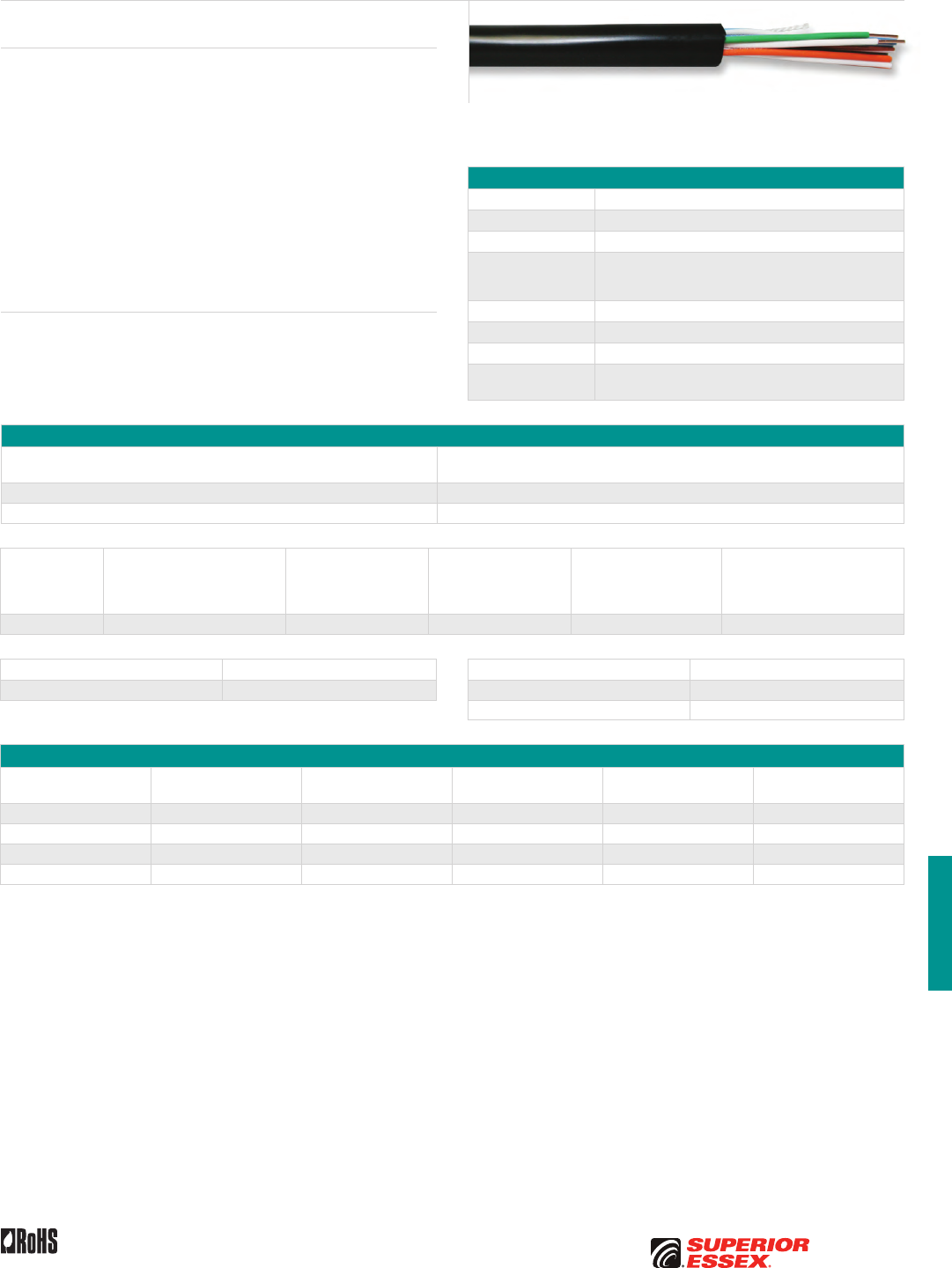
H-13
PREMISES COPPERPREMISES FIBEROSP FIBEROSP COMPOSITECENTRAL OFFICE COPPERRDUP/RUS OSP COPPERBELL OSP COPPEROSP COPPER WIRECANADIAN OSP COPPERTECHNICAL INFO
Toll Free 800.551.8948 | Fax 770.657.6807 | SuperiorEssex.com/CommRev 10/10 Ed 10.3
BW NS Buried Wire Non-Shielded
Product Description
BW NS is a buried service wire designed for direct burial applications. It
is available in 2-pair and 5-pair sizes along with several package options.
This round shaped dry filled product has a rip cord and tough black
outdoor PVC jacket. The wire can be used for distribution circuits and
service entrance wires, and installed with a conventional backyard drop
plow. Each conductor is insulated with polyolefin in distinctive colors. The
insulation of the tip conductor is marked with the color stripe of its mated
ring conductor to reduce the possibility of splitting pairs during installation.
A black, weather resistant, polyvinylchloride jacket is extruded around the
conductors with a rip cord and results in a round shaped product. This
robust PVC jacketing material protects the core from mechanical damage,
degradation by sunlight and ingress of moisture. The jacket is printed on the
surface with standard information.
Features Benefits
• Super absorbent
water blocking dry core
technology filling compound
• Stops and blocks any moisture
movement around the conductors
• Rip cord • Facilitates jacket removal
Specifications
Conductor Solid annealed copper
AWG (mm) 22 (0.64)
Insulation Polyolefin
Core Assembly
Individual conductors carefully twisted into pairs, designed
to minimize resistance unbalance; twist patterns are
similar to those on larger Outside Plant (OSP) cables
Filling Compound Super absorbent water blocking dry core technology
Rip cord Placed parallel to the core
Jacket Weather-resistant PVC
Standards
Compliance
Applicable Sections of GR-3163-CORE
RoHS-compliant
Electrical Specifications
All Pairs
Average Mutual Capacitance @ 1000 Hz
nF/mile (nF/km)
Maximum Pair 94 (58)
Maximum Average 90 (56)
Conductor Size
AWG (mm)
Minimum Insulation
Resistance @ 68°F (20°C)
megohm-mile (megohm-km)
Maximum Average
Attenuation
772 kHz @ 68°F (20°C)
dB/kft (dB/km)
Maximum Conductor
Resistance
@ 68°F (20°C)
Ohms/mile (Ohms/km)
DC Resistance
Unbalance Maximum %
Individual Pair
Conductor to Conductor
Dielectric Strength
Minimum Volts DC
22 (0.64) 1,000 (1,600) 5.1 (17) 91 (56.5) 5.0 4,000
Crosstalk Loss dB/kft (dB/km) Capacitance Unbalance @ 1000 Hz pF @ 1 kft (pF @ 1 km)
Minimum NEXT @ 722 kHz 44 (144) Maximum Individual Pair to Pair 80 (145)
Maximum Individual Pair to Ground 800 (2,625)
Part Numbers and Physical Characteristics
Part Number Pair Count
Nominal Diameter
in (mm)
Approx. Weight
lbs/kft (kg/km)
Standard Length
ft (m) Package
25-262-19 2 0.26 (6.6) 41 (61) 750 (229) POP™ Box
25-263-19 2 0.28 (6.6) 41 (61) 1,500 (457) Reel
25-551-19 5 0.32 (8.1) 59 (88) 500 (152) POP™ Box
25-527-19 5 0.32 (8.1) 59 (88) 1,000 (305) Reel
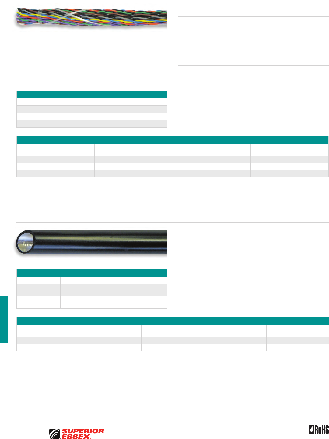
H-14
PREMISES COPPER PREMISES FIBER OSP FIBER OSP COMPOSITE CENTRAL OFFICE COPPER RDUP/RUS OSP COPPER BELL OSP COPPER OSP COPPER WIRE CANADIAN OSP COPPER TECHNICAL INFO
Rev 6/10 Ed 10.1Toll Free 800.551.8948 | Fax 770.657.6807 | SuperiorEssex.com/Comm
Specifications
AWG (mm) 24 (0.51)
Standard Length ft (m) 5,000 (1,524)
Package Reel
Standards Compliance RoHS-compliant
Part Numbers and Physical Characteristics
Part Number Pair Count
Nominal Diameter
in (mm)
Approx. Weight
lbs/kft (kg/km)
11-003-53 25 0.41 (10) 82 (122)
11-003-45 50 0.57 (14) 164 (244)
11-003-46 100 0.82 (21) 328 (488)
Product Description
This Non-jacketed Cable Core is designed for use on the back side of cross
connect and terminal blocks located in a cross connect cabinet adjacent to
the remote terminal. Without a jacket this product must always be utilized
in a cabinet, enclosure or indoors. These products offer enhanced crosstalk
performance in a 100 Ohm design for supporting digital subscriber line
(xDSL) technologies and higher IPTV data speeds.
Features Benefits
• 24 AWG solid copper conductors • Ideal for terminal block stubs
• Polyolefin insulation • Greater crush resistance
and improved transmission
characteristics
• Pairing tight twist
(CAT 5 like twists)
• Enhanced capabilities
for xDSL signals
• Standard telephony solid colors • Easy conductor identification
• No outer jacket • Easy routing
• Binder strings • Holds pair groups together
Non-Jacketed Tight Twist Cable Core
Air Pipe
Product Description
Air Pipe is used for supplying air pressure to underground pressurized cable
systems. Air pressure is distributed off the air pipe at regular intervals and
applied to pressurized cables to supplement and boost air pressure along
the cable route. It is normally placed in ducts. The laminated aluminum and
polyethylene construction assures water vapor will not penetrate to the
pipe interior.
Specifications
Shield 4 mil aluminum tape formed longitudinally with bonded overlap
Jacket Black, medium density polyethylene jacket extruded over
and laminated to the aluminum shield
Standards
Compliance RoHS-compliant
Part Numbers and Physical Characteristics
Part Number
Outer Nominal Diameter
in (mm)
Inner Nominal Diameter
in (mm)
Approx. Weight
lbs/kft (kg/km) Package
85-019-25 0.71 (18) 0.59 (15) 56 (83) 1,980 m Reel
85-018-25 0.71 (18) 0.59 (15) 56 (83) 6,500’ Reel
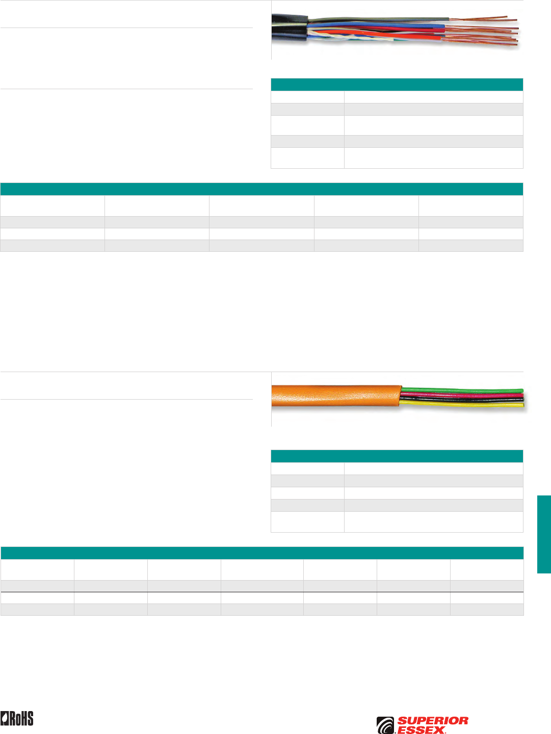
H-15
PREMISES COPPERPREMISES FIBEROSP FIBEROSP COMPOSITECENTRAL OFFICE COPPERRDUP/RUS OSP COPPERBELL OSP COPPEROSP COPPER WIRECANADIAN OSP COPPERTECHNICAL INFO
Rev 6/10 Ed 10.1 Toll Free 800.551.8948 | Fax 770.657.6807 | SuperiorEssex.com/Comm
Specifications
Conductor Solid bare copper
Insulation Polyolefin
Jacket PVC
Jacket Color Bright Orange
Standards
Compliance RoHS-compliant
Part Numbers and Physical Characteristics
Part Number Pair Count AWG (mm) Wire Color
Nominal Diameter
in (mm)
Approx. Weight
lbs/kft (kg/km) Package
12-311-36 2 22 (0.64) Red/Green, Black/Yellow 0.14 (3.6) 13 (19) 1,000’ POP™ Box
12-331-36 1 24 (0.51) Red/Green 0.13 (3.3) 7 (10) 2,000’ POP™ Box
12-322-36 2* 24 (0.51) Red/Green 0.13 (3.3) 7 (10) 2,000’ POP™ Box
*Note: 2 conductors, not a pair.
Bridle Wire
Product Description
Bridle Wire is used to extend the telephone circuit from aerial distribution
cable terminals to building entrance protectors or network interface units
on subscriber premises. This wire has a black PVC jacket with a rip cord for
easy access to conductors.
Features Benefits
• PVC jacket • Provides a tough flexible
protective covering that
withstands exposure to sunlight
and stresses encountered
in standard installations
Specifications
Conductor Solid annealed copper
AWG (mm) 22 (0.64)
Insulation Color coded, solid, polyolefin tip conductors are striped with
mating color for positive identification
Jacket PVC
Standards
Compliance RoHS-compliant
Part Numbers and Physical Characteristics
Part Number Pair Count
Nominal Diameter
in (mm)
Approx. Weight
lbs/kft (kg/km) Package
12-262-01 2 0.19 (4.8) 19 (28) 600’ POP™ Box
12-642-01 6 0.27 (6.9) 42 (63) 450’ Coil
12-842-01 12 0.33 (8.4) 73 (109) 250’ Coil
Temporary Drop Wire
TDW
Product Description
Safety orange colored Temporary Non-shielded Drop Wire intended to
temporarily extend or replace service.
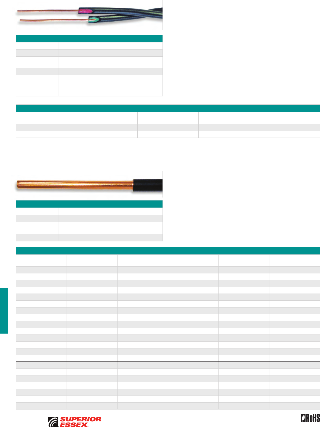
H-16
PREMISES COPPER PREMISES FIBER OSP FIBER OSP COMPOSITE CENTRAL OFFICE COPPER RDUP/RUS OSP COPPER BELL OSP COPPER OSP COPPER WIRE CANADIAN OSP COPPER TECHNICAL INFO
Toll Free 800.551.8948 | Fax 770.657.6807 | SuperiorEssex.com/Comm Rev 10/10 Ed 10.2
Specifications
Conductor Copper covered steel
AWG (mm) 20 (0.13)
Dual Insulation Inner layer: color coded PVC
Outer layer: black PVC
Package Knock-out Box
Standards
Compliance
TR-TSY-000127
UL 83
VW1
RoHS-compliant
Part Numbers and Physical Characteristics
Part Number Style
Nominal Diameter
in (mm)
Approx. Weight
lbs/kft (kg/km)
Standard Length
ft (m)
12-140-03 Pair 0.20 (5.1) 14 (20) 400 (122)
12-220-03 Quad 0.24 (6.1) 32 (47) 250 (76)
Product Description
E-Block Wire is used for “ring wiring” of buildings and as a fusible link for
aerial distribution. E-Block Wire is available in twisted pair and quad forms.
It consists of copper clad steel conductors. Each conductor is dual insulated
with a color coded inner layer of PVC and a black outer layer of PVC.
E-Block Wire
Specifications
Conductor Solid annealed copper
Insulation Weather-resistant PVC
Performance
Compliance RoHS-compliant
NRTL Programs UL Listed
Part Numbers and Physical Characteristics
Part Number AWG Jacket Color
Nominal Diameter
in (mm)
Approx. Weight
lbs/kft (kg/km) Package
12-001-04 6 Black 0.22 (5.6) 91 (135) 500’ Plywood Spool
12-101-04 6 Gray 0.22 (5.6) 91 (135) 200’ Boxed Coil
12-102-04 6 Gray 0.22 (5.6) 91 (135) 200’ Coil
12-105-04 6 Gray 0.22 (5.6) 91 (135) 500’ Coil
12-106-04 6 Gray 0.22 (5.6) 91 (135) 500’ Box Coil
12-107-04 6 Gray 0.22 (5.6) 91 (135) 600’ Coil
12-104-04 6 Gray 0.22 (5.6) 91 (135) 4,000’ Reel
12-018-04 6 Green 0.22 (5.6) 91 (135) 500’ Reel
12-905-04 6 Bare 0.16 (4.1) 79 (118) 600’ Plastic Spool
12-901-04 6 Bare 0.16 (4.1) 79 (118) 200’ Boxed Coil
12-902-04 6 Bare 0.16 (4.1) 79 (118) 2,500’ Plywood Spool
12-903-04 6 Bare 0.16 (4.1) 79 (118) 300’ Plastic Spool
12-904-04 6 Bare 0.16 (4.1) 79 (118) 4,000’ Reel
12-907-04 6 Bare 0.16 (4.1) 79 (118) 500’ Coil
12-111-04 10 Gray 0.14 (3.6) 37 (55) 200’ Boxed Coil
12-112-04 10 Gray 0.14 (3.6) 37 (55) 500’ Boxed Coil
12-011-04 10 Black 0.14 (3.6) 37 (55) 500’ Knock-out Box
12-016-04 10 Green 0.14 (3.6) 37 (55) 500’ Plastic Spool
12-121-04 12 Gray 0.12 (3.0) 25 (37) 200’ Boxed Coil
12-122-04 12 Gray 0.12 (3.0) 25 (37) 300’ Boxed Coil
12-123-04 12 Gray 0.12 (3.0) 25 (37) 500’ Plywood Spool
Ground Wire
Bare or Jacketed
Product Description
Ground Wire is used specifically to ground electrical devices and to
maintain shield continuity at cable splices.
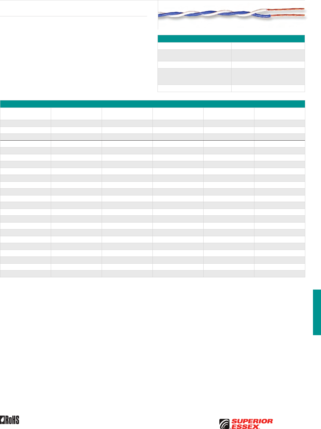
H-17
PREMISES COPPERPREMISES FIBEROSP FIBEROSP COMPOSITECENTRAL OFFICE COPPERRDUP/RUS OSP COPPERBELL OSP COPPEROSP COPPER WIRECANADIAN OSP COPPERTECHNICAL INFO
Toll Free 800.551.8948 | Fax 770.657.6807 | SuperiorEssex.com/CommRev 10/10 Ed 10.2
Specifications
Conductor Solid bare copper
Insulation Flame retardant PVC insulated conductor
each identified by a solid color
Approx. Weight lbs/kft (kg/km) 5 (7)
Performance Compliance
UL 444
CSA C22.2 No. 214-08
RoHS-compliant
NRTL Programs UL, c(UL) Listed CM
Part Numbers and Physical Characteristics
Part Number Pair Count AWG (mm) Wire Color
Nominal Diameter
in (mm) Package
02-360-23 1 22 (0.64) White/Red 0.07 (1.8) 400' Spool
02-361-23 1 22 (0.64) White/Violet 0.07 (1.8) 400' Spool
02-362-23 1 22 (0.64) Violet/Blue 0.07 (1.8) 400' Spool
02-011-23 1 24 (0.51) White/Blue 0.08 (2.0) 1,000’ Spool
02-010-23 1 24 (0.51) White/Green 0.08 (2.0) 1,000’ Spool
02-031-23 1 24 (0.51) Yellow/Red 0.08 (2.0) 1,000’ Spool
02-032-23 1 24 (0.51) Violet/Blue 0.08 (2.0) 1,000’ Spool
02-111-23 1 24 (0.51) White/Blue 0.08 (2.0) 6,000’ Spool
02-131-23 1 24 (0.51) Yellow/Red 0.08 (2.0) 6,000’ Spool
02-050-23 1 24 (0.51) White/Orange 0.08 (2.0) 1,000’ Spool
02-006-23 1 24 (0.51) White/Red 0.08 (2.0) 1,000’ Spool
02-211-23 1 24 (0.51) White/Blue 0.08 (2.0) 6,000’ Spool
02-033-23 1 24 (0.51) Yellow/Blue 0.08 (2.0) 1,000’ Spool
02-113-23 1 24 (0.51) Yellow/Blue 0.08 (2.0) 6,000’ Spool
02-110-23 1 24 (0.51) White/Green 0.08 (2.0) 6,000’ Spool
02-132-23 1 24 (0.51) Violet/Blue 0.08 (2.0) 6,000’ Spool
11-005-90 1 24 (0.51) Violet/Blue 0.08 (2.0) 500’ Spool
02-350-23 1 24 (0.51) White/Orange 0.08 (2.0) 400’ Spool
02-311-23 1 24 (0.51) White/Blue 0.08 (2.0) 500’ Spool
02-020-23 2 24 (0.51) White/Blue, White/Orange 0.12 (3.0) 1,000’ Spool
02-021-23 2 24 (0.51) Red/Blue, Red/Orange 0.12 (3.0) 1,000’ Spool
02-022-23 2 24 (0.51) White/Orange, White/Green 0.12 (3.0) 1,000’ Spool
02-024-23 2 24 (0.51) Violet/Blue, Violet/Orange 0.12 (3.0) 1,000’ Spool
Cross-Connect Category 5 Wire
XCW
Product Description
Cross-Connect Category 5 Wire is designed with a tighter twist to support
higher data speeds and is intended for connections in cross connect cabinets.
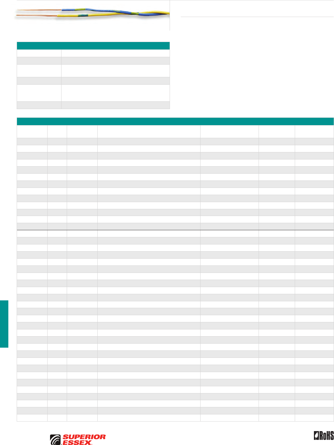
H-18
PREMISES COPPER PREMISES FIBER OSP FIBER OSP COMPOSITE CENTRAL OFFICE COPPER RDUP/RUS OSP COPPER BELL OSP COPPER OSP COPPER WIRE CANADIAN OSP COPPER TECHNICAL INFO
Toll Free 800.551.8948 | Fax 770.657.6807 | SuperiorEssex.com/Comm Rev 10/10 Ed 10.2
Specifications
Conductor Solid bare copper
Insulation Semi-rigid PVC
Individual Nominal
Diameter in (mm) 0.036 (0.9)
Package Spool
Standards
Compliance
UL 444
CSA C22.2 No. 214-08
RoHS-compliant
NRTL Programs UL, c(UL) Listed CM
Part Numbers and Physical Characteristics
Part Number
Pair
Count AWG (mm) Wire Color
Overall Nominal Diameter
in (mm)
Approx. Weight
lbs/kft (kg/km)
Standard Length
ft (m)
02-111-13 1 22 (0.64) White/Blue 0.07 (1.8) 4 (9) 1,000 (305)
02-102-13 1 22 (0.64) Yellow/Blue 0.07 (1.8) 4 (9) 1,000 (305)
02-E02-13 1 22 (0.64) Yellow/Blue 0.07 (1.8) 4 (9) 3,000 (915)
02-113-13 1 22 (0.64) White/Red 0.07 (1.8) 4 (9) 1,000 (305)
02-114-13 1 22 (0.64) White/Black 0.07 (1.8) 4 (9) 1,000 (305)
02-513-13* 1 22 (0.64) White/Red 0.07 (1.8) 4 (9) 1,000 (305)
02-514-13* 1 22 (0.64) White/Black 0.07 (1.8) 4 (9) 1,000 (305)
02-120-13 2 22 (0.64) White/Blue, White/Orange 0.11 (2.8) 9 (20) 1,000 (305)
03-H12-13 1 22 (0.64) White/Violet 0.07 (1.8) 3 (7) 400 (122)
02-G11-13 1 22 (0.64) White/Blue 0.07 (1.8) 3 (7) 400 (122)
02-G50-13 1 22 (0.64) White/Orange 0.07 (1.8) 3 (7) 400 (122)
02-H13-13 1 22 (0.64) Red/White 0.07 (1.8) 3 (7) 400 (122)
02-G16-13 1 22 (0.64) Violet/Blue 0.07 (1.8) 3 (7) 400 (122)
02-706-13* 1 24 (0.51) White/Red 0.07 (1.8) 3 (7) 1,000 (305)
02-001-13 1 24 (0.51) White/Blue 0.07 (1.8) 3 (7) 1,000 (305)
02-050-13 1 24 (0.51) White/Orange 0.07 (1.8) 3 (7) 1,000 (305)
02-006-13 1 24 (0.51) White/Red 0.07 (1.8) 3 (7) 1,000 (305)
02-D06-13 1 24 (0.51) White/Red 0.07 (1.8) 3 (7) 600 (183)
02-053-13 1 24 (0.51) Red/Blue 0.07 (1.8) 3 (7) 1,000 (305)
02-004-13 1 24 (0.51) Red/Green 0.07 (1.8) 3 (7) 1,000 (305)
02-005-13 1 24 (0.51) Red/Slate 0.07 (1.8) 3 (7) 1,000 (305)
02-054-13 1 24 (0.51) Red/Black 0.07 (1.8) 3 (7) 1,000 (305)
02-702-13* 1 24 (0.51) Red/Black 0.07 (1.8) 3 (7) 1,000 (305)
02-002-13 1 24 (0.51) Yellow/Blue 0.07 (1.8) 3 (7) 1,000 (305)
02-409-13 1 24 (0.51) Blue/Black 0.07 (1.8) 3 (7) 3,000 (915)
02-401-13 1 24 (0.51) White/Blue 0.07 (1.8) 3 (7) 3,000 (915)
02-450-13 1 24 (0.51) White/Orange 0.07 (1.8) 3 (7) 3,000 (915)
02-051-13 1 24 (0.51) White/Green 0.07 (1.8) 3 (7) 1,000 (305)
02-052-13 1 24 (0.51) White/Black 0.07 (1.8) 3 (7) 1,000 (305)
02-006-13 1 24 (0.51) White/Red 0.07 (1.8) 3 (7) 1,000 (305)
02-D02-13 1 24 (0.51) Yellow/Blue 0.07 (1.8) 3 (7) 600 (183)
11-001-02 1 24 (0.51) White/Blue 0.07 (1.8) 3 (7) 1,000 (305)
11-001-03 1 24 (0.51) White/Green 0.07 (1.8) 3 (7) 2,000 (610)
02-222-13 2 24 (0.51) White/Blue, White/Orange 0.10 (2.5) 6 (13) 1,000 (305)
02-221-13 2 24 (0.51) Red/Blue, Red/Orange 0.10 (2.5) 6 (13) 1,000 (305)
02-224-13 2 24 (0.51) Yellow/Blue, Yellow/Orange 0.10 (2.5) 6 (13) 1,000 (305)
02-223-13 2 24 (0.51) White/Orange, White/Green 0.10 (2.5) 6 (13) 1,000 (305)
02-032-13 3 24 (0.51) White/Blue, White/Orange, White/Green 0.12 (3.0) 9 (20) 1,000 (305)
02-D30-13 3 24 (0.51) White/Blue, White/Orange, White/Green 0.12 (3.0) 9 (20) 600 (183)
02-041-13 4 24 (0.51) White/Blue, White/Orange, White/Green, White/Brown 0.15 (3.8) 13 (29) 1,000 (305)
*Solid color (not band marked)
Product Description
Indoor/Outdoor Cross-Connect Wire is intended for cross-connecting
points in building entrance enclosures at subscriber’s premises and/or in
Outside Plant (OSP) enclosures. Each insulated conductor is identified by a
combination of solid insulation color, except as noted.
Indoor/Outdoor Cross-Connect Wire
XCW
Toll Free 800.551.8948 | Fax 770.657.6807 | SuperiorEssex.com/Comm
Resources at Your Fingertips
Our Web site is a great resource for information to help
with your next installation, including technical guidelines
and product FAQs – all in one convenient location.
Visit our site for the latest product information and tools
SuperiorEssex.com/Comm


I-1
PREMISES COPPERPREMISES FIBEROSP FIBEROSP COMPOSITECENTRAL OFFICE COPPERRDUP/RUS OSP COPPERBELL OSP COPPEROSP COPPER WIRECANADIAN OSP COPPERTECHNICAL INFO
Toll Free 800.551.8948 | Fax 770.657.6807 | SuperiorEssex.com/Comm
CANADIAN OSP COPPER
Table of Contents
CELFIL BJBB, BJAB, BJMB and BJTB............................I-2
Canadian ALPETH BHBB, BHAB, BKMB and BKTB .................I-4
SEALPAP BHBF, BHAF, BKMF and BKTF ..........................I-6
Canadian Bonded STALPETH DCAZ, DCMZ and DCTZ..............I-8
Canadian Self Support BHBS-BC, BHAS-BC and BKMS-BC.........I-10
Aerial Drop Wire ADW . . . . . . . . . . . . . . . . . . . . . . . . . . . . . . . . . . . . . . I-11
Canadian Integrated Messenger Wire IM/F, IM/H and IM/G .......I-12
Canadian ADP NMS with QuickCount® in Meters .................I-13
Buried Distribution Wire BCBD ...............................I-14
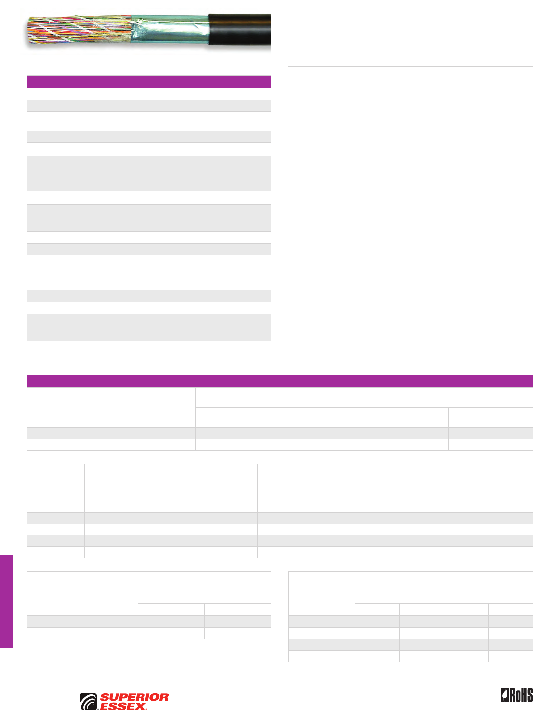
I-2
PREMISES COPPER PREMISES FIBER OSP FIBER OSP COMPOSITE CENTRAL OFFICE COPPER RDUP/RUS OSP COPPER BELL OSP COPPER OSP COPPER WIRE CANADIAN OSP COPPER TECHNICAL INFO
Rev 10/10 Ed 10.3Toll Free 800.551.8948 | Fax 770.657.6807 | SuperiorEssex.com/Comm
CELFIL
BJBB, BJAB, BJMB and BJTB
Specifications
Conductor Solid annealed copper
AWG (mm) Available in 19 (0.90), 22 (0.64), 24 (0.51) and 26 (0.40)
Insulation Dual-extruded cellular inner layer and color coded solid
polyolefin skin
Twisted Pairs Insulated conductors twisted to form pairs with varying lays
≤ 25-Pair Core Assembled in concentric layers to form a cylindrical core
≥ 50-Pair Core
Assembled from concentrically formed units with 25-pair
per unit; these may be stranded into 50-pair or 100-pair
groups, which are then cabled to form the complete
cylindrical core assembly
≥ 1,200-Pair Core Color code is Mirror Image design
Filling Compound
PEPJ compound applied to cable core which completely
coats each insulated conductor and fills interstices
between pairs and units
Core Non-hygroscopic core wrap applied over assembled core
Flooding Compound Applied to fill all voids under shield
Shield
Electrically continuous 8 mil flat aluminum shielding tape,
with polyolefin film fused and chemically bonded to both
sides, applied longitudinally over the core and bonded
to the outer jacket
Rip cord Placed parallel to core
Jacket Black, medium-density polyethylene
Jacket Marking
Manufacturer’s identification, date of jacketing, gauge,
pair count, sequential length and cable type marked
at 1 meter intervals
Standards
Compliance RoHS-compliant
Electrical Specifications
Number of Pairs
Average Mutual
Capacitance @ 1000 Hz
nF/mile (nF/km)
Capacitance Unbalance
Pair to Pair @ 1 kHz
Capacitance Unbalance
Pair to Ground @ 1 kHz
Maximum Individual
pF @ 1 kft (pF @ 1 km)
Maximum RMS
pF @ 1 kft (pF @ 1 km)
Maximum Individual
pF @ 1 kft (pF @ 1 km)
Maximum Average
pF @ 1 kft (pF @ 1 km)
12 or less 83 ± 7 (52 ± 4) 80 (145) - 800 (2,625) -
Over 12 83 ± 4 (52 ± 2) 80 (145) 25 (45) 800 (2,625) 175 (574)
Conductor Size
AWG (mm)
Minimum Insulation
Resistance 68°F (20°C)
gigohm-mile (gigohm-km)
Maximum Average
Attenuation
772 kHz @ 68°F (20°C)
dB/kft (dB/km)
Maximum Conductor
Resistance @ 68°F (20°C)
Ohms/sheath
kft (km)
DC Resistance Unbalance
Maximum %
Dielectric Strength
DC Potential – Volts
Minimum
Average
Individual
Pair
Conductor
to Conductor
Conductor
to Shield
19 (0.90) 1.0 (1.6) 3.2 (10.5) 8.5 (28.0) 1.5 5.0 4,500 10,000
22 (0.64) 1.0 (1.6) 4.5 (14.8) 17.3 (56.6) 1.5 5.0 3,600 10,000
24 (0.51) 1.0 (1.6) 5.6 (18.4) 26.1 (85.5) 1.5 5.0 3,000 10,000
26 (0.40) 1.0 (1.6) 7.0 (23.0) 44.0 (144.2) 1.5 5.0 2,400 10,000
Minimum Near End Crosstalk (NEXT)
dB/kft (dB/km) Conductor Size
AWG (mm)
Minimum Far End Crosstalk
dB/kft (dB/km)
PSELFEXT @ 150 kHz PSELFEXT @ 772 kHz
@ 150 kHz @ 772 kHz Mean Worst Pair Mean Worst Pair
PSWUNEXT Mean 58 (190) 47 (154) 19 (0.90) 65 (213) 59 (194) 51 (167) 45 (148)
PSWUNEXT Worst Pair 53 (174) 42 (138) 22 (0.64) 63 (207) 57 (187) 49 (161) 43 (141)
24 (0.51) 63 (207) 57 (187) 49 (161) 43 (141)
26 (0.40) 61 (200) 57 (187) 47 (154) 43 (141)
Product Description
Superior Essex CELFIL Cable with foam skin insulation is a single jacketed
design for use in duct or direct burial installations.
Features Benefits
• Twisted pairs with varying lays • Minimizes crosstalk
and meets capacitance
unbalance limitations
• Non-hygroscopic core wrap
applied over assembled core
• Furnishes mechanical
as well as high dielectric
protection between shielding
and individual conductors
• Rip cord placed parallel to core • Facilitates easy jacket removal
• Black, medium-density
polyethylene jacket
• Provides a tough, flexible
protective covering that
withstands exposure to sunlight,
atmospheric temperatures,
ground chemicals and stresses
expected in standard installations
I-3
PREMISES COPPERPREMISES FIBEROSP FIBEROSP COMPOSITECENTRAL OFFICE COPPERRDUP/RUS OSP COPPERBELL OSP COPPEROSP COPPER WIRECANADIAN OSP COPPERTECHNICAL INFO
Rev 10/10 Ed 10.3 Toll Free 800.551.8948 | Fax 770.657.6807 | SuperiorEssex.com/Comm
Part Numbers and Physical Characteristics
Part Number Pair Count AWG (mm)
Nominal Diameter
in (mm)
Approx. Weight
lbs/kft (kg/km)
Standard Length
ft (m)
Approx.
Shipping Weight
lbs (kg)
Reel Size
F x T x D
in
BJBB
85-026-13 6 19 (0.90) 0.49 (12) 120 (180) 4,593 (1,400) 660 (300) 44 x 18 x 20
85-028-13 12 19 (0.90) 0.58 (15) 190 (285) 4,593 (1,400) 1,040 (470) 46 x 25 x 20
85-031-13 25 19 (0.90) 0.77 (20) 355 (530) 7,924 (2,415) 3,100 (1,410) 62 x 30 x 24
85-034-13 50 19 (0.90) 1.03 (26) 655 (975) 4,593 (1,400) 3,295(1,500) 62 x 30 x 24
85-038-13 100 19 (0.90) 1.37 (35) 1,225 (1,825) 3,002 (915) 3,965 (1,800) 62 x 30 x 24
85-042-13 200 19 (0.90) 1.92 (49) 2,420 (3,600) 1,558 (475) 4,385 (1,990) 72 x 35 x 36
BJAB
85-057-13 6 22 (0.64) 0.38 (9.7) 70 (105) 9,186 (2,800) 750 (340) 44 x 18 x 20
85-059-13 12 22 (0.64) 0.47 (12) 115 (170) 9,186 (2,800) 1,220 (555) 46 x 25 x 20
85-061-13 18 22 (0.64) 0.53 (14) 155 (230) 4,593 (1,400) 820 (370) 44 x 18 x 20
85-062-13 25 22 (0.64) 0.60 (15) 200 (300) 9,186 (2,800) 2,080 (945) 58 x 25 x 20
85-065-13 50 22 (0.64) 0.76 (19) 350 (520) 6,004 (1,830) 2,345 (1,065) 58 x 25 x 20
85-069-13 100 22 (0.64) 1.02 (26) 650 (965) 4,593 (1,400) 3,275 (1,485) 62 x 30 x 24
85-073-13 200 22 (0.64) 1.37 (35) 1,225 (1,825) 2,608 (795) 3,565 (1,615) 65 x 30 x 32
85-075-13 300 22 (0.64) 1.66 (42) 1,815 (2,700) 2,182 (665) 4,575 (2,075) 72 x 35 x 36
85-077-13 400 22 (0.64) 1.88 (48) 2,375 (3,535) 1,952 (595) 5,335 (2,420) 78 x 40 x 39
85-081-13 600 22 (0.64) 2.29 (58) 3,545 (5,275) 1,542 (470) 6,165 (2,795) 78 x 40 x 39
85-083-13 900 22 (0.64) 2.75 (70) 5,225 (7,775) 854 (260) 5,075 (2,305) 72 x 35 x 36
85-085-13 1,200 22 (0.64) 3.18 (81) 6,950 (10,364) 620 (190) 7,113 (3,226) 96 x 42 x 56
BJMB
85-092-13 6 24 (0.51) 0.35 (8.9) 60 (90) 4,593 (1,400) 320 (145) 30 x 18 x 12
85-094-13 12 24 (0.51) 0.41 (10) 85 (125) 4,593 (1,400) 455 (205) 36 x 18 x 14
85-097-13 25 24 (0.51) 0.52 (13) 140 (210) 4,593 (1,400) 750 (340) 44 x 18 x 20
85-100-13 50 24 (0.51) 0.65 (17) 240 (355) 8,792 (2,680) 2,355 (1,070) 58 x 25 x 20
85-104-13 100 24 (0.51) 0.84 (21) 430 (640) 6,578 (2,005) 3,115 (1,415) 62 x 30 x 24
85-108-13 200 24 (0.51) 1.14 (29) 810 (1,205) 5,232 (1,595) 4,850 (2,205) 72 x 35 x 36
85-110-13 300 24 (0.51) 1.36 (35) 1,180 (1,755) 3,724 (1,135) 5,010 (2,270) 72 x 35 x 36
85-112-13 400 24 (0.51) 1.55 (39) 1,555 (2,315) 2,888 (880) 5,105 (2,320) 72 x 35 x 36
85-116-13 600 24 (0.51) 1.88 (48) 2,305 (3,430) 1,838 (560) 4,850 (2,205) 72 x 35 x 36
85-118-13 900 24 (0.51) 2.26 (57) 3,385 (5,040) 1,280 (390) 4,945 (2,250) 72 x 35 x 36
85-120-13 1,200 24 (0.51) 2.57 (65) 4,450 (6,625) 1,280 (390) 6,395 (2,905) 78 x 40 x 39
85-121-13 1,500 24 (0.51) 2.85 (72) 5,515 (8,210) 1,050 (320) 6,490 (2,950) 78 x 40 x 39
85-124-13 1,800 24 (0.51) 3.11 (79) 6,575 (9,785) 688 (210) 5,225 (2,370) 78 x 40 x 39
BJTB
85-132-13 25 26 (0.40) 0.44 (11) 100 (150) 4,593 (1,400) 525 (235) 36 x 18 x 14
85-135-13 50 26 (0.40) 0.55 (14) 165 (245) 4,593 (1,400) 865 (395) 44 x 18 x 20
85-139-13 100 26 (0.40) 0.70 (18) 290 (430) 4,593 (1,400) 1,535 (695) 52 x 25 x 20
85-143-13 200 26 (0.40) 0.94 (24) 535 (795) 4,593 (1,400) 2,745 (1,245) 62 x 30 x 24
85-145-13 300 26 (0.40) 1.09 (28) 755 (1,125) 2,624 (800) 2,225 (1,010) 58 x 25 x 20
85-147-13 400 26 (0.40) 1.25 (32) 995 (1,480) 2,624 (800) 2,855 (1,295) 58 x 25 x 20
85-151-13 600 26 (0.40) 1.50 (38) 1,465 (2,180) 1,738 (530) 2,835 (1,285) 62 x 30 x 24
85-153-13 900 26 (0.40) 1.79 (46) 2,145 (3,190) 1,722 (525) 3,980 (1,805) 62 x 30 x 24
85-155-13 1,200 26 (0.40) 2.03 (52) 2,805 (4,175) 1,264 (385) 4,160 (1,885) 72 x 35 x 36
85-156-13 1,500 26 (0.40) 2.29 (58) 3,515 (5,230) 1,246 (380) 4,995 (2,265) 72 x 35 x 36
85-157-13 1,800 26 (0.40) 2.50 (64) 4,200 (6,250) 1,214 (370) 5,800 (2,630) 78 x 40 x 39
85-158-13 2,100 26 (0.40) 2.69 (68) 4,885 (7,270) 1,182 (360) 6,475 (2,935) 78 x 40 x 39
85-159-13 2,400 26 (0.40) 2.85 (72) 5,540 (8,245) 1,000 (305) 6,240 (2,830) 78 x 40 x 39
85-161-13 2,700 26 (0.40) 3.01 (77) 6,200 (9,225) 1,000 (305) 6,900 (3,130) 78 x 40 x 39
CELFIL BJBB, BJAB, BJMB and BJTB
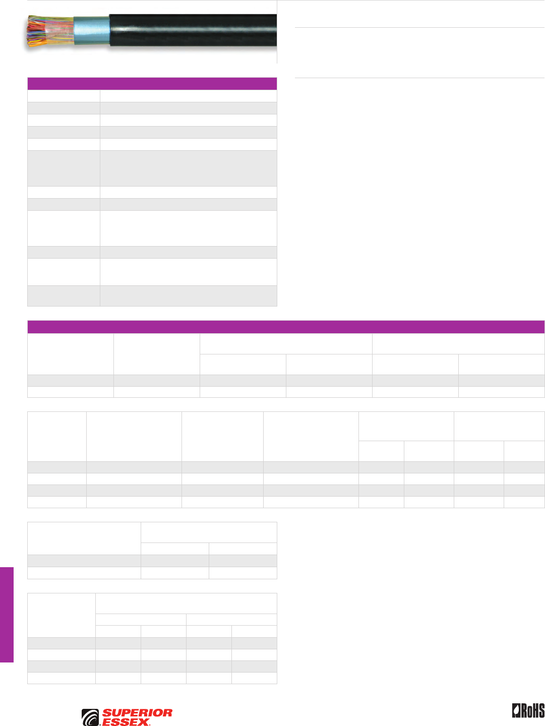
I-4
PREMISES COPPER PREMISES FIBER OSP FIBER OSP COMPOSITE CENTRAL OFFICE COPPER RDUP/RUS OSP COPPER BELL OSP COPPER OSP COPPER WIRE CANADIAN OSP COPPER TECHNICAL INFO
Rev 10/10 Ed 10.3Toll Free 800.551.8948 | Fax 770.657.6807 | SuperiorEssex.com/Comm
Canadian ALPETH
BHBB, BHAB, BKMB and BKTB
Specifications
Conductor Solid annealed copper
AWG (mm) Available in 19 (0.90), 22 (0.64), 24 (0.51) and 26 (0.40)
Insulation Color coded solid polyolefin
Twisted Pairs Insulated conductors twisted to pairs with varying lays
≤ 25-Pair Core Assembled in concentric layers to form a cylindrical core
≥ 50-Pair Core
Assembled from concentrically formed units with 25-pair
per unit; these may be stranded into 50-pair or 100-pair
groups, which are then cabled to form the complete
cylindrical core assembly
≥ 1,200-Pair Core Color code is Mirror Image design
Core Covering Non-hygroscopic core wrap applied over assembled core
Shield
Electrically continuous 8 mil flat aluminum shielding tape
with polyolefin film fused and chemically bonded to both
sides; applied longitudinally over the core and bonded
to the outer jacket
Jacket Black, medium-density polyethylene
Jacket Marking
Manufacturer’s identification, date of jacketing, gauge,
pair count, sequential length and cable type marked
at 1 meter intervals
Standards
Compliance RoHS-compliant
Electrical Specifications
Number of Pairs
Average Mutual
Capacitance @ 1000 Hz
nF/mile (nF/km)
Capacitance Unbalance
Pair to Pair @ 1 kHz
Capacitance Unbalance
Pair to Ground @ 1 kHz
Maximum Individual
pF @ 1 kft (pF @ 1 km)
Maximum RMS
pF @ 1 kft (pF @ 1 km)
Maximum Individual
pF @ 1 kft (pF @ 1 km)
Maximum Average
pF @ 1 kft (pF @ 1 km)
12 or less 83 ± 7 (52 ± 4) 80 (145) - 800 (2,625) -
Over 12 83 ± 4 (52 ± 2) 80 (145) 25 (45) 800 (2,625) 175 (574)
Conductor Size
AWG (mm)
Minimum Insulation
Resistance @ 68°F (20°C)
gigohm-mile (gigohm-km)
Maximum Average
Attenuation
772 kHz @ 68°F (20°C)
dB/kft (dB/km)
Maximum Conductor
Resistance @ 68°F (20°C)
Ohms/sheath
kft (km)
DC Resistance Unbalance
Maximum %
Dielectric Strength
DC Potential – Volts
Minimum
Average
Individual
Pair
Conductor
to Conductor
Conductor
to Shield
19 (0.90) 1.0 (1.6) 3.3 (10.8) 8.5 (28.0) 1.5 5.0 5,000 10,000
22 (0.64) 1.0 (1.6) 4.7 (15.4) 17.3 (56.6) 1.5 5.0 4,000 10,000
24 (0.51) 1.0 (1.6) 5.9 (19.4) 26.1 (85.5) 1.5 5.0 3,000 10,000
26 (0.40) 1.0 (1.6) 7.4 (24.3) 44.0 (144.2) 1.5 5.0 2,400 10,000
Minimum Near End Crosstalk (NEXT)
dB/kft (dB/km)
@ 150 kHz @ 772 kHz
PSWUNEXT Mean 58 (190) 47 (154)
PSWUNEXT Worst Pair 53 (174) 42 (138)
Conductor Size
AWG (mm)
Minimum Far End Crosstalk
dB/kft (dB/km)
PSELFEXT @ 150 kHz PSELFEXT @ 772 kHz
Mean Worst Pair Mean Worst Pair
19 (0.90) 65 (213) 59 (194) 51 (167) 45 (148)
22 (0.64) 63 (207) 57 (187) 49 (161) 43 (141)
24 (0.51) 63 (207) 57 (187) 49 (161) 43 (141)
26 (0.40) 61 (200) 57 (187) 47 (154) 43 (141)
Product Description
Superior Essex ALPETH Cables are designed primarily for aerial use. In this
application, the cable must be attached to a support strand (messenger).
If the cable is to be placed in a duct, the cable must be pressurized.
Features Benefits
• Twisted pairs with varying lays • Minimizes crosstalk
and meets capacitance
unbalance limitations
• Non-hygroscopic core wrap
applied over assembled core
• Furnishes mechanical
as well as high dielectric
protection between shielding
and individual conductors
• Black, medium-density
polyethylene jacket
• Provides a tough, flexible
protective covering that
withstands exposure to sunlight,
atmospheric temperatures,
ground chemicals and stresses
expected in standard installations
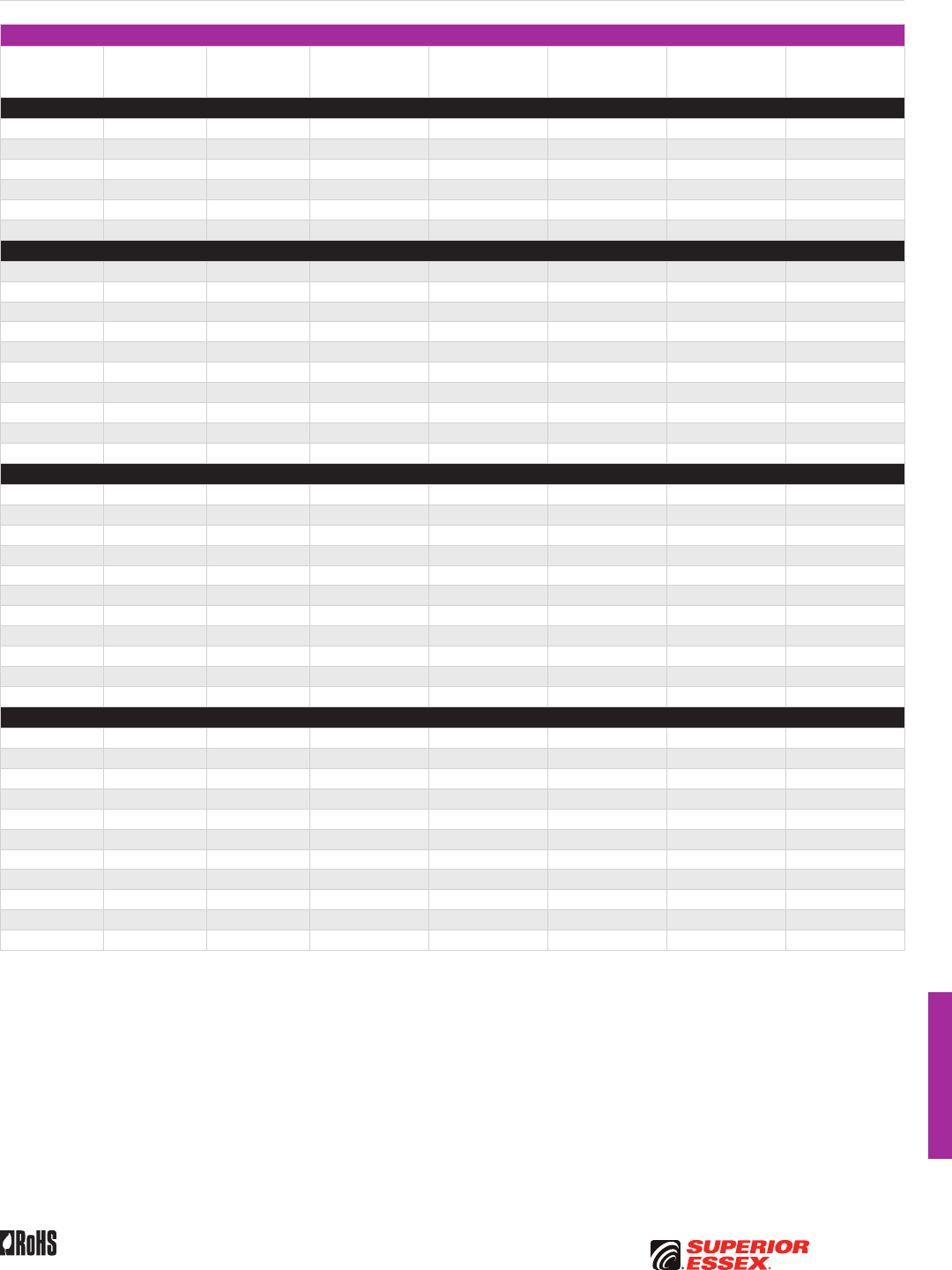
I-5
PREMISES COPPERPREMISES FIBEROSP FIBEROSP COMPOSITECENTRAL OFFICE COPPERRDUP/RUS OSP COPPERBELL OSP COPPEROSP COPPER WIRECANADIAN OSP COPPERTECHNICAL INFO
Rev 10/10 Ed 10.3 Toll Free 800.551.8948 | Fax 770.657.6807 | SuperiorEssex.com/Comm
Canadian ALPETH BHBB, BHAB, BKMB and BKTB
Part Numbers and Physical Characteristics
Part Number Pair Count AWG (mm)
Nominal Diameter
in (mm)
Approx. Weight
lbs/kft (kg/km)
Standard Length
ft (m)
Approx. Shipping
Weight lbs (kg)
Reel Size
F x T x D
in
BHBB
85-026-01 6 19 (0.90) 0.47 (12) 105 (155) 4,593 (1,400) 590 (270) 44 x 18 x 20
85-028-01 12 19 (0.90) 0.56 (14) 170 (255) 4,593 (1,400) 945 (430) 46 x 25 x 20
85-031-01 25 19 (0.90) 0.74 (19) 310 (460) 4,593 (1,400) 1,625 (740) 52 x 25 x 20
85-034-01 50 19 (0.90) 0.98 (25) 565 (840) 4,593 (1,400) 2,965 (1,345) 65 x 30 x 32
85-038-01 100 19 (0.90) 1.31 (33) 1,060 (1,580) 3,002 (915) 3,470 (1,575) 62 x 30 x 24
85-042-01 200 19 (0.90) 1.84 (47) 2,075 (3,090) 1,492 (455) 3,385 (1,535) 62 x 30 x 24
BHAB
85-057-01 6 22 (0.64) 0.38 (9.7) 65 (95) 4,593 (1,400) 345 (155) 30 x 18 x 12
85-059-01 12 22 (0.64) 0.45 (11) 100 (150) 4,593 (1,400) 525 (235) 36 x 18 x 14
85-062-01 25 22 (0.64) 0.59 (15) 180 (270) 5,724 (1,745) 1,195 (540) 46 x 25 x 20
85-065-01 50 22 (0.64) 0.75 (19) 310 (460) 5,724 (1,745) 2,020 (915) 58 x 25 x 20
85-069-01 100 22 (0.64) 1.00 (25) 570 (850) 4,593 (1,400) 2,905 (1,320) 62 x 30 x 24
85-073-01 200 22 (0.64) 1.35 (34) 1,080 (1,605) 3,412 (1,040) 4,300 (1,950) 72 x 35 x 36
85-075-01 300 22 (0.64) 1.64 (42) 1,595 (2,375) 2,182 (665) 4,095 (1,855) 72 x 35 x 36
85-077-01 400 22 (0.64) 1.86 (47) 2,105 (3,135) 2,132 (650) 5,100 (2,315) 72 x 35 x 36
85-081-01 600 22 (0.64) 2.27 (58) 3,135 (4,665) 1,410 (430) 5,035 (2,285) 72 x 35 x 36
85-083-01 900 22 (0.64) 2.74 (70) 4,640 (6,905) 688 (210) 3,805 (1,725) 72 x 35 x 36
BKMB
85-092-01 6 24 (0.51) 0.34 (8.6) 50 (75) 4,593 (1,400) 275 (125) 30 x 18 x 12
85-094-01 12 24 (0.51) 0.40 (10) 75 (110) 4,593 (1,400) 410 (185) 36 x 18 x 14
85-097-01 25 24 (0.51) 0.50 (13) 125 (185) 4,593 (1,400) 680 (310) 44 x 18 x 20
85-100-01 50 24 (0.51) 0.63 (16) 215 (320) 4,593 (1,400) 1,155 (525) 46 x 25 x 20
85-104-01 100 24 (0.51) 0.81 (21) 380 (565) 4,593 (1,400) 1,950 (885) 52 x 25 x 20
85-108-01 200 24 (0.51) 1.09 (28) 705 (1,050) 4,593 (1,400) 3,605 (1,635) 65 x 30 x 32
85-110-01 300 24 (0.51) 1.30 (33) 1,025 (1,525) 1,838 (560) 2,085 (945) 52 x 25 x 20
85-112-01 400 24 (0.51) 1.50 (38) 1,355 (2,015) 1,492 (455) 2,265 (1,030) 58 x 25 x 20
85-116-01 600 24 (0.51) 1.81 (46) 2,010 (2,990) 1,264 (385) 2,830 (1,285) 62 x 30 x 24
85-118-01 900 24 (0.51) 2.17 (55) 2,970 (4,420) 1,182 (360) 4,125 (1,870) 72 x 35 x 36
85-120-01 1,200 24 (0.51) 2.49 (63) 3,915 (5,825) 952 (290) 4,340 (1,970) 72 x 35 x 36
BKTB
85-132-01 25 26 (0.40) 0.43 (11) 90 (135) 4,593 (1,400) 475 (215) 36 x 18 x 14
85-135-01 50 26 (0.40) 0.53 (14) 150 (225) 4,822 (1,470) 830 (375) 44 x 18 x 20
85-139-01 100 26 (0.40) 0.68 (17) 255 (380) 4,593 (1,400) 1,335 (605) 46 x 25 x 20
85-143-01 200 26 (0.40) 0.91 (23) 465 (690) 4,593 (1,400) 2,380 (1,080) 58 x 25 x 20
85-145-01 300 26 (0.40) 1.05 (27) 665 (990) 2,624 (800) 1,950 (885) 52 x 25 x 20
85-147-01 400 26 (0.40) 1.21 (31) 870 (1,295) 2,624 (800) 2,530 (1,145) 58 x 25 x 20
85-151-01 600 26 (0.40) 1.45 (37) 1,290 (1,920) 2,394 (730) 3,455 (1,570) 65 x 30 x 32
85-153-01 900 26 (0.40) 1.74 (44) 1,900 (2,830) 1,526 (465) 3,270 (1,485) 65 x 30 x 32
85-155-01 1,200 26 (0.40) 1.98 (50) 2,495 (3,715) 1,460 (445) 4,255 (1,930) 72 x 35 x 36
85-156-01 1,500 26 (0.40) 2.23 (57) 3,105 (4,620) 1,000 (305) 3,720 (1,685) 72 x 35 x 36
85-157-01 1,800 26 (0.40) 2.43 (62) 3,705 (5,515) 1,312 (400) 5,560 (2,520) 78 x 40 x 39
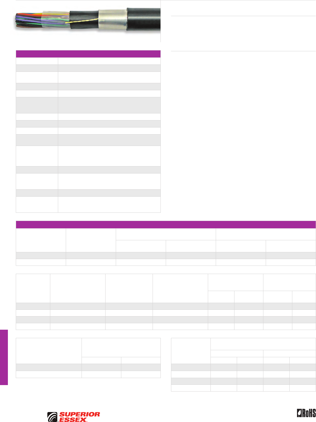
I-6
PREMISES COPPER PREMISES FIBER OSP FIBER OSP COMPOSITE CENTRAL OFFICE COPPER RDUP/RUS OSP COPPER BELL OSP COPPER OSP COPPER WIRE CANADIAN OSP COPPER TECHNICAL INFO
Rev 10/10 Ed 10.3Toll Free 800.551.8948 | Fax 770.657.6807 | SuperiorEssex.com/Comm
SEALPAP
BHBF, BHAF, BKMF and BKTF
Specifications
Conductor Solid annealed copper
AWG (mm) Available in 19 (0.90), 22 (0.64), 24 (0.51) and 26 (0.40)
Insulation Conductors are insulated with solid polyolefin in distinctive
colors to facilitate pair identification
Twisted Pairs Insulated conductors twisted to pairs with varying lays
≤ 25-Pair Core Pairs are combined into a cylindrical core
≥ 50-Pair Core
Multiples of 25-pair groups are assembled to form the
final cable core; each group is identified by color coded
non-hygroscopic binders
≥ 1,200-Pair Core Color code is Mirror Image design
Core Wrap Non-hygroscopic dielectric material
Inner Jacket Polyethylene
Rip cords Placed between the core wrap and the inner jacket
and between the inner jacket and shield
Shield
Electrically continuous 8 mil flat aluminum shielding tape,
with polyolefin film fused and chemically bonded to both
sides, applied longitudinally over the core and bonded to
the outer jacket
Outer Jacket Black, medium-density polyethylene
Jacket Marking
Manufacturer’s identification, plant location, date of jacketing,
pair count, AWG, product identification, sequential length
markings in meters and telephone handset
Package 420 steel reel (F x T x D = 83 x 40 x 42 inches)
Standards
Compliance
Telcordia GR-421-CORE
ANSI/ICEA S-85-625-2007
RoHS-compliant
Electrical Specifications
Number of Pairs
Average Mutual
Capacitance @ 1000 Hz
nF/mile (nF/km)
Capacitance Unbalance
Pair to Pair @ 1 kHz
Capacitance Unbalance
Pair to Ground @ 1 kHz
Maximum Individual
pF @ 1 kft (pF @ 1 km)
Maximum RMS
pF @ 1 kft (pF @ 1 km)
Maximum Individual
pF @ 1 kft (pF @ 1 km)
Maximum Average
pF @ 1 kft (pF @ 1 km)
12 or less 83 ± 4 (52 ± 2) 80 (145) - 800 (2,625) -
Over 12 83 ± 4 (52 ± 2) 80 (145) 25 (45) 800 (2,625) 175 (574)
Conductor Size
AWG (mm)
Minimum Insulation
Resistance @ 68°F (20°C)
gigohm-mile (gigohm-km)
Maximum Average
Attenuation
772 kHz @ 68°F (20°C)
dB/kft (dB/km)
Maximum Conductor
Resistance @ 68°F (20°C)
Ohms/sheath
kft (km)
DC Resistance Unbalance
Maximum %
Dielectric Strength
DC Potential – Volts
Minimum
Average
Individual
Pair
Conductor
to Conductor
Conductor
to Shield
19 (0.90) 1.0 (1.6) 3.3 (10.8) 45 (28.0) 1.5 5.0 5,000 20,000
22 (0.64) 1.0 (1.6) 4.7 (15.4) 91 (56.6) 1.5 5.0 4,000 20,000
24 (0.51) 1.0 (1.6) 5.9 (19.4) 144 (89.5) 1.5 5.0 3,000 20,000
26 (0.40) 1.0 (1.6) 7.4 (24.3) 232 (144.2) 1.5 5.0 2,400 20,000
Minimum Near End Crosstalk (NEXT)
dB/kft (dB/km) Conductor Size
AWG (mm)
Minimum Far End Crosstalk
dB/kft (dB/km)
PSELFEXT @ 150 kHz PSELFEXT @ 772 kHz
@ 150 kHz @ 772 kHz Mean Worst Pair Mean Worst Pair
PSWUNEXT Mean 58 (190) 47 (154) 19 (0.90) 65 (213) 59 (194) 51 (167) 45 (148)
PSWUNEXT Worst Pair 53 (174) 42 (138) 22 (0.64) 63 (207) 57 (187) 49 (161) 43 (141)
24 (0.51) 63 (207) 57 (187) 49 (161) 43 (141)
26 (0.40) 61 (200) 57 (187) 47 (154) 43 (141)
Product Description
Double jacketed air core cable, commonly called “SEALPAP,” is a solid-
insulated design intended for use in Outside Plant (OSP) where a greater risk
of physical damage exists. The inner jacket provides protection to the cable
core in the event of severe damage to the outer protective sheath.
Features Benefits
• Twisted pairs with varying lays • Minimizes crosstalk
and meets capacitance
unbalance limitations
• Core wrap • Protects core and helps provide
core-to-shield dielectric strength
• Inner jacket • Provides protection against
mechanical damage and helps
prevent the ingress of moisture
• Outer jacket bonded to shield • Provides a tough, flexible
protective covering that
withstands exposure to sunlight,
atmospheric temperatures,
and stresses expected in
standard installations
• Bonding provides additional
moisture resistance
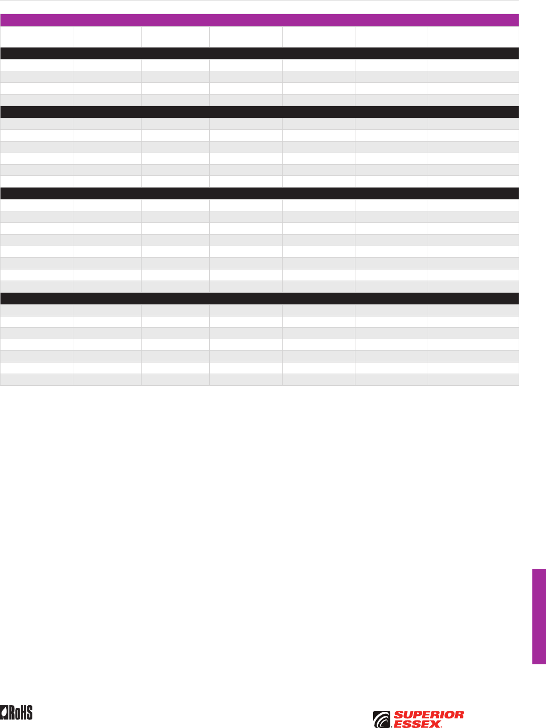
I-7
PREMISES COPPERPREMISES FIBEROSP FIBEROSP COMPOSITECENTRAL OFFICE COPPERRDUP/RUS OSP COPPERBELL OSP COPPEROSP COPPER WIRECANADIAN OSP COPPERTECHNICAL INFO
Rev 10/10 Ed 10.3 Toll Free 800.551.8948 | Fax 770.657.6807 | SuperiorEssex.com/Comm
SEALPAP BHBF, BHAF, BKMF and BKTF
Part Numbers and Physical Characteristics
Part Number Pair Count AWG (mm)
Nominal Diameter
in (mm)
Approx. Weight
lbs/kft (kg/km)
Standard Length
ft (m)
Approx. Shipping Weight
lbs (kg)
BHBF
85-031-41 25 19 (0.90) 0.84 (21) 355 (530) 9,006 (2,745) 3,990 (1,810)
85-034-41 50 19 (0.90) 1.07 (27) 625 (930) 4,512 (1,375) 3,615 (1,640)
85-038-41 100 19 (0.90) 1.43 (36) 1,170 (1,740) 2,986 (910) 4,290 (1,945)
85-042-41 200 19 (0.90) 1.96 (50) 2,230 (3,320) 2,230 (680) 5,770 (2,615)
BHAF
85-062-41 25 22 (0.64) 0.68 (17) 215 (320) 5,724 (1,745) 2,025 (920)
85-065-41 50 22 (0.64) 0.85 (22) 360 (535) 5,724 (1,745) 2,855 (1,295)
85-069-41 100 22 (0.64) 1.09 (28) 635 (945) 4,282 (1,305) 3,515 (1,595)
85-073-41 200 22 (0.64) 1.47 (37) 1,190 (1,770) 3,412 (1,040) 4,855 (2,200)
85-077-41 400 22 (0.64) 1.99 (51) 2,260 (3,365) 2,132 (650) 5,615 (2,545)
85-081-41 600 22 (0.64) 2.42 (62) 3,370 (5,015) 1,410 (430) 5,545 (2,515)
BKMF
85-100-41 50 24 (0.51) 0.72 (18) 255 (380) 6,316 (1,925) 2,405 (1,090)
85-104-41 100 24 (0.51) 0.91 (23) 430 (640) 6,004 (1,830) 3,375 (1,530)
85-108-41 200 24 (0.51) 1.18 (30) 770 (1,145) 2,116 (645) 2,425 (1,100)
85-110-41 300 24 (0.51) 1.43 (36) 1,130 (1,680) 2,280 (695) 3,370 (1,530)
85-112-41 400 24 (0.51) 1.62 (41) 1,475 (2,195) 2,280 (695) 4,160 (1,885)
85-116-41 600 24 (0.51) 1.94 (49) 2,160 (3,215) 1,312 (400) 3,630 (1,645)
85-118-41 900 24 (0.51) 2.33 (59) 3,190 (4,745) 1,050 (320) 4,145 (1,880)
85-120-41 1,200 24 (0.51) 2.64 (67) 4,165 (6,200) 1,312 (400) 6,260 (2,840)
BKTF
85-135-41 50 26 (0.40) 0.63 (16) 185 (275) 4,822 (1,470) 1,685 (765)
85-139-41 100 26 (0.40) 0.77 (20) 300 (445) 4,822 (1,470) 2,240 (1,015)
85-143-41 200 26 (0.40) 1.00 (25) 525 (780) 4,822 (1,470) 3,325(1,510)
85-147-41 400 26 (0.40) 1.33 (34) 970 (1,445) 2,394 (730) 3,115 (1,415)
85-151-41 600 26 (0.40) 1.58 (40) 1,410 (2,100) 2,394 (730) 4,170 (1,890)
85-153-41 900 26 (0.40) 1.87 (48) 2,045 (3,045) 1,510 (460) 3,885 (1,760)
85-155-41 1,200 26 (0.40) 2.13 (54) 2,695 (4,010) 1,526 (465) 4,910 (2,225)
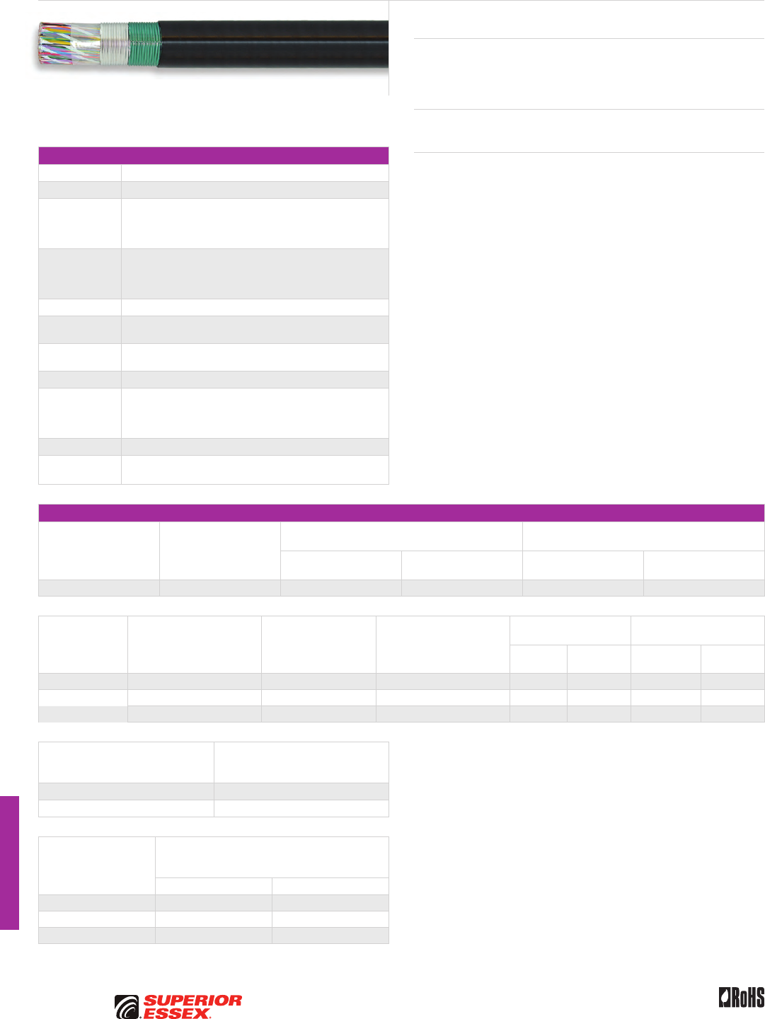
I-8
PREMISES COPPER PREMISES FIBER OSP FIBER OSP COMPOSITE CENTRAL OFFICE COPPER RDUP/RUS OSP COPPER BELL OSP COPPER OSP COPPER WIRE CANADIAN OSP COPPER TECHNICAL INFO
Rev 10/10 Ed 10.3Toll Free 800.551.8948 | Fax 770.657.6807 | SuperiorEssex.com/Comm
Canadian Bonded STALPETH
DCAZ, DCMZ and DCTZ
Specifications
Conductor Solid annealed copper
AWG (mm) Available in 22 (0.64), 24 (0.51) and 26 (0.40)
Insulation
Conductors are dual insulated with an inner layer of foamed,
natural polyolefin covered by an outer layer of solid, colored
polyolefin; conductor insulation is color coded in accordance
with industry standard
≥ 50-Pair Core
Multiples of 25-pair groups are assembled to form the final
cable core; each group is identified by color coded
non-hygroscopic binders; for 1,200-pair and larger,
the color code is Mirror Image design
Core Wrap Non-hygroscopic dielectric material
Shield Corrugated bare 8 mil aluminum tape applied longitudinally over
the core wrap
Armor Corrugated, copolymer coated, 6 mil steel tape applied over the
aluminum shield and bonded to the outer jacket
Jacket Black polyethylene
Jacket
Marking
Manufacturer’s identification, pair count, AWG, product
identification and a telephone handset printed at 2 foot
intervals; sequential footage markings are printed at alternate
2 foot intervals
Package 420 steel reel (F x T x D = 83 x 40 x 42 inches)
Standards
Compliance
Telcordia GR-421-CORE Issue 2
RoHS-compliant
Electrical Specifications
Number of Pairs
Average Mutual
Capacitance @ 1000 Hz
nF/mile (nF/km)
Capacitance Unbalance
Pair to Pair @ 1 kHz
Capacitance Unbalance
Pair to Ground @ 1 kHz
Maximum Individual
pF @ 1 kft (pF @ 1 km)
Maximum RMS
pF @ 1 kft (pF @ 1 km)
Maximum Individual
pF @ 1 kft (pF @ 1 km)
Maximum Average
pF @ 1 kft (pF @ 1 km)
All pairs 83 ± 4 (52 ± 2) 80 (145) 25 (45) 800 (2,625) 175 (574)
Conductor Size
AWG (mm)
Minimum Insulation
Resistance @ 68°F (20°C)
gigohm-mile (gigohm-km)
Maximum Average
Attenuation
772 kHz @ 68°F (20°C)
dB/kft (dB/km)
Maximum Conductor
Resistance @ 68°F (20°C)
Ohms/sheath
mile (km)
DC Resistance
Unbalance Maximum %
Dielectric Strength
DC Potential – Volts
Average
Individual
Pair
Conductor
to Conductor
Conductor
to Shield
22 (0.64) 1.0 (1.6) 5.0 (16.4) 91 (56.5) 1.5 5.0 1,400 5,000
24 (0.51) 1.0 (1.6) 6.3 (20.7) 144 (89.5) 1.5 5.0 1,200 5,000
26 (0.40) 1.0 (1.6) 7.9 (25.9) 232 (144.2) 1.5 5.0 1,000 5,000
Minimum Near End Crosstalk
(NEXT) @ 772 kHz
dB/kft (dB/km)
PSWUNEXT Mean 47 (154)
PSWUNEXT Worst Pair 42 (138)
Conductor Size
AWG (mm)
Minimum Far End Crosstalk
PSELFEXT @ 772 kHz
dB/kft (dB/km)
Mean Worst Pair
22 (0.64) 49 (161) 43 (141)
24 (0.51) 49 (161) 43 (141)
26 (0.40) 47 (154) 43 (141)
Product Description
Canadian Bonded STALPETH Cable is a foam-skin insulated, single jacketed,
armored air core design intended for use in ducts to provide more efficient
duct utilization than standard PIC designs.
Applications
• Congested underground duct systems
Features Benefits
• Tightly controlled individual
conductor dimensions
• Limits resistance unbalance
of paired conductors
• Specially designed
pair twist lays
• Minimizes crosstalk
and meets the capacitance
unbalance requirements
• Core wrap • Protects the core and
helps provide core-to-shield
dielectric strength
• Aluminum tape shield • Assures good electrical
contact with non-piercing
bonding clamps
• Steel tape armor bonded
to outer jacket
• Protects the core from
mechanical damage and reduces
the possibility of tape buckling
during installation, ingress of
water to the aluminum shield and
of water along the cable between
the armor and outer jacket
• Polyethylene jacket • Provides a tough, flexible,
protective covering that
withstands exposure to sunlight,
atmospheric temperatures,
ground chemicals and stresses
expected in standard installations
I-9
PREMISES COPPERPREMISES FIBEROSP FIBEROSP COMPOSITECENTRAL OFFICE COPPERRDUP/RUS OSP COPPERBELL OSP COPPEROSP COPPER WIRECANADIAN OSP COPPERTECHNICAL INFO
Rev 10/10 Ed 10.3 Toll Free 800.551.8948 | Fax 770.657.6807 | SuperiorEssex.com/Comm
Part Numbers and Physical Characteristics
Part Number Pair Count AWG (mm)
Nominal Diameter
in (mm)
Approx. Weight
lbs/kft (kg/km)
Standard Length
ft (m)
Approx.
Shipping Weight
lbs (kg)
DCAZ
07-021-76 900 22 (0.64) 2.49 (63) 4,375 (6,510) 1,600 (488) 7,795 (3,535)
07-021-77 1,200 22 (0.64) 2.85 (72) 5,770 (8,585) 1,200 (366) 7,720 (3,500)
DCMZ
19-116-01 600 24 (0.51) 1.70 (43) 19,60 (2,915) 3,900 (1,189) 8,440 (3,830)
07-021-99 900 24 (0.51) 2.02 (51) 2,860 (4,255) 2,616 (797) 8,275 (3,755)
07-021-68 1,200 24 (0.51) 2.30 (58) 3,755 (5,590) 2,000 (610) 8,305 (3,765)
07-022-12 1,500 24 (0.51) 2.57 (65) 4,660 (6,935) 1,600 (488) 8,250 (3,745)
07-021-69 1,800 24 (0.51) 2.81 (71) 5,545 (8,250) 1,250 (381) 7,725 (3,505)
07-021-75 2,100 24 (0.51) 3.04 (77) 6,440 (9,585) 1,148 (350) 8,200 (3,720)
07-021-98 2,400 24 (0.51) 3.22 (82) 7,320 (10,895) 876 (267) 7,205 (3,270)
DCTZ
07-022-11 900 26 (0.40) 1.62 (41) 1,850 (2,755) 3,904 (1,190) 8,010 (3,635)
07-021-70 1,200 26 (0.40) 1.84 (47) 2,420 (3,600) 3,200 (975) 8,540 (3,875)
07-022-08 1,500 26 (0.40) 2.08 (53) 2,995 (4,455) 2,500 (762) 8,285 (3,755)
07-021-71 1,800 26 (0.40) 2.26 (57) 3,560 (5,300) 2,080 (634) 8,200 (3,720)
07-021-72 2,400 26 (0.40) 2.58 (66) 4,685 (6,970) 1,600 (488) 8,290 (3,760)
07-021-90 2,700 26 (0.40) 2.71 (69) 5,240 (7,800) 1,247 (380) 7,345 (3,330)
07-021-73 3,000 26 (0.40) 2.86 (73) 5,800 (8,630) 1,200 (366) 7,755 (3,520)
07-021-74 3,600 26 (0.40) 3.03 (77) 6,885 (10,245) 1,150 (351) 8,715 (3,950)
Canadian Bonded STALPETH DCAZ, DCMZ and DCTZ
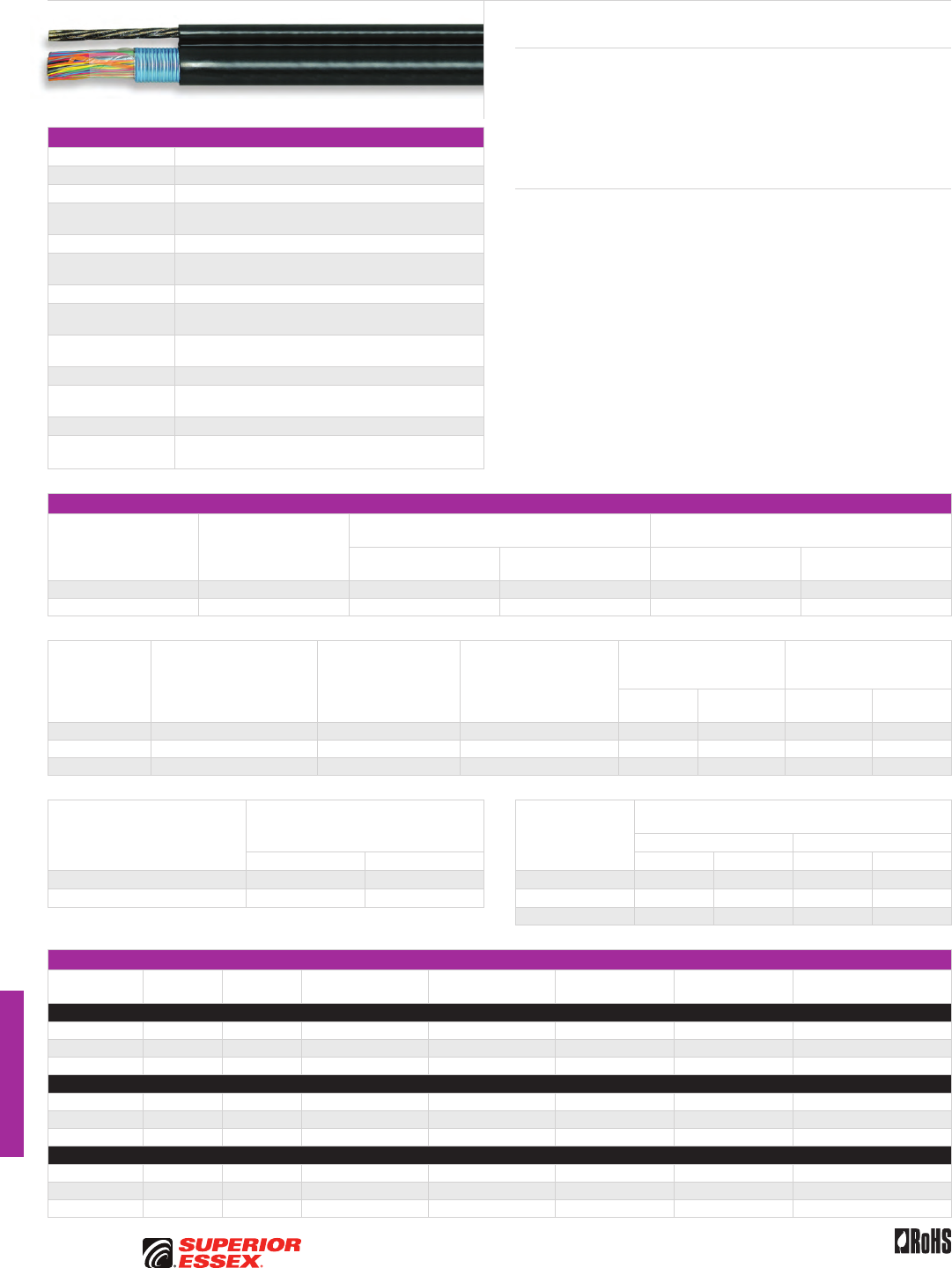
I-10
PREMISES COPPER PREMISES FIBER OSP FIBER OSP COMPOSITE CENTRAL OFFICE COPPER RDUP/RUS OSP COPPER BELL OSP COPPER OSP COPPER WIRE CANADIAN OSP COPPER TECHNICAL INFO
Rev 10/10 Ed 10.3Toll Free 800.551.8948 | Fax 770.657.6807 | SuperiorEssex.com/Comm
Canadian Self Support
BHBS-BC, BHAS-BC and BKMS-BC
Specifications
Conductor Solid annealed copper
AWG (mm) Available in 19 (0.90), 22 (0.64) and 24 (0.51)
Insulation Color coded solid polyolefin
Twisted Pairs Individual insulated conductors twisted into pairs
with varying lays and specific color combinations
≤ 25-Pair Core Pairs are combined into a cylindrical core
≥ 50-Pair Core Multiples of 25-pair groups are assembled into units;
each unit is identified by color coded binders
Core Wrap Non-hygroscopic, dielectric tape applied over core
Shield Corrugated, copolymer coated, 8 mil aluminum tape applied
longitudinally with an overlap
Support Member 0.25 inch, 7-strand Extra High Strength (EHS) galvanized steel
messenger support member is integral part of sheath
Jacket Black, polyethylene
Jacket Markings Manufacturer’s ID, date of jacketing, pair count, AWG and
meter sequentials at 1 meter intervals
Package 420 steel reel (F x T x D = 83 x 40 x 42 inches)
Standards
Compliance
Telcordia GR-421-CORE
RoHS-compliant
Electrical Specifications
Number of Pairs
Average Mutual
Capacitance @ 1000 Hz
nF/mile (nF/km)
Capacitance Unbalance
Pair to Pair @ 1 kHz
Capacitance Unbalance
Pair to Ground @ 1 kHz
Maximum Individual
pF @ 1 kft (pF @ 1 km)
Maximum RMS
pF @ 1 kft (pF @ 1 km)
Maximum Individual
pF @ 1 kft (pF @ 1 km)
Maximum Average
pF @ 1 kft (pF @ 1 km)
12 or less 83 ± 7 (52 ± 4) 80 (145) - 800 (2,625) -
Over 12 83 ± 4 (52 ± 2) 80 (145) 25 (45) 800 (2,625) 175 (574)
Conductor Size
AWG (mm)
Minimum Insulation
Resistance @ 68°F (20°C)
gigohm-mile (gigohm-km)
Maximum Average
Attenuation
772 kHz @ 68°F (20°C)
dB/kft (dB/km)
Maximum Conductor
Resistance @ 68°F (20°C)
Ohms/sheath
kft (km)
DC Resistance Unbalance
Maximum %
Dielectric Strength
DC Potential – Volts
Minimum
Average
Individual
Pair
Conductor
to Conductor
Conductor
to Shield
19 (0.90) 1.0 (1.6) 3.3 (10.8) 45 (28.0) 1.5 5.0 5,000 10,000
22 (0.64) 1.0 (1.6) 4.7 (15.4) 91 (56.6) 1.5 5.0 4,000 10,000
24 (0.51) 1.0 (1.6) 5.9 (19.4) 144 (89.5) 1.5 5.0 3,000 10,000
Minimum Near End Crosstalk (NEXT)
dB/kft (dB/km) Conductor Size
AWG (mm)
Minimum Far End Crosstalk
dB/kft (dB/km)
PSELFEXT @ 150 kHz PSELFEXT @ 772 kHz
@ 150 kHz @ 772 kHz Mean Worst Pair Mean Worst Pair
PSWUNEXT Mean 58 (190) 47 (154) 19 (0.90) 65 (213) 59 (194) 51 (167) 45 (148)
PSWUNEXT Worst Pair 53 (174) 42 (138) 22 (0.64) 63 (207) 57 (187) 49 (161) 43 (141)
24 (0.51) 63 (207) 57 (187) 49 (161) 43 (141)
Part Numbers and Physical Characteristics
Part Number Pair Count AWG (mm)
Minor Dimension
in (mm)
Major Dimension
in (mm)
Approx. Weight
lbs/kft (kg/km)
Standard Length
ft (m)
Approx. Shipping Weight
lbs (kg)
BHBS-BC
07-021-51 6 19 (0.90) 0.48 (12) 0.96 (24) 240 (355) 10,006 (3,050) 1,023 (1,526)
07-021-52 25 19 (0.90) 0.60 (15) 1.07 (27) 440 (655) 5,020 (1,530) 2,990 (4,459)
07-021-53 50 19 (0.90) 0.98 (25) 1.45 (34) 710 (1,055) 5,020 (1,530) 4,345 (6,480)
BHAS-BC
07-021-54 25 22 (0.64) 0.58 (15) 1.05 (27) 325 (485) 10,006 (3,050) 1,109 (1,654)
07-021-55 50 22 (0.64) 0.74 (19) 1.20 (31) 460 (685) 7,513 (2,290) 4,238 (6,320)
07-021-56 100 22 (0.64) 1.00 (25) 1.47 (37) 720 (1,070) 6,004 (1,830) 5,105 (7,613)
BKMS-BC
07-021-57 50 24 (0.51) 0.62 (16) 1.09 (28) 385 (573) 13,303 (4,055) 5,904 (8,805)
07-021-58 100 24 (0.51) 0.80 (22) 1.27 (32) 575 (856) 8,005 (2,440) 5,305 (8,031)
07-021-59 200 24 (0.51) 1.09 (28) 1.56 (40) 1,013 (1,508) 5,020 (1,530) 5,867 (8,750)
Product Description
Self Support Cable is a plastic insulated, single jacketed air core design with
a built-in support member intended specially for aerial applications. The
core and support member (messenger) lay parallel to each other forming
a cross-sectional “figure 8.” The messenger is an integral part of the cable
sheath, yet readily available for gripping, pulling and tensioning. Installation
is fast and easy using standard methods and hardware.
Features Benefits
• Twisted pairs with varying lays
and specific color combinations
• Minimizes crosstalk and provides
pair identification
• Core wrap • Provides core thermal protection
• Shield interfaces and steel
support member are flooded
with adhesive compound
• Provides moisture barrier
and inhibit corrosion
• Polyethylene jacket • Provides a tough protective
covering designed to withstand
exposure to direct sunlight,
atmospheric temperature
changes and stresses expected
in standard installations
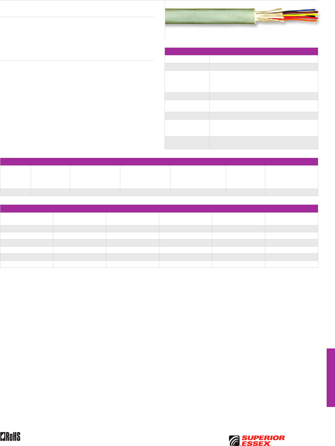
I-11
PREMISES COPPERPREMISES FIBEROSP FIBEROSP COMPOSITECENTRAL OFFICE COPPERRDUP/RUS OSP COPPERBELL OSP COPPEROSP COPPER WIRECANADIAN OSP COPPERTECHNICAL INFO
Rev 10/10 Ed 10.3 Toll Free 800.551.8948 | Fax 770.657.6807 | SuperiorEssex.com/Comm
Aerial Drop Wire
ADW
Specifications
Conductor Solid annealed copper
AWG (mm) 22 (0.64)
Insulation
Individual conductors insulated with solid polyolefin
in distinctive colors; 2-pair color code is Blue/White
and Orange/Red and 4-pair color code is Blue/White,
Orange/Red, Black/Green and Yellow/Brown
Core Assembly Individual conductors twisted into pairs
Strength Members Fiberglass strength members placed in the jacket parallel
to the core assembly
Rip cord Placed parallel to the core
Jacket
Sky blue grey weather-resistant PVC jacket extruded over
the strength members and bonded to the fiberglass
strength members
Standards
Compliance RoHS-compliant
Electrical Specifications
Conductor
Size
AWG (mm)
Average Mutual
Capacitance
@ 1000 Hz
nF/mile (nF/km)
Insulation Resistance
@ 60°F (16°C)
megohm-mile
(megohm-km)
Capacitance
Unbalance @ 1 kHz
Pair to Pair Maximum
pF @ 1 kft (pF @ 1 km)
Conductor DC
Resistance @ 20°F (-7°C)
Maximum Individual
Ohms/kft (Ohms/km)
Resistance
Unbalance
Maximim
Individual Pair %
Dielectric Strength
DC Potential – Volts
Minimum
Conductor to Conductor
22 (0.64) 113 (70) 380 (610) 80 (145) 16.8 (55) 5.0 4,000
Part Numbers and Physical Characteristics
Part Number Pair Count
Nominal Diameter
in (mm)
Approx. Weight
lbs/kft (kg/km)
Standard Length
ft (m) Package
12-022-09 2 0.26 (6.6) 30 (45) 1,476 (450) Coil
12-021-09 2 0.26 (6.6) 30 (45) 656 (200) POP™ Box
12-023-09 2 0.26 (6.6) 30 (45) 5,000 (1,524) Reel
12-041-09 4 0.33 (8.4) 55 (80) 820 (250) Coil
12-042-09 4 0.33 (8.4) 55 (80) 3,937 (1,200) Reel
12-043-09 4 0.33 (8.4) 55 (80) 328 (100) POP™ Box
Product Description
ADW is a PVC jacketed 2-pair or 4-pair aerial service wire designed for use
in extending telephone service to subscriber premises from the distribution
cable or cable terminal. Major features include small size and light weight
coupled with abrasion resistant jacket. Standard hardware and installations
procedures are directly applicable to this product.
Features Benefits
• Twisted pairs with varying lays • Minimizes resistance unbalance
• Fiberglass strength members • Provides the necessary
longitudinal strength
• Rip cord • Facilitates jacket removal
• Weather-resistant PVC jacket
extruded over the strength
members and bonded to the
fiberglass strength members
• Protects the core from
mechanical damage, degradation
by sunlight and the ingress of
moisture
• Provides the required strength
characteristics
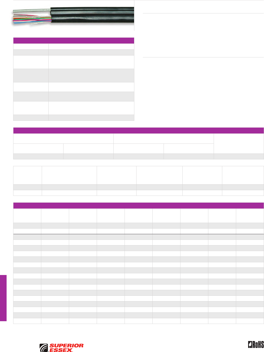
I-12
PREMISES COPPER PREMISES FIBER OSP FIBER OSP COMPOSITE CENTRAL OFFICE COPPER RDUP/RUS OSP COPPER BELL OSP COPPER OSP COPPER WIRE CANADIAN OSP COPPER TECHNICAL INFO
Toll Free 800.551.8948 | Fax 770.657.6807 | SuperiorEssex.com/Comm Rev 10/10 Ed 10.4
Canadian Integrated Messenger Wire
IM/F, IM/H and IM/G
Specifications
Conductor Solid annealed copper
AWG (mm) Available in 19 (0.90) and 22 (0.64)
Insulation
Solid polyolefin in distinctive colors; standard color codes
are used for pair identification with compounds chosen
for electrical balance and permanency
Core Assembly
Tightly controlled individual conductor dimensions; in multi-
pair constructions, pair twist lays are varied; twisted
pairs are formed into a firm, round core
Support Member Available in 0.083 inch (F), 0.109 inch (H), or 0.095 inch (G)
solid extra-strength steel support wire
Jacket Black, fire retardant, polyvinylchloride jacket; steel support
wire is jacketed in an integral extrusion with the core
Performance
Compliance
Telcordia GR-3163-CORE
ANSI/ICEA S-89-648-2006
RoHS-compliant
NRTL Programs UL Listed
Electrical Specifications
Average Mutual Capacitance @ 1000 Hz
Capacitance Unbalance @ 1 kHz
Maximum Individual Minimum Near End
Crosstalk (NEXT) @ 772 kHz
dB/kft (dB/km)
Maximum Individual
nF/mile (nF/km)
Wire Average
nF/mile (nF/km)
Pair to Pair
pF @ 1 kft (pF @ 1 km)
Pair to Ground
pF @ 1 kft (pF @ 1 km)
94 (58) 83 ± 7 (52 ± 4) 80 (145) 800 (2,625) 44 (144)
Conductor Size
AWG (mm)
Minimum Insulation Resistance
megohm-kft (megohm-km)
Maximum Average
Attenuation
772 kHz @ 68°F (20°C)
dB/kft (dB/km)
DC Conductor Resistance
@ 68°F (20°C)
Maximum Individual
Ohms/mile (Ohms/km)
Resistance Unbalance
Maximum %
Individual Pair
Conductor to Conductor
Dielectric Strength
Minimum Volts DC
3 secs, no breakdown
19 (0.90) 5,000 (1,600) 3.3 (11) 45 (28.0) 5.0 5,000
22 (0.64) 5,000 (1,600) 5.1 (17) 91 (56.5) 5.0 4,000
Part Numbers and Physical Characteristics
Part Number
Support Size
in Pair Count AWG (mm)
Minor
Dimension
in (mm)
Major
Dimension
in (mm)
Approx.
Weight
lbs/kft (kg/km)
Standard
Length
ft (m) Package
10-921-38 IM/G 0.095 2 19 (0.90) 0.27 (6.8) 0.51 (12.9) 73 (109) 656 (200) Coil
10-923-38 IM/G 0.095 2 19 (0.90) 0.27 (6.8) 0.51 (12.9) 73 (109) 4,921 (1,500) Reel
10-002-34 IM/F 0.083 2 22 (0.64) 0.22 (5.7) 0.46 (11.7) 55 (82) 600 (183) Coil
10-102-34 IM/F 0.083 2 22 (0.64) 0.22 (5.7) 0.46 (11.7) 55 (82) 5,000 (1,524) Reel
10-503-34 IM/F 0.083 3 22 (0.64) 0.24 (6.2) 0.48 (12.3) 72 (107) 600 (183) Coil
10-106-34 IM/F 0.083 6 22 (0.64) 0.30 (7.6) 0.53 (13.6) 80 (119) 3,500 (1,067) Reel
10-206-34 IM/F 0.083 6 22 (0.64) 0.30 (7.6) 0.53 (13.6) 80 (119) 1,000 (305) Reel
10-006-34 IM/F 0.083 6 22 (0.64) 0.30 (7.6) 0.53 (13.6) 80 (119) 250 (76) Coil
10-306-34 IM/F 0.083 6 22 (0.64) 0.30 (7.6) 0.53 (13.6) 80 (119) 400 (122) Coil
10-261-38 IM/G 0.095 6 22 (0.64) 0.30 (7.6) 0.55 (13.9) 80 (119) 492 (150) Coil
10-262-38 IM/G 0.095 6 22 (0.64) 0.30 (7.6) 0.55 (13.9) 80 (119) 2,461 (750) Reel
10-265-38 IM/G 0.095 6 22 (0.64) 0.30 (7.6) 0.55 (13.9) 80 (119) 5,000 (1,524) Reel
10-281-38 IM/G 0.095 12 22 (0.64) 0.38 (7.6) 0.65 (16.6) 114 (170) 410 (125) Coil
10-284-38 IM/G 0.095 12 22 (0.64) 0.38 (7.6) 0.65 (16.6) 114 (170) 2,460 (750) Reel
10-285-38 IM/G 0.095 12 22 (0.64) 0.38 (7.6) 0.65 (16.6) 114 (170) 8,202 (2,500) Reel
10-102-35 IM/H 0.109 12 22 (0.64) 0.38 (7.6) 0.66 (16.7) 130 (193) 1,000 (305) Reel
10-012-35 IM/H 0.109 12 22 (0.64) 0.38 (7.6) 0.66 (16.7) 130 (193) 250 (76) Coil
10-212-35 IM/H 0.109 12 22 (0.64) 0.38 (7.6) 0.66 (16.7) 130 (193) 5,000 (1,524) Reel
Contact Superior Essex for additional configurations and AWG sizes.
Product Description
IM/F, IM/H and IM/G Aerial Service Wire in 2, 3, 6 and 12-pair is self
supporting. The conductors are laid parallel to a solid extra-strength steel
support wire. Both the conductors and support wire are jacketed in an
integral “figure-8” configuration. This product permits fast, economical
installation from aerial distribution cable terminals to building entrance
protectors or network interface units on the subscriber’s premises. The fully
color coded core expedites splicing and terminating procedures.
Features Benefits
• Tightly controlled individual
conductor dimensions
• Limits resistance unbalance of
the twisted pairs
• Varied pair twist lays • Minimizes crosstalk and meets
capacitance limits
• Polyvinylchloride jacket • Provides a tough flexible
protective covering that
withstands exposure to sunlight,
atmospheric temperatures and
stresses encountered in standard
installations
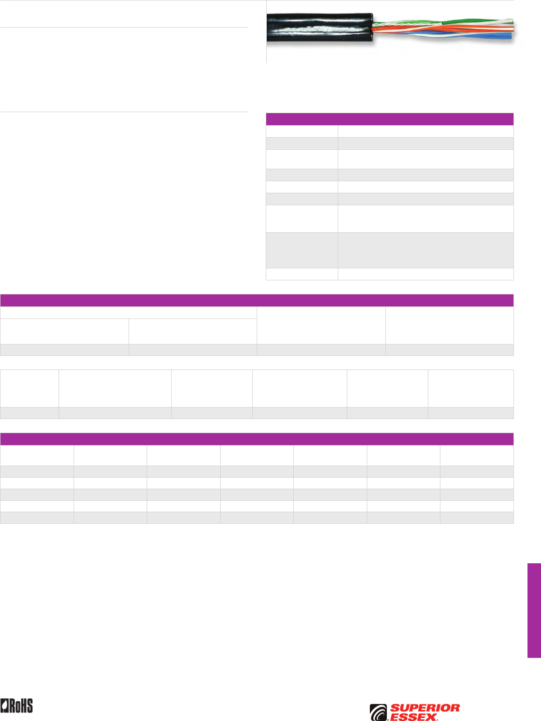
I-13
PREMISES COPPERPREMISES FIBEROSP FIBEROSP COMPOSITECENTRAL OFFICE COPPERRDUP/RUS OSP COPPERBELL OSP COPPEROSP COPPER WIRECANADIAN OSP COPPERTECHNICAL INFO
Toll Free 800.551.8948 | Fax 770.657.6807 | SuperiorEssex.com/CommRev 10/10 Ed 10.4
Canadian ADP NMS
with QuickCount® in Meters
Specifications
Conductor Solid annealed copper
AWG (mm) 22 (0.64)
Insulation Solid polyolefin; insulation of the tip conductor is marked
with a stripe of the mating ring insulation color
Core Assembly Individual conductors are carefully twisted into pairs
Strength Members Fiberglass yarns placed parallel to the core
Rip cord Placed parallel to the core
Jacket
Black, weather resistant, polyvinylchloride jacket extruded
over the yarns and rip cord and bonded to the fiberglass
strength members
Performance
Compliance
Telecordia GR-3163-CORE
RDUP PE-7
ANSI/ICEA S-89-648-2006
RoHS-compliant
NRTL Programs UL Listed
Electrical Specifications
Average Mutual Capacitance @ 1000 Hz Capacitance Unbalance @ 1 kHz
Maximum Individual
Pair to Pair
pF @ 1 kft (pF @ 1 km)
Minimum Near End Crosstalk
(NEXT) @ 772 kHz
dB/kft (dB/km)
Maximum Individual
nF/mile (nF/km)
Wire Average
nF/mile (nF/km)
94 (58) 83 ± 7 (52 ± 4) 80 (145) 48 (157)
Conductor Size
AWG (mm)
Minimum Insulation Resistance
megohm-mile (megohm-km)
Maximum Average
Attenuation
772 kHz @ 68°F (20°C)
dB/kft (dB/km)
DC Conductor Resistance
@ 68°F (20°C)
Maximum Individual
Ohms/mile (Ohms/km)
Resistance Unbalance
Maximum %
Individual Pair
Conductor to Conductor
Dielectric Strength
Minimum Volts DC
3 secs, no breakdown
22 (0.64) 1,000 (1,600) 5.1 (17) 91 (56.5) 5.0 4,000
Part Numbers and Physical Characteristics
Part Number Pair Count
Minor Dimension
in (mm)
Major Dimension
in (mm)
Approx. Weight
lbs/kft (kg/km)
Standard Length
m Package
12-015-08 2 0.18 (4.8) 0.36 (9.1) 35 (50) 150 ReelSaver™ Coil
12-014-08 2 0.18 (4.8) 0.36 (9.1) 35 (50) 228 POP™ Box
12-013-08 2 0.18 (4.8) 0.36 (9.1) 35 (50) 300 Coil
11-003-66 6 0.27 (7.0) 0.48 (12) 70 (105) 305 Reel
11-003-65 6 0.27 (7.0) 0.48 (12) 70 (105) 122 Coil
Product Description
ADP NMS is a PVC-jacketed aerial service wire with QuickCount® in meters.
It is available in 2-pair and 6-pair designs. ADP NMS printed in meters is
designed for use in extending telephone service to subscriber premises
from the distribution cable or cable terminal. Major features include small
size and light weight coupled with abrasion resistant jacket. Standard
hardware and installation procedures are directly applicable to this product.
Features Benefits
• Insulation of the tip conductor
is marked with a stripe of the
mating ring insulation color
• Reduces the possibility of
splitting pairs during installation
• Tightly controlled individual
conductor dimensions
• Limits resistance unbalance
of the twisted pairs
• Fiberglass yarns • Provides necessary
longitudinal strength
• Rip cord • Facilitates jacket removal
• Weather resistant,
polyvinylchloride jacket
bonded to the fiberglass
strength members
• Protects the core from mechanical
damage, degradation by sunlight
and ingress of moisture
• Provides the required strength
characteristics
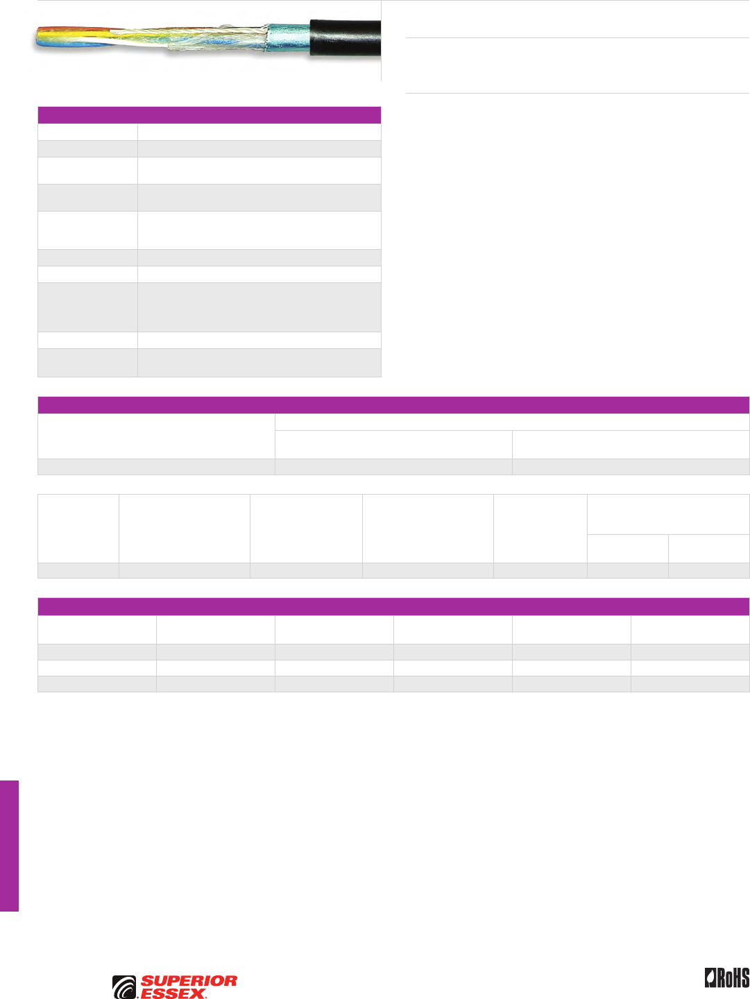
I-14
PREMISES COPPER PREMISES FIBER OSP FIBER OSP COMPOSITE CENTRAL OFFICE COPPER RDUP/RUS OSP COPPER BELL OSP COPPER OSP COPPER WIRE CANADIAN OSP COPPER TECHNICAL INFO
Rev 10/10 Ed 10.3Toll Free 800.551.8948 | Fax 770.657.6807 | SuperiorEssex.com/Comm
Buried Distribution Wire
BCBD
Specifications
Conductor Solid annealed copper
AWG (mm) 22 (0.64)
Insulation Dual-extruded cellular inner layer and a color coded solid
outer layer of polyolefin
Core Assembly Insulated conductors are twisted to form pairs
with varying lays
Filling Compound
PEPJ compound applied to the wire core which completely
coats each insulated conductor and fills the interstices
between pairs
Core Wrap Non-hygroscopic core wrap applied over the core
Flooding Compound Applied to fill all the voids under the shield
Shield
Electrically-continuous 8 mil flat aluminum tape shield with
a polyolefin film fused and chemically bonded to both
sides; applied longitudinally over the core and bonded to
the outer jacket
Jacket Black medium-density polyethylene
Standards
Compliance RoHS-compliant
Electrical Specifications
Average Mutual Capacitance @ 1000 Hz
nF/mile (nF/km)
Capacitance Unbalance Maximum Individual
Pair to Pair
pF @ 1 kft (pF @ 1 km)
Pair to Ground
pF @ 1 kft (pF @ 1 km)
90 (56) 80 (145) 800 (2,625)
Conductor Size
AWG (mm)
Minimum Insulation
Resistance @ 60°F (16°C)
gigohm-mile (gigohm-km)
Maximum Average
Attenuation
772 kHz @ 68°F (20°C)
dB/kft (dB/km)
Maximum Conductor
Resistance @ 68°F (20°C)
Ohms/sheath
kft (km)
Resistance
Unbalance
Maximum %
Individual Pair
Dielectric Strength
DC Potential – Volts
Minimum
Conductor to
Conductor
Conductor to
Shield
22 (0.64) 1.0 (1.6) 4.5 (14.8) 17.3 (56.6) 5.0 3,600 10,000
Part Numbers and Physical Characteristics
Part Number Pair Count
Nominal Diameter
in (mm)
Approx. Weight
lbs/kft (kg/km)
Standard Length
ft (m) Package
85-235-06 4 0.30 (7.6) 45 (65) 1,640 (500) Reel
85-233-06 4 0.30 (7.6) 45 (65) 4,593 (1,400) Reel
85-234-06 4 0.30 (7.6) 45 (65) 656 (200) Coil
Product Description
BCBD Wire with foam skin insulation is a single jacketed design for use in
subscriber distribution.
Features Benefits
• Varied pair twist lays • Minimizes crosstalk
and meets capacitance
unbalance limitations
• Core wrap • Furnishes mechanical and high
dielectric protection between
shielding and individual
conductors
• Polyethylene jacket • Provides a tough, flexible
protective covering that
withstands exposure to sunlight,
atmospheric temperatures,
ground chemicals and stresses
expected in standard installations
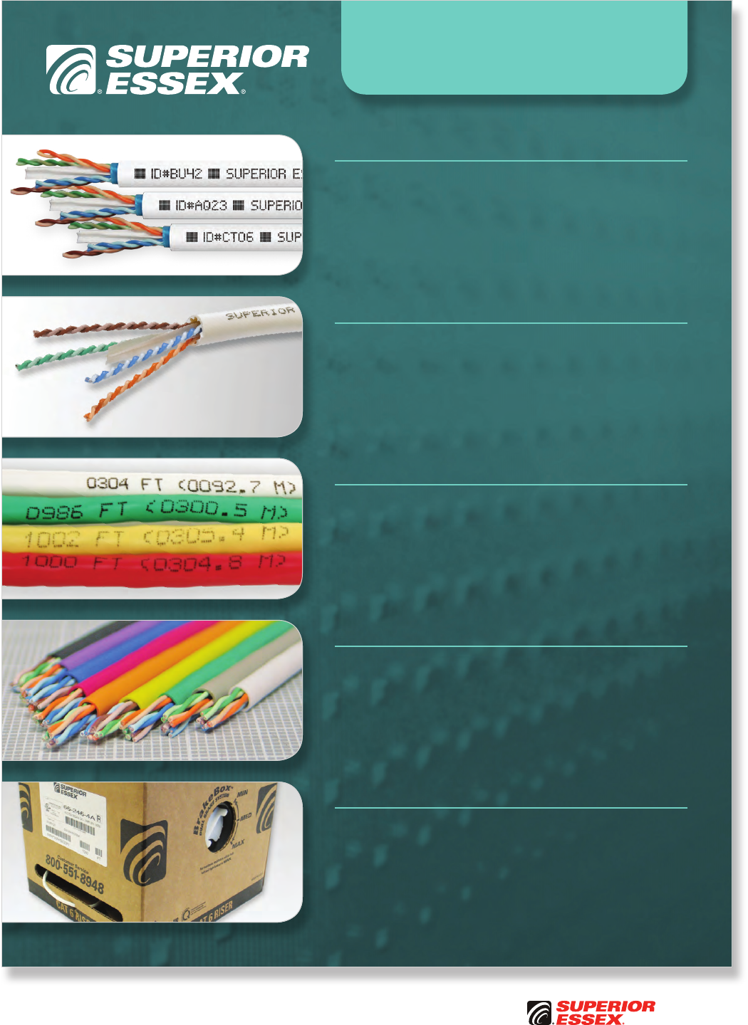
Toll Free 800.551.8948 | Fax 770.657.6807 | SuperiorEssex.com/Comm
QuickCount® Feet/Meters Marking
• Jacket marking in feet and meters
• Provides remaining length of cable on reel removing
the guesswork for cable installers
• Saves installation time and money
ColorTip™ Circuit Identification
• Circumferentially colors 100% of the conductor for easily
identifiable tip and ring mates
• Distinct colors reduces termination time and errors,
even in low light environments
• Permanent, environmentally friendly color that doesn’t
rub or wear off
CableID™ Alpha Numeric Coding
• Unique 4-character printed code, every 2 feet, on the cable
jacket for each 1000-foot box and reel of copper data cable
• Both ends of each cable run are easily identifiable without
the need to separately label or tone the cable
• Reduces installation time and cost for initial installations
and for moves, adds and changes
Standard Jacket Colors
• Extensive, in-stock jacket color offering in many
of the premises copper products
• Most colors available with no minimum quantity and
custom colors available upon request with minimum
order quantities
BrakeBox® Payout Control
The BrakeBox packaging is a true advantage for installers
who are pulling cable in multiple locations.
• Stacks, travels and protects cable better than an open reel
• Two resistance mechanisms on both sides of the box,
each with three variable resistance settings
• Controls back-tension preventing over-spin and tangling
Product Features

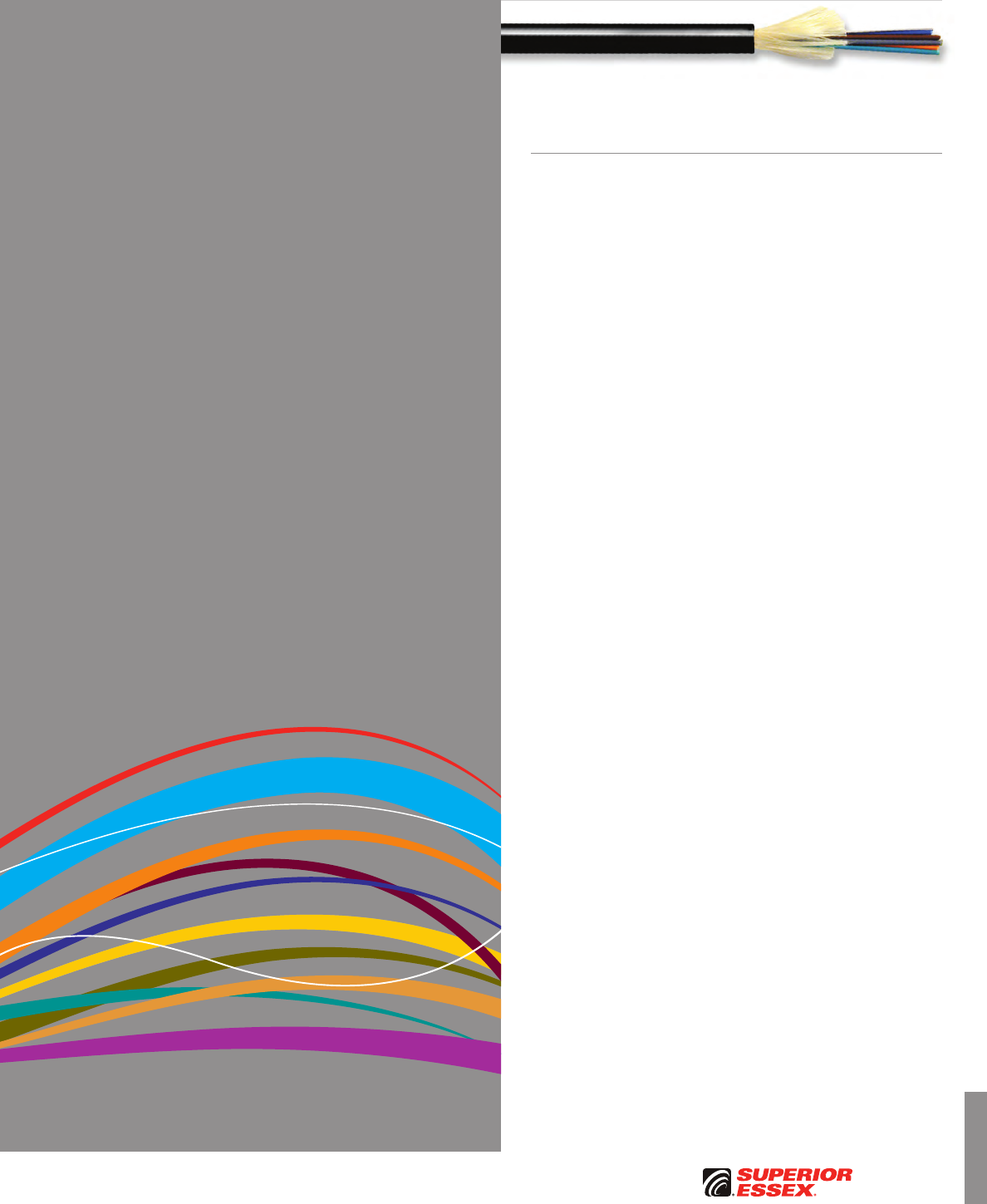
J-1
PREMISES COPPERPREMISES FIBEROSP FIBEROSP COMPOSITECENTRAL OFFICE COPPERRDUP/RUS OSP COPPERBELL OSP COPPEROSP COPPER WIRECANADIAN OSP COPPERTECHNICAL INFO
Toll Free 800.551.8948 | Fax 770.657.6807 | SuperiorEssex.com/Comm
TECHNICAL INFO
Table of Contents
Metric Measurement Conversions . . . . . . . . . . . . . . . . . . . . . . . . . . . .J-2
American Wire Gauge (AWG) Sizes . . . . . . . . . . . . . . . . . . . . . . . . . . .J-2
Optical Fiber Types..........................................J-3
Optical Fiber Selection Chart . . . . . . . . . . . . . . . . . . . . . . . . . . . . . . . . .J-4
Single Mode
Multimode
Optical Fiber Cable..........................................J-6
ANSI/TIA/EIA-598-B Standard Colors
Standard Jacket Colors
OSP Flooding Compound and Jacket Marking Options
OSP Central Members/Strength Members Options
Additional OSP Options
Canadian Central Office Copper Cable . . . . . . . . . . . . . . . . . . . . . . . . .J-6
Insulation Color Codes
Spare Pair Insulation Color Codes
Spare Single Insulation Color Codes
OSP Copper Cable ..........................................J-7
Pair Identification Colors
Groups of Pairs Binder Identification Colors
Super-units Binder Identification Colors
Copper Wire and Cable......................................J-8
NEC Fire Resistance Ratings
Balanced Twisted Pair Transmission Categories
Premises Cable Conduit Fill Quick Reference . . . . . . . . . . . . . . . . . . .J-9
Packaging.................................................J-10
Glossary of Terms..........................................J-16
Standard Warranty.........................................J-21
PerformaLink® Warranty ....................................J-22
Campus Warranty..........................................J-24
Part Number Index.........................................J-28
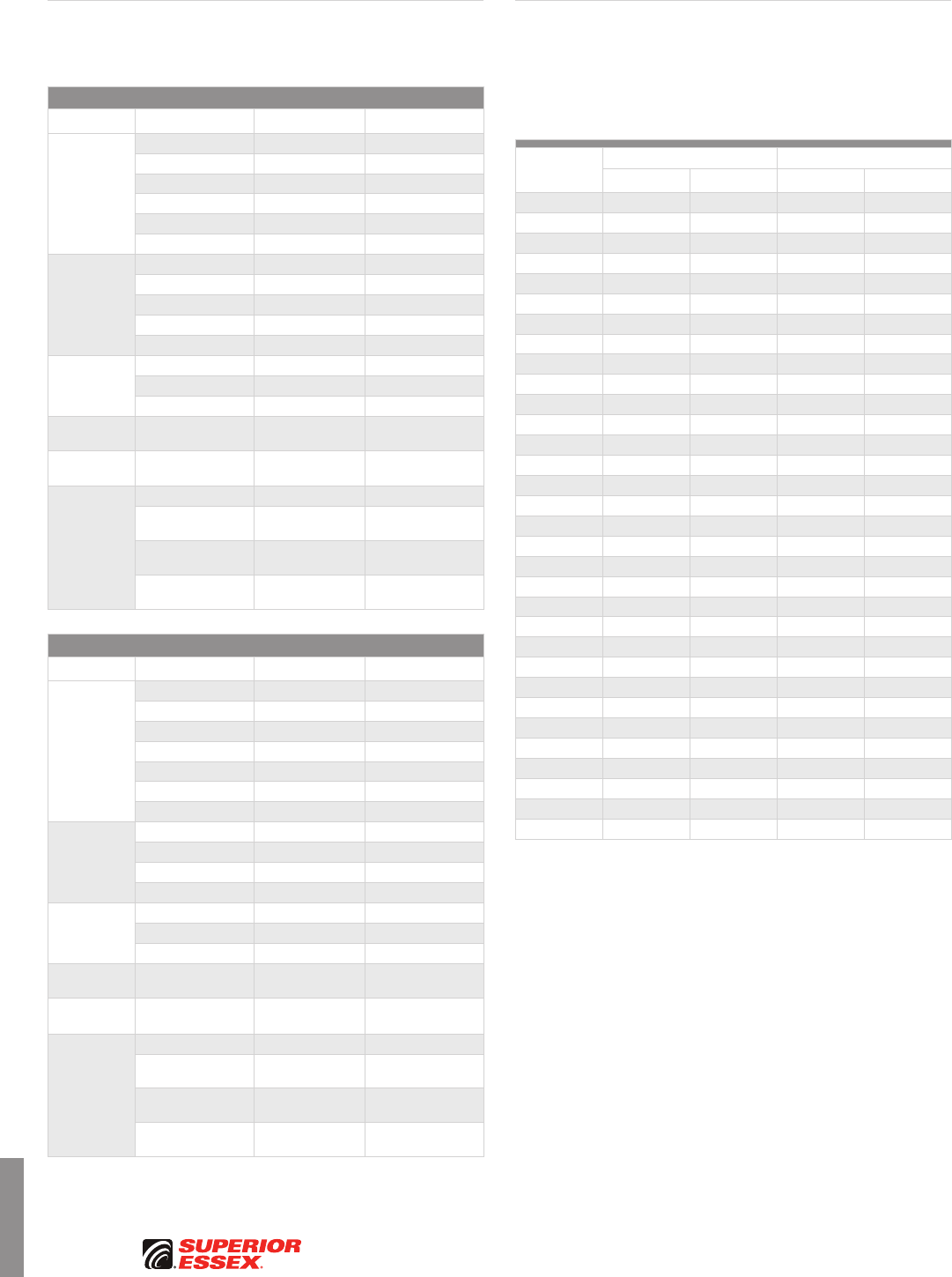
J-2
PREMISES COPPER PREMISES FIBER OSP FIBER OSP COMPOSITE CENTRAL OFFICE COPPER RDUP/RUS OSP COPPER BELL OSP COPPER OSP COPPER WIRE CANADIAN OSP COPPER TECHNICAL INFO
Rev 6/10 Ed 10.1Toll Free 800.551.8948 | Fax 770.657.6807 | SuperiorEssex.com/Comm
Superior Essex uses the U.S. customary system of weights and measures
as well as the metric equivalents. If you need help calculating these figures,
please consult the conversion charts below.
Into Metric
If You Know Multiply By To Get
Length
milli-inch (mil) 25.40 microns (µm)
inches (in) 25.40 millimeters (mm)
inches (in) 2.54 centimeters (cm)
feet (ft) 30.48 centimeters (cm)
yards (yd) 0.91 meters (m)
miles (mi) 1.61 kilometers (km)
Area
sq. inches (in²) 6.45 sq. centimeters (cm²)
sq. feet (ft²) 0.09 sq. meters (m²)
sq. yards (yd²) 0.84 sq. meters (m²)
sq. miles (mi²) 2.59 sq. kilometers (km²)
acres 0.40 hectares (ha)
Mass
(Weight)
ounces (oz) 28.35 grams (g)
pounds (lb) 0.45 kilograms (kg)
short tons 0.91 tons (t)
Temperature Fahrenheit (°F) Subtract 32, then
multiply by 0.56 Celsius (°C)
Mass per
Length
pounds per 1,000 feet
(lbs/kft) 1.49 kilograms per
kilometers (kg/km)
Force
pounds force (lbf) 4.45 newtons (N)
foot–pounds (ft–lb) 1.36 newtons–meters
(N–m)
pounds force per
inches (lbf/in) 1.75 newtons per
centimeters (N/cm)
pounds per sq. inches
(PSI) 6.89 kiloPascals (kPa)
Out of Metric
If You Know Multiply By To Get
Length
microns (µm) 0.04 milli-inch (mil)
millimeters (mm) 0.04 inches (in)
centimeters (cm) 0.39 inches (in)
meters (m) 3.28 feet (ft)
meters (m) 1.09 yards (yd)
kilometers (km) 3,280.84 feet (ft)
kilometers (km) 0.62 miles (mi)
Area
sq. centimeters (cm²) 0.16 sq. inches (in²)
sq. meters (m²) 1.20 sq. yards (yd²)
sq. kilometers (km²) 0.39 sq. miles (mi²)
hectares (ha) 2.47 acres
Weight
grams (g) 0.04 ounces (oz)
kilograms (kg) 2.20 pounds (lb)
tons (t) 1.10 short tons
Temperature Celsius (°C) Multiply by 1.80,
then add 32 Fahrenheit (°F)
Weight per
Unit Length
kilograms per
kilometers (kg/km) 0.67 pounds per 1,000 feet
(lbs/kft)
Force
newtons (N) 0.22 pounds force (lbf)
newtons–meters
(N–m) 0.74 foot–pounds (ft–lb)
newtons per
centimeters (N/cm) 0.57 pounds force per
inches (lbf/in)
kiloPascals (kPa) 0.15 pounds per sq. inches
(PSI)
The table below shows various data including both the resistance of the
various wire gauges and the resistance (Ω) per unit length. The diameter
information in the table applies to solid wires. Stranded wires are calculated
by determining the equivalent cross sectional copper area. The table below
assumes DC, or AC frequencies equal to or less than 60 Hz, and does not take
skin effect into account.
AWG
Diameter Copper Resistance*
in mm (Ω/km) (Ω/kft)
0000 (4/0) 0.4600 11.684 0.1608 0.04901
000 (3/0) 0.4096 10.404 0.2028 0.06180
00 (2/0) 0.3648 9.266 0.2557 0.07793
0 (1/0) 0.3249 8.252 0.3224 0.09827
1 0.2893 7.348 0.4066 0.1239
2 0.2576 6.544 0.5127 0.1563
3 0.2294 5.827 0.6465 0.1970
4 0.2043 5.189 0.8152 0.2485
5 0.1819 4.621 1.028 0.3133
6 0.1620 4.115 1.296 0.3951
7 0.1443 3.665 1.634 0.4982
8 0.1285 3.264 2.061 0.6282
9 0.1144 2.906 2.599 0.7921
10 0.1019 2.588 3.277 0.9989
11 0.0907 2.305 4.132 1.260
12 0.0808 2.053 5.211 1.588
13 0.0720 1.828 6.571 2.003
14 0.0641 1.628 8.286 2.525
15 0.0571 1.450 10.45 3.184
16 0.0508 1.291 13.17 4.016
17 0.0453 1.150 16.61 5.064
18 0.0403 1.024 20.95 6.385
19 0.0359 0.912 26.42 8.051
20 0.0320 0.812 33.31 10.15
21 0.0285 0.723 42.00 12.80
22 0.0253 0.644 52.96 16.14
23 0.0226 0.573 66.79 20.36
24 0.0201 0.511 84.22 25.67
25 0.0179 0.455 106.2 32.37
26 0.0159 0.405 133.9 40.81
27 0.0142 0.361 168.9 51.47
28 0.0126 0.321 212.9 64.90
*Figure for solid copper wire at 68°F, computed based on 100% IACS conductivity of 58.0 MS/m.
Metric Measurement
Conversions
American Wire Gauge
(AWG) Sizes

J-3
PREMISES COPPERPREMISES FIBEROSP FIBEROSP COMPOSITECENTRAL OFFICE COPPERRDUP/RUS OSP COPPERBELL OSP COPPEROSP COPPER WIRECANADIAN OSP COPPERTECHNICAL INFO
Toll Free 800.551.8948 | Fax 770.657.6807 | SuperiorEssex.com/CommRev 7/10 Ed 10.2
Multimode Optical Fiber
Multimode fiber (MMF) is identified by the physical size of the core as
measured in microns (µm) and the applications for which it is typically used.
MMF, the most common types having 62.5/125 µm and 50/125 µm core/cladding
dimensions, are used for data communications links with the local area
network (LAN). The term “multimode” refers to the way the light travels down
the optical fiber. For each pulse of light launched into the optical fiber by light
source (transceiver), the light signal energy travels within the optical fiber
core along multiple paths, or modes. These modes travel at different speeds,
resulting in the pulse of light spreading out. This effect limits the bandwidth
and distances that can be supported by MMF. For this reason, MMF is used
in short distance LAN applications usually less than 2 km (6,560 ft) between
connections. Typical network applications include building-to-building and
communications closet-to-closet backbones, intelligent highway systems and
fiber-to-the-desk. MMF is the choice for these short distance applications
cables because of the large core size, which allows for inexpensive
connectivity, greater durability and the use of low-cost light sources.
Typically, a light emitting diode (LED), operating at a nominal wavelength of
850 nm, is used as the light source for MMF cable applications. The use of LED-
based transceivers, MMF cables and inexpensive MMF connector systems
have provided network designers with a relatively low-cost, high-bandwidth
technology for campus-like networks. Recent technology breakthroughs
in optical fiber transceiver technology have led to a new light source that
extends the distance and increases the signal carrying capacity of MMF. This
next-generation light source uses a vertical cavity surface emitting laser, or
VCSEL (pronounced “vicsel”).
The use of VCSEL transceivers, when compared to traditional LED-based
transmission systems, allows for greater distances for traditional applications
such as 100 Mbps and for higher bandwidth applications such as 1 GB and
10 GB Ethernet. The VCSEL source transmits light through the center region
of the optical fiber core. This has created the requirement for laser-optimized
MMF. One of the most popular emerging applications for VCSEL-based LAN
application is 10 GB Ethernet. By using laser-optimized optical fibers, network
engineers can improve transmission performance over greater distances.
TeraGain® optical fibers are available in 62.5/125 µm and 50/125 µm fiber
types. These optical fibers have been designed to provide greater data rate
and distance support compared to other manufacturers’ optical fiber cables.
In particular, the bandwidths of TeraGain optical fibers are greater than the
standard MMF offered by other manufacturers and exceed the requirements
specified in TIA 568. TeraGain optical fibers can be used with either LED or
laser (VCSEL) transmission equipment. Refer to the table on page J-5 for specific
performance information.
TeraGain 10G 50/125 multimode fibers are specifically optimized for 850 nm
lasers (or VCSELs) that are the heart of the new 10 GB Ethernet systems
specified in TIA 568. These optical fibers exceed industry specifications for
both bandwidth and for differential modal dispersion. TeraGain 10G optical
fibers support 10 GB Ethernet applications in three ranges: 150, 300 and 550
meters. These ranges allow engineers to cost effectively design the right
optical fiber for their application requirements. Superior Essex offers TeraGain
10G/150 as its standard 50 µm MMF in all its premises optical fiber cables.
Refer to the table on page J-5 for specific performance information.
Like the TeraGain 10G 50/125 multimode fibers, TeraFlex 10G multimode fibers
are specifically optimized for 850 nm lasers (or VCSELs) but with the added
benefit of Macrobend Resistance. These optical fibers exceed industry
specifications for not only bandwidth and differential modal dispersion, but for
minimum bend radii allowing use where tight bend radii are encountered. This
is especially important for applications, like 40 GB and 100 GB Ethernet, where
channel margins are tight. TeraFlex 10G optical fibers support 10 GB Ethernet
applications in three ranges: 150 (OM2+), 300 (OM3) and 550 (OM4) meters.
Refer to the table on page J-5 for specific performance information.
Single Mode Optical Fiber
Single mode fiber (SMF) is used primarily for intermediate and long distance
Outside Plant (OSP) applications that have distances between connections of
up to 80 km (50 mi). It is the exceptional information carrying capacity and low-
loss properties of this fiber that make it ideal for these demanding applications.
The core, or light-carrying region of the fiber, is approximately 8.3 µm in
diameter. This narrows the transmission pathway allowing for only a single
path, or mode, for each pulse of light traveling down the core of the fiber. The
light transmission technology is laser-based for all single mode communications
applications. By combining the extremely high bandwidth properties of SMF
with high precision laser-based transceivers, equipment and network systems
designers can create networks capable of sending simultaneous voice and data
transmission well beyond 10 Gbps over many miles.
Superior Essex offers many types of single mode optical fibers for
communications applications. Based on the application, Superior Essex can
recommend the following SMF types.
Standard SMF offered by Superior Essex is an excellent choice for patch
cords, local area network (LAN), wide area network (WAN) and metropolitan
area networks (MAN). This fiber has operating wavelengths centered at
1310 nm and 1550 nm. Refer to the table on page J-4 for performance information.
Reduced Water Peak (RWP) SMF, which has been designed to have low
attenuation at 1383 nm, is becoming the most commonly recommended optical
fiber for all types of network applications. Standard optical fiber displays
an attenuation increase at or about 1383 nm. This wavelength is known as
the water peak region and is where light is strongly absorbed by naturally
occurring water-like end groups in the glass, causing high attenuation or
signal loss. Specifically, hydroxyl end groups, which make up half of a water
molecule, are always present at some level within the glass core and cause
increased attenuation over this wavelength region. Superior Essex RWP SMF
reduces this effect and allows all the wavelengths between 1300 nm and
1550 nm to be usable. This optical fiber is therefore, not only an excellent
choice for traditional applications, but also for more advanced systems such
as coarse wavelength division multiplexing (CWDM) and dense wavelength
division multiplexing (DWDM) technologies. RWP SMF is the standard single
mode optical fiber for all Superior Essex premises cables. Refer to the table
on page J-4 for performance information.
Zero Water Peak SMF offers further reductions to the attenuation at 1383 nm.
Attenuation improvement at 1383 nm is usually 0.03 to 0.04 dB per km. Refer to
the table on page J-4 for performance information.
Non-Zero Dispersion Shifted (NZDS) fiber is used for very high data rates over
very long distances (> 30 km). Because of core/cladding modifications, this
fiber is more expensive than standard SMF. The advantage of NZDS is that
it allows for longer distances between repeaters and therefore lowers the
overall system cost for long distance networks. Refer to the table on page J-4
for performance information.
TeraFlex® bend resistant optical fiber is a SMF that complies with ITU-T
G.652.D and G.657.A. The bend sensitivity of this optical fiber has been
improved so that it can be coiled into a 20 mm diameter loop with ≤ 0.5 dB
incurred loss at 1625 nm and ≤ 0.2 dB incurred loss at 1550 nm – five times
better bending performance than leading RWP optical fibers. TeraFlex offers
excellent Polarized Mode Dispersion (PMD) of ≤ 0.1 ps/√km per individual
fiber. TeraFlex is an ideal choice for FTTP applications where small enclosures
are normal and space is at a premium.
Optical Fiber Types
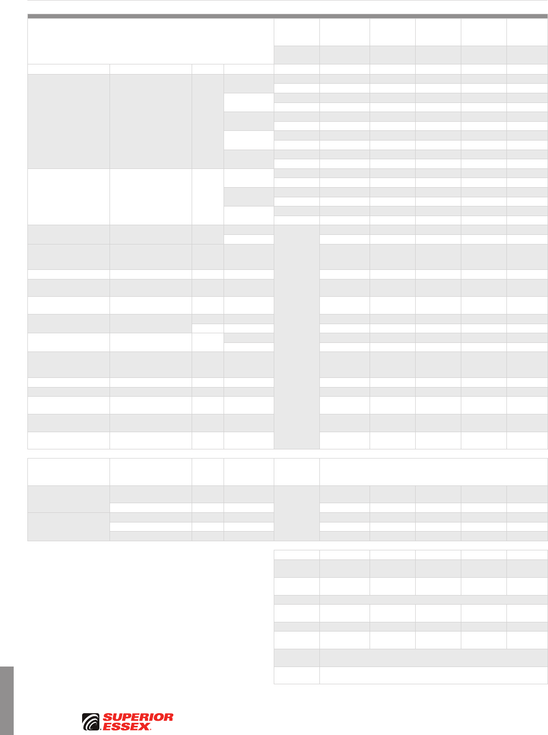
J-4
PREMISES COPPER PREMISES FIBER OSP FIBER OSP COMPOSITE CENTRAL OFFICE COPPER RDUP/RUS OSP COPPER BELL OSP COPPER OSP COPPER WIRE CANADIAN OSP COPPER TECHNICAL INFO
Toll Free 800.551.8948 | Fax 770.657.6807 | SuperiorEssex.com/Comm Rev 7/10 Ed 10.2
Optical Fiber Selection Chart
Single Mode
Performance Property
Fiber
Description Conventional
Reduced
Water Peak
Zero
Water Peak
TeraFlex®
Bend
Resistant NZDS
Fiber Type
Designator 9 3 2 K 8
Parameter Test Method/Standard Units Conditions Cable Type
Maximum Attenuation ANSI/TIA-455-78-B-2002 dB/km
1310 nm Tight Buffer 0.70 0.70 0.70 0.70 -
Loose Tube 0.40 0.35 0.35 0.35 -
1383 nm Tight Buffer - 0.70 0.70 0.70 -
Loose Tube - 0.35 0.35 0.35 -
1490 nm Tight Buffer 0.70 0.70 0.70 0.70 0.70
Loose Tube 0.25 0.25 0.25 0.25 0.30
1550 nm Tight Buffer 0.70 0.70 0.70 0.70 0.70
Loose Tube 0.30 0.25 0.25 0.25 0.30
1625 nm Tight Buffer 0.70 0.70 0.70 0.70 0.70
Loose Tube 0.25 0.25 0.25 0.25 0.25
Typical Attenuation ANSI/TIA-455-78-B-2002 dB/km
1310 nm Tight Buffer N/A 0.41 0.41 0.41 -
Loose Tube 0.34 0.34 0.34 0.34 -
1383 nm Tight Buffer - 0.41 0.41 0.41 -
Loose Tube N/A 0.33 0.31 0.31 -
1550 nm Tight Buffer N/A 0.41 0.41 0.41 0.41
Loose Tube 0.19 0.19 0.19 0.19 0.25
Nominal Group
Refractive Index - - 1310 nm
Tight Buffer
and
Loose Tube
1.467 1.467 1.467 1.467 1.467
1550 nm 1.468 1.468 1.468 1.468 1.468
Maximum Individual
Fiber Polarization
Mode Dispersion
ANSI/TIA/EIA-455-113-96 ps/√km - 0.2 0.2 0.2 0.2 0.2
Cable Cutoff Wavelength ANSI/TIA-455-80-C-2003 nm - 1260 1260 1260 1260 1260
Zero Chromatic
Dispersion Wavelength ANSI/TIA-455-175-B-2003 nm - 1300 – 1324 1300 – 1324 1300 – 1324 1300 – 1324 N/A
Typical Chromatic
Dispersion Slope ANSI/TIA-455-175-B-2003 ps/nm2-
km - 0.087 0.087 0.087 0.087 0.047
Proof Strength TIA/EIA-455-31 kpsi On-line 100 100 100 100 100
GPa On-line 0.69 0.69 0.69 0.69 0.69
Mode Field Diameter ANSI/TIA-455-191-B-2003 µm 1310 nm 8.8 to 9.6 8.8 to 9.6 8.8 to 9.6 8.8 to 9.6 N/A
1550 nm 9.5 to 11.5 9.9 to 10.9 9.9 to 10.9 9.9 to 10.9 7.8 to 10.0
Maximum Macrobend
Attenuation Increase ANSI/TIA-455-62-B-2003 dB
100 turns on
50 mm mandrel
at 1310 nm
0.05 0.05 0.05 0.01 0.05
Cladding Diameter ANSI/TIA-455-176-A-2003 µm - 125.0 ± 1.2 125.0 ± 0.9 125.0 ± 0.9 125.0 ± 0.7 125.0 ± 0.7
Coating Diameter ANSI/TIA-455-176-A-2003 micron - 250 ± 10 250 ± 10 250 ± 10 250 ± 10 250 ± 10
Maximum Core/Clad
Concentricity Error ANSI/TIA-455-176-A-2003 µm - 0.6 0.5 0.5 0.5 0.5
Maximum Cladding
Non-circularity ANSI/TIA-455-176-A-2003 % - 1 1 1 1 0.7
Maximum Coating/Cladding
Concentricity Error ANSI/TIA-455-176-A-2003 µm - 12 12 12 12 12
Guaranteed
Supportable
Ethernet Distances Protocol Units Conditions Cable Type Maximum Transmission Distances (km)
1 Gbps
1000BASE-LH,
1000BASE-LH-LX km 1310 nm
Tight Buffer
and
Loose Tube
10 10 10 10 10
1000BASE-ZX km 1550 nm 70 70 70 70 70
10 Gbps
10GBASE-LR km 1310 nm 25 25 25 25 25
10GBASE-ER km 1550 nm 40 40 40 40 40
10GBASE-ZR km 1550 nm 80 80 80 80 80
Standards
ISO/IEC
Tight Buffer 11801: OS1 11801: OS1 11801: OS1 11801: OS1 -
ISO/IEC
Loose Tube 11801: OS1 24702: OS2 24702: OS2 24702: OS2 -
Telcordia GR-20-CORE
ITU-T G.652.B G.652.D G.652.D G.652.D
G.657.A
G.655.C, E
G.656
TIA492 CAAA CAAB CAAB CAAB N/A
IEC 60793-2-50
Type B1.1 B1.3 B1.3 B1.3 -
ANSI/ICEA
Tight Buffer S-83-596
ANSI/ICEA
Loose Tube S-87-640
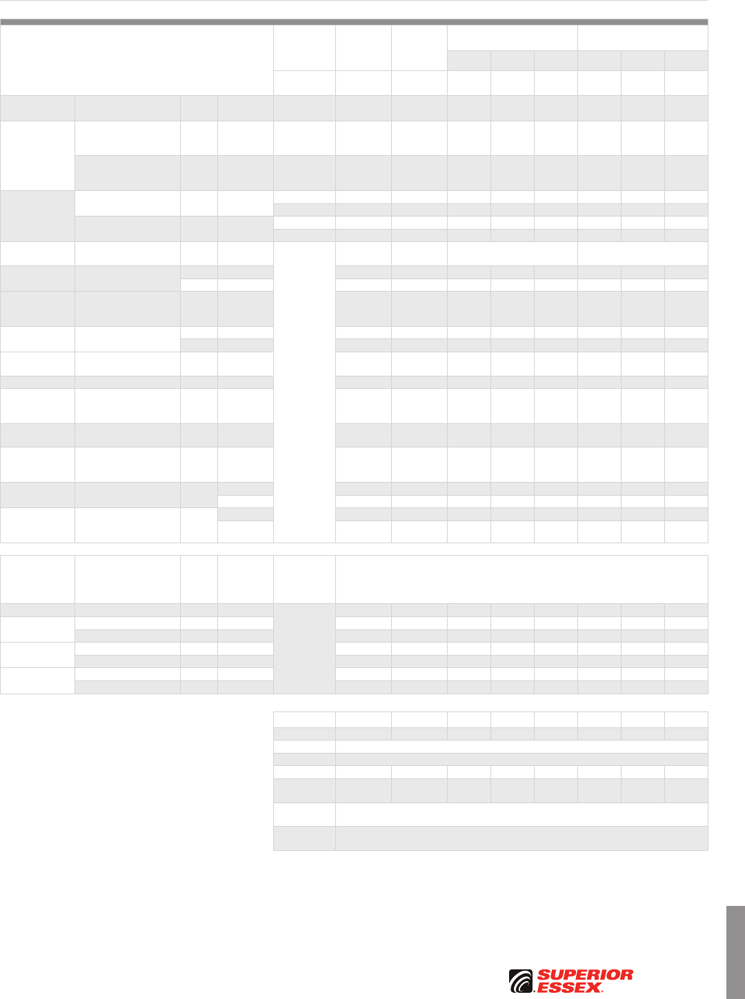
J-5
PREMISES COPPERPREMISES FIBEROSP FIBEROSP COMPOSITECENTRAL OFFICE COPPERRDUP/RUS OSP COPPERBELL OSP COPPEROSP COPPER WIRECANADIAN OSP COPPERTECHNICAL INFO
Toll Free 800.551.8948 | Fax 770.657.6807 | SuperiorEssex.com/CommRev 7/10 Ed 10.2
Performance Property
Fiber
Description
TeraGain®
62.5/125
TeraGain
50/125
TeraGain
Laser Optimized 50/125
TeraFlex® Bend Resistant
Laser Optimized 50/125
10G/150 10G/300 10G/550 10G/150 10G/300 10G/550
Fiber Type
Designator 6 5 A B F M N P
Parameter Test Method/
Standard Units Conditions Cable Type
Maximum
Attenuation
TIA/EIA-455-78 dB/km 850 nm
Tight Buffer
and
Loose Tube
3.5 3.5 3.5 3.5 3.5 3.5 3.5 3.5
TIA/EIA-455-78 dB/km 1300 nm
Tight Buffer
and
Loose Tube
1.5 1.5 1.5 1.5 1.5 1.5 1.5 1.5
Typical
Attenuation
TIA/EIA-455-78 dB/km 850 nm Tight Buffer 3.0 3.0 3.0 3.0 3.0 3.0 3.0 3.0
Loose Tube 2.7 2.2 2.2 2.2 2.2 2.2 2.2 2.2
TIA/EIA-455-78 dB/km 1300 nm Tight Buffer 1.0 1.0 1.0 1.0 1.0 1.0 1.0 1.0
Loose Tube 0.6 0.5 0.5 0.5 0.5 0.5 0.5 0.5
Numerical
Aperture ANSI/TIA-455-177-B-2003 - -
Tight Buffer
and
Loose Tube
0.275 ± 0.015 0.200 ± 0.015 0.200 ± 0.015 0.200 ± 0.015
Nominal Group
Refractive Index OTDR - 850 nm 1.496 1.483 1.483 1.483 1.483 1.483 1.483 1.483
- 1300 nm 1.491 1.479 1.479 1.479 1.479 1.479 1.479 1.479
Macrobend
Attenuation
Change
ANSI/TIA-455-62-B-2003 dB
100 turns
on 75 mm
Mandrel
0.5 0.5 0.5 0.5 0.5 0.5 0.5 0.5
Proof Strength TIA/EIA-455-31 kpsi On-line 100 100 100 100 100 100 100 100
GPa On-line 0.69 0.69 0.69 0.69 0.69 0.69 0.69 0.69
Cladding
Diameter ANSI/TIA-455-176-A-2003 micron - 125 ± 2 125 ± 2 125 ± 2 125 ± 2 125 ± 2 125 ± 2 125 ± 2 125 ± 2
Coating Diameter ANSI/TIA-455-176-A-2003 micron - 250 ± 10 250 ± 10 250 ± 10 250 ± 10 250 ± 10 250 ± 10 250 ± 10 250 ± 10
Core/Clad
Concentricity
Error
ANSI/TIA-455-176-A-2003 microns - 1.5 1.5 1.5 1.5 1.5 1.5 1.5 1.5
Cladding
Non-Circularity ANSI/TIA-455-176-A-2003 % - 1.5% 1.5% 1.5% 1.5% 1.5% 1.5% 1.5% 1.5%
Coating/Clad
Concentricity
Error
ANSI/TIA-455-176-A-2003 microns - 12 µm 12 µm 12 µm 12 µm 12 µm 12 µm 12 µm 12 µm
Min. Bandwidth:
Overfilled Launch TIA/EIA-455-124-2000 MHz-km 850 nm 220 500 700 1,500 3,500 700 1,500 3,500
1300 nm 600 500 500 500 500 500 500 500
Min. Bandwidth:
Laser Effective
Modal Bandwidth
TIA-455-220-A MHz-km
850 nm N/A N/A 950 2,000 4,700 950 2,000 4,700
1300 nm N/A N/A 500 500 500 500 500 500
Guaranteed
Supportable
Ethernet
Distances Protocol Units Conditions Cable Type Maximum Transmission Distances (meters)
10 Mbps IEEE 10BASE-FL meters 850 nm
Tight Buffer
and
Loose Tube
1,250 1,250 1,250 1,250 1,250 1,250 1,250 1,250
100 Mbps IEEE 100BASE-SX meters 850 nm 500 750 1,000 1,000 1,000 1,000 1,000 1,000
IEEE 100BASE-FX meters 1300 nm 2,000 2,000 2,000 2,000 2,000 2,000 2,000 2,000
1 Gbps IEEE 1000BASE-SX meters 850 nm 300 750 1,000 1,000 1,040 1,000 1,000 1,040
IEEE 1000BASE-LX meters 1300 nm 600* 600* 600 600 600 600 600 600
10 Gbps IEEE 10GBASE-SR meters 850 nm 35 82 150 300 550 150 300 550
IEEE 10GBASE-LRM meters 1300 nm 300 300 300 300 300 300 300 300
*Mode conditioning patch cord required
Standards
ISO/IEC 11801 OM1 OM2 OM2 OM3 OM4 OM2 OM3 OM4
Telcordia GR-20-CORE
ITU-T G.651
TIA492 AAAA-A AAAB AAAB AAAC-A AAAD AAAB AAAC-A AAAD
IEC 60793-2-10
Type A1b A1a.1 A1a.1 A1a.2 A1a.3 A1a.1 A1a.2 A1a.3
ANSI/ICEA
Tight Buffer S-83-596
ANSI/ICEA
Loose Tube S-87-640
Optical Fiber Selection Chart
Multimode
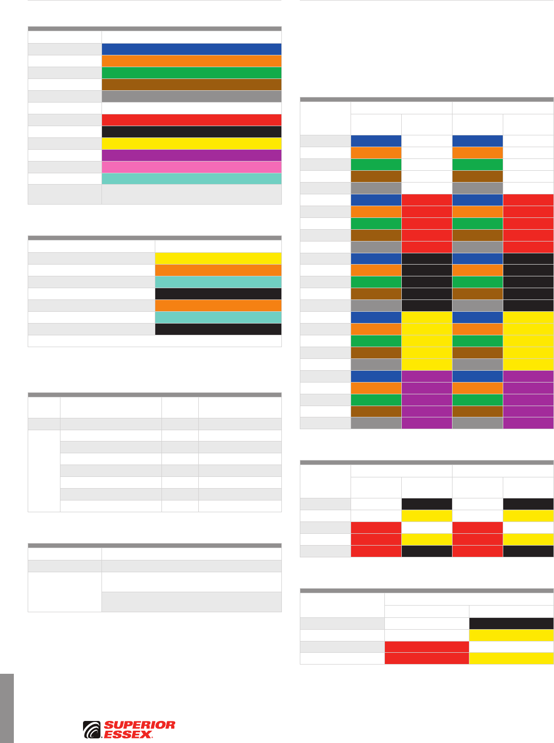
J-6
PREMISES COPPER PREMISES FIBER OSP FIBER OSP COMPOSITE CENTRAL OFFICE COPPER RDUP/RUS OSP COPPER BELL OSP COPPER OSP COPPER WIRE CANADIAN OSP COPPER TECHNICAL INFO
Rev 6/10 Ed 10.1Toll Free 800.551.8948 | Fax 770.657.6807 | SuperiorEssex.com/Comm
ANSI/TIA/EIA-598-B Standard Colors
Fiber Number Fiber Color
fiber 1 Blue
fiber 2 Orange
fiber 3 Green
fiber 4 Brown
fiber 5 Slate
fiber 6 White
fiber 7 Red
fiber 8 Black
fiber 9 Yellow
fiber 10 Violet
fiber 11 Rose
fiber 12 Aqua
fiber 13 and higher The color code is repeated, Black stripe or dash is added,
according to the ANSI/TIA/EIA-598-B specifications
Standard Jacket Colors
Cable Type Standard Jacket Color
Single Mode Premises Yellow
Standard Multimode Premises Orange
Laser-Optimized 50 µm Premises Aqua
Indoor/Outdoor Black
Hybrid Standard Multimode Premises Orange
Hybrid Laser-Optimized 50 µm Premises Aqua
Outside Plant (OSP) Black*
Custom jacket colors also available
*One extruded color stripe is available. Standard stripe colors are Orange, Green, Yellow and Blue
(other colors available upon request).
OSP Flooding Compound and Jacket Marking Options
Flooding Compound
Jacket
Marking
Part No. Designator
(Last Digit in Part No.)
Standard Dry (SAP) Block feet 1
Options
Dry (SAP) Block meters 2
Flooding Compound feet 3
Flooding Compound meters 4
Special Print Dry (SAP) Block feet 5
Special Print Dry (SAP) Block meters 6
Special Print Flooding Compound feet 7
Special Print Flooding Compound meters 8
OSP Central Members/Strength Members Options
Central Member/Strength Member
Standard Dielectric / Dielectric
Options
Standard loose tube cables are available
with a steel center member
Single tube cables are available with steel strength
members embedded in the outer jacket
Additional OSP Options
• Special protection jacket
• Rodent and fuel protection
• Nylon outer jacket
Contact your Superior Essex sales representative for further information.
Insulation Color Codes
The distinctive Canadian insulation color-coding utilizes colored ink in a
systematic pattern of dots/dashes/bands. These marks provide positive
identification of each conductor and each pair within a unit. Cable cores may
contain both pairs and single conductors. And, some cables may contain
“spare” pairs. Each insulated conductor shall be marked with 1 or 2 dots/
dashes/bands in accordance with the table below.
Pair Number
Conductor #1 Conductor #2
Solid Color
Single Band
Color Solid Color
Double Band
Color
1Blue White Blue White
2Orange White Orange White
3Green White Green White
4Brown White Brown White
5Slate White Slate White
6Blue Red Blue Red
7Orange Red Orange Red
8Green Red Green Red
9Brown Red Brown Red
10 Slate Red Slate Red
11 Blue Black Blue Black
12 Orange Black Orange Black
13 Green Black Green Black
14 Brown Black Brown Black
15 Slate Black Slate Black
16 Blue Yellow Blue Yellow
17 Orange Yellow Orange Yellow
18 Green Yellow Green Yellow
19 Brown Yellow Brown Yellow
20 Slate Yellow Slate Yellow
21 Blue Violet Blue Violet
22 Orange Violet Orange Violet
23 Green Violet Green Violet
24 Brown Violet Brown Violet
25 Slate Violet Slate Violet
Spare Pair Insulation Color Codes
Spare Pair
Number
Conductor #1 Conductor #2
Solid Color
Single Band
Color Solid Color
Double Band
Color
1 White Black White Black
2 White Yellow White Yellow
3Red White Red White
4Red Yellow Red Yellow
5Red Black Red Black
Spare Single Insulation Color Codes
Spare Single Number
Single Conductor
Solid Color Triple Band Color
1 White Black
2 White Yellow
3Red White
4Red Yellow
Optical Fiber Cable
Canadian Central Office
Copper Cable
J-7
PREMISES COPPERPREMISES FIBEROSP FIBEROSP COMPOSITECENTRAL OFFICE COPPERRDUP/RUS OSP COPPERBELL OSP COPPEROSP COPPER WIRECANADIAN OSP COPPERTECHNICAL INFO
Rev 6/10 Ed 10.1 Toll Free 800.551.8948 | Fax 770.657.6807 | SuperiorEssex.com/Comm
Pair Identification Colors
For pairs numbering 1 through 25, the pair identification colors are outlined
below. In cable constructions containing more than 25-pair, the colors are
repeated as necessary. Color coded binders are used to identify 25-pair
groups of color coded pairs.
Pair Number Tip Color Ring Color
1 White Blue
2 White Orange
3 White Green
4 White Brown
5 White Slate
6Red Blue
7Red Orange
8Red Green
9Red Brown
10 Red Slate
11 Black Blue
12 Black Orange
13 Black Green
14 Black Brown
15 Black Slate
16 Yellow Blue
17 Yellow Orange
18 Yellow Green
19 Yellow Brown
20 Yellow Slate
21 Violet Blue
22 Violet Orange
23 Violet Green
24 Violet Brown
25 Violet Slate
Groups of Pairs Binder Identification Colors
For cables through 600-pair, 25-pair groups are identified by their binder colors
in the same sequence as the pair identification is accomplished. Group 1 has
White-Blue binders, Group 2 has White-Orange binders, etc. In this manner,
each pair is uniquely identified. In cables having 25-pair or less, binders are
normally not used. However, if specified, the binders will be Group 1, White-
Blue. For cables of 100-pair or less, the use of the White binder is optional.
Group Number Group Pair Counts Binder Colors
1 1-25 White Blue
2 26-50 White Orange
3 51-75 White Green
4 76-100 White Brown
5 100-125 White Slate
6 126-150 Red Blue
7 151-175 Red Orange
8 176-200 Red Green
9 201-225 Red Brown
10 226-250 Red Slate
11 251-275 Black Blue
12 276-300 Black Orange
13 301-325 Black Green
14 326-350 Black Brown
15 351-375 Black Slate
16 376-400 Yellow Blue
17 401-425 Yellow Orange
18 426-450 Yellow Green
19 451-475 Yellow Brown
20 476-500 Yellow Slate
21 501-525 Violet Blue
22 526-550 Violet Orange
23 551-575 Violet Green
24 576-600 Violet Brown
Super-units Binder Identification Colors
It is desirable for manufacturing purposes to combine four 25-pair groups into
“super units” when cables have 900-pair or more.
Pair Number Group Number Binder Color
1-600 1-24 White
601-1,200* 25-48 Red
1,201-1,800* 49-72 Black
1,801-2,400* 73-96 Yellow
2,401-3,000* 97-120 Violet
3,001-3,600* 121-144 Blue
3,601-4,200* 145-168 Orange
*The above information is based on the Full Count binder color coding used in RDUP copper cable
designs having 1,200-pair or more.
Bell Mirror Image binder color coding information and core lay-up
diagrams are available online:
www.SuperiorEssex.com/techtip.aspx
OSP Copper Cable
J-8
PREMISES COPPER PREMISES FIBER OSP FIBER OSP COMPOSITE CENTRAL OFFICE COPPER RDUP/RUS OSP COPPER BELL OSP COPPER OSP COPPER WIRE CANADIAN OSP COPPER TECHNICAL INFO
Rev 6/10 Ed 10.1Toll Free 800.551.8948 | Fax 770.657.6807 | SuperiorEssex.com/Comm
Copper Wire and Cable
NEC Fire Resistance Ratings
Article 800 of the National Electrical Code (NEC), also known as NFPA 70, covers requirements for low-voltage communications cables. The NEC requires that
cables used in premises, both commercial and residential, be “listed for the purpose” by a Nationally Recognized Test Laboratory (NRTL, pronounced “nurtle”).
Other countries have similar requirements. UL (Underwriters Laboratories Inc.) is the most recognized listing agency in the US. UL 444 is the overall specification
used to identify the requirements for listed communications cables.
Many of the fire resistance test procedures called out in UL 444 are written by UL. However, other laboratories, such as ITS (Intertek Testing Services) and CSA
(Canadian Standards Association), can also provide listing compliance to the NEC.
Five levels of fire resistance are specified. These are outlined below, from most stringent to least. The ratings are hierarchical, i.e., from a fire resistance
standpoint, a higher rating can be substituted for any lower rating, but not vice versa.
NEC
Designation
CSA
Equivalent Common Term Test Comments
CMP FT6 Communications
Plenum NFPA 262
• Cable must have resistance to flame spread and reduced smoke generating properties
• Cable is approved for placement in air handling ducts and chambers (plenums) without
the use of fireproof conduit
• Purpose of the rating is to lessen the transmission of fire and visible smoke to unaffected parts
of the building
• Toxic or corrosive elements of the smoke are not measured
• Equivalent to Canadian FT6 rating
CMR N/A Communications
Riser UL 1666 • Cable must not transmit flame from one floor to another when placed vertically in a building shaft (riser)
• Equivalent to Canadian FT4 rating
CMG FT4 Communications
General Use
CSA C22.2
No. 0.3-M
(Vertical Tray)
• Cable may not transmit flame for more than 4 feet, 11 inches
• Cable shall not penetrate floors or ceilings (i.e. cable may only be used within a single floor)
• Designation was added as a part of the harmonization efforts between U.S. and Canadian standards
CM N/A Communications
General Purpose
UL 1581
(Vertical Tray)
• Cable may not transmit flame for more than 4 feet, 11 inches
• Cable shall not penetrate floors or ceilings (i.e. cable may only be used within a single floor)
CMX FT1 Communications
Limited Purpose
UL 1581 VW-1
(Vertical Wire)
• Cable meets the least stringent flame spread requirements of all ratings
• For residential use, but can only be installed in one and two-family (duplex) housing units
• Often rated with optional UL requirements for outdoor use*
* These “outdoor” requirements are limited to some cold temperature properties and UV resistance. They do not qualify a cable to be substituted for an Outside Plant (OSP) cable. For example, they have
no protection against the intrusion of water, which can destroy a cable’s transmission properties and physically degrade a cable as well. The purpose of the “outdoor” rating is to ensure the cable can
withstand outdoor exposure in the short run between the Network Interface Unit and the point of entry into the interior of the home.
Balanced Twisted Pair Transmission Categories
In response to growing demand for data applications, premises cable performance has evolved such that several categories of transmission performance
for balanced twisted pair cables have been developed. These categories are detailed below. The categories are hierarchical, i.e., a higher category can be
substituted for any lower category, but not vice versa.
Category
Maximum
Bandwidth Common Applications Specifications Comments
CAT 6A 500 MHz 10GBASE-T
(IEEE 802.3an)
ANSI/TIA-568-C.2
ANSI/ICEA S-90-661
• Designed for reduced alien crosstalk
CAT 6 250 MHz 1000BASE-T • Doubles the bandwidth of CAT 5e and vastly improves signal-to-noise margins
CAT 5e 100 MHz 1000BASE-T • Characterized by tightly twisted pairs to reduce crosstalk loss
• Proposed FCC minimum category requirement effective 2020
CAT 5 100 MHz
100BASE-T
100 Mbps TPDDI
622 Mbps ATM
• No longer recognized as an appropriate medium for commercial networking
installations (replaced by CAT 5e or higher)
CAT 3 16 MHz
10BASE-T
Analog Voice
Telecom Closet Wiring
• Minimum allowed by the FCC for horizontal cable in commercial
and residential voice and data applications
• Market trend is to abandon CAT 3 in favor of installing CAT 5e or higher
for both data and voice
J-9
PREMISES COPPERPREMISES FIBEROSP FIBEROSP COMPOSITECENTRAL OFFICE COPPERRDUP/RUS OSP COPPERBELL OSP COPPEROSP COPPER WIRECANADIAN OSP COPPERTECHNICAL INFO
Toll Free 800.551.8948 | Fax 770.657.6807 | SuperiorEssex.com/CommRev 11/10 Ed 10.2
Premises Cable Conduit Fill Quick Reference
This information is intended as a guideline. Because conduit sizes may vary by manufacturer, please verify all dimensions prior to using this reference chart. All
dimensions are rounded up. This guide is based on NEC recommendations of 40% fill for 3 or more cables per conduit and on straight runs. For each 90 degree
bend, reduce available space by 15%. Lubricants are recommended (check compatibility with jacket materials).
Conduit Trade Size
in (mm) 0.50 (12.7) 0.75 (19.1) 1.00 (25.4) 1.25 (31.8) 1.50 (38.1) 2.00 (50.8) 2.50 (63.5) 3.00 (76.2) 3.50 (88.9) 4.00 (101.6) 5.00 (127.0)
Conduit Inner Diameter
in (mm) 0.62 (15.7) 0.82 (20.8) 1.05 (26.7) 1.38 (35.1) 1.61 (40.9) 2.07 (52.6) 2.56 (65.0) 3.07 (78.0) 3.55 (90.2) 4.03 (102.4) 5.05 (128.3)
Conduit Outer Diameter
in (mm) 0.84 (21.3) 1.05 (26.7) 1.32 (33.5) 1.70 (43.2) 1.90 (48.3) 2.38 (60.5) 2.88 (73.2) 3.50 (88.9) 4.00 (101.6) 4.50 (114.3) 5.56 (141.2)
Fill Area
in² (cm²) 0.30 (1.94) 0.53 (3.42) 0.86 (5.55) 1.50 (9.68) 2.04 (13.16) 3.36 (21.68) 4.79 (30.90) 7.39 (47.68) 9.89 (63.81) 12.73 (82.13) 20.01 (129.10)
Recommended Fill 40%
in² (cm²) 0.12 (0.77) 0.21 (1.35) 0.35 (2.26) 0.60 (3.87) 0.81 (5.23) 1.35 (8.71) 1.92 (12.39) 2.96 (19.10) 3.95 (25.48) 5.09 (32.84) 8.00 (51.61)
Cable Nominal
Diameter
in (mm)
Cable Area
in² (cm²) Number of Cables at 40% Conduit Fill
0.10 (2.5) 0.008 (0.05) 15 27 44 76 103 171 243 375 500 644 1013
0.13 (3.3) 0.012 (0.08) 10 17 28 49 66 109 156 240 320 412 648
0.15 (3.8) 0.018 (0.12) 7 12 20 34 46 76 108 167 222 286 450
0.18 (4.6) 0.026 (0.17) 5 8 14 23 32 53 75 116 154 199 313
0.20 (5.1) 0.032 (0.21) 4 7 11 19 26 43 61 94 125 161 253
0.21 (5.3) 0.035 (0.23) 3 6 10 17 23 39 55 85 113 146 230
0.22 (5.6) 0.038 (0.25) 3 5 9 16 21 35 50 77 103 133 209
0.23 (5.8) 0.042 (0.27) 3 5 8 14 19 32 46 71 95 122 191
0.24 (6.1) 0.046 (0.30) 3 5 8 13 18 30 42 65 87 112 176
0.25 (6.4) 0.049 (0.32) 2 4 7 12 16 27 39 60 80 103 162
0.26 (6.6) 0.053 (0.34) 2 4 7 11 15 25 36 55 74 95 150
0.27 (6.9) 0.058 (0.37) 2 4 6 10 14 23 33 51 69 88 139
0.28 (7.1) 0.062 (0.40) 2 3 6 10 13 22 31 48 64 82 129
0.29 (7.4) 0.066 (0.43) 2 3 5 9 12 20 29 45 59 77 120
0.30 (7.6) 0.071 (0.46) 2 3 5 8 11 19 27 42 56 72 113
0.31 (7.9) 0.076 (0.49) 2 3 5 8 11 18 25 39 52 67 105
0.32 (8.1) 0.081 (0.52) 1 3 4 7 10 17 24 37 49 63 99
0.33 (8.4) 0.086 (0.55) 1 2 4 7 9 16 22 34 46 59 93
0.34 (8.6) 0.091 (0.59) 1 2 4 7 9 15 21 32 43 56 88
0.35 (8.9) 0.097 (0.63) 1 2 4 6 8 14 20 31 41 53 83
0.40 (10.2) 0.126 (0.81) 1 2 3 5 6 11 15 23 31 40 63
0.45 (11.4) 0.160 (1.03) 1 1 2 4 5 8 12 19 25 32 50
0.50 (12.7) 0.198 (1.28) 1 1 2 3 4 7 10 15 20 26 41
0.55 (14.0) 0.239 (1.54) 1 1 1 3 3 6 8 12 17 21 33
0.60 (15.2) 0.284 (1.83) 0 1 1 2 3 5 7 10 14 18 28
0.65 (16.5) 0.334 (2.15) 0 1 1 2 2 4 6 9 12 15 24
0.70 (17.8) 0.387 (2.50) 0 1 1 2 2 3 5 8 10 13 21
0.75 (19.0) 0.444 (2.86) 0 0 1 1 2 3 4 7 9 11 18
0.80 (20.3) 0.506 (3.26) 0 0 1 1 2 3 4 6 8 10 16
0.85 (21.6) 0.571 (3.68) 0 0 1 1 1 2 3 5 7 9 14
0.90 (22.9) 0.640 (4.13) 0 0 1 1 1 2 3 5 6 8 13
0.95 (24.1) 0.713 (4.60) 0 0 0 1 1 2 3 4 6 7 11
1.00 (25.4) 0.790 (5.10) 0 0 0 1 1 2 2 4 5 6 10
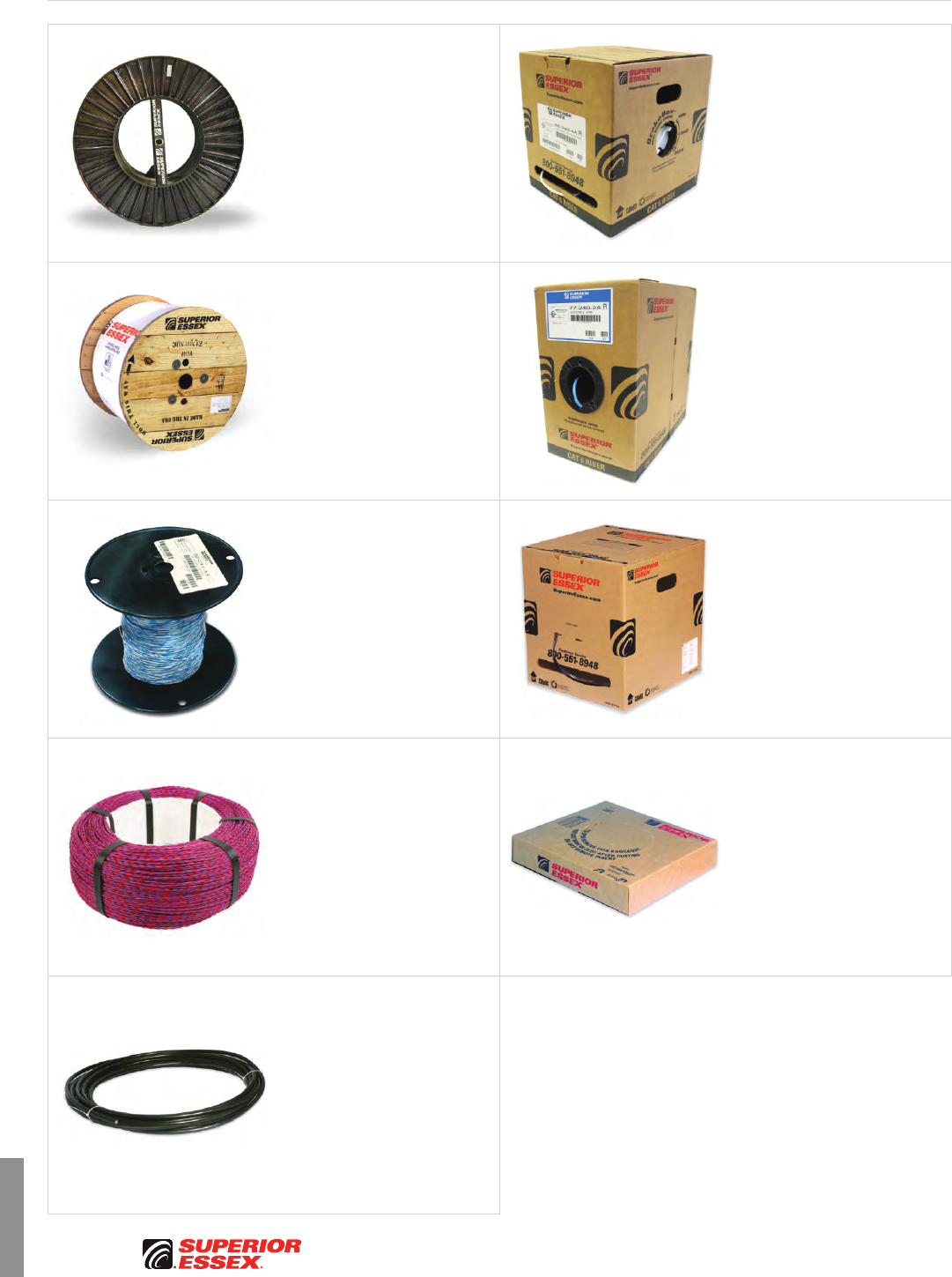
J-10
PREMISES COPPER PREMISES FIBER OSP FIBER OSP COMPOSITE CENTRAL OFFICE COPPER RDUP/RUS OSP COPPER BELL OSP COPPER OSP COPPER WIRE CANADIAN OSP COPPER TECHNICAL INFO
Rev 6/10 Ed 10.1Toll Free 800.551.8948 | Fax 770.657.6807 | SuperiorEssex.com/Comm
Packaging
Descriptions
Steel Reel
Long lengths of cable are placed
onto Steel Reels. An advantage
of this reel is that it is
environmentally-friendly and
recycled for years of service.
BrakeBox®
Dual Brake System
This package is dual purpose.
In this design the cable is placed
onto a plastic spool, which is placed
into a box. The brake allows for
back-tension and over-spin control.
The spool may be taken from the
box for installation or may be left
in the box where the cable pays
out through a slotted opening.
Wood/Plywood Reel
Reels may be made of plywood
or wood. Superior Essex wooden
reels can be recycled an average
of five times before retirement
(see Web site for further details).
POP™ Box
In this package, the cable is coiled
into a box. The product pays out
through a tube opening in the box.
This design does not allow for the
cable to be removed as a unit from
the box.
Spool
Wire is wound onto a spool.
The spool is placed inside a box
for protection during shipment.
Spools are smaller than wood
or steel reels.
Reel-in-a-Box
This package is dual purpose. In
this design the cable is placed onto
a plastic spool, which is placed into
a box. The spool may be taken from
the box for installation or may be
left in the box where the cable pays
out through a slotted opening.
Parallel Cone
This package is designed to fit
into the General Machine Products
(GMP) cast aluminum wire
dispensing system (GMP units
80470 or 80471). When placed onto
the GMP dispenser, the jumper
or distribution frame wire pays out
smoothly. GMP dispensers are most
common in central offices.
Knock-out Box
Cable is coiled and fastened within
a box. Knock out boxes can be
identified by a perforated “knock-
out” that is removed, allowing
access to the cable.
Coils
Coils refer to lengths of cable
wrapped into a shape (usually a
circle) and fastened with multiple ties.
Multiple coils may be placed inside
a box for shipping or shipped on a
pallet, and then secured by stretch-
wrap. Coils are always fastened with
ties. Coils can be custom configured
to fit a customer’s unique cable and
wire feeding systems.
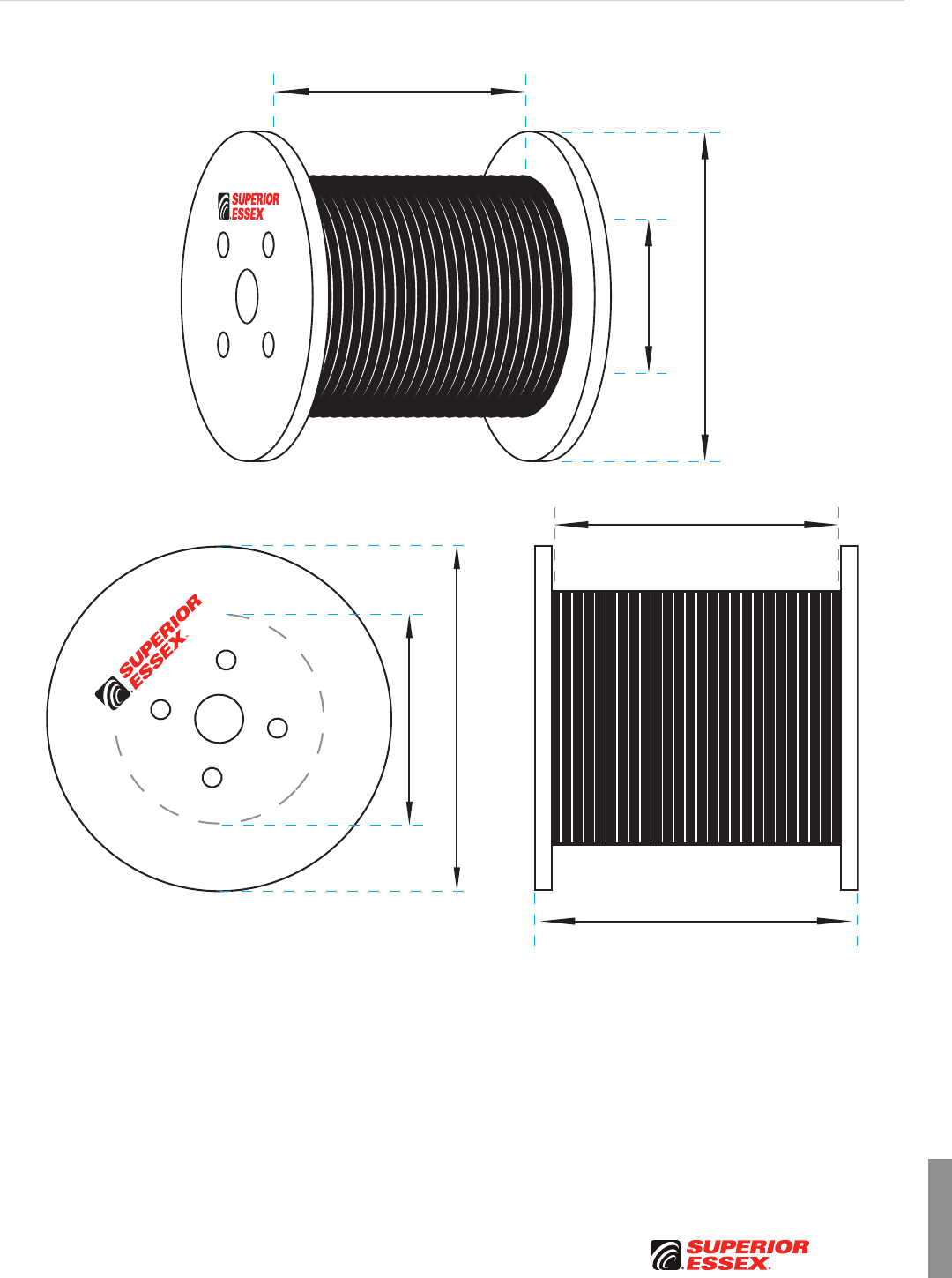
J-11
PREMISES COPPERPREMISES FIBEROSP FIBEROSP COMPOSITECENTRAL OFFICE COPPERRDUP/RUS OSP COPPERBELL OSP COPPEROSP COPPER WIRECANADIAN OSP COPPERTECHNICAL INFO
Rev 6/10 Ed 10.1 Toll Free 800.551.8948 | Fax 770.657.6807 | SuperiorEssex.com/Comm
FD
T
FD
T
W
Packaging
Reel Dimension Diagram Key
Flange x Traverse x Drum
(F x T x D)
F = Flange Diameter
T = Traverse (inside width between flanges)
D = Drum Diameter
W = Overall Width (includes flanges)
J-12
PREMISES COPPER PREMISES FIBER OSP FIBER OSP COMPOSITE CENTRAL OFFICE COPPER RDUP/RUS OSP COPPER BELL OSP COPPER OSP COPPER WIRE CANADIAN OSP COPPER TECHNICAL INFO
Rev 6/10 Ed 10.1Toll Free 800.551.8948 | Fax 770.657.6807 | SuperiorEssex.com/Comm
Premises Fiber Reel Dimensions
Reel Type Plastic Plywood
Flange (F) in 12 12 14 16 24 30
Traverse (T) in 6 9 9 15 18 18
Drum (D) in 5 5 5 8 12 12
Overall Width (W) in 7.125 10.125 10.375 15.75 19.375 19.375
Reel Weight lbs 2 2 2 5 17 28
Premises Fiber Reel Capacities
Cable Nominal Diameter
in (mm)
Cable Length
ft (m)
Cable Length
ft (m)
0.075 (1.91) 2,561 (781) 3,856 (1,175) 7,319 (2,231) 12,836 (3,912)
0.100 (2.54) 1,441 (439) 2,169 (661) 4,172 (1,272) 7,434 (2,266) 28,571 (8,709)
0.125 (3.18) 917 (280) 1,383 (422) 2,665 (812) 4,753 (1,449) 18,270 (5,569) 37,970 (11,573)
0.150 (3.81) 637 (194) 961 (293) 1,749 (533) 3,198 (975) 12,283 (3,744) 25,836 (7,875)
0.175 (4.45) 429 (131) 646 (197) 1,321 (403) 2,314 (705) 8,874 (2,705) 19,346 (5,897)
0.200 (5.08) 329 (100) 495 (151) 982 (299) 1,853 (565) 7,123 (2,171) 14,802 (4,512)
0.225 (5.72) 247 (75) 374 (114) 807 (246) 1,290 (393) 5,318 (1,621) 11,630 (3,545)
0.250 (6.35) 227 (69) 343 (105) 661 (202) 1,183 (361) 4,551 (1,387) 9,459 (2,883)
0.275 (6.99) 169 (51)** 255 (77)** 539 (164)** 934 (285) 3,584 (1,093) 7,623 (2,323)
0.300 (7.62) 157 (47)** 238 (72)** 434 (132)** 723 (220) 3,058 (932) 6,433 (1,961)
0.325 (8.26) 112 (34)** 170 (51)** 344 (104)** 678 (207) 2,604 (794) 5,396 (1,645)
0.350 (8.89) 105 (32)** 160 (48)** 327 (99)** 513 (156) 2,208 (673) 4,813 (1,467)
0.375 (9.53) 100 (30)** 151 (46)** 254 (77)** 485 (148) 1,861 (567) 3,987 (1,215)
0.400 (10.16) 67 (20)** 101 (30)** 242 (73)** 460 (140) 1,770 (540) 3,537 (1,078)
0.425 (10.80) 64 (19)** 96 (29)** 183 (55)** 336 (102)** 1,482 (452) 3,131 (954)
0.450 (11.43) 61 (18)** 92 (28)** 176 (53)** 320 (97)** 1,226 (374) 2,763 (842)
0.475 (12.07) 58 (17)** 88 (26)** 169 (51)** 306 (93)** 1,175 (358) 2,428 (740)
0.500 (12.70) 56 (17)** 85 (25)** 163 (49)** 293 (89)** 1,130 (344) 2,348 (716)
0.525 (13.34) * * * 200 (60)** 922 (281) 2,056 (627)
0.550 (13.97) * * * 193 (58)** 889 (271) 1,789 (545)
0.575 (14.61) * * * 186 (56)** 710 (216) 1,737 (530)
0.600 (15.24) * * * 179 (54)** 687 (209) 1,501 (458)
0.625 (15.88) * * * 173 (52)** 665 (203) 1,461 (445)
0.650 (16.51) * * * 168 (51)** 645 (196)** 1,251 (381)**
0.675 (17.15) * * * * 500 (152)** 1,220 (371)**
0.700 (17.78) * * * * 486 (148)** 1,191 (363)**
0.725 (18.42) * * * * 473 (144)** 1,009 (307)**
0.750 (19.05) * * * * 460 (140)** 986 (300)**
0.775 (19.69) * * * * 449 (136)** 965 (294)**
0.800 (20.32) * * * * 438 (133)** 805 (245)**
0.825 (20.96) * * * * 324 (98)** 789 (240)**
0.850 (21.59) * * * * 317 (96)** 773 (235)**
0.875 (22.23) * * * * 309 (94)** 759 (231)**
0.900 (22.86) * * * * 303 (92)** 621 (189)**
0.925 (23.50) * * * * 296 (90)** 610 (185)**
0.950 (24.13) * * * * 290 (88)** 599 (182)**
0.975 (24.77) * * * * 284 (86)** 589 (179)**
1.000 (25.40) * * * * 279 (85)** 579 (176)**
*Drum diameter is less than 10 times cable diameter (minimum bend radius). **Drum diameter is less than 20 times cable diameter (recommended bend radius).
This chart pertains to round cable only, and may be further limited by the design of the cable.
Packaging
Premises Fiber Reels
J-13
PREMISES COPPERPREMISES FIBEROSP FIBEROSP COMPOSITECENTRAL OFFICE COPPERRDUP/RUS OSP COPPERBELL OSP COPPEROSP COPPER WIRECANADIAN OSP COPPERTECHNICAL INFO
Rev 6/10 Ed 10.1 Toll Free 800.551.8948 | Fax 770.657.6807 | SuperiorEssex.com/Comm
Packaging
OSP Fiber Wood Reels
OSP Fiber Wood Reel Dimensions
Flange (F) in 30 36 48 60 72 84 96
Traverse (T) in 18 30 32 36 36 42 42
Drum (D) in 12 17 23 29.5 37.5 42 48
Overall Width (W) in 20 32 34 39 39 45 45
Reel Weight lbs 59 104 184 416 596 900 1,100
OSP Fiber Wood Reel Capacities
Cable Nominal Diameter
in (mm)
Cable Length
ft (m)
0.35 (8.89) 5,015 (1,529) 11,293 (3,442) 23,685 (7,219) 41,668 (12,700)
0.40 (10.16) 3,686 (1,123) 8,411 (2,564) 17,893 (5,454) 32,687 (9,963) 46,454 (14,159)
0.45 (11.43) 2,879 (878) 6,640 (2,024) 14,038 (4,279) 25,425 (7,750) 35,596 (10,850)
0.50 (12.70) 2,447 (746) 5,667 (1,727) 11,578 (3,529) 20,477 (6,241) 29,187 (8,896)
0.55 (13.97) 1,864 (568) 4,397 (1,340) 9,501 (2,896) 17,252 (5,259) 23,795 (7,253) 40,579 (12,369)
0.60 (15.24) 1,564 (477) 3,726 (1,136) 7,728 (2,356) 14,487 (4,416) 20,240 (6,169) 33,839 (10,314) 45,134 (13,757)
0.65 (16.51) 1,304 (397)** 3,143 (958) 6,749 (2,057) 12,091 (3,685) 17,160 (5,230) 29,324 (8,938) 38,085 (11,608)
0.70 (17.78) 1,242 (378)** 2,635 (803) 5,889 (1,795) 10,003 (3,049) 14,469 (4,410) 25,357 (7,729) 33,321 (10,156)
0.75 (19.05) 1,028 (313)** 2,508 (764) 5,126 (1,562) 8,842 (2,695) 12,927 (3,940) 21,847 (6,659) 29,096 (8,869)
0.80 (20.32) 839 (255)** 2,089 (637) 4,445 (1,355) 7,806 (2,379) 11,549 (3,520) 18,723 (5,707) 25,327 (7,720)
0.85 (21.59) 806 (245)** 1,717 (523) 3,836 (1,169) 6,875 (2,095) 9,580 (2,920) 16,929 (5,160) 21,947 (6,689)
0.90 (22.86) 647 (197)** 1,647 (502)** 3,288 (1,002) 6,034 (1,839) 8,501 (2,591) 15,303 (4,664) 19,987 (6,092)
0.95 (24.13) 624 (190)** 1,333 (406)** 3,165 (965) 5,273 (1,607) 8,172 (2,491) 13,821 (4,213) 18,201 (5,548)
1.00 (25.40) 603 (183)** 1,284 (391)** 2,694 (821) 5,083 (1,549) 7,246 (2,208) 12,466 (3,800) 16,564 (5,049)
1.05 (26.67) 474 (144)** 1,240 (377)** 2,603 (793) 4,424 (1,348) 6,399 (1,951) 11,223 (3,421) 14,128 (4,306)
1.10 (27.94) 459 (139)** 983 (299)** 2,194 (669) 4,280 (1,305) 5,625 (1,714) 10,078 (3,072) 13,673 (4,168)
1.15 (29.21) 445 (135)** 951 (289)** 2,126 (648) 3,702 (1,128) 5,444 (1,659) 9,022 (2,750) 12,390 (3,777)
1.20 (30.48) 338 (103)** 922 (281)** 1,769 (539)** 3,591 (1,095) 4,762 (1,451) 8,048 (2,453) 11,202 (3,414)
1.25 (31.75) * 895 (272)** 1,717 (523)** 3,081 (939) 4,621 (1,408) 7,818 (2,383) 10,100 (3,078)
1.30 (33.02) * 688 (209)** 1,670 (509)** 2,995 (913) 4,016 (1,224) 6,948 (2,118) 9,075 (2,766)
1.35 (34.29) * 669 (203)** 1,366 (416)** 2,542 (775) 3,905 (1,190) 6,764 (2,062) 8,835 (2,693)
1.40 (35.56) * 651 (198)** 1,330 (405)** 2,476 (755) 3,366 (1,026) 5,984 (1,824) 7,913 (2,412)
1.45 (36.83) * 634 (193)** 1,297 (395)** 2,415 (736) 3,279 (999) 5,836 (1,779) 7,719 (2,353)
1.50 (38.10) * 619 (188)** 1,266 (385)** 2,022 (616)** 3,198 (975) 5,132 (1,564) 6,885 (2,099)
*Drum diameter is less than 10 times cable diameter (minimum bend radius). **Drum diameter is less than 20 times cable diameter (recommended bend radius).
This chart pertains to round cable only, and may be further limited by the design of the cable.
J-14
PREMISES COPPER PREMISES FIBER OSP FIBER OSP COMPOSITE CENTRAL OFFICE COPPER RDUP/RUS OSP COPPER BELL OSP COPPER OSP COPPER WIRE CANADIAN OSP COPPER TECHNICAL INFO
Rev 6/10 Ed 10.1Toll Free 800.551.8948 | Fax 770.657.6807 | SuperiorEssex.com/Comm
Packaging
OSP Fiber/Copper Steel Reels
OSP Fiber/Copper Steel Reel Dimensions
Reel Number 413 414 415 416 417 419 420 487
Flange (F) in 48 50 56 66 78 78 83 96
Traverse (T) in 18 25.4 25.4 25.4 25.4 30 39.8 44.5
Drum (D) in 30 30 30 36 42 42 42 42
Overall Width (W) in 24 31.375 31.375 31.625 32.375 37 46.75 52.875
Reel Weight lbs 216 250 282 360 566 610 782 1,400
OSP Fiber/Copper Steel Reel Capacities
Cable Nominal Diameter
in (mm)
Cable Length
ft (m)
0.35 (8.89) 9,866 (3,007) 15,649 (4,770) 23,894 (7,283) 27,367 (8,341)
0.40 (10.16) 7,288 (2,221) 12,535 (3,821) 18,169 (5,538) 25,756 (7,850) 38,265 (11,663)
0.45 (11.43) 5,701 (1,733) 9,374 (2,857) 14,342 (4,371) 19,931 (6,075) 29,604 (9,023) 35,013 (10,672)
0.50 (12.70) 4,814 (1,467) 8,006 (2,440) 11,878 (3,620) 16,777 (5,114) 24,441 (7,450) 28,911 (8,812)
0.55 (13.97) 3,706 (1,130) 6,312 (1,924) 9,807 (2,989) 13,382 (4,079) 20,099 (6,126) 23,778 (7,248) 37,297 (11,368)
0.60 (15.24) 3,109 (948) 5,382 (1,640) 8,043 (2,452) 11,178 (3,407) 16,402 (4,999) 19,408 (5,916) 30,984 (9,444)
0.65 (16.51) 2,598 (792) 4,581 (1,396) 6,528 (1,990) 9,897 (3,017) 13,961 (4,255) 16,523 (5,036) 26,766 (8,158)
0.70 (17.78) 2,442 (744) 3,885 (1,184) 5,691 (1,735) 8,196 (2,498) 11,831 (3,606) 14,003 (4,268) 23,064 (7,030) 38,432 (11,714)
0.75 (19.05) 2,035 (620) 3,276 (999) 4,953 (1,510) 7,293 (2,223) 10,594 (3,229) 12,541 (3,822) 19,792 (6,033) 33,928 (10,341)
0.80 (20.32) 1,677 (511) 3,109 (948) 4,297 (1,310) 6,388 (1,947) 9,490 (2,893) 11,236 (3,425) 17,889 (5,453) 29,885 (9,109)
0.85 (21.59) 1,594 (486) 2,607 (795) 3,711 (1,131) 5,625 (1,715) 7,934 (2,418) 9,395 (2,864) 15,223 (4,640) 26,239 (7,998)
0.90 (22.86) 1,297 (395) 2,160 (658) 3,553 (1,083) 4,938 (1,505) 7,070 (2,155) 8,373 (2,552) 13,718 (4,181) 22,938 (6,992)
0.95 (24.13) 1,239 (378) 2,066 (630) 3,056 (931) 4,317 (1,316) 6,286 (1,916) 7,446 (2,270) 12,349 (3,764) 21,040 (6,413)
1.00 (25.40) 1,187 (362) 1,982 (604) 2,940 (896) 4,152 (1,266) 6,049 (1,844) 7,167 (2,185) 11,098 (3,383) 19,295 (5,881)
1.05 (26.67) 949 (289) 1,622 (494) 2,512 (766) 3,617 (1,102) 5,373 (1,638) 6,366 (1,931) 9,951 (3,033) 16,682 (5,085)
1.10 (27.94) 912 (278) 1,561 (476) 2,425 (739) 3,129 (954) 4,753 (1,449) 5,633 (1,717) 8,897 (2,712) 15,234 (4,643)
1.15 (29.21) 878 (268) 1,251 (381) 2,052 (625) 3,024 (922) 4,184 (1,275) 4,959 (1,512) 8,619 (2,627) 13,891 (4,234)
1.20 (30.48) 683 (208) 1,208 (368) 1,987 (606) 2,597 (792) 4,051 (1,235) 4,803 (1,464) 7,687 (2,343) 12,642 (3,853)
1.25 (31.75) 660 (201) 1,167 (356) 1,660 (506) 2,517 (767) 3,549 (1,082) 4,208 (1,283) 6,826 (2,081) 12,314 (3,753)
1.30 (33.02) 638 (194) 1,130 (344) 1,611 (491) 2,442 (744) 3,445 (1,050) 4,085 (1,245) 6,636 (2,023) 11,191 (3,411)
1.35 (34.29) 617 (188) 881 (269) 1,565 (477) 2,078 (633) 2,998 (914) 3,556 (1,084) 5,866 (1,788) 10,142 (3,091)
1.40 (35.56) 598 (182) 854 (260) 1,287 (392) 2,020 (616) 2,916 (889) 3,460 (1,055) 5,715 (1,742) 9,162 (2,793)
1.45 (36.83) 447 (136) 830 (253) 1,252 (382) 1,697 (517) 2,840 (866) 3,369 (1,027) 5,022 (1,531) 8,955 (2,729)
1.50 (38.10) 434 (132) 807 (246) 1,220 (372) 1,652 (504) 2,452 (747) 2,910 (887) 4,901 (1,494) 8,063 (2,458)
1.55 (39.37) 421 (128) 785 (239) 1,189 (362) 1,610 (491) 2,392 (729) 2,838 (865) 4,276 (1,303) 7,893 (2,406)
1.60 (40.64) 410 (125) 765 (233) 956 (292) 1,571 (479) 2,335 (712) 2,771 (845) 4,178 (1,273) 7,079 (2,158)
1.65 (41.91) 399 (122) 571 (174) 933 (284) 1,298 (396) 1,995 (608) 2,368 (722) 4,086 (1,245) 6,938 (2,115)
1.70 (43.18) 389 (119) 557 (170) 912 (278) 1,268 (386) 1,950 (594) 2,315 (706) 3,534 (1,077) 6,192 (1,887)
1.75 (44.45) 379 (116) 543 (166) 892 (272) 1,239 (378) 1,907 (581) 2,265 (690) 3,460 (1,055) 6,076 (1,852)
1.80 (45.72) 264 (80) 530 (162) 872 (266) 1,212 (369) 1,608 (490) 1,910 (582) 3,390 (1,033) 5,391 (1,643)
1.85 (46.99) 258 (79) 518 (158) 680 (207) 1,187 (362) 1,574 (480) 1,870 (570) 3,324 (1,013) 5,295 (1,614)
1.90 (48.26) 252 (77) 507 (155) 665 (203) 958 (292) 1,542 (470) 1,832 (558) 2,844 (867) 5,203 (1,586)
1.95 (49.53) 246 (75) 496 (151) 652 (199) 939 (286) 1,511 (461) 1,796 (547) 2,790 (850) 4,586 (1,398)
2.00 (50.80) 240 (73) 485 (148) 639 (195) 920 (280) 1,482 (452) 1,761 (537) 2,739 (835) 4,510 (1,375)
2.05 (52.07) 235 (72) 338 (103) 626 (191) 902 (275) 1,228 (374) 1,460 (445) 2,691 (820) 4,437 (1,352)
2.10 (53.34) 230 (70) 331 (101) 615 (187) 885 (270) 1,205 (367) 1,432 (436) 2,269 (692) 3,879 (1,182)
2.15 (54.61) 225 (69) 324 (99) 604 (184) 869 (265) 1,183 (361) 1,407 (429) 2,230 (680) 3,819 (1,164)
2.20 (55.88) 221 (67) 318 (97) 593 (181) 699 (213) 1,162 (354) 1,382 (421) 2,193 (668) 3,761 (1,146)
2.25 (57.15) 216 (66) 311 (95) 441 (134) 685 (209) 1,142 (348) 1,358 (414) 2,160 (658) 3,706 (1,129)
2.30 (58.42) 212 (65) 306 (93) 433 (132) 656 (200) 924 (282) 1,099 (335) 2,123 (647) 3,207 (977)
2.35 (59.69) 130 (40) 300 (91) 425 (130) 644 (196) 908 (277) 1,081 (329) 1,758 (536) 3,161 (963)
2.40 (60.96) 128 (39) 295 (90) 418 (127) 634 (193) 893 (272) 1,063 (324) 1,731 (528) 3,117 (950)
2.45 (62.23) 125 (38) 289 (88) 411 (125) 623 (190) 879 (268) 1,046 (319) 1,705 (520) 3,075 (937)
2.50 (63.50) 123 (37) 285 (87) 405 (123) 613 (187) 865 (264) 1,030 (314) 1,679 (512) 3,035 (925)
2.55 (64.77) * * * 604 (184) 852 (260) 1,014 (309) 1,655 (504) 2,594 (791)
2.60 (66.04) * * * 595 (181) 839 (256) 999 (304) 1,632 (497) 2,560 (780)
2.65 (67.31) * * * 443 (135) 826 (252) 984 (300) 1,319 (402) 2,528 (771)
2.70 (68.58) * * * 437 (133) 647 (197) 771 (235) 1,300 (396) 2,497 (761)
2.75 (69.85) * * * 430 (131) 638 (194) 760 (232) 1,282 (391) 2,466 (752)
2.80 (71.12) * * * 424 (129) 628 (191) 749 (228) 1,265 (386) 2,076 (633)
2.85 (72.39) * * * 418 (127) 619 (189) 738 (225) 1,248 (380) 2,051 (625)
2.90 (73.66) * * * 412 (126) 611 (186) 728 (222) 1,232 (376) 2,027 (618)
2.95 (74.93) * * * 406 (124) 602 (183) 718 (219) 1,217 (371) 2,004 (611)
3.00 (76.20) * * * 400 (122) 594 (181) 709 (216) 1,202 (366) 1,981 (604)
3.05 (77.47) * * * * 587 (179) 700 (213) 1,187 (362) 1,959 (597)
3.10 (78.74) * * * * 579 (176) 691 (211) 927 (283) 1,938 (591)
3.15 (80.01) * * * * 572 (174) 682 (208) 916 (279) 1,600 (488)
3.20 (81.28) * * * * 565 (172) 674 (205) 905 (276) 1,582 (482)
3.25 (82.55) * * * * 421 (128) 503 (153) 894 (272) 1,565 (477)
3.30 (83.82) * * * * 416 (127) 497 (151) 884 (269) 1,549 (472)
3.35 (85.09) * * * * 411 (125) 491 (150) 874 (266) 1,533 (467)
3.40 (86.36) * * * * 406 (124) 485 (148) 864 (263) 1,518 (463)
3.45 (87.63) * * * * 401 (122) 479 (146) 855 (261) 1,503 (458)
3.50 (88.90) * * * * 396 (121) 473 (144) 846 (258) 1,489 (454)
*Drum diameter is less than 12 times the cable diameter (minimum bend radius).
This chart applies to round cable only. Chart shows maximum calculated capacity. Actual available cable lengths may be less than capacity. Capacity is based on 2 inch clearance.

J-15
PREMISES COPPERPREMISES FIBEROSP FIBEROSP COMPOSITECENTRAL OFFICE COPPERRDUP/RUS OSP COPPERBELL OSP COPPEROSP COPPER WIRECANADIAN OSP COPPERTECHNICAL INFO
Rev 6/10 Ed 10.1 Toll Free 800.551.8948 | Fax 770.657.6807 | SuperiorEssex.com/Comm
Packaging
OSP Copper Wood Reels
OSP Copper Wood Reel Dimensions
Flange (F) in 30 36 44 46 52 58 62 65 72 78 84 96
Traverse (T) in 18 18 18 25 25 25 30 30 36 40 40 40
Drum (D) in 12 14 20 20 20 20 24 32 36 39 42 48
Overall Width
(W) in 21 21 21 28 29 29 34 35 41 45 46 46
Reel Weight lbs 46 64 108 165 203 245 288 368 614 699 797 1,175
OSP Copper Wood Reel Capacities
Cable O.D.
in (mm)
Cable Length
ft (m)
0.40 (10.16) 3,723 (1,135) 5,844 (1,781) 8,738 (2,663) 13,498 (4,114) 19,316 (5,888) 25,088 (7,647) 33,422 (10,187) 32,580 (9,930)
0.45 (11.43) 2,908 (886) 4,757 (1,450) 6,802 (2,073) 10,654 (3,247) 15,170 (4,624) 19,545 (5,957) 26,054 (7,941) 25,720 (7,839) 37,698 (11,490)
0.50 (12.70) 2,472 (753) 3,848 (1,173) 5,576 (1,700) 8,838 (2,694) 12,337 (3,760) 16,303 (4,969) 21,714 (6,618) 21,006 (6,403) 31,148 (9,494)
0.55 (13.97) 1,883 (574) 3,078 (938) 4,541 (1,384) 7,297 (2,224) 9,930 (3,027) 12,887 (3,928) 17,191 (5,240) 17,033 (5,192) 25,619 (7,809) 32,856 (10,015) 39,025 (11,895)
0.60 (15.24) 1,580 (482) 2,664 (812) 3,658 (1,115) 5,975 (1,821) 8,378 (2,554) 11,105 (3,385) 14,804 (4,512) 14,431 (4,399) 20,898 (6,370) 28,333 (8,636) 32,542 (9,919)
0.65 (16.51) 1,317 (401) 2,078 (633) 3,177 (968) 4,834 (1,473) 7,023 (2,141) 9,535 (2,906) 12,710 (3,874) 12,174 (3,711) 17,794 (5,424) 23,225 (7,079) 28,199 (8,595) 36,623 (11,163)
0.70 (17.78) 1,254 (382) 1,774 (541) 2,754 (839) 4,218 (1,286) 6,269 (1,911) 8,142 (2,482) 10,858 (3,310) 10,202 (3,110) 15,077 (4,595) 20,946 (6,384) 24,383 (7,432) 32,041 (9,766)
0.75 (19.05) 1,038 (316) 1,698 (518) 2,379 (725) 3,670 (1,119) 5,183 (1,580) 6,902 (2,104) 9,214 (2,808) 9,087 (2,770) 13,514 (4,119) 17,895 (5,454) 21,007 (6,403) 27,978 (8,528)
0.80 (20.32) 847 (258)** 1,445 (440) 2,046 (624) 3,181 (970) 4,598 (1,401) 6,221 (1,896) 8,299 (2,530) 8,090 (2,466) 12,116 (3,693) 15,185 (4,628) 18,003 (5,487) 24,353 (7,423)
0.85 (21.59) 814 (248)** 1,218 (371) 1,748 (533) 2,743 (836) 4,069 (1,240) 5,601 (1,707) 7,469 (2,277) 7,193 (2,192) 10,118 (3,084) 13,652 (4,161) 16,277 (4,961) 21,102 (6,432)
0.90 (22.86) 654 (199)** 1,174 (358)** 1,679 (512) 2,639 (804) 3,589 (1,094) 4,653 (1,418) 6,220 (1,896) 6,381 (1,945) 9,018 (2,749) 12,263 (3,738) 14,713 (4,485) 19,217 (5,857)
0.95 (24.13) 630 (192)** 980 (299)** 1,425 (434) 2,264 (690) 3,151 (960) 4,153 (1,266) 5,554 (1,693) 5,645 (1,721) 8,020 (2,444) 10,999 (3,352) 13,289 (4,050) 17,499 (5,334)
1.00 (25.40) 609 (186)** 948 (289)** 1,374 (419) 2,187 (667) 3,053 (931) 4,034 (1,230) 5,383 (1,641) 4,974 (1,516) 7,733 (2,357) 9,845 (3,001) 11,985 (3,653) 15,925 (4,854)
1.05 (26.67) * 781 (238)** 1,155 (352) 1,861 (567) 2,670 (814) 3,593 (1,095) 4,797 (1,462) 4,361 (1,329) 6,866 (2,093) 8,787 (2,678) 10,789 (3,288) 13,583 (4,140)
1.10 (27.94) * 758 (231)** 1,118 (341) 1,804 (550) 2,318 (707) 3,186 (971) 4,258 (1,298) 4,219 (1,286) 6,071 (1,850) 7,816 (2,382) 9,689 (2,953) 13,145 (4,007)
1.15 (29.21) * 612 (187)** 927 (283) 1,519 (463) 2,255 (687) 2,810 (856) 3,761 (1,146) 3,682 (1,122) 5,342 (1,628) 7,573 (2,308) 8,674 (2,644) 11,911 (3,630)
1.20 (30.48) * * 899 (274) 1,476 (450) 1,944 (593) 2,743 (836) 3,664 (1,117) 3,571 (1,088) 5,181 (1,579) 6,715 (2,047) 7,736 (2,358) 10,769 (3,282)
1.25 (31.75) * * 873 (266) 1,225 (373) 1,895 (578) 2,406 (733) 3,219 (981) 3,096 (944) 4,534 (1,382) 6,523 (1,988) 7,515 (2,291) 9,708 (2,959)
1.30 (33.02) * * 712 (217) 1,193 (364) 1,618 (493) 2,352 (717) 3,143 (958) 3,010 (917) 4,408 (1,344) 5,759 (1,755) 6,679 (2,036) 8,723 (2,659)
1.35 (34.29) * * 693 (211)** 1,162 (354)** 1,580 (482)** 2,049 (625)** 2,743 (836) 2,588 (789) 3,832 (1,168) 5,052 (1,540) 6,502 (1,982) 8,492 (2,588)
1.40 (35.56) * * 675 (206)** 948 (289)** 1,545 (471)** 2,007 (612)** 2,683 (818) 2,520 (768) 3,732 (1,138) 4,921 (1,500) 5,751 (1,753) 7,606 (2,318)
1.45 (36.83) * * 537 (164)** 925 (282)** 1,304 (397)** 1,733 (528)** 2,323 (708) 2,458 (749) 3,640 (1,109) 4,799 (1,463) 5,609 (1,710) 7,419 (2,261)
1.50 (38.10) * * 524 (160)** 904 (276)** 1,276 (389)** 1,699 (518)** 2,274 (693) 2,091 (637) 3,138 (956) 4,182 (1,275) 4,932 (1,503) 6,618 (2,017)
1.55 (39.37) * * 511 (156)** 884 (269)** 1,250 (381)** 1,453 (443)** 1,950 (594) 2,041 (622) 3,064 (934) 4,085 (1,245) 4,818 (1,469) 6,465 (1,971)
1.60 (40.64) * * 500 (152)** 703 (214)** 1,039 (317)** 1,426 (435)** 1,911 (582) 1,995 (608) 2,995 (913) 3,528 (1,075) 4,205 (1,282) 5,737 (1,749)
1.65 (41.91) * * 489 (149)** 688 (210)** 1,019 (311)** 1,400 (427)** 1,875 (572)** 1,674 (510) 2,554 (778) 3,450 (1,052) 4,113 (1,254) 5,612 (1,711)
1.70 (43.18) * * * * * * 1,841 (561)** 1,638 (499) 2,499 (762) 3,376 (1,029) 4,026 (1,227) 4,949 (1,508)
1.75 (44.45) * * * * * * 1,559 (475)** 1,603 (489) 2,447 (746) 3,307 (1,008) 3,483 (1,062) 4,846 (1,477)
1.80 (45.72) * * * * * * 1,531 (467)** 1,571 (479) 2,058 (627) 2,825 (861) 3,412 (1,040) 4,750 (1,448)
1.85 (46.99) * * * * * * 1,505 (459)** 1,295 (395) 2,017 (615) 2,770 (844) 3,345 (1,020) 4,157 (1,267)
1.90 (48.26) * * * * * * 1,255 (383)** 1,269 (387) 1,978 (603) 2,717 (828) 3,282 (1,000) 4,078 (1,243)
1.95 (49.53) * * * * * * 1,235 (376)** 1,245 (379) 1,941 (592) 2,289 (698) 2,808 (856) 4,003 (1,220)
2.00 (50.80) * * * * * * 1,215 (370)** 1,222 (372) 1,906 (581) 2,246 (685) 2,757 (840) 3,931 (1,198)
2.05 (52.07) * * * * * * * 1,201 (366) 1,574 (480) 2,206 (672) 2,708 (825) 3,410 (1,039)
2.10 (53.34) * * * * * * * 966 (294) 1,546 (471) 2,168 (661) 2,661 (811) 3,350 (1,021)
2.15 (54.61) * * * * * * * 949 (289)** 1,520 (463) 2,131 (650) 2,245 (684) 3,294 (1,004)
2.20 (55.88) * * * * * * * 933 (284)** 1,494 (455) 1,763 (537) 2,207 (673) 3,240 (988)
2.25 (57.15) * * * * * * * 917 (280)** 1,470 (448) 1,734 (529) 2,171 (662) 2,778 (847)
2.30 (58.42) * * * * * * * 902 (275)** 1,185 (361) 1,706 (520) 2,137 (651) 2,734 (833)
2.35 (59.69) * * * * * * * 888 (271)** 1,166 (355) 1,679 (512) 2,104 (641) 2,692 (821)
2.40 (60.96) * * * * * * * 875 (267)** 1,148 (350) 1,653 (504) 1,742 (531) 2,651 (808)
2.45 (62.23) * * * * * * * 680 (207)** 1,130 (344)** 1,629 (497) 1,716 (523) 2,241 (683)
2.50 (63.50) * * * * * * * 670 (204)** 1,114 (340)** 1,605 (489) 1,690 (515) 2,207 (673)
2.55 (64.77) * * * * * * * 660 (201)** 1,097 (334)** 1,295 (395) 1,666 (508) 2,176 (663)
2.60 (66.04) * * * * * * * 650 (198)** 1,082 (330)** 1,277 (389) 1,642 (500) 2,145 (654)
2.65 (67.31) * * * * * * * 641 (195)** 1,067 (325)** 1,259 (384)** 1,619 (493) 2,115 (645)
2.70 (68.58) * * * * * * * * 832 (254)** 1,241 (378)** 1,598 (487) 2,087 (636)
2.75 (69.85) * * * * * * * * 820 (250)** 1,224 (373)** 1,291 (393) 2,059 (628)
2.80 (71.12) * * * * * * * * 809 (247)** 1,208 (368)** 1,273 (388) 1,708 (521)
2.85 (72.39) * * * * * * * * 798 (243)** 1,193 (364)** 1,257 (383)** 1,685 (514)
2.90 (73.66) * * * * * * * * 788 (240)** 1,178 (359)** 1,240 (378)** 1,664 (507)
2.95 (74.93) * * * * * * * * 777 (237)** 919 (280)** 1,225 (373)** 1,643 (501)
3.00 (76.20) * * * * * * * * 768 (234)** 907 (276)** 1,210 (369)** 1,623 (495)
3.05 (77.47) * * * * * * * * * 896 (273)** 1,195 (364)** 1,603 (489)
3.10 (78.74) * * * * * * * * * 885 (270)** 1,181 (360)** 1,584 (483)
3.15 (80.01) * * * * * * * * * 874 (266)** 1,167 (356)** 1,282 (391)
3.20 (81.28) * * * * * * * * * 864 (263)** 911 (278)** 1,267 (386)
3.25 (82.55) * * * * * * * * * 854 (260)** 900 (274)** 1,252 (382)**
3.30 (83.82) * * * * * * * * * * 890 (271)** 1,238 (377)**
3.35 (85.09) * * * * * * * * * * 880 (268)** 1,224 (373)**
3.40 (86.36) * * * * * * * * * * 870 (265)** 1,210 (369)**
3.45 (87.63) * * * * * * * * * * 860 (262)** 1,197 (365)**
3.50 (88.90) * * * * * * * * * * 851 (259)** 1,184 (361)**
3.55 (90.17) * * * * * * * * * * * 1,172 (357)**
3.60 (91.44) * * * * * * * * * * * 1,160 (354)**
3.65 (92.71) * * * * * * * * * * * 1,148 (350)**
*Drum diameter is less than 12 times the cable diameter (minimum bend radius). **Drum diameter is less than 15 times the cable diameter (recommended bend radius).
This chart applies to round cable only. Chart shows maximum calculated capacity. Actual available cable lengths may be less than capacity. Capacity is based on 2 inch clearance.

J-16
PREMISES COPPER PREMISES FIBER OSP FIBER OSP COMPOSITE CENTRAL OFFICE COPPER RDUP/RUS OSP COPPER BELL OSP COPPER OSP COPPER WIRE CANADIAN OSP COPPER TECHNICAL INFO
Rev 6/10 Ed 10.1Toll Free 800.551.8948 | Fax 770.657.6807 | SuperiorEssex.com/Comm
Glossary of Terms
Copper
COPPER Glossary of Terms
ACR (Attenuation to Crosstalk Ratio):
The ratio between attenuation and near end
crosstalk, measured in decibels (dB), at a
given frequency. Important characteristic in
networking transmission to assure that signal
sent down a twisted pair is stronger at the
receiving end of the cable than any interfering
signals imposed on that same pair by
crosstalk from adjacent pairs. While it is not
included in TIA 568, it is a good figure of merit
in that it describes the signal to noise ratio.
ACRF: See “ELFEXT”
ADSL (Asymmetric Digital Subscriber Line):
Modems attached to twisted pair copper
wiring that transmit from 1.5 Mbps to 9 Mbps
downstream (to the subscriber) and from
16 KBps to 800 KBps upstream, depending
on line distance.
aerial cable: Cable suspended in the air usually
on utility poles. Except for self supporting
cables an external messenger strand is used
to support the cable.
amplifier: Any device that intensifies a signal
without distorting the shape of the wave.
analog: A signal that varies continuously (i.e.
sound waves). Analog signals have a frequency
and bandwidth measured in hertz (Hz).
ANSI (American National Standards Institute):
A standards-setting, non-government
organization which develops and publishes
standards for transmission codes, protocols
and high-level languages for “voluntary”use
in the United States.
armor: Additional protective covering beneath
the outer jacket to provide physical protection
against severe outdoor environments. Usually
made of plastic-coated steel, it may be
corrugated for flexibility.
armored cable: A cable having an outer
protection usually in the form of a steel
corrugated tape.
Asynchronous Transfer Mode (ATM):
A high-speed, packet-switching technology
used to transmit video, data, voice, etc. via
fixed-length cells of 53 bytes.
ATM: See “Asynchronous Transfer Mode”
attenuation: Also known as Insertion Loss.
Loss of signal power between two points.
Attenuation is a ratio of input power versus
output power, measured in decibels per
unit length, usually decibels per 100 meters
(dB/100 m). The received signal is lower in
signal power than the transmitted signal.
backbone: The facility, such as cables
and connectors, that connects equipment
rooms, telecommunications closets and
entrance facilities. Can be inter-building
or intrabuilding.
bandwidth: A measure of capacity of
communications media. Greater bandwidth
allows communication of more information
in a given period of time. Bandwidth is
generally described either in terms of analog
signals in units of Hertz (Hz), which describes
the maximum number of cycles per second,
or in terms of digital signals in units of bits
per second.
BER (bit error rate): The ratio of incorrectly
transmitted bits to correctly transmitted bits.
binder: A spirally applied colored thread or ribbon
used to separate and identify units and groups
of cable pairs by means of color coding.
B-ISDN (Broadband Integrated Services Digital
Network): A digital network with ATM
switching operating at data rates in excess of
1.544 or 2.048 Mbps. ATM enables transport
and switching of voice, data, image and video
over the same infrastructure.
broadband: An adjective used to describe large-
capacity networks that are able to carry
several services at the same time, such
as data, voice and video.
buried cable: A cable that is buried directly in the
ground without being placed in underground
conduit. Generally waterproof type cables are
employed.
byte (B): Eight bits of digital data.
cable closure: Any of several types of
housings that can be used to enclose cable
sheath openings necessary for splicing
or terminating.
capacitance: The ability of a dielectric material
between conductors to store electrical energy
when a difference of potential exists between
the conductors. The unit of measurement is
the farad, which is the capacitance value that
will store a charge of one coulomb when a
one volt potential difference exists between
the conductors
CATV (cable television): The term originally stood
for “community antenna television,” reflecting
the fact that the original cable systems carried
only broadcast stations received off the air;
however, as cable systems began to originate
their own programming, the term evolved to
mean Cable Television. CATV is a broadband
transmission facility.
CCTV: Closed Circuit Television
Central Office (CO): The location that houses
a switch to serve local telephone subscribers
on the public switched telephone network
(PSTN) for a small regional area.
characteristic impedance: In a transmission
line of infinite length, the ratio of the applied
voltage to the resultant current at the point
the voltage is applied. Or the impedance
which makes a transmission cable seem
infinitely long, when connected across
the cable’s output terminals.
CLEC (Competitive Local Exchange Carrier):
An American term for a telephone
company that was created after the
Telecommunications Act of 1996 made
it legal for companies to compete with
the ILECs. Contrast with ILEC.
CO: See “Central Office”
coaxial capacitance: The capacitance
of a single insulated conductor completely
surrounded by a dielectric medium.
conductor: A material that offers low resistance
to the flow of electrical current.
core network: Combination of telephone
switching offices and transmission plant
connecting switching offices together.
In the United States, local exchange core
networks are linked by several competing
inter-exchange networks; in the rest of the
world (ROW) the Core Network extends
to national boundaries.
crosstalk: The transmitted signal on one circuit
or cable pair causes interference in another
circuit or cable pair.
data link: The cable, receiver and transmitter
that connect two points communicating with
digital data.
dB: See “decibel”
decibel (dB): The unit used to describe relative
gain or loss of signal power, generally per unit
length. Abbreviated dB, the decibel is a ratio
of power out versus power in. Increases or
reductions of 3 dB will result in doubling or
halving, respectively, the power in a circuit.
delay skew: The propagation delay difference
between the slowest and fastest cable pair.
digital: Encoded as a discrete signal in binary
ones and zeros.
digital signal: A signal that takes on only two
values, off or on, typically represented by
“0” or “1.” Digital signals require less power
but (typically) more bandwidth than analog
and copies of digital signals can be made
exactly like the original.
DLC (Digital Loop Carrier): A digital transmission
system designed for a telephony subscriber’s
loop plant. It multiplexes multiple circuits onto
very few wires or onto a single fiber pair.
drop wire cable: Cable containing one
or more pairs of insulated wires used
to run a subscriber’s line from the distribution
terminal at a pole to the protector on the
subscriber’s premises.
DS1 (Digital Signal, level 1): Also known as T-1.
Twenty-four voice channels packed into a 193
bit frame and transmitted at 1.544 Mbps. The
unframed version, or payload, is 192 bits at a
rate of 1.536 Mbps.
DS1C (Digital Signal, level 1 Combined):
Two T2 frames packed into a higher-level
frame transmitted at 3.15 Mbps.

J-17
PREMISES COPPERPREMISES FIBEROSP FIBEROSP COMPOSITECENTRAL OFFICE COPPERRDUP/RUS OSP COPPERBELL OSP COPPEROSP COPPER WIRECANADIAN OSP COPPERTECHNICAL INFO
Rev 6/10 Ed 10.1 Toll Free 800.551.8948 | Fax 770.657.6807 | SuperiorEssex.com/Comm
DS2 (Digital Signal, level 2): Four T1 frames
packed into a higher-level frame transmitted
at 6.312 Mbps.
DSL (Digital Subscriber Line): Modems on either
end of a single twisted pair wire that delivers
ISDN Basic Rate Access.
DSLAM (Digital Subscriber Line Access
Multiplexer): Specifically, a device which
takes a number of ADSL subscriber lines
and concentrates these to a single ATM line.
duct: Conduit for the installation and protection
of cables in congested areas.
EF&I: Engineer, Furnish and Install
electromagnetic coupling: The transfer of energy
by means of a varying magnetic field.
ELFEXT (Equal Level Far End Crosstalk):
Also known as ACRF. The ratio of the
unwanted crosstalk at the far end (from
the transmitter) of the disturbed pair, used
to quantify the noise seen at a receiver due
to a far end transmitter on another pair.
Usually expressed in decibels (dB). Similar
to ACR but is measured at the far end of the
cable. It is an indication of the quality of the
signal sensed by the receiver.
EMI (electromagnetic interference):
“Noise” generated in copper conductors
when electromagnetic fields induce currents.
EMI may be caused by other copper cables
and is caused by proximity to motors and
machinery. The all dielectric optical fiber
cable design makes them immune to EMI.
Equipment Room (ER): A centralized space for
telecommunications equipment that serves
the occupants of a building. An equipment
room is considered distinct from a
telecommunications closet because of
the nature or complexity of the equipment.
far end crosstalk: See “FEXT”
farad: A unit of capacitance that will store one
coulomb of electrical charge when one volt
of electrical pressure is applied.
FEP (Fluorinated Ethylene Propylene):
A fluorinated thermoplastic material with
good electrical insulating properties used
for plenum cable.
FEXT (far end crosstalk): Refers to crosstalk
that is measured at the opposite end of the
cable from which it is being disturbed.
Figure 8 cable: Cables designed for self
supporting aerial installations. The multi-
pair core and steel support messenger are
integrated in a parallel configuration to enable
simultaneous installation of cable
and messenger.
flooding: The act of applying a material over
a cable or any of its components, usually for
the purpose of adhesion, corrosion deterrent,
or to fill voids.
frequency: The number of times a periodic action
occurs in a unit of time. The number
of cycles that an electric current completes
in one second, expressed in hertz.
gas pressurization: A method of preventing water
from entering small cracks in cable splices or
sheath and for alerting personnel
to larger leaks by keeping cables under
pressure with dry gas.
Gigabit Ethernet (GE): This standard was written
by the IEEE 802.3 committee and adopted
as a new standard for Gigabit transmission
of LANs.
group binder: A binder applied over a number
of units giving group identification.
headroom: Any amount of margin that is above
the standard for a category.
hertz (Hz): The unit of frequency, one cycle
per second.
hygroscopic: Readily absorbing
and retaining moisture.
IC (intermediate cross-connect): A secondary
cross-connect in the backbone cabling used
to mechanically terminate and administer
backbone cabling between the main cross-
connect and horizontal cross-connect.
ILEC (Incumbent Local Exchange Carrier):
A local telephone company service
consistent with the services provided by a
previous carrier. ILECs compete with upstart
Competitive Local Exchange Carriers (CLEC).
insertion loss: See “attenuation”
inside plant: Usually considered being all cable
and equipment inside the Central Office (CO)
and customer’s premises.
laminate: A sheet material made by bonding
together two or more layers of the same
or different material.
LAN: See “Local Area Network”
lay: The longitudinal distance that a pair or
unit advances in one spiral turn about the
cable axis.
LCL (longitudinal conversion loss):
Ratio of the common-mode (longitudinal)
signal applied to a cable or transmission
channel to the resultant differential signal
measured at the same end. Used to quantify
the longitudinal signal seen at the transmitter
due to the differential signals present on
the cable or transmission channel which
influences the electromagnetic emissions.
Usually expressed in decibels (dB).
LCTL (longitudinal conversion transfer loss):
Ratio of the common-mode (longitudinal)
signal applied at the near end of a cable or
transmission channel to resultant differential
signal measure at the far end. Used to quantify
the undesired differential noise seen at the
receiver due to longitudinal noise coupled
onto the cable from external sources. Usually
expressed in decibels (dB).
LEC (local exchange carrier): Any carrier that
has been given permission by the state public
utility commission to provide local voice
level telecommunications services within
a predetermined area.
Local Area Network (LAN): A network
connecting several nodes within a limited
geographic area, usually within a building
or campus
Mbps: A million bits per second when referring
to the speed of a telecommunications,
networking or local area networking
transmission facility.
MC (main cross-connect): The centralized
portion of the backbone cabling used to
mechanically terminate and administer the
backbone cabling, providing connectivity
between equipment rooms, entrance facilities,
horizontal cross-connects and intermediate
cross-connects.
mutual capacitance: One of the primary
constants of a cable pair which contributes
to transmission loss.
near end crosstalk: See “NEXT”
NEXT (near end crosstalk): The crosstalk which
occurs when signals transmitted on one pair
of wires are picked up by another (disturbed)
pair in the same cable when measured at the
near (transmitter) end.
ns (nanosecond): One-billionth of a second
or 10-9 second.
OEM (Original Equipment Manufacturer):
An OEM maker is a manufacturer of original
equipment. A company who buys their
components from someone else and simply
assembles the components into a product
is not considered an OEM and is often called
a value-added reseller.
Ohm: The electrical unit of resistance. The
value of resistance through which a potential
difference of one volt will maintain a current
of one ampere.
Outside Plant (OSP): Usually considered all cable
and equipment used outside of the Central
Office (CO) and customers’ premises.
OSP: See “Outside Plant”
pair: Two wires forming a single circuit,
held together by twisting, binding,
or a common jacket.
PE: See “polyethylene”
pedestal: An above ground watertight housing
for splicing and terminating buried cables.
PIC: See “plastic insulated conductor”
plastic insulated conductor (PIC): A metallic
cabling system in which the individual
conductors are covered with an extruded
coating of plastic. Common insulation includes
polyethylene and polypropylene. Although
a plastic, PVC insulated conductors are not
referred to as PIC.
Glossary of Terms
Copper

J-18
PREMISES COPPER PREMISES FIBER OSP FIBER OSP COMPOSITE CENTRAL OFFICE COPPER RDUP/RUS OSP COPPER BELL OSP COPPER OSP COPPER WIRE CANADIAN OSP COPPER TECHNICAL INFO
Rev 6/10 Ed 10.1Toll Free 800.551.8948 | Fax 770.657.6807 | SuperiorEssex.com/Comm
plenum: A compartment or chamber to which
one or more air ducts are connected and
that forms part of the air distribution system
(i.e. the space above the drop ceiling).
plenum cable: Cables made of fire-retardant
materials that generate little smoke. These
cables are installed in plenum air ducts,
vertical shafts etc.
polyethylene (PE): A polyolefin thermoplastic
material having excellent electrical properties.
polyvinylchloride (PVC): A general purpose
thermoplastic used for wire and cable
insulation and jackets.
POTS (Plain Old Telephone Service): The only
name recognized around the world for basic
analog telephone service. POTS takes the
lowest 4 kHz of bandwidth on twisted pair
wiring. Any service sharing a line with POTS
must either use frequencies above POTS or
convert POTS to a digital signal.
POTS Splitter: A device that uses filters to
separate voice from data signals when they
are to be carried on the same phone line,
required for several types of DSL service.
power sum: The method of evaluating the
performance of a single cable pair taking
into account the impact of other cable pairs
operating simultaneously.
propagation delay: The time due to the
transmission medium between when a signal
is transmitted and when it is received.
PSAACRF (Power Sum Alien Attenuation to
Crosstalk Ratio Far End): The combined (power
sum) crosstalk from all adjacent (alien) cables
on a single pair inside a victim (disturbed) cable
taken at the far end (at the receiver). The value
obtain from this test is then taken as a ratio
with the attenuation to yield the reported value.
PSACR (Power Sum-Attenuation-to-Crosstalk
Ratio): Similar to ACR except Power Sum
Near End Crosstalk (PSNEXT) is used in the
calculation instead of Near End Crosstalk
(NEXT). Used to quantify the noise seen at the
receiver due to multiple near end transmitters
relative to the attenuated transmit signal
present at the receiver. Usually expressed
in decibels (dB).
PSACRF: See “PSELFEXT”
PSANEXT (Power Sum Alien Near End Crosstalk):
The combined (power sum) crosstalk from all
adjacent (alien) cables on a single pair inside
a victim (disturbed) cable taken at the near end
(at the transmitter).
PSELFEXT (Power Sum Equal Level Far End
Crosstalk): Also known as PSACRF. The
mathematical summation (power sum) of the
equal level far end crosstalk power relative
to the attenuated signal of the disturbing pair,
coupled into a disturbed pair from all other
pairs within a cable or transmission channel.
Usually expressed in decibels (dB). Used to
quantify the noise seen at the receiver due
to multiple far end transmitters.
PSNEXT (Power Sum Near End Crosstalk):
The combined (power sum) crosstalk from
all other pairs on the victim (disturbed) pair
within a cable taken at the near (transmitter)
end of the cable.
PSTN (public switched telephone network):
The worldwide communications network that
carries phone calls and data.
pulling eye: A strong metal ring usually installed
at the factory, for use in pulling a cable into
a duct.
PVC: See “polyvinylchloride”
RBOC (Regional Bell Operating Company):
The regional holding companies that resulted
from the divestiture of AT&T. The original 22
Bell Telephone companies were combined
into seven regional companies in 1984.
resistance: The property of a conductor, wire
or shield that determines the current flow for
a given applied voltage. In DC circuits, the
opposition a material offers to current flow,
measured in Ohms. In AC circuits, resistance
is the real component of impedance and may
be higher than the value measured at DC.
return loss: Also known as echo. Ratio of the
reflected power in a cable or transmission
channel to the incident power. Effectively
expresses the relationship of impedance
changes throughout a cable or transmission
channel, as a function of frequency, relative
to the normal system impedance. Used
to quantify the noise seen at a receiver
due to reflections (echo) from a near end
transmitter on the same pair when full duplex,
bi-directional transmission is employed.
Usually expressed in decibels (dB).
riser: Pathways for indoor cables that pass
between floors. It is normally a vertical
shaft or space. Also a fire code rating
for indoor cable.
riser cables: Riser cables are intended for
use in elevator (vertical) shafts between floors
in a building. Also a fire-code rating for indoor
cable connectivity.
router: The central switching device in a packet-
switched computer network that directs and
controls the flow of data through the network.
RoHS-compliant: (The Restriction of Hazardous
Substances Directive) RoHS-compliant was
adopted in February 2003 by the European
Union. The RoHS took effect on July 1,
2006, but is not a law; it is simply a directive
for participating countries, including the
European Union (exclusive of the United
States and many other countries). This
directive restricts the use of six hazardous
materials in the manufacture of various types
of electronic and electrical equipment.
RoHS-compliant is often referred to as
the “lead-free” directive.
sag: The downward curvature of an aerial cable
or wire due to its weight.
sheath: The protective outer covering of a cable
core, including metallic shields and jackets.
shield: A tape or braid of metal, usually copper,
aluminum, or other conductive material placed
around or between electric circuits or cables
or their components, to prevent signal leakage
or interference.
spare pair: An additional pair in an OSP copper
cable, above the guaranteed number.
splice box or splice closure: A metal or plastic
housing used around a cable splice to provide
a water and gas tight closure.
SRL (Structural Return Loss): Ratio of the reflected
power in a cable to the incident power
expressed in decibels. Effectively expresses
the relationship of impedance changes
throughout a cable, as a function of frequency
relative to the characteristic impedance of the
cable. Important consideration for transmission
of Analog video. Used as a figure of merit
for consistency of impedance in a cable due
to changes in the cable’s construction or
structure down a long length.
T-1: See “DS1”
Telcordia Technologies: Formerly Bellcore, a
research company once owned by the RBOCs.
TIA (Telecommunications Industry Association):
TIA represents the telecommunications
industry in association with the EIA
(Electronics Industry Association) and
creates telecommunications standards.
UL (Underwriters Laboratories): A privately-
owned company that charges manufacturers
a fee to ensure their products meet various
safety standards, some of which UL develops.
unbalance to ground capacitance:
The inequality between the grounded
capacitance of a wire and its mate of a pair
which causes pickup of energy from external
sources, usually power transmission lines.
UTP (Unshielded Twisted Pair): Cable containing
one or more pairs of twisted copper without
metallic shielding.
velocity of propagation (Vp): The transmission
speed of electrical energy in a length of cable
compared to speed in free space. Usually
expressed as a percentage.
Voice Frequency (VF): Although frequencies
from 32 to 16 kHz are audible to some
persons the band normally used for telephone
communications is limited to about 3500 Hz.
Test frequency most commonly used is 1 kHz.
waterproof cable: Cable containing a waterproof
filling compound that fills all available space
in the core and between core tape and shield
and thus preventing the entrance of water.
Glossary of Terms
Copper

J-19
PREMISES COPPERPREMISES FIBEROSP FIBEROSP COMPOSITECENTRAL OFFICE COPPERRDUP/RUS OSP COPPERBELL OSP COPPEROSP COPPER WIRECANADIAN OSP COPPERTECHNICAL INFO
Rev 6/10 Ed 10.1 Toll Free 800.551.8948 | Fax 770.657.6807 | SuperiorEssex.com/Comm
FIBER Glossary of Terms
absorption: The loss of light energy in an optical
fiber, resulting from conversion of optical
power into heat and caused primarily by
naturally occuring impurities and defects
in the glass.
aerial cable: Optical fiber cable suspended in
the air usually on utility poles. Except for self
supporting cables an external messenger
strand is used to support the cable.
all dielectric: Non-conducting; made entirely
of dielectric (insulating) materials, without
any metal conductors.
aramid yarn: Strength elements that provide
tensile strength, support and additional
protection of the fiber bundles. Kevlar®
and Twaron® are brands of aramid yarns.
armor: Additional protective covering beneath
the outer jacket to provide physical protection
against severe outdoor environments. Usually
made of plastic-coated steel, it may be
corrugated for flexibility.
attenuation: A general term indicating the
decrease in power of a signal in transmission
as it passes from one point to another. In
optical fibers, the power loss results from
absorption and scattering and is normally
measured in decibels (dB) per kilometer at
a specific wavelength.
bandwidth: Measure of the information-carrying
capacity of an optical fiber. (This term is often
used to specify the normalized bandwidth of
a multimode fiber).
bend radius: The radius which a fiber or
cable can be bent before risking increased
attenuation or fiber breaks.
blown fiber: A method for installing fiber cable in
which the cable is blown through the duct.
bonding: Electrically connecting the metallic
components of cable sheaths together.
breakout cable: Multi fiber cables where each
fiber is further protected by an additional
jacket and strength elements.
breaking strength: The amount of force needed
to break a fiber.
broadband: Denotes transmission facilities
capable of handling a wide range of
frequencies simultaneously, thus permitting
multiple channels in data systems, rather than
direct modulation.
buffering: (1) An additional protective material
extruded directly over the fiber coating to
protect it from the environment and handling
(tight-buffered); (2) extruding a tube around
the coated fiber to allow isolation of the fiber
from stresses in the cable (buffer tubes).
buffer tubes: A hard plastic cylindrical tube,
with a diameter several times larger than
the fiber, covering optical fiber(s) used for
protection and isolation.
cable: An assembly of one or more optical
fibers formed into a core and covered with
a protective sheath providing mechanical
and environmental protection.
cable bend radius: The effective radius resulting
when a cable is bent. Often specified as a
minimum bend radius that can be applied
without causing damage to the cable’s
components.
cable core: The central portion of a cable
containing the optical fibers and surrounded
by a sheath.
central member: The center component in some
cable designs. It serves as a strength and
anti-buckling element. The central member
material is typically either steel or glass-
reinforced plastic.
cladding: The material surrounding the core
of an optical fiber. The cladding must have
a lower index of refraction to keep the light
in the core.
coating: A protective material applied directly
over the cladding of the fiber during the
draw process to protect the fiber from the
environment and handling.
composite cable: A cable containing both fiber
and copper media per Article 770 of the
National Electrical Code (NEC).
conduit: Also known as duct. A pipe or tube that
may be buried or installed within buildings
through which cables can be pulled or housed.
dB: See “decibel”
decibel (dB): The unit for measuring the relative
strength of light signals (attenuation), normally
expressed in dB.
dielectric cable: Also known as nonmetallic
cable. A cable that contains no electrically
conducting materials such as metal. Glass
fibers are considered dielectric. Dielectric
cables are sometimes used in areas subject to
high lightning or electromagnetic interference.
distribution cable: Generally tight buffered fiber
cables used for various indoor applications.
Distribution cables are usually 6 thru 144 fiber
count cables.
duct: See “conduit”
duplex cable: A cable containing 2 fibers.
Standard configurations are duplex round
and duplex zip.
EMI (electromagnetic interference):
Any electrical interference that causes
undesirable interference or failure in
electronic equipment. Optical fibers neither
emit nor receive EMI.
FDDI (Fiber Distributed Data Interface):
A transmission standard for a optical fiber
local area network.
fiber: An optical fiber is a thin piece of glass
used for transmitting optical signals. An
optical fiber consists of three layers: the core,
cladding and coating. It is capable of carrying
information in the form of light.
fiber bend radius: The radius a fiber can bend
before the risk of breakage or increase
in attenuation.
fiber core: The central region of an optical fiber
through which light is transmitted. Fiber cores
have a higher index of refraction than the
cladding in order to contain the light.
fiber optics: Light transmission through optical
fibers for communication or signaling.
grounding: Connecting the metal components
of a cable sheath to earth, generally through
a ground rod.
hybrid cable: A optical fiber cable containing
two or more different types of fiber. The
most common hybrid includes 62.5/125 µm
multimode mixed with single mode fiber.
inside plant: Tight buffered optical fiber cables
used for indoor applications.
interbuilding: Refers to between buildings.
interconnect: Tight buffer cables such
as simplex, duplex and quad cables.
intrabuilding: Refers to within buildings.
jacket: A plastic extrusion over a cable.
Kevlar®: A brand of aramid yarn used as cable
strength members. The name is a trademark
of the Dupont Company.
km (kilometer): One thousand meters,
or approximately 3,281 feet, or 0.62 miles.
The kilometer is a standard unit of length
measurement in fiber optics.
LAN: See “Local Area Network”
lashing: Attachment of a cable to a support strand
by wrapping steel wire helically around them.
Local Area Network (LAN): A geographically
limited communications network intended
for the local transport of voice, data and video.
loose tube cable: A type of cable construction
where the fibers are encased in buffer tubes
having a diameter several times larger than
the fiber offering excellent fiber protection
and segregation. This design offers excellent
protection for outdoor environments.
macrobending: Visible bends often caused by
exceeding suggested bend radius of a cable.
MFD: See “mode field diameter”
mode field diameter (MFD): Also known as spot
size. The diameter of the one mode of light
propagating in a single mode fiber. Since the
mode field diameter is larger than the core
diameter, it replaces core diameter as the
practical parameter in single mode fiber.
Glossary of Terms
Fiber

J-20
PREMISES COPPER PREMISES FIBER OSP FIBER OSP COMPOSITE CENTRAL OFFICE COPPER RDUP/RUS OSP COPPER BELL OSP COPPER OSP COPPER WIRE CANADIAN OSP COPPER TECHNICAL INFO
Rev 6/10 Ed 10.1Toll Free 800.551.8948 | Fax 770.657.6807 | SuperiorEssex.com/Comm
MHz (megahertz): A unit of frequency that
is equal to one million cycles per second.
microbending: A small fiber bend, invisible to the
unaided eye, that results in light displacement
and increased loss. They can occur due to
coating, cabling, installation and temperature.
micron: One thousandth of a millimeter or one
millionth of a meter (10-6 meters). A micron
can be used to specify the core diameter
of optical fiber network cabling.
minimum bend radius: The amount of bend
a fiber (or cable) can withstand before
experiencing problems in performance.
MMF: See “multimode fiber”
mode: A term used to describe an independent
light path through a fiber. Only one mode
propagates in a single mode fiber whereas
several modes propagate in a multimode fiber.
multifiber cable: An optical fiber cable that
contains two or more fibers.
multimode fiber (MMF): A type of optical fiber
in which light travels in multiple modes.
The most common multimode fiber sizes
(core/cladding) are 50/125 and 62.5/125.
nm (nanometer): One-billionth of a meter or
10-9 meter; a unit of measurement typically
used to express the wavelength of light.
NEC (National Electrical Code):
Defines flammability requirements for cables
installed within buildings. (Local codes take
precedence but may refer to or require
compliance to the NEC.)
nonmetallic cable: See “dielectric cable”
optical fiber: See “fiber”
OSP: See “Outside Plant”
Outside Plant (OSP): The portion of a cable
network that resides outside of buildings.
PE (polyethylene): A type of thermoplastic
material used for Outside Plant (OSP)
cable jackets.
plenum: A compartment or chamber to which
one or more air ducts are connected and that
forms part of the air distribution system
(i.e. the space above the drop ceiling).
PMD (Polarization Mode Dispersion):
The broadening of a light pulse due to the time
delay of one of the two pulse components.
If significant enough, the result is a bit error.
PVDF (Polyvinylidene Difluoride):
A fluoropolymer material that is resistant to
heat and used in the jackets of plenum cable.
riser cables: Riser cables are intended for use
in elevator (vertical) shafts between floors
in a building. They are OFNR listed (UL 1666).
Also a fire-code rating for indoor cable
connectivity.
RoHS-compliant: (The Restriction of Hazardous
Substances Directive) RoHS-compliant was
adopted in February 2003 by the European
Union. The RoHS took effect on July 1,
2006, but is not a law; it is simply a directive
for participating countries, including the
European Union (exclusive of the United
States and many other countries). This
directive restricts the use of six hazardous
materials in the manufacture of various types
of electronic and electrical equipment.
RoHS-compliant is often referred to as
the “lead-free” directive.
SAP: Abbreviation used to denote super
absorbent polymer.
scattering: A property of the fiber that causes
light to change direction, contributes to
optical attenuation.
sheath: The protective outer covering of a cable
core, including metallic shields and jackets.
single mode fiber (SMF): An optical fiber in
which the signal travels in one mode. The fiber
has a small core diameter, typically 8.3 µm.
SMF: See “single mode fiber”
spot size: See “mode field diameter”
stranding: The manufacturing process by which
cable components, such as buffer tubes
and yarns, are helically assembled around
a central member forming a round core.
strength member: The part of a optical fiber
cable composed of aramid yarns or fiberglass
that increase the tensile strength of the cable.
tensile strength: The pulling strength or force
necessary to break a material.
thermoplastic: A material that softens with
heat but returns to its original condition
when cooled.
tight buffer optical fiber cable: Type of cable
construction where the plastic buffer is
applied directly over the coating on the fiber
to a diameter of 900 µm.
wavelength: The distance between two
successive points on adjacent waves,
usually measured in nanometers (nm).
WiMAX (Worldwide Interoperability for
Microwave Access): A Broadband Wireless
Access (BWA) solution that is based on
standards recommendations from both
the Institute for Electrical and Electronics
Engineers (IEEE) 802.16 working group and
the European Telecommunications Standards
Institute (ETSI).
window: A range of wavelengths within which
a fiber best operates.
Glossary of Terms
Fiber

J-21
PREMISES COPPERPREMISES FIBEROSP FIBEROSP COMPOSITECENTRAL OFFICE COPPERRDUP/RUS OSP COPPERBELL OSP COPPEROSP COPPER WIRECANADIAN OSP COPPERTECHNICAL INFO
Toll Free 800.551.8948 | Fax 770.657.6807 | SuperiorEssex.com/CommRev 9/10 Ed 10.2
Standard Warranty
Terms and Conditions
1. GENERAL
These Terms and Conditions of Sale (the “Terms”) govern Buyer’s purchase of any communication wire products
(the “Products”) from Superior Essex Communications LP or any of its subsidiaries or affiliates (collectively,
“Seller”). Buyer’s purchase of the Products is limited to the terms and conditions contained herein. If there is an
executed written sales agreement in effect between the parties (a “Sales Agreement”), these Terms form a part
thereof. Any additional or different terms in any of Buyer’s forms are hereby deemed to be material alterations
and Seller hereby provides notice of objection and rejection of any such terms. Waiver by Seller of any breach,
remedy or provision of these Terms shall not be construed to be a waiver of any succeeding breach or any other
provision or legal remedy of Seller. These Terms and all accepted orders shall be construed in accordance with the
laws of the State of Georgia, United States of America without regard to its conflict of law principles. The section
headings of these Terms are for ease of reference only and shall not be admissible in any action to alter, modify
or interpret the contents of any section hereof. The International Convention on the Sale of Goods shall have no
application to any sales of Products hereunder.
2. PRICE AND PAYMENT
Orders are not binding upon Seller until accepted by Seller in its sole discretion. No order submitted by Buyer
shall be deemed accepted by Seller unless and until either confirmed in writing by Seller or by delivery of the
Product specified in the order. Seller may modify Buyer’s order where necessary as follows: (a) substituting the
latest or correct part number or part description for the part number or part description set forth on the order; (b)
substituting Seller’s prices in effect as applicable to the order; (c) substituting an estimated delivery schedule
which is reasonable (considering Seller’s stock availability and lead time); and (d) correcting any stenographical
or typographical error. The price of any Product sold to Buyer shall be Seller’s price in effect at time of order
entry. Overdue payments shall bear interest from the due date until paid at a rate of 1.5% (.015) per month or the
maximum legal rate, whichever is less. Unless otherwise agreed to by the parties, all shipping charges and costs
shall be paid by Buyer. Seller’s weights shall govern provisional and final settlement.
Credit is extended at the sole discretion of Seller. If credit has been extended, the amount of credit may be changed
or credit withdrawn by Seller at any time, in its sole discretion. If a cash discount is stipulated, it is subject to
Buyer’s entire account being current. Seller will charge and Buyer shall pay a convenience fee of 2.5% of the total
invoice amount on all invoices paid by Buyer using a credit card. Any discounts given to Buyer by Seller in relation
to the price of the Products are conditional upon payment for the Products being made strictly in accordance with
the Sales Agreement and these Terms and to Buyer’s entire account for all products purchased from Seller being
current. Fees for and relating to the Products are subject to adjustment in the event there are cost increases
created by circumstances such as, but not limited to, changes in government energy policies, fuel and energy
increases, metal premium or metal processing charges, chemical or material price increases, material and supply
shortages, transportation and shipping costs. Any accepted order requiring special manufacturing processes,
inspection, specified weight, packaging, test results, certification, etc., is subject to additional charges.
3. DELIVERY, TITLE, RISK OF LOSS, AND SHIPPING OF PRODUCTS
Title to and risk of loss of the Products shall pass to Buyer upon tender of such Products to Buyer at Seller’s factory
or a common carrier. Unless otherwise agreed to in writing by both parties, Buyer shall pay for shipping costs and
charges for the Products. All shipments will be at the Seller’s option. Wherever transportation rates and carrier’s
liability for damage depend upon the value of the shipment as declared by shipper, Seller will declare such value
as will entitle Buyer to have the Products shipped at the lowest permissible rates unless otherwise instructed in
writing by Buyer.
Buyer will furnish destination instructions for all Products as promptly as possible. Any shipping date provided by
Seller is the Seller’s best estimate and will not operate to bind Seller to ship or make deliveries on such date. In
the absence of destination instructions, Seller will not be required to ship Buyer any Products. Seller shall not be
liable for loss or damage attributed to negligence either in selection of the carrier or in agreeing with a carrier to
contract terms on Buyer’s behalf.
4. LIMITED WARRANTIES AND DISCLAIMERS
Seller warrants to Buyer that at the time of delivery the Products will be free from material defects in workmanship
and materials under normal use and will conform substantially to Seller’s applicable specification. As Buyer’s sole
and exclusive remedy and Seller’s entire liability for any breach of the foregoing warranty, Seller will, at its sole
option and expense, either refund the purchase price paid, repair or replace the Product which fails to meet this
warranty upon return of the nonconforming Product; provided, Buyer notifies Seller of noncompliance in writing
within one (1) year of delivery of such Product. Transportation charges to and from Seller’s location for the return
of nonconforming Products to Seller and their re-shipment to Buyer and the risk of loss thereof will be borne by
Seller. Buyer shall use Seller’s designated carrier for all re-shipments. These warranties do not apply to any Product
that was not properly stored or handled by the Buyer, that was repaired or altered or was otherwise subject to
abuse, neglect or improper use by Buyer, or that has any stage of processing performed on it which causes the
defect. EXCEPT WITH RESPECT TO THE SPECIFIC WARRANTIES SET FORTH IN THIS SECTION 4 OF THESE TERMS,
SELLER MAKES NO OTHER WARRANTIES WHATSOEVER, EXPRESS OR IMPLIED, REGARDING THE PRODUCTS
OR PERFORMANCE OF ITS OBLIGATIONS HEREUNDER, AND SPECIFICALLY DISCLAIMS ANY WARRANTIES OF
MERCHANTABILITY OR FITNESS FOR A PARTICULAR PURPOSE. Without limitation, under no circumstances shall
Seller be liable for any costs associated with reworking, re-manufacturing or scrapping goods in which defective
Product supplied by Seller was incorporated, for any costs associated with production stoppages, machinery
breakdown or recall campaigns, or for any trouble shooting, administrative or engineering charges.
5. CLAIMS OF PATENT INFRINGEMENT
Seller shall conduct, at its own expense, the entire defense of any claim, suit, action or other proceedings (“Claim”)
brought against Buyer by a third party alleging that any Product infringes upon any United States patent of any third
party; provided, however: (i) Seller receives prompt written notice of the Claim; (ii) Seller has full control of the
defense and all related settlement negotiations; (iii) the Products are made according to a specification or design
furnished by Seller, or if a process patent is involved, the process performed by the Products are recommended in
writing by Seller; and (iv) Buyer provides Seller with all necessary assistance, information and authority to perform
the defense and negotiate settlement thereof. Provided all four of the foregoing conditions are met, Seller shall,
at its own expense, either settle said Claim or shall pay all damages (excluding consequential damages) and costs
awarded by the court therein. If the use or resale of such Products is finally enjoined, Seller shall, at Seller’s option,
procure for defendant the right to use or resell the Products, replace them with equivalent non-infringing Products,
modify them so they become non-infringing but equivalent, or remove them and refund the purchase price (less a
reasonable allowance for use, damage or obsolescence). Buyer shall indemnify and hold Seller harmless from all
Claims based upon (i) the use of a Product customized for Buyer based on Buyer’s ideas, specifications or designs,
(ii) the performance of a process performed by the Products not recommended in writing by Seller, or (iii) the use
or sale of the Products delivered hereunder in combination with other products not delivered to Buyer by Seller.
6. EXCUSABLE PERFORMANCE
Seller is excused from performing any of its obligations under these Terms, any order or Sales Agreement if
its performance is prevented, hindered or delayed by delays of suppliers, acts of God, nature, governments or
their agencies, terrorism, war or sabotage, compliance in good faith with any applicable foreign or domestic
governmental regulation or order (whether or not it proves to be invalid), fires, riots, inability to supply or obtain
labor, products, materials, raw materials, supplies, fuel or utilities, labor disputes, work stoppages, lockouts, delays
in transportation, earthquakes, floods, storms or other severe weather conditions, power shortages or power
failures or any other events or circumstances beyond Seller’s reasonable control (an “Event”). To the extent an
Event delays Seller’s performance, such performance shall be extended for as many days beyond the due date as
is required to obtain removal of such delay; provided, however, if Seller is unable to perform any of its obligations
under any order due to an Event for more than thirty (30) days, it may in its sole option terminate, without liability
or penalty, any Sales Agreement, order or obligation in whole or in part. It is expressly understood that the Seller
has available a limited source for the materials used by Seller in the manufacture of the Products. If there is an
interference, limitation or cessation of any material from Seller’s source of supply for any reason, Buyer agrees
to relieve the Seller temporarily, proportionately, or permanently of liability under these Terms or any Sales
Agreement or order, depending upon whether the interruption of the source of supply is a temporary interruption, a
reduced delivery of materials, or a permanent cessation of supply. In the event there is a Product shortage pursuant
to this section, Seller may ration and distribute such Products as it deems appropriate.
7. TAXES AND EXPORTS
Any and all taxes (not including any U.S. income or excess profit taxes attributable to Seller) which may be imposed
by any taxing authority, arising from the sale, delivery or use of the Products and for which Seller may be held
responsible for collection or payment, either on its own behalf or that of Buyer, shall be paid by Buyer to Seller
upon Seller’s demand.
8. FINANCIAL RESPONSIBILITY OF BUYER
Buyer’s solvency is a condition of Seller’s performance and Seller may, at any time, in its sole discretion for
credit reasons (including a good faith belief that a current or future payment is or may be impaired) or because
of Buyer’s breach of this or any other agreement with Seller, suspend or change credit terms, fix a limit on credit,
require progress payments, demand payment in full of any outstanding balance, withhold shipments, demand COD
or request other assurances of payment, cancel or terminate any order or agreement, or repossess all Products
previously delivered, which Products shall become the absolute property of Seller subject to credit therefore. Seller
retains a security interest in Products delivered hereunder until paid in full. Notwithstanding any other provision of
these Terms, Seller reserves the right in its absolute discretion from time to time to require payment in full of the
price of the Products before delivery of all or any of the Products
Seller may terminate any order or Sales Agreement by written notice to Buyer if (i) a receiver or trustee is appointed
for any of Buyer’s property; (ii) Buyer is adjudicated or voluntarily becomes bankrupt under any bankruptcy,
dissolution or reorganization laws or similar legislation; (iii) Buyer becomes insolvent or makes an assignment for
the benefit of creditors; (iv) an execution is issued pursuant to a judgment rendered against Buyer; or (v) Buyer
is unable or refuses to make payment to Seller. If any order or Sales Agreement is terminated by Seller pursuant
to this section, Seller shall be relieved of any further obligation to Buyer and Buyer shall reimburse Seller for its
termination costs and expenses and a reasonable allowance for profit.
Each order shall be treated as a separate transaction, but if Buyer shall fail to fulfill the payment terms of any
order, Seller may without prejudice to any other lawful remedy defer further shipments and/or cancel any order.
Buyer shall be liable to Seller for all costs and fees, including attorneys’ fees, which Seller may reasonably incur
in any actions by Seller taken to collect on any overdue account of Buyer. In addition to any right of set off or
recoupment provided by law, Buyer agrees that all its accounts with Seller will be administered on a net settlement
basis and that Seller may set off debits and credits, including Seller’s attorney fees and costs of enforcement,
against any of Buyer’s accounts regardless of basis for such debits and credits and without advance notice. In
this section, “Seller” includes Seller’s parent, subsidiaries and affiliates, and “Buyer” includes Buyer’s parent,
subsidiaries and affiliates.
9. CANCELLATIONS AND RETURNS
Due to raw material and manufacturing plant scheduling, all orders accepted by Seller are non-cancelable unless (i)
such order is cancelled in writing thirty (30) days prior to the scheduled ship date and (ii) the Products ordered were
not manufactured as special or customized items. If paid for, cancelled Products may be returned for credit only.
Return of any Product must be authorized by Seller. Seller will issue a formal RETURN MATERIAL AUTHORIZATION
(RMA) to support all authorized returns. For any credit, this document must provide the Buyer’s order number,
Seller’s invoice number, part number, description, and quantity of item to be returned, and reason for request.
Standard stock items are returnable at invoice price less a 20% restocking charge, freight prepaid by Buyer to
the plant of manufacturer or Seller’s designated location. Non-stock items and/or special items are not subject to
return. All material must be returned to Seller undamaged and in the original packaging.
10. PACKAGING MATERIAL
The Metal Reels Seller uses to ship Products to Buyer shall always remain the property of Seller and are not a
component of Buyer’s purchase. Seller will arrange with Buyer for pick-up of the Metal Reels from the original ship
to location at Seller’s expense. Seller reserves the right to charge for Metal Reels not returned within 1 year or
which are damaged as the result of improper handling or storage.
11. CHANGES — PROCESS, MATERIAL AND PRODUCT DESIGN
Seller continually develops and uses new processes, materials and product designs in an effort to improve its
Products, while maintaining conformity to specifications. If Buyer’s applications of the Products rely upon any
performance, dimensional or constant criteria other than as required by the applicable specifications, Buyer must
conduct regular testing or evaluation of those specific Products. Seller makes no warranty or representation of
any nature that any material shipped conforms to any material of like product description as may have previously
been delivered to Buyer.
12. LIMITATION OF LIABILITY
IN NO EVENT WILL SELLER BE LIABLE TO BUYER FOR ANY INDIRECT, INCIDENTAL, SPECIAL, PUNITIVE, DELAY,
OR CONSEQUENTIAL DAMAGES, INCLUDING WITHOUT LIMITATION, LOSS OF DIRECT OR INDIRECT PROFITS,
REVENUE, OR USE, WHETHER ARISING IN CONTRACT, TORT, OR OTHERWISE, EVEN IF BUYER OR ANY OTHER
PARTY HAS BEEN ADVISED OF THE POSSIBILITY OF SUCH DAMAGES. IN NO EVENT WILL SELLER’S AGGREGATE
LIABILITY TO BUYER EXCEED ALL AMOUNTS ACTUALLY PAID BY BUYER TO SELLER. These limitations shall apply
notwithstanding any failure of essential purpose of the limited remedy set forth in Section 4.
13. CONFIDENTIALITY
Buyer will not disclose to third persons any proprietary or confidential information of Seller concerning its business
and operations, including without limitation, pricing information, for a period of five (5) years from the date such
confidential information was learned or for confidential information meeting the definition of “trade secret” under
applicable law, until such information is no longer a “trade secret.” Confidential Information does not include any
data or information that is publicly known or in the public domain through means that do not involve a breach by
Buyer of its obligations set forth herein.
14. ADDITIONAL TERMS
The provisions of these Terms and the Sales Agreement, if any, constitute the entire agreement between Buyer
and Seller with respect to the matter contained herein and supersedes any prior oral or written communications,
understanding, representations, proposals or agreements. Seller may revise these Terms from time to time. These
Terms may not be amended or modified by Buyer except upon the execution of a written agreement signed by
both parties indicating an intent to modify these Terms. Neither Buyer nor Seller may assign any of its rights or
obligations hereunder or under any order; provided, however, that Seller shall be permitted to assign any of its
rights or obligations under these Terms, Sales Agreement or any order in connection with the sale or transfer of all
or substantially all of its assets or capital stock, whether by merger, reorganization, consolidation or other similar
transaction. If any provision of these Terms is held invalid, unenforceable or in conflict with any law by a court of
competent jurisdiction or arbitration tribunal, such provision shall be deemed severed from these Terms and the
validity of the remainder of these Terms shall not be affected thereby. The provisions of these Terms that by their
nature are reasonably intended by the parties to survive the expiration or termination of the Terms or any accepted
order, including without limitation sections 4, 5, 11, 12, 13 and this section 14, shall survive the expiration or
termination of the Terms or any accepted order.

J-22
PREMISES COPPER PREMISES FIBER OSP FIBER OSP COMPOSITE CENTRAL OFFICE COPPER RDUP/RUS OSP COPPER BELL OSP COPPER OSP COPPER WIRE CANADIAN OSP COPPER TECHNICAL INFO
Toll Free 800.551.8948 | Fax 770.657.6807 | SuperiorEssex.com/Comm Rev 6/29/10 Ed 10.7
WARRANTY
The PerformaLink® Warranty provides that at the time of delivery, the premises
copper cables (e.g. CAT 5e, CAT 5e ScTP, CAT 6, CAT 6 ScTP, CAT 6A STP,
CAT 6A ScTP) and premises fiber optic network installations will be free
from defects in design, material, and manufacture and conform substantially
to the TIA 568 series industry specifications in force at the time of
purchase for a period of twenty-five (25) years from the delivery date (the
“PerformaLink Warranty”).
SCOPE
The PerformaLink Warranty covers the permanent link of the network as
defined by the ANSI/TIA/EIA-568-B series, which includes the cable and
connecting hardware. The PerformaLink Warranty does not cover other
elements of the channel, such as patch cords and workstation cords. The
customer must notify Superior Essex of warranty noncompliance, in writing,
within 10 days of the defect discovery date.
QUALIFICATION
To qualify for the PerformaLink Warranty, customer must meet the following
conditions:
1. The connectivity equipment used in the network must be supplied by
one or more of the approved suppliers AND each component must be
manufactured, tested, and independently verified by UL, ITS/ETL, or any
approved independent testing agency to meet the TIA 568 series industry
standard in force at the time of purchase. The companies currently
recognized as approved connectivity suppliers are:
2. The network system must be designed and installed by “BICSI Certified” or
Superior Essex approved designers and installers.
3. Each link in the network must be field tested in accordance with the TIA 568
series industry standard in force at the time of purchase AND the installed
network links must have passed all TIA 568 requirements.
4. PerformaLink Warranty registration form must be properly completed and
submitted to Superior Essex within 10 days of installation completion.
5. Copies of all test reports must be submitted along with the registration form
to Superior Essex and be kept on file by the registrant to be resubmitted
when requested by Superior Essex. Data must be exported in the original
native file format of the tester (see below) used and submitted via CD along
with the registration form to Superior Essex.
6. The following field testers are recognized under the Superior Essex
Warranty Programs as acceptable for use to certify installations for
warranty coverage.
The PerformaLink Warranty will be void unless the system is maintained in
accordance with industry standards and no changes are made after warranty
issuance and acceptance date, unless Superior Essex grants written consent.
ADMINISTRATION
To receive the PerformaLink Warranty all customers must complete and return
the PerformaLink Warranty registration form within 10 days of installation
completion. Registration forms can be submitted through mail, fax, or e-mail.
Test data must be sent electronically.
Warranty registration will then be approved or disapproved with a response
sent to the registrant. Registration applications may be sent using one of the
addresses below:
1. PerformaLink® Warranty Superior Essex
6120 Powers Ferry Road
Suite 150
Atlanta, GA 30339-2923
2. E-mail: Warranties@SPSX.com
3. Fax: 770.657.6770
CLAIMS, EXCLUSIVE REMEDIES AND DISCLAIMERS
The validity of any warranty claim shall be determined by Superior Essex in its
sole discretion. A claim will be reviewed for validity only if all of the following
are satisfied:
1. Reported in writing to Superior Essex within ten (10) days of date of defect
discovery;
2. All installation records are provided to Superior Essex (original network
installation design prints, test results, warranty registration) evidence of
original test, including reports showing compliance to all applicable TIA
568 requirements;
3. Copies of all original receipts for materials and labor from the date of initial
installation are provided to Superior Essex; and
4. Superior Essex has full and open access to inspect and evaluate the
installation site.
As customer’s sole and exclusive remedy and the Superior Essex entire
liability for any breach of the foregoing PerformaLink Warranty, Superior Essex
will, at its sole option and expense, i) either replace or repair the defective
components and ii) reimburse customer for necessary and reasonable labor
costs provided prior approval is obtained from Superior Essex. The Superior
Essex total liability hereunder to the customer shall not exceed $500 per each
network permanent link or end-user drop.
EXCEPT WITH RESPECT TO THE SPECIFIC WARRANTIES SET FORTH
HEREIN, SUPERIOR ESSEX MAKES NO OTHER WARRANTIES WHATSOEVER,
EXPRESS OR IMPLIED, REGARDING THE PRODUCTS, INSTALLATION OR
PERFORMANCE OF ITS OBLIGATIONS HEREUNDER, AND SPECIFICALLY
DISCLAIMS ANY WARRANTIES OF MERCHANTABILITY OR FITNESS FOR A
PARTICULAR PURPOSE.
PerformaLink® Warranty
Terms and Conditions
• ADC/Krone
• AllenTel
• AMP/Tyco
• Belden IBDN
• Corning
• Hellermann Tyton
• Hubbell
• Ortronics
• Panduit
• Siemon
• Systimax/
CommScope
• Uniprise/
CommScope
Fluke Networks:
• DSP-4000 Series
• DTX Series
• OMNIScanner 2
Ideal Industries:
• LANTEK® 6, 6a, 7,
7g Series
• LT 8000 Series
• LANTEK II 350, 500,
1000 and LANTEK II
FiberTEK FDX
Agilent:
• WireScope 350
• WireScope Pro
J-23
PREMISES COPPERPREMISES FIBEROSP FIBEROSP COMPOSITECENTRAL OFFICE COPPERRDUP/RUS OSP COPPERBELL OSP COPPEROSP COPPER WIRECANADIAN OSP COPPERTECHNICAL INFO
Rev 6/10 Ed 10.1 Toll Free 800.551.8948 | Fax 770.657.6807 | SuperiorEssex.com/Comm
PerformaLink® Warranty
Application
Warranty Request Date:
End User Information Installation Contractor Information
Company Name: Contractor Name
Primary Contact Name: Primary Contact Name:
Street Address: Street Address:
City: State: Zip: City: State: Zip:
Telephone: Fax: Telephone: Fax:
E-Mail Address: E-Mail Address:
Project
Project Name: Project Manager:
Proj. Manager Telephone: Proj. Manager E-Mail:
Project Site Address: Is Project Manager RCDD certified: Y / N
Certificate Number:
City: State: Zip: List any other certifications:
Project Site Phone Number: Any Remote Site Locations: Y / N
If so, list all locations and contact information:
Other Contact Information:
Project Start Date: Project Completion Date:
Terminations
Voice: Data: Video: Other:
Number of Terminations
Superior Essex Copper Product(s) Used:
Superior Essex Fiber Product(s) Used:
Connectivity Manufacturer(s)
Connectivity Manufacturer(s) Products Used:
Are all components certified to industry standards: Y / N
If so, which standards?
List all network protocol applications:
Is the System Designer BICSI certified? Y / N
If so, provide the designer’s certificate number.
Was system tested in accordance with TIA and BICSI standards? Y / N
Did all terminations pass all tests?: Y / N Have test results been submitted to Superior Essex?: Y / N
Date Submitted:
List Distributor or reseller of Superior Essex:
Signature of the Warranty Holder is required.
Warranty Holder Signature: Date:
Superior Essex use only
Superior Essex Approval Signature: Date: Version of industry standards in place at time of purchase:
J-24
PREMISES COPPER PREMISES FIBER OSP FIBER OSP COMPOSITE CENTRAL OFFICE COPPER RDUP/RUS OSP COPPER BELL OSP COPPER OSP COPPER WIRE CANADIAN OSP COPPER TECHNICAL INFO
Rev 6/10 Ed 10.1Toll Free 800.551.8948 | Fax 770.657.6807 | SuperiorEssex.com/Comm
Campus Warranty
Highlights
A Total Approach to Campus-Wide Cabling
Today’s communications networks encompass more than the inside building data
cabling system. In a campus setting, the network extends outside – between the
buildings and through the telco rooms. Often the voice network is separate from the
data, yet it is designed and installed simultaneously with all other network cabling.
Under the Superior Essex Campus Warranty Program, virtually all of the
telecommunications cabling needs of a campus project can be met with
the comprehensive coverage of a single warranty solution.
What You Get
The Superior Essex Campus Warranty assures that products within the cabling
system will be free from defects in material or workmanship, and will meet all
published performance specifications for the applicable term.
How it Works
The Campus Warranty provides true assurance from a single source. It covers
all the Superior Essex fiber and copper cables used throughout a campus, plus
connectivity hardware.
Obtaining a Campus Warranty that covers the inside building structured cabling,
premises voice, telco room cabling and/or Outside Plant (OSP) cable from
Superior Essex is simple:
1. Install your structured cabling system using copper and/or fiber data cable
from Superior Essex for 100% of the installation in combination with a
connectivity manufacturer that is included in either the PerformaLink®*
or NextLAN®* warranties.
2a. When using Superior Essex premises cable and Leviton connectivity, certify
your structured cabling installation in accordance with the NextLAN Warranty
requirements and your NextLAN Warranty will be provided. Then, submit the
completed Campus Warranty registration form with supporting documentation
to Superior Essex and your extended Campus Warranty on voice-grade
premises and OSP cable products will be provided.
2b. When using Superior Essex cable in combination with an approved
connectivity manufacturer listed in the PerformaLink Warranty (other than
Leviton), you can obtain your structured cabling warranty from Superior Essex
or the connectivity manufacturer. Once the structured cabling warranty is
obtained, submit both the complete Campus Warranty registration form and
required documentation to Superior Essex. Your Campus Warranty on voice
grade premises and OSP cable products will then be provided.
J-25
PREMISES COPPERPREMISES FIBEROSP FIBEROSP COMPOSITECENTRAL OFFICE COPPERRDUP/RUS OSP COPPERBELL OSP COPPEROSP COPPER WIRECANADIAN OSP COPPERTECHNICAL INFO
Rev 6/10 Ed 10.1 Toll Free 800.551.8948 | Fax 770.657.6807 | SuperiorEssex.com/Comm
Campus Warranty Highlights
Premises Voice and OSP Cabling
For projects that use Superior Essex cables for 100% of the copper and fiber
structured cabling portion of the network project (i.e. horizontal and inside
building backbone), Superior Essex will provide a 20-year warranty for voice-grade
premises cables and OSP cables in the network. Specific terms and conditions
regarding the Campus Warranty are available at www.SuperiorEssex.com
or upon request.
Premises Voice Cabling
20-Year extended warranty on all copper voice-grade premises cables used
within the campus project
Outside Plant Cabling
20-Year extended warranty on all OSP copper and fiber cables used within
the campus project
Structured Cabling System
PerformaLink and NextLAN warranties assure that products within the system
will support current and future applications designed to operate over the structured
cabling system as defined by TIA/EIA and ISO/IEC at the time of manufacture.
25-Year Warranty on Cable and Connectivity
Installed as a PerformaLink® System*
PerformaLink structured cabling systems are warranted for 25 years. Superior
Essex will warrant PerformaLink copper or fiber installations to meet or exceed
the applicable TIA/EIA-568 and ISO/IEC 11801 standards when installed
by a certified contractor in accordance with industry standard practices.
Lifetime Warranty on Cable and Connectivity
Installed as a NextLAN® System*
NextLAN cabling systems are warranted for the lifetime of the building.
The NextLAN warranty covers the permanent link, channel and inside building
backbone as described in TIA/EIA-568 (including connectivity). The NextLAN
Lifetime Warranty guarantees the copper or fiber system will meet or exceed
the applicable TIA/EIA-568 and ISO/IEC 11801 standards when installed
by a certified contractor in accordance with industry standard practices.
* Details on the PerformaLink® and NextLAN® Warranties systems
requirements are available at www.SuperiorEssex.com/Comm.
Campus Warranty
Highlights

J-26
PREMISES COPPER PREMISES FIBER OSP FIBER OSP COMPOSITE CENTRAL OFFICE COPPER RDUP/RUS OSP COPPER BELL OSP COPPER OSP COPPER WIRE CANADIAN OSP COPPER TECHNICAL INFO
Toll Free 800.551.8948 | Fax 770.657.6807 | SuperiorEssex.com/Comm Rev 9/23/10 Ed 10.1.3
Campus Warranty
Terms and Conditions
WARRANTY
The Campus Warranty provides that at the time of delivery, premises Voice-
Grade Cable and Outside Plant (OSP) Cable products, when installed as part of
a campus network along with copper and/or fiber cables from Superior Essex
for 100% of the premises LAN installation, will be free from defects in design,
material, and manufacture and conform to manufacturer specifications in
force at the time of purchase for a period of twenty (20) years from the delivery
date (the “Campus Warranty”).
SCOPE
The Campus Warranty covers Superior Essex cable products, installed within
a single campus location, which are not covered by other LAN premises
structured cabling warranty programs.
QUALIFICATION
To qualify for the Campus Warranty, customer must meet the following
conditions:
1. The customer must obtain and submit proof of a premises LAN cabling system
warranty from Superior Essex, Leviton or a connectivity manufacturer
that is an approved participant of the PerformaLink® Warranty Program.
Companies currently recognized as approved PerformaLink connectivity
suppliers. Please see the PerformaLink Warranty Terms and Conditions for
a complete list of approved connectivity suppliers.
2. All cables covered by the Campus Warranty must be installed in accordance
with industry accepted practices.
3. Each copper pair and each optical fiber link covered by the Campus
Warranty must be tested in accordance with industry practices for proper
operation and customer acceptance.
4. Appropriate registration form must be properly completed and submitted to
Superior Essex within 10 days of installation completion.
5. Copies of all test reports along with a copy of the original registration form
must be kept on file by the registrant for submission to Superior Essex in
the event of a warranty claim.
The Campus Warranty will be void unless the cable products are maintained in
accordance with industry standards and no changes are made after warranty
issuance and acceptance date, unless Superior Essex grants written consent.
This warranty does not cover product failures caused by damage to the cable
by persons, machinery, foreign objects, animals, chemicals, acts of God, or by
other means that are beyond normal use.
ADMINISTRATION
To receive the Campus Warranty, all customers must complete and return
the Campus Warranty Registration Form to Superior Essex within 10 days of
installation completion. Registration forms may be submitted through mail, fax,
or E-mail. Warranty registration will then be approved or disapproved with a
response sent to the registrant.
Registration applications may be sent using one of the addresses below:
1. Campus Warranty Superior Essex
6120 Powers Ferry Road
Suite 150
Atlanta, GA 30339-2923
2. E-mail: Warranties@SPSX.com
3. Fax: 770.657.6770
CLAIMS, EXCLUSIVE REMEDIES AND DISCLAIMERS
The validity of any warranty claim shall be determined by Superior Essex in its
sole discretion. A claim will be reviewed for validity only if all of the following
are satisfied:
1. Reported in writing to Superior Essex within ten (10) days of date of defect
discovery;
2. All installation records are provided to Superior Essex (original network
installation design prints, test results, warranty registration) evidence of
original test, including reports showing passing test results for each optical
link or copper pair;
3. Copies of all original receipts for materials and labor from the date of initial
installation are provided to Superior Essex; and
4. Superior Essex has full and open access to inspect and evaluate the
installation site.
As customer’s sole and exclusive remedy and the Superior Essex entire
liability for any breach of the foregoing Campus Warranty, Superior Essex
will, at its sole option and expense, i) either replace or repair the defective
components and ii) reimburse customer for necessary and reasonable labor
costs provided prior approval is obtained from Superior Essex. The Superior
Essex total liability shall not exceed $500 per each cable run.
EXCEPT WITH RESPECT TO THE SPECIFIC WARRANTIES SET FORTH
HEREIN, SUPERIOR ESSEX MAKES NO OTHER WARRANTIES WHATSOEVER,
EXPRESS OR IMPLIED, REGARDING THE PRODUCTS, INSTALLATION OR
PERFORMANCE OF ITS OBLIGATIONS HEREUNDER, AND SPECIFICALLY
DISCLAIMS ANY WARRANTIES OF MERCHANTABILITY OR FITNESS FOR A
PARTICULAR PURPOSE.
J-27
PREMISES COPPERPREMISES FIBEROSP FIBEROSP COMPOSITECENTRAL OFFICE COPPERRDUP/RUS OSP COPPERBELL OSP COPPEROSP COPPER WIRECANADIAN OSP COPPERTECHNICAL INFO
Rev 6/10 Ed 10.1 Toll Free 800.551.8948 | Fax 770.657.6807 | SuperiorEssex.com/Comm
Campus Warranty
Application
Warranty Request Date:
End User Information Installation Contractor Information
Company Name: Contractor Name
Primary Contact Name: Primary Contact Name:
Street Address: Street Address:
City: State: Zip: City: State: Zip:
Telephone: Fax: Telephone: Fax:
E-Mail Address: E-Mail Address:
Project
Project Name: Project Manager:
Project Manager Phone Number:
Project Manager E-Mail Address:
Project Site Address: Is Project Manager RCDD certified: Y / N
Certificate Number:
City: State: Zip: List any other certifications:
Project Site Phone Number: Any Remote Site Locations: Y / N
If so, list all locations and contact information:
Other Contact Information:
Project Start Date: Project Completion Date:
Project Details
Is the structured cabling (horizontal and backbone data) 100% Superior Essex products?: Y / N
(Please enclose copy(ies) of purchase invoices for products eligible for warranty.)
An extended warranty is requested for which products?:
How much (in feet) of each product was installed?:
Were these components installed to industry Standards?: Y / N
List Distributor(s) where Superior Essex products were purchased:
(Please enclose copy(ies) of purchase invoices for products eligible for warranty.)
Signature of the Warranty Holder is required.
Warranty Holder Signature: Date:
Superior Essex use only
Superior Essex Approval Signature: Date: Version of industry standards in place at time of purchase:
Please fax this completed form to Gayle Watson @ 770.657.6770.

J-28
PREMISES COPPER PREMISES FIBER OSP FIBER OSP COMPOSITE CENTRAL OFFICE COPPER RDUP/RUS OSP COPPER BELL OSP COPPER OSP COPPER WIRE CANADIAN OSP COPPER TECHNICAL INFO
Toll Free 800.551.8948 | Fax 770.657.6807 | SuperiorEssex.com/Comm
01-026-38 F-5
01-026-40 F-3
01-028-38 F-5
01-028-40 F-3
01-031-38 F-5
01-031-40 F-3
01-034-38 F-5
01-034-40 F-3
01-038-38 F-5
01-038-40 F-3
01-057-38 F-5
01-057-40 F-3
01-059-38 F-5
01-059-40 F-3
01-062-38 F-5
01-062-40 F-3
01-065-38 F-5
01-065-40 F-3
01-069-38 F-5
01-069-40 F-3
01-073-38 F-5
01-073-40 F-3
01-075-40 F-3
01-077-40 F-3
01-081-40 F-3
01-083-40 F-3
01-085-40 F-3
01-092-38 F-5
01-092-40 F-3
01-094-38 F-5
01-094-40 F-3
01-097-38 F-5
01-097-40 F-3
01-100-38 F-5
01-100-40 F-3
01-104-38 F-5
01-104-40 F-3
01-108-38 F-5
01-108-40 F-3
01-110-38 F-5
01-110-40 F-3
01-112-40 F-3
01-116-40 F-3
01-118-40 F-3
01-120-40 F-3
01-121-40 F-3
01-124-40 F-3
01-125-40 F-3
01-126-40 F-3
02-001-13 H-18
02-002-13 H-18
02-004-13 H-18
02-005-13 H-18
02-006-13 H-18
02-006-13 H-18
02-006-23 H-17
02-010-23 H-17
02-011-23 H-17
02-020-23 H-17
02-021-23 H-17
02-022-23 H-17
02-024-23 H-17
02-031-23 H-17
02-032-13 H-18
02-032-23 H-17
02-033-23 H-17
02-041-13 H-18
02-050-13 H-18
02-050-23 H-17
02-051-13 H-18
02-052-13 H-18
02-053-13 H-18
02-054-13 H-18
02-062-03 A-36
02-065-03 A-36
02-069-03 A-36
02-073-03 A-36
02-075-03 A-36
02-077-03 A-36
02-081-03 A-36
02-097-03 A-36
02-097-61 E-12
02-098-61 E-12
02-100-03 A-36
02-100-61 E-12
02-102-13 H-18
02-104-03 A-36
02-104-61 E-12
02-106-03 A-36
02-108-03 A-36
02-110-03 A-36
02-110-23 H-17
02-111-13 H-18
02-111-23 H-17
02-112-03 A-36
02-113-13 H-18
02-113-23 H-17
02-114-13 H-18
02-116-03 A-36
02-118-03 A-36
02-120-03 A-36
02-120-13 H-18
02-121-03 A-36
02-124-03 A-36
02-125-03 A-36
02-126-03 A-36
02-131-23 H-17
02-132-23 H-17
02-201-61 E-12
02-203-61 E-12
02-211-23 H-17
02-221-13 H-18
02-222-13 H-18
02-223-13 H-18
02-224-13 H-18
02-311-23 H-17
02-350-23 H-17
02-360-23 H-17
02-361-23 H-17
02-362-23 H-17
02-401-13 H-18
02-409-13 H-18
02-431-10 E-12
02-450-13 H-18
02-513-13* H-18
02-514-13* H-18
02-702-13* H-18
02-706-13* H-18
02-810-10 E-12
02-811-10 E-12
02-813-10 E-12
02-815-10 E-12
02-820-10 E-12
02-832-10 E-12
02-840-10 E-12
02-841-10 E-12
02-D02-13 H-18
02-D06-13 H-18
02-D30-13 H-18
02-E02-13 H-18
02-G11-13 H-18
02-G16-13 H-18
02-G50-13 H-18
02-H13-13 H-18
03-H12-13 H-18
04-001-54 A-31
04-001-55 A-31
04-001-58 A-31
04-001-64 A-30
04-001-65 A-30
04-001-68 A-30
04-002-54 A-31
04-002-55 A-31
04-002-58 A-31
04-002-64 A-30
04-002-65 A-30
04-002-68 A-30
04-003-54 A-31
04-003-55 A-31
04-003-58 A-31
04-003-64 A-30
04-003-65 A-30
04-003-68 A-30
04-022-16* H-10
04-023-85 H-9
04-025-16* H-10
04-025-85 H-9
04-026-04 F-15
04-026-21 F-13
04-026-27 F-17
04-026-94 F-19
04-028-04 F-15
04-028-21 F-13
04-028-27 F-17
04-028-94 F-19
04-031-04 F-15
04-031-21 F-13
04-031-27 F-17
04-031-94 F-19
04-034-04 F-15
04-034-21 F-13
04-034-27 F-17
04-034-94 F-19
04-038-04 F-15
04-038-21 F-13
04-038-27 F-17
04-038-94 F-19
04-052-17 H-10
04-052-84 H-9
04-053-17 H-10
04-053-84 H-9
04-055-17 H-10
04-055-84 H-9
04-056-17 H-10
04-056-84 H-9
04-057-04 F-15
04-057-16* H-10
04-057-17 H-10
04-057-21 F-13
04-057-27 F-17
04-057-85 H-9
04-057-94 F-19
04-058-17 H-10
04-058-84 H-9
04-058-85 H-9
04-059-04 F-15
04-059-21 F-13
04-059-27 F-17
04-059-94 F-19
04-061-85 H-9
04-062-04 F-15
04-062-16* H-10
04-062-21 F-13
04-062-27 F-17
04-062-84 H-9
04-062-94 F-19
04-065-04 F-15
04-065-21 F-13
04-065-27 F-17
04-065-94 F-19
04-067-16* H-10
04-069-04 F-15
04-069-21 F-13
04-069-27 F-17
04-069-94 F-19
04-073-04 F-15
04-073-21 F-13
04-073-27 F-17
04-073-94 F-19
04-075-04 F-15
04-075-21 F-13
04-075-27 F-17
04-077-04 F-15
04-077-21 F-13
04-077-27 F-17
04-081-04 F-15
04-081-21 F-13
04-081-27 F-17
04-083-04 F-15
04-083-21 F-13
04-083-27 F-17
04-091-16 H-10
04-092-04 F-15
04-092-21 F-13
04-092-27 F-17
04-092-94 F-19
04-094-04 F-15
04-094-16 H-10
04-094-21 F-13
04-094-27 F-17
04-094-94 F-19
04-097-04 F-15
04-097-21 F-13
04-097-27 F-17
04-097-31 A-32
04-097-37 A-32
04-097-85 H-9
04-097-94 F-19
04-098-85 H-9
04-100-04 F-15
04-100-21 F-13
04-100-27 F-17
04-100-94 F-19
04-101-85 H-9
04-104-04 F-15
04-104-21 F-13
04-104-27 F-17
04-104-31 A-32
04-104-37 A-32
04-104-94 F-19
04-108-04 F-15
04-108-21 F-13
04-108-27 F-17
04-108-94 F-19
04-110-04 F-15
04-110-21 F-13
04-110-27 F-17
04-110-94 F-19
04-112-04 F-15
04-112-21 F-13
04-112-27 F-17
04-112-94 F-19
04-116-04 F-15
04-116-21 F-13
04-116-27 F-17
04-116-94 F-19
04-118-04 F-15
04-118-21 F-13
04-118-27 F-17
04-118-94 F-19
04-120-04 F-15
04-120-21 F-13
04-120-27 F-17
04-121-04 F-15
04-121-21 F-13
04-121-27 F-17
04-124-04 F-15
04-124-21 F-13
04-124-27 F-17
04-601-54 A-31
04-601-55 A-31
04-601-58 A-31
04-601-64 A-30
04-601-65 A-30
04-601-68 A-30
07-021-51 I-10
07-021-52 I-10
07-021-53 I-10
07-021-54 I-10
07-021-55 I-10
07-021-56 I-10
07-021-57 I-10
07-021-58 I-10
07-021-59 I-10
07-021-68 I-9
07-021-69 I-9
07-021-70 I-9
07-021-71 I-9
07-021-72 I-9
07-021-73 I-9
07-021-74 I-9
07-021-75 I-9
07-021-76 I-9
07-021-77 I-9
07-021-90 I-9
07-021-98 I-9
07-021-99 I-9
07-022-08 I-9
07-022-11 I-9
07-022-12 I-9
07-024-74 G-18
09-026-02 F-9
09-026-92 F-11
09-028-02 F-9
09-028-92 F-11
09-031-02 F-9
09-031-77 G-15
09-031-92 F-11
09-034-02 F-9
09-034-05 F-7
09-034-77 G-15
09-034-92 F-11
09-038-02 F-9
09-038-77 G-15
09-038-92 F-11
09-057-02 F-9
09-057-05 F-7
09-057-92 F-11
09-059-02 F-9
09-059-05 F-7
09-059-92 F-11
09-062-02 F-9
09-062-05 F-7
09-062-77 G-15
09-062-92 F-11
09-065-02 F-9
09-065-05 F-7
09-065-77 G-15
09-065-92 F-11
09-069-02 F-9
09-069-77 G-15
09-069-92 F-11
09-073-02 F-9
09-073-77 G-15
09-073-92 F-11
09-075-02 F-9
09-075-77 G-15
09-075-92 F-11
09-077-02 F-9
09-077-77 G-15
09-077-92 F-11
09-081-02 F-9
09-081-77 G-15
09-081-92 F-11
09-083-02 F-9
09-083-77 G-15
09-083-92 F-11
09-085-02 F-9
09-085-77 G-15
09-085-92 F-11
09-087-02 F-9
09-092-02 F-9
09-092-05 F-7
09-092-92 F-11
Part Number Index
Part
Number Page Part
Number Page Part
Number Page Part
Number Page Part
Number Page Part
Number Page

J-29
PREMISES COPPERPREMISES FIBEROSP FIBEROSP COMPOSITECENTRAL OFFICE COPPERRDUP/RUS OSP COPPERBELL OSP COPPEROSP COPPER WIRECANADIAN OSP COPPERTECHNICAL INFO
Toll Free 800.551.8948 | Fax 770.657.6807 | SuperiorEssex.com/Comm
Part
Number Page Part
Number Page Part
Number Page Part
Number Page Part
Number Page Part
Number Page
09-094-02 F-9
09-094-05 F-7
09-094-92 F-11
09-097-02 F-9
09-097-05 F-7
09-097-77 G-15
09-097-92 F-11
09-100-02 F-9
09-100-05 F-7
09-100-77 G-15
09-100-92 F-11
09-104-02 F-9
09-104-05 F-7
09-104-77 G-15
09-104-92 F-11
09-108-02 F-9
09-108-05 F-7
09-108-77 G-15
09-108-92 F-11
09-110-02 F-9
09-110-05 F-7
09-110-77 G-15
09-110-92 F-11
09-112-02 F-9
09-112-77 G-15
09-112-92 F-11
09-116-02 F-9
09-116-77 G-15
09-116-92 F-11
09-118-02 F-9
09-118-77 G-15
09-118-92 F-11
09-120-02 F-9
09-120-77 G-15
09-120-92 F-11
09-121-02 F-9
09-121-77 G-15
09-121-92 F-11
09-124-02 F-9
09-124-77 G-15
09-124-92 F-11
09-125-02 F-9
09-125-77 G-15
09-125-92 F-11
09-126-02 F-9
09-126-92 F-11
09-132-02 F-9
09-132-77 G-15
09-135-02 F-9
09-135-77 G-15
09-139-02 F-9
09-139-77 G-15
09-143-02 F-9
09-143-77 G-15
09-145-02 F-9
09-145-77 G-15
09-147-02 F-9
09-147-77 G-15
09-151-02 F-9
09-151-77 G-15
09-153-02 F-9
09-153-77 G-15
09-155-02 F-9
09-155-77 G-15
09-156-02 F-9
09-156-77 G-15
09-157-02 F-9
09-157-77 G-15
09-158-77 G-15
09-159-02 F-9
09-159-77 G-15
09-164-02 F-9
10-001-15 H-3
10-002-15 H-3
10-002-17 H-3
10-002-34 H-8
10-002-34 I-12
10-003-15 H-3
10-003-17 H-3
10-004-17 H-3
10-006-15 H-3
10-006-17 H-3
10-006-19 H-3
10-006-34 I-12
10-012-15 H-3
10-012-17 H-3
10-012-19 H-3
10-012-35 H-8
10-012-35 I-12
10-016-06 H-2
10-018-17 H-3
10-026-06 H-2
10-040-29 H-4
10-061-29 H-4
10-096-06 H-2
10-102-34 H-8
10-102-34 I-12
10-102-35 H-8
10-102-35 I-12
10-106-34 H-8
10-106-34 I-12
10-116-06 H-2
10-206-34 H-8
10-206-34 I-12
10-212-35 H-8
10-212-35 I-12
10-261-38 H-8
10-261-38 I-12
10-262-38 H-8
10-262-38 I-12
10-265-38 H-8
10-265-38 I-12
10-281-38 H-8
10-281-38 I-12
10-284-38 H-8
10-284-38 I-12
10-285-38 H-8
10-285-38 I-12
10-306-34 H-8
10-306-34 I-12
10-503-34 H-8
10-503-34 I-12
10-921-38 H-8
10-921-38 I-12
10-923-38 H-8
10-923-38 I-12
11-001-02 H-18
11-001-03 H-18
11-002-87 A-37
11-002-88 A-37
11-002-89 A-37
11-003-12 A-37
11-003-13 A-37
11-003-30 D-3
11-003-45 H-14
11-003-46 H-14
11-003-47* E-9
11-003-53 H-14
11-003-55* E-9
11-003-65 I-13
11-003-66 I-13
11-003-91 A-37
11-003-92 A-37
11-005-90 H-17
11006xN01 C-12
11006xx01 C-2
11006xxM1 C-8
11012xN01 C-12
11012xx01 C-2
11012xxM1 C-8
11024C02Q D-8
11024D01Q D-8
11024xN01 C-12
11024xx01 C-2
11024xxM1 C-8
11036xN01 C-12
11036xx01 C-2
11036xxM1 C-8
11048xN01 C-12
11048xx01 C-2
11048xxM1 C-8
11072xN01 C-12
11072xx01 C-2
11072xxM1 C-8
11096xN01 C-12
11096xx01 C-2
11096xxM1 C-8
11120xxM1 C-8
11144xN01 C-12
11144xx01 C-2
11216xN01 C-12
11216xx01 C-2
11288xN01 C-12
11288xx01 C-2
12-001-04 H-16
12-001-11 E-13
12-001-12 E-13
12-001-13 E-13
12-002-11 E-13
12-003-11 E-13
12-003-12 E-13
12-003-13 E-13
12-004-08 H-5
12-004-11 E-13
12-004-12 E-13
12-005-12 E-13
12-005-13 E-13
12-006-08 H-5
12006xx01 C-4
12006xxM1 C-10
12-007-08 H-5
12-008-08 H-5
12-009-08 H-5
12-010-08 H-5
12-011-04 H-16
12012xx01 C-4
12012xxM1 C-10
12-013-08 I-13
12-014-08 I-13
12-015-08 I-13
12-016-04 H-16
12-018-04 H-16
12-019-08 H-5
12-021-09 I-11
12-022-08 H-5
12-022-09 I-11
12-023-08 H-5
12-023-09 I-11
12-024-08 H-5
12024D01Q D-8
12024D02Q D-8
12024xx01 C-4
12024xxM1 C-10
12-025-08 H-5
12-026-08 H-5
12-031-08 H-5
12-031-12 E-13
12-032-08 H-5
12-032-13 E-13
12-033-13 E-13
12-034-13 E-13
12-035-13 E-13
12036xx01 C-4
12036xxM1 C-10
12-041-09 I-11
12-042-09 I-11
12-043-09 I-11
12048xx01 C-4
12048xxM1 C-10
12072xx01 C-4
12072xxM1 C-10
12096xx01 C-4
12096xxM1 C-10
12-101-04 H-16
12-101-13 E-13
12-102-04 H-16
12-102-13 E-13
12-103-13 E-13
12-104-04 H-16
12-104-13 E-13
12-105-04 H-16
12-105-13 E-13
12-106-04 H-16
12-106-13 E-13
12-107-04 H-16
12-107-13 E-13
12-108-13 E-13
12-109-13 E-13
12-111-04 H-16
12-112-04 H-16
12-112-13 E-13
12120xxM1 C-10
12-121-04 H-16
12-122-04 H-16
12-123-04 H-16
12-140-03 H-16
12144xx01 C-4
12-201-15 E-14
12-202-15 E-14
12-202-37 A-37
12-203-13 E-13
12-203-15 E-14
12-203-37 A-37
12-204-15 E-14
12-204-37 A-37
12-205-15 E-14
12-206-15 E-14
12-206-32 A-37
12-207-15 E-14
12-208-15 E-14
12-209-15 E-14
12-210-15 E-14
12-211-15 E-14
12-212-32 A-37
12-212-T5 E-15
12-213-32 A-37
12-213-T5 E-15
12-214-37 A-37
12-214-T5 E-15
12-215-T5 E-15
12-216-15 E-14
12216xx01 C-4
12-220-03 H-16
12-262-01 H-15
12288xx01 C-4
12-301-07 H-7
12-301-15 E-14
12-302-07 H-7
12-303-07 H-7
12-303-13 E-13
12-303-62* A-37
12-304-07 H-7
12-304-13 E-13
12-305-07 H-7
12-305-13 E-13
12-311-13 E-13
12-311-36 H-15
12-313-13 E-13
12-318-13 E-13
12-322-36 H-15
12-326-11 E-13
12-331-36 H-15
12-401-15 E-14
12-402-15 E-14
12-402-37 A-37
12-403-13 E-13
12-403-15 E-14
12-403-37 A-37
12-404-37 A-37
12-406-13 E-13
12-412-32 A-37
12-414-32 A-37
12-414-52 A-37
12-415-52 A-37
12-416-52 A-37
12-417-52 A-37
12-501-07 H-7
12-501-13 E-13
12-519-08 H-5
12-642-01 H-15
12-801-08 H-6
12-802-08 H-6
12-805-62* A-37
12-825-62* A-37
12-842-01 H-15
12-901-04 H-16
12-902-04 H-16
12-903-04 H-16
12-904-04 H-16
12-905-04 H-16
12-907-04 H-16
13006xx01 C-22
13012xx01 C-22
13024xx01 C-22
13036xx01 C-22
13048xx01 C-22
13072xx01 C-22
13096xx01 C-22
13144xx01 C-22
13216xx01 C-22
13288xx01 C-22
18-041-36 A-35
18-042-13 A-35
18-042-33 A-35
18-141-13 A-35
18-141-33 A-35
18-141-36 A-35
18-241-13 A-35
18-241-23 A-35
18-241-26 A-35
18-241-33 A-35
18-241-36 A-35
18-241-43 A-35
18-241-46 A-35
18-241-56 A-35
18-341-13 A-35
18-341-33 A-35
18-341-36 A-35
18-341-46 A-35
18-475-13 A-35
18-475-33 A-35
18-475-36 A-35
18-475-46 A-35
18-499-13 A-35
18-499-33 A-35
18-499-36 A-35
18-499-46 A-35
18-579-13 A-35
18-579-33 A-35
18-579-36 A-35
18-599-13 A-35
18-599-33 A-35
18-599-36 A-35
18-789-13 A-35
18-789-33 A-35
18-799-36 A-35
18-799-46 A-35
18-872-13 A-35
18-872-33 A-35
18-872-46 A-35
18-A99-33 A-35
18-A99-36 A-35
18-B99-33 A-35
18-B99-36 A-35
Part Number Index

J-30
PREMISES COPPER PREMISES FIBER OSP FIBER OSP COMPOSITE CENTRAL OFFICE COPPER RDUP/RUS OSP COPPER BELL OSP COPPER OSP COPPER WIRE CANADIAN OSP COPPER TECHNICAL INFO
Toll Free 800.551.8948 | Fax 770.657.6807 | SuperiorEssex.com/Comm
18-B99-46 A-35
18-C99-33 A-35
18-C99-36 A-35
18-D99-33 A-35
19-083-01 G-11
19-085-01 G-11
19-116-01 G-11
19-116-01 I-9
19-118-01 G-11
19-120-01 G-11
19-121-01 G-11
19-124-01 G-11
19-125-01 G-11
19-126-01 G-11
19-151-01 G-11
19-153-01 G-11
19-155-01 G-11
19-156-01 G-11
19-157-01 G-11
19-158-01 G-11
19-159-01 G-11
19-161-01 G-11
19-162-01 G-11
19-164-01 G-11
19-167-01 G-11
1A006xx01 C-5
1A006xxM1 C-11
1A012xx01 C-5
1A012xxM1 C-11
1A024xx01 C-5
1A024xxM1 C-11
1A036xx01 C-5
1A036xxM1 C-11
1A048xx01 C-5
1A048xxM1 C-11
1A072xx01 C-5
1A072xxM1 C-11
1A096xx01 C-5
1A096xxM1 C-11
1A120xxM1 C-11
1A144xx01 C-5
1A216xx01 C-5
1A288xx01 C-5
1C006xx01 C-7
1C012xx01 C-7
1C024xx01 C-7
1C036xx01 C-7
1C048xx01 C-7
1C072xx01 C-7
1C096xx01 C-7
1C144xx01 C-7
1C216xx01 C-7
1D006xx01 C-6
1D012xx01 C-6
1D024xx01 C-6
1D036xx01 C-6
1D048xx01 C-6
1D072xx01 C-6
1D096xx01 C-6
1D144xx01 C-6
1D216xx01 C-6
1F006x111 C-13
1F006x121 C-14
1F006x141 C-15
1F012x111 C-13
1F012x121 C-14
1F012x141 C-15
1F024x111 C-13
1F024x121 C-14
1F024x141 C-15
1F048x111 C-13
1F048x121 C-14
1F048x141 C-15
1F096x111 C-13
1F096x121 C-14
1F096x141 C-15
1F144x111 C-13
1F144x121 C-14
1F144x141 C-15
1F288x111 C-13
1F288x121 C-14
1F288x141 C-15
1G006xx01 C-3
1G006xxM1 C-9
1G012xx01 C-3
1G012xxM1 C-9
1G024xx01 C-3
1G024xxM1 C-9
1G036xx01 C-3
1G036xxM1 C-9
1G048xx01 C-3
1G048xxM1 C-9
1G072xx01 C-3
1G072xxM1 C-9
1G096xx01 C-3
1G096xxM1 C-9
1G120xxM1 C-9
1G144xx01 C-3
1G216xx01 C-3
1G288xx01 C-3
1H006xx01 C-25
1H012xx01 C-25
1H024xx01 C-25
1H036xx01 C-25
1H048xx01 C-25
1H072xx01 C-25
1H096xx01 C-25
1H144xx01 C-25
1H216xx01 C-25
1N012xx01 C-26
1N024xx01 C-26
1N036xx01 C-26
1N048xx01 C-26
20-031-05 G-5
20-031-42 G-3
20-034-05 G-5
20-034-42 G-3
20-038-05 G-5
20-038-42 G-3
20-042-42 G-3
20-044-42 G-3
20-046-42 G-3
20-062-05 G-5
20-062-20 G-9
20-062-42 G-3
20-062-43 G-7
20-065-05 G-5
20-065-20 G-9
20-065-42 G-3
20-065-43 G-7
20-069-05 G-5
20-069-20 G-9
20-069-42 G-3
20-069-43 G-7
20-073-05 G-5
20-073-42 G-3
20-075-05 G-5
20-075-42 G-3
20-077-05 G-5
20-077-42 G-3
20-081-05 G-5
20-081-42 G-3
20-083-05 G-5
20-083-42 G-3
20-097-05 G-5
20-097-20 G-9
20-097-42 G-3
20-097-43 G-7
20-100-05 G-5
20-100-20 G-9
20-100-42 G-3
20-100-43 G-7
20-104-05 G-5
20-104-20 G-9
20-104-42 G-3
20-104-43 G-7
20-108-05 G-5
20-108-20 G-9
20-108-42 G-3
20-108-43 G-7
20-110-05 G-5
20-110-42 G-3
20-112-05 G-5
20-112-42 G-3
20-116-05 G-5
20-116-42 G-3
20-118-05 G-5
20-118-42 G-3
20-120-05 G-5
20-120-42 G-3
20-121-05 G-5
20-121-42 G-3
20-124-05 G-5
20-124-42 G-3
20-145-05 G-5
20-145-20 G-9
20-145-42 G-3
20-147-05 G-5
20-147-42 G-3
20-151-05 G-5
20-151-42 G-3
20-153-05 G-5
20-153-42 G-3
20-155-05 G-5
20-155-42 G-3
20-156-05 G-5
20-156-42 G-3
20-157-05 G-5
20-157-42 G-3
20-158-05 G-5
20-158-42 G-3
20-159-05 G-5
20-161-05 G-5
20-161-42 G-3
20-162-42 G-3
21-062-48 G-13
21-065-48 G-13
21-069-48 G-13
21-073-48 G-13
21-075-48 G-13
22-031-83 G-17
22-034-83 G-17
22-038-83 G-17
22-042-83 G-17
22-044-83 G-17
22-062-83 G-17
22-065-83 G-17
22-069-83 G-17
22-073-83 G-17
22-075-83 G-17
22-077-83 G-17
22-081-83 G-17
22-083-83 G-17
22-085-83 G-17
22-097-83 G-17
22-100-83 G-17
22-104-83 G-17
22-108-83 G-17
22-110-83 G-17
22-112-83 G-17
22-116-83 G-17
22-118-83 G-17
22-120-83 G-17
22-121-83 G-17
22-124-83 G-17
22-125-83 G-17
22-132-83 G-17
22-135-83 G-17
22-139-83 G-17
22-143-83 G-17
22-145-83 G-17
22-147-83 G-17
22-151-83 G-17
22-153-83 G-17
22-155-83 G-17
22-156-83 G-17
22-157-83 G-17
22-158-83 G-17
22-159-83 G-17
22-161-83 G-17
22-162-83 G-17
24002xx01 B-10
24002xxBB B-7
24004xx01 B-10
24004xxBB B-7
24006xx01 B-10
24006xxBB B-7
24008xx01 B-10
24008xxBB B-7
24012xx01 B-10
24012xxBB B-7
24018xx01 B-10
24024xx01 B-10
24030xx01 B-10
24036xx01 B-10
24048xx01 B-10
24060xx01 B-10
24072xx01 B-10
24-417-83 G-19
24-440-05 G-19
24-440-83 G-19
24-456-05 G-19
24-456-83 G-19
24-472-05 G-19
24-472-83 G-19
24-493-05 G-19
24-493-83 G-19
24-564-05 G-19
24-586-05 G-19
24-586-83 G-19
24-618-83 G-19
24-642-83 G-19
24-657-83 G-19
25-020-79 H-12
25-021-79 H-12
25-061-80 H-11
25-062-80 H-11
25-063-79 H-12
25-063-80 H-11
25-064-79 H-12
25-064-80 H-11
25-069-80 H-11
25-078-80 H-11
25-154-80 H-11
25-262-19 H-13
25-263-19 H-13
25-351-79 H-12
25-351-80 H-11
25-353-80 H-11
25-354-79 H-12
25-355-79 H-12
25-358-80 H-11
25-360-79 H-12
25-360-80 H-11
25-361-79 H-12
25-525-80 H-11
25-526-80 H-11
25-527-19 H-13
25-527-80 H-11
25-530-80 H-11
25-547-79 H-12
25-549-80 H-11
25-551-19 H-13
25-552-79 H-12
25-553-79 H-12
25-555-79 H-12
25-565-80 H-11
25-653-79 H-12
25-654-79 H-12
25-654-80 H-11
25-658-79 H-12
25-658-80 H-11
25-662-79 H-12
25-663-79 H-12
25-667-80 H-11
25-680-80 H-11
25-681-79 H-12
25-681-80 H-11
25-682-80 H-11
25-684-80 H-11
25-685-80 H-11
25-722-80 H-11
25-759-80 H-11
27-118-19 G-12
27-145-19 G-12
27-151-19 G-12
27-153-19 G-12
27-155-19 G-12
27-157-19 G-12
27-159-19 G-12
27-162-19 G-12
27-164-19 G-12
33001x101 B-3
33001yG01 B-3
33002x101 B-3
33002xxBB B-7
33002yG01 B-3
33004x101 B-3
33004xxBB B-7
33004yG01 B-3
34001x101 B-3
34001yG01 B-3
34002x101 B-3
34002xxBB B-7
34002yG01 B-3
34004x101 B-3
34004xxBB B-7
34004yG01 B-3
43006x101 B-6
43006xxBB B-7
43006yG01 B-6
43008HGA1 B-15
43008x101 B-6
43008xxBB B-7
43008yG01 B-6
43012HGA1 B-15
43012HGC1 B-15
43012x101 B-6
43012xxBB B-7
43012yG01 B-6
43018HGA1 B-15
43018x101 B-9
43018xK01 B-6
43018yG01 B-9
43018yK01 B-6
43024HGA1 B-15
43024HGB1 B-15
43024HK1Q B-15
43024HKB1 B-15
43024x101 B-9
43024xK01 B-6
43024yG01 B-9
43024yK01 B-6
43030x101 B-9
43030yG01 B-9
43036HG01 B-15
43036HGB1 B-15
43036HGC1 B-15
43036x101 B-9
43036yG01 B-9
43048HGB1 B-15
43048HGC1 B-15
43048HGD1 B-15
43048x101 B-9
Part Number Index
Part
Number Page Part
Number Page Part
Number Page Part
Number Page Part
Number Page Part
Number Page

J-31
PREMISES COPPERPREMISES FIBEROSP FIBEROSP COMPOSITECENTRAL OFFICE COPPERRDUP/RUS OSP COPPERBELL OSP COPPEROSP COPPER WIRECANADIAN OSP COPPERTECHNICAL INFO
Toll Free 800.551.8948 | Fax 770.657.6807 | SuperiorEssex.com/Comm
43048yG01 B-9
43060HGA1 B-15
43060HGC1 B-15
43060x101 B-9
43060yG01 B-9
43072HGA1 B-15
43072HGC1 B-15
43072x101 B-9
43072yG01 B-9
43084x101 B-9
43084yG01 B-9
43096HGA1 B-15
43096x101 B-9
43096yG01 B-9
43144x101 B-9
43144yG01 B-9
44006x101 B-6
44006xxBB B-7
44006yG01 B-6
44008HGA1 B-15
44008HGB1 B-15
44008x101 B-6
44008xxBB B-7
44008yG01 B-6
44012HGA1 B-15
44012HGC1 B-15
44012HKA1 B-15
44012x101 B-6
44012xxBB B-7
44012yG01 B-6
44018HGA1 B-15
44018x101 B-9
44018xK01 B-6
44018yG01 B-9
44018yK01 B-6
44024HGC1 B-15
44024HGD1 B-15
44024HGG1 B-15
44024HKA1 B-15
44024x101 B-9
44024xK01 B-6
44024yG01 B-9
44024yK01 B-6
44030x101 B-9
44030yG01 B-9
44036HGA1 B-15
44036HGC1 B-15
44036x101 B-9
44036yG01 B-9
44048HGA1 B-15
44048HGC1 B-15
44048x101 B-9
44048yG01 B-9
44060HGA1 B-15
44060HGC1 B-15
44060x101 B-9
44060yG01 B-9
44072HGA1 B-15
44072HGC1 B-15
44072x101 B-9
44072yG01 B-9
44096x101 B-9
44096yG01 B-9
44144x101 B-9
44144yG01 B-9
51002xx01 C-27
51004xx01 C-27
51006xx01 C-16
51006xx01 C-27
51008xx01 C-27
51012xx01 C-16
51012xx01 C-27
51024xx01 C-16
51036xx01 C-16
51048xx01 C-16
51072xx01 C-16
51096xx01 C-16
51-240-E1 A-24
51-240-x1 A-25
51-240-x5 A-22
51-240-xG A-26
51-241-x8 A-22
51-243-x5 A-22
51-243-x8 A-22
51-347-x5 A-27
51-372-x5 A-27
51-478-x5 A-28
51-478-x8 A-28
51-499-EL A-29
52002xx01 C-28
52002xx01 C-29
52004xx01 C-28
52004xx01 C-29
52006xx01 C-17
52006xx01 C-28
52006xx01 C-29
52008xx01 C-28
52008xx01 C-29
52012xx01 C-17
52012xx01 C-28
52012xx01 C-29
52024xx01 C-17
52036xx01 C-17
52048xx01 C-17
52072xx01 C-17
52096xx01 C-17
52-200-x5 A-16
52-200-x8 A-16
52-200-xD A-18
52-240-x5 A-16
52-241-x8 A-16
52-272-xD A-18
53006xx01 C-24
53012xx01 C-24
53024xx01 C-24
53036xx01 C-24
53048xx01 C-24
53072xx01 C-24
53096xx01 C-24
54-246-xA A-10
54-246-xB A-10
54-272-xA A-10
54-272-xB A-10
55-021-23 E-9
55-041-23 E-9
55-141-23 E-9
55-241-23 E-9
55-275-26 E-9
55-299-20 E-3
55-299-21 E-4
55-299-38 E-5
55-341-23 E-9
55-399-20 E-3
55-399-21 E-4
55-399-25 E-2
55-399-26 E-9
55-399-38 E-5
55-399-43 E-11
55-399-46 E-10
55-499-20 E-3
55-499-21 E-4
55-499-23 E-9
55-499-25 E-2
55-499-38 E-5
55-499-43 E-11
55-599-20 E-3
55-599-21 E-4
55-599-23 E-9
55-599-25 E-2
55-599-26 E-9
55-599-38 E-5
55-599-43 E-11
55-599-47 E-10
55-699-20 E-3
55-699-21 E-4
55-699-23 E-9
55-699-26 E-9
55-699-38 E-5
55-699-43 E-11
55-699-46 E-10
55-779-19 E-6
55-789-19 E-6
55-799-19 E-6
55-799-20 E-3
55-799-21 E-4
55-799-23 E-9
55-799-24 E-2
55-799-25 E-2
55-799-26 E-9
55-799-38 E-5
55-799-43 E-11
55-899-20 E-3
55-899-21 E-4
55-899-23 E-9
55-899-25 E-2
55-899-38 E-5
55-899-43 E-11
55-999-20 E-3
55-999-21 E-4
55-999-25 E-2
55-999-38 E-5
55-999-43 E-11
55-A99-20 E-3
55-A99-21 E-4
55-A99-23 E-9
55-A99-25 E-2
55-A99-26 E-9
55-A99-38 E-5
55-A99-43 E-11
55-A99-47 E-10
55-B99-20 E-3
55-B99-21 E-4
55-B99-23 E-9
55-B99-24 E-2
55-B99-25 E-2
55-B99-26 E-9
55-B99-38 E-5
55-C99-25 E-2
55-C99-38 E-5
55-D99-23 E-9
55-D99-25 E-2
55-E12-47 E-10
55-E99-20 E-3
55-E99-21 E-4
55-E99-23 E-9
55-E99-24 E-2
55-E99-25 E-2
55-E99-26 E-9
55-E99-46 E-10
55-E99-47 E-10
55-F31-23 E-9
55-F99-21 E-4
55-F99-26 E-9
55-F99-43 E-11
55-G99-23 E-9
55-G99-26 E-9
55-G99-46 E-10
55-H99-26 E-9
55-H99-47 E-10
55-K99-26 E-9
55-L99-21 E-4
55-L99-26 E-9
55-M99-23 E-9
55-N99-23 E-9
55-N99-46 E-10
55-N99-47 E-10
55-P99-23 E-9
55-P99-26 E-9
55-P99-46 E-10
55-Q99-23 E-9
55-Q99-26 E-9
55-R99-26 E-9
55-R99-47 E-10
55-S99-23 E-9
55-U99-23 E-9
55-V99-24 E-2
55-W99-24 E-2
55-Y99-47 E-10
56-201-55 A-39
56-201-58 A-39
56-201-5A A-38
56-201-5B A-38
56-201-65 A-39
56-201-68 A-39
56-201-6A A-38
56-201-6B A-38
56-201-75 A-39
56-201-78 A-39
56-201-7A A-38
56-201-7B A-38
56-202-25 A-39
56-202-28 A-39
56-202-2A A-38
56-202-2B A-38
56-202-35 A-39
56-202-38 A-39
56-202-3A A-38
56-202-3B A-38
56-202-45 A-39
56-202-48 A-39
56-202-4A A-38
56-202-4B A-38
57001x23Q C-36
57002x01Q C-33
57002x02Q C-34
57002x0BQ C-33
57002x0CQ C-34
57002x11Q C-32
57002x12Q C-35
57002x1BQ C-32
57002x1CQ C-35
57002x23Q C-36
57004x01Q C-33
57004x02Q C-34
57004x0BQ C-33
57004x0CQ C-34
57004x11Q C-32
57004x12Q C-35
57004x1BQ C-32
57004x1CQ C-35
57004x23Q C-36
57006x01Q C-33
57006x0BQ C-33
57006x11Q C-32
57006x1BQ C-32
57006x23Q C-36
57008x23Q C-36
57012x01Q C-33
57012x02Q C-34
57012x0CQ C-34
57012x11Q C-32
57012x12Q C-35
57012x1BQ C-32
57012x1CQ C-35
57012x23Q C-36
5F-220-x5 A-20
5F-220-x8 A-20
5V0063061 D-6
5V0063121 D-6
5V0123121 D-6
5V0123251 D-6
5V0183181 D-6
5V0243251 D-6
5W002301Q D-4
5W002302Q D-4
5W002303Q D-4
5W004301Q D-4
66-240-xA A-12
66-240-xB A-12
66-246-xA A-12
66-246-xB A-12
66-272-xA A-12
66-272-xB A-12
6A-272-xA A-4
6A-272-xB A-4
6F-272-xA A-8
6F-272-xB A-8
6H-272-xA A-2
6H-272-xB A-2
6S-220-xA A-6
6S-220-xB A-6
6T-272-xA A-9
6T-272-xB A-9
70-065-24 D-7
70-065-48 D-7
70-067-36 D-7
70-067-72 D-7
70-069-48 D-7
70-069-72 D-7
70-071-72 D-7
70-071-96 D-7
70-073-96 D-7
70-425-18 D-7
70-425-36 D-7
71-055-02 D-5
71-202-12 D-4
71-402-02 D-5
72002xx21 C-30
72002xx2S C-31
72002xx61 C-30
72002xx6S C-31
72004xx21 C-30
72004xx2S C-31
72004xx61 C-30
72004xx6S C-31
72006xx21 C-30
72006xx2S C-31
72006xx61 C-30
72006xx6S C-31
72012xx61 C-30
72012xx6S C-31
72-312-01 A-43
72-421-03 A-43
72-512-01 A-42
72-621-03 A-42
77-240-xA A-14
77-240-xB A-14
77-246-xA A-14
77-246-xB A-14
77-272-xA A-14
77-272-xB A-14
78-107-91 A-46
78-107-9P A-46
78-11A-9R A-47
78-147-91 A-44
78-147-9P A-44
78-148-91 A-44
79-107-91 A-46
79-107-9P A-46
79-11A-9R A-47
79-147-91 A-44
79-147-9P A-44
79-148-91 A-44
7A-421-03 A-43
7A-621-03 A-42
85-018-25 H-14
85-019-25 H-14
85-026-01 I-5
85-026-13 I-3
85-028-01 I-5
85-028-13 I-3
85-031-01 I-5
85-031-13 I-3
85-031-41 I-7
Part Number Index
Part
Number Page Part
Number Page Part
Number Page Part
Number Page Part
Number Page Part
Number Page

J-32
PREMISES COPPER PREMISES FIBER OSP FIBER OSP COMPOSITE CENTRAL OFFICE COPPER RDUP/RUS OSP COPPER BELL OSP COPPER OSP COPPER WIRE CANADIAN OSP COPPER TECHNICAL INFO
Toll Free 800.551.8948 | Fax 770.657.6807 | SuperiorEssex.com/Comm
Part Number Index
85-034-01 I-5
85-034-13 I-3
85-034-41 I-7
85-038-01 I-5
85-038-13 I-3
85-038-41 I-7
85-042-01 I-5
85-042-13 I-3
85-042-41 I-7
85-057-01 I-5
85-057-13 I-3
85-059-01 I-5
85-059-13 I-3
85-061-13 I-3
85-062-01 I-5
85-062-13 I-3
85-062-41 I-7
85-065-01 I-5
85-065-13 I-3
85-065-41 I-7
85-069-01 I-5
85-069-13 I-3
85-069-41 I-7
85-073-01 I-5
85-073-13 I-3
85-073-41 I-7
85-075-01 I-5
85-075-13 I-3
85-077-01 I-5
85-077-13 I-3
85-077-41 I-7
85-081-01 I-5
85-081-13 I-3
85-081-41 I-7
85-083-01 I-5
85-083-13 I-3
85-085-13 I-3
85-092-01 I-5
85-092-13 I-3
85-094-01 I-5
85-094-13 I-3
85-097-01 I-5
85-097-13 I-3
85-100-01 I-5
85-100-13 I-3
85-100-41 I-7
85-104-01 I-5
85-104-13 I-3
85-104-41 I-7
85-108-01 I-5
85-108-13 I-3
85-108-41 I-7
85-110-01 I-5
85-110-13 I-3
85-110-41 I-7
85-112-01 I-5
85-112-13 I-3
85-112-41 I-7
85-116-01 I-5
85-116-13 I-3
85-116-41 I-7
85-118-01 I-5
85-118-13 I-3
85-118-41 I-7
85-120-01 I-5
85-120-13 I-3
85-120-41 I-7
85-121-13 I-3
85-124-13 I-3
85-132-01 I-5
85-132-13 I-3
85-135-01 I-5
85-135-13 I-3
85-135-41 I-7
85-139-01 I-5
85-139-13 I-3
85-139-41 I-7
85-143-01 I-5
85-143-13 I-3
85-143-41 I-7
85-145-01 I-5
85-145-13 I-3
85-147-01 I-5
85-147-13 I-3
85-147-41 I-7
85-151-01 I-5
85-151-13 I-3
85-151-41 I-7
85-153-01 I-5
85-153-13 I-3
85-153-41 I-7
85-155-01 I-5
85-155-13 I-3
85-155-41 I-7
85-156-01 I-5
85-156-13 I-3
85-157-01 I-5
85-157-13 I-3
85-158-13 I-3
85-159-13 I-3
85-161-13 I-3
85-233-06 I-14
85-234-06 I-14
85-235-06 I-14
A3001x101 B-3
A3001yG01 B-3
A4001x101 B-3
A4001yG01 B-3
B3002x101 B-3
B3002yG01 B-3
B4002x101 B-3
B4002yG01 B-3
C3002x101 B-3
C3002yG01 B-3
C4002x101 B-3
C4002yG01 B-3
D1-2009S5 A-41
D1-3169S5 A-41
D1-5009S5 A-41
D1-6169S5 A-41
D1-A009S5 A-41
D1-B169S5 A-41
D1-D009S5 A-41
D1-E169S5 A-41
D1-J009S5 A-41
D1-K169S5 A-41
D1-M009S5 A-41
D1-N169S5 A-41
D1-S009S5 A-41
D1-T169S5 A-41
D1-V009S5 A-41
D1-W169S5 A-41
D3-2009SA A-40
D3-5009SA A-40
D3-A009SA A-40
D3-B169SA A-40
D3-D009SA A-40
D3-E169SA A-40
D3-J009SA A-40
D3-K169SA A-40
D3-M009SA A-40
D3-N169SA A-40
D3-S009SA A-40
D3-T169SA A-40
D3-V009SA A-40
F1006xx01 C-18
F1012xx01 C-18
F1024xx01 C-18
F1036xx01 C-18
F1048xx01 C-18
F1072xx01 C-18
F1096xx01 C-18
F2006xxS1 C-19
F2012xxS1 C-19
F2024xxS1 C-19
F2036xxS1 C-19
F2048xxS1 C-19
F2072xxS1 C-19
F2096xxS1 C-19
FM006x1S1 C-20
FM012x1S1 C-20
FM024x1S1 C-20
FM036x1S1 C-20
FM048x1S1 C-20
FM072x1S1 C-20
FM096x1S1 C-20
K2-199-x5 A-33
K2-299-y5 A-33
K4-199-xA A-33
K4-299-yA A-33
K8-A99-33 A-33
KC-919-45 A-44
KC-919-E5 A-44
KC-919-x5 A-33
L2-199-x5 A-33
L2-299-y5 A-33
L3002x301 B-17
L3002xW01 B-17
L3004x301 B-17
L3004xW01 B-17
L3006x101 C-23
L3006x401 B-17
L3006xW01 B-17
L3008x401 B-17
L3012x101 C-23
L3012x401 B-17
L3012xW01 B-17
L3018x401 B-17
L3018xK1Q B-17
L3018xW01 B-17
L3024x101 C-23
L3024x401 B-17
L3024xK1Q B-17
L3024xW01 B-17
L3036x401 B-17
L3036xW01 B-17
L3048x101 C-23
L3048x401 B-17
L3048xW01 B-17
L3072x101 C-23
L3072x401 B-17
L3072xW01 B-17
L3096x101 C-23
L3096x401 B-17
L3096xW01 B-17
L3144x101 C-23
L3144x401 B-17
L3144xW01 B-17
L4002x201 B-17
L4002x301 B-17
L4004x201 B-17
L4004x301 B-17
L4006x201 B-17
L4006x401 B-17
L4012x201 B-17
L4012x401 B-17
L4018x201 B-17
L4018x401 B-17
L4018xK1Q B-17
L4024x201 B-17
L4024x401 B-17
L4024xK1Q B-17
L4036x201 B-17
L4036x401 B-17
L4048x201 B-17
L4048x401 B-17
L4072x201 B-17
L4072x401 B-17
L4-199-xA A-33
L4-299-yA A-33
MR0723011 D-2
P3012xx01 B-4
P4012xx01 B-4
P4072xG01 B-5
R1012x101 C-42
R1012xD01 C-38
R1024xD01 C-38
R1048x101 C-42
R1048xD01 C-38
R1072x101 C-42
R1072xD01 C-38
R1096x101 C-42
R1096xD01 C-38
R1144x101 C-42
R1144xD01 C-38
R1192x101 C-42
R1192xD01 C-38
R1216x101 C-42
R1216xD01 C-38
R1288x101 C-42
R1288xD01 C-38
R1360x101 C-42
R1360xD01 C-38
R1432x101 C-42
R1432xD01 C-38
R2012x1S1 C-43
R2012xDS1 C-39
R2024x1S1 C-43
R2024xDS1 C-39
R2036x1S1 C-43
R2048x1S1 C-43
R2048xDS1 C-39
R2072x1S1 C-43
R2072xDS1 C-39
R2096x1S1 C-43
R2096xDS1 C-39
R2144x1S1 C-43
R2144xDS1 C-39
R2192x1S1 C-43
R2192xDS1 C-39
R2216x1S1 C-43
R2216xDS1 C-39
R2288x1S1 C-43
R2288xDS1 C-39
R2360x1S1 C-43
R2360xDS1 C-39
R2432x1S1 C-43
R2432xDS1 C-39
RM060x1S1 C-21
RM072x1S1 C-21
RM096x1S1 C-21
RM144x1S1 C-21
RM192x1S1 C-21
RM216x1S1 C-21
S2360x101 C-41
S2432x101 C-41
S2576x101 C-41
S2864x101 C-41
S2A08x101 C-41
W3002xx01 B-11
W3002xxBB B-7
W3004xx01 B-11
W3004xxBB B-7
W3006xx01 B-11
W3006xxBB B-7
W3008xx01 B-11
W3008xxBB B-7
W3012HGB1 B-15
W3012HGD1 B-15
W3012xx01 B-11
W3012xxBB B-7
W3018HGA1 B-15
W3018xx01 B-11
W3024HGA1 B-15
W3024HGC1 B-15
W3024HGE1 B-15
W3024xx01 B-11
W3030xx01 B-11
W3036HGA1 B-15
W3036HGC1 B-15
W3036HGE1 B-15
W3036xx01 B-11
W3048HGB1 B-15
W3048HGC1 B-15
W3048HGE1 B-15
W3048xx01 B-11
W3060HGA1 B-15
W3060xx01 B-11
W3072HGA1 B-15
W3072HGC1 B-15
W3072xx01 B-11
W3084xx01 B-11
W3096HGA1 B-15
W3096HGB1 B-15
W3096xx01 B-11
W3144HGC1 B-15
W3144xx01 B-11
W4006xx01 B-12
W4008xx01 B-12
W4012xx01 B-12
W7001K101 C-37
W7001KU01 C-37
Part
Number Page Part
Number Page Part
Number Page Part
Number Page Part
Number Page Part
Number Page
