Schneider Electric PowerPact H And J Frame Circuit Breakers
108992-Catalog 108992-Catalog 108992-Catalog 785901 Batch5 unilog cesco-content
113175-Attachment 113175-Attachment 113175-Attachment 785901 Batch5 unilog cesco-content
98553-Catalog 98553-Catalog 98553-Catalog 785901 Batch5 unilog cesco-content
118436-Catalog 118436-Catalog 118436-Catalog 785901 Batch7 unilog cesco-content
184813-Brochure 1 184813-Brochure_1 184813-Brochure_1 785901 Batch5 unilog cesco-content
2014-06-03
: Pdf 252582-Attachment 252582-Attachment 785901 Batch4 unilog
Open the PDF directly: View PDF ![]() .
.
Page Count: 76
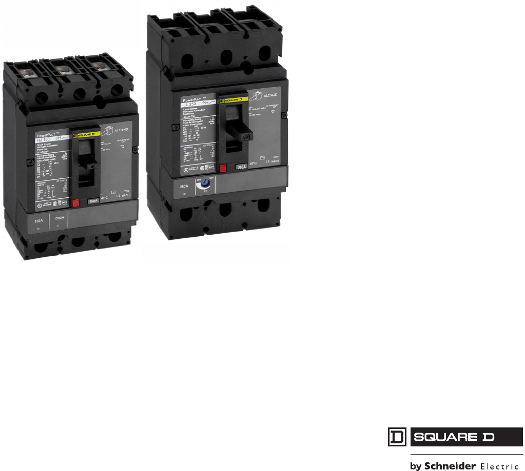
PowerPact® H- and J-Frame
Circuit Breakers
Catalog
0611CT0401R05/09
09
Class 0611
CONTENTS
Description . . . . . . . . . . . . . . . . . . . . . . . . . . . . . . . . . . . . . . . . . . . . . Page
General Information . . . . . . . . . . . . . . . . . . . . . . . . . . . . . . . . . . . . . Page 5
Mounting and Connections. . . . . . . . . . . . . . . . . . . . . . . . . . . . . . . . Page 26
Accessories . . . . . . . . . . . . . . . . . . . . . . . . . . . . . . . . . . . . . . . . . . . Page 34
Wiring Diagrams. . . . . . . . . . . . . . . . . . . . . . . . . . . . . . . . . . . . . . . . Page 45
Dimensions. . . . . . . . . . . . . . . . . . . . . . . . . . . . . . . . . . . . . . . . . . . . Page 47
Trip Curves. . . . . . . . . . . . . . . . . . . . . . . . . . . . . . . . . . . . . . . . . . . . Page 59
MCP Instantaneous Trip Points . . . . . . . . . . . . . . . . . . . . . . . . . . . . Page 70
Courtesy of Steven Engineering, Inc.-230 Ryan Way, South San Francisco, CA 94080-6370-Main Office: (650) 588-9200-Outside Local Area: (800) 258-9200-www.stevenengineering.com
Courtesy of Steven Engineering, Inc.-230 Ryan Way, South San Francisco, CA 94080-6370-Main Office: (650) 588-9200-Outside Local Area: (800) 258-9200-www.stevenengineering.com

PowerPact® H- and J-Frame Circuit Breakers
Table of Contents
3
05/2009
© 2004–2009 Schneider Electric
All Rights Reserved
SECTION 1: GENERAL INFORMATION ...................................................................................5
Introduction ......................................................................................................................................5
Features and Benefits ......................................................................................................................5
Common Design Envelope ........................................................................................................5
High Ampere Interrupting Ratings (AIR) ....................................................................................5
Dual-Break Rotating Contacts ....................................................................................................6
Reduced Let-Through Currents .................................................................................................6
Internal Operating Mechanism .........................................................................................................6
Handle Position Indication ..........................................................................................................6
Flexible Configurations ....................................................................................................................7
Field Installable Accessories and Trip Units ..............................................................................7
Catalog Numbering ....................................................................................................................8
Trip System (Trip Units) .............................................................................................................9
H-Frame Trip Units .....................................................................................................................9
J-Frame Trip Units ...................................................................................................................10
Codes and Standards ....................................................................................................................10
Special Ratings ........................................................................................................................10
Suitable for Isolation (Positive Contact Indication) ........................................................................11
Molded Case Circuit Breakers .......................................................................................................11
Circuit Breaker Ratings ............................................................................................................11
Marine Ratings .........................................................................................................................12
UL Marine Listed Circuit Breakers (UL489SA) ................................................................... 12
UL Naval Listed Circuit Breakers (UL 489 SB)................................................................... 12
American Bureau of Shipping (ABS) .................................................................................. 12
400 Hz Derating .......................................................................................................................12
Reverse Feeding of Circuit Breakers .......................................................................................12
Operating Conditions ...............................................................................................................13
Temperature....................................................................................................................... 13
Altitude ............................................................................................................................... 13
Atmospheric Conditions...................................................................................................... 13
Vibration ............................................................................................................................. 13
Circuit Breaker Endurance ................................................................................................. 13
Corner Grounded Delta Ratings......................................................................................... 13
Unit-Mount Circuit Breaker Catalog Numbers ..........................................................................15
I-Line Circuit Breaker Catalog Numbers ..................................................................................17
UL 489 SC Listed 500 Vdc Circuit Breakers ............................................................................20
Electronic Motor Circuit Protectors ................................................................................................20
Full Load Amp Settings ............................................................................................................21
Automatic Protection Settings ..................................................................................................21
Manual Protection Settings ......................................................................................................21
Automatic Molded Case Switches .................................................................................................24
SECTION 2: MOUNTING AND CONNECTIONS ....................................................................26
Unit-Mount Circuit Breakers ...........................................................................................................26
Mounting ..................................................................................................................................26
Mechanical Lugs ......................................................................................................................27
Bus-Bar Connections ...............................................................................................................28
Voltage Takeoff (Control Wire Terminals) for Mechanical Lugs and Terminal Nuts ................28
Power Distribution Connectors .................................................................................................29
Compression Lugs ...................................................................................................................30
Terminal Shields ......................................................................................................................30
Rear Connections ....................................................................................................................31
I-Line® Circuit breakers ..................................................................................................................31
Plug-In and Drawout Circuit Breakers ...........................................................................................32
Plug-In Circuit Breaker Mounting .............................................................................................32
Courtesy of Steven Engineering, Inc.-230 Ryan Way, South San Francisco, CA 94080-6370-Main Office: (650) 588-9200-Outside Local Area: (800) 258-9200-www.stevenengineering.com

© 2004–2009 Schneider Electric
All Rights Reserved
PowerPact® H- and J-Frame Circuit Breakers
Table of Contents
4
05/2009
Parts of a Plug-In Configuration ...............................................................................................32
Drawout Circuit Breaker Mounting ........................................................................................... 33
Chassis Functions .................................................................................................................... 33
SECTION 3: ACCESSORIES ..................................................................................................... 34
Internal Accessories ...................................................................................................................... 34
Accessory Connections ................................................................................................................. 34
Auxiliary and Alarm Switches ........................................................................................................ 35
Shunt Trip (MX) and Undervoltage Trip (MN) Switches ................................................................ 36
Add-On Ground-Fault Module (GFM) ............................................................................................ 37
Earth Leakage Module (ELM) for PowerPact H- and J-Frame MCCBs ........................................ 38
Motor Operator .............................................................................................................................. 39
Rotary Operating Handles ............................................................................................................. 40
Directly-Mounted Rotary Operating Handles ........................................................................... 40
Class 9421 NEMA Door Mounted Rotary Operating Handles ................................................. 41
Class 9422 Cable Operating Handle .............................................................................................41
Variable Depth Mechanisms .................................................................................................... 42
Circuit Breaker Enclosures and Enclosure Accessories ................................................................ 42
Locking Systems ........................................................................................................................... 43
Interlocking Systems ..................................................................................................................... 44
Interlocking of Circuit Breakers With Toggle Control ............................................................... 44
Interlocking Two Circuit Breakers with Rotary Handles ........................................................... 44
SECTION 4: WIRING DIAGRAMS ............................................................................................ 45
Standard Motor Operator Wiring (Factory Wiring Configuration) ............................................. 46
Remote Reset Wiring Without Overcurrent Trip Switch Protection .......................................... 46
SECTION 5: DIMENSIONS ......................................................................................................... 47
H-Frame Dimensional Drawings .................................................................................................... 47
J-Frame Dimensional Drawings .................................................................................................... 51
Plug-In H- and J-Frame Dimensional Drawings ............................................................................ 53
Drawout H- and J-Frame Dimensional Drawings .......................................................................... 54
Mounting Dimensional Drawings ................................................................................................... 55
H- and J-Frame Door Cutout Dimensional Drawings .................................................................... 56
SECTION 6: TRIP CURVES ....................................................................................................... 59
SECTION 7: MCP INSTANTANEOUS TRIP POINTS ........................................................... 70
Courtesy of Steven Engineering, Inc.-230 Ryan Way, South San Francisco, CA 94080-6370-Main Office: (650) 588-9200-Outside Local Area: (800) 258-9200-www.stevenengineering.com
PowerPact® H- and J-Frame Circuit Breakers
Section 1—General Information
5
05/2009
© 2004–2009 Schneider Electric
All Rights Reserved
Section 1—General Information
Introduction
H-frame and J-frame molded case circuit breakers are designed to protect electrical systems from
damage caused by overloads and short circuits. All circuit breakers are designed to open and close a
circuit by nonautomatic means and to open the circuit automatically on a predetermined overcurrent.
Features and Benefits
The H- and J-frame modular platform provides many options for accessories, configurations, and
actuation. H- and J-frame circuit breakers (15–250 A) and motor-circuit protectors (30–250 A) are
designed to use common accessories. Some of the key features are defined below:
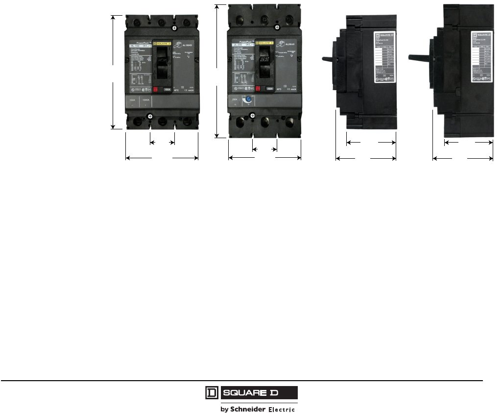
Common Design Envelope
Both the H-frame and J-frame circuit breakers feature common mounting holes, handle locations and
trim dimensions.
High Ampere Interrupting Ratings (AIR)
Circuit breakers are available with interrupting ratings up to:
•125 kA at 240 Vac delta
•100 kA at 480 Vac delta
•50 kA at 600 Vac delta.
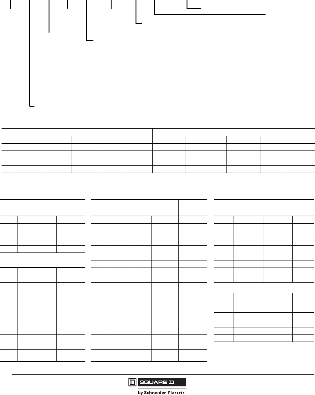
Figure 1: Common Design for H- and J-Frame Circuit Breakers
6.40
[163] 7.52
[191]
1.38
[35]
4.12
[105] 4.12
[105]
3.44
[87]
in.
[mm]
2.87
[73]
1.38
[35]
3.44
[87]
2.87
[73]
Dimensions
06113261
Courtesy of Steven Engineering, Inc.-230 Ryan Way, South San Francisco, CA 94080-6370-Main Office: (650) 588-9200-Outside Local Area: (800) 258-9200-www.stevenengineering.com
© 2004–2009 Schneider Electric
All Rights Reserved
PowerPact® H- and J-Frame Circuit Breakers
Section 1—General Information
6
05/2009
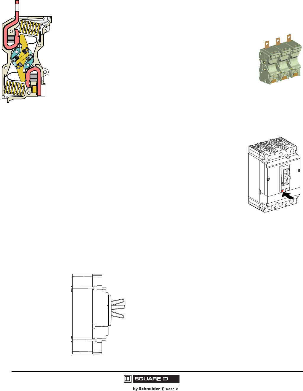
Dual-Break Rotating Contacts
All PowerPact® H-frame and J-frame circuit breakers are equipped with dual-break rotating contacts
that reduce the amount of peak current during a short circuit fault. This reduces the let-through
currents and enhances equipment protection.
Reduced Let-Through Currents
The moving contact has the shape of an elongated “S” and rotates around an
floating axis. The shape of the fixed and moving contacts are such that the
repelling forces appear as soon as the circuit reaches approximately 15 times In.
Due to the rotating movement, repulsion is rapid and the device greatly limits
short-circuit currents, whatever the interrupting level of the unit (D, G, J or L). The
fault current is extinguished before it can fully develop. Lower let-through currents
provide less peak energy, reducing the required bus bar bracing, lowering
enclosure pressure, and delivering improved series or combination ratings.
Special constructions are designed for continuous operation at 100% of their current rating.
The 100% rated circuit breakers require a larger enclosure than the standard enclosures described on
page 42.
Internal Operating Mechanism
H-frame and J-frame circuit breakers have an over-center toggle
mechanism providing quick-make, quick-break operation. The operating
mechanism is also trip-free, which allows tripping even when the circuit
breaker handle is held in the “ON” position.
Internal cross-bars provide common opening and closing of all poles with a
single operating handle.
All H-frame and J-frame circuit breakers have an integral push-to-trip
button in the cover to manually trip the circuit breaker. This should be used
as part of a regular preventive maintenance program.
Handle Position Indication
The H-frame and J-frame circuit breaker handle can assume any of three positions, ON, tripped or
OFF as shown. The center tripped position provides positive visual indication that the circuit breaker
has tripped.
The circuit breaker can be reset by first pushing the handle to the extreme “OFF” position. Power can
then be restored to the load by pushing the handle to the “ON” position.
06113234
06113262
06113266
Push-to-Trip
ON
Tripped
OFF
Courtesy of Steven Engineering, Inc.-230 Ryan Way, South San Francisco, CA 94080-6370-Main Office: (650) 588-9200-Outside Local Area: (800) 258-9200-www.stevenengineering.com
PowerPact® H- and J-Frame Circuit Breakers
Section 1—General Information
7
05/2009
© 2004–2009 Schneider Electric
All Rights Reserved
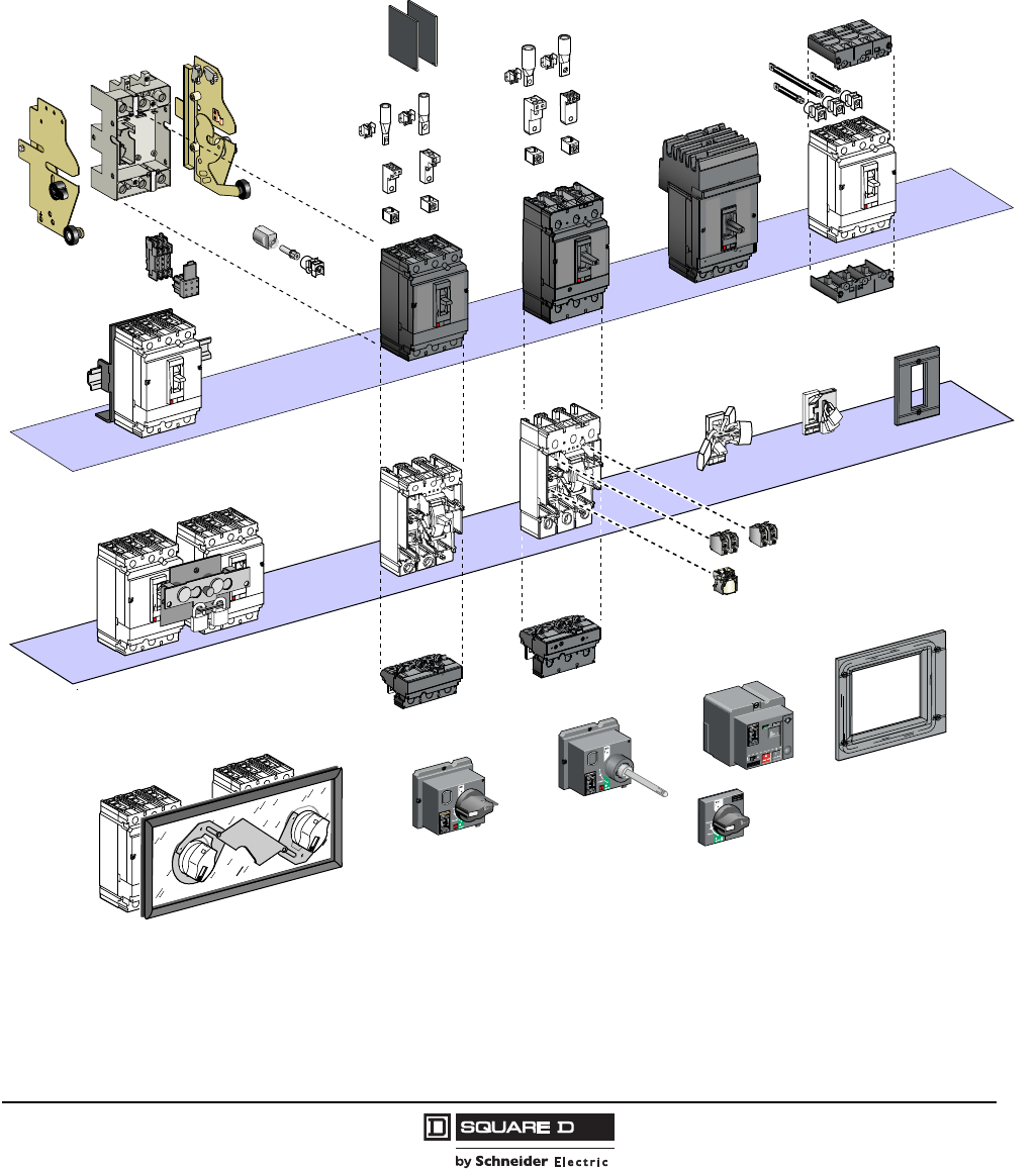
Flexible Configurations
The PowerPact H- and J-frame circuit breakers may be configured with lugs, bus bar connections, rear
connections, I-Line®, drawout cradle, or plug-in base.
Field Installable Accessories and Trip Units
Figure 2: Field Installable Accessories and Trip Units
06113259
Courtesy of Steven Engineering, Inc.-230 Ryan Way, South San Francisco, CA 94080-6370-Main Office: (650) 588-9200-Outside Local Area: (800) 258-9200-www.stevenengineering.com
© 2004–2009 Schneider Electric
All Rights Reserved
PowerPact® H- and J-Frame Circuit Breakers
Section 1—General Information
8
05/2009
Catalog Numbering
Table 1: Interrupting Rating
UL/CSA/NOM IEC 647-2 Icu/Ics
240 Vac 480 Vac 600 Vac 250 Vdc 500 Vdc1
1Special DC J-frame circuit breakers only.
220/240 Vac 380/440/415 Vac 500/525 Vac 250 Vdc 500 Vdc
D25 kA 18 kA 14 kA 20 kA — 25/25 kA 18/18 kA 14/14 kA 20 kA 20 kA
G65 kA 35 kA 18 kA 20 kA 20 kA 65/65 kA 35/35 kA 18/18 kA 20 kA 20 kA
J100 kA 65 kA 25 kA 20 kA — 100/100 kA 65/65 kA 25/25 kA 20 kA 20 kA
L125 kA 100 kA 50 kA 20 kA — 125/125 kA 100/100 kA 50/50 kA 20 kA 20 kA
I-Line® Phasing
— ABC (3P)
6 CBA (3P)
1AB(2P)
2AC(2P)
3BA(2P)
4BC(2P)
5CA(2P)
6CB(2P)
Frame
H H-Frame
J J-Frame
Poles
22P
33P
Amperage
150 15–15- A
250 150–250 A
000 Switch
Voltage
6 600 Vac
Terminations
L Lugs Line/Load Side
M Lugs Line Side
P Lugs Load Side
FBus Bar
AI-Line
S Rear Connected
N Plug-in
DDrawout
K Reverse I-Line
Interruption Rating (kA) (See Table 1)
Trip Unit
— Standard Fixed Trip Unit (Suitable for reverse connection)
F06 60 A H-Frame Only (No trip unit)
F15 150 A H-Frame Only (No trip unit)
F25 250 A J-Frame Only (No trip unit)
T Complete Circuit Breaker (Frame + removable trip unit)
S15 150 A Molded Case Switch (H-Frame automatic switch)
S17 175 A Molded Case Switch (J-Frame automatic switch)
S25 250 A Molded Case Switch (J-Frame automatic switch)
C 100% Continuous Current Rating (See page 42 for minimum enclosure size)
M71 30 A H-Frame Motor Circuit Protector (MCP)
M72 50 A H-Frame Motor Circuit Protector (MCP)
M73 100 A H-Frame Motor Circuit Protector (MCP)
M74 150 A H-Frame Motor Circuit Protector (MCP)
M75 250 A J-Frame Motor Circuit Protector (MCP)
D81 500 Vdc 150–175 A J-Frame Molded Case Circuit Breaker
D82 500 Vdc 200–250 A J-Frame Molded Case Circuit Breaker
Accessory Suffix Code (See Table 2)
J L L 3 6 250 T – – – – –
Table 2: Accessory Suffix Codes (Building Sequence as Listed)
(1) Auxiliary Switch (3) Shunt Trip (4) Undervoltage
Release UVR Voltage (5) Motor Operator
Suffix Contacts Kit Number Suffix Kit Number Suffix Kit Number Suffix Voltage H-Frame J-Frame
AA 1A/1B Standard S29450 SK S29384 UK S29404 24 Vac ML 48/60 Vac S29440 S31548
AB 2A/2B Standard S29450 (2) SL S29385 UL S29405 48 Vac MA 120 Vac S29433 S31540
AE 1A/1B Gold S29482 SA S29386 UA S29406 120 Vac MD 277 Vac S29434 S31541
AF 2A/2B Gold S29482 (2) SD S29387 UD S29407 208–277 Vac MH 380/480 Vac S29435 S31542
(2) Alarm/Overcurrent Trip Switch SH S29388 UH S29408 380–480 Vac MO 24/30 Vdc S29436 S31543
SJ S29389 UJ S29409 525–600 Vac MP 48/60 Vdc S29437 S31544
Suffix Switch Kit Number SN S29382 UN S29402 12 Vdc MR 110/130 Vdc S29438 S31545
BC Alarm Switch (SD) S29450 SO S29390 UO S29410 24 Vdc MS 250 Vdc S29439 S31546
BH Alarm Switch (SD)
Low-level S29452 SU S29391 UU S29411 30 Vdc
(6) IEC Style Rotary Handle
Suffix Handle Type (color) Kit
Number
BD SDE Standard S29450 +
S29451 SP S29392 UP S29412 48 Vdc RD10 Direct Mount (black) S29337
RE10 Extended Door Mount (black) S29338
BJ SDE Low-level S29452 +
S29451 SV S29383 UV S29403 60 Vdc RT10 Telescoping (black) S29343
RD20 Direct Mount (red) S29339
BE SD and SDE
Standard
S29450 (2) +
S29451 SR S29393 UR S29413 125 Vdc RE20 Extended Door Mount (red) S29340
BK SD and SDE
Low-level
S29452 (2) +
S29451 SS S29394 US S29414 250 Vdc
Courtesy of Steven Engineering, Inc.-230 Ryan Way, South San Francisco, CA 94080-6370-Main Office: (650) 588-9200-Outside Local Area: (800) 258-9200-www.stevenengineering.com
PowerPact® H- and J-Frame Circuit Breakers
Section 1—General Information
9
05/2009
© 2004–2009 Schneider Electric
All Rights Reserved
Trip System (Trip Units)
The H-frame and J-frame circuit breakers are equipped with a thermal-magnetic trip system designed
to open automatically under overload or short circuit. H-frame and J-frame circuit breakers contain
individual thermal (overload) and magnetic (short circuit) sensing elements in each pole.
The amperage ratings of the thermal trip elements are calibrated at 104°F (40°C) free air ambient
temperature. Per the National Electric Code® (NEC®), circuit breakers may only be applied
continuously at up to 80% of their rating.
Some models of the H- and J-frame circuit breakers are UL Listed to be applied at up to 100% of their
current rating. Because of the additional heat generated, the use of specially-designed enclosures and
90°C rated wire is required when applying circuit breakers at 100% of continuous current rating.
Markings on the circuit breaker indicate the minimum enclosure size and ventilation required. The
90°C wire must be sized according to the ampacities of the 75°C wire column in the NEC. Circuit
breakers with 100% rating can also be used in applications requiring only 80% continuous loading.
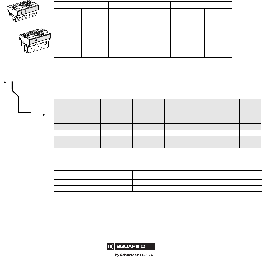
H-Frame Trip Units
Table 3: H-Frame and J-Frame 3P Field-Installable Thermal-Magnetic Trip Unit
15–60 A H-Frame 70–150 A H-Frame 150–250 A J-Frame
Amperage Cat. No. Amperage Cat. No. Amperage Cat. No.
15 A HT3015 70 A HT3070 150 A JT3150
20 A HT3020 80 A HT3080 175 A JT3175
25 A HT3025 90 A HT3090 200 A JT3200
30 A HT3030 100 A HT3100 225 A JT3225
35 A HT3035 110 A HT3110 250 A JT3250
40 A HT3040 125 A HT3125 — —
45 A HT3045 150 A HT3150 — —
50 A HT3050 — — — —
60 A HT3060 — — — —
60A 1125A
(ln)(li)
06113271
250A
1250 2500
(ln)(lm)
06113272
J-Frame Trip Unit
H-Frame Trip Unit
t
0lnlil
H-Frame Trip Curve
(ln) Fixed threshold thermal
protection against
overload
(li) Fixed threshold
magnetic protection
against short circuits
06113269
Table 4: Temperature Rerating (H-Frame Trip Unit Thermal Protection—Long-Time)
Temperature1
1Shaded areas indicate temperature rerated values, non-shaded areas are standard circuit breaker ampere ratings at 40° C (104° F).
Rating (A) In
°C °F
-10 14 23 30 38 46 53 60 68 76 88 103 112 123 137 160 180 221
032 21 28 36 43 49 56 63 71 83 97 107 117 131 151 171 207
10 50 20 26 33 40 46 52 59 66 77 90 101 111 126 141 161 194
20 68 18 24 31 37 42 48 54 62 72 84 96 105 120 132 152 180
30 86 17 22 28 34 39 44 50 56 66 77 88 98 110 121 139 165
40 104 15 20 25 30 35 40 45 50 60 70 80 90 100 110 125 150
50 122 12 17 21 25 30 34 38 43 53 62 72 80 86 95 109 131
60 140 914 17 20 24 28 31 35 46 53 63 70 72 80 93 111
Table 5: H-Frame Trip Unit Short Circuit Protection (Fixed) Ii
Ampere Rating 15–30 A 35–50 A 60–90 A 100–150 A
Hold (A) 350 400 800 900
Trip (A) 750 850 1450 1700
Courtesy of Steven Engineering, Inc.-230 Ryan Way, South San Francisco, CA 94080-6370-Main Office: (650) 588-9200-Outside Local Area: (800) 258-9200-www.stevenengineering.com
© 2004–2009 Schneider Electric
All Rights Reserved
PowerPact® H- and J-Frame Circuit Breakers
Section 1—General Information
10
05/2009
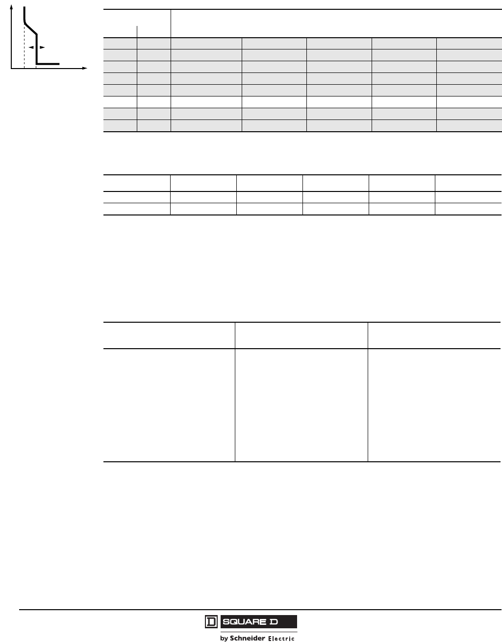
J-Frame Trip Units
Codes and Standards
H- and J-frame circuit breakers, automatic switches and electronic motor circuit protectors are
manufactured and tested in accordance with the following standards:
Special Ratings
The H-frame and J-frame circuit breakers also comply with the following special ratings:
•HACR rating
•SWD switch duty rating (applies only to 15 and 20 A / 277 Vac or less, 2P and 3P)
•HID high intensity discharge lighting rating (15–50 A)
t
0lnlml
J-Frame Trip Unit
(ln) Fixed threshold thermal
protection against
overload
(lm) Adjustable magnetic
protection against short
circuits
06113270
Table 6: Temperature Rerating (J-Frame Trip Unit Thermal Protection—Long-Time)
Temperature1
1Shaded areas indicate temperature rerated values, non-shaded areas are standard circuit breaker ampere ratings at 40° C (104° F).
Rating (A) In
°C °F
-10 14 221 264 289 330 377
032 207 247 273 310 354
10 50 194 230 256 290 330
20 68 180 213 240 270 307
30 86 165 194 220 248 279
40 104 150 175 200 225 250
50 122 131 150 176 193 214
60 140 111 124 151 160 177
Table 7: J-Frame Trip Unit Short Circuit Protection (Adjustable) Im
Ampere Rating1
1UL magnetic trip setting tolerances are -20% +30% from nominal values shown.
150 A 175 A 200 A 225 A 250 A
Low (A) 750 875 1000 1125 1250
High (A) 1500 1750 2000 2250 2500
Table 8: Codes and Standards (Domestic)
NOTE: Apply circuit breakers according to guidelines detailed in the National Electric Code (NEC) and other local wiring codes.
PowerPact H- and J-Frame Circuit
Breakers H- and J-Frame Switches PowerPact H- and J-Frame Motor
Circuit Protectors
UL 4891
IEC Standard 60947-2
CSA 22.2 No. 5-022
Federal Specification W-C-375B/GEN
NEMA AB1
NMX J-266
NMX J-515
UTE, VDE, BS, CEI, UNE
CCC
CE Mark
1PowerPact H- and J-frame circuit breakers and motor circuit protectors are in UL File E10027
2PowerPact H- and J-frame circuit breakers and motor circuit protectors are in CSA File LR40970
UL 4893
IEC Standard 60947-3
CSA 22.2 No. 5-024
Federal Specification W-C-375B/GEN
NEMA AB1
NMX J-266
NMX J-515
UTE, VDE, BS, CEI, UNE
CCC
CE Mark
3PowerPact H- and J-frame switches are in UL File E87159
4PowerPact H- and J-frame switches are in CSA File LR32390
UL 4891
IEC Standard 60947-2
CSA 22.2 No. 5-022
NEMA AB1
NMX J-515
CCC
CE Mark
Courtesy of Steven Engineering, Inc.-230 Ryan Way, South San Francisco, CA 94080-6370-Main Office: (650) 588-9200-Outside Local Area: (800) 258-9200-www.stevenengineering.com
PowerPact® H- and J-Frame Circuit Breakers
Section 1—General Information
11
05/2009
© 2004–2009 Schneider Electric
All Rights Reserved
Suitable for Isolation (Positive Contact Indication)
All PowerPact H-frame and J-frame circuit breakers and switches are suitable for isolation as defined
in the IEC 60947-2 standard.
•The isolation position corresponds to the O (OFF position)
•The operating handle cannot indicate the OFF position unless the contacts are open
•Padlocks may not be installed unless the contacts are open
NOTE: Installation of a rotary handle or a motor mechanism does not alter the functionality of the
position indication system.
The isolation function is certified by tests guaranteeing the mechanical reliability of the position
indication system, the absence of leakage currents and the overvoltage withstand capacity between
upstream and downstream connections.
Molded Case Circuit Breakers
Circuit Breaker Ratings
The interrupting rating is the highest current at rated voltage the circuit breaker is designed to safely
interrupt under standard test conditions. Circuit breakers must be selected with interrupting ratings
equal to or greater than the available short-circuit current at the point where the circuit breaker is
applied to the system (unless it is a branch device in a series rated combination).
Interrupting ratings are shown on the front of the circuit breaker.
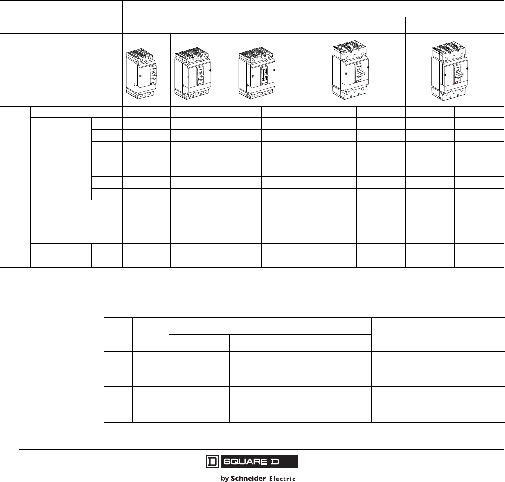
Table 9: UL 489 Circuit Breaker Ratings
150 A H-Frame 250 A J-Frame
Circuit Breaker Type HD HG HJ HL JD JG JJ JL
Number of Poles 2, 3 2, 3 2, 3 2, 3 2, 3 2, 3 2, 3 2, 3
Amperage Range (A) 15–150 15–150 15–150 15–150 150–250 150–250 150–250 150–250
UL/CSA/NOM
(kA)
240 Vac 25 65 100 125 25 65 100 125
480 Vac 18 35 65 100 18 35 65 100
600 Vac 1418255014182550
250 Vdc 2020202020202020
500 Vdc1
1500 Vdc rating applies only to catalog numbers with suffix D81 or D82, meeting UL489SC (Supplement C).
— — — — 20202020
Table 10: IEC 60947-2 Circuit Breaker Ratings
150 A H-Frame 250 A J-Frame
Circuit Breaker Type HD HG HJ HL JD JG JJ JL
Number of Poles 2, 32, 32, 32, 32, 32, 32, 32, 3
Amperage Range (A) 15–150 15–150 15–150 15–150 150–250 150–250 150–250 150–250
IEC 60947-2
Icu/Ics (kA)
220/240 Vac 25/25 65/65 100/100 125/125 25/25 65/65 100/100 125/125
380/440/415 Vac 18/18 35/35 65/65 100/100 18/18 35/35 65/65 100/100
500/525 Vac 14/14 18/18 25/25 50/50 14/14 18/18 25/25 50/50
250 Vdc 2020202020202020
500 Vdc1, 2
12P in series
2500 Vdc rating applies only to catalog numbers with suffix D81 or D82, meeting UL489SC (Supplement C).
20 20 20 20 20 20 20 20
Insulation Voltage Ui750 Vac 750 Vac
Impulse Withstand Voltage Uimp 8 kVac 8 kVac
Operational Voltage Ue525 Vac 525 Vac
Rated Current In150 A 250 A
Utilization Category — A A
Courtesy of Steven Engineering, Inc.-230 Ryan Way, South San Francisco, CA 94080-6370-Main Office: (650) 588-9200-Outside Local Area: (800) 258-9200-www.stevenengineering.com
© 2004–2009 Schneider Electric
All Rights Reserved
PowerPact® H- and J-Frame Circuit Breakers
Section 1—General Information
12
05/2009
Marine Ratings
UL Marine Listed Circuit Breakers (UL489SA)
A standard for molded case circuit breakers which are intended to be installed and used aboard a boat
or vessel is included in Supplement SA SB to UL 489, “Standard for Molded Case Circuit Breakers and
Circuit Breaker Enclosures’’ (also referred to as UL product category DKTY). This UL Standard was
established in accordance with U.S. Coast Guard regulations, applicable American Boat and Yacht
Council Inc. publications, and NFPA® 302 “Standard for Motor Craft (Pleasure and Commercial)’’. In
order to be UL Listed for marine use, circuit breakers must not use aluminum or aluminum alloys for
terminal connections and must be calibrated at an ambient temperature of 40°C. Standard circuit
breakers should not be specified or used in place of marine circuit breakers.
The PowerPact H and J-frame circuit breakers are UL 489 SA and SB Marine Listed for use on vessels
over 65 ft. (19.8 m) in length and under 65 ft. [19.8 m] in length.) These breakers can be added by
ordering with the suffix “YA” which includes the required copper lugs.
UL Naval Listed Circuit Breakers (UL 489 SB)
The standard for molded case circuit breakers which are intended or use aboard non-combatant and
auxiliary naval ships is included in Supplement SB to UL 489, “Standard for Molded Case Circuit
Breakers and Circuit Breaker Enclosures’’. The PowerPact H and J-frame circuit breakers are UL 489
SB are UL Naval Listed for use on vessels over 65 ft. (19.8 m) in length and under 65 feet (19.8 m) in
length. These breakers can be added by ordering with the suffix “YA” which includes the required
copper lugs.
American Bureau of Shipping (ABS)
The PowerPact H- and J-Frame circuit breakers are certified to ABSNVR (American Bureau of
Shipping - Naval Vessel Rules), for use on Naval vessels.
400 Hz Derating
Application of thermal-magnetic circuit breakers at frequencies above 60 Hz requires that special
consideration be given to the effects of high frequency on the circuit breaker characteristics. Thermal
and magnetic operations must be treated separately.
At frequencies below 60 Hz, the thermal rerating of thermal-magnetic circuit breakers is negligible.
However, at frequencies above 60 Hz, thermal rerating is required.
One of the most common high frequency applications is at 400 Hz.
For more information, refer to Data Bulletin 0100DB0101, Determining Current Carrying Capacity in
Special Applications.
Reverse Feeding of Circuit Breakers
The standard unit-mount H- and J-frame circuit breakers have sealed trip units and may be reverse
fed. See Tables 15–18 for catalog numbers.
Circuit breakers with field-interchangeable trip units (designated by the suffix T and labeled “LINE” and
“LOAD”) cannot be reverse fed. Neither can circuit breaker frames without terminations or trip units.
See Tables 19–21.
Table 11: 400 Hz Derating
Circuit Breaker 400 Hz Derating Multiplier
H-Frame 0.95
J-Frame 0.90
Courtesy of Steven Engineering, Inc.-230 Ryan Way, South San Francisco, CA 94080-6370-Main Office: (650) 588-9200-Outside Local Area: (800) 258-9200-www.stevenengineering.com
PowerPact® H- and J-Frame Circuit Breakers
Section 1—General Information
13
05/2009
© 2004–2009 Schneider Electric
All Rights Reserved
Operating Conditions
Temperature
To meet the requirements of the UL489 Standard, molded case circuit breakers are designed, built and
calibrated for use on 50/60 Hz ac systems in a 40°C (104°F) ambient environment. The thermal-magnetic
system is affected by changes in ambient temperature and the circuit breaker may require re-rating to suit
the environment it operates within. The circuit breaker may be operated at temperatures between -25°C
(-13°F) and +70°C (158° F). For temperature rerating tables, see Table 4 and Table 6.
NOTE: A special 50°C (122° F) Rating is available for special high ambient conditions (not UL listed).
Order by adding CA suffix to catalog number.
Altitude
Circuit breakers are suitable for use at altitudes up to 13,100 ft. (4000 m). For altitudes higher than
6560 ft. (2000 m), circuit breakers must be rerated as shown.
Atmospheric Conditions
The materials used in PowerPact circuit breakers will not support the growth of fungus and mold.
Vibration
PowerPact H- and J-frame circuit breakers meet IEC 60068-2-6 Standards for vibration:
•2.0 Hz to 25 Hz - amplitude +/- 1.6 mm
•25.0 Hz to 100 Hz - acceleration +/- 4.0 g
Circuit Breaker Endurance
Corner Grounded Delta Ratings (1Ø-3Ø)
Circuit breakrs suitable for corner-grounded circuits are marked 1Ø-3Ø. For additional information,
refer to data bulletin 2700DB0202R2/09.
Table 12: Altitude Rerating Values per ANSI C37.20.1 (table 10)
Altitude 6,600 ft. (2,000 m) 8,500 ft. (2,600 m) 13,000 ft. (3,900 m)
Voltage 1.00 0.95 0.80
Current 1.00 0.99 0.96
Table 13: Operations (Open-Close Cycles)
Frame
Number of Operations
With Current Without Current
150 A H-Frame 4000 4000
250 A J-Frame 1000 5000
Table 14: Corner Grounded Delta Ratings (1Ø-3Ø)
2P H-Frame 2P J-Frame 3P H-Frame 3P J-Frame
HD HG HJ1
1Built using 3P module
HL1JD1JG1JJ1JL1HD HG HJ HL JD JG JJ JL
Ampere Rating (A) 15–150 150–250 15–150 150–250
Voltage Rating (Vac) 240 240 480 480
UL Interrupting Rating (kA) 42 42 65 100 42 42 65 100 18 35 65 100 18 35 65 100
Courtesy of Steven Engineering, Inc.-230 Ryan Way, South San Francisco, CA 94080-6370-Main Office: (650) 588-9200-Outside Local Area: (800) 258-9200-www.stevenengineering.com
© 2004–2009 Schneider Electric
All Rights Reserved
PowerPact® H- and J-Frame Circuit Breakers
Section 1—General Information
14
05/2009
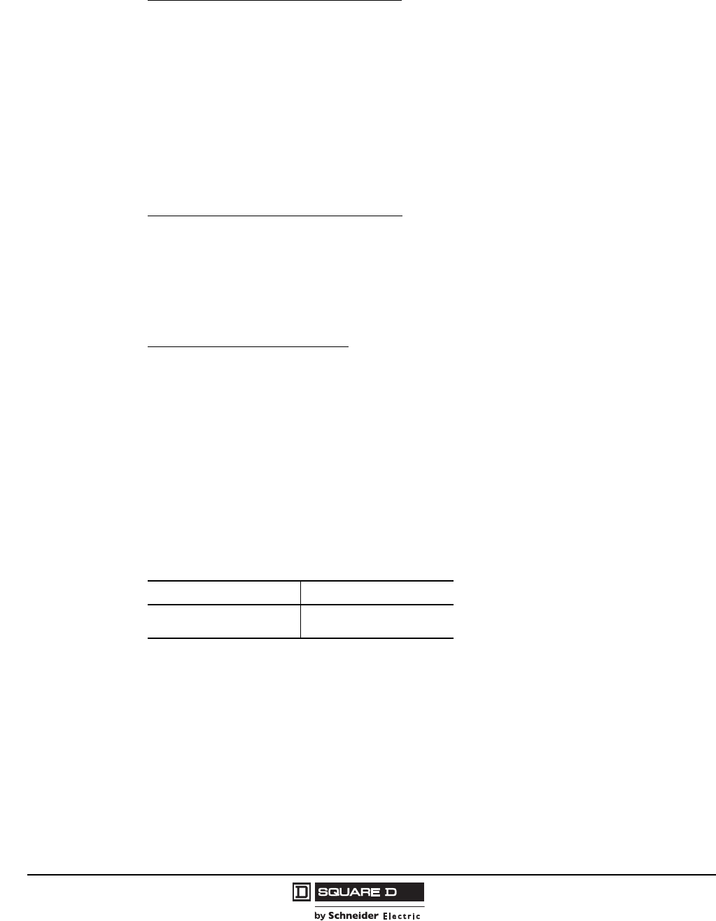
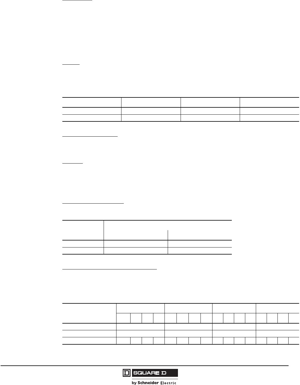
NOTE: Three-pole circuit breakers must be used on three-phase 480 Vac corner-grounded delta
systems. See Figure 2. The outside poles are to be connected to the ungrounded phases and the
grounded conductor connected to the center poles. Connecting the circuit breaker in a manner other
than that described or shown may result in an unsafe application of the circuit breaker.
Figure 3: Three-Phase 240 Vac Corner-Grounded Delta System
Figure 4: Three-Phase 480 Vac Corner-Grounded Delta System
2P
Circuit Breaker
Load
06113257
3P
Circuit Breaker
Load
06113258
Courtesy of Steven Engineering, Inc.-230 Ryan Way, South San Francisco, CA 94080-6370-Main Office: (650) 588-9200-Outside Local Area: (800) 258-9200-www.stevenengineering.com
PowerPact® H- and J-Frame Circuit Breakers
Section 1—General Information
15
05/2009
© 2004–2009 Schneider Electric
All Rights Reserved
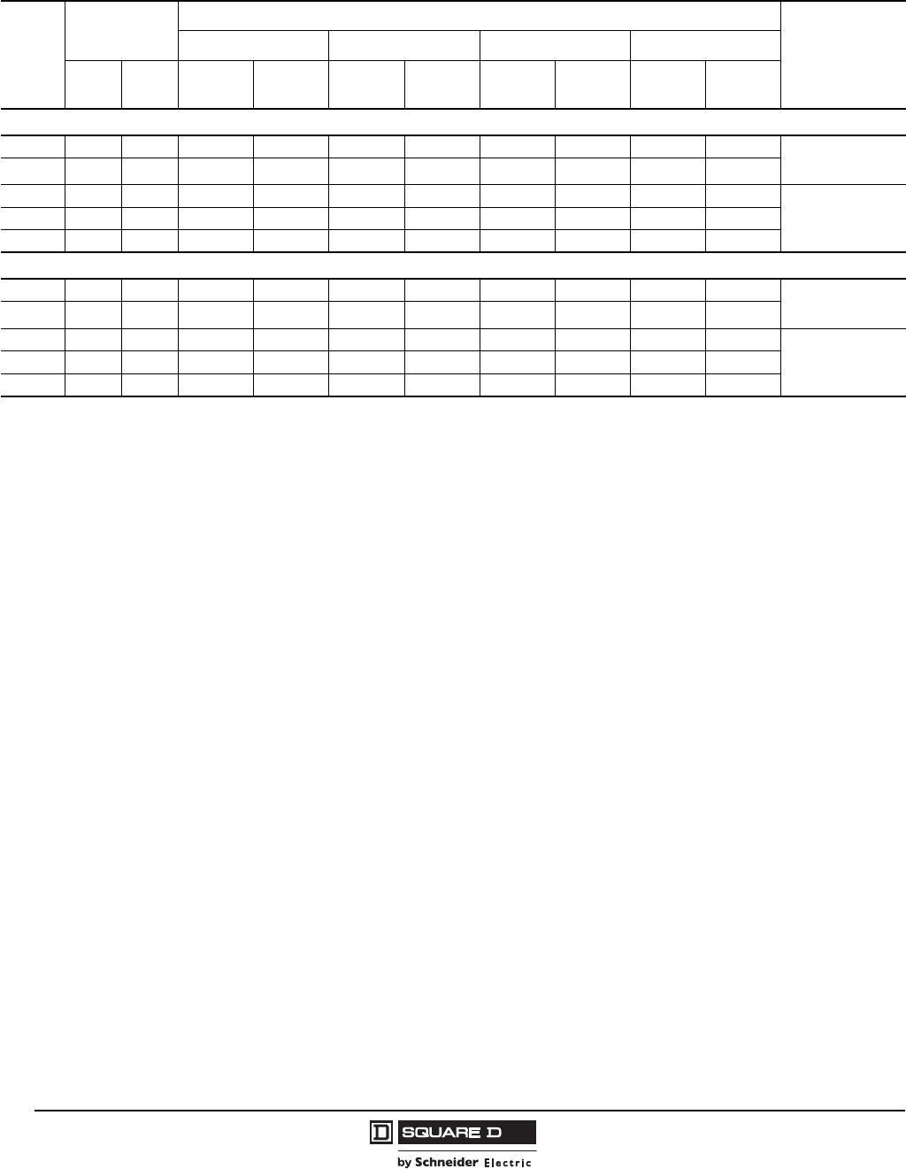
Unit-Mount Circuit Breaker Catalog Numbers
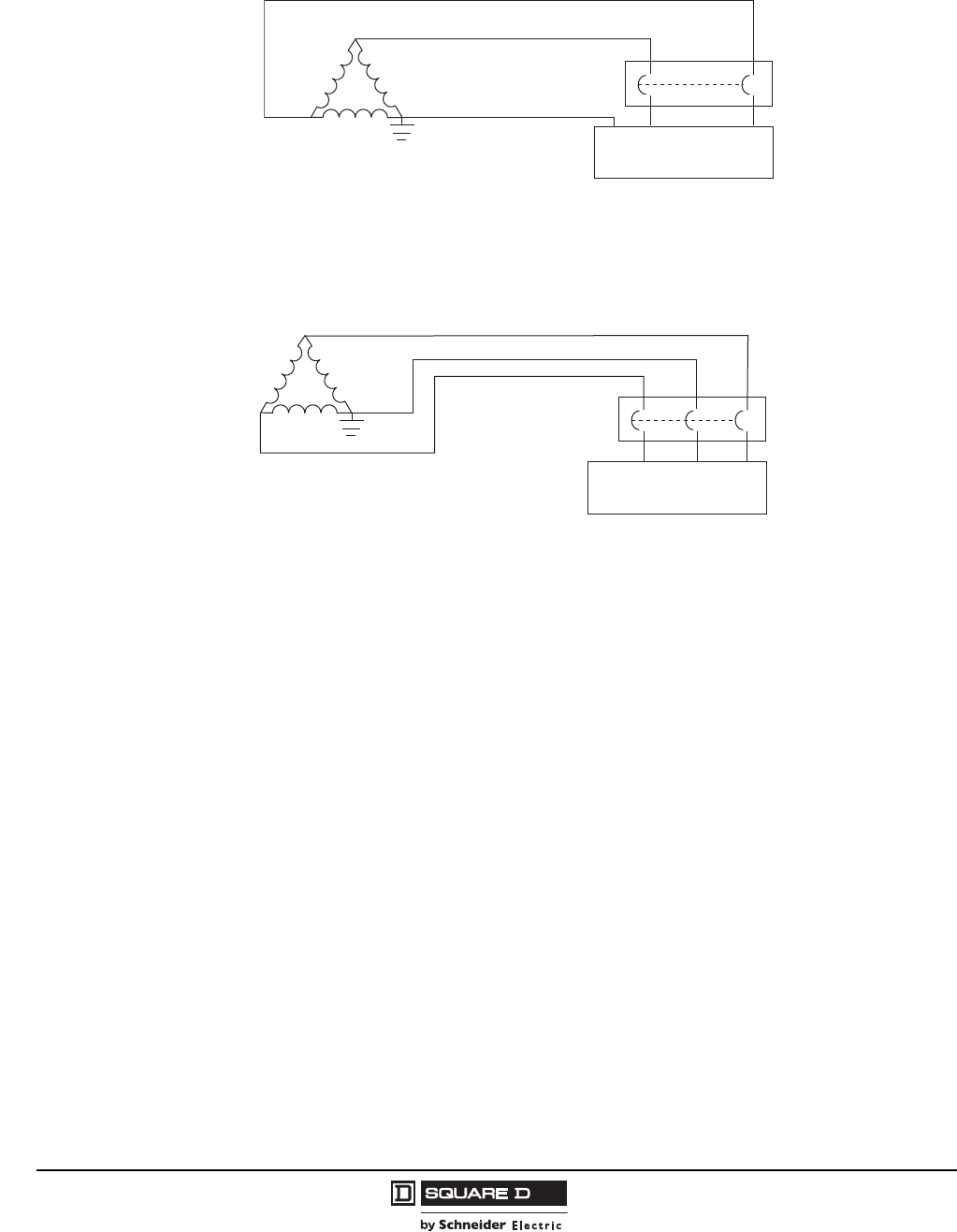
Table 15: PowerPact H-Frame 150 A Unit-Mount Thermal-Magnetic Current Limiting Circuit Breakers (600 Vac, 250
Vdc) with Factory Sealed Trip Unit (Suitable for Reverse Connection)
Current
Rating
@ 40 C
Fixed AC
Magnetic Trip
Interrupting Rating
Terminal Wire
Range
DGJ L
Hold Trip 80%
Rated
100%
Rated
80%
Rated
100%
Rated
80%
Rated
100%
Rated
80%
Rated
100%
Rated
H-Frame, 150 A, 2P, 600 Vac 50/60Hz, 250 Vdc
15 A 350 A 750 A HDL26015 HDL26015C HGL26015 HGL26015C HJL26015 HJL26015C HLL26015 HLL26015C
AL150HD
14–3/0 AWG
Al or Cu
20 A 350 A 750 A HDL26020 HDL26020C HGL26020 HGL26020C HJL26020 HJL26020C HLL26020 HLL26020C
25 A 350 A 750 A HDL26025 HDL26025C HGL26025 HGL26025C HJL26025 HJL26025C HLL26025 HLL26025C
30 A 350 A 750 A HDL26030 HDL26030C HGL26030 HGL26030C HJL26030 HJL26030C HLL26030 HLL26030C
35 A 400 A 850 A HDL26035 HDL26035C HGL26035 HGL26035C HJL26035 HJL26035C HLL26035 HLL26035C
40 A 400 A 850 A HDL26040 HDL26040C HGL26040 HGL26040C HJL26040 HJL26040C HLL26040 HLL26040C
45 A 400 A 850 A HDL26045 HDL26045C HGL26045 HGL26045C HJL26045 HJL26045C HLL26045 HLL26045C
50 A 400 A 850 A HDL26050 HDL26050C HGL26050 HGL26050C HJL26050 HJL26050C HLL26050 HLL26050C
60 A 800 A 1450 A HDL26060 HDL26060C HGL26060 HGL26060C HJL26060 HJL26060C HLL26060 HLL26060C
70 A 800 A 1450 A HDL26070 HDL26070C HGL26070 HGL26070C HJL26070 HJL26070C HLL26070 HLL26070C
80 A 800 A 1450 A HDL26080 HDL26080C HGL26080 HGL26080C HJL26080 HJL26080C HLL26080 HLL26080C
90 A 800 A 1450 A HDL26090 HDL26090C HGL26090 HGL26090C HJL26090 HJL26090C HLL26090 HLL26090C
100 A 900 A 1700 A HDL26100 HDL26100C HGL26100 HGL26100C HJL26100 HJL26100C HLL26100 HLL26100C
110 A 900 A 1700 A HDL26110 HDL26110C HGL26110 HGL26110C HJL26110 HJL26110C HLL26110 HLL26110C
125 A 900 A 1700 A HDL26125 HDL26125C HGL26125 HGL26125C HJL26125 HJL26125C HLL26125 HLL26125C
150 A 900 A 1700 A HDL26150 HDL26150C HGL26150 HGL26150C HJL26150 HJL26150C HLL26150 HLL26150C
H-Frame, 150 A, 3P, 600 Vac 50/60Hz, 250 Vdc
15 A 350 A 750 A HDL36015 HDL36015C HGL36015 HGL36015C HJL36015 HJL36015C HLL36015 HLL36015C
AL150HD
14–3/0 AWG
Al or Cu
20 A 350 A 750 A HDL36020 HDL36020C HGL36020 HGL36020C HJL36020 HJL36020C HLL36020 HLL36020C
25 A 350 A 750 A HDL36025 HDL36025C HGL36025 HGL36025C HJL36025 HJL36025C HLL36025 HLL36025C
30 A 350 A 750 A HDL36030 HDL36030C HGL36030 HGL36030C HJL36030 HJL36030C HLL36030 HLL36030C
35 A 400 A 850 A HDL36035 HDL36035C HGL36035 HGL36035C HJL36035 HJL36035C HLL36035 HLL36035C
40 A 400 A 850 A HDL36040 HDL36040C HGL36040 HGL36040C HJL36040 HJL36040C HLL36040 HLL36040C
45 A 400 A 850 A HDL36045 HDL36045C HGL36045 HGL36045C HJL36045 HJL36045C HLL36045 HLL36045C
50 A 400 A 850 A HDL36050 HDL36050C HGL36050 HGL36050C HJL36050 HJL36050C HLL36050 HLL36050C
60 A 800 A 1450 A HDL36060 HDL36060C HGL36060 HGL36060C HJL36060 HJL36060C HLL36060 HLL36060C
70 A 800 A 1450 A HDL36070 HDL36070C HGL36070 HGL36070C HJL36070 HJL36070C HLL36070 HLL36070C
80 A 800 A 1450 A HDL36080 HDL36080C HGL36080 HGL36080C HJL36080 HJL36080C HLL36080 HLL36080C
90 A 800 A 1450 A HDL36090 HDL36090C HGL36090 HGL36090C HJL36090 HJL36090C HLL36090 HLL36090C
100 A 900 A 1700 A HDL36100 HDL36100C HGL36100 HGL36100C HJL36100 HJL36100C HLL36100 HLL36100C
110 A 900 A 1700 A HDL36110 HDL36110C HGL36110 HGL36110C HJL36110 HJL36110C HLL36110 HLL36110C
125 A 900 A 1700 A HDL36125 HDL36125C HGL36125 HGL36125C HJL36125 HJL36125C HLL36125 HLL36125C
150 A 900 A 1700 A HDL36150 HDL36150C HGL36150 HGL36150C HJL36150 HJL36150C HLL36150 HLL36150C
Courtesy of Steven Engineering, Inc.-230 Ryan Way, South San Francisco, CA 94080-6370-Main Office: (650) 588-9200-Outside Local Area: (800) 258-9200-www.stevenengineering.com
© 2004–2009 Schneider Electric
All Rights Reserved
PowerPact® H- and J-Frame Circuit Breakers
Section 1—General Information
16
05/2009
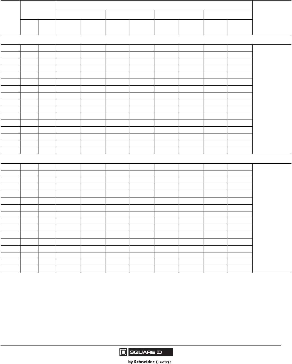
Table 16: PowerPact J-Frame 250 A Unit-Mount Thermal-Magnetic Current Limiting Circuit Breakers with Factory
Sealed Trip Unit (Suitable for Reverse Connection)
Current
Rating
@ 40 C
Fixed AC
Magnetic Trip
Interrupting Rating
Terminal Wire
Range
DGJ L
Hold Trip 80%
Rated
100%
Rated
80%
Rated
100%
Rated
80%
Rated
100%
Rated
80%
Rated
100%
Rated
J-Frame, 250 A, 2P, 600 Vac 50/60Hz, 250 Vdc
150 A 750 A 1500 A JDL36150 JDL36150C JGL36150 JGL36150C JJL36150 JJL36150C JLL36150 JLL36150C AL175JD
4–4/0 AWG
Al or Cu
175 A 875 A 1750 A JDL36175 JDL36175C JGL36175 JGL36175C JJL36175 JJL36175C JLL36175 JLL36175C
200 A 1000 A 2000 A JDL36200 JDL36200C JGL36200 JGL36200C JJL36200 JJL36200C JLL36200 JLL36200C AL250JD
3/0 AWG–350 kcmil
Al or Cu
225 A 1125 A 2250 A JDL36225 JDL36225C JGL36225 JGL36225C JJL36225 JJL36225C JLL36225 JLL36225C
250 A 1250 A 2500 A JDL36250 JDL36250C JGL36250 JGL36250C JJL36250 JJL36250C JLL36250 JLL36250C
J-Frame, 250 A, 3P, 600 Vac 50/60Hz, 250 Vdc
150 A 750 A 1500 A JDL36150 JDL36150C JGL36150 JGL36150C JJL36150 JJL36150C JLL36150 JLL36150C AL175JD
4–4/0 AWG
Al or Cu
175 A 875 A 1750 A JDL36175 JDL36175C JGL36175 JGL36175C JJL36175 JJL36175C JLL36175 JLL36175C
200 A 1000 A 2000 A JDL36200 JDL36200C JGL36200 JGL36200C JJL36200 JJL36200C JLL36200 JLL36200C AL250JD
3/0 AWG–350 kcmil
Al or Cu
225 A 1125 A 2250 A JDL36225 JDL36225C JGL36225 JGL36225C JJL36225 JJL36225C JLL36225 JLL36225C
250 A 1250 A 2500 A JDL36250 JDL36250C JGL36250 JGL36250C JJL36250 JJL36250C JLL36250 JLL36250C
Courtesy of Steven Engineering, Inc.-230 Ryan Way, South San Francisco, CA 94080-6370-Main Office: (650) 588-9200-Outside Local Area: (800) 258-9200-www.stevenengineering.com
PowerPact® H- and J-Frame Circuit Breakers
Section 1—General Information
17
05/2009
© 2004–2009 Schneider Electric
All Rights Reserved
I-Line Circuit Breaker Catalog Numbers
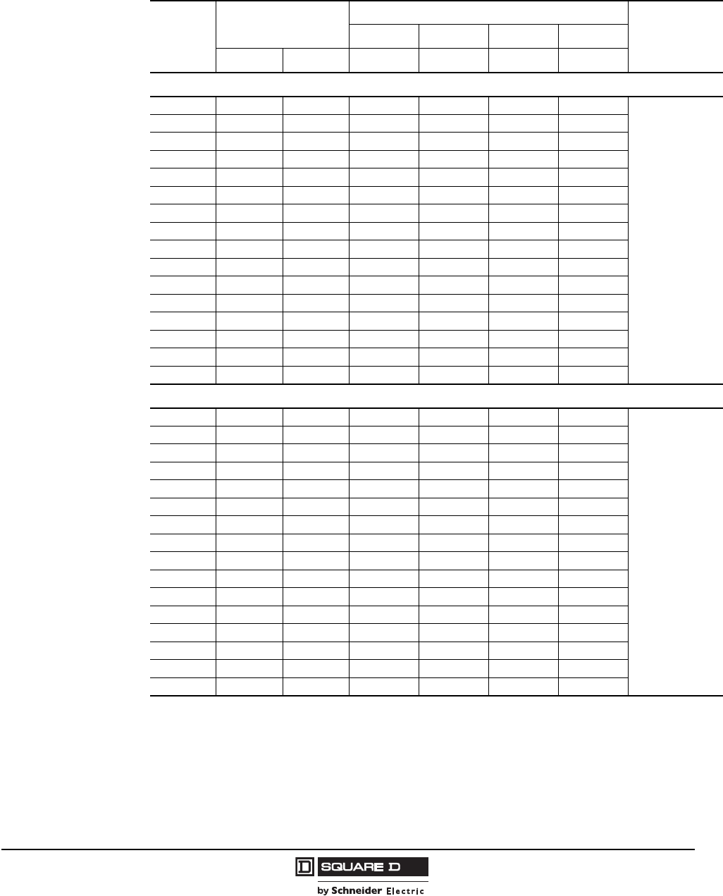
Table 17: PowerPact H-Frame 150 A I-Line® Thermal-Magnetic Current Limiting Circuit
Breakers with Factory Sealed Trip Unit (Suitable for Reverse Connection)
Current
Rating @
40 C
Fixed AC Magnetic Trip
Interrupting Rating1
1( ) Indicate phasing
Terminal Wire
Range
DGJ L
Hold Trip 80% Rated 80% Rated 80% Rated 80% Rated
H-Frame, 150 A, 2P, 600 Vac 50/60Hz, 250 Vdc
15 A 350 A 750 A HDA26015( ) HGA26015( ) HJA26015( ) HLA26015( )
AL150HD
14-3/0 AWG
Al or Cu
20 A 350 A 750 A HDA26020( ) HGA26020( ) HJA26020( ) HLA26020( )
25 A 350 A 750 A HDA26025( ) HGA26025( ) HJA26025( ) HLA26025( )
30 A 350 A 750 A HDA26030( ) HGA26030( ) HJA26030( ) HLA26030( )
35 A 400 A 850 A HDA26035( ) HGA26035( ) HJA26035( ) HLA26035( )
40 A 400 A 850 A HDA26040( ) HGA26040( ) HJA26040( ) HLA26040( )
45 A 400 A 850 A HDA26045( ) HGA26045( ) HJA26045( ) HLA26045( )
50 A 400 A 850 A HDA26050( ) HGA26050( ) HJA26050( ) HLA26050( )
60 A 800 A 1450 A HDA26060( ) HGA26060( ) HJA26060( ) HLA26060( )
70 A 800 A 1450 A HDA26070( ) HGA26070( ) HJA26070( ) HLA26070( )
80 A 800 A 1450 A HDA26080( ) HGA26080( ) HJA26080( ) HLA26080( )
90 A 800 A 1450 A HDA26090( ) HGA26090( ) HJA26090( ) HLA26090( )
100 A 900 A 1700 A HDA26100( ) HGA26100( ) HJA26100( ) HLA26100( )
110 A 900 A 1700 A HDA26110( ) HGA26110( ) HJA26110( ) HLA26110( )
125 A 900 A 1700 A HDA26125( ) HGA26125( ) HJA26125( ) HLA26125( )
150 A 900 A 1700 A HDA26150( ) HGA26150( ) HJA26150( ) HLA26150( )
H-Frame, 150 A, 3P, 600 Vac 50/60Hz, 250 Vdc
15 A 350 A 750 A HDA36015 HGA36015 HJA36015 HLA36015
AL150HD
14-3/0 AWG
Al or Cu
20 A 350 A 750 A HDA36020 HGA36020 HJA36020 HLA36020
25 A 350 A 750 A HDA36025 HGA36025 HJA36025 HLA36025
30 A 350 A 750 A HDA36030 HGA36030 HJA36030 HLA36030
35 A 400 A 850 A HDA36035 HGA36035 HJA36035 HLA36035
40 A 400 A 850 A HDA36040 HGA36040 HJA36040 HLA36040
45 A 400 A 850 A HDA36045 HGA36045 HJA36045 HLA36045
50 A 400 A 850 A HDA36050 HGA36050 HJA36050 HLA36050
60 A 800 A 1450 A HDA36060 HGA36060 HJA36060 HLA36060
70 A 800 A 1450 A HDA36070 HGA36070 HJA36070 HLA36070
80 A 800 A 1450 A HDA36080 HGA36080 HJA36080 HLA36080
90 A 800 A 1450 A HDA36090 HGA36090 HJA36090 HLA36090
100 A 900 A 1700 A HDA36100 HGA36100 HJA36100 HLA36100
110 A 900 A 1700 A HDA36110 HGA36110 HJA36110 HLA36110
125 A 900 A 1700 A HDA36125 HGA36125 HJA36125 HLA36125
150 A 900 A 1700 A HDA36150 HGA36150 HJA36150 HLA36150
Courtesy of Steven Engineering, Inc.-230 Ryan Way, South San Francisco, CA 94080-6370-Main Office: (650) 588-9200-Outside Local Area: (800) 258-9200-www.stevenengineering.com
© 2004–2009 Schneider Electric
All Rights Reserved
PowerPact® H- and J-Frame Circuit Breakers
Section 1—General Information
18
05/2009
Circuit Breakers with Field-Interchangeable Trip Units
Table 18: PowerPact J-Frame 250A I-Line Thermal-Magnetic Current Limiting Circuit
Breakers with Factory Sealed Trip Unit (Suitable for Reverse Connection)
Current
Rating
@ 40 C
Fixed AC Magnetic Trip
Interrupting Rating 1
1( ) Indicate phasing
DGJ L Terminal
Wire Range
Hold Trip 80% Rated 80% Rated 80% Rated 80% Rated
J-Frame, 250 A, 2P, 600 Vac 50/60Hz, 250 Vdc
150 A 750 A 1500 A JDA36150( ) JGA36150( ) JJA36150( ) JLA36150( ) AL175JD
4-4/0 AWG
Al or Cu
175 A 875 A 1750 A JDA36175( ) JGA36175( ) JJA36175( ) JLA36175( )
200 A 1000 A 2000 A JDA36200( ) JGA36200( ) JJA36200( ) JLA36200( )
AL250JD
3/0 AWG-350
kcmil
Al or Cu
225 A 1125 A 2250 A JDA36225( ) JGA36225( ) JJA36225( ) JLA36225( )
250 A 1250 A 2500 A JDA36250( ) JGA36250( ) JJA36250( ) JLA36250( )
J-Frame, 250 A, 3P, 600 Vac 50/60Hz, 250 Vdc
150 A 750 A 1500 A JDA36150 JGA36150 JJA36150 JLA36150 AL175JD
4-4/0 AWG
Al or Cu
175 A 875 A 1750 A JDA36175 JGA36175 JJA36175 JLA36175
200 A 1000 A 2000 A JDA36200 JGA36200 JJA36200 JLA36200 AL250JD
3/0 AWG-350
kcmil
Al or Cu
225 A 1125 A 2250 A JDA36225 JGA36225 JJA36225 JLA36225
250 A 1250 A 2500 A JDA36250 JGA36250 JJA36250 JLA36250
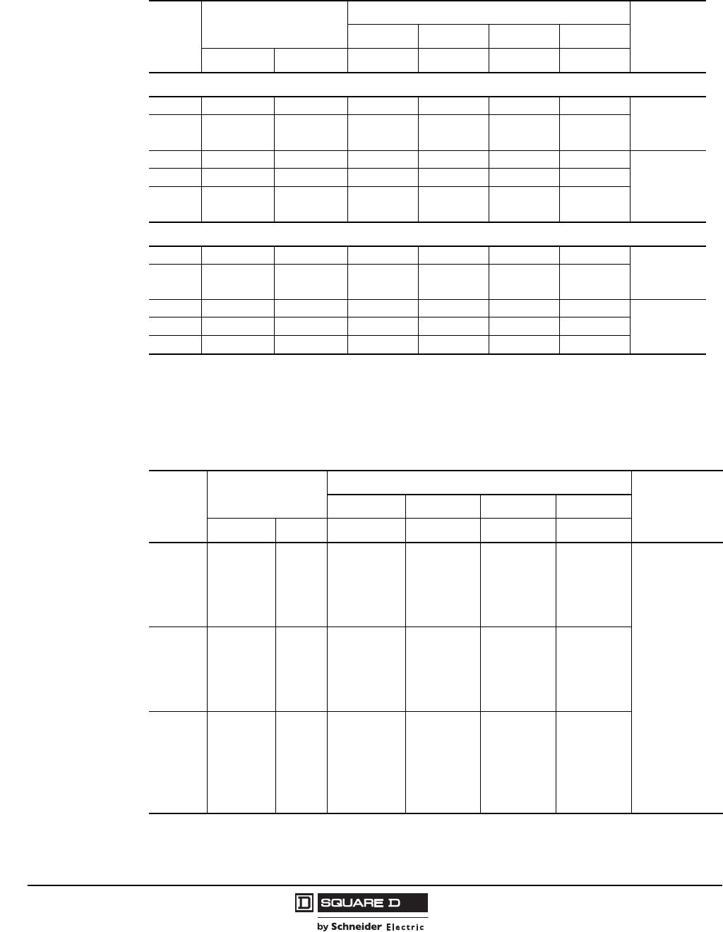
Table 19: H-Frame 150 A Current-Limiting Circuit Breaker Frame with Field-Interchangeable
Thermal-Magnetic Trip Units1 (3P, 600 Vac, 250 Vdc)
1Circuit breakers will be labeled with Line and Load markings and are not suitable for reverse connections.
Only available on standard (80%) rated 3P unit-mount circuit breakers; not available with I-Line® or Plug-In constructions.
Ampere
Rating
Fixed AC
Magnetic Trip
Interrupting Rating
Terminal
Wire Range
DGJL
Hold Trip Cat. No. Cat. No. Cat. No. Cat. No.
15 A 350 A 750 A HDL36015T HGL36015T HJL36015T HLL36015T
AL150HD
14–3/0 AWG
Al or Cu
20 A 350 A 750 A HDL36020T HGL36020T HJL36020T HLL36020T
25 A 350 A 750 A HDL36025T HGL36025T HJL36025T HLL36025T
30 A 350 A 750 A HDL36030T HGL36030T HJL36030T HLL36030T
35 A 400 A 850 A HDL36035T HGL36035T HJL36035T HLL36035T
40 A 400 A 850 A HDL36040T HGL36040T HJL36040T HLL36040T
45 A 400 A 850 A HDL36045T HGL36045T HJL36045T HLL36045T
50 A 400 A 850 A HDL36050T HGL36050T HJL36050T HLL36050T
60 A 800 A 1450 A HDL36060T HGL36060T HJL36060T HLL36060T
70 A 800 A 1450 A HDL36070T HGL36070T HJL36070T HLL36070T
80 A 800 A 1450 A HDL36080T HGL36080T HJL36080T HLL36080T
90 A 800 A 1450 A HDL36090T HGL36090T HJL36090T HLL36090T
100 A 900 A 1700 A HDL36100T HGL36100T HJL36100T HLL36100T
110 A 900 A 1700 A HDL36110T HGL36110T HJL36110T HLL36110T
125 A 900 A 1700 A HDL36125T HGL36125T HJL36125T HLL36125T
150 A 900 A 1700 A HDL36150T HGL36150T HJL36150T HLL36150T
Courtesy of Steven Engineering, Inc.-230 Ryan Way, South San Francisco, CA 94080-6370-Main Office: (650) 588-9200-Outside Local Area: (800) 258-9200-www.stevenengineering.com
PowerPact® H- and J-Frame Circuit Breakers
Section 1—General Information
19
05/2009
© 2004–2009 Schneider Electric
All Rights Reserved
Table 20: J-Frame 250 A Current-Limiting Circuit Breaker Frame with Field-Interchangeable
Thermal-Magnetic Trip Units1 (3P, 600 Vac, 250 Vdc)
1Circuit breakers will be labeled with Line and Load markings and are not suitable for reverse connections.
Only available on standard (80%) rated 3P unit-mount circuit breakers; not available with I-Line® or Plug-In constructions.
Ampere
Rating
Adjustable AC
Magnetic Trip
Interrupting Rating
Terminal
Wire Range
DG J L
Low High Cat. No. Cat. No. Cat. No. Cat. No.
150 A 750 A 1500 A JDL36150T JGL36150T JJL36150T JLL36150T AL175JD
4--4/0 AWG Al or Cu
175 A 875 A 1750 A JDL36175T JGL36175T JJL36175T JLL36175T
200 A 1000 A 2000 A JDL36200T JGL36200T JJL36200T JLL36200T AL250JD
3/0 AWG–350 kcmil
Al or Cu
225 A 1125 A 2250 A JDL36225T JGL36225T JJL36225T JLL36225T
250 A 1250 A 2500 A JDL36250T JGL36250T JJL36250T JLL36250T
Table 21: H-Frame 150A and J-Frame 250 A 3P Basic Current-Limiting Circuit Breaker Frame
Without Terminations or Trip Unit (600 Vac, 250 Vdc)
Circuit Breaker
Frame
Ampere
Rating
Interrupting Rating
DG JL
Cat. No. Cat. No. Cat. No. Cat. No.
H-Frame 15–60 A HDF36000F06 HGF36000F06 HJF36000F06 HLF36000F06
70–150 A HDF36000F15 HGF36000F15 HJF36000F15 HLF36000F15
J-Frame 150–250 A JDF36000F25 JGF36000F25 JJF36000F25 JLF36000F25
Table 22: H-Frame and J-Frame 3P Field-Installable Thermal-Magnetic Trip Unit
15–60 A H-Frame 70–150 A H-Frame 150–250 A J-Frame
Amperage Cat. No. Amperage Cat. No. Amperage Cat. No.
15 A HT3015 70 A HT3070 150 A JT3150
20 A HT3020 80 A HT3080 175 A JT3175
25 A HT3025 90 A HT3090 200 A JT3200
30 A HT3030 100 A HT3100 225 A JT3225
35 A HT3035 110 A HT3110 250 A JT3250
40 A HT3040 125 A HT3125 — —
45 A HT3045 150 A HT3150 — —
50 A HT3050 — — — —
60 A HT3060 — — — —
H-Frame Trip Unit
Courtesy of Steven Engineering, Inc.-230 Ryan Way, South San Francisco, CA 94080-6370-Main Office: (650) 588-9200-Outside Local Area: (800) 258-9200-www.stevenengineering.com
© 2004–2009 Schneider Electric
All Rights Reserved
PowerPact® H- and J-Frame Circuit Breakers
Section 1—General Information
20
05/2009
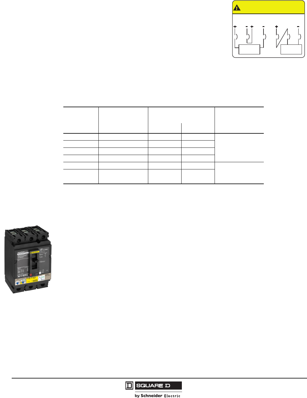
UL 489 SC Listed 500 Vdc Circuit Breakers
The UL Listed thermal-magnetic molded case circuit breakers are
specifically designed for use on ungrounded dc systems having a
maximum short-circuit voltage of 500 Vdc or a maximum floating
(unloaded) voltage of 600 Vdc. The circuit breakers are suitable for
use only with UPS (uninterruptable power supplies) and
ungrounded systems. This two-level voltage rating allows these
circuit breakers to be applied to battery sources having a short-
circuit availability of 20,000 amperes at 500 Vdc.
These circuit breakers are UL Listed for the interrupting ratings
shown only if applied with three poles connected in series (series
connection is external to circuit breaker). See diagram below.
NOTE: Due to external series connection, I-Line® circuit breakers
are not available for this application.
Electronic Motor Circuit Protectors
PowerPact H- and J-frame Electronic Motor Circuit Protectors (MCP) are instantaneous-trip circuit
breakers. They are designed to offer short circuit protection and are National Electrical Code® (NEC®)
compliant when installed as part of a combination controller having motor overload protection. MCP
circuit breakers accept the same accessories and terminals as the equivalent thermal-magnetic circuit
breakers. (See Section 6, FIgures 46 and 47 for trip curves. See Section 3 for Accessories.)
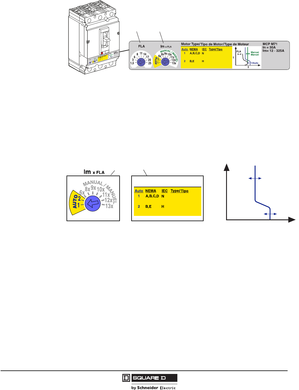
The unique design of the PowerPact MCPs include two dials to allow quick setting adjustments based
on the characteristics of the motor.
The first dial allows for Full Load Amperes (FLA) adjustment across the range of the frame size.
The second dial selects the type of motor protection based on Automatic 1 for Standard Efficiency or
Automatic 2 for High Energy Efficient. When using the automatic settings the MCP microprocessor
automatically adjusts the trip settings for both current and time to align with the start-up characteristic
for the motor type, whether it is a standard or energy-efficient motor. This includes a dampening
means to accommodate a transient motor in-rush current without nuisance tripping of the circuit
breaker. Dial 2 also allows for traditional motor protection from 8 to 13 times the selected FLA.
The MCP dials are detented and allow the device to be set to specific trip values within a typical
accuracy range of +/-5%.
Table 23: DC Molded Case Circuit Breakers
Ampere
Rating
Circuit Breaker
Cat. No.
Adjustable Magnetic Trip
Range—DC Amperes Interrupting Rating
@ 500 Vdc
Low High
100 A JGL37100D81 400 600
20 k AIR
125 A JGL37125D81 400 600
150 A JGL37150D81 400 600
175 A JGL37175D81 400 600
200 A JGL37200D82 500 850
20 k AIR225 A JGL37225D82 500 850
250 A JGL37250D82 500 850
CAUTION/PRECAUCION/
ATTENTION
Connect only as shown/Conectar solo asi/
Francher seulement comme suit:
300 V 300 V
Load/Carga/
Charge
600 V MAX.
MAX. MAX.
Load/Carga/
Charge
or
o
ou
Source = 600 Vdc max. (floating)
500 Vdc max. (loaded)
Courtesy of Steven Engineering, Inc.-230 Ryan Way, South San Francisco, CA 94080-6370-Main Office: (650) 588-9200-Outside Local Area: (800) 258-9200-www.stevenengineering.com
PowerPact® H- and J-Frame Circuit Breakers
Section 1—General Information
21
05/2009
© 2004–2009 Schneider Electric
All Rights Reserved
9n
Full Load Amp Settings
1. Determine the motor’s full-load current by referring to the nameplate on the motor.
2. Set the trip range by turning the FLA dial to the setting closest to the motor’s full load current.
Automatic Protection Settings
The MCP microprocessor automatically adjusts the trip settings for both current and time to align with
the start-up characteristics for the motor type selected. This includes a dampening means to
accommodate a transient motor in-rush current without nuisance tripping of the circuit breaker.
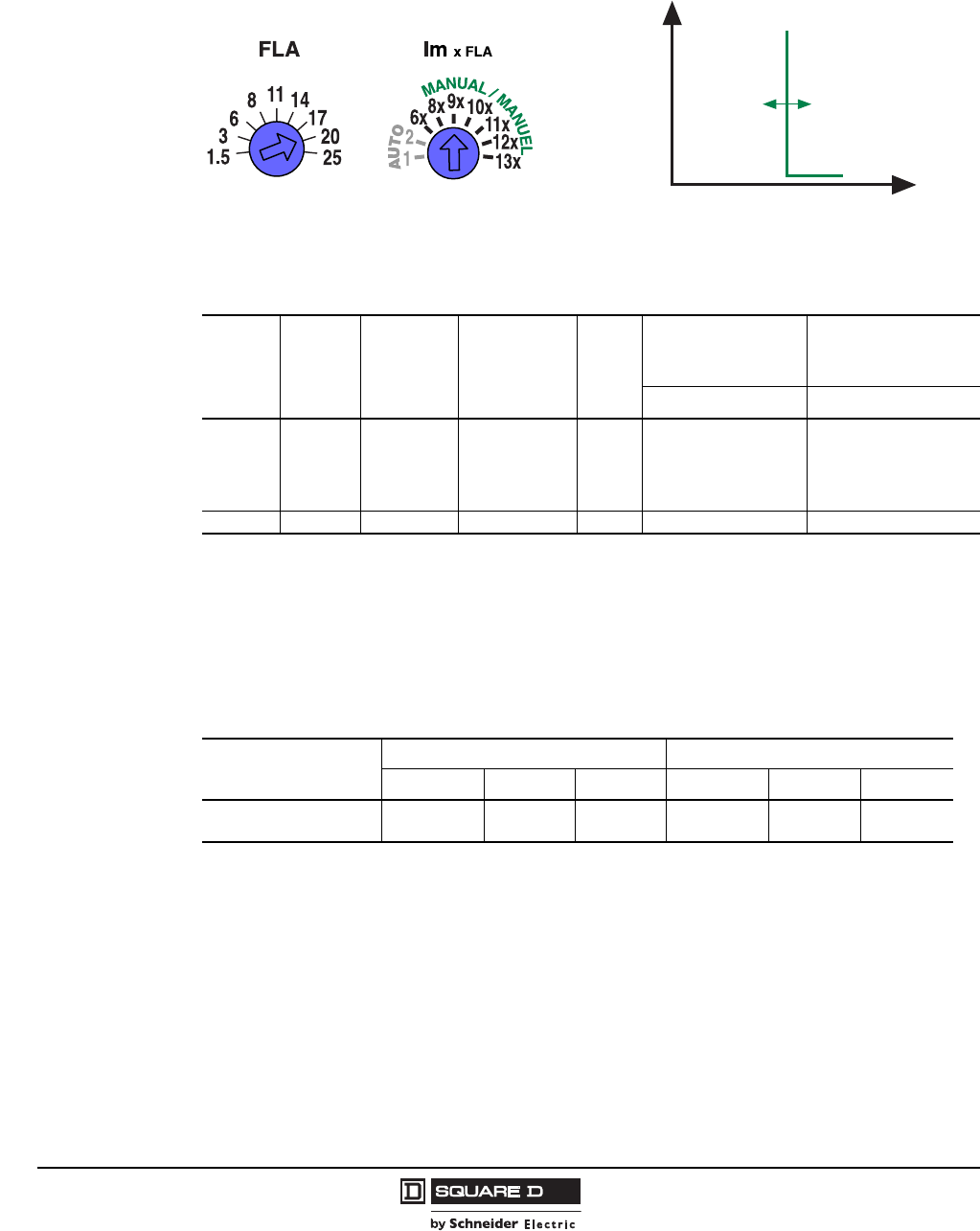
Manual Protection Settings
The manual settings may be adjusted to multiples of current based on the dial setting for motor Full
Load Amps (FLA).
Figure 5: Automatic Protection Settings
06113533
AB
Standard
Energy Efficient
Energie Efficace
Energia Eficiente
Standard
Energy Efficient
Energie Efficace
Energia Eficiente
(A) Full Load Amp Setting (FLA).
(B) Instantaneous Trip Point Settings (Im).
I
t
06114001
Standard
Energy Efficient
Energie Efficace
Motor Type / Tipo de Motor / Type de Moteur
Energia Eficiente
BA
Auto Setting
Dampening for
Motor In-Rush
Instantaneous
Trip Point = (FLA) x (Im)
Courtesy of Steven Engineering, Inc.-230 Ryan Way, South San Francisco, CA 94080-6370-Main Office: (650) 588-9200-Outside Local Area: (800) 258-9200-www.stevenengineering.com
© 2004–2009 Schneider Electric
All Rights Reserved
PowerPact® H- and J-Frame Circuit Breakers
Section 1—General Information
22
05/2009
For example, if FLA dial is set to 20 and Im dial is set to 9x, then the instantaneous trip point will be
180 A.
See Section 7 Tables 63 thru 67 for more information.
•High Short Circuit Current Ratings (SCCR)
The PowerPact MCP helps achieve the high UL508A Short Circuit Current Rating (SCCR) needed
to meet NEC Article 409 requirements for industrial control panels. They deliver up to 100 kA at
480 Vac SCCR when used in combination with approved Square D® NEMA or Telemecanique®
IEC motor starters.
Table 24: H- and J-Frame Electronic Motor Circuit Protectors (MCP)
Frame Current
Full Load
Amperes
Range
Adjustable
Instantaneous
Trip Range
Suffix
J Interrupting
(See SCCR Table
Below)
L Interrupting
(See SCCR Table
Below)
Cat. No. Cat. No.
H-Frame
30 A 1.5–25 A 9–325 A M71 HJL36030M71 HLL36030M71
50 A 14–42 A 84–546 A M72 HJL36050M72 HLL36050M72
100 A 30–80 A 180–1040 A M73 HJL36100M73 HLL36100M73
150 A 58–130 A 348–1690 A M74 HJL36150M74 HLL36150M74
J-Frame 250 A 114–217 A 684–2500 A M75 JJL36250M75 JLL36250M75
Table 25: Short Circuit Current Ratings (SCCR)
Contactor/Starter
J Interrupting L Interrupting
200–240 Vac 480 Vac 600 Vac 200–240 Vac 480 Vac 600 Vac
Tesys D-line and F-line 100 kA 65 kA 25 kA 100 kA 100 kA 50 kA
NEMA Type S 100 kA 65 kA 25 kA 100 kA 100 kA 50 kA
Im
180 Amps
t
I
Instantaneous Trip Point
Courtesy of Steven Engineering, Inc.-230 Ryan Way, South San Francisco, CA 94080-6370-Main Office: (650) 588-9200-Outside Local Area: (800) 258-9200-www.stevenengineering.com
PowerPact® H- and J-Frame Circuit Breakers
Section 1—General Information
23
05/2009
© 2004–2009 Schneider Electric
All Rights Reserved
”
Table 26: MCP Selection by HP Ratings of Induction-Type Squirrel-Cage and Wound-Rotor Motors
Horsepower Rating of Induction-Type Squirrel-Cage and Wound-Rotor Motors 3Ø 60 Hz NEC Full Load
Amperes
PowerPact H-Frame and
J-Frame Electronic MCP
Starter Size 200 Vac 230 Vac 480 Vac 575 Vac
00
1/2 0.9 A
HJL36030M71
and
HLL36030M71
1/2–10 hp
1/2 1.1 A
3/4 1.3 A
3/4 1 1.7 A
1 2.1 A
1/2 2.2 A
1-1/2 2.4 A
1/2 2.5 A
2 2.7 A
1-1/2 3 A
3/4 3.2 A
2 3.4 A
3/4 3.7 A
3 3.9 A
1 4.2 A
14.8 A
3 4.8 A
1-1/2 6 A
5 6.1 A
2 6.8 A
1-1/2 6.9 A
0
5 7.6 A
27.8 A
7-1/2 9 A
3 9.6 A
3 7-1/2 10 11 A
1
10 14 A
HJL36050M72
and
HLL36050M72
10–25 hp
5 15.2 A
15 17 A
517.5 A
15 21 A
7-1/2 20 22 A
7-1/2 25.3 A
2
20 25 27 A
10 28 A
30 32 A
HJL36100M73
and
HLL36100M73
15–50 hp
10 32.2 A
3
25 34 A
30 40 A
40 41 A
15 42 A
15 48.3 A
40 50 52 A
20 54 A
20 60 62 A
HJL36150M74
and
HLL36150M74
30–100 hp
50 65 A
25 68 A
60 75 77 A
25 78.2 A
4
30 80 A
30 92 A
75 96 A
100 99 A
40 104 A
40 120 A
JJL36250M75
and
JLL36250M75
50–150 hp
100 124 A
5
125 125 A
50 130 A
150 144 A
50 150 A
60 154 A
125 156 A
60 177.1 A
150 180 A
75 200 192 A
75 221 A
200 240 A
100 248 A
Shaded area is not covered by J-frame electronic motor circuit protector.
Courtesy of Steven Engineering, Inc.-230 Ryan Way, South San Francisco, CA 94080-6370-Main Office: (650) 588-9200-Outside Local Area: (800) 258-9200-www.stevenengineering.com
© 2004–2009 Schneider Electric
All Rights Reserved
PowerPact® H- and J-Frame Circuit Breakers
Section 1—General Information
24
05/2009
Automatic Molded Case Switches
H-frame and J-frame circuit breakers are also available in automatic molded case switch construction.
Automatic switches are similar in construction to circuit breakers, except that the switches open
instantaneously at a factory-set non-adjustable trip point calibrated to protect only the molded case
switch itself.
Because of their molded case construction, they are more compact than conventional disconnect
switches and accept electrical accessories for added flexibility. Molded case switches are intended for
use as disconnect devices only.
UL 489 requires molded case switches to be protected by a circuit breaker or fuse of equivalent rating.
Molded case switches are labeled with their withstand ratings. The withstand rating of a switch is
defined as the maximum current at rated voltage that the molded case switch will withstand without
damage when protected by a circuit breaker or fuse with an equal or continuous current rating.
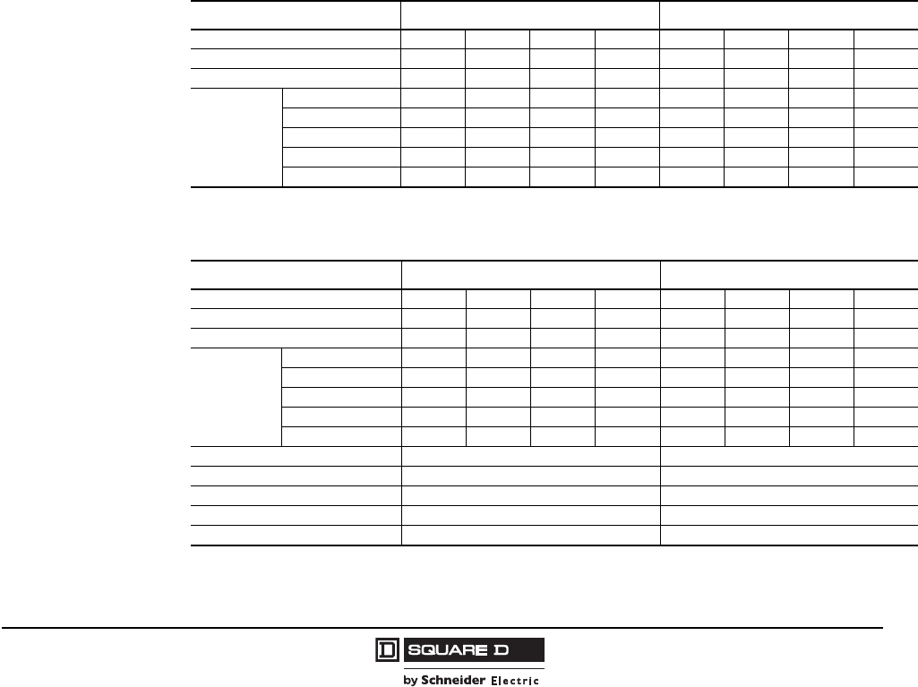
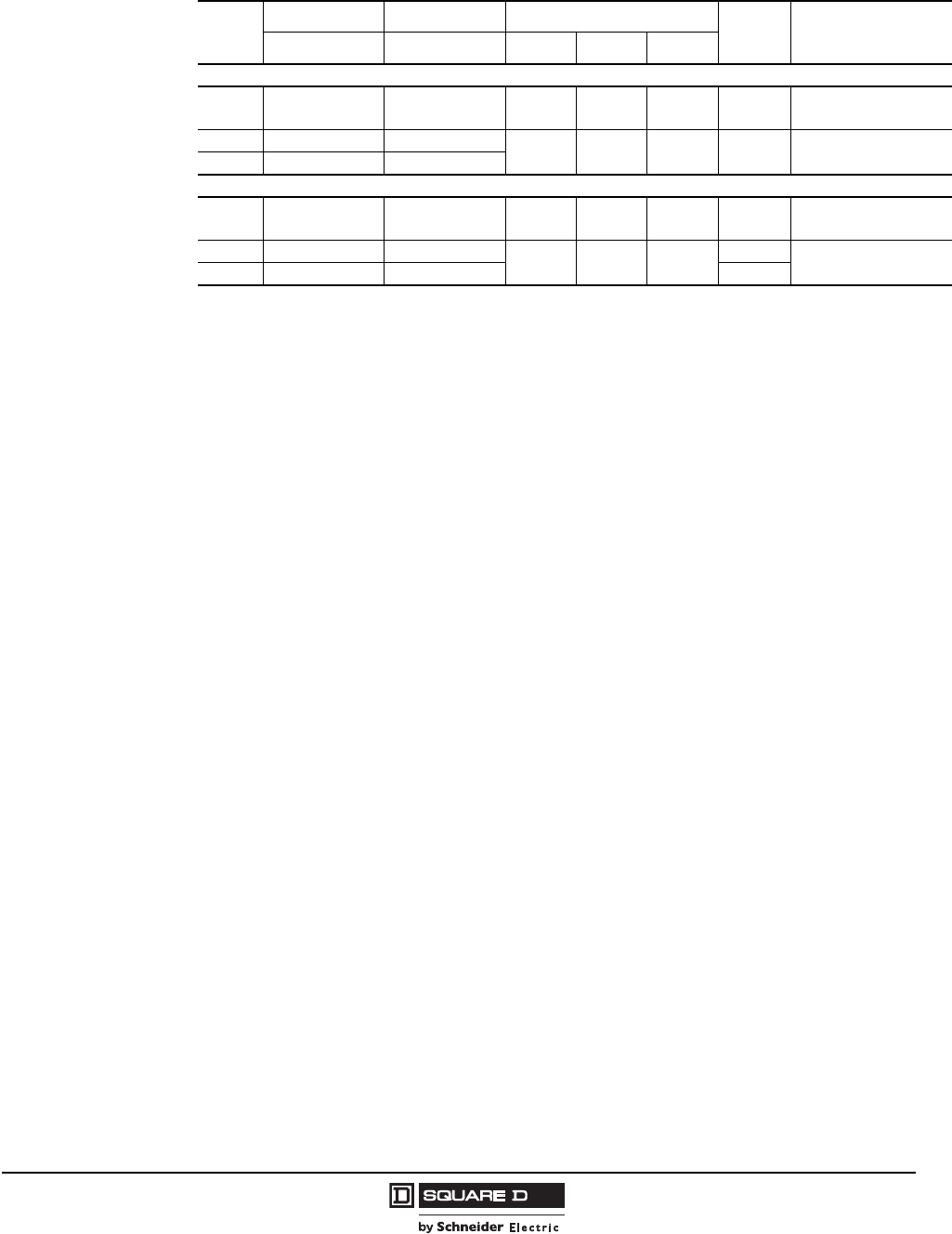
Table 27: Automatic Molded Case Switch Specifications
Frame H-Frame J-Frame
Interrupting Performance “G” “L” “G” “L”
UL 489
Poles 2P 3P 2P13P 2P13P 2P13P
Catalog Number
150 A HGL26000S15 HGL3600S15 HLL26000S15 HLL36000S15 — — — —
175 A — — — — JGL26000S17 JGL36000S17 JLL26000S17 JLL36000S17
250 A — — — — JGL26000S25 JGL36000S25 JLL26000S25 JLL36000S25
Withstand Ratings
240 Vac 65 kA 65 kA 125 kA 125 kA 65 kA 65 kA 125 kA 125 kA
480 Vac 35 kA 35 kA 100 kA 100 kA 35 kA 35 kA 100 kA 100 kA
600 Vac 18 kA 18 kA 50 kA 50 kA 18 kA 18 kA 50 kA 50 kA
250 Vdc 20 kA 20 kA 20 kA 20 kA 20 kA 20 kA 20 kA 20 kA
AC Trip Point 2250 A 2250 A 2250 A 2250 A 3125 A 3125 A 3125 A 3125 A
IEC
60947-3
Rated Insulation Voltage 750 Vac 750 Vac 750 Vac 750 Vac 750 Vac 750 Vac 750 Vac 750 Vac
Rated Impulse
Withstand Voltage 8 kV 8 kV 8 kV 8 kV 8 kV 8 kV 8 kV 8 kV
Rated Operational
Voltage
ac 525 Vac 525 Vac 525 Vac 525 Vac 525 Vac 525 Vac 525 Vac 525 Vac
dc 500 Vdc 500 Vdc 500 Vdc 500 Vdc 500 Vdc 500 Vdc 500 Vdc 500 Vdc
12P devices use a 3P switch frame with the center pole inoperative.
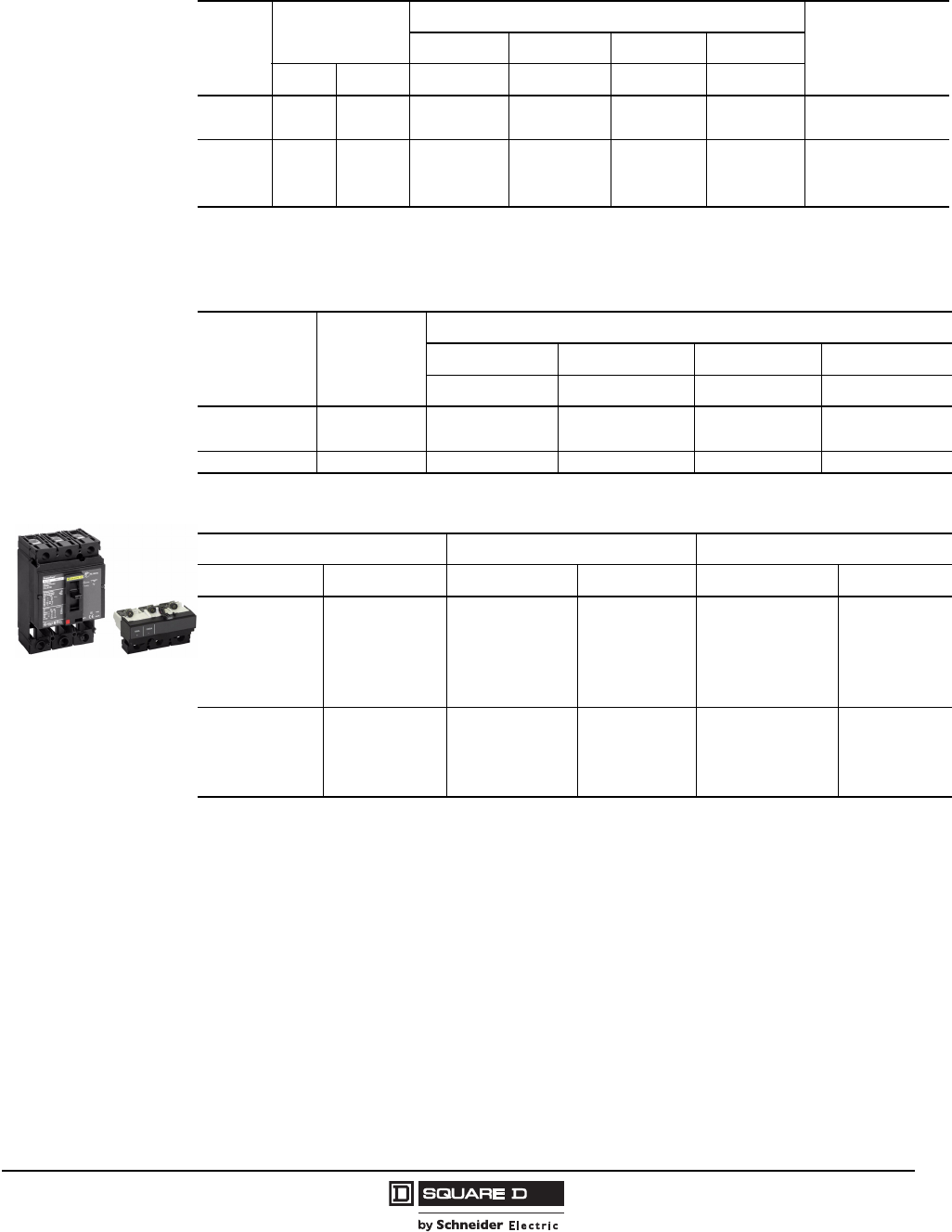
Table 28: PowerPact H-Frame and J-Frame 250 A Unit-Mount Automatic Molded Case
Switches, 600 Vac with Factory Sealed Trip Unit (Suitable for Reverse Connection)
Poles Ampere
Rating
G Interrupting L Interrupting
Terminal Wire Range
Cat. No. Trip Point Cat. No. Trip Point
2
150 A HGL26000S151
1True 2P device. Others are a 2P in a 3P module.
2250 A HLL26000S15 2250A AL150HD 14 AWG–3/0 AWG Al/Cu
175 A JGL26000S17 3125 A JLL26000S17 3125 A AL175JD 4–4/0 AWG Al/Cu
250 A JGL26000S25 3125 A JLL26000S25 3125 A AL250JD 3/0 AWG–350 kcmil Al/Cu
3
150 A HGL36000S15 2250 A HLL36000S15 2250 A AL150HD 14 AWG–3/0 AWG Al/Cu
175 A JGL36000S17 3125A JLL36000S17 3125 A AL175JD 4–4/0 AWG Al/Cu
250 A JGL36000S25 3125A JLL36000S25 3125 A AL250JD 3/0 AWG–350 kcmil Al/Cu
Courtesy of Steven Engineering, Inc.-230 Ryan Way, South San Francisco, CA 94080-6370-Main Office: (650) 588-9200-Outside Local Area: (800) 258-9200-www.stevenengineering.com
PowerPact® H- and J-Frame Circuit Breakers
Section 1—General Information
25
05/2009
© 2004–2009 Schneider Electric
All Rights Reserved
Table 29: PowerPact H-Frame and J-Frame I-Line Automatic Molded Case Switches, 600 Vac
with Factory Sealed Trip Unit (Suitable for Reverse Connection)
Ampere
Rating
2-pole 3-pole Withstand Rating 1
1The withstand rating is the fault current, at rated voltage, that the molded case switch will withstand without damage when
protected by a circuit breaker or fuse with an equal continuous current rating.
Trip
Point Terminal Wire Range
Cat. No. Cat. No. 240 Vac 480 Vac 600 Vac
G Interrupting
150 A HGA26000S15( )2
22-pole device with 3 in. (76 mm) mounting height, all other 2-pole circuit breakers use 3-pole module 4.5 in. (114 mm) mounting
height.
HGA36000S15 65 35 18 1300 A AL150HD
#14–#3/0 AWG Al or Cu
175 A JGA26000S17( ) JGA36000S17 65 35 18 2500 A AL250JD
#3/0–350 kcmil Al or Cu
250 A JGA26000S25( ) JGA36000S25
L Interrupting
150 A HLA26000S15( ) HLA36000S15 125 100 50 1300 A AL150HD
#14–#3/0 AWG Al or Cu
175 A HLA26000S17( ) JLA36000S17 125 100 50 1300 A AL250JD
#3/0–350 kcmil Al or Cu
250 A JLA26000S25( ) JLA36000S25 2500 A
Courtesy of Steven Engineering, Inc.-230 Ryan Way, South San Francisco, CA 94080-6370-Main Office: (650) 588-9200-Outside Local Area: (800) 258-9200-www.stevenengineering.com
© 2004–2009 Schneider Electric
All Rights Reserved
PowerPact® H- and J-Frame Circuit Breakers
Section 2—Mounting and Connections
26
05/2009
Section 2—Mounting and Connections
Unit-Mount Circuit Breakers
The standard lugs can be removed for the installation of compression-type lugs or bus connections. All
lugs are UL Listed for their proper application and marked for use with aluminum and copper (Al/Cu) or
copper only (Cu) conductors. Lugs suitable for copper and aluminum conductors are made of tin-
plated aluminum.
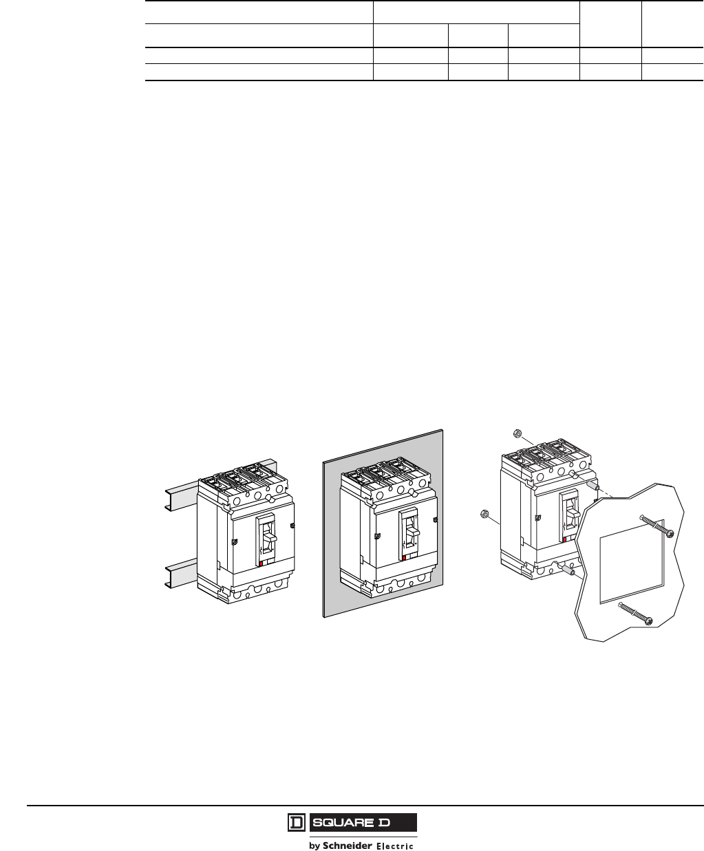
Mounting
H- and J-frame circuit breakers may be mounted vertically, horizontally or flat on their back without any
derating of characteristics.
Fixed-mounted H- and J-frame individually-mounted circuit breakers are supplied with two mounting
screws. These mounting screws are inserted through mounting holes molded into the circuit breaker
case and threaded into the mounting enclosure, rails or through the panel door for flush mounting.
A DIN rail mounting bracket (catalog no. S29305) is available for the H- and J-frame circuit breakers .
NOTE: DIN rail mounting is not compatible with motor operated applications.
Table 30: Circuit Breaker Mounting and Connections
Circuit Breaker Construction Unit Mount1
1Including rail, backplate, and flush mounting
I-Line® Drawout
Connections Lug-Lug Rear Bus Bar
H-Frame X X X X X
J-Frame X X X X X
Figure 6: Unit-Mounting Options
Mounting on Rails Mounting on Backplate Flush Mounting
06113273
06113274
06113275
Courtesy of Steven Engineering, Inc.-230 Ryan Way, South San Francisco, CA 94080-6370-Main Office: (650) 588-9200-Outside Local Area: (800) 258-9200-www.stevenengineering.com
PowerPact® H- and J-Frame Circuit Breakers
Section 2—Mounting and Connections
27
05/2009
© 2004–2009 Schneider Electric
All Rights Reserved
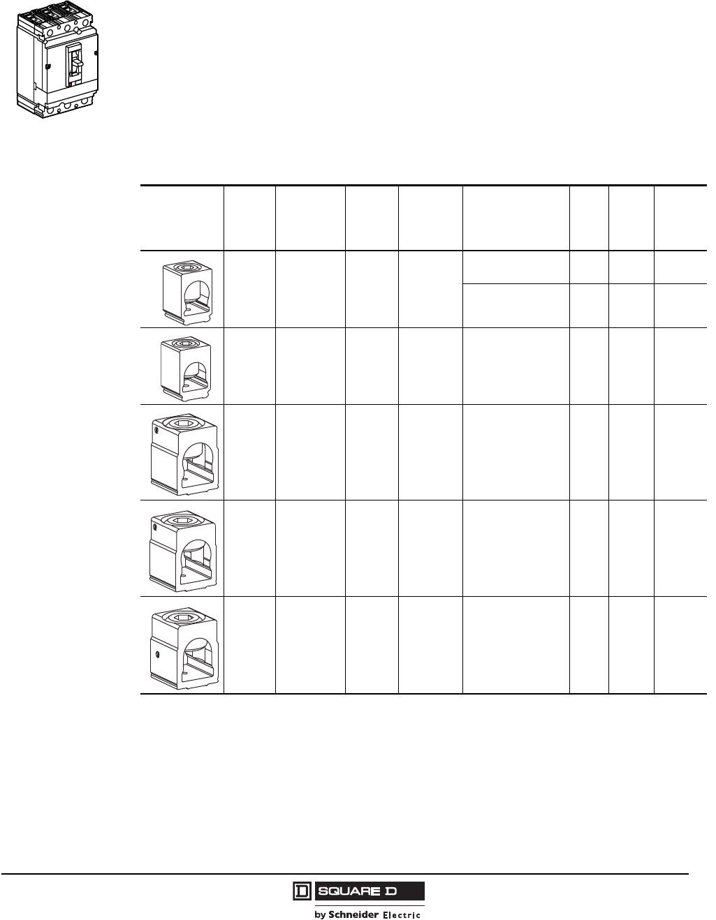
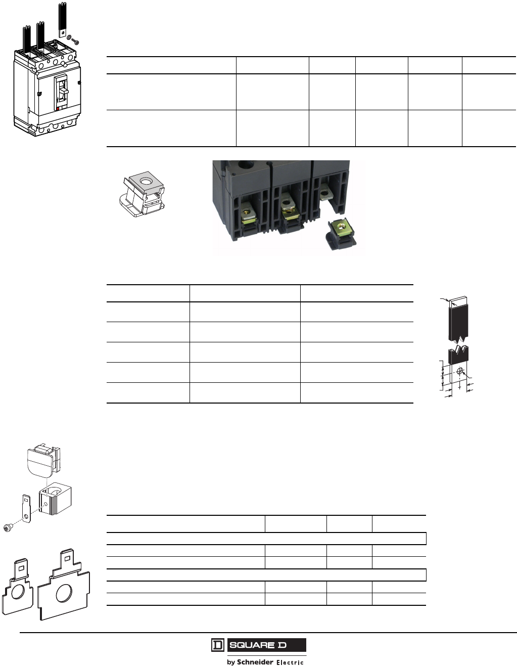
Mechanical Lugs
Unit-mount H-frame and J-frame circuit breakers can be ordered with mechanical line and load side
lugs. The standard lugs can be removed for the installation of compression-type lugs or bus
connections. All lugs are UL Listed for their proper application and marked for use with aluminum and
copper (Al/Cu) or copper only (Cu) conductors. Lugs suitable for copper and aluminum conductors are
made of tin-plated aluminum. Lugs suitable for use with copper conductors only are made of copper.
Mechanical Lugs for the H- and J-frame circuit breakers lay on top of the circuit breaker terminals and
can be installed without the use of any tools. The lugs are held in place with snap features built into the
insulative retainer and are secured with the clamp force applied to the wire binding screw.
Mechanical lugs come in both aluminum and copper versions and are sold either factory installed or as
field installable kits.
Table 31: Mechanical Lugs for H- and J-Frame Circuit Breakers
Catalog
Number Frame Ampere
Range Conductor Wires Per Lug Temp. Strip
Length
Wire
Binding
Screw
Torque
AL150HD HD/HG/HJ/HL 15–150 Al/Cu
(1) 14–10 AWG
(2.5–6 mm2)75°C 0.65 in.
(16 mm)
50 lb-in
(5 N•m)
(1) 8–3/0 AWG
(10–95 mm2)75°C 0.65 in.
(16 mm)
120 lb-in
(14 N•m)
CU150HD HD/HG/HJ/HL 15–150 Cu (1) 14–2/0 AWG
(2.5–70 mm2)75°C 0.65 in.
(16 mm)
120 lb-in
(14 N•m)
AL175JD JD/JG/JJ/JL 150–175 Al/Cu (1)4–4/0 AWG
(20–95 mm2)75°C 1.0 in.
(25 mm)
225 lb-in
(26 N•m)
AL250JD1
1AL250JD lugs are required for 250–350 kcmil wire range.
JD/JG/JJ/JL 200–250 Al/Cu (1) #3/0–350 kcmil
(120–185 mm2)75°C 1.0 in.
(25 mm)
225 lb-in
(26 N•m)
CU250JD JD/JG/JJ/JL 150–250 Cu (1) 1/0 AWG–300 kcmil
(50–185 mm2)75°C 1.0 in.
(25 mm)
250 lb-in
(28 N•m)
06113289
06113290
06113291
06113292
06113293
06113276
Courtesy of Steven Engineering, Inc.-230 Ryan Way, South San Francisco, CA 94080-6370-Main Office: (650) 588-9200-Outside Local Area: (800) 258-9200-www.stevenengineering.com
© 2004–2009 Schneider Electric
All Rights Reserved
PowerPact® H- and J-Frame Circuit Breakers
Section 2—Mounting and Connections
28
05/2009
Bus-Bar Connections
Both H-frame and J-frame circuit breakers may be equipped with captive nuts and screws for direct
connection to bars.
Terminal nut inserts are needed for replacement of lug connections with bus bar connections.
Voltage Takeoff (Control Wire Terminals) for Mechanical Lugs and Terminal Nuts
Mechanical lugs may be equipped with a separate control wire termination. The kit is available factory
installed or as a field installable kit. The adaptor is secured underneath the lug and has a tab extension
suitable for attachment of a .250 inch slip-on connector.
Fully insulated type connectors must be used to prevent live parts from extending into the wiring gutter
area.
06113279
Table 32: Terminal Nuts for Bus Bar Connection of H-Frame and J-Frame Circuit Breakers
Description Frame Tap Cat. No. Qty Per Kit Torque
H-Frame Terminal Nut Insert–English HD/HG/HJ/HL 1/4-20 S37425 2
80–90 lb-in
(9–10.2 N•m)
H-Frame Terminal Nut Insert–English HD/HG/HJ/HL 1/4-20 S37444 3
H-Frame Terminal Nut Insert–Metric HD/HG/HJ/HL M6 S37426 2
J-Frame Terminal Nut Insert–English JD/JG/JJ/JL 1/4-20 S37427 2
80–90 lb-in
(9–10.2 N•m)
J-Frame Terminal Nut Insert–English JD/JG/JJ/JL 1/4-20 S37445 3
J-Frame Terminal Nut Insert–Metric JD/JG/JJ/JL M8 S37428 2
Table 33: Bar Dimensions
Dimension H-Frame J-Frame
A0.250 in.
(6.4 mm)
0.3125 in.
(7.9 mm)
B0.125–0.375 in.
(3.2–9.5 mm)
0.125–0.375 in.
(3.2–.5 mm)
C0.50 in.
(12.7 mm)
0.50–0.75 in.
(12.7–1.1 mm)
D0.3 in.
(7.6 mm)
0.625 in.
(15.9 mm)
E0.3 in.
(7.6 mm)
0.375 in.
(9.5 mm)
Terminal Nut Insert
==
D
EC
A Ø
B
06113283
06114127
06113294
Mechanical Lug Control
Wire Terminal
Bussbar Control Wire
Terminal
Table 34: Control Wire Terminals
Description Frame Cat. No. Qty Per Kit
Mechanical Lugs
Control Wire Terminal for H-Frame Lugs HD/HG/HJ/HL S37423 2
Control Wire Terminal for J-Frame Lugs JD/JG/JJ/JL S37424 2
Bussbar Connection
Control Wire Terminal for H-Frame Terminal Nut HD/HG/HJ/HL S37429 2
Control Wire Terminal for J-Frame Terminal Nut JD/JG/JJ/JL S37430 2
Courtesy of Steven Engineering, Inc.-230 Ryan Way, South San Francisco, CA 94080-6370-Main Office: (650) 588-9200-Outside Local Area: (800) 258-9200-www.stevenengineering.com
PowerPact® H- and J-Frame Circuit Breakers
Section 2—Mounting and Connections
29
05/2009
© 2004–2009 Schneider Electric
All Rights Reserved
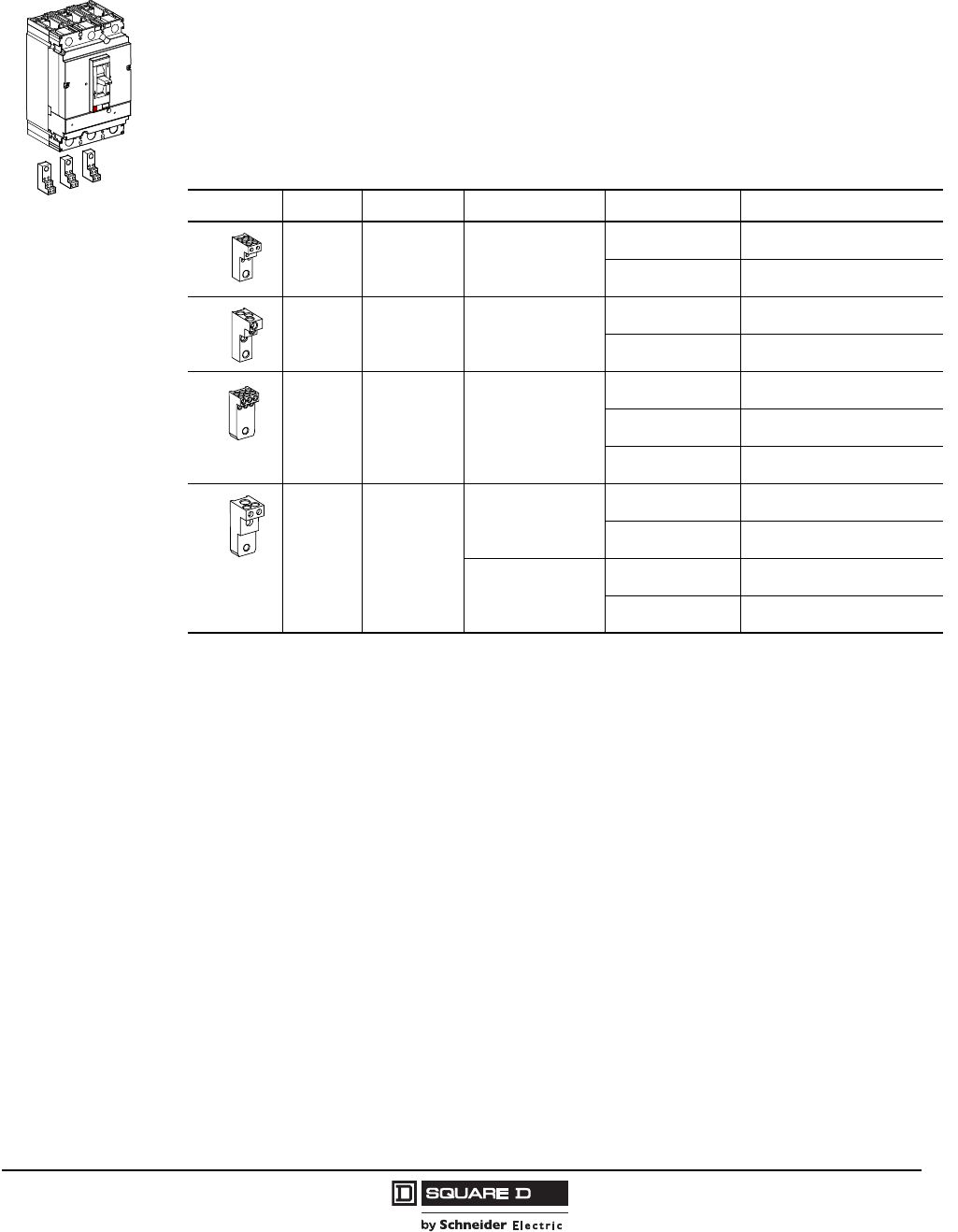
Power Distribution Connectors
The power distribution connectors (PDC) can be used for multiple load wire connections on one circuit
breaker. Use in place of standard distribution blocks to save space and time. Field installable kit
includes tin-plated aluminum lug, connectors, and required mounting hardware.
•For use on load end of circuit breaker only
•For use in UL 508 Industrial Control applications only
•For use in UL 1995/CSA C22.2 No. 236 heating and cooling equipment
•For copper wire only
See Table 37 for the phase barriers for PDCs.
06113295
Table 35: Power Distribution Connectors
Frame Kit Number Number of Wires Wire Range Wire Binding Screw Torque
H-Frame PDC6HD6 6
8–6 AWG
(10—16 mm2)
25 lb-in
(2.8 N•m)
14–10 AWG
(2.5—6 mm2)
20 lb-in
(2.3 N•m)
H-Frame PDC3HD2 3
6–2 AWG
(16—35 mm2)
40 lb-in
(4.5 N•m)
14–8 AWG
(2.5—10 mm2)
35 lb-in
(4.0 N•m)
J-Frame PDC6JD4 6
6–4 AWG
(16—25 mm2)
35 lb-in
(4.0 N•m)
8 AWG
(10 mm2)
25 lb-in
(2.8 N•m)
14–10 AWG
(2.5—6 mm2)
20 lb-in
(2.3 N•m)
J-Frame PDC3JD20
214–6 AWG Cu
(2.5–16 mm2)
35 lb-in
(4.0 N•m)
and 1 3–2/0 AWG Cu
(35–70 mm2)
50 lb-in
(5.6 N•m)
24–1 AWG Cu
(25–70 mm2)
40 lb-in
(4.5 N•m)
and 1 3–2/0 AWG Cu
(35–70 mm2)
50 lb-in
(5.6 N•m)
06113296
06113297
06113298
06113299
Courtesy of Steven Engineering, Inc.-230 Ryan Way, South San Francisco, CA 94080-6370-Main Office: (650) 588-9200-Outside Local Area: (800) 258-9200-www.stevenengineering.com
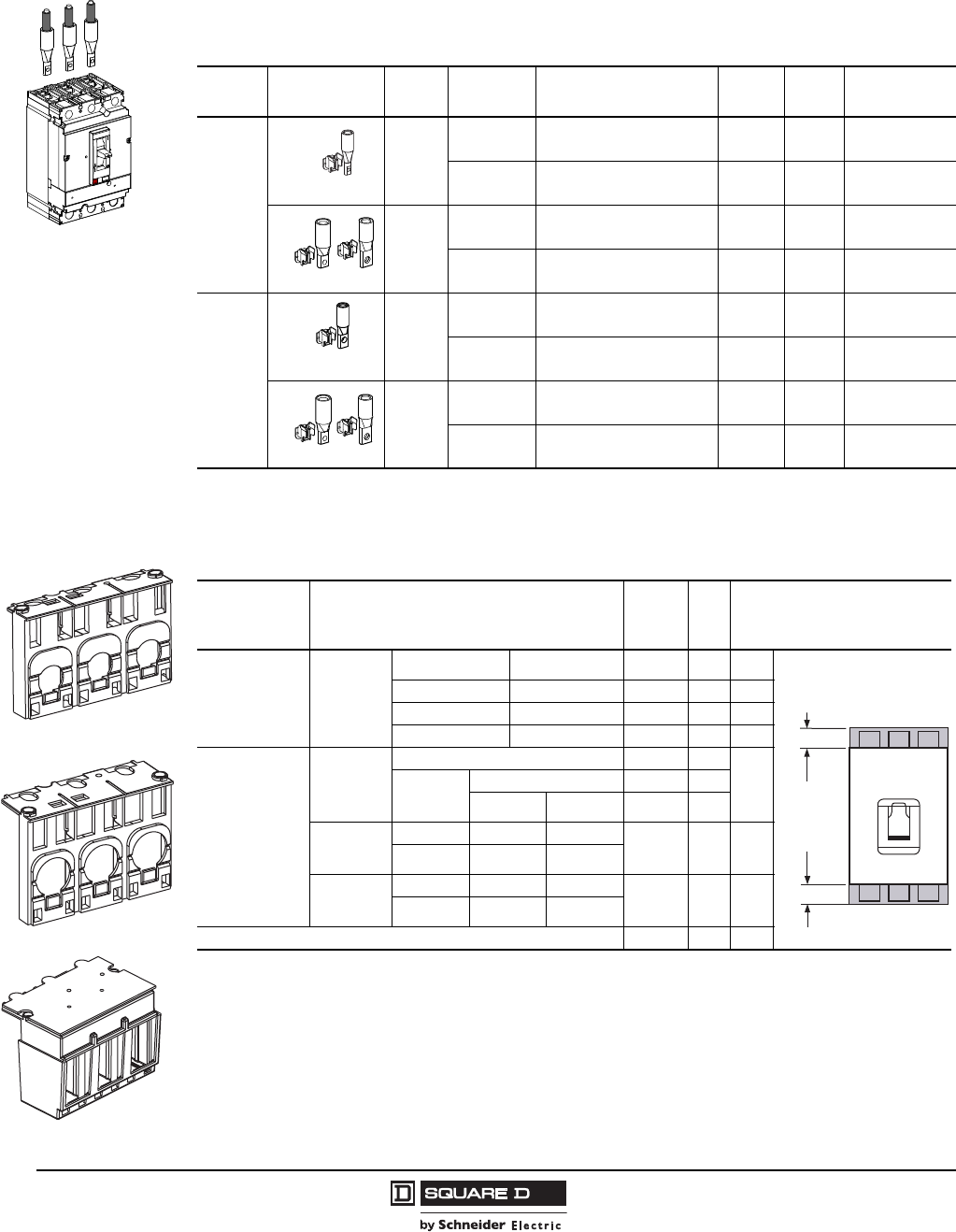
© 2004–2009 Schneider Electric
All Rights Reserved
PowerPact® H- and J-Frame Circuit Breakers
Section 2—Mounting and Connections
30
05/2009
Compression Lugs
Both copper and aluminum compression lug kits are available for the H-frame and J-frame circuit
breakers. Each kit contains required insulators and all mounting hardware.
Terminal Shields
06113300
Table 36: Compression Lug Kits
Lug
Type Frame Kit Number Wire Range Ampere
Rating
Lugs
Per Kit
Mounting
Screw Torque
Aluminum
H-Frame
YA060HD 6–2 AWG Cu or Al
(16–35 mm2)
60 A 3 80–90 lb-in
(9.0–10.2 N•m)
YA150HD 1/0–4/0 AWG Cu or Al
(50–95 mm2)
150 A 3 80–90 lb-in
(9.0–10.2 N•m)
J-Frame
YA150JD 1–3/0 AWG Cu or Al
(50–95 mm2)
200 A 3 130–140 lb-in
(14.7–15.8 N•m)
YA250J35 3/0 AWG–350 kcmil Cu or Al
(95–185 mm2)
250 A 3 130–140 lb-in
(14.7–15.8 N•m)
Copper
H-Frame
CYA060HD 6–1/0 AWG Cu
(16–50 mm2)
60 A 3 80–90 lb-in
(9.0–10.2 N•m)
CYA150HD 4–2/0 AWG Cu
(25–70 mm2)
150 A 3 80–90 lb-in
(9.0–10.2 N•m)
J-Frame
CYA150JD 4–2/0 AWG Cu
(25–70 mm2)
150 A 3 130–140 lb-in
(14.7–15.8 N•m)
CYA250J3 2/0 AWG–300 kcmil Cu
(70–185 mm2)
250 A 3 130–140 lb-in
(14.7–15.8 N•m)
06113301
06113302
06113303
06113304
06113494
06114129
H-Frame Short Lug Shield
06113493
J-Frame Short Lug Shield
J-Frame Long Lug Shield
Table 37: Terminal Shields and Phase Barriers
Used With Description Cat. No.
Qty
Per
Kit
Dimension B (in.)
Mechanical Lugs Short Lug
Shield1
1Short lug shields provide IP20 protection for mechanical lugs and are compatible with control wire terminals.
Frame Max. Wire Size
H-Frame 60 A 3 AWG S37446 1 0.50
H-Frame 150 A 3/0 AWG S37447 1 0.50
J-Frame 350 kcmil S37448 1 0.24
Power
Distribution
Connectors and
Compression
Lugs
Compatible with:
PDC
Compression Lugs
Aluminum Copper
H-Frame
Long Lug
Shield
PDC6HD6 YA060HD CYA060HD
S37449212.24
PDC3HD2 YA150HD CYA150HD
J-Frame
Long Lug
Shield
PDC6JD4 YA150JD CYA150JD
S37450211.68
PDC3JD2 2
2J-frame terminal shield is not compatible with the YA250J35 compression terminal.
CYA250J3
Phase Barriers 29329 6 3.13
Extremity
of
Molded Case
w/Mechanical
Lugs
“B” See Table
Phase barrier or
terminal shield
extension past end
of circuit breaker
“B” See Table
Courtesy of Steven Engineering, Inc.-230 Ryan Way, South San Francisco, CA 94080-6370-Main Office: (650) 588-9200-Outside Local Area: (800) 258-9200-www.stevenengineering.com
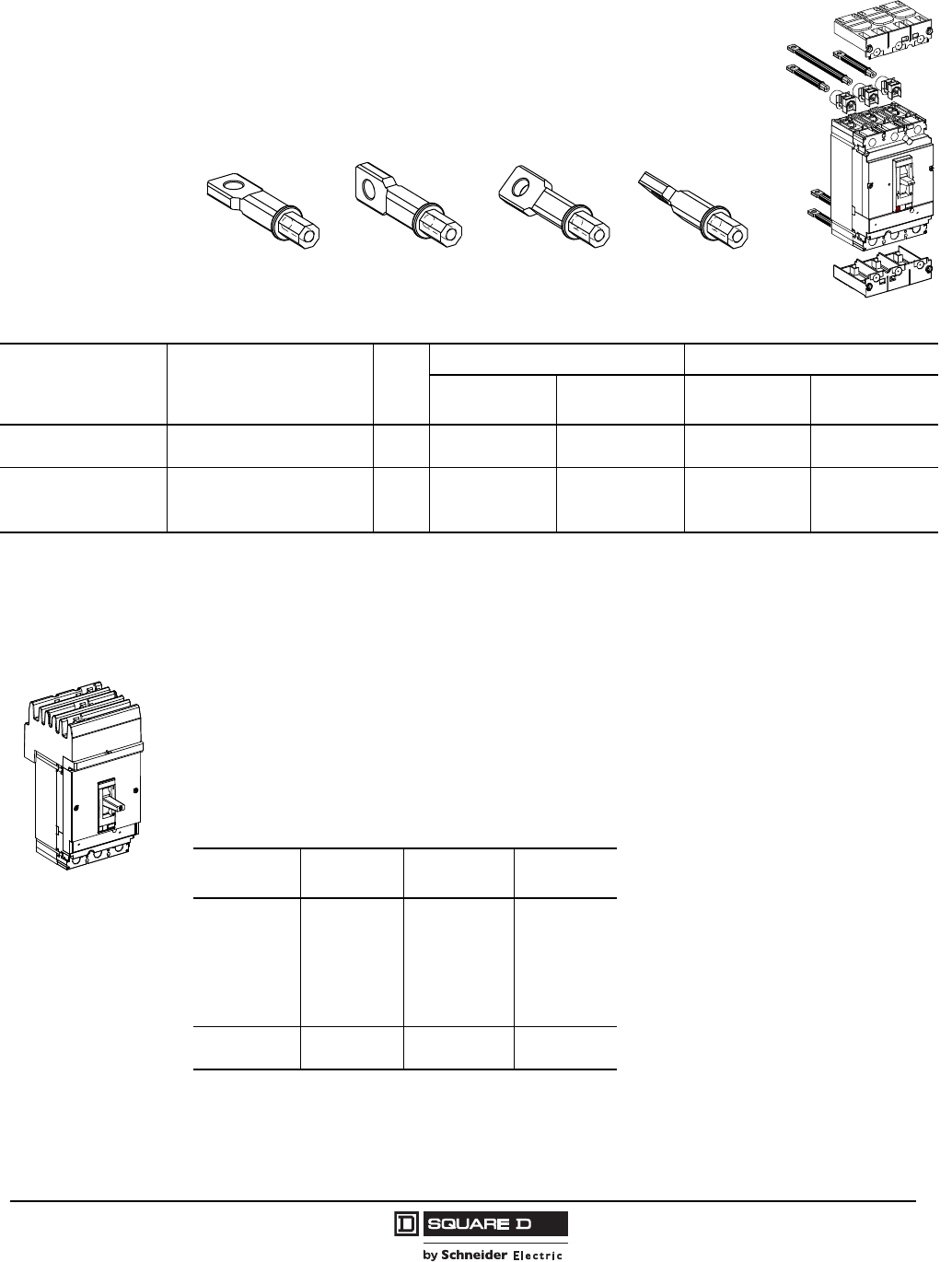
PowerPact® H- and J-Frame Circuit Breakers
Section 2—Mounting and Connections
31
05/2009
© 2004–2009 Schneider Electric
All Rights Reserved
Rear Connections
Rear connections are easily installed on the circuit breaker terminals.
The same connection may be installed flat, vertical or at a 45° angle with all
combinations possible. The circuit breaker is mounted on a backplate.
I-Line® Circuit breakers
H- and J-frame circuit breakers are available in I-Line construction for easy installation and removal in
I-Line panelboards and switchboards.
I-Line circuit breakers use “blow-on” type line side connectors. In case of a short circuit, increased
magnetic flux causes the plug-on connectors of the circuit breaker to tighten their grasp on the
panelboard or switchboard bus bars. The I-Line connectors and circuit breaker mounting bracket are
integral parts of I-Line circuit breakers and cannot be removed or replaced. I-Line circuit breakers
come with mechanical load side lugs.
Figure 7: Four Positions Possible for Each Connector
06113277
Horizontal Vertical 45° Angle
06113278
Table 38: Rear Connections
Device Description Poles
H-Frame J-Frame
Factory-Installed
Termination No.
Field-Installable
Catalog Number
Factory-Installed
Termination No.
Field-Installable
Catalog Number
Mixed Rear Connection Kit 2
3
S
S
—
S37432
S
S
—
S37437
Consisting of:
Short Rear Connections (Set of 2)
Long Rear Connections (Set of 2)
Short Terminal Cover (3P)
2 or 3
2 or 3
3
—
—
—
2x S374331
S37434
S37436
—
—
—
2x S374381
S37439
S37440
1For use with 3P circuit breakers only.
06113282
Table 39: Phase Options—Example HDA36150( )
Phase Option
Number
Phase
Connection 2P Example 3P Example
1
2
3
4
5
6
AB
AC
BA
BC
CA
CB
HDA261501
HDA261502
HDA261503
HDA261504
HDA261505
HDA261506
—
—
—
—
—
—
Standard
6
ABC
CBA
—
—
HDA36150
HDA361506
Courtesy of Steven Engineering, Inc.-230 Ryan Way, South San Francisco, CA 94080-6370-Main Office: (650) 588-9200-Outside Local Area: (800) 258-9200-www.stevenengineering.com
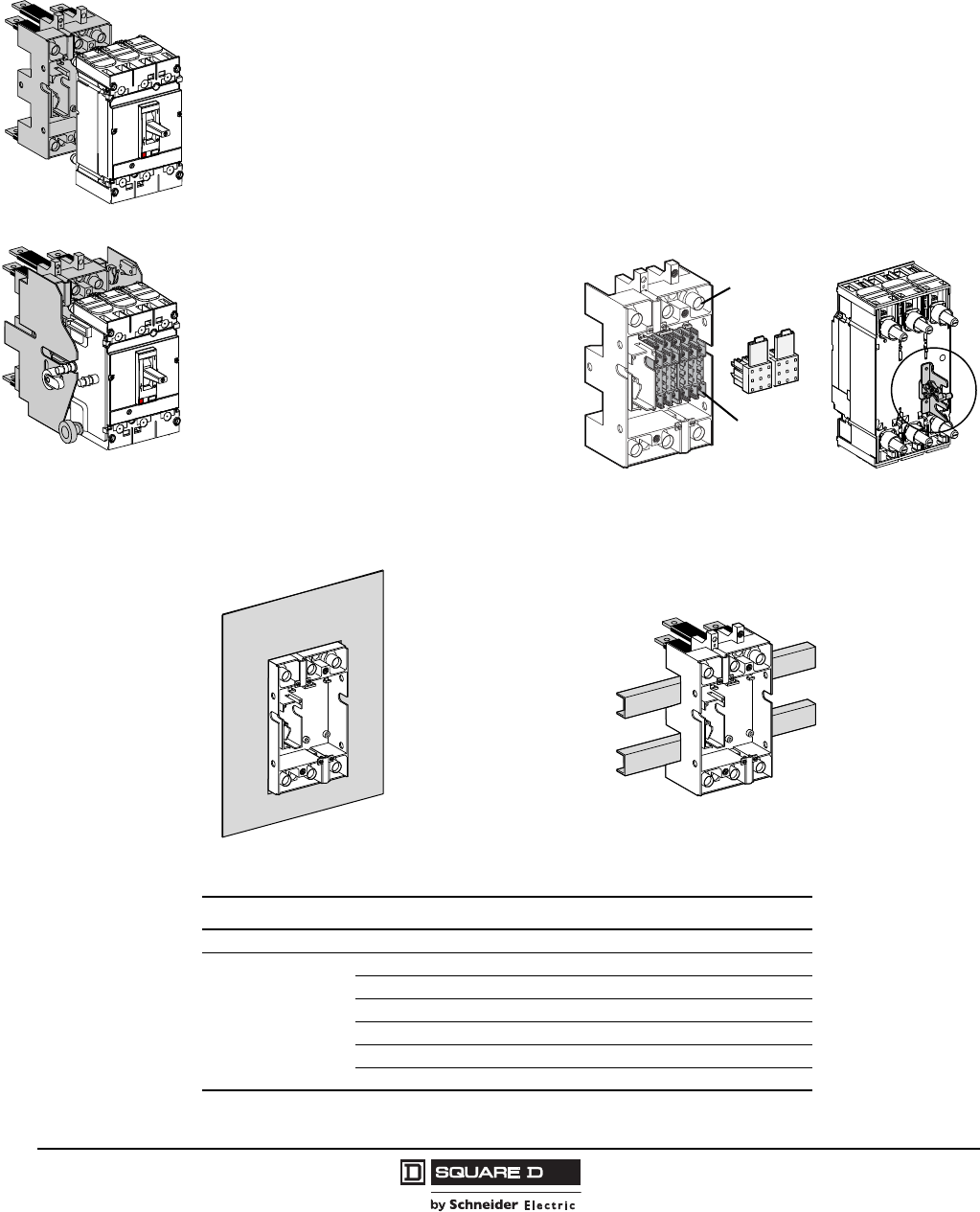
© 2004–2009 Schneider Electric
All Rights Reserved
PowerPact® H- and J-Frame Circuit Breakers
Section 2—Mounting and Connections
32
05/2009
Plug-In and Drawout Circuit Breakers
H- and J-frame circuit breakers are available in a plug-in and drawout construction.
Plug-In Circuit Breaker Mounting
The plug-in base is mounted through a front panel. The plug-in configuration makes it possible to:
•Extract and/or rapidly replace the circuit breaker without having to touch connections
•Allow for addition of future circuits at a later date
When the circuit breaker is in the connected position, the primary voltage is fed through the circuit
breaker by means of multiple finger disconnects. Control voltage of internal accessories is provided
through secondary disconnects.
Parts of a Plug-In Configuration
•Disconnects: Provides both primary and
secondary disconnect to the circuit
breaker.
•Safety Trip Interlock: The safety trip
causes automatic tripping if the circuit
breaker is ON before engaging or
withdrawing it; the safety trip does not
prevent the circuit breaker operation, even
when the circuit breaker is disconnected.
•Plug-in Base: The plug-in base provides
mounting through a front panel or mounting
on rails.
Plug-In Mounting
Drawout Mounting
06113284 06113281
Figure 8: Plug-In Base (Mounting Options)
Table 40: Plug-In Mounting
Description Suffix Catalog No.
Kit for Compact NSF Circuit Breaker (Stationary and Moving Part) N 29293
Consisting of:
Stationary Part — —
Plug-In Base — 29278
Moving Part HJ00 —
Short Terminal Covers — 29321
Safety Trip Interlock — 29270
Power Connections — 29268 (3)
123
4
5
6
7
8
9
123
4
5
6
7
8
9
Secondary
Disconnects
Primary
Disconnects
Safety Trip Interlock
Mounted on Back of
Circuit Breaker
06113311
Mounting Through
a Front Panel Mounting on Rails
06113285
Courtesy of Steven Engineering, Inc.-230 Ryan Way, South San Francisco, CA 94080-6370-Main Office: (650) 588-9200-Outside Local Area: (800) 258-9200-www.stevenengineering.com
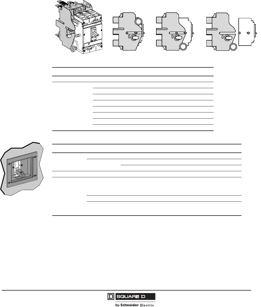
PowerPact® H- and J-Frame Circuit Breakers
Section 2—Mounting and Connections
33
05/2009
© 2004–2009 Schneider Electric
All Rights Reserved
Drawout Circuit Breaker Mounting
The drawout-mounted chassis is Listed under UL file E113555 and Certified under CSA file LR69561.
The chassis is made up of two side plates installed on the base and two other plates mounted on the
circuit breaker.
Chassis Functions
All functions of the plug-in base, plus:
•Disconnected position: the power circuit is disconnected, the circuit breaker is simply “withdrawn”
and may still be operated (ON (I), OFF (O), push-to-trip)
•Circuit breaker may be locked using one to three padlocks–padlock diameters 0.19–0.31 in.
(5–8 mm)
Figure 9: Drawout Mounting Positions
Table 41: Drawout Mounting
Description Suffix Catalog No.
Kit for Compact NSF Circuit Breaker (Stationary and Moving Part) N 29293
Consisting of:
Stationary Part — —
Plug-In Base — 29278
Fixed Part of Chassis 29282
Moving Part HJ00 —
Moving Part of Chassis 29282
Short Terminal Covers — 29321
Safety Trip Interlock — 29270
Power Connections — 29268 (3)
Connected Disconnected Removed
06113288
pus
h
to
Toggle Collar
Table 42: Plug-In and Drawout Accessories
Description Catalog No.
Secondary
Disconnecting
Blocks
Fixed Part 9-Wire Connector 29273
Moving Part 9-Wire Connector 29274
Support for 2 Moving Connectors 29275
Shutters Two Shutters for Plug-In Base 29271
Chassis
Accessories
Extended Escutcheon for Toggle
(For circuit breakers with toggle through front panel, intended to maintain the
degree of protection whatever the position of the circuit breaker. Supplied with a
toggle extension.)
29284
Locking Device (Key Lock is Not Included) 29286
Two Position Indicating Switches (Connected/Disconnected)
(Circuit breaker position switches may be applied on the fixed part of the
chassis, indicating the “connected” and “disconnected” positions.)
29287
Courtesy of Steven Engineering, Inc.-230 Ryan Way, South San Francisco, CA 94080-6370-Main Office: (650) 588-9200-Outside Local Area: (800) 258-9200-www.stevenengineering.com
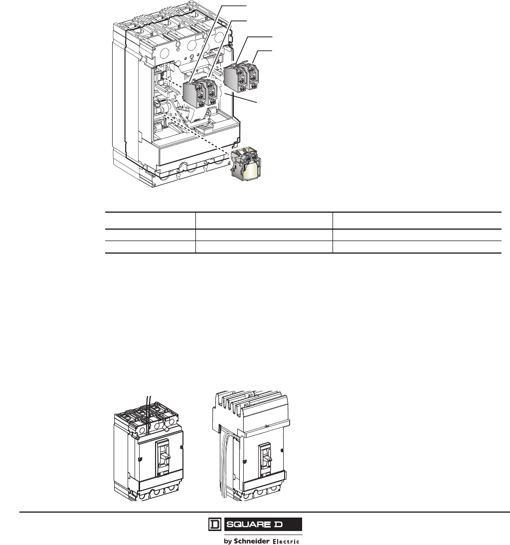
© 2004–2009 Schneider Electric
All Rights Reserved
PowerPact® H- and J-Frame Circuit Breakers
Section 3—Accessories
34
05/2009
Section 3—Accessories
Internal Accessories
Field-installable accessories provide flexibility for installation at point of use.
Auxiliary switches and the shunt trip or undervoltage release are easy to install, reliable and common
to many PowerPact® circuit breakers.
Accessory Connections
Electrical accessories are fitted with numbered terminal blocks for wires with the following maximum size:
•16 AWG (1.5 mm2) for auxiliary switches (OF1 or OF2), and shunt trip (MX) or undervoltage trip (MN)
•14 AWG (2.5 mm2) for the motor operator
Auxiliary circuit wiring exits fixed mounted devices through a knock-out in the front cover.
Figure 10: Accessory Locations
Table 43: Maximum Accessory Combinations
Poles Device Combination
2P (HD + HG)1
1All other 2P devices are 2P in a 3P module
Shunt trip or UVR (Undervoltage Release) 1A/1B + Alarm (SD)
3P Shunt trip or UVR (Undervoltage Release) 2A/2B + Alarm (SD) + Overcurrent Trip (SDE)
Figure 11: Accessory Connections
(OF1) Auxiliary Switch
(SD) Alarm Switch
(MX) Shunt Trip or
(MN) Undervoltage Trip
(SDE) Overcurrent Trip Switch
(OF2) Auxiliary Switch
SDE Adapter
06113305
06164128
C1 C2
MX/SHT
200/240V
NOTE: See page 32 for plug-in
and drawout options.
Courtesy of Steven Engineering, Inc.-230 Ryan Way, South San Francisco, CA 94080-6370-Main Office: (650) 588-9200-Outside Local Area: (800) 258-9200-www.stevenengineering.com
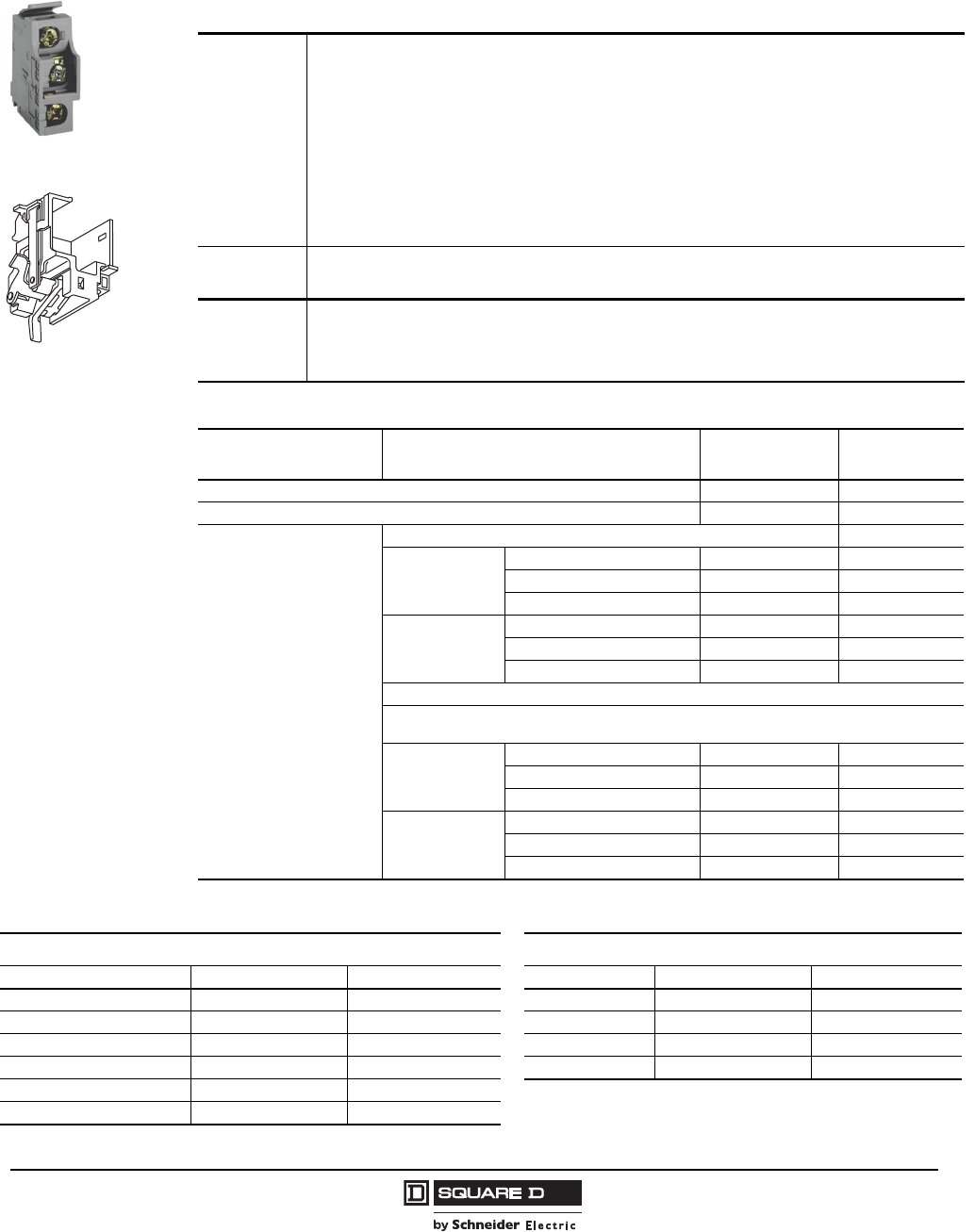
PowerPact® H- and J-Frame Circuit Breakers
Section 3—Accessories
35
05/2009
© 2004–2009 Schneider Electric
All Rights Reserved
Auxiliary and Alarm Switches
Auxiliary switches provide remote information of the circuit breaker status and can thus be used for
indications, electrical locking, relays, etc.
OF/SD Switch
SDE
Applications
Open/Closed (OF) Auxiliary Switch
• Indicates the position of the circuit breaker contacts
Trip Indication (SD) Switch
• Bell alarm indicates that the circuit breaker has tripped due to an overload, short circuit or ground fault, the
operation of a shunt trip or undervoltage trip or the “push-to-trip” button
• Resets when the circuit breaker is reset
Overcurrent Trip Switch (SDE)
• Indicates that the circuit breaker has tripped due to an overload, short circuit or ground fault
• Resets when the circuit breaker is reset
The above auxiliary switches are also available in low-level versions capable of switching very low loads (e.g.,
for controlling PLCs or electronic circuits).
Installation &
Connection
• The OF, SD and SDE switches snap into cavities behind the front accessory cover of the circuit breaker
• One model serves for all indication functions depending on where it is fitted in the circuit breaker
• The SDE function of a circuit breaker equipped with a thermal-magnetic trip unit requires the SDE adapter
Standards
• The internal accessories comply with requirements of Underwriters Laboratories® Inc. (UL®)
• UL 489 and Canadian Standard Association C22.2 No. 5-02 Standards
• All internal accessories are Listed for fixed installation per UL file E103955 and Certified under CSA file LR 69561
• Auxiliary switches comply with UL 489, CSA C22.2 No. 5-02 and IEC 60947-5 Standards
• “Low-level” switches are not UL Recognized
Table 44: Electrical Characteristics
Characteristic Voltage Standard
(Silver Contacts)
Low-Level
(Gold Contacts)
Supplied as Standard (Form C) 4 4
Maximum Number of Contacts 4 4
Breaking Capacity
at a Power Factor (p.f.) of 0.3
Standard (100 mA/24 V minimum load)
Vac
240/380 6 A 5 A
480 6 A 5 A
600/690 6 A —
Vdc
24/48 2.5 A 2.5 A
240 0.5 A 0.8 A
380 0.3 A 0.3 A
Low-level (1 mA/4 V minimum load with a maximum current and voltage of 100 mA 10 V.
NOTE: NOTE: If the maximum voltage and current is exceeded, the low-level function of the switch will
be lost but the switch will continue to function as a standard switch with the following specifications.
Vac
24/48 5 A —
240 5 A —
380 5 A —
Vdc
24/48 5/2.5 A —
125 0.5 A —
250 0.3 A —
Table 45: Switch Catalog Numbers
Alarm/Overcurrent Trip Switch Auxiliary Switch
Switch Factory-Installed Suffix Field-Installable Kit No. Contacts Factory-Installed Suffix Field-Installable Kit No.
Alarm Switch (SD) BC S29450 1A/1B Standard AA S29450
Alarm Switch (SD) Low-level BH S29452 2A/2B Standard AB S29450 (2)
SDE Standard1BD S29450 + S29451 1A/1B Gold AE S29482
SDE Low-level1BJ S29452 + S29451 2A/2B Gold AF S29482 (2)
SD and SDE Standard1BE S29450 (2) + S29451
SD and SDE Low-level1BK S29452 (2) + S29451
1Includes SDE Adapter S29451.
Courtesy of Steven Engineering, Inc.-230 Ryan Way, South San Francisco, CA 94080-6370-Main Office: (650) 588-9200-Outside Local Area: (800) 258-9200-www.stevenengineering.com
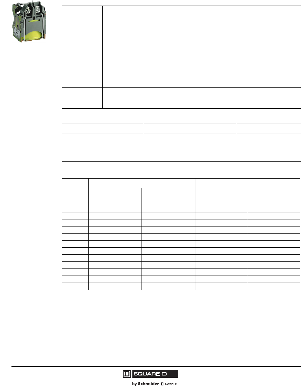
© 2004–2009 Schneider Electric
All Rights Reserved
PowerPact® H- and J-Frame Circuit Breakers
Section 3—Accessories
36
05/2009
Shunt Trip (MX) and Undervoltage Trip (MN) Switches
A voltage release can be used to trip the circuit breaker via a control signal.
Applications
Shunt trip (MX)
• Trips the circuit breaker when the control voltage rises above 70% of its rated voltage
• Impulse type 20 ms or maintained control signals
• AC shunt trips are suitable for ground fault protection when combined with a Class I ground fault
sensing element
Undervoltage trip (MN)
• Trips the circuit breaker when the control voltage drops below a tripping threshold
• Drops out between 35% and 70% of the rated voltage
• Circuit breaker closing is possible only if the voltage exceeds 85% of the rated voltage
• Permanent type
• If an undervoltage condition exists, operation of the closing mechanism of the circuit breaker will not
permit the main contacts to touch, even momentarily. This is commonly called “Kiss Free”
Installation and
Connection
• Accessories are common to H- and J-frame circuit breakers and snap into cavities under the front
accessory cover of the circuit breaker
• Each terminal may be connected by one #18–#14 AWG (1.0–2.5 mm2) stranded copper wire
Operation
• The circuit breaker must be reset locally after being tripped by shunt trip or undervoltage trip (MN or MX)
• MN or MX tripping has priority over manual (or motor operator) closing; in the presence of a standing trip
order such an action does not result in any closing, even temporarily, of the main contacts
• Endurance: 50% of the rated mechanical endurance of the circuit breaker for circuit breakers
Table 46: Electrical Characteristics
Description AC DC
Rated Voltage (V) 24, 48, 110.130, 208.277, 380.480, 525, 600 12, 24, 30, 48, 60, 125, 250
Consumption Pickup (MX) < 10 VA < 5 W
Seal-in (MN) < 5 VA < 5 W
Clearing Time (ms) < 50 < 50
Table 47: Shunt Trip and Undervoltage Trip Suffix Codes and Kit Numbers
Voltage
Shunt Trip Undervoltage Release UVR
Factory-Installed Suffix Field-Installable Kit No. Factory-Installed Suffix Field-Installable Kit No.
24 Vac SK S29384 UK S29404
48 Vac SL S29385 UL S29405
120 Vac SA S29386 UA S29406
208-277 Vac SD S29387 UD S29407
380-480 Vac SH S29388 UH S29408
525-600 Vac SJ S29389 UJ S29409
12 Vdc SN S29382 UN S29402
24 Vdc SO S29390 UO S29410
30 Vdc SU S29391 UU S29411
48 Vdc SP S29392 UP S29412
60 Vdc SV S29383 UV S29403
125 Vdc SR S29393 UR S29413
250 Vdc SS S29394 US S29414
Courtesy of Steven Engineering, Inc.-230 Ryan Way, South San Francisco, CA 94080-6370-Main Office: (650) 588-9200-Outside Local Area: (800) 258-9200-www.stevenengineering.com
PowerPact® H- and J-Frame Circuit Breakers
Section 3—Accessories
37
05/2009
© 2004–2009 Schneider Electric
All Rights Reserved
Add-On Ground-Fault Module (GFM)
The Micrologic® Ground-Fault Moduel (GFM) is a UL Listed circuit breaker accessory which protects
equipment from damage caused by ground faults. It is an add-on module which, when connected to a
PowerPact H- or J-frame circuit breaker, provides ground-fault sensing and ground-fault relay
functions.
HD/JD ground-fault modules feature:
•Adjustable ground-fault pickup levels.
•Adjustable ground-fault time delays.
•Integral ground-fault push-to-test feature.
•Ground-fault indicator (mechanical for local, contacts for remote).
•All GFMs are supplied for I-Line® mounting as standard, easily convertible to unit mount by
removing the I-Line bracket.
•Fault-powered (via the sensing current transformer) for electronics, shunt trip, and integral test
feature. Meets NEC 230-95(c).
•A 12 Vdc shunt trip module (Catalog No. S29382) is required in the circuit breaker. This may be
field installed or factory installed when the circuit breaker is ordered with an -SN suffix.
The GFM system requires the following:
•H-frame (15–150 A) or J-frame (150–250 A) molded case circuit breaker.
•Shunt trip for circuit breaker (may be factory-installed or field-installed).
•Bus bar connection (terminal nut inserts) for OFF end of circuit breaker.
•Optional neutral current transformer, catalog number GFM25CT (must be ordered for 4-wire
applications).
See Section 6, Figure 48–49 for GFM trip curves.
09603039
Ground-Fault Module
Module de défaut de mise à la terre
Modulo de falla a tierra
Ground-Fault Indicator
ault Indicator
Push to reset
Indicateur de défaut de
mise à la terre
Pousser pour réinitialiser
Indicador de falla a tierra
Oprima para restablecer
Push-to-test
Requires 120 V Pick-upDelay Band
1=min.
1
23
4
20A
40A
60A
80A
100A
Class I Ground-fault Protection
Protection de défaut de mise à la terre classe I
Protección de falla a tierra clase I
100A 600 Vac/V max.
Replace cover after adjusting/Replacer le couvercle avant aprés le réglage/Vuelva a colocar la cubierta después de ajustar
52H
4
LISTED
Circuit
Breaker
Accessory
GFM150HD
®
4068715 H238
DANGER PELIGRO
HAZARD OF ELECTRICAL SHOCK OR BURN.
DANGER DE D’CHARGE ELECTRIQUE OU DE
BRULURE.
PELIGRO DE DESCARGA ELECTRICA O
QUEMADURAS.
Ter m i n al strip wiring ter minals must not be
be dielectric tested.
No se deben realizar pruebas dieléctricasa a
las terminalses de la tabilla de conexiones.
Les bornes de câblage de la barrette de
connexion ne doivent pas étre véroflées
diélectriquement.
Replace lug cover after
wiring.
Replacez le couvre-
cosse après le câblage
.
Vuelva a colocar después
de realizar el cableado
PELIGRODANGER
®
!
J-Frame Circuit Breaker
with GFM Installed
Table 48: Ground-Fault Module
Catalog No. Rating Sensitivity Time Delay (Approximate)
GFM150HD 150 A 20, 40, 60, 80, 100 A 0.2, 0.3, 0.4, 0.6 sec
GFM250JD 250 A 40, 80, 120, 160, 200 A 0.2, 0.3, 0.4, 0.6 sec
Courtesy of Steven Engineering, Inc.-230 Ryan Way, South San Francisco, CA 94080-6370-Main Office: (650) 588-9200-Outside Local Area: (800) 258-9200-www.stevenengineering.com
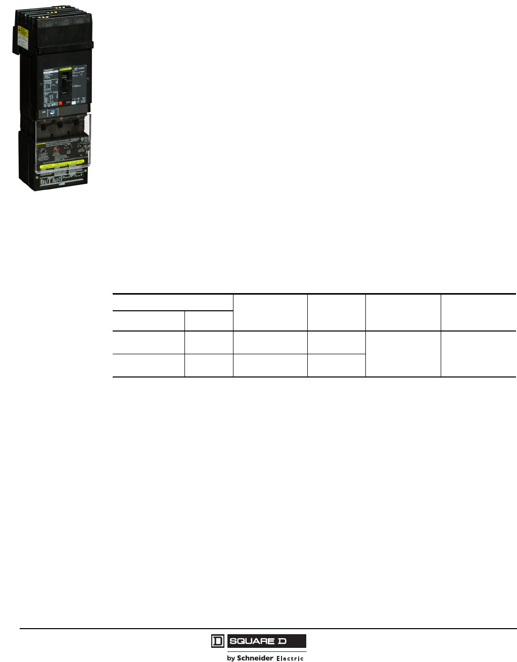
© 2004–2009 Schneider Electric
All Rights Reserved
PowerPact® H- and J-Frame Circuit Breakers
Section 3—Accessories
38
05/2009
Earth Leakage Module (ELM) for PowerPact H- and J-Frame MCCBs
The Earth Leakage Module (ELM) is an add-on module which, when connected to a PowerPact H- or
J-frame MCCB, provides low-level ground-fault sensing and ground-fault relay functions.
Because these ELMs are highly sensitive (30 mA to 3 A), they provide much greater protection than
GFMs (20 Amps to 200 Amps sensitivity). The ELMs provide greater protection of control circuits and
other sensitive equipment. The associated circuit breaker must have a 48 Vdc shunt trip), which may
be field-installed (kit S29392) or factory-installed (suffix –SP) in the H- or J-Frame circuit breaker.
The add-on Earth Leakage Module (ELM) features:
•Adjustable ground-fault pickup levels as low as 30 mA
•Adjustable ground-fault time delays from instantaneous to 500 msec
(time delay can be applied to any setting)
•Integral ground fault push-to-test feature
•Ground-fault indicator; pop-up button for local status and contacts for remote indication (to be used
only with the tripping option)
•All ELMs are supplied for I-Line® mounting and are easily convertible to unit-mount by removing
the I-Line mounting feet
•Three poles; 240 to 600 Vac maximum: 3-phase, 3-wire (no neutral) and 1-phase, 2-wire
applications
•Line-power obtained through internal bus to provide power for electronics, shunt trip, and integral
test feature.
•A shunt trip is required in the circuit breaker; it may be field-installed or factory-installed in the
PowerPact H and J circuit breakers.
•UL 1053 – Ground-fault Sensing and Relaying Equipment
See Section 6, Figure 50 for ELM Trip Curves.
J-Frame Circuit Breaker
with ELM Installed
Table 49: ELM Selection Chart 1
1At 250 A, the ELM250JD can be used with 80% rated circuit breakers only.
Companion Circuit Breaker Enclosure Space
Required I-Line
Switchboard
Catalog
Number
Pick-Up
Adjustments
Ground-Fault
Time Delay
Adjustments
Prefix Size
HD, HG, HJ, HL 15–150 A LA ELM150HD 30 mA
100 mA
300 mA
1A
3A
Instantaneous
60 ms
100 ms
500 msec
JD, JG, JJ, JL 150–250 A LA ELM250JD
Courtesy of Steven Engineering, Inc.-230 Ryan Way, South San Francisco, CA 94080-6370-Main Office: (650) 588-9200-Outside Local Area: (800) 258-9200-www.stevenengineering.com
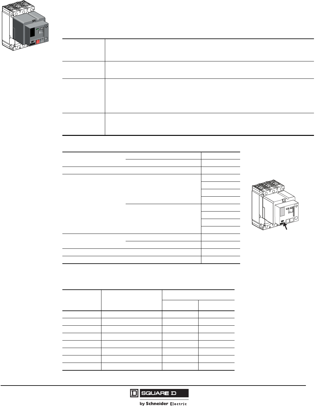
PowerPact® H- and J-Frame Circuit Breakers
Section 3—Accessories
39
05/2009
© 2004–2009 Schneider Electric
All Rights Reserved
Motor Operator
The motor operator remotely operates the circuit breaker featuring easy and sure operation:
•All circuit breaker indications and information remain visible and accessible, including trip unit
settings and circuit breaker connection
•Suitability for isolation is maintained and padlocking remains possible
•Double insulation front face
Applications
• Local motor-driven operation, centralized operation, automatic distribution control
• Normal/standby source changeover or switching to a replacement source to optimize energy costs
• Load shedding and reconnection to optimize energy costs
• Synchrocoupling—less than five cycle closing time
Installation and
Connection
• All installation (fixed, plug-in/drawout mounting) and connection capabilities are maintained
• Connections of the motor operator module are to a built-in terminal block behind its front cover
• Stranded copper wire 14 AWG (2.5 mm2)
Automatic
Operation
The motor operator is connected in series with the overcurrent (SDE) trip switch. (The SDE adapter is
included with the motor operator.) See wiring diagrams on page 44.
• ON (I) and OFF (O) by two impulse type or continuous control signals
• Depending on the wiring, resetting can be done locally, remotely or automatically
• Optional manual reset if tripping due to an electrical fault (with SDE)
• Anti-pumping feature.
Manual
Operation
• Transfer to manual mode with possibility of remote mode indication
• ON (I) and OFF (O) by two push buttons
• Recharging of stored-energy system by pumping the lever nine times
• Padlocking in off position
Table 50: Motor Operator Characteristics
Response Time (ms) Opening < 500
Closing < 80
Maximum Cycles Per Minute 4
Control Voltage
AC 50/60 Hz
48–60
110–130
208–277
380–480
DC
24–30
48–60
110–130
250
Consumption AC (VA) Opening/Closing 500
DC (W) Opening/Closing 500
Minimum Operating Order (ms) 700
Operating Voltage 85–110% rated
Table 51: Motor Operator Accessory Suffix Codes and Catalog Numbers
Voltage Factory-Installed Suffix
Field-Installable Catalog No.
H-Frame J-Frame
48/60 Vac ML S29440 S31548
120 Vac MA S29433 S31540
277 Vac MD S29434 S31541
380/480 Vac MH S29435 S31542
24/30 Vdc MO S29436 S31543
48/60 Vdc MP S29437 S31544
110/130 Vdc MR S29438 S31545
250 Vdc MS S29439 S31546
Manual Mode
Switch
Courtesy of Steven Engineering, Inc.-230 Ryan Way, South San Francisco, CA 94080-6370-Main Office: (650) 588-9200-Outside Local Area: (800) 258-9200-www.stevenengineering.com
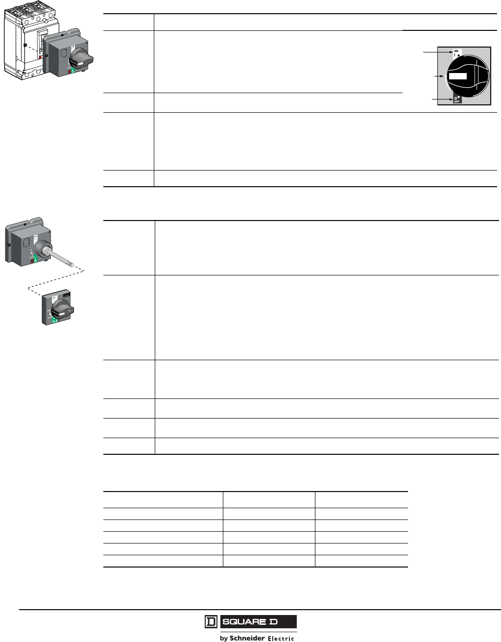
© 2004–2009 Schneider Electric
All Rights Reserved
PowerPact® H- and J-Frame Circuit Breakers
Section 3—Accessories
40
05/2009
Rotary Operating Handles
Directly-Mounted Rotary Operating Handles
IEC-Style Door-Mounted Rotary Operating Handle
Directly Mounted Rotary
Operating Handle
Installation The directly mounted rotary operating handle replaces the circuit breaker front accessory cover (secured by screws).
Operation
The direct rotary handle maintains:
• Suitability for isolation
• Indication of three positions: ON (I), Tripped and OFF (O)
• Access to the “push-to-trip” button
• Visibility of, and access to, trip unit settings
• The circuit breaker may be locked in the OFF position by using one to three
padlocks (not supplied), padlock shackle diameter 0.19–0.31 in. (5–8 mm)
Models • Standard with black handle
• VDE type with red handle and yellow bezel for machine tool control
Variations
Accessories transform the standard direct rotary handle for the following situations:
• Motor control centers (MCCs):
– Opening of door prevented when circuit breaker is on
– Closing of circuit breaker inhibited when door is open
• Machine tool control; complies with CNOMO E03.81.501N; degree of protection IP54
• Early make or early break contacts may be installed into direct mount rotary handle
Standards The directly-mounted rotary operating handle is UL Listed under file E103955 and CSA Certified under file LR 69561
I/ON
(Closed)
Tripped
O/OFF
(Open)
Door Mounted Rotary
Operating Handle
Installation
The extended rotary operating handle is made up of:
• A unit that replaces the front accessory cover of the circuit breaker (secured by screws)
• An assembly (handle and front plate) on the door that is always secured in the same position, whether the
circuit breaker is installed vertically or horizontally
• An adjustable extension shaft
• The handle mechanism can be used in NEMA 3R and 12 enclosure applications
Operation
The door mounted operating handle makes it possible to operate circuit breakers installed in enclosure from the
front. The door mounted operating handle maintains:
• Suitability for isolation
• Indication of the three positions OFF (O), ON (I) and tripped
• Visibility of and access to trip unit settings when the door is open
• Degree of protection: IP40 as per IEC 529
Defeatable interlock prevents opening of door when circuit breaker is on
The circuit breaker may be locked in the off position by using one to three padlocks, padlock shackle diameter
0.19–0.31 in. (5–8 mm); padlocks are not supplied; locking prevents opening of the switchboard door
Shaft
Length
The shaft length is the distance between the back of the circuit breaker and the door:
• Minimum shaft length is 7.4 (185 mm)
• Maximum shaft length is 24 in. (600 mm)
• Extended shaft length must be adjusted
Models • Standard with black handle
• VDE type with red handle and yellow bezel for machine tool control
Variations For withdrawable configurations, the extended rotary handle is also available with a telescopic shaft containing
two stable positions
Standards The extended rotary operating handle is UL Listed under file E103955 and CSA Certified under file LR 69561
Table 52: Rotary Operating Handle Suffix Codes and Kit Numbers
Handle Type (color) Factory-Installed Suffix Field-Installable Kit No.
Direct Mount (black) RD10 S29337
Extended Door Mount (black) RE10 S29338
Telescoping (black) RT10 S29343
Direct Mount (red) RD20 S29339
Extended Door Mount (red) RE20 S29340
Courtesy of Steven Engineering, Inc.-230 Ryan Way, South San Francisco, CA 94080-6370-Main Office: (650) 588-9200-Outside Local Area: (800) 258-9200-www.stevenengineering.com
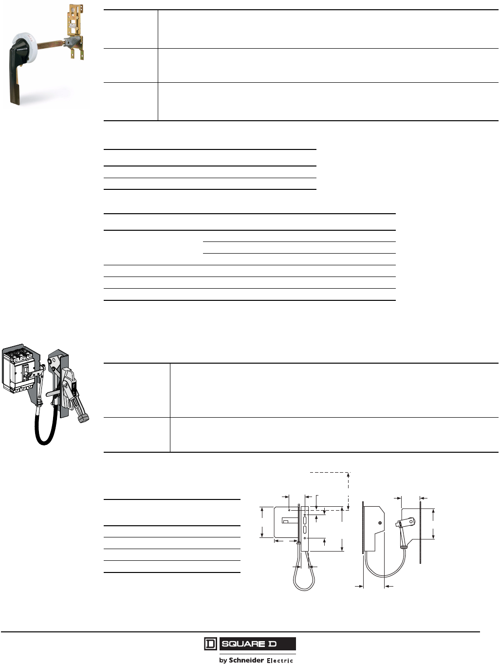
PowerPact® H- and J-Frame Circuit Breakers
Section 3—Accessories
41
05/2009
© 2004–2009 Schneider Electric
All Rights Reserved
Class 9421 NEMA Door Mounted Rotary Operating Handles
Class 9422 Cable Operating Handle
Flange-mounted handle cable operating mechanism is for use with Class 9422 Type A handle
operators especially designed for tall, deep enclosures where placement flexibility is required.
Installation
The extended rotary operating handle is made up of:
• A mounting plate that provides a rotary actuator for a standard toggle circuit breaker
• Handle assemblies available for NEMA 3, 3R, 4, and 4X
• Available in standard or short (3 in.) handle assemblies
Operation
The door mounted operating handle makes it possible to operate circuit breakers installed in enclosure from the front.
Provides ON (I) and OFF (O) indication
The circuit breaker may be locked in the off position
Shaft Length
The shaft length is the distance between the back of the circuit breaker and the door:
• Minimum mounting depth is 5.5 in. (138 mm)
• Maximum mounting depth is 10.75 in. (273 mm) with standard shaft
• Maximum mounting depth is 21.3 in. (543 mm) with long shaft
Table 53: Class 9421 Door-Mounted Operating Mechanism
Description Catalog Number
Standard Shaft Kit 9421LJ1
Long Shaft Kit 9421LJ4
Table 54: Component Parts
Description Catalog Number
Standard Handle Assembly
Type 1, 3R, 12 9421LH6
NEMA Type 3 and 4, Painted 9421LH48
NEMA Type 3 and 4, Chrome Plated 9421LC48
Operating Mechanism Includes Lockout 9421LJ7
Standard Shaft Support Bracket Not Required 9421LS8
Long Shaft Support Bracket Included 9421LS10
F
Applications
• The cable operator maintains:
Suitability for isolation
Indication of three positions: O (OFF), I (ON) and tripped
Access to push-to-test
• The circuit breaker may be locked in the off position by one to three padlocks
• Door can be locked closed due to interlocking features of the handle operator
Installation
• Handle is mounted on flange of enclosure using specified mounting dimensions while circuit breaker and
operating mechanism are mounted to inside of enclosure using two screws
• Cable lengths available in 3-, 5- or 10-foot lengths to accommodate a variety of mounting locations
Handles are available in painted Nema 1, 3, 3R, 4 (sheet steel) and 12 ratings or chrome (Nema 4, 4x)
Table 55: Class 9422
Cable Mechanisms
Cable Mechanism
Length
Catalog
Number
36 in. 9422CSF30
60 in. 9422CSF50
84 in. 9422CSF70
120 in. 9422CSF10
1.44
(37)
9.12
(232)
4.25
(108)
4.69
(119)
1.00
(25)
CA
B
X
E
D
06113534
Refer to NEC Article 430-10 for minimum
dimension X from circuit breaker top
mounting hole to wall or barrier to ensure
adequate wire bending space.
Note: Bend radius in cable must never be less than 6 in. (152 mm). Electrical
clearances must be maintained between cable and live electrical parts.
in.
[mm]
Dimensions:
Courtesy of Steven Engineering, Inc.-230 Ryan Way, South San Francisco, CA 94080-6370-Main Office: (650) 588-9200-Outside Local Area: (800) 258-9200-www.stevenengineering.com
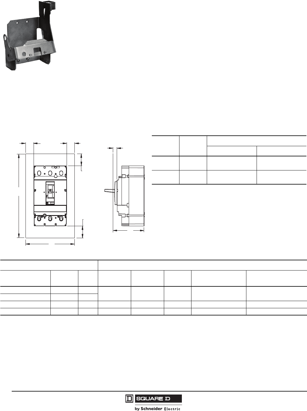
© 2004–2009 Schneider Electric
All Rights Reserved
PowerPact® H- and J-Frame Circuit Breakers
Section 3—Accessories
42
05/2009
Variable Depth Mechanisms
Designed for installation in custom built control enclosures where main or branch circuit protective
devices are required.
•All circuit breaker operating mechanisms are suitable for either right- or left-hand flange mounting,
convertible on the job.
•Variable mounting depth range: 5.88–17.75 in. (149–451 mm).
•Operating mechanism 9422RQ1 (does not include handle mechanism).
Circuit Breaker Enclosures and Enclosure Accessories
•Square D circuit breaker enclosures are UL Listed, CSA Certified and are suitable for use as
service entrance equipment, except as footnoted.
•The short circuit rating of an enclosed circuit breaker is equal to the rating of the circuit breaker
installed, except as footnoted.
•Circuit breakers are ordered and shipped separately for field installation.
06113535
Table 56: Enclosure Dimensions
Circuit
Breaker Amperage
Enclosure Dimensions (h x w x d)
80% 100%
H-Frame 15–150 A 18.13 x 8.63 x 4.13 in.
(461 x 219 x 105 mm)
62 x 14 x 22.5 in.
(572 x 356 x 1575 mm)
J-Frame 150–250 A 28.5 x 12.38 x 5.38 in.
(724 x 314 x 137 mm)
62 x 14 x 22.6 in.
(572 x 356 x 1575 mm)
48996-053-01
1.00 MIN
[25,4]
1.00 MIN
[25,4]
4.00 MIN
[101,6]
00 MIN
4.00 MIN
[101,6]
h
h
d
Table 57: Circuit Breaker Enclosure Catalog Numbers
Circuit Breaker Enclosure Cat. No.
Cat. No. Prefix Rating Poles NEMA 1
Flush
NEMA 1
Surface
NEMA
3R1
NEMA 4, 4X, 5, 3, 3R
Stainless Steel
NEMA 12/3R, 5
(Without Knockouts)2
HDL,HGL,HJL,HLL 15–150 A 2, 3 J250F J250S J250R J250DS J250AWK
JDL,JGL,JJL,JLL 150–250 A 2, 3
HDL 15–100 A 3 — HD100S3, 4, 5 —— —
JDL 150–250 A 3 — JD250S3, 5, 6 —— —
1Enclosures with NRB or RB suffix have provisions for 3/4 in. through 2-1/2 in. bolt-on hubs in top endwall. Enclosures with R suffix have blank endwalls and require
field cut opening. For details and hub catalog numbers see Digest 174 page 3-9.
2Suitable for rainproof NEMA 3R application by removing drain screw from bottom endwall.
3Copper wire only
4Maximum short circuit rating is 25 kAIR, 240 Vac
5Order service ground kit PKOGTA2 if required.
6Maximum short circuit rating is 18 kAIR, 480 Vac.
Courtesy of Steven Engineering, Inc.-230 Ryan Way, South San Francisco, CA 94080-6370-Main Office: (650) 588-9200-Outside Local Area: (800) 258-9200-www.stevenengineering.com
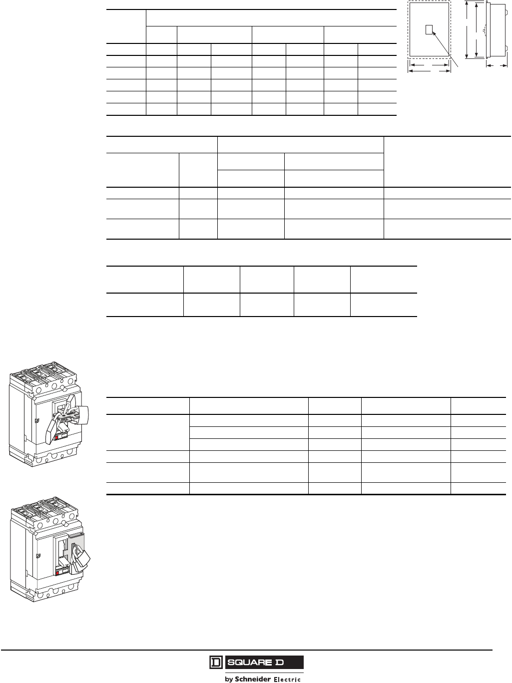
PowerPact® H- and J-Frame Circuit Breakers
Section 3—Accessories
43
05/2009
© 2004–2009 Schneider Electric
All Rights Reserved
Locking Systems
Padlocking systems can receive up to three padlocks with diameters of 0.19–0.31 in. (5–8 mm);
padlocks not supplied.
Table 58: Dimensions
Cat. No.
Approximate Dimension
Series H W D
HD100S A01 17.00 in. 431.8 mm 7.90 in. 200.7 mm 4.75 in. 120.7 mm
J250F A01 32.40 in. 823 mm 15.40 in. 391 mm 6.00 in. 152 mm
J250S A01 31.36 in. 797 mm 14.36 in. 365 mm 6.00 in. 152 mm
J250R A01 31.05 in. 789 mm 14.47 in. 368 mm 6.28 in. 160 mm
J250DS A01 32.26 in. 819 mm 9.72 in. 247 mm 7.94 in. 202 mm
J250AWK A01 32.26 in. 819 mm 9.72 in. 247 mm 7.94 in. 202 mm
Table 59: Insulated Groundable Neutral Assembly
Circuit Breaker Neutral Assembly For Use With Terminal Lug Data—Total
Available (Line plus Load)
AWG/kcmil
Cat. No. Prefix Ampere
Rating
NEMA 1 & 3R NEMA 4, 4X, 5, 12 & 12K
Cat. No. Cat. No.
HDL,HGL,HJL,HLL 15–100 A SN100FA SN100FA (4) 14–1/0 Cu or (4) 12–1/0 Al
HDL,HGL,HJL,HLL 125–150 A SN400LA SN400LA (2) 1–600 or
(4) 1–250 Al/Cu, plus (2) 4–300 Al/Cu
JDL,JGL,JJL,JLL 150–250 A SN400LA SN400LA (2) 1–600 or
(4) 1–250 Al/Cu, plus (2) 4–300 Al/Cu
Table 60: Service Ground Kits
Circuit Breaker
Cat. No. Prefix
Ground Bar
Cat. No.
Number of
Terminals
Conductors
Per Terminal Wire Range
HDL,HGL,HJL,HLL,
JDL,JGL,JJL,JLL PKOGTJ250 2 1 6 AWG–300 kcmil
Al/Cu
W
NEMA Type 1
W
D
H
H
WB enclosure
uses 2 circuit breakers
Fixed Padlock Attachment
Removable Attachment*
06113316
Table 61: Device Locking Options
Control Device Function Type Accessories Required Kit Cat. No.
Toggle
Lock in OFF (O) Position Padlock Removable Device S29370
Lock in OFF (O) or ON (I) Position Padlock Fixed Device1
1Not available for 2P HD and HG devices
S29371
Lock in OFF (O) Position Padlock Stationary Device S37422
Direct Rotary Handle Lock in OFF (O) Position Padlock None —
Extended Rotary
Operating Handle
Lock in OFF (O) Position,
Door Opening Prevented Padlock None —
Motor Operator Lock in OFF (O) Position, Motor Padlock None —
Courtesy of Steven Engineering, Inc.-230 Ryan Way, South San Francisco, CA 94080-6370-Main Office: (650) 588-9200-Outside Local Area: (800) 258-9200-www.stevenengineering.com
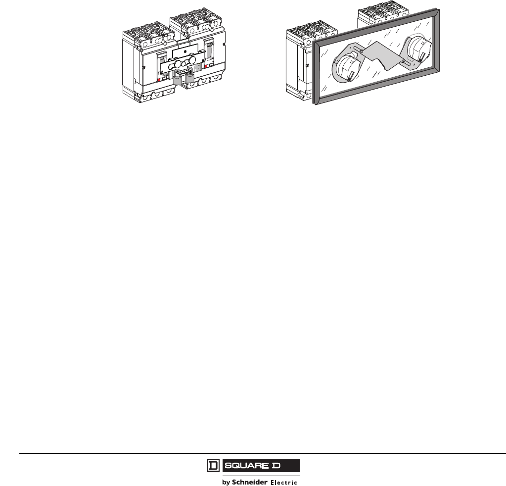
© 2004–2009 Schneider Electric
All Rights Reserved
PowerPact® H- and J-Frame Circuit Breakers
Section 3—Accessories
44
05/2009
Interlocking Systems
Interlocking of Circuit Breakers With Toggle Control
The toggle interlock system can receive one or two padlocks with diameters of 0.19–0.31 in. (5–8 mm).
Both interlocked circuit breakers should be fixed version or plug-in version. Two sliding interlocking
bars can be used to interlock three circuit breakers installed side-by-side, in which case one circuit
breaker is in the ON (I) position and the two others in the OFF (O) position. (Kit S29354. Not available
for 2P HD and HG devices.)
Interlocking Two Circuit Breakers with Rotary Handles
The rotary handles are padlocked with the devices in the OFF (I) position. The interlock mechanism
inhibits the two devices from being closed (ON/I) at the same time, but allows for both devices to be
open (OFF/O) simultaneously. (Kit S29369. Not available for 2P HD and HG devices.)
Figure 12: Interlocking Systems
Interlocking with Toggle Control (S29354)
06113319
Interlocking with Rotary Handles (S29369)
06113320
Courtesy of Steven Engineering, Inc.-230 Ryan Way, South San Francisco, CA 94080-6370-Main Office: (650) 588-9200-Outside Local Area: (800) 258-9200-www.stevenengineering.com
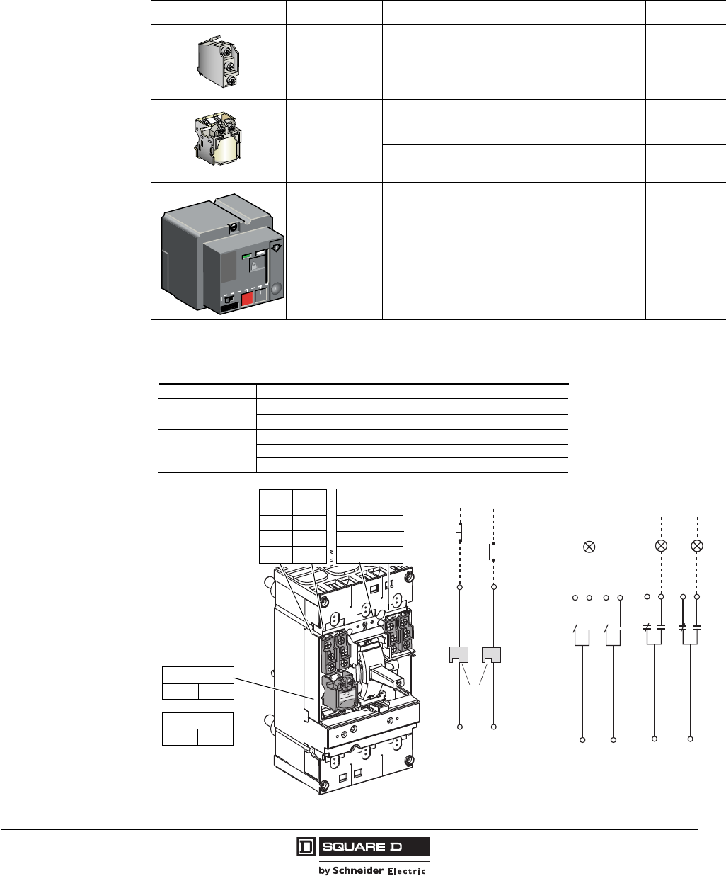
PowerPact® H- and J-Frame Circuit Breakers
Section 4—Wiring Diagrams
45
05/2009
© 2004–2009 Schneider Electric
All Rights Reserved
Section 4—Wiring Diagrams
Table 62: Connector Descriptions
Function Description Connector
Auxiliary Contacts
Open/Closed circuit breaker or switch position contacts OF/AX
Bell alarm SD/AL
Remote Operation
Undervoltage trip device MN/UVR
Shunt trip MX/SHT
Remote Operation Motor operator MCH
Figure 13: Control Wiring Diagrams
push OFF
manuauto
5...8
OFF
discharged
O
O
push ON
C1 C2
MX/SHT
200/240V
06113153
or
D4
D1
MN MX
C2
C1
06113096
22
24
21
OF2/
AX
Closed
06113097
12
14
OF1/
AX
11
92
94
91
SD/
AL
Fault
82
84
81
SDE
Fault
MN/UVR
MX/SHT
or
C1 C2
D1 D4
11 91
12 92
14 94
81 21
82 22
84 24
OF1/
AX
SD/
AL SDE OF2/
AX
Remote Operation Alarm Contacts
Connector
Function
Open/Closed circuit breaker or switch position contacts
Description
Auxiliary Contacts OF/AX
SD/AL
MN/UVR
MX/SHT
MCH
Remote Operation
Bell alarm
Undervoltage trip device
Shunt trip
Motor operator
Courtesy of Steven Engineering, Inc.-230 Ryan Way, South San Francisco, CA 94080-6370-Main Office: (650) 588-9200-Outside Local Area: (800) 258-9200-www.stevenengineering.com
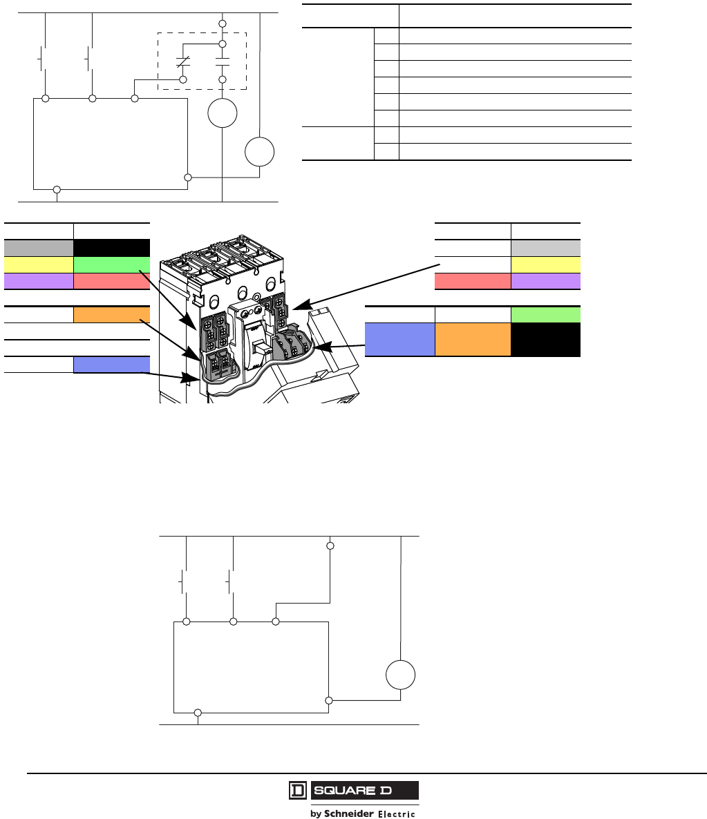
© 2004–2009 Schneider Electric
All Rights Reserved
PowerPact® H- and J-Frame Circuit Breakers
Section 4—Wiring Diagrams
46
05/2009
Standard Motor Operator Wiring (Factory Wiring Configuration)
A circuit breaker may be configured for remote operations. Remotely operated circuit breakers are
factory wired for the power supply to the motor being switched by the overcurrent trip switch. This
prevents the circuit breaker from being remotely reset after an overload fault as a precaution against
closing on a fault.
Remote Reset Wiring Without Overcurrent Trip Switch Protection
To configure circuit breaker for remote operation without overcurrent switch protection, follow the
wiring diagram below.
Figure 14: Standard Motor Operator Control Wiring
OF1 / AX SD / AL SDE / OAL OF2 / AX
11 grey91 black 21 grey
12 yellow 92 green 22 yellow
14 violet 94 red 84 red 24 violet
MX / SHT
C1 white C2 orange B2 A2 white L1 green
OR / O / OU B4 blue A4 orangeA1 black
MN / UVR
D1 white D4 blue
Color wiring legend
Motor Mechanism Module
BPO
(open)
BPF
(close)
SDE
OAL
L1A1
AC Input Common, DC Negative (-)
A2A4
H1
H2
8284
81
B4
B2
06113111
AC Input Common, DC Positive (+)
Description
Connector
A4 Electrical opening (positive DC)
A2 Electrical closing (positive DC)
B4 Power supply connection (positive DC)
A1 Power supply connection (negative DC)
L1 Automatic position indicator
84 Overcurrent trip indicator
Indicator H1 Lamp signal indicating MCH in automatic position
H2 Lamp signal indicating overcurrent trip condition
Figure 15: Motor Operator Without Overcurrent Switch Protection
06113476
BPO
(open)
BPF
(close)
Motor Mechanism Module
A4 A2 B2
B4
L1
A1
H1
AC Input Voltage, DC Positive (+)
AC Input Common, DC Negative (-)
Courtesy of Steven Engineering, Inc.-230 Ryan Way, South San Francisco, CA 94080-6370-Main Office: (650) 588-9200-Outside Local Area: (800) 258-9200-www.stevenengineering.com
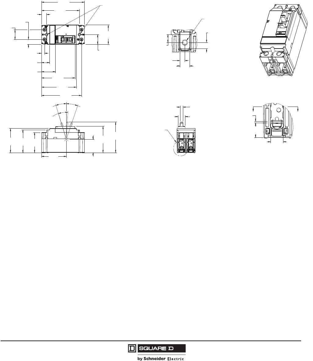
PowerPact® H- and J-Frame Circuit Breakers
Section 5—Dimensions
47
05/2009
© 2004–2009 Schneider Electric
All Rights Reserved
Section 5—Dimensions
H-Frame Dimensional Drawings
Figure 16: 15–150 A Bus Bar H-Frame 2P HD/HG Circuit Breaker
BB
Ø.20
[5,1]
MOUNTING HOLE
SEE DETAIL A
ISOMETRIC VIEW
SCALE 1:2
DETAIL A
SCALE 1:1
SECTION B-B
SCALE 1:1
Ø.20
[5,1]
1.37
34,8[]
5.20
132,0[]
5.66
143,8[]
6.40
162,6[]
.44
11,3[]
.74
18,8[]
1.20
30,5[]
2.06
52,4[] 5.01
127,3[]
5.96
151,3[]
1.38
35,0[]
.68
17,3[]
2.74
69,7[]
2.87
72,9[]
3.24
82,4[]
3.44
87,3[]
3.69
93,8[]
1.91
48,5[]
3.74
95,1[]
4.36
110,8[]
OFF
17.9°
ON
19.5°
TRIPPED
21.5°
.62
15,9[]
.69
17,5[]
.08
2,0[]
.30
7,5[]
.49
12,3[]
.24
6,2[]
1.06
27,0[]
.43
10,8[]
.37
9,5[]
48996-018-01
Dimensions: in.
[mm]
Courtesy of Steven Engineering, Inc.-230 Ryan Way, South San Francisco, CA 94080-6370-Main Office: (650) 588-9200-Outside Local Area: (800) 258-9200-www.stevenengineering.com
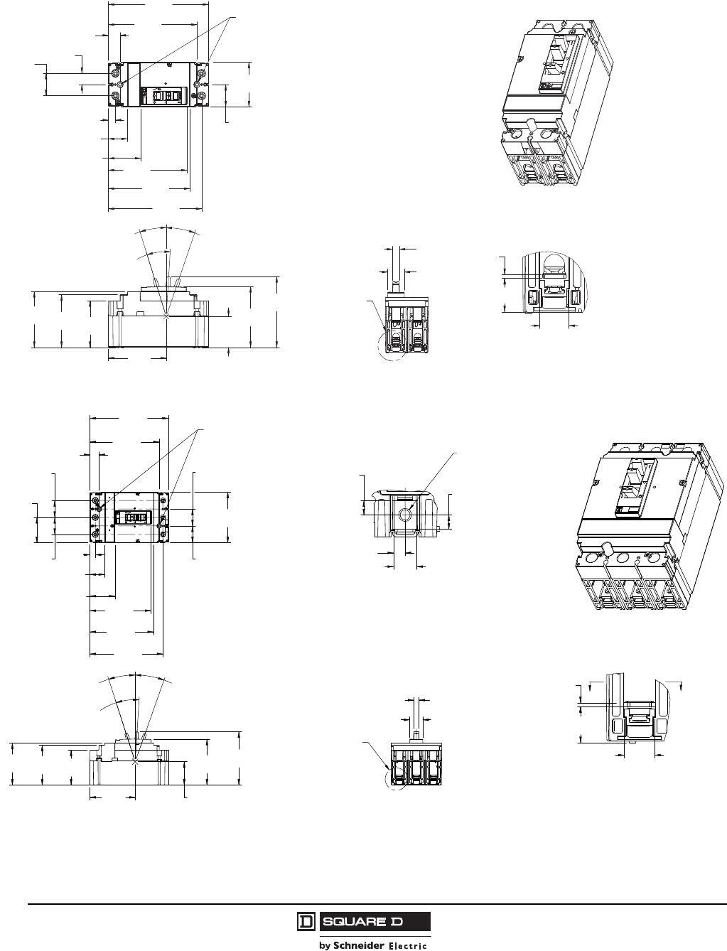
© 2004–2009 Schneider Electric
All Rights Reserved
PowerPact® H- and J-Frame Circuit Breakers
Section 5—Dimensions
48
05/2009
Figure 17: 15–150 A Unit Mount H-Frame 2P HD/HG Circuit Breaker
Figure 18: 15–150 A Bus Bar H-Frame 3P Circuit Breaker
1.37
34,8[]
5.20
132,0[]
5.66
143,8[]
6.40
162,6[]
.69
17,5[]
1.38
35,0[] 2.74
69,7[]
.44
11,3[]
.74
18,8[]
1.20
30,5[]
2.06
52,4[] 5.01
127,3[]
5.96
151,3[]
2.87
72,9[]
3.24
82,4[]
3.44
87,3[]
1.91
48,5[]
OFF
17.9°
TRIPPED
21.5°
ON
19.5°
3.74
95,1[]
4.36
110,8[]
3.69
93,8[]
1.06
27,0[]
.43
10,8[]
.62
15,9[]
.69
17,5[]
.08
2,0[]
Ø.20
[5,1]
MOUNTING HOLE
SEE DETAIL A
ISOMETRIC VIEW
SCALE 1:2
DETAIL A
SCALE 1:1
48996-016-01
Dimensions: in.
[mm]
B
B
Ø.20
[5,1]
(MOUNTING HOLE)
SEE DETAIL A
SCALE 1:2
DETAIL A
SCALE 1:1
SECTION B-B
SCALE 1:1
1.38
35,0[]
1.37
34,8[]
5.20
132,1[]
5.66
143,8[]
6.40
162,6[]
2.04
51,9[]
1.20
30,5[]
.74
18,8[]
.44
11,3[]
4.99
126,7[]
5.96
151,3[]
1.38
35,0[]
1.38
35,0[]
2.06
52,4[] 4.12
104,7[]
2.87
72,9[]
3.24
82,4[]
3.44
87,4[]
3.74
95,1[]
4.36
110,8[]
TRIPPED
21.5°
OFF
17.9°
ON
19.5°
1.91
48,5[]
3.69
93,8[]
.08
2,0[]
.62
15,9[]
.29
7,4[]
.47
12,0[]
.24
6,0[]
.29
7,4[]
.73
18,6[]
Ø
(1/4-20 TERMINAL NUT)
.26
6,7[]
.40
10,3[]
1.06
27,0[]
Dimensions: in.
[mm]
Courtesy of Steven Engineering, Inc.-230 Ryan Way, South San Francisco, CA 94080-6370-Main Office: (650) 588-9200-Outside Local Area: (800) 258-9200-www.stevenengineering.com
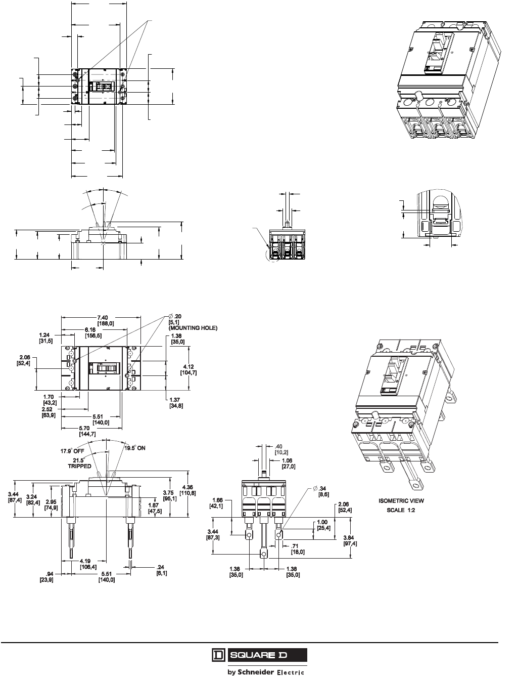
PowerPact® H- and J-Frame Circuit Breakers
Section 5—Dimensions
49
05/2009
© 2004–2009 Schneider Electric
All Rights Reserved
Figure 19: 15–150 A Lug-Lug H-Frame 3P Circuit Breaker
Figure 20: 15–150 A Rear Connected H-Frame 3P Circuit Breaker
Ø.20
[5,1]
(MOUNTING HOLE)
SEE DETAIL A
ISOMETRIC VIEW
SCALE 1:2
DETAIL A
SCALE 1:1
5.20
132,1[]
5.66
143,8[]
6.40
162,6[]
1.38
35,0[]
1.37
34,8[]
1.20
30,5[]
.74
18,8[]
.44
11,3[]
2.04
51,9[] 4.99
126,7[]
5.96
151,3[]
2.06
52,4[] 4.12
104,7[]
2.87
72,9[]
3.24
82,4[]
3.44
87,4[] 1.91
48,5[]
TRIPPED
21.5°
OFF
17.9°
ON
19.5°
3.69
93,8[]
3.74
95,1[]
4.36
110,8[]
1.06
27,0[]
.43
10,8[]
.62
15,9[]
.08
2,0[]
.73
18,6[]
1.38
35,0[]
1.38
35,0[]
48996-012-01
Dimensions: in.
[mm]
Courtesy of Steven Engineering, Inc.-230 Ryan Way, South San Francisco, CA 94080-6370-Main Office: (650) 588-9200-Outside Local Area: (800) 258-9200-www.stevenengineering.com
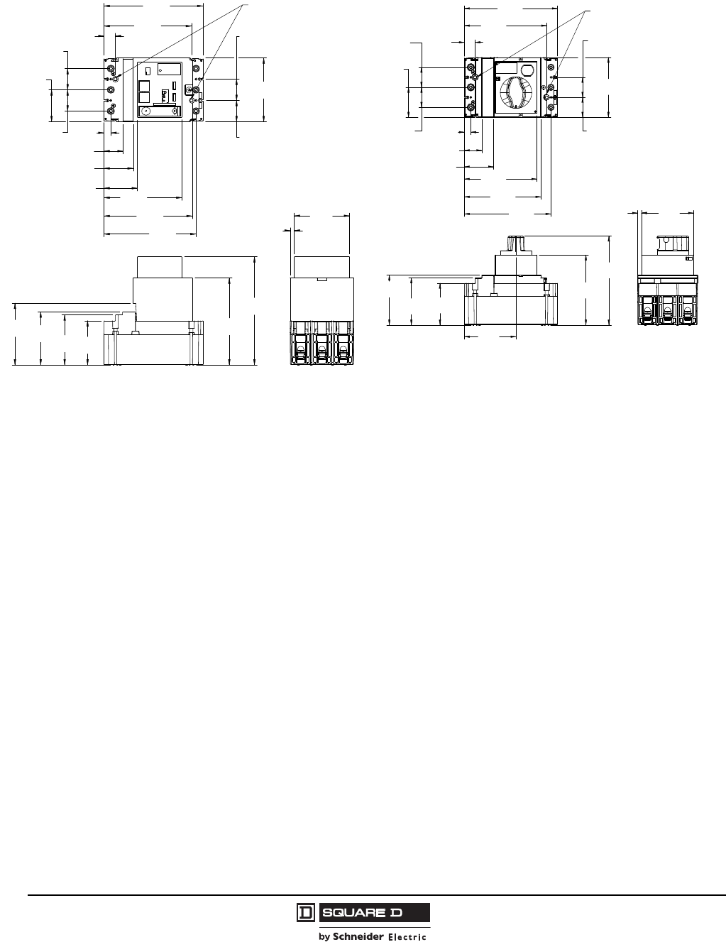
© 2004–2009 Schneider Electric
All Rights Reserved
PowerPact® H- and J-Frame Circuit Breakers
Section 5—Dimensions
50
05/2009
Figure 21: Motor Operator Detail (H-Frame) Figure 22: Rotary Handle Detail (H-Frame)
Ø .20
5,1[]
(MOUNTING HOLE)
6.40
162,6[]
5.66
143,8[]
.74
18,8[]
4.12
104,7[]
1.38
35,0[]
1.37
34,8[]
5.04
128,0[]
2.16
55,0[]
1.89
48,1[]
1.24
31,5[]
2.06
52,4[]
1.38
35,0[]
1.38
35,0[]
7.01
178,1[]
5.63
143,1[]
2.87
72,9[]
3.24
82,4[]
3.44
87,4[]
4.00
101,7[]
3.58
91,0[]
.27
6,8[]
.44
11,3[]
5.96
151,3[]
5.71
145,0[]
3.58
91,0[]
.27
[6,7]
4.82
122,4[]
6.12
155,4[]
2.87
72,9[]
3.24
82,4[]
3.44
87,4[]
3.54
[90,2]
6.40
[162,6]
.74
18,8[]
5.66
143,8[]
.44
[11,3]
1.20
30,5[]
2.02
[51,2] 5.00
[126,9]
5.27
[133,9]
5.96
[151,3]
1.37
34,8[]
1.38
[35,0]
4.12
[104,7]
1.38
[35,0]
1.38
[35,0]
2.06
[52,4]
Ø.20
[5,1]
(MOUNTING HOLE)
Dimensions: in.
[mm]
Courtesy of Steven Engineering, Inc.-230 Ryan Way, South San Francisco, CA 94080-6370-Main Office: (650) 588-9200-Outside Local Area: (800) 258-9200-www.stevenengineering.com
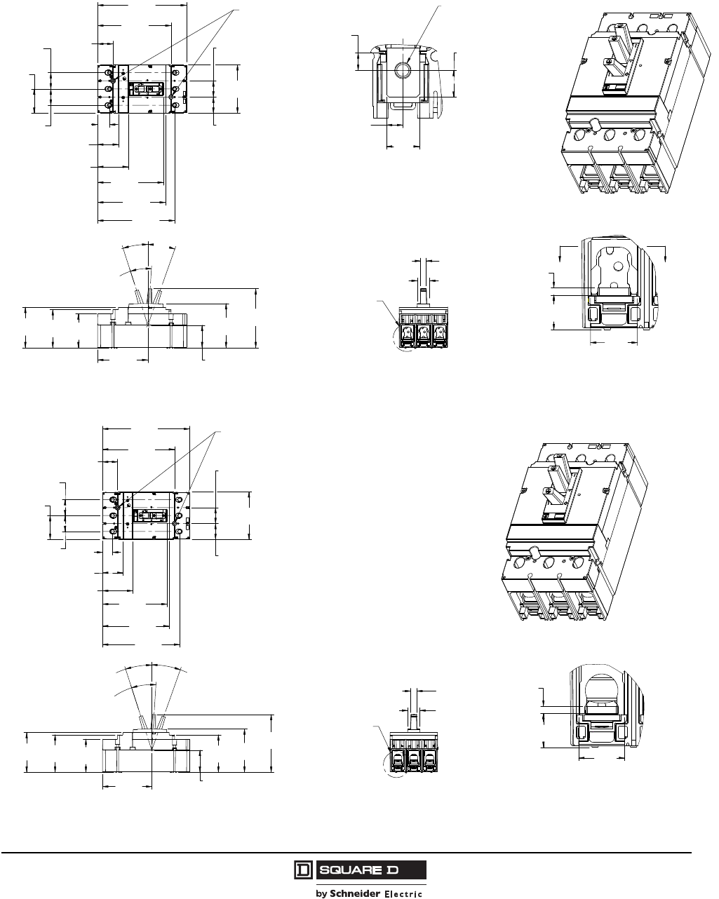
PowerPact® H- and J-Frame Circuit Breakers
Section 5—Dimensions
51
05/2009
© 2004–2009 Schneider Electric
All Rights Reserved
J-Frame Dimensional Drawings
Figure 23: 150–250 A Bus Bar J-Frame 3P Circuit Breaker
BB
Ø .20
[5,1]
(MOUNTING HOLE)
SEE DETAIL A
ISOMETRIC VIEW
SCALE 1:2
DETAIL A
SCALE 1:1
SECTION B-B
SCALE 1:1
1.37
34,8[]
1.38
35,0[]
1.00
25,5[]
1.30
33,0[]
1.76
44,7[]
2.60
66,1[] 5.57
141,5[]
6.52
165,5[]
5.74
145,8[]
6.22
158,0[]
7.52
191,0[]
1.38
35,0[]
1.38
35,0[]
2.06
52,4[] 4.12
104,7[]
3.24
82,4[]
3.44
87,4[]
ON
19.5°
TRIPPED
21.5°
1.91
48,5[]
3.74
95,1[]
5.00
127,0[]
.48
12,2[]
OFF
17.9°
4.25
108,0[]
.35
8,9[]
.70
17,7[]
.57
14,4[]
.16
4,0[]
.37
9,4[]
.73
18,6[]
Ø
(5/16-18 TERMINAL NUT)
.35
8,9[]
1.05
26,6[]
.99
25,2[]
2.87
72,9[]
48996-022-01
Dimensions: in.
[mm]
Figure 24: 150–250 A Lug-Lug J-Frame 3P Circuit Breaker
Ø .20
[5,1]
(MOUNTING HOLE)
SEE DETAIL A
ISOMETRIC VIEW
SCALE 1:2
DETAIL A
SCALE 1:1
1.30
33,0[]
2.60
66,1[] 5.57
141,5[]
1.37
34,8[]
1.38
35,0[]
5.74
145,8[]
6.22
158,0[]
7.52
191,0[]
1.38
35,0[]
1.38
35,0[]
2.06
52,4[] 4.12
104,7[]
2.87
72,9[]
3.24
82,4[]
3.44
87,4[]
4.25
108,0[]
1.91
48,5[]
3.24
82,4[]
3.74
95,1[]
5.00
127,0[]
TRIPPED
21.5°
OFF
17.9°
ON
19.5°
1.06
27,0[]
.53
13,4[]
.99
25,2[]
1.76
44,7[]
.16
4,0[]
.73
18,6[]
.86
21,9[]
6.66
169,2[]
48996-014-01
Dimensions: in.
[mm]
Courtesy of Steven Engineering, Inc.-230 Ryan Way, South San Francisco, CA 94080-6370-Main Office: (650) 588-9200-Outside Local Area: (800) 258-9200-www.stevenengineering.com
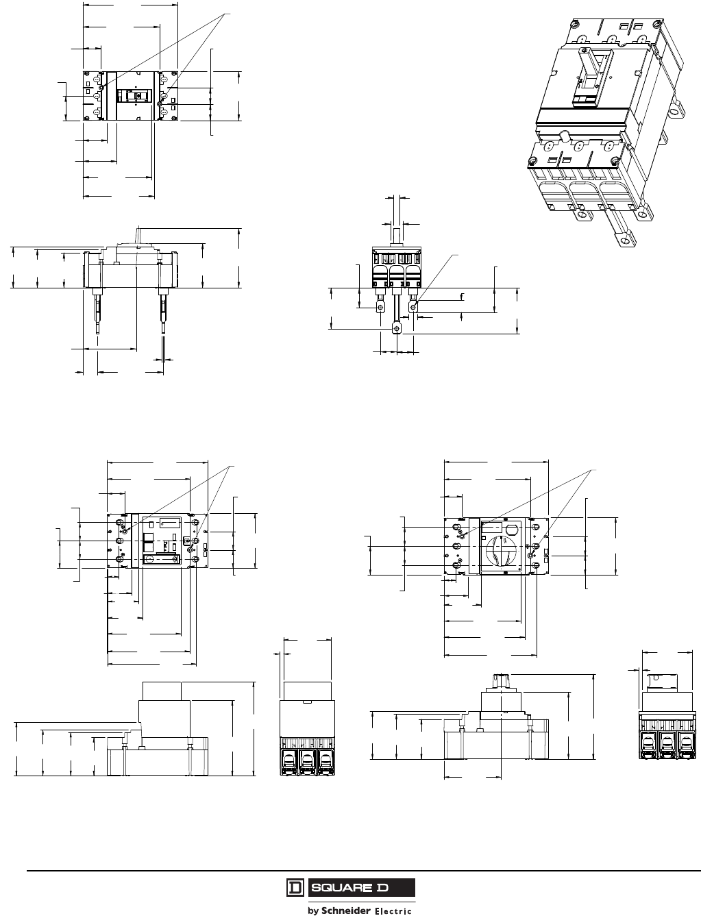
© 2004–2009 Schneider Electric
All Rights Reserved
PowerPact® H- and J-Frame Circuit Breakers
Section 5—Dimensions
52
05/2009
Figure 25: 150–250 A Rear Connected J-Frame 3P Circuit Breaker
Ø .20
5,1[]
(MOUNTING HOLE)
ISOMETRIC VIEW
SCALE 1:2
8.00
203,2[]
6.46
164,1[]
6.02
152,9[]
4.12
104,7[]
1.38
35,0[]
1.37
34,8[]
5.81
147,6[]
2.84
72,2[]
2.04
51,8[]
1.54
39,1[]
2.06
52,4[]
5.00
126,9[]
.24
6,0[]
5.51
[140,0]
1.24
31,6[]
3.24
82,4[]
3.44
87,4[]
4.49
114,2[]
.48
12,2[]
1.04
26,5[]
2.06
52,3[]
3.84
97,5[]
.71
18,0[]
1.00
25,3[]
1.66
42,1[]
3.44
87,3[]
1.38
35,0[]
1.38
35,0[]
Ø.34
8,6[]
2.95
74,9[]
3.74
[95,1]
48996-023-01
Dimensions: in.
[mm]
Figure 26: J-Frame Motor Operator Detail Figure 27: J-Frame Rotary Handle Detail
Ø .20
5,1[]
(MOUNTING HOLE)
7.52
191,0[]
5.50
139,8[]
2.63
66,8[]
4.12
104,7[]
1.38
35,0[]
1.37
34,8[]
1.30
33,0[]
1.80
45,7[] 2.36
59,9[]
6.22
158,0[]
2.06
52,4[]
1.38
35,0[]
1.38
35,0[]
2.87
72,9[]
3.24
82,4[]
3.44
87,4[]
4.01
101,7[]
5.63
143,1[]
7.01
178,1[]
3.58
91,0[]
.27
6,8[]
.86
22,0[]
6.65
169,0[]
6.17
156,7[]
Ø .20
5,1[]
(MOUNTING HOLE)
7.52
191,0[]
6.22
158,0[]
1.30
33,0[]
4.12
104,7[]
1.38
35,0[]
1.37
34,8[]
5.83
148,0[]
5.55
141,0[]
2.06
52,4[]
1.38
35,0[]
1.38
35,0[]
6.12
155,4[]
4.82
122,4[]
2.87
72,9[]
3.24
82,4[]
3.44
87,4[]
4.11
104,5[]
3.58
91,0[]
.27
6,7[]
6.66
169,0[]
.86
21,8[]
1.76
44,7[] 2.68
68,1[]
Dimensions: in.
[mm]
Courtesy of Steven Engineering, Inc.-230 Ryan Way, South San Francisco, CA 94080-6370-Main Office: (650) 588-9200-Outside Local Area: (800) 258-9200-www.stevenengineering.com
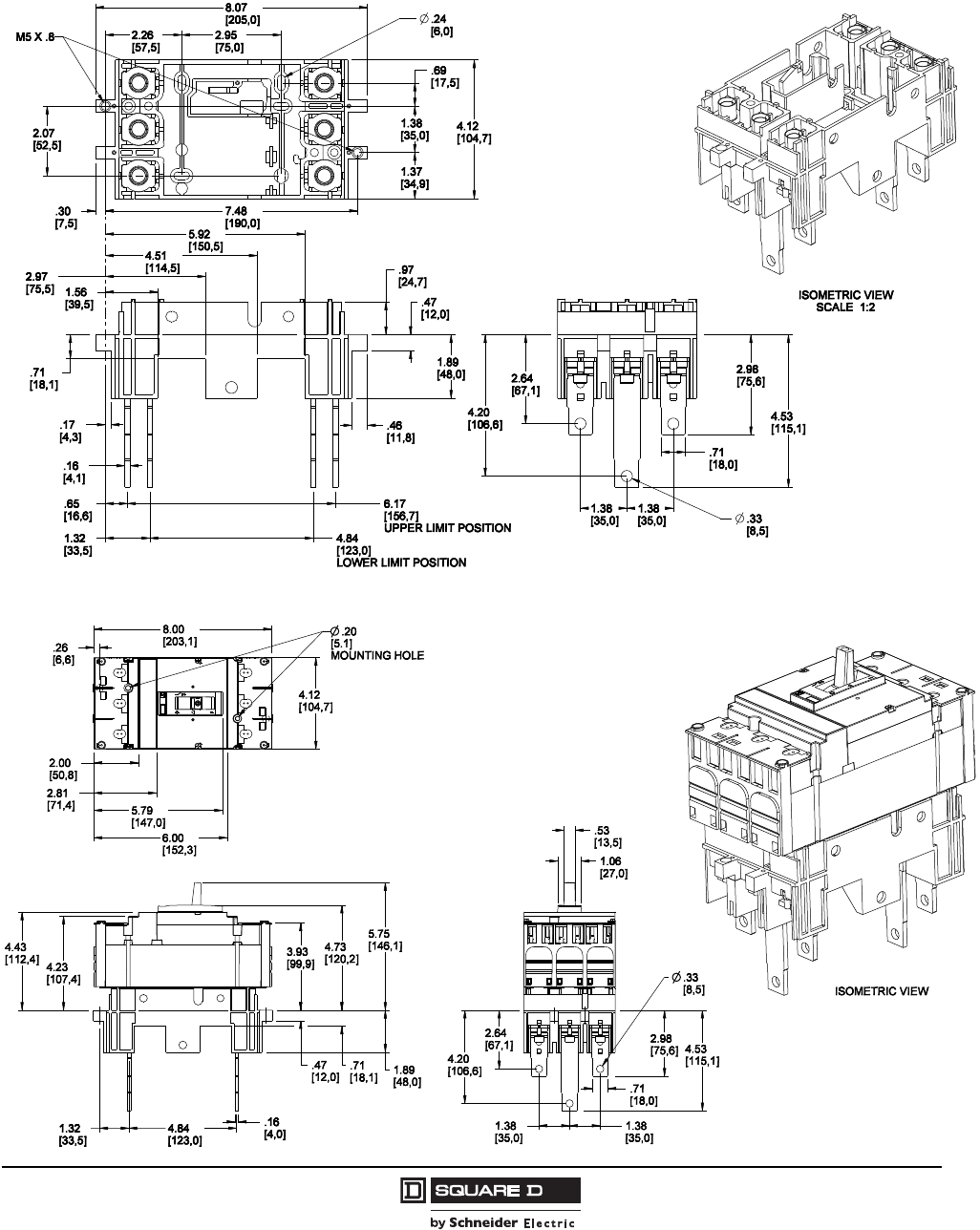
PowerPact® H- and J-Frame Circuit Breakers
Section 5—Dimensions
53
05/2009
© 2004–2009 Schneider Electric
All Rights Reserved
Plug-In H- and J-Frame Dimensional Drawings
Figure 28: 15–250 A H- and J-Frame Plug-In Base 3P Circuit Breaker
48996-045-01
Dimensions: in.
[mm]
Figure 29: 15–250 A H- and J-Frame Plug-In Circuit Breaker 3P Circuit Breaker
48996-024-01
Dimensions: in.
[mm]
Courtesy of Steven Engineering, Inc.-230 Ryan Way, South San Francisco, CA 94080-6370-Main Office: (650) 588-9200-Outside Local Area: (800) 258-9200-www.stevenengineering.com
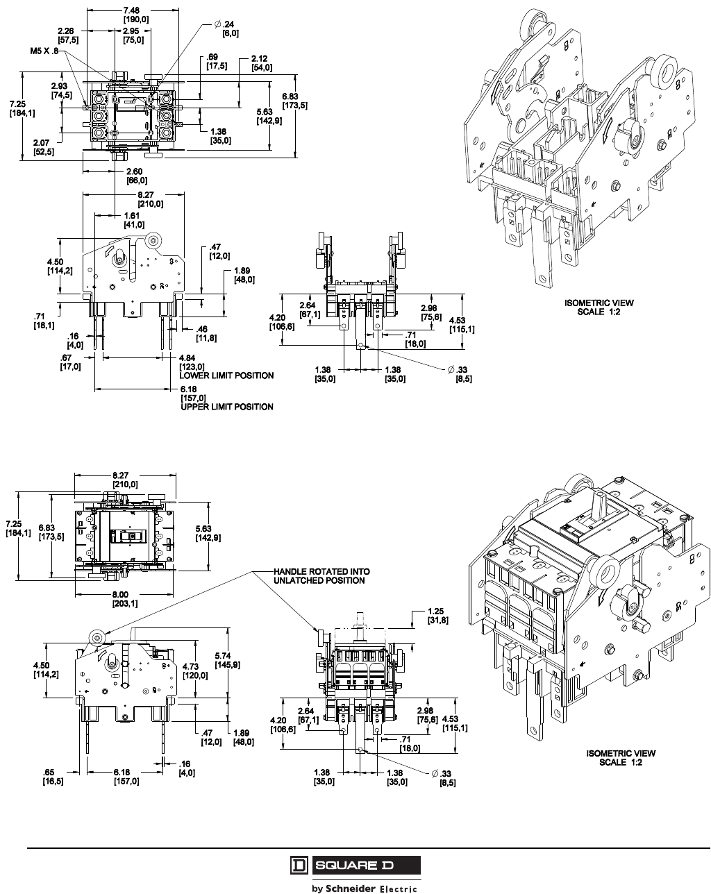
© 2004–2009 Schneider Electric
All Rights Reserved
PowerPact® H- and J-Frame Circuit Breakers
Section 5—Dimensions
54
05/2009
Drawout H- and J-Frame Dimensional Drawings
Figure 30: 15–250 A H and J-Frame Cradle 3P Circuit Breaker
48996-046-01
Dimensions: in.
[mm]
Figure 31: 15–250 A H- and J-Frame Drawout Circuit Breaker 3P Circuit Breaker
48996-025-01
Dimensions: in.
[mm]
Courtesy of Steven Engineering, Inc.-230 Ryan Way, South San Francisco, CA 94080-6370-Main Office: (650) 588-9200-Outside Local Area: (800) 258-9200-www.stevenengineering.com
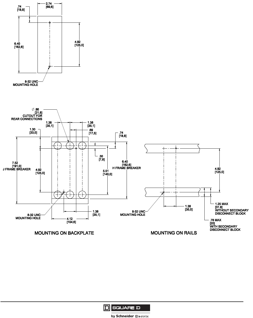
PowerPact® H- and J-Frame Circuit Breakers
Section 5—Dimensions
55
05/2009
© 2004–2009 Schneider Electric
All Rights Reserved
Mounting Dimensional Drawings
Figure 32: H-Frame 2P (HD and HG) Circuit Breaker
Dimensions: in.
[mm]
Figure 33: H and J-Frame 3P Circuit Breaker
Dimensions: in.
[mm]
Courtesy of Steven Engineering, Inc.-230 Ryan Way, South San Francisco, CA 94080-6370-Main Office: (650) 588-9200-Outside Local Area: (800) 258-9200-www.stevenengineering.com
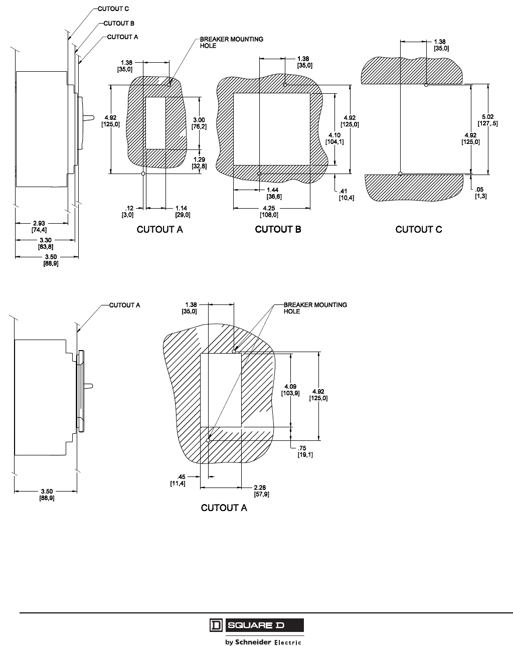
© 2004–2009 Schneider Electric
All Rights Reserved
PowerPact® H- and J-Frame Circuit Breakers
Section 5—Dimensions
56
05/2009
H- and J-Frame Door Cutout Dimensional Drawings
Figure 34: H and J-Frame Circuit Breaker Toggle Handle Door Cutout
Dimensions: in.
[mm]
Figure 35: H and J-Frame Circuit Breaker Toggle Handle With Escutcheon Door Cutout
Dimensions: in.
[mm]
Courtesy of Steven Engineering, Inc.-230 Ryan Way, South San Francisco, CA 94080-6370-Main Office: (650) 588-9200-Outside Local Area: (800) 258-9200-www.stevenengineering.com
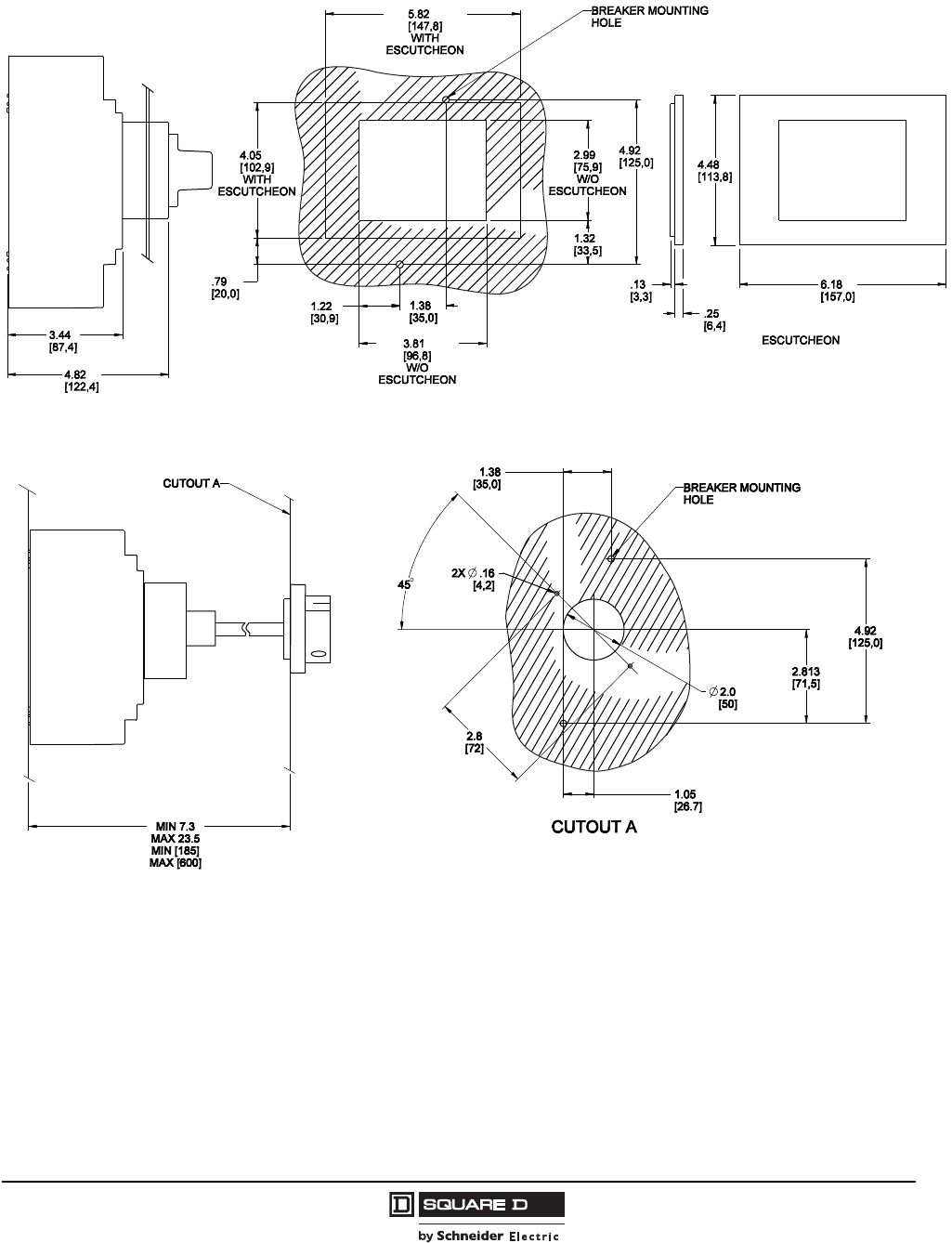
PowerPact® H- and J-Frame Circuit Breakers
Section 5—Dimensions
57
05/2009
© 2004–2009 Schneider Electric
All Rights Reserved
Figure 36: H and J-Frame Circuit Breaker Fixed Rotary Handle Cutout
Dimensions: in.
[mm]
Figure 37: H and J-Frame Circuit Breaker Door Mounted Rotary Handle Cutout
Dimensions: in.
[mm]
Courtesy of Steven Engineering, Inc.-230 Ryan Way, South San Francisco, CA 94080-6370-Main Office: (650) 588-9200-Outside Local Area: (800) 258-9200-www.stevenengineering.com
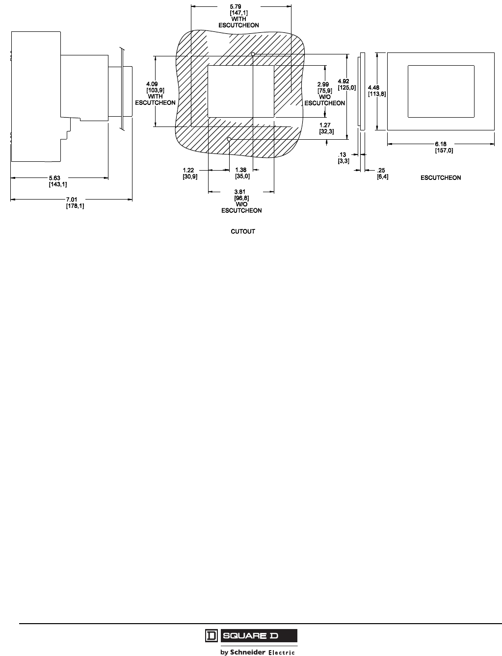
© 2004–2009 Schneider Electric
All Rights Reserved
PowerPact® H- and J-Frame Circuit Breakers
Section 5—Dimensions
58
05/2009
Figure 38: H and J-Frame Circuit Breaker Motor Operator Cutout
Dimensions: in.
[mm]
Courtesy of Steven Engineering, Inc.-230 Ryan Way, South San Francisco, CA 94080-6370-Main Office: (650) 588-9200-Outside Local Area: (800) 258-9200-www.stevenengineering.com
PowerPact® H- and J-Frame Circuit Breakers
Section 6—Trip Curves
59
05/2009
© 2004–2009 Schneider Electric
All Rights Reserved
Section 6—Trip Curves
Figure 39: 15-35 A — HD, HG, HJ and HL
1.5
700
150
200
300
400
600
800
900
2000
3000
4000
5000
7000
8000
9000
10000
.5
.6
.7
.8
.9
1
2
3
4
5
6
7
8
9
10
15
20
30
40
50
60
70
80
90
100
6000
1500
1000
500
.005
.006
.007
.008
.009
.01
.015
.02
.03
.04
.05
.06
.07
.08
.09
.1
.15
.2
.3
.4
.5
.6
.7
.8
.9
1
1.5
2
3
4
5
6
7
8
9
10
20
30
40
50
60
70
80
90
100
15
200
300
400
500
600
700
800
900
1000
1500
2000
3000
4000
6000
7000
8000
9000
5000
10000
1
.5
.6
.7
.8
.9
1.5
2
3
4
5
6
7
8
9
10
15
20
30
40
50
60
70
80
90
100
MULTIPLES OF RATED CURRENT
TIME IN SECONDS
.005
.006
.007
.008
.009
.01
.015
.02
.03
.04
.05
.06
.07
.08
.09
.1
.15
.2
.3
.4
.5
.6
.7
.8
.9
1
1.5
2
3
4
5
6
7
8
9
10
15
20
30
40
50
60
70
80
90
100
150
200
300
400
500
600
700
800
900
1000
1500
2000
3000
4000
5000
6000
7000
8000
9000
10000
TIME IN SECONDS
1
/
2
CYCLE
(60 Hz)
1
/
2
CYCLE
(50 Hz)
150
200
300
400
500
600
700
800
900
1000
1500
2000
3000
4000
5000
6000
7000
8000
9000
10000
150
MULTIPLES OF RATED CURRENT
1 CYCLE
(60 Hz)
1 CYCLE
(50 Hz)
MAXIMUM SINGLE-POLE TRIP TIMES
AT 25°C BASED ON NEMA AB-4 2003
25 A
30 A, 35 A
20 A
15 A
MAXIMUM CLEARING TIME
(AT 50 Hz) (AT 60 Hz)
2535
2030
15
HD, HG, HJ, HL MOLDED CASE CIRCUIT BREAKERS
CHARACTERISTIC TRIP CURVE NO. 50-1
CIRCUIT BREAKER INFORMATION
Circuit Breaker Continuous Maximum Number
Prefix Ampere Rating AC Voltage of Poles
HD, HG, HJ, HL 15–35 600 2, 3
This curve is to be used for application and coordination purposes only. The
EZ-AMP overlay feature at the bottom of the page should be used during
coordination studies.
All time/current characteristic curve data is based on 40°C ambient cold start.
Terminations are made with conductors of appropriate length and ratings.
Curve No. 0050TC0401
June 2004
Drawing No. 48095-050-01
TM
© 2004 Schneider Electric All Rights Reserved
Courtesy of Steven Engineering, Inc.-230 Ryan Way, South San Francisco, CA 94080-6370-Main Office: (650) 588-9200-Outside Local Area: (800) 258-9200-www.stevenengineering.com
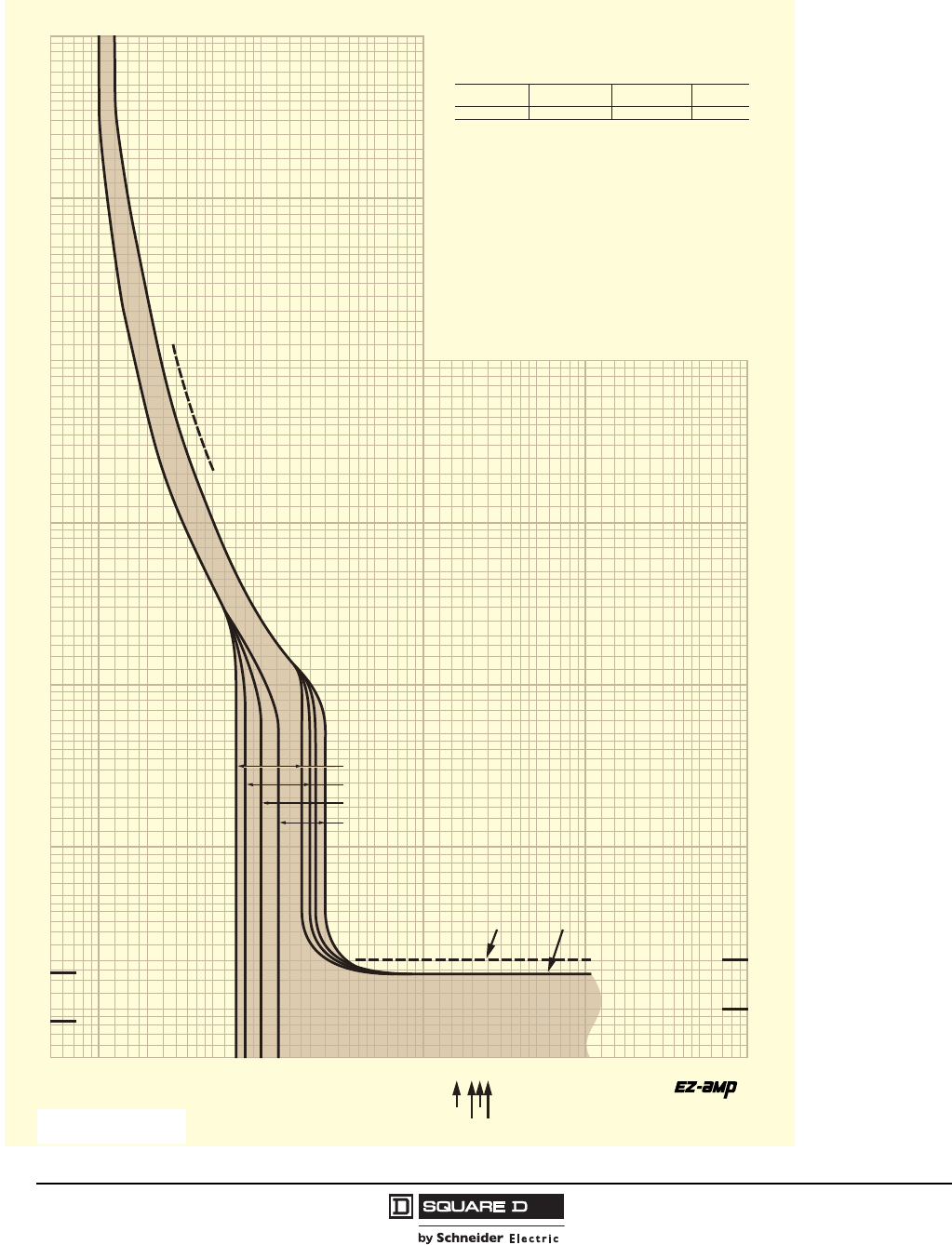
© 2004–2009 Schneider Electric
All Rights Reserved
PowerPact® H- and J-Frame Circuit Breakers
Section 6—Trip Curves
60
05/2009
Figure 40: 40-60 A — HD, HG, HJ and HL
1.5
700
150
200
300
400
600
800
900
2000
3000
4000
5000
7000
8000
9000
10000
.5
.6
.7
.8
.9
1
2
3
4
5
6
7
8
9
10
15
20
30
40
50
60
70
80
90
100
6000
1500
1000
500
.005
.006
.007
.008
.009
.01
.015
.02
.03
.04
.05
.06
.07
.08
.09
.1
.15
.2
.3
.4
.5
.6
.7
.8
.9
1
1.5
2
3
4
5
6
7
8
9
10
20
30
40
50
60
70
80
90
100
15
200
300
400
500
600
700
800
900
1000
1500
2000
3000
4000
6000
7000
8000
9000
5000
10000
1
.5
.6
.7
.8
.9
1.5
2
3
4
5
6
7
8
9
10
15
20
30
40
50
60
70
80
90
100
MULTIPLES OF RATED CURRENT
TIME IN SECONDS
.005
.006
.007
.008
.009
.01
.015
.02
.03
.04
.05
.06
.07
.08
.09
.1
.15
.2
.3
.4
.5
.6
.7
.8
.9
1
1.5
2
3
4
5
6
7
8
9
10
15
20
30
40
50
60
70
80
90
100
150
200
300
400
500
600
700
800
900
1000
1500
2000
3000
4000
5000
6000
7000
8000
9000
10000
TIME IN SECONDS
1/2 CYCLE
(60 Hz)
1/2 CYCLE
(50 Hz)
150
200
300
400
500
600
700
800
900
1000
1500
2000
3000
4000
5000
6000
7000
8000
9000
10000
150
MULTIPLES OF RATED CURRENT
1 CYCLE
(60 Hz)
1 CYCLE
(50 Hz)
MAXIMUM SINGLE-POLE TRIP TIMES
AT 25°C BASED ON NEMA AB-4 2003
45 A
50 A
40 A
60 A
MAXIMUM CLEARING TIME
(AT 50 Hz) (AT 60 Hz)
40
60 45
50
HD, HG, HJ, HL MOLDED CASE CIRCUIT BREAKERS
CHARACTERISTIC TRIP CURVE NO. 50-2
CIRCUIT BREAKER INFORMATION
Circuit Breaker Continuous Maximum Number
Prefix Ampere Rating AC Voltage of Poles
HD, HG, HJ, HL 40–60 600 2, 3
This curve is to be used for application and coordination purposes only. The
EZ-AMP overlay feature at the bottom of the page should be used during
coordination studies.
All time/current characteristic curve data is based on 40°C ambient cold start.
Terminations are made with conductors of appropriate length and ratings.
Curve No. 0050TC0402
June 2004
Drawing No. 48095-050-02
TM
© 2004 Schneider Electric All Rights Reserved
Courtesy of Steven Engineering, Inc.-230 Ryan Way, South San Francisco, CA 94080-6370-Main Office: (650) 588-9200-Outside Local Area: (800) 258-9200-www.stevenengineering.com
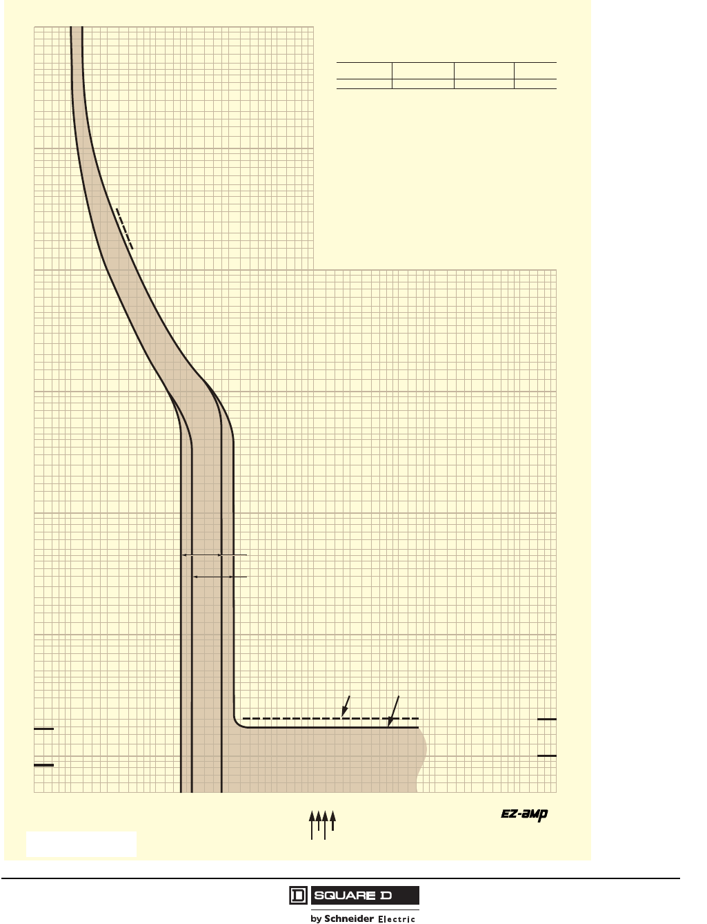
PowerPact® H- and J-Frame Circuit Breakers
Section 6—Trip Curves
61
05/2009
© 2004–2009 Schneider Electric
All Rights Reserved
Figure 41: 70-100 A — HD, HG, HJ, and HL
1.5
700
150
200
300
400
600
800
900
2000
3000
4000
5000
7000
8000
9000
10000
.5
.6
.7
.8
.9
1
2
3
4
5
6
7
8
9
10
15
20
30
40
50
60
70
80
90
100
6000
1500
1000
500
.005
.006
.007
.008
.009
.01
.015
.02
.03
.04
.05
.06
.07
.08
.09
.1
.15
.2
.3
.4
.5
.6
.7
.8
.9
1
1.5
2
3
4
5
6
7
8
9
10
20
30
40
50
60
70
80
90
100
15
200
300
400
500
600
700
800
900
1000
1500
2000
3000
4000
6000
7000
8000
9000
5000
10000
1
.5
.6
.7
.8
.9
1.5
2
3
4
5
6
7
8
9
10
15
20
30
40
50
60
70
80
90
100
MULTIPLES OF RATED CURRENT
TIME IN SECONDS
.005
.006
.007
.008
.009
.01
.015
.02
.03
.04
.05
.06
.07
.08
.09
.1
.15
.2
.3
.4
.5
.6
.7
.8
.9
1
1.5
2
3
4
5
6
7
8
9
10
15
20
30
40
50
60
70
80
90
100
150
200
300
400
500
600
700
800
900
1000
1500
2000
3000
4000
5000
6000
7000
8000
9000
10000
TIME IN SECONDS
1/2 CYCLE
(60 Hz)
1/2 CYCLE
(50 Hz)
150
200
300
400
500
600
700
800
900
1000
1500
2000
3000
4000
5000
6000
7000
8000
9000
10000
150
MULTIPLES OF RATED CURRENT
1 CYCLE
(60 Hz)
1 CYCLE
(50 Hz)
MAXIMUM CLEARING TIME
(AT 50 Hz) (AT 60 Hz)
70
80100
90
MAXIMUM SINGLE-POLE TRIP TIMES
AT 25°C BASED ON NEMA AB-4 2003
90 A, 100 A
70 A, 80 A
HD, HG, HJ, HL MOLDED CASE CIRCUIT BREAKERS
CHARACTERISTIC TRIP CURVE NO. 50-3
CIRCUIT BREAKER INFORMATION
Circuit Breaker Continuous Maximum Number
Prefix Ampere Rating AC Voltage of Poles
HD, HG, HJ, HL 70–100 600 2, 3
This curve is to be used for application and coordination purposes only. The
EZ-AMP overlay feature at the bottom of the page should be used during
coordination studies.
All time/current characteristic curve data is based on 40°C ambient cold start.
Terminations are made with conductors of appropriate length and ratings.
Curve No. 0050TC0403
June 2004
Drawing No. 48095-050-03
TM
© 2004 Schneider Electric All Rights Reserved
Courtesy of Steven Engineering, Inc.-230 Ryan Way, South San Francisco, CA 94080-6370-Main Office: (650) 588-9200-Outside Local Area: (800) 258-9200-www.stevenengineering.com
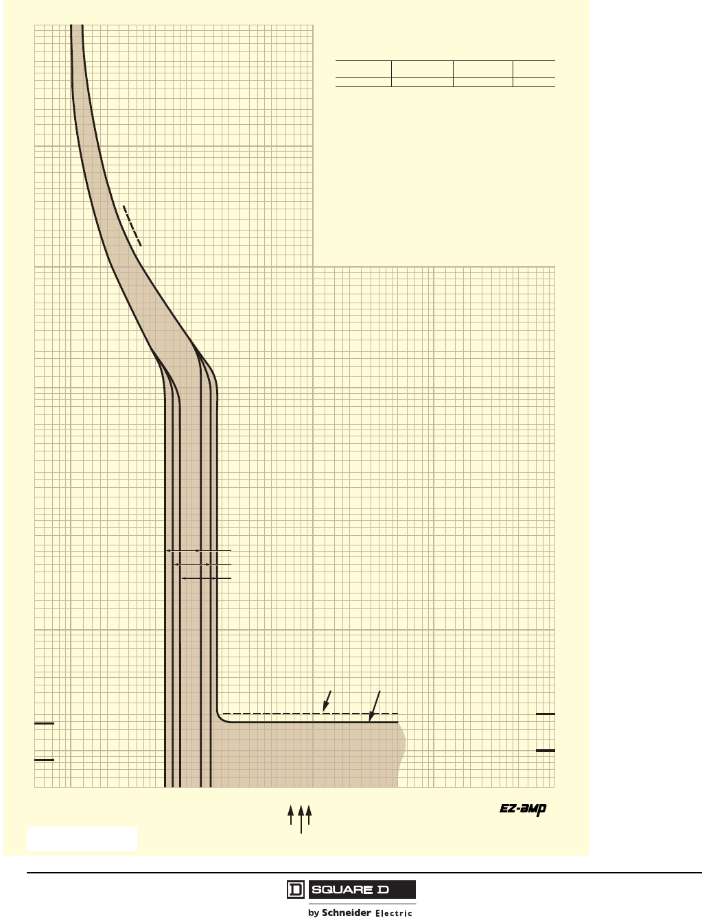
© 2004–2009 Schneider Electric
All Rights Reserved
PowerPact® H- and J-Frame Circuit Breakers
Section 6—Trip Curves
62
05/2009
Figure 42: 110-150 A — HD, HG, HJ, and HL
1.5
700
150
200
300
400
600
800
900
2000
3000
4000
5000
7000
8000
9000
10000
.5
.6
.7
.8
.9
1
2
3
4
5
6
7
8
9
10
15
20
30
40
50
60
70
80
90
100
6000
1500
1000
500
.005
.006
.007
.008
.009
.01
.015
.02
.03
.04
.05
.06
.07
.08
.09
.1
.15
.2
.3
.4
.5
.6
.7
.8
.9
1
1.5
2
3
4
5
6
7
8
9
10
20
30
40
50
60
70
80
90
100
15
200
300
400
500
600
700
800
900
1000
1500
2000
3000
4000
6000
7000
8000
9000
5000
10000
1
.5
.6
.7
.8
.9
1.5
2
3
4
5
6
7
8
9
10
15
20
30
40
50
60
70
80
90
100
MULTIPLES OF RATED CURRENT
TIME IN SECONDS
.005
.006
.007
.008
.009
.01
.015
.02
.03
.04
.05
.06
.07
.08
.09
.1
.15
.2
.3
.4
.5
.6
.7
.8
.9
1
1.5
2
3
4
5
6
7
8
9
10
15
20
30
40
50
60
70
80
90
100
150
200
300
400
500
600
700
800
900
1000
1500
2000
3000
4000
5000
6000
7000
8000
9000
10000
TIME IN SECONDS
1/2 CYCLE
(60 Hz)
1/2 CYCLE
(50 Hz)
150
200
300
400
500
600
700
800
900
1000
1500
2000
3000
4000
5000
6000
7000
8000
9000
10000
150
MULTIPLES OF RATED CURRENT
1 CYCLE
(60 Hz)
1 CYCLE
(50 Hz)
MAXIMUM CLEARING TIME
(AT 50 Hz) (AT 60 Hz)
110
125
150
MAXIMUM SINGLE-POLE TRIP TIMES
AT 25°C BASED ON NEMA AB-4 2003
150 A
125 A
110 A
HD, HG, HJ, HL MOLDED CASE CIRCUIT BREAKERS
CHARACTERISTIC TRIP CURVE NO. 50-4
CIRCUIT BREAKER INFORMATION
Circuit Breaker Continuous Maximum Number
Prefix Ampere Rating AC Voltage of Poles
HD, HG, HJ, HL 110–150 600 2, 3
This curve is to be used for application and coordination purposes only. The
EZ-AMP overlay feature at the bottom of the page should be used during
coordination studies.
All time/current characteristic curve data is based on 40°C ambient cold start.
Terminations are made with conductors of appropriate length and ratings.
Curve No. 0050TC0404
June 2004
Drawing No. 48095-050-04
TM
© 2004 Schneider Electric All Rights Reserved
Courtesy of Steven Engineering, Inc.-230 Ryan Way, South San Francisco, CA 94080-6370-Main Office: (650) 588-9200-Outside Local Area: (800) 258-9200-www.stevenengineering.com
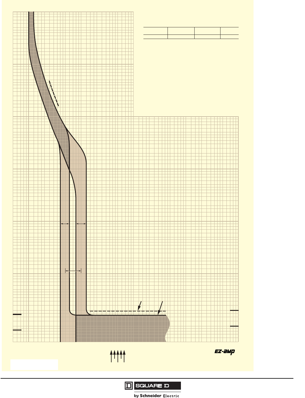
PowerPact® H- and J-Frame Circuit Breakers
Section 6—Trip Curves
63
05/2009
© 2004–2009 Schneider Electric
All Rights Reserved
Figure 43: 150-250 A — JD, JG, JJ, and JL
1.5
700
150
200
300
400
600
800
900
2000
3000
4000
5000
7000
8000
9000
10000
.5
.6
.7
.8
.9
1
2
3
4
5
6
7
8
9
10
15
20
30
40
50
60
70
80
90
100
6000
1500
1000
500
.005
.006
.007
.008
.009
.01
.015
.02
.03
.04
.05
.06
.07
.08
.09
.1
.15
.2
.3
.4
.5
.6
.7
.8
.9
1
1.5
2
3
4
5
6
7
8
9
10
20
30
40
50
60
70
80
90
100
15
200
300
400
500
600
700
800
900
1000
1500
2000
3000
4000
6000
7000
8000
9000
5000
10000
1
.5
.6
.7
.8
.9
1.5
2
3
4
5
6
7
8
9
10
15
20
30
40
50
60
70
80
90
100
MULTIPLES OF RATED CURRENT
TIME IN SECONDS
.005
.006
.007
.008
.009
.01
.015
.02
.03
.04
.05
.06
.07
.08
.09
.1
.15
.2
.3
.4
.5
.6
.7
.8
.9
1
1.5
2
3
4
5
6
7
8
9
10
15
20
30
40
50
60
70
80
90
100
150
200
300
400
500
600
700
800
900
1000
1500
2000
3000
4000
5000
6000
7000
8000
9000
10000
TIME IN SECONDS
1/2 CYCLE
(60 Hz)
1/2 CYCLE
(50 Hz)
150
200
300
400
500
600
700
800
900
1000
1500
2000
3000
4000
5000
6000
7000
8000
9000
10000
150
MULTIPLES OF RATED CURRENT
1 CYCLE
(60 Hz)
1 CYCLE
(50 Hz)
LIMITS HIGH
SETTING
LIMITS LOW
SETTING
MAGNETIC TRIP
ADJUSTMENT RANGE
MAXIMUM CLEARING TIME
(AT 50 Hz) (AT 60 Hz)
225
200
150
250
175
MAXIMUM SINGLE-POLE TRIP TIMES
AT 25°C BASED ON NEMA AB-4 2003
JD, JG, JJ, JL MOLDED CASE CIRCUIT BREAKERS
CHARACTERISTIC TRIP CURVE NO. 50-5
CIRCUIT BREAKER INFORMATION
Circuit Breaker Continuous Maximum Number
Prefix Ampere Rating AC Voltage of Poles
JD, JG, JJ, JL 150–250 600 2, 3
This curve is to be used for application and coordination purposes only. The
EZ-AMP overlay feature at the bottom of the page should be used during
coordination studies.
All time/current characteristic curve data is based on 40°C ambient cold start.
Terminations are made with conductors of appropriate length and ratings.
Curve No. 0050TC0405
June 2004
Drawing No. 48095-050-05
TM
© 2004 Schneider Electric All Rights Reserved
Courtesy of Steven Engineering, Inc.-230 Ryan Way, South San Francisco, CA 94080-6370-Main Office: (650) 588-9200-Outside Local Area: (800) 258-9200-www.stevenengineering.com
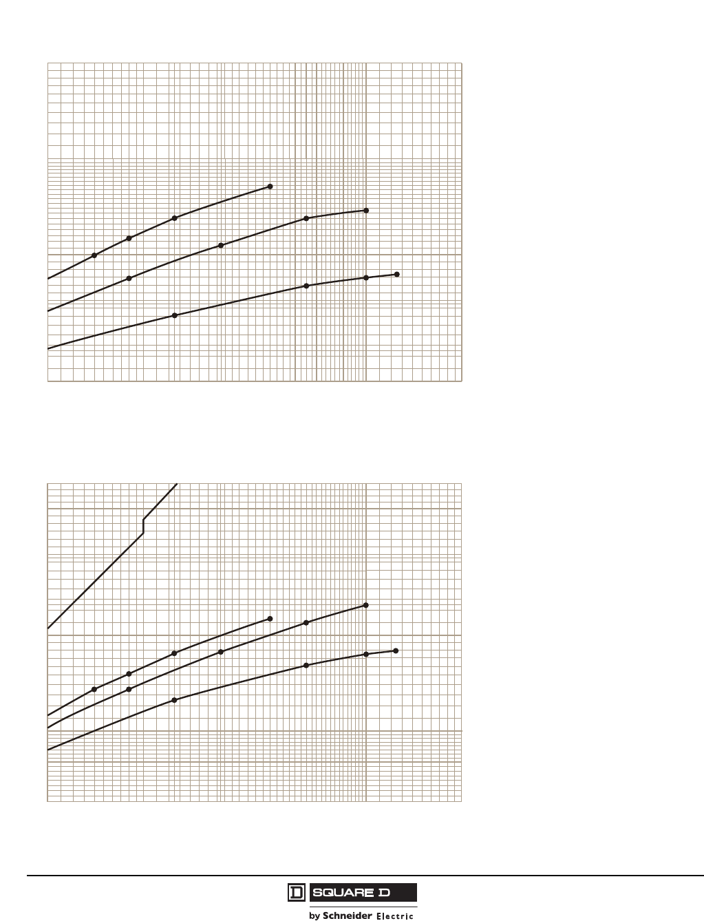
© 2004–2009 Schneider Electric
All Rights Reserved
PowerPact® H- and J-Frame Circuit Breakers
Section 6—Trip Curves
64
05/2009
Figure 44: H-Frame 150 A (HD, HG, HJ, and HL)
20 30 40 50 60 70 80 9010
.2
.3
.4
.5
.6
.7
.8
.9
200100
2
1
Available Short Circuit Current (RMS Symmetrical Amperes x 103)
Curve No. 50-6
Typical* Let-Through I2t (Amperes2 Seconds x 106)
*Based on typical values obtained throughout the circuit breaker development and UL test programs.
I2t
20 30 40 50 60 70 80 9010
6
7
8
9
10
200100
20
30
40
50
60
Available Short Circuit Current (RMS Symmetrical Amperes x 103)
Typical* Peak Let-Through Current (Amperes x 103)
Curve No. 50-7
*Based on typical values obtained throughout the circuit breaker development and UL test programs.
Ip
240 V
J
D
D
D
G
G
G
J
J
L
D
240 V
D
D
G
G
G
J
J
JL
480 V
L
600 V
L
480 V
L
600 V
L
Maximum
Available
Peak Current
at 25% Power Factor
Maximum
Available
Peak Current
at 15% Power Factor
Curve No. 50-6 Let-Through I
2
t
and 50-7 Peak Let-Through Current I
p
Courtesy of Steven Engineering, Inc.-230 Ryan Way, South San Francisco, CA 94080-6370-Main Office: (650) 588-9200-Outside Local Area: (800) 258-9200-www.stevenengineering.com
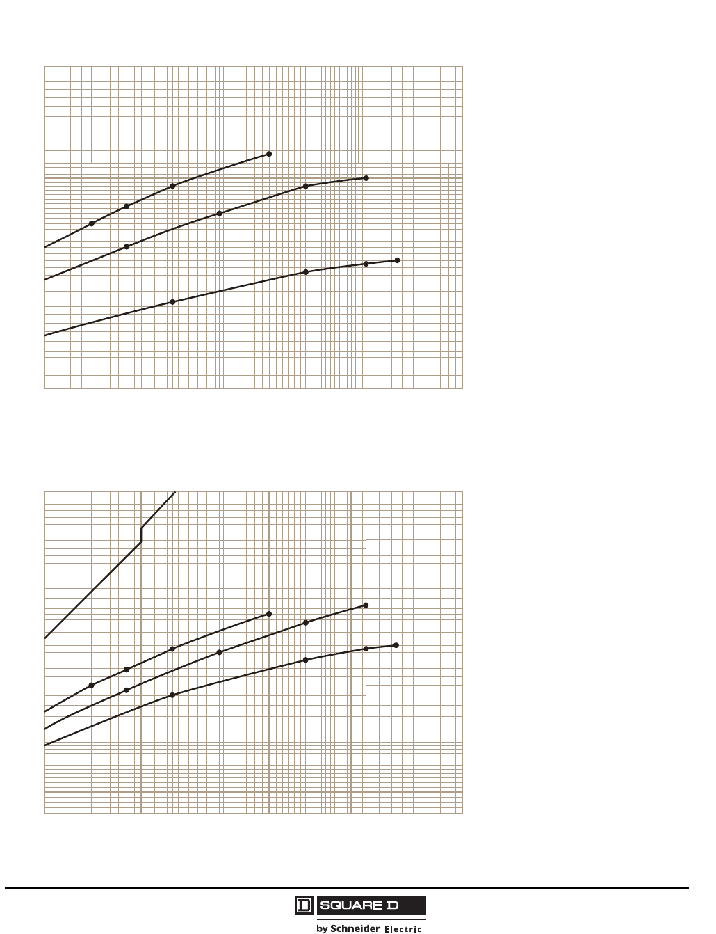
PowerPact® H- and J-Frame Circuit Breakers
Section 6—Trip Curves
65
05/2009
© 2004–2009 Schneider Electric
All Rights Reserved
Figure 45: J-Frame 250 A (JD, JG, JJ, and JL)
20 30 40 50 60 70 80 9010
.2
.3
.4
.5
.6
.7
.8
.9
200100
2
1
Available Short Circuit Current (RMS Symmetrical Amperes x 103)
Curve No. 50-8
Typical* Let-Through I2t (Amperes2 Seconds x 106)
*Based on typical values obtained throughout the circuit breaker development and UL test programs.
I2t
20 30 40 50 60 70 80 9010
6
7
8
9
10
200100
20
30
40
50
60
Available Short Circuit Current (RMS Symmetrical Amperes x 103)
Typical* Peak Let-Through Current (Amperes x 103)
Curve No. 50-9
*Based on typical values obtained throughout the circuit breaker development and UL test programs.
Ip
D
240 V
Maximum
Available
Peak Current
at 25% Power Factor
Maximum
Available
Peak Current
at 15% Power Factor
J
D
D
G
G
G
J
J
L
D
240 V
D
D
G
G
G
J
J
JL
480 V
L
600 V
L
480 V
L
600 V
L
Curve No. 50-8 Let-Through I
2
t
and 50-9 Peak Let-Through Current I
p
Courtesy of Steven Engineering, Inc.-230 Ryan Way, South San Francisco, CA 94080-6370-Main Office: (650) 588-9200-Outside Local Area: (800) 258-9200-www.stevenengineering.com
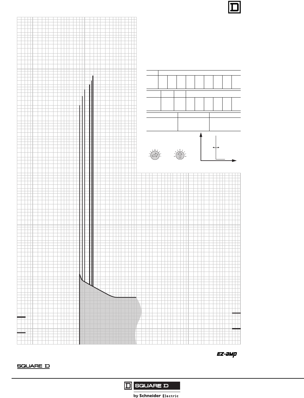
© 2004–2009 Schneider Electric
All Rights Reserved
PowerPact® H- and J-Frame Circuit Breakers
Section 6—Trip Curves
66
05/2009
Figure 46: H- and J-Frame Motor Circuit Protector
POWERPACT H/J FRAME MOTOR CIRCUIT PROTECTOR
WITH MANUAL SETTINGS
CHARACTERISTIC TRIP CURVE NO. 045-1
The time-current curve information represents the typical response and is to
be used for application and coordination purposes only.
Curves apply from -30C to +60C ambient temperature.
Notes:
• The MCP is an instantaneous only breaker that detects the peaks of the
current. In order to trip within the specified time-current levels, consecutive
peaks of the current must exceed the selected setting’s threshold.
• Total clearing times shown include the response times of the trip unit, the
circuit breaker opening, and the extinction of the current.
• The time-current curve represents single-phase to three-phase fault currents.
MOTOR CIRCUIT PROTECTOR INFORMATION
Suffix # FLA Adjustments
M71 1.5 3 6 8 11 14 17 20 25
M72 14 17 21 24 27 29 32 36 42
M73 30 35 41 46 51 56 63 71 80
M74 58 71 79 86 91 97 110 119 130
M75 114 137 145 155 163 172 181 210 217
Suffix Lowest Highest IM
# Setting Setting Adjustment
M71 12 325 8x 9x 10x 11x 12x 13x
M72 112 546 8x 9x 10x 11x 12x 13x
M73 240 1040 8x 9x 10x 11x 12x 13x
M74 464 1690 8x 9x 10x 11x 12x 13x
M75 912 2500 8x 9x 10x 11x 12x 13x
Suffix # Nominal Fault Current Level Maximum Clearing Time
M71 670
M72 1150
M73 2150 1/2-1 Cycle
M74 3450
M75 3600
© 2006 Schneider Electric all rights reserved
Curve No. 0045TC0601
August 2006
Drawing No. 48095-045-01
TM
Courtesy of Steven Engineering, Inc.-230 Ryan Way, South San Francisco, CA 94080-6370-Main Office: (650) 588-9200-Outside Local Area: (800) 258-9200-www.stevenengineering.com
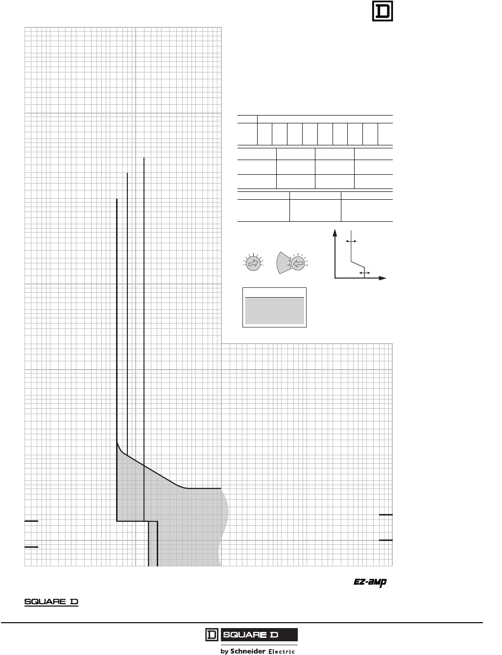
PowerPact® H- and J-Frame Circuit Breakers
Section 6—Trip Curves
67
05/2009
© 2004–2009 Schneider Electric
All Rights Reserved
Figure 47: H- and J-Frame Motor Circuit Protector
POWERPACT H/J FRAME MOTOR CIRCUIT PROTECTOR
WITH AUTO SETTINGS
CHARACTERISTIC TRIP CURVE NO. 045-2
The time-current curve information represents the typical response and is to
be used for application and coordination purposes only.
Curves apply from -30C to +60C ambient temperature.
Notes:
• The MCP is an instantaneous only breaker that detects the peaks of the
current. In order to trip within the specified time-current levels, consecutive
peaks of the current must exceed the selected setting’s threshold.
• Total clearing times shown include the response times of the trip unit, the
circuit breaker opening, and the extinction of the current.
• The time-current curve represents single-phase to three-phase fault currents.
MOTOR CIRCUIT PROTECTOR INFORMATION
Suffix # FLA Adjustments
M71 1.5 3 6 8 11 14 17 20 25
M72 14 17 21 24 27 29 32 36 42
M73 30 35 41 46 51 56 63 71 80
M74 58 71 79 86 91 97 110 119 130
M75 114 137 145 155 163 172 181 210 217
Suffix # Auto Instantanious Trip Dampening For Motor
Setting Point % FLA In-Rush % FLA
M71, M72 Auto 1 800 1300
M73, M74 Auto 2 1100 1700
6x 600 1300
Auto 1 800 1300
M75 Auto 2 1100 1100 – 1700
6x 600 1100 – 1300
Suffix # Nominal Fault Current Level Maximum Clearing Time
M71 670
M72 1150
M73 2150 1/2-1 Cycle
M74 3450
M75 3600
© 2006 Schneider Electric all rights reserved
Curve No. 0045TC0602
August 2006
Drawing No. 48095-045-02
TM
Courtesy of Steven Engineering, Inc.-230 Ryan Way, South San Francisco, CA 94080-6370-Main Office: (650) 588-9200-Outside Local Area: (800) 258-9200-www.stevenengineering.com
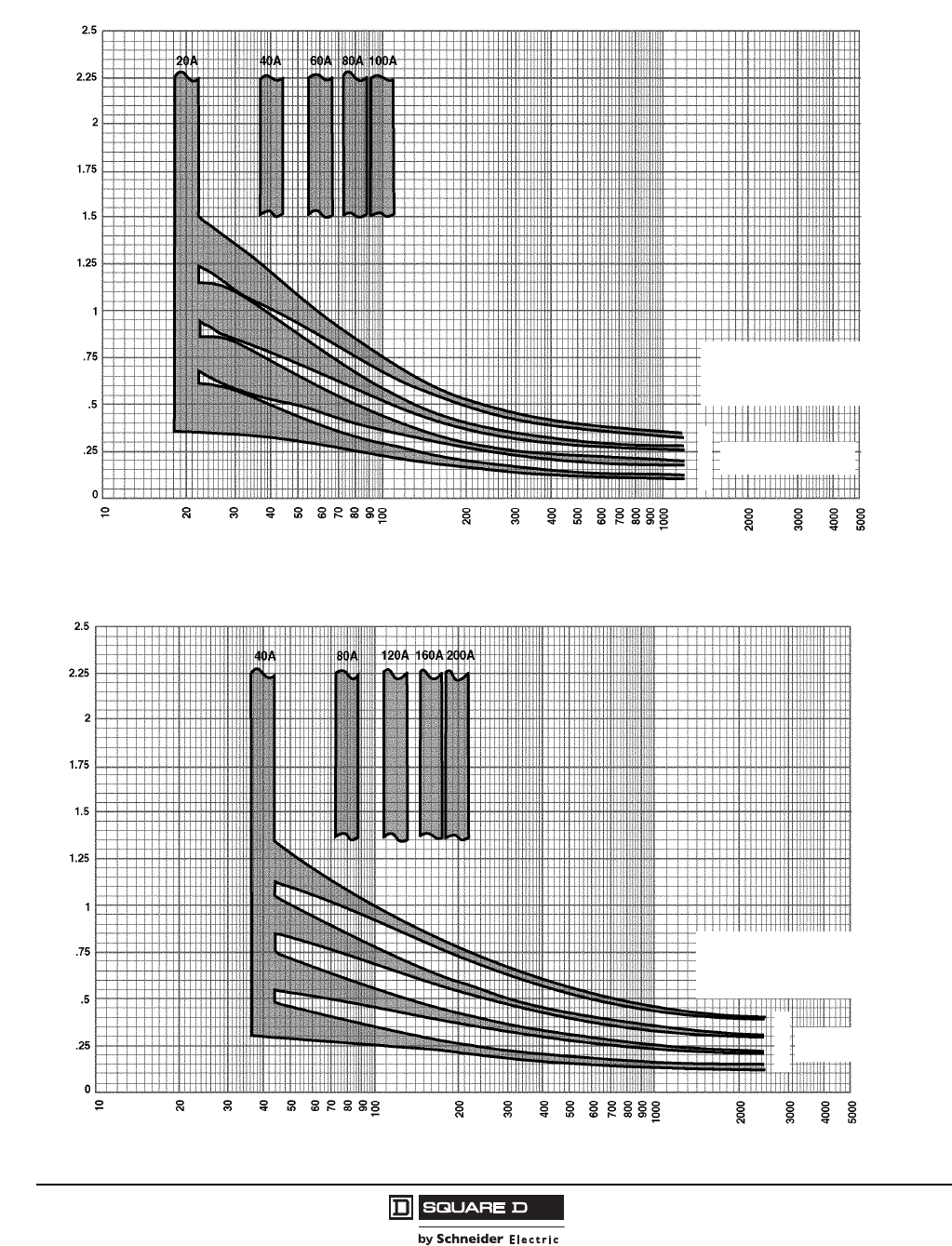
© 2004–2009 Schneider Electric
All Rights Reserved
PowerPact® H- and J-Frame Circuit Breakers
Section 6—Trip Curves
68
05/2009
Figure 48: Ground Fault Module GFM150HD Trip Curve
Pickup Levels ±10% Curve 980-1
Time in Seconds
Current in Amperes
Circuit Breaker Will
Instantaneous Trip
Above 1200 A
4
3
2
1
Delay Band
09603011
Figure 49: Ground Fault Module GFM250JD Trip Curve
Pickup Levels ±10% Curve 980-2
Time in Seconds
Current in Amperes
Circuit Breaker Will
Instantaneous Trip
Above 2500 A
4
3
2
1
Delay Band
09603012
Courtesy of Steven Engineering, Inc.-230 Ryan Way, South San Francisco, CA 94080-6370-Main Office: (650) 588-9200-Outside Local Area: (800) 258-9200-www.stevenengineering.com
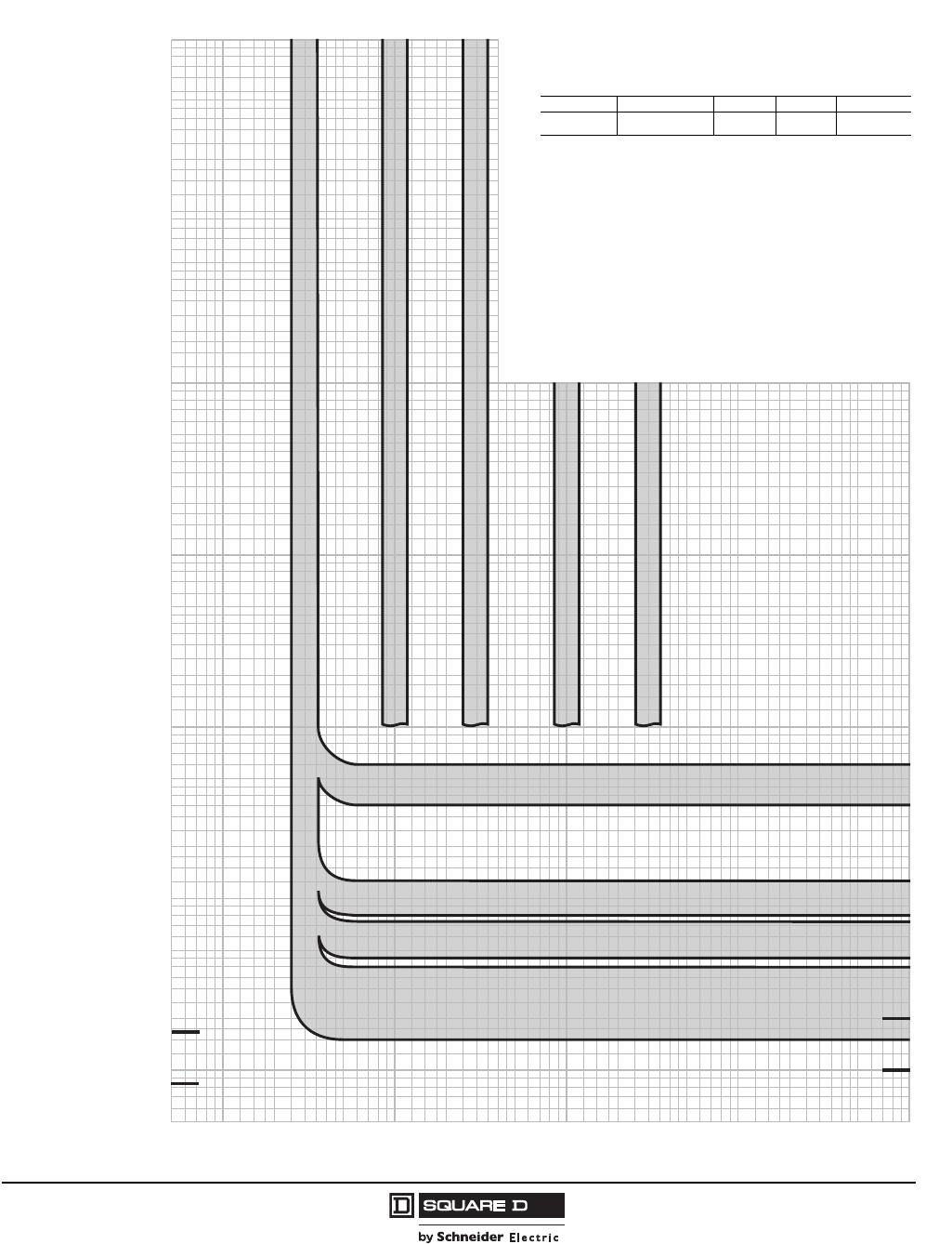
PowerPact® H- and J-Frame Circuit Breakers
Section 6—Trip Curves
69
05/2009
© 2004–2009 Schneider Electric
All Rights Reserved
Figure 50: Earth Leakage Module Trip Curve
.015
.005
.006
.007
.008
.009
.01
.02
.03
.04
.05
.06
.07
.08
.09
.1
.15
.2
.3
.4
.015
.005
.006
.007
.008
.009
.01
.02
.03
.04
.05
.06
.07
.08
.09
.1
.15
.2
.3
.4
.005
.006
.007
.008
.009
.01
.015
.02
.03
.04
.05
.06
.07
.08
.09
.1
.15
.2
.3
.4
.5
.6
.7
.8
.9
1
1.5
2
3
4
5
6
7
8
9
10
20
30
40
50
60
70
80
90
100
15
1500
2000
3000
4000
6000
7000
8000
9000
5000
10000
TRIP THRESHOLD CURRENT (AMPERES)
TIME IN SECONDS
.005
.006
.007
.008
.009
.01
.015
.02
.03
.04
.05
.06
.07
.08
.09
.1
.15
.2
.3
.4
.5
.6
.7
.8
.9
1
1.5
2
3
4
5
6
7
8
9
10
15
20
30
40
50
60
70
80
90
100
150
200
300
400
500
600
700
800
900
1000
150
200
300
400
500
600
700
800
900
1000
1500
2000
3000
4000
5000
6000
7000
8000
9000
10000
TIME IN SECONDS
1
/
2
CYCLE
(60 Hz)
1
/
2
CYCLE
(50 Hz)
1.5
2
3
4
5
6
7
8
9
10
.5
.6
.7
.8
.9
1
15
20
30
40
50
60
70
80
90
100
1.5
2
3
4
5
6
7
8
9
10
.5
.6
.7
.8
.9
1
15
20
30
40
50
60
70
80
90
100
TRIP THRESHOLD CURRENT (AMPERES)
1 CYCLE
(60 Hz)
1 CYCLE
(50 Hz)
3.0 A
1.0 A
300 MA
0.50 SECONDS
0.10 SECONDS
0.06 SECONDS
INSTANTANEOUS
100 MA
30 MA
EARTH LEAKAGE MODULES (ELM) FOR
POWERPACT®H AND J-FRAME
MOLDED CASE CIRCUIT BREAKERS
CHARACTERISTIC TRIP CURVE NO. 961-1
Catalog Number Circuit Breaker CB Amps CB Voltage Number Of Poles
ELM150HD PowerPact H-Frame 15–150 600 3
ELM250JD PowerPact J-Frame 150–250 600 3
Total clearing times shown include the response times of the ELM,
the circuit breaker shunt trip, the circuit breaker opening, and the
extinction of the current. Curves apply from -30°C to +60°C ambient
temperature. Refer also to the circuit breaker trip curves for
PowerPact H- and J-Frame Circuit Breakers.
Note: Trip curves define the performance under normal conditions.
Add 0.030 seconds for closing breaker/module on an existing fault.
Courtesy of Steven Engineering, Inc.-230 Ryan Way, South San Francisco, CA 94080-6370-Main Office: (650) 588-9200-Outside Local Area: (800) 258-9200-www.stevenengineering.com
© 2004–2009 Schneider Electric
All Rights Reserved
PowerPact® H- and J-Frame Circuit Breakers
Section 7—MCP Instantaneous Trip Points
70
05/2009
Section 7—MCP Instantaneous Trip Points
Table 63: M71 Instantaneous Trip Points
Automatic Setting (A) Manual Adjustment (A)
Im Setting 1 2 6x 8x 9x 10x 11x 12x 13x
Motor Type NEMA A, B, C, D B, E (FLA) x (Im)
IEC N H
FLA
1.5 12 16.5 9 12 13.5 15 16.5 18 19.5
3 24 33 18 242730333639
6 48 66 36 485460667278
8 64 88 48 6472808896104
11 88 121 66 88 99 110 121 132 143
14 112 154 84 112 126 140 154 168 182
17 136 187 102 136 153 170 187 204 221
20 160 220 120 160 180 200 220 240 260
25 200 275 150 200 225 250 275 300 325
Dampening for motor in-rush (% FLA) 1300% 1700% 1300% —
Table 64: M72 Instantaneous Trip Points
Automatic Setting (A)1
1± 5% of nominal amperage shown above
Manual Adjustment (A)1
Im Setting 1 2 6x 8x 9x 10x 11x 12x 13x
Motor Type NEMA A, B, C, D B, E (FLA) x (Im)
IEC N H
FLA
14 112 154 84 112 126 140 154 168 182
17 136 187 102 136 153 170 187 204 221
21 168 231 126 168 189 210 231 252 273
24 192 264 144 192 216 240 264 288 312
27 216 297 162 216 243 270 297 324 351
29 232 319 174 232 261 290 319 348 377
32 256 352 192 256 288 320 352 384 416
36 288 396 216 288 324 360 396 432 468
42 336 462 252 336 378 420 462 504 546
Dampening for motor in-rush (% FLA) 1300% 1700% 1300% —
Courtesy of Steven Engineering, Inc.-230 Ryan Way, South San Francisco, CA 94080-6370-Main Office: (650) 588-9200-Outside Local Area: (800) 258-9200-www.stevenengineering.com
PowerPact® H- and J-Frame Circuit Breakers
Section 7—MCP Instantaneous Trip Points
71
05/2009
© 2004–2009 Schneider Electric
All Rights Reserved
Table 65: M73 Instantaneous Trip Points
Automatic Setting (A)1
1± 5% of nominal amperage shown above
Manual Adjustment (A)1
Im Setting 1 2 6x 8x 9x 10x 11x 12x 13x
Motor Type NEMA A, B, C, D B, E (FLA) x (Im)
IEC N H
FLA
30 240 330 180 240 270 300 330 360 390
35 280 385 210 280 315 350 385 420 455
41 328 451 246 328 369 410 451 492 533
46 368 506 276 368 414 460 506 552 598
51 408 561 306 408 459 510 561 612 663
56 448 616 336 448 504 560 616 672 728
63 504 693 378 504 567 630 693 756 819
71 568 781 426 568 639 710 781 852 923
80 640 880 480 640 720 800 880 960 1040
Dampening for motor in-rush (% FLA) 1300% 1700% 1300% —
Table 66: M74 Instantaneous Trip Points
Automatic Setting (A)1
1± 5% of nominal amperage shown above
Manual Adjustment (A)1
Im Setting 1 2 6x 8x 9x 10x 11x 12x 13x
Motor Type NEMA A, B, C, D B, E (FLA) x (Im)
IEC N H
FLA
58 464 638 348 464 522 580 638 696 754
71 568 781 426 568 639 710 781 852 923
79 632 869 474 632 711 790 869 948 1027
86 688 946 516 688 774 860 946 1032 1118
91 728 1001 546 728 819 910 1001 1092 1183
97 776 1067 582 776 873 970 1067 1164 1261
110 880 1210 660 880 990 1100 1210 1320 1430
119 952 1309 714 952 1071 1190 1309 1428 1547
130 1040 1430 780 1040 1170 1300 1430 1560 1690
Dampening for motor in-rush (% FLA) 1300% 1700% 1300% —
Table 67: M75 Instantaneous Trip Points
Automatic Setting (A)1
1± 5% of nominal amperage shown above
Manual Adjustment (A)1
Im Setting 1 2 6x 8x 9x 10x 11x 12x 13x
Motor Type NEMA A, B, C, D B, E (FLA) x (Im)
IEC N H
FLA
114 912 1254 684 912 1026 1140 1254 1368 1482
137 1096 1507 822 1096 1233 1370 1507 1644 1781
145 1160 1595 870 1160 1305 1450 1595 1740 1885
155 1240 1705 930 1240 1395 1550 1705 1860 2015
163 1304 1793 978 1304 1467 1630 1793 1956 2119
172 1376 1892 1032 1376 1548 1720 1892 2064 2236
181 1448 1991 1086 1448 1629 1810 1991 2172 2353
210 1680 2310 1260 1680 1890 2100 2310 2500 2
22500 A maximum instantaneous trip point
2500 2
217 1736 2387 1302 1736 1953 2170 2387 2500 22500 2
Dampening for motor in-rush (% FLA) 1100–1300% 1100–1700% 1100–13
00% —
Courtesy of Steven Engineering, Inc.-230 Ryan Way, South San Francisco, CA 94080-6370-Main Office: (650) 588-9200-Outside Local Area: (800) 258-9200-www.stevenengineering.com

© 2004–2009 Schneider Electric
All Rights Reserved
PowerPact® H- and J-Frame Circuit Breakers
Section 7—MCP Instantaneous Trip Points
72
05/2009
Courtesy of Steven Engineering, Inc.-230 Ryan Way, South San Francisco, CA 94080-6370-Main Office: (650) 588-9200-Outside Local Area: (800) 258-9200-www.stevenengineering.com

PowerPact® H- and J-Frame Circuit Breakers
Index
73
05/2009
© 2004–2009 Schneider Electric
All Rights Reserved
INDEX
A
accessories
auxiliary switches 35
locations of internal 34
maximum combinations of 34
motor operator 36
accessory connections 34
accessory suffix codes 8, 36, 39
AIR See ampere interrupting rating
altitude.See operating conditions
ampere interrupting rating 5
automatic protection settings 21
auxiliary switches 35
B
bus-bar connections 28
C
cable operating handle 41
catalog numbering 8
chassis, drawout circuit breaker 33
codes and standards
H- and J-frame circuit breakers 10
H- and J-frame switches 10
connections. See mounting and connections
connector
MN/UVR 45
MX/SHT 45
OF/AX 45
SD/AL 45
D
dimensional drawings
H-frame 47
J-frame 51, 53–55
DIN rail mounting bracket 26
drawout circuit breakers
chassis functions 33
mounting 33
E
endurance operations 13
F
features and benefits 24
common design envelope 5
dual-break rotating contacts 6
high interrupting ratings (AIR) 5
reduced let-through currents 6
field installable accessories 7
full load amp settings 21
H
handle position indication 6
H-frame dimensional drawings 47
I
I-Line® circuit breakers 31
installation
plug-in circuit breakers 32
interlocking 44
internal accessories 34
interrupting rating 11
J
J-frame dimensional drawings 51, 53–55
L
locking systems 43
locks
direct rotary handle 43
extended rotary operating handle 43
motor operator 43
toggle 43
lugs
voltage takeoff for mechanical 28
M
manual protection settings 21
maximum accessory combinations 34
MCP See motor circuit protector
molded case switches 24
motor circuit protector 20
automatic protection settings 21
full load amp settings 21
motor circuit selector
selection 23
motor operator 36
mounting and connections 26
drawout circuit breakers 33
I-Line® circuit breakers 31
plug-in circuit breakers 32
unit-mount circuit breakers 26
MX shunt trip 45
N
numbering, catalog 8
O
open/closed position switch 45
operating conditions 24
altitude 13
temperature 13
vibration 13
operating handle
cable operating mechanism 41
operating handles
direct mounted rotary 40
door mounted rotary 40–41
operating mechanism 6
operations, endurance 13
P
plug-in circuit breakers
mounting 32
parts of configuration 32
safety trip interlock 32
positive contact indication 11
R
ratings
circuit breaker interrupting 11
corner grounded delta 13
UL 489 11
re-rating
Courtesy of Steven Engineering, Inc.-230 Ryan Way, South San Francisco, CA 94080-6370-Main Office: (650) 588-9200-Outside Local Area: (800) 258-9200-www.stevenengineering.com

© 2004–2009 Schneider Electric
All Rights Reserved
PowerPact® H- and J-Frame Circuit Breakers
Index
74
05/2009
altitude 13
rotary operating handles 39
directly mounted 40
door mounted 40–41
S
safety trip interlock 32
shunt trip (MX) 35–36, 45
special ratings 10
specifications 24
molded case switches 24
suffix codes 8, 36, 39
switch
alarm 35
auxiliary 35
changeover 35
electrical characteristics
MX/MN 36
OF, SD and SDE 35
MN undervoltage trip switch 36
MX shunt trip 36
switches
OF auxiliary switch 45
switches, automatic molded case 24
T
temperature See operating conditions
trip curves 59, 70
trip units 9
U
UL 489 ratings 11
undervoltage trip 45
undervoltage trip (MN) 36
unit-mount circuit breakers 26
bus-bar connections 28
mounting 26
V
voltage takeoff for mechanical lugs 28
W
wire sizes for accessory connections 34
Courtesy of Steven Engineering, Inc.-230 Ryan Way, South San Francisco, CA 94080-6370-Main Office: (650) 588-9200-Outside Local Area: (800) 258-9200-www.stevenengineering.com
Courtesy of Steven Engineering, Inc.-230 Ryan Way, South San Francisco, CA 94080-6370-Main Office: (650) 588-9200-Outside Local Area: (800) 258-9200-www.stevenengineering.com

0611CT0401R05/09 © 2004–2009 Schneider Electric All Rights Reserved
Replaces 0611CT0401R8/07
Schneider Electric USA
Street Address
City, State Zip Country
1-888-SquareD
(1-888-778-2733)
www.us.SquareD.com
Schneider Electric Canada
19 Waterman Avenue,
M4B 1 Y2
Toronto, Ontario
1-800-565-6699
www.schneider-electric.ca
05/2009
Courtesy of Steven Engineering, Inc.-230 Ryan Way, South San Francisco, CA 94080-6370-Main Office: (650) 588-9200-Outside Local Area: (800) 258-9200-www.stevenengineering.com
