2740_EIA_RS 232 C 2740 EIA RS
User Manual: Pdf 2740_EIA_RS-232-C
Open the PDF directly: View PDF ![]() .
.
Page Count: 8
(
In
this report:
Mechanical
Characteristics .......... 2
Interchange
Circuits ...................... 2
Standard Interfaces
for
Selected
Configurations .......... 5
Summary
of
Electrical
Characteristics .......... 6
DATAPRO
Data
Networking
2740
Standards
Electronic Industries
Association
(EIA)
RS-232-C Interface
Standard
Synopsis
Editor's Note
The subject
of
this
report
is
consid-
ered
as
a mature standard.
No
signifi-
cant developments
are
anticipated,
but
because
of
its importance
in
the
industry,
coverage
is
being continued.
Copies
of
the RS-232-C standard can
be obtained from the Electronic In-
dustries Association, Engineering
Department, 2001 I Street NW,
Washington,
DC
20006. A compan-
ion publication, "Application Notes
for EIA Standard RS-232-C," is also
available.
-By
Algis
V.
Salciunas
Product
Manager
Report Highlights
RS-232-C is a set
of
specifications
that
applies to the transfer
of
data
between data terminal equipment
(DTE) and data circuit-terminating
equipment (DCE).
It
defines the in-
terface circuit functions
and
their
corresponding connector
pin
assign-
ments.
It
is the most common
DTE
to
DCE
interface used
in
the United
States. Full-
or
half-duplex opera-
tions are supported for synchronous
or
asynchronous transmissions at
speeds up to 20K bps.
1
~
1991
McGraw-Hili,
Incorporated.
Reproduction
Prohibited.
Oatapro
InformatIOn
ServlOes
Group.
Delran
NJ
08075
USA
MAY
1991
2
2740
Standards
Analysis
The Electronic Industries Association (EIA) Stan-
dard RS-232-C defines the electrical
and
mechani-
cal characteristics
of
the interface for connecting
data
terminal equipment (DTE) and data circuit-
terminating equipment (DCE) using serial binary
data communications.
In
the United States, RS-
232-C
is
the most widely used
DTE
to
DCE inter-
face.
It
applies to all classes
of
service: private line,
dial-up, point-to-point, multipoint, switched, nons-
witched, two-wire, and four-wire service. Asyn-
chronous and synchronous data transmission is
supported at speeds
up
to
20K bps in full-
or
half-
duplex mode. RS-232-C is a single-ended
or
unbal-
anced interface; all
of
the interchange signals share
a common electrical ground.
RS-232-C is functionally compatible with the
International Telegraph
and
Telephone Consulta-
tive Committee (CCITT) Recommendation V.24.
Another similar interface, ISO IS211 0, has been
adopted by the International Organization for
Standardization (ISO). Both the EIA RS-232-C and
the ISO
IS2II
0 specify a 25-pin connector. Pin
incompatibilities exist, however, because
of
the
diagnostic features outlined in RS-232-C.
RS-232-C coexists with another EIA standard
for
DTE
to
DCE interface, RS-449, which specifies
requirements for expanded transmission speeds,
longer cable lengths, and additional functions.
Equipment meeting RS-232-C standards can be
made compatible with equipment meeting RS-449
standards by using an interface converter.
As
the terms relate
to
this interface, data ter-
minal equipment (DTE) is business machine hard-
ware such as teleprinters,
CR
Ts, front-end ports,
CPUs, etc.; data circuit-terminating equipment
(DCE)
is
hardware such as modems, limited dis-
tance data sets,
or
the data service units (DSUs).
Mechanical Characteristics
The
physical connection between
DTE
and DCE is
made through plug-in, 25-pin connectors. The con-
nectors are keyed with
13
pins on the top row and
MAY
1991
Electronic Induatrl
..
Aaaoclation (EIAI
RS·I32-C Interface
Standard
Data
Networking
12
pins
on
the bottom row
to
prevent improper
connection. The male connector is always associ-
ated with the DTE, and the female is always associ-
ated with the DCE.
The
cable is provided by the
DTE. The use
of
short cables, each less than 50 feet
or
15
meters, is recommended. Use oflonger ca-
bles is permissible, however, provided that load
capacity requirements are met. Longer cables are
used with the length restricted by the data rate (in
synchronous applications, the clock leads generally
run twice as fast as the data leads),
and
by the envi-
ronment. Proximity
to
heavy rotating machinery
or
other noisy/radiating devices will limit the prac-
tical cable length.
Pin assignments are explicit and unalterable,
unless unassigned. Special functions not specifi-
cally defined should be allotted
to
unassigned pins.
For
example, pin
25
(unassigned) is sometimes
used to "busy
out"
a connected modem that is as-
sociated with a switched application. This causes
the modem to
go
"off
hook," thus preventing an
incoming call from being connected/answered. Be-
cause some pins are unassigned,
and
because all
the functions defined by RS-232-C are not neces-
sarily required for a specific application, all 25 pins
are not usually used. Contact the
DTE
vendor to
determine the specific configuration.
Interchange Circuits
An interchange circuit is defined as a circuit be-
tween the data terminal equipment and the data
circuit-terminating equipment. RS-232-C describes
the four categories
of
interchange circuits that ap-
ply generally to all systems. They are ground
or
common return, data, control, and timing circuits.
Twenty-two circuits are specified by possible func-
tions, and three are unassigned. See Table
1.
Ground Circuits
The
ground interchange circuits are Protective
Ground (AA) and Signal Ground (AB). Protective
Ground is electrically bonded
to
the equipment
frame; it can be connected to
an
external ground
(e.g., the ground pin
of
an electrical power plug).
Signal Ground establishes a common reference for
all interchange circuits, except Protective Ground.
Data
Circuits
Two types
of
data circuits are described. A
primary
channel is a data transmission channel that has the
@
1991
McGraw-Hili,
Incorporated.
Reproduction
Prohibited.
Datepro Information
Sarvices
Group.
Delran
NJ
08075
USA
(
Data Networking
Electronic
Indu.trl
••
A
••
ociatlon
lElA)
RS-232-C
Interface
Standard
2740
Standards
3
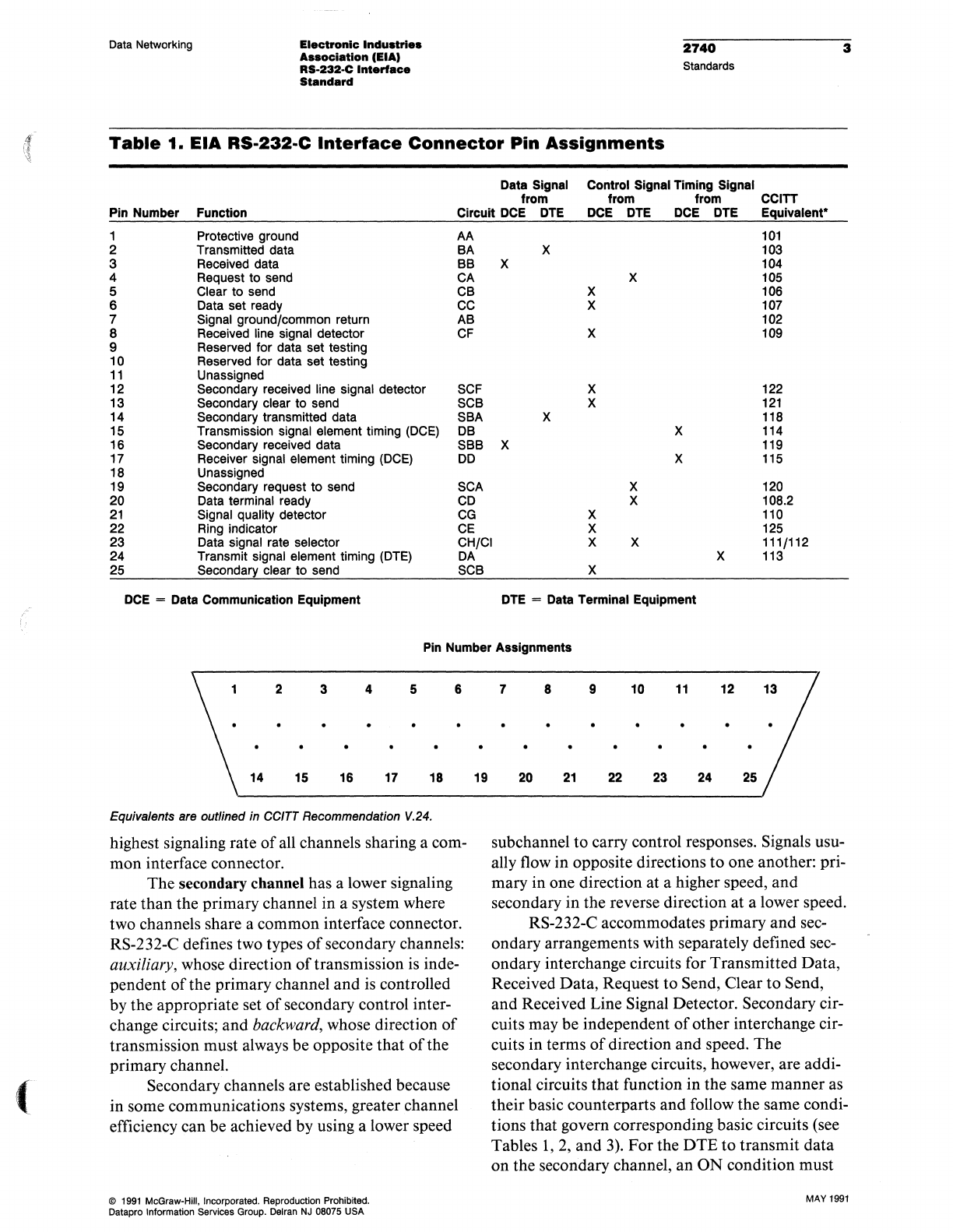
Table
1.
EIA
RS·232·C
Interface
Connector
Pin
Assignments
Data Signal Control Signal Timing Signal
from from from CCITT
Pin Number Function Circuit
DCE
DTE
DCE
DTE
DCE
DTE Equivalent·
1 Protective ground AA
101
2 Transmitted data BA X
103
3 Received data BB X
104
4 Request to send CA X
105
5 Clear to send CB X
106
6 Data set ready
CC
X
107
7 Signal ground/common return AB
102
8 Received line signal detector
CF
X
109
9 Reserved for data set testing
10 Reserved for data set testing
11
Unassigned
12 Secondary received line signal detector
SCF
X
122
13 Secondary clear to send SCB X
121
14
Secondary transmitted data SBA X
118
15
Transmission signal element timing (DCE) DB X
114
16
Secondary received data SBB X
119
17 Receiver signal element timing (DCE)
DO
X
115
18
Unassigned
19
Secondary request to send SCA X
120
20
Data terminal ready
CD
X
108.2
21
Signal quality detector
CG
X
110
22
Ring indicator
CE
X
125
23 Data signal rate selector CH/CI X X 111/112
24
Transmit signal element timing (DTE)
DA
X
113
25 Secondary clear to send SCB X
DCE
= Data Communication Equipment
DTE
= Data Terminal Equipment
Pin Number Assignments
2 3 4 5 6
14 15 16 17 18
Equivalents are outlined in CCITT Recommendation V.24.
highest signaling rate
of
all channels sharing a com-
mon interface connector.
The
secondary channel has a lower signaling
rate than the primary channel in a system where
two channels share a common interface connector.
RS-232-C defines two types
of
secondary channels:
auxiliary, whose direction
of
transmission is inde-
pendent
of
the primary channel and is controlled
by the appropriate set
of
secondary control inter-
change circuits; and backward, whose direction
of
transmission must always be opposite that
of
the
primary channel.
Secondary channels are established because
in some communications systems, greater channel
efficiency can be achieved by using a lower speed
@
1991
McGraw-Hili. Incorporated. Reproduction Prohibited.
Datapro Information Services Group. Delran
NJ
08075 USA
19
7 8 9 10
11
12
20
21
22
23
24
25
subchannel
to
carry control responses. Signals usu-
ally flow in opposite directions to one another: pri-
mary in one direction at a higher speed, and
secondary in the reverse direction at a lower speed.
RS-232-C accommodates primary and sec-
ondary arrangements with separately defined sec-
ondary interchange circuits for Transmitted Data,
Received Data, Request
to
Send, Clear
to
Send,
and Received Line Signal Detector. Secondary cir-
cuits may be independent
of
other interchange cir-
cuits in terms
of
direction and speed. The
secondary interchange circuits, however, are addi-
tional circuits that function in the same manner as
their basic counterparts and follow the same condi-
tions that govern corresponding basic circuits (see
Tables
1,2,
and 3).
For
the
DTE
to
transmit data
on
the secondary channel,
an
ON
condition must
MAY
1991
4
2740
Standards
be present
on
the following four circuits:
SCA
(Sec-
ondary Request to Send);
SCB
(Secondary Clear to
Send); CC (Data Set Ready); and CD (Data Termi-
nal Ready).
When the data circuits are idle, they are in a
mark hold condition (binary "ones"). Data is
transferred in bipolar fashion. A binary
"one"
(mark) is represented by a voltage more negative
than
-3
volts; a binary "zero" (space) is repre-
sented by a voltage more positive than + 3 volts.
Control
Circuits
Control signals are used to enable and disable data
transmission and reception, and to indicate the
operational status and condition
of
the DTE and
DCE. A control function is considered to be in the
ON
condition when the voltage is more positive
than + 3 volts; it is considered to be in the OFF
condition when the voltage is more negative than
- 3 volts. These control circuits include Request to
Send
(RTS), Clear to
Send
(CTS), Data
Set
Ready
(DSR), Data Terminal
Ready
(DTR), Received
Line
Signal Detector (carrier detect, CD), and
Ring
(RI).
Assuming a half-duplex transmission between
DTE/DCE-1 and DTE/DCE-2 is run over the pub-
lic switched network, the control sequence might
be as follows:
1.
All control circuits OFF.
2.
DTE/DCE-1 places a call to DTE/DCE-2;
DCE-1 turns DSR
ON
to DTE-1, DTE-l turns
DTR
ON
to DCE-I.
3.
DCE-2 turns RI
ON
to DTE-2.
4.
DTE-2 turns
DTR
ON
to DCE-2.
5.
DCE-2 goes
"off
hook" and turns DSR ON to
DTE-2.
6.
DTE-2 turns RTS
ON
to DCE-2.
7.
DCE-2 turns CTS
ON
to DTE-2 (ENQ trans-
mitted), DTE/DCE-2 turns OFF RTS and
CTS.
8.
DCE-l turns CD
ON
to DTE-I.
9.
DTE-l decodes ENQ, turns
ON
RTS.
10.
DCE-1 turns ON CTS; DTE-1 transmits re-
sponse.
The four basic control signals relating
to
transmis-
sion are:
1.
Request to Send
(RTS)-Circuit
CA
MAY
1991
Electronic Industllea
Auocilltlon
(EIA)
RS·232-C
Inte~
Standard
Data Networking
• Conditions the local DCE for data transmis-
sion.
• Controls the direction
of
transmission on half-
duplex channels, maintains transmit, and inhib-
its receive.
• Maintains the DCE in the transmit mode on
duplex or one-way only channels; otherwise,
holds it in nontransmit.
• RTS transition (OFF to ON) causes the DCE to
enter transmit mode and turn CTS ON.
• RTS transition (ON to OFF) causes the DCE to
complete the data transmission, enter the re-
ceive
or
nontransmit mode, and turn CTS OFF.
2.
Clear
to
Send
(CTS)-Circuit
CB
• Indicates to the DTE that data can be transmit-
ted (CTS ON) or cannot be transmitted (CTS
OFF).
• CTS
ON
is delayed until the remote DCE is ini-
tialized.
• When RTS is not implemented, CTS must be
ON
continuously.
3.
Data Set Ready
(DSR)-Circuit
CC
• Indicates the local data set status.
• ON indicates that the data set is connected to
the communications channel ("Off Hook" or
switched service) and is not in test, talk (alter-
native voice/data), or dial mode. The ON con-
dition
of
this circuit should not be interpreted
as either the status
of
any remote station equip-
ment
or
an indication that a communication
channel has been established to a remote data
station.
• ON indicates completed timing functions,
if
any, required for call establishment (switched
service).
•
ON
indicates completed transmission
of
a dis-
creet answer tone, the duration
of
which is con-
trolled by the local data set.
• OFF, occurring during transmission, indicates
that the connection has been lost. A new trans-
mission must be originated.
4.
Data
Terminal Ready
(DTR)-Circuit
CD
• Used to control switching
ofthe
DCE to the
communications channel.
@
,1991
McGraw-HUI,
Incorporated. Reproduction Prohibited.
Datapro Information Services Group. Delran
NJ
08075
USA
(
Data Networking Electronic Industries
Associlition
(EIAI
RS·232·C
Interface
Standard
• The ON condition prepares the data set to con-
nect and maintain connection to the communi-
cations channel.
• With automatic answering equipment, connec-
tion to the communications channel occurs
when both the Data Terminal Ready and the
Ring Indicator circuit are in the ON condition.
The OFF condition
of
the Data Terminal Ready
circuit does not disable the Ring Indicator
sig-
nal.
• In switched systems, Data Set Ready must be
OFF before Data Terminal Ready is turned ON
again.
Other control interchange circuits include the fol-
lowing.
The
Ring
Indicator, Circuit CE, indicates that
a ring (call) signal is being received on the commu-
nications channel through the switched network.
The circuit
is
in an ON condition during ringing
and in an
OFF
condition between rings
or
when
ringing is not present.
The Received
Line
Signal Detector, Circuit
CF,
presents an ON condition to indicate that data
signals are being received,
and
that they are accept-
able for demodulation. An OFF condition indi-
cates that data signals are not being received,
or
that they are not acceptable for demodulation. The
OFF condition causes the Received
Data
(Circuit
BB)
to be held in a binary one (marking) condition.
The Signal Quality Detector, Circuit CG, indi-
cates whether there is a high probability
of
error in
received data. The ON condition is maintained,
unless a high probability
of
error has occurred.
Probable error is indicated by the OFF condition.
This condition can be used to effect retransmis-
sion.
Data Signal
Rate
Detector, Circuit
CH
or
CI
. '
IS used to select between two signaling rates when
the data set
or
data terminal accommodates dual
rates. The ON condition selects the higher rate
or
range
of
rates. Circuit CH indicates that the data
terminal provides the selection signal. Circuit CI
indicates that the data set provides the selection
signal. Selection is between two asynchronous rates
or
between two synchronous rates.
Timing
Circuits
Two circuits are used to provide
Transmitter
Sig-
nal
Element
Timing.
@
1991
McGraw·HIII,
Incorporated. Reproduction Prohibited.
Datapro Information
Services
Group.
Delran
NJ
08075
USA
2740
Standards
5
Circuit DA provides signal element timing
information
to
the transmitting signal converter,
the DCE. The ON-OFF transition indicates the
occurrence
of
the center
of
the data element. The
DTE normally provides timing information on this
circuit when the DTE is powered ON.
If
Circuit
CA
(Request to Send) is OFF, timing information
on Circuit DA may be withheld by the
DTE
for
short periods.
Circuit
DB
provides signal element timing to
the DTE. A data signal on Circuit
BA
(Transmitted
Data) is provided from the DTE in which the tran-
sition between signal elements occurs at the time
of
the OFF-ON transition in Circuit DB.
If
Circuit
CC (Data Set Ready) is OFF, it is permissible for
the DCE to withhold timing information for short
periods. The performance
of
maintenance tests
within the DCE, for example, may require the
withholding
of
timing information.
Receiver Signal Element Timing, Circuit DD,
provides timing to the data terminal from the data
set. The ON-OFF transition indicates the center
of
the received data elements.
Standard
Interfaces
for
Selected
Configurations
EIA RS-232-C describes a selected set
of
data
transmission configurations
or
interfaces. A provi-
sion is made for the addition
of
custom configura-
tions. Determining factors in the selection
of
an
interface type are whether the DTE transmits, re-
ceives,
or
does both; whether the mode
of
opera-
tion is half
or
full duplex; and whether a secondary
channel
is
used. The interface designations do not
relate to which terminal originates
or
answers the
call, but rather to the data transmitted.
RS-232-C defines selected interface types by
letter designation. These types are described in Ta-
ble 2, where the direction
of
data transfer pertain-
ing to the interface is stated (function),
and
the use
of
Request to Send and Received Line Signal De-
tector interchange circuits is stipulated (comment).
This list indicates that interfaces A
and
B,
which
are one-way only transmissions, differ only in
terms
of
the use ofRTS. Interface D is normally
employed with half-duplex operation using R
TS,
and interface E is normally employed with full-
duplex operation without using RTS. When inter-
face D is used in full-duplex operation, however,
R
TS is used with special significance.
MAY
1991
8
2740
Standards
Electronic Induatrt
..
__
elation lElA)
RS-232-C
Interface
Standard
Data Networking
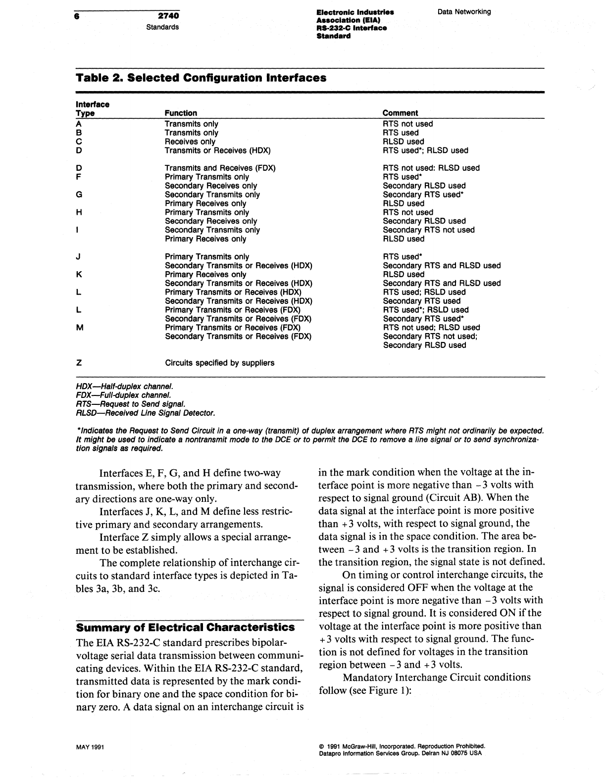
Table
2.
Selected
Configuration
Interfaces
Interface
Type
A
B
C
o
o
F
G
H
J
K
L
L
M
z
Function
Transmits only
Transmits only
Receives only
Transmits
or
Receives (HOX)
Transmits and Receives (FOX)
Primary Transmits only
Secondary Receives only
Secondary Transmits only
Primary Receives only
Primary Transmits only
Secondary Receives only
Secondary Transmits only
Primary Receives only
Primary Transmits only
Secondary Transmits or Receives
(HOX)
Primary Receives only
Secondary Transmits
or
Receives (HOX)
Primary Transmits
or
Receives
(HOX)
Secondary Transmits
or
Receives
(HOX)
Primary Transmits
or
Receives
(FOX)
Secondary Transmits
or
Receives
(FOX)
Primary Transmits
or
Receives
(FOX)
Secondary Transmits
or
Receives
(FOX)
Circuits specified by suppliers
HDX-Half-duplex
channel.
FDX-Full-duplex channel.
RTS-Request
to Send signal.
RLSD-Received
Line Signal Detector.
Comment
RTS not used
RTS used
RLSO used
RTS used·; RLSO used
RTS not used: RLSO used
RTS used·
Secondary RLSO used
Secondary RTS used·
RLSO used
RTS not used
Secondary RLSO used
Secondary RTS
not
used
RLSO used
RTS used·
Secondary RTS and RLSO used
RLSO used
Secondary RTS and RLSO used
RTS used; RSLO used
Secondary RTS used
RTS used·; RSLO used
Secondary RTS used·
RTS
not
used; RLSO used
Secondary RTS not used;
Secondary RLSO used
"Indicates the Request to Send Circuit in a one-way (transmit)
of
duplex arrangement where
RTS
might not ordinarily be expected.
It
might
be
used to Indicate a nontransmlt mode to the
DCE
or
to permit the
DCE
to remove a line signal
or
to send synchroniza-
tion signals
as
required.
Interfaces E, F, G, and H define two-way
transmission, where both the primary and second-
ary directions are one-way only.
Interfaces J, K,
L,
and
M define less restric-
tive primary and secondary arrangements.
Interface Z simply allows a special arrange-
ment to be established.
The complete relationship
of
interchange cir-
cuits
to
standard interface types is depicted in Ta-
bles 3a, 3b, and
3c.
Summary
of
Electrical Characteristics
The EIA RS-232-C standard prescribes bipolar-
voltage serial data transmission between communi-
cating devices. Within the EIA RS-232-C standard,
transmitted data is represented by the mark condi-
tion for binary one
and
the space condition
for
bi-
nary zero. A data signal
on
an
interchange circuit is
MAY
1991
in the mark condition when the voltage at the in-
terface point is more negative
than
- 3 volts with
respect to signal ground (Circuit
AB).
When the
data signal
at
the interface point is more positive
than + 3 volts, with respect
to
signal ground, the
data signal is in
the
space condition. The area be-
tween - 3 and + 3 volts is the transition region.
In
the transition region, the signal state is not defined.
On
timing
or
control interchange circuits, the
signal is considered OFF when the voltage at the
interface point is more negative
than
- 3 volts with
respect to signal ground.
It
is considered
ON
if
the
voltage
at
the interface point
is
more positive than
+ 3 volts with respect to signal ground. The func-
tion is not defined for voltages in the transition
region between - 3 and + 3 volts.
Mandatory Interchange Circuit conditions
follow (see Figure
1):
@
1991
McGraw-Hili,
Incorporated.
Reproduction
Prohibited.
Datapro
Information
Services
Group.
Delran
NJ
08075
USA
r
\
(
Data Networking
Electronic
Industrl
..
Association
lElA)
RS·232-C
Interface-
Standard
2740
Standards
7
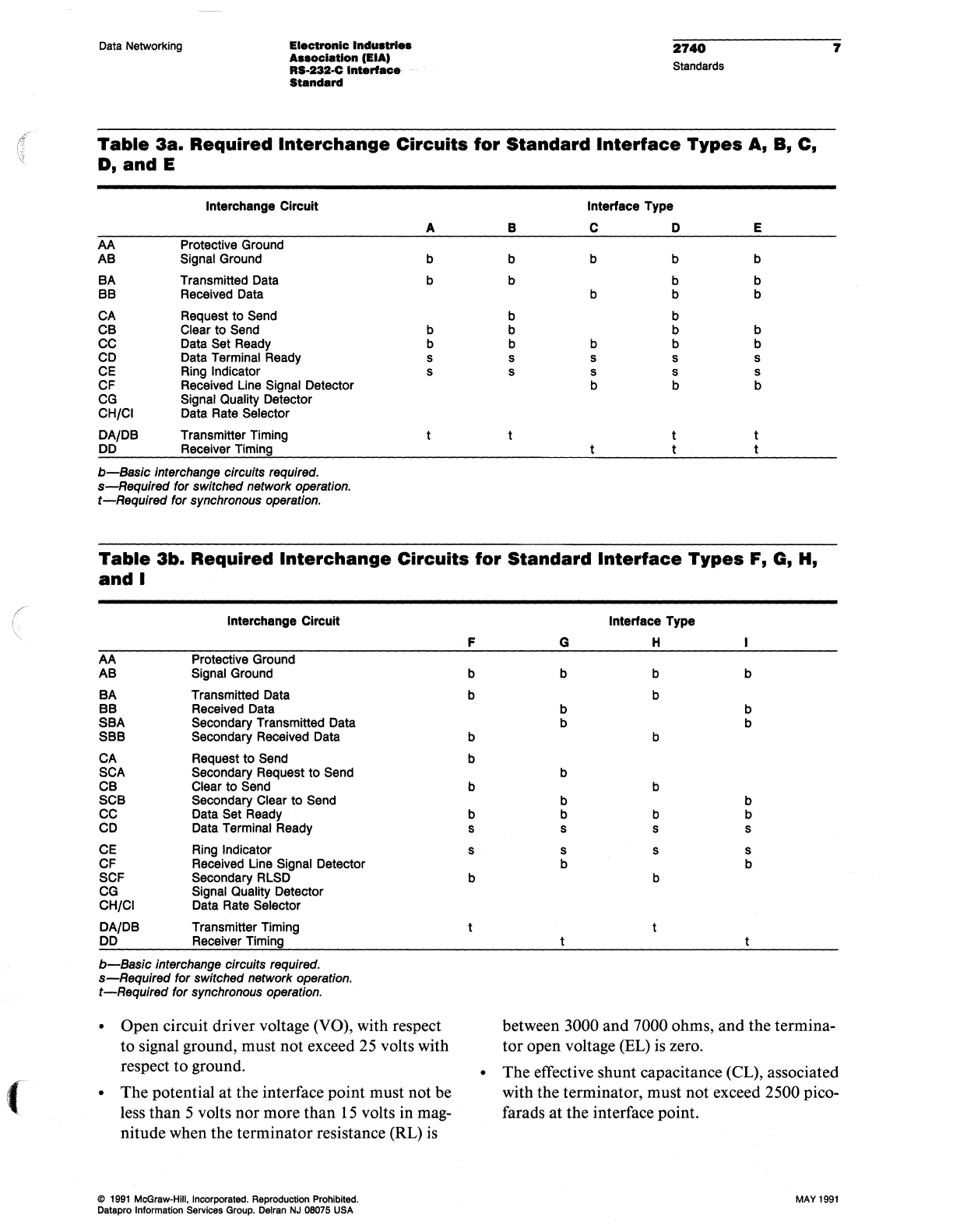
Table
3a.
Required
Interchange
Circuits
for
Standard
Interface
Types
A,
B, C.
D.
and
E
Interchange Circuit Interface Type
A B C D E
AA
Protective Ground
AB
Signal Ground b b b b b
BA
Transmitted Data b b b b
BB
Received Data b b b
CA Request
to
Send b b
CB
Clear to Send b b b b
CC Data Set Ready b b b b b
CD Data Terminal Ready s s s s s
CE Ring Indicator s s s s s
CF
Received Line Signal Detector b b b
CG Signal Quality Detector
CH/CI Data Rate Selector
DA/DB Transmitter Timing
DO Receiver Timing
b-Basic
interchange circuits required.
s-Requlred
for switched network operation.
t-Required
for synchronous operation.
Table
3b.
Required
Interchange
Circuits
for
Standard
Interface
Types
F, G,
H,
and
I
Interchange Circuit
AA
Protective Ground
AB
Signal Ground
BA
Transmitted Data
BB
Received Data
SBA
Secondary Transmitted Data
SBB
Secondary Received Data
CA
Request
to
Send
SCA Secondary Request
to
Send
CB
Clear
to
Send
SCB
Secondary Clear
to
Send
CC Data Set Ready
CD Data Terminal Ready
CE Ring Indicator
CF Received Line Signal Detector
SCF Secondary RLSD
CG Signal Quality Detector
CH/CI Data Rate Selector
DA/DB Transmitter Timing
DO Receiver Timing
b-Basic
interchange circuits required.
s-Requlred
for switched network operation.
t-Required
for synchronous operation.
• Open circuit driver voltage (YO), with respect
to signal ground, must not exceed 25 volts with
respect
to
ground.
•
The
potential at the interface point must not be
less than 5 volts nor more than
15
volts in mag-
nitude when the terminator resistance (RL) is
@
1991
McGraw-Hili.
Incorporated.
Reproduction
Prohibited.
Datapro Information
Servtces
Group.
Delran
NJ
08075
USA
F
b
b
b
b
b
b
s
s
b
G
b
b
b
b
b
b
s
s
b
Interface Type
H
b
b
b
b
b
s
s
b
b
b
b
b
b
s
s
b
between 3000 and 7000 ohms, and the termina-
tor
open voltage (EL) is zero.
•
The
effective shunt capacitance (CL), associated
with the terminator, must not exceed 2500 pico-
farads at the interface point.
MAY
1991
8
2740
Standards
Electronic
Industries
AssocIation
(EIA)
RS·232-C
Interface
Standard
Data
Networking
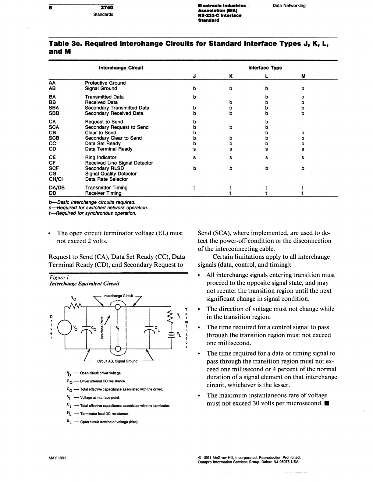
Table
3c.
Required
Interchange
Circuits
for
Standard
Interface
Types
'""
K,
L,
andM
AA
AB
BA
BB
SBA
SBB
CA
SeA
CB
SCB
CC
CD
CE
CF
SCF
CG
CHICI
DA/DB
DO
Interchange Circuit
Protective Ground
Signal Ground
Transmitted Data
Received Data
Secondary Transmitted Data
Secondary Received Data
Request
to
Send
Secondary Request
to
Send
Clear
to
Send
Secondary Clear
to
Send
Data Set Ready
Data Terminal Ready
Ring Indicator
Received Line Signal Detector
Secondary RLSD
Signal Quality Detector
Data Rate Selector
Transmitter Timing
Receiver Timing
b-Baslc
Interchange circuits required.
s-Requlred
for switched network operation.
t-Required
for synchronous operation.
•
The
open circuit terminator voltage (EL) must
not exceed 2 volts.
Request
to
Send (CA),
Data
Set Ready (CC),
Data
Terminal Ready (CD), and Secondary Request
to
Figure
1.
Interchange Equivalent Circuit
T
o
V
e
MAY
1991
'b
-
Open
circu~
driver
Voltage.
AO
-
Driver
internal
DC
resistance.
Co
-
Total
effective
capackance
associated
with
the
driver.
V
1 -
Voltage
at
interface
point
C L -
Total
effective
espaounce
associated
with
the
terminator.
'\.
-
Terminator
load
DC
resistance.
EL
-
Open
circuk
terminator
voltage
(bias).
'\.
~
m
j
n
a
t
o
J
b
b
b
b
b
b
b
b
b
s
s
b
Interface Type
K L M
b b b
b b
b b b
b b b
b b b
b
b b
b b
b b b
b b b
s s s
s s s
b b b
Send (SCA), where implemented, are used
to
de·
tect the power-off condition
or
the disconnection
of
the interconnecting cable.
Certain limitations apply
to
all interchange
signals (data, control, and timing):
• All interchange signals entering transition must
proceed to the opposite signal state, and may
not reenter the transition region until the next
significant change in signal condition.
• The direction
of
voltage must not change while
in the transition region.
•
The
time required for a control signal
to
pass
through the transition region must not exceed
one millisecond.
•
The
time required for a data
or
timing signal to
pass through the transition region must not ex-
ceed one millisecond
or
4 percent
of
the normal
duration
of
a signal element
on
that interchange
circuit, whichever is the lesser.
•
The
maximum instantaneous rate
of
voltage
must not exceed 30 volts
per
microsecond
.•
@
1991
McGraw-Hili, Incorporated. Reproduction
PrOhibited.
Datepro Irrformation
Services
Group.
Delran
NJ
08075
USA
