274929 Catalog
2014-07-05
: Pdf 274929-Catalog 274929-Catalog 754182 Batch5 unilog
Open the PDF directly: View PDF ![]() .
.
Page Count: 16
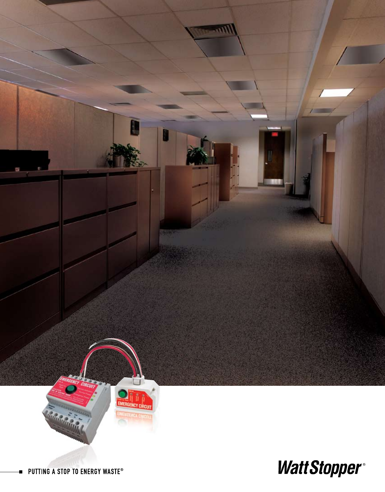
You can have it all,
energy savings and
emergency lighting
EMERGENCY LIGHTING CONTROL

Emergency lighting requirements
Benefits of controlling emergency lighting
Introducing WattStopper’s ELCU
Applications
Product details
Specifications
4
5
5-8
9-11
12-15
16
Table of
Contents
Safety and
Energy Savings
Emergency
Lighting Control Ensures

Offering energy savings through efficient
lighting control is what
WattStopper is all about. But when it
comes to emergency lighting, users want
complete reliability and security. We also
understand you want
the most flexibility in
your control options.
That’s why we’ve
developed the ELCU
emergency lighting
control product line.
It meets all these
needs:
• Eliminatesenergywastecausedby
always on emergency lighting
• Allowsyourchoiceofcontroldeviceto
switch emergency lighting in conjunction
with normal lighting
• CompatiblewithWattStopperoccupancy
sensors, lighting control panels,
daylighting controls and dimmers
• UL924listedforuseinemergency
circuits
• Testfeaturesfacilitatecodecompliance
• StatusLEDsenhancesafetyofpersonnel
• Canalsocontrolsupplementalstandby
lighting
Complete
reliability
and security
Safety and
Energy Savings
Imagine the Difference
Standard Emergency Lighting
• Limitedcontroloptions
• Onlyrespondstogeneralpoweroutage
• Burns24/7–wastesenergy
• Shorterlamplife
Emergency Lighting with ELCU
• Emergencylightsarecontrolledwith
normal lighting
• Respondstolocalpowerfailures
• Savesenergy
• Longerlamplifeandreduced
maintenance costs
• Canrespondtosecurityorfirealarms
• Convenienttestingoptions

54
Emergency lighting
rules and regulations
The National Fire Protection Agency’s Life Safety Code (NFPA 101) specifies illumination
requirements (in most cases, 1 footcandle) for specific areas in buildings with different
occupancies that must be immediately available to facilitate egress in the event of an emer-
gency.TheserequirementsarediscussedinArticle7.8“IlluminationofMeansofEgress,”
Article7.9“EmergencyLighting,”andarticlesdealingwithspecificoccupancies.While
egress lighting and emergency lighting do have separate definitions, one set of lighting is
typically used to meet the requirements of both definitions.
NFPA70,theNational Electrical Code, defines what kinds of equipment may be used, and
the installation and maintenance practices that must be followed, to meet the illumina-
tion requirements of the Life Safety Code. The NEC discusses Emergency Systems in
Article700,anddefinesthemas“thosesystemslegallyrequiredandclassedasemer-
gency by municipal, state, federal, or other codes, or by any governmental agency having
jurisdiction. These systems are intended to automatically supply illumination, power, or
both, to designated areas and equipment in the event of failure of the normal supply or in
the event of accident to elements of a system intended to supply, distribute, and control
powerandilluminationessentialforsafetytohumanlife.”
TheNECalsodefinesLegallyRequiredStandbySystems(Article701)andOptional
StandbySystems(Article702),whichareoftenconfusedwithEmergencySystems,since
all are designed for use in the event of power failures, emergencies, natural disasters,
fire, etc. To clarify, Emergency Systems are those essential for safety to life, Legally
Required Standby Systems are extra systems required for specific types of buildings to
provide power to aid in fire fighting, rescue operations, control of health hazards, etc.,
and Optional Standby Systems are those intended to minimize the disruption to business
caused by power failures.
Underwriters Laboratories tests and approves the components of emergency systems to
be safe for a specific use. Two distinct listing categories apply to emergency lighting and
power control equipment: UL 1008 and UL 924. UL 1008, Automatic Transfer Switches for
Use in Emergency Systems, applies to the switching gear that transfers the power feed for
the emergency circuits from the normal source to the emergency source and back. UL 924,
Standard for Safety for Emergency Lighting and Power Equipment, applies to most of the
components downstream of the transfer switch. All components of an emergency circuit
must be appropriately designed and listed.
NFPA
101
NEC
UL
Emergency lighting is required in all public
facilities, but what is meant by the broad
term,“emergencylighting,”andwhich
regulations spell out the equipment and
performance that are required? Here’s a
brief overview.
Testing requirements:
Both NFPA 101 and the NEC require periodic functional testing of emergency lighting equipment.
54
Energy savings
Most facilities operate emergency lighting
24/7.Thisrepresentsasignificantenergy
usage that is not necessary. Now, with the
ELCU product line, building owners and man-
agers can control this emergency lighting
along with their normal lighting for increased
energy savings. And by operating the lighting
for fewer hours, they will also realize savings
from longer maintenance intervals for emer-
gency lamp replacement.
Emergency lighting typically consumes .15 to
.25 watts per square foot, or 12 to 21 percent
of an average building’s lighting load. Over
half of this power usage can be eliminated
by turning these lights off along with normal
lighting, after hours and on weekends.
Enhancing safety
With an ELCU, building operators can be
confident emergency lighting will come on
when it’s needed. In fact, they
can be assured of optimal
response because the ELCU
provides control at the branch
circuit level and it will force
emergency lighting on even if
normal power is interrupted
in only part of a building.
What’s
more, they
can turn
emergency
lighting on
when they
want to,
such as for
emergency
preparedness drills or trainings. By connect-
ing ELCU units with security, fire alarm or
other life safety systems, building managers
can automate the activation of emergency
lighting when it makes the most sense.
ELCU products are specifically UL listed and
labeled for use in emergency lighting cir-
cuitsandincludeLEDpowerindicatorlights
designed to insure personnel safety.
Flexibility
Sometimes building occupants want the ability
toturnalllighting–evenemergencylighting
–off,suchasforpresentationsorfilmsin
theaters, lecture halls, auditoriums, or in
museum galleries or classrooms. With an
ELCU, this is easy to do.
Why control emergency
lighting?
ELCU provides
protection at
the branch
circuit level
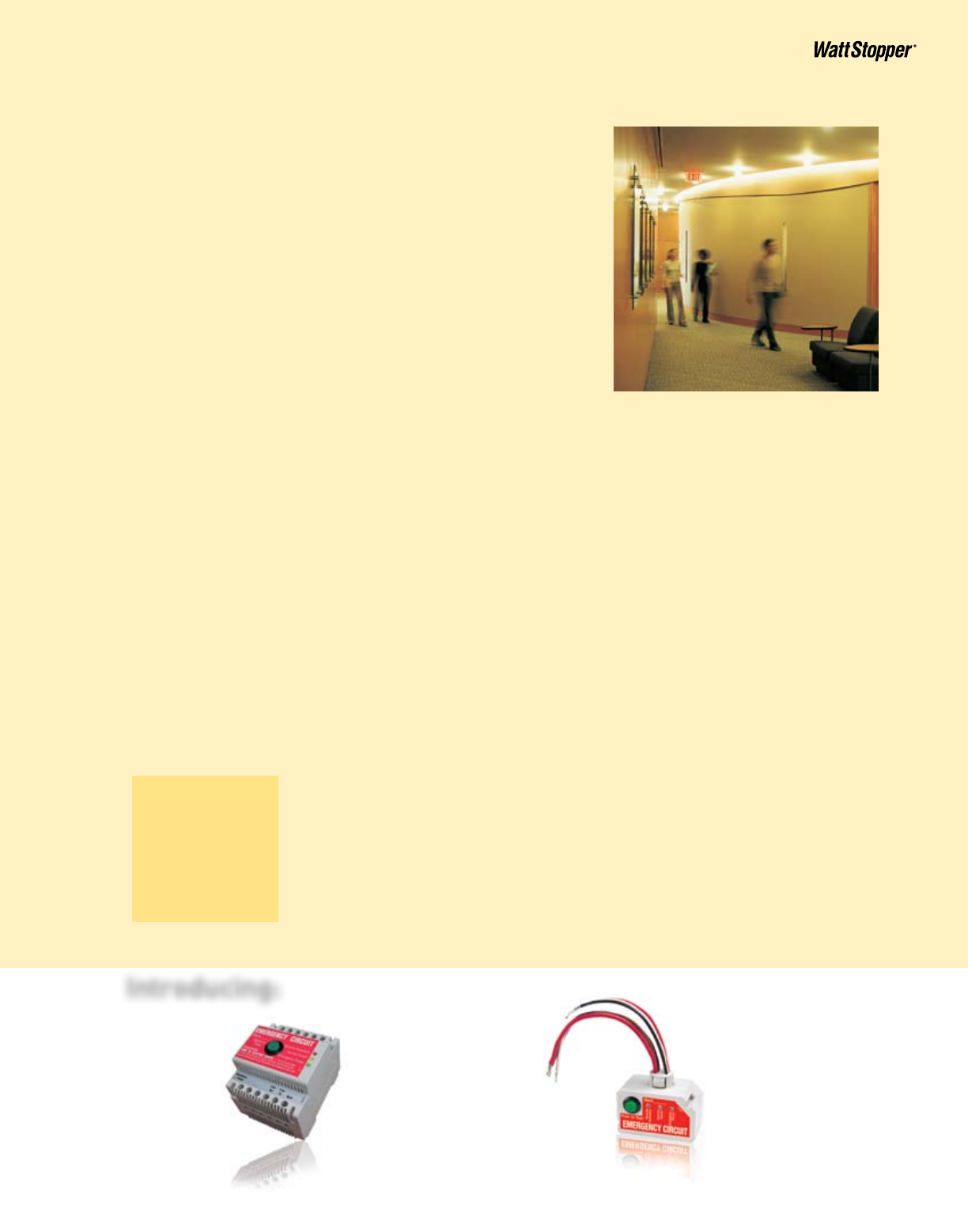
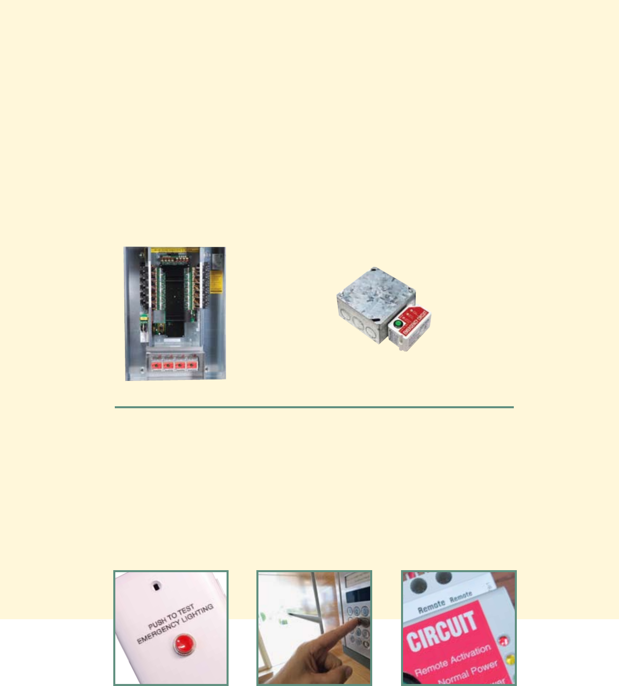
ELCU-100
DINrail-mountedcontroller
ELCU-200
Plenum-rated controller
Introducing:
Controllers offer
optimum flexibility
and safety
76
ELCU products monitor the status of the
normal power line and switch emergency
lights on only when they’re needed,
whether for normal usage or for an
emergency condition. An ELCU does this in
one of two ways, depending on whether it
is wired as a control device or as a bypass
device.
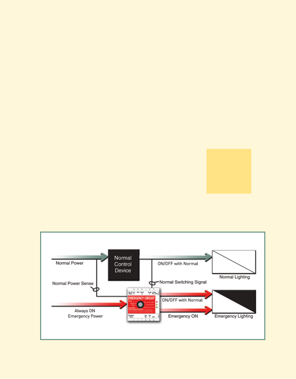
ELCU as a control device
An ELCU allows the status of normal
lightingcontroldevices–occupancy
sensors, lighting control panels, daylighting
controls–tocontrolemergencylightingin
tandem with normal lighting. It does this
by sensing the normal power line before
the control device and receiving a switching
signal from the line after the device.
When normal power is present to the
control device, and the device is feeding
power through to the normal lighting,
the ELCU switches the emergency
lights on. When normal power remains
uninterrupted, but the control device
turns the normal lighting off, the ELCU
follows suit and switches the emergency
lights off. However, when normal power to
the control device is lost for any reason,
the ELCU forces the emergency lights
onregardlessoftheon/offstatusofthe
control device.
This primary
application for ELCU
products allows
building owners and
designers to leverage
the energy saving
benefits of their control devices while still
complying with all the code requirements
for emergency lighting circuits.
Leverage the
energy saving
benefits
of control
devices
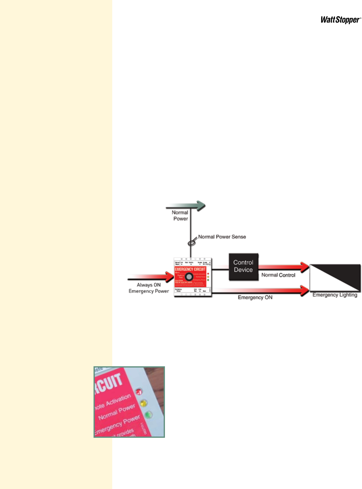
ELCU as a shunt or bypass device
In some cases it is desirable to have a
control device, often a line voltage dimmer,
on the emergency line in order to directly
control the emergency lighting. However,
that device must be bypassed in the
event of a power failure to ensure that
emergency lights come on, and come on at
full brightness. An ELCU provides a simple
solution for this kind of application too.
As a shunt, the ELCU senses the normal
power line. When power is present, it
allows the control device on the emergency
line to directly operate the emergency
lighting. In the event of a loss of normal
power, the ELCU completely bypasses the
control device, rerouting, or shunting, the
emergency line around it, immediately
forcing the emergency lighting on full in
compliance with code requirements.
76
Power status LEDs
AyellowstatusLEDindicatesthepresenceof
normalpower.AseparategreenLEDindicates
emergency power.
Select ELCU model
based on mounting
requirements
98
The ELCU-100
mounts on a
DINrail.
An ELCU should be mounted in close
proximity to the normal control device that
it is sensing. By offering two ELCU models,
WattStopper makes this easy to do. The
ELCU-100mountsonaDINrail,eitherin
a lighting control panel or in an enclosure.
The ELCU-200 mounts to a junction box
and is plenum-rated.
Remote control
options
The ELCU-200
mounts to a
junction box.
In addition to normal operation, an ELCU
can be instructed to turn emergency light-
ing on by a remote device. This could be
a conveniently located remote test switch
or another building system such as a fire
alarm or security system. When the unit
hasbeenactivatedremotely,astatusLED
on the ELCU indicates this condition.
98
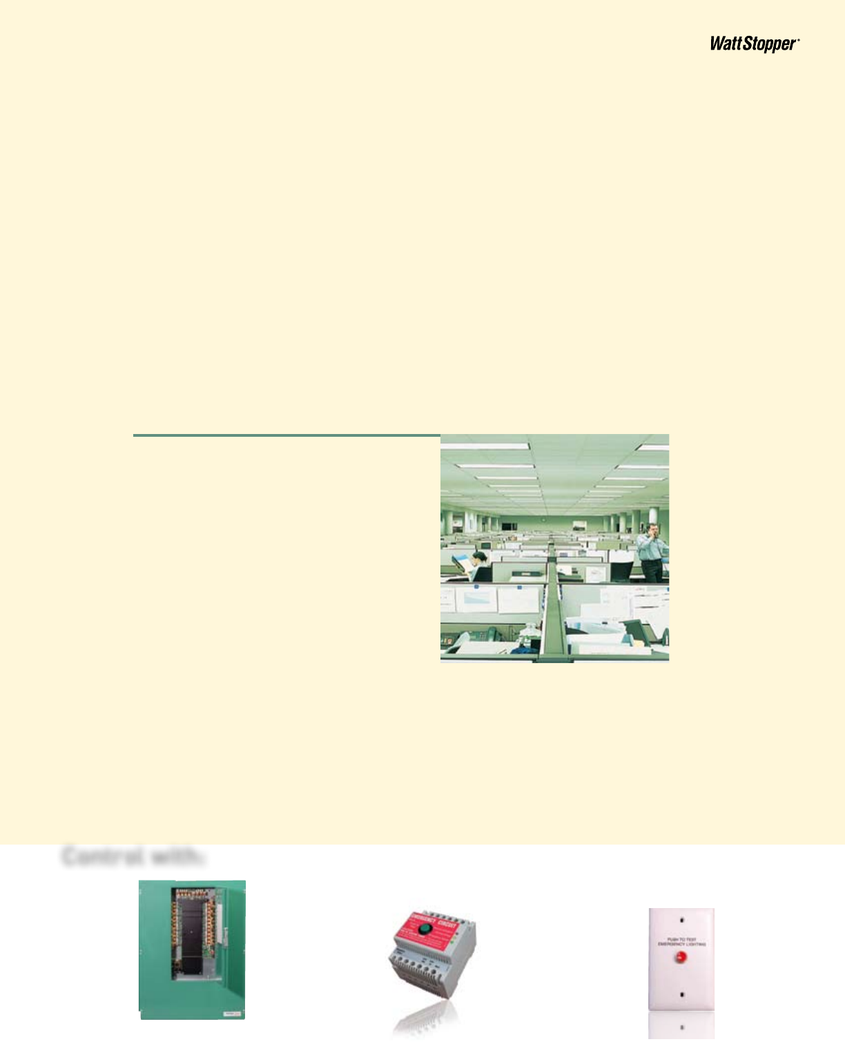
Open office
Large open space with multiple users
throughout the day.
Control needs:
Scheduled lighting control to ensure that lights
are on during periods of use and to switch lights
off overnight and during weekends and holidays
to meet energy code requirements.
Solution:
Overall switching is handled by a Lighting
Integrator panel. An ELCU-100 is installed on
the emergency circuit and connected to the
relay serving the area. The ELCU turns off the
emergency lights when the relay for the area is
turned off. If normal power to this relay is lost
for any reason, the emergency lights will turn on.
A remote test switch is installed in the
maintenance room for the floor for convenience.
Integrating ELCU
products into your
lighting designs
ELCUs are appropriate for emergency lighting,
night lighting and standby lighting applications
that include controls such as occupancy
sensors, lighting control panels, bi-level
controls, daylighting controls, dimmers and
switches.
An ELCU-100 is used for applications where
the normal control device is centrally located.
Examples include lobbies, corridors and some
open offices.
An ELCU-200 is used for applications where
the normal control device is located in the
space being controlled. Examples include
classrooms, conference rooms and open
offices with occupancy sensors.
Lighting Control Panel Emergency Lighting Controller Remote Test Switch
Control with:
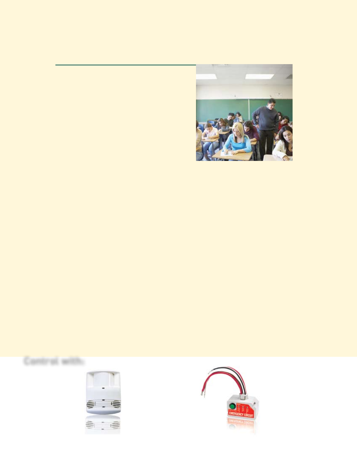
School classroom
Large room used for multiple purposes on
a complex schedule subject to change.
Control needs:
Bi-level switching to allow selection of the
right level of lighting for different activities.
Occupancy sensor to ensure that lights are
turned off during recesses, field trips and
all periods of vacancy.
Solution:
Lighting control is provided by a dual
technologyDT-200sensorinconjunction
with dual wall switches. An ELCU-200 is
installed on the emergency circuit, with
theswitchinglinewiredtoeitherthe“a”
or“b”portionofthenormallighting.The
ELCU turns the emergency lights on or off
along with the selected normal lighting. If
normal power is lost for any reason, the
emergency lights will turn on.
Additionally, the ELCU is connected to the
fire alarm system and emergency lights
will come on whenever the fire alarm is
activated regardless of the state of the
switches or the utility power.
11
10
Occupancy Sensor Emergency Lighting Controller
Control with:
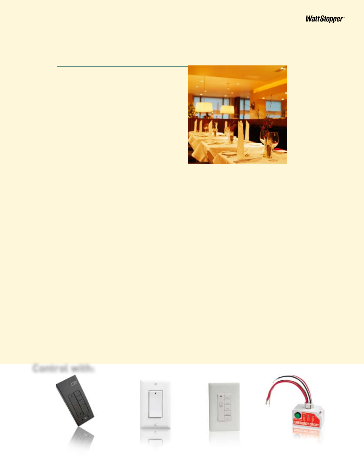
Restaurant
Diningandbarareasthatareopen
throughout the day and include upscale
decor that would be marred by unit
equipment.
Control needs:
Scene control with different looks for setup,
lunch, cocktails, dinner and cleanup.
Solution:
MiroDRD4andMR2000dimmersareused
for decorative and downlighting circuits
throughout the space.Two additional Miro
dimmers are used for emergency lighting
circuits along with ELCU-200s that are
wiredforshuntoperation.MiroDRD6scene
controllers are located near the entrance
andbehindthebar.AMiroMRD5handheld
scene controller gives the maitre d’ control
of all the dimmers from any location.
Duringnormaloperation,allofthe
dimmers respond to the scene controllers.
If power is lost, the ELCU will bypass
emergency power around the dimmer and
bring emergency lighting on at full
brightness.
11
10
Remote
Scene Controller
Room Scene
Controller
Miro Dimmer Emergency Lighting Controller
Control with:
Energy saving report
SCENE
DIM
DIGITA
L
PROJECT
LOCATION/TYPE
LIGHTING CONTROL PANEL SYSTEMS
12 www.wattstopper.com
800.879.8585
Emergency Lighting Control
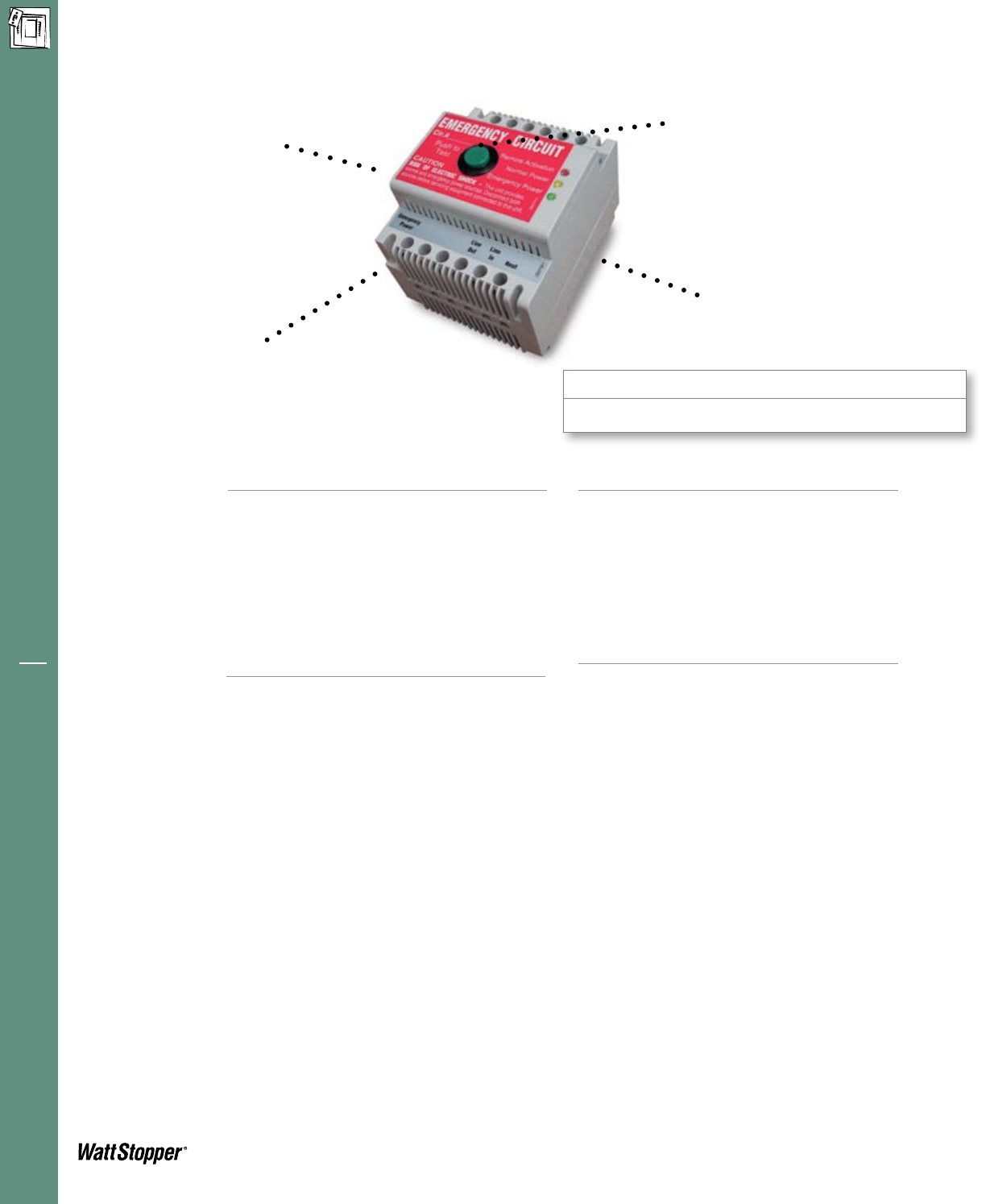
ELCU-100 Emergency Lighting Control Unit
• Eliminatesenergywastecausedby“alwaysON”
emergency lighting
• Integralpush-to-testbuttonactivatesemer-
gency mode for a true test condition
• Connectstoremotetestswitchorotherinputto
activate emergency ON from a remote location
• Operatesasacontroldeviceorasashunt
• Senseslocalsinglecircuitpowerfailure
• Zerocrossswitchingtechnologyforreliability
and increased product life
WattStopper’s Emergency Lighting Control Unit
(ELCU) is a self-contained, emergency lighting
control device. The ELCU provides all required
functionality to allow any standard lighting control
device to control emergency lighting in conjunction
with normal lighting in any area within a building.
Mounting
Applications
The ELCU is designed to control lighting in areas
where emergency lighting fixtures are connected
on dedicated emergency lighting circuits that are
typically on 24 hours per day. The ELCU allows
normal control of emergency lighting for energy
savingsand/ortaskrelatedreasonswhilestrictly
adhering to National Electric Code requirements.
It is suitable for any application where enhanced
energy saving is desired.
Operation
The ELCU monitors a single circuit that provides
normal lighting to an area. As long as normal
power is present, the ELCU permits lighting
control devices (i.e., occupancy sensors, panels,
dimmers, or wall switches) to control the emer-
gency lighting fixtures as well as the general
lighting. If power is lost for any reason, including
the tripping of a single branch circuit breaker, the
ELCU will force the emergency fixtures for that
area on. The ELCU can be wired either as a control
device, so that emergency lighting follows the
control of normal lighting, or as a bypass device to
shunt emergency power around a control device
when normal power fails.
Description
Product
Overview
Features • CompatiblewithWattStopperoccupancy
sensors, daylighting controls, lighting control
panels, and dimmers
• LEDindicationforemergencyandnormal
power
• Half-seconddelayedONpositivelyidentifies
emergency fixtures for required maintenance
• Providesabsolutefail-to-onemergencylighting
• UL924listed,meetsNEC,OSHAandNFPA
safety codes
TheELCUisequippedwithanintegralDINrail
mounting groove and retaining clip mechanism.
ItcanbeinstalledontheDINrailtrackprovided
within a WattStopper enclosure (i.e., LS-E8,
LS-E12), or in a WattStopper lighting control panel.
Interfaces with fire alarm
panel or security system
Guarantees emergency lighting
remains ON or is turned on when
power to the control device is lost
“Watchdog” feature allows
emergency loads to be controlled in
tandem with normal power loads
UL listed for use in
emergency circuits
Integrated push-to-test
button

Energy saving report
SCENE
DIM
DIGITA
L
LIGHTING CONTROL PANEL SYSTEMS
www.wattstopper.com | 800.879.8585 13
Emergency Lighting Control
System Wiring
Pub. No. 22105rev.08/2010
Ordering
Information
Specifications • 120/277VAC;60Hz
• Maximumload:
-Ballast 20A@120/277VAC
-Incandescent 10A@120/277VAC
-Motor 1HP@120VAC
• Remoteactivation:supplies24VDCsourcefor
dry contact closure
• Integralcontrol:push-to-testbuttononunit
• Housing:fireratedV-0,176°F(80°C)
• Terminaltorque:4/428inchpound-force
(0.5Nm)
• Dimensions:2.78”x3.44”x2.63”(71mmx
87mmx67mm)LxWxD
• UL,cULlistedEmergencyLightingandPower
Equipment;fiveyearwarranty
ELCU Wiring Diagrams
Jumper Wire or Normally
Closed Input from
• Test Switch
• Fire Alarm Input
• Security Input
• Other
Remote
In
Switch
In
Neut.
Line
In
Normal
Power
Emergency
Power
Line
In
Line
Out
Neut
Emergency
Lighting
Emergency Line
Emergency Neutral
"Sensing"
Line
"Switching"
Line
Remote
Out +24VDC
ELCU-100
Normal Line
Normal Neutral
Normal
Lighting
ON/OFF
Control
Device
Jumper Wire or Normally
Closed Input from
• Test Switch
• Fire Alarm Input
• Security Input
• Other
Remote
In
Switch
In
Neut.
Line
In
Normal
Power
Emergency
Power
Line
In
Line
Out
Neut
Emergency
Lighting
Emergency Line
Emergency Neutral
"Sensing"
Line
Remote
Out +24VDC
Dimmer
ELCU-100
Normal Line
Normal Neutral
Dimmer Normal
Lighting
When wired as a control device, the ELCU receives a
switching signal from the output of the control device
(relay, switch, power pack, etc.)
When wired as a shunt, the switching line is not used.
Note: Use with Watt Stopper universal dimmers or
contact dimmer manufacturer to determine the
suitablity of the specified dimmer for shunt operation.
CatalogNo.Description Voltage
ELCU-100
EMTS-100
LS-E8
LS-E12
120/277VAC;60Hz
24VDC,normallyclosedcontact
N/A
N/A
*LS-E8andLS-E12enclosuresincludescrewcoverandDINrail
Emergency Lighting Control Unit
Remote test switch on single gang plate
Surface Mount Enclosure for 1 or 2 ELCU units*
Surface Mount Enclosure for up to 6 ELCU units*
Energy saving report
SCENE
DIM
DIGITA
L
PROJECT
LOCATION/TYPE
LIGHTING CONTROL PANEL SYSTEMS
14 www.wattstopper.com
800.879.8585
Emergency Lighting Control
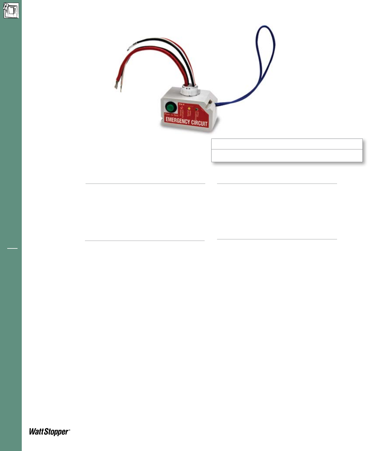
ELCU-200 Emergency Lighting Control Unit
• Eliminatesenergywastecausedbyemergency
lighting that is always on
• Integralpush-to-testbuttonactivates
emergency mode for a true test condition
• ConnectstoEMTS-100RemoteTestSwitchor
other input to activate emergency on from a
remote location
• Operatesasacontroldeviceorasashunt
• Senseslocalsinglecircuitpowerfailure
• Zerocrossswitchingtechnologyforreliability
and increased product life
WattStopper’s ELCU-200 Emergency Lighting
Control Unit is a self-contained device that allows
any standard lighting control device to control
emergency lighting in conjunction with normal
lighting in any area within a building.
Mounting
Operation
The ELCU-200 monitors a single circuit that
provides normal lighting to an area. As long as
normal power is present, the ELCU-200 permits
lighting control devices (e.g., occupancy sensors,
panels, dimmers, or wall switches) to control the
emergency lighting fixtures as well as the general
lighting. If power is lost for any reason, including
the tripping of a single branch circuit breaker, the
ELCU-200 will force on the emergency fixtures for
that area. The ELCU-200 can be wired either as a
control device, so that emergency lighting follows
the control of normal lighting, or as a bypass
device to shunt emergency power around a control
device (e.g., a dimmer) when normal power fails.
Description
Product
Overview
Features • CompatiblewithWattStopperoccupancy
sensors, daylighting controls, lighting control
panels, and dimmers
• LEDindicationforemergencyandnormal
power
• Half-seconddelayedonpositivelyidentifies
emergency fixtures for required maintenance
• Providesabsolutefail-to-onemergencylighting
• UL924listed,meetsNEC,OSHAandNFPA
safetycodes;UL2043plenumrated
• QualifiesforuseonARRA-fundedprojects
The ELCU-200 mounts directly to a junction box
orelectricalenclosurethathasastandard1/2”
knockout. It is compatible with all WattStopper
occupancy sensors, daylighting controllers and
power packs.
Interfaces with
fire alarm panel or
security system
UL listed for use in
emergency circuits
Integrated push-to-test button
Applications
The ELCU-200 is designed to control lighting
in areas where emergency lighting fixtures are
connected on dedicated emergency lighting
circuits that are typically on 24 hours per day. The
ELCU-200 allows normal control of emergency
lightingforenergysavingsand/ortaskrelated
reasons while strictly adhering to National Electric
Code (NEC) requirements. It is suitable for any
application where enhanced energy saving of
emergency lighting is desired.
Guarantees emergency lighting
remains ON or is turned on when
power to the control device is lost
“Watchdog” feature allows
emergency loads to be controlled in
tandem with normal power loads
Energy saving report
SCENE
DIM
DIGITA
L
LIGHTING CONTROL PANEL SYSTEMS
www.wattstopper.com | 800.879.8585 15
Emergency Lighting Control
Installation and
System Wiring
Pub. No. 29103rev9/2010
Ordering
Information
Specifications • 120/277VAC;60Hz
• Maximumload:
-Ballast 20A@120/277VAC
-Incandescent 10A@120VAC
-Motor 1HP@120VAC
• Remoteactivation:supplies24VDCsourcefor
dry contact closure
• Integralcontrol:push-to-testbuttononunit
• Housing:fireratedV-0,176°F(80°C)
• Operatingtemperaturerange:32to131°F(0to
55°C)
• Relativehumidityrange:5to95%,
noncondensing
• Dimensions:1.7”x2.97”x1.64”(43.2mmx
75.4mmx41.7mm)HxWxDwitha1/2“
(12.7mm)threadednipple
• UL,cULlistedEmergencyLightingandPower
Equipment;fiveyearwarranty
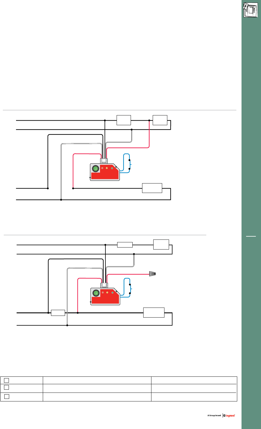
ELCU Wired As a Control Device
CatalogNo.Description Voltage
ELCU-200
ELCU-200-U
EMTS-100
120/277VAC;60Hz
120/277VAC;60Hz
24VDC,normallyclosedcontact
Emergency Lighting Control Unit
Emergency Lighting Control Unit, ARRA-compliant
Remote Test Switch on single gang plate
Emergency
Power Out
Standard wiring for switched control of emergency lighting
along with normal lighting
Alternate wiring for dimmer bypass on an emergency circuit
09860r1
Cir.#_______
Emergency
Power
Remote
Activation
Normal
Power
Push to Test
R8.5
mm
Circle
CUT-OUT
EMERGENCY CIRCUIT
Normal Line
Normal Neutral
Cut Jumper Loop
to use with
normally closed
- Test switch
- Fire alarm panel
- Security panel
- Other
Emergency
Power In
Emergency
Neutral
Emergency
Power Out
Normal
Neutral Normal
Switch Sense
Normal
Power Sense
Control
Device
Normal
Lighting
Emergency Line
“Always On”
Emergency Neutral
Emergency
Lighting
09860r1
Cir.#_______
Emergency
Power
Remote
Activation
Normal
Power
Push to Test
R8.5
mm
Circle
CUT-OUT
EMERGENCY CIRCUIT
Normal Line
Normal Neutral
Cut Jumper Loop
to use with
normally closed
- Test switch
- Fire alarm panel
- Security panel
- Other
Emergency
Power In
Emergency
Neutral
Normal
Neutral
Dimmer Normal
Lighting
Emergency Neutral
Emergency
Lighting
Dimmer
Cap
Emergency Line
“Always On”
Normal Switch Sense
Normal
Power Sense
Emergency
Power Out
Standard wiring for switched control of emergency lighting
along with normal lighting
Alternate wiring for dimmer bypass on an emergency circuit
09860r1
Cir.#_______
Emergency
Power
Remote
Activation
Normal
Power
Push to Test
R8.5
mm
Circle
CUT-OUT
EMERGENCY CIRCUIT
Normal Line
Normal Neutral
Cut Jumper Loop
to use with
normally closed
- Test switch
- Fire alarm panel
- Security panel
- Other
Emergency
Power In
Emergency
Neutral
Emergency
Power Out
Normal
Neutral Normal
Switch Sense
Normal
Power Sense
Control
Device
Normal
Lighting
Emergency Line
“Always On”
Emergency Neutral
Emergency
Lighting
09860r1
Cir.#_______
Emergency
Power
Remote
Activation
Normal
Power
Push to Test
R8.5
mm
Circle
CUT-OUT
EMERGENCY CIRCUIT
Normal Line
Normal Neutral
Cut Jumper Loop
to use with
normally closed
- Test switch
- Fire alarm panel
- Security panel
- Other
Emergency
Power In
Emergency
Neutral
Normal
Neutral
Dimmer Normal
Lighting
Emergency Neutral
Emergency
Lighting
Dimmer
Cap
Emergency Line
“Always On”
Normal Switch Sense
Normal
Power Sense
ELCU Wired As a Shunt, or Bypass, Device
When wired as a control device, the ELCU-200 receives a switching signal
from the output of the control device (relay, switch, power pack, etc.)
When wired as a shunt, the switching line is not used.
Note: Use with WattStopper universal dimmers or contact dimmer manufacturer to
determine the suitablity of the specified dimmer for shunt operation.

1. The Emergency Lighting Control Unit (ELCU) shall provide all
required functionality to allow any standard lighting control device
to control emergency lighting in conjunction with normal lighting
in any area within a building.
2. The emergency lighting control unit shall allow control of emer-
gency lighting fixtures in tandem with normal lighting in an area
while ensuring that emergency lighting will turn on immediately
to full brightness upon loss of normal power supplying the control
device. Emergency lighting operation shall be independent for
each controlled area and shall not require a generalized power
failure for proper operation.
3.Thedeviceshallbeself-contained,measure2.78”x3.44”x2.63”,
andprovideintegralDINrailchannelformountinginpanelorbox.
(ELCU-100)
or,
Thedeviceshallbeself-contained,measure1.70”x2.97”x1.64”,
and provide integral one half inch pipe nipple mount with snap
in locking feature for mounting into a standard junction box KO.
(ELCU-200)
4. The device shall have normally closed dry contacts capable of
switching20ampemergencyballastloads@120-277VAC,60Hz,
or10amptungstenloads@120VAC,60Hz.(ELCU-100)
or,
The device shall have normally closed dry contacts capable of
switching20ampemergencyballastloads@120-277VAC,60Hz,
or10amptungstenloads@120VAC,60Hz.(ELCU-200)
5. The device shall have universal rated voltage inputs provided for
normalpowersenseandnormalswitchedpowerat120-277VAC,
60 Hz.
6. The device shall have an integral momentary test switch (top
mounted on ELCU-100). Pressing and holding this switch shall
instantly force the unit into emergency mode and turn on emer-
gency lighting. Releasing the test switch shall immediately return
the unit to normal operation.
7.Theunitshallprovidededicatedterminals(ELCU-100),orleads
(ELCU-200),and24VDCsourceforconnectiontoremotetest
switch, fire alarm system, or other external system capable of
providing a normally closed dry contact closure. Breaking contact
between the terminals, or leads, shall force and hold the emer-
gency lighting on until the terminals are again closed. An integral
LEDindicatorshallindicatetheunit’scurrentremoteactivation
status.
8.ThedeviceshallprovideseparateLEDstoindicatethepresenceof
normalandemergencypowersources.TheLEDsshallindicate
the unit’s current operational mode (normal or emergency).
9. The device’s normal power input terminal (ELCU-100), or lead
(ELCU-200), shall be connected to the line side of the control
device such that any upstream fault causing a loss of power,
including the tripping of the branch circuit breaker, will force the
unit into the emergency mode and turn on the emergency lighting.
10. The unit shall automatically switch emergency lighting on and
off as normal lighting is switched. When normal power is not
available, the unit shall force and hold emergency lighting on
regardless of the state of any external control device until normal
power is restored.
11. The unit shall utilize zero crossing circuitry to protect relay con-
tacts from the damaging effects of inrush current generated by
switching electronic ballast loads.
12.UnithousingshallbeUL94V-Oplenumratedandshallbe
equipped with compression wire terminals (ELCU-100) rated
for #14 - #12 solid or stranded copper wire or with flying leads
(ELCU-200).
13. To ensure quality and reliability, the unit shall be manufactured
by an ISO 9002 certified manufacturing facility and shall have a
defectrateoflessthan1/3of1%.
14. The unit shall be UL and cUL listed and labeled for connection to
both normal and emergency lighting power sources.
15. The unit shall have a 5-year warranty.
2800DeLaCruzBlvd.
Santa Clara, CA 95050
TechSupport:800.879.8585
www.wattstopper.com
Please Recycle
WattStopper products and practices reflect
our commitment to sustaining out natural
resources. This project was manufactured
with papers made with recycled fiber to
conserve resources and reduce emissions.
WS-09-20072
Specifications
