Robotiq 2F 85 & 140 Instruction Manual PDF
2F-85 2F-140 Instruction Manual Pdf 20180725 2F-85_2F-140_Instruction_Manual_PDF_20180725 2F-85_2F-140_Instruction_Manual_PDF_20180725 support_s production robotiq-website-api 3:
2018-07-25
: Pdf 2F-85 2F-140 Instruction Manual Pdf 2F-85_2F-140_Instruction_Manual_PDF 20180725150835877 uploads production
Open the PDF directly: View PDF ![]() .
.
Page Count: 163 [warning: Documents this large are best viewed by clicking the View PDF Link!]
- Revisions
- 1. General Presentation
- 2. Safety
- 3. Installation
- 4. Control
- 4.1. Overview
- 4.2. Gripper Register Mapping
- 4.3. Robot Output Registers & Functionalities
- 4.4. Robot Input Registers & Status
- 4.5. Picking Features
- 4.6. Control Logic
- 4.7. Modbus RTU Communication
- 4.8. Control over Universal Robots with URCaps
- 4.9. Control over Universal Robots without URCaps
- 5. User Interface
- 6. Specifications
- 7. Maintenance
- 8. Spare Parts, Kits and Accessories
- 9. Troubleshooting
- 10. Warranty and Patent
- 11. Contact
- 12. Harmonized Standards, Declarations and Certificates
Robotiq 2F-85 & 2F-140
Instruction Manual robotiq.com | leanrobotics.org
Original Notice
© 2018 Robotic Inc.

Revisions 7
1. General Presentation 10
1.1. Gripper nomenclature 11
1.2. 2F-85 vs. 2F-140 12
1.3. Object picking 13
1.4. Setup and control 16
2. Safety 17
2.1. Warning 18
2.1.1. Risk assessment and final application: 18
2.2. Intended Use 19
3. Installation 20
3.1. Scope of Delivery 21
3.2. Required Tools and Equipment 22
3.3. Environmental and Operating Conditions 23
3.4. Mechanical Installation 24
3.4.1. Installing fingers on the Gripper 24
3.4.2. Installing the fingertips or finger pads on the Gripper 25
3.4.3. Installing the Gripper onto the robot: 26
Multiple Grippers 26
3.5. Electrical Setup 27
3.6. Testing the Gripper 30
3.7. Installation for Universal Robots 32
3.7.1. Multiple Grippers wiring 33
3.8. URCap Package 34
3.8.1. Installing URCap Package 35
Multiple Grippers 37
3.8.2. Uninstalling URCap Package 39
3.8.3. License Agreement 40
3.9. URPackage without URCaps 43
3.9.1. Installation 44
4. Control 45
4.1. Overview 45
2F-85 &2F-140 - Instruction Manual
2

2F-85 &2F-140 - Instruction Manual
4.2. Gripper Register Mapping 47
4.3. Robot Output Registers &Functionalities 48
4.4. Robot Input Registers &Status 51
4.5. Picking Features 54
4.5.1. Force control 54
4.5.2. Re-Grasp 59
4.5.3. Object detection 60
4.6. Control Logic 61
4.7. Modbus RTUCommunication 62
4.7.1. Connection Setup 63
4.7.2. Read holding registers (FC03) 64
4.7.3. Read input registers (FC04) 65
4.7.4. Preset multiple registers (FC16) 66
4.7.5. Master read & write multiple registers FC23 67
4.7.6. Modbus RTU example 69
4.8. Control over Universal Robots with URCaps 78
4.8.1. Gripper Dashboard 79
Overview 79
Single Gripper 79
Multiple Grippers 80
Features 80
4.8.2. Gripper Calibration menu and wizard 81
Features 83
4.8.3. Gripper Toolbar 85
Overview 85
Single Gripper 86
Multiple Grippers 87
Features 88
Gripper activation 88
Gripper operation window 89
Show/hide Gripper Toolbar 90
4.8.4. Gripper Node 90
Command window 91
Features 94
3

2F-85 &2F-140 - Instruction Manual
Edit action screen 96
Single Gripper 96
Multiple Grippers 97
Features 98
Grip Check node 99
About 100
Error messages overview 101
Gripper Program Template 101
Advanced Gripper Functions 102
Single Gripper 102
Multiple Grippers 104
4.8.5. Retro-compatibility of URCaps with legacy driver programs 107
4.9. Control over Universal Robots without URCaps 109
4.9.1. Gripper Toolbar 109
Overview 109
Features 110
Toolbar collapsed 110
Toolbar expanded 111
4.9.2. Demo Scripts 113
4.9.3. Custom Programs 114
4.9.4. Provided Variables and Functions 115
5. User Interface 117
6. Specifications 118
6.1. Technical dimensions 119
6.1.1. Couplings 123
Blank coupling 123
Coupling for ISO 9409-1-50-4-M6 124
Coupling for ISO 9409-1-31.5-4-M5 125
Coupling for ISO 9409-1-40-4-M6 126
Coupling for PCD 56 with 8 x M4 127
Coupling for PCD 56 with 6 x M4 128
Coupling for PCD 60 with 4 x M5 129
Coupling for PCD 63 with 6 x M6 130
4

2F-85 &2F-140 - Instruction Manual
6.1.2. Fingertips 131
Blank fingertip 132
Flat silicone fingertip 133
Grooved fingertip 134
6.2. Mechanical specifications 135
6.2.1. Payload and force 136
6.2.2. Equilibrium Line 139
6.2.3. Center of mass, tool center point and moment of inertia 140
6.2.4. Moment and force limits 143
6.3. Electrical specifications 144
7. Maintenance 145
7.1. Gripper cleaning 147
7.2. Periodic inspection 149
7.3. Fingertip replacement 150
7.4. Overhaul 151
8. Spare Parts, Kits and Accessories 152
9. Troubleshooting 155
10. Warranty andPatent 158
11. Contact 161
12. Harmonized Standards, Declarations and Certificates 162
12.1. Translation of original EC declaration of incorporation 162
12.2. Applied standards 163
5

2F-85 &2F-140 - Instruction Manual
6

Revisions
Robotiq may modify this product without notice, when necessary, due to product improvements, modifications or changes in
specifications. If such modification is made, the manual will also be revised, see revision information. See the latest version of this
manual online at support.robotiq.com.
Revision 2018/05/23
lMajor update following the release of UCG-1.2.0
lNew subsections in Section 4: Control
lGripper Dashboard
lGripper Calibration menu and Calibration wizard for object validation
Revision 2017/06/06
Added section:
l4.8.2.1 Multiple Grippers
Revised sections:
l3.8.1 Installation procedure for URCaps
l4.8.1 Gripper Toolbar
Revision 2016/07/04
Major revision : Updated for URcaps release Section added :
l3.8 URCaps Package
l3.9 UR Package without URCaps
l4.8 Control over Universal Robots with URCaps
l4.9 Control over Universal Robots without URCaps
Revision 2015/09/15
Major revision : Updated for 2-Finger 140
Revision 2015/07/21
Section added :
l4.5 Picking features : Force control, re-grasp and object detection.
lA. Harmonized standards, declarations and certificates
Minor modifications :
lSection 1. General Presentation
lSection 3.7 Universal Robots package
Revision 2014/11/05
Modification for Robotiq 2-Finger 85 Adaptive Robot Gripper version 3
Revision 2014/07/22
2F-85 &2F-140 - Instruction Manual
7

2F-85 &2F-140 - Instruction Manual
Modification for use on Robotiq Universal Controller
Minor modifications : User Interface section, maintenance section
Revision 2013/02/06
Section added : Couplings ISO models and Baxter robots Minor modifications
Revision 2013/02/06
Section added : Communication with UR robots Minor modifications
Revision 2012/10/18
Official release
Revision 2012/03/02
Beta release
8

2F-85 &2F-140 - Instruction Manual
Copyright
© 2016 Robotiq Inc. All rights reserved.
This manual and the product it describes are protected by the Copyright Act of Canada, by laws of other countries, and by international
treaties, and therefore may not be reproduced in whole or in part, whether for sale or not, without prior written consent from Robotiq.
Under copyright law, copying includes translation into another language or format.
Information provided by Robotiq in this document is believed to be accurate and reliable. However, no responsibility is assumed by
Robotiq for its use. There may be some differences between the manual and the product if the product has been modified after the
edition date.
The information contained in this document is subject to change without notice.
9

1. General Presentation
The terms "Gripper", "Adaptive Gripper", "Robotiq Gripper", "Robotiq Adaptive Gripper", "2-Finger 85", "2-Finger 140", "2F-85"
and "2F-140" used in the following manual all refer to the Robotiq 2-Finger Adaptive Robot Gripper. The Robotiq 2-Finger Adaptive
Gripper has two versions, 85 and 140. The 2-Finger version will change finger opening dimensions, which will be 85 mm (2F-85) or
140mm (2F-140). Both versions use the same base, installation and control will be exactly the same. The 2-Finger Gripper is a robotic
peripheral that is designed for industrial applications. Its design makes it a unique robotic end-of-arm tool to quickly pick, place and
handle a large range of parts of varying sizes and shapes.
Info
Unless specified, information in this manual applies to both the 85 and the 140 mm version of the 2-Finger Adaptive Robot
Gripper.
Info
The following manual uses the metric system, unless specified, all dimensions are in millimeters.
Info
The following section presents the key features of the Gripper and must not be considered as appropriate to Gripper
operation, each feature is detailed in the appropriate section of the manual. Safety guidelines must be read and understood
before any operation is attempted with theGripper.
2F-85 &2F-140 - Instruction Manual
10
2F-85 &2F-140 - Instruction Manual
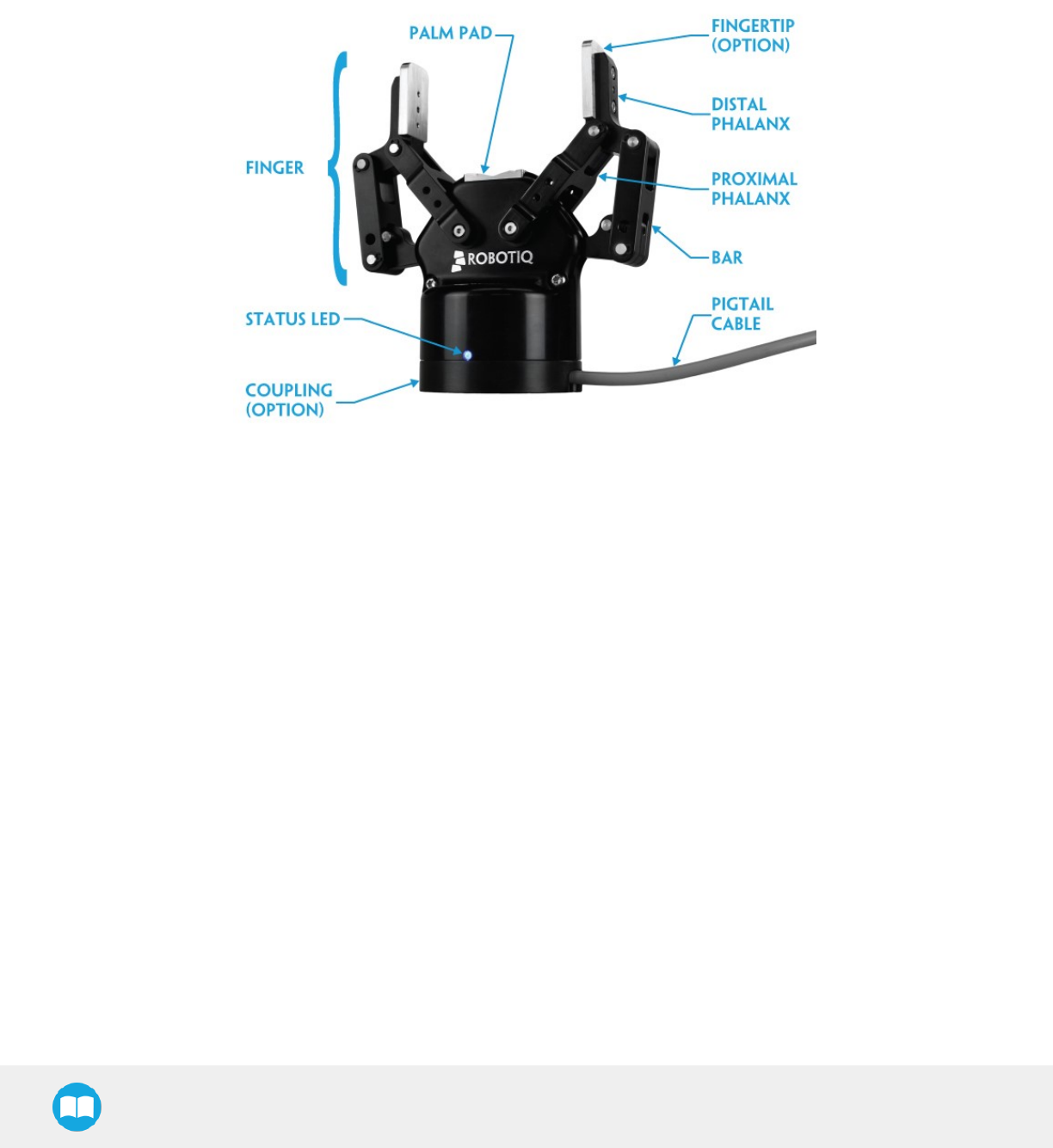
1.1. Gripper nomenclature
The 2-Finger Gripper has two articulated fingers that each have two joints (two phalanxes per finger), as shown in the figure below. The
Gripper can engage up to five points of contact with an object (two on each of the phalanges plus the palm). The fingers are under-
actuated, meaning they have fewer motors than the total number of joints. This configuration allows the fingers to automatically adapt
to the shape of the object they grip and it also simplifies the control of the Gripper.
Fig. 1-1: Robotiq 2-Finger Adaptive Gripper.
Please refer to the for details on standard and optional parts.
The status LED presented in the figure above will be :
lsolid blue/red when booting
lsolid blue when powered with no errors (while communication is active)
lsolid red if minor fault occurs, see status details in the Control section.
lblinking red/blue if major fault occurs, see status details in the Control section.
11
2F-85 &2F-140 - Instruction Manual
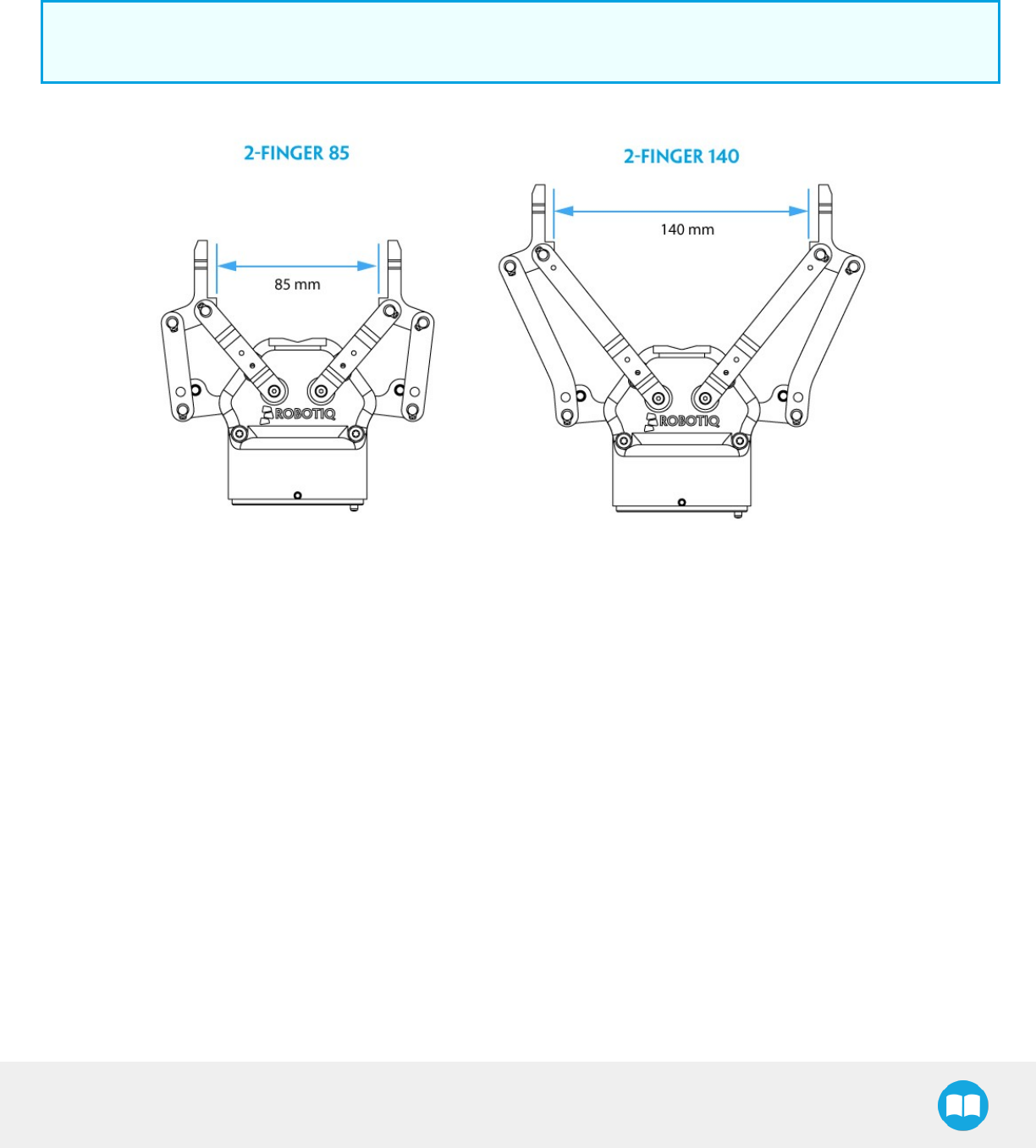
1.2. 2F-85 vs. 2F-140
The 2-Finger Gripper comes with either 85 mm opening (2-Finger 85) or 140 mm opening (2-Finger 140) according to the figure below.
The Gripper chassis will remain the same, only the fingers will change. Please refer to the Mechanical Installation section for installation
instructions. Finger kits are available in the Spare Parts and Accessories section.
Info
Details on the 2-Finger 85 and 2-Finger 140 (dimensions and specifications) can be found in the Specifications section.
Fig. 1-2: The 2-Finger 85 and 140 mm versions.
12
2F-85 &2F-140 - Instruction Manual
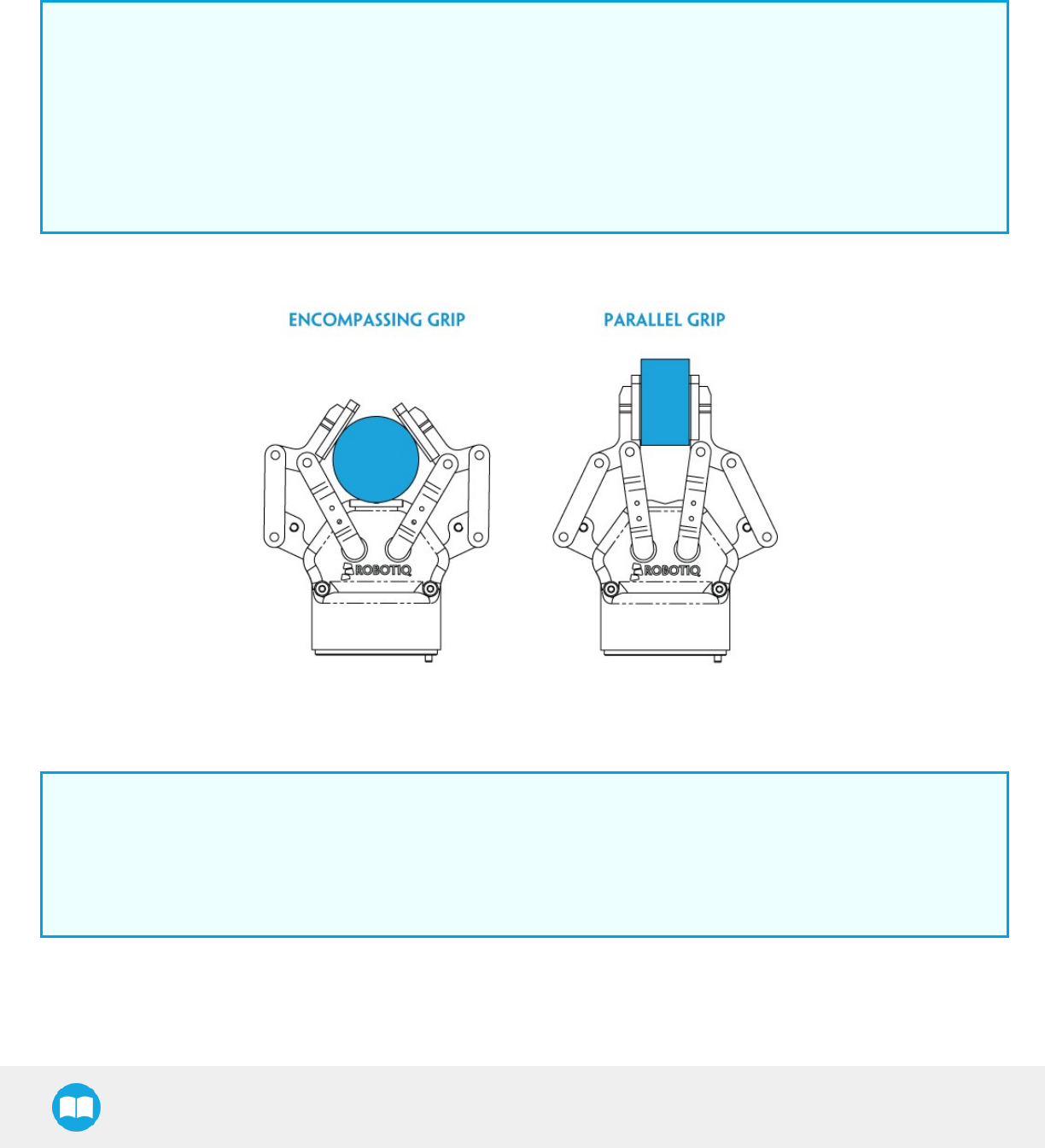
1.3. Object picking
The 2-Finger Gripper has a single actuator for opening and closing the fingers, the fingers automatically adapt to the shape of the
object manipulated.
Fingers will adopt either a parallel grip or encompassing grip as shown in the figure below.
Info
Closing or opening is done via the "Go to requested position" command and is input to the Gripper Whether the fingers
close to produce an emcompassing or fingertip grip is decided at the Gripper level automatically. It will depend on:
lThe part's geometry;
lThe relative position of the part with respect to the Gripper.
In other words, picking the same part could result in either an emcompassing or fingertip grip based on a part's position and
geometry.
Fig. 1-3: 2-Finger parallel and encompassing grips.
Info
It is important to note that a fingertip grip can only be performed when the fingers touch the object with the upper section of
the distal phalanxes first. Inversely, for an encompassing grip, the fingers must touch the object with the proximal or the lower
section of the distal phalanxes first. Also, to ensure stability, the object should be held against the Gripper palm while
performing an encompassing grip. Refer to the figure below for a visual representation of the parallel and encompassing
grip regions on the distal phalanx of the 2-Finger Gripper.
13
2F-85 &2F-140 - Instruction Manual
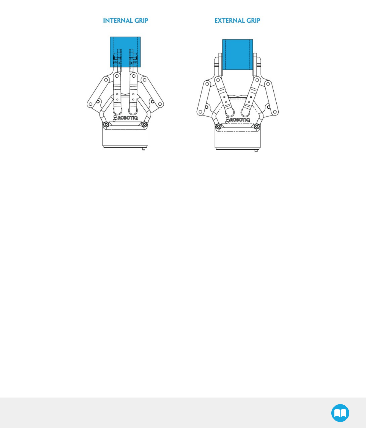
The 2-Finger Adaptive Robot Gripper also allows for internal gripping. The fingers can pick hollow parts from the inside by applying
pressure with the outside of the fingers. Refer to the figure below for a visual representation and to the Picking Features section for
details on the possible position commands of your Gripper.
Fig. 1-4: Finger internal and external gripping.
14
2F-85 &2F-140 - Instruction Manual
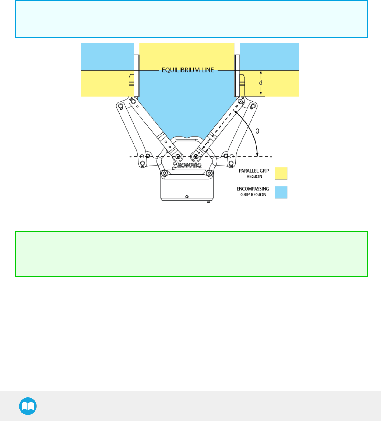
The Gripper equilibrium line is the gripping region that separates the encompassing grip from the parallel grip. When gripping an
object close enough to the inside (palm) of the Gripper, the encompassing grip will occur (unless the object size or shape is not
adequate) and the fingers will close around theobject.
If gripped above the equilibrium line, the same object will be picked up in a parallel grip by the fingertips and the fingers will close with
a parallel motion. The figure below shows the encompassing grip region, the equilibrium line, and the parallel grip region on the2-
Finger Adaptive Robot Gripper.
Info
The details of the equilibrium line relation between opening angle and the related position d can be found in the Mechanical
specifications section.
Fig. 1-5: Equilibrium line on the 2-Finger, shown with no fingertip pads.
Tip
Gripping an object that could be grasped by an encompassing grip (a cylinder for example) on the equilibrium line is not
recommended, as slight variations on the position will switch the grip from parallel to encompassing and vice versa. Robot
programming should be done so that the gripping mode will be predetermined.
15

2F-85 &2F-140 - Instruction Manual
1.4. Setup and control
The Gripper is powered and controlled directly via a single Device Cable that carries a 24V DC supply and Modbus RTU
communication over RS-485, see Section 3.5 for wiring information and Section 4 for control of the Gripper (various software packages
are available for control via various robotcontrollers).
Info
Robotiq Universal Controller is available when industrial communication protocols are required (other then Modbus RTU
over serial).
Gripper Coupling is required for 2-Finger usage, the Coupling will provide mechanical and electrical connectivity. Please refer to the
Mechanical Installation section for installation of the Coupling, to the Specifications section for technical drawings, and to the Spare
Parts, Kits and Accessories section for available couplings.
The 2-Finger has an embedded object detection feature using indirect sensing methods. When picking an object via the "go to"
command, the Gripper status will allow you to know if an object is picked or not via a simple object detection bit (0 or 1). When an
object is detected, the Gripper will stop. If the object is being dropped, the Gripper will automatically close to keep the object until the
''go to'' command limit is attained. For details on object detection, see Control section.
16

2. Safety
Warning
The operator must have read and understood all of the instructions in the following manual before handling the Robotiq
2-Finger Adaptive Robot Gripper.
Caution
The term "operator" refers to anyone responsible for any of the following operations on the 2-Finger Adaptive Robot
Gripper:
lInstallation
lControl
lMaintenance
lInspection
lCalibration
lProgramming
lDecommissioning
This documentation explains the various components of the 2-Finger and general operations regarding the whole life-cycle of the
product from installation to operation and decommissioning.
The drawings and photos in this documentation are representative examples and differences may exist between them and the delivered
product.
2F-85 &2F-140 - Instruction Manual
17

2F-85 &2F-140 - Instruction Manual
2.1. Warning
Caution
Any use of the Gripper in noncompliance of these warnings is inappropriate and may cause injury or damage.
Warning
lThe Gripper needs to be properly secured before operating the robot.
lDo not install or operate a Gripper that is damaged or lacking parts.
lNever supply the Gripper with an alternative current source.
lMake sure all cord sets are always secured at both ends, at the Gripper and at the robot.
lAlways satisfy the recommended keying for electrical connections.
lBe sure no one is in the robot and/or Gripper path before initializing the robot's routine.
lAlways satisfy the Gripper payload.
lSet the Gripper pinch force and speed accordingly, based on your application.
lKeep fingers and clothes away from the Gripper while the power is on.
lDo not use the Gripper on people or animals.
lFor welding applications, make sure there are no Gripper parts on the ground path of the welding power source.
Any use of the Gripper in noncompliance of these warnings is inappropriate and may cause injury or damage.
2.1.1. Risk assessment and final application:
The Robotiq 2-Finger Adaptive Gripper is meant to be used on an industrial robot. The robot, Gripper and any other equipment used
in the final application must be evaluated with a risk assessment. It is the robot integrator's duty to ensure that all local safety measures
and regulations are respected. Depending on the application, there may be risks that need additional protection/safety measures, for
example, the work-piece the Gripper is manipulating may be inherently dangerous to the operator.
18

2F-85 &2F-140 - Instruction Manual
2.2. Intended Use
The Gripper unit is designed for gripping and temporarily securing or holding parts.
Caution
The Gripper is NOT intended for applying force against objects or surfaces.
The product is intended for installation on a robot or other automated machinery and equipment.
Info
Always comply with local and/or national laws, regulations and directives on automation safety and general machine safety.
The unit may be used only within the range of its technical data. Any other use of the product is deemed improper and unintended use.
Robotiq will not be liable for any damages resulting from any improper or unintended use.
19

3. Installation
The following subsections will guide you through the installation and general setup of your Robotiq 2-Finger Adaptive Robot Gripper.
lSection 3.1 details the scope of delivery for the 2-Finger, verify your package.
lSection 3.2 lists the required tools, parts and equipment for proper use of your Gripper.
lSection 3.3 explains the operating conditions that must be met for the 2-Finger to operate normally.
lSection 3.4 guides you through the mechanical installation using the 2-Finger Coupling and other optional parts.
lSection 3.5 describes the required electrical set up of the Gripper, its power source and communication wiring.
lSection 3.6 explains you how to test the Gripper via the Robotiq User Interface.
lSection 3.7 explains how to get and install software packages meant to control your Gripper with Universal Robots
lFinally, section 3.8 and 3.9 will explain you how to install / uninstall the URCaps package or the legacy driver package provided for
UniversalRobots.
Warning
Before installing:
lRead and understand the safety instructions related to the 2-Finger Adaptive Robot Gripper.
lVerify your package according to the Scope of delivery and your order.
lHave the required parts, equipment and tools listed in the requirements readily available
Warning
When installing:
lSatisfy the environmental conditions.
lDo not operate the Gripper, or even turn on the power supply, before it is firmly anchored and the danger zone is cleared.
The fingers of the Gripper may move and cause injury or damage.
2F-85 &2F-140 - Instruction Manual
20

2F-85 &2F-140 - Instruction Manual
3.1. Scope of Delivery
Robotiq 2-Finger Adaptive Gripper 85 Robotiq 2-Finger Adaptive Gripper 140
Standard upon delivery:
lRobotiq 2-Finger Adaptive Gripper85 complete unit: AGC-GRP-
002
l85 mm opening fingers without fingertips or pads (these
are bought separately unless specified)
lPalm pad
lUSBto RS-485 signal converter: ACC-ADT-USB-RS485
Standard upon delivery:
lRobotiq 2-Finger Adaptive Gripper140 complete unit: AGC-
GRP-140
l140 mm opening fingers without fingertips or pads (these
are bought separately unless specified)
lPalm pad
lUSBto RS-485 signal converter: ACC-ADT-USB-RS485
Depending on your choice:
lCoupling according to your robot bolt pattern:
AGC-CPL-XXX-002
Info
Please refer to the Spare Parts, Kits and Accessories
section for a list of availablecouplings.
lRobotiq device cable:
lCBL-COM-2065-10-HF for 10 meters cable
Depending on your choice:
lCoupling according to your robot bolt pattern:
AGC-CPL-XXX-002
Info
Please refer to the Spare Parts, Kits and Accessories
section for a list of availablecouplings.
lRobotiq device cable:
lCBL-COM-2065-10-HF for 10 meters cable
Info
The following are not included in standard delivery:
lOptions such as adapter plates or couplings for mounting on various industrial robots, fingertips or finger pads.
lHardware required for options; accessories or fixtures for the 2-Finger Adaptive Robot Gripper, unless specified.
lPower supply units, power supply wiring or fuses.
Info
When bought as a kit, the 2-Finger 85 or 140 will come in a package with the appropriate coupling, fingertips or finger pads
and cabling. Please refer to the Spare Parts, Kits and Accessories section.
21

2F-85 &2F-140 - Instruction Manual
3.2. Required Tools and Equipment
The following tools are required to install the 2-Finger Adaptive Gripper:
l4 mm hex key to mount the Gripper onto its coupling.
lMetric hex key according to your coupling to mount the coupling onto the robot.
Optional tools if installing finger kits : AGC-FIN-KIT-085 or AGC-FIN-KIT-140:
l5 - 6 mm snap ring pliers
l2 mm hex key
The following parts are required for setup :
lPower supply (see below).
lFuse, see information below.
lEmergency stop is not provided, but its use is strongly advised.
The Gripper needs to be supplied by a DC voltage source. This power supply is not included with the Gripper. Required power supply
must match the Robotiq device. The following table shows the specifications with regards to the power supply required to operate the
Gripper and the optional Robotiq Controller.
SPECIFICATION VALUE
Output voltage 24 V DC ±10%
Output current 1 A
Overcurrent
Recommended power supply with internal protection, otherwise fusing is
required.
2 A fuse at 25°C [77°F]1
Table 3-1: 2-Finger power supply requirements.
Info
1Suggested fuse is a: Phoenix Contact # 0916605 2 A thermal, use AWG #20 wiring.
Warning
If your power supply could exceed the specified regulation, over-voltage protection is required.
Robotiq recommends the use of the following power supplies:
lFor the 1A output current: TDK-Lambda DPP Series, 100W Single Output DIN Rail Mount Power Supply:DPP30-24.
Tip
Optional Robotiq Universal Controller can use the same power supply.
22

2F-85 &2F-140 - Instruction Manual
3.3. Environmental and Operating Conditions
CONDITION VALUE
Minimum storage/transit
temperature -30°C [-22°F]
Maximum storage/transit
temperature 60°C [140°F]
Minimum operating temperature -10°C [14°F]
Maximum operating temperature 50°C [122°F]
Humidity (non-condensing) 20-80% RH
Vibration < 0.5G
Others
lFree from dust, soot or water
lFree from corrosive liquids or gases
lFree from explosive liquids or gases
lFree from powerful electromagnetic inter-
ference
Table 3-2: Environmental and operating conditions of the 2-Finger Adaptive Gripper.
23
2F-85 &2F-140 - Instruction Manual
3.4. Mechanical Installation
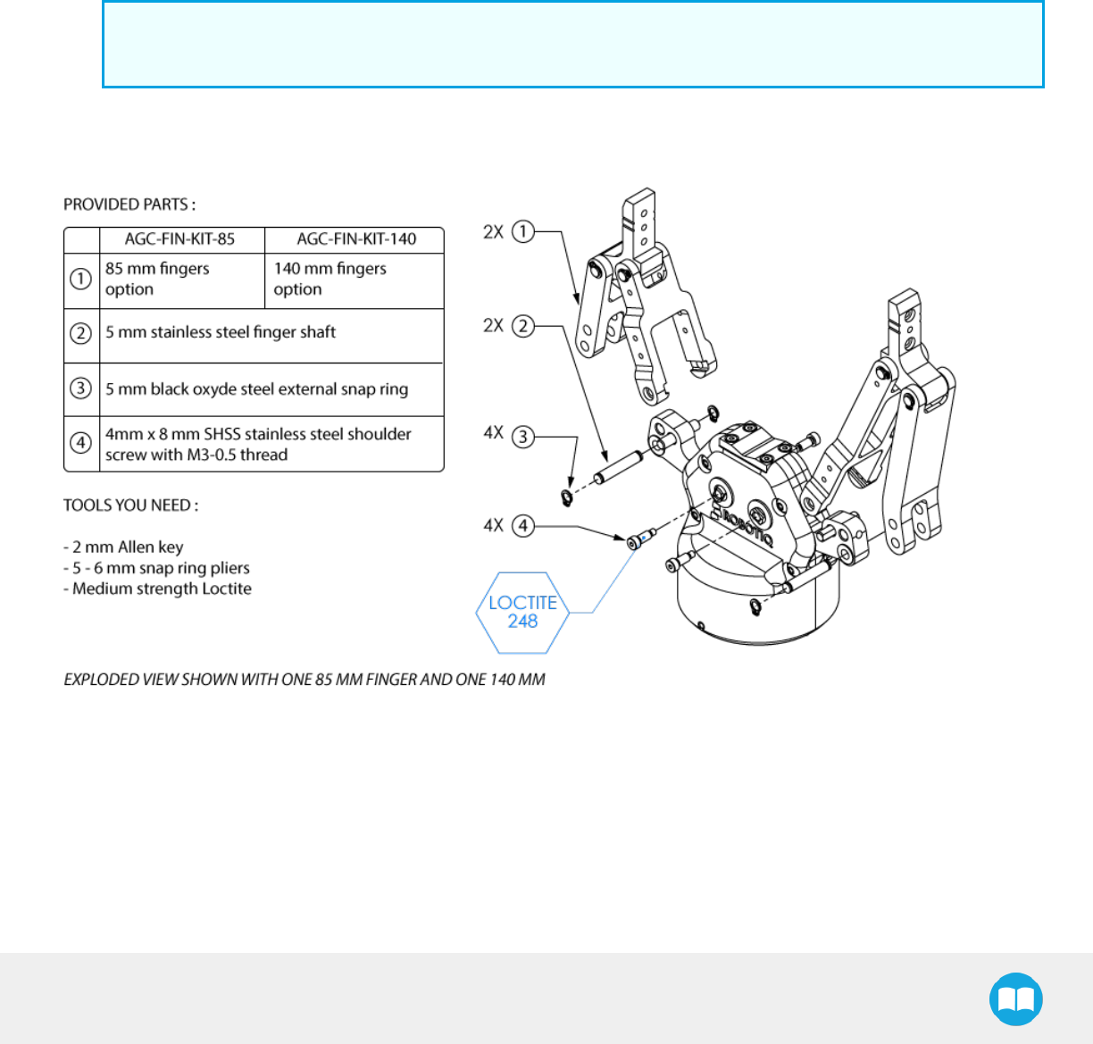
3.4.1. Installing fingers on the Gripper
Depending on your order, you may or may not have fingers already mounted on the Gripper. The first step of installation should be to
install the fingers. Refer to the figure below for finger placement. To do so :
1. Align fingers on chassis axes. To do so, the slot present on the finger bar must be aligned correctly to the corresponding chassis
axis.
2. Insert finger shaft between finger bar bottom hole (top hole is for parallel locking) and corresponding chassis hole.
a. Fix in place by inserting snap rings on both sides of the shaft using snap ring pliers.
Info
Use protective glasses when using snap ring and snap ring pliers.
3. Apply medium strength thread-locker to the provided stainless steel shoulder screws, align the finger bar and screw into the
chassis axis.
Fig. 3-1: 2-Finger Adaptive Gripperinstallation.
24
2F-85 &2F-140 - Instruction Manual
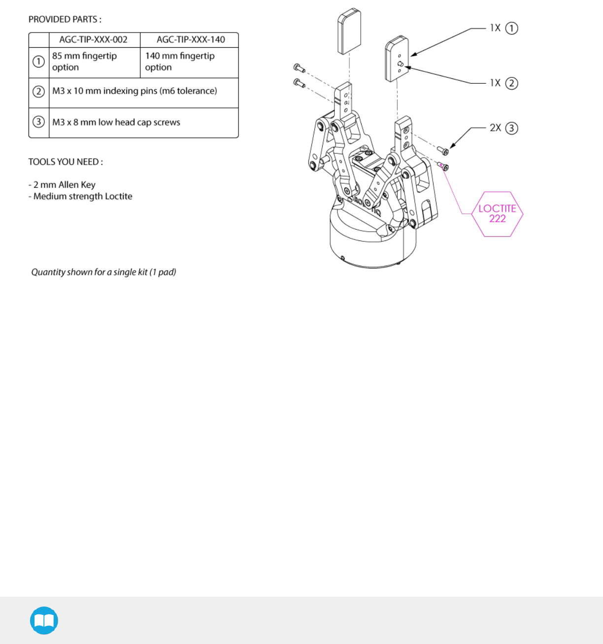
3.4.2. Installing the fingertips or finger pads on the Gripper
Depending on your options, you may have fingertips to install. The second step of the installation should be to install the fingertips. To
do so :
1. Align the fingertip indexing pin to the fingertip dowel hole.
2. Insert the two M3-0.5 x 8 low head cap screws and screw on after applying medium strength thread-locker.
Fig. 3-2: Installing the fingertip (pads) onto the Gripper
25
2F-85 &2F-140 - Instruction Manual
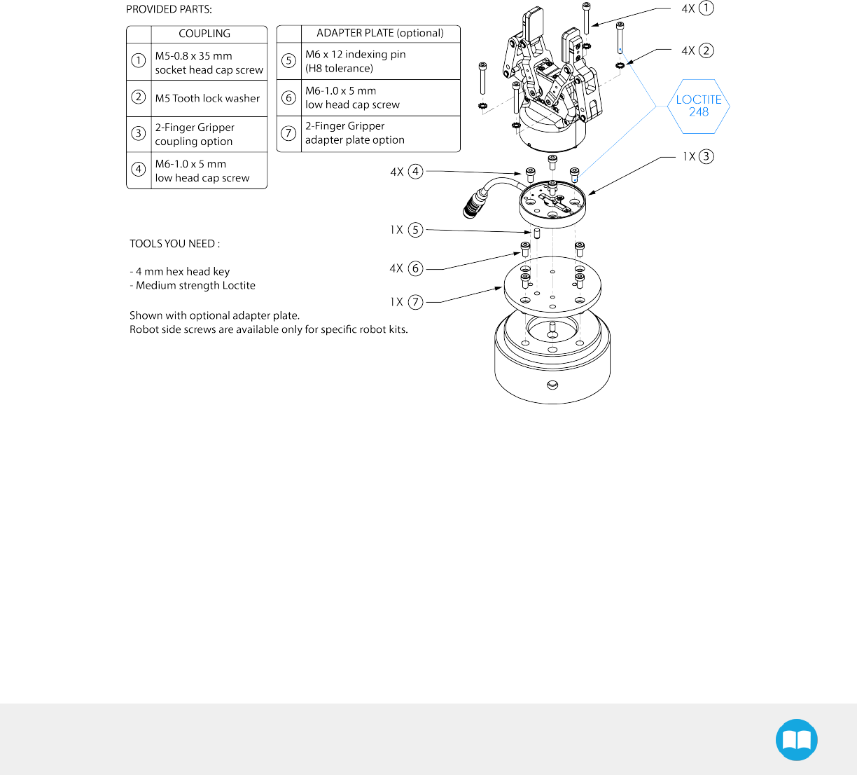
3.4.3. Installing the Gripper onto the robot:
You must use a coupling to attach the Gripper to the robot. Be sure to use the coupling related to your robot model. If there is no
coupling for your robot, you can modify a blank coupling or Robotiq can create a custom version for you. Some couplings may require
an additional adapter plate. To create your own coupling or adapter plate you can refer to the Coupling section. To see the details of
the available couplings and adapter plates, please refer to the Spare Parts, Kits and Accessories section.
Here are the steps to follow to mount the Gripper to your robot (exploded view in the figure below). Note that all screws must be locked
in place using medium strength thread-locker.
1. Screw the adapter plate or the coupling to the robot.
2. Screw the coupling to the adapter plate (if adapter plate is required).
3. Screw the Gripper onto its coupling.
Fig. 3-3: Installing the Gripper to a robot using an adapter plate and coupling.
Multiple Grippers
When installing multiple grippers on one robot, every gripper must have its own coupling.
1. Install a mounting plate (not provided) first on the robot arm.
2. Mount the grippers couplings on the mounting plate using the provided M6 X 10mm screws.
3. Mount the grippers onto their coupling using the provided M5 X 35mm screws.
26
2F-85 &2F-140 - Instruction Manual
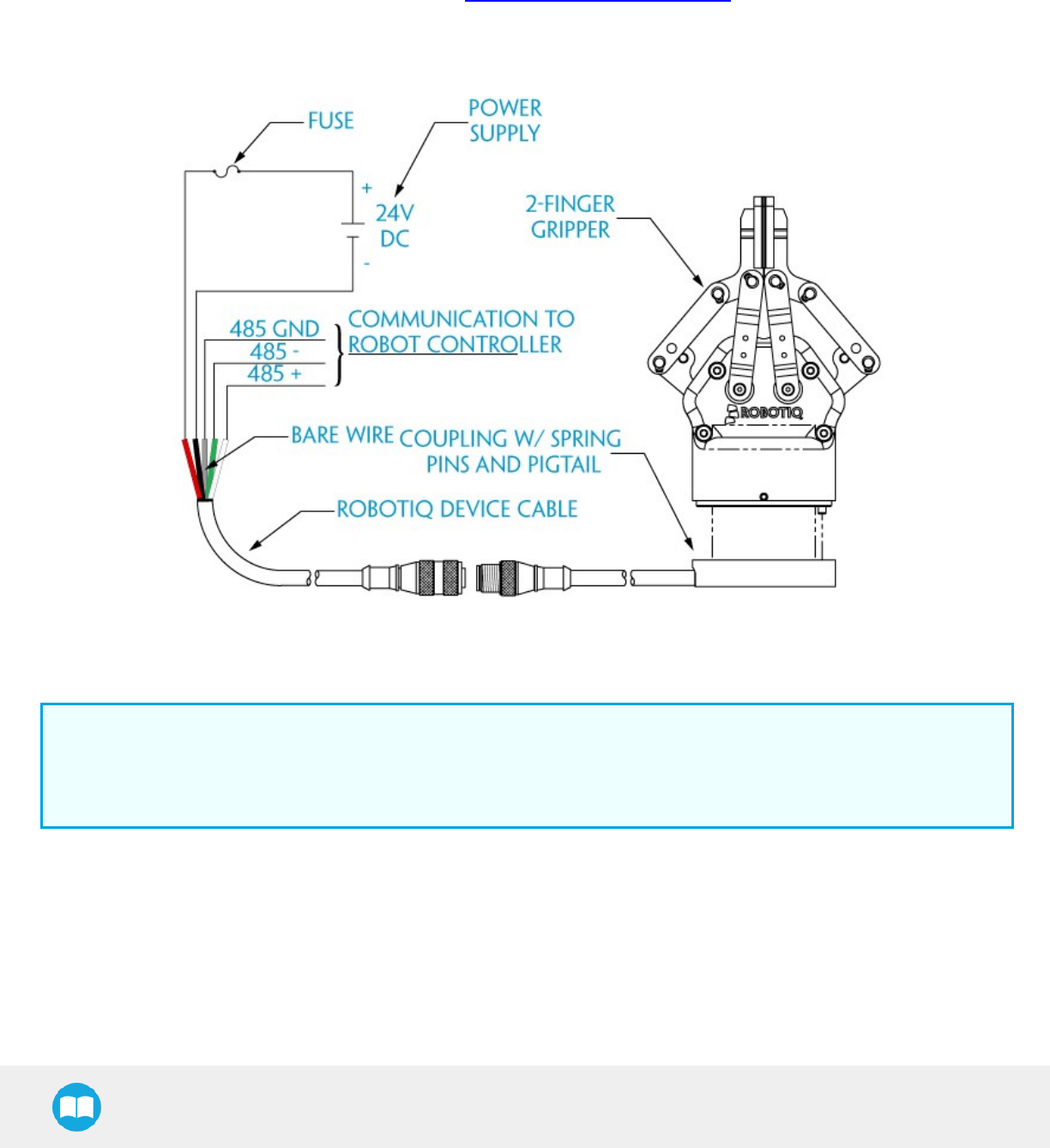
3.5. Electrical Setup
Power and communication are established with the 2-Finger Adaptive Robot Gripper via a single Device Cable. The Device Cable
provides a 24V power supply to the Gripper and enables serial RS-485 communication to the robot controller. An optional Robotiq
Universal Controller may be used between the Gripper and the network / robot controller if fieldbus communication is required.
If a Robotiq Universal Controller is used, please refer to the Robotiq Universal Controller manual. The figure below represents the
wiring schematic of the 2-Finger with device cable, power supply, fuse (please refer to the Required Tools and Equipment section) and
grounding.
Fig. 3-4: Robotiq 2-Finger with pigtail cable and device cable wiring schematic.
Info
RS-485 signals (A, B and GND) are isolated from the main 24 V power supply. 4 GND can be connected to any other ground
reference as long as the voltage potential between the grounds does not exceed 250 V. Grounding reference is at the user's
discretion.
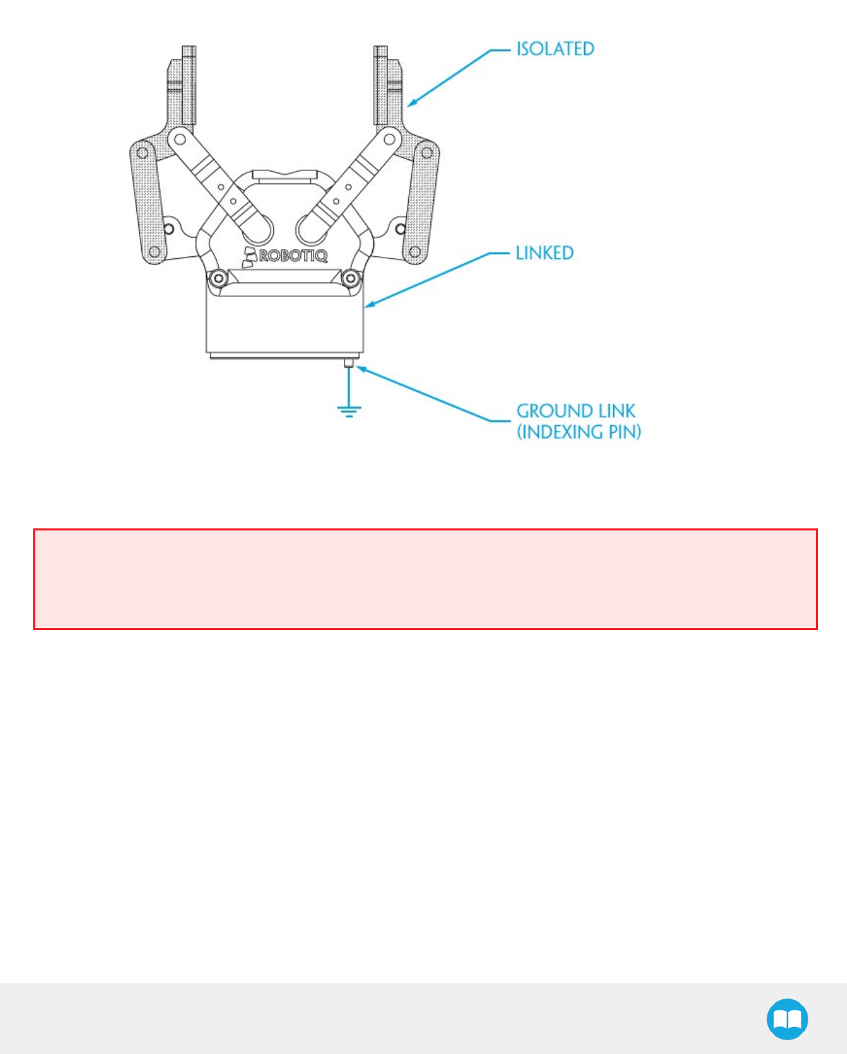
Gripper grounding is optional and is done via the robot ground. The coupling indexing pin (dowel) is the ground connector. Gripper
coupling, chassis and proximal phalanx are linked as illustrated in the figure below. They link through the coupling indexing pin to the
robot ground. Proximal bars, distal phalanx, fingertip base and fingertips are isolated.
27
2F-85 &2F-140 - Instruction Manual
Fig. 3-5: Robotiq 2-Finger electrical isolation / grounding.
Warning
Use proper cabling management. Be sure to have enough forgiveness in the cabling to allow movement of the Gripper along
all axes without pulling out the connectors. Always protect the controller-side (robot side) connector of the cable with a strain
relief cable clamp.
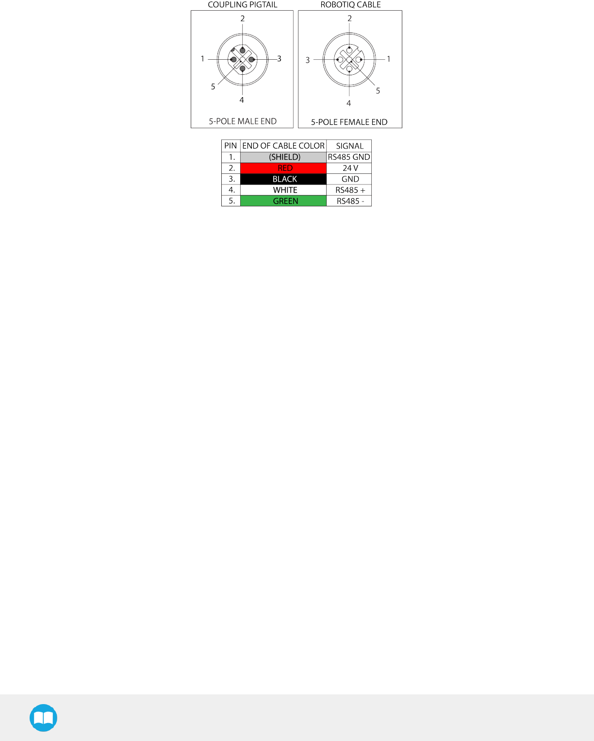
The figure below represents the 2-Finger pigtail connector from the coupling (AGC-CPL-XXX), device cable - robot side
(CBL-COM-2065-XX) and their associated pinout.
28
2F-85 &2F-140 - Instruction Manual
Fig. 3-6: Pinout of the 2-Finger pigtail and device cable.
If additional cable is used, suggested cable specifications are as follows:
Power supply, fusing:
lminimum #22 AWG TEW, 300 V or 600 V
RS-485 signals :
lminimum #24 AWG TEW, 300 V or 600 V
lA and B signals must be balanced at 120 Ohms
29
2F-85 &2F-140 - Instruction Manual
3.6. Testing the Gripper
Once installed and properly secured, your Robotiq 2-Finger Adaptive Gripper should be tested with the Robotiq User Interface test
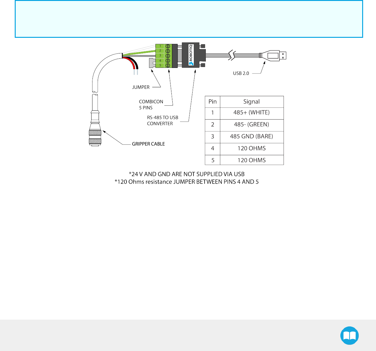
software using the provided USB converter. To do so:
1. Follow the instructions to install the Robotiq User Interface.
Use the provided RS-485 to USB converter ACC-ADT-USB-RS485 (see the schematic in the figure below) to plug into a PC with
the Robotiq User Interface installed.
2. Power up your Gripper with the previously recommended power supply.
3. Execute the R.U.I. software and select ''auto-connect'' on the connection screen.
4. You are now connected to your Gripper, you can click "activate" to begin using the Gripper.
Info
The Activate command will initiate movement of the Gripper for auto-calibration procedures. Do not interfere with the
Gripper. Be sure you have satisfied robot safety measures.
Fig. 3-7: RS-485 to USB converter ACC-ADT-USB-RS485 pinout.
30
2F-85 &2F-140 - Instruction Manual
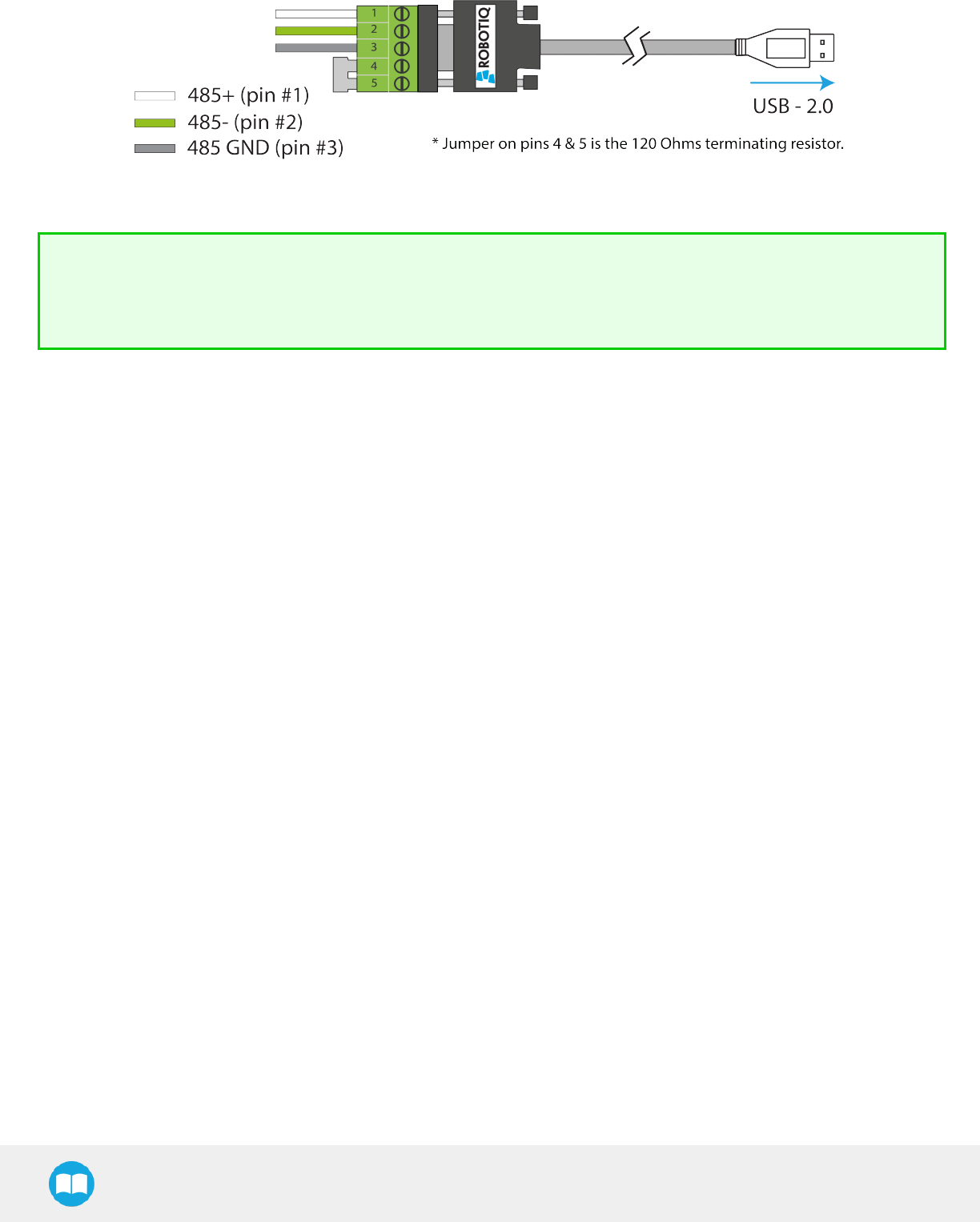
Fig. 3-8: Wiring of the USB to RS-485 converter.
Tip
With the R.U.I. controlling the Gripper, you can go to the "view" menu to see input and output register values to further your
understanding on how to command the Gripper. You can also test gripping your parts with various speed and force settings.
See Section 4. for Control details.
31
2F-85 &2F-140 - Instruction Manual
3.7. Installation for Universal Robots
The table below shows which Robotiq software to use with your Universal Robots’ controller. If you are using a CB3 or CB3.1 controller,
it is recommended to use the 2-Finger Adaptive Gripper URCap Package.
Robotiq Software Controller CB1 Controller CB2 Controller CB3 Controller CB3.1
Driver Package
(includes Gripper toolbar) Incompatible Compatible Compatible Compatible
2-Finger Adaptive Gripper URCap Package
(includes Gripper toolbar and Gripper node) Incompatible Incompatible Compatible Compatible
Table 3-3: Compatibility between Robotiq software and Universal Robots controller
Refer to the appropriate section depending on your controller version:
lSection 3.8 covers the installation of the 2-Finger Adaptive GripperURCap Package.
lSection 3.9 covers the software installation when not using URCaps.
Info
The robot's PolyScope version must be 3.5 and later in order to install the URCap.
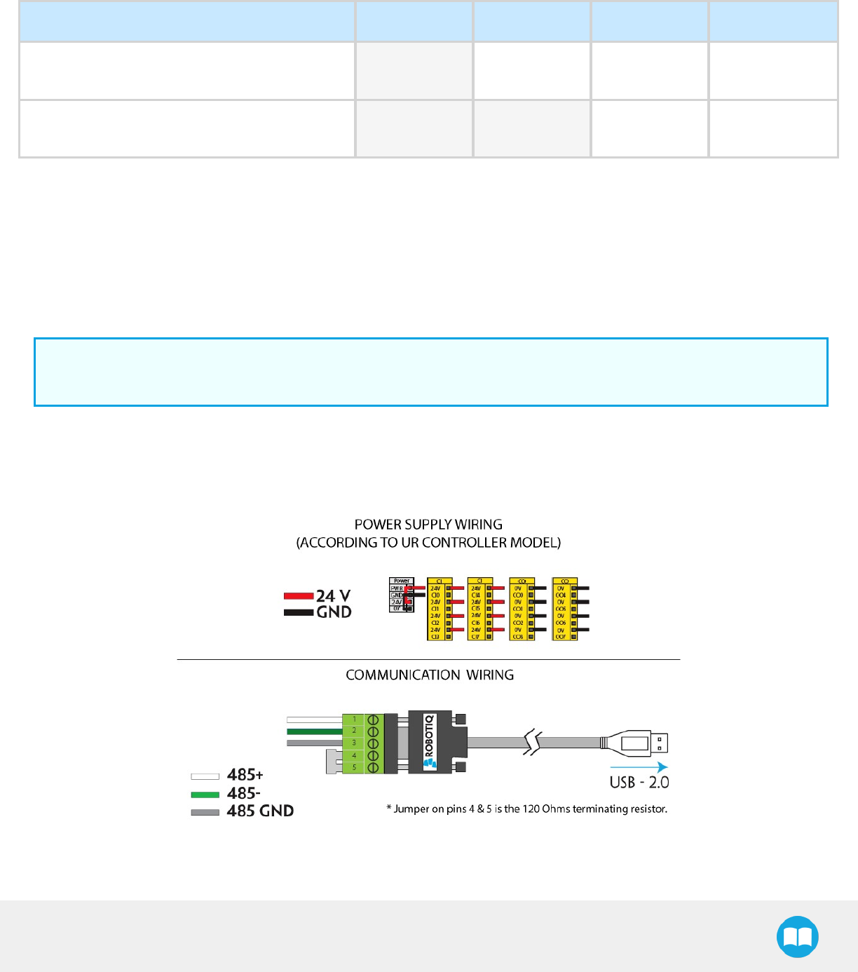
Prior to any software installation on Universal Robots, connect the white, blue and bare wires to the Robotiq RS-485 signal converter
(ACC-ADT-RS485-USB) as shown in the figure below. Also connect the red (24V) and black (0V) wires in the controller according to that
same figure.
Fig. 3-9: 2-Finger Adaptive Robot Gripper wiring to Universal Robots’ controller.
32
2F-85 &2F-140 - Instruction Manual
Multiple Grippers wiring
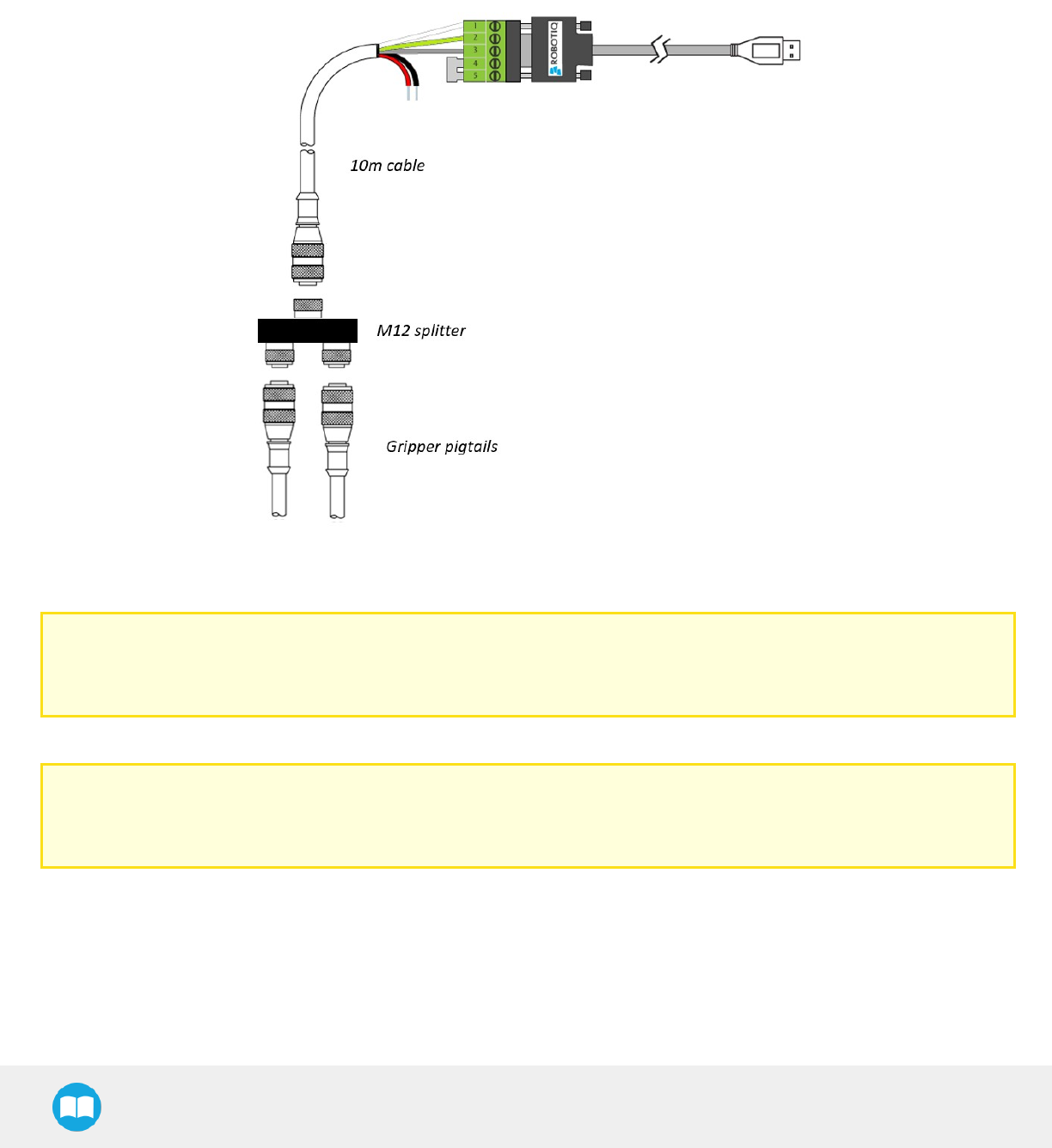
3.7.1. Multiple Grippers wiring
It is possible to connect and control up to four grippers on the same UR robot. Only one USB to RS485 converter (ACC- ADT-USB-
RS485) must be used. Use M12 splitters (ACC-SPLIT-M12-2:1) to connect all the grippers pigtails to one 10m cable (CBL-COM-2065-10-
HF) that connects to the USB to RS485 converter.
Fig. 3-10: Multiple grippers wiring on Universal Robots.
Caution
Make sure to refer to the Installing URCap Package section to configure the grippers properly before controlling and
programming them.
Caution
Prior to use over Universal Robots, adjust the payload and the center of gravity from the Installation tab (refer to the
Mechanical specifications section.
33

2F-85 &2F-140 - Instruction Manual
3.8. URCap Package
Robotiq provides you with a Universal Robots URCap package that enables direct serial communication (via USB) to your UR controller.
Info
To get the URCaps package for your UR controller, visit support.robotiq.com.
Make sure the 2-Finger Adaptive Gripper is properly mounted to the robot arm. Refer to the Mechanical Installation section for detailed
information on the mechanical installation. Before proceeding with the installation of the URCap package, make sure your Universal
Robots controller is compatible with the package (refer to the Installation for Universal Robots section).
Info
The robot's PolyScope version must be 3.5 and later in order to install the URCap.
The Gripper’s URCaps package contains:
lThe URCaps for the Gripper;
lThe Gripper toolbar;
lThe Gripper node.
Tip
For other robots, where no driver package is available, we recommend the use of the Robotiq Universal Controller which
allows fieldbus communication. Available communication protocols with this Universal Controller are:
lModbus TCP
lEtherNet IP
lEtherCAT
lPROFINET
lDeviceNET
lCANopen
For details on controlling the Gripper, please refer to the Control section.
Info
Visit support.robotiq.com for detailed information on how to program using the URCaps package (please refer to the
Control section).
34
2F-85 &2F-140 - Instruction Manual
3.8.1. Installing URCap Package
Make sure the 2-Finger Adaptive Gripper is properly mounted to the robot arm. Refer to the Mechanical Installation section for detailed
information on the mechanical installation. Before proceeding with the installation of the URCap package, make sure your Universal
Robots’ controller is compatible with the package (refer to the Installation for Universal Robots section).
Follow this procedure to install the 2-Finger Adaptive Gripper URCap package:
lMake sure that your PolyScope version is up-to-date and that your
Universal Robots controller is compatible with the Gripper’s URCap
package.
lGo to support.robotiq.com and click on the 2-Finger Adaptive Grip-
per product page.
lDownload the UCG-X.X.X and extract on the root of a blank USB
stick.
lInsert the USB stick in the UR teach pendant or controller.
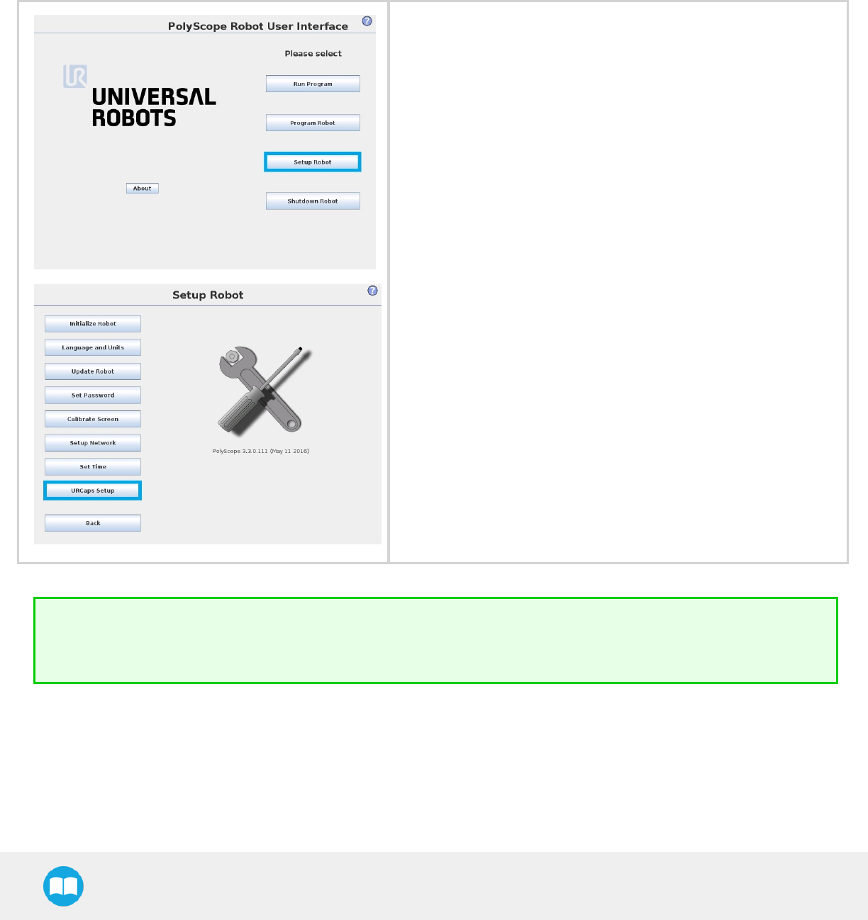
lGo to Setup Robot.
lTap URCaps Setup.
Tip
In PolyScope, go to the Home page and tap the About button. A window containing the Universal Robots software version
will pop up.
35
2F-85 &2F-140 - Instruction Manual
lTap the plus button (+) to add the Gripper’s URCap package.
lOpen Robotiq_Grippers-X.X.X.urcap.
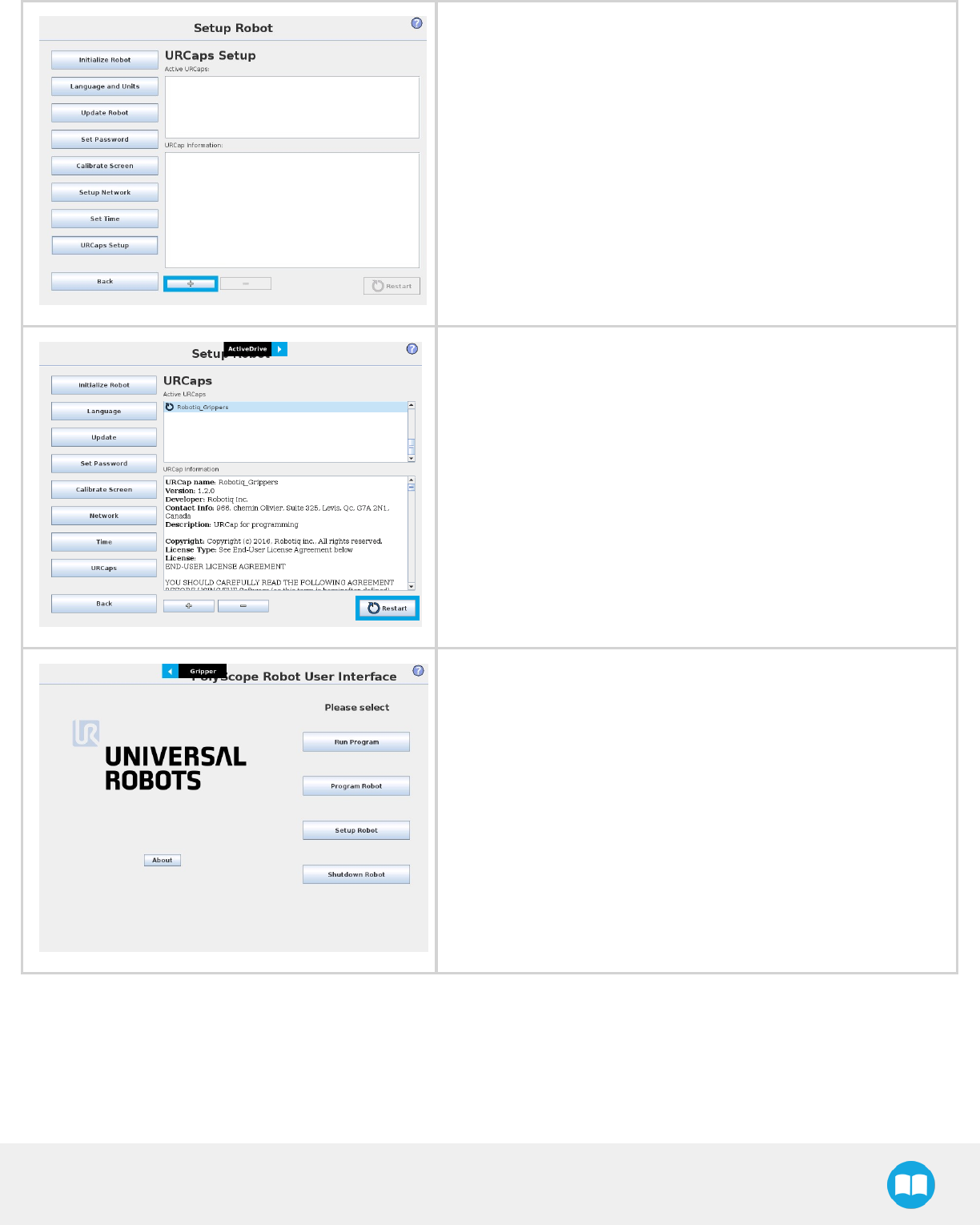
lRestart PolyScope to complete the URCap installation. By doing so,
you accept the License Agreement that is detailed in the URCap
Information text box (see below for the LicenseAgreement).
lWhen PolyScope reopens, the Gripper toolbar will appear on
thescreen.
36

2F-85 &2F-140 - Instruction Manual
Multiple Grippers
It is possible to connect and control up to four grippers on the same UR robot. Only one USB to RS485 converter (ACC- ADT-USB-
RS485) must be used. Use M12 splitters (ACC-SPLIT-M12-2:1) to connect all the grippers pigtails to one 10m cable (CBL-COM-2065-10-
HF) that connects to the USB to RS485 converter.
Fig. 3-11: Wiring for multiple grippers.
When installing multiple grippers on one UR robot, their gripper ID must be set properly. To do so, perform the following steps for
each gripper:
lConnect only one gripper at the time using the M12 splitter.
37
2F-85 &2F-140 - Instruction Manual
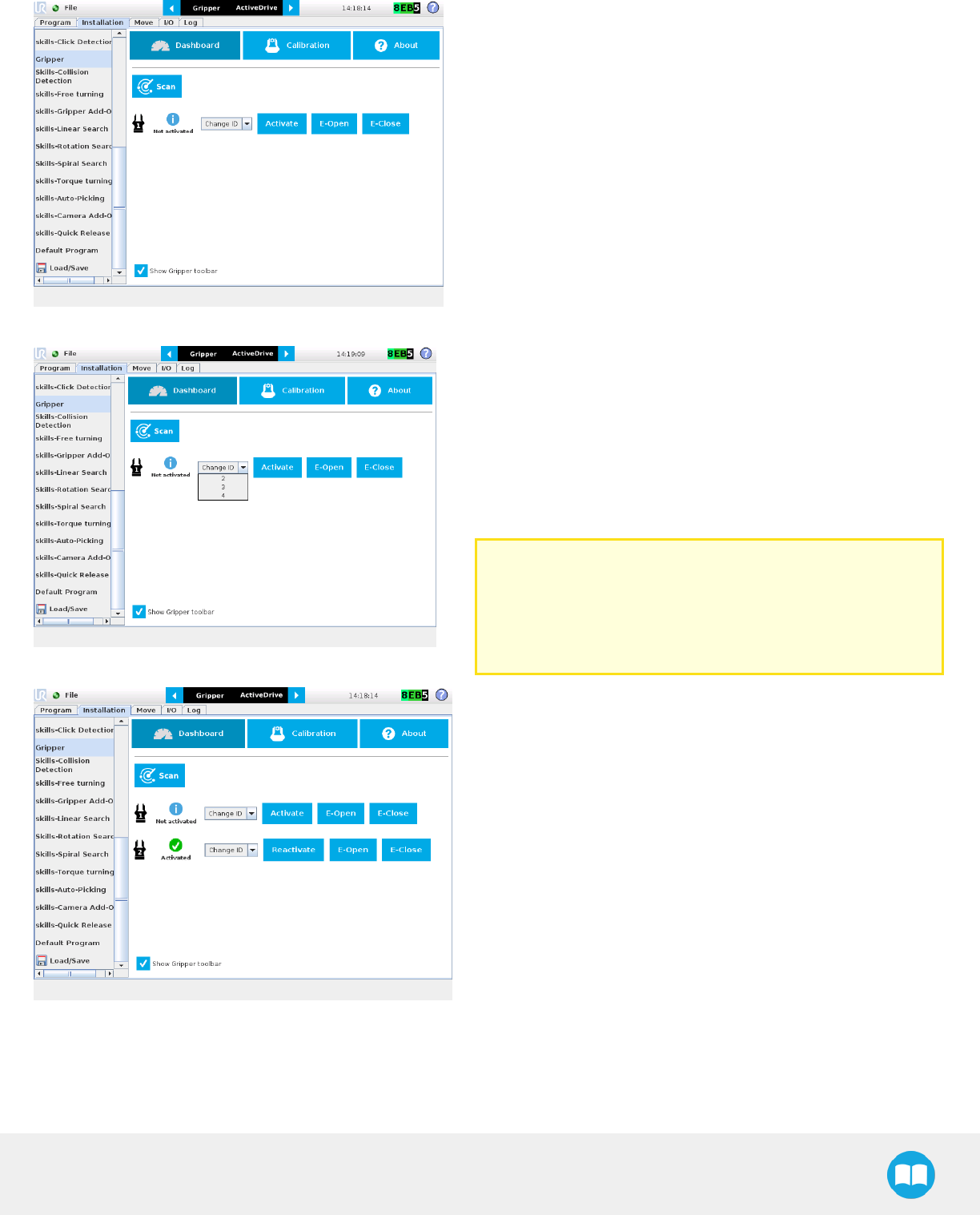
lFrom the PolyScope home page, go to Program Robot and then tap
the Installation tab.
lTap on Gripper.
lSelect the Dashboard menu.
lTap the Scan button to detect Grippers.
lChange the Gripper ID to the desired one.
lMake sure it is different from the other Gripper IDs.
lGripper ID is saved to the Gripper's internal memory. ID will be kept
at all time.
lClick on Activate to activate the Gripper.
lPerform the same routine for all grippers, if applicable, connecting
only one at the time.
Caution
Make sure all grippers have different IDs. With their factory
settings, all grippers have Gripper IDset to 1. If you have
more than one gripper connected with the same ID,
communication issues will arise.
lOnce all grippers IDs have been set, connect them all to the
M12splitter.
lGo back to the Configure tab and confirm that all grippers are recog-
nized and can be controlled.
38
2F-85 &2F-140 - Instruction Manual
3.8.2. Uninstalling URCap Package
If you wish to uninstall the 2-Finger Gripper URCap, follow this procedure:
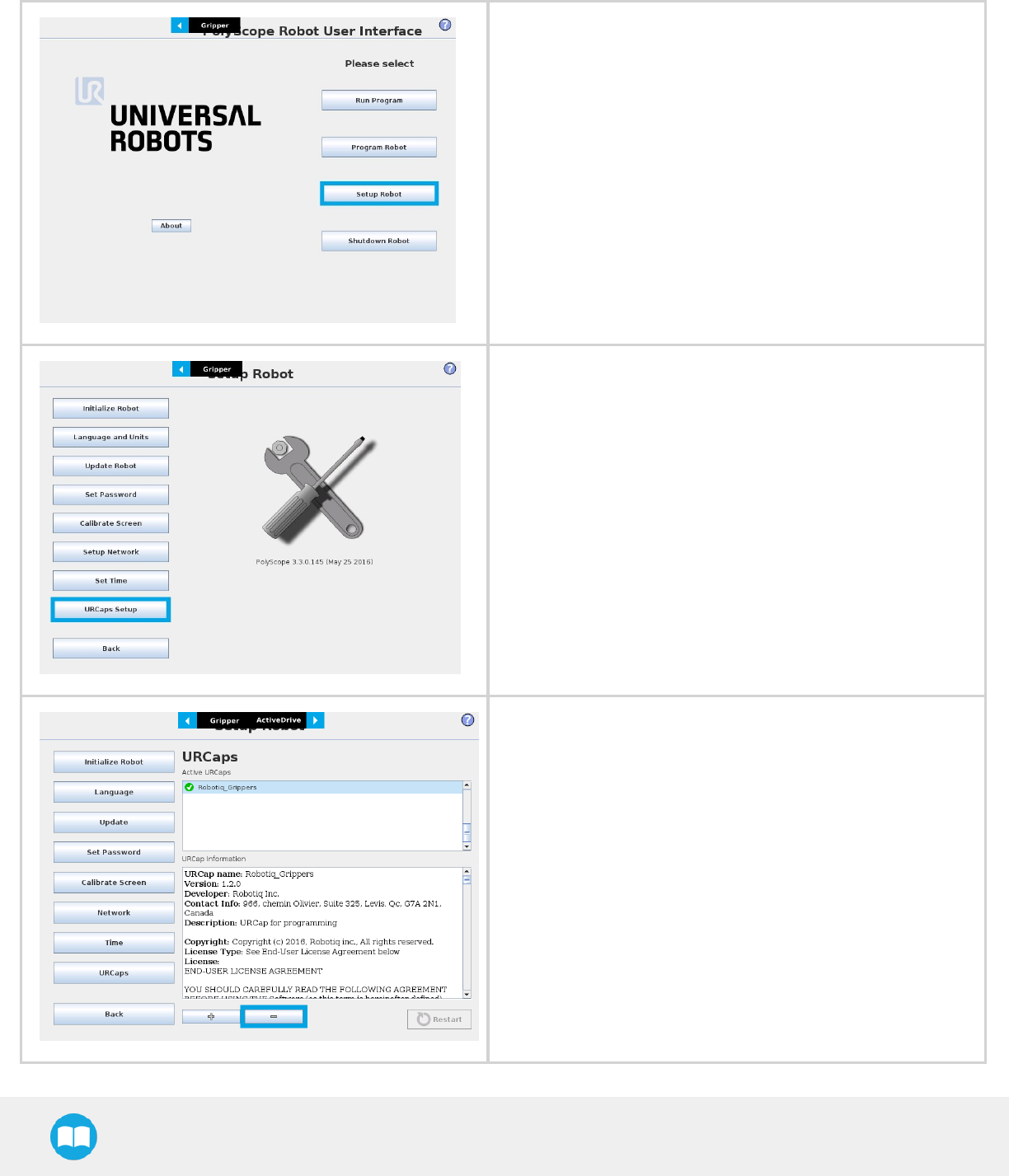
lGo to Setup Robot.
lTap URCaps Setup.
lIn the Active URCaps text box, tap the Gripper URCap.
lThe Gripper URCap should be highlighted.
lTap the minus button (-) to uninstall the URCap.
lRestart PolyScope to complete the uninstallation process.
39

2F-85 &2F-140 - Instruction Manual
3.8.3. License Agreement
END-USER LICENSE AGREEMENT
YOU SHOULD CAREFULLY READ THE FOLLOWING AGREEMENT BEFORE USING THE Software (as this term is hereinafter
defined). Using the Software indicates your acceptance of the agreement. If you do not agree with it, you are not authorized to use the
Software.
IMPORTANT-READ CAREFULLY: This End-User License Agreement (the “Agreement”) is a legal agreement between you and the
Licensor (as this term is hereinafter defined), the licensor of the Software. This Agreement covers the Software. The Software includes
any “on-line” or electronic documentation and all modifications and upgrades related thereto. By installing, or otherwise using the
Software, you agree to be bound by the terms of this Agreement. If you do not agree to the terms of this Agreement, the Licensor
cannot and does not license the Software to you. In such event, you must not use or install the Software.
1. Definition.
1. “UR” means Universal Robots A/S, a corporation incorporated under the laws of Denmark, having its registered office
at Energivej 25, DK-5260 Odense S, which specializes into the conception, advanced manufacturing and sale of robotic
products (the “UR’s Business”);
2. “Software” means any of the Licensor’s softwares provided to its customers for the purposes mentioned in Sub-section
1.4 hereof including their modifications and upgrades and their related materials;
3. “Licensor” means Robotiq inc., a corporation incorporated under the laws of Quebec, having its registered office at
325-966 chemin Olivier, Lévis, Québec, Canada, G7A 2N1, which specializes into the conception, advanced man-
ufacturing and sale of robotic products (the “Licensor’s Business”);
4. “End-User” means a customer authorized pursuant to this Agreement to install or use the Software in order to make a
specific product from the Licensor’s Products compatible and functional with a specific product of the UR’s Product;
5. “Licensor’s Products” means those products developed by the Licensor in the course of the Licensor’s Business;
6. “UR’s Products” means those products developed by UR in the course of the UR’s Business;
7. “Licensor’s Authorized Representatives” means and includes the Licensor and Licensor’s authorized vendors, resellers,
distributors and licensors;
8. “Purchase Agreement” means an agreement between the End-User and the Licensor pursuant to which the End-User
purchased one or more of the Licensor’s Products.
2. License. Subject to the terms and conditions hereof, the Licensor grants to the End-User a personal, temporary, non-exclusive,
non-assignable and non-transferable and revocable license to use the Software in accordance with the terms and conditions
hereof.
3. Software and Documentation. The Licensor may provide, if applicable, all documentation containing the detailed specifications
for operation and use of the Software, which Software shall be used in accordance with such documentation. This doc-
umentation, if applicable, will be provided, wholly or in part, within (i) this Agreement, (ii) the Licensor’s Web site http://ro-
botiq.com/ (iii) the Licensor’s Products and the Purchase Agreement therewith, or (iv) any other agreement, document, support,
whatsoever decided by the Licensor.
The use of the Software requires the Licensor’s Products, UR’s Products, compatible systems and certain software (which may
require some expenses), may require periodical updating and may be affected by such elements. Most equipment will be com-
patible with the Software. However, the Software may not function on certain types of equipment.
4. Modifications and Upgrades. The Licensor shall be under no obligation to provide any upgrade or modification to the Software.
However, the End-User shall be entitled to receive free of charge all modifications and upgrades of the Software provided by the
Licensor if, at such time, the End-User is not in default in respect of any of its obligation contained herein. Such modifications and
upgrades of the Software shall be installed by the End-User itself by consulting the Licensor’s Website http://robotiq.com/ where
a link to proceed to such installation will be made available thereof. A new version of the Software shall not be covered by this
40

2F-85 &2F-140 - Instruction Manual
Section 4 but shall require that a new End-User Software License Agreement be entered into between the Licensor and the End-
User.
5. Fees. The grant by Licensor to the End-User of the present license shall be free to the extent that the End-User agrees and com-
plies to the term and conditions herein at all time.
6. Maintenance. During the term of this Agreement, the Licensor will maintain the Software in an operable condition and will make
available any corrections and improvements as are generally incorporated in the Software by the Licensor without additional
charge to the End-User. The Licensor may temporarily and without notice suspend or limit access to the Software if necessary or
desirable in order to maintain, restore, modify or repair any part of the Software or for any reason related to business. During
such works, the Software will not be available but the Licensor undertakes to deploy its best efforts to perform such works at
appropriate times and to limit any inconvenience arising therefrom.
7. Title to Software. The licensed Software is composed of confidential data and trade secrets and is proprietary to and constitutes
trade secret information and intellectual property of the Licensor. Title and ownership rights to the Software, including the intel-
lectual property rights related thereto, shall remain with the Licensor. The End-User agrees to maintain the confidential nature of
the Software and related materials provided for the End-User’s own internal use under this Agreement. The license granted
herein does not include the right to sublicense to others, and may not be assigned to others, in whole or in part, without the prior
written consent of the Licensor. The End-User may not or allow others to modify or prepare directive works, copy (except for nor-
mal backups for recovery purposes), reproduce, republish, reverse engineer, upload, post, transmit, or distribute, in any manner,
the Software.
8. Restricted Use. The Software shall be used solely and exclusively by the End-User and its employees for the purpose mentioned
in Sub-section 1.4 hereof. Any other use of the Software, including resell derivative modifications or extensions, is expressly pro-
hibited.
9. Exclusion of Warranty on Software. The End-User expressly acknowledges and agrees that use of the Software is at the End-User
sole risk. The Software is provided “AS IS” and without warranty of any kind. THE LICENSOR AND THE LICENSOR’S
AUTHORIZED REPRESEN-TATIVES DO NOT WARRANT THAT Software WILL BE FREE OF ERRORS AND YOU
ACKNOWLEDGE THAT THE EXISTENCE OF ANY SUCH ERRORS DOES NOT CONSTITUTE A BREACH OF THIS
AGREEMENT. TO THE EXTENT PERMITTED BY LAW LICENSOR AND LICENSOR’S AUTHORIZED REPRESEN-TATIVES
EXPRESSLY DISCLAIM ALL WARRANTIES, EXPRESS OR IMPLIED, INCLUDING , BUT NOT LIMITED TO, THE IMPLIED
WARRANTIES OF MERCHANTA-BILITY AND FITNESS FOR A PARTICULAR PURPOSE UNLESS OTHERWISE STATED
HEREIN. LICENSOR AND LICENSOR’S AUTHORIZED REPRESENTATIVES DO NOT WARRANT THAT THE FUNCTIONS
CONTAINED IN THE Software WILL MEET THE END-USER REQUIREMENTS OR THAT THE OPERATION OF THE Software
WILL BE CORRECT. FURTHERMORE, LICENSOR AND LICENSOR’S AUTHORIZED REPRESEN-TATIVES DO NOT WARRANT
OR MAKE ANY REPRESENTATIONS REGARDING THE USE OR THE RESULTS OF THE USE OF THE Software IN TERMS OF
ITS CORRECTNESS, ACCURACY, RELIABILITY, OR OTHERWISE. NO ORAL OR WRITTEN INFORMATION OR ADVICE GIVEN
BY LICENSOR AND LICENSOR’S AUTHORIZED REPRESENTATIVE SHALL CREATE A WARRANTY OR IN ANY WAY
INCREASE THE SCOPE OF THIS WARRANTY. SHOULD THE Software PROVE DEFECTIVE IN YOUR TECHNOLOGY
ENVIRONMENT, YOU ASSUME THE ENTIRE COST OF ALL NECESSARY SERVICING, REPAIR OR CORRECTION TO YOUR
OWN TECHNOLOGY ENVIRONMENT.
10. Limitation of liability. TO THE MAXIMUM EXTENT PERMITTED BY LAW, LICENSOR AND LICENSOR’S AUTHORIZED
REPRESENTATIVES SHALL NOT BE LIABLE FOR ANY INCIDENTAL OR CONSEQUENTIAL DAMAGES FOR BREACH OF
ANY EXPRESS OR IMPLIED WARRANTY, BREACH OF CONTRACT, NEGLIGENCE, STRICT LIABILITY OR ANY OTHER
LEGAL THEORY RELATED TO THE Software. SUCH DAMAGES INCLUDE, BUT ARE NOT LIMITED TO, LOSS OF PROFITS,
LOSS OF REVENUE, LOSS OF DATA, LOSS OF USE OF THE PRODUCT OR ANY ASSOCIATED EQUIPMENT, DOWN TIME
AND USER’S TIME, EVEN IF THE LICENSOR HAS BEEN ADVISED OF THE POSSIBILITY OF SUCH DAMAGES. IN ANY CASE,
LICENSOR ENTIRE LIABILITY UNDER ANY PROVISION OF THIS AGREEMENT SHALL BE LIMITED TO THE AMOUNT
ACTUALLY PAID IN RESPECT OF THE LICENSOR’S PRODUCTS PURCHASED BY THE END-USER PURSUANT TO A
PURCHASE AGREEMENT.
11. Training, Maintenance and Support There is no entitlement to training, maintenance and support under this license unless oth-
erwise specified in the Purchase Agreement or any other written agreement between the End-User and the Licensor. The End-
User may provide the Licensor with details regarding any bug, defect or failure in the Software promptly and with no delay from
such event; the End-User shall comply with the Licensor’s request for information regarding bugs, defects or failures and furnish
him with information, screenshots and try to reproduce such bugs, defects or failures upon Licensor’s demand.
41

2F-85 &2F-140 - Instruction Manual
12. Expiration and Termination. The Licensor may terminate this Agreement for default by the End-User. This Agreement will also be
automatically terminated upon the election of such by the Licensor or the official launch of the Software, whichever event comes
first. Upon termination of this Agreement for any reason, the End-User shall promptly uninstall the Software on any UR’s Products
and Licensor’s Products, computer, or server on which it has been installed, deliver to the Licensor all CDs, DVDs, magnetic
tapes, cards, and other tangible items and materials embodying the Software, and return to the Licensor all copies thereof or des-
troy such copies and warrant in writing that all copies thereof have been destroyed. In the event of termination of this Agreement,
all obligations of the parties under this Agreement due for performance on the date of termination shall survive the termination,
and the party terminating shall not be liable to the other party for any damages arising out of the termination.
13. Miscellaneous.
1. This Agreement constitutes the entire understanding and agreement between the Licensor and the End-User and
replaces any prior agreement relating to the same subject matter.
2. This Agreement shall be governed and construed in accordance with the laws of the province of Quebec and the fed-
eral laws of Canada applicable therein. Any legal action or proceeding between the Licensor and the End-User for any
purpose concerning this Agreement or the parties' obligations hereunder shall be brought exclusively in a court of com-
petent jurisdiction sitting in the judicial district of Trois-Rivières, Quebec.
3. The Licensor’s failure to insist upon or enforce strict performance of any provision of this Agreement shall not be con-
strued as a waiver of any provision or right. Neither the course of conduct between the parties nor trade practice shall
act to modify any provision of this Agreement.
4. The Licensor may assign its rights and duties under this Agreement to any party at any time without notice to the End-
User. The End-User may not assign this Agreement without the prior written consent of the Licensor.
5. If any part of this Agreement is null, illegal or non-enforceable, this Agreement shall be interpreted as if this part was
never part of this Agreement.
6. The provisions of this Agreement are for the benefit of the Licensor and its officers, directors, employees, agents,
licensors and suppliers. Each of these individuals or entities shall have the right to assert and enforce those provisions
directly against the End-User on its own behalf. This Agreement is also for the benefit of, and binds, the End-User and
its heirs, successors, legal representatives and permitted assigns.
7. Any rights not expressly granted herein are reserved.
8. The parties confirm that they have agreed that this Agreement and all related documents be drafted in English only. Les
parties aux présentes confirment qu’elles ont accepté que la présente convention et tous les documents y afférents soi-
ent rédigés en anglais seulement.
42

2F-85 &2F-140 - Instruction Manual
3.9. URPackage without URCaps
Robotiq provides you with a Universal Robots driver package that enables direct serial communication (via USB) to your UR controller.
Info
To get the driver package for your UR controller, visit the Documentation Archives.
If your Universal Robots’ controller is not compatible with the URCaps package (refer to the Installation for Universal Robots section for
compatibility), you can install the driver package. This package allows programming of the Gripper with scripts in a PolyScope program.
It includes program templates and examples to help you get started with your own custom program. It also contains the Gripper
toolbar for jogging and controlling the Gripper.
Info
The URCap package also contains a driver package that is different from this section’s. If you have already installed the
URCaps, you do not need to install the driver package. This section applies to Robotiq’s software excluding the URCap
package. If you wish to use the URCaps package, refer to the Control section.
Tip
Make sure your PolyScope version is up-to-date and that your controller is compatible with the driver package for UR (refer to
the Installation for Universal Robots section for controller compatibility). To view your PolyScope version, go to the
PolyScope home page and tap the About button. A window containing the Universal Robots software version will pop up.
Tip
For other robots, where no driver package is available, we recommend the use of the Robotiq Universal Controller which
allows fieldbus communication. Available communication protocols with this Universal Controller are :
lModbus TCP
lEtherNet IP
lEtherCAT
lPROFINET
lDeviceNET
lCANopen
For details on controlling the Gripper, refer to the Control section.
43

2F-85 &2F-140 - Instruction Manual
3.9.1. Installation
To install the driver package, follow this procedure:
lDownload the Robotiq 2-Finger Gripper software driver package (DCU-X.X.X) from the Documentation Archives.
lExtract the content of the .zip file onto a blank USB flash drive.
lPlug the flash drive into the robot controller or teach pendant.
lInstallation is automatic. The pendant screen will show installation status. Do not unplug the flash drive until the operation is com-
pleted.
lWhen a green "USB" text is shown, unplug the USB drive.
Testing the Gripper:
lWhen the installation is completed, the Gripper toolbar button will appear on the teach pendant’s screen after a short delay.
lUse the toolbar to jog and test the Gripper. Refer to the Control over Universal Robots without URCaps section to get detailed inform-
ation on how to use the Gripper toolbar.
Removing the package
lLocate the uninstall.sh file provided in the driver package.
lCopy the file on a blank USB stick.
lRename the file to urmagic_uninstall.sh.
lPlug the USB stick into the UR controller or teach pendant.
lUninstallation is automatic.
44

4. Control
Info
Unless specified, all values in this section are hexadecimal values.
4.1. Overview
The Robotiq 2-Finger Adaptive Gripper is controlled directly via Modbus RTU using a RS 485 signal. It can also be controlled via an
optional Robotiq Universal Controller using an industrial protocol. The programming of the Gripper can be done with the Teach
Pendant of the robot or by offline programming. Communication method used to control the 2-Finger Gripper does not change the
control logic or the registers setup described in the following subsections.
Tip
Robotiq suggests using the Robotiq User Interface test software to explore the various features of the Gripper, like object
detection and forcecontrol.
Since the Robotiq 2-Finger has its own embedded controller, high-level commands, such as "Go to requested position" are used to
control it.
Info
The operator can:
lControl force, speed and position of the Gripper fingers.
lFinger movement is always synchronized, movement is initiated via a single "Go to requested position" command.
lParallel or encompassing grip is done automatically.
lA built in object detection feature is available, the user can be notified after an object is picked once the "Go to" command
has been initiated. The feature also works for lost or dropped objects, and the user can be alerted if an object is dropped
after being detected.
lEngage directional (open or close ) auto-release for emergencies.
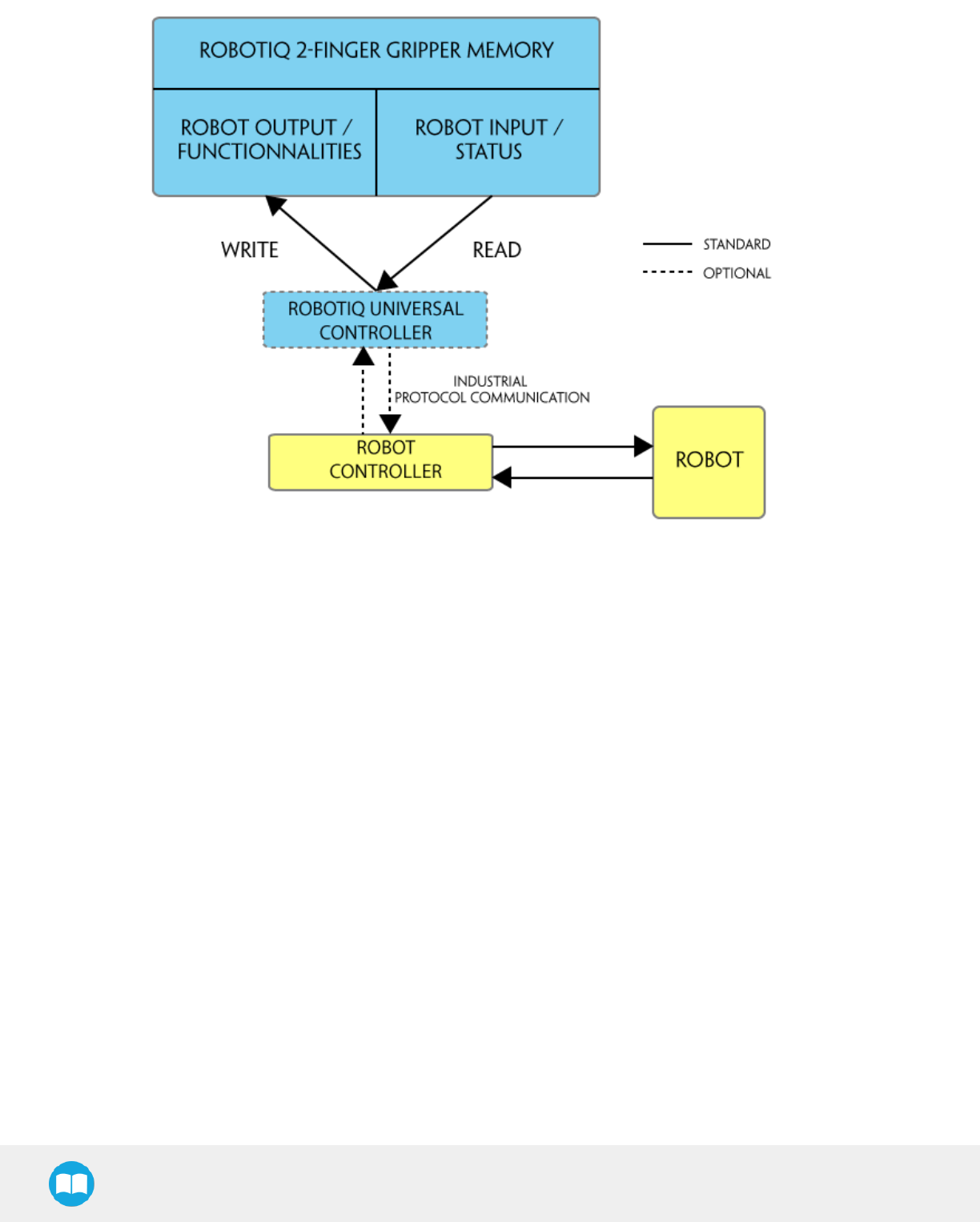
Control using registers
The Gripper has an internal memory that is shared with the robot controller. One part of the memory is for the robot output; gripper
functionalities. The other part of the memory is for the robot input; gripper status. Two types of actions can then be done by the robot
controller :
1. Write in the robot output registers to activate functionalities;
2. Read in the robot input registers to get the status of the Gripper.
The Gripper Register Mapping section will map the different registers used to control the Gripper or to read its status while the Robot
Output Registers &Functionalities section will detail the output (write) register functions, and the Robot Input Registers &Status section
will detail the input (read) register status. The figure below is a representation of the memory and the control logic of the Gripper.
2F-85 &2F-140 - Instruction Manual
45
2F-85 &2F-140 - Instruction Manual
Fig. 4-1: 2-Finger control logic overview
46

2F-85 &2F-140 - Instruction Manual
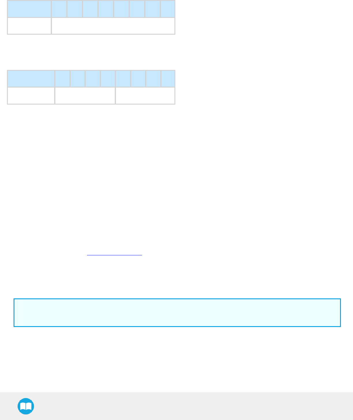
4.2. Gripper Register Mapping
Register mapping
Caution
Byte numeration starts at zero and not at 1 for the functionalities and status registers.
Register Robot Output / Functionalities Robot Input / Status
Byte 0 ACTIONREQUEST GRIPPERSTATUS
Byte 1 RESERVED RESERVED
Byte 2 RESERVED FAULTSTATUS
Byte 3 POSITIONREQUEST POSREQUESTECHO
Byte 4 SPEED POSITION
Byte 5 FORCE CURRENT
Byte 6 to 15 RESERVED RESERVED
Table 4-1: Registers of the 2-Finger Gripper.
47

2F-85 &2F-140 - Instruction Manual
4.3. Robot Output Registers &Functionalities
Register: ACTIONREQUEST
Address: Byte 0
Bits 7 6 5 4 3 2 1 0
Symbols Reserved rARD rATR rGTO Reserved rACT
rACT: First action to be made prior to any other actions, rACT bit will activate the Gripper. Clear rACT to reset the Gripper and clear
fault status.
l0x0 - Deactivate Gripper.
l0x1 - Activate Gripper (must stay on after activation routine is completed).
Warning
When setting rACT to one, the Gripper will begin movement to complete its auto-calibration feature.
Info
Power loss will set rACT;rACT bit must then be cleared, then set to allow operation of the Gripper.
Caution
rACT bit must stay on afterwards for any other action to be performed.
rGTO: The "Go To" action moves the Gripper fingers to the requested position using the configuration defined by the other registers,
rGTO will engage motion while byte 3, 4 and 5 will determine aimed position, force and speed. The only motions performed without
the rGTO bit are activation and automatic release routines.
l0x0 - Stop.
l0x1 - Go to requested position.
rATR: Automatic Release routine action slowly opens the Gripper fingers until all motion axes reach their mechanical limits. After all
motion is completed, the Gripper sends a fault signal and needs to be reactivated before any other motion is performed. The rATR bit
overrides all other commands excluding the activation bit (rACT).
l0x0 - Normal.
l0x1 - Emergency auto-release.
Caution
The automatic release is meant to disengage the Gripper after an emergency stop of the robot.
The automatic release is not intended to be used under normal operating conditions.
Automatic release will require rACT to be cleared (rACT == 0) then set (rACT == 1).
48

2F-85 &2F-140 - Instruction Manual
rARD: Auto-release direction. When auto-releasing, rARD commands the direction of the movement. The rARD bit should be set prior
to or at the same time as the rATR bit, as the motion direction is set when the auto-release is initiated.
l0x0 - Closing auto-release
l0x1 - Opening auto-release
Register: GRIPPER OPTIONS
Address: Byte 1
Bits 7 6 5 4 3 2 1 0
Symbol Reserved
Register: GRIPPER OPTIONS 2
Address: Byte 2
Bits 7 6 5 4 3 2 1 0
Symbol Reserved
Register: POSITIONREQUEST
Address: Byte 3
Bits 7 6 5 4 3 2 1 0
Symbol rPR
This register is used to set the target position for the Gripper's fingers. The positions 0x00 and 0xFF correspond respectively to the fully
opened and fully closed mechanical stops. For detailed finger trajectory, please refer to the Specifications section.
l0x00 - Open position, with 85 mm or 140 mm opening respectively
l0xFF - Closed
lOpening / count: 0.4 mm (for 85 mm stroke) and 0.65 mm (for 140 mm stroke)
Info
The activation feature of the Robotiq Adaptive Gripper will allow the Gripper to adjust to any fingertips. No matter what is
the size and shape of the fingertips used, 0 will always be fully opened and 255 fully closed, with a quasi-linear relationship
between 0 and 255.
49

2F-85 &2F-140 - Instruction Manual
Register: SPEED
Address: Byte 4
Bits 7 6 5 4 3 2 1 0
Symbol rSP
This register is used to set the Gripper closing or opening speed in real time, however, setting a speed will not initiate a motion.
l0x00 - Minimum speed
l0xFF - Maximum speed
Register: FORCE
Address: Byte 5
Bits 7 6 5 4 3 2 1 0
Symbol rFR
The force setting defines the final gripping force for the Gripper. The force will fix the maximum current sent to the motor while in
motion. If the current limit is exceeded, the fingers stop and trigger an object detection notification. Please refer to the Robot Input
Registers &Status section for details on force control.
l0x00 - Minimum force
l0xFF - Maximum force
Info
Register byte 6 to 15 are reserved and should be set to zero.
50

2F-85 &2F-140 - Instruction Manual
4.4. Robot Input Registers &Status
Register: GRIPPERSTATUS
Address: Byte 0
Bits 7 6 5 4 3 2 1 0
Symbol
sgOBJ gSTA gGTO Reserved gACT
gACT: Activation status, echo of the rACT bit (activation bit).
l0x0 - Gripper reset.
l0x1 - Gripper activation.
gGTO: Action status, echo of the rGTO bit (go to bit).
l0x0 - Stopped (or performing activation / automatic release).
l0x1 - Go to Position Request.
gSTA: Gripper status, returns the current status & motion of the Gripper fingers.
l0x00 - Gripper is in reset ( or automatic release ) state. See Fault Status if Gripper is activated.
l0x01 - Activation in progress.
l0x02 - Not used.
l0x03 - Activation is completed.
gOBJ: Object detection status, is a built-in feature that provides information on possible object pick-up. Ignore if gGTO == 0.
l0x00 - Fingers are in motion towards requested position. No object detected.
l0x01 - Fingers have stopped due to a contact while opening before requested position. Object detected opening.
l0x02 - Fingers have stopped due to a contact while closing before requested position. Object detected closing.
l0x03 - Fingers are at requested position. No object detected or object has been loss / dropped.
Caution
In some circumstances object detection may not detect an object even if it is successfully gripped. For example, picking up a
thin object in a fingertip grip may be successful without object detection occurring. For such reasons, use this feature with
caution. In these applications when the "Fingers are at requested position" status of register gOBJ, this is sufficient to
proceed to the next step of the routine.
Tip
Checking for the correct position of the fingers (byte 4), as well as object detection (byte 0, bit 6 & 7) before proceeding to the
next step of a routine is a more reliable method than object detection or finger position alone.
51
2F-85 &2F-140 - Instruction Manual
Register: RESERVED
Address: Byte 1
Bits 7 6 5 4 3 2 1 0
Symbol Reserved
Register: FAULTSTATUS
Address: Byte 2
Bits 7 6 5 4 3 2 1 0
Symbols kFLT gFLT
gFLT: Fault status returns general error messages that are useful for troubleshooting. Fault LED (red) is present on the Gripper chassis,
LED can be blue, red or both and be solid or blinking.
l0x00 - No fault (LED is blue)
lPriority faults (LED is blue)
l0x05 - Action delayed, activation (reactivation) must be completed prior to perfmoring the action.
l0x07 - The activation bit must be set prior to action.
Minor faults (LED continuous red)
l0x08 - Maximum operating temperature exceeded, wait for cool-down.
Major faults (LED blinking red/blue) - Reset is required (rising edge on activation bit rACT needed).
l0x0A - Under minimum operating voltage.
l0x0B - Automatic release in progress.
l0x0C - Internal fault; contact support@robotiq.com.
l0x0D - Activation fault, verify that no interference or other error occurred.
l0x0E - Overcurrent triggered.
l0x0F - Automatic release completed.
Info
While booting, status LED will be solid blue / red.
kFLT : See your optional Controller Manual (input registers & status).
52

2F-85 &2F-140 - Instruction Manual
Register: POSITIONREQUESTECHO
Address: Byte 3
Bits 7 6 5 4 3 2 1 0
Symbol gPR
gPR: Echo of the requested position for the Gripper, value between 0x00 and 0xFF.
l0x00 - Full opening.
l0xFF - Full closing.
Register: POSITION
Address: Byte 4
Bits 7 6 5 4 3 2 1 0
Symbol gPO
gPO: Actual position of the Gripper obtained via the encoders, value between 0x00 and 0xFF.
l0x00 - Fully opened.
l0xFF - Fully closed.
Register: CURRENT
Adress: Byte 5
Bits 7 6 5 4 3 2 1 0
Symbol gCU
gCU: The current is read instantaneously from the motor drive, value between 0x00 and 0xFF, approximate current equivalent is 10 *
value read inmA.
Tip
Built-in features like object detection and force control use the finger's electrical current readings. The user does not need to
create thesefeatures.
53

2F-85 &2F-140 - Instruction Manual
4.5. Picking Features
As stated in previous sections, object picking is done via a simple "Go To" command, rGTO bit calls for movement, while rPR byte is
the aimed position, rSP and rFR will be the desired speed and force settings respectively. This section describes key features in object
picking applications:
lForce control
lRe-grasp
lObject detection
4.5.1. Force control
The 2-Finger Gripper gripping force is controlled via the rFR byte (refer to the Gripper Register Mapping section).The Gripper behavior
will change according to the rFR forcerequested.
lrFR = 0 : Very fragile objects or deformable objects mode
lLowest force
lRe-grasp feature is off
l1rFR 127 : Solid & fragile objects
lLow torque mode
lRe-grasp feature is on
l128 rFR 255 : Solid & strong objects
lHigh torque mode
lRe-grasp feature is on
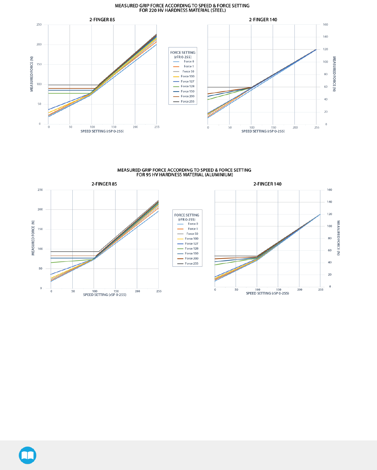
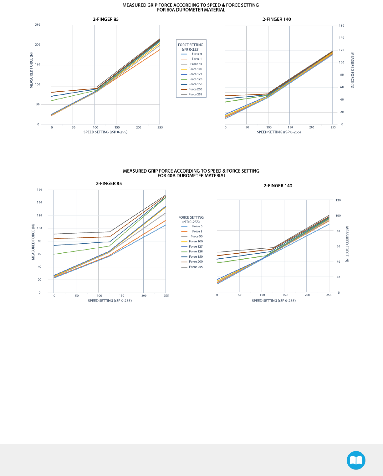
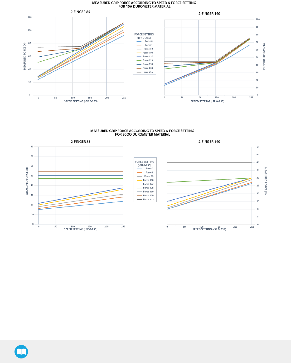
The table below shows the expected applied force according to the payload material hardness, speed setting rSP and force setting
rFR. All tests were done with the latest 2-Finger Gripper generation with firmware GC3-1.3.9. Data was obtained with a Load Cell from
Phidget,S Type,model 3138.
54

2F-85 &2F-140 - Instruction Manual
FINGERPAD PAYLOAD MEASURED FORCE MIN / MAX (N)
TYPE HARDNESS TYPE HARDNESS 2-Finger 85 2-Finger 140
Steel 4340 220 HV Steel 4340 220 HV325 - 220 15 - 120
Aluminium 6061195 HV Aluminium 6061 95 HV 25 - 220 15 - 120
Aluminium 6061195 HV Silicone (TIP-204)260 A Durometer 25 - 220 15 - 120
Aluminium 6061195 HV Silicone rubber 40 ADurometer425 - 155 15 - 100
Aluminium 6061195 HV Neoprene rubber 10 A Durometer 25 - 115 15 - 75
Aluminium 6061195 HV Polyurethane rubber 30 OO Durometer 25 - 115 15 - 75
1Available with blank fingertip AGC-TIP-203-002.
2Available with flat silicone fingertip AGC-TIP-204-002.
3HV refers to Vickers hardness test.
4 Durometer refers to Shore durometer hardness, scale A or scale OO.
55
2F-85 &2F-140 - Instruction Manual
Fig. 4-2: Grip force on hardness 220 HV (4340 annealed carbon steel).
Fig. 4-3: Grip force on hardness 95 HV (6061-T6 aluminium).
56
2F-85 &2F-140 - Instruction Manual
Fig. 4-4: Grip force on hardness 60A (silicone).
Fig. 4-5: Grip force on hardness 40 A (silicone).
57
2F-85 &2F-140 - Instruction Manual
Fig. 4-6: Grip force on hardness 10 A (neoprene).
Fig. 4-7: Grip force on hardness 30 OO (polyurethane).
58

2F-85 &2F-140 - Instruction Manual
4.5.2. Re-Grasp
Re-grasp feature is a built-in feature meant to prevent object lost due to slipping or inaccurate initial grip. The Re-grasp feature will
allow the Gripper to initiate movement when an object is slipping or dropped. When Re-grasping, the Gripper will attempt to close until
it reaches the position (rPR) request.
lThis feature is automatically set according to the force request rFR.
Info
Feature is off at force request rFR = 0, otherwise it is on.
lRe-grasp will keep the position setting:
lFinger motion will stop when rPR position is reached, even if there is no object.
lForce and speed settings are not used, Re-grasp force and speed will automatically adjust to keep the object from being lost /
dropped.
Info
While your initial settings for force and speed are not used for Re-grasp, they will never be exceeded to prevent damaging
the part.
Info
The rOBJ status is cleared when a motion is detected.
59

2F-85 &2F-140 - Instruction Manual
4.5.3. Object detection
When the Gripper grabs an object, gOBJ status will allow you to know if object retention was successful. This is a built-in feature for the
2-Finger Grippers meant to be used by the robot controller (or PLC) commanding the overall application. The Object detection feature
will change the gOBJ status and can be used inside your robot program. As stated in the previous section:
gOBJ: Only valid if gGTO = 1.
l0x00 - Fingers are in motion towards requested position. No object detected.
l0x01 - Fingers have stopped due to a contact while opening before requested position. Object detected.
l0x02 - Fingers have stopped due to a contact while closing before requested position. Object detected.
l0x03 - Fingers are at requested position. No object detected or object has been lost / dropped.
Object detection exemple:
1. Set position, speed and force at maximum (full closing):
a. rPR == 0xFF, rSP == 0xFF, rFR ==0xFF,
2. Set ''go to requested'' will initiate movement :
a. rGTO == 0x01
3. Then object detection status will be "in motion"
a. gOBJ = 0x00
4. Until an object is picked, object detection status will then be "stopped due to contact while closing"
a. gOBJ = 0x02
5. The user can now assume it is holding the payload, and proceed to the next step.
Object lost example:
1. From previous example, after an object is picked, gOBJ = 0x02
2. If gOBJ = 0x03 after it was 0x02, user can assume the object as been lost.
60
2F-85 &2F-140 - Instruction Manual
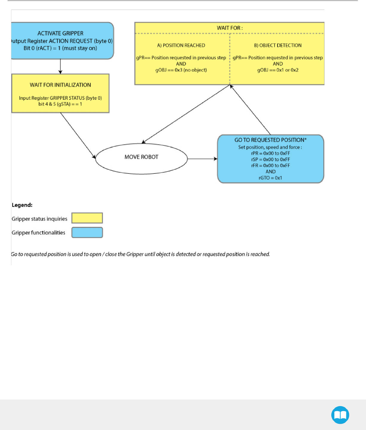
4.6. Control Logic
Fig. 4-8: Example of the 2-Finger control logic with associated registers.
61

2F-85 &2F-140 - Instruction Manual
4.7. Modbus RTUCommunication
The Gripper can be controlled by Modbus RTU directly with RS485 or over USB using the ACC-ADT-USB-RS485. This section is
intended to provide guidelines for setting up a Modbus scanner that will adequately communicate with the Gripper.
For a general introduction to Modbus RTU and for details regarding the CRC algorithm, the reader is invited to read the Modbus over
serial line specification and implementation guide available at: http://www.modbus.org/docs/Modbus_over_serial_line_V1_02.pdf.
For debugging purposes, the reader is also invited to download one of many free Modbus scanners such as the CAS Modbus Scanner
from Chipkin Automation Systems available at: http://www.store.chipkin.com/products/tools/cas-modbus-scanner.
Info
Modbus RTU is a communication protocol based on a Big Endian byte order. Therefore, the 16-bit register addresses are
transmitted with the most significant byte first. However, the data port is in the case of Robotiq products based on the Little
Endian byte order. As such, the data parts of Modbus RTU messages are sent with the less significant byte first.
Tip
Modbus RTU specification and details can be found at www.modbus.org.
62

2F-85 &2F-140 - Instruction Manual
4.7.1. Connection Setup
The following table describes the connection requirements for controlling the Gripper using the Modbus RTU protocol.
PROPRIETY VALUE
Physical Interface RS-4851
Baud Rate2115,200 bps
Data Bits 8
Stop Bit21
Parity2None
Supported Functions
Read Holding Register (FC03)
Read Input Registers (FC04)
Preset Single Register (FC06)
Preset Multiple Register (FC16)
Master read & write multiple registers (FC23)
Exception Responses Not supported
Slave ID20x0009 (9)
Robot Output / Gripper Input First Register 0x03E8 (1000)
Robot Input / Gripper Output First Register 0x07D0 (2000)
1Various converters are available in the Spare parts section.
2These parameters can be adjusted using the Robotiq User Interface.
Each register (word - 16 bits) of the Modbus RTU protocol is composed of 2bytes (8 bits) from the Gripper. The first Gripper output
Modbus register(0x07D0) is composed from the first 2Robotiq Gripper bytes (byte 0 and byte 1).
Info
200 Hz is the usual speed when commanding / reading from the Robotiq Gripper. It is therefore recommended to send
commands with a minimum delay of 5 ms between them.
Info
Maximum baud rate of ACC-ADT-USB-RS485 is 115200 bps.
120 Ohms termination resistor is already present on the converter.
63

2F-85 &2F-140 - Instruction Manual
4.7.2. Read holding registers (FC03)
Function code 03 (FC03) is used for reading the status of the Gripper (robot input). Examples of such data are Gripper status, object
status, finger position, etc.
Example of FC03 Read function:
This message asks for register 0x07D0 (2000) and register 0x07D1 (2001) which contains Gripper Status, Object Detection, Fault Status
and Position Request Echo.
Request is: 09 03 07 D0 00 02 C5 CE
Bits Description
09 SlaveID
03 Function Code 03 (Read Holding Registers)
07D0 Address of the first requested register
0002 Number of registers requested (2)
C5CE Cyclic Redundancy Check (CRC)
Response is: 09 03 04 E0 00 00 00 44 33
Bits Description
09 SlaveID
03 Function Code 03 (Read Holding Registers)
04 Number of data bytes to follow (2 registers x 2 bytes/register = 4 bytes)
E000 Content of register 07D0
0000 Content of register 07D1
4433 Cyclic Redundancy Check (CRC)
64

2F-85 &2F-140 - Instruction Manual
4.7.3. Read input registers (FC04)
Function code 04 (FC04) is used for requesting the status of the Gripper's analog input register. Examples of such data are Gripper
status, object status, finger position, etc.
Example of FC04 read function:
This message asks for register 0x07D0 (2000) and register 0x07D1 (2001) which contains Gripper Status, Object Detection, Fault Status
and Position Request Echo.
Request is: 09 04 07 D0 00 02 C5 CE
Bits Description
09 SlaveID
04 Function Code 03 (Read Holding Registers)
07D0 Address of the first requested register
0002 Number of registers requested (2)
700E Cyclic Redundancy Check (CRC)
Response is: 09 04 04 E0 00 00 00 44 33
Bits Description
09 SlaveID
04 Function Code 04 (Read Holding Registers)
04 Number of data bytes to follow (2 registers x 2 bytes/register = 4 bytes)
E000 Content of register 07D0
0000 Content of register 07D1
4584 Cyclic Redundancy Check (CRC)
65

2F-85 &2F-140 - Instruction Manual
4.7.4. Preset multiple registers (FC16)
Function code 16 (FC16) is used to activate functionalities of the Gripper (robot output). Examples of such data are action request,
speed, force, etc.
Example of setting multiple registers FC16:
This message requests to set position request, speed and force of the Gripper by setting register 0x03E9 (1002) and 0x03EA.
Request is: 09 10 03 E9 00 02 04 60 E6 3C C8 EC 7C
Bits Description
09 SlaveID
10 Function Code 16 (Preset Multiple Registers)
03E9 Address of the first register
0002 Number of registers written to
04 Number of data bytes to follow (2 registers x 2 bytes/register = 4 bytes)
60E6 Value written to register 0x03E9
3CC8 Value written to register 0x03EA
EC7C Cyclic Redundancy Check (CRC)
Response is: 09 10 03 E9 00 02 91 30
Bits Description
09 SlaveID
10 Function Code 16 (Preset Multiple Registers)
03E9 Address of the first register
0002 Number of written registers
9130 Cyclic Redundancy Check (CRC)
66

2F-85 &2F-140 - Instruction Manual
4.7.5. Master read & write multiple registers FC23
Function code 23 (FC23) is used for reading the status of the Gripper (robot input) and activating functionalities of the Gripper (robot
output) simultaneously. Examples of such data are Gripper status, object status, finger position, etc. Action requests are speed, force,
etc.
Example of reading and writing multiple registers FC23:
This message reads registers 0x07D0 (2000) and 0x07D1 (2001), which contains Gripper Status, Object Detection, Fault Status and
Position Request Echo. It also sets the position request, speed and force of the Gripper by writing to registers 0x03E9 (1001) and
0x03EA (1002).
Request is: 09 17 07 D0 00 02 03 E9 00 02 04 00 E6 3C C8 2D 0C
Bits Description
09 SlaveID
17 Function Code 23 (read and write multiple registers)
07D0 Address of the first requested register, read
0002 Number of registers requested (2), read
03E9 Address of the first register written to
0002 Number of registers written to (3)
04 Number of data bytes to follow (2 registers X 2 bytes/registers = 4 bytes)
00E6 Value written to register 0x03E9
3CC8 Value written to register 0x03EA
2D0C Cyclic Redundancy Check (CRC)
Response is: 09 17 04 01 00 09 E6 F6 C1
Bits Description
09 SlaveID
17 Function Code 23 (read and write multiple registers)
04 Number of data bytes to follow (2 registers x 2 bytes/register = 4 bytes)
1000 Content of register 07D0
67

2F-85 &2F-140 - Instruction Manual
Bits Description
09E6 Content of register 07D1
F6C1 Cyclic Redundancy Check (CRC)
Note that the content of the response might change depending on the Gripper's status.
68

2F-85 &2F-140 - Instruction Manual
4.7.6. Modbus RTU example
This section depicts the example given in the Control Logic section when programmed using the Modbus RTU protocol. The example
is typical of a pick and place application. After activating the Gripper, the robot is moved to a pick-up location to grip an object. It
moves again to a second location to release the gripped object.
Step 1: Activation Request ( clear and set rACT)
Request is (clear rAct): 09 10 03 E8 00 03 06 00 00 00 00 00 00 73 30
Bits Description
09 SlaveID
10 Function Code 16 (Preset Multiple Registers)
03E8 Address of the first register
0003 Number of registers written to
06 Number of data bytes to follow (3 registers x 2 bytes/register = 6 bytes)
0000 Value to write to register 0x03E9 (ACTION REQUEST = 0x01 and GRIPPER OPTIONS = 0x00): rACT = 1 for "Activate
Gripper"
0000 Value written to register 0x03EA
0000 Value written to register 0x03EB
7330 Cyclic Redundancy Check (CRC)
Response is: 09 10 03 E8 00 03 01 30
Bits Description
09 SlaveID
10 Function Code 16 (Preset Multiple Registers)
03E8 Address of the first register
0003 Number of written registers
0130 Cyclic Redundancy Check (CRC)
69

2F-85 &2F-140 - Instruction Manual
Request is (set rAct): 09 10 03 E8 00 03 06 01 00 00 00 00 00 72 E1
Bits Description
09 SlaveID
10 Function Code 16 (Preset Multiple Registers)
03E8 Address of the first register
0003 Number of registers written to
06 Number of data bytes to follow (3 registers x 2 bytes/register = 6 bytes)
0100 Value to write to register 0x03E9 (ACTION REQUEST = 0x01 and GRIPPER OPTIONS = 0x00): rACT = 1 for "Activate
Gripper"
0000 Value written to register 0x03EA
0000 Value written to register 0x03EB
72E1 Cyclic Redundancy Check (CRC)
Response is: 09 10 03 E8 00 03 01 30
Bits Description
09 SlaveID
10 Function Code 16 (Preset Multiple Registers)
03E8 Address of the first register
0003 Number of written registers
0130 Cyclic Redundancy Check (CRC)
70

2F-85 &2F-140 - Instruction Manual
Step 2: Read Gripper status until the activation is completed
Request is: 09 03 07 D0 00 01 85 CF
Bits Description
09 SlaveID
03 Function Code 03 (Read Holding Registers)
07D0 Address of the first requested register
0001 Number of registers requested (1)
85CF Cyclic Redundancy Check (CRC)
Response (if the activation IS NOT completed): 09 03 02 11 00 55 D5
Bits Description
09 SlaveID
03 Function Code 03 (Read Holding Registers)
02 Number of data bytes to follow (1 register x 2 bytes/register = 2 bytes)
1100 Content of register 07D0 (GRIPPER STATUS = 0x11, RESERVED = 0x00): gACT = 1 for "Gripper Activation", gSTA = 1 for
"Activation inprogress"
55D
5Cyclic Redundancy Check (CRC)
Response (if the activation IS completed): 09 03 02 31 00 4C 15
Bits Description
09 SlaveID
03 Function Code 03 (Read Holding Registers)
02 Number of data bytes to follow (1 register x 2 bytes/register = 2 bytes)
3100 Content of register 07D0 (GRIPPER STATUS = 0x31, RESERVED = 0x00): gACT = 1 for "Gripper Activation", gSTA = 3 for
"Activation is completed"
4C15 Cyclic Redundancy Check (CRC)
71

2F-85 &2F-140 - Instruction Manual
Step 3: Move the robot to the pick-up location
Step 4: Close the Gripper at full speed and full force
Request is: 09 10 03 E8 00 03 06 09 00 00 FF FF FF 42 29
Bits Description
09 SlaveID
10 Function Code 16 (Preset Multiple Registers)
03E8 Address of the first register
0003 Number of registers written to
06 Number of data bytes to follow (3 registers x 2 bytes/register = 6 bytes)
0900 Value written to register 0x03E8 (ACTION REQUEST = 0x09 and GRIPPER OPTIONS = 0x00): rACT = 1 for "Activate
Gripper", rGTO = 1 for "Go to Requested Position"
00FF Value written to register 0x03E9 (GRIPPER OPTIONS 2 = 0x00 and POSITION REQUEST = 0xFF): rPR = 255/255 for full
closing of the Gripper
FFFF Value written to register 0x03EA (SPEED = 0xFF and FORCE = 0xFF): full speed and full force
4229 Cyclic Redundancy Check (CRC)
Response is: 09 10 03 E8 00 03 01 30
Bits Description
09 SlaveID
10 Function Code 16 (Preset Multiple Registers)
03E8 Address of the first register
0003 Number of written registers
0130 Cyclic Redundancy Check (CRC)
72

2F-85 &2F-140 - Instruction Manual
Step 5: Read Gripper status until the grip is completed
Request is: 09 03 07 D0 00 03 04 0E
Bits Description
09 SlaveID
03 Function Code 03 (Read Holding Registers)
07D0 Address of the first requested register
0003 Number of registers requested (3)
040E Cyclic Redundancy Check (CRC)
Example of response if the grip is not completed: 09 03 06 39 00 00 FF 0E 0A F7 8B
Bits Description
09 SlaveID
03 Function Code 03 (Read Holding Registers)
06 Number of data bytes to follow (3 registers x 2 bytes/register = 6 bytes)
3900 Content of register 07D0 (GRIPPER STATUS = 0x39, RESERVED = 0x00): gACT = 1 for "Gripper Activation", gGTO = 1
for "Go to Position Request" and gOBJ = 0 for "Fingers are in motion"
00FF Content of register 07D1 (FAULT STATUS = 0x00, POSITION REQUEST ECHO = 0xFF): the position request echo tells
that the command was well received and that the GRIPPER STATUS is valid.
0E0A Content of register 07D2 (POSITION = 0x0E, FINGER CURRENT = 0x0A): the position is 14/255 and the motor current is
100mA (these values will change during motion)
F78B Cyclic Redundancy Check (CRC)
73

2F-85 &2F-140 - Instruction Manual
Example of response if the grip is completed: 09 03 06 B9 00 00 FF BD 00 1D 7C
Bits Description
09 SlaveID
03 Function Code 03 (Read Holding Registers)
06 Number of data bytes to follow (3 registers x 2 bytes/register = 6 bytes)
B900 Content of register 07D0 (GRIPPER STATUS = 0xB9, RESERVED = 0x00): gACT = 1 for "Gripper Activation", gGTO = 1
for "Go to Position Request" and gOBJ = 2 for "Fingers have stopped due to a contact while closing"
00FF Content of register 07D1 (FAULT STATUS = 0x00, POSITION REQUEST ECHO = 0xFF): the position request echo tells
that the command was well received and that the GRIPPER STATUS is valid.
BD00 Content of register 07D2 (POSITION = 0xBD, FINGER CURRENT = 0x00): the position is 189/255 (can be used to validate
the size of the seized object)
1D7C Cyclic Redundancy Check (CRC)
74

2F-85 &2F-140 - Instruction Manual
Step 6: Move the robot to the release location
Step 7: Open the Gripper at full speed and full force
Request is: 09 10 03 E8 00 03 06 09 00 00 00 FF FF 72 19
Bits Description
09 SlaveID
10 Function Code 16 (Preset Multiple Registers)
03E8 Address of the first register
0003 Number of registers written to
06 Number of data bytes to follow (3 registers x 2 bytes/register = 6 bytes)
0900 Value written to register 0x03E8 (ACTION REQUEST = 0x09 and GRIPPER OPTIONS = 0x00): rACT = 1 for "Activate
Gripper", rGTO = 1 for "Go to Requested Position"
0000 Value written to register 0x03E9 (GRIPPER OPTIONS 2 = 0x00 and POSITION REQUEST = 0x00): rPR = 0/255 for full
opening of the Gripper (partial opening would also be possible)
FFFF Value written to register 0x03EA (SPEED = 0xFF and FORCE = 0xFF): full speed and full force
7219 Cyclic Redundancy Check (CRC)
Response is: 09 10 03 E8 00 03 01 30
Bits Description
09 SlaveID
10 Function Code 16 (Preset Multiple Registers)
03E8 Address of the first register
0003 Number of written registers
0130 Cyclic Redundancy Check (CRC)
75

2F-85 &2F-140 - Instruction Manual
Step 8: Read Gripper status until the opening is completed
Request is: 09 03 07 D0 00 03 04 0E
Bits Description
09 SlaveID
03 Function Code 03 (Read Holding Registers)
07D0 Address of the first requested register
0003 Number of registers requested (3)
040E Cyclic Redundancy Check (CRC)
Example of response if the opening is not completed: 09 03 06 39 00 00 00 BB 10 30 E0
Bits Description
09 SlaveID
03 Function Code 03 (Read Holding Registers)
06 Number of data bytes to follow (3 registers x 2 bytes/register = 6 bytes)
3900 Content of register 07D0 (GRIPPER STATUS = 0x39, RESERVED = 0x00): gACT = 1 for "Gripper Activation", gGTO = 1
for "Go to Position Request" and gOBJ = 0 for "Fingers are in motion"
0000 Content of register 07D1 (FAULT STATUS = 0x00, POSITION REQUEST ECHO = 0x00): the position request echo tells
that the command was well received and that the GRIPPER STATUS is valid.
BB10 Content of register 07D2 (POSITION = 0xBB, FINGER CURRENT = 0x10): the position is 187/255 and the motor current is
160mA (these values will change during motion)
30E0 Cyclic Redundancy Check (CRC)
76

2F-85 &2F-140 - Instruction Manual
Example of response if the opening is completed: 09 03 06 F9 00 00 00 0D 00 56 4C
Bits Description
09 SlaveID
03 Function Code 03 (Read Holding Registers)
06 Number of data bytes to follow (3 registers x 2 bytes/register = 6 bytes)
F900 Content of register 07D0 (GRIPPER STATUS = 0xF9, RESERVED = 0x00): gACT = 1 for "Gripper Activation", gGTO = 1
for "Go to Position Request" and gOBJ = 3 for "Fingers are at requested position"
0000 Content of register 07D1 (FAULT STATUS = 0x00, POSITION REQUEST ECHO = 0x00): the position request echo tells
that the command was well received and that the GRIPPER STATUS is valid.
0D00 Content of register 07D2 (POSITION = 0x0D, FINGER CURRENT = 0x00): the position is 13/255 (the fingers have reached
their software limit)
564C Cyclic Redundancy Check (CRC)
Step 9: Loop back to step 3 if other objects have to be gripped.
77

2F-85 &2F-140 - Instruction Manual
4.8. Control over Universal Robots with URCaps
The URCap package contains many features to program and control the Gripper. The package provides:
lGripper toolbar: The Gripper toolbar is automatically installed with the URCap package. It allows jogging and testing of the Gripper. It
is a great tool to try grasps with the Gripper while programming.
lGripper node: The URCap package adds a Gripper node that is used to add a Gripper command. A node can make the Gripper
move to a specific opening, grasp an object and modify the speed and force applied by the Gripper.
Caution
Starting from Gripper URCap version 1.0.2, the gripper activation script command (rq_activate() or rq_activate_and_wait())
must be preceded by the reset command (rq_reset()). This will force the gripper's activation routine. Thus, if the gripper was
already activated, it will activateagain.
78
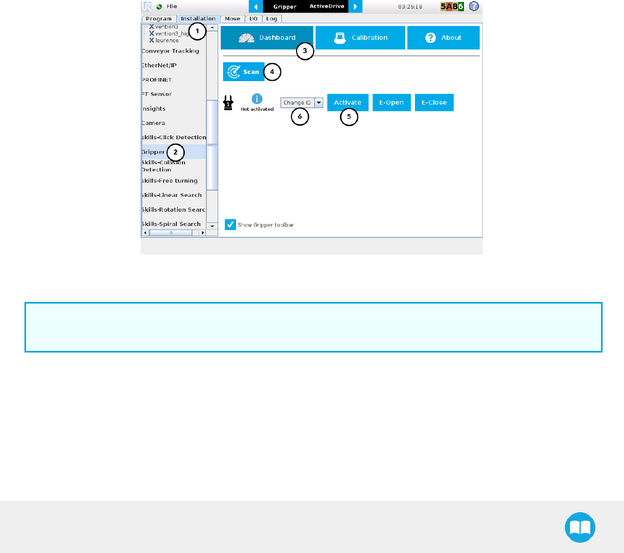
2F-85 &2F-140 - Instruction Manual
4.8.1. Gripper Dashboard
Overview
Single Gripper
Open or create a robot program
1Go the Installation tab
2Select Gripper in the left pane
3Tap the Dashboard button
4In no Gripper is found, tap the Scan button to detect any Gripper that might be connected to the robot
5Tap the Activate button
Fig. 4-9: Gripper Dashboard (steps highlighted)
6If required, change the IDof the Gripper; ID numbers range from 1 to 4
Info
The default Gripper IDallocated to the first device connected is 1.
79
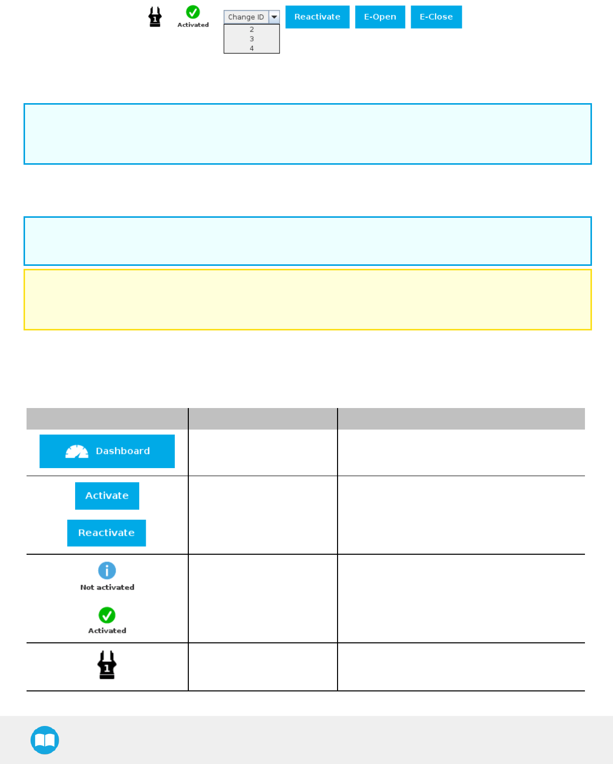
2F-85 &2F-140 - Instruction Manual
Fig. 4-10: Gripper IDmodification in the Gripper Dashboard
Info
The E-Open and E-Close buttons allow the user to open and close the Gripper even if the latter is not activated.
These emergency commands use very low speed and force settings.
Multiple Grippers
Info
The URCap allows the user to connect and control up to 4Grippers at the same time.
Caution
If you wish to program using multiple grippers at the same time, connect them to the robot one after the other; each Gripper
connection requiring its own scan and activation before going on to the next.
For each Gripper connected, follow steps 3 to 6 set out in the Control section.
Features
Icon Functionality Name Description
Dashboard
After selecting Gripper in the left pane of the
Installation tab, tap this button to access the Gripper
Dashboard.
Activate/Reactivate The Activate and Reactivate buttons enables the
corresponding Gripper.
Not activated/Activated Gripper status: One or the other of these icons is
displayed next to the corresponding Gripper icon.
Gripper Label indicating the Gripper's ID, ranging from 1 to 4.
80
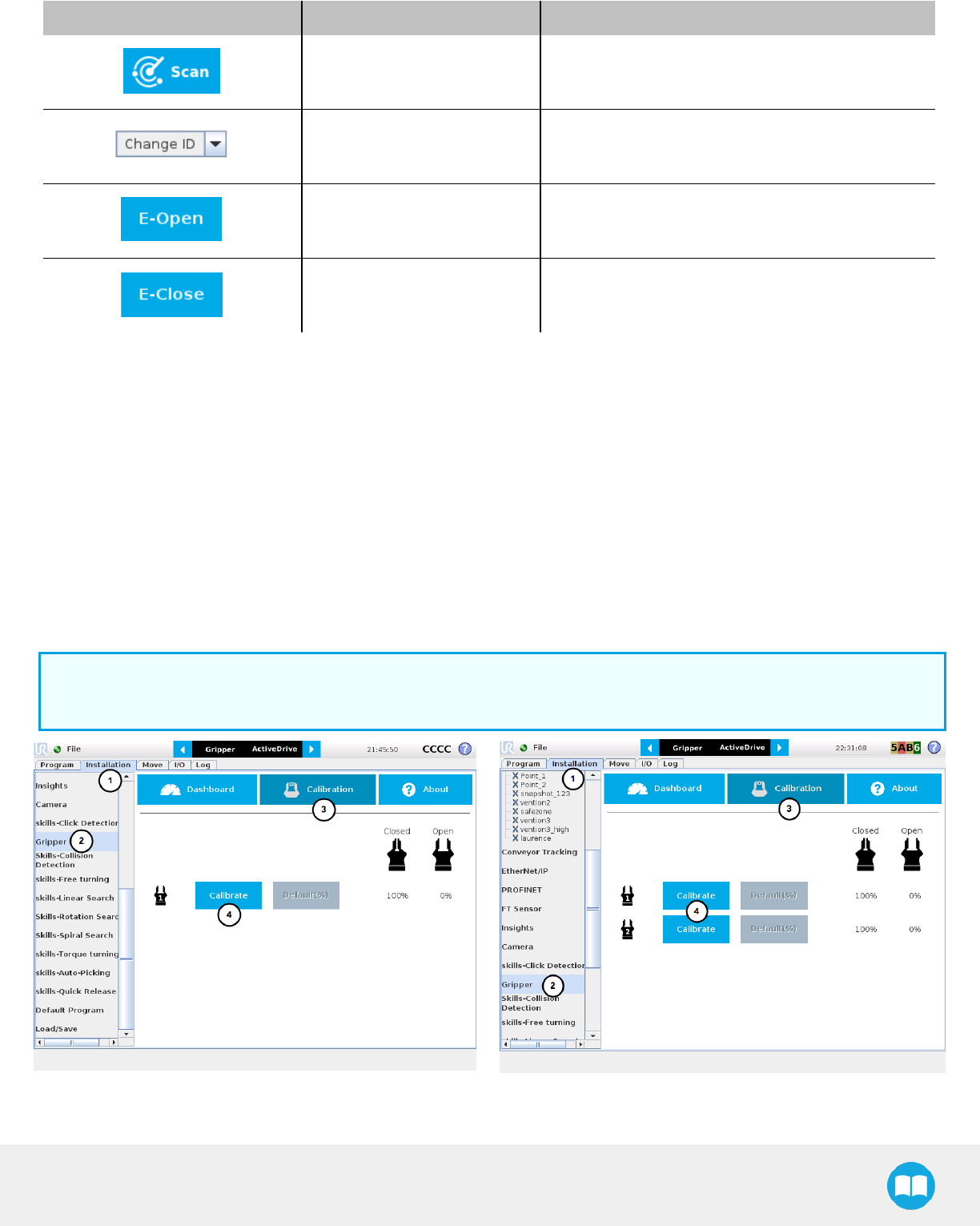
2F-85 &2F-140 - Instruction Manual
Icon Functionality Name Description
Scan
Command allowing for a detection of connected
Grippers. After tapping this button, the latter will
display in the Gripper Dashboard.
Change ID
Tap the arrow next to the textbox to expand a list of
available Gripper IDs. Selecting an available number
will allocate it to the corresponding Gripper.
E-Open
Tapping this button sends an emergency open
command to the corresponding Gripper, whether it is
activated or not.
E-Close
Tapping this button sends an emergency close
command to the corresponding Gripper, whether it is
activated or not.
4.8.2. Gripper Calibration menu and wizard
Depending on the fingers/fingertips used, the operator will calibrate the Gripper and measure the stroke by defining the fully open and
fully closed positions.
Make sure the Gripper is activated.
1Go to the Installation tab
2Select Gripper in the left pane
3Tap the Calibration button at the top of the window
4Tap the Calibrate button next to the Gripper icon to launch the Calibration wizard
Info
A gripper that has not been calibrated will display open and closed values in percentage.
Fig. 4-11: Gripper Calibration menu with Grippers, not calibrated (steps highlighted)
81
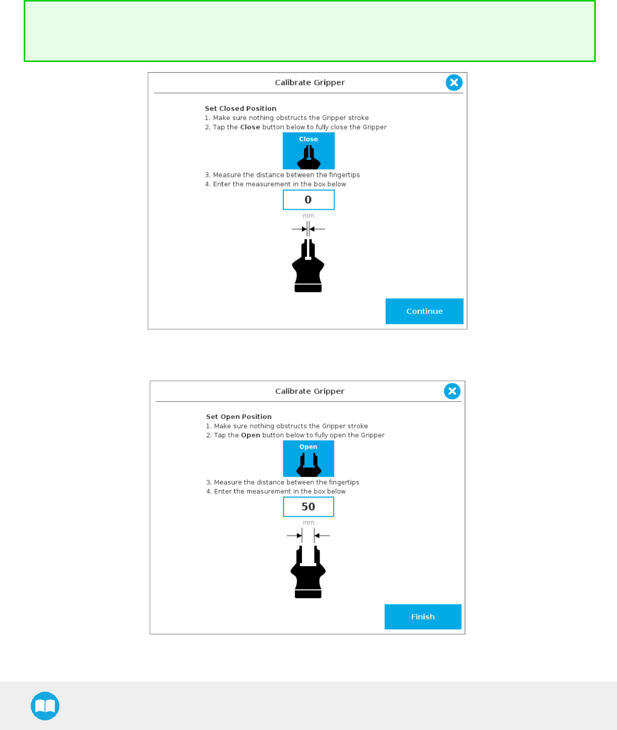
2F-85 &2F-140 - Instruction Manual
Tapping the Calibrate button in the Gripper Calibration menu launches the Calibration wizard.
Follow the instructions on the screen of the teach pendant.
Tip
Depending on the PolyScope settings defined by the user, the units of measurement can either display according to the
metric or imperial system.
Fig. 4-12: First step of the calibration wizard
Fig. 4-13: Second step of the calibration wizard
82
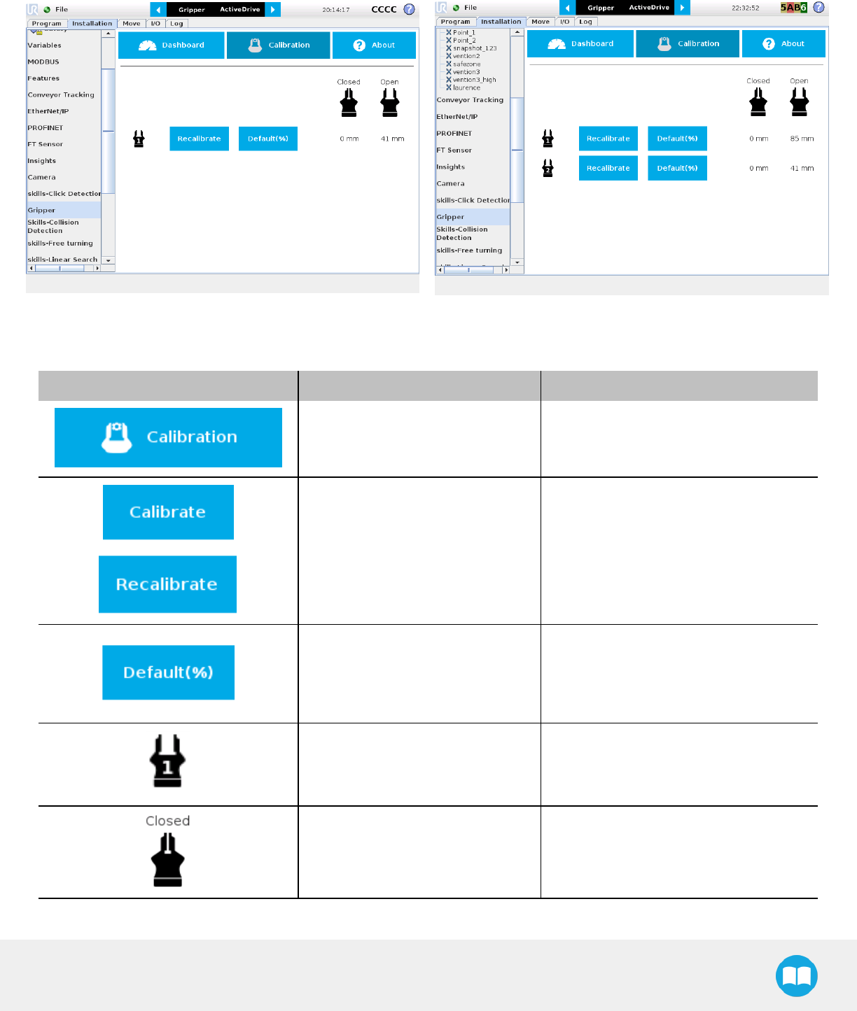
2F-85 &2F-140 - Instruction Manual
Following their respective calibration, the Grippers will display their actual stroke, from the fully closed to the fully open position.
Fig. 4-14: Gripper Calibration menu with Grippers calibrated
Features
Icon Functionality Name Description
Calibration
After selecting the Gripper in the left pane
of the Installation tab, tap this button to
access the Gripper Calibration menu.
Calibrate/Recalibrate The Calibrate and Recalibrate buttons
launch the Gripper Calibration wizard.
Default (%)
Following a calibration, tap this button to
reset the calibration and return to the
default percentage values. The button is
greyed out if no calibration has been
performed for the corresponding Gripper.
Gripper Label indicating the Gripper's ID, ranging
from 1 to 4.
Fully closed dimension table header Visual aid above the fully closed
dimensions in the Calibration menu.
83
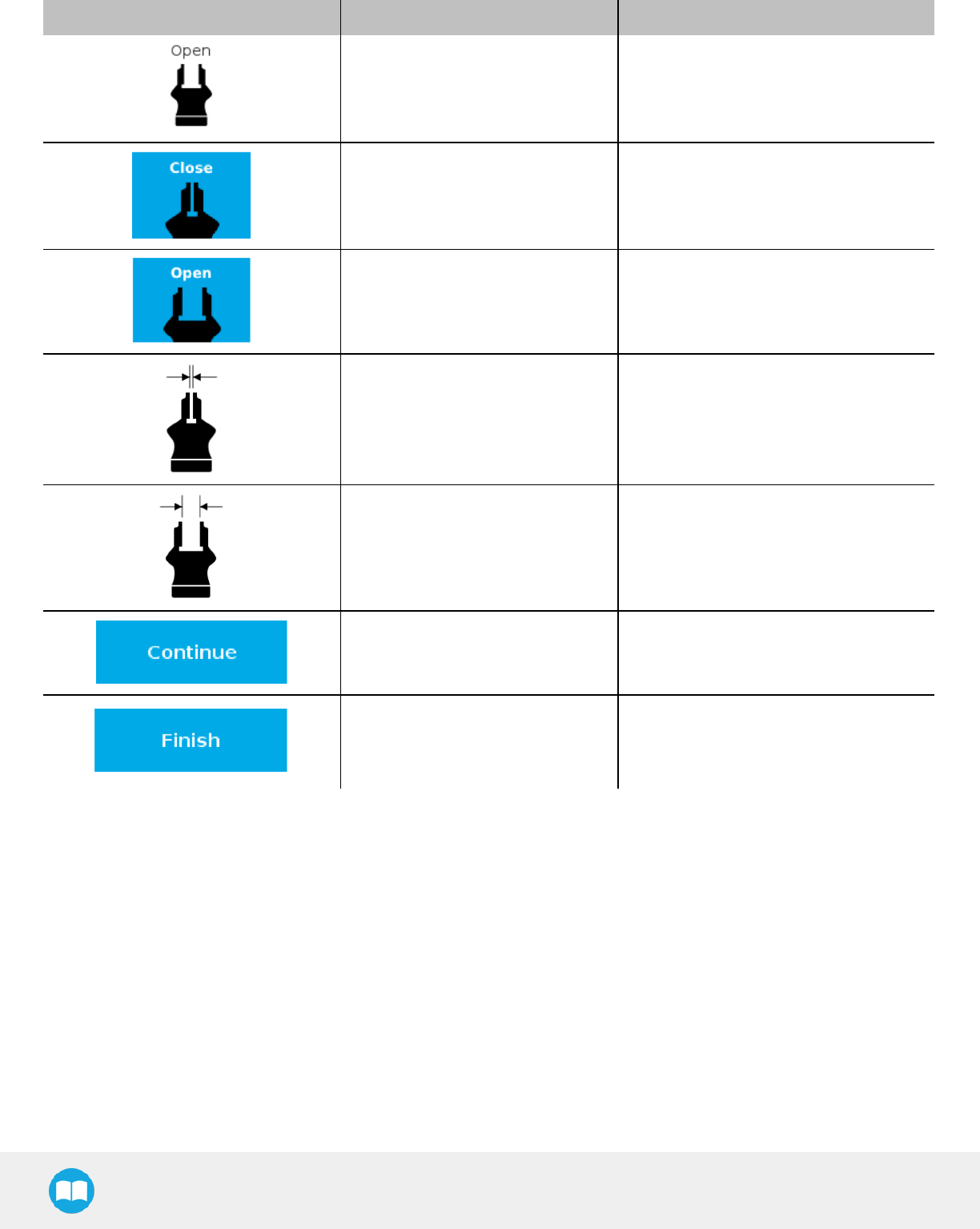
2F-85 &2F-140 - Instruction Manual
Icon Functionality Name Description
Fully open dimension table header Visual aid above the fully open dimensions
in the Calibration menu
Close Tap this button to close the Gripper in the
Calibration wizard.
Open Tap this button to open the Gripper in the
Calibration wizard.
Fully closed Visual aid for entering the fully closed
dimension in the Calibration wizard.
Fully open Visual aid for entering the fully open
dimension in the Calibration wizard.
Continue
Tap this button at the end of the first step
of the Calibration wizard in order to go to
the next step.
Finish
Tap this button at the the end of the
Calibration wizard to complete the
calibration process for the corresponding
Gripper.
84
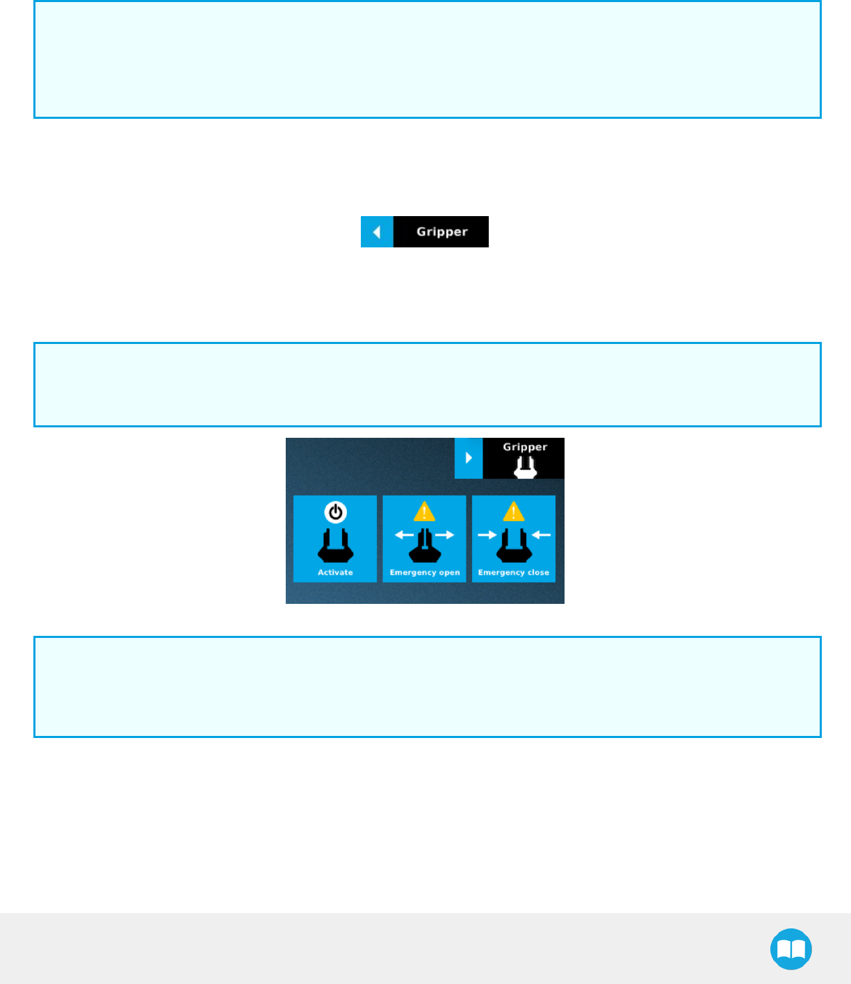
2F-85 &2F-140 - Instruction Manual
4.8.3. Gripper Toolbar
The Gripper Toolbar is generally used to test and jog the Gripper, meaning it has no effect on the programming of the robot.
Info
The Gripper URCap package contains the Gripper toolbar. Therefore, the toolbar is automatically installed with the URCap
package. The Gripper toolbar can be installed and used without the URCap package (please refer to the Control over
Universal Robots without URCaps section for information on how to install the toolbar and the driver package without the
URCap).
Overview
Right after the installation of the Gripper URCap, a collapsed Gripper toolbar will display at the top of the screen; please refer to the
figure below.
Fig. 4-15: Gripper toolbar (collapsed)
lTap the collapsed Gripper toolbar to expand it.
lWhen the Gripper is not activated, the toolbar displays the window in the figure below.
Info
If the Gripper has already been activated at this point, the toolbar will expand normally and allow for the testing and jogging
features. If that is the case, please refer to the following subsection.
Fig. 4-16: Gripper toolbar before activation (expanded)
Info
The Emergency open and Emergency close buttons allow the user to open and close the Gripper even if the latter is not
activated.
The emergency commands use very low speed and force settings.
lTap the Activate button to enable the Gripper
85
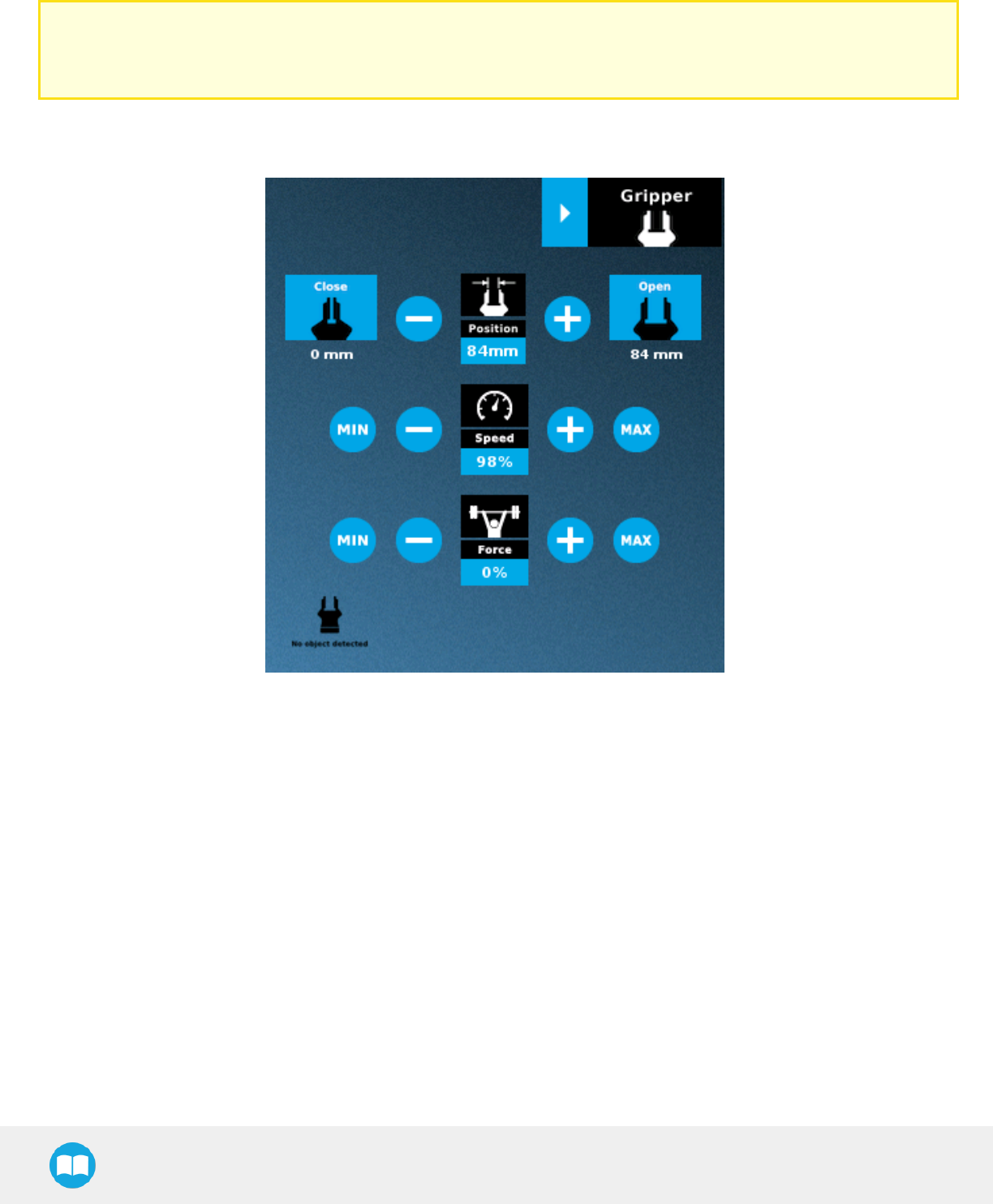
2F-85 &2F-140 - Instruction Manual
Single Gripper
Caution
If the Gripper has not been calibrated at this point, the Open and Close values will remain in percentage. Please refer to the
Control section for instructions.
Once the Gripper is activated, the toolbar can be expanded and used to test and jog the Gripper
Fig. 4-17: Gripper toolbar after activation (expanded, single Gripper)
86
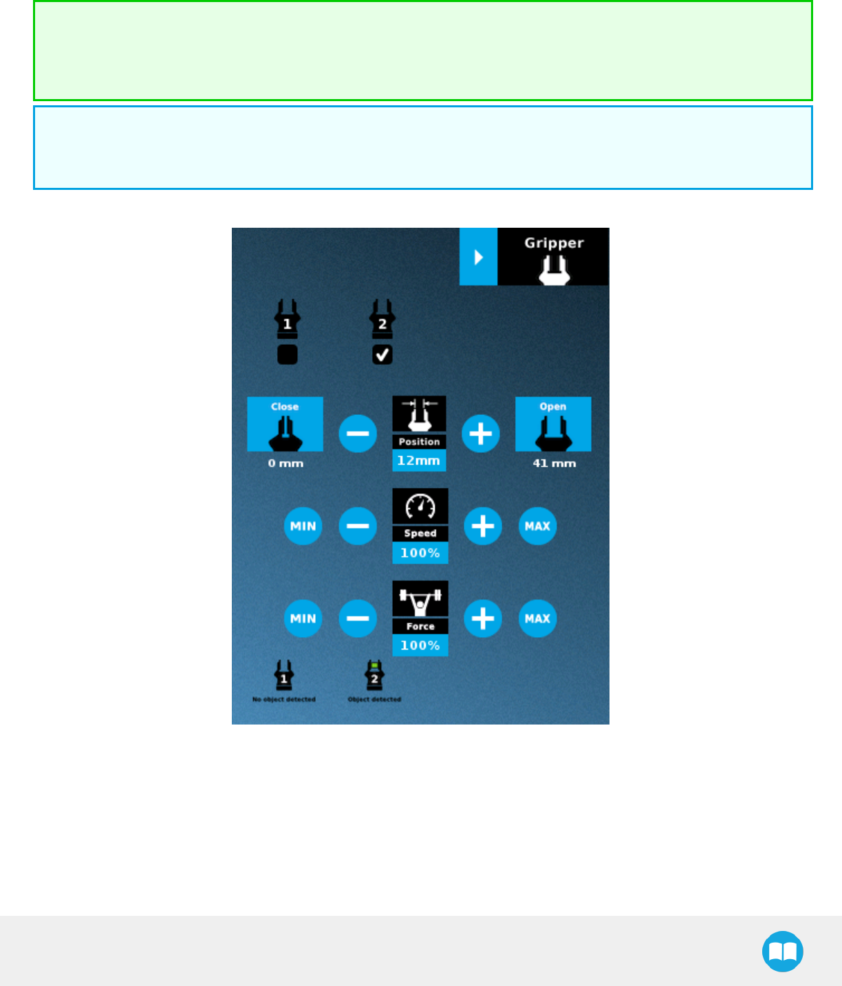
2F-85 &2F-140 - Instruction Manual
Multiple Grippers
If multiple Grippers are used, check one or several Grippers and test their settings and features.
Tip
The first Gripper selected is the "master", meaning that its settings will be copied over to the others when they are selected.
In order to modify each Gripper's settings individually, select a Gripper, edit it, uncheck its box and carry on to the next
Gripper.
Info
For consistency, selecting multiple Grippers at the same time displays the open and close values in percentage since their
stroke might be different.
Fig. 4-18: Gripper toolbar (expanded, multiple Grippers)
87
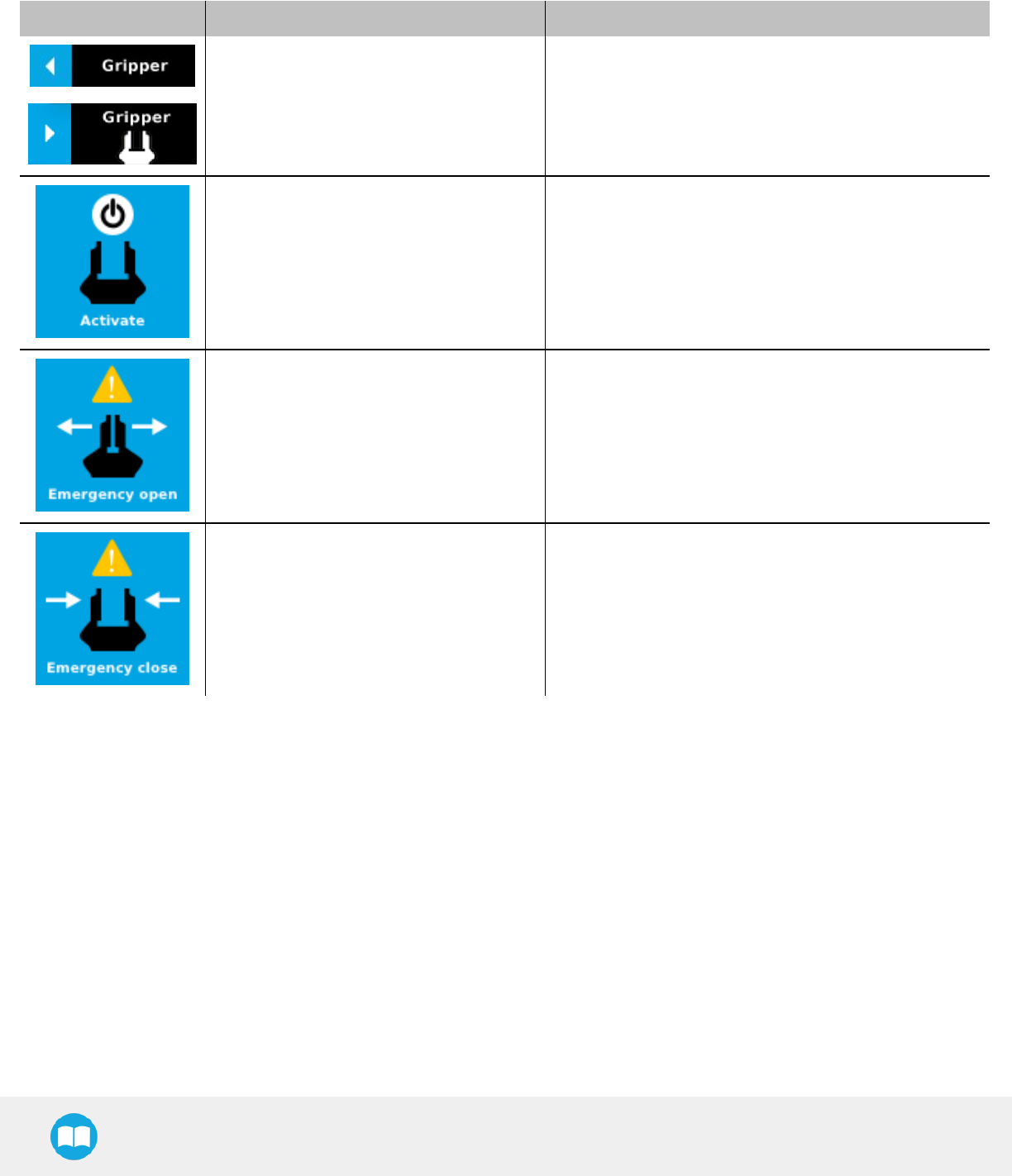
2F-85 &2F-140 - Instruction Manual
Features
Gripper activation
Icon Functionality Name Description
Gripper toolbar
Tap to toggle between the expanded and collapsed
Gripper toolbar. When greyed out, the functionality is not
available.
Activate Tap to activate the Gripper. The Gripper will fully open and
close to set the zero of the position value.
Emergency open Slowly moves the Gripper to its fully closed position.
Emergency close Slowly moves the Gripper to its fully open position.
88
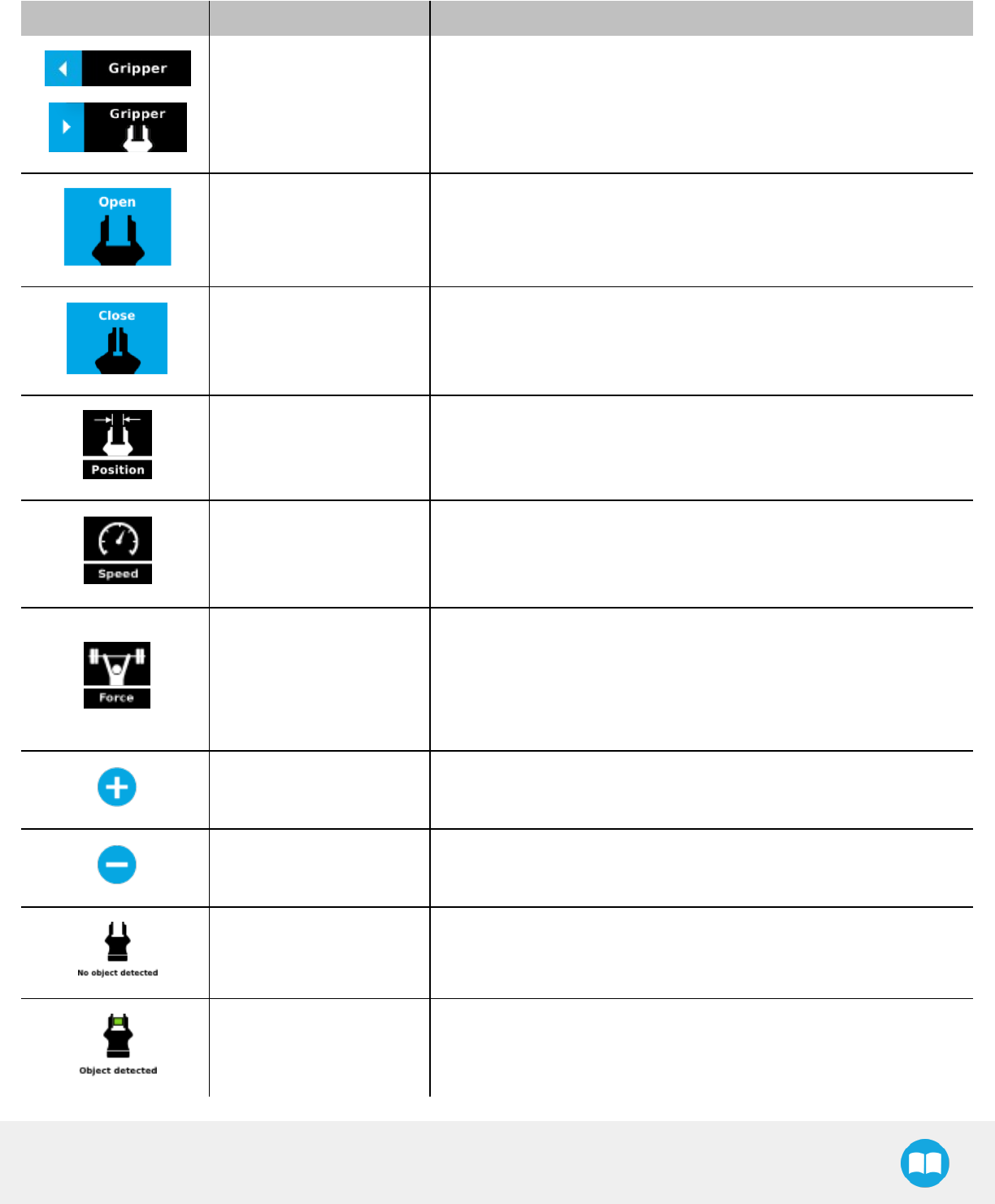
2F-85 &2F-140 - Instruction Manual
Gripper operation window
Primary Icon Functionality Name Description
Gripper toolbar
Tap to toggle between expanded and collapsed Gripper toolbar.
When greyed out, the functionality is not available.
Open Tap to fully open the Gripper.
Close Tap to fully close the Gripper.
Requested position
Shows the actual position of the Gripper according to the system of units
defined in PolyScope (imperial vs. metric).
If the Gripper is not calibrated, the values will display in percentage.
Requested speed
Shows the actual speed set of the Gripper.
l0% = minimum speed
l100%= maximum speed
Requested force
Shows the actual force set of the Gripper:
l0% : minimum force, regrasp feature disabled
l1% : minimum force, with regrasp feature enabled
l100% : maximum force, with regrasp feature enabled
Plus Tap to increase the corresponding parameter.
Minus Tap to decrease the corresponding parameter.
No object detected Icon shown when no object is detected during a grasp.
Object detected The icon shows a green checkmark when an object is detected during
agrasp.
89
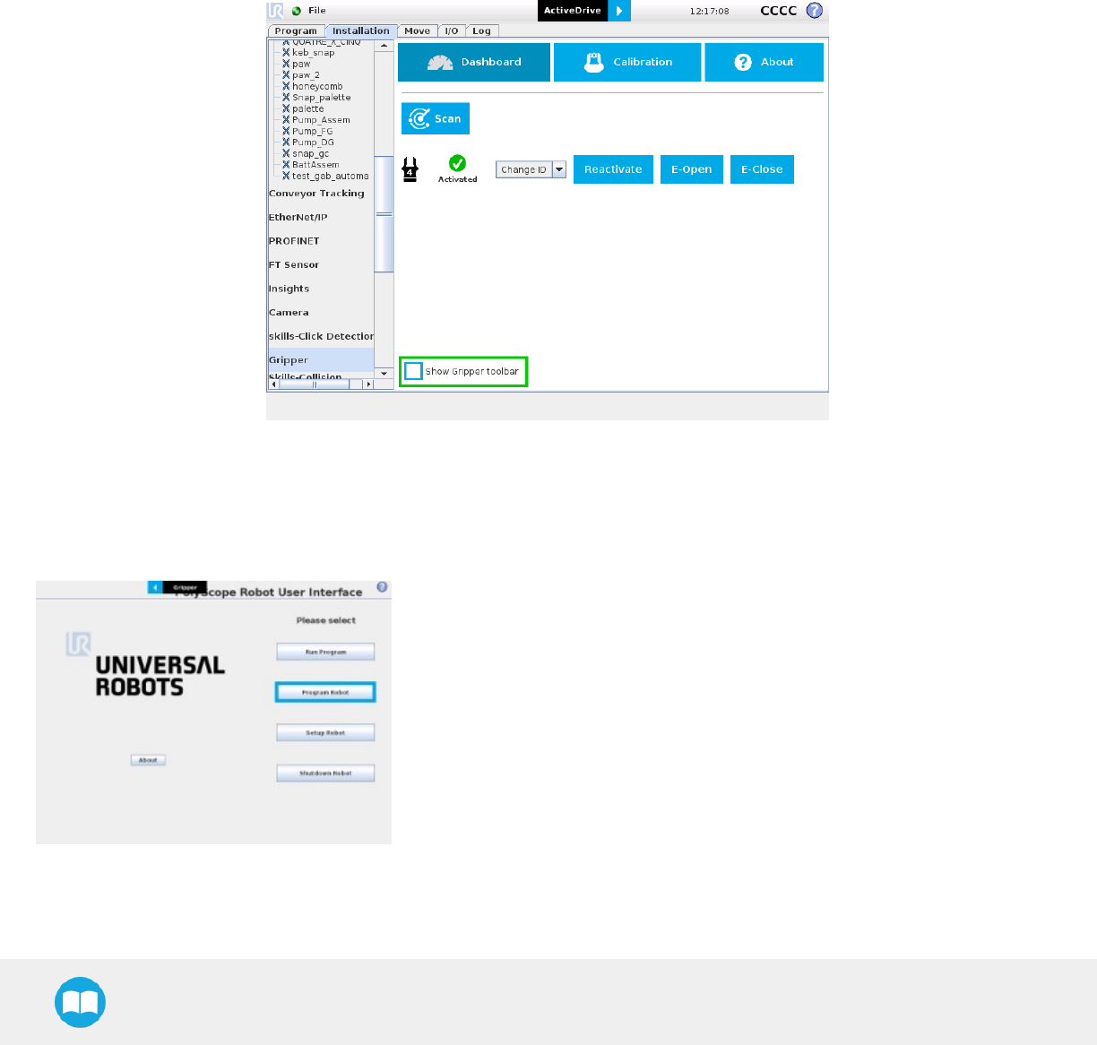
2F-85 &2F-140 - Instruction Manual
Show/hide Gripper Toolbar
It is possible to toggle between a shown and a hidden Gripper Toolbar.
1Create or load a robot program
2Tap the Installation tab
3Select Gripper in the left pane
4Tap the Dashboard submenu
5Check/Uncheck the box in the lower left corner
4.8.4. Gripper Node
To add and edit a Gripper node inside your robot program, follow the steps below:
lTap Program Robot
lOpen an empty program or load one.
90
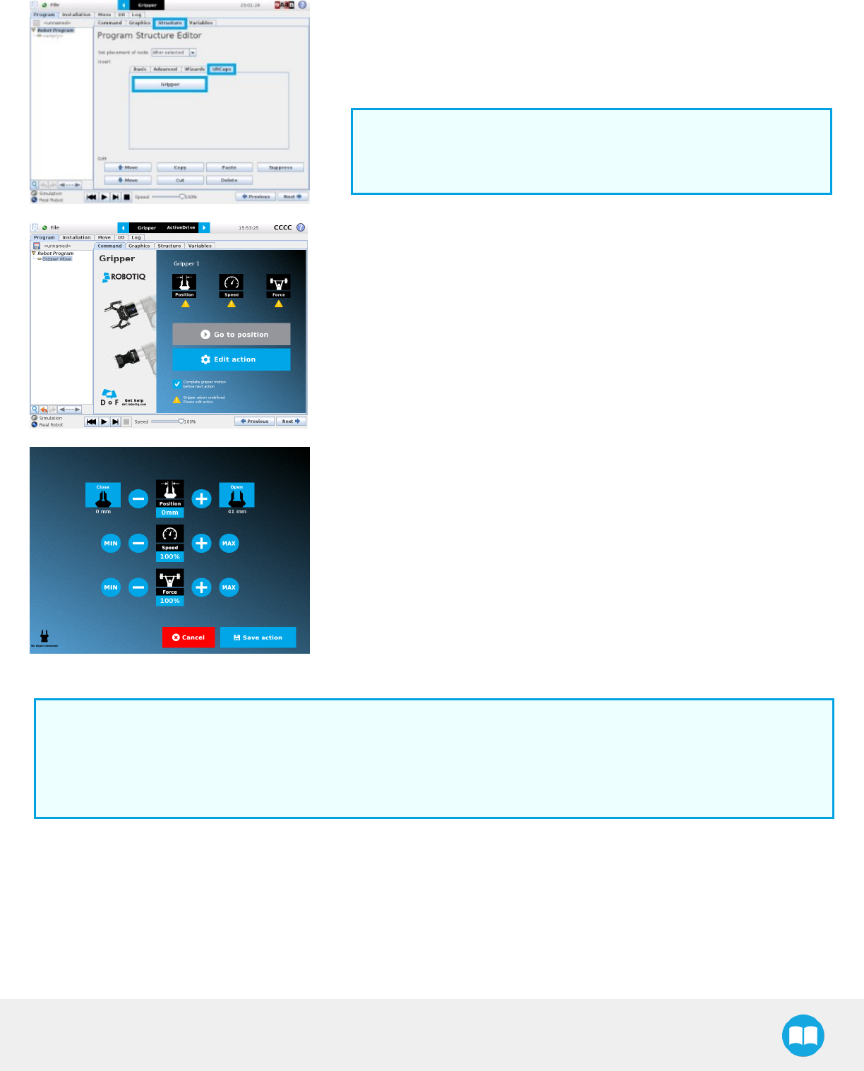
2F-85 &2F-140 - Instruction Manual
lGo to the Structure tab.
lGo to the URCaps submenu.
lTap the Gripper button.
Info
A Gripper node will be inserted in the program after tapping the
Gripperbutton.
lGo to the Command tab to edit the Gripper node previously inserted.
lTap Edit action to edit the node's parameters.
The Edit action screen will appear.
Info
The Gripper needs to be activated before it can receive a command. To do so, use the rq_activate_and_wait() function script
at the beginning of the program or activate with the Gripper toolbar. Starting from Gripper URCap version 1.0.2, the gripper
activation script command (rq_activate() or rq_activate_and_wait()) must be preceded by the reset command (rq_reset()). This
will force the gripper's activation routine. Thus, if the gripper was already activated, it will activate again.
Command window
The Command window shows the requested action parameters for the Gripper node. Depending on the position, speed and force
parameters, warning messages may display.
To edit the Gripper node, tap Edit action (please refer to the Edit action screen section for more details).
91
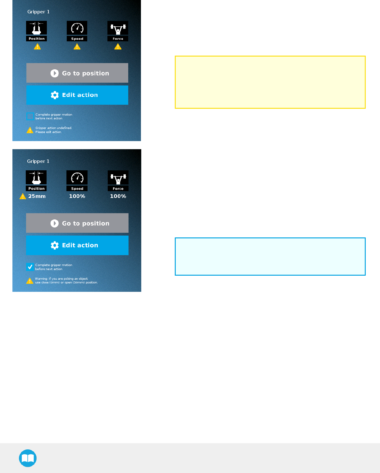
2F-85 &2F-140 - Instruction Manual
When the node is not defined, the Command window shows warning
messages. Tap Edit action to modify the Gripper’s action.
Caution
Tap the Go to position button prior to editing the action.
Whereas the command window displays the command that the
Gripper should execute in this particular node, the Edit action
screen displays the current Gripper position.
When the node requests the Gripper to close/open, the Command
window warns that a partial opening/closing should not be performed for
picking an object.
lFor positioning and partial movement of the hand, moving to a specific
position (between the fully open and fully close positions) issuitable.
lTo pick an object, use the close (or open) actions along with the object
detectionfeature (please refer to the Edit action screen section).
Info
When the action is set for multiple Grippers, the header lists the
selected Grippers (e.g. Grippers 1,2,3,4)
92
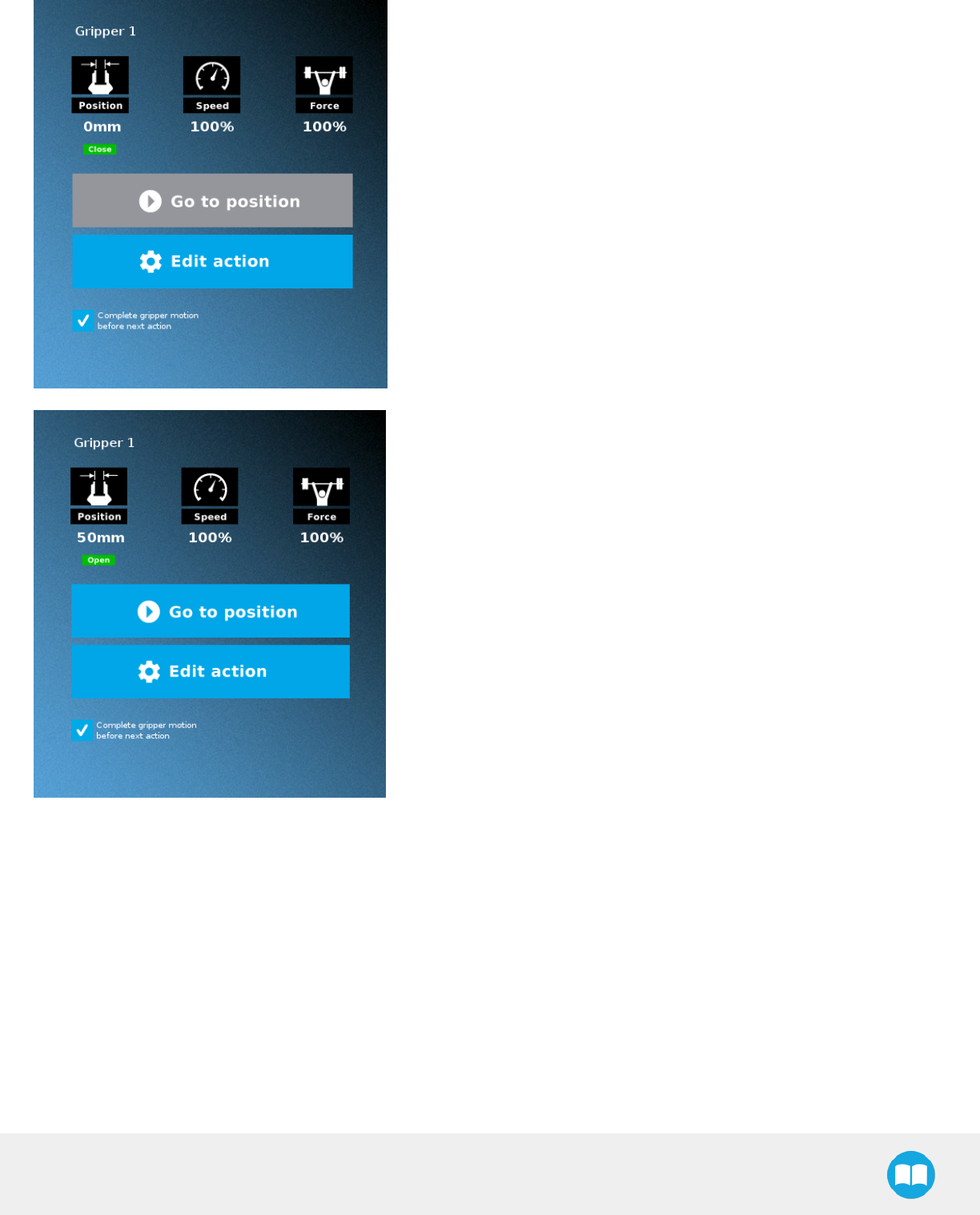
2F-85 &2F-140 - Instruction Manual
When the Gripper action is set to close, a green "Close" icon appears.
When the Gripper action is to open, a green "Open" icon appears.
93
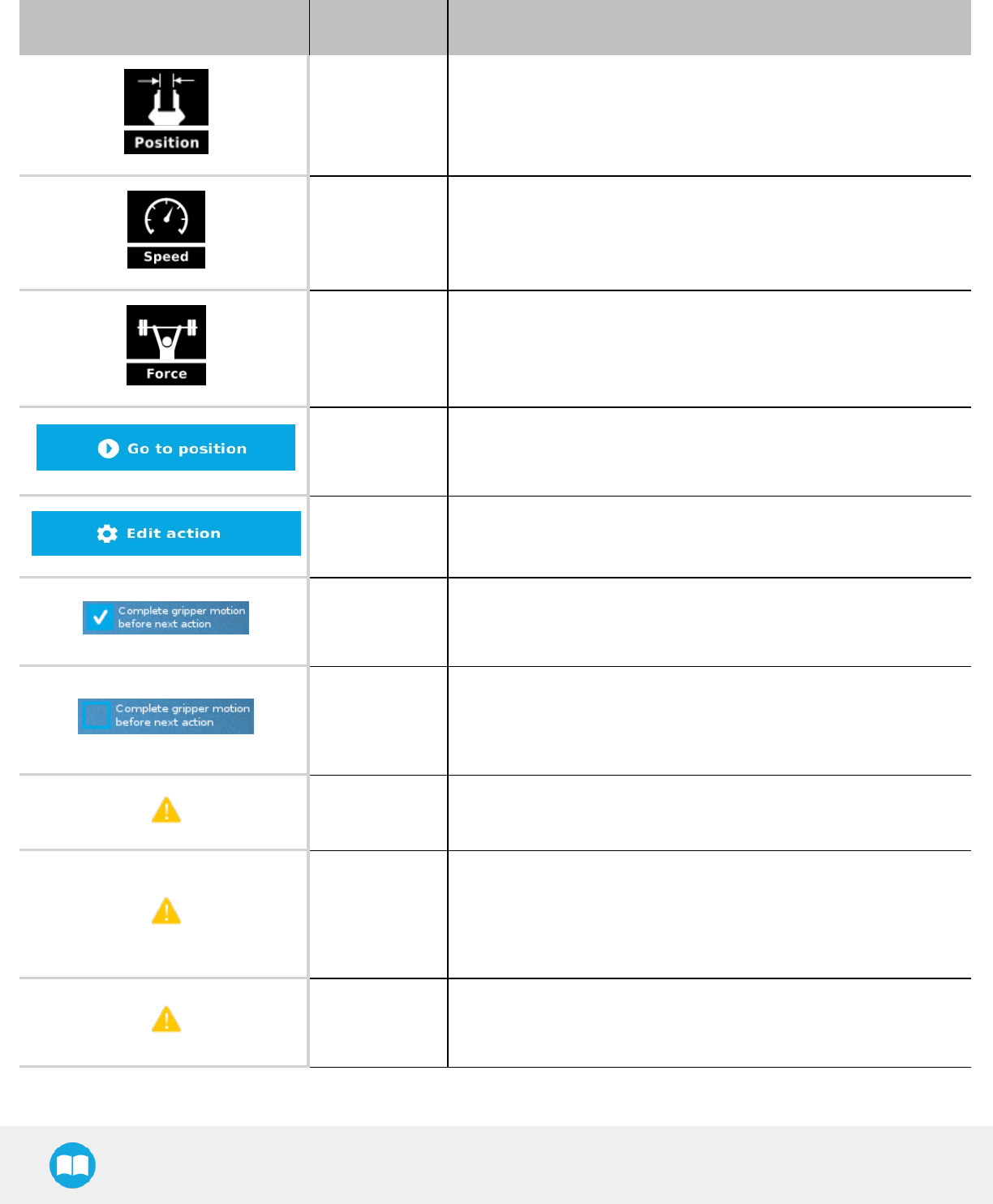
2F-85 &2F-140 - Instruction Manual
Features
Icon Functionality
Name Description
Requested
position Shows the position requested for the current Gripper node. Read only.
Requested
speed Shows the speed requested for the selected Gripper node. Read only.
Requested force Shows the force requested for the selected Gripper node. Read only.
Go to position
Sends all node parameters (position, force, speed) to the Gripper.
Note: This button is disabled (grey) when the Gripper is already at the
node position or when the Gripper is not powered/activated.
Edit action Opens the Edit action screen, where you can edit the Gripper’s action
parameters.
Complete
motion
Selected by default.
Selected: The Gripper completes its motion before executing the next
action on the PolyScope program tree. This is slower but safer.
Do not
complete
motion
Selected by default.
Unselected: As soon as the Gripper starts moving, PolyScope will
execute the next action on the program tree. This allows you to move the
Gripper and robot at the same time.
Warning
message
section
Gripper not
activated
“Warning, the Gripper is not powered or not activated. The Gripper will
not move.”
Make sure that the Gripper is installed correctly and powered. You need
to activate it using the Gripper toolbar before running Gripper
commands.
Gripper action
undefined
“Gripper action undefined! Please edit action.”
When creating a new node, all action parameters are undefined. Tap the
edit action button to define parameters.
94
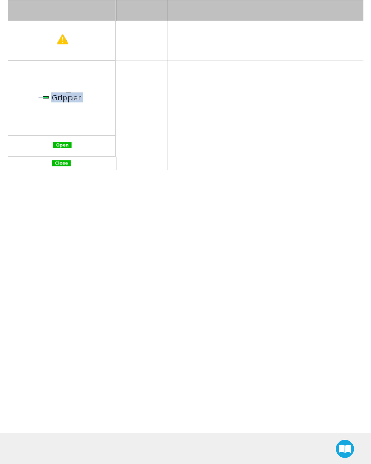
2F-85 &2F-140 - Instruction Manual
Icon Functionality
Name Description
Object picking
warning
“Warning, if you are picking an object, use close (100%) or open (0%)
position.”
It is highly recommended to only use 0% or 100% position when trying
to pick an object.
Node name
Node name is automatically set to:
lGripper Open, when position = 0% or fully open value as defined in
the Calibrationwizard
lGripper Close, when position = 100% or fully closed value as defined
in the Calibrationwizard.
lGripper Move x%/mm/in, when position is between the fully open and
fully closedvalues.
Open request When position requested is 0%, or the fully opened value defined in the
Calibrationwizard.
Close request When position request is 100%.
95
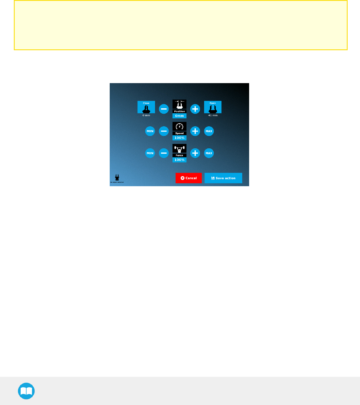
2F-85 &2F-140 - Instruction Manual
Edit action screen
Tap Edit action from the Command window and use the Edit action screen to edit the Gripper’s parameters and adjust its position,
speed and force. In normal usage conditions, the Gripper will move as soon as you change the position setting. The Gripper will not
move if it is not properly powered, connected and activated.
Caution
The Gripper needs to be activated before it can receive a command. To do so, use the rq_activate_and_wait() function script
at the beginning of the program or activate with the Gripper toolbar. Starting from Gripper URCap version 1.0.2, the gripper
activation script command (rq_activate() or rq_activate_and_wait()) must be preceded by the reset command (rq_reset()). This
will force the gripper's activation routine. Thus, if the gripper was already activated, it will activate again.
Single Gripper
Fig. 4-19: Edit action screen, single Gripper
96
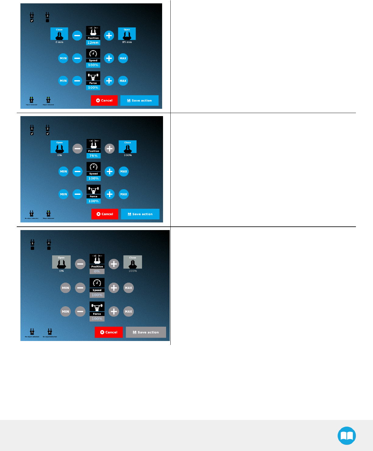
2F-85 &2F-140 - Instruction Manual
Multiple Grippers
lWhen selecting one gripper, all buttons are available. The action
will apply to the selected gripper.
lWhen jogging the position, the selected gripper will move auto-
matically.
lIt is possible to jog the position (%).
lWhen selecting two or more grippers, it is not possible to jog the
position.
lTo jog the position, select only one gripper, jog the position and
then select all grippers. The second gripper will move to the
requested position.
lWhen no grippers are selected, the action cannot be edited.
97
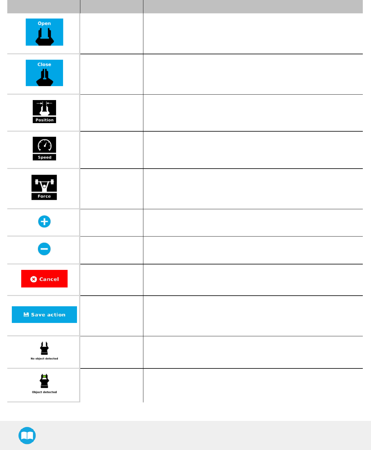
2F-85 &2F-140 - Instruction Manual
Features
Primary Icon Functionality Name Description
Open Tap to fully open the Gripper. Use this when you want to grip an object (internal
grip), for example.
Close Tap to fully close the Gripper. Use this when you want to grip an object (external
grip), for example.
Requested position Shows the position request for the selected Gripper node.
Requested speed Shows the speed requested for the selected Gripper node. Use the Plus and
Minus icons to modify.
Requested force Shows the force requested for the selected Gripper node. Use the Plus and Minus
icons to modify.
Plus Tap to increase the corresponding parameter.
Minus Tap to decrease the corresponding parameter.
Cancel Cancels modifications and brings back the Gripper node command screen.
Save action
Saves settings into the selected Gripper node and brings back the Gripper node
command screen.
Note: This functionality is not available (grey) when the Gripper has the same
action parameters as the selected Gripper node.
No object detected Icon shown when no object is detected during a grasp.
Object detected Icon shows a green checkmark when an object is detected during a grasp.
98
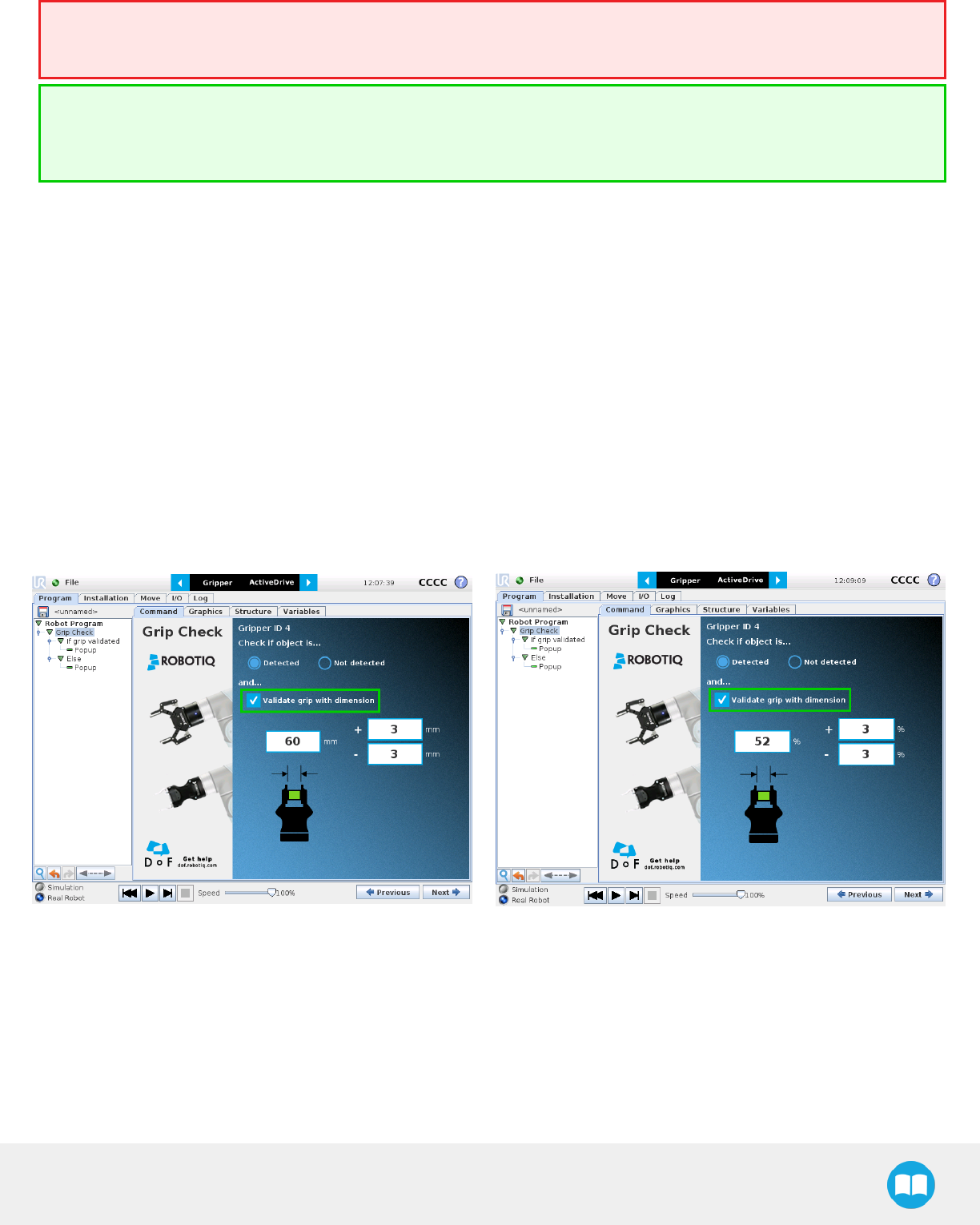
2F-85 &2F-140 - Instruction Manual
Warning
If the Gripper is powered and initialized, it will move as soon as a change to the parameter is made (position, speed, force).
Tip
Change speed and force when grasping fragile objects or other specific parts. In all other cases, it is recommended to use
maximum speed andforce.
Grip Check node
In order to add and edit a Grip Check node:
1Open a robot program or create one
2Go to the Installation tab
3Tap the URCaps submenu
4Select Grip Check
TheGrip Check node is pre-packaged as an If statement that prompts the user to select between if the object is detected and if the
object is not detected. Selecting the former option allows the user to check a box and choose whether or not the grasp should be
validated according to the object's dimension (in percentage if the Gripper is not calibrated, or in mm/in if the Gripper is calibrated—
depending on the PolyScope configuration).
99
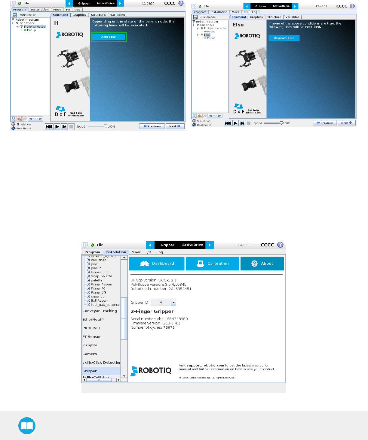
2F-85 &2F-140 - Instruction Manual
Given that the Grip Check node is an If statement, tapping the actual node in the Command tab brings up the option to add an Else
instruction to the program tree.
About
In this window, the user can access information such as the Gripper's hardware, software and firmware versions, the number of cycles
completed by the device and more.
1Create or load a robot program
2Tap the Installation tab
3Select Gripper in the left pane
4Tap the About submenu
100
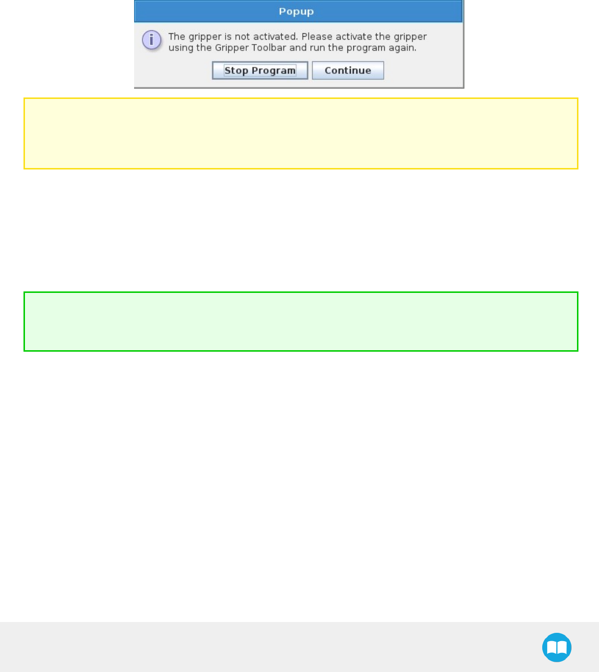
2F-85 &2F-140 - Instruction Manual
Error messages overview
If a program is running without the Gripper being activated, the program will stop at the execution of a Gripper node and the following
message will be displayed in a popup. Tap Stop Program and activate the gripper with the toolbar to continue or add an activation
command in the program (see Advanced Gripper Functions).
Caution
Starting from Gripper URCap version 1.0.2, the gripper activation script command (rq_activate() or rq_activate_and_wait())
must be preceded by the reset command (rq_reset()). This will force the gripper's activation routine. Thus, if the gripper was
already activated, it will activate again.
Gripper Program Template
With the URCap package installation, a program template will automatically be installed in the program folder of PolyScope. It contains
comments and pop up windows that explain Gripper nodes functions and advanced functions.
Load and open the gripper_tutorial.urp program located in the root program folder. Make sure the Gripper is well connected to the UR
controller. Run the program. You will see pop up windows with comments on the Gripper nodes and advanced functions.
Tip
Use the gripper_tutorial.urp to know how to program the Gripper using nodes and advanced functions. You can copy the
tutorial and start a new program based on it.

2F-85 &2F-140 - Instruction Manual
Advanced Gripper Functions
The use of Gripper URCaps nodes allows to move the Gripper and modify its speed and force. However, some advanced functions are
only available through UR Script commands.
Info
The Gripper needs to be activated before it can receive a command. To do so, use the rq_activate_and_wait() function script
at the beginning of the program or activate with the Gripper toolbar.
Single Gripper
Name Description
rq_activate()
Sends the Gripper activation command. If it is already activated, nothing happens. Note that
the Gripper must be activated to complete any other operation. Program execution continues
before the end of activation.
rq_activate_and_wait()
Sends the Gripper activation command. If it is already activated, nothing happens. Note that
the Gripper must be activated to complete any other operation. Program execution waits for
theactivation.
rq_auto_release_close_and_wait() Slowly moves the Gripper to its maximum closed position. The Gripper must be activated after
this command. Meant for emergency procedures.
rq_auto_release_open_and_wait() Slowly moves the Gripper to its maximum opened position. The Gripper must be activated
after this command. Meant for emergency procedures.
rq_close() Moves the Gripper its fully closed position.
rq_close_and_wait() Moves the Gripper to its fully closed position and waits until the motion is completed to
execute the next command.
rq_current_pos()
Returns the current position of the fingers, from 0 to 255. Can be used to verify that the pick is
successful, by comparing the finger position when the pick was taught with the similar-sized
object.
rq_current_pos_norm()
Returns the current position of the fingers, normalized from 0% to 100%. Can be used to verify
that the pick is successful, by comparing the finger position when the pick was taught with the
similar-sized object.
rq_current_pos_mm()
Returns the current position of the fingers in millimeters, considering that the PolyScope
configuration has been set to use the metric system as measurement system. Can be used to
verify that the pick is successful, by comparing the finger position when the pick was taught with
the similar-sized object.
rq_current_pos_in()
Returns the current position of the fingers in inches, considering that the PolyScope
configuration has been set to use the imperial system as measurement system. Can be used to
verify that the pick is successful, by comparing the finger position when the pick was taught with
the similar-sized object.
rq_go_to() Sets the Go To bit to 1.
rq_is_gripper_activated() Sets global variable rq_gripper_act to 1 if the Gripper is activated and returns True. Otherwise
sets the variable to 0 and returns False.
rq_is_motion_complete() Returns True if the motion of the Gripper is complete and False otherwise. Can be useful to
102

2F-85 &2F-140 - Instruction Manual
Name Description
synchronize a program after a Gripper node is run without the option “Complete Gripper
motion before next action”.
rq_is_object_detected()
Returns True if the Gripper motion has stopped due to an object. Returns False if Gripper
motion was not impeded by an object. Useful for verifying that an object has been picked
correctly before going to the next step. Note: this function is not reliable for very small objects.
Refer to the user manual for more details.
rq_move_and_wait("position") Moves the Gripper to the position defined by the argument and waits until the motion
iscompleted.
rq_move("position") Moves the Gripper to the position defined by the argument.
rq_move_and_wait_norm
("position")
Moves the Gripper to the position defined by the argument, normalized from 0% to 100%.
Waits until the motion is completed.
rq_move_norm("position") Moves the Gripper to the position defined by the argument, normalized from 0% to 100%.
rq_open() Moves the Gripper to its fully opened position.
rq_open_and_wait() Moves the Gripper to its fully opened position and waits until the motion is completed.
rq_print_gripper_driver_state() Prints the driver's state to the UR log window.
rq_print_gripper_driver_version() Prints the driver version to the UR log window.
rq_print_gripper_fault_code() Prints the Gripper's fault code in the UR log window.
rq_print_gripper_firmware_version() Prints the Gripper's firmware version to the UR log window.
rq_print_gripper_num_cycles() Prints the Gripper's number of cycles in the UR log window.
rq_reset() Resets the Gripper's activation status. Use after an autorelease before activating the Gripper.
rq_set_force("force") Sets the Gripper's force defined by the argument, from 0 to 255.
rq_set_force_norm("force") Sets the Gripper's force defined by the argument, normalized from 0% to 100%.
rq_set_speed("speed") Sets the Gripper's speed defined by the argument, from 0 to 255.
rq_set_speed_norm("speed") Sets the Gripper's speed defined by the argument, normalized from 0% to 100%.
rq_stop() Stops the Gripper's motion. The Go To bit is set to 0.
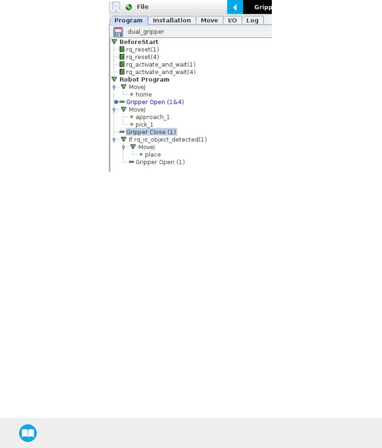
2F-85 &2F-140 - Instruction Manual
Multiple Grippers
Here is an example of how to use the script commands with more than one gripper.
Fig. 4-20: Example of URscript commands with multiple Grippers
104

2F-85 &2F-140 - Instruction Manual
The functions listed below can be called using subprograms in PolyScope or with a script. Functions with the suffix _and_wait will wait
for the Gripper to complete its operation before going to the next step.
Name Description
rq_activate("gripper ID")
Sends the Gripper activation command. If it is already activated, nothing happens. Note that
the Gripper must be activated to complete any other operation. Program execution continues
before the end of activation.
rq_activate_and_wait("gripper ID")
Sends the Gripper activation command. If it is already activated, nothing happens. Note that
the Gripper must be activated to complete any other operation. Program execution waits for
theactivation.
rq_auto_release_close_and_wait
("gripperID")
Slowly moves the Gripper to its maximum closed position. The Gripper must be activated after
this command. Meant for emergency procedures.
rq_auto_release_open_and_wait
("gripperID")
Slowly moves the Gripper to its maximum opened position. The Gripper must be activated
after this command. Meant for emergency procedures.
rq_close("gripper ID") Moves the Gripper its fully closed position.
rq_close_and_wait("gripper ID") Moves the Gripper to its fully closed position and waits until the motion is completed to
execute the next command.
rq_current_pos("gripper ID")
Returns the current position of the fingers, from 0 to 255. Can be used to verify that the pick is
successful, by comparing the finger position when the pick was taught with the similar-sized
object.
rq_current_pos_norm("gripper ID")
Returns the current position of the fingers, normalized from 0% to 100%. Can be used to verify
that the pick is successful, by comparing the finger position when the pick was taught with the
similar-sized object.
rq_current_pos_mm("gripper ID")
Returns the current position of the fingers in millimeters, considering that the PolyScope
configuration has been set to use the metric system as measurement system. Can be used to
verify that the pick is successful, by comparing the finger position when the pick was taught with
the similar-sized object.
rq_current_pos_in("gripper ID")
Returns the current position of the fingers in inches, considering that the PolyScope
configuration has been set to use the imperial system as measurement system. Can be used to
verify that the pick is successful, by comparing the finger position when the pick was taught with
the similar-sized object.
rq_go_to("gripper ID") Sets the Go To bit to 1.
rq_is_gripper_activated("gripper
ID")
Sets global variable rq_gripper_act to 1 if the Gripper is activated and returns True. Otherwise
sets the variable to 0 and returns False.
rq_is_motion_complete("gripper
ID")
Returns True if the motion of the Gripper is complete and False otherwise. Can be useful to
synchronize a program after a Gripper node is run without the option “Complete Gripper
motion before next action”.
rq_is_object_detected("gripper
ID")
Returns True if the Gripper motion has stopped due to an object. Returns False if Gripper
motion was not impeded by an object. Useful for verifying that an object has been picked
correctly before going to the next step. Note: this function is not reliable for very small objects.
Refer to the user manual for more details.
rq_move_and_wait("position",
"gripper ID")
Moves the Gripper to the position defined by the argument and waits until the motion
iscompleted.
rq_move("position") Moves the Gripper to the position defined by the argument.

2F-85 &2F-140 - Instruction Manual
Name Description
rq_move_and_wait_norm
("position")
Moves the Gripper to the position defined by the argument, normalized from 0% to 100%.
Waits until the motion is completed.
rq_move_norm("position",
"gripper ID") Moves the Gripper to the position defined by the argument, normalized from 0% to 100%.
rq_open("gripper ID") Moves the Gripper to its fully opened position.
rq_open_and_wait("gripper ID") Moves the Gripper to its fully opened position and waits until the motion is completed.
rq_print_gripper_driver_state
("gripper ID") Prints the driver's state to the UR log window.
rq_print_gripper_driver_version
("gripper ID") Prints the driver version to the UR log window.
rq_print_gripper_fault_code
("gripper ID") Prints the Gripper's fault code in the UR log window.
rq_print_gripper_firmware_version
("gripper ID") Prints the Gripper's firmware version to the UR log window.
rq_print_gripper_num_cycles
("gripper ID") Prints the Gripper's number of cycles in the UR log window.
rq_reset("gripper ID") Resets the Gripper's activation status. Use after an autorelease before activating the Gripper.
rq_set_force("force", "gripper ID") Sets the Gripper's force defined by the argument, from 0 to 255.
rq_set_force_norm("force",
"gripper ID") Sets the Gripper's force defined by the argument, normalized from 0% to 100%.
rq_set_speed("speed", "gripper
ID") Sets the Gripper's speed defined by the argument, from 0 to 255.
rq_set_speed_norm("speed",
"gripper ID") Sets the Gripper's speed defined by the argument, normalized from 0% to 100%.
rq_stop("gripper ID") Stops the Gripper's motion. The Go To bit is set to 0.
106
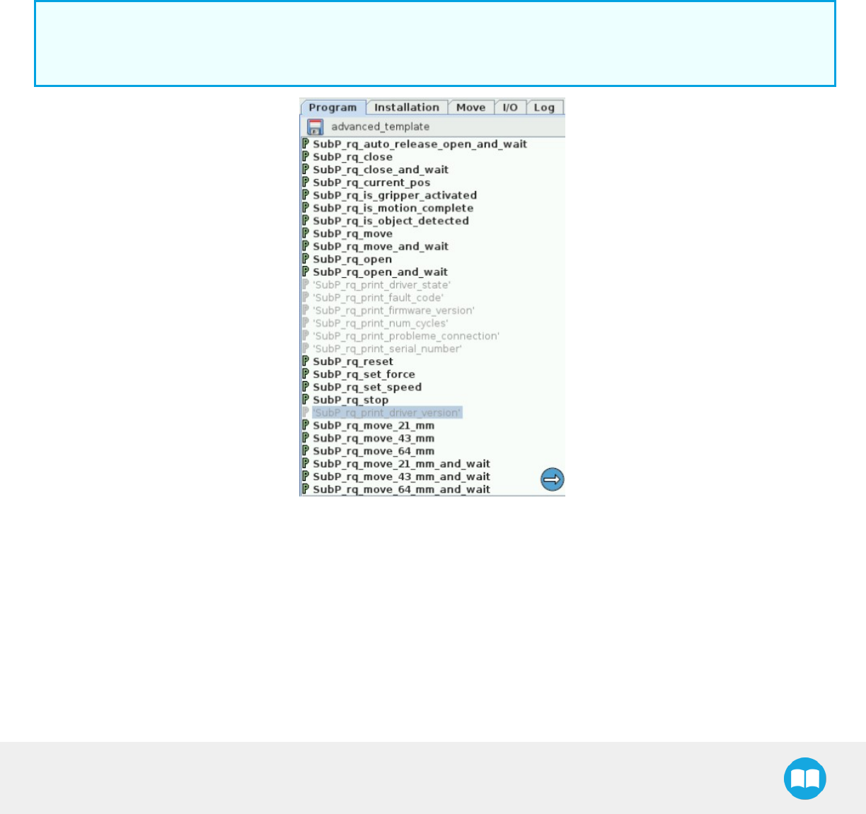
2F-85 &2F-140 - Instruction Manual
4.8.5. Retro-compatibility of URCaps with legacy driver programs
The Gripper URCap can be used within programs that were made with the legacy driver package. To do so, you need to do the
followingmodifications:
1. Open your .urp program in PolyScope and execute it.
a. You should see an error message that tells you that some functions are double defined. This is because the URCap
embeds the functions directly in the program preamble, so there is no need for a BeforeStart section.
2. Comment all the lines of the BeforeStart section from your older .urp program.
a. You will still get an error. It arises because we changed some functions names due to a naming conflict.
3. To solve the problem, you can either suppress those functions or rename them.
Info
Since they are probably not used in a production program, the fastest method would be to suppress them, as shown in the
figure below.
Fig. 4-21: Older program's subprograms to suppress or rename to use with URCaps package.
Here is the list of the functions that were renamed:
lrq_print_fault_code -> rq_print_gripper_fault_code
lrq_print_num_cycles -> rq_print_gripper_num_cycles
lrq_print_driver_state -> rq_print_gripper_driver_state

2F-85 &2F-140 - Instruction Manual
lrq_print_firmware_version -> rq_print_gripper_firmware_version
lrq_print_driver_version -> rq_print_gripper_driver_version
108
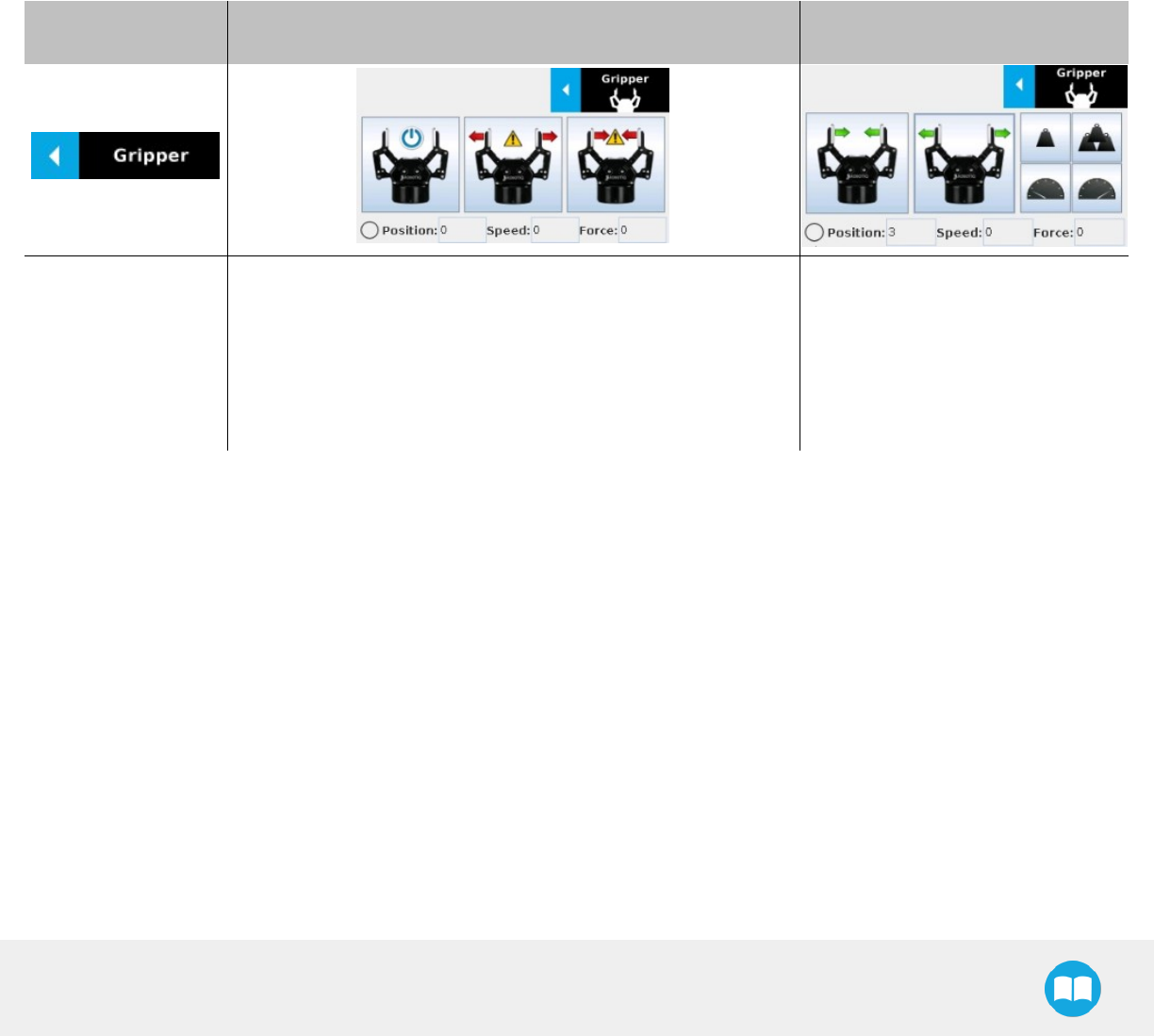
2F-85 &2F-140 - Instruction Manual
4.9. Control over Universal Robots without URCaps
If your Universal Robots’ controller is not compatible with the URCap package (refer to the Installation for Universal Robots section),
you can install the driver package. This package allows programming of the Gripper with scripts in a PolyScope program. It includes
program templates and examples to help you get started with your own custom program. It also contains the Gripper toolbar for
jogging and controlling the Gripper.
4.9.1. Gripper Toolbar
Overview
The Gripper toolbar is automatically installed with the driver package. The Gripper toolbar allows you to jog and test the Gripper. It is a
great tool to try grasps with the Gripper while programming.
Toolbar collapsed Toolbar expanded, Gripper activation window Toolbar expanded, Gripper
operation window :
Tap the Gripper
button to expand
thetoolbar.
lWhen the Gripper is not activated, the toolbar shows thiswindow.
lYou need to tap the Activate button to be able to jog the Grip-
per.
lEmergency open and close allows you to control the Gripper
without activating, this mode will use a very low speed and
forcesetting
Use the buttons of this window to jog
and test the Gripper.
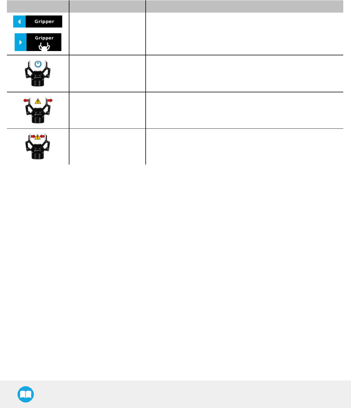
2F-85 &2F-140 - Instruction Manual
Features
Toolbar collapsed
Icon Functionality Name Description
Gripper toolbar Tap to toggle between expand and collapse the 2-Finger Adaptive Gripper
toolbar. When grey, the functionality is not available.
Activate Tap to activate the 2-Finger Adaptive Gripper. The Gripper will fully open and
close to set the zero of the position value..
Emergency open Slowly moves the Gripper to its fully closed position.
Emergency close Slowly moves the Gripper to its fully open position.
110
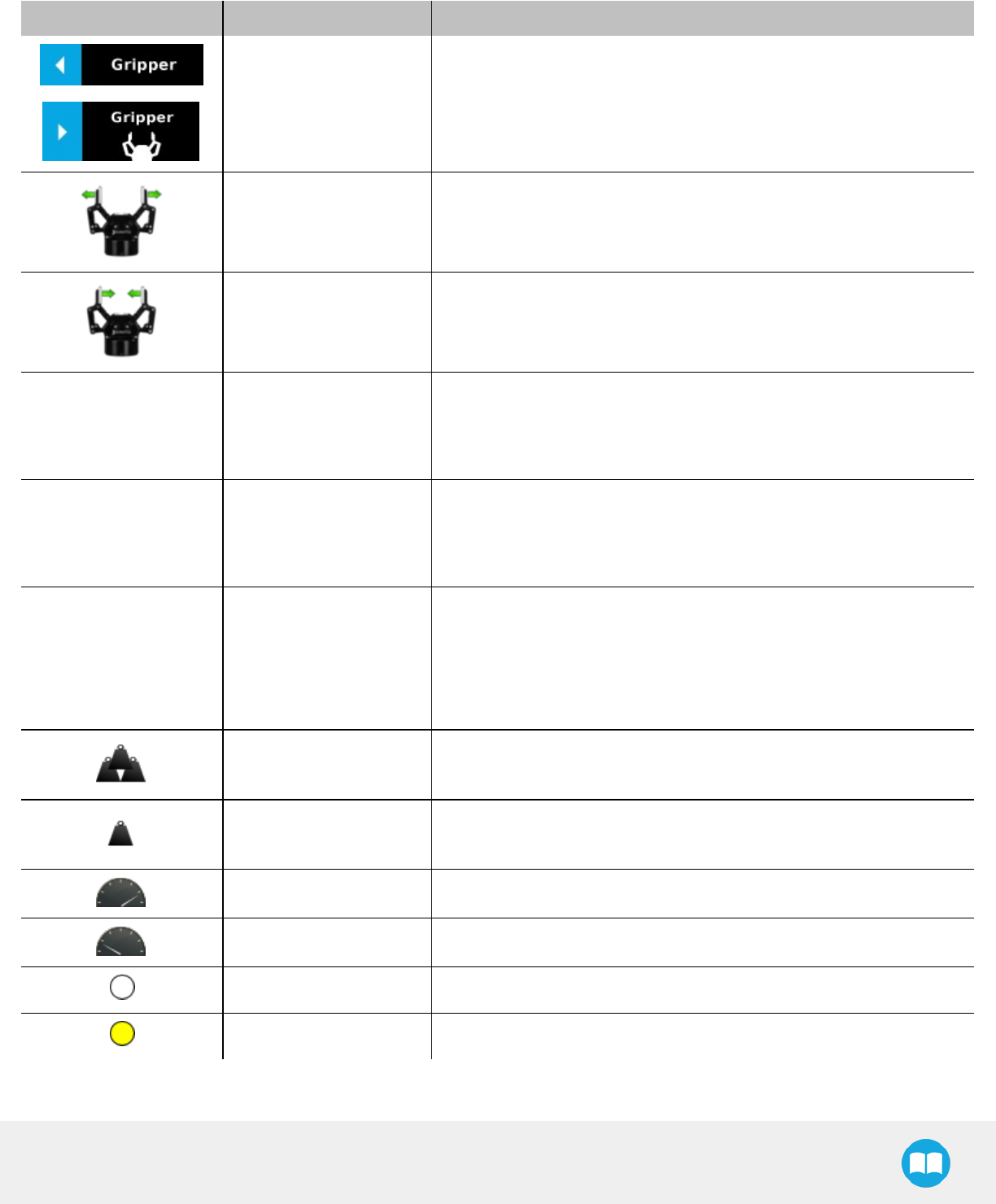
2F-85 &2F-140 - Instruction Manual
Toolbar expanded
Icon Functionality Name Description
Gripper toolbar Tap to toggle between expand and collapse the 2-Finger Adaptive Gripper
toolbar. When grey, the functionality is notavailable.
Open Tap to fully open the Gripper.
Close Tap to fully close the Gripper.
Position Requested position
Shows the actual position of the Gripper:
l0% : fully open
l100% : fully closed
Speed Requested speed
Shows the actual speed set of the Gripper:
l0% : minimum speed
l100% : maximum speed
Force Requested force
Shows the actual force set of the Gripper:
l0% : minimum force, regrasp feature disabled
l1% : minimum force, with regrasp feature enabled
l100% : maximum force, with regrasp feature enabled
Increase force Tap to increase the force request.
Decrease force Tap to decrease the force request.
Increase speed Tap to increase the speed request..
Decrease speed Tap to decrease the speed request.
No object detected Icon shown when no object is detected during a grasp.
Object detected Icon shown when an object is detected during a grasp.

2F-85 &2F-140 - Instruction Manual
When communication with the Gripper is not established, the expanded toolbar shows the driver version:
Fig. 4-22: Gripper toolbar expanded with driver version
Info
The driver state "RQ_STATE_INIT" means the driver is attempting to connect to a Robotiq Gripper. When connection is
established, the normal toolbar detailed above will appear.
Tip
If you see the following toolbar with communication not established, check if your Gripper is powered first, then check if the
RS-485 to USB converter is properly wired.
112

2F-85 &2F-140 - Instruction Manual
4.9.2. Demo Scripts
The following section details the demo scripts provided with the driver package.
pick_and_place_demo_with_subprograms.script is a demo script for pick and place applications using provided subprograms. The
script uses subprograms included in the package such as rq_set_force, rq_set_speed, etc.
Info
All provided subprograms are identified with the prefix rq_.
The script uses rq_speed and rq_force as speed and force parameters to be used during the program. They can be modified using
values from 0 to 255 (please refer to the Provided Variables and Functions section).
The script does the following actions in sequence :
lAssign initial values to the global variables in the Init Variables section.
lInitiate the communication with the Gripper in the BeforeStart section.
lThe Robot Program section contains the commands sent to the Gripper:
lActivate the Gripper with SubP_rq_activate_and_wait.
Info
Remember that all _and_wait subprograms will wait for the action to be completed before going to the next step.
lMove the robot to a predetermined position
Tip
Run with Universal Robots simulator first or make sure that the UR robot work area is totally cleared before running the
script, as it will move therobot.
lClose the Gripper with rq_close_and_wait.
lWatch for object detection status:
lIf an object is detected, the script moves the robot and opens the Gripper.
lIf no object is detected, the script prompts a warning
.pick_and_place_demo_async_partial_opening_without_subprograms.script is similar to the previous demo, but without using
subprograms. This demo uses asynchronous commands so that the robot and the Gripper will move at the same time (the previous
example had the Gripper and the robot move separately).
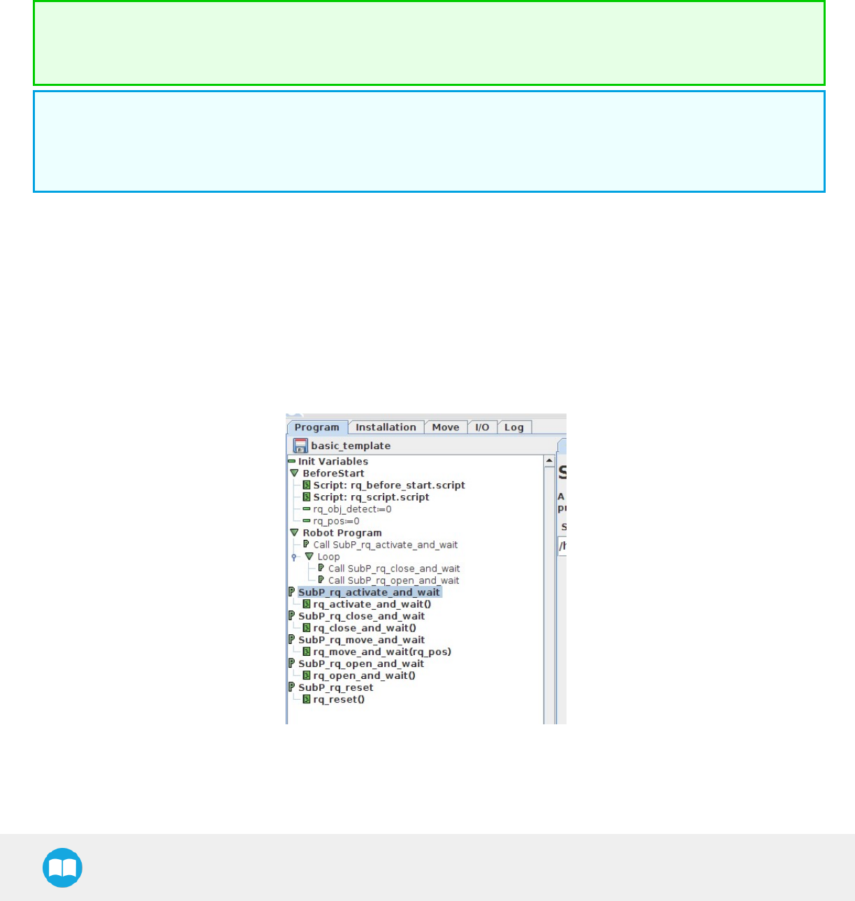
2F-85 &2F-140 - Instruction Manual
4.9.3. Custom Programs
You can create your own program that commands the Gripper with the provided templates :
lOpen basic_template.script in the list of provided templates;
lPush play to test the Gripper. The program will activate the Gripper and then do a loop of closing and opening the Gripper;
lAdd your instructions under the robot program section. Program instructions can be added with PolyScope.
Tip
When programming an object pick up, use the rq_is_object_detected subprogram and rq_object_detect variable to know if
an object has been picked. The subprogram sets the rq_object_detect variable to 1 if an object is detected, 0 otherwise.
Info
Subprograms with the _and_wait will wait for the instruction to be completed before going to the next step. For example, rq_
close_and_wait will wait for the motion to be completed before continuing to the next step, while rq_close will initiate motion
and go to the next programmed step.
As shown in the figure below, the basic_template program will execute these instructions in a sequence:
lAssign initial values to the global variables with the Init Variables section.
lInitiate communication with the Gripper with the Before Start section.
lThe Robot Program section contains the commands sent to the Gripper:
lActivate the Gripper with SubP_rq_activate_and_wait.
lClose the Gripper with rq_close_and_wait.
lOpen the Gripper with rq_open_and_wait.
Fig. 4-23: Basic template as shown in UR PolyScope.
When using the advanced_template, you have access to all of the subprograms listed in the Provided Variables and Functions section.
Unused subprograms can be removed from the list. You must use global variables to pass information, not arguments.
114

2F-85 &2F-140 - Instruction Manual
4.9.4. Provided Variables and Functions
The file rq_script.script contains function definitions and variables that enhance the programming of the Gripper. Here is the list of
these variables and functions.
Variables are used when programming the Gripper using subprograms. Since it is not possible to pass arguments to subprograms, the
global variables listed below must be used.
Name Range Description
rq_force() [0-255] Force set point. Change this variable by calling the subprogram SubP_rq_set_force.
rq_gripper_
act() [0-1] 1 if the Gripper is activated. This variable is updated by calling either SubP_rq_is_gripper_
activated or SubP_rq_activate_and_wait.
rq_move_
complete() [0-1]
1 if the motion is complete. This variable is updated by calling one of the following:
lSubP_rq_move_and_wait;
lSubP_rq_open_and_wait;
lSubP_rq_close_and_wait;
lSubP_rq_is_motion_complete.
rq_object_
detect() [0-1]
1 if an object is detected. This variable is updated by calling one of the following:
lSubP_rq_move_and_wait;
lSubP_rq_open_and_wait;
lSubP_rq_close_and_wait;
lSubP_rq_is_object_detected.
rq_pos() [0-255] Position set point. This variable is updated by calling SubP_rq_current_pos.
rq_speed() [0-255] Speed set point. Change this variable by calling the subprogram SubP_rq_set_speed.

2F-85 &2F-140 - Instruction Manual
Name Description
rq_activate()
Sends the Gripper activation command. If it is already activated, nothing happens. Note that
the Gripper must be activated to complete any other operation. Program execution
continues before the end of activation.
rq_activate_and_wait()
Sends the Gripper activation command. If it is already activated, nothing happens. Note that
the Gripper must be activated to complete any other operation. Program execution waits for
the activation.
rq_auto_release_close_and_
wait()
Slowly moves the Gripper to its maximum closed position. The Gripper must be activated
after this command. Meant for emergency procedures.
rq_auto_release_open_and_
wait()
Slowly moves the Gripper to its maximum opened position. The Gripper must be activated
after this command. Meant for emergency procedures.
rq_close() Moves the Gripper its fully closed position.
rq_close_and_wait() Moves the Gripper to its fully closed position and waits until the motion is completed to
execute the next command.
rq_current_pos() Sets global variable rq_pos to the current Gripper position and returns this value.
rq_is_gripper_activated() Sets global variable rq_gripper_act to 1 if the Gripper is activated and returns True.
Otherwise sets the variable to 0 and returns False.
rq_is_motion_complete() Sets global variable rq_mov_complete to 1 if the Gripper motion is complete and returns
True. Otherwise sets the variable to 0 and returns False.
rq_is_object_detected() Sets global variable rq_obj_detect to 1 if the Gripper has detected an object and returns
True. Otherwise, sets the variable to 0 and returns False.
rq_move_and_wait() Moves the Gripper to the position defined by the argument and waits until the motion is
completed.
rq_move() Moves the Gripper to the position defined by the argument.
rq_open() Moves the Gripper to its fully opened position.
rq_open_and_wait() Moves the Gripper to its fully opened position and waits until the motion is completed.
rq_set_force() Writes the value of rq_force into the force setting.
rq_set_speed() Writes the value of rq_speed into the speed setting.
116


6. Specifications
Caution
The following manual uses the metric system, unless specified, all dimensions are in millimeters.
The following subsections provide data on the various specifications for the Robotiq 2-Finger 85 and 140 Adaptive Grippers.
lSection 6.1 lists the technical dimensions of the Grippers
lDimensions for custom (blank) coupling
lDimensions of all available couplings
lDimensions for custom fingertip
lDimensions of all available fingertips
lSection 6.2 presents the mechanical specifications of the Grippers.
lSection 6.3 gives electrical specifications for the Grippers.
2F-85 &2F-140 - Instruction Manual
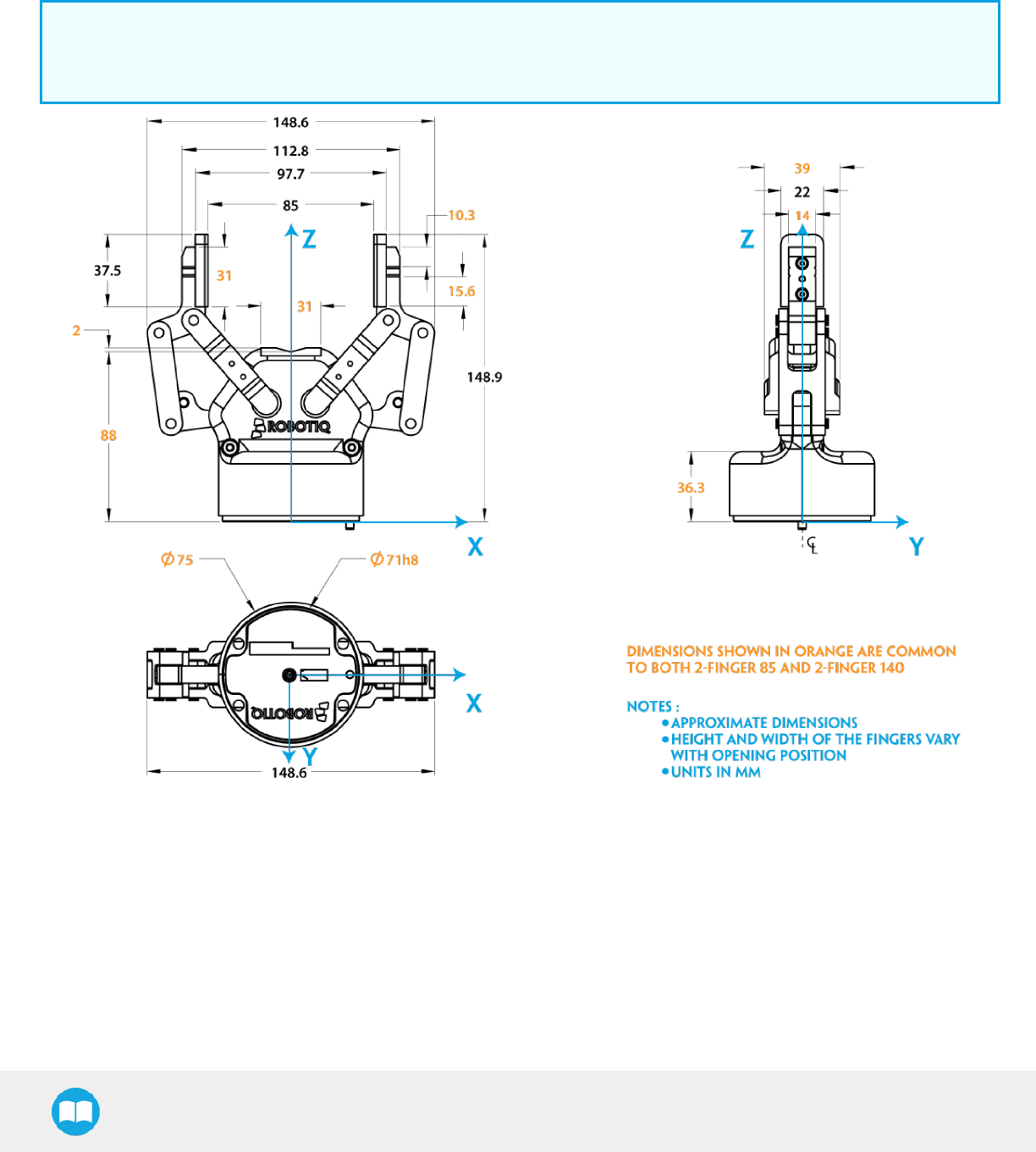
2F-85 &2F-140 - Instruction Manual
6.1. Technical dimensions
The 2-Finger 85 and 2-Finger 140 share the same basic chassis and thus have the same technical dimensions for everything except the
fingers. Figure 6-1 represents the Robotiq 2-Finger 85 Adaptive Robot Gripper's dimensions with axis X, Y, Z and origin referenced for
finger motion. Figure 6-3 will show the equivalent with 140 mm fingers (2-Finger 140).
Info
All technical drawings in the present section are shown with silicone flat fingertip option: AGC-TIP-204-002 (2-Finger 85) or
AGC-TIP-220-140 (2- Finger 140).
Fig. 6-1: 2-Finger 85 general dimensions (opened).
As mentioned in the figure above, height and width of the fingers vary with opening position. Figure 6-1 represents the 2F-85 Gripper in
the opened position (position request = 0), while Figure 6-2 represents the 2F-85 Gripper in the closed position (position request =
255).
119
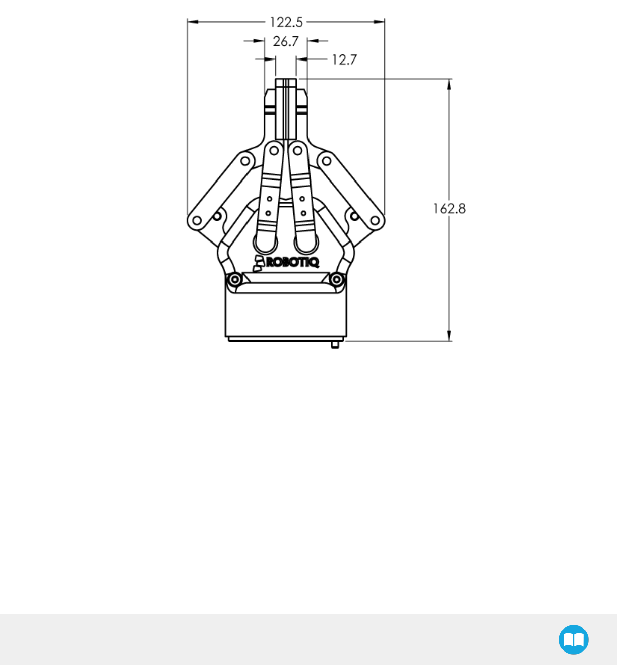
2F-85 &2F-140 - Instruction Manual
Fig. 6-2: 2-Finger 85 dimensions (closed).
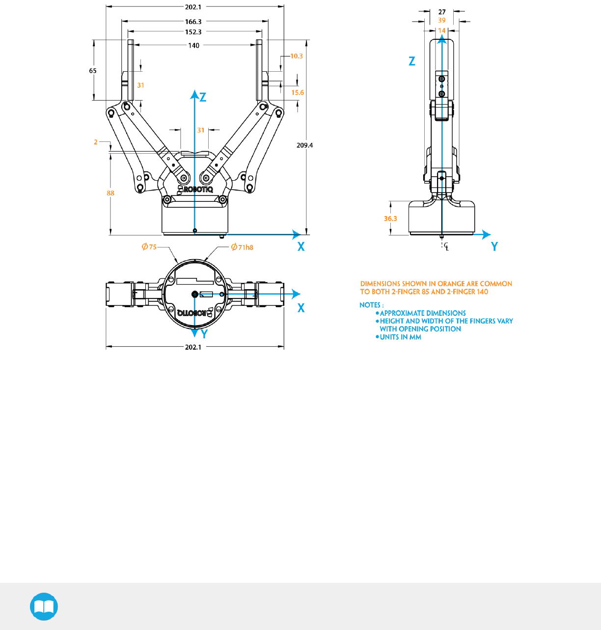
2F-85 &2F-140 - Instruction Manual
Fig. 6-3: 2-Finger 140 general dimensions (opened).
121
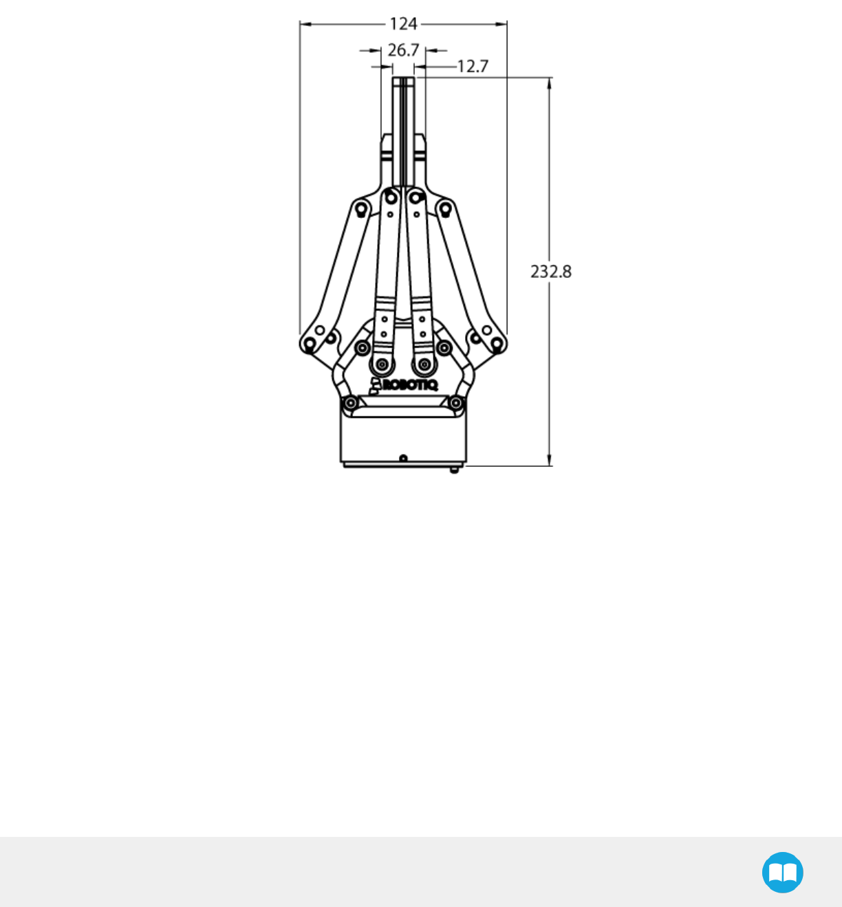
2F-85 &2F-140 - Instruction Manual
Fig. 6-4: 2-Finger 140 dimensions (closed).
As mentioned in the figure above, the height and width of the fingers vary with opening position. Figure 6-3 represents the 2F-140
Gripper in the opened position (position request = 0), while Figure 6-4 represents the 2F-140 Gripper in the closed position (position
request = 255).
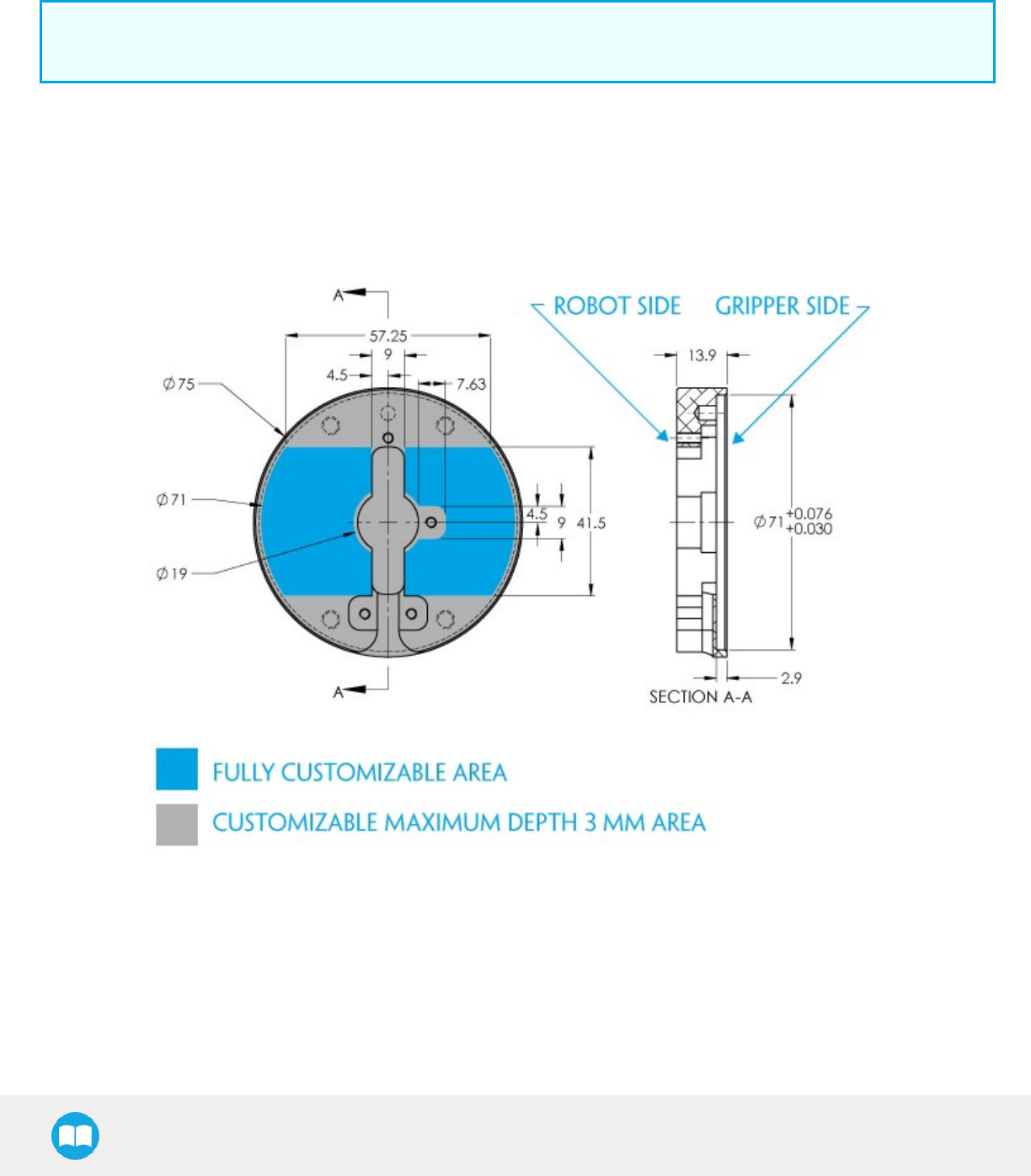
2F-85 &2F-140 - Instruction Manual
6.1.1. Couplings
The Robotiq 2-Finger Adaptive Robot Gripper requires a coupling provided by Robotiq to operate. The coupling is mandatory since it
integrates electronics and electrical contacts.
Info
The coupling is common to both the 2-Finger 85 and the 2-Finger 140.
Blank coupling
Below are the dimensions of the blank coupling, AGC-CPL-BLANK-002 (refer to the Spare Parts, Kits and Accessories section), available
to create a custom bolt pattern. Blue section can be fully customized (holes can be place in any part of this section) while the grey
section can only be worked to a depth of3mm.
Fig. 6-5: Blank coupling AGC-CPL-BLANK-002 workable area dimensions.
123
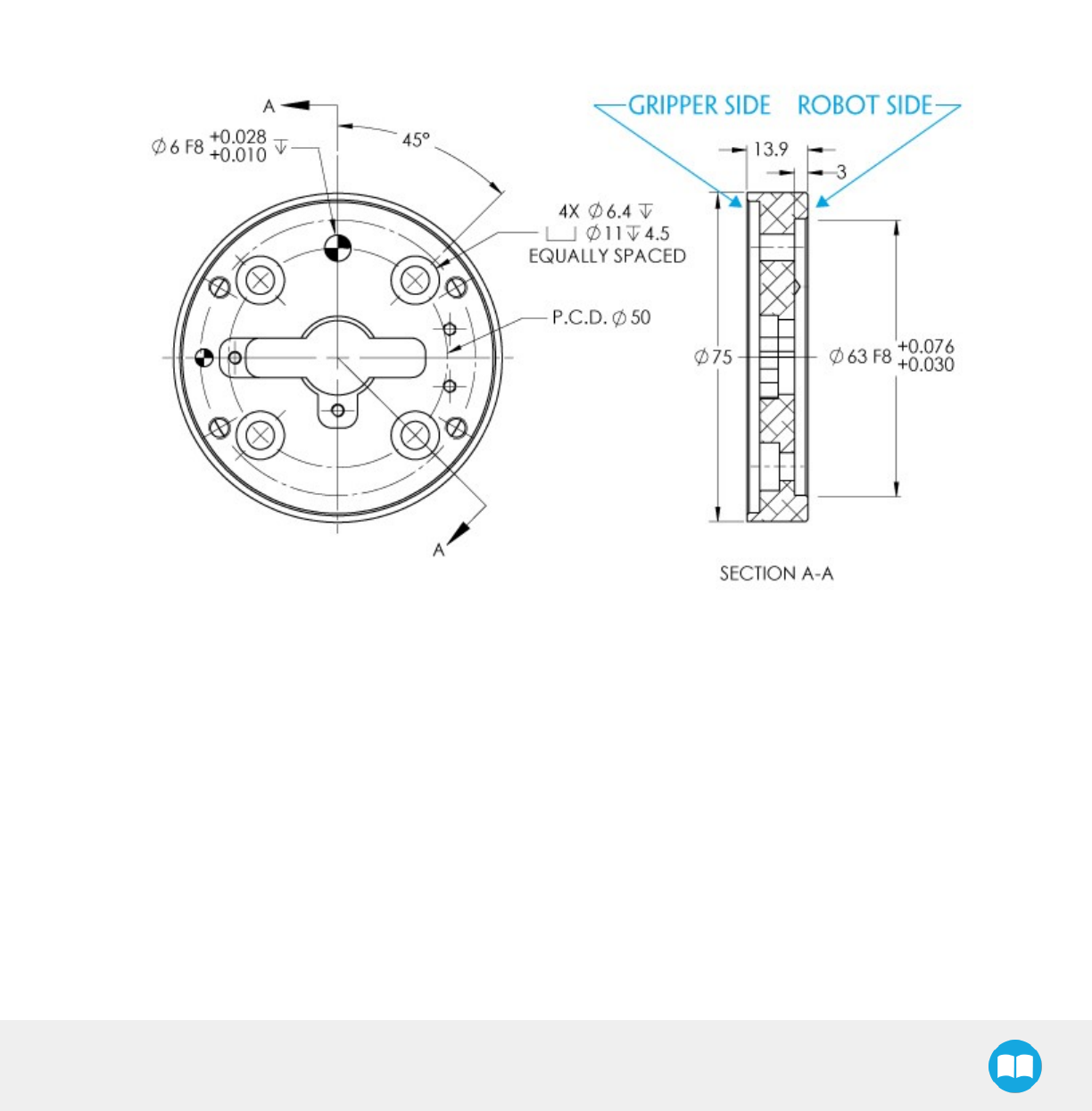
2F-85 &2F-140 - Instruction Manual
Coupling for ISO 9409-1-50-4-M6
Bolt pattern for coupling AGC-CPL-062-002 (refer to the Spare Parts, Kits and Accessories section) is compatible with :
l50 mm pitch circle diameter :
l(4) M6-1.0 low head socket cap screw clearance
l(1) M6 indexing pin
lISO 9409-1 standard 50-4-M6
Fig. 6-6: Coupling for ISO 9409-1-50-4-M6.
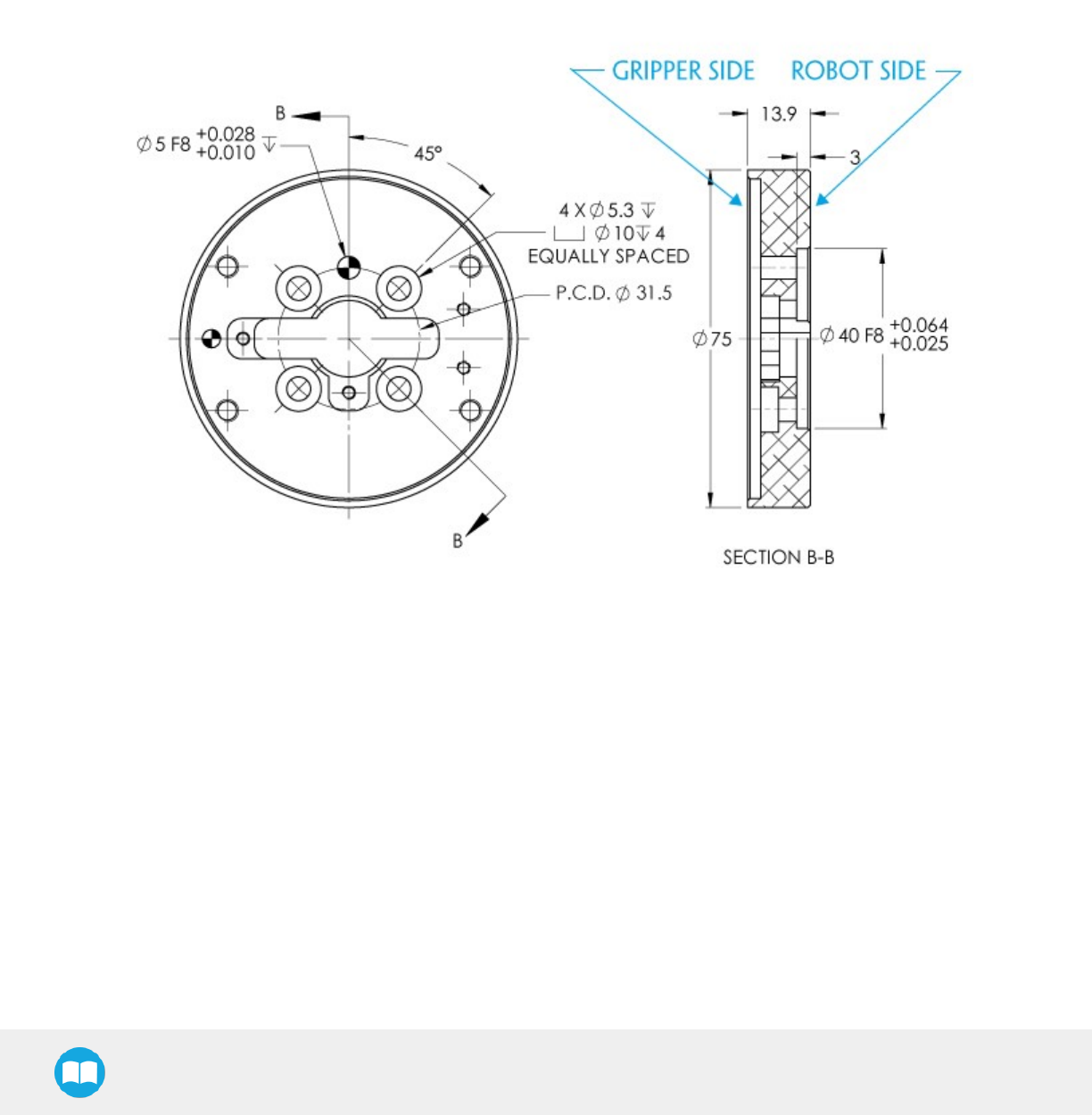
2F-85 &2F-140 - Instruction Manual
Coupling for ISO 9409-1-31.5-4-M5
Bolt pattern for coupling AGC-CPL-063-002 (refer to the Spare Parts, Kits and Accessories section) is compatible with :
l31.5 mm pitch circle diameter :
l(4) M5-0.8 low head socket cap screw clearance
l(1) M5 indexing pin
lISO 9409-1 standard 31.5-4-M5
Fig. 6-7: Coupling for ISO 9409-1-31.5-4-M5.
125
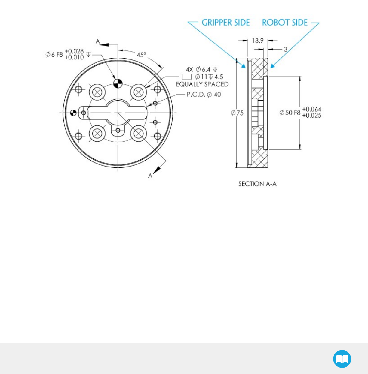
2F-85 &2F-140 - Instruction Manual
Coupling for ISO 9409-1-40-4-M6
Bolt pattern for coupling AGC-CPL-064-002 (refer to the Spare Parts, Kits and Accessories section) is compatible with :
l40 mm pitch circle diameter :
l(4) M6-1.0 low head socket cap screw clearance
l(1) M6 indexing pin
lISO 9409-1 standard 40-4-M6
Fig. 6-8: Coupling for ISO 9409-1-40-4-M6.
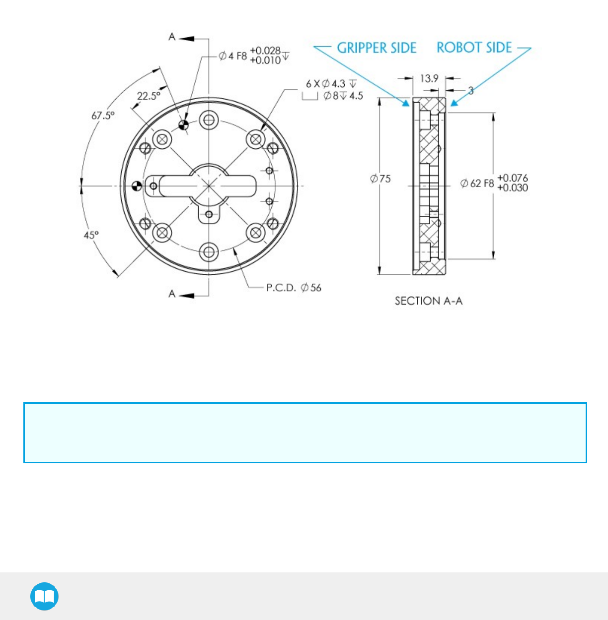
2F-85 &2F-140 - Instruction Manual
Coupling for PCD 56 with 8 x M4
Bolt pattern for coupling AGC-CPL-065-002 (refer to the Spare Parts, Kits and Accessories section) is compatible with :
l56 mm pitch circle diameter :
l(8) M4-0.7 low head socket cap screw clearance
l(1) M4 indexing pin
l62 mm diameter internal insert
Fig. 6-9: Coupling for PCD 56 mm with 8 x M4 clearance.
Info
Although coupling AGC-CPL-065-002 is compatible with 8 x M4 threads on a 56 mm PCD it uses only 6 of the 8 normally
present holes.
127
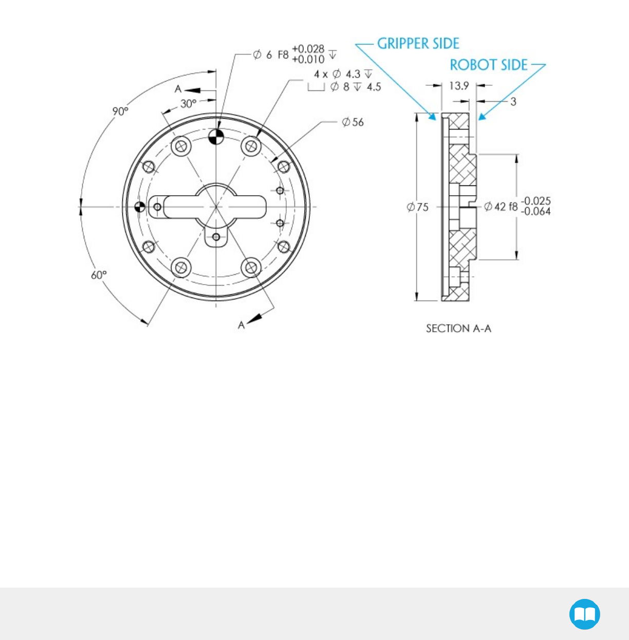
2F-85 &2F-140 - Instruction Manual
Coupling for PCD 56 with 6 x M4
Bolt pattern for coupling AGC-CPL-066-002 (refer to the Spare Parts, Kits and Accessories section) is compatible with:
l56 mm pitch circle diameter:
l(6) M4-0.7 low head socket cap screw clearance
l(1) M6 indexing pin
l42 mm diameter external insert
Fig. 6-10: Coupling for PCD 56 mm with 6 x M4 clearance.
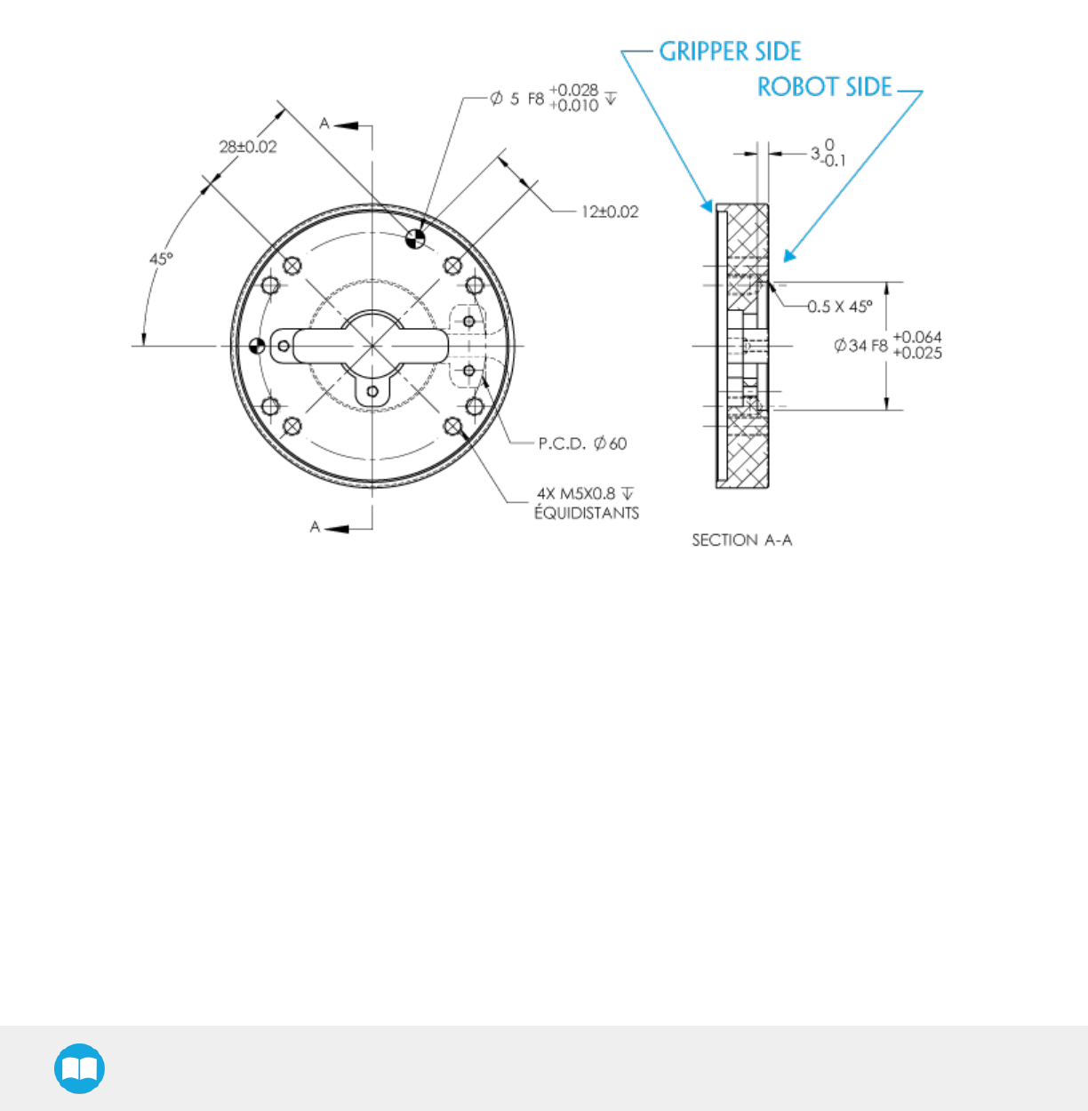
2F-85 &2F-140 - Instruction Manual
Coupling for PCD 60 with 4 x M5
Bolt pattern for coupling AGC-CPL-067-002 (refer to the Spare Parts, Kits and Accessories section) is compatible with :
l60 mm pitch circle diameter :
l(4) M5-0.8 low head socket cap screw clearance
l(1) M5 indexing pin
l34 mm diameter external insert
Fig. 6-11: Coupling for PCD 60 mm with 4 x M5 clearance.
129
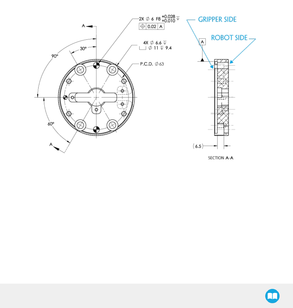
2F-85 &2F-140 - Instruction Manual
Coupling for PCD 63 with 6 x M6
Bolt pattern for coupling AGC-CPL-068-002 (refer to the Spare Parts, Kits and Accessories section) is compatible with :
l63 mm pitch circle diameter :
l(6) M6-1.0 low head socket cap screw clearance
l(2) M6 indexing pins
Fig. 6-12: Coupling for PCD 63 mm with 6 x M6 clearance.
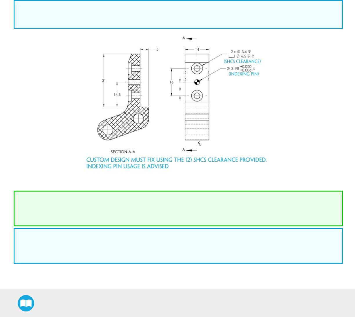
2F-85 &2F-140 - Instruction Manual
6.1.2. Fingertips
The contact grip points for the Robotiq 2-Finger Adaptive Robot Gripper are its two fingertip pads and palm pad. Many fingertips are
available from Robotiq (refer to the Spare Parts, Kits and Accessories section). The user can customize their own fingertips from blanks
or create them from scratch. The figure below represents the fingertip holder, the permanent, non customizable part of the Gripper
finger on which the fingertip must be mounted.
Custom fingertip designs must abide by the following:
lFingertip must not exceed 100 mm in height from the fingertip's base.
lFingertip must not exceed 100 mm in width from the fingertip's base (refer to Y axis from figure 6-18).
lRefer to the Mechanical specifications section to evaluate the grip force according to your fingertip design.
lApplied forces to the gripper must not exceed moment and force limits detailed in the Moment and force limits section.
Info
Both 2-Finger 85 and 2-Finger 140 use the same fingertips and finger holder.
Fig. 6-13: Finger holder for standard or custom designed fingertips.
Tip
Custom fingertips will still be subject to the equilibrium line rule for proper actuation of the Gripper, see General Presentation
section.
Info
Socket head cap screw clearance will need low head cap screws if you intend to perform an internal grip, otherwise the screw
head won't be recessed into the fingertip holder.
131
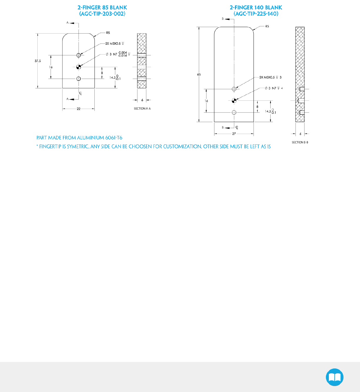
2F-85 &2F-140 - Instruction Manual
Blank fingertip
The figure below represents a blank fingertip AGC-TIP-203-002 (2-Finger 85) and AGC-TIP-225-140 (2-Finger 140); refer to the Spare
Parts, Kits and Accessories section. This fingertip is meant for the customization of one surface (it is symmetric) while the other surface
will mount onto the fingertip holder shown in the Fingertips section.
Fig. 6-14: Blank fingertip AGC-TIP-203-002 and AGC-TIP-225-140.
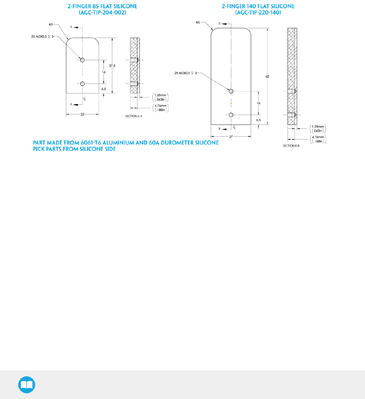
2F-85 &2F-140 - Instruction Manual
Flat silicone fingertip
The figure below represents a flat silicone fingertip AGC-TIP-204-002 (2-Finger 85) and AGC-TIP-220-140 (2-Finger 140); please refer to
the Spare Parts, Kits and Accessories section. This fingertip has a flat silicone surface with an optimal friction coefficient for picking
parts while the other surface will mount onto the fingertip holder shown in the Fingertips section.
Fig. 6-15: Flat silicone fingertip AGC-TIP-204-002 and AGC-TIP-220-140
133
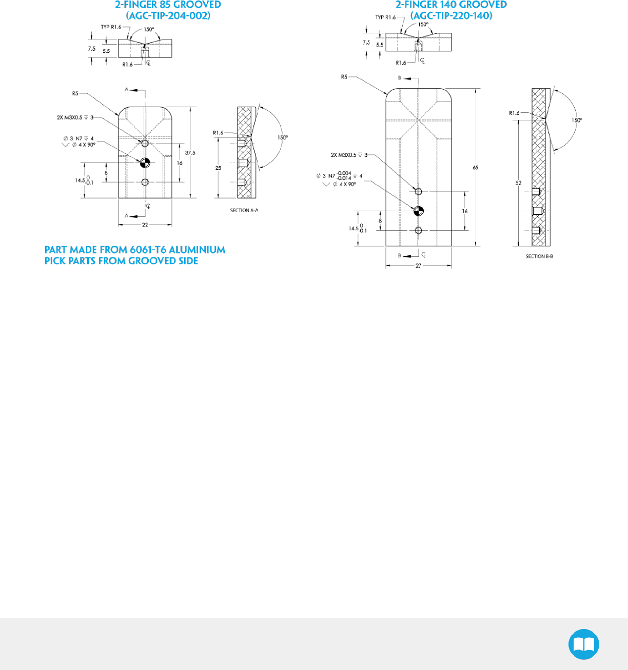
2F-85 &2F-140 - Instruction Manual
Grooved fingertip
The figure below represents the available grooved fingertip AGC-TIP-205-002 (2-Finger 85) and AGC-TIP-221-140 (2-Finger 140);
please refer to the Spare Parts, Kits and Accessories section. This fingertip has a grooved surface with an optimal shape for picking
cylindrical parts (by its horizontal and vertical grooves) while the other surface will mount onto the fingertip holder shown in the
Fingertips section.
Fig. 6-16: Grooved fingertip AGC-TIP-205-002 and AGC-TIP-221-140.

2F-85 &2F-140 - Instruction Manual
6.2. Mechanical specifications
Specification
2-FINGER 85 2-FINGER140
Metric Units Imperial
Units Metric Units Imperial Units
Gripper Opening 85 mm 3.35 in 140 mm 5.5 in
Minimum diameter for
encompassing 43 mm 1.69 in 90 mm 3.5 in
Maximum height 162.8 mm 6.4 in 232.8 mm 9.15 mm
Maximum width 148.6 mm 5.85 in 202.1 mm 8.0 in
Weight 850 g 1.9 lbs 897 g 2 lbs
Grip force Maximum force calculation below; refer to the Force control section
Finger speed 20 to 150
mm/s
0.8 to 5.9
in/s 30 to 250 mm/s 1.2 to 9.8 in/s
Position repeatability10.05 mm 0.002 in 0.08 mm 0.003 in
Force repeatability +/- 10%
Position resolution20.4 mm 0.016 in 0.6 mm 0.022 in
Grip force resolution Maximum force calculation below; refer to the Force control section
Info
All specs are measured with coupling AGC-CPL-062-002 and fingertip AGC-TIP-204-002 (2-Finger 85) or AGC-TIP-220-140
(2-Finger140).
1Repeatability is defined as the positional deviation resulting from the average displacement determined when picking an object with a
parallel grip using standard silicone fingertips. For more details see the blog.robotiq.com article on repeatability.
2Resolution is the increment modified from a 1 bit difference of position/speed/force request (from 0 to 255).
135
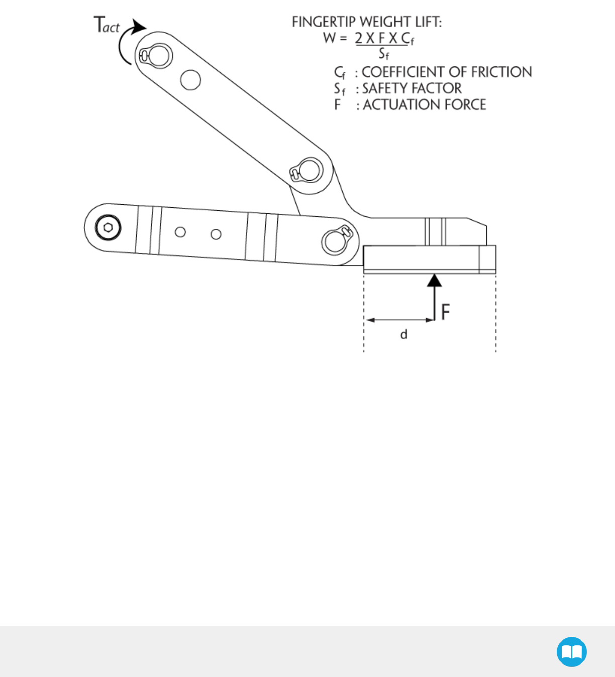
2F-85 &2F-140 - Instruction Manual
6.2.1. Payload and force
Actuation force model used to calculate recommended payload is described in the figure below, the user must not exceed the force (F)
and torque (T) limits:
Fig. 6-17: Actuation force on the fingertip of the Adaptive Gripper 2-Finger (see charts below for 2-Finger 85 and 2-Finger 140 force).
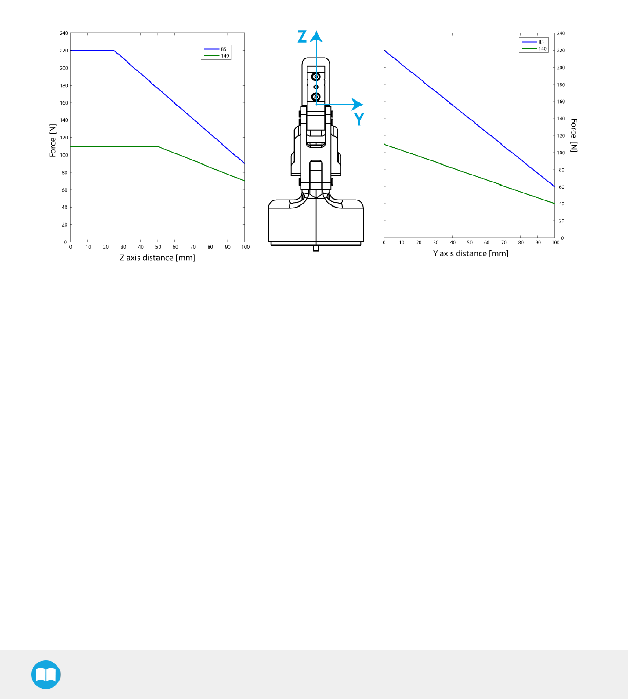
2F-85 &2F-140 - Instruction Manual
Fig. 6-18: Grip force in the Y and Z axis for the 2-Finger 85 and 2-Finger 140.
137

2F-85 &2F-140 - Instruction Manual
Info
lThe "Actuation Force" is the force that can be applied to an object by the motor of the Gripper.
lThe Gripper is self-locking.
Info
The user of the Gripper must always ensure that the result of the forces against the finger is always lower than the maximum
holding force as seen in figure 6-18.
As defined in figure 6-17, the weight that can be lifted is defined by :
lFis the force that is applied to the load by the Gripper.
lCf is the friction coefficient between the fingertip and the part load.
lSf is a safety factor to be determined by the robot integrator.
Info
For example, if the silicone fingertips AGC-TIP-204 are used to lift a lubricated steel part (machine tending with cutting oils),
the friction coefficient would be 0.3 (tested static coefficient of friction).
Maximum weight with a safety factor of 2.4 would be :
W = (2 x 200 N x 0.3) / 2.4 = 50 N
This calculation means that a 5 kg part will be held by the Gripper when not moving (standing still). When accelerating, the
payload will decrease.
For example, if your robot accelerates at 2g then the 5 kg part would weight 100 N and would be dropped.
The biggest factor in such calculations will always be the friction coefficient, we recommend testing the coefficient.
Warning
You must consider the robot acceleration in your payload calculations.
Robot emergency stops will lead to major deceleration velocities.
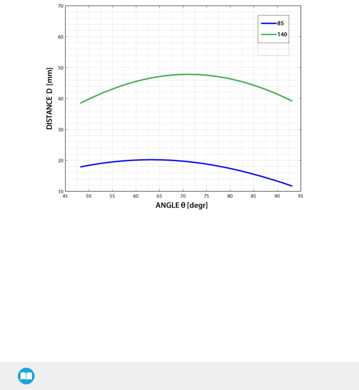
2F-85 &2F-140 - Instruction Manual
6.2.2. Equilibrium Line
Equilibrium line position (explained in the General Presentation section) is detailed in the figure below, where:
lθis the opening angle between the Gripper proximal bar and center line
ld is the distance between the bottom of the finger pads and the equilibrium line as seen on the Z axis in figure 1.5.
Fig. 6-19: Position of the Gripper equilibrium line according to the opening angle for 2-Finger 85 and 2-Finger 140 options.
139

2F-85 &2F-140 - Instruction Manual
6.2.3. Center of mass, tool center point and moment of inertia
Coupling is included when Gripper is not mounted on the Camera. Dual Gripper adapter plate included where appropriate.
End-of-arm tooling
TCP (mm) Center of mass (mm)
Mass (g)Gripper 1 Gripper 2
X Y Z
X Y Z X Y Z
FT 300 Force Torque Sensor 0.0 0.0 37.5 - - - 0.0 0.0 17.0 300.0
Wrist Camera 0.0 0.0 23.5 - - - 0.0 5.0 9.0 230.0
2F-85 0.0 0.0 171.0 - - - 0.0 0.0 57.0 900.0
2F-140 0.0 0.0 241.0 - - - 0.0 0.0 66.0 975.0
Hand-E 0.0 0.0 156.8 - - - 0.0 0.0 58.0 1070.0
FTSensor + 2F-85 0.0 0.0 208.5 - - - 0.0 0.0 75.1 1200.0
FTSensor + 2F-140 0.0 0.0 278.5 - - - 0.0 0.0 83.1 1275.0
FTSensor + Hand-E 0.0 0.0 194.3 - - - 0.0 0.0 78.3 1370.0
Camera + 2F-85 0.0 0.0 194.5 - - - 0.0 1.0 65.9 1130.0
Camera + 2F-140 0.0 0.0 264.5 - - - 0.0 1.0 74.1 1205.0
Camera + Hand-E 0.0 0.0 180.3 - - - 0.0 0.9 68.7 1300.0
FTSensor + Camera + 2F-85 0.0 0.0 232.0 - - - 0.0 0.8 85.3 1430.0
FTSensor + Camera + 2F-140 0.0 0.0 302.0 - - - 0.0 0.8 92.8 1505.0
FTSensor + Camera + Hand-E 0.0 0.0 217.8 - - - 0.0 0.7 89.5 1600.0
Hand-E/Hand-E 153.9 0.0 137.9 -153.9 0.0 137.9 0.0 0.0 62.2 2405.0
Hand-E/2F-85 153.9 0.0 137.9 -163.9 0.0 147.9 6.7 0.0 61.5 2235.0
Hand-E/2F-140 153.9 0.0 137.9 -213.4 0.0 197.4 1.1 0.0 64.4 2310.0
2F-85/2F-85 163.9 0.0 147.9 -163.9 0.0 147.9 0.0 0.0 60.7 2065.0
2F-85/2F-140 163.9 0.0 147.9 -213.4 0.0 197.4 -5.8 0.0 63.8 2140.0
2F-140/2F-140 213.4 0.0 197.4 -213.4 0.0 197.4 0.0 0.0 66.7 2215.0
Camera + Hand-E/Hand-E 153.9 0.0 161.4 -153.9 0.0 161.4 0.0 0.4 79.0 2635.0
Camera + Hand-E/2F-85 153.9 0.0 161.4 -163.9 0.0 171.4 6.1 0.5 77.9 2465.0
Camera + Hand-E/2F-140 153.9 0.0 161.4 -213.4 0.0 220.9 1.0 0.5 80.7 2450.0
Camera + 2F-85/2F-85 163.9 0.0 171.4 -163.9 0.0 171.4 0.0 0.5 76.6 2295.0
Camera + 2F-85/2F-140 163.9 0.0 171.4 -213.4 0.0 220.9 -5.3 0.5 79.7 2370.0

2F-85 &2F-140 - Instruction Manual
End-of-arm tooling
TCP (mm) Center of mass (mm)
Mass (g)Gripper 1 Gripper 2
X Y Z
X Y Z X Y Z
Camera + 2F-140/2F-140 213.4 0.0 220.9 -213.4 0.0 220.9 0.0 0.5 82.6 2445.0
FTSensor + Hand-E/Hand-E 153.9 0.0 175.4 -153.9 0.0 175.4 0.0 0.0 90.6 2705.0
FTSensor +Hand-E/2F-85 153.9 0.0 175.4 -163.9 0.0 185.4 5.9 0.0 89.3 2535.0
FTSensor + Hand-E/2F-140 153.9 0.0 175.4 -213.4 0.0 234.9 0.9 0.0 92.1 2610.0
FTSensor + 2F-85/2F-85 163.9 0.0 185.4 -163.9 0.0 185.4 0.0 0.0 87.9 2365.0
FTSensor + 2F-85/2F-140 163.9 0.0 185.4 -213.4 0.0 234.9 -5.1 0.0 90.9 2440.0
FTSensor + 2F-140/2F-140 213.4 0.0 234.9 -213.4 0.0 234.9 0.0 0.0 93.8 2515.0
FTSensor +Camera + Hand-
E/Hand-E 153.9 0.0 198.9 -153.9 0.0 198.9 0.0 0.4 106.4 2935.0
FTSensor +Camera + Hand-
E/2F-85 153.9 0.0 198.9 -163.9 0.0 208.9 5.4 0.4 104.7 2765.0
FTSensor + Camera + Hand-
E/2F-140 153.9 0.0 198.9 -213.4 0.0 258.4 0.9 0.4 107.5 2840.0
FTSensor + Camera + 2F-
85/2F-85 163.9 0.0 208.9 -163.9 0.0 208.9 0.0 0.4 102.9 2595.0
FTSensor + Camera + 2F-
85/2F-140 163.9 0.0 208.9 -213.4 0.0 258.4 -4.7 0.4 105.9 2670.0
FTSensor + Camera + 2F-
140/2F-140 213.4 0.0 258.4 -213.4 0.0 258.4 0.0 0.4 108.8 2745.0
The coordinate system used to calculate the moment of inertia and center of mass of the Gripper is shown in Figure 6-20.
The moment of inertia are calculated for a configuration where the fingers are fully open. Here is the approximate moment of inertia
matrix for theGripper:
141
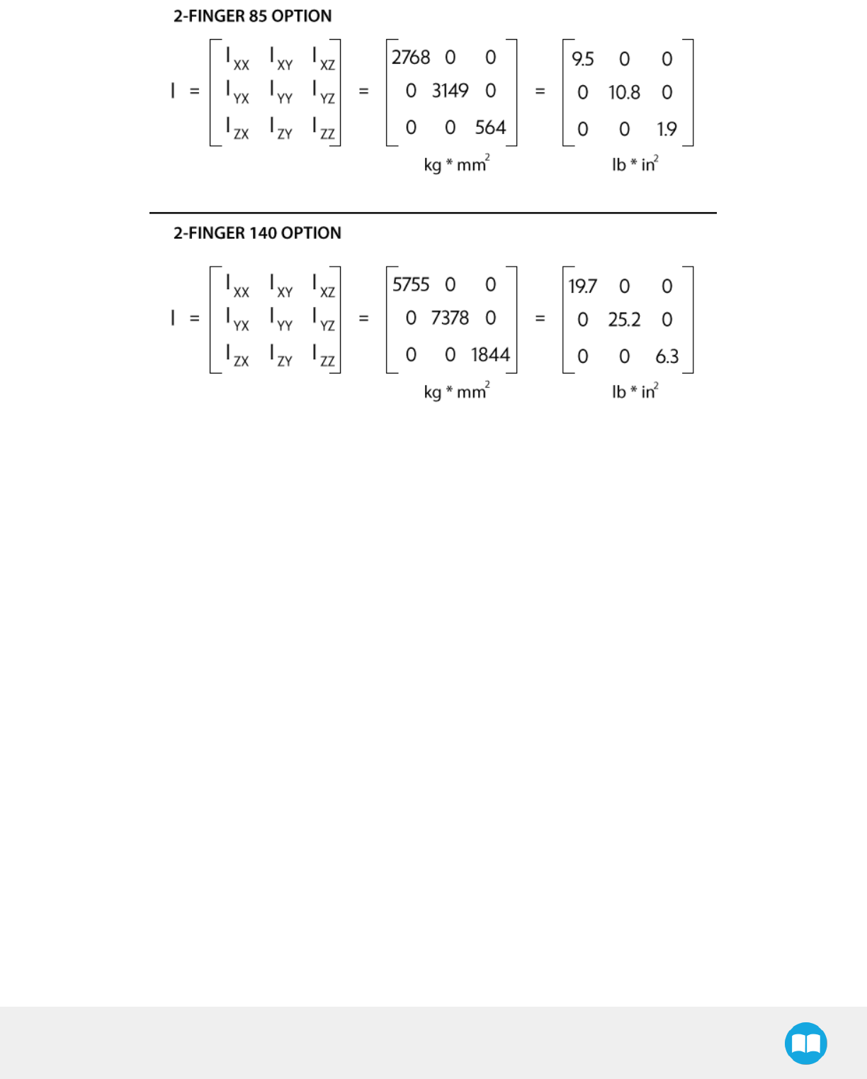
2F-85 &2F-140 - Instruction Manual
Fig. 6-20: Robotiq 2-Finger inertia matrix.
2F-85 &2F-140 - Instruction Manual
6.2.4. Moment and force limits
The 2-Finger Adaptive Gripper has maximum moments and force limit. The listed moments and forces are independent to the force
applied by the Gripper itself on it's payload. For payload calculation, refer to the Mechanical specifications section.
Warning
The following limits must be respected at all time. Calculation of maximum moment and force should include the robot
acceleration and a safetyfactor.
Parameters
Finger Option
2-Finger 85 2-Finger 140
Fx, Fy, Fz 50 N 25 N
Mx* 5 Nm 5 Nm
My* 5 Nm 5 Nm
Mz 3 Nm 3 Nm
* Moments in x and y are calculated from the base of the fingertips as shown in figure 6-18.
Example usage of the listed limit :
lAfter picking it's normal payload, the robot can use the 2-Finger 85 Gripper to apply up to 50 N of force in any direction. Applying
more then 50 N could damage the Gripper or result in payload loss.
lThe Gripper can pick a screwdriver and apply 3 Nm of torque to screw ( such moment would be in the Z axis).
143

2F-85 &2F-140 - Instruction Manual
6.3. Electrical specifications
SPECIFICATION VALUE
Operating supply voltage 24 V DC ±10%
Absolute maximum supply voltage 28 V DC
Quiescent power (minimum power
consumption) < 1 W
Peak current 1 A

7. Maintenance
The Adaptive Gripper requires only external maintenance with limited downtime. Maintenance for both 2-Finger Adaptive Robot
Grippers is required after specified usage, measured in time (normal 40h week) or in cycles (requesting an open and closed movement
from the Gripper).
Following the maintenance interval will ensure :
lCorrect functioning of your Gripper.
lValidity of your warranty.
lProper lifetime for your Gripper.
Please visit support.robotiq.com for details on the maintenance operation.
Warning
Unless specified, any repairs done on the Gripper will be done by Robotiq.
Info
A cycle is defined as a go to requested position command that results in grip force being applied (picking an object while
opening or closing or closing the fingers on themselves).
2F-85 &2F-140 - Instruction Manual

2F-85 &2F-140 - Instruction Manual
Operation Daily Weekly Semiannually
(or 1 M cycles)
Annually
(or 2 M cycles)
Gripper Cleaning Dirty
conditions
Normal
conditions
Periodic Inspection X
Finger Pad
Replacement1X
Overhaul2X
Table 7-1: Maintenance intervals for the 2-Finger Grippers
1Replace pads before if wear is visible.
2Overhaul is recommended after 2M cycles and is done by Robotiq at the user's expense, please contact Robotiq support.
Visit support.robotiq.com for details on the required maintenance operations.
Caution
Maintenance operations are for the average normal usage of the Gripper, the maintenance intervals must be adjusted
according to environmental conditions such as:
lOperating temperature
lHumidity
lPresence of chemical(s)
lPresence of physical parts (debris, scraps, dust, grease etc.)
lInteraction with operated parts (sharp or rough)
lDynamics of the operation (accelerations)
146
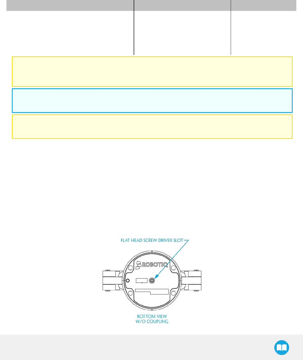
2F-85 &2F-140 - Instruction Manual
7.1. Gripper cleaning
Maintenance Interval Tools You Need Parts You Need
Weekly or daily in dirty operating conditions
lFlat head precision 2 mm screwdriver
l4 mm hex key
lDry tissue or towel
lMedium strength thread locker
None
Caution
The Robotiq 2-Finger Adaptive Robot Gripper is not waterproof or water resistant without additional protection, only clean
the Gripper with a drytowel.
Info
Always turn off the robot and Gripper power supply before performing any maintenance operations on the Gripper.
Caution
Maintenance operator must be grounded to prevent electrostatic discharge that could damage the Gripper electronics.
1. Remove the Gripper from its coupling using the 4 mm hex key to unscrew the four (4) M5-0.8 x 35mm socket head cap screws.
Note that each screw uses a tooth lock washer, do not lose them.
2. Use the flat head precision screwdriver to open or close the Gripper by accessing the transmission shaft under the Gripper, where
the coupling connects. Illustrated in the figure below.
a. Open or close to access the palm pad and other parts of the Gripper.
3. Clean the Gripper with a dry towel, remove all debris, dirt and dust from the surface of the Gripper, clean all pads, dry thoroughly.
4. Clean the coupling with a dry towel, pay particular attention to the electrical contact.
5. Visually inspect the Gripper and pay attention to any visible damage.
6. Put the coupling back on and fix it with the four (4) M5-0.8 x 35mm socket head cap screws, use the tooth lock washers, apply
medium strength thread locker to the M5 screws.

2F-85 &2F-140 - Instruction Manual
Fig. 7-1: Flat head screwdriver slot for manual opening and closing of the Gripper.
148

2F-85 &2F-140 - Instruction Manual
7.2. Periodic inspection
Maintenance Interval Tools You Need Parts You Need
Monthly
lFlat head precision 2 mm screwdriver
l4 mm hex key
lDry tissue or towel
lMedium strength thread locker
None (unless damage is detected)
Info
Always turn off robot and Gripper power supply before doing maintenance operations on the Gripper.
1. Remove and clean the Gripper following instructions in the Gripper cleaning section.
2. Inspect the Gripper :
a. Finger movement must be symmetric and fluid:
i. Test the return movement by pushing fingers open, the fingers must come back to the initial starting position
on its own.
ii. Test the general movement of the fingers by actuation using the screwdriver insertion hole in the chassis.
b. Finger pad wear must not affect gripping, if wear is visible and affects movement, change fingerpad(s).
c. Check for any collision damage, if damage is visible, contact support@robotiq.com.
d. Check for any sign of wear on the Gripper chassis, if wear is present and may affect the Gripper, contact sup-
port@robotiq.com.
3. Put back in place respecting instructions from the Gripper cleaning section.

2F-85 &2F-140 - Instruction Manual
7.3. Fingertip replacement
Maintenance Interval Tools You Need Parts You Need
1 Million cycles or when wear is visible
lFlat head 2 mm precision screwdriver
l4 mm hex key
l2 mm hex key
lDry tissue or towel
llow strength thread locker
lmedium strength thread locker
2x Robotiq 2-Finger Adaptive Robot Gripper
fingertip (with or without silicone pad).
Refer to the Spare Parts, Kits and Accessories section section to order Robotiq 2-Finger Adaptive Robot Gripper replacement parts.
Info
Always turn off robot and Gripper power supply before doing maintenance operations on the Gripper.
1. Remove and clean the Gripper following instructions from the Gripper cleaning section.
2. Remove the worn fingertip by removing the M3 screws with the 2 mm hex key.
3. Clean the fingertip holder and dry thoroughly.
4. Insert the new fingertip by inserting the indexing pin in the fingertip holder.
5. Fix the fingertip using the provided M3-0.5 x 8 mm socket head cap screws (low head), apply low strength thread locker to the M3
screw threads.
6. Repeat for remaining finger.
150

2F-85 &2F-140 - Instruction Manual
7.4. Overhaul
Maintenance Interval Tools You Need Parts You Need
2 Million cycles or at warranty expiration None None
Gripper overhaul is necessary when the Gripper reaches 2 Million cycles or when warranty expires. Overhaul is done by Robotiq, please
contact Robotiq support service.
Gripper overhaul includes, but is not limited to :
lWorn parts changed
lPower transmission gearing mechanism
lPlain bearings
lBall bearings
lQuality control
lSpecification test (force, speed, position)
Overhaul takes a maximum of 5 business days after reaching Robotiq, shipping is at customer's expense.
Tip
Loan units are available while your Gripper is under maintenance.

8. Spare Parts, Kits and Accessories
Spare parts, kits and accessories list:
Info
The following list is up to date at print time and is subject to change, check online for updates.
Info
Unless specified, screws, dowel pins and other hardware are included only for the Gripper side, never for the robot side.
Item Description
Ordering
Number
(2-Finger 85)
Ordering
Number
(2-Finger 140)
Gripper basic unit Adaptive Robot Gripper 2-Finger basic unit with
fingers (no fingertips, no coupling) AGC-GRP-002 AGC-GRP-140
Kit for Universal
Robots
Gripper basic unit, 10 m cables and couplings for
Universal Robots with silicone fingertips AGC-UR-KIT-002 AGC-UR-KIT-140
Controller Optional controller for industrial communications see
Robotiq Universal Controller Items UNI-CTR-XXXX
Finger Kit
Finger upgrade kit for 85 or 140 mm option.
Included:
l2 x Replacement finger
l2 x Hardware kit
l1 x Allen key
AGC-FIN-KIT-85 AGC-FIN-KIT-140
Blank coupling Blank coupling for Adaptive Robot Gripper 2-Finger,
with screws for Gripper fixation and 1 m pigtail cable AGC-CPL-BLANK-002
ISO 9409-1-50-4-
M6 coupling
ISO 9409-1-50-4-M6 coupling for Adaptive Robot
Gripper 2-Finger, with screws for Gripper fixation and
1 m pigtail cable
AGC-CPL-062-002
ISO 9409-1-31.5-4-
M5 coupling
ISO 9409-1-31.5-4-M5 coupling for Adaptive Robot
Gripper 2-Finger, with screws for Gripper fixation and
1 m pigtail cable
AGC-CPL-063-002
ISO 9409-1-40-4-
M6 coupling
ISO 9409-1-40-4-M6 coupling for Adaptive Robot
Gripper 2-Finger, with screws for Gripper fixation and
1 m pigtail cable
AGC-CPL-064-002
56-8M4-1D4
coupling
Coupling for 56 mm PCD1with (8) M4 and (1) 4mm
indexing pin, with screws for 2-F Gripper fixation and
1 m pigtail cable
AGC-CPL-065-002
2F-85 &2F-140 - Instruction Manual

2F-85 &2F-140 - Instruction Manual
Item Description
Ordering
Number
(2-Finger 85)
Ordering
Number
(2-Finger 140)
56-6M4-1D6
coupling
Coupling for 56 mm PCD1with (6) M4 and (1) 6mm
indexing pin, with screws for 2-F Gripper fixation and
1 m pigtail cable
AGC-CPL-066-002
60-4Ø5-1D5
coupling
Coupling for 60 mmPCD1with (4) M5 thread and (1)
5mm indexing pin, with screws for 2-F Gripper
fixation and 1 m pigtailcable
AGC-CPL-067-002
63-6M6-2D6
coupling
Coupling for 63 mm PCD1with (6) M6 and (2) 6mm
indexing pins, with screws for 2-F Gripper fixation
and 1 m pigtail cable
AGC-CPL-068-002
40-4M5-1D3
coupling
Coupling for 40 mm PCD1with (4) M5 and (1) 3mm
indexing pins, with screws for 2-F Gripper fixation
and 1 m pigtailcable
AGC-CPL-070-002
31.5-4M4 coupling Coupling for 31.5 mm PCD1with (4) M4, with screws
for 2-F Gripper fixation and 1m pigtailcable AGC-CPL-071-002
Adapter plate to
63-4M6-71-2D3
Wrist adapter plate for use with AGC-CPL-064-002.
Interface to 63mm PCD1with (4) M6 screws and 71
mm PCD1with (2) M3 indexing pins
AGC-APL-151-002
Adapter plate to
63-4M6-61_4-2D6
Wrist adapter plate for use with AGC-CPL-064-002.
Interface to 63mm PCD1with (4) M6 screws and 61.4
mm PCD 1 with (2) M6 indexing pins
AGC-APL-152-002
Adapter plate to
80-6M8-2D82D8
Wrist adapter plate for use with AGC-CPL-064-002.
Interface to 80mm PCD1with (6) M8 screws and (2)
M8 indexingpins
AGC-APL-153-002
2-Finger Device
Cable (5M)
5 m Robotiq device cable for power and
communication. Straight M12 5-pins female on one
side, single ended on the other, shielded
CBL-COM-2065-05
2-Finger Device
Cable (10M)
10 m Robotiq device cable for power and
communication. Straight M12 5-pins female on one
side, single ended on the other, shielded
CBL-COM-2065-10
USB to RS485
adapter
USB to RS485 adapter, can be used with device cable
for USBconnection ACC-ADT-USB-RS485
Blank fingertip2
Blank aluminium fingertip for 2-Finger Adaptive
Gripper, included:
lone (1) C-203 or C-225 Fingertip.
ltwo (2) screws M3-0.5 x 8 mm LHCS
lone (1) dowel pin 3 x 10 m6
AGC-TIP-203-002 AGC-TIP-225-140
Silicone fingertip2
Flat silicone fingertip for 2-Finger Adaptive Gripper,
included:
lone (1) C-204 or C-220 Fingertip.
AGC-TIP-204-002 AGC-TIP-220-140
153

2F-85 &2F-140 - Instruction Manual
Item Description
Ordering
Number
(2-Finger 85)
Ordering
Number
(2-Finger 140)
ltwo (2) screws M3-0.5 x 8 mm LHCS
lone (1) dowel pin 3 x 10 m6
Grooved fingertip2
Grooved aluminium fingertip for 2-Finger Adaptive
Gripper, meant to pick cylindrical objects in both Y
and Z axis, included:
lone (1) C-205 or C-221 Fingertip.
ltwo (2) screws M3-0.5 x 8 mm LHCS
lone (1) dowel pin 3 x 10 m6
AGC-TIP-205-002 AGC-TIP-221-140
Replacement palm
pad
Replacement palm pad for the 2-Finger Adaptive
Gripper,included:
lone (1) Palm pad C-010
lfour (4) screws M3-0.5 x 8 mm LHCS
AGC-PAD-010-002
Replacement finger
Replacement finger for 2-Finger Adaptive Gripper,
included:
lone (1) finger
ltwo (2) replacement screws M4 x 8 SSCS
lthree (3) replacement snap rings (5 mm external)
AGC-FIN-002 AGC-FIN-140
Parallel locking
pins2
Parallel mechanism locking pin for 2-Finger Adaptive
Gripper,included :
ltwo (2) locking pins C-020
lsix (6) snap rings (5 mm, external)
AGC-PARA-KIT-002
1Pitch Circle Diameter
2Part listed for a two units since two are required per Gripper.
Tip
For legacy part replacement visit the documentation archives and the appropriate manual or consult your Robotiq
distributor.

9. Troubleshooting
When using 2-Finger with USB to RS485 serial converter:
Troubleshooting from the Gripper LED:
1. LED is not lit, Gripper not powered.
a. Check Gripper power supply and electrical setup, see Section 3.5.
2. LED is solid blue and red, Gripper is in fault.
a. Disconnect the communication and power cycle the Gripper. The led should turn solid red when powered.
b. While powered with red LED, connect the communication, LED should turn solid blue when connection is established.
3. Flashing blue and red LED, Gripper is in fault.
a. Gripper may be in auto-release, wait for auto-release to be completed, then turn off auto-release and initialize the Grip-
per.
b. Gripper may have a major fault, check the error from fault status and contact support.
4. Solid blue, no fault and communicating.
a. If you can control the Gripper from the GUI on the pendant, check your program structure.
b. If you can not control the Gripper from the pendant, contact support.
5. Solid red, no fault, but Gripper is not communicating.
a. USB-RS485 converter LEDs are :
lNot lit, no USB communication.
i. Check USB connection.
ii. Re-install drivers.
iii. Contact support.
lRed flashes at slow rate.
i. Check the DB-9 connector.
ii. Check the cable.
iii. Check the communication parameters from the Robotiq User Interface, see recovery procedure.
iv. Contact support.
lRed and green flashing at high speed.
i. Check fault status, maximum operating temperature could be exceeded.
ii. Contact support.
2F-85 &2F-140 - Instruction Manual

2F-85 &2F-140 - Instruction Manual
When using 2-Finger with Universal Robots package:
Troubleshooting from the previous section (LED references) still applies.
From the UR teach pendant:
URcap install:
1. Verify that the latest URCap is installed from the "Robot Setup" menu, inside the "URCaps" tab
a. URCaps installation instructions are in the Installing URCap Package section
b. Inside the URCaps tab, if you select the appropriate URCap file, you can see the current software version
c. Gripper toolbar should appear if installed properly
2. URCap is installed but Gripper cannot be controlled :
1. If Gripper LED is not blue, follow the steps in the first section above
2. If Gripper LED is blue, URCap is installed with the latest available version, contact support@robotiq.com
156

2F-85 &2F-140 - Instruction Manual
Driver package install:
1. Driver checkup :
a. Use the latest driver version available at support.robotiq.com
lUse the installation instruction from the URPackage without URCaps section
b. To check your driver version :
lWith the Gripper unplugged
lFrom the UR teach pendant screen, click the "Gripper" button
i. Driver version will be shown
ii. If Gripper button is not displayed, driver package is not properly installed, see instruction from
the Control over Universal Robots without URCaps section
2. Driver is installed but Gripper cannot be controlled :
a. If Gripper LED is not blue, follow the steps in the first section above
b. If Gripper LED is blue, driver is installed with the latest available version, contact support@robotiq.com

10. Warranty andPatent
Robotiq warrants the 2-Finger 85 and 2-Finger 140 Adaptive Robot Grippers against defects in material and workmanship for a period
of one year from the date of reception when utilized as intended. Robotiq also warrants that this equipment will meet applicable
specifications under normaluse.
Warning
Warranty applies under the following conditions:
lUsage respects the operating and storage conditions specified in Section 3.3
lProper installation of the Gripper specified in Section 3 and the following subsections.
lUsage under normal one-shift operation (40h a week)
lOr until a 2 000 000 cycle count1has been reached.
lUsage respects maintenance specified in Section 7.
lUsage respects recommended payload and force specified in the Payload and force section.
1Cycle count: One (1) cycle is defined as an object picking attempt, successful or not(open or closing onto an object, or closing on itself).
It is calculated in the internal memory of the 2-Finger Adaptive Gripper and can been seen with the Robotiq User Interface.
During the warranty period, Robotiq will repair or replace any defective 2-Finger Adaptive Robot Gripper, as well as verify and adjust the
Gripper free of charge if the equipment should need to be repaired or if the original adjustment is erroneous. If the equipment is sent
back for verification during the warranty period and found to meet all published specifications, Robotiq will charge standard verification
fees.
The unit is considered defective when at least one of the following conditions occurs :
lThe Gripper fingers cannot close or open;
lThe Gripper feedback necessary for the robot program is not accessible.
Parts that come into contact with the work piece and wearing parts such as the finger and palm pads are not covered by the warranty.
Caution
The warranty will become null and void if the :
lUnit has been tampered with, repaired or worked on by unauthorized individuals.
lWarranty sticker has been removed.
lScrews, other than as explained in this guide, have been removed.
lUnit has been opened other than as explained in this guide.
lUnit serial number has been altered, erased, or removed.
lUnit has been misused, neglected, or damaged by accident.
2F-85 &2F-140 - Instruction Manual

2F-85 &2F-140 - Instruction Manual
This warranty is in lieu of all other warranties expressed, implied, or statutory, including, but not limited to, the implied warranties of
merchantability and fitness for a particular purpose. In no event shall Robotiq be liable for special, incidental, or consequential
damages.
Robotiq shall not be liable for damages resulting from the use of the Robotiq 2-Finger Adaptive Robot Gripper, nor shall Robotiq be
responsible for any failure in the performance of other items to which the 2-Finger Adaptive Robot Gripper is connected or the
operation of any system of which the Gripper may be a part.
159

2F-85 &2F-140 - Instruction Manual
Exclusions
This warranty excludes failure resulting from: improper use or installation, normal wear and tear, accident, abuse, neglect, fire, water,
lightning or other acts of nature, causes external to the Gripper or other factors beyond Robotiq's control.
Robotiq reserves the right to make changes in the design or construction of any of its products at any time without incurring any
obligation to make any changes whatsoever on units already purchased.
Patent
This product incorporates technology developed by Lionel Birglen, professor at Polytechnique Montreal, and is used under license of
Polyvalor LP.

11. Contact
www.robotiq.com
Contact Us
Phone
1-888-ROBOTIQ (762-6847)
(01) 418-380-2788 Outside US and Canada
Fax
1-418-800-0046
Technical support and engineering
option 3
Sales
option 2
Head office
Robotiq:
966, chemin Olivier
Suite 500
St-Nicolas, Québec
G7A 2N1
Canada
Where automation Pros come to share their know-how and get answers.
dof.robotiq.com
2F-85 &2F-140 - Instruction Manual

12. Harmonized Standards, Declarations and Certificates
12.1. Translation of original EC declaration of incorporation
2F-85 &2F-140 - Instruction Manual

2F-85 &2F-140 - Instruction Manual
12.2. Applied standards
This section describes all applied harmonized standards for the design and production of the Robotiq 2-Finger Adaptive Gripper.
Standards are applied were applicable, some points may not be applied if not applicable to this specific product. Conformity is not
enforced by any laws, it is self-applied and the aim is to define normal safety and performance requirements for similar products.
Caution
Conformity of the product is only met if all instructions of the following manual are followed. Among others; installation,
safety measure and normal usage must be respected.
The following standards have been applied:
NF EN ISO
14539 2000 Manipulating industrial robots — Object handling with grasp-type grippers — Vocabulary and
presentation ofcharacteristics
NF EN ISO
12100 2010 Safety of machinery — General principles for design — Risk assessment and risk reduction
NF EN IEC
60204-1 2006 Safety of machinery — Electrical equipment of machines — Part 1: General requirements
163
