MICRO SWITCH™ V7 Premium Miniature Basic Switches 310427 Catalog
310427-Attachment 310427-Attachment 310427-Attachment 784549 Batch3 unilog cesco-content
2014-09-08
: Pdf 310427-Catalog 310427-Catalog 784549 Batch3 unilog
Open the PDF directly: View PDF ![]() .
.
Page Count: 11

MICRO SWITCH™
Premium Miniature Basic Switches
V7 Series
Datasheet
2sensing.honeywell.com
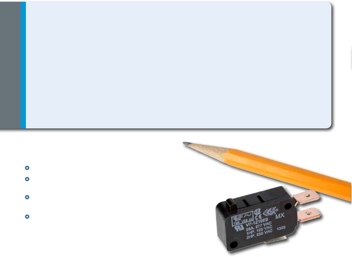
What makes our switches better?
Certified with CSA, ENEC, and UL for global acceptability
Reliable snap-spring mechanism with more than 60 years of
proven service
Available with pin plungers, integral levers (fitted two posi-
tions), or auxiliary levers to meet equipment requirements
Electrical ratings from 0.1 A up to 25 A for
design flexibility in one package size
MICRO SWITCH™ V7 Series
Premium Miniature Basic Switches
Honeywell’s MICRO SWITCH™ V7 miniature switches are designed for long term-reliability in a rugged switch
packaged with a thermoplastic housing. These switches may be installed in a wide range of applications from simple
or precision on/off limits, presence/absence sensing, or embedded in pressure or temperature assemblies.
The V7 switch is available as a pin plunger style or with optional integral or auxiliary levers to actuate the switch and
offer versatility in the application. The switch requires as little as 0,15 Newtons [approximately ½ ounce] to operate
for extremely sensitive applications or an operating force of almost 4 Newtons [14 ounces] where higher forces are
required. The V7 switch can reliably control logic level electrical loads from less than 0.1 A to power duty switching up
to 25 A. Agency certications for the MICRO SWITCH™ V7 switches are provided through CSA, ENEC, and UL for
global use around the world.
COST OPTIMIZATION • RELIABILITY
PERFORMANCE • GLOBAL ACCEPTANCE
Big performance in a small package.

3
sensing.honeywell.com
Features
and Benefits
Features
and Benefits
ACTUATION ON TIME
MICRO SWITCH™ V7 Series basic switches operate with forces as low
as 15 g and carry options to increase to 397 g, and can thereby easily
accommodate different actuator mechanisms.
RELIABLE PERFORMANCE IN HARSH CONDITIONS
Switches feature industry-leading temperature ranges of -40 °C to 175 °C [-40
°F to 347 °F] to allow for years of reliable performance in harsh conditions.
LONG LIFE CYCLE RATING
The long life cycle rating (up to 10,000,000 cycles) reduces the need to replace
switches over the life of OEM platform applications, therefore reducing total system
cost.
DESIGN FLEXIBILITY
Available with pin plungers, integral levers (fitted 2 positions), and auxiliary levers to
meet a variety of equipment requirements, MICRO SWITCH™ V7 Series switches
also boast electrical ratings from 0.1 A up to 25 A for design flexibility in one
package size.
Global acceptance: UL, CSA, ENEC
VENDING MACHINE MOTORS
Switch controls motors or solenoids in vending machines for dispensing of product.
MICROWAVE DOOR INTERLOCK
Switch in door interlock of microwave that disconnects power if door opened.
OVEN CLEANING LATCH
Switch in door latch for oven clean operation.
PRESSURE SWITCH ASSEMBLY
Pressure switch senses incoming water pressure for power washer.
Potential Applications
4sensing.honeywell.com
V7 Series
PRODUCT NOMENCLATURE
V7
Switch T
ype1Operating
Force
1
Termination Style
(Inches)
E8
D9
D8 0.187 x 0.02
quick connect
0.250 x 0.032
quick connect
0.187 x 0.02
quick connect
spread
0.250 x 0.032
quick connect
spread
Left angle
PCB
SPNO on
edge PCB
NOTES:
1 Not all possible combinations are available, these are only guidelines
2 Lever length measured from center of back mounting hole to end of straight lever or center of roller
3 All ratings are UL/CSA, and where noted are also European-rated ENEC
4 Consider the temperature required and the mounting hole size when making this selection
5 Electric ratings “W” x “X” only used with “A” Mounting Construction and vice versa
6 European ENEC rating requires Mounting Construction code “9” or “0”
Electrical Rating3,6
C
V7 Series
Miniature
Basic
Switch
3
1
1
SPNC
2
SPDT
SPNO
Circuitry
Code
Mounting/
Construction4,6
1
1
Use only if this switch
has a special feature.
Could be any number
.
Special
Designator
7
D8
E9
P02
P07
022
201
002 Straight
22,1 mm [0.87 in]
207
263
266
048
636
4
3
7
150 °C [302 °F]
2,9 mm [0.11 in]
mtg. holes
85 °C [185 °F]
2,9 mm [0.11 in]
mtg. holes
85 °C [185 °F]
2,9 mm [0.11 in]
mtg. holes
85 °C [185 °F]
3,1 mm [0.12 in]
mtg. holes
85 °C [185 °F]
3,1 mm [0.12 in]
mtg. holes
177 °C [350 °F]
w/ 2,9 mm
[0.11 in] mtg. holes
150 °C [302 °F]
3,1 mm [0.12 in]
mtg. holes
8
9
0
A
Lever
Style2
B
A
C
5 A @
125 Vac3 A
11 A @
125 Vac10 A
1 A @
125 Vac1 A
10 A @
125 Vac5 A
3 A @
125 Vac
15 A @
125 Vac
__
__
No
rating
__
D
E
F
H
K
J
S
19 A @
125 Vac16 A
22 A @
125 Vac20 A
21 A @
125 Vac16 A
25 A @
125 Vac20 A
1 A
15.1 A @
125 Vac
6 A @
125 Vac
0.1 A @
125 Vac
__
__
V
W
X
Z
1
2
150 g max.
175 g max.
(V & J electrical
rating)
225 g max.
(K & Z electrical
rating)
75 g max.
3
4
5
50 g max.
25 g max.
15 g max.
66 oz to 14 oz
max.
7
8
9
8 oz max.
85 g max.
300 g max.
North
America
Europe
(ENEC)
Formed quick-connect
terminals available
Formed levers available
——
Straight
35,6 mm [1.4 in]
Roller
20,6 mm [0.81 in]
Roller
34,0 mm [1.34 in]
Sim. roller
32,8 mm [1.29 in]
Tall sim. roller
34,0 mm [1.34 in]
Straight
59,4 mm [2.34 in]
Paddle
139,5 mm [5.5 in]
O
N
L
Y
Not all combinations of model code are available.
Please contact your Honeywell provider/representative for assistance.

5
sensing.honeywell.com
MICRO SWITCH™ Premium Miniature Basic Switches
Table 1. Specifications
Characteristic Parameter
Circuitry SPDT, SPNC, SPNO
Operating force 0,25 N to 3,9 N [15 g to 397 g]
Termination
quick connect; 4,75 mm x 0,51 mm [0.187 in x 0.02 in]
quick connect: 6,35 mm x 0,81 mm [0.25 in x 0.032 in]
PCB (printed circuit board)
Actuators pin plunger, integral lever options, auxiliary lever options
Agency certification CSA, ENEC, UL; RoHS compliant
Operating temperature -40 °C to 85 °C [-40 °F to 185 °F], options for 175 °C [347 °F]
Mechanical life up to 10 million cycles
Contact material silver, gold plated, gold alloy
Housing material high strength thermoplastic
Table 2. Electrical Ratings
Rating code UL, CSA ENEC3
A5 A 125 Vac, 250 Vac, 277 Vac
1/10 HP 250 Vac 3 (1) A, 250 Vac 2
B
11 A 1/3 HP 125 Vac, 250 Vac or 277 Vac
1/2 A 125 Vdc; 1/4 A 250 Vdc
4 A 125 Vac “L” 1
10 (3) A, 250 Vac 2
C
15.1 A 1/2 HP 125 Vac, 250 Vac or 277 Vac
1 /2A 125 Vdc
1/4 A 250 Vdc; 5 A 125 Vac “L” 1
–
E
10 A 1/3 HP 125 Vac, 250 Vac or 277 Vac
1/2 A 125 Vdc
1/4 A 250 Vdc, 4 A 125 Vac “L” 1
5 (2) A, 250 Vac 2
F3 A 125 Vac, 250 Vac, 277 Vac
1/10 HP 250 Vac –
S 0.1 A, 125 Vac 1 (0.05) A, 250 Vac 2
V21 A 1 HP 125 Vac, 250 Vac, 277 Vac
2 HP 250 Vac, 277 Vac 16 (4) A, 250 Vac 2
W 15.1 A 125 Vac, 250 Vac, 277 Vac –
Z25 A, 277 Vac
1 HP, 125 Vac; 2 HP, 250 Vac 20 (5) A, 250 Vac 2
1 Incandescent lamp rating
2 XX(Y) - XX = max. rated resistive value in amps, and (Y) = max. rated inductive value in amps
3 European ENEC rating requires Mounting Construction code “9” or “0”. See page four, Mounting Construction column

6sensing.honeywell.com
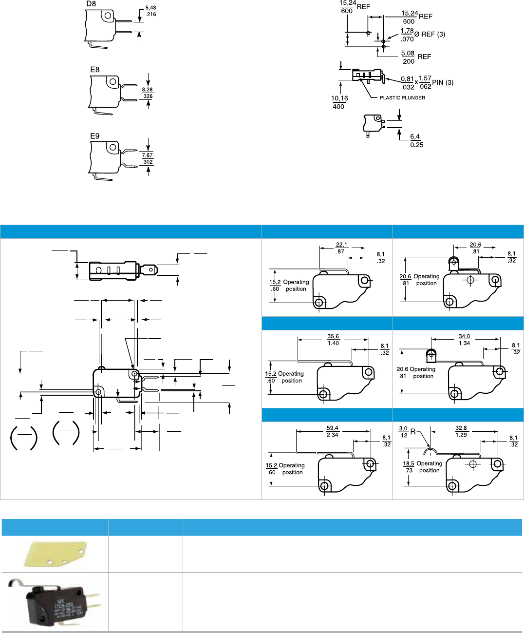
V7 Series O.F. • Operating force
R.F. • Release force
P.T. • Pretravel
O.T. • Overtravel
D.T. • Differential travel
O.P. • Operating position
PRODUCT SPECIFICATIONS AND LISTINGS
Contact your Honeywell rep or distributor for additional listings
Catalog Listing
Elect.
Rating
UL/CSA
(CE)
Elect.
Rating
Spec.
(page 4)
Contacts
O.F. max.
newtons
[grams]
O.P. nominal
mm [inches]
P.T. max.
mm
[inches]
O.T. min.
mm
[inches]
D.T.
mm [inches]
Pin plunger
BZ/BA Type
V7-2S17DB 0.1 A (---) S SPDT 0,79 [75] 14,7 [0.578] 1,19 [0.047] 1,27 [0.050] 0,05 - 0,25
[0.002-0.010]
V7-1S17D8 0.1 A (---) S SPDT 1,47 [150] 14,7 [0.578] 1,19 [0.047] 1,27 [0.050] 0,05 - 0,25
[0.002-0.010]
V7-5F17D8 3 A (---) F SPDT 0,15 [15] 14,7 [0.578] 1,19 [0.047] 1,27 [0.050] 0,05 - 0,25
[0.002-0.010]
V7-4A17D8 5 A (---) A SPDT 0,25 [25] 14,7 [0.578] 1,19 [0.047] 1,27 [0.050] 0,05 - 0,25
[0.002-0.010]
V7-3E17D8 10 A (---) E SPDT 0,49 [50] 14,7 [0.578] 1,19 [0.047] 1,27 [0.050] 0,05 - 0,25
[0.002-0.010]
V7-1B37D8 11 A (---) B SPNC 1,47 [150] 14,7 [0.578] 1,19 [0.047] 1,27 [0.050] 0,05 - 0,25
[0.002-0.010]
V7-2B17D8 11 A (---) B SPDT 0,74 [75] 14,7 [0.578] 1,19 [0.047] 1,27 [0.050] 0,05 - 0,25
[0.002-0.010]
V7-2B17E9 11 A (---) B SPDT 0,74 [75] 14,7 [0.578] 1,19 [0.047] 1,27 [0.050] 0,05 - 0,25
[0.002-0.010]
V7-7B17D8 11 A (---) B SPDT 2,22 [227] 14,7 [0.578] 1,19 [0.047] 1,27 [0.050] 0,05 - 0,25
[0.002-0.010]
V7-1C17D8 15 A (---) C SPDT 1,47 [150] 14,7 [0.578] 1,19 [0.047] 1,27 [0.050] 0,05 - 0,25
[0.002-0.010]
V7-1C17E9 15 A (---) C SPDT 1,47 [150] 14,7 [0.578] 1,19 [0.047] 1,27 [0.050] 0,05 - 0,25
[0.002-0.010]
V7-1C37B8 15 A (---) C SPNC 1,47 [150] 14,7 [0.578] 1,19 [0.047] 1,27 [0.050] 0,05 - 0,25
[0.002-0.010]
V7-1V19E9 21 A (16 A) V SPDT 1,72 [175] 14,7 [0.578] 1,19 [0.047] 1,27 [0.050] 0,05 - 0,25
[0.002-0.010]
V7-1V29E9 21 A (16 A) V SPNO 1,72 [175] 14,7 [0.578] 1,19 [0.047] 1,27 [0.050] 0,05 - 0,25
[0.002-0.010]
V7-1V39E9 21 A (16 A) V SPNC 1,72 [175] 14,7 [0.578] 1,19 [0.047] 1,27 [0.050] 0,05 - 0,25
[0.002-0.010]
V7-1Z19E9 25 A (20 A) Z SPDT 2,21 [225] 14,7 [0.578] 1,19 [0.047] 1,27 [0.050] 0,05 - 0,25
[0.002-0.010]
V7-1Z29E9 25 A (20 A) Z SPNO 2,21 [225] 14,7 [0.578] 1,19 [0.047] 1,27 [0.050] 0,05 - 0,25
[0.002-0.010]
V7-1Z20E9* 25 A (20 A) Z SPNO 2,21 [225] 14,7 [0.578] 1,19 [0.047] 1,27 [0.050] 0,05 - 0,25
[0.002-0.010]
Lever
22,1 mm
[0.87 in]
V7-1C17D8-002 15 A (---) C SPDT 1,57 [160] 15,2 [0.600] 1,52 [0.060] 0,89 [0.035] 0,36 [0.015] max.
V7-1C17E9-002 15 A (---) C SPDT 1,57 [160] 15,2 [0.600] 1,52 [0.060] 0,89 [0.035] 0,36 [0.015] max.
V7-6C18D8-002* 15 A (---) C SPDT 4,05 [413] 15,2 [0.600] 1,52 [0.060] 0,89 [0.035] 0,36 [0.015] max.
*3,1 mm mtg holes

7
sensing.honeywell.com
MICRO SWITCH™ Premium Miniature Basic Switches O.F. • Operating force
R.F. • Release force
P.T. • Pretravel
O.T. • Overtravel
D.T. • Differential travel
O.P. • Operating position
Catalog Listing
Elect.
Rating
UL/CSA
(CE)
Elect.
Rating
Spec.
(page 4)
Contacts
O.F. max.
newtons
[grams]
O.P. nominal
mm [inches]
P.T. max.
mm
[inches]
O.T. min.
mm
[inches]
D.T.
mm [inches]
Lever
35,6 mm
[1.40 in]
V7-1S17D8-022 0.1 A (---) S SPDT 0,83 [85] 15,2 [0.60] 3,04 [0.120] 2,16 [0.085] 0,76 [0.030] max.
V7-3S17D8-022 0.1 A (---) S SPDT 0,29 [30] 15,2 [0.60] 3,04 [0.120] 2,16 [0.085] 0,76 [0.030] max.
V7-3S17E9-022 0.1 A (---) S SPDT 0,29 [30] 15,2 [0.60] 3,04 [0.120] 2,16 [0.085] 0,76 [0.030] max.
V7-1B17D8-022 11 A (---) B SPDT 0,80 [82] 15,3 [0.603] 3,04 [0.120] 1,70 [0.067] 0,69 [0.027] max.
V7-1B19D8-022 11 A (10 A) B SPDT 0,80 [82] 15,3 [0.603] 3,25 [0.128] 1,78 [0.070] 0,71 [0.028] max.
V7-2B17D8-022 11 A (---) B SPDT 0,40 [41] 15,3 [0.603] 3,04 [0.120] 1,70 [0.067] 0,71 [0.027] max.
V7-6B19E9-022 11 A (10 A) B SPDT 2,11 [215] 15,2 [0.60] 3,25 [0.128] 1,35 [0.053] 0,76 [0.030] max.
Lever
59,4 mm
[2.34 in]
V7-3S17D8-048 0.1 A (---) S SPDT 0,16 [16] 15,3 [0.603] 5,97 [0.235] 3,00 [0.118] 1,27 [0.050] max.
V7-2B17D8-048 11 A (---) B SPDT 0,20 [20] 15,3 [0.603] 5,97 [0.235] 2,92 [0.115] 1,27 [0.050] max.
V7-1C17D8-048 15 A (---) C SPDT 0,44 [45] 15,2 [0.603] 5,94 [0.234] 4,19 [0.165] 1,52 [0.060] max.
V7-1V19E9-048 21 A (16 A) V SPDT 0,54 [55] 15,4 [0.605] 6,35 [0.250] 3,05 [0.120] 1,40 [0.055] max.
V7-9W1AE9-048** 15 A (---) W SPDT 0,88 [90] 15,2 [0.603] 6,35 [0.250] 3,15 [0.124] 1,37 [0.054] max.
Lever Sim.
Roll 32,8 mm
[1.29 in]
V7-1S17D8-263 0.1 A (---) S SPDT 0,88 [90] 18,54 [0.730] 2,79 [0.110] 1,90 [0.075] 0,76 [0.030] max.
V7-3E19E9-263 10 A (5 A) E SPDT 0,32 [33] 18,54 [0.730] 2,54 [0.100] 1,90 [0.075] 0,76 [0.030] max.
V7-1B17D8-263 11 A (---) B SPDT 0,88 [90] 18,54 [0.730] 2,79 [0.110] 1,52 [0.060] 0,76 [0.030] max.
V7-1C17D8-263 15 A (---) C SPDT 0,89 [91] 18,54 [0.730] 2,79 [0.110] 1,55 [0.061] 0,61 [0.024] max.
V7-1V29E9-263 21 A (16 A) V SPNO 1,08 [110] 18,49 [0.728] 2,90 [0.114] 1,62 [0.064] 0,64 [0.025] max.
V7-1Z10E9-263* 25 A (20 A) Z SPDT 1,33 [136] 18,49 [0.728] 2,90 [0.114] 1,62 [0.064] 0,64 [0.025] max.
Lever, Roller
20,57 mm
[0.81 in]
V7-2S17D8-201 0.1 A (---) S SPDT 0,88 [90] 20,57 [0.810] 1,19 [0.047] 1,02 [0.040] 0,38 [0.015] max.
V7-6B19E9-201 11 A (10 A) B SPDT 4,50 [459] 20,52 [0.808] 1,42 [0.056] 0,86 [0.034] 0,33 [0.013] max.
V7-7B17D8-201 11 A (---) B SPDT 2,78 [283] 20,52 [0.808] 1,42 [0.056] 0,86 [0.034] 0,33 [0.013] max.
V7-1C17D8-201 15 A (---) C SPDT 1,72 [175] 20,57 [0.810] 1,19 [0.047] 0,81 [0.032] 0.30 [0.012] max.
Lever, Roller
34,04 mm
[1.34 in]
V7-1S17D8-207 0.1 A (---) S SPDT 0,83 [85] 20,57 [0.810] 2,84 [0.112] 2,03 [0.080] 0,76 [0.030] max.
V7-2A17D8-207 5 A (---) A SPDT 0,42 [43] 20,57 [0.810] 2,92 [0.115] 1,52 [0.060] 0,64[0.025] max.
V7-1B17D8-207 11 A (---) B SPDT 0,83 [85] 20,57 [0.810] 2,92 [0.115] 1,52 [0.060] 0,76 [0.030] max.
V7-1C17D8-207 15 A (---) C SPDT 0,88 [90] 20,57 [0.810] 2,92 [0.115] 1,52 [0.060] 0,64[0.025] max.
V7-1V19E9-207 21 A (16 A) V SPDT 0,98 [100] 20,52 [0.808] 3,07 [0.121] 1,65 [0.065] 0,76 [0.030] max.
*3,1 mm mtg holes
** 177 °C [350 °F]
PRODUCT SPECIFICATIONS AND LISTINGS
Contact your Honeywell rep or distributor for additional listings
8sensing.honeywell.com
V7 Series
STANDARD ACTUATOR OPTIONS
Straight Lever (-002) Roller Lever (-201)
10,2
0.40 6,4
0.25
COM
NC
NO
2,8
0.11
1,5
0.06
8,9
0.35
0,8
0.03
2,4
0.10
14,4
0.57
22,2
0.88
28,8
1.14
3,20
0.126
3,46
0.134
opt
18,2
0.72
(3)
dia
3,10
0.122
opt
2,90
0.114
10,3
0.41
dia
20,2
0.80
2,8
00.11
2,8
0.11
1,0
.04
2,90
0.114 Ø hole (3,10/.122 option)
max.
Straight lever (-022)
�
�
Straight Lever (-022) Roller Lever (-207)
Straight Lever (-048) Simulated Roller Lever (-263)
�
ACCESSORIES
Part Number Description
15PA177-V7 Insulator packet: 500 pieces of 0,46 mm [0.018 in] thick varnished fiberglass
15PA260 Plunger boot seal: Elastomer, dust and splash resistant
(Switch not included)
AVAILABLE TERMINALS
Quick Connect (QC)
D8 Terminals: 0.187 in wide x 0.020 in thick.
E8 Terminals: 0.187 in wide x 0.020 in thick.
E9 Terminals: 0.250 in wide x 0.032 in thick.
Printed Circuit Board (PO2)
These terminals interface with snap-on receptacles and other
components from AMPMODU interconnection system.
9
sensing.honeywell.com
MICRO SWITCH™ Premium Miniature Basic Switches
This Honeywell datasheet supports the following MICRO SWITCH™ V7 Series Basic Switch Listings
V7-1C17D8-002
V7-1C37D855-002
V7-6C18D8-002
V7-1C27D855-002
V7-1C33D855-002
V7-1C39D8-002
V7-1C17E9-002
V7-6C28E9-002
V7-1B17D8-022
V7-1B19D8-022
V7-1C17D8-022
V7-3S17E9-022
V7-6B19E9-022
V7-1S17D8-022
V7-2B17D8-022
V7-3S17D8-022
V7-1B29P07-022
V7-1C18E9-022
V7-3E17E9-022
V7-2B27D8-022
V7-2S17D8-022
V7-9W1AE9-022
V7-1Z19E9-022
V7-2B17D8-048
V7-1V19E9-048
V7-1C17D8-048
V7-1X2AD8-048
V7-9W1AE9-048
V7-1B17D8-048
V7-3S17D8-048
V7-9W2AE9-048
V7-7B17D8-048
V7-1A17D8-048
V7-2B29E9-048
V7-2B19E9-048
V7-6C18D8-048
V7-1B27D8-048
V71A17D8048
V7-1C17D8-201
V7-7B17D8-201
V7-1C13D8-201
V7-2B17D8-201
V7-1C17E9-201
V7-2S17D8-201
V7-6B19E9-201
V7-1S17D8-201
V7-7B17D862-201
V7-1D19D8-201
V7-3A17D8-201
V7-1D10E9-201
V7-1V17D8-201
V7-1C17D8-207
V7-1B17D8-207
V7-2B17D8-207
V7-1C17E9-207
V7-2A17D8-207
V7-1V19E9-207
V7-1B10E9-207
V7-1A27D8-207
V7-7D17D8-207
V7-2S17D8-207
V7-1S17D8-207
V7-1C17D8-263
V7-1B17D8-263
V7-6C17D8-263
V7-1Z10E9-263
V7-1S17D8-263
V7-1C27E9-263
V7-1V29E9-263
V7-3E19E9-263
V71Z10E9-263
V7-7B19D8-263
V7-1S18D8-263
V7-1B37D8-263
V7-3A17D8-263
V7-1B178-263
V7-1A27D8-636
V7-1C17D8
V7-2B17D8
V7-1V39E9
V7-1Z19E9
V7-1B37D8
V7-2S17D8
V7-1C17E9
V7-1C37D8
V7-1Z29E9
V7-3E17D8
V7-5F17D8
V7-7B17D8
V7-1S17D8
V7-1V19E9
V7-3E17E9
V7-1Z20E9
V7-4A17D8
V7-5F27E9
V7-1Y39E9
V7-1V29E9
V7-1D10D8
V7-2B17E9
V7-6C17D8
V7-4S17D8
V7-1Y19E9
V7-1C27E9
V71Z10E9
V7-1B17D8
V7-6B19D8
V7-1C18D8
V7-1A17D8
V7-2B29D8
V7-5D17E9
V7-3A17D8
V7-4S37D8
V7-7B19E9
V7-1Z10E9
V7-2A17E9
V7-5F27D8
V7-3S17E9
V7-1S10D8
V7-1Z39E9
V7-2B27E9
V7-3E19E9
V7-1A17P02
V7-4S27D8
V7-7B27D8
V7-1Z13E9
V7-1Z30E9
V7-2A27D8
V7-7A19D8
V7-2B37E9
V7-1C29D8
V7-1C13E9
V7-3A18D8
V7-9W2AE9
V7-4A18E9
V7-9W1AE9
V7-1A28D8
V7-1B19E9
V7-1K29E9
V7-2B17-D8
V7-3E10E8
V7-6C37E9-036
V7-1C27D94
V7-1C17D8-295
V7-1C29D7
V7-1Z13E993
V7-1V19E9-269
V7-6C13D8-132
V7-6B19D8-057
V7-2B17D8-162
V7-4A29E8-424
V7-1C17D844
V7-1B17D8-122
V7-1C17D844-429
V7-7A19D8-374
V7-4A17D8-407
V7-5F17D8-289
V7-6C17D8-057
V7-2B29D8-384
V7-1X1AD8-304
V7-6C17D8-162
V7-1A23E9-172
V7-1X2AD9C2
V7-1C27E9-292
V7-2S17E9-420
V7-1C17D8-294
V7-7B17D8-073
V7-3S17D8-148
V7-7C19D8-640
V7-1V19E994-403
V7-1A17D8-057
V7-1E17D8-366
V7-5F17D8-336
V7-1C17E9-292
V7-6A17D8-057
V7-2E17E9-420
V7-6C17D8-439
V7-1X1AD9C1
V7-7B10D8-274
V7-7B19D8-426
V7-3E17D8-148
V7-1A28D882
V7-7B29D883
V7-7B17D8-481
V7-2E17E9-366
V7-1C29E7
V7-1S19D8-369
V7-7B19D8-640
V7-7B17D8-140
V7-1X2AE9-292
V7-1Z13E987
V7-1X2AD8-294
V7-6B19D8-672
V7-7B29E9-053
V7-1V20E94
V7-1B19D8-369
15PA177-V7
15PA260

10 sensing.honeywell.com
V7 Series
ADDITIONAL INFORMATION
The following associated literature is available on the Honeywell web
site at sensing.honeywell.com:
• Product installation instructions
• Product range guide
• Product nomenclature tree
• Product application-specific information
– Application note: Electronic sensors and electromechanical
switches in valves and flow meters
– Application note: Electronic sensors and MICRO SWITCH ™
switches in industrial air compressors
– Application note: Sensors and switches for HVAC/R
applications
– Application note: Sensors and switches in oil rig applications
– Application note: Sensors and switches in sanitary valves
– Application note: Sensors and switches for valve monitors and
valve indicators
– Application note: Treadmill equipment
– Application note: V7 available terminals
– Technical bulletin: Applying precision switches
– Technical bulletin: Low energy switch guide
WARNING
PERSONAL INJURY
DO NOT USE these products as safety or emergency stop
devices or in any other application where failure of the
product could result in personal injury.
Failure to comply with these instructions could result in
death or serious injury.
WARNING
MISUSE OF DOCUMENTATION
• The information presented in this product sheet is for
reference only. Do not use this document as a product
installation guide.
• Complete installation, operation, and maintenance
information is provided in the instructions supplied with
each product.
Failure to comply with these instructions could result in
death or serious injury.
WARRANTY/REMEDY
Honeywell warrants goods of its manufacture as being free of
defective materials and faulty workmanship. Honeywell’s standard
product warranty applies unless agreed to otherwise by Honeywell
in writing; please refer to your order acknowledgement or consult
your local sales office for specific warranty details. If warranted
goods are returned to Honeywell during the period of coverage,
Honeywell will repair or replace, at its option, without charge those
items it finds defective. The foregoing is buyer’s sole remedy
and is in lieu of all other warranties, expressed or implied,
including those of merchantability and fitness for a particu-
lar purpose. In no event shall Honeywell be liable for conse-
quential, special, or indirect damages.
While we provide application assistance personally, through our
literature and the Honeywell website, it is up to the customer to
determine the suitability of the product in the application.
Specifications may change without notice. The information we
supply is believed to be accurate and reliable as of this printing.
However, we assume no responsibility for its use.

004987-1-EN IL50 GLO
June 2014
Copyright © 2014 Honeywell International Inc. All rights reserved.
Sensing and Control
Honeywell
1985 Douglas Drive North
Golden Valley, MN 55422
honeywell.com
Find out more
Honeywell serves its customers
through a worldwide network
of sales offices, representatives
and distributors. For application
assistance, current specifications,
pricing or name of the nearest
Authorized Distributor, contact
your local sales office.
To learn more about Honeywell’s
sensing and control products,
call +1-815-235-6847 or
1-800-537-6945,
visit sensing.honeywell.com,
or e-mail inquiries to
info.sc@honeywell.com
