TriPlus II 31709620 Tri Plus RSH User Guide
2016-05-17
: Pdf 31709620 Triplus Rsh User Guide 31709620 TriPlus RSH User Guide TriPlus RSH GC AS Manuals User ation
Open the PDF directly: View PDF ![]() .
.
Page Count: 258 [warning: Documents this large are best viewed by clicking the View PDF Link!]
- Contents
- Preface
- Getting Familiar with Your TriPlus RSH
- Instrument Basics
- Definition of Terms, Naming Conventions, and Start Screen Icons
- The TriPlus RSH System
- TriPlus RSH Configurations
- Crossrails
- Head
- TriPlus RSH Tools
- LS Tool
- HS Tool
- SPME 1 and SPME 2 Tools
- ITEX-2 Tool
- Control Interface
- Definitions of Active and Passive Hardware Modules
- Modules Description and Specifications
- TR Station
- ATC Station
- Standard Wash Station
- Large Volume Wash Station
- Large Solvent Station
- Fast Wash Station
- Agitator
- Vortexer
- MHE Station
- SPME Conditioning Station
- Barcode Reader
- Standard Tray Holder
- Liquid Cooled Tray Holder
- Temperature Controlled Drawer
- Electronic Box for OC Injector Actuator
- Handheld Controller
- TriPlus RSH Basic Informations
- Setup Menu Item
- Starting Setup Menu Item
- Setup Menu Item Modules
- Agitator
- Vortexer
- Barcode Reader
- Chromatograph System
- Input/Output Interface
- Injectors
- OC Actuator
- Motors
- Obstacle
- Sample Drawers
- Tool Stations
- TR Station
- ATC Station
- Signals
- Solvent Stations
- SPME Conditioning Station
- Syringe Types
- Tool Adapters
- Tools
- Naming Convention and Relationship between Software Classes‚ Tray Holder, Trays, Tray Types, and Cap Type
- Tray Holders
- Tray Types
- Trays
- Vial Types
- Vials
- Wash Stations
- Tray Slots
- Unknown
- Valves
- Setup Menu Item - Set Date and Time
- Setup Menu Item - Set TriPlus RSH Name
- Setup Menu Item - Setup Network
- Maintenance Menu Items
- Service Menu Item
- Analytical Troubleshooting

Thermo Scientific
TriPlus RSH
Robotic Sample Handling
User Guide
P/N 31709620 Ninth Edition December 2015
© 2015 Thermo Fisher Scientific Inc. All rights reserved.
TriPlus RSH, TRACE 1300, TRACE 1310, TRACE GC Ultra and FOCUS GC are trademarks of Thermo
Fisher Scientific Inc., and its subsidiaries.
Published by Thermo Fisher Scientific S.p.A., Strada Rivoltana 20090 Rodano-Milan, Italy
Tel: +39 02 95059303; Fax: +39 02 95059388
Thermo Fisher Scientific Inc. provides this document to its customers with a product purchase to use in the
product operation. This document is copyright protected and any reproduction of the whole or any part of this
document is strictly prohibited, except with the written authorization of Thermo Fisher Scientific Inc.
The contents of this document are subject to change without notice. All technical information in this
document is for reference purposes only. System configurations and specifications in this document supersede
all previous information received by the purchaser.
Thermo Fisher Scientific Inc. makes no representations that this document is complete, accurate or error-
free and assumes no responsibility and will not be liable for any errors, omissions, damage or loss that might
result from any use of this document, even if the information in the document is followed properly.
This document is not part of any sales contract between Thermo Fisher Scientific Inc. and a purchaser. This
document shall in no way govern or modify any Terms and Conditions of Sale, which Terms and Conditions of
Sale shall govern all conflicting information between the two documents.
Release history:
First edition, released September 2011 “Original Instructions”
Second edition, released October 2011; Third edition, released March 2012; Fourth edition, released
September 2012; Fifth edition, released March 2013; Sixth edition, released October 2013; Seventh Edition,
released June 2014; Eighth Edition, February 2015; Ninth Edition, December 2015
For Research Use Only. Not for use in diagnostic procedures.

fold
fold
Reader’s Survey
TriPlus RSH User Guide, PN 31709620, Ninth Edition
If not, please comment below. Attach additional sheets if necessary.
__________________________________________________________ __________________________________________________________________
__________________________________________________________ __________________________________________________________________
__________________________________________________________ __________________________________________________________________
__________________________________________________________ __________________________________________________________________
__________________________________________________________ __________________________________________________________________
__________________________________________________________ __________________________________________________________________
__________________________________________________________ __________________________________________________________________
__________________________________________________________ __________________________________________________________________
__________________________________________________________ __________________________________________________________________
Customer Registration Card
Register now…and receive all the privileges associated with being a Thermo Fisher Scientific product user including customer
support, application reports, and technical reports.
Name __________________________________________________Title__________________________________________________________________
Company __________________________________________________ __________________________________________________________________
Address ___________________________________________________ __________________________________________________________________
City/State _________________________________________Postal Code__________________________________________________________________
Country ___________________________________________________ __________________________________________________________________
Telephone_______________________________________________ Ext. __________________________________________________________________
Serial Number __________________________________ Date purchased __________________________________________________________________
Fold and mail or e-mail to:
Strongly
Agree Agree Neutral Disagree Strongly
Disagree
The manual is well organized. 1 2 3 4 5
The manual is clearly written. 1 2 3 4 5
The manual contains all the information I need. 1 2 3 4 5
The instructions are easy to follow. 1 2 3 4 5
The instructions are complete. 1 2 3 4 5
The technical information is easy to understand. 1 2 3 4 5
Examples of operation are clear and useful. 1 2 3 4 5
The figures are helpful. 1 2 3 4 5
I was able to operate the system using this manual. 1 2 3 4 5
MY ORGANIZATION IS: (Check only one) MY PRIMARY APPLICATION IS: (Check only one)
❏Commercial (for profit) lab ❏Analytical
❏Government lab ❏Biomedical
❏Hospital/Clinic ❏Clinical/Toxicology
❏Industrial lab ❏Energy
❏Research Institute ❏Environmental
❏University/College ❏Food/Agricultural
❏Veterinary ❏Forensic/Toxicology
❏Other______________________ ❏Pharmaceutical
❏Research/Education
MY PRIMARY JOB FUNCTION IS: (Check only one) ❏Other______________________
❏Administration
❏Lab management
❏Operator
❏Other______________________
Editor, Technical Publications
Thermo Fisher Scientific S.p.A.
Strada Rivoltana km 4
20090 Rodano (MI)
Italy
Editor, Technical Publications
Thermo Fisher Scientific CMD GC-GC/MS
2215 Grand Avenue Parkway
Austin TX 78728-3812
Unites States of America

Declaration
Manufacturer: Thermo Fisher Scientific
Thermo Fisher Scientific is the manufacturer of the instrument described in this manual and, as such, is responsible
for the instrument safety, reliability and performance only if:
•installation
•re-calibration
•changes and repairs
have been carried out by authorized personnel and if:
• the local installation complies with local law regulations
• the instrument is used according to the instructions provided and if its operation is only entrusted to qualified
trained personnel
Thermo Fisher Scientific is not liable for any damages derived from the non-compliance with the aforementioned
recommendations.
Thermo Fisher Scientific S.p.A.
Strada Rivoltana, 20090 Rodano - Milan - Italy — Tel: +39 02 950591 - Fax: +39 02 9505276
Regulatory Compliance
Thermo Fisher Scientific performs complete testing and evaluation of its products to ensure full compliance with
applicable domestic and international regulations.
Thermo Fisher Scientific declares, under sole responsibility, that the product as originally delivered complies with
the requirements of the following applicable European Directives and carries the CE marking accordingly:
• Low Voltage Directive:2006/95/EC
• EMC Directive:2004/108/EC
• Machinery Directive: 2006/42/EC
… and conforms with the following product standards:
Safety
This device complies with:
• IEC61010-1:2010 3rd Edition | IEC/EN 61010-1 3rd Edition
• ANSI/UL 61010-1:2004 2nd Edition | CAN/CSA C22.2 No. 61010-1:2004 2nd Edition.
• EN 61010-2-010:2003 | EN 61010-2-051:2003 | EN 61010-2-081:2001+A1:2003 | EN 61010-2 101:2003
Electromagnetic Compatibility
This device complies with:
• IEC 61326-1:2nd Edition | EN 61326-1:2013 | CISPR 11:5th Edition
• EN 61000-6-2:2005 | IEC 61000-6-2:2nd Edition| IEC 61000-6-3:2nd Edition am1 | EN 61000-6-3:2007 +
A1:2011
• Conducted Emission, Subpart B. FCC part 15, §15.107(a) and §15.109(a)
Laser Class 1
• The selected Class 1 Laser for the TriPlus RSH module Barcode Reader complies with the following regula-
tions:
• 21 CFR1040.10 and 1040.11 except for deviations pursuant to Laser Notice No. 50, dated July 26, 2001
• EN60825-1:1994 + A1:2002 + A2:2001
• IEC60825-1:1993 + A1:1997 + A2:2001
FCC Compliance Statement
Notice on Lifting and Handling of
Thermo Scientific Instruments
For your safety, and in compliance with international regulations, the physical handling of this Thermo Fisher
Scientific instrument requires a team effort to lift and/or move the instrument. This instrument is too heavy and/
or bulky for one person alone to handle safely.
Notice on the Proper Use of
Thermo Scientific Instruments
In compliance with international regulations: Use of this instrument in a manner not specified by Thermo Fisher
Scientific could impair any protection provided by the instrument.
Notice on the Susceptibility
to Electromagnetic Transmissions
Do not use radio frequency transmitters, such as mobile phones, in close proximity to the instrument.
THIS DEVICE COMPLIES WITH PART 15 OF THE FCC RULES. OPERATION IS SUBJECT TO THE
FOLLOWING TWO CONDITIONS: (1) THIS DEVICE MAY NOT CAUSE HARMFUL
INTERFERENCE, AND (2) THIS DEVICE MUST ACCEPT ANY INTERFERENCE RECEIVED,
INCLUDING INTERFERENCE THAT MAY CAUSE UNDESIRED OPERATION.
CAUTION Read and understand the various precautionary notes, signs, and symbols contained
inside this manual pertaining to the safe use and operation of this product before using the device.
WEEE Compliance
This product is required to comply with the European Union’s Waste Electrical & Electronic Equipment (WEEE) Directive
2012/19/EU. It is marked with the following symbol:
Thermo Fisher Scientific has contracted with one or more recycling or disposal companies in each European Union (EU)
Member State, and these companies should dispose of or recycle this product. See www.thermoscientific.com/rohsweee for
further information on Thermo Fisher Scientific’s compliance with these Directives and the recyclers in your country.
WEEE Konformität
Dieses Produkt muss die EU Waste Electrical & Electronic Equipment (WEEE) Richtlinie 2012/19/EU erfüllen. Das Produkt
ist durch folgendes Symbol gekennzeichnet:
Thermo Fisher Scientific hat Vereinbarungen mit Verwertungs-/Entsorgungsfirmen in allen EU-Mitgliedsstaaten getroffen,
damit dieses Produkt durch diese Firmen wiederverwertet oder entsorgt werden kann. Mehr Information über die Einhaltung
dieser Anweisungen durch Thermo Fisher Scientific, über die Verwerter, und weitere Hinweise, die nützlich sind, um die
Produkte zu identifizieren, die unter diese RoHS Anweisung fallen, finden sie unter www.thermoscientific.com/rohsweee.
Conformité DEEE
Ce produit doit être conforme à la directive européenne (2012/19/EU) des Déchets d'Equipements Electriques et
Electroniques (DEEE). Il est marqué par le symbole suivant:
Thermo Fisher Scientific s'est associé avec une ou plusieurs compagnies de recyclage dans chaque état membre de l’union
européenne et ce produit devrait être collecté ou recyclé par celles-ci. Davantage d'informations sur la conformité de Thermo
Fisher Scientific à ces directives, les recycleurs dans votre pays et les informations sur les produits Thermo Fisher Scientific qui
peuvent aider la détection des substances sujettes à la directive RoHS sont disponibles sur www.thermoscientific.com/rohsweee.
Conformità RAEE
Questo prodotto è marcato con il seguente simbolo in conformità alla direttiva europea 2012/19/EU (RAEE) sui rifiuti di
apparecchiature elettriche ed elettroniche:
Thermo Fisher Scientific si è accordata con una o più società di riciclaggio in ciascun Stato Membro della Unione Europea
(EU), e queste società dovranno smaltire o riciclare questo prodotto. Per maggiori informazioni vedere il sito
www.thermoscientific.com/rohsweee.
Conformidad RAEE
Este producto es marcado con el siguiente símbolo en conformidad a la Directiva 2012/19/EU de la Unión Europea sobre los
residuos de aparatos eléctricos y electrónicos:
Thermo Fisher Scientific ha contratado una o más empresas de reciclo para tratar residuos en cada Estado Miembro de la
Unión Europea, y estas empresas deberían reciclar o eliminar este producto. Referirse a www.thermoscientific.com/rohsweee
para una mayor información sobre la conformidad de Thermo Fisher Scientific con estas Directivas y para las empresas de
reciclaje en su país.
IMPORTANT
The symbol indicates the product must not be disposed of with the normal household wastes. Correct disposal of
this product prevents any potentially negative impact on the environmental and human health that could arise
from any inappropriate handling of the product itself.
WEEE and RoHS rules, while laid down at European level, are put into national law at national level. When ex-
porting to Europe, it is essential to comply with national law in each relevant country. The EU law simply serves
as a template for national laws, which may differ considerably.
Each EU Member State has own regulations regarding the application of these directives. Please refer to the
regulations in force in your country.

Thermo Scientific TriPlus RSH User Guide ix
C
Preface . . . . . . . . . . . . . . . . . . . . . . . . . . . . . . . . . . . . . . . . . . . . . . . . . . . . . . . . . . . . . .xv
About Your System. . . . . . . . . . . . . . . . . . . . . . . . . . . . . . . . . . . . . . . . . . . . . .xvi
Power Rating . . . . . . . . . . . . . . . . . . . . . . . . . . . . . . . . . . . . . . . . . . . . . . . . . .xvi
Contacting Us . . . . . . . . . . . . . . . . . . . . . . . . . . . . . . . . . . . . . . . . . . . . . . . . .xvi
Related Documentation . . . . . . . . . . . . . . . . . . . . . . . . . . . . . . . . . . . . . . . . . .xvi
Safety Alerts and Important Information . . . . . . . . . . . . . . . . . . . . . . . . . . . . xvii
Special Notices . . . . . . . . . . . . . . . . . . . . . . . . . . . . . . . . . . . . . . . . . . . . . . xvii
Safety Symbols and Signal Words . . . . . . . . . . . . . . . . . . . . . . . . . . . . . . . . xvii
Instrument Markings and Symbols . . . . . . . . . . . . . . . . . . . . . . . . . . . . . . . . . .xix
Safety Information and Warnings. . . . . . . . . . . . . . . . . . . . . . . . . . . . . . . . . . . xx
General Considerations . . . . . . . . . . . . . . . . . . . . . . . . . . . . . . . . . . . . . . . . . xx
Electrical Hazards . . . . . . . . . . . . . . . . . . . . . . . . . . . . . . . . . . . . . . . . . . . . .xxi
Laser Safety Information . . . . . . . . . . . . . . . . . . . . . . . . . . . . . . . . . . . . . . . xxii
Other Hazards. . . . . . . . . . . . . . . . . . . . . . . . . . . . . . . . . . . . . . . . . . . . . . .xxiii
Working with Toxic or other Harmful Compounds . . . . . . . . . . . . . . . . . . xxv
Biological Hazards. . . . . . . . . . . . . . . . . . . . . . . . . . . . . . . . . . . . . . . . . . . . xxv
Maintenance . . . . . . . . . . . . . . . . . . . . . . . . . . . . . . . . . . . . . . . . . . . . . . . . xxvi
Disposal. . . . . . . . . . . . . . . . . . . . . . . . . . . . . . . . . . . . . . . . . . . . . . . . . . . . xxvi
Chapter 1 Getting Familiar with Your TriPlus RSH . . . . . . . . . . . . . . . . . . . . . . . . . . . . . . . . . . .1
Instrument Basics . . . . . . . . . . . . . . . . . . . . . . . . . . . . . . . . . . . . . . . . . . . . . . . . 2
Definition of Terms, Naming Conventions, and Start Screen Icons . . . . . . . . . . 3
Definition of Terms . . . . . . . . . . . . . . . . . . . . . . . . . . . . . . . . . . . . . . . . . . . . 3
Naming Conventions . . . . . . . . . . . . . . . . . . . . . . . . . . . . . . . . . . . . . . . . . . . 6
Start Screen Icons . . . . . . . . . . . . . . . . . . . . . . . . . . . . . . . . . . . . . . . . . . . . . . 7
The TriPlus RSH System . . . . . . . . . . . . . . . . . . . . . . . . . . . . . . . . . . . . . . . . . 10
Sampling Unit. . . . . . . . . . . . . . . . . . . . . . . . . . . . . . . . . . . . . . . . . . . . . . . . 10
Modules . . . . . . . . . . . . . . . . . . . . . . . . . . . . . . . . . . . . . . . . . . . . . . . . . . . . 11
Optional Components. . . . . . . . . . . . . . . . . . . . . . . . . . . . . . . . . . . . . . . . . . 12
Power Module. . . . . . . . . . . . . . . . . . . . . . . . . . . . . . . . . . . . . . . . . . . . . . . . 12
User Interface . . . . . . . . . . . . . . . . . . . . . . . . . . . . . . . . . . . . . . . . . . . . . . . . 12
Contents
Contents
xTriPlus RSH User Guide Thermo Scientific
TriPlus RSH Configurations . . . . . . . . . . . . . . . . . . . . . . . . . . . . . . . . . . . . . . . 13
TriPlus RSH for Liquids . . . . . . . . . . . . . . . . . . . . . . . . . . . . . . . . . . . . . . . . 13
TriPlus RSH for Headspace. . . . . . . . . . . . . . . . . . . . . . . . . . . . . . . . . . . . . . 14
TriPlus RSH for SPME (Solid Phase Micro Extraction) . . . . . . . . . . . . . . . . 14
TriPlus RSH for ITEX (In-tube Extraction) . . . . . . . . . . . . . . . . . . . . . . . . . 15
Crossrails. . . . . . . . . . . . . . . . . . . . . . . . . . . . . . . . . . . . . . . . . . . . . . . . . . . . . . 16
Crossrail X. . . . . . . . . . . . . . . . . . . . . . . . . . . . . . . . . . . . . . . . . . . . . . . . . . . 16
Crossrail Y. . . . . . . . . . . . . . . . . . . . . . . . . . . . . . . . . . . . . . . . . . . . . . . . . . . 16
Head . . . . . . . . . . . . . . . . . . . . . . . . . . . . . . . . . . . . . . . . . . . . . . . . . . . . . . . . . 17
TriPlus RSH Tools . . . . . . . . . . . . . . . . . . . . . . . . . . . . . . . . . . . . . . . . . . . . . . 18
Tool Identification . . . . . . . . . . . . . . . . . . . . . . . . . . . . . . . . . . . . . . . . . . . . 20
LS Tool . . . . . . . . . . . . . . . . . . . . . . . . . . . . . . . . . . . . . . . . . . . . . . . . . . . . . . . 21
Syringes for LS Tools. . . . . . . . . . . . . . . . . . . . . . . . . . . . . . . . . . . . . . . . . . . 24
HS Tool . . . . . . . . . . . . . . . . . . . . . . . . . . . . . . . . . . . . . . . . . . . . . . . . . . . . . . 25
Syringes for HS Tools . . . . . . . . . . . . . . . . . . . . . . . . . . . . . . . . . . . . . . . . . . 27
SPME 1 and SPME 2 Tools . . . . . . . . . . . . . . . . . . . . . . . . . . . . . . . . . . . . . . . 27
Syringes for SPME Tools. . . . . . . . . . . . . . . . . . . . . . . . . . . . . . . . . . . . . . . . 29
Definition of SPME Penetration Depth . . . . . . . . . . . . . . . . . . . . . . . . . . . . 29
ITEX-2 Tool . . . . . . . . . . . . . . . . . . . . . . . . . . . . . . . . . . . . . . . . . . . . . . . . . . . 30
Control Interface. . . . . . . . . . . . . . . . . . . . . . . . . . . . . . . . . . . . . . . . . . . . . . . . 33
Definitions of Active and Passive Hardware Modules . . . . . . . . . . . . . . . . . . . . 35
Active Versus Passive Module . . . . . . . . . . . . . . . . . . . . . . . . . . . . . . . . . . . . 35
Active Versus Composite Module . . . . . . . . . . . . . . . . . . . . . . . . . . . . . . . . . 36
Modules Description and Specifications . . . . . . . . . . . . . . . . . . . . . . . . . . . . . . 37
TR Station . . . . . . . . . . . . . . . . . . . . . . . . . . . . . . . . . . . . . . . . . . . . . . . . . . . . 38
ATC Station . . . . . . . . . . . . . . . . . . . . . . . . . . . . . . . . . . . . . . . . . . . . . . . . . . . 39
Standard Wash Station . . . . . . . . . . . . . . . . . . . . . . . . . . . . . . . . . . . . . . . . . . . 40
Large Volume Wash Station . . . . . . . . . . . . . . . . . . . . . . . . . . . . . . . . . . . . . . . 41
Large Solvent Station. . . . . . . . . . . . . . . . . . . . . . . . . . . . . . . . . . . . . . . . . . . . . 41
Fast Wash Station . . . . . . . . . . . . . . . . . . . . . . . . . . . . . . . . . . . . . . . . . . . . . . . 42
Agitator . . . . . . . . . . . . . . . . . . . . . . . . . . . . . . . . . . . . . . . . . . . . . . . . . . . . . . . 43
Vortexer . . . . . . . . . . . . . . . . . . . . . . . . . . . . . . . . . . . . . . . . . . . . . . . . . . . . . . 45
MHE Station . . . . . . . . . . . . . . . . . . . . . . . . . . . . . . . . . . . . . . . . . . . . . . . . . . 47
Naming Convention for MHE Station . . . . . . . . . . . . . . . . . . . . . . . . . . . . . 49
Principles of Multiple Headspace Extraction (MHE). . . . . . . . . . . . . . . . . . . 49
MHE Cycle Step-by-Step . . . . . . . . . . . . . . . . . . . . . . . . . . . . . . . . . . . . . . . 54
Quantification from MHE Measurements. . . . . . . . . . . . . . . . . . . . . . . . . . . 56
SPME Conditioning Station . . . . . . . . . . . . . . . . . . . . . . . . . . . . . . . . . . . . . . . 61
Contents
Thermo Scientific TriPlus RSH User Guide xi
Barcode Reader . . . . . . . . . . . . . . . . . . . . . . . . . . . . . . . . . . . . . . . . . . . . . . . . . 63
Safety Information. . . . . . . . . . . . . . . . . . . . . . . . . . . . . . . . . . . . . . . . . . . . . 64
Supported Types of Barcode Symbols . . . . . . . . . . . . . . . . . . . . . . . . . . . . . . 65
Approved Barcode Labels . . . . . . . . . . . . . . . . . . . . . . . . . . . . . . . . . . . . . . . 66
Barcode Label Positioning . . . . . . . . . . . . . . . . . . . . . . . . . . . . . . . . . . . . . . . 66
Reading the Barcode from a Vial or Well Plate . . . . . . . . . . . . . . . . . . . . . . . 67
Multidimensional Barcodes . . . . . . . . . . . . . . . . . . . . . . . . . . . . . . . . . . . . . . 67
Barcode Label Size. . . . . . . . . . . . . . . . . . . . . . . . . . . . . . . . . . . . . . . . . . . . . 67
Barcode Reader Specifications . . . . . . . . . . . . . . . . . . . . . . . . . . . . . . . . . . . . 67
Standard Tray Holder . . . . . . . . . . . . . . . . . . . . . . . . . . . . . . . . . . . . . . . . . . . . 68
Liquid Cooled Tray Holder. . . . . . . . . . . . . . . . . . . . . . . . . . . . . . . . . . . . . . . . 69
Temperature Controlled Drawer . . . . . . . . . . . . . . . . . . . . . . . . . . . . . . . . . . . . 70
Temperature Control . . . . . . . . . . . . . . . . . . . . . . . . . . . . . . . . . . . . . . . . . . 72
Temperature Alarm . . . . . . . . . . . . . . . . . . . . . . . . . . . . . . . . . . . . . . . . . . . . 72
Temperature Stability . . . . . . . . . . . . . . . . . . . . . . . . . . . . . . . . . . . . . . . . . . 72
Condensation Build-up . . . . . . . . . . . . . . . . . . . . . . . . . . . . . . . . . . . . . . . . . 73
Safety Warning . . . . . . . . . . . . . . . . . . . . . . . . . . . . . . . . . . . . . . . . . . . . . . . 73
Temperature Controlled Drawer Specifications . . . . . . . . . . . . . . . . . . . . . . . 74
Electronic Box for OC Injector Actuator. . . . . . . . . . . . . . . . . . . . . . . . . . . . . . 75
Handheld Controller. . . . . . . . . . . . . . . . . . . . . . . . . . . . . . . . . . . . . . . . . . . . . 76
Menu Screen . . . . . . . . . . . . . . . . . . . . . . . . . . . . . . . . . . . . . . . . . . . . . . . . . 76
Menu Screen Status Bar Symbols. . . . . . . . . . . . . . . . . . . . . . . . . . . . . . . . . . 77
Function Keys and Buttons . . . . . . . . . . . . . . . . . . . . . . . . . . . . . . . . . . . . . . 78
Scroll Wheel and Enter Button . . . . . . . . . . . . . . . . . . . . . . . . . . . . . . . . . . . 79
Handheld Controller Versus the Virtual Handheld Controller . . . . . . . . . . . 79
Chapter 2 TriPlus RSH Basic Informations . . . . . . . . . . . . . . . . . . . . . . . . . . . . . . . . . . . . . . . . .81
Starting the TriPlus RSH . . . . . . . . . . . . . . . . . . . . . . . . . . . . . . . . . . . . . . . . . 82
How to Start the TriPlus RSH . . . . . . . . . . . . . . . . . . . . . . . . . . . . . . . . . . . 82
Short-cuts from Startup Screen . . . . . . . . . . . . . . . . . . . . . . . . . . . . . . . . . . . 84
Access Levels . . . . . . . . . . . . . . . . . . . . . . . . . . . . . . . . . . . . . . . . . . . . . . . . . . . 85
User Level . . . . . . . . . . . . . . . . . . . . . . . . . . . . . . . . . . . . . . . . . . . . . . . . . . . . . 85
Extended User Level . . . . . . . . . . . . . . . . . . . . . . . . . . . . . . . . . . . . . . . . . . . . . 86
Service Level . . . . . . . . . . . . . . . . . . . . . . . . . . . . . . . . . . . . . . . . . . . . . . . . . . . 87
Changing Access Level. . . . . . . . . . . . . . . . . . . . . . . . . . . . . . . . . . . . . . . . . . 87
Example of Differences in Access Levels . . . . . . . . . . . . . . . . . . . . . . . . . . . . 89
Setup, Installation, and Maintenance Menu Items. . . . . . . . . . . . . . . . . . . . . . . 90
Help Menu Item . . . . . . . . . . . . . . . . . . . . . . . . . . . . . . . . . . . . . . . . . . . . . . . . 90
About Menu Item . . . . . . . . . . . . . . . . . . . . . . . . . . . . . . . . . . . . . . . . . . . . . . . 91
Shutdown Menu Item . . . . . . . . . . . . . . . . . . . . . . . . . . . . . . . . . . . . . . . . . . . . 91
Operation of the TriPlus System in Combination with Other
Chromatography Data Systems . . . . . . . . . . . . . . . . . . . . . . . . . . . . . . . . . . . 92
Chapter 3 Setup Menu Item . . . . . . . . . . . . . . . . . . . . . . . . . . . . . . . . . . . . . . . . . . . . . . . . . . . . . .93
Starting Setup Menu Item. . . . . . . . . . . . . . . . . . . . . . . . . . . . . . . . . . . . . . . . . 94
Contents
xii TriPlus RSH User Guide Thermo Scientific
Setup Menu Item Modules . . . . . . . . . . . . . . . . . . . . . . . . . . . . . . . . . . . . . . . . 95
Agitator . . . . . . . . . . . . . . . . . . . . . . . . . . . . . . . . . . . . . . . . . . . . . . . . . . . . . 97
Vortexer . . . . . . . . . . . . . . . . . . . . . . . . . . . . . . . . . . . . . . . . . . . . . . . . . . . 101
Barcode Reader . . . . . . . . . . . . . . . . . . . . . . . . . . . . . . . . . . . . . . . . . . . . . . 103
Chromatograph System . . . . . . . . . . . . . . . . . . . . . . . . . . . . . . . . . . . . . . . . 104
Input/Output Interface . . . . . . . . . . . . . . . . . . . . . . . . . . . . . . . . . . . . . . . . 106
Injectors . . . . . . . . . . . . . . . . . . . . . . . . . . . . . . . . . . . . . . . . . . . . . . . . . . . 109
OC Actuator . . . . . . . . . . . . . . . . . . . . . . . . . . . . . . . . . . . . . . . . . . . . . . . . 110
Motors . . . . . . . . . . . . . . . . . . . . . . . . . . . . . . . . . . . . . . . . . . . . . . . . . . . . 113
Obstacle . . . . . . . . . . . . . . . . . . . . . . . . . . . . . . . . . . . . . . . . . . . . . . . . . . . 116
Sample Drawers. . . . . . . . . . . . . . . . . . . . . . . . . . . . . . . . . . . . . . . . . . . . . . 118
Tool Stations. . . . . . . . . . . . . . . . . . . . . . . . . . . . . . . . . . . . . . . . . . . . . . . . 121
TR Station. . . . . . . . . . . . . . . . . . . . . . . . . . . . . . . . . . . . . . . . . . . . . . . . . . 122
ATC Station . . . . . . . . . . . . . . . . . . . . . . . . . . . . . . . . . . . . . . . . . . . . . . . . 122
Signals . . . . . . . . . . . . . . . . . . . . . . . . . . . . . . . . . . . . . . . . . . . . . . . . . . . . . 124
Solvent Stations. . . . . . . . . . . . . . . . . . . . . . . . . . . . . . . . . . . . . . . . . . . . . . 127
SPME Conditioning Station . . . . . . . . . . . . . . . . . . . . . . . . . . . . . . . . . . . . 129
Syringe Types . . . . . . . . . . . . . . . . . . . . . . . . . . . . . . . . . . . . . . . . . . . . . . . 131
Tool Adapters . . . . . . . . . . . . . . . . . . . . . . . . . . . . . . . . . . . . . . . . . . . . . . . 134
Tools . . . . . . . . . . . . . . . . . . . . . . . . . . . . . . . . . . . . . . . . . . . . . . . . . . . . . . 135
Naming Convention and Relationship between Software Classes‚ Tray
Holder, Trays, Tray Types, and Cap Type. . . . . . . . . . . . . . . . . . . . . . . . 141
Tray Holders . . . . . . . . . . . . . . . . . . . . . . . . . . . . . . . . . . . . . . . . . . . . . . . . 142
Tray Types . . . . . . . . . . . . . . . . . . . . . . . . . . . . . . . . . . . . . . . . . . . . . . . . . 146
Trays . . . . . . . . . . . . . . . . . . . . . . . . . . . . . . . . . . . . . . . . . . . . . . . . . . . . . . 158
Vial Types . . . . . . . . . . . . . . . . . . . . . . . . . . . . . . . . . . . . . . . . . . . . . . . . . . 160
Vials . . . . . . . . . . . . . . . . . . . . . . . . . . . . . . . . . . . . . . . . . . . . . . . . . . . . . . 164
Wash Stations . . . . . . . . . . . . . . . . . . . . . . . . . . . . . . . . . . . . . . . . . . . . . . . 168
Tray Slots . . . . . . . . . . . . . . . . . . . . . . . . . . . . . . . . . . . . . . . . . . . . . . . . . . 174
Unknown . . . . . . . . . . . . . . . . . . . . . . . . . . . . . . . . . . . . . . . . . . . . . . . . . . 174
Valves . . . . . . . . . . . . . . . . . . . . . . . . . . . . . . . . . . . . . . . . . . . . . . . . . . . . . 174
Setup Menu Item - Set Date and Time . . . . . . . . . . . . . . . . . . . . . . . . . . . . . . 176
Setup Menu Item - Set TriPlus RSH Name . . . . . . . . . . . . . . . . . . . . . . . . . . 177
Setup Menu Item - Setup Network . . . . . . . . . . . . . . . . . . . . . . . . . . . . . . . . . 178
Chapter 4 Maintenance Menu Items . . . . . . . . . . . . . . . . . . . . . . . . . . . . . . . . . . . . . . . . . . . . .181
Maintenance Menu . . . . . . . . . . . . . . . . . . . . . . . . . . . . . . . . . . . . . . . . . . . . . 182
Check Tool Calibration. . . . . . . . . . . . . . . . . . . . . . . . . . . . . . . . . . . . . . . . . . 183
Check Teaching Module . . . . . . . . . . . . . . . . . . . . . . . . . . . . . . . . . . . . . . . . . 183
Check Configuration. . . . . . . . . . . . . . . . . . . . . . . . . . . . . . . . . . . . . . . . . . . . 184
Reset Configuration . . . . . . . . . . . . . . . . . . . . . . . . . . . . . . . . . . . . . . . . . . . . 184
Create Diagnostic Backup . . . . . . . . . . . . . . . . . . . . . . . . . . . . . . . . . . . . . . . . 185
Create Configuration Backup . . . . . . . . . . . . . . . . . . . . . . . . . . . . . . . . . . . . . 186
Copy Backup. . . . . . . . . . . . . . . . . . . . . . . . . . . . . . . . . . . . . . . . . . . . . . . . . . 187
Restore Backup . . . . . . . . . . . . . . . . . . . . . . . . . . . . . . . . . . . . . . . . . . . . . . . . 188
Contents
Thermo Scientific TriPlus RSH User Guide xiii
Import Templates . . . . . . . . . . . . . . . . . . . . . . . . . . . . . . . . . . . . . . . . . . . . . . 188
Chapter 5 Service Menu Item . . . . . . . . . . . . . . . . . . . . . . . . . . . . . . . . . . . . . . . . . . . . . . . . . . .189
Service Menu. . . . . . . . . . . . . . . . . . . . . . . . . . . . . . . . . . . . . . . . . . . . . . . . . . 190
Prerequisites . . . . . . . . . . . . . . . . . . . . . . . . . . . . . . . . . . . . . . . . . . . . . . . . 190
Installation Item . . . . . . . . . . . . . . . . . . . . . . . . . . . . . . . . . . . . . . . . . . . . . . . 191
Set Regional Settings . . . . . . . . . . . . . . . . . . . . . . . . . . . . . . . . . . . . . . . . . . 193
Set Date and Time . . . . . . . . . . . . . . . . . . . . . . . . . . . . . . . . . . . . . . . . . . . 194
Set TriPlus RSH Name . . . . . . . . . . . . . . . . . . . . . . . . . . . . . . . . . . . . . . . . 195
Setup Network . . . . . . . . . . . . . . . . . . . . . . . . . . . . . . . . . . . . . . . . . . . . . . 196
Calibrate Motors . . . . . . . . . . . . . . . . . . . . . . . . . . . . . . . . . . . . . . . . . . . . . 199
Teach Tool Station . . . . . . . . . . . . . . . . . . . . . . . . . . . . . . . . . . . . . . . . . . . 202
Configure SPME Tool . . . . . . . . . . . . . . . . . . . . . . . . . . . . . . . . . . . . . . . . 207
Set Reference Point . . . . . . . . . . . . . . . . . . . . . . . . . . . . . . . . . . . . . . . . . . . 209
Calibrate Tools . . . . . . . . . . . . . . . . . . . . . . . . . . . . . . . . . . . . . . . . . . . . . . 210
Setup Module . . . . . . . . . . . . . . . . . . . . . . . . . . . . . . . . . . . . . . . . . . . . . . . 213
Teach Module . . . . . . . . . . . . . . . . . . . . . . . . . . . . . . . . . . . . . . . . . . . . . . . 214
Check Teaching Modules . . . . . . . . . . . . . . . . . . . . . . . . . . . . . . . . . . . . . . 218
Create a Backup File . . . . . . . . . . . . . . . . . . . . . . . . . . . . . . . . . . . . . . . . . . 220
Create New Tray System Item. . . . . . . . . . . . . . . . . . . . . . . . . . . . . . . . . . . . . 222
Teach Home Position . . . . . . . . . . . . . . . . . . . . . . . . . . . . . . . . . . . . . . . . . . . 224
Changing Home Position . . . . . . . . . . . . . . . . . . . . . . . . . . . . . . . . . . . . . . 224
Chapter 6 Analytical Troubleshooting. . . . . . . . . . . . . . . . . . . . . . . . . . . . . . . . . . . . . . . . . . . .227
General Points Regarding Chromatographic Effects . . . . . . . . . . . . . . . . . . . . 228
Headspace Technique Points Regarding Chromatographic Effects . . . . . . . . . 230

Thermo Scientific TriPlus RSH User Guide xv
P
Preface
This manual describes the features and the components of the TriPlus RSH (Robotic Sample
Handling) integrated sampling system. Inside, you find all of the informations necessary for
the routine operations of your sampling system. This includes operating procedures, sample
injection techniques, diagrams, and the description of the major components.
This User Guide is intended for frequent or new TriPlus RSH users who are experienced at
using automated systems to run existing analytical methods.
This manual is organized as follows:
•Chapter 1, “Getting Familiar with Your TriPlus RSH,” provides informations to
familiarize with the TriPlus RSH.
•Chapter 2, “TriPlus RSH Basic Informations,” provides basic informations to start the
TriPlus RSH, and for using the Handheld Controller.
•Chapter 3, “Setup Menu Item,” describes the options of the Setup Menu operated either
with the Virtual Handheld Controller, or directly using the installed Handheld
Controller.
•Chapter 4, “Maintenance Menu Items,” describes the options of the Maintenance Menu
operated either with the Virtual Handheld Controller, or directly using the installed
Handheld Controller.
•Chapter 5, “Service Menu Item,” describes the options of the Service Menu operated
either with the Virtual Handheld Controller or directly using the installed Handheld
Controller.
•Chapter 6, “Analytical Troubleshooting,” gives a quick overview of possible causes and
recommended actions which can be taken to eliminate an erratic behavior.
Note The TriPlus RSH must be installed and set up properly before the Operating
Instructions can be used.
Preface
About Your System
xvi TriPlus RSH User Guide Thermo Scientific
About Your System
Thermo Fisher Scientific systems operate safely and reliably under carefully controlled
environmental conditions. If the equipment is used in a manner not specified by the
manufacturer, the protections provided by the equipment might be impaired. If you maintain
a system outside the specifications listed in this guide, failures of many types, including
personal injury or death, might occur. The repair of instrument failures caused by operation
in a manner not specified by the manufacturer is specifically excluded from the Standard
Warranty and service contract coverage.
Power Rating
Tr i P l u s RS H
• 100/240 Vac +/-10%; 50/60 Hz; 5 A max; 200 VA (400 VA when two Power Modules
are required).
Detailed instrument specifications are in the Product Specification or Product Brochure.
Contacting Us
Thermo Fisher Scientific provides comprehensive technical assistance worldwide and is
dedicated to the quality of our customer relationships and services.
Use http://www.thermoscientific.com address for products information.address for products
information.
Use http://www.gc-gcms-customersupport.com/WebPage/Share/Default.aspx address to
contact your local Thermo Fisher Scientific office, or affiliate GC-GC/MS Customer
Support.
Related Documentation
In addition to this guide, Thermo Scientific provides the following documents for the TriPlus
RSH.
•TriPlus RSH Safety Guide, PN 31709600
•TriPlus RSH Preinstallation Requirements Guide, PN 31709610
•TriPlus RSH User Guide, PN 31709620
•TriPlus RSH Hardw are Manu al, PN 31709640
To suggest ways we can improve the documentation, follow this link to complete our Reader’s
Survey.
Preface
Safety Alerts and Important Information
Thermo Scientific TriPlus RSH User Guide xvii
Safety Alerts and Important Information
Make sure you follow the precautionary notices presented in this manual. The safety and
other special notices appear in boxes.
Special Notices
Notices includes the following:
Safety Symbols and Signal Words
All safety symbols are followed by WARNING or CAUTION, which indicates the degree of risk
for personal injury, instrument damage, or both. Cautions and warnings are following by a
descriptor, such as BURN HAZARD. A WARNING is intended to prevent improper actions that
could cause personal injury. Whereas, a CAUTION is intended to prevent improper actions
that might cause personal injury, instrument damage, or both. You can find the following
safety symbols on your instrument, or in this guide:
IMPORTANT Highlights information necessary to prevent damage to software, loss of
data, or invalid test results; or might contain information that is critical for optimal
performance of the system.
Note Emphasizes important information about a task.
Tip Helpful information that can make a task easier.
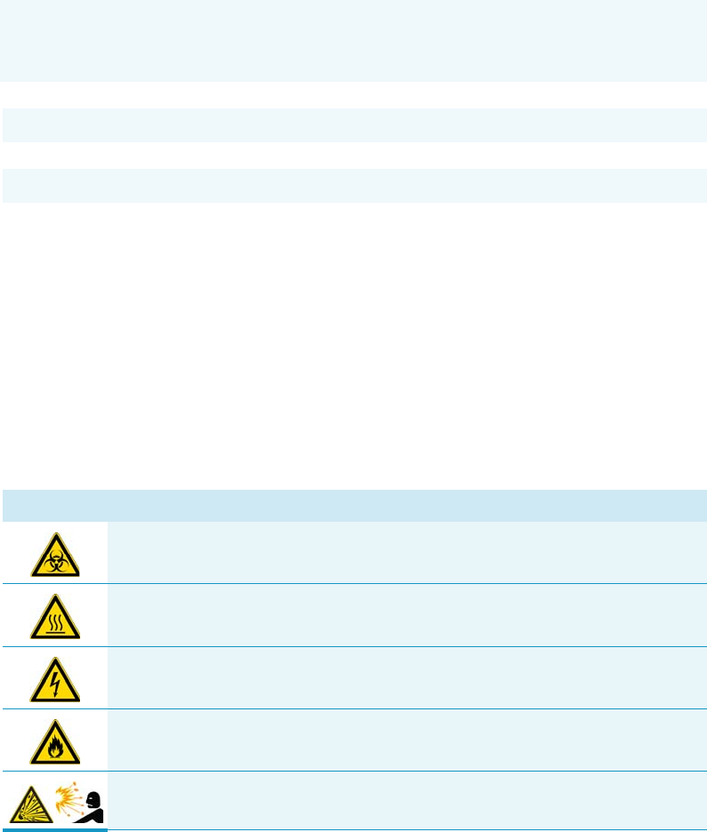
Symbol Descriptor
BIOHAZARD: Indicates that a biohazard will, could, or might occur.
BURN HAZARD: Alerts you to the presence of a hot surface that could or might
cause burn injuries.
ELECTRICAL SHOCK HAZARD: Indicates that an electrical shock could or
might occur.
FIRE HAZARD: Indicates a risk of fire or flammability could or might occur.
EXPLOSION HAZARD. Indicates an explosion hazard. This symbol indicates
this risk could or might cause physical injury.
Preface
Safety Alerts and Important Information
xviii TriPlus RSH User Guide Thermo Scientific
FLAMMABLE GAS HAZARD. Alerts you to gases that are compressed,
liquefied or dissolved under pressure and can ignite on contact with an
ignition source. This symbol indicates this risk could or might cause physical
injury.
GLOVES REQUIRED: Indicates that you must wear gloves when performing a
task or physical injury could or might occur.
CLOTHING REQUIRED. Indicates that you should wear a work clothing when
performing a task or else physical injury could or might occur.
BOOTS REQUIRED. Indicates that you must wear boots when performing a
task or else physical injury could or might occur.
MATERIAL AND EYE HAZARD. Indicates you must wear eye protection when
performing a task.
HAND AND CHEMICAL HAZARD: Indicates that chemical damage or physical
injury could or might occur.
HARMFUL. Indicates that the presence of harmful material will, could, or
might occur.
INSTRUMENT DAMAGE: Indicates that damage to the instrument or
component might occur. This damage might not be covered under the
standard warranty.
LIFTING HAZARD. Indicates that a physical injury could or might occur if two
or more people do not lift an object.
MATERIAL AND EYE HAZARD: Indicates that eye damage could or might
occur.
READ MANUAL: Alerts you to carefully read your instrument’s
documentation to ensure your safety and the instrument’s operational ability.
Failing to carefully read the documentation could or might put you at risk for a
physical injury.
TOXIC SUBSTANCES HAZARD: Indicates that exposure to a toxic substance
could occur and that exposure could or might cause personal injury or death.
LASER HAZARD. Indicates that exposure to a laser beam will, could, or might
cause personal injury.
Preface
Instrument Markings and Symbols
Thermo Scientific TriPlus RSH User Guide xix
Instrument Markings and Symbols
Tab le 1 explains the symbols used on Thermo Fisher Scientific instruments. Only a few of
them are used on the TriPlus RSH. See the asterisk.
RADIOACTIVE HAZARD. Indicates that the presence of radioactive material
could or might occur.
For the prevention of personal injury, this general warning symbol precedes
the WARNING safety alert word and meets the ISO 3864-2 standard. In the
vocabulary of ANSI Z535 signs, this symbol indicates a possible personal
injury hazard exists if the instrument is improperly used or if unsafe actions
occur. This symbol and another appropriate safety symbol alerts you to an
imminent or potential hazard that could cause personal injury.
Table 1. Instrument Marking and Symbols (Sheet 1 of 2)
Symbol Description
Direct Current
*Alternating Current
Both direct and alternating current
Three-phase alternating current
Earth (ground) terminal
Protective conductor terminal
Frame or chassis terminal
Equipotentiality
*On (Supply)
*Off (Supply)
Equipment protected throughout by DOUBLE INSULATION or
REINFORCED INSULATION (Equivalent to Class II of IEC 536)
Fuse
*Instruction manual symbol affixed to product. Indicates that the you must
refer to the manual for specific WARNING or CAUTION information to
avoid personal injury or damage to the product.
3
Preface
Safety Information and Warnings
xx TriPlus RSH User Guide Thermo Scientific
Safety Information and Warnings
This safety guide raises awareness of potential safety issues and general points for
consideration for Thermo Fisher Scientific representatives during installation, and repair of
the TriPlus RSH, or parts of it (following the life cycle principle), as well as for the end user
TriPlus RSH in the lab during the learning phase, and in routine work.
General Considerations
• Before a unit is put to use, consult the TriPlus RSH User Guide and related documents
under all circumstances.
• Changes or modifications to this unit not expressly approved by the party responsible for
compliance, could void your’s authority to operate the equipment.
• Be aware that if the equipment is used in a manner not specified by the manufacturer, the
protective and safety features of the equipment might be impaired.
• The repair of instrument failures caused by operation in a manner not specified by the
manufacturer is expressly excluded from the standard warranty and service contract
coverage.
Caution, risk of electric shock
*Caution, hot surface
*Caution, biohazard
*Caution, Laser beam
*Symbol in compliance to the Directive 2012/19/EU on Waste Electrical
and Electronic Equipment (WEEE) placed on the European market after
August, 13, 2005.
Table 1. Instrument Marking and Symbols (Sheet 2 of 2)
Symbol Description
IMPORTANT Read this section first before operating the TriPlus RSH.
Preface
Safety Information and Warnings
Thermo Scientific TriPlus RSH User Guide xxi
• When for technical reasons it is necessary to work on instrument parts which might
involve a potential hazard (moving parts, components under voltage, and so on.) contact
the Thermo Fisher Scientific authorized representative. In general, this type of situation
arises when access to the parts is only possible using a tool. When you perform a
maintenance operation, you must have received proper training to carry out that specific
task.
Electrical Hazards
Every analytical instrument has specific hazards. Be sure to read and comply with the
following pre-cautions. They ensure the safe and long-term use of your TriPlus RSH.
The installation over-voltage category is Level II. The Level II category pertains to equipment
receiving its electrical power from the local level, such as an electrical wall outlet.
Connect the TriPlus RSH only to instruments complying with IEC 61010 safety regulations.
The power line and the connections between the TriPlus RSH and other instruments, used in
the configuration setup of the total analytical system, must maintain good electrical
grounding. Poor grounding represents a danger for the operator, and might seriously affect the
performance of the instrument.
Do not connect the TriPlus RSH to power lines that supply devices of a heavy duty nature,
such as motors, refrigerators and other devices that can generate electrical disturbances.
Use only fuses of the type and current rating specified. Do not use repaired fuses, and do not
short-circuit the fuse holder. The supplied power cord must be inserted into a power outlet
with a protective earth (ground) contact. When using an extension cord, make sure that the
cord also has an earth contact.
If the supplied power cord does not fit the local electrical socket and a replacement or adapter
has to be purchased locally, make sure that only a certified power cord is used. Any power cord
used must be certified by the appropriate local authorities.
Pay attention not to leave any cable connecting the TriPlus RSH and the chromatographic
system, or the power cord close to heated zone, such as the injector or detector heating blocks,
or the GC hot air vents.
Always replace any cable showing signs of damage with another one provided by the
manufacturer. Safety regulations must be respected.
Do not change the external or internal grounding connections. Tampering with or
disconnecting these connections could endanger you and damage the TriPlus RSH. The
instrument is properly grounded in accordance with these regulations when shipped. To
ensure safe operation, you do not must make any changes to the electrical connections or the
instrument's chassis.
Preface
Safety Information and Warnings
xxii TriPlus RSH User Guide Thermo Scientific
Do not turn the instrument on if you suspect that it has incurred any type of electrical
damage. Instead, disconnect the power cord and contact a Thermo Fisher Scientific
representative for a product evaluation. Do not attempt to use the instrument until it has been
evaluated. Electrical damage might have occurred if the TriPlus RSH shows visible signs of
damage, exposure to any liquids or has been transported under severe stress.
Damage can also result if the instrument is stored for prolonged periods under unfavorable
conditions: for example, subjected to heat, moisture, and so on. Ensure that the power
supply/controller unit is always placed in a clean and dry position. Avoid any liquid spills in
the vicinity.
Before attempting any type of maintenance work, always disconnect the power cords from the
power supply(ies) if optional devices are installed. Capacitors inside the instrument might still
be charged also if the instrument is turned off.
To avoid damaging electrical parts, do not disconnect an electrical assembly while power is
applied to the TriPlus RSH. After the power is turned off, wait approximately 30 seconds
before you disconnect an assembly.
The instrument includes a number of integrated circuits. These circuits might be damaged if
exposed to excessive line voltage fluctuations, power surges or electrostatic charges, or both.
Never try to repair or replace any components of the instrument without the assistance of a
Thermo Fisher Scientific representative. There are no operator-serviceable or replaceable parts
inside the power supply(ies) or in the TriPlus RSH. If a power supply is not functioning,
contact a Thermo Fisher Scientific representative.
The power supplies for the TriPlus RSH, the Temperature Controlled Drawer have the
symbols I/O on the label for the power switch to indicate ON/OFF. If a Temperature
Controlled Drawer is installed in combination with a TriPlus RSH, a second power supply is
active in the complete system. Turning OFF the two power supplies, or pulling the two power
cords in an emergency, stop the entire TriPlus RSH.
It is important that the power supply(ies) is in a location where the power ON/OFF switch is
accessible and easy to operate, and where it is possible to unplug the AC power cord from the
power supply/wall outlet in case of emergency.
Laser Safety Information
Safety Warning for Laser Class 1 Product.
Preface
Safety Information and Warnings
Thermo Scientific TriPlus RSH User Guide xxiii
The selected Class 1 Laser for the TriPlus RSH module Barcode Reader complies with the
following regulations:
• 21 CFR1040.10 and 1040.11 except for deviations pursuant to Laser Notice No. 50,
dated July 26, 2001
• EN60825-1:1994 + A1:2002 + A2:2001
• IEC60825-1:1993 + A1:1997 + A2:2001
The software contains a built-in safety time limit such that the laser scanning mechanism
cannot be operated in AIM mode for more than 5 continuous seconds.
Other Hazards
To avoid injury and possible infection through contamination during TriPlus RSH operation,
keep your hands away from the syringe.
Do not operate the TriPlus RSH without the safety guard. The safety guard must be installed
for safe operation. Do not place any objects inside the area of the safety guard. Keep away
from the area around the safety guard during operation of the TriPlus RSH.
Danger of crushing to fingers and hands. To avoid injury keep your hands away from moving
parts during operation. Turn off the power to the TriPlus RSH if you must reach inside a
mechanically powered system with moving parts.
To avoid injury, observe safe laboratory practice when handling solvents, changing tubing, or
operating the TriPlus RSH. Know the physical and chemical properties of the solvents you
use. See the MSDS (Material Safety Data Sheets) from the manufacturer of the solvents being
used.
When using the TriPlus RSH, follow the generally accepted procedures for quality control
and method development.
When using the TriPlus RSH in the field of chromatographic analysis, if a change is observed
in the retention of a particular compound, in the resolution between two compounds, or in
the peak shape, immediately determine the reasons for the changes. Do not rely on the
separation results until you determine the cause of a change.
WARNING The installed Laser device is a Class 1 Laser Product.
Class 1 Laser devices are not considered to be hazardous when used for their intended
purpose. The following statement is required to comply with US and international
regulations.
CAUTION Use of controls, adjustments or performance of procedures other than those
specified herein might result in hazardous laser light exposures.

Preface
Safety Information and Warnings
xxiv TriPlus RSH User Guide Thermo Scientific
Do not operate on the instrument components that form part of the work area of the TriPlus
RSH when it is in motion.
Use caution when working with any polymer tubing under pressure:
• Always wear eye protection when near pressurized polymer tubing.
• Do not use polymer tubing that has been severely stressed or kinked.
• Do not use polymer tubing, in particular no PEEK or Tefzel tubing when using
tetrahydrofuran (THF), dimethylsulfoxide (DMSO), chlorinated organic solvents,
concentrated mineral acids such as nitric, phosphoric or sulfuric acids, or any related
compounds.
Do not use vials without a sealing cap, or microtiter or deepwell plates without a plate seal.
Vapor phase from organic solvents can be hazardous and flammable. Acidic vapor phase can
cause corrosion to critical mechanical parts.
When sample vials have to undergo heating and agitation, it is important to consider the glass
quality. Use high quality glass only. Remember that depending on the application conditions,
high pressure can build up in the vial. Whenever a temperature greater than 60 °C is applied,
consider the vapor pressure of the solvent used to ensure that no excessive pressure builds up.
This is important when using a temperature above 100°C and especially at the maximum
temperature of 200 °C. Be aware that solid materials can also contain volatile compounds
such as water (humidity) which could cause build-up of excess vapor pressure.
Do not reuse headspace vials. During the process of washing the vial, micro-cracks can form
which will weaken the glass wall and increase the chances of the vial breaking.
In case of a single fault situation where the temperature control of the Agitator fails, there is
the potential danger that the device will heat up in an uncontrolled manner until it reaches
the cut-off temperature of the over temperature fuse, in this case, 240 °C. Based on this single
fault scenario, when working with flammable solvents, ensure that the solvent used has a flash
point which is 25 °C higher than the maximum potential temperature (240 °C) of the
Agitator.
When filling-up a standard reservoir or replacing a solvent such as a washing solvent, remove
the solvent reservoir bottle from the system to avoid a possible spill over the instrument.
Depending on the physical, chemical or hazardous properties of the solvent, use the
appropriate protective measures for handling.

Preface
Safety Information and Warnings
Thermo Scientific TriPlus RSH User Guide xxv
Working with Toxic or other Harmful Compounds
Before using dangerous substances (toxic, harmful, and so on) read the hazard indications and
information reported in the Material Safety Data Sheet (MSDS) supplied by the
manufacturer, referring to the relevant CAS (Chemical Abstract Service) number. The TriPlus
RSH requires the use of several chemical products with different hazard characteristics, which
are present in vials and syringes. Before using these substances or replacing the syringe, please
read the hazard indications and information reported in the MSDS supplied by the
manufacturer referring to the relevant CAS number.
When preparing the samples, please refer to local regulations for the ventilation conditions of
the work room.
All waste materials must be collected and eliminated in compliance with the local regulations
and directives in the country where the instrument is used.
Biological Hazards
In laboratories where samples with potential biological hazards are handled, you must label
any equipment or parts thereof which might become contaminated with biohazardous
material. The appropriate warning labels are included with the shipment of the instrument.
It is your responsibility to label the relevant parts of the instrument.
When working with biohazardous materials, it is your responsibility to fulfill the following
mandatory requirements:
• Instructions on how to safely handle biohazardous material must be provided.
• Operators must be trained and made aware of the potential dangers.
• Personal protective equipment must be provided.
• Instructions must be provided on what to do in case operators are exposed to aerosols or
vapors during normal operation (within the intended use of the equipment) or in case of
single fault situations such as a broken vial. The protective measures must consider
potential contact with the skin, mouth, nose (respiratory organs), and eyes.
• Instructions for decontamination and safe disposal of the relevant parts must be provided.
It is your responsibility to handle hazardous chemicals or biological compounds (including,
but not limited to, bacterial or viral samples and the associated waste), safely and in
accordance with international and local regulations.
WARNING Before using hazardous substances (toxic, harmful, and so on), please read the
hazard indications and information reported in the applicable Material Safety Data Sheet
(MSDS). Use personal protective equipment according to the safety requirements.

Preface
Safety Information and Warnings
xxvi TriPlus RSH User Guide Thermo Scientific
Maintenance
Any external cleaning or maintenance must be performed with the TriPlus RSH turned off
and the power cord disconnected. Avoid using solvents and spraying on electrical parts. For
the removal of potentially dangerous substances (toxic, harmful, and so on) read the hazard
indications and information reported in the MSDS (Material Safety Data Sheet) supplied by
the manufacturer referring to the relevant CAS (Chemical Abstract Service) number. Use
proper protective gloves.
When working with hazardous materials such as radioactive, biologically hazardous material,
and so on, it is important to train all operators how to respond in case of spills or
contamination.
Depending on the class of hazardous material, the appropriate measures have to be taken
immediately. Therefore, the chemicals or solvents needed for decontamination have to be on
hand.
Any parts of the equipment which can potentially be contaminated, such as the sample vial
rack, syringe tool, wash module, and so on, must be cleaned regularly. The waste solvent from
cleaning and any hardware which requires to be disposed of has to be properly eliminated
with all the necessary precautions, abiding by national and international regulations.
When preparing for decontamination, ensure that the solvent or chemical to be used will not
damage or react with the surface, dye (color) of the instrument, table or other nearby objects.
If in doubt, please contact your Thermo Fisher Scientific representative to verify the
compatibility of the type or composition of solvents with the TriPlus RSH.
Disposal
Do not dispose of this equipment or parts thereof unsorted in municipal waste.
Follow local municipal waste regulations for proper disposal provisions to reduce
the environmental impact of waste electrical and electronic equipment (WEEE).
European Union customers: Call your local customer service representative
responsible for the TriPlus RSH for complimentary equipment pick-up and
recycling.
WARNING The customer has to ensure that the TriPlus RSH has not been contaminated
by any hazardous chemical or biological compounds including (but not limited to)
bacteria or viruses.
Any part which had direct contact with the analytical sample must be identified and must
undergo an appropriate decontamination procedure prior to shipping for disposal.
Potentially dangerous components are: Syringes, Vials and Well Plates. Any critical parts
sent for disposal must be handled according to national laws for hazardous compounds.
The customer and the service engineer are fully responsible for enforcing these
requirements. Thermo Fisher Scientific will hold the representative, customer responsible,
or both, if these regulations are not observed.

Thermo Scientific TriPlus RSH User Guide 1
1
Getting Familiar with Your TriPlus RSH
This chapter provides informations to familiarize with the TriPlus RSH.
Contents
•Instrument Basics
•Definition of Terms, Naming Conventions, and Start Screen Icons
•The TriPlus RSH System
•TriPlus RSH Configurations
•Crossrails
•Head
•TriPlus RSH Tools
•LS Tool
•HS Tool
•SPME 1 and SPME 2 Tools
•ITEX-2 Tool
•Control Interface
•Definitions of Active and Passive Hardware Modules
•Modules Description and Specifications
•TR Station
•ATC Station
•Standard Wash Station
•Large Volume Wash Station
•Large Solvent Station
•Fast Wash Station
•Agitator
•Vortexer
•MHE Station
•SPME Conditioning Station
•Barcode Reader
•Standard Tray Holder
•Liquid Cooled Tray Holder
•Temperature Controlled Drawer
•Electronic Box for OC Injector Actuator
•Handheld Controller
1 Getting Familiar with Your TriPlus RSH
Instrument Basics
2TriPlus RSH User Guide Thermo Scientific
Instrument Basics
The TriPlus RSH, offers you great flexibility in various applications. A unique automated tool
changer is provided, increasing throughput and allowing sample preparation steps before the
injection cycle. Refer to the Prep Cycles Calibration Dilution and Standard Addition.
The new versatility and seminal technical aspects are highlighted.
The TriPlus RSH has several advantages for use and provides greater flexibility and security
for routine and research applications, including:
• System Setup using the Virtual Handheld Controller software (or optional Handheld
Controller).
• Guided teaching wizards for tools and modules.
• The future-oriented Servo motor — a new control concept for motors with a high
intelligence, providing high security on X-,Y-, and Z-positioning at any time.
• The communication Bus increases the flexibility for adding so-called Active modules and
controlling these modules in a bidirectional manner. A self-detection mode simplifies the
addition of a module to the TriPlus RSH configuration.
The bidirectional communication allows control of the module at any given time or
position. Data stored in a log file not only gives you a high degree of security but also
facilitates the tractability of cycle performance, providing easy access to essential
information which might be requested by inspection authorities.
• A unique ATC Station allows an automated change of Tools (syringes with different
volumes or different tool types) for advanced sampling preparation, liquid handling
(dilutions), derivatization steps or any other time-consuming repetitive step. This added
versatility alongside the increase in throughput are significant benefits for you.
• New optional hardware modules, for example the Vortexer, for efficient phase mixing,
expands the range of applications and adds to the system versatility.
• A large range of syringe volumes is available for liquid or gaseous sample injection for
different GC-injector types (split/splitless, on-column, and so on.) and GC-columns
(from micro capillary to packed columns) enhancing the available options for you.
• A large range of vial sizes or microtiter plates which can be used in various tray holders.
• Vial bottom sensing allows aspiration of the very last drop in a vial.
• Barcode reader with dual scan module for barcode identification in any position.
• Wide range of predefined cycles for advanced liquid handling.
The TriPlus RSH can be set up and configured using either the Handheld Controller or
the Virtual Handheld Controller (PC software).
The options and parameters are identical, but the handling differs between the Handheld
Controller (Scroll Wheel and Enter button) and the normal control within the software.
The setup procedure is described in the sections “Service Menu Item” on page 189.
1 Getting Familiar with Your TriPlus RSH
Definition of Terms, Naming Conventions, and Start Screen Icons
Thermo Scientific TriPlus RSH User Guide 3
Definition of Terms, Naming Conventions, and Start Screen Icons
This section details the definition of the terms, the naming conventions used in this manual,
and the start screen icons visualized on the Handheld Controller.
See the related topics:
•“Definition of Terms” on page 3
•“Naming Conventions” on page 6
•“Start Screen Icons” on page 7
Definition of Terms
•TriPlus RSH System — The brand name for the entire System product family.
The product family includes not only the TriPlus RSH instruments but also the various
optional modules.
•TriPlus RSH — A generic term referring to the TriPlus RSH system.
TriPlus RSH is more used in combination with the basic unit with X- and Y-axes, Head
(Z-axis), and Power installed.
•Module — A generic term used to refer to both active and passive modules.
•Active Module — A module which is controlled by the BUS connector via active control.
An active module requires a device firmware which is part of the RSH Firmware. An
active module is recognized when connected to the BUS, it can be de-activated but not
deleted.
•Passive Module — A static module, e.g. a non-temperature programmable tray holder,
does not require any control or checks through the BUS.
A passive module requires an object template which is part of the RSH Firmware. A
specific device firmware is not required.
A passive module cannot be deactivated but it can be deleted.
•Composite Module — An active module consisting of one or more devices which also
communicate with the BUS, but in slave functionality. A typical example is the RSH
Head (Z-axis).
•Device — A single active module communicating with the BUS but in slave
functionality. Each device requires a device firmware which is part of the RSH Firmware.
•Motor — Generic term for the new generation of motors used for the axes.
The motor uses the logic of a servo-motor with electronic and software control.
The various motors are specified with the suffix of where the motor is applied, such as
motor-X, or motor-Z.
•Base — The combination of the X- and Y-Axes, with or without the electronics installed.
1 Getting Familiar with Your TriPlus RSH
Definition of Terms, Naming Conventions, and Start Screen Icons
4TriPlus RSH User Guide Thermo Scientific
•Head — Consist of Z-axis, the Needle Guide Motor, and the Plunger Motor. The cover
is part of the entire unit as well.
•Tool — Generic term for the holder of a syringe, or SPME Fiber. Four different tools are
used:
–LS Tool for liquid sample syringes.
–HS Tool for gaseous sample syringes (Headspace technique).
–SPME Tools for the SPME Fiber technique.
–ITEX Tool for the In-tube extraction technique
A tool consists of the lower and upper needle guides, the electronic identification, heating
and purge gas connections if required, the coupling pivots for the tool itself, and the
needle guide. A tool is designed for a specific syringe type tailored for the application
(liquid, headspace, SPME, or ITEX), with a specific glass barrel outer diameter and
needle length.
•Control Software — The entire software package of the operating system, application
software, configuration, and various device firmware. The file extension is *.pack.
•RSH Firmware — Starting with software version 2.0 the Control Software is renamed
to Firmware. The definition is identical as described above with Control Software
•Device Firmware — The software for an active module. The device firmware is part of
the RSH Firmware.
•Activity — The lowest level of command available with the RSH Firmware.
Activities depend on the Application Software version, and are downloaded to the
program from the TriPlus RSH when the initial connection is made, and updated during
the run time on a regular basis.
Activities are grouped in classes:
–Public: Activities available to build a custom specific script.
–Private: Activities not available to build a script. They are necessary for internal
control, and for the integration of the TriPlus RSH into another Chromatography
Data System (CDS).
A Script is built by linking Activities together in a sequence.
•Script — Created by building a sequence of TriPlus RSH operations, which are linked by
a series of Activities.
A Script can be a Method depending on the functionality built-into the script.
•Cycle — Consists of the specific operations necessary to process one sample. The cycle
operations are repeated for each sample within a job (sequence). Cycles are designed for
specific applications.
1 Getting Familiar with Your TriPlus RSH
Definition of Terms, Naming Conventions, and Start Screen Icons
Thermo Scientific TriPlus RSH User Guide 5
•Method — Defines how the samples are processed. The elements of a method are a cycle,
a syringe, and a parameter list. Methods have names with up to eight characters and can
be edited, copied, and deleted.
•Method Parameters — Associated with the cycle operations. User-assigned parameter
values define how a processing operation is performed. A zero parameter value will disable
a cycle operation. Cycle parameters are application-specific.
•Objects — Data structures describing the properties of physical modules, such as Tray
Holder, Agitator, Motors, and so on.
•Module Type — Unique identification of a module, defines the machine object
description of the combining device.
•Module ID — Unique identification of a module.
•Tray Hold er — Holds one or more trays. Each tray holder has a reference position (X-,
Y-, Z-coordinates), that defines its location. A tray holder is a passive module.
•Slot — The physical place where a Tray can be positioned in the Tray Holder.
•Sample Tray — Generic term. A tray can be a rack for holding vials, or a well plate for
deepwell plates, or microtiter plates. A tray holds multiple samples.
Trays are defined by designating the tray type, and the Tray Holder. Tray names are used
to identify the sample source within a Job.
•Well Plate — A generic term used for all types of well plates. The most common well
Plates are deepwell plates, or microtiter plates.
The well plates have a standardized footprint. The tray holder drawers are designed to
accept well plates. Passive tray holders for the TriPlus RSH have three slots, each one
designed with the footprint dimensions of a Well Plate.
•Tray Typ e — Generic term. A Tray Type can be a Tray for vials or a plate for well plates.
A Tray Type defines the pattern and sampling sequence of sample locations within a Tray.
•Vial Type — The physical dimensions of a Vial and parameters required for automation,
such as Needle Penetration Depth or Penetration Speed, are described by the various item
parameters of the Vial Type.
•Cap Type — Describes the material of the vial cap, which in turn determines whether or
not a vial can be transported.
•Needle Guide Type — Selectable parameter in the software class To ol s. Selects the
required tool that is mounted to the Lower Needle Guide of the tool. For example, you
can select the large magnetic ring for transporting 10/20 mL vials or the Foil Cutter for
use with sealed Well Plate.
•Stack — A passive Tray Holder with a drawer system. It is not temperature controllable.
•Temperature Controlled Drawer — An active Tray Holder with drawer system. It is
temperature controllable.

1 Getting Familiar with Your TriPlus RSH
Definition of Terms, Naming Conventions, and Start Screen Icons
6TriPlus RSH User Guide Thermo Scientific
•Liquid Cooled Tray Holder — A passive module controlled through external liquid
circulation bath.
Naming Conventions
This section provides the standard naming convention for TriPlus RSH Trays and Tray Types.
Following these conventions will allow the TriPlus RSH to be pre-configured for certain
applications, will simplify software backups and application development, and will improve
technical support and training.
An example of naming convention id detailed in Table 1.
Table 1. Example of Tray Types Naming Convention (Sheet 1 of 2)
Tray Type Tray Description
Tra y 1 5
(VT15)
Tray with same footprint as Well Plate; 15 positions (3 x 5).
Pattern: Regular for 10 and 20 mL vials with OD 23 mm and height 47/78
mm.
Tra y 5 4
(VT54)
Tray with same footprint as Well Plate; 54 positions (6 x 9).
Pattern: Regular for 2 mL vials with OD 12 mm and height 34 mm.
Tra y 7 0
(VT70)
Tray with same footprint as Well Plate; 70 positions (7 x 10).
Pattern: Regular for 1 mL vials with OD 7.5 mm and height 45 mm.
Viewing window in position 68 for needle penetration check.
Tra y 6 0
(R60)
Tray with footprint for entire Tray Holder (passive Tray Holder with 3 Slots).
60 positions (6 x 10).
Pattern: Staggered+ for 10 and 20 mL vials with OD 23, and height
47/78 mm.
Viewing window in position 60 (for needle penetration check).
Tray 32
(R32)
Tray with footprint for Liquid Cooled Tray Holder;32 positions (4 x 8).
Pattern: Regular for 20 mL vials with OD 23 and height 78 mm.
DWP96 Well Plate Type. Deep Well Plate DW96. 96 positions (8 x 12).
Pattern: Regular.
Plate Height: 43.0 mm; Well Cavity Depth: 39.0 mm;
Well Cavity Diameter: 7.0 mm.
1 Getting Familiar with Your TriPlus RSH
Definition of Terms, Naming Conventions, and Start Screen Icons
Thermo Scientific TriPlus RSH User Guide 7
Start Screen Icons
The Start screen icons are listed in Table 2.
MTP96 Well Plate Type. Microtiter Plate MT96. 96 positions (8 x 12).
Pattern: Regular.
Plate Height: 14.6 mm; Well Cavity Depth: 10.9 mm;
Well Cavity Diameter: 7.0 mm.
MTP384 Well Plate Type. Microtiter Plate MT384. 384 positions (24 x 16).
Pattern: Regular.
Plate Height: 14.4 mm; Well Cavity Depth: 11.5 mm;
Well Cavity Diameter: 3.7 mm.
Table 1. Example of Tray Types Naming Convention (Sheet 2 of 2)
Tray Type Tray Description
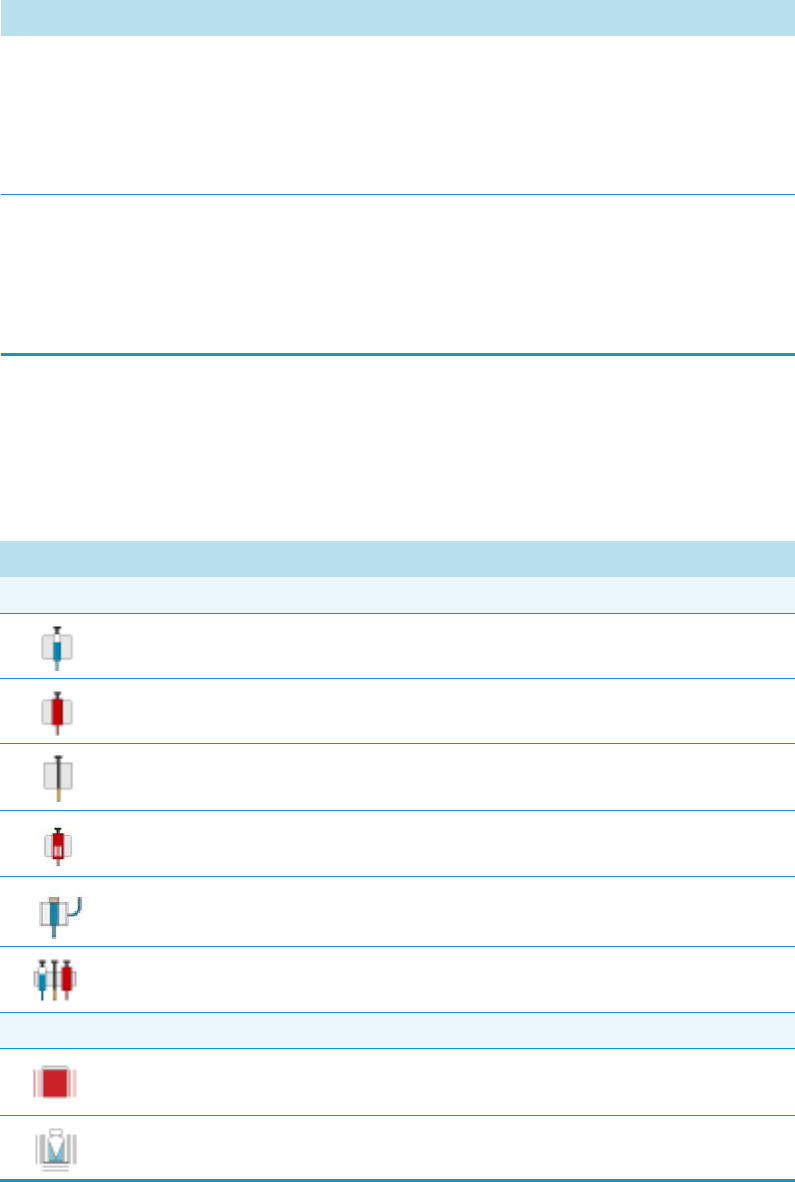
Table 2. Start Screen Icons (Sheet 1 of 3)
Icon Description
Tool and Tool Change Station
LS Tool, Syringe tool for liquid Injections
HS Tool; Headspace Tool
SPME Tool; Tool for SPME Holder
ITEX Tool
Dilutor Tool
ATC Station; Active module for automated tool change.
Active Module
Agitator
Vortexer
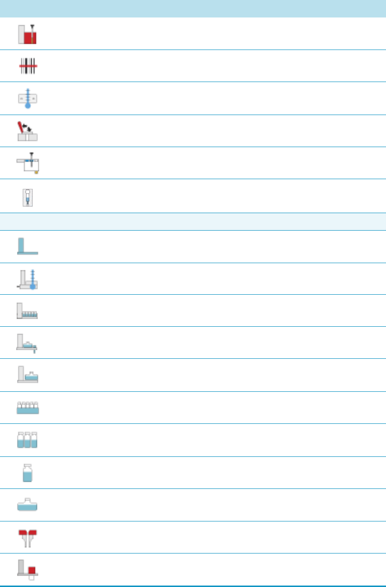
1 Getting Familiar with Your TriPlus RSH
Definition of Terms, Naming Conventions, and Start Screen Icons
8TriPlus RSH User Guide Thermo Scientific
SPME Fiber Conditioning Station
Barcode Reader
Temperature Controller Drawer
OC Injector (On-column Injector)
Fast Wash Module
Dilutor Syringe Module
Passive Module
Tray Holder (rectangular)
Liquid Cooled Tray Holder
Standard Wash Station (5x10 mL Vials)
Large Solvent Wash Station (2 x 100 mL bottles and 1 Waste Position)
Solvent Station (Solvent reservoir station for 3 x 100 mL bottles)
Tray, rectangular (Tray to hold vials with volume from 1 to 40 mL)
Vials, set of vials
Vial, single vial (Vial Type CV)
Solvent Reservoir Bottle (Vial Type SR)
Injector (GC Injector)
MHE Module
Table 2. Start Screen Icons (Sheet 2 of 3)
Icon Description
1 Getting Familiar with Your TriPlus RSH
Definition of Terms, Naming Conventions, and Start Screen Icons
Thermo Scientific TriPlus RSH User Guide 9
Synchronization and Signals
Input and Output Signals
Input Signal
Output Signal
Chromatographic System.
Specifies synchronization of Input and Output Signals, Cryo Trap, and Delay
Time for a Fake Injection for an analytical system.
General Icons
TriPlus RSH System
Head (Injection unit)
Table 2. Start Screen Icons (Sheet 3 of 3)
Icon Description
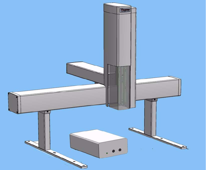
1 Getting Familiar with Your TriPlus RSH
The TriPlus RSH System
10 TriPlus RSH User Guide Thermo Scientific
The TriPlus RSH System
The TriPlus RSH is an integrated sampling system based on three axes X,Y and Z, constituted
by a basic body on which a series of components are installed. See Figure 1.
Figure 1. TriPlus RSH Schematic View
The components are chosen by the operator according to their own analytical demands.
Choosing the appropriate components, TriPlus RSH sampler may be configured for Liquids
LS, Headspace HS, or Solid Phase Micro Extraction SPME, or In-tube Extraction ITEX.
Sampling Unit
The sampling unit consists of the following major components:
•Sampler Support — Constitutes the supporting base allowing the installation of the
sampler on the gas chromatograph.
•Crossrails (X and Y-axes) — The sampler is provided with two sliding crossrails that
constitute the basic body:
1 Getting Familiar with Your TriPlus RSH
The TriPlus RSH System
Thermo Scientific TriPlus RSH User Guide 11
–Longitudinal Crossrail (X-axis)
Represents the X-axis of the system, and the structure bearing the sampling unit
components. The longitudinal crossrail (X-axis) is available in the standard or
extended version.
–Orthogonal Crossrail (Y-axis)
Represents the Y-axis of the system. It slides on the longitudinal crossrail driving the
movements of the Head fixed thereto.
•Head (Z-axis) — Couples and uncouples the injection tools for the liquid, headspace,
SPME, or ITEX applications, and accomplishes the necessary movements to carry out the
three main operating steps. The Head includes an integrated gas supply.
Modules
•Tool Station — Represents the injection tool holder. Two stations are available:
–TR Station containing a single slot for an injection tool.
–ATC Station with three slots for the tools with the possibility to change an injection
tool automatically for specific needs.
•Washing Stations — Accommodate the vials of solvents and a waste vial or a drain tube
to collect the solvents in a waste container.
Four types of washing stations are available:
– Standard Wash Station (5 x 10 mL vial)
– Large Volume Wash Station (2 x 100 mL reservoir)
– Large Solvents Station (3 x 100 mL reservoir)
– Fast Washing Station
Tray Hold er — Accommodate the sample tray.
Three types of tray holders are available:
– Standard (room temperature) tray holder
– Liquid Cooled Tray Holder
– Temperature Controlled Drawer (it requires a dedicated power supply).
Each type of tray holder accommodates the relevant type of sample tray.
• Sample Tray
It is placed on the dedicated tray holder hanging to the crossrail X. The following options
are available according to the type of tray holder in use:
– 15, 32, 54, 60, and 70 positions.
– 96 positions Deep Well Plate DW96
– 96 positions Microtiter Plate MT96

1 Getting Familiar with Your TriPlus RSH
The TriPlus RSH System
12 TriPlus RSH User Guide Thermo Scientific
– 384 positions Microtiter Plate MT384
•Agitator (Incubation Oven) — The main component of the HS and SPME application.
Accurate thermostatting of up to six sample vials is crucial to obtain reproducible results
in head-space analysis. This condition is ensured by accurate temperature control of the
vials located in the incubation oven.
•Vortexer — Used for intensive shaking (orbital interval shaking) at ambient temperature.
•On-Column Injector Actuator — This device is not provided with the TriPlus RSH
sampler. It is an external device required for automatic injections through the TriPlus
RSH sampler into the On-Column injector. The device allows the opening of the
On-Column injector rotary valve when the syringe needle is inserted. When the needle is
removed, the actuator closes the valve.
Optional Components
•ITEX Tool — Required when the In-tube Extraction technique is used. It extend the
range of headspace techniques.
•MHE Station — Required when the Multiple Headspace Extraction (MHE) technique is
used.
•Fiber Conditioning Station — Allows the conditioning of the SPME fiber.
•Bar Code Reader — Reads the bar codes located on the vials and sends the content
during the report printout.
•Dilutor Module — Used for a typical solvent handling and for sampling an exact volume
of an aliquot and pipetting it into another vessel for further processing.
Power Module
The sampler is electrically supplied by the dedicated external power module. The TriPlus
RSH cannot work without this power module. A second power module is required to supply
the Temperature Controlled Drawer.
User Interface
The TriPlus RSH can be set up and configured using either the Handheld Controller or the
Virtual Handheld Controller (PC software)
The functions of the TriPlus can be controlled through a data processing system for PC with
dedicated software.
Note The Dilutor Module is described in a separated manual as additional section of
the TriPlus RSH User Guide and Hardware Manual. Refer to Dilutor Module for
TriPlus RSH Instruction Manual.
1 Getting Familiar with Your TriPlus RSH
TriPlus RSH Configurations
Thermo Scientific TriPlus RSH User Guide 13
TriPlus RSH Configurations
This section provides a brief overview of the various configurations of the TriPlus RSH as
applicable to the GC technique. The TriPlus RSH can be installed on the gas chromatographs
for sample introduction into up to: three injectors by using the standard module longitudinal
crossrail or four injectors by using the extended longitudinal crossrail.
The sampler may be configured in the following versions:
•“TriPlus RSH for Liquids” on page 13
•“TriPlus RSH for Headspace” on page 14
•“TriPlus RSH for SPME (Solid Phase Micro Extraction)” on page 14
•“TriPlus RSH for ITEX (In-tube Extraction)” on page 15
TriPlus RSH for Liquids
This version features the following characteristics:
•Injectors into which the sample may be introduced — S/SL, PTV, PKD, PPKD, and
OCI.
•Washing Station — Standard Wash Station, Large Solvent Wash Station, Large Solvent
Station, Fast Wash Station
•Sample Tray
– 15-position tray (Tray 15)
– 32-position tray (Tray 32)
– 54-position tray (Tray 54)
– 60-position tray (Tray 60)
– 96 positions Deep Well Plate DW96
– 96 positions Microtiter Plate MT96
– 384 positions Microtiter Plate MT384
•Sample Vial
– 0.5, 0.7, 2.0, 2.5, 10, and 20 mL
– 96/384 positions Microtiter or Deep Well plate
•Syringe Types — 0.5 μL, 1.0 μL, 5.0 μL, and 10 μL (standard); 25 μL, 50 μL, 100 μL,
250 μL, 500 μL, 1000 μL, and 10000 μL syringes for sample injection, volume transfer,
or both.
•Syringe Needle Length — 57 or 85 mm
1 Getting Familiar with Your TriPlus RSH
TriPlus RSH Configurations
14 TriPlus RSH User Guide Thermo Scientific
TriPlus RSH for Headspace
This version features the following characteristics:
•Injectors into which the sample may be introduced — S/SL, PTV, PKD, and PPKD
•Washing Station — Two vials and four vials
•Sampler Tray — 60-position tray
•Sample Vial — 2, 10, and 20 mL
•Incubation Oven (Agitator) capacity — 6 vials (5 vials when the MHE station is
present).
•Incubation Oven (Agitator) temperature control — from 40 °C to 200 °C
•Syringe capacity — 1, 2.5, and 5 mL
•Syringe Needle Length — 65 mm, compatible with every injector port
•Syringe temperature control — from 40 to 150 °C
•Operating modes
– Constant (with or without enrichment)
– Progressive (with or without enrichment)
– Multiple Headspace Extraction (MHE)
–Constant DoublePro
TriPlus RSH for SPME (Solid Phase Micro Extraction)
This version features the following characteristics:
•Injectors into which the sample may be introduced — S/SL and PTV
•Washing Station — Two vials and four vials, Fast Wash Station
•Sampler tray — 60-position tray
•Sample vial — 2, 10, and 20 mL with the 60-position tray
•Incubation oven (Agitator) capacity — 6 vials
•Incubation oven (Agitator) temperature control — from 40 °C to 200 °C
•Fiber Conditioning Station temperature control — from 40 °C to 350 °C
•Operating modes
– Constant (with or without enrichment)
– Progressive (with or without enrichment)
1 Getting Familiar with Your TriPlus RSH
TriPlus RSH Configurations
Thermo Scientific TriPlus RSH User Guide 15
TriPlus RSH for ITEX (In-tube Extraction)
This version features the following characteristics:
•Injectors into which the sample may be introduced — S/SL, PTV, PKD, and PPKD
• ITEX2 Tool
•Washing Station — Two vials and four vials
•Sampler Tray — 60-position tray
•Sample Vial — 2, 10, and 20 mL
•Incubation Oven (Agitator) capacity — 6 vials.
•Incubation Oven (Agitator) temperature control — from 40 °C to 200 °C
•Syringe capacity — 1, 2.5, and 5 mL
•Syringe Needle Length — 65 mm, compatible with every injector port
•Syringe temperature control — from 40 to 150 °C
•Trap temperature control — from 100 to 350 °C
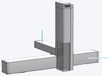
1 Getting Familiar with Your TriPlus RSH
Crossrails
16 TriPlus RSH User Guide Thermo Scientific
Crossrails
The crossrails constitutes the primary structure up on which the sampling unit components
are installed according to the configuration of the sampler.
The two sliding crossrails, shown in Figure 2, constitute the X and Y axes of the sampler. They
are connected to one another through a mechanism that manages the movements of the
system by both a motorized truck and a tray located in every crossrail.
Figure 2. Crossrails X and Y
Crossrail X
It represents the X-axis of the system and is the structure bearing the sampling units
components. It consists of the following sections:
•Front-upper section — The part of the crossrail on which the crossrail Y slides.
•Lower section — Includes the slots to connect the sampler support and the components.
•Back section — Includes the Control Interface for the connection of the sampling unit
to the power module, the GC, and the components installed. See the section “Control
Interface” on page 33. It includes the inlet port for the connection of the syringe flushing
gas.
•Internal section — Contains the main low voltage electronics boards. It also manages the
movement along the crossrail X.
Crossrail Y
It represents the Y-axis of the system. It is connected to the crossrail X through the motorized
truck. Crossrail Y motors carry out the movements of the Head (Z-axis).
It consists of the following sections.
•Front section — Includes the guides and the electric connections for the Head
installation.
Crossrail Y
Crossrail X
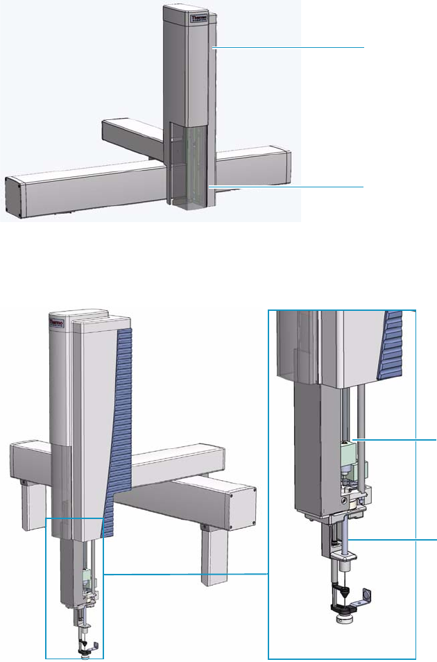
1 Getting Familiar with Your TriPlus RSH
Head
Thermo Scientific TriPlus RSH User Guide 17
•Lower section — The part that slides along the crossrail X.
Head
It represents the Z-axis of the system. It consists of a vertical structure fixed on the crossrail Y
which guides the movements along the X and Y axes. See Figure 3.
Figure 3. Head
The front side is provided with a viewing window allowing access to the injection device.
See Figure 4.
Figure 4. Injection Device
Head
Viewing Window
Injection Device
Tool
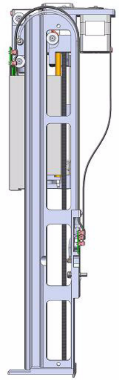
1 Getting Familiar with Your TriPlus RSH
TriPlus RSH Tools
18 TriPlus RSH User Guide Thermo Scientific
The injection device includes an active needle guide and a coupling plate to couple/uncouple
the RSH Tools. See the section “TriPlus RSH Tools” on page 18.
The movements of the injection device are controlled by stepper motors housed in the Head.
See Figure 5.
Figure 5. Injection Device Motors
TriPlus RSH Tools
The TriPlus RSH requires more information and intelligence on the level of tools than just
the syringe identification numbers as used with common samplers.
The capability to use a tool for one task, store the tool away and select a second tool for the
next task in the cycle sequence necessitates knowledge of the geometry of the syringe and
holder.
The location of the syringe holder is tracked at any point in time with a unique number.

1 Getting Familiar with Your TriPlus RSH
TriPlus RSH Tools
Thermo Scientific TriPlus RSH User Guide 19
Specific tools are:
•LS Tool — Used for liquid injection with a metallic plunger typically used for GC
technique or with a polymer plunger used for syringes with a larger volume than 10 μL or
for gaseous samples. The syringe is in the tool holder, and the entire assembly is called LS
Tool. See the section “LS Tool” on page 21.
•HS Tool — Used for headspace injection. The entire assembly consists of a gas-tight
syringe with a side hole for purging, the syringe heater and the syringe holder.
See the section “HS Tool” on page 25.
•SPME Tools — Automates the SPME Fiber holder.
See the section “SPME 1 and SPME 2 Tools” on page 27.
•ITEX Tool — Used for In-tube extraction technique.
See the section “ITEX-2 Tool” on page 30.
The syringe consists of the holder to insert and keep the tool in position, the upper and lower
needle guide, and the PCB board.
The following attributes are generally stored with a TriPlus RSH Tool:
• Tool ID (Identification Number)
• Maintenance Counter for Couplings (total number of couplings for the tool)
• Maintenance Counter for Plunger movements (total number of plunger strokes/counts)
• Maintenance Counter Plunger movements of actual syringe (strokes or counts)
The same Tool holder is mechanically interchangeable for all syringes in the same class, with a
defined glass barrel diameter and needle length.
The specific attributes of the syringe can be added to the tool at the moment of installation.
The very first time you select a tool, define which syringe will be used for this specific tool.
Syringe attributes such as the Syringe Volume, Needle Length, and Plunger Type, must be
selected from the filtered pre-selection for the specific tool inserted in the TR Station.
A unique ID is used to monitor the tool during the application.
This number is used by the system to verify that the tool syringe settings are known and
applicable. If not, a new syringe definition will be required.
This concept allows to apply the same Tool Holder for different syringe sizes, as long as they
are within the same class, with the same glass barrel diameter and needle length. See the
example in Figure 6.
For example:
• Class: LS Tool
• Glass Barrel Diameter: 6.6 mm
• Needle length: 57 mm
This Tool Holder type is named D7-57. It can be used for the following syringe volumes, all
of which have a needle length of 57 mm: 0.5, 1.0, 2.0, 5.0, 10, 25, and 100 μL.

1 Getting Familiar with Your TriPlus RSH
TriPlus RSH Tools
20 TriPlus RSH User Guide Thermo Scientific
Figure 6. LS Tool with Needle Length 57 mm and 85 mm
Tool Identification
The tools are labeled at the side. The code identifies the Tool required for your’s needs. See the
example in Figure 7.
Figure 7. Example Tools Identification Label
57 mm Needle Length LS Tool
85 mm Needle Length LS Tool
LS Tool
HS Tool
SPME Tool

1 Getting Familiar with Your TriPlus RSH
LS Tool
Thermo Scientific TriPlus RSH User Guide 21
The Tools are branded by the factory for the basic configuration, which means:
• Tool Type as Liquid Syringe (LS), Headspace (HS), and SPME.
• Tool internal diameter to accept Syringe Glass Barrel with defined outer diameter, for
example: 6.6 or 7.7 mm.
• Length of Needle or distance for Needle Guide.
Any syringe with the same characteristics can be inserted in the tool with the described
preconditions. Labels for the various syringe types are provided. See the example in Table 3.
LS Tool
The LS Tool is used for liquid or gaseous samples but not for the headspace technique.
Syringes with a metallic plunger are used typically for the gas chromatographic technique
where ideally organic solvents, such as alkanes, ketones, esters, or alcohols, are used.
Table 3. Some Examples of Labels Description
Label Description
LS 10 μL; NL57 Liquid Syringe Tool
Syringe Volume: 10 μL; 57 mm Needle Length
LS 10 μL: NL85 Liquid Syringe Tool
Syringe Volume: 10 μL; 85 mm Needle Length
HS 2500 μL; NL65 Headspace Tool
Syringe Volume: 2500 μL; 65 mm Needle Length
SPME 1 SPME Tool
SPME 1-1: 10 mm Fiber Length
SPME 1-2: 20 mm Fiber Length
SPME 2 SPME 2 Tool
SPME 2-1: 10 mm Fiber Length
SPME 2-2: 20 mm Fiber Length
Note Needle Length is defined as free standing needle length. The usable length is 12 mm
less than the needle length as specified (Needle Guide).
Note This plunger type is not recommended for sample solutions which contain matrix
particles, or a solvent which does not form a solvent film in between the syringe plunger
and the glass barrel surface. The metal can bite into the glass which will destroy the
plunger.
Examples of critical solvents to watch out for are mixtures of water and an organic solvent
as water and ethanol, or DMSO (dimethyl sulfoxide).
For such applications, we recommend using a syringe with a polymer plunger.
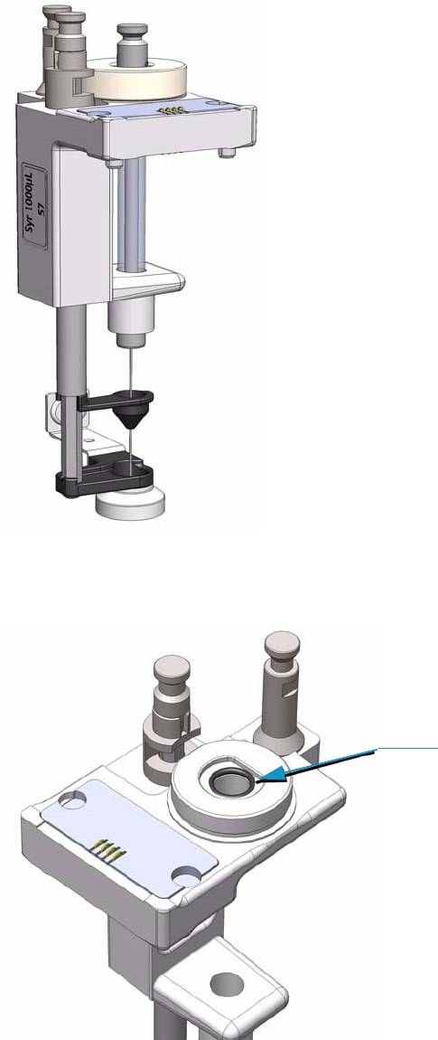
1 Getting Familiar with Your TriPlus RSH
LS Tool
22 TriPlus RSH User Guide Thermo Scientific
The LS Tool is a single block, easy to use to install a syringe. See Figure 8.
Figure 8. LS Tool
The syringe flange is supported by an O-ring (support bearing). See Figure 9.
Figure 9. Support Bearing
Supporting Bearing
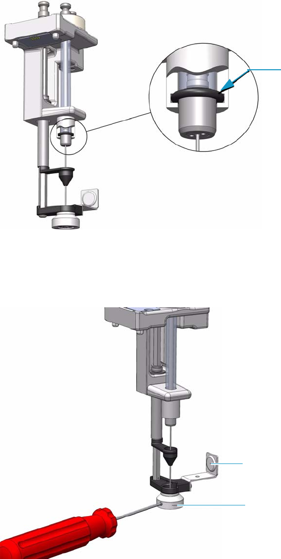
1 Getting Familiar with Your TriPlus RSH
LS Tool
Thermo Scientific TriPlus RSH User Guide 23
At the lower part of the block a second O-ring is installed which guides the syringe glass barrel
and prevents direct metal contact. See Figure 10.
Figure 10. O-Ring
The Magnet Adapter Ring is used to transport vials from a Tray to the Agitator.
The lower needle guide has the Stack Drawer Magnet installed, fixed with two screws.
The magnet is required to open and close a stack drawer. See Figure 11.
Figure 11. LS Tool - Magnets
Refer also to “Syringes for LS Tools” on page 24.
Second O-ring
Stack Drawer Magnet
Magnet Adapter

1 Getting Familiar with Your TriPlus RSH
LS Tool
24 TriPlus RSH User Guide Thermo Scientific
Syringes for LS Tools
Tab le 4 lists the type of syringes suitable for the LS tool.
Liquid Syringe (LS) Tools are full compatibility with Thermo Injector technology. See
Tab le 5 .
Table 4. List of Syringes for LS Tools
Syringes Type Volume
7 mm diameter syringe barrel with 57 mm
needle length.
0.5 μL, 1.0 μL, 5.0 μL, 10 μL, 25 μL, 50 μL,
100 μL
7 mm diameter syringe barrel with 85 mm
needle length
0.5 μL, 1.0 μL, 5.0 μL, 10 μL, 25 μL, 50 μL,
100 μL volumes
8 mm diameter syringe barrel with 57 mm
needle length
250 μL, 500 μL, 1000 μL volumes
8 mm diameter syringe barrel with 85 mm
needle length
250 μL, 500 μL, 1000 μL volumes
18 mm diameter syringe barrel with 57 mm
needle length
10000 μL volume
Table 5. LS Tool - Injector Compatibility (Sheet 1 of 2)
Injector
SSL injector hot needle
• Splitless injection — 85 mm needle length LS tool
• Split injection — 57 mm needle length LS tool
• Large Volume splitless — 57 mm needle length LS tool
SSL injector cold needle
• SSL injector cold needle — 57 mm needle length LS tool
OC injector
• Conventional injection — 85 mm needle length LS tool
• Large volume injection — 85 mm needle length LS tool
PTV injector
• Conventional injection — 57 mm needle length LS tool
• Large volume injection — 57 mm needle length LS tool
• Large volume with programmable depth — 85 mm needle length LS tool
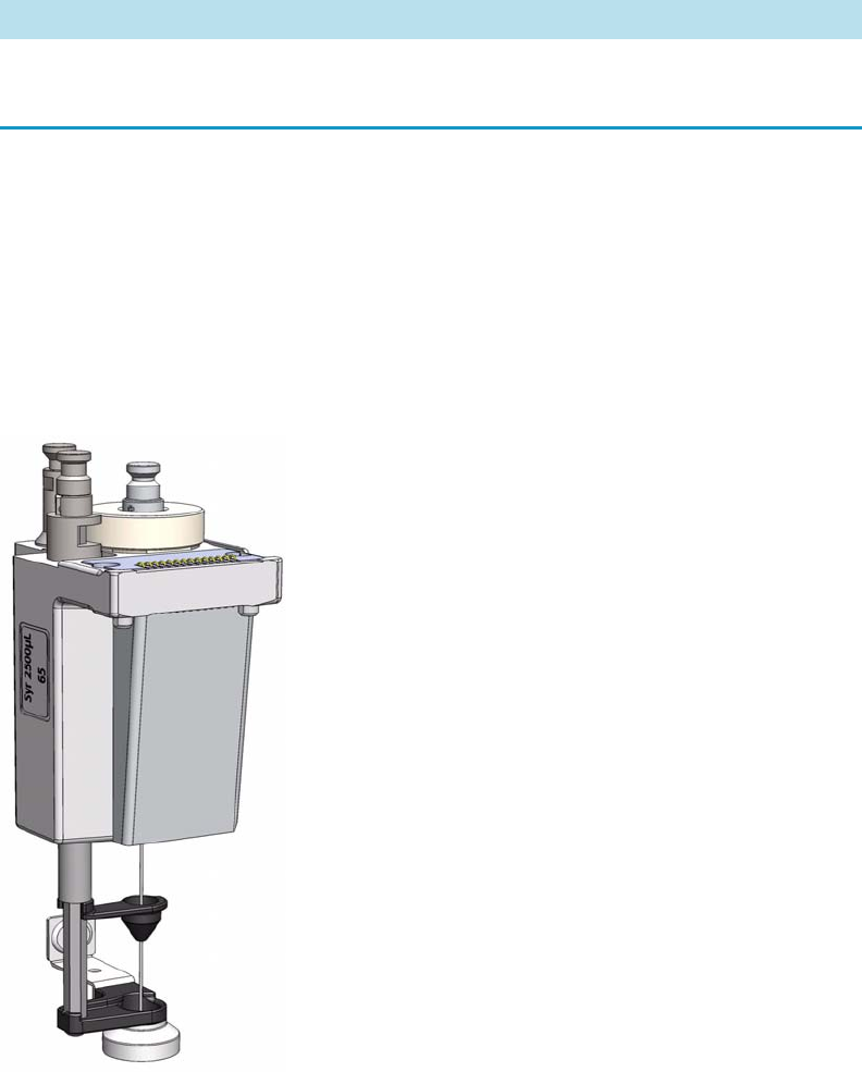
1 Getting Familiar with Your TriPlus RSH
HS Tool
Thermo Scientific TriPlus RSH User Guide 25
Automated Bottom Sensing with a syringe needle length of 85 mm is not recommended.
High risk of needle bending.
HS Tool
The Headspace Tool (HS Tool) is used for the Headspace.The HS Tool is provided as a single
block, easy to use to install a syringe and the purge gas line. See Figure 12.
Figure 12. HS Tool
The syringe temperature is controlled from 40 °C up to 150 °C, in 1 °C steps. The syringe is
flushed with inert gas flow through X-Y-Z-axis.
Besides the coupling pivots for the needle guide and the tool, the purge gas connector is
directly installed on the cover plate of the tool.
The syringe flange is supported by the polymer counterpart to the retaining nut. In the
heating cylinder there are two O-rings which seal the gas flow to enable a syringe purge. It is
recommended to replace these O-rings during preventative maintenance.
PKD injector
• PKD injector — 57 mm needle length LS tool
Table 5. LS Tool - Injector Compatibility (Sheet 2 of 2)
Injector
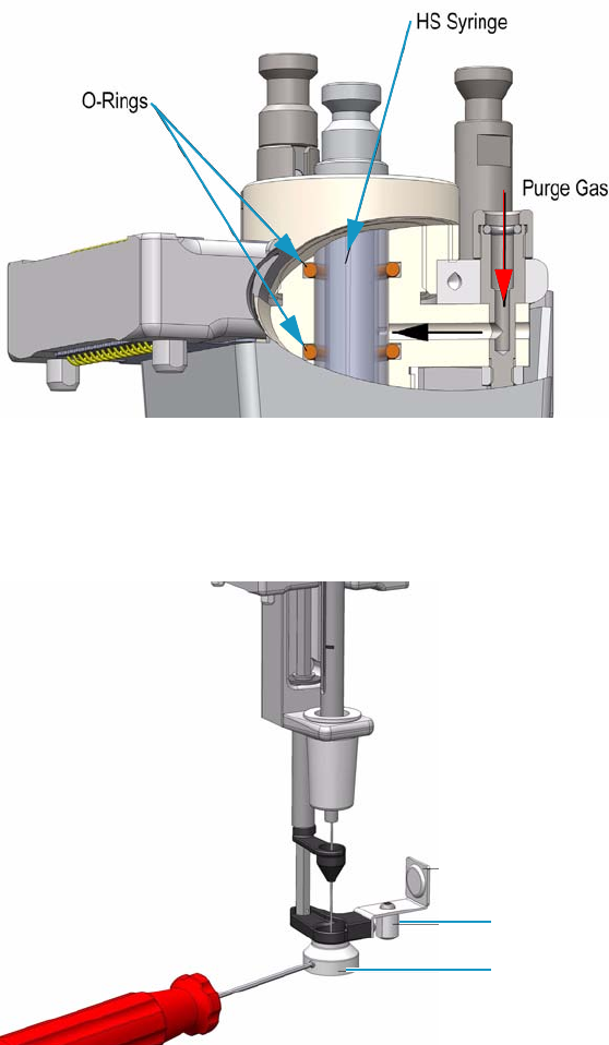
1 Getting Familiar with Your TriPlus RSH
HS Tool
26 TriPlus RSH User Guide Thermo Scientific
Figure 13 shows the cut-out of the HS tool visualizing the Purge Gas Flow and the Sealing
O-ring.
Figure 13. HS Tool Cut-out
The Magnet Adapter Ring is used to transport vials from a Tray to the Agitator, as an
example. The lower needle guide has the Stack Drawer Magnet installed, and fixed with two
screws. The magnet is required to open and close a Stack Drawer. See Figure 14.
Figure 14. HS Tool - Magnets
Refer to “Syringes for HS Tools” on page 27.
Stack Drawer Magnet
Magnet Adapter
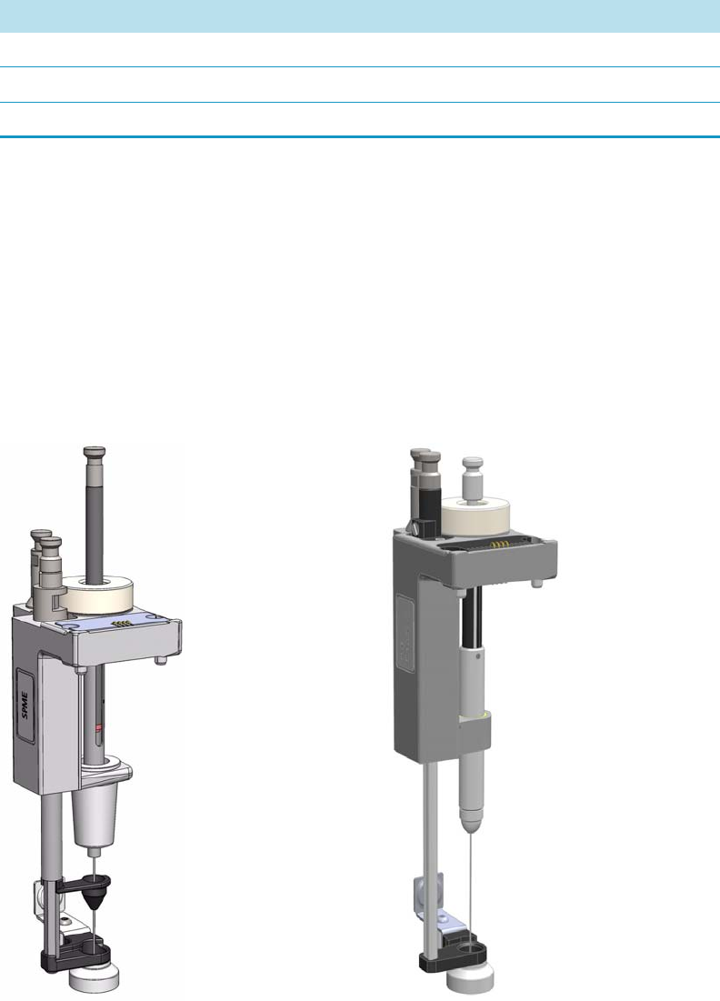
1 Getting Familiar with Your TriPlus RSH
SPME 1 and SPME 2 Tools
Thermo Scientific TriPlus RSH User Guide 27
Syringes for HS Tools
Tab le 6 lists the type of syringes suitable for the HS tool.
SPME 1 and SPME 2 Tools
The SPME 1 and SPME 2 Tools for Solid Phase Micro Extraction are a dedicated devices
adapted for the SPME Fiber Holder. Currently, there are two different fiber lengths
commercially available: 10 mm and 20 mm. Both types can be adapted with the SPME Tool.
The TriPlus RSH System software allows setting the fiber extension length to the necessary
distance.
The SPME Tool is a single block, used to install a SPME Holder. See Figure 15.
Figure 15. SPME 1 and SPME2 Tools
Table 6. List of Syringes for HS Tool
Syringe
For gas tight syringe of 1.0 mL volume and 65 mm needle length
For gas tight syringe of 2.5 mL volume and 65 mm needle length
For gas tight syringe of 5.0 mL volume and 65 mm needle length
SPME 1 Tool SPME2 Tool
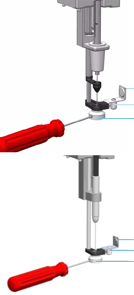
1 Getting Familiar with Your TriPlus RSH
SPME 1 and SPME 2 Tools
28 TriPlus RSH User Guide Thermo Scientific
The holder is fixed in position by the SPME Tool adapter and the retaining nut.
No O-rings are necessary to fix or protect the SPME holder. A dedicated magnet is required
for the SPME Tool. See Figure 16.
Figure 16. SPME Tool - Magnets
The Magnet Adapter Ring is used to transport vials from a Tray to the Agitator, as an
example. The lower needle guide has the Stack Drawer Magnet installed and fixed with two
screws. The magnet is required to open and close a Temperature Controlled Drawer.
See the section “Syringes for SPME Tools” on page 29.
Stack Drawer Magnet
Magnet Adapter
Adapter for SPME Conditioning Station
Stack Drawer Magnet
Magnet Adapter
Adapter for SPME Conditioning Station
SPME 1
SPME 2
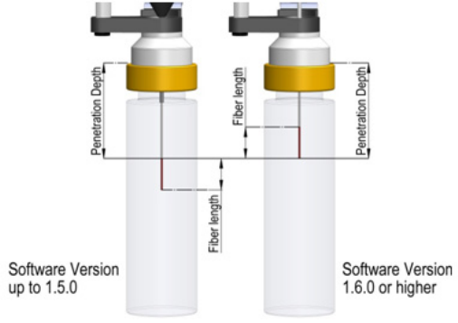
1 Getting Familiar with Your TriPlus RSH
SPME 1 and SPME 2 Tools
Thermo Scientific TriPlus RSH User Guide 29
Syringes for SPME Tools
SPME syringe fiber Tool includes a combination of four different fibers for starting-up.
Definition of SPME Penetration Depth
Up to RSH Firmware version 1.5.0, the definition of the parameter for SPME Penetration
Depth has been defined without including the Fiber length.
Starting with RSH Firmware version 1.6.0 the definition has been changed to reflect the
total length, including the Fiber length. See Figure 17.
Figure 17. SPME Penetration Depth Parameter Comparison
This change in the definition is valid for the SPME Penetration Depth for the following
classes:
•Vial
•Injector
• SPME Conditioning Module
As a result this change in definition affects several method parameters for existing methods.
When working with RSH Firmware version 1.6.0, to achieve the same depth in the fiber
exposure as in the previous RSH Firmware version, the following method parameters have to
be changed.
• Class Vial Depth: Parameter Sampling depth mode
• Class Injection: Parameter Injector depth
• Class Fiber Conditioning | Derivatization Vial: Parameter Derivatization depth.
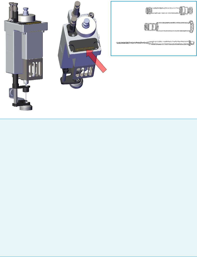
1 Getting Familiar with Your TriPlus RSH
ITEX-2 Tool
30 TriPlus RSH User Guide Thermo Scientific
ITEX-2 Tool
The ITEX-2 tool consists of a dedicated gas-tight syringe with an adapter for a replaceable
side-hole needle and a heated syringe cartridge. The side-hole needle includes an integrated
trap (standard trap material is Tenax® TA) and a trap desorber heater. See Figure 18.
Figure 18. ITEX Tool
Note The ITEX-2 tool performs enrichment of volatile or semi-volatile compounds
during headspace analysis. ITEX can be considered an automated dynamic headspace
technique. In classical headspace technique, one sampling is done per vial. In this device,
analytes are adsorbed (loaded) on a sorbent trap contained within a side-hole needle
attached to a gas-tight syringe. Following this loading procedure, analytes are thermally
desorbed and led directly into the GC injector, then analyzed by the required technique,
mainly using GC/MS detection. Loading takes place by continuously moving the
headspace syringe plunger up and down as a pump, passing the headspace gas phase that
exists above a sample through the sorbent trap inside the needle numerous times.
The cycle of the ITEX-2 tool consists of four steps:
1. The sample vial is placed into the Agitator and the equilibrium is established (time
and temperature controlled).
2. The sample is loaded on the trap by continuously pumping the syringe plunger up
and down.
3. Thermal desorption of analyte directly into the GC injector.
4. The Trap material is cleaned with inert gas, Trap Cleaning Time/Flush Time.
The Trap temperature can be raised for the cleaning step.
Contacts for ID, Heater and
Heater Control, Fan, and Fan
Control
Plunger for ITEX
Syringe
ITEX Syringe
Barrel
ITEX Trap
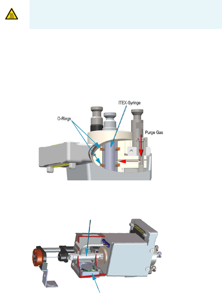
1 Getting Familiar with Your TriPlus RSH
ITEX-2 Tool
Thermo Scientific TriPlus RSH User Guide 31
Besides the coupling pivots for the needle guide and the tool, the purge gas connector is
directly installed on the cover plate of the tool. The syringe flange is supported by the polymer
counterpart to the retaining nut. In the heating cylinder there are two O-rings which seal the
gas flow to enable a syringe purge. It is recommended to replace these O-rings during
preventative maintenance.
Figure 19 shows the cut-out of the ITEX tool visualizing the Purge Gas Flow and the Sealing
O-ring.
Figure 19. ITEX Tool Cut-out (1)
The heating and cooling functionality for the Trap is integrated in the lower part of the tool.
See Figure 20.
Figure 20. ITEX Tool Cut-out (2)
del gas di lav aggio
WARNING - BURN HAZARD The ITEX Tool can operate at a maximum temperature of
200 °C. Operating at this temperature, its outer surface will reach about 70 °C. Do not
touch the outside of the ITEX Tool. Always let the ITEX Tool cool down before you
touch it, or before you remove the Syringe.
Trap Cooler
Trap Heater
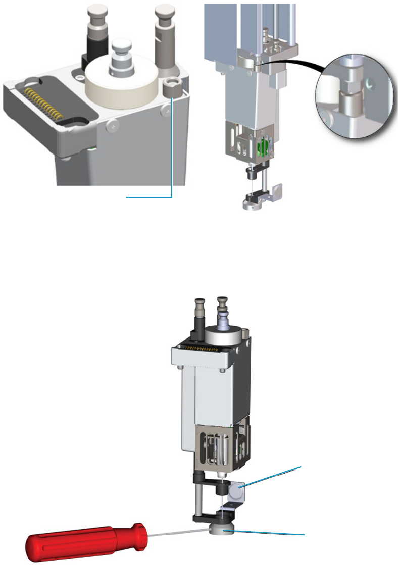
1 Getting Familiar with Your TriPlus RSH
ITEX-2 Tool
32 TriPlus RSH User Guide Thermo Scientific
The purge gas adapter mounted on the ITEX-Tool couples with the adapter from the head.
The coupling is sealed with an O-ring installed in the ITEX Tool Purge Gas Adapter. See
Figure 21.
Figure 21. ITEX Tool Purge Gas Adapter
The Magnet Adapter Ring is used to transport vials from a Tray to the Agitator, as an
example. The lower needle guide has the Stack Drawer Magnet installed, and fixed with two
screws. The magnet is required to open and close a Stack Drawer. See Figure 22.
Figure 22. ITEX Tool - Magnets
ITEX Tool Purge Gas Adapter
Stack Drawer Magnet
Magnet Adapter
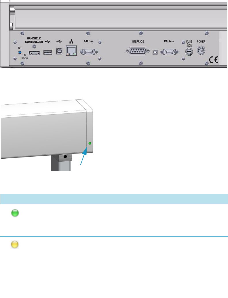
1 Getting Familiar with Your TriPlus RSH
Control Interface
Thermo Scientific TriPlus RSH User Guide 33
Control Interface
The back part of the crossrail X includes the following components as shown in Figure 23.
Figure 23. Control Interface
•Status — This LED (Light Emission Diode) provides indications on the instrument
operating conditions showing a solid or blinking light.
The LED light on the right side cover of the X-axis
shows the identical status as the Status Light
displayed on the Handheld Controller. See Table 7 .
See also the section “Menu Screen Status Bar
Symbols” on page 77, and to the section System
Status LED at Status Bar or at X-Axis Side Cover
in the chapter Troubleshooting of the TriPlus RSH
Hardware Manual.
Table 7. Status LED Lights (Sheet 1 of 2)
Symbols Description
Green status light, blinking: TriPlus RSH is working (moving). Execution
mode. The Handheld Controller is partially blocked to specific actions.
Green status light, steady on: TriPlus RSH is ready in Standby. Idle Mode.
Yellow status light, blinking: RSH Firmware is booting.
Yellow status light, steady on: A problem has been detected which cannot be
resolved by the robotic system.
Examples: Bent needle (mechanical problem), missing Tool, and so on. detected
at the moment of sample execution. A software run-time error can also cause a
status light change to steady-on yellow.
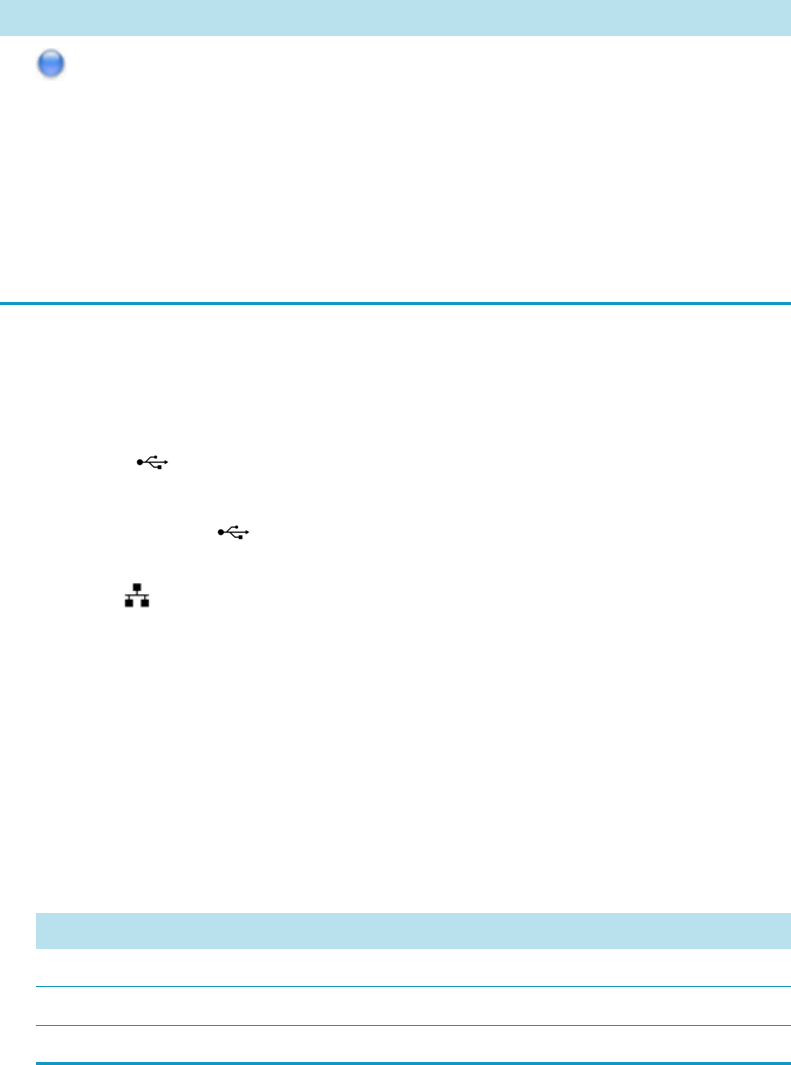
1 Getting Familiar with Your TriPlus RSH
Control Interface
34 TriPlus RSH User Guide Thermo Scientific
•S1 — Reset button to restore the factory default settings without knowing the IP
Address.
•HANDHELD CONTROLLER — A 20-pin port connector for the connection between
the TriPlus RSH and the Handheld Controller.
•USB Host — USB Type A connector for the connection of the USB stick only for
service purposes.
•USB Device/Client — USB Type connector for the connection to an USB device
or USB client.
•Ethernet — RJ45 Ethernet cable connects the TriPlus RSH directly to a computer,
and a LAN (Local Area Network) for the network connection of the TriPlus LAN
sampler.
•BUS — Two Mini Delta Ribbon 14-pin connectors for the connection to the CPU board
and the components installed on the sampler.
•INTERFACE — DSB 15-pin female connector for the connection between the sampler
and the GC.
•FUSE — Housing for the fuse T6.3; 250 VDC. See Tab le 8.
•POWER — KYon KPJX-3S-S connector receives 36 V from the Power Module.
Blue status light, blinking: The TriPlus RSH is in the process of software
Update or Backup. (For the processes Copy Backup and Restore the Status
light remains green).
Blue status light, permanent: TriPlus RSH is in a safe state (power reduced to
a minimum) and requires manually moving the Head to the Tea ch Po int .
Note: If an error is detected at the same time that an action is required
according to the Blue Status Light, then by default the yellow status light will
dominate.
Table 8. Fuses Parameters
Parameter Value
Rated Current 6.3 A
Rated Voltage 250VAC
Fuse Dimensions 5 x 20 mm
Table 7. Status LED Lights (Sheet 2 of 2)
Symbols Description

1 Getting Familiar with Your TriPlus RSH
Definitions of Active and Passive Hardware Modules
Thermo Scientific TriPlus RSH User Guide 35
Definitions of Active and Passive Hardware Modules
This section details the definitions of the hardware modules.
Active Versus Passive Module
An Active module is defined as a module that sends or receives specific commands and
checks. The control communication is done via the BUS serial protocol for all active devices.
A typical example is the motor for the X-Axis which has to be accelerated to a certain speed
and stopped after a defined travel distance. The motor records the position at every point of
its trajectory and is reported back to the processor via the BUS using the X-motor (Servo
motor X-axis).
Another example is an Agitator where the temperature and motor for sample agitation have to
be controlled and monitored.
A Passive module is a static device. Typical examples are non-temperature programmable Tray
Holders, a TR Station, or a Standard Wash Station.
You can easily distinguish the difference between active and passive devices by checking for
any serial connectors at the device. See the example in Figure 24, which shows the passive
module TR Station on the left, and the active module ATC Station for three Tools on the
right. Every Active Module has two connectors for daisy chaining to the next module.
Figure 24. Example of Passive and Active Modules
At the level of the RSH Firmware, it is important to understand other differences between the
two classes of modules:
Passive Module Active Module
Connectors

1 Getting Familiar with Your TriPlus RSH
Definitions of Active and Passive Hardware Modules
36 TriPlus RSH User Guide Thermo Scientific
•Active module — The device firmware is always included in (or is part of ) the basic RSH
Firmware. When the module is connected to the BUS, the device is recognized and made
available for use via serial control. A module ID# is automatically provided and stored.
Loading or activating a specific firmware object is not necessary.
An active device can be de-activated but not deleted. A deactivation is done by
disconnecting the serial cable. The device ID# is stored. If the device is re-activated later,
the same device ID# will be re-assigned.
•Passive module — The template of a passive module is included in (or part of) the basic
RSH Firmware. Using the Handheld Controller, add the module by selecting Options |
Setup | Modules.
A dialog guides you through the screens to define the various Attributes and Parameters.
After the newly-defined module is stored, it is available for further setup definitions such
as teaching the positions.
A module ID# is automatically provided and stored as long as the device is in operation.
Loading or activating a specific device firmware is not possible for a Passive module.
A passive module cannot be deactivated but it can be deleted. The module ID# will not
be stored. If the same device is re-activated later, another module ID# will be randomly
provided.
Active Versus Composite Module
The term Active module is used for a module which communicates with the BUS. An Active
module can consist of one or more devices which also communicate with the Active versus
Composite module.
The term Active module is used for a module which communicates with BUS. An Active
module can consist of one or more devices which also communicate with the BUS but in slave
functionality. A typical example is the Tr iPlus RSH Head (Z-axis) which contains three
different motors, each of them connected to the BUS.
A Composite module, such as the TriPlus RSH, is composed of several devices.
Note It is possible to delete an active device in the Service access level.
Note This differentiation is not important for the routine use of the TriPlus RSH.
You must understand this difference when a device must be replaced, for example a
motor-Z as part of the TriPlus RSH Head.
1 Getting Familiar with Your TriPlus RSH
Modules Description and Specifications
Thermo Scientific TriPlus RSH User Guide 37
Modules Description and Specifications
This section covers the description and specifications of the following modules:
•“TR Station” on page 38
•“ATC Station” on page 39
•“Standard Wash Station” on page 40
•“Large Volume Wash Station” on page 41
•“Large Solvent Station” on page 41
•“Fast Wash Station” on page 42
•“Agitator” on page 43
•“Vortexer” on page 45
•“MHE Station” on page 47
•“SPME Conditioning Station” on page 61
•“Barcode Reader ” on page 63
•“Liquid Cooled Tray Holder” on page 69
•“Temperature Controlled Drawer” on page 70
•“Electronic Box for OC Injector Actuator” on page 75
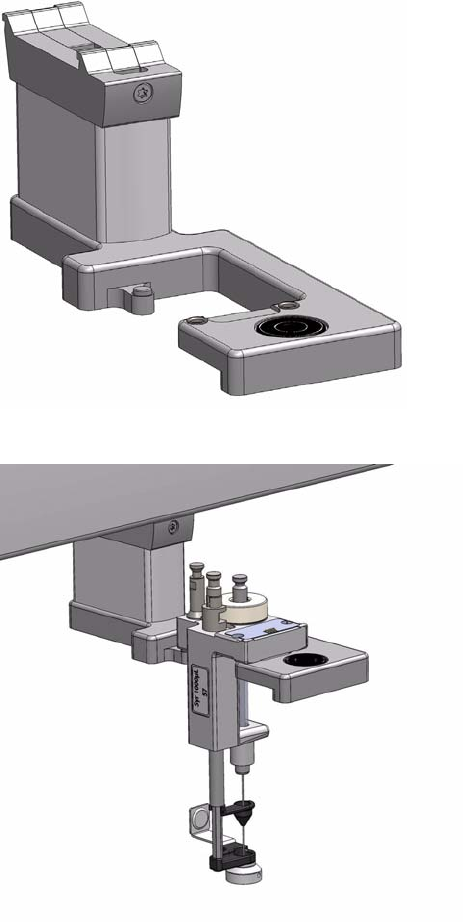
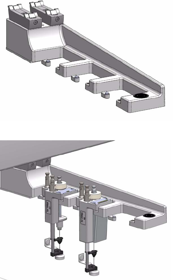
1 Getting Familiar with Your TriPlus RSH
ATC Station
Thermo Scientific TriPlus RSH User Guide 39
ATC Station
This active module containing three slots for tools allows you to change an injection tool
automatically for specific needs. See Figure 27 and Figure 28.
Figure 27. ATC Station
Figure 28. ATC Station with Tools
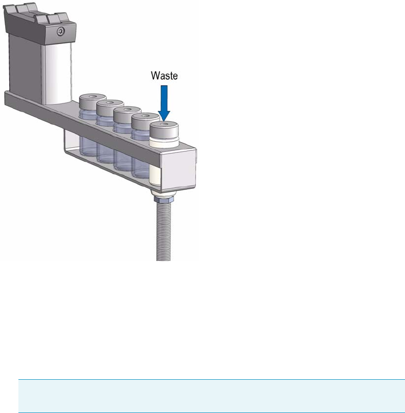
1 Getting Familiar with Your TriPlus RSH
Standard Wash Station
40 TriPlus RSH User Guide Thermo Scientific
Standard Wash Station
The Standard Wash Station is shown in Figure 29.
Figure 29. Standard Wash Station with Drainage Adapter
Contains five 10 mL vials. The configuration within the Standard Wash Station can be
flexible. Options include:
• 2 x Wash Vials and 2 x Waste Vials and a Vial dedicated for Internal Standard, Reagent,
and so on.
• 4 x Wash Vials and 1 x Waste Vial. This configuration allows using four different Wash
Solvents for critical applications
• When the size of the Waste Vial becomes a problem replace the Vial in the waste position
with a drainage adapter.
Note The single Waste Vial can be too small in size to accept 4 x 10 mL wash solvent
(at worst case).
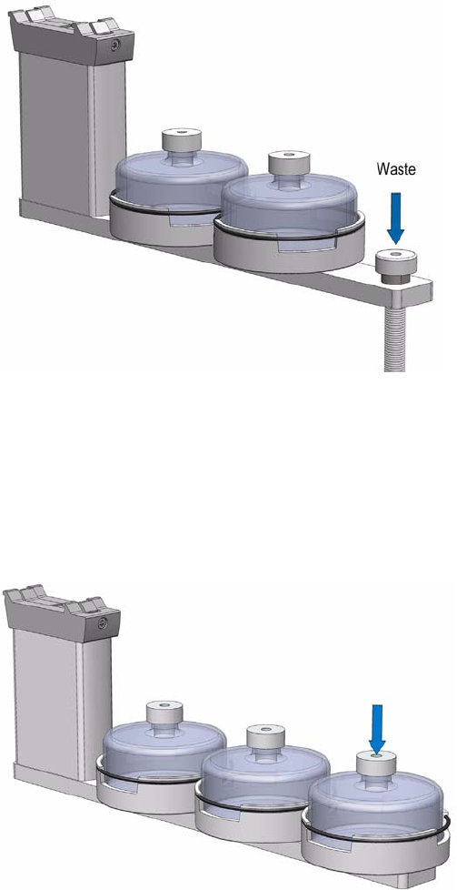
1 Getting Familiar with Your TriPlus RSH
Large Volume Wash Station
Thermo Scientific TriPlus RSH User Guide 41
Large Volume Wash Station
The Large Volume Wash Station is shown in Figure 30.
Figure 30. Large Volume Wash Station
Contains two 100 mL vials and one vial for waste port for diverting waste to large reservoir.
Large Solvent Station
The Large Solvent Station is shown in Figure 31.
Figure 31. Solvents Station
Contains three 100 mL vials.
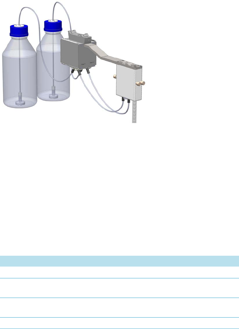
1 Getting Familiar with Your TriPlus RSH
Fast Wash Station
42 TriPlus RSH User Guide Thermo Scientific
Fast Wash Station
The Fast Wash Station is shown in Figure 32.
Figure 32. Fast Wash Station
The Fast Wash Station is an active module. Communication and control of the station is
provided through the BUS from the system.
Two Micro Pumps actively deliver the required flow of two different wash solvents.
The syringe is washed by inserting the needle into a glass liner; the provided wash solution is
aspirated and dispensed. The needle is washed outside during this process. The dispensed
solvent passes from the overfilled liner into an internal flow channel to the waste outlet.
This wash process can be repeated.
The wash solvent can also be changed by moving the syringe to the second wash port and
starting the wash process over again. The advantage of this station is that the head does not
need to move to the waste position to eject the wash solvent.
The Fast Wash Station dimensions, mass, operating, and environmental requirements are
detailed in Ta ble 9 and Table 10.
Table 9. Fast Wash Station - Dimensions and Mass (Sheet 1 of 2)
Length Dimension in mm (in.)
Width 60 (2.36)
Depth 315 (16.73)
Including cable connectors [380 (15.0)]
Height 135 (5.3)
Including cable connectors [185 (7.3)]
Associated Cables (two pieces) 0.15 (0.33)
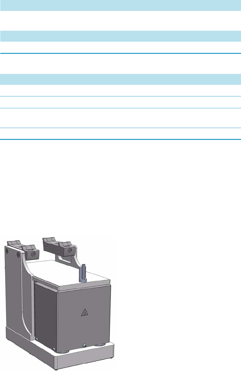
1 Getting Familiar with Your TriPlus RSH
Agitator
Thermo Scientific TriPlus RSH User Guide 43
Agitator
The Agitator is an active module used for heating and shaking the sample. See Figure 33.
Its main function is to speed up the formation of the equilibrium between two phases which
can be used for applications such as static headspace, or SPME (Solid Phase Micro Extraction),
or ITEX (In-tube Extraction). The Agitator can also be used for chemical derivatization
reactions, liquid/liquid extractions, and so on. Temperature and shaking parameters can be
individually controlled.
Figure 33. Agitator Module
Solvent reservoir kit 1.30 (2.87)
Including two 1000 mL bottles
Mass Dimension in kg (lbs)
Fast Wash Station 0.750 (1.65)
Table 10. Operating and Environmental Requirements
Parameter Requirements
Operating temperature range 4 to 40 °C
Maximum relative humidity 80%, non-condensing
Bench space Consider bench space for the two 1000 mL
bottles, or by your request.
Altitude limitations 3000 m above sea level
Table 9. Fast Wash Station - Dimensions and Mass (Sheet 2 of 2)
Length Dimension in mm (in.)
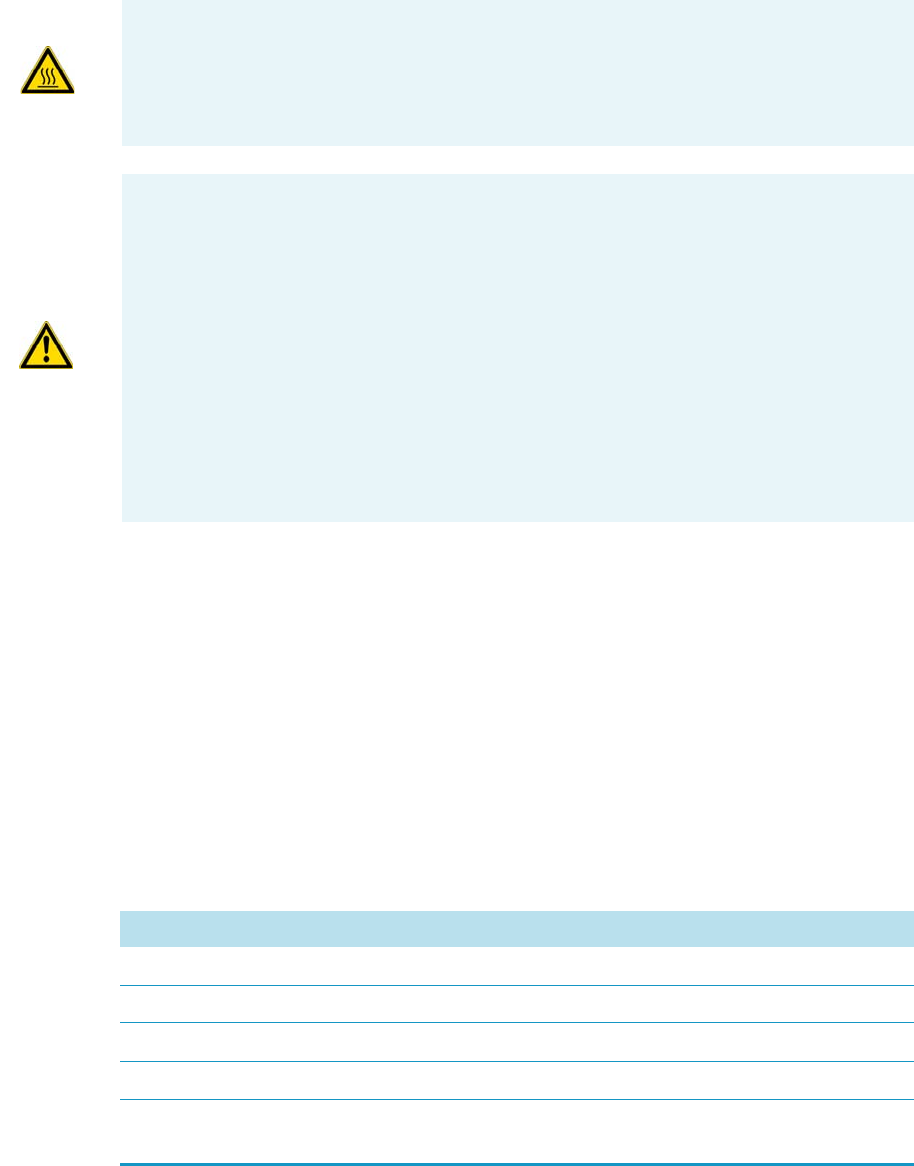
1 Getting Familiar with Your TriPlus RSH
Agitator
44 TriPlus RSH User Guide Thermo Scientific
The Agitator specifications are:
•Sample Capacity — Six heated vial positions for 2 mL, 10 mL, and 20 mL vials.
– Spacers for 10 mL vials are optionally available.
– Spacers for 2 mL vials are optionally available.
•Tem p e ra tu re C o ntro l — From 40 °C to 200 °C in 1 °C increments.
•Electrical Connectors — Two BUS connectors for daisy chaining.
The Agitator dimensions, mass, operating and environmental requirements are detailed in
Tab le 11 and Ta bl e 12.
WARNING -BURN HAZARD The Agitator can operate at a maximum temperature of 200
°C. Operating at this temperature, its outer surface will reach approximately 70 °C.
When the Agitator is heated, do not touch the outside surface, do not reach into it; do not
try to remove vials manually from it. The vials will be at the selected operating
temperature, and there is a danger of burns.
WARNING When sample vials have to undergo heating and agitation, it is important to
consider the glass quality. Use high quality glass only.
Remember that depending on the application conditions, high pressure can build up in
the vial. Whenever a temperature greater than 60 °C is applied, consider the vapor
pressure of the solvent used to ensure that no excessive pressure builds up. This is
important when using a temperature above 100 °C and especially at the maximum
temperature of 200 °C.
Be aware that solid materials can also contain volatile compounds such as water
(humidity) which could cause build-up of excess vapor pressure.
Do not reuse headspace vials. During the process of washing the vial, micro-cracks can
form which will weaken the glass wall and increase the chances of the vial breaking.
Table 11. Agitator - Dimensions and Mass
Length Dimension in mm (inches)
Width 114 (4.45)
Depth 180 (7.09)
Height 176 (6.93)
Mass Dimension in kg (pounds)
Agitator (with cable and 6x10 mL vial
spacers)
2.38 (5.25)
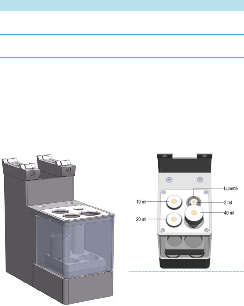
1 Getting Familiar with Your TriPlus RSH
Vortexer
Thermo Scientific TriPlus RSH User Guide 45
Vortexer
The Vortexer is an active module which used for intensive shaking (orbital interval shaking) at
ambient temperature. See Figure 34.
Its main application is the automated liquid/liquid extraction of two immiscible solvent
phases. An emulsion is temporarily formed which will break after the shaking stops. Only one
vial at time can be treated.
Figure 34. Vortexer Module
Shaking speed can be selected. The temperature control of the module is not possible.
Table 12. Agitator - Operating and Environmental Requirements
Parameter Requirements
Operating temperature range 40 to 200°C
Maximum relative humidity 80%, non-condensing
Vibration Negligible
Static electricity Negligible

1 Getting Familiar with Your TriPlus RSH
Vortexer
46 TriPlus RSH User Guide Thermo Scientific
The Vortexer specifications are:
•Sample Vial Dimensions — 2, 10, 20, and 40 mL.
– 2 mL Vial; diameter 11.5 ± 0.5 mm; height 34 mm (including magnetic cap)
– 10 mL Vial; diameter 23 ± 0.5 mm, height 48 mm (including magnetic cap)
– 20 mL Vial; diameter 23 ± 0.5 mm, height 78 mm (including magnetic cap)
– 40 mL Vial; diameter 27.5 ± 1 mm, height 100 mm (including magnetic cap)
•Sample Capacity — 1 vial treated at once
•Electrical Connectors — Two BUS connectors for daisy chaining
•Agitation Speed — Up to 2000 rpm
The Vortexer dimensions, mass, operating, and environmental requirements are detailed in
Tab le 13 and Ta bl e 14.
WARNING The Vortexer operates at a maximum speed of 2000 rpm. Operating at this
speed places very high stress on the glass vials. Use quality glass vials from reliable suppliers
only. Do not wash and recycle used vials; there is a danger of micro-cracks present in the
glass.
It is mandatory using the mixer with the installed protective cover. During the mixing step
it is important to keep the TriPlus RSH Head always above the vial to avoid an uplift of
the vial caused by the spin.
Use only one vial at time for mixing.
The recommended application for the Vortexer is liquid/liquid extraction. If a solid
material is mixed with a liquid at high speeds, this will likely cause cracking of the vial.
When sample vials have to undergo vigorous agitation, it is important to consider the glass
quality. Use high quality glass only.
Do not reuse headspace vials. During the process of washing the vial, micro-cracks can
form which will weaken the glass wall and increase the chances of the vial breaking.
Table 13. Vortexer - Dimensions and Mass
Length Dimension in mm (in.)
Width 82 (3.23)
Depth 180 (7.09)
Height 177 (7.0)
Mass Dimension in kg (lbs)
Vortexer (with cable) 2.10 (4.63)
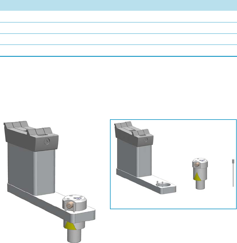
1 Getting Familiar with Your TriPlus RSH
MHE Station
Thermo Scientific TriPlus RSH User Guide 47
MHE Station
The MHE (Multiple Headspace Extraction) Station is an add-on passive module to extend
the range of headspace applications. See Figure 35.
Figure 35. MHE Station
In a classical headspace technique, one sampling is performed per vial. Sample quantification
can be inaccurate in the presence of interfering matrices or in cases where a calibration
standard cannot be made using a matrix composition identical to that of the sample.
See the section “Principles of Multiple Headspace Extraction (MHE)” on page 49 for details.
The MHE station consists of a venting tool (MHE Adapter) combined with a MHE Adapter
Holder. The MHE technique requires a series of sampling cycles using the same vial.
First, the vial is pressurized to reach a specific pressure. The vial is then sampled and vented.
The vial is re-pressurized and sampled again. This process is repeated multiple times to obtain
the final results. See the section“MHE Cycle Step-by-Step” on page 54.
Table 14. Operating and Environmental Requirements
Parameter Requirements
Operating temperature range Ambient, no control
Maximum relative humidity 80%, non-condensing
Vibration To be tested
Static electricity Negligible
MHE Adapter Holder MHE Adapter Needle

1 Getting Familiar with Your TriPlus RSH
MHE Station
48 TriPlus RSH User Guide Thermo Scientific
The MHE adapter and MHE Adapter Holder dimensions, mass, operating, and
environmental requirements are detailed in Ta ble 1 5, Ta bl e 1 6, and Tabl e 17.
CAUTION The MHE Venting Adapter contains a spring-loaded white insert to protect
the needle. Use caution when handling the white insert; the needle can pierce skin.
Note The MHE Adapter has a threaded gas vent outlet, allowing an optional OD 1/16
inch waste tube to be attached. This optional gas venting tube can be used for applications
requiring hazardous or toxic gases. The pressure setting for the MHE technique is 1.0 to
1.5 bar (about 15 psi). If your system was previously used for static headspace
applications, you may need to adjust your pressure regulator.
Table 15. MHE Adapter - Dimensions and Mass
Length Dimension in mm (in.)
Width 25 (1.0)
Height 51 (2.0)
Mass Dimension in kg (lbs)
MHE Adapter 0.027 (0.06) without vent tubing
Table 16. MHE Adapter Holder - Dimensions and Mass
Length Dimension in mm (in.)
Width 35 (1.4)
Depth 150 (5.9)
Height 110 (4.3) with MHE Adapter inserted
Mass Dimension in kg (lbs)
MHE Adapter 0.285 (0.63) without vent tubing
Table 17. Operating and Environmental Requirements
Parameter Requirements
Operating temperature range 4 to 40 °C
Maximum relative humidity 80%, non-condensing
Latitude limitations 3000 meters above sea level
1 Getting Familiar with Your TriPlus RSH
MHE Station
Thermo Scientific TriPlus RSH User Guide 49
Naming Convention for MHE Station
MHE Adapter — The MHE Adapter, equipped with a built-in needle, is used as the tool to
release the pressure from the vial.
The MHE Adapter is also equipped with a vent outlet connector for connecting a vent line. In
cases toxic gases are released from the vial, the venting line can be positioned into a
neutralizing agent or to a fume hood to protect the operator and the environment.
MHE Needle — The MHE Needle is a dedicated needle used for the MHE Adapter only.
Length: 46 mm, Gauge 22, Point style 5 (side hole needle tip).
MHE Adapter Holder — Parks the MHE Adapter in between the cycles, or in standby
position.
Principles of Multiple Headspace Extraction (MHE)
This section provides a brief description of the MHE principle.
Introduction
The multiple headspace technique is used in instances where interfering matrices interact with
the analyte, such as by partial adsorption, or if a solid analyte contains low concentrations of
moisture. Whenever it is impossible to prepare the calibration standard using an identical
matrix to that of the actual sample, single point calibration using the static headspace
technique will fail.
The term multiple headspace extraction (MHE) is partially self-descriptive. To determine the
quantity of an analyte, sampling is carried out by repeated extraction of gas from the same vial
above a sample solution containing the analyte (known as the headspace). The method thus
approaches continuous gas extraction but is carried out in a stepwise fashion.
In concept, the procedure is analogous to the multiple extraction of a sample from a simple
elution column, where each passage of eluate through the column reduces the amount of
analyte contained in a subsequent passage. The peak area from any given extraction will be
smaller than that of the previous extraction step. The sum of the peaks will be proportional to
the total content of the analyte.
A quantitative determination of the total amount of analyte present in a sample depends on
the relationship between peak area and the amount of analyte. The sum of the amounts of
analyte that are removed will eventually equal the total amount of analyte in the original
sample if the extractions are continued to infinity.
Theoretically, summing up the peaks obtained from an infinite number of column extractions
would allow the calculation of the absolute amount of analyte in a sample. In practice, it is
sufficient to carry out a limited number of extractions, permitting a determination of the
underlying exponential relationship between the measured area and the number of
extractions, in turn allowing for the determination of the total amount of analyte in the
sample.
1 Getting Familiar with Your TriPlus RSH
MHE Station
50 TriPlus RSH User Guide Thermo Scientific
The effect of the sample matrix is eliminated by extracting the entire amount of the analyte.
Contrary to the situation that exists in single-headspace extraction, it is therefore possible to
use calibration standards that are not prepared with the same matrix as the actual samples. For
MHE to provide meaningful results, the only prerequisite is that equilibrium must exist with
respect to the analytes in terms of the distribution between the phases in the headspace vial.
Instrumentation in MHE
In normal extraction using headspace gas chromatographic technique with a gas-tight syringe,
the following steps are employed in order to sample an aliquot of the headspace gas:
The vial is thermostatted in order for equilibrium to be established between the phases in the
headspace vial.
The gas-tight syringe is used to introduce an aliquot of headspace gas to the GC.
Loop-injection headspace samplers use a pressurization step to start the headspace cycle. The
vial is pressurized to a preselected value, usually using Helium gas, which is also often the
carrier gas. The pressure is selected so that it is always greater than the pressure increase due to
sample heating and vapor pressure of the sample.
The sample is introduced onto the GC column for analysis and the system is ready for the
next sampling after cleaning.
In MHE, equilibrium must be reestablished in the headspace following each extraction. With
a syringe-based system the following steps would normally be employed:
• The vial is thermostatted in order for the equilibrium to be established between the
phases in the headspace vial.
• The vial is pressurized.
• The gas-tight syringe is used to introduce an aliquot of headspace gas to the GC.
• The vial is vented. This is accomplished by a specially designed venting tool that
punctures the septum.
The pressurized headspace gas vents through the MHE Adapter needle (venting tool) to
atmospheric pressure;
• Equilibrium is established again before the next analysis (Step 1).
• This procedure is repeated a number of times; typically three to five samplings are
performed from a single vial (analytical sample and standard).
• The main steps are described in the section “MHE Cycle Step-by-Step” on page 54.
Examples
In the following examples, we will briefly go through the basics of multiple headspace
extraction (MHE).
1 Getting Familiar with Your TriPlus RSH
MHE Station
Thermo Scientific TriPlus RSH User Guide 51
We will look at four examples situations of equilibrium between the condensed (solid or
liquid) phase and the gas phase (the headspace). The examples will be shown in increasing
complexity with respect to the equilibrium distribution and removal of the headspace between
subsequent extractions.
In each of the four cases described below, the complexity of the equilibrium distribution and
of the removal of the headspace between subsequent extractions will be increased. The final
conclusion is that the MHE method will work in most cases, with the only prerequisite that
the distribution of the analyte between the gas and the condensed phases is actually governed
by an equilibrium.
Situation 1
The equilibrium between the solid phase and the gas phase is assumed to be a
50/50-distribution. In the course of each extraction, all of the headspace is
removed/exchanged.
The measured area of the analyte peak is A.
A(ref) — Area we would measure if all of the analyte were in the headspace (corresponding to
the measured signal from a similar gas standard).
A(0) — Measured area of the analyte peak from the first extraction.
With 50% of the analyte present in the headspace, this amounts to:
A(0) = ½ * A(ref)
The total area that is determined over a number of subsequent extractions is:
A(tot) = A(0) + ½ * A(0) + ¼ * A(0) + 1/8 * A(0) + ……, or
A(tot) = A0 / (1-½) = 2 * A0
However, A(0) = ½ * A(ref) and therefore:
A(tot) = A(ref)
Thus, it would be correct to determine the total amount of analyte by comparing the
measured sum of analyte areas to a calibration measurement with data from a single
determination of a gas standard.
Situation 2
The equilibrium between the condensed phase and the headspace is assumed to be 25/75
(with 75% in the gas phase). Furthermore, we assume that the entire headspace is exchanged
during the course of each extraction step.
The measured area of the analyte peak is A.
1 Getting Familiar with Your TriPlus RSH
MHE Station
52 TriPlus RSH User Guide Thermo Scientific
A(ref) — Area that would be measured if all of the analyte were present in the headspace
(again corresponding to the measured signal from a similar gas standard).
A(0) — Actual area measured from the first extraction with 75% of the analyte in the gas
phase:
A(0) = ¾ * A(ref)
The total area determined by the MHE procedure is:
A(tot) = A(0) + ¼ * A(0) + 1/16 * A(0) + ……, or
A(tot) = A(0) / (1-¼) = 4/3 * A(0)
However, A(0) = ¾ * A(ref) and therefore:
A(tot) = A(ref)
In this case, you also arrive at the correct value by determining the total amount of analyte by
comparing the measured sum of analyte areas to a calibration measurement using data from a
single determination of a gas standard.
The conclusion is, when in equilibrium, the relative ratio of the condensed phase versus the
headspace plays no role in the amount of analyte content that is determined from an
MHE-series.
Furthermore, it can be concluded that quantification based on a single determination from a
gas standard will, in this particular case, yield the correct result, assuming that the entire
headspace is removed/exchanged during each extraction step.
Situation 3
The equilibrium between the condensed phase and the headspace is assumed to be 50/50.
Furthermore, we assume that only a part of the headspace is removed between each sampling.
The relative amount of the headspace removed between each successive extraction constant
and is denoted α.
The measured area of the analyte peak is A.
A(ref) — Area that would be measured if all of the analyte were present in the headspace
(again corresponding to the measured signal from a similar gas standard).
A(0) — Actual area measured from the first extraction with 50% of the analyte in the gas
phase:
A(0) = ½ * A(ref)
The total area determined by MHE is:
A(tot) = A(0) + (1-? * ½) * A(0) + (1-? * ½)2 * A(0) + ……, or
A(tot) = A(0) / (1-(1-? * ½)) = A(0) * 2/α
1 Getting Familiar with Your TriPlus RSH
MHE Station
Thermo Scientific TriPlus RSH User Guide 53
However, A(0) = ½ * A(ref) and thus:
A(tot) = ½ * A(ref) * 2/a, or
A(tot) = A(ref)/a
If α =1 (the entire headspace is exchanged between each extraction) then:
A(tot) = A(ref)
If α = ½ (half of the headspace is exchanged between each extraction step) then:
A(tot) = 2 * A(ref)
In this case A(tot) will be over-determined by a factor of two relative to A(ref). In other words,
the content of analyte will be over-determined by a factor of two.
Situation 4
Similar to Situations 1 to 3 as described above, the general description for an equilibrium
distribution with β being the relative amount of the analyte in the gas phase (in the
headspace) and ? being the relative amount of the headspace that is exchanged between each
successive extraction, is given by:
A(tot) = β * A(ref) * (1 + (1-α * β) + (1-α * β)2 + …)
Using the expression for the geometric sum yields:
A(tot) = β * A(ref)/(1-(1-α * β)) = β* A(ref) * 1/(α * β)
or:
A(tot) = A(ref)/α
That is: the total area, A(tot), will be over-determined by a factor of 1/α relative to A(ref).
In other words, the content of analyte will be over-determined by the factor 1/α. Thus the
total area will depend on the amount of headspace removed during each successive extraction,
but it will not depend on the position of the equilibrium (β).
Conclusion
If the headspace is only partially removed/exchanged between each extraction, the total area
that results from the MHE determination will be greater than A(ref), where A(ref) denotes
the area from a pure gas standard measured only once).
Therefore, if MHE quantification is performed based on a singly-determined gas standard,
the amount of analyte in the sample will be overestimated by a factor of 1/?, with ? being the
amount of the headspace that is removed/exchanged between each successive extraction.
1 Getting Familiar with Your TriPlus RSH
MHE Station
54 TriPlus RSH User Guide Thermo Scientific
If the MHE quantification is based on gas standards that are subjected to the same MHE
extraction sequences as the actual samples, there will be no overestimation. The amount
calculated will be correct.
References
For more details, please refer to the corresponding publication on the static headspace
technique and, in particular, on the MHE technique.
Title: ‘Static Headspace-Gas Chromatography – Theory and Practice’
Authors: Bruno Kolb and Leslie S. Ettre, Second Edition.
Published by: John Wiley & Sons, Inc.
MHE Cycle Step-by-Step
This section details the basics steps for a routine operation of the MHE station.
1. The sample vial is placed into the Agitator and the equilibrium is established.
Time and temperature are controlled. See A in Figure 36.
2. The vial is pressurized by inserting the headspace syringe needle 22 mm into the vial.
The purge gas is activated for a fixed time of 30 seconds. See B in Figure 36.
3. The Headspace Syringe Needle is withdrawn from the vial. The gas purge valve is shut off
after withdrawal. See C in Figure 36.
4. A sample aliquot is taken up into the syringe according to the sample volume defined in
the sample list. See D in Figure 36.
5. The sample aliquot is injected into the GC. See E in Figure 36.
6. The Injection Unit moves the MHE Adapter from the Adapter Holder to the sample vial
in the Agitator. See F in Figure 36.
7. The MHE Adapter needle is inserted into the vial (14 mm).
The pressurized gas is vented to the atmosphere. See G in Figure 36.
8. The MHE Adapter is removed from the sample vial and positioned back into the MHE
Adapter Holder.
9. The sample vial will equilibrate to the same conditions as applied in Step 1.
This cycle is repeated as often as defined by the MHE Counter method variable.
See H in Figure 36.
10. After this cycle has been completed, the sample vial is transported back to its original
position in the Rack. The next sample is placed in the Agitator and the cycle will be
repeated.
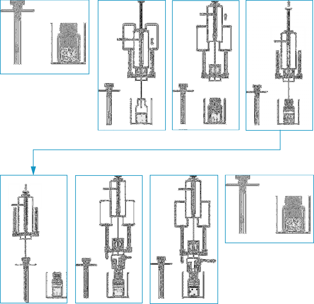
1 Getting Familiar with Your TriPlus RSH
MHE Station
Thermo Scientific TriPlus RSH User Guide 55
Figure 36. MHE Cycle Steps
AD
EFG H
BC
1 Getting Familiar with Your TriPlus RSH
MHE Station
56 TriPlus RSH User Guide Thermo Scientific
Quantification from MHE Measurements
The raw data from analytical samples deriving from MHE measurements must be treated
differently from those deriving from a classic, static headspace experiment.
In general, software packages for chromatographic data handling are not designed to cope in
an automated manner with MHE raw data.
Raw data can be extracted from a chromatogram resulting from a single GC run into an Excel
spreadsheet.
A sample Excel spreadsheet with a template is provided for quantification using the MHE
technique.
An example with explanations is given in the section “Example of Quantitative
Determination: Acetone and 2-Propanol in Granulate Samples” on page 56.
Example of Quantitative Determination: Acetone and 2-Propanol in Granulate Samples
The determination of residual solvents, such as acetone and 2-propanol in granulates as used
in the production of pharmaceutical products, is most often performed by headspace analysis.
Often the analysis is performed as a standard, single extraction determination with
quantitation based on direct comparison to the response from gas standards.
The drawback of this procedure is that it neglects any sample with matrix interaction.
This can lead to the analyte not residing entirely in the gas phase (the headspace) in its
distribution between the condensed phase and the headspace. In this case the analyte amount
will be underestimated. In other words, the determined amount of analyte will be lower than
the true value.
In contrast, a true measure of the total content of the analyte can be obtained by applying
multiple headspace extraction (MHE).
The following simple example briefly describes the practical steps involved in such an
MHE-determination
The current example describes the procedure to determine the residual content of acetone and
2-propanol in samples of polyvinyl pyrrolidone-bound 5-amino salicylic acid (5-ASA)
granulate. For simplicity, only the determination of the acetone content is discussed.
The determination of the 2-propanol content is performed using a similar procedure.
A three-level calibration curve (double determination at each level) is used for the
quantitation – thus a total of six calibration samples are run. In this particular example, the
calibration curve is used for determining the acetone content in one sample – in practice the
number of samples will obviously be larger.
1 Getting Familiar with Your TriPlus RSH
MHE Station
Thermo Scientific TriPlus RSH User Guide 57
Procedure for Determining Acetone Content
The steps for determining the acetone content are outlined in the following example:
•A — Each of the six calibration standards is extracted five times for increasing the quality
of the determination).
See “A. Performing the actual MHE Measurements” on page 57.
•B — For each of the six calibration samples, the five areas from the five extractions are
taken into account in determining the total area.
See “B. Determination of the Total Area” on page 57.
•C — An external standard calibration curve is established for acetone by plotting the
calculated total area as a function of the amount of acetone in the standard.
Remember that each of the total areas is a result of the MHE calculation for five
extractions.
See “C. Construction of the Calibration Curve” on page 60.
•D — The total area is determined for any one of the real samples. The total content of
the analyte is calculated from this value and the calibration curve.
See “D. Calculation of the Analyte Content in Real Samples” on page 60.
A. Performing the actual MHE Measurements
The parameters of the actual MHE measurements, such as incubation time, incubation
temperature, injection parameters, and so on, can be controlled using the MHE cycle that is
part of the MHE kit.
B. Determination of the Total Area
As you are performing a multiple headspace extraction to determine the total area, you can
expect a functional relationship of the type.
A = A(0) * exp(-k * n), where n is the extraction number
See Step 1 and Figure 37.
Therefore, by plotting the natural logarithm of the area as a function of the extraction
number, you can expect a linear relationship, from which the constants A(0) and k can be
directly determined by means of the standard linear regression techniques.
Finally, the total area can be determined as:
A = A(0)/(1-exp(-k)).
The linear regression determination of the constants can be easily performed using a simple
Excel setup as well as the determination of the total area. The following Excel-sheet shows the
MHE-data for one of the calibration samples. See Figure 37.
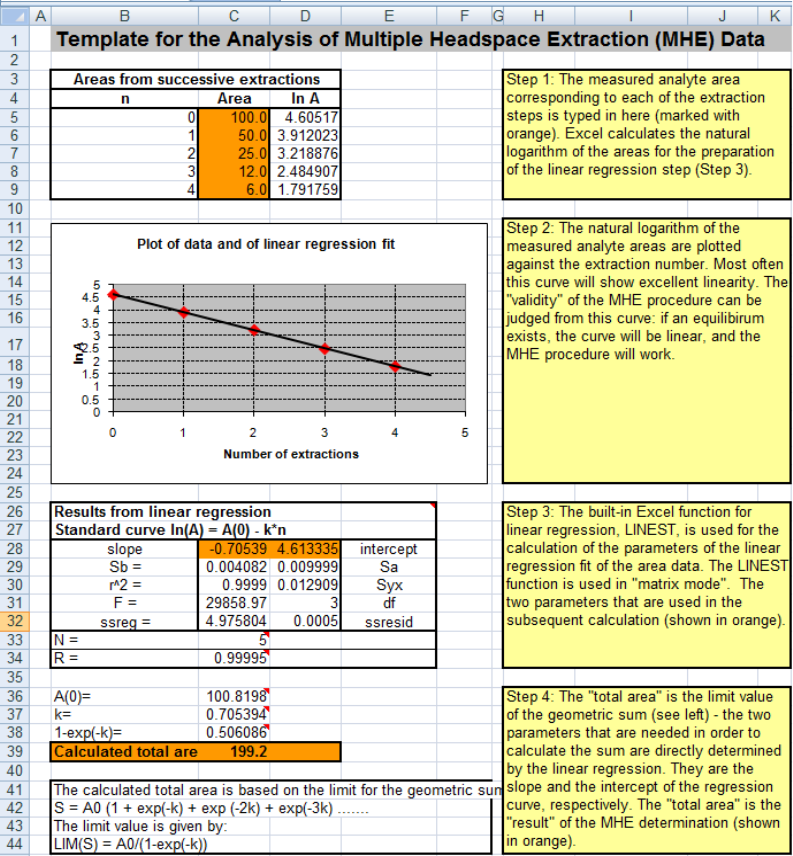
1 Getting Familiar with Your TriPlus RSH
MHE Station
58 TriPlus RSH User Guide Thermo Scientific
Figure 37. Sample Excel Setup for MHE Quantitation
The following is an overview of each of the steps involved in completing and interpreting the
data shown the Excel spreadsheet of Figure 37.
Step 1
The measured analyte area corresponding to each of the extraction steps is typed here.
See the orange field Area in Figure 38.
Excel calculates the natural logarithm of the areas for the preparation of the linear regression
step. See Step 3.
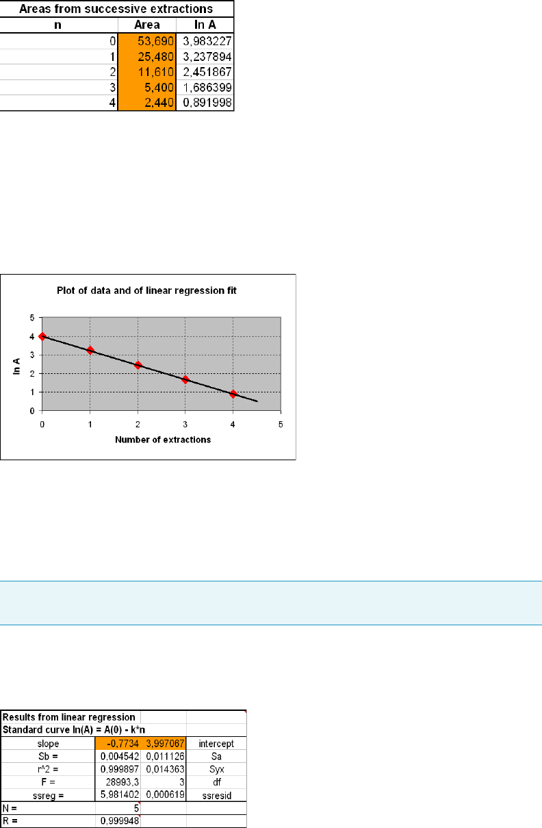
1 Getting Familiar with Your TriPlus RSH
MHE Station
Thermo Scientific TriPlus RSH User Guide 59
Figure 38. Entering Measured Areas of Calibration Standard Analyte
Step 2
The natural logarithm of the measured analyte areas are plotted against the extraction
number. Usually, this curve will show good linearity. The validity of the MHE procedure can
be judged from this curve: if equilibrium exists, the curve will be linear, and the MHE
procedure will work. See Figure 39.
Figure 39. Linear Regression for Calibration Standard Analyte
Step 3
The built-in Excel function for linear regression LINEST is used for the calculation of the
parameters of the linear regression fit of the area data. The LINEST function is used in
matrix mode.
Figure 40 shows the example of the slope and intercept parameters used in the subsequent
calculation.Calculation of Linear Regression for Calibration Standard Analyte
Figure 40. Calculation of Linear Regression for Calibration Standard Analyte
Note LINEST is the name of this function in the UK version of Excel. This name might
be different in other language versions of Excel.
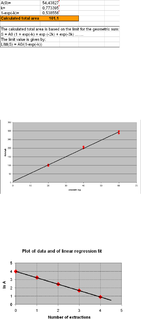
1 Getting Familiar with Your TriPlus RSH
MHE Station
60 TriPlus RSH User Guide Thermo Scientific
Step 4
The total area is the limit value of the geometric sum. The two parameters needed for the
calculation of the sum are directly determined by the linear regression. They are the slope and
the intercept of the regression curve, respectively. The calculated total area is the result of the
MHE determination. See Figure 41.
Figure 41. Calculation of Total Area of Calibration Standard Analyte
C. Construction of the Calibration Curve
For each of the calibration samples the resulting total area, (determined according to the
description above), is plotted against the amount of analyte.
In the following example we have three concentration levels of standards, each determined
twice – thus the calibration curve comprises six points in total. See Figure 42.
Figure 42. Calibration Curve: Total Area versus Amount of Acetone
D. Calculation of the Analyte Content in Real Samples
From the MHE measurements of each of the actual samples, an MHE plot is generated.
A typical example yields an MHE curve as shown in Figure 43.
Figure 43. MHE Plot of Analyte form an Analytical Sample
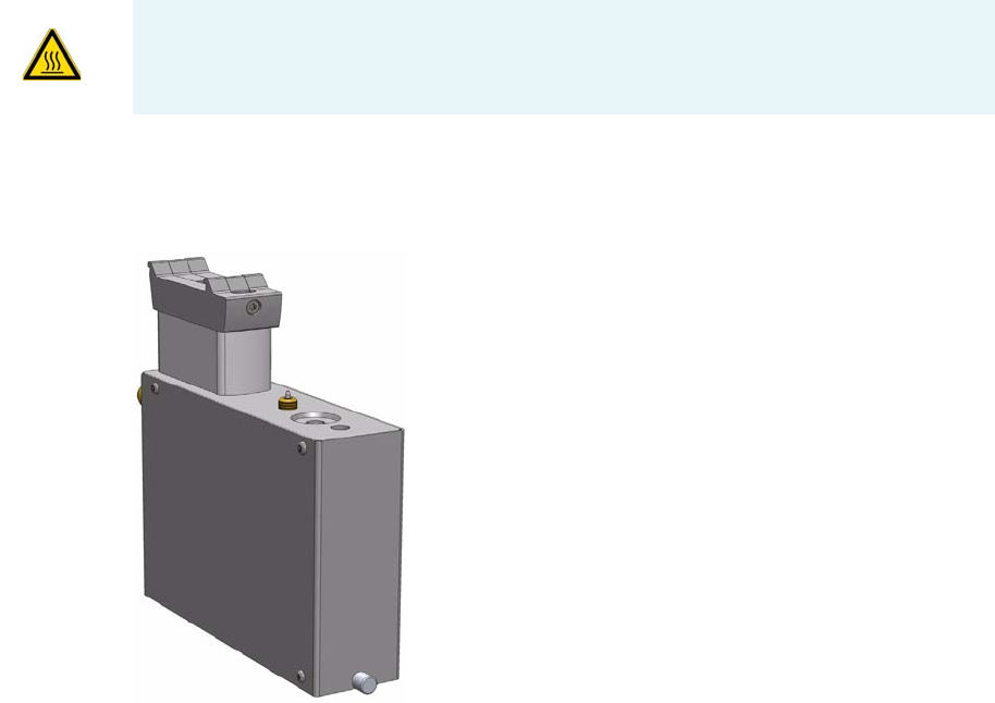
1 Getting Familiar with Your TriPlus RSH
SPME Conditioning Station
Thermo Scientific TriPlus RSH User Guide 61
The total area is determined from the MHE-plot of Figure 43.
Consequently, the acetone content can be determined as follows:
1. Calculate the total area using the Excel spreadsheet. In this example the total area is 101.1
2. Compare the total area against the calibration plot from which the amount can be
determined as 19 μg. See Figure 43.
SPME Conditioning Station
The SPME Conditioning Station is an optional device used for the SPME (Solid Phase Micro
Extraction) technique. See Figure 44.
It conditions or cleans a fiber between chromatographic runs.
A flow of inert gas protects the fiber from degradation when it is exposed to elevated
temperatures. The temperature for conditioning or cleaning can be selected.
Figure 44. SPME Conditioning Station
A spare fiber can be conditioned in the front well to ensure that a spare fiber is always ready
for use. The front position is designed to condition a spare SPME Fiber. See Figure 45.
WARNING The SPME Conditioning Station operates at a maximum temperature of
350 °C. Operating at this temperature, the outer surface will reach approximately 70 °C.
Do not touch the outside of the SPME Conditioning Station.
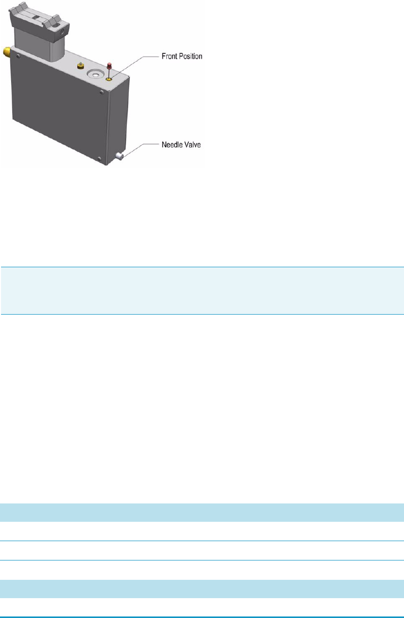
1 Getting Familiar with Your TriPlus RSH
SPME Conditioning Station
62 TriPlus RSH User Guide Thermo Scientific
Figure 45. Spare Fiber Inserted in front Position
The fiber is manually placed into the hole, and brought to the exposed position. If this second
position is used, open the needle valve for gas flow in the second channel (front).
The needle valve is the metallic knob in front of the conditioning module.
After the spare fiber has been removed from the front position, close the needle valve in front
of the conditioning station (metallic knob).
It is not only a matter of saving gas, but letting gas flow unrestricted through this open,
second channel would reduce the gas flow in the channel for the automated conditioning.
This could result in damage to the fiber, as it is not be protected by inert gas.
The SPME Conditioning Station specifications are:
•Tem p e ra tu re C o ntro l — From 30 °C to 350 °C selectable in 1°C increments.
•Electrical Connectors — Two BUS connectors for daisy chaining.
The SPME Conditioning Station dimensions, mass, operating and environmental
requirements are detailed in Tabl e 18 and Tab le 19 .
Note Saving gas, letting gas flow unrestricted through this open, second channel reduces
the gas flow in the channel for the automated conditioning. This could result in damage
to the fiber, as it will not be protected by inert gas.
Table 18. SPME Conditioning Station - Dimensions and Mass
Length Dimension in mm (in.)
Width 44 (1.73)
Depth 190 (7.48)
Height 160 (6.30)
Mass Dimension in kg (lbs)
SPME Conditioning Station (with Cable) 1.08 (2.38)
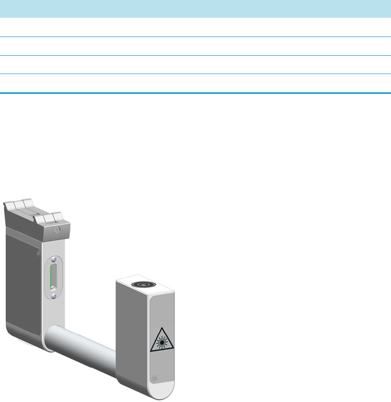
1 Getting Familiar with Your TriPlus RSH
Barcode Reader
Thermo Scientific TriPlus RSH User Guide 63
Barcode Reader
The Barcode Reader is an active module used to decode and read barcodes applied in
horizontal bars on vials of 1 to 20 mL volume. See Figure 46.
Figure 46. Barcode Reader
The Barcode Reader consists of two scanners. The vial with the barcode label is positioned in
the middle. The distance between the two scanners is optimized by the scan angle. The two
scanners are activated one after another.
• If the first scanner can read and decode the barcode symbols, the second scanner is not
activated.
• If the first one fails, the second scanner is activated, and if the barcode is positively
interpreted the process is ended.
When both scanners cannot read the barcode, an error exception is run. The error handling
itself is part of the CDS software and in most cases you can select one of the following
options:
Table 19. SPME Conditioning Station - Operating and Environmental Requirements
Parameter Requirements
Operating temperature range 30 to 350 °C
Maximum relative humidity 80%, non-condensing
Vibration Negligible
Static electricity Negligible
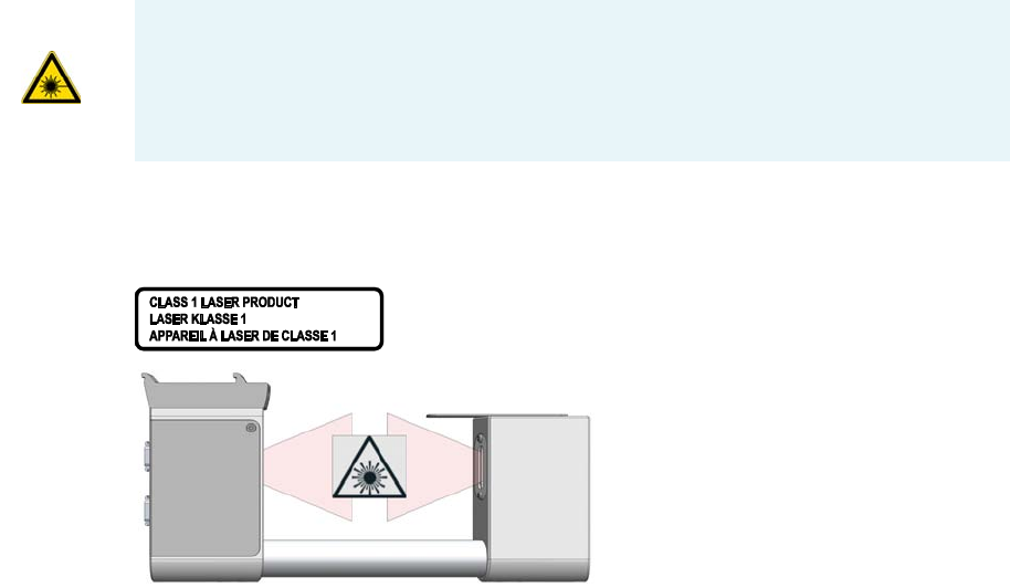
• Continue with sample handling but stamp the field Sample ID with an error comment
BC not readable.
• Stop the process of data handling, stop the entire Sample List.
This approach of using two scanners confers the advantage that the vial with the barcode label
does not require to be oriented directly towards the scanner. Respecting the minimum length
of 19 mm for the barcode allows the vial be positioned randomly in the and the barcode label
will be successfully interpreted.
Safety Information
The installed laser device is a Class 1 Laser Product.
Figure 47 shows the laser warning label and the location of the laser aperture.
Figure 47. Laser Warning Label and Laser Aperture
The selected Laser Class 1 for the module Barcode Reader complies with the following
regulations:
• 21 CFR1040.10 and 1040.11 except for deviations pursuant to Laser Notice No. 50,
dated July 26, 2001.
• EN60825-1:1994 + A1:2002 + A2:2001
• IEC60825-1:1993 + A1:1997 + A2:2001
The software contains a built-in safety time limit such that the laser scanning mechanism
cannot be operated in AIM mode for more than 5 continuous seconds.
WARNING Class 1 laser devices are not considered to be hazardous when used for their
intended purpose. The following statement is required to comply with international
regulations:
Use of controls, adjustments or performance of procedures other than those specified
herein might result in hazardous laser light exposures.
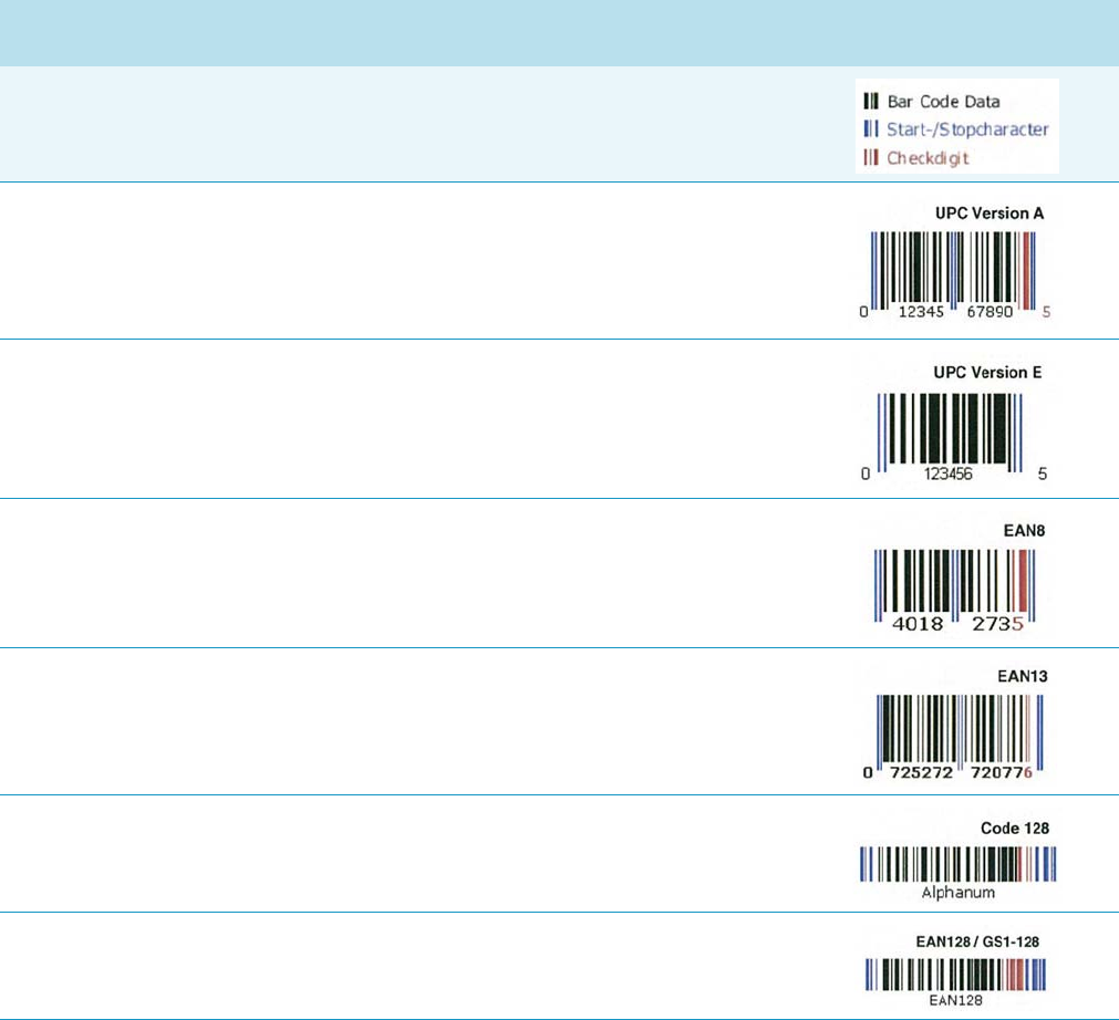
1 Getting Familiar with Your TriPlus RSH
Barcode Reader
Thermo Scientific TriPlus RSH User Guide 65
Supported Types of Barcode Symbols
The following barcode types can be decoded. See Tab le 2 0.
Prerequisites are:
• Horizontal scan line
• 1D scanner
Table 20. Barcode Symbologies (Sheet 1 of 2)
Barcode Type Description Min Length Max
Length Barcode Symbology
Key for Barcode Symbologies
UPC-A Universal Product Code,
12 numerical digits.
11 usable digits +1 check digit.
12 12
UPC-E Universal Product Code,
Zero-compressed UPC code,
7 numerical digits.
6 usable digits + 1 check digit.
66
EAN-8 Derived from the longer European
Article Number (EAN-13),
8 numerical digits.
7 usable digits + 1 check digit.
77
EAN-13 European (International) Article
Number, 13 numerical digits.
12 usable digits + 1 check digit.
12 12
Code-128 High density barcode for
alphanumerical codes, supporting all
128 ASCII characters.
1 Unlimited
EAN-128/GS10128 Alpha-numerical codes, supporting all
128 ASCII characters.
1 48

1 Getting Familiar with Your TriPlus RSH
Barcode Reader
66 TriPlus RSH User Guide Thermo Scientific
Approved Barcode Labels
The Barcode labels should be made of polyester and not paper. Polyester can withstand high
temperatures (Agitator 200 °C maximum) and the barcode lines will be printed clearly.
The minimum length of the barcode is 18 mm if used with a 20 mL vial. This dimension
refers to the actual barcode length and not the label itself. Adapt the label accordingly. Please
note that this is the minimum length; when possible use larger dimensions for reliable
processing of the barcodes.
Barcode Label Positioning
Place the barcode label on the vial such that the barcode bars are horizontally positioned.
•Maximum tilt of the barcode label: ±20°.
•Label Width: The barcode label width (length of the bars/spaces) has to be at least
18mm.
•Minimal barcode density (minimal width of a bare or a space): 5 mil (0.005”) /
0.127mm.
The allowed area for the placing of the label is given in Figure 48.
Code 39 (3 of 9) Alphanumeric code, consisting of
uppercase letters (A-Z), numeric digits
(0-9) and some special characters (-, .,
$, /, +, %, and space).
1 Unlimited
2 of 5 Interleaved Numerical characters. 1 Unlimited
ISBT 128 Used for labeling of human blood. 1 Unlimited Application specific barcodes
Table 20. Barcode Symbologies (Sheet 2 of 2)
Barcode Type Description Min Length Max
Length Barcode Symbology
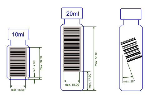
1 Getting Familiar with Your TriPlus RSH
Barcode Reader
Thermo Scientific TriPlus RSH User Guide 67
Figure 48. Examples of Barcode Label Positioning and Label Size
Reading the Barcode from a Vial or Well Plate
The Barcode Reader reads a barcode label from an individual vial, but it is not able to scan
and treat multiple units of information, as would typically be received from a multiple well
plate.
Multidimensional Barcodes
The scan engine used for the Barcode Reader Module is designed as a one-dimensional (1D)
scanner. Two-dimensional barcodes (2D) cannot be decoded.
Barcode Label Size
The minimum length of the barcode is 18 mm if used with a 20 mL Vial. Please note that this
refers to the actual barcode length and not the label itself.
Barcode Reader Specifications
The Barcode Reader Specifications are:
•Vial Sizes — 2 mL, 10 mL, and 20 mL
•Electrical Connectors — Two BUS connectors for daisy chaining.
The Barcode Reader dimensions, mass, operating and environmental requirements are
detailed in Ta ble 2 1 and Ta bl e 2 2.
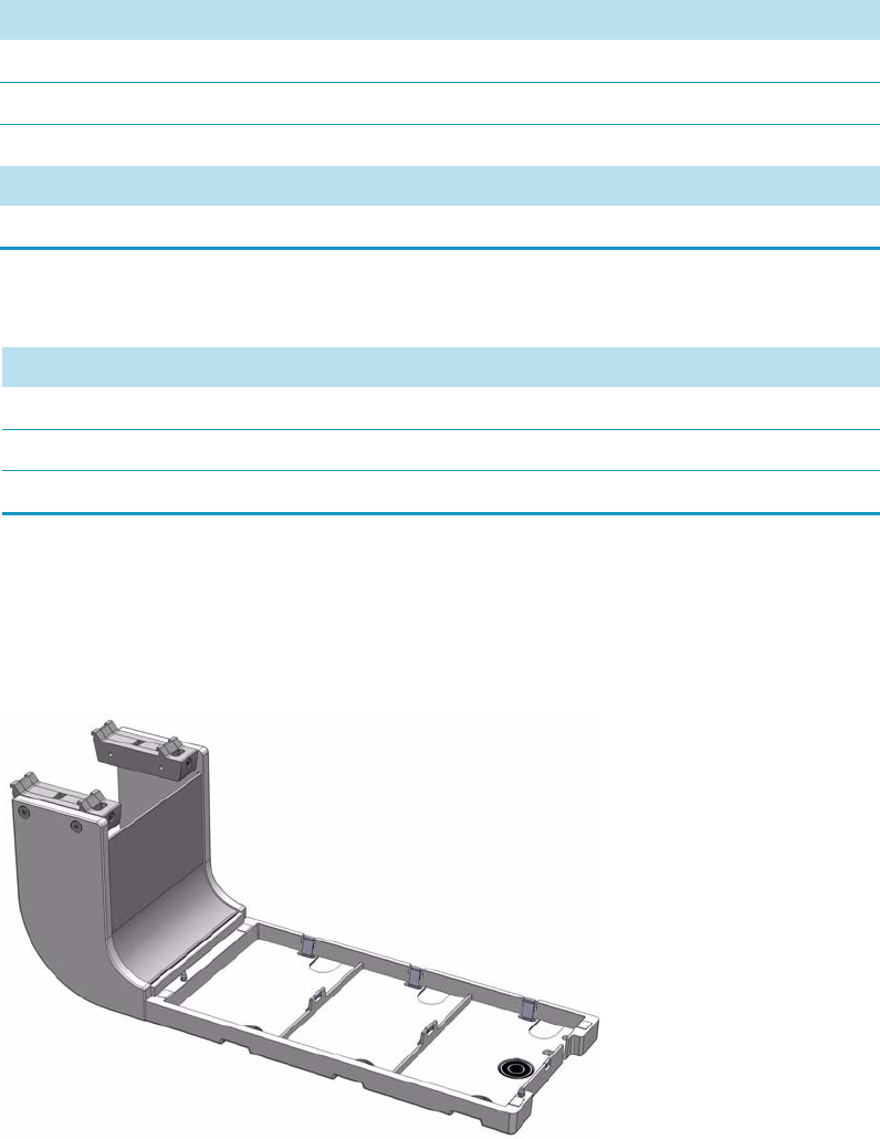
1 Getting Familiar with Your TriPlus RSH
Standard Tray Holder
68 TriPlus RSH User Guide Thermo Scientific
Standard Tray Holder
The Standard Tray Holder is a passive module. See in Figure 49.
Figure 49. Standard Tray Holder
Up to four different holders can be simultaneously installed, each compatible with:
• Three sample tray VT15, VT54, VT70
• One sample tray R60
Table 21. Barcode Reader - Dimensions and Mass
Length Dimension in mm (in.)
Width 30 (1.18)
Depth 273 (10.75)
Height 128 (5.04)
Mass Dimension in kg (lbs)
Barcode Reader Module (with cable) 0.83 (1.83)
Table 22. Barcode Reader - Operating and Environmental Requirements
Parameter Requirements
Maximum relative humidity 80%, non-condensing
Vibration Negligible
Static electricity Negligible
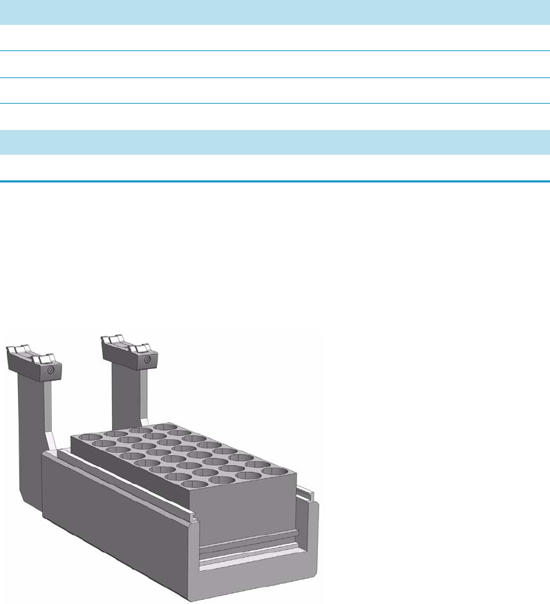
1 Getting Familiar with Your TriPlus RSH
Liquid Cooled Tray Holder
Thermo Scientific TriPlus RSH User Guide 69
The Standard Tray Holder specifications are:
•Sample Capacity — 648 x 2 mL vial
•Vial Size — 0.3, 0.5, 0.7, 2.0, 2.5, 10, and 20 mL and micro volume non-standard vials
•Electrical Connectors — None
The Standard Tray Holder dimensions and mass are detailed in Tab le 2 3 .
Liquid Cooled Tray Holder
The Liquid Cooled Tray Holder is a passive module for an external re-circulating bath.
See Figure 50.
Figure 50. Liquid Cooled Tray Holder
In the bottom section of the Tray Holder, there is an open tube. The ¼-in. hose connections
for this tube can be seen at the back of the unit. Liquid from an external bath is circulated into
the Tray Cooler through this tube; the liquid can be either heated or cooled.
Table 23. Standard Tray Holder - Dimensions and Mass
Length Dimension in mm (in.)
Width 134 (5.28)
Depth 375 (14.76)
Height 103 (4.06)
Compartment Width/Depth/Height 110/220/46 (4.33/8.66/1.81)
Mass Dimension in kg (lbs)
Standard Tray Holder 2.50 (5.51)
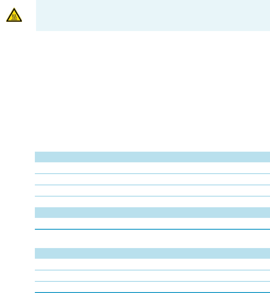
1 Getting Familiar with Your TriPlus RSH
Temperature Controlled Drawer
70 TriPlus RSH User Guide Thermo Scientific
The Liquid Cooled Tray Holder specifications are:
•Sample Capacity — Holds one tray for 32 vials capacity of 10 mL, and 20 mL vials.
•Tem p e ra tu re C o ntro l — From 4 °C to 70 °C controlled through external liquid
circulation bath, not provided.
•Connection Tube Dimensions — Stainless steel tube, OD 8 mm (0.3-in.), and
ID 6 mm (0.24-in.) open tube for hose connection.
•Electrical Connectors — None
The Liquid Cooled Tray Holder dimensions, mass, operating and environmental
requirements are detailed in Tabl e 24 and Tab le 25 .
Temperature Controlled Drawer
The Temperature Controlled Drawer is a temperature controlled sample tray that keeps the
analytical sample below or above ambient temperature. See Figure 51.
It is an active module with one drawer, two slots, and heated or cooled with a Peltier device.
Includes a separated power supply.
CAUTION The Liquid Cooled Tray Holder operates within a temperature range from
+4 °C to 70 °C.
Table 24. Liquid Cooled Tray Holder - Dimensions and Mass
Length Dimension in mm (in.)
Width 134 (5.28)
Depth 375 (14.76)
Height 103 (4.06)
Compartment Width / Depth / Height 110 / 220 / 46 (4.33 / 8.66 / 1.81)
Mass Dimension in kg (lbs)
Liquid Cooled Tray Holder 2.50 (5.51)
Table 25. Liquid Cooled Tray Holder - Operating and Environmental Requirements
Parameter Requirements
Maximum relative humidity 80%, non-condensing
Vibration Negligible
Static electricity Negligible
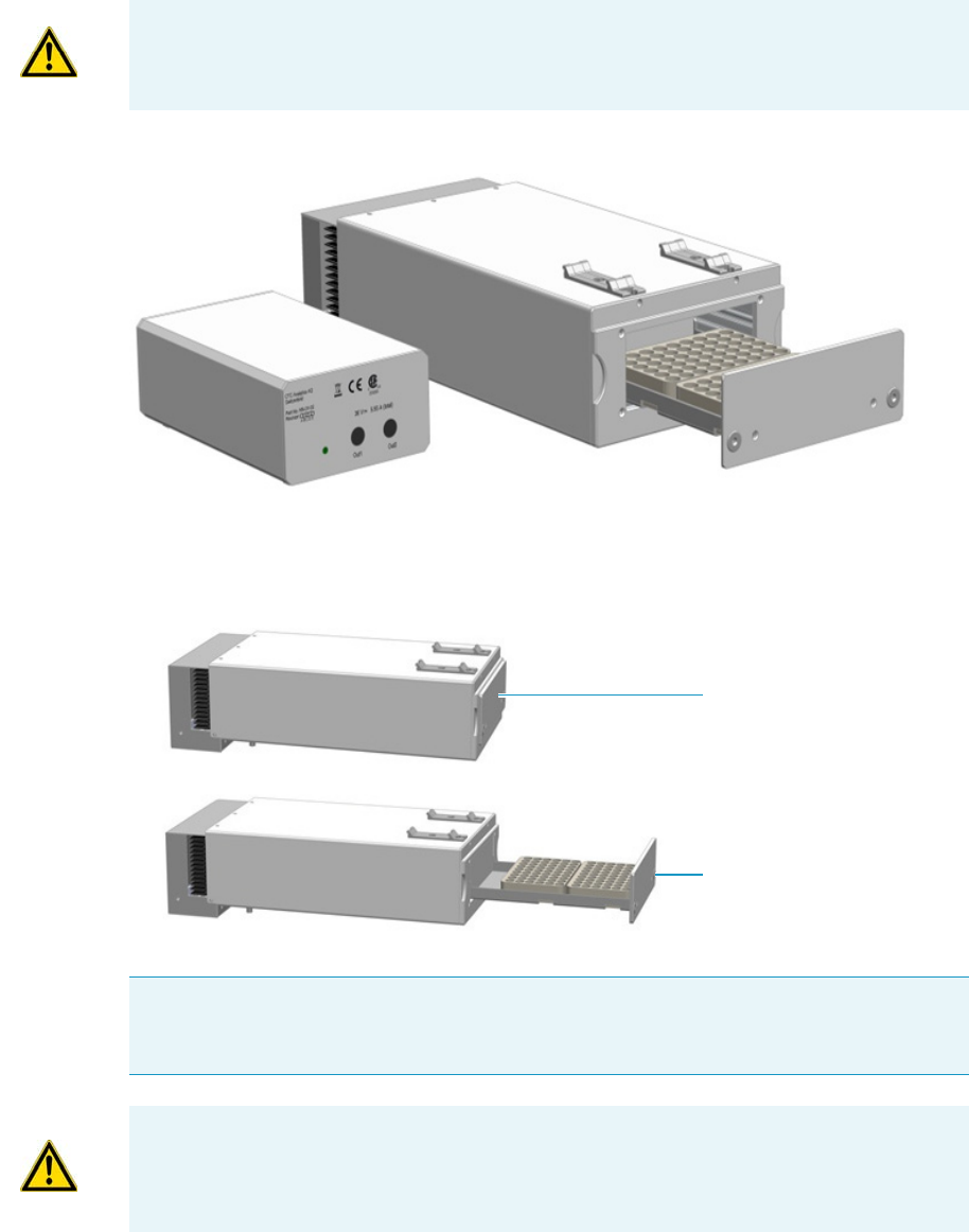
1 Getting Familiar with Your TriPlus RSH
Temperature Controlled Drawer
Thermo Scientific TriPlus RSH User Guide 71
Figure 51. Temperature Controlled Drawer
The position of the drawer is recognized by a sensor, and translated from the software in the
following descriptions. See Figure 52.
Figure 52. Two Positions of Temperature Controlled Drawer
WARNING It is mandatory to use a second Power Module. Do not use the same power
supply as used for the TriPlus RSH. See the chapter Installation of the TriPlus RSH
System in the TriPl us R SH Hardware Manual for details.
Note An Opening drawer status indicates an undefined status, or could also signal a
defective PCB or sensor. Check whether the status changes after manually opening and
closing the drawer.
Drawer
Power Module
Drawer Closed
Drawer Opened
CAUTION This module can adapt to Racks made for different vial sizes. When the
different racks are used, consider the different vial heights and ensure that the Stack
Drawer Magnet, attached to the lower needle guide, does not catch at the front row of
vials from behind the rack.
1 Getting Familiar with Your TriPlus RSH
Temperature Controlled Drawer
72 TriPlus RSH User Guide Thermo Scientific
Temperature Control
The cooling/heating capacity of a temperature control device based on the Peltier technique is
always relative to room temperature. The maximum temperature difference that can be
reached between the device and ambient temperature is limited. The Temperature Controlled
Drawer can attain a minimum of 14 °C (TΔ) below ambient temperature.
The controller allows the user to set a range of temperatures from +1 °C to 45 °C.
The actual temperature range selections are greater than the actual specified limits
(+4 °C to 40 °C). This allows to reach the desired temperature to be reached more easily when
the ambient temperature is too high or too low. For example, heating to a higher temperature
could be important for metabolism or kinetics studies at the human body temperature of
37 °C.
The cooling option is usually necessary to protect the sample from higher ambient
temperatures during the analytical run time.
Temperature Controlled Drawer is rarely used to store a sample at a given temperature for
prolonged periods.
The displayed temperature represents the temperature in the compartment and not in the
sample liquid. To verify the temperature independently, insert a temperature probe at the
front of the compartment by removing one plastic screw from the front cover. Position the
probe in the middle of the drawer where the Tray separator projects upwards.
Tape the probe to the metal plate of the drawer.
To reach +4 °C in the analytical solution, program a set value lower than +4 °C. The material
used to contain the sample may be glass, polypropylene, polyethylene, or similar polymer
products. All of these have excellent insulating properties.
If the sample has to be cooled as low as +4 °C, it is advisable to cool the sample Tray first in a
refrigerator before the Tray is placed into a Temperature Controlled Drawer. This shortens the
cool-down time.
Temperature Alarm
A fuse to prevent overheating is built in for unattended automated runs. The Peltier element
will turn off automatically at +72 °C ± 5 °C.
A damaged over-temperature fuse must be replaced by an authorized Thermo Fisher Scientific
service engineer.
Temperature Stability
It is recommended observing the following the guidelines:

1 Getting Familiar with Your TriPlus RSH
Temperature Controlled Drawer
Thermo Scientific TriPlus RSH User Guide 73
• Switch on the Temperature Controlled Drawer at least 30 minutes before an analytical
operation at +10 °C or 75 minutes before an operation at +4 °C.
• For high-throughput analyses – typical cycle time of 60 seconds or less per analysis – leave
the drawers open between injections.
• For longer cycle times, it is recommended to use the System option to close the drawer
after each sampling.
• Select the drawer-closing method from the Cycle Activities menu.
Condensation Build-up
Condensation build-up is directly related to the ambient temperature and humidity (dew
point). Long-term tests have shown very little condensation build-up in an environment with
relative humidity up to 60% and ambient temperatures of 22 °C ±2 °C.
Condensation at the bottom of the compartments will be channeled to the drain outlet
labeled Condensation Drain. The outlet is plugged with a paper filter.
This helps to evaporate the collected water in the drain line using the excess heat from the
Peltier element. A drain line from the outlet to a reservoir bottle is not necessary under normal
conditions.
Safety Warning
If a purge gas is used, it is your responsibility to ensure that a two-stage safety pressure
regulating device is installed between the gas supply and the Temperature Controlled Drawer.
If the Temperature Controlled Drawer is operated under severe conditions, a flow of clean and
dry (oil-free) air or nitrogen could be used to dry the compartments continually.
Connect the corresponding gas line to the Swagelok fitting (1/8-in.) at the back of the
Temperature Controlled Drawer labeled Purge Gas. A flow of approximately
300 to 400 mL/min is required to keep the compartments moisture-free.
If using an application that produces an acidic vapor phase, use the same gas line connection
to flush a stream of inert gas, such as nitrogen or helium, into the compartments. A stream of
a few mL/min can help to avoid corrosion of the rolls. Checking the lines regularly for
condensation build-up is recommended.
It is good practice to clean the inside of the Temperature Controlled Drawer when changing
analytical samples. Dry out the Temperature Controlled Drawer at ambient temperature at
regular intervals. Open the drawers 1 to 5 cm to allow air circulation. The compartment
drying frequency depends greatly on the ambient conditions.
Note Do not use any flammable or explosive gas such as hydrogen.

1 Getting Familiar with Your TriPlus RSH
Temperature Controlled Drawer
74 TriPlus RSH User Guide Thermo Scientific
Temperature Controlled Drawer Specifications
The specifications are:
•Sample Capacity — Accommodate two different sample trays.
Compatible VT70, VT54, and VT 15 (10 mL vials only).
•Tot a l v ial h eig h t — 47 mm (including cap)
•Tem p e ra tu re C o ntro l — From 4 °C – 40 °C in 0.1 °C increments
Peltier element for the cooling device
•Temperature Cooling — The specification for the Temperature Controlled Drawer
temperature cooling is defined as:
TΔ = ≥ 14.0 °C within 60 minutes.
TΔ = T Room temperature – T Temperature Controlled Drawer
•Electrical Connectors — Two BUS connectors for daisy chaining and a connector for
external power supply.
The Temperature Controlled Drawer dimensions, mass, operating and environmental
requirements are detailed in Tabl e 26 and Tab le 27 .
Table 26. Temperature Controlled Drawer - Dimensions and Mass
Length Dimension in mm (in.)
Temperature Controlled Drawer
Width 197 (7.78)
Depth 425 (16.73)
Height 103 (4.06)
Power Supply
Width 135 (5.31)
Depth 215 (8.46)
Height 75 (2.95)
Mass Dimension in kg (lbs)
Temperature Controlled Drawer 3.57 (7.87)
Power Supply 1.30 (2.87)
Associated cables (3 pieces) 0.50 (1.10)
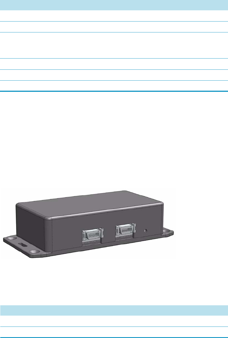
1 Getting Familiar with Your TriPlus RSH
Electronic Box for OC Injector Actuator
Thermo Scientific TriPlus RSH User Guide 75
Electronic Box for OC Injector Actuator
The OC Injector Actuator, not provided with the TriPlus RSH, is a combination of the
On-column Injector and the Actuator to open and close the rotary valve of the On-Column
injector. The device consists of an electronic box and the BUS daisy chain cable. See
Figure 53.
The OC Injector is an active module where the OC Electronic Box is connected to the BUS
connector while the cable from the GC Injector is connected to the Box.
Figure 53. OC Electronic Box
The electronic module is laid out to activate the OC Actuator. A specification is not
applicable. The Electronic Box for OC Injector Actuator - dimensions, mass, operating and
environmental requirements are detailed in Ta ble 2 8 and Ta ble 29.
Table 27. Temperature Controlled Drawer - Operating and Environmental Requirements
Parameter Requirements
Operating temperature range 4 to 40 °C
Maximum relative humidity 80%, non-condensing
Bench space At least 50 mm (2-in.) at the back space for
air circulation.
Access to power switch(es) and power cords.
Vibration Negligible
Static electricity Negligible
Altitude limitations 3000 meters above sea level
Table 28. Electronic Box for OC Injector Actuator - Dimensions and Mass (Sheet 1 of 2)
Length Dimension in mm (in.)
Width 44 (1.73)
Depth 190 (7.48)
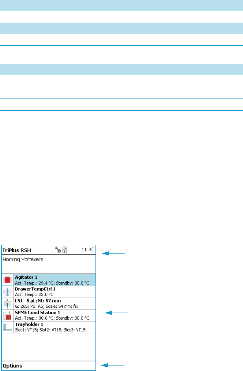
1 Getting Familiar with Your TriPlus RSH
Handheld Controller
76 TriPlus RSH User Guide Thermo Scientific
Handheld Controller
This section provides a description of the Handheld Controller.
Menu Screen
Different menu screens are displayed, depending on the TriPlus RSH operating state and the
particular function being accessed by the operator. All menu screens have the same basic
format. The uppermost line is the Status bar where the selected section, the status and time
are displayed.
The Content Area shows the list of selected items. The Function Keys are located in the
Menu Bar. See Figure 54.
Figure 54. Main Screen
Height 160 (6.30)
Mass Dimension in kg (lbs)
OC Electronic Box (with cable) 1.08 (2.38)
Table 29. Electronic Box for OC Injector Actuator - Operating and Environmental Requirements
Parameter Requirements
Maximum relative humidity 80%, non-condensing
Vibration Negligible
Static electricity Negligible
Table 28. Electronic Box for OC Injector Actuator - Dimensions and Mass (Sheet 2 of 2)
Length Dimension in mm (in.)
Status Bar
Menu Bar with Function Keys
Content Area
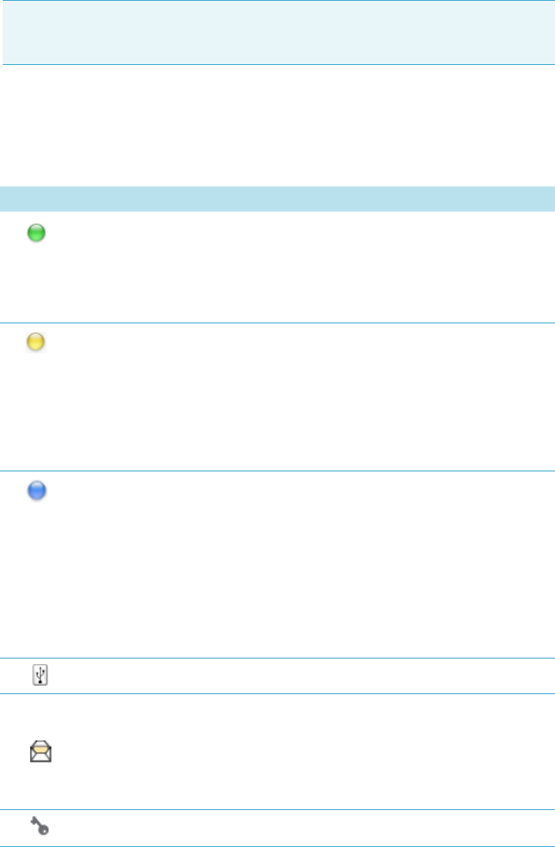
1 Getting Familiar with Your TriPlus RSH
Handheld Controller
Thermo Scientific TriPlus RSH User Guide 77
Menu Screen Status Bar Symbols
The following symbols can be displayed in the Menu Screen Status Bar.
Note Start Screen displays the installed tools, the Active Modules (such as the Agitator
which can be heated, cooled, or both), the SPME Conditioning Station, the Cooled Tray
Single, and the Tray Holder(-s) as the only passive module.
Table 30. Menu Screen Status Bar Symbols (Sheet 1 of 2)
Symbols Description
Green status light, blinking: TriPlus RSH is working (moving). Execution
mode.
The Terminal is partially blocked to specific actions.
Green status light, steady on: TriPlus RSH is ready in Standby. Idle Mode.
Yellow status light, blinking: RSH Firmware is booting.
Yellow status light, steady on: A problem has been detected which cannot be
resolved by the robotic system.
Examples: Bent needle (mechanical problem), missing Tool, and so on. detected
at the moment of sample execution. A software run-time error can also cause a
status light change to steady-on yellow.
Blue status light, blinking: The TriPlus RSH is in the process of software
Update or Backup. (For the processes Copy Backup and Restore the Status
light remains green.)
Blue status light, permanent: TriPlus RSH is in a safe state (power reduced to a
minimum) and requires manually moving the Head to the Te a ch Po int .
Note: If an error is detected at the same time that an action is required
according to the Blue Status Light, then by default the yellow status light will
dominate.
USB Symbol: A USB device is connected to control.
Message (Envelope): A system message is pending.
Example: Error message after software upgrade or after a device has been
disconnected. In User Access Level the message symbol is displayed only.
To view and process the system message(-s) the operator has to change the access
level to Extended User.
Key is the indicator for the access level Extended User.
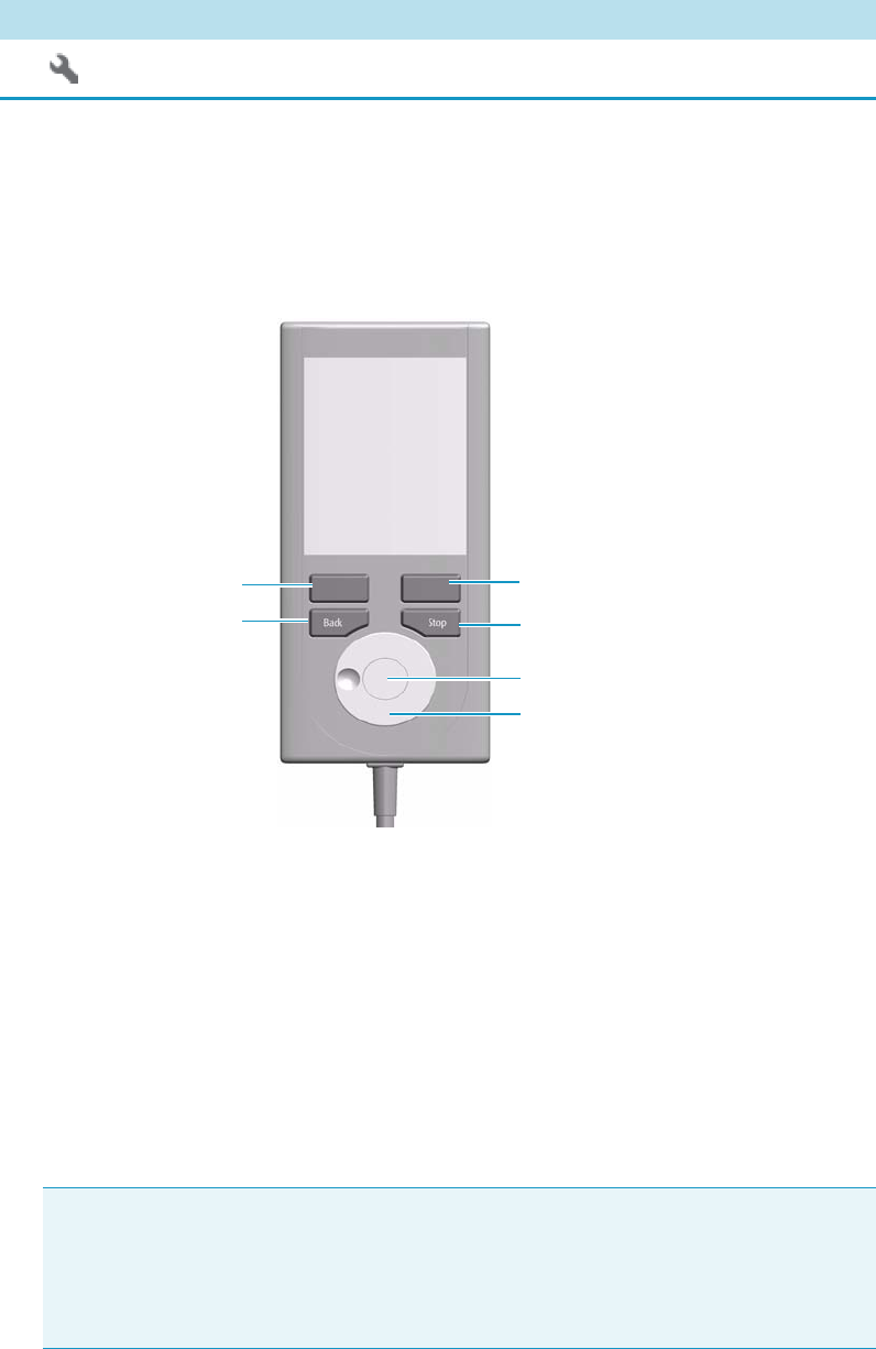
Function Keys and Buttons
Options for a particular menu are assigned to the corresponding function key on the left side.
See Figure 55.
Figure 55. Handheld Controller Buttons
• The Menu Button Option on the left side opens a pull-up menu, and is a dynamic
allocatable key.
• The Function Key on the right side is reserved for Default Actions, such as Ok, Next,
and so on.
• Pressing the Back button returns to the previous menu. If the Back button is pressed
continuously, the cursor will jump back to the home screen (start page).
• Pressing the Stop button stops the ongoing activity at the first possibility. The behavior is
closer to stop the run, but the stop itself occurs after an activity has completed its tasks,
for example the filling of a syringe.
Flat Wrench is the indicator for the access level Service User.
Table 30. Menu Screen Status Bar Symbols (Sheet 2 of 2)
Symbols Description
Note The term Stop usually relates to the controlled end of a process, for example
finishing a sample from the sample list. The automated run is paused and the user has
the possibility to interfere with, make corrections to, continue with or stop the run
completely. The Stop button used with the TriPlus RSH can terminate the process
during the run.
Stop Button
Function Key “Default Action”
Menu Button “Option”
Back Button
Enter Button (Central Knob)
Scroll Wheel
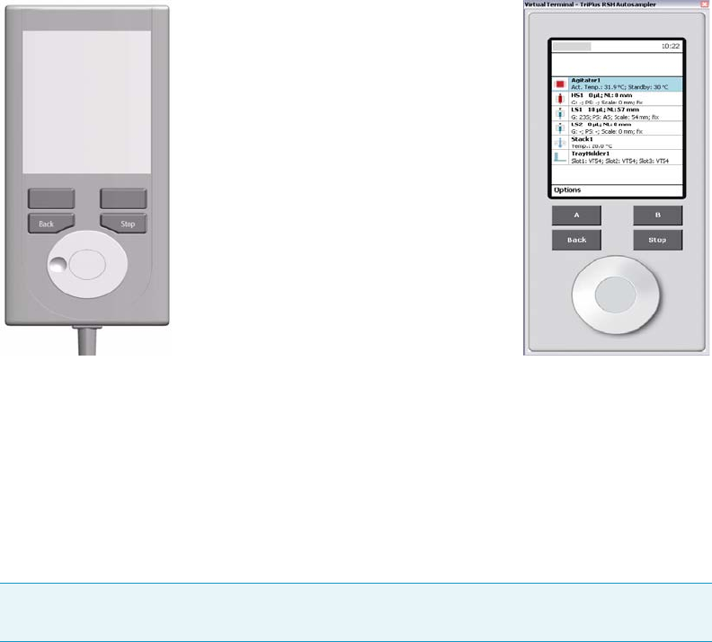
1 Getting Familiar with Your TriPlus RSH
Handheld Controller
Thermo Scientific TriPlus RSH User Guide 79
Scroll Wheel and Enter Button
Rotate the outer knob to scroll through items in a menu. To select a highlighted item, press
the Enter button (central knob). Use the outer knob to scroll through the available options
for that item or to change a numeric value. Press the inner knob again to enter the displayed
option. The inner knob is also used for other operations that require an Enter function to
continue or complete an operation.
Handheld Controller Versus the Virtual Handheld Controller
With every TriPlus RSH, Virtual Handheld Controller Software is provided. As indicated by
its name, this software replaces the actual hardware, the Handheld Controller. However, the
Handheld Controller is still available as an option.
Figure 56. Handheld Controller and Virtual Handheld Controller
The functionality of both the hardware Handheld Controller and the Virtual Handheld
Controller software are basically the same. Menus, selection of modules, definition of
attributes, or feeding parameter values are identical. The only difference is the handling.
When using the Handheld Controller, use the Scroll Wheel, Enter button, Menu Buttons,
and so on. If the software Virtual Handheld Controller is running, the keyboard functions are
used.
To open a pull-up menu, use the Enter key and the menu items, where for example a name
has to be given. You receive the same context menu to enter a number or character.
See Figure 57. Use the mouse cursor to select the name. Do not use the standard keyboard
keys to select the name.
For example: when the position of a module is defined as the X-, Y-, Z-, the values are
changed by moving the arrow key up and down.
Handheld Controller Virtual Handheld Controller
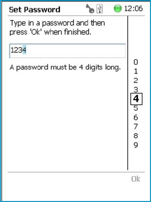
1 Getting Familiar with Your TriPlus RSH
Handheld Controller
80 TriPlus RSH User Guide Thermo Scientific
Figure 57. Example Context Menu to Enter a Password

Thermo Scientific TriPlus RSH User Guide 81
2
TriPlus RSH Basic Informations
This chapter provides basic informations to start the TriPlus RSH, and for using the
Handheld Controller.
Basic informations are provided for the different Access Levels to start the TriPlus RSH, and
for using the Handheld Controller. The use of the Handheld Controller is similar to the
Virtual Handheld Controller, and the PC software-based Handheld Controller.
Contents
•Starting the TriPlus RSH
•Access Levels
•User Level
•Extended User Level
•Service Level
•Setup, Installation, and Maintenance Menu Items
•Help Menu Item
•About Menu Item
•Shutdown Menu Item
•Operation of the TriPlus System in Combination with Other
Chromatography Data Systems

2 TriPlus RSH Basic Informations
Starting the TriPlus RSH
82 TriPlus RSH User Guide Thermo Scientific
Starting the TriPlus RSH
This section describes how to start the TriPlus RSH.
How to Start the TriPlus RSH
1. Turn on the power and observe the software loading process.
The following start screen appears. See the example of Figure 58.
Figure 58. Example of Start Screen
In case any error occurs during the start-up process, the start screen shows a blinking
Envelope in the Status Line as an indicator of a Pending Message, a Service Issue, or
both. See Figure 59.
Figure 59. Indicating Messages
IMPORTANT Before starting the TriPlus RSH, make sure that the sampler and all the
modules are properly already installed.
A syringe of the appropriate type, or several syringes (Tools), named using the appropriate
Method, must be installed in the TR Station or ATC Station, and positioned in the slot.
The arrow below the list
of the modules indicates
that you must scroll down
to see the remaining part
of the list.
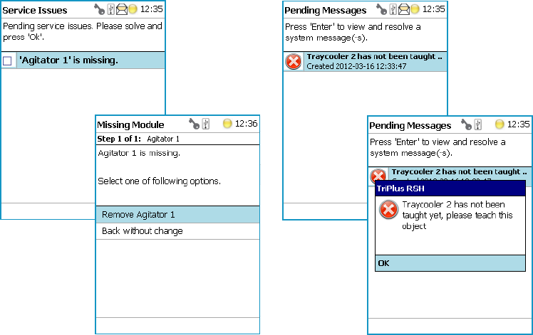
2 TriPlus RSH Basic Informations
Starting the TriPlus RSH
Thermo Scientific TriPlus RSH User Guide 83
The envelope symbol indicates that a message pending or a Service Issue is found.
When powered up, the TriPlus RSH is always in the User access level.
In this level, the message symbol is visible in the status line, but you have no access rights
to verify or acknowledge the error.
Changing the Access Level to Extended User, you can see details of the messages by
selecting each message line and pressing Enter. The Pending Message in the example
shows that the reconnected Agitator has not been taught yet.
See the example in Figure 60.
Figure 60. Example of Agitator Missing in Extended User Level
2. To retrieve the message proceed as follows:
a. Change the Access Level to Extended User.
b. Press the Options key to access the pull-up menu for further information.
c. Select the menu item Pending Message to receive detailed information on the error
message.
A common reason for an error is typically when a BUS cable is not connected from one
to another active module. During the boot-up procedure, the presence of all active
modules is verified. If one or more modules are not found, (or it is not possible to check
functions such as Homing) an error is recorded. See the example in Figure 61.
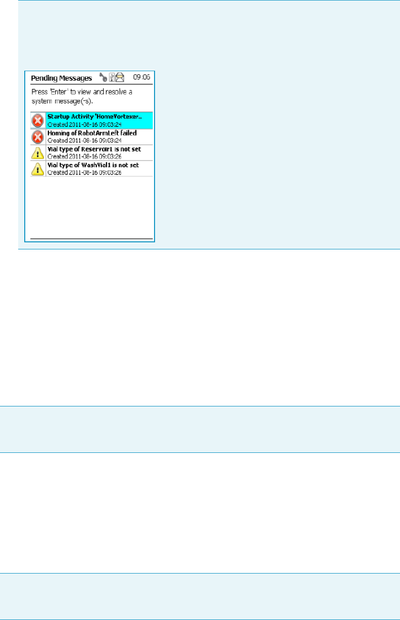
2 TriPlus RSH Basic Informations
Starting the TriPlus RSH
84 TriPlus RSH User Guide Thermo Scientific
When an error is observed, check all connections, try to eliminate the source of the
problem, and restart the TriPlus RSH again.
The messages accompanied by the Exclamation Mark warning symbol indicate that a
module has not been completely configured. Figure 61 shows an example where the Vial
Type has not been set for the Solvent Reservoir, or for Wash Vial#1.
See also the information provided by the error message or consult the chapter
Troubleshooting in the TriPlus RSH Hardware Manual.
Short-cuts from Startup Screen
The following steps are required to use the short-cuts:
1. Position the cursor on the list item at the start screen for which you wish to check certain
parameters.
2. Press the Enter button to open the dialog for the selected item.
3. Selecting the Options pull-up menu, it provides a list of specific tasks, limited to the
typical needs for routine work.
The example in Figure 61 shows the resulting errors when the Vortexer cable is not
connected, and the homing could not be performed. All the subsequent boot-up checks
failed.
Figure 61. List Items of Pending Messages
Note Selecting a menu list item from the startup screen provides direct access, and offers
the same functionality as when selecting the item using the path Menu Button |Options |
Setup | RSH Modules.
Note Parameters which can be modified are described in detail in “Setup Menu Item” on
page 93. Parameters which have read-only access are often self-explanatory and are usually
only mentioned in the listing.

2 TriPlus RSH Basic Informations
Access Levels
Thermo Scientific TriPlus RSH User Guide 85
Access Levels
The RSH Firmware is designed with three different Access Levels. Each level accesses own
discrete items and sections of the firmware. The purpose of this distinction is to display only
specific items and sections of the firmware for each level. Settings which require to be changed
rarely, such as those set during installation of the TriPlus RSH, are hidden for level 1 users
(User Level), and revealed at level 2 (Extended User Level).
The distinction between User and Extended User Levels contributes to the user friendliness
of the TriPlus RSH.
Besides being user-friendly, the distinction allows the Extended User Level to be reserved for
a person responsible for the system, or for a specific group of users. This protection enhances
the reliability of the system and the lab environment in which the TriPlus RSH is used.
Accidental changes can be minimized or avoided.
A third level, Service, is reserved for the service technician. This level is mainly used during
the installation phase or when servicing the TriPlus RSH. Accessing the Service Level requires
a software key which is only provided for trained and authorized service technicians.
For details see the following sections:
•“User Level” on page 85
•“Extended User Level” on page 86
•“Service Level” on page 87
User Level
The User Level is the normal working level recommended for routine use. This level is
assigned as the default level.
The prerequisites for operating with the User Level are that the TriPlus RSH has been
completely assembled, the required active and passive modules are activated, and all positions
have been taught to the system. The synchronization signals have to be matched with the
analytical system (e.g. the Ready and Start signals).
The system has to be completely installed, tested, and verified for the use in combination with
the required GC system. When these prerequisites are fulfilled, and a routine run is to be
started, the TriPlus RSH is completely controlled by the Chromatography Data System
(CDS).
With the User Level, specific menu items are specially marked as shown in the example of the
Agitator pull-up menu Options. See the example in Figure 63.
IMPORTANT Please note that the TriPlus RSH is always started in the User access level.
If the Extended User mode is required, you have to change the access level. See the
section “Changing Access Level” on page 87.
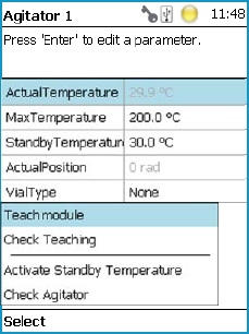
2 TriPlus RSH Basic Informations
Extended User Level
86 TriPlus RSH User Guide Thermo Scientific
Figure 62. Example of User Level Pull-up Menu Options
You check parameters through the Virtual Handheld Controller or Handheld Controller.
All other functionality, such as the number of samples, how to treat a sample, the injection
technique, and so on, are under the control of the CDS.
Extended User Level
The Extended User Level provides the same basic functionality as the User Level but certain
parameters of the RSH Firmware can be controlled, such as those that may be used for new
modules, X-,Y-,Z-axes position teaching, changing a sync signal, and so on.
It is highly recommended to operate the TriPlus RSH in the User Level and only for special
cases to activate the Extended User Level.
The Extended User access level provides the experienced operator more possibilities to
interact with the TriPlus RSH compared to the routine User Level.
The distinction between the access levels enables the interface to be simplified for routine
work, while providing the possibility to fine-tune the TriPlus RSH according to the specific
requirements of your particular applications.
With the Extended User Level, specific menu items are specially marked as shown in the
example of the Agitator pull-up menu Options. See the example in Figure 63.
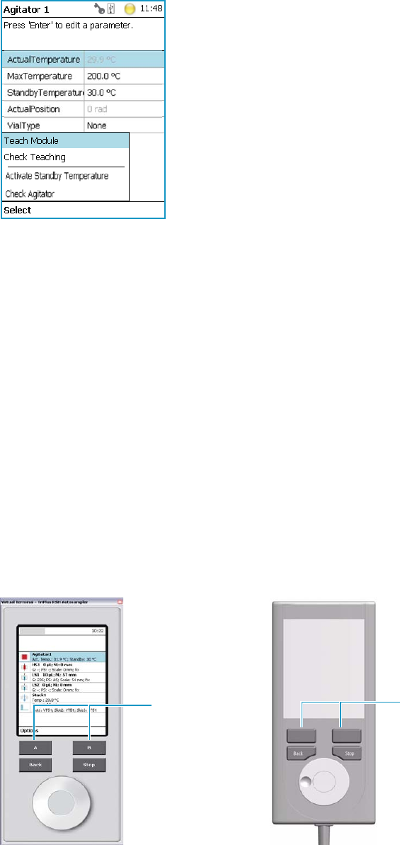
2 TriPlus RSH Basic Informations
Service Level
Thermo Scientific TriPlus RSH User Guide 87
Figure 63. Example of Extended User Level Pull-up Menu Options
Service Level
The Service Level provides full access to the TriPlus RSH. This level is reserved for qualified
service engineers only. This level will be required for installation or any major repairs such as
replacing a device (active module).
To open the Service access level, a software key is necessary. This key is provided on a Service
USB stick which is handed over to trained service engineers.
The various menu items, accessible with Service rights, are described in the chapter “Setup
Menu Item” on page 93.
Changing Access Level
Using the Virtual Handheld Controller the Access levels can be changed by pressing the two
characters A and B simultaneously at the keyboard. See Figure 64.
Figure 64. Virtual Handheld Controller and Virtual Handheld Controller
A and B Buttons Menu Buttons
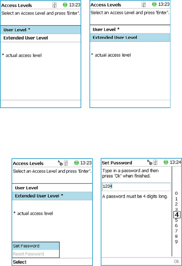
2 TriPlus RSH Basic Informations
Service Level
88 TriPlus RSH User Guide Thermo Scientific
If the TriPlus RSH is equipped with a Handheld Controller, press the two Menu Buttons
simultaneously (see Figure 64) to access the screen shown in Figure 65. The User Access
Level is the default level.
Figure 65. Changing Access Level
1. Select the required level and press Enter to activate it. The asterisk indicates the current
active level.
2. When the Extended User Access Level is selected, a password can be set. See Figure 66.
Figure 66. Selecting Extended User Level and Setting a Password
3. Select Set Password from the pull-up menu.
a. Place the cursor on the first digit and press the Enter button. A pop-up menu opens
providing numerals from 0 to 9 for selection.
b. Accepting the password by pressing Ok stores it. The password can be changed or
reset as long as you are working under the Extended User Level. See Figure 67.
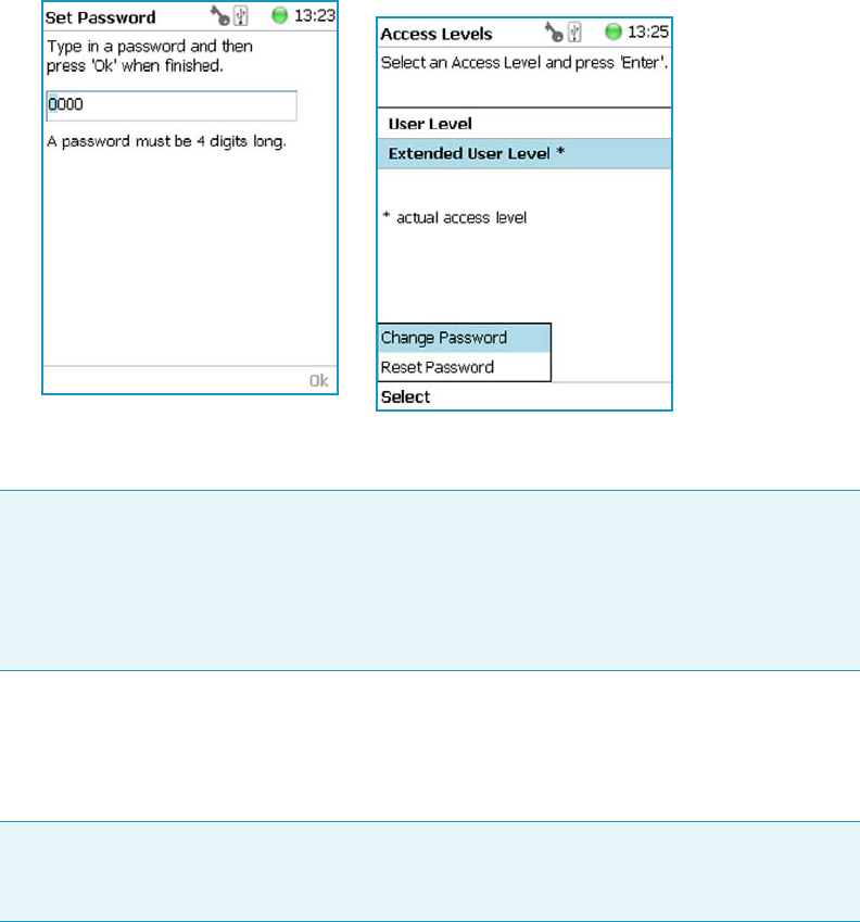
2 TriPlus RSH Basic Informations
Service Level
Thermo Scientific TriPlus RSH User Guide 89
When the User level is active and you wish returning to the Extended User Level, follow
the dialog shown in Figure 67.
Figure 67. Entering Another Password to Access Extended User Level
Note that the Ok is grayed-out (inactive) as long as the correct password is not entered.
A password cannot be set when operating under the User Level.
The Service Level is only accessible with the software key, provided with a Service USB stick.
This key is provided to trained and authorized service technicians only.
Example of Differences in Access Levels
The main difference between the two access levels is that the menu item Service is not
available in the User level. See Figure 68.
Note In case a password is forgotten, restore the RSH Firmware. See the chapter RSH
Firmware in the Tr iPl us RSH Hardware Manual. Use a backup file which does not yet
contain the password.
Be aware that changes made to the TriPlus RSH or any changes in settings made after the
installation of the backup file to recover the forgotten password will no longer be active.
Note If the Handheld Controller (or Virtual Handheld Controller) is not in use, a
time-out function begins and after 60 minutes of inactivity the software reverts
automatically to the default User Level.
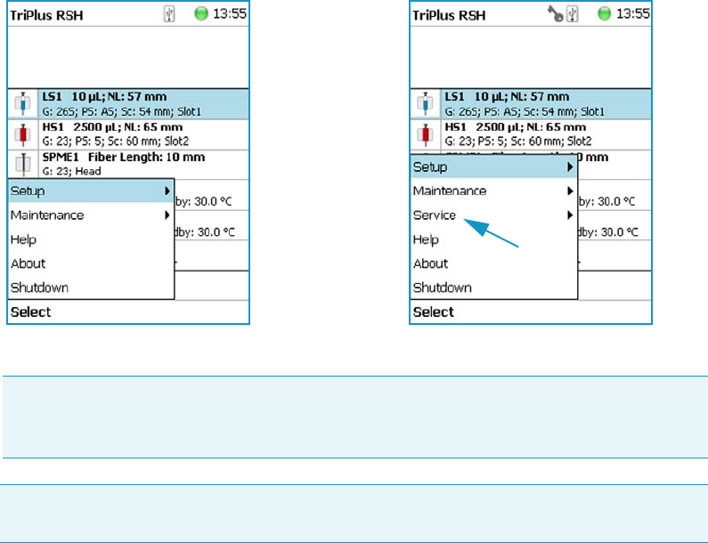
2 TriPlus RSH Basic Informations
Setup, Installation, and Maintenance Menu Items
90 TriPlus RSH User Guide Thermo Scientific
Figure 68. Differences in Access Levels
Setup, Installation, and Maintenance Menu Items
The description of the options of the RSH Firmware operated either with the Virtual
Handheld Controller, or directly using the installed Handheld Controller are detailed in the
following chapters:
•Chapter 3, “Setup Menu Item.”
•Chapter 4, “Maintenance Menu Items.”
•Chapter 5, “Service Menu Item.”
Help Menu Item
Figure 69 shows the rudimentary Handheld Controller functions.
Note If the Handheld Controller (or the Virtual Handheld Controller) is not in use, a
time-out function begins and after 30 minutes of inactivity the software reverts
automatically to the default User Level.
Please note that the TriPlus RSH is always started in the User Access level. If the Extended
User mode is required, you have to change the access level. See “User Level” on page 85.
User Level Extended User Level
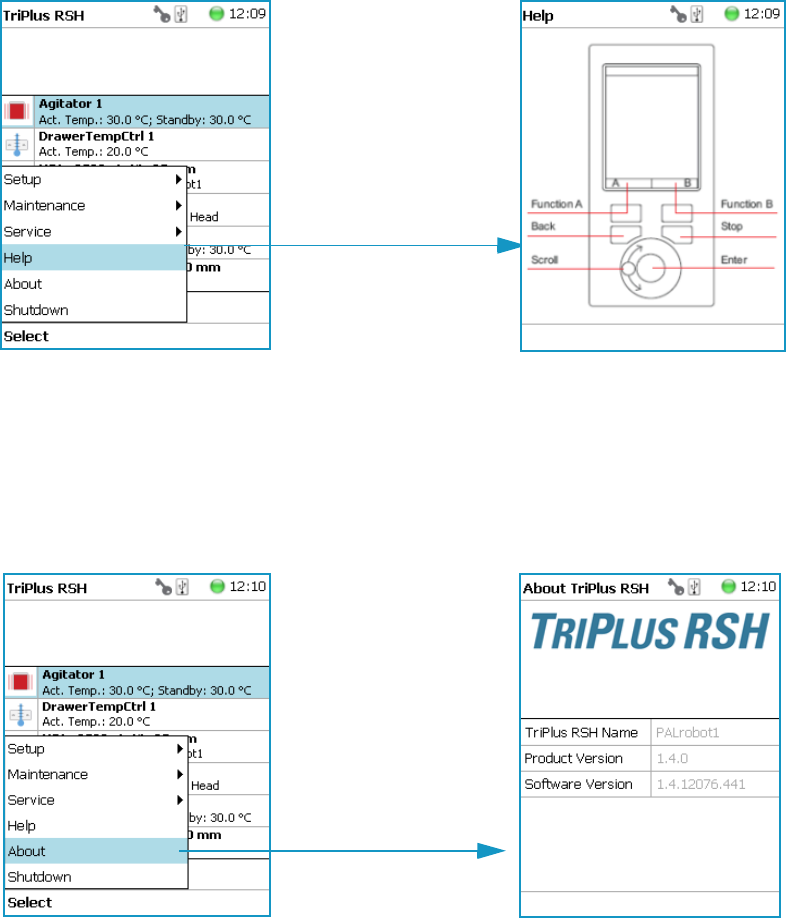
2 TriPlus RSH Basic Informations
About Menu Item
Thermo Scientific TriPlus RSH User Guide 91
Figure 69. Menu Item Help
About Menu Item
This item informs you on which software versions are currently installed with the particular
Tr i P l u s RS H . S e e Figure 70.
Figure 70. Menu Item About
Shutdown Menu Item
The menu item Shutdown gives the operator the possibility to shut down the TriPlus RSH in
a controlled manner. See Figure 71.
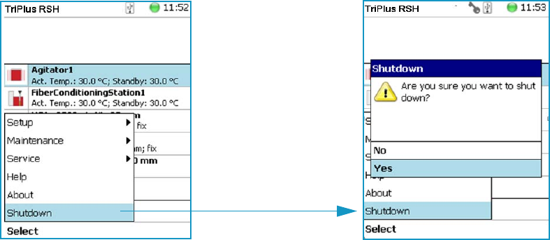
2 TriPlus RSH Basic Informations
Operation of the TriPlus System in Combination with Other Chromatography Data Systems
92 TriPlus RSH User Guide Thermo Scientific
Figure 71. Menu Item Shutdown
The main advantage of this automated shut down is that the Tool is parked. If the system is
shut down by simply turning off the power supply, the slider will move very slowly
downwards.
Parts of the Tool, particularly the syringe needle, can touch the bench surface, or any other
object. This can damage the syringe needle.
The following steps are automatically performed during a controlled Shutdown:
• The Head moves to an empty position of the ATC Station, engages and remains in this
position.
• In case a TR Station is part of the TriPlus RSH configuration, the mead moves to the
single slot.
• The software shuts down, closes the application and disables the axes.
After the TriPlus RSH has completed the shutdown procedure, it is necessary to turn off the
power at the power supply (switch at power).
To restart the TriPlus RSH after the shutdown process, toggle the switch of the power supply,
turn it off – wait about 30 seconds – then turn on the power of the system.
Operation of the TriPlus System in Combination with Other
Chromatography Data Systems
For operation of the TriPlus RSH with a Thermo Scientific Chromatography Data System
(CDS), for example: Chromeleon, Xcalibur, ChromQuest, or Chrom-Card, a software driver
is used. The specific requirements for operating the integrated System within the CDS are
outlined by the supplier of the CDS software.

Thermo Scientific TriPlus RSH User Guide 93
3
Setup Menu Item
This chapter describes the options of the Setup Menu operated either with the Virtual
Handheld Controller, or directly using the installed Handheld Controller.
Contents
•Starting Setup Menu Item
•Setup Menu Item Modules
•Setup Menu Item - Set Date and Time
•Setup Menu Item - Set TriPlus RSH Name
•Setup Menu Item - Setup Network
Note Items highlighted in green are only visible in the access level Extended User.
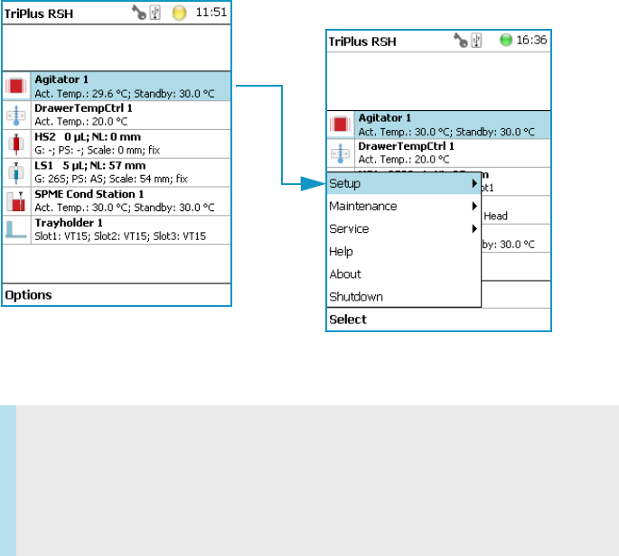
3 Setup Menu Item
Starting Setup Menu Item
94 TriPlus RSH User Guide Thermo Scientific
Starting Setup Menu Item
The Setup function is available under the Options pull-up menu. The Extended User Level
access level provides limited higher functionality in Setup than in the restricted User Level.
The menu items are listed in alphabetical order.
Press the Options button to open the pull-up menu and select the menu item Setup.
See Figure 72.
Figure 72. Start Screen Options Pull-up Menu
#
Refer to the following Setup Items:
•“Setup Menu Item Modules” on page 95
•“Setup Menu Item - Set Date and Time” on page 176
•“Setup Menu Item - Set TriPlus RSH Name” on page 177
•“Setup Menu Item - Setup Network” on page 178
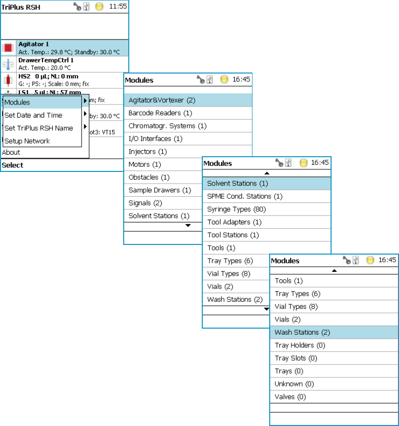

3 Setup Menu Item
Setup Menu Item Modules
96 TriPlus RSH User Guide Thermo Scientific
For details, see to the following modules:
•“Agitator” on page 97
•“Vortexer” on page 101
•“Barcode Reader” on page 103
•“Chromatograph System” on page 104
•“Input/Output Interface” on page 106
•“Injectors” on page 109
•“OC Actuator” on page 110
•“Motors” on page 113
•“Obstacle” on page 116
•“Sample Drawers” on page 118
•“Tool Stations” on page 121
•“TR Station” on page 122
•“ATC Station” on page 122
•“Signals” on page 124
•“Solvent Stations” on page 127
•“SPME Conditioning Station” on page 129
•“Syringe Types” on page 131
•“Tool Adapters” on page 134
•“Tools” on page 135
•“Tray Holders” on page 142
•“Tray Types” on page 146
•“Trays” on page 158
•“Vial Types” on page 160
•“Vials” on page 164
•“Wash Stations” on page 168
•“Tray Slots” on page 174
•“Unknown” on page 174
•“Valves” on page 174
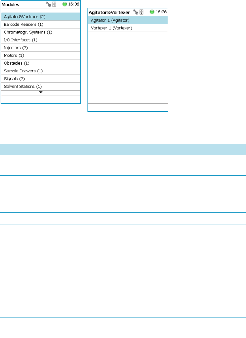
3 Setup Menu Item
Setup Menu Item Modules
Thermo Scientific TriPlus RSH User Guide 97
Agitator
Upon selecting the list item Agitator & Vortexer, the following parameters are available for
modification. See Figure 74.
Figure 74. Agitator Parameters
Select Agitator, then press Enter to edit a parameter. See Table 3 1.
Table 31. Agitator Parameters (Sheet 1 of 2)
Item Description
Actual Temperature Reads out the actual temperature of the module; read-only
function.
Max Temperature Sets the upper temperature limit.
The Maximum Temperature which can be set is 200 °C, but
this parameter is often defined by the specific needs for the
application.
Min Temperature Sets the minimal temperature limit.
Standby Temperature The Standby Temperature can be adjusted to the
application’s requirements. Setting the Standby Temperature
using this function does not yet activate the newly-selected
temperature. To activate it, go to the pull-up menu Options
and select Activate Standby Temperature.
The Standby Temperature is activated when the TriPlus
RSH is powered up. In routine use, the Standby
Temperature is activated after a job has been terminated.
The Standby Temperature is typically lower than the
application temperature.
Vial Type Pos. 1 The Vial Type for Position 1 is displayed. Read-only.
The Vial Type can be set with the task Setup Modules.

3 Setup Menu Item
Setup Menu Item Modules
98 TriPlus RSH User Guide Thermo Scientific
Vial Type Pos. 2 The Vial Type for Position 2 is displayed. Read-only.
The Vial Type can be set with the task Setup Modules.
Vial Type Pos. 3 The Vial Type for Position 3 is displayed. Read-only.
The Vial Type can be set with the task Setup Modules.
Vial Type Pos. 4 The Vial Type for Position 4 is displayed. Read-only.
The Vial Type can be set with the task Setup Modules.
Vial Type Pos. 5 The Vial Type for Position 5 is displayed. Read-only.
The Vial Type can be set with the task Setup Modules.
Vial Type Pos. 6 The Vial Type for Position 6 is displayed. Read-only.
The Vial Type can be set with the task Setup Modules.
Cover Plate Type Select the cover plate (lid) used for the agitator installed.
• Not specified
•Standard: The lid must be opened for access.
•Perforated: Syringe or SPME needle can be inserted
through the holes in the lid.
Actual Position Reads out the position of the Agitator. Read-only function.
Stdby Temp Control If switched off, the module will not go to standby
temperature if idle.
Tem p G a i n The coefficient used, if a temperature calibration has been
performed. Possible values are between 0 and 2. Read-only.
Temp. Offset The Offset temperature used, if a temperature calibration
has been performed. Possible values are between -10 °C and
+10 °C. Read-only.
Note A job is often described as a sample list or sequence which is treated in a certain
order. A job can also contain a single sample, often seen in method development work.
In such cases, you set the Standby Temperature to the same temperature used for the
application. Dropping the temperature during runs can be time-consuming and
disruptive.
Table 31. Agitator Parameters (Sheet 2 of 2)
Item Description

3 Setup Menu Item
Setup Menu Item Modules
Thermo Scientific TriPlus RSH User Guide 99
Agitator Options Pull-up Menu
Selecting the pull-up menu Options opens up following tasks. See Tab l e 32 .
Table 32. Agitator Pull-up menu Options
Item Description
Check Teaching Checks the teaching position of the module.
This task serves as a quick check to determine if the
X-, Y-, and Z-positions are defined correctly.
In case a teaching point is off, return to the Menu Setup
for readjustment of the teaching position.
Please note that this action can be done under the
Extended User Level but not under User Level.
Setup Module Allows the selection of the Cover Plate Type, to reserve
one or more vials as a source vial (e.g. for a reagent), and
to define the Vial Type for the 6 positions.
See the section “List Items Agitator Reserved Positions
and Vial Type” on page 100
Teach Mod ule The positions of the X-, Y-, and Z-axes can be defined
again, teaching.
Activate Standby Temperature Activates the newly-set Standby Temperature.
Check Agitator Starts the spinning motion of the Agitator.
It is used to test the Agitator function, or the spinning
speed for particular application.
Settings are:
•Options: On; Off; Home
•Speed: Select the required speed, range from 250 rpm
to 750 rpm
Press Run to start the Agitator
To stop the motion, press Options again, select Check
Agitator and set the parameter Options to Off.
Press Run.
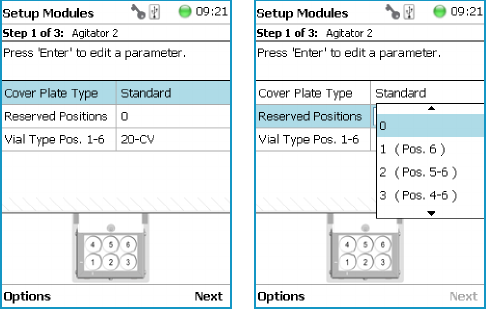
3 Setup Menu Item
Setup Menu Item Modules
100 TriPlus RSH User Guide Thermo Scientific
List Items Agitator Reserved Positions and Vial Type
With the list item Setup Module it is possible to reserve one or more positions in the Agitator
for a source vial (for example to provide an internal standard solution, a reagent solution for a
derivatization, or any other solution) as required by a specific application. Possible reserved
positions for source vials begin at Vial Position 6 and count backwards.
The vial size can be selected for the remaining free positions and can be selected separately for
the reserved vial(-s).
Note that only one vial size can be selected for the reserved vials. The consequence is that
during routine applications the vial overlapping will be possible only within the free available
sample vial positions to optimize the throughput. The behavior of the following two
Activities is summarized:
•Transpo rt Vial activity — Allowed for available free sample vial positions and for
reserved vial positions.
•Move To Object activity — Allowed for reserved vial positions only.
The reason for this limitation is because in the overlapping mode the sample vial position is
managed by the scheduler.
You can change the Vial Type at any time during a routine application selecting the menu
item Agitator, scrolling down to the list item Vial Type and selecting another Vial Type.
Examples of Free available and Reserved Vial Positions are visualized in the following images:
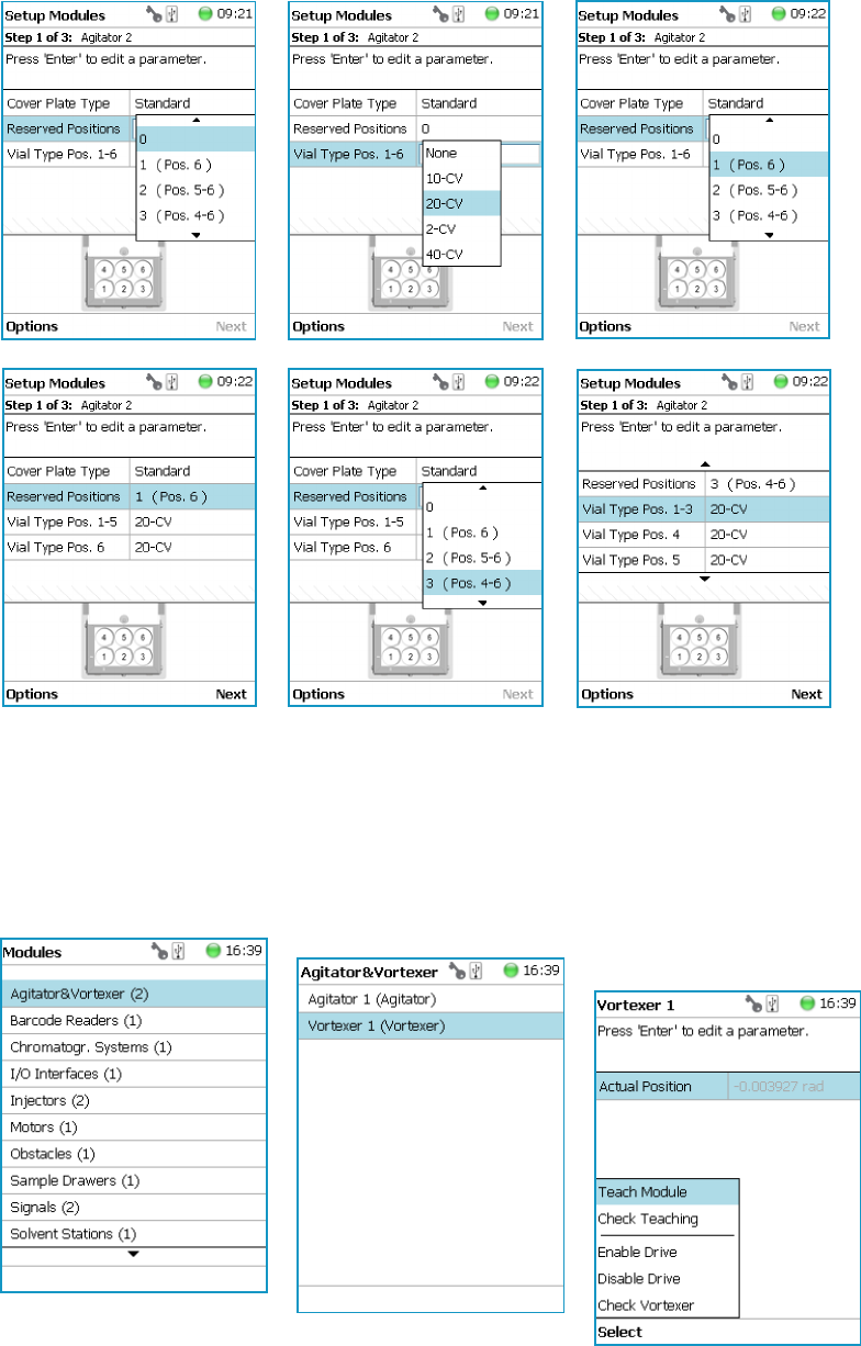

3 Setup Menu Item
Setup Menu Item Modules
102 TriPlus RSH User Guide Thermo Scientific
Select Vortexer, then press Enter to edit a parameter. See Tab l e 33.
Vortexer Options Pull-up Menu
Selecting the pull-up menu Options shows the following tasks. See Tab le 34 .
Table 33. Vortexer Parameters
Item Description
Actual Position Reads out the position of the Agitator; read-only function.
Table 34. Vortexer Pull-up Menu Options
Item Description
Check Teaching Checks the teaching position of the module.
This task serves as a quick check to determine if the X-, Y-,
and Z-positions are defined correctly. In case a teaching
point is off, return to the Menu Setup for readjustment of
the teaching position.
Please note that this action can be done under the Extended
User Level but not under User Level.
Teach Mo du l e The positions of the X-, Y-, Z-axes can be defined again, for
teaching.
Enable Motor Enables the motor of the vortexer.
Disable Motor Disables the motor of the vortexer.
Check Vortexer Starts the spinning motion of the Vortexer. It is used to test
the mixer function or the spinning speed for particular
application.
Settings are:
•Option — On; Off; Home
•Speed — Select the required speed, range from 250 rpm
to 2500 rpm
Press Run to start the Vortexer
To stop the motion, press Options again, select Check
Vortexer and set the parameter Option to Off. Press Run.
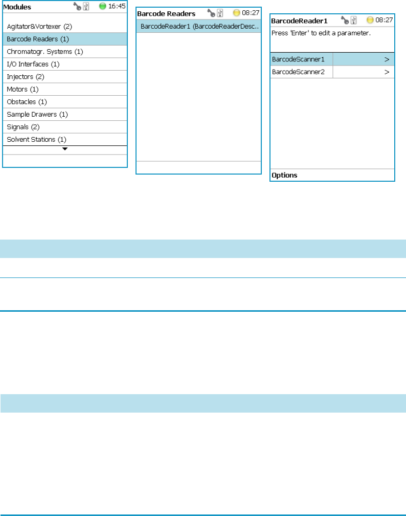
3 Setup Menu Item
Setup Menu Item Modules
Thermo Scientific TriPlus RSH User Guide 103
Barcode Reader
Upon selecting the list item Barcode Reader, the following parameters are available for
modification. See Figure 76.
Figure 76. Barcode Reader Parameters
Press Enter to edit a parameter. See Table 3 5.
Barcode Reader Options Pull-up Menu
Selecting the pull-up menu Options opens up the following tasks. See Table 3 6 .
Table 35. Barcode Reader Parameters
Item Description
Scanner Select Scanner #1 or #2.
Beep After Decode A beep tone can be activated after positive decoding of the
barcode.
Table 36. Options Menu Item Check Teaching (Sheet 1 of 2)
Item Description
Check Teaching Checks the teaching position of the module.
This task serves as a quick check to determine if the X-, Y-,
and Z-positions are defined correctly. In case a teaching
point is off, return to the Menu Setup for readjustment of
the teaching position. Please note that this action can be
done under the Extended User Level but not under User
Level.
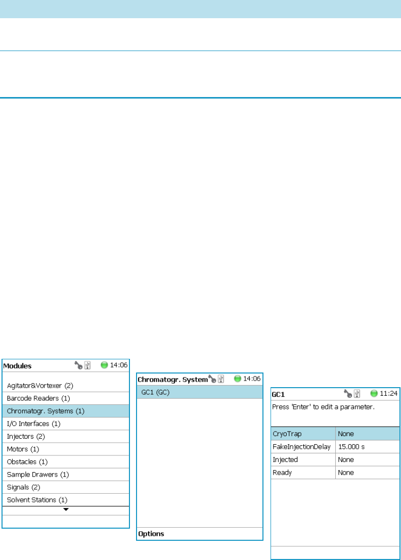
3 Setup Menu Item
Setup Menu Item Modules
104 TriPlus RSH User Guide Thermo Scientific
Chromatograph System
The Chromatograph System is a bundle of Input and Output Signals dedicated for a
chromatographic system. This bundle must be configured and can be assigned to a specific
chromatographic system for routine use. This minimizes erroneous functions and simplifies
the user interface.
This is the last step in the setting up and synchronization of Input/Output Signals between
the TriPlus RSH system and the external device. See also the section “Input/Output Interface”
on page 106, and the section “Signals” on page 124.
Upon selecting the list item Chromatograph System, the following parameters are available
for modification. See Figure 77.
•GC1 = Name for GC System No.1
•(GC) = Class description GC System
Figure 77. Chromatography System - Selection and Parameters
Press Enter to edit a parameter. See Table 3 7.
Tea c h Mo d u l e The positions of the X-, Y-, and Z-axes can be defined again,
teaching.
Scan Barcode Checks the Barcode Reader. Hold a barcode label in the
beam of the laser and activate Scan Barcode. A beep tone
signals a successful reading
Table 36. Options Menu Item Check Teaching (Sheet 2 of 2)
Item Description
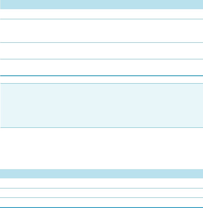
3 Setup Menu Item
Setup Menu Item Modules
Thermo Scientific TriPlus RSH User Guide 105
Chromatograph System Options Pull-up Menu
Selecting the pull-up menu Options opens up the following tasks. See Table 38.
Table 37. Chromatography System Parameters
Item Description
Cryo Trap Sets start signal for the Cryo Trap, Output signal required.
Fake Injection Delay Sets the delay time until the start of a fake injection.
A fake injection performs a start of the chromatographic
system, without injection of a sample.
Injected Sets start signal for the chromatographic system, for example
GC System1. Output Signal is required.
Ready A ready signal from another device is expected as an Input
Signal.
Note The synchronization between the TriPlus RSH and any chromatographic system has
to be checked for each particular system configuration. The setting of the synchronization
signal has to be matched with the pin allocation of the synchronization cable.
The original cable are labeled. Check the labels first before connecting. This is especially
important with the Y-cable configurations where two GC units are connected to a single
TriPlus RSH.
Table 38. Chromatography System Pull-up Menu Options
Item Description
New Chromatograph System Creates a new Chromatograph System.
Copy GC Copies the Chromatograph System, GC1 as the example.
Delete GC Deletes the Chromatograph System; GC1 as the example.
3 Setup Menu Item
Setup Menu Item Modules
106 TriPlus RSH User Guide Thermo Scientific
Input/Output Interface
This section provides the signal settings and synchronization to the external device, such as a
GC System. See Figure 78. It is the second step in the setting up and synchronization of
Input/Output Signals between the system and the external device.
Figure 78. Menu Item for Input/Output Interface
Press Enter to edit a parameter.
Upon selecting the list item I/O Interface, the following parameters are available for
modification. See Table 39.
Table 39. List of Items for Input and Output Signals (Sheet 1 of 3)
Item Description
Immediate
Ignores any Input or Output Signal
Signal On
Debounce Time
Opto In1
Opto-isolator or Opto-coupler
Signal On
Debounce Time
Negative Logic
PWM Out
Pulse-Width Modulation
Signal On
Output Voltage
Reset Button
Reset Button on Control Board (blue)
Signal On
Debounce Time
Low Active
Simulated
This signal can be used for testing, simulation
of sending a signal (Output Signal)
Signal On
Tri gge r Eve n t
Waiting Time
SW Out1
Switch-out Signal, Relay contact
Signal On
Low Active

3 Setup Menu Item
Setup Menu Item Modules
Thermo Scientific TriPlus RSH User Guide 107
SW Out2
Switch-out Signal, Relay contact
Signal On
Low Active
TTL In1
Transistor-Transistor Logic
Debounce Time
Low Active
TTL In2
Transistor-Transistor Logic
Signal On
Debounce Time
Low Active
TTL In3
Transistor-Transistor Logic
Signal On
Debounce Time
Low Active
TTL Out1
Transistor-Transistor Logic
Signal On
Low Active
TTL Out2
Transistor-Transistor Logic
Signal On
Low Active
TTL Out3
Transistor-Transistor Logic
Signal On
Low Active
Beep Volume Selectable scale from 1 to 5
Debounce Time Specifies how long the signal is applied.
Low Active A standby status of a signal from the
chromatographic system can be High Active
or Low Active. Depending on what has to be
applied for the specific system, one has to
match the signal logic on the TriPlus RSH
side.
By setting a mark to Low Active means that
Low Active is selected. Low Active disabled
means High Active selected.
Information for the required signal logic is
provided with the schematic of the sync cable
which is part of the GC mounting kit.
Signal On The term Signal On means that the signal
has been sent or received.
Output/Voltage An output voltage in the range from 0 V
to 35 V can be selected.
Trigger Event Select the desired type of output signal for
testing.
Table 39. List of Items for Input and Output Signals (Sheet 2 of 3)
Item Description

3 Setup Menu Item
Setup Menu Item Modules
108 TriPlus RSH User Guide Thermo Scientific
Input/Output Interface Pull-up Menu
Selecting the pull-up menu Options from the list item Beep Volume opens up to the
following tasks. See Table 40.
From all other list parameters the pull-up menu Beep is directly available.
Waiting Time Select the time to be waited until the signal is
activated, delay time in seconds.
Beep Volume The sound volume for the Beep tone can be
selected.
Table 39. List of Items for Input and Output Signals (Sheet 3 of 3)
Item Description
Table 40. Option Pull-up Menu for Input/Output Interface
Item Description
Reset to Default Resets the selected module parameter to default value.
Beep Actives a Beep sound local on TriPlus RSH.
If activated, the operator can select the Duration,
Frequency, and the Volume of the tonal sound.
Duration The time for the tonal sound is selectable from 100 ms to 60
seconds.
Frequency The frequency of the tonal sound is selectable from 100 Hz
to 10000 Hz.
Run Activates the tonal sound with the selected parameters for
testing.
Beep Utility Sets the frequency and the time length of the beep tone.
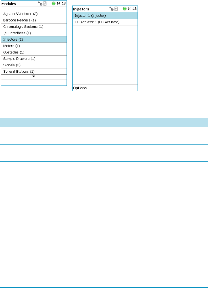
3 Setup Menu Item
Setup Menu Item Modules
Thermo Scientific TriPlus RSH User Guide 109
Injectors
Upon selecting the list item Injectors, the following parameters are available for modification.
See Figure 79.
Figure 79. Injectors - Selection and Parameters
Press Enter to edit a parameter. See Table 4 1.
Table 41. Injector Parameters (Sheet 1 of 2)
Item Description
Default Needle Penetration
Depth
Defines the Needle Penetration Depth in the injector.
It reflects the total length including the length of the fiber.
Max Needle Penetration
Depth
Sets the upper limit of Needle Penetration Depth into the
injector.
Min Needle Penetration
Depth
Sets the minimum limit of Needle Penetration Depth into
the injector.
WARNING This parameter is used for SPME 1 and
SPME 2 Tools only. This parameter is not used for LS, HS,
or ITEX Tools. The default value is 18 mm. The adjustable
range is from 10 mm to 50 mm.
Position Tolerance Checks the difference between the taught X-Y-Axes positions
against the actual position each time the head moves to the
GC Injector. If the difference is greater than the Position
To le r a n ce of 3.0 mm (default value) the TriPlus RSH
immediately stops. This is a safety feature to avoid needle
bending.
WARNING It is highly recommended to check the teaching
positions of the injectors again when the GC is ready (heated
up to the level as used for routine runs).

3 Setup Menu Item
Setup Menu Item Modules
110 TriPlus RSH User Guide Thermo Scientific
Injectors Options Pull-up Menu
Selecting the pull-up menu Options opens up the following tasks. See Table 42.
OC Actuator
The OC Actuator allows the opening and closing of the On-column Injector rotary valve
when the syringe needle is inserted or removed.
The OC Actuator is an active module, which means that the OC Electronic Box is connected
to the Bus and the cable from the GC Injector is connected to the Box. For details see the
section “Obstacle” on page 116.
Selecting the list item OC Actuator opens up the following parameters. See Figure 80.
Z Tolerance A tolerance window to give a plus/minus range (expressed in
mm) in which the Head must expect an object.
• If the value of this item is > 0, indicates a relative
detection mode is triggered, and the sensor from the
Head needle guide is active.
• If the value of this item is set to 0, the sensor of the
needle guide is turned off and the syringe slider moves to
an absolute value: the Z-axis position as specified for the
object.
Table 41. Injector Parameters (Sheet 2 of 2)
Item Description
Table 42. Option Menu for Injectors
Item Description
Reset to Default Resets the selected module parameter to default value.
Teach Mo du l e The positions of the X-, Y-, and Z-axes can be defined again,
(teaching).
Check Teaching Checks the teaching position of the module. This task serves
as a quick check to determine if the X-, Y-, and Z-positions
are defined correctly. In case a teaching point is incorrect,
return to the Menu Setup for readjustment of the teaching
position.
This action can be done under the Extended User Level but
not under User Level.
Note The OC Adapter is part of the GC On-column Injector and it is not provided with
the TriPlus RSH.
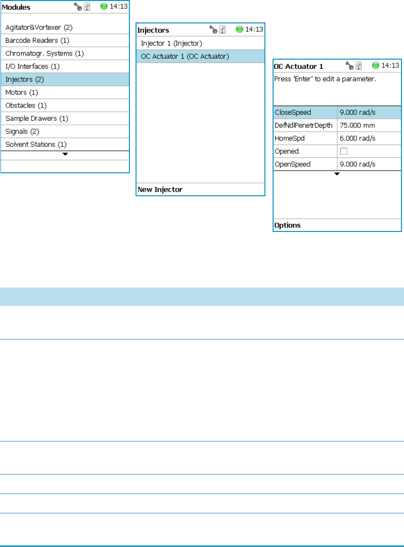
3 Setup Menu Item
Setup Menu Item Modules
Thermo Scientific TriPlus RSH User Guide 111
Figure 80. OC Actuator - Selection and Parameters
Press Enter to edit a parameter. See Tab le 4 3 .
Table 43. OC Actuator Parameters (Sheet 1 of 2)
Item Description
Def Ndl Penetr Depth Allows you to define the Needle Penetration Depth in the
OC injector.
Opened Changes the status Opened or Closed.
This parameter is a check if the gas lock is opened or closed.
If marked as true (check box marked) the injector is defined
as open. This can be verified by inserting a syringe manually
and if a resistance is noted, the gas lock is closed.
If a mismatch is observed, check the settings of the
parameters Homing Direction and Homing Position.
Actual Position Reads out the position of the OC Actuator. This information
can be used for troubleshooting purposes.
Homing Direction Changes the direction of homing.
Homing Position Changes the position of homing.
Max Ndle Penetr Depth Defines the maximum allowed syringe needle penetration in
millimeters.

3 Setup Menu Item
Setup Menu Item Modules
112 TriPlus RSH User Guide Thermo Scientific
OC Actuator Options Pull-up Menu
Selecting the pull-up menu Options opens up the following tasks. See Table 4 4 .
Position Tolerance Checks the difference between the taught X-Y-axes positions
against the actual position each time the head moves to the
OCI.
If the difference is greater than the Position Tolerance of
1.5 mm (default value) then the TriPlus RSH immediately
stops. This is a safety feature to avoid needle bending.
Table 43. OC Actuator Parameters (Sheet 2 of 2)
Item Description
Table 44. OC Actuator Option Parameters
Item Description
Reset to Default Resets the selected module parameter to default value.
Check Teaching Checks the teaching position of the module.This task serves
as a quick check to determine if the X-, Y-, and Z-positions
are defined correctly. In case a teaching point is incorrect,
return to the Menu Setup for readjustment of the teaching
position.
Please note that this action can be done under the Extended
User Level but not under User Level.
Tea c h Mo d u l e The positions of the X-, Y-, Z-axes can be defined again,
(teaching).
Check OC Alignment Verifies the Needle Penetration in the OC Injector.
The head moves to the OCI teach position, checks the
Position Tolerance, inserts the syringe needle and checks for
any resistance. If no resistance is felt the test is positive, the
needle can be inserted without bending.
Check OC Actuator Verifies the opening and closing of the OC Actuator.
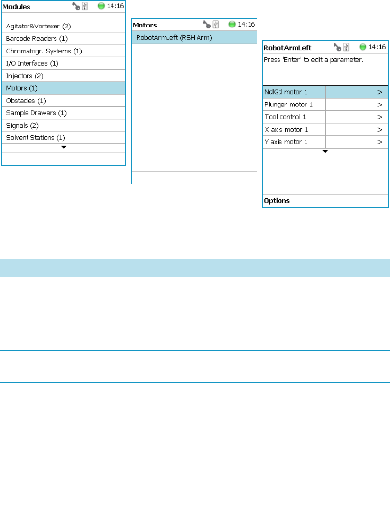
3 Setup Menu Item
Setup Menu Item Modules
Thermo Scientific TriPlus RSH User Guide 113
Motors
Upon selecting the list item Motors, the following parameters are available for modification.
See Figure 81.
Figure 81. Motors Menu
Press Enter to edit a parameter. See Tab le 4 5 .
Table 45. List of Motors (Sheet 1 of 3)
Item Description
Needle Gd Motor (#)
(Motor V)
Actual position — Reads only for information
Plunger Motor (#)
(Motor W)
Actual position — Reads only for information
Check Plunger — Checks the presence of the plunger.
Tool Control Shows which tool is assigned and whether it is attached to
the head. See the section “Tools” on page 135.
X Motor (#) Actual position — Reads only for information
Length X-axis — Selects the length of the 850 mm or
1205 mm X-axis
Y Motor (#) Actual position — Reads only for information
Z Motor (#) Actual position — Reads only for information
Acceleration Factor Allows adjusting the acceleration of the motors.
Note that a change of the Acceleration Factor does affect all
the motors.

3 Setup Menu Item
Setup Menu Item Modules
114 TriPlus RSH User Guide Thermo Scientific
Default Strategy Defines of the global movement of the TriPlus RSH Head
across the system platform. The following selections are
possible:
•Parallel — Allows simultaneously movement of all axes.
This mode is the default mode. When operating the
TriPlus RSH in this mode, the positions and heights of
the known modules are respected. The TriPlus RSH
changes the strategy automatically.
For example: if one module is higher than another, the
TriPlus RSH would lower the Z-axis to the zero position
to allow the modules to cross over.
If an external object is within the platform, for example
a GC Detector, then the X-, Y-, and Z-positions of this
potential obstacle are not known to the TriPlus RSH. In
such a case, it is necessary to switch the strategy to Safe
mode.
•Safe — The Y-axis moves from any point first to zero Y
(back to the X-axis) before the X-movement is started.
This mode allows bypassing of an object (such as a large
GC detector) that would be directly in the travel path if
the Parallel mode is used.
Default Waste Allows selecting the corresponding Wash Module installed.
None: Important: A Waste Module must be defined; default
value is None.
The selection defines a Waste Positions of the following
Wash Stations: Fast Wash Module, Large Wash Module, or
Standard Wash Module.
Needle guide motor Actual Position. Read only for information.
Plunger motor Actual Position. Read only for information.
•Check Plunger — Check the presence of the Plunger.
•Home Det Curr — Defines the drive current for the
homing process.
•Home Spd — Defines the plunger speed at the moment
of homing.
X-axis motor Actual Position. Read only for information.
Y-axis motor Actual Position. Read only for information.
Table 45. List of Motors (Sheet 2 of 3)
Item Description

3 Setup Menu Item
Setup Menu Item Modules
Thermo Scientific TriPlus RSH User Guide 115
Motors Pull-up Menu Options
Selecting the pull-up menu Options opens up the following tasks. See Table 46.
Z-axis motor Actual Position. Read only for information.
Tool Control Shows which tool type is assigned and whether it is mounted
in the TriPlus RSH Head. Read only for information.
Table 45. List of Motors (Sheet 3 of 3)
Item Description
Table 46. Option Pull-up Menu for Motors (Sheet 1 of 2)
Item Description
Calibrate Motors Calibrates the motors. This task might be necessary after a
motor has been disconnected. This is a recovery feature.
For further details see “Service Menu Item” on page 189.
Teach Home Position Allows a Home Position of the head to be defined, which
can be at any X-, Y-, or Z-position.
Home RSH Head Moves the TriPlus RSH Head to Home position and
references all axes.
Disable RSH Head All axes are electrically isolated, enabling the operator to
move the axes manually.
Enable RSH Head The axes (motors) are reconnected to mains again.
Move to Home Moves the TriPlus RSH Head back to Home position,
without referencing the axes.
Select Tool Utility
Visible only when TR Station
is installed
Picks the tool from the TR Station.
Purge Syringe
Visible only when HS Tool or
ITEX Tool is installed
The gas purge valve, used for example for cleaning the
headspace syringe, is manually activated. Can be used to
check the functionality of the purge valve.
ATC Tool
Visible only if ATC Station is
installed
Provides the possibility to change a tool on demand.
If this task is activated, a window opens for the tool; select
the required tool, and press Run.
The RSH Head moves to an open Slot (starting with Slot1,
if occupied it moves to Slot 2 or 3), ejects the tool, and
moves to the Slot where the required tool is parked.
The new tool will be mounted, and the TriPlus RSH will be
ready for the next application.

3 Setup Menu Item
Setup Menu Item Modules
116 TriPlus RSH User Guide Thermo Scientific
Obstacle
The object Obstacle is a module from another device, for example a large Thermal
Conductivity Detector (TCD).
If a module exceeds a certain height, it could get in the path way of the TriPlus RSH.
The dimensions and the position of the Obstacle can be defined. The TriPlus RSH will
exclude this area from the allowed path way and will bypass it.
Upon selecting the list item Tools Station, the following parameters are available for
modification. See Figure 82.
TR Tool
Visible only if TR Station is
installed.
The installed tool will be parked in the TR Station.
Configure SPME Tool
Visible only if SPME Tool
is installed.
Configures the SPME Tool with Fiber adjustments.
Home Motor Allows the Home position of the selected motor.
Enable Motor Allows enabling the selected motor after it has been disabled.
Disable Motor Allows disabling the selected motor to permit moving the
corresponding axis manually.
Calibrate Tool Allows calibrating the tool installed in the head.
Check Tool Calibration Allows checking the calibration point of the tool installed in
the head.
Select Tool Allows selecting another tool. The currently-attached tool is
first parked and the newly-required tool is picked up.
Park Tool Allows parking a tool without picking up another tool from
the TR Station.
Reset to Default Resets the selected module parameter to the default value.
Table 46. Option Pull-up Menu for Motors (Sheet 2 of 2)
Item Description
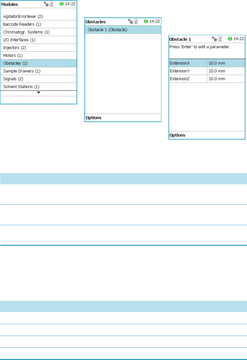
3 Setup Menu Item
Setup Menu Item Modules
Thermo Scientific TriPlus RSH User Guide 117
Figure 82. Obstacle - Selection and Parameters
Press Enter to edit a parameter. See Tab le 4 7 .
Obstacle Options Pull-up Menu
Selecting the pull-up menu Options opens up the following tasks. See Table 4 8 .
Table 47. Obstacle Parameters
Item Description
Extension X Extension from the center point of the Obstacle in X-axis
direction.
Extension Y Extension from the center point of the Obstacle in Y-axis
direction.
Extension Z Extension from the center point of the Obstacle in Z-axis
direction.
Table 48. Obstacle Option Parameters (Sheet 1 of 2)
Item Description
New Obstacle Creates a new obstacle.
Copy Obstacle Copies the present obstacle.
Delete Obstacle Deletes the present obstacle.
Reset to Default Resets the selected module parameter to default value.
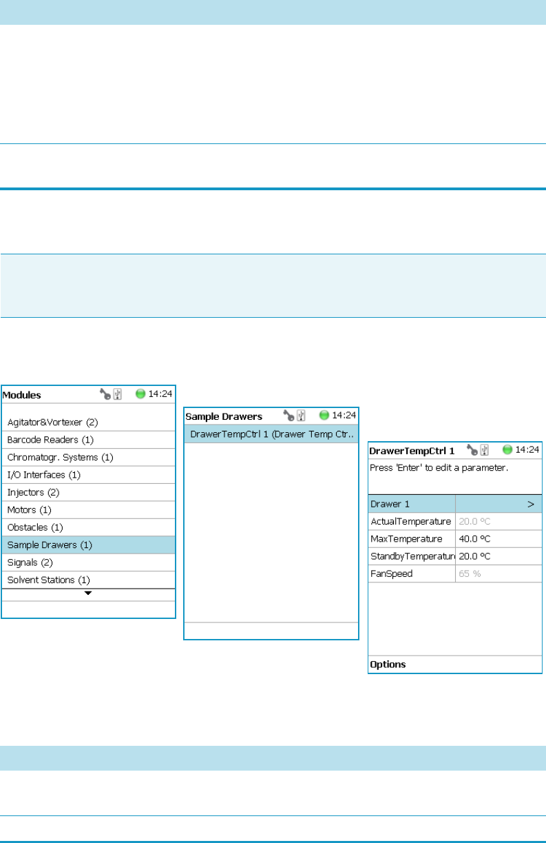
3 Setup Menu Item
Setup Menu Item Modules
118 TriPlus RSH User Guide Thermo Scientific
Sample Drawers
Selecting the list item Sample Drawers opens up the following parameters. See Figure 83.
Figure 83. Menu Item Temperature Controlled Drawer and Menu List Item Stack
Press Enter to edit a parameter. See Table 49.
Check Teaching Checks the teaching position of the module.This task serves
as a quick check to determine if the X-, Y-, and Z-positions
are defined correctly. In case a teaching point is incorrect,
return to the Menu Setup for readjustment of the teaching
position. Please note that this action can be done under the
Extended User Level but not under User Level.
Tea c h Mo d u l e The positions of the X-, Y-, and Z-axes can be defined again,
(teaching).
Table 48. Obstacle Option Parameters (Sheet 2 of 2)
Item Description
Note The Temperature Controlled Drawer can be adjusted through the BUS protocol.
For the power supply it is mandatory to use a second Power Module. Do not use the same
power supply as used for the TriPlus RSH.
Table 49. Stack Module Parameters (Sheet 1 of 3)
Item Description
Drawer # This parameter is for information only.
The status of the drawer can be checked in Drawer Status.
Actual Temperature This parameter is for information only.

3 Setup Menu Item
Setup Menu Item Modules
Thermo Scientific TriPlus RSH User Guide 119
Max Temperature The Maximum Temperature which can be set is 40 °C, but
this parameter is often defined by your specific needs.
Min Temperature Sets the minimum temperature
Standby Temperature The Standby Temperature can be adjusted according to the
application’s requirements. Setting the Standby Temperature
using this function does not yet activate the newly-selected
temperature. To activate it, go to the pull-up menu Options
and select Set Standby Temperature.
The Standby Temperature is activated when the TriPlus RSH is
powered up. In routine use, the Standby Temperature is usually
activated after a job has been terminated.The Standby
Temperature is typically around ambient temperature; this helps to
dry out the internal parts of a Temperature Controlled Drawer,
thus eliminating condensation.
Temp Setpoint Shows the actual target temperature. Read-only.
CloseSpeed The speed for closing the drawer can be adapted to a value
between 15 and 100%. (The default value is 80%.)
OpenSpeed The speed for opening the drawer can be adapted to a value
between 15 and 100%. (The default value is 80%).
Fan Speed Shows read-only information, and can be used for diagnostic
purposes.
Stdby Temp Control If switched off, the module will not go to standby
temperature if idle.
Tem p. G a i n The coefficient used, if a temperature calibration has been
performed. Possible values are between 0 and 2. Read-only.
Tem p. O f f s e t The Offset temperature used, if a temperature calibration
has been performed. Possible values are between -10 °C and
+10 °C. Read-only.
Table 49. Stack Module Parameters (Sheet 2 of 3)
Item Description

3 Setup Menu Item
Setup Menu Item Modules
120 TriPlus RSH User Guide Thermo Scientific
Temperature Controlled Drawer Option Pull-up Menu
Selecting the pull-up menu Options opens up the following tasks. See Table 50.
In the field Drawer •Slot1 to Slot2 — Defines the position of the Tray.
•Drawer Status — Displays the status of the Stack
Drawer position. The following positions are possible:
–Closed
–Opened
Status Opening indicates an error. Readout functions
only.
•Slot Count — Indicates the total number of Slots
available in the Stack Module.
•Magnet Location — It is possible to use either the
magnet plate on the right-hand side or the magnet plate
on the left-hand side of the drawer for opening and
closing. The actual setting is displayed.
In the field Tray
(Rack or Well Plate)
•Cap Type — This is a read-only parameter.
The parameter can been in the class Vial Type.
•Rack Type — Defines the pattern and sampling
sequences of sample locations within a Rack.
•Well Plate Type — Defines the pattern and sampling
sequences of sample locations within a Well Plate.
•Vial Type — Defines the Vial and Cap specifications.
Table 49. Stack Module Parameters (Sheet 3 of 3)
Item Description
Table 50. Option Pull-up Menu for Temperature Controlled Drawer (Sheet 1 of 2)
Item Description
Check Teaching Checks the teaching position of the module.
This task serves as a quick check to determine if the X-, Y-,
and Z-positions are defined correctly.
In case a teaching point is off, return to the Menu Setup for
readjustment of the teaching position. Please note that this
action can be done under the Extended User Level but not
under User Level.
Te a ch mo du l e The positions of the X-, Y-, and Z-axes can be defined
again, teaching.
Activate Standby Temperature This task activates the newly-set Standby Temperature.
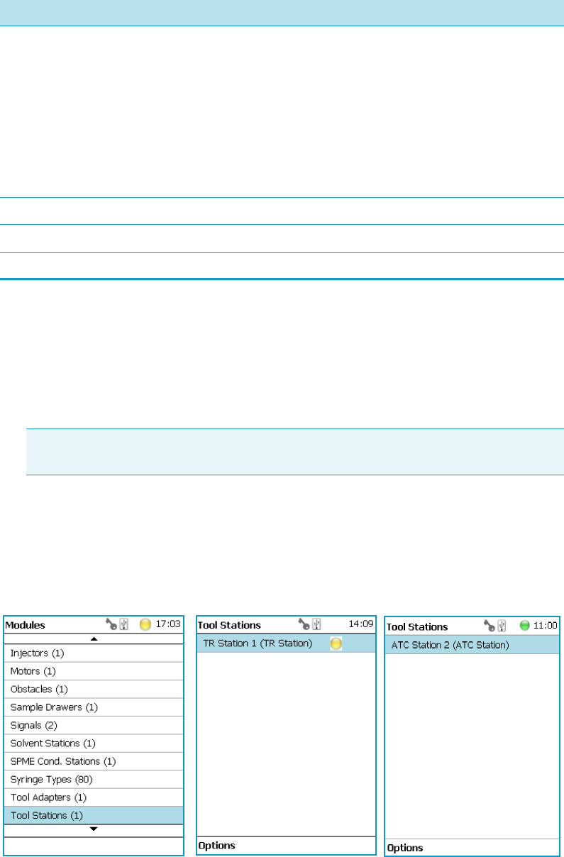
3 Setup Menu Item
Setup Menu Item Modules
Thermo Scientific TriPlus RSH User Guide 121
Tool Stations
The following stations are actively supported:
•TR Station — passive module with single slot for a single tool. See the section “TR
Station” on page 122.
•ATC Station — active module with three slots for three tools. See the section “ATC
Station” on page 122.
Upon selecting the list item Tool Station, the following parameters are available for
modification. See Figure 84. Press Enter to edit a parameter.
Figure 84. Menu Item Tool Stations and Menu List Items for Tool Stations
Adjust Needle Penetration Allows adjusting the Needle Penetration Depths in the
vial. Manually turn the needle as far down in the vial as
required. The cut-out in the Tray Holder frame as well as in
the Rack allows visual control of the needle tip.
Note The value found is not stored automatically.
This task allows for a check only. If the needle penetration should
be changed, select the Rack Type to enter the newly-established
Needle Penetration value.
New Rack Allows creating a new Rack
New Well Plate Allows creating a new Well Plate
Delete Tray Type Allows deleting the present Tray Type.
Table 50. Option Pull-up Menu for Temperature Controlled Drawer (Sheet 2 of 2)
Item Description
Note TR Station is not supported in combination with the RSH Firmware version
1.5.0 or higher.

3 Setup Menu Item
Setup Menu Item Modules
122 TriPlus RSH User Guide Thermo Scientific
TR Station
Upon selecting the item TR Station, the following parameters are available for modification.
See Ta bl e 5 1.
TR Station Pull-up Menu Options
Selecting the pull-up menu Options opens up the following tasks. See Table 52.
ATC Station
Upon selecting the list item ATC Station, the following parameters are available for
modification. See Table 53.
Table 51. List Item of TR Station
Item Description
Slot1 Slot available for tool.
TR Slot Index For information only.
Table 52. Pull-up Menu Options for TR Station
Item Description
New TR Station Creates a new TR Station.
Copy TR Station1 Copies the present TR Station.
Delete TR Station Deletes the present TR Station.
Tea c h Mo d u l e The positions of the X-, Y-, and Z-axes can be defined, for
teaching.
Check Teaching Checks the teaching position of the module.
This task serves as a quick check to determine if the X-, Y-,
and Z-positions are defined correctly.
In case a teaching point is off, return to the Menu ‘Setup’ for
readjustment of the teaching position. Please note that this
action can be done under the Extended User Level but not
under User Level.
Pick Tool Picks the Tool up from the TR Station.
Park Tool Parks the Tool in the TR Station.
Table 53. ATC Station Parameters (Sheet 1 of 2)
Item Description
Slot1 to Slot3 A slot can be selected to see which tool has been assigned to
this particular slot.

3 Setup Menu Item
Setup Menu Item Modules
Thermo Scientific TriPlus RSH User Guide 123
Options Pull-up Menu for ATC Station
Selecting the pull-up menu Options opens up the following tasks. See Table 54.
To ol EE P ROM Ac c e s s Disabling the EEPROM access will electrically isolate the
tool from the ATC Station. This is a protective measure if
the TriPlus RSH Head positions the tool in the ATC
Station. For automation, tool change, or tool calibration, the
automatic disabling and enabling of EEPROM Access is
built into the wizards.
When working with the Virtual Handheld Controller,
however, closing the window of the Virtual Handheld
Controller before a task is finished might cause the ATC
Station to remain disabled. This feature gives the operator
the possibility to manually control the ATC Station.
ATC Slot Index For information only.
Tool Present Indicates if the tool is parked in the Slot (if not, either
mounted in the TriPlus RSH Head, or not recognized by the
system).
Fiber Protection This parameter allows defining the Slot Position for the
SPME Tool.
Note that this parameter is used for the SPME1 Holder only.
Table 53. ATC Station Parameters (Sheet 2 of 2)
Item Description
Table 54. Option Pull Menu for ATC Station
Item Description
Check Teaching Checks the teaching position of the module. This task serves
as a quick check to determine if the X-, Y-, and Z-positions
are defined correctly. In case a teaching point is off, return to
the Menu Setup for readjustment of the teaching position.
Please note that this action can be done under the Extended
User Level but not under User Level.
Teach Mo du l e The positions of the X-, Y-, and Z-axes can be defined, for
teaching.
Reset Invalid Eeprom Allows in the case of a broken communication to the ATC
Station to re-establish it on the running system, without
shutting down the entire TriPlus RSH system.
Park Tool This menu item allows parking a tool in a slot without
picking up another tool.

3 Setup Menu Item
Setup Menu Item Modules
124 TriPlus RSH User Guide Thermo Scientific
Signals
How to set-up the synchronization signals from the TriPlus RSH to an external device
The synchronization signals have to be set step-by step.
1. The first step is assigning an Input Signal and an Output Signal. The next step is to
establish what type of contact is required to receive or send a TTL signal.
It could be TTL (Transistor-Transistor Logic), a relays contact, an Opto-coupler, or
another type. Add the required parameters such as Pulse Duration and Blocking Time.
This section provides informations for copying the default signals, and adding for
example a second output signal if required.
An output signal is required to send a start signal to the external device. Typically the
Switch Out Signal1 (SWOut1) is used for this task.
A second output signal, named Destination Aux, can be used for cases where one
command is sent to two different GC which must be started at the same time. A Y-shape
synchronization cable is required for connecting the TriPlus RSH to the two GC units.
One signal used could be SWOut1 and the second signal would be SWOut2. The
assigned signals have to be matched with the pin allocation of the synchronization cable.
2. The second step is to synchronize the signal parameters with the GC. This step is made in
the section “Input/Output Interface” on page 106.
The Ready signal from the GC is usually sent to the system, and a TTL-In signal is used
to receive the Ready signal. Depending on the GC manufacturer settings, the signal is set
to active high or active low. This synchronization is matched in the section
Input/Output Interface.
3. The third step is to bundle the required Input and Output Signals for a specific
chromatographic system, such as a GC System. This bundle can be configured once and
tested in the combination of the system and the other device. This bundling is described
in the section “Chromatograph System” on page 104 as the last step in setting up signals.
Selecting the list item Signals opens up the following parameters. See Figure 85.
Note Synchronization signals are inputs that tell the TriPlus RSH when to wait or to
proceed with a sample-processing step. Output signals are sent from the system to external
devices to indicate the status or completion of particular processing steps.
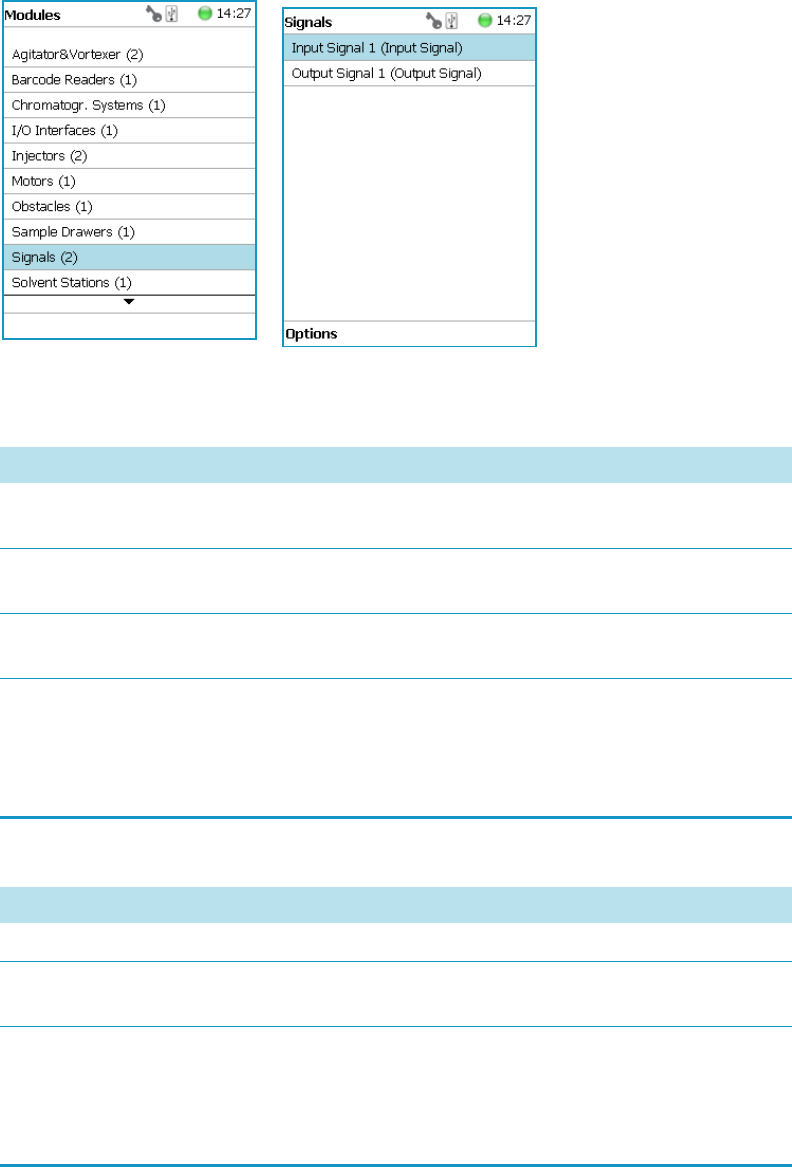
3 Setup Menu Item
Setup Menu Item Modules
Thermo Scientific TriPlus RSH User Guide 125
Figure 85. Menu List Item Signals and List Items Input and Output Signals
Press Enter to edit a parameter. See Table 55 and Ta bl e 5 6.
Table 55. Input Signal Parameters
Items Description
Input Signal Selects the required Input Signal. Typically used for the
Ready Signal (TTL-In).
Signal On Indicates the signal has been received. A crossed-out box
means that a signal has been received.
Blocking Time Used to program a time delay after receiving the signal
(usually the Ready Signal from an external device).
Source Selects the required Input Signal for synchronization with an
external device.
Usually a TTL-In contact is used to receive the Ready
Signal from an external device.
Table 56. Output Signal Parameters (Sheet 1 of 2)
Item Description
Output Signal Selects the required Output Signal
Signal On Indicates if the signal has been received. A crossed-out box
means that a signal has been received.
Destination Selects the required Output signal for the synchronization
with an external device.
Usually a switch out signal (SW Out) contact is used to send
the Start Signal to an external device.

3 Setup Menu Item
Setup Menu Item Modules
126 TriPlus RSH User Guide Thermo Scientific
Signals Option Pull-up Menu
Selecting the pull-up menu Options opens up the following tasks. See Table 57.
Destination Aux Used for cases where one command is sent to two different
GC which must be started at the same time.
Pulse Duration Selects the time how long the signal is sent.
Table 56. Output Signal Parameters (Sheet 2 of 2)
Item Description
Table 57. Option Pull-up Menu for Signals
Item Description
New Signal Creates a new Input or Output Signal. A dialog window
opens allowing you to assign a unique name to the new
signal. When finished, press New and the entire class with
the corresponding parameters is copied over.
Select the required contact, such as a TTL-In or a SW Out
using the parameter Source.
The signal name does not require to be in a consecutive
order for example, Input Signal 2, it can also be a
specifically-named signal such as Inject or Start. Some cycles
require a specifically-named signal. Check the cycle
description for specific names.
Copy Input Signal An Input Signal can be copied with this task. The task
functions in a similar manner as described above with New
Signal.
Copy Output Signal Copies an Output Signal. The task functions in a similar
manner as described above with New Signal.
Delete Input Signal Deletes an Input Signal which is no longer required for the
system configuration in combination with an external
device.
Delete Output Signal Deletes an Output Signal which is no longer required for the
system configuration in combination with an external
device.
Set Signal Activates the selected signal for the time set with the
parameter Duration. Since the Duration time is usually
short, a status change in the parameter Signal ON is not
visible.
Reset to Default Resets the selected module parameters to default value.
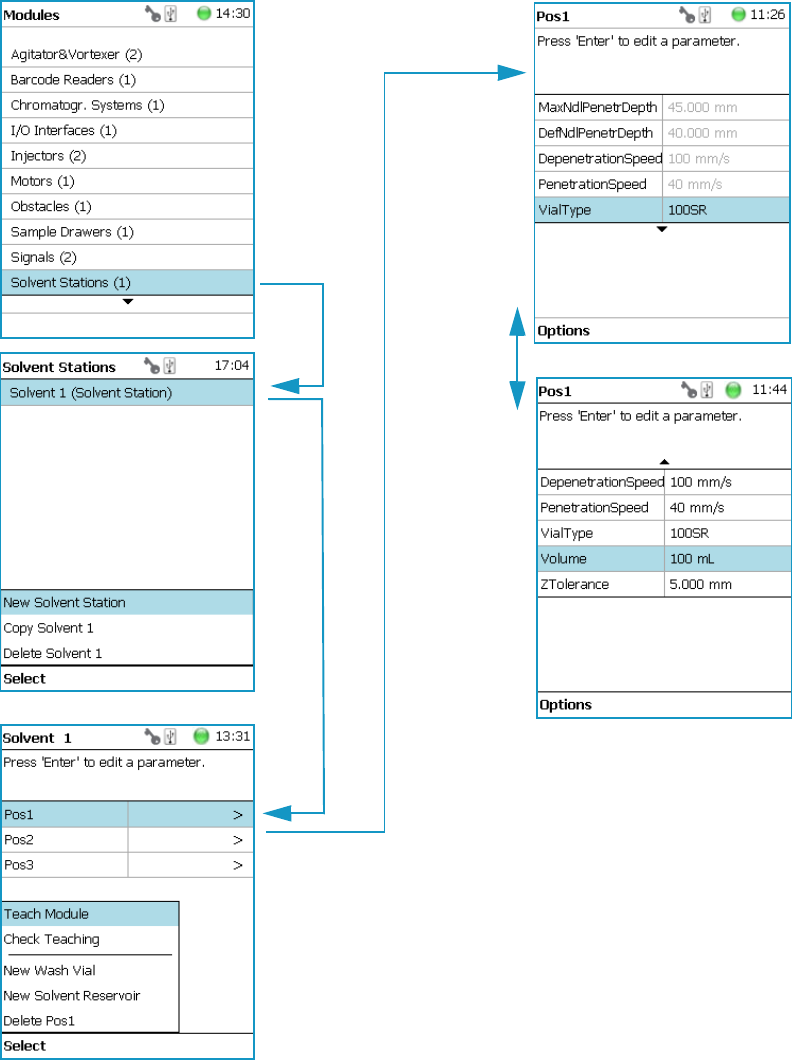
3 Setup Menu Item
Setup Menu Item Modules
Thermo Scientific TriPlus RSH User Guide 127
Solvent Stations
Selecting the list item Solvent Stations opens up the following parameters. See Figure 86.
Figure 86. Menu Items for Solvent Stations and Menu Item Large Solvent Station
Pos1 = Large solvent reservoir bottle (100 mL volume in back position)
Pos2 = Large solvent reservoir bottle (100 mL volume in middle position)
Pos3 = Large solvent reservoir bottle (100 mL volume in front position)

3 Setup Menu Item
Setup Menu Item Modules
128 TriPlus RSH User Guide Thermo Scientific
Selecting one of the positions allows the operator to access following parameters.
See Ta bl e 5 8.
Solvent Station Options Pull-up Menu
Selecting the pull-up menu Options opens up the following tasks. See Table 58.
Table 58. Solvent Station Parameters
Item Description
Max Needle Penetration
Depth
The maximum allowed Needle Penetration can be defined
as a safety measure so that you cannot destroy the needle tip
by going too far down.
The maximum needle penetration must not exceed the
length of the syringe needle, considering the loss of
approximately 12 mm due to the needle guide, and so on.
For a typical needle length of 57 mm or 85 mm for the long
needle, the maximum penetration depth must not exceed
45 mm or 73 mm.
Default Needle Penetration
Depth
The default value of the syringe needle penetration depth in
the reservoir vial is set by this parameter.
Depenetration Speed Selects the required speed for pulling the syringe needle out
of the reservoir vial.
Diameter Defines the diameter of the solvent reservoir.
Height Defines the height of the solvent reservoir.
Penetration Speed The syringe needle penetration speed is set by this value.
It is recommended to use the default value first. Changing
this parameter in one or the other direction might lead to
needle bending.
Vial Type Selects a predefined Vial Type.
Volume Defines the volume of the reservoir container.
Z-Tolerance A tolerance window to give a plus/minus range (expressed in
mm) where the Head must expect an object.
• If the value is set > 0, indicates a relative detection
mode, and the sensor from the Head needle guide is
active.
• If the value is set to 0, the Needle Guide Motor
detection current is turned off and the syringe slider
moves to an absolute value, the Z-axis position as
specified by the object.
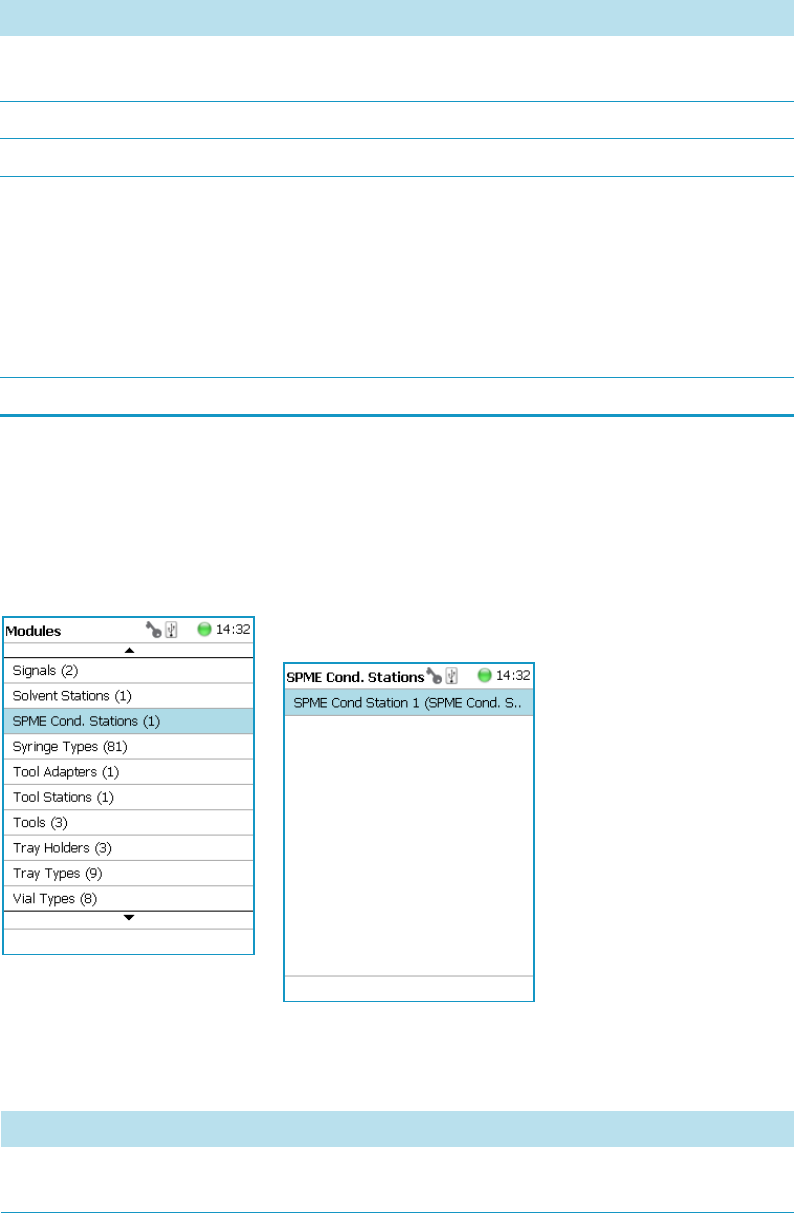
3 Setup Menu Item
Setup Menu Item Modules
Thermo Scientific TriPlus RSH User Guide 129
SPME Conditioning Station
Upon selecting the list item SPME Conditioning Station, the following parameters are
available for modification. See Figure 87.
Figure 87. Menu Item and List Items for SPME Conditioning Station
Press Enter to edit a parameter. See Table 59.
Table 59. Solvent Station Options Parameters
Item Description
New Solvent Station
Description
Creates a new Solvent Station.
Copy Solvent Station 1 Copies the present Solvent Station.
Delete Solvent Station 1 Delete the present Solvent Station.
Check Teaching Checks the teaching position of the module.
This task serves as a quick check to determine if the X-, Y-,
and Z-positions are defined correctly.
In case a teaching point is incorrect, return to the Menu
Setup for readjustment of the teaching position. Please note
that this action can be done under the Extended User Level
but not under User Level.
Teach Mo du l e Resets the selected module parameter to default value.
Table 60. SPME Conditioning Station Parameters (Sheet 1 of 2)
Item Description
Actual Temperature Reads out the actual temperature of the module; read-only
function.
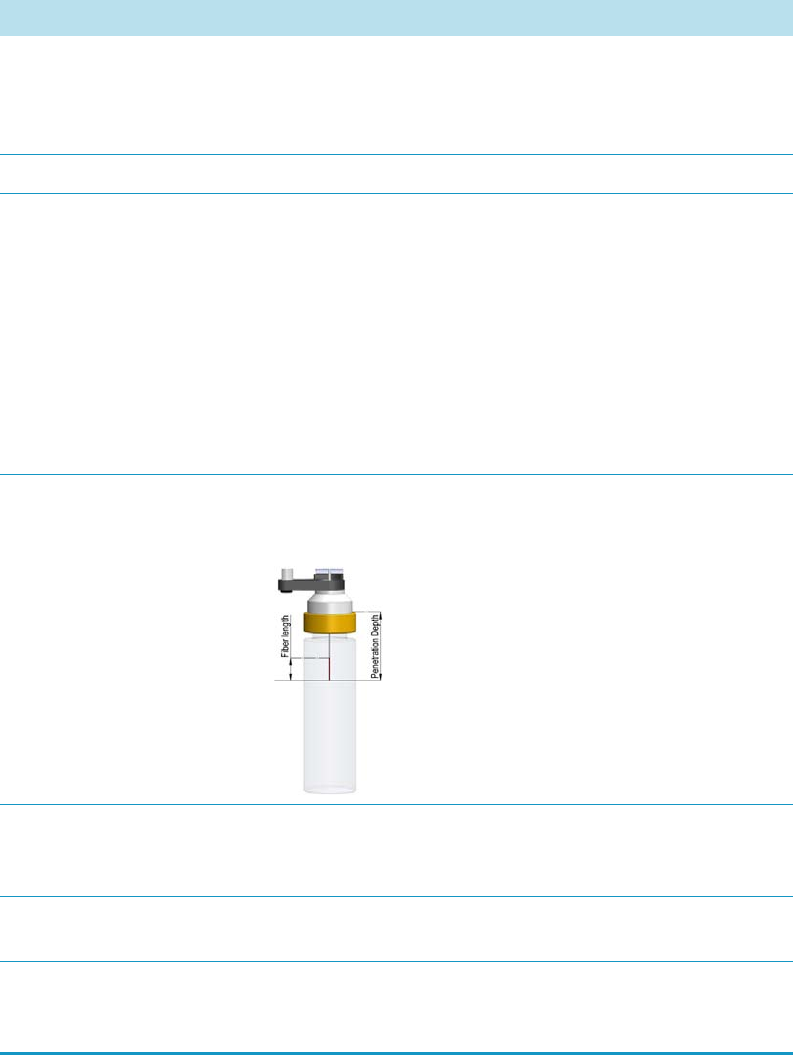
3 Setup Menu Item
Setup Menu Item Modules
130 TriPlus RSH User Guide Thermo Scientific
Max Temperature Sets the upper temperature limit.
The Maximum Temperature which can be set is 350 °C, but
this parameter is often defined by the specific needs for the
application.
Min Temperature Sets the lower temperature limit.
Standby Temperature The Standby Temperature can be adjusted to the
application’s requirements. Setting the Standby Temperature
using this function does not yet activate the newly-selected
temperature. To activate it, go to the pull-up menu Options
and select Activate Standby Temperature.
The Standby Temperature is activated when the TriPlus
RSH is powered up. In routine use, the Standby
Temperature is activated after a job has been terminated.
The Standby Temperature is typically lower than the
application temperature.
Default Needle Penetration
Depth
Defines the penetration depth of the SPME Needle in the
module. The value reflects the total length including the
length of the fiber.
Max Needle Penetration
Depth
Upper limit of penetration depth of the SPME needle in the
module. The value reflects the total length including the
length of the fiber.
Tem p. G a i n The coefficient used, if a temperature calibration has been
performed. Possible values are between 0 and 2. Read-only.
Temp.Offset The Offset temperature used, if a temperature calibration
has been performed. Possible values are between -10 °C and
+10 °C. Read-only.
Table 60. SPME Conditioning Station Parameters (Sheet 2 of 2)
Item Description

3 Setup Menu Item
Setup Menu Item Modules
Thermo Scientific TriPlus RSH User Guide 131
SPME Conditioning Station Options Pull-up Menu
Selecting the pull-up menu Options opens up the following tasks. See Table 60.
Syringe Types
The Syringe Type covers the definition and in the class tool, the appropriate the Syringe Type
is selected for the corresponding tool.
Upon selecting the list item Syringe Type, the following parameters are available for
modification. See Figure 88.
Figure 88. Menu List Item Syringe Types and List Items Syringe Types
Press Enter to edit a parameter.
Selecting a syringe, for example a 10 μL Liquid Syringe, opens all the necessary parameters to
define the syringe in geometry, and to define default values for an optimized use. See
Tab le 62.
Table 61. Option Pull-up Menu for SPME Conditioning Station
Item Description
Check Teaching Checks the teaching position of the module.
This task serves as a quick check to determine if the X-, Y-,
and Z-positions are defined correctly.
In case a teaching point is off, return to the Menu Setup
for readjustment of the teaching position. Please note that
this action can be done under the Extended User Level but
not under User Level.
Tea c h Mo d u l e The positions of the X-, Y-, and Z-axes can be defined
again, teaching.
Activate Standby Temperature Activates the newly-set Standby Temperature.

3 Setup Menu Item
Setup Menu Item Modules
132 TriPlus RSH User Guide Thermo Scientific
Note that the same parameters are used for a liquid syringe and for a headspace syringe.
The SPME technique requires additional parameters.
Table 62. List of Syringe Types Parameters (Sheet 1 of 2)
Item Description
Bottom Sense When this function is enabled, the needle goes down to the
bottom of the internal standard vial.
See the section “Bottom Sense Parameter: Criteria for
Syringe Needle” on page 133.
Def Aspirate Acc Specifies the default aspirate acceleration in μL/s*s.
Def Aspirate Specifies the default aspirate flow rate in μL/s.
Def Aspirate Delay Specifies the default aspirate delay time after the end of the
aspiration.
Def Dispense Acc Specifies the default dispense acceleration in μL/s*s.
Def Dispense Specifies the default dispense flow rate in μL/s.
Def Dispense Delay Specifies the default dispense delay after the end of the
dispense.
Dispense Max Specifies the maximum dispense flow rate in μL/s.
Def Fill Strokes Asp Specifies the default fill strokes aspiration flow rate in μL/s.
Def Fill Strokes Disp Specifies the default fill strokes dispense flow rate in μL/s.
Def Fill Strokes Count Specifies the default number of syringe plunger strokes from
the same vial, to have a homogeneous phase between the
headspace gas in the vial and the sample in the syringe.
Def Fill Strokes Vol Specifies the default fill strokes volume in μL.
Def Pen Vel Specifies the default penetration velocity in mm/s.
Max Fill Strokes Asp Specifies the maximum fill strokes aspirate flow rate in μL/s.
Max Fill Strokes Disp Specifies the maximum fill strokes dispense flow rate in
μL/s.
Max Pen Depth Specifies the maximum penetration depth in mm.
Max Pen Force Specifies the maximum penetration force in N.
Max Pen Vel Specify the maximum penetration speed in mm/s.
Needle Gauge Needle Guide — Specify the syringe suppliers specific.
Needle Inner Dia Specifies the internal diameter of the syringe needle in mm.
Needle Length Specifies the length of the syringe needle in mm.
Needle Out Dia Specifies the external diameter of the syringe needle in mm.
Plunger Type Specify the syringe suppliers specific.

3 Setup Menu Item
Setup Menu Item Modules
Thermo Scientific TriPlus RSH User Guide 133
Bottom Sense Parameter: Criteria for Syringe Needle
In order to use the parameter Bottom Sense successfully, consider the following points:
• For successful bottom detection, the syringe needle has to be intact (not bent from
previous use).
• The needle length does not exceed 65 mm. If longer needles are used, for example 80 mm
in length, then the needle gauge 26 and 26S (outer needle diameter 0.47 mm) is too thin
to withstand the touchdown pressure.
The needle gauge has to be changed to 23 or 23S (outer needle diameter 0.63 mm).
Syringe Types Options Pull-up Menu
Selecting the pull-up menu Options opens up the following tasks. See Table 63.
Point Style Specify the syringe suppliers specific.
Scale Length Specify the length of the scale in mm
Syringe Volume Specifies the volume of the syringe in μL.
Gas Inlet Pos Specifies the position in mm of the gas inlet. HS Tool only.
Fiber Length Specifies the length in mm of the SPME fiber.
Fiber Type Specifies the type of the SPME fiber. SPME Tool only
Table 62. List of Syringe Types Parameters (Sheet 2 of 2)
Item Description
Table 63. Option Pull-up Menu for Syringe Types
Item Description
New Syringe Type Creates a new Syringe Type template.
Copy Syringe Type Copies the present Syringe Type template.
Export Syringe Type Exports the present Syringe Type template to a USB stick.
Export All Exports all Syringe Type templates at once to a USB stick.
Delete Syringe Type Deletes the present Syringe Type template.
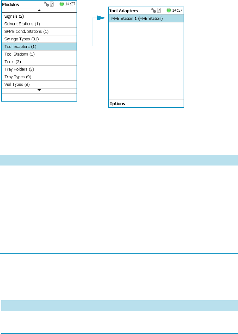
3 Setup Menu Item
Setup Menu Item Modules
134 TriPlus RSH User Guide Thermo Scientific
Tool Adapters
Selecting the list item Tool Adapters opens up the following parameters. See Figure 89.
Figure 89. Menu Item Tool Adapter and List Item MHE Station
Selecting the list item Tool Adapters opens the dialog window for MHE Station.
Press Enter to edit a parameter. See Table 64.
Tool Adapter Options Pull-up Menu
Selecting the pull-up menu Options opens up the following tasks. See Table 65.
Table 64. MHE Station Adapter Parameters
Item Description
Z-Tolerance A tolerance window to give a plus/minus range (expressed in
mm) where the Head must expect an object.
If the value of this item is > 0, this indicates a relative
detection mode, and the sensor from the Head needle guide
is active.
If the value of this item is set to 0 the Needle Guide Motor
detection current is turned off and the syringe slider moves
to an absolute value, the Z-axis position as specified by the
object.
Table 65. Tool Adapter Options Parameters (Sheet 1 of 2)
Item Description
New MHE Station Creates a new MHE Station.
Copy MHE Station Copies the present MHE Station.

3 Setup Menu Item
Setup Menu Item Modules
Thermo Scientific TriPlus RSH User Guide 135
Tools
In the class Tools are the various tool Types defined. Selecting the list item Tools opens up the
following parameters:. See Figure 90.
Figure 90. Menu Item Tools and Menu List Items Tools
•Figure 91 shows the Syringe Type selection for HS, LS, and SPME Tools.
•Figure 92 shows the Syringe Type selection for ITEX Tool.
Delete MHE Station Deletes of the present. MHE Station.
Check Teaching Checks the teaching position of the station.
This task serves as a quick check to determine if the X-, Y-,
and Z-positions are defined correctly.
In case a teaching point is incorrect, return to the Menu
Setup for readjustment of the teaching position.
Please note that this action can be done under the Extended
User Level but not under User Level.
Tea c h Mo d u l e The positions of the X-, Y-, and Z-axes can be defined again,
(teaching).
Reset to Default Resets the selected module parameter to default value.
Table 65. Tool Adapter Options Parameters (Sheet 2 of 2)
Item Description
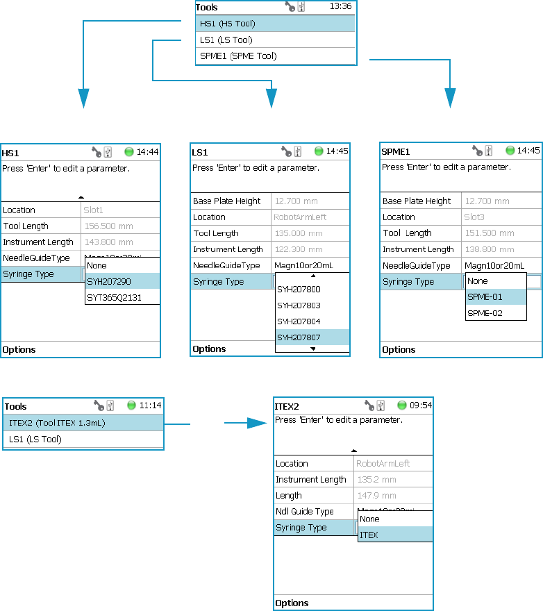

3 Setup Menu Item
Setup Menu Item Modules
Thermo Scientific TriPlus RSH User Guide 137
Table 66. List Item Parameters for HS, LS, SPME, and ITEX Tools (Sheet 1 of 4)
Item Description
Parameters for HS Tool
Syringe Heater This menu list item is specific for the HS Tool. Selecting the
item opens the parameters for:
•Actual Temperature — Reads out the actual
temperature of the syringe; read-only function.
•Max Temperature — Sets the upper temperature limit.
The Maximum Temperature which can be set is 200 °C,
but this parameter is often defined by the specific needs
for the application.
•Min Temperature — Sets the lower temperature limit.
The Minimum Temperature which can be set is 40 °C.
•Standby Temperature — The Standby Temperature
can be adjusted to the application’s requirements.
Setting the Standby Temperature using this function
does not yet activate the newly-selected temperature.
To activate it, go to the pull-up menu Options and
select Set Standby Temperature.
The Standby Temperature is activated when the TriPlus RSH is
powered up. In routine use, the Standby Temperature is activated
after a job has been terminated. The Standby Temperature is
typically lower than the application temperature.
•Te m p Se tp o i n t — Read out the setpoint of the
temperature.
•Stdby Temp Control — If switched off, the module will
not go to standby temperature if idle.
•Te m p G a i n — The coefficient used, if a temperature
calibration has been performed. Possible values are
between 0 and 2. Read-only.
•Te m p . Of f s e t — The Offset temperature used, if a
temperature calibration has been performed. Possible
values are between -10 °C and +10 °C. Read-only.
Location Location (Slot Position) where the specific tool is parked.
Length Defines total length of the tool. Read-only function.
Instrument Length Defines total length of the syringe (instrument). Read-only
function.

3 Setup Menu Item
Setup Menu Item Modules
138 TriPlus RSH User Guide Thermo Scientific
Needle Guide Type This parameter defines if an adapter, such as the magnetic
ring or the foil cutter, is connected to the Needle Guide.
Important: The Needle Guide Type has to be defined,
default value is Not Specified. See “Installation Item” on
page 191.
Syringe Type All syringes with the same geometry (barrel diameter, needle
length) and corresponding syringe type to the tool are
filtered by the software and are selectable for use.
Parameters for ITEX Tool
Syringe Heater This menu list item is specific for the ITEX Tool. Selecting
the item opens the parameters for:
•Actual Temperature — Reads out the actual
temperature of the syringe; read-only function.
•Max Temperature — Sets the upper temperature limit.
The Maximum Temperature which can be set is 150 °C.
•Min Temperature — Sets the lower temperature limit.
The Minimum Temperature which can be set is 40 °C.
•Standby Temperature — The Standby Temperature
can be adjusted to the application’s requirements.
Setting the Standby Temperature using this function
does not yet activate the newly-selected temperature.
To activate it, go to the pull-up menu Options and
select Set Standby Temperature.
The Standby Temperature is activated when the TriPlus RSH is
powered up. In routine use, the Standby Temperature is activated
after a job has been terminated. The Standby Temperature is
typically lower than the application temperature.
•Te m p Se tp o i n t — Read out the setpoint of the
temperature.
•Stdby Temp Control — If switched off, the module will
not go to standby temperature if idle.
•Te m p G a i n — The coefficient used, if a temperature
calibration has been performed. Possible values are
between 0 and 2. Read-only.
•Te m p . Of f s e t — The Offset temperature used, if a
temperature calibration has been performed. Possible
values are between -10 °C and +10 °C. Read-only.
Table 66. List Item Parameters for HS, LS, SPME, and ITEX Tools (Sheet 2 of 4)
Item Description

3 Setup Menu Item
Setup Menu Item Modules
Thermo Scientific TriPlus RSH User Guide 139
Trap Heater This menu list item is specific for the ITEX Tool. Selecting
the item opens the parameters for:
•Actual Temperature — Reads out the actual
temperature of the trap; read-only function.
•Max Temperature — Sets the upper temperature limit.
The Maximum Temperature which can be set is 350 °C.
•Min Temperature — Sets the lower temperature limit.
The Minimum Temperature which can be set is 100 °C.
•Standby Temperature — The Standby Temperature
can be adjusted to the application’s requirements.
Setting the Standby Temperature using this function
does not yet activate the newly-selected temperature.
To activate it, go to the pull-up menu Options and
select Set Standby Temperature.
The Standby Temperature is activated when the TriPlus RSH is
powered up. In routine use, the Standby Temperature is activated
after a job has been terminated. The Standby Temperature is
typically lower than the application temperature.
•Te m p Se tp o i n t — Read out the setpoint of the
temperature.
•Stdby Temp Control — If switched off, the module will
not go to standby temperature if idle.
•Te m p G a i n — The coefficient used, if a temperature
calibration has been performed. Possible values are
between 0 and 2. Read-only.
•Te m p . Of f s e t — The Offset temperature used, if a
temperature calibration has been performed. Possible
values are between -10 °C and +10 °C. Read-only.
Location Location (Slot Position) where the specific tool is parked.
Length Defines total length of the tool. Read-only function.
Instrument Length Defines total length of the syringe (instrument). Read-only
function.
Needle Guide Type This parameter defines if an adapter, such as the magnetic
ring or the foil cutter, is connected to the Needle Guide.
Important: The Needle Guide Type has to be defined,
default value is Not Specified. See “Installation Item” on
page 191.
Table 66. List Item Parameters for HS, LS, SPME, and ITEX Tools (Sheet 3 of 4)
Item Description

3 Setup Menu Item
Setup Menu Item Modules
140 TriPlus RSH User Guide Thermo Scientific
Tools Options Pull-up Menu
Selecting the pull-up menu Options opens up the following tasks. See Table 67.
Syringe Type Use the ITEX syringe only.
Parameters for LS and SPME Tools
Location Location (Slot Position) where the specific tool is parked.
Instrument Length Defines total length of the syringe (instrument). Read-only
function.
Length Defines total length of the tool. Read-only function.
Needle Guide Type Defines if an adapter, such as the magnetic ring or the foil
cutter, is connected to the Needle Guide.
Important: The Needle Guide Type has to be defined,
default value is Not Specified. See “Installation Item” on
page 191.
Needle Penetration Depth Defines the penetration depth of the fiber in the vial.
Syringe Type All syringes with the same geometry (barrel diameter, needle
length) and corresponding syringe type to the tool are
filtered by the software and are selectable for use.
Table 66. List Item Parameters for HS, LS, SPME, and ITEX Tools (Sheet 4 of 4)
Item Description
Table 67. Options Parameters for HS, LS, SPME, and ITEX Tools
Item Description
Calibrate Tool Calibrates the specified tool.
Note This might be necessary after a tool has been
accidently dropped, and assuming that the Needle Guide
was bent. A re-calibration corrects for the difference.
Check Tool Calibration A calibration check is activated.
Select Tool Selects another tool. The current tool is parked first and the
new required one is picked up.
Purge Syringe Available only with HS and ITEX Tools. Allows to purge
manually a headspace syringe.
Park Tool Parks a tool without picking up another tool from the ATC
Station.
Configure SPME Tool This line is visualized when a SPME tool is selected.
This task allows to configure a SPME tool. Fiber
adjustment.
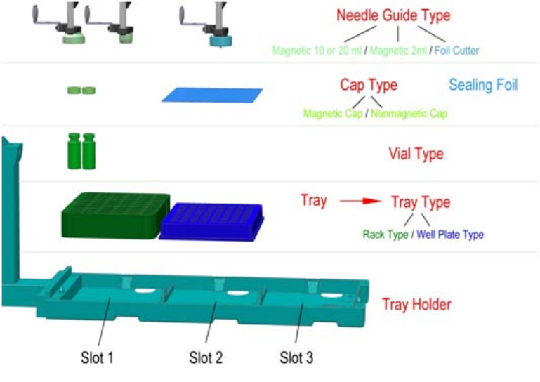
3 Setup Menu Item
Setup Menu Item Modules
Thermo Scientific TriPlus RSH User Guide 141
Naming Convention and Relationship between Software Classes‚ Tray Holder,
Trays, Tray Types, and Cap Type
The RSH Firmware filters the selection of the subsequent classes based on the selection of the
initial item. You should be aware of several important points.
First, the Needle Guide Type must be defined. If Not Specified is selected under Needle
Guide Type, the execution of the run will be prohibited.
In addition, the Cap Type and Needle Guide Type must be compatible in order to transport
a vial. If a mismatch is observed, such as if a 2 mL vial with a magnetic cap is in use but the
Needle Guide Type is selected for a 20 mL vial, then the software will prohibit the execution
of the run.
Figure 93 illustrates the interdependency between the various software classes and subclasses.
The different colors depict the main classes and the parameters assigned to each of them.
See Color Coding and Software Classes.
Figure 93. Relationship between Software Classes: Tray Holder, Tray, Tray Type, Cap Type, and
Needle Guide Type.
Color Coding
The software classes are labeled in red. All related software classes where a Vial is used are
displayed using a green shade and the classes related to Well Plates are displayed using a blue
shade.

3 Setup Menu Item
Setup Menu Item Modules
142 TriPlus RSH User Guide Thermo Scientific
Software Classes
•The Tray Ho lder is the basic item encompassed by this software class; all the other
subsequent software categories, such as Tray, Vial Type, and Cap Type are pre-defined by
the Tray Holder.
•A Tray is a generic term and can be a ‘Rack’ for holding vials or a Well Plate (Deep Well
or Micro Titer Plate).
•A Tra y Typ e is linked to each Tray. Depending on the actual Tray used, the Tray Type can
be either a Rack Type or a Well Plate Type.
•The Vial Type depends on the Rack Type, but the Well Plate Type does not have any type
of vial associated with it (i.e. the class of software that defines the vial type does not exist
for a Well Plate).
•The Cap Type is linked to the ‘Vial Type’. This class defines the cap material, and
whether or not the vial is transportable by magnetic force.
•The Sealing Foil is actually not a software subclass but the presence of the Sealing Foil
with a Well Plate is automatically linked to the Needle Guide Type, which in turn will
determine whether the Foil Cutter will be used.
•The Needle Guide Type is not a software class directly linked to the class Tray Holder
and its subclasses; rather, it is linked to the class Too l s .
The Needle Guide Type will determine which adapter has to be used to handle the
selected vial or well plate.
Is it necessary to transport a vial, and is a Foil Cutter required to pierce the Sealing Foil?
Tray Holders
Tray Holders are passive modules. These modules are described by their geometric design
parameters, but there is no control whatsoever through the TriPlus RSH.
A Tray Holder can be a Liquid Cooled Tray (using a circulation bath for heating/cooling), or
a Tray Holder without any temperature control.
Selecting the list item Tray Holde r opens up the following parameters. See Figure 94.
Note The two types of Tray Holders, the model Tray Holde r and Tray Plate appear very
similar. The main difference is that the Tray Holder can accept a large Rack which spans
all three slots, for example Tray Type R60.
The Tra y Pl at e only accepts all Trays (Racks) which have the same footprint as a Well
Plate. Well Plates are also accepted.
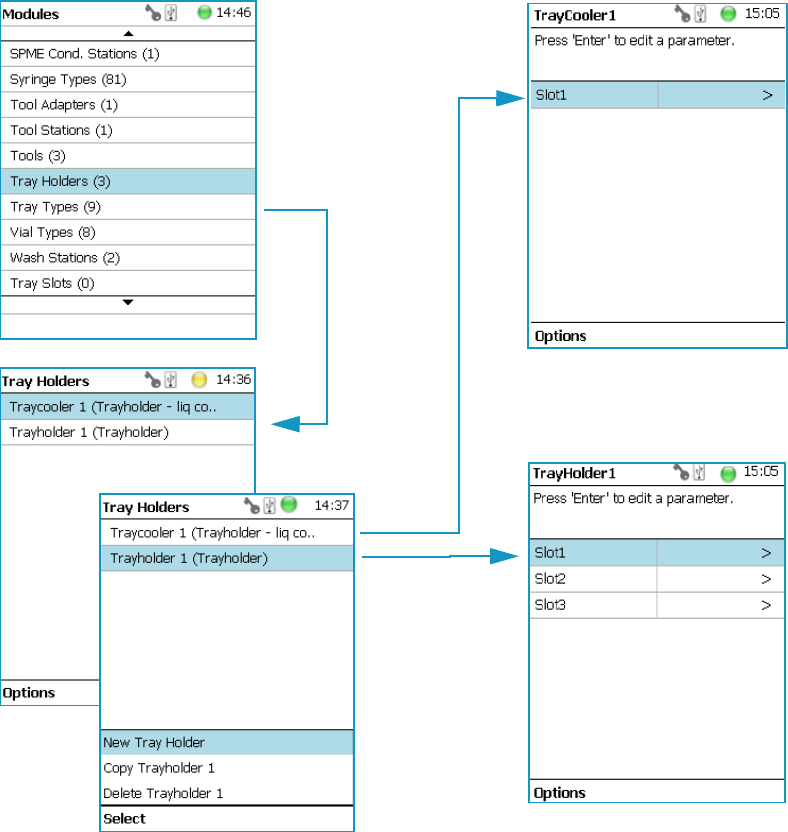
3 Setup Menu Item
Setup Menu Item Modules
Thermo Scientific TriPlus RSH User Guide 143
Figure 94. Menu Item ‘Tray Holder and List Items for Tray Holders
Press Enter to edit a parameter.
Selecting the list item Slot opens the dialog window for Tra y (Rack), which contains the
parameters Tray Type and Vial Type.
If no Tray is assigned yet, use the button New to assign a Tray to a particular Slot.
The dialog for naming a Tray can be started by pressing the Enter button. See the examples.
See Figure 95.
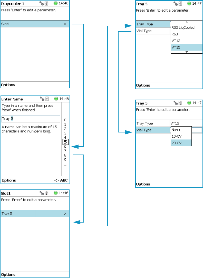
3 Setup Menu Item
Setup Menu Item Modules
144 TriPlus RSH User Guide Thermo Scientific
Figure 95. Tray Type and Vial Type Selections to Assign to Tray
•Slot(#) — Select the required Slot number to assign a Tray Type and Vial Type.
•Tray(#) — Select the required Tray (Rack) number to assign the Tray Type and Vial
Typ e.

3 Setup Menu Item
Setup Menu Item Modules
Thermo Scientific TriPlus RSH User Guide 145
•Cap Type — Describes the Cap Type. Read-only. The definition is made in the class Vial
Typ e.
•Tray Typ e — A list with all predefined Tray (Rack) Types opens up for selection.
•Vial Type — A list with all predefined Vial Types opens up for selection.
•Well Plate — Select the required Well Plate number to assign the Well Plate Type.
•Well Plate Type — A list with all predefined Well Plate Types opens up for selection.
Tray Holder Options Pull-up Menu
Selecting the pull-up menu Options opens up the following tasks. See Table 68.
Another Option pull-up Menu is available when the list item Tray(#) is selected.
See Ta bl e 6 9.
Note A passive Tray Holder module can adapt Trays made for different vial sizes. When
the different Trays are used, consider the various vial heights, and ensure that the Stack
Drawer Magnet, connected to the lower needle guide, does not catch at front row of vials
from behind the Tray.
Table 68. Tray Holder Option pull-up Menu Parameters
Item Description
Create New Tray System Guides through a wizard for creating a new Tray System.
This includes the Tray Holder, Slots, Tray, Tray Type, and
Vial Type.
New Tray Holder Creates of a new Tray Holder.
Copy Tray Holder Copies the present Tray Holder.
Delete Tray Holder Deletes the present Tray Holder.
Table 69. Tray Holder Option pull-up Menu Parameters When Tray(#) is Selected (Sheet 1 of 2)
Item Description
New Tray (New Rack) Allows creating a new Tray (Rack).
New Well Plate Allows creating a new well plate.
Delete Tray Type Allows deleting the present Try Type.
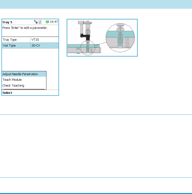
3 Setup Menu Item
Setup Menu Item Modules
146 TriPlus RSH User Guide Thermo Scientific
Tray Types
A Tray Type contains all the information about the geometry of the Tray.
Parameters such as how many sample vials are in a column and in a row, and the distance from
vial to vial are all summarized in this class for each Tray Type.
Selecting the list item Tray Types opens up the following parameters. See Figure 96.
Adjust Needle Penetration Adjusts the Needle Penetration Depths in the vial.
Manually turn the needle as far down in the vial as required.
The cut-out in the Tray Holder frame as well as in the Tray
allows visual control of the needle tip.
Note: The value found is not stored automatically. This task
allows a check only. If the needle penetration must be
changed, select the Tray Type to enter the new established
Needle Penetration value.
Check Teaching Checks the teaching position of the module.
This task serves as a quick check to determine if the X-, Y-,
and Z-positions are defined correctly.
In case a teaching point is incorrect, return to the Menu
Setup for readjustment of the teaching position.
Note that this action can be done under the Extended User
Level but not under User Level.
Teach Mo du l e The positions of the X-, Y-, and Z-axes can be defined again,
teaching.
Table 69. Tray Holder Option pull-up Menu Parameters When Tray(#) is Selected (Sheet 2 of 2)
Item Description
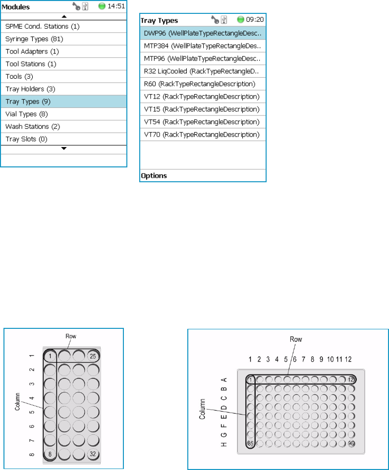
3 Setup Menu Item
Setup Menu Item Modules
Thermo Scientific TriPlus RSH User Guide 147
Figure 96. Menu Item ‘Tray Types and Menu List Items Tray Types
The individual parameters are identical for each Tray Type. The main difference depends on
the primary differentiation of a Tray Type or Plate Type. In a Tray Type vials are inserted, the
combined height of a Tray and the height of the vial above the upper surface of the Tray yields
to the total height of the Tray Module.
A Plate has no vial inserted and the total height of the Tray corresponds with the height of the
Well Plate.
The second main difference is the order of sample treatment. A Tray Type R60 has the vial
numbering in the order of the Y-axis; in a Well Plate the numbering order is by the X-axis.
Press Enter to edit a parameter. See Tab le 7 0 .
Tray type R32 LiqCooled Well Plate type MTP96

3 Setup Menu Item
Setup Menu Item Modules
148 TriPlus RSH User Guide Thermo Scientific
Table 70. Tray Type Parameters (Sheet 1 of 3)
Item Description
1st Sample Offset X Offset distance from Tray Zero Point to first position in
X-axis direction. Unit: mm.
1st Sample Offset Y Offset distance from Tray Zero Po int to first position in
Y-axis direction. Unit: mm.
1st Sample Offset Z Offset distance from Tray Zero Point to first position in
Z-axis direction. Unit: mm.
(This parameter is currently not used with released Tray Types. Value = 0)
Alt Sample Offset X Offset from Tray Ze ro Point to first sample position of
staggered row/column in direction X-axis. Unit: μm.
Alt Sample Offset Y Offset from Tray Ze ro Point to first sample position of
staggered row/column in direction Y-axis. Unit: μm.
Alt Sample Offset Z Offset from Tray Ze ro Point to first sample position of
staggered row/column in direction Z-axis. Unit: μm.
(This parameter is currently not used with released Tray Types. Value = 0)
Cavity Depth Defines the total depth of the cavity. Unit: mm.
Cavity Diameter Defines the diameter of the cavity. Unit: mm.
Columns Number of columns.
Indexing Orientation Defines the order of sampling either in Column Direction
or in Row direction.
Examples: Tray R60: Column Direction. Tray VT54: Row
Direction.
Length X Total length of the Tray in X-axis direction, outer frame of
Tray is considered. Unit: mm.
Length Y Total length of the Tray in Y-axis direction, outer frame of
Tray is considered. Unit: mm.
Length Z Total length of the Tray in Z-axis direction, outer frame of
Tray is considered. Unit: mm.
Penetration Vial Index Specifies the position in the Tray where the cut-out for
needle penetration adjustment is located.
Rows Number of rows.

3 Setup Menu Item
Setup Menu Item Modules
Thermo Scientific TriPlus RSH User Guide 149
Slot Offset X Distance from Tray Holder Zero Point to Slot in X-axis
direction.
Used for Trays which are larger than the footprint of the
Slot, (Oversize).
This parameter is for example used for the Tray Type R60.
Value = -13.5 mm.
Slot Offset Y Distance from Tray Holder Zero Point to Slot in Y-axis
direction.
Used for Trays which are larger than the footprint of the
Slot, (Oversize).
This parameter is for example used for the Tray Type R60.
Value = -13.5 mm.
Slot Offset Z Distance from Tray Holder Zero Point to Slot in Z-axis
direction.
Used for Trays which are larger than the footprint of the
Slot, (Oversize).
This parameter is for example used for the Tray Type R60.
Value = -3.8 mm.
Slot Span Number of the Tray installed on the Tray Holder.
Examples: Tray 60: Slot Span 1. Tray 54: Slot Span 3.
Note: A Tray Type with a Slot Span >1 has to be positioned
in Slot 1. The Rack does span from Slot 1 to Slot 2 to Slot 3.
Total Column Length X Defines the total length of the Column (X-axis). Distance
from center to center of cavity is measured. Unit: mm.
Total Row Length Y Defines the total length of the Row (Y-axis). Distance from
center to center of cavity is measured. Unit: mm.
Uses Adapter Select this parameter when an Adapter is used to compensate
for vial height. The adapter installed plus the vial height
must not exceed the total height of a 20 mL vial.
Example: 10 mL vial plus corresponding adapter must be
equal to the height of a 20 mL vial.
Table 70. Tray Type Parameters (Sheet 2 of 3)
Item Description

3 Setup Menu Item
Setup Menu Item Modules
150 TriPlus RSH User Guide Thermo Scientific
The tray type parameters are described in the following Tab le 7 1.
Z Tolerance A tolerance window to give a plus/minus range (expressed in
mm) where the Head must expect an object.
If the value of this item is > 0, indicates a relative detection
mode, and the sensor from the Head needle guide is active.
If the value of this item is set to 0, the Needle Guide Motor
detection current is turned off, and the syringe slider moves
to an absolute value. The Z-axis position as specified by the
object.
The Z Tolerance is calculated in combination with a Rack
from the Vial top. The Rack plate top surface is not used as
reference.
The Z Tolerance is calculated in combination with a Well
Plate (MTP) from the plate top surface. Unit: mm.
DefNdlPenetrDepth
(Parameter used for MTP
only)
Defines the default value for the syringe needle penetration
depth in the well of the Micro Titer Plate (MTP). Unit: mm.
Depenetration Speed
(Parameter used for MTP
only)
Defines the speed of the syringe needle de-penetration from
the well of the Micro Titer Plate (MTP). Unit: mm/s.
Sealing Foil
(Parameter used for MTP
only)
Setting the mark to Has Foil indicates that the plate is sealed
with a foil. The Foil Piercing Tool will be applied.
MaxVolume
(Parameter used for MTP
only)
Defines the maximum volume of the well of a Micro Titer
Plate (MTP). Unit: mL.
Penetration Speed
(Parameter used for MTP
only)
Defines the speed of the syringe needle penetration from the
well of the Micro Titer Plate (MTP). Unit: mm/s.
Bottom Sense supported
(Parameter used for MTP
only)
Setting the mark to Bottom Sense supported enables the
functionality of needle bottom sensing.
Table 70. Tray Type Parameters (Sheet 3 of 3)
Item Description
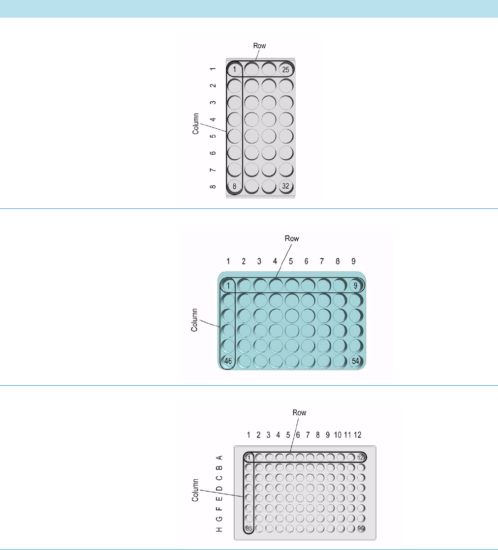
3 Setup Menu Item
Setup Menu Item Modules
Thermo Scientific TriPlus RSH User Guide 151
Table 71. Tray Type Parameters (Sheet 1 of 7)
Tray Type Parameter Illustration
Rows — Number of Rows
Columns — Number of Columns
Definition of Row and Column
Example: Regular order of vials.
Figure 97. Tray type R32 Liquid Cooled
Rows — Number of Rows
Columns — Number of Columns
Definition of Row and Column
Example: Regular order of vials.
Figure 98. Tray type VT54
Rows — Number of Rows
Columns — Number of Columns
Definition of Row and Column
Example: Regular order of wells.
Figure 99. Tray type MTP 96
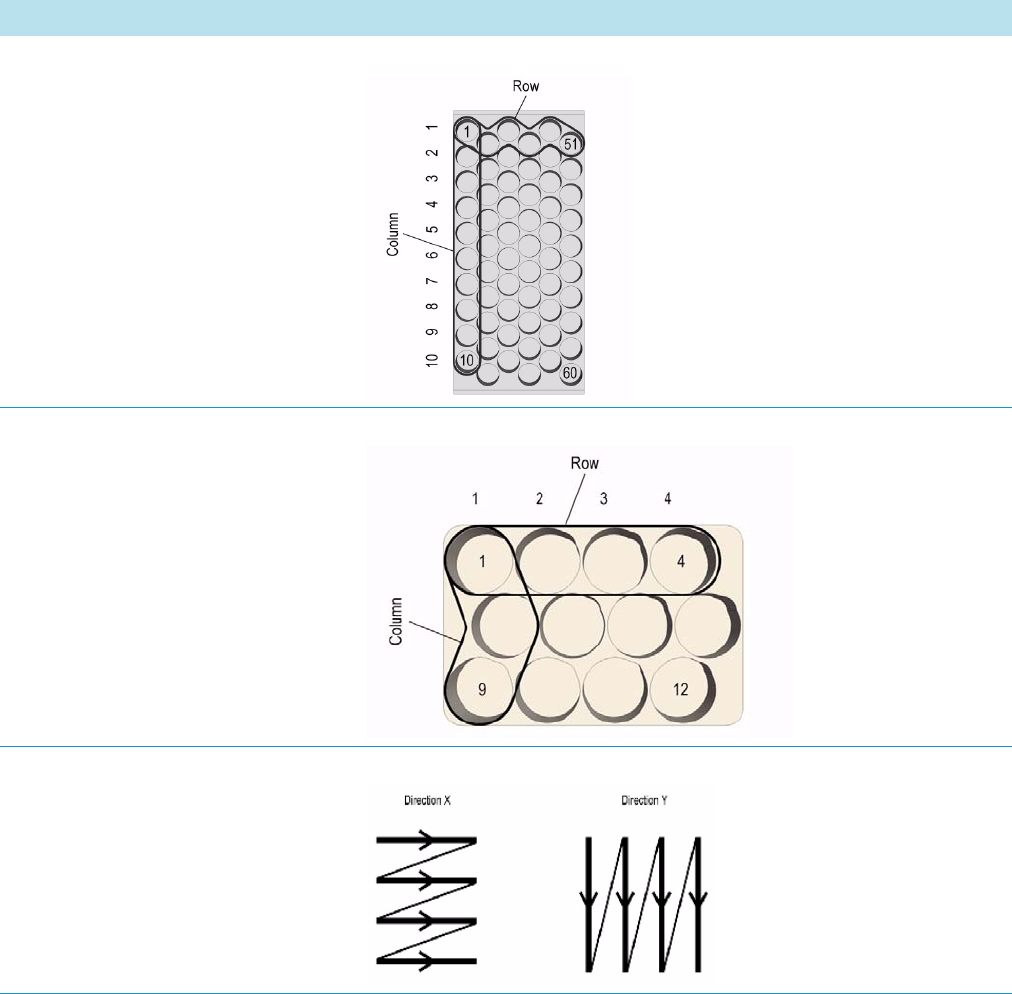
3 Setup Menu Item
Setup Menu Item Modules
152 TriPlus RSH User Guide Thermo Scientific
Rows — Number of Rows
Columns — Number of Columns
Definition of Row and Column
Example: Staggered order of vials.
Figure 100. Tray type R60
Rows — Number of Rows
Columns — Number of Columns
Definition of Row and Column
Example: Staggered order of vials.
Figure 101. Tray type R12
Indexing Orientation
Direction X
(or Row Direction with RSH Firmware
1.4.0 or lower)
Direction Y (or Column Direction
with RSH Firmware 1.4.0 or lower)
Figure 102. Indexing orientation
Table 71. Tray Type Parameters (Sheet 2 of 7)
Tray Type Parameter Illustration
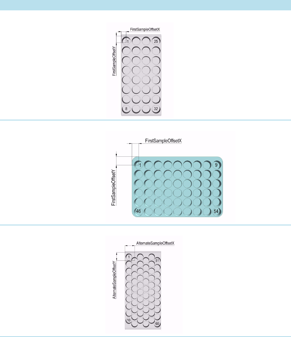
3 Setup Menu Item
Setup Menu Item Modules
Thermo Scientific TriPlus RSH User Guide 153
1st Sample Offset X
1st Sample Offset Y
(1st Sample Offset Z)
Figure 103. Tray type R32 LiqCooled
1st Sample Offset X
1st Sample Offset Y
(1st Sample Offset Z)
Figure 104. Tray type VT54
Alt Sample Offset X
Alt Sample Offset Y
(Alt Sample Offset Z)
Figure 105. Tray type R60
Table 71. Tray Type Parameters (Sheet 3 of 7)
Tray Type Parameter Illustration
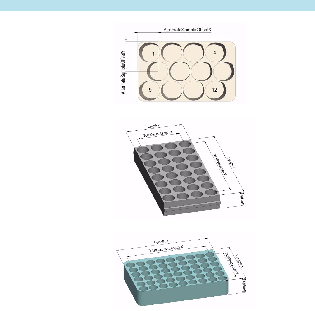
3 Setup Menu Item
Setup Menu Item Modules
154 TriPlus RSH User Guide Thermo Scientific
Alt Sample Offset X
Alt Sample Offset Y
(Alt Sample Offset Z)
Figure 106. Tray type R12
Length X
Length Y
Length Z
Total Column Length X
Total Row Length Y
Figure 107. Tray type R32 Liquid Cooled
Length X
Length Y
Length Z
Total Column Length X
Total Row Length Y
Figure 108. Tray type VT54
Table 71. Tray Type Parameters (Sheet 4 of 7)
Tray Type Parameter Illustration
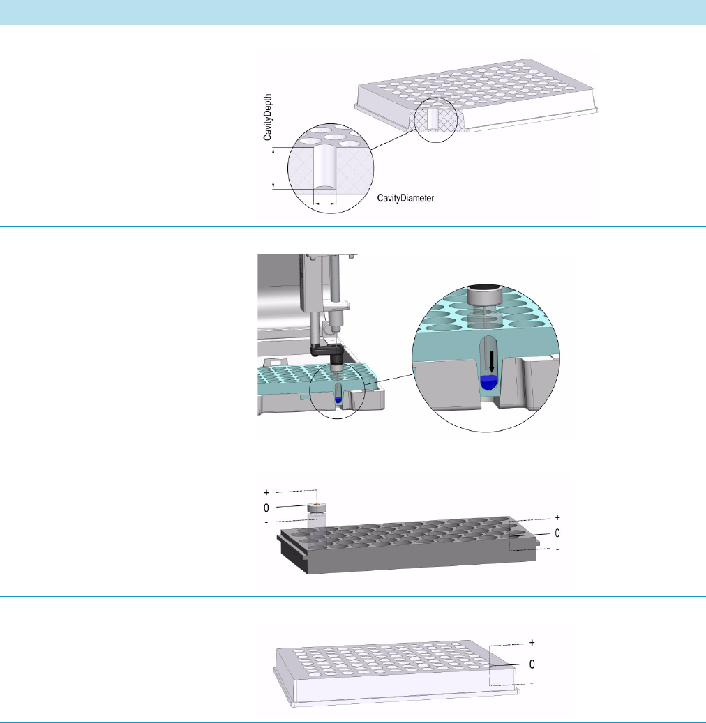
3 Setup Menu Item
Setup Menu Item Modules
Thermo Scientific TriPlus RSH User Guide 155
Cavity Depth
Cavity Diameter
Figure 109. Tray type MTP96
Penetration Vial Index Figure 110. Tray type VT54
Z Tolerance Figure 111. Tray type R60
Z Tolerance Figure 112. Tray type MTP96
Table 71. Tray Type Parameters (Sheet 5 of 7)
Tray Type Parameter Illustration
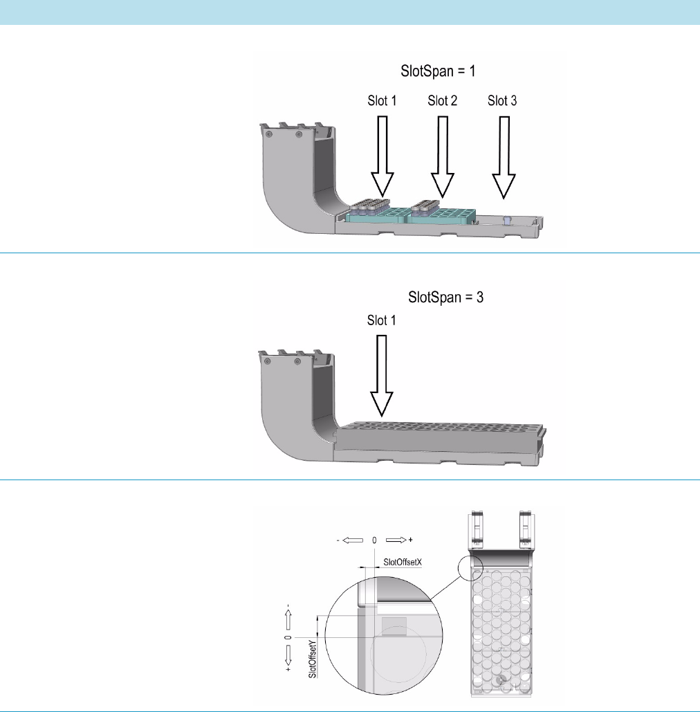
3 Setup Menu Item
Setup Menu Item Modules
156 TriPlus RSH User Guide Thermo Scientific
Slot Span
Example: Slot Span = 1
Figure 113. Tray Holder with Tray Type VT54 inserted
Slot Span
Example: Slot Span = 3
Figure 114. Tray Holder with Tray Type R60 inserted
Slot Offset X
Slot Offset Y
Note that the value has a negative sign if
the Tray is oversize, which means larger
than the Tray Holder.
Figure 115. Tray Holder with Tray Type R60 inserted
Table 71. Tray Type Parameters (Sheet 6 of 7)
Tray Type Parameter Illustration
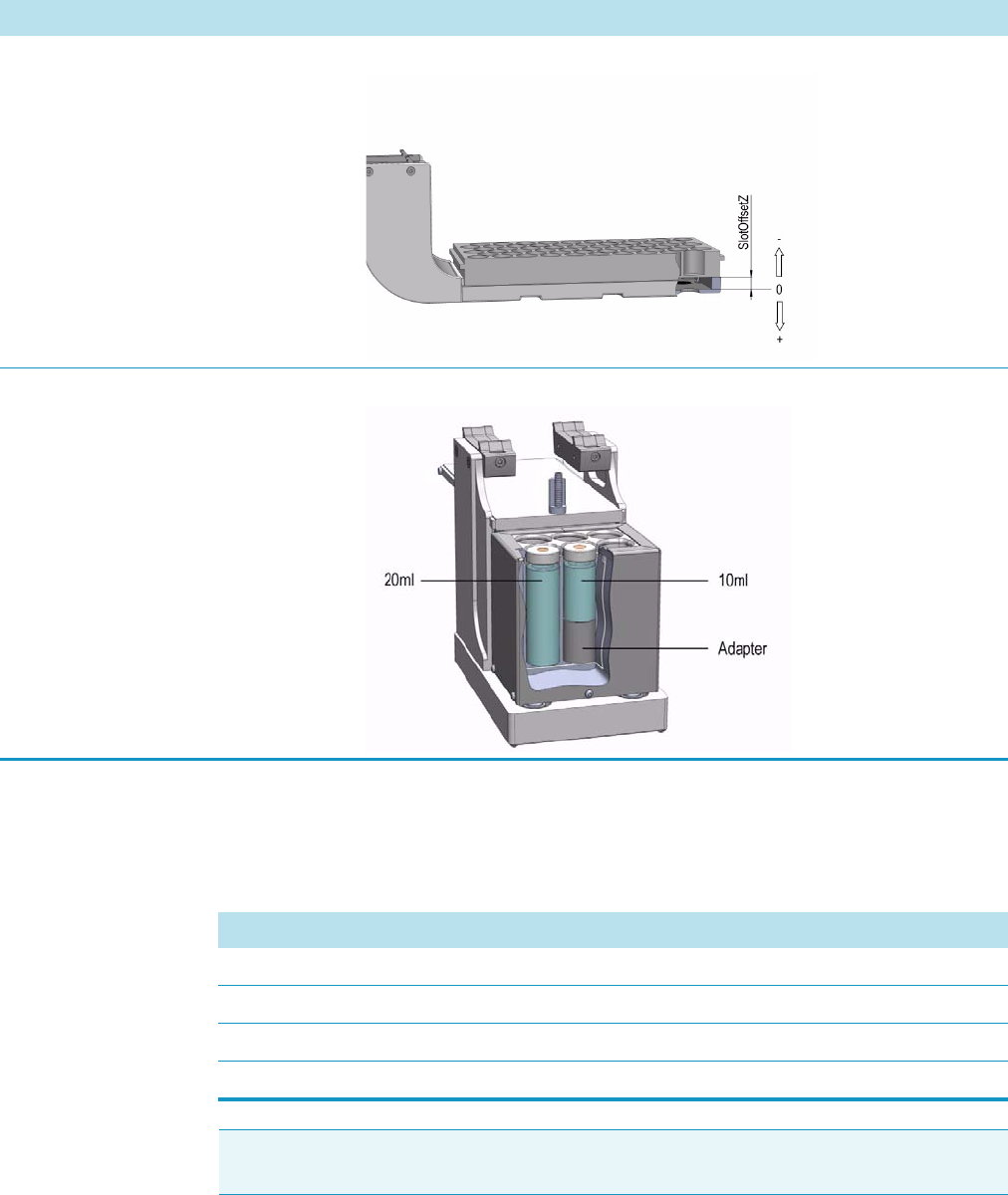
3 Setup Menu Item
Setup Menu Item Modules
Thermo Scientific TriPlus RSH User Guide 157
Tray Types Options Pull-up Menu
Selecting the pull-up menu Options opens up the following tasks. See Table 72.
Slot Offset Z
Note that the value has a negative sign if
the Tray is not inserted in the slot,
support for Tray is higher up.
Figure 116. Tray Holder with Tray Type R60 inserted
Uses Adapter Figure 117. Agitator
Table 71. Tray Type Parameters (Sheet 7 of 7)
Tray Type Parameter Illustration
Table 72. Tray Types Options Pull-up Menu
Item Description
New Tray Type This task creates a new Tray Type.
Copy Tray Type This task copies the present Tray Type (for example VT54).
Delete Tray Type This task deletes the present Tray Type (for example VT54).
Reset to Default Resets the selected Tray Holder parameter to default value.
Note There are no other pull-up menu items available. Currently it is not possible to
create custom Tray Types.
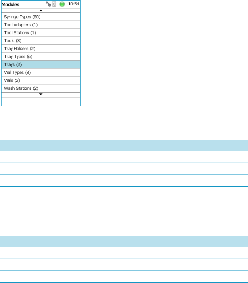
3 Setup Menu Item
Setup Menu Item Modules
158 TriPlus RSH User Guide Thermo Scientific
Trays
The term Trays is a generic term. A Tray can be a Tray or a Well-plate.
A Tray is prepared to accept vials, a well-plate can be typically a Deep well-plate or a Micro
Titer-plate. The software has a structure which interlinks the classes Vial Type, Tray Type
(or Well Type) with the Tray. To create a new Tray these classes have to be prepared in the
order Vial Type and Tray Type . The allocated types are then ready for selection in the class
Tr a y s .
Selecting the list item Tray Types opens up the following parameters. See Figure 118.
Figure 118. Menu Item Trays Menu List Item Trays
Press Enter to edit a parameter. See Tab le 7 3 .
Trays Options Pull-up Menu
Selecting the pull-up menu Options opens up the following tasks. See Table 74.
Table 73. Tray Type and Vial Type Parameters
Item Description
Cap Type Read-only parameter. Definition is made in the class Vial Type.
Tray Type A Tray Type is assigned the specified Tray.
Vial Type A Vial Type is assigned to the specified Tray and selected Tray Type.
Table 74. Tray Option Pull-up Menu Parameters
Item Description
New Tray Creates a new Tray Holder.
Copy Tray Copies the present Tray.
Delete Tray Deletes a present Tray.
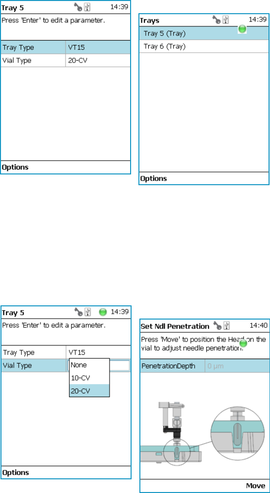
3 Setup Menu Item
Setup Menu Item Modules
Thermo Scientific TriPlus RSH User Guide 159
In the case no Tray (or Plate) is available, the command New Tray is available with the Menu
Button Option. Follow the dialog with the known possibilities to assign a name as shown in
Figure 119.
Figure 119. Menu Button New Tray and Defining Name for New Tray
Another pull-up menu is available from the menu list items Tray Ty pe and Vial Type.
Selecting the item Adjust Needle Penetration allows checking the needle penetration in the
vial.
The position of cut-out in the Tray is specified in the Tray Type, therefore is the position
known. Starting this task, moves the TriPlus RSH Head to the defined vial position where it
waits for the manual adjustments. See Figure 120, illustrating the cut-out in the Tray.
Figure 120. Adjust Needle Penetration Into the Vial
Trays Options Menu Parameters are detailed in Table 75.

3 Setup Menu Item
Setup Menu Item Modules
160 TriPlus RSH User Guide Thermo Scientific
Vial Types
The Vial Type describes the geometry of the vials used and adds parameters such as syringe
needle penetration, search distance, or Z-Tolerance. The Vial Type is a group of parameters
which can be linked to a Tray, Wash Station, or any other module which requires a vial.
Three different classes of Vial Types are available:
•Vial Type
• Wash Vial Type
• Waste Vial Type
Within the same class are the same list items available. The three classes are shown in detail for
the 10-CV Vial type, the 100SR Wash Vial Type, and for the Waste Vial Waste Vial Type.
Selecting the list item Vial Types opens up the following parameters. See Figure 121.
Table 75. Trays Options Menu Parameters
Item Description
Adjust Needle Penetration Adjusts the Needle Penetration Depths in the vial. Manually
turn the needle as far down in the vial as required.
The cut-out in the Tray Holder frame as well as in the Tray
allows visual control of the needle tip.
Note: The value found is not stored automatically.
This task allows a check only. If the needle penetration must
be changed, select the Tray Type to enter the newly
established Needle Penetration value.
Check Teaching Checks the teaching position of the module.
This task serves as a quick check to determine if the X-, Y-,
and Z-positions are defined correctly.
In case a teaching point is incorrect, return to the Menu
Setup for readjustment of the teaching position. Please note
that this action can be done under the Extended User Level
but not under User Level.
Tea c h Mo d u l e The positions of the X-, Y-, and Z-axes can be defined again,
for teaching.

3 Setup Menu Item
Setup Menu Item Modules
Thermo Scientific TriPlus RSH User Guide 161
Figure 121. Menu Items Vial Types and List Items for Vial Type
Vial Types Parameters are detailed in Table 76.
Note The examples for Vial Type 100SR (Wash Vial and Solvent Reservoir Vial) and
Waste Vial show identical parameters.
The sample vial (Vial Type 10-CV) contains extra parameters:
• Allow Needle Transport
•Cap Type
• Dispose In Waste Container
•Strip Distance
Table 76. Vial Types Parameters (Sheet 1 of 3)
Item Description
Default Needle Penetration
Depth
The default value of the syringe needle penetration depth in
the reservoir vial is set by this parameter.

3 Setup Menu Item
Setup Menu Item Modules
162 TriPlus RSH User Guide Thermo Scientific
Allow Needle Transport
Available for Vial Type only.
Sets the transport to Needle Transport. In order to allow
another transport as the common Magnetic Transport the
syringe needle is inserted in the vial septum.
If the weight of the vial is not too high, the vial sticks to the
needle.
All parameter as used for the magnetic transport (such as
stripping of) are not functional.
Cap Type
This parameter has to
correspond with the Tool
parameter “Needle Guide
Type”.
The type of cap used for the vial can be defined.
The following options are available:
•No Cap — Mainly used for Well-plates
•Magnet Cap — A magnetic cap is used to transport a
vial, typically from a Tray to the Agitator.
•Non Magnetic Cap — For applications which do not
require the sample vials to be transported.
Depenetration Speed Defines the speed to retrieve the syringe needle from the vial.
Diameter Defines the diameter of the reservoir container.
Dispose In Waste Container
Available for Vial Type only.
Used if e.g. a pipetting tip or a SPE cartridge has to be
expelled into a dedicated Waste Container.
All parameters as used for liquid disposal, such as rinsing
syringe, and so on are not functional.
Height Defines the height of the reservoir container.
Max Ndl Penetr Depth The maximum allowed Needle Penetration can be defined as
a safety measure so that you cannot destroy the needle tip by
going too far down.
The maximum needle penetration must not exceed the
length of the syringe needle, considering the loss of
approximately 12 mm due to the needle guide.
For a typical needle length of 57 mm or 85 mm for the long
needle, the maximum penetration depth must not exceed
45 mm or 73 mm.
Penetration Speed The syringe needle penetration speed is set by this
parameter. It is recommended to use the default value first.
Changing this parameter in either direction might lead to
needle bending.
Table 76. Vial Types Parameters (Sheet 2 of 3)
Item Description

3 Setup Menu Item
Setup Menu Item Modules
Thermo Scientific TriPlus RSH User Guide 163
Vial Type Options Pull-up Menu
Selecting the pull-up menu Options opens up the following tasks. See Table 77.
Strip Distance When a magnetic cap is used, the distance to move the
TriPlus RSH Head to the side (in the Y-direction) to wipe
off the vial can be defined. Measured in mm.
Volum e This parameter defines the volume of the vial.
Z-Tolerance A tolerance window to give a plus/minus range (expressed in
mm) where the Head must expect an object.
If the value of this item is > 0, this indicates a relative
detection mode, and the sensor from the Head needle guide
is active.
If the value of this item is set to 0, the sensor of the needle
guide is turned off, and the syringe slider moves to an
absolute value, Z-axis position as specified in the object.
IMPORTANT Using the SPME technique pay special attention to the parameters
DefNdlPenetrDepth and MaxNdlPenetrDepth.
The penetration depth is always the penetration of the needle itself. Consider the length of
the SPME fiber, 10 mm or 20 mm length. When the fiber is lowered, it must not touch
the bottom of the vial.
Table 76. Vial Types Parameters (Sheet 3 of 3)
Item Description
Table 77. Vial Type Options Pull-up Menu
Item Description
New Vial Type Creates a new Vial Type.
Copy Vial Type Copies the present Vial Type.
Delete Vial Type Deletes a present Vial Type.
Reset to Default Resets the selected module parameter to the default value.
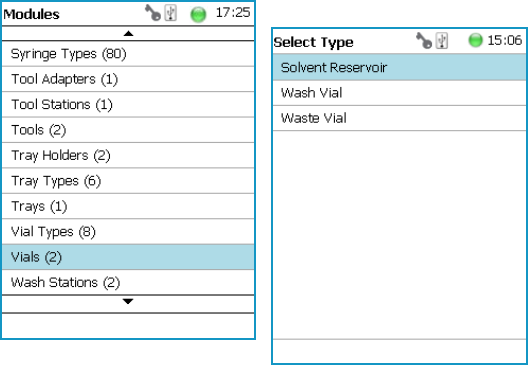
3 Setup Menu Item
Setup Menu Item Modules
164 TriPlus RSH User Guide Thermo Scientific
Vials
In this class of Vials, dedicated vials can be added to the system configuration.
The use of the Vial can be specified according to the following categories:
• Wash Vial
• Waste Vial
• Solvent Reservoir
The use of these Vials is in assigning an extra, custom specific vial, for any use, such as
providing a dedicated vial for a reagent, internal standard or a dilution vial.
When the application requires a second Waste Vial or an extra Wash Vial, then this class of
Vial could be used to define the non-standard vial.
The three categories Wash Vial, Waste Vial, and Solvent Reservoir contain the same
available parameters under the User Access Level.
Selecting the list item Vial opens up the following parameters:
Figure 122. Menu List Vials and Menu List Items for Vials
In the case when there is no Vial (Solvent Reservoir, Wash Vial or Waste Vial) available, the
command New Vial is available with the Menu Button Option. Follow the dialog with the
known possibilities to assign a name as shown in Figure 123.
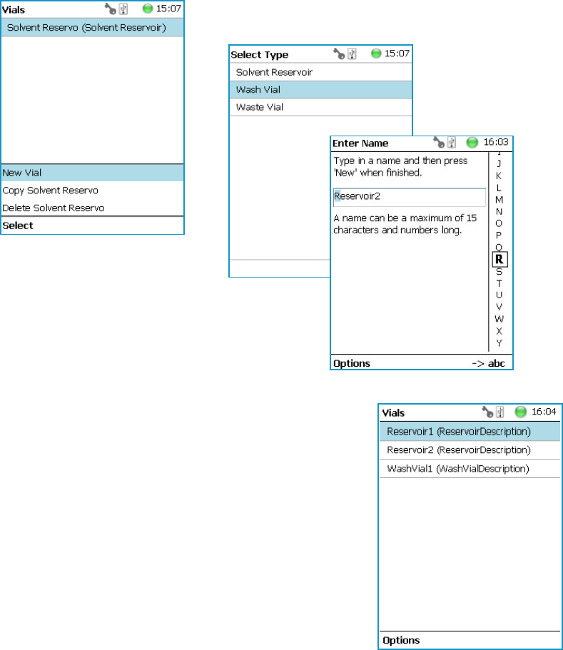
3 Setup Menu Item
Setup Menu Item Modules
Thermo Scientific TriPlus RSH User Guide 165
Figure 123. Menu Button New Vial, Selection of Vial Types, and Defining Name for New Vial
The parameters available for the Vial Type reservoir are slightly different from the parameters
for the Wash Vial and Waste Vial.
See the examples in Figure 124 and Figure 125, and the description in Table 78.

3 Setup Menu Item
Setup Menu Item Modules
166 TriPlus RSH User Guide Thermo Scientific
Figure 124. Menu List Item Reservoir Parameters for Vial Type Reservoir
Figure 125. Parameters for Vial Types Wash or Waste Parameters for Vial Types Wash or Waste
Table 78. Vial Parameters (Sheet 1 of 2)
Item Description
Max Penetration Depths The maximum allowed Needle Penetration can be defined as
a safety measure so that you cannot destroy the needle tip by
going too far down.
The maximum needle penetration must not exceed the
length of the syringe needle, considering the loss of
approximately 12 mm due to the needle guide, and other
factors. For a typical needle length of 57 mm or 85 mm for
the long needle, the maximum penetration depth must not
exceed 45 mm or 73 mm.
Def Nedl Penetr Depth The default value of the syringe needle penetration depth in
the reservoir vial is determined by this parameter.

3 Setup Menu Item
Setup Menu Item Modules
Thermo Scientific TriPlus RSH User Guide 167
Vial Option Pull-up Menu
Selecting the pull-up menu Options opens up the following tasks. See Table 79.
Depenetration Speed This parameter allows you to select the required speed for
pulling the syringe needle out of the reservoir vial.
Diameter Specific for Waste Vial.
Defines the diameter of the reservoir container.
Height Specific for Waste Vial.
Defines the height of the reservoir container.
Penetration Speed The syringe needle penetration speed is set by this value.
It is recommended to use the default value first.
Changing this parameter in one or the other direction might
lead to needle bending.
Vial Type A list with all predefined Vial Types opens up for selection.
Special cases for Waste Vial:
•None — It is selectable, however if selected in
combination with a Wash Module is an error message
(Pending Message) propagated. Incompatible Type.
•Waste Port — Used for the Fast Wash and Large Wash
Module.
•Waste Vial — Used for Standard Wash Module.
•Waste Inset — This type is used for Standard Wash
Module with inserted Waste Line Adapter.
Volum e Specific for Wash and Waste Vial.
Defines the volume of the reservoir container.
Z-Tolerance A tolerance window to give a plus/minus range (expressed in
mm) where the Head must expect an object.
• If the value of this item is > 0, indicates a relative
detection mode, and the sensor from the Head needle
guide is active.
• If the value of this item is set to 0 the sensor of the
needle guide is turned off and the syringe slider moves
to an absolute value, the Z-axis position as specified by
the object.
Table 78. Vial Parameters (Sheet 2 of 2)
Item Description
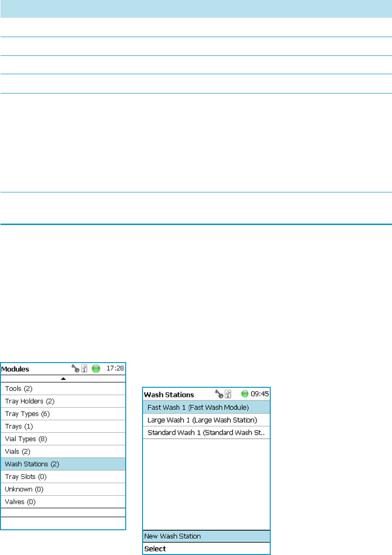
3 Setup Menu Item
Setup Menu Item Modules
168 TriPlus RSH User Guide Thermo Scientific
Wash Stations
Three different wash stations are available with the TriPlus RSH: Standard Wash Station
(passive module), Large Solvent Wash Station (passive module), and Fast Wash Station
(active module).
Selecting the list item Wash Stations opens up the following parameters:
Figure 126. Menu Item Wash Stations Menu and List Items Wash Modules
Press Enter to edit a parameter.
Table 79. Options Vial Type Pull-up Menu
Item Description
New Vial Creates of a new Vial.
Copy Vial Copies the present Vial.
Delete Vial Deletes the present Vial.
Reset to Default Resets the selected Vial parameter to default value.
Check Teaching Checks the teaching position of the module.
This task serves as a quick check to determine if the X-, Y-,
and Z-positions are defined correctly.
In case a teaching point is off, return to the Menu Setup for
readjustment of the teaching position. Please note that this
action can be done under the Extended User Level but not
under User Level.
Te a ch Mo d u l e The positions of the X-, Y-, and Z-axes can be defined again,
(teaching).

3 Setup Menu Item
Setup Menu Item Modules
Thermo Scientific TriPlus RSH User Guide 169
Select the required menu list item to access the parameters. The wash stations differ in
number of positions, Wash Vial size.
•The Standard Wash Station accepts 10 mL vials.
•The Large Volume Wash Station contains two 100 mL vials, and a Waste position with a
drainage tubing.
•The Fast Wash Station contains active pumps to deliver two different wash solvents
The available menu list parameters are identically for the Standard and Large Solvent Wash
Stations, asides from the number of positions. See Table 80 for details.
The menu list parameters for the Fast Wash Station are detailed in Tabl e 8 1.
Table 80. Parameters for Standard and Large Volume Wash Stations (Sheet 1 of 2)
Item Description
Pos 1 to Pos 4 Positions 1 and 2 are available for the Large Solvent Wash
Station.
Positions 1 to 4 are available for the Standard Wash Station.
Each Position can be defined by using the next parameters.
Waste Defines the Waste position.
Max Penetration Depth The maximum allowed Needle Penetration can be defined as
a safety measure so that the you cannot destroy the needle tip
by going too far down.
The maximum needle penetration must not exceed the
length of the syringe needle, considering the loss of
approximately 12 mm due to needle guide, and so on. For a
typical needle length of 57 mm or 85 mm for the long
needle, the maximum penetration depth must not exceed
45 mm or 73 mm.
Def Ndl Penetr Depth This parameters sets the default value of the syringe needle
penetration depth in the reservoir vial.
Depenetration Speed This parameter allows you to select the required speed for
pulling the syringe needle out of the reservoir vial.
Penetration Speed The syringe needle penetration speed is set by this parameter.
It is recommended to use the default value first.
Changing this parameter in one or the other direction might
lead to needle bending.

3 Setup Menu Item
Setup Menu Item Modules
170 TriPlus RSH User Guide Thermo Scientific
Vial Type Defines the Vial Type of the reservoir container in Positions
or the corresponding Waste Type in Waste Position.
Selection for Wash Positions are: Vial Types None, 2SR,
10SR, or 100SR.
Selection for Waste Position are:
•None — If None is selected, an error (Pending Message)
will be propagated.
•Waste Port — Large Wash and Fast Wash Module
•Waste Vial — Standard Wash.
•Waste Inset — Standard Wash with inserted Drainage
Adapter.
Volume Defines the volume of the reservoir vial.
Z-Tolerance A tolerance window to give a plus/minus range (expressed in
mm) where the Head must expect an object.
If the value of this item is > 0, this indicates a relative
detection mode, and the sensor from the Head needle guide
is active.
If the value of this item is set to 0 the Needle Guide Motor
detection current is turned off, and the syringe slider moves
to an absolute value, Z-axis position as specified in the
object.
Diameter Specific for Waste Vial. Defines the diameter of the reservoir
container.
Height Specific for Waste Vial. Defines the height of the reservoir
container.
Is Detectable
Visible for Waste Position only.
Specific for Waste Vial.
Differentiates if the Waste position is a Vial, which is
detectable, or if it is a nipple with a connected waste tubing.
Table 81. Parameters for Fast Wash Stations (Sheet 1 of 3)
Item Description
Wash 1 to Wash 2 Wash positions 1 and 2 can be assigned to Fast Wash Station.
Waste Defines the Waste position.
Table 80. Parameters for Standard and Large Volume Wash Stations (Sheet 2 of 2)
Item Description

3 Setup Menu Item
Setup Menu Item Modules
Thermo Scientific TriPlus RSH User Guide 171
Max Flow Rate Sets the upper limit of flow rate for the selected Wash
Position.
Post Rinse Liner Activates the solvent pump to rinse the wash liner of the
selected Wash Position. Number of rinse cycles is selectable
after the syringe needle has been removed from the Wash
Station.
Note Without the syringe needle inserted in the liner, the
solvent flow is unrestricted. Expect a higher solvent
consumption.
Pre Rinse Liner Activates the solvent pump to rinse the wash liner of the
selected Wash Position. Number of rinse cycles is selectable
before the syringe needle has been inserted into the Wash
Station.
Note Without the syringe needle inserted in the liner, the
solvent flow is unrestricted. Expect a higher solvent
consumption.
Def Ndl Penetr Depth Sets the default value of the syringe needle penetration depth
in the reservoir vial.
The default values are:
• 25 mm in Wash position
• 20 mm in Waste position
Depenetration Speed Selects the required speed for pulling the syringe needle out
of the reservoir vial.
The default values are:
• 100 mm/s in Wash position
• 100 mm/s in Waste position
Max Penetration Depth The maximum allowed Needle Penetration can be defined as
a safety measure so that the you cannot destroy the needle tip
by going too far down.
The maximum needle penetration must not exceed the
length of the syringe needle, considering the loss of
approximately 12 mm due to needle guide, and so on.
For a typical needle length of 57 mm or 85 mm for the long
needle, the maximum penetration depth must not exceed
45 mm or 73 mm.
Table 81. Parameters for Fast Wash Stations (Sheet 2 of 3)
Item Description

3 Setup Menu Item
Setup Menu Item Modules
172 TriPlus RSH User Guide Thermo Scientific
Penetration Speed The syringe needle penetration speed is set by this parameter.
It is recommended to use the default value first. Changing
this parameter in one or the other direction might lead to
needle bending.
The default values are:
• 40 mm/s in Wash position
• 40 mm/s in Waste position
Z-Tolerance A tolerance window to give a plus/minus range (expressed in
mm) where the Head must expect an object.
If the value of this item is > 0, this indicates a relative
detection mode, and the sensor from the Head needle guide
is active.
If the value of this item is set to 0 the Needle Guide Motor
detection current is turned off, and the syringe slider moves
to an absolute value, Z-axis position as specified in the
object.
Diameter Specific for Waste Vial. Defines the diameter of the reservoir
container. The default value is 20 mm
Height Specific for Waste Vial. Defines the height of the reservoir
container. The default value is 80 mm
Vial Type Defines the Vial Type of the reservoir container in Positions
or the corresponding Waste Type in Waste Position.
Selection for Wash Positions are: Vial Types None, 2SR,
10SR, or 100SR.
Selection for Waste Position are:
•None — If None is selected, an error (Pending Message)
will be propagated.
•Waste Port — Large Wash and Fast Wash Module
•Waste Vial — Standard Wash.
•Waste Inset — Standard Wash with inserted Drainage
Adapter.
Volume Defines the volume of the reservoir vial.
Table 81. Parameters for Fast Wash Stations (Sheet 3 of 3)
Item Description

3 Setup Menu Item
Setup Menu Item Modules
Thermo Scientific TriPlus RSH User Guide 173
Wash Stations Option Pull-up Menu
Selecting the pull-up menu Options opens up the following tasks. See Table 82 for Standard
and Large Volume Wash Stations, and Table 83 for Fast Wash Station.
Table 82. Standard and Large Volume Wash Option Parameters
Item Description
Check Teaching Checks the teaching position of the module.
This task serves as a quick check to determine if the X-, Y-,
and Z-positions are defined correctly.
In case a teaching point is incorrect, return to the Menu
Setup for readjustment of the teaching position. Please note
that this action can be done under the Extended User Level
but not under User Level.
Tea c h Mo d u l e The positions of the X-, Y-, and Z-axes can be defined again
(teaching).
New Wash Station Creates of a new Wash Station.
Copy Wash Station Copies of the present Wash Station.
Delete Wash Station Deletes of the present. Wash Station.
Table 83. Fast Wash Option Parameters
Item Description
Tea c h Mo d u l e The positions of the X-, Y-, and Z-axes can be defined again
(teaching).
Reset to Default Resets the selected station parameter to default value.
Check Teaching Checks the teaching position of the module.
This task serves as a quick check to determine if the X-, Y-,
and Z-positions are defined correctly.
In case a teaching point is incorrect, return to the Menu
Setup for readjustment of the teaching position. Please note
that this action can be done under the Extended User Level
but not under User Level.
New Wash Station Creates of a new Wash Station.
Prime Wash Liner Primes the tubing of the selected Wash Position.
Duration Sets the time required for priming.
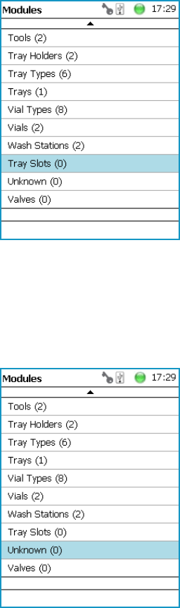
3 Setup Menu Item
Setup Menu Item Modules
174 TriPlus RSH User Guide Thermo Scientific
Tray Slots
This menu List Item will be implemented in future. See Figure 127.
Figure 127. Menu Item Tray Slots
Unknown
This menu List Item will be implemented in future. See Figure 128.
Figure 128. Menu Item Unknown
Valves
This menu List Item will be implemented in future. See Figure 129.
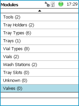
3 Setup Menu Item
Setup Menu Item Modules
Thermo Scientific TriPlus RSH User Guide 175
Figure 129. Menu Item Valves
The Menu Items which are not part of the system configuration, showing (0) behind the class
name, are not listed in the User access level.
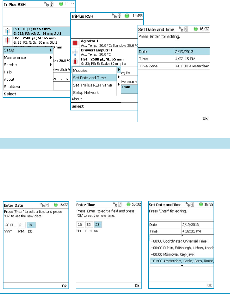
3 Setup Menu Item
Setup Menu Item - Set Date and Time
176 TriPlus RSH User Guide Thermo Scientific
Setup Menu Item - Set Date and Time
Visible in Extended User access level only.
1. Select in the Option | Setup pull-up menu the list item Set Date and Time.
See Figure 130 and Ta ble 84.
Figure 130. Set Date and Time
Table 84. Date and Time Format
Item Description
Set Date and Time Date: format yyyy-mm-dd
Time: format hh:mm:ss
Time Zone: Greenwich Mean Time (GMT) plus or minus
the hour deviation from Greenwich standard time.
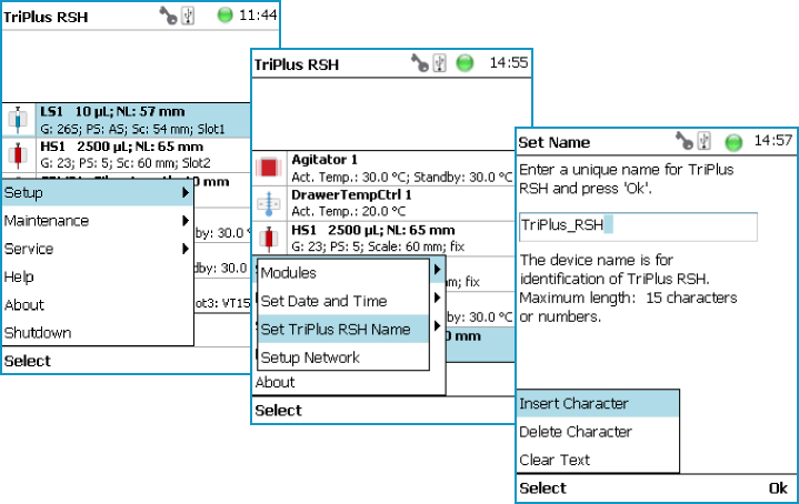
3 Setup Menu Item
Setup Menu Item - Set TriPlus RSH Name
Thermo Scientific TriPlus RSH User Guide 177
Setup Menu Item - Set TriPlus RSH Name
Visible in Extended User access level only.
1. Select from the Option | Setup pull-up menu the list item Set TriPlus RSH Name.
See Figure 131.
Figure 131. Set TriPlus RSH Name
2. Press Enter to receive the alphabetical selection of characters or press the Default Action
button to change from capital to lower case characters or to numbers. The name has to
start with an alphabetical character.
3. Set a unique name for the TriPlus RSH. This name will be stored and can be used for
identification of the system.
4. Press Option to receive the list item Insert or Delete Character or Clear Text.
5. Press Ok when finished.
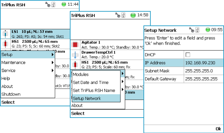
3 Setup Menu Item
Setup Menu Item - Setup Network
178 TriPlus RSH User Guide Thermo Scientific
Setup Menu Item - Setup Network
Visible in Extended User access level only.
In order to select the required network setup according to your laboratory setting, the
following possibilities are available:
•Direct connection — The TriPlus RSH is directly connected to the computer via the
LAN cable. There is no corporate network or router connection.
– IP Address TriPlus RSH: 192.168.1.230
– IP Address computer: 192.168.99.210
– Subnet Mask: 255.255.255.0
– Default Gateway: not required, leave the field empty (if an address is entered, it will
not be used).
•Corporate Network with DHCP Protocol — Ask the network administrator to verify
and integrate the setup within the corporate network. Select the DHCP Protocol, the
network will assign an IP Address and a Subnet Mask to the TriPlus RSH.
•Corporate Network with Fixed IP Address — Ask the network administrator to provide
the IP Address, Subnet Mask and Default Gateway to configure the TriPlus RSH
within the corporate network.
1. Select from the Option | Setup pull-up menu the list item Setup Network.
See Figure 132 and Ta ble 85.
Figure 132. Setup Network
2. Select either the mode DHCP or enter a unique fixed IP Address.
3. Press Ok when finished.

3 Setup Menu Item
Setup Menu Item - Setup Network
Thermo Scientific TriPlus RSH User Guide 179
Table 85. Setup Network Parameters
Items Description
Setup Network Defines the Network communication parameters.
DHCP Dynamic Host Configuration Protocol.
If activated, an IP Address is dynamically sought throughout
the provided network. It is advisable not to use the DHCP
mode but to use a fixed IP Address.
IP Address The IP Address is a fixed system address. The IP Address is
often provided by the network administrator.
Default Address TriPlus RSH: 192.168.99.230
Subnet Mask The Subnet Mask is used for network configuration; it must
be provided by the network administrator.
Default Subnet mask: 255.255.255.0
Default Gateway The Gateway is used if independent networks must
communicate interactively. Communication within the
network is provided by a hub or switch, defined as Gateway.
Default Gateway is 192.168.99.1
Note For more information see Setting up the Network Interface in the TriPlu s R SH
Hardware Manual.

Thermo Scientific TriPlus RSH User Guide 181
4
Maintenance Menu Items
This chapter describes the options of the Maintenance Menu operated either with the Virtual
Handheld Controller, or directly using the installed Handheld Controller.
Contents
•Maintenance Menu
•Check Tool Calibration
•Check Teaching Module
•Check Configuration
•Reset Configuration
•Create Diagnostic Backup
•Create Configuration Backup
•Copy Backup
•Restore Backup
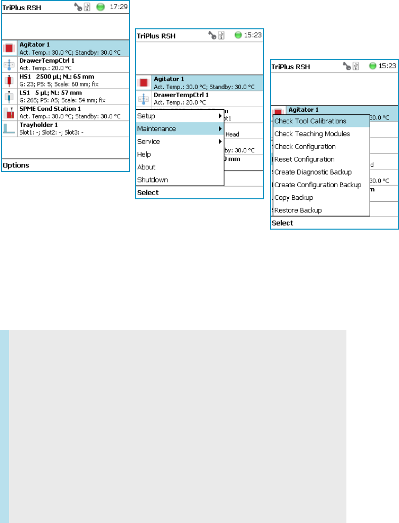
4 Maintenance Menu Items
Maintenance Menu
182 TriPlus RSH User Guide Thermo Scientific
Maintenance Menu
The Maintenance function is available from the Options pull-up menu. See Figure 133.
Figure 133. Maintenance
1. Press the Options button to open the pull-up menu, and select Maintenance.
2. Select the folder Maintenance for accessing the list items Check tool Calibrations,
Check Teaching modules, Backup, and Restore.
Refer to the following items:
•“Check Tool Calibration” on page 183
•“Check Teaching Module” on page 183
•“Check Configuration” on page 184
•“Reset Configuration” on page 184
•“Create Diagnostic Backup” on page 185
•“Create Configuration Backup” on page 186
•“Copy Backup” on page 187
•“Restore Backup” on page 188
•“Import Templates” on page 188
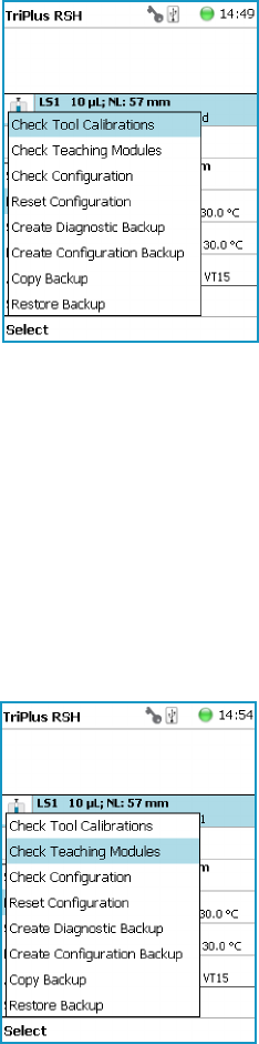
4 Maintenance Menu Items
Check Tool Calibration
Thermo Scientific TriPlus RSH User Guide 183
Check Tool Calibration
Check Tool Calibration accesses the Calibration Wizard without leaving the Maintenance
menu.
Follow the dialog shown on the display of the Handheld Controller, or on the screen of the
Virtual Handheld Controller.
Details are described in TriPlus RSH Check Tool Calibration in the TriPlu s R SH Hardware
Manual.
Check Teaching Module
Selecting Check Teaching modules the TriPlus RSH Head moves from one module to the
next, in the order listed in the table modules.
The unit waits at the programmed teaching point for visual inspection; press the button Next
to continue.
In case a teaching point is incorrect return to the Menu Setup for readjusting the teaching
position of the module involved. The automated check of the teaching position of all the
modules is stopped by pressing the Back button.
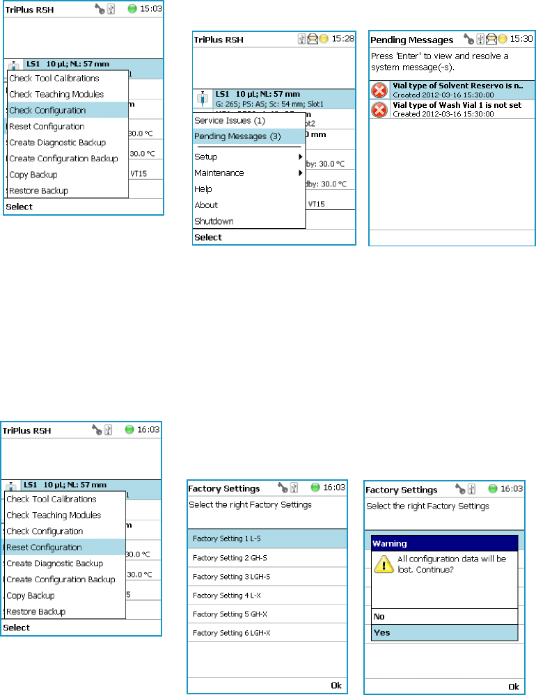
4 Maintenance Menu Items
Check Configuration
184 TriPlus RSH User Guide Thermo Scientific
Check Configuration
Selecting Check Configuration provides the possibility to check the entire system
configuration for any mismatches. Pending Messages or Service Issues which have been
clicked away can be retrieved again.
The software checks the entire configuration for any hidden problems. The message symbol
(envelope) in the Status Line indicates that one or more mismatches have been detected.
Select from the pull-up menu the Pending Messages or Service Issues.
Note that the messages can be opened and viewed in the Extended User access level only.
Reset Configuration
By selecting Reset Configuration the RSH Firmware (Application) resets the configuration
to a standard application package.
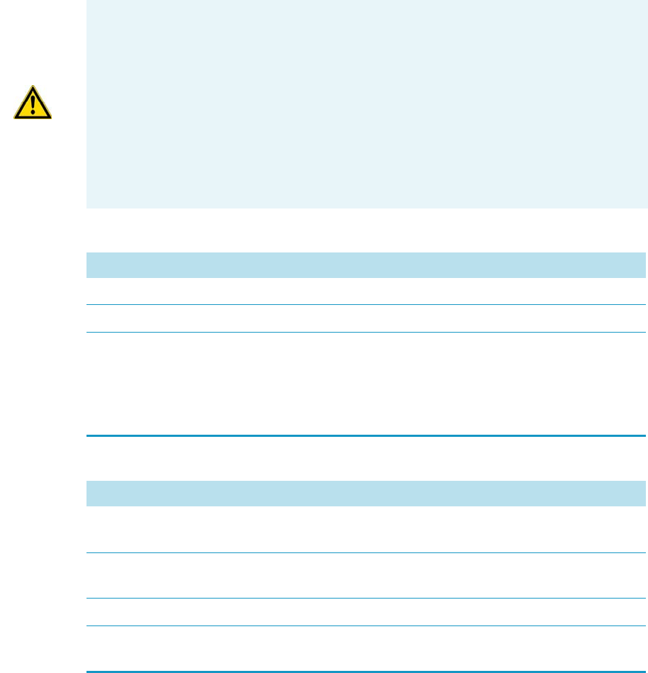
4 Maintenance Menu Items
Create Diagnostic Backup
Thermo Scientific TriPlus RSH User Guide 185
Create Diagnostic Backup
By using the command Create Diagnostic Backup, essential information from the current
status of the TriPlus RSH is extracted, and saved in an encrypted form on the SD card.
WARNING As pointed out in the Warning Message the configuration data will be lost.
This means that in the software, Configuration data base will be deleted and the few
parameters such as the X-Axis length and the Signal settings (see Table 86 and Tab l e 87 )
will be reset to default and re-entered.
All other parameters from the TriPlus RSH system configuration (e.g. teaching points for
modules, and so on) will be deleted. Consequently, must follow all the steps in the
Installation Wizard again.
Path from Start Screen: Options | Service | Installation.
Access level Extended User is required.
Table 86. List Items for Reset Configuration
Item Description
Factory Setting 1-S This will set the length of the X-Axis to 850 mm.
Factory Setting 2-L This will set the length of the X-Axis to 1205 mm
Factory Setting 3 ITSP-S This will set the basic configuration for the dedicated
application ITSP.
The dedicated Tray Types and the Waste Container for deposing
the used ITSP cartridge are configured besides the standard
parameters as listed below.
Table 87. System Parameters affected by Reset Configuration
Item Default Value Settings with Reset Configuration
I/O Interface TTLIn1 and TTLIn2; negative logic; 20 ms Debounce Time
SWOut1 and SWOut2: PWMOut 36V.
Signals Input Signals: TTLIn1 and TTLIn2
Output Signals: SWOut1 and SWOut2
Chromatography System GC1: Input1, Output1
Plunger Check Activated
(Used in Service Installation Wizard Calibrate Tool.)
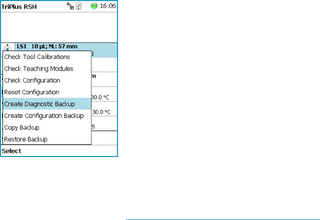
• The primary use of the Diagnostic Backup file is for supporting and troubleshooting a
TriPlus RSH system.
For this purpose it is necessary to send the file by e-mail to the Thermo Fisher Scientific
technical support center: gc.gcms.customersupport@thermofisher.com, with the file
description provide as well the RSH Firmware version used. Refer also to the chapter
RSH Firmware in the TriPlus R SH Ha rdware Manual.
The following software components are saved:
•Application Software
•Device Firmware — The Firmware of all active modules which are part of the specific
TriPlus RSH configuration
•Configuration (Data Base)
•Presets — Defines a model configuration such as liquid and headspace injection
technique, and so on.
This tool is available in the Extended User and Service access levels. After successful creation
of the Diagnostic Backup, copy the file directly onto the USB Stick. The creation of the
Diagnostic Backup file, with extension ‘*.pack, does take approximately eight minutes. The
size of the file is in the range of 12 MB, depending on the configuration of the TriPlus RSH.
The Diagnostic Backup file can also be used for a Restore procedure.
Create Configuration Backup
This command creates a configuration backup file of the TriPlus RSH in its current status.
This configuration backup is stored on the SD card installed on the control board.
Refer also to the chapter RSH Firmware in the TriPlus RSH Ha rdwa re Man ual.
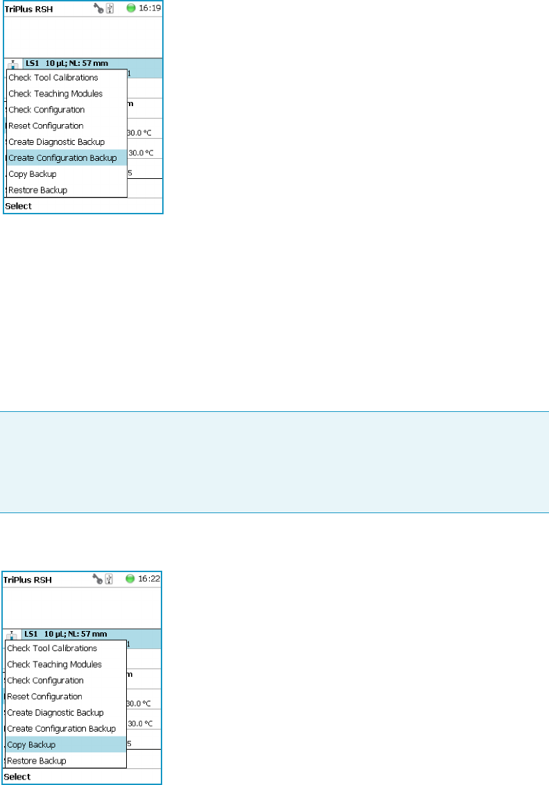
4 Maintenance Menu Items
Copy Backup
Thermo Scientific TriPlus RSH User Guide 187
The command is available in all access levels. After successful creation of the Configuration
Backup, copy the file directly onto the USB Stick. The creation of the Configuration Backup
file does take approximately one to two minutes. The file size is in the range of 1.3 MB,
depending on the TriPlus RSH configuration. The file extension is *.pack.
The Configuration Backup file can also be used for a Restore procedure.
Copy Backup
It is good practice to store the configuration backup in a safe place, if possible on a
network-server. You must keep an authorized configuration backup outside of your premises.
To copy a configuration backup from the SD card, insert the USB stick into the connector
USB Host on the back of the TriPlus RSH.
Refer also to the chapter RSH Firmware in the TriPlus RS H Hardware Manual.
Note Be aware that only one backup file can be stored on the SD card.
If for example a Diagnostic Backup file is created and directly followed by creating a
Configuration Backup file, the first file (in this example the Diagnostic Backup file) will
be overwritten. To save both files, it is necessary to copy each file immediately onto the
USB Stick
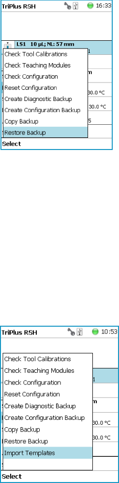
4 Maintenance Menu Items
Restore Backup
188 TriPlus RSH User Guide Thermo Scientific
Restore Backup
The function Restore allows loading a Backup file saved from the same TriPlus RSH system
back to the system. Only a Backup file (*.pack file) can be used. The key, the encryption of
the Application, and the device Firmware files must match.
Refer also to the chapter RSH Firmware in the TriPlus RSH Ha rdwa re Man ual.
Import Templates
Selecting the menu item Import Templates allows the Extended User to import one or more
customized templates for several iemes sach as:
• Needle Types
•Rack Items
•Syringe Types
•Tray Slot Types
•Tray Types
•Valve Types
•Vial Types

Thermo Scientific TriPlus RSH User Guide 189
5
Service Menu Item
This chapter describes the options of the Service Menu operated either with the Virtual
Handheld Controller, or directly using the installed Handheld Controller.
Contents
•Service Menu
•Installation Item
•Create New Tray System Item
•Teach Home Pos it io n
Note Items highlighted in green are only visible in the access level Extended User.
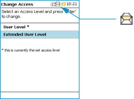
5 Service Menu Item
Service Menu
190 TriPlus RSH User Guide Thermo Scientific
Service Menu
The Menu Service is only available under the Extended User Level. The menu contains the
items Installation and Create New Tray System. The item Installation is a wizard that
guides through the installation procedure covering all points, and controlling the status of the
system. The Create New Tray System item will be used during routine operation.
•See “Prerequisites” on page 190
•See “Installation Item” on page 191
•See “Create New Tray System Item” on page 222
Prerequisites
When the TriPlus RSH is powered on, the User Access Level is always active by default.
To enable access to the Extended User Level press the two Menu Buttons simultaneously, or
press the two characters A and B simultaneously on the keyboard if you are working with a
Virtual Handheld Controller. For more details, see the section “Access Le vels” on page 85.
Figure 134. Changing Access Level
When the TriPlus RSH is powered up the first time, the Message Envelope is shown in the
Menu Screen Status Bar. See the example in Figure 134. The reason for this message is that a
TriPlus RSH cannot be operated as long as the motors are not calibrated. The modules cannot
operate if this step has not been completed.
When pending messages are indicating, verify the message. If the message can be explained
with the concept as described above, click it away. For confirmation check all cables from the
active modules are properly connected.
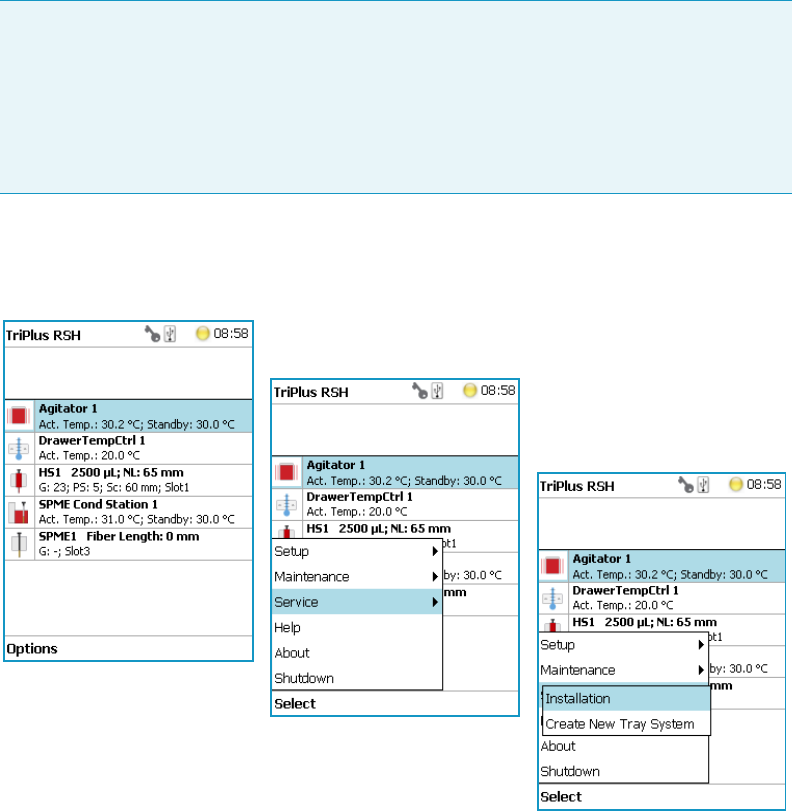
5 Service Menu Item
Installation Item
Thermo Scientific TriPlus RSH User Guide 191
Installation Item
Press the Options button to open the pull-up menu, and select the menu item Service; then
select the list item Installation to start the wizard. See Figure 135.
Figure 135. Selecting the Menu List Item Installation
The Installation wizard begins with the basic setup items. Some of the list items can be
accessed under the menu item Setup.
The Installation wizard includes twelve points. See Figure 136. When the TriPlus RSH is
powered up the very first time, specific sections are grayed out until the section Calibration
Motors has been completed. Each point ticks off as it is completed.
When the TriPlus RSH is powered on for the very first time, these wizard items which have to
be accomplished are active (black). The grayed out wizard items will be active as soon as the
system is calibrated (Calibrate Motors) and if the hardware configuration of the TriPlus RSH
requires these points.
Note During a new installation of the TriPlus RSH, it is advisable to first configure the
Passive modules before activating the Installation Wizard Service. One wizard item is
Teaching Module. If the Passive modules, such as the Injector, Wash Module, and so on,
are not yet configured, it will be necessary to restart this wizard again.
The Quick Reference Guide in the TriPlus RSH Hardware Man ual shows the order of
installation. Use this guide as reference.
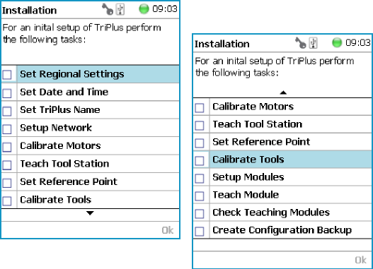
5 Service Menu Item
Installation Item
192 TriPlus RSH User Guide Thermo Scientific
Figure 136. Installation Wizard.
The twelve points to cover are:
•“Set Regional Settings” on page 193
•“Set Date and Time” on page 194
•“Set TriPlus RSH Name” on page 195
•“Setup Network” on page 196
•“Calibrate Motors” on page 199
•“Teach Tool Station” on page 202
•“Configure SPME Tool” on page 207
•“Set Reference Point” on page 209
•“Calibrate Tools” on page 210
•“Setup Module” on page 213
•“Teach Module” on page 214
•“Check Teaching Modules” on page 218
•“Create a Backup File” on page 220
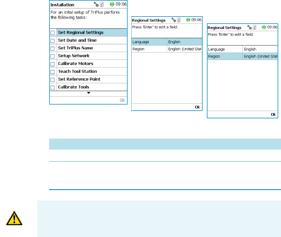
5 Service Menu Item
Installation Item
Thermo Scientific TriPlus RSH User Guide 193
Set Regional Settings
To set regional setting
1. Select the wizard item Set Regional Setting to adjust the language and the region.
See Figure 137.
Figure 137. Wizard Item Set Regional Settings
Table 88. Set Regional Settings
Item Description
Language English is the default language.
Regional
Setting
Corresponds to the country settings of the computer operating system.
The country setting mainly influences formatting such as for dates and
numbers.
IMPORTANT When a Set Regional Setting parameter is changed, a reboot of the system is
required. Please note that the Regional Settings are active for the Handheld Controller
only, the Virtual Handheld Controller is dependent on the settings of the computer
operating system.
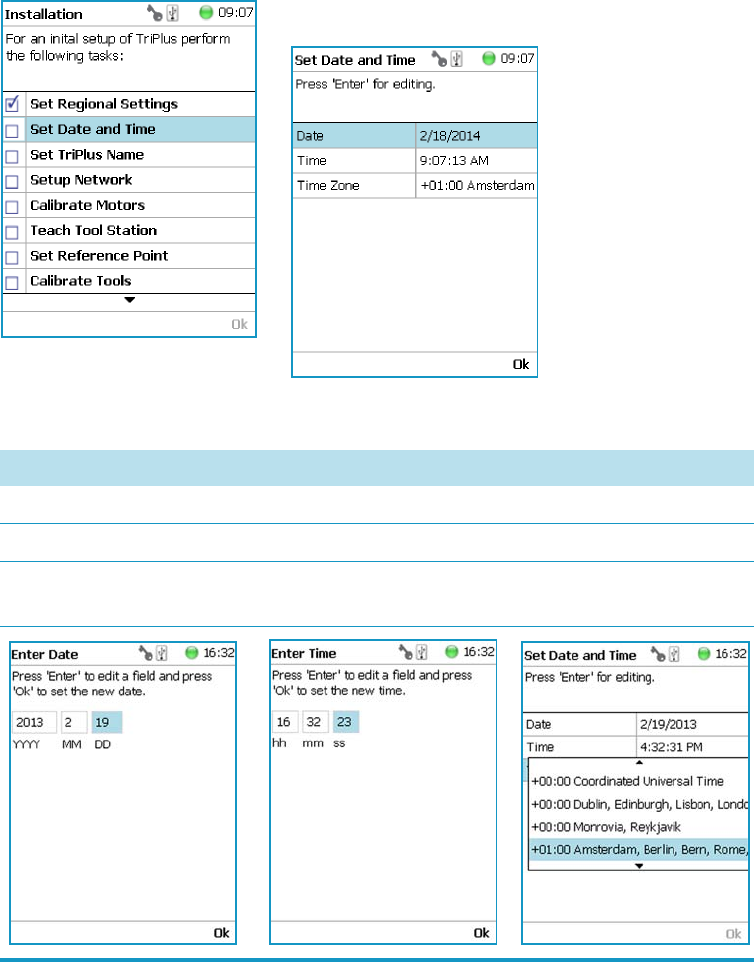
5 Service Menu Item
Installation Item
194 TriPlus RSH User Guide Thermo Scientific
Set Date and Time
To set date and time
1. Select the wizard item Set Date and Time to adjust the date and time. See Figure 138 and
Tab le 89.
Figure 138. Wizard Item Set Date and Time
Table 89. Set Date and Time Parameters
Item Description
Date The format is: yyyy/mm/dd
Time The format is hh:mm:ss
Time Zone Greenwich Mean Time (GMT) plus or minus the time
deviation (in hours) from Greenwich standard time.
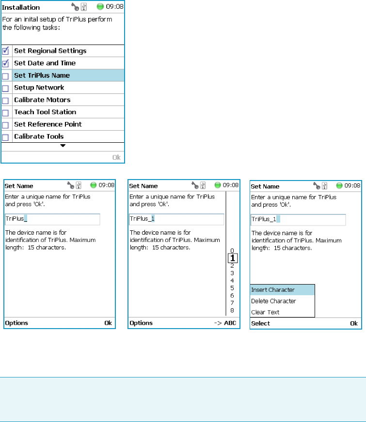
5 Service Menu Item
Installation Item
Thermo Scientific TriPlus RSH User Guide 195
Set TriPlus RSH Name
To set TriPlus RSH name
1. Select the wizard item Set TriPlus RSH Name to set a name for the TriPlus RSH for
identification. See Figure 139 and Table 90.
Figure 139. Wizard Item Set TriPlus RSH Name
2. Press Enter to receive the alphabetical selection of 15 characters maximum or press the
Default Action button to change from capital to lower case characters or to numbers.
3. Press Options to access the list items Insert, or Delete Character, or Clear Text.
4. Press Ok when finished.
Note The name must start with an alphabetical character, and end with an
alphanumerical character. Special characters or spaces cannot be used to start or end
the name.
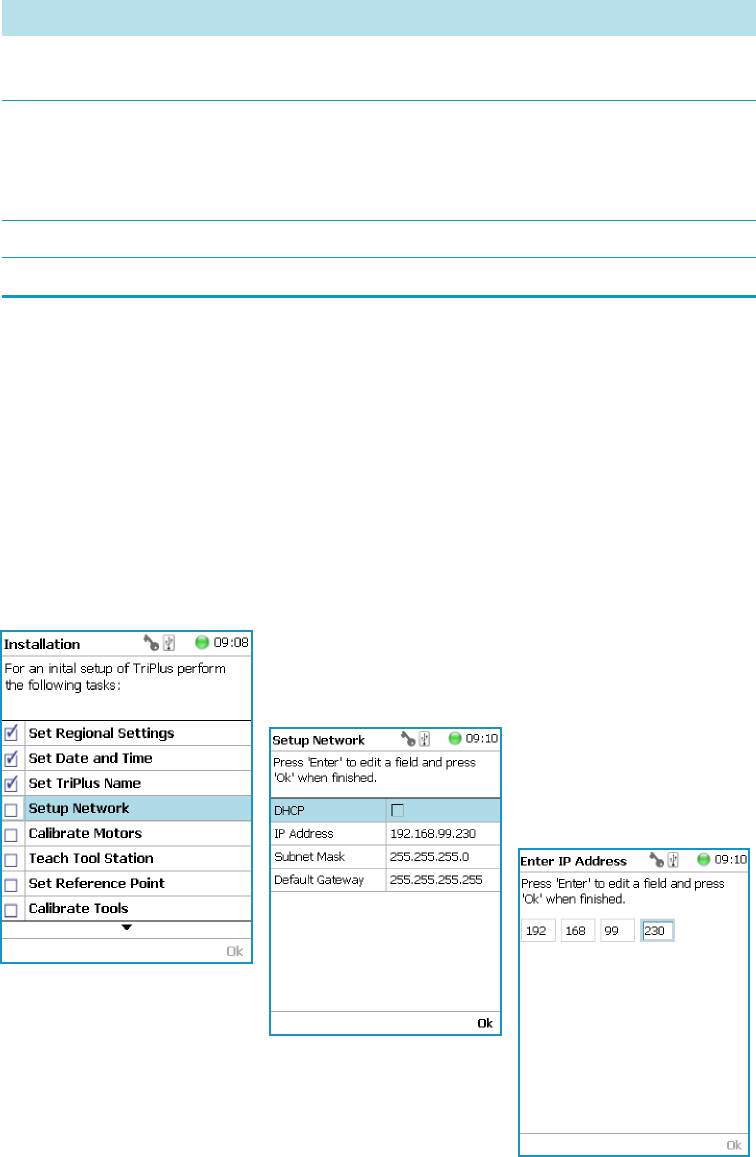
5 Service Menu Item
Installation Item
196 TriPlus RSH User Guide Thermo Scientific
Setup Network
To perform Setup Network
1. Select the wizard item Setup Network to enable a network communication from the
system to the computer, TCP/IP. See Figure 140 and Table 91.
2. Select either the mode DHCP or enter a unique fixed IP Address.
3. Press Ok when finished.
Figure 140. Wizard Item Setup Network
Table 90. Set TriPlus RSH Name Parameter
Item Description
Set TriPlus RSH Name Set a unique name for the TriPlus RSH. This name will be
stored and is used for identification of the system.
Insert Character Allows inserting a character. Press Enter to receive the
selection of capital letters. Pressing the Default Action
button will switch to lower case characters or to the
alphanumeric selection.
Delete Character Deletes the selected character.
Clear Text Clears the full text.
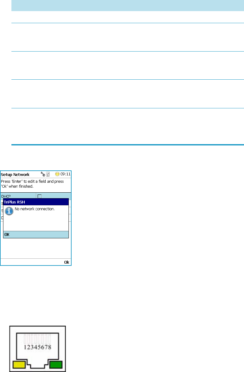
5 Service Menu Item
Installation Item
Thermo Scientific TriPlus RSH User Guide 197
When the network cable is not connected, and a LAN communication is not established, the
following screens will appear.
The system will recognize that no network communication is established or possible. A
corresponding error message will appear.
1. Check the connections of the LAN cable. The default addresses is visible after reentering
the Setup Network screen.
2. Check the LEDs on the Ethernet connector at the back of the TriPlus RSH.
Table 91. Setup Network Parameters
Item Description
Setup Network Defines the Network communication parameters.
DHCP Dynamic Host Configuration Protocol. If activated, an IP Address
is dynamically sought throughout the available network. It is
advisable not to use the DHCP mode but to use a fixed IP Address.
IP Address The IP Address is a fixed system address. The IP Address is often
provided by the network administrator.
Default address TriPlus RSH is 192.168.99.230
Subnet Mask The Subnet Mask is used for network configuration, it must be
provided by the network administrator.
Default address TriPlus RSH is 255.255.255.0
Default Gateway Gateway is used if independent networks must communicate
interactively. Communication within the network is provided by a
hub or switch, defined as the Gateway. Do not assign a Default
Gateway address.
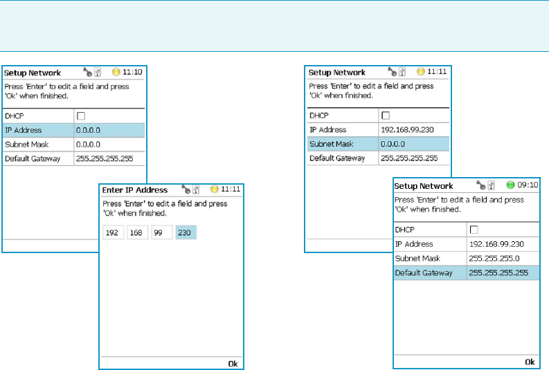
5 Service Menu Item
Installation Item
198 TriPlus RSH User Guide Thermo Scientific
•The LED on the left — Status LED. Orange color indicates that the current is
applied to the connector.
•The LED on the right — Indicates the Ethernet communication status. Green
blinking status indicates that the Ethernet communication is established.
3. When the settings have to be changed, select one Network parameter after the other, and
enter the required numbers. The next examples show the default values.
For more information refer to Setting Up Network Interface in the TriPlus RSH Hardware
Manual.
In order to select the required network setup according to the laboratory setting, the following
possibilities are available:
•Direct connection — The TriPlus RSH is directly connected to the computer via the
LAN cable. There is no corporate network or router connection.
– IP Address TriPlus RSH: 192.168.99.230
– IP Address computer: 192.168.99.210
– Subnet Mask: 255.255.255.0
– Default Gateway: not required, leave the field empty (if an address is entered, it will
not be used)
Note When the LAN communication is not established, newly entered IP address
numbers are not stored.
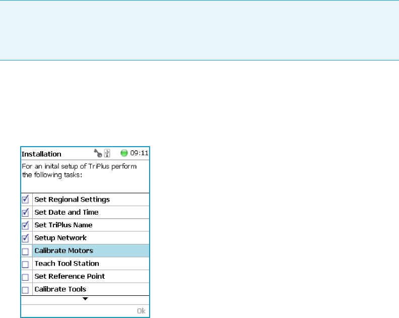
5 Service Menu Item
Installation Item
Thermo Scientific TriPlus RSH User Guide 199
•Corporate Network with DHCP Protocol — Ask the network administrator to verify
and integrate the setup within the corporate network.
Select the DHCP Protocol; the network will assign an IP Address and a Subnet Mask to
the TriPlus RSH.
•Corporate Network with Fixed IP Address — Ask the network administrator to provide
the IP Address, Subnet Mask, and Default Gateway to configure the TriPlus RSH within
the corporate network.
Calibrate Motors
The calibration of the motors is basically a check to determine whether the mechanical stop
points of the various axes can be found reliably. A clearance distance (offset) from the
mechanical stop point is assigned and stored as the electronic stop point. This calibration of
the axes is mandatory and ensures reliable performance.
This step has been repeated when a motor has failed, has been replaced or when any other
major error has occurred. This calibration task brings the TriPlus RSH back to reliable
operation.
To calibrate motors
1. Select the wizard item Calibrate Motors and follow the dialog. In the following example,
the Calibration Wizard guides you from the steps 1 to 6. See Figure 141.
Figure 141. Wizard Item Calibrate Motors and Starting Calibration Wizard Step 1 of 6
Press Calibrate to start the first step Calibrate Axes. All axes from the TriPlus RSH are
calibrated. Wait until the yellow light stops flashing and Next becomes available.
Note Please do not confuse the terms and tasks for Calibration Motors as explained in
this section with those for Calibration Tools as described in the section “Calibrate Tools”
on page 210 When starting the wizard Calibrate Motors at least one tool must be parked
in a slot of the Tool Station.
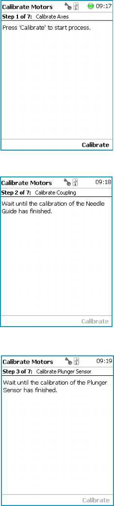
5 Service Menu Item
Installation Item
200 TriPlus RSH User Guide Thermo Scientific
2. Press Next to continue with the Calibrate Coupling (Step 2).
3. When finished, press Next again to Calibrate Plunger Sensor (Steps 3).
4. Step 4 calibrates the coupling of a tool. The wizard text explains that the head must be
moved above the Coupling Pivots.
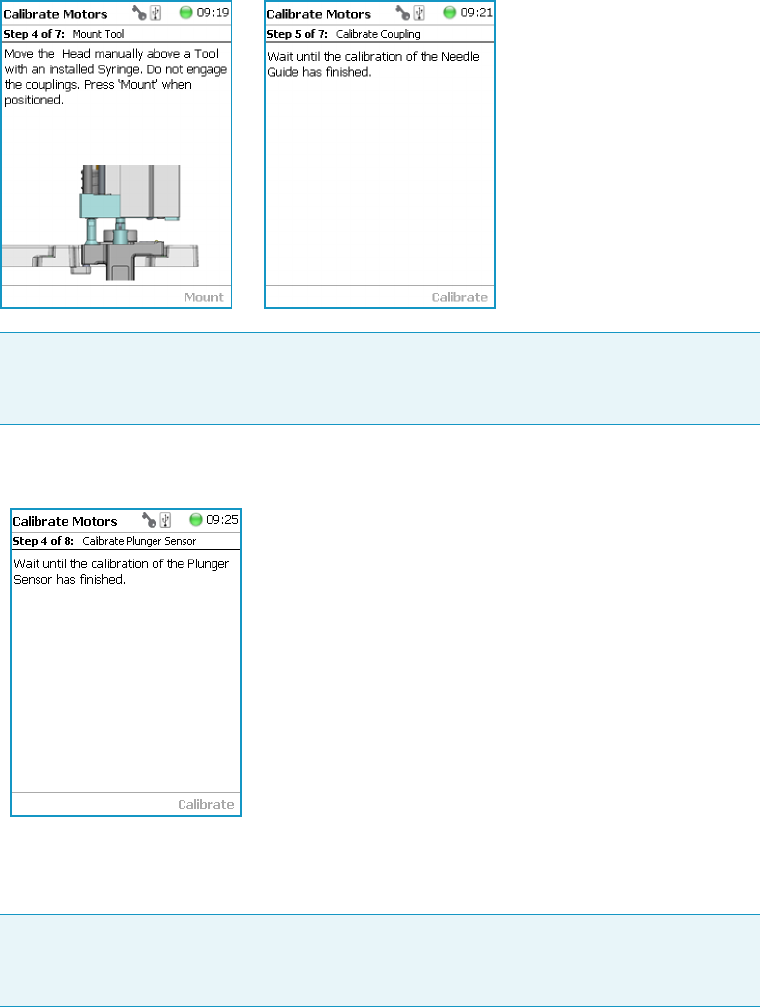
5 Service Menu Item
Installation Item
Thermo Scientific TriPlus RSH User Guide 201
Upon starting the wizard, the TriPlus RSH automatically turns off the current to enable a
manual movement of the TriPlus RSH Head.
5. In case the calibration step is activated with an installed tool, the system dialog will ask
you to move the head first to an empty slot, and Eject the tool first.
When Step 4 has been successfully completed, press Next to continue to step 5 to
calibrate the coupling.
6. In Step 6, the Sensor of the Plunger motor is calibrated. When finished, press Next to
continue.
Note Please note that the TriPlus RSH Head has to be positioned such that the
receiving holes of the Z-Slider are above the Coupling Pivots of the tool but they
must not be engaged.
Note When the tool ejection has been completed, the tool is not installed in the head
of the TriPlus RSH. Continuing with Calibrate Motors, in the Installation Wizard
will detect that the tool is not mounted, and will adapt to this situation accordingly.
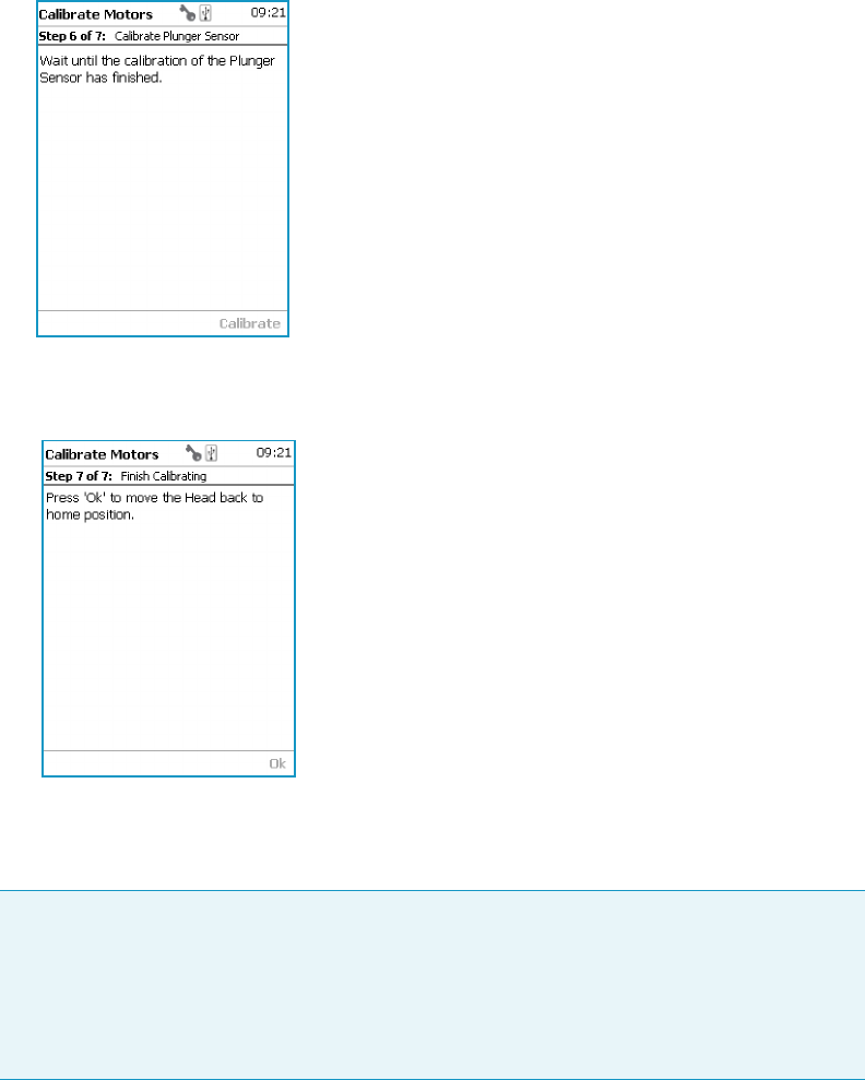
5 Service Menu Item
Installation Item
202 TriPlus RSH User Guide Thermo Scientific
7. Step 7 completes the Calibration Wizard. The head of the TriPlus RSH moves back to
the Home position.
Teach Tool Station
To proceed with different types or configurations of the Tool Station
The TriPlus RSH system can be equipped with a TR Station or with one or two ATC
Stations. The following configurations are allowed:
•One TR Station
• One or two ATC Stations
The following configurations are prohibited:
Note Tool St atio n is a generic term. It can refer to a TR Station (passive module with
single slot) or to a ATC Station (active module with three slots). This section describes the
teaching of a ATC Station. The teaching of a TR Station uses the same steps.
CAUTION When a ATC Station is used in the configuration of the system, remove any
other tool from the slots before the wizard is started.

5 Service Menu Item
Installation Item
Thermo Scientific TriPlus RSH User Guide 203
• Two TR Stations
• The combination of a TR Station with a ATC Station
For the configuration with two ATC Stations see the note Exceptional Circumstances.
After completing the steps to assign the addresses to the two ATC Stations, keep in mind the
following points have to be known. The slots in the two ATC Stations will be identically
numbered from 1 - 3. The Address of the ATC Station will enable the system to distinguish
between these slots.
For example: ATC Station1; Slot1 | ATC Station2; Slot1.
•Following the Service Wizard, the second point after Teach Tool Station is the item Set
Reference Point. It is advisable, but not mandatory, to set the reference point at ATC
Station #1. It is more likely that the second ATC Station will be removed in the future,
and not the first one. Removing the ATC Station to which the Reference Point has been
assigned would result in elimination of the Reference Point for the system.
•When the wizard for Te a ch Too l St at i o n is started, the software will check if the tool
(coupled in the TriPlus RSH head) is parked in the expected position.
In case the two ATC Stations are mixed up, an error message appears. In such a case verify
the identify of the ATC Station, the slot position, or both.
Wizard Teach Tool Station
The wizard procedure is identical for teaching a TR Station or an ATC Station. The difference
is the number of slots to teach.
CAUTION Exceptional Circumstances
To configure two ATC Stations follow the procedure described here:
1. Physically connect both ATC Stations at the desired position of the X-Axis.
2. Define which ATC Station shall be the ATC Station #1.
3. When the TriPlus RSH is powered off, connect the supplied control cable from the
rear side of ATC Station #1 to the connector marked Bus on the TriPlus RSH control
interface. If Bus connector is already occupied, connect the cable to another Active
module with an open connector.
4. DO NOT connect the control cable from ATC Station #2.
5. Power-up the system. The software will assign the module address to ATC station1.
6. Turn off the system and connect the provided control cable to ATC Station #2.
7. Power-up the system again, the software will recognize the second ATC Station and
will assign the address to ATC Station2.
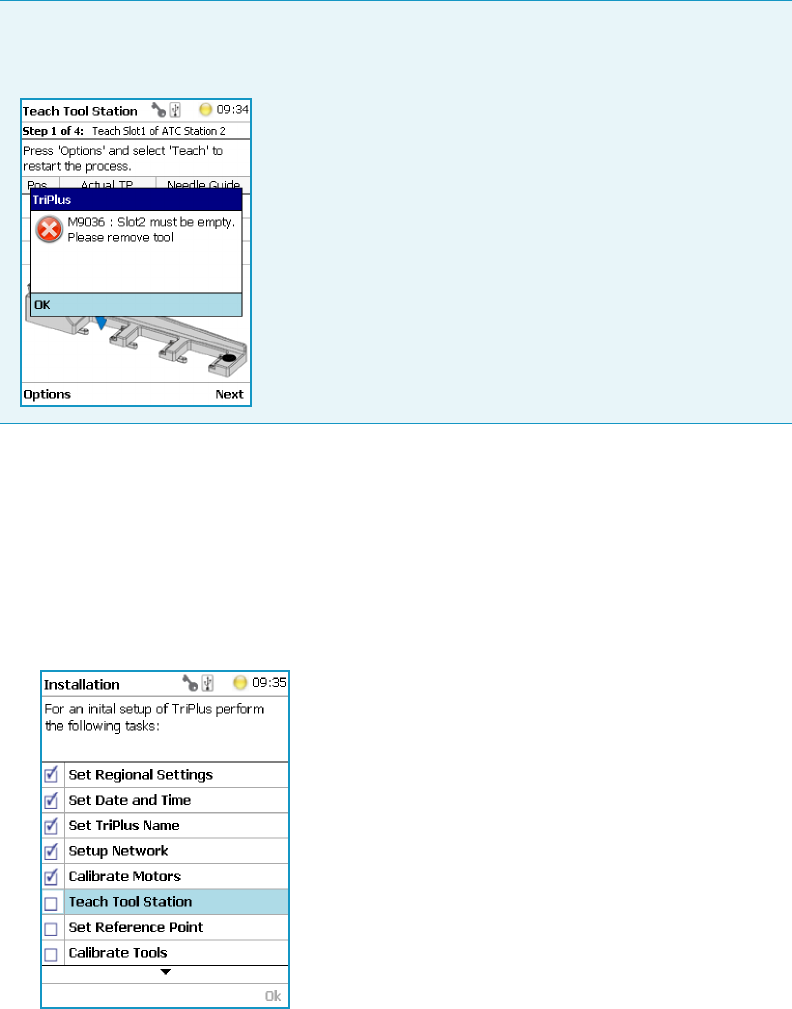
5 Service Menu Item
Installation Item
204 TriPlus RSH User Guide Thermo Scientific
The wizard Tea c h Tool St a t io n calibrates the position of the slot(-s). The height of the tool,
installed in the slot, is calibrated against the TriPlus RSH Injection Unit base plate to define
the coupling distance.
To calibrate the position of the slots
1. Select the wizard item Tea c h To o l St at io n . See Figure 142.
Figure 142. Wizard Item Teach Tool Station
The wizard automatically turns off the current to the TriPlus RSH to enable a manual
movement of the TriPlus RSH Injection Unit to the first Slot.
If you have performed “Calibrate Motors” on page 199, a tool should still be installed.
If for any reason there is no installed tool, the TriPlus RSH will recognize the situation
and will go through an intermediate step to mount a tool.
WARNING When an ATC Station is used in the configuration of the system, remove any
other tool from the slots before the wizard is started. If this is not observed, an error
message will appear.
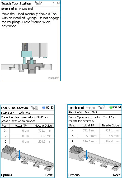
5 Service Menu Item
Installation Item
Thermo Scientific TriPlus RSH User Guide 205
2. Step 1 of 4 requests the installation of a tool if one is not mounted to the TriPlus RSH
Injection Unit. See Figure 143.
Figure 143. Mount a Tool
3. When a tool has already been installed, the wizard starts with Step 1. See Figure 144.
Figure 144. Teach Slot 1
Step 1 asks you to place the TriPlus RSH Injection Unit manually into the first slot.
Ensure that the guiding pins engage well into the guiding holes of the ATC Station.
When positioned well, press Save to store the X-, Y-, and Z-Axes positions.
4. Repeat the previous steps to teach the positions for Slots 2 and 3. See Figure 145.
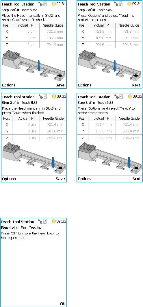
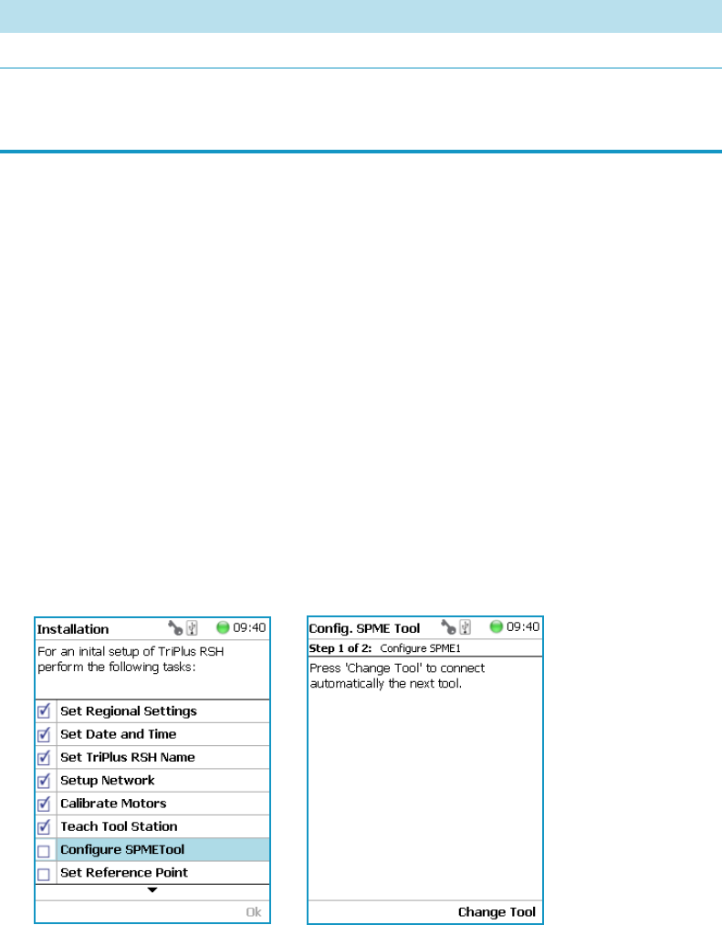
5 Service Menu Item
Installation Item
Thermo Scientific TriPlus RSH User Guide 207
Configure SPME Tool
Working with the SPME Tool requires two adjustments of the SPME Fiber.
Configure SPME Tool parameters are described in Table 92.
The last wizard point was Teach Tool Station. For this task, the tools had to be removed from
the slots. After finishing the teaching task, the wizard will move to the next point, Configure
SPME Tool. If the SPME Tool has not been positioned in a slot at the moment of activating
this wizard point, the task will be grayed out.
To overcome the situation
1. Insert the SPME Tool manually in a slot.
2. Select the previous wizard point Teach Tool Stat ion again.Wait until the first movements
of the Z-Axes are finished.
3. Press Back and leave this wizard point without going through all the steps.Check if the
wizard point Configure SPME Tool is active.
To configure the SPME Tool
1. Select the wizard item Configure SPME Tool. See Figure 147.
Figure 147. Wizard Item Configure SPME Tool
2. When a tool other than the SPME Tool is installed in the TriPlus RSH Injection Unit,
the wizard asks for a tool change.
Table 92. Configure SPME Tool Parameters
Item Description
Fiber Alignment Fiber position is aligned with the needle tip.
Standby Position Offset Fiber is inserted 2 mm into sheath metal needle.
(2 mm retraction is a recommended value). When using very
soft septa, adjust to 3.0 mm.
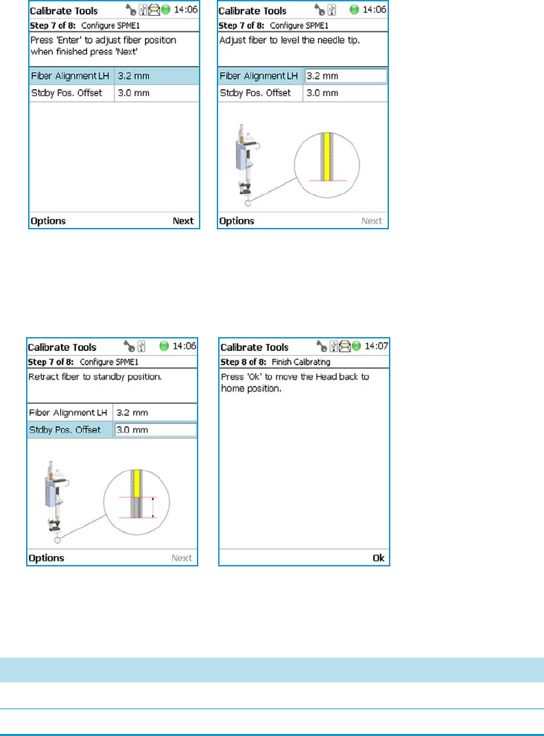
5 Service Menu Item
Installation Item
208 TriPlus RSH User Guide Thermo Scientific
3. Adjust the Fiber Alignment. Align the fiber tip with the needle tip as indicated in the
figure of the handheld controller, or the virtual handheld controller. Turn the fiber
downwards until it is clearly visible. Turn it back at the same level as the needle tip, then
save this value. See Figure 148.
Figure 148. SPME Fiber Alignment
4. Adjust the Standby Position. Bring back the fiber by at least 2 mm into the needle
(protection sheet), so the fiber does not touch the septum when penetrating through.
The fiber could stick to the septum and be damaged or even lost. See Figure 149.
Figure 149. SPME Fiber Standby Position
For the two versions an approximate value for the parameter Fiber Alignment and the
recommended value for the parameter Fiber Standby Position are given in Table 150
Figure 150. Fiber Alignment and Fiber Standby Position
SPME Type Fiber Alignment Fiber Standby Position
SPME 1 10.8 mm 2.0 mm
SPME 2 3.4 mm 2.0 mm
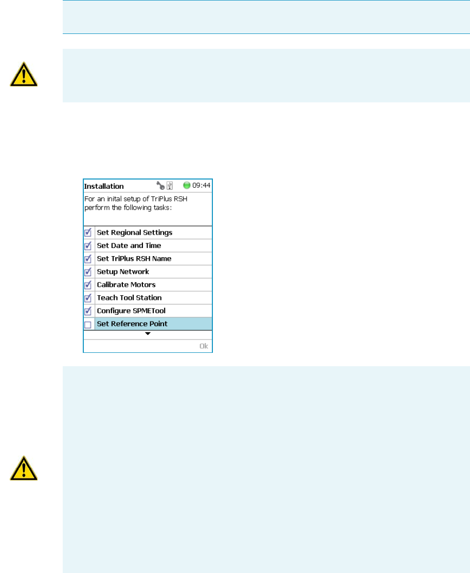
5 Service Menu Item
Installation Item
Thermo Scientific TriPlus RSH User Guide 209
Set Reference Point
To set the Reference Point
1. Select the wizard item Set Reference Point and follow the dialog. See Figure 151.
Figure 151. Wizard Item Set Reference Point
2. Manually position the TriPlus RSH head (Injection Unit) exactly within the guiding rings
of the lunette. Store this value. See Figure 152.
Note The concept of Referencing and Calibration is explained in the chapter Tr iP lus
RSH Defining Object Positions in the TriPlu s R SH Hardware Ma nual.
CAUTION When an ATC Station and more than one tool is used, insert all tools before
the wizard is started.
CAUTION It is advisable to hold with one hand the Y-Axis and with the second hand the
tool body to move in a controlled way the TriPlus RSH Injection Unit to the teaching
position.
Do NOT hold the Needle Guide to move the TriPlus RSH Injection Unit. This part is
mechanically flexible and could lead to misalignment.
The TR Station or ATC Station should not change in their position and only calibrated
tools should be used. If the Station has moved its position, it is necessary to redefine the
Reference Point, and recalibrate all the other tools.
If for any reason, the referencing (Set Reference Point) has been repeated, it is mandatory
to recalibrate all the tools. Using the step Set Reference Point clears the calibration data
for the individual tools. A message will appear to inform the operator of the necessary
steps. It is not important whether a TR or a ATC Station is used. The behavior during
re-calibration will be identical.
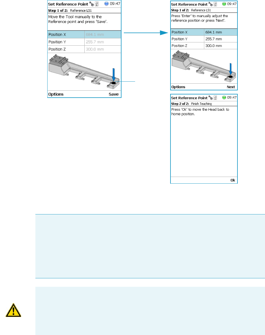
5 Service Menu Item
Installation Item
210 TriPlus RSH User Guide Thermo Scientific
Figure 152. Set Reference Point and Finish Wizard
Calibrate Tools
Lunette
Note The concept of Referencing and Calibration is explained in the chapter Tr iP lus
RSH Defining Object Positions in the TriPlu s R SH Hardware Ma nual.
The tool which is most frequently used should be used for Calibration.
This tool can be considered as the ideal tool. All other tools will be referenced with respect
to the Ideal tool.
This step is not necessary when a single tool station, the TR Station, is used or if only one
tool is in use within the entire system.
CAUTION It is advisable to hold the Y-Axis with one hand and with the other hand hold
the tool body to move the TriPlus RSH Injection Unit in a controlled way to the teaching
position.
Do NOT hold the Needle Guide to move the TriPlus RSH Injection Unit. This part is
mechanically flexible and could lead to misalignment.
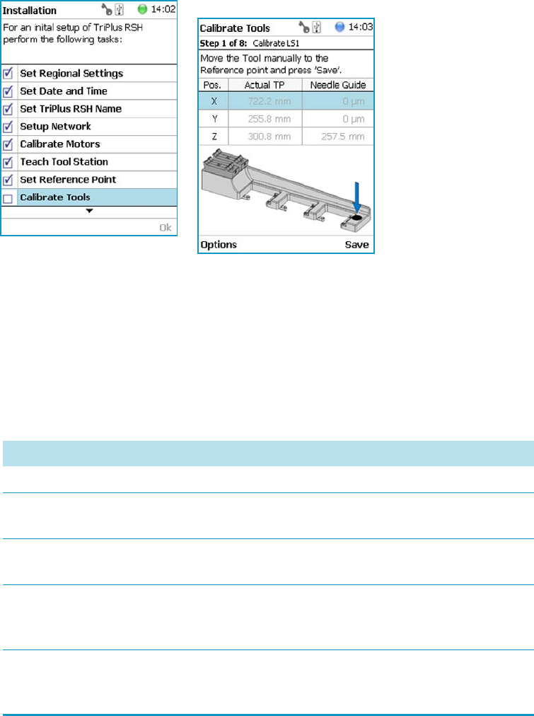
5 Service Menu Item
Installation Item
Thermo Scientific TriPlus RSH User Guide 211
The following example describes calibration of the SPME tool (SPME) positioned in Slot 1,
the Headspace Tool (HS) positioned in Slot 2, and the Liquid Tool (LS) positioned in Slot 3.
To calibrate the tools
1. Select the wizard item Calibrate Tools and follow the dialog. See Figure 153.
Figure 153. Wizard Item Calibrate Tools and Calibration of Ideal Tool
2. Press Save to continue in the wizard. The X-, Y-, and Z-positions will be stored.
Select Next to open the window for assigning the Tool parameters.
The default value of the Tool Parameter is Not Specified. This means that the parameter
has to be specified for the application. The definition can be made at this stage of
installation or later on during routine work. You are able to change this parameter to
adapt it for another application; note that the Extended User Level is required.
Table 93. Calibrate Tools Parameters
Item Description
Not Specified Prohibits the execution of a run.
Magn10or20mL Magnetic Ring installed to enable the transport of 10 or
20 mL vials.
Magn2mL Magnetic Ring not installed but Lower Needle Guide has
Magnets installed to enable transport of a 2 mL vial.
Foil Cutter Foil Cutter installed. The Foil Cutter pierces a sealing foil of a
MTP or DW-Plate before the syringe needle penetrates the
well.
NonMagn2mL The lower Needle Guide has no magnets installed; a magnetic
ring is not connected to it. Typically used for Microtiter Plates
or for vials with a non-magnetic cap.
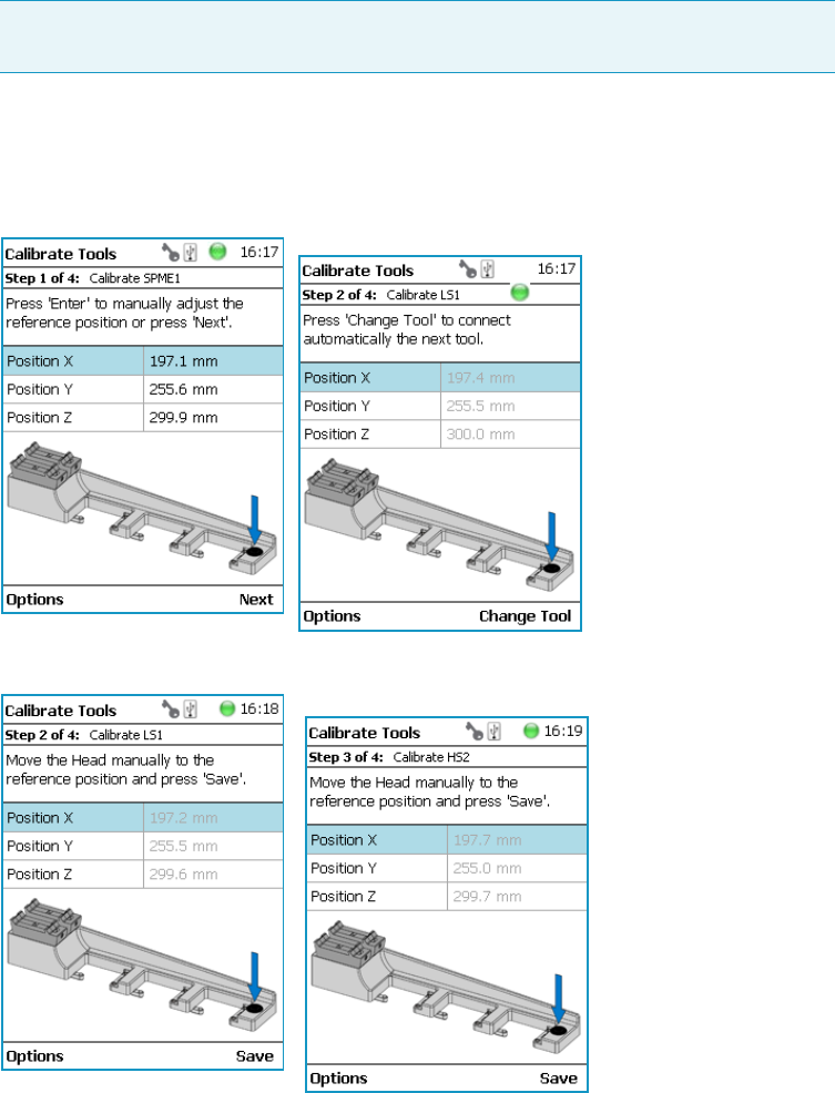
5 Service Menu Item
Installation Item
212 TriPlus RSH User Guide Thermo Scientific
The parameter Cap Type in the class Vial Type has to correspond with the Tool Needle
Guide Type.
Examples:
• Magnetic10/20 | Magnet Cap
•Magnetic 2mL | Magnetic Cap
• Foil Cutter | MTP Plates
3. After the first step of Tool Calibration, the wizard will park the Ideal tool and pick up
the next tool, starting with the tool in Slot 1 and consecutively to Slot 2 and Slot 3.
See Figure 154 and Figure 155.
Figure 154. Preparing Tool Change for Step 2, Check Tool and Pick HS Tool
Figure 155. Tool Change to Prepare for Step 3 and Calibrating HS Tool
Note If Needle Guide Type is defined as Not Specified, the execution of a sample
run is prohibited even if the Cap Type is set to No Cap or Non Magnetic Cap.
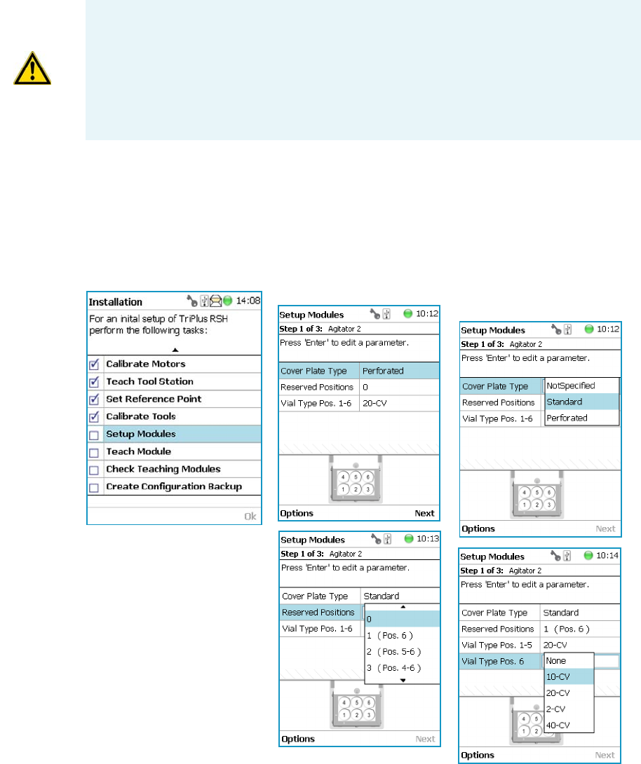
5 Service Menu Item
Installation Item
Thermo Scientific TriPlus RSH User Guide 213
4. When finished, the final wizard step moves the Head back to the Home position.
#
Setup Module
This allows you to predefine the parameters from a module. Typically, this process is done
once at first installation of the TriPlus RSH. See Figure 156.
Figure 156. Wizard Item Setup Module
To setup a module
The example below shows the steps for defining the parameters for the Agitator:
CAUTION TR Station or ATC Station should not change in the position. If the Station
has moved its position, it is necessary to redefine the Reference Point, and recalibrate all
the other tools.
CAUTION If for any reason, the referencing (Set Reference Point) has been repeated, it is
mandatory to recalibrate all the tools. Using the step Set Reference Point clears the
calibration data for the individual tools.

5 Service Menu Item
Installation Item
214 TriPlus RSH User Guide Thermo Scientific
1. Select the Cover Plate Type and the Vial type used for the Agitator:
•Not Specified — Prohibits the execution of a run.
•Standard — Cover without holes.
•Perforated — Cover with 6 holes to enable Syringe Needle penetration through the
cover into the vial inserted in the Agitator.
•Vial Type — Select the type of vials used for the Agitator.
If the Vial Type has to be changed during routine application, this can be done at any
time by going to the Start Screen, selecting the menu item Agitator, scrolling down
to the list item Vial Type and selecting another Vial Type.
Teach Module
The term Teaching is used for the definition of the X-, Y-, and Z-Axis positions for each
module. Refer also to TriPlus RSH Defining Object Positions in the TriPlus RSH Hardware
Manual.
To teach the module
1. Select the wizard item Teach Mo d ule . A dialog will guide the operator through this
teaching wizard. Upon starting the wizard, the TriPlus RSH automatically turns off the
current to enable a manual movement of the TriPlus RSH Injection Unit to the various
modules configured with the system. See Figure 157.
Note The difference between Active and Passive modules are:
•The Active modules are recognized automatically by the system when connected to
the Bus and at the next restart of the system.
•The Passive modules are not automatically recognized; they have to be added to the
configuration. The passive modules, such as Tray Holder, Wash Station, etc. have to
be added first.
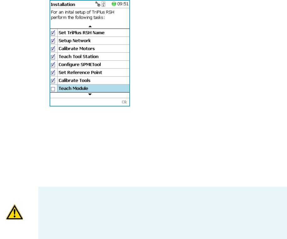
5 Service Menu Item
Installation Item
Thermo Scientific TriPlus RSH User Guide 215
Figure 157. Wizard Item Teach Module
2. If the wizard is started without an attached tool, it first moves the TriPlus RSH Injection
Unit to the first slot of the ATC Station or TR Station, picks up the provided tool, and
waits for the next command.
3. The teaching order follows the order of the objects listed as shown in Setup Modules
(pull-up menu Options). During the teaching process, it is always possible to demand a
fine tuning or to go back to a previous position or module. See the various possibilities
under the Options pull-up menu.
4. When the wizard is started, the first module is displayed, an arrow indicates the teaching
position. Follow the instructions given.
As a general description, move the TriPlus RSH Injection Unit manually to the indicated
teaching position, adjust the lower needle guide perfectly within the center of the lunette
ring. Without the magnetic ring attached, use the inner ring for teaching.
5. The Lower Needle Guide should be centered on the lunette with the bottom of the
Lower Needle Guide lightly touching its surface.
For modules without a lunette, such as the Agitator, it is necessary to insert a vial (with
the corresponding adapter if required), and use the vial cap surface as the reference for the
Z-Axis value.
The teaching process for the active modules are described in chapter TriPlus RSH Defining
Object Positions in the TriPlus RSH Hardware Manual .
6. When you are satisfied with the teaching, press Save and continue by pressing Next to get
to the following module. If in doubt, proceed with the fine tuning.
CAUTION It is advisable to hold the Y-Axis with one hand and with the other hand hold
the tool body to move the TriPlus RSH Injection Unit in a controlled way to the teaching
position.
Do NOT hold the Needle Guide to move the TriPlus RSH Injection Unit. This part is
mechanically flexible and could lead to misalignment.
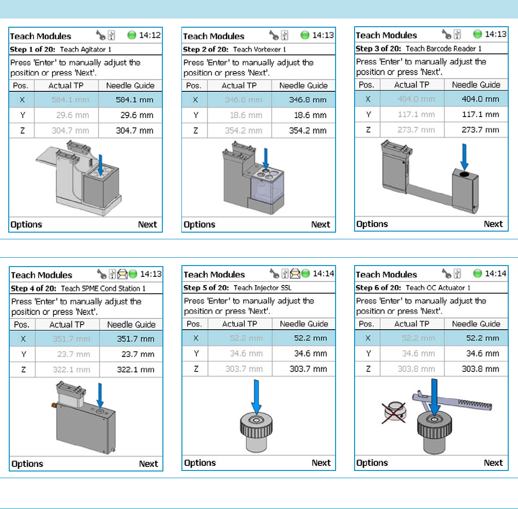
5 Service Menu Item
Installation Item
216 TriPlus RSH User Guide Thermo Scientific
The Teach position of each module is reported in Tab le 94 .
Table 94. Teach Modules Steps (Sheet 1 of 3)
Steps
Agitator Teaching Position Vortexer Teaching Position Barcode Reader Teaching Position
SPME Conditioning Station Teaching
Position
GC Injector Teaching Position OC Actuator Teaching Position
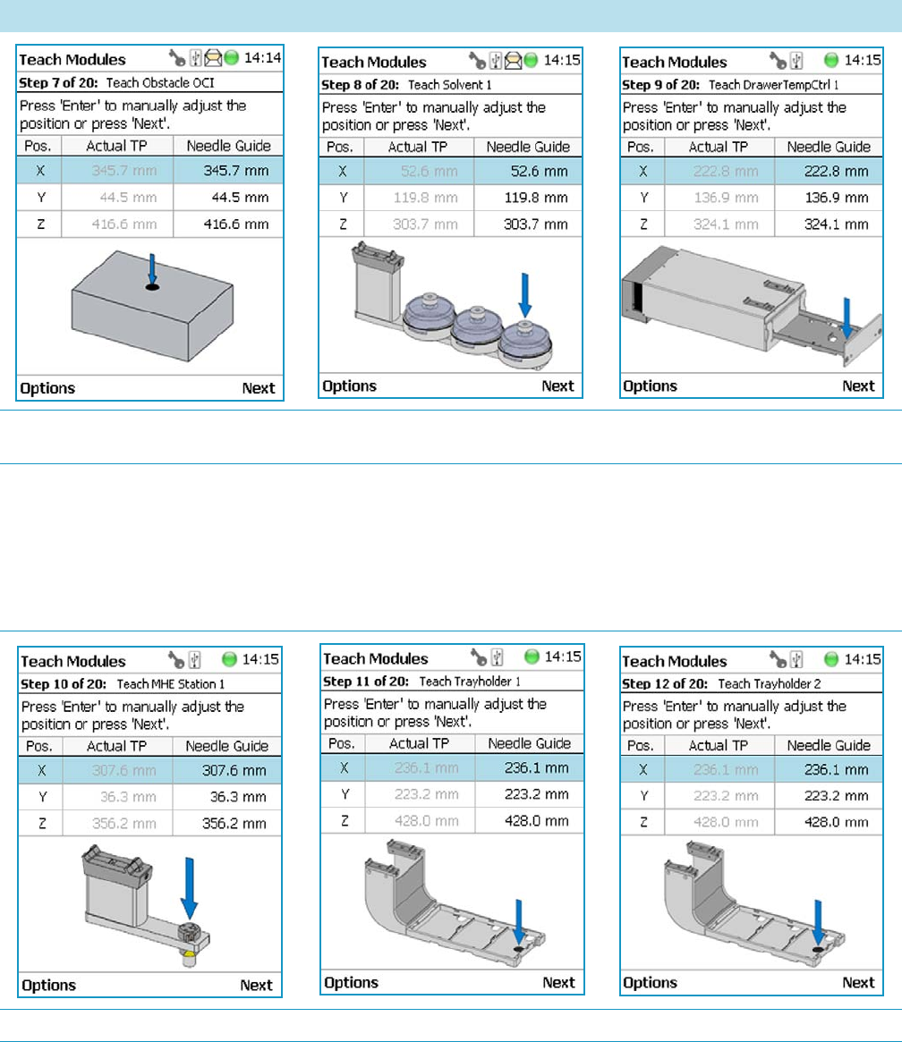
5 Service Menu Item
Installation Item
Thermo Scientific TriPlus RSH User Guide 217
Obstacle Teaching Position Large Solvent Station Teaching Position Temperature Controlled Drawer Stack
Teaching Position
Note Obstacle is a module from another
device, for example the Thermo Conductivity
Detector (TCD) from a GC system. If a module
exceed a certain height, it could be get in the
path way of the TriPlus RSH. The dimension
and the position of the obstacle can be
defined. The TriPlus RSH excludes this area
from the allowed path way and bypasses it.
MHE Station Teaching Position Tray Holder 1 Teaching Position Tray Holder 2 Teaching Position
Table 94. Teach Modules Steps (Sheet 2 of 3)
Steps
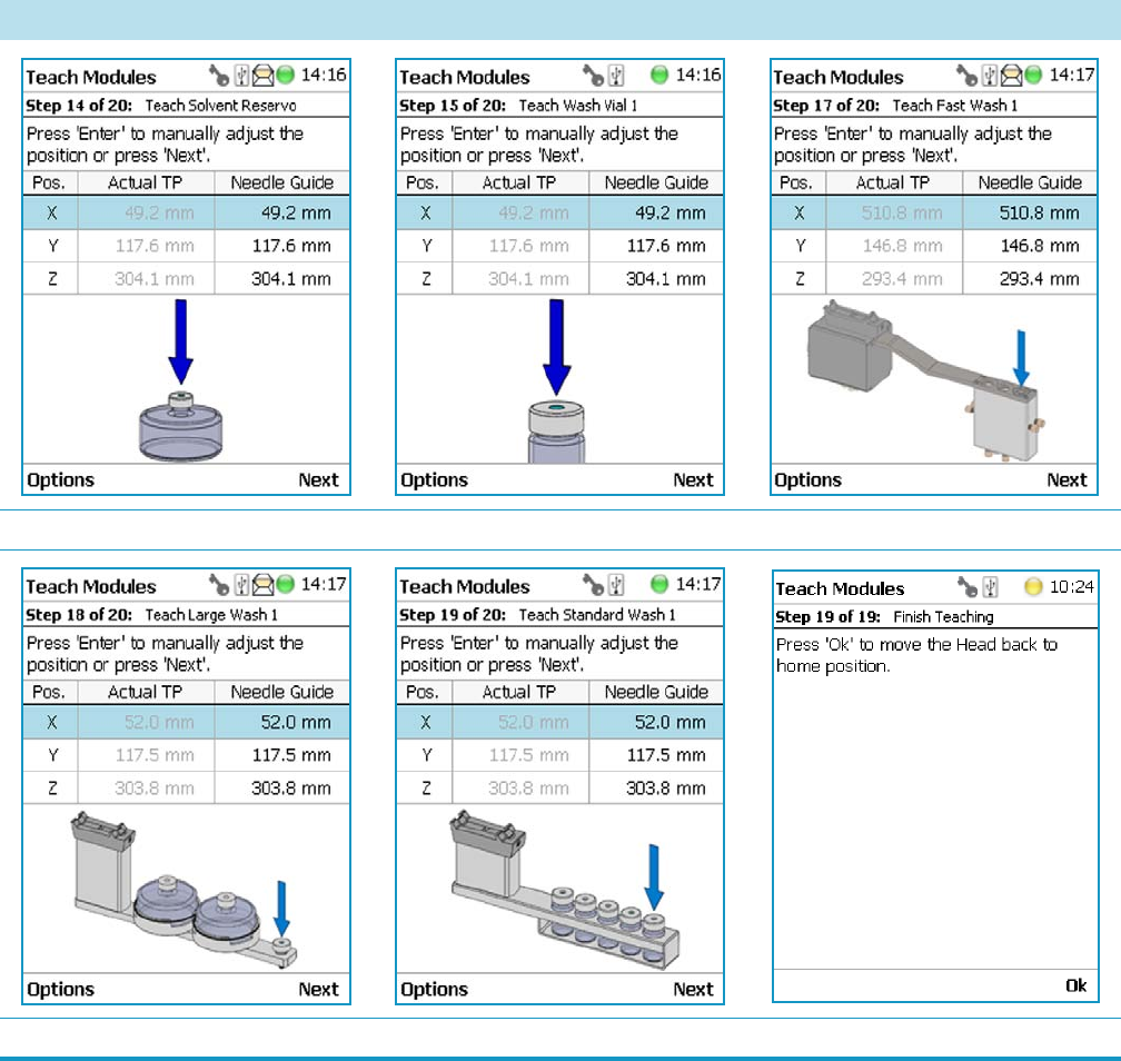
5 Service Menu Item
Installation Item
218 TriPlus RSH User Guide Thermo Scientific
Opening the pull-up menu Options will provide the list items specific to each module
The pull-up menu Previous moves one step back to the previous module and verifies the
teaching position again.
Check Teaching Modules
This section allows to check and verify the teaching positions of all the modules included into
the system.
Solvent Reservoir Teaching Position Wash Vial Teaching Position Fast Wash Station Teaching Position
Large Wash Station Teaching Position Standard Wash Station Teaching Position Teaching Position
Table 94. Teach Modules Steps (Sheet 3 of 3)
Steps
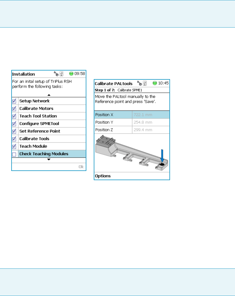
5 Service Menu Item
Installation Item
Thermo Scientific TriPlus RSH User Guide 219
To check the teaching modules
1. Select the wizard item Check Teaching Modules. See Figure 158.
Figure 158. Wizard Item Check Teaching Modules
2. Press Check to activate the wizard. The TriPlus RSH Head moves to the first module in
the list, positions itself at the Teaching Point, and waits for the next command. This gives
the operator the chance to verify the position, and if necessary make some fine tuning and
save the new settings.
3. Modules which have no direct access to the teaching point (lunette) such as the Agitator
or the Vortexer are treated the same way as it would for a routine run.
In other words, the cover of the Agitator is opened automatically or in combination with
the MHE Adapter it moves the TriPlus RSH Head to the side to stripe off the magnetic
adapter.
4. Press Next to continue within the wizard; the TriPlus RSH Head moves to the next
module.
5. The pull-up menu Previous moves one step back to the previous module and verifies the
teaching position again.
Note In this section a fine tuning is not foreseen. If a fine tuning is necessary, go either
back in the section “Teach Module” on page 214, or from the start screen activate the
pull-up menu Option, and select Setup | Modules.
Note It is mandatory to insert a vial into the Agitator or the Vortexer to teach the X-,Y-,
and Z-Axes positions. If the vial is not inserted, the Z-Axis value could be out of range,
resulting in an error.
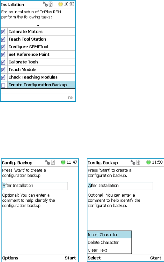
5 Service Menu Item
Installation Item
220 TriPlus RSH User Guide Thermo Scientific
Create a Backup File
It is highly recommended to backup the configuration of system after completing the
Installation wizard.
Backup, Restore, and Updates are explained in chapter Interfacing the TriPlus RSH to
Other Devices in the Tri Plu s RSH Hardware Manu al.
To create a configuration backup file
1. Select the wizard item Create Configuration Backup and follow the dialog. See
Figure 159.
Figure 159. Wizard Item Create a Backup File
2. The proposed name for the backup file is After Installation. The file is tagged with the
current date and time. The file name can be changed by the operator. Press the Enter
button to open the alphanumeric characters or use the pull-up menu Options to insert or
delete a character, see the examples in Figure 160.
Figure 160. Creating a Backup File
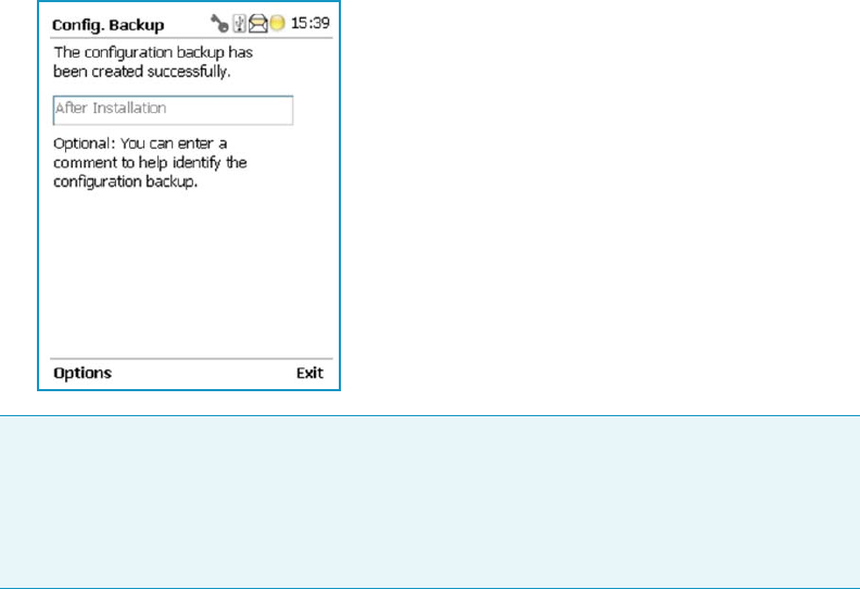
5 Service Menu Item
Installation Item
Thermo Scientific TriPlus RSH User Guide 221
3. After the file name definition, press Start to start the process. The blinking light indicates
that the process has been executed. The progress of the backup is updated to inform the
operator how many percent are completed.
4. This process only takes a few minutes. After completion, press Exit to finish the
installation wizard.
Note The Backup file is stored in the SD card, which is installed on the control board.
This file can be saved on the USB Stick, see the chapter “Setup Menu Item” on page 93.
The file can also be used to make a Restore of the Control Software. Please note this
option is only available with access level rights for the Extended User.
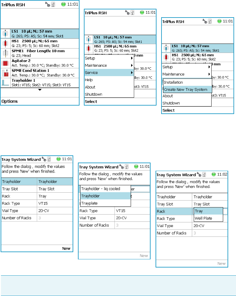
5 Service Menu Item
Create New Tray System Item
222 TriPlus RSH User Guide Thermo Scientific
Create New Tray System Item
Selecting the menu item Create New Tray System enables you to define a combined system
of a Tray Holder, Tray Type, and Vial Type. This task is mainly used if a custom specific Tray
Holder will be used.
To create a new tray system
1. Select the menu item Create New Tray System. See Figure 161.
Figure 161. Selecting Menu Item Create New Tray System
2. By opening the individual list items pre-selected parameters are available for use.
See Figure 162.
Figure 162. Tray Holder Choices
Note The Tray can be either a Tray or a Well Plate. Accordingly, the choices are
preselected for Tray Type or a Well Plate Type.

5 Service Menu Item
Create New Tray System Item
Thermo Scientific TriPlus RSH User Guide 223
3. Press New for creating the newly-defined Tray System, which is a complete setup of Tray
Holder, Tray, Tray Type, and Vial Type.
4. The wizard closes, and the software returns to the Start Screen.
Tab le 95 lists the create New Tray Type parameters.
Table 95. Create New Tray Type Parameters
Item Description
Tr a y Ho ld e r Tray Holder Liquid Holder (passive module).
Tr a y Sl o t Tray Slot, currently the only supported type.
Tr a y Tray, currently the only supported type.
Tr a y Ty p e Tray 15, Tray 54, Tray 32, Tray 60, Tray 70
See the section “Definition of Terms, Naming Conventions,
and Start Screen Icons” on page 3 for details.
Vial Type 1-CV, 2-CV, 10-CV, 20-CV Regular Vials.
2-SR, 10-SR. Vials combined with corresponding adapter,
reservoir.
Number of Racks Defines the numbers of sample trays that can be placed in
the Tray Holder.
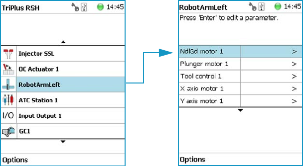
Teach Home Position
This task is not part of the Service | Installation wizard but it must be discussed with the user
during the installation process.
Access to this task by entering the module RobotArmLeft.
The Home Position is the position the head is moved to at the end of a task, for example
when it returns to standby. By default, this position is at the far left side of the X-Axis.
It is highly recommended to optimize this position according to the final configuration of
each system.
The Home Position optimization is performed for several reasons as:
• For convenience, in order to have the head in a preferred standby position.
• To save time minimizing the movement of the head to a module.
• For avoiding the collision of the head and a module.
Changing Home Position
To change a home position
There are two ways to get to the Menu item | Teach Home Position.
1. Use the short cut from the Start Screen with the menu item RobotArmLeft.
2. From the Start Screen select Option | Setup and continue with the modules. Several
additional clicks are required to access the menu item RobotArmLeft. See the following
example.
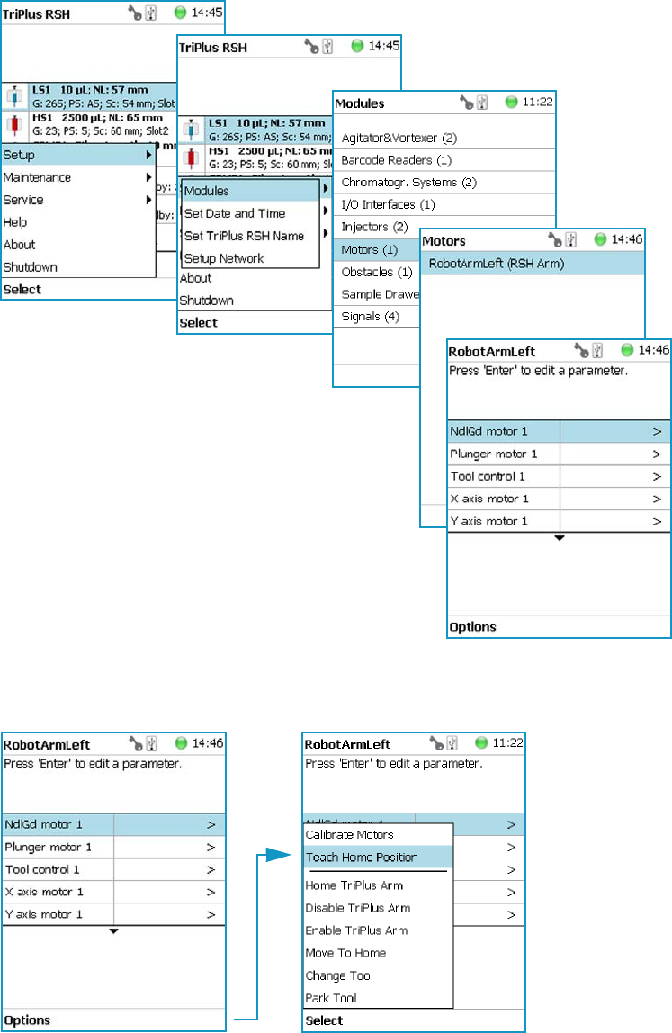
5 Service Menu Item
Teach Home Position
Thermo Scientific TriPlus RSH User Guide 225
3. Under the screen RobotArmLeft select the pull-up menu Options | Teach Home
Position | Select.
4. Move the head to the required position and save the X-, Y-, Z- Axes Positions as the new
Home Position. Press Ok to leave this wizard.
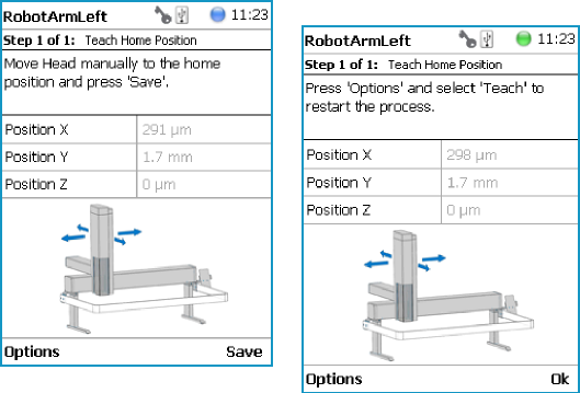
5 Service Menu Item
Teach Home Position
226 TriPlus RSH User Guide Thermo Scientific

Thermo Scientific TriPlus RSH User Guide 227
6
Analytical Troubleshooting
This chapter gives a quick overview of possible causes and recommended actions which can be
taken to eliminate an erratic behavior.
This guide does not replace the troubleshooting guides for chromatographic techniques.
Contents
•General Points Regarding Chromatographic Effects
•Headspace Technique Points Regarding Chromatographic Effects

6 Analytical Troubleshooting
General Points Regarding Chromatographic Effects
228 TriPlus RSH User Guide Thermo Scientific
General Points Regarding Chromatographic Effects
This sections provides general troubleshooting guidelines regarding the chromatographic
effects:
Table 96. General Points Regarding GC Effects - Troubleshooting Guideline (Sheet 1 of 3)
Symptom or Error Message Possible Cause Recommended Action
Very low or no detector signal is
observed.
Clogged syringe. Remove syringe and aspirate/dispense liquid
manually.
Clean syringe.
Bent syringe needle or bent plunger. Inspect the syringe. Replace it if necessary
Note: Bottom Sensing using a long needle
(85 mm) has a high risk of needle bending.
How to remove a syringe with a bent needle
or plunger is explained in the section
Manually Removing a TriPlus RSH Tool
from the RSH Head of the TriPlus RS H
Hardware Manual.
No sample liquid is injected. Check, adjust, the needle penetration into
sample vial.
Sample volume too low. Increase sample volume.
Wrong setting of syringe needle
penetration in GC injector.
Check Needle Penetration Depth settings
and compare with GC manufacturer
recommended parameters.
Syringe does not fill properly. Air bubbles below syringe plunger. It is
possible that air bubbles remain below
the plunger after the first pull-up. If
the plunger is moved up and down
several times, these air bubbles are
worked out.
Increase method parameter Def Fill Strokes
Count (Fill Strokes).
Check the method parameters Def Aspirate
(Fill Speed) and Def Aspirate Delay (Pull-up
Delay).
Wrong type of syringe assigned to tool
holder.
Check the syringe parameters to ensure that
the correct syringe type is assigned to the tool
holder. Verify the scale length parameter.
Syringe needle penetration depth in
vial incorrect.
Check the syringe needle penetration depth in
the sample vial.
Syringe plunger polymer tip worn out. Manually check the tightness of the polymer
plunger tip. When in doubt, replace the
plunger.
Glass barrel cracked. Check the integrity of the syringe. When in
doubt, replace the syringe.

6 Analytical Troubleshooting
General Points Regarding Chromatographic Effects
Thermo Scientific TriPlus RSH User Guide 229
Sample peaks/responses are not
reproducible.
Dirty syringe. Increase PstClnSlv1/Slv2 values in method.
Use PreClnSlv1/Slv2 and Pre Cln Spl.
Syringe pressure difference. Increase Def Aspirate Delay (Pull-up Delay)
value.
Vacuum created in sample vial. Reduce Sample volume in sample vial.
Use Pre Pressure Vial mode.
Highly volatile solvent. Use gas-tight syringe and sample tray cooling.
Improperly crimped vials. Check vial cap by attempting to rotate by
hand. Loose caps might cause selective loss of
volatile compounds from the sample. Adjust
crimping tool correctly.
Method Parameters. Check recommended Method Parameters.The
following parameters are crucial and must be
verified first:
•Def Aspirate Flow Rate (Fill Speed)
•Def Aspirate Delay (Pull-up Delay)
•Def Dispense Flow Rate (Injection
speed)
•Def Dispense Delay (Post Inj Delay)
Note that for dedicated cycles, certain
parameters are locked.
Excessive carryover between samples. Dirty syringe. Increase Pst InjSlv1/2 values in method.
Use PreClnSlv1/Slv2 and PrClnSpl.
Check and, if necessary, replace vial septa
from Wash/Waste vials.
Inappropriate wash solvent. Use appropriate wash solvent.
Wash Solvent and Waste vial septa too
tight.
Check if the syringe fills completely when
washing.
If several cleaning cycles are programmed and
many samples are processed, then vacuum in
the Wash Solvent vials and overpressure in the
Waste vials might build up.
Cut away a segment of the solvent and Waste
septa to ensure equalization of pressure.
Wash solvent level too low. Check the solvent volume in the Wash Vial
and the syringe needle penetration in the vial.
Solvent level in Waste vial to high. Check the volume of the solvent in the Waste
Vial. Check also the needle penetration into
the waste vial.
The needle must not touch the liquid at all.
Table 96. General Points Regarding GC Effects - Troubleshooting Guideline (Sheet 2 of 3)
Symptom or Error Message Possible Cause Recommended Action

6 Analytical Troubleshooting
Headspace Technique Points Regarding Chromatographic Effects
230 TriPlus RSH User Guide Thermo Scientific
Headspace Technique Points Regarding Chromatographic Effects
This sections provides general troubleshooting guidelines regarding the Headspace technique:
Unexplained collisions of Head. Object not defined correctly. Define Object correctly.
See Chapter 5 TriPlus RSH Defining Object
Positions in the TriPlus RSH Hardware
Manual.
Verify the position for all objects, including
passive and active modules.
Object missed by Syringe Needle. When several tools are used from a
ATC Station, have the tools calibrated
to compensate for any deviations.
Check the tool calibration as described in
Chapter 5 TriPlus RSH Defining Object
Positions in the TriPlus RSH Hardware
Manual.
Unexpected collision on Tray Holder. Wrong Vial Type settings in Tray Type. Check the settings in Tray Ty pe (Rack Type).
Table 96. General Points Regarding GC Effects - Troubleshooting Guideline (Sheet 3 of 3)
Symptom or Error Message Possible Cause Recommended Action
Table 97. Headspace Technique Points Regarding GC Effects - Troubleshooting Guideline (Sheet 1 of 2)
Symptom or Error Message Possible Cause Recommended Action
Sample peaks or responses are not
reproducible.
Dirty syringe. Increase method value Syr Purge.
Syringe pressure differences. Increase Def Aspirate Delay (Pull-up Delay)
value.
Vacuum created in sample vials. Reduce sample volume.
Improperly crimped vials. Check vial cap by attempting to rotate
manually. Loose caps might cause selective loss
of more volatile components from sample.
Adjust crimping tool correctly.
None or too low syringe purge gas
pressure.
Check pressure at purge gas regulator (0.5 bar;
7.25 psig; 50 kPa) during the syringe purging
period. Check gas flow at syringe needle tip.
Method parameters. Check recommended Method Parameters.
The following parameters are crucial and must
be verified first:
•Def Aspirate Flow Rate (Fill Speed)
•Def Aspirate Delay (Pull-up Delay)
•Def Dispense Flow Rate (Injection
speed)
•Def Dispense Delay (Post Inj Delay)

6 Analytical Troubleshooting
Headspace Technique Points Regarding Chromatographic Effects
Thermo Scientific TriPlus RSH User Guide 231
Sample peaks or responses are not
reproducible (continued)
Back pressure of GC column too high. Check the back pressure of the GC column.
If the pressure is too high the electronic flow
control device (EPC or EFC) of the GC could
get in overload at the moment of sample
injection. This will lead to uncontrolled
opening of the split valve until the pressure
falls back into a controllable range.
Peak distortion or tailing. Method Parameters. See recommended previous actions.
Needle penetration speed in GC
Injector.
Check the parameter for injection technique.
If all changes give no positive result, check the
Injector Depenetration Speed.
Solvent not suitable for application. Check the boiling point of the solvent and try
to change the solvent (when e.g. a high boiling
point organic solvent is used as matrix).
GC Injector liner not suitable. Check the liner geometry.
GC related parameters. Any parameter such as the injector, oven or
detector temperature can contribute to bad
peak shape. Check the column type and
connections (square cut connections).
Excessive carry-over between samples. Dirty syringe. Increase method value Syr Purge.
Set the value of the method parameter Syringe
Temp 10 °C above the Agitator temperature,
Incubation Temp.
None or too low Syringe Purge gas
pressure.
Check pressure at purge gas regulator (0.5 bar;
7.25 psig; 50 kPa) during Syringe Purge
period.
Check gas purge flow at syringe needle tip.
Unexplained chromatographic peaks. Dirty purge gas. Check the purge gas supply for impurities.
Faulty temperature
read-out.
e.g. value: -99 °C.
HS-syringe cartridge (holder)
temperature heater, over temperature
fuse or sensor broken.
Agitator temperature heater, over
temperature fuse or sensor broken.
SPME Fiber Conditioning Module
temperature heater or sensor broken.
ITEX syringe cartridge (holder)
temperature heater, over
temperature fuse or sensor broken.
ITEX Trap temperature heater or
sensor broken.
Contact your Thermo Fisher Scientific
representative.
Table 97. Headspace Technique Points Regarding GC Effects - Troubleshooting Guideline (Sheet 2 of 2)
Symptom or Error Message Possible Cause Recommended Action
