TriPlus 300 HS 31709671 Tri Plus User Guide
2016-05-17
: Pdf 31709671 Triplus 300 Hs User Guide 31709671 TriPlus 300 HS User Guide TriPlus 300 HS GC AS Manuals User ation
Open the PDF directly: View PDF ![]() .
.
Page Count: 134 [warning: Documents this large are best viewed by clicking the View PDF Link!]
- Contents
- Preface
- Getting Familiar with Your TriPlus 300 Headspace Sampling System
- Introduction
- Definition of Terms
- The TriPlus 300 Headspace Sampling System
- Main Unit
- Autosampler Unit
- Pneumatics
- Analytical Cycle
- Installation Notes
- Who Performs the Installation
- Standard Outfit
- Electrical Requirements
- Environmental Conditions
- Lift and Place the TriPlus 300 Headspace Sampling System
- Assembling the TriPlus 300 Headspace Sampling System
- Pneumatic Supply
- Plumbing the Connection to Gas Chromatograph
- Making the Electrical Connections
- Making the Power Connections
- Powering On the TriPlus 300 Headspace
- Setting the Communications
- Leak Test
- Usage Notes
- TriPlus 300 Headspace User Interface
- Operation
- Maintenance, Parts Replacement, and Diagnostic
- Upgrade Equipment

Thermo Scientific
TriPlus 300 Headspace
Sampling System
User Guide
P/N 317 09671 Revision C December 2015
© 2015 Thermo Fisher Scientific Inc. All rights reserved.
TriPlus 300 Headspace, TRACE 1300, TRACE 1310, ISQ Series, TSQ 8000, ITQ, and DSQ II are
trademarks of Thermo Fisher Scientific Inc., and its subsidiaries.
Published by Thermo Fisher Scientific S.p.A., Strada Rivoltana 20090 Rodano-Milan, Italy
Tel: +39 02 95059303; Fax: +39 02 95059388
Thermo Fisher Scientific Inc. provides this document to its customers with a product purchase to use in the
product operation. This document is copyright protected and any reproduction of the whole or any part of this
document is strictly prohibited, except with the written authorization of Thermo Fisher Scientific Inc.
The contents of this document are subject to change without notice. All technical information in this
document is for reference purposes only. System configurations and specifications in this document supersede
all previous information received by the purchaser.
Thermo Fisher Scientific Inc. makes no representations that this document is complete, accurate or error-
free and assumes no responsibility and will not be liable for any errors, omissions, damage or loss that might
result from any use of this document, even if the information in the document is followed properly.
This document is not part of any sales contract between Thermo Fisher Scientific Inc. and a purchaser. This
document shall in no way govern or modify any Terms and Conditions of Sale, which Terms and Conditions of
Sale shall govern all conflicting information between the two documents.
Release history:
First edition, released April 2013 “Original Instructions”
Second edition, released March 2015; Third Edition, December 2015
For Research Use Only. Not for use in diagnostic procedures.

fold
fold
Reader’s Survey
TriPlus 300 Headspace User Guide, PN 31709671, Third Edition
If not, please comment below. Attach additional sheets if necessary.
__________________________________________________________ __________________________________________________________________
__________________________________________________________ __________________________________________________________________
__________________________________________________________ __________________________________________________________________
__________________________________________________________ __________________________________________________________________
__________________________________________________________ __________________________________________________________________
__________________________________________________________ __________________________________________________________________
__________________________________________________________ __________________________________________________________________
__________________________________________________________ __________________________________________________________________
__________________________________________________________ __________________________________________________________________
Customer Registration Card
Register now…and receive all the privileges associated with being a Thermo Fisher Scientific product user including customer
support, application reports, and technical reports.
Name __________________________________________________Title__________________________________________________________________
Company __________________________________________________ __________________________________________________________________
Address ___________________________________________________ __________________________________________________________________
City/State _________________________________________Postal Code__________________________________________________________________
Country ___________________________________________________ __________________________________________________________________
Telephone_______________________________________________ Ext. __________________________________________________________________
Serial Number __________________________________ Date purchased __________________________________________________________________
Fold and mail or e-mail to:
Strongly
Agree Agree Neutral Disagree Strongly
Disagree
The manual is well organized. 1 2 3 4 5
The manual is clearly written. 1 2 3 4 5
The manual contains all the information I need. 1 2 3 4 5
The instructions are easy to follow. 1 2 3 4 5
The instructions are complete. 1 2 3 4 5
The technical information is easy to understand. 1 2 3 4 5
Examples of operation are clear and useful. 1 2 3 4 5
The figures are helpful. 1 2 3 4 5
I was able to operate the system using this manual. 1 2 3 4 5
MY ORGANIZATION IS: (Check only one) MY PRIMARY APPLICATION IS: (Check only one)
❏Commercial (for profit) lab ❏Analytical
❏Government lab ❏Biomedical
❏Hospital/Clinic ❏Clinical/Toxicology
❏Industrial lab ❏Energy
❏Research Institute ❏Environmental
❏University/College ❏Food/Agricultural
❏Veterinary ❏Forensic/Toxicology
❏Other______________________ ❏Pharmaceutical
❏Research/Education
MY PRIMARY JOB FUNCTION IS: (Check only one) ❏Other______________________
❏Administration
❏Lab management
❏Operator
❏Other______________________
Editor, Technical Publications
Thermo Fisher Scientific S.p.A.
Strada Rivoltana km 4
20090 Rodano (MI)
Italy
Editor, Technical Publications
Thermo Fisher Scientific CMD GC-GC/MS
2215 Grand Avenue Parkway
Austin TX 78728-3812
Unites States of America

Declaration
Manufacturer: Thermo Fisher Scientific
Thermo Fisher Scientific is the manufacturer of the instrument described in this manual and, as such, is responsible
for the instrument safety, reliability and performance only if:
•installation
•re-calibration
•changes and repairs
have been carried out by authorized personnel and if:
• the local installation complies with local law regulations
• the instrument is used according to the instructions provided and if its operation is only entrusted to qualified
trained personnel
Thermo Fisher Scientific is not liable for any damages derived from the non-compliance with the aforementioned
recommendations.
Thermo Fisher Scientific S.p.A.
Strada Rivoltana, 20090 Rodano - Milan - Italy — Tel: +39 02 950591 - Fax: +39 02 9505276
Regulatory Compliance
Thermo Fisher Scientific performs complete testing and evaluation of its products to ensure full compliance with
applicable domestic and international regulations.
Thermo Fisher Scientific declares, under sole responsibility, that the product as originally delivered complies with
the requirements of the following applicable European Directives and carries the CE marking accordingly:
Low Voltage Directive:2006/95/EC
• EMC Directive:2004/108/EC
… and conforms with the following product standards:
Safety
This device complies with>
• EN 61010-1:2001 2nd Edition
• IEC 61010-1:2001 2nd Edition
• CAN/CSA –c22.2 No. 61010.1–04
• UL Std. No 61010-1 2nd Edition
Electromagnetic Compatibility
This device complies with:
• EN 61326-1:2006, EN 55011: 2009, Class A Group 1
• IEC 61326-1:2005, CISPR 11:2009, Class A Group 1
FCC Compliance Statement
Thermo Fisher Scientific hereby declares that our product has been tested and complies with the requirements of
Title 47 Telecommunication FCC Part 15 (2007), Class A Digital Device.
Notice on Lifting and Handling of
Thermo Scientific Instruments
For your safety, and in compliance with international regulations, the physical handling of this Thermo Fisher
Scientific instrument requires a team effort to lift and/or move the instrument. This instrument is too heavy and/
or bulky for one person alone to handle safely.
Notice on the Proper Use of
Thermo Scientific Instruments
In compliance with international regulations: Use of this instrument in a manner not specified by Thermo Fisher
Scientific could impair any protection provided by the instrument.
Notice on the Susceptibility
to Electromagnetic Transmissions
Do not use radio frequency transmitters, such as mobile phones, in close proximity to the instrument.
THIS DEVICE COMPLIES WITH PART 15 OF THE FCC RULES. OPERATION IS SUBJECT TO
THE FOLLOWING TWO CONDITIONS: (1) THIS DEVICE MAY NOT CAUSE HARMFUL
INTERFERENCE, AND (2) THIS DEVICE MUST ACCEPT ANY INTERFERENCE RECEIVED,
INCLUDING INTERFERENCE THAT MAY CAUSE UNDESIRED OPERATION.
CAUTION Read and understand the various precautionary notes, signs, and symbols contained
inside this manual pertaining to the safe use and operation of this product before using the device.
WEEE Compliance
This product is required to comply with the European Union’s Waste Electrical & Electronic Equipment (WEEE) Directive
2012/19/EU. It is marked with the following symbol:
Thermo Fisher Scientific has contracted with one or more recycling or disposal companies in each European Union (EU)
Member State, and these companies should dispose of or recycle this product. See www.thermoscientific.com/rohsweee for
further information on Thermo Fisher Scientific’s compliance with these Directives and the recyclers in your country.
WEEE Konformität
Dieses Produkt muss die EU Waste Electrical & Electronic Equipment (WEEE) Richtlinie 2012/19/EU erfüllen. Das Produkt
ist durch folgendes Symbol gekennzeichnet:
Thermo Fisher Scientific hat Vereinbarungen mit Verwertungs-/Entsorgungsfirmen in allen EU-Mitgliedsstaaten getroffen,
damit dieses Produkt durch diese Firmen wiederverwertet oder entsorgt werden kann. Mehr Information über die Einhaltung
dieser Anweisungen durch Thermo Fisher Scientific, über die Verwerter, und weitere Hinweise, die nützlich sind, um die
Produkte zu identifizieren, die unter diese RoHS Anweisung fallen, finden sie unter www.thermoscientific.com/rohsweee.
Conformité DEEE
Ce produit doit être conforme à la directive européenne (2012/19/EU) des Déchets d'Equipements Electriques et
Electroniques (DEEE). Il est marqué par le symbole suivant:
Thermo Fisher Scientific s'est associé avec une ou plusieurs compagnies de recyclage dans chaque état membre de l’union
européenne et ce produit devrait être collecté ou recyclé par celles-ci. Davantage d'informations sur la conformité de Thermo
Fisher Scientific à ces directives, les recycleurs dans votre pays et les informations sur les produits Thermo Fisher Scientific qui
peuvent aider la détection des substances sujettes à la directive RoHS sont disponibles sur www.thermoscientific.com/rohsweee.
Conformità RAEE
Questo prodotto è marcato con il seguente simbolo in conformità alla direttiva europea 2012/19/EU (RAEE) sui rifiuti di
apparecchiature elettriche ed elettroniche:
Thermo Fisher Scientific si è accordata con una o più società di riciclaggio in ciascun Stato Membro della Unione Europea
(EU), e queste società dovranno smaltire o riciclare questo prodotto. Per maggiori informazioni vedere il sito
www.thermoscientific.com/rohsweee.
Conformidad RAEE
Este producto es marcado con el siguiente símbolo en conformidad a la Directiva 2012/19/EU de la Unión Europea sobre los
residuos de aparatos eléctricos y electrónicos:
Thermo Fisher Scientific ha contratado una o más empresas de reciclo para tratar residuos en cada Estado Miembro de la
Unión Europea, y estas empresas deberían reciclar o eliminar este producto. Referirse a www.thermoscientific.com/rohsweee
para una mayor información sobre la conformidad de Thermo Fisher Scientific con estas Directivas y para las empresas de
reciclaje en su país.
IMPORTANT
The symbol indicates the product must not be disposed of with the normal household wastes. Correct disposal of
this product prevents any potentially negative impact on the environmental and human health that could arise
from any inappropriate handling of the product itself.
WEEE and RoHS rules, while laid down at European level, are put into national law at national level. When ex-
porting to Europe, it is essential to comply with national law in each relevant country. The EU law simply serves
as a template for national laws, which may differ considerably.
Each EU Member State has own regulations regarding the application of these directives. Please refer to the
regulations in force in your country.

Thermo Scientific TriPlus 300 Headspace User Guide ix
C
Preface . . . . . . . . . . . . . . . . . . . . . . . . . . . . . . . . . . . . . . . . . . . . . . . . . . . . . . . . . . . . .xiii
About Your System. . . . . . . . . . . . . . . . . . . . . . . . . . . . . . . . . . . . . . . . . . . . . .xiv
Power Rating . . . . . . . . . . . . . . . . . . . . . . . . . . . . . . . . . . . . . . . . . . . . . . . . . .xiv
Contacting Us . . . . . . . . . . . . . . . . . . . . . . . . . . . . . . . . . . . . . . . . . . . . . . . . .xiv
Related Documentation . . . . . . . . . . . . . . . . . . . . . . . . . . . . . . . . . . . . . . . . . .xiv
Safety Alerts and Important Information . . . . . . . . . . . . . . . . . . . . . . . . . . . . . xv
Special Notices . . . . . . . . . . . . . . . . . . . . . . . . . . . . . . . . . . . . . . . . . . . . . . . xv
Safety Symbols and Signal Words . . . . . . . . . . . . . . . . . . . . . . . . . . . . . . . . . xv
Instrument Markings and Symbols . . . . . . . . . . . . . . . . . . . . . . . . . . . . . . . . . xvii
Safety Information and Warnings. . . . . . . . . . . . . . . . . . . . . . . . . . . . . . . . . .xviii
General Considerations . . . . . . . . . . . . . . . . . . . . . . . . . . . . . . . . . . . . . . . .xviii
Electrical Hazards . . . . . . . . . . . . . . . . . . . . . . . . . . . . . . . . . . . . . . . . . . . . .xix
Other Hazards. . . . . . . . . . . . . . . . . . . . . . . . . . . . . . . . . . . . . . . . . . . . . . . . xx
Working with Toxic or other Harmful Compounds . . . . . . . . . . . . . . . . . . .xxi
Biological Hazard Warning Note. . . . . . . . . . . . . . . . . . . . . . . . . . . . . . . . . xxii
Maintenance . . . . . . . . . . . . . . . . . . . . . . . . . . . . . . . . . . . . . . . . . . . . . . . . xxii
Disposal. . . . . . . . . . . . . . . . . . . . . . . . . . . . . . . . . . . . . . . . . . . . . . . . . . . .xxiii
Chapter 1 Getting Familiar with Your TriPlus 300 Headspace Sampling System . . . . . . . . .1
Introduction . . . . . . . . . . . . . . . . . . . . . . . . . . . . . . . . . . . . . . . . . . . . . . . . . . . . 2
Definition of Terms . . . . . . . . . . . . . . . . . . . . . . . . . . . . . . . . . . . . . . . . . . . . . . 2
The TriPlus 300 Headspace Sampling System. . . . . . . . . . . . . . . . . . . . . . . . . . . 3
Main Unit . . . . . . . . . . . . . . . . . . . . . . . . . . . . . . . . . . . . . . . . . . . . . . . . . . . . . . 3
Oven . . . . . . . . . . . . . . . . . . . . . . . . . . . . . . . . . . . . . . . . . . . . . . . . . . . . . . . . 5
Sampling System . . . . . . . . . . . . . . . . . . . . . . . . . . . . . . . . . . . . . . . . . . . . . . . 5
Pneumatic Interface. . . . . . . . . . . . . . . . . . . . . . . . . . . . . . . . . . . . . . . . . . . . . 6
Electrical Interface. . . . . . . . . . . . . . . . . . . . . . . . . . . . . . . . . . . . . . . . . . . . . . 7
Touch screen . . . . . . . . . . . . . . . . . . . . . . . . . . . . . . . . . . . . . . . . . . . . . . . . . . 8
Autosampler Unit . . . . . . . . . . . . . . . . . . . . . . . . . . . . . . . . . . . . . . . . . . . . . . . . 9
Pneumatics . . . . . . . . . . . . . . . . . . . . . . . . . . . . . . . . . . . . . . . . . . . . . . . . . . . . 11
Contents
Contents
x TriPlus 300 Headspace User Guide Thermo Scientific
Analytical Cycle. . . . . . . . . . . . . . . . . . . . . . . . . . . . . . . . . . . . . . . . . . . . . . . . . 12
Standby . . . . . . . . . . . . . . . . . . . . . . . . . . . . . . . . . . . . . . . . . . . . . . . . . . . . . 12
Equilibration . . . . . . . . . . . . . . . . . . . . . . . . . . . . . . . . . . . . . . . . . . . . . . . . . 13
Pressurization . . . . . . . . . . . . . . . . . . . . . . . . . . . . . . . . . . . . . . . . . . . . . . . . 13
Loop Fill . . . . . . . . . . . . . . . . . . . . . . . . . . . . . . . . . . . . . . . . . . . . . . . . . . . . 14
Injection . . . . . . . . . . . . . . . . . . . . . . . . . . . . . . . . . . . . . . . . . . . . . . . . . . . . 15
Vial Venting . . . . . . . . . . . . . . . . . . . . . . . . . . . . . . . . . . . . . . . . . . . . . . . . . 16
Purging . . . . . . . . . . . . . . . . . . . . . . . . . . . . . . . . . . . . . . . . . . . . . . . . . . . . . 17
Installation Notes . . . . . . . . . . . . . . . . . . . . . . . . . . . . . . . . . . . . . . . . . . . . . . . 18
Who Performs the Installation. . . . . . . . . . . . . . . . . . . . . . . . . . . . . . . . . . . . 18
Standard Outfit. . . . . . . . . . . . . . . . . . . . . . . . . . . . . . . . . . . . . . . . . . . . . . . 18
Electrical Requirements . . . . . . . . . . . . . . . . . . . . . . . . . . . . . . . . . . . . . . . . . 18
Environmental Conditions . . . . . . . . . . . . . . . . . . . . . . . . . . . . . . . . . . . . . . 18
Lift and Place the TriPlus 300 Headspace Sampling System . . . . . . . . . . . . . 19
Assembling the TriPlus 300 Headspace Sampling System . . . . . . . . . . . . . . . 19
Pneumatic Supply . . . . . . . . . . . . . . . . . . . . . . . . . . . . . . . . . . . . . . . . . . . . . 19
Plumbing the Connection to Gas Chromatograph . . . . . . . . . . . . . . . . . . . . 20
Making the Electrical Connections . . . . . . . . . . . . . . . . . . . . . . . . . . . . . . . . 22
Making the Power Connections . . . . . . . . . . . . . . . . . . . . . . . . . . . . . . . . . . 23
Powering On the TriPlus 300 Headspace . . . . . . . . . . . . . . . . . . . . . . . . . . . 23
Setting the Communications . . . . . . . . . . . . . . . . . . . . . . . . . . . . . . . . . . . . . 24
Leak Test . . . . . . . . . . . . . . . . . . . . . . . . . . . . . . . . . . . . . . . . . . . . . . . . . . . 27
Usage Notes . . . . . . . . . . . . . . . . . . . . . . . . . . . . . . . . . . . . . . . . . . . . . . . . . . . 27
Temperatures . . . . . . . . . . . . . . . . . . . . . . . . . . . . . . . . . . . . . . . . . . . . . . . . 28
Carrier Gas Optimization . . . . . . . . . . . . . . . . . . . . . . . . . . . . . . . . . . . . . . . 28
Auxiliary Gas Pressure Optimization . . . . . . . . . . . . . . . . . . . . . . . . . . . . . . . 29
Equilibration Time Conditioning . . . . . . . . . . . . . . . . . . . . . . . . . . . . . . . . . 29
Shaking Conditioning . . . . . . . . . . . . . . . . . . . . . . . . . . . . . . . . . . . . . . . . . . 29
Sample Vials Size . . . . . . . . . . . . . . . . . . . . . . . . . . . . . . . . . . . . . . . . . . . . . 29
Missing and Wrong Size Vials . . . . . . . . . . . . . . . . . . . . . . . . . . . . . . . . . . . 30
Sample Vial Septa . . . . . . . . . . . . . . . . . . . . . . . . . . . . . . . . . . . . . . . . . . . . . 30
Vial Closure . . . . . . . . . . . . . . . . . . . . . . . . . . . . . . . . . . . . . . . . . . . . . . . . . 30
Matrix Effects . . . . . . . . . . . . . . . . . . . . . . . . . . . . . . . . . . . . . . . . . . . . . . . . 31
Chapter 2 TriPlus 300 Headspace User Interface . . . . . . . . . . . . . . . . . . . . . . . . . . . . . . . . . . .33
TriPlus 300 Headspace User Interface Overview . . . . . . . . . . . . . . . . . . . . . . . 34
Status Bar . . . . . . . . . . . . . . . . . . . . . . . . . . . . . . . . . . . . . . . . . . . . . . . . . . . . . 36
Menu . . . . . . . . . . . . . . . . . . . . . . . . . . . . . . . . . . . . . . . . . . . . . . . . . . . . . . 36
Status . . . . . . . . . . . . . . . . . . . . . . . . . . . . . . . . . . . . . . . . . . . . . . . . . . . . . . 37
Time Clock and Date . . . . . . . . . . . . . . . . . . . . . . . . . . . . . . . . . . . . . . . . . . 40
Desktop. . . . . . . . . . . . . . . . . . . . . . . . . . . . . . . . . . . . . . . . . . . . . . . . . . . . . . . 41
Tool Bar . . . . . . . . . . . . . . . . . . . . . . . . . . . . . . . . . . . . . . . . . . . . . . . . . . . . . . 42
Contents
Thermo Scientific TriPlus 300 Headspace User Guide xi
Device Status and Ready Conditions. . . . . . . . . . . . . . . . . . . . . . . . . . . . . . . . . 43
Temperature Tab . . . . . . . . . . . . . . . . . . . . . . . . . . . . . . . . . . . . . . . . . . . . . 44
Press/Flow Tab . . . . . . . . . . . . . . . . . . . . . . . . . . . . . . . . . . . . . . . . . . . . . . . 45
Instrument Status . . . . . . . . . . . . . . . . . . . . . . . . . . . . . . . . . . . . . . . . . . . . . 45
Chapter 3 Operation . . . . . . . . . . . . . . . . . . . . . . . . . . . . . . . . . . . . . . . . . . . . . . . . . . . . . . . . . . . .47
Control of Analysis . . . . . . . . . . . . . . . . . . . . . . . . . . . . . . . . . . . . . . . . . . . . . . 48
Start of analysis . . . . . . . . . . . . . . . . . . . . . . . . . . . . . . . . . . . . . . . . . . . . . . . 48
End of analysis . . . . . . . . . . . . . . . . . . . . . . . . . . . . . . . . . . . . . . . . . . . . . . . 48
Cycle . . . . . . . . . . . . . . . . . . . . . . . . . . . . . . . . . . . . . . . . . . . . . . . . . . . . . . . . . 49
Temperature . . . . . . . . . . . . . . . . . . . . . . . . . . . . . . . . . . . . . . . . . . . . . . . . . 51
Equilibration . . . . . . . . . . . . . . . . . . . . . . . . . . . . . . . . . . . . . . . . . . . . . . . . . 52
Pressurization . . . . . . . . . . . . . . . . . . . . . . . . . . . . . . . . . . . . . . . . . . . . . . . . 53
Loop Fill . . . . . . . . . . . . . . . . . . . . . . . . . . . . . . . . . . . . . . . . . . . . . . . . . . . . 54
Injection . . . . . . . . . . . . . . . . . . . . . . . . . . . . . . . . . . . . . . . . . . . . . . . . . . . . 54
Others . . . . . . . . . . . . . . . . . . . . . . . . . . . . . . . . . . . . . . . . . . . . . . . . . . . . . 56
Summary. . . . . . . . . . . . . . . . . . . . . . . . . . . . . . . . . . . . . . . . . . . . . . . . . . . . 57
Method . . . . . . . . . . . . . . . . . . . . . . . . . . . . . . . . . . . . . . . . . . . . . . . . . . . . . . . 59
Sequence . . . . . . . . . . . . . . . . . . . . . . . . . . . . . . . . . . . . . . . . . . . . . . . . . . . . . 61
Creating a Sequence . . . . . . . . . . . . . . . . . . . . . . . . . . . . . . . . . . . . . . . . . . . 62
Changing Method Parameters During Run . . . . . . . . . . . . . . . . . . . . . . . . . 63
Changing Sequence Parameters During Run . . . . . . . . . . . . . . . . . . . . . . . . 64
Priority Sequence . . . . . . . . . . . . . . . . . . . . . . . . . . . . . . . . . . . . . . . . . . . . . 64
Sequence Interrupted. . . . . . . . . . . . . . . . . . . . . . . . . . . . . . . . . . . . . . . . . . . 65
Changing Autosampler Parameters During a Run . . . . . . . . . . . . . . . . . . . . . 65
Timed Events . . . . . . . . . . . . . . . . . . . . . . . . . . . . . . . . . . . . . . . . . . . . . . . . . . 66
Clock Time Events . . . . . . . . . . . . . . . . . . . . . . . . . . . . . . . . . . . . . . . . . . . . 66
Method Actions. . . . . . . . . . . . . . . . . . . . . . . . . . . . . . . . . . . . . . . . . . . . . . . . . 69
Available Actions . . . . . . . . . . . . . . . . . . . . . . . . . . . . . . . . . . . . . . . . . . . . . . 70
Method Developing Optimization (MDO). . . . . . . . . . . . . . . . . . . . . . . . . . . . 72
MDO Parameters . . . . . . . . . . . . . . . . . . . . . . . . . . . . . . . . . . . . . . . . . . . . . 72
Options. . . . . . . . . . . . . . . . . . . . . . . . . . . . . . . . . . . . . . . . . . . . . . . . . . . . . . . 73
Gases Tab . . . . . . . . . . . . . . . . . . . . . . . . . . . . . . . . . . . . . . . . . . . . . . . . . . . 74
Com Tab. . . . . . . . . . . . . . . . . . . . . . . . . . . . . . . . . . . . . . . . . . . . . . . . . . . . 74
Others Tab . . . . . . . . . . . . . . . . . . . . . . . . . . . . . . . . . . . . . . . . . . . . . . . . . . 76
Gas & Energy Saving Tab . . . . . . . . . . . . . . . . . . . . . . . . . . . . . . . . . . . . . . . 77
Setup. . . . . . . . . . . . . . . . . . . . . . . . . . . . . . . . . . . . . . . . . . . . . . . . . . . . . . . . . 77
AS Tab . . . . . . . . . . . . . . . . . . . . . . . . . . . . . . . . . . . . . . . . . . . . . . . . . . . . . 79
Remote Tab. . . . . . . . . . . . . . . . . . . . . . . . . . . . . . . . . . . . . . . . . . . . . . . . . . 79
Others Tab . . . . . . . . . . . . . . . . . . . . . . . . . . . . . . . . . . . . . . . . . . . . . . . . . . 80
Carrier Tab . . . . . . . . . . . . . . . . . . . . . . . . . . . . . . . . . . . . . . . . . . . . . . . . . . 80
Contents
xii TriPlus 300 Headspace User Guide Thermo Scientific
Chapter 4 Maintenance, Parts Replacement, and Diagnostic . . . . . . . . . . . . . . . . . . . . . . . .81
Maintenance . . . . . . . . . . . . . . . . . . . . . . . . . . . . . . . . . . . . . . . . . . . . . . . . . . . 82
Load/Unload Tab . . . . . . . . . . . . . . . . . . . . . . . . . . . . . . . . . . . . . . . . . . . . . 83
Temperature Tab . . . . . . . . . . . . . . . . . . . . . . . . . . . . . . . . . . . . . . . . . . . . . 83
Valves Tab. . . . . . . . . . . . . . . . . . . . . . . . . . . . . . . . . . . . . . . . . . . . . . . . . . . 84
Gases Tab . . . . . . . . . . . . . . . . . . . . . . . . . . . . . . . . . . . . . . . . . . . . . . . . . . . 84
Movements Tab . . . . . . . . . . . . . . . . . . . . . . . . . . . . . . . . . . . . . . . . . . . . . . 85
FW Update Tab . . . . . . . . . . . . . . . . . . . . . . . . . . . . . . . . . . . . . . . . . . . . . . 85
Calibration . . . . . . . . . . . . . . . . . . . . . . . . . . . . . . . . . . . . . . . . . . . . . . . . . . . . 86
Touch Screen Calibration . . . . . . . . . . . . . . . . . . . . . . . . . . . . . . . . . . . . . . . 87
Diagnostic . . . . . . . . . . . . . . . . . . . . . . . . . . . . . . . . . . . . . . . . . . . . . . . . . . . . . 88
Hardware . . . . . . . . . . . . . . . . . . . . . . . . . . . . . . . . . . . . . . . . . . . . . . . . . . . 88
Alarms. . . . . . . . . . . . . . . . . . . . . . . . . . . . . . . . . . . . . . . . . . . . . . . . . . . . . . 89
Lock/Unlock Page . . . . . . . . . . . . . . . . . . . . . . . . . . . . . . . . . . . . . . . . . . . . . . . 92
External Cleaning of the TriPlus 300 Headspace Instrument . . . . . . . . . . . . . . 93
Replacing the Transfer Line Needle . . . . . . . . . . . . . . . . . . . . . . . . . . . . . . . . . 93
Replacing the Sampling Needle . . . . . . . . . . . . . . . . . . . . . . . . . . . . . . . . . . . . 94
Handling Precautions . . . . . . . . . . . . . . . . . . . . . . . . . . . . . . . . . . . . . . . . . . . . 94
Installing the HS Adapter Kit on the SSL/SSLBKF Injector . . . . . . . . . . . . . . . 95
Chapter 5 Upgrade Equipment. . . . . . . . . . . . . . . . . . . . . . . . . . . . . . . . . . . . . . . . . . . . . . . . . . .105
Chiller. . . . . . . . . . . . . . . . . . . . . . . . . . . . . . . . . . . . . . . . . . . . . . . . . . . . . . . 105
Barcode Reader . . . . . . . . . . . . . . . . . . . . . . . . . . . . . . . . . . . . . . . . . . . . . . . . 107
About the Barcode Reader . . . . . . . . . . . . . . . . . . . . . . . . . . . . . . . . . . . . . . 107
Barcode Reader Description . . . . . . . . . . . . . . . . . . . . . . . . . . . . . . . . . . . . 108
User Information . . . . . . . . . . . . . . . . . . . . . . . . . . . . . . . . . . . . . . . . . . . . 108
Label Positioning . . . . . . . . . . . . . . . . . . . . . . . . . . . . . . . . . . . . . . . . . . . . 109

Thermo Scientific TriPlus 300 Headspace User Guide xiii
P
Preface
This manual describes the features and the components of the TriPlus 300 Headspace
sampling system. Inside, you will find all the informations necessary for the routine
operations of your sampling system. This includes operating procedures, sample injection
techniques, diagrams, and the description of the major components.
This User Guide is intended for frequent or new TriPlus 300 Headspace sampling system
users who are experienced at using automated systems to run existing analytical methods.
This manual is organized as follows:
•Chapter 1, “Getting Familiar with Your TriPlus 300 Headspace Sampling System,”
provides informations to familiarize you with the TriPlus 300 Headspace sampling
system.
•Chapter 2, “TriPlus 300 Headspace User Interface,” describes the user interface of your
TriPlus 300 Headspace sampling system.
•Chapter 3, “Operation,” provides the instructions for operating with your TriPlus 300
Headspace sampling system.
•Chapter 4, “Maintenance, Parts Replacement, and Diagnostic,” provides instructions for
maintaining your TriPlus 300 Headspace sampling system.
•Chapter 5, “Upgrade Equipment,” describes how to install the upgraded equipment that
is available for the TriPlus 300 Headspace sampling system.
Note The TriPlus 300 Headspace sampling system must be installed and set up properly
before the Operating Instructions can be used.
Preface
About Your System
xiv TriPlus 300 Headspace User Guide Thermo Scientific
About Your System
Thermo Fisher Scientific systems operate safely and reliably under carefully controlled
environmental conditions. If the equipment is used in a manner not specified by the
manufacturer, the protections provided by the equipment might be impaired. If you maintain
a system outside the specifications listed in this guide, failures of many types, including
personal injury or death, might occur. The repair of instrument failures caused by operation
in a manner not specified by the manufacturer is specifically excluded from the Standard
Warranty and service contract coverage.
Power Rating
Main Unit
• 100-120/200-240 Vac ±10% max; 60 Hz; 1300 VA.
• 100-115/200-230 Vac ±10% max; 50 Hz; 1300 VA.
Autosampler Unit
• 24 Vdc through a portable external power supply
Electrical characteristics of the supply
−input 85-264 Vac; 47/63 Hz
−output 12 Vdc; 24 VA
Detailed instrument specifications are in the Product Specification or Product Brochure.
Contacting Us
Thermo Fisher Scientific provides comprehensive technical assistance worldwide and is
dedicated to the quality of our customer relationships and services.
Use http://www.thermoscientific.com address for products information.address for products
information.
Use http://www.gc-gcms-customersupport.com/WebPage/Share/Default.aspx address to
contact your local Thermo Fisher Scientific office, or affiliate GC-GC/MS Customer
Support.
Related Documentation
In addition to this guide, Thermo Scientific provides the following documents for the TriPlus
300 Headspace sampling system.
Preface
Safety Alerts and Important Information
Thermo Scientific TriPlus 300 Headspace User Guide xv
•TriPlus 300 Headspace Preinstallation Requirements Guide, PN 31709672
•TriPlus 300 Headspace User Guide, PN 31709671
To suggest ways we can improve the documentation, follow this link to complete our
documentation survey.
Safety Alerts and Important Information
Make sure you follow the precautionary notices presented in this manual. The safety and
other special notices appear in boxes.
Special Notices
Notices includes the following:
Safety Symbols and Signal Words
All safety symbols are followed by WARNING or CAUTION, which indicates the degree of risk
for personal injury, instrument damage, or both. Cautions and warnings are following by a
descriptor, such as BURN HAZARD. A WARNING is intended to prevent improper actions that
could cause personal injury. Whereas, a CAUTION is intended to prevent improper actions
that might cause personal injury, instrument damage, or both. You can find the following
safety symbols on your instrument, or in this guide:
IMPORTANT Highlights information necessary to prevent damage to software, loss of
data, or invalid test results; or might contain information that is critical for optimal
performance of the system.
Note Emphasizes important information about a task.
Tip Helpful information that can make a task easier.
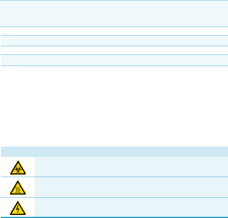
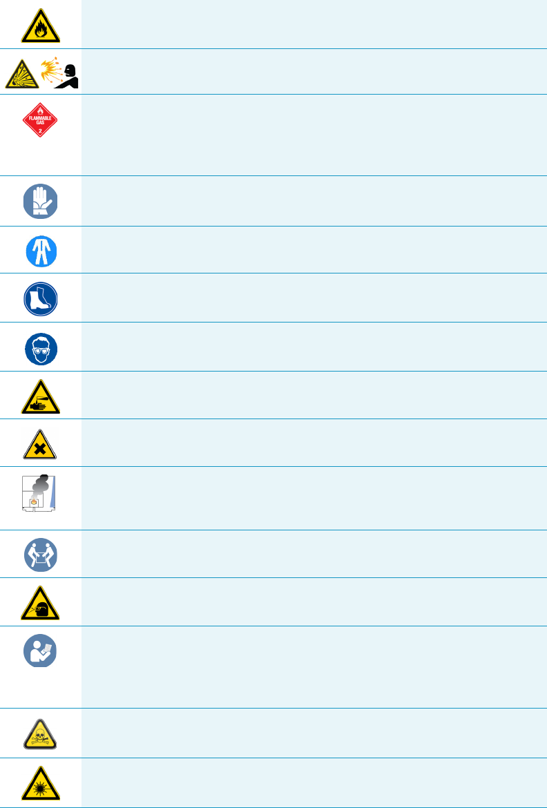
Symbol Descriptor
BIOHAZARD: Indicates that a biohazard will, could, or might occur.
BURN HAZARD: Alerts you to the presence of a hot surface that could or might
cause burn injuries.
ELECTRICAL SHOCK HAZARD: Indicates that an electrical shock could or
might occur.
Preface
Safety Alerts and Important Information
xvi TriPlus 300 Headspace User Guide Thermo Scientific
FIRE HAZARD: Indicates a risk of fire or flammability could or might occur.
EXPLOSION HAZARD. Indicates an explosion hazard. This symbol indicates
this risk could or might cause physical injury.
FLAMMABLE GAS HAZARD. Alerts you to gases that are compressed,
liquefied or dissolved under pressure and can ignite on contact with an
ignition source. This symbol indicates this risk could or might cause physical
injury.
GLOVES REQUIRED: Indicates that you must wear gloves when performing a
task or physical injury could or might occur.
CLOTHING REQUIRED. Indicates that you should wear a work clothing when
performing a task or else physical injury could or might occur.
BOOTS REQUIRED. Indicates that you must wear boots when performing a
task or else physical injury could or might occur.
MATERIAL AND EYE HAZARD. Indicates you must wear eye protection when
performing a task.
HAND AND CHEMICAL HAZARD: Indicates that chemical damage or physical
injury could or might occur.
HARMFUL. Indicates that the presence of harmful material will, could, or
might occur.
INSTRUMENT DAMAGE: Indicates that damage to the instrument or
component might occur. This damage might not be covered under the
standard warranty.
LIFTING HAZARD. Indicates that a physical injury could or might occur if two
or more people do not lift an object.
MATERIAL AND EYE HAZARD: Indicates that eye damage could or might
occur.
READ MANUAL: Alerts you to carefully read your instrument’s
documentation to ensure your safety and the instrument’s operational ability.
Failing to carefully read the documentation could or might put you at risk for a
physical injury.
TOXIC SUBSTANCES HAZARD: Indicates that exposure to a toxic substance
could occur and that exposure could or might cause personal injury or death.
LASER HAZARD. Indicates that exposure to a laser beam will, could, or might
cause personal injury.
Preface
Instrument Markings and Symbols
Thermo Scientific TriPlus 300 Headspace User Guide xvii
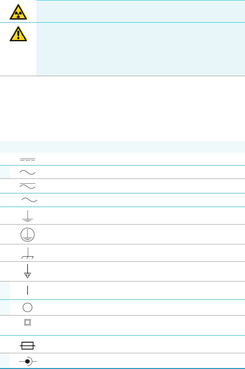
Instrument Markings and Symbols
Tab le 1 explains the symbols used on Thermo Fisher Scientific instruments. Only a few of
them are used on the TriPlus 300 Headspace sampling system. See the asterisk.
RADIOACTIVE HAZARD. Indicates that the presence of radioactive material
could or might occur.
For the prevention of personal injury, this general warning symbol precedes
the WARNING safety alert word and meets the ISO 3864-2 standard. In the
vocabulary of ANSI Z535 signs, this symbol indicates a possible personal
injury hazard exists if the instrument is improperly used or if unsafe actions
occur. This symbol and another appropriate safety symbol alerts you to an
imminent or potential hazard that could cause personal injury.
Table 1. Instrument Marking and Symbols (Sheet 1 of 2)
Symbol Description
Direct Current
*Alternating Current
Both direct and alternating current
Three-phase alternating current
Earth (ground) terminal
Protective conductor terminal
Frame or chassis terminal
Equipotentiality
*On (Supply)
*Off (Supply)
Equipment protected throughout by DOUBLE INSULATION or
REINFORCED INSULATION (Equivalent to Class II of IEC 536)
Fuse
*Jack socket
3
+-
Preface
Safety Information and Warnings
xviii TriPlus 300 Headspace User Guide Thermo Scientific
Safety Information and Warnings
The purpose of this safety guide is to make users aware of potential safety issues and general
concerns for Thermo Fisher Scientific representatives during installation, and repair of the
TriPlus 300 Headspace sampling system, or parts of it (following the life-cycle principle), as
well as for the end user TriPlus 300 Headspace sampling system in the lab during the learning
phase and in routine work.
General Considerations
• Before using your system, consult the TriPlus 300 Headspace User Guide and related
documents under all circumstances.
• Changes or modifications to this unit not expressly approved by the party responsible for
compliance, could void your’s authority to operate the equipment.
• Be aware that if the equipment is used in a manner not specified by the manufacturer, the
protective and safety features of the equipment might be impaired.
• The repair of instrument failures caused by operation in a manner not specified by the
manufacturer is expressly excluded from the standard warranty and service contract
coverage.
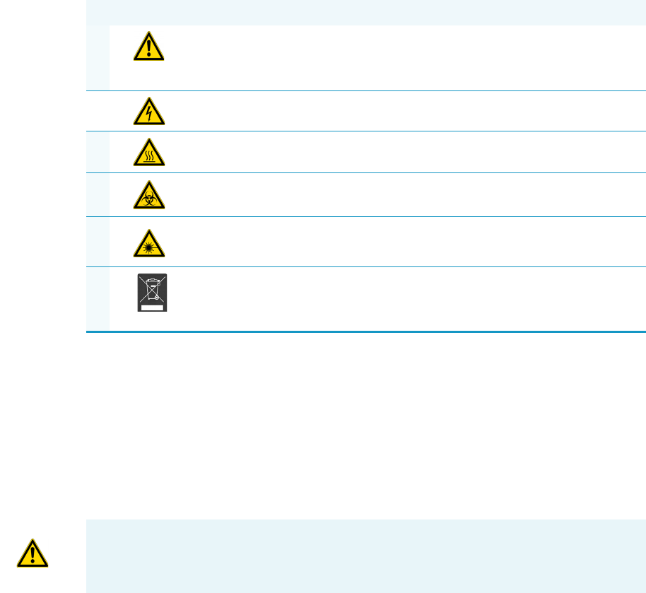
*Instruction manual symbol affixed to product. Indicates that the you must
refer to the manual for specific WARNING or CAUTION information to
avoid personal injury or damage to the product.
Caution, risk of electric shock
*Caution, hot surface
*Caution, biohazard
*Caution, Laser beam
*Symbol in compliance to the Directive 2012/19/EU on Waste Electrical
and Electronic Equipment (WEEE) placed on the European market after
August, 13, 2005.
Table 1. Instrument Marking and Symbols (Sheet 2 of 2)
Symbol Description
IMPORTANT Read this section first before operating the TriPlus 300 Headspace sampling
system.

Preface
Safety Information and Warnings
Thermo Scientific TriPlus 300 Headspace User Guide xix
• When for technical reasons it is necessary to work on instrument parts which might
involve a potential hazard (moving parts, components under voltage, and others) contact
Thermo Fisher Scientific authorized representative. In general, this type of situation arises
when access to the parts is only possible using a tool. When you perform a maintenance
operation, you must have received proper training to carry out that specific task.
Electrical Hazards
Every analytical instrument has specific hazards. Be sure to read and comply with the
following pre-cautions. They ensure the safe and long-term use of your TriPlus 300
Headspace sampling system. The installation over-voltage category is Level II. The Level II
category pertains to equipment receiving its electrical power locally, such as from an electrical
wall outlet.
Connect the TriPlus 300 Headspace sampling system only to instruments complying with
IEC 61010 safety regulations.
The power line and the connections between the TriPlus 300 Headspace sampling system and
other instruments, used in the configuration setup of the total analytical system, must
maintain good electrical grounding.
Poor grounding represents a danger to the operator, and might seriously affect the
performance of the instrument.
Do not connect the TriPlus 300 Headspace sampling system to power lines that supply
devices of a heavy duty nature, such as motors, refrigerators, and other devices that can
generate electrical disturbances.
Use only fuses of the type and current rating specified. Do not use repaired fuses, and do not
short-circuit the fuse holder. The supplied power cord must be inserted into a power outlet
with a protective earth (ground) contact.
When using an extension cord, ensure that the cord also has an earth contact.
If the supplied power cord does not fit the local electrical socket and a replacement or adapter
must be purchased locally, ensure that only a certified power cord is used. Any power cord
used must be certified by the appropriate local authorities.
Pay attention not to leave any cables connecting the TriPlus 300 Headspace sampling system
and the chromatographic system, or the power cord close to heated zone, such as the injector
or detector heating blocks, or the GC hot air vents.
Always replace any cable showing signs of damage with another one provided by the
manufacturer. Safety regulations must be respected.
Do not change the external or internal grounding connections. Tampering with or
disconnecting these connections could endanger you and damage the TriPlus 300 Headspace
sampling system. The instrument is properly grounded in accordance with these regulations
when shipped. To ensure safe operation, do not make any changes to the electrical
connections or the instrument's chassis.

Preface
Safety Information and Warnings
xx TriPlus 300 Headspace User Guide Thermo Scientific
Do not turn the instrument on if you suspect that it has incurred any type of electrical
damage. Instead, disconnect the power cord and contact a Thermo Fisher Scientific
representative for a product evaluation. Do not attempt to use the instrument until it has been
evaluated. Electrical damage might have occurred if the TriPlus 300 Headspace sampling
system shows visible signs of damage, exposure to any liquids or has been transported under
severe stress.
Damage can also result if the instrument is stored for prolonged periods under unfavorable
conditions: for example, subjected to heat, moisture, and so on. Ensure that the power
supply/controller unit is always placed in a clean and dry position. Avoid any liquid spills in
the vicinity.
Before attempting any type of maintenance work, always disconnect the power cords from the
power supply if optional devices are installed. Capacitors inside the instrument might still be
charged if the instrument is turned off.
To avoid damaging electrical parts, do not disconnect an electrical assembly while power is
supplied to the TriPlus 300 Headspace sampling system. After the power is turned off, wait
approximately 30 seconds before you disconnect an assembly.
The instrument includes a number of integrated circuits. These circuits might be damaged if
exposed to excessive line voltage fluctuations, power surges or electrostatic charges, or both.
Never try to repair or replace any components of the instrument without the assistance of a
Thermo Fisher Scientific representative. There are no operator-serviceable or replaceable parts
inside the TriPlus 300 Headspace sampling system. If a instrument is not functioning, contact
a Thermo Fisher Scientific representative.
The power supplies for the TriPlus 300 Headspace sampling system have the symbols I/O to
indicate ON/OFF. It is important that the power ON/OFF switch is accessible and easy to
operate, and where it is possible to unplug the AC power cord from the power supply/wall
outlet in case of emergency.
Other Hazards
There is danger of crushing to fingers and hands. To avoid injury keep your hands away from
moving parts during operation.
Turn off the power to the TriPlus 300 Headspace sampling system if you must reach inside a
mechanically powered system with moving parts.
To avoid injury, observe safe laboratory practice when handling solvents, changing tubing, or
operating the TriPlus 300 Headspace sampling system. Know the physical and chemical
properties of the solvents you use.
See the MSDS (Material Safety Data Sheets) from the manufacturer of the solvents being
used.
When using the TriPlus 300 Headspace sampling system, follow the generally accepted
procedures for quality control and method development.

Preface
Safety Information and Warnings
Thermo Scientific TriPlus 300 Headspace User Guide xxi
When using the TriPlus 300 Headspace sampling system in the field of chromatographic
analysis, if a change is observed in the retention time of a particular compound, in the
resolution between two compounds, or in the peak shape, immediately determine the reasons
for the changes. Do not rely on the separation results until you determine the cause of a
change.
Do not operate on the instrument components that form part of the work area of the TriPlus
300 Headspace sampling system when it is in motion.
Do not use vials without a sealing cap. Vapor phase from organic solvents can be hazardous
and flammable. Acidic vapor phase can cause corrosion to critical mechanical parts.
When sample vials have to undergo heating and agitation, it is important to consider the glass
quality. Use high quality glass only. Remember that depending on the application conditions,
high pressure can build up in the vial. Whenever a temperature greater than 60 °C is applied,
consider the vapor pressure of the solvent used to ensure that no excessive pressure builds up.
This is important when using temperatures above 100°C and especially at the maximum
temperature of 300 °C. Be aware that solid materials can also contain volatile compounds
such as water (humidity) that may cause build-up of excess vapor pressure.
Do not reuse headspace vials. During the process of washing the vial, micro-cracks can form
which will weaken the glass wall and increase the chances of the vial breaking.
Working with Toxic or other Harmful Compounds
The TriPlus 300 Headspace sampling system requires the use of several chemical products
with different hazard characteristics, which are present in vials and syringes. Before using these
substances or replacing the syringe, please read the hazard indications and information
reported in the MSDS supplied by the manufacturer referring to the relevant CAS number.
When preparing the samples, please refer to local regulations for the ventilation conditions of
the work room.
All waste materials must be collected and eliminated in compliance with the local regulations
and directives in the country where the instrument is used.
WARNING Before using hazardous substances (toxic, harmful, and so on), please read the
hazard indications and information reported in the applicable Material Safety Data Sheet
(MSDS). Use personal protective equipment according to the safety requirements.

Preface
Safety Information and Warnings
xxii TriPlus 300 Headspace User Guide Thermo Scientific
Biological Hazard Warning Note
In laboratories where samples with potential biological hazards are handled, the user must
label any equipment or parts which might become contaminated with biohazardous material.
The appropriate warning labels are included with the shipment of the instrument. It is the
user’s responsibility to label the relevant parts of the equipment.
When working with biohazardous materials, you are responsible for fulfilling the following
mandatory requirements:
• Providing instructions on how to safely handle biohazardous material.
• Training operators to be aware of potential hazards.
• Providing personal protective equipment.
• Providing instructions for what to do if operators are exposed to aerosols or vapors during
normal operation (within the intended use of the equipment) or in case of single fault
situations such as a broken vial. The protective measures must consider potential contact
with the skin, mouth, nose (respiratory organs), and eyes.
• Providing instructions for decontamination and safe disposal of relevant parts.
Maintenance
Any external cleaning or maintenance must be performed with the TriPlus 300 Headspace
sampling system turned off and the power cord disconnected. Avoid using solvents and sprays
on electrical parts. For removal of potentially dangerous substances (toxic, harmful, and
others) read the hazard indications and information reported in the MSDS (Material Safety
Data Sheet) supplied by the manufacturer referring to the relevant CAS (Chemical Abstract
Service) number. Use proper protective gloves.
When working with hazardous materials such as radioactive, biologically hazardous material,
and so on, it is important to train all operators how to respond in case of spills or
contamination.
Depending on the class of hazardous material, the appropriate measure have to be taken
immediately. Therefore, the chemicals or solvents needed for decontamination must be on
hand.
Any parts of the equipment which can potentially be contaminated, such as the sample vial
rack, syringe tool, wash module, and others, must be cleaned regularly. The waste solvent
from cleaning and any hardware that must be disposed must be properly eliminated with all
the necessary precautions, abiding by national and international regulations.

Preface
Safety Information and Warnings
Thermo Scientific TriPlus 300 Headspace User Guide xxiii
When preparing for decontamination, ensure that the solvent or chemical to be used will not
damage or react with the surface, or dye (color) of the instrument, table or other nearby
objects. If in doubt, please contact your Thermo Fisher Scientific representative to verify the
compatibility of the type or composition of solvents with the TriPlus 300 Headspace sampling
system.
Disposal
Do not dispose of this equipment or parts thereof unsorted in municipal waste. Follow local
municipal waste regulations for proper disposal provisions to reduce the environmental
impact of waste electrical and electronic equipment (WEEE).
European Union customers: Call your local customer service representative responsible for the
TriPlus 300 Headspace sampling system for complimentary equipment pick-up and recycling.
WARNING The customer must ensure that the TriPlus 300 Headspace sampling system
has not been contaminated by any hazardous chemical or biological compounds including
(but not limited to) bacteria or viruses.
Any part which had direct contact with the analytical sample must be identified and must
undergo the appropriate decontamination procedure prior to shipping for disposal.
The customer and the service engineer are fully responsible for enforcing these
requirements. Thermo Fisher Scientific will hold the representative, customer, or both
responsible, if these regulations are not observed.

Thermo Scientific TriPlus 300 Headspace User Guide 1
1
Getting Familiar with Your TriPlus 300 Headspace
Sampling System
This chapter provides informations to familiarize with the TriPlus 300 Headspace sampling
system.
Contents
•Introduction
•Definition of Terms
•The TriPlus 300 Headspace Sampling System
•Main Unit
•Autosampler Unit
•Pneumatics
•Analytical Cycle
•Installation Notes
•Usage Notes
1 Getting Familiar with Your TriPlus 300 Headspace Sampling System
Introduction
2 TriPlus 300 Headspace User Guide Thermo Scientific
Introduction
The TriPlus 300 Headspace sampling system is an automatic sampler for headspace gas
chromatographic analysis in order to determine the concentration of volatile compounds in a
liquid or solid matrices. The TriPlus 300 Headspace sampling system is able to automatically
sample up to 120 samples (60 with the optional sample tray).
In the headspace technique the samples are placed in tightly closed vials.
Each vial is heated, and the volatile compounds are transferred from the solid or liquid sample
into the gaseous phase above it, the so-called headspace, until a condition of thermodynamic
equilibrium is reached.
Afterwards, an aliquot of headspace is withdrawn and injected into the gas chromatograph.
The trend of a volatile compound to transfer into the headspace is expressed by the partition
coefficient K. The coefficient depends on the compound solubility in the matrix, and it is
strongly affected by the temperature and the composition of the matrix itself.
The TriPlus 300 Headspace sampling system automatically performs all the analytical phases
from the equilibration to sampling and transfer to the GC with high repeatability.
The analytical times are optimized according to the set parameters, such as equilibration time
and analytical time, in order to fully exploit the instrument’s capability.
Besides a sampling technique, the headspace technique is also an extraction and concentration
technique. It offers the advantages of a reduced manipulation of the sample, a higher
sensitivity than the direct injection, and a longer lifetime of chromatographic columns since
only the volatile fraction is injected into the column.
It can be easily connected and synchronized to any gas chromatograph for an automatic and
reliable management of the entire analytical system.
Definition of Terms
This section defines the terms used in this guide:
•TriPlus 300 Headspace — The brand name for the entire sampling system product
family. The product family includes the Main Unit and the Autosampler Unit.
•Main Unit — Term referring to the part of the TriPlus 300 Headspace sampling system
that includes oven, sampling system, and interfaces.
•Autosampler — Term referring to the Autosampler Unit of the TriPlus 300 Headspace
sampling system.
1 Getting Familiar with Your TriPlus 300 Headspace Sampling System
The TriPlus 300 Headspace Sampling System
Thermo Scientific TriPlus 300 Headspace User Guide 3
The TriPlus 300 Headspace Sampling System
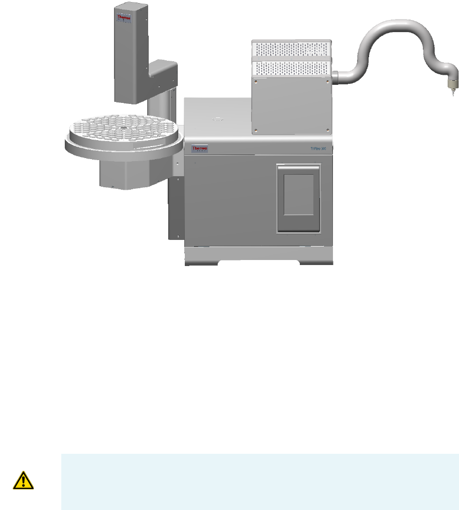
The TriPlus 300 Headspace sampling system consists of two parts: Main Unit and
Autosampler Unit. See Figure 1.
Figure 1. TriPlus 300 Headspace Sampling System
See the related topics:
•“Main Unit” on page 3
•“Autosampler Unit” on page 9
Main Unit
The the Main Unit includes the following components: oven, sampling system, pneumatic
interface, electrical interface, and touch screen. See Figure 2.
Main Unit
Autosampler Unit
CAUTION The oven is located inside the Main Unit and can accessible by opening the top
cover of the Main Unit through the two lateral push-buttons.
Open the top cover ONLY if necessary for maintenance or service.
1 Getting Familiar with Your TriPlus 300 Headspace Sampling System
Main Unit
4 TriPlus 300 Headspace User Guide Thermo Scientific
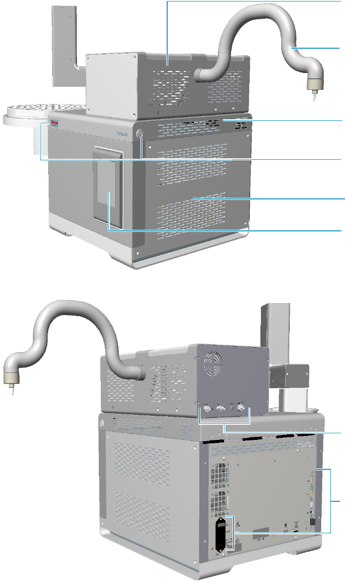
Figure 2. Main Unit: Front and Back View
Sampling
system
Transfer
line tube
Top cover
Top cover
push buttons
Oven
Touch
screen
Pneumatic
interface
Electrical
interface
1 Getting Familiar with Your TriPlus 300 Headspace Sampling System
Main Unit
Thermo Scientific TriPlus 300 Headspace User Guide 5
See the related topics:
•“Oven” on page 5
•“Sampling System” on page 5
•“Pneumatic Interface” on page 6
•“Electrical Interface” on page 7
•“Touch screen” on page 8
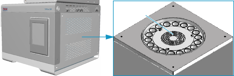
Oven
The oven contains an 18-seat rotating carousel for the vial housing and equilibration.
See Figure 3.
Figure 3. Oven and Carousel
A circular resistance heats up the oven from ambient +5 °C to 300 °C, and a fan provides a
constant and uniform temperature.
Vials are automatically inserted into the carousel and can be shaken in slow, medium, or high
mode during the equilibration phase through a back and forth movement of the carousel.
Two motor-driven levers lift the vials out of the carousel for the sampling when they are
placed in correspondence with the sampling needle, or for their recovery when they are placed
under the inlet/outlet hole of the oven.
The carousel and the lifters can be moved manually by using the commands in the Movement
page of the Maintenance section of the software. See “Maintenance” on page 82.
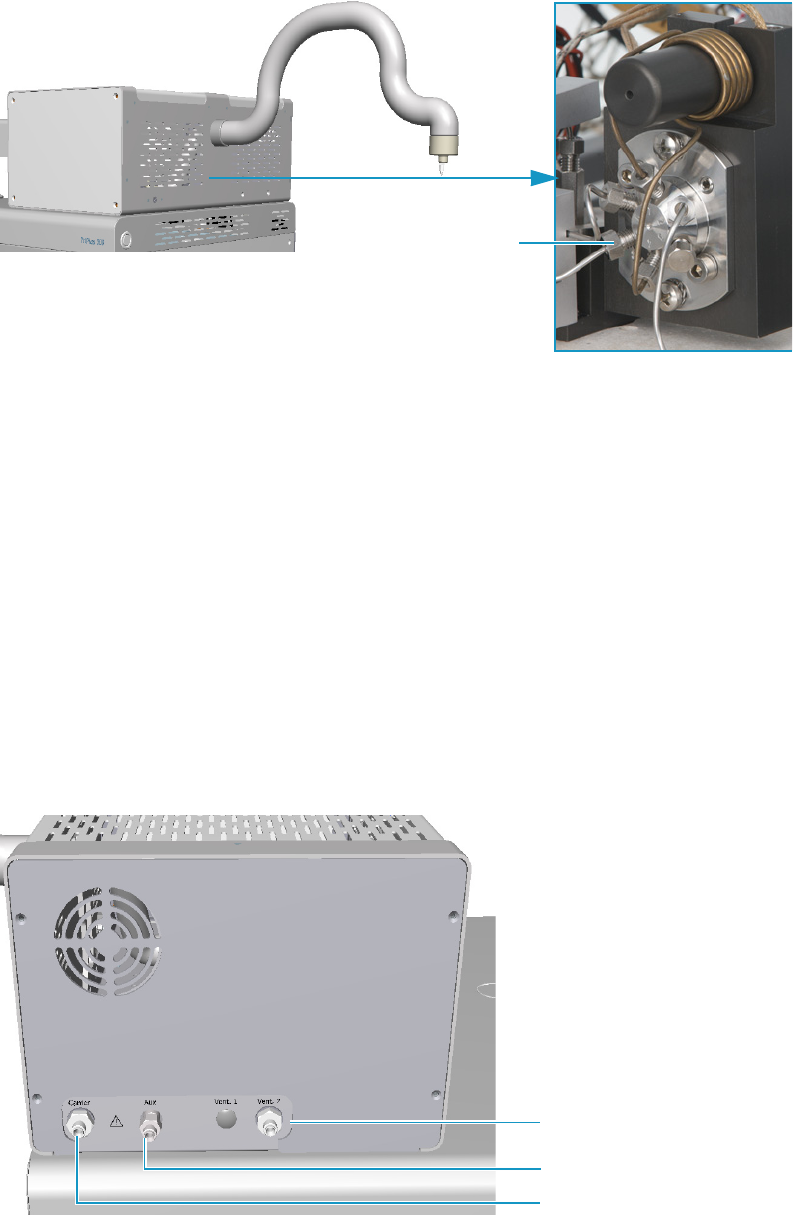
Sampling System
The sampling system consists of an electrically actuated 6-port switching valve equipped with
a stainless steel coated loop. See Figure 4.
Oven
Carousel
1 Getting Familiar with Your TriPlus 300 Headspace Sampling System
Main Unit
6 TriPlus 300 Headspace User Guide Thermo Scientific
Figure 4. Sampling System
The standard volume of the loop is 1.0 mL. Three optional loops with a volume of 0.5 mL,
3.0 mL, and 5.0 mL are available. The transfer of gas from the headspace sampler to the GC is
carried out through a heated transfer line tube, which is a 1.0 mm i.d., 80 cm long stainless
steel tube internally coated with inert material. A needle is screwed at the end of the transfer
line to be introduced into the GC injector. See “Installation Notes” on page 18.
The components are placed inside an insulating aluminum box that can be heated from
ambient +5 °C to 300 °C. The switching valve group is protected by a thermally insulated
aluminum box.
Pneumatic Interface
The pneumatic interface on the back of the sampling system includes the connectors to make
pneumatic connections among the TriPlus 300 Headspace sampling system and the external
devices. See Figure 5.
Figure 5. Pneumatic Interface
6-port switching valve
Transfer line
tube
Vent outlet port
Auxiliary gas inlet port
Carrier gas inlet port
1 Getting Familiar with Your TriPlus 300 Headspace Sampling System
Main Unit
Thermo Scientific TriPlus 300 Headspace User Guide 7
The pneumatic interface includes:
•A inlet port marked Carrier for connecting the carrier gas coming from the GC.
•An inlet port marked Aux for connecting the auxiliary gas supply from the cylinder.
• An outlet port marked Vent for connecting the instrument to an exhausting device.
See also “Plumbing the Connection to Gas Chromatograph” on page 20.
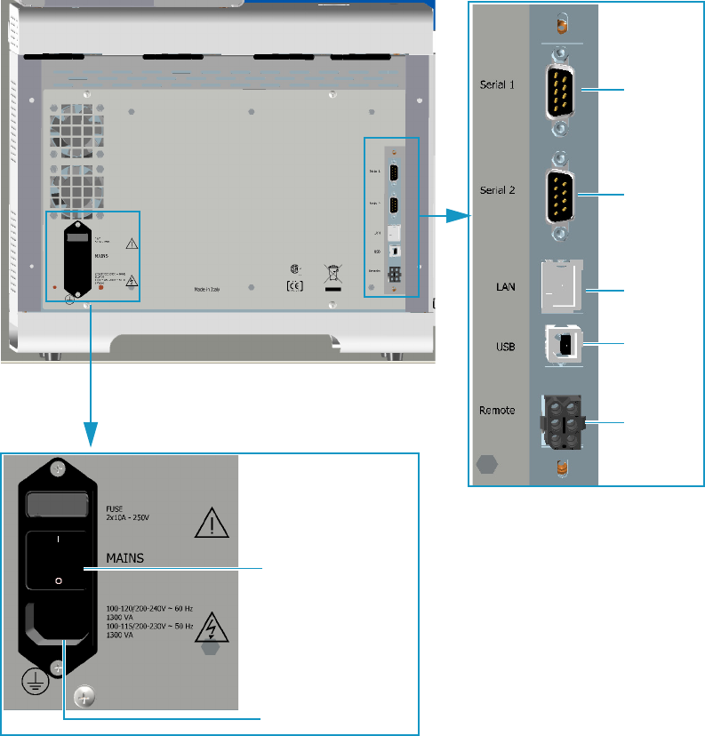
Electrical Interface
The electrical interface on the back of the Main Unit includes the connectors to make
electrical and communication connections among the unit and the external devices.
See Figure 6.
Figure 6. Electrical Interface
Power switch
AC input connector
Serial 1
Serial 2
USB
LAN
Remote
1 Getting Familiar with Your TriPlus 300 Headspace Sampling System
Main Unit
8 TriPlus 300 Headspace User Guide Thermo Scientific
The electrical interface includes:
•The Power Switch marked Mains to power the instrument On/Off.
– Position I = instrument On
– Position O = instrument Off
• AC Input connector (Main socket) for connecting the power cable to the Main Unit and
the wall outlet.
The power rating is: 100-120/200-240 Vac ±10% max; 60 Hz; 1300 VA.
100-115/200-230 Vac ±10% max; 50 Hz; 1300 VA.
The power supply includes two 10 A, 250 V fuses.
• A RJ45 connector marked LAN for the network connection.
• An USB port for service use only.
• A 9-pin male connector marked Serial 1 for service use only.
• A 9-pin male connector marked Serial 2 to dialog with the Autosampler Unit.
• A connector marked Remote to synchronize the TriPlus 300 Headspace sampling system
with the GC (Ready In/Out and Start In/Out signals). See the Autosampler Handshake
connector on the back of the GC.
See also “Making the Electrical Connections” on page 22 and “Making the Power
Connections” on page 23.
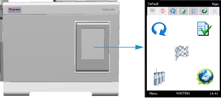
Touch screen
The touch screen is the user interface that provides immediate and detailed status displays,
and guidance for ease of use and local control. See Figure 7.
Figure 7. Touch screen
For further details, see Chapter 2, “TriPlus 300 Headspace User Interface.”
1 Getting Familiar with Your TriPlus 300 Headspace Sampling System
Autosampler Unit
Thermo Scientific TriPlus 300 Headspace User Guide 9
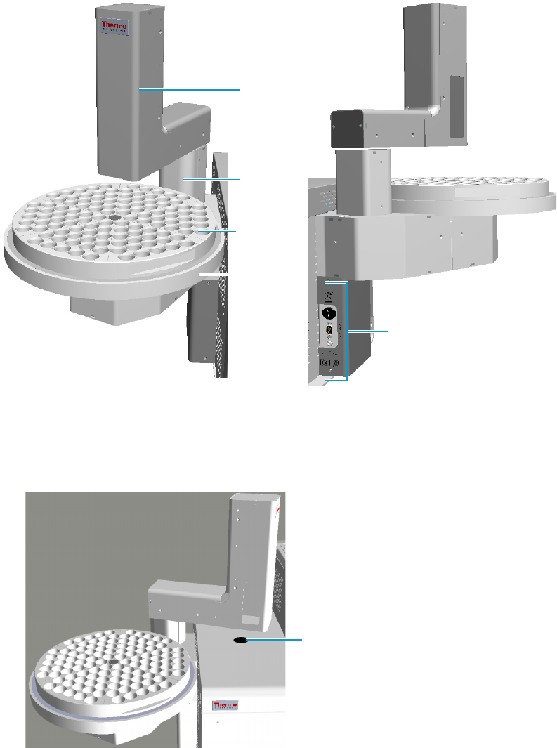
Autosampler Unit
The Autosampler Unit is located on the left side of the Main Unit. It can operate using
normal headspace vials with magnetic caps and different sizes such as 10, 20, and 22 mL.
See Figure 8.
Figure 8. Autosampler Unit: Front and Back View
The Autosampler Unit includes:
• A moving arm and a rotating dish placed under the tray. The arm shifts from the tray to
the insert position on the Main Unit. There is also a moving arm on the turret (vertical Z
axis) to catch the vials on the tray and release on the Main Unit or the other way round.
Moving
arm
Electrical interface
Rotating
dish
Turret
Sample
tray
Insert position
1 Getting Familiar with Your TriPlus 300 Headspace Sampling System
Autosampler Unit
10 TriPlus 300 Headspace User Guide Thermo Scientific
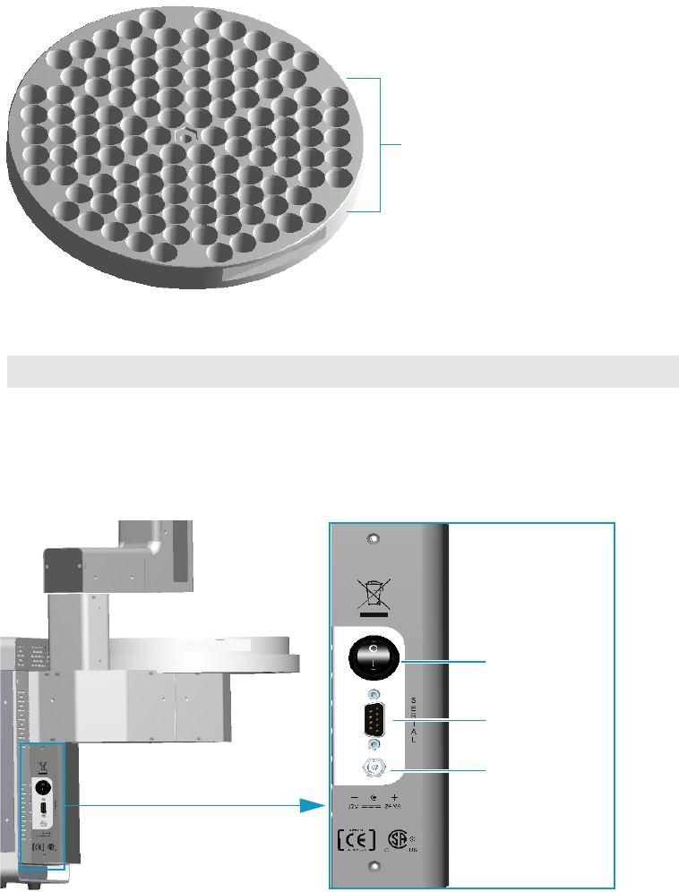
• A 120-position sample tray subdivided into 6 triangular sectors with each containing 20
seats. See Figure 9.
Figure 9. 120-position Sample Tray
The vial numbering is:
• The electrical interface is located on the back. See Figure 10.
Figure 10. Autosampler Unit: Electrical Interface
The electrical interface of the Autosampler Unit includes:
•The Power Switch to power the instrument On/Off.
– Position I = instrument On
– Position O = instrument Off
1st Sector 2nd Sector 3rd Sector 4th Sector 5th Sector 6th Sector
1 - 20 21 - 40 41 - 60 61 - 80 81 - 100 101 - 120
Single sector
Serial
Power switch
Jack connector
1 Getting Familiar with Your TriPlus 300 Headspace Sampling System
Pneumatics
Thermo Scientific TriPlus 300 Headspace User Guide 11
• A 9-pin male connector marked Serial that communicates with the Main Unit.
• A jack connector marked 12V, 24 VA for the connection of the Vdc power cable of
the external portable power supply.
The Autosampler Unit can be equipped with the following optional components:
• A 60-position sample tray subdivided into 6 triangular sectors with each containing 10
seats.
• A Chiller for cooling all the vials on the tray through a refrigerant coil installed
underneath the plate. See “Chiller” on page 105.
• A Barcode reader. See “Barcode Reader” on page 107.
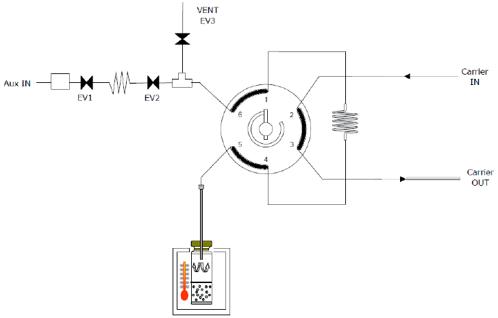
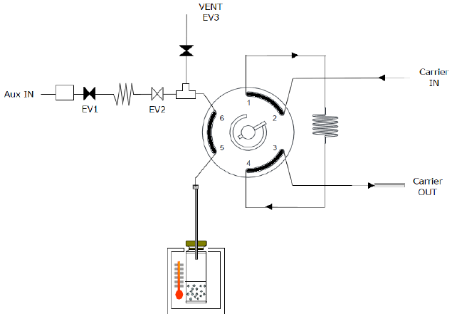
Pneumatics
The pneumatics scheme is shown in Figure 11. The instrument is equipped with two separate
inlets on the back for carrier gas (CARRIER IN), and auxiliary gas (AUX IN).
Figure 11. Pneumatics
•The carrier gas can be regulated by the gas chromatograph, the TriPlus 300 Headspace
sampling system, or both. If the carrier gas pressure is lower than 50 millibar, the
instrument signals an error condition, and the sequence cannot be started. The carrier gas
flows to the injector through the transfer line.
•The auxiliary gas pressurizes the vials and transfers the analytes from the sample into the
loop. It is possible to use a gas other than the carrier gas (usually Nitrogen).
The auxiliary gas is regulated by a electronic flow control (EFC).
1 Getting Familiar with Your TriPlus 300 Headspace Sampling System
Analytical Cycle
12 TriPlus 300 Headspace User Guide Thermo Scientific
Analytical Cycle
The analytical cycle of a sample is made up of a sequence of operative phases starting from the
vial loading into the thermostatic oven until its recovery. The operative phases are:
•Standby
•Equilibration
•Pressurization
•Loop Fill
•Injection
•Vial Venting
•Purging
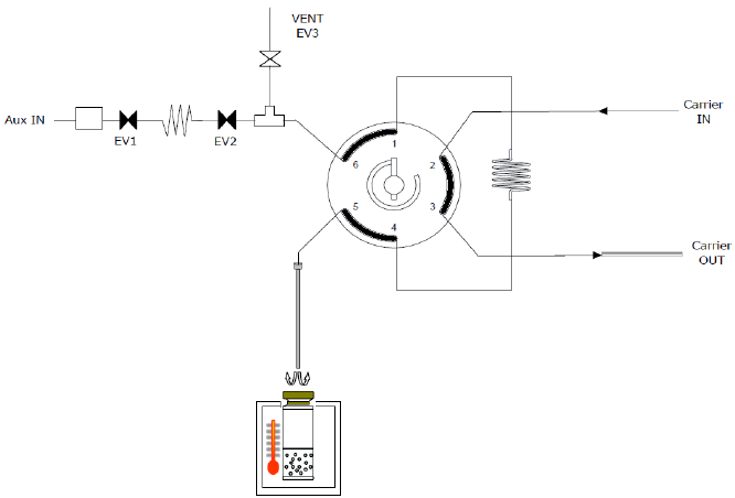
Standby
The instrument is in standby condition before and after a sampling sequence, and between a
sampling and the next one of the same sequence. The Aux In valves EV1 and EV2 are open
while the vent valve EV3 is closed, so the auxiliary gas flushes at 30 mL/min through the
switching valve, the sampling loop, and the needle to prevent carry over. See Figure 12.
The carrier gas flows to the GC through the switching valve and the transfer line reaching the
GC injector to feed the column.
Figure 12. Standby/Equilibration Phase
1 Getting Familiar with Your TriPlus 300 Headspace Sampling System
Analytical Cycle
Thermo Scientific TriPlus 300 Headspace User Guide 13
Equilibration
The vial is automatically moved into the oven. The equilibration stage retains the same valve
configuration as the standby phase; see Figure 12. During the equilibration phase the vial
remains in the oven at a constant temperature (OVEN TEMP) for a certain time
(EQUILIBRATION TIME), and three shaking levels can be selected: low, medium, or high.
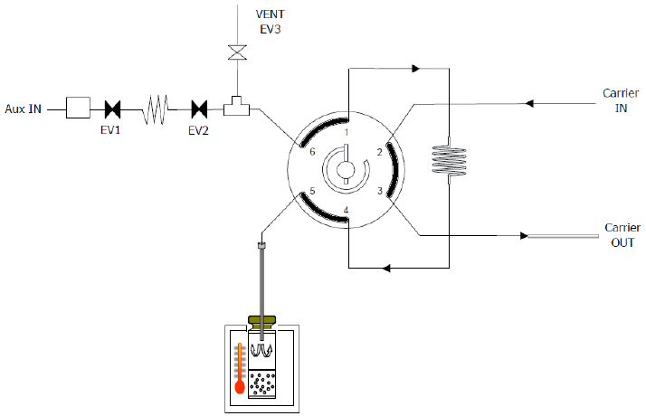
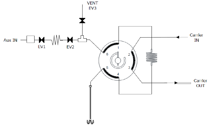
Pressurization
The pressurization phase starts at the end of the equilibration time. The shaking stops, if
activated, and the carousel rotates till positioning the vial in correspondence of the sampling
needle. The Aux In valves EV1 and EV2 close temporarily. After the sampling needle has
pierced the septum vial, EV1 and EV2 open again, and the pressurization starts. See
Figure 13.
Figure 13. Pressurization Phase
The vial can be pressurized in four different modes:
•Pressure — The vial is pressurized at a target pressure level.
•Standard — The pressurization of the vial starts at a programmed time.
•Flow — The flow rate is controlled for pressurizing the vial up to a fixed pressure. This
mode allows to fill the vial reducing the perturbation.
•Volume — The flow rate is controlled for inserting the target volume in a given time.
This mode is useful for calculating the molar amounts of the sample in the headspace,
and then in the loop.
For more details, see “Pressurization ” on page 53.
1 Getting Familiar with Your TriPlus 300 Headspace Sampling System
Analytical Cycle
14 TriPlus 300 Headspace User Guide Thermo Scientific
At the end of the pressurization, and during the pressure equilibration time of 0.2 min, the
system performs a vial leak check to control the security of the vial. If the vial does not pass
the leak check, a message will be shown in the log file.
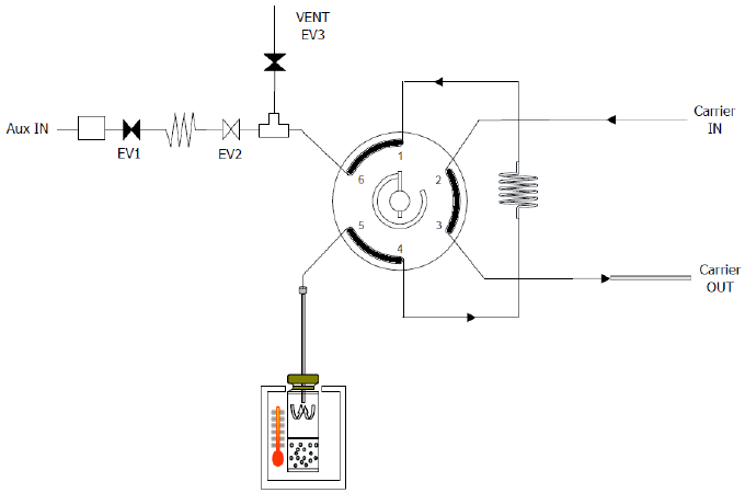
Loop Fill
After the vial leak check and the pressure equilibration time, the Vent valve EV3 opens.
The overpressure inside the vial is expelled into the atmosphere through the Vent outlet on
the back of the instrument, thus filling the sampling loop. The Vent valve EV3 will close at
the programming time or at the pressure value. See Figure 14.
Figure 14. Loop Fill Phase
Three loop fill modes are supported:
•Pressure — Inserts the pressure target that the loop has to achieve with a totally opening
of the EV3 Vent.
•Custom — Sets the rate at which the loop fills, and the final sampling loop pressure.
•Standard — Opens the Vent valve EV3 completely opens for the selected time.
– By setting a shorter interval, the loop undergoes a light overpressure, thus sampling a
volume higher than the nominal one.
– By setting a longer interval, the loop equilibrates to the atmosphere, and the sampled
volume is exactly the nominal one.
For more details see “Loop Fill ” on page 54”.
1 Getting Familiar with Your TriPlus 300 Headspace Sampling System
Analytical Cycle
Thermo Scientific TriPlus 300 Headspace User Guide 15
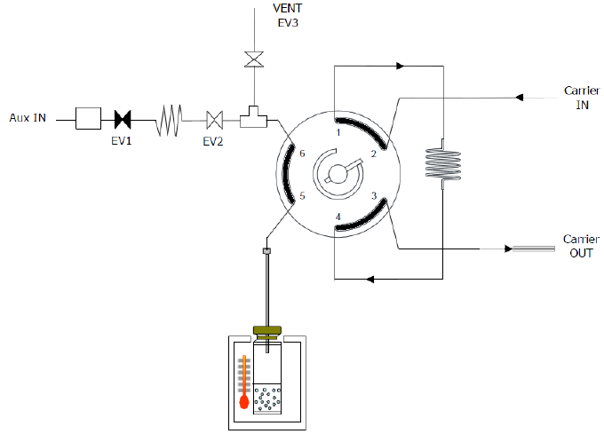
Injection
At the end of the Loop Filling phase, the Switching Valve rotates, and the carrier gas intercepts
the sampling loop, and transfers its content into the GC column through the transfer line.
See Figure 15. At the same time, the TriPlus 300 Headspace sampling system sends a start
signal to the GC to begin the analysis.
Figure 15. Injection Phase
The TriPlus 300 Headspace sampling system operates in three different extraction and
injection modes:
•Standard — The TriPlus 300 Headspace sampling system equilibrates the vial,
punctures it once, fills the sample loop (single extraction), then starts a run while
injecting the sample into the GC.
The loading time of the vials into the oven is automatically calculated to guarantee the
same equilibration time for all the samples, and the optimization of the total time analysis
times. According to the equilibration times and GC time, more vials can be
contemporaneously present inside the oven.
•Multiple Headspace Injection (MHI) — Each vial is pierced only once, but up to 100
injections can be performed before starting the GC analysis. This technique is used for
trace analysis in order to concentrate in the GC injector (for example a PTV) or in a trap.
After the first injection, the vial remains half-way between the oven and the sampling
system. The sample cycle (pressurization, loop fill, and injection) is repeated for the
number of times selected in the method. (Equilibration is not repeated). The start
command to the GC is sent only at the end of the last injection.
This operation mode does not allow the shake function of the vials sequentially, and each
vial is incubated singularly.
1 Getting Familiar with Your TriPlus 300 Headspace Sampling System
Analytical Cycle
16 TriPlus 300 Headspace User Guide Thermo Scientific
•Multiple Headspace Extraction (MHE) — Each vial is sampled multiple times. Up to
100 samplings can be performed on the same vial automatically. Each vial is incubated
first for a time equal to the equilibration time set in the method, while the incubation
time of the subsequent samplings corresponds to the longest time set in the method
(equilibration time or GC time). At each sampling an analysis is performed. Two typical
uses for the multiple extraction mode are: calibration for solid samples and kinetic
studies. Repetitions can be carried out in two modes: single puncture or multiple
puncture.
a. Single puncture — The vial is pierced only at the first sampling since the needle
remains into the septum for all the subsequent samplings. After the vial equilibration,
pressurization, and loop fill, the sample is injected into the GC, and TriPlus 300
Headspace sampling system sends the Start command to the GC. This sequence is
repeated on the same vial for the number of replicates decided by the user. This
operation mode does not allow the shake function of the samples because the vial
remains half-way between the oven and the sampling system. For the same reason,
the vials cannot be loaded sequentially, and each vial is incubated singularly.
b. Multiple puncture — Works as above but each vial is brought to the carousel inside
the oven after injection or vial venting, if set. The vial is lifted up at each subsequent
replicate so that the septum is pierced again. This operation mode allows sample
shaking, and guarantees the optimization of the working time just as in the standard
operation.
Vial Venting
Vial venting is the next optional phase after the injection. During the vial venting the
switching valve is in position 2, and the valve EV3 opens for 10 seconds in order to eliminate
the residual pressure in the vial. See Figure 16.
Figure 16. Vial Venting Phase
1 Getting Familiar with Your TriPlus 300 Headspace Sampling System
Analytical Cycle
Thermo Scientific TriPlus 300 Headspace User Guide 17
In Multiple Headspace Extraction (MHE) the vial venting is the default setting, and it is
carried out in a different mode. It is not indispensable, but it can be useful to improve the
technique.
Consists of a pressurization phase and venting simultaneously to the injection phase.
During the first half time of the injection, the TriPlus 300 Headspace sampling system opens
the Valve EV2 and closes the Vent valve EV3 to pressurize the vial up to 2 bar.
During the second half time, the pressurization valve EV2 is closed and the Vent vial EV3 is
opened in order to depressurize the vial.
Purging
The Purge phase consists of two phases: the first is fixed; the second is optional. See Figure 17.
Figure 17. Purging Phase
At the beginning of the purging phase the lifter sampling goes down, and the vial is removed
from the carousel.
During the fixed phase the auxiliary gas flow is regulated to 100 mL/min and it is maintained
for one minute. For both phases, the EV3 is open, and the switching valve is in position 1 to
connect the loop to the auxiliary gas circuit. The gas flows through the sampling valve, the
loop, the needle, and the Vent valve EV3 to guarantee cleaning of the system and to prevent
the carryover.
In the optional phase you insert the time and the purging flow.

1 Getting Familiar with Your TriPlus 300 Headspace Sampling System
Installation Notes
18 TriPlus 300 Headspace User Guide Thermo Scientific
Installation Notes
This section provides some preliminary information for the installation and the connection of
the TriPlus 300 Headspace sampling system, and lists the electrical requirements.
Who Performs the Installation
WARNING The TriPlus 300 Headspace sampling system should be installed by authorized
Thermo Fisher Scientific field service engineers, who will check its correct operation.
For more details, please contact your Thermo Fisher Scientific local representatives.
Should the instrument not be installed by Thermo Fisher Scientific personnel, please strictly
adhere to the following instructions.
Standard Outfit
Use the standard outfit checklist accompanying the instrument to verify that all items have
been received.
Electrical Requirements
The instrument must be electrically supplied as indicated in the TriPlus 300 Headspace
Preinstallation Guide.
Environmental Conditions
The instrument is generally best located in an environment where atmospheric conditions can
be controlled and extreme temperatures avoided.
The precision of the instrument can be regarded as a function of the precision of the
laboratory temperature control. Therefore, do not place the instrument near heating or air
conditioning vents which may cause differential heating and drafts.
In laboratories with windows, window coverings should be installed to protect the instrument
from direct sunlight.
For further details, refer to the TriPlus 300 Headspace Preinstallation Guide.
WARNING The power line and the connections among the instruments must maintain
good electrical grounding. Poor grounding represents a danger to the operator and may
seriously affect the instrument performance.
Do not connect the TriPlus 300 Headspace sampling system to lines feeding devices of a
heavy duty nature, such as motors, UV lamps, refrigerators and other devices that can
generate disturbances. If other instruments, such as a computer, balance, printer, or
others, have to be connected to the same electrical line as the TriPlus 300 Headspace
sampling system ensure that the electrical line is capable of withstanding such electrical
consumptions by calculating the total absorption.

1 Getting Familiar with Your TriPlus 300 Headspace Sampling System
Installation Notes
Thermo Scientific TriPlus 300 Headspace User Guide 19
Lift and Place the TriPlus 300 Headspace Sampling System
Each person should move the instrument from the floor to the work space requires at least
two people. Each person should position himself at one of the sides of the instrument, with
their hands underneath it.
The instrument is normally installed on the left side of the gas chromatograph.
The maximum distance from the gas chromatograph should be calculated considering the
length of the transfer line, which is approximately 80 cm.
For further details about the working space, refer to the TriPlus 300 Headspace Preinstallation
Guide.
Assembling the TriPlus 300 Headspace Sampling System
To assemble the TriPlus 300 Headspace sampling system:
1. Remove the lower cover of the Autosampler Unit using a 1.5-mm Allen wrench for the
four fixing screws.
2. Remove the plastic cover of the Autosampler Unit using a 1.5-mm Allen wrench for the
three fixing screws.
3. Manually screw in the two spacer screws on the two central holes on the left side of the
Main Unit.
4. Hook the Autosampler Unit to the two spacer screws on the Main Unit.
5. Install the four screws holding the Autosampler Unit to the Main Unit using a 3 mm
Allen wrench.
6. |Tighten the two screws hooking the Autosampler Unit to the Main Unit using a 8 mm
Allen wrench.
7. Reinstall the lower cover by using the 1.5 mm Allen wrench.
Pneumatic Supply
TriPlus 300 Headspace sampling system is equipped with two distinct inlets for carrier and
auxiliary gas. The maximum inlet pressure allowed is 9 bar (130.5 psig).
CAUTION This operation must be carried out by authorized and trained Thermo Fisher
Scientific technical personnel.

1 Getting Familiar with Your TriPlus 300 Headspace Sampling System
Installation Notes
20 TriPlus 300 Headspace User Guide Thermo Scientific
The choice of carrier gas is primarily based on the analysis and the type of detector installed
on the gas chromatograph. You can use either helium or hydrogen up to 9 bar to work in fast
GC analysis.
The auxiliary gas can be different from the carrier gas (for example nitrogen) because the
inlets are separate. Usually nitrogen is used because of its density and low cost.
Connect the instrument to the supply line using preconditioned steel or copper tubing with
the minimum number of connections. Do not use plastic tubing as it is permeable to Oxygen
and other substances and could contaminate the column or detector.
The tubing diameter is based on the distance between the instrument and the gas supply
source and the total gas flow rate is required.
A 1/8-in tubing, as the one supplied with the instrument, is suitable for most cases.
The gas inlets, located on the back of the instrument, consists of 1/8SW male bulkhead
connectors.
To connect the pipes proceed as follows:
• Cut the tubing to the desired length. Always leave it slightly longer for minor movements
of the instrument.
• Fit a 1/8-in stainless steel nut on the tubing and a brass seal with the conical part facing
outwards. Both pieces are shipped with the instrument.
• Insert the tubing to the bottom of the gas inlet connector and finger-tighten the nut
• With a 7/16-in wrench tighten the nut 1 and 1/4 turns.
• Check the seal on the pneumatic line.
Plumbing the Connection to Gas Chromatograph
This section provides the instruction for plumbing the TriPlus 300 Headspace sampling
system to the GC.
Tip Use a two-stage pressure regulator upstream from the lines and a single-stage regulator
near the instrument.
Install filters on the gas lines to eliminate hydrocarbons, oxygen and humidity, and to
achieve the best performance.
WARNING When using hydrogen as carrier gas, be very careful to avoid the formation of
explosive air/hydrogen mixtures. Check the seal on the lines which supply the hydrogen.
Hydrogen must not be used as an auxiliary gas.
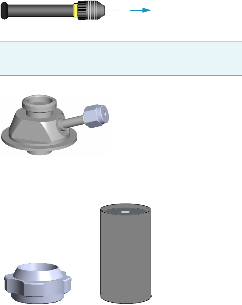
1 Getting Familiar with Your TriPlus 300 Headspace Sampling System
Installation Notes
Thermo Scientific TriPlus 300 Headspace User Guide 21
Connecting the Transfer Line
Connect the TriPlus 300 Headspace sampling system to the gas chromatograph by inserting
the end of the transfer line in the gas chromatograph SSL/SSLBKF injector.
Figure 18. Transfer Line Connection
The transfer line needle has dimensions 0.7 mm o.d. and 0.4 mm i.d.
Figure 19. Loop Type HS Adapter
To prevent the transfer line needle from blocking the sample during insertion and from
bending, replace the septum cap of the SSL/SSLBKF injector with the septum cap provided
into the standard outfit of the TriPlus 300 Headspace sampling system. See Figure 20
Figure 20. Original and Dedicated Septum Cap
CAUTION For connecting the transfer line to the GC injector, the septum holder must be
replaced with the dedicated adapter supplied with the instrument. See Figure 19.
For details see “Installing the HS Adapter Kit on the SSL/SSLBKF Injector” on page 95.
To the injector
Original septum cap
Dedicated septum cap
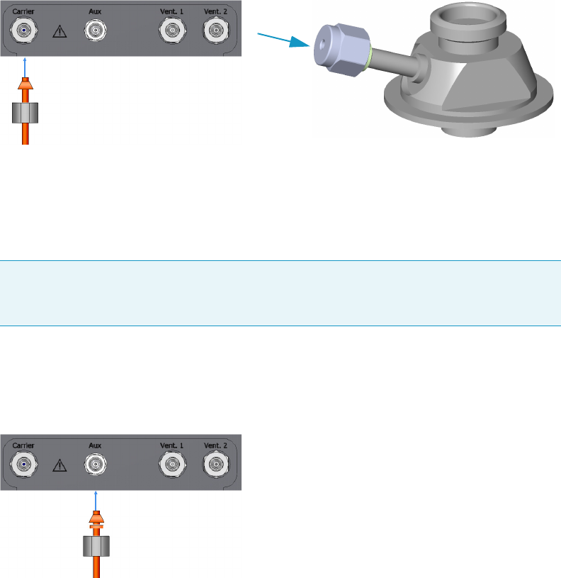
1 Getting Familiar with Your TriPlus 300 Headspace Sampling System
Installation Notes
22 TriPlus 300 Headspace User Guide Thermo Scientific
Connecting the Carrier Gas
In the standard configuration, the instrument is set up to use the gas chromatograph carrier
gas regulation system, and thus the standard configuration is not equipped with any pressure
or flow rate regulator.
Figure 21 shows you how to connect the carrier gas:
Figure 21. Carrier Gas Connection
• Using the proper nuts and ferrules, connect the carrier gas supply tube between the
dedicated loop type HS adapter on the SSL injector and the inlet port marked Carrier on
the back of the Main Unit.
• Regulate the pressure or gas flow rate directly from the gas chromatograph.
Connecting the Auxiliary Gas
Figure 22 shows you how to connect the auxiliary gas:
Figure 22. Auxiliary Gas Connection
• Connect the auxiliary gas supply tubing coming from the cylinder to the inlet port
marked Aux on the back of the instrument using an 1/8 SW adapter. The maximum inlet
pressure is 4 bar.
Making the Electrical Connections
Perform the electrical connections as follows:
Note Adding an external circuit to the carrier gas line causes an additional pressure drop
which cannot be calculated. Thus it may be possible that the carrier gas flow rate
calculated by the gas chromatograph is much higher than the one actually occurring.

1 Getting Familiar with Your TriPlus 300 Headspace Sampling System
Installation Notes
Thermo Scientific TriPlus 300 Headspace User Guide 23
To perform the electrical connections
1. Using the RS232 serial cable provided, connect the RS232 connector marked Serial 2 on
the back of the Main Unit to the RS232 connector marked Serial on the back of the
Autosampler Unit.
2. Using the LAN cable, connect the RJ45 connector marked LAN on the back of the Main
Unit to the network.
3. Using the cable provided connect the connector Remote on the on the back of the
instrument to the Autosampler Handshake connector on the back of the gas
chromatograph.
Making the Power Connections
To connect the power to the TriPlus 300 Headspace sampling system
1. Connect the power cable to the AC Input connector (Main socket) on the back of the
Main Unit.
2. Plug in the Vdc power cable of the external portable power supply into the jack marked
12 V-24 VA located on the back of the Autosampler Unit.
Powering On the TriPlus 300 Headspace
To power on the TriPlus 300 Headspace sampling system
1. Before turning on the power make sure that the chromatography system is properly
connected and powered on, and the gases are flowing into the system.
2. Flip up the power switch, located on the back of the Main Unit, to the On (up) position
marked I.
3. Flip up the power switch, located on the back of the Analytical unit, to the On (up)
position marked I.
4. The TriPlus 300 Headspace sampling system automatically runs the self-testing routine
during which all the configured devices are checked one by one.
5. At the end, the Hardware tab of the diagnostic page shows all the devices in a list.
See “Hardware” on page 88 for details.
CAUTION For safety the instrument is grounded through a three-conductor power line
cord according to the International Electrotechnical Commission (IEC) regulations.
The cord must be inserted in a socket equipped with a correctly connected earth ground
contact. Make sure the socket is grounded. Before connecting the instrument to the power
supply, make sure that the power switches on the rear of the Main and Autosampler Unit
are in the OFF position.
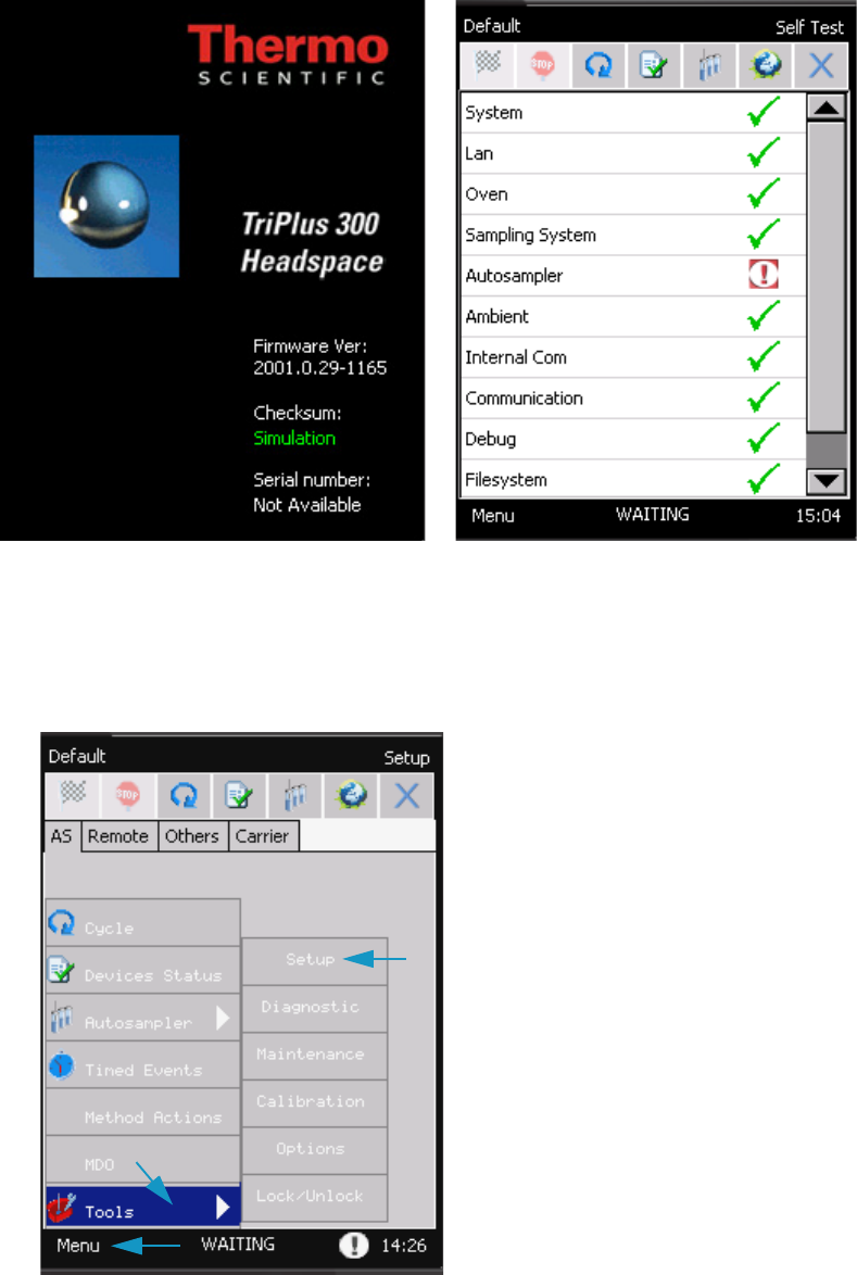
1 Getting Familiar with Your TriPlus 300 Headspace Sampling System
Installation Notes
24 TriPlus 300 Headspace User Guide Thermo Scientific
Setting the Communications
To set the communication between Main Unit and Autosampler Unit
1. Select Menu | Tool | Setup.
2. Press Unlock, then insert 1111 as password, and press OK.
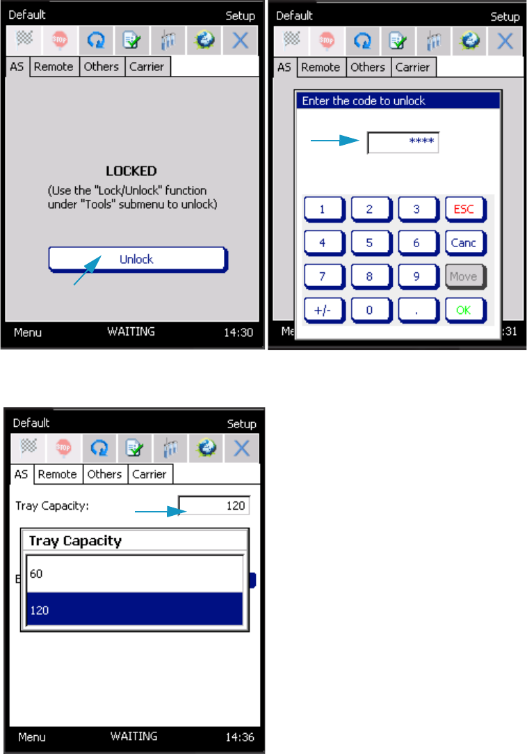
1 Getting Familiar with Your TriPlus 300 Headspace Sampling System
Installation Notes
Thermo Scientific TriPlus 300 Headspace User Guide 25
3. In the Tra y Capa city field select the number of sample positions of the tray. Choose 60
or 120 accordingly.
4. Select Barcode On if present, otherwise select Off.
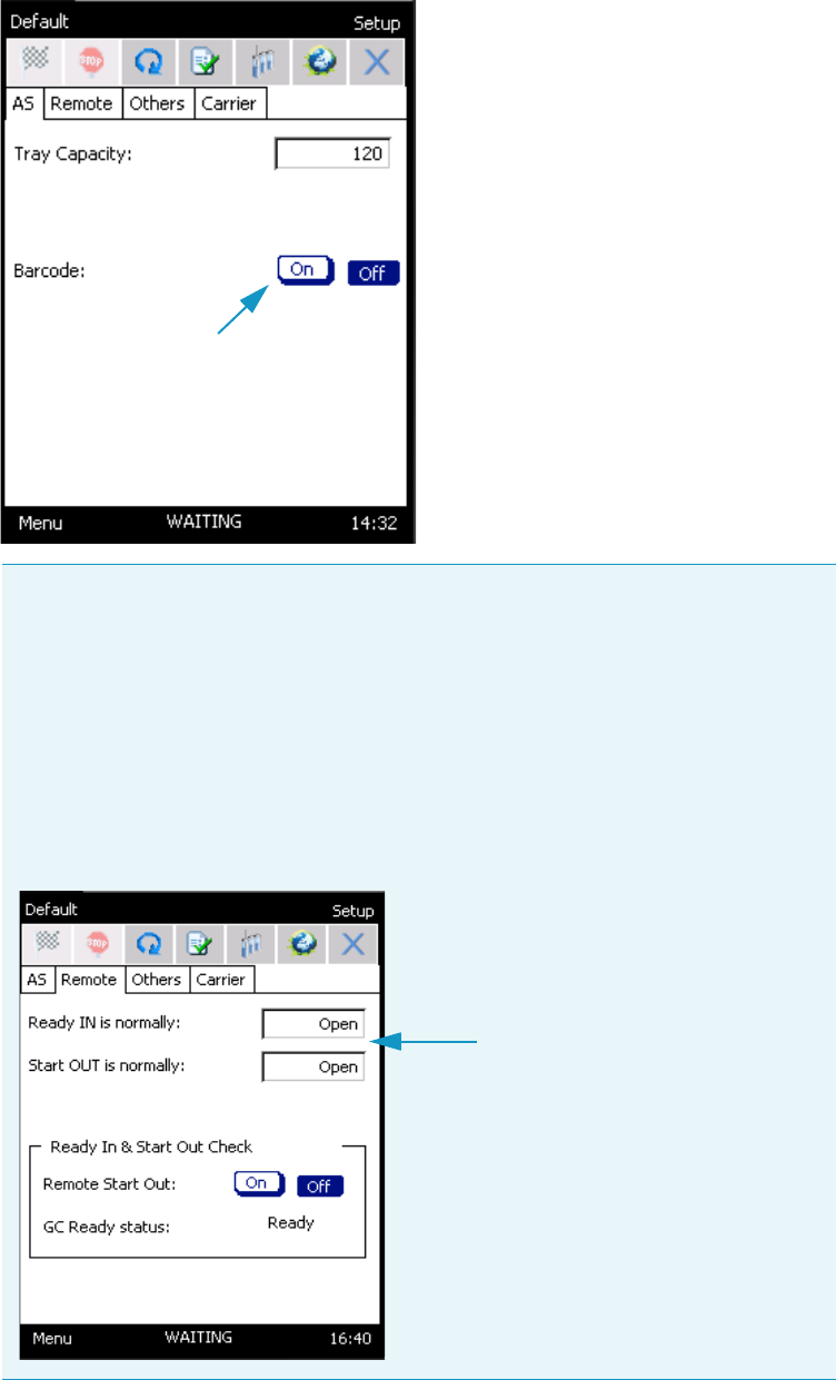
1 Getting Familiar with Your TriPlus 300 Headspace Sampling System
Installation Notes
26 TriPlus 300 Headspace User Guide Thermo Scientific
Note TriPlus 300 Headspace sampling system communicates with the gas
chromatograph via two connections:
• A connection for receiving the Ready In signal from the gas chromatograph
when it is in the Ready condition.
• A connection to send the gas chromatograph the Start Out signal.
In standard conditions, the instrument is configured to receive the Ready In and to
send the Start Out commands as a closing contact.
On Menu |Tools | Setup | Unlock | Password 1111 | Remote the configuration for
both the commands is set as Normally Open.
1 Getting Familiar with Your TriPlus 300 Headspace Sampling System
Usage Notes
Thermo Scientific TriPlus 300 Headspace User Guide 27
Leak Test
After the TriPlus 300 Headspace sampling system has been assembled and connected to the
gas chromatograph, it is advisable to perform a leak test on the entire pneumatic circuit, from
the carrier gas inlet to the column outlet. This procedure should be repeated every time a
modification is being made on the system, for example: column or transfer line replacement.
To perform the leak test
1. Disconnect the column from the detector and insert a silicone rubber septum in its end.
2. Leave the TriPlus 300 Headspace sampling system in stand-by conditions, and regulate
the carrier gas pressure to approximately 2 bar (30 psig). Wait a few minutes for the
pressure to stabilize in the entire system and check the value of the current pressure.
3. Turn off the pressure supply and check the value reading. After a minimum decrease, the
pressure value must be constant.
• If after approximately five minutes the pressure drop is less than 0.04 bar, the system
is sealed.
• If the pressure decreases more than 0.04 bar, it means that there is a leak in the
system.
– Re-pressurize the system and find the leak by using a soapy solution.
– Find the leak, tighten the fitting until it is eliminated and repeat the leak test.
4. Remount the column.
Usage Notes
This section provides some advice about the Headspace technique for optimizing the
parameters that can affect the sensitivity, precision, and accuracy of an analysis.
The related topics are:
•“Temperatures” on page 28
•“Carrier Gas Optimization” on page 28
•“Auxiliary Gas Pressure Optimization” on page 29
•“Equilibration Time Conditioning” on page 29
•“Shaking Conditioning” on page 29
•“Sample Vials Size ” on page 29
•“Sample Vial Septa ” on page 30
•“Vial Closure ” on page 30
•“Matrix Effects ” on page 31
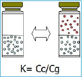
1 Getting Familiar with Your TriPlus 300 Headspace Sampling System
Usage Notes
28 TriPlus 300 Headspace User Guide Thermo Scientific
Temperatures
The oven temperature can have a profound effect on the concentration of analyte that passes
into the gas phase.
In general as the temperature increases, the amount of analyte in the gaseous phase increases,
and consequently the sensitivity of the method.
The tendency of a compound to go into the gaseous phase is determined by the partition
coefficient K:
where: Cc is the concentration of the analyte in the condensed phase
(matrix phase), and Cg is the gaseous phase.
The partition coefficient K is highly dependent on temperature as
demonstrated by the following equation:
dK/dT = 1/T2
Consider the following when choosing the oven temperature:
• The best results are achieved when the temperature is maintained at the minimum level
sufficient to ensure the desired analytical sensibility
• Do not set the oven temperature within 10 °C of the boiling point of any solvent, except
in special cases.
• Thermo labile compounds may degrade at elevated temperatures.
The manifold and transfer line temperatures must be higher than the oven temperature to
avoid the condensation of the analytes in the pneumatic system, and consequently avoid the
presence of carry over.
The function Method Developing Optimization (MDO) increases the temperatures in steps
for optimizing your method. See “Method Developing Optimization (MDO)” on page 72.
Carrier Gas Optimization
The carrier gas flow rate should be set high enough to transfer the headspace sample out of the
loop into the GC without causing peak broadening.
For example, for a packed GC column that gives 15-seconds-wide peaks, the flow should be at
least 6 mL/min for a 1 mL loop. For a 3 mL loop and the same conditions, the minimum flow
should be 18 mL/min.
For a capillary column that generates a 1-second-wide peak, the flow rate would be higher
than 60 mL/min. In this case the flow rate will be the total flow (column flow + split flow).

1 Getting Familiar with Your TriPlus 300 Headspace Sampling System
Usage Notes
Thermo Scientific TriPlus 300 Headspace User Guide 29
Auxiliary Gas Pressure Optimization
The pressure developed in the vial allows you to transfer the head space sample to the loop.
The auxiliary gas pressure should be set at the minimum value to ensure the loop filling.
To optimize your selection of vial pressurization, run a series of vials using different pressures,
and interpret the optimum condition from peak areas versus vial pressurization.
Equilibration Time Conditioning
The time that the sample vial spends in the oven determines the amount of analyte in the
head space and the presence of absence of equilibrium.
In order to determine if the equilibrium is reached, use the MDO function, increasing the
equilibration time for each step. Then plot the peak area versus equilibration time.
The system is at equilibrium when the curve flattens out.
Shaking Conditioning
In same cases, and especially for aqueous samples, shaking during the equilibration phase
reduces the time required to reach the equilibrium.
The function Method developing Optimization (MDO) optimizes the shaking level.
See “Method Developing Optimization (MDO)” on page 72.
Sample Vials Size
The TriPlus 300 Headspace sampling system can use 10 mL, 20 mL, and 22 mL vials.
The vial size may change with each method in use in a sequence.
The vial can have crimp caps or be screw cap vials with flat or rounded bottoms and can have
clear or amber glass. Use amber glass for light –sensitive samples.
Vials must be conform to the following specifications:
Note Optimization is valid only for analysis of a specific sample at a specific oven
temperature.
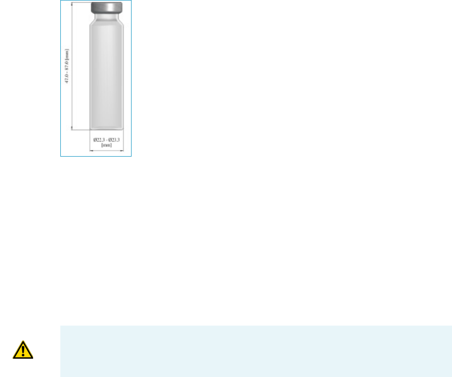
1 Getting Familiar with Your TriPlus 300 Headspace Sampling System
Usage Notes
30 TriPlus 300 Headspace User Guide Thermo Scientific
Generally, fill the 10 mL vial up to 50% of typical height, or up to 50-75%
of the maximum height with 20 – 22 mL vials.
A larger sample size may give greater sensitivity. Peak areas are influenced
by the relative amount of the gas and condensed phases in the vial.
Increasing the sample size may increase the peak area. If the sensitivity is
not a fundamental requirement, small vials may be preferred because a
shorter equilibration time is required.
Missing and Wrong Size Vials
Before sampling, the Autosampler Unit moves to the position of the current vial and moves
down to check the presence and size of the vial, and the status frame will be displayed.
If the instrument does not find the vial, or the vial is a different size than the one set in the
method, the autosampler performs the action selected in Method Actions.
See “Method Actions” on page 69.
The information of missing or wrong size vials will be reported in the Log page of the Status.
window. See “Status” on page 37.
Sample Vial Septa
The use of septa with the lower layer in PTFE is recommended to avoid contamination of the
sample. Always confirm that there are no peaks in the blank analysis chromatogram.
Vial Closure
A frequent, and non-negligible cause of error, is a leak due to incorrect closure of the vial. To
close the vials, use a crimper then check each vial for proper crimping.
• The cap should be finger-tight.
• If the cap is loose the vial may leak.
• Adjust the crimper and close the vial again.
• The cap should be flat.
IMPORTANT The Autosampler Unit recognizes the type of the vial by its height.
They are commercial 22 and 20 mL which have the same height; in this case the
autosampler does not distinguish them.
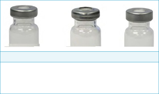
1 Getting Familiar with Your TriPlus 300 Headspace Sampling System
Usage Notes
Thermo Scientific TriPlus 300 Headspace User Guide 31
The deformation of the cap can generate some problems for the autosampler during the
pick- up phase of the vial from the tray or from the Oven.
Matrix Effects
The composition of the sample matrix may affect the amount of the analyte that is transferred
to the headspace.
Adding an inorganic salt to an aqueous sample increases the concentration of organic
molecules in the gas phase. The salts makes these compounds less soluble in the sample
matrix, and the sensitivity increases.
Usually the matrix is not a pure compound, but a complex mixture of compounds, some of
which may be not volatile. The interaction of the matrix components with the analyte
influence its solubility. This is called matrix effect.
Matrix effects are important when an external standard must be developed. The composition
of the matrix in the standard must resemble as much as possible that of the sample.
The effect of the matrix on a standard can be compensated by quantifying results using MHE.
Correct crimp Over crimp Under crimp
Undeformed sides,
good seal
Deformed sides,
upward bulge,
probably problem with
autosampler
Loose seal, caps
twists easily

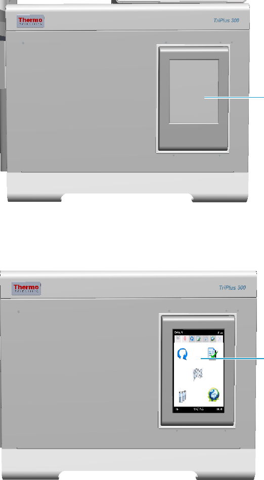
2 TriPlus 300 Headspace User Interface
TriPlus 300 Headspace User Interface Overview
34 TriPlus 300 Headspace User Guide Thermo Scientific
TriPlus 300 Headspace User Interface Overview
The TriPlus 300 Headspace sampling system user interface is a touch screen that provides
immediate and detailed status display and guides you for ease of use and local control. See
Figure 23.
Figure 23. User Interface
When the TriPlus 300 Headspace sampling system is powered on, the touch screen main
menu appears. See Figure 24.
Figure 24. Touch screen Main menu
The display allows to access to every parameter by no more than four touches on the touch
screen. The display is subdivided into three blocks: Status Bar, Desktop, and Tool Bar.
See Figure 25.
User interface
Touch screen
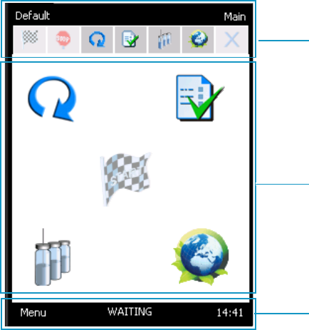
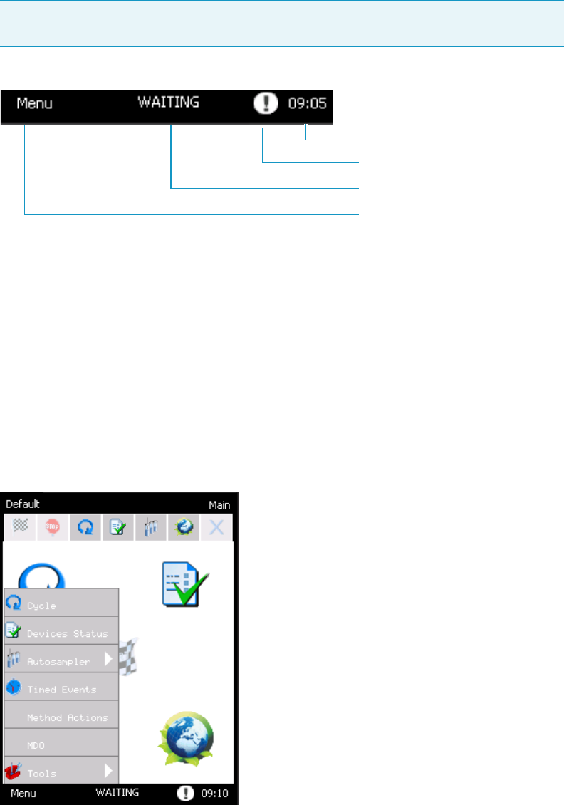
2 TriPlus 300 Headspace User Interface
Status Bar
36 TriPlus 300 Headspace User Guide Thermo Scientific
Status Bar
The Status bar is on the bottom of the screen. This section includes the functions Menu,
Status, and Time Clock. See Figure 26.
Figure 26. Status Bar Description
For details see the related topics:
•“Menu” on page 36
•“Status” on page 37
•“Time Clock and Date” on page 40
Menu
This section allows access to many functions and gives you the ability to select the submenu.
See Figure 27.
Figure 27. Menu Page
Note If your system has a problem or other communications, a blinking exclamation
mark appears on the right of the status bar indicating an alarm condition. See Figure 26.
Time clock
Alarm
Status
Menu
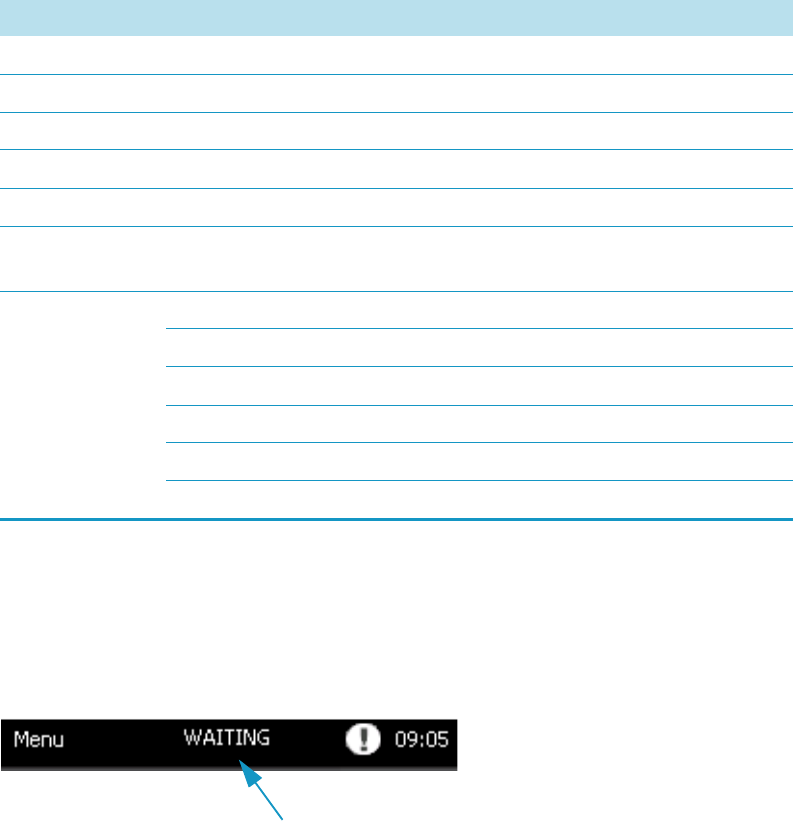
2 TriPlus 300 Headspace User Interface
Status Bar
Thermo Scientific TriPlus 300 Headspace User Guide 37
Menu and Submenu items are reported in Table 1together with the chapter of the manual
where you find detailed information.
Status
This section shows in real time the TriPlus 300 Headspace sampling system status. See the
example in Figure 28.
Figure 28. Status Conditions
A different inscription is shown depending on the actual status of the system: READY,
WAITING GC READY, WAITING GC, WAITING, AUTORUN, RUNNING, PAUSE,
ABORT. See the section “Device Status and Ready Conditions” on page 43 for details.
Pressing on this bar, the Status window appears. This window is subdivided into five tabs
TriPlus 300 HS, Sequence, Vial, Alarms, and Log. See Figure 29.
Table 1. Menu, Submenu, and Reference Chapter
Menu Submenu Reference
Cycle --- “Cycle” on page 49
Device Status --- “Device Status and Ready Conditions” on page 43
Autosampler Sequence “Sequence ” on page 61
Times Events --- “Timed Events” on page 66
Method Actions --- “Method Actions” on page 69
MDO --- “Method Developing Optimization (MDO)” on
page 72
To o l s S et u p “Setup” on page 77
Diagnostic “Diagnostic” on page 88
Maintenance “Maintenance” on page 82
Calibration “Calibration” on page 86
Options “Options” on page 73
Load/Unload “Load/Unload Tab” on page 83
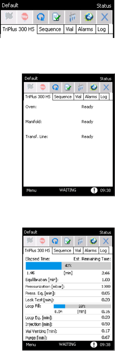
2 TriPlus 300 Headspace User Interface
Status Bar
38 TriPlus 300 Headspace User Guide Thermo Scientific
Figure 29. Status tabs
•TriPlus 300 HS — Visualizes the status of the TriPlus 300 Headspace sampling system
– When a device of the instrument such as Oven, Manifold, and Transfer Line, is not
in the ready condition, the red inscription Not Ready appears.
– When the analysis is running, for each step a blue bar showing the progression of the
set is displayed. In the upper part of the page a progressive status bar that indicates
the elapsed time and estimated remaining time for the whole sequence appears.
•Sequence — Shows the Status of the automatic sampler configured, the sequence row,
vial, and current repetition.
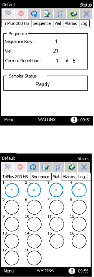
2 TriPlus 300 Headspace User Interface
Status Bar
Thermo Scientific TriPlus 300 Headspace User Guide 39
•Vial — Visualizes during the run the tray position of the vial in the middle of the circle in
the corresponding position of the carousel.
•Alarms — Visualizes all the messages concerning problems or advice.
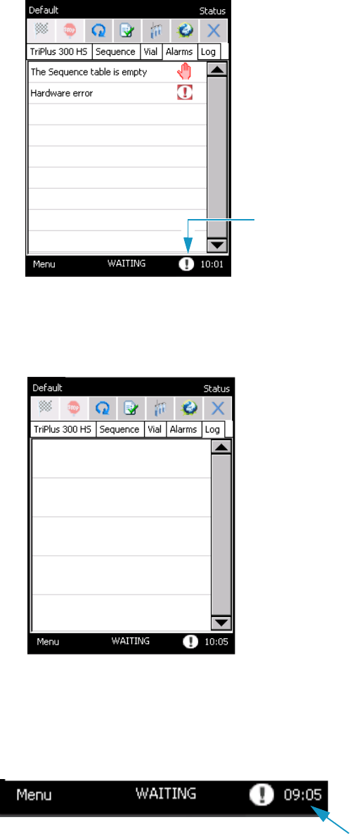
2 TriPlus 300 Headspace User Interface
Status Bar
40 TriPlus 300 Headspace User Guide Thermo Scientific
– To access this page, press the exclamation mark blinking on the right of the status
bar. See “Alarms” on page 89.
•Log — Contains the information about any problems that occurred during the sampling
sequences.
Time Clock and Date
This section allows you to read time and date. See the example in Figure 30.
Figure 30. Time and Date
Exclamation mark
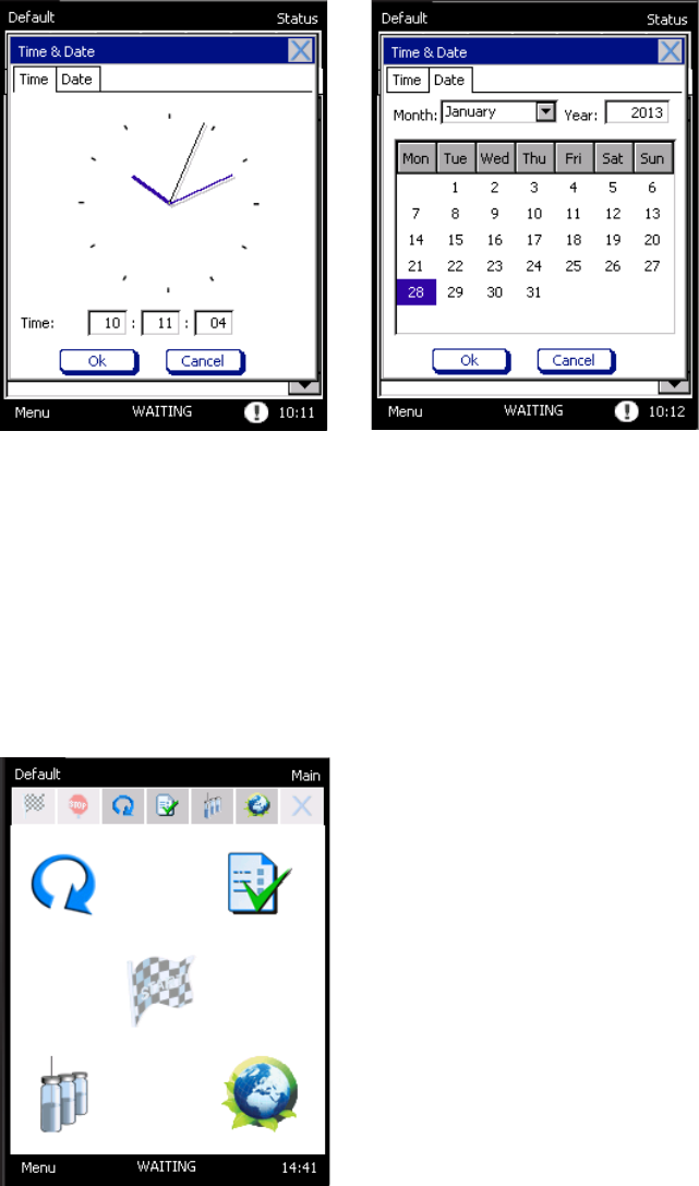
2 TriPlus 300 Headspace User Interface
Desktop
Thermo Scientific TriPlus 300 Headspace User Guide 41
When you press on the current clock (in the example 09:05), the window Time & Date
appears. The window is subdivided into two tabs. See Figure 31.
Figure 31. Time and Date Windows
• To set the time, open the tab Time and enter the hour, minutes, and seconds in the three
dedicated boxes.
• To set the date, open the tab Date and select the month, day and year.
Desktop
The desktop is the central portion of the display. See Figure 32.
Figure 32. Desktop Buttons
Here you find five buttons that allow to access to the following components:
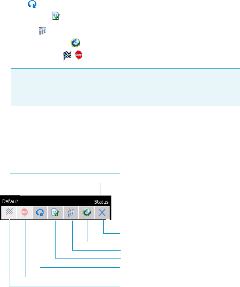
2 TriPlus 300 Headspace User Interface
Tool Bar
42 TriPlus 300 Headspace User Guide Thermo Scientific
•Cycle — See the section “Cycle” on page 49.
•Devices Status — See the section “Device Status and Ready Conditions” on page 43.
•Sequence — See the section “Sequence ” on page 61.
•Gas & Energy Saving — See “Gas & Energy Saving Tab” on page 77.
•Start/Stop buttons — See the section “Control of Analysis” on page 48.
Tool Bar
The Tool bar is on the top of the display and consists of three parts: the Upper left side, the
Upper right side, and the Lower rows. See Figure 33.
Figure 33. Tool Bar
1. Upper left side — Displays the name of the current method. If you press on this name,
the Manage Methods page appears. If the method is changed, it will add an asterisk
following the name of the method. See the section “Method” on page 59.
2. Upper right side — Displays the name of the open window.
3. Lower rows — Includes seven shortcut keys for starting an application:
•Start — Starts the analysis. See “Start of analysis ” on page 48.
•Stop — Stops the analysis. See “End of analysis ” on page 48.
Note These buttons are alternatively displayed on the desktop:
•Start is displayed when the instrument is out of an analysis.
•Stop is available when an analysis is in progress.
Current method
Name of the current window
Stop
Start
Device Status
Gas & Energy Saving
Close/Exit
Cycle
Sequence
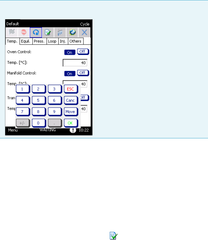
2 TriPlus 300 Headspace User Interface
Device Status and Ready Conditions
Thermo Scientific TriPlus 300 Headspace User Guide 43
•Cycle — Opens the Cycle window for setting all the analytical parameters. The cycle
consists of six pages:
–Temperature
– Equilibration
– Pressurization
–Loop
–Injection
–Others
See the section “Cycle” on page 49 for details.
•Device Status — Opens the Devices Status windows, with the Temperatures and
Press/Flow pages. See the section “Device Status and Ready Conditions” on page 43.
•Sequence — Open the sequence table window. See the section “Sequence ” on page 61.
•Gas & Energy Saving — Opens the Gas & Energy Saving page, where select you gas and
energy saving options. See the section “Gas & Energy Saving Tab” on page 77.
•X — Closes the current window and returns to the desktop.
Device Status and Ready Conditions
In the Device Status window, accessible selecting the icon, you control the actual and the
set values for the listed parameters. Also, the Ready condition function is found.
The instrument reaches the Ready status when all the parameters checked for the Ready
conditions satisfy the set conditions.
Note In order to set a parameter, press on the corresponding box and a numeric
keypad appears. Digit the value and press OK.
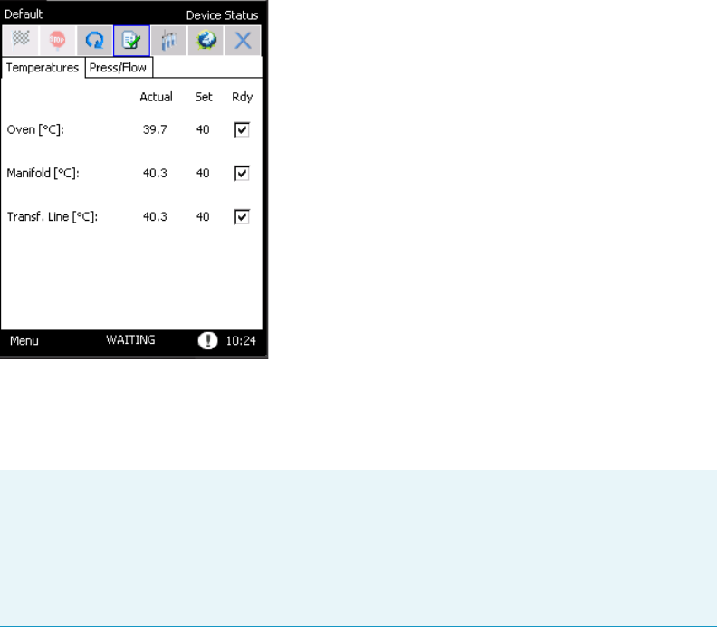
2 TriPlus 300 Headspace User Interface
Device Status and Ready Conditions
44 TriPlus 300 Headspace User Guide Thermo Scientific
Device Status window contains two tabs: Tem p e ratu re s and Press/Flow.
Temperature Tab
The parameters available in the Temperatures tab include all the devices that have a
temperature regulation as Oven, Manifold, and Transf er Line. See Figure 34.
Figure 34. Device Status: Temperatures Tab
The tolerance on the ready condition is different for each device, depending on its
characteristics and type of heating/cooling systems. In the Default method, the Ready
conditions for the Oven, Manifold, and Tra nsfer li ne temperatures are active.
Note
•To eliminate a parameter from the Ready condition, press on the corresponding
check box and clear the selection.
•To include a parameter in the Ready conditions, press on the corresponding check
box to display the selection.
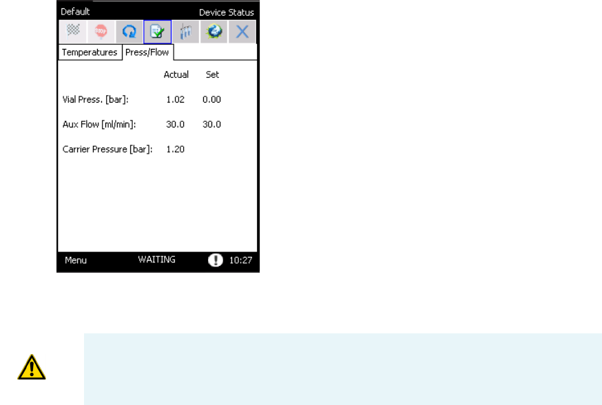
2 TriPlus 300 Headspace User Interface
Device Status and Ready Conditions
Thermo Scientific TriPlus 300 Headspace User Guide 45
Press/Flow Tab
In the Press/Flow tab, you find the parameters for the Auxiliary and Carrier gases.
See Figure 35.
Figure 35. Device Status: Pressure/Flow Tab
•Carrier Pressure visualizes the pressure of carrier gas coming from the gas
chromatograph.
• The actual value of the Auxiliary gas depends on the cycle step.
See “Instrument Status” on page 45 for details.
•Aux Flow is always visualized because the instrument controls a flow in each step,
Stand-by included.
Instrument Status
This section details the status of the instrument shown on the Status bar. See also “Status” on
page 37.
•Ready — Indicates that all the devices that are selected as ready conditions, see Ready
conditions, have reached the values initially set in the method in the Cycle pages.
The Oven, Manifold, and Transfer Line Temperatures are set in the Tem p page and
remain constant during the entire analytical cycle.
The instrument accepts the START command only after all conditions are shown as
Ready.
CAUTION If there is no carrier gas it is not possible to start the analytical sequence.
2 TriPlus 300 Headspace User Interface
Device Status and Ready Conditions
46 TriPlus 300 Headspace User Guide Thermo Scientific
•Waiting GC ready— Shown when the gas chromatograph is not in the ready condition
at the end of a sequence line, and the following line has to be started. The instrument
remains in this condition until the gas chromatograph reaches the ready condition and
the following line is started.
•Waiting GC (min:s) — Shown with the corresponding countdown when the cycle on
one vial is ended and the instrument is waiting before starting the cycle on the next vial,
in order to respect the GC ready interval. The cycle on the next vial will start at the end of
the countdown.
•Waiting — Shown when one or more components are not in the ready condition, for
instance when Manifold, Oven, or Transfer line are reaching the temperature values set.
The instrument remains in the WAITING condition until all the parameters reach the
condition set in the method. See Ready conditions.
•Autorun — Appears on the Start icon when the instrument is not in Ready status.
When you press this short key, the instrument passes into Autorun condition. The
sequence will start automatically when all ready conditions are reached.
•Running — Indicates that the analysis is running.
•Pause — Appears after a sequence is stopped and it remains until one of the possible
options is selected to resume the sequence.
•Abort — Appears when the Abort option is selected, and is displayed until the Abort
procedure is ended.

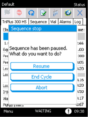
3 Operation
Control of Analysis
48 TriPlus 300 Headspace User Guide Thermo Scientific
Control of Analysis
The control of the analysis is carried out by the use of the Start and Stop buttons.
See the following related topics:
•“Start of analysis ” on page 48
•“End of analysis ” on page 48
Start of analysis
The analysis starts by pressing START positioned in the middle of the desktop, or the short
key on the tool bar.
The START command determines the beginning of the sequence and will be accepted only if
the instrument is in READY status.
If the instrument is not in Ready status, the inscription AUTORUN appears.
When you press the Start short key, the instrument passes into AUTORUN condition.
See “Instrument Status” on page 45. In this case, when all ready conditions are reached, the
sequence will start automatically.
End of analysis
The analysis ends automatically when the analytical cycle for the vials in the sequence is
completed. However, the analysis can be stopped before completion of the program by
pressing STOP in the middle of the desktop, or the short key on the tool bar.
When you press STOP the instrument enters the Pause state and a pop-up appears.
See Figure 36.
Figure 36. Stop Sequence

3 Operation
Cycle
Thermo Scientific TriPlus 300 Headspace User Guide 49
• Selecting Resume restarts the sequence from the point it was stopped.
• Selecting End cycle stops the sequence but the cycle on the current vials, or the vials still
present in the carousel, will be completed.
• Pressing Abort interrupts both the analysis and sequence.
If Abort is pressed when the sample has finished the equilibration phase and it is
performing one of the following steps, the instrument will make a purge step to avoid that
sample remains in the pneumatic circuit.
When you press STOP the instrument immediately stops in its current position.
The instrument will stop, or go on when one of the options is selected.
At the next START, the sequence starts from the first repetition of the first level.
If the sequence is interrupted, the instrument returns to the conditions of the first method of
the sequence.
Cycle
The analytical Cycle is composed of six steps: Equilibration, Pressurization, Loop Fill,
Injection, Vial Venting, and Purge.
The Cycle window consists of six pages, four of these for the steps of the analysis and two
additional pages: Tem p for the temperature machine, Others to insert the GC Time, the sum
of the time between gas chromatograph analysis and its cooling time, the vial size, and the Bar
Code Reader if configured.
In the lower part of Others page the analysis time information is displayed the Cycle Time
label indicates the sum of the duration of the five steps (Equilibration, Pressurization, Loop
Fill, Injection and Vial Venting/Purge), and GC Time. See the section “Others ” on page 56
for details.
Every value in the cycle pages is a parameter of the method, and any modification will be
prompted to be saved into the method in use.
In order to set a new value for any parameter, press on the corresponding text box and use the
numeric keypad to type the value. See Figure 37.
CAUTION If you press STOP while the instrument is removing one vial from the
autosampler and other vials are still present in the carousel, it is possible that the vial will
be kept in that position until the analysis on the vials in the carousel is ended. Finally, all
the vials will be removed.
If you stop the sequence during certain critical activities, for example when the instrument
is taking or releasing a vial, it is possible that the sampler will perform the removal
movements twice.
These operations are necessary to preserve the correct handling of the vials and do not
influence the correct overlapping of the analysis times.
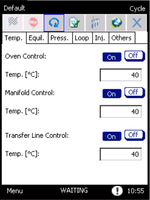
3 Operation
Cycle
50 TriPlus 300 Headspace User Guide Thermo Scientific
Figure 37. Cycle Page
If you enter a value out of the allowed range the message Out of range will be shown with the
indication of the correct range. The minimum or maximum value allowed will be
automatically saved by pressing OK.
See the following related topics:
•“Temperature” on page 51
•“Equilibration” on page 52
•“Pressurization ” on page 53
•“Loop Fill ” on page 54
•“Injection” on page 54
•“Others ” on page 56
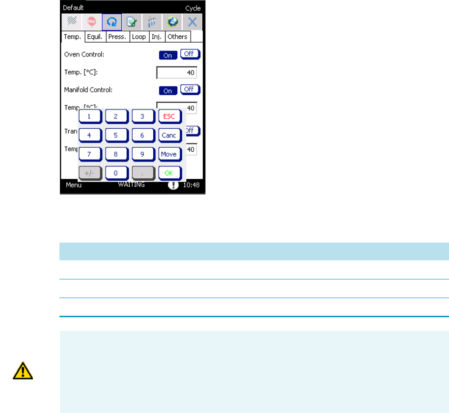
3 Operation
Cycle
Thermo Scientific TriPlus 300 Headspace User Guide 51
Temperature
In this tab you find all the temperatures for Oven, Manifold, and Tra nsfer Li ne.
These parameters will be maintained for the entire analysis. To enable the temperature control
click ON on the right side. See Figure 38.
Figure 38. Cycle: Temperature Tab
Tab le 2 shows the interval ranges and the default values for all the parameters:
Table 2. Temperature Parameters
Parameter Range Default Value
Oven Control from 30 to 300 °C 40 °C
Manifold Control from 30 to 300 °C 40 °C
Transfer Line Control from 30 to 300 °C 40 °C
ATTENTION Best practice is to set the oven temperature 10 °C below the boiling point of
the solvent inside the vial. Otherwise the high pressure generated inside the vial could
cause the leak pressure or the explosion of the vial.
In addition, it is recommended to insert temperature values for the Manifold and Transfer
Line equal or higher than the Oven temperature to avoid condensation of the sample.
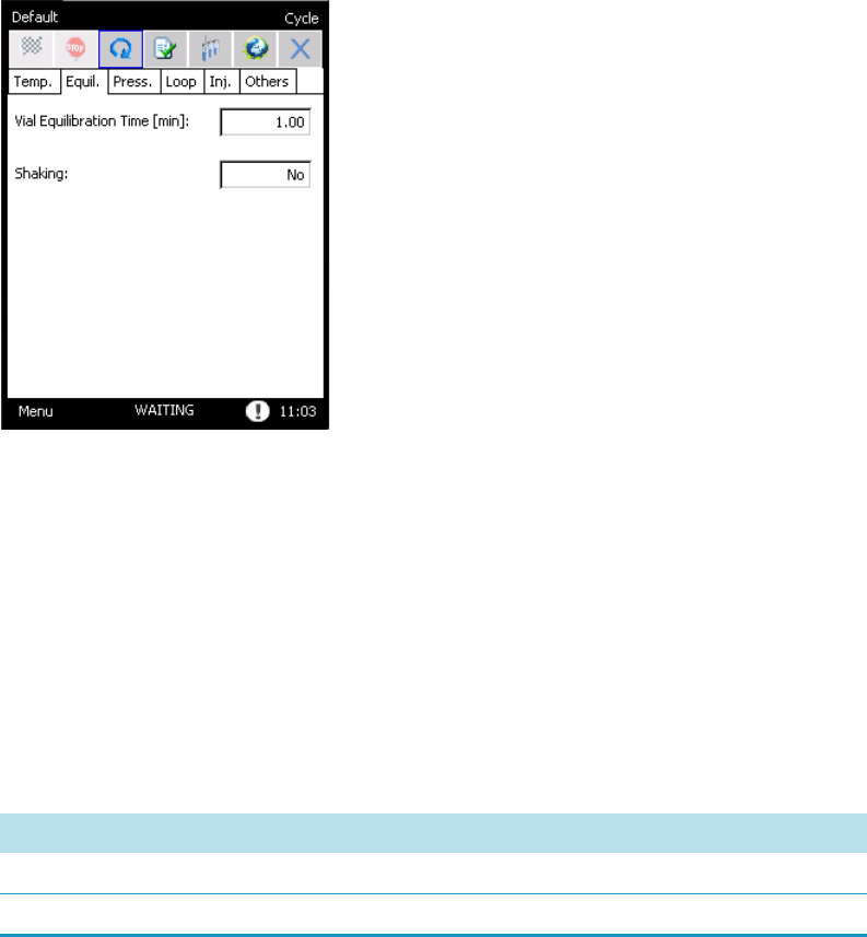
3 Operation
Cycle
52 TriPlus 300 Headspace User Guide Thermo Scientific
Equilibration
The parameters associated with this step are: Vial Equilibration Time and Shaking.
See Figure 39.
Figure 39. Cycle: Equilibration Tab
The vial equilibration time is the time during which the vial is conditioned in the oven at a
fixed temperature before the pressurization starts. The incubation time is kept constant for all
samples.
If the shaking option is enabled, the carousel will keep moving clockwise and
counter-clockwise during the incubation in order to stir the samples.
To select the shaking option press on the drop-down menu and choose one of the four
options.
Tab le 3 shows the interval ranges and the default values for all the parameters:
Table 3. Equilibrium Parameters
Parameter Range Default Value
Vial Equilibrium Time from 0.50 to 999.00 min 0.50 min
Shaking None, Slow, Medium, High None
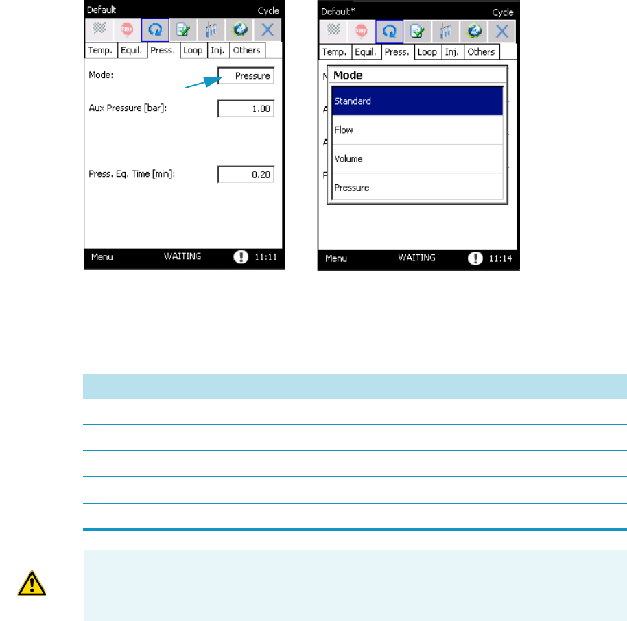
3 Operation
Cycle
Thermo Scientific TriPlus 300 Headspace User Guide 53
Pressurization
The parameters associated with this step are: Mode, Aux Volume, Aux Time, Aux Pressure,
Aux Flow, and Press. Eq. Time.
When a Mode of pressurization is chosen from the drop-down menu, the other parameters in
the page are activated depending on the selected mode. See Figure 40.
Figure 40. Cycle: Pressurization Tab
The Press. Eq. Time is the time for equilibrating the vial pressure after the pressurization step.
Tab le 4 shows the interval ranges and the default values for all the parameters:
Table 4. Pressurization Parameters
Parameter Range Default Value
Aux Flow 10.0 - 300.0 mL/min 30.0 mL/min
Aux Volume 1 - 90 mL 10 mL
Aux Pressure 0.20 - 4.00 bar 1.00 bar
Aux Time 0.10 - 5.00 min 0.20 min
Press. Eq. Time 0.20 - 5.00 min 0.20 min
WARNING The Volume pressurization needs a inlet auxiliary alimentation of 6 bar to
work properly; for other types of pressurization an inlet pressure of 2 bar above the set
value is required.
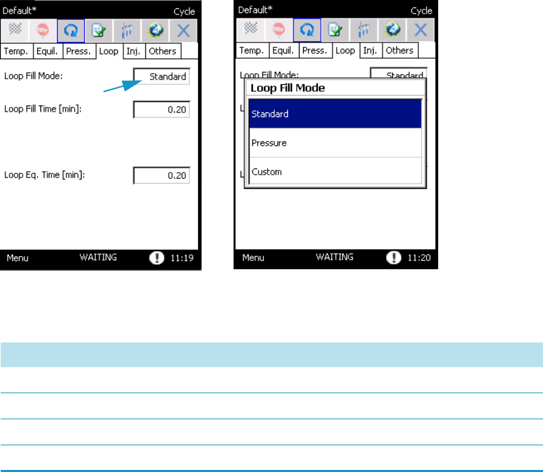
3 Operation
Cycle
54 TriPlus 300 Headspace User Guide Thermo Scientific
Loop Fill
The parameters associated with this step are: Loop Fill Mode, Loop Pressure, Loop Rate,
Loop Fill Time, and Loop Eq. Time.
If the Loop Fill Mode is selected by the drop-down menu, the corresponding parameters
appear on screen. See Figure 41.
Figure 41. Cycle: Loop Fill Tab
Tab le 5 shows the interval ranges and the default values for all the loop-fill parameters:
Injection
The parameters associated with this step are: Injection Time, Injection Mode, Vial Venting,
and Purge.
The injection time is the time of the sample transfer to the GC.
In the drop-down of the injection mode you select the type of injection: Standard, MHI, and
MHE. See Figure 42.
Table 5. Loop Fill Parameters
Parameter Range Default Value
Loop Pressure 0.00 - 3.50 bar 0.50 bar
Loop Rate 0.10 - 25.00 bar/min 5.00 bar/min
Loop Fill Time 0.10 - 5.00 min 0.20 min
Loop Eq. Time 0.00 - 5.00 min 0.2 min
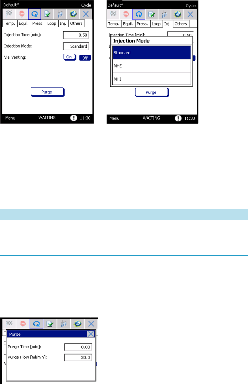
3 Operation
Cycle
Thermo Scientific TriPlus 300 Headspace User Guide 55
Figure 42. Cycle: Injection Tab
•When you choose the MHI mode (Multiply Headspace Injection) the Injection
Number parameter will appear. It represents the number of the injections before sending
the start command to the GC.
• By using MHE option (Multiply Headspace Extraction) the Puncture parameters will
be available.
Tab le 6 shows the interval ranges and the default values for all the parameters:
It is also possible to set the purging parameters to clean the system after the analysis.
Selecting ON for Vial Venting, activates a standard procedure.
Pressing the Purge button makes a pop-up menu appear. See Figure 43.
Figure 43. Purge Parameters
Table 6. Injection Parameters
Parameter Range Default Value
Injection Time 0.10 - 999.00 min 0.50 min
Puncture Single - Multiple None
Injection 1 -100 2
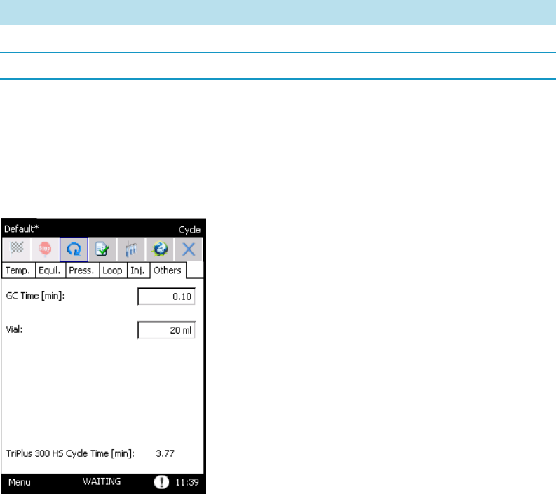
3 Operation
Cycle
56 TriPlus 300 Headspace User Guide Thermo Scientific
To set the flow rate of the auxiliary gas flowing in the pneumatic system and the time, insert
the values in the corresponding boxes Purge Time and Purge Flow. See Table 7.
Others
The parameters associated with this step are: GC Time, Vial, and Barcode Reader. See
Figure 44.
Figure 44. Cycle: Others Tab
•The GC Time indicates the minimum time interval between two injections. Set this
parameter according to the analysis duration including, in case of programmed
temperature, the time needed for oven cooling. It is suggested to insert a value slightly
higher to ensure the GC will be ready at the end of the sampling cycle.
The TriPlus 300 Headspace sampling system automatically calculate the frequency at
which the vials are loaded into the oven. The vial loading is optimized so that all the vials
are equilibrated for the same time, and the analysis can run without inactive times.
In the lower part on this page the TriPlus 300 HS Cycle Time indicates the total time of
the analysis: the sum of the Cycle Time, and GC time.
•The Vial Size is an important parameter for the headspace analytical technique because a
different vial volume can produce different analytical results.
Table 7. Purging Parameters
Parameter Range Default Value
Purge Time 0.00 - 999.00 min 0.00 min
Purge Flow 30.0 - 300.00 mL/min 30.00 mL/min

3 Operation
Cycle
Thermo Scientific TriPlus 300 Headspace User Guide 57
The TriPlus 300 Headspace sampling system can work with standard 10, 20, and 22 mL
headspace vials with crimped or screw magnetic caps and PTFE coated silicone rubber
septa.
The Autosampler Unit automatically recognizes the size of the vial and sends this
information to the Main Unit.
If there is a mismatch between the vial loaded and the vial size saved in the method, the
TriPlus 300 HS system will behave as described in the Method Sequence Options and
the message Vial Wrong Size will appear in the log page.
•The Barcode Reader is an optional for the Autosampler Unit. When installed you start
the reading of barcodes by selecting On on this parameter. For details about the barcode
reader see “Barcode Reader” on page 107.
Tab le 8 shows the interval ranges and the default values for all the parameters:
Summary
Tab le 9 summarizes the interval ranges and the default values for all the parameters of the
Cycle page:
Table 8. Others Parameters
Parameter Range Default Value
GC Time 0.00 - 999.00 min 0.00 min
Vial Size 10, 20, 22 mL 20 mL
ATTENTION The autosampler recognizes the vial size based on its height, thus it is not be
able to distinguish between vials of 20 mL and vials of 22mL with the same height.
In this circumstance the message Vial Wrong Size will appear if a wrong vial is used.
Vial Size Height
10 mL 46 mm ± 0.5 mm
20 mL 75 mm ± 0.5 mm
22 mL 85 mm ± 0.5 mm
Table 9. Cycle Parameters (Sheet 1 of 2)
Step Parameter Range Default Value
Temperature Oven Control from ambient +5 °C to 300 °C 40 °C
Manifold Control from ambient +5 °C to 300 °C 40 °C
Transfer Line Control from ambient +5 °C to 300 °C 40 °C

3 Operation
Cycle
58 TriPlus 300 Headspace User Guide Thermo Scientific
Equilibration Vial Equilibrium Time from 0.50 to 999.00 min 0.50 min
Shaking None, Slow, Medium, High None
Pressurization Aux Flow 10.0 - 300.0 mL/min 30.0 mL/min
Aux Volume 1 - 90 mL 10 mL
Aux Pressure 0.20 - 4.00 bar 1.00 bar
Aux Time 0.10 - 5.00 min 0.20 min
Press. Eq. Time 0.20 - 5.00 min 0.20 min
Loop Fill Loop Pressure 0.00 - 3.50 bar 0.50 bar
Loop Rate 0.10 - 25.00 bar/min 5.00 bar/min
Loop Fill Time 0.10 - 5.00 min 0.20 min
Loop Eq. Time 0.00 - 5.00 min 0.2 min
Injection Injection Time 0.10 - 999.00 min 0.50 min
Puncture Single - Multiple None
Injection 1 -100 2
Purge Time 0.00 - 999.00 min 0.00 min
Purge Flow 30.0 - 300.00 mL/min 30.00 mL/min
Other GC Time 0.00 - 999.00 min 0.00 min
Vial Size 10, 20, 22 mL 20 mL
Table 9. Cycle Parameters (Sheet 2 of 2)
Step Parameter Range Default Value
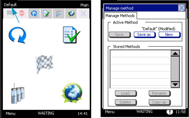
3 Operation
Method
Thermo Scientific TriPlus 300 Headspace User Guide 59
Method
A method controls the functioning of the instrument during the analytical runs. To create a
method, specify all the parameters of the analytical cycle. See the section “Cycle” on page 49
for details.
When you press on the method name, the Manage Methods window appears. See Figure 45.
The maximum number of method that can be saved is 100.
Figure 45. Manage methods window
Three options are available in the dialog area Active Method of the Manage Methods
window:
•Save — Saves the modification preserving the same name of the loaded method.
This function is active if:
– The current method has been modified.
– The active method is different from the Default method.
•Save as — Saves the parameters by entering a new method name. This key is active when:
– The instrument is not running.
– There is still some memory space to save the method.
An alphanumeric keypad appears in order to enter a new method name.
Type the name and press OK to confirm. See Figure 46.
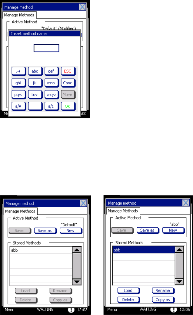
3 Operation
Method
60 TriPlus 300 Headspace User Guide Thermo Scientific
Figure 46. Manage Methods Window: Keypad
•New — Creates a new method starting from the Default method.
This function is active if:
– The instrument is not running.
– There is still some memory space to save the method.
All saved methods are listed in the frame Stored Method. See Figure 47.
Figure 47. Manage Methods Window: Stored Methods
When you press on the name of the method you want to select, four options are activated:
•Load — Loads a method. This function is active if the current method has been
modified.
If the current method has been modified and not saved, before loading the selected
method, the pop-up Save Active Method opens.
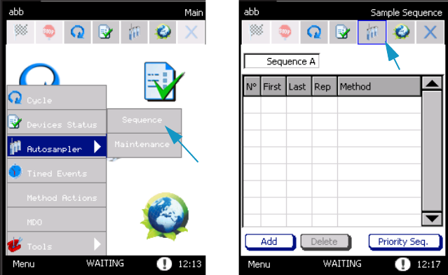
3 Operation
Sequence
Thermo Scientific TriPlus 300 Headspace User Guide 61
By answering Yes, the changes to the current method will be saved; by answering No, the
changes will be lost.
•Copy as — Copies a memorized method and saves it with a new name. This key is
activated when there is still some memory space to save the method.
•Delete — Eliminates a method. This function is active if the instrument is not running.
Pressing Delete, a pop-up Delete Method is displayed. Reply Yes to the question if you
want to eliminate the method.
•Rename — Changes the name of the method. The function is available when the current
method has been modified.
Sequence
The Sample Sequence window allows all parameters concerning the sampling sequence to be
set. The Sequence button is displayed on the tool bar, on the desktop, or you may access the
Sequence Table by selecting Menu, Autosampler, and then Sequence. See Figure 48.
Figure 48. Sequence Page
See the following related topics:
•“Creating a Sequence” on page 62
•“Changing Method Parameters During Run ” on page 63
•“Changing Sequence Parameters During Run ” on page 64
•“Priority Sequence ” on page 64
•“Sequence Interrupted” on page 65
•“Changing Autosampler Parameters During a Run” on page 65
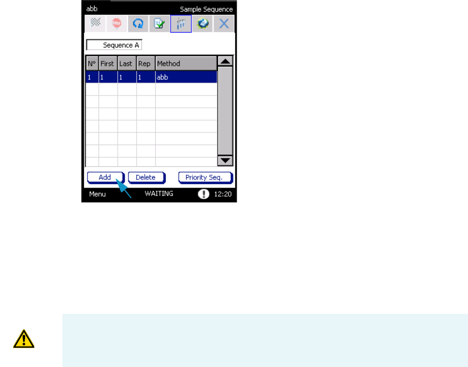
3 Operation
Sequence
62 TriPlus 300 Headspace User Guide Thermo Scientific
Creating a Sequence
To create a sequence of samples, proceed as described in the following procedure:
To create a sequence
1. Press Add to create a new row in the table.
2. In the cells First and Last respectively enter the position of the first and the last vials to be
sampled. See Figure 49.
Figure 49. Sample Sequence
• If the number of the first vial is higher than that of the last vial, the alarm First vial >
Last vial will appear; the vial number range is 1-120.
An optional tray with 60 positions is available; the vial number range is 1-60.
• If you enter a value out of the allowed range, the message Out of range is displayed
with the indication of the correct range. The minimum or maximum value allowed
will be automatically saved by pressing OK.
3. In the cell Rep, specify the number of repetitions for each vial. The possible number of
repetitions is in the range from 1 to 100. All the repetitions for the same vial will be
processed before moving to the next one, and the mode of the repetition depends on the
injection types you are choose.
4. By clicking on the column Method, all the stored methods will be shown. Select the
method to be used for each sequence row. Up to five different sequences can be stored as
Sequence A, B, C, D, or E according to the selection on the drop-down menu.
See Figure 50.
CAUTION Before starting a sequence, ensure the cover of the oven is properly close to
avoid any damage to the instrument.
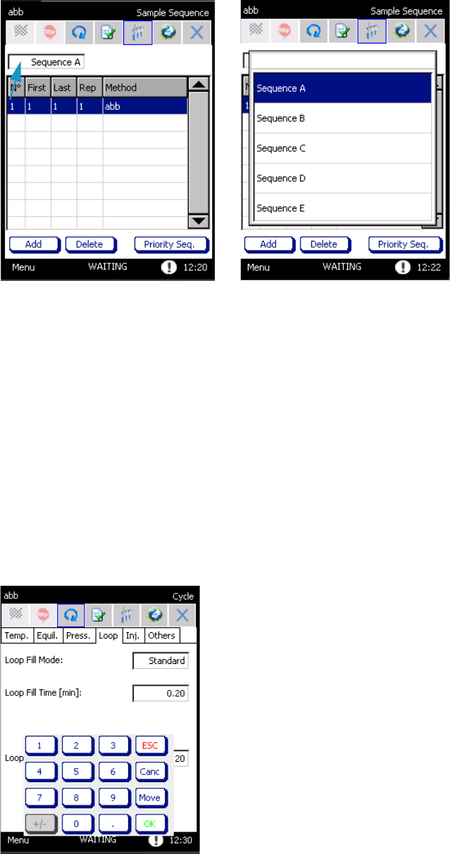
3 Operation
Sequence
Thermo Scientific TriPlus 300 Headspace User Guide 63
Figure 50. Sample Sequence Drop-down Menu
A pop-up Load First Sequence Method appears if the current method is different from
the first sequence method.
–By pressing Yes, the first sequence method will be loaded.
–By selecting No, the first method will be loaded after pressing START.
Changing Method Parameters During Run
It is possible to modify some of the method parameters while a sequence is running.
To change method parameters during run
1. In order to set the new value, press the corresponding box. Anumeric keypad will appear.
See the example in Figure 51.
Figure 51. Method: Changing Parameters During a Run
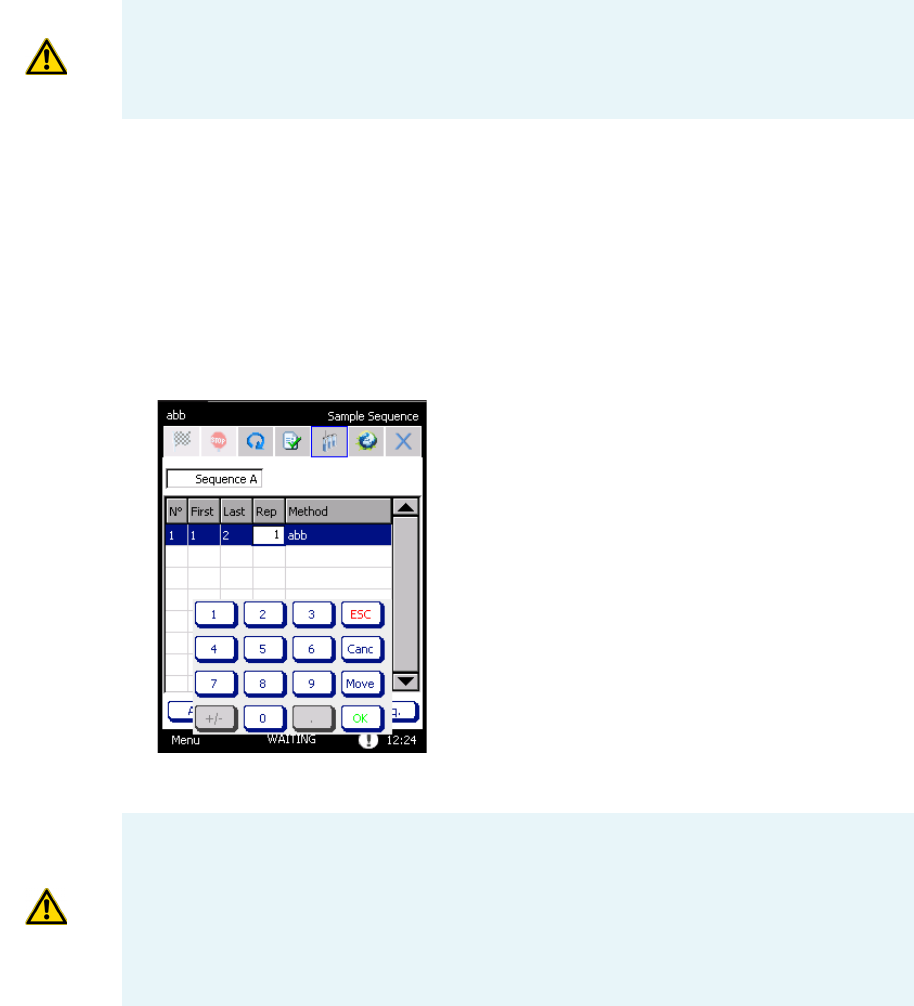
3 Operation
Sequence
64 TriPlus 300 Headspace User Guide Thermo Scientific
2. Enter the desired value and press OK.
Changing Sequence Parameters During Run
It is possible to modify some of the sequence parameters while the instrument is running.
Changing sequence parameters during run
1. Press the corresponding box in order to set the new value; a numeric keypad appears.
See the example in Figure 52.
Figure 52. Sequence: Changing Parameters During a Run
2. Enter the desired value and press OK.
Priority Sequence
The Priority sequence allows setting a sequence during the analysis. This sequence will start
immediately after the end of the current analysis.
ATTENTION If the value cannot be modified during the run, the corresponding box will
be colored grey. Every modifications will be active for the next vial inserted into the
carousel. When the method is modified, an asterisk is shown to the side of the method
name in the upper part of the page.
ATTENTION The first vial cannot be modified during the run.
If you change the last vial, the new value will be immediately implemented.
If you change the repetition number, the new value will be active for the next vial in the
carousel.
The method selected for the current row cannot be modified while the sequence is
running. By pressing the corresponding box, the Select Method window appears.
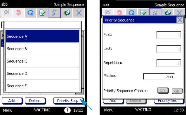
3 Operation
Sequence
Thermo Scientific TriPlus 300 Headspace User Guide 65
To set a priority sequence during the analysis
1. Press the Priority Seq. button in order to program the priority sequence; a pop-up menu
appears. See Figure 53.
Figure 53. Sequence: Priority Sequence
2. Insert the first and the last vial to be sampled in the corresponding boxes, the number of
repetitions, and the method.
Sequence Interrupted
In case a problem occurs during a sequence and the TriPlus 300 Headspace sampling system is
powered off, a message will be displayed when the instruments is powered on again.
The pop-up Oven contains vials appears if a sequence is stopped and some vials are present
in the oven. The following message is displayed:
“The sample sequence has not been completed. Do you want TriPlus 300 HS to
automatically recover vials from the oven?”.
• If you select Yes, the vials are removed by the instrument.
•If you select No, you must remove the vials manually from the load/unload page, as in the
case of a carousel sequence.
A hardware error will appear if the Autosampler Unit is powered off during a sequence.
Changing Autosampler Parameters During a Run
All the autosampler parameters can be modified while the sequence is running.
The changes are applied to the next sampling step.
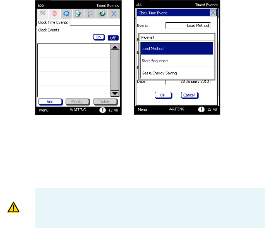
3 Operation
Timed Events
66 TriPlus 300 Headspace User Guide Thermo Scientific
Timed Events
This section details the timed events.
Clock Time Events
Clock time events happen at certain times on specific days, based on a real time-clock.
See and Figure 54 and “Time Clock and Date” on page 40.
Figure 54. Clock Time Events
The following functions can be programmed:
•Load a method
•Start a sequence
•Gas & Energy saving
To set timed events
1. Select Menu > Timed Events to access to Clock Time Events.
ATTENTIONAll events are listed in the page Clock Time Events. Up to 25 events can be
stored.
When you select an event, the functions MODIFY and DELETE are activated for
modifying or eliminating a selecting event from the list.
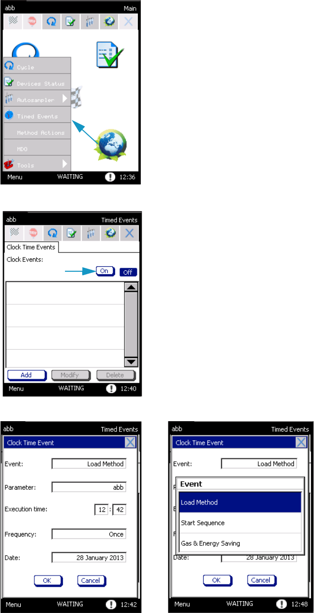
3 Operation
Timed Events
Thermo Scientific TriPlus 300 Headspace User Guide 67
2. Open the page Clock time events and press ON to enable the clock events.
3. Click Add; the pop-up Clock Time Event appears.
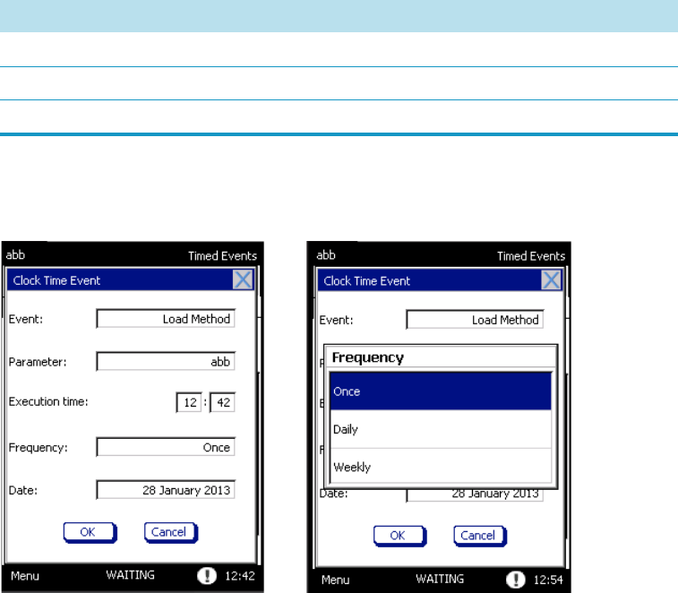
3 Operation
Timed Events
68 TriPlus 300 Headspace User Guide Thermo Scientific
4. Select the event, the parameter (for example: the method name if the instrument must
load a method, or start a method, and so on), the execution time, and the frequency.
The available events are listed in Tabl e 10.
5. Use the box corresponding to Execution time for entering the time, based on 24-hour
clock, the event must take place. See Figure 55.
Figure 55. Clock Time Events Parameters
The programming event can occur:
•ONCE — Pressing on this box, a calendar will appear. Select the day, month, and
year you want the event to occur.
•DAILY — The event will occur every day at the selected time.
•WEEKLY — Choose the day or the days of the week you want the event to happen.
Press OK to confirm the programming of the event.
Table 10. Available Events
Event Parameter
Load Method Method
Start Sequence Sequence
Gas & Energy Saving Gas & Energy Saving
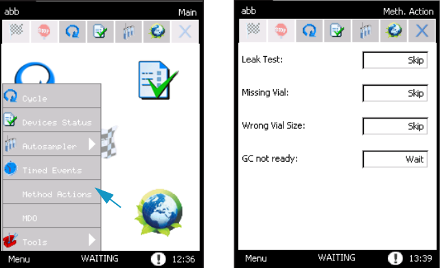
3 Operation
Method Actions
Thermo Scientific TriPlus 300 Headspace User Guide 69
Method Actions
The Method Actions are a part of the method allowing to handle certain types of TriPlus 300
Headspace sampling system or GC errors. See Figure 56.
Figure 56. Method Actions
The selection of the Method Action parameters allows you to handle some minor issues
according to the type of work you are carrying out.
The issues you can control are:
•Leak Test — In case of vial leak test failure during a sequence.
•Vial Missing — When the autosampler does not find a sample vial.
•Wrong Vial Size — Control of the TriPlus 300 Headspace sampling system when the
loaded sample vial size does not match the vial size defined in the method.
•GC not Ready — The GC is not in Ready status for the new injection or at the
beginning of a sequence.
•Barcode Read Error — When the barcode reader encounters an error while reading the
barcode.
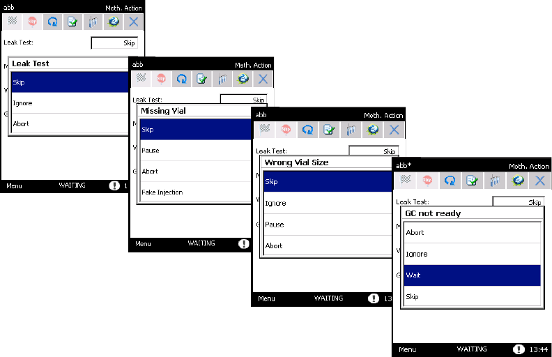
3 Operation
Method Actions
70 TriPlus 300 Headspace User Guide Thermo Scientific
Available Actions
The available actions depend on the nature of the issue. See Figure 57.
Figure 57. Method Actions: Available Actions
•Skip — The current vial and its possible repetitions are skipped, and the next vial of the
sequence will be processed:
– If the vial is already in the oven, it will be returned to the tray.
– In the GC Ready status case, during the removal of the vial a fixed purge step
(1 minute with 100 mL/min flow) will be performed.
– In event that you insert skip as parameter on GC not Ready.
– If the GC is not ready at the beginning of the sequence, the TriPlus 300 Headspace
sampling system will wait for the GC to be ready.
•Ignore — TriPlus 300 Headspace sampling system continues processing of sequence.
•Pause — The sequence pauses. The vials in the carousel are processed.
•Wait — If selected in GC not Ready, the TriPlus 300 Headspace sampling system waits
for the GC to be ready before injecting a sample.
•Abort — Aborts the processing of the current vial and the sequence. The vials inside the
carousel are returned to the tray.
In case the GC is not ready at the injection time, two different events can happen, depending
on the processed sequence line:
3 Operation
Method Actions
Thermo Scientific TriPlus 300 Headspace User Guide 71
• If TriPlus 300 Headspace sampling system was processing the first line of the sequence, it
will abort.
• If TriPlus 300 Headspace sampling system was processing the second or the following
lines, the instruments will wait for the ready status of the GC.
•
In this page you will find the following entries and corresponding drop-down menu for the
appropriate option. See Table 11.
When TriPlus 300 Headspace is in Pause status due to the control of Missing Vial, Wrong
Vial Size, and Barcode Reading Error, a further action can be selected in the pop-up:
•For Missing Vial:
–Skip — The autosampler skips the current vial.
–Repeat — The autosampler repeats the same position. This option could be useful
for inserting the missing vial and re-starting the sequence.
–Abort — The sequence aborts.
–Fake Injection — The missing vial undergoes a fake injection.
•For Wrong Vial Size:
–Skip — The vial is returned to the tray, and the next one will be processed.
–Resume — The autosampler restarts the sampling.
–Abort — The sequence aborts.
IMPORTANT In case the actions Pause, Skip and Wait are used, TriPlus 300 Headspace
sampling system will recalculate the times necessary for the overlapping sequence.
Table 11. Method Actions Options
Method Actions Ignore Skip Abort Waiting
Leak Test Default Available Available ---
Missing Vial --- Default Available ---
Wrong Vial Size Available Default Available ---
GC Ready Status Available Available Available Default
Barcode Reading Error Default Available Available ---
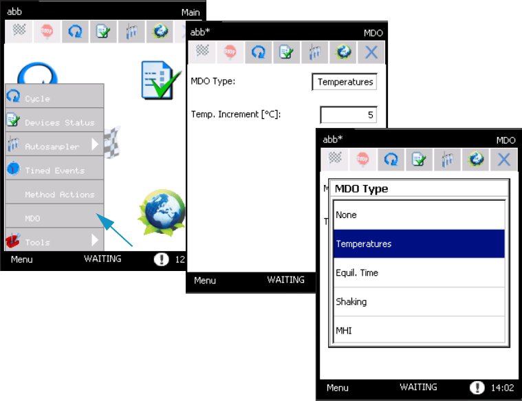
3 Operation
Method Developing Optimization (MDO)
72 TriPlus 300 Headspace User Guide Thermo Scientific
Method Developing Optimization (MDO)
The Method Developing Optimization (MDO) function empirically determines the same
parameters that provide the best optimization for your needs in order to create a method that
extracts sufficient samples to be analyzed.
This procedure increments a parameter as temperature, equilibration time, shaking level,
injection number in MHI mode, by a set amount in consecutive runs.
MDO Parameters
Select Menu | MDO to access MOD window. See Figure 58.
Figure 58. Method Developing Optimization
All the parameters that can vary during the optimization are listed in a drop-down menu:
•Te m p e r a t u re (°C) — All thermal zones increment by the same amount.
This value is inserted in the corresponding text box. If a heated zone reaches or would
exceed its maximum temperature, it will hold its maximum temperature for any
remaining vial.
Increasing the temperature can improve the peak areas of the sample, and increases the
throughput of the analysis.
It is important not exceed the boiling point of the sample compounds or solvent.
Moreover, when working at high temperatures the sample might be degraded, or transfers
more solvent.
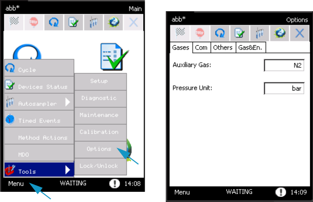
3 Operation
Options
Thermo Scientific TriPlus 300 Headspace User Guide 73
Using the temperature MDO option, the sequence is carried out in overlap mode because
each vial has a different incubation temperature, and must be individually equilibrated.
•Equilibration Time (min) — Increments the equilibration time for each analysis. When
increasing the equilibration time, consider that more solvent could be introduced or the
sample could be degraded
•Shaking — For each analysis, the instrument sets an increasing shaking level.
When the TriPlus 300 Headspace sampling system reaches the highest level of shaking,
this is maintained for all subsequent vials. The shaking benefits samples with a larger
amounts of liquid, liquid samples with high viscosity, and analytes with high partition
coefficients K.
•MHI (Multiple Headspace Injection) — If you select the MHI parameter, a text box
indicates where to insert the increments of the injection number. Increasing the number
of injections permits enrichment of the sample into the GC injector or trap.
Options
Select Menu > Tools > Options to access Options page. In this page you find information on
different options. See Figure 59
Figure 59. Options Page
The page is subdivided into four tabs:
•“Gases Tab” on page 74
•“Com Tab” on page 74
•“Others Tab” on page 76
•“Gas & Energy Saving Tab” on page 77
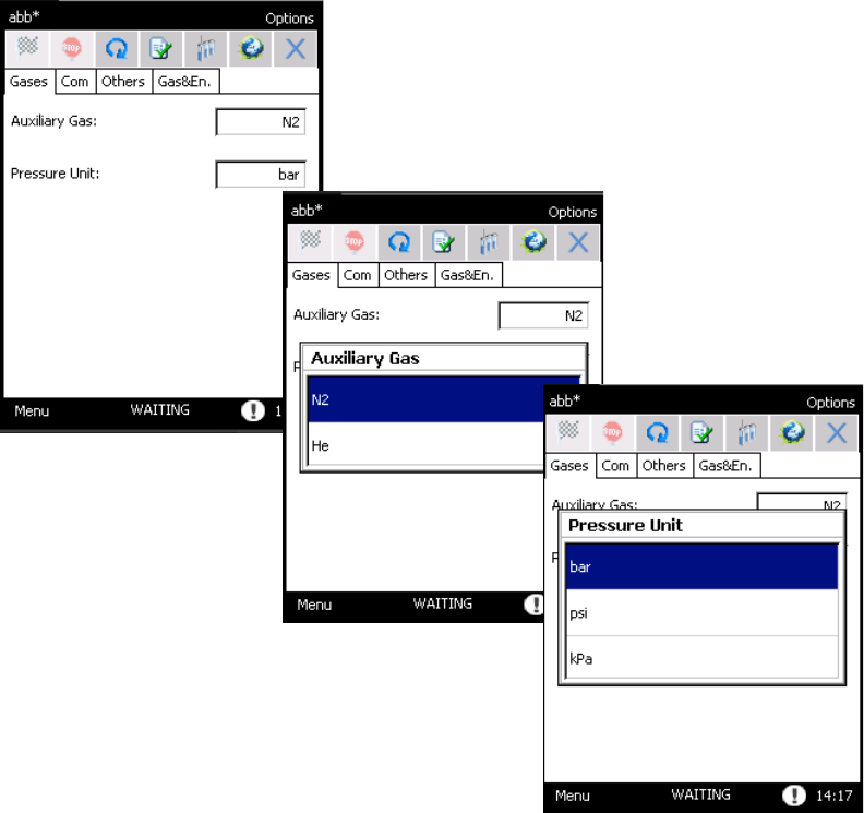
3 Operation
Options
74 TriPlus 300 Headspace User Guide Thermo Scientific
Gases Tab
In this tab you select the options related to the auxiliary gas and carrier gas. See Figure 60.
Figure 60. Options Page: Gases Tab
•Auxiliary Gas — The auxiliary flow rate displayed depends on the type of gas used
(Nitrogen or Helium).
•Pressure Unit — In this text box you select the pressure measurement unit. The units
available are: bar, psi and kPa. The default unit is bar. All set values will be automatically
converted.
Com Tab
This tab contains all the parameters to connect the TriPlus 300 Headspace sampling system to
the software. See Figure 61.
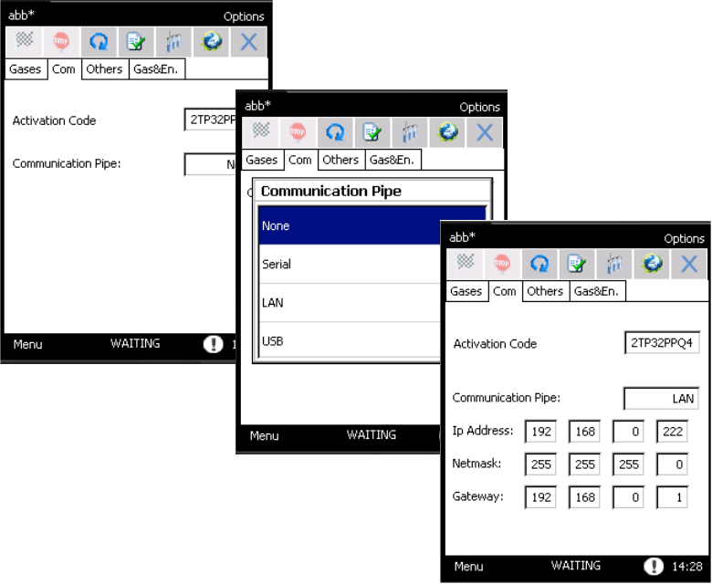
3 Operation
Options
Thermo Scientific TriPlus 300 Headspace User Guide 75
Figure 61. Options Page: Com Tab
•Activation Code — A specific code must be entered in the Activation code box to
control the TriPlus 300 Headspace sampling system through the software. This code is
strictly correlated to each software license and it is reported in the documentation
provided with the package.
– If the Activation code is not inserted a red message appears:
“Enter the right Activation code to enable the communication with the
Acquisition system”
– If the Activation code is wrong, a red message appears:
“Enter the right Activation code to enable the communication with the
Acquisition system”
In this case the communication with software control driver is not enabled.
•Communication Pipe — The TriPlus 300 Headspace sampling system can
communicate to a PC through three communication types: USB, LAN. or RS232.
Besides, the analog output is available for all the detector signals. Select the
communication pipe type through the pop-up window.
–None — Select this option to disable communication.
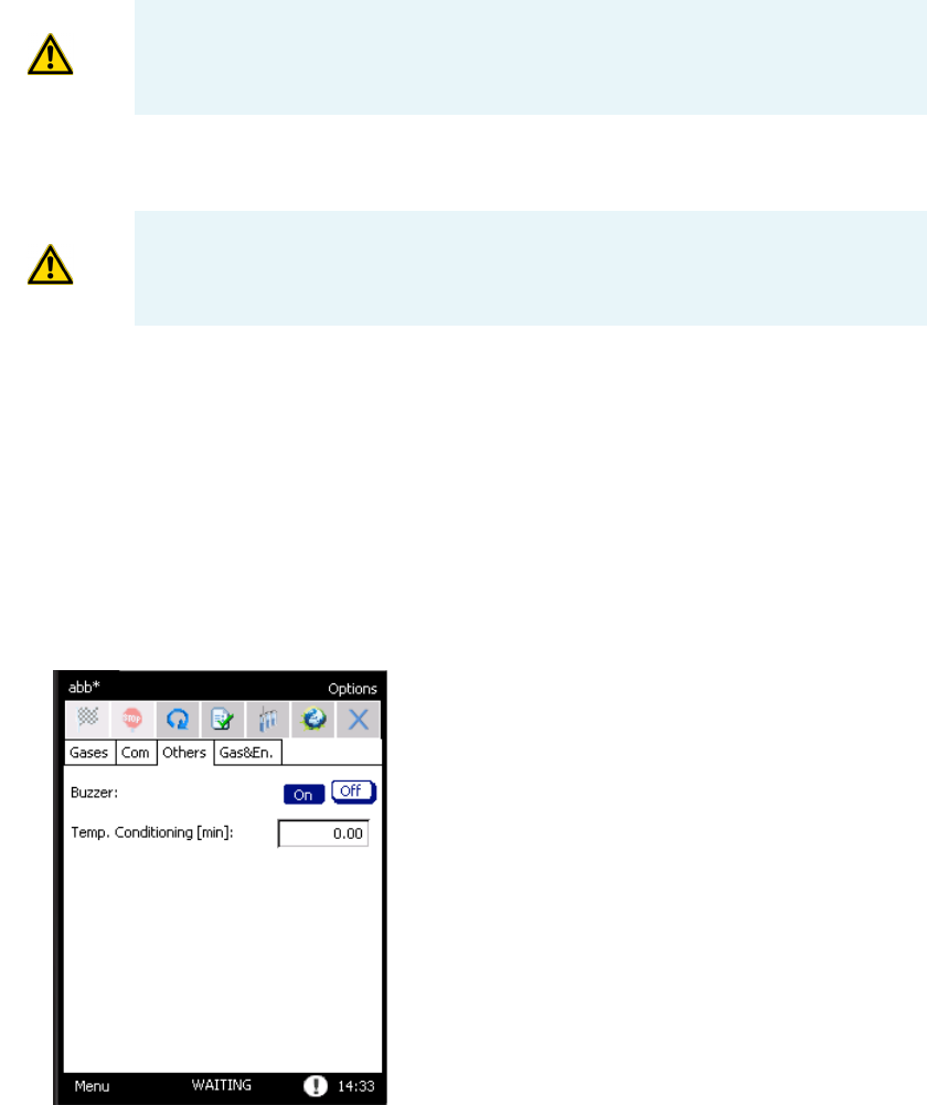
3 Operation
Options
76 TriPlus 300 Headspace User Guide Thermo Scientific
–Serial — Select this option to connect the serial port 1 or 2 to a COM port of the PC
through a RS232 serial cable. This communication type is suggested only for service.
–USB — This is the easiest communication pipe to configure a point to point between
PC and TriPlus 300.
–LAN — Use the LAN communication type to connect one or more instruments to a
single computer through a hub. A static IP address is required.
With a default subnet mask, the first three numbers must be the same as the GC and
PC address. The last number must be different for each instrument connected to the
LAN port.
Others Tab
The Others tab contains two parameters. See Figure 62.
Figure 62. Options Page: Others Tab
•Buzzer — This option enables or disables the buzzer of the TriPlus 300.
•Temp. Conditioning — Use this function to set a conditioning time, expressed in
minutes, for the devices to be heated, in order to obtain a higher stable temperature.
This parameters refers to the lapse of time for the heated zones to equilibrate after
reaching their setpoint, before a vial is loaded.
IMPORTANT This type of communication has lower performance than USB and
LAN and thus is only provided as an alternative for situations where USB and
LAN communication are not applicable.
IMPORTANT If this option is selected, connect the USB cable only after
installing the driver.
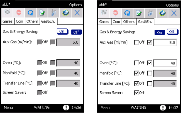
3 Operation
Setup
Thermo Scientific TriPlus 300 Headspace User Guide 77
Gas & Energy Saving Tab
This tab is available through the button on the tool bar, at the top of the screen, on the
desktop, or in option. It enables gas saving for the auxiliary gas and carrier gas if configured,
and energy savings by switching off the heaters and deactivating the touch screen. See
Figure 63.
Figure 63. Options Page: Gas & Energy Saving Tab
The selected parameters will be activated after 10 minutes of complete inactivity of the
machine and the Gas & Energy levels will be shown on the Status Bar.
You can set a flow or temperature value in the text box on the right side, or deactivate them
with the OFF check mark.
When the TriPlus 300 Headspace sampling system is in Gas & Energy Saving, a pop-up
menu will appear asking if you would like to deactivate the saving control.
If you select Yes, the control is deactivated, if you select No the window will disappear and the
TriPlus 300 Headspace sampling system will stay in saving mode. When the Screen Saver is
activated, click on the touch screen to see the pop-up menu, and then choose if you want to
keep this mode.
Setup
This page allows you to set the specific configurations for each instrument. This task is
performed at the factory or by Thermo Fisher Scientific technical personnel during
instrument installation.
All setup parameters are accessible through the standard password 1111, and preferably
managed by Thermo Fisher Scientific technical personnel to avoid unintentional
modifications.
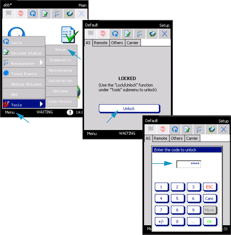
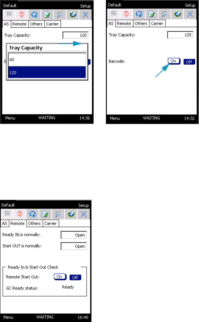
3 Operation
Setup
Thermo Scientific TriPlus 300 Headspace User Guide 79
AS Tab
In this tab the Tray Capacity of the sample tray installed on the Autosampler Unit is set.
Choose 60 or 120 accordingly. See Figure 65.
Figure 65. Setup Page: AS Tab
If the Barcode reader is present select On, otherwise select Off.
Remote Tab
In this tab the Read In and Start Out signals are set. See Figure 66 and “Setting the
Communications” on page 24.
Figure 66. Setup Page: Remote Tab
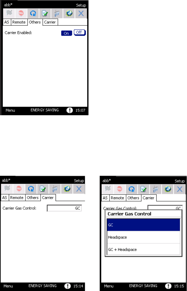
3 Operation
Setup
80 TriPlus 300 Headspace User Guide Thermo Scientific
Others Tab
In this tab the Carrier gas is enabled (On) or disabled (Off). See Figure 67.
Figure 67. Setup Page: Others Tab
Carrier Tab
In this tab the control of the Carrier gas is set among GC, Headspace, and GC+Headspace.
See Figure 68.
Figure 68. Setup Page: Carrier Tab

Thermo Scientific TriPlus 300 Headspace User Guide 81
4
Maintenance, Parts Replacement, and Diagnostic
This chapter provides guidelines for maintaining the TriPlus 300 Headspace sampling system,
and performing its diagnostics.
Contents
•Maintenance
•Calibration
•Diagnostic
•Lock/Unlock Page
•External Cleaning of the TriPlus 300 Headspace Instrument
•Replacing the Transfer Line Needle
•Replacing the Sampling Needle
•Handling Precautions
•Installing the HS Adapter Kit on the SSL/SSLBKF Injector
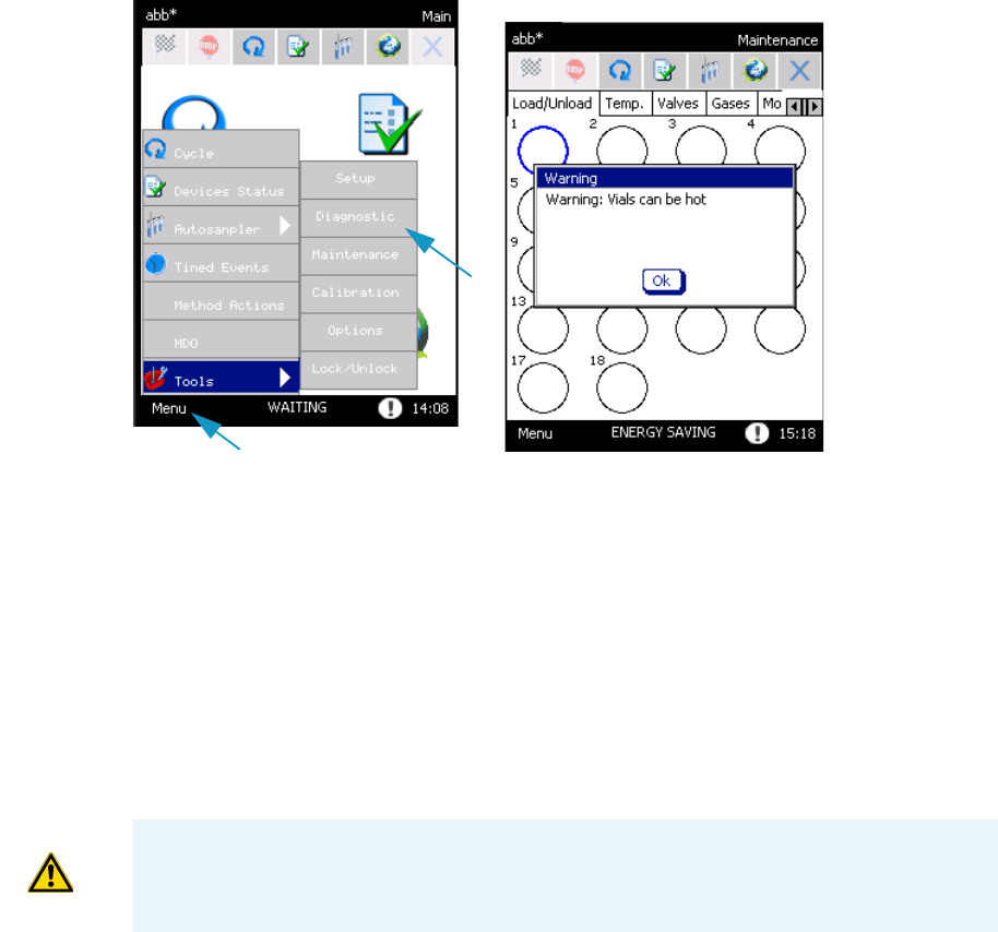
4 Maintenance, Parts Replacement, and Diagnostic
Maintenance
82 TriPlus 300 Headspace User Guide Thermo Scientific
Maintenance
To access the Maintenance section, press Menu | Tools | Maintenance. See Figure 69.
Figure 69. Maintenance Page
The Maintenance window includes six tabs for maintaining the instrument maintenance:
•Load/Unload Tab
•Temperature Tab
•Valves Tab
•Gases Tab
•Movements Tab
•FW Update Tab
ATTENTION These tabs are accessible through a password, and preferably managed by
Thermo Fisher Scientific trained technical personnel. You can only access to the
Load/Unload tab. See “Load/Unload Tab” on page 83.
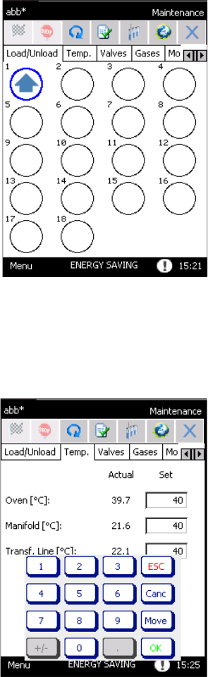
4 Maintenance, Parts Replacement, and Diagnostic
Maintenance
Thermo Scientific TriPlus 300 Headspace User Guide 83
Load/Unload Tab
In the load/unload page you move the carousel and the Insertion and Sampling lifter in order
to load vials without using the Automatic sampler. See Figure 70.
Figure 70. Maintenance Page: Load/Unload
Temperature Tab
In this tab you can change the temperatures setpoints. See Figure 71.
Figure 71. Maintenance Page: Temperature Tab
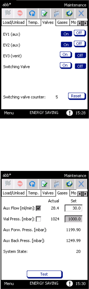
4 Maintenance, Parts Replacement, and Diagnostic
Maintenance
84 TriPlus 300 Headspace User Guide Thermo Scientific
Valves Tab
In this tab you may change the valves setting. See Figure 72.
Figure 72. Maintenance Page: Valves Tab
Gases Tab
In this tab you may change the gases setting. See Figure 73.
Figure 73. Maintenance Page: Gases Tab
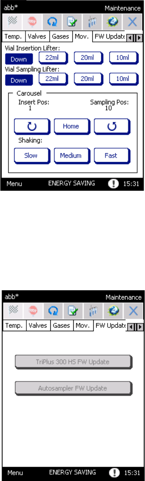
4 Maintenance, Parts Replacement, and Diagnostic
Maintenance
Thermo Scientific TriPlus 300 Headspace User Guide 85
Movements Tab
In this tab you may change the movements of the carousel. See Figure 73.
Figure 74. Maintenance Page: Movements Tab
FW Update Tab
In this tab you may update the firmware of the TriPlus 300 Headspace sampling system.
See Figure 75.
Figure 75. Maintenance Page: FW Update Tab
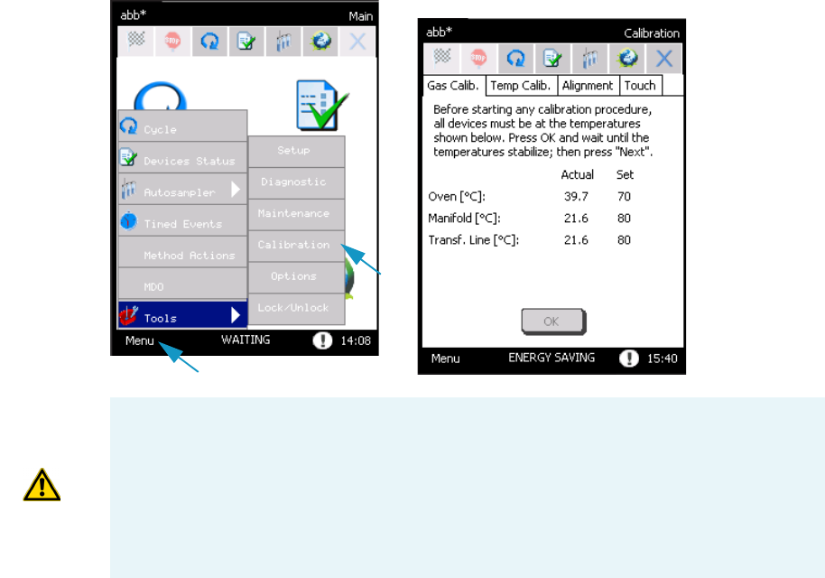
4 Maintenance, Parts Replacement, and Diagnostic
Calibration
86 TriPlus 300 Headspace User Guide Thermo Scientific
Calibration
To access the Calibration section, select Menu | Tools | Calibration. See Figure 76.
Figure 76. Calibration Page
ATTENTION The Gas calibration, Temperatures Calibration, and Alignment tabs are
accessible only through a password and preferably managed by Thermo Fisher Scientific
trained technical personnel. You may only access to the Tou c h tab. See Tou ch Sc re e n
Calibration .
Note The gas calibration is performed at factory or during the instrument installation,
using nitrogen as auxiliary gas.
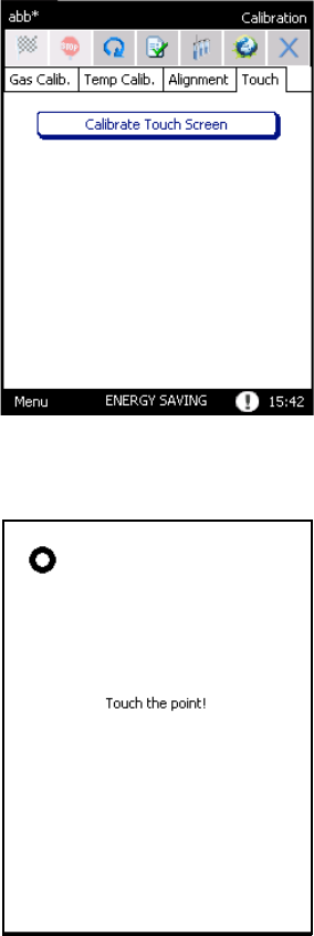
4 Maintenance, Parts Replacement, and Diagnostic
Calibration
Thermo Scientific TriPlus 300 Headspace User Guide 87
Touch Screen Calibration
You can calibrate the touch screen in order to make it suitable to your finger.
To calibrate the touch screen
1. Open the page Touch and press the button Calibrate touch screen. See Figure 77.
Figure 77. Touch Screen Calibration (1)
2. A series of circles will be displayed. Press at the middle of each circle. See Figure 78.
Figure 78. Touch Screen Calibration (2)
3. At the end of this procedure the message Congratulation your touch screen has been
calibrated appears.
4. Press the touch screen again to continue.
• Use the original packing to transport the instrument. Do not turn the instrument upside
down.
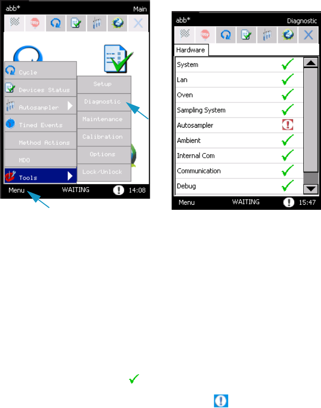
4 Maintenance, Parts Replacement, and Diagnostic
Diagnostic
88 TriPlus 300 Headspace User Guide Thermo Scientific
Diagnostic
To access the Diagnostic section, select Menu | Tools | Diagnostic. See Figure 69.
Figure 79. Diagnostic Page
This section provides information about the diagnostics of the instrument. The related topics
are:
•“Hardware” on page 88
•“Alarms” on page 89
Hardware
When the instrument is powered on, a Self test is performed to check that the instrument is
functioning correctly. During this procedure, all the configured devices are checked one by
one. At the end, the Hardware tab of the diagnostic page shows all the devices in a list.
If the device passes the test, a symbol appears.
• If a device fails the test, an exclamation mark appears. If you press on the device's
name, a pop-up menu appears reporting detailed information about the device, its
malfunctioning, or both.
The Diagnostic page can be entered any time after the self test. To access to Diagnostic page
select Menu | Tools | Diagnostic.
The first item in the list is System. You can read the serial number of the instrument, the
firmware version of the Main Board, and the other controllers.
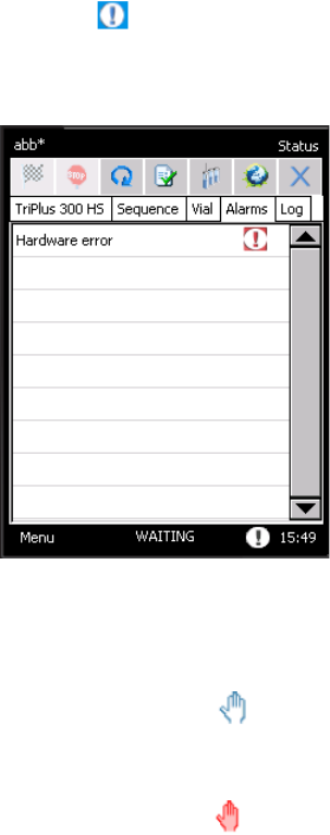
4 Maintenance, Parts Replacement, and Diagnostic
Diagnostic
Thermo Scientific TriPlus 300 Headspace User Guide 89
Alarms
When the control unit diagnoses an error, an exclamation mark blinks on the status bar near
the time clock.
Select the icon to display the Alarms page, where the alarm messages are listed.
See Figure 80.
Figure 80. Alarms Page
If you press on the row, a pop-up menu appears containing details on the problem and, in
most cases, the instructions for to solve it.
The errors can be divided in:
•Blue hand alarms — Indicates an error concerning a wrong setpoint.
In this case the START of the analysis is not blocked. See “Blue Hand Alarms” on
page 90.
•Red hand alarms — Indicates an error that could cause serious damages.
In this case the START of the analysis is blocked. See “Red Hand Alarms” on page 90.
Hardware Errors indicate a malfunction of the instrument. They are visualized by a red hand,
with the message Hardware error. Refer to the Diagnostic page for details.
If these problems occur, it is preferable to call Thermo Fisher Scientific technical personnel.

4 Maintenance, Parts Replacement, and Diagnostic
Diagnostic
90 TriPlus 300 Headspace User Guide Thermo Scientific
Blue Hand Alarms
The Blue hand alarms are listed in Table 12.
Red Hand Alarms
The Red hand alarms are listed in Table 13.
Table 12. List of Blue Hand Alarms
Message Error Description How to Solve It
Load Method A method parameter
was not found in the
flash memory.
The corresponding
default value has
been loaded.
The default value of
the parameter has
been loaded.
Modify the value of
the parameter in the
method.
See “Cycle” on
page 49.
Load Sequence A sequence
parameter was not
found in the flash
memory.
The corresponding
default value has
been loaded.
The default value of
Sequence Nr.Seq,
Column [row] has
Modify the sequence
parameter in the
analysis table.
See “Sequence ” on
page 61.
Table 13. List of Red Hand Alarms (Sheet 1 of 3)
Message Error Description How to Solve It
Sequence: First Out
Of Range
The First vial in a
sequence row is out
of range, because you
switched between
autosampler
sequences and
carousel sequences.
Rows: 1, …
Range 1...18
Modify the First vial
in the Analysis Table.
See “Sequence ” on
page 61.
Sequence: Last Out
Of Range
The Last vial in a
sequence row is out
of range, because you
switched between
autosampler
sequences and
carousel sequences.
Rows: 1, ...
Range 1...18
Modify the Last vial
in the Analysis table.
See “Sequence ” on
page 61.

4 Maintenance, Parts Replacement, and Diagnostic
Diagnostic
Thermo Scientific TriPlus 300 Headspace User Guide 91
Sequence: First vial >
Last vial
You selected a first
vial > than last vial.
Rows: 1, …
First vial > Last vial
Modify the First and
Last values in the
Analysis table.
See “Sequence ” on
page 61.
Analysis table is
empty
There are no entries
in the Analysis table.
No entries in analysis
table
Insert at least a line
in the Analysis table.
See “Sequence ” on
page 61.
Carrier Gas Pressure
too low
The carrier gas
pressure is below the
50 mbar threshold.
Carrier gas pressure
below threshold
Check carrier gas
supply and check for
possible leaks.
Autosampler
Disconnected
TriPlus 300
Headspace sampling
system lost
communication with
the autosampler, or
the autosampler was
shut down during a
sequence.
The autosampler is
disconnected, check
wiring and power
cycle it.
Check the
autosampler wiring
and power cycle it.
Log message A problem occurred
during a sequence
and a new message
was displayed in the
log file.
Log file has a new
message.
Check the log file in
the Status page. See
“Status” on page 37.
Hardware error It indicates a
malfunction of the
instrument.
See Diagnostic page. See Diagnostic page
for details; if
necessary contact the
Te chni ca l Su p p o r t .
Carousel Error Carousel lost its
position or a
hardware failure
occurred.
Carousel lost
position or hardware
failure.
Cycle the power for
the TriPlus 300
Headspace sampling
system. If the
problem persists
contact the Technical
Support.
Table 13. List of Red Hand Alarms (Sheet 2 of 3)
Message Error Description How to Solve It
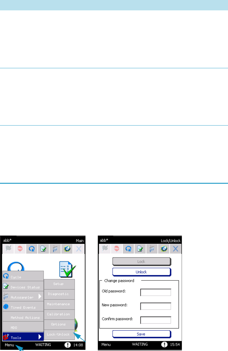
4 Maintenance, Parts Replacement, and Diagnostic
Lock/Unlock Page
92 TriPlus 300 Headspace User Guide Thermo Scientific
Lock/Unlock Page
To access the Lock/Unlock section, select Menu | Tools | Lock/Unlock. See Figure 81.
Figure 81. Lock/Unlock Page
Insertion Lifter Error Insertion lifter lost its
position or a
hardware failure
occurred.
Insertion Lifter lost
position or hardware
failure.
Cycle the power for
the TriPlus 300
Headspace sampling
system. If the
problem persists
contact the Technical
Support.
Sampling Lifter Error Sampling lifter lost
its position or a
hardware failure
occurred.
Sampling Lifter lost
position or hardware
failure.
Cycle the power for
the TriPlus 300
Headspace sampling
system. If the
problem persists
contact the Technical
Support.
Switching Valve
Error
Switching valve lost
its position or a
hardware failure
occurred.
Switching Valve lost
position or hardware
failure.
Cycle the power for
the TriPlus 300
Headspace sampling
system. If the
problem persists
contact the Technical
Support.
Table 13. List of Red Hand Alarms (Sheet 3 of 3)
Message Error Description How to Solve It

4 Maintenance, Parts Replacement, and Diagnostic
External Cleaning of the TriPlus 300 Headspace Instrument
Thermo Scientific TriPlus 300 Headspace User Guide 93
In this page you can lock or unlock the touch screen by pressing the relevant button.
When the Unlock button is pressed, the system requires a password. Type the password to
unlock the touch screen.
If you want, you may change the password and save it by pressing the Save button.
External Cleaning of the TriPlus 300 Headspace Instrument
To clean the exterior the TriPlus 300 Headspace Instrument
1. Clean the instrument on the outside with a water and soap solution or with a household
non-abrasive product. Pay special attention when cleaning the back side of the sampling
unit. Do not spray anything, but clean using a cloth imbued with the cleaning solution.
2. .Dry with a clean cloth.
If you suspect that any substance used for cleaning or submitted to analysis may have entered
the instrument, though it is very unlikely, immediately switch off the instrument and call the
authorized Technical Service personnel for proper action.
Replacing the Transfer Line Needle
The transfer line needle is connected to the line by a fitting and a stainless steel ferrule.
To replace the transfer line needle
1. Disconnect the power supply cord before opening the instrument.
2. Use a 7 mm wrench to support the fitting and with another 7 mm wrench unscrew the
needle.
3. Replace the needle and tighten the fitting until sealed. It is not necessary to replace the
stainless steel ferrule on the tube.
4. Check the seal by closing the tube outlet, for example with a septum, and pressurizing the
carrier gas line.
WARNING The external cleaning must be performed with the instrument off and the
power cord disconnected. Avoid using solvents and spraying anything on the electrical
parts. For the removal of possible dangerous substances (toxic, harmful, and so on), read
the hazard indications and information reported in the Safety Sheet supplied by the
manufacturer referring to the relevant CAS (Chemical Abstract Service) number. Use
proper protective equipment.
4 Maintenance, Parts Replacement, and Diagnostic
Replacing the Sampling Needle
94 TriPlus 300 Headspace User Guide Thermo Scientific
Replacing the Sampling Needle
To replace the sampling needle proceed as follows:
To replace the sampling needle
1. Disconnect the power supply cord before opening the instrument.
2. Insert the Teflon seal in the upper part of the new needle and the Kalretz™ O-ring in the
lower part. Insert the new needle in the holder pushing it from the upper part.
3. Reassemble the needle holder on the manifold, paying attention that the needle enters the
guide positioned in the lower part of the manifold.
4. Reassemble the screw that blocks the needle holder to the manifold and tighten it.
5. Replace the tubing entering the manifold from the right side. Use a 7 mm wrench to
tighten the fitting.
6. Replace the fitting in the upper part of the manifold and tighten it with an 8 mm wrench.
7. Replace the tubing entering the manifold from the upper part and use a 7 mm wrench to
tighten the fitting.
8. Close the cover of the aluminum box that contains the manifold and the switching valve
and tighten the screw located in the left side of the box.
9. Put the cover back on the front part and secure it with the screw located on side.
Handling Precautions
If it is necessary to move the instrument, the following precautionary measures should be
taken:
• Remove the vials from the carousel.
• Remove the needle from the transfer line.
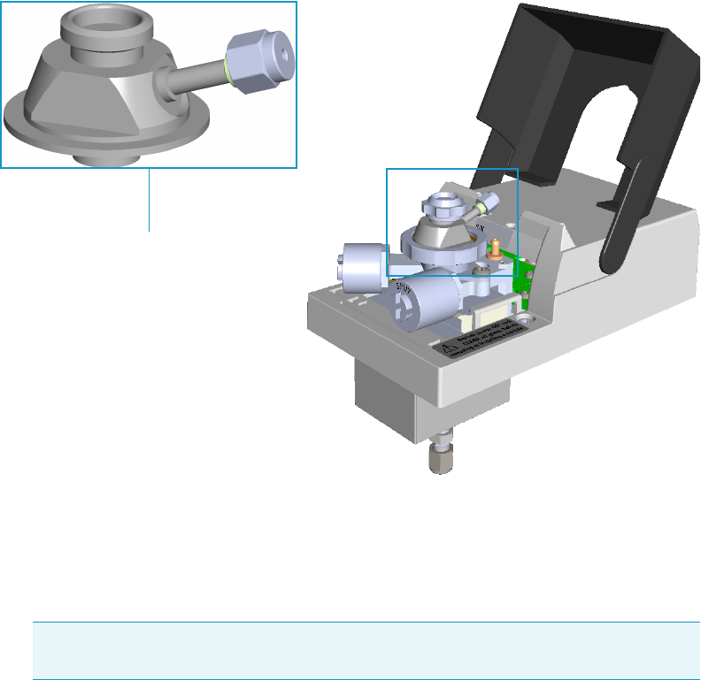
4 Maintenance, Parts Replacement, and Diagnostic
Installing the HS Adapter Kit on the SSL/SSLBKF Injector
Thermo Scientific TriPlus 300 Headspace User Guide 95
Installing the HS Adapter Kit on the SSL/SSLBKF Injector
This section provides the instructions for installing the HS Adapter kit on the TRACE 1300
Series GC SSL/SSLBKF injectors for the use with a TriPlus 300 Headspace sampling system.
See Figure 82.
Figure 82. HS Adapter
To install the HS adapter:
1. Put the TRACE 1300 Series GC in standby condition.
2. Cool the oven, injector, and detector to room temperature.
3. Close the gas supplies.
4. Power off the GC.
a. Push down the power switch (breaker), located at the back of the instrument, to the
position O.
b. Unplug the power cable from the AC Input connector into the back of the GC and
from the wall outlet.
5. Remove the column end from the injector and the detector.
a. Open the front door of the GC.
Note By pressing the Maintenance button, the GC cool down is automatically
carried out.
HS adapter
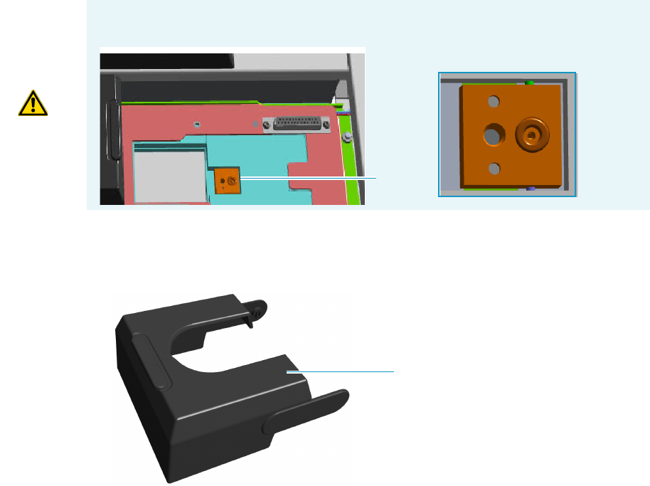
4 Maintenance, Parts Replacement, and Diagnostic
Installing the HS Adapter Kit on the SSL/SSLBKF Injector
96 TriPlus 300 Headspace User Guide Thermo Scientific
b. Loosen the retaining nut from the injector fitting on the upper interior wall of the
GC oven.
c. Remove the analytical column with its nut and ferrule from the bottom of the
injector.
d. Remove the analytical column with its nut and ferrule from the bottom of the
detector.
6. Remove the SSL/SSLBKF injector module from its seat.
a. Open the module flap cover.
b. Using a T20 Torxhead screwdriver, unscrew the three captive fixing screws.
c. Lift the module from its seat in the injector housing. Place the SSL/SSLBKF module
on a clean surface.
7. Replace the module flap cover with the one’s provided. See Figure 83.
Figure 83. Module Flap Cover for the HS Adapter
8. Reinstall the injector module into the main frame.
a. Open the module flap cover.
b. Place the injector module in its seat. Be sure to insert the 25-pin male connector, on
the bottom of the module, into the 25-pin female connector on the injector seat of
the injector housing.
WARNING Make sure the o-ring remains into its seat on the gas connection.
Do not install the module if the o-ring is missing.
O-ring
Module flap cover
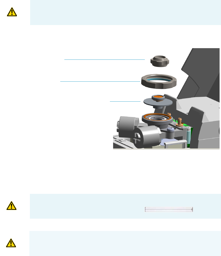
4 Maintenance, Parts Replacement, and Diagnostic
Installing the HS Adapter Kit on the SSL/SSLBKF Injector
Thermo Scientific TriPlus 300 Headspace User Guide 97
c. Use a T20 Torxhead screwdriver to tighten the three captive fixing screws without
overtightening.
9. Remove the top parts of the injector. See Figure 84.
Figure 84. Injector Top Parts Removal
a. Unscrew the septum cap of the injector.
b. Unscrew the ring nut.
c. Remove the septum holder/liner cap with septum from the injector body head.
10. Replace the liner.
a. Use tweezers to remove the current liner with the liner seal (o-ring) from the injector.
b. Holding the HS/SPME liner with tweezers, place a new liner seal over the liner.
c. Insert the liner into the injector and push it gently towards the bottom of the injector.
11. Install the HS adapter on the top of the injector. See Figure 85.
CAUTION To maintain the correct alignment the screws must be tightened in turn.
Tighten each screw only a small amount before moving to the next screw. Repeat until all
are secure.
Septum Cap
Ring nut
Septum holder/Liner cap with septum
IMPORTANT We suggest replacing the liner currently installed into the injector with the
HS/SPME straight glass empty liner P/N 453A1335.
CAUTION Be careful not to break the glass liner when removing it. Glass splinters might
fall into the lower part of the vaporization chamber.
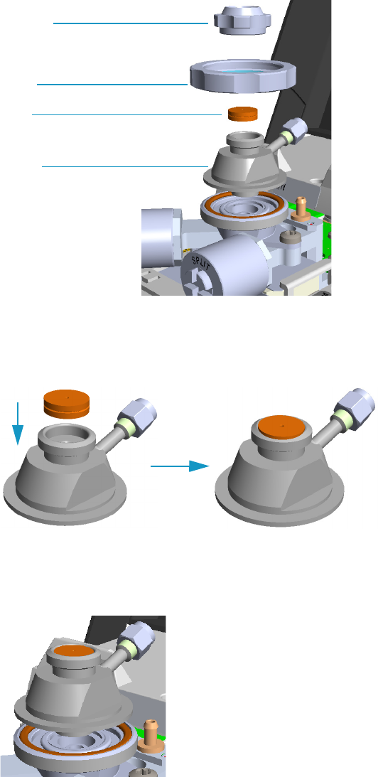
4 Maintenance, Parts Replacement, and Diagnostic
Installing the HS Adapter Kit on the SSL/SSLBKF Injector
98 TriPlus 300 Headspace User Guide Thermo Scientific
Figure 85. HS Adapter (1)
a. Avoid touching the septum with your fingers. Insert a new septum into the septum
holder cavity of the HS adapter using tweezers. See Figure 86.
Figure 86. HS Adapter (2)
b. Place the HS adapter with the septum on the body head of the injector.
See Figure 87.
Figure 87. HS Adapter (3)
c. Guide the ring nut on the HS adapter with the septum, then fix it by screwing in the
ring nut. See Figure 88.
Septum cap
Septum
Ring nut
HS adapter
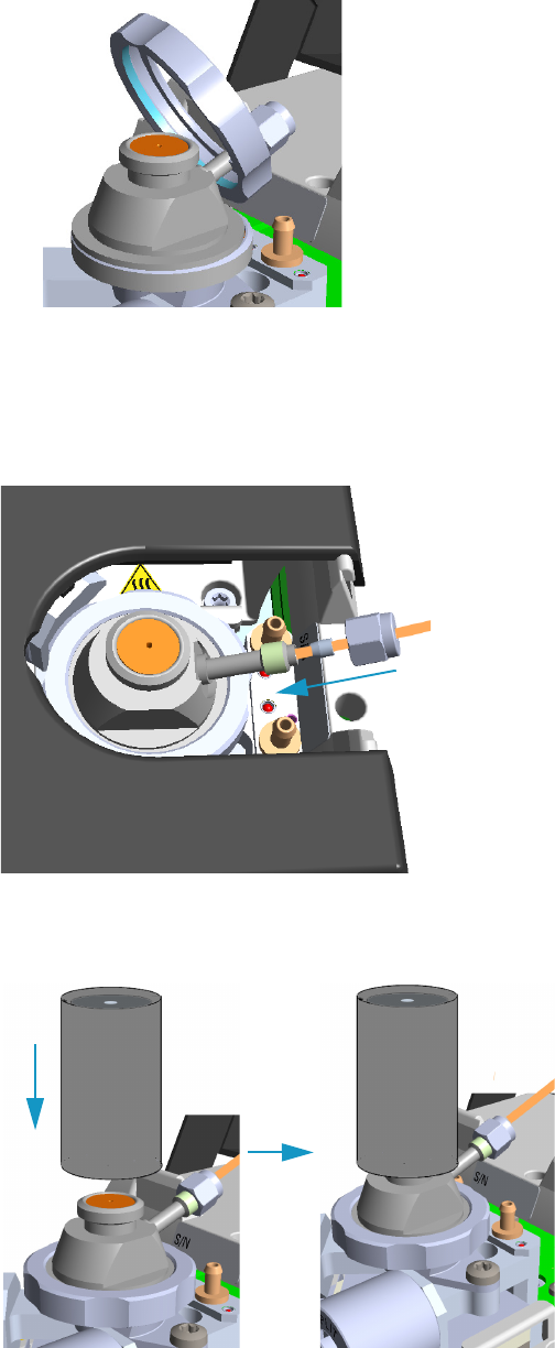
4 Maintenance, Parts Replacement, and Diagnostic
Installing the HS Adapter Kit on the SSL/SSLBKF Injector
Thermo Scientific TriPlus 300 Headspace User Guide 99
Figure 88. HS Adapter (4)
12. Close the module flap cover.
13. Connect the carrier gas line coming from the TriPlus 300 Headspace sampling system to
the HS adapter by using the proper nut and ferrule. See Figure 89.
Figure 89. HS Adapter (5)
14. Screw and finger-tighten the septum cap provided. See Figure 90
Figure 90. HS Adapter (6)
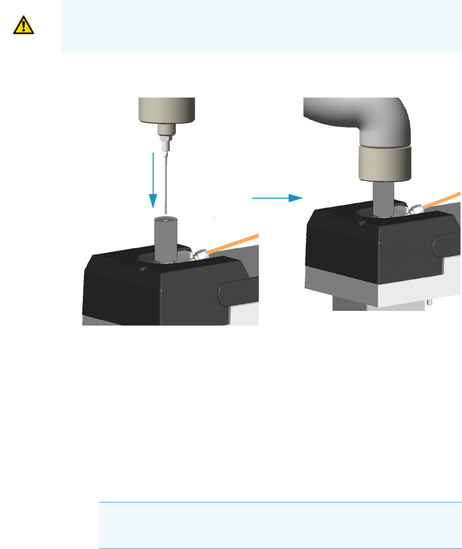
4 Maintenance, Parts Replacement, and Diagnostic
Installing the HS Adapter Kit on the SSL/SSLBKF Injector
100 TriPlus 300 Headspace User Guide Thermo Scientific
15. Insert the transfer line needle into the septum cap. See Figure 91.
Figure 91. Transfer Line Connection
16. Cut the piece of column end previously connected to the injector.
a. Use a scoring wafer to score and break the column in order to remove the current
ferrule and the nut.
17. Connect the column to the injector.
a. Wipe about 100 mm (4 in.) of the column with a tissue soaked in methanol.
b. Insert the column through the injector retaining nut and the proper ferrule (open end
up). Wipe the column again with a tissue soaked in methanol.
c. Use a scoring wafer to score and break the column about 1 cm (0.4 in.) from the end.
Use a magnifying glass to check for an even, flat cut. Repeat if necessary.
d. Position the column so that the end of the column extends the proper distance of
30 mm above the end of the ferrule.
.
e. Insert the notched septum on the column to hold the retaining nut at this position.
Thread the retaining nut into the injector but do not tighten.
CAUTION Do not overtighten the septum cap because you might damage the septum and
affect instrument performance.
Tip Slide a notched septum on the column before the injector retaining nut to
make it easier to measure the proper distance between the nut and the end of the
column.

4 Maintenance, Parts Replacement, and Diagnostic
Installing the HS Adapter Kit on the SSL/SSLBKF Injector
Thermo Scientific TriPlus 300 Headspace User Guide 101
f. Adjust the column position so that the septum contact the bottom of the retaining
nut.
g. Finger-tighten the retaining nut until it starts to grip the column plus a quarter turn.
h. Remove the notched septum from the column.
18. Open the gas supplies.
19. Power on the GC.
a. Plug the power cable into the AC Input connector on the back of the GC and into
the wall outlet.
b. Flip out the power switch (breaker) to the position I.
20. Setup the GC.
a. Set the oven and injector temperature to 50 °C.
b. Use the column-flowmeter connector to verify that there is flow through the column.
If you do not have a flowmeter, dip the column outlet in a small vial of methanol.
Bubbles indicate there is flow through the column. If there is no flow, check that the
carrier gas is on, the GC inlet is pressurized, and the column is not plugged. If there is
still no flow, consult the section Analytical Troubleshooting in the TRACE
1300/TRACE 1310 User Guide, or contact the Technical Support.
c. Allow the column to purge for few minutes.
21. Perform a column leak check.
22. Calibrate the carrier gas flow (column evaluation).
a. Select the column and input the physical characteristics of the column.
b. If a pre-/post-column is present, set the length and nominal internal diameter of the
pre-/post-column in the same valid ranges for the column. The following two lines
are added to the menu.
c. According to the physical characteristics of the column, the system calculates and
displays the relevant Column K-factor.
d. Start column evaluation. At the end of the routine, a message will indicate that
evaluation was successful.
e. Expect a K-factor of approximately 0.7 – 0.9 for a 15 m, 0.25 mm ID column
(1.3 – 2.0 for a 30 m, 0.25 mm ID column). If the column does not report a K-factor
within this range or within 0.1 units of the previous stored value, check for a leak or
broken column using the leak detector. The K-factor is a measured resistance for the
column. A K-factor that is too low may indicate a leak in the system, while a K-factor
that is too high may indicate a blockage.
Note For the most reproducible results, you should conduct a more detailed
column evaluation. However, the following steps, while recommended, are not
required.
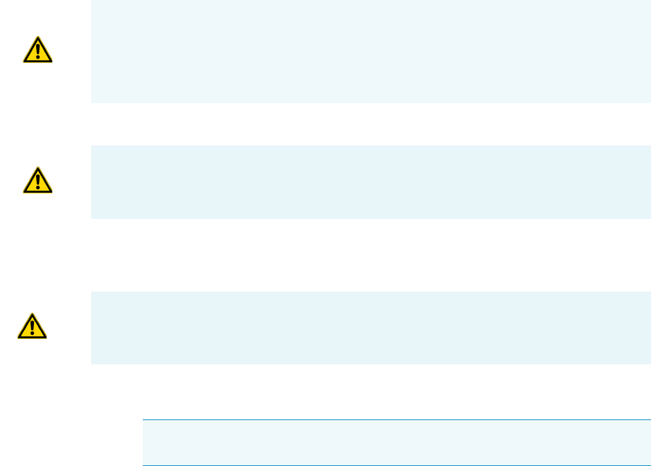
4 Maintenance, Parts Replacement, and Diagnostic
Installing the HS Adapter Kit on the SSL/SSLBKF Injector
102 TriPlus 300 Headspace User Guide Thermo Scientific
23. Disconnect the column-flowmeter.
a. Disconnect the column from the column-flowmeter connector.
b. Remove the clear plastic component, including its fittings, from the oven and set it
aside.
c. Close the GC door.
24. Condition the column.
The column must be conditioned before inserting it into the detector.
Column conditioning consists of passing a carrier gas flow through the column heated at
a programmed temperatures as described in the column manufacturer’s instructions.
In case the column does not have any column conditioning instructions, perform the
column conditioning by setting a final temperature up to 10 °C - 20 °C below its
recommended maximum temperature.
a. Run the temperature program that is recommended by the manufacturer.
25. Connect the column to the detector inside the GC.
a. Lower the oven temperature to 30 °C and allow it to cool.
b. Unwind the column enough to easily connect its ends to the injector and the
detector..
c. Wipe about 100 mm (4 in.) of the column with a tissue soaked in methanol.
d. Use a scoring wafer to score and break the column outlet about 2.5cm (1 in.) from
the end. Use a magnifying glass to check for an even, flat cut. Repeat if necessary.
CAUTION When performing column conditioning, the column should be connected only
to the injector leaving the column outlet disconnected to avoid the possibility of
contamination of the detector.
Do not use hydrogen as the carrier for conditioning! It could vent into the oven and
present an explosion hazard.
INSTRUMENT DAMAGE: Never exceed the column manufacturer’s maximum operating
temperature.
WARNING-BURN HAZARD: The injector, detector, oven, and transfer line may be hot.
Allow them to cool to room temperature before touching them.
Note Wear clean, lint- and powder-free gloves when you handle the column and
injector ferrule.

4 Maintenance, Parts Replacement, and Diagnostic
Installing the HS Adapter Kit on the SSL/SSLBKF Injector
Thermo Scientific TriPlus 300 Headspace User Guide 103
e. Insert the column through the proper detector retaining nut and ferrule (open end
up). Wipe the column again with a tissue soaked in methanol.
f. Position the column so that the end of the column extends the proper distance above
the end of the ferrule as reported in Tab le 14.
For PDD see the instruction described at the step g on page 103.
i. For FID, NPD, TCD, insert the column into the detector, paying attention to
not force it further. Finger-tighten the retaining nut, then withdraw the column
2-3 mm. Tighten the retaining nut an additional a quarter turn.
ii. For ECD and FPD, insert the notched septum on the column to hold the
retaining nut in this position. Thread the retaining nut into the detector but do
not tighten.
Finger-tighten the retaining nut until it starts to grip the column plus a quarter
turn. Remove the notched septum from the column.
g. For PDD the column must penetrate 136 mm inside the capillary column adapter.
h. End of the column installation.
i. Close the front door of the GC.
Tip Slide a notched septum on the column before the detector retaining nut to
make it easier to measure the proper distance between the bottom nut and end of
the column.
Table 14. Column Insertion Depth For FID, NPD, TCD, ECD, FPD, and PDD Detectors
FID NPD TCD ECD FPD PDD
Insert the column as far as goes and withdrawn
about 2mm
23 mm 125 mm 136 mm
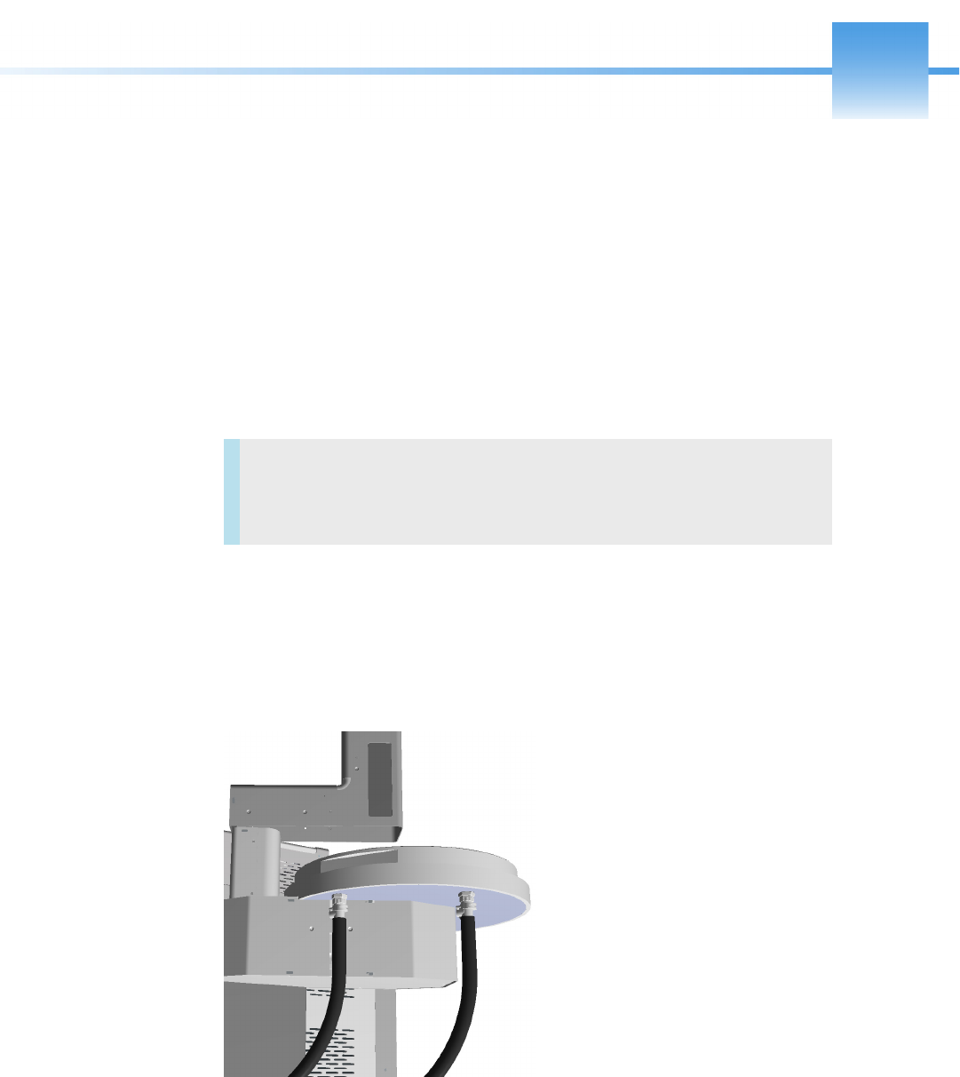
Thermo Scientific TriPlus 300 Headspace User Guide 105
5
Upgrade Equipment
This chapter describes how to upgrade the TriPlus 300 Headspace sampling system with the
available optional devices.
Chiller
The chiller is an optional accessory of the Autosampler Unit for cooling all the 120 vials on
the tray through a refrigerant coil installed underneath the plate. See Figure 92.
Figure 92. Chiller
The chiller requires an external recirculating cooling pump. All the control parameters must
be set on this device. Refer to the chiller pump manual.
Contents
•Chiller
•Barcode Reader
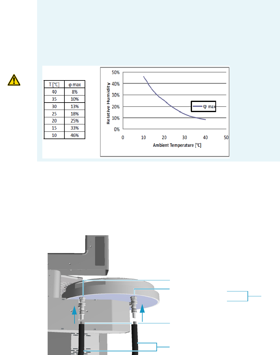
5 Upgrade Equipment
Chiller
106 TriPlus 300 Headspace User Guide Thermo Scientific
The difference between the temperature of the liquid inside the coil and the vials on the tray is
about 10 °C, so the chiller temperatures values must be 10 degrees lower then the vial
temperature required.
To install the chiller
The installation of the chiller is very easy: under of the chiller plate you find two fittings in
order to connect the IN and OUT silicon tubes of the refrigerant circuit.
The two tubes are covered with insulating material.
1. Connect the tubes as shown in Figure 93.
Figure 93. Tubes Connection
IMPORTANT Be careful!!!
If the relative humidity in the air is high, it could create condensation on the tube and
under the plate. In the event of very low temperatures ice could be formed, and you must
manually remove the ice.
On the table below find the assessment of the maximum humidity forming respect to
ambient temperature wherein the Chiller can work without forming condensation.
IN
OUT
In/Out silicon tubes
Insulating material
5 Upgrade Equipment
Barcode Reader
Thermo Scientific TriPlus 300 Headspace User Guide 107
•IN is the inlet of refrigerant liquid.
•OUT is the outlet of refrigerant liquid.
Barcode Reader
The Barcode Reader is an optional accessory of the autosampler tray that reads the labels
attached to the sample vials for positive identification of the samples.
The Barcode reader supports the checksums and the following fonts:
• Code 128
•3 of 9
•Matrix 2 of 5
• Standard 2 of 5
•Interleaved 2 of 5
•UPC-A
• EAN/JAN 13
• EAN/JAN 8
•UPC-E
•QR Code (2D)
About the Barcode Reader
A barcode is an optical machine-readable representation of data relative to the object to which
is attached.
The first use of barcodes was to label railroad cars, but they were not commercially successful
until they were used to automate supermarket checkout systems.
Originally barcodes represented data by varying the widths and spacings of parallel lines
(linear or one-dimensional), later they evolved into rectangles, dots, hexagons, and other
geometric patterns in two dimension (2D).
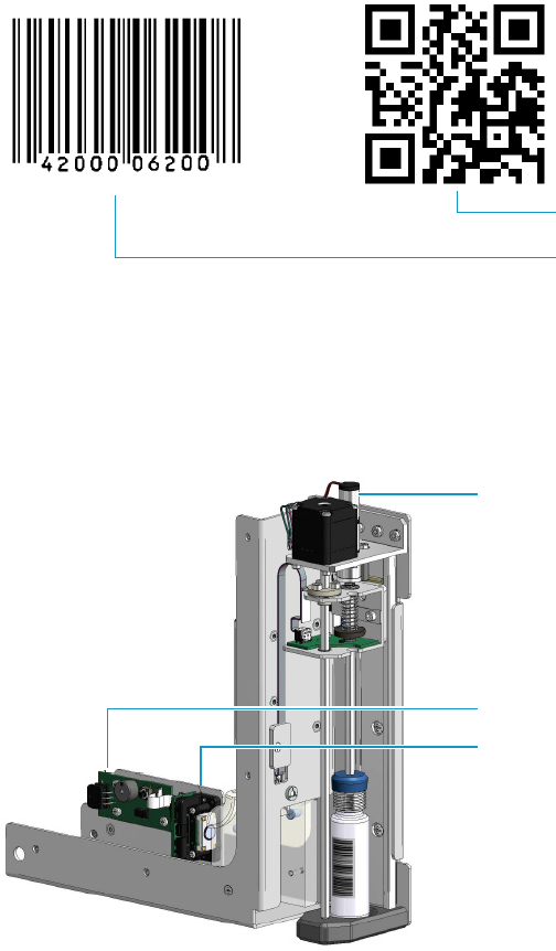
5 Upgrade Equipment
Barcode Reader
108 TriPlus 300 Headspace User Guide Thermo Scientific
Barcode Reader Description
The barcode reader consists of three main parts. See Figure 94.
Figure 94. Barcode Reader
• An optical scanner positioned inside the horizontal arm for enabling the reading of the
barcode.
• An electronic board connected to the optical scanner by a flat cable.
• A motor rotating the vial for the complete reading of the barcode.
User Information
To enable the barcode reader select Menu > Setup > AS. Activate the barcode reader by
selecting barcode ON. See Figure 94.
One-dimensional barcode
Two-dimensional barcode (2D)
Optical scanner
Motor
Electronic board
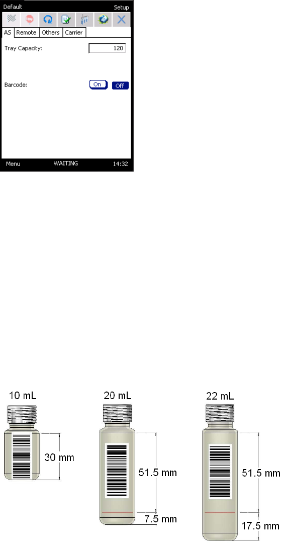
5 Upgrade Equipment
Barcode Reader
Thermo Scientific TriPlus 300 Headspace User Guide 109
Figure 95. Barcode Reader Configuration
In order to provide a logical control over a reading error select an action in Method Sequence
Action (Menu > Method Actions) from the list:
•Ignore — The autosampler continues the processing of the sequence.
•Skip — The current vial and its possible repetitions are skipped, and the next vial of the
sequence is processed. If the vial is already in the oven it will be returned to the tray.
•Abort — Aborts the processing of the current vial and the sequence. The vials inside the
carousel are returned to the tray.
Label Positioning
Figure 96 and Figure 97 show how to place the labels to avoid any reading errors.
Figure 96. Label positioning for One-dimensional barcode
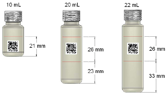
5 Upgrade Equipment
Barcode Reader
110 TriPlus 300 Headspace User Guide Thermo Scientific
Figure 97. Label positioning for Two-dimensional barcode
