TriPlus 300 HS PIR 31709672 Tri Plus PIG Pre Installation Guide
2016-05-17
: Pdf 31709672 Triplus 300 Hs Pig Pre-Installation Guide 31709672 TriPlus 300 HS PIG Pre-Installation Guide TriPlus 300 HS GC AS Manuals User ation
Open the PDF directly: View PDF ![]() .
.
Page Count: 32
- Contents
- Preface
- TriPlus 300 Headspace Site Preparation

Thermo Scientific
TriPlus 300 Headspace
Sampling System
Preinstallation Requirements Guide
P/N 317 09672 Revision C December 2015
© 2015 Thermo Fisher Scientific Inc. All rights reserved.
TriPlus 300 Headspace, TRACE 1300, TRACE 1310, ISQ Series, TSQ 8000 Series, ITQ, and DSQ II are
trademarks of Thermo Fisher Scientific Inc., and its subsidiaries.
Published by Thermo Fisher Scientific S.p.A., Strada Rivoltana 20090 Rodano-Milan, Italy
Tel: +39 02 95059303; Fax: +39 02 95059388
Thermo Fisher Scientific Inc. provides this document to its customers with a product purchase to use in the
product operation. This document is copyright protected and any reproduction of the whole or any part of this
document is strictly prohibited, except with the written authorization of Thermo Fisher Scientific Inc.
The contents of this document are subject to change without notice. All technical information in this
document is for reference purposes only. System configurations and specifications in this document supersede
all previous information received by the purchaser.
Thermo Fisher Scientific Inc. makes no representations that this document is complete, accurate or error-
free and assumes no responsibility and will not be liable for any errors, omissions, damage or loss that might
result from any use of this document, even if the information in the document is followed properly.
This document is not part of any sales contract between Thermo Fisher Scientific Inc. and a purchaser. This
document shall in no way govern or modify any Terms and Conditions of Sale, which Terms and Conditions of
Sale shall govern all conflicting information between the two documents.
Release history:
First edition Revision A, released April 2013 “Original Instructions”
Second edition Revision B, released March 2015; Third edition Revision C, released December 2015
For Research Use Only. Not for use in diagnostic procedures.

TriPlus 300 Headspace Installation Request Form
Once you read the TriPlus 300 Headspace Preinstallation Requirements Guide, print and complete this form. After all the
requirements on this form are fulfilled, sign and date the form. Then mail or fax this form to your local Thermo Fisher
Scientific sales/service office.
Fill in the information below (please print clearly):
Name __________________________________________________________
Company _______________________________________________________Telephone ____________________
Address _____________________________________________________________________________________
Address _____________________________________________________________________________________
City ________________________________________ State ______________ Country______________________
Signature _______________________________________________________ Date _________________________
Additional Information
Have any special acceptance specifications been agreed to in the contract? Yes No
If Yes, attach full details of specifications.
Is there any additional equipment that needs to be interfaced to the system? Yes No
If Yes, attach full details of additional equipment.
Note We reserve the right to invoice you for the Field Service Engineer’s time if the installation requirements are not
met on the date of the installation. To avoid any additional cost, please ensure your site is properly prepared.
Requirements Checklist
All laboratory remodeling has been completed.
Your TriPlus 300 Headspace is on site.
Principal operator will be available during the
installation / certification period.
Doorways, hallways, etc. are a minimum width of 80 cm
(32 in.).
Available floor area is sufficient and flooring will
support the mass of the system.
Available workbench is sufficient for all of the
equipment. List the bench measurements:
Width:
Depth:
Height:
Workbench can support the mass of the system [158 kg
(348 lbs)] and is free from vibration.
Lighting is adequate.
Main power is installed and is in compliance with local
electrical codes.
Power outlets are of the correct configuration. NEMA
type:____________________________
The power outlets are enough for the electrical
connections.
Voltage of power outlet has been measured.
Measured voltage: ________________________
Power is free from fluctuations due to slow changes in
the average voltage or changes due to surges, sags, or
transients.
One or more RJ-45 wall outlet. To connect your system
to your site’s LAN network, you must have an
additional shielded twisted pair network cable.
Air conditioning is adequate for temperature, humidity,
and particulate matter control. The laboratory can be
maintained at a constant temperature, between 15 and
27 °C (59 and 81 °F).
Relative humidity is between 40% and 80% with no
condensation.
Air in your laboratory is free of excessive dust, smoke or
other particulate matter.
Work area is free from magnetic disruption and
electrostatic discharge.
One voice telephone line is installed near the system.
Principal Operator Level of Experience
GC, Injector and Column Knowledge: Experienced Moderate Limited
Gas Chromatography Theory Knowledge: Experienced Moderate Limited
Data System Knowledge: Experienced Moderate Limited
IMPORTANT PREINSTALLATION INFORMATION... PLEASE READ

North America
United States
1400 North Point Pkwy #10
West Palm Beach, FL 33407
E-mail:
us.customer-support.analyze@thermofisher.com
Phone.........................[1] 800 532 4752
Fax .............................[1] 877 373 4006
Canada
2845 Argentia Road, Unit 4
Mississauga, Ontario, L5N 8G6
E-mail:
us.customer-support.analyze@thermofisher.com
Phone.........................[1] 800 530 8447
Fax .............................[1] (905) 890 9161
Europe
Austria
Wehlistrasse 27b
A-1200 Wien
E-mail: service.sid.austria@thermofisher.com
Phone.........................[43] (0) 1 333 50 34-0
Fax .............................[43] (0) 1 333 50 34-26
Belgium
Clintonpark “Keppekouter”
Ninovesteenweg 198
B-9320 ERMEBODEGEM - AALST
E-mail: service.sid.benelux@thermofisher.com
Phone.........................[32] (0) 2 482 3030
Fax .............................[32] (0) 2 482 3031
Denmark
Fruebjergvej 3
2100 København Ø
E-mail: service.sid.dk@thermofisher.com
Phone.........................[45] (70) 236267
Fax .............................[45] (70) 236263
Finland—see “Sweden, Norway, and Finland”
France
(Also representing French-speaking North Africa,
Algeria, Morocco, and Tunisia)
16 Avenue du Québec
Silic 765
Z.A. de Courtaboeuf
F-91963 Les Ulis Cédex
E-mail: service.sid.lesulis@thermofisher.com
Phone.........................[33] (0) 1 60 92 49 50
Fax .............................[33] (0) 1 60 92 48 99
Germany
Im Steingrund 4-6
D-63303 Dreieich
E-mail: service.dreieich@thermofisher.com
Phone.........................[49] (0) 6103 408 1050
Fax .............................[49] (0) 6103 408 1213
Italy
Strada Rivoltana
I-20090 Rodano (Milano)
E-mail: assistenza.tecnica.it@thermofisher.com
Phone.........................Numero Verde (800) 823 162
Fax .............................[39] (02) 95320 225
Netherlands
Takkebijsters 1
NL-4817 BL Breda
E-mail: service.sid.benelux@thermofisher.com
Phone.........................[31] (0) 76 579 55 55
Fax .............................[31] (0) 76 581 09 61
Norway—see “Sweden, Norway, and Finland”
Spain
C/Valportillo I, no22 1a Planta
Edificio Caoba
ES-28108 Alcobendas - Madrid
E-mail: service.sid.spain@thermofisher.com
Phone.........................[34] (914) 845 965
Fax .............................[34](914) 843 598
Notes: The country code is enclosed in square brackets [ ]. The city code or area code is enclosed in parenthesis ( ). For countries other than the U.S.A., when you
are dialing from within the specified country, dial the 0 of the city code. For countries other than Italy, when you are dialing from outside the country, do not dial the 0
of the city code.
Offices for Thermo Scientific CMD Products
For up-to-date contact inform ation, visit www.thermoscientific.com.
Europe—continued
Sweden, Norway, and Finland
Pyramidbacken 3
S-141 75 Kungens Kurva (Stockholm)
Sweden
E-mail: service.sid.nordic@thermofisher.com
Phone.........................[46] (0) 8 556 468 20
Fax .............................[46] (0) 8 556 468 08
Switzerland
Neuhofstrasse 11
4153 Reinach
E-mail: service.sid.ch@thermofisher.com
Phone.........................[41] (617) 16 77 40
Fax .............................[41] (617) 16 77 20
United Kingdom
Stafford House
1 Boundary Park
Boundary Way
Hemel Hempstead
Hertfordshire HP2 7GE
E-mail: service.sid.hemel@thermofisher.com
Phone ........................[44] (0) 870 241 1034
Fax .............................[44] (0) 1442 233 667
Australasia and Asia
Australia
P.O. Box 9092
5 Caribbean Drive
Scoresby, VIC 3179
E-mail: analyze.au@thermofisher.com
Phone.........................[61] 39757 4300
Fax .............................[61] 9763 1169
Japan
C-2F
3-9 Moriya-cho, Kanagawa-ku
Yokohama 221-0022
E-mail: analyze.jp@thermofisher.com
Phone.........................[81] (45) 453 9100
Fax .............................[81] (45) 453 9110
P.R. China
7th Floor, 7F Tower West, Younghe Plaza
No. 28, Andingmen East Street
Dong Cheng District
Beijing 100007
E-mail: analyze.cn@thermofisher.com
Phone (free lines).......800 810 5118
...................................400 650 5118
Fax ...........................[86] (010) 8419 3589
Building 6
No.27 Xin Jinqiao Road
Pudong District
Shanghai 201206
Phone.........................[86] (21) 6865 4588
Fax ............................[86] (21) 6445 7830
Offices for Thermo Scientific CMD Products—Continued

Declaration
Manufacturer: Thermo Fisher Scientific
Thermo Fisher Scientific is the manufacturer of the instrument described in this manual and, as such, is responsible
for the instrument safety, reliability and performance only if:
•installation
•re-calibration
•changes and repairs
have been carried out by authorized personnel and if:
• the local installation complies with local law regulations
• the instrument is used according to the instructions provided and if its operation is only entrusted to qualified
trained personnel
Thermo Fisher Scientific is not liable for any damages derived from the non-compliance with the aforementioned
recommendations.
Thermo Fisher Scientific S.p.A.
Strada Rivoltana, 20090 Rodano - Milan - Italy — Tel: +39 02 950591 - Fax: +39 02 9505276
Regulatory Compliance
Thermo Fisher Scientific performs complete testing and evaluation of its products to ensure full compliance with
applicable domestic and international regulations.
Thermo Fisher Scientific declares, under sole responsibility, that the product as originally delivered complies with
the requirements of the following applicable European Directives and carries the CE marking accordingly:
Low Voltage Directive:2006/95/EC
• EMC Directive:2004/108/EC
… and conforms with the following product standards:
Safety
This device complies with>
• EN 61010-1:2001 2nd Edition
• IEC 61010-1:2001 2nd Edition
• CAN/CSA –c22.2 No. 61010.1–04
• UL Std. No 61010-1 2nd Edition
Electromagnetic Compatibility
This device complies with:
• EN 61326-1:2006, EN 55011: 2009, Class A Group 1
• IEC 61326-1:2005, CISPR 11:2009, Class A Group 1
FCC Compliance Statement
Thermo Fisher Scientific hereby declares that our product has been tested and complies with the requirements of
Title 47 Telecommunication FCC Part 15 (2007), Class A Digital Device.
Notice on Lifting and Handling of
Thermo Scientific Instruments
For your safety, and in compliance with international regulations, the physical handling of this Thermo Fisher
Scientific instrument requires a team effort to lift and/or move the instrument. This instrument is too heavy and/
or bulky for one person alone to handle safely.
Notice on the Proper Use of
Thermo Scientific Instruments
In compliance with international regulations: Use of this instrument in a manner not specified by Thermo Fisher
Scientific could impair any protection provided by the instrument.
Notice on the Susceptibility
to Electromagnetic Transmissions
Do not use radio frequency transmitters, such as mobile phones, in close proximity to the instrument.
THIS DEVICE COMPLIES WITH PART 15 OF THE FCC RULES. OPERATION IS SUBJECT TO
THE FOLLOWING TWO CONDITIONS: (1) THIS DEVICE MAY NOT CAUSE HARMFUL
INTERFERENCE, AND (2) THIS DEVICE MUST ACCEPT ANY INTERFERENCE RECEIVED,
INCLUDING INTERFERENCE THAT MAY CAUSE UNDESIRED OPERATION.
CAUTION Read and understand the various precautionary notes, signs, and symbols contained
inside this manual pertaining to the safe use and operation of this product before using the device.
WEEE Compliance
This product is required to comply with the European Union’s Waste Electrical & Electronic Equipment (WEEE) Directive
2012/19/EU. It is marked with the following symbol:
Thermo Fisher Scientific has contracted with one or more recycling or disposal companies in each European Union (EU)
Member State, and these companies should dispose of or recycle this product. See www.thermoscientific.com/rohsweee for
further information on Thermo Fisher Scientific’s compliance with these Directives and the recyclers in your country.
WEEE Konformität
Dieses Produkt muss die EU Waste Electrical & Electronic Equipment (WEEE) Richtlinie 2012/19/EU erfüllen. Das Produkt
ist durch folgendes Symbol gekennzeichnet:
Thermo Fisher Scientific hat Vereinbarungen mit Verwertungs-/Entsorgungsfirmen in allen EU-Mitgliedsstaaten getroffen,
damit dieses Produkt durch diese Firmen wiederverwertet oder entsorgt werden kann. Mehr Information über die Einhaltung
dieser Anweisungen durch Thermo Fisher Scientific, über die Verwerter, und weitere Hinweise, die nützlich sind, um die
Produkte zu identifizieren, die unter diese RoHS Anweisung fallen, finden sie unter www.thermoscientific.com/rohsweee.
Conformité DEEE
Ce produit doit être conforme à la directive européenne (2012/19/EU) des Déchets d'Equipements Electriques et
Electroniques (DEEE). Il est marqué par le symbole suivant:
Thermo Fisher Scientific s'est associé avec une ou plusieurs compagnies de recyclage dans chaque état membre de l’union
européenne et ce produit devrait être collecté ou recyclé par celles-ci. Davantage d'informations sur la conformité de Thermo
Fisher Scientific à ces directives, les recycleurs dans votre pays et les informations sur les produits Thermo Fisher Scientific qui
peuvent aider la détection des substances sujettes à la directive RoHS sont disponibles sur www.thermoscientific.com/rohsweee.
Conformità RAEE
Questo prodotto è marcato con il seguente simbolo in conformità alla direttiva europea 2012/19/EU (RAEE) sui rifiuti di
apparecchiature elettriche ed elettroniche:
Thermo Fisher Scientific si è accordata con una o più società di riciclaggio in ciascun Stato Membro della Unione Europea
(EU), e queste società dovranno smaltire o riciclare questo prodotto. Per maggiori informazioni vedere il sito
www.thermoscientific.com/rohsweee.
Conformidad RAEE
Este producto es marcado con el siguiente símbolo en conformidad a la Directiva 2012/19/EU de la Unión Europea sobre los
residuos de aparatos eléctricos y electrónicos:
Thermo Fisher Scientific ha contratado una o más empresas de reciclo para tratar residuos en cada Estado Miembro de la
Unión Europea, y estas empresas deberían reciclar o eliminar este producto. Referirse a www.thermoscientific.com/rohsweee
para una mayor información sobre la conformidad de Thermo Fisher Scientific con estas Directivas y para las empresas de
reciclaje en su país.
IMPORTANT
The symbol indicates the product must not be disposed of with the normal household wastes. Correct disposal of
this product prevents any potentially negative impact on the environmental and human health that could arise
from any inappropriate handling of the product itself.
WEEE and RoHS rules, while laid down at European level, are put into national law at national level. When ex-
porting to Europe, it is essential to comply with national law in each relevant country. The EU law simply serves
as a template for national laws, which may differ considerably.
Each EU Member State has own regulations regarding the application of these directives. Please refer to the
regulations in force in your country.

Thermo Scientific TriPlus 300 Headspace Preinstallation Requirements Guide xi
C
Preface . . . . . . . . . . . . . . . . . . . . . . . . . . . . . . . . . . . . . . . . . . . . . . . . . . . . . . . . . . . . .xiii
About Your System. . . . . . . . . . . . . . . . . . . . . . . . . . . . . . . . . . . . . . . . . . . . . .xiii
Power Rating . . . . . . . . . . . . . . . . . . . . . . . . . . . . . . . . . . . . . . . . . . . . . . . . . .xiii
Contacting Us . . . . . . . . . . . . . . . . . . . . . . . . . . . . . . . . . . . . . . . . . . . . . . . . .xiv
Related Documentation . . . . . . . . . . . . . . . . . . . . . . . . . . . . . . . . . . . . . . . . . .xiv
Safety Alerts and Important Information . . . . . . . . . . . . . . . . . . . . . . . . . . . . .xiv
Special Notices . . . . . . . . . . . . . . . . . . . . . . . . . . . . . . . . . . . . . . . . . . . . . . .xiv
Safety Symbols and Signal Words . . . . . . . . . . . . . . . . . . . . . . . . . . . . . . . . . xv
Instrument Markings and Symbols . . . . . . . . . . . . . . . . . . . . . . . . . . . . . . . . . .xvi
Safety Information and Warnings . . . . . . . . . . . . . . . . . . . . . . . . . . . . . . . . . . xvii
General Considerations . . . . . . . . . . . . . . . . . . . . . . . . . . . . . . . . . . . . . . . .xviii
Electrical Hazards . . . . . . . . . . . . . . . . . . . . . . . . . . . . . . . . . . . . . . . . . . . .xviii
Other Hazards. . . . . . . . . . . . . . . . . . . . . . . . . . . . . . . . . . . . . . . . . . . . . . . . xx
Working with Toxic or other Harmful Compounds . . . . . . . . . . . . . . . . . . .xxi
Biological Hazard Warning Note. . . . . . . . . . . . . . . . . . . . . . . . . . . . . . . . . .xxi
Maintenance . . . . . . . . . . . . . . . . . . . . . . . . . . . . . . . . . . . . . . . . . . . . . . . . xxii
Disposal. . . . . . . . . . . . . . . . . . . . . . . . . . . . . . . . . . . . . . . . . . . . . . . . . . . . xxii
Chapter 1 TriPlus 300 Headspace Site Preparation . . . . . . . . . . . . . . . . . . . . . . . . . . . . . . . . . .1
Entrance Requirements . . . . . . . . . . . . . . . . . . . . . . . . . . . . . . . . . . . . . . . . . . . . 2
Space and Load Requirements. . . . . . . . . . . . . . . . . . . . . . . . . . . . . . . . . . . . . . . 2
GC-GC/MS System + TriPlus 300 Headspace Configuration Space and
Mass Requirements . . . . . . . . . . . . . . . . . . . . . . . . . . . . . . . . . . . . . . . . . . . 3
Lighting Requirements . . . . . . . . . . . . . . . . . . . . . . . . . . . . . . . . . . . . . . . . . . . . 4
Power Requirements . . . . . . . . . . . . . . . . . . . . . . . . . . . . . . . . . . . . . . . . . . . . . . 4
Power Line . . . . . . . . . . . . . . . . . . . . . . . . . . . . . . . . . . . . . . . . . . . . . . . . . . . 5
Electrical Specifications . . . . . . . . . . . . . . . . . . . . . . . . . . . . . . . . . . . . . . . . . . 5
Environment Requirements. . . . . . . . . . . . . . . . . . . . . . . . . . . . . . . . . . . . . . . . . 6
Environmental Conditions . . . . . . . . . . . . . . . . . . . . . . . . . . . . . . . . . . . . . . . 6
Gas Equipment Requirements. . . . . . . . . . . . . . . . . . . . . . . . . . . . . . . . . . . . . . . 7
LAN Network Requirements. . . . . . . . . . . . . . . . . . . . . . . . . . . . . . . . . . . . . . . . 9
Receiving Instruments . . . . . . . . . . . . . . . . . . . . . . . . . . . . . . . . . . . . . . . . . . . . 10
What Happens Next? . . . . . . . . . . . . . . . . . . . . . . . . . . . . . . . . . . . . . . . . . . . . 10
Contents
Contents
xii TriPlus 300 Headspace Preinstallation Requirements Guide Thermo Scientific

Thermo Scientific TriPlus 300 Headspace Preinstallation Requirements Guide xiii
P
Preface
This guide contains preinstallation requirements that must be in compliance before installing
the TriPlus 300 Headspace sampling system.
About Your System
Thermo Fisher Scientific systems operate safely and reliably under carefully controlled
environmental conditions. If the equipment is used in a manner not specified by the
manufacturer, the protections provided by the equipment might be impaired. If you maintain
a system outside the specifications listed in this guide, failures of many types, including
personal injury or death, might occur. The repair of instrument failures caused by operation
in a manner not specified by the manufacturer is specifically excluded from the Standard
Warranty and service contract coverage.
Power Rating
Main Unit
• 100-120/200-240 Vac ±10% max; 60 Hz; 1300 VA.
• 100-115/200-230 Vac ±10% max; 50 Hz; 1300 VA.
Autosampler Unit
• 24 Vdc through a portable external power supply
Electrical characteristics of the supply
−input 85-264 Vac; 47/63 Hz
−output 12 Vdc; 24 VA
Detailed instrument specifications are in the Product Specification or Product Brochure.

Preface
Contacting Us
xiv TriPlus 300 Headspace Preinstallation Requirements Guide Thermo Scientific
Contacting Us
Thermo Fisher Scientific provides comprehensive technical assistance worldwide and is
dedicated to the quality of our customer relationships and services.
Use http://www.thermoscientific.com address for products information.address for products
information.
Use http://www.gc-gcms-customersupport.com/WebPage/Share/Default.aspx address to
contact your local Thermo Fisher Scientific office, or affiliate GC-GC/MS Customer
Support.
Related Documentation
In addition to this guide, Thermo Scientific provides the following documents for the TriPlus
300 Headspace.
•TriPlus 300 Headspace Preinstallation Requirements Guide, PN 31709672
•TriPlus 300 Headspace User Guide, PN 31709671
To suggest ways we can improve the documentation, follow this link to complete our
documentation survey.
Safety Alerts and Important Information
Make sure you follow the precautionary notices presented in this manual. The safety and
other special notices appear in boxes.
Special Notices
Notices includes the following:
IMPORTANT Highlights information necessary to prevent damage to software, loss of
data, or invalid test results; or might contain information that is critical for optimal
performance of the system.
Note Emphasizes important information about a task.
Tip Helpful information that can make a task easier.
Preface
Safety Alerts and Important Information
Thermo Scientific TriPlus 300 Headspace Preinstallation Requirements Guide xv
Safety Symbols and Signal Words
All safety symbols are followed by WARNING or CAUTION, which indicates the degree of risk
for personal injury, instrument damage, or both. Cautions and warnings are following by a
descriptor, such as BURN HAZARD. A WARNING is intended to prevent improper actions that
could cause personal injury. Whereas, a CAUTION is intended to prevent improper actions
that might cause personal injury, instrument damage, or both. You can find the following
safety symbols on your instrument, or in this guide:
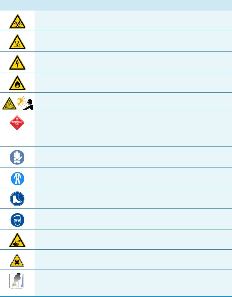
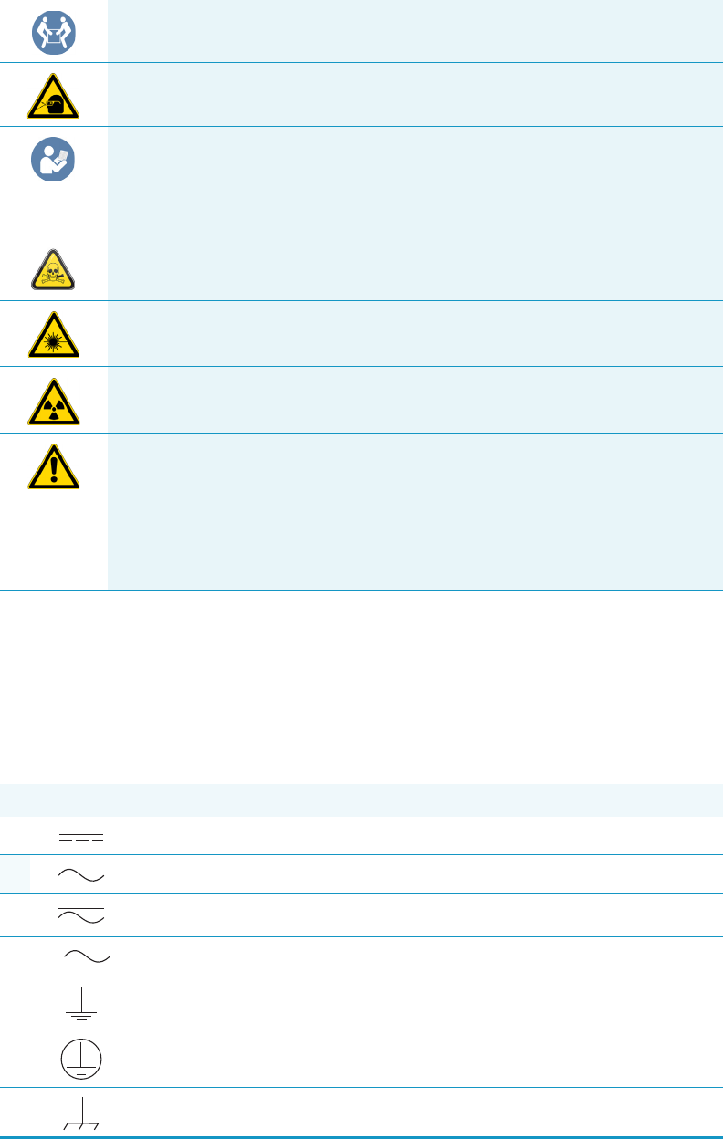
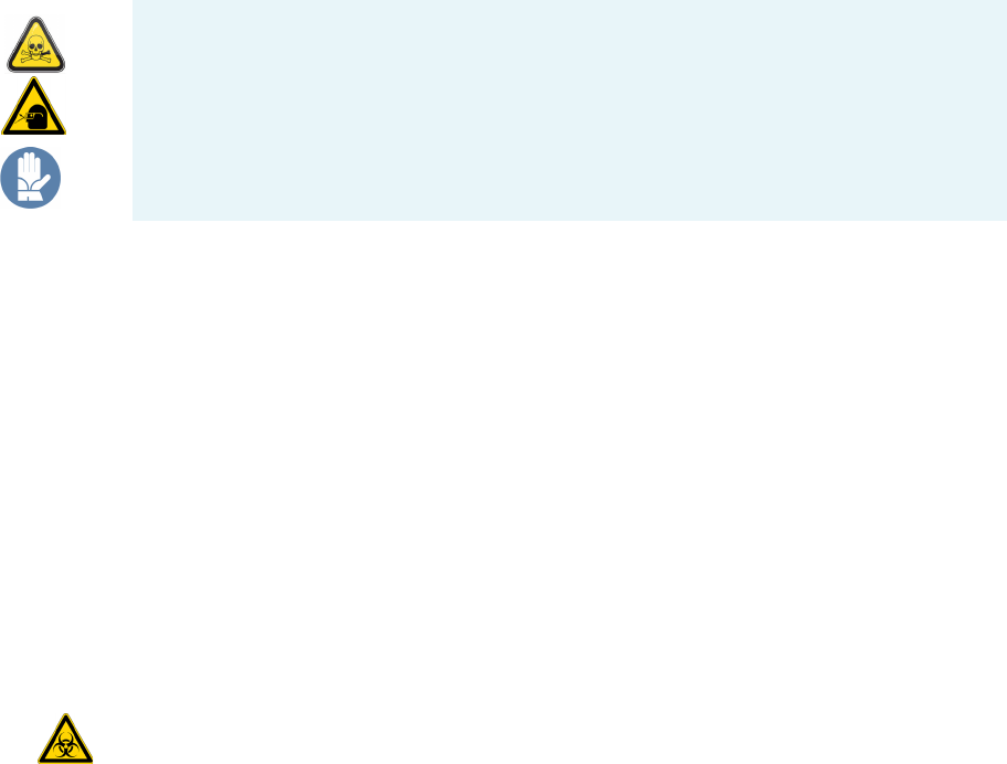
Symbol Descriptor
BIOHAZARD: Indicates that a biohazard will, could, or might occur.
BURN HAZARD: Alerts you to the presence of a hot surface that could or might
cause burn injuries.
ELECTRICAL SHOCK HAZARD: Indicates that an electrical shock could or
might occur.
FIRE HAZARD: Indicates a risk of fire or flammability could or might occur.
EXPLOSION HAZARD. Indicates an explosion hazard. This symbol indicates
this risk could or might cause physical injury.
FLAMMABLE GAS HAZARD. Alerts you to gases that are compressed,
liquefied or dissolved under pressure and can ignite on contact with an
ignition source. This symbol indicates this risk could or might cause physical
injury.
GLOVES REQUIRED: Indicates that you must wear gloves when performing a
task or physical injury could or might occur.
CLOTHING REQUIRED. Indicates that you should wear a work clothing when
performing a task or else physical injury could or might occur.
BOOTS REQUIRED. Indicates that you must wear boots when performing a
task or else physical injury could or might occur.
MATERIAL AND EYE HAZARD. Indicates you must wear eye protection when
performing a task.
HAND AND CHEMICAL HAZARD: Indicates that chemical damage or physical
injury could or might occur.
HARMFUL. Indicates that the presence of harmful material will, could, or
might occur.
INSTRUMENT DAMAGE: Indicates that damage to the instrument or
component might occur. This damage might not be covered under the
standard warranty.
Preface
Instrument Markings and Symbols
xvi TriPlus 300 Headspace Preinstallation Requirements Guide Thermo Scientific
Instrument Markings and Symbols
Table 1 explains the symbols used on Thermo Fisher Scientific instruments. Only a few of
them are used on the TriPlus 300 Headspace sampling system. See the asterisk.
LIFTING HAZARD. Indicates that a physical injury could or might occur if two
or more people do not lift an object.
MATERIAL AND EYE HAZARD: Indicates that eye damage could or might
occur.
READ MANUAL: Alerts you to carefully read your instrument’s
documentation to ensure your safety and the instrument’s operational ability.
Failing to carefully read the documentation could or might put you at risk for a
physical injury.
TOXIC SUBSTANCES HAZARD: Indicates that exposure to a toxic substance
could occur and that exposure could or might cause personal injury or death.
LASER HAZARD. Indicates that exposure to a laser beam will, could, or might
cause personal injury.
RADIOACTIVE HAZARD. Indicates that the presence of radioactive material
could or might occur.
For the prevention of personal injury, this general warning symbol precedes
the WARNING safety alert word and meets the ISO 3864-2 standard. In the
vocabulary of ANSI Z535 signs, this symbol indicates a possible personal
injury hazard exists if the instrument is improperly used or if unsafe actions
occur. This symbol and another appropriate safety symbol alerts you to an
imminent or potential hazard that could cause personal injury.
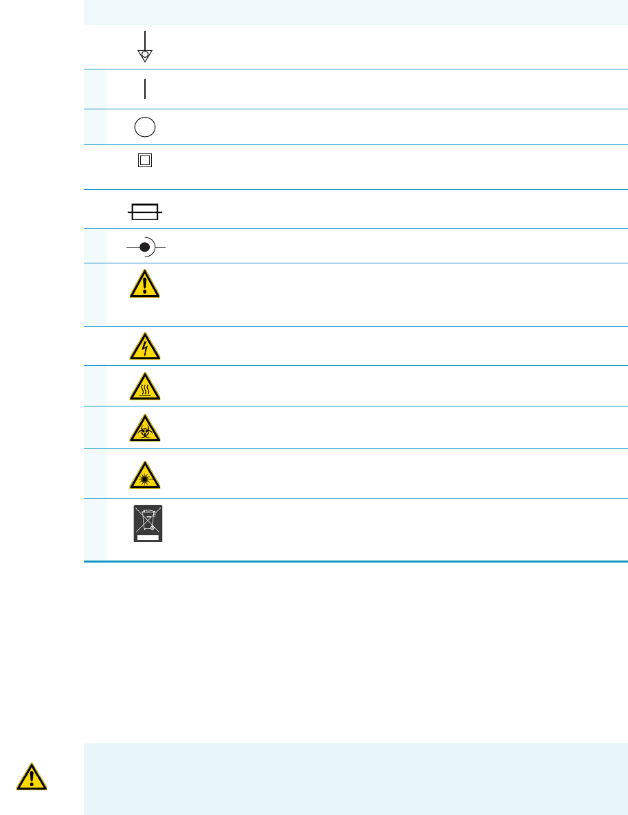
Table 1. Instrument Marking and Symbols (Sheet 1 of 2)
Symbol Description
Direct Current
*Alternating Current
Both direct and alternating current
Three-phase alternating current
Earth (ground) terminal
Protective conductor terminal
Frame or chassis terminal
3
Preface
Safety Information and Warnings
Thermo Scientific TriPlus 300 Headspace Preinstallation Requirements Guide xvii
Safety Information and Warnings
The purpose of this safety guide is to make users aware of potential safety issues and general
concerns for Thermo Fisher Scientific representatives during installation, and repair of the
TriPlus 300 Headspace sampling system, or parts of it (following the life-cycle principle), as
well as for the end user TriPlus 300 Headspace sampling system in the lab during the learning
phase and in routine work.
Equipotentiality
*On (Supply)
*Off (Supply)
Equipment protected throughout by DOUBLE INSULATION or
REINFORCED INSULATION (Equivalent to Class II of IEC 536)
Fuse
*Jack socket
*Instruction manual symbol affixed to product. Indicates that the you must
refer to the manual for specific WARNING or CAUTION information to
avoid personal injury or damage to the product.
Caution, risk of electric shock
*Caution, hot surface
*Caution, biohazard
*Caution, Laser beam
*Symbol in compliance to the Directive 2012/19/EU on Waste Electrical
and Electronic Equipment (WEEE) placed on the European market after
August, 13, 2005.
Table 1. Instrument Marking and Symbols (Sheet 2 of 2)
Symbol Description
+-
IMPORTANT Read this section first before operating the TriPlus 300 Headspace sampling
system.

Preface
Safety Information and Warnings
xviii TriPlus 300 Headspace Preinstallation Requirements Guide Thermo Scientific
General Considerations
• Before using your system, consult the TriPlus 300 Headspace User Guide and related
documents under all circumstances.
• Changes or modifications to this unit not expressly approved by the party responsible for
compliance, could void your’s authority to operate the equipment.
• Be aware that if the equipment is used in a manner not specified by the manufacturer, the
protective and safety features of the equipment might be impaired.
• The repair of instrument failures caused by operation in a manner not specified by the
manufacturer is expressly excluded from the standard warranty and service contract
coverage.
• When for technical reasons it is necessary to work on instrument parts which might
involve a potential hazard (moving parts, components under voltage, and others) contact
Thermo Fisher Scientific authorized representative. In general, this type of situation arises
when access to the parts is only possible using a tool. When you perform a maintenance
operation, you must have received proper training to carry out that specific task.
Electrical Hazards
Every analytical instrument has specific hazards. Be sure to read and comply with the
following pre-cautions. They ensure the safe and long-term use of your TriPlus 300
Headspace sampling system. The installation over-voltage category is Level II. The Level II
category pertains to equipment receiving its electrical power locally, such as from an electrical
wall outlet.
Connect the TriPlus 300 Headspace sampling system only to instruments complying with
IEC 61010 safety regulations.
The power line and the connections between the TriPlus 300 Headspace sampling system and
other instruments, used in the configuration setup of the total analytical system, must
maintain good electrical grounding.
Poor grounding represents a danger to the operator, and might seriously affect the
performance of the instrument.
Do not connect the TriPlus 300 Headspace sampling system to power lines that supply
devices of a heavy duty nature, such as motors, refrigerators, and other devices that can
generate electrical disturbances.
Use only fuses of the type and current rating specified. Do not use repaired fuses, and do not
short-circuit the fuse holder. The supplied power cord must be inserted into a power outlet
with a protective earth (ground) contact.
When using an extension cord, ensure that the cord also has an earth contact.
Preface
Safety Information and Warnings
Thermo Scientific TriPlus 300 Headspace Preinstallation Requirements Guide xix
If the supplied power cord does not fit the local electrical socket and a replacement or adapter
must be purchased locally, ensure that only a certified power cord is used. Any power cord
used must be certified by the appropriate local authorities.
Pay attention not to leave any cables connecting the TriPlus 300 Headspace sampling system
and the chromatographic system, or the power cord close to heated zone, such as the injector
or detector heating blocks, or the GC hot air vents.
Always replace any cable showing signs of damage with another one provided by the
manufacturer. Safety regulations must be respected.
Do not change the external or internal grounding connections. Tampering with or
disconnecting these connections could endanger you and damage the TriPlus 300 Headspace
sampling system. The instrument is properly grounded in accordance with these regulations
when shipped. To ensure safe operation, do not make any changes to the electrical
connections or the instrument's chassis.
Do not turn the instrument on if you suspect that it has incurred any type of electrical
damage. Instead, disconnect the power cord and contact a Thermo Fisher Scientific
representative for a product evaluation. Do not attempt to use the instrument until it has been
evaluated. Electrical damage might have occurred if the TriPlus 300 Headspace sampling
system shows visible signs of damage, exposure to any liquids or has been transported under
severe stress.
Damage can also result if the instrument is stored for prolonged periods under unfavorable
conditions: for example, subjected to heat, moisture, and so on. Ensure that the power
supply/controller unit is always placed in a clean and dry position. Avoid any liquid spills in
the vicinity.
Before attempting any type of maintenance work, always disconnect the power cords from the
power supply if optional devices are installed. Capacitors inside the instrument might still be
charged if the instrument is turned off.
To avoid damaging electrical parts, do not disconnect an electrical assembly while power is
supplied to the TriPlus 300 Headspace sampling system. After the power is turned off, wait
approximately 30 seconds before you disconnect an assembly.
The instrument includes a number of integrated circuits. These circuits might be damaged if
exposed to excessive line voltage fluctuations, power surges or electrostatic charges, or both.
Never try to repair or replace any components of the instrument without the assistance of a
Thermo Fisher Scientific representative. There are no operator-serviceable or replaceable parts
inside the TriPlus 300 Headspace sampling system. If a instrument is not functioning, contact
a Thermo Fisher Scientific representative.
The power supplies for the TriPlus 300 Headspace sampling system have the symbols I/O to
indicate ON/OFF. It is important that the power ON/OFF switch is accessible and easy to
operate, and where it is possible to unplug the AC power cord from the power supply/wall
outlet in case of emergency.
Preface
Safety Information and Warnings
xx TriPlus 300 Headspace Preinstallation Requirements Guide Thermo Scientific
Other Hazards
There is danger of crushing to fingers and hands. To avoid injury keep your hands away from
moving parts during operation.
Turn off the power to the TriPlus 300 Headspace sampling system if you must reach inside a
mechanically powered system with moving parts.
To avoid injury, observe safe laboratory practice when handling solvents, changing tubing, or
operating the TriPlus 300 Headspace sampling system. Know the physical and chemical
properties of the solvents you use.
See the MSDS (Material Safety Data Sheets) from the manufacturer of the solvents being
used.
When using the TriPlus 300 Headspace sampling system, follow the generally accepted
procedures for quality control and method development.
When using the TriPlus 300 Headspace sampling system in the field of chromatographic
analysis, if a change is observed in the retention time of a particular compound, in the
resolution between two compounds, or in the peak shape, immediately determine the reasons
for the changes. Do not rely on the separation results until you determine the cause of a
change.
Do not operate on the instrument components that form part of the work area of the TriPlus
300 Headspace sampling system when it is in motion.
Do not use vials without a sealing cap. Vapor phase from organic solvents can be hazardous
and flammable. Acidic vapor phase can cause corrosion to critical mechanical parts.
When sample vials have to undergo heating and agitation, it is important to consider the glass
quality. Use high quality glass only. Remember that depending on the application conditions,
high pressure can build up in the vial. Whenever a temperature greater than 60 °C is applied,
consider the vapor pressure of the solvent used to ensure that no excessive pressure builds up.
This is important when using temperatures above 100°C and especially at the maximum
temperature of 300 °C. Be aware that solid materials can also contain volatile compounds
such as water (humidity) that may cause build-up of excess vapor pressure.
Do not reuse headspace vials. During the process of washing the vial, micro-cracks can form
which will weaken the glass wall and increase the chances of the vial breaking.
Preface
Safety Information and Warnings
Thermo Scientific TriPlus 300 Headspace Preinstallation Requirements Guide xxi
Working with Toxic or other Harmful Compounds
The TriPlus 300 Headspace sampling system requires the use of several chemical products
with different hazard characteristics, which are present in vials and syringes. Before using these
substances or replacing the syringe, please read the hazard indications and information
reported in the MSDS supplied by the manufacturer referring to the relevant CAS number.
When preparing the samples, please refer to local regulations for the ventilation conditions of
the work room.
All waste materials must be collected and eliminated in compliance with the local regulations
and directives in the country where the instrument is used.
Biological Hazard Warning Note
In laboratories where samples with potential biological hazards are handled, the user must
label any equipment or parts which might become contaminated with biohazardous material.
The appropriate warning labels are included with the shipment of the instrument. It is the
user’s responsibility to label the relevant parts of the equipment.
When working with biohazardous materials, you are responsible for fulfilling the following
mandatory requirements:
• Providing instructions on how to safely handle biohazardous material.
• Training operators to be aware of potential hazards.
• Providing personal protective equipment.
• Providing instructions for what to do if operators are exposed to aerosols or vapors during
normal operation (within the intended use of the equipment) or in case of single fault
situations such as a broken vial. The protective measures must consider potential contact
with the skin, mouth, nose (respiratory organs), and eyes.
• Providing instructions for decontamination and safe disposal of relevant parts.
WARNING Before using hazardous substances (toxic, harmful, and so on), please read the
hazard indications and information reported in the applicable Material Safety Data Sheet
(MSDS). Use personal protective equipment according to the safety requirements.

Preface
Safety Information and Warnings
xxii TriPlus 300 Headspace Preinstallation Requirements Guide Thermo Scientific
Maintenance
Any external cleaning or maintenance must be performed with the TriPlus 300 Headspace
sampling system turned off and the power cord disconnected. Avoid using solvents and sprays
on electrical parts. For removal of potentially dangerous substances (toxic, harmful, and
others) read the hazard indications and information reported in the MSDS (Material Safety
Data Sheet) supplied by the manufacturer referring to the relevant CAS (Chemical Abstract
Service) number. Use proper protective gloves.
When working with hazardous materials such as radioactive, biologically hazardous material,
and so on, it is important to train all operators how to respond in case of spills or
contamination.
Depending on the class of hazardous material, the appropriate measure have to be taken
immediately. Therefore, the chemicals or solvents needed for decontamination must be on
hand.
Any parts of the equipment which can potentially be contaminated, such as the sample vial
rack, syringe tool, wash module, and others, must be cleaned regularly. The waste solvent
from cleaning and any hardware that must be disposed must be properly eliminated with all
the necessary precautions, abiding by national and international regulations.
When preparing for decontamination, ensure that the solvent or chemical to be used will not
damage or react with the surface, or dye (color) of the instrument, table or other nearby
objects. If in doubt, please contact your Thermo Fisher Scientific representative to verify the
compatibility of the type or composition of solvents with the TriPlus 300 Headspace sampling
system.
Disposal
Do not dispose of this equipment or parts thereof unsorted in municipal waste. Follow local
municipal waste regulations for proper disposal provisions to reduce the environmental
impact of waste electrical and electronic equipment (WEEE).
European Union customers: Call your local customer service representative responsible for the
TriPlus 300 Headspace sampling system for complimentary equipment pick-up and recycling.
WARNING The customer must ensure that the TriPlus 300 Headspace sampling system
has not been contaminated by any hazardous chemical or biological compounds including
(but not limited to) bacteria or viruses.
Any part which had direct contact with the analytical sample must be identified and must
undergo the appropriate decontamination procedure prior to shipping for disposal.
The customer and the service engineer are fully responsible for enforcing these
requirements. Thermo Fisher Scientific will hold the representative, customer, or both
responsible, if these regulations are not observed.
Thermo Scientific TriPlus 300 Headspace Preinstallation Requirements Guide 1
1
TriPlus 300 Headspace Site Preparation
This chapter provides the information you need to prepare your site for the installation of the
TriPlus 300 Headspace sampling system.
The TriPlus 300 Headspace sampling system operates reliably under controlled environment
conditions. Operating or maintaining a system outside the specifications outlined in this
guide might cause many different types of system failures. The repair of such failures is
specifically excluded from the standard warranty and service contract coverage.
Contents
•Entrance Requirements
•Space and Load Requirements
•Lighting Requirements
•Power Requirements
•Environment Requirements
•Gas Equipment Requirements
•LAN Network Requirements
•Receiving Instruments
•What Happens Next?
CAUTION This guide does not includes the information to prepare your lab for the
installation of your gas chromatographic system. You may find all the instruction in the
Preinstallation Requirements Guide of your GC-GC/MS system.
Note In addition to the information in this guide, you must also obey the building and
safety rules and regulations for construction that apply in your area.
1 TriPlus 300 Headspace Site Preparation
Entrance Requirements
2 TriPlus 300 Headspace Preinstallation Requirements Guide Thermo Scientific
Entrance Requirements
Use the following guidelines to make sure the entrance to your site will allow delivery of the
TriPlus 300 Headspace sampling system.
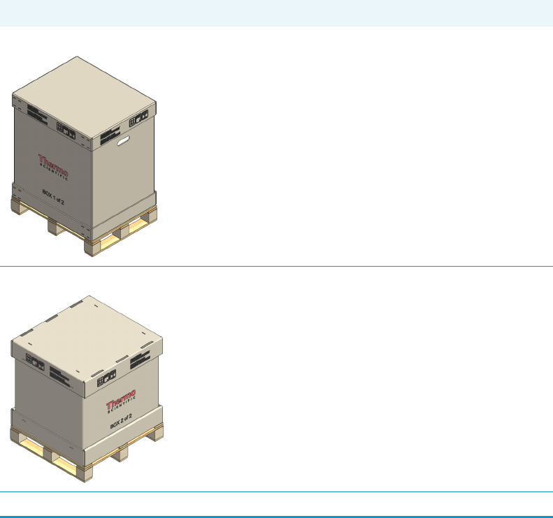
1. Ensure the width of your delivery door opening is at least 80 cm (32 in.).
2. Make sure you have enough room to move boxes around corners, into elevators, or
through doorways. The table below contains the dimensions and weight of shipping
boxes, so that you can make accommodations:
Space and Load Requirements
TriPlus 300 Headspace sampling system must be installed on the left of the GC-GC/MS
units. Use the following tables to verify and determine the space and mass requirements for
the instrument of your GC-GC/MS system.
Table 1. Container Dimensions
Container Depth Width Height (*) Mass (*)
TriPlus 300 Headspace Box 1:2 78.5 cm
(31 in.)
63.5 cm
(25 in.)
99.6 cm
(39 in.)
25 kg
(55 lbs)
TriPlus 300 Headspace Box 2:2 76.5 cm
(30 in.)
71.5 cm
(28 in.)
84 cm
(33 in.)
70 kg
(154 lbs)
(*) Including pallet
1 TriPlus 300 Headspace Site Preparation
Space and Load Requirements
Thermo Scientific TriPlus 300 Headspace Preinstallation Requirements Guide 3
3. Allow at least 30 cm (12 in.) of clearance behind the system.
4. Make sure you have at least 90 cm (3 ft.) of clearance above the system.
5. Make sure your workbench can support a TriPlus 300 Headspace system. Remember,
additional instruments add to the total weight.
6. Ensure that your work area is stable and free of vibration from nearby equipment. The
system is a sensitive instrument.
GC-GC/MS System + TriPlus 300 Headspace Configuration Space and Mass
Requirements
TriPlus 300 Headspace sampling system must o be installed on the left of the GC-GC/MS
system. The maximum distance from the GC-GC/MS system must considers the length of
the transfer line that connects the TriPlus 300 Headspace sampling system to the GC injector.
Use Table 3 to determine the space and mass requirements according to your GC-GC/MS
system + TriPlus 300 Headspace sampling system configuration.
IMPORTANT The measure reported in the tables are rounding-up for excess.
The tables do not include optional instruments e.g. computers, printers, etc. The
GC-GC/MS system should be placed on a workbench that has minimum dimensions of
0.75×2 m (2.5×6 ft.).
Table 2. Space and Load Requirements
Instrument Depth Width Height Mass
cm in. cm in. cm in. kg lbs
TriPlus 300 Headspace
Main Unit + Autosampler Unit
55 22 82 32 73 29 63 139
TRACE 1300 60 24 44 17 45 18 35 77
TRACE 1310 67 26 44 17 45 18 35 77
TSQ 8000 Series MS 89 35 40 16 45 18 61 135
ISQ Series MS 69 27 36 14 46 18 45 99
DSQ II MS 68 27 38 15 44 17 45 98
ITQ MS 68 27 38 15 44 17 45 98
Computer1, 2 48 19 20 8 43 17 12 27
Monitor216 7 46183213 4 8
Keyboard223 9 461850 2 1 2
1 This item is placed on the floor under the system, thereby reducing the weight requirements for your workbench.
2 Dimensions vary per manufacturer, therefore approximations are provided.
1 TriPlus 300 Headspace Site Preparation
Lighting Requirements
4 TriPlus 300 Headspace Preinstallation Requirements Guide Thermo Scientific
Lighting Requirements
Use the following guidelines to check the lighting of your site:
1. Ensure that your work area is properly lit. You may need an overhead lamp to light your
work area.
2. You may need a small, high-intensity lamp when you clean the TriPlus 300 Headspace.
Power Requirements
This section provides details about the power requirements.
IMPORTANT The dimensions reported in Table 3 are rounding-up for excess.
The dimensions are calculated considering the distances that must be left between the
units of the GC-GC/MS system:
•1 cm between a GC and a TSQ 8000 Series mass spectrometer
•1 cm between a GC and a ISQ Series mass spectrometer
•5 cm between a GC and a ITQ mass spectrometer
•5 cm between a GC and a DSQ II mass spectrometer
A distance of about 3/5 cm between the GC-GC/MS system and the TriPlus 300 is left
for opening the top cover of the Main through the two lateral push-buttons.
The dimensions reported in Tab l e 3 consider a distance of 5 cm.
Table 3. Overall Dimensions of the GC-GC/MS System + TriPlus 300 Headspace Configuration
Configuration Depth Width Height Mass
cm in. cm in. cm in. kg lbs
TriPlus 300 Headspace + TRACE 1300 60 24 131 52 73 29 98 216
TriPlus 300 Headspace + TRACE 1310 67 26 131 52 73 29 98 198
TriPlus 300 Headspace + TSQ 8000 Series + TRACE
1300/1310
89 35 172 68 73 29 158 348
TriPlus 300 Headspace + ISQ Series + TRACE 1300/1310 69 27 168 66 73 29 143 315
TriPlus 300 Headspace + DSQ II + TRACE 1300/1310 68 27 174 69 73 29 143 315
TriPlus 300 Headspace + ITQ + TRACE 1300/1310 68 27 174 69 73 28 143 315
1 TriPlus 300 Headspace Site Preparation
Power Requirements
Thermo Scientific TriPlus 300 Headspace Preinstallation Requirements Guide 5
Power Line
Electrical Specifications
Use the following guidelines to ensure your site is equipped with enough power to support the
system.
CAUTION The power line and the connections between the instruments must maintain
good electrical grounding. Poor grounding represents a danger for the operator and might
seriously affect the instrument performance.
Do not connect the TriPlus 300 Headspace sampling system to lines feeding devices of a
heavy-duty nature, such as motors, UV lamps, refrigerators, air compressors, and other
devices that can generate disturbances.
Pay attention not to leave any cable connecting the sampling unit and the
chromatographic system or the power cord close to the GC hot air vents.
Occasionally, unacceptable quality in line power sources might adversely affect the
operation of the GC-GC/MS system. It is the user’s responsibility to correct line voltage
problems.
Specifying power conditioning equipment is a complex task that is best handled by a
company or consultant specializing in that field. Contact your Thermo Fisher Scientific
Field Service Engineer (FSE) for assistance in locating a power consultant.
Table 4. System Power Requirements
Equipment Maximum Power (W)
TriPlus 300 Headspace 1300
TRACE 1300/1310 2000
TSQ 8000 Series MS including foreline pump 1080
ISQ Series MS, including foreline pump 1200
DSQ II MS 700
ITQ MS 700
Computer * 400
Monitor * 25
* Power requirements vary by manufacturer.

1 TriPlus 300 Headspace Site Preparation
Environment Requirements
6 TriPlus 300 Headspace Preinstallation Requirements Guide Thermo Scientific
Environment Requirements
The operating environment in your laboratory is affected by such factors as temperature,
humidity, particulate matter, and electrostatic discharge.
It is your responsibility to provide an acceptable operating environment for your TriPlus 300
Headspace sampling system. Attention to the operating environment will ensure continued
high performance of your TriPlus 300 Headspace sampling system.
Environmental Conditions
•Internal use
• Up to 3000 meters altitude over sea level
• Temperature 5 to 40 °C (41 to 104 °F)
•Relative humidity from 5 to 95%, non-condensing
• Voltage variations must not exceed the nominal voltage by ± 10%
• Transient overloads in compliance with installation categories II
• Pollution degree according to IEC 664 (3.7.3) 2
• Protection degree IP00
Use the following guidelines to ensure your site has the proper environmental conditions for
the system:
The TriPlus 300 Headspace sampling system operates in an environment where normally only
non-conductive pollution occurs, but in which temporary conductivity due to condensation
must be expected. This is a Pollution Degree 2 environment, as specified in International
Standard EN 61010-1: 1993 and subsequent amendments.
Use the following guidelines to ensure your site has the proper environmental conditions for
the system:
1. Ensure that your room temperature is 5-40 °C (41-104 °F). The analytical performance is
only confirmed for temperatures between 15-35 °C (59-95 °F). For best performance, the
operating temperature should be constant. Use the table below to calculate the amount of
heat your system will generate and ensure your air-conditioning system can handle that
amount of heat.
Table 5. Maximum Heat Generated by Each Instrument (Sheet 1 of 2)
Equipment Heat Output (BTU per Hr.) Heat Output (in W)
TriPlus 300 Headspace 4440 1300
TRACE 1300/1310 6830 2000
TSQ 8000 Series MS, including
foreline pump
3685 1080
ISQ MS, including foreline pump 4095 1200
DSQ II MS 2390 700
ITQ MS 2390 700

1 TriPlus 300 Headspace Site Preparation
Gas Equipment Requirements
Thermo Scientific TriPlus 300 Headspace Preinstallation Requirements Guide 7
2. Ensure that the relative humidity in your laboratory is between 40 and 75%, with no
condensation. However, the instrument perform best at 20-25 °C room temperature and
relative humidity of 40 to 50%. A temperature and humidity monitor in your laboratory
helps ensure that the climate is within these specifications.
3. Ensure that the air in your site is free of excess particulate matter.
For reference, the air should contain fewer than 100,000 particles (larger than 5 μm) per
cubic meter. If the concentration is larger than this amount, dust can accumulate on
electronic components. This accumulation reduces their ability to cool off properly and
could cause them to overheat. If your environment is particularly dusty, we recommend
that you purchase the optional dust filter for your system.
4. Ensure that your site is free of electrostatic discharge (ESD), which might damage the
electronic components of your system. Ensure your static has been discharged before
touching internal components of the instrument. ESD can damage sensitive components,
resulting in premature failures.
Take the following precaution to prevent electrostatic discharge:
• Use a static-dissipating floor covering (such as tile or conductive linoleum) in the
room housing your instrument.
• Use laboratory chairs covered with natural fibers or other static-dissipating material.
• Wear laboratory coats and clothing made from natural fibers or other
static-dissipating material.
• Do not place polystyrene (foam) cups or packing materials on the instrument.
Gas Equipment Requirements
Use the following guidelines to make sure you have the gas supplies for your system ready far
in advance of installation. You will need a supply of ultra-high purity GC gases.
The TriPlus 300 Headspace sampling system requires auxiliary gases for all the operating
processes, and receives the carrier gas from the GC unit used to transfer the sample to the
injector.
•The auxiliary gases used with the instrument are helium and nitrogen.
•The carrier gas used with the GC are helium, nitrogen, hydrogen, air, argon,
argon/methane. Other gases are rarely used.
Computer * 1365 400
Monitor * 85 25
* Power requirements vary by manufacturer. ** Single power module *** Two power modules
Table 5. Maximum Heat Generated by Each Instrument (Sheet 2 of 2)
Equipment Heat Output (BTU per Hr.) Heat Output (in W)
1 TriPlus 300 Headspace Site Preparation
Gas Equipment Requirements
8 TriPlus 300 Headspace Preinstallation Requirements Guide Thermo Scientific
5. You must provide the gas supplies for your GC-GC/MS system. Be sure to order your
gases and regulators far enough ahead of time to have them ready for the installation
process.
6. You will need a supply of ultra-high purity GC gas. Typical cylinders are about 23 cm (9
in.) wide by 140 cm (55 in.) tall and output >15,000 kPa (>2200 psig).
A single full-size tank contains 8000 L of helium or 6000 L of hydrogen and each will last
about three months with a typical usage rate of 50 mL/min.
WARNING Before using gases, carefully read the hazard indications and information
reported in the Safety Sheet supplied by the manufacturer referring to the CAS (Chemical
Abstract Service) number. It is the user’s responsibility to see that all local safety
regulations for the use of gases are obeyed.
CAUTION Secure gas cylinders to an immovable structure or wall. Handle all gases
according to local safety regulations.
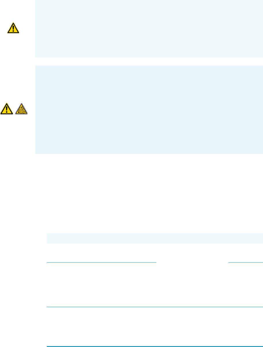
WARNING - EXPLOSION HAZARD The use of hydrogen as a carrier gas is dangerous.
Hydrogen is potentially explosive and must be used with extreme care. Any use of
hydrogen gas must be reviewed by appropriate health and safety staff, and all installations
of hydrogen systems must be performed to applicable codes and standards. Thermo Fisher
Scientific assumes no liability for the improper use of hydrogen as a carrier gas.
All Thermo Fisher Scientific gas chromatographs normally uses an inert gas as carrier gas.
If you wish to use hydrogen as a carrier gas, the hydrogen sensor must be installed into the
oven of your GC. Contact a Thermo Fisher Scientific sales representative if you plan to
use hydrogen as the carrier gas in your GC. If you don’t have the hydrogen sensor, you
must use an inert carrier gas.
Table 6. Auxiliary Gas Specifications
Gas Type Purity1Outlet Pressure Regulator Connector 2
Helium 99.999% 400-700 kPa
(58-100 psig)
Dual stage brass regulator
with stainless steel
diaphragm.
The regulator output
pressure should be
adjustable from 300 to
1000 kPa (45–145 psig)
CGA-580
Nitrogen 99.999% 400-700 kPa
(58-100 psig)
CGA-580
1. Ultra-high purity with less than 1.0 ppm each of water, oxygen, and total hydrocarbons and contained in one
tank. Impurities below 1.0 ppm generally do not require purification. Gases with higher impurity levels may require
the use of appropriate water, oxygen and hydrocarbon traps.
2. Connectors will vary with cylinder size. Confirm that your regulator will work with your gas tank. All connections
to the TriPlus 300 are 1/8 in. Swagelok fittings.

1 TriPlus 300 Headspace Site Preparation
LAN Network Requirements
Thermo Scientific TriPlus 300 Headspace Preinstallation Requirements Guide 9
Oxygen and moisture cannot be prevented from entering the system during cylinder
changes. To minimize the impact of these contaminants on the GC-GC/MS system, high
purity gas handling equipment should be used. To further protect the system from oxygen
and moisture, point-of-use purifiers should be installed in the carrier gas lines just before
they reach the GC to remove any residual contaminants. See Tab l e 7.
7. Gas lines should be:
• As short as possible, run to the back or side of the GC-GC/MS system.
• Made of pre-cleaned copper or stainless steel when using helium and hydrogen.
• Free of oil and moisture.
8. Obtain the proper gas line filters, which help prevent impurities and contaminants from
entering your system. Water, oxygen, and total hydrocarbons should be less than 1 ppm
to avoid high background noise and prevent contamination. The GC-GC/MS system is
equipped with intake filters that trap moisture, oxygen, and hydrocarbons.
9. Store gas tanks and bottles properly so they will not damage cables or gas lines. Ensure
they are secured in accordance with standard safety practices.
LAN Network Requirements
The connection between the TriPlus 300 Headspace instrument and a Thermo Scientific
Chromatography Data System (Chromeleon, Xcalibur, Chrom-Card, ChromQuest) must be
carried out via Local Area Network (LAN).
Your lab must be provided with one or more RJ-45 wall outlet. To connect your system to
your site’s LAN network, you must have an additional shielded twisted pair network cable
(cross cable).
Table 7. Trap Specifications
Traps Use
Moisture trap Water in the gas lines may damage the analytical column and
contaminate the system. Water content should be less than 1 ppm in
all cases. If you are using multiple traps, install the moisture trap
closest to the gas supply, before the hydrocarbon and the oxygen trap.
Hydrocarbon
trap
Hydrocarbon traps remove organic materials from gases. If you are
using multiple traps, install the hydrocarbon trap after the moisture
trap, but before the oxygen trap.
Oxygen trap Oxygen content in the gas lines should be less than 1 ppm. To
achieve a level of oxygen of less than 1 ppm, install an
oxygen-removing trap in the gas lines between the gas tank and the
TriPlus 300 Headspace instrument. If you are using multiple traps,
the oxygen trap should be the last trap in the series.

1 TriPlus 300 Headspace Site Preparation
Receiving Instruments
10 TriPlus 300 Headspace Preinstallation Requirements Guide Thermo Scientific
Receiving Instruments
When you receive the TriPlus 300 Headspace instrument:
1. Inspect the boxes for damage on arrival. Our instruments are shipped by electronic
equipment carriers who specialize in the handling of delicate equipment. Occasionally,
however, equipment is inadvertently damaged in transit. If you notice evidence of
external damage, do not refuse shipment. Instead, call Customer Service.
2. Once you are finished inspecting your shipment, move the cartons to a protected
location, preferably the installation site. Leave the boxes as complete as possible and do
not unpack or open the boxes without our Field Service Engineer (FSE) present. Doing
otherwise might void your warranty or order.
3. Complete the Installation Request Form located at the front of this guide and forwards it
to Customer Support.
What Happens Next?
After the Installation Request Form is received, Customer Support will contact you to
schedule the installation of your system. It is important to confirm that all the requirements
on the form are met BEFORE the Field Service Engineer arrives.
The Field Service Engineer will install the system and confirm that all performance tests pass.
a. If equipment is damaged, keep boxes and their equipment in their existing condition
and immediately notify the carrier.
b. Submit a damage claim directly to the carrier, and send a copy (including any
shortage claims) to your authorized Thermo Fisher Scientific sales representative.
c. Do not return any equipment to the dealer or the factory without prior factory
authorization.
Note We are not responsible for connecting to or establishing communication with your
site LAN network. The FSE will test the system’s ability to communicate on a mini-hub or
LAN switch only (preferable).
The IP addresses assigned to the instrument must be fixed (permanently assigned)
addresses. If you intend to connect your system to your site’s network, each piece of
equipment must have a unique, fixed (static) IP address assigned to it.
