TS450 Spare Parts 31715004 TRACE 1300 Series GC Guide
2016-05-17
: Pdf 31715004 Trace 1300 Series Gc Spare Parts Guide 31715004 TRACE 1300 Series GC Spare Parts Guide TRACE 1300 TRACE 1310 GC AS Manuals User ation
Open the PDF directly: View PDF ![]() .
.
Page Count: 96
- Contents
- Preface
- Ordering Spare Part

Thermo Scientific
TRACE 1300 and TRACE 1310
Gas Chromatographs
Spare Parts Guide
PN 31715004 Revision F January 2016
© 2016 Thermo Fisher Scientific Inc. All rights reserved.
TRACE 1300 and TRACE 1310 are trademarks of Thermo Fisher Scientific. Microsoft® is a registered
trademark of Microsoft. Adobe® is a registered trademark of Adobe Systems Incorporated in the United States
and/or other countries. Swagelok® is a registered trademark of Swagelok Company. Viton® and Vespel® are
registered trademarks of DuPont. SilFlow®, NoVent®, and FingerTite® are registered trademarks of SGE
Analytical Science. All other trademarks are the property of Thermo Fisher Scientific and its subsidiaries.
Published by Thermo Fisher Scientific S.p.A., Strada Rivoltana 20090 Rodano-Milan, Italy
Tel: +39 02 95059373; Fax: +39 02 95059388
Thermo Fisher Scientific Inc. provides this document to its customers with a product purchase to use in the
product operation. This document is copyright protected and any reproduction of the whole or any part of this
document is strictly prohibited, except with the written authorization of Thermo Fisher Scientific Inc.
The contents of this document are subject to change without notice. All technical information in this
document is for reference purposes only. System configurations and specifications in this document supersede
all previous information received by the purchaser.
Thermo Fisher Scientific Inc. makes no representations that this document is complete, accurate or error-
free and assumes no responsibility and will not be liable for any errors, omissions, damage or loss that might
result from any use of this document, even if the information in the document is followed properly.
This document is not part of any sales contract between Thermo Fisher Scientific Inc. and a purchaser. This
document shall in no way govern or modify any Terms and Conditions of Sale, which Terms and Conditions of
Sale shall govern all conflicting information between the two documents.
Release history:
First Edition, released March 2012 - “Original Instructions”
Second Edition September 2012; Third Edition October 2013; Fourth Edition January 2014; Fifth Edition
March 2015; Sixth Edition, January 2016
For Research Use Only. Not for use in diagnostic procedures.

Declaration
Manufacturer: Thermo Fisher Scientific
Thermo Fisher Scientific is the manufacturer of the instrument described in this manual and, as such, is responsible
for the instrument safety, reliability and performance only if:
•installation
•re-calibration
•changes and repairs
have been carried out by authorized personnel and if:
• the local installation complies with local law regulations
• the instrument is used according to the instructions provided and if its operation is only entrusted to qualified
trained personnel
Thermo Fisher Scientific is not liable for any damages derived from the non-compliance with the aforementioned
recommendations.
Thermo Fisher Scientific S.p.A.
Strada Rivoltana, 20090 Rodano - Milan - Italy — Tel: +39 02 950591 - Fax: +39 02 9505276
Regulatory Compliance
Thermo Fisher Scientific performs complete testing and evaluation of its products to ensure full compliance with
applicable domestic and international regulations.
When the system is delivered to you, it meets all pertinent electromagnetic compatibility (EMC) and safety
standards.
Safety
This device complies with the following safety standards according to Machinery Directive 2006/42/EC and Low
Voltage Directive 2006/95/EC.
• International Electrotechnical Commission (IEC): 61010-1:2001 (2nd edition) -61010-2-010:2003
(2nd edition)-61010-2-081:2001 (1st edition)+ A1:(2003)
• National differences: CAN/CSA C22.2 No. 61010-1 (2nd Edition)-UL 61010-1 (2nd Edition)
• EuroNorm (EN): 61010-1:2001 (2nd Edition) – 61010-2-010:2004 (2nd Edition) - 61010-2-081:2002
(1st Edition)
Electromagnetic Compatibility
This device complies with the following regulations on Electromagnetic Compatibility (EMC) and Radio
Frequency Interference (RFI) according to directive 2004/108/EC:
• CISPR 11/EN 55011: Group 1 Class A
• IEC/EN 61326-1:2012 (
IMPORTANT: Class A equipment is intended for use in an industrial environment. In others
environments there may be potential difficulties in ensuring electromagnetic compatibility, due
to the conducted as well as radiated disturbances.

FCC Compliance Statement
Notice on Lifting and Handling of
Thermo Scientific Instruments
For your safety, and in compliance with international regulations, the physical handling of this Thermo Fisher
Scientific instrument requires a team effort to lift and/or move the instrument. This instrument is too heavy and/
or bulky for one person alone to handle safely.
Notice on the Proper Use of
Thermo Scientific Instruments
In compliance with international regulations: Use of this instrument in a manner not specified by Thermo Fisher
Scientific could impair any protection provided by the instrument.
Notice on the Susceptibility
to Electromagnetic Transmissions
Do not use radio frequency transmitters, such as mobile phones, in close proximity to the instrument.
THIS DEVICE COMPLIES WITH PART 15 OF THE FCC RULES. OPERATION IS SUBJECT TO
THE FOLLOWING TWO CONDITIONS: (1) THIS DEVICE MAY NOT CAUSE HARMFUL
INTERFERENCE, AND (2) THIS DEVICE MUST ACCEPT ANY INTERFERENCE RECEIVED,
INCLUDING INTERFERENCE THAT MAY CAUSE UNDESIRED OPERATION.
CAUTION Read and understand the various precautionary notes, signs, and symbols contained
inside this manual pertaining to the safe use and operation of this product before using the device.
WEEE Compliance
This product is required to comply with the European Union’s Waste Electrical & Electronic Equipment (WEEE) Directive
2012/19/EU . It is marked with the following symbol:
Thermo Fisher Scientific has contracted with one or more recycling or disposal companies in each European Union (EU)
Member State, and these companies should dispose of or recycle this product. See www.thermoscientific.com/rohsweee for
further information on Thermo Fisher Scientific’s compliance with these Directives and the recyclers in your country.
WEEE Konformität
Dieses Produkt muss die EU Waste Electrical & Electronic Equipment (WEEE) Richtlinie 2012/19/EU erfüllen. Das Produkt
ist durch folgendes Symbol gekennzeichnet:
Thermo Fisher Scientific hat Vereinbarungen mit Verwertungs-/Entsorgungsfirmen in allen EU-Mitgliedsstaaten getroffen,
damit dieses Produkt durch diese Firmen wiederverwertet oder entsorgt werden kann. Mehr Information über die Einhaltung
dieser Anweisungen durch Thermo Fisher Scientific, über die Verwerter, und weitere Hinweise, die nützlich sind, um die
Produkte zu identifizieren, die unter diese RoHS Anweisung fallen, finden sie unter www.thermoscientific.com/rohsweee.
Conformité DEEE
Ce produit doit être conforme à la directive européenne (2012/19/EU) des Déchets d'Equipements Electriques et
Electroniques (DEEE). Il est marqué par le symbole suivant:
Thermo Fisher Scientific s'est associé avec une ou plusieurs compagnies de recyclage dans chaque état membre de l’union
européenne et ce produit devrait être collecté ou recyclé par celles-ci. Davantage d'informations sur la conformité de Thermo
Fisher Scientific à ces directives, les recycleurs dans votre pays et les informations sur les produits Thermo Fisher Scientific qui
peuvent aider la détection des substances sujettes à la directive RoHS sont disponibles sur www.thermoscientific.com/rohsweee.

Conformità RAEE
Questo prodotto è marcato con il seguente simbolo in conformità alla direttiva europea 2012/19/EU (RAEE) sui rifiuti di
apparecchiature elettriche ed elettroniche:
Thermo Fisher Scientific si è accordata con una o più società di riciclaggio in ciascun Stato Membro della Unione Europea
(EU), e queste società dovranno smaltire o riciclare questo prodotto. Per maggiori informazioni vedere il sito
www.thermoscientific.com/rohsweee.
Conformidad RAEE
Este producto es marcado con el siguiente símbolo en conformidad a la Directiva 2012/19/EU de la Unión Europea sobre los
residuos de aparatos eléctricos y electrónicos:
Thermo Fisher Scientific ha contratado una o más empresas de reciclo para tratar residuos en cada Estado Miembro de la
Unión Europea, y estas empresas deberían reciclar o eliminar este producto. Referirse a www.thermoscientific.com/rohsweee
para una mayor información sobre la conformidad de Thermo Fisher Scientific con estas Directivas y para las empresas de
reciclaje en su país.

Thermo Scientific TRACE 1300 and TRACE 1310 Spare Parts Guide vii
C
Preface . . . . . . . . . . . . . . . . . . . . . . . . . . . . . . . . . . . . . . . . . . . . . . . . . . . . . . . . . . . . . . ix
About Your System. . . . . . . . . . . . . . . . . . . . . . . . . . . . . . . . . . . . . . . . . . . . . . .ix
Power Rating . . . . . . . . . . . . . . . . . . . . . . . . . . . . . . . . . . . . . . . . . . . . . . . . . . . x
Contacting Us . . . . . . . . . . . . . . . . . . . . . . . . . . . . . . . . . . . . . . . . . . . . . . . . . . x
Related Documentation . . . . . . . . . . . . . . . . . . . . . . . . . . . . . . . . . . . . . . . . . . . x
Safety Alerts and Important Information . . . . . . . . . . . . . . . . . . . . . . . . . . . . . . x
Special Notices . . . . . . . . . . . . . . . . . . . . . . . . . . . . . . . . . . . . . . . . . . . . . . . . x
Safety Symbols and Signal Words . . . . . . . . . . . . . . . . . . . . . . . . . . . . . . . . . .xi
Instrument Markings and Symbols . . . . . . . . . . . . . . . . . . . . . . . . . . . . . . . . . . xii
Hydrogen Safety Precautions . . . . . . . . . . . . . . . . . . . . . . . . . . . . . . . . . . . . . .xiii
Using Hydrogen with TRACE 1300/TRACE 1310 . . . . . . . . . . . . . . . . . . .xiv
Hydrogen Connection Guidelines . . . . . . . . . . . . . . . . . . . . . . . . . . . . . . . . . xv
Purchasing Hydrogen . . . . . . . . . . . . . . . . . . . . . . . . . . . . . . . . . . . . . . . . . xvii
Properly Storing Hydrogen . . . . . . . . . . . . . . . . . . . . . . . . . . . . . . . . . . . . . xvii
Hydrogen Safety Codes, Standards and References . . . . . . . . . . . . . . . . . . .xviii
Hazardous Substances Precautions. . . . . . . . . . . . . . . . . . . . . . . . . . . . . . . . . xx
Venting Toxic Gases . . . . . . . . . . . . . . . . . . . . . . . . . . . . . . . . . . . . . . . . . . . xx
Liquid Nitrogen Safety Precautions . . . . . . . . . . . . . . . . . . . . . . . . . . . . . . . . . xx
Carbon Dioxide Safety Precautions. . . . . . . . . . . . . . . . . . . . . . . . . . . . . . . . . .xxi
Chapter 1 Ordering Spare Part . . . . . . . . . . . . . . . . . . . . . . . . . . . . . . . . . . . . . . . . . . . . . . . . . . . .1
Abbreviations . . . . . . . . . . . . . . . . . . . . . . . . . . . . . . . . . . . . . . . . . . . . . . . . . . . 2
Identifying A Part . . . . . . . . . . . . . . . . . . . . . . . . . . . . . . . . . . . . . . . . . . . . . . . . 2
Column Components . . . . . . . . . . . . . . . . . . . . . . . . . . . . . . . . . . . . . . . . . . . . 13
Oven Components . . . . . . . . . . . . . . . . . . . . . . . . . . . . . . . . . . . . . . . . . . . . . . 15
GC/GC-MS Components. . . . . . . . . . . . . . . . . . . . . . . . . . . . . . . . . . . . . . . . . 18
Gas Inlet Manifold Components. . . . . . . . . . . . . . . . . . . . . . . . . . . . . . . . . . . . 22
Injector Modules Components . . . . . . . . . . . . . . . . . . . . . . . . . . . . . . . . . . . . . 23
SSL Injector Module Components . . . . . . . . . . . . . . . . . . . . . . . . . . . . . . . . 24
SSLBKF Injector Module Components. . . . . . . . . . . . . . . . . . . . . . . . . . . . . 27
PTV Injector Module Components. . . . . . . . . . . . . . . . . . . . . . . . . . . . . . . . 30
PTVBKF Injector Module Components . . . . . . . . . . . . . . . . . . . . . . . . . . . . 32
GSV Module Components . . . . . . . . . . . . . . . . . . . . . . . . . . . . . . . . . . . . . . 35
Instant Connect Helium Saver Injector Module (HeS-S/SL)
Components . . . . . . . . . . . . . . . . . . . . . . . . . . . . . . . . . . . . . . . . . . . . . . . 37
Contents
Contents
viii TRACE 1300 and TRACE 1310 Spare Parts Guide Thermo Scientific
Injection Port Liners . . . . . . . . . . . . . . . . . . . . . . . . . . . . . . . . . . . . . . . . . . . . . 40
SSL Injector Ports Liner . . . . . . . . . . . . . . . . . . . . . . . . . . . . . . . . . . . . . . . . 40
PTV Injector Ports Liner. . . . . . . . . . . . . . . . . . . . . . . . . . . . . . . . . . . . . . . . 41
Detector Modules Components . . . . . . . . . . . . . . . . . . . . . . . . . . . . . . . . . . . . 42
FID Detector Module Components . . . . . . . . . . . . . . . . . . . . . . . . . . . . . . . 43
NPD Detector Module Components . . . . . . . . . . . . . . . . . . . . . . . . . . . . . . 45
ECD Detector Module Components. . . . . . . . . . . . . . . . . . . . . . . . . . . . . . . 47
TCD Detector Modules Components . . . . . . . . . . . . . . . . . . . . . . . . . . . . . . 49
FPD Detector Module Components . . . . . . . . . . . . . . . . . . . . . . . . . . . . . . . 50
PDD Detector Module Components . . . . . . . . . . . . . . . . . . . . . . . . . . . . . . 54
Upgrade Modules . . . . . . . . . . . . . . . . . . . . . . . . . . . . . . . . . . . . . . . . . . . . . . . 56
Electronic Module Boards . . . . . . . . . . . . . . . . . . . . . . . . . . . . . . . . . . . . . . . . . 60
External Modules . . . . . . . . . . . . . . . . . . . . . . . . . . . . . . . . . . . . . . . . . . . . . . . 62
Cryo Components. . . . . . . . . . . . . . . . . . . . . . . . . . . . . . . . . . . . . . . . . . . . . . . 63
Kits & Miscellanea . . . . . . . . . . . . . . . . . . . . . . . . . . . . . . . . . . . . . . . . . . . . . . 65
Tools . . . . . . . . . . . . . . . . . . . . . . . . . . . . . . . . . . . . . . . . . . . . . . . . . . . . . . . . . 71

Thermo Scientific TRACE 1300 and TRACE 1310 Spare Parts Guide ix
P
Preface
This guide contains detailed information about ordering spare parts for the TRACE 1300 and
TRACE 1310 GC.
About Your System
Thermo Scientific systems provide high-caliber gas chromatography (GC) instrumentation.
Your TRACE 1300/TRACE 1310 GC system can be a stand-alone unit or coupled with other
instruments.
GC represents a powerful analytical separation technique. Complex mixtures of individual
compounds can be injected into the GC, either manually or by using an autosampler, and
then separated the eluate for presentation to the detector. The detector generates signals of the
GC eluate and its components. These signals are then processed by a Thermo Scientific
Chromatography Data System for qualitative identification, as well as accurate and precise
quantification of the individual compounds present in the sample.
IMPORTANT Thermo Scientific systems optimize the separation and detection
capabilities of GC by providing high performance analytical capabilities for both research,
and routine applications. More information about the use of this system can be found in
related documentation sources, and by using the provided contact information.
WARNING Thermo Scientific systems operate safely and reliably under carefully
controlled environmental conditions. If the equipment is used in a manner not specified
by the manufacturer, the protections provided by the equipment might be impaired. If
you maintain a system outside the specifications listed in this guide, failures of many
types, including personal injury or death, might occur. The repair of instrument failures
caused by operation in a manner not specified by the manufacturer is specifically excluded
from the standard warranty and service contract coverage.
WARNING Operation of this system requires the use of chemical substances with
different hazard specifications. Before using any chemicals, read the hazard indications
and information reported in the Safety Sheet supplied by the manufacturer, referring to
the relevant CAS (Chemical Abstract Service) number.

Preface
Power Rating
xTRACE 1300 and TRACE 1310 Spare Parts Guide Thermo Scientific
Power Rating
TRACE 1300/TRACE 1310 gas chromatograph
• 120 Vac ±10%,50/60 Hz, 2000 VA
• 230 Vac ±10%, 50/60 Hz, 2000 VA
Detailed instrument specifications are in the Product Specifications or Product Brochure.
Contacting Us
Thermo Fisher Scientific provides comprehensive technical assistance worldwide and is
dedicated to the quality of our customer relationships and services.
Use http://www.thermoscientific.com address for products information.
Use http://www.gc-gcms-customersupport.com/WebPage/Share/Default.aspx address to
contact your local Thermo Fisher Scientific office or affiliate GC-GC/MS Customer Support.
Related Documentation
In addition to this guide, Thermo Scientific provides the following documents for the
TRACE 1300 and TRACE 1310.
TRACE 1300 and TRACE 1310 Document Set, PN 31715000
• TRACE 1300 and TRACE 1310 Preinstallation Requirements Guide, PN 31715001
•TRACE 1300 and TRACE 1310 Hardware Manual, PN 31715002
• TRACE 1300 and TRACE 1310 User Guide, PN 31715003
•TRACE 1300 and TRACE 1310 Spare Parts Guide, PN 31715004
Safety Alerts and Important Information
Make sure you follow the precautionary notices presented in this manual. The safety and
other special notices appear in boxes.
Special Notices
Notices includes the following:
IMPORTANT Highlights information necessary to prevent damage to software, loss of
data, or invalid test results; or might contain information that is critical for optimal
performance of the system.
Preface
Safety Alerts and Important Information
Thermo Scientific TRACE 1300 and TRACE 1310 Spare Parts Guide xi
Safety Symbols and Signal Words
All safety symbols are followed by WARNING or CAUTION, which indicates the degree of risk
for personal injury, instrument damage, or both. Cautions and warnings are following by a
descriptor, such as BURN HAZARD. A WARNING is intended to prevent improper actions that
could cause personal injury. Whereas, a CAUTION is intended to prevent improper actions
that might cause personal injury, instrument damage, or both. You can find the following
safety symbols on your instrument or in this manual:
Note Emphasizes important information about a task.
Tip Helpful information that can make a task easier.
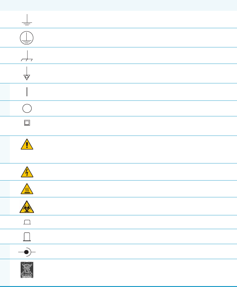
Symbol Descriptor
BIOHAZARD: Indicates that a biohazard will, could, or might occur.
BURN HAZARD: Alerts you to the presence of a hot surface that could or might
cause burn injuries.
ELECTRICAL SHOCK HAZARD: Indicates that an electrical shock could or
might occur.
FIRE HAZARD: Indicates a risk of fire or flammability could or might occur.
EXPLOSION HAZARD. Indicates an explosion hazard. This symbol indicates
this risk could or might cause physical injury.
FLAMMABLE GAS HAZARD. Alerts you to gases that are compressed,
liquefied or dissolved under pressure and can ignite on contact with an
ignition source. This symbol indicates this risk could or might cause physical
injury.
GLOVES REQUIRED: Indicates that you must wear gloves when performing a
task or physical injury could or might occur.
CLOTHING REQUIRED. Indicates that you should wear a work clothing when
performing a task or else physical injury could or might occur.
BOOTS REQUIRED. Indicates that you must wear boots when performing a
task or else physical injury could or might occur.
MATERIAL AND EYE HAZARD. Indicates you must wear eye protection when
performing a task.
HAND AND CHEMICAL HAZARD: Indicates that chemical damage or physical
injury could or might occur.
Preface
Instrument Markings and Symbols
xii TRACE 1300 and TRACE 1310 Spare Parts Guide Thermo Scientific
Instrument Markings and Symbols
Tabl e 1 explains the symbols used on Thermo Scientific instruments. Only a few of them are
used on the TRACE 1300/1310. See the asterisk.
HARMFUL. Indicates that the presence of harmful material will, could, or
might occur.
INSTRUMENT DAMAGE: Indicates that damage to the instrument or
component might occur. This damage might not be covered under the
standard warranty.
LIFTING HAZARD. Indicates that a physical injury could or might occur if two
or more people do not lift an object.
MATERIAL AND EYE HAZARD: Indicates that eye damage could or might
occur.
READ MANUAL: Alerts you to carefully read your instrument’s
documentation to ensure your safety and the instrument’s operational ability.
Failing to carefully read the documentation could or might put you at risk for a
physical injury.
TOXIC SUBSTANCES HAZARD: Indicates that exposure to a toxic substance
could occur and that exposure could or might cause personal injury or death.
LASER HAZARD. Indicates that exposure to a laser beam will, could, or might
cause personal injury.
RADIOACTIVE HAZARD. Indicates that the presence of radioactive material
could or might occur.
For the prevention of personal injury, this general warning symbol precedes
the WARNING safety alert word and meets the ISO 3864-2 standard. In the
vocabulary of ANSI Z535 signs, this symbol indicates a possible personal
injury hazard exists if the instrument is improperly used or if unsafe actions
occur. This symbol and another appropriate safety symbol alerts you to an
imminent or potential hazard that could cause personal injury.
Table 1. Instrument Marking and Symbols (Sheet 1 of 2)
Symbol Description
Direct Current
*Alternating Current
Both direct and alternating current
Three-phase alternating current
3
Preface
Hydrogen Safety Precautions
Thermo Scientific TRACE 1300 and TRACE 1310 Spare Parts Guide xiii
Hydrogen Safety Precautions
Hydrogen is a colorless, odorless, highly flammable gas with the molecular formula H2 and an
atomic weight of 1.00794, making it the lightest element. Hydrogen gas presents a hazard, as
it is combustible over a wide range of concentrations; at ambient temperature and pressure,
the range is from about 4 to 74.2% by volume.
Earth (ground) terminal
Protective conductor terminal
Frame or chassis terminal
Equipotentiality
*On (Supply)
*Off (Supply)
Equipment protected throughout by DOUBLE INSULATION or
REINFORCED INSULATION (Equivalent to Class II of IEC 536)
*Instruction manual symbol affixed to product. Indicates that the user must
refer to the manual for specific WARNING or CAUTION information to
avoid personal injury or damage to the product.
Caution, risk of electric shock
*Caution, hot surface
*Caution, biohazard
In-position of a bistable push control
Out-position of a bistable push control
*Jack socket
*Symbol in compliance to the Directive 2012/19/EU on Waste Electrical
and Electronic Equipment (WEEE) placed on the European market after
August, 13, 2005.
Table 1. Instrument Marking and Symbols (Sheet 2 of 2)
Symbol Description
+-

Preface
Hydrogen Safety Precautions
xiv TRACE 1300 and TRACE 1310 Spare Parts Guide Thermo Scientific
Hydrogen has a flash point of - 423 °F (- 253 °C) and an auto-ignition temperature of
1040 °F (560 °C). It has a very low ignition energy and the highest burning velocity of any
gas. If hydrogen is allowed to expand rapidly from high pressure, it can self-ignite. Hydrogen
burns with a flame that can be invisible in bright light.
Before you begin using hydrogen, conduct a risk assessment based on the quantity of
hydrogen to be used and the conditions of your laboratory. Ask yourself:
“What hydrogen hazards associated with this project are most likely to occur?”
“What hydrogen hazards associated with this project have the potential to result in the
worst consequences?”
• Try to reduce or eliminate the higher risks by using the proper ventilation to remove
hydrogen gas before an ignitable concentration can accumulate. Also consider purging the
hydrogen to further reduce hazards and ensure that anyone working with hydrogen has
basic hydrogen safety training.
• As with laboratory safety in general, be sure to wear safety glasses, laboratory coats, gloves,
and so on. Typically there are no specific requirements for gaseous hydrogen, other than
eye protection when working with a compressed gas. If working with liquid (cryogenic)
hydrogen, wear insulated gloves and protective shoes in addition to eye protection.
• Post “No Smoking” and “No Open Flames” signs to identify hydrogen sources and
cylinders. Maintain, inspect, and leak-test all hydrogen sources regularly.
• Clearly mark all hydrogen shutoff valves and label permanent hydrogen piping as such at
the supply or discharge point and at regular intervals along its length. Where hydrogen
gas piping passes through a wall, be sure to label both sides of the wall.
• Have contingency plans in place should an incident occur.
• Ensure that site emergency response team, as well as the local fire department, knows the
location of all hydrogen storage tanks.
Using Hydrogen with TRACE 1300/TRACE 1310
The use of hydrogen as a carrier gas, or as fuel gas for certain flame detectors, requires strict
attention and compliance with special precautions due to the hazards involved.
WARNING - EXPLOSION HAZARD The use of hydrogen as a carrier gas is dangerous.
Hydrogen is potentially explosive and must be used with extreme care. Any use of
hydrogen gas must be reviewed by appropriate health and safety staff, and all installations
of hydrogen systems must be performed to applicable codes and standards. Thermo Fisher
Scientific assumes no liability for the improper use of hydrogen as a carrier gas.

Preface
Hydrogen Safety Precautions
Thermo Scientific TRACE 1300 and TRACE 1310 Spare Parts Guide xv
Hydrogen is a dangerous gas, particularly in an enclosed area when it reaches a concentration
corresponding to its lower explosion level (4% in volume). An explosion hazard could develop
in the oven when hydrogen is used as a carrier gas in the case oven elements are not perfectly
connected to each other, or when the connection materials are worn out, broken, or otherwise
faulty.
Use the following safety precautions when using hydrogen:
• Ensure that all hydrogen cylinders comply with the safety requirements for proper use
and storage. Hydrogen cylinders and delivery systems must comply with local regulations.
• Make sure the gas supply is turned completely off when connecting hydrogen lines.
• Perform a leak test to ensure that the hydrogen lines are leak-tight before using the
instrument. Repeat this test to eliminate all leaks.
• Ensure your TRACE 1300/TRACE 1310 has a Thermo Scientific hydrogen sensor
installed for continuously monitoring the hydrogen level in the oven.
Hydrogen Connection Guidelines
Use the following guidelines to safely connect hydrogen to your system:
•Piping—Hydrogen must be delivered to equipment using appropriate piping and be
done in such a way as to pose essentially no hazard to end-users. Piping systems for the
delivery of hydrogen should be designed and installed by a person qualified by specific
training and experience with hydrogen piping systems.
Stainless steel is usually recommended because it is a safe, cost-effective material. Piping
of black iron or copper must not be used, as the pipe can become brittle with age.
Elastomeric/plastic tubing of various plastics and polymers should not be used, unless the
WARNING - EXPLOSION HAZARD Hydrogen is a dangerous gas that, when mixed with
air, could create an explosive mixture. The use of hydrogen as a carrier gas requires
extreme caution. Special precautions must be taken because of the risk of explosion. When
hydrogen is used as carrier gas the gas chromatograph must be equipped with a hydrogen
sensor.
Never use hydrogen as carrier gas in your TRACE 1300/TRACE 1310 system unless your
oven has a hydrogen sensor installed. Thermo Fisher Scientific FSEs are not authorized to
install or repair any instrument using hydrogen as a carrier gas unless the instrument is
equipped with the appropriate sensor.
If your oven does not have a hydrogen sensor already installed, contact your Thermo
Fisher Scientific sales representative. To comply with instrument safety requirements, a
Thermo Fisher Scientific FSE or authorized service personnel should install the sensor
into your TRACE 1300/TRACE 1310.
Preface
Hydrogen Safety Precautions
xvi TRACE 1300 and TRACE 1310 Spare Parts Guide Thermo Scientific
tubing is approved for use with hydrogen. If elastomeric/plastic tubing is used for
hydrogen gas delivery, the tubing should be tested for hydrogen permeability to minimize
leakage.
The hydrogen piping system must be flexible enough to endure routine thermal
expansion and contraction. The system should also include considerations for the most
severe condition of temperature and pressure expected during service. Piping and
supports must be able to withstand static loading introduced by such things as ice and
snow; and dynamic loading from high wind and earthquake.
Caution should be used if burying hydrogen piping. Proper controls should be used to
protect against damage and corrosion, and also to prevent Hydrogen from entering a
building if there is any leakage.
•Fittings—All fittings must be of the proper type approved or designed for use with
hydrogen gas. Use as few fittings as possible to minimize the potential for leaks. After
installation, ensure that leak testing is carried out prior to system use, and on a regular
basis.
There must be no PTFE tape or other things like plumber's putty used to enhance a seal, as
this actually is a detriment to a good seal. Ideally the best installation would use stainless
steel tubing with appropriate gas-tight fittings.
Welding is usually preferred for joints in hydrogen piping systems since welding provides
a better connection and reduces the potential for leaks compared to mechanical fittings.
Soft solder joints are not permitted for hydrogen systems (due to the low melting point of
soft solder and its potential for brittle failure at cryogenic temperatures). Brazed joints are
permitted, but such joints should be protected against the possibility of external fire.
Tubing connections should be clamped to barbed or press-fit type connections. Hose
clamps or jubilee clamps must not be used.
•Valves—All valves must be suitable for hydrogen service and for the specific operating
conditions. Valves, including regulators, must not be used for hydrogen, unless they are
designed and identified for such a use. Ball valves are often chosen because of their
superior leak tightness through the valve seat. Pneumatic operators are usually chosen for
remotely operated valves so that potential ignition sources (electricity) are remote from
the valve.
Manual shutoff valves should be provided near each point of use, within immediate reach.
If a hydrogen cylinder or hydrogen generation system is located within immediate reach,
a separate point-of-use shutoff valve is usually not necessary.
Line regulators that have their source away from the point of use should have a manual
shutoff valve near the point of use.
An emergency gas shutoff device in an accessible location outside the use area should be
provided in addition to the manual point-of-use valve in each educational and
instructional laboratory space that has a piped gas supply system.
Preface
Hydrogen Safety Precautions
Thermo Scientific TRACE 1300 and TRACE 1310 Spare Parts Guide xvii
If necessary, the piping system should have uninterruptible pressure relief. The pressure
relief system should be designed to provide a discharge rate sufficient to avoid further
pressure increase and should vent to a safe location outside or to a ventilation system
exhaust.
Purchasing Hydrogen
Use the following guidelines when purchasing hydrogen:
• Hydrogen Generator—Because it minimizes the amount of hydrogen present and reduces
the degree of hazard, a hydrogen generator (also called an electrolyzer) is the safest way to
purchase hydrogen in the quantity used in gas chromatography/mass spectroscopy
systems.
However, to minimize the degree of hazard, operate the hydrogen generator only in a
non-explosive environment because hydrogen buildup can be ignitable. Thus, your
ventilation system for the room or lab hood where the hydrogen generator operates must
maintain an air exchange rate at least two orders of magnitude greater than the maximum
hydrogen production rate of the hydrogen generator. Follow the manufacturers'
directions about proper use and maintenance of the regulator.
To prevent the possibility of releasing hydrogen, set the hydrogen generator to shut down
if:
−There is a loss of flow to the ventilation system
−A hydrogen detector alarms at 25% of the lower flammable limit of hydrogen in air.
Vent the oxygen exhausted by the electrolyzer to the outside as well.
• Hydrogen Cylinder—Hydrogen can be delivered in standard laboratory gas bottles or
cylinders. These cylinders have a limited amount of hydrogen in them and are a safe way
to transport and store hydrogen. Always secure, compressed hydrogen gas cylinders, like
all compressed gas cylinders, in an upright position, ideally with a non-combustible chain
or cable. If the cylinder falls over, the valve can fall off, causing the pressurized cylinder to
take off like a rocket, leading to the release of hydrogen and possibly an explosion, severe
injury, or death. Never crack a hydrogen cylinder valve to remove dust or dirt from
fittings prior to attaching a regulator, as there is a risk of self-ignition.
Properly Storing Hydrogen
Storing and handling compressed hydrogen gas and cryogenic liquid hydrogen present
potential health and safety hazards. Using proper storage and handling techniques is essential
to maintaining a safe work environment.
Use the following guidelines when storing hydrogen:
Preface
Hydrogen Safety Precautions
xviii TRACE 1300 and TRACE 1310 Spare Parts Guide Thermo Scientific
• Store spare hydrogen gas cylinders outside and away from doors, windows, building air
intake vents, structures, and vehicle routes. This precaution applies when the hydrogen is
or is not in use. Indoor storage of spare hydrogen cylinders has special requirements,
which are beyond the scope of this document. Documentation for each vessel should
include a description of the vessel, a list of available drawings or other documents, the
most recent inspection results, and the responsible person's name.
• Prevent spare cylinders from toppling by wrapping them with chains. The chains should
also be protected against corrosion and excessive heat.
• Separate spare hydrogen cylinders from oxidizing gases (such as oxygen) with a 5 ft.
(1.5 m) tall fire barrier with a half-hour fire rating or place the cylinders at least 20 ft.
(6 m) apart.
• When moving hydrogen cylinders:
−Remove the regulator and replace the cylinder valve cap before moving.
−Move cylinders on cylinder carts or with other appropriate transport devices.
−Never roll or drop a cylinder and never lift a cylinder by its protective cap.
• Bulk hydrogen systems include either gaseous or liquid hydrogen in fixed installations; in
some gas systems a semi-permanent trailer (tube trailer) can be used. Storage vessels for
compressed hydrogen gas or liquid hydrogen should be designed, constructed, tested, and
maintained in accordance with applicable codes and standards. Bulk hydrogen systems
represent a level of complexity again which is beyond the scope of this document;
however some general guidelines are provided.
• The bulk hydrogen storage system should not be located beneath electric power lines,
close to other flammable gases/liquids, or close to public areas. It should be readily
accessible to authorized personnel and delivery equipment, but protected from physical
damage or tampering.
• As liquid hydrogen systems also have a cryogenic hazard, additional safety considerations
for the use of cryogenic liquids might be necessary.
Hydrogen Safety Codes, Standards and References
The following list of safety codes, standards, and references is in no way an exhaustive list. In
fact, there may be federal, state, or local codes that apply to your specific location. Check with
all appropriate agencies with jurisdiction before installing or using a hydrogen system.
• Air Products Safetygram #4 Gaseous Hydrogen
• ANSI/AIAA standard for hydrogen safety guidelines is AIAA G-095-2004, Guide to
Safety of Hydrogen and Hydrogen Systems
• ASME B31.1, Power Piping Code
• ASME B31.3, Process Piping Code
Preface
Hydrogen Safety Precautions
Thermo Scientific TRACE 1300 and TRACE 1310 Spare Parts Guide xix
• ASME B31.8, Gas Transmission and Distribution Systems
• BCGA Code Of Practice CP4 Industrial Gas Cylinder Manifolds and Gas Distribution
Pipework
• BCGA Code Of Practice CP33 The Bulk Storage of Gaseous Hydrogen at Users'
Premises
• CGA G-5, Hydrogen
• CGA G-5.4, Standard for Hydrogen Piping Systems at Consumer Locations
• CGA G-5.5, Hydrogen Vent Systems
• CGA G-5.6, Hydrogen Pipeline Systems
• CGA G-5.8, High Pressure Hydrogen Piping Systems at Consumer Locations.
• FM Global Property Loss Prevention Data Sheets 7-50: Compressed Gases in Cylinders
• FM Global Property Loss Prevention Data Sheets 7-91: Hydrogen
• IGC Doc 121/04/E, Hydrogen Transportation Pipelines System Design Features
•NASA
• NSS 1740.16 Safety Standard For Hydrogen And Hydrogen Systems Guidelines for
Hydrogen System Design, Materials Selection, Operations, Storage, and Transportation
• NFPA 52, Vehicular Fuel Systems Code
• NFPA 55, Standard for the Storage, Use, and Handling of Compressed Gases and
Cryogenic Fluids in Portable and Stationary Containers, Cylinders, and Tanks, 2005
Edition
• NFPA 68, Standard on Explosion Protection by Deflagration Venting
• NFPA 70, National Electrical Code
• NFPA 497, Recommended Practice for the Classification of Flammable Liquids, Gases,
or Vapors and of Hazardous (Classified) Locations for Electrical Installations in Chemical
Process Areas
• NFPA 13, Standard for the Installation of Sprinkler Systems
• NFPA 45, Standard on Fire Protection for Laboratories Using Chemicals
• NFPA 55, Standard for the Storage, Use, and Handling of Compressed Gases and
Cryogenic Fluids in Portable and Stationary Containers, Cylinders, and Tanks
• NFPA 68, 2007 Standard on Explosion Protection by Deflagration Venting
• NFPA 69, Standard on Explosion Prevention Systems
• NFPA 91, Standard for Exhaust Systems for Air Conveying of Vapors

Preface
Liquid Nitrogen Safety Precautions
xx TRACE 1300 and TRACE 1310 Spare Parts Guide Thermo Scientific
• NFPA 255, Standard Method of Test of Surface Burning Characteristics of Building
Materials
• OSHA 29CFR1910.103 1910.103 Hydrogen
Hazardous Substances Precautions
Venting Toxic Gases
When analyzing toxic compounds be aware that during the normal operation of the GC some
of the sample might be vented outside the instrument through the inlet and detector exits;
therefore, make sure to vent the exhaust gases to a fume hood. Consult local Environmental
and Safety Regulations for instructions in exhausting fumes from your system.
Liquid Nitrogen Safety Precautions
Liquid nitrogen is a colorless, odorless, extremely cold liquid and gas under pressure. It can
cause rapid suffocation when concentrations are sufficient to reduce oxygen levels below
19.5%. A Self Contained Breathing Apparatus (SCBA) might be required. Contact with
liquid or cold vapors can cause severe frostbite. Cold vapors in the air will appear as a white
fog due to condensation of moisture. Oxygen concentrations must be monitored in the release
area. All cryogenic liquids produce large volumes of gas when they vaporize.
WARNING Before using hazardous substances (toxic, harmful, and so on), read the
hazard indications and information reported in the applicable Material Safety Data Sheet
(MSDS.) Use Personal protection according to the safety requirements.
WARNING Before using Liquid Nitrogen, read the hazard indications and the
instructions reported in the Safety sheet supplied by the manufacturer, with reference to
the CAS number (Chemical Abstract Service) 7727-37-9.
Use personal protection:
•Protective gloves: Loose fitting thermal-insulated or leather gloves.
•Eye protection: Full face shield and safety glasses are recommended.
•Other protective equipment: Safety shoes when handling containers. Long sleeved
shirts and trousers without cuffs. Work clothing that sufficiently prevents skin contact
should be worn.

Preface
Carbon Dioxide Safety Precautions
Thermo Scientific TRACE 1300 and TRACE 1310 Spare Parts Guide xxi
Carbon Dioxide Safety Precautions
Carbon dioxide is a colorless, cryogenic liquid. At low concentrations, is odorless. At higher
concentrations carbon dioxide will have a sharp, acidic odor. At concentrations between 2 and
10%, Carbon dioxide can cause nausea, dizziness, headache, mental confusion, increased
blood pressure, and increased respiratory rate. If the gas concentration reaches 10% or more,
suffocation and death can occur within minutes. Contact with the cold gas can cause freezing
of exposed tissue. Moisture in the air could lead to the formation of carbonic acid that can be
irritating to the eyes. All forms of carbon dioxide are noncombustible. Carbon dioxide is
heavier than air and should not be allowed to accumulate in low lying areas.
WARNING Before using carbon dioxide, read the indications of hazard and the
instructions reported in the Safety sheet supplied by the manufacturer with reference to
the CAS number (Chemical Abstract Service) 124-38-9.
Use personal protection:
•Protective gloves: Loose fitting thermal insulated or leather gloves.
•Eye protection: Full face shield and safety glasses are recommended.
•Other protective equipment: Safety shoes when handling containers. Long sleeved
shirts and trousers without cuffs. Work clothing that sufficiently prevents skin contact
should be worn.

Thermo Scientific TRACE 1300 and TRACE 1310 Spare Parts Guide 1
1
Ordering Spare Part
This chapter contains illustrations and part numbers for all of the replaceable components in
the TRACE 1300/TRACE 1310. Refer to the TRACE 1300 and TRACE 1310 Hardware
Manual for information about installing these components in your instrument.
Throughout the TRACE 1300/TRACE 1310 documentation, any component with a part
number can be ordered from us. Components without a part number are not available.
Contents
•Abbreviations
•Identifying A Part
•Column Components
•Oven Components
•GC/GC-MS Components
•Gas Inlet Manifold Components
•Injector Modules Components
•Injection Port Liners
•Detector Modules Components
•Upgrade Modules
•Electronic Module Boards
•External Modules
•Cryo Components
•Kits & Miscellanea
•Too ls

1 Ordering Spare Part
Abbreviations
2TRACE 1300 and TRACE 1310 Spare Parts Guide Thermo Scientific
Abbreviations
Tabl e 1 details the abbreviations used in this guide.
Identifying A Part
To identify a part, you need to know where it was located in the TRACE 1300/TRACE 1310
or the part’s relationship to a particular functionality of the TRACE 1300/TRACE 1310.
Use the categories in the table below to find a location or functionality that relates to the
component you need. For example, if you know the part is related to the SSL injector look in
the Injector Component category. Then refer to the illustrations in that category to visually
identify that particular part.
Table 1. List of Abbreviation
Abbreviation Description
AOI Analog Output Interface
ECD Electron Capture Detector
FID Flame Ionization Detector
FPD Flame Photometric Detector
GC Gas Chromatograph
GC-MS Gas Chromatograph and Mass Spectrometer
GDI Generic Detector Interface
GSV Gas Sampling Valve
HeS-S/SL Instant Connect Helium Saver Injector
NPD Nitrogen Phosphorus Detector
PDD Pulsed Discharge Detector
SSL Split/Splitless Injector
SSLBKF Split/Splitless Injector for Backflush applications
Pkg Package
PTV Programmable Temperature Vaporizing Injector
PTVBKF Programmable Temperature Vaporizing Injector for Backflush applications
TCD Thermal Conductivity Detector
IMPORTANT Only components with a part number are available for purchase. The part
you are looking for may be shown in an illustration, but if it does not list a part number, it
is not available.

1 Ordering Spare Part
Identifying A Part
Thermo Scientific TRACE 1300 and TRACE 1310 Spare Parts Guide 3
Table 2. Parts That Can Be Reordered (Sheet 1 of 9)
Component Uses
Thermo
Scientific
Parts Number
Category
Graphite Ferrule for 0.1 - 0.32 mm ID Columns (Pkg of 10) SSL, SSLBKF, GSV, FID, NPD, TCD, ECD, FPD 290GA139
Column
Components
Graphite Ferrule for 0.45 - 0.53 mm ID Columns (Pkg of 10) 290GA140
Graphite Vespel® Ferrule for 0.1- 0.25 mm ID Columns
(Pkg of 10)
290VA191
Graphite Vespel® Ferrule for 0.32 mm ID Columns (Pkg of 10) 290VA192
Graphite Vespel® Ferrule for 0.53 mm ID Columns (Pkg of 10) 290VA193
Polyimide-Valcon® Reducing Ferrule for 0.36 < 0.4 mm OD
Tubing (Pkg of 5)
PDD 29003426
Polyimide-Valcon® Reducing Ferrule for 0.4 < 0.5 mm OD
tubing (Pkg of 5)
29003427
Blind Ferrule SSL, SSLBKF, FID, ECD, NPD, TCD, FPD 29003421
PTV, PTVBKF 29003419
Encapsulated Graphite Ferrule for 0.25 mm ID Columns
(Pkg of 10)
PTV, PTVBKF, SSLBKF, GSV (Tee connector) 29053488
Encapsulated Graphite Ferrule for 0.32 mm ID Columns
(Pkg of 10)
29053487
Encapsulated Graphite Ferrule for 0.53 mm ID Columns (
Pkg of 10)
29053486
SilFlow™ Fingertight Ferrule for 0.35 mm ID Columns
(Pkg of 10)
No Vent, HeS-S/SL 29063465
SilFlow™ Fingertight Ferrule for 0.4 mm ID Columns (Pkg of 10) No Vent, HeS-S/SL 29063466
Silflow™ Fingertight Ferrule for 0.5 mm ID Columns (Pkg of 10) HeS-S/SL 29063467
SilFlow™ Blanking Ferrule (Pkg of 5) No Vent, HeS-S/SL 290ST414
SilFlow™ Nut (Pkg of 10) No Vent, HeS-S/SL 290SF302
SilFlow Fingertight Tool No Vent, HeS-S/SL 60201-401
Reducing Graphite Vespel® Ferrule 1/8-1/16-in. HeS-S/SL 29003422
Retaining Nut, Hexagonal, 1/4-in. (Pkg of 5) SSL, FID, NPD, TCD, ECD, FPD 35050458
Split Retaining Nut, M4 SSLBKF, GSV, PTV, PTVBKF 35053221
Nut 1/16-in. SS ZN1 (Pkg of 10) HeS-S/SL 35023099
Ferrule 1/16-in. SSZF1 (Pkg of 10) HeS-S/SL 29024283
Spring Loaded Nut (see kit P/N 19050251) SSLBKF, PTVBKF 1R120434-0010
Column Support (Rack) GC, GC-MS 36814159
Column-Flow Meter Connector GC, GC-MS 24507000
Tubing pre-cleaned, Pre-cut 316 SS; 1/16-in., 1 m long;
0.25 mm ID
HeS-S/SL 39104801
Precolumn, 0.53 mm ID, 2 m long SSLBKF, PTVBKF 26050-0253

1 Ordering Spare Part
Identifying A Part
4TRACE 1300 and TRACE 1310 Spare Parts Guide Thermo Scientific
Oven Heater Baffle Assemble GC, GC-MS 26600800
Oven
Components
Oven Heater Temperature Sensor GC, GC-MS 40303530
Oven Motor GC, GC-MS 31807047
Oven Blower Fan GC, GC-MS 41003510
Flaps Stepper Motor GC, GC-MS 23043678
Oven Multiple GC, GC-MS 39305418
Duct for ISQ/TSQ 8000 Mass Spectrometer GC-MS 25907025
Duct for ITQ Mass Spectrometer GC-MS 25907015
Duct for TSQ Quantum Mass Spectrometer GC-MS
Duct for DSQ II Mass Spectrometer GC-MS 25907020
Duct Insulator, Small Size GC-MS 30200115
Hydrogen Sensor GC, GC-MS 27605006
Fan, Cooling GC, GC-MS 23043702
GC/GC-MS
Components
Filter, High Current Line, 16 A: 250 V GC, GC-MS 23850005
Touch Display Assy TRACE 1310 GC, GC-MS 33322000
Status Panel TRACE 1300 GC, GC-MS 23719540
Top Cover Assemble GC, GC-MS 24104386
Right Panel Assemble GC, GC-MS 33311010
Left Panel Assemble GC, GC-MS 33311015
Left Panel Assemble for ISQ/ITQ MS GC, GC-MS 33312000
Rear Cover Assemble GC, GC-MS 33311025
Cover Door Assemble for TRACE 1300 GC, GC-MS 30200128
Cover Door Assemble for TRACE 1310 GC, GC-MS 33311000
Door Assy Internal (with insulating) GC, GC-MS 33315353
Cables Holder-Handle GC, GC-MS 28502213
Gas Block Plug Kit GC, GC-MS 19050773
Syringe 10 μL, 50 mm needle length GC, GC-MS 36500525
Test Column, 7 m, 0.32 mm ID, 0.25 μm F.T. GC, GC-MS 26080001
Transformer, Toroidal 500 VA GC, GC-MS 41325072
O-ring, Injector/Detector Meting Block GC, GC-MS 29031303
Gas Inlet Manifold Components Kit GC, GC-MS 19050751 Gas Inlet
Manifold
Components
Gas Inlet Fitting 1/8-in. for Toggle Valve GC, GC-MS 35008438
Table 2. Parts That Can Be Reordered (Sheet 2 of 9)
Component Uses
Thermo
Scientific
Parts Number
Category

1 Ordering Spare Part
Identifying A Part
Thermo Scientific TRACE 1300 and TRACE 1310 Spare Parts Guide 5
Filter, Split Line SSL, SSLBKF, GVS, HeS-S/SL, PTV, PTVBKF 28113197
Injector
Modules
Components
Filter, Carrier Line SSL, SSLBKF, GSV, HeS-S/SL, PTV, PTVBKF 28113196
Fitting Cap, Backflush Line SSLBKF, PTVBKF, GSV 35003036
Injector Body, SSL SSL, SSLBKF 24705240
Injector Body, HeS-S/SL HeS-S/SL 24705255
He Saver Potted Box Assembly HeS-S/SL 27609926
Injector Head Assemble PTV, PTVBKF 36812739
Liner Cap/Septum Holder SSL, SSLBKF, HeS-S/SL 40203005
Liner Cap PTV, PTVBKF 29004012
Liner Seal SSL, SSLBKF, HeS-S/SL 29001320
Liner Seal PTV, PTVBKF 29001325
O-Ring External, Body Head SSL, SSLBKF, HeS-S/SL 29001316
O-Ring, Internal, Body Head SSL, SSLBKF, HeS-S/SL 29001313
O-Ring (Parafluor 2--6) Manifold SSL, SSLBKF, PTV, PTVBKF, HeS-S/SL 29011310
Retaining Nut (for Column Adapter) SSL, SSLBKF 35001126
Ring Nut SSL, SSLBKF, HeS-S/SL 35001821
Septum, BTO 11 mm OD with center guide SSL, SSLBKF, HeS-S/SL, PTV, PTVBKF 31303233
Septum Cap SSL, SSLBKF, HeS-S/SL, PTV, PTVBKF 35001820
Septum Cap for AI 1310 Autosampler and for HS (TriPlus Only) SSL, SSLBKF, HeS-S/SL, PTV, PTVBKF 35001819
Silver Seal PTV, PTVBKF 29013820
Base Seal and washer SSL, SSLBKF 290GA081
Precolumn, 2 m length, 0,5 mm SSLBKF, PTVBKF 26050-0253
High Temperature Tee Connection SSLBKF, PTVBKF 34708447
Tee Connector Low Volume SSLBKF, PTVBKF 34708449
Terminal Bottom Fitting 1 mm ID PTV, PTVBKF 35008429
Terminal Bottom Fitting 0.5 mm ID PTV, PTVBKF 35008428
Six-ports Diaphragm Valve GSV 40516165
Kit Sample Loop 20 μL GSV 19071405
Kit Sample Loop 50 μL GSV 19071404
Kit Sample Loop 100 μL GSV 19071403
Kit Sample Loop 250 μL GSV 19071402
Kit Sample Loop 500 μL GSV 19071401
Kit Sample Loop 1000 μL GSV 19071400
Bottom Insulator HeS-S/SL 29004408
Table 2. Parts That Can Be Reordered (Sheet 3 of 9)
Component Uses
Thermo
Scientific
Parts Number
Category

1 Ordering Spare Part
Identifying A Part
6TRACE 1300 and TRACE 1310 Spare Parts Guide Thermo Scientific
Adapter TRACE 1300 to 1/16-in. HeS-S/SL 35002123 Injector
Modules
Components
(Continued)
O-ring, Gas Delivery Block HeS-S/SL 29031303
SSL Split Straight Liner, Deactivated,
4 mm ID x 6.3 mm OD x 78.5mm Length, Quartz Wool
SSL, SSLBKF, HeS-S/SL 453A2265
Injection
Port Liners
SSL Splitless Liner, single Taper, Deactivated,
4 mm ID x 6.3 mm OD x 78.5 mm Length, Quartz Wool
SSL, SSLBKF, HeS-S/SL 453A1925
SSL Split Straight Liner, Deactivated, 4 mm ID x 6.3 mm OD x
78.5 mm Length
SSL, SSLBKF, HeS-S/SL 453A1295
SSL Splitless Liner, Single Taper, Deactivated,
4 mm ID x 6.3 mm OD x 78.5 mm Length
SSL, SSLBKF, HeS-S/SL 453A1345
SSL Direct Straight Liner for HS/SPME,
Deactivated, 1.2 mm ID x 6.3 mm OD x 78.5 mm Length
SSL, SSLBKF, HeS-S/SL 453A1335
SSL Mini-LAM Liner, Deactivated,
4 mm ID x 6.3 mm OD x 78.5 mm Length
SSL, SSLBKF, HeS-S/SL 453A2009
PTV Liner, Deactivated,
2 mm ID x 2.75 mm OD x 120 mm Length, Quartz Wool
PTV 45352070
PTV Siltek Metal Liner,
2 mm ID x 2.75 mm OD x 120 mm Length
PTV, PTVBKF 45322044
PTV Liner, Non-Deactivated,
2 mm ID x 2.75 mm OD x 120 mm Length
PTV, PTVBKF 45322045
PTV Siltek Metal Liner,
1 mm ID x 2.75 mm OD x 120 mm Length
PTV, PTVBKF 45322046
PTV Straight Liner, Deactivated,
1 mm ID x 2.75 mm OD x 120 mm Length
PTV, PTVBKF 45352054
PTV Straight Liner, Deactivated,
2 mm ID x 2.75 mm OD x 120 mm Length
PTV, PTVBKF 45352057
PTV Siltek Metal Liner,
2 mm ID x 2.75 mm OD x 120 mm Length
PTV, PTVBKF 45322056
PTV Liner with Sintered Lining,
1 mm ID x 2.75 mm OD x 120 mm Length
PTV, PTVBKF 45352060
PTV Liner with Three Baffles, Deactivated,
1 mm ID x 2.75 mm OD x 120 mm Length
PTV, PTVBKF 45352062
PTV Baffle Liner (Siltek), Deactivated,
2 mm ID x 2.75 mm OD x 120 mm Length
PTV, PTVBKF 453T2120
PTV Silcosteel Liner Simile On-Column, 1 mm ID x 2.75 mm OD
x120 mm Length, with 0.6 mm ID Restriction
PTV 45322052
Table 2. Parts That Can Be Reordered (Sheet 4 of 9)
Component Uses
Thermo
Scientific
Parts Number
Category

1 Ordering Spare Part
Identifying A Part
Thermo Scientific TRACE 1300 and TRACE 1310 Spare Parts Guide 7
Retaining Nut (for Column Adapter) FID, NPD, ECD, TCD, FPD 35001126
Detector
Modules
Components
Cell Top Cover Assemble (Top Body) FID 24705245
Collecting Electrode FID 27700900
Collecting Electrode (Anode) ECD 21600210
Collecting Electrode for Thermionic Source NPD 27701600
Collecting Electrode Pin FID 20601604
NPD, ECD 20604305
Collecting Electrode (Anode) Seal ECD 29032608
Collecting Electrode (Anode) Screw ECD 35006118
Collector Insulator FID 30202400
Detector Cap (Ring Nut) FID 35001124
Measuring Tool Flowmeter Adapter FID 34709348
NPD 34709610
FPD 34709630
Glow-Plug (Igniter) FID, FPD 40303535
Glow-Plug Cable FID 23043717
Insulator Ring FID 29004612
Collector Insulator NPD 30202405
Jet; Ceramic Flame FID 40402200
Jet; Stainless Steel NPD 40404516
Jet, Deactivated Silcosteel FPD 40404518
Polarizing Electrode FID 27702330
Thermionic Source TID 2 (standard) for both N and P detections NPD 46500256
Thermionic Source TID 4 (optional) for enhanced N response NPD 46500257
FPD Detector Assembly FPD 29903110
Aluminium O-ring FPD 29032630
Kit Interferential Filter for Sulphur (28107101 + Spacer) FPD 19050785
Kit Interferential Filter for Phosphorus (28107102 + Spacer) FPD 19050786
Interferential Filter for Sulphur FPD 28107000
Interferential Filter for Phosphorus FPD 28107100
Interferential Filter for Tin FPD 28107001
Photomultiplier Tube FPD 28600460
Fixing Tool, FPD Detector Assembly FPD 20501608
PDD Pulse Generator (Pulser) PDD 43210075
Table 2. Parts That Can Be Reordered (Sheet 5 of 9)
Component Uses
Thermo
Scientific
Parts Number
Category

1 Ordering Spare Part
Identifying A Part
8TRACE 1300 and TRACE 1310 Spare Parts Guide Thermo Scientific
PDD Purifier Assy PDD 43210076 Detector
Modules
Components
(Continued)
PDD Mini Helium Purifier Kit PDD 19071500
PDD Cell PDD 41910716
PDD Flow restriction PDD 24505908
PDD Packed Column Adapter PDD 26060521
GDI Low Flow Restrictor GDI 24503330
GDI Medium Flow Restrictor GDI 24503333
GDI High Flow Restrictor GDI 24503334
Test Mixture FID 33819020
NPD, FPD 33819006
TCD 33819016
ECD 33819011
PDD 33819032
Detector Module, ECD for China market ECD 19070029
Upgrade
Modules
Detector Module, ECD for International market ECD 19070030
Detector Module, ECD for USA market (General License) ECD 19070031
Detector Module, ECD for USA market (Special License) ECD 19070032
Detector Module, ECD for Canada market ECD 19070033
Detector Module, FID FID 19070001
Detector Module, NPD NPD 19070060
Detector Module, TCD Nickel-Iron (Ni-Fe) filament cell TCD 19070040
Detector Module, TCD Tungsten-Rhenium (W-Re) filament cell TCD 19070041
Detector Module TCD In-Series Connection TCD 19070045
Detector Module, FPD FPD 19070096
Dummy Module All Modules 19070097
Electronic Module 120 Vac GC, GC-MS 43210168
Electronic Module 230 Vac GC, GC-MS 43210167
Injector Module, SSL SSL 19070010
Injector Module, SSLBKF SSLBKF 19070011
Injector Module, Gas Sampling Valve GSV 19070095
Injector Module, Helium Saver S/SL HeS-S/SL 19070013
Injector Module, PTV PTV 19070020
Injector Module, PTVBKF PTVBKF 19070021
FTIR Make-up Module GC-FTIR 19070050
Table 2. Parts That Can Be Reordered (Sheet 6 of 9)
Component Uses
Thermo
Scientific
Parts Number
Category

1 Ordering Spare Part
Identifying A Part
Thermo Scientific TRACE 1300 and TRACE 1310 Spare Parts Guide 9
No Vent Microfluidics Module GC-MS 19070090 Upgrade
Modules
(Continued)
Detector Module, PDD PDD 19070014
Analog Output Interface GC, GCMS 19070022
Rear Backplane Board (BKP-HRM; PC1256) GC, GC-MS 23661000
Electronic
Module
Boards
Oven CPU-Power Control Board (OVN-HRM; 230 V; PC1257) GC, GC-MS 23661010
Oven CPU-Power Control Board (OVN-HRM; 120 V; PC1257-01) GC, GC-MS 23661011
Main CPU Board (CPU-HRM; PC1258) GC, GC-MS 23661015
Memory Board (MEM-HRM; PC1259) GC, GC-MS 23661020
External Interface Board (EXT-HRM; PC1263) GC, GC-MS 23661025
Power Supply Board GC, GC-MS 20806090
Aux Temperature/Cryo Module GC, GC-MS 19070070
External
Modules
Auxiliary Gases Module GC, GC-MS 19070080
NPD Thermionic Source Power Module GC, GC-MS 43215010
Oven Cryo CO2 Assemble GC, GC-MS 19050753
Cryo
Components
Oven Cryo N2 Assemble GC, GC-MS 19050752
PTV Cryo CO2 Assemble GC, GC-MS 19050755
PTV Cryo N2 Assemble GC, GC-MS 19050754
Merlin Valve Kit SSL, SSLBKF, PTV, PTVBKF, HeS-S/SL 19050735
Kits &
Miscellanea+
Clamp Bracket for Backflush SSLBKF, PTVBKF, GSV 19050757
Packed Column Adapters Kit SSL, FID, NPD, TCD, ECD 19050758
Graph-pack (Encapsulated Graphite) Ferrules Adapters SSL, FID, NPD, TCD, ECD 19050759
Oven Exhaust Kit GC, GC-MS 19050760
SSL Maintenance Kit SSL, SSLBKF, HeS-S/SL 19050770
SSL O-Ring Kit SSL, SSLBKF, HeS-S/SL 19050771
FID Igniter Kit FID 19050775
FID Maintenance Kit FID 19050776
NPD Maintenance Kit NPD 19050777
ECD Anode Replacement Kit ECD 19050779
FPD Maintenance Kit FPD 19004589
FPD Dual PMT FPD Kit FPD 19050783
PTV Maintenance Kit PTV, PTVBKF 19050780
TriPlus Leg Support for TRACE 1300/1310 GC, GC-MS 19050489
TriPlus RSH Mounting Leg GC, GC-MS 1R77010-1066
TriPlus RSH Mounting Kit GC, GC-MS 1R77010-1005
Table 2. Parts That Can Be Reordered (Sheet 7 of 9)
Component Uses
Thermo
Scientific
Parts Number
Category

1 Ordering Spare Part
Identifying A Part
10 TRACE 1300 and TRACE 1310 Spare Parts Guide Thermo Scientific
Power Cable, 16 A, 230 V GC, GC-MS 23033025
Kits &
Miscellanea
(Continued)
Power Cable, 20 A, 120 V GC, GC-MS 23033030
LAN Communication Pin-to-Pin Cable GC, GC-MS 23043592
EV Helium Saver Connection Cable HeS-S/SL 23043731
LAN Communication Cross Cable GC, GC-MS, SSL, SSLBKF, PTV, PTVBKF, FID,
NPD, TCD, ECD, FPD
23043593
MS Start Cable GC/MS 23043546
Screw TORX M3 x 6 mm GC, GC-MS 40921705
Screw TORX M3 x 8 mm GC, GC-MS 40901608
Screw TORX M4 x 6 mm GC, GC-MS 40921800
Screw TORX M4 x 8mm GC, GC-MS 40921700
Screw TORX M3 x 12 mm GC, GC-MS 40901609
Screw TCZ Plastic Sir 4 x 10 mm GC, GC-MS 40939002
Tee Connector for Holder Kit SSLBKF, PTVBKF 19050251
Tee Connector Kit for High Temperature SSLBKF, PTVBKF 19050254
No Vent Microfluidics Installation Kit GCMS 19098025
Dual Detector Microfluidics Kit GCMS 19071030
UHP Helium & N2 GPK Gas Purification Kit HeS-S/SL 1R120577-0001
Oxygen Trap High Capacity HeS-S/SL 1R77607-0001
Helium Regulator Kit HeS-S/SL 1R77607-0001
Hot Injection Adapter SSL, SSLBKF 19050733
Packed Column Adapter Kit for Gas Sampling Valve GSV 19050762
Pressure Regulator Kit for Gas Sampling Valve GSV 19050763
Backflush Kit for Gas Sampling Valve GSV 19050764
Manual Injection Kit for Gas Sampling Valve GSV 19050784
Generic Detector Interface (GDI) GC, GC-MS 19070015
Deans Switch Microfluidics Kit GC, GC-MS 19005580
Purge & Trap Adapter Kit SSL, SSLBKF 19050730
Thermospray SSL Injector Module Kit GC/GC-MS 19070016
SSL Adapter Head for PerkinElmer TurboMatrix™ HS SSL 34709361
Packed columns Support Kit GC-GC-MS 19070124
Table 2. Parts That Can Be Reordered (Sheet 8 of 9)
Component Uses
Thermo
Scientific
Parts Number
Category

1 Ordering Spare Part
Identifying A Part
Thermo Scientific TRACE 1300 and TRACE 1310 Spare Parts Guide 11
Ceramic Column Cutter GC-GC-MS 60201-318
Tools
Screwdriver, Flat Head, 4x0.8x25 mm PTV, PTVBKF 20502605
Tweezers, Bent Tip GC, GC-MS 20500510
T6 Torxhead Screwdriver FID, NPD 20502620
T10 Torxhead Screwdriver NPD 20502622
T20 Torxhead Screwdriver GC, GC-MS 20502621
Wrench, Single Open-Ended, 5-mm PTV, PTVBKF 20501621
Wrench, Single Open-Ended, 6-mm FID, NPD 20501622
Wrench, Open-Ended, 1/4-5/16-in. GC-GC-MS 20501623
Wrench, Elbowed Box, 8-mm FID, NPD 20501630
Wrench, Single Open-Ended, 7/16-in. GC, GC-MS 20503015
Wrench, Socket, 1/2-in. GC-GC-MS 20503022
Table 2. Parts That Can Be Reordered (Sheet 9 of 9)
Component Uses
Thermo
Scientific
Parts Number
Category
1 Ordering Spare Part
Column Components
12 TRACE 1300 and TRACE 1310 Spare Parts Guide Thermo Scientific
Column Components
You can purchase the following column components for the TRACE 1300/TRACE 1310 gas
chromatograph. See Table 3.
Be sure to reference the component’s part number when placing an order with your local
Sales/Service Representative. See the TRACE 1300 and TRACE 1310 Hardware Manual for
information about installing these components or Table 2 for a comprehensive list of available
components.
Note Visit www.thermo.com/columns for information about ordering a column.
The images are not in scale.
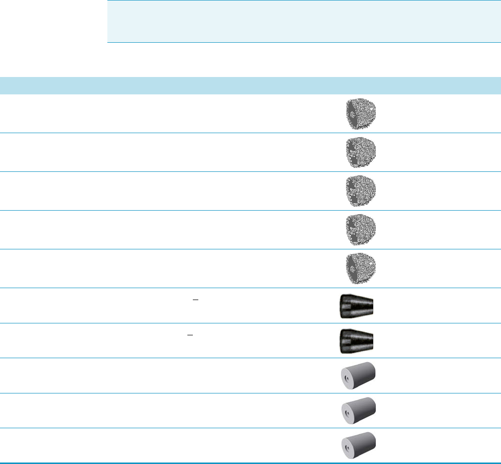
Table 3. Column Components (Sheet 1 of 3)
Description Quantity Part Number
Graphite Ferrule for 0.1 mm - 0.32 mm Column for SSL, SSLBKF, GSV, FID,
NPD, TCD, ECD, FPD
Pkg of 10 290GA139
Graphite Ferrule for 0.45 mm - 0.53 mm Column for SSL, SSLBKF, GSV, FID,
NPD, TCD, ECD, FPD
Pkg of 10 290GA140
Graphite Vespel® Ferrule for 0.1 mm - 0.25 mm Column for SSL, SSLBKF,
GSV, FID, NPD, TCD, ECD, FPD
Pkg of 10 290VA191
Graphite Vespel® Ferrule for 0.32 mm Column for SSL, SSLBKF, GSV, FID,
NPD, TCD, ECD, FPD
Pkg of 10 290VA192
Graphite Vespel® Ferrule for 0.53 mm Column for SSL, SSLBKF, GSV, FID,
NPD, TCD, ECD, FPD
Pkg of 10 290VA193
Polyimide Valcon Reducing Ferrule for 0.36 < 0.4 mm OD Tubing for PDD (Pkg of 5) 29003426
Polyimide Valcon Reducing Ferrule for 0.4 < 0.5 mm OD tubing for PDD (Pkg of 5) 29003427
Encapsulated Graphite Ferrule for 0.1 - 0.25 mm Column for PTV, PTVBKF,
SSLBKF, and GSV (Tee connector)
Pkg of 10 29053488
Encapsulated Graphite Ferrule for 0.32 mm Column for PTV, PTVBKF,
SSLBKF, and GSV (Tee connector)
Pkg of 10 29053487
Encapsulated Graphite Ferrule for 0.53 mm Column for PTV, PTVBKF,
SSLBKF, and GSV (Tee connector)
Pkg of 10 29053486
1 Ordering Spare Part
Column Components
Thermo Scientific TRACE 1300 and TRACE 1310 Spare Parts Guide 13
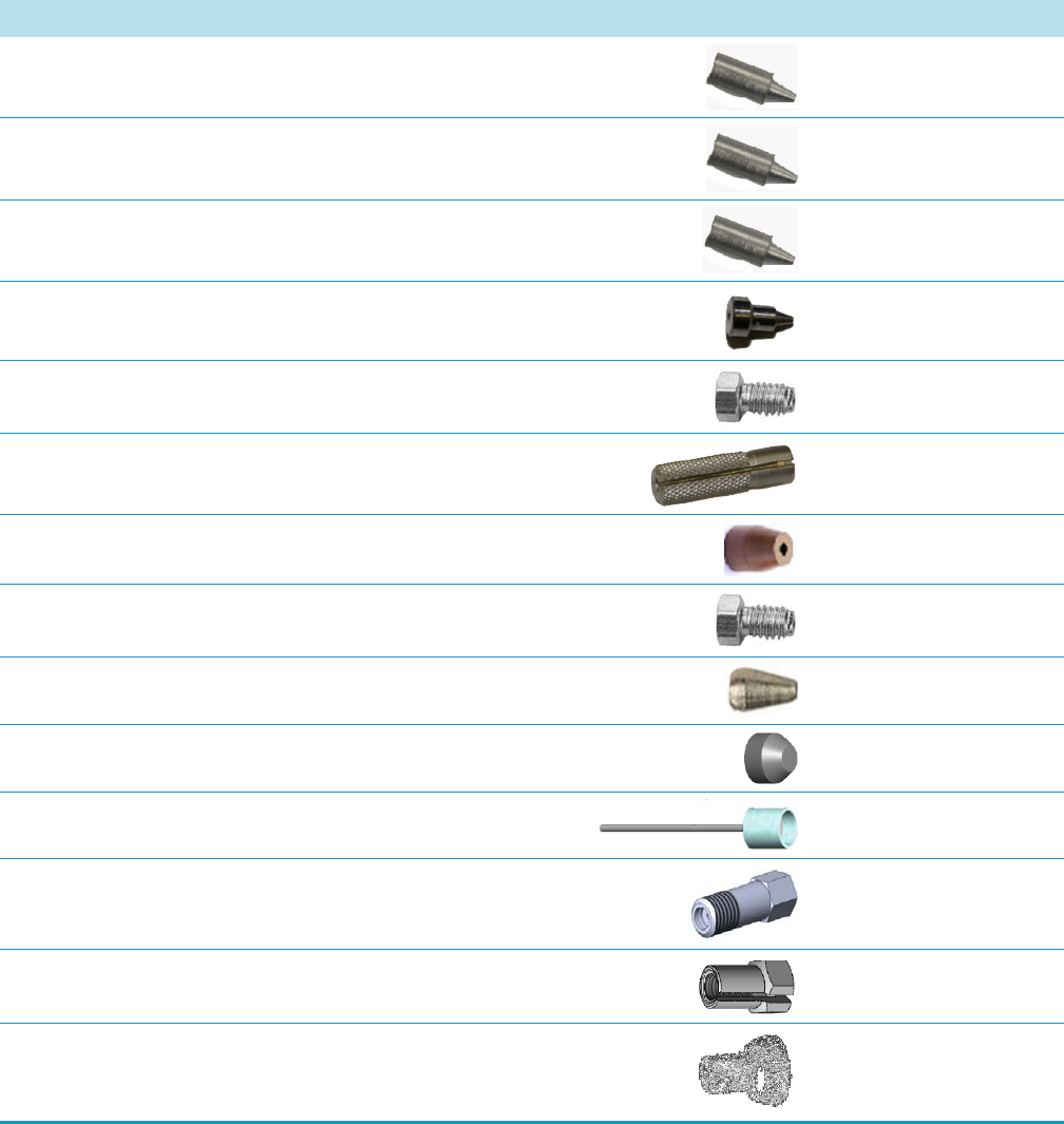
SilFlow™ Fingertight Ferrule for 0.35 mm ID Column for HeS-S/SL Pkg of 10 29063465
SilFlow™ Fingertight Ferrule for 0.4 mm ID Column for HeS-S/SL and
NoVent Microfluidics
Pkg of 10 29063466
SilFlow™ Fingertight Ferrule for 0.5 mm ID Column for HeS-S/SL and
NoVent Microfluidics
Pkg of 10 29063467
SilFlow™ Blanking Ferrule for HeS-S/SL and NoVent Microfluidic Pkg of 5 290ST414
SilFlow™ Nut for HeS-S/SL and NoVent Microfluidics Pkg of 10 290SF302
SilFlow™ Fingertight Tool for HeS-S/SL and NoVent Microfluidics Each 60201-401
Reducing Graphite Vespel® Ferrule 1/8-1/16-in. for HeS-S/SL Each 29003422
Nut 1/16-in. SS ZN1 for HeS-S/SL Pkg of 10 35023099
Ferrule 1/16-in. SSZF1 for HeS-S/SL Pkg of 10 29024283
Blind Ferrule for SSL, SSLBKF, FID, ECD, NPD, TCD, and FPD Each 29003421
Blind Ferrule for PTV, and PTVBKF Each 29003419
Retaining Nut, Hexagonal, 1/4-in. (M6) Pkg of 5 35050458
Split Retaining Nut (M4) Pkg of 5 35053221
Spring Loaded Nut (see kit P/N 19050251) Each 1R120434-
0010
Table 3. Column Components (Sheet 2 of 3)
Description Quantity Part Number
1 Ordering Spare Part
Column Components
14 TRACE 1300 and TRACE 1310 Spare Parts Guide Thermo Scientific
Column Support (Rack) Each 36814159
Column-Flow Meter Connector Each 24507000
Tubing pre-cleaned, Pre-cut 316 SS; 1/16-in., 1 m long; 0.25
mm ID for Helium Saver and SSL
Each 39104801
Precolumn 0.53 mm ID, 2 m Long Each 26050-0253
Table 3. Column Components (Sheet 3 of 3)
Description Quantity Part Number
1 Ordering Spare Part
Oven Components
Thermo Scientific TRACE 1300 and TRACE 1310 Spare Parts Guide 15
Oven Components
You can purchase the following Oven components for the TRACE 1300/TRACE 1310 gas
chromatograph. See Table 4.
Be sure to reference the component’s part number when placing an order with your local
Sales/Service Representative. See the TRACE 1300 and TRACE 1310 Hardware Manual for
information about installing these components or Table 2 for a comprehensive list of available
components.
Note The images are not in scale.
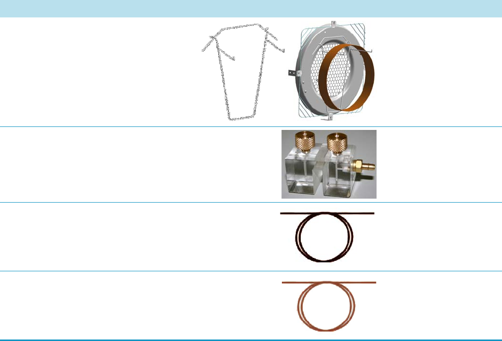
Table 4. Oven Components (Sheet 1 of 3)
Description Quantity Part Number
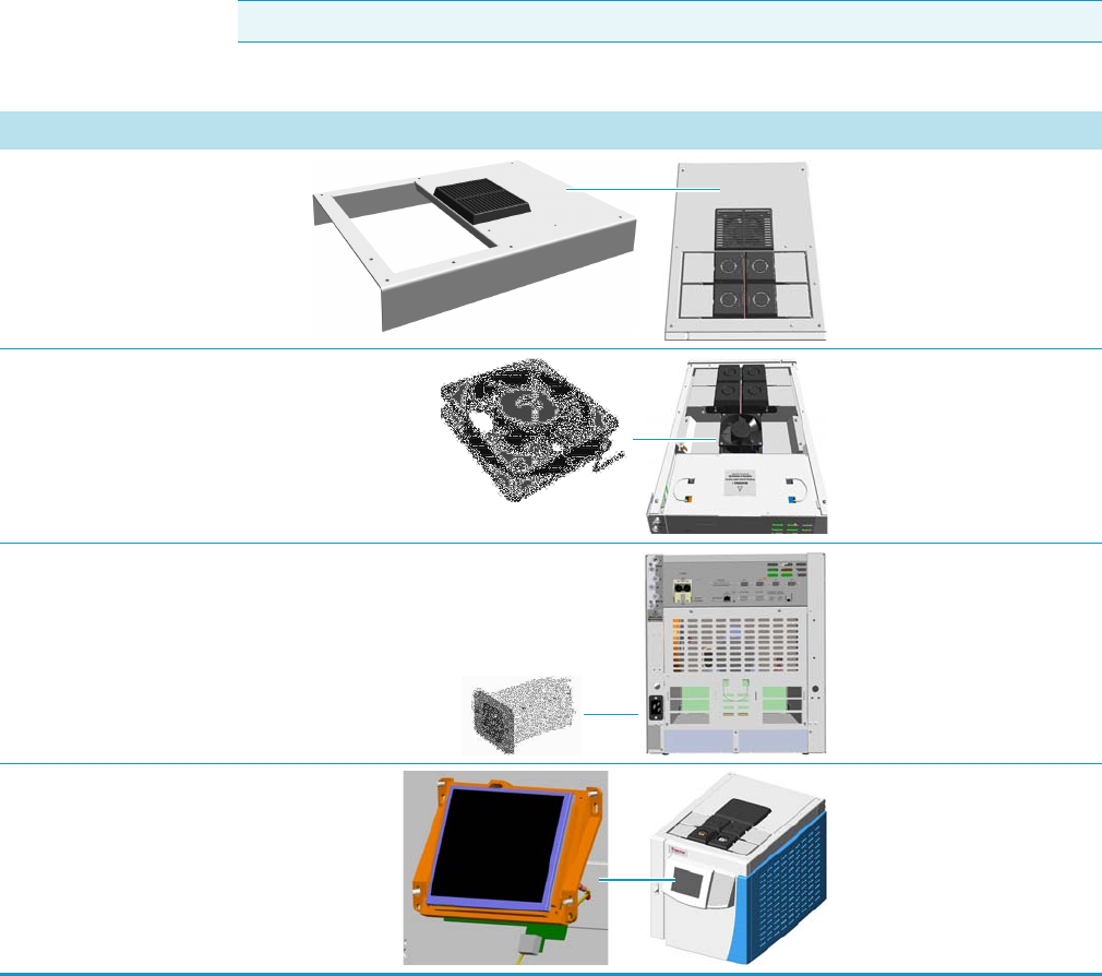
Oven Heater Baffle Assemble
(120/230 V)
Each 26600800
Oven Heater Temperature Sensor Each 40303530
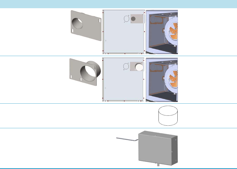
Oven Motor Each 31807047
1 Ordering Spare Part
Oven Components
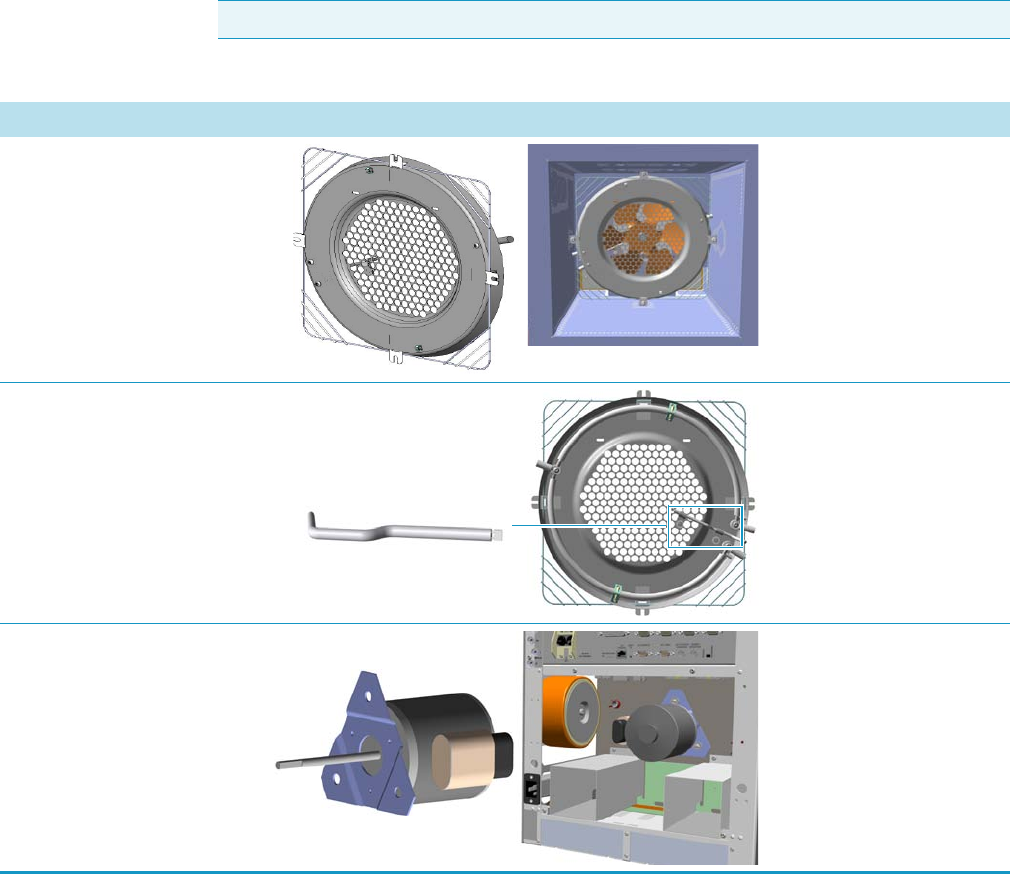
16 TRACE 1300 and TRACE 1310 Spare Parts Guide Thermo Scientific
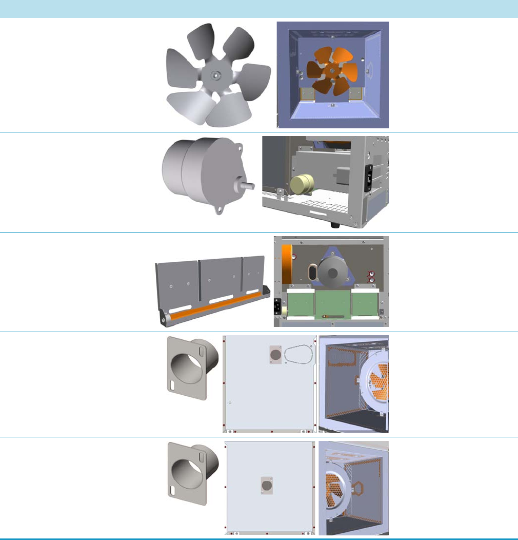
Oven Blower Fan Each 41003510
Flaps Stepper Motor Each 23043678
Oven Multiple Each 39305418
Duct for ITQ Mass Spectrometer Each 25907015
Duct for TSQ Quantum Mass
Spectrometer
Each 25907015
Table 4. Oven Components (Sheet 2 of 3)
Description Quantity Part Number
1 Ordering Spare Part
Oven Components
Thermo Scientific TRACE 1300 and TRACE 1310 Spare Parts Guide 17
Duct for DSQ Mass
Spectrometer
Each 25907020
Duct for ISQ/TSQ 8000 Mass
Spectrometer
Each 25907025
Duct Insulator Each 30200115
Hydrogen Sensor Each 27605006
Table 4. Oven Components (Sheet 3 of 3)
Description Quantity Part Number
1 Ordering Spare Part
GC/GC-MS Components
18 TRACE 1300 and TRACE 1310 Spare Parts Guide Thermo Scientific
GC/GC-MS Components
You can purchase the following components for the TRACE 1300/TRACE 1310 gas
chromatograph stand-alone and MS versions (GC/GC-MS). See Ta ble 5 .
Be sure to reference the component’s part number when placing an order with your local
Sales/Service Representative. See the TRACE 1300 and TRACE 1310 Hardware Manual for
information about installing these components or Table 2 for a comprehensive list of available
components.
Note The images are not in scale.
Table 5. GC/GC-MS Components (Sheet 1 of 4)
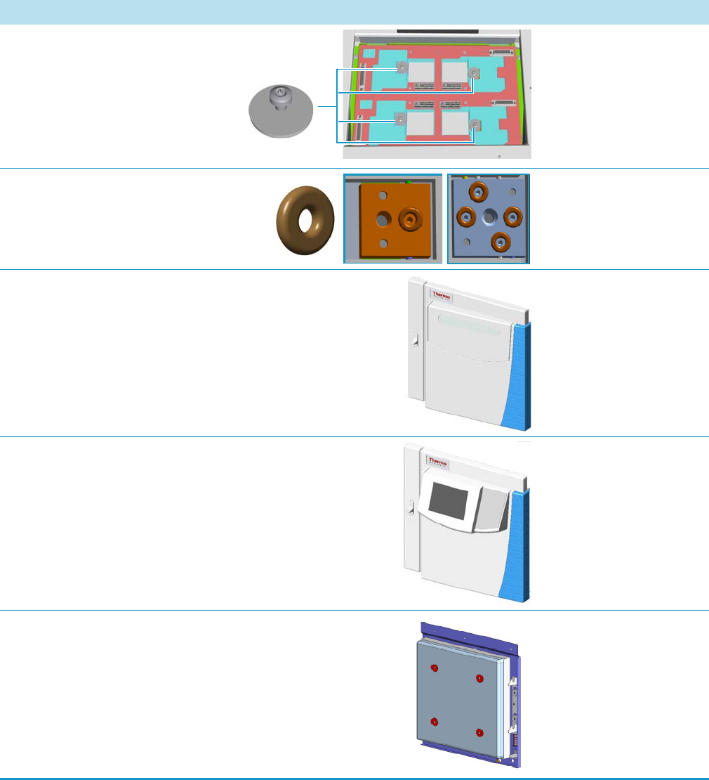
Description Quantity Part Number
Top Cover Assemble Each 24104386
Cooling Fan Each 23043702
High Current Line Filter 16 A; 250 V Each 23850005
Touch Display Assy TRACE 1300 Each 33322000
1 Ordering Spare Part
GC/GC-MS Components
Thermo Scientific TRACE 1300 and TRACE 1310 Spare Parts Guide 19
Status Panel TRACE 1300 Each 23719540
Right Panel Assemble Each 33311010
Left Panel Assemble Each 33311015
Left Panel for ISQ/ITQ MS Assemble Each 33312000
Rear Cover Assemble Each 33311025
Cables Holder-Handle Each 28502213
Table 5. GC/GC-MS Components (Sheet 2 of 4)
Description Quantity Part Number
1 Ordering Spare Part
GC/GC-MS Components
20 TRACE 1300 and TRACE 1310 Spare Parts Guide Thermo Scientific
Gas Block Plug Kit Each 19050773
Injector/Detector Meting Block O-ring Pkg of 10 29031303
Door Cover Assemble for TRACE 1300 Each 30200128
Door Cover Assemble for TRACE 1310 Each 33311000
Door Assy Internal (with insulating) Each 33315353
Table 5. GC/GC-MS Components (Sheet 3 of 4)
Description Quantity Part Number
1 Ordering Spare Part
GC/GC-MS Components
Thermo Scientific TRACE 1300 and TRACE 1310 Spare Parts Guide 21
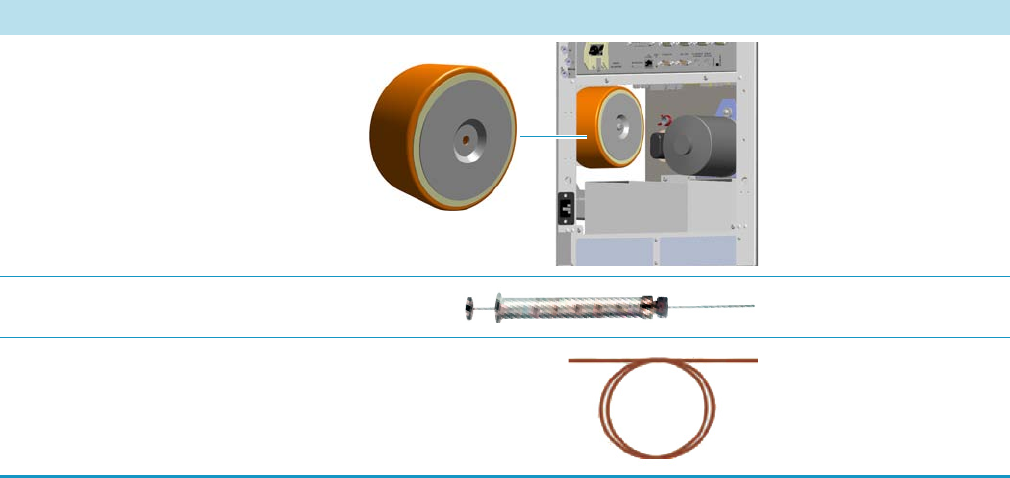
Toroidal Transformer 500 VA Each 41325072
Syringe 10 μL, 50 mm Needle Valve Each 36500525
Test Column, 7 m, 0.32 mm ID, 0.25 μm F.T. Each 26080001
Table 5. GC/GC-MS Components (Sheet 4 of 4)
Description Quantity Part Number
1 Ordering Spare Part
Gas Inlet Manifold Components
22 TRACE 1300 and TRACE 1310 Spare Parts Guide Thermo Scientific
Gas Inlet Manifold Components
You can purchase the following manifold components for the TRACE 1300/TRACE 1310
gas chromatograph. See Figure 1 and Ta ble 6 .
Be sure to reference the component’s part number when placing an order with your local
Sales/Service Representative. See the TRACE 1300 and TRACE 1310 Hardware Manual for
information about installing these components or Table 2 for a comprehensive list of available
components.
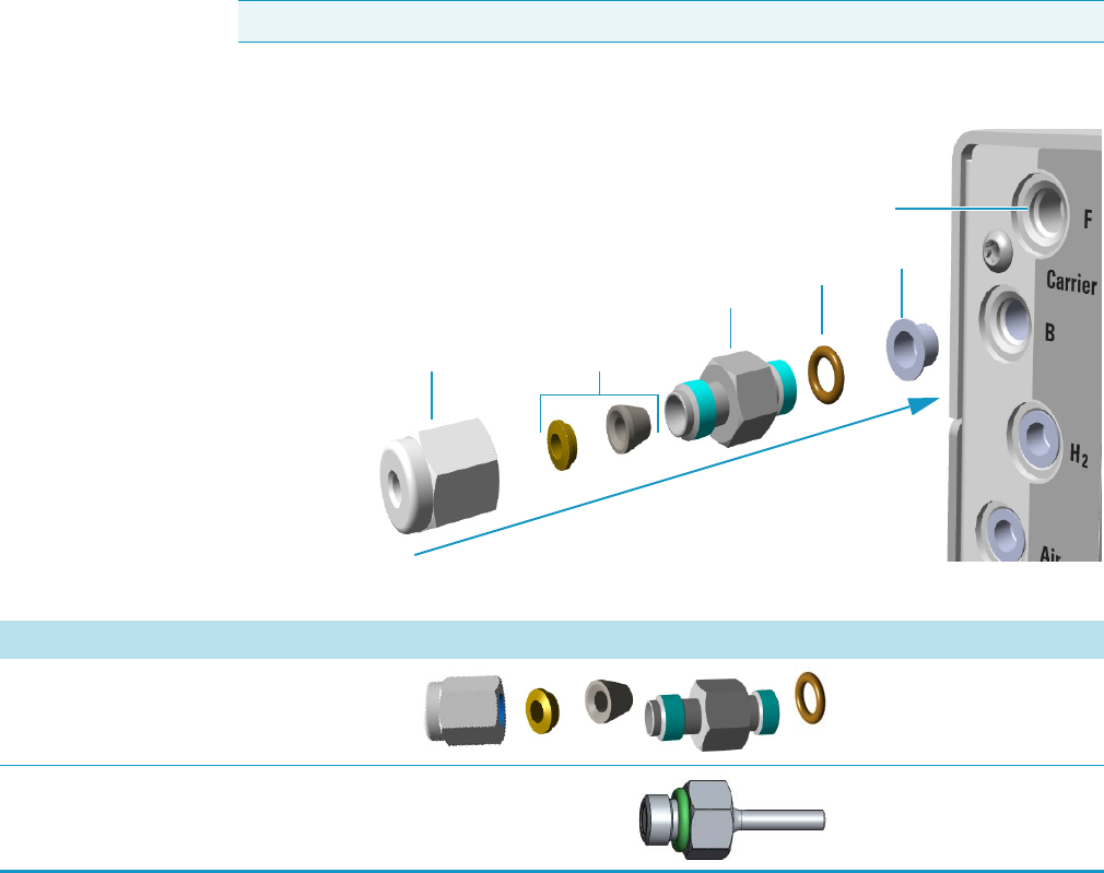
Figure 1. Fittings for Gas Inlet Connection
Note The images are not in scale.
Cap
Gas Inlet Port
O-Ring
Gas Inlet Fitting
Ferrules
Nut
Table 6. Gas Inlet Manifold Components
Description Quantity Part Number
Gas Inlet Fittings Kit Each 19050751
Gas Inlet Fitting 1/8-in. (for Toggle Valve) Each 35008438

1 Ordering Spare Part
Injector Modules Components
Thermo Scientific TRACE 1300 and TRACE 1310 Spare Parts Guide 23
Injector Modules Components
You can purchase the following components for the injector modules. Be sure to reference the
component’s part number when placing an order with your local Sales/Service Representative.
See the TRACE 1300 and TRACE 1310 Hardware Manual for information about installing
these components or Tabl e 2 for a comprehensive list of available components.
The following injector modules components can be replaced on the TRACE 1300/TRACE
1310.
•SSL Injector Module Components
•SSLBKF Injector Module Components
•PTV Injector Module Components
•PTVBKF Injector Module Components
•GSV Module Components
•Instant Connect Helium Saver Injector Module (HeS-S/SL) Components
•SSL Injector Ports Liner
•PTV Injector Ports Liner
Note The images are not in scale.
1 Ordering Spare Part
Injector Modules Components
24 TRACE 1300 and TRACE 1310 Spare Parts Guide Thermo Scientific
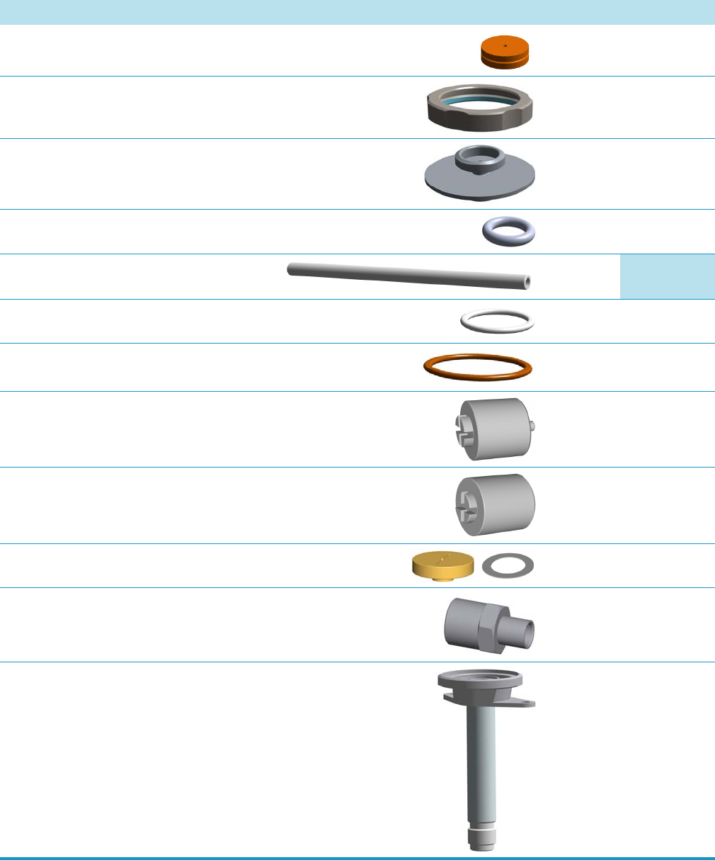
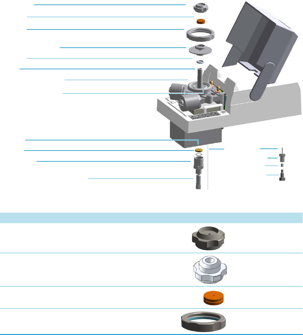
SSL Injector Module Components
The following SSL injector components can be replaced. See Figure 2 and Table 7.
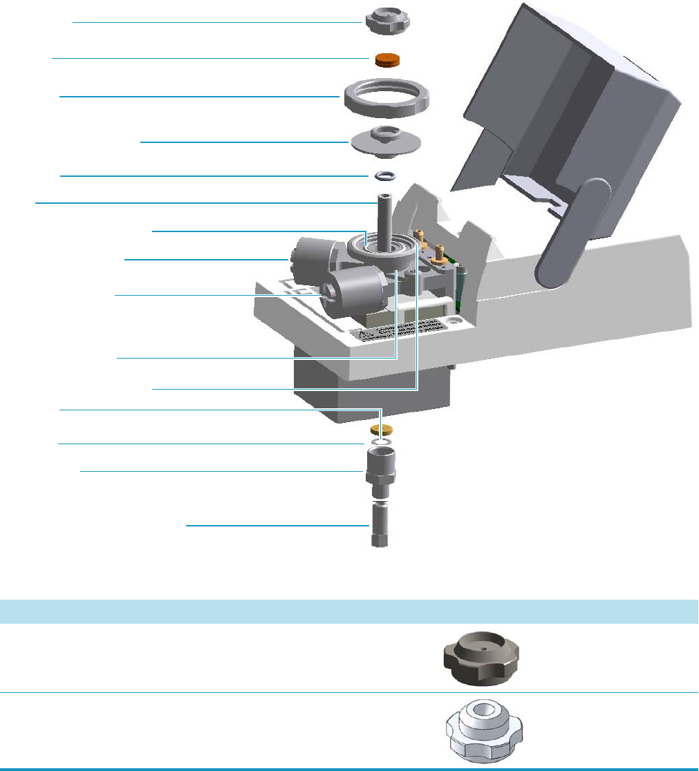
Figure 2. Split Splitless Injector Components
Base Seal
Retaining Nut
Washer
Body Head Internal O-Ring
Body Head External O-Ring
Ring Nut
Liner
Liner Seal
Septum
Septum Cap
Septum Holder/Liner Cap
Carrier Gas Line Filter
Split Gas Line Filter
SSL Injector Body
(Terminal Fitting for Capillary Column)
Table 7. SSL Injector Components (Sheet 1 of 3)
Description Quantity Part Number
Septum Cap Each 35001820
Septum Cap for AI/AS1310 Autosampler and for HS applications
with the TriPlus Autosampler.
Each 35001819
1 Ordering Spare Part
Injector Modules Components
Thermo Scientific TRACE 1300 and TRACE 1310 Spare Parts Guide 25
Septum with Center Guide Pkg of 50 31303233
Ring Nut Each 35001821
Liner Cap/Septum Holder Each 40203005
Liner Seal for SSL Pkg of 5 29001320
Liner
See SSL Injector Ports Liner on page 41
Each
Body Head Internal O-Ring Each 29001313
Body Head External O-Ring Each 29001316
Carrier Line Filter Each 28113196
Split Line Filter Each 28113197
Base Seal and Washer Pkg of 10 290GA081
Retaining Nut (for Column Adapter) Each 35001126
SSL Injector Body Each 2470524
Table 7. SSL Injector Components (Sheet 2 of 3)
Description Quantity Part Number

1 Ordering Spare Part
Injector Modules Components
26 TRACE 1300 and TRACE 1310 Spare Parts Guide Thermo Scientific
O-ring Parafluor 2-006 for SSL manifold Pkg of 3 29011310
Table 7. SSL Injector Components (Sheet 3 of 3)
Description Quantity Part Number
1 Ordering Spare Part
Injector Modules Components
Thermo Scientific TRACE 1300 and TRACE 1310 Spare Parts Guide 27
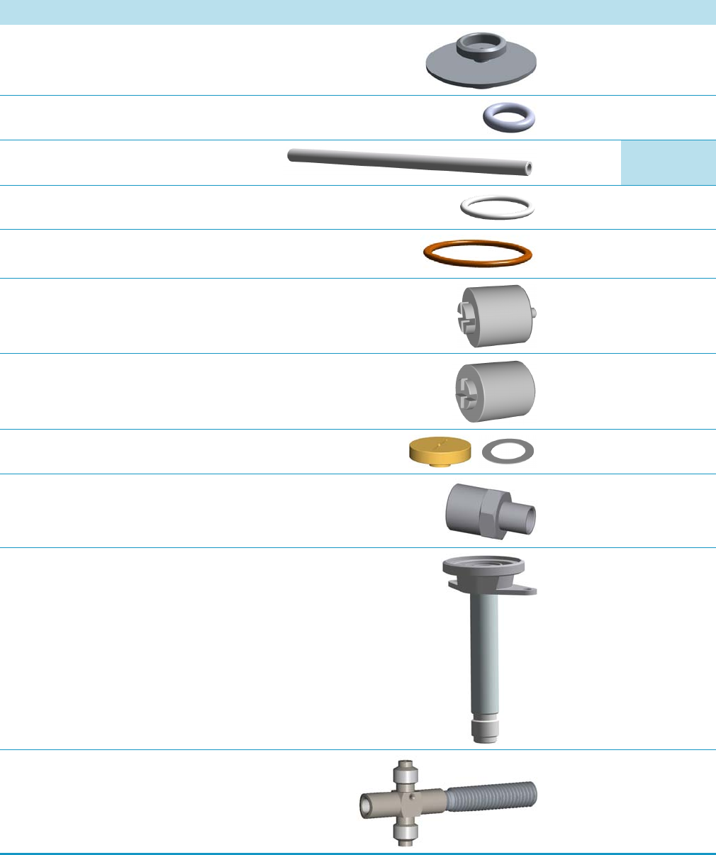
SSLBKF Injector Module Components
The following SSLBKF injector components can be replaced. See Figure 3 and Tabl e 8.
Figure 3. Split Splitless Injector for Backflush Components
Base Seal
Retaining Nut
Washer
(Terminal Fitting for Capillary Column)
Body Head Internal O-Ring
Body Head External O-Ring
Ring Nut
Liner
Liner Seal
Septum
Septum Cap
Septum Holder/Liner Cap
Backflush Line
Backflush Line Fitting
Ferrule
Fitting Cap
Table 8. SSLBKF Injector Components (Sheet 1 of 3)
Description Quantity Part Number
Septum Cap Each 35001820
Septum Cap for AI/AS1310 Autosampler and for HS applications
with the TriPlus Autosampler.
Each 35001819
Septum with Center Guide Pkg of 50 31303233
Ring Nut Each 35001821
1 Ordering Spare Part
Injector Modules Components
28 TRACE 1300 and TRACE 1310 Spare Parts Guide Thermo Scientific
Liner Cap/Septum Holder Each 40203005
Liner Seal for SSL Pkg of 5 29001320
Liner
See SSL Injector Ports Liner on page 41
Each
Body Head Internal O-Ring Each 29001313
Body Head External O-Ring Each 29001316
Carrier Line Filter Each 28113196
Split Line Filter Each 28113197
Base Seal and Washer Pkg of 10 290GA081
Retaining Nut (for Column Adapter) Each 35001126
SSL Injector Body Each 24705240
Tee Connector Low Volume Each 34708449
Table 8. SSLBKF Injector Components (Sheet 2 of 3)
Description Quantity Part Number

1 Ordering Spare Part
Injector Modules Components
Thermo Scientific TRACE 1300 and TRACE 1310 Spare Parts Guide 29
High Temperature Tee Connector Each 34708447
Fitting Cap Each 35003036
O-ring Parafluor 2-006 for SSL manifold Pkg of 3 29011310
Table 8. SSLBKF Injector Components (Sheet 3 of 3)
Description Quantity Part Number
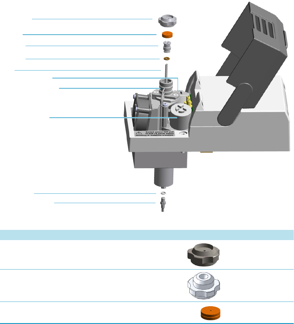
1 Ordering Spare Part
Injector Modules Components
30 TRACE 1300 and TRACE 1310 Spare Parts Guide Thermo Scientific
PTV Injector Module Components
The following PTV injector components can be replaced. See Figure 4 and Tabl e 9 .
Figure 4. Programmable Temperature Vaporizing Injector Components
Silver Seal
Liner
Liner Seal
Septum
Septum Cap
Liner Cap
Split Gas Line Filter
Carrier Gas Line Filter
Terminal Bottom Fitting
Injection Head Assembly
Table 9. PTV Injector Components (Sheet 1 of 2)
Description Quantity Part Number
Septum Cap Each 35001820
Septum Cap for AI/AS 1310 Autosampler and for HS applications
with the TriPlus Autosampler.
Each 35001819
Septum with Center Guide Pkg of 50 31303233
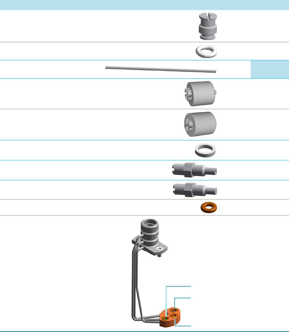
1 Ordering Spare Part
Injector Modules Components
Thermo Scientific TRACE 1300 and TRACE 1310 Spare Parts Guide 31
Liner Cap Each 29004012
Liner Seal for PTV Pkg of 5 29001325
Liner
See PTV Injector Ports Liner on page 42
Each
Carrier Line Filter Each 28113196
Split Line Filter Each 28113197
Silver Seal Pkg of 2 29013820
Terminal Bottom Fitting 1.0 mm ID Each 35008429
Terminal Bottom Fitting 0.5 mm ID Each 35008428
O-ring Parafluor 2-006 for PTV manifold Pkg of 3 29011310
PTV Injector Head Assembly Each 36812739
Table 9. PTV Injector Components (Sheet 2 of 2)
Description Quantity Part Number
Split
Carrier
Purge
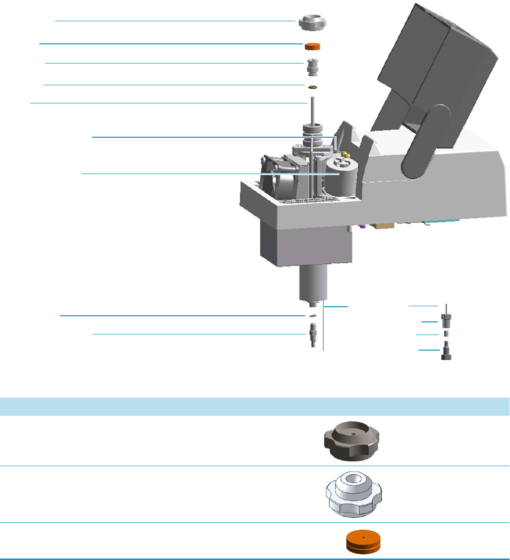
1 Ordering Spare Part
Injector Modules Components
32 TRACE 1300 and TRACE 1310 Spare Parts Guide Thermo Scientific
PTVBKF Injector Module Components
The following PTVBKF injector components can be replaced. See Figure 5 and Tabl e 10 .
Figure 5. Programmable Temperature Vaporizing Injector for Backflush Components
Silver Seal
Liner
Liner Seal
Septum
Septum Cap
Liner Cap
Split Gas Line Filter
Carrier Gas Line Filter
Terminal Bottom Fitting
Backflush Line
Backflush Line Fitting
Ferrule
Fitting Cap
Table 10. PTVBKF Injector Components (Sheet 1 of 3)
Description Quantity Part Number
Septum Cap Each 35001820
Septum Cap for AI/AS 1310 Autosampler and for HS applications
with the TriPlus Autosampler.
Each 35001819
Septum with Center Guide Pkg of 50 31303233
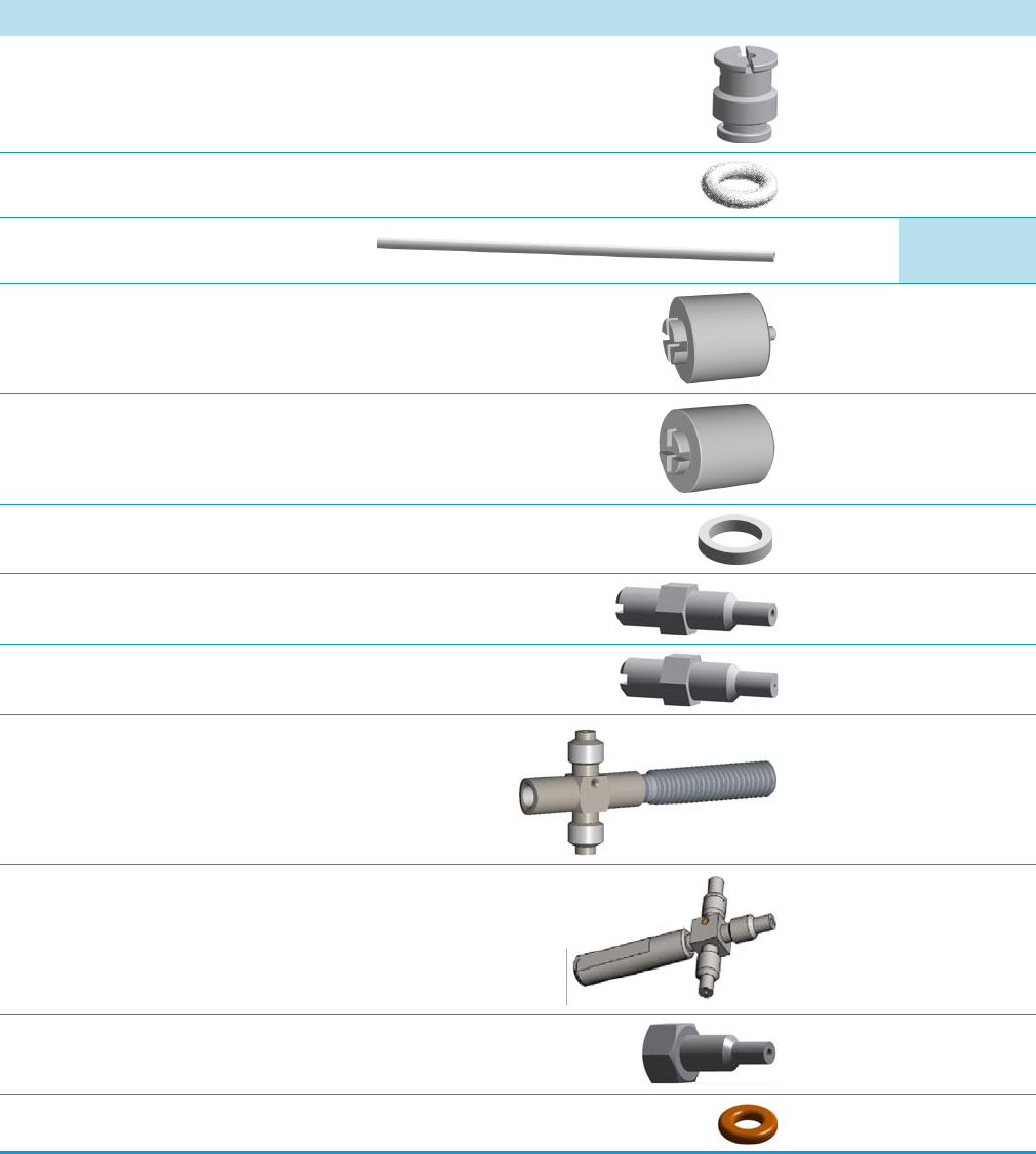
1 Ordering Spare Part
Injector Modules Components
Thermo Scientific TRACE 1300 and TRACE 1310 Spare Parts Guide 33
Liner Cap Each 29004012
Liner Seal for PTV Pkg of 5 29001325
Liner
See PTV Injector Ports Liner on page 42
Each
Carrier Line Filter Each 28113196
Split Line Filter Each 28113197
Silver Seal Pkg of 2 29013820
Terminal Bottom Fitting 1.0 mm ID Each 35008429
Terminal Bottom Fitting 0.5 mm ID Each 35008428
Tee Connector Low Volume Each 34708449
High Temperature Tee Connector Each 34708447
Fitting Cap Each 35003036
O-ring Parafluor 2-006 for PTV manifold Pkg of 3 29011310
Table 10. PTVBKF Injector Components (Sheet 2 of 3)
Description Quantity Part Number

1 Ordering Spare Part
Injector Modules Components
34 TRACE 1300 and TRACE 1310 Spare Parts Guide Thermo Scientific
PTV Injector Head Assembly Each 36812739
Table 10. PTVBKF Injector Components (Sheet 3 of 3)
Description Quantity Part Number
Split
Carrier
Purge
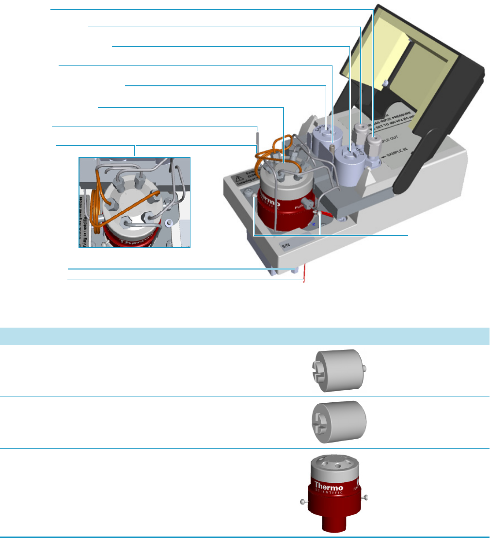
1 Ordering Spare Part
Injector Modules Components
Thermo Scientific TRACE 1300 and TRACE 1310 Spare Parts Guide 35
GSV Module Components
The following GSV injector components can be replaced. See Figure 6 and Table 11.
Figure 6. Gas Sampling Valve Module Components
Split Line Vent
Sample OUT (WASTE)
6-ports Diaphragm Valve
Carrier Line Active Carbon Filter
Split Line Active Carbon Filter
Sample IN
Bottom Fittings
Backflush Line
Sample Loop
Relief Pins
Purge Tubing
Table 11. Gas Sampling Valve Components (Sheet 1 of 2)
Description Quantity Part Number
Carrier Line Filter Each 28113196
Split Line Filter Each 28113197
Six-port Diaphragm Valve Each 40516165

1 Ordering Spare Part
Injector Modules Components
36 TRACE 1300 and TRACE 1310 Spare Parts Guide Thermo Scientific
Kit Sample Loop 20 μL Each 19071405
Kit Sample Loop 50 μL Each 19071404
Kit Sample Loop 100 μL Each 19071403
Kit Sample Loop 250 μL Each 19071402
Kit Sample Loop 500 μL Each 19071401
Kit Sample Loop 1000 μL Each 19071400
Table 11. Gas Sampling Valve Components (Sheet 2 of 2)
Description Quantity Part Number
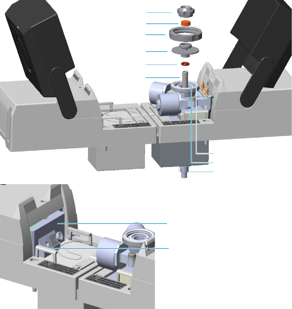
1 Ordering Spare Part
Injector Modules Components
Thermo Scientific TRACE 1300 and TRACE 1310 Spare Parts Guide 37
Instant Connect Helium Saver Injector Module (HeS-S/SL) Components
The following Instant Connect Helium Saver Injector module (HeS-S/SL) components can
be replaced. See Figure 7 and Tabl e 12.
Figure 7. Instant Connect Helium Saver Module: Injector Components
Septum Cap
Septum
Ring Nut
Septum Holder/Liner Cap
Liner Seal
Liner
Body Head External O-Ring
Body Head Internal O-Ring
Bottom Fittings
Helium Saver Potted Box Assembly
Gas Delivery Block
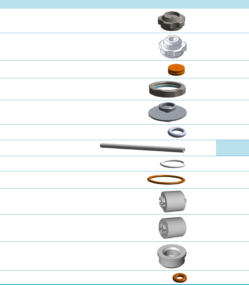
1 Ordering Spare Part
Injector Modules Components
38 TRACE 1300 and TRACE 1310 Spare Parts Guide Thermo Scientific
Table 12. Helium Saver S/SL Injector Components (Sheet 1 of 2)
Description Quantity Part Number
Septum Cap Each 35001820
Septum Cap for AI/AS 1310 Autosampler and for HS applications
with the TriPlus Autosampler.
Each 35001819
Septum with Center Guide Pkg of 50 31303233
Ring Nut Each 35001821
Liner Cap/Septum Holder Each 40203005
Liner Seal for SSL Pkg of 5 29001320
Liner
See SSL Injector Ports Liner on page 41
Each
Body Head Internal O-Ring Each 29001313
Body Head External O-Ring Each 29001316
Carrier Line Filter Each 28113196
Split Line Filter Each 28113197
Bottom Insulator Each 290004408
O-ring Parafluor 2-006 for SSL manifold Pkg of 3 29011310
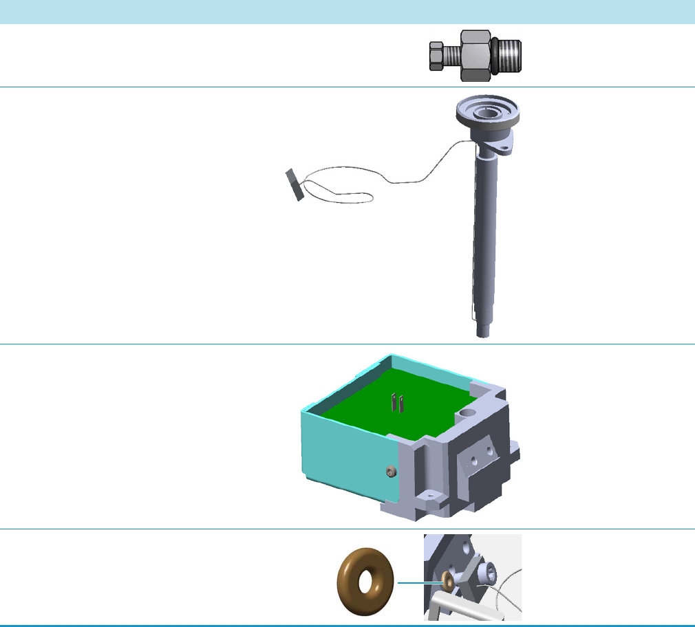
1 Ordering Spare Part
Injector Modules Components
Thermo Scientific TRACE 1300 and TRACE 1310 Spare Parts Guide 39
TRACE 1300 to 1/16-in. Adapter Each 35002123
HeS-S/SL Injector Body Each 24705255
He Saver Potted Box Assembly Each 27609926
Gas Delivery Block O-ring Pkg of 10 29031303
Table 12. Helium Saver S/SL Injector Components (Sheet 2 of 2)
Description Quantity Part Number
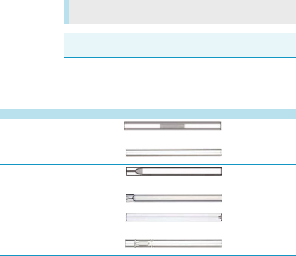
1 Ordering Spare Part
Injection Port Liners
40 TRACE 1300 and TRACE 1310 Spare Parts Guide Thermo Scientific
Injection Port Liners
You can purchase the following injection port liners for the TRACE 1300/TRACE 1310 gas
chromatograph. Be sure to reference the part number when placing an order with your local
Sales/Service Representative. See the TRACE 1300/TRACE 1310 User Guide for information
about these liners or Ta ble 2 for a comprehensive list of available components.
SSL Injector Ports Liner
The following SSL injector ports liner can be replaced. See Table 13.
•SSL Injector Ports Liner
•PTV Injector Ports Liner
Note Visit www.thermo.com/injection port liners for information about ordering a liner.
The images are not in scale.
Table 13. SSL Injection Port Liners
Description Quantity Part Number
SSL Split Straight Liner, Deactivated,
4 mm ID x 6.3 mm OD x 78.5 mm Length,
Quartz Wool
Pkg of 5 453A2265
SSL Split Straight Liner, Deactivated,
4 mm ID x 6.3 mm OD x 78.5 mm Length
Pkg of 5 453A1295
SSL Splitless Liner, Single Taper, Deactivated,
4 mm ID x 6.3 mm OD x 78.5 mm Length,
Quartz Wool
Pkg of 5 453A1925
SSL Splitless Liner, Single Taper,
4 mm ID x 6.3 mm OD x 78.5 mm Length
Pkg of 5 453A1345
SSL Direct Straight Liner for HS/SPME,
Deactivated,
1.2 mm ID x 6.3 mm OD x 78.5 mm Length
Pkg of 5 453A1335
SSL Mini-LAM Liner, Deactivated,
4 mm ID x 6.3 mm OD x 78.5 mm Length
Pkg of 5 453A2009
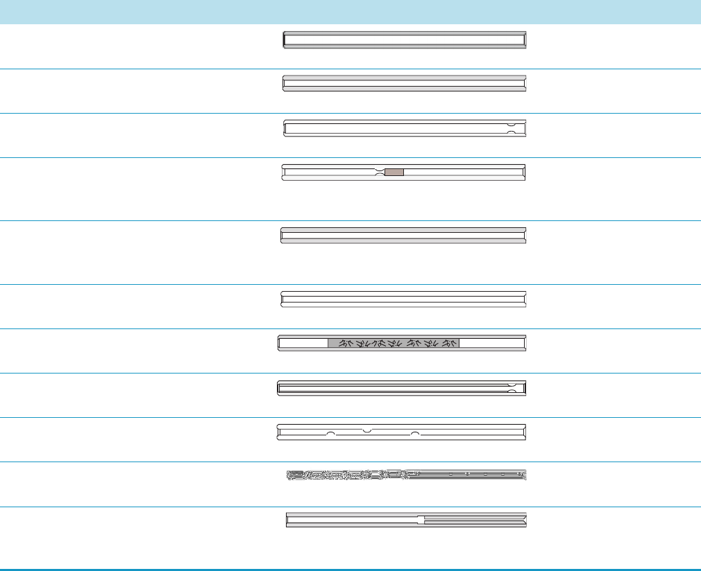
1 Ordering Spare Part
Injection Port Liners
Thermo Scientific TRACE 1300 and TRACE 1310 Spare Parts Guide 41
PTV Injector Ports Liner
The following PTV injector port liner can be replace. See Tabl e 14 .
Table 14. PTV Injection Port Liners
Description Quantity Part Number
PTV Siltek Metal Liner,
2 mm ID x 2.75 mm OD x 120 mm Length
Pkg of 2 45322044
PTV Liner, Non-Deactivated,
2 mm ID x 2.75 mm OD x 120 mm Length
Pkg of 5 45322045
PTV Straight Liner, Deactivated,
2 mm ID x 2.75 mm OD x 120 mm Length
Pkg of 5 45352057
PTV Liner, Deactivated,
2 mm ID x 2.75 mm OD x 120 mm Length,
Quartz Wool
Pkg of 5 45352070
PTV Siltek Metal Liner,
1.3 mm ID x 2.75 mm OD x 120 mm
Length
Each 45322046
PTV Straight Liner, Deactivated,
1 mm ID x 2.75 mm OD x 120 mm Length
Pkg of 5 45352054
PTV Siltek Metal Liner,
2 mm ID x 2.75 mm OD x 120 mm Length, Silica Wool
Each 45322056
PTV Liner with Sintered Lining,
1 mm ID x 2.75 mm OD x 120 mm Length
Pkg of 5 45352060
PTV Liner with Three Baffles, Deactivated,
1 mm ID x 2.75 mm OD x 120 mm Length
Pkg of 5 45352062
PTV Baffle Liner (Siltek), Deactivated,
2 mm ID x 2.75 mm OD x 120 mm Length
Pkg of 5 453T2120
PTV Silcosteel Liner Simile OC,
1 mm ID x 2.75 mm OD x 120mm Length
with 0.6 mm ID Restriction
Each 45322052

1 Ordering Spare Part
Detector Modules Components
42 TRACE 1300 and TRACE 1310 Spare Parts Guide Thermo Scientific
Detector Modules Components
You can purchase the following components for the detector modules. Be sure to reference the
component’s part number when placing an order with your local Sales/Service Representative.
See the TRACE 1300 and TRACE 1310 Hardware Manual for information about installing
these components or Tabl e 2 for a comprehensive list of available components.
The following Detector modules components can be replaced on the TRACE 1300/TRACE
1310.
•FID Detector Module Components
•NPD Detector Module Components
•ECD Detector Module Components
•TCD Detector Modules Components
•FPD Detector Module Components
•PDD Detector Module Components
•GDI Generic Detector Interface Components
Note The images are not in scale.
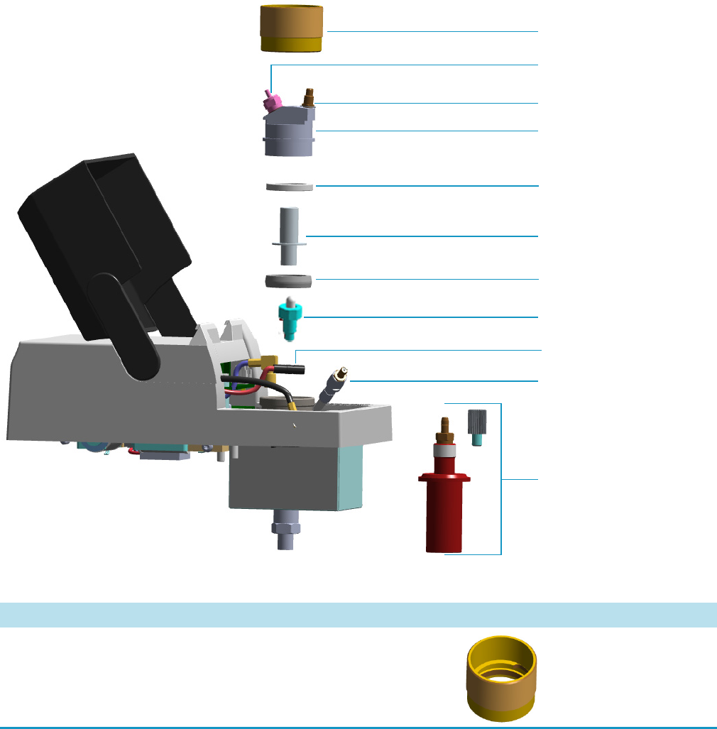
1 Ordering Spare Part
Detector Modules Components
Thermo Scientific TRACE 1300 and TRACE 1310 Spare Parts Guide 43
FID Detector Module Components
The following FID detector components can be replaced. See Figure 8 and Tabl e 1 5.
Figure 8. Flame Ionization Detector Components
Detector Cap
Cell Top Cover Assemble
Insulator Ring
Collecting Electrode
Collector Insulator
Polarizing Electrode
FID Flowmeter Adapter
FID Ceramic Flame Jet
Collecting Electrode Pin
Glow-Plug
Glow-Plug Cable
Table 15. FID Detector Components (Sheet 1 of 2)
Description Quantity Part Number
FID Detector Cap Each 35001124
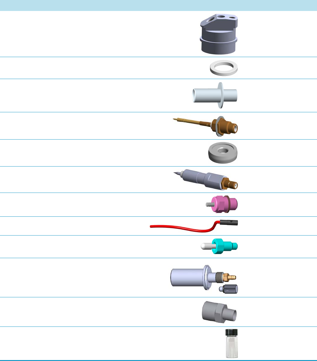
1 Ordering Spare Part
Detector Modules Components
44 TRACE 1300 and TRACE 1310 Spare Parts Guide Thermo Scientific
FID Cell Top Cover (Top Body) Each 24705245
FID Insulator Ring Each 29004612
FID Collecting Electrode Each 27700900
FID Collecting Electrode Pin Each 20601604
FID Collector Insulator Each 30202400
FID Polarizing Electrode Each 27702330
FID/FPD Glow-Plug (Igniter) Each 40303535
FID Glow-Plug Cable Each 23043717
FID Ceramic Flame Jet Each 40402200
FID Measuring Tool Flowmeter Adapter Each 34709348
Retaining Nut (for Column Adapter) Each 35001126
FID Test Mixture Each 33819020
Table 15. FID Detector Components (Sheet 2 of 2)
Description Quantity Part Number
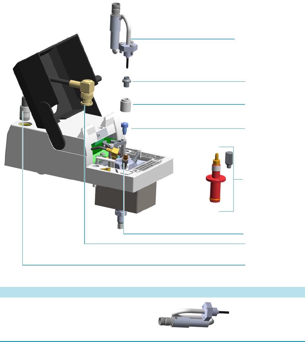
1 Ordering Spare Part
Detector Modules Components
Thermo Scientific TRACE 1300 and TRACE 1310 Spare Parts Guide 45
NPD Detector Module Components
The following NPD detector components can be replaced. See Figure 9 and Tab l e 16 .
Figure 9. Nitrogen Phosphorus Detector Components
Insulator
Collecting Electrode Pin
Thermionic Source Assembly
Collecting Electrode
Signal Cable
Thermionic Source
Assembly Cable
NPD Flowmeter Adapter
NPD Jet
Table 16. NPD Detector Components (Sheet 1 of 2)
Description Quantity Part Number
NPD Thermionic Source TID 2 (Black ceramic) for both
Nitrogen and Phosphorous detections.
Note This thermionic source is provided as standards with
the NPD detector module.
Each 46500256
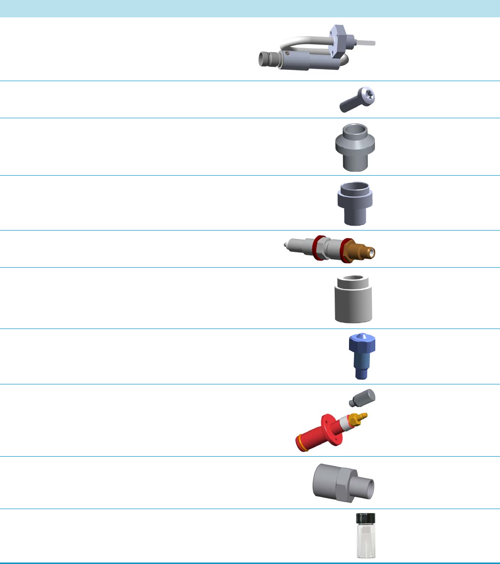
1 Ordering Spare Part
Detector Modules Components
46 TRACE 1300 and TRACE 1310 Spare Parts Guide Thermo Scientific
NPD Thermionic Source TID 4 (White ceramic) for
enhanced Nitrogen response.
Each 46500257
NPD Thermionic Source Fixing Screw Pkg of 5 40921705
NPD Collecting Electrode Each 27701600
NPD Collecting Electrode (for BLOS Type Thermionic Source) Each 27701605
NPD Collecting Electrode Pin Each 20604305
NPD Collecting Insulator (for DET Type Thermionic Source) Each 30202405
NPD Jet Each 40404516
NPD Measuring Tool Flowmeter Adapter Each 34709610
Retaining Nut (for Column Adapter) Each 35001126
NPD Test Mixture Each 33819006
Table 16. NPD Detector Components (Sheet 2 of 2)
Description Quantity Part Number
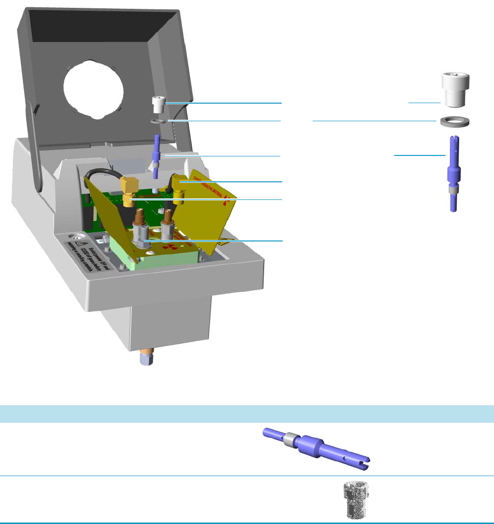
1 Ordering Spare Part
Detector Modules Components
Thermo Scientific TRACE 1300 and TRACE 1310 Spare Parts Guide 47
ECD Detector Module Components
The following ECD detector components can be replaced. See Figure 10 and Tabl e 17.
Figure 10. Electron Capture Detector Components
Collecting Electrode Screw Plug
Collecting Electrode (Anode)
Signal Pin
Excitation Pin
Chimney
Seal
Table 17. ECD Detector Components (Sheet 1 of 2)
Description Quantity Part Number
ECD Collecting Electrode (Anode) Each 21600210
ECD Collecting Electrode (Anode) Screw Each 35006118
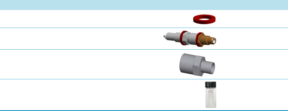
1 Ordering Spare Part
Detector Modules Components
48 TRACE 1300 and TRACE 1310 Spare Parts Guide Thermo Scientific
ECD Collecting Electrode Seal Pkg of 10 29032608
ECD Collecting Electrode Pin Each 20604305
Retaining Nut (for Column Adapter) Each 35001126
ECD Test Mixture Each 33819011
Table 17. ECD Detector Components (Sheet 2 of 2)
Description Quantity Part Number
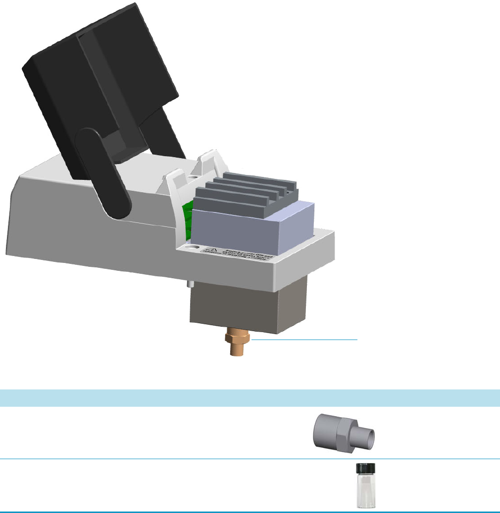
1 Ordering Spare Part
Detector Modules Components
Thermo Scientific TRACE 1300 and TRACE 1310 Spare Parts Guide 49
TCD Detector Modules Components
The following TCD detector components can be replaced. See Figure 11 and Tab le 18 .
Figure 11. Thermal Conductivity Detector Components
Retaining Nut
Table 18. TCD Detector Components
Description Quantity Part Number
Retaining Nut (for Column Adapter) Each 35001126
TCD Test Mixture Each 33819016
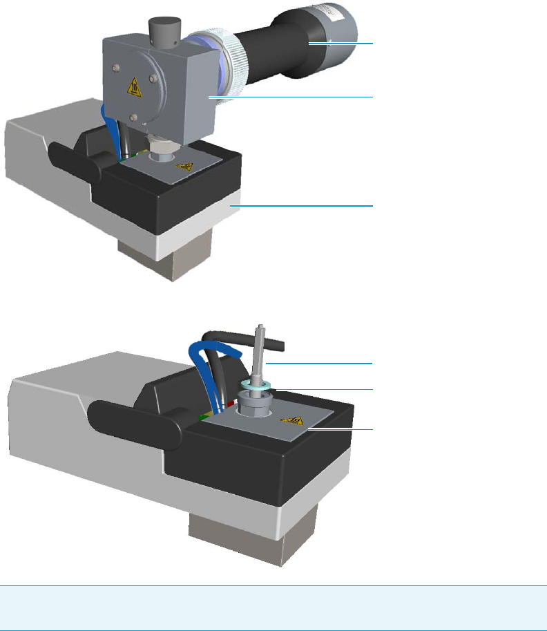
1 Ordering Spare Part
Detector Modules Components
50 TRACE 1300 and TRACE 1310 Spare Parts Guide Thermo Scientific
FPD Detector Module Components
The following FPD detector components can be replaced. See Figure 12, Figure 13,
Figure 14, and Table 19 .
Figure 12. Flame Photometric Detector Module
Figure 13. FPD Control Module Components
Note The signal, excitation voltage, and ignition/heating cables will not be shown in the
next illustrations for graphic convenience.
FPD Cell Assembly
FPD Control Module
Photomultiplier Assembly
FPD Detector Base Body
Aluminium O-Ring
FPD Jet
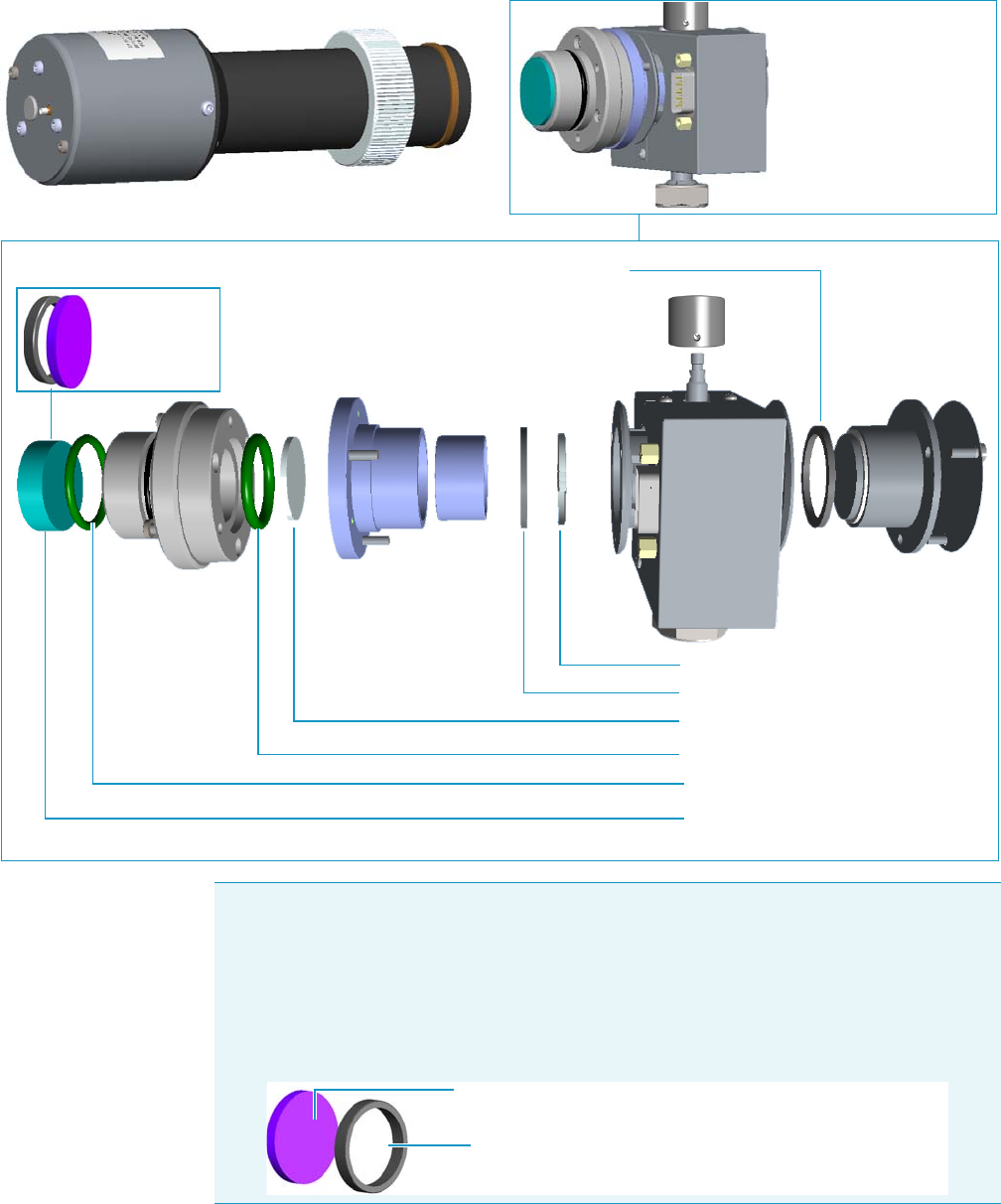
1 Ordering Spare Part
Detector Modules Components
Thermo Scientific TRACE 1300 and TRACE 1310 Spare Parts Guide 51
Figure 14. FPD Cell Assembly Components
Interferential Filter
Viton® O-ring
Viton® O-ring
Filter-side Heat Shield
Graphite Seal
Flame-side Heat Shield
Graphite Seal
Photomultiplier Assembly
* See the FPD Maintenance Kit PN 19004589 on page 58
See the Note
below
Note Instead of the filters PN 28107000 and PN 28107100, a new type of interferential
filters for sulphur and phosphorous are available as kit:
• PN 19050785 includes an interferential filter for sulphur (PN 28107101) and a
spacer.
• PN 19050786 includes an interferential filter for phosphorous (PN 28107102) and a
spacer.
Spacer
Interferential Filter
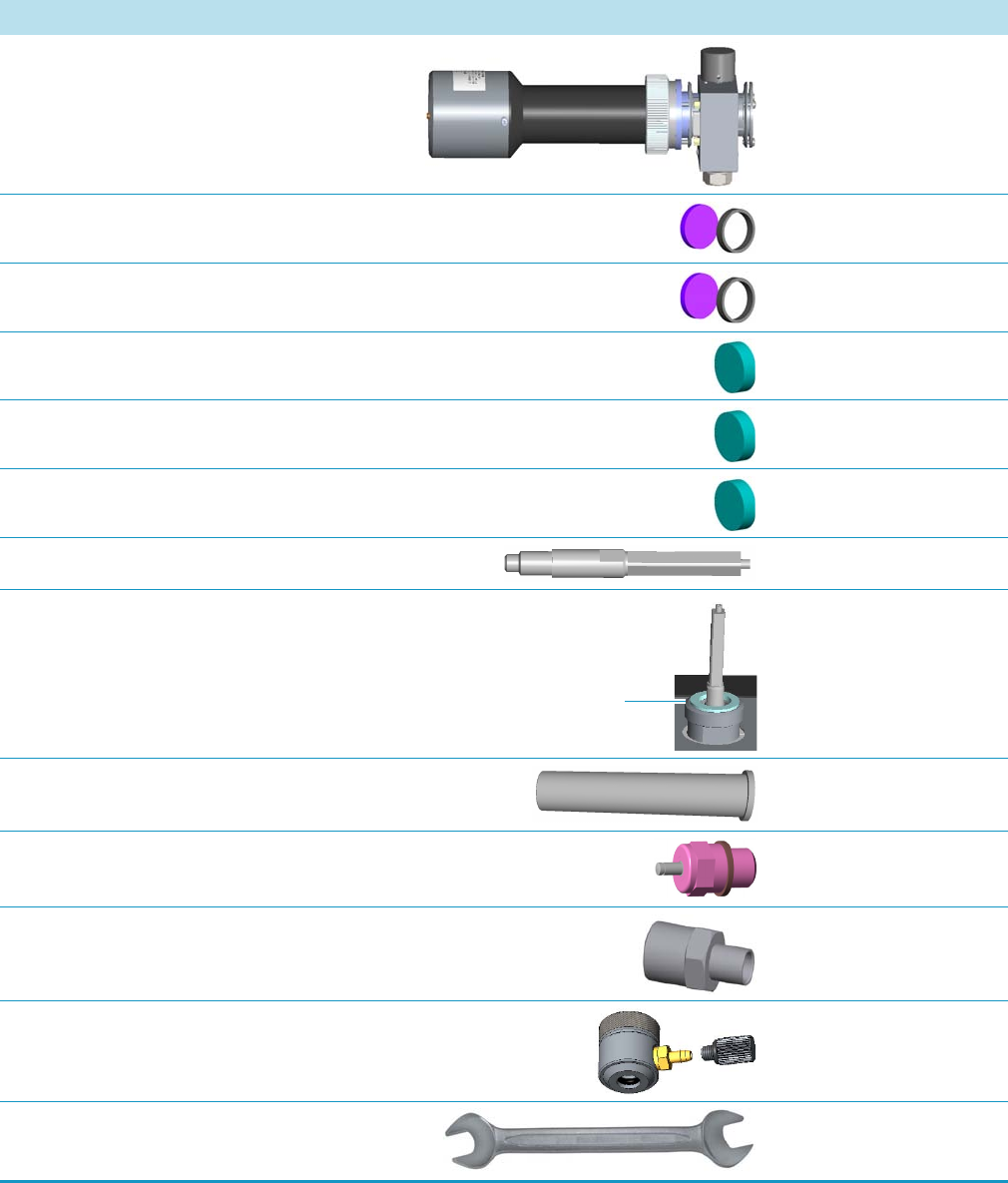
1 Ordering Spare Part
Detector Modules Components
52 TRACE 1300 and TRACE 1310 Spare Parts Guide Thermo Scientific
Table 19. FPD Detector Components (Sheet 1 of 2)
Description Quantity Part Number
FPD Detector Assembly Each 29903110
Kit FPD Interferential Filter for Sulphur (28107101 + Spacer) Each 19050785
Kit FPD Interferential Filter for Phosphorus (28107102 + Spacer) Each 19050786
FPD Interferential Filter for Sulphur Each 28107000
FPD Interferential Filter for Phosphorus Each 28107100
FPD Interferential Filter for Tin Each 28107001
FPD Jet Deactivated Silcosteel Each 40404518
FPD Aluminium O-ring Pkg of 10 29032630
FPD Photomultiplier Tube Each 28600460
FID/FPD Glow-Plug (Igniter) Each 40303535
Retaining Nut (for Column Adapter) Each 35001126
FPD Measuring Tool Flowmeter Adapter Each 34709630
FPD Detector Fixing Tool (20-22 mm wrench) Each 20501608
Aluminium O-ring

1 Ordering Spare Part
Detector Modules Components
Thermo Scientific TRACE 1300 and TRACE 1310 Spare Parts Guide 53
FPD Test Mixture Each 33819006
Table 19. FPD Detector Components (Sheet 2 of 2)
Description Quantity Part Number
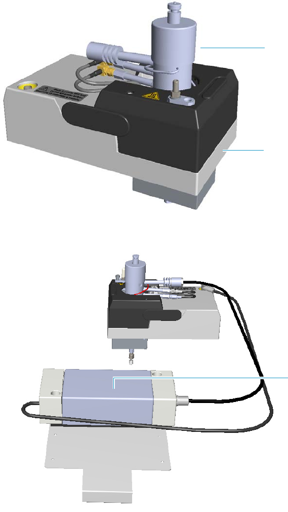
1 Ordering Spare Part
Detector Modules Components
54 TRACE 1300 and TRACE 1310 Spare Parts Guide Thermo Scientific
PDD Detector Module Components
The following PDD detector components can be replaced. See Figure 15, Figure 16, and
Tabl e 20 .
Figure 15. Pulsed Discharge Detector Module
Figure 16. PDD Pulse Generator
PDD Control Module
Detector Cell
Pulse Generator
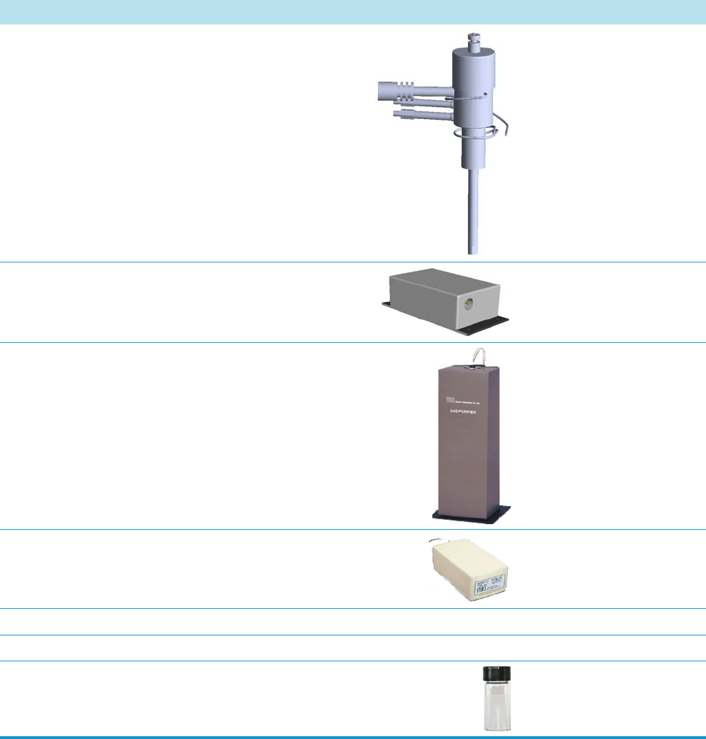
1 Ordering Spare Part
Detector Modules Components
Thermo Scientific TRACE 1300 and TRACE 1310 Spare Parts Guide 55
Table 20. PDD Detector Components
Description Quantity Part Number
PDD Cell Each 41910716
PDD Pulse Generator (Pulser) Each 43210075
PDD Purifier Assy Each 43210076
PDD Mini Helium Purifier Kit Each 19071500
PDD Flow Restrictor Each 24505908
PDD Packed Column Adapter Each 26060521
PDD Test Mixture Each 33819032
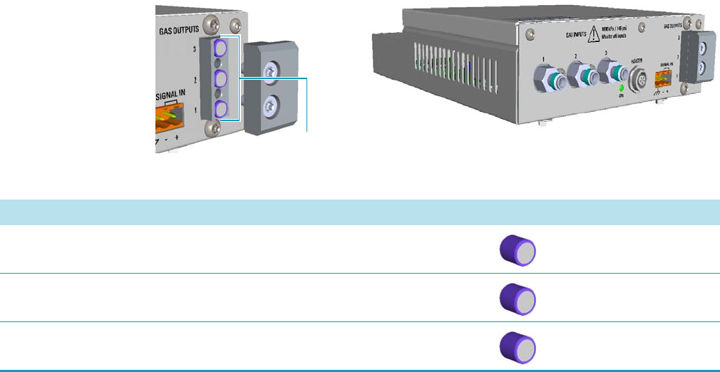
1 Ordering Spare Part
Detector Modules Components
56 TRACE 1300 and TRACE 1310 Spare Parts Guide Thermo Scientific
GDI Generic Detector Interface Components
The following GDI Generic Detector Interface components present into the GDI electrical
interface can be replaced. See Figure 17, and Tab le 21.
Figure 17. GDI Electrical Interface
Flow Restrictors
Table 21. GDI Generic Detector Interface Components
Description Quantity Part Number
Low Flow Restrictor Each 24503330
Medium Flow Restrictor Each 24503333
High Flow Restrictor Each 24503334
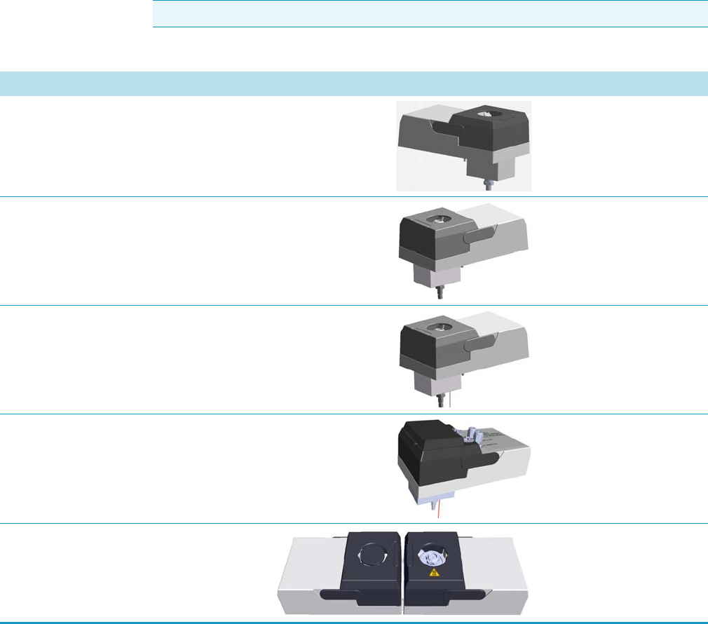
1 Ordering Spare Part
Upgrade Modules
Thermo Scientific TRACE 1300 and TRACE 1310 Spare Parts Guide 57
Upgrade Modules
The following upgrade modules are available for the TRACE 1300/TRACE 1310.
See Tabl e 2 2.
Contact your local Sales/Service Representative to place an order. Once you receive the
module, refer to the TRACE 1300 and TRACE 1310 Hardware Manual for installation
information or Table1 for a comprehensive list of available components.
Note The images are not in scale.
Table 22. Module (Sheet 1 of 4)
Description Quantity Part Number
Dummy Module Each 19070097
SSL Injector Module Each 19070010
SSLBKF Injector Module Each 19070011
Gas Sampling Valve Module Each 19070095
Helium Saver S/SL Module Each 19070013
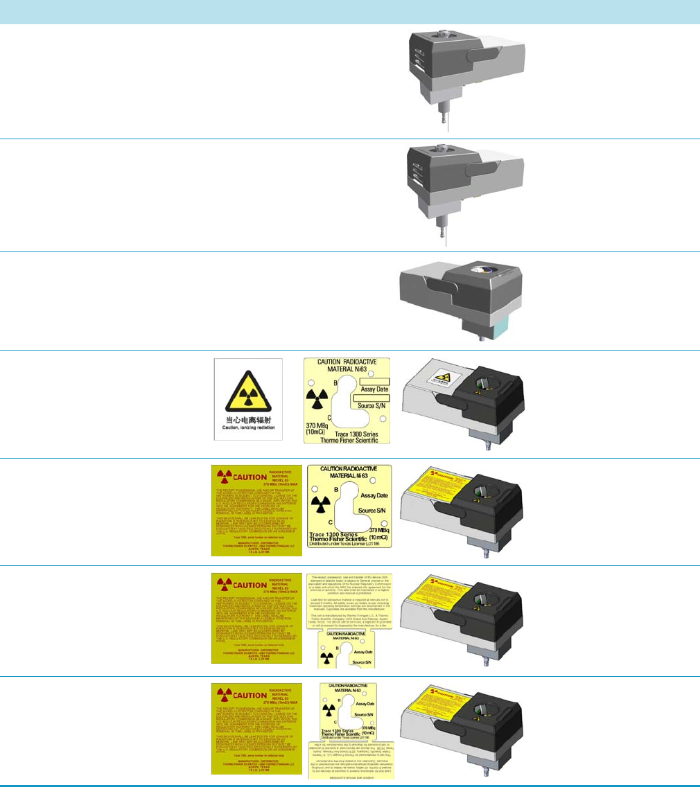
1 Ordering Spare Part
Upgrade Modules
58 TRACE 1300 and TRACE 1310 Spare Parts Guide Thermo Scientific
PTV Injector Module Each 19070020
PTVBKF Injector Module Each 19070021
FID Detector Module Each 19070001
ECD Detector Module for
China Market
Each 19070029
ECD Detector Module for
International Market
Each 19070030
ECD Detector Module for USA
Market (General License)
19070031
ECD Detector Module for USA
Market (Specific License)
19070032
Table 22. Module (Sheet 2 of 4)
Description Quantity Part Number
1 Ordering Spare Part
Upgrade Modules
Thermo Scientific TRACE 1300 and TRACE 1310 Spare Parts Guide 59
ECD Detector Module for
Canada Market
19070033
TCD Detector Module with Nickel-Iron (Ni-Fe) filament cell Each 19070040
TCD Detector Module with Tungsten-Rhenium (W-Re)
filament cell
Each 19070041
In-Series Connection TCD Detector Module Each 19070045
FTIR Make-up Module Each 19070050
NPD Detector Module Each 19070060
Table 22. Module (Sheet 3 of 4)
Description Quantity Part Number
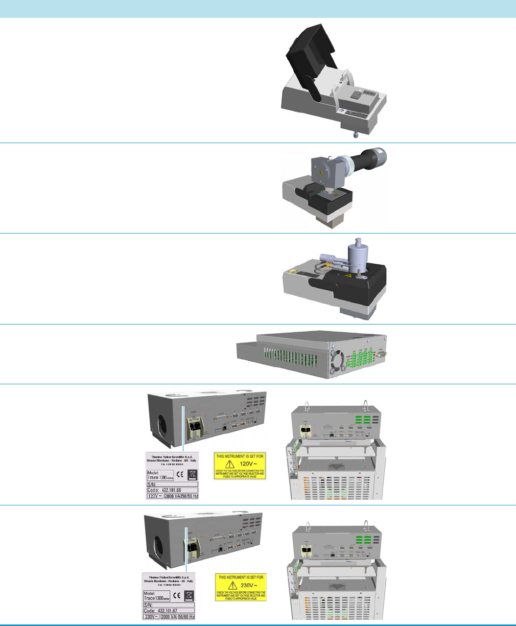
1 Ordering Spare Part
Upgrade Modules
60 TRACE 1300 and TRACE 1310 Spare Parts Guide Thermo Scientific
No Vent Microfluidics Module Each 19070090
FPD Detector Module Each 19070096
PDD Detector Module Each 19070014
AOI Analog Output Interface Module Each 19070022
Electronic Module 120 Vac Each 43210168
Electronic Module 230 Vac Each 43210167
Table 22. Module (Sheet 4 of 4)
Description Quantity Part Number
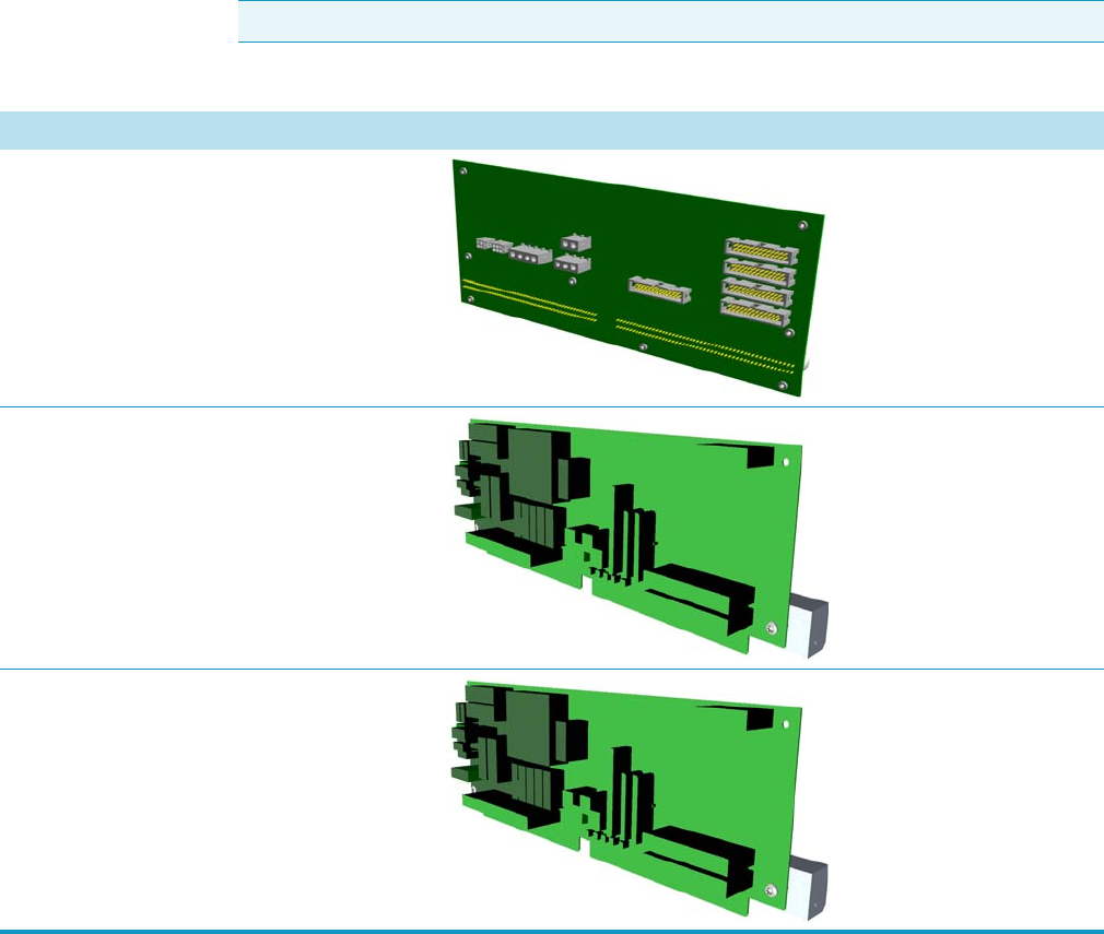
1 Ordering Spare Part
Electronic Module Boards
Thermo Scientific TRACE 1300 and TRACE 1310 Spare Parts Guide 61
Electronic Module Boards
You can purchase the following boards for the electronic module of the TRACE
1300/TRACE 1310 gas chromatograph. See Tab le 23.
Be sure to reference the component’s part number when placing an order with your local
Sales/Service Representative.
Note The images are not in scale.
Table 23. Electronic Board (Sheet 1 of 2)
Description Quantity Part Number
Rear Backplane Board (BKP-HRM; PC1256) Each 23661000
Oven CPU and Power Control Board
(OVN-HRM; 230 V; PC1257)
Each 23661010
Oven CPU and Power Control Board
(OVN-HRM; 120V; PC1257-01)
Each 23661011
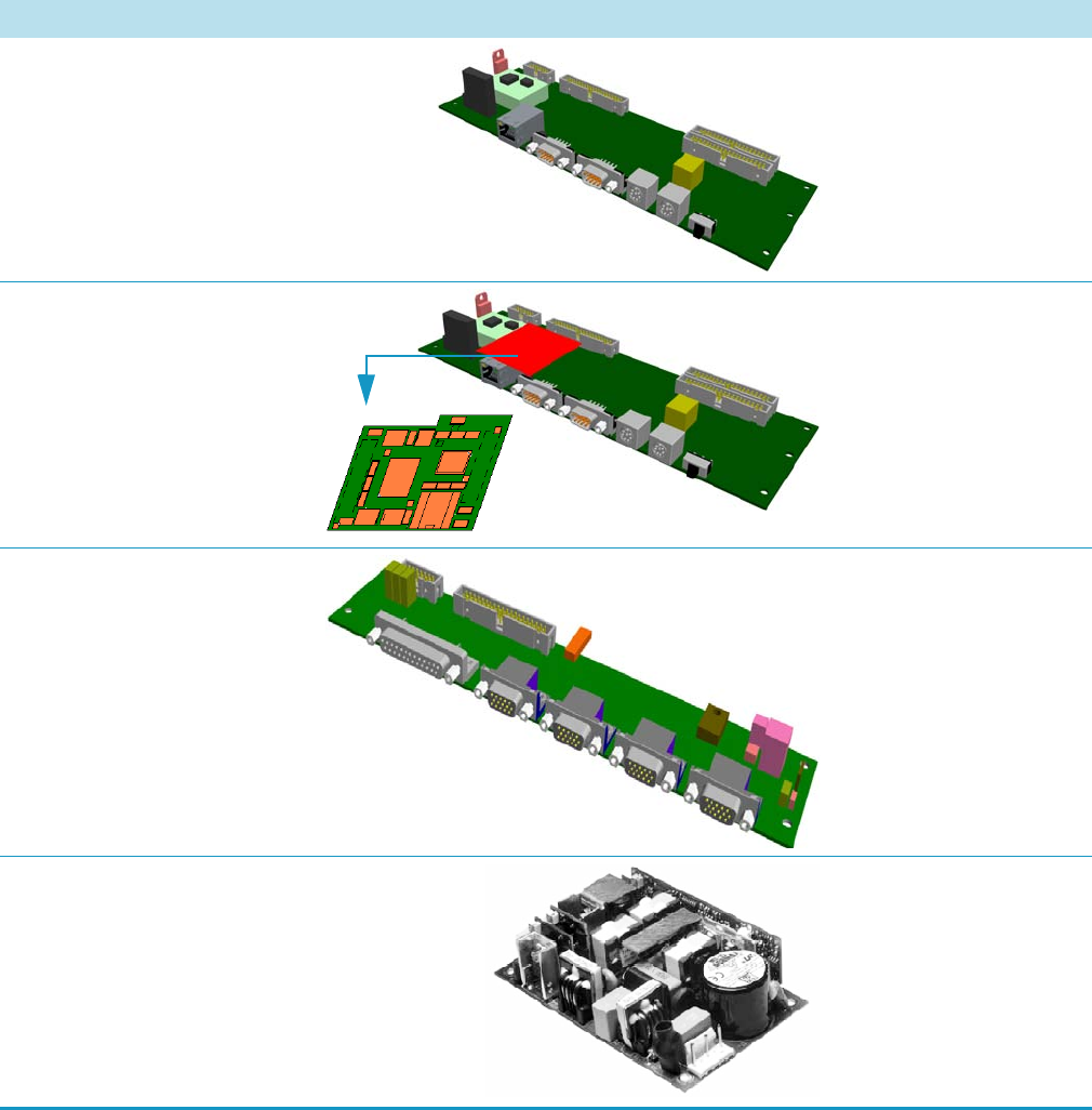
Main CPU Board (CPU-HRM; PC1258) Each 23661015
Memory Board
(MEM-HRM; PC1259)
Each 23661020
External Interface Board
(EXT-HRM; PC1263)
Each 23661025
Power Supply Board Each 20806090
Table 23. Electronic Board (Sheet 2 of 2)
Description Quantity Part Number
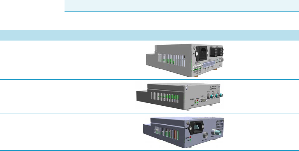
1 Ordering Spare Part
External Modules
Thermo Scientific TRACE 1300 and TRACE 1310 Spare Parts Guide 63
External Modules
The following external modules are available for the TRACE 1300/TRACE 1310.
See Tabl e 2 4.
Contact your local Sales/Service Representative to place an order. Once you receive the
module, refer to the TRACE 1300 and TRACE 1310 Hardware Manual for installation
information.
Note The images are not in scale.
Table 24. External Module
Description Quantity Part Number
Aux Temperature/Cryo Module Each 19070070
Auxiliary Gases Module Each 19070080
NPD Thermionic Source Power Module Each 43215010

1 Ordering Spare Part
Cryo Components
64 TRACE 1300 and TRACE 1310 Spare Parts Guide Thermo Scientific
Cryo Components
The following cryogenic components are available for the TRACE 1300/TRACE 1310.
See Tabl e 2 5.
Contact your local Sales/Service Representative to place an order. Once you receive the
module, refer to the TRACE 1300 and TRACE 1310 Hardware Manual for installation
information.
Note The images are not in scale.
Table 25. Cryo Components
Description Quantity Part Number
Oven Cryo CO2 Assemble Each 19050753
Oven Cryo N2 Assemble Each 19050752
PTV Cryo CO2
Assemble
Each 19050755
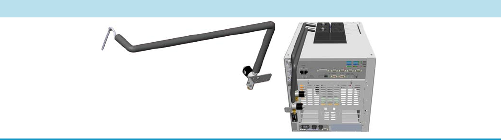
1 Ordering Spare Part
Cryo Components
Thermo Scientific TRACE 1300 and TRACE 1310 Spare Parts Guide 65
PTV Cryo N2
Assemble
Each 19050754
Table 25. Cryo Components
Description Quantity Part Number
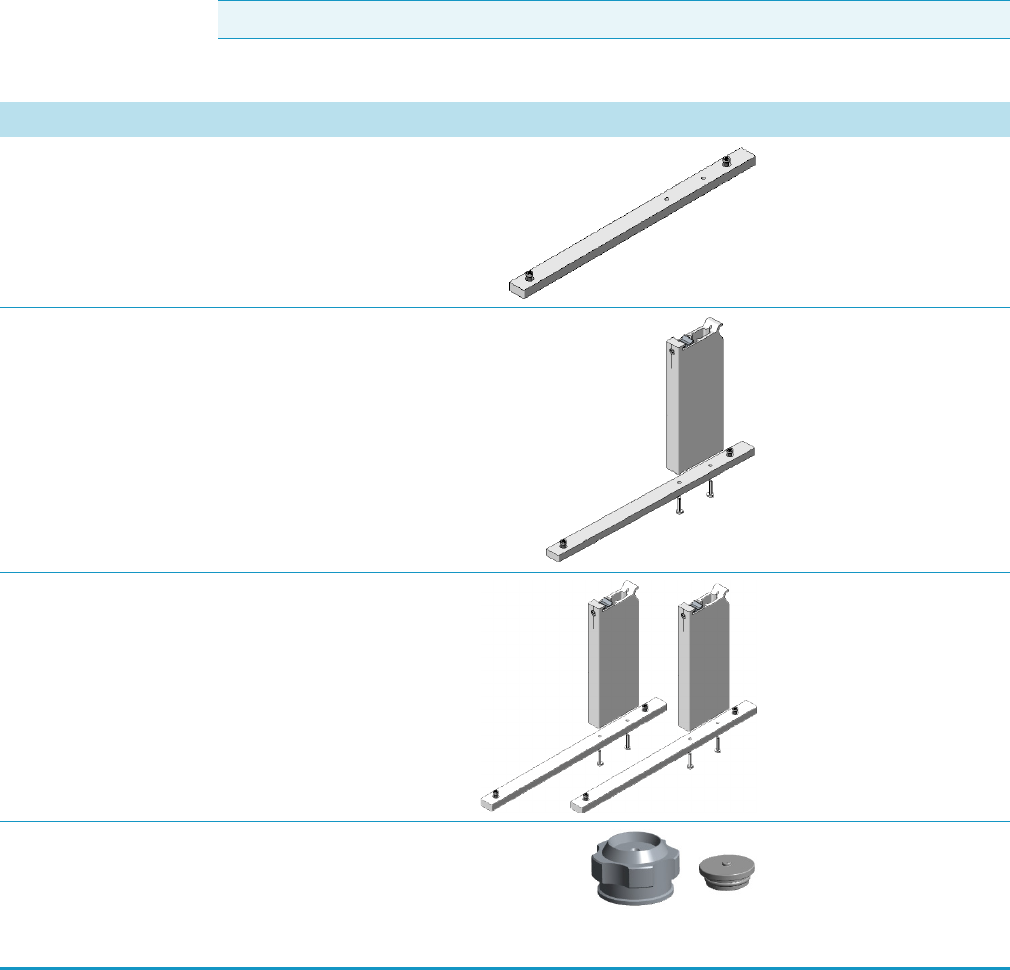
Kits & Miscellanea
The following kits, cables, and miscellanea are available for the TRACE 1300/TRACE 1310.
See Figure 9 and Tabl e 16.
Contact your local Sales/Service Representative to place an order. Once you receive the kit,
refer to the TRACE 1300 and TRACE 1310 Hardware Manual for installation information.
Note The images are not in scale.
Table 26. Kits and Miscellanea
Description Quantity Part Number
TriPlus Leg Support for TRACE 1300/1310 Pkg of 2 19050489
TriPlus RSH Mounting Leg Pkg of 1 1R77010-10
66
TriPlus RSH Mounting Kit Pkg of 2 1R77010-10
05
Merlin Valve Kit
The Kit includes:
Merlin Microseal High Pressure Valve
Septum Cap
Each 19050735
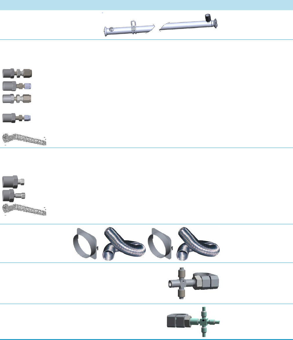
1 Ordering Spare Part
Kits & Miscellanea
Thermo Scientific TRACE 1300 and TRACE 1310 Spare Parts Guide 67
Clamp Bracket for Backflush Kit Each 19050757
Packed Column Adapters Kit
The Kit includes:
Adapter for the connection of the 1/8-inch OD packed column to the SSL injector.
Adapter for the connection of the 1/16-inch OD packed column to the SSL injector.
Adapter for the connection of the 1/8-inch OD packed column to the FID, NPD, ECD, TCD,
or FPD detector.
Adapter for the connection of the 1/16-inch OD packed column to the FID, NPD, ECD,
TCD, or FPD detector.
1/2-inch wrench
Each 19050758
Graph-pack (Encapsulated Graphite) Ferrules Kit
The Kit includes:
Adapter for the connection to the SSL injector
Adapter for the connection to the FID, NPD, ECD, TCD, or FPD detector
1/2-inch wrench
Each 19050759
Oven Exhaust Kit Each 19050760
Tee Connector for Holder Kit Each 19050251
Tee Connector Kit for High Temperature Each 19050254
Table 26. Kits and Miscellanea
Description Quantity Part Number
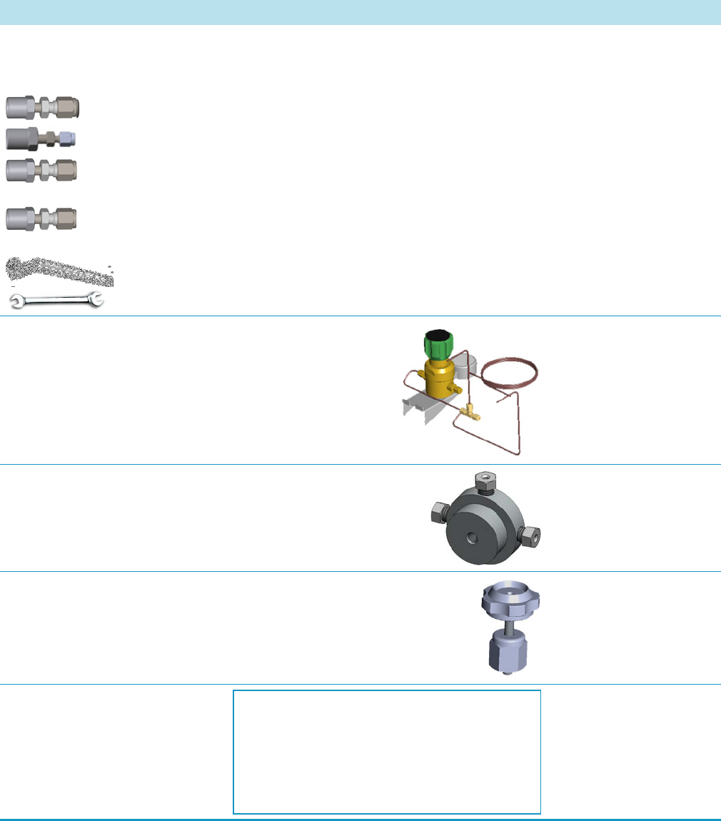
1 Ordering Spare Part
Kits & Miscellanea
68 TRACE 1300 and TRACE 1310 Spare Parts Guide Thermo Scientific
Packed Column Adapters Kit for Gas Sampling Valve
The Kit includes:
Adapter for the connection of the 1/8-inch OD packed column to the GSV injector.
Adapter for the connection of the 1/16-inch OD packed column to the GSV injector.
Adapter for the connection of the 1/8-inch OD packed column to the FID, NPD, ECD, TCD,
or FPD detector.
Adapter for the connection of the 1/16-inch OD packed column to the FID, NPD, ECD,
TCD, or FPD detector.
1/2-inch wrench
Open ended wrench 1/4-5/16-inch
Each 19050762
Pressure Regulator Kit for Gas Sampling Valve Each 19050763
Kit Backflush for Gas Sampling Valve Each 19050764
Manual Injection Kit for Gas Sampling Valve Each 19050784
SSL/SSLBKF/HeS-S/SL
Maintenance Kit
Each 19050770
Table 26. Kits and Miscellanea
Description Quantity Part Number
The Kit includes:
19050771 SSL O-Ring Kit
28113197 Split Line Filter
290GA082 Base Seal
31303246 Septum BTO with Center Guide (Pkg of 5)
453A1925 SSL Splitless Liner (Pkg of 1)

1 Ordering Spare Part
Kits & Miscellanea
Thermo Scientific TRACE 1300 and TRACE 1310 Spare Parts Guide 69
SSL/SSLBKF/HeS-S/SL
O-Ring Kit
Each 19050771
FID Igniter Kit Each 19050775
FID Maintenance Kit Each 19050776
NPD Maintenance Kit Each 19050777
ECD Collecting Electrode (Anode)
Replacement Kit
Each 19050779
FPD Maintenance Kit Each 19004589
PTV/PTVBKF Maintenance
Kit
Each 19050780
Table 26. Kits and Miscellanea
Description Quantity Part Number
The Kit includes:
29001312 Liner Seal
29001313 Body Head Internal O-ring
29001316 Body Head External O-ring
29011310 Manifold O-rings (Pkg of 3)
The Kit includes:
40303535 FID/FPD Glow-Plug (Igniter)
20601604 FID Collecting Electrode Pin
24705245 FID Cell Top Cover Assemble
The Kit includes:
40402200 FID Ceramic Flame Jet
29004612 FID Insulator Ring (Top)
30202400 FID Collector Insulator (Bottom)
The Kit includes:
40404516 NPD Jet
30202405 NPD Collector Insulator
27701600 NPD Collecting Electrode
The Kit includes:
29002608 ECD Collecting Electrode (Anode) Seal (Pkg of 1)
21600210 ECD Collecting Electrode (Anode)
The Kit includes:
29003414 Graphite Seal (Pkg of 2)
45101750 Heat Shield (Pkg of 1)
29000050 Viton O-ring
29000381 Viton O-ring
The Kit includes:
31303246 Septum BTO with Center Guide (Pkg of 5)
45302044 Splitless, Silcosteel Deactivated, 2 mm ID (Pkg of 1)
29001318 Liner Seal
28113197 Split Line Filter
29011310 Head O-Ring (Pkg of 3)
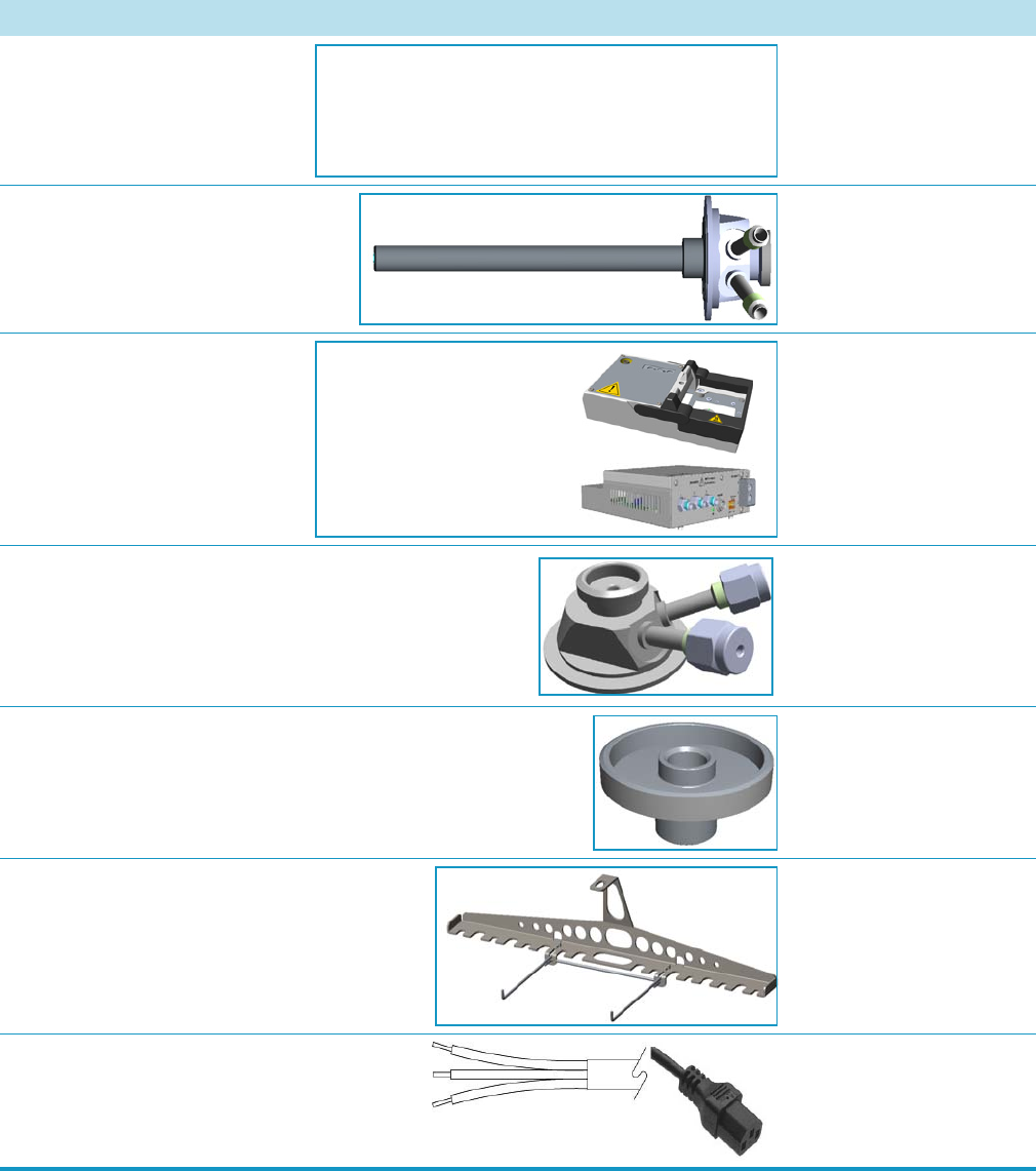
1 Ordering Spare Part
Kits & Miscellanea
70 TRACE 1300 and TRACE 1310 Spare Parts Guide Thermo Scientific
Dual Detector Microfluidics Kit Each 19071030
SSL/SSLBKF Hot Injection Adapter Each 19050733
Generic Detector Interface Kit Each 19070015
Purge & Trap Adapter Kit Each 19050730
SSL Adapter Head for PerkinElmer TurboMatrix™ HS Each 34709361
Packed Columns Support Kit Each 19070124
Power Cable 16 A, 230 V Each 23033025
Table 26. Kits and Miscellanea
Description Quantity Part Number
The Kit includes:
19098026 Microfluidics Kit
19050757 Clamp Bracket for Backflush Kit
31608055 Clamp Assembly
The Kit includes:
29903130 GDI Detector Module
29903131 GDI Control Module
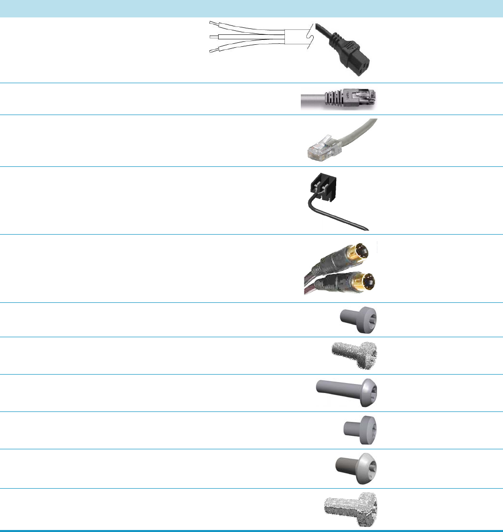
1 Ordering Spare Part
Kits & Miscellanea
Thermo Scientific TRACE 1300 and TRACE 1310 Spare Parts Guide 71
Power Cable 20A, 120 V Each 23033030
LAN Communication Pin-to pin Cable Each 23043592
LAN Communication Cross Cable Each 23043593
EV Helium Saver Connection Cable Each 23043731
MS Start Cable Each 23043546
Screw TORX M3 x 6 mm Pkg of 5 40921705
Screw TORX M3 x 8 mm Each 40901608
Screw TORX M3 x 12 mm Each 40901609
Screw TORX M4 x 6 mm Pkg of 5 40921800
Screw TORX M4 x 8 mm Pkg of 5 40921700
Screw Plastic 4 x 10 mm Pkg of 5 40939002
Table 26. Kits and Miscellanea
Description Quantity Part Number

Tools
The TRACE 1300/TRACE 1310 ships with the tools you will need to perform maintenance
on the instrument. See Table 27.
Contact your local Sales/Service Representative to place an order.
Note The images are not in scale.
Table 27. Tools
Description Quantity Part Number
Ceramic Column Cutter Each 60201-318
Flat Head Screwdriver for PTV and PTVBKF Each 20502605
Tweezers Each 2050510
T6 Torxhead Screwdriver Each 20502620
T10 Torxhead Screwdriver Each 20502622
T20 Torxhead Screwdriver Each 20502621
Wrench, Single Open-Ended, 5-mm Each 20501621
Wrench, Single Open-Ended, 6-mm Each 20501622
Wrench, Open-Ended, 1/4-5/16-in. Each 20501623
Wrench, Elbowed Box, 8-mm Each 20501630
Wrench, Single Open-Ended, 7/16-in Each 20503015

1 Ordering Spare Part
Tools
Thermo Scientific TRACE 1300 and TRACE 1310 Spare Parts Guide 73
Wrench, Single Open-Ended, 1/2-in. Each 20503022
Table 27. Tools
Description Quantity Part Number
1 Ordering Spare Part
Tools
74 TRACE 1300 and TRACE 1310 Spare Parts Guide Thermo Scientific
