Range Hoods.p65 31 9107 GE 2003 Monogram Stainless Steel Hoods
2013-04-09
: Pdf 31-9107 Ge - 2003 Monogram Stainless Steel Hoods 31-9107 GE - 2003 Monogram Stainless Steel Hoods GE, Camco, Hotpoint, Mofat
Open the PDF directly: View PDF ![]() .
.
Page Count: 28
PUB # 31-9107 08/03
MODEL SERIES:
ZV30RS
ZV30SS
ZV30TS
ZV36RS
ZV36SS
ZV36TS
ZV48RS
ZV48SS
ZV48TS
TECHNICAL SERVICE GUIDE
GE Consumer Products
2003 Monogram
30-, 36-, and 48 in.
Stainless Steel Hoods
Technical Consultant:
Tom Ledbetter
Cincinnati Zone

– 2 –
IMPORTANT SAFETY NOTICE
The information in this service guide is intended for use by
individuals possessing adequate backgrounds of electrical,
electronic, and mechanical experience. Any attempt to repair a
major appliance may result in personal injury and property
damage. The manufacturer or seller cannot be responsible for the
interpretation of this information, nor can it assume any liability in
connection with its use.
WARNING
To avoid personal injury, disconnect power before servicing this
product. If electrical power is required for diagnosis or test
purposes, disconnect the power immediately after performing the
necessary checks.
RECONNECT ALL GROUNDING DEVICES
If grounding wires, screws, straps, clips, nuts, or washers used
to complete a path to ground are removed for service, they must
be returned to their original position and properly fastened.
!
GE Consumer Products
Technical Service Guide
Copyright © 2003
All rights reserved. This service guide may not be reproduced in whole or in part
in any form without written permission from the General Electric Company.

– 3 –
Autotransformer - ZV30, ZV36, and ZV48...................................................................................10
Autotransformer - ZV30R, ZV36R, and ZV48R ..........................................................................15
Baffle Grease Filter and Drip Trays - ZV30, ZV36, and ZV48 ...................................................... 7
Control Features ...........................................................................................................................6
Data Location ................................................................................................................................4
Fan Motor - ZV30, ZV36, and ZV48 ..............................................................................................7
Fan Motor - ZV30R, ZV36R, and ZV48R ...................................................................................12
Fan Motor Indicator Light - ZV30, ZV36, and ZV48 ..................................................................... 11
Fan Motor Indicator Light - ZV30R, ZV36R, and ZV48R ............................................................ 15
Grease Baffles - ZV30R, ZV36R, and ZV48R ............................................................................12
Heat Lamp Panel - ZV30, ZV36, and ZV48 ...................................................................................7
Heat Lamp Panel - ZV30R, ZV36R, and ZV48R.........................................................................12
Heat Lamp Socket - ZV30, ZV36, and ZV48 .................................................................................8
Heat Lamp Socket - ZV30R, ZV36R, and ZV48R.......................................................................12
Heat Lamp Switch - ZV30, ZV36, and ZV48 .................................................................................8
Heat Lamp Switch - ZV30R, ZV36R, and ZV48R .......................................................................13
Introduction ....................................................................................................................................4
Nomenclature ................................................................................................................................4
Illustrated Parts ...........................................................................................................................21
Rotary Switch - ZV30, ZV36, and ZV48 ......................................................................................10
Rotary Switch - ZV30R, ZV36R, and ZV48R .............................................................................. 14
Schematics .................................................................................................................................19
Surface Lights - ZV30, ZV36, and ZV48 .......................................................................................9
Surface Lights - ZV30R, ZV36R, and ZV48R .............................................................................13
Surface Light Sockets - ZV30, ZV36, and ZV48 ...........................................................................9
Surface Light Sockets - ZV30R, ZV36R, and ZV48R .................................................................14
Troubleshooting ...........................................................................................................................16
Warranty........................................................................................................................................5
Table of Contents
– 4 –
The 2003 Monogram Stainless Steel, 30-, 36- and 48 in.
Range Hood models are being introduced with a new
motor mount that allows for easy removal and
replacement of the fan motor.
Other features include:
• Baffle grease filters and drip trays to allow for quick
and easy cleaning.
• A four-setting light control.
• A four-setting fan control.
• An infrared heat lamp.
• A fan ON indicator light.
• Kitchen utensil rods, located on each side of the
hood used to hang and display cooking utensils,
pots and pans, or nonflammable decorative items.
Introduction
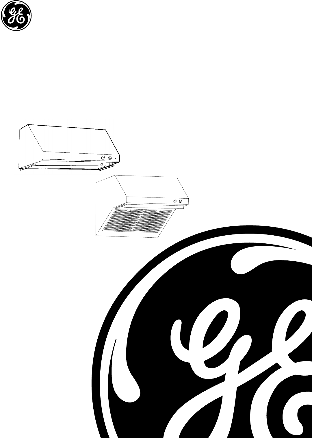
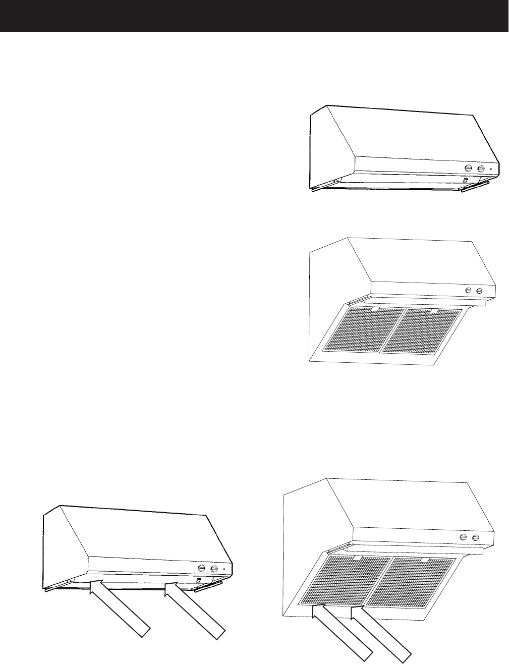
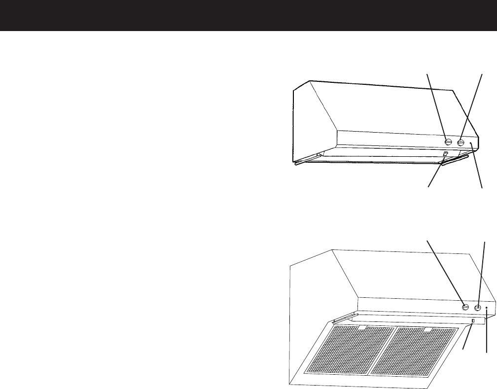
Model ZV30
Model ZV30R
To access the nomenclature and schematic
diagram, remove the left grease baffle.
Nomenclature
Schematic
Schematic
Nomenclature
Nomenclature

– 5 –
Warranty
Monogram Hood Warranty
Proof of original purchase date is needed to obtain service under warranty.
What Is Covered
Full One-Year Warranty
For one year from date of original purchase, we will provide, free of charge, parts and service labor in
your home to repair or replace any part of the hood that fails because of a manufacturing defect.
This warranty is extended to the original purchaser and any succeeding owner for products purchased
for ordinary home use in the mainland 48 states, Hawaii, and Washington, D.C. In Alaska, the warranty
is the same except that it is LIMITED because you must pay to ship the product to the service shop or
for the service technician’s travel costs to your home.
All warranty service will be provided by our Factory Service Centers or by our authorized Customer
Care® Servicers during normal working hours.
Should your appliance need service, during warranty period or beyond, call 800.444.1845.
What Is Not Covered
• Service trips to your home to teach you how to use the product.
• Replacement of home fuses or resetting of circuit breakers.
• Incidental or consequential damage caused by possible defects with this appliance.
• Replacement of the filters and light bulbs.
• Damage to the product caused by accident, fire, floods, or acts of God.
• Failure of the product if it is used for other than its intended purpose or used commercially.
• Improper installation.
If you have an installation problem, contact your dealer or installer. You are responsible for providing
adequate electrical, gas, exhausting, and other connecting facilities as described in the Installation
Instructions provided with the product.
Some states do not allow the exclusion or limitation of incidental or consequential damages, so the
above limitation or exclusion may not apply to you. This warranty gives you specific legal rights, and
you may also have other rights which vary from state to state.
To know what your legal rights are in your state, consult your local or state consumer affairs office or
your state’s Attorney General.
Warrantor: General Electrical Company. Louisville, KY 40225
– 6 –
Control Features
1 - Light Control
The two surface lights are controlled using a 5-
position switch (OFF, 1, 2, 3, and HI). Turn the light
from OFF to HI to adjust the intensity of the light while
cooking.
2 - Fan Control
The fan speed is controlled using a 5-position switch
(OFF, 1, 2, 3, and HI). Turn the fan control speed
from OFF to HI as needed.
3 - Fan Indicator Light
The fan indicator light comes ON when the fan is
turned ON.
4 - Heat Lamp Control
The heat lamp is controlled by its own ON/OFF
rocker switch. Press the rocker switch for the
warming lamps to begin heating.
12
43
12
43
– 7 –
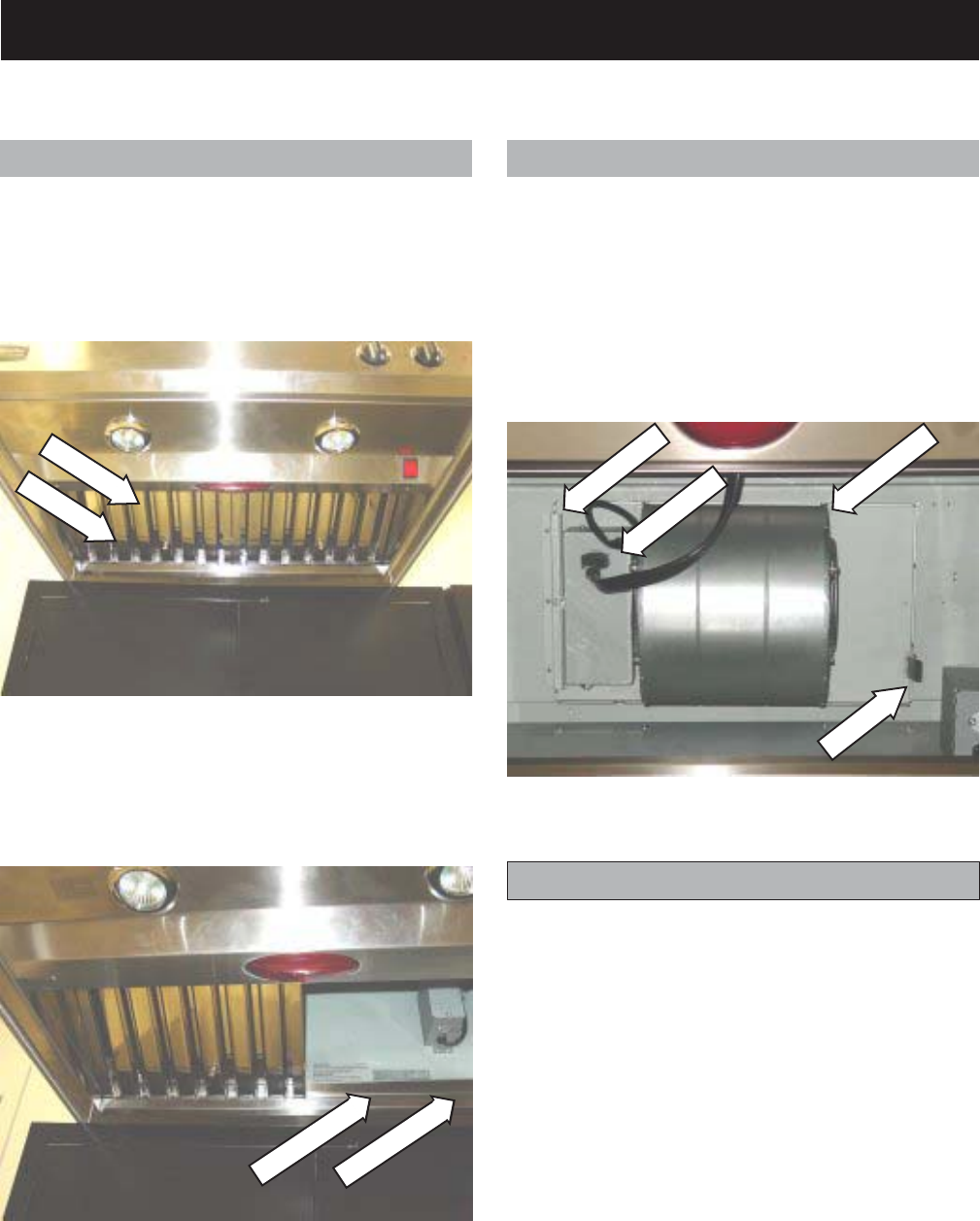
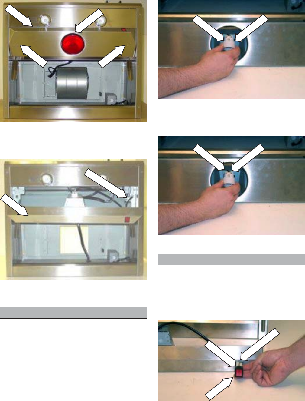
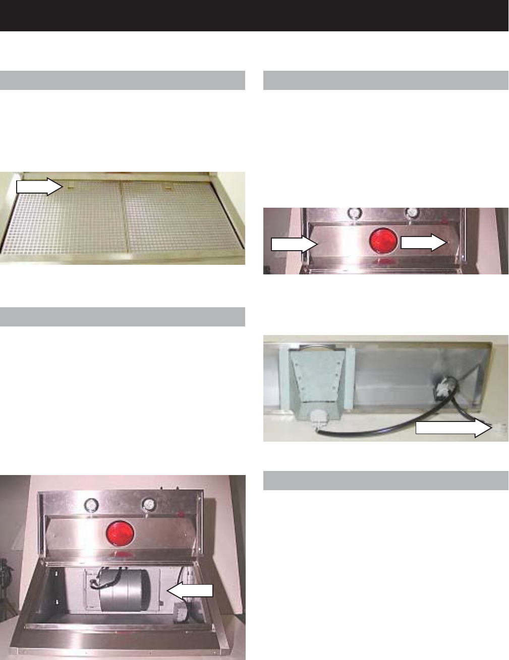
ZV30, ZV36, and ZV48 Components
Channel
Drip Tray
2. Remove the 2 drip trays from drip tray
channel.
Heat Lamp Panel
Removal and Replacement
WARNING: Heat lamp may be hot.
The bulb is a 120 volt, 175 watt, par-38 infrared
bulb. Part No. - WB08X10029.
1. Remove the heat lamp.
2. Remove the 2 screws from the heat lamp
panel, then lower the panel from the range
hood.
.
Motor
Channel
Connector
Clip
Knob
Knob
Baffle Grease Filter and Drip Trays
Removal and Replacement
1. Grasp the 2 handle knobs. Slide the grease
filter forward and up until it clears the drip tray
and remove. Remove the drip trays.
Fan Motor
Removal and Replacement
1. Disconnect the electrical connector from the
fan motor.
2. Press back the motor mount retaining clip.
3. Slide the motor mount from the channel and
remove the fan motor.
(Continued next page)
– 8 –
3. Label and disconnect the 4 electrical
connectors from the heat lamp switch.
3. Disconnect the electrical connector and
remove the heat lamp panel.
Heat Lamp Socket
Removal and Replacement
WARNING: Heat lamp socket may be hot.
Tech Tip: Use of a plastic putty knife or a taped
metal putty knife helps prevent scratching of
metal surfaces.
1. Remove the Heat Lamp Panel.
2. Press the socket clamps in and pull the heat
lamp socket from the heat lamp panel.
3. Loosen the 2 wire retaining screws and
remove the wires from the heat lamp socket.
Clamp
Clamp
2 Screws
Socket
Panel
Lamp
Screw
Screw
Panel
Connector
Clamps
Switch
Connectors
Heat Lamp Switch
Removal and Replacement
1. Remove the Heat Lamp Panel.
2. Press the switch clamps in and pull the
switch from the heat lamp panel.
– 9 –
4. Loosen the 2 wire retaining screws and
remove the wires from the surface light
socket.
Screw
Screw
Clamp
Clamp
Socket
Trim Ring
Trim Ring
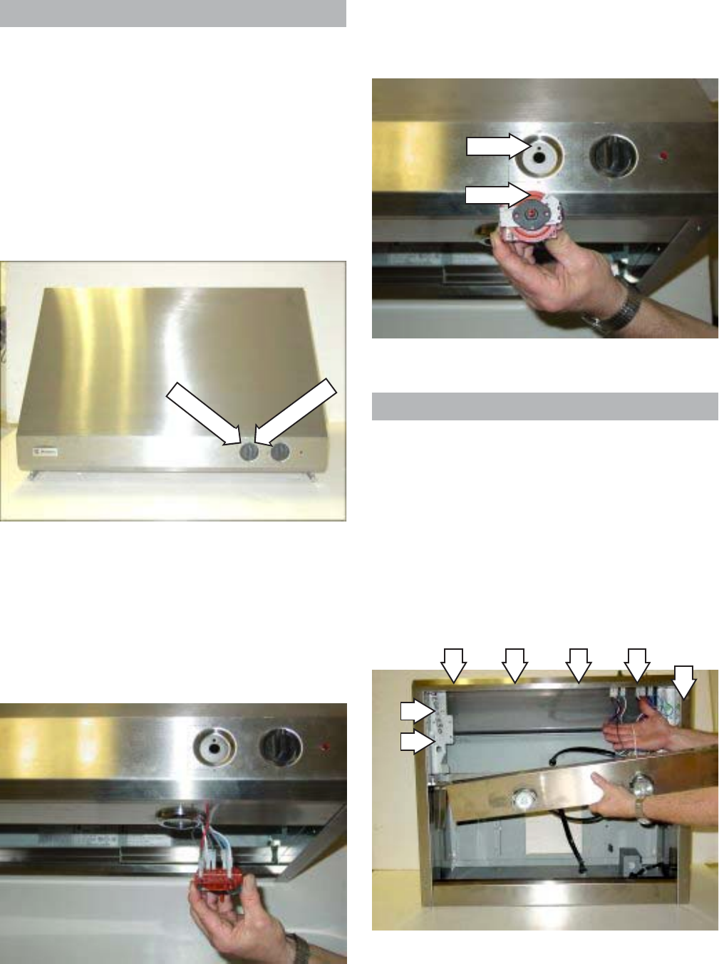
Surface Lights
Removal and Replacement
WARNING: Surface lights may be hot.
The surface lights are 120 volt, 50 watt, par-16
halogen flood bulbs. Part No. WB08X10028.
1. Turn the trim ring counterclockwise until it falls
from the socket.
2. Remove the light from the socket.
Surface Light Sockets
Removal and Replacement
1. Remove the Heat Lamp Panel.
2. Remove the Surface Lights.
3. Press the socket clamps in and pull the
socket from the overhead light panel.
– 10 –
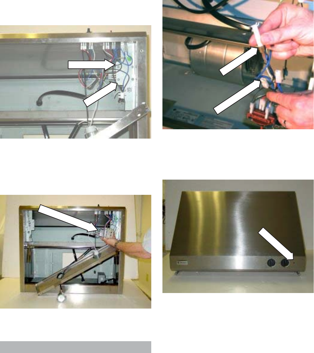
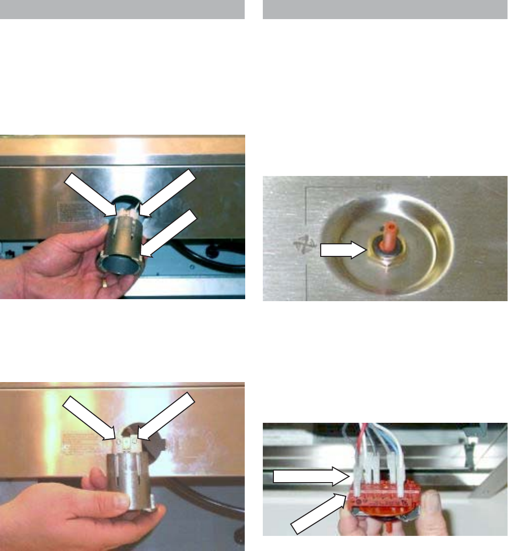
.
4. Reach behind the hood and pull the rotary
switch out to access the electrical
connectors.
5. Label and disconnect the 7 wires from the
rotary switch and remove the rotary switch.
Switch
Nut
Note: Make sure the pin on the rotary switch is
aligned with the hole in the panel before installing
the nut.
Pin
Hole
Rotary Switch
Removal and Replacement
Note: The procedure to remove both the fan
rotary switch and the light rotary switch are
identical.
1. Remove the Heat Lamp Panel.
2. Pull the control knob from the rotary switch.
3. Remove the nut from the front of the rotary
switch
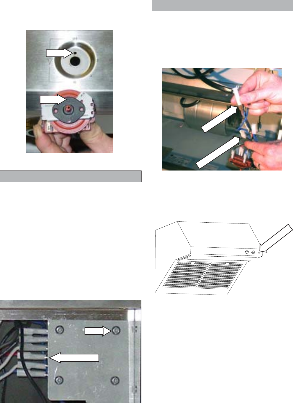
Autotransformer
Removal and Replacement
1. Remove the Heat Lamp Panel.
2. Remove the light switch control knob. (See
Rotary Switch.)
3. Remove the fan switch control knob. (See
Rotary Switch.)
4. Remove the 7 screws that hold the surface
light panel to the hood.
– 11 –
5. Remove the 4 screws that hold the
autotransformer to the mounting bracket.
6. Label and disconnect the 7 wires from the
autotransformer and remove the auto-
transformer.
Bracket
4 Screws
3. Pull the indicator light socket from the red
indicator cap.
Socket
2 Terminal Lugs
Cap
Autotransformer
Fan Motor Indicator Light
Removal and Replacement
1. Remove the Heat Lamp Panel.
2. Reach behind the hood and disconnect the 2
wires from the indicator light socket.
– 12 –
ZV30R, ZV36R, and ZV48R Components
Clip
3. Disconnect the electrical connector and
remove the heat lamp panel.
screw
screw
Grease Baffles
Removal and Replacement
1. Lift the tabs to release the baffles.
2. Remove the 2 baffles from the hood.
Fan Motor
Removal and Replacement
WARNING: Heat lamp may be hot.
1. Disconnect the electrical connector from the
fan motor.
2. Press back the motor mount retaining clip.
3. Slide the motor mount from the channel and
remove the fan motor.
Heat Lamp Panel
Removal and Replacement
WARNING: Heat lamp may be hot.
1. Remove the heat lamp.
2. Remove the 2 screws from the heat lamp
panel and lower the heat lamp panel from the
range hood.
Heat Lamp Socket
Removal and Replacement
WARNING: Heat lamp socket may be hot.
1. Remove the Heat Lamp Panel.
2. Press the socket clamps in and pull the heat
lamp socket from the heat lamp panel.
Disconnect
Tab
– 13 –
3. Loosen the 2 wire retaining screws and
remove the wires from the heat lamp socket.
Clamp
Clamp
2 Screws
Socket
Clamps
Switch
4 Connectors
Retainer
Heat Lamp Switch
Removal and Replacement
1. Remove the Heat Lamp Panel.
2. Press the switch clamps in and pull the
switch from the heat lamp panel.
3. Label and disconnect the 4 electrical
connectors from the heat lamp switch.
Surface Lights
Removal and Replacement
WARNING: Surface lights may be hot.
1. Turn the trim ring counterclockwise until it falls
from the socket.
2. Remove the light from the socket.
– 14 –
6. Label and disconnect seven terminal lugs
from the rotary switch.
4. Loosen the 2 wire retaining screws and
remove the wires from the overhead light
socket.
4. Reach behind the hood and pull the rotary
switch out to access the electrical
connectors.
5. Label and disconnect the 7 terminal lugs from
the rotary switch and remove the rotary
switch.
Connectors
Switch
Socket
Screw
Screw
Clamp
Clamp
Nut
Surface Light Sockets
Removal and Replacement
1. Remove the Heat Lamp Panel.
2. Remove the surface lights.
3. Press the socket clamps in and pull the
socket from the surface light panel.
Rotary Switch
Removal and Replacement
Note: The procedure to remove both the fan
rotary switch and the light rotary switch are
identical.
1. Remove the Heat Lamp Panel.
2. Pull the control knob off the rotary switch.
3. Remove the nut from the front of the rotary
switch.
– 15 –
Autotransformer
Removal and Replacement
1. Remove the Heat Lamp Panel.
2. Remove the light switch control knob. (See
Rotary Switch.)
3. Remove the fan switch control knob. (See
Rotary Switch.)
4. Remove four screws from the
autotransformer.
5. Label and disconnect seven terminal lugs
from the autotransformer.
Note: Make sure the pin on the rotary switch is
aligned with the hole in the panel before installing
the nut.
3. Pull the indicator light socket from the red
indicator cap.
Socket
2 Terminal Lugs
Screw
Terminal Lugs
Cap
Hole
Pin
Fan Motor Indicator Light
Removal and Replacement
1. Remove the Heat Lamp Panel.
2. Reach behind the hood and disconnect the 2
wires from the indicator light socket.
– 16 –
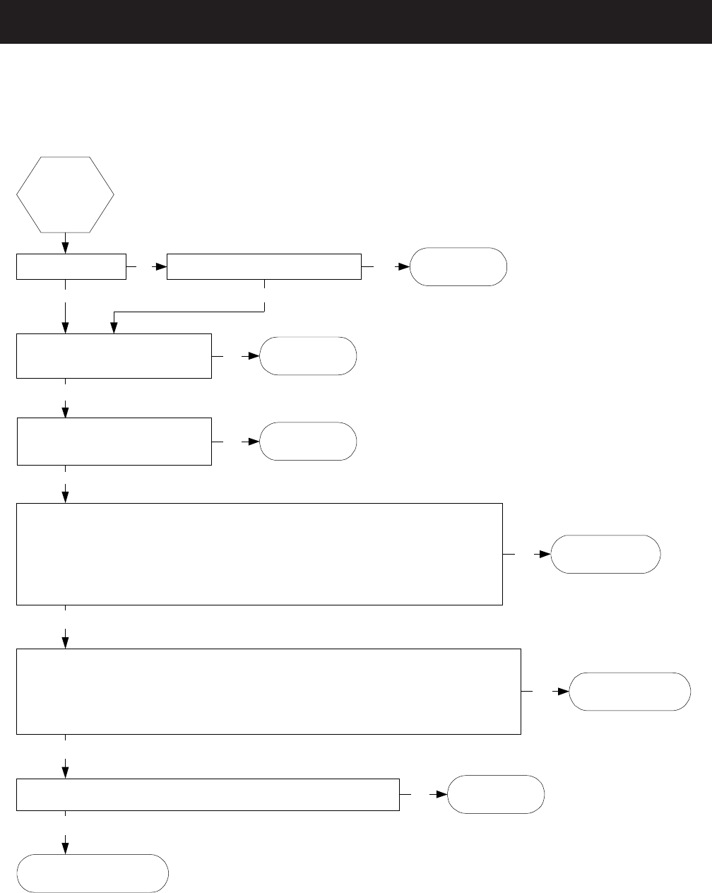
Troubleshooting
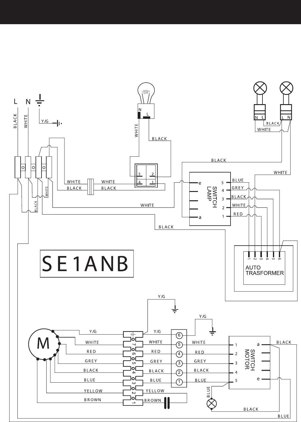
Single Fan Motor (Use schematic SE1ANB)
The fan
does not
work.
!With the lamp switch set to OFF, is 120
volts present between pin (a) and pin (e)
on the fan motor switch?
Yes
Yes
!Is the circuit breaker open or fuse blown? Reset the circuit
breaker or replace the
fuse.
No Repair faulty wiring.
No Replace the fan motor
switch.
Isolate the fan motor switch.
! With the fan motor switch set to (1), is continuity present between pin (a) and pin (1) on the fan motor switch?
! With the fan motor switch set to (2), is continuity present between pin (a) and pin (2) on the fan motor switch?
! With the fan motor switch set to (3), is continuity present between pin (a) and pin (3) on the fan motor switch?
! With the fan motor switch set to (HI), is continuity present between pin (a) and pin (4) on the fan motor switch?
! With the fan motor switch set to (1), is continuity present between pin (e) and pin (5) on the fan motor switch?
! With the fan motor switch set to (2), is continuity present between pin (e) and pin (5) on the fan motor switch?
! With the fan motor switch set to (3), is continuity present between pin (e) and pin (5) on the fan motor switch?
! With the fan motor switch set to (HI), is continuity present between pin (e) and pin (5) on the fan motor switch?
Yes
No Repair faulty wiring
between the terminal board
and the fan motor switch.
Replace the capacitor. If the motor
fails to operate replace the motor.
Yes
No
Disconnect power and remove the wires from
terminals from (a) and (e) on the fan motor switch.
!Can you turn the fan blade by hand? Replace the fan motor.
Yes
No
!Do the lights work?
No
Isolate the fan motor switch.
! Is the resistence between the white wire and the red wire leading from the fan motor switch approximately 2.5 ohms?
! Is the resistence between the white wire and the grey wire leading from the fan motor switch approximately 4.7 ohms?
! Is the resistence between the white wire and the black wire leading from the fan motor switch approximately 8.3 ohms?
! Is the resistence between the white wire and the blue wire leading from the fan motor switch approximately 14.2 ohms?
Locate the fan motor capacitor.
! Is the resistence between the brown wire and the yellow wire approximately 18.1 ohms?
Yes
No Replace the fan motor.
Yes
Note: On dual motor models, if one of the
capacitors is open, or if the wires and/or
connections to the capacitor are open, the motors
will run slower than normal. If both capacitors are
open, then both motors will hum.
– 17 –
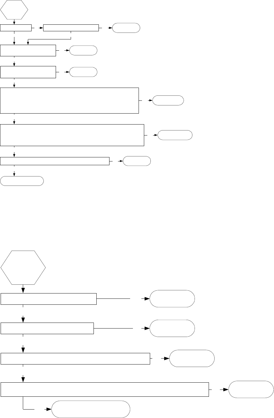
Heat Lamp
Fan Motor Indicator Light
The fan
does not
work.
!With the lamp switch set to OFF, is 120
volts present between pin (a) and pin (e)
on the fan motor switch?
Yes
Yes
!Is the circuit breaker open or fuse blown? Reset the circuit
breaker or replace the
fuse.
No Repair faulty wiring.
No Replace the fan motor
switch.
Isolate the fan motor switch.
! W ith the fan motor switch set to (1), is continuity present between pin ( a) and pin (1) on the fan motor switch?
! W ith the fan motor switch set to (2), is continuity present between pin ( a) and pin (2) on the fan motor switch?
! W ith the fan motor switch set to (3), is continuity present between pin ( a) and pin (3) on the fan motor switch?
! W ith the fan motor switch set to (HI), is continuity present between pin (a) and pin (4) on the fan motor switch?
! W ith the fan motor switch set to (1), is continuity present between pin ( e) and pin (5) on the fan motor switch?
! W ith the fan motor switch set to (2), is continuity present between pin ( e) and pin (5) on the fan motor switch?
! W ith the fan motor switch set to (3), is continuity present between pin ( e) and pin (5) on the fan motor switch?
! W ith the fan motor switch set to (HI), is continuity present between pin (e) and pin (5) on the fan motor switch?
Yes
No Repair faulty wiring
between the terminal board
and the fan motor switch.
Replace the capacitor. If the motor
fails to operate replace the motor.
Yes
No
Disconnect power and remove the wires from
terminals from (a) and (e) on the fan motor switch.
!Can you turn the fan blade by hand? Replace the fan motor.
Yes
No
!Do the lights work?
No
Isolate the fan motor switch.
! Is the resistence between the white wire and the red wire leading from the fan motor switch approximately 2.5 ohms?
! Is the resistence between the white wire and the grey wire leading from the fan motor switch approximately 4.7 ohms?
! Is the resistence between the white wire and the black wire leading from the fan motor switch approximately 8.3 ohms?
! Is the resistence between the white wire and the blue wire leading from the fan motor switch approximately 14.2 ohms?
Locate the fan motor capacitor.
! Is the resistence between the brown wire and the yellow wire approximately 18.1 ohms?
Yes
No Replace the fan motor.
Yes
Yes
No
No Repair faulty wiring.
!Is the circuit breaker open or fuse blown?
!Is 120 volts present between pin (4) and pin (1) on the heat lamp switch?
Reset the circuit
breaker or replace the
fuse.
!Does the heat lamp bulb have continuity?
Yes
No Replace the lamp bulb.
Yes Replace the heat lamp switch.
If the problem persists, replace
the heat lamp socket.
Yes
No Repair faulty wiring.
!Is continuity present between pin (2) on the heat lamp switch and terminal (L) on the heat lamp socket?
!Is continuity present between pin (5) on the heat lamp switch and terminal (N) on the heat lamp socket?
The heat
lamp does
not work.
– 18 –
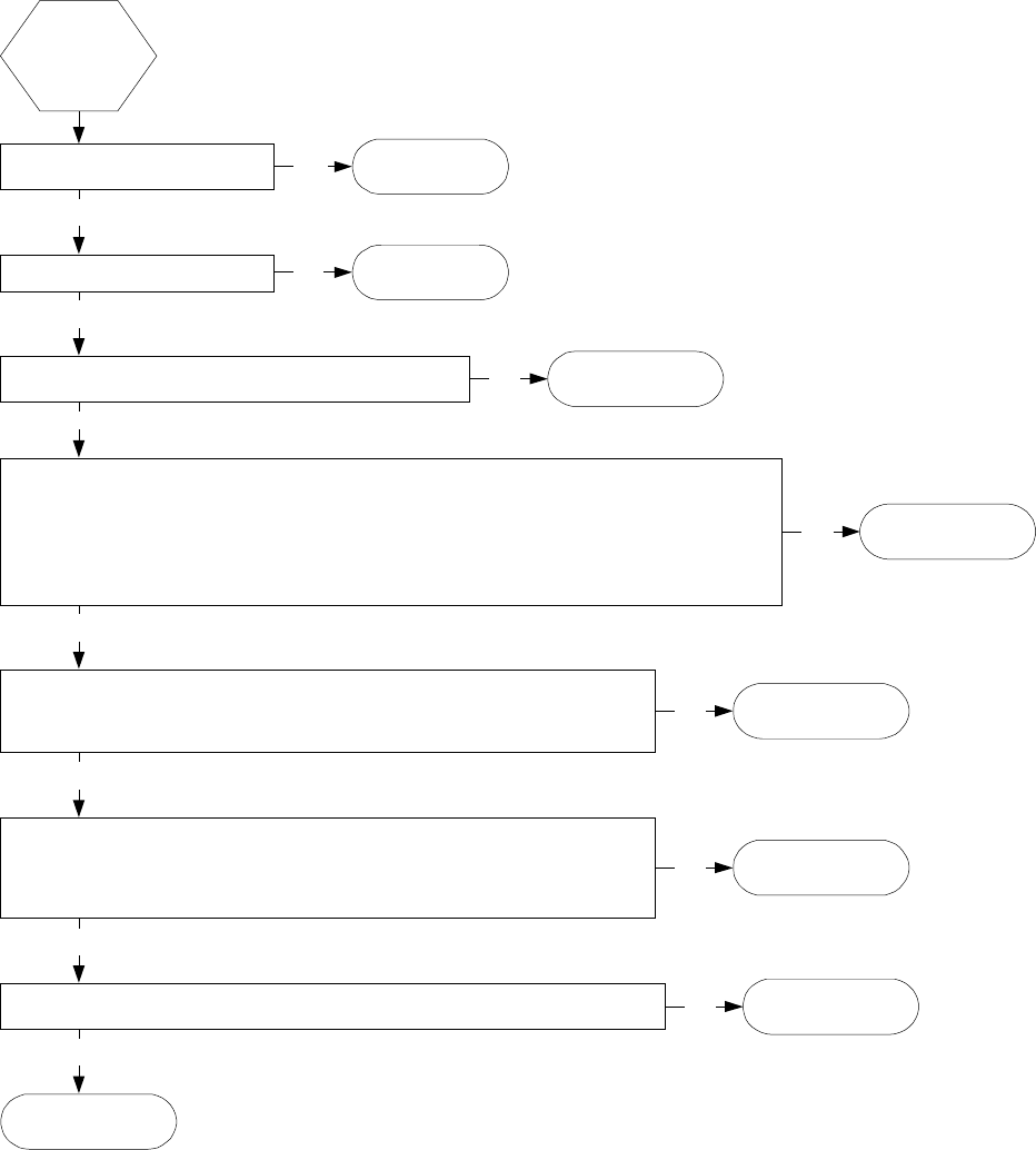
Surface Lights
Yes
No
!Is the circuit breaker open or fuse
blown?
Reset the circuit
breaker or replace the
fuse.
Replace the faulty
lamp socket.
!Does the lamp bulb have continuity?
Yes
No Replace the lamp bulb.
One or both
of the
surface
lights do
not work.
No Repair faulty wiring.
!With the lamp switch set to OFF, is 120 volts present between pin
(e) on the lamp switch and pin (6) on the autotransformer?
! Is continuity present between pin (5) on the lamp switch and pin (1) on the autotransformer?
! Is continuity present between pin (4) on the lamp switch and pin (6) on the autotransformer?
! Is continuity present between pin (3) on the lamp switch and pin (5) on the autotransformer?
! Is continuity present between pin (2) on the lamp switch and pin (4) on the autotransformer?
! Is continuity present between pin (1) on the lamp switch and pin (3) on the autotransformer?
Yes
Isolate the lamp switch.
! Is continuity present between pin (1) and pin (2) on the autotransformer?
! Is the resistence between pin (1) and pin (3) on the autotransformer approximately 3.2 ohms?
! Is the resistence between pin (1) and pin (4) on the autotransformer approximately 3.9 ohms?
! Is the resistence between pin (1) and pin (5) on the autotransformer approximately 4.4 ohms?
! Is the resistence between pin (1) and pin (6) on the autotransformer approximately 5.0 ohms?
No Repair faulty wiring.
Yes
No Replace the
autotransformer.
! Is continuity present between lamp switch pin (a) and terminal (L) on both lamp sockets?
! Is continuity present between autotransformer pin (2) and terminal (N) on both lamp sockets? No Repair faulty wiring.
Yes
Yes
No Replace the
lamp switch.
Isolate the lamp switch.
! With the lamp switch set to (1), is continuity present between pin (a) and pin (1) on the lamp switch?
! With the lamp switch set to (2), is continuity present between pin (a) and pin (2) on the lamp switch?
! With the lamp switch set to (3), is continuity present between pin (a) and pin (3) on the lamp switch?
! With the lamp switch set to (HI), is continuity present between pin (a) and pin (4) on the lamp switch?
! With the lamp switch set to (1), is continuity present between pin (e) and pin (5) on the lamp switch??
! With the lamp switch set to (2), is continuity present between pin (e) and pin (5) on the lamp switch?
! With the lamp switch set to (3), is continuity present between pin (e) and pin (5) on the lamp switch?
! With the lamp switch set to (HI), is continuity present between pin (e) and pin (5) on the lamp switch?
Yes
– 19 –
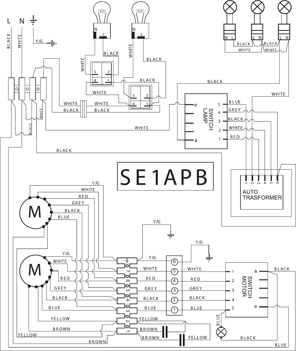
Schematics
All ZV30 and ZV36 - RSF1SS, SSF1SS, and TSF1SS Models
WARNING: Power must be disconnected before servicing the appliance.
– 20 –
All ZV48 - RSF1SS, SSF1SS, and TSF1SS Models
WARNING: Power must be disconnected before servicing the appliance.
– 21 –
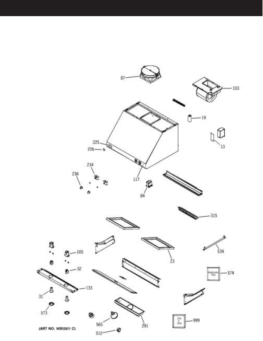
Illustrated Parts
ZV30, ZV36, and ZV48 - SSF1SS Models

– 22 –
VIEW
NUMBER
CATALOG
NUMBER DESCRIPTION QUANTITY
13 WB02X10872 JUNCTION BOX COVER 1
19 WB27X10669 CAPACITOR 1
23 WB02X10869 FILTER, BAFFLE 2
31 WB08X10028 120V 50W HALOGEN BULB 2
32 WB08X10030 LAMPHOLDER 2
84 WB20X10026 TRANSFORMER 1
87 WB02X10871 DUCT TRANSITION W/DAMPER 1
103 WB38X10069 BLOWER ASSEMBLY 1
105 WB08X10032 LAMPHOLDER SUPPORT 2
117 WB08X10033 INDICATOR LIGHT 1
133 WB07X10607 HALOGEN LAMP PANEL 30" 1
225 WB02X10832 MONOGRAM LOGO 1
226 WB01X10070 CLIP LOGO 2
234 WB24X10110 SWITCH, MOTOR/LAMP 2
236 WB03X10163 KNOB ASSEMBLY 2
291 WB07X10608 HEAT LAMP PANEL 30" 1
315 WB02X10870 GREASE TRAY 30" 2
512 WB24X10111 HEAT-LAMP ROCKER SWITCH 1
539 WB02X10873 UTENSIL ROD-TAPER 30" 2
565 WB08X10029 120V 175W INFRARED LAMP 1
573 WB08X10031 BEZEL LAMP 2
574 WB01X10196 HARDWARE BAG 1
999 49-80150 USE & CARE MANUAL 1
999 49-80151 INSTALL INSTRUCTION 1
ZV30, ZV36, and ZV48 - SSF1SS Models
– 23 –
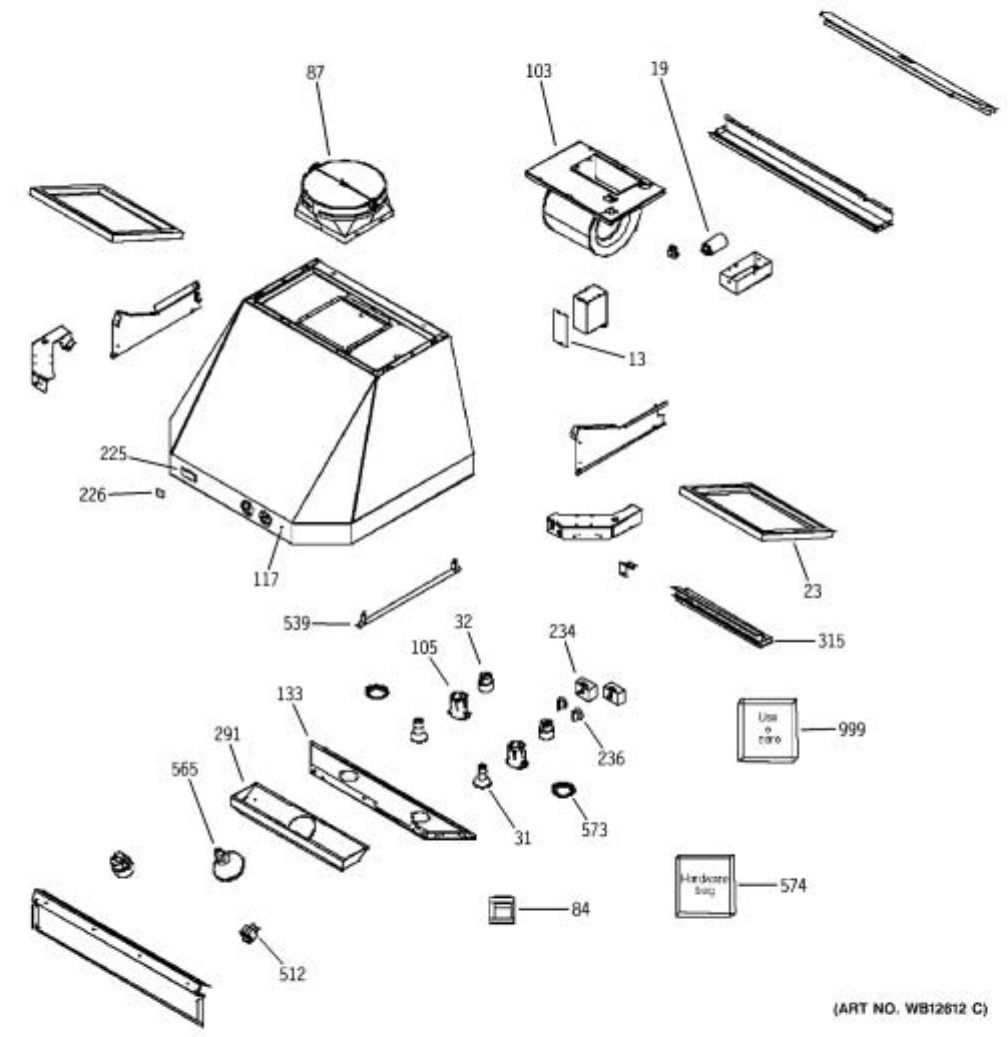
ZV30, ZV36, and ZV48 - TSF1SS Models

– 24 –
VIEW
NUMBER CATALOG NUMBER DESCRIPTION QUANTITY
13 WB02X10872 JUNCTION BOX COVER 1
19 WB27X10669 CAPACITOR 1
23 WB02X10869 FILTER, BAFFLE 2
31 WB08X10028 120V 50W HALOGEN BULB 2
32 WB08X10030 LAMPHOLDER 2
84 WB20X10026 TRANSFORMER 1
87 WB02X10871 DUCT TRANSITION W/DAMPER 1
103 WB38X10069 BLOWER ASSEMBLY 1
105 WB08X10032 LAMPHOLDER SUPPORT 2
117 WB08X10033 INDICATOR LIGHT 1
133 WB07X10613 HALOGEN LAMP PANEL 30" 1
225 WB02X10832 MONOGRAM LOGO 1
226 WB01X10070 CLIP LOGO 2
234 WB24X10110 SWITCH, MOTOR/LAMP 2
236 WB03X10163 KNOB ASSEMBLY 2
291 WB07X10608 HEAT LAMP PANEL 30" 1
315 WB02X10870 GREASE TRAY 30" 2
512 WB24X10111 HEAT-LAMP ROCKER SWITCH 1
539 WB02X10873 UTENSIL ROD-TAPER 30" 2
565 WB08X10029 120V 175W INFRARED LAMP 1
573 WB08X10031 BEZEL LAMP 2
574 WB01X10196 HARDWARE BAG 1
999 49-80150 USE & CARE MANUAL 1
999 49-80151 INSTALL INSTRUCTIONS 1
ZV30, ZV36, and ZV48 - TSF1SS Models
– 25 –
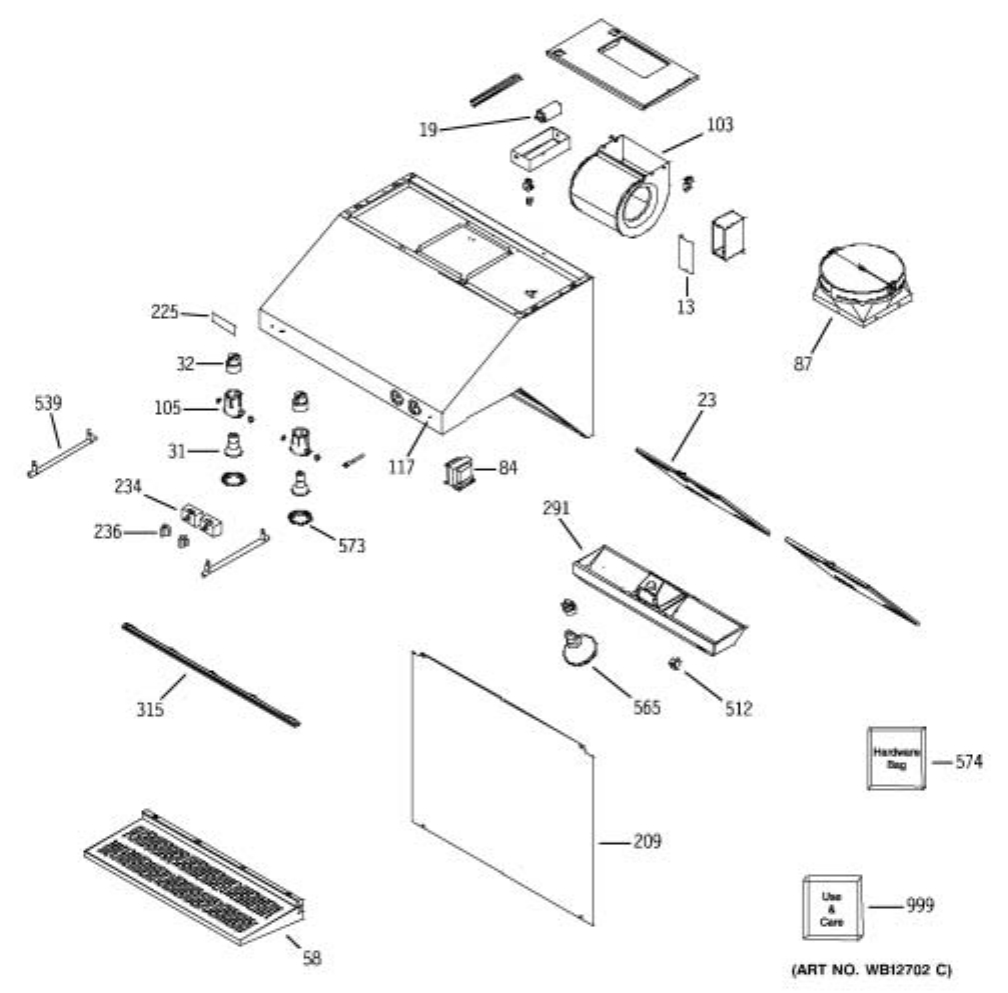
ZV30, ZV36, and ZV48 - RSF1SS Models

– 26 –
VIEW
NUMBER
CATALOG
NUMBER DESCRIPTION QUANTITY
13 WB02X10872 JUNCTION BOX COVER 1
19 WB27X10669 CAPACITOR 1
23 WB02X10897 FILTER, BAFFLE 2
31 WB08X10028 120V 50W HALOGEN BULB 2
32 WB08X10030 LAMPHOLDER 2
58 WB07X10660 SHELF 1
84 WB20X10026 TRANSFORMER 1
87 WB02X10871 DUCT TRANSITION W/DAMPER 1
103 WB38X10069 BLOWER ASSEMBLY 1
105 WB08X10032 LAMPHOLDER SUPPORT 2
117 WB08X10033 INDICATOR LIGHT 1
209 WB61X10004 BACK SPLASH 1
225 WB01X10070 CLIP LOGO 1
225 WB02X10832 MONOGRAM LOGO 1
234 WB24X10110 SWITCH, MOTOR/LAMP 2
236 WB03X10163 KNOB ASSEMBLY 2
291 WB07X10608 HEAT LAMP PANEL 30" 1
315 WB02X10899 GREASE TRAY 30" 2
512 WB24X10111 HEAT-LAMP ROCKER SWITCH 2
539 WB02X10900 UTENSIL ROD-TAPER 30" 2
565 WB08X10029 120V 175W INFRARED LAMP 1
573 WB08X10031 BEZEL LAMP 2
574 WB01X10211 HARDWARE BAG 1
999 49-80152 USE & CARE 1
999 49-80150-1 INSTALLATION 1
ZV30, ZV36, and ZV48 - RSF1SS Models

– 27 –
Notes

Notes
