Game Programming For The Propeller Powered HYDRA 32360 Dev Manual V1.0.1
User Manual: Pdf
Open the PDF directly: View PDF ![]() .
.
Page Count: 812 [warning: Documents this large are best viewed by clicking the View PDF Link!]

Game
Programming
for
the
Propeller
Hydra A Guide to Developing Games
,
Graphics, and Media Applications
Hydra Game System BY ANDRE LAMOTH
Programming for the Propeller Pow
e
Hydra A Guide to Developing Games
,
Graphics, and Media Applications
Hydra Game System BY ANDRE LAMOTH
Programming for the Propeller Pow
e
Hydra A Guide to Developing Games
,
Graphics, and Media Applications
Hydra Game System BY ANDRE LAMOTH
Programming for the Propeller Pow
e
Hydra A Guide to Developing Games
,
Graphics, and Media Applications
Hydra Game System BY ANDRE LAMOTH
Programming for the Propeller Pow
e
Hydra A Guide to Developing Games
,
A Guide to Developing Games, Graphics, and Media Applications for the HYDRA Game System
Game Programming
for the Propeller
Powered HYDRA
B
Y
A
NDRE
L
A
M
OTHE
Andre LaMothe
´

Front Matter
Warranty
Parallax Inc. warrants its products against defects in materials and workmanship for a period of 90 days from receipt of product. If you
discover a defect, Parallax Inc. will, at its option, repair or replace the merchandise, or refund the purchase price. Before returning the product
to Parallax, call for a Return Merchandise Authorization (RMA) number. Write the RMA number on the outside of the box used to return the
merchandise to Parallax. Please enclose the following along with the returned merchandise: your name, telephone number, shipping address,
and a description of the problem. Parallax will return your product or its replacement using the same shipping method used to ship the product
to Parallax.
14-Day Money Back Guarantee
If, within 14 days of having received your product, you find that it does not suit your needs, you may return it for a full refund. Parallax Inc. will
refund the purchase price of the product, excluding shipping/handling costs. This guarantee is void if the product has been altered or
damaged. See the Warranty section above for instructions on returning a product to Parallax.
Copyrights and Trademarks
This documentation is copyright ©2006 by Nurve Networks LLC. By obtaining a printed or electronic copy of this documentation or software
you agree that it is to be used exclusively with Propeller-chip-based HYDRA products. Any other uses are not permitted and may represent a
violation of copyrights, legally punishable according to Federal copyright or intellectual property laws. Any duplication of this documentation for
commercial uses is expressly prohibited. Excerpts from the Propeller Manual v1.0 are Copyright © 2006 by Parallax Inc. and used here with
permission.
Propeller and Spin are trademarks of Parallax, Inc. HYDRA is a trademark of Nurve Networks LLC. Other brand and product names herein
are trademarks or registered trademarks of their respective holders.
Version 1.0, 2nd Printing
ISBN 1-928982-40-9
Disclaimer of Liability
Parallax Inc. is not responsible for special, incidental, or consequential damages resulting from any breach of warranty, or under any legal
theory, including lost profits, downtime, goodwill, damage to or replacement of equipment or property, or any costs of recovering,
reprogramming, or reproducing any data stored in or used with Parallax products. Parallax Inc. is also not responsible for any personal
damage, including that to life and health, resulting from use of any of our products. You take full responsibility for your Propeller microcontroller
application, no matter how life-threatening it may be.
Errata
While great effort is made to assure the accuracy of our texts, errors may still exist. If you find an error, please let us know by sending an
email to editor@parallax.com. We continually strive to improve all of our educational materials and documentation, and frequently revise our
texts. Occasionally, an errata sheet with a list of known errors and corrections for a given text will be posted to our web site,
www.parallax.com. Please check the individual product page’s free downloads for an errata file.
Supported Hardware, Firmware and Software
This manual is valid with the following hardware, software, and firmware versions:
HYDRA Board Propeller Chip Software Firmware
Rev A P8X32A-D40 Propeller IDE v1.0 P8X32A v1.0

Dedication
Dedication
I dedicate this book to Fox Mulder and Dana Scully. Without the X-Files to look forward to
each night at 3:00 a.m. I would have surely gone insane!

Front Matter
Acknowlegements
Writing a book is a tremendous amount of work for the author, but there is a small army of
people that support him and do a lot of work behind the scenes, especially since this book is
really part of a larger product, the “HYDRA Game Console Kit.” I would like to thank the
following people for their support and contribution to this project. First, Chip and Ken Gracey
of Parallax for collaborating on a project of this scale. Hopefully, this is the first in a long
series of collaborations.
Next, all the support staff at Parallax including Stephanie Lindsay who created the look and
feel, edited and laid out the book, and Rich Allred who transcribed my artwork into final
renderings for the book and read my cryptic writing! Also, thanks to Jen Jacobs for the
artwork and packaging of the book and kit (and making it “edgy” enough). Next to Aristides
Alvarez for managing the final manufacturing, assembly, and production of the HYDRA itself
along with Mac Ma in China for manufacturing support. Additionally, Lauren Bares in
marketing, Lynette Cepeda in purchasing, Jim Carey in sales, Jeff Martin in software
engineering, and last, but not least Jim Ewald that made sure my email got through!
I would also like to thank all the vendors, companies, and friends that helped the HYDRA
project and this book in one way or another (in no particular order); Iain Cliffe of Labcenter
Electronics (www.labcenter.co.uk) for the use of Proteus to design the HYDRA, Sellam Ismail
of Vintage Tech (www.vintage.org) for always getting me those hard to find retro items, Ari
Feldman for the use of SpriteLib (http://www.flyingyogi.com/fun/spritelib.html). And Mike
Perone of Barracuda Networks (www.barracudanetworks.com) for hosting and spam
firewalls. To Steve Wozniak and Depech Mode, thanks for the concert! And David Perry of
Shiny Entertainment and Game Consultants (www.gameconsultants.com) for helping get the
word out about the XGS and HYDRA. To Steve Russell for writing the foreword, I really
appreciate it.
The next group of people I would like to thank are the demo coders that created many of the
cutting edge demos for the HYDRA (found in Chapter 25). The demo coders are: Rémi
Veilleux, Colin Phillips, Robert Woodring, Jay T. Cook, Nick Sabalausky, Rainer Blessing,
Matthew Kanwisher and Michael Thompson. Also, special thanks to Lorenzo Phillips
(www.ldp-solutions.com) that managed the software development and asset organization as
well as Terry Smith for webmastering (www.ternaryworks.net).
Finally, to my mom, dad, and beautiful girlfriend Ines – they all put up with me once again
through my 7 day a week, 100+ hour schedule from hell.

Author Bio
Author Bio
André LaMothe holds degrees in Mathematics, Computer Science and Electrical Engineering.
He has been programming since 1977 when he started writing games on the TRS-80 at the
local Radio Shack. He has worked in many fields of Computer Science and engineering.
Highlights include the head of Graphics R&D at Software Publishing Corporation by 19, a
NASA Artifical Intelligence research associate at 20, and the creator of one of the first super
computer, networked Virtual Reality games at 24. He is the founder of Xtreme Games LLC,
the Xtreme Games Developers Conference, as well as Nurve Networks LLC. Additionally, Mr.
LaMothe is a best-selling author with numerous titles on game development, graphics, and
DirectX programming. He is a native Californian and lives in sunny Silicon Valley. You can
reach him at ceo@nurve.net.

Front Matter

Table of Contents
Game Programming for the Propeller Powered HYDRA Ì Page 7
FOREWORD BY STEVE RUSSEL............................................................................................... 9
CHAPTER 0: INTRODUCTION AND A LITTLE HISTORY ABOUT GAME DEVELOPMENT...............................11
PART I: THE HYDRA HARDWARE ....................................................................... 25
CHAPTER 1: HYDRA SYSTEM OVERVIEW AND QUICK START ........................................................27
CHAPTER 2: 5V & 3.3V POWER SUPPLIES...............................................................................77
CHAPTER 3: RESET CIRCUIT................................................................................................81
CHAPTER 4: USB-SERIAL PROGRAMMING PORT ........................................................................83
CHAPTER 5: DEBUG INDICATOR HARDWARE.............................................................................91
CHAPTER 6: GAME CONTROLLER HARDWARE............................................................................95
CHAPTER 7: COMPOSITE NTSC / PAL VIDEO HARDWARE..........................................................103
CHAPTER 8: VGA HARDWARE............................................................................................115
CHAPTER 9: AUDIO HARDWARE..........................................................................................125
CHAPTER 10: KEYBOARD & MOUSE HARDWARE ......................................................................141
CHAPTER 11: GAME CARTRIDGE, EEPROM & EXPANSION PORT HARDWARE ..................................159
CHAPTER 12: HYDRA-NET NETWORK INTERFACE PORT...........................................................167
PART II: PROPELLER CHIP ARCHITECTURE AND PROGRAMMING.... 175
CHAPTER 13: PROPELLER CHIP ARCHITECTURE AND PROGRAMMING .............................................177
CHAPTER 14: COG VIDEO HARDWARE..................................................................................233
CHAPTER 15: THE SPIN LANGUAGE .....................................................................................245
CHAPTER 16: PROGRAMMING EXAMPLES ON THE PROPELLER CHIP / HYDRA ..................................319
PART III: GAME PROGRAMMING ON THE HYDRA.................................... 425
CHAPTER 17: INTRODUCTION TO GAME DEVELOPMENT .............................................................427
CHAPTER 18: BASIC GRAPHICS AND 2D ANIMATION ................................................................461
CHAPTER 19: TILE ENGINES AND SPRITES.............................................................................509
CHAPTER 20: GETTING INPUT FROM THE “USER” WORLD..........................................................559
CHAPTER 21: SOUND DESIGN FOR GAMES.............................................................................593
CHAPTER 22: ADVANCED GRAPHICS AND ANIMATION ...............................................................619
CHAPTER 23: AI, PHYSICS MODELING, AND COLLISION DETECTION - A CRASH COURSE! ...................673
CHAPTER 24: GRAPHICS ENGINE DEVELOPMENT ON THE HYDRA ................................................759
CHAPTER 25: HYDRA DEMO SHOWCASE..............................................................................779
BACK MATTER.......................................................................................................... 799
EPILOG........................................................................................................................800
INDEX .........................................................................................................................801

Front Matter
Page 8 · Game Programming for the Propeller Powered HYDRA
Foreword
Game Programming for the Propeller Powered HYDRA Page 9
Foreword by
Steve Russel
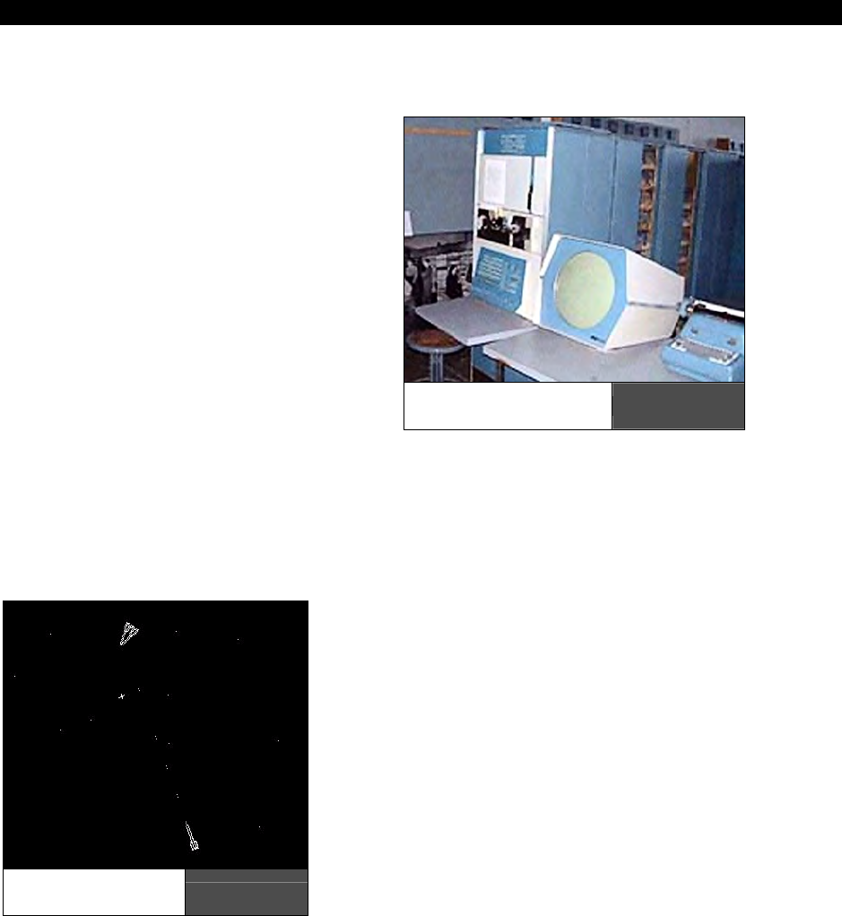
Over 45 years ago, a new PDP-1 computer
arrived near my office with a display system
that could do more than anything I had seen
before. There was just one demonstration
program, but it didn’t use all the power of the
display.
I thought that I could make a better
demonstration program, and after discussion
with my friends, I started writing code. That
program developed into “Spacewar!” – one of
the first computer games to use a display and
the distant ancestor of Atari Asteroids. I
learned that playing computer games was fun,
but writing them was even more fun!
One of the great things about writing a game is finding solutions to the puzzle of trying to
get the most fun into the game while getting it to work well. Unlike most computer
programming assignments, with a game you can adjust the problem to fit the available
solution.
The development of SpaceWar! was a collaboration, for example Dan Edwards looked at my
version of Spacewar! and decided it needed a sun and gravity to better show the problems of
getting a spaceship into orbit. Even after he developed a run-time code generator that wrote
a custom program to drive the display at its
maximum speed, there still was only time to
compute the gravity effect on 2 spaceships!
We left the torpedoes untouched by gravity, and
decided that they were “photon torpedoes” that
were unaffected by gravity since they are pure
energy (a game developer’s perogative). The
game still played fast enough, and the spaceship
orbits added a great deal to the fun.
At one point, I decided that the torpedoes would
be more “realistic” if they had a little random error,
just like real torpedoes. I added this but everyone
else complained loudly, so I took it out in the next
version.
The PDP Computer
and Display Figure F:1
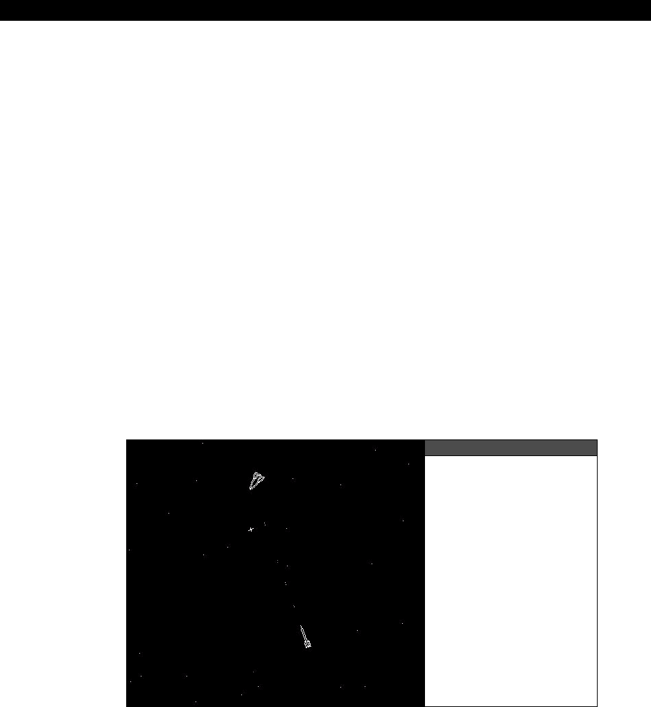
Screen Shot of
SpaceWar! Figure F:2

Front Matter
Page 10 · Game Programming for the Propeller Powered HYDRA
A few years later I had a different, much better display system arrive. I was able to write a
very primitive flight simulator for it, but the pace was so slow that it was no fun. I learned
that just having 3 dimensions doesn’t necessarily make a game better.
You have much better hardware, software and examples to start with, so I hope you will
learn how much fun game programming is with less pain and more fun than I did nearly half
a century ago!
It turned out that I never got a new version of Spacewar! working well until some time
between midnight and 6 AM.
Steve Russell
Co-creator of SpaceWar!
San Jose, California
July 2006
Introduction and a Little History 0
Game Programming for the Propeller Powered HYDRA Page 11
Chapter 0:
Introduction and
a Little History
about Game
Development
Welcome to
Game Programming for the Propeller Powered HYDRA
. This is a no-
holds-barred development manual about creating basic games and graphics applications on
the Propeller powered HYDRA game console. As you might know, game development is the
most complex field of computer science in the world and takes years to master. A video
game is unlike any other program you can write for a computer; games must be fast, fun,
graphically intensive, real-time, support multiple players, run on minimal hardware, and
perform complex and/or seemingly impossible mathematical calculations at a rate fast
enough to update the screen at 30-60 frames per second or more!
Additionally, games pull from advanced research in artificial intelligence, optimization theory,
multiprocessing, compiler design, memory management, data structures, physics modeling,
networking, compression, search algorithms, and much more. And if that wasn’t enough,
there are all the graphic, audio, and artistic media assets needed for a game. Some games
literally are built upon tens to hundreds of terabytes of data and take hundreds of man-years
to develop! Thus, video games are the ultimate fusion of science and art, together creating a
real-time experience that billions of people have enjoyed since the late 50’s.
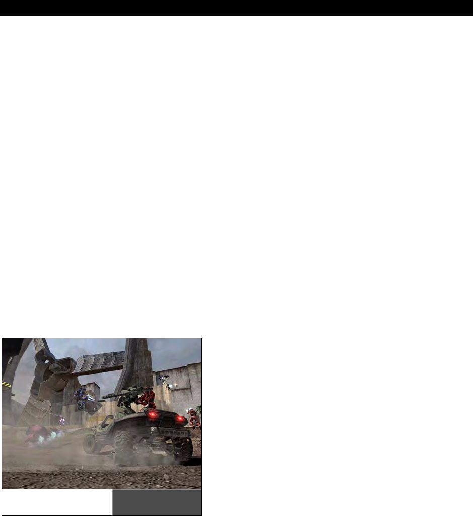
Today games such as Halo II shown in
Figure 0:1 amaze and delight millions. With
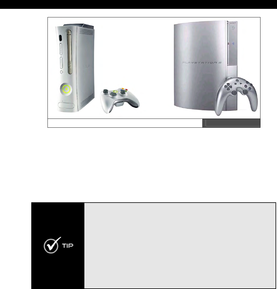
the new next-generation systems available
such as the XBOX 360 and the Playstation
III (shown in Figure 0:2) the future is almost
frightening to think of what will come next.
The sheer computational power of these
systems is staggering – each system is
capable of an excess of 1.5 trillion floating-
point operations per second! Both with
multiple computational elements, especially
the PS3 which contains the most advanced
processor in the world – the
“Cell”
processor, a multibillion-dollar joint venture
among Sony, IBM, and Toshiba.
Halo II Running
on the XBOX Figure 0:1
Introduction and a Little History
Page 12 Game Programming for the Propeller Powered HYDRA
The XBOX 360 (left) and Playstation III (right) Figure 0:2
Everyone knows that game development is serious business. With a gross revenue in excess
of $30B, the game industry is larger that the movie industry, so getting into game
development is one of the most desired job positions now and in the future for many
engineers, programmers, and artists. Never has there been more freedom technically and
artistically than there is today for game development. For fun, let’s take a stroll down
memory lane of some of the highlights in the game development and computer industry. This
list is by no means complete. In fact, I highly recommend that you read some good books on
the history of the video game industry and the computer industry, it’s fascinating stuff.
I highly recommend the following texts if you’re interested in learning more
about the foundations of the video game and computer industries and the
amazing personality and technical challenges therein:
• Hackers: Heroes of the Computer Revolution by Steven Levy
• The Ultimate History of Video Games by Steven Kent
• Supercade: A Visual History of the Video Game Age by Van Burnham
• Masters of DOOM: How Two Guys Created an Empire and Transformed
Pop Culture by David Kushner
• Opening the XBOX: Inside Microsoft’s Plan to Unleash an Entertainment
Revolution
Finally, watch the DVDs Pirates of Silicon Valley and Nerds 1.0, both fascinating
introspections into the genius and innovation the early years of computing
generated.
Introduction and a Little History 0
Game Programming for the Propeller Powered HYDRA Page 13
0.1 A Brief History of Games 1958 - 1993
Ironically, game development is a very complex field. Most would think games are toys and
simple, but many game developers have been programming 10-25+ years and are experts in
numerous fields of computer science; moreover, the field is extremely competitive and
changes on a day-to-day basis. Nonetheless, developing games and graphics applications are
some of the most rewarding things to do with a computer; there is nothing like playing your
own games, or watching others have fun with what you have made! As an artist it’s the
ultimate form of what I call “liquid art.” Additionally, learning to develop games makes you a
much better programmer; you will no longer be limited by memory, processor speeds, or the
need for high-level languages; a game developer can literally make impossible things happen
with a computer.
0.1.1 Table Tennis for Two (1958)
History is replete with examples that literally changed the world. With that in mind let’s take
a look at few key events in the development of the video game industry.
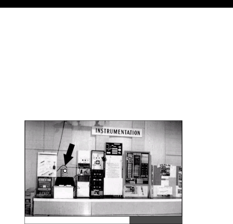
Table Tennis for Two Hardware Figure 0:3
Let’s begin by setting the record straight. Many people think that
Nolan Bushnell
created
the first video game with
“PONG,”
then others think that technically it was
Ralph Baer
with the
“Brown Box”
and the Magnavox
Odyssey
game console, still others think it’s
“Space War!”
developed by
Stephen “Slug” Russell
, but they are all wrong – in fact, it
Introduction and a Little History
Page 14 Game Programming for the Propeller Powered HYDRA
was a physicist –
William Higginbotham
in 1958 at the Brookhaven National Laboratory
developed a game called
“Table Tennis for Two”
for an open house to show their new
analog computer. Figure 0:3 shows a picture of the hardware that “Table Tennis for Two”
ran on with an arrow pointing to the output device. Also, check out the link below to see the
game in action (Real Player format):
http://real.bnl.gov/ramgen/bnl/PONG.rm
The game was developed completely in hardware by means of an analog computer. The lab
wanted to show off something interesting other than weapons design research, so Willy took
the manual that came with the analog computer and read about examples of drawing
trajectories and curves on the oscilloscope. He took this information, and with the addition of
some hardware he and a colleague cobbled together the VERY first video game in history.
0.1.2 Space War! (1962)
Next up was the creation of “
Space War!”
by Stephen “Slug” Russell at MIT. Other major
contributors include Peter Samson, Martin Graetz, Wayne Witanen, Alan Kotok and Dan
Edwards. The game was written on a DEC PDP-1 in pure assembly language in 1962. Steve
“Slug” was nick-named “Slug” since like all software engineers, he took forever to finish
anything! Figure 0.4 shows a screen shot of the original Space War! hardware, quite a
difference from your laptop. You can actually play a remake of Space War! by following this
URL:
http://lcs.www.media.mit.edu/groups/el/projects/spacewar/
Figure 0:4
Space War! Running
on a DEC PDP-1
Introduction and a Little History 0
Game Programming for the Propeller Powered HYDRA Page 15
0.1.3 Ralph Baer, the Brown Box, and the Maganvox Odyessy (1966)
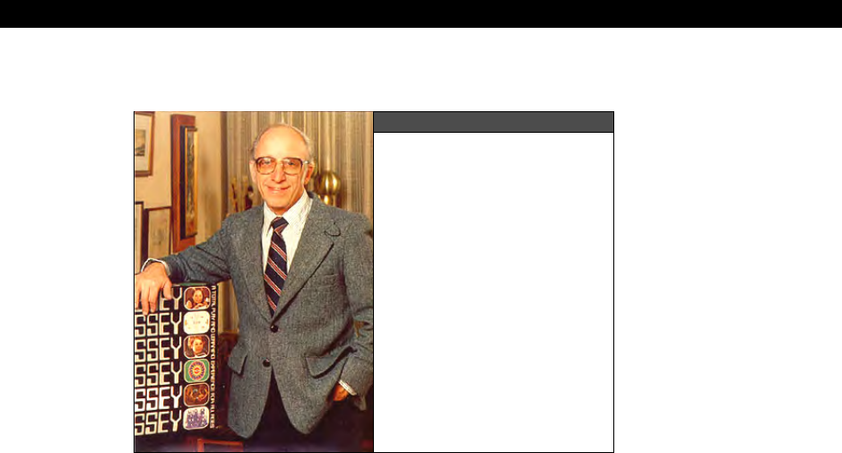
Figure 0:5
Ralph Baer and his
Magnavox Odyssey
Ralph H. Baer was a TV engineer who had an interest in interactive TV. He was the first
person to ever have the notion of moving objects around on a TV screen, and quite frankly
his associates and boss at Sander and Associates told him to forget about it and focus on
making better TV sets. Nonetheless, Ralph kept working away on his
“Brown Box”
and in
1968 had a working prototype of a hard-wired game system capable of moving simple dots
around on the screen.
Figure 0:5 shows Ralph and the Magnavox
Odyssey
system. The rendering ability (if you
can call it that) of the Odyssey was non-existent, so in a brilliant stroke of “engineering
ingenuity” Ralph thought “Why not add transparent backgrounds as overlays on the TV set
itself?” So, that’s what they did; the games that ran on the Odyssey all were nothing more
than dots moving around, but when you put a nice background on the TV set screen itself of
a tennis court, baseball diamond, or haunted house, it was like nothing anyone had seen.
The Odyssey sold about 100-150,000 units depending on where you get your information.
Interestingly though, it came out in 1972 officially, which was the same time that Atari PONG
came out.
Introduction and a Little History
Page 16 Game Programming for the Propeller Powered HYDRA
0.1.4 Atari PONG (1972)
Next, the most important commercial game was
“PONG”
developed by
Nolan
Bushnell
and
Al
Alcorn
of newly formed
Atari
in 1972. This game was responsible for putting games
on the map and was the genesis of the entire video game industry as we know it. It all
happened at Andy Capp’s Tavern in Sunnyvale, CA. Nolan Bushnell, with his newly founded
company Atari, decided to test a prototype of new game that his new engineer Al Alcorn
developed called PONG in local neighborhood Andy Capp’s Tavern as an experiment.
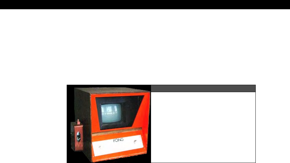
Figure 0:6
Original Atari PONG machine
developed by Nolan Bushnell
and Al Alcorn
Figure 0:6 shows one of the hand-made early prototypes. To their surprise, one week after
the game was deployed there was a line around the corner to play, and the coin mech (a
coffee can) was jammed since the machine was completely full of quarters! This moment in
time launched the $30B video game industry, and Atari, one of the icons of American
business and innovation, was created.
Atari was the fastest growing company in history at the time! And Bushnell, when he sold the
company for $24M+ and change, was the “rock star” of Silicon Valley. Atari PONG more or
less put the Odyssey out of business when Atari came out with a home version of PONG –
remember it? The Atari version of PONG and the system it ran on (PONG on a chip) was
light-years ahead of the Odyssey. The reason why is that the Odyssey technology was really
early 60’s technology and it took Ralph Baer such a long time to get the suits to listen, by the
time they did, Nolan Bushnell was able to create the 2nd generation of games with PONG
and capture the consumer market. But, we should acknowledge that technically the first
game console was the brain-child of Ralph Baer, thus the designation of
“Father of the
Video Games”
goes to Nolan Bushnell, while the
“Grandfather of Video Games”
goes to
Ralph Baer! Interestingly, the first big patent infringement goes to Nolan Bushnell and PONG:
Magnavox, on their knees, financially sued Atari as a last-ditch effort saying that PONG was a
copy of games on the Odyssey. Atari did settle, but patenting dots running around on the
screen – you’ve got to be kidding!
Introduction and a Little History 0
Game Programming for the Propeller Powered HYDRA Page 17
0.1.5 The Apple Computer (1977)
The personal computer industry was also a result of video games.
Steve Jobs
(co-founder of
Apple) worked at Atari, and he and
Steve
“The WOZ” Wozniak
were both interested in
developing their own computer and game system to play games on and hack. Steve Jobs
actually worked at Atari – Nolan Bushnell requested him to create a prototype of a new game
called
“Breakout”
and Jobs accepted the challenge, enlisting electronics guru Steve
Wozniak to do the design.
Together after a 4 day straight engineering/programming tribute to sleep deprivation, the
result was a completed game in a ridiculously low number of chips with NO microprocessor!
In fact, the design was so clever, so optimized, that Atari engineers couldn’t understand it!
However, the knowledge that Steve Wozniak learned and experimented with over those 4
days helped him develop both the Apple I and II computers, and the beginning of the
personal computer era begun in 1977.
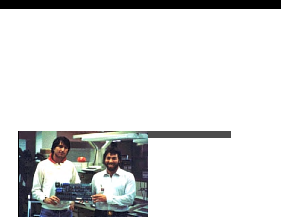
Figure 0:7
The two Steves
(Jobs left, Woz right)
holding their creation
– the Apple II
Figure 0:7 shows the two Steves working on the original Apple I personal computer; this was
of course followed by the Apple II which made Apple computer the fastest growing company
in American history and the largest IPO (initial public offering) in history – I still am mad at
my dad for not believing me in the late 70’s when I told him to buy Apple stock!
Introduction and a Little History
Page 18 Game Programming for the Propeller Powered HYDRA
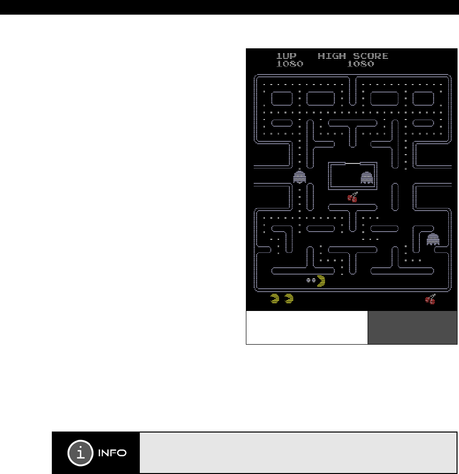
0.1.6 Pac-Man (1980)
So, now we have the creation of the
video game industry and the personal
computer industry, the 80’s are upon us,
and things are getting serious and
competitive. With the USA taking the
lead position in the industry, the
Japanese weren’t far behind with their
own blockbuster game and their
contribution to changing the world of
games.
Toru Iwatani
, a 24 year old
programmer, was in Tokyo and decided
to sit down with some friends and have
some pizza at the American franchise
Shakey’s Pizza. While ordering pizza,
someone took a single piece of the
cheese pizza and that image of a yellow
circle with a piece removed was the
inspiration for “Pac-Man,” quite arguably
one of the most successful games in
history. Toru and his colleagues worked
for 18 months on the game with a team
of hardware and software engineers to
develop Pac-Man. It was the largest
game ever developed and the largest
team ever to develop a game, but it paid
off.
Pac-Man as shown in Figure 0:8 was an instant hit in America and all over the world where
the machines were sent. The characters of Pac-Man also become overnight stars and
everything from sequels to cartoons to breakfast cereals had a Pac-Man logo on it. The age
of engineered games and product marketing was born. People realized this was serious
business, and there were billions to be made…
Pac-Man was originally called “PUC-MAN”, but when shipped to America, kids
used to erase part of the “P” and the resulting name was less than desired by
Namco. Thus, they change it to “Pac-Man” so at worst the game would read
“Fac-Man”!
Pac-Man –
the First System
Engineered Game
Figure 0:8
Introduction and a Little History 0
Game Programming for the Propeller Powered HYDRA Page 19
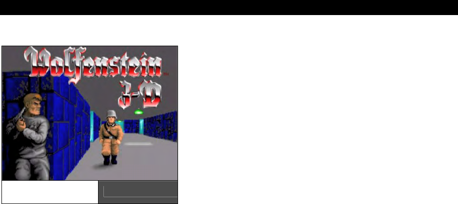
0.1.7 Wolfenstein 3D and the Era of First Person Shooters (1992)
Certainly, there are dozens of games worth
mentioning that were eventful in the industry,
but we don’t have time to really cover them in
the depth that they deserve. Games like Space
Invaders, Asteroids, Computer Space, and more
all made a difference in the early 60’s, 70’s and
80’s, but it wasn’t until the 90’s that games got
scary – enter
id Software
the creators of
Wolfenstein 3D
as shown in Figure 0:9.
Another Cinderella story,
John
Carmack
and
John
Romero
both were Apple II fanatics, both
loners, and both interested in making games and
world domination. John Romero, a little older
than Carmack, had been bouncing around
working at various places on game projects; at some point he met up with John Carmack and
the results were similar to Bill Gates and Paul Allen getting together. John and John literally
changed the world with their games. Soon after their initial meeting they were working at a
company called
Softdisk
Publishing
, and to make a long and interesting story short, they
were making a game a month for Softdisk to place on a floppy with a magazine! This is a
feat to say the least, but during this time they got really good at making games, and did
what most game programmers take years to do in months. Thus they honed their skills to a
white-hot blaze ready to cut the fabric of space-time.
Ready to take on the world and report to no one, they started id Software. Their first game
of note was
“Commander Keen”
(1990), a side scrolling tour de force thought to be
impossible to achieve on the IBM PC, but they were just warming up. Carmack, turning into
the technical guru of the group, had been experimenting with “ray casting” technology, a
simplified version of “ray tracing” used to create photo real imagery in CG movies. However,
ray casting allows 3D rendering to be achieved at blazing speeds due to simplified
geometrical assumptions and a lot of tricks. The results of this ray casting technology was
“Wolfenstein 3D” released in 1992, a 3D remake of the popular Apple II game “Castle
Wolfenstein”, but Wolfenstein 3D was 3D, and immersed the users in a fluid world running at
blistering speeds. Figure 0:9 shows a screen shot.
Wolfenstein 3D was not only a technical marvel and for the billionth time made all the
doubters realize that game developers are sorcerers and capable of magic, but Wolfenstein
was highly controversial – its depiction of Nazis’, blood and gore got the whole world up in a
roar, but it was the first real-time cinematic experience on a personal computer. And like it or
not, the world wanted more...and more they got…
Wolfenstein 3D
by id Software Figure 0:9
Introduction and a Little History
Page 20 Game Programming for the Propeller Powered HYDRA
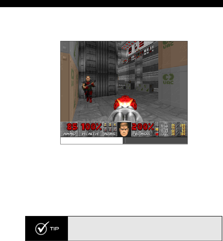
0.1.8 DOOM (late 1993)
DOOM shown in Figure 0:10 speaks for itself; there are few people that do not know what
DOOM is or who haven’t played it.
Enter DOOM Figure 0:10
DOOM by far was the most impressive technical achievement on a PC the world had ever
seen. Released in 1993, DOOM was based on a technology called
“Binary Space Partition”
or
BSP trees, a technique discovered in the 60’s to bisect space into half spaces for easier
computation in a recursive algorithm.
Technical details aside, the results of the algorithm coupled with a game developer’s clever
programming was the most incredible experience ever on a PC: DOOM. Millions of people
were stunned by the technology, and numerous industries including military, medical, and
architectural, were affected. Not to mention the game spawned (no pun intended) the entire
3D accelerator market.
If you are interested in DOOM technology and how BSP trees work and how to
implement them, you will be pleased to know that The Black Art of 3D Game
Programming by yours truly is in electronic form included with the CD of this
book. It came out in 1994/1995, and within it I showed the world how DOOM
worked among other things.

Introduction and a Little History 0
Game Programming for the Propeller Powered HYDRA Page 21
0.2 Origins of the HYDRA
A few other hits have come out since including Quake, Half Life and of course Halo, but none
with the impact of awe of these early games. The technology of game development is now
being disseminated at an exponential rate; books, courses, and entire degrees in game
development technology are now available. Alas, we won’t be changing the world here, but I
can’t think of a more engaging way to have fun with the new Propeller chip than to make
games on it! The Propeller chip has something near and dear to my heart and that’s
multiprocessing
. I simply love multiprocessing; if I could I would multiprocess in my sleep
– I would! Game developers for years, including myself, have had to fake multiprocessing
and/or use pseudo-multiprocessing with Pentium or PowerPC chips via
“multiple execution
units”
which isn’t the same. The Propeller chip is a true multiprocessing processor and
definitely a very interesting chip to develop games on. Therefore, I thought “What better
application than a game console around it, and to make some games on to get people
interested in the processor and of course interested in games!”
When I developed the HYDRA, I wanted to keep the system open, simple, and more or less
just a Propeller chip without adding a lot of ancillary hardware, thus the HYDRA has no extra
computing augmentation and is more or less completely powered for the most part by the
Propeller chip itself. The HYDRA is a good example of what you can do with just a Propeller
chip; if you were to add extra SRAM or other hardware then the Propeller can be used to
create all kinds of embedded applications. Additionally, the HYDRA was developed to simply
experiment with the Propeller chip; the HYDRA has an expansion port, mouse and keyboard
ports, game ports, dual 3.3 V / 5.0 V supplies, VGA and NTSC/PAL out, networking
(RJ-11 based) and much more – I had a lot of fun designing it, and hopefully you have a lot
of fun learning the Propeller chip and game development with it!
0.3 What to Expect
There is so much to cover in game development, a complete treatise on the subject usually
takes about 1000-2000 pages to even scratch the surface. Alas rather than go nuts like I
usually do, I decided to take a more beginners’ approach with this book since unlike my
other game development books where I assume we are all programming on a PC with
DirectX, this is not the case. In this case, we have new hardware, a new chip, a new
language, and you might be learning game development for the first time, not to mention
being only a beginning programmer as well. Thus, I decided rather than engaging the
transwarp drive like I usually do, let’s keep this at impulse speed for most of the time with a
romp here and there to warp speed!
With that in mind, I assume that you are a programmer; this book will not teach you
programming. However, I don’t assume you have done any game or graphics programming,
so that part we will explore together, but you should be familiar with one or more of the

Introduction and a Little History
Page 22 Game Programming for the Propeller Powered HYDRA
following languages: BASIC, C/C++, JAVA, ASM, PASCAL, DELPHI, etc. I will discuss the
language constructs of the Propeller chip’s native language “Spin”, but I will not teach
programming concepts. Additionally, there is a large part of the book on the Propeller chip
itself and a lot of Assembly language material; if you are new to Assembly language, I
suggest you read a good book on 6502, or ARM, or even 8086 and write some programs to
get the hang of the language. Specifics aside, I will always try my best to teach where
possible, so those of you that get bored, simply skip past anything that is old news to you.
Now, let’s take a look at the three main sections that make up the book:
The HYDRA Hardware - This is a fast and furious circuit description of the HYDRA
Game Console’s implementation around the Propeller chip. Not meant to be
complete, it simply gives you a frame of reference as programmers, so you know
what hardware does what along with some technical detail here and there. Each
chapter tends to focus on a specific aspect of the HYDRA, thus some chapters are
short; others are longer.
Propeller Chip Architecture and Programming – This is the nitty-gritty of the
Propeller chip and has examples of programming graphics, sound, joysticks, I/O,
networking, and explains both the ASM and high-level language (Spin) supported by
the Propeller chip as well as the technical description of the Propeller chip itself. This
part of the book is hands-on and you will get to run a number of demos and see
what they do. Also, we will focus on using Parallax general-purpose objects rather
than high performance gaming code, so we can keep a black box approach.
Game Programming on the HYDRA – This is the fun part. Once we have all the
fundamentals down and you know what the HYDRA does and how the Propeller chip
works and is programmed, then we can sit down and start learning about game
development and graphics.
0.4 Target Audience
Typically game development is all about software; however, if you have purchased a HYDRA
then you probably are interested in embedded systems, hardware, and may even be a
full-fledged Electrical Engineer. On the other hand, you might be a programmer that is
interested in getting into embedded systems, and what better way than with games? Trying
to cater to everyone is nearly impossible, so this book is going to be more of a software
guide rather than a hardware guide in as much as we are going to spend 90% of our time
programming, rather than doing circuit analysis. That is, when I show a circuit to you, I am
going to assume that you understand electronics, rather than explain the nitty-gritty. If you
don’t know anything about electronics, the explanation will be more than enough for
programming purposes. So this book is about writing games, graphics, and media
applications on the HYDRA and learning the Propeller chip, it’s not about designing game
consoles or the hardware therein. Considering that, we are still going to cover every single

Introduction and a Little History 0
Game Programming for the Propeller Powered HYDRA Page 23
piece of hardware in the HYDRA in the first part of this book before getting into software.
This way, even software guys will have some idea of what does what, and hardware guys will
have a good reference for each sub-system to know what’s doing what, or can make changes
if they wish.
0.5 Conventions Used in this Book
The book’s text is more or less straightforward: what you see is what you get. Typically, I
will highlight important terms in the text the first time I introduce them, secondly, code
listings will always be set off in a fixed point font and in a slightly smaller font pitch that the
general text so more code can fit per page. Also, from time to time you will see special
sidebars, like Notes, Warnings, etc. Lastly, when discussing key presses and menu item
selection sequences I will always place angled brackets around the key or menu selection
sequence, for example, if I wanted to tell you to press the control key and J at the same
time, you will see “<CTRL + J>”, similarly if I want you to go to the main menu, then select
the sub-menu tools, then from there select configuration, I will write it something like this
<Main Menu
→
Tools
→
Configuration>.
And I may italicize the sequence and or
highlight it to bring your attention to it and separate it from the text. Also, in the text, to set
off code variables, I will simply italicize them. For example, if I wanted to talk about a “for
loop”, I would say something like, “referring to the
FOR
statement on line 10…”, as you can
see the “
FOR
” element is italicized.
0.6 Requirements
The main part of working with the HYDRA or the Propeller chip is using the Propeller Tool
IDE. Currently, it only supports Windows XP, 2000, 2003. There are no Windows 95/98/ME
tools or Linux. In the near future, I suspect there will be, so stayed tuned. But, most
everyone with a PC has a copy of Windows XP/200X on it, so you should be fine. Other than
that you should have at least one USB port free, and a standard multimedia type PC. Since
the only thing you will use the PC for is compiling programs, you don’t need a lot of
horsepower, so a Pentium II or greater (or AMD equivalent) is more than enough.
Additionally, you will need a NTSC/PAL compatible TV to connect to the output of the HYDRA
since it generates standard composite video. Also, if you want to experiment with the
HYDRA’s VGA output abilities you will need a VGA monitor or a simple KVM to switch your PC
with the HYDRA. The HYDRA kit comes with everything else you need, so turn the page and
let’s start experimenting!
Last, but not least, skim entire book BEFORE doing anything! There are a few
items that are embedded in the middle or end that will help you understand
things, so best to read the whole thing first THEN go ahead and start playing
with the hardware and programming.

Introduction and a Little History
Page 24 Game Programming for the Propeller Powered HYDRA

H
ardware Part I The Hydra Hardware Part I T
The Hydra Hardware Part I The Hydra Hardwar
e
Part I The Hydra Hardware Part I The Hydra
H
H
ardware Part I The Hydra Hardware Part I T
The Hydra Hardware Part I The Hydra Hardwar
e
Part I The Hydra Hardware Part I The Hydra
H
H
ardware Part I The Hydra Hardware Part I T
The Hydra Hardware Part I The Hydra Hardwar
e
Part I The Hydra Hardware Part I The Hydra
H
H
ardware Part I The Hydra Hardware Part I T
The Hydra Hardware Part I The Hydra Hardwar
e
Part I The Hydra Hardware Part I The Hydra
H
Part I: The HYDRA Hardware

I The HYDRA Hardware
Page 26 Game Programming for the Propeller Powered HYDRA
Chapter 1: HYDRA System Overview and Quick Start, p. 27
Chapter 2: 5V & 3.3V Power Supplies, p. 77.
Chapter 3: Reset Circuit, p. 81.
Chapter 4: USB-Serial Programming Port, p. 83.
Chapter 5: Debug Indicator Hardware, p. 91.
Chapter 6: Game Controller Hardware, p. 95.
Chapter 7: Composite NTSC / PAL Video Hardware, p. 103.
Chapter 8: VGA Hardware, p. 115.
Chapter 9: Audio Hardware, p. 125.
Chapter 10: Keyboard & Mouse Hardware, p. 141.
Chapter 11: Game Cartridge, EEPROM & Expansion Port Hardware, p. 159.
Chapter 12: HYDRA-NET Network Interface Port, p. 167.
HYDRA System Overview 1
Game Programming for the Propeller Powered HYDRA Page 27
Chapter 1:
HYDRA System
Overview and
Quick Start
In this chapter, we are going to get acquainted with the HYDRA game console and the
Propeller Chip, as well as the Propeller Tool IDE itself. Of course, we are going to have some
fun and try some games, load some programs, and in general get comfortable with the
HYDRA system and everything that comes with it. Here’s a general outline of what we are
going to do:
Take inventory of the HYDRA game console kit
Experiment with the “Quick Start” demos
Learn a little about the HYDRA and Propeller chip
Install the USB drivers for the Propeller Tool
Install the Propeller Tool and learn about the IDE
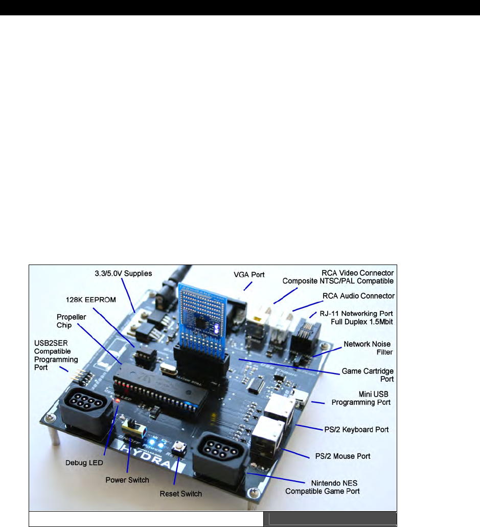
The HYDRA Game Console Figure 1:1

I The HYDRA Hardware
Page 28 Game Programming for the Propeller Powered HYDRA
The HYDRA Game Console (HGC) is developed around the Parallax Propeller chip.
Figure 1:1 shows an image of the HYDRA with all the various functional units labeled. The
HYDRA has the following hardware:
40-Pin DIP Package of the Propeller chip, as DIP makes future upgrades and change
outs easy; runs 80 MHz.
RCA Video and Audio Out Ports.
HD15 Standard VGA Out Port.
PS/2 Mouse and Keyboard Support.
Two Nintendo NES/Famicom compatible gamepad ports.
RJ-11 (phone jack), Peer to Peer networking port, supports full-duplex serial at up to
2.56 Mb at 100 meters with simple coding.
Single 9 VDC power in with regulated output of 5.0 V @ 500 mA and 3.3 V @
500 mA on board to support external peripherals and components (Note: the
Propeller chip is a 3.3 V device).
Removable passive XTAL to support faster speeds and experimenting with various
reference clocks.
Debugging LED output.
On-Board 128 KB Serial EEPROM used to hold program memory when power shuts
down. The Propeller chip uses 32 KB currently only.
Cartridge/Game/Expansion Port that exposes I/O, power, networking, USB, etc.
Onboard Mini-B USB interface/programming port based on the FTDI USB chip.
Backup external 4-Pin programming port compatible with Parallax “USB2SER”
hardware/tools.
The HYDRA is more or less a minimal part count gaming platform to show off the capabilities
of the Propeller chip. The hardware around the Propeller chip enhances functionality and
interfacing, but doesn’t add computational elements, thus all work performed by the HYDRA
is solely the responsibility of the Propeller chip.
HYDRA System Overview 1
Game Programming for the Propeller Powered HYDRA Page 29
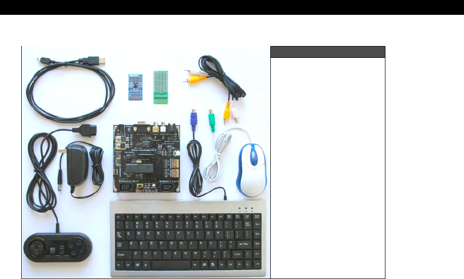
1.1 HYDRA Kit Package Contents
Figure 1:2
The HYDRA Game
Console Kit Contents
You should have the following items in your HYDRA kit, referring to Figure 1:2 (which shows
most of the kit). So, take inventory and make sure you have everything you should have with
the kit, and once you have confirmed everything and are ready to have some fun, read on.
(1) HYDRA Game Console
(1) PS/2 Mouse
(1) PS/2 Keyboard
(1) 128 KB Game Cartridge Pre-Loaded with “Ball Buster” demo game
(1) Blank experiment card to build your own HYDRA projects on
(1) Mini-USB programming cable to connect from your PC to the HYDRA
(1) 9 V 500 mA, DC unregulated wall adapter with 2.1 mm plug and tip (+) positive, ring (-)
negative
(1) RCA A/V cable
(1) Nintendo-compatible controller
(1) CD ROM with all the software, demos, tools, and IDE

I The HYDRA Hardware
Page 30 Game Programming for the Propeller Powered HYDRA
1.2 HYDRA “Quick Start”
Demos
Your HYDRA is pre-loaded with a simple
“Asteroids”
clone demo programmed into
the on-board serial EEPROM at U4 (top left of
the Propeller chip), a screen shot is shown in
Figure 1:3. We will use this to test your
system out.
The following are a series of steps to try the
demo out and make sure your hardware is
working and a stray high energy neutron
didn’t damage your EEPROM!
Step 1: Place your HYDRA on a flat surface,
no carpet! Static electricity!
Step 2: Make sure the power switch at the front is in the OFF position, this is to the
RIGHT.
Step 3: Plug your wall adapter in and plug the 2.1 mm power connector into the female
port located at the top-left corner of the HYDRA.
Step 4: Make sure the XTAL marked 10 MHz is inserted into the XTAL port, top-center
above the Propeller chip at J13. It’s possible that during transport the XTAL came loose and
isn’t inserted all the way and/or is loose in the packaging, so make sure the XTAL is inserted.
Step 5: If you have plugged the cartridge into the system, then UNPLUG it – we want to
run the code off the serial 128K EEPROM memory which is on-board (located top-left above
the Propeller chip).
Step 6: Insert the A/V cable into the yellow (video) and white (audio) port of the HYDRA
located top-right of the board, insert them into your NTSC/Multi-System TV’s A/V port, and
then switch your TV set to “Video Input” mode.
Step 7: Plug the mouse into the PS/2 mouse port (it’s labeled “Mouse”), make sure to hold
the port socket as you insert and be careful not to “force” the male into the female, ease it in
and take your time. If it won’t go in, try pulling it out and then putting it back in a couple
times to loosen up the connection. You don’t want to break the port off the PCB, as these
boards can be cracked and some of the parts are a little tight in some cases.
Step 8: Turn the power ON by sliding the ON/OFF switch to the RIGHT.
Step 9: You will see the logo/splash screen. Use the left mouse button to start the game
and fire, right mouse button to thrust, left/right to rotate!
The Parallaxaroids
Demo Running Figure 1:3
HYDRA System Overview 1
Game Programming for the Propeller Powered HYDRA Page 31
You should see something like that shown in Figure 1:3. The actual program that is loaded
into the Propeller chip is located on your CD here:
CD_ROOT:\HYDRA\SOURCES\ASTEROIDS_DEMO_013.SPIN
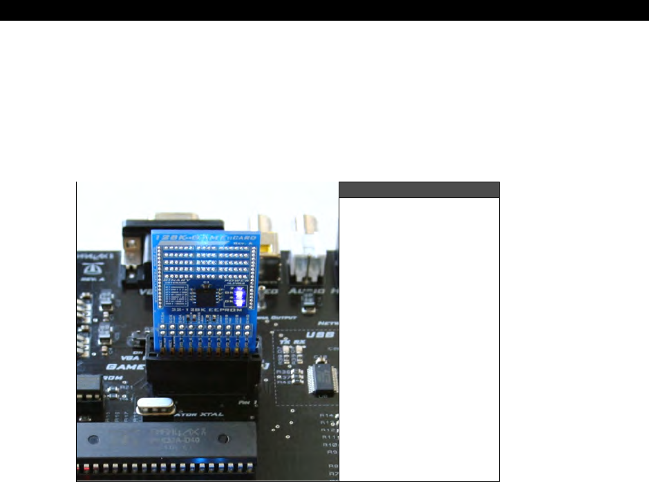
Next, let’s have some fun, let’s “hot-plug” another game in! Simply take your game cartridge
and while the HYRDA is ON and running
Parallaxaroids
, plug the game cart into the system
with its orientation such that the text and serial EEPROM chip are
facing you
. This is shown
in Figure 1:4.
Figure 1:4
Inserting the game
cartridge the right
way.
If all goes well, nothing will happen, but you will see the LED to the right of the cartridge
port turn ON, and the power LEDs on the cartridge itself will illuminate; this indicates a
cartridge is in the system.
Now, press the RESET button located next to the power switch and the HYDRA will re-boot
from the CARTRIDGE rather than the on-board serial EEPROM (the cartridge always has
priority). The cartridge basically overrides the onboard serial EEPROM and electrically
disconnects it, so that the system feeds from the cartridge if it’s inserted. Additionally, if you
were to download a program to the HYDRA with the cartridge in, the cartridge would be
programmed with the new program not the base board EEPROM. In any event, with the new
cartridge in you should see a “Breakout/Arkanoid” like game running on screen named “Ball
Buster” Now, plug in your mouse and/or gamepad (left port) and both input devices will
move the paddle. The controls are listed in Table 1:1 on the next page.
I The HYDRA Hardware
Page 32 Game Programming for the Propeller Powered HYDRA
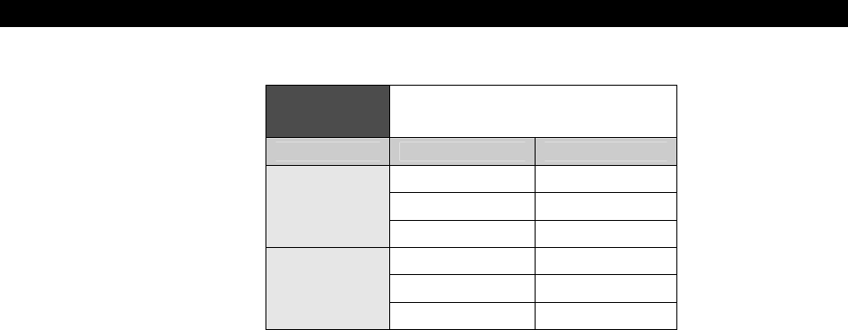
Table 1:1 Ball Buster Demo Controls
for Each Input Device
Device Action Control
Launch Ball Left Button
Move Left Motion Left
Mouse
Move Right Motion Right
Launch Ball A/B
Rotate Left Dpad Left
Gamepad
Rotate Right Dpad Right
Feel free to hot pull the cartridge out as well, just hit the Reset button again and the HYDRA
will boot the Parallaxaroids game once again – cool huh! This concludes our little demo of a
couple games, powering the unit, resetting the unit, and inserting a cartridge.
The actual top level file for the “Ball Buster” demo is located on the CD here:
CD_ROOT:\HYDRA\SOURCES\JTC_B_Buster_005.spin
HYDRA System Overview 1
Game Programming for the Propeller Powered HYDRA Page 33
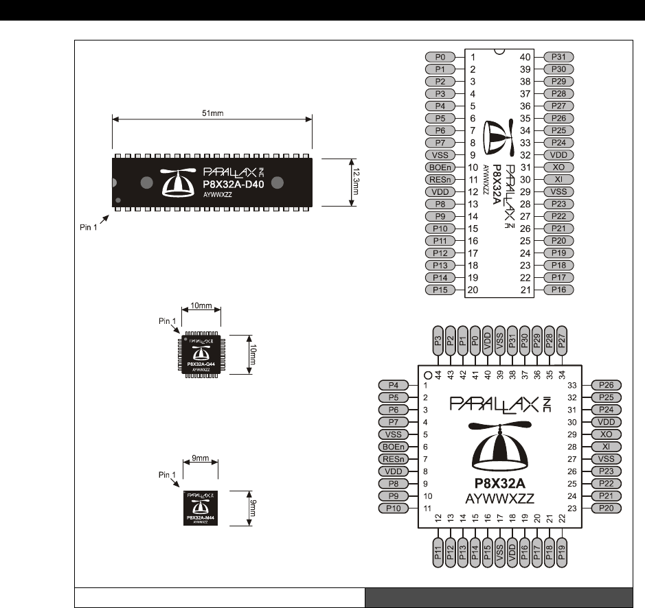
1.3 The Propeller Chip
The Propeller chip comes in 40 pin DIP (dual inline package) or a 44 pin LQFP (low quad
flat pack) as well as a 44-pin QFN (quad flat no lead) type package. Figure 1:6 shows the
packaging and pinout of the chip. The Propeller chip was designed by
Chip Gracey
of
Parallax Inc. as a low cost, high performance microcontroller with multiprocessing
capabilities.
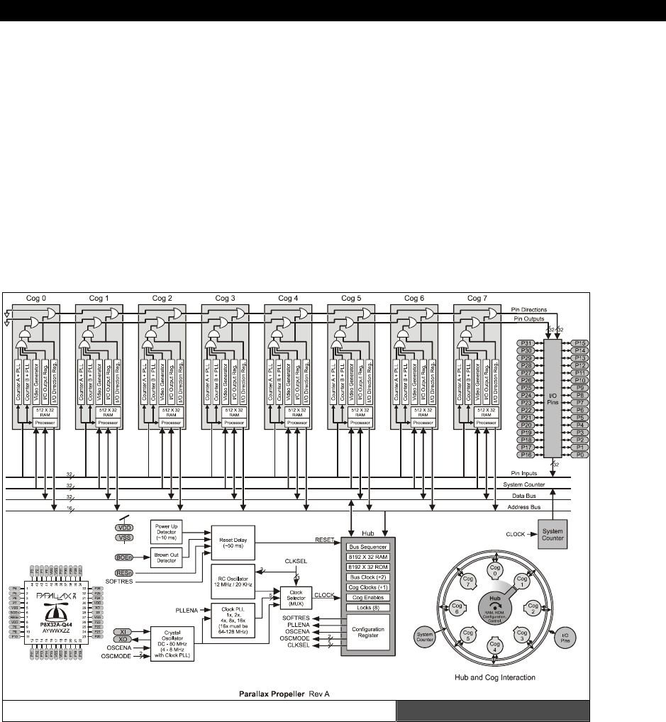
The Propeller chip has 8 cores and is, simply put, a symmetrical multiprocessing
microcontroller supporting a
“round robin”
non-pre-emptive shared memory access
scheme; however, all cores, called
“cogs”
run simultaneously and independently when not
accessing main memory.
Figure 1:5 shows the Propeller chip architecture in block diagram form, and Table 1:2 lists
the pins and their function for the Propeller chip.
Propeller Chip Block Diagram Figure 1:5
Image from Propeller Manual v1.0 courtesy of Parallax Inc.
I The HYDRA Hardware
Page 34 Game Programming for the Propeller Powered HYDRA
P8X32A-D40 40-pin DIP
P8X32A-Q44 44-pin LQFP
P8X32A-M44 44-pin QFN
Propeller Chip Package Types Figure 1:6
Image from Propeller Manual v1.0 courtesy of Parallax Inc.
HYDRA System Overview 1
Game Programming for the Propeller Powered HYDRA Page 35
Table 1:2 Propeller Chip Pin Names and Functions
Pin Name Direction Description
P0 – P27 I/O General purpose I/O. Can source/sink 30 mA each at 3.3 vdc. Do not
exceed 100 mA source/sink total across any group of I/O pins at once.
P28 I/O
I2C SCL connection to external EEPROM (General purpose I/O after
boot up).
P29 I/O
I2C SDA connection to external EEPROM (General purpose I/O after
boot up).
P30 O, I/O Tx to host (General Purpose I/O after boot up/download).
P31 I, I/O
Rx from host (General Purpose I/O after boot up/download sequence,
if not connected to host).
VDD --- 3.3 v power (2.7 – 3.3 vdc).
VSS --- Ground (0 vdc).
BOEn I
Brown Out Enable (active low). Must be connected to either VDD or
VSS. If low, RESn becomes a weak output (delivering VDD through 5
K) for monitoring purposes but can still be driven low to cause reset.
If high, RESn is CMOS input with Schmitt Trigger.
RESn I/O Reset (active low). When low, resets the Propeller chip: all cogs
disabled and I/O pins floating. Propeller restarts 50 ms after RESn
transitions from low to high.
XI I
Crystal Input. Can be connected to output of crystal/oscillator pack
(with XO left disconnected), or to one leg of crystal (with XO
connected to other leg of crystal or resonator) depending on CLK
Register settings. No external resistors or capacitors are required.
XO O
Crystal Output. Provides feedback for an external crystal, or may be
left disconnected depending on CLK Register settings. No external
resistors or capacitors are required.
I The HYDRA Hardware
Page 36 Game Programming for the Propeller Powered HYDRA
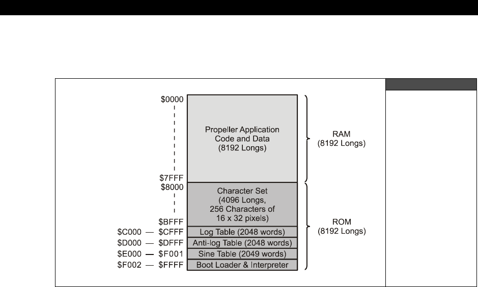
The Propeller chip is a 32-bit RISC-like architecture (without pipelining) chip with a
fixed
instruction size of
32 bits
. The on chip memory is
64 Kbytes
and is organized as two
32 Kbyte
(8192 LONGs) banks as shown in Figure 1:7.
Figure 1:7
Structure of
the Propeller
Chip’s Memory
Image from Propeller Manual v1.0 courtesy of Parallax Inc.
The first 32K from [0x0000 - 0x7FFF] is RAM, the second 32K from [0x8000 - 0xFFFF]
is ROM. These memories are physically different, but logically addressed with a simple 0-64K
address. The ROM contains the interpreter, data tables (sine, log, character data etc.) and
other run-time objects needed for the Propeller chip’s operation. The RAM is used for
program memory, data, and video memory and is shared among all cogs. The Propeller chip
doesn’t differentiate between RAM and ROM, it is simply an address space from [0x0000 -
0xFFFF]. Additionally, there is no dedicated external memory interface integrated into the
Propeller chip’s architecture, therefore, memory is at a premium when programming, so care
must be taken to conserve memory (especially when doing graphics since you must use a
portion of the internal 32K for video buffers). The Propeller chip is programmed using either
Assembly Language (which you will find reminiscent of a fusion of ARM/SX/PIC/6502
assembly code) or a high-level language called
“Spin.”
A snippet of ASM is shown next:

HYDRA System Overview 1
Game Programming for the Propeller Powered HYDRA Page 37
' Plot pixel at px,py
'
plotd mov px,dx 'set px,py to dx,dy
mov py,dy
plotp tjnz pwidth,#wplot 'if width > 0, do wide plot
mov t1,px 'compute pixel mask
shl t1,#1
mov mask0,#%11
shl mask0,t1
shr t1,#5
cmp t1,xlongs wc 'if x or y out of bounds, exit
if_c cmp py,ylongs wc
if_nc jmp #plotp_ret
mov bits0,pcolor 'compute pixel bits
and bits0,mask0
shl t1,#1 'get address of pixel long
add t1,basesptr
mov t2,py
rdword t1,t1
shl t2,#2
add t1,t2
rdlong t2,t1 'write pixel
andn t2,mask0
or t2,bits0
wrlong t2,t1
plotp_ret
plotd_ret ret
The above ASM snippet is an excerpt from the graphics driver and is the plot pixel function.
Additionally, the High-Level Interpreted Language (HLL) used to program the Propeller is
called
Spin
(which is reminiscent of Pascal\BASIC), a snippet is shown below:
' move asteroids
gr.colorwidth(1,0)
repeat i from 0 to NUM_ASTEROIDS-1
base := i*ASTEROIDS_DS_LONG_SIZE
x := asteroids[base+ASTEROID_DS_X_INDEX] += asteroids[base+ASTEROID_DS_DX_INDEX]
y := asteroids[base+ASTEROID_DS_Y_INDEX] += asteroids[base+ASTEROID_DS_DY_INDEX]
' test for screen boundaries
if (x > SCREEN_WIDTH/2 )
I The HYDRA Hardware
Page 38 Game Programming for the Propeller Powered HYDRA
asteroids[i*ASTEROIDS_DS_LONG_SIZE + ASTEROID_DS_X_INDEX] := - SCREEN_WIDTH/2
elseif (x < -SCREEN_WIDTH/2 )
asteroids[i*ASTEROIDS_DS_LONG_SIZE + ASTEROID_DS_X_INDEX] := SCREEN_WIDTH/2
if (y > SCREEN_HEIGHT/2 )
asteroids[i*ASTEROIDS_DS_LONG_SIZE + ASTEROID_DS_Y_INDEX] := - SCREEN_HEIGHT/2
elseif (y < -SCREEN_HEIGHT/2 )
asteroids[i*ASTEROIDS_DS_LONG_SIZE + ASTEROID_DS_Y_INDEX] := SCREEN_HEIGHT/2
This snippet is from the “Parallaxaroids” demo game and shows a loop construct along with
some assignments, array access, and conditional code, notice there is
no
begin/end
construct, thus the loop block/nesting level is defined by indention, this is definitely an area
that can cause problems (so the Propeller Tool IDE has special align and display modes to
help you with this), but keep it in mind that a single space can change the nesting level!
When we discuss the Spin language we will cover this quirk in more detail.
The Propeller chip’s native Assembly Language is the best way to get performance and save
memory; however, if you are not concerned with speed or need ultra high performance then
the Spin HLL is the way to go. Now, a caveat – Spin HLL code must reside in main memory,
while memory containing assembly code may be used for other purposes after the cog
running that code has been launched. This extra memory consumption may become
important when video buffers are used as well.
So for very large programs where speed is critical Assembly is a better choice, or you could
write a FORTH or other HLL interpreter and run it then feed it from the EEPROM using a
caching scheme. Of course, these limitations are consistent with most microcontrollers.
There is currently no debugger built into the IDE. However, it’s possible to
access the USB TX/RX lines after boot etc. and a packet protocol to send back
debug information like “printf’s” etc. could be developed on the PC side to send
information. Additionally, a simple RS232 interface can be made that hooks to
the PC as well with the same idea in mind. Therefore, the trick is to use Spin/ASM
with a graphics driver and then send it debug information from your application
through a shared memory and let it print on the screen or simply to print debug
information on the screen for your graphic applications. So “old school”
debugging is what has to be used here. For example, when we start developing
applications and games, I will show you how to connect a VT100 terminal
program and then send debugger information to it in real-time from the HYDRA.
1.3.1 System Startup and Reset Details
Although it’s early in our discussion to get too technical, you might want to know what
exactly happens with the HYDRA/Propeller chip is booted. On startup/reset the Propeller chip
looks at the TX (P31) / RX (P30) lines connected from the PC host, these serial lines are
interfaced via the USB connection and from the Propeller chip’s point of view are standard

HYDRA System Overview 1
Game Programming for the Propeller Powered HYDRA Page 39
serial connections and from the PCs point of view are a standard serial port COMx
(implemented as a VCP or “Virtual COM Port” in Windows-speak).
In any event, if there is activity on these lines, the Propeller chip will try to negotiate a link
with the PC host using a very complex serial communication scheme that guarantees the PC
is trying to talk and there isn’t noise on the lines (a pattern-matching protocol is used). If the
PC host is present then the Propeller chip will load the 32 Kbyte program image from the
host and either copy it directly into RAM or the Propeller chip’s firmware will copy the
program into the EEPROM connected on lines P28 (Serial Clock SCK) and P29 (Serial Data
SDA) respectively and then reset the chip which then pulls the program from the EEPROM
and execute. Its important to realize that the
“binary image”
created on the PC by the
Propeller compiler is 32 Kbytes and it is exactly copied into the RAM of the Propeller chip 1:1,
this is a nice feature since you know that everything is always contained in this exact 32
Kbyte image no matter what the size is of the actual program/data (as long as its less than
or equal to 32K), that is, if you have a small or large program the IDE will always create a 32
Kbyte image for the Propeller chip.
Once the program is download the Propeller chip launches Cog 0, runs the internal
interpreter on it, and starts executing code at the very first PUB, that is, “public” Spin
statement, more on this later.
1.4 Installing the Software
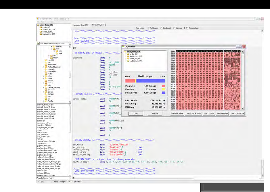
The Propeller Tool IDE used to develop all programs for the Propeller chip is shown in Figure
1:8 on the next page, it’s a Delphi based application that you will use to develop applications
for the Propeller chip/HYDRA. The Propeller tool only supports Windows XP, 2000, and 2003.
It should work on Windows XP/64-bit versions as well. If you are a Windows 95/98 or NT
user you will have to install one of these new variants of Windows over your old OS or as a
dual boot setup if you want to use the Propeller IDE.
The Propeller Tool is the primary programming tool for the Propeller chip/HYDRA and allows
editing and viewing of the various files and statistics as builds are performed. Propeller chip
programs can be composed of both ASM and Spin code both with the extension “.spin” and
are compiled and assembled into their final form by the tool as a “binary” image that is
composed of a single 32 Kbyte image. However, you can code completely in Spin if you
wish, ASM is not necessary. But, you will find that 90% of all the drivers we have written for
the HYDRA/Propeller chip use ASM. Moving on, the tool has a number of standard Windows
IDE features, so the best thing to do is play with it as well as read the online Help.
I The HYDRA Hardware
Page 40 Game Programming for the Propeller Powered HYDRA
The Propeller Tool IDE for the Propeller Chip Figure 1:8
Also of note, there is a syntax highlighting technology that you may like or dislike, but it can
be disabled and customized via the menu options. The idea of the syntax highlighting is to
change the color of both the foreground and the background of your code to signify various
code blocks.
As noted, with this tool you can write programs in both Spin and ASM; however, when doing
so extra care must be taken when creating blocks or nesting levels since the HLL uses white
space to define “blocks”.
You can program the Propeller chip in a mixture of both HLL and Assembly, but
only
ASM or
HLL can run on a core at a time. However, the interesting thing is that all your code for you
final application is coalesced into a SINGLE 32 Kbyte binary image object that is loaded
directly into the Propeller chip’s RAM or onto an EEPROM for permanent storage when power
goes down. In the next section, we will install the software tool itself and cover the use of

HYDRA System Overview 1
Game Programming for the Propeller Powered HYDRA Page 41
the Propeller IDE is some detail, so you know your way around the menus and functionality
of the tool.
1.4.1 Installing the Propeller Tool and all the Software
Before we can do anything with the HYDRA we have to install all the sources for the HYDRA
along with the Propeller Tool software. First, you need to have all the sources on your
system, so step one is to simply copy the entire source tree from the CD to your PC. Insert
the
“HYDRA Software and Tools”
CD that came with your HYDRA into your CD ROM
drive, there is no Autoplay, so use Explorer or My Computer to access your CD ROM and
open up the CD drive. Inside you will find the following directory structure (more or less):
CD_ROOT:\
└HYDRA\
└SOURCES\
└DESIGNS\
└DRIVERS\
└DEMOS\
└TOOLS\
└MEDIA\
└DOCS\
└EBOOKS\
└GOODIES\
└README.TXT
The contents of each of the directories is are follows:
HYDRA\ This is the main root directory of the entire CD, everything is within this
directory, thus to copy the entire CD, simply right click on this directory,
“copy” and then you can paste it anywhere you like on your hard drive, I
suggest placing it at the root of C:\ so the paths are short to the files within.
DESIGNS\ This directory contains electronic design schematics.
SOURCES\ This directory is the source directory that contains the entire source for the
book.
DRIVERS\ This directory contains any 3rd party drivers for the HYDRA and/or Propeller
chip.
DEMOS\ This directory contains copies all the HYDRA demos as well as any other
demos from the book. Some of this data is copied from the SOURCES\
directory, but is copied here to find more directly if you want to play with
demos.
I The HYDRA Hardware
Page 42 Game Programming for the Propeller Powered HYDRA
MEDIA\ This directory contains stock media and assets you can use for your game
and graphics development. All the media is royalty free and can be used for
anything you wish, even in commercial applications. However, you can not
license, sell, or otherwise transfer the files in the MEDIA\ directory as a
product.
DOCS\ This directory contains documents, tutorials, articles all relating the HYDRA,
Propeller chip, and game development.
EBOOKS\ In this directory you will find complete eBooks. Included specifically with the
HYDRA is
“The Black Art of 3D Game Programming”
which can be used
as a companion guide to this book for more advanced DOS game
programming techniques and PC development that are similar to working
with the HYDRA – a $60 value!
GOODIES\ This directory contains all kinds of cool little extras, so check it out and see
what made it on the CD!
README.TXT This is the README.TXT file for the CD, please read it carefully it has many
last minute changes, errata, and anything else you need to know.
Copying the Files to your Hard Drive
The best way to “install” all the HYDRA book materials is to simply drag and drop the entire
CD to your hard drive. There are a number of ways to do this: you can right click the HYDRA\
directory on the CD and select “Copy” then paste it into your hard drive at the desired
location, or you can “drag” the HYDRA\ directory to the desired location on your hard drive
and select “Copy Here.” However you do it, I suggest that you copy the files somewhere
“close” to the root of your hard drive, C:\, D:\, etc. so that if you do have to type in
command line instructions or file names they will be short. I suggest dragging HYDRA\ right
onto the root of your main drive, “C:\” for example, then you can work within the HYDRA\
directory directly.
Whenever copying files from a CD ROM directly to your PC’s hard drive, you may
have to reset the “Archive” or “Read-Only” flag(s) on the copied files, that is, if
you right click on a file or directory on a CD ROM and select “Properties” you
will see that the “Read-Only” flag is selected in the “Attributes” area of the
dialog. You can’t do anything about this on the CD, but when you copy the CD to
the hard drive you must reset this flag otherwise Windows won’t allow you to
“write” on top of a file or edit it.
To reset the read-only flag of your sources, simply select the HYDRA\ directory
after you have copied it to the hard drive, right click, select properties, then
uncheck the “Read-Only” flag, then click “Apply” and “OK”. Now, all the files
should have their read-only flags reset and you are ready to go.
HYDRA System Overview 1
Game Programming for the Propeller Powered HYDRA Page 43
1.4.2 Installing the FTDI USB Drivers
The first thing you need to do is make sure you have the latest copy of the FTDI drivers
available on your PC. You can find the latest drivers for your particular Windows OS at:
http://www.ftdichip.com/Drivers/VCP.htm
The USB chip used on the HYDRA is the FT232RL model, so download the VCP (virtual COM
port) drivers for this particular chip and save them to a location on your hard drive. To keep
things organized, you might want to download the driver files into the
CD_ROOT:\HYDRA\DRIVERS\ directory on your hard drive and decompress them into
directories within to keep things organized.
Additionally, you will find that I have already provided you with the latest drivers at the time
this book was printed. They are located in the directory:
CD_ROOT:\HYDRA\DRIVERS\FTDI\
Note that in general throughout the book, I will refer to file paths with the
CD_ROOT:\HYDRA\... notation, this simply means the HYDRA\ directory on your
CD-ROM or hard drive, wherever it is, that’s the one I want!
Within the FTDI\ sub-directory you will find two more directories:
WINDOWS\
WINDOWS64\
The WINDOWS\ directory has the FTDI drivers for Windows XP, 2000, and 2003 while the
WINDOWS64\ directory has the drivers for the Windows XP 64-bit Edition (if you’re lucky
enough to have a computer this powerful). In any event, please read the release info.doc file
as well as any readme files within these directories, it will save you headaches if something
goes awry.
Now, here’s the tricky part. Depending on your PC, your OS, and your luck, you may or may
not have to do anything to install the drivers. In the best case, Windows will install the
hardware for you and you won’t have to do a thing, in the worst case you may have to install
the drivers, two times over in some cases. So, let’s hope for the best. The basic plan is that
we will power up the HYDRA, then insert the USB cable from the PC into the mini-B port on
the HYDRA (right side, top, above the PS/2 ports), when we do this Windows will detect the
hardware and “hopefully” have drivers for it already, if not, Windows will ask to install the
drivers and the usual dialogs will come up. Here are the steps to install the drivers, of course,
your particular PC/Windows setup might display varying dialogs, but this should give you a
good idea of what to expect.
I The HYDRA Hardware
Page 44 Game Programming for the Propeller Powered HYDRA
FTDI Driver Installation Steps
Step 1: I suggest shutting down all programs, performing a restart on your PC to make sure
that any pending software updates are complete and any lost resources or crashed programs
are reset, this way we have a fresh PC to work with.
Step 2: Power up the HYDRA and insert the black USB cable that came with the HYDRA kit
into a free USB port on your PC, then insert the other end of the USB cable into the mini-B
port on the HYDRA. The PC should detect the USB connection. If it doesn’t make sure the
HYDRA is powered, if you still have problems chances are you have a bad or unconnected
USB port on your PC, move the cable to another USB port on the PC.
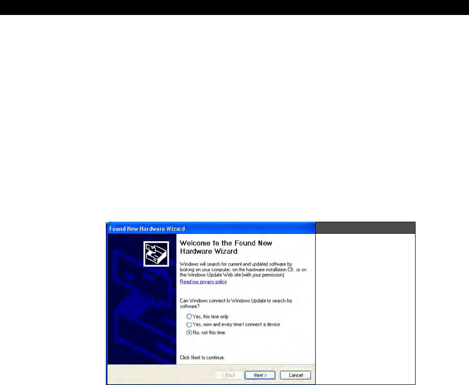
Step 3: In the system tray to the bottom right of the Window’s desktop, you should see a
“new hardware found” alert and Windows will either install the drivers automatically, or it will
launch the Hardware Installation Wizards beginning with the “Found New Hardware Wizard”
as shown in Figure 1:9, select the “No, not at this time” search option and click <Next>.
Figure 1:9
The Found New
Hardware Wizard
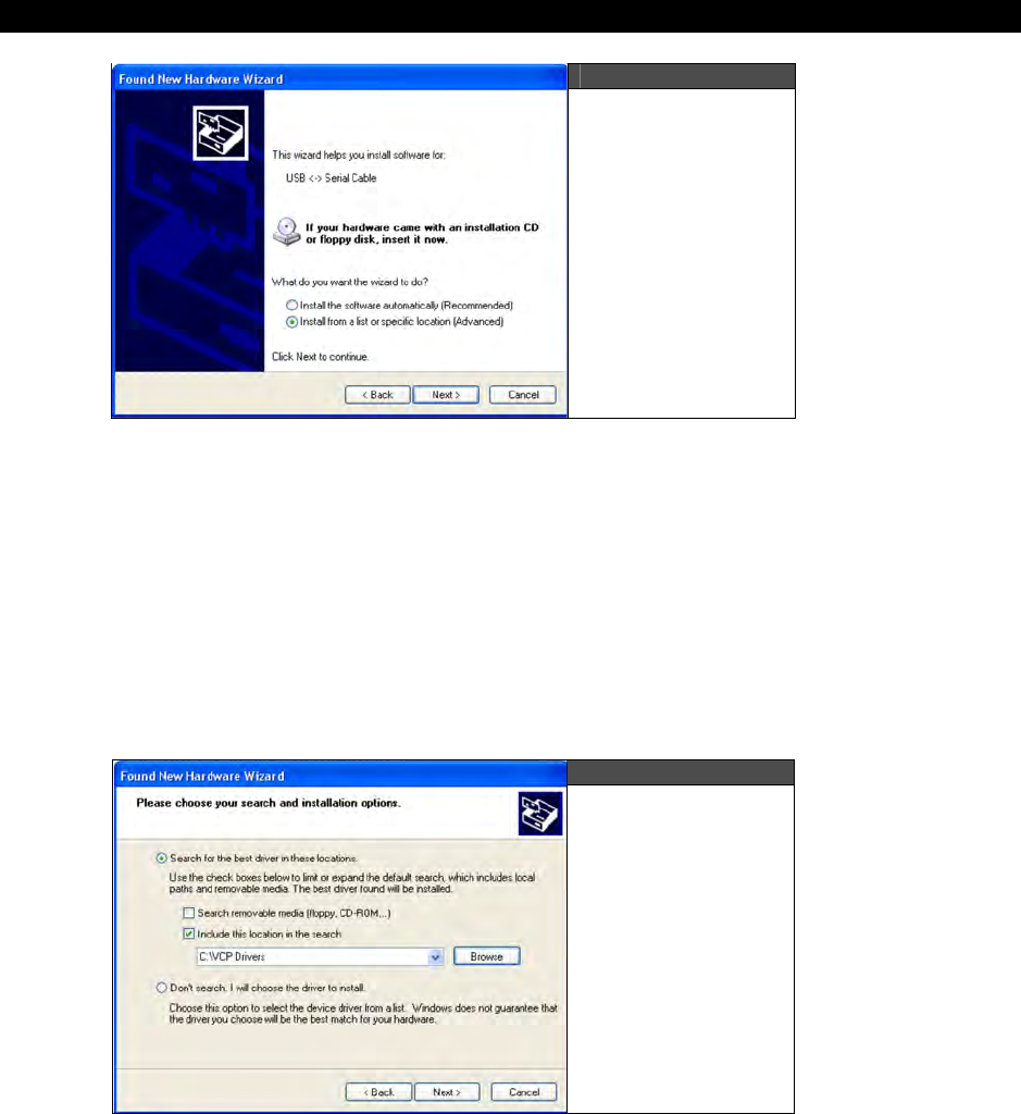
Step 4: The next wizard asks you if you want to install the software automatically or from a
specific location. This is shown in Figure 1:10. Select the option “Install from a list of specific
location (Advanced)” option and click <Next>.
HYDRA System Overview 1
Game Programming for the Propeller Powered HYDRA Page 45
Figure 1:10
The Software
Installation Origin
Step 5: The next dialog that comes up is the search path selection dialog as shown in Figure
1:11, select the top option “Search for the best driver in these locations.”, and only check the
“Include this location in the search” checkbox, then navigate with the <Browse> button to
find the location of the FTDI drivers as installed on your drive. They should be in this
directory:
CD_ROOT:\HYDRA\DRIVERS\FTDI\WINDOWSxx
...where “xx” denotes either the WINDOWS\ or WINDOWS64\ directory. Simply, select one of
these directories (or the directory of the freshly downloaded drivers if you downloaded them
from FTDI’s site) and hit <Next>.
Figure 1:11
Search Path
Option Dialog
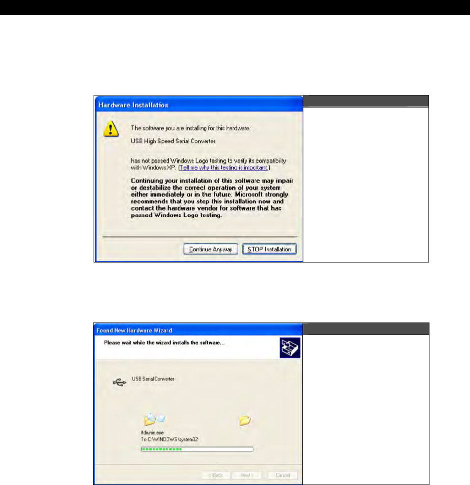
I The HYDRA Hardware
Page 46 Game Programming for the Propeller Powered HYDRA
Step 6: The FTDI drivers may or may not have been Windows Logo certified yet, thus, if you
see the alert box shown in Figure 1:12, simply click “Continue Anyway”. The FTDI drivers
are under constant updates, so typically they are updated so frequently that they are never
stable enough to Windows Logo test.
Figure 1:12
The Windows Alert
for Non-Certified
Drivers
Step 7: If everything went right then you should see the file installation process start as
shown in Figure 1:13, nothing to do here, but cross your fingers and follow the white rabbit.
Figure 1:13
The FTDI Drivers
Installing
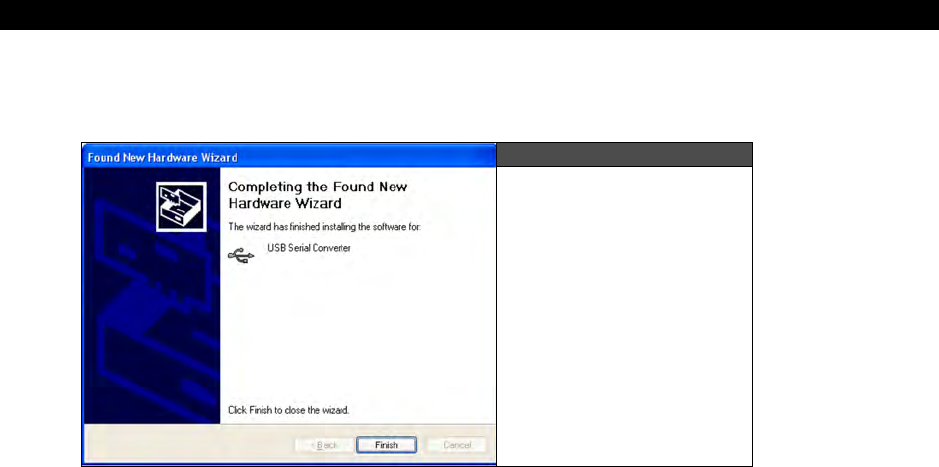
HYDRA System Overview 1
Game Programming for the Propeller Powered HYDRA Page 47
Step 8: If everything installed properly, you will see the hardware installation completed
dialog as shown in Figure 1:14, simple click <Finish> and you are done (hopefully).
Figure 1:14
The successful
installation of the FTDI
USB drivers
Step 9: Give the PC a moment, you
may
see it discover yet more USB hardware, if you do
then simply follow steps 1-8 again, and that should do it. When complete, give you your PC a
restart to make sure everything took and then you are ready to go!
1.4.3 Installing the Propeller Tool IDE
The Propeller Tool installer/Setup program is named PROPELLER_SETUP.EXE and is located
on the CD-ROM within the directory:
CD_ROOT:\HYDRA\TOOLS\PROPELLER\PROPELLER_SETUP.EXE
Either navigate to the CD-ROM or your local copy on your hard drive and launch the installer.
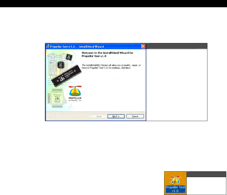
I The HYDRA Hardware
Page 48 Game Programming for the Propeller Powered HYDRA
When you launch the installer, you should see and installation splash logo and welcome
screen something like that shown in Figure 1:15. Simply click <Next> and continue. During
the installation, you will be prompted where to install the Propeller Tool, I suggest you install
it near the root of your drive preferably where you copied all the source files from the book.
Figure 1:15
Installing the
Propeller Tool IDE
Of course, you can always install it in the \Program Files directory, but many times your main
C:\ drive gets so full of application files that performance slows down quite a bit, so I prefer
to install applications on a drive other than my OS drive to optimize performance.
When the installer is complete you will be shown a standard finished alert, simply click
<OK>, <Done> and exit.
1.4.4 Testing the Propeller Tool IDE
Before we get into any discussions of the tool itself, let’s
confirm that everything is working. On the Windows
desktop, you should see an icon to launch the Propeller
Tool, as shown in Figure 1:16.
Double-click the icon and the Propeller Tool should launch. If you do not see and icon, then
click <Start Menu All Programs Parallax Inc Propeller Tool v1.0> to launch the
program. When the program launches, if it gives any warnings or alerts just click <OK> or
<Next> and ignore them. You should then see the main IDE interface shown in Figure 1:8
without any files open of course.
Figure 1:16
The Propeller
Tool Icon
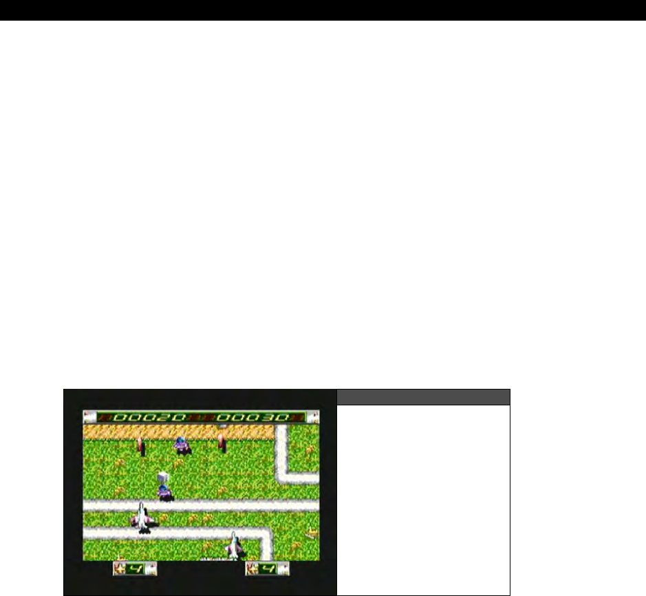
HYDRA System Overview 1
Game Programming for the Propeller Powered HYDRA Page 49
Loading a Program in the HYDRA
Now, for the fun part, let’s try and load something into the HYDRA. Make sure the HYRDA is
powered up and the USB cable is plugged into the HYDRA itself from your PC. Plug your
game controller into the left port. And of course have your HYDRA’s A/V cables plugged into
your TV set and the input on your TV set to “Video Input.” Also, you might want to take out
the game cartridge if you have it plugged in, doesn’t matter, but let’s all stay on the same
page.
Now, we are going to load a game into the HYDRA. Here’s the steps:
Step 1: From the main menu go to <File Open> and browse your hard drive or CD-ROM
for the HYDRA sources, they are located in CD_ROOT:\HYDRA\SOURCES\*.*.
Step 2: Locate the file REM_ALIENINVADER_013.SPIN and open it. The program should
load into the editor and you will see the source. The game is composed of a number of
objects.
Step 3: Press <F10> on the keyboard, this will compile all the files (you will see it happen),
then the Propeller Tool will search through all the COM ports and see if it can find the
HYDRA/Propeller chip connected to it, once it does it will start a RAM only download, that is
the program will be programmed into the Propeller chip RAM, but not the EEPROM.
Figure 1:17
Alien Invaders
running on the HYDRA
Step 4: If everything went well, the HYDRA will reboot, then you will see the game start
running and something like that shown in Figure 1.12 will display on your TV set.
Try the game out for a moment, then hit the RESET button on the HYDRA, notice that
Parallaxaroids reloads? This is because it’s still on the onboard EEPROM. If you wanted to
overwrite the EEPROM then you could have pressed <F11>.

I The HYDRA Hardware
Page 50 Game Programming for the Propeller Powered HYDRA
Now that you have successfully installed the IDE and loaded a program and ran it, it’s time to
learn a little bit more about the Propeller Tool itself.
If you had trouble then look below for some trouble shooting tips based on messages from
the IDE and what you see on the screen:
Trouble Shooting Tips
IDE Message - “Propeller Chip Not Found” – This means either you have the power off
on the HYDRA, the USB cable is not plugged in, or you didn’t install the USB driver.
No Video – If the program downloaded fine, then make sure you have the video output and
audio output from the HYDRA plugged into the correct ports on the TV’s video input, also,
make sure you have the TV set for external video input mode.
No Audio – Good! There is none, this demo is so big, we couldn’t fit sound in!
1.5 Propeller Tool IDE Primer
In this section we are going to briefly discuss the Propeller IDE and its functionality. This is
by no means a complete treatise on the Propeller tool and is not an introduction to
programming, but simply to familiarize you with the use of the tool and its various functions,
menus, and short cuts. For a more information please read the Propeller tool’s online help.
Editor’s Note: You may also refer to the
Propeller Manual v1.0
, which is the source of the
information in this section. It is available for purchase or free PDF download from
www.parallax.com/propeller.
1.5.1 Propeller Tool Interface Overview
Referring to Figure 1.13, the IDE is composed of a number of panes. Panes 1, 2, and 3 are
all part of the “Integrated Explorer”. The Integrated Explorer is the region to the left of the
main text Editor pane (pane 4) that provides views of the project you’re working on as lists
of the folders and files on disk.
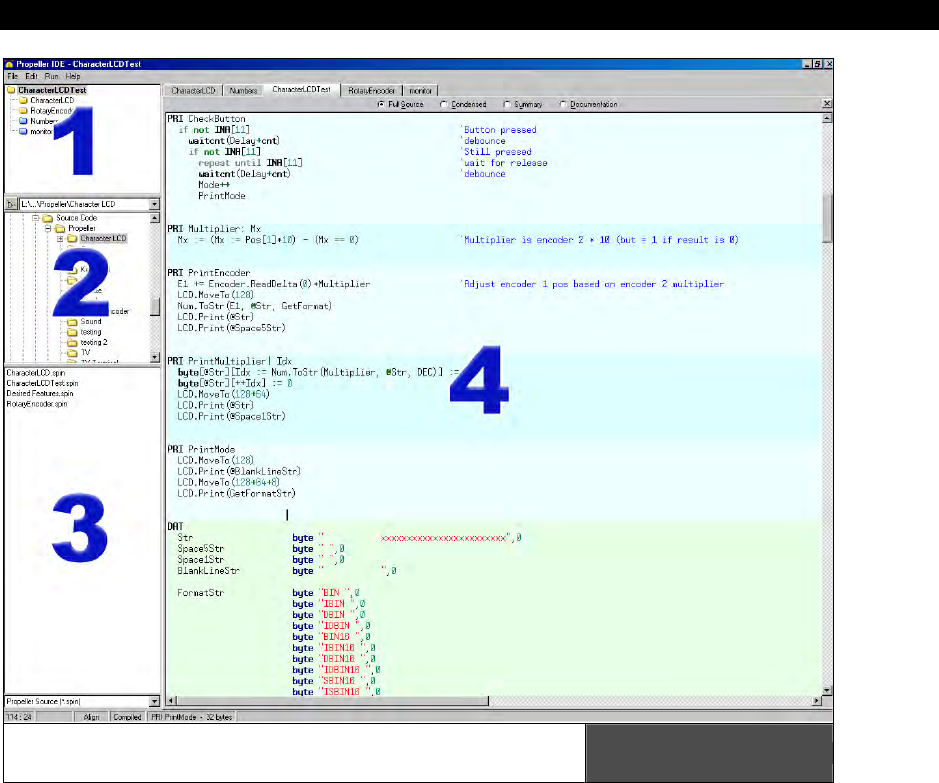
HYDRA System Overview 1
Game Programming for the Propeller Powered HYDRA Page 51
The Propeller Tool’s main window contains
four major sections or “panes.” Figure 1:18
Image from Propeller Manual v1.0 courtesy of Parallax Inc.
We’ll take a look at each of the four panes in turn in a moment:
Pane 1: Object View Pane
Pane 2: Recent Folders Field and Folder List
Pane 3: File List and Filter Field
Pane 4: Editor Pane
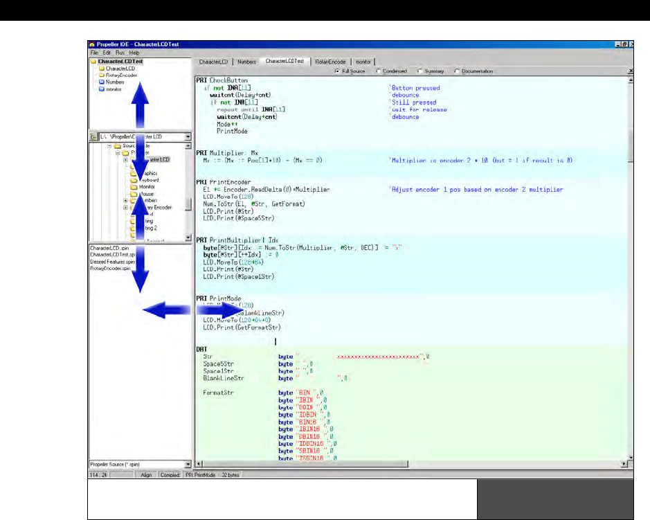
I The HYDRA Hardware
Page 52 Game Programming for the Propeller Powered HYDRA
The Integrated Explorer and its components
can be resized via the splitter bars. Figure 1:19
Image from Propeller Manual v1.0 courtesy of Parallax Inc.
The Integrated Explorer is separated from the Editor pane by a tall, vertical splitter bar that
can be resized with the mouse at any time by simply dragging. The Integrated Explorer can
even be hidden by resizing it down to nothing (left click and drag its vertical splitter bar), by
selecting <File Hide Explorer> from the main menu bar, or by using the keyboard shortcut
<CTRL + E>. The menu and shortcut options toggle the Integrated Explorer between the
following modes:
1. Visible (set to its last known size)
2. Invisible (completely collapsed into the left edge of the Propeller Tool

HYDRA System Overview 1
Game Programming for the Propeller Powered HYDRA Page 53
Pane 1: Object View Pane
Pane 1 is the Object View pane. Spin, the Propeller chip’s native language is a loosely
“object-based” language, where objects are external files that contain executable source
code and even other objects. Thus, a Propeller Project can be made up of multiple objects or
in other words multiple source files, the concept is similar to including source files in C/C++
with the pre-processor. The Object View displays the hierarchical view of the most recently
compiled project providing visual feedback on the structure of your project. Using the Object
View, you can determine what objects are included in your project, how they fit together
with other objects, their physical location on disk (working folder, library folder or editor
only), and potential circular references.
Pane 2: Recent Folders Field and Folder List
Pane 2 contains two components:
1. The Recent Folders field
2. The Folder List
These two components work together to provide navigational access to the disk drives
available on your PC. The Folder List displays a hierarchical view of folders within each disk
drive and can be manipulated in a similar fashion as the left pane of the Windows Explorer.
The Recent Folders field (above the Folder List) provides a drop-down list of the most recent
folders you’ve loaded files from. Selecting a folder from the Recent Folders field causes the
Folder List to immediately navigate to that folder. In addition, if you select a folder in the
Folder List which exists in the Recent Folders list, the Recent Folder field will automatically
update itself to display that item.
Pane 3: File List and Filter Field
Pane 3 contains two components:
1. The File List
2. The Filter field (bottom)
The File List displays all the files contained in the folder selected from the Folder List which
match the filter criteria of the Filter field. The File List can be used in a similar fashion as the
right pane of Windows Explorer.
The Filter field (below the File List) provides a drop-down list of file extensions or filters to
apply to files in the File List. Typically it will be set to show Spin files only (those with “.spin”
file extensions) but can also be set to show text files (.txt) or all files (*.*). If you navigate
to a folder and don’t see the files you expect to see, make sure that the current filter in the
Filter field is set appropriately.
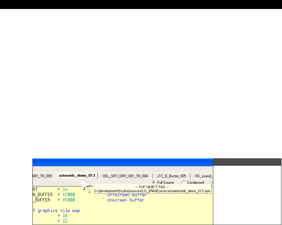
I The HYDRA Hardware
Page 54 Game Programming for the Propeller Powered HYDRA
Files in the Files List can be opened and viewed in the editor by double clicking on the file,
dragging it into the Editor pane itself, or right clicking and selecting Open from the shortcut
menu.
Pane 4: Editor Pane
Pane 4 is the Editor pane. The Editor pane provides a view of the open Spin source code
files and is the general work area where you can review and edit all the source code objects
for your project. Each file (source code object) you open is organized within the Editor pane
as an individual tab named after the file it contains. The currently active editor tab is
highlighted differently than the rest (bolded). You can have as many files open at once as
you wish, limited only by memory. As the number of files increases and the tab control runs
out of screen space, scroll arrows will appear on the right hand side of the tab control
allowing you to navigate through the off-screen files.
You can switch between open tabs by:
1. Clicking on the desired tab with the mouse.
2. Pressing <ALT + Left Arrow> or <ALT + Right Arrow>
3. Pressing <CTRL+TAB> or <CTRL+SHIFT+TAB>
Figure 1:20
Hover the mouse
over an edit tab to
see the full path and
file name of the
contained file.
If you hover the mouse pointer over a tab long enough it will display a hint message with the
full path and filename of the file it represents as shown in Figure 1:20.
The source code inside each file being edited is automatically syntax highlighted. Both, the
foreground and background colors are highlighted to help distinguish block types, element
types, comments vs. executable code, and so forth. You can turn this off if you wish by
selecting the Tools/Option menu item from the main menu and altering the editor syntax
highlighting settings.
HYDRA System Overview 1
Game Programming for the Propeller Powered HYDRA Page 55
Each file opened in an edit tab can display source code in one of four views:
1. Full Source view
2. Condensed view
3. Summary view
4. Documentation view
The view mode can be changed individually for each file edit tab by either:
1. Selecting the respective radio button with the mouse (located in a row under the tab
control).
2. Pressing <Alt + Up Arrow> or <Alt + Down Arrow>.
3. Pressing <Alt+ [letter] > where [letter] is the underlined hot key of the desired view.
4. Pressing <Alt> and rotating the mouse wheel (if you have one) up or down.
The Documentation view can not be entered if the object can not be fully
compiled at that moment.
Since a project can consist of many objects, developing a project can be awkward unless you
can see both the object you’re working on and the object you’re interfacing to at the same
time. The Editor pane helps here by allowing its edit tabs to be dragged and dropped to
different locations as shown in Figure 1:21. For example, once multiple objects are open,
you can use the left mouse button to select and drag the tab of an object down towards the
bottom half of the Editor pane and simply drop it there. The display changes to show you a
new tab region where you just dropped that edit tab. You can continue to drag and drop
edit tabs to this new region if you wish.
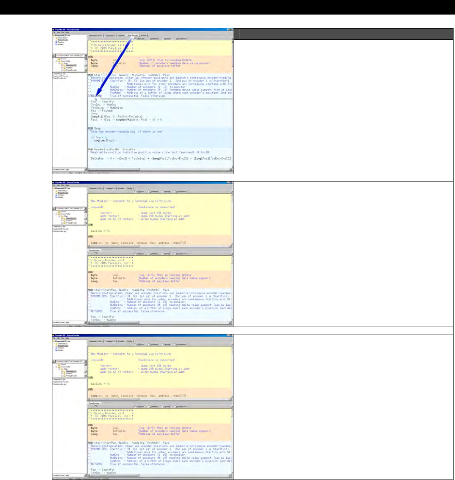
I The HYDRA Hardware
Page 56 Game Programming for the Propeller Powered HYDRA
Figure 1:21
Step 1: To see more than one object’s
source code simultaneously, left click and
drag an edit tab to a lower region of the
Editor Pane.
Step 2: Release the button to drop the
edit tab. The edit tab and its contents now
appear in the new region.
Step 3: Repeat steps 1 and 2 as necessary
for other edit tabs and resize both regions
using the horizontal splitter between them.
Image from Propeller Manual v1.0 courtesy of Parallax Inc.
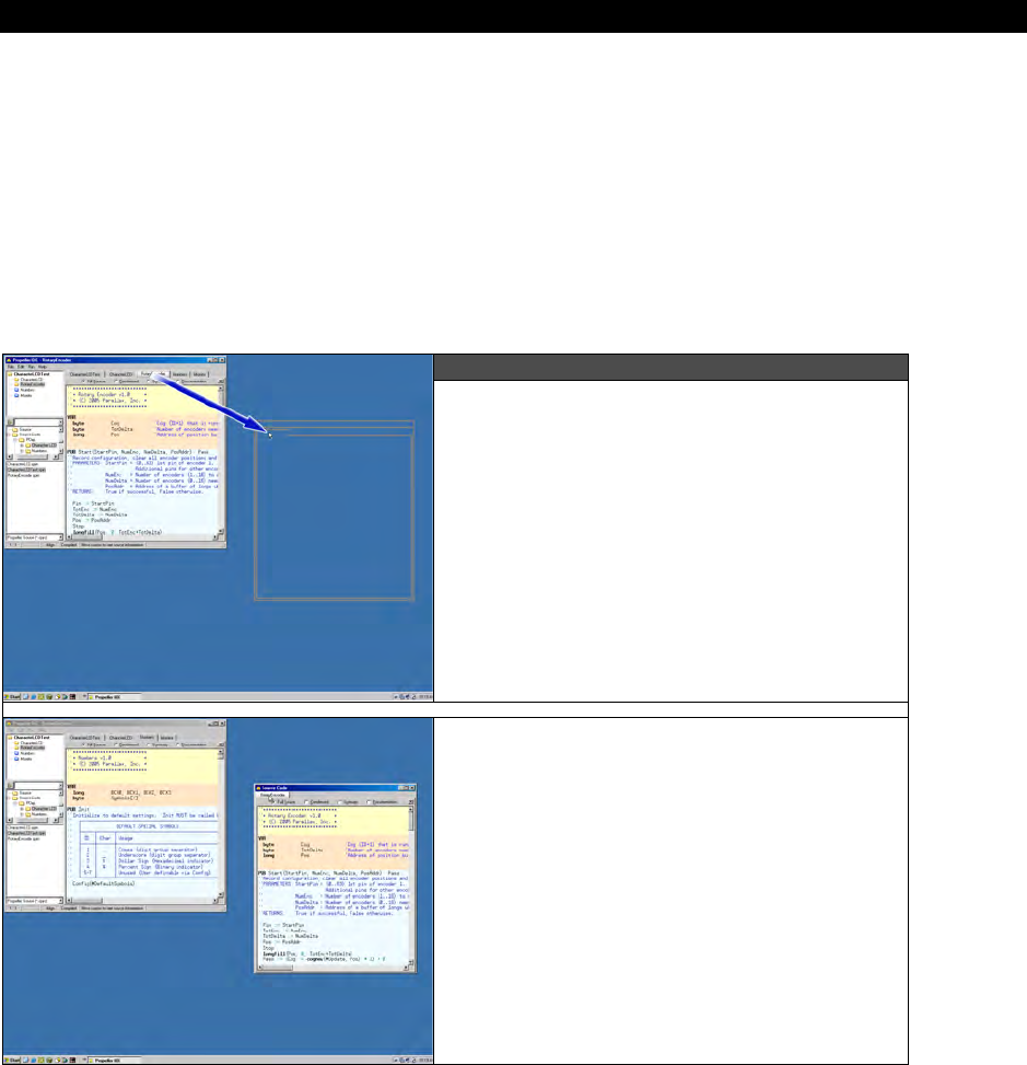
HYDRA System Overview 1
Game Programming for the Propeller Powered HYDRA Page 57
The vertical size of each of the edit regions can be changed by dragging the horizontal
splitter separating them. Of course, the objects you’re interfacing to can be viewed in
whatever mode is convenient at the moment (Full Source, Condensed, Summary, or
Documentation) while the object you’re developing remains in the Full Source view (the only
editable view).
The Editor pane also allows undocking its tabs and for them to be dragged and dropped
completely outside of the Propeller Tool as shown in Figure 1:22. When an edit tab is
undocked, the new tabs occupy a new window that can be manipulated independently of the
main Propeller Tool application window. This is particularly useful for development on multi-
monitor systems.
Figure 1:22
Step 1: If desktop space allows, you can
even drag edit tabs outside the
application itself; left click and drag an
edit tab to a region outside the Propeller
Tool.
Step 2: Release the button to drop the
edit tab; it will drop into a form of it’s
own that can be moved and sized
independent of the Propeller Tool. You
can drag and drop more edit tabs into
this new form also.
Image from Propeller Manual v1.0 courtesy of Parallax Inc.
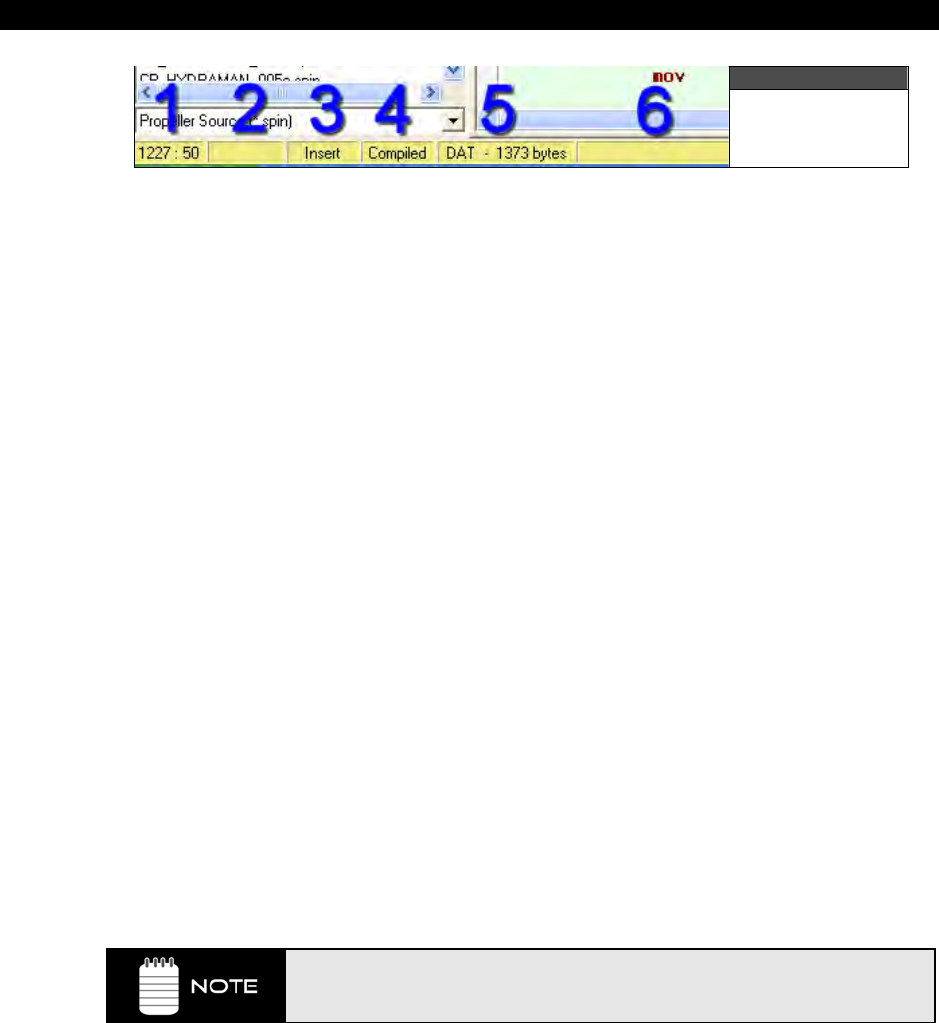
I The HYDRA Hardware
Page 58 Game Programming for the Propeller Powered HYDRA
Figure 1:23
The Status Bar
The Status Bar at the bottom of the Propeller Tool is separated into six panels as shown in
Figure 1:23. Each panel displays useful information at various stages of the development
process.
Panel 1 – Displays the row and column position of the editor’s caret in the currently active
edit tab.
Panel 2 – Displays the “modified” status of the current edit tab; if it’s blank then the current
line hasn’t been modified, if the panel reads “modified” then the current line has been
modified, lastly the panel can indicated “read-only.”
Panel 3 – Display the current edit mode:
1. Insert (default)
2. Align (available for “.spin” files only)
3. Overwrite mode
The edit modes can be toggled through by pressing the Insert key.
Panel 4 – Displays the compilation status of the current edit tab; blank, meaning uncompiled
or “Compiled” meaning the source has recently been compiled. This panel indicates whether
or not the current source code is still in the form it was in when it was last compiled. If the
code has not been changed since the last compile operation, this panel will say “Compiled.”
Panel 5 – Displays context sensitive information about the current edit tab’s source code if
that code has not been changed since the last compile operation. Move the edit tab’s cursor
to various regions in the source such as CON, DAT, or PUB/PRI blocks to see information
relating to that block.
Panel 6 – Displays temporary messages about the most recent operation(s). This is the
area of the Status Bar where error messages, if any, from the last compile operation are
displayed until another message overwrites it. This area also indicates successful
compilations, font size changes, and other status information.
The entire Status Bar displays hints describing the function of each menu item
on the menu bar as well as various other items when you let the mouse pointer
hover over those items.

HYDRA System Overview 1
Game Programming for the Propeller Powered HYDRA Page 59
1.5.2 Propeller Tool Menu Items
The following lists outline the various menu items and options controlled via the application
menu items.
File Menu
New Create a new edit tab with a blank page. Any existing edit
tabs are unaffected.
Open… Open a file in a new edit tab with the Open file dialog.
Open From… Open a file in a new edit tab from a recently accessed folder
using the Open file dialog.
Save Save current edit tab’s contents to disk using the existing file
name, if applicable.
Save As… Save current edit tab’s contents to disk with a new file name
using the Save As dialog.
Save To… Save current edit tab’s contents to disk in a recently
accessed folder using the Save As dialog.
Save All Save all unsaved edit tab’s contents to disk using their
existing names, if applicable.
Close Close current edit tab (will prompt if file is unsaved).
Close All Close all edit tabs (will prompt for any files unsaved).
Select Top Object File… Select the top object file of current project. This setting is
used for all of the Compile Top… operations and remains
until changed.
Archive
→ Project… Collect all objects and data files for the project shown in
Object View and store them in a compressed (.zip) file along
with a “readme” file containing archive and structure
information. The compressed file is named after the
project’s top file with “Archive” plus the date/time stamp
appended and is stored in the top file’s work directory.
→ Project + Propeller Tool Perform the same task as above but add the entire Propeller
Tool executable to the compressed file.

I The HYDRA Hardware
Page 60 Game Programming for the Propeller Powered HYDRA
Hide/Show Explorer Hide or show the Integrated Explorer panels (left side of the
application window).
Print Preview… View a sample of the output before printing.
Print… Print the current edit tab’s contents.
<recent files> The menu area between the Print… and Exit items displays
the most recently accessed files, up to ten. Selecting one of
these items opens that file. Point the mouse at a recent file
menu item to see the full path and file name in the status
bar.
Exit Close the Propeller Tool.
Edit Menu
Undo Undo the last edit action on the current edit page. Each edit
page retains its own undo history buffer until closed.
Multiple undo actions are allowed, limited only by memory.
Redo Redo the last undone action on the current edit page. Each
edit page retains its own redo history buffer until closed.
Multiple redo actions are allowed, limited only by memory.
Cut Delete the selected text from the current edit page and copy
it to the Windows clipboard.
Copy Copy the selected text from the current edit page to the
Windows clipboard.
Paste Paste text from the Windows clipboard to the current edit
page at the current caret position.
Select All Select all text in the current edit page.
Find / Replace… Open the Find/Replace dialog; see Find/Replace Dialog on
page 49 for details.
Find Next Find the next occurrence of the last search string entered
into the Find/Replace dialog.
Replace Replace the current selection with the string entered into the
Replace field of the Find/Replace dialog.
Go To Bookmark Go to bookmark 1, 2, 3… (visible only when bookmarks are
shown).

HYDRA System Overview 1
Game Programming for the Propeller Powered HYDRA Page 61
Text Bigger Increase the font size in every edit page.
Text Smaller Decrease the font size in every edit page.
Preferences… Open the Preferences window. Users can customize many
settings within the Propeller Tool using this feature.
Run Menu
Compile Current
→ View Info… Compile source code in current edit tab and, if successful,
display Object Info form with the results. The Object Info
form displays many details about the resulting object
including object structure, code size, variable space, free
space and redundancy optimizations.
→ Update Status Compile source code in current edit tab and, if successful,
update the status info on the Status Bar for every object in
the project.
→ Load RAM Compile source code in current edit tab and, if successful,
download the resulting application into Propeller chip’s RAM
and run it.
→ Load EEPROM Compile source code in current edit tab and, if successful,
download the resulting application into Propeller chip’s
EEPROM (and RAM) and run it.
Compile Top
→ View Info… Same as Compile Current View Info except compilation is
started from the file designated as the “Top Object File.”
→ Update Status Same as Compile Current Update Status except
compilation is started from the file designated as the “Top
Object File.”
→ Load RAM Same as Compile Current Load RAM + Run except
compilation is started from the file designated as the “Top
Object File.”
→ Load EEPROM Same as Compile Current Load EEPROM + Run except
the compilation is started from the file designated as the
“Top Object File.”

I The HYDRA Hardware
Page 62 Game Programming for the Propeller Powered HYDRA
Identify Hardware… Scan available ports for the Propeller chip and, if found,
display the port it is connected to and the hardware version
number.
Help Menu
Propeller Tool… Display on-line help about the Propeller Tool.
Spin Language… Display on-line help about the Spin language.
Assembly Language… Display on-line help about the Propeller Assembly language.
Example Projects… Display on-line help containing example Propeller Projects.
View Character Chart… Display the interactive Parallax Character Chart. This
character chart shows the Parallax font’s character set in
three possible views: Standard Order, ROM Bitmap and
Symbolic Order.
View Parallax Website… Open up the Parallax website using the computer’s default
web browser.
E-mail Parallax Support… Open up the computer’s default email software and start a
new message to Parallax support.
About… Displays the About window with details about the Propeller
Tool.
1.5.3 Object View Pane Details
The Object View displays a hierarchical view of the project you most recently compiled
successfully. There are two Object Views in the Propeller Tool:
1. The Object View at the top of the Integrated Explorer in the main application’s
window
2. The Object Info View in the upper left of the Object Info form.
Both of these Object Views function in a similar fashion. The Object View provides visual
feedback on the structure of the most recent compilation as well as information for each
object within the compiled project.
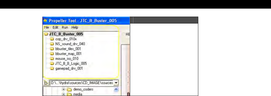
HYDRA System Overview 1
Game Programming for the Propeller Powered HYDRA Page 63
Figure 1:24
Example Object View
display showing the
structure of the
“JTC_B_Buster_005”
compilation.
Referring to Figure 1:19, the Object View indicates the structure of the “JTC_B_Buster_005”
game application. In this example, the “JTC_B_Buster_005” object is the top object file and
it includes a number of sub-objects including; “cop_drv_010x”, “NS_sound_drv_040”,
“bbuster_tiles_001”, etc. Notice that the file names of the top level object and sub-objects do
not include the file extension, its assumed to be “.spin” unless they are data files.
The icons to the left of each object name indicate the folder that the object exists in. There
are the four color coded possibilities:
Yellow Object is within the Work Folder.
Blue Object is within the Library Folder.
Stripe Object is in Work Folder, but another object with the same name is also
being used from the Library Folder.
Hollow Object is not in any folder because it has never been saved.
The following paragraphs describe the folder types.
Work Folder
The Work Folder (yellow) is the folder where the top object file exists. Every project has
one, and only one, work folder.
Library Folder
The Library Folder (blue) is where the Propeller Tool’s library objects exist, such as those that
came with the Propeller Tool software. The Library Folder is always the folder that the
Propeller Tool executable started from, and every object (file with .spin extension) within it is
considered to be a library object.

I The HYDRA Hardware
Page 64 Game Programming for the Propeller Powered HYDRA
Striped Folders
Objects with striped icons indicate that an object from the work folder and an object from
the library folder each refer to a sub-object of the same name and that sub object happens
to exist in both the work and library folders. This same-named object may be:
1. An exact copy of the same object,
2. Two versions of the same object, or
3. Two completely different objects that just happen to have the same name.
Regardless of the situation, it is recommended that you resolve this potential problem as
soon as possible since it may lead to problems later on, such as not being able to use the
Archive feature.
Hollow Folders
Objects with hollow icons indicate that the object was created in the editor and has never
been saved to any folder on the hard drive. This situation, like the one mentioned above, is
not an immediate problem but can lead to future problems if it is not addressed soon.
Using the mouse to point at and select objects can provide additional information as well.
Clicking on an object within the Object View opens that object into the Editor pane. Left
clicking opens that object in Full Source view, right clicking opens it in Documentation view
and double clicking opens it, and all its sub-objects, in Full Source view. If the object was
already open, the Editor pane simply makes the related edit tab active and switches to the
appropriate view; Full Source for a left click or double click, or Documentation for a right
click.
1.5.4 Info Object View (F8)
The Info Object View shown in Figure 1:25 works exactly like the Object View with a few
exceptions:
1. Clicking on an object within the Info Object View updates the Object Info display
with information pertaining to that object.
2. Double-clicking on an object within the Info Object View opens that object in the Edit
pane.
3. Data files are not selectable in the Info Object View.
RAM Usage Panel
The RAM Usage panel displays statistics about RAM allocation of the object currently selected
in the Info Object View. The horizontal bar gives a summary view of the entire RAM with a
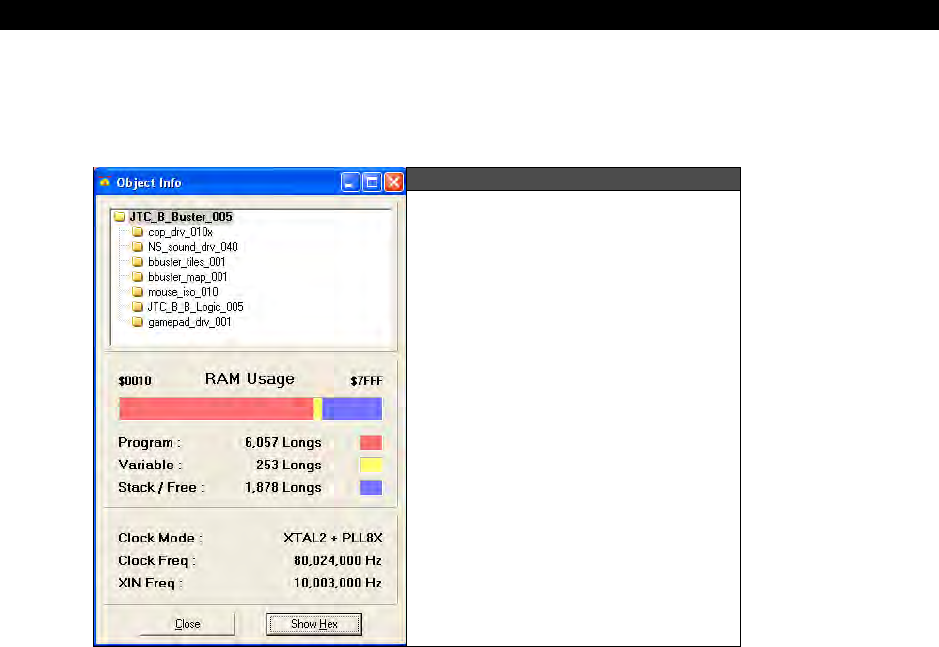
HYDRA System Overview 1
Game Programming for the Propeller Powered HYDRA Page 65
color legend and numerical details below it. For example, Figure 1:25 shows that the
“JTC_B_Buster_005” object consumes 6057 LONGs (24228 bytes) for program space and 253
LONGs (1012 BYTEs) for variable space, leaving only 1878 LONGs (7512 BYTEs) free.
Figure 1:25
Object Info Form Showing
information about the
“JTC_B_Buster_005.Spin”
Project
Clock Panel
The clock panel, under the RAM Usage panel, displays the clock/oscillator settings of the
object currently selected in the Info Object View. For example, Figure 1.20 shows that the
“JTC_B_Buster_005” object configured the clock for XTAL2 + PLLX8 mode, at 80,024,000 Hz
and an XIN frequency of 10,003,000 Hz.
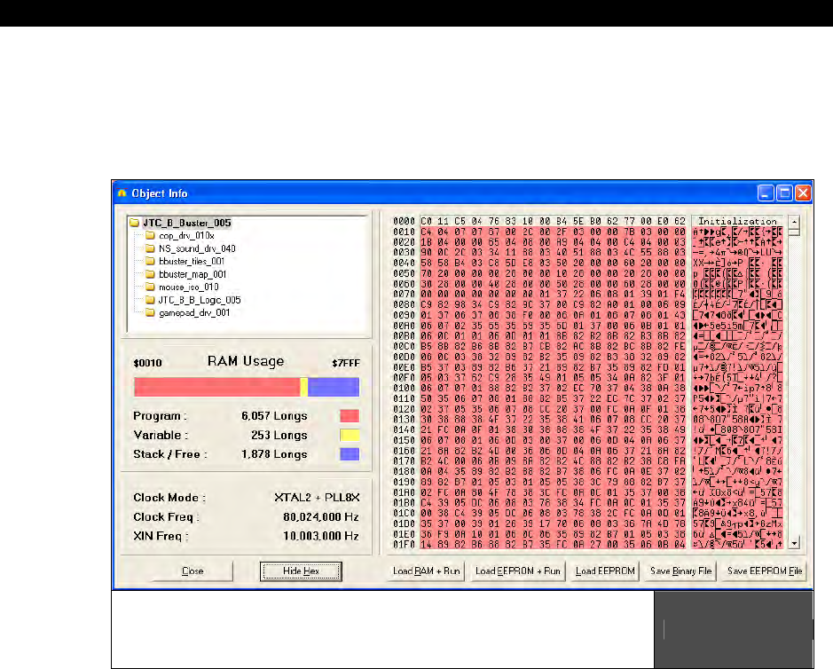
I The HYDRA Hardware
Page 66 Game Programming for the Propeller Powered HYDRA
Hex View
The Show/Hide Hex button shows or hides the detailed object hex view, as shown below in
Figure 1:26. The hex view shows the actual compiled object data, in hexadecimal, that are
loaded into the Propeller’s RAM/EEPROM upon download.
Example Object Info Form display with the Object
Hex View Open, Showing the Hex Values of the
“JTC_B_Buster_005” Compilation
Figure 1:26
The buttons under the hex display allow for downloading and saving of the currently
displayed hex data. The first three buttons, <Load RAM + Run>, <Load EEPROM + Run>,
and <Load EEPROM>, perform the same function as the similarly named menu items under
the <Run Compile Current> main menu item. It’s important to note that they use the
current object (the one selected in the Info Object View) as the source to download. In
other words, you can actually select a sub-object from the project and download just that; a
practical procedure only if that object were designed to run completely on its own.
The last two buttons, <Save Binary File>, and <Save EEPROM File>, each save the hex data
from the currently selected object to a file on disk. <Save Binary File> saves only the
portion actually used by the object; the program data, but not variable or stack/free space.
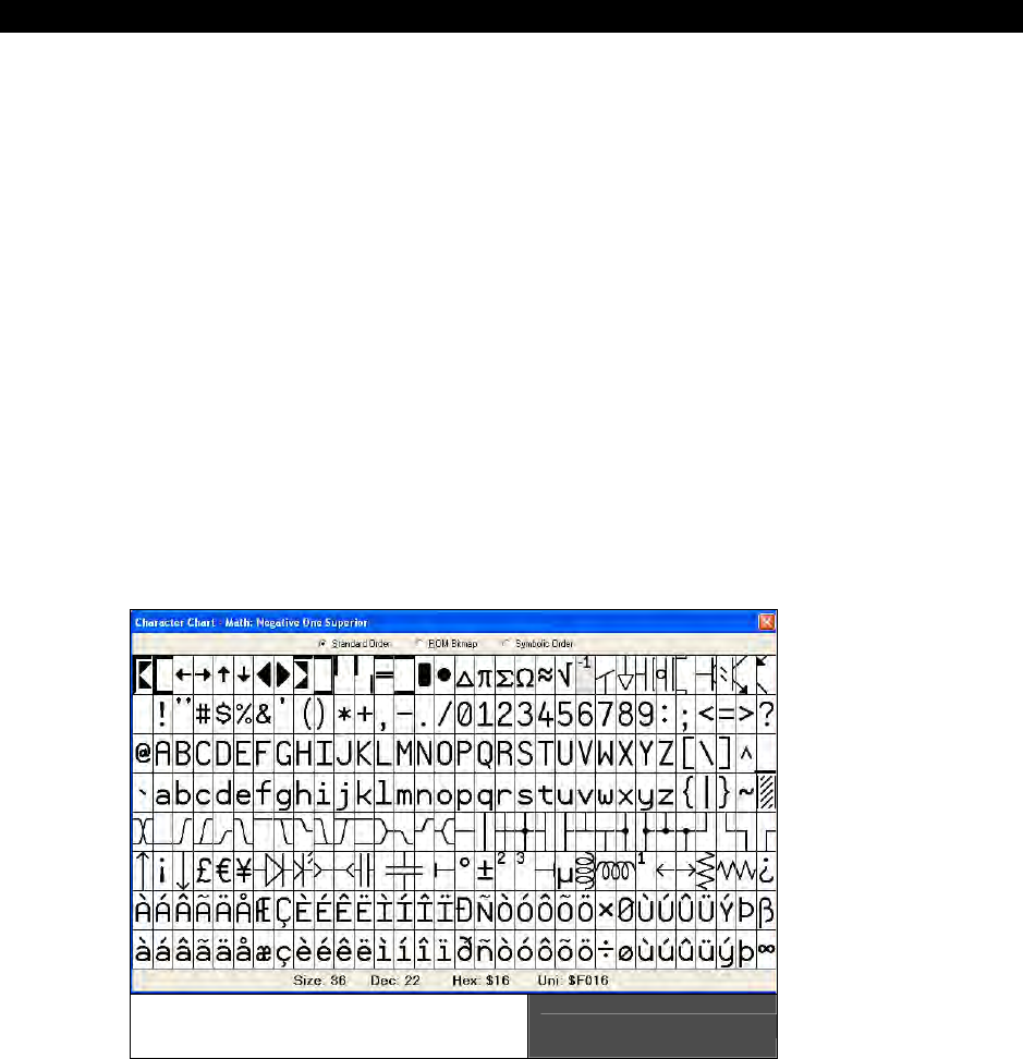
HYDRA System Overview 1
Game Programming for the Propeller Powered HYDRA Page 67
<Save EEPROM File> saves the entire EEPROM image, including variable and stack/free
space. Use <Save EEPROM File> if you wish to have a file that you can load into an
EEPROM programmer for production purposes.
1.5.5 The Character Chart
The Character Chart window is available from the <Help View Character Chart…> menu
item. It shows the entire character set for the Parallax Font that is used by the Propeller
Tool and is also built into the ROM of the Propeller chip. There are three views in the
Character Chart: Standard Order, ROM Bitmap, and Symbolic Order.
In each of the three views, the mouse, left mouse button, cursor keys and enter button can
be used to highlight and select a character. If clicked (or enter pressed), the highlighted
character will be entered into the current edit tab at the current cursor location. As a new
character is highlighted, the title bar and info bar of the window updates to show the name,
size and address information for that character. Moving the mouse wheel up or down
changes the font size displayed in this window.
Standard Order
Figure 1:27 displays the characters in the standard ANSI numerical order. The exponent (-1)
in the first row of the display is selected in this example (light grey highlight).
Parallax Character Chart
(Standard Order) Figure 1:27
The information at the bottom of the window shows the font size, in points, and the
character’s location in the character set in decimal, hexadecimal, and Unicode.
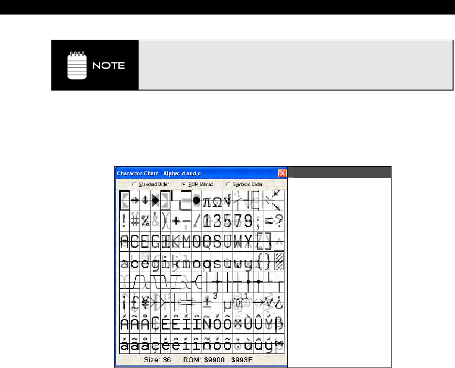
I The HYDRA Hardware
Page 68 Game Programming for the Propeller Powered HYDRA
The Unicode value is the address of the character in the True Type® Font file that
is used by the Propeller Tool. The decimal and hexadecimal values are the
logical addresses of the character in the character set within the Propeller chip
and correspond to that location in the ANSI character set used by most
computers.
ROM bitmap
ROM Bitmap, Figure 1.23 shows the characters in a way representative of how they are
stored in the Propeller’s ROM.
Figure 1:28
Parallax Character
Font Chart
(ROM Bitmap)
This view uses four colors, white, light gray, dark gray, and black, to represent the bit
pattern of each font character. Each character, in the Propeller’s ROM, is defined with two
bits of color (four colors per row in each character cell). The rows of each pair of adjacent
characters are overlapped in memory for the purpose of creating the run-time characters
used to draw 3D buttons with hot key and focus indicators. The information at the bottom of
the window shows the font size, in points, and the selected character’s pixel data address
range in the Propeller’s ROM.
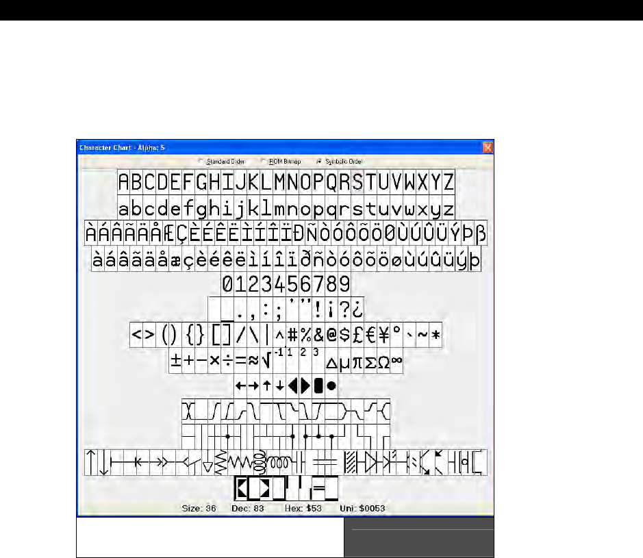
HYDRA System Overview 1
Game Programming for the Propeller Powered HYDRA Page 69
Symbolic Order
Symbolic Order orders the characters arranged categorically as shown in Figure 1.24. This is
useful for finding the special characters in the Parallax font for depicting timing diagrams,
lines, arrows, and schematics.
Parallax Character Font Chart
(Symbolic Order) Figure 1:29

I The HYDRA Hardware
Page 70 Game Programming for the Propeller Powered HYDRA
1.5.6 View Modes, Bookmarks and Line Numbers
While developing objects, or conversing about them with other users, it may sometimes be
difficult to quickly navigate to certain regions of code simply because of the size of the file
itself or because large sections of code and comments obscure the desired section. There
are a number of features built into the Propeller Tool to assist with this problem, including
different View Modes, Bookmarks and Line Numbers.
View Modes
Each edit tab can display an object’s source in one of four view modes:
1. Full Source mode
2. Condensed mode
3. Summary mode
4. Documentation mode
Full Source view displays every line of source code within the object and is the only view
that supports editing.
Condensed view hides every line that contains only a code comment as well as contiguous
lines that are blank, showing only compilable lines of code.
Summary view displays only the block heading lines (CON, VAR, OBJ, PUB, PRI, and DAT);
a convenient way to see the entire object’s structure at a glance.
Documentation view displays the object’s documentation generated by the compiler from
the source code’s doc comments.
By briefly switching to another view you may be able to locate the routine or region of code
desired. For example, Figure 1:30 (top) shows the Graphics object open in an edit page. If
you were having trouble finding the “plot” routine within the source code, you could switch to
the Summary view (middle) locate the “plot” routine’s header line and click the mouse on
that line to place the cursor there, then switch back to Full Source view (bottom). Keep your
eye on the line with the cursor because the code will expand to full view above and below
the line where the cursor is. The view mode can be changed a number of ways.
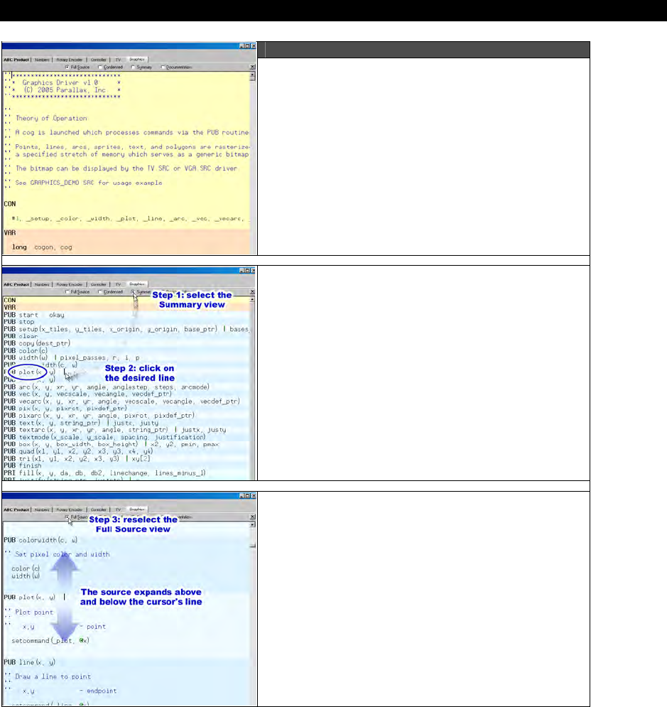
HYDRA System Overview 1
Game Programming for the Propeller Powered HYDRA Page 71
Figure 1:30
Can’t find a routine in an object?
Step 1: Select Summary Mode.
Step 2: Click on the routine’s line.
Step 3: Select Full Source mode again; the
code re-expands around the cursor’s line.
Image from Propeller Manual v1.0 courtesy of Parallax Inc.
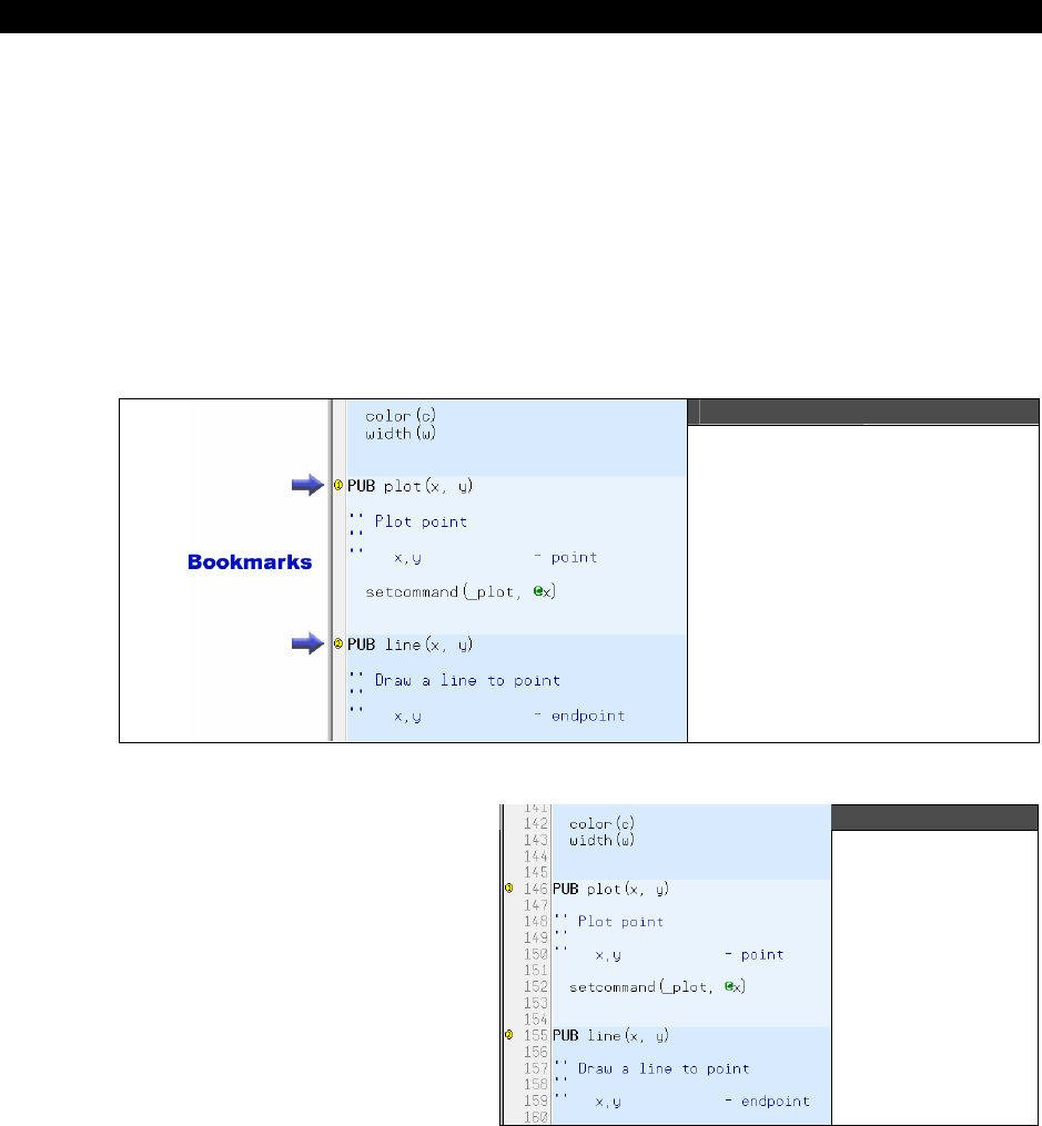
I The HYDRA Hardware
Page 72 Game Programming for the Propeller Powered HYDRA
Bookmarks
You can also set bookmarks on various lines of each edit page’s source code to quickly jump
to desired locations. Figure 1:31 shows an example of two bookmarks set in the Graphics
object’s edit tab. To enable bookmarks, press <Ctrl+Shift+B> to make the Bookmark
Gutter visible; a blank area to the left of the edit page. Then click the mouse in the
Bookmark Gutter next to each line you want to be able to navigate to quickly. Finally, from
anywhere in the page, press <Ctrl+#> where # is the bookmark number that you want to
go to; the cursor will instantly jump to that location. Up to 9 bookmarks (1 – 9) can be set in
each edit tab. The bookmarks are not saved in the source code; however, the bookmark
settings of the last 10 files accessed are remembered by the Propeller Tool and restored
upon reopening those files.
Figure 1:31
Edit tab with Bookmarks
Enabled and two Bookmarks
Set
Images on this page from Propeller Manual v1.0 courtesy of Parallax Inc.
Line Numbers
At any time, you can enable or
disable line numbers in the edit
tab. Line Numbers show up in the
Line Number Gutter, next to the
Bookmark Gutter as shown in
Figure 1:32. Lines are
automatically numbered as they
are created; they are a visual item
only and are not stored in the
source code. Line Numbers and
Bookmarks are independent of
each other and can be enabled or
disabled individually.
Figure 1:32
Edit tab with
bookmarks and
line numbers
enabled
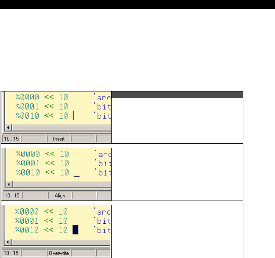
HYDRA System Overview 1
Game Programming for the Propeller Powered HYDRA Page 73
Edit Modes
There are three edit modes provided by the Editor pane:
1. Insert (default)
2. Align (available for “.spin” objects only)
3. Overwrite
You can switch between each mode by using the <Insert> key. The current mode is
reflected by both the caret/cursor shape and panel 3 of the lower status bar.
Figure 1:33
Insert Edit Mode: Caret is the standard
blinking, vertical bar and the status bar
shows “Insert.”
Align Edit Mode: Caret is a blinking
underline and the status bar shows
“Align.”
Overwrite Edit Mode: Caret is a blinking,
solid block and the status bar shows
“Overwrite.”
Image from Propeller Manual v1.0 courtesy of Parallax Inc.

I The HYDRA Hardware
Page 74 Game Programming for the Propeller Powered HYDRA
Insert and Overwrite Modes
The Insert and Overwrite modes are similar to that of many other text editors. These are the
only two modes available to edit tabs containing files other than Propeller “.spin” objects,
such as “.txt” files.
Align Mode
The Align mode is a special version of the Insert mode designed specifically for maintaining
source code. To understand Align mode, we first need to consider common programming
techniques. There are two very common practices used when writing modern source code:
indention of code and alignment of comments to the right of code. It is also common for
source code to be viewed and edited using more than one editor application. Historically,
programmers have used either tabs or spaces for indention and alignment purposes, both of
which prove problematic. Tab characters cause alignment issues because some editors use
different sized tab settings than others. Both tab and space characters cause alignment
issues because future edits cause right-side comments to shift out of alignment.
For Spin code, the Propeller Tool solves this problem first by disallowing tab characters (Tab
key presses emit the proper number of space characters), and second by providing the Align
edit mode. While in the Align mode, characters inserted into a line affect neighboring
characters but not characters separated by more than one space. The result is that
comments and other items separated by more than one space maintain their intended
alignment for as long as possible.
Since the Align mode maintains existing alignments as much as possible, much less time is
wasted realigning elements due to future edits by the programmer. Additionally, since
spaces are used instead of tab characters, the code maintains the same look and feel in any
editor that displays it with a mono-spaced font.
The Align mode isn’t perfect for all situations, however. We recommend you use Insert
mode for most code writing and briefly switch to Align mode to maintain existing code where
alignment is a concern. The Insert key rotates the mode through Insert Align
Overwrite and back to Insert again. The Ctrl+Insert key shortcut toggles only between
Insert and Align modes. A little practice with the Align and Insert modes will help you
program more time-efficiently.
Note that non-Spin source (without a .spin extension) does not allow the Align mode. This is
because, for non-Spin source, the Propeller Tool is designed to maintain any existing tab
characters and to insert tab characters when the Tab key is pressed in order to maintain the
original intent of the file, which may be a tab-delimited data source for a Spin program or
other use where tab characters are desired.
Block Selections
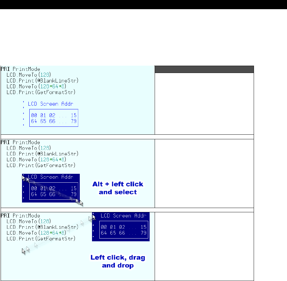
HYDRA System Overview 1
Game Programming for the Propeller Powered HYDRA Page 75
In addition to normal text selections made with the mouse, the Propeller Tool allows block
selections (rectangular regions of text). To make a block selection, first press and hold the
Alt key, then left-click and drag the mouse to select the text region. After the selection is
made, cut and copy operations behave as they do with other selections. Figure 1:34
demonstrates block selection and movement of the text block with the mouse.
Figure 1:34
Original code. We’d like to
move the “LCD Screen Addr’’
comments to the right of the
PrintMode routine.
First press and hold the Alt
key. Next left-click and drag
the mouse to make the
selection.
Finally, click and drag (from
anywhere in the selected
block) and drop the selection
in the desired location.
Image from Propeller Manual v1.0 courtesy of Parallax Inc.

I The HYDRA Hardware
Page 76 Game Programming for the Propeller Powered HYDRA
1.5.7 Keyboard Shortcuts and Propeller Quick Reference Guide
There are many keyboard shortcuts built into the Propeller Tool. Complete shortcuts lists in
two formats, one categorically organized and one listed by key, are available through the
Propeller Tool’s Help menu.
Also available through the Help file is a 4-page condensed guide to the Spin and Propeller
Assembly programming languages organized in table format for quick reference.
1.6 Summary
In this chapter we inventoried the HYDRA, tried some games and demos, got the software
and drivers loaded onto your PC an took a look at the Propeller Tool IDE. In the next chapter
and the chapters to follow we are going to take a look at each of the hardware sub-systems
of the HYDRA, so you can at least have a general idea of how they work and how to make
modifications and hacks to them if you want to void your warranty! See you in Chapter 2.
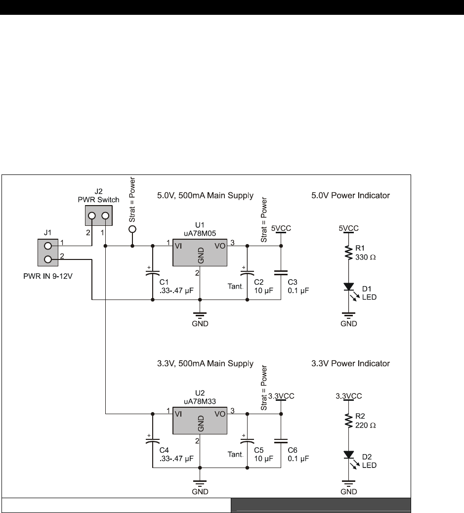
5V & 3.3V Power Supplies 2
Game Programming for the Propeller Powered HYDRA Page 77
Chapter 2: 5V
& 3.3V Power
Supplies
The HYDRA, like any embedded system, needs power, so what better place to start
discussing the hardware than with the power supply design? In this chapter, we are going to
cover the following topics:
The 3.3V power supply.
The 5.0V power supply.
The HYDRA Power Supply Design Figure 2:1
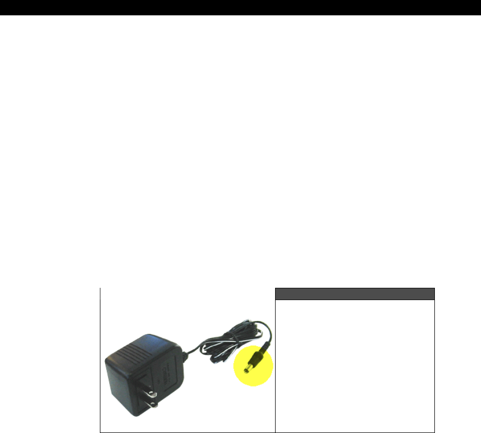
I The HYDRA Hardware
Page 78 Game Programming for the Propeller Powered HYDRA
2.1 General Power Supply Overview
The HYDRA game console has a dual 3.3 V/ 5.0 V power supply system that is fed by a single
9 VDC unregulated input from a wall adapter. The supply designs are shown in Figure 2:1 for
reference.
The HYDRA is a mixed voltage system since the Propeller uses 3.3 V, but the keyboard and
mouse need 5.0 V, as do potential future peripherals; thus both supplies are available and
can each supply up to 500 mA for all your needs. Additionally, the power supplies are
exported to the 20-pin expansion port for plug-in cartridges. Initially, the power is fed in from
a 2.1 mm female power jack at J1, the voltage should be from 9-12 VDC, but does NOT need
regulation, unregulated DC is fine and hopefully there is a fat 2,000 – 20,000 µF filter cap on
the output to smooth the DC.
The wall adapter that comes with the HYDRA is something like that shown in Figure 2:2, it’s
a standard 300-500 mA 9 V DC adapter you can find almost anywhere, the only important
detail is that the TIP is
positive
and the RING must be
negative
. If you are having trouble
seeing the schematic of the power supplies, you can find an electronic version of it in higher
resolution here (as well as all the other circuits discussed in the upcoming chapters):
CD_ROOT:\HYDRA\DESIGNS\hydra_power_01.gif
Figure 2:2
The 9 VDC wall adapter that
comes with the HYDRA kit

5V & 3.3V Power Supplies 2
Game Programming for the Propeller Powered HYDRA Page 79
2.2 The 3.3 V Power Supply
The 9 V raw power is fed through the power jack at J1 and into the power switch at J2 then
into the regulation circuit based on a standard UA78M33 linear regulator. The UA78M33 is a
very hearty regulator with built-in protection so we don’t have to add diodes and other
assorted protection components to it. Referring back to Figure 2:1, the capacitors C1, C2,
and C3 provide filtering on the input and output. The large 10 µF tantalum on the output
helps provide large currents on demand. When powering the HYDRA up, R1 and D1 provide
a “power good” indicator, and you should see the LED illuminate to indicate the supply is
working. Of course, there is no substitute for a voltmeter if you really want to check the
voltage and be sure if you are having power problems.
The Propeller chip is a 3.3 V device, so this supply is the main supply of the system that
powers the Propeller; however, add-in cards plugged into the expansion slot might want to
use a lot of current, thus a regulator that can provide at least 500 mA of current is desired
just in case.
2.3 The 5.0 V Power Supply
Many people supply the 3.3 V supply from the 5 V supply; this is a mistake. Any power
supply designer will tell you that, not only do you cut your output load of your 5 V supply
down since it’s constantly working to supply your 3.3 V supply, you add the entire path of the
5 V supply into your 3.3 V system’s final output since whenever the 3.3 V supply pulls, it pulls
through the 5.0 V which can lead to pulling your 5.0 V supply down many hundreds of
millivolts. Moreover, if you want to rate your 3.3 V at 500 mA and your 5.0 V at 500 mA, you
can’t! You need to rate your 5.0 V at 1 A(!) since it is responsible for supplying both front
ends to the power. Finally, if the 5 V goes bad, then they both go bad, with two separate
paths; if one supply goes bad, you still have the other and many vital systems may still
operate.
With that in mind, the 5.0 V supply is identical to the 3.3 V supply, but instead of a 3.3 V
linear regulator, the 5.0 V supply uses a 5.0 V regulator, the UA75M05. Again, this is a very
robust regulator with built-in protection, so we can save parts. Also, the input and output
filtering is very forgiving and as long as you have 0.1 µF – 1.0 µF on both the input and
output, the regulator will work great, but I like to throw a nice 10 µF tantalum on all my
power supplies’ outputs for a low-impedance path for current sourcing.
Lastly, the 5.0 V supply has a “power good” indicator constructed of R2 and D2 that provides
some indication the supply is working. Both power indicators are of course up front on the
HYDRA by the power switch.
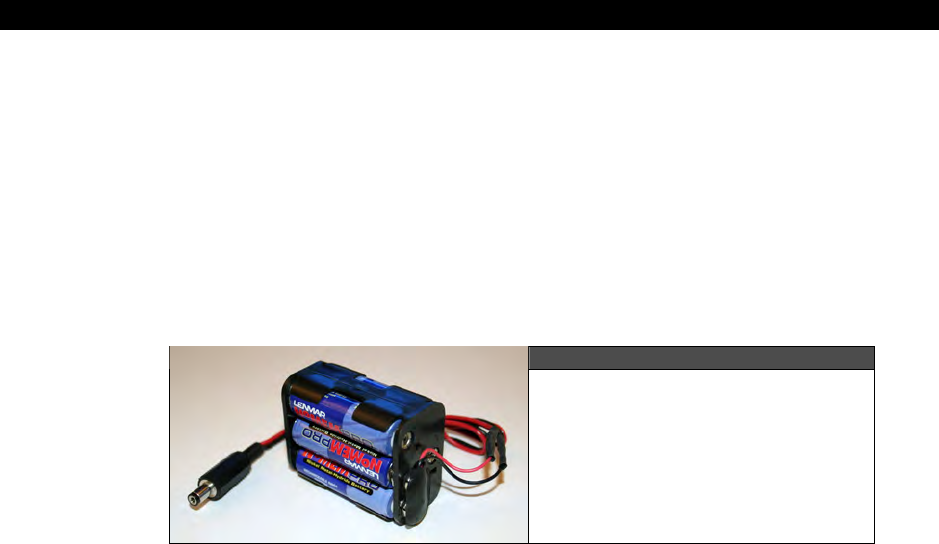
I The HYDRA Hardware
Page 80 Game Programming for the Propeller Powered HYDRA
2.4 Summary
The power supplies for the HYDRA are rather simplistic; all the work is done by the
regulators. Also, you might wonder “Can the HYDRA can be powered from battery?”
Absolutely, a 9 V transistor battery “will” work, for a while, but I suggest getting a series 6-
AA cell battery pack to create a total of 9 V (6 × 1.5 V), and then connect a 2.1 mm power
connect into the end of the cable and connect it to your pack (most battery packs like this
have a 9 V transistor battery clip, so I usually just solder on a cable to my 2.1 mm jack). I
have found that using standard rechargeable batteries, I can run the HYDRA for hours in this
configuration. Figure 2:3 shows a picture of my little battery pack I use for the HYDRA.
Figure 2:3
An ad-hoc HYDRA battery pack
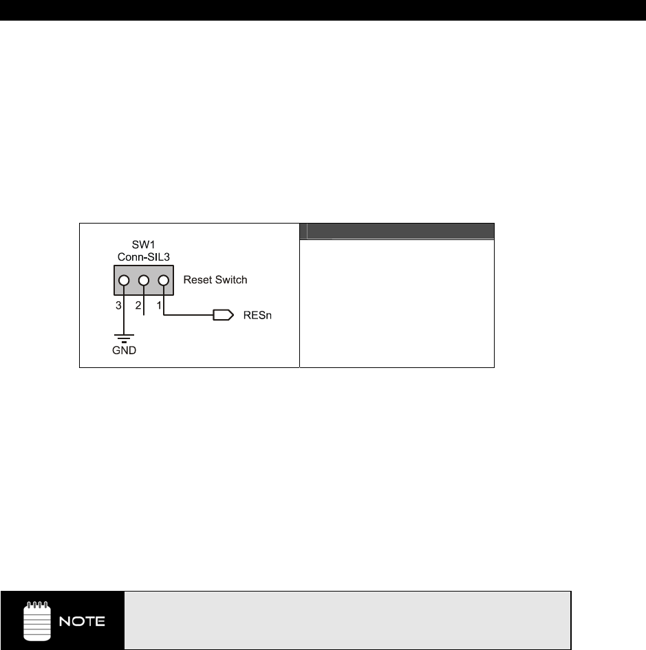
Reset Circuit 3
Game Programming for the Propeller Powered HYDRA Page 81
Chapter 3:
Reset Circuit
In this incredibly short chapter we are going to discuss the HYDRA’s reset circuitry including:
Reset circuit design
Resetting the HYDRA manually
Resetting the HYDRA via the USB/USB2SER interfaces
Figure 3:1
The HYDRA Reset Circuit
3.1 Reset Circuit Design
The Propeller chip can be reset externally via the USB hardware (via the DTR line) or by
pressing the Reset button located at the front of the HYDRA. The reset circuitry on the
Propeller chip doesn’t require much conditioning, thus the manual reset circuit is nothing
more than a switch (as shown in Figure 3:1) that pulls the RESn line to ground when
depressed. If you do want to reset the Propeller chip with some external hardware then you
call pull LOW on the
RESn
line; however, make sure that you place a weak HIGH on the line
with a 2.2-100 KΩ resistor on your circuit, so there is a HIGH on the line if your device is not
actively pulling the
RESn
low.
The Propeller chip keeps a weak HIGH on the RESn line itself via a 5 KΩ pull-up
resistor, thus you technically do NOT need to pull up the reset circuit, but it
won’t hurt if you wish to. Additionally, the brown-out circuit will pull RESn low if
a brown-out condition occurs.
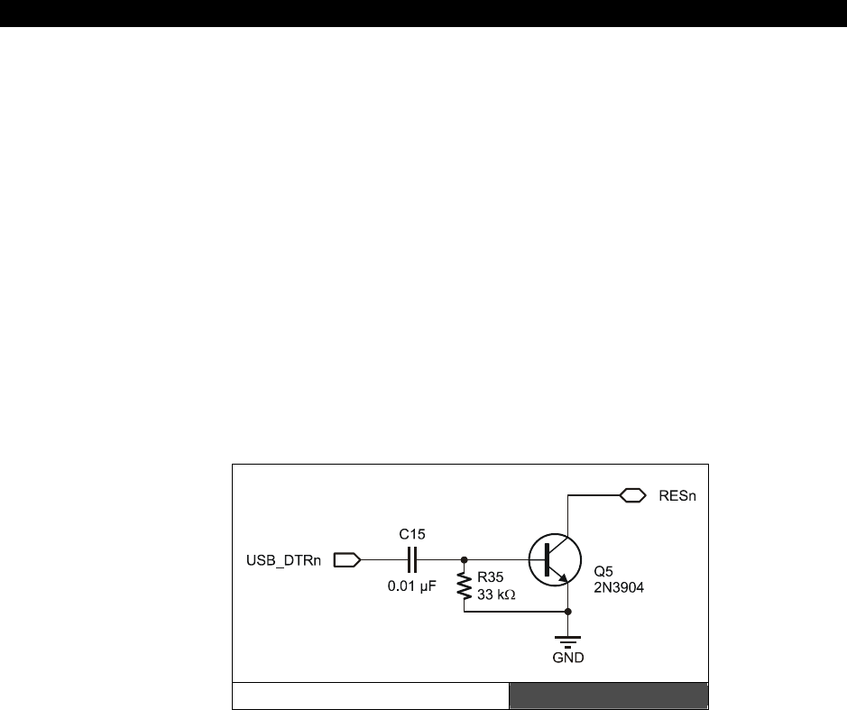
I The HYDRA Hardware
Page 82 Game Programming for the Propeller Powered HYDRA
3.2 Manual Reset of the HYDRA
To reset the HYDRA manually, simply press the momentary Reset switch located in the front
of the HYDRA and the system will reset. During reset, the Propeller chip will look for
communication from the PC host, and if there is none, the Propeller will then commence to
load from an external EEPROM. If there is no EEPROM, the Propeller chip will go into a low
power shutdown state until reset again. If an external EEPROM is found (which is always the
case on the HYDRA), the first 32 KB of the EEPROM are loaded in the SRAM of the Propeller,
then the Spin interpreter is launched and the code is executed. More details on this process
later in Part II.
3.3 Reset Via DTR
Historically, the DTR or
data terminal ready
line on the serial interface was commonly
used to initiate a reset on serial controlled hardware (modems etc.). The HYDRA is designed
so that if DTR is pulled HIGH or asserted then RESn will be pulled LOW on the Propeller chip
and the entire HYDRA will reset. Referring to the circuit in Figure 3:2, Q5 is normally OFF,
thus no current flows in the collector-emitter circuit. However, when the signal USB_DTRn is
driven HIGH with a pulse, Q5 conducts and pulls RESn LOW, therefore resetting the system.
DTR Reset Circuit Figure 3:2
3.4 Summary
This was a pretty straightforward chapter; the HYDRA is reset either manually with the Reset
switch or electronically via the DTR line or via the RESn line coming in from the secondary
backup USB2SER programming port. The one thing to remember is that the RESn line on the
Propeller is internally pulled HIGH by a 5 KΩ resistor to 3.3 V, so technically you do not need
a pull-up on it, but if you want a really robust design, it can’t hurt!

USB – Serial Programming Port 4
Game Programming for the Propeller Powered HYDRA Page 83
Chapter 4:
USB-Serial
Programming
Port
In this chapter, we are going to discuss the USB to serial hardware. The HYDRA ultimately
uses a simple serial protocol to communicate with the PC, but due to the lack of old style
9-pin serial ports, the HYDRA has both a built-in USB interface as well as a port that supports
the Parallax USB2SER device in case you only have a single USB port and you want to
program both the HYDRA and other serial devices on your workbench. In any event, here’s
what we are going to cover:
General USB serial overview
Parallax USB2SER USB serial interface
Onboard USB interface
Communicating with the serial interface
4.1 General USB Serial Overview
If you are at all a hardware hacker then you are more than familiar with the tried-and-true
RS-232 serial standard. RS-232 is both an electrical as well as protocol standard that has
been around for a long time. In the 70’, 80’s and even 90’s every single computer on the
planet had a standard DB9 serial port on it and most PCs had two. From a standpoint of
interfacing, RS-232 is nearly the simplest of all standards to get up an running, based on a
±12V system to transmit data/receive data a minimal system can operate on a subset of the
specification with only the TX (transmit), RX (receive) and GND (ground) lines.
However, since the proliferation of the USB interface, standard serial interfaces have
disappeared; in fact, many new PCs do NOT have a single DB9 serial port! This is really bad
news for hardware hackers and embedded system enthusiasts, since interfacing to USB is
NOT trivial; moreover, the protocol for USB is just as complex as Ethernet! Sure, there are
chips that do it, but what used to take a DB9 and a couple resistors now takes a chip, a
driver on the PC side, and a lot of trial an error. Nevertheless, we are stuck with USB
interfaces, so we have to deal with it.
However, some manufactures have acknowledged the need for “simple” serial interfaces
through USB and designed a number of chips that facilitate this transparent to the user. That
is, you use the chip in your design, load the manufacturer’s driver into the PC, and then
either through an API or virtual COM port, you can communicate to your hardware via the
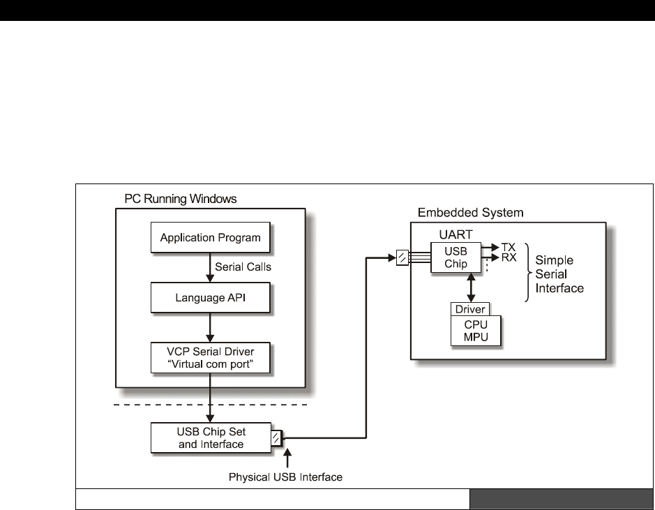
I The HYDRA Hardware
Page 84 Game Programming for the Propeller Powered HYDRA
USB interface as if the hardware were a simple serial interface. On your hardware itself, the
chip does the entire protocol interface for USB, and at the end of the day when you send a
BYTE to your hardware, the chip sends out on the USB to serial interface coming from the
chip the data on the TX line. So in most cases, these special USB-to-serial chips have a
“serial” like modem interface on them that you use on your design as if it came from a
standard old style RS-232 interface. Figure 4:1 shows the entire data flow from the PC to the
embedded hardware, so you can get an idea of everything in between.
From PC to Embedded Hardware Figure 4:1
So the point is that even if you only have a new USB port, you can still write old-style serial
code that talks to COMx on the PC and with one of these USB-to-serial chips, the chip plus
driver from manufacturer will make it all work for you. Of course, you still have to design the
chip into your system and this can be hard or easy depending on the chip you select. In the
case of the HYDRA I opted to use the new FTDI FT232R shown in Figure 4:2.
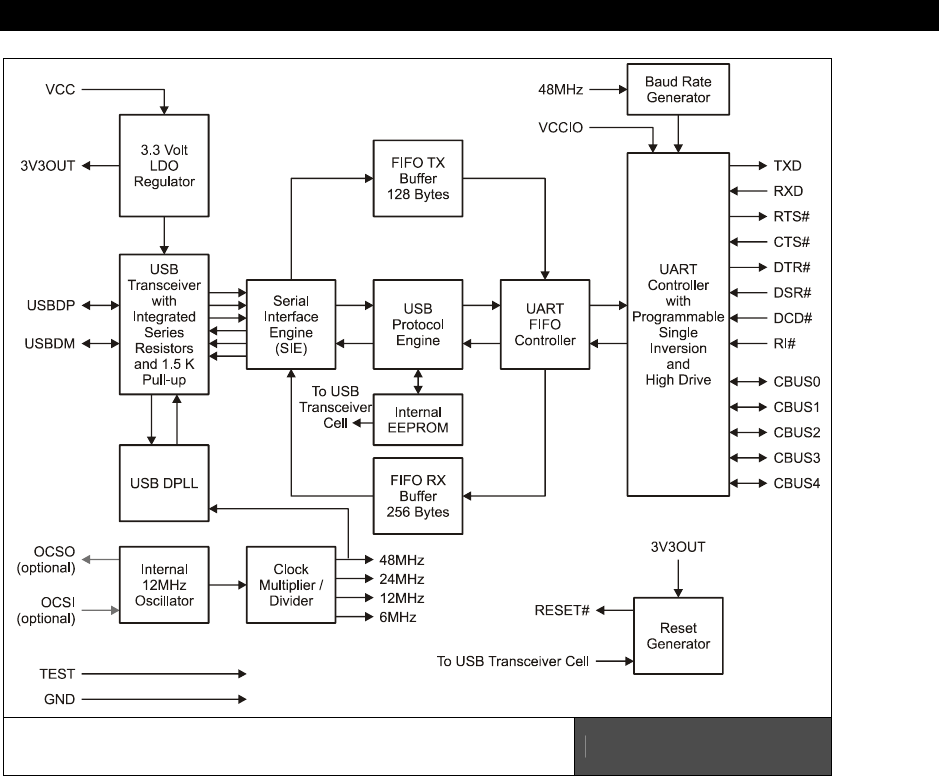
USB – Serial Programming Port 4
Game Programming for the Propeller Powered HYDRA Page 85
Block Diagram of the FTDI FT232R
Single Chip USB Solution Figure 4:2
The FT232R is a pretty slick little chip, and with nothing more than a few resistors, caps, and
the physical interface for the USB connector, you have a complete USB solution that outputs
a standard serial interface. Referring to Figure 4:2, this is a block diagram of the chip; as you
can see at the end of the day, there is a UART-like interface on the top right hand side of the
design and this is what you connect to your serial interface on your hardware after you have
the chip all hooked up.
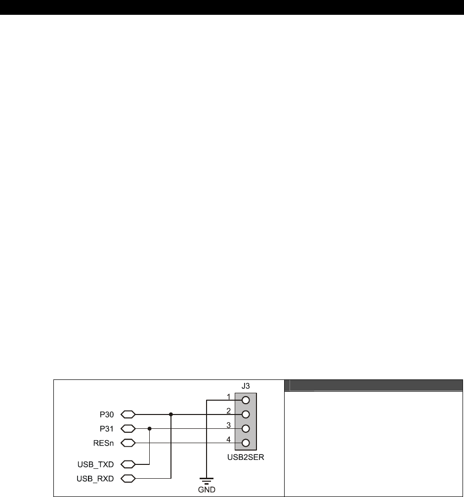
I The HYDRA Hardware
Page 86 Game Programming for the Propeller Powered HYDRA
Momentarily, we will discuss the hardware around the FT232R chip in the HYDRA itself, but if
you want to take a look at the datasheet and a reference design for the chip, I have included
them on the CD here:
CD_ROOT:\HYDRA\DOCS\DS_FT232R_v104.pdf
CD_ROOT:\HYDRA\DOCS\USB232R.pdf
Summing up, the HYDRA uses a USB interface physically, but through the use of the FT232R
USB to serial interface chip and their associate virtual COM port driver, from the PC’s point of
view (and the Propeller IDE) the HYDRA interface is a standard serial port. Moreover, from
the point of view of the Propeller chip on the HYDRA, the USB port is a simple RS-232 style
interface, so everyone is happy and we can use simple serial communications protocols, etc.
riding inside of complex USB protocols!
4.2 Parallax USB2SER USB Serial Interface
The HYDRA has a onboard USB chip as noted, so you simply connect your PC to the HYDRA
and you are off and running; however, as I was working with the design of the HYDRA and
experimenting myself, I started with the Parallax USB2SER device to get my first Propeller
designs up and running then I embedded the USB solution into the HYDRA itself.
Nonetheless, when I finished the HYDRA, I was about to remove the 4-pin USB2SER
interface header (1 penny worth of hardware) when I realized that I want to keep it. The
reason why is simple: in many cases, you might only have a single USB port for hardware
hacking, if you’re a Parallax customer then you might already have a USB2SER device that
you like to use to connect your other hardware to your PC, then when you want to play with
the HYDRA, you would have to unplug the USB cable and plug the HYDRA into the USB port.
So for the small percentage of users that have only a single USB port and use the USB2SER
device already on their workbench, leaving the little USB2SER header is a good thing, so I did
it. Thus, let’s start briefly by talking about this interface to the HYDRA.
Figure 4:3
The USB2SER Interface Pinout
USB – Serial Programming Port 4
Game Programming for the Propeller Powered HYDRA Page 87
Figure 4:3 shows the hardware pinout and design of the USB2SER interface on the HYDRA.
One end of the USB2SER connects to the PC via a USB mini-B cable, the other plug or
header has 4 signals on it as shown in Table 4:1.
Table 4:1 The USB2SER Header Pinout
USB2SER Pin # Description Propeller Chip Connection
1 GND GND
2 RX P30
3 TX P31
4 Reset RESn
The USB2SER header interface is simply connected to the appropriate lines on the Propeller
chip and HYDRA and the communications are handled transparently during programming etc.
Additionally, once the Propeller chip is programmed and running, the TX/RX lines connected
to the USB port at pins P30/P31 respectively can be used to communicate with the PC via the
USB connection, thus one can use these to do upstream communication and/or talk with
third-party tools you create.
For example, say the HYDRA is connected via the USB2SER to the PC host, and the Propeller
IDE is not running, and the HYDRA boots with some onboard program on the EEPROM or
cart. There could potentially be an app listening on the PC to the USB (serial port COMx) and
with software you write you could download assets from the PC, or whatever. So the
important point is that the USB serial connection to the host is freely available
after
programming is done, and the IDE has released the serial port resource connected to the
USB port.
I The HYDRA Hardware
Page 88 Game Programming for the Propeller Powered HYDRA
4.3 Onboard USB Interface
Refer to Figure 4:4; this is the complete design for the onboard USB interface. As you can
see, the center of the design is of course the FTDI FT232R chip. The design is more or less
based on their reference design along with consideration for some Propeller-specific issues.
Of course there are transmit and receive LEDs for example! Anyway, let’s briefly discuss
some of the issues when interfacing with USB. First, the USB lines are “transmission lines”
and thus they must be damped by a terminating network on the receiver end otherwise you
will get ringing and reflections. Normally, this means either a serial or parallel termination
network; USB specs usually call for a simple 33 Ω in series with each of the data lines D- and
D+. However, the FTDI chip comes with series terminating resistors, so you don’t need them.
Secondly, the USB interface starts up in either slow or fast mode; this is controlled by a
pull-up resistor connected to the D+ or D- line. To initiate high speed mode, a pull-up from
the D+ line should be made through a 1.5 kΩ resistor to 3.3 V; similarly for low speed mode
a 1.5 kΩ pull-up should be connected to the D- line 3.3 V. The FTDI chip handles this for us
as well and starts out in high speed mode.
USB is a differential signaling standard; that is, the difference in voltage is the
code, rather than the absolute value. This helps cancel out noise since:
[ ((D+) + noise) – ( (D-) + noise) ] = (D+ - D-)
That is, the noise cancels out.
Alas, there isn’t much for an EE to do with the FTDI chip, it does everything for us. About the
only thing you should add to the design are the filtering caps to the interface and power and
that’s about it. As far as the HYDRA is concerned, the DBUSxx I/O lines on the FTDI chip are
all that we are concerned with. In fact, we only need the TX, RX, and DTR line for the
HYDRA; however, the rest of the lines are there if you were to ever need them, but they are
not exported to the expansion port, so you would have to piggy-back on them if you wanted
access.
Do not connect both the USB2SER interface and the onboard USB cable at the
same time. Although this will not damage the HYDRA or the USB chips, the USB
chip on the USB2SER and the onboard USB chip on the HYDRA would both
potentially be driving the serial TX and RX lines on the HYDRA, and that will
cause errors on the system during programming, etc.
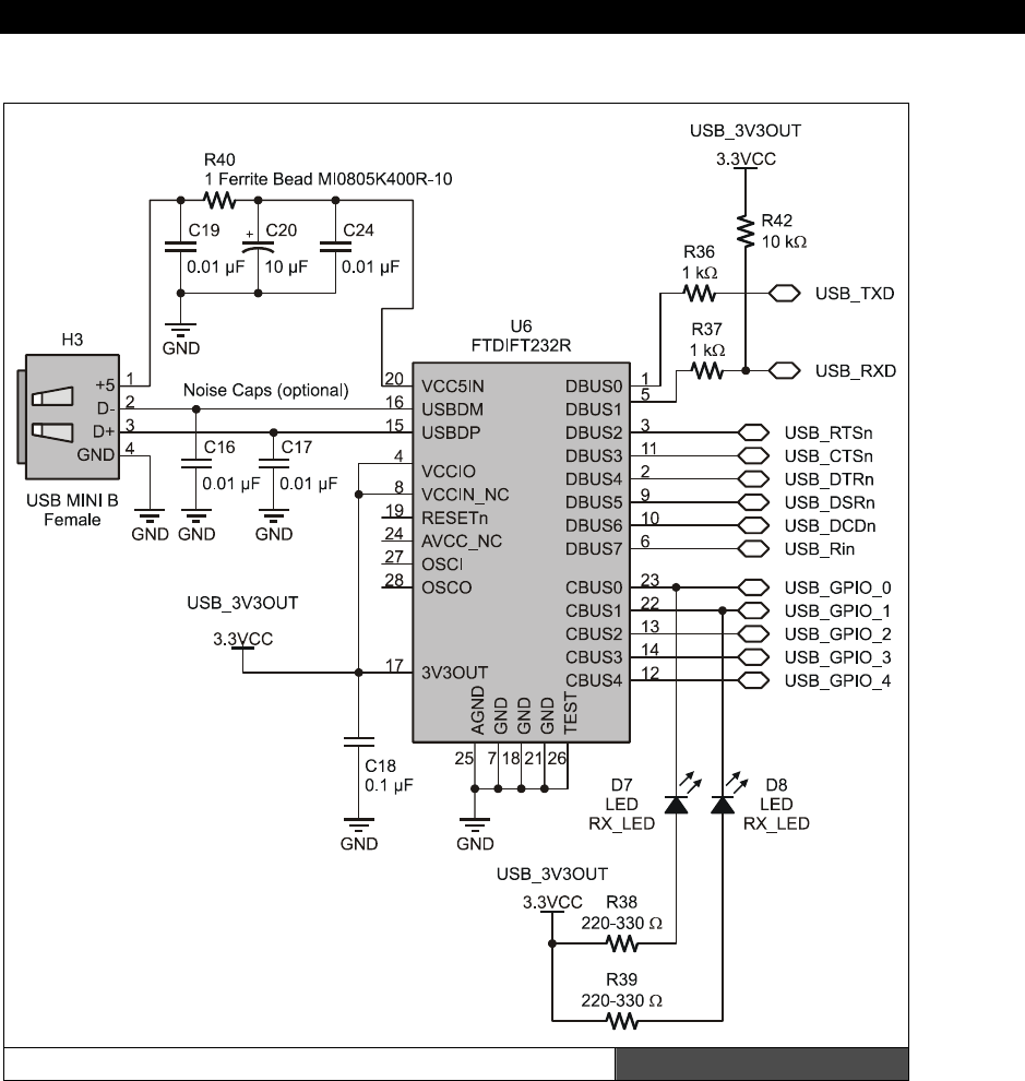
USB – Serial Programming Port 4
Game Programming for the Propeller Powered HYDRA Page 89
HYDRA Onboard USB Interface Figure 4:4

I The HYDRA Hardware
Page 90 Game Programming for the Propeller Powered HYDRA
4.4 Communicating with the Serial Interface
The USB interface TX and RX lines always go to Propeller chip pins P31 and P30 respectively,
as shown in Table 4:1 on page 84. So, all communicating you wish to do will end up on those
lines from the Propeller chip’s point of view. Now, to communicate with the HYDRA/Propeller
chip via the USB interface on the PC, all you have to do is install the VCP (virtual COM
drivers) from FTDI (which we already did in Chapter 1) and you can simply open a COM port
to whatever COM port the USB is connected to and then use it like you would any COM port
with standard C, Visual Basic, or whatever your tool of choice is.
For example, after the Propeller tool is done programming the Propeller chip on the HYDRA,
or if you just connect the HYDRA to a USB port with a program already in it, then you can
communicate to the HYDRA via serial communications. This is very useful for more advanced
applications, tools, and of course debugging. You can write a simple serial driver on the
HYDRA that communicates with P31/P30 using a standard serial protocol like N81 at a
reasonable speed like 56 or 115 K bits and then send strings to the PC; just run
HyperTerminal and you will see the characters on the screen. We will actually do this later in
the book.
4.5 Summary
The USB interface is one of the most complex interfaces I have ever worked on, and to write
drivers, design hardware, etc. is a nightmare, but with a single chip like the FTDI chip and
the drivers they supply all these problems go away. Additionally, the problem of DB9 serial
ports disappearing the way of the dinosaur isn’t an issue. Of course, if you only do happen to
have an old-style DB9 serial port, then you can probably find a serial to USB converter and
still make things work! In any event, if you want to explore USB interfacing in more detail, I
suggest reading through the FTDI docs, datasheets, and reference designs, and you also
might try picking up a copy of
“USB Complete”
by Jan Axelson.
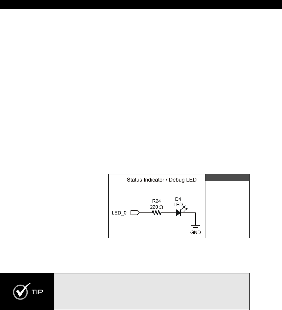
Debug Indicator Hardware 5
Game Programming for the Propeller Powered HYDRA Page 91
Chapter 5:
Debug Indicator
Hardware
The Propeller chip has no debugging facilities as of yet. Plans are in place to add debugging
to the IDE as well as an API that runs on a cog to help with the debugging, but with the
current release of the IDE and tools there is no formal debugging support. Thus, debugging
has to be done old school. But, this isn’t that bad – I like old school! There are numerous
options for this which I will describe momentarily. However, at very least I have put in a
single debugging LED, so you can at least use it to indicate “something” is working in your
code, and use it for an indicator and debugging tool. In this chapter, we are going to discuss
the debugging support on the HYDRA and some ideas to further extend debugging. The
topics included are:
The debug LED design
Additional debugging techniques
5.1 Debug LED Design
The only “hardware” for debugging
on the HYDRA is the single LED
circuit shown in Figure 5:1. The LED
is connected to the Propeller chip via
port P0 through a current-limiting
resistor. To turn the LED on/off,
simply write a 1 or 0 to the port P0
(you will learn about the I/O port
communications and more in Part II
of this book).
The LED has its cathode to ground, thus a 1 or HIGH on I/O port P0 results in the LED
turning ON, a LOW or 0 results in the LED turning OFF.
Some TTL/CMOS (especially CMOS) circuitry can’t source a lot of current, but
can sink a lot of current, thus it’s a better idea to connect the cathode to the I/O
port in that case and use reverse logic to turn the LED on/off. However, this isn’t
a problem with the Propeller chip since it can source/sink 30 mA per I/O. Of
course, you wouldn’t want to drive all 32 I/Os at 30 mA, that might be too much
current for the chip to handle at one time.
Figure 5:1
The LED
Debugging
Indicator
Design
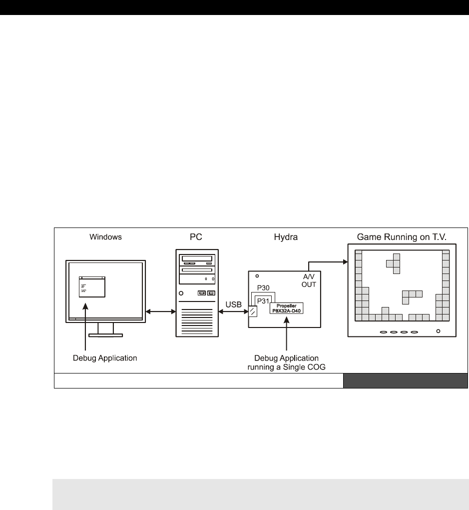
I The HYDRA Hardware
Page 92 Game Programming for the Propeller Powered HYDRA
5.2 Additional Debugging Techniques
If you are “old school” then you are a master of debugging and can think of 1000 ways to
debug code. Using debuggers to debug programs hasn’t been around for that long. In fact,
many people still don’t know how to use the debugger in VC++! In any event, it’s “nice” to
step through code and watch registers, but there is no “direct” way to do this with the
language, IDE, or processor. However, with some clever software we can do this more or
less. The first step is to get a simple graphical app working that acts like a “terminal” and
runs on a single cog (or the PC), then as you are trying to experiment and debug code you
can print to the terminal to “watch” variables. In fact, you can potentially watch single
instruction execution by placing hooks in your code to call your terminal update every single
instruction. Additionally, you can “synthesize” breakpoints in your code by making a call to
your “terminal” or debugger program so that when called it dumps what the cog is doing or
memory or whatever and doesn’t return until you hit a key or press the joystick or something
like that. So more or less, to debug, think graphically, and think “printf” – try and visualize
your code execution by printing state out and using the debugging LED where possible.
A PC-hosted Debugging Application Figure 5:2
Another possibility is to write a PC-hosted app that talks to the Propeller chip over the USB
port TX/RX lines, using a single cog to send information to the application as shown in Figure
5:2. For example, you can write an object/program that runs on a cog as a debug client,
then you make calls to it and pass it variables to watch something, like this:
Debug.Add_Watch(&x, "X position", UNSIGNED_BYTE, DEFAULT_X, DEFAULT_Y, 1000)
Debug Indicator Hardware 5
Game Programming for the Propeller Powered HYDRA Page 93
The intent of this hypothetical call might be to “add” a watch variable to a list with the
address of the variable “x”, and indicate that “x” is to be displayed as an unsigned 8-bit
value, and on the debugging display print the text “X Position” next to the output and simply
place the watch variable at the next available x,y location, finally the 1000 might mean to
update every 1000 milliseconds. The debugging client running on a cog would simply add
this information to a local list and then it would access global memory or whatever and send
it to the PC and the PC host program would do all the display. This way you can have a
completely asynchronous debugger running “hidden” on a cog that for the most part does
NOT interfere with your game or demo code. Of course, you can’t read a cog’s local memory
unless the cog shadows it to global memory.
If you want to you “can” run the Propeller chip at DC and pulse the clock
yourself with a single-step button (with debouncing of course), this way you can
potentially put probes or whatever on the pins of the chips, or control it.
Additionally, you could surround the Propeller chip with some extra debugging
hardware that via the PC, you could single-step the chip and so forth. Of course,
if you do this then you need to run the Propeller chip’s clock input mode as
straight clock in “XIN” mode, without any XTAL reference or PLL modes; more
on this later.
Lastly, a really slick way to add a little bit of debugging I/O is with a serial or quasi-parallel
LCD. You can buy a number of very simple LCDs from DigiKey or other online vendors and
interface them to the HYDRA through the expansion port (which will be discussed later in
Part I). Typically, the LCDs take a simple stream of commands to print characters on the LCD
and some LCDs even have bitmap displays. Common sizes for monochrome LCDs are 20x2,
40x2, 20x4, and 40x4 characters. Hantronix is one of my favorite vendors, they also make
full-color LCDs with entire graphics engines built in, so you could potentially make a plug-in
card that had a full color LCD and print debug information to that and forgo the complex PC
serial interface.
5.3 Summary
In this chapter, we discussed probably the simplest piece of hardware on the HYDRA – the
debug LED, but one thing is for certain, a single LED can work wonders when debugging
ASM code! Also, we discussed some ideas to get some more advanced debugging techniques
online, I highly suggest taking the time and effort to invest in getting your debugging
techniques down before you start into heavy coding (in ASM at least) on the Propeller chip, it
will definitely save you time in the long run.

I The HYDRA Hardware
Page 94 Game Programming for the Propeller Powered HYDRA

Game Controller Hardware 6
Game Programming for the Propeller Powered HYDRA Page 95
Chapter 6:
Game Controller
Hardware
Originally I was going to use Atari 2600 joysticks for the HYDRA; however, due to their
scarcity and the lack of extra controls on them, the decision was made to go with classic NES
(Nintendo Entertainment System) controllers. The primary reasons are that NES controllers
are abundant, easy to interface to, have lots of nostalgia, can be interfaced via 4 signal lines,
third-party models look really cool, and most importantly, if the HYDRA interfaces to the NES
controller then any “NES compatible” device can be interfaced since they all use the same
connector! Thus, light guns, VR gloves, and any and all manner of bizarre NES hardware
from the 80’s/90’s can be interfaced to the HYDRA through the controller ports, so it’s a good
plan. With that in mind, in this chapter we are going to discuss the following topics:
Overview of the NES hardware
NES controller protocol and interfacing
Supporting Super NES controllers
6.1 The Classic NES Controller (1983)
If you have never heard of Nintendo, then may I be the first to greet you from Earth,
because you must be from another planet! The Nintendo Entertainment System or NES, also
known as the Nintendo Family Computer (Famicom) was released in Japan in 1983 and
shortly after in the USA in 1985. The system was even more successful than the Atari 2600
and more or less put the last stake in the heart of Atari home consoles forever. The NES sold
more than 60,000,000 units worldwide in its heyday and still sells to this day (I just bought
4 of them from eStarland.com)! There are over 200 clones of the system in circulation and
the word “Nintendo” is used in many cultures as a youth slang term with many “varied”
meanings.
The system itself was nothing compared to the Propeller chip’s computing power, the NES
was powered by the 8-bit 6502 running at 1.79 MHz, but the NES did have quite a bit of
dedicated graphics hardware making it quite a contender in the 8-bit era, it sported multiple
tile maps, graphics planes, sprites, sound, and a lot more. In any event, as noted I opted to
use the NES controllers for the aforementioned reasons, plus being an Atari guy, sometimes
its nice to jump ship and see how the other side lives, so all in all I am very happy with the
NES controllers on the HYDRA. They give the system a retro feel, but are powerful enough to
use as serious input devices for more than just games. Plus, the final controllers shipped with
the HYDRA look very cool.
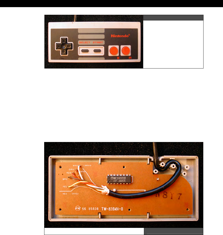
I The HYDRA Hardware
Page 96 Game Programming for the Propeller Powered HYDRA
Figure 6:1
NES Controller
(front)
The classic NES controller / gamepad is shown in Figure 6:1, and internal shot is shown in
Figure 6:2. As you can see there isn’t much to the NES controller electronics (a single 4021
serial chip), but that’s the beauty of it. The interface is so simple, we can use 4 lines to
interface to the NES controller and read all 8 inputs (Up, Down, Left, Right, A, B, Select,
Start).
Of course, we aren’t using these collectors’ item controllers on the HYDRA, that would be
sacrilege; but all NES controllers must be compatible with the original standard, so we are
going to discuss NES controllers with the original in mind, but the controller that comes with
your HYDRA will be from the 21st century and a bit more sleek in its design.
NES Controller (inside) Figure 6:2
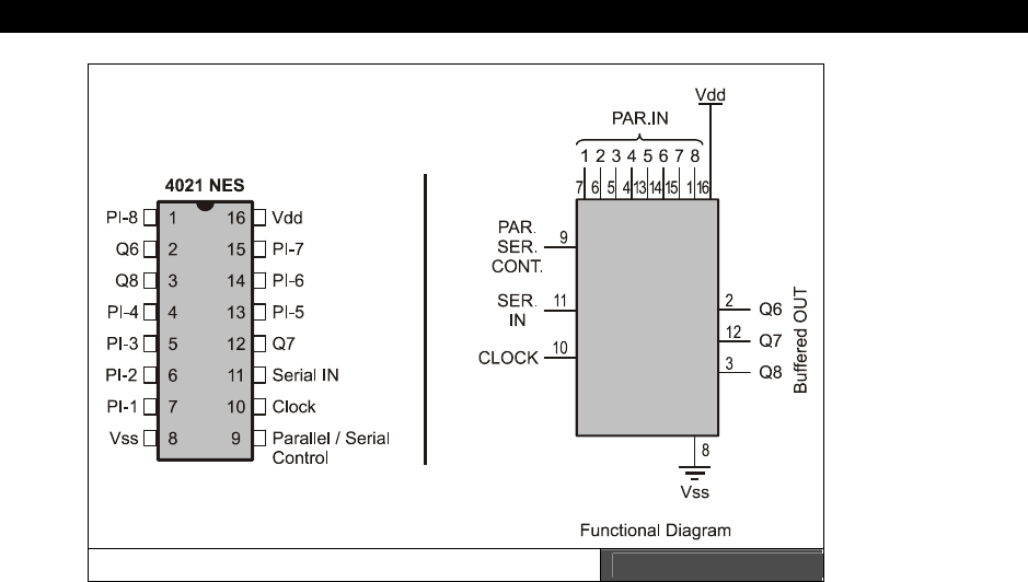
Game Controller Hardware 6
Game Programming for the Propeller Powered HYDRA Page 97
Pinout of the 4021 NES Controller Chip Figure 6:3
The NES controller is based on a parallel to serial shift register internally that “latches” the
button states and then shifts them out to the host. The shift register used in the original NES
control is the
CMOS 4021 shift register
. Figure 6:3 shows the pinout of the 4021 and the
complete data sheet is on the CD located at:
CD_ROOT\HYDRA\DOCS\cd4021b.pdf
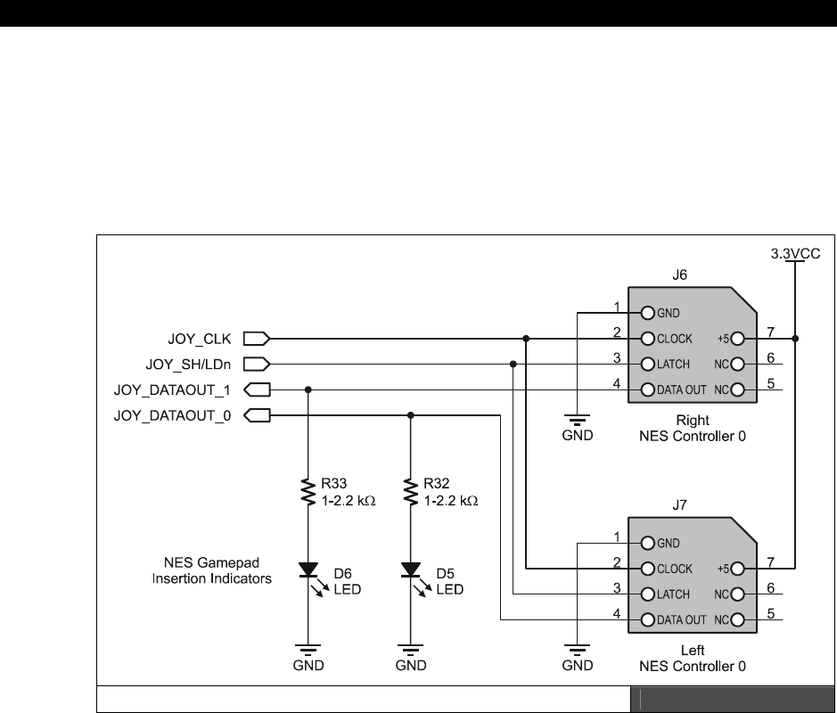
I The HYDRA Hardware
Page 98 Game Programming for the Propeller Powered HYDRA
Figure 6:4 shows the HYDRA controller interface for the right and left controllers. As
mentioned, all the signals are paralleled except for the JOY_DATAOUT_0 and
JOY_DATAOUT_1 lines since these are the independent data streams from each controller.
Also, notice that the LEDs that are connected to the data out lines, the resistors are large
enough to minimize current drain, and thus the signals are not degraded, but when the NES
controllers are plugged in the weak pull ups on the outputs of these lines power the LEDs
and indicate that the controller is plugged in.
The HYDRA Gamepad Interface Ports Design Figure 6:4
The actual pinouts and colors (for the classic NES controller) are shown in Table 6:1.
Referring to the table, you can see that the original spec for the NES controllers uses +5 for
power. I was a bit worried that the old 4021’s wouldn’t work at 3.3 V and I would have to
Frankenstein the 5 V supply into the NES controller, but then make sure the levels match the
outputs and inputs to interface to the Propeller, but the 4021 is a CMOS device and works
fine at 3.3 V. Of course, running any CMOS device rated for 3-7 V at lower voltages lowers
the maximum clocking rate, but in this context it’s irrelevant, since we can read the controller
bits at a rate of 200 ns each.
Game Controller Hardware 6
Game Programming for the Propeller Powered HYDRA Page 99
Table 6:1 NES Controller Pinout
Pin # Function Wire Color* Pin on Propeller Chip/Design Designator
1 Ground Brown GND
2 Clock Red JOY_CLK (P3)
3 Latch Orange JOY_SH/LDn (P4)
4 Data Out Yellow JOY_DATAOUT_0 (P5), JOY_DATAOUT_1 (P6)**
5 No Connect None
6 No Connect None
7 + 5 Power White
Notes * Colors on original NES Nintendo controllers only; 3rd party controllers have different colors.
** Where JOY_DATA_OUT_0|1 are the left and right controller ports respectively.
*These colors are on “stock” controllers ONLY, in fact many third-party
manufacturers of NES/SNES controllers not only get the colors wrong, but
sometimes use the correct colors and connect them to the wrong pins! The best
thing to do is rip the connector apart and see what color is connected to what
pin on the 4021 and power supply rails.
6.2 Interfacing to the NES Controllers
Interfacing to the NES controllers is a completely digital affair; on the HYDRA for example,
we can run the clock, latch, and power lines in parallel, then send the data from each
controller (if its plugged in) to the Propeller chip. To read the state of the NES controllers,
you must perform the following steps:
Step 1: Set the Latch line (P3 on Propeller chip) to LOW (this is connected to the
parallel/serial select on the 4021).
Step 2: Set the Clock to LOW.
Now, we are in a known state.
Step 3: Pulse the Latch line HIGH for at least 200 ns, this will latch the data into the shift
register.
Step 4: Read the bits in from the Data Out lines at P5 and P6, the first bit will be available
after the latching process. To read the remaining bits, pulse the Clock line 7 times, as you
are doing this you can shift each bit read from the Data Out line into a BYTE, so that the first
bit ends up in the bit7 position and the last bit in the bit0 position. Realize that the HYDRA
reads the controllers in parallel, so you can perform the read operation once with some
clever bit manipulation.
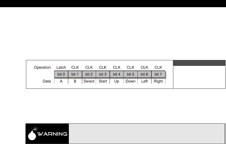
I The HYDRA Hardware
Page 100 Game Programming for the Propeller Powered HYDRA
Step 5: The button states are all inverted; that is, pressed is digital 0, released is 1, so you
might want to invert the results so 1 means “pressed”, just personal preference.
After performing these steps you simply use bit operations to determine which buttons are
pressed. The button encodings are shifted out in the following sequence starting from left to
right, where the left-most bit is available on the data out lines after the initial latching
operation as shown in Figure 6:5.
Figure 6:5
NES Data Format
Also, a bonus feature of the NES controller is that when you read it on the HYDRA, if the
controller is NOT plugged in then the value $FF will be returned, thus we can use this
sentinel to determine if a controller is plugged in or not!
When you latch and clock the bits, remember that the 4021 chip has a maximum
clocking rate. I suggest keeping the clocks 200 ns or greater to allow for settling
and propagation delays, you don’t want to loose the fire button bit under a high
stress condition if you are reading the controller too fast!
6.3 Super NES Controller Interfacing (1990)
Again for a quick history lesson: the new 16-bit system, Super Nintendo (SNES), was
released in Japan in 1990 and 1991 in the USA. The system once again became an instant hit
and sold a total of 50,000,000 units worldwide, thus making the combined sales for NES and
SNES in excess of 100,000,000 units!!! The SNES had better graphics and a much more
powerful 65816 processor (basically a 16-bit version of the 6502) running at 1.79 – 3.58 Mhz
in a “variable” speed mode of operation. The overall design of the SNES was a little more
sleek and updated, and of course they updated the controllers as well. The new controller
has a few more buttons, but the underlying protocol for reading the controller is the same.
Additionally, the mechanical interface for the SNES controller (shown in Figure 6:6) is even
more bizarre than the NES controller.
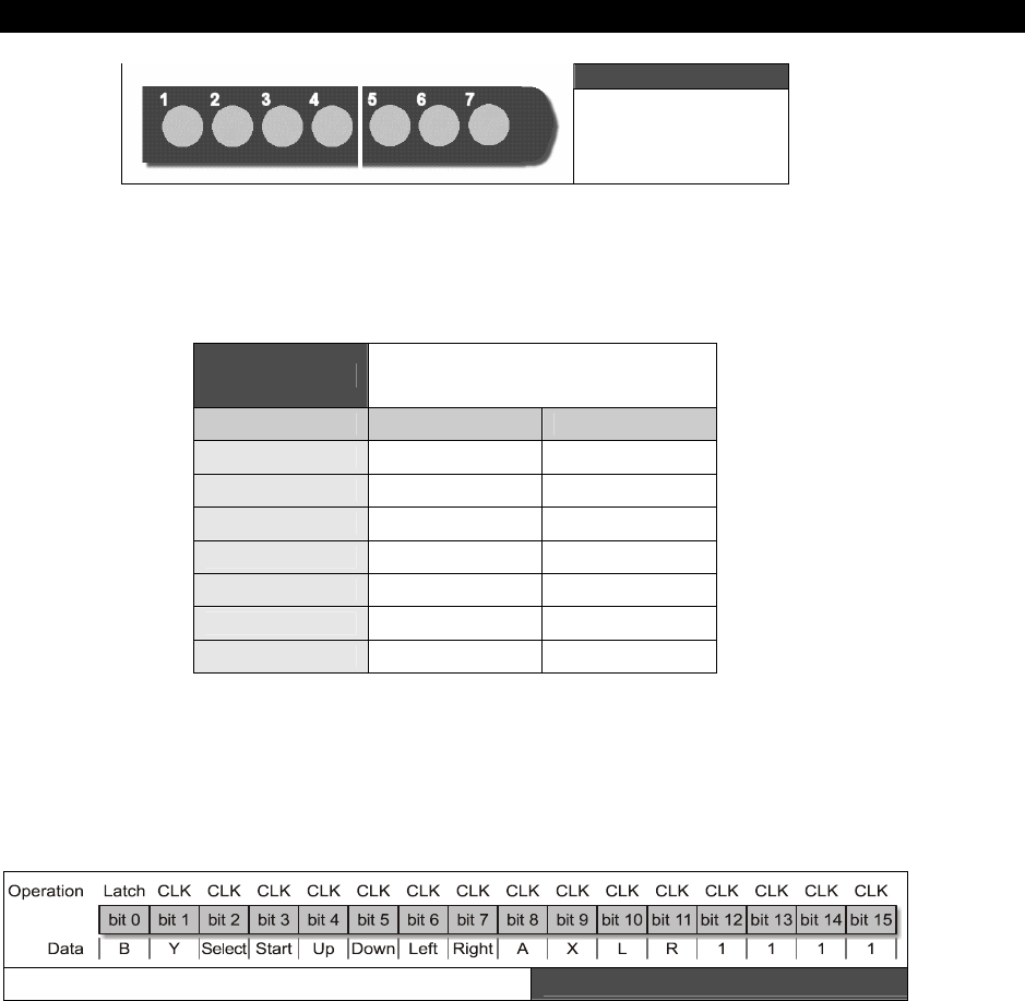
Game Controller Hardware 6
Game Programming for the Propeller Powered HYDRA Page 101
Figure 6:6
Super Nintendo
Controller Pinout
The Super NES controller is almost identical to the NES controller as far as the protocol goes,
so the techniques here are applicable to the SNES controller as well. Figure 6:6 shows the
pinout of the Super NES controller and Table 6:2 lists the pinout.
Table 6:2 Super NES Controller Port
Pinouts
Pin # Function Wire Color
1 + 5 power White
2 Clock Yellow
3 Latch Orange
4 Data Out Red
5 No Connect None
6 No Connect None
7 Ground Brown
The only difference is that the Super NES streams out 4 more bits representing X, Y, R (right
shoulder button), and L (left shoulder button) which makes for a total of 12 bits. However,
Nintendo opted to add 4 more cycles for future expansion and made the read protocol a total
of 16 bits as shown in Figure 6:7; notice the last 4 bits are always HIGH, or 1s.
SNES Data Format Figure 6:7

I The HYDRA Hardware
Page 102 Game Programming for the Propeller Powered HYDRA
6.4 Summary
In conclusion, the NES controllers are pretty slick internally since they simplify the HYDRA’s
need for support hardware due to their built in serializing chips. Also, hopefully you can
appreciate how simple and brilliant they were. A piece of software or hardware is seen
through its interfaces or GUI; this is true with Windows and true with game consoles, so
considering that, any idea that helped sell 100,000,000 units is worth taking a closer look at!
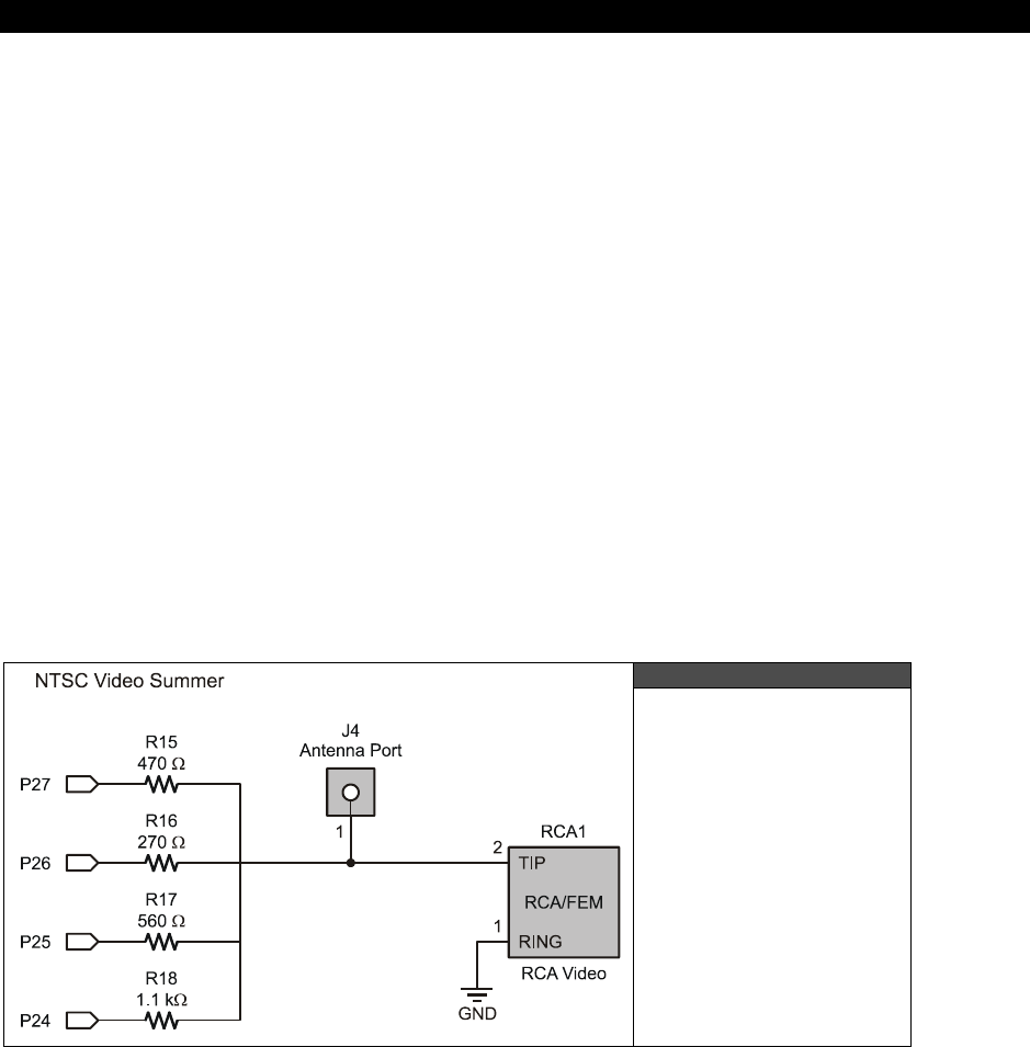
Composite NTSC / PAL Video Hardware 7
Game Programming for the Propeller Powered HYDRA Page 103
Chapter 7:
Composite
NTSC / PAL
Video Hardware
In this chapter, we are going to take a look at the composite video hardware for the HYDRA
and take a brief look at basic NTSC concepts. This is by no means a treatise or even a tidbit
about NTSC video generation, later in the chapter I will give you some good book titles and a
website to read about NTSC/PAL video engineering. For the HYDRA though, we are for the
most part simply going to use the drivers that Parallax, myself, and other coders have written
in ASM to generate video and use them as black boxes, as objects, or as functions included
in our programs. So without any further ado, here’s what’s in store this chapter:
HYDRA composite video hardware
The Propeller chip’s video streaming unit hardware
Brief NTSC primer
7.1 HYDRA Video Hardware
Figure 7:1
The HYDRA’s Video
Hardware
The HYDRA has very little hardware for video. In fact, all the video generation and timing is
done within the Propeller chip itself via a mixture of software and hardware; there is no

I The HYDRA Hardware
Page 104 Game Programming for the Propeller Powered HYDRA
dedicated GPU, no VRAM, or frame buffer of any kind. Later we will discuss this in detail in
Part II, but for now realize that each cog has what’s called a
“Video Streaming Unit”
or
VSU. The VSU of each cog can run independently and more or less simply serializes a stream
of data that you pass it in 32-bit chunks. The data is formatted in such a way that it either
assumes you are driving a NTSC/PAL device (with a resistor summing network on the output
port) or an RGB device (BYTE device with no electronics on the output port) like VGA. The
hardware you place on the outside of the Propeller chip to make the internal hardware work
is minimal at best. Figure 7:1 shows the actual video hardware for the composite NTSC/PAL
signal.
It’s more or less a simple 3-bit D/A resistor network (R16, R17, R18) and the 4th bit (R15) is
for audio modulation when the cog is in RF modulation mode (yes, the cogs can transmit
video via RF if you hook a wire to the output at J4!). The resistors are selected such that with
a 3.3 V supply and the signal terminating into a 75 Ω load (TV load) the maximum voltage
will be approximately 1.0 V when all the lines are HIGH (P26..P24), this is WHITE and 0.0 V
is SYNC level.
Referring to the circuit, the cog’s internal hardware assumes that you have hooked up a
resistor network such as that shown in Figure 7:1 to a 4-bit port of the cog and then you use
a couple of special instructions to set up the video configuration registers and “feed” the VSU
with pixel and color data. So you could say that the Propeller chip uses hardware to stream
pixel data out to a 3-bit DAC, that you feed it. The pixel data might be
sync, black
, or
luma, chroma
data (more on this in the NTSC primer below), the cog will output the proper
voltage via the DAC along with the proper phase delay for chroma (color) since it knows you
are driving NTSC/PAL video hardware (if you configure it this way), but that’s all the VSU
does.
Additionally, the VSU can work in “dumb” byte-oriented data mode and simply send out
BYTEs of data, this mode is used to drive VGA of the format RGB (2.2.2) plus Hsync and
Vsync, that’s a total of 8 bits or one BYTE per output. In this mode, you basically pass the
VSU VGA values and it sends them out each clock at 25.175 MHz (VGA clock rate). The
NTSC/PAL hardware is very minimal since the cog does all the work. The only downside is
that the timing and data feed to the cog’s VSU unit must be done with software, and a
“feeder”
loop more or less can only be done with very tight ASM code. Moreover, the cog’s
video hardware formats that output to the 3-bit DAC only allow 16 colors with a 3-4 shades
depending how close you want to go to the sync and white rails. And there is
no
general
control on saturation, but there are some tricks to get extra saturated colors in addition to
the standard colors (more later during graphics programming in Part III). Therefore, you can
control luma and chroma, but not saturation. Nonetheless, you will find that the saturation of
colors generated is very pleasing.

Composite NTSC / PAL Video Hardware 7
Game Programming for the Propeller Powered HYDRA Page 105
Generating NTSC or PAL is not a matter of hardware, but a matter of software,
that is, how you send data to the VSU and time the signal.
SECAM (a French standard loosely meaning “sequential color with memory”) on
the other hand is a whole other ball park, but can be generated with the VSU as
well if you really want to do it.
It’s worth mentioning that the VSU is nothing more than a serial streaming unit (not
necessarily only for video), it can generate video of any rate at the output, so there are no
real limits to the speed you can update video. The downside is that you must use the internal
32K program RAM for video memory. This can be quite disturbing in Spin code, since Spin
BYTE codes must reside in main memory, so you will find the demos and games you can
make that drive bitmapped video are very constrained since you eat up so much RAM to
support double buffering etc. However, in ASM, you have quite a bit of room and crazy
demos and games can be made.
Lastly, even though the HYDRA only has one video output, each cog has its
own
VSU that
can work independently of other cogs, thus you could potentially drive 8 TV’s at the same
time with different displays or demos if you wanted to add the resistor networks to each!
7.2 Brief NTSC Primer
The NTSC standard) is technically referred to as the RS-170 and was ratified in 1941, later
color was added and the full standard was updated to RS-170A. NTSC (National Television
Systems Committee) is an analog standard designed to be easy to generate and easy to
decode. Also, the standard had to be very forgiving. It’s amazing that over a half century has
passed and NTSC still gets the job done. To cover NTSC is any detail would take a whole
book, therefore, we are only going to briefly discuss it, and take more of a hands-on, black
box approach when we get to graphics programming. Rather than worrying about generating
NTSC signals yourself, the drivers I will provide you with will take care of it. With that in
mind, let’s take a quick look at NTSC and its underlying principles.
7.2.1 Basic Monochrome NTSC
NTSC is designed to be displayed by a raster device, that is, a CRT (cathode ray tube) that
draws images a frame at a time, where each frame is composed of a number of horizontal
lines.
The rendering device, usually a CRT’s electron gun, starts at the top left corner of the screen
and draws a line or row of pixels by emitting a stream of electrons toward the phosphor-
coated CRT, then when the electron(s) strikes the phosphors they give off light and you see
a pixel (monochrome or color, depending on the type of phosphor).
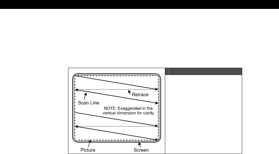
I The HYDRA Hardware
Page 106 Game Programming for the Propeller Powered HYDRA
Figure 7:2 shows how the NTSC signal is drawn. As the beam of electrons reaches the right
side of the screen, a sync pulse referred to as the
horizontal sync
or
Hsync
instructs the
CRT to retrace back to the left to draw another line. When the screen is completely drawn
then another sync pulse referred to as the
vertical sync
or
Vsync
instructs the raster beam
to make its way back up to the top left and the process starts again.
Figure 7:2
A Raster Screen Setup
The standard NTSC screen is composed of 525 lines, where each line consists of about 227
“pixels”
(picture elements). The 525 lines are broken into two interlaced
“frames”
, where
each frame is 262.5 lines and the frames are drawn at a rate of 60 frames per second
(FPS); interlacing these two frames together results in a “fused” display at 30 frames a
second. However, for graphics and games, we don’t use interlacing typically, and we simply
draw only 262.5 lines at 60 FPS.
The NTSC signal itself is composed of an analog voltage from 0 to 1.0 V or sometimes from 0
to 1.4 V. The voltage represents different things to the decoder on the TV. A voltage of 0 V
means “sync,” 0.25 means
blanking level
or
“blacker than black”
and a little bit above
this (say 0.3 V) is black, and anything from black to the maximum voltage of 1.0 (or 1.4 V)
creates shades of gray, and the maximum voltage (1 or 1.4 V) is white. Thus, the NTSC
signal is more or less an amplitude-modulated “luminance” signal with syncing information
embedded into it as well as color (more on this in a moment).
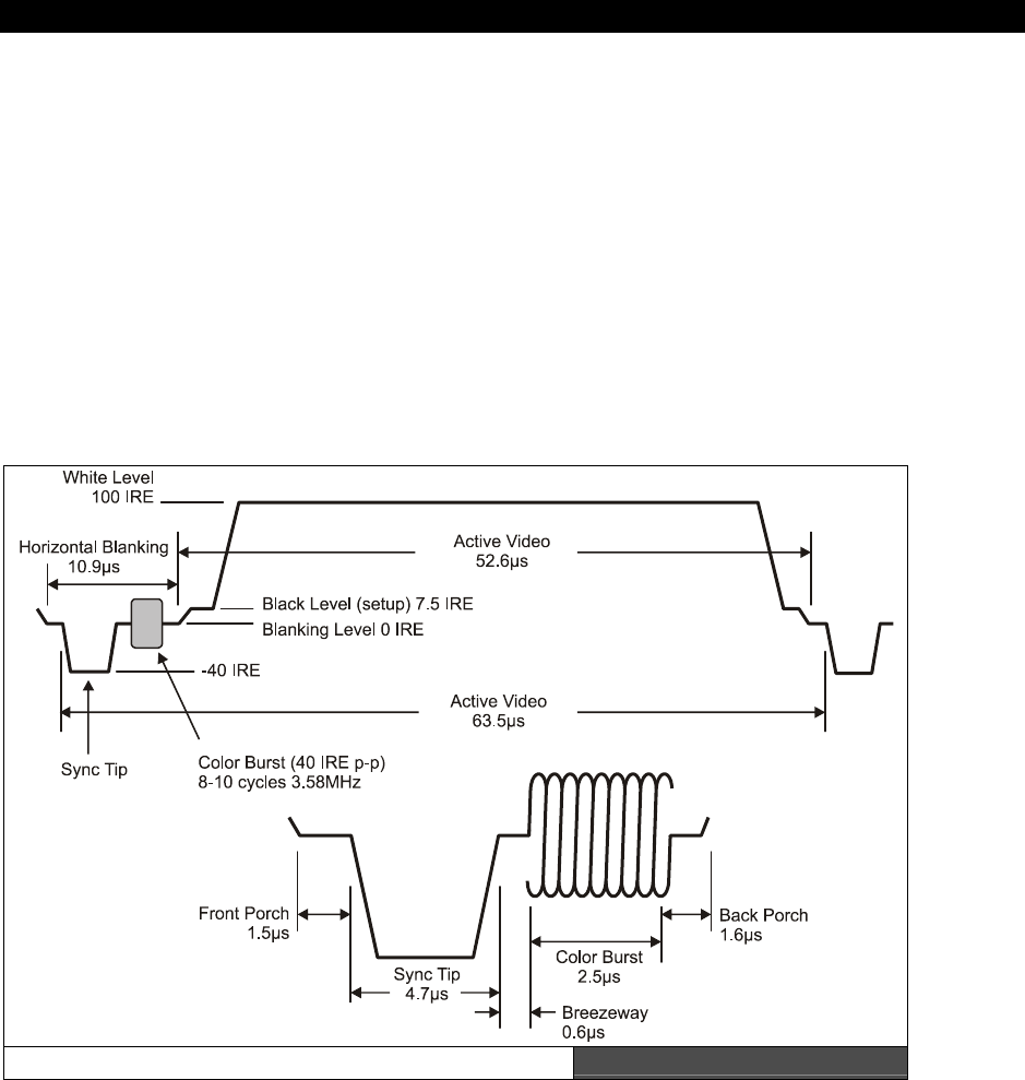
Composite NTSC / PAL Video Hardware 7
Game Programming for the Propeller Powered HYDRA Page 107
7.2.2 Dissecting a Video Line
Figure 7:3 depicts a standard NTSC video line) (not to scale of course), there are a number
of specific regions that make up the signal. First, an entire NTSC video line is always 63.5 µs,
that means that each line is rendered at a rate of (63.5 µs)-1 = 15.748 kHz. Now, let’s inspect
the video line carefully: it starts off with a
horizontal blanking period
, this is the time
when the electron gun is sweeping back from the right edge back to the left after drawing a
line of video.
The horizontal blanking period is composed of 5 major elements:
Front porch (1.5 µs)
Sync tip (4.7 µs)
Breezeway (0.6 µs)
Color burst (2.5 µs)
Back porch (1.6 µs)
A Single Line of Video Figure 7:3

I The HYDRA Hardware
Page 108 Game Programming for the Propeller Powered HYDRA
Front Porch (1.5 µs) – The front porch is really just the end of the last video line or the
beginning of the current line; it’s 1.5 µs in length and should be set to the blanking level or
blacker than black. In practice the blanking level and black can usually be the same value
and 0.25-0.3 V works fine.
Sync tip (4.7 µs) – The sync tip, or Hsync to be more precise, is very important; this
instructs the TV to initiate the horizontal retrace. The signal itself has a frequency of
15.748 kHz, but is very short, just a sliver really, but the TV electronics are looking for it. The
sync tip should be at 0.0 V.
Breezeway (0.6 µs) – The breezeway is the period right before the “
color burst
”
(which
we will discuss shortly) and simply gives the TV a moment to catch its breath before the very
important color burst reference tone is sent. The color burst enables the transmission of color
in the old black and white signal in a very ingenious way, more on this shortly. The
breezeway should again be at the blanking or black level.
Color burst (2.5 µs) – The color burst is 9-10 cycles of a 3.58 MHz reference tone, this is
locked onto by a phase locked loop in the tuner of the TV and then used as a reference for
the color signal. The color burst itself should ride on the blanking level with a peak to peak
value of about 0.25 V.
Back porch (1.6 µs) – The back porch follows the color burst, and is more or less simply
the time after the color burst, but before the active video signal.
Ok, that’s the horizontal blanking signal in its entirety, this must be sent at a rate of
15.748 kHz and the entire length of the signal is simply the sum of the constituent parts. The
next portion of the video line is the “active video” and this is where all the action happens.
The active video portion of the video line is 52.6 µs long and is nothing more than an
amplitude-modulated signal where the luminance, referred to as “luma” in literature, is
encodes as the amplitude of the signal at any one time from black (0.25 V) to white (1.0 V).
Now, when talking about a monochrome or black-and-white signal, you could change this
signal at any rate you want; however, you are band-limited to about 4.5 MHz on an average
TV. In other words, the maximum number of luma changes that the TV can keep up with is
about 52.6 µs / (4.5 MHz)-1 = 234 per active video line! Ouch! And it gets worse with color,
so prepare yourself. Thus if you are trying to map a 640 pixel screen to the TV, you are way
out of luck, at most you will be able to see 234 pixels and in reality a lot less, they tend to
blend into each other.
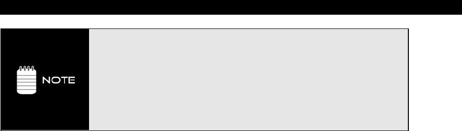
Composite NTSC / PAL Video Hardware 7
Game Programming for the Propeller Powered HYDRA Page 109
You may have noticed that in the TV signal diagram there is a unit of measure
called “IRE” this stands for “Institute of Radio Engineers.” There are a total of
140 IRE units in a TV signal from sync to white.
Now here’s the clincher: depending on what reference you use and what set you
use, 140 IRE units are usually mapped to 1.0 V OR 1.4 V – that’s where this
1.0 -1.4 V discrepancy comes into play. However, for all intents and purposes, I
have never found a set that wouldn’t work with either scale.
In other words, NTSC is so forgiving and so adaptive that whether you use 1.0 V
for white or 1.4 V for white, the entire system will work just fine. The HYDRA for
example uses a 1.0 V scale for video.
Additionally, the resolution is not only limited by the input bandwidth to the set, but
physically by how many phosphors are actually on the front of the TV screen and how fine
the “mask” is that lets the electrons through, and so forth. There are lots of factors, but
these all new sets are very resolute and can handle even higher resolutions than the NTSC
spec specifies.
Anyway, the image is composed of 262 of these video lines, you simply generate the
blanking signal at the beginning (end) of each line (however you want to think of it) then
stream your pixels out of your D/A and amplitude modulate them based on their brightness
in your image buffer from black to white. When you have drawn all 262 lines of video
(remember for games and graphics we typically do not interlace) then you need to tell the
electron gun to retrace back for another frame; this is called the
“vertical blanking
period”
and we need to generate a vertical sync pulse to make this happen.
7.2.3 Vertical Blanking Period
If you know anything about video game programming then you have heard about the
“vertical blank” – this is the time when the electron gun is retracing from the bottom of the
screen to the top, and a literal “eternity” of time to do graphics and game processing. In fact,
on early systems like the Atari 2600, 800, C64, Apple II, NES, etc. if it weren’t for the
“vblank”
many games would be impossible since there is so little time between feeding the
video hardware pixels to do game computations.
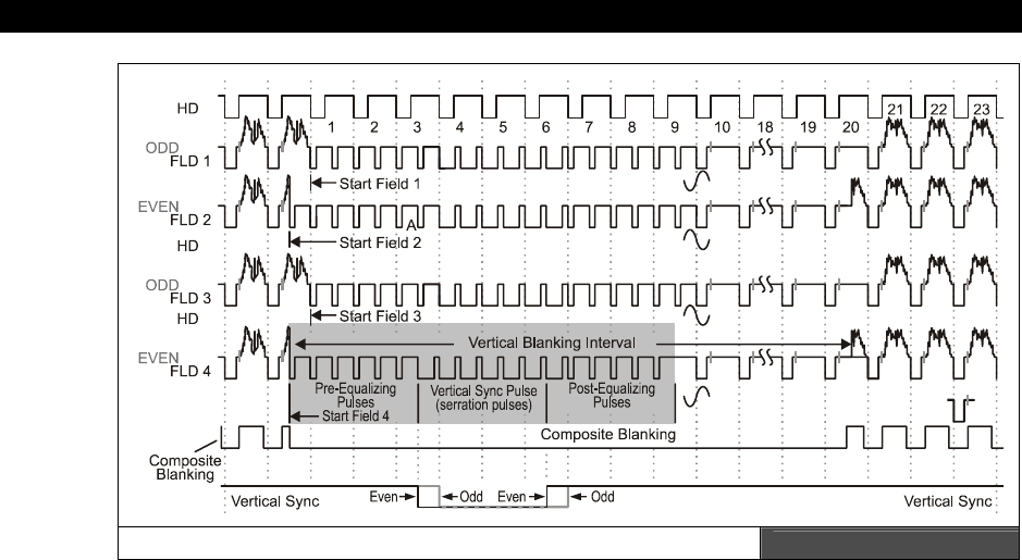
I The HYDRA Hardware
Page 110 Game Programming for the Propeller Powered HYDRA
A Close-up of the Vertical Blanking Period Figure 7:4
Figure 7:4 shows the complete NTSC spec for what’s called a
“super frame.”
In reality, as
the 525 interlaced lines are being drawn as 2 frames there are actually 4 different flavors of
slightly different frames then it repeats, but this is irrelevant unless we are making a DVD
player or broadcasting CBS. In our case, all we care about it is following the spec close
enough. With that in mind, take a look at the shaded area in the figure near field 4, which
shows a typical vertical blanking signal. The vertical blanking interval is composed of three
major parts that make up a total of 18 lines of video. Thus, given a screen is 262 lines
total: with 18 for the vertical sync, there are 262−18 = 244 lines of
“visible video.”
Given
that, the different phases of the vertical blanking period are:
Pre-equalization pulses (6 lines of video)
Vertical sync pulse (6 lines of video)
Post-equalizing pulses (6 lines of video)
Pre-equalization pulses – These pulses are nothing more than Hsync-only pulses that
prepare the vertical retrace circuitry for the upcoming vertical sync pulse while keeping the
Hsync circuitry locked. There are 6 lines of video that make up these pulses, and they are
nothing more than 6 blank lines with just Hsync in them, no color burst, no video.
Vertical sync pulse – This is where the action takes place. There is a 6-video-line-long
sequence of nothing but Hsync pulses, but they are inverted, that is instead of being at black

Composite NTSC / PAL Video Hardware 7
Game Programming for the Propeller Powered HYDRA Page 111
and dropping to sync for 4.7 µs, these pulses, referred to as
“serration pulses”
are at sync
the entire video line, then for 4.7 µs come back to the blanking or black level. This is filtered
by the Vsync filter on the set and gets through to the vertical retrace hardware, but at the
same time keeps the Hsync hardware synchronized as well.
Post-equalization pulses – These pulses are nothing more than Hsync -only pulses that
allow the horizontal sync hardware to catch back up with the signal after the large vertical
sync pulse. There are 6 lines of video that make up these pulses, and they are nothing more
than 6 blank lines with just Hsync in them, no color burst, no video.
When it’s all said and done the total number of wasted lines is 18 for the entire vertical
blanking process, so you have the remaining 244 lines to draw your video. However, there is
another issue to address – overscan. Overscan is the portion of the screen both vertically and
horizontally that you can’t see. This anomaly is due to mechanical interfacing, the CRT itself,
and other manufacturing issues. Thus, typically, the top and bottom 10-20 lines of video on
most TVs are unviewable, thus most game systems center the video and display 192-200
lines of video. Of course, you can render on the overscan area if you wish, but then just
make sure to not put scoring information or other vital stats there, since on some TVs users
won’t be able to see the data, considering that most graphics engines stick to 192-200 lines
with 224 being the max (224 is used since it’s a multiple of 8 and 16 and those are common
bitmap tile sizes).
Additionally, since you don’t need to send out active video luma information during the
vertical blank and overscan periods, these are the best times to update game logic and/or
prepare the next frame of video data. For example, when developing graphics and TV drivers
for the Propeller, the vertical blank and overscan times can be used to pre-process video data
and get it ready for rendering during the active scan portion of the screen rendering. The
reason why is that during the actual rasterization of the screen there is little time between
pixels to do calculations, so pre-computing addresses, buffering data, and so forth can be
done in the blanking periods then passed on during the rasterization periods.
Let that all sync in (pun intended), and let’s talk about color!
7.2.4 Adding Color to NTSC
Adding color to the NTSC signal is probably one of the greatest hacks in electronics history.
After the initial format specification for RS-170 in 1941, engineers, doing what they do best,
improved the system and added color to both the cameras and the CRTs. The only problem
was that they simply couldn’t tell the USA and other adoptive countries to just change the
signal specifications overnight. Moreover, hundreds of thousands of B/W TVs were already in
use if not millions, so a new broadcast signal format was out of the question. However, color
would be added, it had to be “hidden” in the current NTSC B/W luma only signal and it had
to not interfere with a standard B/W set. Thus, if a broadcast was sent in full color a B/W set
could still pick it up and display it and it would look good, but at the same time, anyone
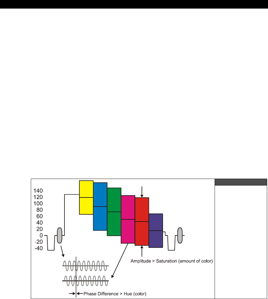
I The HYDRA Hardware
Page 112 Game Programming for the Propeller Powered HYDRA
dishing out the big dollars for a color TV would be able to see the Technicolor version of
“Wizard of OZ” in all its glory. The first color TVs and systems were deployed in the USA
around 1953 and it went flawlessly. The question is how did they do it?
Referring back to Figure 7:3, you see the section of signal after the Hsync pulse, this is called
the color burst. In a luma-only NTSC signal from the 40’s you wouldn’t see this, but in a color
signal from 1953 and on, you would. This little region in the original NTSC signal wasn’t used
for anything, just a few microseconds before the actual luma signal was sent, but it was
enough time for a brilliant hack for the color. The idea was that in this color burst region, the
NTSC signal would modulate onto the blanking signal 9-10 cycles of a 3.58 MHz sine wave.
This 3.58 MHz signal was decided to be the carrier frequency of “color.” So the new color TVs
would look for this 3.58 MHz signal via a signal trap tuned to 3.58 MHz, if present then the
signal is a color signal and an internal phase locked loop (basically a method to lock onto the
frequency and phase of a signal) locks onto and synchronizes the TVs internal color hardware
to the signal. So by the time the luma signal portion of the NTSC signal is received the TVs
tuner is locked onto the 3.58 MHz color burst as well.
Now comes the ingenious part: the 3.58 MHz signal is above (for the most part) the
maximum bandwidth of the luma signal, so anything at 3.58 MHz and above is usually
filtered out of the luma and ignored (I know I said most sets have a bandwidth of about 4.5
MHz, but bear with me), so if a 3.58 MHz signal is modulated on the luma signal then we can
filter it and look at the signal. So what though? Well, the trick is that instead of the amplitude
of the 3.58 MHz that is modulated on the luma encoding color, the phase shift or difference
encodes color. Take a look at Figure 7:5 to see this.
Figure 7:5
Color Burst
Signal
Encoding

Composite NTSC / PAL Video Hardware 7
Game Programming for the Propeller Powered HYDRA Page 113
In real-time as the luma signal is sent, the phase of the initial color burst after the Hsync is
used as a reference point for color, so you basically continually send the 3.58 MHz signal
modulated on your luma signal, and the phase difference from the color burst reference
signal and the current 3.58 MHz signal is the actual color! Moreover, the saturation of the
color or is richness is the local amplitude of the 3.58 MHz signal modulated on the luma. The
color signal overall is called the chroma signal. Again, Figure 7:5 has the vertical scale in IRE
units, but depending on what the overall range is the chroma saturation usually ranges from
0.1 - 0.3 V, where 0.1 V is washed out and 0.3 V is deep color.
Now, taking all this into consideration, the maximum number of pixels you can have color
changes on a standard NTSC TV can be calculated as follows. Given:
Color burst frequency = 3.58 MHz, or 279 ns per cycle.
The visible portion of the active video is 52.6 µs.
Therefore, the total number of individual perceivable colors changes per active video
line is, or
“Color Clocks”
is:
Color Clocks = 52.6 µs / 279 ns = 188.
That’s it! Not, 320, not 256, but a measly 188! Of course, you can overdrive the color, and
maybe people do. In fact, on the HYDRA, many demos drive the color at 256 pixels per line,
however, if you were to take a magnifying lens and look at each pixel individually, you
couldn’t see the color, you need a couple pixels next to each other before the color stabilizes.
This is why on old game systems you see resolutions like 160 or 184 across (both multiples
of 8), they are both within the bandwidth limit of the color on NTSC. On the other hand if
you are writing bitmap games and want higher resolution, it surely won’t hurt to have 224 or
256 pixels per line (which are common), you simply won’t be able to make out single pixel
colors, but when many pixels are combined you get a “free” blurring / anti-aliasing effect
which makes things look really good. But do not try this with text, you will see lots of “color
artificating,” that is, you have one pixel with one color, then try and put another next to it,
and they both change color! This is caused by over-driving the color bandwidth of the TV.
Therefore, if you want really crisp text, try suppressing the color signal altogether (which is
easy with the HYDRA and Propeller chip) then only using color with games and graphics.
7.3 Summary
The composite video hardware on the HYDRA is almost embarrassing since the Propeller
does all the work for us, in fact, the Propeller really doesn’t have much video hardware
either, it’s all in the software that generates video. The only hardware the Propeller has is the
VSU unit which is a glorified serial shift register, but this is all we need to generate NTSC,
PAL, or whatever since we can use software to synthesize the various timings and analog
voltages needed for video.

I The HYDRA Hardware
Page 114 Game Programming for the Propeller Powered HYDRA
If you are interested in learning more about NTSC and all the myriad of video standards in
the word (there are dozens of variants of PAL for example), be sure to pick up
“Video
Demystified”
by Keith Jack as well as
“Video Engineering”
by Luther and Inglis, neither
are for the faint of heart, but
Video Demystified
is a bit easier to read. Also, there are
numerous websites online about NTSC standards, one of the most complete, albeit ugly, is:
www.ntsc-tv.com

VGA Hardware 8
Game Programming for the Propeller Powered HYDRA Page 115
Chapter 8:
VGA Hardware
In this chapter, we are going to take a look at the VGA hardware on the HYDRA. The VGA
hardware is a little more exciting that the composite video hardware, in fact, the VGA design
actually uses an external chip and a few more components than just resistors, so I am
excited. Also, in this chapter we are going to briefly take a look at the VGA spec, so you have
a conversational understanding of it and why VGA is both good and bad from a video
generation point of view. So, here’s what’s in store:
VGA origins
HYDRA VGA hardware design
VGA signal primer
8.1 Origins of the VGA
Before we start into the design, let’s get some history and terminology correct. First, the last
time I saw a real VGA monitor was about 20 years ago, the new 21st century monitors that
you are used to are super-sets of VGA; they are typically multisync, variable refresh, and can
go up to 2400×2400 or more. The “VGA” specification is more of a base point than anything
anyone actually uses anymore. IBM released the VGA or “Video Graphics Array” technology in
1987 roughly. It was touted to change the world (definitely an improvement from CGA and
EGA), but it was doomed from the start with not enough resolution. Shortly after, higher
resolution monitors were available and the VGA specification was enhanced with the Super
VGA standard, but this was only a momentary hold on its execution; what was needed was a
more progressive standard that could change at any time, and thus the VESA “Video
Electronics Standard Association” graphics cards and drivers were created and the rest is
history. However, the original specs for the VGA are shown below.
256 KB Video RAM
16-color and 256-color modes
262,144-value color palette (six bits each for red, green, and blue)
Selectable 25 MHz or 28 MHz master clock
Maximum of 720 horizontal pixels
Maximum of 480 lines
Refresh rates up to 70 Hz
Planar mode: up to 16 colors (4 bit planes)
Packed-pixel mode: 256 colors, 1 BYTE per pixel (Mode 13h)
Hardware smooth scrolling support

I The HYDRA Hardware
Page 116 Game Programming for the Propeller Powered HYDRA
Some "raster operations" (Raster Ops) support to perform bitmap composition
algorithms
Barrel shifter in hardware
Split screen support
Soft fonts
Supports both bitmapped and alphanumeric text modes
Standard graphics modes supported by VGA are:
640×480 in 16 colors
640×350 in 16 colors
320×200 in 16 colors
320×200 in 256 colors (Mode 13h, "chunky graphics mode")
I spent many years writing graphics algorithms and drivers for VGA cards, now my cell phone
has better graphics! However, the VGA spec is great for baseline computer displays and any
standard modern computer monitor will display old school 640×480 VGA modes and refresh
rates. This is the design focus on the HYDRA’s VGA output, to simply drive a standard VGA
monitor at 640×480 resolution at 60 Hz refresh rate.
8.2 VGA Design
The VGA hardware for the HYDRA is very minimal since the Propeller chip is doing all the
signal generation with the aforementioned VSU in the previous chapter. However, to facilitate
the use of the expansion port, I have added a buffer on the VGA output port to isolate it
when you are using the IO bus on the expansion port which shares the same I/O pins.
Otherwise, when not driving the VGA port, if you had a monitor attached your random I/O
activity would potentially drive or damage the VGA monitor. Figure 8:1 shows the final design
of the VGA hardware.
Referring to Figure 8:1, you see that P16 – P23 are connected to all the VGA signals and
there are 2 bits for each channel; Red, Green, and Blue, as well as a single bit for Hsync and
Vsync. These outputs are connected to the VGA buffer at U5 which is a 74HC244 8-bit
tri-state buffer. Its output is connected to the HD15 connector via a series of 2-bit D/A
converters that sum each 2-bit channel pair (R0, R1), (G0, G1), and (B0, B1) and directly
interface the sync bits. The VGA spec dictates that for each channel 0% intensity is 0.0 V and
100% intensity is 1.0 V (some references use 0.7 V). Also, each channel input to the VGA
monitor itself per input has a nominal impedance of 75 Ω (similar to the NTSC input
impedance).
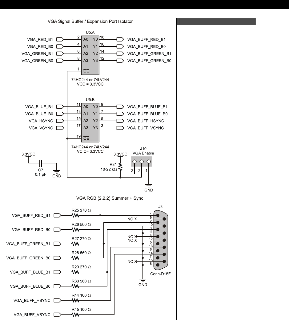
VGA Hardware 8
Game Programming for the Propeller Powered HYDRA Page 117
Figure 8:1
The VGA Interface
and Support Hardware
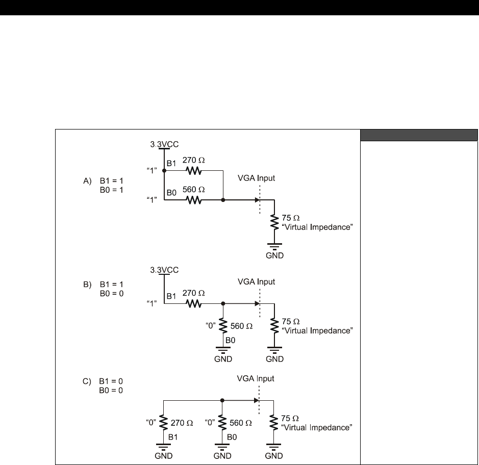
I The HYDRA Hardware
Page 118 Game Programming for the Propeller Powered HYDRA
Therefore, from the D/A’s perspective with both bits on, the circuit looks like that shown in
Figure 8:2 (for any particular channel; R, G, or B). Recall that the Propeller chip is a 3.3 V
device with both channel bits HIGH, that means that we have a 270 Ω in parallel with a
560 Ω and this combination in series with the intrinsic impedance of 75 Ω of the VGA, thus,
we can do a simple computation to compute the voltage at the 75 Ω VGA input realizing we
have a voltage divider configuration:
VGA_IN_RED = 3.3 V × 75 Ω / ( (270 Ω || 560 Ω) + 75 Ω) = 0.96 V
Figure 8:2
Electrical Model of
VGA Inputs and
2-bit D/A Channels
...which is what we desire; performing similar math for all 4 combinations of inputs we get
the results shown in Table 8:1 for codes. Considering there are 4 shades of each channel; R,
G, and B that means that there are a total of 4×4×4 = 64 colors available in VGA mode. Not
bad!
VGA Hardware 8
Game Programming for the Propeller Powered HYDRA Page 119
Table 8:1 VGA Input Voltages for all 2-Bit Inputs
B1 B0 Code VGA Voltage Description
0 0 0 0.0 V Black
0 1 1 0.30 V Dark Gray
1 0 2 0.64 V Gray
1 1 3 0.96 V White
Pay attention to the “VGA Enable” switch J10, it’s next to the 74HC244 chip on
the HYDRA and shown in the design (Figure 8:1 on page 117).
You must ENABLE this switch if you want the VGA buffer to send the VGA
signals to the VGA port. If you want to use the I/O port and do NOT want the VGA
port on then DISABLE the switch at J10.
For reference the VGA port has the following pinout shown in Table 8:2. The VGA port on the
HYDRA is a female HD15 (High Density) which is standard on the back of video card
hardware. It will connect to any VGA monitor.
Table 8:2 VGA Female Header Pinout (HD15)
Pin Function Color Code (Most Manufacturers)
1 RED Video BLACK
2 GREEN Video BLACK/WHITE
3 BLUE Video BROWN
4 RESERVED BROWN/WHITE
5 -Ground RED+SHIELD
6 -RED Ground ORANGE
7 -GREEN Ground YELLOW
8 -BLUE Ground MINT GREEN
9 NC NC
10 -GROUND GREEN
11 ID0 (Ground) BLUE
12 ID 1 (NC) PURPLE
13 VSYNC GREY
14 HSYNC WHITE
15 NC SHRIMP
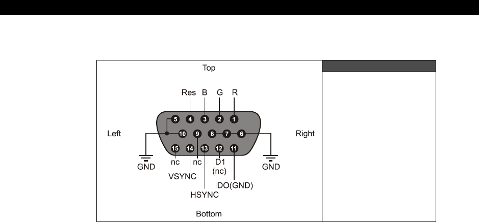
I The HYDRA Hardware
Page 120 Game Programming for the Propeller Powered HYDRA
Looking at the VGA port on the HYDRA (the female), the pinout is as show in Figure 8:3.
Figure 8:3
Female HD-15
VGA port on HYDRA
8.3 VGA Signal Primer
The VGA standard is much easier to understand that the NTSC standard, in fact, using a
visual explanation (Figure 8:4) is usually all people need to see, but still there are some
gotcha’s so we are going to discuss them as well in the brief primer. To start, the actual
important signals you need to generate for VGA are (referring to Table 8:2) Red, Green, and
Blue video as well as Hsync and Vsync. The R,G,B signals are analog voltages representing
the instantaneous intensity of any particular channel and range from 0-1.0 V, but the Hsync
and Vsync are simply TTL signals, usually active LOW (but these can be inverted on most
monitors) where a logic LOW is sync, and a logic HIGH is no sync. Now, let’s look more
closely at the signal itself.
To begin with, the VGA standard as implemented is 640×480 pixels across as shown in
Figure 8:4(A). The image is rendered left to right, top to bottom, similar to the NTSC/PAL
signals, and thus a similar syncing scheme is used that is composed of both a horizontal sync
pulse each line and a vertical sync pulse each frame. However, there are no color burst
signals, serrations, pre-equalizations pulses, etc. and the interface is nearly digital as noted.
The main clock usually used in a VGA generation system is 25.175 MHz; all timing can be
derived from this base frequency. Typically, designers like to run the system dot clock at this
frequency and compute all events as a number of clocks.
For example, getting ahead of myself, take a look at Figure 8:4(B), the Hsync pulse which is
labeled “B” in the table (and a negative polarity), its 3.77 µs, therefore at a dot clock of
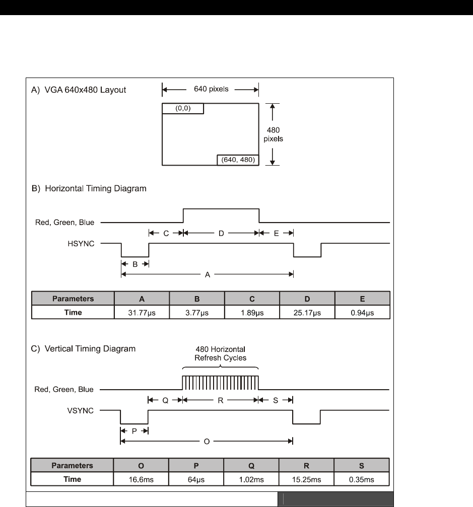
VGA Hardware 8
Game Programming for the Propeller Powered HYDRA Page 121
25.175 MHz, or inverting this to get the period time we get 39.72194638 ns. This is how long
a pixel takes, anyway, dividing this into our Hsync time we get:
Number of dot clocks for Hsync pulse = 3.77 µs/ 39.72194638 ns = 94.90 clocks.
The VGA Timing Specifications Figure 8:4

I The HYDRA Hardware
Page 122 Game Programming for the Propeller Powered HYDRA
Call it 95 dot clocks, thus you can simply use a counter and count 95 clocks, drive Hsync
LOW and that’s it. The entire VGA signal can be generated like this. Of course, the tough part
is when you get to video, here you only have roughly 39 nanoseconds to do whatever you
are going to do; this amounts to more or less doing nothing but accessing a video buffer as
fast as you can and getting the next data WORD ready to build the pixel. This is why the
Propeller’s VSU is so cool, it can do this for you and stream BYTEs to the VGA interface (more
on this later in Part II). Anyway, let’s take a closer look at the video portion of the signal as
well as the horizontal and vertical timing aspects of VGA.
8.3.1 VGA Horizontal Timing
Referring to Figure 8:4(B), each of the 480 lines of video are composed of the following
standard named regions:
A (31.77 µs) Scanline time
B (3.77 µs) Hsync pulse
C (1.89 µs) Back porch
D (25.17 µs) Active video time
E (0.94 µs) Front porch
As you can see even the names are similar to NTSC. However, unlike NSTC, VGA is very
unforgiving and you must follow the spec very closely. The next interesting thing is that all
the signals are riding on different lines. For example, the Hsync and Vsync both have their
own signal lines, and the R, G, and B signals do as well, so it’s much easier to generate all
the signals in a large state machine and then route them to the output ports.
Therefore, to generate a line of video (with a negative sync polarity), you start by turning off
all the R, G, B channels with a 0.0 V, and simply hold the Hsync line LOW for 3.77 µs (B).
Then you wait 1.89 µs (C) and the VGA is ready to take R, G, B data, now you clock out 640
pixels at 25.175 MHz for a total time of 25.17 µs (D) for the active video portion. You then
turn the video lines R, G, B off, and wait 0.94 µs (E) and then start the process again. And
that’s all there is too it. Perform this process 480 times then it’s time for a vertical sync and
retrace, so let’s look at that.
8.3.2 8.3.2 VGA Vertical Timing
The vertical sync and retrace is much easier than the horizontal timing since there is no video
to interleave in the signal. Referring to Figure 8:4(C) the various named timing regions of the
vertical timing are:
O (16.68 ms) Total frame time
P (64 µs) Vsync pulse
Q (1.02 ms) Back porch
R (15.25 ms) Active video time
S (0.35 ms) Front porch
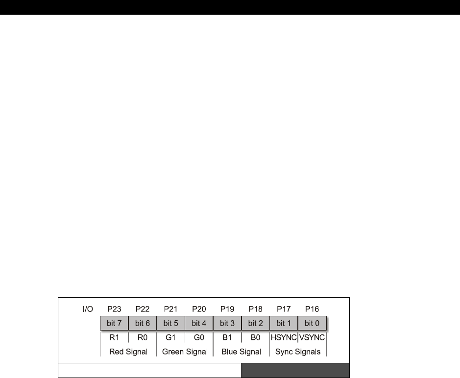
VGA Hardware 8
Game Programming for the Propeller Powered HYDRA Page 123
The meaning of each is similar to that in the horizontal sync period, except the “event” they
are focused around is the 480 lines of active video, so the 480 lines are encapsulated in (R).
The most important thing to realize is that these times are measured in milliseconds for the
most part except for the Vsync pulse. So once again, the timing of an entire frame starts off
with the Vsync pulse (P) for 64 µs, after which comes the back porch (Q) for 1.02 ms,
followed by the active video (R) for 15.25 ms. During the active video you don’t need to
worry about the Vsync line since you would be generating 480 lines of video, when complete,
back to the Vsync timing region (S), the front porch for 0.35 ms, and then the frame is
complete.
The thing to remember is that unlike composite video, a VGA signal needs to be driven by
multiple signals for each of the constituent controls; R, G, B, Hsync, and Vsync, which in my
opinion is much easier than modulating and mixing them all together as in NTSC which is a
bloodbath of crosstalk and noise! Now that we have the horizontal and vertical timing for
VGA covered, let’s review the actual video data portion of the signal during the active video
and see what that’s all about.
8.3.3 VGA RGB Video
Generating RGB video is trivial on any system, there is no look-up, no math, just send out
BYTEs or WORDs that represent the RGB values and that’s it. On the HYDRA for example,
there are 2-bits per channel, so the encoding of the VGA data BYTE is as simple as
generating BYTEs in the format shown in Figure 8:5.
VGA Data BYTE Encoding Figure 8:5
For example, forgoing how to do I/O yet on the Propeller chip, let’s say that we have a BYTE
buffer called
vga_byte
and a function
Write_VGA(value, time_us)
that we use to send data
to the VGA port, given that, we can write all kinds of functions that send out different signals
as long as we stream the BYTEs to the port at the 25.175 MHz rate everything will work out
fine. For example, say that we are working with a positive sync system, that is a VGA monitor
that wants a TTL HIGH for sync, then to generate a Hsync pulse we could use some pseudo-
code like this:
vga_byte = %00000010;
Write_VGA(vga_byte, 3.77);

I The HYDRA Hardware
Page 124 Game Programming for the Propeller Powered HYDRA
Ok, now consider we want to draw 640 pixels from an array
video_buffer[ ]
that is storing
the pixel data in BYTE format already in the proper format for our hardware, then all we
would do is this:
byte video_buffer[640]; // pre-initialized video buffer
for (pixel = 0; pixel < 640; pixel++)
Write_VGA(video_buffer[pixel], 0.039721946);
Of course, you would need some mighty fast hardware to delay at a resolution of 39 ns, but
you get the idea. This is a “model” of the algorithm for a line of video, this coupled with the
model for the horizontal timing, vertical timing, and put it all together as a state machine and
you have a VGA generator!
8.4 Summary
Hopefully this chapter has shed some light on the VGA standard. It’s a very cool system, the
only downside being that it’s really fast at 25.175 MHz (39 ns per pixel) and difficult to drive
with a microcontroller that doesn’t have dedicated hardware (like the Propeller chip). But,
speed aside, the standard is “nearly” digital, doesn’t have any funny stuff with the color
encoding, and lends itself nicely to bitmap hardware designs based on RGB color space.
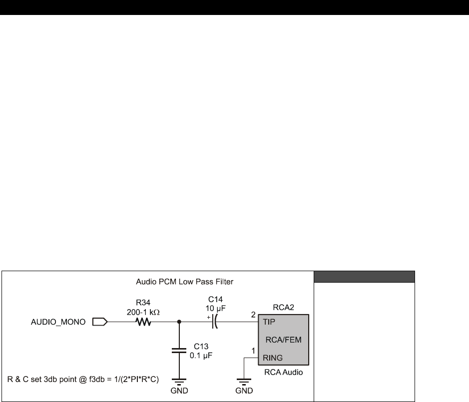
Audio Hardware 9
Game Programming for the Propeller Powered HYDRA Page 125
Chapter 9:
Audio Hardware
There is no dedicated audio hardware inside the Propeller chip or on the HYDRA itself,
therefore we have to rely on software audio generation techniques to create sound for the
system. However, knowing that software is going to be used to generate sound we can add a
little analog circuitry to “help” the audio software out and allow us to use certain common
techniques for generating sounds. In this chapter, we are going to take a look at the circuit
that is used for the audio output. Once again, the Propeller chip takes the fun out of it by
being powerful enough to do everything internally! Anyway, here’s what’s in store this
chapter:
Audio circuit design
Low-pass filters
Frequency modulation (FM)
Pulse code modulation (PCM)
Pulse width modulation (PWM)
Figure 9:1
The HYDRA
Analog Audio
Hardware
9.1 Audio Circuit Design and a Little Background on Low-Pass
Filters
The audio on the HYDRA is generated completely in software and the output is filtered
through a simple analog filter. The circuit is shown in Figure 9:1. Referring to the circuit, we
see that the signal AUDIO_MONO (P7 on the Propeller chip) generates the signal input into
the network. This signal is passed through a low-pass filter consisting of a resistor (R34 @
200 – 1 kΩ) and a capacitor (C13 @ 0.1 µF). Note that these reference designators may
I The HYDRA Hardware
Page 126 Game Programming for the Propeller Powered HYDRA
change in the future, but the point is there is an R/C network here. Moving on, there is also
another AC coupling capacitor (C14 @ 10 µF) which leads to the final output via an RCA
connector and that’s it. The circuit has two sections and they each serve different purposes,
let’s follow the signal through these sections.
The input signal, call it Vin(t), comes in at the port and the low-pass filter made up of R34
and C13 passes low frequencies but blocks high frequencies. This is what’s called a
“single-
pole RC filter.”
The “gain” of the filter or the “transfer function” describes the relationship
between the output and the input signal, thus for a single with a gain of 1 or unity, the
output, (call it Vout(t), would be equal to the input (with some possible phase variance, but
this is irrelevant for our discussion). The single-pole RC filter acts like a voltage divider, but
we have to use more complex math to describe it based on imaginary numbers and/or
differential equations. This is tough to analyze with algebra, but there is a trick based on the
“Laplace Transform”
which transforms differential equations into algebraic equations, and
then we can work with the circuit as if it were made of resistors and transform back when
done. This is all not that important, but its fun to know a little about analog stuff, so let’s
continue.
The Laplace transform denoted by )]([ tfL which looks like this:
∫
+∞ −
= 0 )(
)]
( [ dtetft f L st
...is a simple integral transform where more or less the function f(t) in the time
domain you want to work with is integrated against an exponential term. The
result of this is the transformation of the time domain function into the “S-
domain” written as F(s), where they are much easier to work with.
So given all that, we want to know what the voltage or signal is at the top of C13 (Vout)
since this signal or voltage will then affect the remainder of the circuit. Using a voltage
divider made of R34 and C13, we need to write a relationship between the input voltage at
AUDIO_MONO, call it Vin(t), and the output voltage of the RC filter at the top of C13, call it
Vout(t). Ok, here goes a few steps:
Vout(s) = Vin(s) × [ (1/sC) / (R + 1/sC)]
Then dividing both sides by Vin(s) we get,
Gain = H(s) = [ (1/sC) / (R + 1/sC)]
Simplifying a bit, results in,
Gain = H(s) = 1 / (1 + sRC)
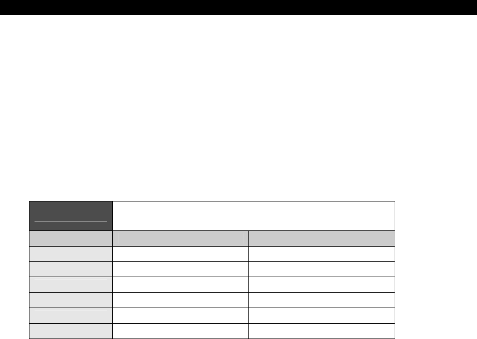
Audio Hardware 9
Game Programming for the Propeller Powered HYDRA Page 127
Then transforming back from the S-domain to the frequency domain we get,
Gain = H(f) = 1 / (1 + 2 × PI × f × RC)
Note: Technically there is another term in there relating to phase, but it’s not important for
this discussion. In any event, now this is interesting, this equation:
Gain = H(f) = 1 / (1 + 2 × PI × f × RC)
...describes the amplification or more correctly the attenuation of our signal as a function of
frequency f. This is very interesting. Let’s try something fun. Let’s plug in some values really
quickly and see what happens, let’s try 0 Hz, 1 Hz, 100 Hz, 1000 Hz, 1 MHz and see what we
get. Table 9:1 shows the results.
Table 9:1 The Results of Passing Various Frequencies through
a Low-Pass Single-Pole RC Filter
Frequency (f Hz) Gain Comments
0 1/1 DC gain is 1.0 or no attenuation
1 1/(1+2 × PI × RC)
10 1/(1+2 × PI × 10 × RC)
100 1/(1+2 × PI × 100 × RC)
1,000 1/(1+2 × PI × 1000 × RC)
1,000,000 1/(1+2 × PI × 1,000,000 × RC)
This is very interesting; ignoring for a moment the actual values of RC, we see that larger
values of f (frequency) very quickly dominate the denominator and the quotient goes to 0.
This is why this filter is called
“single-pole”
, as the term in the denominator goes to infinity
the quotient goes to zero. Ok, so how does this help us? Well, if we select values of RC, we
can tune the frequency so that this “attenuation” effect gets really strong. This is typically
called the
“3dB point”
, that is the point where the signal is attenuated by 3 dB (decibels)
It’s not really important to know what a decibel is, it’s a measure of power or ratio of signals
more or less, but what is important is that 3 dB is about 70% of the signal. So, if you want to
filter out everything above 10 kHz you would set the 3dB point for about 10 kHz (maybe a bit
more) and you would see the signal gets filtered. Also, note that at DC, frequency f = 0, the
right-hand term in the denominator sum (1 + 2 × PI × 0 × RC) = 1, thus the gain is 1/1 or
1.0 which is exactly what it should be! Cool huh!

I The HYDRA Hardware
Page 128 Game Programming for the Propeller Powered HYDRA
Filters can be a lot of fun since you can chain them together; low-pass, high-pass to make a
band pass, or multiple low- and high-pass to make them fall off faster and so forth. Here’s a
cool tool on the web to get a “feel” for filters:
Low-pass:
http://www.st-andrews.ac.uk/~www_pa/Scots_Guide/experiment/lowpass/lpf.html
High-pass:
http://www.st-andrews.ac.uk/~www_pa/Scots_Guide/experiment/highpass/hpf.html
In any event, playing with the math, the 3dB point for our circuit is:
f3dB = 1/(2 × PI × RC)
Notice, f is not in there since we solved for it. Therefore, we have everything we need to use
the circuit and the equation. Let R and C in our circuit be 1 kΩ and 0.1 µF respectively;
plugging them in we get:
f3dB = 1/(2 × PI × 1 kΩ× 0.1 µF) = 1.59 kHz
...which might be a little low. To loosen this up, let’s make the resistor smaller – 200 Ω:
f3dB = 1/(2 × PI × 200 Ω × 0.1 µF) = 7.95 kHz
...which is a rather high frequency, about 50% of the max range of most human ears which
top out at 15-20 kHz.
Why is this important? Well, first off if you send a signal through our little low-pass filter to
the output (connected to the audio port on the TV) then the signal is going to attenuate at
high frequencies. We will get back to this momentarily; let’s move on to the second stage in
the audio circuit which is based on C14 and POT1. This stage of the circuit is an AC-pass
filter, which means that it will only pass AC and the DC component will be blocked.
In other words, say that the input was a sine wave or square wave with a peak-to-peak
voltage of 1 V, but it was riding on a 2 V signal, this would look like the top trace in Figure
9:2. However, after going through the AC coupling capacitor, the signal would look like the
bottom trace shown in Figure 9:2. So all C14 does is block the DC.
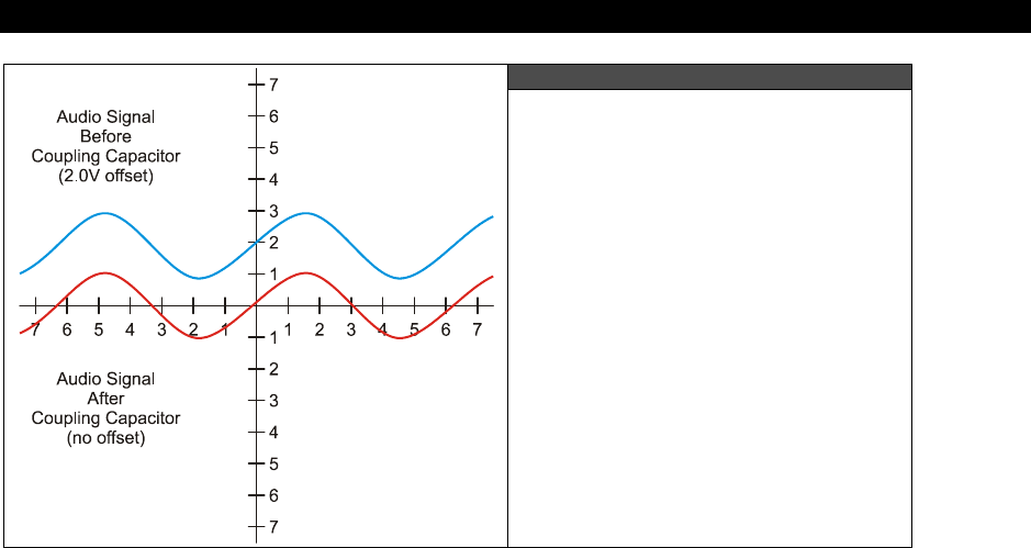
Audio Hardware 9
Game Programming for the Propeller Powered HYDRA Page 129
Figure 9:2
Sine Wave Riding on a Constant
DC Offset as it is Passed Through
a Coupling Capacitor
Now, let’s talk about the some more hardware-related concepts about making sounds with a
couple specific techniques with the HYDRA.
9.1.1 Pulse Code Modulation (PCM)
The most common method to make sound on a game console is to use
PCM
or
Pulse Code
Modulation
. This is really nothing more than storing a series of samples of the sound in
some resolution; 4,8,12,16 bit along at some playback rate. A Windows .WAV file for
example is PCM data, you simply output the data at the proper rate to a D/A converter with
an amplifier connected to a speaker and you will hear the sound. There are a number of
issues with this: first, it takes huge amounts of memory (even with compression), secondly
you need a D/A (digital to analog) converter on the hardware and there are no “synthesis”
opportunities really (of course you can always synthesize the samples). PCM is not an option
for the HYDRA since there is simply so little memory, even with the extended 128K EEPROM's
extra 96 K available to you for assets that wouldn’t get you very far, so PCM was decided to
not make the cut at least as a hardware interface, but you can actually synthesize PCM
through PWM (more on this in a moment).
9.1.2 Frequency Modulation (FM)
Frequency modulation with a fixed waveform is very easy to do electronically and the HYDRA
can do this no problem. The idea here is to output a square wave or sine wave directly to the
output device and then modulate the frequency. So if we use the Propeller chip’s internal
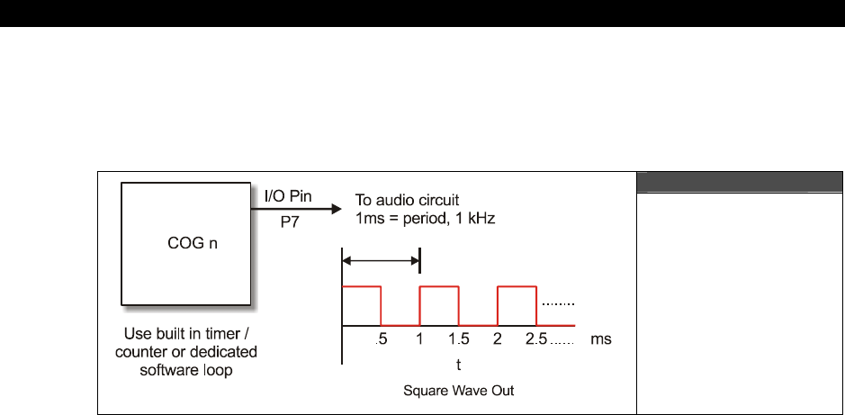
I The HYDRA Hardware
Page 130 Game Programming for the Propeller Powered HYDRA
timers we can do this (more on this later) or we can write a software loop to do it. For
example, if you wanted to hear a 500 kHz, 1 kHz, and 2 kHz signal you just write a software
loop that toggles the output AUDIO_MONO at that rate and you will hear the sound on the
attached output device. Figure 9:3 shows this graphically.
Figure 9:3
Synthesizing a
Single Frequency
Now, there are a couple problems with this: first it’s not readily apparent how to “add”
signals and play more than one sound at once. In fact, it’s nearly impossible directly using
this technique. Secondly, the only signal you can output is a square wave, you can’t output
sine waves. This tends to make the sounds have a “textured” sound since harmonics are in
the square wave. That is, if you output a square wave at frequency f then you will find that
there are harmonics at 3 f, 5 f, etc. all these sine waves are what really make up a square
wave. Take a look at Fourier transform theory to see this:
http://homepages.inf.ed.ac.uk/rbf/CVonline/LOCAL_COPIES/OWENS/LECT4/node2.html
Of course our little low-pass filter is going to filter most of these harmonics, but you aren’t
going to hear a pure sine until you increase the frequency to about the 3 dB cutoff which
may be desired.
In any event, if all you need is a single channel, some noise, pure tones, then FM with the
AUDIO_MONO port at (P7) is more than enough. You can use software or the built-in timers
to do it on each cog and simply sweep the frequency to get different sounds since you can’t
change the amplitude.
9.1.3 Pulse Width Modulation (PWM)
Pulse width modulation or PCM is a very clever way to create ANY kind of sound with a single
bit of output! The bad news is that the relationships of the output and the algorithms are a
“bit” complicated and take a little bit of numerical analysis, but once you get it working it’s
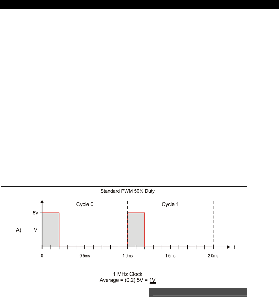
Audio Hardware 9
Game Programming for the Propeller Powered HYDRA Page 131
not an issue and you can build libraries to create any sound you wish – in fact many
advanced synthesizers use PWM systems, so it’s very powerful.
To start with you might want to “Google” for PWM techniques and read up a bit. Watch out
since most PWM references are about using PWM for motor control. Here are a few PWM
articles to get your started:
http://www.freescale.com/files/32bit/doc/app_note/MC68EZ328PWM.pdf
http://www.freescale.com/files/32bit/doc/app_note/MC68EZ328DTMF.pdf
http://www.intel.com/design/mcs96/technote/3351.htm
http://ww1.microchip.com/downloads/en/AppNotes/00655a.pdf
After reading all these documents you should have a fairly good grasp of PCM techniques.
More or less, PCM is really a method of digital to analog conversion using a single bit output
along with a low-pass filter that acts as an “averaging” or “integration” device. A PCM
signal is at fixed output frequency usually many times the highest frequency you want to
synthesize, for example a good rule of thumb is that the PCM signal should be 10-100x
greater than the frequencies you want to synthesize. Also, the PCM period is
fixed
, and the
modulation of information in the PCM signal is in the duty cycle of the signal. Recall, duty
cycle is defined as:
Duty Cycle = Time Waveform is HIGH / Total Period of Waveform
Duty Cycle Modes (A) Figure 9:4
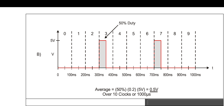
I The HYDRA Hardware
Page 132 Game Programming for the Propeller Powered HYDRA
Duty Cycle Modes (B) Figure 9:5
For example, say we had a 1 kHz signal, this means the period is 1/1 kHz = 1 ms = 1000 µs.
Now, let’s say we are talking about square waves in a digital system with a HIGH of 5 V and
a LOW of 0 V. Furthermore, let’s say that the duty cycle is 20%; what would the final
waveform look like? Figure 9:4 depicts this. As you can see the waveform is HIGH 20% of
the total period or 200 µs, and the waveform is LOW for 800 µs. Therefore, if you were to
average this signal f(t) over time you would find that the average is simply the area under
the HIGH part divided by the total AREA of the waveform which is:
Average Signal @ 20% duty cycle = (5 V) × [(200 µs)/(1000 µs)] = 1.00 V.
This is a VERY interesting result — by just varying the time we pulse a digital output HIGH
we can create an analog voltage! Thus, we can modulate the analog voltage in any shape we
wish to create a final waveform of any shape we want: sounds, explosions, voices, etc. Plus
since this is all digital we can synthesis as many channels as we wish, since at the end of the
day we need only a single bit as the output. Figure 9:5 shows another PWM-like technique
where instead of modulating the duty cycle, complete 50% duty cycle pulses are sent, but
they are interspersed with 0% duty cycles as a function of time. If the rate of these “pulses”
is high enough, they too create an “average” voltage over time. In Figure 9:5 there are 10
total cycles and in 2 of them we have 50% duty cycles for a total analog voltage per 10
clocks of:
Average Signal @ 20% duty cycle = (5V) × (50%) × [(100 ns)/(1000 ns)] = 0.25 V.

Audio Hardware 9
Game Programming for the Propeller Powered HYDRA Page 133
Notice we are dealing in nanoseconds in the second example; this technique needs to run at
a higher frequency to give the “average” enough time to change at the highest frequency
rate you want to synthesize in this method of D/A.
Now, the only mystery component to the D/A PWM converter is “averaging” of the signal.
Well, fortunately for us, a low-pass filter as used in the HYDRA’s sound circuit (shown in
Figure 9:1) acts as an averaging circuit, in fact, those of you with an EE background know
that 1/S is integral in the S-Domain and a low-pass filter has a 1/S term it in. Intuitively it
makes sense as well since a low-pass filter as shown in Figure 9:1 is really just a charging
circuit and as we send these pulses to it, the circuit charges a bit, then another pulse comes
and it charges a bit more. When a pulse doesn’t come or the duty cycle is smaller, then the
RC circuit discharges, so the PWM-modulated pulse train gets turned into a signal by the
averaging process and looks like a stair step where you can see the averaging period
superimposed on the signal. But, for now realize that the low-pass filter (LPF) that the
HYDRA uses on the audio circuit acts as an LPF as well as an averaging circuit for PWM, so it
has two uses – pretty cool.
Selecting the Filtering Frequency
Also, there are a couple of concerns with the actual values of the LPF so that you don’t get
too much noise. Noise is going to come from the PWM frequency itself. For example, say you
use a PWM frequency of 1 MHz, then your filter obviously needs to cut this frequency out,
but it also needs to cut in at the highest frequency you plan to synthesize. For example, if
you plan to have sounds all the way up to CD-quality at 44 kHz then you might set the 3dB
point at 50 kHz.
Also, we are using an “inactive” single-pole filter. You might want a “sharper” response in a
more high-end sound system like a 2- or 4-pole system. You can achieve this by daisy
chaining our little LPFs together OR you can use an “active filter” based on a transistor or
better yet a simple operational amplifier like the 741. Or even better yet, pick an 8-pole
switched capacitor filter by National, TI, or Linear Tech and the signal will hit a “brick wall” at
the cutoff ☺.
But, for our purposes of games, simple music, sound effects, and explosions, a single-pole
passive filter will do fine. If there is one thing I know, most people can’t tell the difference
between Mozart and Snoop Dogg, so sound can be a little rough.
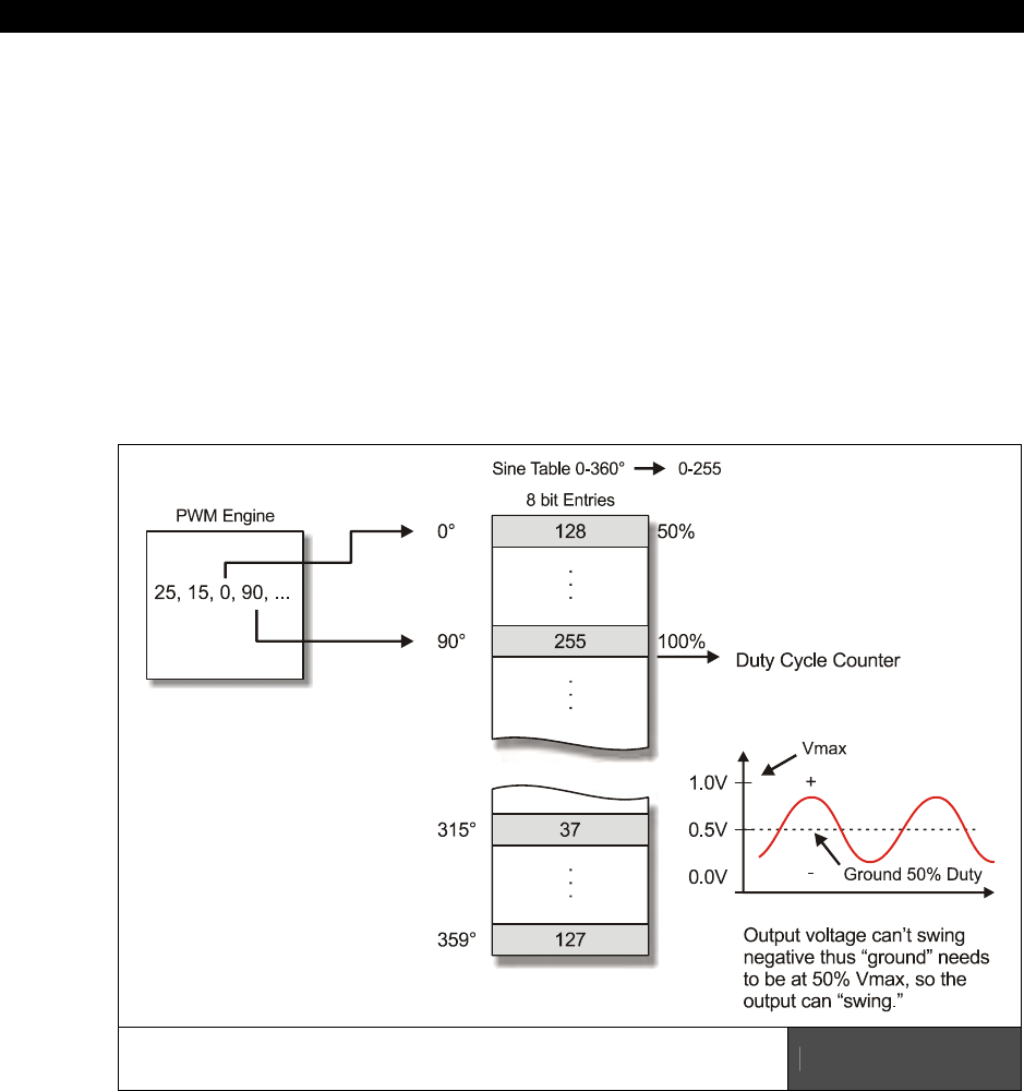
I The HYDRA Hardware
Page 134 Game Programming for the Propeller Powered HYDRA
PWM Setup Procedure
Let’s briefly digress a moment and work up an example with real numbers, so you can see
this all in your head. Many readers probably have worked with PWM, but may use more
experimental techniques to get results rather than a formal analysis, so this might be
interesting for you.
So to PWM modulate a signal we encode the signal onto the PWM carrier by means of
encoding the information or analog value of the signal onto the PWM carrier by modulating
the period or the duty cycle
of the fixed frequency PWM carrier. This is a VERY important
concept to understand – the PWM frequency/period NEVER changes, only the duty cycle of
any particular cycle. Thus by modulating the information onto the duty cycle we can then
later demodulate the signal by integrating or averaging the PWM signal with a RC circuit and
presto, we have an analog voltage!
Indexing into a Sine Look-up Table to Synthesize a
Signal at a Given PWM Rate Figure 9:6

Audio Hardware 9
Game Programming for the Propeller Powered HYDRA Page 135
The first thing we need to do is decide what kind of waveforms we want to synthesize,
remember they can be
anything
, they can be periodic and simple like sine, square wave
(redundant), triangle, saw-tooth, noise, or even digitized speech. But, to start simple, let’s
synthesize a single sine wave. So first we need a look-up table for sine wave, let’s call it
sinetable[ ] and assume it has 256 entries and we generate it such that a single cycle has
a low of 0 and a high of 255 and is encoded in 8 bits (similar to an example in the
references). Now, the algorithm is fairly simple, we need to index through the sine table a
rate such that we complete a single cycle of our sine wave at the desired output signal
frequency. As a quick and dirty example, let’s say that we use a PWM frequency of 256 kHz
and we want to play a 1 kHz sine wave, then this means that each second there are 256,000
PWM pulses. We want to index into our table and play 1000 iterations of our data which has
a length of 256 entries, thus we need to index into our table at a rate of:
256,000 / (1000 × 256) = 1
Interesting; so every cycle we simple increment a counter into the sine table and output the
appropriate duty cycle in the table look-up. This is shown in Figure 9:6. As another example,
say we want to synthesize a 240 Hz signal, then let’s see what we would need:
256,000 / (240 × 256) = 4.16
In this case, we would increment a counter until it reached 4, then we would increment our
index into our sine table. But this example as well as the last should bring something to your
attention: there is a max frequency we can synthesize and our signal synthesis is going to be
inaccurate for anything but integral divisors, so that’s an issue we need to address in a
moment. First, let’s look at the maximum signal frequency: if you want to play back all 256
sine samples then the maximum “signal” frequency is always:
Maximum Synthesis Frequency = PWM frequency / Number of Samples per Cycle
...which in this example is:
256,000 / 256 = 1000 Hz
So, you have two options: either increase the PWM frequency or index into your sample table
at larger intervals. This problem along with the lack of precision can be handled by use of
fixed-point arithmetic and a little numerical trick. We are going to scale all the math by 8 bits
(or in essence multiply by 256) then we are going to create two variables: one called a
phase accumulator
(PHASE_ACC) and one called a
phase increment
(PHASE_INC). Then
instead of using count-down algorithms, we are going to simply add the phase increment to
the phase accumulator and use the phase accumulator as an index into the sine table.
Therefore, what we have done is turned out 256 element sine table into a “virtual” 256×256
= 65536 element sine table for math purposes to give us more accuracy for slower, non-
integral waveforms as well as to allow fast waveforms to index and skip elements in the look-
up table, so a possible setup is something like this:
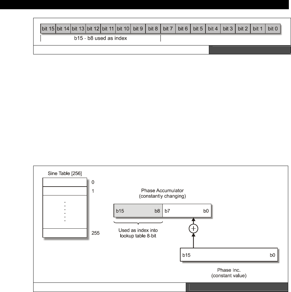
I The HYDRA Hardware
Page 136 Game Programming for the Propeller Powered HYDRA
The Phase Accumulator 16-Bit Figure 9:7
Now, we have two interesting properties: first, no matter what the index in the upper 8-bits
can never exceed 255, so we can never go out of bounds of our table; secondly, we can put
very small numbers into the phase accumulator via that phase increment variable.
So now the algorithm for PWM sound is simple:
Step 1: Run the PWM at the output frequency 256,000 Hz.
Step 2: Calculate the Phase Increment (PHASE_INC) to add to the Phase Accumulator
(PHASE_ACC) such that the final desired “signal” frequency is output via the look-up into the
sine or waveform table.
Step 3: Continually add the Phase Increment to the Phase Accumulator and every cycle use
the upper 8-bits of the Phase Accumulator as the index into the 256 element sine table.
Our Final PWM Setup Figure 9:8
Now, to recap, we still have a table that has only 256 elements, but we are going to pretend
it has 65536 elements, that is, 256×256 to improve our accuracy, this is nothing more than

Audio Hardware 9
Game Programming for the Propeller Powered HYDRA Page 137
using a shift << 8 and create a fixed point value in 8.8 format. Next, we are going to call out
a couple variables to make the algorithm easy, one is an accumulator called PHASE_ACC that
simply accumulates the current count, then we convert it back to an integer by shifting it >>
8 times OR just using the upper 8-bits at the index into our 256 element sine table (the later
is preferred). Then we simply need the magic number PHASE_INC that for a given PWM
frequency (256,000 in this case) and a desired output signal frequency along with a specific
number of data table elements will make the whole thing work. Here’s the final math:
Given,
A complete sine waveform has 65536 data entries in our virtual table and 256 in the
real table.
The PWM frequency is 256 K.
NUM_INCREMENTS = The number of times that the PWM signal increments through
the final signal table in ONE complete wave cycle. This is shown in Figure 9:8.
In other words,
NUM_INCREMENTS = signal period / PWM period
= PWM frequency / signal frequency
Now, let’s compute PHASE_INC:
PHASE_INC = 65536 / NUM_INCREMENTS
That is, the PHASE_INC is the rate at which we need to increment through the data table to
maintain the relationship so that the output is changing at the rate of the signal frequency.
Now, plugging this all in together and moving things around a bit:
PHASE_INC = 65536 × signal frequency / PWM frequency
And of course PHASE_ACC is simply set to 0 to begin with when the algorithm starts. As an
example, let’s compute some values and see if it works. First let’s try a 1 kHz signal and see
what we get:
PHASE_INC = 65536 × 1 kHz / 256,000 = 256
I The HYDRA Hardware
Page 138 Game Programming for the Propeller Powered HYDRA
So this means that we add 256 to the phase accumulator each PWM cycle, then use the
upper 8 bits of the phase accumulator as the index, let’s try it a few cycles as see if it works.
Table 9:2 Test of PWM Algorithm at 1 kHz with PHASE_INC of 256
Iteration PHASE_INC PHASE_ACC PHASE_ACC (upper 8 bits)
0 256 0 0
1 256 256 1
2 256 512 2
3 256 768 3
4 256 1024 4
5 256 1280 5
6 256 1536 6
7 256 1792 7
. .
. .
255 256 65280 255
Referring to Table 9:2, we see that for each cycle of the PWM the PHASE_ACC is
incremented by 1 and the next element in the 256 element sine table is accessed, thus the
table is cycled through at a rate of 256,000 / 256 = 1,000 Hz! Perfect! Now, let’s try another
example where the frequency is higher than what we could sustain with our more crude
approach at the beginning of the section with only a counter and not using the accumulator
and fixed point approach. Let’s try to synthesize a 2550 Hz signal.
PHASE_INC = 65536 × 2550 / 256,000 = 652.8
Now, this is a decimal number which will be truncated during the fixed point math to 652,
but this is fine, that’s only an error or:
Truncation error = 100 × (0.8 / 652.8) = 0.12%
I think I can live with that! Table 9:3 shows the results of the synthesis algorithm running
once again.
Audio Hardware 9
Game Programming for the Propeller Powered HYDRA Page 139
Table 9:3 Test of PWM Algorithm at 2500 Hz with PHASE_INC of 652
Iteration PHASE_INC PHASE_ACC PHASE_ACC (upper 8 bits)
0 652 0 0
1 652 652 2
2 652 1304 5
3 652 1956 7
4 652 2608 10
5 652 3260 12
6 652 3912 15
7 652 4564 17
. .
. .
255 652 65000 253
As you can see in this case, each cycle the sine table is accessed by skipping an entry or two
causing a bit of distortion, but since the table has 256 entries the amount of distortion is
1-2% at most, so once again we see that the technique works perfectly. Also, notice that it
takes only 100 cycles of the PWM clock to iterate through one complete cycle of the sine
table which makes sense as well.
In conclusion, the software is where the magic is here. The PWM audio circuitry couldn’t be
simpler than as shown in Figure 9:1. Additionally, you can synthesize multiple channels by
simply having multiple phase accumulators and phase increments; in fact, to synthesize a
64-channel system you would just need something like:
WORD phase_inc[64], phase_acc[64];
...and you simply run a loop over everything, sum up all the phase accumulators each cycle,
and use the sum as the index into the sine table. Of course, the sine table itself has to be
scaled in the amplitude axis and you must do an auto-scale so that the sum doesn’t overflow,
but you get the idea. Moreover, you can store other waveforms like square, triangle,
sawtooth, and so on and then mix various waveforms. Finally, you can easily overlay an
ADSR (attack-decay-sustain-release) envelope to a note-based system and create just about
anything. The only downside to PWM is that it must be VERY accurate, your ears are VERY
sensitive to frequency shifts, so the timing loops must be perfect, thus a hardware timer or a
tight loop needs to be used that doesn’t vary, otherwise you will hear it.

I The HYDRA Hardware
Page 140 Game Programming for the Propeller Powered HYDRA
9.2 Summary
Sound is always one of those things in game consoles and game development in general that
never gets the attention it deserves. Generating sound can be done in a number of ways: on
larger PCs, sound is always generated as PCM data with 8-16 bit D/A’s on the output, but on
small embedded systems they don’t have the memory to do this, thus, a different technique
has to generate the final output and limits must be placed on the types of sounds that can be
generated. PWM is perfect for sound effects, explosions, game sounds, and even music, but
if you want digitized explosions, voice, and so forth, you can use PWM to generate the actual
analog output, sure, but you still need to store all the data – and even at 11 kHz with 8-bit
samples huge amounts of memory can be eaten up for just a few seconds of digital sound.
Thus, on the HYDRA for example, we are going to stick to using FM and PWM techniques
with software-based algorithms for the most part to generate “procedural sounds” that fit
well into the domain of game sound-effects.

Keyboard & Mouse Hardware10
Game Programming for the Propeller Powered HYDRA Page 141
Chapter 10:
Keyboard &
Mouse Hardware
The goal of the HYDRA is to of course be a platform to learn the Propeller chip while at the
same time having fun with game development, but more importantly the HYDRA platform
itself was designed to be a completely stand-alone computing platform for educational,
hobby, and even industrial applications. For example, with a built-in BASIC interpreter or
other language, you can directly plug the HYDRA into your TV set, plug in a keyboard and
mouse, and use it like you would an Atari 800 or Apple II. Thus, the HYDRA has not one but
two PS/2 ports on it which are compatible with any PS/2 device. It just so happens that you
are typically are going to plug a PS/2 keyboard and mouse into these ports, but this is not a
necessity, you can plug any PS/2 device you wish into either port as long as you write a
driver for it. Currently there are drivers for both keyboard and mouse only, but you are free
to write whatever you wish; the hardware interface is robust enough to handle any device. In
any case, this chapter is about the PS/2 interfaces and we are going to focus on the
keyboard and mouse devices and take a brief look at the protocols of each. If you haven’t
ever written a driver for either, they are very interesting devices and support a lot more
functionality than you might believe. Thus, in this chapter we are going to discuss the
following topics:
Hardware interfaces for the mouse and keyboard on the HYDRA
Interfacing to the keyboard and the keyboard serial protocol
Interfacing to the mouse and the mouse serial protocol
10.1 PS/2 Hardware Designs
The Propeller chip is a 3.3 V device, but PS/2 keyboards and mice are 5 V devices, thus a
little bit of extra electronics had to be added to “buffer” or “isolate” the signals. Typically, to
interface to a keyboard or mouse you simply need two bi-directional data lines to connect to
the keyboard/mouse; these are referred to as DATA and CLOCK. PS/2 keyboards and mice
both use a simple 2-line serial protocol (similar to I2C). In the case of the keyboard there is a
microcontroller inside that scans the key matrix and handles the serial communications (in
fact it’s a full blown embedded system), and the mouse is similar, as it has a microcontroller
that tracks the movement of the mouse ball or (optical hardware) by counting pulses and
translating them into relative motions. Newer optical mice of course take pictures of the
mouse surface and compute image gradients to determine motion (pretty cool stuff), but the
idea is the same in that the data is translated into motion data and sent serially to the host.
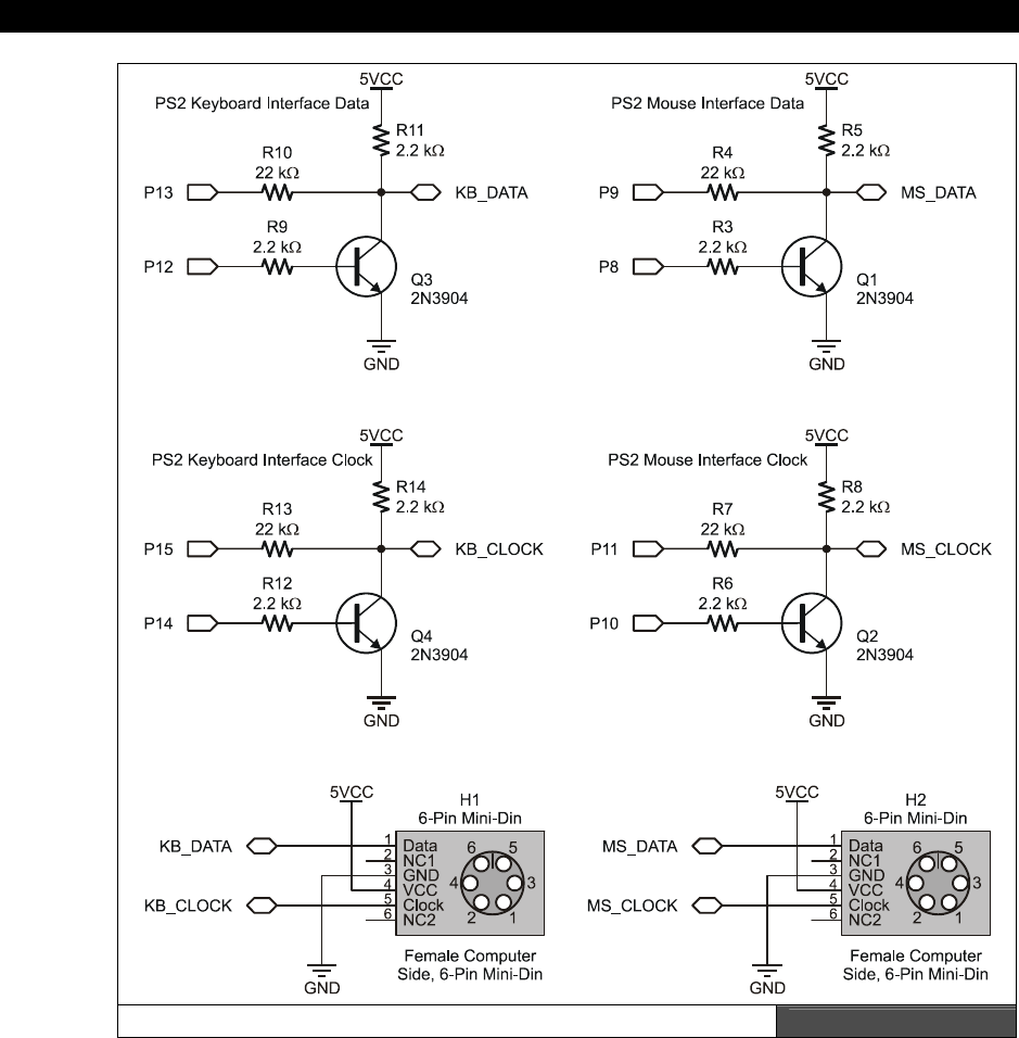
I The HYDRA Hardware
Page 142 Game Programming for the Propeller Powered HYDRA
The HYDRA’s Keyboard and Mouse Interface Hardware Figure 10:1
The keyboard and mouse interfaces are identical, so we are only going to review the
hardware of one of these devices: the
keyboard
. Referring to Figure 10:1, the connector H1

Keyboard & Mouse Hardware10
Game Programming for the Propeller Powered HYDRA Page 143
is the female receptacle that a PS/2 keyboard plugs into. The pinout is shown in the figure
which we review in a moment, but the point is that there are only two connections we must
concern ourselves with: the DATA line at pin 1 and the CLOCK line at pin 5. Other than
that, we need to provide the keyboard with power at pin 4 (+5 V), and lastly, the ground
reference GND is at pin 3.
Normally, if we had a 5V-compatible system, we could use only 2 data lines from the
microcontroller (one for clock, one for data), but since the Propeller chip is 3.3 V device, the
original design of the keyboard and mouse interface drivers used two (2) lines each for
DATA and CLOCK with transistors to buffer the signals depending on direction. This is not
necessary, but a precaution. Technically, one could design hardware that interfaced the 2
lines from the keyboard or mouse to 2 lines on the Propeller chip (and save a total of 4 lines
between the keyboard and mouse), but the original software drivers used 4 lines per
interface and a buffer design, so I followed it.
To communicate, either the keyboard/mouse or the host (HYDRA) can initiate a conversation.
For example, the HYDRA can talk to the keyboard and instruct it to change settings, or the
keyboard can send scan codes to the HYDRA as well as status information. In most cases, we
can just let the keyboard boot and never worry about it, but if you want to send and receive
you
have
the hardware that allows this. The use of 4 lines to talk to the keyboard/mouse
along with some simple transistors facilitates this.
To begin with, let’s assume that the keyboard wants to talk to the Propeller chip; in this case,
the Propeller chip would need to set P13 and P15 to inputs and “listen” for the keyboard
protocol. The outputs P12 and P14 are unused and should be set LOW during this
transaction, so that transistors Q3 and Q4 are OFF. Now, in this configuration (READ
mode), the keyboard drives P13 and P15, the voltage swing is 0 V and 5 V, but this is fine
since we have the current limiters R10 and R13 in there, so when a 5 V HIGH is on either
the data or KB_DATA or KB_CLOCK lines the inputs of the Propeller chip will clamp to 3.3
V and the 22 kΩ current limiters will make sure current isn’t driven too hard into the Propeller
chip. In this case, when DATA or CLOCK on the keyboard are driven to LOWs by the
keyboard they will drive LOW and pull the inputs to the Propeller chip LOW as well, so all is
good. Finally, if the keyboard places the outputs DATA or CLOCK into a tri-state or high
impedance mode then the 2.2 kΩ pull-ups to +5, R11 and R14, will drive the inputs
KB_CLOCK and KB_DATA HIGH as well, so there is never a time when there is an
undefined logic state on the lines KB_DATA and KB_CLOCK. Of course, the same
arguments are valid for the mouse interface.

I The HYDRA Hardware
Page 144 Game Programming for the Propeller Powered HYDRA
On the other hand, if the Propeller chip wants to control the conversation then it can drive
the DATA and CLOCK lines either LOW or HIGH. When driving the lines HIGH, the
Propeller chip outputs a 3.3 V to either port P12 or P14, a LOW is desired on either CLOCK
or DATA then the transistor much be switched ON. To do this a HIGH must be gated to
the base of the transistor at P12 or P14, this will turn ON either transistor and connect
either KB_CLOCK or KB_DATA to ground which is what we want. If it’s desired that
KB_DATA or KB_CLOCK is driven HIGH then the pull-ups at R11 and R14 will do this for
us, and we only need to make sure the transistors are OFF and therefore the voltage at
either P12 or P14 is LOW respectively.
To review, the keyboard (and mouse) are controlled via two bi-directional data lines: CLOCK
and DATA. PS/2 mouse and keyboards are typically 5 V systems, so to interface them
safely to the Propeller chip and to use the drivers already written for keyboard (and mouse)
we use 4 lines, two each for the DATA and the CLOCK lines to allow bi-directional
communication and control of the lines while maintaining both the 3.3 V and 5 V systems
safely. We will discuss programming the keyboard at length later, but for now let’s briefly
review how the keyboard and mouse both send data.
10.2 Keyboard Operation
The keyboard protocol is straightforward and works as follows: for every key pressed there is
a
"scan code"
referred to as the
"make code"
that is sent; additionally when every is key
released there is another scan code referred to as the
"break code"
that in most cases is
composed of $EO followed by the original make code scan value. However, many keys may
have multiple make codes and break codes. Table 10:1 lists the scan codes for keyboards
running in default mode (startup).

Keyboard & Mouse Hardware10
Game Programming for the Propeller Powered HYDRA Page 145
Table 10:1 Keyboard Default Scan Codes
KEY MAKE BREAK KEY MAKE BREAK KEY MAKE BREAK
A 1C F0,1C 9 46 F0,46 [ 54 FO,54
B 32 F0,32 ` 0E F0,0E INSERT E0,70 E0,F0,70
C 21 F0,21 - 4E F0,4E HOME E0,6C E0,F0,6C
D 23 F0,23 = 55 F0,55 PG UP E0,7D E0,F0,7D
E 24 F0,24 \ 5D F0,5D DELETE E0,71 E0,F0,71
F 2B F0,2B BKSP 66 F0,66 END E0,69 E0,F0,69
G 34 F0,34 SPACE 29 F0,29 PG DN E0,7A E0,F0,7A
H 33 F0,33 TAB 0D F0,0D U ARROW E0,75 E0,F0,75
I 43 F0,43 CAPS 58 F0,58 L ARROW E0,6B E0,F0,6B
J 3B F0,3B L SHFT 12 F0,12 D ARROW E0,72 E0,F0,72
K 42 F0,42 L CTRL 14 F0,14 R ARROW E0,74 E0,F0,74
L 4B F0,4B L GUI E0,1F E0,F0,1F NUM 77 F0,77
M 3A F0,3A L ALT 11 F0,11 KP / E0,4A E0,F0,4A
N 31 F0,31 R SHFT 59 F0,59 KP * 7C F0,7C
O 44 F0,44 R CTRL E0,14 E0,F0,14 KP - 7B F0,7B
P 4D F0,4D R GUI E0,27 E0,F0,27 KP + 79 F0,79
Q 15 F0,15 R ALT E0,11 E0,F0,11 KP EN E0,5A E0,F0,5A
R 2D F0,2D APPS E0,2F E0,F0,2F KP . 71 F0,71
S 1B F0,1B ENTER 5A F0,5A KP 0 70 F0,70
T 2C F0,2C ESC 76 F0,76 KP 1 69 F0,69
U 3C F0,3C F1 05 F0,05 KP 2 72 F0,72
V 2A F0,2A F2 06 F0,06 KP 3 7A F0,7A
W 1D F0,1D F3 04 F0,04 KP 4 6B F0,6B
X 22 F0,22 F4 0C F0,0C KP 5 73 F0,73
Y 35 F0,35 F5 03 F0,03 KP 6 74 F0,74
Z 1A F0,1A F6 0B F0,0B KP 7 6C F0,6C
0 45 F0,45 F7 83 F0,83 KP 8 75 F0,75
1 16 F0,16 F8 0A F0,0A KP 9 7D F0,7D
2 1E F0,1E F9 01 F0,01 ] 5B F0,5B
3 26 F0,26 F10 09 F0,09 ; 4C F0,4C
4 25 F0,25 F11 78 F0,78 ' 52 F0,52
5 2E F0,2E F12 07 F0,07 , 41 F0,41
6 36 F0,36
PRNT
SCRN E0,12,
E0,7C
E0,F0,
7C,E0,
F0,12 . 49 F0,49
7 3D F0,3D SCROLL 7E F0,7E / 4A F0,4A
8 3E F0,3E PAUSE E1,14,77,
E1,F0,14,
F0,77 -NONE-
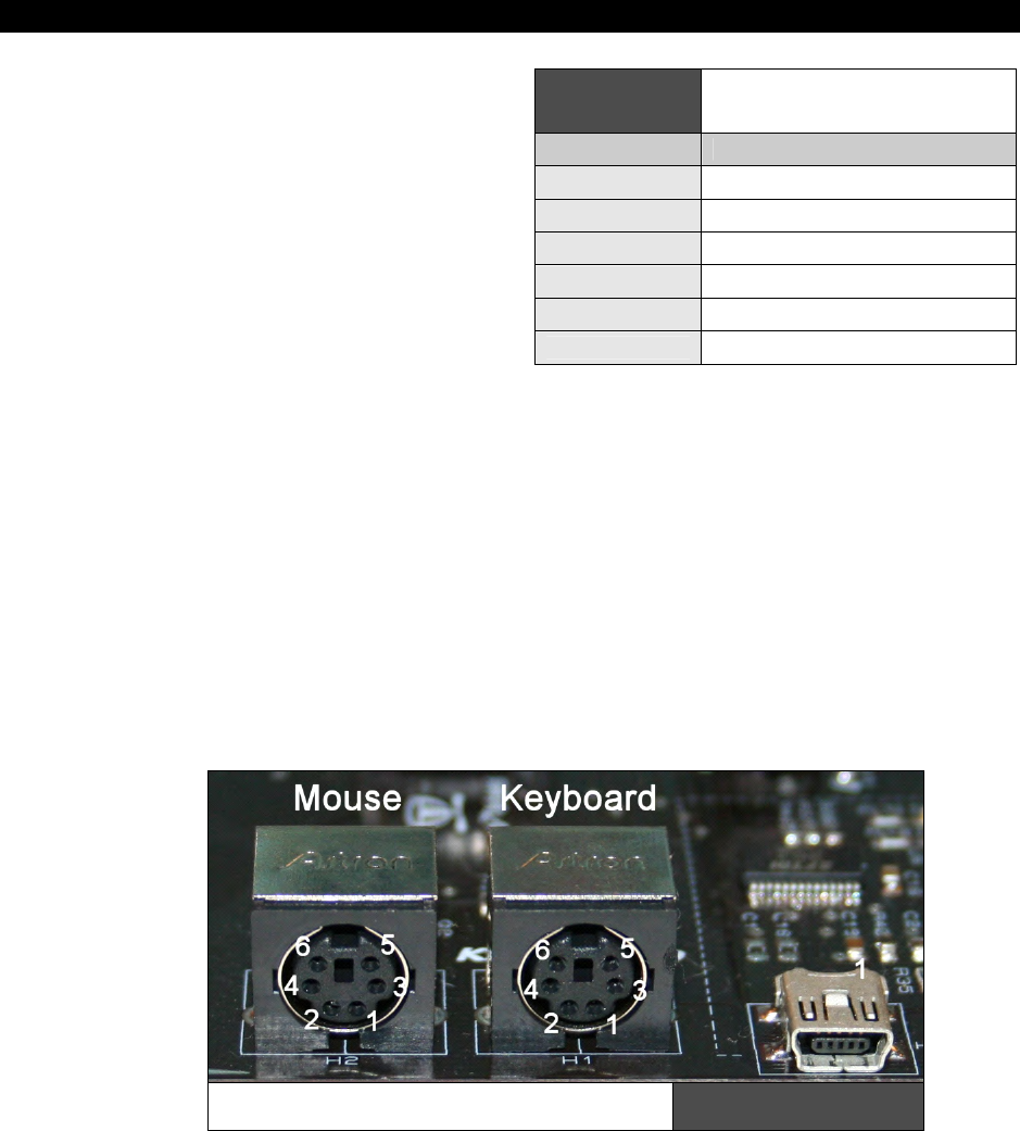
I The HYDRA Hardware
Page 146 Game Programming for the Propeller Powered HYDRA
The keyboard hardware interface is
either an old style male 5-pin DIN or
a new PS/2 male 6-pin mini-DIN
connector. The 6-pin mini DIN’s pinout
is shown in Figure 10:2 (referenced
looking at the computer’s female side
where you plug the keyboard into,
notice the staggering of the pin
numbering).
Table 10:2 lists the signals for
reference, and the descriptions of the
signals are as follows:
DATA – Bi-directional and used to send and receive data.
CLOCK – Bi-directional; however, the keyboard nearly always controls it. The host can pull
the CLOCK line LOW though to inhibit transmissions; additionally during host → keyboard
communications the CLOCK line is used as a “request to send” line of sorts to initiate the host
→ keyboard transmission. This is used when commands or settings need to be sent to the
keyboard.
VCC/GROUND – Power for the keyboard (or mouse). Specifications state no more than
100 mA
will be drawn, but I wouldn’t count on it and plan for
200 mA
for “blinged-out”
keyboards with lots of lights etc.
When both the keyboard and the host are inactive the CLOCK and DATA lines should be
HIGH (inactive).
PS/2 6-Pin Mini Din Connector
at HYDRA Socket Figure 10:2
Table 10:2 Pinout of PS/2 6-Pin Mini
Din
Pin Function
1 DATA (bi-directional open collector)
2 NC
3 GROUND
4 VCC (+5 @ 100 mA)
5 CLOCK
6 NC
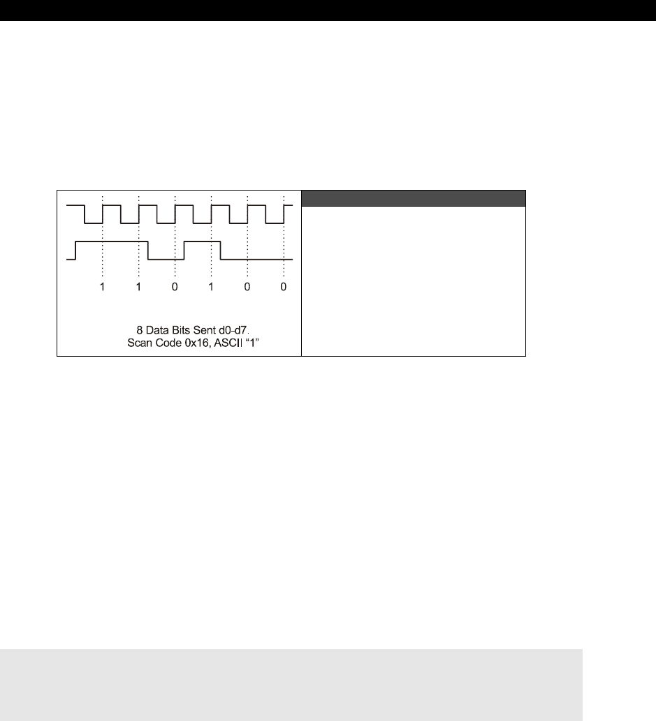
Keyboard & Mouse Hardware10
Game Programming for the Propeller Powered HYDRA Page 147
10.2.1 Communication Protocol from Keyboard to Host
When a key is pressed on the keyboard, the keyboard logic sends the
make scan code
to
the host computer. The scan code data is clocked out by the keyboard in an 11-bit packet;
the packet is shown in Figure 10:3. The packet consists of a
single LOW start bit
(35 µs)
followed by
8 data bits
(70 µs each),
a parity bit
, and finally a
HIGH stop bit
. Data
should be sampled by the host computer on the data line on the falling edge of the CLOCK
line (driven by keyboard). Below is the general algorithm for reading the keyboard.
Figure 10:3
Keyboard Serial Data Packet
10.2.2 Keyboard Read Algorithm
The read algorithm makes the assumption that the main host has been forcing the keyboard
to buffer the last key. This is accomplished by holding
CLOCK
LOW
. Once the host releases
the keyboard, the keyboard will start clocking the clock line and
drop the DATA line
with a
start bit
if there was a key in the buffer, else the
DATA line will stay HIGH
. So the
following steps are
after
the host releases the keyboard and is trying to determine by means
of polling if there is a key in the keyboard buffer.
Step 1: Delay 5 µs to allow hold on CLOCK line to release and keyboard to send buffered
scan code.
Step 2 (Start of frame): If both CLOCK and DATA are low (start bit) then enter into read
loop, else return, no key present.
Step 3 (Start of data): Wait until clock goes high...
Step 4 (Read data): Read data bits loop:
for t = 0 to t <= 7 do
wait for CLOCK to go low...
delay 5 us to center sample
bit(t) = DATA
next t
I The HYDRA Hardware
Page 148 Game Programming for the Propeller Powered HYDRA
Step 5: (Read parity and Stop Bits): Lastly the parity and stop bits must be read.
And that’s it! Of course, if you want to be strict then you should verify the parity bit, but you
don’t need to unless you want to perform error correction.
Both the keyboard and mouse use an “odd parity” scheme for error detection.
Odd parity is HIGH when the number of 1’s in a string is ODD, LOW otherwise.
Even parity is HIGH when the number of 1’s in a string is EVEN, LOW otherwise.
Note that parity only tells us there is an error, but not how to correct it.
10.2.3 Keyboard Write Algorithm
The process of sending commands to the keyboard or “writing” to the keyboard is identical to
that when reading. The protocol is the same except the host initiates the conversation. Then
the keyboard will actually do the clocking while the host pulls on the data line at the
appropriate times. The sequence is as follows:
Step 1: Wait for the keyboard to stop sending data (if you want to play nice). This means
that both the DATA and CLOCK lines will be in a HIGH state.
Step 2 (Initiate transmission): The host drives the CLOCK line LOW for 60 µs to tell the
keyboard to stop all transmissions. This is redundant if you waited for Step 1; however, the
keyboard might not want to shut up, therefore, this is how you force it to stop and listen.
Step 3 (Data ready for transmission): Drive the DATA line LOW, then release the
CLOCK line (by release we mean not to put a HIGH or a LOW, but to set the CLOCK into a
tri-state or input mode, so the keyboard can control it). This puts the keyboard into the
“receiver” state.
Step 4 (Write data): Now, the keyboard will generate a clock signal on the CLOCK line,
you retrieve your DATA, and when the CLOCK line is HIGH you send it on the DATA line.
The host program should serialize the command data (explained momentarily) made up of 8
bits, a parity bit, and a stop bit for a total of 10 bits.
Step 5 (End transmission): Once the last data bit is sent then the parity (odd parity) and
stop bit is sent then the host drives the DATA line (stop bit) and releases the DATA line.
10.2.4 Keyboard Commands
Table 10:3 illustrates some of the commands one can send to a generic keyboard based on
the 8042 keyboard controller originally in the IBM PC spec. This table is not exhaustive and
only a reference, many keyboards don’t follow the commands 100% and/or have other
commands, so be wary of the commands.
Keyboard & Mouse Hardware10
Game Programming for the Propeller Powered HYDRA Page 149
Table 10:3 Keyboard Commands
Code Description
$ED
Set/Reset Mode Indicators: keyboard responds with ACK then waits for a following
option BYTE. When the option BYTE is received the keyboard again ACK's and then sets
the LEDs accordingly. Scanning is resumed if scanning was enabled. If another command
is received instead of the option BYTE (high bit set on) this command is terminated.
Hardware defaults to these indicators turned off.
Keyboard Status Indicator Option BYTE
|7-3|2|1|0|
│ │ │ └──── Scroll-Lock indicator (0=off, 1=on)
│ │ └────── Num-Lock indicator (0=off, 1=on)
│ └──────── Caps-Lock indicator (0=off, 1=on)
└─────────── reserved (must be zero)
$EE Diagnostic Echo: keyboard echoes the $EE BYTE back to the system without an
acknowledgement.
$F0
PS/2 Select/Read Alternate Scan Code Sets: instructs keyboard to use one of the three
make/break scan code sets. Keyboard responds by clearing the output buffer/typematic
key and then transmits an ACK. The system must follow up by sending an option BYTE
which will again be ACK'ed by the keyboard:
return BYTE indicating scan code set in use.
select scan code set 1 (used on PC & XT).
select scan code set 2.
03 select scan code set 3.
$F2 PS/2 Read Keyboard ID: keyboard responds with an ACK and a two-BYTE keyboard ID
of 83AB.
$F3
Set Typematic Rate/Delay: keyboard responds with ACK and waits for rate/delay BYTE.
Upon receipt of the rate/delay BYTE the keyboard responds with an ACK, then sets the
new typematic values and scanning continues if scanning was enabled.
Typematic Rate/Delay Option BYTE
|7|6|5|4|3|2|1|0|
│ │ │ └─┴─┴─┴─┴─ typematic rate indicator(A in period formula)
│ └─┴─────────── typematic delay(B is period formula)
└─────────────── always zero
delay = (rate+1) * 250 (in milliseconds)
rate = (8+A) * (2^B) *0.00417 (in seconds)
Defaults to 10.9 characters per second and a 500 ms delay. If a command BYTE (BYTE
with high bit set) is received instead of an option BYTE this command is cancelled.
$F4 Enable Keyboard: cause the keyboard to clear its output buffer and last typematic key
and then respond with an ACK. The keyboard then begins scanning.
(Table 10:3 is continued on the next page.)
I The HYDRA Hardware
Page 150 Game Programming for the Propeller Powered HYDRA
Table 10:3 Keyboard Commands (continued)
Code Description
$F5 Default w/Disable: resets keyboard to power-on condition by clearing the output buffer,
resetting typematic rate/delay, resetting last typematic key and setting default key types.
The keyboard responds with an ACK and waits for the next instruction.
$F6 Set Default: resets to power-on condition by clearing the output buffer, resetting typematic
rate/delay and last typematic key and sets default key types. The keyboard responds with
an ACK and continues scanning.
$F7
PS/2 Set All Keys to Typematic: keyboard responds by sending an ACK, clearing its
output buffer and setting the key type to Typematic. Scanning continues if scanning was
enabled. This command may be sent while using any Scan Code Set but only has effect
when Scan Code Set 3 is in use.
$F8
PS/2 Set All Keys to Make/Break: keyboard responds by sending an ACK, clearing its
output buffer and setting the key type to Make/Break. Scanning continues if scanning was
enabled. This command may be sent while using any Scan Code Set but only has effect
when Scan Code Set 3 is in use.
$F9
PS/2 Set All Keys to Make: keyboard responds by sending an ACK, clearing its output
buffer and setting the key type to Make. Scanning continues if Scanning was enabled.
This command may be sent while using any Scan Code Set but only has effect when Scan
Code Set 3 is in use.
$FA
PS/2 Set All Keys to Typematic Make/Break: keyboard responds by sending an ACK,
clearing its output buffer and setting the key type to Typematic make/Break. Scanning
continues if scanning was enabled. This command may be sent while using any Scan
Code Set but only has effect when Scan Code Set 3 is in use.
$FB
PS/2 Set Key Type to Typematic: keyboard responds by sending an ACK, clearing its
output buffer and then waiting for the key ID (make code from Scan Code Set 3). The
specified key type is then set to typematic. This command may be sent while using any
Scan Code Set but only has effect when Scan Code Set 3 is in use.
$FC
PS/2 Set Key Type to Make/Break: keyboard responds by sending an ACK, clearing its
output buffer and then waiting for the key ID (make code from Scan Code Set 3). The
specified key type is then set to Make/Break. This command may be sent while using any
Scan Code Set but only has effect when Scan Code Set 3 is in use.
$FD
PS/2 Set Key Type to Make: keyboard responds by sending an ACK, clearing its output
buffer and then waiting for the key ID (make code from Scan Code Set 3). The specified
key type is then set to Make. This command may be sent while using any Scan Code Set
but only has effect when Scan Code Set 3 is in use.
$FE Resend: should be sent when a transmission error is detected from the keyboard.
$FF Reset: Keyboard sends ACK and waits for system to receive it then begins a program
reset and Basic Assurance Test (BAT). Keyboard returns a one BYTE completion code
then sets default Scan Code Set 2.
There are software “objects” written by Parallax that do all this for us on the Propeller chip,
but if you want to write your own or optimize the current drivers then this information comes
in handy. Now, let’s briefly review the mouse protocol.

Keyboard & Mouse Hardware10
Game Programming for the Propeller Powered HYDRA Page 151
10.3 Communication Protocol from Mouse to Host
The mouse protocol is exactly the same as the keyboard protocol as far as sending and
receiving BYTEs with the 11-bit packet. The only difference of course is the data format the
mouse sends to the host and the commands the host (HYDRA) can send the mouse. Again,
we will see programming examples in Part II, but let’s just review the technical details briefly
to get acquainted with the commands and data.
10.3.1 Basic Mouse Operation
The standard PS/2 mouse interface supports the following inputs:
X (right/left) movement
Y (up/down) movement
Left, Middle, and Right buttons
The mouse has an internal microcontroller that translates the motion of the mouse
whether it be a mechanical ball, optical tracking system, or something else. These
inputs along with the buttons are scanned at a regular frequency and updates are made to
the internal “state” of the mouse via various counters and flags that reflect the movement
and button states. Obviously there are mice these days with a lot more than 3 buttons and 2
axes, but we are not going to concern ourselves with these (extensions), we just need to
read the X,Y position along with the state of the buttons for simple mousing and game
applications.
The standard PS/2 mouse has two internal 9-bit 2’s complement counters (with an
overflow bit each) that keep track of movement in the X and Y axis. The X and Y counters
along with the state of the three mouse buttons are sent to the host in the form of a 3-BYTE
data packet. The movement counters represent the amount of movement that has occurred
since the last movement data packet was sent to the host; therefore they are relative
positions, not absolute.
Each time the mouse reads its inputs (controlled internally by the microcontroller in the
mouse), it updates the state of the buttons and the deltas in the X, Y counters. If there is an
overflow, that is if the motion from the last update is so large it can’t fit in the 9 bits of either
counter, then the overflow flag for that axis is set to let the host know there is a problem.
The parameter that determines the amount by which the movement counters are
incremented/decremented is the
resolution
. The default resolution is
4 counts/mm
and
the host may change that value using the "Set Resolution" ($E8) command. Additionally,
the mouse hardware can do a scaling operation to the sent data itself to save the host the
work. The
scaling
parameter controls this. By default, the mouse uses 1:1 scaling, which
means that the reported motion is the same as the actual motion. However, the host may
select 2:1 scaling by sending the "Set Scaling 2:1" ($E7) command. If 2:1 scaling is
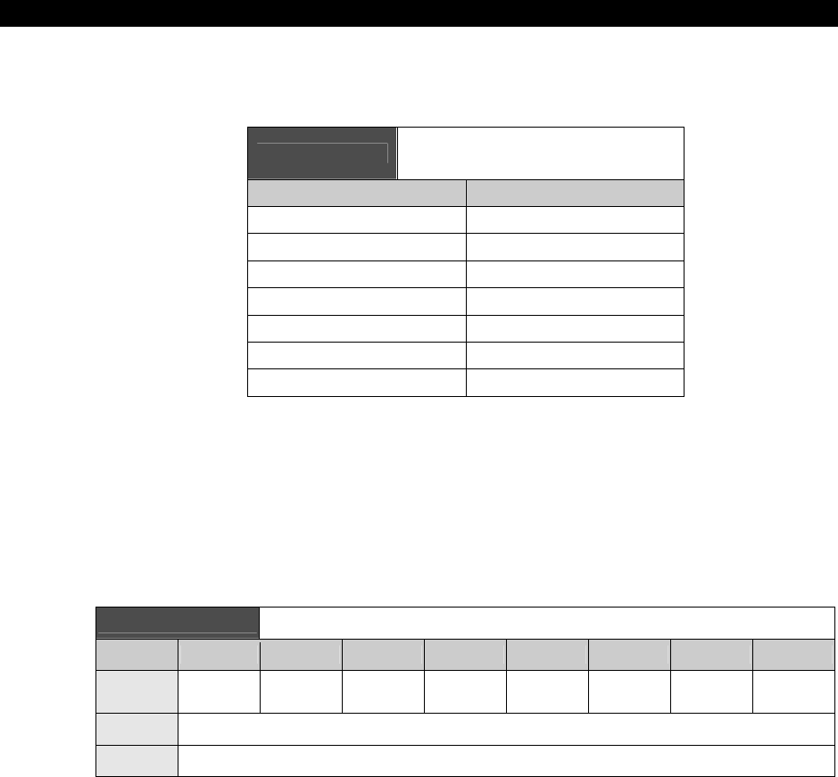
I The HYDRA Hardware
Page 152 Game Programming for the Propeller Powered HYDRA
enabled, the mouse applies the following mapping as shown in Table 10:4 to the counters
before sending their contents to the host in the data packet.
Table 10:4 Mouse Scaling reported Data
Mapping when in 2:1 mode
Actual Movement (delta) Reported Movement
0 0
1 1
2 1
3 3
4 6
5 9
delta > 5 delta × 2
So the scaling operation only takes affect when the actual movement delta is greater than 1,
and for delta > 5, the reported movement is always (delta × 2). Now, let’s look at the
actual data packet format for the mouse state.
10.3.2 Mouse Data Packets
The PS/2 mouse sends the movement information to the host which includes the position
counters, button state, overflow flags and sign bits in the format show in Table 10:5.
Table 10:5 Mouse Data Packet Format
Bit 7 Bit 6 Bit 5 Bit 4 Bit 3 Bit 2 Bit 1 Bit 0
BYTE 1 Y overflow
bit X overflow
bit Y sign bit X sign bit Always 1 Middle
Button Right Button Left Button
BYTE 2 X Movement (delta)
BYTE 3 Y Movement (delta)
The movement counters are 9-bit 2's complement integers; since the serial protocol only
supports 8 bits at a time, the uppermost sign bit for each 9-bit integer is stored in BYTE 1 of
the overall movement packet. Bit 4 holds the 9th bit of the X movement and Bit 5 holds the
9th bit of the Y movement. Typically, you don’t need to worry about the 9th bits since that
would be a lot of motion in one update, so just use BYTEs 2 and 3 to track motion.

Keyboard & Mouse Hardware10
Game Programming for the Propeller Powered HYDRA Page 153
The motion counters are updated when the mouse reads its input and movement has
occurred. As noted, the movement counters only record
differential
or delta motion rather
than absolute. With a 9-bit value recording each counter, a total amount of -255 to +256 can
be represented in 9-bit 2’s complement. If this range is exceeded, the appropriate overflow
bit is set for either the X or Y counter. Note that the movement counters are reset whenever
a movement data packet is successfully sent to the host. The counters are also reset after
the mouse receives any command from the host other than the "Resend" ($FE) command.
Next, let’s discuss the different mouse operation modes.
10.3.3 Modes of Operation
There are four standard modes of operation which dictate how the mouse reports data to the
host, they are:
RESET: The mouse enters
Reset
mode
at power-up or after receiving the
"Reset" ($FF) command. For this mode to occur both the DATA and CLOCK lines
must be HIGH.
STREAMING: This is the default mode (after Reset finishes executing) and is the
mode in which most software uses the mouse. If the host has previously set the
mouse to Remote mode, it may re-enter Stream mode by sending the
"Set Stream Mode" ($EA) command to the mouse.
REMOTE: Remote mode is useful in some situations and may be entered by sending
the "Set Remote Mode" ($F0) command to the mouse.
WRAP: This diagnostic mode is useful for testing the connection between the mouse
and its host. Wrap mode may be entered by sending the "Set Wrap Mode" ($EE)
command to the mouse. To exit Wrap mode, the host must issue the "Reset"
($FF) command or "Reset Wrap Mode" ($EC) command. If the "Reset" ($FF)
command is received, the mouse will enter Reset mode. If the "Reset Wrap Mode"
($EC) command is received, the mouse will enter the mode it was in prior to Wrap
mode.
RESET Mode - The mouse enters Reset mode at power-on or in response to the
"Reset" ($FF) command. After entering reset mode, the mouse performs a diagnostic self-
test referred to as BAT (Basic Assurance Test) and sets the following default values:
Sample Rate = 100 samples/sec
Resolution = 4 counts/mm
Scaling = 1:1
Data Reporting Disabled

I The HYDRA Hardware
Page 154 Game Programming for the Propeller Powered HYDRA
After Reset, the mouse sends a BAT completion code of either $AA (BAT successful) or $FC
(Error). The host's response to a completion code other than $AA is undefined. Following the
BAT completion code of $AA (ok) or $FC (error), the mouse sends its device ID of $00. This
distinguishes the standard PS/2 mouse from a keyboard or a mouse in an
extended
mode
.
After the mouse has sent its device ID of $00 to the host, it will enter
Stream mode
. Note
that one of the default values set by the mouse is
"Data Reporting Disabled."
This
means the mouse will not issue any movement data packets until it receives the
"Enable
Data Reporting"
command. The various modes of operation for the mouse are:
STREAM Mode - In stream mode, the mouse sends movement data when it detects
movement or a change in state of one or more mouse buttons. The rate at which this data
reporting occurs is the
sample rate
(defaults to 100 samples/sec on Reset). This
parameter can range from 10 to 200 samples/sec on most drivers. The default sample rate
value is 100 samples/sec, but the host may change that value by using the "Set Sample
Rate" command. Stream mode is the default mode of operation following reset.
REMOTE Mode - In this mode the mouse reads its inputs and updates its counters/flags at
the current sample rate, but it
does not
automatically send data packets when movement
occurs, rather the host must
“poll”
the mouse using the
"Read Data"
command. Upon
receiving this command the mouse sends back a single movement data packet and resets its
movement counters.
WRAP Mode - This is an
"echoing"
mode in which every BYTE received by the mouse is
sent back to the host. Even if the BYTE represents a valid command, the mouse will not
respond to that command — it will only echo that BYTE back to the host. There are two
exceptions to this: the
"Reset"
command and
"Reset Wrap Mode"
command, this is
obviously the only way to get the mouse back out of the Wrap mode! The mouse treats
these as valid commands and does not echo them back to the host. Thus Wrap mode is a
good diagnostic mode to test if a mouse is connected and if it’s working.
10.3.4 Sending Mouse Commands
A mouse command similar to a keyboard command in that it is sent using the standard 11-bit
serial protocol outlined in the Keyboard Write section. The commands supported are shown
in Table 10:6.
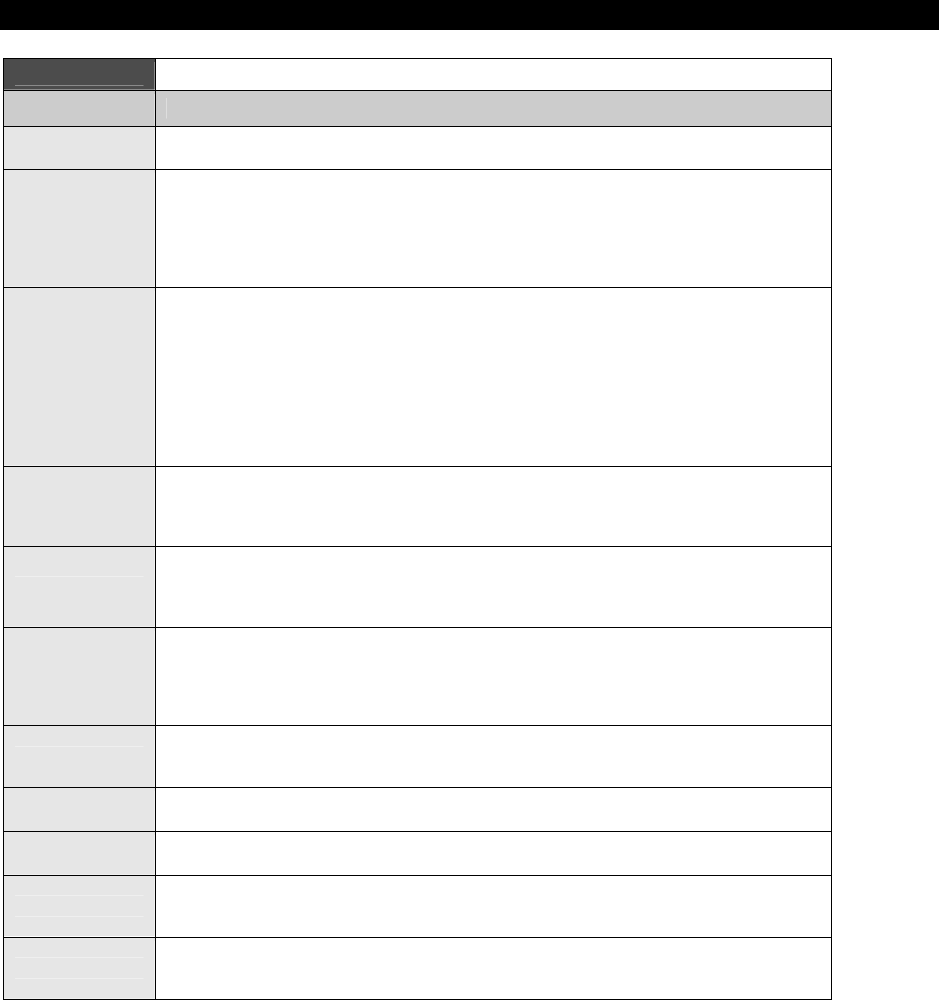
Keyboard & Mouse Hardware10
Game Programming for the Propeller Powered HYDRA Page 155
Table 10:6 Command Set for Standard PS/2 Mouse
Code Description
$FF Reset: The mouse responds to this command with "acknowledge" ($FA) then enters Reset
Mode.
$FE
Resend: The host can send this command whenever it receives invalid data from the
mouse. The mouse responds by resending the last packet it sent to the host. If the mouse
responds to the "Resend" command with another invalid packet, the host may either issue
another "Resend" command, issue an "Error" command, cycle the mouse's power supply to
reset the mouse, or it may inhibit communication (by bringing the Clock line low). The action
taken depends on the host.
$F6
Set Defaults: The mouse responds with "acknowledge" ($FA) then loads the following
values into its driver:
Sampling rate = 100
Resolution = 4 counts/mm
Scaling = 1:1
Disable Data Reporting
The mouse then resets its movement counters and enters Stream mode
$F5
Disable Data Reporting: The mouse responds with "acknowledge" ($FA) then disables
Data Reporting mode and resets its movement counters. This only effects data reporting in
Stream mode and does not disable sampling. Disabled Stream mode functions the same as
Remote mode.
$F4
Enable Data Reporting: The mouse responds with "acknowledge" ($FA) then enables Data
Reporting mode and resets its movement counters. This command may be issued while the
mouse is in Remote mode (or Stream mode), but it will only effect data reporting in Stream
mode.
$F3
Set Sample Rate: The mouse responds with "acknowledge" ($FA) then reads one more
BYTE from the host which represents the sample rate in unsigned 8-bit magnitude format.
The mouse saves this BYTE as the new sample rate. After receiving the sample rate, the
mouse again responds with "acknowledge" ($FA) and resets its movement counters. Most
mice accept sample rates of 10, 20, 40, 60, 80, 100 and 200 samples/sec.
$F2 Get Device ID: The mouse responds with "acknowledge" ($FA) followed by its device ID
($00 for the standard PS/2 mouse.) The mouse also resets its movement counters in most
cases.
$F0 Set Remote Mode: The mouse responds with "acknowledge" ($FA) then resets its
movement counters and enters Remote mode.
$EE Set Wrap Mode: The mouse responds with "acknowledge" ($FA) then resets its movement
counters and enters Wrap mode.
$EC Reset Wrap Mode: The mouse responds with "acknowledge" ($FA) then resets its
movement counters and enters the mode it was in prior to Wrap mode (Stream Mode or
Remote Mode.)
$EB Read Data: The mouse responds with acknowledge ($FA) then sends a movement data
packet. This is the only way to read data in Remote Mode. After the data packet has been
successfully sent, the mouse resets its movement counters.
(Table 10:6 is continued on the next page.)
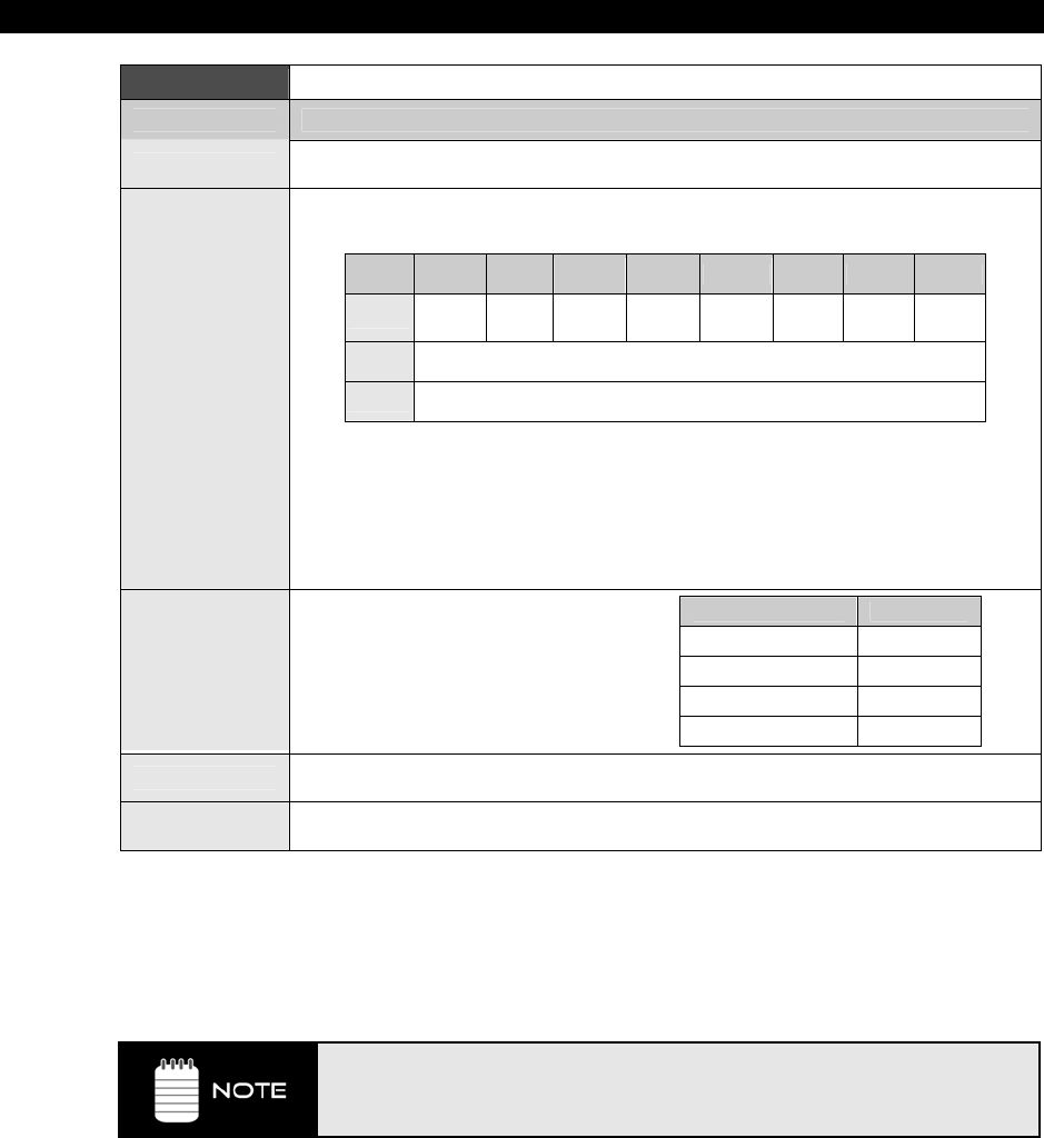
I The HYDRA Hardware
Page 156 Game Programming for the Propeller Powered HYDRA
Table 10:6 Command Set for Standard PS/2 Mouse (continued)
Code Description
$EA Set Stream Mode: The mouse responds with "acknowledge" then resets its movement
counters and enters Stream mode.
$E9
Status Request: The mouse responds with "acknowledge" then sends the following 3-
BYTE status packet (then resets its movement counters) as shown below:
Bit 7 Bit 6 Bit 5 Bit 4 Bit 3 Bit 2 Bit 1 Bit 0
BYTE 1 Always 0 Mode Enable Scaling Always 0 Left
Button Middle
Button Right
Button
BYTE 2 Resolution
BYTE 3 Sample Rate
Right, Middle, Left button = 1 if button pressed; 0 if button is not pressed.
Scaling = 1 if scaling is 2:1; 0 if scaling is 1:1 (Refer to commands $E7 and $E6).
Enable = 1 if data reporting is enabled; 0 if data reporting is disabled (Refer to commands
$F5 and $F4).
Mode = 1 if Remote Mode is enabled; 0 if Stream mode is enabled (Refer to commands $F0
and $EA).
$E8
Set Resolution: The mouse responds with
acknowledge ($FA) then reads the next
BYTE from the host and again responds
with acknowledge ($FA) then resets its
movement counters. The BYTE read from
the host determines the resolution as
follows:
BYTE Read from Host Resolution
$00 1 count /mm
$01 2 count /mm
$02 4 count /mm
$03 8 count /mm
$E7 Set Scaling 2:1: The mouse responds with acknowledge ($FA) then enables 2:1 scaling
mode.
$E6 Set Scaling 1:1: The mouse responds with acknowledge ($FA) then enables 1:1 scaling
(default).
Lastly, the only
commands
the standard PS/2 mouse will send
to the host
are "Resend"
($FE) and "Error" ($FC). They both work the same as they do as host-to-device
commands. Other than that the mouse simply sends 3-BYTE data motion packets in most
cases.
If the mouse is in Stream mode, the host should disable data reporting
(command $F5) before sending any other commands. This way, the mouse won’t
keep trying to send packets back while the host is trying to communicate with
the mouse.

Keyboard & Mouse Hardware10
Game Programming for the Propeller Powered HYDRA Page 157
10.3.5 Mouse Initialization
During the mouse power-up both the DATA and CLOCK lines must be pulled HIGH and/or
released/tri-stated by the host. The mouse will then run its power-up self-test or BAT and
start sending the results to the host. The host watches the CLOCK and DATA lines to
determine when this transmission occurs and should look for the code $AA (ok) followed by
$00 (mouse device ID). However, you can forgo this step if you like and just wait 1-2
seconds and “assume” the mouse was plugged in properly. You do not have to respond to
this code in other words. If you wish to Reset the mouse, you can at any time send the
command code $FF, and the mouse should
respond
with $FA to acknowledge that
everything went well.
Once the mouse sends the $AA, $00 startup codes, it enters its standard default mode as
explained in the sections above. The only thing we need to do to get the mouse sending
packets is to tell the mouse to start reporting movement. This is done by sending the
command “Enable Data Reporting” ($F4); the mouse responds with $FA to acknowledge
the command worked and then will start streaming out 3-BYTE movement packets at the
default rate of 100 samples/sec. This step is necessary, since on start-up if the mouse simply
started streaming data packets the host could lose important data, thus the mouse “waits” to
be told to start streaming the data and reporting the motion.
The movement data packets are formatted as shown in Table 10:5 on page 152. You simply
need to read these packets and send them upstream to your application.
10.3.6 Reading Mouse Movement
Assuming that the mouse has been initialized and is in Streaming mode with Reporting mode
enabled, you simply loop and read each 3-BYTE movement packet. As you read the first
BYTE you use it to determine the state of the buttons as well as any overflows with the
counters. Then the next two BYTEs, the X and Y deltas, should be added to running counters
(16-bit) that track the absolute position of the mouse cursor. That’s it!
10.4 Summary
The amount of technology in a PC always amazes me; if you haven’t ever written a keyboard
or mouse driver, you are probably thinking, “I had no idea there was so much going on with
the mouse and keyboard!” That’s the thing about the PC, it’s truly a marvel of technology
and all the interfaces used are very well thought out (usually). This of course makes our lives
much easier since there is good documentation on how to interface to the mouse and
keyboard, which in turn makes writing drivers much less painful. Also, remember that for
games and specific applications you do not need a bulletproof driver as you might for a real
PC. The keyboard and mouse drivers provided by Parallax (which we will discuss later) are
fairly complete and definitely overkill. When you design games and applications on the
HYDRA (and Propeller chip), you will find that these drivers are a good starting point, but you

I The HYDRA Hardware
Page 158 Game Programming for the Propeller Powered HYDRA
will tend to strip them and simplify them to save memory so you can write larger and larger
programs. For example, I have written both keyboard and mouse drivers in about 20-30 lines
of ASM code, that’s all you really need to for the really baseline functionality.
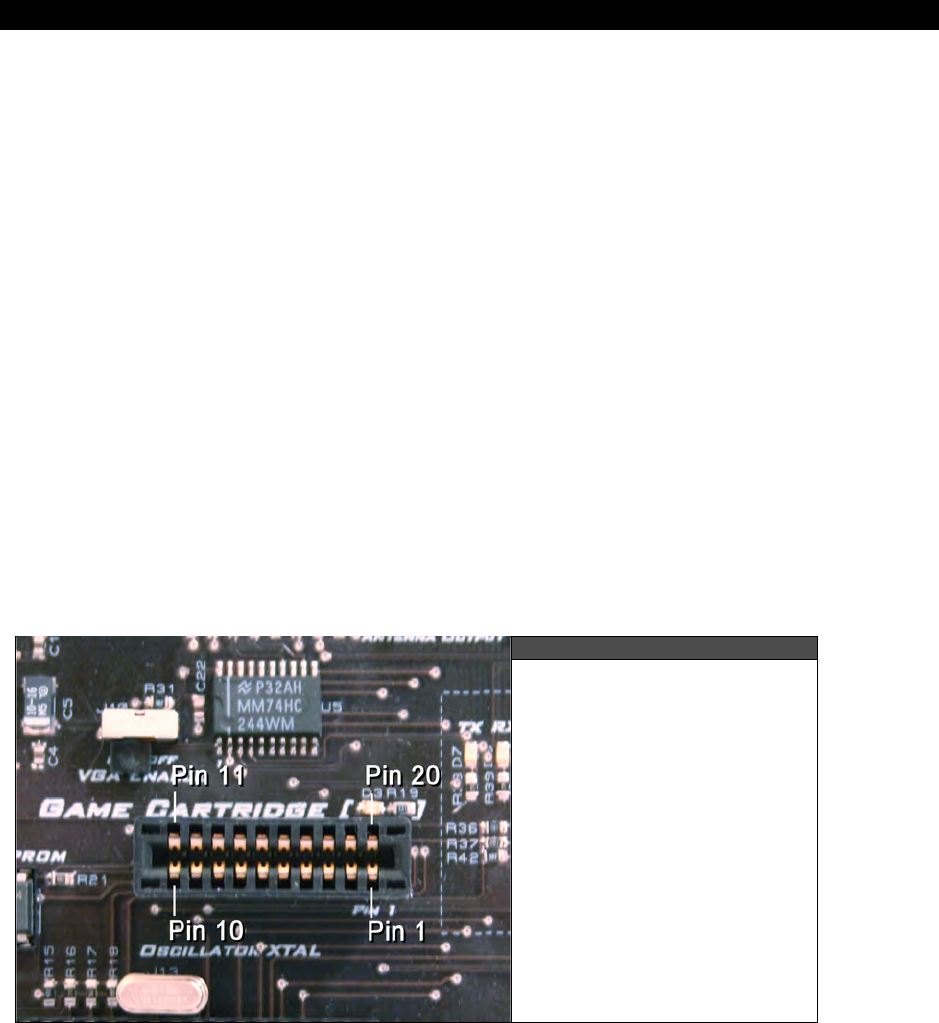
Game Cartridge, EEPROM & Expansion Port 11
Game Programming for the Propeller Powered HYDRA Page 159
Chapter 11:
Game Cartridge,
EEPROM &
Expansion Port
Hardware
In this chapter we are going to discuss the
“expansion port
” on the HYDRA as well as the
design of the onboard serial EEPROM since they are related. The expansion port is the most
powerful aspect of the HYDRA since it allows you to plug in enhancement products to
upgrade the HYDRA including more memory, I/O, extra processors, or whatever you can
think up! As is, the HYDRA comes with both a
128 K Game Card
as well as a
Blank Experimenter Card
. We are going to discuss all these topics and more, here’s
what’s in store:
Game expansion port design and signals.
Blank Experimenter Card design.
128 K Memory Card design.
Onboard 128 K serial EEPROM design.
11.1 HYDRA Expansion Port Design
Figure 11:1
The HYDRA Expansion Port
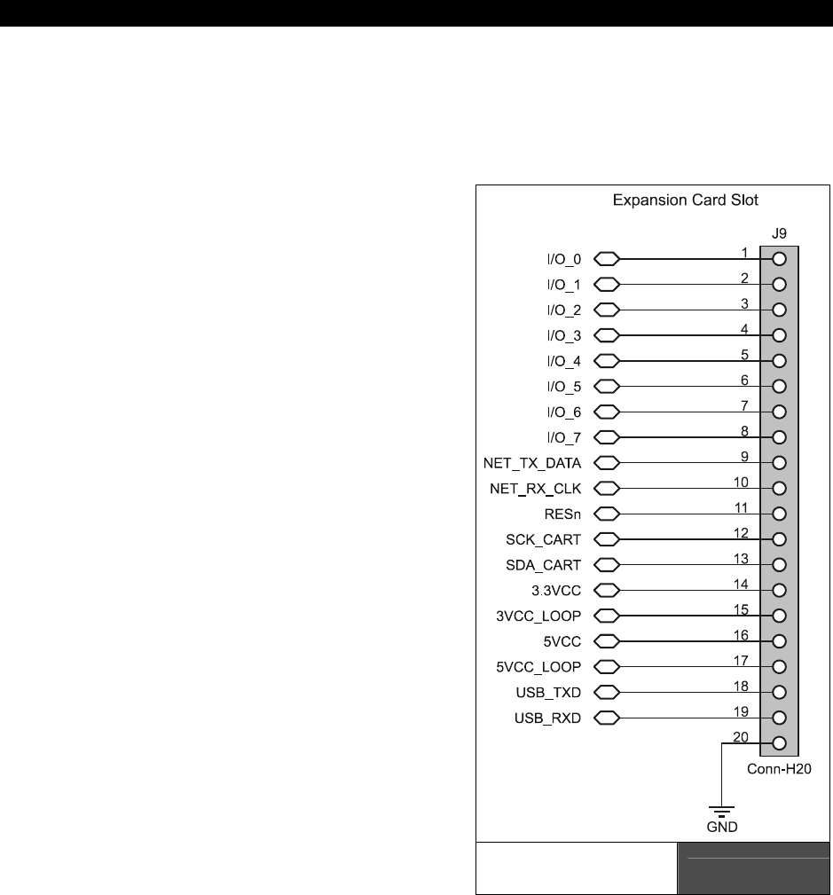
I The HYDRA Hardware
Page 160 Game Programming for the Propeller Powered HYDRA
The HYDRA has a 20 pin expansion port (J9) as shown in Figure 11:1 that can be used for a
number of expansion functions. The port itself is an industry standard female edge connector
interface with 0.1” contact spacing on both sides. Typically, the idea of an “expansion port” is
to export as much of the system busses and I/O as possible, so future upgrades and add-ons
can be built on the platform. With this in mind, the expansion port exports:
Power (for both the 3.3 V and 5.0 V
supplies)
Networking (the built in RJ-11 ad-hoc
serial network)
USB (serial TX and RX along with
ground)
8 I/Os (general I/Os from Propeller chip
also used for VGA interface)
System reset
Serial EEPROM interface (so an EEPROM
on the cartridge can be loaded rather
than the onboard EEPROM)
Loop-back signals to detect cartridge
insertions
Everything is self-explanatory except maybe
the
“loop-back”
power lines. There are
used to indicate a cartridge is plugged in.
The power lines are looped back on the
cartridge and then “sensed” back on the
HYDRA via the signal lines 33VCC_LOOP
and 5VCC_LOOP. This way the HYDRA
can tell if something is plugged in and your
code can take different execution paths, or
you can wire them directly to hardware
selection logic to gate in/out various
components. Referring to the image in
Figure 11:1 of the expansion port take a
look at Figure 11:2, it’s the actual design of
the expansion port and shows the lines that
are exported.
The Design of the
Expansion Port Figure 11:2
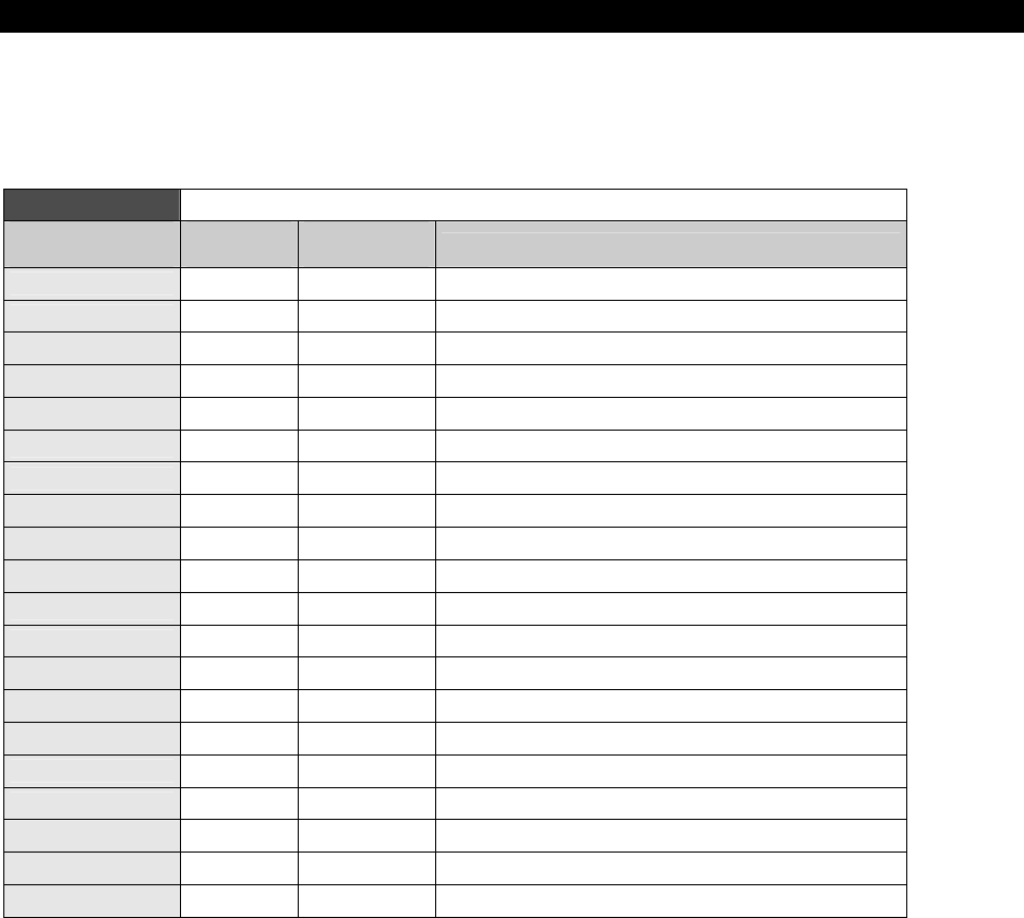
Game Cartridge, EEPROM & Expansion Port 11
Game Programming for the Propeller Powered HYDRA Ì Page 161
11.1.1 Expansion Port Signal Definitions
Table 11:1 below lists the actual signal names and their connections to the Propeller chip as
well as their functions for the expansion port.
Table 11:1 The Mapping of Expansion Port Signals to the Propeller Chipb
Expansion Port
Signal Expansion
Port Pin Propeller
Pin# / Name Description
I/O_0 1 21 / P16 General I/O (shared with VGA_VSYNC)
I/O_1 2 22 / P17 General I/O (shared with VGA_HSYNC)
I/O_2 3 23 / P18 General I/O (shared with VGA_BLUE_B0)
I/O_3 4 24 / P19 General I/O (shared with VGA_BLUE_B1)
I/O_4 5 25 / P20 General I/O (shared with VGA_BLUE_G0)
I/O_5 6 26 / P21 General I/O (shared with VGA_BLUE_G1)
I/O_6 7 27 / P22 General I/O (shared with VGA_BLUE_R0)
I/O_7 8 28 / P23 General I/O (shared with VGA_BLUE_R1)
NET_TX_DATA 9 3 / P2 HYDRA Net Transmit Line
NET_RX_CLK 10 2 / P1 HYDRA Net Receive / Clocking Line
RESn 11 11 / RESn System Reset Active LOW
SCK_CART 12 37 / P28 Serial Clock for Cartridge / EEPROM
SDA_CART 13 38 / P29 Serial Data for Cartridge / EEPROM.
33VCC 14 POWER Connects to 3.3 V Power Supply
3VCC_LOOP 15 POWER Optional Feedback Loop from Cartridge to HYDRA
5VCC 16 POWER Connects to 5.0 V Power Supply
5VCC_LOOP 17 POWER Optional Feedback Loop from Cartridge to HYDRA
USB_TXD 18 N/A USB Transmit Serial Line
USB_RXD 19 N/A USB Receive Serial Line
GND 20 POWER Connects to System GROUND
The only signals that deserve some extra explanation are the I/O_0..7 lines. These lines are
shared with the VGA interface, so when you are driving a VGA monitor, you can’t use these
lines on your plug-in card (unless of course that is the intent). The VGA Enable switch at J10
enables or disables the VGA outputs. So if you want to drive VGA with these lines, you would
place the VGA Enable switch into the “on” position. When you are not driving VGA, it’s best
to keep the VGA Enable in the “off” position. The VGA Enable switch as noted early in the
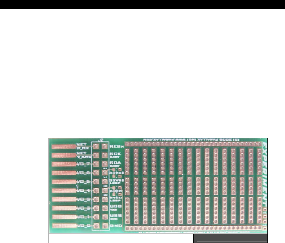
I The HYDRA Hardware
Page 162 Game Programming for the Propeller Powered HYDRA
book simply enables/disables the tri-state buffer logic and doesn’t let the I/O’s drive the VGA
interface if they are not meant to.
Additionally, you might be concerned with power draw from the cartridge port and how much
you can pull from the HYDRA? The HYDRA’s power adaptor is 300-500 mA, so as long as you
leave enough to power the HYDRA and the systems in use then there is no limit to the
power-up to the supply current of the power adaptor. However, I suggest that if you do
design an expansion card yourself, that you decouple the power coming in on the 3.3 V and
5.0 V supplies with a 0.01–0.1 µF cap, and a 1.0–10.0 µF tantalum cap to keep the power
clean. Both the experimenter card and the 128 K expansion card have power decoupling on
them already.
11.2 Blank Experimenter Card
To get you started on your own experiments, the HYDRA kit comes complete with a blank
experimenter card as shown in Figure 11:3.
The Blank Experimenter Card Figure 11:3
As you can see, the card has nothing on it but decoupling caps and power LEDs. The header
areas have a solder through-pin for each signal, so you can simply wire into them.
Additionally there is space on the surface to place a couple of DIP-style TTL chips along with
some passive components. There are 3 rows of 18 contacts, along with large “common” rails
along the top and bottom referring to the figure. This is a great way to start experimenting
with expanding the HYDRA and/or adding small boards to the Propeller chip’s functionality
via the expansion port. The 128 KB memory expansion game card was derived from this
design.
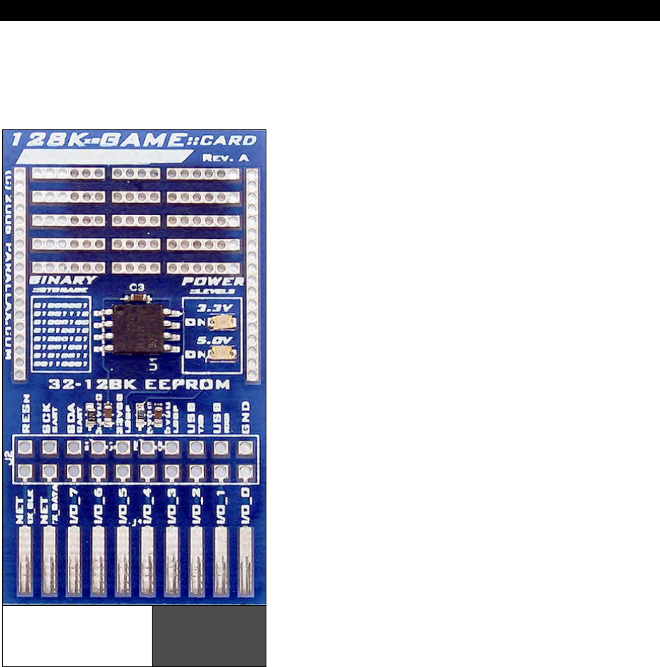
Game Cartridge, EEPROM & Expansion Port 11
Game Programming for the Propeller Powered HYDRA Page 163
11.3 128K Memory Card
Figure 11:4 shows the 128 KB memory expansion card that comes with the HYDRA kit. The
serial EEPROM is based on the 8-pin 24C1024 model which a number of manufactures’ sell
(Atmel is my favorite).
The 128 KB memory expansion card is more or
less a copy of the 128 KB serial EEPROM
design found on the HYDRA itself copied to an
expansion card. The 32 KB and 128 KB
expansion cards are similar, but simply have
smaller EEPROMs on them.
The magic of the card is that when plugged in,
the Propeller chip on the HYDRA reads the
card’s serial EEPROM rather than the onboard
serial EEPROM. This is facilitated via the
loop-back signals. When the card is inserted,
the loop-back signals, specifically the
3VCC_LOOP signals, are used to enable the
card’s EEPROM while disabling the onboard
serial EEPROM. This is possible since the serial
EEPROMs have addressing lines A0..2 that
allow up to 8 devices to be chained together
on the same buses as long as only one device
is selected at a time.
The 128 K
Memory Expansion
/ Game Card
Figure 11:4
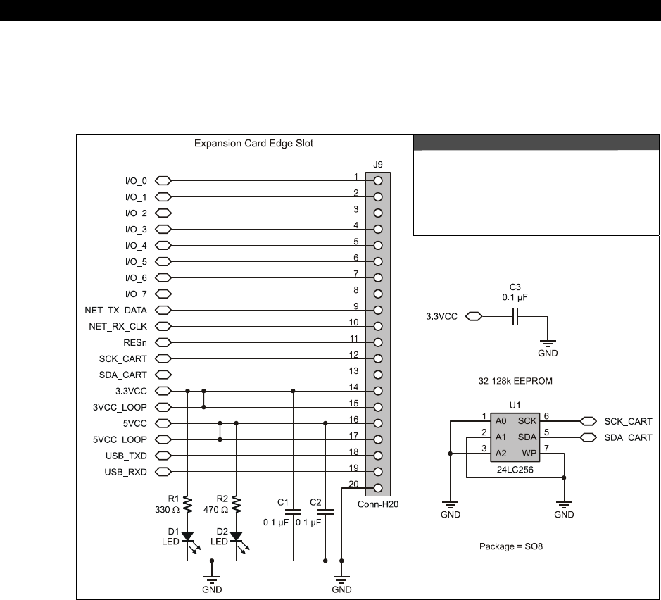
I The HYDRA Hardware
Page 164 Game Programming for the Propeller Powered HYDRA
Figure 11:5 shows the design of the expansion card. Notice all 3 address selects are LOW;
this always selects the EEPROM, thus when plugged into the HYDRA it will always be
addressed. Therefore, it’s up to the design of the HYDRA’s onboard 128 KB serial EEPROM
design which we will take a look at next.
Figure 11:5
The Design for the 128 K
Memory Expansion/Game Card
11.4 Onboard 128 K Serial EEPROM Design
The Propeller chip works with a 32 KB “image” that the IDE/compiler generates. All your
code, assets, and data must fit into this 32 KB. However, after the Propeller chip is done
reading the 32 KB memory image from the serial EEPROM on boot, the lines are released and
you can still access the EEPROM device yourself. The HYDRA uses the largest available serial
EEPROMs which are 128 KB. This way you can fit your 32 KB Propeller program in the
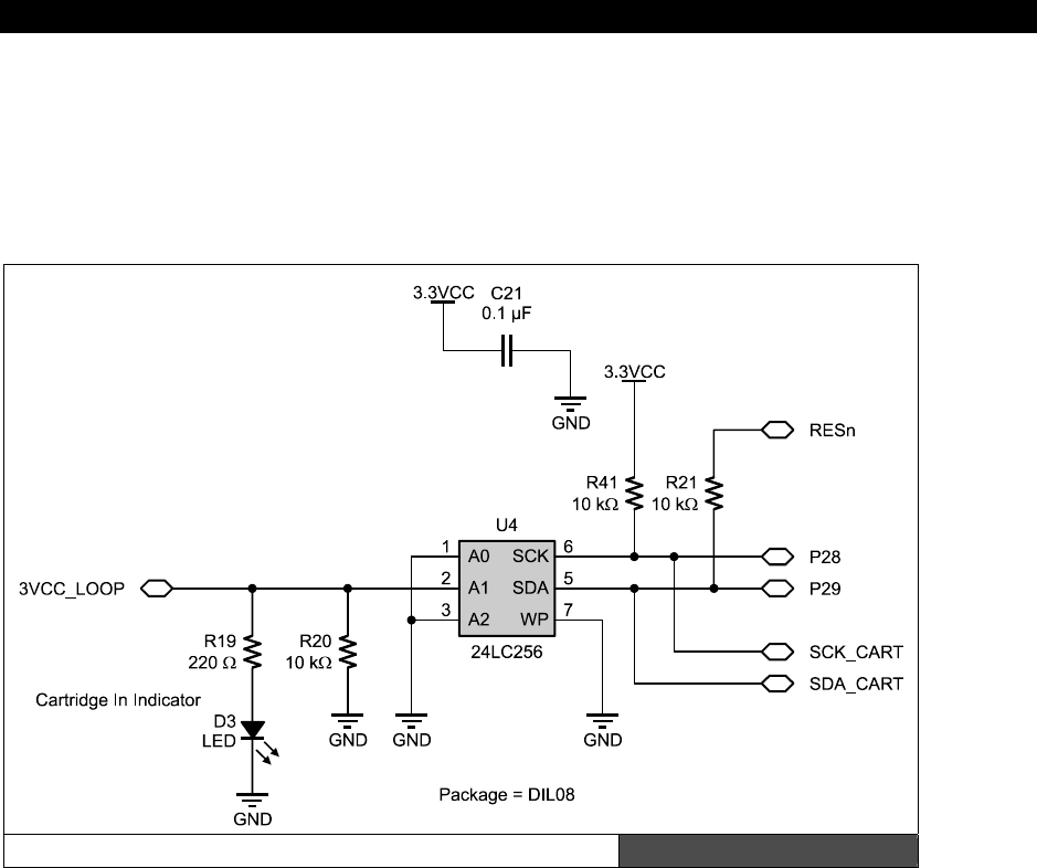
Game Cartridge, EEPROM & Expansion Port 11
Game Programming for the Propeller Powered HYDRA Ì Page 165
EEPROM, but you have an additional 96 KB of storage for assets, data, real-time monitoring,
digitizing – you name it! Also, later when more tools are available from Parallax and others,
you will be able to access the expanded 96 KB of the serial EEPROM and place assets there
as part of the Propeller took itself. However, for now, we must as programmers write our
own tools to do this and write our own drivers to talk to the serial EEPROM’s expanded
memory.
aThe Onboard 128 K EEPROM Design Figure 11:6
Figure 11:6 depicts the design for the onboard serial EEPROM, pins 5 and 6 of the EEPROM
are connected to the system lines P28/P29 which are the
“serial clock”
(SCK) and
“serial data”
(SDA) respectively on the Propeller chip. Those connections are standard and
nothing exciting is going on there. The only action happens on the addressing lines, notice
there are 3 addressing lines A2..0. A0 and A2 are grounded, but A1 is driven by a weak
pull-down as well as the 3VCC_LOOP signal from the expansion port. Normally, when A1 is
grounded the serial EEPROM is selected and Propeller chip reads from it, but the moment a
game card is plugged in the 3VCC_LOOP is driven HIGH, disabling the onboard serial
EEPROM and the EEPROM that the game card is gated in! Presto, plug-and-play that works!

I The HYDRA Hardware
Page 166 Game Programming for the Propeller Powered HYDRA
If you’re interested in learning more about serial EEPROMs and designing around them as
well as programming them please review this file on the CD:
CD_ROOT:\HYDRA\DOCS\atmel 24c1024_datasheet.pdf
11.5 Summary
Having an open interface to expand any hardware device is the #1 feature as far as I am
concerned. The Atari 800 for example was a feat of engineering, 10 times more advanced
than the Apple II, but the Apple II sold 10 times more units because the Apple II allowed
users to build their own expansion cards for the device and also openly documented the
hardware interface. The Atari 800 had expansion slots as well, but they were very hard to
find information on to interface with. So the moral of the story is: the easier it is to build add
on cards the more useful hardware will be. I personally can’t think of a fraction of the cool
things that can be done with a Propeller chip, but I know that by having an expansion port
with a commonly found edge connector interface, others can create their own add-on
hardware and expand the HYDRA itself. At some point, I hope to see Ethernet interfaces,
LCD, IDE, flash drive, and even SRAM, CPU, and FPGA cards! At very least take the free
blank expansion card, throw a 7447 on there and a 7-segment display and use it for
debugging!

HYDRA-NET Network Interface Port12
Game Programming for the Propeller Powered HYDRA Page 167
Chapter 12:
HYDRA-NET
Network
Interface Port
The simplest interface in the world is the good old RS-232 standard; however, the physical
interfaces are usually DB9 or DB25 and are very bulky and expensive. Ethernet is great, but
very complex and very expensive as well. So when designing the HYDRA, I wanted to
facilitate networking but I didn’t want it to be expensive, bulky, or complex to program. On
the other hand, I wanted to be able to connect HYDRAs hundreds of feet from each other
with commonly available cabling – After thinking about it, I thought why not use phone
cables? They have 4 conductors (2-conductor products exist as well), act like twisted pairs,
cost nearly nothing (a 100-foot phone extension line is $5.00 USD) and they are very flexible
and look cool and come in colors to boot! So, I was sold. I therefore designed a physical
network interface on the HYDRA for RJ-11 standard phone connectors, and designed
electronics to help interface the HYDRA using standard RS-232 serial techniques. In this
chapter, we are going to look at the networking on the HYDRA, the hardware, and some
software demos. Here’s what’s in store:
The hardware design and reflection cancellation technology
Discussion of RJ-11 phone cable interfaces and standards
Serial Protocols
Demo and ideas for networking games together
12.1 HYDRA-NET Hardware Interface Design
Figure 12:1 on the next page shows the design for the network interface. There are only two
lines that are interfaced to the Propeller chip: NET_TX_DATA (I/O P2) and NET_RX_CLK
(I/O P1) (these are the transmit and receive lines respectively). The interface to the physical
cabling is via a simple transmission line termination scheme. If have no idea what a
“transmission line” is then consider yourself lucky. But, if you have done any electrical
engineering with long lines or communication design then you are familiar with them.
Simply put, when the length of the transmission cable starts to be more than one quarter
length the wavelength of the transmission wave, simple connections from A to B do not act
like wire anymore – they act like distributed capacitance and inductance, and special care has
to be taken when designing circuits with long transmission cables. What happens is that
when an output signal changes state (even a TTL or CMOS signal) this happens very quickly,
say 5 ns, but this wave “propagates” down the transmission line. For short wires this is

I The HYDRA Hardware
Page 168 Game Programming for the Propeller Powered HYDRA
irrelevant, but if you try to send a signal that is changing at a very high frequency more than
a few inches all kinds of bad things can happen. For example, with the 5 ns rise time
example, one end of the transmission line is at 5V, but the other end is at 0V for a “long”
time until the wave arrives, but it gets worse, depending on the “impedance” at the end of
the wire run, the wave might even “reflect” back at you and you might find 10 volts on your
5 V output!
The HYDRA-NET Hardware Interface Design Figure 12:1
To minimize all this nastiness you can do a few things: run your transmission lines very
slowly, make them short, or you can add active/passive hardware to “fix” the problems. This
is the approach I took when designing the HYDRA-NET: I ran a number of simulations, did
some math, tried some experiments and came up with a termination network that gives good
results for both slow and fast edges, and low and high frequency transmissions as well as
short and long transmission lines. I have run the network at 100 M at 256 Kbits/sec no
problem, so the network works fine for most purposes. Moreover, we will learn shortly that
RJ-11 phone cable is actually pretty good for this sort of thing.
HYDRA-NET Network Interface Port12
Game Programming for the Propeller Powered HYDRA Page 169
Anyway, returning back to the design, there is a small 51 Ω resistor in series with the
transmit circuit, and this dampens the transmission and matches the impedance of the
transmission line as much as possible to the output of the circuit. On the receiver pin, I use
what’s called parallel termination, that is, the design tries to set the termination, so that both
LOW and HIGH signals get through in one piece. The pull-up at R23 is always there, but you
can switch in the extra 51 Ω pull-down resistor via the switch at J12. Also, notice there is a
small capacitor there, this is called “AC termination,” that is, when idle no current will flow
and waste power, only AC transient signals will cause the termination circuit to activate.
Thus, when you are working with the networking, try turning the cancellation on/off
depending on your signaling speed and distance, and usually one setting will make a
otherwise hopeless serial transmission straighten up and come through loud and clear.
12.2 RJ-11 Phone Interfacing
As noted, the HYDRA-NET uses a 4-wire full-duplex communication scheme. A standard RJ-
11 (phone jack) and phone line are employed for ease of use and interfacing. The phone line
must have all 4-conductors and be
"crossed-over."
I have tested the network at a nominal
speed of 256 Kbit and a maximum speed of about 2.56 Mbit. Higher speeds are possible, but
synchronization is hard to maintain as noise, crosstalk, and reflections decrease the signal
integrity at higher bit rates. The hardware is designed to facilitate full duplex, non-clocked,
asynchronous communications; however, you are still free to send data in one direction and
use the other line as a “clock” rather than using software algorithms to track start, data, stop
bits as most asynchronous serial communication must employ. The pinout of the RJ-11 is
show in Table 12:1.
Table 12:1 RJ-11 Pinout
and Meaning
Pin # Function
1 Ground
2 Receive
3 Transmit
4 Ground
It’s unimportant which way you refer to the pinout orientation, since at the receiver’s end the
cable is crossed over; that is from one HYDRA unit pin 2,3 become pins 3,2 on the other unit,
but always the GROUND pins “surround” the data lines since they are on pin 1 and 4 (giving
better noise immunity and decreasing radiation outside the cable).
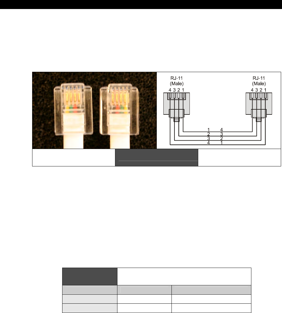
I The HYDRA Hardware
Page 170 Game Programming for the Propeller Powered HYDRA
Figure 12:2 (left) is an actual picture, on the left the wires are colored black, red, green,
yellow (left to right), but on the right, notice they are reversed. Similarly, Figure 12:2 (right)
shows electrically how the crossing over works. Note that you must always use a crossed
over RJ-11 phone cable, these are very common, simply inspect both ends, hold them the
same way and you should notice that the colors of the wire through the connector are
reversed at each end. This is “crossed” over.
Crossed over RJ-11
Cable Figure 12:2 Electrical Diagram
12.3 Network Protocol
The HYDRA’s networking port is simply a hardware level interface; you may use any protocol
you wish to transmit your data since it’s under software control, but a standard NRZ (non-
return to zero) serial scheme is suggested to keep drivers very similar to standard RS-232
systems. For example, at startup the TX line is driven HIGH (via a pull-up resistor), this could
be the “waiting” state then a start bit might be indicated by pulling the line LOW, and then
sending the data bits (8 of them usually) along with a final HIGH stop bit to signify the end
of the frame along with a parity bit potentially, etc. It’s up to you. However, the hardware
has been designed such that full duplex transmission on RJ-11 phone cable will be employed.
On the HYDRA the following I/O’s are being used to transmit and receive data:
Table 12:2 I/O pins used on Propeller Chip for
Communication
Propeller Chip Pin Name Meaning
Pin 3 NET_TX_DATA Transmit data
Pin 2 NET_RX_CLOCK Receive data or clock use
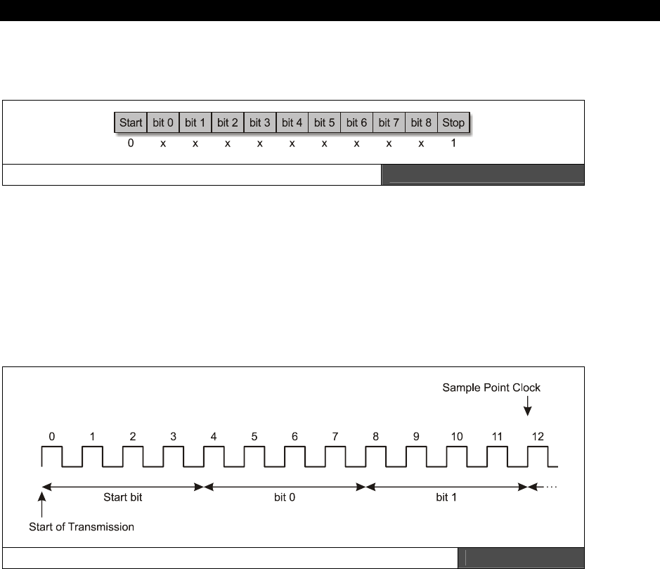
HYDRA-NET Network Interface Port12
Game Programming for the Propeller Powered HYDRA Ì Page 171
For the networking demos, the following simple packet protocol based on standard RS-232
serial protocol was employed, refer to Figure 12:3.
aHYDRA-NET Demo Serial Protocol Figure 12:3
The clocking scheme might use an internal software loop bit rate that is 4 to 8 times faster
than the bit rate to break up each clock into 4 segments to help “center” data sampling, for
example, a bit rate of 64 Kbit would require the software clock loop to run at a rate of:
64 K × 4 = 256 K cycles per second.
All samples of the serial input stream are sampled on the 3rd clock HIGH phase from the
beginning of the data bit.
aThe Internal Software Clock and Data Rate Compared Figure 12:4
Once the start of transmission is found, the state machine should wait 4 cycles; this is the
end of the start bit. Then each data bit consists of 4 cycles, on the HIGH phase of the 3rd
clock of each cycle, the data bit is sampled. This continues until all 8 bits are read in, then
the state machine confirms a HIGH bit for the 9th data bit and the frame is complete. An
optional parity bit can be inserted if one wishes; it simply reflects the even/odd parity and
can be used for error correction if needed at higher speeds.

I The HYDRA Hardware
Page 172 Game Programming for the Propeller Powered HYDRA
12.4 Demo Programs
Thus far, we haven’t really seen any demo other
than the software pre-loaded on the HYDRA;
however, I thought that the networking is a
large enough system that a simple demo might
be in order. Additionally, it’s doubtful you have
two HYDRA units, thus this might be the only
way for you to see two units networked.
The demo program is a one-way peer-to-peer
network demo where each unit is either a
sender or a receiver running Spin code and a
single processor. This demo simply uses a single
character send and receive buffer to hold the
outgoing and incoming data on either
application along with a graphical terminal
display as shown in Figure 12:5, which depicts a
messy setup of two HYDRAs with network cable
and keyboard.
Screen shots of the sender (right) and receiver (left) programs are shown in Figure 12:6.
Networking in Action: Sender (right) and Receiver (left) Figure 12:6
Networking
Setup Figure 12:5
HYDRA-NET Network Interface Port12
Game Programming for the Propeller Powered HYDRA Page 173
The basic networking layer organization that is going on is shown with the following graph:
Figure 12:7
Sending Client
│
└ Buffer
│
└ Transmitter (running on cog)
│
└ Transport layer
│
└ Receiver (running on cog)
│
└ Buffer
│
└ Receiving Client
Basic Networking
Layer Organization
Transmission - When transmitting, the sending client simply calls the transmission function
with the BYTE to send and can either wait for the transmission or return immediately. Either
way, there is no ACK from the receiver that the data was received. A global counts the
number of BYTEs sent.
Reception - When the receiver receives data, it will buffer the BYTE in the receive buffer
and set a flag; if the client does NOT poll the flag and retrieve the BYTE by the time another
BYTE is received, then the BYTE will be overwritten and the flag still set. A global counter
counts the number of BYTEs received. The client can either call and return or block for a
BYTE as well.
The demo consists of two terminal programs; one is the
sender
and one is the
receiver
. As
you type with the keyboard on the
“sender”
it will be echoed, and sent to the
“receiver”
where the receiver will print it on the screen as well. More or less it’s a very crude server-
client demo that is half duplex, making it full duplex is simply a matter of spinning another
cog and running both server and client on each HYDRA at the same time. I leave it to you
Neo. We will revisit this demo later in Part II, but if you want to take a sneak peek at the
source, check out these files:
CD_ROOT:\HYDRA\SOURCES\hydra_net_sender_demo_011.spin
CD_ROOT:\HYDRA\SOURCES\hydra_net_receiver_demo_011.spin
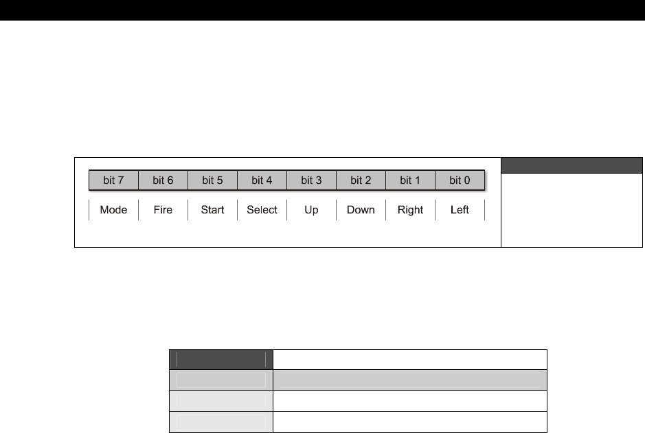
I The HYDRA Hardware
Page 174 Game Programming for the Propeller Powered HYDRA
12.5 Networking Games Together
Of course, instead of sending characters one can create a higher level protocol that is block
oriented to send more data. However, for simple games a single BYTE and a full duplex
system can facilitate most games running peer-to-peer. For example, one possible data
encoding is shown Figure 12:8.
Figure 12:8
BYTE Encoding
Game Data for
User Input
By using a “MODE” bit, it’s possible to send the state of the game controller OR to send other
information such as ASCII codes or other control codes agreed upon by the clients, this way
the data is polymorphic, Table 12:3 shows a way to interpret the MODE bit.
Table 12:3 BYTE Encoding Table
Mode Bit Encoding
0 (normal) b6 - b0, single bit encoding, mutually exclusive
1 (extended) b6 - b0, 7 bit binary encoding
12.6 Summary
Networking is a fascinating field on all levels; hardware, software, and applications. However,
one thing is certain, network programming is hard enough to get working at an application
layer without having to deal with Ethernet or USB protocols, thus the HYDRA uses a simple
physical interface that works fine for logic level full duplex serial transmissions. Moreover,
with the noise cancellation hardware at each end built into the hardware you can get some
pretty serious speeds and cable lengths, so some “real” networking experiments and
applications can be built with the HYDRAs.

Part II Propeller A
r
and Programming Par
t
Propeller Architect
Programming Part II
Architecture and Pr
o
Part II Propeller A
r
and Programming Par
t
Propeller Architect
Programming Part II
Architecture and Pr
o
Part II Propeller A
r
and Programming Par
t
Part II: Propeller Chip
Architecture and
Programming

II Propeller Architecture and Programming
Page 176 Game Programming for the Propeller Powered HYDRA
Welcome to Part II of the book! If you aren’t a hardware guru then Part II will be much
more palatable than Part I. In Part II, we are going to concentrate on the Propeller chip’s
internals and general programming of the chip, and important details about the Propeller
chip’s programming considering the HYDRA’s hardware support around the chip. These
chapters aren’t 100% about software, but more of a transition from hardware to low-level
programming with some references to hardware. Then in Part III, it’s all software and
high-level game development, so that’s where the fun starts and the pixels will really start to
fly (or more technically translate). So let’s get started with some low-level discussion of the
Propeller chip itself and find out what makes it tick.
Chapter 13: Propeller Chip Architecture and Programming, p. 177.
Chapter 14: Cog Video Hardware, p. 233.
Chapter 15: The Spin Language, p. 245.
Chapter 16: Programming Examples on the Propeller Chip / HYDRA, p. 319.

Propeller Chip Architecture13
Game Programming for the Propeller Powered HYDRA Page 177
Chapter 13:
Propeller Chip
Architecture and
Programming
In this chapter, we are going to discuss the Propeller chip’s general architecture, internal
organization, and register sets, talk about its peripherals, and much more. There is a lot of
information in this chapter and you might want to read it a couple times to make it sink in. I
wrote it, and I still have to re-read it from time to time to remember all the details about the
chip, so I suggest reading it once and not worrying too much about detail, then once you
have the “big picture” read the chapter again to reinforce missed details. The chapter covers
the following main topics:
Propeller chip architecture
System startup and initialization sequence
Assembly language instruction set
The Propeller chip’s registers
Port I/O techniques
Understanding the counters
ROM look-up tables and Spin interpreter
The Propeller chip is a 32-bit RISC-like multiprocessing microcontroller with 32 Kbytes of RAM
and 32 Kbytes of internal ROM with firmware, tables, and other run-time information. Also, in
the 32K ROM is the on-chip language interpreter for the
“Spin”
language that the Propeller
chip runs at high level and on boot. As far as multiprocessing goes, the Propeller chip has 8
processing cores numbered 0..7, referred to as
“cogs.”
Each cog is exactly identical except
that during boot, a Cog 0 takes control until the boot process is complete and the program is
loaded and run from the HOST PC or EEPROM.
Figure 13:1 on the next page shows the overall architecture of the Propeller chip. Notice its
simplicity: there are no interrupts, no other peripherals other than 2 timers per cog, I/O
support, and a video serializer per cog. Other than that, the chip is simply a multiprocessor of
the MIMD (Multiple Instruction Multiple Data) class. Also, the I/O is interesting. There are 32
I/O pins, but since the Propeller chip has 8 processors, all of which can access all of the I/O,
there is a huge possibility for conflict. Therefore, the cogs are each gated to the I/O control
via OR and AND gates, so that the “best” possible solution to any I/O conflict is the result.
That is if one cog uses an I/O for output then another uses it for input, the idea is to
minimize the erroneous results and not hurt any outside hardware. The best course of action

II Propeller Chip Architecture and Programming
Page 178 Game Programming for the Propeller Powered HYDRA
of course is to watch what you are doing as a programmer and make sure that any process
running on one cog doesn’t step on the toes of another.
Propeller Chip Block Diagram Figure 13:1
Image from Propeller Manual v1.0 courtesy of Parallax Inc.
As far as main memory, it’s very limited as mentioned, with only 32 Kbytes of RAM to hold all
program and data under normal conditions. Additionally, there is no dedicated video RAM,
therefore, we only have a total of 32K to put all our programs, data, and video RAM in during
run time. However, there is some hope for assets. The EEPROM used in the HYDRA is a
128 Kbyte model and the Propeller chip only uses the first 32K of it, thus, one could always
store run-time assets and even some form of I-Code on the EEPROM and load it later. There
is no facility for this built into the IDE, but as programmers we are free to write tools on the
PC to download information to the EEPROM to store larger assets on it.

Propeller Chip Architecture13
Game Programming for the Propeller Powered HYDRA Page 179
13.1 Propeller Chip on Reset
Upon reset, all 8 cogs are shut down, forcing all pins to become inputs (high impedance).
Then, a single cog (Cog 0) is booted with a startup program from the main memory’s 32K
ROM. This program checks for a serial host connection on P31 (RX). If a host is present, a
conversation ensues via P30 (TX), and the host may load the main memory’s RAM with
high-level code. The host may also direct the code to be programmed into an EEPROM
before executing it. If no host is present, the startup program attempts to read and execute
high-level code from the first 32K of a 24LC256-1024 EEPROM on P28 (SCL) and
P29 (SDA). If neither a serial host nor an EEPROM is present, the program will place the
chip in shutdown mode. Until a new reset occurs, power is minimized and all pins will be
floating.
High-level code is what initially executes from the programmer’s perspective. It is capable of
booting extra cogs with either other high-level tasks or assembly language programs. In the
case of high-level code execution, a cog is loaded with an interpreter program from the main
memory’s ROM which executes the high-level code residing in the main memory’s RAM.
13.2 Cog Internal Architecture
Each cog has its own 512 x 32-bit register space. These 512 registers are all used for RAM
and or program instructions, except for the last 16 which are special-purpose Cog Registers.
The RAM space is used for executable code, data, and variables. The last 16 locations serve
as interfaces to the Hub, I/O pins, and local cog peripherals. Note that the largest ASM
program you can have per cog is 512-16 = 496 ASM instructions. This is quite a limitation if
you want to write a complete game in ASM that fits on one cog; therefore the approach is to
write your game in Spin high-level code for the slow stuff and make calls to the cogs running
your low-level high-speed functions like graphics, sound, etc. Or, it is possible to write a
“loader” that pages in and out more ASM instructions into a single cog.
Additionally, the math is very limited on the cog: there is no multiply, no divide, but there is
support for signed and unsigned 32-bit addition and subtraction. Therefore, math-heavy
algorithms should use tight loops or look-up tables for multiplication and division.
When a cog is booted, its RAM locations are loaded sequentially from main memory and its
special-purpose registers are cleared to zero. After loading, the cog begins executing
instructions, starting at location $000. It will continue to execute code until it is stopped or
rebooted by either itself or another cog, or a reset occurs. Table 13:1 on the next page is a
summary of the special registers within a cog.
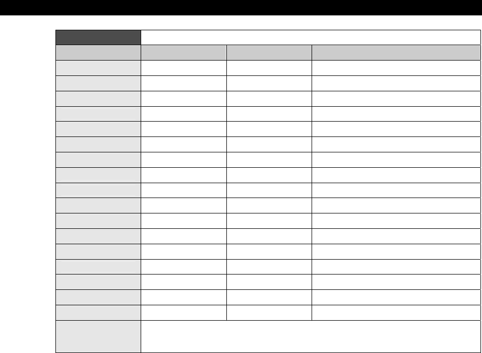
II Propeller Chip Architecture and Programming
Page 180 Game Programming for the Propeller Powered HYDRA
Table 13:1 Cog Registers
Address Name Access Description
$000-$1EF — Read/Write General Purpose RAM
$1F0 PAR Read-Only* Boot Parameter
$1F1 CNT Read-Only* System Counter
$1F2 INA Read-Only* Input States for P31..P0
$1F3 INB Read-Only* Input States for P63..P32 **
$1F4 OUTA Read/Write Output States for P31..P0
$1F5 OUTB Read/Write Output States for P63..P32 **
$1F6 DIRA Read/Write Direction States for P31..P0
$1F7 DIRB Read/Write Direction States for P63..P32 **
$1F8 CTRA Read/Write Counter A Control
$1F9 CTRB Read/Write Counter B Control
$1FA FRQA Read/Write Counter A Frequency
$1FB FRQB Read/Write Counter B Frequency
$1FC PHSA Read/Write Counter A Phase
$1FD PHSB Read/Write Counter B Phase
$1FE VCFG Read/Write Video Configuration
$1FF VSCL Read/Write Video Scale
Notes * Only accessible as a Source Register (i.e. MOV DEST,SOURCE)
** Allocated for future use, but not currently implemented.
Remember: all addresses are LONG or 4-BYTE addresses.
13.3 Propeller Chip ASM Instruction Format
Before discussing the usage of the internal registers, a basic understanding of the instruction
format is needed. Each 32-bit instruction is broken into a number of fields from left to right.
Each field has a different purpose and in some cases can have more than one purpose. The
cog executes 32-bit instructions from its register space. The instruction codes contain several
bit fields. Table 13:2 and Table 13:3 show the instruction format and fields.

Propeller Chip Architecture13
Game Programming for the Propeller Powered HYDRA Page 181
Table 13:2 32-Bit Instruction Format
Operation Code Update
Z Flag Update C
Flag Update
Result Source
# Execution
Condition Destination
Register Source
Register #
31..26 25 24 23 22 21..18 17..9 8..0
iiiiii z c r i
cccc ddddddddd sssssssss
Table 13:3 Instruction Field Bit Locations
Field Range Description
Operation Code 31..26 Perform ADD, SUB, AND, OR, JMP, etc.
Execution/
Update Effects 25..23
In conjunction with Controls writes to C Flag, Z Flag, and Destination
Register:
If bit 25 is set, the Z Flag will be written.
If bit 24 is set, the C Flag will be written.
If bit 23 is set, the Destination Register will be written.
Source Literal 22 If set, bits 8..0 will be zero-extended and used as a 32-bit constant.
Execution
Condition 21..18 C and Z flag condition upon which instruction will execute.
Destination
Register 17..9 Register which supplies the first 32-bit input to the instruction and/or
receives the effect of the operation.
Source Register
or Literal 8..0 Register or constant which supplies the second 32-bit input to the
instruction.
Source Register or Literal Value [8..0]
This 9-bit field either selects a register (any of the 512 32-bit registers) or provides a 9-bit
(0-511 range) zero-extended literal value to be used as the source by the instruction. Bit 22
controls how this field is used: 0 for register, 1 for literal. When entering assembly code, the
# symbol sets literal mode.
Destination Register [17..9]
This 9-bit field selects which of the 512 registers will be used as the destination by the
instruction.
Execution Condition [21..18]
This 4-bit field selects the condition upon which the instruction executes. The condition is a
logical combination of the C and Z flags. The condition codes are shown in Table 13:4 on the
next page.
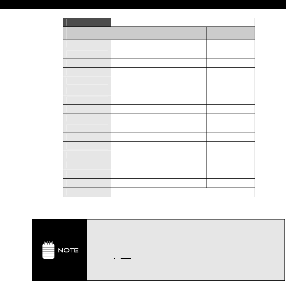
II Propeller Chip Architecture and Programming
Page 182 Game Programming for the Propeller Powered HYDRA
Table 13:4 Instruction Execution Condition Codes
Execution
Condition Instruction
Prefix Instruction
Prefix Instruction
Prefix
1111 ALWAYS *
1100 IF_C IF_B
0011 IF_NC IF_AE
1010 IF_Z IF_E
0101 IF_NZ IF_NE
1000 IF_C_AND_Z IF_Z_AND_C
0100 IF_C_AND_NZ IF_NZ_AND_C
0010 IF_NC_AND_Z IF_Z_AND_NC
0001 IF_NC_AND_NZ IF_NZ_AND_NC IF_A
1110 IF_C_OR_Z IF_Z_OR_C IF_BE
1101 IF_C_OR_NZ IF_NZ_OR_C
1011 IF_NC_OR_Z IF_Z_OR_NC
0111 IF_NC_OR_NZ IF_NZ_OR_NC
1001 IF_C_EQ_Z IF_Z_EQ_C
0110 IF_C_NE_Z IF_Z_NE_C
0000 NEVER
NOTE * ALWAYS is the default, in case no condition is specified.
In some cases, the various fields of an instruction are interpreted in different
ways. These cases will be clearly marked in the instruction set listing. When
talking about the I-Field, it has 9 bits including the 5 bits of the I-Field itself along
with the first 3 bits of the FLAGS field ”zcr”.
iiiiiii zcri cccc ddddddddd sssssssss
The above underlined 5 bits “i cccc” are left out of I, D, S during register access,
etc.
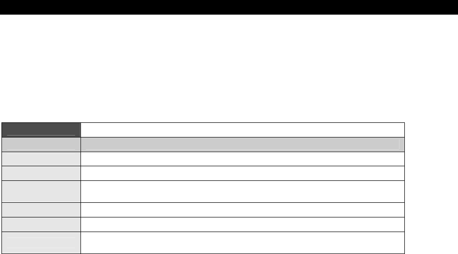
Propeller Chip Architecture13
Game Programming for the Propeller Powered HYDRA Page 183
Execution/Update Effects [25..23]
The instruction format includes a set of flags which are NOT the processor flags, but indicate
which “flags” to update in the processor’s flags when the instruction executes. The Condition
Code determines when the instruction executes. This instruction architecture allows each
instruction to have an embedded conditional of sorts and allows very optimal coding
techniques. These flags are shown in Table 13:5.
Table 13:5 Instruction Set/Processor ALU Flags/Modifiers
Flags Meaning
Z Update the Zero flag (WZ).
C Update the Carry flag (WC).
R Result Flag enable, indicates whether are not we are going to write the results,
whatever they may be, below are the two possible settings that affect this flag.
- NR Do not write the result into the destination.
- WR Write the result into the destination.
I Immediate value or memory pointer for S as address, always 32-bit, if
immediate value then 9 bits only ZERO extended, no negatives!
By default neither the Z or C flags are written for any operation, thus you must always
modify the instruction opcode by appending the appropriate modifier(s) at the end of the
instruction. The actual syntax for each modifier is as follows:
WC Write carry flag
WZ Write zero flag
NR Override default behavior of operation and do NOT write results
WR Override default behavior of operation and write results
# Set the immediate
Instruction Code [31..26]
This 6-bit field simply encodes the instruction to execute. Although, one shouldn’t rely on
current opcode mappings to stay the same, later various Propeller chips may decide to
change the opcodes and/or bit encodings. But, nevertheless, these 6 bits define the
instruction to execute.
II Propeller Chip Architecture and Programming
Page 184 Ë Game Programming for the Propeller Powered HYDRA
13.4 Cog Registers
As noted, each cog has a set of (16) 32-bit registers addressed at $1EF-$1FF (LONG
addresses) which are available from HLL as well as ASM. The following sections briefly
outlines the registers. We will discuss their programming later in the document. Let’s briefly
cover all the registers then discuss their usage.
13.4.1 Parameter Registers (PAR)
PAR Parameter address from cog boot, when a cog boots you can access this 14-
bit value that tells you the base address of where the cog memory is:
0000000000000000 | xxxxxxxxxxxxxx00
16 bits 14-bit address that is shifted left 2 bits
resulting always in a LONG base address.
The caller that sends the PAR value must make sure it’s on a LONG 32-bit
boundary; otherwise, the lower 2 address bits will simply be ignored.
13.4.2 I/O Registers
Each cog has its own set of I/O registers used to communicate with the outside world. On
the current version of the Propeller chip there are 32 I/Os which comprise the “A port.” On
future Propeller chips there will also be another 32-bit “B port” for a total of 64 I/Os.
However, the internal hardware is partially in place for “B port” even though there is no
physical hardware to support it as of yet, therefore, you can write and read the registers, but
nothing will happen on the outside world – however, in a parallel universe there will be some
side effects, luckily though we can ignore them!
INA Port inputs
OUTA Port outputs; since all cogs can write these simultaneously the final outputs
are a logical OR of the cogs’ outputs.
DIRA Port directions, 0 = input, 1 = output. Note: there are NO pull-ups on I/Os.
INB Future expansion, read only
OUTB Future expansion
DIRB Future expansion

Propeller Chip Architecture13
Game Programming for the Propeller Powered HYDRA Page 185
13.4.3 Timer/Counter Registers
Each cog has two timers: A,B. Each timer is independent and can operate in a number of
different modes. However, the inputs and outputs of each timer depending on their setup
can be programmed to use any of the I/O pins as well. Also, note that when using the video
hardware of a cog. The Video Streaming Unit (VSU, discussed later) uses a timer and some
specific constraints must be taken into consideration in this case.
CNT Global system 32-bit counter (full-speed)
CTRA Counter A configuration
FRQA Frequency of counter A
PHSA Phase of counter A
CTRB Counter B configuration
FRQB Frequency of counter B
PHSB Phase of counter B
13.4.4 Video Registers
The Propeller chip has no dedicated GPU to speak out, rather it has a very simple video
serializer that allows you to set up some timing parameters and then “feed” pixel data to the
video serializer, referred to as the Video Streaming Unit (VSU). This pixel data is then sent
out to external I/O via a set of pins in a format that is related to NTSC/PAL or VGA
depending on how you have set up the VSU unit. There are two registers that control this:
VCFG Video configuration
VSCL Video scale
We will discuss their setup in detail later in the document. Next we are going to discuss the
instruction set and various programming techniques, then review the control registers in
detail.
13.5 Instruction Set
Table 13:6 on the next two pages is a tentative instruction set reference for the Propeller
chip’s cogs. Table 13:7 follows, which lists the opcodes for each instruction. In the future,
the actual bit encodings may change, but from a programming point of view and using the
assembler, you should be insulated from changes.

II Propeller Chip Architecture and Programming
Page 186 Game Programming for the Propeller Powered HYDRA
Table 13:6 Cog Assembly Language Instruction Set
Instruction Description Z Out C Out r Clocks
RDBYTE D,S Read main memory byte S[15..0] into D (0-ext'd) Result = 0 - 1 7..22 *
RDWORD D,S Read main memory word S[15..1] into D (0-ext'd) Result = 0 - 1 7..22 *
RDLONG D,S Read main memory long S[15..2] into D Result = 0 - 1 7..22 *
WRBYTE D,S Write D[7..0] to main memory byte S[15..0] - - 0 7..22 *
WRWORD D,S Write D[15..0] to main memory word S[15..1] - - 0 7..22 *
WRLONG D,S Write D to main memory long S[15..2] - - 0 7..22 *
SYSOP D,S System op, implements the 8 codes below
CLKSET D Set the global CLK register to D[7..0] - - 0 7..22 *
COGID D Get this cog number (0..7) into D Result = 0 - 1 7..22 *
COGINIT D Initialize a cog according to D Result = 0 No cog free 0 7..22 *
COGSTOP D Stop cog number D[2..0] - - 0 7..22 *
LOCKNEW D Checkout a new lock number (0..7) into D Result = 0 No lock free 1 7..22 *
LOCKRET D Return lock number D[2..0] - - 0 7..22 *
LOCKSET D Set lock number D[2..0] - Prior lock state 0 7..22 *
LOCKCLR D Clear lock number D[2..0] Result = 0 Prior lock state 0 7..22 *
ROR D,S Rotate D right by S[4..0] bits Result = 0 D[0] 1 4
ROL D,S Rotate D left by S[4..0] bits Result = 0 D[31] 1 4
SHR D,S Shift D right by S[4..0] bits Result = 0 D[0] 1 4
SHL D,S Shift D left by S[4..0] bits Result = 0 D[31] 1 4
RCR D,S Rotate carry right into D by S[4..0] bits Result = 0 D[0] 1 4
RCL D,S Rotate carry left into D by S[4..0] bits Result = 0 D[31] 1 4
SAR D,S Shift D arithmetically right by S[4..0] bits Result = 0 D[0] 1 4
REV D,S Reverse 32–S[4..0] bottom bits in D and 0-extend Result = 0 D[0] 1 4
MINS D,S Set D to S if signed (D < S) D = S Signed (D < S) 1 4
MAXS D,S Set D to S if signed (D => S) D = S Signed (D < S) 1 4
MIN D,S Set D to S if unsigned (D < S) D = S Unsigned (D < S) 1 4
MAX D,S Set D to S if unsigned (D => S) D = S Unsigned (D < S) 1 4
MOVS D,S Insert S[8..0] into D[8..0] Result = 0 - 1 4
MOVD D,S Insert S[8..0] into D[17..9] Result = 0 - 1 4
MOVI D,S Insert S[8..0] into D[31..23] Result = 0 - 1 4
JMPRET D,S Insert PC+1 into D[8..0] and set PC to S[8..0] Result = 0 - 1 4
JMP S Set PC to S[8..0] Result = 0 - 0 4
CALL #S Like JMPRET, but assembler handles details Result = 0 - 1 4
RET Like JMP, but assembler handles details Result = 0 - 0 4
TEST D,S AND S with D to affect flags only Result = 0 Parity of Result 0 4
AND D,S AND S into D Result = 0 Parity of Result 1 4
ANDN D,S AND !S into D Result = 0 Parity of Result 1 4
OR D,S OR S into D Result = 0 Parity of Result 1 4
XOR D,S XOR S into D Result = 0 Parity of Result 1 4
MUXC D,S Copy C to bits in D using S as mask Result = 0 Parity of Result 1 4
MUXNC D,S Copy !C to bits in D using S as mask Result = 0 Parity of Result 1 4

Propeller Chip Architecture13
Game Programming for the Propeller Powered HYDRA Ì Page 187
Table 13:6 Cog Assembly Language Instruction Setb
Instruction Description Z Out C Out r Clocks
MUXZ D,S Copy Z to bits in D using S as mask Result = 0 Parity of Result 1 4
MUXNZ D,S Copy !Z to bits in D using S as mask Result = 0 Parity of Result 1 4
ADD D,S Add S into D Result = 0 Unsigned Carry 1 4
SUB D,S Subtract S from D Result = 0 Unsigned Borrow 1 4
CMP D,S Compare D to S Result = 0 Unsigned Borrow 0 4
ADDABS D,S Add absolute S into D Result = 0 Unsigned Carry 1 4
SUBABS D,S Subtract absolute S from D Result = 0 Unsigned Borrow 1 4
SUMC D,S Sum either –S if C or S if !C into D Result = 0 Signed Overflow 1 4
SUMNC D,S Sum either S if C or –S if !C into D Result = 0 Signed Overflow 1 4
SUMZ D,S Sum either –S if Z or S if !Z into D Result = 0 Signed Overflow 1 4
SUMNZ D,S Sum either S if Z or –S if !Z into D Result = 0 Signed Overflow 1 4
MOV D,S Set D to S Result = 0 S[31] 1 4
NEG D,S Set D to –S Result = 0 S[31] 1 4
ABS D,S Set D to absolute S Result = 0 S[31] 1 4
ABSNEG D,S Set D to –absolute S Result = 0 S[31] 1 4
NEGC D,S Set D to –S if C or S if !C Result = 0 S[31] 1 4
NEGNC D,S Set D to S if C or –S if !C Result = 0 S[31] 1 4
NEGZ D,S Set D to –S if Z or S if !Z Result = 0 S[31] 1 4
NEGNZ D,S Set D to S if Z or –S if !Z Result = 0 S[31] 1 4
CMPS D,S Compare-signed D to S Result = 0 Signed Borrow 0 4
CMPSX D,S Compare-signed-extended D to S+C Z & (Result = 0) Signed Borrow 0 4
ADDX D,S Add-extended S+C into D Z & (Result = 0) Unsigned Carry 1 4
SUBX D,S Subtract-extended S+C from D Z & (Result = 0) Unsigned Borrow 1 4
CMPX D,S Compare-extended D to S+C Z & (Result = 0) Unsigned Borrow 0 4
ADDS D,S Add-signed S into D Result = 0 Signed Overflow 1 4
SUBS D,S Subtract-signed S from D Result = 0 Signed Overflow 1 4
ADDSX D,S Add-signed-extended S+C into D Z & (Result = 0) Signed Overflow 1 4
SUBSX D,S Subtract-signed-extended S+C from D Z & (Result = 0) Signed Overflow 1 4
CMPSUB D,S Subtract S from D if D => S D = S Unsigned (D => S) 1 4
DJNZ D,S Dec D, jump if not zero to S (no jump = 8 clocks) Result = 0 Unsigned Borrow 1 4 or 8
TJNZ D,S Test D, jump if not zero to S (no jump = 8 clocks) Result = 0 0 0 4 or 8
TJZ D,S Test D, jump if zero to S (no jump = 8 clocks) Result = 0 0 0 4 or 8
WAITPEQ D,S Wait for pins equal - (INA & S) = D Result = 0 - 0 5+
WAITPNE D,S Wait for pins not equal - (INA & S) != D Result = 0 - 0 5+
WAITCNT D,S Wait for CNT = D, then add S into D Result = 0 Unsigned Carry 1 5+
WAITVID D,S Wait for video peripheral to grab D and S Result = 0 - 0 5+
NOP No operation, just elapses 4 clocks - - - 4
* The Hub allows each cog an opportunity to execute a Hub instruction every 16 clocks. Because each cog runs independently of the
Hub, each cog must sync to the Hub when executing a Hub instruction. This will cause a Hub instruction to take between 7 and 22
clocks. Afterwards, there will be 9 free clocks before a subsequent Hub instruction can execute and take the minimal 7 clocks. This is
enough time to execute two 4-clock instructions without missing the next sync. So, to minimize clock waste, you can insert two
normal instructions between any two otherwise-contiguous Hub instructions, without any increase in execution time. Beware that
Hub instructions can cause execution timing to appear indeterminate - particularly, the first Hub instruction in a sequence.
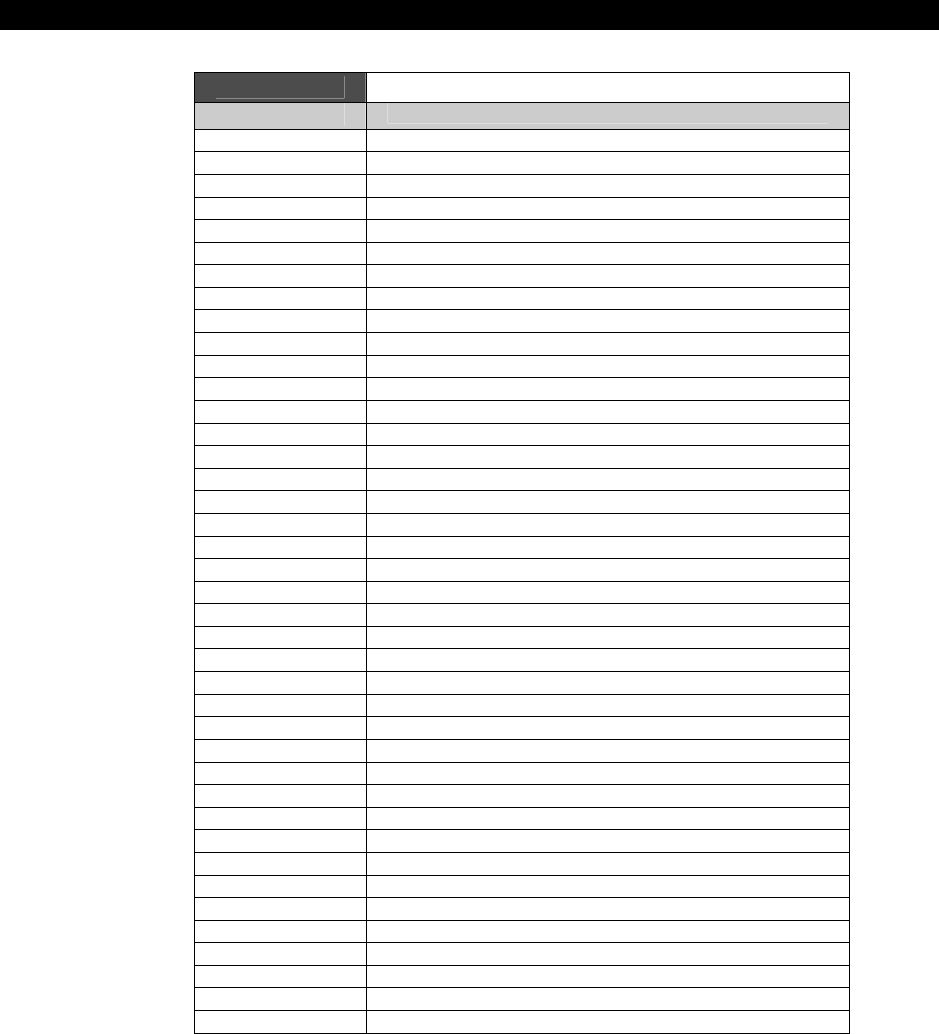
II Propeller Chip Architecture and Programming
Page 188 Game Programming for the Propeller Powered HYDRA
Table 13:7 Cog Assembly Language Opcodes
Instruction iiiiii zcri cccc ddddddddd sssssssss
RDBYTE D,S 000000 001i 1111 ddddddddd sssssssss
RDWORD D,S 000001 001i 1111 ddddddddd sssssssss
RDLONG D,S 000010 001i 1111 ddddddddd sssssssss
WRBYTE D,S 000000 000i 1111 ddddddddd sssssssss
WRWORD D,S 000001 000i 1111 ddddddddd sssssssss
WRLONG D,S 000010 000i 1111 ddddddddd sssssssss
SYSOP D,S 000011 00ri 1111 ddddddddd sssssssss
CLKSET D 000-11 0001 1111 ddddddddd ------000
COGID D 000-11 0011 1111 ddddddddd ------001
COGINIT D 000-11 0001 1111 ddddddddd ------010
COGSTOP D 000-11 0001 1111 ddddddddd ------011
LOCKNEW D 000-11 0011 1111 ddddddddd ------100
LOCKRET D 000-11 0001 1111 ddddddddd ------101
LOCKSET D 000-11 0001 1111 ddddddddd ------110
LOCKCLR D 000-11 0001 1111 ddddddddd ------111
ROR D,S 001000 001i 1111 ddddddddd sssssssss
ROL D,S 001001 001i 1111 ddddddddd sssssssss
SHR D,S 001010 001i 1111 ddddddddd sssssssss
SHL D,S 001011 001i 1111 ddddddddd sssssssss
RCR D,S 001100 001i 1111 ddddddddd sssssssss
RCL D,S 001101 001i 1111 ddddddddd sssssssss
SAR D,S 001110 001i 1111 ddddddddd sssssssss
REV D,S 001111 001i 1111 ddddddddd sssssssss
MINS D,S 010000 001i 1111 ddddddddd sssssssss
MAXS D,S 010001 001i 1111 ddddddddd sssssssss
MIN D,S 010010 001i 1111 ddddddddd sssssssss
MAX D,S 010011 001i 1111 ddddddddd sssssssss
MOVS D,S 010100 001i 1111 ddddddddd sssssssss
MOVD D,S 010101 001i 1111 ddddddddd sssssssss
MOVI D,S 010110 001i 1111 ddddddddd sssssssss
JMPRET D,S 010111 001i 1111 ddddddddd sssssssss
JMP S 010111 000i 1111 --------- sssssssss
CALL #S 010111 0011 1111 ????????? sssssssss
RET 010111 0001 1111 --------- ---------
TEST D,S 011000 000i 1111 ddddddddd sssssssss
AND D,S 011000 001i 1111 ddddddddd sssssssss
ANDN D,S 011001 001i 1111 ddddddddd sssssssss
OR D,S 011010 001i 1111 ddddddddd sssssssss
XOR D,S 011011 001i 1111 ddddddddd sssssssss
MUXC D,S 011100 001i 1111 ddddddddd sssssssss
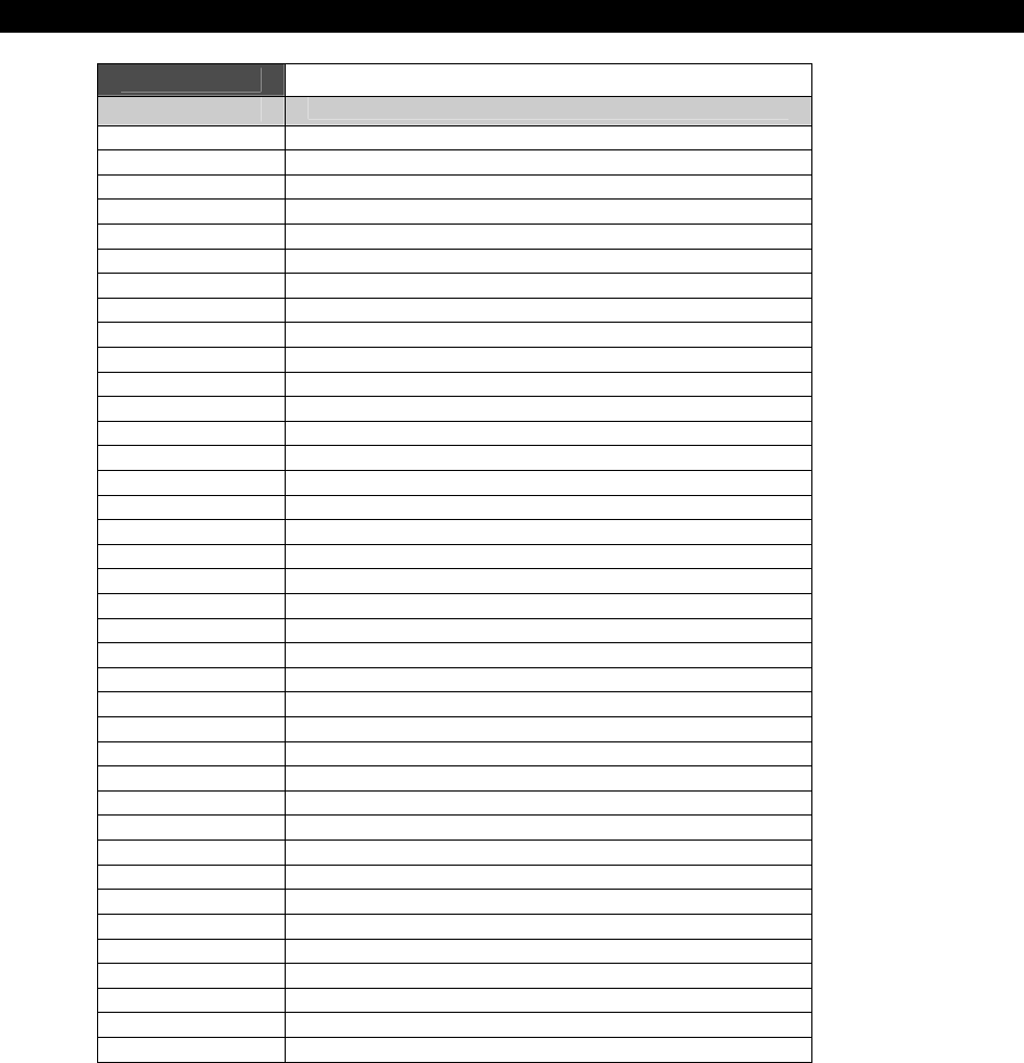
Propeller Chip Architecture13
Game Programming for the Propeller Powered HYDRA Ì Page 189
Table 13:7 Cog Assembly Language Opcodesb
Instruction iiiiii zcri cccc ddddddddd sssssssss
MUXNC D,S 011101 001i 1111 ddddddddd sssssssss
MUXZ D,S 011110 001i 1111 ddddddddd sssssssss
MUXNZ D,S 011111 001i 1111 ddddddddd sssssssss
ADD D,S 100000 001i 1111 ddddddddd sssssssss
SUB D,S 100001 001i 1111 ddddddddd sssssssss
CMP D,S 100001 000i 1111 ddddddddd sssssssss
ADDABS D,S 100010 001i 1111 ddddddddd sssssssss
SUBABS D,S 100011 001i 1111 ddddddddd sssssssss
SUMC D,S 100100 001i 1111 ddddddddd sssssssss
SUMNC D,S 100101 001i 1111 ddddddddd sssssssss
SUMZ D,S 100110 001i 1111 ddddddddd sssssssss
SUMNZ D,S 100111 001i 1111 ddddddddd sssssssss
MOV D,S 101000 001i 1111 ddddddddd sssssssss
NEG D,S 101001 001i 1111 ddddddddd sssssssss
ABS D,S 101010 001i 1111 ddddddddd sssssssss
ABSNEG D,S 101011 001i 1111 ddddddddd sssssssss
NEGC D,S 101100 001i 1111 ddddddddd sssssssss
NEGNC D,S 101101 001i 1111 ddddddddd sssssssss
NEGZ D,S 101110 001i 1111 ddddddddd sssssssss
NEGNZ D,S 101111 001i 1111 ddddddddd sssssssss
CMPS D,S 110000 000i 1111 ddddddddd sssssssss
CMPSX D,S 110001 000i 1111 ddddddddd sssssssss
ADDX D,S 110010 001i 1111 ddddddddd sssssssss
SUBX D,S 110011 001i 1111 ddddddddd sssssssss
CMPX D,S 110011 000i 1111 ddddddddd sssssssss
ADDS D,S 110100 001i 1111 ddddddddd sssssssss
SUBS D,S 110101 001i 1111 ddddddddd sssssssss
ADDSX D,S 110110 001i 1111 ddddddddd sssssssss
SUBSX D,S 110111 001i 1111 ddddddddd sssssssss
CMPSUB D,S 111000 001i 1111 ddddddddd sssssssss
DJNZ D,S 111001 001i 1111 ddddddddd sssssssss
TJNZ D,S 111010 000i 1111 ddddddddd sssssssss
TJZ D,S 111011 000i 1111 ddddddddd sssssssss
WAITPEQ D,S 111100 000i 1111 ddddddddd sssssssss
WAITPNE D,S 111101 000i 1111 ddddddddd sssssssss
WAITCNT D,S 111110 001i 1111 ddddddddd sssssssss
WAITVID D,S 111111 000i 1111 ddddddddd sssssssss
NOP ------ ---- 0000 --------- ---------

II Propeller Chip Architecture and Programming
Page 190 Game Programming for the Propeller Powered HYDRA
13.5.1 Assembler Directives
A complete guide to assembly language programming is beyond the scope of this book; we
are rather going to learn by example from reviewing code etc. If you already know assembly
language then you will pick up Propeller Assembly very easily, if you aren’t an assembly
language programmer then just try to follow along, but it won’t be important to using Spin
based coding. But, to begin with there is no “assembler” per se, your Spin code and ASM
code can exist in the same source file. There is no such thing as “inline” assembly, but the
point is that from the compiler’s point of view it understands both Spin and assembly code.
All assembly code must start in a DAT section though, so you will see all examples of
assembly after a DAT declaration. During compilation of your program files, when a DAT is
seen by the compiler, it then starts assembling the ASM instructions into their proper formats
and computing addresses correctly for you. The following are the most important assembler
directives:
ORG — When programming in ASM, you must direct the assembler to place the ASM code
into cog memory in the range from $000 - $1FF. Thus, ORG resets the assembler’s data
output offset to cog address $000 (LONG address) for purposes of creating the ASM in the
cog’s 512 LONG register file ($000 - $1FF). ORG also supports an offset parameter from base
$0. For example, say you wanted your ASM to start at LONG address $100, then you could
use the ORG directive as follows:
Example: Generate all ASM code starting at LONG cog address $100.
ORG $100 ' start all assembler output at cog address $100
FIT addr — The FIT directive simply safeguards your data tables from the ASM code
generated. By using the FIT directive you can tell the assembler where it shouldn’t encroach
upon. If during assembly the code and data exceed the address in the FIT directive then an
error would be thrown. Note: the FIT directive should always go at the end of your ASM
code.
Example: Tell assembler not to exceed memory location $150 with code + data.
FIT $150 ' if anything goes past $150 then an error is thrown
RES — Simply reserves data space for future storage, simply advances the data pointer by
the size of the memory reserves. Also, reserves LONGs since LONGs are the basic unit of cog
memory/instructions.

Propeller Chip Architecture13
Game Programming for the Propeller Powered HYDRA Page 191
Example: Reserve 16 LONGs for a sine table.
Sinetable Res 16 ' the data pointer is advanced by 16, to skip this
' region and sinetable is an alias
' to the beginning of the reserved memory.
Example: A complete “object” that is composed of both Spin and ASM code.
CON
DEBUG_LED_PORT_MASK = $00000001 ' debug LED is on I/O P0
VAR
long cogon, cog
PUB start(glow_led_parms_ptr) : okay
'' Start glowing LED- starts a cog
'' returns false if no cog available
''
stop
okay := cogon := (cog := cognew(@entry,glow_led_parms_ptr)) > 0
PUB stop
'' Stops driver - frees a cog
if cogon~
cogstop(cog)
DAT
org $000
' Entry point
'
entry
' initialize debug LED
or DIRA, #DEBUG_LED_PORT_MASK ' set pin to output
and OUTA, #!DEBUG_LED_PORT_MASK ' turn LED off to begin
mov lptr, par ' copy parameter pointer
' to global pointer for
' future ref

II Propeller Chip Architecture and Programming
Page 192 Game Programming for the Propeller Powered HYDRA
rdlong debug_led_inc, lptr ' now access main memory
' and retrieve the value
:glow_loop
' add the current brightness to the counter
add debug_led_ctr, debug_led_brightness wc
' based on carry turn LED on/off
if_c or OUTA, #DEBUG_LED_PORT_MASK
if_nc and OUTA, #!DEBUG_LED_PORT_MASK
' update brightness and invert increment if we hit 0
add debug
_
led
_
brightness, debug
_
led
_
inc wz
if_z neg debug_led_inc, debug_led_inc
' loop and do forever
jmp #:glow_loop
'// VARIABLES //////////////////////////////////////////////////////////////////
debug_led_ctr long $00000000 ' PWM counter
debug_led_inc long $0000000 ' increment to add to counter
debug_led_brightness long $80000000 ' current brightness level
lptr long $00000000 ' general long pointer
The Spin code at the top is “glue” that allows other objects to call this object, but the
important part to note is that the ASM code starts where you see the DAT section at the
bottom half of the listing with an ORG $000. Also, note that you can have many DAT sections
with ASM code in them and then load them into other cogs, the assembler doesn’t care, but
be advised that a single cog can only fit 512-16 LONGs of ASM code into it at load.
13.6 Hub Instructions
The instructions which access main memory, the global CLK register, the cogs, and the locks
are all “Hub” instructions. What critically transpires during their execution is a function of the
central Hub, which coordinates chip-wide operations.
The Hub runs at half the cogs’ clock frequency, serving each of the eight cogs, in turn, with
each subsequent clock. From the cog’s perspective, this is once every 16 cog clocks. Because
the Hub runs steadily, dedicating a Hub clock cycle to each cog, and because the cogs run
independently, taking various numbers of cog clocks for different instructions, each cog must
re-sync to the Hub whenever it executes a Hub instruction. This results in execution times
ranging from 7 to 22 clocks for each Hub instruction. Once a Hub instruction has executed on
any particular cog, there will be 9 free clocks before another Hub instruction could execute
on the same cog, at that point the next Hub instruction will take the minimum number of
Propeller Chip Architecture13
Game Programming for the Propeller Powered HYDRA Page 193
clocks – 7 rather than up to 22. Luckily, 9 clocks is enough time for two 4-clock instructions
to execute before another Hub instruction would take 8 clocks. So, to minimize clock waste,
you can insert two 4-clock instructions between any two otherwise-contiguous Hub
instructions without any increase in execution time. Beware that Hub instructions can inject
jitter into your execution schedule – specifically, the first Hub instruction in the sequence.
For deterministic timing, you might want to place them outside of time-critical
code sequences in which the Hub-sync is unknown.
Summing up, when you execute the first Hub instruction in some algorithm or loop on a cog,
the cog must sync up with the Hub; this synchronization plus the actual Hub instruction
executing always takes from 7..22 clocks. Then once this first Hub instruction executes taking
from 7..22 clocks, it takes 9 clocks before the Hub comes back around. When it does, it will
take 7 clocks to execute the next Hub instruction, and this pattern of 9,7 will continue, thus
in the 9 clocks of wait time you can execute 2 normal 4-clock instructions. Thus the
execution stream of a Hub algorithm loop might look like this:
Given,
H0 – 1st Hub instruction, requires synchronization, sync+execution time always 7..22
clocks
Hi – ith Hub instruction, since the Hub is synced, always executes in 7 clocks, but will
take 9 clocks before the Hub instruction can execute thus it’s a good time to
“interleave” other instructions in the stream
W – A single unused wait clock
Op4 – Any 4-clock opcode
Instruction stream at beginning of 1st Hub instruction…
H0(7..22),Op4(4),Op4(4),W(1),Hi+1(7),Op4(4),Op4(4),W(1),Hi+2(7),Op4(4),Op4(4),W(1),
Hi+3(7),Op4(4),Op4(4),W(1),Hi+4(7)…
The following sub-sections elaborate on different Hub instruction groups.

II Propeller Chip Architecture and Programming
Page 194 Game Programming for the Propeller Powered HYDRA
13.6.1 Main memory access
The Hub instructions which access main memory are:
RDBYTE D,S 'Read byte at S into D and zero-extend
RDWORD D,S 'Read word at S into D and zero-extend
RDLONG D,S 'Read long at S into D
WRBYTE D,S 'Write D into byte at S
WRWORD D,S 'Write D into word at S
WRLONG D,S 'Write D into long at S
The main Propeller chip memory is 64 Kbytes in size and can be accessed from any cog. It is
accessible as 64 Kbytes, 32 K-words, or 16 K-longs, each on their respective boundaries.
All accesses are aligned according to data size. WORDs can only begin at even addresses
(multiples of 2) and LONGs can only begin at even-even addresses (multiples of 4). Of
course, you can arrange your data any way you want, but to take advantage of efficient
WORD and LONG accesses, you must pay attention to alignment.
13.6.2 CLK Register Write
Inside the Hub is a global CLK register which selects the master clock. A single Hub
instruction used to set this register:
CLKSET D 'Write D[7..0] into the global CLK register
More on this register later in this chapter.
13.6.3 Cog Control
There are three Hub instructions which govern the starting and stopping of cogs:
COGID D 'Get this cog number into D
COGINIT D 'Init a cog according to D
COGSTOP D 'Stop cog number D
COGID writes the executing cog number into D. This instruction is used when a cog needs
to know “who” it is, among the eight, for the purpose of stopping or restarting itself.
COGINIT is the instruction used to start or restart a cog. The D register has three fields
within it that determine which cog gets started, where its program begins in main memory,
and what its PAR register will contain.
D[31..18] will be written to bits [15..2] of the started cog’s PAR register. By this
mechanism, a LONG address parameter can be conveyed to a cog at start-time. This
parameter is intended to be used as a pointer to some agreed-upon structure in
main memory via which communication with another cog (or cogs) may take place.

Propeller Chip Architecture13
Game Programming for the Propeller Powered HYDRA Page 195
D[17..4] specifies the LONG address in main memory of the cog program to be
loaded. Cog registers $000..$1EF will be loaded sequentially, starting at this address.
The writable cog registers $1F4..$1FF will be initialized to 0. When the loading and
initialization are complete, the started cog begins executing at register address $000,
thus there better be an instruction there!
D[3] determines whether a new cog or a specified cog will be started.
If D[3] is ‘1’, the Hub will start the lowest-numbered inactive cog and return
that cog’s number (0..7) into D. The C flag will also be used to convey
whether or not there was an inactive cog available. A ‘0’ in C indicates that
the operation was successful. A ‘1’ indicates that no cog was available and
none was started. Be sure to put both the ‘WR’ and ‘WC’ modifiers after the
COGINIT instruction so that these results will be written into D and C.
Starting cogs in this fashion means that you will never have to plan which
cog will run what program. The Hub, which knows the instantaneous state of
all cogs, will do the picking for you.
If D[3] is ‘0’, the Hub will start the cog numbered in D[2..0]. This is useful
for restarting active cogs. To start a new cog, it is recommended that you
use the D[3] = ‘1’ approach, detailed above.
COGSTOP simply stops the cog numbered in D[2..0]. When a cog is stopped, it receives no
clock and consumes no power. It will be held in an inactive reset state until started by a
COGINIT instruction.
13.6.4 Lock usage
Locks are special global bits which can be utilized to solve the problem of multiple-access
contention, that is, multiple cogs writing the same data at the same time.
Imagine you have an area in main memory which holds some data that is to be accessed by
more than one cog. If the elemental data exceeds a LONG in size, it will take multiple reads
or writes for any cog to access it. It would be necessary to avoid the possibility of one or
more cogs reading data while one or more other cogs are writing (or think they are writing)
the same data. Access needs to be limited to one cog at a time in order to avoid misreads
and miswrites. Such exclusive access control can be achieved by using a lock.
A lock is a global bit that can be set or cleared by any cog through certain Hub instructions.
At the time a cog sets or clears a lock, it can also learn the prior state of that lock. The fact
that the Hub allows only one cog at a time to set or clear a lock makes this an effective
access control mechanism.
To use a lock, all cogs which intend to share some resource must agree on a lock number
and its initial state. For our discussion, let’s make the lock’s initial state ‘0’. Now, for any cog

II Propeller Chip Architecture and Programming
Page 196 Game Programming for the Propeller Powered HYDRA
to gain exclusive access to the shared resource, it must keep setting the lock until it sees that
its prior state was ‘0’. After this, all other cogs will get only ‘1’s back. The winning cog now
has exclusive access to the resource. When it is done accessing the resource, it must clear
the lock so that another cog can gain access. Locks may be used creatively for many such
purposes.
The Hub maintains an inventory of eight locks. It keeps track of which locks are available for
check-out and notes when a lock is returned. On reset, all locks are ‘returned’ and ready for
check-out. Though it’s possible to set or clear any arbitrary lock, it is recommended that you
check out a lock, so that the Hub will know that it is in use and will not grant it to some other
cog. It’s also critical to return the lock when you are through with it, so that it may be
checked out again.
There are four Hub instructions used to manipulate locks:
LOCKNEW D wc 'Check-out a new lock number into D, C=1 if none
LOCKRET D 'Return lock number D
LOCKSET D wc 'Set lock number D, C=prior lock state
LOCKCLR D wc 'Clear lock number D, C=prior lock state
LOCKNEW Checks out a new lock from the Hub and puts its number (0..7) into D.
The C flag is used to convey whether or not the operation was
successful. A ‘0’ indicates success, while a ‘1’ indicates that no free lock
was available. Be sure to put a ‘WC’ modifier after the instruction, so
that C will be written.
LOCKRET Returns the lock numbered in D[2..0] to the Hub’s inventory.
LOCKSET Sets the lock numbered in D[2..0] and, if ‘WC’ is after the instruction,
writes the lock’s prior state into the C flag.
LOCKCLR Clears the lock numbered in D[2..0] and, if ‘WC’ is after the instruction,
writes the lock’s prior state into the C flag.
13.7 Branching Instructions
Branching instructions are used to alter the course of the cog’s program counter, or PC. The
PC is a 9-bit counter that tracks the program’s execution address. It normally increments
with each instruction, but it can be loaded with an arbitrary value via branching instructions.
Additionally, all the branching instructions (except “RET”) use the source register S to specify
the branch address. Always remember to put “#” in front of the S expression when you
intend to jump to a constant address. This will almost always be the case in your code. If you
don’t use the “#” you will be specifying a register’s contents as your branch address.
Sometimes you may want to do this, but most often your intent will be to branch to a
constant address and you must remember to use “#.” For the applicable instructions cited in
this section, both forms will be shown to keep you mindful of this critical issue.

Propeller Chip Architecture13
Game Programming for the Propeller Powered HYDRA Page 197
Also, remember, like all other instructions, branches can be
preceded
by conditionals (if_z,
If_c, etc.), making them into conditional branches.
The simplest branch instruction is “JMP S.” This simply sets the PC to S[8..0]:
JMP #S 'Jump to the constant address S
JMP S 'Jump to where register S points
The most complex branch instruction is “JMPRET D,S.” This is like “JMP S” but has the
additional effect of writing PC+1 (what would have been the next execution address) into
bits 8..0 of D. The purpose of that extra action is to insert a “return address” into a “JMP #S”
instruction’s source bit field. This way, if the code branched to by “JMPRET D,S” ends with a
“JMP #S” instruction at the D address, that segment of code effectively becomes a
subroutine that many identical “JMPRET D,S” instructions could branch to, and then return
from.
Here is JMPRET:
JMPRET D,#S 'Jump to the constant address S and set D[8..0] to PC+1
JMPRET D,S 'Jump to where register S points and set D[8..0] to PC+1
To keep you sane, the assembler provides special “CALL” and “RET” instructions which form
“JMPRET D, #S” and “JMP #S” instructions, respectively. This makes it easy to realize the
subroutine scheme described above. These special instructions must be used with
coordinated symbol names that you make up. To use the “CALL” instruction, you must
specify a “#” followed by the symbolic name of the subroutine you are calling. There must
be, somewhere in your program, an identical symbol name which ends with “_RET” and
precedes a “RET” instruction. The assembler uses the address of the ‘*_RET’ symbol as the D
in the “JMPRET D,#S,”, or “CALL” instruction; the S comes from the subroutine’s start
symbol. The “RET” instruction is assembled as “JMP #0”, but gets modified at run time. Here
is an example of these instructions in action:
CALL #sub1 'Call to the constant address "sub1"
'...and set the sssssssss bit field of "sub1_ret" to PC+1
'---------------------------------------------------------------------------------
sub1 <code> 'Start of "sub1" subroutine
sub1_ret RET 'Return to caller (sssssssss modified, jump to #S)
Note that cogs have no call stack. They use end-of-subroutine jumps to return to callers. For
this reason, subroutines can’t be called recursively under normal conditions (without extra
coding). However, there is no depth limit.
Finally, there are three conditional branching instructions which branch according to D:
II Propeller Chip Architecture and Programming
Page 198 Game Programming for the Propeller Powered HYDRA
DJNZ D,#S 'Decrement D, jump to constant address S if D is not 0
DJNZ D,S 'Decrement D, jump to where register S points if D is not 0
TJNZ D,#S 'Test D, jump to constant address S if D is not 0
TJNZ D,S 'Test D, jump to where register S points if D is not 0
TJZ D,#S 'Test D, jump to constant address S if D is 0
TJZ D,S 'Test D, jump to where register S points if D is 0
These D-dependent branches are very useful for fast looping. They take 4 clocks when they
branch, and 8 clocks when they don’t.
13.8 Add, Subtract, and Compare Instructions
There is a variety of add, subtract, and compare instructions which warrants elaboration.
Some instructions perform unsigned math, while others perform signed math. Some perform
base-LONG operations, while others perform extended-LONG operations. The differences are
in how the Z and C flags are treated, particularly the C flag. Table 13:8 below contains the
basic math instructions:
Table 13:8 Basic Math Instructions
ADD/SUB/CMP Base Extended
ADD D,S ADDX D,S
SUB D,S SUBX D,S
Unsigned
CMP D,S CMPX D,S
ADDS D,S ADDSX D,S
SUBS D,S SUBSX D,S
Signed
CMPS D,S CMPSX D,S
Here are the unsigned base instructions, shown with both flags written:
ADD D,S wz,wc 'Add S into D, Z=1 if 0, C=1 if carry
SUB D,S wz,wc 'Subtract S from D, Z=1 if 0, C=1 if borrow
CMP D,S wz,wc 'Compare D to S, Z=1 if 0, C=1 if borrow
The “ADD” instruction produces a carry, or C=1, if the addition of S into D causes a roll-over
in D. In other words, the result is greater than $FFFFFFFF. The “SUB” instruction produces a
borrow, or C=1, if the subtraction of S from D causes a roll-under in D. Or, in other words,
the result is less than 0 (S is greater than D). The “SUB” and “CMP” instructions are the

Propeller Chip Architecture13
Game Programming for the Propeller Powered HYDRA Page 199
same, except that “CMP” does not store the result – it only indicates through the Z and C
flags if D is above, below, or equal to S.
Next are the signed base instructions, shown with both flags written:
ADDS D,S wz,wc 'Add-signed S into D, Z=1 if 0, C=1 if overflow
SUBS D,S wz,wc 'Subtract-signed S from D, Z=1 if 0, C=1 if overflow
CMPS D,S wz,wc 'Compare-signed D to S, Z=1 if 0, C=1 if borrow
In the signed “ADDS” and “SUBS” instructions, an overflow, or C=1, occurs when the result is
either above $7FFFFFFF or below $80000000 – the range of signed LONG values. The signed
“CMPS” instruction, however, produces a signed borrow, or C=1, if S is greater than D, signs
considered.
The unsigned and extended instructions are shown below with both flags written:
ADDX D,S wz,wc 'Add-extended S+C into D, AND Z, C=1 if carry
SUBX D,S wz,wc 'Subtract-extended S+C from D, AND Z, C=1 if borrow
CMPX D,S wz,wc 'Compare-extended D to S+C, AND Z, C=1 if borrow
These instructions differ from “ADD,” “SUB,” and “CMP” by incorporating C into the
computation, and by ANDing the old Z with what would have been the new Z. These extra
qualities make these instructions chainable. For example, the following double-LONG
operations wind up with Z and C valid for the entire 64-bit operation:
ADD D0,S0 wz,wc 'Add lower longs, affect flags
ADDX D1,S1 wz,wc 'Add upper longs, Z=1 if 0, C=1 if carry
SUB D0,S0 wz,wc 'Subtract lower longs, affect flags
SUBX D1,S1 wz,wc 'Subtract upper longs, Z=1 if 0, C=1 if borrow
CMP D0,S0 wz,wc 'Compare lower longs, affect flags
CMPX D1,S1 wz,wc 'Compare upper longs, Z=1 if 0, C=1 if borrow
These operations could be further extended by adding an extra “ADDX,” “SUBX,” or “CMPX”
for every additional LONG pair to be operated on.
The signed and extended instructions are as follows, shown with both flags written:
ADDSX D,S wz,wc 'Add-signed-extended S+C into D, AND Z, C=overflow
SUBSX D,S wz,wc 'Sub-signed-extended S+C from D, AND Z, C=overflow
CMPSX D,S wz,wc 'Compare-signed-extended D to S+C, AND Z, C=borrow
Like “ADDX”, “SUBX”, and “CMPX”, these instructions incorporate C into the operation, and
logically AND the old Z with what would have been the new Z. The difference is in their C

II Propeller Chip Architecture and Programming
Page 200 Game Programming for the Propeller Powered HYDRA
flag output, which is signed. Here they are, used in double-LONG operations, with both Z and
C valid afterwards for the entire 64-bit operation:
ADD D0,S0 wz,wc 'Add lower longs, then signed-extended uppers
ADDSX D1,S1 wz,wc 'Z=1 if 0, C=1 if overflow
SUB D0,S0 wz,wc 'Subtract lower longs, then signed-extended uppers
SUBSX D1,S1 wz,wc 'Z=1 if 0, C=1 if overflow
CMP D0,S0 wz,wc 'Compare lower longs, then signed-extended uppers
CMPSX D1,S1 wz,wc 'Z=1 if 0, C=1 if signed borrow
To extend these further, “ADDX,” “SUBX,” and “CMPX” instructions may be inserted between
the shown pairs to handle any middle-LONGs. In a multiple-LONG signed operation, the
beginning instruction is unsigned, any middle instructions are unsigned-extended, and the
last instruction is signed-extended.
All these add, subtract, and compare instructions are quite similar. The differences lie in
whether they are signed (C indicates overflow or signed borrow) and whether they are
extended (C flag incorporated into operation, and Z flag ANDed).
13.9 Multiplication, Division, and Square Root
Since the Propeller chip has no built-in multiplication or division instruction, these and any
other complex mathematical operations must be performed via software. For example,
multiplication, division, and square root can be computed by using add, subtract, and shift
instructions.
The most common approach to multiplication is a simple shift and add algorithm where the
multiplier’s bits are tested and for each bit of the multiplier that is “1” the multiplicand is
added to the product with the appropriate shift. Here is an unsigned multiplier routine that
multiplies two 16-bit values to yield a 32-bit product:
' Multiply x[15..0] by y[15..0] (y[31..16] must be 0)
' on exit, product in y[31..0]
'
multiply shl x,#16 'get multiplicand into x[31..16]
mov t,#16 'ready for 16 multiplier bits
shr y,#1 wc 'get initial multiplier bit into c
:loop if_c add y,x wc 'if c set, add multiplicand into product
rcr y,#1 wc 'get next multiplier bit into c, shift prod.
djnz t,#:loop 'loop until done
multiply_ret ret 'return with product in y[31..0]
The above routine’s execution time could be cut by about one third if the loop was unrolled,
getting rid of the “DJNZ” instruction.

Propeller Chip Architecture13
Game Programming for the Propeller Powered HYDRA Page 201
Division is like multiplication, but backwards. It is potentially more complex though, because
a comparison test must be performed before a subtraction can take place. To remedy this,
there is a special “CMPSUB D,S” instruction which tests to see if a subtraction can be
performed without causing an underflow. If no underflow would occur, the subtraction takes
place and the C output is 1. If an underflow would occur, D is left alone and the C output is
0.
Here is an unsigned divider routine that divides a 32-bit value by a 16-bit value to yield a 16-
bit quotient and a 16-bit remainder:
' Divide x[31..0] by y[15..0] (y[16] must be 0)
' on exit, quotient is in x[15..0] and remainder is in x[31..16]
'
divide shl y,#15 'get divisor into y[30..15]
mov t,#16 'ready for 16 quotient bits
:loop cmpsub x,y wc 'if y =< x then subtract it, quotient bit into c
rcl x,#1 'rotate c into quotient, shift dividend
djnz t,#:loop 'loop until done
divide_ret ret 'quotient in x[15..0], remainder in x[31..16]
Like the multiplier routine, this divider routine could be recoded with a sequence of 16
“CMPSUB” plus “RCL” instruction pairs to get rid of the “DJNZ” and cut execution time by
~1/3. By making such changes, speed can often be gained at the expense of code size.
Finally, here’s a square-root routine that uses the “CMPSUB” instruction:
' Compute square-root of y[31..0] into x[15..0]
'
root mov a,#0 'reset accumulator
mov x,#0 'reset root
mov t,#16 'ready for 16 root bits
:loop shl y,#1 wc 'rotate top two bits of y into accumulator
rcl a,#1
shl y,#1 wc
rcl a,#1
shl x,#2 'determine next bit of root
or x,#1
cmpsub a,x wc
shr x,#2
rcl x,#1
djnz t,#:loop 'loop until done
root_ret ret 'square root in x[15..0]

II Propeller Chip Architecture and Programming
Page 202 Game Programming for the Propeller Powered HYDRA
Many complex math functions can be realized by additions, subtractions, and shifts. Though
specific examples were given here, these types of algorithms may be coded in many different
ways to best suit the application. For applications as demanding as games and graphics
typically you may have multiple algorithms for multiplication and division that take advantage
of a-priori knowledge of the data set. For example, if you always know the multiplier will be a
power of 2 then you can always use shifts alone. Or if both the multiplicand and multiplier
are both very small then look up tables can be used and so forth.
13.10 WAIT Instructions
The “wait” instructions are used to stall the cog until some target condition is met. Once a
wait instruction is engaged, the target condition is re-checked every clock cycle. Once the
condition is met, the instruction finishes and the next instruction executes. During the wait,
cog power consumption is reduced. These instructions are mainly used to align a cog’s
execution timing with some event.
The first two wait instructions deal with the I/O pins’ input states. They wait for some set of
pins to either equal, or not equal, some set of states. The S operand is used as a mask to
isolate the pins of importance, while the D operand is the value to compare the isolated pins
to. These instructions are as follows:
WAITPEQ D,S 'Wait for (INA & S) to equal D
WAITPNE D,S 'Wait for (INA & S) to not equal D
The “WAITCNT D,S” instruction waits for the global free-running 32-bit counter to equal
some value. The global counter increments at the cog clock rate and can be read via the CNT
register in each cog. Keep in mind that 32 bits can take a long time to wrap around if you
miss the mark. This instruction is:
WAITCNT D,S 'Wait for CNT to equal D, then add S into D
By adding S into D, this instruction can singly serve as a synchronization mechanism to align
execution to a fixed period. Here is an example of this:
mov dira,#1 'Make P0 an output
add time,cnt 'Add cnt into time to accommodate the initial sync
:loop waitcnt time,period '(re)sync to cnt, adding in the period afterwards
xor outa,#1 'toggle P0 - always on the same relative clock
<code> 'put indeterministic code after time-critical code
jmp #:loop 'loop to resync to the next period
time long 3 'cnt-tracking variable, initial 3 accommodates sync
period long 100 '100 clocks per period
Propeller Chip Architecture13
Game Programming for the Propeller Powered HYDRA Page 203
Lastly, there is the “WAITVID D,S” instruction which passes color and pixel data to the video
peripheral. The video peripheral must be running for this instruction not to hang:
WAITVID D,S 'Hand off colors in D, pixels in S
When the video peripheral is ready for its next set of color and pixel data, it grabs D and S,
regardless of what instruction the cog is currently executing. It is critical that the cog be
waiting in a “WAITVID D,S” instruction when this happens; otherwise, the video peripheral
picks up indeterminate data and displays it. You have to make sure your program beats the
video peripheral to the pickup.
13.11 Main Memory
Main memory consists of 32 Kbytes of RAM followed by 32 Kbytes of ROM. The RAM is
completely user-programmable while the ROM is fixed and contains the Spin interpreter, boot
code, and some mathematical lookup tables as well as the system character set. Table 13:9
below outlines the memory map.
Table 13:9 Main Memory Map
Address Range Memory Type Contents
$0000-$7FFF RAM
User Memory – 8,192 LONGs / 16,384 WORDs / 32,768
BYTEs
$8000-$BFFF ROM
Character Definitions 4,096 LONGs define 256 different 16 x
32-pixel characters
$C000-$CFFF ROM Log Table – 2,048 WORDs of fractional exponents
$D000-$DFFF ROM Anti-Log Table – 2,048 WORDs of top-bit-set 17-bit mantissas
$E000-$F001 ROM
Sine Table – 2,049 unsigned WORDs cover 0° to 90° of sine,
inclusively
$F002-$FFFF ROM Booter and Interpreter programs
The tables in ROM are intended to facilitate real-time signal processing by high-speed
assembly language programs. High-level programs may not find much direct use for this
data, though they may leverage objects which take advantage of it.
13.11.1 User Memory ($0000-$7FFF)
The first half of main memory is all RAM. This space is used for your program, variables, and
stack(s).
When a program is loaded into the chip, either serially or from an external EEPROM, this
entire memory space is written. Your program begins at $0010 and extends for some number

II Propeller Chip Architecture and Programming
Page 204 Game Programming for the Propeller Powered HYDRA
of LONGs. The area after your program, extending to $7FFF, is used as stack space (for Spin
only). Data spanning from $0000 to $000F is used mainly to hold the initial interpreter
pointers. However, there are two values stored here that might be of interest to your
program: the LONG at $0000 contains the initial master clock frequency, in Hz, and the BYTE
at $000F contains the initial value written into the global CLK register. If you change the
global CLK register, you will need to update these two variables so that objects which
reference them will have current information. The master clock frequency can be read as
“FREQ” in the high-level language. It can also be read and written with the Spin code
“LONG[0].” The global CLK register copy can be read and written with “BYTE[15],” more
later on these “direct memory access keywords” later when we cover the Spin language in
more depth.
13.11.2 Character Definitions ($8000-$BFFF)
The first half of ROM is dedicated to a set of 256 character definitions. Each character
definition is 16 pixels wide by 32 pixels tall. These character definitions can be used for video
generation, graphical LCDs, printing, etc. The character set is based on a
North American/Western European layout, with many specialized characters added and
inserted. There are connecting waveform and schematic building-block characters, Greek
characters commonly used in electronics, and several arrows and bullets.
The character definitions are numbered 0 to 255 from left-to-right, then top-to-bottom, as
shown in Figure 13:2. They are arranged as follows: Each pair of adjacent even-odd
characters is merged together to form 32 LONGs (evens shown in red, odds shown in
yellow). The first character pair is located in $8000-$807F. The second pair occupies $8080-
$80FF, and so on, until the last pair fills $BF80-$BFFF. The character pairs are merged such
that each character’s 16 horizontal pixels (per row) are spaced apart and interleaved with
their neighbors’ with the even character taking bits 0, 2, 4, ...30, and the odd character
taking bits 1, 3, 5, ...31. The leftmost pixels are in the lowest bits, while the rightmost pixels
are in the highest bits. This forms a LONG for each row of pixels in the character pair. 32
such LONGs, building from top row down to bottom, make up the complete merged-pair
definition. The definitions are encoded in this manner so that a cog video peripheral can
handle the merged LONGs directly, using color selection to display either the even or the odd
character.
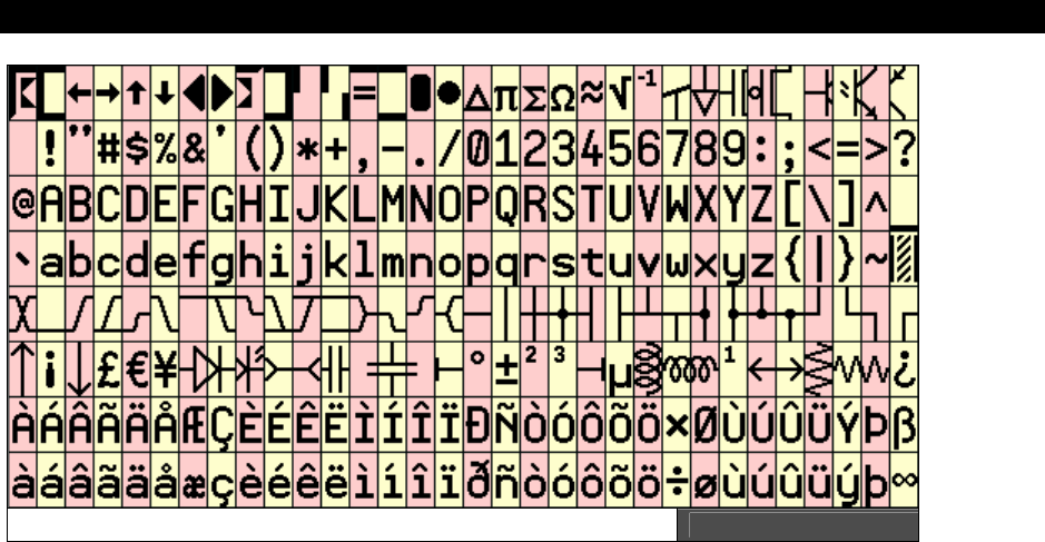
Propeller Chip Architecture13
Game Programming for the Propeller Powered HYDRA Ì Page 205
aThe Propeller Chip ROM Character Set ($8000 - $BFFF) Figure 13:2
Some character codes have inescapable meanings, such as 9 for Tab, 10 for Line Feed, and
13 for Carriage Return (0 can also be touchy). These character codes invoke actions and do
not equate to static character definitions. For this reason, their character definitions have
been used for special four-color characters. These four-color characters are used for drawing
3-D box edges at run time and are implemented as 16 × 16 pixel cells, as opposed to the
normal 16 × 32 pixel cells. They occupy even-odd character pairs 0-1, 8-9, 10-11, and 12-13.
13.11.3 Base 2 Log and Anti-Log Tables ($C000-DFFF)
The log and anti-log tables are useful for converting values between their number form and
exponent form. The log tables are base 2. If you are rusty on math, a logarithm is a way of
referring to one number raised to the power of another. Let’s review base 10 logs first. For
example, you are probably used to seeing something like this:
102 = 100
...which states “10 to the 2nd power is 100”, but what if we were to ask the question, “10
raised to what power equals 100?” This is the idea of a logarithm. And this is how we would
write that statement out:
Log10 100 = 2
The subscripted “10” is referred to as the “base” of the logarithm, and you would normally
say something like “the log base 10 of 100 equals 2”. Additionally, if the base is assumed by
convention then it can be omitted, for example, in electrical engineering typically base 10

II Propeller Chip Architecture and Programming
Page 206 Game Programming for the Propeller Powered HYDRA
numbers are used so much that “log” with no base by convention always means base 10 log,
thus you might see an engineer write something like:
Log 1000
...which means, “10 to the what power equals 1000?” The answer is of course 3. In general,
logs have the following format:
Log
b x = y
...where b is the base.
In other words, “b to the power of y equals x” or mathematically:
b
y = x
So logs can help analyze data that grows in an exponential way with numbers that are
smaller and that increment by single digits. Also, you may have seen “log” written as “ln”
which is called the “natural logarithm.” It is just a specific log with a specific base, that base
being the mathematical constant “e” which is equal to 2.71828. Thus, a natural log is really
just this:
Log
e x = y
And “e” is so common in engineering and physics that someone named a log after it, so they
could stop writing “e” as the base, and that name is “ln” or natural log, written as:
Ln x = y
And that’s it.
So how do logarithms help us? Well, they turn multiplication and division into addition and
subtraction for one thing, take a look at these rules:
Log A * B = Log A + Log B
Log A / B = Log A – Log B
And this holds for any base; 10, e, etc. So referring to these Log formulas, if you wanted
multiply two numbers together, you could simply convert them to logs then add! But, there is
a catch, and that catch is once you convert them to logs (with a lookup table usually) then
how do you convert the final sum of logs back to a normal number? This is where the anti-
log comes into play.
Anti-log is the inverse function of Log; that is, antilog is really the exponential function itself:
by = x
Where b is the base 10 by convention, therefore,

Propeller Chip Architecture13
Game Programming for the Propeller Powered HYDRA Page 207
Antilog (y) = 10y
Example:
Antilog (3) = 1000, since Antilog (3) = 103 = 1000
Finally, if you take the antilog of a log then results will cancel out and you will be left with the
original value. That is say you had this:
Log 1000
We know that this is equal to 3, but if you take the antilog of this you get:
Antilog (Log 1000) = Antilog (3) = 103 = 1000
That is the original inner parameter 1000 is “pulled” out. Thus going back to our original
formula:
Log A × B = Log A + Log B
If we want to multiply two numbers, we simply need to find the log of each, and then find
the antilog of the sum like this:
Antilog (Log A × B) = Antilog (Log A + Log B)
A × B = Antilog ((Log A + Log B))
Let’s give it a try using a simple numbers that are powers of 10, thus easy to compute logs
for:
100 × 1000 = ?
Log (100 × 1000) = Log 100 + Log 1000
= 2 + 3
= 5
Now, to finish we need to take the antilog of the right hand side:
100 × 1000 = antilog (5) = 105 = 100,000!
For algorithms where you are performing lots of multiplies and divides rather than additions
and subtractions, using logs can greatly speed things up. Logarithmic encoding is also useful
for compressing numbers into fewer bits – sacrificing resolution at higher magnitude. In
many applications, such as audio synthesis, the nature of signals is logarithmic in both
frequency and magnitude. Processing such data in exponential form is quite natural and
efficient, as it transforms logarithmic data to linear data.
Now, before looking at the actual log and antilog tables, there is no point is using base 10
numbers on a computer, since all calculations are done in binary anyway (base 2), thus the

II Propeller Chip Architecture and Programming
Page 208 Game Programming for the Propeller Powered HYDRA
log and antilog tables are base 2. Of course, the same rules for multiplication, division, and
so forth all hold for any log base, so this is exactly what we want to do.
13.11.4 Log Table ($C000-$CFFF)
The log lookup table contains pre-computed data used to convert unsigned numbers into
base-2 exponents. The log table is comprised of 2,048 unsigned WORDs which make up the
base-2 fractional exponents of numbers. To use this table is a bit tricky, so let’s try an
example so you can see how it works. The first step to computing the base 2 log of a
number is to determine the
integer
portion of the exponent of the number you are
converting (trying saying that 3 times fast!). This is simply the leading bit’s position (0..31) of
the number you are converting:
Example: compute the log base 2 of $60000000
Find the leading bit position?
$60000000 = 0110_0000_0000_0000_0000_0000_0000_00002
30th bit position or $1E, this is the “leading bit’s position.”
So the integer portion of the log would be 30 or $1E. This makes sense, since what we are
really asking is “What smallest value of y for 2y is at least as large as our target log of
$60000000?” And that would be 230.
Note, that this “integer” portion will always fit within 5 bits, since at most the largest number
we might want to compute the log base 2 of is $8xxxxxxxx (that is the 31st bit is HIGH and to
represent 31 we need 5 bits). The
second
step in the algorithm to is to isolate this 5 bit
number ($1E in this case) into our partial result so that they occupy bit positions 20..16. In
the case of the example we are using of $60000000 to start with, we would place the 30
decimal or $1E hex into bit positions 20..16 of our partial result, like so:
= $001E0000
= 0000_0000_0001_1110_0000_0000_0000_00002
20th..16th bit positions
So far we have a partial result of $001E0000.
The
third
step is to top-justify and isolate the first 11 bits below the leading bit of the
original $60000000 into positions 11..1 of the partial result, we use bits 11..1 rather than
10..0 since each entry in the log table is a WORD or 2 BYTEs. Anyway, here are the details of
the step:

Propeller Chip Architecture13
Game Programming for the Propeller Powered HYDRA Page 209
Once again we refer to the original number $60000000
$60000000 = 0110_0000_0000_0000_0000_0000_0000_00002
↑ ↑
11 bits below the leading “1”
...of which we left or “top justify” these 11 bits into 12 bits resulting in:
1000_0000_00002
...then pad 4 more bits resulting in:
0000_1000_0000_00002 = $0800
...and we are almost done! We take this result $0800 which is the “index” into the lookup
table and look up the fractional value in the log look up table, so we perform the following
step:
Fractional_log = Log_Table[ $0800 ]
...and in this case, the value there happens to be $9C50 (I looked it up), then the
final
step
is to add the
integer
part we manually computed to the
fractional
part we just looked up:
$001E0000 + $9C50 = $001E9C50.
Integer part Fractional part
...which is indeed the log base 2 of $60000000. Note that bits 20..16 make up the integer
portion of the exponent, while bits 15..0 make up the fractional portion, with bit 15 being the
½, bit 14 being the ¼, and so on, down to bit 0. The exponent can now be manipulated by
adding, subtracting, and shifting. Always insure that your math operations will never drive
the exponent below 0 or cause it to overflow bit 20. Otherwise, it may not convert back to a
number correctly.
Here is a routine that will convert an unsigned number into its base-2 exponent using the log
table:
' Convert number to exponent
'
' on entry: num holds 32-bit unsigned value
' on exit: exp holds 21-bit exponent with 5 integer bits and 16 fractional bits
'
numexp mov exp,#0 'clear exponent
test num,num4 wz 'get integer portion of exponent
muxnz exp,exp4 'while top-justifying number

II Propeller Chip Architecture and Programming
Page 210 Game Programming for the Propeller Powered HYDRA
if_z shl num,#16
test num,num3 wz
muxnz exp,exp3
if_z shl num,#8
test num,num2 wz
muxnz exp,exp2
if_z shl num,#4
test num,num1 wz
muxnz exp,exp1
if_z shl num,#2
test num,num0 wz
muxnz exp,exp0
if_z shl num,#1
shr num,#30-11 'justify sub-leading bits as word offset
and num,table_mask 'isolate table offset bits
add num,table_log 'add log table address
rdword num,num 'read fractional portion of exponent
or exp,num 'combine fractional and integer portions
numexp_ret ret '91..106 clocks
'(variance is due to Hub sync on RDWORD)
num4 long $FFFF0000
num3 long $FF000000
num2 long $F0000000
num1 long $C0000000
num0 long $80000000
exp4 long $00100000
exp3 long $00080000
exp2 long $00040000
exp1 long $00020000
exp0 long $00010000
table_mask long $0FFE 'table offset mask
table_log long $C000 'log table base
num long 0 'input
exp long 0 'output

Propeller Chip Architecture13
Game Programming for the Propeller Powered HYDRA Page 211
13.11.5 Anti-Log Table ($D000-$DFFF)
The anti-log table contains data used to convert base 2 exponents into unsigned numbers,
much simpler than the log table. The anti-log table is comprised of 2,048 unsigned WORDs
which are each the lower 16 bits of a 17-bit mantissa (the 17th bit is implied and must be set
separately). To use this table, shift the top 11 bits of the exponent fraction (bits 15..5) into
bits 11..1 and isolate. Add $D000 for the anti-log table base. Read the WORD at that location
into the result – this is the mantissa. Next, shift the mantissa left to bits 30..15 and set bit 31
– the missing 17th bit of the mantissa. The last step is to shift the result right by 31 minus the
exponent integer in bits 20..16. The exponent is now converted to an unsigned number.
Here is a routine that will convert a base-2 exponent into an unsigned number using the anti-
log table:
' Convert exponent to number
'
' on entry: exp holds 21-bit exponent with 5 integer bits and 16 fraction bits
' on exit: num holds 32-bit unsigned value
'
expnum mov num,exp 'get exponent into number
shr num,#15-11 'justify exponent fraction as word
'offset
and num,table_mask 'isolate table offset bits
or num,table_antilog 'add anti-log table address
rdword num,num 'read mantissa word into number
shl num,#15 'shift mantissa into bits 30..15
or num,num0 'set top bit (17th bit of mantissa)
shr exp,#20-4 'shift exponent integer into bits 4..0
xor exp,#$1F 'inverse bits to get shift count
shr num,exp 'shift number into final position
expnum_ret ret '47..62 clocks
'(variance is due to Hub sync on RDWORD)
num0 long $80000000 '17th bit of the mantissa
table_mask long $0FFE 'table offset mask
table_antilog long $C000 'anti-log table base
exp long 0 'input
num long 0 'output

II Propeller Chip Architecture and Programming
Page 212 Game Programming for the Propeller Powered HYDRA
13.11.6 Sine Table ($E000-$F001)
The sine table provides 2,049 unsigned 16-bit sine samples spanning from 0° to 90°,
inclusively (resulting in a 0.0439° resolution). A small amount of assembly code can mirror
and flip the sine table samples to create a full-cycle sine/cosine lookup routine which has 13-
bit angle resolution and 17-bit sample resolution:
' Get sine/cosine
'
' quadrant: 1 2 3 4
' angle: $0000..$07FF $0800..$0FFF $1000..$17FF $1800..$1FFF
' table index: $0000..$07FF $0800..$0001 $0000..$07FF $0800..$0001
' mirror: +offset -offset +offset -offset
' flip: +sample +sample -sample -sample
'
' on entry: sin[12..0] holds angle (0° to just under 360°)
' on exit: sin holds signed value ranging from $0000FFFF (1) to $FFFF0001 (-1)
'
getcos add sin,sin_90 'for cosine, add 90°
getsin test sin,sin_90 wc 'get quadrant 2|4 into c
test sin_sin_180 wz 'get quadrant 3|4 into nz
negc sin,sin 'if quadrant 2|4, negate offset
or sin,sin_table 'or in sin table address >> 1
shl sin,#1 'shift left to get final word address
rdword sin,sin 'read word sample from $E000 to $F000
negnz sin,sin 'if quadrant 3|4, negate sample
getsin_ret
getcos_ret ret '39..54 clocks
'(variance is due to Hub sync on RDWORD)
sin_90 long $0800
sin_180 long $1000
sin_table long $E000 >> 1 'sine table base shifted right
sin long 0
As with the log and anti-log tables, linear interpolation could be applied to the sine table to
achieve higher resolution. Also, remember the following simple trigonometric identities (they
come in handy when trying to relate sine to cosine):
Cos(x) = Sin(x + 90°)
Cos(-x) = Cos(x)
Sin(-x) = -Sin(x)
Sin(2x) = 2 Sin(x) Cos(x)
Cos2 x + Sin2 x = 1

Propeller Chip Architecture13
Game Programming for the Propeller Powered HYDRA Page 213
13.12 Booter and Interpreter ($F002-$FFFF)
The last part of ROM contains the
boot
loader
and the
Spin
interpreter
. These are
assembly language programs which are critical to the operation of the Propeller chip. The
boot loader program runs automatically on reset and is responsible for booting the chip. On
reset, the boot loader begins by waiting briefly to see if a host (PC in most cases) is
attempting to connect serially on pins P31 and P30. If a host is present, it can command the
boot loader to receive a high-level program to transfer into RAM. It may also command the
booter to program that data into an external EEPROM and/or to launch the interpreter to
execute it. If no serial host is present, the boot loader attempts to load a high-level program
into RAM from an external EEPROM connected on pins P29 and P28. If successful, the
interpreter will be launched to execute it. If no EEPROM is present, or the high-level program
was corrupted, the boot loader will shut down the chip to conserve power.
The Spin interpreter program’s job is to execute high-level programs only. It is initially
launched by the boot loader into Cog 0. As the interpreter executes a high-level program, it
may be directed to re-launch itself into other cogs, so that other high-level programs can run
concurrently.
13.13 The Global CLK Register
The global CLK register controls the Propeller chip’s master clock source. It is writable from
Spin with the instruction “CLKSET(value)” or the assembly language “CLKSET D” instruction.
Whenever the CLK register is written, a global delay of ~100 µs will occur as the clock-
switchover circuit transitions from potentially one clock source to another.
Whenever you change this register, a copy of the value written should be placed in
BYTE[15]. Also, LONG[0] should be updated with the resulting master clock frequency. This
is done so that objects which reference these data will have current information upon which
to base their timing calculations. In most cases, you will not do this though and will simply
run the chip at a constant speed; however, if you are doing “on demand performance”
computing and want to minimize power consumption then this detail becomes important. The
CLK register is outlined in Table 13:10 on the next page.
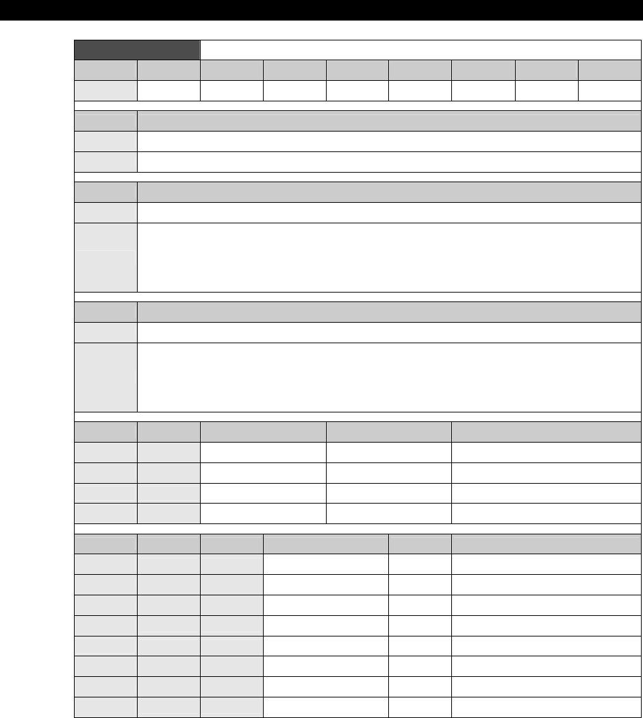
II Propeller Chip Architecture and Programming
Page 214 Game Programming for the Propeller Powered HYDRA
Table 13:10 Bit Encodings for the Global CLK Register
Bit 7 6 5 4 3 2 1 0
Name RESET PLLENA OSCENA OSCM1 OSCM2 CLKSEL2 CLKSEL1 CLKSEL0
RESET Effect
0 Always write ‘0’ here unless you intend to reset the chip.
1 Same as a hardware reset – reboots the chip.
PLLENA Effect
0 Disables the PLL circuit.
1
Enables the PLL circuit. The PLL internally multiplies the XIN pin frequency by 16. OSCENA must be
‘1’ to propagate the XIN signal to the PLL. The PLL’s internal frequency must be kept within 64 MHz to
128 MHz – this translates to an XIN frequency range of 4 MHz to 8 MHz. Allow 100 µs for the PLL to
stabilize before switching to one of its outputs via the CLKSEL bits. Once the OSC and PLL circuits
are enabled and stabilized, you can switch freely among all clock sources by changing the CLKSEL
bits.
OSCENA Effect
0 Disables the OSC circuit.
1
Enables the OSC circuit so that a clock signal can be input to XIN, or so that XIN and XOUT can
function together as a feedback oscillator. The OSCM bits select the operating mode of the OSC
circuit. Note that no external resistors or capacitors are required for crystals and resonators. Allow a
crystal or resonator 10ms to stabilize before switching to an OSC or PLL output via the CLKSEL bits.
When enabling the OSC circuit, the PLL may be enabled at the same time so that they can share the
stabilization period.
OSCM1 OSCM2 XOUT Resistance XOUT Capacitance Frequency Range
0 0 Infinite 6 pF DC to 160 Hz Input
0 1 2000 36 pF 4 MHz to 6 MHz Crystal/Resonator
1 0 1000 26 pF 8 MHz to 32 MHz Crystal/Resonator
1 1 500 16 pF 20 MHz to 60 MHz Crystal/Resonator
CLKSEL2 CLKSEL1 CLKSEL0 Master Clock Source Notes
0 0 0 12 MHz Internal No internal parts; range 8 to 20 MHz
0 0 1 20 kHz Internal Very low power; range 13 to 33 kHz
0 1 0 XIN OSC OSCENA must be ‘1’
0 1 1 XIN × 1 OSC+PLL OSCENA and PLLENA must be ‘1’
1 0 0 XIN × 2 OSC+PLL OSCENA and PLLENA must be ‘1’
1 0 1 XIN × 4 OSC+PLL OSCENA and PLLENA must be ‘1’
1 1 0 XIN × 8 OSC+PLL OSCENA and PLLENA must be ‘1’
1 1 1 XIN × 16 OSC+PLL OSCENA and PLLENA must be ‘1’
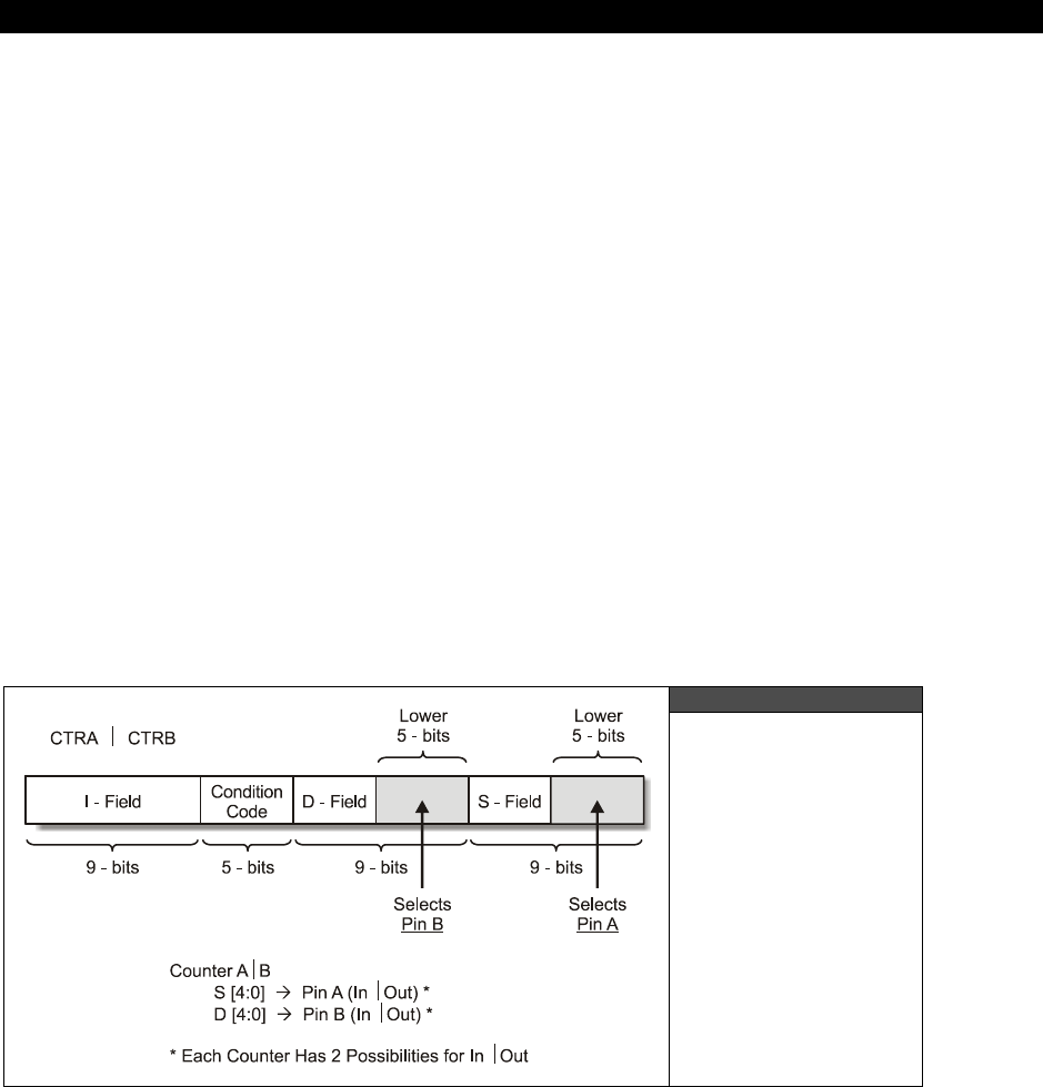
Propeller Chip Architecture13
Game Programming for the Propeller Powered HYDRA Page 215
13.14 Counter Operations and Modes
As mentioned, each cog has
two
internal 32-bit counters A and B, and these counters are
controlled via the counter control register file for the cog. Additionally, there is a
“global”
counter accessed via the CNT register in the register file for each cog that allows any cog to
use a common synchronous clock for event timing etc.
Once again, three pairs of registers make up a counter module:
CTRA/B Configuration register, full R/W
PHSA/B Phase accumulator, full R/W (automatically updates per mode)
FRQA/B Phase adder, write-only, though R/W okay
Additionally, there is a bit of naming that might confuse you. Each counter A and B each has
two pins that can be selected an inputs or outputs; these are also referred to as A and B, so
diagrammatically we have:
Counter A has two pins of interest referred to as A and B.
Counter B has two pins of interest referred to as A and B.
Thus, when discussing counters I will refer to counter/pin always in that order. This will make
more sense when we see the counter control modes in the tables below, but watch out – it’s
easy to get confused.
13.14.1 Bit Encodings for the Counter Configuration Registers
Figure 13:3
The Bit Encodings
for the Counter
Configuration
Register(s)
CTRA and CTRB
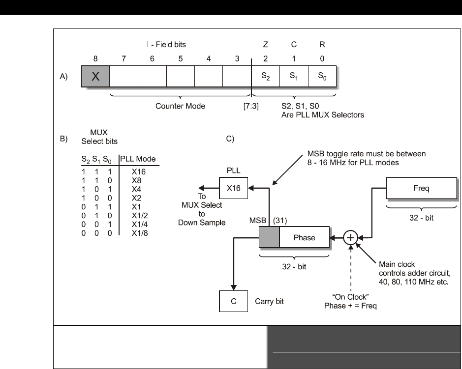
II Propeller Chip Architecture and Programming
Page 216 Game Programming for the Propeller Powered HYDRA
Visualization of the I-Field (A)
Clock MUX Selects (B)
and Counter Operation (C)
Figure 13:4
Referring to Figure 13:3 and Figure 13:4, and the bit encodings for the counter configuration
register as shown in Table 13:11 below, let’s begin our discussion of counter operation. To
begin with, remember that all registers and instructions can be referenced by their various
fields; I, CC, D, and S. With that in mind, the uppermost 9 bits of the CTRA (or CTRB)
register are referred to at the I-field; these bits control two things. First the counter mode
(PLL, duty cycle, numerically controlled oscillator, etc. as shown in Table 13:10 on page 214)
is selected via bits [7-3]; bits [2-0] select which PLL “tap” is used to finally select the output
signal by from 1/8th to 16. If you refer to Figure 13:4(B), you see that the 3 bits form a
selector which selects which frequency the final output of the counter hardware is multiplied
by. We will discuss this in more detail in a moment.
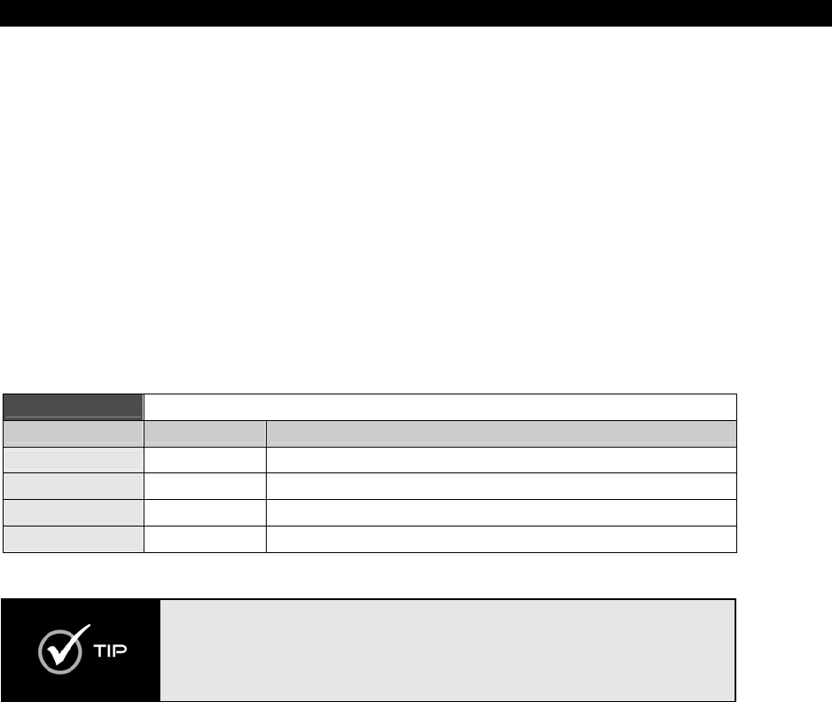
Propeller Chip Architecture13
Game Programming for the Propeller Powered HYDRA Page 217
Next, depending on the mode the counter is set in, you can select a Pin A or B option for
each counter (where it makes sense). So for either counter A or B, the selection of pins is
encoded in the control register’s S and D fields like so:
Counter A or B S-field bits [4-0] selects Pin A (in/out depending on mode of operation)
D-field bits [4-0] selects Pin B (in/out depending on mode of operation)
Refer to Figure 13:3 to see this a little bit better. Anyway, so now we can select the counter
mode in I-field bits [7-3], we can select the PLL multiplier in I-field bits [2-0], and we select
the Pin A option in S-Field bits [4-0] and the Pin B option in D-field bits [4-0]. And of course,
there are two counters and we have two control registers named CTRA and CTRB
respectively. Also, note we do not need to set Pin A or Pin B options to input or output as
they are inferred to be input or output respectively by the counter mode you select
(however, at the I/O level you must set the pins for input or output with the direction
register).
Table 13:11 Bit Mapping for Counter Control Registers CTRA and CTRB
Field Bits Function
I-Field CTRA/B[30..26] Sets counter “mode”
I-Field CTRA/B[25..23] Selects PLL tap (0..7 map to x1/8, x1/4, x1/2, x1, x2, x4, x8, x16)
S-Field CTRA/B[4..0] Selects pin Out A / In A (0-31)
D-Field CTRA/B[13..9] Selects pin Out B / In B (0-31)
You can use the following ASM instructions to write into the fields of
CTRA/CTRB:
MOVI — sets mode
MOVD — sets Pin B
MOVS — sets Pin A
Alright, this is great, but how does the counter actually work? Referring to Figure 13:4(C),
you see a diagram that visualizes what the counter does, so let’s break it down step by step
and work through the flow diagram of how the counters A and B work; both are identical of
course.
Step 1: The 32-bit value stored in the FRQx register is added to the PHSx register at the
final system clock frequency. So if you are running the Propeller chip at a final frequency of
80 MHz, then this is the frequency at which this addition takes place. Example: if you have a
0x00000001 in FRQx then it will take PHSx 232 counts to overflow.

II Propeller Chip Architecture and Programming
Page 218 Game Programming for the Propeller Powered HYDRA
Step 2: PHSx is used as an “accumulator” and continuously accumulates the additions of
FRQx. The MSB (most significant bit) feeds the PLL (phase-locked loop) and that clock rate is
always multiplied by 16, then you select which PLL tap you want from x1/8th to x16 with bits
25..23 of the I-field.
Step 3: Now, depending on what “mode” the counter is in, the output will be one of the
following:
PLL Modes – The output from bit 31 of PHSx is multiplied by 16 and then the PLL
multiplexer selection bits S2, S1, S0 (in I-field [25..23]) select the “tap” frequency
from 1/8th to x16.
NCO Modes – The MSB (bit 31) of PHSx is the output, there is no PLL multiplication
in this mode.
DUTY Cycle Modes – The resulting overflow carry out bit C (from bit 31) from the
resulting additions is the output. The carry bit is also referred to as bit 32, so
PHSx[31] would be the MSB and PHSx[32] is the carry bit from the additions of FRQx
into PHSx.
Now, there are other modes that the counter can run in that can be used for A/D (analog to
digital conversion) as well as performing logic functions, but these aren’t very important to
HYDRA programming. Table 13:12 on the next page lists these though.
So to use a counter you must at very least setup the CTRx register for either the A or B
counter and then depending on the mode you select modify PHSx and FRQx as desired to get
the desired effect; PLL, NCO, or Duty Cycle. We will discuss what you can do with these
modes shortly, but first let’s take a look at the counter configuration mode table, Table
13:12.
13.14.2 Counter Configuration Mode Table
Table 13:12 below lists all the counter configuration modes that are available for either
Counter A or B, these modes are selected via the cog registers CTRA and CTRB.

Propeller Chip Architecture13
Game Programming for the Propeller Powered HYDRA Page 219
Table 13:12 Counter Configuration Mode
CTRx [30..26] PHSx += FRQx OUTA OUTB Description of Mode
(0) 00000 FALSE FALSE FALSE Off
PLL Modes
(1) 00001 TRUE FALSE FALSE PLL internal, FM aural carrier TV or routed to video
(2) 00010 TRUE PLL FALSE PLL singe
(3) 00011 TRUE PLL ! PLL PLL differential
Numerically Controlled Oscillator Modes
(4) 00100 TRUE PHSx[31] FALSE NCO single
(5) 00101 TRUE PHSx[31] !PHSx[31] NCO differential
Duty Cycle Modes
(6) 00110 TRUE PHSx[32] FALSE duty single
(7) 00111 TRUE PHSx[32] !PHSx[32] duty differential
Special Analog Modes
(8) 01000 INA' FALSE FALSE pos
(9) 01001 INA’ FALSE !INA’ pos with feedback
(10) 01010 INA’ & !INA” FALSE FALSE pos edge
(11) 01011 INA’ & !INA” FALSE !INA’ pos edge with feedback
(12) 01100 !INA’ FALSE FALSE neg
(13) 01101 !INA’ FALSE !INA’ neg w/ feedback
(14) 01110 !INA’ & INA” FALSE FALSE neg edge
(15) 01111 !INA’ & INA” FALSE !INA’ neg edge w/feedback
Logic Function Implementation Mode
See * below FALSE FALSE Logic implementation mode
(16) 1xxxx
*Add if FUNC (MUX (INA', INB')) = 1
Where,
INA' = INA from 1 clock ago.
INA'' = INA from 2 clocks ago.
INB' = INB from 1 clock ago.
INA(B)'
┌──────┐ │ ┌──────┐
INA(B)──────┤D Q├───┻───┤D Q├────INA(B)"
┌───┤CLK │ ┌───┤CLK │
│ └──────┘ │ └──────┘
CLK─────┻──────────────┘
DELAYS ‘ = 1 clock delay, “ = 2 clock delays
When using the counters or any I/O for that matter, no matter what, you always
have to set the appropriate pins A,B as input or output to coincide with the mode
setting.

II Propeller Chip Architecture and Programming
Page 220 Game Programming for the Propeller Powered HYDRA
Now, let’s briefly discuss what you might use each mode for, but before doing that, I want to
make sure you can make sense of Table 13:12 above. The table is read as follows: first you
find the mode you are interested in, say mode 2 “(2)” for example. Ok, now there are five
column heads in this table. The first column head “CTRx” simply means the mode bits that
you must set in the CTRx register to select the related mode, easy enough. The next column
“PHSx+=FRQx” means that the value in the frequency register is added to the phase register
each system clock under a specific condition: always, or never. For example, in the case of
mode 2, this addition always takes place, but in mode 0, we see a FALSE in the column, thus
frequency is never added; this makes sense since mode 0 is OFF. Moving onto the next
column headings OUTA and OUTB, these columns tell us what exactly is getting output by
the counter. For example, in mode 2 the OUTA column shows “PLL” and in the OUTB column
it shows FALSE. This means that if you set a counter (A or B) to PLL mode 2, then you can
select a single output Pin A and the PLL output will drive it. Of course, you set this pin in the
S-field bits [4..0] of the counter control register and you MUST make sure that on the DIRA
I/O control you have that pin set as an output as well. Lastly, the “Description…” column is
just that, a description.
So, now that we can read this table, let’s take a look at yet another mode and see if we can
understand its use. Take a look at mode 5. This mode is NCO (numerically controlled
oscillator) mode, that’s easy to see from the description and header. Ok, next let’s see when
the phase register is updated, we look in the “PHSx+=FRQx” column and we see TRUE, thus
all the time, every system clock, the addition takes place, good enough. Next, we look at the
OUTA and OUTB columns and they get interesting, we see the final output to Pin A is
PHSx[31], that is the MSB of the PHSx register, this is fine, but then we see that the output
to Pin B is !PHSx[31], the “!” means
not
or
invert
, thus mode 5 is interesting since it’s a
“differential mode,”
while the pin you select as output A is going HIGH, the pin you select
as output B is going LOW, thus they are 180 degrees out of phase or referred to as a
differential signal. Now that you can read the table a bit, let’s discuss what these modes do
for us.
If you want to use any of the system counters to generate sound, either simple
tones or more complex PWM sounds, then obviously you MUST set the output
pin to drive the sound hardware at I/O pin P7 (8) which is named AUDIO_MONO
in the HYDRA design.
13.14.3 PLL (Phase-Locked Loop) Modes
The PLL modes 1, 2, 3 are used to generate a standard square wave output (except mode 1
which has no output, but it’s useful for video and FM aural generation since the signal is
routed to that hardware). The main clock frequency F (usually 64-100 MHz) drives the adder
circuit and the value in FRQx is added/accumulated into PHSx, the MSB of the PHSx register
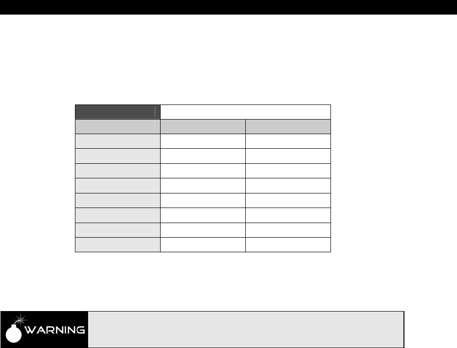
Propeller Chip Architecture13
Game Programming for the Propeller Powered HYDRA Page 221
PHSx[31] is multiplied by 16 using a phased locked loop circuit or PLL (PLLs can be used for
many things and one of them is frequency multiplication), then you can select which sub-
multiple of this you wish with the PLL MUX select bits in the CTRx register bits [2..0], as
shown in Figure 13:4(B) on page 216 there are 8 different frequencies you can select as
shown in a slightly different form in Table 13:13 below.
Table 13:13 PLL Final Frequency Selection
Mode Bits [S2,S1,S0] Final Rate Output
0 000 ×1/8
1 001 ×1/4
2 010 ×1/2
3 011 ×1
4 100 ×2
5 101 ×4
6 110 ×8
7 111 ×16
For example, whatever rate the MSB toggles at, if you wanted that ×16 you would select 111
or mode 7.
There are two very important rules when using the PLL modes. The frequency
that gets driven into the PLL must be between 4 and 8 MHz inclusive. This means
that the final output will always be between 64 and 128 MHz.
Now, let’s do a concrete example of what values would do what since PLL modes are very
useful for generating sound using PWM modes as well as generating high frequency clocks
(remember the final PLLs ×16 output must ALWAYS be between 64 and 128 MHz, so it’s
fairly high frequency).
Example Derivation of Frequency Formula for PLL Modes
The MSB of the PHSx register always needs to toggle at a rate between 8 and 16 MHz or a
frequency between 4 and 8 MHz. This first constraint is the key to programming the PLL. So,
first, we need to realize that we ONLY can generate frequencies at the MSB between 4 and 8
MHz then this is always multiplied by 16 then with the PLL mux we can pick off any sub-
multiple from 1/8th to the full 16×. To make the derivation simpler, let’s forget about the ×16

II Propeller Chip Architecture and Programming
Page 222 Game Programming for the Propeller Powered HYDRA
part since this is a scaling operation and we can always look at it later. First let’s just find a
formula that describes the PLL counter mode up to the MSB before the x16 to the multiplier.
Ok, so reviewing the flow chart in Figure 13:4(C) on page 216, FRQx is added to PHSx each
main system clock cycle, let’s call this Fm Hz. So, at Fm Hz we are adding FRQx into PHSx
and it overflows whenever the sum is greater than (232 – 1). For example, if we were to put a
0x8000_0000 into FRQx then it would take 2 additions to overflow PHSx or as a function of
the main clock Fm, we would see the MSB look like this (assuming everything starts at 0),
Table 13:14 illustrates what happens.
Table 13:14 Digital Mechanics of the PLL Mode Addition
as a Function of the Main Clock C
Clock Cycle PHSx[32] carry bit MSB PHS[31] PHSx FRQx
0 0 0
0x0000_0000 0x8000_0000
1 0 1
0x8000_0000 0x8000_0000
2 1 0
0x0000_0000 0x8000_0000
3 0 1
0x8000_0000 0x8000_0000
4 1 0
0x0000_0000 0x8000_0000
5 0 1
0x8000_0000 0x8000_0000
6 1 0
0x0000_0000 0x8000_0000
7 0 1
0x8000_0000 0x8000_0000
8 1 0
0x0000_0000 0x8000_0000
As you can see from the table, the pattern of 010101010….01 continues forever with this
addend in FRQx’s MSB, remember the high hex digit “8” is really 1000 binary, so that high bit
is set. Also, note the carry bit PHSx[32] is the invert of the MSB bit. This is just a result of
adding half the max magnitude each time.
Now, analyzing the situation, basically it takes 2 adds to overflow the counter, or in other
words if we take the maximum number of values represented in magnitude only by PHSx, a
32-bit register, this is 232, if we divide this by the number we are adding, 0x8000_0000, the
result should be how many cycles it takes to overflow or toggle the MSB, or in general the
formula that relates FRQx to how many cycles it takes to overflow the PHSx counter is:
cycles to overflow PHSx = (232) / FRQx
Now we are getting somewhere, so in the case of our example, it took 2 cycles to overflow
the counter, or the counter PHSx MSB is toggling every main clock cycle Fm. So, in other
words the MSB is toggling at a frequency 1/2 that of the main clock frequency Fm. So if we

Propeller Chip Architecture13
Game Programming for the Propeller Powered HYDRA Page 223
were running the main clock at 80 Mhz, then the MSB would be clocking at a rate of 40 Mhz,
this is too high for the constraint of that it should run between 4 and 8 MHz, but this is
irrelevant for now. Let’s see if we can find the final relationship with any main clock
frequency. This is fairly simple, if we think about it: let’s say it took 10,000 clocks to overflow
the PHSx – that means that if we run our system at 80 MHz, this overflow would occur every
80,000,000/10,000 = 8000 times a second, but this is the toggle rate, NOT the frequency.
The frequency is 1/2 this, or 4000 Hz, thus we can use this insight to create a final formula
that relates everything together: the system clock Fm, the value in FRQx, and the final MSB
frequency Fmsb (that gets sent to the PLL multiplier). The formula is:
Fmsb = Fm
(232/ FRQx)
Fmsb as a function of main system frequency Fm and FRQx value:
Fmsb = (Fm × FRQx) / (232)
Fmsb as a function of main system frequency Fm and FRQx value:
Fmsb = (Fm × FRQx) / (232)
And that’s it! Of course, you can re-arrange this anyway you like to solve for the unknown.
For example, if you have a main system clock frequency of 80 MHz, you want to synthesize a
6 Mhz Fmsb frequency, what FRQx value would you use? Then you would use this variant of
the formula:
FRQx as a function of desired Fsm and main system frequency Fm:
FRQx = (Fmsb × (232)) / Fm
Plugging in our knowns, we get:
FRQx = ((6.0×106)× (232)) / 80×106
= 322.1225472 × 10⁶
So, we plug 322 million and change into the FRQx register and let the PLL run, the output at
the MSB of PHSx will clock at a rate of 6 Mhz, and we are in business. Then we can get any
multiple of this 6 MHz by selecting the appropriate tap in the PLL mux, from 1/8th to x16, so
we can get any of these frequencies as shown in Table 13:15 on the next page:
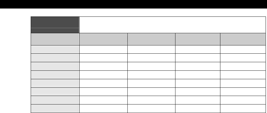
II Propeller Chip Architecture and Programming
Page 224 Game Programming for the Propeller Powered HYDRA
Table 13:15 Computation of Final PLL Output Based on
MSB Frequency and Divider Select
Mode Bits [S1,S2,S0] / Rate MSB Frequency
into PLL Final PLL Rate
Output at Pin
0 000 x1/8 6.0 MHz 0.75 MHz
1 001 x1/4 6.0 MHz 1.5 MHz
2 010 x1/2 6.0 MHz 3.0 MHz
3 011 x1 6.0 MHz 6.0 MHz
4 100 x2 6.0 MHz 12.0 MHz
5 101 x4 6.0 MHz 24.0 MHz
6 110 x8 6.0 MHz 48.0 MHz
7 111 x16 6.0 MHz 96.0 MHz
Hopefully, this laborious example gives you an idea of how the PLL mode works. It’s not that
complex, but yet is unintuitive, since you have to work your example such that you find a
FRQx value that results in a MSB frequency that is ALWAYS between 4 and 8 MHZ, but then
the FINAL frequency out of the PLL is multiplied by 16 then you select any rate from this
divider chain in the PLL mux, so you have to work a bit to get what you want.
13.14.4 NCO (Numerically Controlled Oscillator) Modes
The NCO or numerically controlled oscillator modes are much easier to understand since
there is no PLL multiplication and there are no constraints on the frequency you can toggle
the MSB at. In NCO modes, the MSB of PHSx (that is, PHSx[31]) is used as the final out at
the pin(s) you select. There are two NCO modes, single and differential. In single mode 4,
only Pin A is used as an output; in differential mode 5, both Pin A and Pin B are used and Pin
B is 180 degrees out of phase, or the logical inversion of, Pin A.
The formula that describes the output frequency can be derived directly from our work with
the PLL modes, but we don’t have to worry about the 4 to 8 MHz frequency rule and there is
no PLL scaling, so the formula that relates the system clock frequency Fm, the value in FRQx,
and the desired output frequency Fmsb is:
FRQx = (Fmsb × 232) / Fm
Now, let’s try it. Let’s assume we want to synthesize a 1 kHz square wave at Pin A, so we
want to use single mode NCO which is mode 4, and we would need to compute the FRQx
value and that’s it, which is:

Propeller Chip Architecture13
Game Programming for the Propeller Powered HYDRA Page 225
FRQx = ((1.0×103) × (232)) / 80.0×106
= 53687.09
Rounding off, we get 53687 or in hex we would load FRQx with 0x0000_D1B6 and we would
be off and running with a 1 kHz square wave (almost minus the error incurred by truncation).
13.14.5 Duty Cycle Modes
The duty cycle modes 6 and 7 are very similar to the NCO modes, except that instead of the
MSB bit PHSx[31] driving the output pin, the carry out of PHSx[31] drives the output pin. So
you see either a carry or no carry every cycle. Now, some interesting things happen when
you track the carry bit, for example if the value in FRQx (the addend) is always the same,
then you will always get one or more carry pulses followed by 0’s. For example, the carry out
will look something like this:
Example 1: 1,0,0,1,0,0,1,0,0
...or maybe,
Example 2: 1,0,1,0,1,0,1,0
...or maybe,
Example 3: 1,0,0,0,0,0,0,0,0,0,0,0,1,0,0,0,0,0,0,0,0,0,0,0,
..or maybe,
Example 4: 1,1,1,0,1,1,1,0
That is, with a constant value in FRQx, at best you can get the carry to toggle each cycle
with the value of 0x8000_0000 in FRQx, or you can get it to be 1 most of the time with a
number larger than 0x8000_0000, or you can make the carry happen seldom with a number
less than 0x8000_0000. Of course if you change FRQx each cycle, you could get the carry to
do what you want dynamically, but this is not how these modes are intended to be used; you
should keep the value in FRQx constant until you are ready to change your final averaged
duty cycle value. If you look at Example 1, and assume a very high clock rate like 80 MHz is
driving this toggle then for all intent purposes this is happening at an infinite rate to a low-
pass filter. Therefore, if we average the carry pulses over time then as time goes forward
they will “settle” to a value. In Example 1, we see there is a single 1 carry pulse, then two
0’s, then it repeats, so it looks like over time this will average to a “duty cycle” of 30%, since
there is one 1 per each three clocks.
In Example 2, we can run the same analysis. Here if we are running at a very high clock rate
like 80 MHz, then the toggling of the 1’s is happening very quickly, so fast that we can
average the signal together again over a long set of pulses. Looking at Example 2, we see

II Propeller Chip Architecture and Programming
Page 226 Game Programming for the Propeller Powered HYDRA
the pattern repeats every 12 pulses, and out of those 12 pulses, there is only one carry pulse
that is 1; the other 11 are 0. Thus, we have a duty cycle of 1/12 = 8.3%.
This is very interesting, why? Because if we pass this signal through our low-pass filter, it will
“average” the pulses into an analog voltage almost instantly due to the high clock rate. Thus
by modulating the number of carry pulses as a ratio to the number of 0 pulses over a
number of cycles, we can get any analog voltage we want! Therefore, if we feed our little
“duty cycle” D/A converter with sine values we can generate a sine wave or whatever, thus
it’s an ad-hoc PWM generator. But, instead of generating a constant clocked PWM cycle and
modulating the width of the high to low cycle to change the final analog output, this duty
cycle mode streams 1’s and 0’s out at a constant rate; the overall “averaging” frequency
changes, but the final analog value will be that of the repeat cycle length of the stream. Thus
in Example 1, we see the pattern repeating at a rate of 3 clock pulses with an average of
30%, but in Example 2, the repeat doesn’t happen for 12 clock pulses, therefore the
frequency response of the first example is 6x better roughly than the second. However, since
the main clock is at 80 MHz and this is the rate the “clocking” is happening, we don’t notice
this too much. In any event, take a look at Figure 13:5 to see this duty mode compared to a
normal PWM waveform.
As you can see in Figure 13:5(A), in standard PWM D/A we fix the clock rate, in this case 1
MHz, and then we modulate the signal’s duty cycle on a per cycle basis, that is the ratio of
the HIGH to the LOW. But, in this modified “duty cycle” mode we aren’t doing that, rather we
use a fixed frequency to clock the system at, yes, but we use the ratio of 1 pulses to 0 pulses
to generate the average where the length of all the 1’s is the same. As long as we send the
signal to a low-pass filter, then it will average the signal out almost immediately and we will
get a nice analog signal out.
Now, as mentioned the only downfall to this technique is the cycle length before the carry
pattern repeats changes, thus frequency of the overall averaging isn’t constant for different
values of final output, but at high frequencies this is ok. Additionally, there is another good
aspect to this duty cycle mode for sound generation and D/A conversion and that is as you
change the value in FRQx the carry ratio immediately changes, thus the “response” is very
quick. Unlike normal duty cycle mode used in PWM with fixed frequency, you don’t have to
wait for the current cycle to complete, you just change the FRQx value any time you want
and the output will change almost immediately with no glitches.
And of course, there is no PLL involved in this mode, so that’s not a concern and you need
not worry about any frequency constraints on PHSx[32], the carry bit, either.
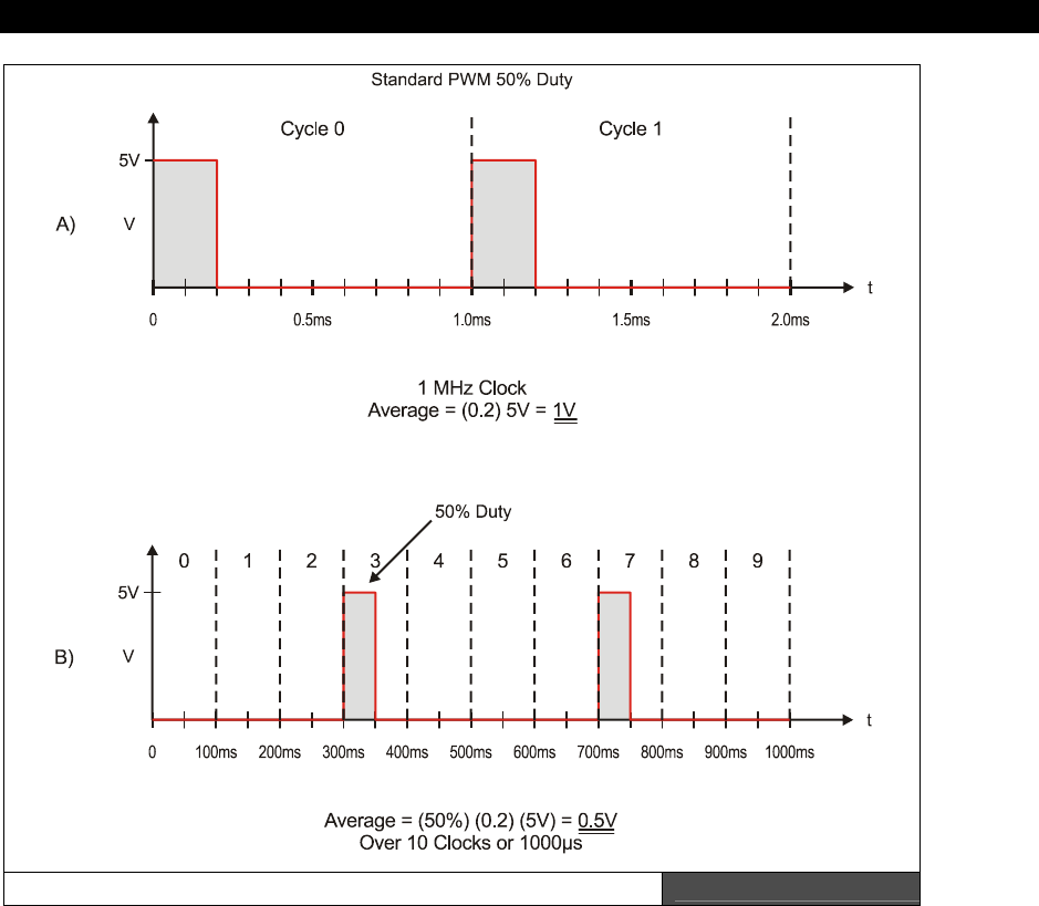
Propeller Chip Architecture13
Game Programming for the Propeller Powered HYDRA Page 227
Standard PWM and Psuedo-Duty Cycle PWM Mode Figure 13:5
As an example, let’s see the equation to generate a 50% overall duty cycle? Well, we already
did this! Remember back on our PLL example Table 13:14 on page 222, and take a look at
the carry column. Notice it makes the pattern:
0,0,1,0,1,0,1,0,1,0,1…,0,1

II Propeller Chip Architecture and Programming
Page 228 Game Programming for the Propeller Powered HYDRA
This is exactly what we want: once the pattern gets going we get a constant stream of
(0,1)’s which will average to 50% duty. So we program the duty cycle mode the exact same
way as the NCO mode, and simply select a FRQx value of 0x8000_0000 in this case.
So this would get us 50% analog voltage out, now what if we needed 25%? No problem, we
need a pattern of (1,0,0,0) to repeat or in other words, we want to overflow into the carry
every 4 clocks, so what 32-bit number does this? 0x4000_0000 will do the job, let’s see with
another table exercise. take a look at Table 13:16 below:
Table 13:16 Duty Cycle Mode to Generate a 25% Duty Cycle Signal
Clock Cycle PHSx[32] carry bit MSB PHSx[31] PHSx FRQx
0 0 0
0x0000_0000 0x4000_0000
1 0 0
0x4000_0000 0x4000_0000
2 0 1
0x8000_0000 0x4000_0000
3 0 1
0xC000_0000 0x4000_0000
4 1 0
0x1000_0000 0x4000_0000
5 0 0
0x5000_0000 0x4000_0000
6 0 1
0x9000_0000 0x4000_0000
7 0 1
0xD000_0000 0x4000_0000
8 1 0
0x2000_0000 0x4000_0000
9 0 0
0x6000_0000 0x4000_0000
10 0 1
0xA000_0000 0x4000_0000
11 0 1
0xE000_0000 0x4000_0000
12 1 0
0x3000_0000 0x4000_0000
13 0 0
0x7000_0000 0x4000_0000
14 0 1
0xB000_0000 0x4000_0000
15 0 1
0xF000_0000 0x4000_0000
16 1 0
0x4000_0000 0x4000_0000
Reviewing the table is interesting, we see a 50% duty cycle in PHSx[31], while at the same
time we see a 1 to 4 carry pulse ratio in PHSx[32], this is exactly what we want, so at a rate
of 80/4 = 20 Mhz, we will put out this “fuzz” of 1’s and 0’s that average to 25% since there is
one 1 and three 0’s per 4 pulses. Also, notice where the pattern repeats, its takes it until
clock 16 to repeat and it takes it 1 clock to “start up” into the pattern. Now, there is an
interesting note, it is impossible to get a 100% signal out, why? Well, even if we add the
largest possible number to itself every time and overflow the PHSx register each time, there
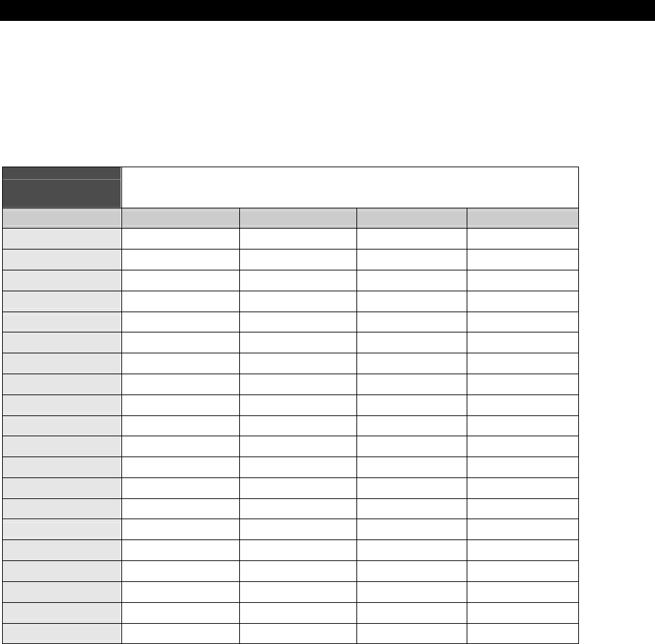
Propeller Chip Architecture13
Game Programming for the Propeller Powered HYDRA Page 229
will be one time at 4 billion cycles into the pattern that the PHSx register will cycle to 0 and
we won’t get a carry, this will happen once every 53 seconds or so, and since we are
synthesizing sound that is changing at a rate in the kHz range this will never be an issue, but
it is a numerical fact nonetheless. Let’s see it in action and try to get a 100% duty cycle, by
adding the max number that can be represented in FRQx which is (232−1), this is shown in
Table 13:17.
Table 13:17 Duty Cycle Mode to Generate a 99.999999999%
Duty Cycle Signal
Clock Cycle PHSx[32] carry bit MSB PHSx[31] PHSx FRQx
0 0 0
0x0000_0000 0xFFFF_FFFF
1 1 0
0xFFFF_FFFF 0xFFFF_FFFF
2 1 1
0xFFFF_FFFE 0xFFFF_FFFF
3 1 1
0xFFFF_FFFD 0xFFFF_FFFF
4 1 1
0xFFFF_FFFC 0xFFFF_FFFF
5 1 1
0xFFFF_FFFB 0xFFFF_FFFF
6 1 1
0xFFFF_FFFA 0xFFFF_FFFF
7 1 1
0xFFFF_FFF9 0xFFFF_FFFF
8 1 1
0xFFFF_FFF8 0xFFFF_FFFF
9 1 1
0xFFFF_FFF7 0xFFFF_FFFF
10 1 1
0xFFFF_FFF6 0xFFFF_FFFF
11 1 1
0xFFFF_FFF5 0xFFFF_FFFF
12 1 1
0xFFFF_FFF4 0xFFFF_FFFF
13 1 1
0xFFFF_FFF3 0xFFFF_FFFF
14 1 1
0xFFFF_FFF2 0xFFFF_FFFF
.
.
232 1 1
0x0000_0000 0xFFFF_FFFF
232 + 1 0 1
0xFFFF_FFFF 0xFFFF_FFFF
232 + 2 1 0
0xFFFF_FFFE 0xFFFF_FFFF
Notice how we get a 0 as the first cycle completes and when we reach the end of the pattern
232 iterations later. Also, notice how the number in PHSx counts down. This makes sense
since you can think of this as a 2’s complement problem, and we are adding
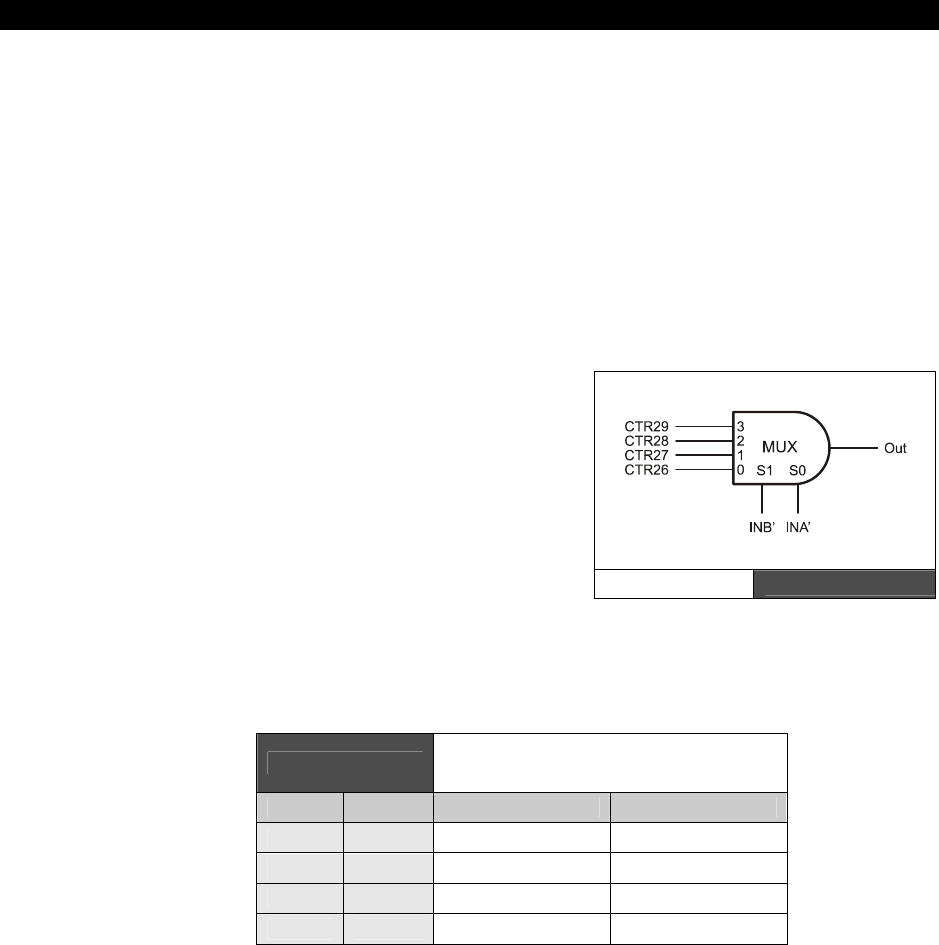
II Propeller Chip Architecture and Programming
Page 230 Game Programming for the Propeller Powered HYDRA
0xFFFF_FFFF = 1 in 2’s complement, thus, we are subtracting away from the initial
0x0000_0000 value each time.
To generate any analog voltage at the output pin simply select a number in FRQx that results
in the desired ratio of 1’s to 0’s in the carry bit PHSx[32].
13.14.6 Special Analog Modes
These modes are used for analog to digital conversion and other such analog processes.
They also make use of clocking or timing flip flops which can be used to delay the input INA
one to two clocks resulting in INA' and INA" as shown in Table 13:12 on page 219. These
modes are advanced and not important for game development; refer to the Propeller Manual
for more information on these modes.
13.14.7 LUT Logic Mode (1xxxx)
Mode 1xxxx allows a logic function to be
implemented with the counter that increments if
and only if the output of the logic function is "1".
The system works by setting CTR29..CTR26 to the
desired bits "look up table style" and then INA' and
INB' selects one of the 4 values, this value is then
gated to the output, and if the output is "1", true,
the counter is updated and FREQ is added to
PHASE. Abstractly, the circuit looks like that
shown in Figure 13:6.
Example: Say we want to implement a logical AND, then we might generate the following
truth table that implements the AND function and then we simply map the 1’s and 0’s into
CTR26..CTR29 that realize the AND function. This is shown in Table 13:18 below:
Table 13:18 Logic Function Mapping for INA'
and INB' to Realize AND
INB' INA' Desired Output Selected Input
0 0 0 CTR26
0 1 0 CTR27
1 0 0 CTR28
1 1 1 CTR29
Reviewing the table, we see that CTR26, 27, 28 should all be 0, and CTR29 should be 1.
Again, not very useful for game development or graphics.
LUT Circuit Figure 13:6

Propeller Chip Architecture13
Game Programming for the Propeller Powered HYDRA Page 231
13.15 Summary
This chapter hopefully has given you both a detailed overview of the Propeller chip as well as
some concrete examples of each of the systems. I can say that hands-down people have the
most trouble understanding the counters. The best approach to all this stuff is simply to write
it down and do examples bit by bit, that’s how I figured it out! In any event, the Propeller
chip is a true “RISC” processor not only formally in as much as it has a fixed instruction
width, but the Propeller chip has nearly no on-board peripherals. One of the design trade-offs
on the Propeller chip was to give you sheer processing speed and let you decide what to do
with it, rather than use silicon for on-board peripherals that you will never use like a CAN
networks, 32-channel D/As, USB and Ethernet controllers, etc. But, you can
always
create
them with a few external passive components and some assembly code! The main idea of
the Propeller chip is to give you a lot of parallel computing “fabric” and let you decide what
to do with it – in our case, we are going to make games ☺.

II Propeller Chip Architecture and Programming
Page 232 Game Programming for the Propeller Powered HYDRA
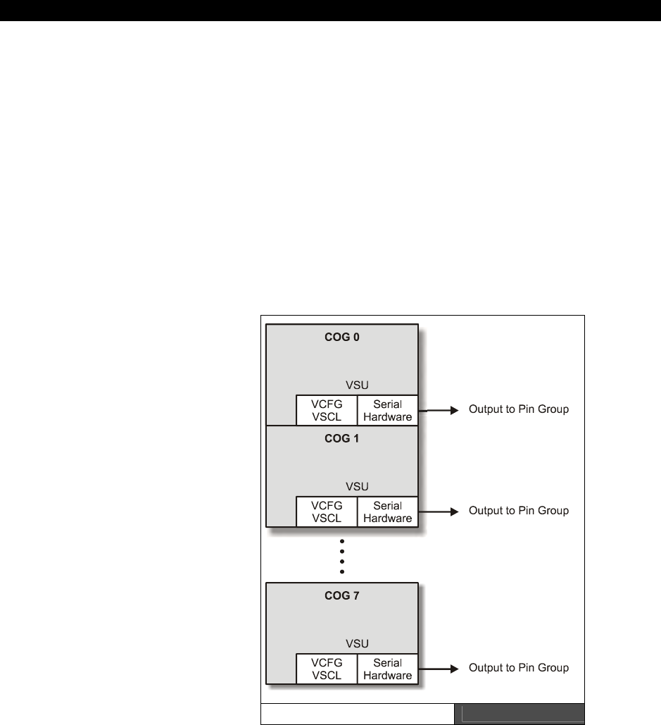
Cog Video Hardware14
Game Programming for the Propeller Powered HYDRA Page 233
Chapter 14: Cog
Video Hardware
In this short chapter we are going to discuss the video hardware support within each cog of
the Propeller chip. I am very proud of the information in here since it was very difficult to
come by, many hours of reverse engineering, discussions with Chip Gracey, and
experimentation were needed to figure it out down to the details since in graphics every bit
counts! I began designing the HYDRA and writing this book with early prototypes of the
Propeller chip, and the early documentation I had had a single line of text to describe the
video hardware! Alas, a lot of work went into this. As I discovered things I gave them my
own names as I went along, so you will see me refer to the video hardware with certain
acronyms like the “VSU” etc., that you won’t find in the Propeller manual but the ideas are
the same. Likewise other authors writing about the Propeller chip may use their own words
and phrases. Anyway, in this chapter we are going to discuss the following topics:
Video hardware configuration
registers
Understanding the Video
Streaming Unit (VSU)
Setting up NTSC and VGA
modes
The Propeller chip has no GPU or
other such dedicated graphics
processing unit; graphics are
achieved through a mixture of
software and hardware. Each cog has
a VSU or “Video Streaming Unit”
which is clocked via the cogs PLL “A”
channel in mode 1. The VSU more or
less streams data out to a port that is
feed via software by your program.
On this port a simple D/A resistor
network or straight 8-bit VGA is
connected. The VSU knows nothing
about graphics, it only knows how to
serialize data and send it out. Figure
14:1 shows a diagram of the VSU in
relation to its cog. VCFG Register Encoding Figure 14:1
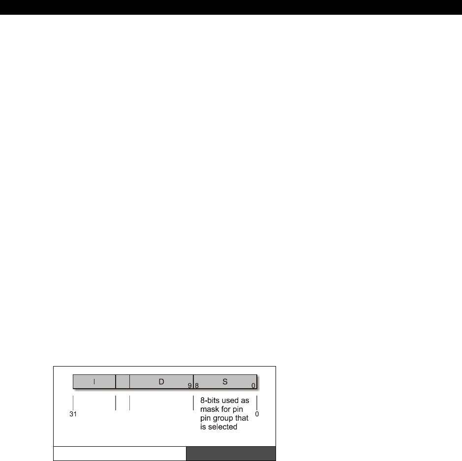
II Propeller Chip Architecture and Programming
Page 234 Game Programming for the Propeller Powered HYDRA
As indicated by the figure, each cog has a VSU unit. Therefore up to 8 different video devices
could in theory be connected to a single Propeller chip; however, due to the lack of memory
it would be difficult to have 8 different applications doing something different especially with
bitmapped modes. In essence, the VSU hardware helps convert pixel/color data into a
NTSC/PAL/VGA signal, but your program driving the VSU needs to know about all the timing
of the signal. The VSU’s final output does understand the NTSC/PAL signal and can help in
converting your data into chroma/luma information and is designed such that it’s easy to
generate NTSC/PAL sync levels and so forth, but this is all the help you get. It seems
minimal, but another way to think of it is that a single “cog” and the software you write
become a virtual software GPU, so ultimately this gives you the best of all worlds, true you
have to code a “GPU,” but you can in theory do anything you wish! For those of you who are
DirectX programmers, this is very reminiscent of pixel or shader programming, you have to
put a lot of work in to get the shader working, but its worth it since you can change its
behavior on the fly.
In any case, the following paragraphs explain how to use the VSU units and how to set up
the two control registers that initialize the streaming process. To refresh your memory, each
cog has 16 registers, two of which are the video registers:
VCFG - Video Configuration Register
VSCL - Video Scale Register
14.1 Video Configuration (VCFG) - $1FE
Each cog has a small "Video Streaming Unit" or VSU. This Video Streaming Unit simply sends
"frames" of data out at a constant rate which is determined by the settings in the Video Scale
Register or (VSCL). The configuration of the VSU is determined by the Video Configuration
Register or VCFG.
The VCFG register sets color modes,
pin groups, enables or disables
chroma signals, and allows the VSU to
function in a number of ways. The
VCFG register is encoded using the
nomenclature for an instruction that is
the I field, D field, and S field, and is
organized as shown in Figure 14:2.
VCFG Register Encoding Figure 14:2
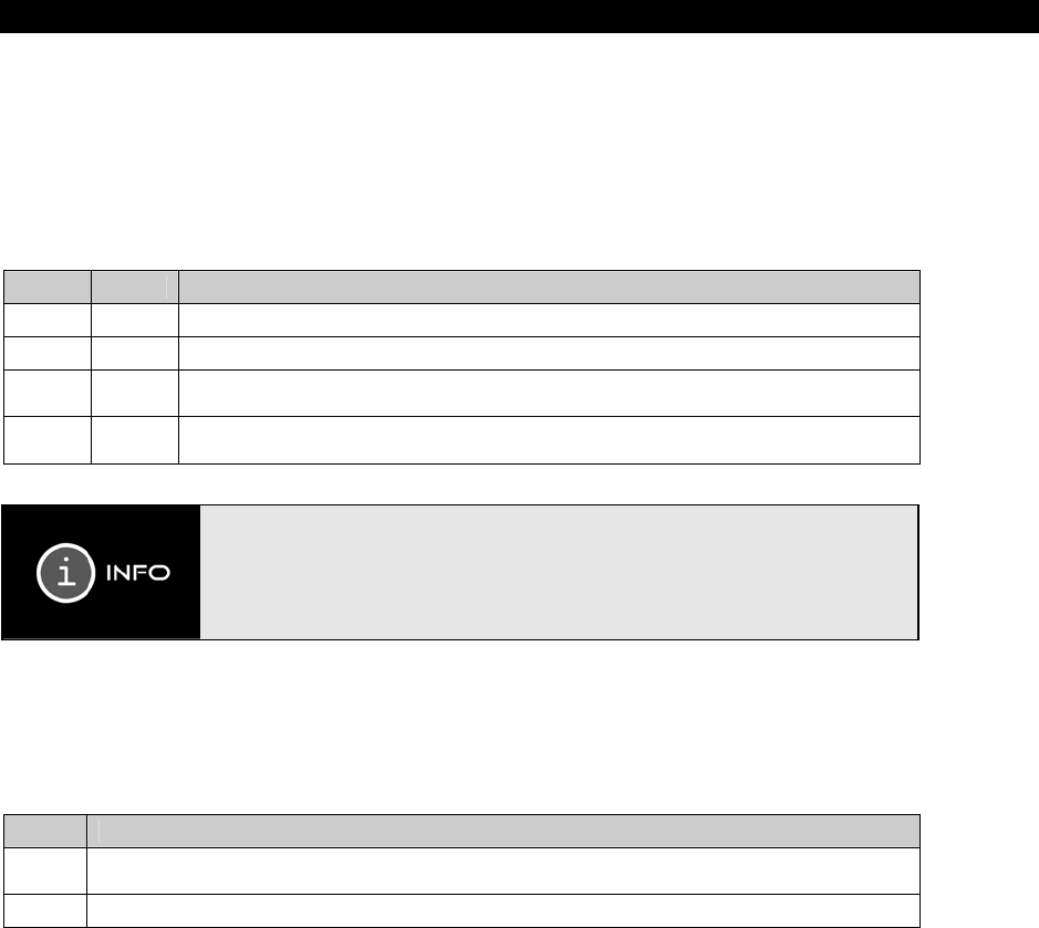
Cog Video Hardware14
Game Programming for the Propeller Powered HYDRA Page 235
14.1.1 The I-Field Bit Definitions
The following tables define the various bit encodings for the VCFG register as laid out in the
I-field portion of the generic instruction format discussed throughout the text.
Video Hardware Select bits [30:29]
These bits select whether video is enabled and where the baseband and broadcast video is
sent, that is, which nibble on the port gets the data streams.
Bit 30 Bit 29 Video Hardware Select
0 0 Video hardware is Disabled.
0 1 Enables 8-parallel discrete outputs, used for VGA mode.
1 0
Selects composite video mode with Baseband video sent to bottom nibble [3:0]
and Broadcasted video sent to top nibble [7:4].
1 1
Selects composite video mode with Baseband video sent to top nibble [7:4] and
Broadcasted video sent to bottom nibble [3:0].
Baseband video means the signal ranges from 0 Hz to n Hz, that is there is no
“carrier” that the signal is modulated on. The baseband signal is just the signal,
you standard video in ports on your TV set are baseband ports. Now, broadcast,
is more complex in this case the baseband signal is “modulated” onto a carrier
frequency using various modulation techniques such as AM (amplitude
modulation) or FM (frequency modulation). TVs use AM, radio’s use both.
Color Mode bit [28]
The color mode bit selects with 1 or 2 bits per pixel. In 1-bit per pixel mode (2-color), a
single pixel data LONG represents 32 screen pixels, in 2-bit mode (4-color), each data LONG
represents 16 pixels.
Bit 28 Color Mode
0 2-color mode; means that the data in pixels is 1 bit per pixel, only color 0,1 are used during
video hardware output.
1 4-color mode; means that the data in pixels is 2 bits per pixel, all 4 colors 0,1,2,3 are used.
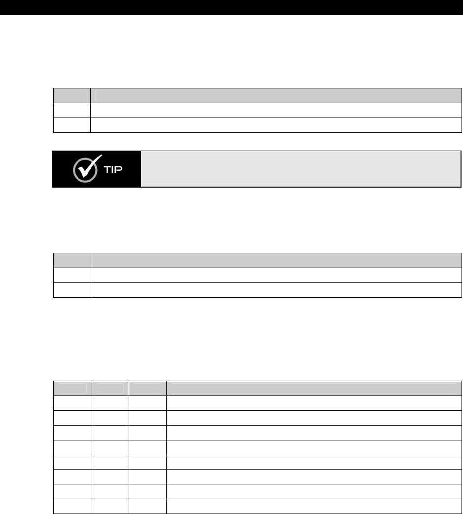
II Propeller Chip Architecture and Programming
Page 236 Game Programming for the Propeller Powered HYDRA
Broadcast Chroma Enable bit [27]
Useful if you want to use the upper bit of the video out as an S-video chroma output and you
don’t want the chroma on the broadcast signal (video modulated on a standard TV channel
frequency).
Bit 27 Broadcast Chroma Enable
0 Disable Chroma on Broadcast.
1 Enable Chroma on Broadcast.
S-video stands for “Super Video” and is simply normal NTSC, but the luma and
chroma aren’t mixed, they are separate on two different wires. There is also “P-
Video” which stands for Pimp Video ☺.
Baseband Chroma Enable bit [26]
Useful if you want to use the upper bit of the video out as an S-video chroma output and you
don’t want the chroma on the baseband signal.
Bit 26 Baseband Chroma Enable
0 Disable Chroma on Baseband Video.
1 Enable Chroma on Baseband Video.
Aural FM sub-carrier select bits [25..23]
When broadcasting video (which we aren’t using this feature for games), you can select
which cogs PLL A is using to generate the FM aural sub-carrier frequency that the sound will
be modulated on, of course as with video you must always use PLL mode 1 (no outputs on
Pin A and B) for the counter mode.
Bit 25 Bit 24 Bit 23 Aural Sub-Carrier Select
0 0 0 Use Cog 0’s PLL A
0 0 1 Use Cog 1’s PLL A
0 1 0 Use Cog 2’s PLL A
0 1 1 Use Cog 3’s PLL A
1 0 0 Use Cog 4’s PLL A
1 0 1 Use Cog 5’s PLL A
1 1 0 Use Cog 6’s PLL A
1 1 1 Use Cog 7s PLL A
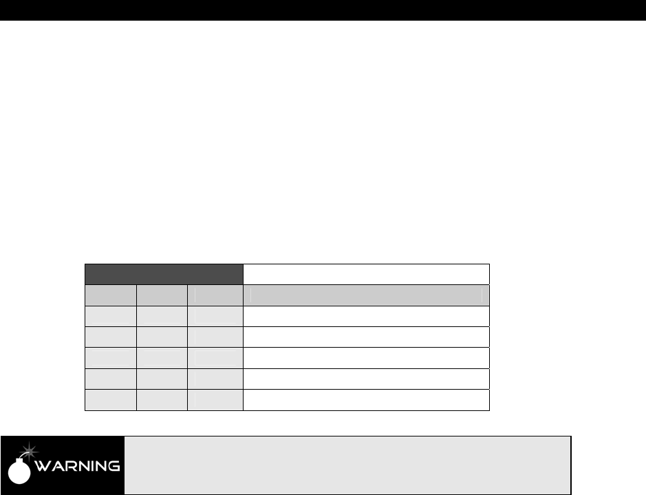
Cog Video Hardware14
Game Programming for the Propeller Powered HYDRA Page 237
14.1.2 S-Field Bit Definitions
The lower 8 bits of the S-Field act as an AND “mask” that masks off the pin group selected as
video output (see D - Field). In other words, you would set these bits to 11110000 if you
want the upper 4 bits only, or 00001111 if you wanted the lower 4 bits only (these would be
in NTSC modes), or 1111_1111 if you wanted all the bits enabled which is appropriate for
VGA modes since all 8 signals are needed, 6 for R, G, B and 2 for Hsync and Vsync.
14.1.3 D-Field Bit Definitions
The lower 3 bits of the D-field form the pin group selection bits [d2,d1,d0], so the value 0..7
in these bits select which group of 8 I/O pins get the video data stream. Of course, the
current Propeller chips only have 32 I/Os, so values 1XX are useless in this register. Table
14:1 shows the various pin groups selected by each pattern.
Table 14:1 Pin Group Selection Encoding
Bit D2 Bit D1 Bit D0 Pin Groups on Propeller Chip
0 0 0 Group 0: P0 – P7
0 0 1 Group 1: P8 – P15
0 1 0 Group 2: P16 – P23
0 1 1 Group 3: P24 – P31
1 x x Reserved for Future Expansion
Make sure that DIRA sets the proper pins to OUTPUTS, they are not assigned
outputs by simply setting up the VCGF etc. registers. For example, on the
HYDRA pin group 2 is used, thus you would need to set pins P16-P23 to outputs
before the video would even have a chance of getting out to the pins.
14.2 Video Scale (VSCL) - $1FF
The Video Scale Register or VSCL sets the rate at which “pixels” and “frames” are processed
and sent out to the external DAC (selected by the pin group bits you set). The video driver
program basically passes the VSU two 32-bit LONGs, one LONG is the “pixels” to process and
the other LONG is the “colors” that the “pixels” represent. The format of the pixel and color
LONGs are shown in the following sections.
A "frame" consists of one LONG of data or 32 bits; these 32 bits can represent either 16 or
32 pixels of video depending on the setting of the color mode bit 28 in the VCFG (1 or 2-bit
per pixel mode). The VSU hardware is clocked not by the master clock directly, but by
Counter A’s PLL mode of the cog the program is running on. So you must set the Counter A
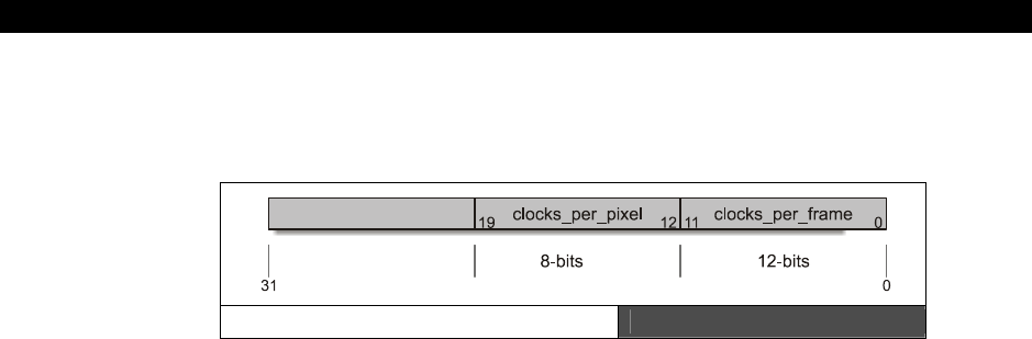
II Propeller Chip Architecture and Programming
Page 238 Game Programming for the Propeller Powered HYDRA
to PLL mode and place the proper value into the freq register. The final PLL muxed clock
signal from the PLL is fed into the VSU hardware and controls the timing chain thereof. The
VSCL register is shown below in Figure 14:3.
The VSCL Register Figure 14:3
clocks_per_pixel is the number of clocks that occur before each pixel is shifted out.
clocks_per_frame is the number of clocks that occur for an entire frame. This is usually 16
or 32 times the clocks_per_pixel value since there are 16 pixels per 32-bit pixel LONG in
4-color mode, and 32 pixels per 32-bit pixel LONG in 2-color mode.
Example: VSU running in 4 color mode, therefore, 16 pixels per 32 bit pixel WORD.
If clocks_per_pixel was set to 32 or $20 then you would set clocks_per_frame to 16×32 =
512 = $200 or the final value of the 32-bit LONG would be:
$20200
But, this says nothing about how fast the video would clock out, this is controlled by PLL A.
14.2.1 Pixel and Color Data format
The VSU simply streams data out to the pin group selected in the VCFG with the color and
format selected in the VCFG (2-color, 4-color, or VGA). But, it’s the responsibility of the video
driver program itself (that you write) to generate the pixel and color data and pass it to the
VSU. Once the VCFG and VSCL registers are initialized then the VSU will start streaming data
out. It’s up to the program to pass the proper data and to keep up with the VSU. So typically
the following steps are needed to get video working:
Step 1: Set up the VCFG register. In most cases you will set it to 4-color chroma (2-bits per
pixel) enabled on base band with pin group x, on the HYDRA the pin group should be pin
group 3, I/Os [27..24].
Step 2: Set up Counter A in PLL mode 1 and run it at a rate that is some multiple of the
color burst ideally; this clock signal will "feed" the shifting logic.
Step 3: Initialize the VSCL register with the clocks_per_pixel and clocks_per_frame that you
desire, remember clocks_per_frame will typically be either 16 or 32 times the
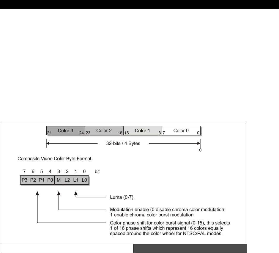
Cog Video Hardware14
Game Programming for the Propeller Powered HYDRA Page 239
clocks_per_pixel, since there can only be 16 or 32 pixels per pixel LONG depending if you are
in 4- or 2-color mode respectively.
Step 4: Use the "WAITVID D, S" instruction where D holds the colors and S holds the pixels.
The VSU suspends the cog until it can process your request, once it does, the VSU will buffer
D and S and then allow your execution thread to continue. When this happens you must do
whatever processing you wish and then loop back to Step 3 with the NEXT set of colors and
pixels BEFORE clocks_per_frame are up! The format of “colors” and “pixels” are described in
the sections following.
14.2.2 Color 32-bit LONG Format
The color format is always the same, the 32 bits represent 4 possible colors that are
“indexed” by the pixel data, and the colors are encoded as a single BYTE each in the
following way:
Color Encoding Figure 14:4
The color byte is used to represent everything you do with video, for example: sync, black,
color burst, and active video. By setting different bits you can create "colors" that represent
these signals. For example, Table 14:2 on the next page shows how to create black, sync,
color burst, shades of gray, and all 1dddddd6 colors with 75% intensity.
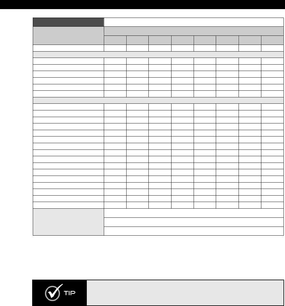
II Propeller Chip Architecture and Programming
Page 240 Game Programming for the Propeller Powered HYDRA
Table 14:2 Color Encoding for Various Color Values
Bit Encoding
Desired Signal P3 P2 P1 P0 M L2 L1 0
Sync (Control Values) 0 0 0 0 0 0 0 0
Grayscale Values Group
Black 0 0 0 0 0 0 1 0
Dark Gray 0 0 0 0 0 0 1 1
Grey 0 0 0 0 0 1 0 0
Light Grey 0 0 0 0 0 1 0 1
Bright Grey 0 0 0 0 0 1 1 0
White 0 0 0 0 0 1 1 1
Color Values Group
Blue 0.0 0 0 0 0 1 x x x
* 22.5 0 0 0 1 1 x x x
Purple 45.0 0 0 1 0 1 x x x
Magenta 67.5 0 0 1 1 1 x x x
* 90.0 0 1 0 0 1 x x x
Red 112.5 0 1 0 1 1 x x x
Orange 135.0 0 1 1 0 1 x x x
Brown 157.5 0 1 1 1 1 x x x
Yellow 180.0 1 0 0 0 1 x x x
Yell/Grn 202.5 1 0 0 1 1 x x x
Green 225.0 1 0 1 0 1 x x x
* 247.5 1 0 1 1 1 x x x
* 270.0 1 1 0 0 1 x x x
Cyan 292.5 1 1 0 1 1 x x x
* 315.0 1 1 1 0 1 x x x
* 337.5 1 1 1 1 1 x x x
Where 011 < xxx <110, i.e. 3 < xxx < 6
*Colors without names are simply linear mixes of the adjacent colors.
Notes
When chroma/color is enabled the luma signal is modulated ±1.
Referring to the table, the highest ‘safe’ value to use for brightness/luma is 6 and the lowest
“safe” value is 3, so keep your luma in the range of [3,6] when using chroma, otherwise, the
system won’t have enough freedom to encode the color signal modulation since a +/-1
modulates your luma signal and you don’t want it going out of range.
There is a trick to get more colors that “does” work: if you set the LUMA to 0
and ENABLE chroma then you will get the values 0 − 1 = 7 and 0 + 1 = 1, which
create a “super” saturated color set and the LUMA value of 1 is just enough to
keep from going into sync, so it all works out.
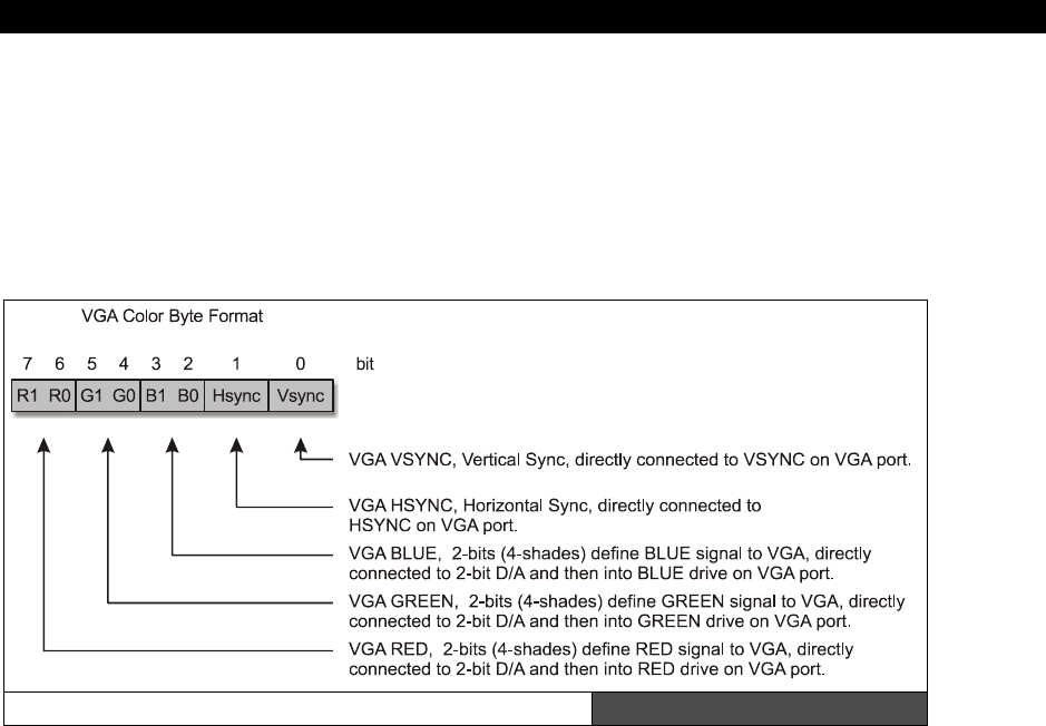
Cog Video Hardware14
Game Programming for the Propeller Powered HYDRA Page 241
14.2.3 VGA Modes
When the VSU is configured for VGA modes via the VCFG register, each 1 or 2-bit color refers
to either 2 or 4 VGA “color.”. A VGA color is really just a BYTE that gets streamed out via a
lookup table that translates your color select to a bit pattern. This 8-bit value just gets
dumped to the I/O port, the Propeller chip has no idea it’s VGA, but we wire it to the VGA
header in such a way that with the proper programming it’s a VGA signal. Figure 14:5 shows
how the VGA signal, colors, and sync are encoded on the HYDRA.
VGA Color Encoding Format Figure 14:5
14.2.4 "Pixel" data 32-bit LONG Format
When calling the VSU with pixel and color data, the pixel data is either interpreted as 1 or 2
bit pixels, thus a 32-bit LONG pixel data can represent either 32 or 16 bits respectively. In 2
color mode then only the first colors 0,1 in the color long are used, in 4 color mode then all 4
colors in the 32-bit color WORD are used. In any case, the 32-bit pixel data formats are
shown on the next page.
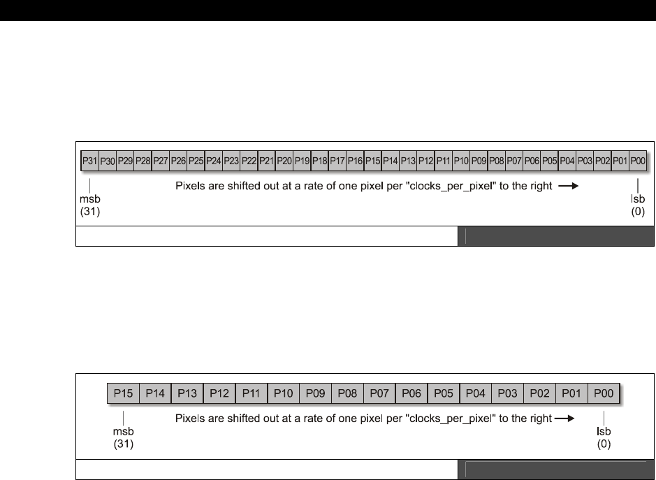
II Propeller Chip Architecture and Programming
Page 242 Game Programming for the Propeller Powered HYDRA
2-color (1 bit per pixel) format, 32 total pixels
In 2-color mode, there is 1-bit per pixel therefore, each pixel can be 0 or 1, which
references/indexes color BYTEs 0,1 in the 32-bit/4-BYTE color descriptor. Therefore, each of
the bits shown in Figure 14:6 below represent either color 0 or 1.
2-Color (1 Bit per Pixel) Mode Figure 14:6
4-color (2-bits per pixel) format, 16 total pixels
In 4-color mode, each pixel can be 0, 1, 2, 3, which references/indexes color BYTEs 0,1,2,3
in the 32-bit/4-BYTE color descriptor. Therefore, there are only 16 pixels, each 2 bits in size
as shown in Figure 14:7.
4-Color (2 Bits per Pixel) Mode Figure 14:7
14.3 Summary
In this chapter we tackled the video hardware on the Propeller chip, as you can see, it’s
nothing more than a serializer with some features that help it generate NTSC and VGA video.
But, you could use the VSU for anything from an IDE interface to a sound port! The main
take-away is to realize that all the magic happens in the software, the VSU only serializes
your data and allows you to continue your “work” while it streams the data out (i.e. WAITVID
instruction). This is the key to generating video, that is, to pre-compute your pixels and
color, pass them to the VSU and move on. Also, remember that EVERYTHING is generated by
the VSU: sync, pixels, color, luma, all of it; as far as the VSU is concerned everything is just
bit patterns. The only thing that that really does any analog work for us is the simple 3-
resistor DAC on the output of the Propeller chip that generates an analog voltage for us
driven by the VSU (if we set it up correctly). Now, you’re probably wondering how exactly to

Cog Video Hardware14
Game Programming for the Propeller Powered HYDRA Page 243
write an assembly program to generate video? This is a lot of work and very complex, we
aren’t going to tackle that yet since we are trying to keep things high-level and to leverage
the drivers Parallax, myself, and other coders have spent weeks writing. But, rest assured in
Part III of the book we will cover a very simple video driver and I will explain every section of
it in detail. For now, let the VSU sink into your brain…

II Propeller Chip Architecture and Programming
Page 244 Game Programming for the Propeller Powered HYDRA

The Spin Language15
Game Programming for the Propeller Powered HYDRA Page 245
Chapter 15: The
Spin Language
“Spin” is the High-Level Language (HLL) that the Propeller chip is programmed in. Spin was
developed by
Chip Gracey
as an easy-to-use language with syntax supporting simplified
operations. The language itself is influenced by Pascal, BASIC, and Assembly language. When
programming Spin, in the IDE the Spin code is compiled into a
“BYTE Code
” meaning that
operations are translated to single BYTE-sized operations. This byte code program is then
written into the final binary object of the 32 Kbyte program image space which ultimately is
downloaded directly into the Propeller chip or stored on a serial EEPROM that the Propeller
chip boots from on startup. Then the ROM-based Spin interpreter runs the BYTE Code, much
like a JAVA machine works. In this chapter, we are going to discuss the majority of concepts
related to Spin, see the syntax of the language, and look at examples and some demos that
do various things to give you a starting point. If you do not know how to program in BASIC,
C/C++, or some other high-level language you will need to augment your reading here with
a basic programming book. Here are the major topics we are going to cover:
Spin and its relationship to the Propeller on boot
General Propeller program organization
Spin language reference
Spin programming
Various Spin demos
Tricks and tips with Spin
15.1 Spin on Boot
When the Propeller chip boots, first it determines if there is a host on the communication
lines. If so, then the firmware loads the external program into the Propeller chip’s 32K
program memory as a single binary image, else the Propeller chip looks to the external
EEPROM interface and tries to load the program from there in a similar fashion. If neither is
present the Propeller chip goes into a reset/sleep state waiting for a host connection. In most
cases, you will have a host PC or an EEPROM with the pre-programmed Propeller chip code
in it. In this case, the Propeller chip always boots
Cog 0
up and loads the Spin interpreter
into it. The Spin interpreter is an ASM application, and must fit into the 512 32-bit LONGs of
Cog 0, in fact there are less than that (512 −16 LONGs) for the interpreter due to the cog’s
register space which takes up 16 LONGs! In any case, Cog 0 is loaded with the interpreter
and your code will start executing at the first “public” declaration.
II Propeller Chip Architecture and Programming
Page 246 Game Programming for the Propeller Powered HYDRA
All Propeller chip programs must start with SOME Spin code as the entry point (a
single public function at least). After the initial Spin code, you can launch more
cogs with Spin or ASM, but the Propeller chip always starts off by loading the
Spin interpreter into Cog 0 and attempts to run a Spin program at startup.
15.2 Programming in Spin
Spin BYTE code resides in main memory. While more memory-efficient than assembly
language, Spin is considerably slower. For simple operations it is up to 250 times slower than
assembly code, but this gap narrows for more complex operations (i.e. square root).
Therefore, tradeoffs can be made when coding in either language. Generally, high-level
operations which are not too timing-critical can be most easily and efficiently coded in Spin.
Where blistering speed is required, assembly language would be your choice.
The compiler does not currently support optimization of any kind such as aliasing, loop
unrolling, or intermediate value reusing during complex calculations, so beware, what your
write is what you get! In general, with bitmapped video memory for a game, assets, and
driver objects, a few hundreds lines of Spin will use up all the remaining memory; therefore,
when developing games and high performance graphics applications you will typically use
Spin more as a housekeeping language for global control and write your game code in
assembly language. Of course, for simple demos along the lines of the “Parallaxaroids” demo
I provided you with, Spin will suffice, but will quickly run you out of memory as it did in the
demo which uses all the available 32 Kbytes of memory when the various other objects are
included. On the other hand, if you stick to low memory footprint “character/tile” based
graphics then Spin can get you a long way and entire games can be written with Spin and
some ASM drivers to do graphics, etc.
Also, it’s of interest that Spin is also loosely an
“Object Oriented”
language in as much as
all programs are considered
“Objects.”
Objects can be included as files and then you access
the subroutines using syntax much like any other OO language. But other than that there is
no
inheritance
,
operator
overloading
,
polymorphism
etc. (which is probably a good
thing!)
The Spin environment is smart enough that during compilation of your program
if it notices that multiple objects have been included that are the same it will strip
them and make sure only one copy of the object is stored in the final binary
image, therefore there is some modicum of code reuse with objects, so you don’t
have to worry about that.
Since I am hoping you are already a programmer or familiar with programming at some
level, I am simply going to show you the syntax of the language and its various constructs

The Spin Language15
Game Programming for the Propeller Powered HYDRA Page 247
with examples sprinkled about. A bit of experimentation will be necessary on your part to get
a good feel for the language, but as mentioned it’s derived from ideas based on BASIC /
PASCAL, so its easy to pick up, the only “gotcha” is the use of
indentation
for block nesting
level, the built in syntax highlighting helps resolve this, but nonetheless, it takes some
getting used to, so be patient. For example, the program:
' initialize y
y:=0
' a dead loop, that iterates 100 times and does nothing but waste time
Repeat x from 0 to 99
y:=y+1
' y still equals 0 here
... is entirely different from this program:
' initialize y
y:=0
' this loop iterates 100 times and contains the y increment block
Repeat x from 0 to 99
y:=y+1 ' this line is now WITHIN the block of the repeat loop!
' y now equals 100
Thus, with a high resolution monitor, small font size, a single space can change the operation
of your program – more on this later.
We have had enough theory in the previous chapters, so for the first step, let’s just load and
run some programs to get the hang of the environment and programming the Propeller chip,
then we can get into the syntax and details of the language itself. To make sure we are on
the same page (any SX programmers out there?) follow the steps below to make sure we
both have the same starting environment.
Step 1: Insert your USB cable into your PC and insert the mini-B connector into the
HYDRA’s USB port (also, if you happen to be using other Parallax devices and a USB2SER
device then you can insert it into the secondary programming header to the left of the
board). If you followed the installation in Chapter 1 of the book, you should have already
installed USB drivers for the FTDI chip; otherwise, you will need to do so now. Refer to
Chapter 1 for more details on the installation of drivers.
Step 2: The latest version of the Propeller chip IDE at the time of this printing is located in
a single .EXE file on your CD here:
CD_ROOT:\HYDRA\TOOLS\PROPELLER\PROPELLER_SETUP.EXE

II Propeller Chip Architecture and Programming
Page 248 Game Programming for the Propeller Powered HYDRA
Once again, you should have already installed the IDE and set it up; if you haven’t please do
so now (referring to Chapter 1 for details).
Step 3: Get your HYDRA out, and plug in the power and the A/V cables to your TV set. Also,
plug in the keyboard, mouse, and gamepad into Port 0 (left). Remove the game cartridge if
there is one. And make sure the USB cable is plugged into the HYDRA’s USB port.
Step 4: Power up the HYDRA and press reset. There “might” be a program on the on-board
EEPROM depending on what you have been doing, if so, disregard it. Now, you are ready for
the experiments.
Experiment 1: Load in the Parallaxaroids demo in the IDE ( <CTRL + O> ).
If you haven’t played with the IDE, then here’s your chance. You should have the IDE up and
running. Under
File
→
Open
, browse for ASTEROIDS_DEMO_013.SPIN on your hard
drive or CD. And load the program in. You should see the editing pane fill with code. Try
scrolling around a bit and take a look.
Experiment 2: View information about program ( <F8> ).
Now that we have a program in memory, let’s try compiling it, but not uploading it to the
system. On the main menu select
Run
→
Compile Current
→
View Info
. This compiles
the program and shows you the binary image, etc. in the “Object Viewer.” You can also load,
and save binary images from this dialog and more. But, for now just look around. You can
learn a lot by building really simple programs and looking at the images in the viewer. When
you are done Close the window.
Experiment 3: Compile and load the program directly into the Propeller chip ( <F10> ).
Now, we are going to compile and load the program into the Propeller chip. We are NOT
going to re-program the EEPROM, so if you press reset after this experiment, then whatever
was on the EEPROM will re-load. In any event, click
Run
→
Compile Current
→
Load
RAM and Run
from the main menu bar. You will see the compilation take place and a quick
upload, then you should see the game start up very quickly.
Experiment 4: Compile and load the program into the EEPROM and then run it ( <F11 > ).
In this experiment, we are going to not only compile the program and load it, but first copy it
to the EEPROM, so the hardware will “retain” the program even after a reset. Try clicking
Run
→
Compile Current
→
Load EEPROM and Run
. This selection will first load the
EEPROM, and then the Propeller chip will reset, then retrieve the program from the EEPROM
under the booter and run it.
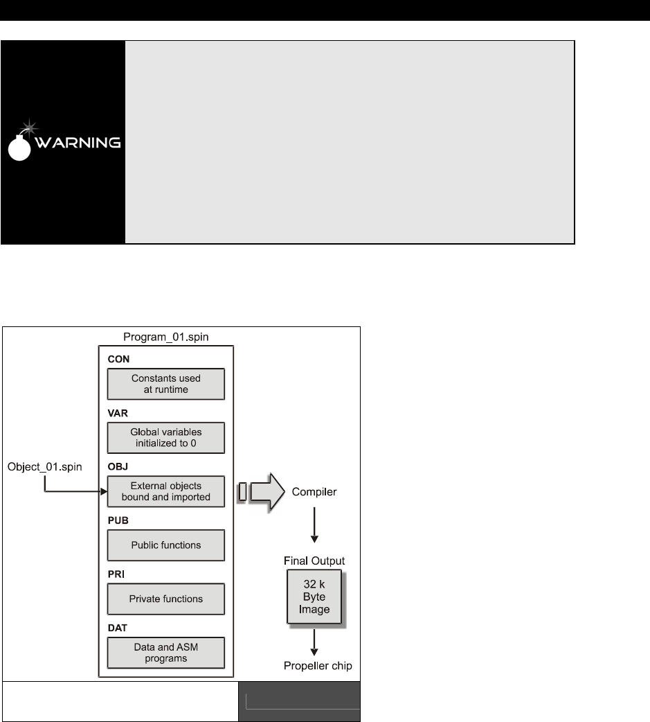
The Spin Language15
Game Programming for the Propeller Powered HYDRA Page 249
Some things to observe about Spin that are non-intuitive for BASIC, Java and
C/C++ programmers (most of us) is that Spin uses white space to delineate
“block level.” This can be cause for great amounts of frustration and errors if
you don’t pay attention to it. The IDE has coloring (which can be turned off) to
help with this, but the coloring may be obtrusive to your work.. So heavy
commenting and using a whole TAB (made from 2 – 4 spaces) to create a new
block level can help. Also, use [CTRL+I] to toggle the Propeller tool’s block
group indicators.
Also, moving and copying code becomes difficult, say for example you have a
block of code that you like, you copy and past it INTO another block, but now all
the spacing is wrong, this will give you the most frustration. The original design
goal of Spin was to minimize typing when writing “small” programs; however,
games are not conducive to this model, so watch out for your block level. Many
times, you will write some code that won’t work, and the cause is that a single
space or TAB is putting a block inside/outside where you thought it was..
15.3 Organization of a Spin Program
Spin is a functional language
with object oriented
encapsulation of functions at a
file scope level. That is, you
can create a Spin “object”
which is a collection of
subroutines, data, etc. that you
can “include” in another
program and then make calls
to the functions within the
object. Figure 15:1 shows this
graphically. The language as
mentioned before uses spacing
to create block level
designation and has no
“begin”, “end” symbols. The
language is case insensitive as
well. Variable and function
names follow the same rules as
most HLLs and can include
alphanumeric characters as
well as underscores.
A Graphical Representation
of a Spin Program Figure 15:1

II Propeller Chip Architecture and Programming
Page 250 Game Programming for the Propeller Powered HYDRA
A Spin program can contain
constants
,
variables
(globals),
objects
(pulled in from other
files),
public
functions
and variables,
private
functions
and variables, and finally a
data
section(s) (usually at the end of the program). The block designators that indicate these
sections are:
15.3.1 Spin Code Block Designators
The following is a list of code block designator keywords as well as some brief examples.
Note that once you declare a block designator, that block type stays in flux until another
block designator is encountered in the program. For example, once you type “CON” the
compiler is in “constant” mode until you direct it otherwise.
CON — The CON block designator starts a “Constants” section; here is where you place your
constants that are simply compiler-resolved symbols for convenience and take up no storage.
Notice they have no type information.
Example: Some simple working constants for a graphics program.
CON
' size of graphics tile map
X_TILES = 16
Y_TILES = 12
' screen size
SCREEN_WIDTH = 256
SCREEN_HEIGHT = 192
VAR — The VAR block designator defines global object-wide variables, these take up space
in main memory (the 32K region) not the cog memory of 512 LONGs, this is used to hold the
interpreter running your Spin code when using high-level coding. You can define BYTEs (8
bits), WORDs (16 bits), or LONGs (32 bits).
Example: LONGs, WORDs, BYTEs, and array variables.
VAR
long mouse_x, mouse_y ' holds mouse x,y position
word screen[x_tiles * y_tiles] ' storage for screen tile map
long colors[64] ' color look up table
' active asteroids
byte num_active_asteroids
All VARS are initialized to 0 on program start, but local variables in functions are
NOT!

The Spin Language15
Game Programming for the Propeller Powered HYDRA Page 251
OBJ — The OBJ block designator starts an “Object” import region, this is where you can
import and name other objects that are located in external Spin files. These objects will be
imported during compile time and merged with your program. Also, note no matter how
many times you import an object, only one copy of the code is imported, so multiple objects
are distilled into a single object with a copy of the unique data.
Example: Loads in TV, graphics, and mouse and objects.
OBJ
tv : "tv.spin" ' instantiate a tv object
gr : "graphics.spin" ' instantiate a graphics object
mouse : "mouse_iso.spin" ' instantiate a mouse object
The file extension “.spin” is unnecessary and can be ommited; however the
Propeller IDE will only search for files with the " .spin" extension, thus you can’t
import a file with the name “foo.dat” for example, even if its valid Spin code.
PUB — The PUB block designator is used to create a “Public” function which is accessible
outside the scope of the file to other objects that might import the file containing the PUB.
This is similar to defining a function in other HLLs and then exporting it.
Execution of all Spin programs always starts at the first PUB encountered in the
top level file, or if the program only has one file the first PUB encountered there.
Example: A simple function that computes the square of the sent value.
PUB Square (x) : ret_val
ret_val := (x*x)
Later we will delve into the syntax of function declarations in much more detail. For now,
note that functions may have zero or more parameters, may have a named return value
(otherwise it’s aliased to RESULT always), and finally PUBs may have locals.
PRI — The PRI block designator is used to create a “Private” function which is not accessible
outside the scope of the file to other objects; other than that, the syntax and use is identical
to PUB.
DAT — The DAT block designator defines the beginning of a “Data” section and continues
until another block designator is encountered. DAT sections are used in Spin to define data
and tables; DAT sections are also used to write actual ASM code, that is, you must declare a
DAT section then put your ASM code. The reason for this is that ASM code is like “data” to
the compiler and it simply merges it into the final object and then you pass it to a cog at

II Propeller Chip Architecture and Programming
Page 252 Game Programming for the Propeller Powered HYDRA
some point. Note that ASM defined in a DAT section can never exceed 512 LONGs
(technically 512 – 16 LONGs due to the register file at the end of each cogs memory).
Example 1: The declaration of some strings in a high-level Spin program.
DAT
score_string byte "Score",0 'text
hiscore_string byte "High",0 'text
ships_string byte "Ships",0 'text
start_string byte "PRESS START",0 'text
parallax_string byte "PaRaLLaXaRoiDs",0 'text
hex_table byte "0123456789ABCDEF" ' hex lookup table
Notice there is no “string” type in Spin, so we simply use standard ASCII-Z format and
encode a string with a NULL (0) terminator at the end. However, if you wanted you could
encode strings using a Pascal format where you insert the length of the string into the first
character followed by the string characters themselves. The point is, any string processing
you must do yourself. Nonetheless, the few string functions Spin does support assume
ASCII-Z format.
Example 2: An ASM excerpt from the graphics driver, notice it starts with a DAT section.
DAT
'*************************************
'* Assembly language graphics driver *
'*************************************
org
'
' Graphics driver - main loop
'
loop rdlong t1,par wz 'wait for command
if_z jmp #loop
movd :arg,#arg0 'get 8 arguments
mov t2,t1
mov t3,#8
:arg rdlong arg0,t2
add :arg,d0
add t2,#4
djnz t3,#:arg
The code actually retrieves parameters from the caller. If you’re interested, there
will be more on ASM programming techniques when we get to ASM examples
later in the text.

The Spin Language15
Game Programming for the Propeller Powered HYDRA Page 253
DAT section variables can be accessed by Spin as if they were variables; the named DAT
section is an address. Therefore, later when we discuss pointers and memory access,
remember that DAT sections are where we can store data, tables, etc. and to access any
element named in a DAT section, we simply use the named region. For example, in Example
1 above, if we wanted the starting address of the hex table, we would refer to it as
“hex_table” in the Spin code, more on this later.
15.4 Spin Language Elements
In the next sections we will briefly discuss the important various Spin language elements
such as data types, conditionals, loop constructs, built-in functions, math operators and
more. This is by no means an exhaustive description of the language (for a complete treatise
on Spin please refer to the Propeller Manual). The Spin language itself is the native high-level
code that the Propeller chip runs with. The interpreter for Spin is in pure ASM and fits into
the 512 LONGs of a single cog; therefore whenever you use Spin on a cog what you are
really doing is launching the cog, loading the interpreter into it and then the interpreter starts
executing the BYTE code for your compiled Spin program out of RAM memory. You can mix
ASM and Spin by launching a cog with a pointer to the ASM code, then the interpreter
basically loads the cog up with the binary image of the ASM and starts executing.
The Spin language supports a crude form of object-oriented programming in as much as you
can create a program/object with
“methods,”
PUB functions, and then load the object into
your main file and access these methods using a dot “.” access notation (more on this later
when we discuss objects). Other than that, there is no operator overloading, no
polymorphism, no inheritance, no constructors, no data structures (other than arrays) etc.,
the language is really a “to the metal” stripped Pascal/BASIC/ASM for the most part that is
designed to help you work with multiple processors and run code on them with the least
amount of pain. However, as noted previously in the docs, the Spin language is a BYTE code
interpreted language and thus 20–40x slower than ASM code due to its interpretation, so
keep that in mind, you will still have to write time-critical code in ASM in many cases.
15.4.1 General Syntax of Spin
Spin has its roots in a Pascal, BASIC, and ASM. The syntax is somewhat non-orthogonal, but
you will find that after a while its idiosyncrasies are minimal. The language was designed to
be very easy to use, and as WYSIWYG as possible (unlike C++/JAVA where things happen
without you knowing it). The only syntactic oddity of the language is that it relies on
“white
space”
to define block nesting level, this is unlike any standard language such as C, C++,
Pascal, Java, Javascript, Prolog, Modula, etc. However, you will find some “scripting”
languages that subscribe to this concept such as
Python
. The reasoning behind this is
simple, for very short programs (scripts), one usually only needs a few lines of code and
extra “begin/end” statements waste typing; however, for a general programming language
using white space to define blocks is a hindrance for a number of reasons, the most

II Propeller Chip Architecture and Programming
Page 254 Game Programming for the Propeller Powered HYDRA
important is that the alignment of code dictates is functionality, a single space in the wrong
place can push something in and out of a block or scope. Additionally, file
exporting/importing becomes and issue since if you like to edit with an external editor etc.
the editor might change spacing and thus the program’s meaning – things to consider.
The Propeller chip IDE is designed to help with this with syntax highlighting, but for those of
us that don’t want to look at a shaded rainbow when coding or if you are part of the 5–10%
of men that are color blind, this is an issue, thus care should be taken when coding. I have
had many rounds of debugging while pulling hair only to realize there was an extra space
somewhere. Alas, then be VERY careful when coding and especially when copying and
pasting blocks of code. Or, if you don’t mind a visual aid, turn on the block group indicators
<Ctrl+I> which show the logical structure of conditional or loop blocks. If you have some
code you want to move, like a complex conditional statement if/else tree, copy and paste
then re-align it all within the sub-block you wish using the block selection and block indenting
and outdenting features. The best approach is to use 2-4 spaces to move into a block or a
tab (which is converted to spaces) to move down into various nesting levels, so you can
“see” the difference visually without coloring.
Spin is also case insensitive; other than the initial spacing of functions, and reserved words
that must be spaced in to be nested, the language is free-flowing.
There are no end-of-line delimiters in Spin. Lines end with a carriage return. For
example, C/C++ uses “;” to end the line/statement.
15.4.2 Comments in Spin
One of the most important things in any programming language is commenting! Spin uses a
single quote to denote a normal comment like this:
x := x + 1 ' this increments x
Additionally, to help with documentation generation in the IDE, you can use a double single
quote to pass the comment to the documentation formatter:
x := x + 1 '' this increments x and this comment will be in the documentation.
In general, you want to use single quote comments for your detailed comments about the
inner workings of an algorithm and the double single quote comments on higher level
functionality comments.

The Spin Language15
Game Programming for the Propeller Powered HYDRA Page 255
Lastly, there is a block comment that allows you to comment out entire blocks of code, this is
useful for obvious reasons, but the most important one is there is no conditional
assembly/compilation functionality, so if you want to turn a code block off to save size or
target a certain piece of hardware, etc. the only way would be to remove the code or have a
different file for all variations, not very effective, but with block comments you can at least
include/exclude code in a primitive manner, the block comment starts with a left curly brace
“{“ and ends with a right curly brace “}”. Here’s an example:
{ ' start block comment
' initialize particles
repeat i from 0 to NUM_PARTICLES-1
base := i*PARTICLES_DS_WORD_SIZE
particles[base+PARTICLE_DS_TYPE_STATE_INDEX ] := PARTICLE_TYPE_NULL |
OBJECT_STATE_DEAD
particles[base+PARTICLE_DS_X_INDEX ] := 0
particles[base+PARTICLE_DS_Y_INDEX ] := 0
particles[base+PARTICLE_DS_DX_INDEX ] := 0
particles[base+PARTICLE_DS_DY_INDEX ] := 0
particles[base+PARTICLE_DS_COUNTER_INDEX ] := 0
} ' end block comment
Additionally, there is a documentation version of the block comment denoted by enclosing
the text in double curly braces {{ and }}.
15.4.3 Spin Reserved Words
Now let’s look at the most important reserved words and functions in Spin as shown in Table
15:1 on the next page. (for a complete listing of all reserved words, please refer to the
Propeller Manual).
As you can see there are almost no built in libraries, no math calls, no graphics, no sound,
not much of anything. Spin is very small and has to be to fit into the 512 LONGs of a single
cog, so any functionality you want, you must code with external libraries. This isn’t bad since
you can write just about anything you want, but of course the performance will be slower
than native functions that are built in. However, you can always use ASM as well. Of course,
Parallax as well as myself are going to build as many cool libraries as possible and include
them with the products. Currently anything that might be considered “useful” and a library
will be stored in a LIBRARY\ directory where the Propeller IDE .EXE is located and installed.
In any event, take a good look at the table and we will discuss each class in the next section.
II Propeller Chip Architecture and Programming
Page 256 Game Programming for the Propeller Powered HYDRA
Table 15:1 Spin Reserved Words Organized by Category
(abridged list)
Block Designators Table and Set Lookup Cog Manipulation
CON
VAR
OBJ
PUB
PRI
DAT
LOOKUP
LOOKUPZ
LOOKDOWN
LOOKDOWNZ
RUN
COGNEW
COGINIT
COGSTOP
COGID
Conditional Blocks Memory Movement & Filling HUB Synchronization
IF
IFNOT
ELSEIF
ELSEIFNOT
ELSE
CASE
OTHER
BYTEFILL
WORDFILL
LONGFILL
BYTEMOVE
WORDMOVE
LONGMOVE
LOCKNEW
LOCKRET
LOCKSET
LOCKCLR
Looping Constructs String Functions Cog Register Access
REPEAT
WHILE
UNTIL
FROM/TO/STEP
NEXT
STRSIZE
STRCOMP
Function Control & Branching Waiting Functions
QUIT
RETURN
ABORT
RESULT
WAITPEQ
WAITPNE
WAITCNT
WAITVID
Logical Values Clocking
TRUE
FALSE
CLKSET
CLKMODE
CLKFREQ
CHIPVER
SPR
PAR
CNT
INA
INB
OUTA
OUTB
DIRA
DIRB
CTRA
CTRB
FRQA
FRQB
PHSA
PHSB
Data Types Math Video Configuration
BYTE
WORD
LONG
FLOAT
ROUND
TRUNC
CONSTANT
VCFG
VSCL
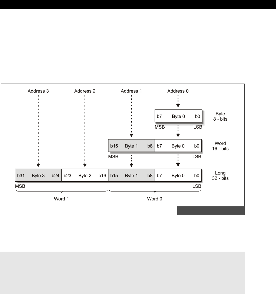
The Spin Language15
Game Programming for the Propeller Powered HYDRA Page 257
In any event, take a good look at the table and we will discuss each class of
statement/function/keyword in the paragraphs below.
15.4.4 Spin Data Types and Data Structures
The Spin language supports three basic data types, they are:
BYTE 8 bits
WORD 16 bits
LONG 32 bits
The Spin Data Types Laid Out as they are in Memory Figure 15:2
The Propeller chip is a “little endian” processor meaning memory is stored in low BYTE to
high BYTE order as shown in Figure 15:2.
Here are some examples of defining variables in a VAR section:
VAR
LONG position, angle ' defines a couple 32-bit longs
WORD energy ' defines a 16-bit word
BYTE character ' defines an 8-bit byte

II Propeller Chip Architecture and Programming
Page 258 Game Programming for the Propeller Powered HYDRA
Notice that you can define more than one typed variable by separating them by commas.
Also, there is no static initialization of variables, rather they are all initialized to zero on
startup. This is somewhat of a pain, but simply means on entry to your main code, you
simply need to initialize all your variables with constants or named constants from a CON
section.
Other than the basic three types there are no other data types and there is no intrinsic
support for records or structures of any kind (they can be simulated with arrays though).
Also, there are no signed/unsigned variants of each type, therefore, BYTE and WORD are
signed or unsigned depending how you use them. That is if you assign a negative constant
value to a BYTE then you assign the BYTE to a WORD type there will be NO sign extension if
you are doing your math in 2’s complement. Now, on the other hand, 32-bit values when
assigned to a smaller type will work out in 2’s complement as long as the magnitude doesn’t
overflow. For example, given these two declarations:
VAR
LONG x ' define a long
BYTE y ' define a byte
...then somewhere in the body of a function we make these assignments:
x := -1 ' looks like $FFFF_FFFF in memory, 32-bit 2's complement -1
y := -1 ' looks like $FF in memory, 8-bit 2's complement -1
Now, if we were to assign the 8-bit value to the 32-bit value we would write this:
' example 1: assigning a smaller data type to a larger
x := y ' x = $0000_00FF which is 255! should be -1
' example 2: assigning a larger data type to a smaller
y := x ' y = $FF which is -1, correct!
As you can see, without sign extension the result in the larger data type is incorrect, thus
care must be taken when making assignments if you are doing you math with mixed data
types and using 2’s complement math. Later, we will see the math operators that help
remedy this with sign extension.
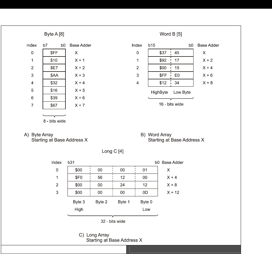
The Spin Language15
Game Programming for the Propeller Powered HYDRA Page 259
15.4.5 Data Structures in Spin
Arrays in Spin Figure 15:3
Spin is very lean, so there is no support for records, structures, or any abstract data types;
basically, the language only supports singletons and 1D arrays (which must be defined in a
VAR section for globals, locals can be defined at the start of methods). The 1D array type is
shown in Figure 15:3.

II Propeller Chip Architecture and Programming
Page 260 Game Programming for the Propeller Powered HYDRA
The syntax has been shown before, but formally to declare a 1D array use:
BYTE name[SIZEm] ' creates a byte array m bytes long
WORD name[SIZEm] ' creates a word array m words long or 2m bytes long
LONG name[SIZEm] ' creates a long array m longs or 4m bytes long
The syntax to access an array is simple, just use the array name and an index, the
interpreter will take care of scaling and will always return the value with the proper size, for
example:
VAR
BYTE string[80] ' define a string that holds 80 characters
.
.
string[0] := 64 ' assign 64 to the first entry
string[79] := 0 ' assign 0 (null) to the last entry
All arrays are ZERO based, that is an array with n elements is accessed 0 to n-1.
Since there is no data structure support, one trick is to use “simulated records.” For
example, let’s assume we wanted to represent a record that has 3 BYTE fields: x,y,z, and we
want 100 of these records, and we want to access any of them with some simple syntax.
Then we can do this:
VAR
BYTE point[3*100] ' allocate 100 records each 3 bytes long, assume
' format is x0,y0,z0, x1,y1,z1...
.
.
' access element i
x: = point[i*3+0] ' x is at offset 0 of triple
y: = point[i*3+1] ' y is at offset 1 of triple
z: = point[i*3+2] ' z is at offset 2 of triple
There are also some special memory access operators that are similar to “peek” and “poke”
that allow direct memory access, there syntax uses the actual keywords/data types “BYTE,”
“WORD,” and “LONG” but we will discuss these operators in the section on “Spin Data,
Memory, and Pointer Manipulation” later in the document.
15.4.6 Spin Constant, Math and Variable Expressions
Spin expressions can be composed of single numbers, constants, variables, unary operations
and binary operations as well as function calls that are evaluated as part of an expression.

The Spin Language15
Game Programming for the Propeller Powered HYDRA Page 261
Literal constants can be written in decimal (default numeric mode), binary (with the prefix
“%”), hexadecimal (with the prefix “$”), and simple one- to four-character ASCII literals.
Here are some examples:
Literals
Decimal : 56, 202, 1919234, 405000, 100_000_000
Binary: %0011, %11101101, %1111_1111_1111_0000
Hexadecimal: $F4, $a6, $FFF8_B800, $AB005690
Notice the use of the underscore character “_” to make numbers more readable, a really nice
feature.
All ASCII literals stored in a 32-bit LONG (in little endian format)
ASCII “x” — In memory looks like $00_00_00_78, will work as single length ASCII-Z string.
Boolean Constants
Additionally, there are two 32-bit system constants for TRUE and FALSE, they are:
“TRUE” — In binary, the value is 11111111_11111111_11111111_11111111, “-1” in two’s
complement.
“FALSE” — In binary, the value is 00000000_00000000_00000000_00000000, “0” in two’s
complement.
Be careful when using these values, since TRUE (all 1’s) technically is (-1) in decimal two’s
complement. The reason for all 1’s rather than TRUE being equal to binary “1” is that for
binary operations all 1’s makes more sense for masking operations since
every
single bit is
TRUE.
Variable and Function Names
Moving on, variable names in Spin for numeric data types as well as function names must
start with letter and can contain letters, numbers and underscores. Here are some examples:
VAR
long x, y1
word POWER_LEVEL
byte _data_port
long _word0
Literals, variables, and functions can all be combined to create complex mathematical
expressions involving both unary and binary operations. We will discuss these expressions in
the next section.
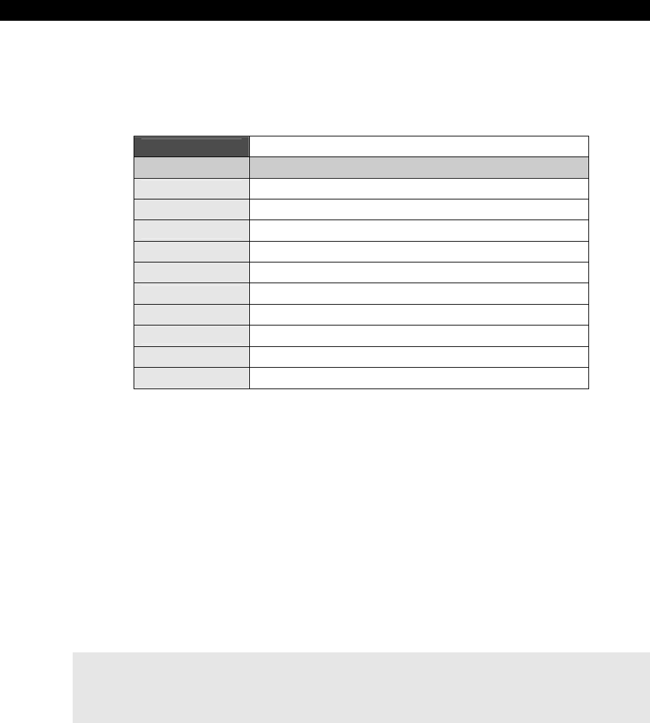
II Propeller Chip Architecture and Programming
Page 262 Game Programming for the Propeller Powered HYDRA
15.4.7 Spin Mathematical, Logical, and Binary Operations
The first and most important part of an expressions is the
assignment
operator. The
assignment operator in Spin is “:=” which you may recognize from Pascal. Let’s begin with
the simpler unary operations that can be performed on variables, they are shown in Table
15:2.
Table 15:2 Variable Modifiers
Modifier Description
?var Rnd forward, LFSR 4-tap, 32 iteration, use a LONG
var? Rnd reverse, LFSR 4-tap, 32 iteration, use a LONG
~var Sign-extend from bit 7 (handy on BYTEs)
~~var Sign-extend from bit 15 (handy on WORDs)
var~ Post-clear to 0, read and reset
var~~ Post-set to -1 (all bits high), read and set
var++ Post-increment
++var Pre-increment
var-- Post-decrement
--var Pre-decrement
15.4.7.1 Random Number Generation
The table is self-explanatory except for the first two entries which are used to generate
random numbers. LFSR stands for “linear feedback shift register” and it’s a technique where
a binary vector is shifted to the left or right in a circular feedback method, but certain bits are
combined with logical operations such as XOR at certain points along the feedback path,
these are called “taps”. In any event, these kinds of digital counters create binary patterns
with pseudo-random behavior and thus can be used to create random numbers or white
noise. The “?var” and “var?” operators facilitate this with a 32-bit, 4 tap, 32 iteration LFSR or
in other words, you put a number into a variable var then apply the pre or post “?” operator
and the 32-bit value in “var” will be shifted 32 times using a LFSR, this process is slow, but
the result will be nearly random for any input value. Thus you can seed a variable with some
number say 13, then LFSR it each time you want a new random number and just leave the
old result. Here’s an example:
CON
seed = 13 ' seed for the LFSR
VAR
long random ' holds the random number
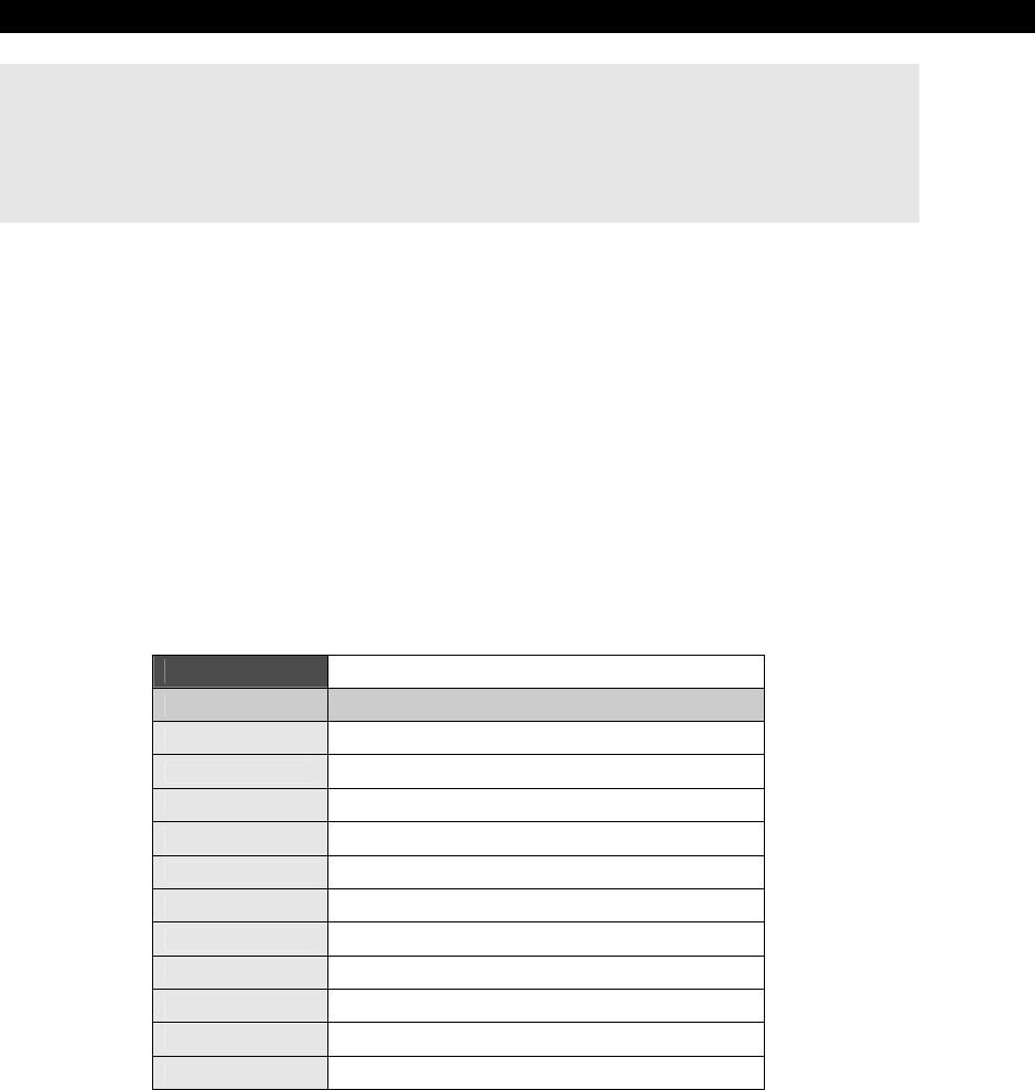
The Spin Language15
Game Programming for the Propeller Powered HYDRA Page 263
.
.
random := seed ' assign the seed
.
.
random := ?random ' get next random number, assign it back to self
Of course, we are not writing complete working Spin programs with all the initialization code,
but we will later in the chapter.
15.4.7.2 Spin Math Operators
Next are the math operators for Spin. This is where Spin really shines and with just an
operator or two you can get a lot of work done (although the code starts to look a little
“perlesque!”). Table 15:4 on the next page lists all the operators.
Notice many of the operators have fairly redundant and cryptic syntax, so be careful when
writing the operators out, I suggest putting a space on either side, so you can “see” the
operator(s) and won’t make typos! Given that there are so many operators, you might find
yourself getting results that don’t make sense when writing complex expressions, so make
sure to parenthesis your expressions to make sure the are evaluated in the way you think
they will be. Additionally, Table 15:3 is a guide to the operator precedence.
Table 15:3 Operator Precedence Table
Operator Precedence
0 (highest) ( ), -, !, ||, >|, |<, ^^ (unary)
1 ->, <-, >>, << ~>, ><
2 &
3 |, ^
4 *, **, /, //
5 +, -
6 |>, <|
7 <, >, <>, ==, =<, =>
8 NOT (unary)
9 AND
10 (lowest) OR

II Propeller Chip Architecture and Programming
Page 264 Game Programming for the Propeller Powered HYDRA
Table 15:4 Math Operators
Normal Assign Unary/
Binary Description
:= Assignment
-> ->= b Rotate right
<- <-= b Rotate left
>> >>= b Shift right
<< <<= b Shift left
#> #>= b Limit minimum (signed), ex: “x #>= y”, equivalent to “if x < y then x = y”
<# <#= b Limit maximum (signed) , ex: “x <#= y”, equivalent to “if x > y then x = y”
- - u Negate
! ! u Bitwise NOT
& &= b Bitwise AND
|| || u Absolute value
| |= b Bitwise OR
^ ^= b bitwise XOR
+ += b Add
- -= b Subtract
~> ~>= b Shift arithmetic right, assumes 32-bit long (copies sign bit and shifts right)
>< ><= b Reverse bits, ex: x >< y, reverses lowermost y bits, zero’s all others
AND AND= b Boolean/Logical AND (promotes non-0 to -1, that is all 1’s).
>| >| u Encode (0-32), ex. returns number of bits necessary to encode value or
(log 2 n)
OR OR= b Boolean/Logical OR (promotes non-0 to -1, that is all 1’s)
|< |< u Decode
* *= b Multiply, 32-bit x 32-bit, returns lower half of 64-bit result (signed)
** **= b Multiply, 32-bit x 32-bit, returns upper half of 64-bit result (signed)
/ /= b Divide, return quotient (signed)
// //= b Divide, return remainder (signed) (mod operator)
^^ ^^ u Square root
< <= b Test - below (signed)
> >= b Test - above (signed)
<> <>= b Test - not equal
== === b Test – equal
=< =<= b Test - below or equal (signed)
=> =>= b Test - above or equal (signed)
NOT NOT u Boolean/Logical NOT (promotes non-0 to -1, that is all 1’s)

The Spin Language15
Game Programming for the Propeller Powered HYDRA Page 265
15.4.7.3 Compile-Time Floating-Point Support
Recently, some floating-point support was added to the Spin compiler at
compile time
only
. In other words, there still is no intrinsic floating-point type or support, but the
compiler’s parser now has some helper code that allows you to create constant expressions
at compile time and then use these at run time along with a run-time library object. More or
less, the compiler’s help could have been implemented in the library as well, but the designer
Chip Gracey was able to “easily” add some conversion and expression evaluation functions in
the parser without much trouble thus they were added. So the rules are that you can use this
functions
only
in the CON section at compile time, they will compile the expressions and
then convert them to single precision IEEE spec floating-point numbers, something like this:
S EEEEEEEE FFFFFFFFFFFFFFFFFFFFFFF
0 1 8 9 31
...where S is the sign bit, E is the exponent and F is the fraction (also known as the
significand
), both in standard binary format. There are approximately 24 bits of fractional
resolution and 7 bits of exponent.
Then once you have your floating-point constant you can use it in your code and assign it to
a LONG and then the LONG will have a floating-point value in it as far as the bits are
encoded, then you make calls to the floating-point library function to add, subtract, etc.
during run time. Also, all floating-point expressions must be in either of these formats:
Format 1: Standard floating-point long hand.
whole_part . decimal_part
Examples: 0.4, -4.5, 12323.454
You must always have a decimal point and either a leading or trailing 0 even if there is no
whole_part or decimal_part. Usually, compilers will “promote” all integers to floats in an
expression and then do the math, but this compiler is simpler and doesn’t do this, hence you
must make everything a float yourself.
Format 2: IEEE scientific notation format (non-normalized).
mantissa E+/- multiplier = mantissa × 10+/-multipler
...where the mantissa must be a floating-point number itself, for example, these are all valid
floating-point numbers to the compiler:
1.0E2 = 1.0×10² (normalized)
456.23E5 = 456.23x105 = 4.5623×10⁷ (normalized)
-56343.232E-3 = -56343.232x10-3 = -5.6343232×101 (normalized)
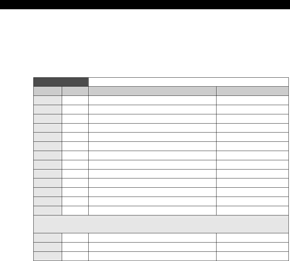
II Propeller Chip Architecture and Programming
Page 266 Game Programming for the Propeller Powered HYDRA
Notice for fun I have normalized all the values so that there is only one significant digit
leading each; however, when you write floating-point numbers using this exponential
scientific notation you don’t need to write them in normalized format.
Since the library isn’t complete at the time of this writing, for now, we are simply going to
cover the basic compile-time operations that are implemented. Table 15:5 shows the
operations that are available at compile-time.
Table 15:5 Compile-Time Operators for Floating-Point
Operator Type Meaning Example
FLOAT( ) Function Converts an integer into a single precision float x = float(3)
TRUNC( ) Function Converts a float to an integer via truncation x = trunc(3.5), returns 3
ROUND( ) Function Converts a float to an integer by rounding up x = round(3.6), returns 4
+,-,*,/ Binary Standard add, subtract, multiply, divide y = 3.4+9.0*4.5
- Unary Negation z = -6.0
^^ Unary Prefix square root w = ^^69.0, returns 8.30662
|| Binary Prefix absolute value a = ||-45.0, returns 45.0
> Binary Boolean greater than, returns 0.0 or 1.0 c = (5.0 > 3.0), returns 1.0
< Binary Boolean less than, returns 0.0 or 1.0 c = (5.0 < 3.0), returns 0.0
=> Binary Boolean equal to or greater than, returns 0.0 or 1.0 c = (5.0 => 3.0), returns 1.0
=< Binary Boolean equal to or less than, returns 0.0 or 1.0 c = (5.0 =<3.0), returns 0.0
<> Binary Boolean not equal, returns 0.0 or 1.0 c = (3 <> 9), returns 1.0
== Binary Boolean equal to, returns 0.0 or 1.0 c = (3==9), returns 0.0
Note: These three operators first promote the floating-point number to either 0.0 or 1.0; these are the
“floating-point” Boolean values. The promotion rule is that 0.0 maps to 0.0; anything else maps to 1.0.
AND Binary Promotes operands to floating point then ANDs c = (3.0 AND -3.0), ret. 1.0
OR Binary Promotes operands to floating point then ANDs c = (0.0 OR -5.6), ret. 1.0
NOT Unary Promotes to floating point then NOTs c = NOT z, returns 0.0
Additionally, there is new function/operator that runs at compile time that supports both float
and normal integer expressions called “Constant( )”. Constant( ) evaluates compile time
constant expressions and solves them, so that at run time this evaluation isn’t done.
Normally, a compiler would do this automatically, but Spin currently is limited in its
optimizations, thus
any
expression during run time that is even of simple constant nature
such as:

The Spin Language15
Game Programming for the Propeller Powered HYDRA Page 267
x*4*5
...with a smart compiler would evaluate as x*20, but Spin actually does two operations at run
time:
t = x*4, t = t*5
With the “Constant( )” operator we can force the compiler to evaluate this, so
Constant(x*4*5)
...results in BYTE code for:
x*20
...which is what is desired during run time.
15.4.8 Spin Statements
Statements typically include assignment, conditionals, control structures, loops and function
calls. We have already seen the assignment statement, so now let’s take a look at the various
types of other statements Spin provides.
15.4.8.1 Conditionals
The most basic form of condition is the “if” statement, Spin supports standard “if” as well as
“elseif” and “else.” Additionally, there are more exotic “ifnot” and “elseifnot” forms that are
Spin-centric and not commonly found in other languages. The various forms of conditional
syntax are:
Example 1: Basic “if” statement.
if conditional_expression
{code}
Example 2: More complex “if” followed by “elseif” statement.
if conditional_expression1
{code}
elseif conditional_expression2
{code}
.
.
elseif conditional_expression_n
{code}

II Propeller Chip Architecture and Programming
Page 268 Game Programming for the Propeller Powered HYDRA
Example 3: Next, adding the final “else” to catch all other possibilities...
if conditional_expression
{code}
else
{code}
...or with “elseif”:
if conditional_expression1
{code}
elseif conditional_expression2
{code}
.
.
elseif conditional_expression_n
{code}
else
{code}
Example 4: The “ifnot” statement.
if conditional_expression1
{code}
ifnot conditional_expression2 ' code executes if "conditional_expression2"
' is FALSE.
{code}
elseif conditional_expression3
{code}
.
.
elseif conditional_expression_n
{code}
else
{code}
Example 5: The “elseifnot” statement.
if conditional_expression1
{code}
ifnot conditional_expression2 ' code executes if "conditional_expression2"
' is FALSE.
{code}
elseif conditional_expression3
{code}
.
.

The Spin Language15
Game Programming for the Propeller Powered HYDRA Page 269
elseif conditional_expression_n-1
{code}
elseifnot conditional_expression_n ' the "elseifnot" executes if the previous
' conditionals are FALSE and the "elseifnot"
{code} ' condition is FALSE as well
else
{code}
Of course you can nest these structures as you wish; however, keep in mind that the interior
block is created by one or more spaces, so you have to space or tab once to get into the
execution block for when the conditional is true. Also, the “conditional_expression” can be
any valid expression and unlike C/C++ etc. you don’t need to surround it by parens;
however, its always a good idea to parenthesize your expressions to make sure they are
evaluated in the order you think they are going to be, that is, the operator precedence might
be different than what you think. Therefore, if you are unsure, parenthesize!
The last conditional control structure is the standard n-way switch or “case” statement. The
syntax is reminiscent of C/C++/Java languages. There is a “case” followed by an expression,
then each one of the evaluation blocks. There are three different types of ways of defining
evaluation blocks; you can use a single constant expression, you can use a range of values
that increment linearly from one constant expression to another using the “..” notation, and
finally, you can separate various non-sequential values by commas. The syntax variants are
shown below:
CASE expression
const_exp1.. const_exp2, cexp3: ' a range followed by another single value
{code}
const_exp4, const_exp5: ' two single ordinal value/expressions
' separated by commas (could be more)
{code}
const_exp6: ' a single ordinal value/expression
{code}
OTHER: ' the catch all or default case
{code}
Note that all “const_exp” are constant expressions and must be based on
constants or arithmetic expressions that can be evaluated at compile time.

II Propeller Chip Architecture and Programming
Page 270 Game Programming for the Propeller Powered HYDRA
15.4.8.2 Looping Constructs
There are a number of looping constructs in Spin, all of which are similar to what you are
used to in C/C++, Java, and Pascal. There loops that repeat indefinitely, loops that evaluate
the looping expression at the beginning of the loop, and others that evaluate it at the end of
the loop. Additionally, there are for constructs that allow you to step though a loop starting
from one value to another by a step value. Also, inside each loop you will see two optional
statements denoted in the curly braces {NEXT} and {QUIT}, “NEXT” instructs the loop to
return to the “REPEAT” clause or the top of the loop, and “QUIT” exits the loop body. The
following is a list of all the looping constructs in Spin:
Example 1: Basic infinite loop.
REPEAT
{code goes here}
{NEXT}
{QUIT}
Example 2a: “While” loop with pre-evaluation of condition.
The form executes the loop body zero or more times.
REPEAT WHILE condition
{code goes here}
{NEXT}
{QUIT}
Example 2b: “While” loop with post-evaluation of condition.
This form executes the loop body at least once.
REPEAT
{code goes here}
{NEXT}
{QUIT}
WHILE condition(...) note the WHILE must be at the same column as the REPEAT
Example 3a: “Until” loop with pre-evaluation.
The form executes the loop body zero or more times.
REPEAT UNTIL condition
{code goes here}
{NEXT}
{QUIT}

The Spin Language15
Game Programming for the Propeller Powered HYDRA Page 271
Example 3b: “Until” loop with post-evaluation.
This form executes the loop body at least once.
REPEAT
{code goes here}
{NEXT}
{QUIT}
UNTIL cond
Example 4: “Repeat” with countdown
The “count_expression” is evaluated at the time of loop entry and this result is used as the
counter for the loop, so if the “count_expression” has variables, constants, and function calls
this is fine, but “count_expression” will only be evaluated once on entry to the loop. If the
final evaluation of “count_expression” is n, then the loop executes n times exactly (unless a
NEXT or QUIT is encountered).
REPEAT count_expression
{code goes here}
{NEXT}
{QUIT}
Example 5: Standard “FOR” loop with starting and ending expression.
This is a standard “FOR” loop with a starting and ending expression. Note, both expressions
are evaluated only once at the start of the loop. Additionally, you can optionally add a “STEP”
by a constant value if you don’t want the loop to increment by the default value of 1.
REPEAT var FROM start_expr TO finish_expr {STEP delta}
{code goes here}
{NEXT}
{QUIT}
15.4.8.3 Function Declarations and Calls
Spin is a functional language that supports a structured programming paradigm by allowing
you to create functions that can be called locally or through an object (more on objects
later). First, all functions return a single 32-bit value, this is passed back through the named
return value or through the
super-global
named “RESULT.” That is, every time a function is
called “RESULT” is an alias to the return value (whether you have one or not) and when you
use the “RETURN” statement to exit a function and send back a value this is written to
RESULT as well as returned (also RESULT is always initialized to 0 on entry to the function).
Thus, all functions have an implied return value named RESULT, it’s always 0, on entry. If
you don’t explicitly return a value at the end of the function, then the function will evaluate
to the default value of RESULT which is 0. There are a number of ways to return results from

II Propeller Chip Architecture and Programming
Page 272 Game Programming for the Propeller Powered HYDRA
a function, first note that the statement “RETURN” has two forms; “RETURN” by itself which
simply returns from the function, and “RETURN expr” which returns from the function with a
value of expr which is of course aliased to RESULT as well as will be passed out to the caller
as the result of the function call. With that in mind, there are many ways to return results
from a function, for example:
Example 1: Assign the default return value RESULT a value at the end of the function.
result := expression
But, this will NOT exit the function, unless it’s the last line of the function; if you want to
make sure the function exits then you would put a “return” after this, like this:
result := expression
return
Of course, this “return” is implied if it’s the end of the function, but you might want to have
the assignment and return in a conditional.
Example 2: Create a return value in the function declaration.
Assuming, you create a named return value, call it “ret_val”, you can return it using either
technique above as well as using “return expr” as an option as well:
ret_val := expr
...and then at some point the function would exit, but if we want to insure exit immediately
with the return value then we can use this syntax:
return ret_val
Moving on, the syntax of functions allows you to have any number of parameters, a return
value, and locals, the syntax is a bit tricky, so let’s take a look at the general syntax of
functions with some pseudo BNF notation examples where “{ thing }” means “thing” is
optional, and {“thing*} means 0 or more “things” which are optional.
Function Declarations
All functions take and return 32-bit values therefore there is no need to declare a return type
or parameter types. Additionally, all locals are 32-bit. The syntax of functions is a bit tricky,
functions can have zero or more parameters, locals, as well as a named return value. Note
“ws” stands for “white space” in the examples below:

The Spin Language15
Game Programming for the Propeller Powered HYDRA Page 273
Example 1: Public function with no return, no locals, no parameters:
PUB func_name ( )
{code goes here}
{RETURN expression} this is optional
Example 1 syntax:
PUB Do_Nothing( )
Return
Example 2: Private Function with return and locals:
PRI func_name1 (parm1, parm2, ..., parmn) ws {: return_value} ws | ws
{local(s),}*
{code goes here}
{RETURN expression} this is optional
Notice the RETURN value is optional, that is if you don’t want to return a value, maybe the
function is more of a procedure – then you can omit the RETURN statement; however, note
that RESULT, which is 0, will be returned on the stack and if you try to use the function call
in an expression, it will evaluate to zero in this case. Also, the syntax is a little hard to
decrypt, reading from left to right, there are 1 to n parameters in the parens after the
function name, then there is white space followed by a “:” and the name of the return value
variable which is optional itself, then if you want one or more locals you indicate the local list
with the pipe character “|” then give the list of locals separated by commas.
Example 2 syntax: Two parameters, a return value named “ret_val” and two locals.
PRI Distance(x, y) : ret_val | temp1, temp2
{code goes here}
return ret_val
Example 3: Public Function parameters and locals variables, but no named return value.
PUB func_name1 (parm1, parm2, ..., parmn) ws | {local(s),}*
Example 3 syntax: One parameter and one local...
PUB Square (x) | temp
temp:=x*x
return(temp)

II Propeller Chip Architecture and Programming
Page 274 Game Programming for the Propeller Powered HYDRA
....or this would work as well,
PUB Square (x) | temp
temp:=x*x
result := temp
As you can see, we can either “RETURN” the result, or we can assign the result to the return
value either named or the super-global “RESULT” at the end of the function body. Or we can
just do nothing and return the default of 0, if the function is more of a “procedure” and we
aren’t interested in using the function in an expression.
Example 4: Public function with no parameters, no return value, no locals.
If you want no parameters, no return value, no locals, use this syntax:
PUB foo
return
Scoping Rules
The scoping rules for Spin functions are a bit unintuitive. In general, most programming
languages allows “locals” to functions to have local “scope” meaning, these locals can’t be
seen outside the function or procedure declaration. Therefore, one can use the variable
“index” as a global and use “index” in every single function as a local as well without a
problem. Figure 15:4 shows this graphically.

The Spin Language15
Game Programming for the Propeller Powered HYDRA Page 275
Figure 15:4
Spin Variable Scope
Diagrams
However, in Spin there are “funny” scoping rules. Locals can
NOT
have the same name as
globals, BUT, locals between functions
CAN
have the same name. Additionally, parameters
and return values can
NOT
have the same name as any global -- BUT, function to function
CAN
have the same name.
In this example:
PUB func_name1(var1, var2,, varn) : ret_val | local1, local2
...var1, var2, retvar, local1, and local2 all collide with global scope! So you can’t have a
global in a VAR section with any of these names! But, you can have two functions with the
same parameters, return value, and local names like this:
PUB func_name1(var1, var2,, varn) : ret_val | local1, local2
PUB func_name2(var1, var2,, varn) : ret_val | local1, local2

II Propeller Chip Architecture and Programming
Page 276 Game Programming for the Propeller Powered HYDRA
The Abort Keyword
“Abort” is like “return,” but keeps on returning to the first caller with a leading “\” in front of
the function name. This leading backslash “tags” the function as the “exit” point for an
“abort.”
Example 1: Func1 is tagged as an exit point for aborting.
\Func1(parms...)
' function body for Func1 contains a call to Func2
Func2(parms...)
' end Func1
'//////////////////////////////////////////////////////////////////////////////
\Func2(parms...)
' function body for Func2 contains a call to Func3
Func4(parms...)
' end Func2
'/////////////////////////////////////////////////////////////////////////////////
Func3( )
' function body for Func3 contains an Abort and Return
if (something)
Return ' returns to Func2
else
Abort ' returns to first "\" abort tagged function, or Func1 in this case!
' end Bar
Reviewing the example, the call graph is Func1 Func2 Func3. Func3 then can either
return to Func2, or if the Abort code is true then Func3 will return all the way back to Func1
and skip Func2 in the call return stack. Additionally, there are two forms of Abort:
ABORT — Returns to nearest most \ tagged call on stack like return.
ABORT value — Returns the value and OVERIDES the current return value in “return.”
15.4.9 Spin Data, Memory and Pointer Manipulations
Spin supports pointers and pointer arithmetic; however, “pointers” aren’t any special typed
value, they are just vars that numerically are equal to memory addresses that we can
perform mathematical operations on and additionally use them to dereference memory
locations. Therefore, there is no “pointer” type per se. However, accessing memory is very
easy and can be done in a number of ways.

The Spin Language15
Game Programming for the Propeller Powered HYDRA Page 277
First, to get the address of any variable the “@” operator is used. For example, if we have
the following VAR section:
Byte a[10] ' 10 bytes of space starting at memory location where "a" is stored
Long x[100] ' 100 longs of space starting at memory location where "x" is stored
Long y ' 1 long of storage starts at memory location where "y" is stored
Long z ' 1 long of storage starts at memory location where "z" is stored
Long lptr ' 1 long of storage starts at memory location where "ptr" is stored
Word wptr ' 1 word of storage starts at memory location where "wptr" is stored
Memory Storage Layout for Variables Figure 15:5
Figure 15:5 shows a hypothetical memory layout for the storage of the variable declarations,
just for discussion purposes. Note that these addresses may not ever happen in a real
program.
Then we can write something like this:
lptr := @x
wptr := @x
These statements compute the address where “x” is stored in memory and assigns this value
to lptr and wptr, literally. This address/number will always fall between 0 – (64K-1), since
that’s the size in BYTEs of the Propeller chip’s internal memory. Therefore, if you want to use
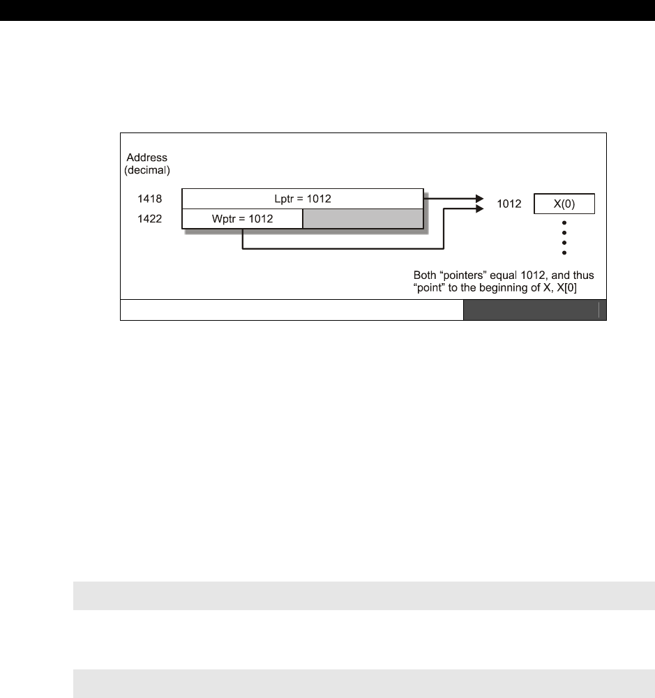
II Propeller Chip Architecture and Programming
Page 278 Game Programming for the Propeller Powered HYDRA
a variable as a pointer then you must use a size of WORD or LONG, so that the address
space can fit, a BYTE variable won’t work since it only can address 0-255 (unless you know
you are accessing the first 256 BYTEs. Figure 15:6 shows the relationship between lptr,
wptr, and x at this point.
Pointers in Memory Figure 15:6
In any event, both lptr and wptr now point to x. We can use a number of syntaxes to access
the LONG array x[ ].
lptr[0] - Accesses the long at x[0], or (@x + 0*4)
lptr[1] - Accesses the long at x[1] , or (@x + 1*4)
lptr[n] - Accesses the long at x[n] , or (@x + n*4)
The interesting thing is that lptr is itself a LONG, therefore, whenever we access anything
with the syntax “lptr[n]” then the access is always on a LONG boundary, that is, the indexing
is smart enough to know that lptr is itself a LONG, and assumes that when used in this way it
should index by LONGs. On the other hand, wptr is a WORD, therefore, when we assign the
address of the LONG array x[ ] to wptr, we get a slightly different behavior. For example,
take a look at these two lines of code:
wptr[0] ' Accesses the low word at x[0], or (@x + 0*2)
wptr[1] ' Accesses the high word at x[0] , or (@x + 1*2)
Notice that both accesses are within x[0]. To access the next two WORDs which reside in
the next LONG or x[1], the following code can be used:
wptr[2] ' Accesses the low word at x[1], or (@x + 2*2)
wptr[3] ' Accesses the high word at x[1] , or (@x + 3*2)

The Spin Language15
Game Programming for the Propeller Powered HYDRA Page 279
Figure 15:7 shows the WORD and LONG accesses graphically. Moving on, there are some
other forms of memory access based on “variable modifiers.”
Figure 15:7
LONG Memory with
WORD Access Pointers
15.4.9.1 Accessing Memory with Variable Modifiers
In addition to using a variable name as a pointer with array index syntax, you can also use a
type modifier with the dot “.” operator to access data with another WORD size. That is, say
you have a variable or array that is based on LONGs, but you want to access it as if it were
BYTEs, or maybe you have an array that is WORDs and you want to access it as if it were
BYTEs, and so forth. However, the modifier syntax only allows “downcasting,” that is, you
must always access memory in chunks as big or smaller than the size of the base.
The syntax is as follows:
varname.LONG[i] – Accesses the memory starting at “varname” as LONGs, indexed by i.
varname.WORD[i] – Accesses the memory starting at “varname” as WORDs, indexed by i.
varname.BYTE[i] – Accesses the memory starting at “varname” as BYTEs, indexed by i.
...where “varname” can be any of the following types and sizes:
VAR BYTE/WORD/LONG
DAT BYTE/WORD/LONG
Local LONG such as subroutine parameters and locals
For example, let’s say we have the following variables:
long x[10]
word y[10]
byte z[10]

II Propeller Chip Architecture and Programming
Page 280 Game Programming for the Propeller Powered HYDRA
Then if we wanted to access them using the modifiers we simply use a dot followed by the
size modifier. Here are some examples:
Example 1: Accessing the LONG array as LONGs, redundant example.
x.LONG[0] ' accesses the first LONG of the array identical to x[0]
Example 2: Accessing the LONG array as WORDs.
x.WORD[3] ' accesses the 3rd word in the LONG array of x, or technically the
' low word of the 2nd LONG
Example 3: Accessing the WORD array as BYTEs.
y.BYTE[19] ' accessed the very last BYTE of the entire WORD array defined by
' y[10] = 10 words or 20 bytes.
Example 4: Accessing the BYTE array as BYTE.
z.BYTE[9] ' accesses the last BYTE of the BYTE array
Example 4 is another redundant example since BYTE can only downcast to BYTE, therefore,
the modifier doesn’t do much, you could just say “z[9]” which is equivalent to z.BYTE[9], that
is, in general if you access a variable of a given type using the SAME type as the modifier
there is no difference in just accessing the memory as an indexed array.
Lastly, its interesting to note than in Spin there is
NO
bounds checking, everything is just
memory and an address, so if you define a variable as a singleton, you can STILL access it as
an array, for example:
long x
x[100] := 1 ' this is legal!
Additionally, you can use the variable name with modifier syntax like this:
x.WORD[20] := 2 ' this is legal as well
This of course is very dangerous if you’re not careful! So remember the compiler doesn’t
know the difference between a singleton and an array, you can access both with any index.
The only thing the array does for you is the compiler makes sure to allocate space in the
memory map for you. However, this freedom is powerful since it allows you to index into
anything you wish and create, self-modifying BYTE code even!

The Spin Language15
Game Programming for the Propeller Powered HYDRA Page 281
15.4.10 Spin and DAT Blocks
For a moment let’s digress a bit and talk about DAT sections since they are special cases of
memory that we can access. DAT sections are just like variables in that they are stored at a
location in main memory, but unlike variables in a VAR section, we can pre-initialize DAT
sections with real data statically and this data will always be present on BOOT, that is, it’s
stored statically in the binary image of the program. If you recall, in the VAR section we can’t
pre-initialize anything, but the compiler does guarantee that all VARs are initialized to 0 on
start-up. With all that in mind, if we had a DAT section as shown below:
DAT
score_string byte "Score",0 'text
hiscore_string byte "High",0 'text
ships_string byte "Ships",0 'text
start_string byte "PRESS START",0 'text
parallax_string byte "PaRaLLaXaRoiDs",0 'text
hex_table byte "0123456789ABCDEF" 'hex lookup table
...then @hex_table would be the starting address of the hex table. Also, if we used array
indexing syntax on hex_table like this:
hex_table[n]
...then we would access the nth BYTE of hex_table[ ] always. This is because the DAT
declaration has hex_table “typed” as a BYTE. Similarly, WORD and LONG data would be
indexed on WORD and LONG boundaries as well.
15.4.10.1 Direct Memory Access with BYTE, WORD, and LONG Operators
As if having data types named BYTE, WORD, and LONG along with modifier BYTE, WORD,
and LONG weren’t enough there is yet
another
way to access memory directly! The idea is
to use BYTE, WORD, and LONG as if they were peek/poke statements from BASIC and
access memory directly at some base address. There are two forms:
Base Address Direct
Base Address Direct Plus Indexed
Base Address Direct
The base address direct form is simple, you simply give a base address and use BYTE,
WORD, or LONG to indicate the size of the data you want to access there.

II Propeller Chip Architecture and Programming
Page 282 Game Programming for the Propeller Powered HYDRA
BYTE[addr] — Accesses the BYTE at base address addr.
WORD[addr] — Accesses the WORD at base address addr.
LONG[addr] — Accesses the LONG at base address addr.
Example 1: Write a 53 into memory location 1000 assuming BYTE size data.
BYTE[1000] := 53
Base Address Direct Plus Index
The base address plus index form allows you to “index” from the base address by the data
size; BYTE, WORD, or LONG.
BYTE[addr][index] — Accesses the BYTE at base address addr + index*1
WORD[addr][index] — Accesses the WORD at base address addr + index*2
LONG[addr][index] — Accesses the LONG at base address addr + index*4
Example 2: Write a 211 into memory location 1004 assuming BYTE size data.
BYTE[1000][4] := 211
The indexed mode is useful when you want to think in terms of a single base address and
then index from there. Here is another example that shows memory and the data stored in it
as it’s being accessed and modified:
Example 3: Memory manipulation showing memory each step of access.
long ptr ' create a long variable, we will use this as a pointer
ptr := 1024 ' point ptr at address 1024 in RAM, the 256th LONG or
' BYTE 1024, or WORD 512
Now, to access the first BYTE we could write:
byte[ptr] := $01
Memory Address Data (after access)
1024 $01
1025 x
1026 x
1027 x
1028 x

The Spin Language15
Game Programming for the Propeller Powered HYDRA Page 283
Now, to access the first WORD we could write:
word[ptr] := $02
Memory Address Data (after access)
1024 $02
1025 $00
1026 x
1027 x
1028 x
Now, to access the first LONG we could write:
long[ptr] := $03
Memory Address Data (after access)
1024 $03
1025 $00
1026 $00
1027 $00
1028 x
Additionally, with the array index and BYTE modifier we can access the 3rd BYTE from the
base address:
byte[ptr][3] := $05
Memory Address Data (after access)
1024 $03
1025 $00
1026 $00
1027 $05
1028 x
15.4.11 Spin Special Language Elements
In this next section we are going to cover the majority of the functional and system data
access keywords from Table 15:1 on 256 that have special meaning. This will complete the
language specification for the most part save the multiprocessing and object oriented aspects
which we will discuss in the next sections respectively.
15.4.11.1 System and Cog Registers
Each cog has a group of 16 registers, each 32-bit in size. We have discussed these registers
before in numerous sections, refer to Table 15.6 on the next page. Spin allows you to access
these registers with the following literal names listed in the “Name” column of the table.
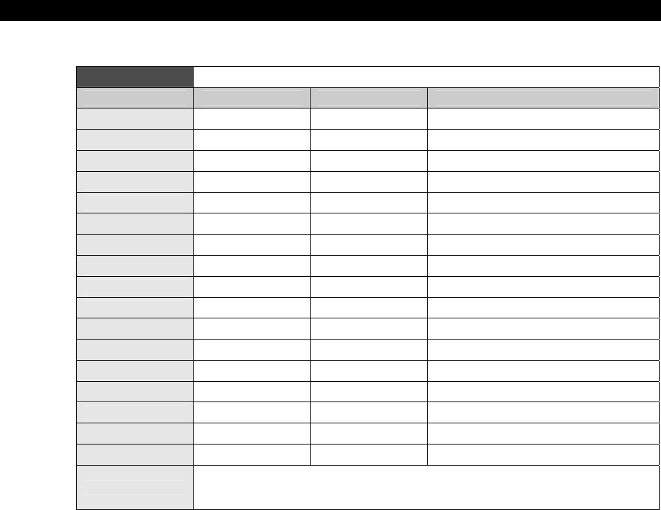
II Propeller Chip Architecture and Programming
Page 284 Game Programming for the Propeller Powered HYDRA
Table 15:6 Cog Registers
Address Name Access Description
$000-$1EF — Read/Write General Purpose RAM
$1F0 PAR Read-Only* Boot Parameter
$1F1 CNT Read-Only* System Counter
$1F2 INA Read-Only* Input States for P31..P0
$1F3 INB Read-Only* Input States for P63..P32 **
$1F4 OUTA Read/Write Output States for P31..P0
$1F5 OUTB Read/Write Output States for P63..P32 **
$1F6 DIRA Read/Write Direction States for P31..P0
$1F7 DIRB Read/Write Direction States for P63..P32 **
$1F8 CTRA Read/Write Counter A Control
$1F9 CTRB Read/Write Counter B Control
$1FA FRQA Read/Write Counter A Frequency
$1FB FRQB Read/Write Counter B Frequency
$1FC PHSA Read/Write Counter A Phase
$1FD PHSB Read/Write Counter B Phase
$1FE VCFG Read/Write Video Configuration
$1FF VSCL Read/Write Video Scale
NOTES * Only accessible as a Source Register (i.e. MOV DEST,SOURCE)
** Allocated for future use, but not currently implemented.
Remember all addresses are LONG or 4-BYTE addresses.
Cog Register Access Notes
SPR Special Purpose Register, allows access to all registers of the cog via an
index syntax SPR[ index] , where:
SPR [ 0 ] accesses cog register $1F0 (PAR)
SPR [ 15 ] accesses cog register $1FF (VSCL)
.....etc. This way you can use numerical algorithms to access the registers
rather than their names.
PAR The parameter address from the cog boot, this indicated where the
parameters are located.

The Spin Language15
Game Programming for the Propeller Powered HYDRA Page 285
CNT The system wide 32-bit counter running at full speed, one clock per
system cycle.
INA The I/O Port A input buffer lower 32 bits, P31..P0.
INB The I/O Port B input buffer, upper 32 bits, P63..P32, (future expansion).
OUTA The I/O Port A output buffer, lower 32 bits, P31..P0.
OUTB The I/O Port B output buffer, upper 32 bits, P63..P32, (future expansion).
DIRA Direction states for Port A, P31..P0, 1=output, 0=input.
DIRB Direction states for Port B, P63..P32, 1=output, 0=input.
CTRA Counter A control bits, described earlier in document.
CTRB Counter B control bits, described earlier in document.
FRQA Counter A frequency bits, described earlier in document.
FRQB Counter B frequency bits, described earlier in document.
PHSA Counter A phase, described earlier in document.
PHSB Counter B frequency bits, described earlier in document.
Obviously, some of this is review like the counter material, but it’s useful to discuss the CNT
keyword and all the I/O registers. The I/O material deserves its own section which is next,
but let’s see an example of the CNT register usage.
The Global Counter CNT Register
The CNT register is a free-running 32-bit counter that is incremented once every system-wide
clock cycle. Each cog accesses this register, gets the same value back at the same time, that
is, there is a
single
global counter accessed by CNT,
not
multiple counters. In Spin, simply
use the symbol “CNT” to access the register (read only of course):
To get the current count and store it:
curr_count := CNT
A crude wait loop that waits 10,000 clocks:
wait_cnt := CNT + 10_000
repeat while (CNT < wait_cnt)

II Propeller Chip Architecture and Programming
Page 286 Game Programming for the Propeller Powered HYDRA
15.4.11.2 Spin Input Output
The I/O model of the Propeller chip is simple and Spin makes it even easier, you simply set
the
direction
of the I/O pin(s) with the DIRA register then
write
using the OUTA register
or
read
using the INA register.
The DIRB, INB, and OUTB registers are not used and are reserved for future
expansion.
Now, the first thing that should come to mind about I/O on a multiprocessor chip is there is
going to potentially be a lot of conflict! And this is true. The bottom line is that every cog can
access the I/O pins and set the direction of them as well; this means that one instant a pin
might be an input, the next an output. The bottom line is that as the programmer you have
to set the pins in the right direction and not step on any toes yourself. The Propeller chip
architecture uses an “I/O conflict resolution” design based on OR’ing and AND’ing things
together as shown back in Figure 13:1, but this just helps, so there isn’t any hardware
conflict internally. At the end of the day, if you set an I/O for an output with one cog and
another cog sets it for an input and keeps doing this each cycle and your input cog only does
it once, then you will never be able to communicate – therefore, be careful!
Thankfully, in the case of the HYDRA, there is really no concern about this for the most part
since only one piece of hardware is connected to each I/O pin set, so usually the directions
and use of the I/O are the same. But, it might be the case that you want two or more cogs
both to talk to the same piece of hardware, maybe something like video for example; in this
case, you better set the I/O the way you want it each time and then put it back the way it
was or work out some global agreement with yourself – this all falls under “multiprocessing /
parallel programming” techniques, you will learn them as you go. Now that we have had
“
the talk
” about safe multiprocessor I/O, let’s see some examples.
Example 1: Set the I/O pins P7-P0 to outputs, and write a $35 to the port.
DIRA := $FF ' set the lower 8 bits to 1, which means "outputs",
' all other bits will be 0 or "inputs".
Another syntax that would work is using the “..” range notation:
DIRA [ 7..0 ] := $FF ' set the lower 8 bits to 1, which means "outputs",
' notice the ".." bit range notation.
Once the direction is set, it’s simply a matter of writing to the OUTA register our value:
OUTA := $35

The Spin Language15
Game Programming for the Propeller Powered HYDRA Page 287
Example 2: Wait on I/O P0 (bit 0) for it to turn HIGH then exit loop.
' step 1: set I/O P0 to an input
DIRA[0] := 0 ' bit 0 set to 0, the bracket notation means which bit or bit(s)
' with the range ".." notation.
' step 2: enter loop and wait
repeat while (!INA[0])
The bit range syntax only works on register access; you can’t use it in any other
cases.
15.4.11.3 Table and Set Lookup
The following functions are useful for table lookups, conversions, translations, and mapping
algorithms.
LOOKUP Looks up a value in a list, 1-based.
LOOKUPZ Looks up a value in a list, 0-based.
LOOKDOWN Scans for a value in a list and returns the index if the value is found,
1-based.
LOOKDOWNZ Scans for a value in a list and returns the index if the value is found,
0-based.
LOOKUP Functional Syntax:
LOOKUP(index: cexp0..cexp1, cexp2, etc.)
Description: Returns constant expression indexed by “index” (with 1 as first index), else 0 if
out of range. Note “cexp?” is a “constant expression evaluated at execution time.”
LOOKUPZ Functional Syntax:
LOOKUPZ(index: cexp0..cexp1, cexp2, etc.)
Description: Returns constant expression indexed by “index” (with 1 as first index), else 0 if
out of range. Note “cexp?” is a “constant expression evaluated at execution time.”
Comments: Both lookup functions are used to look up a value indexed by “index,” either
0-based indexing or 1-based indexing.

II Propeller Chip Architecture and Programming
Page 288 Game Programming for the Propeller Powered HYDRA
Example 1: Maps the integers 1,2,3,4,5 to 7,6,4,5,4.
repeat i from 1 to 5
value := LOOKUP(i: 7,6,4,5,4)
Example 2: Maps the integers 0,1,2,3,4 to 7,6,4,5,4.
repeat j from 0 to 4
value := LOOKUPZ(j: 7,6,4,5,4)
LOOKDOWN Functional Syntax:
LOOKDOWN(value: cexp0..cexp1, cexp2, etc.)
Description: Returns the offset (1-based indexing) of the “value” if found in the list of
constant expressions, 0 otherwise.
LOOKDOWNZ Functional Syntax:
LOOKDOWNZ(value: cexp0..cexp1, cexp2, etc.)
Description: Returns the offset (0-based indexing) of the “value” if found in the list of
constant expressions, 0 otherwise.
Comments: Both the lookdown functions basically look for the “value” in the list of constant
expressions, if “value” is found, then the 0- or 1-based index of the location is returned.
Example 1: Look for location of 5 in list, 1-based lookdown.
index := LOOKDOWN(5: 10,3,19,90,4,-5,5,1,2,3) ' returns 7 since "5" is located 7th
' in the list.
Example 2: Look for location of 90 in list, 0-based lookdownz.
index := LOOKDOWNZ(90: 10,3,19,90,4,-5,5,1,2,3) ' returns 3 since "90" is located
' 3rd in the list.

The Spin Language15
Game Programming for the Propeller Powered HYDRA Page 289
15.4.11.4 Memory Movement and Filling
The following functions are used to move, copy, or fill memory. The all operate with memory
addresses or pointers to main memory, thus all addresses must be in range from 0 to 64K-1
for source addresses, 0 to 32K-1 for destination addresses.
BYTEFILL Fills a region of memory on BYTE boundaries a BYTE at a time.
WORDFILL Fills a region of memory on WORD boundaries a WORD at a time.
LONGFILL Fills a region of memory on LONG boundaries a LONG at a time.
BYTEMOVE Moves BYTEs from one location to another a BYTE at a time.
WORDMOVE Moves WORDs from one location to another a WORD at a time.
LONGMOVE Moves LONGs from one location to another a LONG at a time.
BYTEFILL/WORDFILL/LONGFILL Functional Syntax:
BYTEFILL(start_addr, value, count)
WORDFILL(start_addr, value, count)
LONGFILL(start_addr, value, count)
Where,
start_addr = 16-bit starting address, must be BYTE, WORD, or LONG aligned
depending on fill.
value = Value to fill memory with; must be BYTE, WORD or LONG depending on fill.
count = Number of “words” to fill of appropriate size.
Description: The functions all simply fill memory starting at the given address (0 to 32K -1).
Each respective function fills on either BYTE, WORD, or LONG boundaries, one BYTE, WORD,
or LONG at a time. Also, “count” always refers to the “word” size, so “count” in BYTEFILL( )
means how many BYTEs to fill, “count” in LONGFILL( ) means how many LONGs to fill, etc.
Example 1: Fill a string with ASCII “A”
BYTEFILL(string_ptr, "A", 80)
Example 2: Zero out a region of 1024 BYTEs, which we know to be on a LONG boundary,
as fast as possible.
LONGFILL(mem_ptr, $00_00_00_00, 256) ' notes count = 256 LONGs which is 1024 BYTEs

II Propeller Chip Architecture and Programming
Page 290 Game Programming for the Propeller Powered HYDRA
BYTE/WORD/LONGMOVE Functional Syntax:
BYTEMOVE(dest_addr, source_addr, count)
WORDMOVE(dest_addr, source_addr, count)
LONGMOVE(dest_addr, source_addr, count)
Where,
source_addr = 16-bit source address of memory to move from, must be BYTE,
WORD, or LONG aligned depending on fill.
dest_addr = 16-bit destination address of memory to move to, must be BYTE,
WORD, or LONG aligned depending on fill.
count = Number of “words” to move of appropriate size.
Description: The functions all simply move memory from a source address (in the range of
0 to 64K-1) to a destination address (in the range of 0- to 32K-1). Each respective function
moves either BYTEs, WORDs, or LONGs one BYTE, WORD, or LONG at a time. Also, “count”
always refers to the “word” size, so “count” in BYTEMOVE( ) means how many BYTEs to
move, “count” in LONGMOVE( ) means how many LONGs to move, etc.
Example: Copy stringA to stringB assuming the length of stringA is 25 characters
BYTEFILL(@stringB, @stringA, 25+1) ' this +1 is to copy the NULL terminator
15.4.11.5 String Functions
The next set of functions are string “helper” functions. For more complex string handling, you
must write an object or library yourself.
STRSIZE Computes the length of an ASCII-Z (NULL-terminated string).
STRCOMP Compares two strings together alphanumerically and returns result.
STRSIZE Functional Syntax:
STRSIZE(string_ptr)
Description: Computes the length of a string by scanning for a NULL (0) terminator then
returns the length of the string (not counting the NULL terminator).

The Spin Language15
Game Programming for the Propeller Powered HYDRA Page 291
STRCOMP Functional Syntax:
STRCOMP(stringa_ptr, stringb_ptr)
Description: Compares same size NULL-terminated strings and returns if they are equal or
not, TRUE or FALSE respectively.
Comments: The strings must be pointers or addresses of the actual strings, remember
there is no “string” type.
Example 1: Compute the length of the string.
length : = STRSIZE(@andre_string) ' length will equal 5 after call
DAT
andre_string BYTE "ANDRE",0
Example 2: Compares input string to “STOP”
VAR
BYTE input_string[80] ' used to hold input
.
.
if (STRCOMP(@input_string, @stop_string)==TRUE)
{do work}
.
.
DAT
stop_string BYTE "STOP", 0
15.4.11.6 Waiting Functions
The next class of functions are the “waiting” functions that are used to wait for external
or
internal events, either I/O events or timer/clock events.
WAITPEQ Waits for the I/O port pins to equal a specific pattern.
WAITPNE Waits for the I/O port pins to not be equal to a specific pattern.
WAITCNT Waits for the global counter.
WAITVID Waits for the video streaming hardware to pick up next block of
colors and pixels.
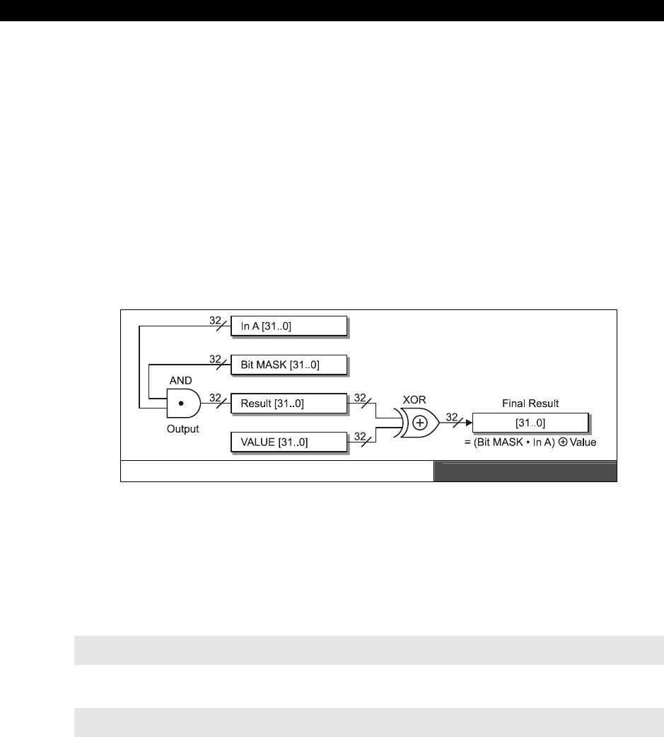
II Propeller Chip Architecture and Programming
Page 292 Game Programming for the Propeller Powered HYDRA
WAITPEQ/WAITPNE Functional Syntax:
WAITPEQ(value, bit_mask, port)
WAITPNE(value, bit_mask, port)
Where,
Value = 32-bit value to compare port inputs to.
bit_mask = 32-bit mask to AND value with.
Port = Indicates which port to use; 0=Port A, 1=Port B.
Description: The WAITPEQ( ) and WAITPNE( ) functions respectively are used to “wait” for
a specific value at the I/O port input P31..P0. Currently, the port must always equal 0, or
Port A since Port B is for the 64-bit I/O part.
Port Compare Visualization Diagram Figure 15:8
Figure 15:8 illustrates the mechanics of the wait function’s masking and comparison. In
essence, first the bitmask is AND'ed with the input Port A bits, this masks the bits of interest,
then this result is compared to value using an XOR operation, the result of this operation is
wherever the bits are the
same
the result of the XOR will be 0’s, wherever the bits are
different, the results are 1’s, thus the outcome of all this
is
0 then WAITPEQ( ) exits while
WAITPNEQ( ) waits until the result is
non-0
. Therefore, WAITPEQ( ) is programmatically
equivalent to:
repeat while ((value ^ INA) & bit_mask) ' where ^ is XOR and & is bitwise AND
...and WAITPNE( ) is equivalent to:
repeat while !((bit_mask & INA) ^ value)) ' where ^ is XOR and & is bitwise AND

The Spin Language15
Game Programming for the Propeller Powered HYDRA Page 293
WAITCNT Functional Syntax:
WAITCNT(count)
Description: The WAITCNT( ) function
waits
until the counter
reaches
the value of
“count,” it
does
not
count down from “count.”
WAITVID Functional Syntax:
WAITVID(colors, pixels)
Where,
colors = Is a 32-bit number that represents the 2 or 4 “color” BYTEs as described in
the text earlier, these might be NTSC/PAL values or VGA values, etc. It’s
these
“colors” that are referenced by “pixels.” In 2-color mode, pixels represents 32-pixels
and accesses the first 2 “color” BYTEs in the “colors” parameter, in 4-color mode,
each pair of 2 pixels in the “pixels” parameter represents one the 4 color “BYTEs” in
the 32-bit “colors” parameter.
pixels = 32 bits that represent the pixels to be streamed out by the VSU to either
the NTSC port or the VGA port. The streaming occurs at a rate set up in the VSCL
(video scale register) and VCFG (video configuration register) and depending on the
mode of operation set in the VCFG registers, either 1 bit at a time or 2 bits at a time
represent a “pixel,” in either 2 or 4 color mode respectively, and these “pixels” index
into the “colors” parameter for the final color BYTE to be streamed.
Description: The WAITVID( ) function waits/blocks until the VSU (video streaming unit)
needs more colors and pixels, takes them and then returns. The function is nearly useless in
Spin since Spin is too slow to “feed” the VSU, but technically the function does work and will
wait the first time, chances are by the next time you go and get ready for another pass, the
VSU will be many lines down the screen!
Example: Wait until Port bits P3..P0 are equal to 9.
WAITPEQ($00_00_00_09, $00_00_00_0F, 0) ' enable lower 4-bits only with mask
' $F, compare to $9

II Propeller Chip Architecture and Programming
Page 294 Game Programming for the Propeller Powered HYDRA
15.5 Spin and Multiprocessing
Figure 15:9
The Propeller Chip Cogs and Hub
The Hub runs at ½ the clock rate as the
system clock. Each cog gets access as
the Hub cycles around.
Multiprocessing and parallel programming are a huge subject and something for you to
research on your own. There are numerous books about the subject and internet is full of
information. I suggest the following reading on the subject (one is a general college text, one
is a more Windows-specific text):
“Introduction to Parallel Programming” by Steven Brawer
“Multithreading Applications in Win32, The Complete Guide to Threads”
by Jim Beveridge & Robert Weiner
And here are a few links on internet to some interesting articles (read the last one and that’s
pretty much all you need):
http://www.mhpcc.edu/training/workshop/parallel_intro/MAIN.html
http://library.lanl.gov/numerical/bookf90pdf/chap222f9.pdf
http://www.llnl.gov/computing/tutorials/parallel_comp/
In any case, I want to briefly discussion the multiprocessing on the Propeller chip and what
you need to consider when programming it. The rest you will learn as you go, or you will die
and be crushed by enormous gravitational anomalies, the choice is yours. However, I
strongly suggest you re-modulate the deflector output to 23.54653434 Tera-Hz and divert
power from the impulse drive to the forward shields.

The Spin Language15
Game Programming for the Propeller Powered HYDRA Page 295
As shown in Figure 15:9, the Propeller chip has 8 processing cores called “cogs,” each cog is
identical and has 512 LONGs of local storage (where 16 LONGs are internal registers used by
the cog). Each cog can run completely independently on its own data and program, thus the
Propeller chip is what’s called a MIMD machine (Multiple Instruction Multiple Data), which is
the most flexible and most common parallel processing architecture. Additionally, there are
SIMD (Single Instruction Multiple Data) as well as other bizarre variants. The idea of parallel
processing on the Propeller chip is to keep things “simple” and not get into or to avoid
altogether the problems of parallel processing in general. To that end, we are going to use
the cogs in more of a “task” based parallel processing, in other words, one cog is going to do
sound, one is going to do video, another might handle I/O and so forth. We are NOT going
to try and “parallelize” single algorithms, this is for high-end parallel computing and
something for you to explore on your own.
What we are concerned with is how to “approach” running multiple tasks on a Propeller chip
and communication between them. As noted, the Propeller chip has a total of 64K of shared
memory, 32K of it is ROM and the other 32K of it is RAM (loaded on boot) from the IDE or a
EEPROM with a 32K image of the programs to load into the Propeller chip. On boot, Cog 0
always gets control, loads the Spin interpreter, and then execution starts there. \
Now, here is the important part: on boot, Cog 0 gets control, that is, Cog 0
always
loads the
Spin interpreter into its 512 LONGs of local memory space and
then
starts executing your
program’s 1st line of code which is
always
Spin code – always. Now, from this point your
main program can always call on “objects” which are simple external files that contain
programs; these programs may or may not spawn more cogs, so don’t equate “objects” with
multiprocessing. Objects are simply containers for programs, nothing more. In any case, we
will see exactly how to start other cogs and run either Spin or ASM with them, but for now
let’s talk about how cogs talk.
15.5.1 Communication between Cogs
There is no communication API for inner-cog communications per se, communication
between cogs is handled by you, the programmer using a “
shared
memory
” paradigm.
However, there is a resource “locking” mechanism that will help you build programs that
have “critical sections” and create parallel tasks that must wait for each other.

II Propeller Chip Architecture and Programming
Page 296 Game Programming for the Propeller Powered HYDRA
Both ASM and Spin support these locking instructions, they are:
LOCKNEW Checks out the next available lock from the HUB and returns
the ID 0-7, if there is no available lock then the function
returns -1.
LOCKRET(id) Returns the lock referred to by ID to the HUB’s inventory,
returns nothing.
LOCKSET(id) Sets the lock referred to by ID to 1, and returns the lock’s
prior state 0 or 1.
LOCKCLR(id) Clears the lock referred to by ID, and returns the lock’s prior
state 0 or 1.
Note: On startup all locks are checked in, and cleared to 0.
In brief, to refresh you memory locks are single bits (8 of them) that can only be accessed by
one cog at a time, therefore, the hardware guarantees that no two cogs can access a lock at
once, thus locks can be used by cog programs to create various resource synchronization
schemes. A lock is basically a
“binary semaphore.”
The assembly language versions are listed in the ASM instruction table and have
the same functionality. An in-depth discussion of the functionality is in the Hub
Instruction / Lock Usage section, please refer to that.
Locks can help you synchronize multiple cogs with any resource. For example, you might
have a device connected to some I/O port, then you have 4 different cogs that are all
running various I/O programs that want this resource. You come up with the convention that
all 4 cogs are going to use Lock 0, the moment Lock 0 becomes “set” then the resource is in
“use” and the other cogs must “wait” for it, they can continue working and try and again
later for the resource or just sit and wait. Algorithmically, all the cogs would have nearly
identical code, something like:
Example 1: Using Lock 0 to synchronize access to some resource, low-level method.
' wait until resource is available
repeat while (LOCKSET(0)==1)
' at this point LOCKSET(0) returned 0, so the last cog using the resource has
' released it. Additionally, the actual call to LOCKSET(0) set Lock 0 to 1, thus
' we do NOT need to set it ourselves.
' do work with shared resource...

The Spin Language15
Game Programming for the Propeller Powered HYDRA Page 297
.
.
' now release the lock
LOCKCLR(0)
Most of you will never use locks is a game program, since each cog is going to be doing
something completely different (video, audio, input, logic) and they rarely will need to share
an outside resource. The only “resource” you might find necessary to share is main memory
itself. This can be very complex in a parallel programming system, but the Propeller chip uses
a “round robin” hub as discussed before which cycles around every 16 clocks to each cog and
gives it access to main memory, thus there is no possibility for any two cogs to ever access
memory at the same time. However, the downside to this is that that maximum bandwidth to
access main memory is one read/write per 16 system clocks; since you only get one
read/write operation per turn and then the hub moves on, the 32K shared memory has
1/16th the speed of your local 512 LONGs of cog program memory.
15.5.1.1 Sidebar Discussion: Using Locks, Two Methodologies
In the example above we didn’t “check out” a lock, we simply “agreed” to use Lock 0 and
coded our tasks to all assume this. The is the low-level way of doing things or more
advanced method for programmers that want to handle all the details. However, the
high-level way of doing things is to use the LOCKNEW( ) and LOCKRET( ) functions to “check
out” and “check in” locks. The idea here is that at the start of your master task you will check
out a lock with LOCKNEW( ) then pass the returned lock to all the tasks that start new
processes as a parameter, or maybe you might store it in a global.
The idea is to either pick one methodology or the other, do not mix them. Either do all the
lock selection yourself or use the LOCKNEW( ) / LOCKRET( ) functions. The reason of course
is if you use a lock there is no way to tell the lock system that it’s in use, thus if another task
makes a call to LOCKNEW( ), it’s possible that your manually allocated lock might be given to
the caller as a free lock and disaster would strike!
15.5.2 Accessing Shared Memory
In Spin, accessing shared memory occurs whenever you define any VARs, DATs, LOCALS, or
PARAMETERs (greater than 7), in general all Spin program memory is in the shared memory,
thus very slow, so watch out!
Summing up, the idea of the Propeller chip is to do coarse-grained multiprocessing in a really
simple way, not in a complex way, so you can’t read/write memory at the same time by the
simple fact the hub won’t allow it. Moreover, if you do find you need to synchronize all cogs
to some event or share a resource then you can employ locks.

II Propeller Chip Architecture and Programming
Page 298 Game Programming for the Propeller Powered HYDRA
15.5.3 Starting Cog Tasks
In both ASM and Spin there are a similar set of cog task control instructions. We are going to
focus on the Spin-related syntax for now. The cog manipulation functions allow you to start
new cogs and have them run Spin functions or ASM programs, it’s all pretty cool, and
relatively simple for the most part. First, here are the primary functions themselves.
COGNEW(addr, ptr) Selects the next available cog and runs the code located at
addr with parameters located at address ptr; there are two
variants of this function. Returns cog new task runs on, -1
otherwise.
COGINIT(cog_id, addr, ptr) Same as COGNEW, but forces the cog selected with cog_id
(0..7) to stop and start with the new code described by addr
and ptr.
COGSTOP(cog_id) Stops the cog identified by cog_id.
COGID Returns the ID (0..7) of the cog running where the call was
made.
COGNEW Functional Syntax:
Variant One: When launching a cog with a Spin function from Spin itself:
COGNEW(function_name(parm1, parm2,….,parmn), stack_ptr)
Variant Two: When launching an ASM program from Spin:
COGNEW(entry_addr, par_ptr)
Where,
function_name(parm1, parm2,…., parmn) = The function that you want the
launched cog to start executing from.
stack_ptr = A pointer to start of the “stack” space in main memory to be used by
the task launched on the new cog.
entry_addr = Points to the ASM language program’s entry point in main memory
load into the cog and execute.
par_ptr = Points to the address of the parameter area that you want to relay to the
ASM program launched on the cog and accessed in ASM via the PAR symbol.

The Spin Language15
Game Programming for the Propeller Powered HYDRA Page 299
The COGNEW( ) function is a bit complex since it has two “forms.” In general COGNEW( ) is
always used to start up a new cog with a task of some sort (either Spin or ASM code).
However, the task might be a Spin function or some ASM. If the task is Spin code then what
happens is the cog is launched, the Spin interpreter is loaded into the cog, then the cog
starts running your code. So if its desired to run more Spin code on another cog then what
you do is literally place the name of the function you want to run on the other cog as the first
parameter to the COGNEW( ) function (function name, parens, and parameters, the whole
thing) along with a pointer to the “stack” the cog will use. The stack space is more or less a
pointer to memory that you set aside for that cog. Every cog no matter what needs some
unique stack space to store the activation records for each function call, along with all math
temporary variables needed during expression analysis. For example, if you launch another
cog with some Spin function, and you know that that Spin function is going to make 8 calls
deep and each call is going to have a total of 8 parameters and 8 local variables, then that
means that each function call will need 16 LONGs, at worst case it will go 8 deep for a total
of 128 LONGs, and then throw in a few LONGs for math expression analysis and you might
come up with a stack of 136 LONGs. This is an extreme case, but the point is that EVERY
single cog needs its own stack, large or small, but it still needs it, and you MUST pass the
address to this stack, we will see how to do this later though.
If you use the COGNEW( ) function to start a cog with an assembly language program then
something entirely differently happens. The COGNEW( ) function is passed the entry address
of the assembly code in entry_addr, along with the location in main memory of the
parameters for the ASM function in par_ptr which is then accessible in ASM with the PAR
symbol. Now, there are a number of subtle differences when starting a cog with ASM. First,
unlike starting a cog with Spin, there is no interpreter loaded when you run ASM on a cog,
the COGNEW( ) function simply copies the ASM code right out of main memory into the 512
LONGs of register space for the cog that gets the task, that’s it, there is no interpreter etc.
Therefore, the first constraint is that all ASM tasks must be 512 LONGs or less, in fact, they
must be 512−16 LONGs since the last 16 LONGs in a cog’s address space are for the cog
registers, so all ASM programs must be relatively small.
The second thing is that typically you want to access some Spin code’s variables or
parameters from ASM; this is what the par_ptr is for. When you use COGNEW( ) to launch
your ASM task, you send the address of parameters you want to communicate through,
which are typically defined in a VAR section of Spin code in the program file that launches
the cog with the ASM. This way, the ASM knows where to place results in the main memory.
It is a bit tricky how this mechanism works, so we will look at it later in the example
programs, but for now the bottom line is that when launching ASM code from Spin, we use
the entry point address along with a pointer to the parameter passing area in main memory
as the parameters to the COGNEW( ) function call.

II Propeller Chip Architecture and Programming
Page 300 Game Programming for the Propeller Powered HYDRA
COGINIT Functional Syntax:
Variant One: When launching a cog with a Spin function from Spin itself:
COGINIT(id, function_name(parm1, parm2,….,parmn), stack_ptr)
Variant Two: When launching an ASM program from Spin.
COGINIT(cog_id, entry_addr, par_ptr)
Where,
function_name(parm1, parm2,…., parmn) = The function that you want the
launched cog to start executing from.
stack_ptr = A pointer to the start of the “stack” space in main memory to be used
by the task launched on the new cog.
entry_addr = Points to the ASM language program’s entry point in main memory
load into the cog and execute.
par_ptr = Points to the address of the parameter area that you want to relay to the
ASM program launched on the cog and accessed in ASM via the PAR symbol.
cog_id = The ID of the cog to run the task on, overrides any task running on the
cog with the same ID.
The COGINIT( ) function is identical to the COGNEW( ) function, has both variants, but
COGINIT( ) has one more leading parameter – the cog ID cog_id (0..7). Also note sending a
-1 will select the new available cog, that is, the function then has the same behavior as
COGNEW. COGINIT( ), rather than finding the next available cog to run your task on, allows
you, the caller, to define the ID of the cog you want the task started on. Moreover, if
something is running on the requested cog, then it’s terminated and left to “hang in the
wind,” so watch out!
COGSTOP Functional Syntax:
COGSTOP(cog_id)
Description: COGSTOP( ) terminates the task running on the cog with cog_id (if there is
one), return nothing.

The Spin Language15
Game Programming for the Propeller Powered HYDRA Page 301
COGID Functional Syntax:
COGID
This is a “self” identification function, when running in a multiprocessor system, a task might
want to know its own ID; use this function to determine this, it returns 0..7 (the ID of the
cog it’s called on).
When launching another cog that is going to run Spin code, you must give the new task
some stack space. This stack space must be in a region that you know is safe, there are a
number of ways to do this, but in general you can create some stack space in the VAR
section and then reference it when you launch the cog. For example, say from your master
process you were going to launch 4 more tasks that are going to run Spin code. Also say that
you have done some rough calculations and there will never be more than 8 locals or params
per function call, and the depth of function calls per task won’t exceed 4. Therefore, you
might need 4×8 = 32 LONGs to handle function calls and activation records, then throw in
another 8 LONGs assuming some of your math expressions might need up to 8 temps. This
makes for a total of 40 LONGs per task on each cog, thus you might create this stack in the
VAR section like this:
VAR
cog_stack[40*4] ' set aside 40 LONGs per each task running on each new cog
Then when you launch each cog task, you use a function and an address to the stack space
you have set aside, for example, say the function that you are going to run on each cog
starts at “Parallel_Process” and has no parameters, then you might write:
' from master cog spawn each new task on a new cog
COGNEW(Parallel_Process, @cog_stack[0] ) ' launch cog running "Parallel Process"
' and 40 LONGs of stack
COGNEW(Parallel_Process, @cog_stack[40] ) ' launch cog running "Parallel Process"
' and 40 LONGs of stack
COGNEW(Parallel_Process, @cog_stack[80] ) ' launch cog running "Parallel Process"
' and 40 LONGs of stack
COGNEW(Parallel_Process, @cog_stack[120] ) ' launch cog running "Parallel Process"
' and 40 LONGs of stack

II Propeller Chip Architecture and Programming
Page 302 Game Programming for the Propeller Powered HYDRA
The Stack Relationship to the Master Cog and all the
Sub-Tasks Spawned on Other Cogs Figure 15:10
Figure 15:10 illustrates the relationships between the stack space pre-allocated in the VAR
section of the master cog along with the tasks that are started on the other cogs. Some
things to remember: each cog runs the same function in this case, starting at the address
“Parallel_Process,” note that we do not need to put the “@” operator in front of the function
name as the compiler knows to do this. Secondly, the VAR section allocation of cog_stack[ ]
is absolute, that is, the address of it is the same for all cogs since they all use a shared
memory, this makes things easier. The master process allocates the memory so nothing else
will step on it, then each of the cogs is given a region of this as “stack.” We could also do a
more low-level stack allocation by using the “_stack” keyword, let’s discuss this a moment.
15.5.4 Allocating Stack Space
Although we haven’t discussed this at all, and it’s somewhat appropriate to discuss in the
“objects” section, we might as well cover it here as well. In Spin, you need a stack just like
any other HLL; additionally, just like any other compiler you can tell the compiler how much
to allocate to stack space and if the compiled code and data exceed this value the compiler

The Spin Language15
Game Programming for the Propeller Powered HYDRA Page 303
throws an error. If you don’t indicate any hints to the compiler about stack space then the
compiler will grow the code and data potentially too large without warning you.
Figure 15:11
Stack Allocation
and the Usage of
“_stack”
In Spin, the stack always starts after the entire binary image of all the Spin, ASM, DAT, and
VAR data and then grows toward the end of RAM memory at address 32K-1 or $7FFF. The
stack is always LONG-aligned and each element of the stack is a LONG. Now, let’s say that
you know you are going to do some heavy recursion or whatever and you need a stack of
1024 LONGs, then you tell the compiler this in the CON section with the “_stack” keyword,
note the value always refers to the number of LONGs not BYTEs:
CON
_stack = (1024) ' tell compiler to set aside 1024 longs
' (4096 bytes) minimum for stack
Now, all this does really is set a lower limit from the top of memory, that is, at (32K – 4096)
there is a marker. If the total memory allocation for all your compiled program plus data is
greater than this number (32K – 4096) then the compiler flags an error. Figure 15:11 shows
the stack allocation and compiler directive “_stack” in action. Alright, now let’s see a couple
examples of spawning tasks on other cogs in Spin.

II Propeller Chip Architecture and Programming
Page 304 Game Programming for the Propeller Powered HYDRA
15.5.5 Execution Dynamics
Although we haven’t spent a lot of time writing complete programs, there are a couple of
cog-related items I want to review before getting to the example demos. The first is that all
Spin programs start at the first PUB encountered in the program. If there are multiple files
involved (a program with objects) then the first PUB encountered in the “top level” file is
executed. Now, that being said, there are a couple of interesting details to discuss now that
we are talking about cogs and parallel programming. The first interesting fact is that if you
have a Spin program running on a cog that consists of something like this:
PUB Start
' .. do work
repeat while TRUE ' this is an infinite loop
...the interpreter will run this code on a cog, do whatever “work” there is; I/O, etc. and then
hit that last line which is an infinite loop for all intents and purposes, thus the interpreter will
continue interpreting code and the cog will stay online consuming power and maintaining any
counters, I/O states, etc. that you set up. On the other hand, what if you have a program
like this?
PUB Start
' .. do work
PUB Foo
' ..do work
In this case execution will start at “Start” and the work will be done, but then when the
interpreter gets to the end of the body of “Start” it will not start executing “Foo,” no one
called “Foo,” thus the interpreter will shut down the cog, power it down, and all internal
working including counters and I/O will turn off! Therefore, if you don’t put some code at the
end of the main line and just let it end, the cog will turn off. This may be absolutely the
intent, that is, the startup cog runs some initialization code, then launches some other cogs,
then you want it to shut down and become available for other tasks OR you might want the
cog to continue to stay running since you have some I/O states that are important, thus you
will need an infinite loop at the end of the main line or some other looping construct to keep
the cog alive. With that all said, let’s finally see some examples! As a demo of parallel
programming, I have created a demo that spins two cogs; each blinks the LED at its own
rate, this results in a “fluttering” effect. The code for the demo is located on the CD here:
CD_ROOT:\HYDRA\SOURCES\PARALLEL_BLINK_010.SPIN

The Spin Language15
Game Programming for the Propeller Powered HYDRA Page 305
Example 1: Start code on Cog 0 by default then launch 2 more cogs with blinking light
tasks.
CON
_clkmode = xtal1 + pll4x ' enable external clock and pll times 4
_xinfreq = 10_000_000 ' set frequency to 10 MHZ
_stack = 40 ' accomodate display memory and stack
VAR
long blink_stack[20] ' allocate 20 longs for the task stack
'///////////////////////////////////////////////////////////////////////////////
PUB Start
{ this is the first entry point the system will see when the Propeller chip
starts, execution ALWAYS starts on the first PUB in the source code for the top
level file }
' spawn 2 cogs each with the Blink function and some stack space
COGNEW (Blink(5_000_000), @blink_stack[0])
COGNEW (Blink(1_500_000), @blink_stack[10])
'sit in infinite loop, that is do not release COG 0
repeat while TRUE
'///////////////////////////////////////////////////////////////////////////////
PUB Blink(rate)
{ this is the parallel function, it simple blinks the debug LED on the HYDRA, note
is must set the direction output and then falls into an infinite loop and turns
the LED on / off with a delay count. The interesting thing to realize is that the
"rate" is sent as a param when we launch the cog, so there will be 2 cogs running
this SAME infinite loop, but each with a different blink rate, the results will be
a blinking light that has both one constant blink rate with another super-imposed
on it }
DIRA[0] := 1
repeat while TRUE
OUTA[0] := !OUTA[0]
waitcnt(CNT + rate)
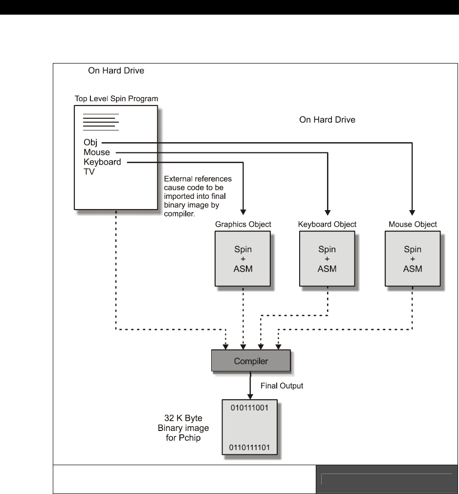
II Propeller Chip Architecture and Programming
Page 306 Game Programming for the Propeller Powered HYDRA
15.6 Spin Objects
Spin Objects and their Relationship
to the Overall Program Figure 15:12

The Spin Language15
Game Programming for the Propeller Powered HYDRA Page 307
Spin is not an object-oriented language in the usual sense of the word. But, Spin allows some
“OO” techniques in as much as we can simulate some OO behaviors such as some
organizational techniques at very least. Spin does have the ability to bring in code from
other modules named “objects,” execute the object’s functions using a dot “.” Operator as
well as access the objects CON section using a “#” operator. You could think of the object
name as a namespace and the dot operator “.” calls the function from that namespace while
the “#” operator allows access to CONstants defined in that sub-object. Figure 15:12 shows
a simplified visualization of this. In this case, we have a main program called GAME.SPIN
and GAME.SPIN relies on 4 other objects:
MOUSE_ISO_010.SPIN – Version 1.0 of the isolated mouse driver
KEYBOARD_ISO_010.SPIN – Version 1.0 of the isolated keyboard driver
GRAPHICS_DRV_010.SPIN – Version 1.0 of the graphics engine driver
TV_DRV_010. – Version 1.0 of the NTSC/PAL TV driver
To refresh your memory from earlier discussions, the versioning convention for
Spin system files is very simple: the last 3 digits refer to the major and minor
version, 2 digits for major, one digit for minor; thus version 0.0 to 99.9 can be
referred to. For example, version 3.4 would be 034, version 12.9 would be 129,
and so forth.
Referring to Figure 15:12 and seeing the file’s names, our main program file would include
these external files as “objects” and this is done in the OBJ section of your program. An
object is defined with the following syntax:
object_name : "object file name.spin" ' the ".spin" file extension is assumed
' and not required.
So you simply create a name for the object, follow it by a colon “:” then by the actual
filename of the object that contains the code, this must be in quotes. This creates an
“instantiation” of the object; if you create another instantiation of the object with a different
object_name, they are completely irrelated, they will both have their own VAR sections, but
they will share the same code. That is, the compiler is smart enough to distill redundant code
into one copy of it, so there is some “smart linking” of objects that are instantiated more
than once so that only once copy of the code is present and multiple copies of the data, just
like in Windows. In any event, declaring the object brings in the object for use in your main
program. Here’s an example of bringing in multiple objects into your program, one
instantiation of each:

II Propeller Chip Architecture and Programming
Page 308 Game Programming for the Propeller Powered HYDRA
OBJ
Mouse : "MOUSE_ISO_010.SPIN" ' Version 1.0 of the isolated mouse driver
Keyboard : "KEYBOARD_ISO_010.SPIN" ' Version 1.0 of the isolated keyboard driver
Graphics : "GRAPHICS_DRV_010.SPIN" ' Version 1.0 of the graphics engine driver
tv : "TV_DRV_010.SPIN" ' Version 1.0 of the NTSC/PAL TV driver
Given the code above, we have 4 objects declared in our main program with the names
mouse, keyboard, graphics, and tv respectively. Now, each of these files has code in them,
potentially Spin and ASM, or just Spin. However, there is one important necessity: all objects
MUST have at least one Spin PUB function to “connect” with the caller. You can’t just have an
object with pure ASM, it wouldn’t make sense, the transition from object to object occurs at
the interpreter level, the interpreter is running Spin on your cog then a call to function in
another object is made, thus it too must be Spin, but then once in the Spin of the other
object, you can always spawn another cog with some ASM. In fact, this is what all the
objects above do, if you look at the code for them on the CD here:
CD_ROOT:\HYDRA\SOURCES\*.*
You will notice that all of them enter with a “START( )” function of sorts in Spin that does
some housekeeping, spawns another cog that runs the ASM driver (ASM is needed for high
speed) and then returns to the caller. In any event, when you call an object’s sub-function
you use the syntax:
object_name.sub_function(parm1, parm2,…,parmn)
All that happens from the compiler’s point of view is that the code for the object is compiled
into the final program, and with the “.” operator you can make calls to it from one file to
another as long as you declare an object with the proper filename to the object you want to
communicate with. There is no parallel processing, no cogs involved, nothing, the SAME cog
that is running your code before the call to the object’s sub-function is the same cog that
executed the object’s sub-function call. But here’s the interesting thing: if you do want to
have ASM in your object then typically what you do is have a “Start” function in the object,
this start function might take a parameter or two from your main program, then you call the
object’s Start sub-function with the syntax (and maybe some parms):
object_name.Start(parm1,…,parmn)
Then the cog interpreter transfers control to the Start( ) function in the object and executes
whatever code is there:
PUB Start(parm1,..., parmn)
' ... do work

The Spin Language15
Game Programming for the Propeller Powered HYDRA Page 309
'...spawn some ASM or more Spin possibly on another cog, maybe not...
' return to caller, potentially after starting another task on a CIG
return
I highly recommend you study in detail the 4 driver objects listed above in the examples. See
how they work. In all of them you will see the same pattern of architecture, there is a Start,
Stop, Present (sometimes), and then typically a parameter is sent to the Start( ) function
from the caller – this might be a pingroup or a memory address, etc. – to tell the object
important information. For example. the mouse driver is relatively straightforward, let’s take
a look at it. These drivers are official Parallax drivers and very clean.
15.6.1 Example: Understanding the Mouse Driver Object
The mouse driver base version is included as an object in a main program as follows:
OBJ
mouse : "MOUSE_ISO_010.SPIN" ' Version 1.0 of the isolated mouse driver.
Then to call sub-functions of the mouse driver, this syntax used is:
mouse.sub_function(parms…)
In our case, let’s just try a couple things to get going. If you have reviewed the mouse driver
code in MOUSE_ISO_010.SPIN then you see the “start( )” function, this takes a single
parameter: the pingroup to communicate with the mouse on. In the design of the HYDRA the
mouse pins are fixed at pingroup 2 (the keyboard on 3), but this allows the object to be used
in general, thus the first rule of objects is try and make them flexible. In any event, to use
the mouse the first thing we would do in our main GAME program’s initialization function is to
start the mouse driver by calling the object’s sub-function “start” like this:
mouse.start(2) ' start the mouse driver on pingroup 2 I/O's compatible with HYDRA
Ok, at this point, let’s take a look at the actual mouse driver VAR section and the “start” and
“stop” functions. I am going to cut most of the comments out, and just keep the content
along with my notes; refer to the program on CD for all the original comments:
' Include this from the mouse driver, so you can see some of the data structures
VAR
long cogon, cog

II Propeller Chip Architecture and Programming
Page 310 Game Programming for the Propeller Powered HYDRA
long oldx, oldy, oldz 'must be followed by parameters (9 contiguous longs)
long par_x 'absolute x read-only (6 contiguous longs)
long par_y 'absolute y read-only
long par_z 'absolute z read-only
long par_buttons 'button states read-only
long par_present 'mouse present read-only
long par_pingroup 'pin group write-only
' //////////////////////////////////////////////////////////////////////////////
PUB start(pingroup) : okay
' call stop to stop the driver it was already started previously
stop
{ Now assign the local var par_pingroup the sent parm pingroup value, this is done
so any ASM spawned from here on another cog can access it, notice all the "par"
pre-fixed vars in the VAR section? These are the parameter section that at some
point will be passed to the ASM as the address for the PAR register so the ASM can
communicate with the Spin code's VAR area, remember this is what PAR is for in the
16 registers of each cog, to communicate some address that relates to the
"parameter" area or common memory region to pass information between Spin to ASM }
par_pingroup := pingroup
{ This line of code is contrived, but more or less, what it does is start a cog
running with the ASM code located at entry point "entry" with the parameter
passing area located at @par_x. This triple assignment serves a number of
purposes, the inner most function call to COGNEW( ) returns a Boolean TRUE or
FALSE if a cog 0..7 came back, if a -1 came back then we are out of cogs! The
Boolean is redundantly assigned to okay and cogon for kicks. }
okay := cogon := (cog := cognew(@entry,@par_x)) >= 0
' return to caller by default
' //////////////////////////////////////////////////////////////////////////////
PUB stop
'' Stop mouse driver - frees a cog
' test if cogon was already set, post clear either way with the "~" operator
if cogon~
cogstop(cog) ' stop the cog
longfill(@oldx, 0, 9) ' clear out some memory that was used, prepare for restart

The Spin Language15
Game Programming for the Propeller Powered HYDRA Page 311
' more code, then finally another DAT section with the actual ASM mouse driver
DAT
'***************************************
'* Assembly language PS/2 mouse driver *
'***************************************
org
'
'
' Entry
'
entry mov x,par 'load _pingroup input
parameter
add x,#5*4
rdlong _pingroup,x
shl _pingroup,#2 'set pin masks
mov mask_dw,#%0001
shl mask_dw,_pingroup
' more asm . . .
The important thing to understand here is that from our main GAME program we call the
mouse sub-function “start,” it continues running on the current cog, then tests if the mouse
driver is already running. If so, then the variable
cog
in the MOUSE_ISO_010.SPIN object
file is holding the ID of the cog, so this task is terminated with a call to “stop” from the
“start” sub-function, then once this housecleaning is handled then a call is made to launch a
new cog with the ASM code mouse driver itself located at “@entry.” Additionally, COGNEW’s
2nd parm is the address of the parameter passing area that the ASM program can access
with the PAR keyword, this is sent as “@par_x” which is the first LONG in the list of
parameters in the object’s VAR section representing the parameter passing area. This is
shown in Figure 15:13.
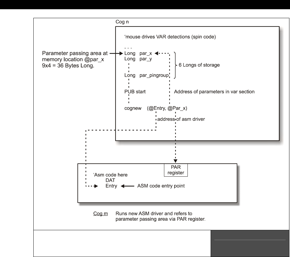
II Propeller Chip Architecture and Programming
Page 312 Game Programming for the Propeller Powered HYDRA
The Parameter Passing Area for the Mouse Driver
and its relationship to Higher Level Objects
and the ASM Driver Itself
Figure 15:13
So to review, we import the mouse driver in our OBJ section with a named import of the
filename. Then we call the “start” sub-function with the pingroup, “start” resets the driver if
it’s already running on another cog, then it restarts the ASM mouse driver on another cog,
remembers the cog number, and then returns to the caller, the main GAME program.
Now the interesting part: as the ASM mouse driver is running on another cog, it is passing
results of the mouse movements into the parameter passing area all the time (as shown in
The Spin Language15
Game Programming for the Propeller Powered HYDRA Page 313
Figure 15:13) asynchronously to what we are doing. Then, when we want to know the
mouse state, we call the mouse object with a sub-function like “mouse.abs_x” or
“mouse.abs_y” to get the absolute state of the mouse position. These functions are called
from our original cog that our main GAME program was running on, and all they do is access
the common parameter passing area and return the variable of interest that the ASM
program is continually writing to. For example, here’s the “abs_x” sub-function in the mouse
driver file:
PUB abs_x : ax
'' Get absolute-x
ax := par_x
Note that the assignment of par_x to ax implies return from the function. Anyway, look at the
body – there is no code! Of course not, since the work is being done on another cog that was
spawned earlier, so this is really an accessor function that just bridges the gap from the
calling and the ASM running on another cog via the parameter passing area.
You can also access CONstants from your objects using this syntax:
“objectname”#”constant_name”
For example, say that you had an object file name “weapons_object.spin” with
the following CON section:
CON
ENERGY = 100
...and you create an object in your main program called weapon like this:
OBJ
weapon : "weapons_object.spin"
...then to access the constant “ENERGY” you would use the following syntax
from your main program:
weapon#ENERGY
In conclusion, if you are going to make objects that you want others to use they should have
some kind of “start” or “init.” Also if they do spawn other cogs, they should be “well
behaved” and track and terminate multiple calls, so you don’t restart the same driver multiple
times when only one is needed.
II Propeller Chip Architecture and Programming
Page 314 Game Programming for the Propeller Powered HYDRA
15.6.2 Setting the Clock Modes
The Propeller chip can be clocked in three different ways:
An external crystal.
An external clock generator.
The internal 12 MHz and 20 kHz RC clock.
To set the clock mode you use the keyword “_clkmode” in the CON section of your program
to “add” the various flag bits together to form the final clock mode control WORD; however,
some control bits only make sense in some modes. For example, if you select one of the RC
modes then you can’t use the PLL multiplier rates. Once you have set the clock mode up
correct for external oscillator or external crystal with PLL, then you must let the Propeller chip
know the actual input frequency with the “_xinfreq” keyword. Table 15:7 shows all the mode
option bits for “_clkmode.” This is repeated from the Propeller chip discussions earlier, but
more simplified for the Spin language.
Table 15:7 Clock Mode Selection Constants
_CLKMODE(s) Descriptions
RCFAST Selects internal 12 MHz RC clock (used at startup until switch over to external
clocking is made)
RCSLOW Select internal 20 kHz RC clock (very low power)
XINPUT Selects clock input via XI pin, used for external oscillators (the most accurate)
XTAL1 Used for slow crystal via XI and XO pins (2 k drive, 35 pF caps)
XTAL2 Used for medium crystal via XI and XO pins (1 k drive, 25 pF caps)
XTAL3 Used for fast crystal via XI and XO pins (500 drive, 15 pF caps)
PLL1X Uses PLL clock 1x (may be used with XINPUT / XTAL1 / XTAL2 / XTAL3)
PLL2X Uses PLL clock 2x (may be used with XINPUT / XTAL1 / XTAL2 / XTAL3)
PLL4X Uses PLL clock 4x (may be used with XINPUT / XTAL1 / XTAL2 / XTAL3)
PLL8X Uses PLL clock 8x (may be used with XINPUT / XTAL1 / XTAL2 / XTAL3)
PLL16X Uses PLL clock 16x (may be used with XINPUT / XTAL1 / XTAL2 / XTAL3)
In general, we are going to use the HYDRA system which has an external crystal (XTAL), in
most cases we will use the XTAL1 or XTAL2 modes for slow and medium speed crystals from
1-10MHz. Additionally, we will always scale this input speed with the PLLxx modes to arrive
at our final processing clock – usually 40, 80, or 100 MHz or thereabouts.

The Spin Language15
Game Programming for the Propeller Powered HYDRA Page 315
Example 1: Set the clocking for an external 10 MHz oscillator, but we want a system clock
of 40 MHz.
CON
_clkmode = XINPUT + pll4x ' enable external clock and pll times 4
_xinfreq = 10_000_000 ' set frequency to 10 MHz, final clock will be 40 MHz
Example 2: Set the clocking for an external 5 MHz crystal, but we want a system clock of 80
MHz.
CON
_clkmode = XTAL1 + pll16x ' enable external clock slow and pll times 16
_xinfreq = 5_000_000 ' set frequency to 5 MHz, final clock will be 80 MHz
15.7 A Minimal Spin Program Template
Now that we have covered much of the Spin language, its syntax, and the hardware itself,
it’s time to digress for a moment and talk about a minimum Spin program. That is, what at
very least do you need to do something in Spin? Well, this depends!
First, if you want to use objects then you have to import them, but if you just want a
“template” to start with so your programs will have structure, use something like this:
CON
' constants potentially
' also in this section you will define your clock mode something like this
' additionally you may want to define a stack, so the compiler can flag a
' warning if the code+data bump into it
VAR
' here you might have any globals that you want you program to use
OBJ
' here's where you import your objects and bind them to variable names
PUB
' you need at least ONE single PUB in your top level program
PRI
' you might want to have one or more private functions
DAT
' if you need data or ASM this is where you put it

II Propeller Chip Architecture and Programming
Page 316 Game Programming for the Propeller Powered HYDRA
Considering all this, here’s the simplest program you can make on the HYDRA that does
something useful, it’s the LED blinker stripped to nothing:
CON
_clkmode = xtal1 + pll8x ' enable external clock and pll times 8
_xinfreq = 10_000_000 ' set frequency to 10 MHZ, final clock will be 80 MHz
PUB Start
{ This is the first entry point the system will see when the Propeller chip
starts. Execution ALWAYS starts on the first PUB in the source code for the top
level file. }
' set output direction for debug LED
DIRA[0] := 1
repeat
OUTA[0] := !OUTA[0] ' set LED to opposite of what it was
waitcnt(CNT + 5_000_000) ' wait 5,000,000 clocks and continue
In this program, the only important thing that is a must is that the _clkmode and _xinfreq
constants are set. In this case, we select the clock mode “_clkmode” to take the input crystal
(mode 2, medium speed crystal) and then we add in PLL8X to tell the PLL to spin the clock
8x its frequency. Then the next line “_xinfreq” indicates the actual crystal we have plugged
into the HYDRA (10 MHz most of the time).
15.8 Spin Tricks and Tips
The following is a list of tricks and tips that you can use when coding in Spin, they are not in
any particular order.
Trick - Default CON Section
The compiler defaults to a CON section at the start of a program, so you don’t have to say
CON at the top of your program if your first block is going to be constants.
Trick - Constant Evaluation
The compiler doesn’t do expression optimization or aliasing, in fact, even a simple run-time
expression like:
x := x * 5 * 4

The Spin Language15
Game Programming for the Propeller Powered HYDRA Page 317
...will not be simplified by the compiler to:
x := x * 20
The compiler will actually generate BYTE code to do the following operations:
temp := x*5
x := temp*4
Therefore, as an optimization you can pre-solve constant expressions yourself or you can use
the manual evaluator to “help” the compiler evaluate expressions with the CONSTANT( )
operator. The CONSTANT( ) operator will simplify any “compile time” solvable expression into
a single term. So, you can write:
x := x *CONSTANT(4*5)
...and the compiler will replace “CONSTANT(4*5)” with 20. Of course this is an oversimplified
expression, but you get the idea. CONSTANT( ) also works with floating-point expressions
that can be resolved at compile time as well.
Trick - Simulating BYTE, WORD, and LONG Pointers
Many times when programming, you want to use the data size of BYTE, WORD, or LONG,
that is 8, 16, or 32-bit data size, but you also want to use a pointer to some memory block
that is “indexed” by similar size chunks. In Spin this isn’t obvious how to do this when you
have a simple variable that is being used as a “pointer.” For example, say you have defined
a pointer variable as:
WORD ptr;
Now, you can assign ptr anything you want, but if you want it to “act” like a BYTE, WORD, or
LONG pointer it’s a little tricky, here’s the syntax to do it:
Use ptr as a LONG pointer which indexes to memory location ptr*4
LONG[0][ptr]
Use ptr as a WORD pointer which indexes to memory location ptr*2
WORD[0][ptr]
Use ptr as a BYTE pointer which indexes to memory location ptr*1
BYTE[0][ptr]

II Propeller Chip Architecture and Programming
Page 318 Game Programming for the Propeller Powered HYDRA
The trick here to this syntax is that we use the “base plus index” memory access mode, but
put the base as 0, this way the index is always “scaled” by the type setting: BYTE, WORD, or
LONG. In essence we have simulated the behavior as a BYTE, WORD, or LONG pointer, in as
much as when you index it you would expect the indexing to occur on data widths equal to
the type of pointer itself. In this case, though, we artificially select the scaling with LONG,
WORD, or BYTE syntax.
15.9 Summary
This chapter has been probably the most tedious thus far, lots of information to remember,
but use this chapter more as a reference, no point in memorizing all the language constructs
since typically programmers only use 5-10% of a language’s syntax anyway. The main idea is
to know features “exist,” you can always go back and find the exact details or syntax relating
to them. Well, we are almost done with the fundamentals, next chapter we are going to run
some demos, and finally its time for Part III or game programming – it’s about time!

Programming Examples 16
Game Programming for the Propeller Powered HYDRA Page 319
Chapter 16:
Programming
Examples on the
Propeller Chip /
HYDRA
Well, that’s it, hopefully at this point you have some overall idea of what the Propeller chip
does and its relationship to the HYDRA’s hardware support around it. Next, we are going to
look at a number of demo programs to get you started and give you something to work with.
Hopefully, within hours you will have reverse engineered them all and will start making your
own crazy demos. At first as noted, you should start with Spin demos only then later try
some ASM, then even later try modifying the graphics driver itself and making variants of it
along with the tv driver. Just make sure to use my file naming and software conventions,
otherwise, you will quickly loose control of everything and start overwriting files. This chapter
is more of a hands-on chapter rather than a lot of theory. Here’s the general demos and code
bases we are going to play with:
Basic graphics programming
Game controller interfacing
Sound programming
EEPROM primer
Hybrid ASM/Spin programming and parameter passing
To begin with, here’s is a listing of all the basic Parallax Spin drivers and files that come with
the system that we will base our work on (all of these files are located in the SOURCES\ sub-
directory):
MOUSE_ISO_010.SPIN PS/2 Mouse driver, uses another cog when launched
KEYBOARD_ISO_010.SPIN PS/2 Keyboard driver, uses another cog when launched
TV_DRV_010.SPIN NTSC/PAL TV driver, uses another cog when launched
VGA_DRV_010.SPIN VGA 640×480 driver, uses another cog when launched
GRAPHICS_DRV_010.SPIN Graphics engine driver, is coupled to the TV driver, but
still uses another cog when launched

II Propeller Chip Architecture and Programming
Page 320 Game Programming for the Propeller Powered HYDRA
Considering that most drivers run separately on their own cog, you can very quickly run out
of cogs! So keep this in mind – it might not we wise to run everything on a separate cog. In
fact, you may find it better to merge like operations into a “smart” driver, for example, a
single cog driver that does keyboard, mouse, and gamepad to save processing power, etc.
You will typically include both the graphics and tv drivers with each program along with the
mouse, gamepad, and keyboard drivers potentially. The following demos are simply to get
you started, there is going to be a fair amount of “reverse engineering” and code analysis on
your part to really understand things. I am going to give you a demo of everything important
and you can use these as a starting point. Later in Part III of the book we will develop more
demos, and skeleton drivers to perform higher performance graphics, sounds, and I/O. But,
the drivers illustrated in this chapter are more generic and based on Parallax’s original
drivers, thus we will refer to them as “reference” drivers and use them to model more
specific high-performance drivers later as needed.
16.1 Running the Demos
For each demo there will be one or more files that make up the demo. Typically there will be
a single “top level” file that might include other objects; simply run the demo from the
/SOURCES directory and any other files will be loaded by the Propeller IDE that are called out
in the top level file. Make sure to have your USB cable connected to your HYDRA and have
the Propeller IDE up and running with all drivers installed and functioning.
16.2 Programming Conventions and Filenaming
The following short rules and conventions were used by myself and the various “demo”
coders that developed for the HYDRA. Reviewing them will help you understand the naming
conventions as well as give you a set of conventions to follow (or not) that will help you keep
everything organized. Typically, you are going to develop only a few types of applications
and files:
Source code for games/demos in Spin/ASM usually
Drivers for the Propeller chip/HYDRA
PC Tools written in some RAD tool or C/C++/BASIC etc
Data files
The main goal of my programming conventions is that if all the files from EVERYONE on the
planet were dumped into a single directory not a single name collision would occur; this is
trivial if the correct measures are taken. For example, the following are bad ideas for file
names:
game.spin ' terrible!
driver2.asm ' crap!

Programming Examples 16
Game Programming for the Propeller Powered HYDRA Page 321
gamestuff.dat ' you gotta be kidding!
myobj.src ' ya right!
...and so on. These names are useless in large scale software development with more than
one person in the team. So we are going to use three simple tactics to create intelligent,
useful, informative names:
Tactic 1: All files must have a version suffix at the very end of the file name.
Tactic 2: All files must have a 2-4 letter “developer/library” prefix pre-pended to
them.
Tactic 3: All files must have intelligent (short) names, no spaces, but underscores
are okay.
Version Suffix
We have discussed this already, but there will be a 3 digit version code on EVERY single
source file. The format is:
MMm
The first two digits are the Major version number, the last digit is the Minor number, zeros
are used if there is no digit. This format allows us to version 0.1 to 99.9, some examples are:
version 1.3 = 013
version 1.0 = 010
version 0.5 = 005
version 10.8 = 108
...and so forth. You should append the version field to the end of all file names, example:
tv_driver_010.spin ' tv driver version 1.0
graphics_api_020.asm ' graphics api version 2.0
music_files_003.dat ' music data files version 0.3
...and so on.
In most cases, you will probably just use major version numbers, since minor version
numbers are useless really, but they are there if you need them. Typically, all your programs
will simply start with version 1.0.

II Propeller Chip Architecture and Programming
Page 322 Game Programming for the Propeller Powered HYDRA
Developer “Tagging” with Code/Library Names
There are so many programmers working on so many projects that people are inevitably
going to think of the same names, thus to protect your code a great idea is to “code” a
unique sequence of characters into every single file name, typically at the front or end of the
file name works best. This will identify the coder/library and will make collisions nearly
impossible. For example, OpenGL uses “GL” in front of every function call; we are going to do
the same. For example, say you want to use “Bob Brown’s Game Engine” then you might use
BBGE or BGE for your code, and your files would look like this:
BGE_asteroids_demo_011.spin ' some spin game source
BGE_tv_driver_fast_texturing_001.spin ' a spin/asm driver
BGE_table_generator_021.CPP ' some external C++ for a tool
These are beautiful names, they indicate the developer/library “BGE” which we know is good
old Bob. Then the file names themselves are descriptive, finally there is a version code, so
these will never be confused or collided with. Of course, I hope everyone can find more
interesting names for the libraries. For example, “HEL” for the HYDRA Extreme Library –
which is mine, so that’s now taken!!!!
So every file you make has your developer prefix pre-pended to it along with the version
code. This includes all HYDRA stuff as well as your PC tools, data files, whatever. We want to
immediately be able to say “Bob” made that, it does this, and it’s version xxx.
Modifying Drivers
As far as core names for your games, tools, drivers, it’s up to you. However, if you do decide
to modify one of the “system” drivers written by Parallax, me, or Chip Gracey then please use
a name that is similar since it might end up on internet and will help people figure out its
origins. Additionally, in the source itself comment at the top of your source what driver it was
originally based on and what general modifications you made. For example, let’s say we want
to modify the graphics driver graphics_drv_010.spin and remove all the text stuff, add
better clipping, and support for textured triangles, then we might call the new driver:
HEL_FAST_GRAPHICS_DRV_010.SPIN
In this case, the name still indicates this is some kind of graphics driver, and this is the “HEL”
library (which we know whose that is!) and its version 1.0 of the driver. Then in the top of
the source we might find something like this:
{{HEL_FAST_GRAPHICS_DRV_010.SPIN - Written by Andre' LaMothe
Last modified 1.20.06, version 1.0
Programming Examples 16
Game Programming for the Propeller Powered HYDRA Page 323
This new graphics driver was originally based on Parallax's default graphics
driver GRAPHICS_DRV_010.SPIN.
I modified it to work faster, removed text support, and added texture mapping and
better object space clipping.}}
UNDER NO CIRCUMSTANCES should you modify an original driver then release
it with the same name on internet, it will cause confusion! Please make another
version of a default driver and update the version name with your own tag, these
files are like “original DNA” and only Parallax or myself will modify these
officially.
Deployment and Packaging
When you have completed a game or demo, another good idea is to always ZIP it up along
with a README.TXT file. Also, every single file for the demo should be in the ZIP. The reason
for this is the concept of a
“package”
– no one wants to hunt for a file, a version, etc. So
if you always deploy your demos/games as a ZIP with everything in there that the user needs
then he/she will be very happy. I almost have a hatred for open source projects since they
are so unorganized, nothing ever compiles, files are missing, etc. It’s like someone does all
this work and then no one else can appreciate it, so take time to “package” your projects,
the world will thank you. Here are some examples of how I do it:
Example 1: Single File
Say you made a game called HEL_centipede_023.SPIN and this is the only file. Then you
would create a zip and place the file in there:
HEL_centipede_game_01_20_06.ZIP
The ZIP does NOT necessarily have to have the same name as the file, since you might have
100 files in there, but you do want to put the developer tag on the zip as well as a DATE
code this time. Thus, when you upload another version maybe 2 days later then on the FTP
we would find:
HEL_centipede_game_01_20_06.ZIP
HEL_centipede_game_01_22_06.ZIP
This way we have backups and a record of all the work as well, and we can always see other
previous versions. Of course, you do NOT need to include standard drivers supplied by me or
Parallax, these are assumed, but anything you make must be in there.

II Propeller Chip Architecture and Programming
Page 324 Game Programming for the Propeller Powered HYDRA
Example 2: Multiple Files
Let’s say that you have a game that is composed of a number of source files, a driver object,
a data file, and a C++ console application:
HEL_raycaster_034.spin
HEL_raycaster_data_010.spin
HEL_graphics_engine3D_021.spin
HEL_data_generator_ray_010.CPP
HEL_data_generator_ray_010.EXE
readme.txt
Then we would take all this and package it into a single ZIP with today’s date:
HEL_Raycaster_demo_01_20_06.ZIP
Now, there is a lot going on in this example, we have lots of files, and things are so complex
that we need a README.TXT to explain what’s what. Obviously, the readme is simple enough
where it doesn’t need a version or date, but it should explain things a bit, so someone that
opens this package doesn’t have to “reverse engineer” it and immediately can read what the
C++ files are for etc.
Now, let’s make a single change and see what happens. So 3 days from now, I decide to
rewrite the C++ code, and update the ray caster itself, so we change 2 files, once again, we
package all of them!
HEL_raycaster_035.spin
HEL_raycaster_data_010.spin
HEL_graphics_engine3D_021.spin
HEL_data_generator_ray_020.CPP
HEL_data_generator_ray_020.EXE
readme.txt
Now, we take it all and make a zip and if deployed on internet or on FTP we might see:
HEL_Raycaster_demo_01_20_06.ZIP
HEL_Raycaster_demo_01_23_06.ZIP
16.3 Graphics Programming
Basic graphics programming on the HYDRA is facilitated via the Parallax drivers
TV_DRV_010.SPIN and GRAPHICS_DRV_010.SPIN. The TV driver more or less
continually sends data out from the bitmap memory via the VSU unit and keeps the timing

Programming Examples 16
Game Programming for the Propeller Powered HYDRA Page 325
correct for the TV display. The graphics driver on the other hand is just a generic set of
graphics routines, not really tuned for speed or game programming, but more general
graphics and business rendering. You will immediately find the use of polar coordinates for
everything for example very slow and non-standard, but polar coordinates allow easier
rotation of simple circularly symmetrical objects, drawing of pie charts, etc. However, don’t
worry, you are free to write your own graphics drivers and or modify the current drivers.
With all that in mind, what I am going to do is show you a master demo that does all kinds
of stuff, and then briefly cover some of the details of this implementation of
GRAPHICS_DRV_010.SPIN. Although, we don’t want to spend too much time on the
generic reference drivers since you will inevitably re-write the drivers completely, or strip
them down since they not really designed for “game/graphics” rendering, but they are great
to get some demos up and running and use to develop demo programs quickly. Later in Part
III of the book we will develop a number of tile engines and other graphics drivers that are
more specific, but it’s very important that you follow the underlying principles of the Parallax
reference drivers since they are indicative of the kinds of issues and design decisions that
must be made when designing TV and graphics drivers in general, thus they are a good
“model” to begin with.
16.3.1 Master Graphics Demo – Graphics_Demo_010.SPIN
Figure 16:1
The Master Graphics Demo in Action
Figure 16:1 is a screen shot of the master graphics demo in action (written by Chip Gracey).
It doesn’t show every single function that the graphics driver GRAPHICS_DRV_010.SPIN
supports, but it gives you an idea of what the driver can do. To run the demo, follow these
steps:
Step 1: Load the file “GRAPHICS_DEMO_010.SPIN” into the Propeller IDE from the
directory CD_ROOT:\HYDRA\SOURCES\.

II Propeller Chip Architecture and Programming
Page 326 Game Programming for the Propeller Powered HYDRA
Step 2: Press the F10 or F11 button to program the Propeller chip and start the demo.
The demo shows off rotation, sprites, use of multiple colors, text, scaling, rotation, and
numerous other effects.
16.3.2 TV and Graphics Drivers
There are two primary reference drivers that make all the graphics happen on the Propeller
chip and the HYDRA respectively, they are the NTSC/PAL TV driver) and the Graphics driver
itself, both of which are purely software and you don’t have to use if you do not wish to, but
give us a way to get something on the screen quickly. However, for now I suggest using
these for your first demos and games and then later you can re-write the Graphics driver and
potentially the NTSC/PAL driver yourself.
The NTSC/PAL driver is very low-level and primarily responsible for feeding TV with video
data via the VSU, thus the NTSC/PAL driver TV_DRV_010.SPIN is primarily a timing chain
state machine that drives the NTSC/PAL TV display. If you review the code you will find all
kinds of interested things, the first is that at the top of the file there is a number of constants
and parameters:
CON
fntsc = 3_579_545 'NTSC color frequency
lntsc = 3640 'NTSC color cycles per line * 16
sntsc = 624 'NTSC color cycles per sync * 16
fpal = 4_433_618 'PAL color frequency
lpal = 4540 'PAL color cycles per line * 16
spal = 848 'PAL color cycles per sync * 16
paramcount = 14
colortable = $180 'Start of colortable inside cog
The driver code continues on for many pages, then at the end there is a listing that describes
the “TV Parameters” list. This is a list of 14 LONGs that you pass to the TV driver when you
initialize it (the driver is totally programmable); through these parameters you tell the driver
where video RAM is, the color table, the character table, the screen size, the origin, and a
number of other settings. For your convenience here’s the TV parameters explanations pulled
from the source file for your review (take a few moments and peruse the listing):
''VAR 'TV parameters - 14 contiguous longs
''
'' long tv_status '0/1/2 = off/invisible/visible read-only
'' long tv_enable '0/non-0 = off/on write-only
'' long tv_pins '%pppmmmm = pin group, pin group mode write-only

Programming Examples 16
Game Programming for the Propeller Powered HYDRA Page 327
'' long tv_mode '%ccip = chroma, interlace, ntsc/pal write-only
'' long tv_screen 'pointer to screen (words) write-only
'' long tv_colors 'pointer to colors (longs) write-only
'' long tv_ht 'horizontal tiles write-only
'' long tv_vt 'vertical tiles write-only
'' long tv_hx 'horizontal tile expansion write-only
'' long tv_vx 'vertical tile expansion write-only
'' long tv_ho 'horizontal offset write-only
'' long tv_vo 'vertical offset write-only
'' long tv_broadcast 'broadcast frequency (Hz) write-only
'' long tv_auralcog 'aural fm cog write-only
''
''The preceding VAR section may be copied into your code.
''After setting variables, do start(@tv_status) to start driver.
''
''All parameters are reloaded each superframe, allowing you to make live
''changes. To minimize flicker, correlate changes with tv_status.
''
''Experimentation may be required to optimize some parameters.
''
''Parameter descriptions:
'' _________
'' tv_status
''
'' driver sets this to indicate status:
'' 0: driver disabled (tv_enable = 0 or CLKFREQ < requirement)
'' 1: currently outputting invisible sync data
'' 2: currently outputting visible screen data
'' _________
'' tv_enable
''
'' 0: disable (pins will be driven low, reduces power)
'' non-0: enable
'' _______
'' tv_pins
''
'' bits 6..4 select pin group:
'' %000: pins 7..0
'' %001: pins 15..8
'' %010: pins 23..16
'' %011: pins 31..24
'' %100: pins 39..32
'' %101: pins 47..40
'' %110: pins 55..48
'' %111: pins 63..56
''
'' bits 3..0 select pin group mode:
'' %0000: %0000_0111 - baseband

II Propeller Chip Architecture and Programming
Page 328 Game Programming for the Propeller Powered HYDRA
'' %0001: %0000_0111 - broadcast
'' %0010: %0000_1111 - baseband + chroma
'' %0011: %0000_1111 - broadcast + aural
'' %0100: %0111_0000 baseband -
'' %0101: %0111_0000 broadcast -
'' %0110: %1111_0000 baseband + chroma -
'' %0111: %1111_0000 broadcast + aural -
'' %1000: %0111_0111 broadcast baseband
'' %1001: %0111_0111 baseband broadcast
'' %1010: %0111_1111 broadcast baseband + chroma
'' %1011: %0111_1111 baseband broadcast + aural
'' %1100: %1111_0111 broadcast + aural baseband
'' %1101: %1111_0111 baseband + chroma broadcast
'' %1110: %1111_1111 broadcast + aural baseband + chroma
'' %1111: %1111_1111 baseband + chroma broadcast + aural
'' -----------------------------------------------------------
'' active pins top nibble bottom nibble
''
'' the baseband signal nibble is arranged as:
'' bit 3: chroma signal for s-video (attach via 560-ohm resistor)
'' bits 2..0: baseband video (sum 270/560/1100-ohm resistors to form 75-ohm
'' 1V signal)
''
'' the broadcast signal nibble is arranged as:
'' bit 3: aural subcarrier (sum 560-ohm resistor into network below)
'' bits 2..0: visual carrier (sum 270/560/1100-ohm resistors to form 75-ohm
'' 1V signal)
'' _______
'' tv_mode
''
'' bit 3 controls chroma mixing into broadcast:
'' 0: mix chroma into broadcast (color)
'' 1: strip chroma from broadcast (black/white)
''
'' bit 2 controls chroma mixing into baseband:
'' 0: mix chroma into baseband (composite color)
'' 1: strip chroma from baseband (black/white or s-video)
''
'' bit 1 controls interlace:
'' 0: progressive scan (243 display lines for NTSC, 286 for PAL)
'' less flicker, good for motion
'' 1: interlaced scan (486 display lines for NTSC, 572 for PAL)
'' doubles the vertical display lines, good for text
''
'' bit 0 selects NTSC or PAL format
'' 0: NTSC
'' 3016 horizontal display ticks
'' 243 or 486 (interlaced) vertical display lines

Programming Examples 16
Game Programming for the Propeller Powered HYDRA Page 329
'' CLKFREQ must be at least 14_318_180 (4 * 3_579_545 Hz)*
'' 1: PAL
'' 3692 horizontal display ticks
'' 286 or 572 (interlaced) vertical display lines
'' CLKFREQ must be at least 17_734_472 (4 * 4_433_618 Hz)*
''
'' * driver will disable itself while CLKFREQ is below requirement
'' _________
'' tv_screen
''
'' pointer to words which define screen contents (left-to-right, top-to-bottom)
'' number of words must be tv_ht * tv_vt
'' each word has two bitfields: a 6-bit colorset ptr and a 10-bit pixelgroup
'' ptr
'' bits 15..10: select the colorset* for the associated 16 * 16 pixel tile
'' bits 9..0: select the pixelgroup** address %ppppppppppcccc00
'' (p=address, c=0..15)
''
'' * colorsets are longs which each define four 8-bit colors
''
'' ** pixelgroups are 16 longs which define (left-to-right, top-to-bottom)
'' the 2-bit (four color) pixels that make up a 16 * 16 pixel tile
'' _________
'' tv_colors
''
'' pointer to longs which define colorsets
'' number of longs must be 1..64
'' each long has four 8-bit fields which define colors for 2-bit
'' (four color) pixels
'' first long's bottom color is also used as the screen background color
'' 8-bit color fields are as follows:
'' bits 7..4: chroma data (0..15 = blue..green..red..)*
'' bit 3: controls chroma modulation (0=off, 1=on)
'' bits 2..0: 3-bit luminance level:
'' values 0..1: reserved for sync - don't use
'' values 2..7: valid luminance range, modulation adds/subtracts 1
'' (beware of 7)
''
'' * because of TV's limitations, it doesn't look good when chroma changes
'' abruptly - rather, use luminance - change chroma only against a black or
'' white background for best appearance
'' _____
'' tv_ht
''
'' horizontal number of 16 * 16 pixel tiles - must be at least 1
'' practical limit is 40 for NTSC, 50 for PAL
'' _____
'' tv_vt

II Propeller Chip Architecture and Programming
Page 330 Game Programming for the Propeller Powered HYDRA
''
'' vertical number of 16 * 16 pixel tiles - must be at least 1
'' practical limit is 13 for NTSC, 15 for PAL (26/30 max for interlaced
'' NTSC/PAL)
'' _____
'' tv_hx
''
'' horizontal tile expansion factor - must be at least 3 for NTSC, 4 for PAL
''
'' make sure 16 * tv_ht * tv_hx + ||tv_ho + 32 is less than the horizontal
'' display ticks
'' _____
'' tv_vx
''
'' vertical tile expansion factor - must be at least 1
''
'' make sure 16 * tv_vt * tv_vx + ||tv_vo + 1 is less than the display lines
'' _____
'' tv_ho
''
'' horizontal offset in ticks - pos/neg value (0 for centered image)
'' shifts the display right/left
'' _____
'' tv_vo
''
'' vertical offset in lines - pos/neg value (0 for centered image)
'' shifts the display up/down
'' ____________
'' tv_broadcast
''
'' broadcast frequency expressed in Hz (ie channel 2 is 55_250_000)
'' if 0, modulator is turned off - saves power
''
'' broadcasting requires CLKFREQ to be at least 16_000_000
'' while CLKFREQ is below 16_000_000, modulator will be turned off
'' ___________
'' tv_auralcog
''
'' selects cog to supply aural fm signal - 0..7
'' uses ctra pll output from selected cog
''
'' in NTSC, the offset frequency must be 4.5MHz and the max bandwidth +-25kHz
'' in PAL, the offset frequency is and max bandwidth vary by PAL type
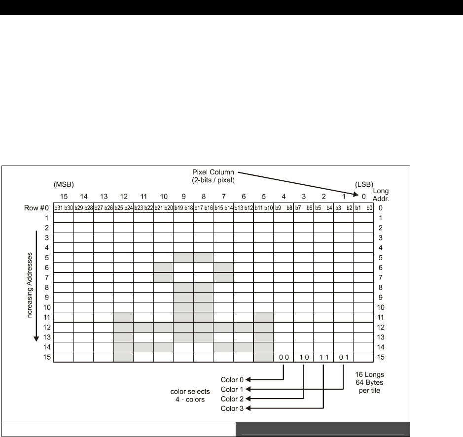
Programming Examples 16
Game Programming for the Propeller Powered HYDRA Page 331
Considering this massive list of possibilities there is a lot this driver can do and probably why
you do not want to re-write it at first, but use it as-is then later potentially re-write if you
need to free up memory and or have it work in other ways with memory or something that
are more conducive to your games’ architecture. However, that being said, I think that in
most cases we probably can use this driver for 50% of our games and demos. Still, the
GRAPHICS_DRV_010.SPIN definitely will need customizing for more advanced games and
at very least to cut out all the business graphics and generalization it has that we don’t need
for games. Alas, when it comes time to start making changes you will start with the
GRAPHICS_DRV_010.SPIN driver at first, but at first just use them as-is to get things
going!
A Single Graphics Tile Figure 16:2
In any event, the TV driver runs on a cog by itself and simply feeds the TV display with video
data. The video data comes from an “on-screen” bitmap buffer in the shared 32K memory
that is 2 bits per pixel, supports 4 colors, and is contiguous, but has a very strange memory
mapping which we will get to shortly. The size of the bitmap buffer is related to the number
of
tiles
you decide to run the TV in horizontally and vertically. The size of a tile is
always
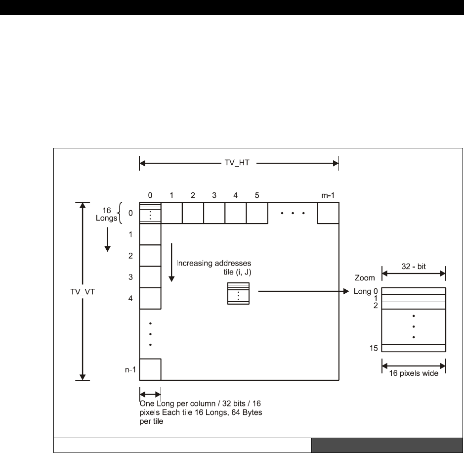
II Propeller Chip Architecture and Programming
Page 332 Game Programming for the Propeller Powered HYDRA
16×16
pixels, that is, a single tile is constructed of 16 LONGs where each LONG is 32 bits
and supports 16 pixels at 2 bits per pixel, so this works out nicely. This is shown in Figure
16:2.
Therefore, the TV driver really is a tile-mapped system consisting
of M-tiles horizontally
(columns, referred to as TV_HT in the TV driver)
, and
N-tiles vertically (rows,
referred to as TV_VT in the TV driver)
where each tile is 16×16 pixels, this is the actual
memory for the bitmap and referred to as the
“Tile Bitmap Memory”
or
“TBM.”
This is
shown in Figure 16:3.
The Tile Bitmap Memory (TBM) Figure 16:3
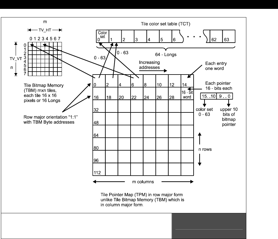
Programming Examples 16
Game Programming for the Propeller Powered HYDRA Ì Page 333
aTile Pointer Map (TPM) pointing to the
Tile Bitmap Memory (TBM) and
Tile Colorset Table (TCT) with 1:1 organization
Figure 16:4
However, there is one more level of indirection! The memory is tile mapped like this and
referenced as described, but there is a
“Tile Pointer Map”
or
“TPM”
which is a 2D array
with the same M×N dimensions as shown in Figure 16:4. Each entry in the TPM is a single
16-bit WORD which contains both a pointer to the tile’s bits in bitmap memory along with an
index into the
“Tile Colorset Table”
or
“TCT.”
The Tile Colorset Table is an array of 64
LONGs, where each 32-bit LONG represents 4 colors each (8 bits per color), these colors are
used for the tile in question. Thus each tile can have 4 colors each out of a set of 64
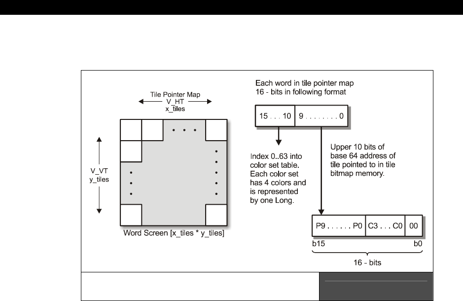
II Propeller Chip Architecture and Programming
Page 334 Game Programming for the Propeller Powered HYDRA
potential
“Color Sets.”
The organization of each Tile Pointer Map entry is shown below in
Figure 16:5 (paraphrased from the driver listing above):
The Bit Encoding of the Tile Pointer Map
(TV_Screen) in Detail Figure 16:5
Each 16-bit WORD from the Tile Pointer Map (TV_Screen in the TV driver) array has two
bitfields:
A 6-bit index (0..63) into the Tile Colorset Table that indicates which Color Set
(a single LONG) of 4 colors to use for the tile.
A 10-bit pointer into the Tile Bitmap Memory which must be on a 64-LONG
boundary, this 10-bit value is augmented in the actual addressing and is turned into
a 16-bit address as shown below.
Bits 15..10: Select the Color Set for the associated 16×16 bitmap tile to use. Remember
each tile is build of 16×16 pixels, where each pixel is 2 bits, each 2 bits refers to 4 colors,
these colors (Color Set) are actually a single LONG pointed to by this 6-bit index. The format
of the Color Set is 4 BYTEs, each is one color, each is in the standard color format discussed
in the VSU discussions.
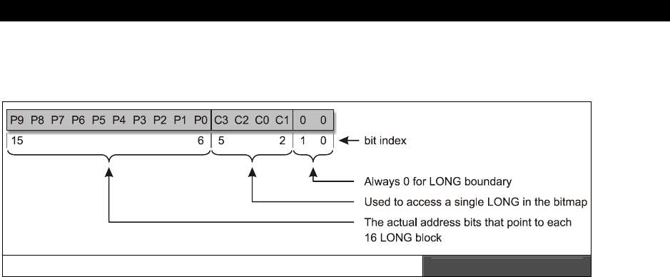
Programming Examples 16
Game Programming for the Propeller Powered HYDRA Page 335
Bits 9..0: Pointer bits to the Tile Bitmap data where these 10 bits form the upper 10 bits of
the final 16-bit address augmented as shown in Figure 16:6.
Close-up of the Bit Encoding of a Tile Pointer Map Entry Figure 16:6
Referring the encoding above and Figure 16:5 as well, the bottom line is that each Tile
Pointer Map entry (TV_Screen WORD) points to the bitmap data and the color data for each
tile. The color part is easy: the upper 6 bits are an index into the Tile Colorset Table, simple
as that. But the lower 10 bits that form the pointer to the bitmap data are a little more
complex: you don’t give the actual address in these 10 bits, but you give the address to the
16-LONG block or 64-BYTE block, thus you can think of these 10 bits as the upper 10 bits of
a 16-bit address where the lower 6 bits MUST be 0. That is, they will always refer to a block
of 64 BYTEs or 16 LONGs since the addressing in the TV driver simply shifts these bits 6
places to the left and then manipulates the lower 6 bits during its addressing, but the “base”
address you supply as the 10 bits is a 64 BYTE or 16 LONG block where the bitmap is.
This is a very cool feature and allows you to either write directly into the bitmap tile memory
with each tile pointer pointing into its respective tile bitmap OR you can use the tile pointer
memory to point to the SAME bitmap. This way you can implement either full bitmap or
character graphics. For example, if you just want to do graphics, sprites, lines, etc. then you
need a stardard bitmap set up, so what you would do is decide on the size and number of
tiles of your bitmap screen, say 16×12 tiles (256×192 pixels), then in the tile pointer map
you would point each pointer directly to its 1:1 representative tile in memory and that would
be the last time you mess with the tile pointer map. Then all you do is update the tile
graphics memory map. This is shown in Figure 16:7, where the Tile Pointer Map is being
used as a Character Map and each pointer points to the start of a character in memory
facilitating character modes.
On the other hand, if you are going to primarily be doing
“classic”
tile graphics, then you
can have your “tiles” in memory wherever you wish.
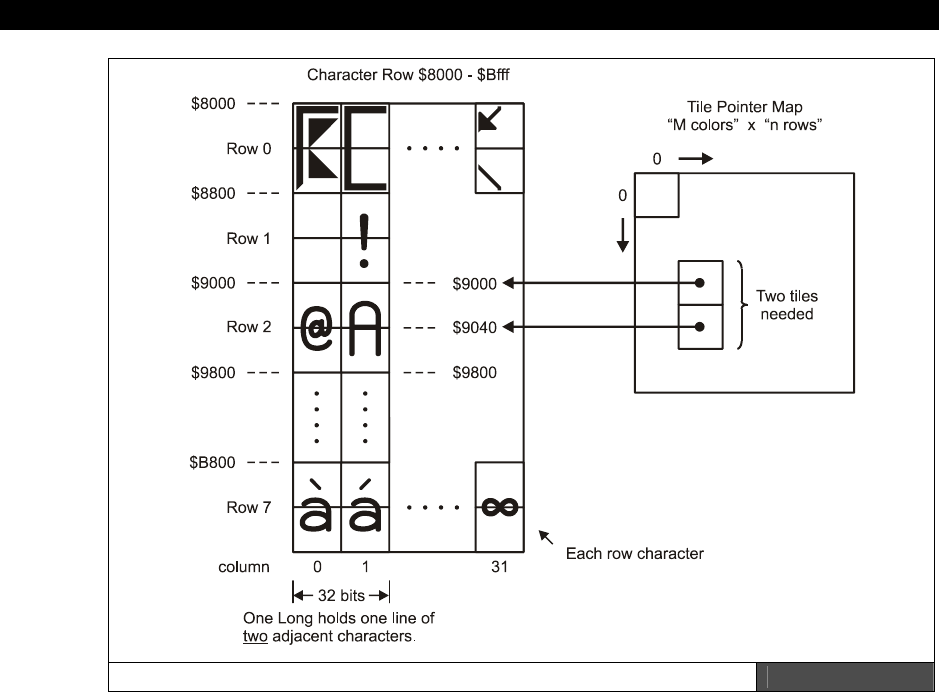
II Propeller Chip Architecture and Programming
Page 336 Game Programming for the Propeller Powered HYDRA
The Tile Pointer Map being used as a Character Map Figure 16:7
Tiles don’t need to be contiguous in any way since you aren’t going to use any of the raster
graphics routines for lines, etc., the only constraint is that the tile bitmaps are 16×16 in the
proper format (16 LONGs per bitmap, each LONG represents 16 pixels of 2 bits per pixel).
Then you simply point your tile pointer map entries to these tile entries. This way you need
only update the tile pointer map and instantly the bitmaps would change on screen! For
example, to implement a character mode you would point each entry in the tile pointer map
to the SPACE character in the ROM (character 32) and you would see a blank screen, then if
you wanted an “A” to show up in the top left corner of the screen you would point the tile
pointer map entries to the “A” bitmap entry in the character set in the ROM at $8000 – this is
why each character is made of 16 LONGs, where each LONG represents (16) 2-bit pixels.
Then the trick is to only turn on certain colors in the “color table” so that only the “A” shows
up. If you recall there are TWO characters compressed into each ROM character location
(more on this later).
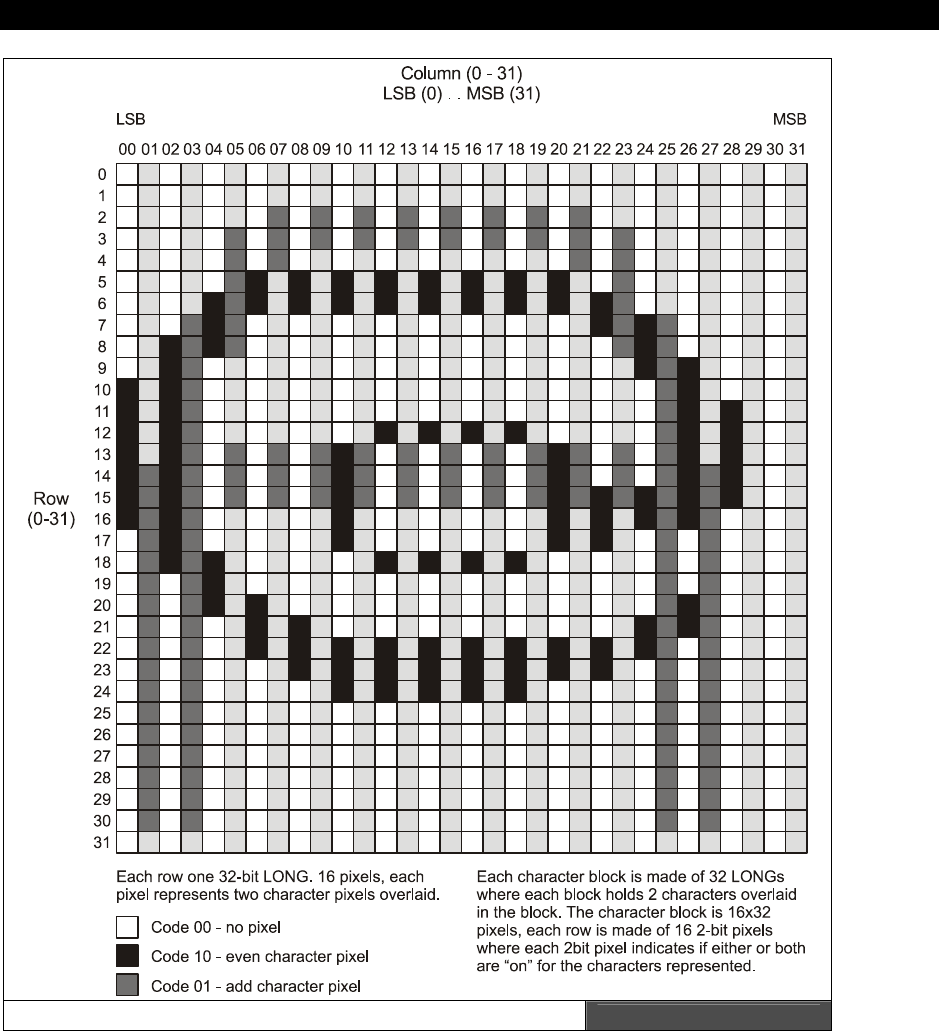
Programming Examples 16
Game Programming for the Propeller Powered HYDRA Page 337
A Character in the Character ROM located at $8000 Figure 16:8

II Propeller Chip Architecture and Programming
Page 338 Game Programming for the Propeller Powered HYDRA
The only problem with pointing the tile pointer map to a
character
in the character ROM is
that we need to
“stack”
two standard bitmap tiles since the characters in the ROM are 16
pixels wide by
32 pixels tall
, but the TV driver assumes 16×16 pixel tiles. Therefore we
need to bitmap tiles to point to a single character definition in ROM, this is shown in Figure
16:8 (the “A” and “@” characters are overlaid/encoded as a pair in this example). This is a
bit of a bummer, since it’s nice to have one character per one tile, but the character set was
made tall to support some extra drawing and schematic characters, so if you want to use it
then you must use two tile pointer map entries to point to the top and bottom of the tile
pointer map to the character definition LONGs in the ROM lookup at $8000.
Therefore, at the end of the day, if you set up a tile map of 16×12 tiles where each tile is
16×16 pixels (by definition) then if you want to use the built-in ROM character set (which is
very tall at 16×32), you are going to only be able to draw 16 columns by 6 rows since it
takes 2 characters stacked to display the super-tall 16×32 character, and this cuts your rows
down by half. Therefore, you might want to make your own 8×8 character sets etc. Of
course, the graphics driver actually has a bitmap character engine that can draw very small
characters, but it is 100× slower literally than just pointing the tile point map to a character
definition in ROM.
16.3.2.1 Video Memory Mapping and Organization
The actual organization of the
Tile Bitmap Memory
and the
Tile Pointer Map
are a bit
tricky, so we are going to discuss that in a moment, but first let’s talk about animation and
double buffering. The TV driver supports a
“double buffered”
architecture, that is you
draw on an
“off-screen”
buffer and the TV driver renders an
“on-screen”
buffer.
Therefore, on start-up you tell the TV driver the address of the on-screen buffer only
(actually you do this indirectly through the Tile Pointer Map), the off-screen buffer is
manipulated by the Graphics driver and it’s the job of the Graphics driver to “copy” the
contents of the
off-screen
buffer to the
on-screen
buffer. Therefore, there is no coupling
between the TV and Graphics drivers other than if you want to see something then you need
to copy it into the on-screen buffer since this is the only thing the TV driver renders. The
relationship between the buffers and the drivers is shown in Figure 16:9.
The cool thing about this is that you can write your own “graphics” driver fairly easily, you
just have to remember that to “see” anything you have to have a function that copies the
contents of your off-screen bitmap data into the on-screen bitmap data which the TV driver
is always rendering. Thus, with the off-screen and on-screen buffers you can implement
standard double-buffered flicker-free animation.
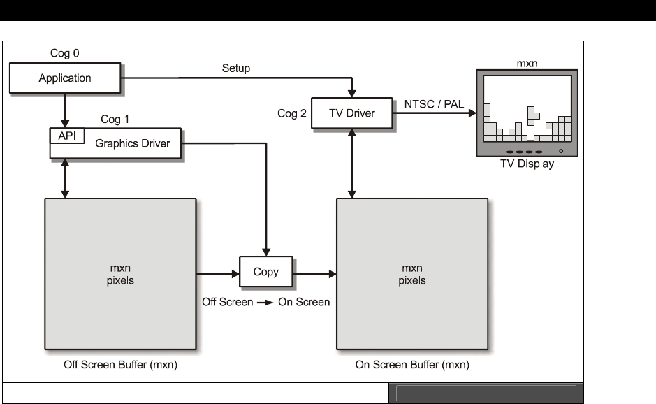
Programming Examples 16
Game Programming for the Propeller Powered HYDRA Page 339
On Screen and Off Screen Video Buffers Figure 16:9
Plot Pixel Algorithm LONG Based Version
The memory organization of the Tile Memory Map isn’t standard left-to-right, top-to-bottom.
It’s primarily top-to-bottom (column major), left-to-right within a single LONG of 16 pixels for
the width of each span, but within each bitmap tile, it is left-to-right, top-to-bottom. Refer to
Figure 16:10 to see this graphically. So the bottom line is this: the bitmap memory for a
single tile is always 16×16 pixels which consists of 16 LONGs that represent 16 pixels (2 bits
per pixel for a total of 32 bits per 16-pixel span ) per line and 16 lines. The TV driver always
draws like this. Now, when you couple the TV driver with the Graphics driver, the Graphics
driver assumes you have organized your bitmap pointers in the Tile Pointer Map such that
they point to Tile Bitmap Memory in the way shown in Figure 16:10, that is, each tile bitmap
in memory of 16 LONGs is contiguous from top-to-bottom, left-to-right.
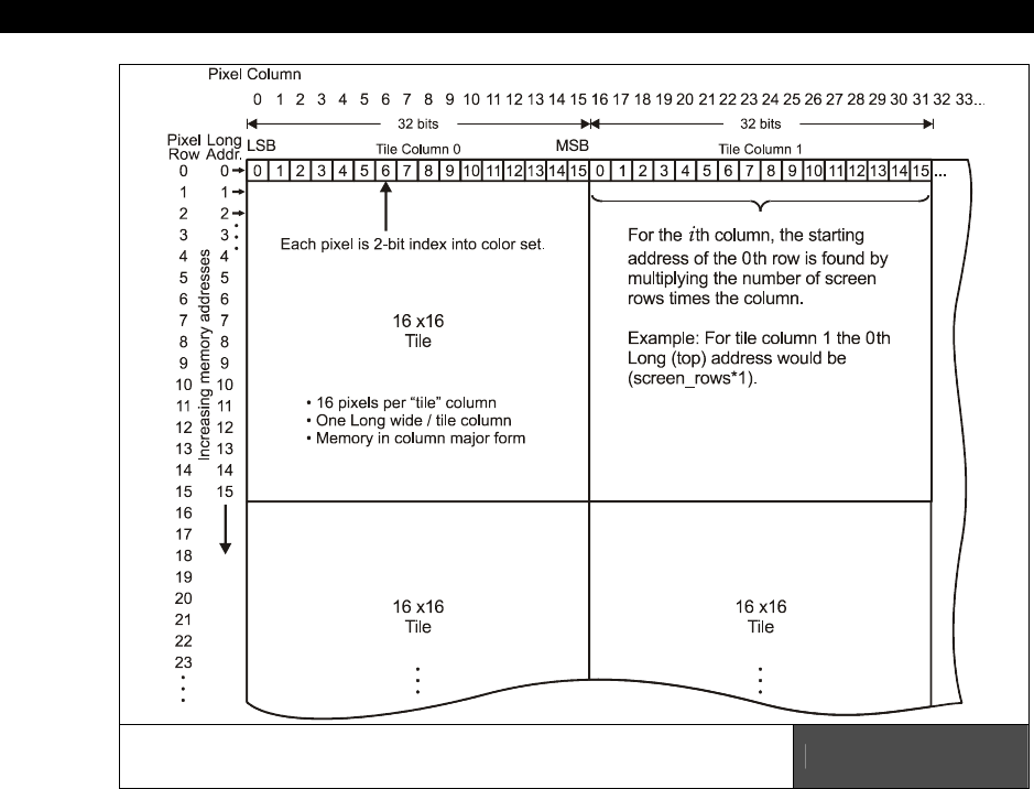
II Propeller Chip Architecture and Programming
Page 340 Game Programming for the Propeller Powered HYDRA
A Close-up View of the Memory Mapping
for Tile Bitmap Memory Figure 16:10
Referring to Figure 16:10, take a look at the memory calculations to access a single pixel in
the bitmap. Let’s discuss how I arrived at the calculations to locate a single pixel and then
how to access the pixel and write to it. First off, we can either think in terms of BYTEs or
LONGs. LONGs are better overall since the architecture is 32-bit and we don’t get a
performance hit for using LONGs, also, each pixel row in a single tile bitmap is a single LONG
which represents 16 pixels. So this makes LONGs ultimately the best choice. On the other
hand later, you might want to write a bit blitter and think in terms of BYTEs and/or
something else that is more “BYTE friendly” and accessing the Tile Bitmap Memory as BYTEs
is better. Therefore, we are going to see the code both ways. First, let’s write a LONG access
algorithm that plots pixels. Here’s the algorithm outline:

Programming Examples 16
Game Programming for the Propeller Powered HYDRA Page 341
Assume we want to plot a pixel located at (x,y) in color 0,1,2,3 with the upper left hand
corner being (0,0), and the lower right being (191, 191) – a 12×12 tile map of 16×16 tiles.
Step 1: Locate the memory address of the LONG that the pixel is located in.
Step 2: Read the LONG out of memory that we are going to write the pixel into.
Step 3: Shift our pixel into the correct bit position and logically mask and OR our data with
the pixel data in the read LONG.
Step 4: Write the LONG value back to the Tile Bitmap Memory.
Some things to remember are that there are 16 pixels per LONG, also, each LONG is
rendered from left to right on the screen within a tile bitmap, it is organized in memory from
low bit to high bit. That is, bits 0 and 1 represent pixel 0 and it is drawn as the first
(left-most) pixel. Bits 2 and 3 represent pixel 1 and it is drawn as the 2nd pixel from the left
of the tile bitmap’s current pixel row.
In a moment, we will see a listing of the code that performs all the steps, but briefly let’s
discuss the address calculation and the pixel preparation step. To calculate the address, we
start by realizing that the TV/Graphics drivers are accessing the bitmaps, each consisting of
16 LONGs (representing 16×16 pixels) in a top-to-bottom fashion, then once each column is
defined then the next column continues in memory. With this in mind, there are a lot of ways
to approach this, but I started with calculating which “column” the (x,y) pixel is located in. To
do this we need to divide the x by 16, since there are 16 pixels per tile or per LONG:
tile_column = x/16
Now, if we are assuming that we are going to use “LONG” math and that all addresses are
LONG based, that is 0 would be physical address 0, 1 would be physical address 4, and so
on, then we can figure out how many LONGs there are per column pretty easily at a 12×12
tile screen:
longs_per_column = 16×12 = 192
That was easy, so to index from column to column with LONG addressing we simply multiply
192 to our index to locate the top of the column address. Alright, getting there, now within a
column, to index vertically from top to bottom, we know that there is one LONG per pixel
group (16 pixels), so all we need to do is ADD the y coordinate. Summing up, we have:
long_memory_index = (x/16 × 192) + y
Now, assuming that the “base” of the video RAM (off-screen or on-screen) buffer is located
at physical address vram_base, we need to convert this to a LONG address by dividing by 4,
the final LONG address to the LONG that contains our target pixel is:
final_physical_long_address = vram_base/4 + (x/16 × 192) + y
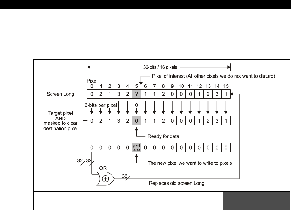
II Propeller Chip Architecture and Programming
Page 342 Game Programming for the Propeller Powered HYDRA
Ok, almost there, we have the LONG we need to work with, but which of the 16-pixels in the
LONG do we want to access? Well, first who cares, we just read the entire LONG out and
store it in read_pixel_value for example, then once we have the pixels from the screen we
are free to mask in our pixel.
We only want to access a single pixel in the 16 pixels
represented by the LONG. Figure 16:11
There are 16 pixels to choose from in the LONG, and we only want to modify one of them.
So typically we need to read the data, then mask the pixels on the screen and zero out the
target bits then OR in our color value. Figure 16:11 shows this operation. All of you are
graphics guys, so this is a common operation. You can also, XOR the bits or perform other
logical operations etc. Anyway, to either mask or OR the final color bits in, we need to
compute the location in the LONG where we want to write the 2 bits that compose the pixel
(with the real pixel data or a mask). Thus, we need to compute which “pixel” in the block of
16 that each LONG represents to shift our 2-bit pixel data:
pixel_shift = (x mod 16) * 2
And that is the last piece of the puzzle, putting it all together with a simple function that plots
pixels on the sent buffer located at x,y with a color from 0-3. Here’s a function (Note I have
pre-pended line numbers to make the following discussion easier):

Programming Examples 16
Game Programming for the Propeller Powered HYDRA Page 343
1: PUB Plot_Pixel2(x, y, video_buffer, color) | video_offset, pixel_value
2: ' plot pixel calculation using LONG aligned calcs 192x192 bitmap, 12x12 tiles
3: video_offset := (video_buffer >> 2) + (x >> 4) * (192) + y
4:
5: ' read pixel group from memory
6: pixel_value := long[0][video_offset]
7:
8: ' mask AND out target bits, so color mixing doesn't occur
9: pixel_value := pixel_value & !(%11 << ((x & %1111) << 1))
10:
11: ' OR color with pixel value
12: pixel_value := pixel_value | (color << ((x & %1111) << 1))
13:
14: ' write pixel back to memory
15: long[0][video_offset] := pixel_value
To call the function, you simply would pass it the BYTE address to the video buffer along with
the x,y and color you want to plot with:
Plot_Pixel(video_ram, x,y, color)
And that’s it! Now, one of the main reasons I went through all this discussion is so that I
could finally show you some of the memory access tricks in use. Take a look at line 6, see
the syntax “long[0][video_offset]”? This means go to the memory location BYTE address 0,
then using LONG indexing using “video_offset” add the LONG index into memory and access
a LONG at that final location, or in other words the final BYTE address is:
byte address = 0 + video_offset × 4
But, using the memory accessor technique is less clunky than multiplying manually. In any
event, that is the LONG version of accessing the Tile Bitmap Memory and plotting a pixel.
Plot Pixel Algorithm BYTE-Based Version
The BYTE-based version is nearly identical to the LONG version except that we are going to
use BYTE math and indexing instead of LONG math and indexing. Plus, each pixel row is a
single LONG that represents 16 pixels, but now we are going to think of each pixel row as a
set of 4 BYTEs, where each BYTE represents 4 pixels (each still consisting of 2 bits). Ok, the
steps are the same, so I am going to just show the highlights, since this is probably all boring
you guys. First, we are going to compute the final BYTE address of the BYTE that contains
our pixel of interest, but in this BYTE there will be 4 pixels, 3 of which we do not want to
disturb.
We start once again by realizing that we want a column major calculation, the tile column is
still:
tile_column = x/16

II Propeller Chip Architecture and Programming
Page 344 Game Programming for the Propeller Powered HYDRA
Then to compute the address of the top of each column, we realize there are 192 LONGs per
column or in BYTEs, we have:
bytes_per_column = 192*4
But, we have the final LONG starting address, but not the BYTE within, we need to work a
little harder now and find the BYTE offset with the LONG, this is computed as:
byte_index = (x mod 16) >> 2
...which will be from 0-3. Last, but not least this gets us to the right BYTE in a row of pixels,
but to get to the correct row of pixels, we need to add the y into the calculation. This is
simple – now there are 4 BYTEs per tile bitmap row, thus from any row n to n+1, the
difference in memory is just y×4, or in this case 192*4 = 768 BYTEs. Doing a common sense
check this is correct since we said we are doing a 12×12 tile setup with 16×16 pixel tiles,
thus each tile bitmap is 4 BYTEs per row times 16 rows is 64 BYTEs, and there are 12 tiles
vertically per column for a total of 64*12 = 768 BYTEs. Now, putting this all together into a
final physical BYTE address we have:
final_physical_byte_address = (x/16) * (192×4) + ((x mod 16) >> 2) + (y×4)
Lastly, we have the same read pixel, masking and shifting operations to perform, but now
instead of computing which pixel in 16, there are only 4 pixels per BYTE, so the mask and
shifting change to reflect this. Taking all this into consideration here’s the pixel plot function
that works with BYTEs and BYTE addressing:
1: PUB Plot_Pixel(x, y, video_buffer, color)| video_offset, pixel_value
2: ' plot pixel calculation using BYTE aligned calcs 192x192 bitmap, 12x12 tiles
3: video_offset := video_buffer+(x >> 4)*(192*4)+((x & %1111) >> 2)+(y << 2)
4:
5: ' read pixel group from memory
6: pixel_value := byte[video_offset]
7:
8: ' mask AND out target bits, so color mixing doesn't occur
9: pixel_value := pixel_value & !(%00000011 << ((x & %11) << 1))
10:
11: ' OR color with pixel value
12: pixel_value := pixel_value | (color << ((x & %11) << 1))
13:
14: ' write pixel back to memory
15: byte[video_offset] := pixel_value
Again, I have numbered the lines, so we can discuss the code (they aren’t part of the code).
Everything follows our algorithmic construction to the letter, the only interesting thing about
this function is the memory operation. Notice we are using the syntax “byte[offset]” – this
accesses the BYTE at video_offset. The important thing to realize is that the value in the

Programming Examples 16
Game Programming for the Propeller Powered HYDRA Page 345
brackets is
always
a BYTE address or base address. The type operator only tells Spin how
large of a chunk of memory to access at this location, so since we are working with BYTEs
this works out for us; we could have also achieved the same thing with this syntax:
byte[0][video_offset]
This would have been redundant since it basically computes the final address as:
“0 + video_offset.”
So that wraps it up for the memory mapping and the tile bitmap organization. But, remember
this is only a side effect of how the Parallax TV and Graphics drivers like things, later when
you have exausted their capabilities you can re-write them. Also, the Graphics driver itself
GRAPHICS_DRV_010.SPIN has all kinds of functionality as mentioned before including a
plot pixel function, but I wanted to show you how to access the video memory as seen by
the TV driver so you can experiment and/or make special graphics functions that might not
be supported by the graphics driver currently. We are going to get to some working demos
soon, but bear with me, we still need to discuss the color indirection the TV driver uses.
16.3.2.2 Setting up the TV Driver Example
To set up the TV driver we have to set up all the parameters and pass it both a “TV_Screen”
and “TV_Colors” array that we have generated. The TV_Screen array is what we are
generalizing to Tile Pointer Map and the TV_Colors array is more or less a 1-D array of
LONGs where each LONG represents a palette of 4 colors.
Each of these LONGs are indexed by a 6-bit index in the Tile Pointer Map and allow each tile
to have its own set of 4 colors. So what we need to do is build these two arrays up. The
color array is arbitrary and more of a “creative” thing since you can have 64 color sets and
each set has 4 colors that are applied to a single tile; therefore, there is no “correct” way to
do this, just the way that makes sense for your colors for your game. For example, if you
wanted to use the SAME 4 colors on the top of the screen and the SAME 4 colors on the
bottom of the screen, then you would only need TWO entries in the TV_Colors array or two
LONGs, since all your Tile Pointer Map color entries would all point to either the first or
second entry in the TV_Colors array which in this case consists of only two entries.
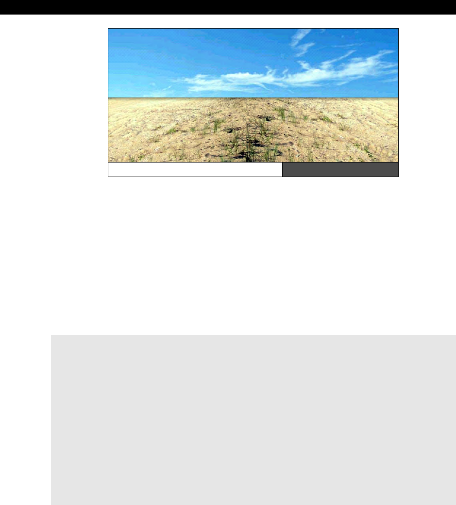
II Propeller Chip Architecture and Programming
Page 346 Game Programming for the Propeller Powered HYDRA
A Two-Region Color System Figure 16:12
Figure 16:12 shows this graphically (exaggerated albeit), in the top region we might have
“sky” colors like blues and whites, and in the bottom region we might have “ground” colors
like browns, greens, grays, and blacks, and in the interface we might have a blend of the two
color schemes to make the transition smooth. Every tile in the top and bottom would use the
same set of 4 colors, this way when we move bitmap objects through the tile space, their
colors are consistent. On the other hand, if you were making a very colorful game and
objects stayed on tile boundaries then every tile could have its own set of 4 colors and you
could use the max allotted color sets of 64, and 64 different indexes in the Tile Pointer Map.
Therefore, you must have from 1 to 64 color sets, but its not necessary to have all 64 if you
do not need them!
In any case, to start the TV driver code we need to create some CONs and VARs:
CON
' size of graphics tile map
X_TILES = 16
Y_TILES = 12
SCREEN_WIDTH = 256
SCREEN_HEIGHT = 192
' graphics driver and screen constants
PARAMCOUNT = 14
OFFSCREEN_BUFFER = $2000 ' offscreen buffer
ONSCREEN_BUFFER = $5000 ' onscreen buffer
VAR
' these parameters are going to be passed by address to the TV driver
long tv_status '0/1/2 = off/visible/invisible read-only
long tv_enable '0/? = off/on write-only

Programming Examples 16
Game Programming for the Propeller Powered HYDRA Page 347
long tv_pins '%ppmmm = pins write-only
long tv_mode '%ccinp = chroma,interlace,ntsc/pal,swap write-only
long tv_screen 'pointer to screen (words) write-only
long tv_colors 'pointer to colors (longs) write-only
long tv_hc 'horizontal cells write-only
long tv_vc 'vertical cells write-only
long tv_hx 'horizontal cell expansion write-only
long tv_vx 'vertical cell expansion write-only
long tv_ho 'horizontal offset write-only
long tv_vo 'vertical offset write-only
long tv_broadcast 'broadcast frequency (Hz) write-only
long tv_auralcog 'aural fm cog write-only
word screen[x_tiles * y_tiles] ' storage for screen tile map
long colors[64] ' color look up table
The CONstant section creates some named constants that help use refer to the size of the
tile map and the size of the screen. The VARiable section builds all the VARs that the TV
driver needs access to. The next thing you need to do is include the TV driver itself as an
object and bind it to a variable name:
OBJ
tv : "tv_drv_010.spin" ' instantiate a tv object
This instantiates a single object. Remember we could instantiate more TV objects if we
wanted to and drive multiple TVs, each with its own cog and pingroup, but the HYDRA only
has one TV output, so this will do fine.
Next, in the body of your code, you “start” the TV driver up and tell it where the parameters
are along with the TV_Screen and TV_Colors data structures:
0: 'start tv
1: longmove(@tv_status, @tvparams, paramcount)
2: tv_screen := @screen
3: tv_colors := @colors
4: tv.start(@tv_status)
Notice that we never initialized the values in the parameters we declared in the VAR section?
Well, there is a little trick: in the DAT section we create a list of initializers and then “copy”
these values with the LONGMOVE( ) function from the data section to the memory in the VAR
section. These initializations must be one to one and in sequence. This is similar to
individually initializing each value, thus we also need these initial values declared in the DAT
section like this:

II Propeller Chip Architecture and Programming
Page 348 Game Programming for the Propeller Powered HYDRA
DAT
' TV PARAMETERS FOR DRIVER /////////////////////////////////////////////
tvparams long 0 'status
long 1 'enable
long %011_0000 'pins
long %0000 'mode
long 0 'screen
long 0 'colors
long x_tiles 'hc
long y_tiles 'vc
long 10 'hx timing stretch
long 1 'vx
long 0 'ho
long 0 'vo
long 55_250_000 'broadcast
long 0 'auralcog
Analyzing the bits takes some time, but it’s a good exercise; refer to the TV driver parameter
listing above a few pages. Briefly, though let’s take a look at the four lines of code that start
the TV driver, they are labeled above. Let’s look at each line:
Line 1 – copies our static initializers into the parameter passing area defined in our VAR
section with the “longmove(@tv_status, @tvparams, paramcount)” instruction.
Line 2 – assigns the address of the memory used to hold the “TV_Screen” or what we call
the “Tile Pointer Map” to “tv_screen,” this is going to be passed momentarily.
Line 3 – assigns the address of the color lookup table or “Tile Colorset Table” (where each
LONG entry represents 4 color) to “tv_colors.”
Line 4 – starts the tv driver up by calling the sub-function “start” with the beginning of the
parameters from our program’s VAR section.
Moving on, the next thing we need to do (actually you can do this before you start the TV
driver) is build the TV_Color and TV_Screen data structures; these are the Colorset Table and
the Tile Pointer Map respectively.
'init colors
repeat i from 0 to 64
colors[i] := $00001010 * (i+4) & $F + $2B060C02
'init tile screen
repeat dx from 0 to tv_hc - 1
repeat dy from 0 to tv_vc - 1
screen[dy * tv_hc+dx] := onscreen_buffer >> 6+dy+dx*tv_vc+((dy & $3F) << 10)

Programming Examples 16
Game Programming for the Propeller Powered HYDRA Page 349
Forgive the cryptic use of constants in the setup, they are “fudged” in the color initialization
to give a “rainbow” color effect vertically down the screen. The initialization of the tile pointer
map though is consistent, so that starting from “onscreen_buffer” in memory wherever that
is, the pointers are initialized to point to 64 BYTE blocks (16 LONG blocks) that each
represent a tile in such a way that the Tile Bitmap Memory is organized in the column major
form required by the Graphics driver algorithms (we will learn about that next).
At this point, the TV driver is up and running and video will display. Now, we can either delve
into the bitmap memory directly or use the Parallax Graphics driver to draw graphics
16.3.3 The Graphics Driver Details
The reference Graphics driver is named GRAPHICS_DRV_010.SPIN and was designed to
give the best performance for a number of applications, not necessarily games. Nonetheless,
it has a lot of cool features, supports rotation, sprites, polygons, pixels, lines, filled triangles,
text and much more.
The only weirdness you are going to find is the use of polar coordinates to define polygons.
For example, in every graphics engine you have ever used or written, I am sure you used
standard Cartesian cords to represent vertices of a polygon or shape. This driver uses polar
cords to simplify rotation. The problem is of course to make a simple square you have to
compute the distance from the origin to each vertex using the Pythagorean theorem and
then compute the angle for each polar point (r, theta). This is a huge pain and for complex
objects you must resort to using inverse tangents to compute angles based on the vertex
(x,y). A tool could be written to convert, but definitely not an intuitive architecture, however,
rotation is sped up by this since it turns into addition!
In any event, other than the weird polar cords used to define polygons and shapes,
everything else is pretty much what you would expect. I am not going to go over every
function since there are too many to review and you can figure them out for yourself by
reviewing the driver.
However, do review the graphics demo GRAPHICS_DEMO_010.SPIN since it uses much
of the functionality. Nevertheless, a handful of demos will be shown that perform basic
operations to get you started with the least amount of code. And as mentioned, all your
initial experimentation should use the reference graphics driver, then you should start
modifying it and optimizing it as need be.
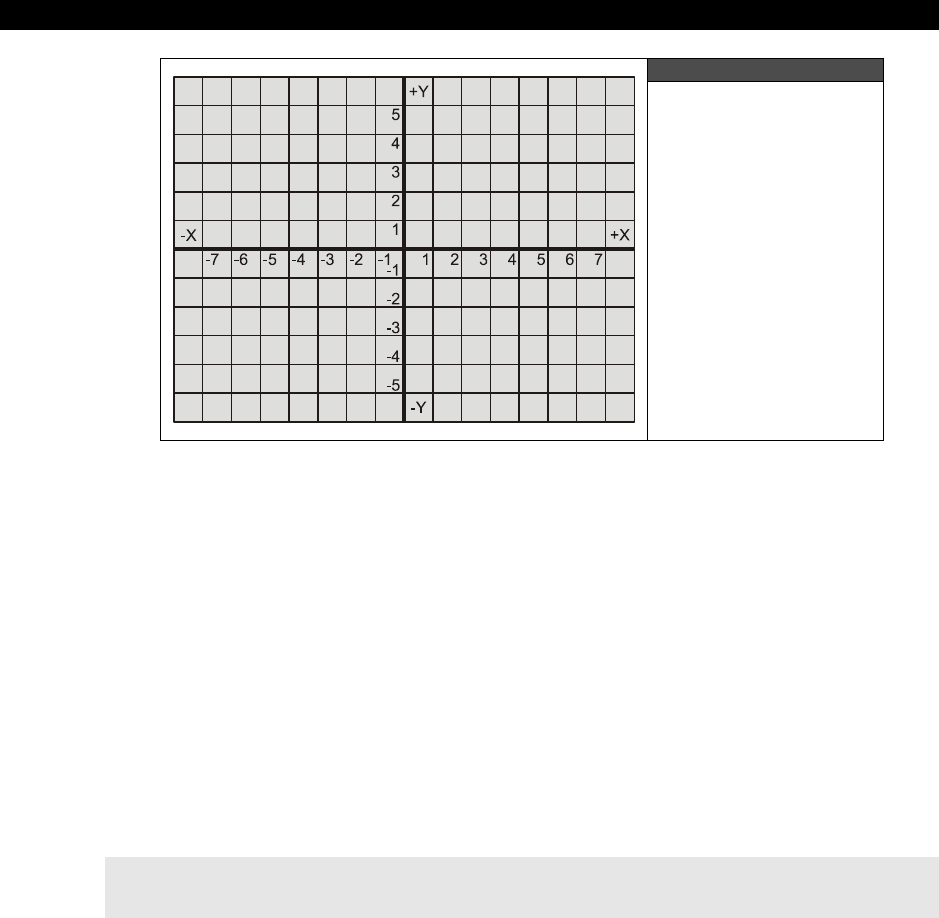
II Propeller Chip Architecture and Programming
Page 350 Game Programming for the Propeller Powered HYDRA
Figure 16:13
Coordinate Mapping
of Graphics Driver
The graphics driver uses a double-buffered architecture, that is, it renders into an “off-screen
buffer” then has a function call that copies the “offscreen buffer” into the “on-screen buffer”
that the TV driver or other driver is rendering. So during initialization, we pass the Graphics
driver the offscreen_buffer along with some other parameters and that’s it. Also, unlike most
graphics systems, this graphics driver uses coordinates that are like standard graph paper or
a Cartesian coordinate system. That is, positive X is to the right, but unlike normal graphics
systems that have positive Y going down, this driver has positive Y going up. Therefore, the
origin (0,0) of the driver is normally at the
bottom left hand corner
(rather than the top
left hand corner of most graphics drivers). Also, you can translate this origin by passing
values to the Graphics driver via the “setup” calls and center it just as a 2D Cartesian system;
this mapping is shown in Figure 16:13 above. Let’s take a look at all this in detail now…
16.3.3.1 Initializing and Using the Graphics Driver
The first step in using the Graphics driver is to of course include it as an object and bind it to
a variable name like this:
OBJ
gr : "graphics_drv_010.spin" ' instantiate a graphics object
Of course, you would have a TV object in there as well, but I omitted it for simplicity. Now,
the Graphics driver doesn’t need a parameter table, you simply pass all the important
information as parameters. The “setup” function is shown next:

Programming Examples 16
Game Programming for the Propeller Powered HYDRA Page 351
Functional Syntax:
PUB setup(x_tiles, y_tiles, x_origin, y_origin, base_ptr)
Where,
x_tiles = Number of x tiles (tiles are always 16×16 pixels each).
y_tiles = Number of y tiles.
x_origin = Relative-x center pixel.
y_origin = Relative-y center pixel.
base_ptr = Base address of bitmap.
Discussion: The setup( ) function is rather straightforward: the x_tiles and y_tiles indicate
the size of the screen overall since each tile is 16×16. Also, the x_origin and y_origin allow
you to move the (0,0) point to anywhere you wish: for example, if the final screen size was
256×128 and you wanted to move the origin from the bottom left corner to the center of the
screen, then the x_origin and y_origin would be set to 128,64 respectively which translates
the origin to the center of the screen. Also, another nice feature of the Graphics driver is that
is does all clipping for you! So when drawing pixels, lines, polygons, whatever, you don’t
have to worry about pre-clipping anything, they will be clipped for you. However, be warned
the clipping is done at the pixel-plotting level, so it’s not the fastest thing in the world! Lastly,
you pass the starting address of video memory to be used as the off-screen buffer. All
rendering will be done here and for the most part is invisible until you copy the off-screen
buffer to the visible on-screen buffer than the TV Driver is rendering. The Graphics driver has
a function call to do this as well.
Example: Set up a 256×192 pixel screen consisting of 16×12 tiles with the origin at the
bottom left corner and an offscreen rendering area at $4000.
gr.setup(16, 12, 0, 0, $4000)
Next, let’s briefly take a quick look at the function list in the Graphics driver, we aren’t going
to cover each since there are too many and you can simply look at the driver source itself for
more insight.
Remaining Graphics Driver Function List
The following is a list of the remaining graphics drivers functions and their prototypes and
parameters, please review the source in GRAPHICS_DRV_010.SPIN for a more details
since this list doesn’t have complete discussions or examples of each function.

II Propeller Chip Architecture and Programming
Page 352 Game Programming for the Propeller Powered HYDRA
Functional Syntax:
PUB start : okay
'' Start graphics driver - starts a cog.
Functional Syntax:
PUB stop
'' Stop graphics driver - frees a cog.
Functional Syntax:
PUB clear
'' Clear bitmap.
Functional Syntax:
PUB copy(dest_ptr)
'' Copy bitmap, use for double-buffered display (flicker-free).
Functional Syntax:
PUB color(c)
'' Set pixel color to two-bit pattern where c is color code in bits[1..0].
Functional Syntax:
PUB width(w)
'' Set pixel width, actual width is w[3..0] + 1, w is 0..15 for round
'' pixels,16..31 for square pixels.
Functional Syntax:
PUB colorwidth(c, w)
'' Set pixel color and width c and w respectively.
Functional Syntax:
PUB plot(x, y)
'' Plot point at x,y.

Programming Examples 16
Game Programming for the Propeller Powered HYDRA Page 353
Functional Syntax:
PUB line(x, y)
'' Draw a line from the last endpoint to x,y
PUB arc(x, y, xr, yr, angle, anglestep, steps, arcmode)
'' Draw an arc.
'' x,y - center of arc.
'' xr,yr - radii of arc.
'' angle - initial angle in bits[12..0] (0..$1FFF = 0°..359.956°).
'' anglestep - angle step in bits[12..0].
'' steps - number of steps (0 just leaves (x,y) at initial arc position).
'' arcmode - 0: plot point(s), 1: line to point(s), 2: line between points,
'' 3: line from point(s) to center.
Functional Syntax:
PUB vec(x, y, vecscale, vecangle, vecdef_ptr)
'' Draw a vector sprite.
'' x,y - center of vector sprite.
'' vecscale - scale of vector sprite ($100 = 1x).
'' vecangle - rotation angle of vector sprite in bits[12..0].
'' vecdef_ptr - address of vector sprite definition.
Functional Syntax:
PUB vecarc(x, y, xr, yr, angle, vecscale, vecangle, vecdef_ptr)
'' Draw a vector sprite at an arc position.
'' x,y - center of arc.
'' xr,yr - radii of arc.
'' angle - angle in bits[12..0] (0..$1FFF = 0°..359.956°).
'' vecscale - scale of vector sprite ($100 = 1x).
'' vecangle - rotation angle of vector sprite in bits[12..0].
'' vecdef_ptr - address of vector sprite definition.
Functional Syntax:
PUB pix(x, y, pixrot, pixdef_ptr)
'' Draw a pixel sprite.
'' x,y - center of vector sprite.
'' pixrot - 0: 0°, 1: 90°, 2: 180°, 3: 270°, +4: mirror.
'' pixdef_ptr - address of pixel sprite definition.

II Propeller Chip Architecture and Programming
Page 354 Game Programming for the Propeller Powered HYDRA
Functional Syntax:
PUB pixarc(x, y, xr, yr, angle, pixrot, pixdef_ptr)
'' Draw a pixel sprite at an arc position.
'' x,y - center of arc.
'' xr,yr - radii of arc.
'' angle - angle in bits[12..0] (0..$1FFF = 0°..359.956°).
'' pixrot - 0: 0°, 1: 90°, 2: 180°, 3: 270°, +4: mirror.
'' pixdef_ptr - address of pixel sprite definition.
Functional Syntax:
PUB text(x, y, string_ptr) | justx, justy
'' Draw text
'' x,y - text position (see textmode for sizing and justification).
'' string_ptr - address of zero-terminated string (it may be necessary to call
'' finish immediately afterwards to prevent subsequent code from
'' clobbering the string as it is being drawn.
Functional Syntax:
PUB textarc(x, y, xr, yr, angle, string_ptr) | justx, justy
'' Draw text at an arc position.
'' x,y - center of arc.
'' xr,yr - radii of arc.
'' angle - angle in bits[12..0] (0..$1FFF = 0°..359.956°).
'' string_ptr - address of zero-terminated string (it may be necessary to call
'' finish immediately afterwards to prevent subsequent code from
'' clobbering the string as it is being drawn.
Functional Syntax:
PUB textmode(x_scale, y_scale, spacing, justification)
'' Set text size and justification.
'' x_scale - x character scale, should be 1+.
'' y_scale - y character scale, should be 1+.
'' spacing - character spacing, 6 is normal.
'' justification - bits[1..0]: 0..3 = left, center, right, left.
'' bits[3..2]: 0..3 = bottom, center, top, bottom.
Functional Syntax:
PUB box(x, y, box_width, box_height) | x2, y2, pmin, pmax
'' Draw a box with round/square corners, according to pixel width.
'' x,y - box left, box bottom.

Programming Examples 16
Game Programming for the Propeller Powered HYDRA Page 355
Functional Syntax:
PUB quad(x1, y1, x2, y2, x3, y3, x4, y4)
'' Draw a solid quadrilateral.
'' vertices must be ordered clockwise or counter-clockwise.
Functional Syntax:
PUB tri(x1, y1, x2, y2, x3, y3)
'' Draw a solid triangle.
Functional Syntax:
PUB finish
'' Wait for any current graphics command to finish.
'' use this to insure that it is safe to manually manipulate the bitmap.
As you can see the Graphics driver is quite extensive. Use it as a model to write your own
graphics drivers in the future. For example, one immediate optimization that can be done is
to cut all the functions that you don’t use in your demo(s) and then to optimize the rendering
functions, so it’s a good base to start with. Of course, the actual “code” that does most of the
work is in assembly language in the DAT section of the GRAPHICS_DRV_010.SPIN
source, so you are going to have to code in ASM to optimize the driver and redo it when the
time comes and you have pushed it to its limits.
Now, that you have a firm foundation and have a picture (no pun intended) of how the TV
and Graphics drivers related to each other, let’s see a few quick demos of some of the more
basic functions. Of course, you could just crack open any of the game demos or the
GRAPHICS_DEMO_010.SPIN itself, but they have a lot of other stuff in them, so
sometimes it’s nice to see the bare minimum for a demo. Alas, in the next sections will be a
collection of rudimentary demos that do very little other than what they are intended, this
way you can see what’s what and not have to deal with a bunch of ancillary code.

II Propeller Chip Architecture and Programming
Page 356 Game Programming for the Propeller Powered HYDRA
16.3.3.2 Plot Pixel Demo
Figure 16:14
Plot Pixel Demo Screen Shot
Close-up (a visual thrill ride)
We have already seen how to access video RAM directly and plot pixels as organized by the
TV driver, TV_DRV_010.SPIN. However, in this demo and all those remaining we are going
to see how to perform basic graphics functions using the Graphics driver itself. The first
demo plots a single dot on the screen and moves it from left to right as shown in Figure
16:14. The code for the demo is located on the CD in the path below and is listed below for
reference:
CD_ROOT:\HYDRA\SOURCES\PLOT_PIXEL_010.SPIN
' //////////////////////////////////////////////////////////////////////
' Plot Pixel Demo - plot a single pixel on screen and animates it by
' moving it from left to right
' AUTHOR: Andre' LaMothe
' LAST MODIFIED: 1.3.06
' VERSION 1.0
'
' //////////////////////////////////////////////////////////////////////
'///////////////////////////////////////////////////////////////////////
' CONSTANTS SECTION ////////////////////////////////////////////////////
'///////////////////////////////////////////////////////////////////////
CON
_clkmode = xtal2 + pll4x ' enable external clock and pll times 4
_xinfreq = 10_000_000 + 3000 ' set frequency to 10 MHZ plus some error
_stack = ($3000 + $3000 + 64) >> 2 ' accomodate display memory and stack

Programming Examples 16
Game Programming for the Propeller Powered HYDRA Page 357
' graphics driver and screen constants
PARAMCOUNT = 14
OFFSCREEN_BUFFER = $2000 ' offscreen buffer
ONSCREEN_BUFFER = $5000 ' onscreen buffer
' size of graphics tile map
X_TILES = 16
Y_TILES = 12
SCREEN_WIDTH = 256
SCREEN_HEIGHT = 192
'///////////////////////////////////////////////////////////////////////
' VARIABLES SECTION ////////////////////////////////////////////////////
'///////////////////////////////////////////////////////////////////////
VAR
long tv_status '0/1/2 = off/visible/invisible read-only
long tv_enable '0/? = off/on write-only
long tv_pins '%ppmmm = pins write-only
long tv_mode '%ccinp = chroma,interlace,ntsc/pal,swap write-only
long tv_screen 'pointer to screen (words) write-only
long tv_colors 'pointer to colors (longs) write-only
long tv_hc 'horizontal cells write-only
long tv_vc 'vertical cells write-only
long tv_hx 'horizontal cell expansion write-only
long tv_vx 'vertical cell expansion write-only
long tv_ho 'horizontal offset write-only
long tv_vo 'vertical offset write-only
long tv_broadcast 'broadcast frequency (Hz) write-only
long tv_auralcog 'aural fm cog write-only
word screen[X_TILES * Y_TILES] ' storage for screen tile map
long colors[64] ' color look up table
'///////////////////////////////////////////////////////////////////////
' OBJECT DECLARATION SECTION ///////////////////////////////////////////
'///////////////////////////////////////////////////////////////////////
OBJ
tv : "tv_drv_010.spin" ' instantiate a tv object
gr : "graphics_drv_010.spin" ' instantiate a graphics object
'///////////////////////////////////////////////////////////////////////
' PUBLIC FUNCTIONS /////////////////////////////////////////////////////
'///////////////////////////////////////////////////////////////////////
PUB start | i, dx, dy, x, y

II Propeller Chip Architecture and Programming
Page 358 Game Programming for the Propeller Powered HYDRA
'start tv
longmove(@tv_status, @tvparams, paramcount)
tv_screen := @screen
tv_colors := @colors
tv.start(@tv_status)
'init colors
repeat i from 0 to 64
colors[i] := $00001010 * (i+4) & $F + $FB060C02
'init tile screen
repeat dx from 0 to tv_hc - 1
repeat dy from 0 to tv_vc - 1
screen[dy*tv_hc+dx] := onscreen_buffer >> 6+dy+dx*tv_vc+((dy & $3F) << 10)
'start and setup graphics 256x192, with origin (0,0) at center of screen
gr.start
gr.setup(X_TILES, Y_TILES, SCREEN_WIDTH/2, SCREEN_HEIGHT/2, offscreen_buffer)
' BEGIN GAME LOOP ////////////////////////////////////////////////////
' infinite loop
repeat while TRUE
'clear the offscreen buffer
gr.clear
' RENDERING SECTION (render to offscreen buffer always//////////////
' set pen attributes, color 1, size 0
gr.colorwidth(1,0)
' plot the pixel
gr.plot(x, 0)
' move the pixel
if (++x > SCREEN_WIDTH/2)
x := -SCREEN_WIDTH/2
'copy bitmap to display offscreen -> onscreen
gr.copy(onscreen_buffer)
' synchronize to frame rate would go here...
' END RENDERING SECTION ////////////////////////////////////////////
' END MAIN GAME LOOP REPEAT BLOCK ////////////////////////////////////

Programming Examples 16
Game Programming for the Propeller Powered HYDRA Page 359
'///////////////////////////////////////////////////////////////////////
' DATA SECTION /////////////////////////////////////////////////////////
'///////////////////////////////////////////////////////////////////////
DAT
' TV PARAMETERS FOR DRIVER /////////////////////////////////////////////
tvparams long 0 'status
long 1 'enable
long %011_0000 'pins
long %0000 'mode
long 0 'screen
long 0 'colors
long x_tiles 'hc
long y_tiles 'vc
long 10 'hx timing stretch
long 1 'vx
long 0 'ho
long 0 'vo
long 55_250_000 'broadcast on channel 2 VHF, each channel is
' 6 MHz above the previous
long 0 'auralcog
The code is fairly straightforward: the TV driver parameters are defined in the VAR section
then the TV driver and Graphics driver are included in the OBJ section. The code continues
into the initialization section where the TV driver and Graphics driver are initialized. Then we
fall into the main loop, set the pen color and width, plot a single pixel, and move it checking
for bounds overflow. This is more or less the smallest program you can write to do all this.
Also, notice the program clears the off-screen buffer, then renders, then copies the off-
screen buffer to the on-screen buffer. Even though there is hardly any animation happening
other than the pixel walking across the screen, this is a complete “game loop” with double-
buffered animation.
Therefore, the pixel plotting aside, you can use this program as a “template” for your other
graphics programs to get things started. Also, notice I am running the chip at 40 MHz even
though it will go 80 MHz.
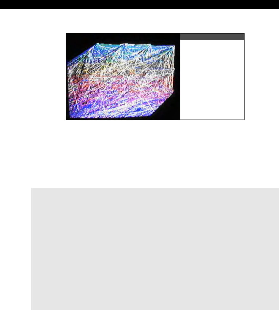
II Propeller Chip Architecture and Programming
Page 360 Game Programming for the Propeller Powered HYDRA
16.3.3.3 Line Drawing Demo
Figure 16:15
The Line Drawing
Demo in Action
To draw lines, you must use the Line( ) function, but to “seed” the starting point, you must
use the Plot( ) function. Therefore, whenever you draw a line, the line is drawn from the last
“plot” or the endpoint of the last line drawn. Figure 16:15 shows the line drawing demo in
action. The code for the demo is located on the CD in the path below and is listed below for
reference:
CD_ROOT:\HYDRA\SOURCES\DRAW_LINES_010.SPIN
' //////////////////////////////////////////////////////////////////////
' Line Drawing Demo - Draw lines randomly on screen
' AUTHOR: Andre' LaMothe
' LAST MODIFIED: 1.4.06
' VERSION 1.0
'
' //////////////////////////////////////////////////////////////////////
'///////////////////////////////////////////////////////////////////////
' CONSTANTS SECTION ////////////////////////////////////////////////////
'///////////////////////////////////////////////////////////////////////
CON
_clkmode = xtal2 + pll4x ' enable external clock and pll times 4
_xinfreq = 10_000_000 + 3000 ' set frequency to 10 MHZ plus some error
_stack = ($3000 + $3000 + 64) >> 2 'accomodate display memory and stack
' graphics driver and screen constants
PARAMCOUNT = 14

Programming Examples 16
Game Programming for the Propeller Powered HYDRA Page 361
OFFSCREEN_BUFFER = $2000 ' offscreen buffer
ONSCREEN_BUFFER = $5000 ' onscreen buffer
' size of graphics tile map
X_TILES = 16
Y_TILES = 12
SCREEN_WIDTH = 256
SCREEN_HEIGHT = 192
'///////////////////////////////////////////////////////////////////////
' VARIABLES SECTION ////////////////////////////////////////////////////
'///////////////////////////////////////////////////////////////////////
VAR
long tv_status '0/1/2 = off/visible/invisible read-only
long tv_enable '0/? = off/on write-only
long tv_pins '%ppmmm = pins write-only
long tv_mode '%ccinp = chroma,interlace,ntsc/pal,swap write-only
long tv_screen 'pointer to screen (words) write-only
long tv_colors 'pointer to colors (longs) write-only
long tv_hc 'horizontal cells write-only
long tv_vc 'vertical cells write-only
long tv_hx 'horizontal cell expansion write-only
long tv_vx 'vertical cell expansion write-only
long tv_ho 'horizontal offset write-only
long tv_vo 'vertical offset write-only
long tv_broadcast 'broadcast frequency (Hz) write-only
long tv_auralcog 'aural fm cog write-only
word screen[X_TILES * Y_TILES] ' storage for screen tile map
long colors[64] ' color look up table
'///////////////////////////////////////////////////////////////////////
' OBJECT DECLARATION SECTION ///////////////////////////////////////////
'///////////////////////////////////////////////////////////////////////
OBJ
tv : "tv_drv_010.spin" ' instantiate a tv object
gr : "graphics_drv_010.spin" ' instantiate a graphics object
'///////////////////////////////////////////////////////////////////////
' PUBLIC FUNCTIONS /////////////////////////////////////////////////////
'///////////////////////////////////////////////////////////////////////
PUB start | i, dx, dy, x, y, color
'start tv
longmove(@tv_status, @tvparams, paramcount)

II Propeller Chip Architecture and Programming
Page 362 Game Programming for the Propeller Powered HYDRA
tv_screen := @screen
tv_colors := @colors
tv.start(@tv_status)
'init colors
repeat i from 0 to 64
colors[i] := $00001010 * (i+4) & $F + $FB060C02
'init tile screen
repeat dx from 0 to tv_hc - 1
repeat dy from 0 to tv_vc - 1
screen[dy*tv_hc+dx] := onscreen_buffer >> 6+dy+dx*tv_vc+((dy & $3F) << 10)
'start and setup graphics 256x192, with origin (0,0) at bottom left of screen
gr.start
gr.setup(X_TILES, Y_TILES, 0, 0, onscreen_buffer)
' BEGIN GAME LOOP ////////////////////////////////////////////////////
' initialize some vars
x := 0
y := 0
color := 1
'clear the onscreen buffer
gr.clear
' plot the pixel at origin to seed starting point for line draw
gr.plot(0, 0)
' infinite loop
repeat while TRUE
' RENDERING SECTION (render to offscreen buffer always//////////////
' set pen attributes, color (1..3), size 0
gr.colorwidth(1 + (?color) // 3,0)
' draw the next line segment to a pseudo-random location onscreen
' notice the update of x,y pseudo-randomly with LFSR operator "?"
' "//" is the modulus operator which keeps are values on screen
gr.line(?x // 256, ?y // 192)
' synchronize to frame rate would go here...
' END RENDERING SECTION ////////////////////////////////////////////
' END MAIN GAME LOOP REPEAT BLOCK ////////////////////////////////////

Programming Examples 16
Game Programming for the Propeller Powered HYDRA Page 363
'///////////////////////////////////////////////////////////////////////
' DATA SECTION /////////////////////////////////////////////////////////
'///////////////////////////////////////////////////////////////////////
DAT
' TV PARAMETERS FOR DRIVER /////////////////////////////////////////////
tvparams long 0 'status
long 1 'enable
long %011_0000 'pins
long %0000 'mode
long 0 'screen
long 0 'colors
long x_tiles 'hc
long y_tiles 'vc
long 10 'hx timing stretch
long 1 'vx
long 0 'ho
long 0 'vo
long 55_250_000 'broadcast on channel 2 VHF, each channel is
'6 MHz above the previous
long 0 'auralcog
The demo has nearly the same initialization as the pixel plotting demo, but calls the Graphic’s
driver’s Setup( ) function is a bit different. In the line demo, the origin is set to (0,0) at the
bottom left of the screen for fun. Also, since I don’t want any animation this time, the
Graphics driver is told to render directly on the visible on-screen buffer, this way the line
rendering is “accumulated” and we see lots of lines. Some things to note about the line
drawing is the clever use of the LFSR (linear feedback shift register) operator to generate
pseudo-random numbers for the endpoint of the lines. Notice the geometrical pattern they
generate, they cover most of the screen, but there are “holes” in the coverage, these holes
are numerical values that never occur in the sequence which is interesting. In any event, let’s
move on to something more complex and render some triangles and polygons.

II Propeller Chip Architecture and Programming
Page 364 Game Programming for the Propeller Powered HYDRA
16.3.3.4 Triangle Demo
Figure 16:16
The Triangle Demo
in Action
The Graphics driver can draw open or closed line-based polygons, filled triangles as well as
quads. In most cases, you will use triangles or polygon countours to draw your graphics, so
we are going to take a look at these two functions. Again, there are variants of these
functions, so look through the Graphics driver source to really get the low-down. The triangle
demo simply draws a collection of random triangles on the screen, 100 at a time, and then
refreshes the page (running at 80 MHz); the demo is shown running Figure 16:16. The code
for the demo is located on the CD in the path below and is listed below for reference:
CD_ROOT:\HYDRA\SOURCES\DRAW_TRIANGLES_010.SPIN
' //////////////////////////////////////////////////////////////////////
' Triangle Drawing Demo - Draws sets of 100 triangles per frame
' AUTHOR: Andre' LaMothe
' LAST MODIFIED: 1.4.06
' VERSION 1.0
'
' //////////////////////////////////////////////////////////////////////
'///////////////////////////////////////////////////////////////////////
' CONSTANTS SECTION ////////////////////////////////////////////////////
'///////////////////////////////////////////////////////////////////////
CON
_clkmode = xtal2 + pll8x ' enable external clock and pll times 8
_xinfreq = 10_000_000 + 3000 ' set frequency to 10 MHZ plus some error
_stack = ($3000 + $3000 + 64) >> 2 ' accommodate display memory and stack
' graphics driver and screen constants

Programming Examples 16
Game Programming for the Propeller Powered HYDRA Page 365
PARAMCOUNT = 14
OFFSCREEN_BUFFER = $2000 ' offscreen buffer
ONSCREEN_BUFFER = $5000 ' onscreen buffer
' size of graphics tile map
X_TILES = 16
Y_TILES = 12
SCREEN_WIDTH = 256
SCREEN_HEIGHT = 192
'///////////////////////////////////////////////////////////////////////
' VARIABLES SECTION ////////////////////////////////////////////////////
'///////////////////////////////////////////////////////////////////////
VAR
long tv_status '0/1/2 = off/visible/invisible read-only
long tv_enable '0/? = off/on write-only
long tv_pins '%ppmmm = pins write-only
long tv_mode '%ccinp = chroma,interlace,ntsc/pal,swap write-only
long tv_screen 'pointer to screen (words) write-only
long tv_colors 'pointer to colors (longs) write-only
long tv_hc 'horizontal cells write-only
long tv_vc 'vertical cells write-only
long tv_hx 'horizontal cell expansion write-only
long tv_vx 'vertical cell expansion write-only
long tv_ho 'horizontal offset write-only
long tv_vo 'vertical offset write-only
long tv_broadcast 'broadcast frequency (Hz) write-only
long tv_auralcog 'aural fm cog write-only
word screen[X_TILES * Y_TILES] ' storage for screen tile map
long colors[64] ' color look up table
'///////////////////////////////////////////////////////////////////////
' OBJECT DECLARATION SECTION ///////////////////////////////////////////
'///////////////////////////////////////////////////////////////////////
OBJ
tv : "tv_drv_010.spin" ' instantiate a tv object
gr : "graphics_drv_010.spin" ' instantiate a graphics object
'///////////////////////////////////////////////////////////////////////
' PUBLIC FUNCTIONS /////////////////////////////////////////////////////
'///////////////////////////////////////////////////////////////////////
PUB start | i, dx, dy, x, y, color, x0, y0, x1, y1, x2, y2
'start tv

II Propeller Chip Architecture and Programming
Page 366 Game Programming for the Propeller Powered HYDRA
longmove(@tv_status, @tvparams, paramcount)
tv_screen := @screen
tv_colors := @colors
tv.start(@tv_status)
'init colors
repeat i from 0 to 64
colors[i] := $00001010 * (i+4) & $F + $FB060C02
'init tile screen
repeat dx from 0 to tv_hc - 1
repeat dy from 0 to tv_vc - 1
screen[dy*tv_hc+dx] := onscreen_buffer >> 6+dy+dx*tv_vc + ((dy & $3F) << 10)
'start and setup graphics 256x192, with origin (0,0) at center of screen
gr.start
gr.setup(X_TILES, Y_TILES, SCREEN_WIDTH/2, SCREEN_HEIGHT/2, offscreen_buffer)
' BEGIN GAME LOOP ////////////////////////////////////////////////////
' seed x,y with some arbitrary #'s
x := 13
y := 177
' infinite loop
repeat while TRUE
'clear the offscreen buffer
gr.clear
' RENDERING SECTION (render to offscreen buffer always//////////////
' draw 1000 triangles per frame
repeat i from 0 to 100
' generate the vertices seperately for fun
x0 := -SCREEN_WIDTH/2 + ?x // SCREEN_WIDTH
y0 := -SCREEN_HEIGHT/2 + ?y // SCREEN_HEIGHT
x1 := -SCREEN_WIDTH/2 + ?x // SCREEN_WIDTH
y1 := -SCREEN_HEIGHT/2 + ?y // SCREEN_HEIGHT
x2 := -SCREEN_WIDTH/2 + ?x // SCREEN_WIDTH
y2 := -SCREEN_HEIGHT/2 + ?y // SCREEN_HEIGHT
' draw the triangle with the generated vertex list
gr.tri (x0, y0, x1, y1, x2, y2)
' set pen attributes to cycling color, size 0

Programming Examples 16
Game Programming for the Propeller Powered HYDRA Page 367
gr.colorwidth(++color // 4,0)
'copy bitmap to display offscreen -> onscreen
gr.copy(onscreen_buffer)
' synchronize to frame rate would go here...
' END RENDERING SECTION ////////////////////////////////////////////
' END MAIN GAME LOOP REPEAT BLOCK ////////////////////////////////////
'///////////////////////////////////////////////////////////////////////
' DATA SECTION /////////////////////////////////////////////////////////
'///////////////////////////////////////////////////////////////////////
DAT
' TV PARAMETERS FOR DRIVER /////////////////////////////////////////////
tvparams long 0 'status
long 1 'enable
long %011_0000 'pins
long %0000 'mode
long 0 'screen
long 0 'colors
long x_tiles 'hc
long y_tiles 'vc
long 10 'hx timing stretch
long 1 'vx
long 0 'ho
long 0 'vo
long 55_250_000 'broadcast on channel 2 VHF, each channel is
'6 MHz above the previous
long 0 'auralcog
The triangle demo doesn’t do anything new, but makes the call to the Tri( ) function which
takes 3 sets of x,y cords and renders the filled triangle. As you can see, even at 80 MHz,
when you run the demo even 100 polys a frame is really taxing the graphics engine. Here’s
where some of the non-performance design issues are going to really pop up. For example,
the clipping is per pixel, and when rendering triangles you would always clip the top and
bottom and then clip only the endpoints of spans, the Graphics engine doesn’t do this and
simply clips every pixel. This slows it down by a factor of 5 to 10, so don’t count on making
Quake with it ☺. However, for some simple 3D demos, this triangle rasterizer should be good
to get some solid cubes on the screen.

II Propeller Chip Architecture and Programming
Page 368 Game Programming for the Propeller Powered HYDRA
The code for all the demos is meant to be clear not clever; however, the compiler
is not optimizing, thus what you see is what you get. See if by syntax changes
alone you can speed the rendering up any?
16.3.3.5 Polygon Demo
Figure 16:17
A Screen Shot Close-up
of the Polygon Demo
The polygon support in the Graphics engine allows you to draw unfilled polygons made of
lines where the polygon can be open or closed. A screen shot of the demo program we will
look at shortly is shown in Figure 16:17. In fact, its not really a “polygon” demo per se, but a
collection of vectors that make up the polygon, thus you can draw polygons, but what you
are really doing is drawing what the engine refers to as a
“Vector Sprite.”
A vector:sprite
is a collection of vectors that make up the contour of the object where each vector is a Polar
coordinate based vector in the format of (r, theta) rather than (x,y) vertices, this is shown in
Figure 16:18.
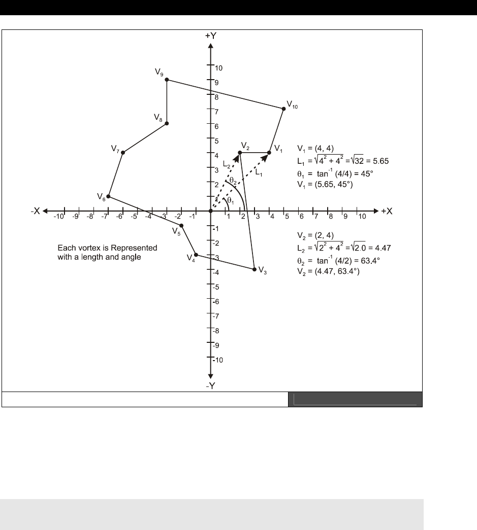
Programming Examples 16
Game Programming for the Propeller Powered HYDRA Page 369
Polar-Based Coordinates making up an Object Figure 16:18
Now, what the cool part is that vector sprites are really data structures that define the sprite
and then are passed to the vector sprite rendering function named Vec( ) which does all the
work and the function supports “on the fly” rotation and scaling, so its very powerful!
The prototype and data structure for the Vector Sprite is shown below pulled right from the
Graphics driver GRAPHICS_DRV_010.SPIN:
PUB vec(x, y, vecscale, vecangle, vecdef_ptr)
'' Draw a vector sprite

II Propeller Chip Architecture and Programming
Page 370 Game Programming for the Propeller Powered HYDRA
''
'' x,y - center of vector sprite
'' vecscale - scale of vector sprite ($100 = 1x)
'' vecangle - rotation angle of vector sprite in bits[12..0]
'' vecdef_ptr - address of vector sprite definition
''
''
'' Vector sprite definition:
''
'' word $8000 | 4000 + angle ' vector mode + 13-bit angle
' (mode: $4000=plot, $8000=line)
'' ' where angle is a 13 bit value bits[12..0]
'' ' mapping (0..$1FFF = 0°..359.956°)
'' word length ' vector length
'' ... ' more vectors
'' ...
'' word 0 'end of definition
'' ' angular constants to make object declarations easier
'' ANG_0 = $0000
'' ANG_360 = $2000
'' ANG_240 = ($2000*2/3)
'' ANG_180 = ($2000/2)
'' ANG_120 = ($2000/3)
'' ANG_90 = ($2000/4)
'' ANG_60 = ($2000/6)
'' ANG_45 = ($2000/8)
'' ANG_30 = ($2000/12)
'' ANG_22_5 = ($2000/16)
'' ANG_15 = ($2000/24)
'' ANG_10 = ($2000/36)
'' ANG_5 = ($2000/72)
Reviewing the parameters, we need to pass to the function the screen position to draw the
vector sprite (this is always the center of the sprite), along with the scale (notice $100 is 1×)
and rotation angle (more on this in a moment), finally a pointer to the actual vector sprite
data which is in the format shown above in the “Vector Sprite Definition.” So each vector
consists of:
1. A
vector mode angle
WORD which defines polar angle of the vector as well as
indicates if only a point should be plotted ($4000) at the endpoint or if a line ($8000)
should be drawn from the last endpoint.
angle = ($8000 | $4000) + $2000 * theta/360
There is a table I have generated with some common angles in the listing above as
well. But, basically 0-360 maps to $0000 to $2000.

Programming Examples 16
Game Programming for the Propeller Powered HYDRA Page 371
2. The
length
of the vector in pixels – this is equivalent to r in the polar coord
(r,theta), simply compute the length with the standard Pythagorean formula:
r = √(x2 + y2)
...where x,y is the point of the vertex assuming a center of (0,0).
To end the vector sprite definition place a $0000 at the end and this stops the sequence.
Figure 16:18 above shows a polar sprite asteroid graphed on graph paper and here’s the
data structure for it from the demo we will see shortly:
DAT
asteroid_large
word $4000+$2000*45/360 ' vertex 0, start as a point
word 8*8
word $8000+$2000*63/360 ' vertex 1
word 4*8
word $8000+$2000*108/360 ' vertex 2
word 6*8
word $8000+$2000*147/360 ' vertex 3
word 7*8
word $8000+$2000*206/360 ' vertex 4
word 4*8
word $8000+$2000*213/360 ' vertex 5
word 7*8
word $8000+$2000*243/360 ' vertex 6
word 9*8
word $8000+$2000*296/360 ' vertex 7
word 4*8
word $8000+$2000*303/360 ' vertex 8
word 7*8
word $8000+$2000*348/360 ' vertex 9
word 10*8
word $8000+$2000*45/360 ' vertex 0
word 8*8
word 0 ' terminates vector sprite

II Propeller Chip Architecture and Programming
Page 372 Game Programming for the Propeller Powered HYDRA
There are 10 vertices that make the asteroids and then the last vertex is connected to the
first. Also, notice the first vertex uses the mode $4000 pattern which indicates “point,” and
from then on we use $8000 which means draw a line from the last vertex. As a demo, I have
created a program that draws a single asteroids polygon and rotates it around slowly as it
moves around. The code for the demo is located on the CD in the path below and is listed
below for reference:
CD_ROOT:\HYDRA\SOURCES\POLYGON_VECTOR_010.SPIN
' //////////////////////////////////////////////////////////////////////
' Polygon Drawing Demo - Draws a single polygon based on the vector sprite
' and moves it around on the screen
' AUTHOR: Andre' LaMothe
' LAST MODIFIED: 1.4.06
' VERSION 1.0
'
' //////////////////////////////////////////////////////////////////////
'///////////////////////////////////////////////////////////////////////
' CONSTANTS SECTION ////////////////////////////////////////////////////
'///////////////////////////////////////////////////////////////////////
CON
_clkmode = xtal2 + pll4x ' enable external clock and pll times 8
_xinfreq = 10_000_000 + 3000 ' set frequency to 10 MHZ plus some error
_stack = ($3000 + $3000 + 64) >> 2 'accomodate display memory and stack
' graphics driver and screen constants
PARAMCOUNT = 14
OFFSCREEN_BUFFER = $2000 ' offscreen buffer
ONSCREEN_BUFFER = $5000 ' onscreen buffer
' size of graphics tile map
X_TILES = 16
Y_TILES = 12
SCREEN_WIDTH = 256
SCREEN_HEIGHT = 192
' angular constants to make object declarations easier
ANG_0 = $0000
ANG_360 = $2000
ANG_240 = ($2000*2/3)
ANG_180 = ($2000/2)
ANG_120 = ($2000/3)

Programming Examples 16
Game Programming for the Propeller Powered HYDRA Page 373
ANG_90 = ($2000/4)
ANG_60 = ($2000/6)
ANG_45 = ($2000/8)
ANG_30 = ($2000/12)
ANG_22_5 = ($2000/16)
ANG_15 = ($2000/24)
ANG_10 = ($2000/36)
ANG_5 = ($2000/72)
'///////////////////////////////////////////////////////////////////////
' VARIABLES SECTION ////////////////////////////////////////////////////
'///////////////////////////////////////////////////////////////////////
VAR
long tv_status '0/1/2 = off/visible/invisible read-only
long tv_enable '0/? = off/on write-only
long tv_pins '%ppmmm = pins write-only
long tv_mode '%ccinp = chroma,interlace,ntsc/pal,swap write-only
long tv_screen 'pointer to screen (words) write-only
long tv_colors 'pointer to colors (longs) write-only
long tv_hc 'horizontal cells write-only
long tv_vc 'vertical cells write-only
long tv_hx 'horizontal cell expansion write-only
long tv_vx 'vertical cell expansion write-only
long tv_ho 'horizontal offset write-only
long tv_vo 'vertical offset write-only
long tv_broadcast 'broadcast frequency (Hz) write-only
long tv_auralcog 'aural fm cog write-only
word screen[X_TILES * Y_TILES] ' storage for screen tile map
long colors[64] ' color look up table
'///////////////////////////////////////////////////////////////////////
' OBJECT DECLARATION SECTION ///////////////////////////////////////////
'///////////////////////////////////////////////////////////////////////
OBJ
tv : "tv_drv_010.spin" ' instantiate a tv object
gr : "graphics_drv_010.spin" ' instantiate a graphics object
'///////////////////////////////////////////////////////////////////////
' PUBLIC FUNCTIONS /////////////////////////////////////////////////////
'///////////////////////////////////////////////////////////////////////
PUB start | i, dx, dy, x, y, color, rotation
'start tv
longmove(@tv_status, @tvparams, paramcount)
tv_screen := @screen

II Propeller Chip Architecture and Programming
Page 374 Game Programming for the Propeller Powered HYDRA
tv_colors := @colors
tv.start(@tv_status)
'init colors
repeat i from 0 to 64
colors[i] := $00001010 * (i+4) & $F + $FB060C02
'init tile screen
repeat dx from 0 to tv_hc - 1
repeat dy from 0 to tv_vc - 1
screen[dy*tv_hc+dx] := onscreen_buffer >> 6+dy+dx*tv_vc+((dy & $3F) << 10)
'start and setup graphics 256x192, with origin (0,0) at bottom left of screen
gr.start
gr.setup(X_TILES, Y_TILES, SCREEN_WIDTH/2, SCREEN_HEIGHT/2, offscreen_buffer)
' BEGIN GAME LOOP ////////////////////////////////////////////////////
' initialize postion of asteroid
x := 0
y := 0
' set pen attributes
gr.colorwidth(1, 0)
' infinite loop
repeat while TRUE
'clear the offscreen buffer
gr.clear
' RENDERING SECTION (render to offscreen buffer always//////////////
' draw asteroid polygon at $100 = 1x scale with slowly incrementing
'rotation angle
gr.vec(x, y, $100, rotation, @asteroid_large)
' animate asteroid
rotation := (rotation+=4 // ANG_360)
' translate asteroid
if (++x > SCREEN_WIDTH/2)
x -= SCREEN_WIDTH
'copy bitmap to display offscreen -> onscreen
gr.copy(onscreen_buffer)
' synchronize to frame rate would go here...

Programming Examples 16
Game Programming for the Propeller Powered HYDRA Page 375
' END RENDERING SECTION ////////////////////////////////////////////
' END MAIN GAME LOOP REPEAT BLOCK ////////////////////////////////////
'///////////////////////////////////////////////////////////////////////
' DATA SECTION /////////////////////////////////////////////////////////
'///////////////////////////////////////////////////////////////////////
DAT
' TV PARAMETERS FOR DRIVER /////////////////////////////////////////////
tvparams long 0 'status
long 1 'enable
long %011_0000 'pins
long %0000 'mode
long 0 'screen
long 0 'colors
long x_tiles 'hc
long y_tiles 'vc
long 10 'hx timing stretch
long 1 'vx
long 0 'ho
long 0 'vo
long 55_250_000 'broadcast on channel 2 VHF, each channel is
'6 MHz above the previous
long 0 'auralcog
asteroid_large
word $4000+$2000*45/360 ' vertex 0
word 8*2
word $8000+$2000*63/360 ' vertex 1
word 4*2
word $8000+$2000*108/360 ' vertex 2
word 6*2
word $8000+$2000*147/360 ' vertex 3
word 7*2
word $8000+$2000*206/360 ' vertex 4
word 4*2
word $8000+$2000*213/360 ' vertex 5

II Propeller Chip Architecture and Programming
Page 376 Game Programming for the Propeller Powered HYDRA
word 7*2
word $8000+$2000*243/360 ' vertex 6
word 9*2
word $8000+$2000*296/360 ' vertex 7
word 4*2
word $8000+$2000*303/360 ' vertex 8
word 7*2
word $8000+$2000*348/360 ' vertex 9
word 10*2
word $8000+$2000*45/360 ' vertex 0
word 8*2
word 0 ' terminates vector sprite
The demo uses the double-buffer display since we need animation to smoothly draw the
asteroid. Also, notice that after the asteroid is drawn with the call to Vec( ), we animate its
angle and position. One note, the angle is not cumulative, that is the rendering rotates the
vector sprite every single time. Typically this would be a tragedy performance wise, but since
the internal format is polar, the rotation ends up being a single addition per vertex, so not
much of a performance hit. Lastly, the scaling factor might be a little confusing at first glance
since $100 means 1x size, but this is understandable since $100 (hex) is 256 decimal which
is “1.0” in fixed point 24.8 format which the Vec( ) function uses in some calculations. Next,
let’s move on to text.
16.3.3.6 Text Demo
Figure 16:19
A Screen Shot Close-up
of the Text Demo

Programming Examples 16
Game Programming for the Propeller Powered HYDRA Page 377
Figure 16:19 is a screen shot of the text demo running. The Graphics driver really shines in
the area of text. This is one of the worst implemented features in any graphics engine
(especially Windows GDI), typically all you have is a bitmap font and that’s that. Of course in
many cases that’s all you want, but the Graphics driver here allows all kinds of scaling and
even arc text to be drawn, so it’s pretty cool if you have a text-heavy interface you want to
do. The only bad news is that you only have a single font choice, which is the built-in vector
font, but its pretty good and fairly legible. But, no one said that you can’t modify it!
Remember, anything you change you must RE-SAVE as another graphics driver, document it
and call it something intelligent if you want to deploy it on the internet.
In any case, to draw text we are concerned with two basic functions: Textmode( ) and
Text( ). Their definitions are listed once again for reference below; Texmode( ) sets up the
rendering of the text and Text( ) does the actual drawing:
PUB textmode(x_scale, y_scale, spacing, justification)
'' Set text size and justification
''
'' x_scale - x character scale, should be 1+
'' y_scale - y character scale, should be 1+
'' spacing - character spacing, 6 is normal
'' justification - bits[1..0]: 0..3 = 0=left, 1=center, 2=right, 3=left
'' bits[3..2]: 0..3 = 0=bottom, 1=center, 2=top, 3=bottom
PUB text(x, y, string_ptr)
'' Draw text
''
'' x,y - text position (see textmode for sizing and justification)
'' string_ptr - address of zero-terminated string (it may be necessary to
'' call finish immediately afterwards to prevent subsequent
'' code from clobbering the string as it is being drawn
The Textmode( ) parameters should be obvious from inspection, basically they describe the
scale, spacing and justification you wish. I suggest experimenting to see what works and
what doesn’t, remember depending on what your colors are, resolution, etc. you have to find
the “sweet spot” for text rendering that looks best. Also, you must of course set the pen up
with the Colorwidth( ) function to see anything.
The Text( ) rendering function itself is very simple, you just pass the x,y position and a
pointer to a standard ASCII-Z string and that’s it. Thus you will typically define your strings
statically in a DAT section or you might put them in a VAR section if you want to alter them
on the fly.

II Propeller Chip Architecture and Programming
Page 378 Game Programming for the Propeller Powered HYDRA
As an example, SCROLLING_TEXT_010.SPIN draws a scrolling marquee. The code for
the demo is located on the CD in the path below and is listed as well for reference:
CD_ROOT:\HYDRA\SOURCES\SCROLLING_TEXT_010.SPIN
' //////////////////////////////////////////////////////////////////////
' Scrolling Text Drawing Demo - Draws a scrolling marquee of text
' AUTHOR: Andre' LaMothe
' LAST MODIFIED: 1.5.06
' VERSION 1.0
'
' //////////////////////////////////////////////////////////////////////
'///////////////////////////////////////////////////////////////////////
' CONSTANTS SECTION ////////////////////////////////////////////////////
'///////////////////////////////////////////////////////////////////////
CON
_clkmode = xtal2 + pll8x ' enable external clock and pll times 8
_xinfreq = 10_000_000 + 3000 ' set frequency to 10 MHZ plus some error
_stack = ($3000 + $3000 + 64) >> 2 ' accomodate display memory and stack
' graphics driver and screen constants
PARAMCOUNT = 14
OFFSCREEN_BUFFER = $2000 ' offscreen buffer
ONSCREEN_BUFFER = $5000 ' onscreen buffer
' size of graphics tile map
X_TILES = 16
Y_TILES = 12
SCREEN_WIDTH = 256
SCREEN_HEIGHT = 192
'///////////////////////////////////////////////////////////////////////
' VARIABLES SECTION ////////////////////////////////////////////////////
'///////////////////////////////////////////////////////////////////////
VAR
long tv_status '0/1/2 = off/visible/invisible read-only
long tv_enable '0/? = off/on write-only
long tv_pins '%ppmmm = pins write-only
long tv_mode '%ccinp = chroma,interlace,ntsc/pal,swap write-only
long tv_screen 'pointer to screen (words) write-only
long tv_colors 'pointer to colors (longs) write-only
long tv_hc 'horizontal cells write-only

Programming Examples 16
Game Programming for the Propeller Powered HYDRA Page 379
long tv_vc 'vertical cells write-only
long tv_hx 'horizontal cell expansion write-only
long tv_vx 'vertical cell expansion write-only
long tv_ho 'horizontal offset write-only
long tv_vo 'vertical offset write-only
long tv_broadcast 'broadcast frequency (Hz) write-only
long tv_auralcog 'aural fm cog write-only
word screen[X_TILES * Y_TILES] ' storage for screen tile map
long colors[64] ' color look up table
byte sbuffer[128] ' string buffer holds the string
'///////////////////////////////////////////////////////////////////////
' OBJECT DECLARATION SECTION ///////////////////////////////////////////
'///////////////////////////////////////////////////////////////////////
OBJ
tv : "tv_drv_010.spin" ' instantiate a tv object
gr : "graphics_drv_010.spin" ' instantiate a graphics object
'///////////////////////////////////////////////////////////////////////
' PUBLIC FUNCTIONS /////////////////////////////////////////////////////
'///////////////////////////////////////////////////////////////////////
PUB start | i, dx, dy, x, y, color, x0, y0, x1, y1, x2, y2, scroll, scroll_counter
'start tv
longmove(@tv_status, @tvparams, paramcount)
tv_screen := @screen
tv_colors := @colors
tv.start(@tv_status)
'init colors
repeat i from 0 to 64
colors[i] := $00001010 * (i+4) & $F + $FB060C02
'init tile screen
repeat dx from 0 to tv_hc - 1
repeat dy from 0 to tv_vc - 1
screen[dy*tv_hc+dx] := onscreen_buffer >> 6+dy+dx * tv_vc+((dy & $3F) << 10)
'start and setup graphics 256x192, with origin (0,0) at bottom left of screen
gr.start
gr.setup(X_TILES, Y_TILES, 0,0, offscreen_buffer)
' BEGIN GAME LOOP ////////////////////////////////////////////////////
' set up the text mode and color information

II Propeller Chip Architecture and Programming
Page 380 Game Programming for the Propeller Powered HYDRA
gr.textmode(2,1,5,3) ' scale 2x1, 5 for spacing, justification left-bottom
gr.colorwidth(color,0) ' color 2, smallest pixel width
' infinite loop
repeat while TRUE
'clear the offscreen buffer
gr.clear
' RENDERING SECTION (render to offscreen buffer always//////////////
' copy a screen worth of the static string into the working string sbuffer
BYTEMOVE(@sbuffer, @text_string + scroll, 26)
' terminate the string
sbuffer[26] := 0
' draw the text
gr.text(0,SCREEN_HEIGHT/2, @sbuffer)
if (++scroll_counter > 7)
' scroll the text for next frame
scroll := ++scroll // 58
' reset counter
scroll_counter := 0
' update color
gr.colorwidth(1 + (++color//3) ,0) ' force color to be from 1..3
'copy bitmap to display offscreen -> onscreen
gr.copy(onscreen_buffer)
' synchronize to frame rate would go here...
' END RENDERING SECTION ////////////////////////////////////////////
' END MAIN GAME LOOP REPEAT BLOCK ////////////////////////////////////
'///////////////////////////////////////////////////////////////////////
' DATA SECTION /////////////////////////////////////////////////////////
'///////////////////////////////////////////////////////////////////////
DAT
' TV PARAMETERS FOR DRIVER /////////////////////////////////////////////
tvparams long 0 'status
long 1 'enable
long %011_0000 'pins
long %0000 'mode
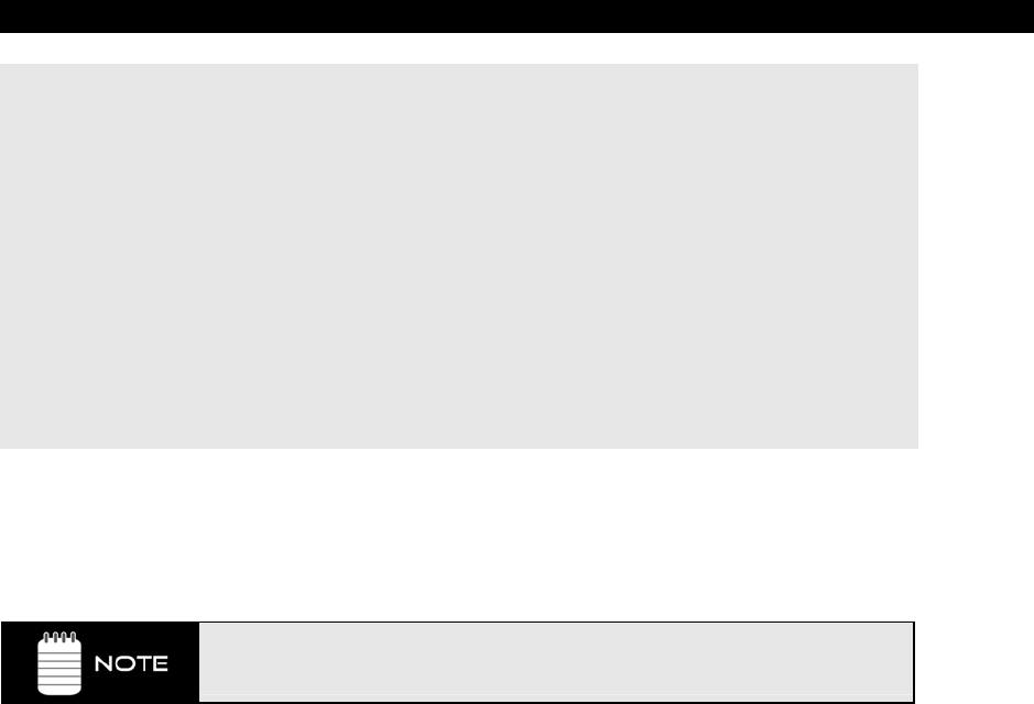
Programming Examples 16
Game Programming for the Propeller Powered HYDRA Page 381
long 0 'screen
long 0 'colors
long x_tiles 'hc
long y_tiles 'vc
long 10 'hx timing stretch
long 1 'vx
long 0 'ho
long 0 'vo
long 55_250_000 'broadcast on channel 2 VHF, each channel is
'6 MHz above the previous
long 0 'auralcog
text_string byte "..........................I'm sorry Dave, I can't do
that..........................",0
' NOTE: the two lines above belong on the SAME line in the IDE.
The demo is fairly straightforward. You will notice constants in the program are simply the
length of the string and the length of the “…” segment which is when we can do a reset and
restart the scrolling without any visual disruptions. Anyway, try experimenting with the
Textmode( ) function and see what kind of weird things you can make it do.
Notice how slow the text rendering is? When the dots are on the screen it speeds
up, then when there is text you see it slow down! Text is slow on GDI and it’s
slow here too – slow text seems to be a universal constant ☺.
Well, that’s it for basic graphics. Next, let’s take a look at the mouse, keyboard, and
gamepad interfacing.
16.4 Mouse, Keyboard and Gamepad Programming
Well, we are almost done, now for the boring stuff – Input/Output! The HYDRA supports
three input devices:
PS/2 mouse
PS/2 keyboard
Nintendo-compatible Gamepad
All three can be plugged in at once and communicated to at once. Currently, there are cog
object based drivers for all three devices. Actually, later you will find that there is no need to
run the mouse, keyboard, and gamepad scanning on multiple cogs; in fact, once you start
coding games and graphics you will quickly find yourself running out of cogs. Thus, once you
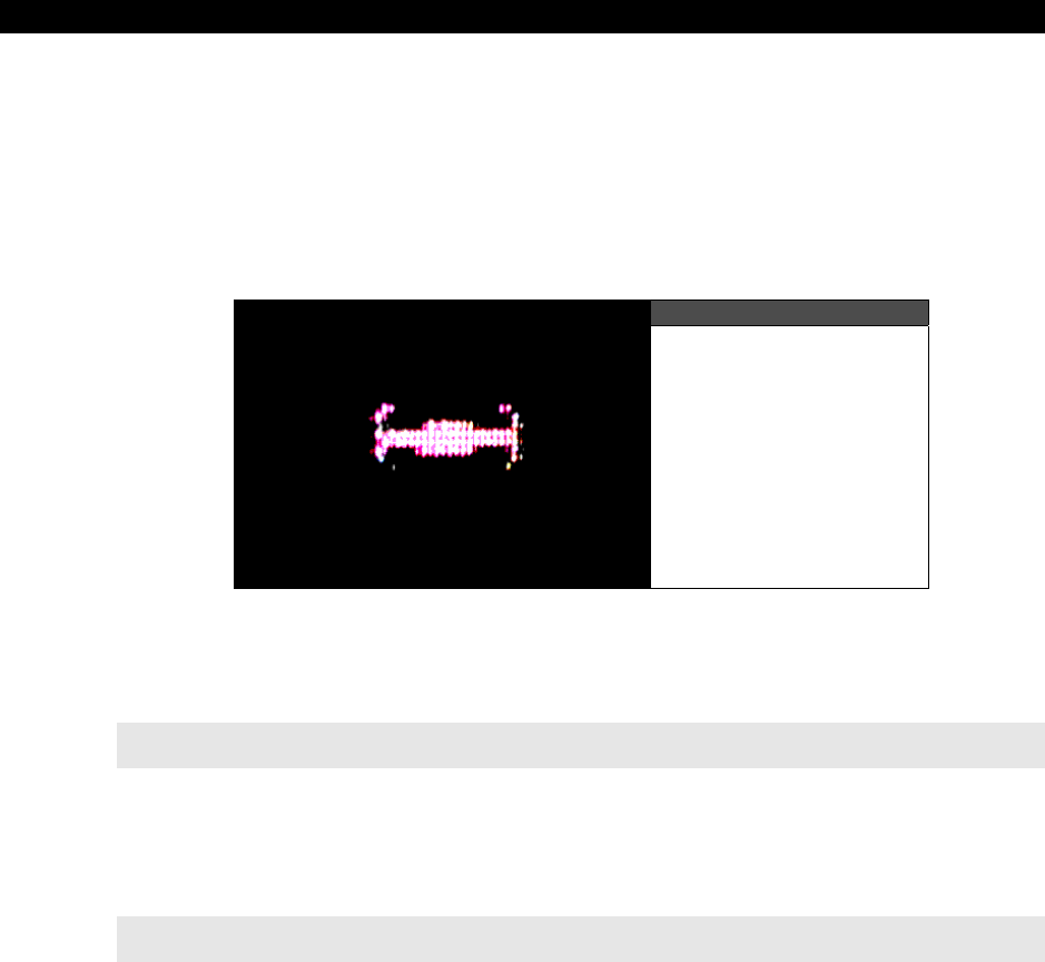
II Propeller Chip Architecture and Programming
Page 382 Game Programming for the Propeller Powered HYDRA
get into more serious coding you will want to make a stripped-down “I/O Object” that runs
on a single cog and does all the reading of the keyboard, mouse, and gamepad and packs
these into DirectX or SDL-like chunks. Additionally, this object might do output on the little
debug LED, maybe allow patterns or something, or some PWM modulation to make it “glow”
with games – there’s a cool idea! In any event, let’s take a quick look at some simple
examples of each input device.
16.4.1 Mouse Demo
Figure 16:20
Screen Shot Close-up
of the Mouse Demo
Figure 16:20 shows a simple demo of the mouse in action. The Mouse driver object is named
MOUSE_ISO_010.SPIN as mentioned before. It is instantiated by declaring an object in
the OBJ section like this:
OBJ
mouse : "mouse_iso_010.spin" ' instantiate a mouse object
Once the mouse is instantiated is must be “started” by making a call to the start( ) sub-
function of the mouse object with the pingroup that the mouse should use to communicate
with. On the HYDRA the pingroup is always 2, thus to start the mouse you need to make this
call:
mouse.start(2) ' start mouse and bind it to pingroup 2
The mouse driver, like the graphics driver, has a lot of functionality, in fact, a lot of overkill
for our purposes, so at some point you will want to merge all the input drivers into one and
run them on a single cog with bare-bones functionality. However, starting from the robust
and complete mouse driver is always best. The mouse send packets whenever there is an
event, the driver handles this for us, and returns the mouse postion and button state for
querying. The functions that retrieve the mouse deltas and buttons are shown below:

Programming Examples 16
Game Programming for the Propeller Powered HYDRA Page 383
Functional Syntax:
PUB button(b) : state
'' returns the state of a particular button, see bit encoding below
'' returns TRUE or FALSE if the button is down
Functional Syntax:
PUB buttons : states
'' returns the states of all buttons encoded as follows:
'' bit4 = right-side button
'' bit3 = left-side button
'' bit2 = center/scrollwheel button
'' bit1 = right button
'' bit0 = left button
Functional Syntax:
PUB delta_x : dx
'' Returns mouse delta-x
Functional Syntax:
PUB delta_y : dy
'' Returns mouse delta-y
Of course there are functions to retrieve pretty much everything else the mouse has to offer,
so make sure to review the mouse driver itself in MOUSE_ISO_010.SPIN. As an example,
MOUSE_DEMO_010.SPIN draws a little Tie fighter on the screen and lets you mouse it
around and change its wing configuration with the buttons. The code for the demo is located
on the CD in the path below and is listed below for reference:
CD_ROOT:\HYDRA\SOURCES\MOUSE_DEMO_010.SPIN
' //////////////////////////////////////////////////////////////////////
' Mouse Demo - Demos the mouse and moves a little tie fighter cursor
' AUTHOR: Andre' LaMothe
' LAST MODIFIED: 1.5.06
' VERSION 1.0
'
' //////////////////////////////////////////////////////////////////////
'///////////////////////////////////////////////////////////////////////
' CONSTANTS SECTION ////////////////////////////////////////////////////
'///////////////////////////////////////////////////////////////////////

II Propeller Chip Architecture and Programming
Page 384 Game Programming for the Propeller Powered HYDRA
CON
_clkmode = xtal2 + pll8x ' enable external clock and pll times 8
_xinfreq = 10_000_000 + 3000 ' set frequency to 10 MHZ plus some error
_stack = ($3000 + $3000 + 64) >> 2 ' accomodate display memory and stack
' graphics driver and screen constants
PARAMCOUNT = 14
OFFSCREEN_BUFFER = $2000 ' offscreen buffer
ONSCREEN_BUFFER = $5000 ' onscreen buffer
' size of graphics tile map
X_TILES = 16
Y_TILES = 12
SCREEN_WIDTH = 256
SCREEN_HEIGHT = 192
'///////////////////////////////////////////////////////////////////////
' VARIABLES SECTION ////////////////////////////////////////////////////
'///////////////////////////////////////////////////////////////////////
VAR
long tv_status '0/1/2 = off/visible/invisible read-only
long tv_enable '0/? = off/on write-only
long tv_pins '%ppmmm = pins write-only
long tv_mode '%ccinp = chroma,interlace,ntsc/pal,swap write-only
long tv_screen 'pointer to screen (words) write-only
long tv_colors 'pointer to colors (longs) write-only
long tv_hc 'horizontal cells write-only
long tv_vc 'vertical cells write-only
long tv_hx 'horizontal cell expansion write-only
long tv_vx 'vertical cell expansion write-only
long tv_ho 'horizontal offset write-only
long tv_vo 'vertical offset write-only
long tv_broadcast 'broadcast frequency (Hz) write-only
long tv_auralcog 'aural fm cog write-only
word screen[X_TILES * Y_TILES] ' storage for screen tile map
long colors[64] ' color look up table
long mousex, mousey ' holds mouse x,y absolute position
'///////////////////////////////////////////////////////////////////////
' OBJECT DECLARATION SECTION ///////////////////////////////////////////
'///////////////////////////////////////////////////////////////////////
OBJ
tv : "tv_drv_010.spin" ' instantiate a tv object

Programming Examples 16
Game Programming for the Propeller Powered HYDRA Page 385
gr : "graphics_drv_010.spin" ' instantiate a graphics object
mouse : "mouse_iso_010.spin" ' instantiate a mouse object
'///////////////////////////////////////////////////////////////////////
' PUBLIC FUNCTIONS /////////////////////////////////////////////////////
'///////////////////////////////////////////////////////////////////////
PUB start | i, dx, dy, x, y
'start tv
longmove(@tv_status, @tvparams, paramcount)
tv_screen := @screen
tv_colors := @colors
tv.start(@tv_status)
'init colors
repeat i from 0 to 64
colors[i] := $00001010 * (i+4) & $F + $FB060C02
'init tile screen
repeat dx from 0 to tv_hc - 1
repeat dy from 0 to tv_vc - 1
screen[dy*tv_hc+dx] := onscreen_buffer >> 6+dy+dx*tv_vc+((dy & $3F) << 10)
'start and setup graphics 256x192, with origin (0,0) at center of screen
gr.start
gr.setup(X_TILES, Y_TILES, SCREEN_WIDTH/2, SCREEN_HEIGHT/2, offscreen_buffer)
'start mouse on pingroup 2 (HYDRA mouse port)
mouse.start(2)
' initialize mouse postion
mousex := 0
mousey := 0
' BEGIN GAME LOOP ////////////////////////////////////////////////////
' infinite loop
repeat while TRUE
'clear the offscreen buffer
gr.clear
' INPUT SECTION ////////////////////////////////////////////////////
' update mouse position with current delta (remember mouse works in deltas)
' for fun notice the creepy syntax at the end?
' These are the "bounds" operators!
mousex := mousex + mouse.delta_x |> -128 <| 127
mousey := mousey + mouse.delta_y |> -96 <| 95

II Propeller Chip Architecture and Programming
Page 386 Game Programming for the Propeller Powered HYDRA
' RENDERING SECTION (render to offscreen buffer always//////////////
'draw mouse cursor
gr.colorwidth(1,0)
' test for mouse buttons to change bitmap rendered
if mouse.button(0) ' left button
' draw tie fighter with left wing retracted at x,y with rotation angle 0
gr.pix(mousex, mousey, 0, @tie_left_bitmap)
elseif mouse.button(1) ' right button
' draw tie fighter with right wing retracted at x,y with rotation angle 0
gr.pix(mousex, mousey, 0, @tie_right_bitmap)
else
' draw tie fighter w/ normal wing configuration at x,y w/ rotation angle 0
gr.pix(mousex, mousey, 0, @tie_normal_bitmap)
'copy bitmap to display offscreen -> onscreen
gr.copy(onscreen_buffer)
' synchronize to frame rate would go here...
' END RENDERING SECTION ////////////////////////////////////////////
' END MAIN GAME LOOP REPEAT BLOCK ////////////////////////////////////
'///////////////////////////////////////////////////////////////////////
' DATA SECTION /////////////////////////////////////////////////////////
'///////////////////////////////////////////////////////////////////////
DAT
' TV PARAMETERS FOR DRIVER /////////////////////////////////////////////
tvparams long 0 'status
long 1 'enable
long %011_0000 'pins
long %0000 'mode
long 0 'screen
long 0 'colors
long x_tiles 'hc
long y_tiles 'vc
long 10 'hx timing stretch
long 1 'vx
long 0 'ho
long 0 'vo
long 55_250_000 'broadcast on channel 2 VHF, each channel is
' 6 MHz above the previous

Programming Examples 16
Game Programming for the Propeller Powered HYDRA Page 387
long 0 'auralcog
'' Pixel sprite definition:
''
'' word ' This aligns the WORD data structure
'' byte xwords, ywords ' x,y dimensions expressed as WORDsexpress
' dimensions and center, define pixels
'' byte xorigin, yorigin ' Center of pixel sprite
'' word %%xxxxxxxx,%%xxxxxxxx ' Now comes the data in row major WORD form...
'' word %%xxxxxxxx,%%xxxxxxxx
'' word %%xxxxxxxx,%%xxxxxxxx
' bitmaps for mouse cursor
tie_normal_bitmap word ' tie fighter in normal wing
' configuration
byte 2,8,3,3 ' 2 words wide (8 pixels) x 8
' words high (8 lines),
' 8x8 sprite
word %%01000000,%%00000010
word %%10000000,%%00000001
word %%10000111,%%11100001
word %%11111111,%%11111111
word %%11111111,%%11111111
word %%10000111,%%11100001
word %%10000000,%%00000001
word %%01000000,%%00000010
tie_left_bitmap word ' tie fighter with left wing
' retracted configuration
byte 2,8,3,3 ' 2 words wide (8 pixels) x 8
' words high (8 lines),
' 8x8 sprite
word %%00000000,%%00000010
word %%01100000,%%00000001
word %%10000111,%%11100001
word %%11111111,%%11111111
word %%11111111,%%11111111
word %%10000111,%%11100001
word %%01100000,%%00000001
word %%00000000,%%00000010
tie_right_bitmap word ' tie fighter with right wing
' retracted configuration
byte 2,8,3,3 ' 2 words wide (8 pixels) x 8
' words high (8 lines),
' 8x8 sprite

II Propeller Chip Architecture and Programming
Page 388 Game Programming for the Propeller Powered HYDRA
word %%01000000,%%00000000
word %%10000000,%%00000110
word %%10000111,%%11100001
word %%11111111,%%11111111
word %%11111111,%%11111111
word %%10000111,%%11100001
word %%10000000,%%00000110
word %%01000000,%%00000000
The demo consists of the standard infinite rendering loop with a double buffer, the off-screen
buffer is cleared, the mouse position is updated, and depending on the mouse button
pressed a different mouse sprite is drawn. This leads me to the bonus part of the demo and
that is the use of “pixel sprites.” Take a look at the end of the source and you will see some
bitmaps defined for the Tie fighters (try bluring your eyes to seem them). The bitmaps are
encoded as an array of WORDs, where each WORD makes up 8 pixels. The data structure
has a little header where you tell it the number of WORDs and the number of rows, etc. then
there is a Graphics driver function called Pix( ) that renders the sprite, so check it out in the
demo. Try scaling the sprite, and drawing many of them to get an idea of the performance.
16.4.2 Keyboard Demo
Figure 16:21
Screen Shot of the
Keyboard Demo in Action
The keyboard demo is shown in Figure 16:21 – it’s a little more exciting than the mouse – it
is actually a little key echo and terminal program. The name of the demo is
KEYBOARD_DEMO_010.SPIN. The demo is based on the keyboard driver object named
KEYBOARD_ISO_010.SPIN which is a fully implemented PS/2 keyboard driver. This driver
is much more complex than the mouse driver and supports nearly all the functionality and
key maps for PS/2 keyboards. Of course, this means there is a lot of overhead and wasted
code on features you don’t need, but once again it’s a good starting point.

Programming Examples 16
Game Programming for the Propeller Powered HYDRA Page 389
To get the keyboard up and running, you must instantiate the keyboard object in the OBJ
section like so:
OBJ
key : "keyboard_iso_010.spin" ' instantiate a keyboard object
Next you must “start” the keyboard up with the Start( ) sub-function, once again, it takes the
pingroup you want to bind to the keyboard serial stream lines, on the HYDRA this is pingroup
3. Here’s how you start the keyboard up:
'start keyboard on pingroup 3
key.start(3)
Then you are ready to receive keys. The keyboard driver will buffer 16 keycodes and then
throw away the first keycode. There are numerous functions, but three of them can do most
the work; one to test if a key is pressed, one to get the next key, and finally, one that reads
the entire key state at once. They are listed below:
Functional Syntax:
PUB gotkey : truefalse
'' Checks if there is a key in the circular buffer
'' Returns TRUE or FALSE
Functional Syntax:
PUB getkey : keycode
'' Get next key (will wait for keypress)
'' Returns key
Functional Syntax:
PUB keystate(k) : state
'' Get the state of a particular key
'' Returns TRUE or FALSE
With these three functions you can do pretty much anything you want and read the keyboard
in real-time without blocking, you simply need to test for a key press with gotkey then
retrieve the key with getkey.
For a demo, I thought we would get a little more interesting, so I made a little screen
terminal that echoes the keyboard to the screen like a typewriter. Simply plug in your
keyboard, load the demo and try pressing keys. <Return> skips a line and <ESC> clears

II Propeller Chip Architecture and Programming
Page 390 Game Programming for the Propeller Powered HYDRA
the screen. The code for the demo is located on the CD in the path below and is listed below
for reference:
CD_ROOT:\HYDRA\SOURCES\KEYBOARD_DEMO_010.SPIN
' //////////////////////////////////////////////////////////////////////
' Keyboard Demo - This demo allows keys to be pressed and echoes them to
' the screen.
'
' AUTHOR: Andre' LaMothe
' LAST MODIFIED: 1.6.06
' VERSION 1.0
' COMMENTS:
'
' CONTROLS: keyboard
' ESC - Clear Screen
'
' //////////////////////////////////////////////////////////////////////
'///////////////////////////////////////////////////////////////////////
' CONSTANTS SECTION ////////////////////////////////////////////////////
'///////////////////////////////////////////////////////////////////////
CON
_clkmode = xtal1 + pll8x ' enable external clock and pll times 8
_xinfreq = 10_000_000 + 3000 ' set frequency to 10 MHZ plus some error
_stack = ($2400 + $2400 + $100) >> 2 ' accommodate display memory and stack
' graphics driver and screen constants
PARAMCOUNT = 14
OFFSCREEN_BUFFER = $3800 ' offscreen buffer
ONSCREEN_BUFFER = $5C00 ' onscreen buffer
' size of graphics tile map
X_TILES = 12
Y_TILES = 12
SCREEN_WIDTH = 192
SCREEN_HEIGHT = 192
BYTES_PER_LINE = (192/4)
KEYCODE_ESC = $CB
KEYCODE_ENTER = $0D
KEYCODE_BACKSPACE = $C8

Programming Examples 16
Game Programming for the Propeller Powered HYDRA Page 391
'///////////////////////////////////////////////////////////////////////
' VARIABLES SECTION ////////////////////////////////////////////////////
'///////////////////////////////////////////////////////////////////////
VAR
long tv_status '0/1/2 = off/visible/invisible read-only
long tv_enable '0/? = off/on write-only
long tv_pins '%ppmmm = pins write-only
long tv_mode '%ccinp = chroma,interlace,ntsc/pal,swap write-only
long tv_screen 'pointer to screen (words) write-only
long tv_colors 'pointer to colors (longs) write-only
long tv_hc 'horizontal cells write-only
long tv_vc 'vertical cells write-only
long tv_hx 'horizontal cell expansion write-only
long tv_vx 'vertical cell expansion write-only
long tv_ho 'horizontal offset write-only
long tv_vo 'vertical offset write-only
long tv_broadcast 'broadcast frequency (Hz) write-only
long tv_auralcog 'aural fm cog write-only
word screen[x_tiles * y_tiles] ' storage for screen tile map
long colors[64] ' color look up table
' string/key stuff
byte sbuffer[9]
byte curr_key
byte temp_key
long data
' terminal vars
long row, column
' counter vars
long curr_cnt, end_cnt
'///////////////////////////////////////////////////////////////////////
' OBJECT DECLARATION SECTION ///////////////////////////////////////////
'///////////////////////////////////////////////////////////////////////
OBJ
tv : "tv_drv_010.spin" ' instantiate a tv object
gr : "graphics_drv_010.spin" ' instantiate a graphics object
key : "keyboard_iso_010.spin" ' instantiate a keyboard object
'///////////////////////////////////////////////////////////////////////
' EXPORT PUBLICS //////////////////////////////////////////////////////

II Propeller Chip Architecture and Programming
Page 392 Game Programming for the Propeller Powered HYDRA
'///////////////////////////////////////////////////////////////////////
PUB start | i, j, base, base2, dx, dy, x, y, x2, y2, last_cos, last_sin
'///////////////////////////////////////////////////////////////////////
' GLOBAL INITIALIZATION ///////////////////////////////////////////////
'///////////////////////////////////////////////////////////////////////
'start keyboard on pingroup 3
key.start(3)
'start tv
longmove(@tv_status, @tvparams, paramcount)
tv_screen := @screen
tv_colors := @colors
tv.start(@tv_status)
'init colors
repeat i from 0 to 64
colors[i] := $00001010 * (i+4) & $F + $FB060C02
'init tile screen
repeat dx from 0 to tv_hc - 1
repeat dy from 0 to tv_vc - 1
screen[dy*tv_hc+dx] := onscreen_buffer >> 6+dy+dx*tv_vc+((dy & $3F) << 10)
'start and setup graphics
gr.start
gr.setup(X_TILES, Y_TILES, SCREEN_WIDTH/2, SCREEN_HEIGHT/2, onscreen_buffer)
' initialize terminal cursor position
column :=0
row := 0
' put up title screen
' set text mode
gr.textmode(2,1,5,3)
gr.colorwidth(1,0)
gr.text(-SCREEN_WIDTH/2,SCREEN_HEIGHT/2 - 16, @title_string)
gr.colorwidth(3,0)
gr.plot(-192/2, 192/2 - 16)
gr.line(192/2, 192/2 - 16)
gr.colorwidth(2,0)
' BEGIN GAME LOOP ////////////////////////////////////////////////////
repeat
' get key

Programming Examples 16
Game Programming for the Propeller Powered HYDRA Page 393
if (key.gotkey==TRUE)
curr_key := key.getkey
'print character to screen
Print_To_Term(curr_key)
else ' gotkey
curr_key := 0
' ////////////////////////////////////////////////////////////////////
PUB Print_To_Term(char_code)
' prints sent character to terminal or performs control code
' supports, line wrap, and return, esc clears screen
' test for new line
if (char_code == KEYCODE_ENTER)
column :=0
if (++row > 13)
row := 13
elseif (char_code == KEYCODE_ESC)
gr.clear
gr.textmode(2,1,5,3)
gr.colorwidth(1,0)
gr.text(-SCREEN_WIDTH/2,SCREEN_HEIGHT/2 - 16, @title_string)
gr.colorwidth(3,0)
gr.plot(-SCREEN_WIDTH/2, SCREEN_HEIGHT/2 - 16)
gr.line(SCREEN_WIDTH/2, SCREEN_HEIGHT/2 - 16)
gr.colorwidth(2,0)
column := row := 0
else ' not a carriage return
' set the printing buffer up
sbuffer[0] := char_code
sbuffer[1] := 0
gr.text(-SCREEN_WIDTH/2 + column*12,SCREEN_HEIGHT/2 - 32 - row*12, @sbuffer)
' test for text wrapping and new line
if (++column > 15)
column := 0
if (++row > 13)
row := 13
' scroll text window
'///////////////////////////////////////////////////////////////////////
' DATA SECTION /////////////////////////////////////////////////////////
'///////////////////////////////////////////////////////////////////////
DAT
' TV PARAMETERS FOR DRIVER /////////////////////////////////////////////

II Propeller Chip Architecture and Programming
Page 394 Game Programming for the Propeller Powered HYDRA
tvparams
long 0 'status
long 1 'enable
long %011_0000 'pins
long %0000 'mode
long 0 'screen
long 0 'colors
long x_tiles 'hc
long y_tiles 'vc
long 10 'hx timing stretch
long 1 'vx
long 0 'ho
long 0 'vo
long 55_250_000 'broadcast
long 0 'auralcog
' STRING STORAGE //////////////////////////////////////////////////////
title_string byte "HYDRA Keyboard Demo",0 'text
blank_string byte " ",0
I think that’s about the most exciting demo thus far ☺. Anyway, the Print_To_Term( )
function might be useful for debugging, so you might want to steal it.
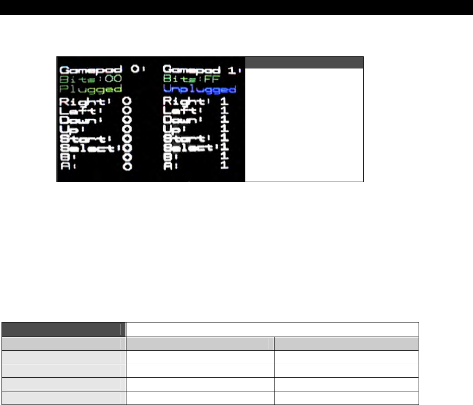
Programming Examples 16
Game Programming for the Propeller Powered HYDRA Page 395
16.4.3 Gamepad Demo
Figure 16:22
A Screen Shot
of the Action-Packed
Gamepad Demo
As discussed in the hardware section of this guide the HYDRA Gamepads are NES-
compatible, that is, based on Nintendo Entertainment System’s controllers. These are readily
available, simple to interface to and found in abundance. Moreover, there are numerous
third-party manufacturers of these controllers to this day.
Figure 16:22 shows the gamepad demo running, basically it shows the state of either
gamepad and can detect if they are plugged in or not. The algorithm to read the gamepads
simply latches the state of the controllers and then clocks in the button state bits. Thus, each
controller is interfaced via a latch, clock, and data pin. The latch and clock are in parallel, but
the data pin(s) are separate. The I/O pins once again are shown in Table 16:1 below:
Table 16:1 The Gamepad Interface on the HYDRA
Propeller Chip Pin Name HYDRA Function Physical Pin
P3 JOY_CLK 4
P4 JOY_SH/LDn 5
P5 JOY_DATAOUT0 6
P6 JOY_DATAOUT1 7
Below is a crude high-level Spin-based function that reads both game controllers and
encodes them into a single WORD with the lower 8 bits representing the button states of
Gamepad 0 (left) and the upper 8 bits representing the button states of Gamepad 1 (right)
respectively. The encoding of the bits is shown below (excerpted from the demo):

II Propeller Chip Architecture and Programming
Page 396 Game Programming for the Propeller Powered HYDRA
' NES Bit Encoding
'
' RIGHT = %00000001
' LEFT = %00000010
' DOWN = %00000100
' UP = %00001000
' START = %00010000
' SELECT = %00100000
' B = %01000000
' A = %10000000
The Gamepads do have a maximum clocking rate of anywhere from 5-10 MHz, but Spin is
slow enough where we can run the Spin code at full speed at 80 MHz system clock and not
have any delay code. However, once you convert the function to ASM, you must take timing
into consideration and make sure that you give the little NES controller enough time to clock
and settle when you read it. The function that reads the controllers is shown below:
PUB NES_Read_Gamepad : nes_bits | i
' //////////////////////////////////////////////////////////////////
' NES Game Paddle Read
' //////////////////////////////////////////////////////////////////
' reads both gamepads in parallel encodes 8-bits for each in format
' right game pad #1 [15..8] : left game pad #0 [7..0]
'
' set I/O ports to proper direction
' P3 = JOY_CLK (4)
' P4 = JOY_SH/LDn (5)
' P5 = JOY_DATAOUT0 (6)
' P6 = JOY_DATAOUT1 (7)
' NES Bit Encoding
'
' RIGHT = %00000001
' LEFT = %00000010
' DOWN = %00000100
' UP = %00001000
' START = %00010000
' SELECT = %00100000
' B = %01000000
' A = %10000000
' step 1: set I/Os
DIRA [3] := 1 ' output
DIRA [4] := 1 ' output
DIRA [5] := 0 ' input
DIRA [6] := 0 ' input

Programming Examples 16
Game Programming for the Propeller Powered HYDRA Page 397
' step 2: set clock and latch to 0
OUTA [3] := 0 ' JOY_CLK = 0
OUTA [4] := 0 ' JOY_SH/LDn = 0
'Delay(1)
' step 3: set latch to 1
OUTA [4] := 1 ' JOY_SH/LDn = 1
'Delay(1)
' step 4: set latch to 0
OUTA [4] := 0 ' JOY_SH/LDn = 0
' step 5: read first bit of each game pad
' data is now ready to shift out
' first bit is ready
nes_bits := 0
' step 6: read first bits
' left controller
nes_bits := INA[5] | (INA[6] << 8)
' step 7: read next 7 bits
repeat i from 0 to 6
OUTA [3] := 1 ' JOY_CLK = 1
'Delay(1)
OUTA [3] := 0 ' JOY_CLK = 0
nes_bits := (nes_bits << 1)
nes_bits := nes_bits | INA[5] | (INA[6] << 8)
'Delay(1)
' invert bits to make positive logic
nes_bits := (!nes_bits & $FFFF)
' //////////////////////////////////////////////////////////////////
' End NES Game Paddle Read
' //////////////////////////////////////////////////////////////////
Notice I invert the bits on exit; normally when a button is down it returns a 0, up returns a 1.
This is cool, I prefer positive logic myself. In any event, the function is straightforward and
simply performs the clocking and bit shifting into the final holding data WORD “nes_bits”

II Propeller Chip Architecture and Programming
Page 398 Game Programming for the Propeller Powered HYDRA
which is returned on exit. Also, notice the calls to Delay( ) are commented out; as
mentioned, Spin was slow enough that they weren’t needed.
Based on this function, I have created a demo that shows the state of both controllers on the
screen and can determine if a controller is plugged in or not. This is ascertained by looking
at the bits and if they are all 1’s then no controller is in, this is true since when the controller
isn’t in and you try to read it, you will be reading “air” on the data line, but this line is pulled
up so it ends up giving you a stream of 1’s when the controller is unplugged. The code for
the demo is located on the CD in the path below and is listed below for reference:
CD_ROOT:\HYDRA\SOURCES\GAMEPAD_DEMO_010.SPIN
' //////////////////////////////////////////////////////////////////////
' Nintendo Gamepad Demo Program - Reads the nintendo gamepads and prints
' the state out on the screen, reads both gamepads at once into a 16-bit
' vector, each gamepad is encoded as 8-bits in the following format:
' RIGHT = %00000001 (lsb)
' LEFT = %00000010
' DOWN = %00000100
' UP = %00001000
' START = %00010000
' SELECT = %00100000
' B = %01000000
' A = %10000000 (msb)
'
' Gamepad 0 is the left gamepad, gamepad 1 is the right game pad
'
' AUTHOR: Andre' LaMothe
' LAST MODIFIED: 1.07.06
' VERSION 1.0
' COMMENTS: Use gamepads, note that when a controller is NOT plugged in
' the value returned is $FF, this can be used to "detect" if the game
' controller is present or not.
'
' //////////////////////////////////////////////////////////////////////
'///////////////////////////////////////////////////////////////////////
' CONSTANTS SECTION ////////////////////////////////////////////////////
'///////////////////////////////////////////////////////////////////////
CON
_clkmode = xtal1 + pll8x ' enable external clock and pll times 8
_xinfreq = 10_000_000 + 3000 ' set frequency to 10 MHZ plus some error
_stack = ($3000 + $3000 + 64) >> 2 ' accomodate display memory and stack

Programming Examples 16
Game Programming for the Propeller Powered HYDRA Page 399
' graphics driver and screen constants
PARAMCOUNT = 14
OFFSCREEN_BUFFER = $2000 ' offscreen buffer
ONSCREEN_BUFFER = $5000 ' onscreen buffer
' size of graphics tile map
X_TILES = 16
Y_TILES = 12
' size of screen
SCREEN_WIDTH = 256
SCREEN_HEIGHT = 192
' position of state readouts for the left and right gamepads
GAMEPAD0_TEXT_X0 = 10
GAMEPAD0_TEXT_Y0 = 172
GAMEPAD1_TEXT_X0 = 128
GAMEPAD1_TEXT_Y0 = 172
' NES bit encodings
NES_RIGHT = %00000001
NES_LEFT = %00000010
NES_DOWN = %00000100
NES_UP = %00001000
NES_START = %00010000
NES_SELECT = %00100000
NES_B = %01000000
NES_A = %10000000
'///////////////////////////////////////////////////////////////////////
' VARIABLES SECTION ////////////////////////////////////////////////////
'///////////////////////////////////////////////////////////////////////
VAR
long tv_status '0/1/2 = off/visible/invisible read-only
long tv_enable '0/? = off/on write-only
long tv_pins '%ppmmm = pins write-only
long tv_mode '%ccinp = chroma,interlace,ntsc/pal,swap write-only
long tv_screen 'pointer to screen (words) write-only
long tv_colors 'pointer to colors (longs) write-only
long tv_hc 'horizontal cells write-only
long tv_vc 'vertical cells write-only
long tv_hx 'horizontal cell expansion write-only
long tv_vx 'vertical cell expansion write-only
long tv_ho 'horizontal offset write-only

II Propeller Chip Architecture and Programming
Page 400 Game Programming for the Propeller Powered HYDRA
long tv_vo 'vertical offset write-only
long tv_broadcast 'broadcast frequency (Hz) write-only
long tv_auralcog 'aural fm cog write-only
word screen[x_tiles * y_tiles] ' storage for screen tile map
long colors[64] ' color look up table
' string/key stuff
byte sbuffer[9]
long data
' nes gamepad vars
long nes_buttons
'///////////////////////////////////////////////////////////////////////
' OBJECT DECLARATION SECTION ///////////////////////////////////////////
'///////////////////////////////////////////////////////////////////////
OBJ
tv : "tv_drv_010.spin" ' instantiate a tv object
gr : "graphics_drv_010.spin" ' instantiate a graphics object
'///////////////////////////////////////////////////////////////////////
' EXPORT PUBLICS //////////////////////////////////////////////////////
'///////////////////////////////////////////////////////////////////////
PUB start | i, j, base, base2, dx, dy, x, y, x2, y2, mask
'///////////////////////////////////////////////////////////////////////
' GLOBAL INITIALIZATION ////////////////////////////////////////////////
'///////////////////////////////////////////////////////////////////////
'start tv
longmove(@tv_status, @tvparams, paramcount)
tv_screen := @screen
tv_colors := @colors
tv.start(@tv_status)
'init colors
repeat i from 0 to 64
colors[i] := $00001010 * (i+4) & $F + $FB060C02
'init tile screen
repeat dx from 0 to tv_hc - 1
repeat dy from 0 to tv_vc - 1
screen[dy*tv_hc+dx] := onscreen_buffer >> 6+dy+dx*tv_vc+((dy & $3F) << 10)
'start and setup graphics

Programming Examples 16
Game Programming for the Propeller Powered HYDRA Page 401
gr.start
gr.setup(16, 12,0,0, offscreen_buffer)
' BEGIN GAME LOOP //////////////////////////////////////////////////////
repeat
'clear bitmap
gr.clear
' INPUT SECTION //////////////////////////////////////////////////////
' get nes controller buttons (right stick)
nes_buttons := NES_Read_Gamepad
' END INPUT SECTION ///////////////////////////////////////////////////
' RENDERING SECTION ///////////////////////////////////////////////////
'draw text
gr.textmode(2,1,5,3)
' print out total gamepad states vector as 2 hex digits each
' each controller printing could be merged into a single loop, but
' too confusing, rather be long and legible than too clever!
' gamepad 0 first, lower 8-bits ///////////////////////////////////////
gr.colorwidth(2,0)
gr.text(GAMEPAD0_TEXT_X0,GAMEPAD0_TEXT_Y0, @gamepad0_string)
' insert the hex digits right into output string!
bits_string[5] := hex_table[ (nes_buttons & $00F0) >> 4 ]
bits_string[6] := hex_table[ (nes_buttons & $000F) >> 0]
gr.colorwidth(1,0)
gr.text(GAMEPAD0_TEXT_X0,GAMEPAD0_TEXT_Y0-12, @bits_string)
' print of gamepad is plugged in?
if (( nes_buttons & $00FF) <> $00FF)
gr.colorwidth(1,0)
gr.text(GAMEPAD0_TEXT_X0,GAMEPAD1_TEXT_Y0-12*2, @plugged_string)
else
gr.colorwidth(3,0)
gr.text(GAMEPAD0_TEXT_X0,GAMEPAD1_TEXT_Y0-12*2, @unplugged_string)
gr.colorwidth(2,0)
gr.text(GAMEPAD0_TEXT_X0,GAMEPAD0_TEXT_Y0, @gamepad0_string)
' print out the button states in unencoded strings
' step one extract the bit for each button and insert it into

II Propeller Chip Architecture and Programming
Page 402 Game Programming for the Propeller Powered HYDRA
' the display strings "in place" then we just print the strings
' out!
mask := $01
repeat i from 0 to 7
' test if button is down represented by the bit in mask
' updated the 6th character in the next description string with a 0 or 1,
' each string is fixed length, so we can look at the bit and then index into
' the strings and update the character in place and then print them all out
gr.colorwidth(2,0)
' test for bit set or not, update string with ASCII "1" or "0"
if (mask & nes_buttons)
button_string_start_address[i*9+7] := $31
else
button_string_start_address[i*9+7] := $30
' print the string out with the embedded "1" or "0"
gr.text(GAMEPAD0_TEXT_X0,GAMEPAD0_TEXT_Y0-12*i-40,
@button_string_start_address + 9*i)
' move to next bit
mask := mask << 1
' end repeat loop
' gamepad 1 next, upper 8-bits ///////////////////////////////////////
gr.colorwidth(2,0)
gr.text(GAMEPAD1_TEXT_X0,GAMEPAD1_TEXT_Y0, @gamepad1_string)
' insert the hex digits right into output string!
bits_string[5] := hex_table[ (nes_buttons & $F000) >> 12 ]
bits_string[6] := hex_table[ (nes_buttons & $0F00) >> 8 ]
gr.colorwidth(1,0)
gr.text(GAMEPAD1_TEXT_X0,GAMEPAD1_TEXT_Y0-12, @bits_string)
' end print data
' print of gamepad is plugged in?
if (( nes_buttons & $FF00) <> $FF00)
gr.colorwidth(1,0)
gr.text(GAMEPAD1_TEXT_X0,GAMEPAD1_TEXT_Y0-12*2, @plugged_string)
else
gr.colorwidth(3,0)
gr.text(GAMEPAD1_TEXT_X0,GAMEPAD1_TEXT_Y0-12*2, @unplugged_string)
' print out the button states in unencoded strings
' step one extract the bit for each button and insert it into
' the display strings "in place" then we just print the strings
' out!
mask := $0100

Programming Examples 16
Game Programming for the Propeller Powered HYDRA Page 403
repeat i from 0 to 7
' test if button is down represented by the bit in mask
' updated the 6th character in the next description string with a 0 or 1,
' each string is fixed length, so we can look at the bit and then index into
' the strings and update the character in place and then print them all out
gr.colorwidth(2,0)
' test for bit set or not, update string with ASCII "1" or "0"
if (mask & nes_buttons)
button_string_start_address[i*9+7] := $31
else
button_string_start_address[i*9+7] := $30
' print the string out with the embedded "1" or "0"
gr.text(GAMEPAD1_TEXT_X0,GAMEPAD0_TEXT_Y0-12*i-40,
@button_string_start_address + 9*i)
' move to next bit
mask := mask << 1
' end repeat loop
'copy bitmap to display
gr.copy(onscreen_buffer)
' END RENDERING SECTION ///////////////////////////////////////////////
' END MAIN GAME LOOP REPEAT BLOCK //////////////////////////////////
' ////////////////////////////////////////////////////////////////////
PUB NES_Read_Gamepad : nes_bits | i
' //////////////////////////////////////////////////////////////////
' NES Game Paddle Read
' //////////////////////////////////////////////////////////////////
' reads both gamepads in parallel encodes 8-bits for each in format
' right game pad #1 [15..8] : left game pad #0 [7..0]
'
' set I/O ports to proper direction
' P3 = JOY_CLK (4)
' P4 = JOY_SH/LDn (5)
' P5 = JOY_DATAOUT0 (6)
' P6 = JOY_DATAOUT1 (7)
' NES Bit Encoding
'
' RIGHT = %00000001
' LEFT = %00000010
' DOWN = %00000100

II Propeller Chip Architecture and Programming
Page 404 Game Programming for the Propeller Powered HYDRA
' UP = %00001000
' START = %00010000
' SELECT = %00100000
' B = %01000000
' A = %10000000
' step 1: set I/Os
DIRA [3] := 1 ' output
DIRA [4] := 1 ' output
DIRA [5] := 0 ' input
DIRA [6] := 0 ' input
' step 2: set clock and latch to 0
OUTA [3] := 0 ' JOY_CLK = 0
OUTA [4] := 0 ' JOY_SH/LDn = 0
'Delay(1)
' step 3: set latch to 1
OUTA [4] := 1 ' JOY_SH/LDn = 1
'Delay(1)
' step 4: set latch to 0
OUTA [4] := 0 ' JOY_SH/LDn = 0
' step 5: read first bit of each game pad
' data is now ready to shift out
' first bit is ready
nes_bits := 0
' left controller
nes_bits := INA[5] | (INA[6] << 8)
' step 7: read next 7 bits
repeat i from 0 to 6
OUTA [3] := 1 ' JOY_CLK = 1
'Delay(1)
OUTA [3] := 0 ' JOY_CLK = 0
nes_bits := (nes_bits << 1)
nes_bits := nes_bits | INA[5] | (INA[6] << 8)
'Delay(1)
' invert bits to make positive logic
nes_bits := (!nes_bits & $FFFF)
' //////////////////////////////////////////////////////////////////
' End NES Game Paddle Read
' //////////////////////////////////////////////////////////////////

Programming Examples 16
Game Programming for the Propeller Powered HYDRA Page 405
' ////////////////////////////////////////////////////////////////////
PUB Delay (count) | i, x, y, z
' delay count times inner loop length
repeat i from 0 to count
'///////////////////////////////////////////////////////////////////////
' DATA SECTION /////////////////////////////////////////////////////////
'///////////////////////////////////////////////////////////////////////
DAT
' TV PARAMETERS FOR DRIVER /////////////////////////////////////////////
tvparams long 0 'status
long 1 'enable
long %011_0000 'pins
long %0000 'mode
long 0 'screen
long 0 'colors
long x_tiles 'hc
long y_tiles 'vc
long 10 'hx timing stretch
long 1 'vx
long 0 'ho
long 0 'vo
long 55_250_000 'broadcast
long 0 'auralcog
' STRING STORAGE //////////////////////////////////////////////////////
hex_table byte "0123456789ABCDEF"
gamepad0_string byte "Gamepad 0:",0 'text
gamepad1_string byte "Gamepad 1:",0 'text
bits_string byte "Bits: ",0
plugged_string byte "Plugged",0
unplugged_string byte "Unplugged",0
button_string_start_address
RIGHT_button_string byte "Right: ",0
LEFT_button_string byte "Left: ",0
DOWN_button_string byte "Down: ",0
UP_button_string byte "Up: ",0
START_button_string byte "Start: ",0
SELECT_button_string byte "Select: ",0
B_button_string byte "B: ",0
A_button_string byte "A: ",0
II Propeller Chip Architecture and Programming
Page 406 Game Programming for the Propeller Powered HYDRA
This is probably the longest listing I have placed in this book, so forgive me, but I think it’s a
good example of a lot of programming techniques with Spin including some string tricks, like
modifying strings in memory with small changes then re-using them, since there is very little
support for string manipulation in Spin and nothing like sprint( ) for example to build up
strings from various params. In any case, try plugging in your controller, pulling it out and
placing it in the other port, etc. and playing with the buttons to make sure it all works!
Additionally, there is an ASM version of the driver and a demo program around it, all within a
single file. This is a good example of not using a separate object, but you still want to use
ASM for something:
CD_ROOT:\HYDRA\SOURCES\GAMEPAD_DEMO_011.SPIN
Lastly, there is a object for the gamepad, but we will discuss it later when doing more game
programming in Part III, but for reference, the file is:
CD_ROOT:\HYDRA\SOURCES\GAMEPAD_DRV_001.SPIN
16.5 VGA Demo
Figure 16:23
The VGA Terminal
Demo in Action
The VGA is programmed by the direct BYTE mode of the VSU, 8 bits at a time are sent out
from the final pin group each clock. These outputs are directly connected to R(2 bits),
G(2 bits), B(2 bits) along with Hsync, and Vsync. Thus, the “colors” streamed out represent
not only RGB values, but also sync to buld up the VGA image. The VGA signal specification is
shown once again in Figure 16:24 for reference.
Just as with NTSC/PAL you must generate the VGA signal with the VSU and then stream the
data for the pixels to the RGB lines when appropriate. Currently, there is a basic VGA driver
that you can work with in a tile/character mode to get started. The name of the driver is
VGA_DRV_010.SPIN and its located on the CD here:
CD_ROOT:\HYDRA\SOURCES\VGA_DRV_010.SPIN

Programming Examples 16
Game Programming for the Propeller Powered HYDRA Page 407
The VGA Timing Specifications Figure 16:24

II Propeller Chip Architecture and Programming
Page 408 Game Programming for the Propeller Powered HYDRA
The driver is too long to list, but it basically drives the VGA similarly to how the
TV_DRV_010.SPIN drives the NTSC/PAL composite video, but the VGA driver is
considerably simplified due to the lack of fields, complex sync, etc. In any event, as an
example of VGA usage there are two programs: a terminal, and a demo that prints on the
terminal. The terminal program named VGATERM_013.SPIN emulates a simple text terminal,
then a demo program VGACHRS_010.SPIN prints to the terminal. The programs are
located on the CD here:
CD_ROOT:\HYDRA\SOURCES\VGATERM_013.SPIN
CD_ROOT:\HYDRA\SOURCES\VGACHRS_010.SPIN
Figure 16:23 showed the VGACHRS_010.SPIN program in action. The top level
VGACHRS_010.SPIN program that calls the terminal program and prints to the terminal is
shown below:
CON
_xinfreq = 10_000_000
_clkmode = xtal1 + pll8x
OBJ
term : "vgaterm_013.spin"
'
' Start monitor3
'
PUB start: I
term.start(%10111)
term.print($110)
repeat 4
repeat i from 0 to $FF
term.print(i)
As you can see there’s not much to it. The major problem with the VGA is speed: the VGA
dot clock is 25.175 MHz roughly which is 7× faster than NTSC roughly, and this is hard to
keep up with and do much. Thus, the challenge is to use tile modes rather that bitmapped
modes to save memory as well as combining processors where possible to divide the
workload.

Programming Examples 16
Game Programming for the Propeller Powered HYDRA Page 409
16.6 Sound Programming
There aren’t any reference sound drivers from Parallax for sound similar to the graphics and
TV driver, but later in Part III I will provide you with a very complex sound engine that
supports multiple channels, envelope control and more. However, for now, let’s take a look at
some simple single-channel examples to get you started on generating sound yourself.
Please review the material in PWM and the counters from the various parts of the book thus
far.
To begin with, the first “problem” is that we have a single pin that outputs sound on the
HYDRA, thus everything has to happen at the output of that pin. For example, if we could
drive 4 pins and then sum them with a resistor network then we could do “poor man’s” multi-
channel mixing. Of course, each channel would be a square wave always, and always toggle
between 0 and 3.3 V, but this would be more than enough to do basic sound, music, and
even noise. However, we are not this lucky, the HYDRA only has a single pin (I/O P7) that
outputs sound, thus we have to use tricks to get a varying analog output such as PWM
techniques. The way to think of sound is that as long as you can generate an analog voltage
output from a numerical input, then you can off-load the sound mixing in the numerical
processing section. So ultimately writing a very complex sound engine is very easy once you
know how to approach it, you simply write the software driver so that an analog voltage can
be generated on the sound output P7. Once this is done, you “feed” the driver with numbers
that represent the “sound” you want, it might be a sine wave, square wave, noise, or the
sum of 100 wave forms! Its all up to you, so with that in mind let’s take a look at some
samples.
16.6.1 Simple Square Wave
The simplest sound we can possibly generate is a square wave of some frequency f. We can
do this two ways: directly with a software loop and sending the output to P7, or we can use
one of the internal counters to do it. The pseudo-code for manually toggling the sound
output pin in Spin would be something like:
DIRA[7] := 1 ' set P7 to output
Repeat
OUTA[7] := 0 ' set output pin to LOW
Repeat delay_low ' wait a moment
OUTA[7] := 1 ' set output pin to HIGH
Repeat delay_high ' wait a moment
' repeat process

II Propeller Chip Architecture and Programming
Page 410 Game Programming for the Propeller Powered HYDRA
Given the above code, you would hear a square wave on the output. Of course, you would
have to select “delay_low” and “delay_high” to give enough time for the audio signal
frequency to be audible and of course the duty cycle would be:
100% * delay_high / (delay_low + delay_high)
The above method works fine, but of course you have to perform this processing all the time
in a tight loop, better to take advantage of the built-in counters in each cog. The best mode
to use to generate a pure square wave is NCO or PLL mode, but the PLL mode has no
advantage, so the NCO (numerically controlled oscillator) is the best mode = “00100,” refer
to Table 13:12 on page 219 for more information.
Refreshing your memory, in the NCO modes, the value in register FRQx is added to PHSx
every system clock, then the 31 bits of PHSx are gated to the “output” selected in the CTRx
register. So we are going to use this counter mode, and assign the output pin to P7 which is
connected to the HYDRA’s sound output hardware. The complete demo that encapsulates all
we just discussed can be found on the CD here:
CD_ROOT:\HYDRA\SOURCES\sound_demo_010.spin
...and the source is shown below:
CON
_clkmode = xtal2 + pll8x ' set PLL to x8
_xinfreq = 10_000_000 ' set input XTAL to 10MHz, thus final freq = 80MHz
VAR
long mousex, mousey ' track mouse position
long sd_freq ' frequency of sound (related to frequency actually)
OBJ
mouse : "mouse_iso_010.spin" ' import the generic mouse driver
PUB start
'start mouse on pingroup 2
mouse.start(2)
'set up parms and start sound engine playing
sd_freq := $00000200 ' anything lower is hard to hear
' step 1: set CTRA mode to NCO single mode "00100", Pin B 0, Pin A = 7
CTRA := %0_00100_000_00000_000000000_000000111
' mode Pin B Pin A
' step 2: set the frequency value to be added to the PHSA register each clock
FRQA := sd_freq

Programming Examples 16
Game Programming for the Propeller Powered HYDRA Page 411
' step 3: set pin 7 to output
DIRA := %00000000_00000000_00000000_10000000
' sit in loop and update frequency with mouse movement
repeat
sd_freq += mouse.delta_x << 8
' don't allow frequency to go lower than a rumble
if (sd_freq < $00000200)
sd_freq := $00000200
' and finally update frequency
FRQA := sd_freq
The program more or less sets up Counter A and connects it to P7 (the sound pin) and then
uses the mouse movement to modulate the frequency of the square wave. If you have an
o-scope you might want to look at the final waveform audio output to confirm it is a square
wave. The only loss of functionality when using the counter to generate a simple square
wave is that we have no control on the duty cycle, it’s always 50%, but in most cases this is
fine.
16.6.2 PWM Demo Sine Wave
If all you need is a single channel of sound then manual square wave generation or using the
counter to drive the sound pin will do, but for games, music, etc. you are going to need at
least 2-3 channels and the ability to play more complex wave forms than square waves.
Using PWM techniques allows you to generate any analog voltage from 0 to 3.3 V roughly,
which in turn means you can synthesize any wave form you want. Of course, there are limits
to the frequency you can synthesize with PWM since the PWM frequency has to be 10–100×
that of the frequency you are synthesizing to get a “clean” signal, but that aside, with PWM
on the HYDRA we can create any sound we want.
As a first example, we are going to use a pseudo-PWM technique using the “duty cycle”
mode discussed in Chapter 13. The duty cycle mode outputs the carry bit from the counter’s
operation, and this carry is “1” proportional to the value in FRQx, that is, the larger the value
in FRQx, the more that PHSx overflows and thus the more the carry is “1.” If we output the
carry into a RC integrator circuit, the result is an analog voltage and viola! we have a 1-bit
output acting as a D/A converter.
Using the duty cycle mode we can generate any wave form by simply placing into FRQx the
magnitude of the value we want to synthesize (scaled by a constant) and updating this value
at some constant audio rate, say 11, 22, or 44 kHz. Thus, to generate a sine wave, all we
need is a table of sine values and then we index into the sine table at some rate, take the
output, scale it by a magic number and then plug it into the FRQx value of the counter we

II Propeller Chip Architecture and Programming
Page 412 Game Programming for the Propeller Powered HYDRA
are using to generate the signal and that’s it. For a concrete example of this, I have created
a demo that uses a top level program to load in the synthesizer object and direct it to
generate the sine wave and output it to the HYDRA’s sound pin. To try the demo simply load
in this file from the CD:
CD_ROOT:\HYDRA\SOURCES\sound_demo_020.spin
...which then will in turn load the sine wave sound generation object named
SOUND_SINE_DRV_011.SPIN which is in ASM. Trying running the top level program, and
be sure to have the audio output of the HYDRA plugged into your TV. Also, the demo needs
the mouse, so have that plugged in. Once the demo runs, slide the mouse left to right to
change the frequency of the sine wave (also if you have an o-scope, try scoping the sound
output to see how clean the sine wave is).
The top level file code is very simple and more or less just calls the sound driver object, so
we aren’t going to waste space with it, but the sine driver is important, so let’s take a look at
it below (with some of the comments and header source removed in the listing, refer to the
copy on CD for the full listing):
org
' Entry
'
entry mov cntacc,cnt ' init cntacc
add cntacc,cntadd ' add to counter number of cycles such that
' this loop executes at a rate of 22050 Hz
:loop
mov t2, par ' retrieve parameter values from caller
rdlong _pin, t2 ' pin # to output signal
add t2, #4
rdlong _freq, t2 ' frequency to play
add t2, #4
rdlong _volume, t2 ' volume (unused in this demo)
mov t1, #1 ' convert pin # into bit position
shl t1, _pin
or dira, t1 ' set general direction of I/O to output
' without disturbing other settings
movs ctra, _pin ' set cntr A pin to the HYDRA's output pin
movi ctra, #%0_00110_000 ' duty cycle mode "00110", single ended
mov t1, phase ' calculate samples
shr t1, #32-13
mov t2, _volume
call #polar

Programming Examples 16
Game Programming for the Propeller Powered HYDRA Page 413
mov output_amp, t1
waitcnt cntacc, cntadd ' wait for count sync
add phase, _freq ' update phases
mov frqa, output_amp ' update channel output
jmp #:loop ' loop
' /////////////////////////////////////////////////////////////////////////////
' Polar to cartesian conversion function, computes y = t2*sine(t1)
'
' in: t1 = 13-bit angle
' t2 = 16-bit length
'
' out: t1 = x|y
'
polar test t1,sine_180 wz ' get sine quadrant 3|4 into nz
test t1,sine_90 wc ' get sine quadrant 2|4 into c
negc t1,t1 ' if sine quadrant 2|4, negate table offset
or t1,sine_table ' or in sine table address >> 1
shl t1,#1 ' shift left to get final word address
rdword t1,t1 ' read sine/cosine word
call #multiply ' multiply sine/cosine by length to get x|y
shr t1,#2 ' justify x|y integer
add t1,h80000000 ' convert to duty cycle
negnz t1,t1 ' if sine quadrant 3|4, negate x|y
polar_ret ret
' local literal pool
sine_90 long $0800 '90° bit
sine_180 long $1000 '180° bit
sine_table long $E000 >> 1 'sine table address
shifted right
h80000000 long $80000000
' /////////////////////////////////////////////////////////////////////////////
' 16x16 Multiply function (unrolled), simply performs a "shift-add" multiply
'
' input: t1 = 16-bit multiplicand (t1[31..16] must be 0)
' t2 = 16-bit multiplier
'
' output: t1 = 32-bit product (t1*t2)
'

II Propeller Chip Architecture and Programming
Page 414 Game Programming for the Propeller Powered HYDRA
multiply shl t2,#16
shr t1,#1 wc
if_c add t1,t2 wc
rcr t1,#1 wc
if_c add t1,t2 wc
rcr t1,#1 wc
if_c add t1,t2 wc
rcr t1,#1 wc
if_c add t1,t2 wc
rcr t1,#1 wc
if_c add t1,t2 wc
rcr t1,#1 wc
if_c add t1,t2 wc
rcr t1,#1 wc
if_c add t1,t2 wc
rcr t1,#1 wc
if_c add t1,t2 wc
rcr t1,#1 wc
if_c add t1,t2 wc
rcr t1,#1 wc
if_c add t1,t2 wc
rcr t1,#1 wc
if_c add t1,t2 wc
rcr t1,#1 wc
if_c add t1,t2 wc
rcr t1,#1 wc
if_c add t1,t2 wc
rcr t1,#1 wc
if_c add t1,t2 wc
rcr t1,#1 wc
if_c add t1,t2 wc
rcr t1,#1 wc
if_c add t1,t2 wc
rcr t1,#1 wc
multiply_ret ret
' /////////////////////////////////////////////////////////////////////////////
' variables and locals
cntadd long 80_000_000 / 22_050 ' clock frequency is hard coded here
' roughly 3628 clocks per synthesis cycle
cntacc long $0
' temporary registers
t1 long $0
t2 long $0

Programming Examples 16
Game Programming for the Propeller Powered HYDRA Page 415
t3 long $0
' PWM variables
phase long $00000000 ' phase accumulator for fundamental
output_amp long $00000000 ' final summed output amplitude
' parameters from caller
_pin long $0 ' 0 - 31
_freq long $0 ' any 32-bit value, but only a small range of values
' will be audible
_volume long $0 ' $0000-FFFF, unused in this version of drivers,
' always FULL volume
All the action happens between the label “:loop” and “jmp #:loop.” The program begins by
retrieving the latest copies of the parameters from the caller, this way the caller can change
the parameters at any time and they will update in the driver. Next, the counter is set up
including the output pin, mode, and direction. This must be done always. Then the main
synthesis algorithm begins where you see “compute samples,” the value in “phase” is used
as the angle of the sine wave, and “_volume” is used to scale the sinewave. The angle and
volume or amplitude are sent to a sine function that uses the built-in sine table from 0-90
degrees and computes the results then scales them appropriately. The results are returned in
“t1” and then passed into the final output variable “output_amp” which is written to the
FRQA register. This value is proportional to the final voltage output.
Lastly, you will notice the use of the system counter CNT. The algorithm recomputes the
signal at a rate of 22050 Hz, or roughly every 3628 clocks given a 80 MHz system clock;
hence at the top of the loop this value (3628) is added to the current CNT value and stored,
and then at the end of the loop a waitcnt call is made to keep the synthesis locked at 22050.
Thus, we are outputting a new data point 22050 times a second, or in other words, the
highest frequency signal we can generate is 11025 Hz, but this will NOT look like a sine
wave, it will look distorted, since we should have at least a few sample points to make up
each sine wave. Thus 2.2 kHz (1/10th) the synthesis rate is where things start to look funny if
you want to get technical.
16.6.3 PWM Demo “Engine” Sound
In the last example, we generated a sound that was a function of the sine wave or
something like:
Y = a sin(t)
We can plug anything we wish into the synthesis function, for example, I know that if you
output an exponential curve waveform, it will sound like an engine as you change the
frequency. Since we can’t generate a true exponential curve, we can do the next best thing:
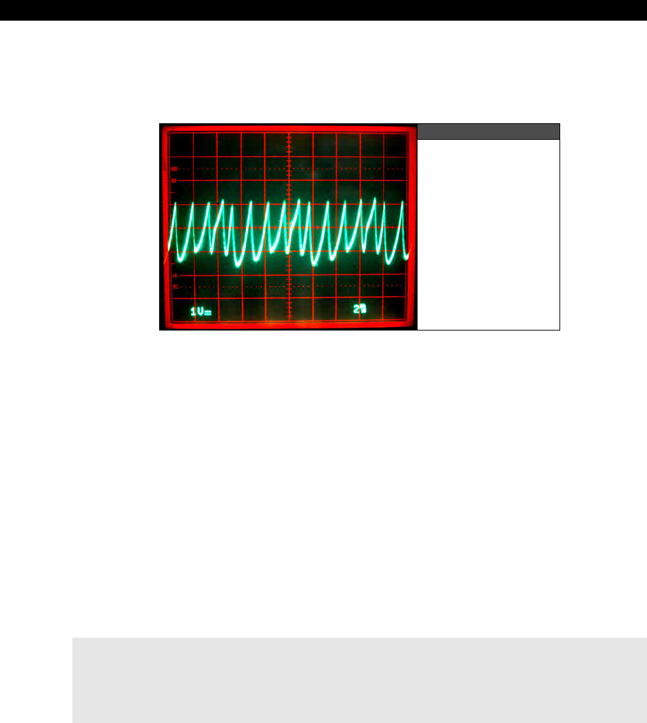
II Propeller Chip Architecture and Programming
Page 416 Game Programming for the Propeller Powered HYDRA
use a power to exponentiate the signal. Cubing works best, but a simple square will suffice.
All we need to do is synthesis something like:
Y = a * t2
Figure 16:25
A Screen Shot of
the Synthesized
“Engine” Sound
Take a look at Figure 16:25 to see the results of summing these signals (you can’t see it on
the static figure, but there are two signals superimposed, both with the same shape, but they
are harmonics and each have slightly different amplitudes). I have generated another demo
using this technique which is on the CD:
CD_ROOT:\HYDRA\SOURCES\sound_demo_030.spin
Again, the driver itself is in ASM and called from the demo top level file, the driver for the
“engine” sound is called SOUND_ENGINE_DRV_011.SPIN and is on the CD in the same
place. So try loading up the top level file and running the demo and moving the mouse
around. I think you will find the sound pretty authentic. Also, “sound engineering” takes a lot
of trial and error, you start with what you know and then experiment until it sounds “right.”
In the real world, sounds are never simple, they usually have many harmonics, distortions,
etc. that give them “texture” and “personality,” thus I found by adding a slightly attenuated
harmonic of the squared term the engine sounded “better.” So when you check out the
driver SOUND_ENGINE_DRV_011.SPIN be sure to look for this added functionality. The
core of the code in the “engine” sound driver is shown below for reference:
' the idea is to square the phase accumlator
mov t1, phase ' calculate samples
shr t1, #32-16 ' scale the phase down to fit into 16 bits
mov t2, t1
call #multiply
mov output_amp, t1 ' final output = scale*(phase*phase)

Programming Examples 16
Game Programming for the Propeller Powered HYDRA Page 417
' same thing with phase2 accumulator which is a harmonic
mov t1, phase2 ' calculate samples
shr t1, #32-16 ' scale the phase down to fit into 16 bits
mov t2, t1
call #multiply
add output_amp, t1 ' sum both harmonics
' final output = scale * [ (phase*phase) + (phase2*phase2) ]
waitcnt cntacc, cntadd ' wait for count sync
add phase, _freq ' update phase (fundamental)
mov t1, _freq ' compute 1/2 harmonic
shr t1, #2
add phase2, t1 ' update phase2 (harmonic)
mov frqa, output_amp ' update channel output counter
jmp #:loop ' loop infinitely
As you can see, the code has two blocks at the top, each responsible for generating a
squared term. Then the outputs are summed, scaled, and sent to the FRQA register, and
that’s it! Pretty cool huh? The neat thing is that anything you can imagine mathematically,
including digitized audio data, you can play back. So, given that the HYDRA has a large
EEPROM memory, you could theoretically store a lot of audio data in the EEPROM,
decompress on the fly, and synthesize out using the techniques outlined here.
16.7 Accessing the EEPROM
As discussed numerous times, the Propeller chip has an on-chip 32 Kbytes of RAM, this RAM
holds every single program code and data asset. The compiler builds the 32K “image” for you
and no matter how large or how small your actual program(s) + data are, the image will
always be 32 Kbytes so that the loader, IDE, and everybody else simply has to load 32K
directly into the Propeller chip, or 32K from EEPROM in to the Propeller chip. So, the question
is raised: “Can we extend this memory?” The answer is yes and no. Currently, the Propeller
chip and IDE have no concept of anything greater than 32 Kbytes, in fact. The 32K EEPROM
on the HYDRA is all that is necessary for operation. But, nonetheless the HYDRA has a 128K
EEPROM (as do the game cartridges); this extra memory is to facilitate two things: expansion
later on potentially of the Propeller chip, but more importantly for you to use for extra
programming to store assets in the 96K above the base 32K needed by the Propeller chip.
No matter what, the IDE is going to build a 32K image and dump it to the Propeller chip or
the EEPROM, so this means that if we are clever not only can we simply access the EEPROM
from our programs to read/write game data on the fly, like scores, etc. but we can also build
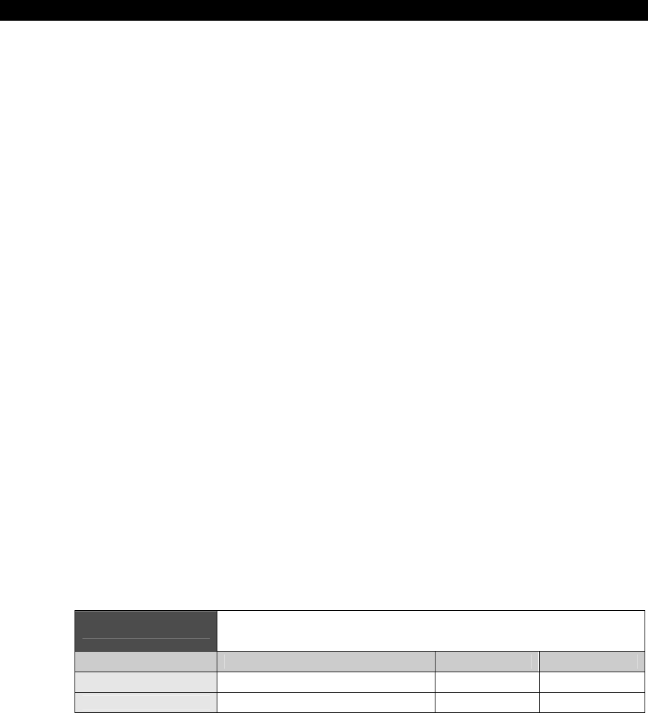
II Propeller Chip Architecture and Programming
Page 418 Game Programming for the Propeller Powered HYDRA
tools on the PC that use a “host” program we write on the HYDRA/Propeller chip that allows
us to talk to the EEPROM through the serial port on the PC. Before we take a look at both of
these possibilities, let’s take a look at how the EEPROM works for now and discuss some
ideas. Later in the Part III we will see some code/drivers that communicate with it and do
something useful.
16.7.1 EEPROM Operation
The EEPROM used in the HYDRA is an Atmel 24C1024 (or equivalent) 128 Kbyte serial
EEPROM, there are other models that are smaller and larger. The key word in the description
is “serial,” this means that we access data, read and write via a serial protocol which is rather
slow as far as game speeds are concerned. But, with proper caching and common sense you
can definitely use the EEPROM to hold assets and cache them into the primary 32K into a
small region of memory using a demand page memory access scheme etc. So the first thing
you need to do is understand how to program this EEPROM and the underlying serial
protocol, thus you need to start by reading the datasheets for the EEPROM which are located
on the CD here:
CD_ROOT:\HYDRA\DOCS\atmel_24c1024_datasheet.pdf
CD_ROOT:\HYDRA\DOCS\atmel_24c256_datasheet.pdf
It may take a few times to understand, but basically you simply need to learn to read and
write to the EEPROM. The trick of course is that you are going to read and write only AFTER
the first 32K since that is where the run-time image is always stored. Of course, if you know
what you’re doing you can alter the 32K image on the EEPROM as well. For example, say you
write a program, and you know exactly where a data structure is located in the final binary
32K image. To determine this you can use the IDE’s memory view or even a sentinel to
target the memory. Whatever you do, once you know where this is, when you run a game,
you can go to that memory location and store the player’s score for example, and the game
would update and next time it booted this new score would be in the EEPROM, this way you
could store a high score table or whatever.
However, at first it’s probably best to access memory after the first 32K, so you don’t step on
anything. Assuming that you understand the protocol now, all you need to know is the actual
I/O pins that connect to the EEPROM’s data and clock lines; they are shown in Table 16:2.
Table 16:2 The Pinouts and Assignments for the
Serial EEPROM Interface
General Name Exported Name on Cartridge Pin Name Pin Number
Serial Clock (SCK_CART) P28 37
Serial Data (SDA_CART) P29 38

Programming Examples 16
Game Programming for the Propeller Powered HYDRA Page 419
There are two things to remember: first there is an EEPROM on the board, and potentially
one on the game cart if it is inserted. Either way, from your perspective there is only ONE
EEPROM in, thus, you can’t use both of them! The hardware swaps out the base EEPROM the
moment it detects an insertion, so only one EEPROM is addressable at once, and the priority
is CARTRIDGE (if inserted), then BASE secondarily. Now, let’s discuss the access scenarios.
16.7.2 Accessing the EEPROM for Simple Memory Operations in Game
You will first want to write a driver that can access the EEPROM via pins P28/P29 and
support a subset of the communication protocol that at least allows BYTE writes and reads,
later you might want to add the page and sequential access modes for higher speeds. Later I
will write a more robust function or object that allows EEPROM access.
In any event, once you have your driver then it’s as simple as using it to talk to the EEPROM
that is active. Remember though, do not access the EEPROM’s first 32 Kbytes unless you are
absolutely sure where you are writing to since you can frag the execution image. But, feel
free to access the 96K above. A first app might be something that “remembers” a simple
piece of data, then something that is more interesting might be an app that is like a word
processor based on the little terminal I made, as the person types it’s stored in the EEPROM
and later you can load the document(s) into the program! That would be cool!
16.7.3 Accessing the EEPROM for Asset Storage via the PC/HYDRA
The more interesting use of the EEPROM’s extra 96 Kbytes of storage is of course for asset
storage or implementation of a “virtual machine.” Let’s discuss the asset storage first.
16.7.3.1 Asset Storage
The EEPROM is of course too slow to be used as any kind of real-time memory, but with
caching and some memory management, you can definitely make a crude memory system
out of it using the RAM on the Propeller chip for the high-speed memory and the EEPROM as
the slow storage. Along these lines, there are all kinds of possibilities to store extra assets
like image data, sprites, tables, and sound data on the EEPROM and then bring them in or
access them on the fly in slow EEPROM memory if speed isn’t a concern. In either case, you
need a “workflow” to do this. Currently, there is no support in the IDE for extra assets to be
written to the EEPROM memory above 32K and there are no tools either. Thus, we have to
write our own.
So here’s how you do it: first we need a “client” program on the PC that allows us to talk to
the HYDRA over the serial communications port. The is the easy part, you can write a
Windows app with Builder, Delphi, or VB that basically shows you a graphical image of the
EEPROM and then lets you drag-and-drop binary files into the image. Then when you are
done, it writes the upper 96K of memory (or reads as well). This is all done over the serial
port you have connected to the HYDRA with, let’s say Com3 for fun. So you write this app on
the PC that can do all this importing and file building and it’s going to talk to the HYDRA over

II Propeller Chip Architecture and Programming
Page 420 Game Programming for the Propeller Powered HYDRA
a com port such as Com3 (Com 1 and 2 are usually taken by the mouse and keyboard on
older machines).
Anyway, now for the hard part – now you have to write an app that “sits” on the HYDRA (the
Propeller chip) and is a “host” or “server” that listens to the com port (via the USB
connection) and waits for commands, then when it receives commands this host program
takes data you send from the PC over the cable and then writes it to the EEPROM above the
32K mark. So we use the HYDRA and the Propeller chip to host this communication since we
can’t access pins P28/P29 from the PC directly, if we
could
then we could read/write the
EEPROM from the PC and not need the surrogate of the Propeller chip/HYDRA to help us out.
This is not a hard thing to do, but must be well though-out. You basically want a really easy
app to “build assets” on the PC then a good protocol that allows reading/writing BYTEs on
the EEPROM via a host program running on the HYDRA. Then when you are done building
the EEPROM, you would erase this host program running on the HYDRA, of course it could be
made as an object and even part of a larger game program.
16.7.3.2 Virtual Machine Implementation
The next cool idea that you might want to try is to implement a virtual machine or emulator.
For example, Spin is just a virtual machine, but simply happens to be built-in, but no one said
you can’t write another assembly language virtual machine and then have it run code you
generate from a compiler yourself. You could simply write a virtual machine that is less than
512 LONGs, fits into a single cog (like Spin) that then runs code out of main memory. You
could set this up from a main program with some Spin to start things off, load your virtual
machine and then a DAT section to hold your code. Or maybe you could write another tool
that you can code in FORTH, or 6502, or whatever, then it’s compiled into BYTE codes or
whatever and converted into Spin DAT statements which you import manually.
But, the cool opportunity is to write a virtual machine and then free up the 32K memory on
the Propeller chip for video memory, etc. and then run your code out of the EEPROM with a
memory paging and caching scheme to keep things moving quickly, that is, every time you
get down to 256 virtual instructions, the memory management software brings in another 1-
2K of instructions off the EEPROM for your virtual machine. This way, large programs can be
executed.
16.8 Assembly Language Parameter Passing
Last but not least, I want to discuss interfacing Spin/ASM code. This is typically a “trouble
area” for many people similar to recursion, so I think its worth discussing in brief, so you can
take advantage of it and not limit yourself.

Programming Examples 16
Game Programming for the Propeller Powered HYDRA Page 421
As mentioned before, when you make a call to start up a cog with an ASM program you start
the cog up like so:
cognew(@asm_entry_point , parameter_ptr)
...where “asm_entry_point” is the address of your actual ASM code, and “parameter_ptr” is
usually a pointer to the base of your parameter list in main memory (0-64K byte addressed).
I say, “usually” since parameter_ptr can be anything you wish! It could be a single value, it
could be a pointer, it could be a pointer to a pointer, whatever – the point is that it is passed
by “value” and when your ASM code starts, the value passed will be accessible in the PAR
register.
Thus, if you make the call from Spin:
cognew(@asm_entry_point , 0)
...then PAR on entry to your ASM code would be 0, for example, given the code below:
DAT
ORG
asm_entry_point ' this is where the cog starts execution
mov r0, PAR ' copy VALUE in PAR to r0, so we can modify it
.
.
.
' temporary 32-bit registers in "cog memory"
r0 long $0
r1 long $0
r2 long $0
Then after the “mov” instruction, r0 would be equal to 0. The reason why I copy PAR into r0
is because PAR is read-only, you can’t “bump” it; you can use it to read from, etc. but if you
want to pull parms from the caller, you can’t modify PAR, thus it’s a good idea to copy it into
a temporary variable that is local and in cog memory.
Now, once you have PAR or a copy of it, then you can do whatever you want with it. For
example, use it as a pointer to read from main memory (or write to main memory), or just
use it as a parameter (if that was the intent of the caller). So, let’s take a look at a few
examples to solidify these concepts with some pseudo-code.

II Propeller Chip Architecture and Programming
Page 422 Game Programming for the Propeller Powered HYDRA
16.8.1 Reading Parameters from Spin
Many times you want to send a set of “start-up” parameters to your ASM program running on
another cog. For example, the TV driver does exactly this, you send it the base address of a
dozen or so LONG-sized parms then the ASM code indexes from the first parameter pointed
to by PAR by increasing PAR by 4 each time to move to the next LONG. Remember PAR is
always main memory relative addressing, thus BYTE-based, NOT LONG-based like the cog
addressing. This is VERY important – when talking about addresses in main memory, we are
always talking about BYTE addresses, when talking about cog addresses, we are always
talking about LONG addresses 0-511, so keeping that in mind it will save you a lot of
headaches.
As an example, let’s say we want to write a graphics driver and we want to send the driver
the width, height, and bits per pixel for the mode. Also, let’s keep it simple and say that
every parameter will be stored in a LONG, so we have both our Spin program and the ASM
we are going to launch into another cog that we want to “pass” the base address of our
parameter list, here’s how all that would work (note this is pseudo-code, I am omitting the
usual start-up Spin stuff, etc.):
VAR
LONG width, height, bpp ' these are the parameters we want to "pass" to ASM
PUB start
' start another cog with the asm driver, and send the address of "width"
' this assumes that height and bpp follow in memory, that is they are this order:
'addr x width
'addr x+4 height
'addr x+8 bpp
'which they always are unless the compiler messed up !
cognew(@asm_entry_point, @width)
' do stuff…
repeat ' main loop would go here…
' and now we switch to a DAT section & put our ASM at the end of our Spin program
DAT
ORG
asm_entry_point
' on entry PAR points to width, height, bpp, in that order, each 1 LONG in size.
mov r0, PAR ' copy PAR to R0 local, so we can alter it
rdlong _width, r0 ' r0 points to "width" in main memory, read it

Programming Examples 16
Game Programming for the Propeller Powered HYDRA Page 423
' out and copy to local "_width"
add r0, #4 ' next parm is 4 BYTES down, add 4 to copy of PAR in r0
rdlong _height, r0 ' r0 points to "height" in main memory, read
' it out and copy to local "_height"
add r0, #4 ' next parm is 4 BYTES down, add 4 to copy of PAR in r0
rdlong _bpp, r0 ' r0 points to "bpp" in main memory, read it
' out and copy to local "_bpp"
' now, _width, _height and _bpp have the parms sent by caller.
' local copies of width, height, bpp, common tactic is to use a "_" in front
' of the parameter name
_width LONG $0
_height LONG $0
_bpp LONG $0
' local registers and working vars for fun
r0 LONG $0
r1 LONG $0
r2 LONG $0
So, the trick is to set up a parameter block in your high-level Spin code, and simply pass the
base address of the parameters to the ASM code via the PAR register by means of the
cognew( ) function’s 2nd parameter. Also, notice the use of “_” to indicate local copies of
parms, this is just an idea, and you can do whatever you like. Sometimes, I use “L” for local,
sometimes “_” and other techniques, the idea is to help the reader of your code later track
what were parms and what are the local copies of them.
16.8.2 Writing Values to Spin
If you followed the previous example, then it should be a snap to write values back to Spin.
There are a billion reasons you would want to do this: anything from watching a real-time
value, to using a memory location as a return value for some ASM process or even parallel
processing message passing. The point is it’s very easy to do. Let’s say that you want to
“watch” a memory location that an ASM program sends back some kind of status
information. For example, later in the book you will see a number of video drivers that I
create and they all send back various “raster state” information to the caller than started that
cog running them. For example, a LONG that encodes the state of the sync, the current video
line, the number of sprites doing something, whatever. Here’s how you would write some
generic “status” value back to the caller that starts up a cog with some ASM code:
VAR
LONG status ' the ASM cog program is going to write back to this location
II Propeller Chip Architecture and Programming
Page 424 Game Programming for the Propeller Powered HYDRA
PUB start
cognew(@asm_entry_point, @status)
' do stuff...
repeat ' main loop would go here…
' and now we switch to a DAT section & put our ASM at the end of our Spin program
DAT
ORG
asm_entry_point
' on entry PAR is pointing to status
mov r0, PAR ' copy PAR to R0 local, so we can alter it if needed
' now r0 -> status, so we can write anything we want to it, let’s write $ff
wrlong r0, #$FF ' r0 <- $ff, in other words main_memory[PAR=@status] := $FF
' local registers and working vars for fun
r0 LONG $0
r1 LONG $0
r2 LONG $0
The ASM code starts up in more or less the same way, we need a copy of the PAR register
(so we can change it if we need to), then we simply use the “wrlong” instruction rather than
the “rdlong” instruction, and write a value out to the main memory. Then anyone listening to
the memory location will see it change, this is how you can pass back one or more values.
I have been using LONGs for the parameter passing discussion, but you are free
to use BYTEs or WORDs as well along with the RDWORD, RDBYTE, WRWORD,
WRBYTE ASM instructions. Just make sure to advance your PAR pointer by 1, 2,
or 4 for BYTE, WORD, or LONG addresses respectively.
16.9 Summary
This chapter has finally put some of the theory to practice and we have covered numerous
demos and examples using the various drivers for graphics, I/O, sound, and more. I suggest
if you already haven’t done so, you take some time to get familiar with the IDE and try
compiling, altering, and experimenting with the demos I have provided. When we begin Part
III, I will assume that you are familiar with the hardware and the IDE and I won’t take the
time to explain in detail every little step. My goal isn’t to turn you into the next John
Carmack, but if you have never written a game before, you should walk away with being able
to develop some reasonably sophisticated 2D games from Pong to Pac-Man, so let’s get
started!

Page 425 Game Programming for the Propeller Powered HYDRA
Programming
on
the
Hydra
Part
II
on the Hydra Part III Game Prog
r
Part III Game Programming on th
e
Programming on the Hydra Part I
I
on the Hydra Part III Game Prog
r
Part III Game Programming on th
e
Programming on the Hydra Part I
I
on the Hydra Part III Game Prog
r
Part III Game Programming on th
e
Programming on the Hydra Part I
I
on the Hydra Part III Game Prog
r
Part III Game Programming on th
e
Programming on the Hydra Part I
I
on the Hydra Part III Game Prog
r
Part III Game Programming on th
e
Programming on the Hydra Part I
I
Part III: Game Programming
on the HYDRA

III Game Programming on the HYDRA
Page 426 Game Programming for the Propeller Powered HYDRA
Chapter 17: Introduction to Game Development, p. 427.
Chapter 18: Basic Graphics and 2D Animation, p. 461.
Chapter 19: Tile Engines and Sprites, p. 509.
Chapter 20: Getting Input from the “User” World, p. 559.
Chapter 21: Sound Design for Games, p. 593.
Chapter 22: Advanced Graphics, p. 619.
Chapter 23: AI, Physics Modeling, and Collision Detection - A Crash Course! p. 475.
Chapter 24: Graphics Engine Development on the HYDRA, p. 759.
Chapter 25: HYDRA Demo Showcase, p. 779.

Introduction to Game Development17
Game Programming for the Propeller Powered HYDRA Page 427
Chapter 17:
Introduction
to Game
Development
This chapter begins the primary game development coverage of the book. The previous
chapters were all foundation materials needed to give us a common framework, language,
and vocabulary for the Propeller and HYDRA, so that we can start to discuss how to make
games. From here on out, I am going to try and keep things as practical as possible without
too much theory. Additionally, the previous chapters had to do with the Propeller chip, ASM,
the instruction set, the hardware, really important things that you want to refer to in the
book. The remainder of the book has a LOT of code, that is really big, so rather than show
you huge listings and kill trees, I am going to explain algorithms and the architecture and
main points of a program and leave listings (for the most part) on the CD, so you can refer to
them later. This will save precious pages and give us more time to discuss game
development rather than look at code.
Also, you will notice that the chapters from here on out have very specific titles and outlines;
however, I always take any opportunity I can to show some game code, thus if we are
talking about the mouse, I will make a little game demo that uses it, and so forth, so you will
learn game development not in any specific location in these chapters, but throughout them,
so read between the lines. In this chapter, we are going to discuss some of the creative and
artistic aspects of game development then finish off with technical material and our first
collaborative game. With that in mind, we are going to discuss the following topics primarily:
What exactly is a game?
Introduction to game development and the creative process
Tools used to create games
Game loops and organization
Data structures used in games
Mars Lander
17.1 What Exactly is a Game?
I get asked this question all the time. A game has a very loose definition, but more or less
(when talking about computer games), a game is an interactive application, usually graphical,
that users use to entertain themselves with – period.

III Game Programming on the HYDRA
Page 428 Game Programming for the Propeller Powered HYDRA
Games can be separated into hundreds of categories these days, but typically for any game
you can assign them loosely to one or more of the following categories:
Arcade games
Role-playing games
Platform games
Board games
First-person shooter games
Simulations
Arcade games tend to refer to games that used to be found only in arcades such as
Pacman
,
Centipede
,
Galaxians
, and other “twitch” games that are more action and
shoot-em-up related. Figure 17:1 shows some classic arcade games in action. There isn’t
much story line going on in an arcade game, you usually just blow things up, chase things, or
run away, they are pure action and hand-eye coordination games usually.
Some Classic Arcade Games Figure 17:1
Role-playing games (also known as RPGs) are less action-oriented and might even have a
minimal graphics and sound and sometimes “turn” based game play, meaning you do not
interact in real-time, but tell the computer what you want to do and take turns with the
computer or other players. In the the late 80’s and early 90’s is when role playing games or
“RPG”s really picked up momentum and fan base with classics such as
Kings
Quest
, along
with console-based variations such as the
Legend
of
Zelda
, both shown in Figure 17:2.
Now, some might argue that Zelda is not a pure RPG, some may argue that Kings Quest has
arcade elements to it and so forth. Thus, what people define as “pure” is often argued!
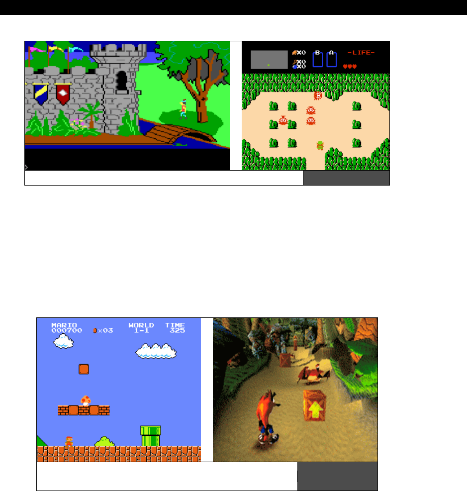
Introduction to Game Development17
Game Programming for the Propeller Powered HYDRA Page 429
Kings Quest (left) and Legend of Zelda (right) Figure 17:2
Platform games really are a sub-genre of arcade games, but became so popular that they
came to be known as
“platformers.”
Both games in the arcade, and on PCs and consoles
helped to make this designation stick. Platformer games can be 2D or 3D (early on games
here all 2D, but later even 3D games had 2D game play and thus are called platformers). A
platformer game is simply one where the game character tends to do a lot of jumping around
on “platforms” – simple as that! For example, two classic platformer games from two
different generations are Super Mario Brothers (8-bit era) and Crash Bandicoot (from
the PSX 3D era). Both are shown in Figure 17:3.
Good old Mario Brothers (left) and its next
generation brother Crash Bandicoot (right) Figure 17:3
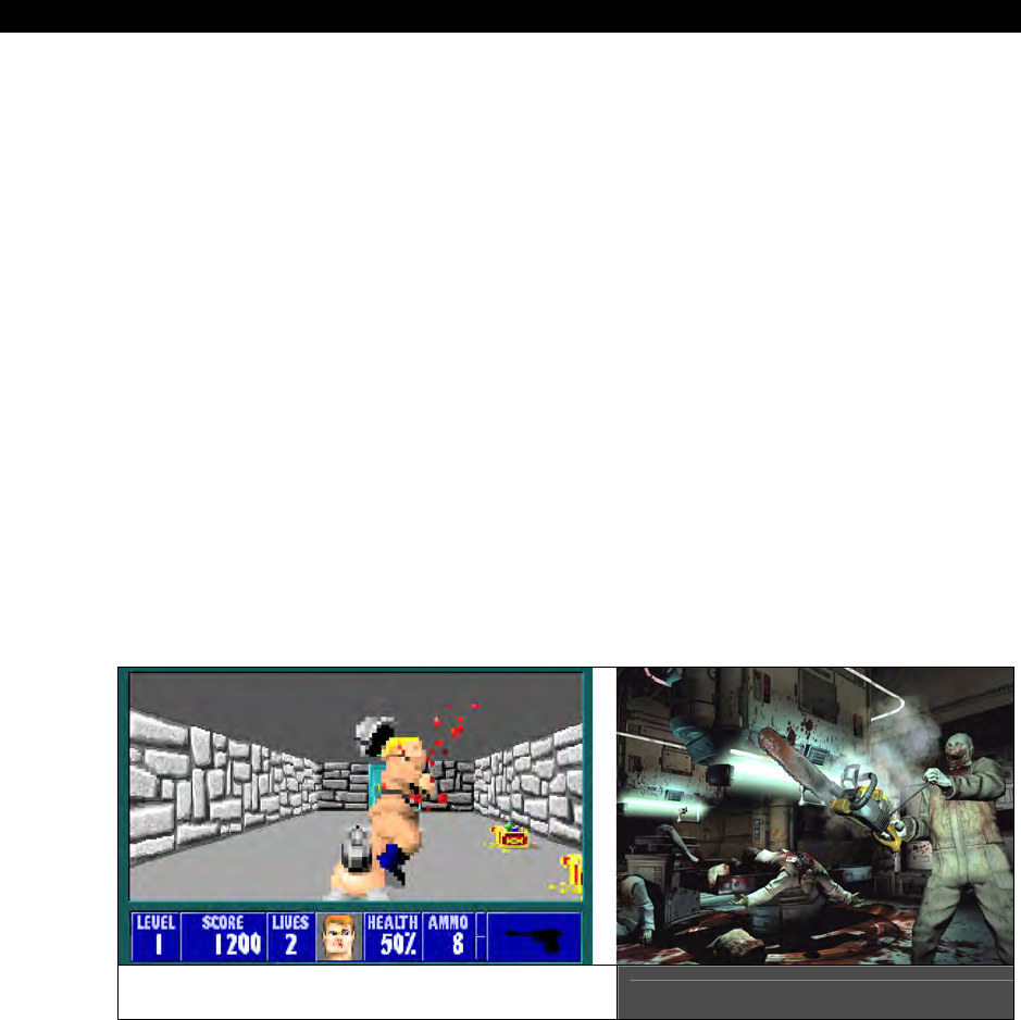
III Game Programming on the HYDRA
Page 430 Game Programming for the Propeller Powered HYDRA
Board games are video game implementations of “physical” board games. For example,
chess on the computer, or Scrabble and so forth. You might ask, “What’s the point of playing
a board game on the computer screen?” – well, other than the $500M in revenues each year
these games make, the other main reason is that many times it’s inconvenient to set up a
physical board, the players are geographically in different locations, or the players want to
play a “variation” of the board game that is based on the rules of the game (say checkers),
but played with giant alien dinosaurs instead! Thus, video board games both identical to real
board games as well as variations are very popular. Moreover, board games are easier to
play since most of the population has played cards, chess, checkers, and Monolopy, so they
can usually pick the games up very quickly. Lastly, sometimes you might want to play strip
poker, but can’t find 5 supermodels to do it with, but the computer can easily accommodate
you with 5 artificial players!
First-person shooter games need no introduction. They were more or less invented in the
early 90’s as well as the term coined
“first-person shooter”
or FPS (not to be confused
with “frames per second”) to refer to this kind of game. FPS games are typically technological
demos as well as “push the envelope” kinds of games. In 1990 roughly, no one had seen a
high-speed 3D game on the PC, then
Wolfenstein 3D
came out by
id Software
and the
age of FPS games was upon us. FPS games take the highest amount of skill and technology
to develop. Today, some of the more popular FPS games are the
Halo
series, the
DOOM
and
QUAKE
series as well as others that have followed suit. Figure 17:4 shows the evolution
from Wolfenstein 3D (left) to DOOM 3 (right).
Simulations have been around for a long time; however, they never really looked that
good. A simulation game is a game where the idea is to copy or simulate something in the
real world such as flying an airplane, driving a car or boat, or even experiencing a war or
FPS from Old to New Figure 17:4
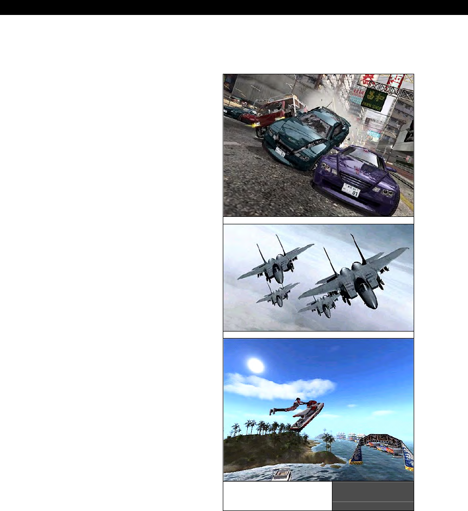
Introduction to Game Development17
Game Programming for the Propeller Powered HYDRA Page 431
playing paint ball! In the 80’s and 90’s computers didn’t have the processing power to make
really good simulations, but all you have to do is take a look at the latest simulation games
on the XBOX 360 or PSX 3 and you can see we have come a long way.
Figure 17:5 shows three prime examples of
just how real simulations have become with a
driving game
Burnout Revenge
(top), a
flying game
Over G Fighters
(center), and
finally a jet-skiing game
Splash Down
!
(bottom). Amazing aren’t they? The reality of
simulations these days has come from two
different directions;
graphics
and
physics
modeling
. Game programmers have always
been interested in graphics, but, they’d never
had the computing power to even think about
modeling real-world physics. But with today’s
game machines putting out trillions of
operations a second, it’s a snap to perform
real-time physics modeling.
That about wraps it up for the main types of
games, of course there are many sub-genres,
games that fit in more than one genre, and so
forth, but the point is these are a good
starting point. In this book, we are going to
focus on category one: the arcade games.
Arcade games are “relatively” easy to make,
they are 10,000 lines of code in comparison to
1-10 million lines of code for a state-of-the-art
FPS game. Plus, most people have played
them and know what they look and feel like,
so it’s a good reference point. Lastly, the
HYDRA / Propeller have a limited amount of
memory and computational power, so we
have to choose our battles and not bite off too
much!
The last comment I want to make before we
start into the technical matter of this chapter
is that there is no “way” to make a game. A
game is a program just like any other
program, but someone, somewhere, has
Simulation
Games Figure 17:5

III Game Programming on the HYDRA
Page 432 Game Programming for the Propeller Powered HYDRA
convinced the world there is a “make game” button on some magical tool that takes
“English” descriptions and translates them to millions of lines of code and hundreds of billions
of bytes of assets – this is not the case. A game is a fusion of a number of engineering and
artistic disciplines and a lot of work, but as long as we all start with Pong, anyone can work
their way up to HALO given enough time, It’s always amusing to me when someone reads a
game development book cover to cover and then asks, “yes, but how do you make HALO?”
Obviously, they didn’t comprehend the book, and secondly they have oversimplified the
process about 10 orders of magnitude. So the thing to remember about game development
is this:
“Every single pixel, every color, every sound, behavior, character of text, all of it –
the game programmer designed, created, and thought about.”
Keep that in mind, respect it, and making games will make sense to you.
17.2 Introduction to Game Development and the Creative Process
Large games today are made by hundreds of artists and developers and take anywhere from
2 to 10 years to develop and many millions of dollars. The development cycle is very similar
to a Hollywood movie. Luckily, we aren’t doing games of that scope, so we can forget about
something that complicated and start off simple. But, herein lies the paradox – 99/100
programmers can NOT successfully negotiate a Pong or Pacman game from start to end.
Games are so complex that they quickly get out of control if not programmed correctly and in
an organized manner. Other types of programming are much more relaxed than game
development. For example, I would say that over 50% of websites on internet are “incorrect”
and have dozens if not thousands of serious bugs; however, all we do is view websites, the
occasional glitch, lock up, or refresh is acceptable, but games do
not
give us this latitude.
When was the last time you were in an arcade and a video game locked up? Ever remember
your Nintendo locking up? Even once? I don’t. The point is games have to be very solid; if
you design them too loosely they will spin out of control into spaghetti code oblivion faster
than your typical application.
In addition, games are ultra high-performance so, unlike 99% of other applications you might
use including word processors, paint programs, editors, etc. slow-down isn’t that important.
But in a game, if all the action stopped on the screen and you saw a little hour glass pop up
that would be unacceptable, thus the action has to continue at full speed and this is yet
another challenge. So in a nutshell games have to be fast, small, correct, and fun! That’s a
lot of things to worry about.
Taking all that in, the best way I can describe how to write games after 25+ years of doing
it, is that you should start with a simple idea, sketch out your idea, and just think about it.
When people design games they go way over board on hundreds of features and details that
are irrelevant (like the motivation of the dead character’s father, who cares, it’s a pixel on the

Introduction to Game Development17
Game Programming for the Propeller Powered HYDRA Page 433
screen!) When you start coding a game, it’s going to be enough work getting a cross-hair on
the screen let alone saving the princess and playing orchestral music! So for now, come up
with really simple ideas, then decide what things will generally look like, the size of the
imagery and characters (8×8, 16×16, 32×32 etc.), the game play, flow, or “story line.” Story
line in our context is going to be “blue ship blows up red ship.” Then once you have all this
down, you need to start coding the game.
Games are very special kinds of applications and do have a software pattern which we will
discuss in a moment, but as long as you start with a good framework to write your game
then you will have a lot of fun and you will finish it. If you start with a bad code base, the
game will get harder and harder to modify and very soon you will reach the point where you
can’t add anything, since changing anything makes the rest of the game break. A properly
written game is easy to add onto and fun to program.
There is a program called MAME – “Multi Arcade Machine Emulator.” It’s one of
the most advanced and impressive pieces of collaborative software ever created.
Basically, programmers from all over the world have reverse engineered every
single game system on the planet both computer and arcade based, then with
the ROMs of these games, you can play them. I suggest downloading MAME,
getting some free ROMs and trying it out and playing games from the 70’s and
80’s to get ideas for directions to go with your early games on the HYDRA. You
can Google for “MAME” but here’s a place to start: http://www.mame.net/.
17.3 Tools Used to Create Games
For the kinds of games we are going to make, we are going to use “old school” techniques
since the Propeller has a limited amount of RAM (32K) and there isn’t a large asset tool chain
in the IDE to get assets into the programs (we will talk about ways around this later), so we
are going to use old techniques like graph paper and manual data entry for the most part.
But, at some point you are going to want to use more advanced tools to develop the art
assets for your games. There are a number of tools that are typically employed by game
developers:
2D Paint programs
Level editing programs
3D Modeling programs
Sound editing programs
Full motion video editing and compositing software
Custom tools
2D paint programs are used to create 2D imagery, backgrounds, and sprites for games.
Some of the more popular 2D painting programs are Photoshop, Paint Shop Pro and
Corel Paint. Some old school products you can still get ahold of, such as Fractal Paint for

III Game Programming on the HYDRA
Page 434 Game Programming for the Propeller Powered HYDRA
example. Painting programs can take a lot of work to learn, I usually suggest for begineers
that aren’t art savy to start with something like Paint Shop Pro. There are evaluation versions
of all these programs that you can download online, many of them work for at least 30 days
without registration. In our case, the most art we are ever going to do is simple background,
tile, and sprite artwork. However, as said most of the art we will do with graph paper and
manually encode the data, but as you get more advanced you will want to use better-looking
art. Even if you’re not artistic you can start with some “stock” media that looks very good,
and with a paint program tweak the art to your suiting. One such library than many newbie
game developers use is called “SpriteLib” which I have included on the CD here:
CD_ROOT:\HYDRA\MEDIA\GRAPHICS\SPRITELIB
SpriteLib is a GNU licensed sprite library that more or less allows you to do anything with it,
other than sell it. However, you can use it in your games both personal and commercial.
You may be thrown by the word “sprite.” This term was coined in the late 70’s -
early 80’s to refer to objects that moved around on a video game screen. People
would refer to the background as the playfield sometimes, and as the foreground
objects moving around as “sprites.” Thus, these days when we refer to any 2D
foreground object that is a game character, typically we call it a “sprite” – hence
the phrase “sprite engine” – a piece of software that renders sprites, or “sprite
art,” art that is usually 8×8, 16×16, 32×32, etc. images of game characters in
various states of animation.
Of course, these sprites are in a .BMP format which means that somehow we need to get
them into a game. On a PC that means simply opening a .BMP file with C/C++ etc. and
reading, parsing, and extracting the pixel data based on the .BMP file format. But, when
dealing with embedded systems and the HYDRA and Propeller, there are a lot of steps to get
the sprite data from the .BMP file. First, we have to make a tool chain that can extract the
.BMP images, then covert it to either Spin code, or data statements, or if possible just binary
information that is uploaded in another step to the EEPROM as “assets” after the program.
But, the bottom line is that a lot of work has to be done when dealing with embedded system
game development and assets.
Level editing programs are very common in most modern games since anything more
advanced than Asteroids. Level editors are more or less custom built tools that allow a “game
designer” the latitude to place game play objects on a 2D screen (usually) and assign
attributes. Then the level editor outputs a file that the game engine reads and with zero
programming there is a new level! There are hundreds of level editors, if not thousands.
Typically, for any popular game, someone will dissect the engine and build a level editor.
Some common examples are the DOOM editor and QUAKE editors. But, “generic” level
editors are a lot harder to make, since no two games are alike nor is their data.

Introduction to Game Development17
Game Programming for the Propeller Powered HYDRA Page 435
So, you won’t find many “level editing” tools since your game will typically be so different
than anyone else’s that what someone thinks is a good representation of level data will be
useless to you. However, considering 2D games have been around for 30 years more or less
people have a reasonable idea of what basic 2D level editing a programmer might want and
from time to time create level editors. Two such programs are Mappy and Tile Studio. Both
are very capable; Tile Studio has a slightly slicker interface, but is a little more complicated to
use. However, Mappy works well for very simple tile worlds (which we will learn about later)
and is the tool of choice in my book for very simple map editors if you don’t want to make
one. As a comparision to show what a 2D and 3D map editors looks like, check out Figure
17:6; it depicts Tile Studio on the left and the QUAKE editor on the right. Both Mappy and
Tile studio can be found on the CD here:
CD_ROOT:\HYDRA\TOOLS\MAPPY
CD_ROOT:\HYDRA\TOOLS\TILE_STUDIO
A 2D Level Editor (left) along with QuakeEd (right) Figure 17:6
3D modeling programs are very advanced tools typically used in 3D game character or
environment creation. However, 3D modelers are also used to create hyper-realistic
characters and backgrounds for 2D games to give them a more realistic look than an artist
can. Some commonly used 3D modelers for game and movies are
Maya
(Alias) and
3D
Studio Max
(Autodesk/Discreet). A lower-end for the more cost conscious (but still very
powerful) modeler is
Truespace
(Caligari). Expect to pay anywhere from $2500 – $5,000 for
MAX or Maya and about $650 for TrueSpace. No matter what, these are serious programs for
serious work. Typically, a “modeler” will model a game object in 3D space out of polygons,
curves, and surfaces, then this mathematical description can be exported for direct use by a
game engine, or the image and/or animation can be “rendered” to video as the final product.
For example, Maya was used for
“Lord of the Rings”
and 3D Studio Max for
“Lost in

III Game Programming on the HYDRA
Page 436 Game Programming for the Propeller Powered HYDRA
Space”
as examples. 3D modeling is not something you will learn overnight, it takes months
to get the hang of and year to completely master, but the results are breathtaking. You can
create absolutely photoreal imagery and render it out or export the data out for use in your
game engines. Of course, this isn’t going to affect us too much considering a single model in
a next generation game might be 4-32 megs of data. But, the idea is 3D modelers can be
used to create sprites, backgrounds, etc. that look really cool and have proper lighting; an
example done in Truspace is shown in Figure 17:7.
Figure 17:7
Caligari TrueSpace
in Action
Sound editing programs
are used by game developers to create sounds for games.
Typically games have two kinds of sounds: digital sounds used for explosions, sounds effects,
dialog, and music which is usually synthesized, but these days is always digitized usually in
MPx format for playback. Of course, on small embedded systems you usually won’t have the
memory to play digital sound effects, but if they are short you can get away with it. For
example, on the HYDRA the EEPROM is 128K bytes, the program always uses 32K, so that
leaves 96K bytes. Ok, with compression, let’s say that we can get 2K bytes per second
compressed digital sound. That means 48 seconds of digital sound, hardly enough for a song,
but more than enough for a few explosions, sound effects, and even some quick voice
samples. So digital sound on the HYDRA is definitely in the “doable” range. And in fact, the
piano keyboard demo starts up by saying “HYDRA” if you listen carefully. The top level
source file is here on the CD:
CD_ROOT:\HYDRA\SOURCES\NS_sound_demo_052.spin
Anyway, there are lots of sound programs on the market, but some of the more common
ones used for simpler games are
Cool Edit Pro
(which is now Adobe Audition), and
Sound
Forge Audio Studio
(Sony). Both are downloadable off the internet and I recommend both of
them. Sound Forge is my favorite though. Figure 17:8 shows Sound Forge in action. More or

Introduction to Game Development17
Game Programming for the Propeller Powered HYDRA Page 437
less, you can import sounds in numerous formats, edit them, compress them, experiment
with them, and apply numerous filters to them to get what you want. Additionally, there are
many sound libraries on internet, some are free, some are paid. One that is very popular is
by a company called Sound Ideas located on the web at http://www.sound-ideas.com/.
Figure 17:8
Sound Forge in Action
However, sound editing is a huge pain, so I have included a free library of sounds that I have
created over the years for various games royalty free (just don’t sell them), they are located
on the CD here:
CD_ROOT:\HYDRA\MEDIA\SOUNDS\
So if you want to experiment with sound effects and the HYDRA, you will have some source
material to start with. Again, there will be a lot of work getting the sound data “out” of the
PC and into the Propeller chip, since you will have to write a tool that reads a sound file in a
a common format such as .WAV, .RAW, etc. and then convert it to Spin code (or some other
custom format/tool you create that downloads directly to the EEPROM).
Full motion video editing and compositing software are used mostly to take video
generated by rendering, the game engine, or real actors, and composite and/or merge it
together. This is the type of tool that is used to make “cut scenes” in games. Again, we don’t
have enough memory to play video clips, but if someone hooked a HYDRA to an IDE then we
would, thus, its good to know a little about it. So if you want to merge video, edit,
composite, and manipulate, one of the most popular programs is Adobe Premier. You can
probably make an entire movie with it. Also, you might want to check out Adobe After
Effects which is a titling and video effects suite that gives you movie-style transitions and
effects to add to your video.

III Game Programming on the HYDRA
Page 438 Game Programming for the Propeller Powered HYDRA
Custom tools are the most common tools used by game developers. All of the tools we
have discussed up till now are more or less used to manipulate very common data formats:
graphics, video, audio. But, game data has no “format” since you make it up as you go.
Thus, a game developer tends to write a lot of custom tools to do things to data. For
example, you might want to use some .BMP files in your game, and you want to convert
them to a Spin DAT section with the format where one LONG is on each line and represents
16 pixels, so your .BMP file might be 16×16 or maybe an array of 16×16 bitmaps, and you
would have to write a tool that would do the following:
1. Open the .BMP file on the PC.
2. Parse the .BMP file.
3. Locate and extract the desired bitmaps from the file.
4. Convert them to another colorspace (the one used on the HYDRA).
5. Write a .TXT file with Spin-compliant code that you can import into your Spin
program later.
Wow, that’s a lot of work! But, the trick is to use a “tool” language to develop tools and
quickly. I prefer C/C++ console applications, but PERL, PHP and Python are also good
choices (I suggest the ActiveState implementations, you can find them at
http://www.activestate.com/). Additionally, if you need to develop any GUI-based tools then
I suggest Microsoft Visual BASIC, Delphi, or Builder as they are all excellent, easy to
learn, drag and drop. In fact, many of the coders that developed tools and demos for the
HYDRA created numerous tools and they typically used C/C++ and PERL more or less. So
either is a good choice.
At this point, what you might want to do for fun is simply download all these
applications (demo or eval versions) and play with them a bit, just to see what
they are all about. I have never seen a person that isn’t 10× more artistic using a
computer than on paper, that is, even if you can’t draw a stick figure on paper,
with the computer and a good tool you can do pretty well, so it’s worthwhile to
try some of the tools out and see what they do.
So, you should have an idea of how games are thought up, what kinds of games are out
there, and the tools used in games, so now it’s finally time to get technical and start talking
about coding games. We are going to start with basic code organization and work our way
on from there. The thing to remember is there are no hard, fast rules, only heuristic
techniques when it comes to game development. Typically, if you can write 3-5 working
games, you will get the hang of it and be able to visualize any game (even HALO) and how
to do it. The low-level details still always have to be worked out of course, but the structure
of Pacman and HALO share a lot in common.

Introduction to Game Development17
Game Programming for the Propeller Powered HYDRA Page 439
17.4 Game Loops, Design Patterns and Code Organization
When coding games there are some “tactics” used that help make the process easier. Some
tactics have to do with the actual layout and syntax of the code, and some have to do with
the structure of the code itself. Games are real-time, event-driven applications, thus they
have to be written in the proper way.
17.4.1 Clean, Fast, and Simple
If you learned to program in the 90’s or the 21st century then chances are you have never
written any assembly language, your own compiler, or coded on a small, highly constrained
system. If you have, then what I am going to say doesn’t apply to you. Today’s computers
and compilers do so much for the programmer, programmers have forgotten how to do
anything themselves. Web programming is a perfect example: with a few lines of code you
can make an application that does something and millions of people can use! That sounds
great, but most web programmers could never write the web browser, the TCP/IP stack, the
HTML server, etc. but a game programmer
could
. So the point is that programming
techniques you might be comfortable with for making other applications have to be thrown
out of the window in most cases in oorder to make games. Games push the machine to its
absolute limits in all ways, thus, you can’t waste memory, time, or other resources. Games
like DOOM used to fit on a single floppy disk! An .ini file for a Windows applications barely
fits on a floppy disk these days! Thus, the point is that to make games you are going to have
to think way out of the box; if you try to apply the same programming style, syntax, and
organizational skills you have been using to make web applications or very high-level
language applications based on VB etc. then you are going to get frustrated very quickly and
think “It’s impossible!”
The most important thing when coding games is to keep your programming clean, fast, and
simple. Do NOT be clever, clever is slow, complicated and hard to debug. Also, when you
code a game, it will tend to be a very complex program to follow, so make it easy to modify
and debug. For example, don’t use really clever syntax. Here’s a C example from a
programmer that is way too clever:
*(++x)--;
...which means, pre-increment pointer “x”, then derefence “x” and subtract 1 from it. This is
valid C, but its really hard to track, really hard to debug, and three things are happening all
at once. The problem is that in a simple embedded system like the HYDRA we can almost
code like this which is really bad, since if we are trying to find where a bug is happening on
this line of code, there is only 1 line of code, we can’t figure out what’s happening in
between.

III Game Programming on the HYDRA
Page 440 Game Programming for the Propeller Powered HYDRA
So a better way to code is:
x++;
*x -- ;
Now, we have broken it into two lines, we can put “prints” before and after the lines, and it’s
easier to understand. Remember, to the compiler both methods are usually the exact same,
so why write cryptic, hard-to-debug-and-understand code? The trick to game programming is
to code in a very straightforward manner. If you think that putting more statements or
operations on the same line or mashing them together makes the compiler create faster
code, it does not; the compiler will create the same code usually no matter what. So make
your code really easy to understand. When you are debugging a game, this will help
immensly since games are so complex and hard to track, since they run in real-time, and
since and they are very hard to step through, thus, the easier the code is to deal with the
better. You can always go and make the code more clever later.
17.4.2 Naming Conventions and Style
This is a favorite area for many people to get “artistic” when programming. Games should
use intelligent naming, but not overboard, come up with a convention and stick to it. Also,
use variable names that are short enough, so that you don’t have to work in a 5 point font to
see more than a few lines of code and columns of code. For example, here’s a bad way to
name variables:
Players_X_Velocity_variable
First off, never mix upper and lower case in variables, just make them all lower case, or
make the first letter always upper case, or the first letter of each sub word upper case,
something sane. Secondly, the name is simply too long, what this tends to do is make you
view your code in a really small font to get enough code on a single page. This increases the
chances of not seeing bugs, etc. Try to use short names that are not cryptic, but not
overboard:
player_x_vel
This still gets the point across, is short, and easy to type. Another good rule of thumb is try
to code in a certain width, for example, set some boundaries like 80, 120, or 160 (max)
columns to do your coding. This makes it easier to “see” more at once on the same page.
Game code is very complex, and due to the constant desire to optimize you make VERY long
functions, thus you want to be able to see as much of a function on the editor screen at once
as possible. Also, using too much white space in your code, too much indenting, and large
variable names is a sure-fire way to make debugging very hard and frustrating. One of my
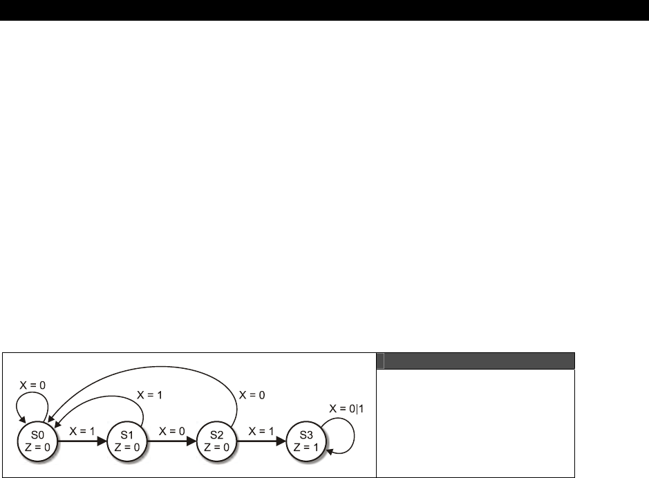
Introduction to Game Development17
Game Programming for the Propeller Powered HYDRA Page 441
latest 3D rendering engines is about 1,000,000 lines of highly optimized code; if I were to
put too much white space, it would bloat to 1.5 million or maybe 2 million lines of editor
code, which would take too long to search and scroll in. Game programming is a very
interactive process: you tweak, recompile, look at it, play it, then stop, re-tweak, etc. so you
want as much code on the screen as possible and to keep typing to a minimum without
losing the simplicity I spoke of earlier.
This stuff might seem obvious, but I have seen countless souls become frustrated trying to
code games since they exponentially get complex in no time and are too hard to debug, then
the programmers give up. But, if you follow some sane rules and conventions you can get
over the exponential complexity “hump” in your game code and finish your games.
Last, but not least, choose clever algorithms, not clever syntax. A optimal algorithm is worth
more than clever, ugly, contrived code. If you have a bad algorithm, all the syntactic
cleverness is not going to make it faster. For example, I can code a Bubble Sort in a couple
lines of code, but no matter how much I mash the code into 1-2 lines, it will never beat a
100-line Quick Sort.
17.4.3 Finite State Machines
Figure 17:9
A Simple Finite State
Machine that Searches
for “NEO”
One of the most commonly used software structures in games is the
finite state machine
or FSM. If you already know what an FSM is just skim this section. An FSM is an abstract
machine implemented physically, electronically, or virtually, that is a machine that has a finite
number of possible states. These states are controlled by the FSM’s current state along with
its inputs. Figure 17:9 shows a generic finite state machine. As you can see each state is
labeled by a circle with the state value / name inside the circle. Also inside the circle shows
the output variables of the state, in this case this state machine has input x and output z.
There are no limits or constraints on the number of inputs or outputs, it’s up to you. Finally,
each state has one or more transition edges leaving or entering each state. This particular
FSM hunts for the sequence “101” in the input stream via x (“101” was the apartment
number in the movie “The Matrix,” so we are searching for “NEO” with this state machine).
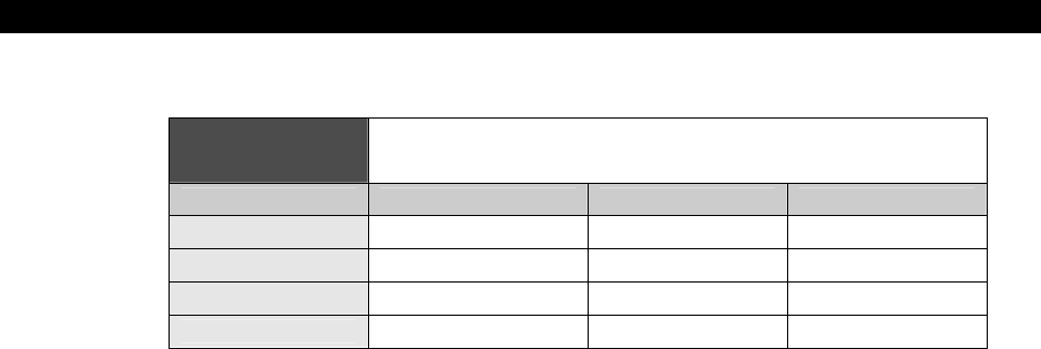
III Game Programming on the HYDRA
Page 442 Game Programming for the Propeller Powered HYDRA
Table 17:1 shows the state transition table (another tool used in FSM design).
Table 17:1 State Transition Table for the “101”
Search State Machine
Present State (Si) Input (x) Next State (Si*1) Output (z)
S0 0 / 1 S0 / S1 0
S1 0 / 1 S2 / S0 0
S2 0 / 1 S0 / S3 0
S3 0 / 1 S3 / S3 1
Referring to the state table, there is no “correct” way to draw one; there are a number of
styles, but Table 17:1 is what you will see in most college EE texts in one form or another.
Sometimes, the present states are written as column heads with inputs down the left edge
and so forth, thus it’s a matter of taste and what is appropriate to get the point across. In
this particular table, we have 4 states: S0, S1, … S3. S0 is the starting state; when the
system is reset it starts in this state, then the state machine reads in x and searches for the
pattern “101.” Each time another symbol in the sequence “101” is reached the state
machine advances to the next state; if a bit in the sequence is incorrect then the machine
goes back to state 0. Also, once the machine reaches state 3, it stays there outputting 1.
Also, notice that the state outputs are irrelevant of the inputs, they are coupled to each state
S0, S1, …, S3. Now, to read the table you simply note what your current state is, say S2 (I
have bolded this row), then you take a look at what your input (x) is. If its 0 in this case
then the next state would be S0, if x is 1 then the next state is S3. The use of the “a / b”
notation simply saves space and is a way to say for these input states “a / b” map them to
these next states “c / d.” You could put numerous inputs with more slashes if need be.
Now, there should be one little detail burning in your mind and that’s “What happens when
the state transitions and inputs are scanned/reviewed?” This is a good question. In an
electrical system, the states would be represented by clocked flip flops, and the inputs would
be re-evaluated each clock. So the system would follow a clock, but in a computer program
this is a little harder to nail down. But, the idea is that you will have a main “game loop” and
all your FSMs will re-evaluate as the main loop evaluates, so if your main loop evaluates 60
times a second (video rates) then so will your main loop FSMs.
So, how can FSM help us in games? Well, they are everywhere in games, for example:
Game loop control
Artificial intelligence algorithms
I/O reading
Telecommunications

Introduction to Game Development17
Game Programming for the Propeller Powered HYDRA Page 443
In fact, we are going to write all our games as a hierarchy of state machines in almost a
fractal manner.
17.4.3.1 States of a Game
Now we are ready to talk about game program architecture. Games are written as state
machines within state machines. Games have to react to input, render the display, play
music, perform calculations, do artificial intelligence, model physics, send packets of data
over networks, and a lot more. The only way to begin to control all this madness is with state
machines and a hierarchical design approach. So let’s think for a moment about the tasks
that a game must perform at the highest level: think about Pacman, Asteroids, Centipede,
Breakout, Pong, or some other basic arcade game. They all have a number of things in
common from a software point of view. Each game consists of two main components; the
program and data:
1. The game program itself.
2. Assets such as graphics, sound, tables, and data.
Also, all the games aside from the gameplay and what they look like all do the same thing
more or less. They sit and wait for you to start them, then the game starts, you play, you
die, it ends, the game resets and waits for the next player (or quarter). So we are starting to
see some organization here. Let’s continue drilling down with our programming hats on.
All these games are applications that have a number of states they must go through before
the “game” starts. Typically these global game states can be broken down into a list similar
to the one below, and organized as shown in Figure 17:10 on the next page.
Initialization
Menu Mode
Game Start
Game Run
Game Over
Game Restart
Game End
This list is by no means ultimate truth, but simply a guideline, you might do things slightly
different by splitting up states, merging them, or adding others, but at the end of the day,
these states in the abstract will all exist in one way or another. Now, let’s review what each
might entail.
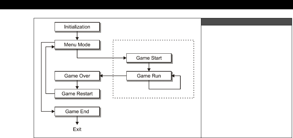
III Game Programming on the HYDRA
Page 444 Game Programming for the Propeller Powered HYDRA
Figure 17:10
The Standard Game States
Commonly Used
in Most Games
Initialization — In this state the game program just started up. It needs to load assets,
initialize devices, load drivers, and do all the housekeeping chores that are associated with
not only the game, but with the program as an application. Memory is allocated here and
other resources as well.
Menu Mode — After the game initializes, typically the game will jump into a “menu” mode,
or in more advanced games a “demo” or “attract” mode (which we will discuss later). In this
mode, typically the game logic will not be running (for simpler games) and the user will
simply be presented with a menu and allowed to navigate the menu with various input
devices to select number of players, skill level, preference settings etc. This Menu Mode may
itself be a number of state machines, but globally the “menu state” is unique.
Game Start — At some point the player is going to start the game via the Menu mode and
the game needs to start. The Game Start mode is designed to get the game ready to run and
clear out variables, and get everything ready for the game to enter into the “run” mode. This
is the last state before the game runs so anything that needs to be reset for a new game
play round needs to get reset here. When the state is complete, it typically automatically
transitions into the Game Run state and the game begins immediately on the next frame or
main loop cycle. Note: notice below there is a “Game Restart” state, many times there is a
slight difference when a game runs the first time, and when a game runs the 2nd time
onward. The Game Restart state is a state to catch this and do any processing. Of course, its
easy to catch this in Game Start by tracking a variable that indicates the current “run” of the
game, but some programmers like a separate state, so no harm to add it for fun.

Introduction to Game Development17
Game Programming for the Propeller Powered HYDRA Page 445
Game Run — This is the main state of the game. If the main loop is here then the game is
running and running at 30-60 frames per second doing everything internally to render,
calculate game logic, do animation, get input an so on. The state loops back to itself each
cycle unless the player dies, or exits, for example, hits ESC and then forces the system back
to the menu state. This state is the “real-time” state of the game more or less.
Game Over — At this state the player has usually died or requested an exit some other way.
Before going back to the main menu the Game Over state might want to do some clean up,
or specifically some kind of sequence or state sequence pertaining to dying or the end of the
game. This state again could be merged into a “sub-state” of the Game Run, but then again
we can merge everything into everything if we really want to, so let’s keep it separate for
now. When the Game Over state is complete it will usually transition right back to the Game
Menu state.
Game Restart — As noted, this is a secondary state that in some game loops is called after
a Game Over state to reset a few more things, or update some other variables that pertain to
the nth run of the game rather than run 1 of the game.
Game End — This state can only be reached via the Menu Mode state and more or less
releases all the resources that the game used. So here is where you release drivers, de-
allocate memory (if you are in an operating system environment), turn all the sound channels
off, and make as if it all never happened.
That’s some of the main global states a game has. The trick is to write a state machine in
your code as a series of case/switch statements or even “if” statements that implement these
states (or a subset of them). Now, let’s take a look more closely at some of the specific
needs for basic games.
17.4.3.2 Basic Game Loops
Alright, now that we have discussed the structure of main game loop for a game, let’s
discuss some details and then talk about some more simplified models of the loop to start
with. First off, the main idea is that it’s a good architecture to use a state machine as the
main loop. The state machine cleanly seperates each of the game’s main states and makes it
easy to program, otherwise, you will find yourself “coupling” states and things will quickly
turn to a mess. Now, the states previously outlined are only suggestions, you can merge, add
states, whatever, the point is to keep it simple.
Additionally, since we are writing games, there is a very tight relationship with the game loop
and the animation of the game. Typically, we want to run a game at 30-60 FPS, so that
animation is fluid and not jerky. This rate of animation can be difficult to maintain in Spin,
since with a lot of logic updating the screen 30-60 times a second might not be possible. But,
when this starts happening then we simply have to switch to ASM, but I am going to try and
offload as much work as possible into the graphics and NTSC drivers, so the main Spin game

III Game Programming on the HYDRA
Page 446 Game Programming for the Propeller Powered HYDRA
logic does very little. So the question is, “How do you maintain a constant frame rate in a
game?” Well, the answer to this is complicated. First, let’s say that there are 100 objects on
the screen and with the 100 objects the game runs at 5 FPS; there is no way to make this
faster, so we can either remove objects or let the game run slow. It’s not really acceptable to
remove game objects, so typically a programmer will write a game such that the game can
maintain 30-60 FPS a most cases. But, what if a game only has 1 object on the screen? Then
the main loop will update much faster than 30-60 FPS and the game will go too fast! This is a
very common problem with games that have wildly varying amounts of core logic. So what
you want to do is simple: at the top of your game run state you take a measure of the
current time or clock, you run your logic, and then at the end of the game loop you “wait”
until 1/30th or 1/160th of second has elapsed then continue. So if the game loop took more
than 1/30th or 1/60th of second (depending on how fast you want the game to run) then the
wait code would fall through, but if the game logic only took 1/1000th of a second, then the
wait code would wait and the game would run at a consistent speed. For example, if we were
running the HYDRA at its normal 80 MHz then each clock is 12.5 ns, therefore, 1/60th of a
second would be 1,333,333.33 clocks, so all we need to do is wait this many clocks to
guarantee that the main loop runs no faster than 60 FPS and the game has consistent timing
for the animation. Here’s some Spin code that would do this:
' main loop entry
timer_count := CNT + 1_333_333
' game logic goes here…
' now wait until 1/60th of second from entry elapses…
waitcnt(timer_count)
Of course, if the “game logic” takes more than 1/60th of second then the loop would just fall
through. Next, let’s talk about the main animation cycle or run state of the game.
In the game run state, the game logic follows these general steps shown below and
diagramed in Figure 17:11:
Step 1: Erase the image on the screen or off-screen buffer.
Step 2: Get player input and process it.
Step 3: Perform game logic, AI, collision detection, etc.
Step 4: Draw image on screen or offscreen buffer.
Step 5: Copy offscreen buffer to visible screen (only if using a double-buffered scheme).
Step 6: Synchronize to frame rate (optional).
Step 7: GOTO 1
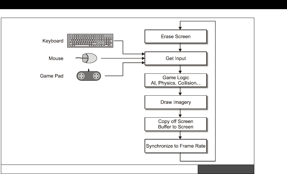
Introduction to Game Development17
Game Programming for the Propeller Powered HYDRA Page 447
The General Game Run State or “Animation Loop” Figure 17:11
Once again, these steps are a guideline and in reality might be further separated or merged,
but the idea is
“erase-move-draw”
– this is the basis of all games –
“erase-move-
draw.”
For every game demo that we develop, you will see this structure in the main loop
in one form or another.
17.4.3.3 “Attract” / Demo Modes
The next subject I want to talk about is demo and “attract” modes. The term “attract” mode
was coined by Atari since they wanted their early games to “attract” attention, so the term
“attract mode” is similar in meaning to demo mode. Anyway, the idea of a demo mode is that
the game “demos” the game play either using artificial intelligence or pre-recorded user
game play that is feed back through the input system as if the player were playing, this is
shown in Figure 17:12 on the next page. This is yet another game state and usually related
to the menu state of a game. If you leave a game long enough, it automatically transitions
from the menu state after some time (maybe 10-30 seconds) and goes into demo mode to
show the game playing, then if a player hits a key it jumps back to the menu state.

III Game Programming on the HYDRA
Page 448 Game Programming for the Propeller Powered HYDRA
Figure 17:12
The Data Flow for
Demo Modes
To implement this kind of feature, aside from the actual demo mode logic and/or data, the
way to approach it is the concept of “sub-states” in the game run state. That is, when the
main loop enters into the game run state, normally there might only be one state, “normal,”
but to support a demo mode state, there could be a sub-state that indicates further sub-
processing within the parent state. This can save code since its usually easier to code a sub-
state in a main state rather than copy an entire state. For example, both the run and demo
states both erase, move, draw everything, but the demo mode doesn’t read player input, it
reads from a file or an artificial intelligence controls game play. Thus, the only real difference
between a normal run state and the demo mode is one section of code, thus it’s wasteful to
copy all the other code. A better approach is to use a conditional and a sub-state variable to
branch to various blocks to get the player control either from input devices or a data file or
AI. Below shows a snippet of pseudo code to illustrate the idea:
CON
' a couple primary states
GAME_STATE_INIT = 0
GAME_STATE_RUN = 1
' a couple sub-states relating to the “run” state
GAME_STATE_RUN_NORMAL = 0
GAME_STATE_RUN_DEMO = 1
VAR

Introduction to Game Development17
Game Programming for the Propeller Powered HYDRA Page 449
long game_state, game_sub_state
Pub Start
' state off in run/normal
game_state := GAME_STATE_RUN
game_sub_state := GAME_STATE_RUN_NORMAL
'...lots of stuff
' main loop
case game_state
GAME_STATE_INIT: ' do all the init here…
GAME_STATE_RUN: ' here’s the run state
' erase...
' test for sub-state here
if (game_sub_state = GAME_RUN_NORMAL)
' do normal user input…
else ' must be GAME_RUN_DEMO
' read from demo file or use AI to play game
' move / logic...
' draw...
' end run state
Of course, there might be many sub-states, and even sub-states within the sub-states, the
point is to balance code re-use with code complexity. If the code complexity goes up too
much then you might have to break a state back out from a sub-state to a primary state.
Also, you might want to always use “case” statements rather than “if’s” based on memory
usage, the only way to find out which is better is to compile and check memory usage.
Remember, Spin programs use up a lot of memory compared to ASM, so code needs to be as
optimal as possible.
17.4.4 Advanced architectures wth engines
The last topic I want to discuss is more advanced game architectures that you might find in
“level” based games or more modern games like DOOM, HALO, etc. If you write a brute force
“shooter” game, where objects appear on the screen and you simply shoot them and then
re-generate, the game “engine” is the “game,” there isn’t a nice delination between
“program” and “data,” but unless you want to “code” every little thing in a game, a more
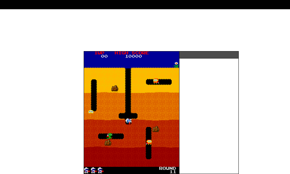
III Game Programming on the HYDRA
Page 450 Game Programming for the Propeller Powered HYDRA
modern technique is to write a “game engine” that runs the game, and then the behavior of
the game is more data-driven by a “level file” of sorts. The level file might have game field
data only, or it might have other data in it, even little “scripts” written in some custom
language.
Figure 17:13
Atari’s Dig Dug
For example, say you want to make a
“Dig Dug”
clone as shown in Figure 17:13. Dig Dug is
more or less a “chase” game like Pacman, but you are under ground, can dig away rock,
drop rocks, and fire a water hose at the enemies. The point is that each “level” has different
graphics, different positions of the enemies to start, different positions of the rocks, and so
forth. To “program” each level would be a pain since you would have to use code, recompile,
etc. But, if you make an engine that can read “files” or level data in some format, then an
artist or level designer can design levels and know nothing about game programming! This is
exactly how all modern games are made; level designers are given tools to design levels and
don’t even know how to program, but they can play characters, apply textures, place traps
and so forth. Let’s see how we might do this with the Dig Dug example. Let’s assign the
following ASCII characters the values shown below:
‘ ’ = Empty dug out rock ‘s’ = Sky
‘y’ = Dirt yellow ‘R’ = A Rock
‘0’ = Dirt orange ‘F’ = A Fygar dragon
‘r’ = Dirt red ‘P’ = A Pooka
‘b’ = Dirt brown ‘H’ = Dig Dug himself

Introduction to Game Development17
Game Programming for the Propeller Powered HYDRA Page 451
Alright, now based on these character encodings, if we want to generate level data like
something shown in Figure 17:13, (assuming a 16×18 tile universe) then the data would look
like:
"ssssssssssssssss"
"ssssssssssssssss"
"ssssssssssssssss"
"yyyyyyy yyyyyyyy"
"yyyyyyy yyy P y"
"yy yRyy yyyyyyyy"
"yyPyyyy yyyyyyyy"
"00 0000 00000000"
"00 0000 00000000"
"00000 H 000000"
"0000000000000000"
"bbbbbbbbbbbbbbbb"
"bbbbbbbbbbbb Rbb"
"bbb F bbbbb bbb"
"bbbbRbbbbbbbPbbb"
"rrrrrrrrrrrr rrr"
"rrrrrrrrrrrr rrr"
"rrrrrrrrrrrrrrrr"
Take a moment and stare at the data and you will see that if you map the key to the ASCII
data it is indeed similar to the image shown in Figure 17:13! Thus, once you write an
“engine” that reads a string array or ASCII array in Spin of this format, then there are
countless game levels you can design! Better yet, a non-programmer can design the game
levels and simply give them to you for inclusion in the game source. This is the power of
game engines and “data driven” design.
17.5 Data Structures Used in Games
Spin has no data structure support other than singletons and arrays, thus, if you are used to
complex structures like linked lists, trees, or even named records you are out of luck.
However, this isn’t really an issue since game developers like to keep things simple anyway.
In the paragraphs below, we are going to discuss some ideas and tactics when it comes to
data structures used in games.
17.5.1 Globals, Arrays, Linked lists
Writing a video game is like rendering a painting, you do it one layer at a time: first the
background, then some of the foreground objects, then lighting, then touch-up, etc.
Therefore, as you code, you don’t need to be perfect and follow every rule in the book. For
example, games must be fast. This is the number one concern second to size, thus the use
of globals is very liberal, in fact, most games have a “global pool” at the top of the program
that is used in many algorithms throughout the game. Moreover, the concept of functional

III Game Programming on the HYDRA
Page 452 Game Programming for the Propeller Powered HYDRA
encapsulation and side effects are loose. That is, it’s okay to have functions that have no
locals and that simply refer to globals, this way, there is nothing created on the stack and
destroyed on exit to a function. So, in general globals are good in games and help get things
going. If you are a messy programmer and have a hard time remembering what’s what then
globals will bury you, but the point is that when you start coding a game, many of your
functions may have no parameters and no locals, everything will be global.
Next, application programmers love to over-design data structures, many times a simple
array will suffice for 90% of all programs. Sure, for sorting, searching and advanced
algorithms we have to use linked lists, trees, and other more advanced data structures. But,
in most cases static arrays are the best way to represent a set of objects even if the number
of objects changes. Although, this isn’t as much a concern in Spin since there is no heap, no
OS, and no memory allocation/de-allocation functionality; the idea is that if you know the
maximum size something is going to be, simply make an array that big and use a variable to
track how many elements are active, or the last element.
17.5.2 Simulating Records
One area that neither Spin nor assembly language support is records. That is a way to create
a named data structure, or an array of them, and access them with an index and field
operator. For example, say you wanted to define a player like so with C code:
typedef PLAYER_TYP
{
word state // state of player
word x,y // position of player
word xv, yv // velocity of player
word color // color of player
} PLAYER;
Then you could create an array of PLAYERs with the following syntax:
PLAYER players[10];
...and you could access the ith player’s state field like this:
players[i].state
Spin has no support for named structures and accessing data like this, however, we can
synthesize it with some clever programming. The idea is that we want to use a single array
to hold n records, each record composed of a number of fields. Let’s synthesis one possible
solution using Spin to emulate the above C language structure support:
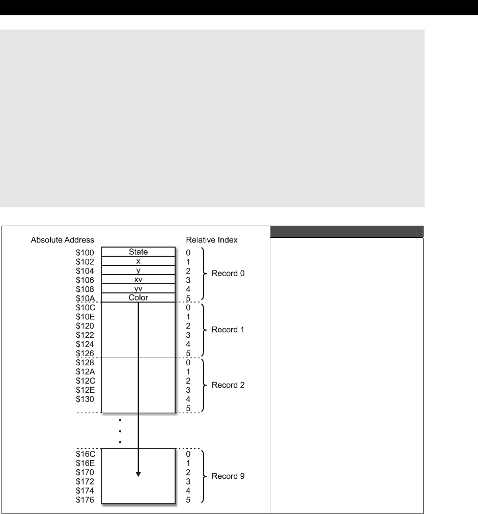
Introduction to Game Development17
Game Programming for the Propeller Powered HYDRA Page 453
CON
' index values into the record
PLAYER_STATE_INDEX = 0 ' index of “state” in record
PLAYER_X_INDEX = 1 ' index of “x” in record
PLAYER_Y_INDEX = 2 ' index of “y” in record
PLAYER_XV_INDEX = 3 ' index of “xv” in record
PLAYER_YV_INDEX = 4 ' index of “yv” in record
PLAYER_COLOR_INDEX = 5 ' index of “color” in record
PLAYER_SIZE = 6 ' 6 words per player record
NUM_PLAYERS = 10
VAR
word players[NUM_PLAYERS*PLAYER_SIZE] ' set aside a total of 60 words to hold
' all the data
Figure 17:14
The layout of Player[ ]
Records in Spin Memory

III Game Programming on the HYDRA
Page 454 Game Programming for the Propeller Powered HYDRA
Figure 17:14 shows how memory is laid out for our
player[ ]
array assuming the starting
address of the array is $100. Basically, we simply use a consistent convention to access each
record as an offset from a base and then index into the field to get the appropriate field. So
syntax to access any field of any record n is simply:
players[PLAYERS_SIZE * n + field_index]
...where field_index is one of the constants PLAYER_STATE_INDEX, PLAYER_X_INDEX, etc.
For example, if we wanted the 3rd player’s color we would type:
players[PLAYERS_SIZE * 3 + PLAYER_COLOR_INDEX]
...and that’s it. Now, there is some really bad news here with Spin: there is very little
optimization going on inside those brackets, so the index calculation will be done each time
and waste code and time. You can surround the internal index of the brackets with a
CONSTANT( ) call, but this only works for constants, that are not a function of a variable. So,
be careful if you start using complex mathematical expressions to generate array indices as
the time to calculate the array index will kill your performance, so try to keep things to a
multiply
and an
add
if possible.
Also, a simple optimization you can do is this: say that you are indexing with n as the index
and need to access each element in a record and do something with it, simply pre-compute
the multiplication to find the base, then use this as part of your final index. Thus instead of
this code:
players[PLAYERS_SIZE * n + PLAYER_STATE_INDEX]
players[PLAYERS_SIZE * n + PLAYER_X_INDEX]
players[PLAYERS_SIZE * n + PLAYER_Y_INDEX]
players[PLAYERS_SIZE * n + PLAYER_XV_INDEX]
players[PLAYERS_SIZE * n + PLAYER_YV_INDEX]
players[PLAYERS_SIZE * n + PLAYER_COLOR_INDEX]
...pre-compute the multiplication factor like this:
player_base_address := PLAYERS_SIZE * n
players[player_base_address + PLAYER_STATE_INDEX]
players[player_base_address + PLAYER_X_INDEX]
players[player_base_address + PLAYER_Y_INDEX]
players[player_base_address + PLAYER_XV_INDEX]
players[player_base_address + PLAYER_YV_INDEX]
players[player_base_address + PLAYER_COLOR_INDEX]

Introduction to Game Development17
Game Programming for the Propeller Powered HYDRA Page 455
...so now, each index expression has been simplified to a single addition rather than a
multiplication and addition. Of course, in a modern compiler, this would be done
automatically, but with Spin you have to give it a little help which is kinda fun, since you can
use a lot of old DOS programming optimizations in Spin that have long been optimized by
modern compilers and don’t work anymore.
17.5.3 Pre-computation, Lookup Tables, and Caching Strategies
The above pre-computation trick leads us to caching and lookup tables. With Spin, the best
way to do math and computation is not to do it at all, so the more you can cache, pre-
compute, or otherwise calculate before run-time the better. For example, there are few
places to do this; in Spin “what you see if what you get” so if you perform a multiplication
and then 5 lines down the
same
multiplication, the compiler will simply do it again. An
optimizing compiler will track this and store the computation and cache it for later use in the
current block. So after you do your coding, if you find a term that is in common, try pre-
computing it at the top of the loop, and caching it in a single variable and use the variable for
the expression or factor to speed things up.
The second place to use these techniques is where you can generate complex mathematical
or functional tables rather than use logic to compute them in real-time. A simple and obvious
example is trigonometric tables, which the Propeller chip actually has in look-up tables along
with log tables. But, don’t think look-up tables are only for math, you can use look-up tables
for anything that you need to be fast. If it’s worth the speed versus memory trade off then
do it, or at least try.
Lastly, formal “caching” is a technique where you are forced to perform some kind of
calculation or resource access during real-time that you simply can’t pre-compute or
generate, there is too much of it; however, you might find that if you perform one
computation at time t, then you continue to peform that computation temporally near time t,
thus you can cache the result, and before you do the computation test if the cache holds the
results. Thus the cache might only be few hundred bytes of storage, but can save you a lot
of computation time. Graphics algorithms make heavy use of caches for bitmap data,
texturing, lighting, and so forth, so give crude caching a try as well.
17.6 Mars Lander
Well, this wouldn’t be a game book if we didn’t write some games, so it seems only
traditional to start off with something simple to use our techniques thus far. I was going to
make a Pong game, but I am so sick of Pong for the “hello world” of games, I thought why
not a lunar lander game? That’s a little more interesting I think. So, let’s design “Mars
Lander” together then I will go off and code it. I am going to give myself no more than 1
hour to code it, and this is a good way for you to get good at games as well, that is, set a
time limit, an hour, week, month or year to make your game, and when the time is up, the
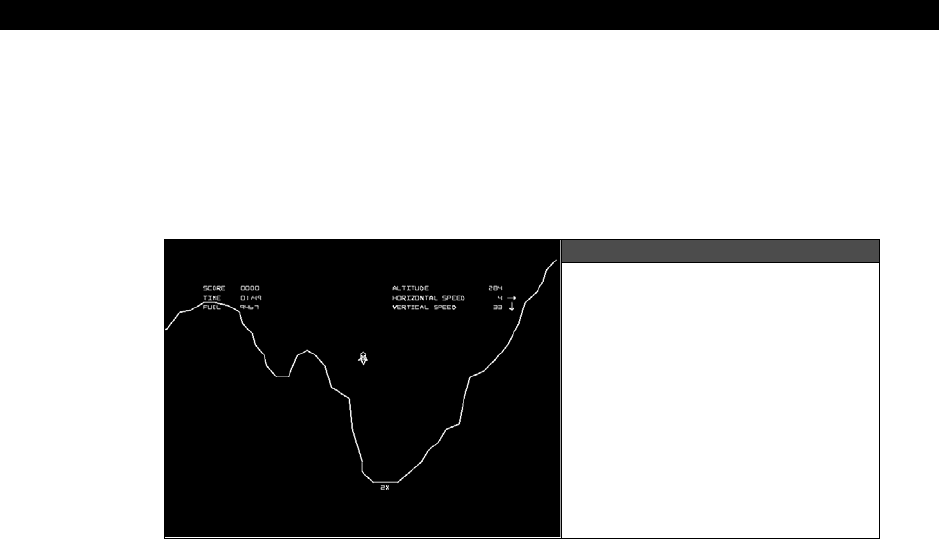
III Game Programming on the HYDRA
Page 456 Game Programming for the Propeller Powered HYDRA
time is up, otherwise, you will never finish. An hour is a good amount of time to make a lunar
lander along the lines I am thinking. So, let’s do the design. First, if you have never seen
Lunar Lander
, it’s yet another Atari classic game (however there were earlier PC-based
versions), based on the excitement of the moon landing in 1969. Lunar Lander is a simulation
game, and the idea is simple: land the lunar module on the moon’s surface without smashing
it into the ground at too high a velocity. The game looks something like that shown in Figure
17:15.
Figure 17:15
Atari Lunar Lander in Action
The original Atari version game was done with vector graphics and an o-scope display
controlled by a 6502 @ 1.5 MHz. We will try to make our game similar by using green vector-
like line graphics. The gameplay consists of a randomly generated terrain and then the lander
drops into view, you can control the horiztonal and vertical velocity with thrusters. The idea
was to land as soft as possible and use the least amount of fuel as possible. Thus, our design
consists of the following elements:
1. We need to generate a random terrain with at least one flat spot for landing.
2. We need to draw the ship and terrain each frame, get user input, and simulate
gravity and velocity effects.
3. We need to perform a collision detection algorithm to test when the lunar lander
touches the terrain and if it has landed on the landing zone with a low enough
velocity. Then the player gets some points and the game restarts.
Some things that need to be developed are ways to draw random terrain, how to implement
gravity, and finally, some kind of floating-point or fixed-point support for the velocity and
acceleration. We will get more into these details later, but for now, I am going to use fixed-
point math (if you haven’t used fixed-point, don’t worry we will discuss it later). For gravity, I
am going to use these simple equations for linear motion from any physics book:
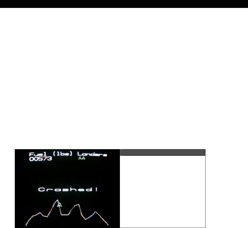
Introduction to Game Development17
Game Programming for the Propeller Powered HYDRA Page 457
velocity = acceleration × time
position = velocity × time + ½ × acceleration × time2
acceleration = gravity (on moon)
Now, in a game, “time” is virtual and can be “real-time” or simulated time, such as the frame
rate, so at the end of the data, the final form of the equation we are going to use is simply
this, given the y position of our lander is lander_y:
lander_ya = thrust + gravity_moon
lander_yv = lander_yv + lander_ya
lander_y = lander_y + lander_yv
...where, “lander_yv” is the y component of velocity of the lander, “lander_ya” is the y
component of acceleration of the lander (generated by thrust or gravity), and finally
“lander_y” is the y position on the screen of the lander. Of course, there are lots of scaling
and sign issues, but don’t worry about them for now, the idea here is to just get a general
design down and how we are going to do it. The code of course will look quite different
since there are going to be tricks, shortcuts and fixed point math, but its all based on the
above equations.
Figure 17:16
Our Little Mars Lander Game
The results of all our hard work is shown in Figure 17:16. The code for the game can be
found on the CD here:
CD_ROOT:\HYDRA\SOURCES\mars_lander_011.spin
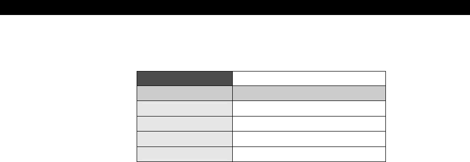
III Game Programming on the HYDRA
Page 458 Game Programming for the Propeller Powered HYDRA
Simply load this file and compile and download it into the HYDRA. The game only uses the
NES compatible controller for input, the controls are as follows:
Table 17:2 Mars Lander Controller
Controller Input Action
Dpad Right Rotate Right
Dpad Left Rotate Left
B Thrust
Start Start Game
Try to keep the lander downward velocity under a couple pixels/sec and land it on the “flat
spot” on the terrain highlighted in green. You will notice that the game has all the main game
states when you review the code such as
initialization
,
menu
,
start
,
run
, and
end
.
See if you can add some features to the game, maybe sound or some “zooming” technology,
so as you get closer to the landing zone the game “zooms” into it. Also, notice the game logic
is very simple, and by no means robust, the collision for example is very crude. The player’s
ship is a polygon composed of lines, the polygon can rotate all around, therefore to test for
all collision possibilities you would have to test each line of the polygon against the terrain
and test if it intersects. This is very slow and there are tricks around this (not implemented
at this time), alas, this demo’s collision detection for the mars terrain simply “reads” pixels
from the screen and if the center of the ship pierces “red” then we know we are hiting the
terrain and the player dies. This techniques is called
“color space”
collision detection and is
based on reading the pixel data out of the screen image and knowing that one or more
colors mean different things like hot, cold, water, barrier, or die! On the other hand the
landing zone collision detection works by testing the current x,y position of the lander against
the landing zone with is more or less a line from (x1, y) to (x2, y), if the lander is close to y
and between x1 and x2 and the downward velocity of the lander is less than our threshold
then a safe landing has occurred. As you can see, the devil is in the details.
Collision detection is one of the biggest problems in game programming, that is, how to test
collision between objects (many of them bitmaps) in a fast and efficient manner. There are
all kinds of algorithms designed for this since the problem turns out to be n2 or C(n,2) in
many cases which even for small n explodes. Anyway, this game is meant to be a black box
for you to play with, so how it works isn’t important yet.

Introduction to Game Development17
Game Programming for the Propeller Powered HYDRA Page 459
“c(n,2)” in the paragraph above means “n choose 2”, it comes from a field of
math called “Combinotorics” and relates to the number of ways to choose
subsets from a set where order is unimportant. The formula in general for c(n,r)
is [ n!/(n-r)! ] where n! is means “n-factorial” and is equal to
[ n*(n-1)*(n*2)*…*2*1 ],
...where 1! = 1 as well as 0! = 1.
17.7 Summary
In this chapter we discussed a number of artistic and technical issues and concepts related to
game development. Hopefully, you have a better idea of the work flow and what’s involved
now, so you can see how things “connect” together. You are probably a bit overwhelmed
right now seeing all the tools that are involved, most people really have no idea what goes
into a game and when they learn a little about it they are shocked to see how complex it all
is! The important thing about a game to understand is that is more than just a program, it’s
a huge array of assets, art, sound, music, level data and more and all this is used to make
the game work. In the following chapters, we are going to tackle the technical aspects of
game development including graphics, input, sound, 3D, optimization, and so forth – it
should be a lot of fun, so let’s get cracking!

III Game Programming on the HYDRA
Page 460 Game Programming for the Propeller Powered HYDRA

Basic Graphics and 2D Animation18
Game Programming for the Propeller Powered HYDRA Page 461
Chapter 18:
Basic Graphics
and 2D Animation
In this chapter, we are going to start formalizing graphics and animation techniques on the
HYDRA. For the most part, we will probably stick with the Parallax reference drivers for
graphics and NTSC generation since in this chapter we are more interested in discussing
concepts that relate to simple point, line, and geometrical graphics rather than high
performance concepts. Also, we need to cover a bit of math to find robust ways to describe
motion and so forth. Lastly, this is not a “graphics theory” book, and thus, we are not going
to derive and implement line drawing algorithms, flood fills, texture mappers, etc. as that is
beyond the scope of this book, but I will point you in the right direction if you’re interested
when the subjects come up. Rather, we are going to use API functions that either myself or
Parallax has written, so we can simply concentrate on getting things on the screen, moving
them around, and building our arsenal of game programming techniques. With that in mind,
here’s what’s in store this chapter:
Coordinate systems
Plotting pixels
Drawing lines
Polygons
Erase-Move-Draw
Double buffering
Page flipping
Translation and coordinate frames
Simple motion techniques
Color animation
18.1 2D Coordinate systems
In computer graphics and rendering there are countless “coordinate systems” used to
transform graphics problems into a more relevant format. There are systems that you have
heard about such as
Cartesian
,
Polar
, and
Cylindrical
and those more exotic used in
games such as
Hexagonal
,
Isometric
, and others. However, for our purposes we are
sticking to basic 2D graphics, so we can get away with Cartesian and Polar coordinates for
now. Let’s briefly review these systems since both the Parallax graphics drivers as well as the
ones provided in this book use these systems more or less.
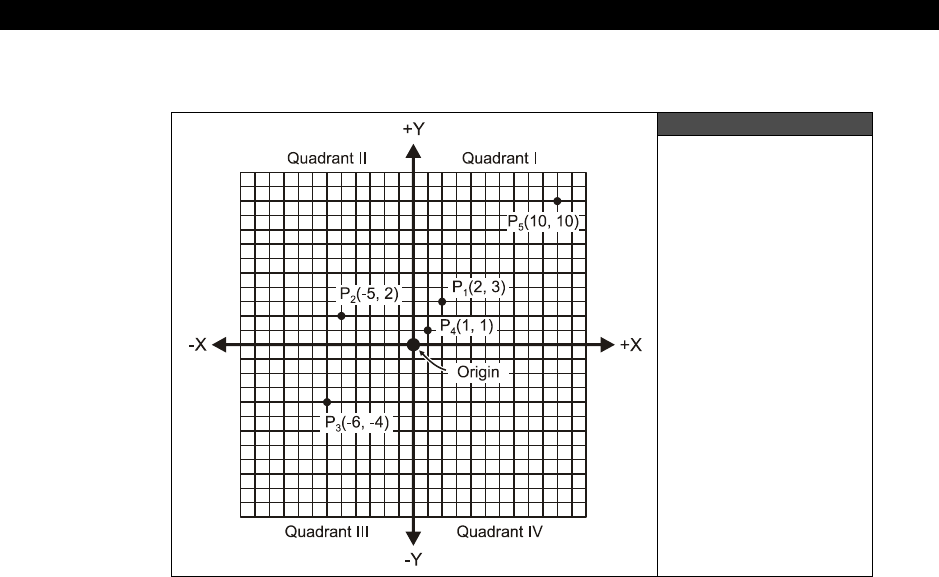
III Game Programming on the HYDRA
Page 462 Game Programming for the Propeller Powered HYDRA
18.1.1 Cartesian Coordinates
Figure 18:1
A 2D Cartesian
Coordinate System
Referring to Figure 18:1, this is the standard Cartesian coordinate system you have seen a
million times in school and have probably drawn many graphs on. The 2D version has two
axes – the X-axis (also known as the
abscissa
) which is horizontal as well as the Y-axis (also
known as the
ordinate
) which is vertical. There are four quadrants labeled counter-
clockwise. The top right is Quadrant I, top left is Quadrant II, bottom left is Quadrant III,
and finally the bottom right is Quadrant IV. If you are graphing all positive values then you
would typically use only Quadrant I.
To locate a point on the coordinate sytem, an ordered pair (x,y) is used. For example, refer
to Figure 18:1. There are a number of points labeled. The coordinate (0,0) has special
meaning and is referred to as the
“origin.”
Other points are all generic, for example in the
figure I have labeled P1 as (2,3), P2 as (-5, 2), and so on. The naming of coordinates allows
us to refer to them by symbol rather than the actual coordinates. For example, once again
referring to the figure, if I were to refer to P4, you know that means coordinates (1,1).
Additionally, when writing coordinates its customary to write them with their label and then
the coordinates in parenthesis; for example P5(10,10).
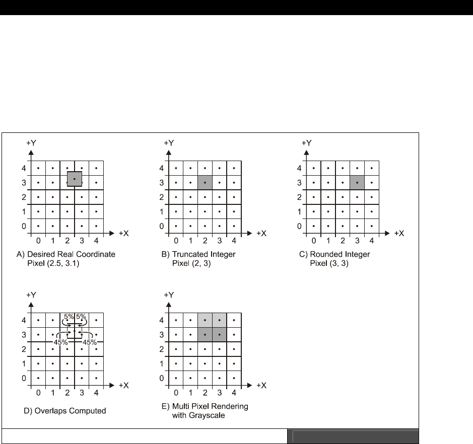
Basic Graphics and 2D Animation18
Game Programming for the Propeller Powered HYDRA Page 463
That’s about all there is to Cartesian coordinates. But, there are some very important
differences when using them for computer graphics. First, computer screens are
integer
matrices
, meaning there is a finite number of pixels horizontally and vertically. This is
commonly referred to as
resolution
. For example, on an NTSC screen some common games
systems use 256×192, 224×192, 160×192; however, on a computer monitor the resolutions
are much higher such as 800×600, 1024×768 and even up to 2400×2400 on high-end
graphics workstations.
Subpixel Accurate Rendered Problem Figure 18:2
Coming back to the comment about integer matrices – what this means is that you can only
plot pixels at integer valued (x,y) coordinates, there are no decimal coordinates like there are
in a real Cartesian coordinate system. The computer can’t plot a pixel between two pixels on
the NTSC/VGA screen, that’s just a fact of the physical limitations of the screen. Thus when
rendering, there are many techniques that have been developed to “synthesize” the effects

III Game Programming on the HYDRA
Page 464 Game Programming for the Propeller Powered HYDRA
of fractional coordinates. For example, if your graphics engine outputs (2.5, 3.1) there is no
coordinate here on the screen, so you have to make a decision what pixel(s) to plot.
Referring to Figure 18:2(A), we see the mathematically desired pixel location, and the reality
of the integer computer screen we must plot on. Notice that the integer coordinates are now
the “centers” of each rectangular grid element (dots indicate dead centers). An easy way out
is to simply truncate all coordinates when they get to the rendering engine; using this
technique we have:
trunc(2.5, 3.1) = (2, 3)
...and we can simply plot this which is shown in Figure 18:2(B). This is a bad idea since you
completely throw away the fractional information. The question is “Is there any way to take
advantage of the fractional information, even a little bit?” Yes, we can “round” the
coordinates like so:
round(2.5, 3.1) = (3, 3)
The results of the rounding and plotting are shown in Figure 18:2(C), this is a much better
approach and the best you can do when you only want to plot single pixels. However, if you
want to work a little harder you can anti-alias the image and plot multiple pixels around the
center of the desired pixel which will cost more work, but give a more realistic result. For
example, looking at Figure 18:2(A), and doing a little geometry, we see that the
mathematically correct pixel overlaps 4 pixels with the following coordinates and
percentages, shown in Figure 18:2(D):
Overlap Region 1 – (2,4) = 5%
Overlap Region 2 – (3,4) = 5%
Overlap Region 3 – (3,3) = 45%
Overlap Region 4 – (2,3) = 45%
So taking this into consideration, we can distribute the fractionally located pixel onto multiple
integer coordinate locations by plotting 4 pixels each with an intensity equal to the
percentage of overlap into the neighboring integer coordinates. This technique costs a lot
more computation obviously, and tends to average or blur an image, but gives better results
depending on what you are doing. The final results are rendered in Figure 18:2(E) to show
you the effect in gray scale. Typically, games are more concerned with speed rather than
correctness, so if you can get away with truncation or rounding then do so.
The next detail we need to discuss are the inversion of the Y-axis on 99% of all graphics
workstations and APIs. The Cartesian coordinate system has positive X moving to the right,
and positive Y moving upward. However, on most graphics systems and APIs, game
programmers usually use an inverted Quadrant I of the Cartesian coordinate system and map
it to the screen, this is shown in Figure 18:3. In this system the origin is at the
top-left
hand
corner of the screen with positive X moving right, and positive Y moving down. The reasons
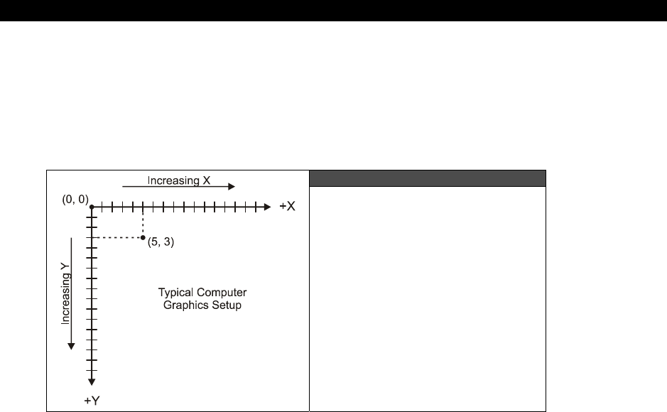
Basic Graphics and 2D Animation18
Game Programming for the Propeller Powered HYDRA Page 465
for this inversion compared to Cartesian coordinates comes from the fact that early
computers graphics drivers had very little computation time to work with, thus instead of
rendering a nice Cartesian system, they inverted the Y axis to save time since memory was
scanned out top to bottom to facilitate feeding the rasterizer. So positive Y ended up going
downward. Alas, most graphics systems work with (0,0) as the top-left with positive X to the
right and positive Y going down.
Figure 18:3
Inverted Quadrant I Graphics
However, on modern computers and APIs, you have enough time to invert coordinates, so
you can map the screen anyway you like; nonetheless, 2D game programmers still like the
old way with (0,0) at the top. Please note that the Parallax graphics driver we are going to
use in this chapter uses a standard Cartesian Quadrant I approach, but later when we see
my drivers and the other demos know they all use normal (0,0) top left format.
Alright, so Cartesian coordinates are what most people are used to, you simply give an (x,y)
coordinate and locate it on the screen or graph paper, but many times certain operations
lend themselves to different types of representations. Once such representation is called
Polar coordinates; let’s take a look at that since the Parallax driver makes heavy use of Polar
coordinates for polygon definition and other functions.
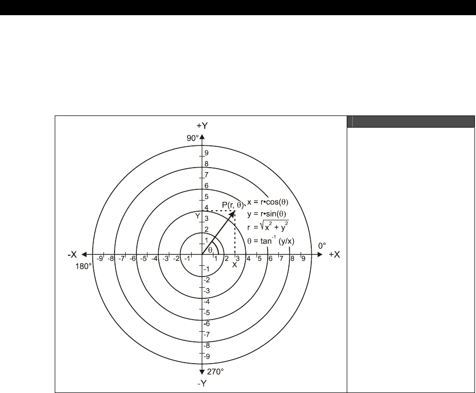
III Game Programming on the HYDRA
Page 466 Game Programming for the Propeller Powered HYDRA
18.1.2 Polar Coordinates
Polar coordinates are useful to represent geometries with circular or radial symmetry as well
as motions that are circular. Figure 18:4 shows the standard 2D Polar system overlapped on
a 2D Cartesian system. Points in Polar coordinates are represented by a distance or length
term referred to r (measured from the origin) and an angle (theta), (measured from the
positive X-axis) in the format P(r, ).
Figure 18:4
A Standard 2D Polar
Coordinate System
In Figure 18:5 we see a number of Polar points plotted with various distance r’s and θ
angles. The reason this type of coordinate system is useful for example is rotation. If I asked
you to write me the equations for rotation in a 2D plane you might have a little trouble
remembering them; but here’s a hint:
x' = x*cos (θ) - y*sin (θ)
y' = x*sin (θ) + y*cos (θ)

Basic Graphics and 2D Animation18
Game Programming for the Propeller Powered HYDRA Page 467
For example, if we wanted to rotate the point (1,0) in Cartesian coordinates 90 degrees
counter-clockwise, applying the formulas, we better get (0,1) – let’s see:
x' = 1*cos (90) - 0*sin (90) = 0
y' = 1*sin (90) + 0*cos (90) = 1
...which is correct. But, surely not at all obvious, the derivation is about a page long.
Figure 18:5
A Few Polar Points
But, in Polar coordinates, look how easy it is to rotate a point. Referring to Figure 18:6 on
the next page, if we want to rotate point P1 by 30 degrees counter-clockwise, well we just
add 30 degrees to the Polar coordinate and we are done, thus:
P1(3, 15) rotated 30 degrees P1'(3,15+30) = P1'(3, 45)
That’s what’s cool about Polar coordinates. Now, the only problem is that rotation is great,
but it’s not for free, you must transform your Cartesian coordinates to Polar, perform the

III Game Programming on the HYDRA
Page 468 Ë Game Programming for the Propeller Powered HYDRA
rotation and then transform
back
. Also, computer screens do not operate on Polar
coordinates, so they are purely mathematical in nature and a tool used to simplify certain
operations such as rotation as shown. In any case, now let’s look at the transformation
equations that convert Polar to Cartesian and vice versa. Referring back to page 466, Figure
18:4 has some extra labeling on it showing the Cos and Sin terms in relation to the angle as
well as the computation of r. The formulas are given below.
Figure 18:6
_Polar Rotation is a
Snap!
Polar to Cartesian
Given a point in Polar coordinates
P(r, θ) the Cartesian coordinates:
x = r*cos(θ)
Cartesian to Polar
r = √(x2 + y2)
θ = tan-1 (y/x)
y = r*cos(θ)
As you can see the Cartesian to Polar conversion is pretty complex as far as computer cycles
go, so this is one you want to do offline or pre-compute.

Basic Graphics and 2D Animation18
Game Programming for the Propeller Powered HYDRA Page 469
18.2 Drawing Primitives
At this point, we are going to experiment with some of the drawing
“primitives”
that are
commonly used in computer graphics: point, lines, and polygons. We could draw them
manually by manipulating video memory, but instead we will rely on the reference graphics
driver from Parallax. Additionally, I have create a couple templates that you can use to get a
demo up and running quickly. The first template is called graphics_template_010.spin; it
sets up a 256×192, 4-color graphics mode with only a single graphics buffer which is directly
mapped to the screen, that is, if you plot a point or draw a line, you will immediately see it.
The code for the template is shown below (slightly abridged for space):
CON
_clkmode = xtal2 + pll4x ' enable external clock and pll times 4
_xinfreq = 10_000_000 + 3000 ' set frequency to 10 MHZ plus some error
_stack = ($3000 + $3000 + 64) >> 2 ' accomodate display memory and stack
' graphics driver and screen constants
PARAMCOUNT = 14
OFFSCREEN_BUFFER = $2000 ' offscreen buffer, unused in this template
ONSCREEN_BUFFER = $5000 ' onscreen buffer
' size of graphics tile map
X_TILES = 16
Y_TILES = 12
SCREEN_WIDTH = 256
SCREEN_HEIGHT = 192
' color constant's to make setting colors for parallax graphics setup easier
COL_Black = %0000_0010
COL_DarkGrey = %0000_0011
COL_Grey = %0000_0100
COL_LightGrey = %0000_0101
COL_BrightGrey = %0000_0110
COL_White = %0000_0111
COL_PowerBlue = %0000_1_100
COL_Blue = %0001_1_100
COL_SkyBlue = %0010_1_100
COL_AquaMarine = %0011_1_100
COL_LightGreen = %0100_1_100
COL_Green = %0101_1_100
COL_GreenYellow = %0110_1_100
COL_Yellow = %0111_1_100
COL_Gold = %1000_1_100
COL_Orange = %1001_1_100

III Game Programming on the HYDRA
Page 470 Game Programming for the Propeller Powered HYDRA
COL_Red = %1010_1_100
COL_VioletRed = %1011_1_100
COL_Pink = %1100_1_100
COL_Magenta = %1101_1_100
COL_Violet = %1110_1_100
COL_Purple = %1111_1_100
' each palette entry is a LONG arranged like so: color3|color2|color1|color 0
COLOR_0 = (COL_Black << 0)
COLOR_1 = (COL_Red << 8)
COLOR_2 = (COL_Green << 16)
COLOR_3 = (COL_Blue << 24)
' VARIABLES SECTION ///////////////////////////////////////////////////////////
VAR
long tv_status '0/1/2 = off/visible/invisible read-only
long tv_enable '0/? = off/on write-only
long tv_pins '%ppmmm = pins write-only
long tv_mode '%ccinp = chroma,interlace,ntsc/pal,swap write-only
long tv_screen 'pointer to screen (words) write-only
long tv_colors 'pointer to colors (longs) write-only
long tv_hc 'horizontal cells write-only
long tv_vc 'vertical cells write-only
long tv_hx 'horizontal cell expansion write-only
long tv_vx 'vertical cell expansion write-only
long tv_ho 'horizontal offset write-only
long tv_vo 'vertical offset write-only
long tv_broadcast 'broadcast frequency (Hz) write-only
long tv_auralcog 'aural fm cog write-only
word screen[X_TILES * Y_TILES] ' storage for screen tile map
long colors[64] ' color look up table
' OBJECT DECLARATION SECTION //////////////////////////////////////////////////
OBJ
tv : "tv_drv_010.spin" ' instantiate a tv object
gr : "graphics_drv_010.spin" ' instantiate a graphics object
' PUBLIC FUNCTIONS ////////////////////////////////////////////////////////////
PUB start | i, dx, dy, x, y
'start tv
longmove(@tv_status, @tvparams, paramcount)
tv_screen := @screen
tv_colors := @colors
tv.start(@tv_status)
'init colors, each tile has same 4 colors

Basic Graphics and 2D Animation18
Game Programming for the Propeller Powered HYDRA Page 471
repeat i from 0 to 64
colors[i] := COLOR_3 | COLOR_2 | COLOR_1 | COLOR_0
'init tile screen
repeat dx from 0 to tv_hc - 1
repeat dy from 0 to tv_vc - 1
screen[dy * tv_hc + dx] := onscreen_buffer >> 6+dy+dx*tv_vc+((dy&$3F)<<10)
{ start and setup graphics 256x192, with origin (0,0) at bottom left of screen,
simulating quadrant I of a cartesian coordinate system. notice that the setup call
uses the PRIMARY onscreen video buffer, so all graphics will show immediately on
the screen, this is convenient for simple demos where we don't need animation }
gr.start
gr.setup(X_TILES, Y_TILES, 0, 0, onscreen_buffer)
' BEGIN GAME LOOP ///////////////////////////////////////////////////////////
' infinite loop
repeat while TRUE
' RENDERING SECTION (render to offscreen buffer always/////////////////////
' set pen attributes, first parm color, second parm size
gr.colorwidth(3,0)
' render graphics directly to screen here, replace Plot with all your calls…
gr.plot(0,0)
' END RENDERING SECTION ///////////////////////////////////////////////////
' END MAIN GAME LOOP REPEAT BLOCK ///////////////////////////////////////////
' DATA SECTION ////////////////////////////////////////////////////////////////
DAT
' TV PARAMETERS FOR DRIVER /////////////////////////////////////////////
tvparams long 0 'status
long 1 'enable
long %011_0000 'pins
long %0000 'mode
long 0 'screen
long 0 'colors
long x_tiles 'hc
long y_tiles 'vc
long 10 'hx timing stretch
long 1 'vx
long 0 'ho
long 0 'vo

III Game Programming on the HYDRA
Page 472 Game Programming for the Propeller Powered HYDRA
long 55_250_000 'broadcast on channel 2 VHF
long 0 'auralcog
In the main loop, you will see a single call to “plot” and you would simply replace this with
your code. But, there is no erasing of the previous image and or off-screen buffering, so
whatever is written to the on-screen buffer will immediately show up there. We will use this
template as a starting point for anything we want to simply graph or draw that doesn’t need
animation. If we do need animation, that is, objects to move around and not leave a trail, we
need some of the techniques detailed in the next section to “double-buffer” or “page flip” the
off-screen buffer and on-screen buffer. There is another template just for this purpose, it’s
name is graphics_template_020.spin. Its nearly the same as the single-buffered version
except the main even loop looks like this:
' infinite loop
repeat while TRUE
'clear the offscreen buffer
gr.clear
' RENDERING SECTION (render to offscreen buffer always/////////////////////
' set pen attributes, first parm color, second parm size
gr.colorwidth(3,0)
' render graphics to offscreen buffer for "presentation" by copy() function
gr.plot(0,0)
'copy bitmap to display offscreen -> onscreen
gr.copy(onscreen_buffer)
As you can see, the loop begins by clearing the
off-screen buffer
, then rendering, then
copying it to the viewable
on-screen buffer
. This is one of the basic techniques of
animation called double-buffering which we will discuss in more detail in the next section; for
now we just need these templates to experiment. As usual, the complete source for them
can be found in this directory:
CD_ROOT:\HYDRA\SOURCES\
18.2.1 Plotting pixels
Plotting pixels isn’t the most interesting thing you can do, but it’s the start of everything.
Pixels are great for bullets, particles, debris and so forth, so don’t discount them! You have
seen pixel plotting a couple of times, but for fun let’s use pixel plotting to graph some
functions. The idea is that we will have two nested loops that iterate over the entire screen.
Then we will take each x,y Cartesian pair and plug them into a function z = f(x,y) that we
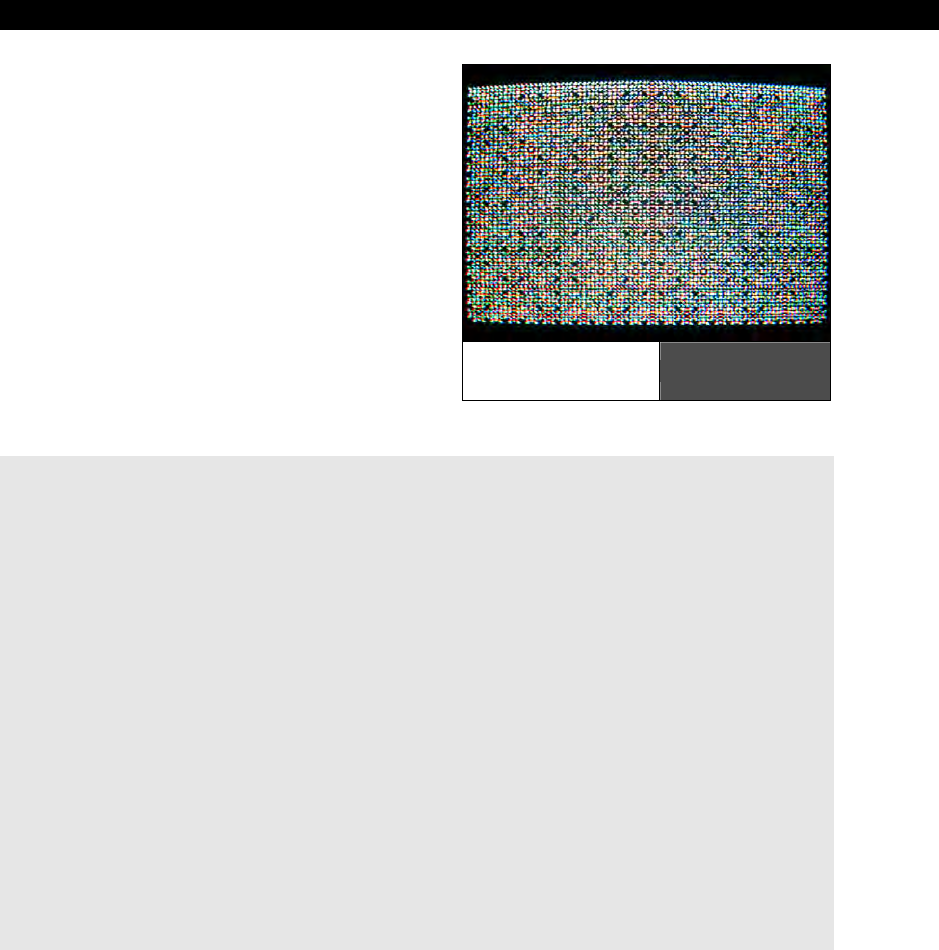
Basic Graphics and 2D Animation18
Game Programming for the Propeller Powered HYDRA Page 473
want to plot. The results can be very
interesting. For example, you can plot
transcedentals or fractals or whatever you like.
Then for x,y you use some rules to derive the
color from z. Figure 18:7 shows a screen shot
of a demo program that plots the function:
z = f(x * (x XOR y) * y)
Of course, you have to scale the results
properly, so the color is an integer from 0..3
(since there are only 4 colors possible). But, it’s
a lot of fun. The demo program is called
function_plot_demo_010.spin and is
located in the CD_ROOT:\HYDRA\SOURCE
directory as usual. The main loop code that
does the rendering is shown below:
' render graphics directly to screen, replace this with your code
repeat y from 0 to 191
repeat x from 0 to 255
' make this any functions of x and y you like
' simply uncomment the function you want to plot and comment the rest
' gets interesting. be patient....
' color := 1*x*3*x ^ 5*y*7*y
' see the flowers?
color := x*(x^y)*y
' reminds me of brain tissue
' color := (x*x) ^ (y*y)
' Use this rule when the color is negative - > make positive
if (color < 0)
color := -color
' use this rule to set the color -> color mod 3
gr.colorwidth(color // 3,0)
' finally plot pixel
gr.plot(x,y)
Notice there are a couple other functions in there commented out? Give them a try and see
what you get!
Function
Plotting Demo Figure 18:7

III Game Programming on the HYDRA
Page 474 Game Programming for the Propeller Powered HYDRA
Also, before moving onto lines, note that in Spin the rendering is very slow, you can actually
see the pixels being drawn. If we were to code this in ASM, we could probably get it to run at
60 FPS which means that it’s possible to algorithmically or procedurally create imagery on
the fly and use it for backgrounds in games or whatever. The point is that with a single line
of code (a function), we have defined every single pixel on the screen! So imagine what
some very clever functions could be used for in a game where memory is at a premium – you
could simply use functions to generate bitmap data in game. Of course, the imagery will
usually be
“mathematical”
looking, but it’s better than a black playfield.
See if you can use the graphing program plus the proper rules and scaling to do
some Fractal rendering. Remember, fractals are “self similar” functions; simply
put, they are generated by seeding a function then using the output of the
function as the input back to the function.
18.2.2 Drawing lines
The next important primitive is the
line
. Lines are the basis of wireframe geometry and with
them we can create a number of types of graphics displays and games. Now, technically the
“lines” in Figure 18:8 are line segments, a line usually extends in both directions for infinity,
but in graphics people tend to refer to line segments as lines, so we will adhere to this
convention. Anyway, referring to the figure, any particular line is defined by two endpoints
P1(x1, y1) and P2(x2, y2).
Figure 18:8
Lines in the Plane

Basic Graphics and 2D Animation18
Game Programming for the Propeller Powered HYDRA Page 475
One of the earliest problems in computer graphics was how to draw lines. This was more or
less solved by
Jack
Bresenham
in 1965 roughly, while working at IBM. He basically created
a line drawing algorithm based on integer calculations and decision variables. I am not going
to go into details since we are going to use library API calls to draw lines for us (which
actually use Brensenham’s algorithm as well). But, I do want to talk about a couple line
representations, since this will become important later when we do other types of rendering
and collision detection.
First, the
“Y-Intercept”
form for a line is:
y = m*x + b
...where m is the
“slope,”
(rise over run, or dy/dx) and b is the
“y-intercept”
which is
where the line intercepts the Y-axis at x=0. To plot a line with this form, you need (m, b),
then you simply plug in values for x (or y) and solve for y. This form is great in math books
and algebra tests, but doesn’t help us much in computer graphics. A more practical form of
the line is called the
“Point-Slope”
form, shown below:
y – y1 = m*(x – x1)
...where, m is the slope and (x1, y1) is any point on the line (even either end point). This
form is much better, since for computer graphics we tend to think of lines as two points, thus
we can compute the slope of any line P1(x1, y1) to P2(x2, y2) as:
m = dy/dx = (y2 – y1) / (x2 – x1)
Plugging back into our point slope form we get:
y – y1 = [ (y2 – y1) / (x2 – x1)] * (x – x1)
...and you can re-arrange and solve for either x or y. Now, we already have a line drawing
API call, so why learn this? Well, understanding lines comes in handy for two main reasons
other than drawing them;
clipping
and
collision
. For example, the line drawing function
inside of the Parallax graphics driver has
no
clipping. That means if you pass a line that is
outside of the visible screen area, it will actually compute all the points on the line, pass
them to the plotter which finally clips, thus a lot of work is done for nothing. A better
approach would be to clip the lines before passing them to the line drawing API.

III Game Programming on the HYDRA
Page 476 Game Programming for the Propeller Powered HYDRA
Line Clipping Figure 18:9
Figure 18:9 shows a line before and after clipping. As you can see, by clipping the line we
can save ourselves a lot of work, if we only draw the clipped line (or pass the clipped line to
the line function). Thus, given a line P1(x1, y1) to P2(x2, y2), the idea is to write a function that
clips the line to the screen rectangle which in the case of our discussions so far is (0,0) to
(255, 191) and outputs a new line P1'(x1', y1') to P2' (x2', y2').
Clipping is a very complex problem, give it a try and you will see why. Thus, there are dozens
of well-known algorithms to do it, but at the end of the day they all have to find intersections
between lines and that’s where the point-slope form of the line comes into play. For example,
referring to Figure 18:9(A) before the clipping, we can visually ascertain that the line pierces
the left edge of the screen, but the question is “Where?” Well, this is
easy
to compute since
we have both endpoints of the line: P1 and P2, thus we can compute the slope which is just:
m = dy/dx = (y2 – y1) / (x2 – x1)
Also, since we are clipping against the left edge of the screen, this is really just a line with
x = 0, thus we can plug x = 0 into either line formula and compute the resulting y.
Using the point slope form and re-arranging a bit get:
y = y1 + m*(0 – x1)
y = y1 – m*x1
Therefore, the clipped endpoint on the left side is (0, y1 – m*x1). This technique can be used
on all 4 sides of the screen (x=0, x=255, y=0, y=191), to clip any line against any boundary,
and the resulting end points of the line can then be sent out to the rendering function and
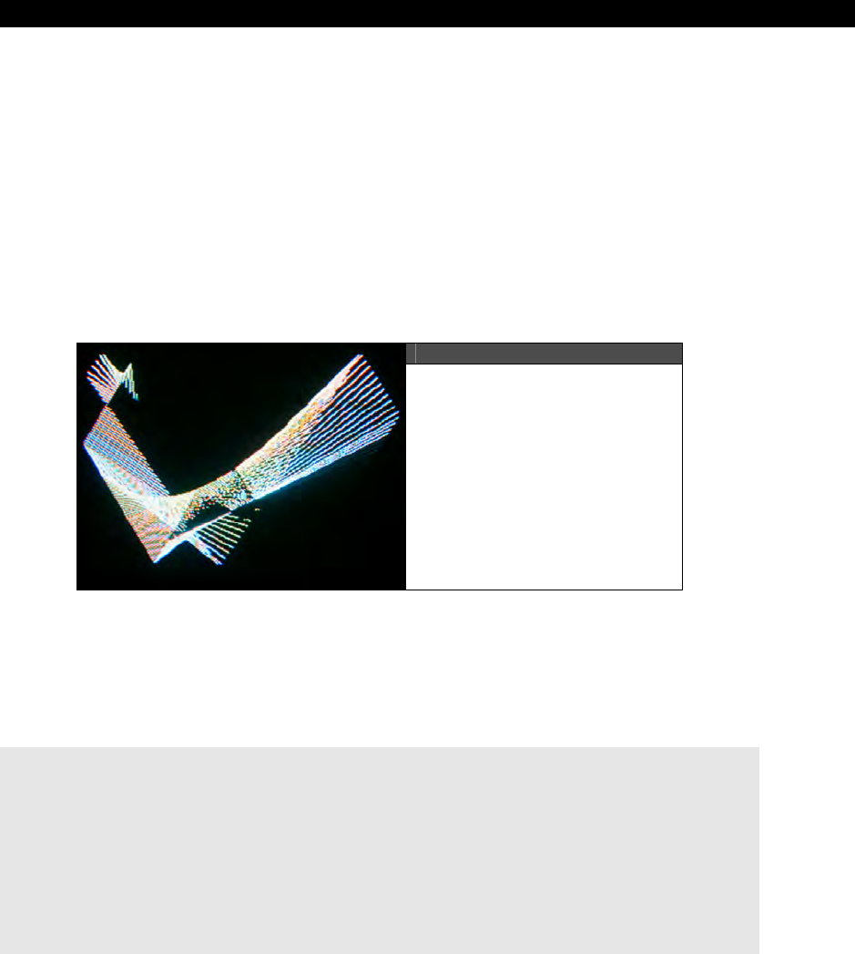
Basic Graphics and 2D Animation18
Game Programming for the Propeller Powered HYDRA Page 477
you can rest assured that only the visible line will be drawn. Again, lines simply drawn aren’t
that interesting and we have done this already, so to keep the policy of all demos are game
development related, let’s use lines to create a screen saver-like display.
What we need to do is start wth two endpoints, call them P1 and P2, then each of these
points has a translation applied to it each frame (we will formalize this in the last section of
this chapter), then we simply move the end points, draw the line and see what happens. Of
course, we have to have some rules for when an endpoint hits the screen edge; we will
simply bounce the endpoint off and change its direction. Also, we will select color by some
simple function. Lastly, as the lines are drawn they are going to quickly fill the screen up,
thus we are going to
follow
the screen saver with a screen eraser that lags behind some
number of lines; maybe 10-20, so you can see this constantly changing pattern.
Figure 18:10
The Screen Saver in Action
Figure 18:10 shows the screen saver in action. The code for it is in the file
screen_saver_010.spin located on the CD in the usual CD_ROOT:\HYDRA\SOURCES\
directory. The code is based on the graphics template graphics_template_010.spin (the
one with only an on-screen video buffer). The main code that performs the screen saver
rendering is shown below:
' infinite loop
repeat while TRUE
' RENDERING SECTION (render to offscreen buffer always/////////////////////
' based on function of line state select a color
gr.colorwidth(1+(eraser_count / 20) // 3,0)
' draw the current line
gr.plot(plines[0], plines[1])
gr.line(plines[2], plines[3])

III Game Programming on the HYDRA
Page 478 Game Programming for the Propeller Powered HYDRA
' move the endpoints
plines[0] += vlines[0]
plines[1] += vlines[1]
plines[2] += vlines[2]
plines[3] += vlines[3]
' test for out of bounds
if (plines[0] > 255)
vlines[0] := -vlines[0]
plines[0] += vlines[0]
if (plines[2] > 255)
vlines[2] := -vlines[2]
plines[2] += vlines[2]
if (plines[1] > 191)
vlines[1] := -vlines[1]
plines[1] += vlines[1]
if (plines[3] > 191)
vlines[3] := -vlines[3]
plines[3] += vlines[3]
' should we start erasing?
if (++eraser_count > 100)
' begin erase code
gr.colorwidth(0,0)
gr.plot(plines[4], plines[5])
gr.line(plines[6], plines[7])
' move the endpoints
plines[4] += vlines[4]
plines[5] += vlines[5]
plines[6] += vlines[6]
plines[7] += vlines[7]
' test for out of bounds
if (plines[4] > 255)
vlines[4] := -vlines[4]
plines[4] += vlines[4]
if (plines[6] > 255)
vlines[6] := -vlines[6]
plines[6] += vlines[6]
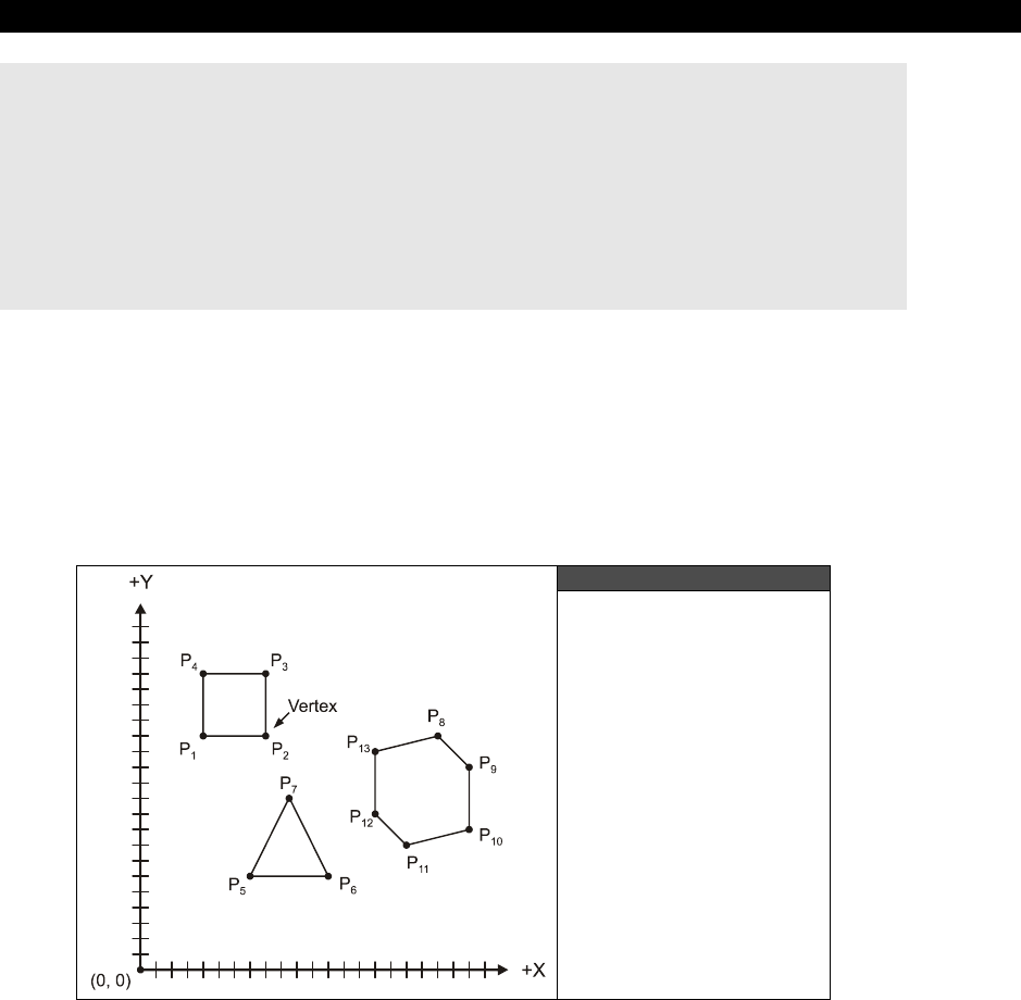
Basic Graphics and 2D Animation18
Game Programming for the Propeller Powered HYDRA Page 479
if (plines[5] > 191)
vlines[5] := -vlines[5]
plines[5] += vlines[5]
if (plines[7] > 191)
vlines[7] := -vlines[7]
plines[7] += vlines[7]
' end erase code
' add a time delay with a little flair
repeat i from 0 to 100 + 3*(eraser_count // 10)
Referring to the code, the line is drawn, the positions updated, collision detection is run, then
the code loops. Additionally, refer to the variable eraser_count in the main loop; when it
reaches 100, then it starts and erases the line that follows the screen saver with the exact
same starting conditions, thus it erases the lines that were drawn in the past. Try optimizing
the code by using loops and a lookup table for the boundary conditions rather than hard
coding them (as 191 and 255).
18.2.3 Polygons
Figure 18:11
A Few Good Polygons
A
polygon
more or less is a closed shape composed of 3 or more connected line segments
in a plane. For example, Figure 18:11 shows a triangle and square, as well as an arbitrary
polygon. In computer graphics polygons are the basis for everything you see in a modern 3D
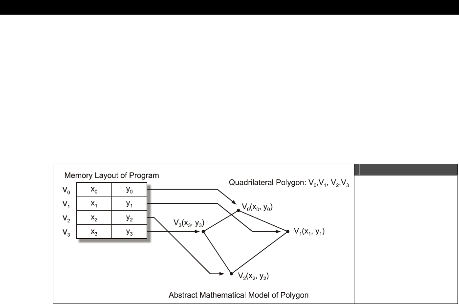
III Game Programming on the HYDRA
Page 480 Game Programming for the Propeller Powered HYDRA
computer game, except that the polygons in games are typically always triangles: they are
textured, lit, and there are millions of them. You might ask “Why represent everything as
triangles in 3D games?” Well, triangles have a lot of nice properties; like they are always
coplanar, also they are easy to render, and easy for hardware to fill, texture, and light.
Polygons like quadrilaterals etc. are much harder to work with. Thus, even when 3D
modelers draw game objects with tools like 3D Studio MAX, at some point all the complex
geometry is turned in triangles. Similarly, pretty much every 3D engine on the planet at some
point turns all the objects in the game into a stream of triangles and passes them to the
rendering pipeline. So if you can get triangle rendering down then you can make anything,
since you can decompose any polygon into a set of triangles.
Figure 18:12
Representing a
Polygon in Memory
The first thing we need to do is come up with a way to represent polygons, so we can
manipulate them. This is really a data structure decision, but in most cases, a polygon is a
collection of 2D points which are referred to as
vertices
, so a simple array will suffice. Thus,
we could define a polygon as a list of (x,y) pairs where each (x,y) entry defines a single
vertex as shown in Figure 18:12. The interesting thing is that we do not define a polygon as
a set of lines, but rather as a set of vertices, then to draw the polygon, we draw lines
between the vertices starting at vertex 0 and then ending at vertex n, then we
“close”
the
polygon by drawing a line from vertex n to vertex 0.
Now, earlier in the chapters on Spin programming and the graphics demos, there were some
demos that used the Parallax reference graphics driver’s
Vec( )
sub-function to draw a
polygon. Basically, the Vec( ) sub-function of the graphics driver takes a data structure that
consists of a set of vectors in polar format; here’s the function prototype for reference:

Basic Graphics and 2D Animation18
Game Programming for the Propeller Powered HYDRA Page 481
PUB vec(x, y, vecscale, vecangle, vecdef_ptr)
'' Draw a vector sprite
''
'' x,y - center of vector sprite
'' vecscale - scale of vector sprite ($100 = 1x)
'' vecangle - rotation angle of vector sprite in bits[12..0]
'' vecdef_ptr - address of vector sprite definition
''
'' Vector sprite definition:
''
'' word $8000|$4000+angle 'vector mode+13-bit angle (mode: $4000=plot,$8000=line)
'' 'where angle is a 13 bit value bits[12..0]
'' 'mapping (0..$1FFF = 0°..359.956°)
'' word length 'vector length
'' ... 'more vectors
'' ...
'' word 0 'end of definition
We have already played with this, so I am not going to review it, but the problem is that it
uses polar coordinates to define the vertices of the “sprite” or polygon. This is hugely
inconvenient since drawing objects in polar coordinates is very hard since you have to
compute the angle and length of every vertex. Alas, we are going to tuck Vec( ) away for a
rainy day and for now keep things more abstract, and come up with our own polygon
drawing function that uses Cartesian coordinates.
Figure 18:13
Our Star Raider Ship

III Game Programming on the HYDRA
Page 482 Game Programming for the Propeller Powered HYDRA
With that in mind, our first attempt might simply be a function that leverages the graphics
library’s line function and takes an array of vertices along with a color to draw the polygon.
Here’s a function that does the job:
PUB Draw_Polygon(vertex_list_ptr, num_vertices, color) | v_index
' draws the sent polygon, totally unoptimized, no error detection
' vertex_list_ptr = pointer to WORD array of x,y vertex pairs
' num_vertices = number of vertices in polygon
' color = color to render in 0..3
' step 1: set color
gr.colorwidth(color, 0)
' notice the pointer casting to byte and the sign extension ~ operator
' step 2: plot starting point
gr.plot(~byte[vertex_list_ptr][0], ~byte[vertex_list_ptr][1])
' step 3: draw remaining polygon edges
repeat v_index from 1 to num_vertices-1
gr.line(~byte[vertex_list_ptr][2*v_index+0],~byte[vertex_list_ptr][2*v_index+1])
' step 4: close polygon by drawing back to starting vertex
gr.line(~byte[vertex_list_ptr][0], ~byte[vertex_list_ptr][1])
The function takes a pointer to the vertex list, the number of vertices, and the color you want
the polygon rendered in. If we wanted to use the function, we simply need a polygon model
such as shown in Figure 18:13; there are 12 vertices in the model, and we design it on graph
paper with (0,0) at the center of the model. The actual data for the model in Spin looks
something like:
' Polygon definition for space ship, array of (x,y) pairs,
' each representing a vertex
' 2 bytes per vertex, allows vertices to be -128 to +127
' notice they are scaled by PSCALE
fighter_poly byte 0*PSCALE,4*PSCALE ' vertex 0
byte 1*PSCALE,0*PSCALE ' vertex 1
byte 3*PSCALE,-1*PSCALE ' vertex 2
byte 4*PSCALE,0*PSCALE ' vertex 3
byte 4*PSCALE,-1*PSCALE ' vertex 4
byte 3*PSCALE,-2*PSCALE ' vertex 5
byte 0*PSCALE,-3*PSCALE ' vertex 6
byte -3*PSCALE,-2*PSCALE ' vertex 7
byte -4*PSCALE,-1*PSCALE ' vertex 8
byte -4*PSCALE,0*PSCALE ' vertex 9
byte -3*PSCALE,-1*PSCALE ' vertex 10
byte -1*PSCALE,0*PSCALE ' vertex 11

Basic Graphics and 2D Animation18
Game Programming for the Propeller Powered HYDRA Page 483
Note that it’s inconvenient to work in large numbers on graph paper, so I designed the model
very small and then scale it in the data set via the factor PSCALE (which is set to 10 in the
upcoming demo). Now, let’s put all this to use: we will start with the template
graphics_template_010.spin, and add the function and the data. The resulting program is
named draw_polygon_010.spin and can be found in the standard directory
CD_ROOT:\HYDRA\SOURCES\. Load and run the program on the HYDRA and see what
you get!
If you see part of a line and a dot then the program worked right, but what happened? Well,
we defined the polygon model at the origin (0,0), and we rendered it there as well, that is,
we drew it at (0,0) on the screen which is the bottom left hand corner (when using the
Parallax reference driver as we have set it up). So what we need to do is translate the model
more toward the center of the screen. This brings us the concept of
“local”
and
“world”
coordinates which we are going to delve into in detail in the next section, but for now, suffice
it to say it’s a good idea to define your models with a local origin at (0,0), but when you
actually draw them you want to be able to add an offset to each (x,y) vertex so you can
translate the model anywhere on the screen during rendering. So what we need to do is add
some more parameters to the function to support this translation, we will call them (x0, y0).
Updating the polygon drawing function we get something like this:
PUB Draw_Polygon2(vertex_list_ptr, num_vertices, color, x0, y0) | v_index
' draws the sent polygon, totally unoptimized, no error detection
' vertex_list_ptr = pointer to WORD array of x,y vertex pairs
' num_vertices = number of vertices in polygon
' color = color to render in 0..3
' x0, y0 = x,y translation factors
' step 1: set color
gr.colorwidth(color, 0)
' notice the pointer casting to byte and the sign extension ~ operator
' step 2: plot starting point
gr.plot(~byte[vertex_list_ptr][0]+x0, ~byte[vertex_list_ptr][1]+y0)
' step 3: draw remaining polygon edges
repeat v_index from 1 to num_vertices-1
gr.line(~byte[vertex_list_ptr][2*v_index+0]+x0,~byte[vertex_list_ptr][2*v_index+1]+y0)
' step 4: close polygon by drawing back to starting vertex
gr.line(~byte[vertex_list_ptr][0]+x0, ~byte[vertex_list_ptr][1]+y0)
The only difference is that we pass translation factors x0,y0 to the function and simply offset
the polygon rendering by these factors – simple. A demo named draw_polygon_011.spin
shows the new function and adds the ability to move around with the game pad for fun. The
demo is located on the CD in CD_ROOT:\HYDRA\SOURCES\.
III Game Programming on the HYDRA
Page 484 Game Programming for the Propeller Powered HYDRA
Both Draw_Polygon( ) and Draw_Polygon2( ) are totally unoptimized. See if you
can optimize them 10-20× by using pre-computation, shifts, etc. Try making the
call to the rendering function 1000-10,000 times and use a stop watch to review
your optimizations, that is, run the program with the call 1000 -10,000 times, get a
baseline, then make an optimization, and time it again, and so forth.
18.3 Screen Update Techniques
We have discussed the concept of screen updating and animation a number of times
informally and have in fact been using various techniques thus far ad-hoc. However, now I
want to clearly define the various methods of screen updating so you can see what they do
and how they are used.
18.3.1 Erase-Move-Draw
The first form of animation that was historically used in computer games is simply to erase
the old image, move it, draw it, and then loop. Additionally, programmers would put a little
time delay in after the drawing portion so the image would seem to be stable. The problem
with this method is that as you erase the image, if you take more than a 60th of second or so
to draw it again, the human brain will pick this up and you will see “flicker” which I am sure
everyone has seen once in their life playing a game. To show this, try program
draw_polygon_012.spin located on the CD in CD_ROOT:\HYDRA\SOURCES\.
Basically, I took the last demo and removed the off-screen buffer and drew everything in the
on-screen primary buffer, notice that you see flicker now – it’s horrible! But, there is a way to
minimize it a bit by leaving the image on the screen for more time than it’s off screen, so
let’s add a small delay to the end of the main loop, something as simple as:
repeat 5000 ' time delay
A demo of this version can be found in draw_polygon_013.spin located on the CD at
CD_ROOT:\HYDRA\SOURCES\. Try running the demo and you will see that it looks a lot
better, the flicker is still there, but it doesn’t look like the ship is phasing in and out of space-
time like an episode of
Star
Trek
. Of course, a side effect of this is that we have slowed
down the main loop and wasted thousands of compute cycles simply to make sure the image
persists on our retinas a little better. Nonetheless, this simple technique is useful for quick-
and-dirty graphics and/or when you have a very slow graphics system and erasing the entire
screen or having off-screen buffers is out of the question. In conclusion, if you want to use
the simple erase-move-draw technique in your game to perform animation, you simply erase
all the objects in the game at the top of the loop, then move them, then draw them and
optionally put a delay in there to keep them on the screen longer.
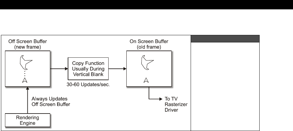
Basic Graphics and 2D Animation18
Game Programming for the Propeller Powered HYDRA Page 485
18.3.2 Double Buffering
Figure 18:14
Double Buffering
Graphically
Diagrammed
The Parallax reference driver (as well as many graphics APIs used commonly for games) uses
the technique of
double
buffering
to perform flicker free animation. Double buffering is a
surprisingly simple technique where you have two video buffers; one is being accessed by
the video driver and rendered on the screen while the other is simply memory that has the
same shape and size. So the trick is to draw all your objects on the off-screen buffer, so the
user can’t see the manipulation, then in a single instant
copy
the off-screen buffer to the
on-screen buffer, this is shown graphically in Figure 18:14. Therefore, you could take an
hour drawing the image in the off-screen buffer, but the user would see it instantly appear
on the screen when it was finally rendered. Of course, there is a concern about the copy
function and how fast it is. For example, if the copy function is really slow then the user will
see the old image replaced by the new one. But, the idea is to copy the off-screen buffer to
the on-screen buffer at a time when the raster is retracing, such as the vertical blank, that
way the user never sees any glitches and the image is rock solid.
Using the Parallax reference graphics driver, double buffering is a snap, you simply start the
graphics driver up with a pointer to a chunk of memory you want to refer to as the off-screen
buffer and then all calls to the graphics functions will render into that buffer. The size of the
buffer can be calculated as follows:
1-bit color depth (2 colors)
screen RAM needed for buffer = SCREEN_WIDTH * SCREEN_HEIGHT / 8
2-bit color depth (4 colors)
screen RAM needed for buffer = SCREEN_WIDTH * SCREEN_HEIGHT / 4

III Game Programming on the HYDRA
Page 486 Game Programming for the Propeller Powered HYDRA
The term “color depth” simply means how many bits per pixel.
The terms “on-screen buffer” and “off-screen buffer” are also known as “primary
buffer” and “back buffer” or “secondary buffer.” I may use these more
contemporary terms from time to time.
As you can see, the formula is very straightforward and makes sense. For example, in the
last few demos we have been using a 256×192 screen resolution at 4 colors, and plugging
this into the memory formula we get:
256*192/4 = 12288 or $3000 hex
This is why you see the lines of code at the top of each program:
_stack = ($3000 + $3000 + 64) >> 2 ' accomodate display memory and stack
' graphics driver and screen constants
OFFSCREEN_BUFFER = $2000 ' offscreen buffer
ONSCREEN_BUFFER = $5000 ' onscreen buffer
They manually set the location of the buffers and let the stack directive know where we have
placed them, so the compiler can indicate an overflow if the code encroaches on them. The
entire double-buffering rendering loop we have been using looks like:
' initialize graphics driver with offscreen buffer
gr.start
gr.setup(X_TILES, Y_TILES, 0, 0, offscreen_buffer)
repeat
' clear the offscreen buffer
gr.clear
' render graphics here…
'copy bitmap to display offscreen -> onscreen
gr.copy(onscreen_buffer)
...and that’s it! First, the offscreen buffer is cleared off, so we can render on a clean slate,
then we draw all the graphics we want on it, and finally copy the off-screen buffer to the on-
screen buffer. Of course, at the end of the loop you might want to add a counter that locks
the frame rate to 30-60 FPS and no higher, so the animation stays consistent as the game
changes.
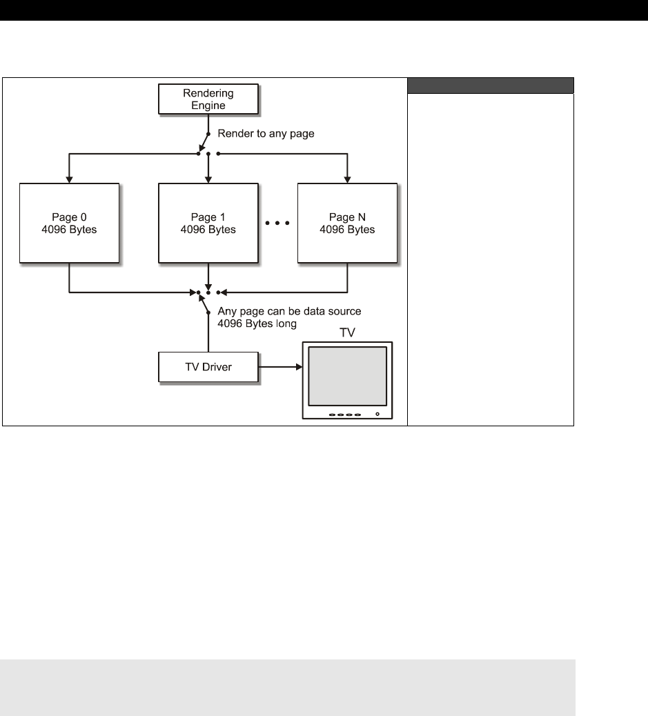
Basic Graphics and 2D Animation18
Game Programming for the Propeller Powered HYDRA Page 487
18.3.3 Page Flipping
Figure 18:15
Page Flipping Setup
Page
flipping
is similar to double buffering, but not exactly the same. With page flipping
there is no
copy
operation from the off-screen buffer to the on-screen buffer, rather the TV
rasterization engine/driver is redirected to read from another region of memory, i.e. another
page
– hence the term page flipping. To implement page flipping you have to design it into
the rasterizing driver to support reading any region of memory as the video buffer. For
example, if your TV driver could only use the memory from $2000 - $3000 as video RAM and
video RAM was always $1000 (4096 bytes) in size then you can’t page flip. Thus, as shown in
Figure 18:15, you need the ability to re-vector or re-point the video RAM pointer from the
video driver’s point of view.
The Parallax reference TV driver doesn’t support page flipping by design, but it does if you
want to cheat a bit. If you look at all our graphics demos thus far, during setup you will see a
snippet of code that looks like this:
'init tile screen
repeat dx from 0 to tv_hc - 1
repeat dy from 0 to tv_vc - 1
screen[dy*tv_hc+dx] := onscreen_buffer >> 6+dy+dx*tv_vc+((dy & $3F) << 10)
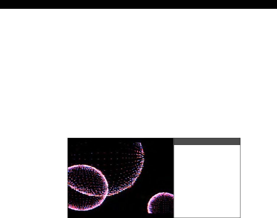
III Game Programming on the HYDRA
Page 488 Game Programming for the Propeller Powered HYDRA
This little magical snippet sets up the screen tile pointer array if you recall. This array is more
or less a tile map where each tile has a pointer to a bitmap region, if the bitmaps are
assigned in a way such that they are linear and organized then the graphics driver can render
into them as if they were a contiguous large bitmap. The point is that, see that variable
“onscreen_buffer”
? All we need to do is change this to the starting address on any
memory region that is large enough for the tile map, such as another page of memory, and
once the loops run we will have peformed a page flip. In a roundabout way albeit since we
are going to do it a tile at a time, but still it’s a page flip. If we time this during the vertical
blank, then chances are we wouldn’t see anything as well, and it would be perfect.
So to test this out, let’s write a program that draws an image on one page and a different
image on another page, then with the game pad, pressing a button(s) will change the
current page simply by calling this looping code with the other page. First, we need an
image for each page, so how about on one page we draw a kaleidoscope image by plotting
random pixels and colors on the screen and then mirroring it vertically. On the second page,
I will render a set of 3D spheres, this way there is no mistake that each page is different.
Figure 18:16
The Page Flipping
Demo Running
The page flipping demo is called page_flip_demo_010.spin and is located on the CD in
CD_ROOT:\HYDRA\SOURCES\. Simply load and run the demo with the game pad
plugged into the left port, and wait for it to finish drawing, you should see something like
that shown in Figure 18:16. When it’s done, press the right or left game pad arrow and
instantly the page will flip between the two video images. As you can see this is a very cool
technique because the
copy
step needed in a double-buffered scheme is no longer needed
(which make graphics faster). All that’s need to support page flipping in a rendering engine
that allows you to pass a pointer to the region of memory you want rendered. The Parallax
reference driver doesn’t support this directly, but we hacked it to make it work by altering
the screen pointers on the fly. Later in the book when we start using more advanced tile
engines with sprites they
will
support.
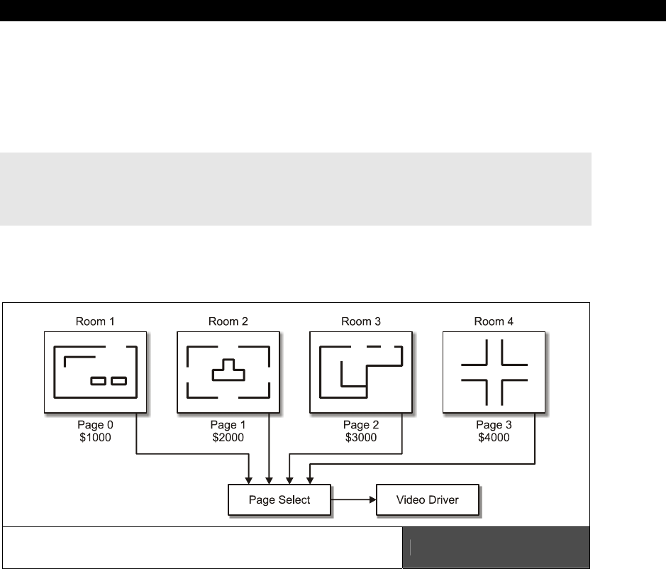
Basic Graphics and 2D Animation18
Game Programming for the Propeller Powered HYDRA Page 489
Page flipping is a more efficient method of performing screen updates since you save the
copy operation; moreover, if you have a tile-based system, you can even save the rendering
time and simply prepare each screen of the game as a page and then as the user moves
around the game world from room to room, you simply switch pages without any copying or
other work, this is shown in Figure 18:17 abstractly. The function that performs the actual
page flip from the demo looks like this:
PUB Set_Video_Page(page_address) | dx, dy
' init tile screen with sent page address
repeat dx from 0 to tv_hc - 1
repeat dy from 0 to tv_vc - 1
screen[dy*tv_hc+dx] := page_address >> 6+dy+dx*tv_vc+((dy & $3F) << 10)
More or less it’s just the screen setup loop embedded in a function with a variable parameter
for the starting address of the page.
Page Flipping used to Support a Multi-Room
Game World with Ease Figure 18:17
18.4 Coordinate Frames and Basic Animation
In this last section, we are going to formally talk about some more mathematical concepts
relating to coordinate systems along with some animation tricks. So, first let’s review the
ideas behind local, world, and screen coordinates and see why they are needed and desired
in game programming.
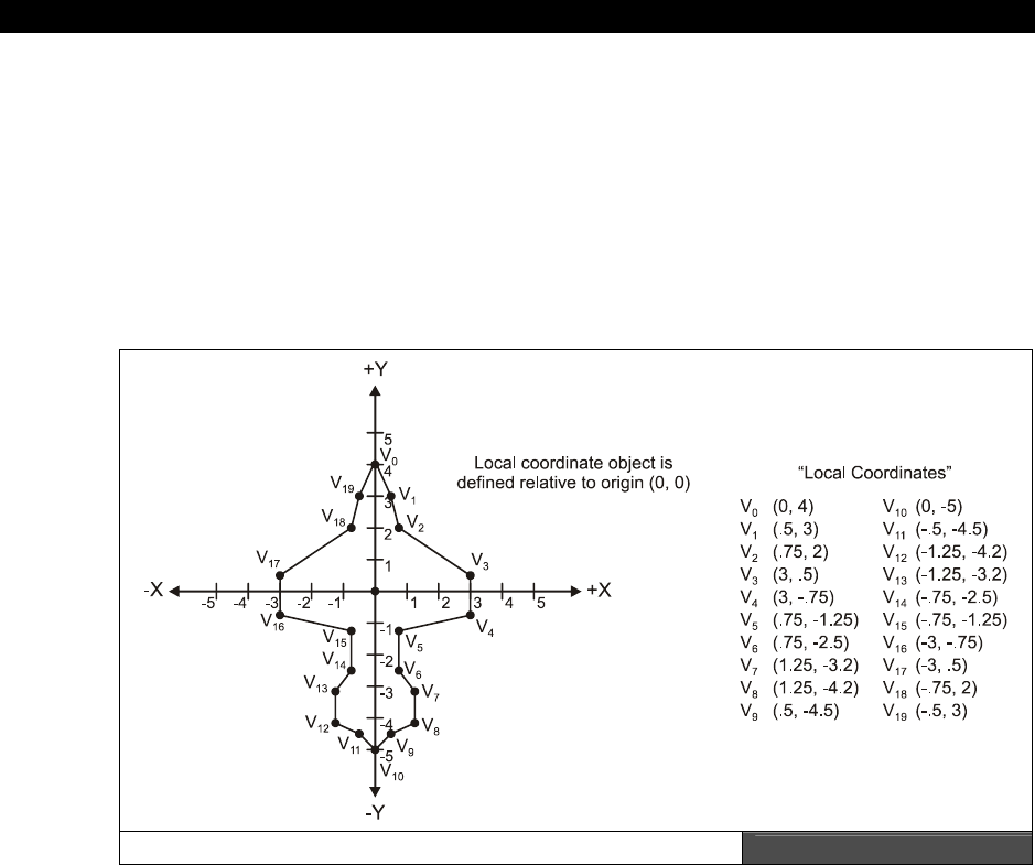
III Game Programming on the HYDRA
Page 490 Game Programming for the Propeller Powered HYDRA
18.4.1 Local, World, and Screen Coordinates
The first step in designing a polygon model 2D or 3D is to create the model itself. As in our
previous example I did this on simple graph paper, but a tool could have been used as well.
The technique is simply to start with a 2D (or 3D) Cartesian coordinate system and draw the
model out, then locate the vertices and make a vertex list. All the vertices in the vertex list
are
relative
to the origin of the object/model at (0,0). These coordinates are called
local
coordinates
because they refer to the model’s own “local” coordinate system at (0,0), the
coordinates are abstract and not useful until we further process them. Figure 18:18 shows a
fighter defined in local coordinates.
An Object Defined in Local Coordinates Figure 18:18
For example, let’s say we wanted to have a giant scrolling game world 4×1 screen, where
each screen was 256×192 pixels for a total of 1024×192 resolution. Figure 18:19(A) shows
something like this. This is the entire “world” that the game lives in, the universe if you will,
thus it’s referred to as
world
coordinates
. So, world coordinates locate an object in the
game world or the entire universe of geometry, if you will. Now, the idea of world
coordinates is they help you define the entire game world, you simply move your objects
around in world coordinates then finally map them to the screen which we will get to in a
moment. A crude and naive approach at graphics is to try and “hack” this functionality, but if
you want a big world, its better just to have one.
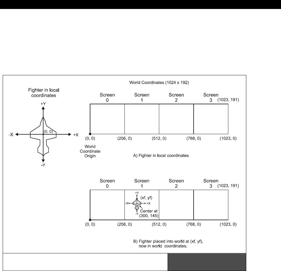
Basic Graphics and 2D Animation18
Game Programming for the Propeller Powered HYDRA Page 491
Now, the cool thing about local and world coordinates is that is very easy to build up a scene
for a game. You take your local coordinate models at (0,0), then you translate them to their
current world coordinate positions. Then, add each local coordinate vertex value to the
object’s final world coordinate location and all the points are perfectly translated or
transformed to world coordinates. For example, referring to Figure 18:19(B), I have assumed
that the fighter’s world position center is at (xf, yf)=(300, 145).
A Large World Coordinate System with
4 Screens, each 256×92 Figure 18:19

III Game Programming on the HYDRA
Page 492 Game Programming for the Propeller Powered HYDRA
Thus, if we wanted to move the entire model into world space, then we simply need to add
these offsets to each vertex; the pseudo-code for this transform in general is:
' Assume local coordinates of each vertex stored in local_x[], local_y[]
' move local model to position (x0, y0) in world space
repeat j from 0 to num_vertices – 1
world_x[ j ] := local_x[ j ] + x0
world_y[ j ] := local_y[ j ] + y0
Now, the last question is “Great, we have our objects running around in world coordinates,
but how do we get them back on the screen?” This is a good question with many answers,
but the simplest is that we need a screen transform, or to be consistent we need to convert
to
screen coordinates
. In our case, screen coordinates have been a 256×192 pixel matrix
that mimics Quadrant I from the Cartesian coordinate system. Now, here is where you can
get creative: you can compress, scale, shrink, shear, invert, flip, do whatever you want to the
world coordinates when you transform them to screen coordinates. For example, the simplest
transform is 1:1, that is:
screen x = world x
screen y = world y
In this case, you don’t do anything – you assume that your “window” to the world/universe is
only 256×192, and as long as objects fall within it, you will see them. For example, Figure
18:19 shows this setup. See how we still have a large world universe, but the viewing
window or screen is always from (0 – 255, 0 – 191), so you only see objects in that region?
This is great as long as your objects move through the window or screen, but if you want to
scroll around then you have to
move
the window which just means more transformations,
but we will get to scrolling later. For now, we will just use a 1:1 world-to-screen transform
and always refer to any polygon models in local coordinates with world coordinate locations
that we want them to end up at.
One last question you might have is “How do bitmaps work in local and world coordinates?”
Well, bitmaps are usually 8×8, or 16×16, etc. matrices of pixels. In most cases they are
referenced from a single origin, usually the top left corner, so this is the origin and we simply
draw a bounding rectangle around them mentally. This is the polygon that defines them,
thus when we want to move a bitmap model from local to world, we simply need to keep
track of a single
point
– the origin of the bitmap which might be a corner or sometimes the
center. Figure 18:20 shows this.
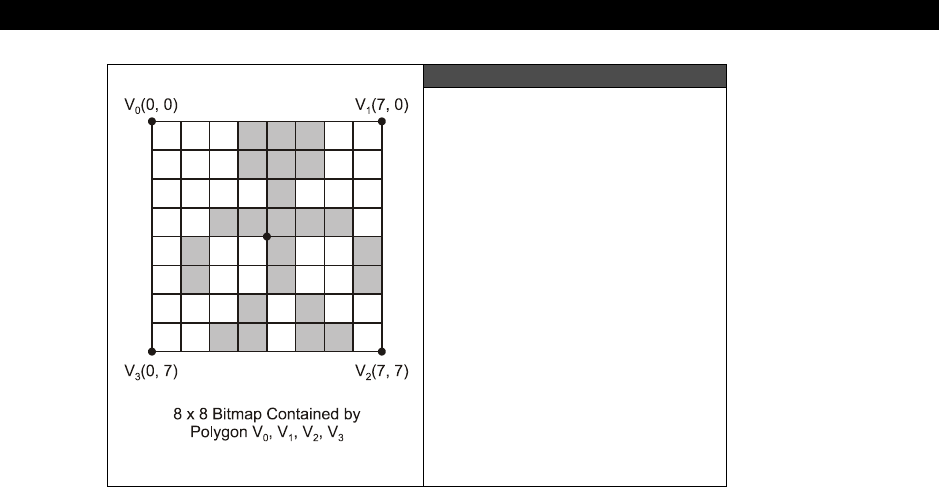
Basic Graphics and 2D Animation18
Game Programming for the Propeller Powered HYDRA Page 493
Figure 18:20
Polygons are Bitmaps Too!
18.4.2 Translation and Scaling
Alright, we already have used the concept of
translation
many times, translation is nothing
more than moving a point in 2D space along a straight line by adding constants to the
current position. For example, if we have a point at (x,y) and we want to translate it (dx, dy)
then we apply the math:
x := x + dx
y := y + dy
That’s it. This code and underlying algorithm simply moves the object by (dx, dy) each frame
or time unit. As an aside, this can be transformed into a parametric representation very
easily, which is just a fancy way of using a single value to control how far the original point is
moved. So we can parmeterize the formula by making it a function of t (which is standard
practice) like this:
x := x + t*dx
y := y + t*dy
Now, as you plug in …, -2, -1, 0, 1, 2, … you can force the math to move the object any
amount of positive or negative units along the path defined by (dx, dy). This kind of formula
is called
parametric
since its based on a single parameter, more on this in the next section.
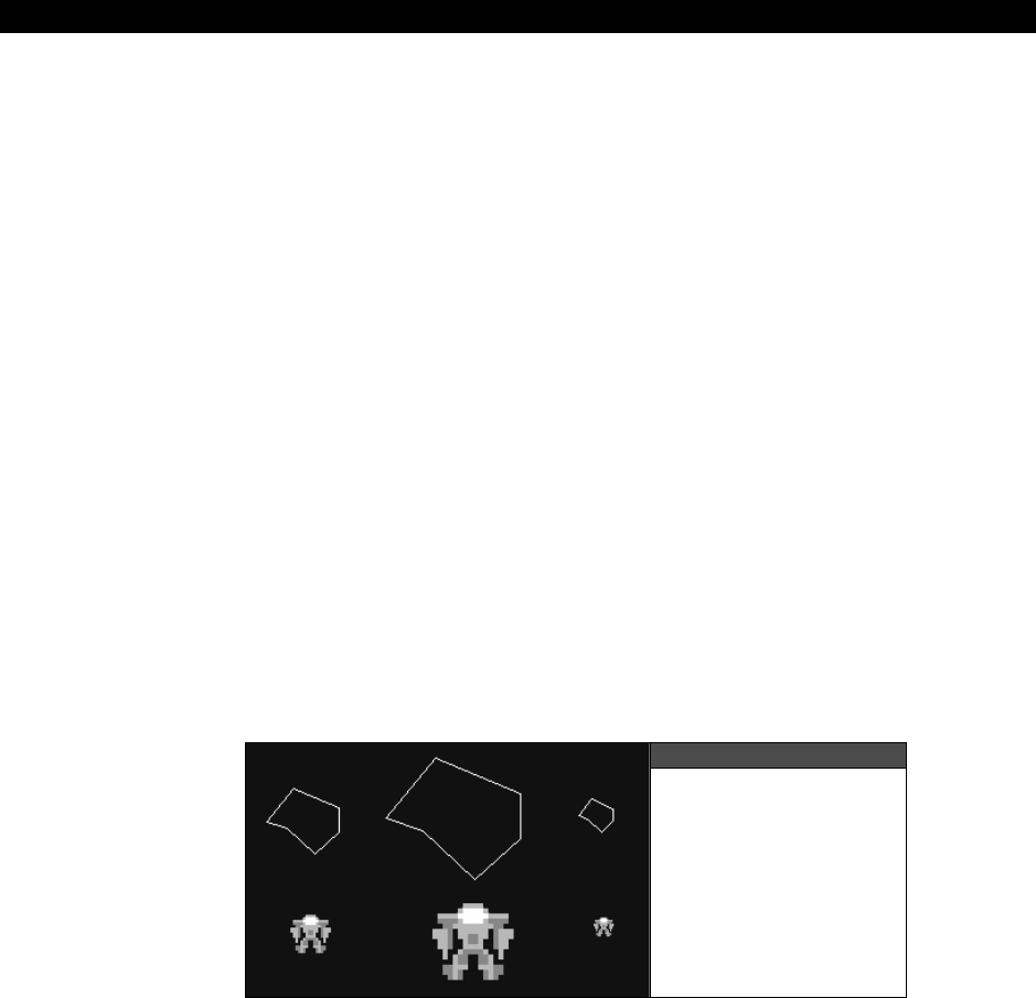
III Game Programming on the HYDRA
Page 494 Game Programming for the Propeller Powered HYDRA
Anyway, the (dx, dy) is really the slope of the line that we are translating the point along
which is:
m = slope = dy/dx
And of course, we can normalize the translation direction (vector) by dividing the x,y
components by their combined length:
length = sqrt( dx*dx + dy*dy)
dx' = dx / length
dy' = dy / length
Then if you use these normalized versions of dx', dy' and plug it into the parametric
equation you get this:
x := x + t*dx'
y := y + t*dy'
The cool thing about the normalized dx', and dy', is that when t = 1.0 the the translation is
equal to the original equation:
x := x + dx
y := y + dy
So it’s like a “programmable” equation ☺.
Figure 18:21
Scaling Applied to
Polygons and
Bitmaps Alike
Alright, so that’s the formally informal deal with translation, now let’s cover
scaling
. Scaling
is simply the process of making an object larger or smaller, usually a polygon, but you can
scale a bitmap just as easily. Figure 18:21 shows both a polygon and a bitmap scaled to 1.0,
2.0 and 0.5 (left to right) and how they look. Bitmap scaling is a bit complex and has to do
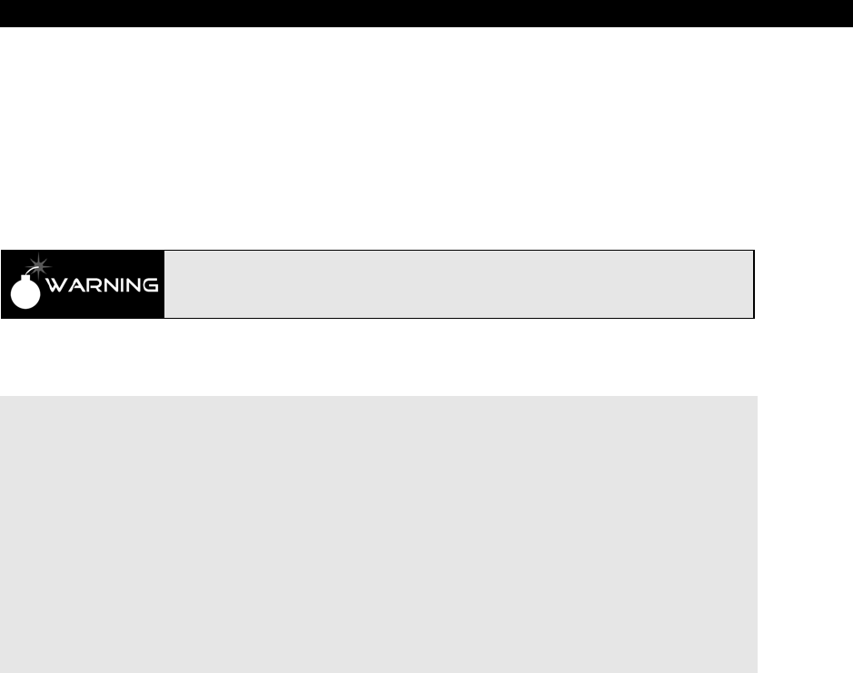
Basic Graphics and 2D Animation18
Game Programming for the Propeller Powered HYDRA Page 495
with sampling theory, so I might discuss it later, but for now let’s stick to polygon scaling and
see how to do it.
Remember our local coordinates used to define a polygon? Well, they are perfect to support
scaling. All we need to do is multiply each vertex in the polygon model by a scale factor, call
is scale, and that’s it:
xs = scale * x
ys = scale * y
For this to work properly the model, vertices or object must be in local
coordinates, if not, the scaling operation will end up translating the object as
well.
Let’s add this functionality to our Draw_Polygon2( ) function by adding a scale parameter,
and here’s the results:
PUB Draw_Polygon3(vertex_list_ptr, num_vertices, color, x0, y0, s) | v_index
' step 1: set color
gr.colorwidth(color, 0)
' notice the pointer casting to byte and the sign extension ~ operator
' step 2: plot starting point
gr.plot(~byte[vertex_list_ptr][0]*s+x0, ~byte[vertex_list_ptr][1]*s+y0)
' step 3: draw remaining polygon edges
repeat v_index from 1 to num_vertices-1
gr.line(~byte[vertex_list_ptr][2*v_index+0]*s+x0,~byte[vertex_list_ptr][2*v_index+1]*s+y0)
' step 4: close polygon by drawing back to starting vertex
gr.line(~byte[vertex_list_ptr][0]*s+x0, ~byte[vertex_list_ptr][1]*s+y0)
Some of the comments have been removed for brevity, but more or less the function is the
same as Draw_Polyon2( ) except that the parameter (s) has been added and used to scale
each vertex value. As an example of scaling in action, take a look at program
scale_demo_010.spin located on the CD in CD_ROOT:\HYDRA\SOURCES\. It’s
basically the previous translation demo with the added scaling, but it’s neat since you can
make the ship any size you want, simply use the game pad to move the ship around
(translate) and use the NES A and B button to change the size of the ship. Notice, that the
Parallax reference driver clips the lines for us, so you can make the ship any size you want
and it will draw properly and clip to the screen edges. Note that the scale factor can only be
an integer, if you want to scale by fractional values then fixed-point or floating-point math
must be programmed in software. Lastly, for fun, I called the drawing function multiple times
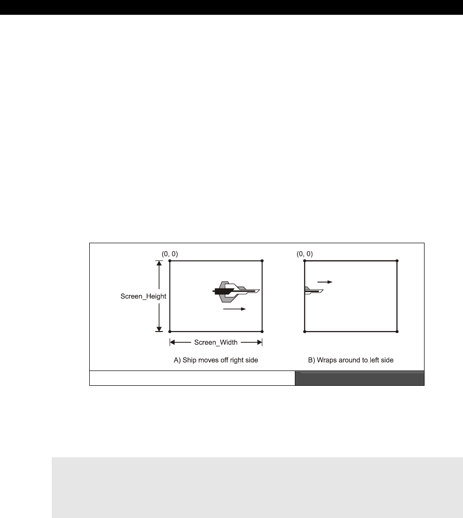
III Game Programming on the HYDRA
Page 496 Game Programming for the Propeller Powered HYDRA
to draw a small “fleet” of ships, see if you can add logic so that as they scale their separation
distances also scale.
18.4.3 Simple Motion Techniques
One of the themes of this chapter is “animation,” but you might be thinking that you haven’t
seen a whole lot of animation as of yet! Well, this is not true, in computer graphics anything
that
moves
or
changes
is animated, so all these demos are animation demos of a kind. But,
if you are thinking about walking, jumping, running, etc. these are animations of course, but
really nothing more than playing data sets through a renderer. For example, with our simple
polygon function, if we were to digitize the vertices of some character walking and then load
and play each as a polygon, it would look like animation. This is called
keyframe
animation
and is a type of character animation, but first things first, we need to get the
hang of moving single points around in different ways then we can connect points to lines,
lines to polygons, polygons to models, and so on. Now, lets take a look at some different
motion methods that lend themselves to old school game programs.
18.4.3.1 Wrap Around Motion
Wrap_Around Motion Figure 18:22
This effect has been used in a number of demos thus far, more or less the idea is to test
your object or point of interest to see if it has passed some threshold, usually the screen
edges; if so, simply send it to the other side of the screen as shown in Figure 18:22. The
pseudo-Spin code for a point at (x,y) moving with velocity (dx, dy):
' translate point first
x := x + dx
y := y + dy
' test x-bounds
if (x >= SCREEN_WIDTH)
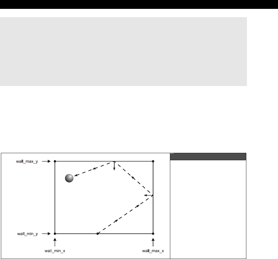
Basic Graphics and 2D Animation18
Game Programming for the Propeller Powered HYDRA Page 497
x := x – SCREEN_WIDTH
else
if (x < 0)
x := x + SCREEN_WIDTH
' test y-bounds
if (y >= SCREEN_HEIGHT)
y := y – SCREEN_HEIGHT
else
if (y < 0)
y := y + SCREEN_HEIGHT
The only part of the code that is tricky is the reset of the x or y location, you would think that
if the object moves off the right edge then you simply reset x to 0. This will work, but it’s not
as accurate as slightly adjusting x to take into consideration the amount that x exceeded the
SCREEN_WIDTH during the conditional, so if x went off the screen by 5 pixels then it winds
up on the other side 5 pixels in, which just looks better.
18.4.3.2 Bouncing Ball Motion
Figure 18:23
Bouncing Ball Motion
This is the basis of many games, such as a bouncing ball as shown in Figure 18:23. If you
ask a physicist how to do it, he would reply “Well you need to consider the elastic and non-
elastic collision response, compute the angle of reflection, taking into consideration
deformation, energy absorbtion, friction, slippage, and other aspects...” You ask a game
programmer how to bounce a ball, he replies “Easy!” and shows you the following pseudo-
code:

III Game Programming on the HYDRA
Page 498 Game Programming for the Propeller Powered HYDRA
' move ball
x := x + dx
y := y + dy
' reflect on x
if (x >= wall_max_x or x <= wall_min_y)
dx = -dx
x := x + dx
' reflect on y
if (y >= wall_max_y or y <= wall_min_y)
dx = -dx
x := x + dx
So what is this code doing exactly? If it’s not obvious to you, don’t worry, the simplest things
are so simple they are hard to see sometimes – this fragment assumes there is an object
with a
“virtual”
center at (x,y) moving at a rate (dx, dy). And by virtual, I mean that maybe
it’s a ball, an object, a car, but for purposes of bouncing and collision we are only going to
consider its center point (incorrect technically, but good enough for games). The algorithm
moves the ball, then tests the ball against four boundaries which are planes parallel to the X
and Y axes, typically they are the screen boundaries but they might be smaller like a little
square in the middle of the screen. If the ball’s postion exceeds any of the boundaries then
the algorithm “bounces it back” by inverting the velocity on that axis and then repositioning
the ball by re-evaluating the motion equation in that dimension/axis.
Since this is a little more tricky than the wrap around algorithm, a demo is in order. So for
kicks, let’s bounce a square ball in a square region in the middle of the 256×192 screen so
you can see the algorithm in action. Also for fun, let’s give you control over the size of the
region, so you can make it wider or taller with the game pad right/left and up/down arrow
keys for fun. The program that does this is called bounceball_region_010.spin and is
located on the CD here: CD_ROOT:\HYDRA\SOURCES\. Give it a try and see how it
reacts. Also, notice that the region has a minimum width and height requirement, otherwise,
the “ball” might get out and travel into oblivion – can you get a ball to escape?
The code of the demo is nearly identical to the algorithm above, so no need to list it, but you
might want to take a look at the whole program since it’s a hop, skip and a jump away from
a start of a Pong or Breakout game. But, before moving on, I want to discuss a couple
important concepts in relation to
collision
detection
. Collision detection is a very complex
field in computer graphics, simulation, and physics modeling; determining exactly when two
bodies collide and how they collide is computationally complex and expensive. Obviously,
games do not do all these calculations (at least old ones don’t), so there must be tricks to it.
And there are – tricks like using a bounding box around a complex object, or assuming an
object is a single point and only testing its center like we did. Tricks like these are usually
tolerated in simple games and thus uses, but as games get more complex, especially 3D
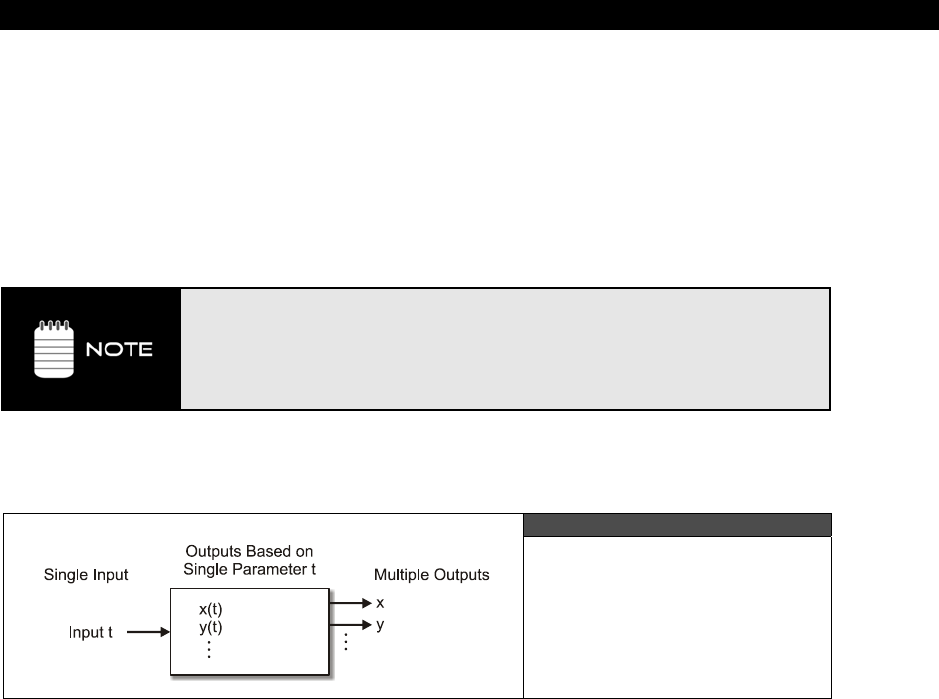
Basic Graphics and 2D Animation18
Game Programming for the Propeller Powered HYDRA Page 499
games, when your foot is on the ladder you need to know if your foot is on the ladder. But
you would be surprised at the collision detection even in games like HALO and DOOM, in
many cases, the complex characters you see are surrounded with invisible cylinders or
simplified bounding boxes to perform collision detection for both weapon/player collision and
player/world collision. This is why we have all said, more than once, “That didn’t hit me!”
while dying in a game. The collision detection used a crude bounding volume or trick to
speed up collision testing and that time it just was wrong! So no, you’re not crazy, games
do
make mistakes.
Although crude, this demo is a good example of a “particle system”, that is, a set
of simple objects (particles) with a simple rule, and a lot of them. This is how
rain, debris, sparks, and other effects are accomplished on advanced 3D games.
Of course there are thousands of particles in those effects and they are colored
and have textures on them sometimes, but the idea is the same. This system is
something like a gas in a 2D plane.
18.4.3.3 Parametric Motion
Figure 18:24
Parametric Motion
Controller
Parametric
motion
simply means that a single variable, a
“parameter,”
is used as an
input to “drive” a set of equations that control the position of an object, usually (x,y) in 2D or
(x,y,z) in 3D. However, parametric control can be used to control anything like color, shape,
size, and so forth. Nonetheless, for this brief discussion we are going to focus on parametric
motion just to keep it simple. Referring to Figure 18:24, the idea is that we control a single
variable and the “parametric controller” outputs any number of variables; x,y in our case.
Typical examples of parametric motion are found in physics texts where time (t) is used to
drive a system of linked Newtonian motion formulas. For example, if we start with the
formula for position then we get the following parametric formulas for position (x,y) , velocity
(vx, vy), and acceleration (ax, ay):
Position (x,y) at time t
x(t) = x0 + vx*t + ½ * ax*t2

III Game Programming on the HYDRA
Page 500 Game Programming for the Propeller Powered HYDRA
y(t) = x0 + vy*t + ½ * ay*t2
Where (x0, y0) are the initial position at t=0.
Velocity (xv, yv) at time t
xv(t) = xv0 + ax*t
yv(t) = yv0 + ay*t
Where (xv0, yv0) are the initial velocity at t=0.
The formulas assume constant acceleration, that is, (ax,ay) are constant for all t. So, the idea
is that if you have the initial position (x0, y0) and the initial velocity (xv0, yv0) then you can
compute the position of your point at any time t from negative infinity to positive infinity.
These basic motion equations are commonly used to model basic physics and we will get to
that when we discuss the subject later in the book. But for now, they are just an example of
parametric motion.
As another example, say you wanted to make a shoot-em-up game and wanted the aliens to
follow a circular or elliptical path, but how? Simple, just use the parametric versions of a
circle to control a point (x,y) as a function of angle:
x(t) = r1*cos(t)
y(t) = r2*sin(t)
Where 0 <= t <= 360.
The above formula will create a circular path with x-axis intercepts at (-r1, +r1) and y-axis
intercepts at (-r2, +r2). If r1=r2 then you will get a circle. What about a spiral? Well, for a
spiral to work, we need to slowly change the radius as a function of t as well and make it
bigger or smaller, no problem:
x(t) = (r1+t/rate1)*cos(t)
y(t) = (r2+t/rate2)*sin(t)
So if t ranged from 0 to 360 depending on how you selected r1, r2, rate1, and rate2, you could
get almost any spiral you wanted, of course, the above formulas work best with floating-
point math and the Propeller doesn’t support floating-point math natively nor does Spin. So
you have to fudge things to get them to work, for example by using large numbers and
division/multiplicaton to simulate fixed-point math. As an example of this in action take a look
at spiral_demo_010.spin on the CD located in CD_ROOT:\HYDRA\SOURCES\. Try
altering the constants at the top of the program to get different spiral motion patterns in
real-time. Also, notice the program renders with triangles and draws a grid each frame.

Basic Graphics and 2D Animation18
Game Programming for the Propeller Powered HYDRA Page 501
18.4.4 Color Animation
Well, at this point, I think you can see it’s a lot of fun to move objects around the screen,
you can make them do anything and look like anything. Game and graphics programming is
very artistic for this reason, it’s “art in motion,” and it’s programmed, so it’s the fusion of art
and science which is very cool. In any event, in the previous section, the concept of
keyframe animation was brought up which was animation by means of displaying various
frames or models of a character as it’s performing some action: running, jumping, dying,
whatever. But, geometrical animations are not the only ones you can do; remember
animation as far as we are concerned as game programmers is anything that moves or
changes, thus we can even animate the
colors
of the screen!
Organization of the VGA Color Look-up Table Figure 18:25
Color animation is simple. For it to work, you must have color indirection, that is, a register
or memory location needs to hold a color value, then this value is referenced indirectly during
rendering. For example, on the PC VGA archictecture there is what’s called
a color look-up
table (CLUT)
, this table has 256 entries, each entry is usually a full RGB color in 18 to 24
bit, but that would give up to 16.7 million colors which obviously the VGA didn’t display at
once. But you could select 256 of these 16.7 million colors at one time, thus you would set
the color palette up with 256 colors you wanted and then use an index 0..255 as the pixel
value which would be used by hardware to “look up” the full 24-bit RGB value in the CLUT,
and then that color would show up on the VGA screen; this is shown in Figure 18:25. Now,
the cool thing about this is that drawing pixels is expensive, if you wanted to redraw 50% of
the VGA screen that’s 640×480*50% = 153,600 BYTEs, ouch! But, if you only wanted to
change the color of all these pixels then a single write to the CLUT would do it.

III Game Programming on the HYDRA
Page 502 Game Programming for the Propeller Powered HYDRA
With this technique, you could simulate movement, like marquee signs do, or turn an object
off and make it invisible by selecting a color that had RGB (0,0,0). All these tricks are called
color animation. Now on the HYDRA, we basically need to write the graphics engine
ourselves to support this properly, but the Propeller has the hardware indirection to make it
easy. If you recall from the discussion on the VSU, the VSU streams out bytes of color
indexed by the pixels we send to it, the bytes are “colors” stored in the “colors” LONG, thus
we have our look-up! However, to expose this the high-level engine needs to do it somehow
and the Parallax reference driver we have been using isn’t very cooperative here, but again,
we can force it to at least show the effect and later with the more advanced engines I will
show you, this type of functionality will be built-in more directly.
To animate colors on the screen, we have to go back to the setup of the colors array during
the initialization of the Parallax reference driver, here’s the code for reference:
{ init colors, each tile has same 4 colors, (note color_1 and color_2 are flipped
due to bit flipping in graphics driver) }
repeat i from 0 to 64
colors[i] := COLOR_3 | COLOR_2 | COLOR_1 | COLOR_0
...where colors[i] is simply a LONG array where each entry is a 4-BYTE color look up table
which is perfect, and in fact is even more flexible since we can do color animation on a tile by
tile basis. So, to perform color animation, we simply modify the 64 entries (or fewer) and do
whatever we want to them. Let’s start with a couple common effects and you can go from
there.
18.4.4.1 Glowing Effect
The first color animation trick will be to make a color “glow,” to do this you need to change
the color or brightness or both at some rate. So what we are going to draw is a random Mars
cavern scene in the primary buffer only and animate a single color. We have four colors for
each tile to play with: color 0, 1, 2, 3. We are going to map the colors in the following way:
Color 0: Background color - black.
Color 1: Top cavern color - reddish.
Color 2: Bottom cavern color – reddish.
Color 3: Animated color will cycle through the greens.
To implement this animation, we first need to draw the trench, that’s easy, we will use one
of the primary buffer templates to do that and use a random variable to create the top and
bottom terrain, then for the last pixel or two of the top layer of radioactive “crust” in our
cavern we will draw it in Color 3 (the animation color), then fall into our main loop and
animate the color.

Basic Graphics and 2D Animation18
Game Programming for the Propeller Powered HYDRA Page 503
Figure 18:26
Caverns of Mars
The program that makes this all happen is caverns_glow_010.spin which is located in
CD_ROOT:\HYDRA\SOURCES\. The demo is shown running in Figure 18:26 which of
course doesn’t do it justice, so make sure to run it. The program is too big to list, but the
color animation fragment is listed below for reference:
' rotate colors
repeat while TRUE
' animate the color (glow it)
glow_intensity += glow_delta
' keep glow_intensity between 2 and 6
if ( (glow_intensity) < 2 or (glow_intensity) > 6)
glow_delta := -glow_delta
glow_intensity += glow_delta
' now mask in glow_intensity as the luminance component of the green that is
' representing the crust
palette[3] := (COL_Green & $F8) | glow_intensity
' write the new colors into all the tiles
repeat i from 0 to 63
colors[i]:=(palette[3]<<24)|(palette[2]<<16)|(palette[1]<< 8)|(palette[0]<<0)
' delay a moment
waitcnt(cnt + 5_000_000)
As you can see, the code is a very simple loop that animates color 3 of every single tile. The
animation slowly increments through the brightness of a pure green and then once they
reach maximum brightness start decreasing, so you get a nice glowing effect. Try using a
different base color other than red, maybe blue, and see what they look like. The rendering
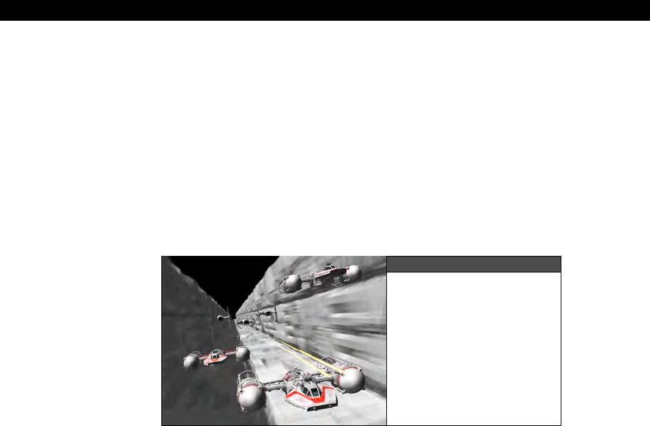
III Game Programming on the HYDRA
Page 504 Game Programming for the Propeller Powered HYDRA
of the caverns themselves are nothing more than a random variable that is queried to
determine whether to shift right or left as the cavern is rendered, more or less, the cavern is
simply two
“random walks”
that are filled to the right and left respectively.
18.4.4.2 Color Rotation and the Star Wars Trench
Every respectable game programmer at one time or another has tried to replicate the effect
of the trench from the movie Star Wars; Figure 18:27 shows a screen shot from the
Playstation version of it. There are direct ways of doing it, such as 3D graphics and solid or
wire frame graphics, or more indirect ways such as cheating like was done in the 80’s on
simple game systems to get the “effect,” Thus, we aren’t going for what you see in the figure
since that’s real 3D, we are just trying to make something look like we are flying through a
3D trench.
Figure 18:27
The Star Wars Trench
So the idea here to achieve the animation is similar to the marquee idea, that is, to mimic
movement by sequencing lights, but instead of sequencing lights we are going to sequence
colors with a technique called
“color rotation.”
Color rotation is just that, we “rotate” a set
of colors just like rotating a set of bits, for example, when you use a ROL or ROR instruction
in assembly, they mean to “Rotate Left” or “Rotate Right,” same idea here, but with larger
chunks of data representing the colors in a tile. Referring to Figure 18:28, you can see the
idea schematically. Colors 1,2,3 are rotated in increasing order, so here’s what happens in
pseudo code (notice we need to use a temp var):
temp := color 3 'hold color 3, so we don’t loose it
color 3 := color 2 'rotate color right
color 2 := color 1 'rotate color right
color 1 := temp 'finally copy color 3 back into color 1
...and to rotate in the opposite direction would be:
temp := color 1 'hold color 1, so we don’t loose it
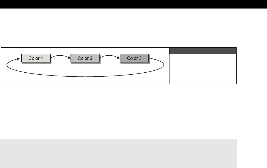
Basic Graphics and 2D Animation18
Game Programming for the Propeller Powered HYDRA Page 505
color 1 := color 2 'rotate color left
color 2 := color 3 'rotate color left
color 3 := temp 'finally copy color 1 back into color 3
Figure 18:28
Color Rotation
Schematically
Diagramed
Of course, the concept of left and right is really arbitrary and nothing more than
right
means
increasing
and
left
means
decreasing
integer order. Anyway, to rotate in the opposite
direction is the same idea, just invert the indices. So, as a first shot at color rotation, let’s try
this: draw a pseudo 3D perspective horizon covering the bottom half of the screen as
horizontal strips of color in the sequence color 1,2,3,1,2,3,… and then rotate to create the
illusion of forward motion in 3D. The code for this rendering is shown below for reference:
' render perspective colorized horizon for rotation
repeat y from 0 to SCREEN_HEIGHT/2
gr.colorwidth(1 + (y/(30-y/5)) // 3, 0)
gr.plot(0,y)
gr.line(SCREEN_WIDTH-1, y)
Notice all the fudging with the math – this is typical when doing this kind of rendering, rather
than use real 3D math, you simply “experiment” until you get the visual results you like. In
this case, 4 lines of code create the perspective illusion! The program that shows everything
is color_rotation_010.spin which is located on the CD here:
CD_ROOT:\HYDRA\SOURCES\
Try the program out, you can increase and decrease the speed of color rotation with the up
and down directionals on the game pad (plugged into the left port of course). The program
uses a standard primary-only setup to save memory; the actual color rotation is shown
below:
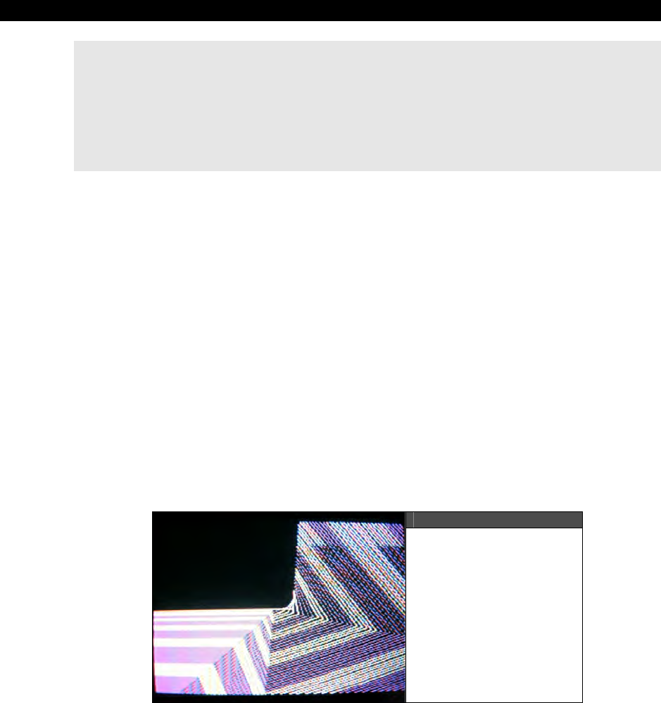
III Game Programming on the HYDRA
Page 506 Game Programming for the Propeller Powered HYDRA
' the 4 colors are located in palette, we are going to rotate 3->2->1->3
temp_color := palette[1] ' save this for a moment
palette[1] := palette[2]
palette[2] := palette[3]
palette[3] := temp_color
' now write color palette back into screen colors array, so tiles use them
repeat i from 0 to 63
colors[i]:=(palette[3]<<24)|(palette[2]<<16)|(palette[1]<<8)|(palette[0] << 0)
Notice the color rotation works in two parts: part one performs rotation on a set of
“shadow”
colors, then in part two they are copied into the 64-element color array that
represents the color look-ups for each tile. See if you can alter the code so that you can
change directions of the rotatation from up/down.
Now, that we have that under out belts, I think you get the idea of how motion can be
simulated without actually moving anything! The previous demo literally moved the entire
screen RAM, so it seemed, but really all that moved was the colors of the rendering, not the
data rendered, this is the key to color animation. The indirection of color look-up tables gives
you the abilty to seemingly move a lot of data when in fact you are only changing what it
looks like. In any event, to get the Star Wars trench animation to look semi-real, what we
need is to first draw a perspective correct 3D trench of some gray metal colors that gets
bigger as it gets closer, then to rotate the colors toward us. So the plan will be to use the
following color scheme:
Color 0: Background black
Color 1: Dark violet
Color 2: Dark violet
Color 3: White
Figure 18:29
Our HYDRA-Powered
3D Star Wars Trench

Basic Graphics and 2D Animation18
Game Programming for the Propeller Powered HYDRA Page 507
Notice that colors 1 and 2 are the same? The reason is that this will help “sell” the 3D effect
better. Alright, taking that all in to consideration, Figure 18:29 shows our meager attempt at
the trench effect with a little tile on the aspect to make it look better. To try the program out
load color_trench_010.spin located in CD_ROOT:\HYDRA\SOURCES\. The program
does absolutely nothing different than the previous color rotation demo other than draw
something
different
to animate. This is the cool part about this type of animation, whatever
is on the screen will animate, so you can do all kinds of cool tricks with it. The Spin code that
performs the rendering of the trench is semi-interesting and shown below for reference.
repeat y from 0 to SCREEN_HEIGHT/2
gr.colorwidth(1 + (y/(25 - y/5)) // 3, 0)
' draw pseudo-3D trench
y_inv := SCREEN_HEIGHT/2 - y
gr.plot(0,y)
gr.line(SCREEN_WIDTH/2 - y_inv/1 - 10, y)
gr.line(SCREEN_WIDTH/2 - y_inv/3 - 10, y - 2*y_inv)
gr.line(SCREEN_WIDTH/2 + 5*y_inv/1 - 10, y - y_inv/5)
gr.line( (SCREEN_WIDTH/2 + y_inv/3 + 10) , y + 5*y_inv)
Note, this kind of “artistic” graphics programming is mostly trial and error to get the visual
effect with as few lines of code as possible.
18.5 Summary
This chapter has covered a lot of material and a lot of new concepts such as double
buffering, page flipping, coordinate systems, color rotation, and much more. Hopefully you
are starting to see how fun game development and graphics programming is! There is no
limit to what you can do with a few simple ideas. The idea is to keep building upon them
until you have a HALO III, so let’s keep working!

III Game Programming on the HYDRA
Page 508 Game Programming for the Propeller Powered HYDRA

Tile Engines and Sprites 19
Game Programming for the Propeller Powered HYDRA Page 509
Chapter 19:
Tile Engines
and Sprites
In this chapter, we are going to discuss tile and sprite engines from a technical and design
point of view then take a look at a simple “starter” tile/sprite engine that I have developed
for you. This engine supports tile graphics, 4 colors per tile from a unique palette per tile,
multiple sprites, page flipping, scrolling, and more. Additionally, the tile engine works on a
single cog and generates video as well! With it, you should be able to make anything you
see on an Atari 800 or C64 more or less. We aren’t going to go into the programming of the
tile engine, that’s a bit too much to cover for right now. Later in the book we’ll discuss the
design, but for now, think of it as an object like anything else, with a really simple interface.
Considering that, here’s what’s in store for this chapter:
Tile and sprite engine basics
Overview of the sample tile/sprite engine
Displaying multiple tile maps
Moving tile based objects around tile maps
Using the sprite engine
19.1 Tile Engine Technology Overview
Simply put, bitmapped graphics take up too much memory and are too slow for most small
game systems to handle. For example, if you do some simple math you will see that
supporting bitmapped graphics is challenging on constrained hardware. Let’s say you wanted
to implement a 256 color (1 BYTE per pixel) bitmapped display with two pages of video and a
resolution of 224×192. Assuming that 256 colors can be encoded with 1 BYTE per pixel using
the pixel data directly or a look-up that maps the 8-bit pixel data we have:
1 byte * 224 * 192 * 2 = 86016 BYTEs or 84 Kbytes!
This is nearly three times as much static RAM than the Propeller chip has, so this isn’t going
to work. Moreover, that amount of data is a lot ot refresh, clear, and move at 60 FPS, so
simply trying to update the screen is difficult even if you had the memory. Even if we backed
off quite a bit down to 2 bits per pixel, and lowered the resolution to 160×192, we still end
up with:
160 × 192 * 2 / 4 = 15360 BYTEs or 15 Kbytes.

III Game Programming on the HYDRA
Page 510 Game Programming for the Propeller Powered HYDRA
A 40×24 character map represents 320×192 pixels
and costs 960 BYTEs Figure 19:1
This is a little more reasonable, and in fact is exactly how the Parallax bitmap video drivers
works, that is, you can select 1 or 2 bits per pixel and with a double-buffered graphics
system you can fit it in memory, but it only leaves you 17K roughly for your program code!
Not very good tradeoffs. These are the exact same problems game programmers were faced
with 20-30 years ago when they first started developing commercial games.
One of the solutions to the problem was to redefine the character set of the computer, so
that the bitmaps that normally represent the characters “A” “B” “C” etc. were overwriten with
game characters and then printed out like text. This was good since character modes take
much less memory than bitmap modes. For example, a 40×24 display of characters that are
8×8 bitmaps only takes 40*24 = 960 BYTEs, assuming 1 BYTE per character (which is
usually the case) and each character is represented by an 8×8 character definition index
within the 960 BYTEs. With this we can represent a screen with a resolution of (320×192) as
shown in Figure 19:1. Of course, the character definition bitmaps take up memory
themselves, but we only need to define the characters we are going to use, we don’t need to
define 256 of them. So for example, we might only need 30-40 characters to “build” up all
our game art in character format.
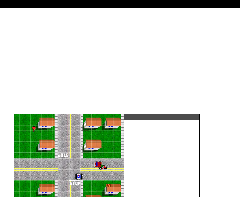
Tile Engines and Sprites 19
Game Programming for the Propeller Powered HYDRA Page 511
Additionally, we can use 1, 2, 4, or 8 bits per pixel or whatever we want to save more
memory for the actual characters themselves. For example, most game programmers will use
2, 4, or 8 bits per pixel, so the amount of memory to define each character is minimal; more
on this in a moment.
Alright, so game programmers started redefining the character sets in game systems and PCs
to represent game characters and this worked out great, an entire screen would take 1-2K to
represent, but could look like anything. Of course, the only problem was that depending on
the hardware you were on you might be stuck with a certain number of characters per
screen, a certain bit depth, and worst of all a ROM character set that you couldn’t redefine.
In these cases, some programmers were able to synthesize “character” graphics with the
bitmap graphics, and render the characters “on the fly” straight to the raster without using
bitmap memory etc. However, the point is that this technique is very powerful however you
do it and later became known as
“tile graphics.”
More or less, any game can be made with
tile graphics.
Figure 19:2
Tile Engine Matrix Shows
Tile Locations
Now, the bad news…tile graphics are great, but the problem is objects can only be drawn on
tile boundaries. For example, say you have tiles that are all 16×16 pixels, then you can lay
them down to make your background or what is known as the
“playfield”
in old-school
parlance. You can only place a tile on a tile boundary, just like characters on a text screen,
you can’t put a tile half way between two tiles; Figure 19:2 shows this. Referring to the
figure, you see there is an imaginary tile “matrix” (fine white lines) that shows the boundary
of where tiles can go, so you can only place them on these integral locations. For a tile setup
of 16×16 pixels, this means that each tile has to be located at pixel location (i*16, j*16),
where (i, j) run from 0..m, and 0...n, the tile map width and height.
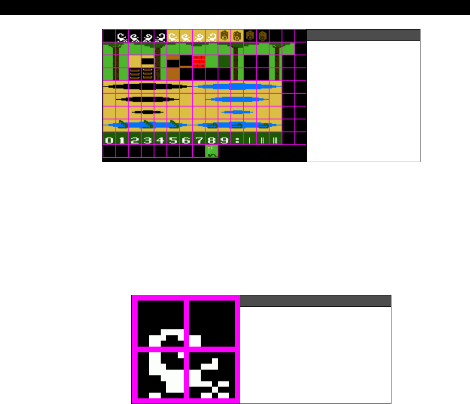
III Game Programming on the HYDRA
Page 512 Game Programming for the Propeller Powered HYDRA
Figure 19:3
Pitfall 16×6 Tileset
This isn’t too bad of a problem, but if you want to move a game character around then you
have to move it by an entire tile size which may look pretty rough. For example, Figure 19:3
shows some tiles I created based on the Pitfall game, they are all 16×16 and you can see
how “tiling” them next to each other would result in complete backgrounds. But, the problem
is the game characters that need to move like the “scorpion” up top and “Pitfall Harry”
bottom center. If we were to move these object by whole tiles they would look pretty rough
during game play. If your game can live with this then fine, otherwise, you have to come up
with some concessions to make it look better.
Figure 19:4
Using Smaller Tiles to
Increase Motion Resolution
One such concession is to make the tiles smaller. For example, you could make the tiles 8×8,
then each 16×16 tile would be broken into (4) 8×8 tiles, that when tiled next to each other
make the original 16×16. Figure 19:4 shows this for my little rendition of the scorpion. Now,
if we want to draw or move the scorpion, we must move/draw 4 tiles, this isn’t bad, it’s 4
BYTEs to update in tile memory. But, a side effect is that tile memory is now 4 times bigger
which can start to become an issue. Nonetheless, this is a good approach since now we can
move a tile character 8 pixels at a time that is 16 pixels large, or 50% of its width or height,
this is still “a lot” and surely not what you would call “fine” motion, but usually tolerable. And

Tile Engines and Sprites 19
Game Programming for the Propeller Powered HYDRA Page 513
you will find many 8-bit games that do just this and you never noticed while playing! Now
that you have an idea of what a tile engine is, let’s talk about modern tile engines and what
they tend to support.
19.1.1 Modern Tile Engines
Tile Engine Resolution Mapping with
Larger Tile Map to Support Clipping Figure 19:5
Modern tile engines are usually based on hardware, or a hardware/software combination.
Most modern graphics cards do not have any kind of tile graphics support, tile graphics are
simply supported via bitmapped graphics and a layer of software. Thus, there are no
constraints on them unless dictated by hardware. Tile engines usually have a few parameters
that define their capabilities such as:
Tile sizes
Screen size
Scrolling support
Page flipping support
Special effects and layering

III Game Programming on the HYDRA
Page 514 Game Programming for the Propeller Powered HYDRA
Tile Sizes — You will usually find tile engines that support numerous tile sizes such as 8×8,
16×16, 32×32, and sometimes other sizes that are not powers of two, and not equal in the X
and Y dimensions, but game programmers and artists like tiles that are 8×8, 16×16, and
32×32, so most people stick with these. Additionally, these sizes make math and
computations very easy since they are powers of two.
Screen Size — This is the actual size of the screen in pixels, for NTSC, you will find the
following resolutions common for tile engine implementations: 160×192, 224×192, 224×224,
256×192, 256×224, 256×256. Where considering the bandwidth of NTSC, the highest
“visible” on-screen resolution is 160×192, the other modes extend off the screen edges or
they are comrpressed on screen, but single pixels can’t respond to color changes on a pixel
by pixel basis and need 2 or more pixels in a row to actually see the color. The larger tile
resolutions are good to support clipping. That is, you make the tile map 256×256 logically,
but physically you can only see 160×192 of it, thus the other portion of the screen client area
is off the edges of the screen logically, so when you move or draw tiles they tend to “clip” off
the screen as shown in Figure 19:5. Also, using 256×256 for a screen resolution is nice since
position is encoded in a single BYTE and wraps around nicely.
Scrolling Support — Scrolling simply means moving a view window over the data set. In
tile graphics, this might mean that the tile map is 100×100 tiles, but only 40×24 of these
tiles are on screen at once. Thus, scrolling might be implemented in a number of ways such
as how the tile memory is addressed or with specific registers or memory locations that
control scrolling of the tile map. Also, scrolling can be
“fine”
or
“coarse.”
Fine scrolling
usually means you can scroll by a single pixel or line, coarse scrolling means you must scroll
by an entire character/tile size. If you are doing a space shooter game or a high-speed racing
game then coarse scrolling will suffice, but if you want a character to slowly walk around the
environment then fine scrolling is a must.
Page Flipping Support — We have already discussed what page flipping is in the previous
chapter, but to reiterate: page flipping simply is the ability to “point” the screen memory
base address to another region of memory and instantly the new data is used to draw the
screen. This is page flipping and is much faster than copying the screen of data from a back
buffer to the primary buffer. Of course, with tile graphics, we are talking about screens that
cost only 1-2 K, so even without page flipping we can always copy data from an off-screen
tile buffer to an on-screen tile buffer in a few thousand machine cycles. Nevertheless, page
flipping is a nice feature to have especially for a nice
“Adventure”
type game where you
might have 10-20 levels each represented by a single page of tiles and you want to change a
single pointer to move the player from room to room.
Special Effects and Layering — This covers a lot of ground and could be anything from
color effects to distortions and so forth. For example, a tile engine might use a single BYTE to
represent each tile, and each tile is encoded as a 16×16 bitmap where each pixel is 2 bits,
and these 2 bits represent 1 of 4 colors from a palette of 16. Thus, each tile might have a
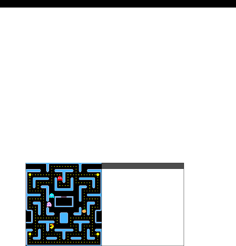
Tile Engines and Sprites 19
Game Programming for the Propeller Powered HYDRA Page 515
palette assigned to it as well. So lots of color special effects can be achieved with this, for
example, on the bottom tiles of the screen you use color 1 to represent water, but on top
you use color 1 to represent grass, so when a character that uses color 1 as part of its
bitmap walks on grass or water, you see the green or blue change which is cool and nearly a
free effect. Another feature for tile engines is
“layering”
– here what we are talking about
is at the driver or rendering level, multiple tile maps are layered on each other either with
some kind of stencil, or logical combination rule (AND, OR, XOR) etc. This can be a very
powerful effect to create layered scrolling and 3D parallax effects.
19.2 Augmenting Tile Engines with Sprites
Your first question might be “What is a sprite?” Well, we aren’t talking about the “sprites” in
fairy tales, we are talking about sprites in video games. A
“sprite”
is a usually a 2D bitmap
object that can move freely over the background bitmap or tile graphics. Sprites usually have
collision detection and can even be scaled. Usually, they are implemented in software these
days, but in the 70’s and 80’s systems usually had hardware sprites as part of the design. For
example, the Atari 800 had 4 sprites (plus another 4 missiles that could be combined into
one more sprite), and the C64 had 8 sprites with more colors than the Atari though, and the
Apple II had no sprites!
Figure 19:6 shows a screen shot of
Ms Pacman
in play. The ghosts and player are all
sprites, while the background maze, power pills, dots, and power-up fruits were all tile
graphics. In fact, if you boot a real Ms Pacman machine or a MAME emulated version, you
can actually see the tile graphics start up.
Figure 19:6
A Screen Shot of Ms Pacman
with Sprite Graphics
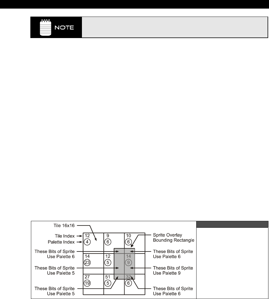
III Game Programming on the HYDRA
Page 516 Game Programming for the Propeller Powered HYDRA
The term “Sprite” was originally coined in the 1970’s by Texas Instruments
documentation about their video generation chip. Atari also coined the terms
“Player Missile” graphics to refer to sprites as well.
Sprites are the last feature you need to complete a graphics engine for games. As noted, tile
graphics are fine to create the background or playfield for your games, but the objects
moving around in the foreground usually need to move over the background without
disturbing it, but more importantly need to move smoothly on a pixel-by-pixel basis rather
than in
“tile space.”
This is exactly what sprites give us the ability to do. Typically, sprites
are implemented as bitmaps just like the tiles, and may even share the same format as the
tile’s bitmaps; however, we can place sprites anywhere we want instantly, and moving them
is usually done with single operations to registers or memory locations from an API stand
point (the actual implementation might be hardware or software though at the driver level,
thus there could be a lot of magic happening underneath).
Sprites usually have a number of features just like the tile engines such as:
Sizes
Colors and transparency
Scaling
Z-Ordering
Sizes — Sprites usually are the same size as the tile engine or a multiple thereof. So,
common sizes are 8×8, 16×16, 32×32. However, since sprites mostly represent foreground
game objects and not a regular matrix of background tiles, the constraint of width equaling
height is loosened. For example, if you needed a “tree” sprite, it would be inefficient to have
a 192×192 size sprite when you only needed it to be 32×192. Thus, many times sprites will
actually have a programmable height or width, and/or give you more size choices like 16×32,
32×16, etc.
Figure 19:7
Sprite Color Use
Constrained by Tile
Palettes
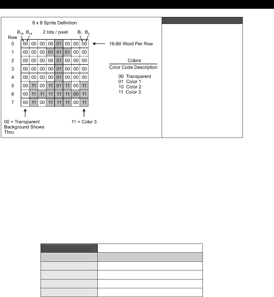
Tile Engines and Sprites 19
Game Programming for the Propeller Powered HYDRA Page 517
Figure 19:8
Sprite Transparency
Encoding
Colors and Transparency — Depending on how the graphics hardware/software/drivers
work the sprites may have to use the same colors as the tile or bitmap graphics do. For
example, any portion of a sprite bitmap that overlaps a tile must use its palette, this is shown
in Figure 19:7. This might be a physical limitation of the hardware itself, or simply a way to
save memory. On the other hand, each sprite might have its own set of colors and might
even have more color space that the tiles (or less). For example, maybe the tiles have 4
colors each, and the sprites have 256. Lastly, sprites represent objects that need to move
over the playfield graphics, thus they need to have “transparency” in them, so the
background can show through. This is usually represented by a single color code, usually
Color 0. Therefore, in a sprite bitmap anywhere there is a Color 0, this will show through the
background. This is shown in Figure 19:8 for an 8×8 sprite with 2-bit color. Thus, in a sprite
with 4 colors encoded in 2 bits, the encoding might be like that shown in Table 19:1.
Table 19:1 Color Encoding for 2-bit Sprites
Color Code Description
00 Transparent color, show background
01 Color 1
10 Color 2
11 Color 3

III Game Programming on the HYDRA
Page 518 Game Programming for the Propeller Powered HYDRA
So, the problem with transparency (other than the nightmare to implement it in the driver) is
that one color encoding, namely Color 0, is used to represent transparent, thus we loose a
whole color in our 2-bit encoding. Alas, one strategy is to have a flag in the sprite definition
that indicates if you want the sprite to be “transparent,” otherwise, the color code 00 will just
render over the background as opaque (whatever actual color it is).
Figure 19:9
Sprite Scaling Visually
Scaling — Having the ability to scale a sprite is very powerful. For example, by simply
scaling a sprite by some factor, you can make it look larger or smaller (closer or farther), and
get 3D effects. Implementing sprite scaling is usually quite easy once you have written the
sprite rendering software (or designed the hardware) since it’s mostly a matter of
oversampling, undersampling or playing games with memory addresses; there is no real
“scaling” going on. However, most sprite scaling systems only allows multiple-of-two scaling.
Figure 19:9 shows a character from Ari Feldman’s
“SpriteLib”
at 1:1 and then scaled 2× on
the Y axis (making it taller). As you can see, the sprite still looks good, and could be used as
another sprite or game character simply by scaling it. Thus, sprite scaling can also be used to
create other characters from the sprites you have or character variations programmatically.
One of the most famous examples of this is “
Wing Commander
” which was a 3D game on
the PC implemented 100% via sprite scaling and transformations!
Figure 19:10
Sprite Z-ordering

Tile Engines and Sprites 19
Game Programming for the Propeller Powered HYDRA Page 519
Z-Ordering — The last important feature of sprites is called “Z-ordering” which is more or
less that sprites are drawn in some order, thus if you place one sprite on another, they will
look like they are layered in 3D from back to front. Thus, this effect can be used to make
sprites walk behind trees, etc. You can use one sprite as a tree or a rock for example, and
one sprite for your walking character. As long as the walking character is rendered first, and
the tree second, the tree will look like its in front of the sprite. As an example, take a look at
the Pitfall mock up in Figure 19:10, here we see a scorpion sprite behind a tree (top left),
and player sprite in front of the trees (swinging on the vine). Thus, the order in which
everything is rendered creates the illusion of 3D.
Alright, now that you have a good grasp on tile engines and sprites let’s take a look at the
first tile engine we are going to use to write the forthcoming demos with.
19.3 Our First Tile Engine – HEL GFX 4.0
The first tile engine we are going to experiment is named HEL_GFX_ENGINE_040.SPIN
and is 100% assembly language. The engine is located in CD_ROOT:\HYDRA\SOURCE
directory as usual along with all the other demos from this chapter. The engine was written
over about 4 days with a number of rewrites to keep the code as simple to understand as
possible and it’s heavily commented. The idea of this book and source is for you to be able to
use it yourself for education and experimenting, and if you can’t understand it then it’s
worthless! So as an author I always defer to easy rather than clever, but sometimes features
have to be removed to make that happen. Alas, I had a number of goals when creating this
first engine:
1. The ASM code has to be straightforward, not too clever, but some cool techniques
should be used.
2. The entire engine and NTSC driver has to fit in a single cog.
3. The programming interface has to be really easy as well as the data structures, be
and similar to 8-bit game programming.
4. The tile engine should be a reasonable resolution and support multiple sprites.
5. Scrolling and page flipping should be supported.
6. Each tile should have its own color palette.
Taking all that into consideration, I came up with an engine with the following features for
the HEL (HYDRA Extreme Graphics Library) GFX 4.0 engine:

III Game Programming on the HYDRA
Page 520 Game Programming for the Propeller Powered HYDRA
Tile Engine Specs
Tiles are 16×16, 2 bits per pixel (4 colors per tile), each with its own palette.
Each tile takes 16 LONGs of memory.
Tile map is 10×12 tiles physically (16×12 logically) at 16×16 pixel tiles that equals a
screen resolution of 160×192.
The tile map can be 1, 2, 4, 8, 16, etc. screens wide, so large horizontal scrolling
regions are possible.
Index color palettes, with 256 palettes possible, each with 4 colors per tile.
The tile map can be any vertical height in memory as long as there are at least 12
rows of data.
The sprites can be disabled and not rendered.
Horizontal, vertical, and other “state” information is passed back to the caller in real-
time through a shared variable.
Sprite Engine Specs
Sprites are 16×16, no scaling currently, but only simple code changes are needed to
support it later.
Up to 8 sprites on the screen at once (with support for 12 before engine degrades).
Up to 5 sprites on a single scan line at once.
Sprites support transparency with 3 foreground colors mapped from tiles they
overlay.
Z-ordering of sprites, always rendered in order of sprite 0…n, so 3D effects possible.
Sprites are clipped on edges of screen, so smooth on-screen / off-screen transitions
are possible.
Sprite motion de-coupled from tile engine scrolling, so they don’t interfere with one
another.
Each sprite is composed of 16 LONGs for the sprite, plus 16 LONGs for the sprite
mask.
As you can see, the engine isn’t a bad start. Also, this isn’t “version” 4.0 per se, but more like
engine model 4.0. There are other engines with different features that I made, but this
seemed the most appropriate for now.
The engine has way too many features to review in this chapter, plus I am getting anxious to
get to more game coding, so we are going to look at a subset of the features, look at the
setup and data structures, see some demos (many of them actually) and then move on to
the next chapter. The idea is to get you up to speed ASAP, you can always read the source
yourself if you want to peek ahead!
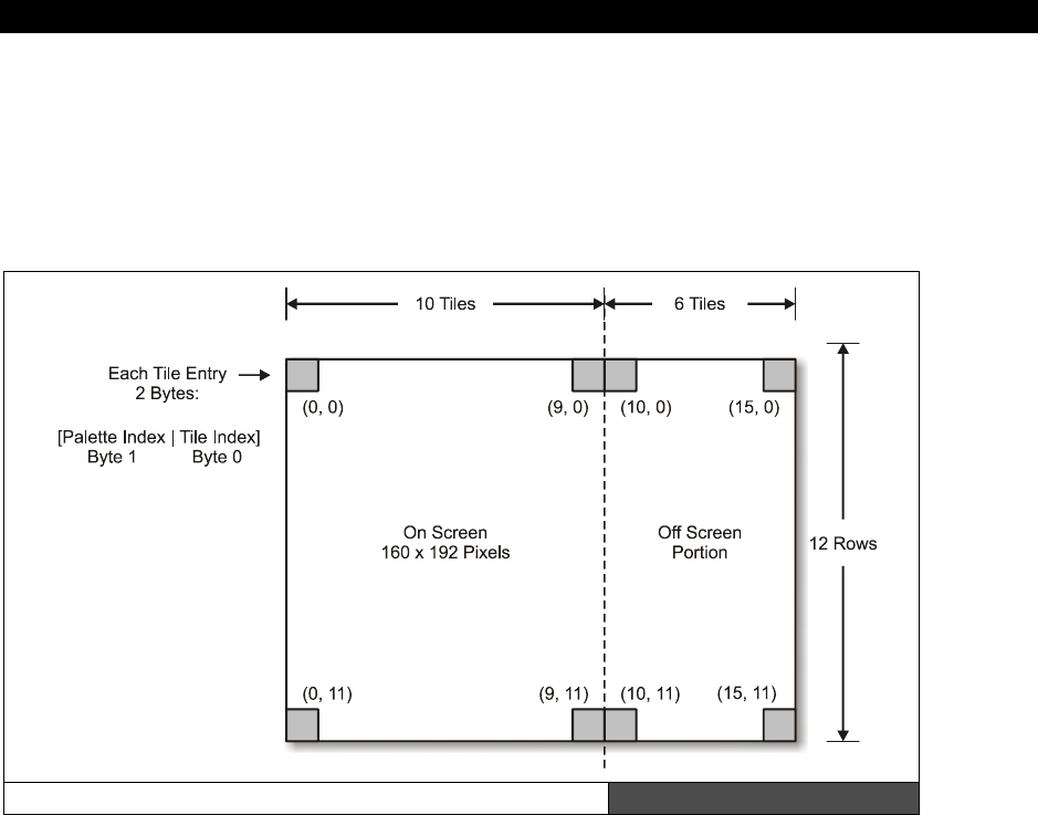
Tile Engines and Sprites 19
Game Programming for the Propeller Powered HYDRA Page 521
Anyway, as outlined in the specs there is both the tile engine and the sprite engine that
composes the graphics engine itself. You can turn sprites off as well and just use the tile
engine alone if you like. Another little quirk of the engine is that each tile screen is 16×12,
but only 10×12 tiles are shown. This is so the math is easy, and you can scroll a few tiles
without much work.
19.3.1 HEL GFX Engine 4.0 theory of operation
The HEL GFX Engine 4.0 Screen Layout Figure 19:11
Now that you know the specifications of the engine, let’s discuss the basic theory of
operation (concentrating on the tile aspect only for now), that is, how you use it, set it up,
the data structures and so forth. Then we will move onto the sprite engine component and
some real demos and see it in action. Let’s start by looking at Figure 19:11, this is the
general layout of the graphics engine’s tiles and sprites. As you can see, the origin of the tile
engine is at the upper left hand corner of the screen, this is tile (0,0) while the lower right
hand corner is tile (9, 11) on the visible screen. The tile map extends past the visible screen
logically to column 15, but these tiles won’t be visible unless you scroll the tile map.
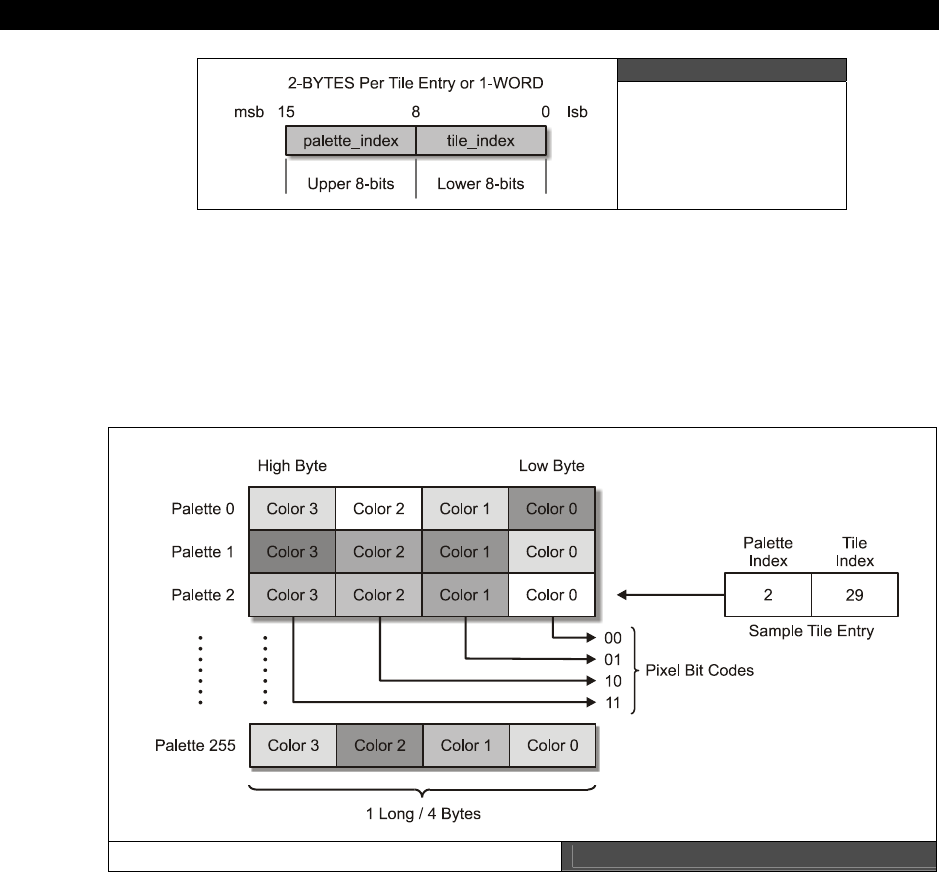
III Game Programming on the HYDRA
Page 522 Game Programming for the Propeller Powered HYDRA
Figure 19:12
Tile Entry Encoding
Moving on, we see that each tile is composed of a single 2-BYTE WORD that contains the
index to the tile (0..255) and the index to the palette you wish the tile to use (0..255) as
shown in Figure 19:12. The high BYTE holds the palette index, the low BYTE holds the tile
index. Although the engine comments say you can only have 64 palettes and 64 tiles, you
can in fact have up to 256, but this would eat memory up, so
theoretically
256 palettes and
256 tiles are the limits.
Color Palette Table Figure 19:13
Each tile represents a bitmap that you would like displayed at that location, and the palette
you wish it to use, as shown in Figure 19.11. The palette table can be up to 256 entries,
where each entry represents a 4-color palette where the low BYTE is Color 0, and the high
BYTE is Color 3. This is shown in Figure 19:13. The encoding of each color is standard VSU
Tile Engines and Sprites 19
Game Programming for the Propeller Powered HYDRA Page 523
format where you need to put in the chroma, luma, etc. However, for reference I have
created a named table of colors shown below in Table 19:2.
Table 19:2 Color Table Names and Values used by
HEL GFX Engine 4.0
SHADES COLORS
Color Name Binary Value Color Name Binary Value Color Name Binary Value
Black %0000_0010 PowderBlue %1111_1_100 Gold %0111_1_100
Dark Grey %0000_0011 Blue %1110_1_100 Orange %0110_1_100
Grey %0000_0100 SkyBlue %1101_1_100 Red %0101_1_100
Light Grey %0000_0101 AquaMarine %1100_1_100 Violet Red %0100_1_100
Bright Grey %0000_0110 Light Green %1011_1_100 Pink %0011_1_100
White %0000_0111 Green %1010_1_100 Magenta %0010_1_100
GreenYellow %1001_1_100 Violet %0001_1_100
Yellow %1000_1_100 Purple %0000_1_100
Note: (Last 3 bits controls LUMA, colors are all at LUMA value 4 in table)
Colors are in reverse order from Parallax drivers, or in order 0-360 phase lag
from 0 = Blue, on NTSC color wheel so code $0 = 0 degrees, $F = 360 degrees,
more intuitive mapping, and is 1:1 with actual hardware.
You can create a color palette with a single entry if you wish and then point all your tile
palette indices to this single palette with the index equal to 0. After the tile palette index
entry in the tile structure is the tile bitmap index itself, this index references one of 256
potential tiles you want displayed on the screen. Each tile is a 2-bit-per-color 16×16 bitmap,
thus each tile takes 16 LONGs or 64 BYTEs which isn’t bad! Figure 19:14 on the next page
shows the layout of the tile bitmaps. Each bitmap is 16 LONGs where each LONG represents
one row of the tile bitmap. The tiles must be contiguous in memory, since the graphics
engine locates the tile bitmaps based on the base address of the tile bitmaps plus the tile
index * 64, since there are 64 BYTEs per tile.
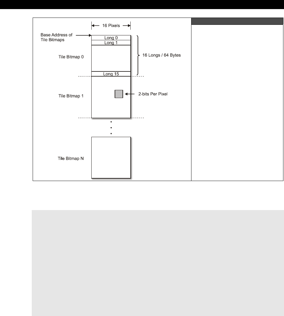
III Game Programming on the HYDRA
Page 524 Game Programming for the Propeller Powered HYDRA
Figure 19:14
Format of the Tile Bitmaps
To create the tiles, you can use a tool, or whatever, but for now we will hand enter them. For
example, here’s the tile bitmap for a Pacman ghost which we will use in upcoming demos:
' a ghost with eyes to left
tile_ghost_lt long %%0_0_0_0_0_0_0_0_0_0_0_0_0_0_0_0 ' tile 4
long %%0_0_0_0_0_0_0_0_0_0_0_0_0_0_0_0
long %%0_0_0_0_0_2_2_2_2_2_2_0_0_0_0_0
long %%0_0_0_2_2_2_2_2_2_2_2_2_2_0_0_0
long %%0_0_0_2_2_2_2_2_2_2_2_2_2_0_0_0
long %%0_0_2_3_3_3_3_2_2_3_3_3_3_2_0_0
long %%0_0_2_3_3_3_3_2_2_3_3_3_3_2_0_0
long %%0_0_2_3_3_1_1_2_2_3_3_1_1_2_0_0
long %%0_0_2_3_3_1_1_2_2_3_3_1_1_2_0_0
long %%0_0_2_2_2_2_2_2_2_2_2_2_2_2_0_0
long %%0_2_2_2_2_2_2_2_2_2_2_2_2_2_2_0
long %%0_2_2_2_2_2_2_2_2_2_2_2_2_2_2_0
long %%0_2_2_2_2_2_2_2_2_2_2_2_2_2_2_0
long %%0_2_2_0_0_2_2_0_0_2_2_0_0_2_2_0
long %%0_2_2_0_0_2_2_0_0_2_2_0_0_2_2_0
long %%0_0_0_0_0_0_0_0_0_0_0_0_0_0_0_0

Tile Engines and Sprites 19
Game Programming for the Propeller Powered HYDRA Page 525
The best way to see it is to blur your eyes and the image will form. Also, notice I am using
the feature of the IDE where you can encode 2 binary bits with a single digit 0..3 if you use
the %% directive, so it makes this kind of encoding very easy.
Looking at the bitmap, all the 2’s are the general base color of the ghost, the 3’s are the
whites of his eyes, and the 1’s are the color of his eyes. The 0’s are background color (not
transparent, tiles use all 4 colors) and in this case will actually be made black in the demo,
but could be gray, blue, whatever as well. Remember, all these numbers 0,1,2,3 are really
color references in the palette for the tile. And the palette for the tile is the high BYTE of the
tile entry!
Of course, if you want more tile bitmaps you just put them one after another in your
program until you run out of memory, and remember they are indexed 0..n as they are
defined linearly in memory.
To save the graphics engine a step, all tile bitmaps are read low bit to high bit,
What this means is that the bitmaps are actually flipped on the horizontal axis,
thus left is right, right is left like an image in the mirror. Thus, when you draw
you bitamaps, draw them backwards or make your tool do it.
That’s about all there is to it. Here’s a list of steps you need to set up for the tile engine so
far:
Step 1: You need a 16×12 array of tile entries where each entry is a WORD; the upper BYTE
is the palette index and the lower BYTE is the bitmap index.
Step 2: You need at least one palette entry to reference for the tile set. Each palette entry is
1 LONG and each BYTE in the LONG represents the colors 0,1,2,3 as referenced by the 2-bit
pairs in the tile bitmap. The color palette is in standard VSU format and the colors
represented are those listed in Table 19:2. You can have up to 256 palettes if you want, but
in most cases you will have only a few palettes or maybe one palette for each tile if you are
really trying to be colorful.
Step 3: The tile engine supports up to 256 tiles. Each tile is 16×16 pixels, where each pixel
is 2 bits, thus you need 1 LONG per row, or 16 LONGs per bitmap. Bitmaps are defined
linearly in memory from top to bottom, index 0 to index n. And they are mirrored on the X-
axis to save the graphics engine a step.

III Game Programming on the HYDRA
Page 526 Game Programming for the Propeller Powered HYDRA
19.3.2 HEL GFX Engine API and Data Structures
In the previous section, we outlined the graphical data elements needed for the tile engine
(we will get to the sprite engine shortly). We need a tile map, palettes, and some tile
bitmaps. Once we have them, we should be able to tell the graphics engine where they are
and we should see something on the screen, that’s as simple as it gets! Alright, so again
there are decisions to make about how to interface to the engine, but again instead of
making it complicated and writing a zillion support functions to access variables, etc. I went
with a memory-mapped approach like the old game systems do, so you just set some
pointers and parameters and pass it to the engine and presto the engine starts working. So
first off let’s take a look at the parameters for the engine and what they control. There are a
total of 6 parameters that control the interface to the graphics engine, that’s it. We tell the
graphics engine about them when we call the “Start” method and simply pass the base
address of the first parameter in Spin memory. The parameters are shown below from the
code demo itself:
long tile_map_base_ptr_parm ' base address of the tile map
long tile_bitmaps_base_ptr_parm ' base address of the tile bitmaps
long tile_palettes_base_ptr_parm ' base address of the palettes
long tile_map_sprite_cntrl_parm ' points to value that holds various "control"
' values for the tile map/sprite engine
' currently, encodes map width & no. of sprites
long tile_sprite_tbl_base_ptr_parm ' base address of sprite table
long tile_status_bits_parm ' real-time engine status vars vsync, hsync,etc
This is a lot easier with a picture to see what goes where, so refer to Figure 19:15 for the
explanation as well as the code listing above. As you can see, there are only 6 parameters
and they are assumed to be in binary order as shown in the listing since the base address of
the 1st parameter will be passed to the engine and it will index from there 0..5 to access
each parameter. They control the following things: the base address of the tile map itself, the
base address of the tile bitmaps, the base address of the palettes, general control and setup
for the tile and sprite engine, the sprite table itself (more on this later), and finally a status
WORD that can be read from the caller to see where the tile engine is. In Spin this isn’t that
useful, since Spin is about 200 times slower than ASM. But if you use the engine from
another ASM module then special effects can be implemented on the fly by looking at the
location of the raster, etc. which is returned in the status bits. Below is a detailed explanation
of each parameter:
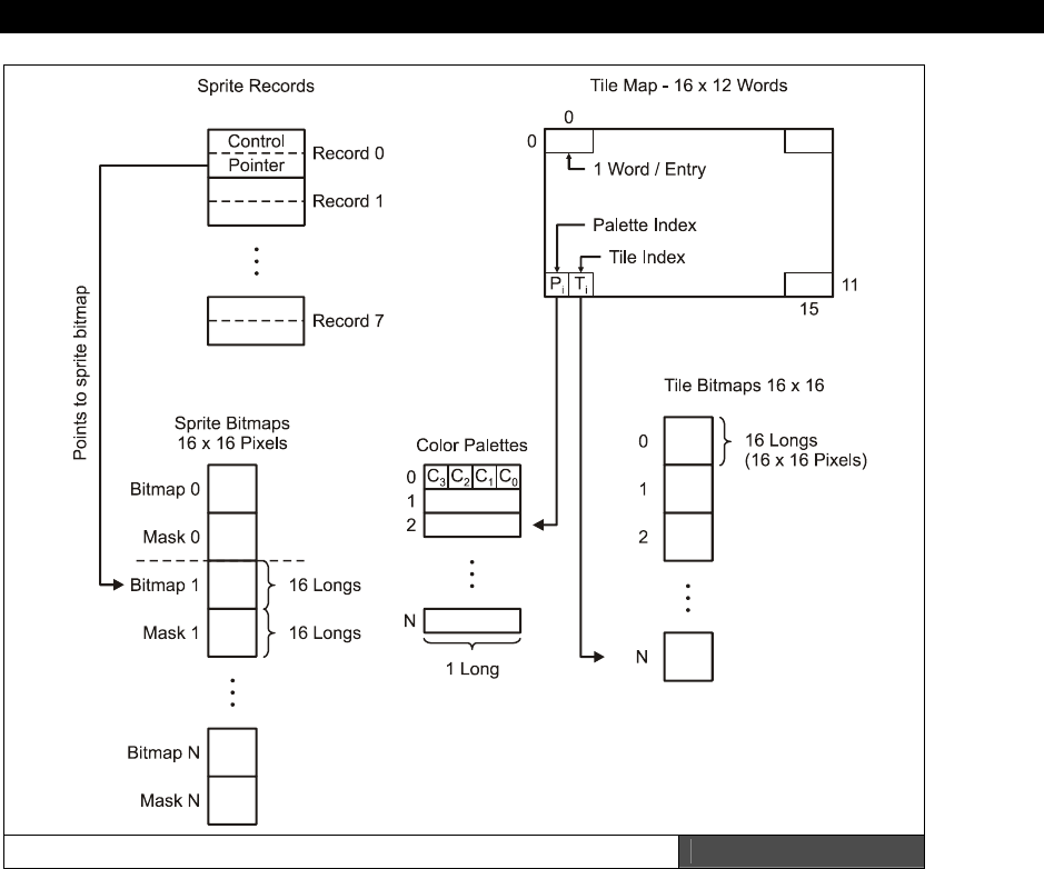
Tile Engines and Sprites 19
Game Programming for the Propeller Powered HYDRA Page 527
Graphical Depiction of Data Sructures and Parameters Figure 19:15
Parameters to Graphics Engine
long tile_map_base_ptr_parm - This is the base address of your tile map(s). The tile
map(s) must be on a WORD boundary and each tile map must be 16×12 WORDs (or larger if
scrolling is desired, but width must always be a 16, 32, 64, 128, or 256.
long tile_bitmaps_base_ptr_parm — This is the base address of the the tile bitmaps,
assumes that each tile bitmap is 16 LONGs and encoded as 2 bits per pixel. You must have at
least a single tile bitmap for the engine to operate.

III Game Programming on the HYDRA
Page 528 Game Programming for the Propeller Powered HYDRA
long tile_palettes_base_ptr_parm — This is the base address of the palette table which
is used to color each tile. Each entry in the table is exactly 1 LONG and represents one single
palette which can be indexed by each tile map entry. A minimum of one palette is needed for
the tile engine to operate.
long tile_map_sprite_cntrl_parm — This, passed by value parameters, is the control
interface to the tile/sprite engine. Currently, it only controls two features of the engine: the
width of the tile map and the number of active sprites (0..8). The control word is a single
LONG formatted as shown in Figure 19:16.
Figure 19:16
Format of Tile Engine Sprite
Control Word
Where, xx = don't care/unused.
ss = number of sprites to process 0..8.
ww = the number of "screens" or multiples of 16 that the tile map is. eg.
0 would be 16 wide (standard)
1 would be 32 tiles
2 would be 64 tiles, etc.
This allows multiscreen-width playfields and thus large horizontal/vertical scrolling games.
Note that the final size is always a power of 2, multiple of 16, such as 16, 32, 64, 128 or 256.
long tile_sprite_tbl_base_ptr_parm — This is the base address of the “sprite table” data
structure. Each sprite is composed of 2 LONGs that define its position, bitmap, and other
control aspects. More on this later. There can be up to 8 sprites, thus the data structure
pointed to by this parameter is up to 8*8 = 64 BYTEs.
long tile_status_bits_parm — Last, but not least, is the is the tile engine’s status flags.
This is passed as an address to the tile engine, so it can output real time “state” information
back to the caller. It’s mostly here for future expansion, and this particular engine only tracks
Vsync and Hsync. The bit definitions are shown in Figure 19:17.
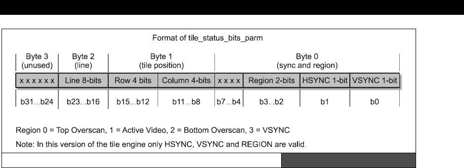
Tile Engines and Sprites 19
Game Programming for the Propeller Powered HYDRA Page 529
Bit Encoding for Tile Engine Status Bits Figure 19:17
So, all you have to do is create these data structures, instantiate a parameter list as outlined,
and then point everything correctly and start the engine up. Let’s do just that with an
example.
19.4 Using the HEL GFX 4.0 Tile Engine
I have created a number of demos to show you how to use the tile/sprite engine. Of course,
since I had to draw the art by hand with numbers, don’t expect HALO or anything! For the
first set of demos, I decided on something that looked like Pacman since it’s easy to draw
and we all have an idea of what it should look like. Moreover, Pacman-type games are good
examples of tile backgrounds with sprite foreground objects. And of course, in Pacman there
are 4 ghosts, and the player, so sprite-wise it works out great if you want to complete the
demo into a full-blown game.
Since the source code for all the demos is rather large and we are trying to save space here,
what I am going to do is show you a lot of detail on the first demo’s setup via code listings
and then as the demos progress only show code listings of the important changes. Of course,
you can always look on the CD for the full listings. So without further ado, let’s take a look at
all the demos.
19.4.1 Multiple Page Tile Engine Demo
For the first demo we are going to set up three tile pages, each 16×12 tiles, then using the
gamepad you can cycle through them. Figure 19:18 on the next page shows the three tile
pages during runtime. Left to right, it shows the first tile page, the second tile page with the
dots added, and the final tile page with the dots and power ups added. The cycling of the
pages is simply an address change and happens within one frame update. Thus, this demo
shows you how to set up the tile engine for a standard tile display, switch tile pages, and
that’s about it.
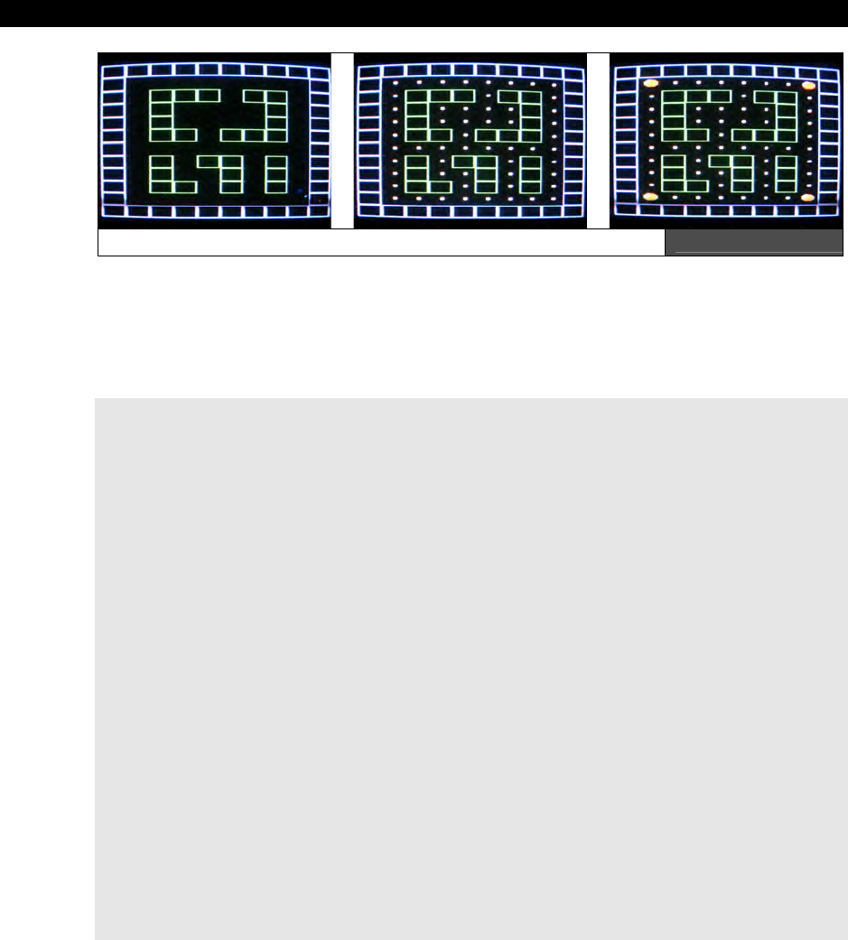
III Game Programming on the HYDRA
Page 530 Game Programming for the Propeller Powered HYDRA
A Screen Shot of the Multiple Page Tile Engine Demo Figure 19:18
You may wish to open the programs to view the complete source at a comfortable font size
as we cover aspects of it; this file’s name is PACMAN_TILE_DEMO_001.SPIN and is in
the source directory on the CD as usual. When the demo runs, simply press the <SELECT>
button on the gamepad (plugged into the left port) to cycle through tile sets. Remember, we
are NOT drawing anything new, only switching a single pointer!
DAT
tile_maps ' you place all your 16x12 tile maps here, you can have as many as you like, in real-time simply re-point the
' tile_map_base_ptr_parm to any time map and within 1 frame the tile map will update
' the engine only renders 10x12 of the tiles on the physical screen, the other 6 columns allow you some "scroll room"
' 16x12 WORDS each, (0..191 WORDs, 384 bytes per tile map) 2-BYTE tiles (msb)[palette_index | tile_index](lsb)
' 16x12 tile map, each tile is 2 bytes, there are a total of 64 tiles possible, and thus 64 palettes
'
' <---------------------------visible on screen-------------------------------->|<------ to right of screen ---------->|
' column 0 1 2 3 4 5 6 7 8 9 | 10 11 12 13 14 15
' just the maze
tile_map0 word $00_01,$00_01,$00_01,$00_01,$00_01,$00_01,$00_01,$00_01,$00_01,$00_01,$00_01,$00_01,$00_01,$00_01,$00_01,$00_01 ' row 0
word $00_01,$00_00,$00_00,$00_00,$00_00,$00_00,$00_00,$00_00,$00_00,$00_01,$00_00,$00_00,$00_00,$00_00,$00_00,$00_00 ' row 1
word $00_01,$00_00,$01_01,$01_01,$01_01,$00_00,$01_01,$01_01,$00_00,$00_01,$00_00,$00_00,$00_00,$00_00,$00_00,$00_00 ' row 2
word $00_01,$00_00,$01_01,$00_00,$00_00,$00_00,$00_00,$01_01,$00_00,$00_01,$00_00,$00_00,$00_00,$00_00,$00_00,$00_00 ' row 3
word $00_01,$00_00,$01_01,$00_00,$00_00,$00_00,$00_00,$01_01,$00_00,$00_01,$00_00,$00_00,$00_00,$00_00,$00_00,$00_00 ' row 4
word $00_01,$00_00,$01_01,$01_01,$00_00,$01_01,$01_01,$01_01,$00_00,$00_01,$00_00,$00_00,$00_00,$00_00,$00_00,$00_00 ' row 5
word $00_01,$00_00,$00_00,$00_00,$00_00,$00_00,$00_00,$00_00,$00_00,$00_01,$00_00,$00_00,$00_00,$00_00,$00_00,$00_00 ' row 6
word $00_01,$00_00,$01_01,$00_00,$01_01,$01_01,$00_00,$01_01,$00_00,$00_01,$00_00,$00_00,$00_00,$00_00,$00_00,$00_00 ' row 7
word $00_01,$00_00,$01_01,$00_00,$00_00,$01_01,$00_00,$01_01,$00_00,$00_01,$00_00,$00_00,$00_00,$00_00,$00_00,$00_00 ' row 8
word $00_01,$00_00,$01_01,$01_01,$00_00,$01_01,$00_00,$01_01,$00_00,$00_01,$00_00,$00_00,$00_00,$00_00,$00_00,$00_00 ' row 9
word $00_01,$00_00,$00_00,$00_00,$00_00,$00_00,$00_00,$00_00,$00_00,$00_01,$00_00,$00_00,$00_00,$00_00,$00_00,$00_00 ' row 10
word $00_01,$00_01,$00_01,$00_01,$00_01,$00_01,$00_01,$00_01,$00_01,$00_01,$00_01,$00_01,$00_01,$00_01,$00_01,$00_01 ' row 11
' maze plus dots
tile_map1 word $00_01,$00_01,$00_01,$00_01,$00_01,$00_01,$00_01,$00_01,$00_01,$00_01,$00_01,$00_01,$00_01,$00_01,$00_01,$00_01 ' row 0
word $00_01,$00_02,$00_02,$00_02,$00_02,$00_02,$00_02,$00_02,$00_02,$00_01,$00_00,$00_00,$00_00,$00_00,$00_00,$00_00 ' row 1
word $00_01,$00_02,$01_01,$01_01,$01_01,$00_02,$01_01,$01_01,$00_02,$00_01,$00_00,$00_00,$00_00,$00_00,$00_00,$00_00 ' row 2
word $00_01,$00_02,$01_01,$00_02,$00_02,$00_02,$00_02,$01_01,$00_02,$00_01,$00_00,$00_00,$00_00,$00_00,$00_00,$00_00 ' row 3
word $00_01,$00_02,$01_01,$00_02,$00_02,$00_02,$00_02,$01_01,$00_02,$00_01,$00_00,$00_00,$00_00,$00_00,$00_00,$00_00 ' row 4
word $00_01,$00_02,$01_01,$01_01,$00_02,$01_01,$01_01,$01_01,$00_02,$00_01,$00_00,$00_00,$00_00,$00_00,$00_00,$00_00 ' row 5
word $00_01,$00_02,$00_02,$00_02,$00_02,$00_02,$00_02,$00_02,$00_02,$00_01,$00_00,$00_00,$00_00,$00_00,$00_00,$00_00 ' row 6
word $00_01,$00_02,$01_01,$00_02,$01_01,$01_01,$00_02,$01_01,$00_02,$00_01,$00_00,$00_00,$00_00,$00_00,$00_00,$00_00 ' row 7
word $00_01,$00_02,$01_01,$00_02,$00_02,$01_01,$00_02,$01_01,$00_02,$00_01,$00_00,$00_00,$00_00,$00_00,$00_00,$00_00 ' row 8
word $00_01,$00_02,$01_01,$01_01,$00_02,$01_01,$00_02,$01_01,$00_02,$00_01,$00_00,$00_00,$00_00,$00_00,$00_00,$00_00 ' row 9
word $00_01,$00_02,$00_02,$00_02,$00_02,$00_02,$00_02,$00_02,$00_02,$00_01,$00_00,$00_00,$00_00,$00_00,$00_00,$00_00 ' row 10
word $00_01,$00_01,$00_01,$00_01,$00_01,$00_01,$00_01,$00_01,$00_01,$00_01,$00_01,$00_01,$00_01,$00_01,$00_01,$00_01 ' row 11
' maze plus powerpills
tile_map2 word $00_01,$00_01,$00_01,$00_01,$00_01,$00_01,$00_01,$00_01,$00_01,$00_01,$00_01,$00_01,$00_01,$00_01,$00_01,$00_01 ' row 0
word $00_01,$00_03,$00_02,$00_02,$00_02,$00_02,$00_02,$00_02,$00_03,$00_01,$00_00,$00_00,$00_00,$00_00,$00_00,$00_00 ' row 1
word $00_01,$00_02,$01_01,$01_01,$01_01,$00_02,$01_01,$01_01,$00_02,$00_01,$00_00,$00_00,$00_00,$00_00,$00_00,$00_00 ' row 2
word $00_01,$00_02,$01_01,$00_02,$00_02,$00_02,$00_02,$01_01,$00_02,$00_01,$00_00,$00_00,$00_00,$00_00,$00_00,$00_00 ' row 3
word $00_01,$00_02,$01_01,$00_02,$00_02,$00_02,$00_02,$01_01,$00_02,$00_01,$00_00,$00_00,$00_00,$00_00,$00_00,$00_00 ' row 4
word $00_01,$00_02,$01_01,$01_01,$00_02,$01_01,$01_01,$01_01,$00_02,$00_01,$00_00,$00_00,$00_00,$00_00,$00_00,$00_00 ' row 5
word $00_01,$00_02,$00_02,$00_02,$00_02,$00_02,$00_02,$00_02,$00_02,$00_01,$00_00,$00_00,$00_00,$00_00,$00_00,$00_00 ' row 6
word $00_01,$00_02,$01_01,$00_02,$01_01,$01_01,$00_02,$01_01,$00_02,$00_01,$00_00,$00_00,$00_00,$00_00,$00_00,$00_00 ' row 7
word $00_01,$00_02,$01_01,$00_02,$00_02,$01_01,$00_02,$01_01,$00_02,$00_01,$00_00,$00_00,$00_00,$00_00,$00_00,$00_00 ' row 8
word $00_01,$00_02,$01_01,$01_01,$00_02,$01_01,$00_02,$01_01,$00_02,$00_01,$00_00,$00_00,$00_00,$00_00,$00_00,$00_00 ' row 9
word $00_01,$00_03,$00_02,$00_02,$00_02,$00_02,$00_02,$00_02,$00_03,$00_01,$00_00,$00_00,$00_00,$00_00,$00_00,$00_00 ' row 10
word $00_01,$00_01,$00_01,$00_01,$00_01,$00_01,$00_01,$00_01,$00_01,$00_01,$00_01,$00_01,$00_01,$00_01,$00_01,$00_01 ' row 11
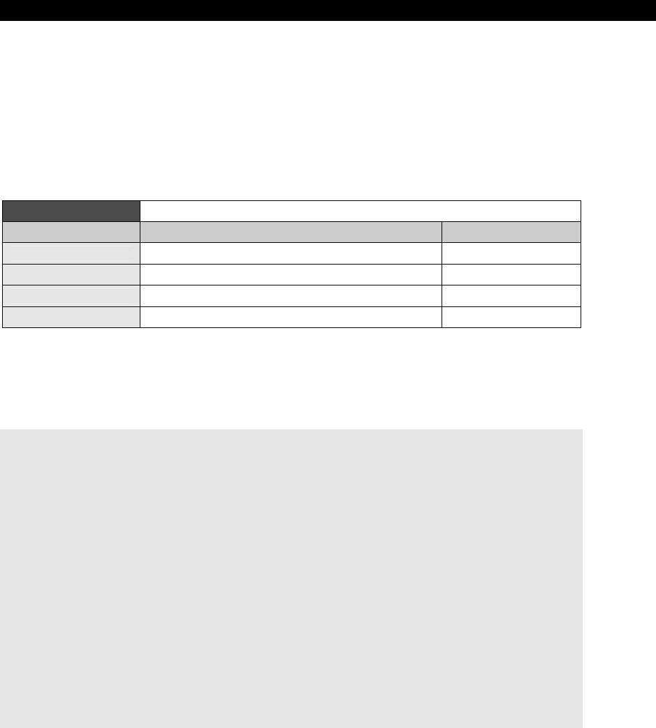
Tile Engines and Sprites 19
Game Programming for the Propeller Powered HYDRA Page 531
As you can see there are three tile maps, each 16×12 WORDs, where each WORD is a single
tile entry. Each tile map is complete and represents an entire screen of data that can be
displayed by the engine, and we can flip or cycle through them at will by changing a single
pointer. Now, take a look closely at the tile map data for the last tile map “tile_map2” and
note that the left most BYTE of each WORD is of course the palette index for the tile (most of
them are $00), while the rightmost BYTE is the actual tile index, in this it case ranges from
$00 - $03, where these codes represent the following tiles as shown in Table 19:3 along with
the label names of the actual bitmap data.
Table 19:3 Tile Code Representations and Data Structures
Tile Code Represents Bitmap Data Name
$00 Blank tile used for background tile_blank
$01 Box tile used to draw the maze geometry tile_box
$02 Dot tile used to draw the maxe dots tile_dot
$03 Powerup tile used to draw the 4 powerups tile_powerup
So referring to Table 19:3, we see that tile index $01 for example means use the bitmap
from “tile_box.” This bitmap and all the others must be 16 LONGs that define the bitmaps for
the actual tiles. Here’s the actual declaration for the first two tile bitmaps “tile_blank” and
“tile_box”:
tile_bitmaps long
' tile bitmap memory, each tile 16x16 pixels, or 1 LONG by 16,
' 64-bytes each, also, note that they are mirrored right to left
' since the VSU streams from low to high bits, so your art must
' be reflected, we could remedy this in the engine, but for fun
' I leave it as a challenge in the art, since many engines have
' this same artifact (feature:)
' empty tile
tile_blank long %%0_0_0_0_0_0_0_0_0_0_0_0_0_0_0_0 ' tile 0
long %%0_0_0_0_0_0_0_0_0_0_0_0_0_0_0_0
long %%0_0_0_0_0_0_0_0_0_0_0_0_0_0_0_0
long %%0_0_0_0_0_0_0_0_0_0_0_0_0_0_0_0
long %%0_0_0_0_0_0_0_0_0_0_0_0_0_0_0_0
long %%0_0_0_0_0_0_0_0_0_0_0_0_0_0_0_0
long %%0_0_0_0_0_0_0_0_0_0_0_0_0_0_0_0
long %%0_0_0_0_0_0_0_0_0_0_0_0_0_0_0_0
long %%0_0_0_0_0_0_0_0_0_0_0_0_0_0_0_0
long %%0_0_0_0_0_0_0_0_0_0_0_0_0_0_0_0
long %%0_0_0_0_0_0_0_0_0_0_0_0_0_0_0_0
long %%0_0_0_0_0_0_0_0_0_0_0_0_0_0_0_0
long %%0_0_0_0_0_0_0_0_0_0_0_0_0_0_0_0
long %%0_0_0_0_0_0_0_0_0_0_0_0_0_0_0_0
long %%0_0_0_0_0_0_0_0_0_0_0_0_0_0_0_0
long %%0_0_0_0_0_0_0_0_0_0_0_0_0_0_0_0

III Game Programming on the HYDRA
Page 532 Game Programming for the Propeller Powered HYDRA
' box segment
tile_box long %%1_1_1_1_1_1_1_1_1_1_1_1_1_1_1_1 ' tile 1
long %%1_0_0_0_0_0_0_0_0_0_0_0_0_0_0_1
long %%1_0_0_0_0_0_0_0_0_0_0_0_0_0_0_1
long %%1_0_0_0_0_0_0_0_0_0_0_0_0_0_0_1
long %%1_0_0_0_0_0_0_0_0_0_0_0_0_0_0_1
long %%1_0_0_0_0_0_0_0_0_0_0_0_0_0_0_1
long %%1_0_0_0_0_0_0_0_0_0_0_0_0_0_0_1
long %%1_0_0_0_0_0_0_0_0_0_0_0_0_0_0_1
long %%1_0_0_0_0_0_0_0_0_0_0_0_0_0_0_1
long %%1_0_0_0_0_0_0_0_0_0_0_0_0_0_0_1
long %%1_0_0_0_0_0_0_0_0_0_0_0_0_0_0_1
long %%1_0_0_0_0_0_0_0_0_0_0_0_0_0_0_1
long %%1_0_0_0_0_0_0_0_0_0_0_0_0_0_0_1
long %%1_0_0_0_0_0_0_0_0_0_0_0_0_0_0_1
long %%1_0_0_0_0_0_0_0_0_0_0_0_0_0_0_1
long %%1_1_1_1_1_1_1_1_1_1_1_1_1_1_1_1
If you blur your eyes, you will easily be able to see the single wide pixel border in the box
tile. Alright, so that’s the data structures for the tiles; of course the dot and powerup are
defined in the demo as well. Next, we need those palettes. When you run the program, you
will see that there is a bit of color, so more than one palette is needed. As explained in the
design discussions above, we know that each palette (up to 256 of them) represents the 4
colors that any tile can use via bit code 00, 01, 10,11. The palettes are a single LONG each,
with one BYTE representing each color in VSU format, low BYTE is color 0, high BYTE is color
3. Here are the actual palettes for this demo:
' some pacman palettes...
palette_map long $07_5C_0C_02 ' palette 0 - background and wall tiles, 0-black,
' 1-blue, 2-red, 3-white
long $07_5C_BC_02 ' palette 1 - background and wall tiles, 0-black,
' 1-green, 2-red, 3-white
That completes the outline of the data structures, now let’s see how they are used by the
engine setup. First, assuming that the VAR section has the set of the 6 parameters we need
defined, then of course the tile engine object needs to be instantiated like so (along with the
gamepad driver in this case):
OBJ
game_pad : "gamepad_drv_001.spin"
gfx: "HEL_GFX_ENGINE_040.SPIN"
...and we are ready to go. So we need to make the following connections before starting the
tile engine:
1. Point the tile map pointer to the tile map we want displayed.
2. Point the tile bitmap(s) pointer to the base of the tile bitmap definitions.
3. Point the tile palette(s) pointer to the base of the tile palettes.
4. Set the tile/sprite engine control parameters.

Tile Engines and Sprites 19
Game Programming for the Propeller Powered HYDRA Page 533
5. Point the sprite bitmap pointer to the base of the sprite bitmap data (0 for now).
6. Point the sprite data structure pointer to the base of the sprites records themselves
(0 for now).
The last two steps we still have to do even though we aren’t using sprites yet. The following
code excerpt shows how this is all done in the demo:
' set up tile and sprite engine data before starting it, so no ugly startup
' points ptrs to actual memory storage for tile engine
tile_map_base_ptr_parm := @tile_map0
tile_bitmaps_base_ptr_parm := @tile_bitmaps
tile_palettes_base_ptr_parm := @palette_map
' these control the sprite engine, all 0 for now, no sprites
tile_map_sprite_cntrl_parm := $00_00 ' 0 sprites, tile map set to 0,
' where 0=16 tiles wide
' 1=32 tiles, 2=64 tiles, etc.
tile_sprite_tbl_base_ptr_parm := 0
tile_status_bits_parm := 0
Then last but not least we call the “start” method of the tile engine object with the address
of the first parameter in the parameter passing area, and it will start running.
' launch a COG with ASM video driver
gfx.start(@tile_map_base_ptr_parm)
At this point, we should see the first tile map as shown in Figure 19:18(left) on the TV
screen. Now, the next step is to control the current page shown, this is nothing more than a
matter of reading the controller input and cycling through the pages of tiles. Here’s the entire
main event loop that does that:
' enter main event loop...
repeat while 1
' main even loop code here...
if (game_pad.button(NES0_SELECT))
' select next tile map...
if (++tile_map_index > 2)
tile_map_index := 0
' set proper tile map (can you think of another way to do this?
' lookup, or fixed math offsets?)
case tile_map_index
0:
tile_map_base_ptr_parm := @tile_map0
1:
tile_map_base_ptr_parm := @tile_map1
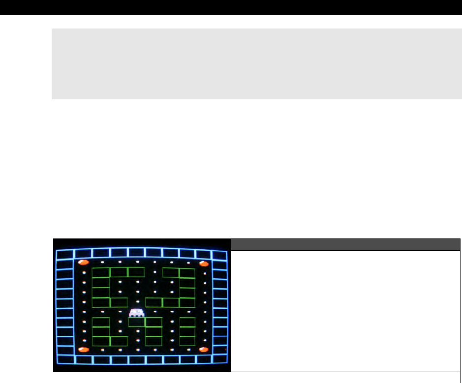
III Game Programming on the HYDRA
Page 534 Game Programming for the Propeller Powered HYDRA
2:
tile_map_base_ptr_parm := @tile_map2
' wait a moment...
repeat 100_000
' return back to repeat main event loop...
Pretty cool huh? In 10 lines of code or so, we are flipping through multiple pages of tiles
which in this case are not that exciting, but they could be levels in an adventure game, or
rooms, or whatever. The code that actually makes the change is in the
case
statement, any
change made to
tile_map_base_ptr
will be shown on the next frame, since the tile engine
is “watching” this pointer. Thus, this simple memory-mapped interface works quite well to
control the engine without a bunch of function calls! Anyway, make sure to take a close look
at the whole program in its entirety PACMAN_TILE_DEMO_002.SPIN. Now, let’s move on
to something a little more exciting…
19.4.2 Moving a Tile Based Character Around the Screen
Figure 19:19
A Screen Shot of our Tile Based Ghost
Character Moving Around on the Tile Map
For the next demo, we are going to move an object around the tile map. Figure 19:19 shows
a screen shot of the next demo for this section running. The demo’s name is
PACMAN_TILE_DEMO_002.SPIN and it’s almost identical to the last demo except for the
fact that I have added a ghost that you can move around. I know, I know, in Pacman you
control the little yellow pacman, but I like being the bad guy, so we are the ghost! In any
event, there are a couple important concepts to understand that are brought to light by this
demo. The first is that, as noted before when working with tile graphics, we can only move a
tile-based object a tile at a time, we can’t move it on sub-tile boundaries. Go ahead and play
with the demo to see this for yourself, run PACMAN_TILE_DEMO_002.SPIN and control
the ghost with the gamepad’s dpad. See how it only moves a whole tile in each direction?
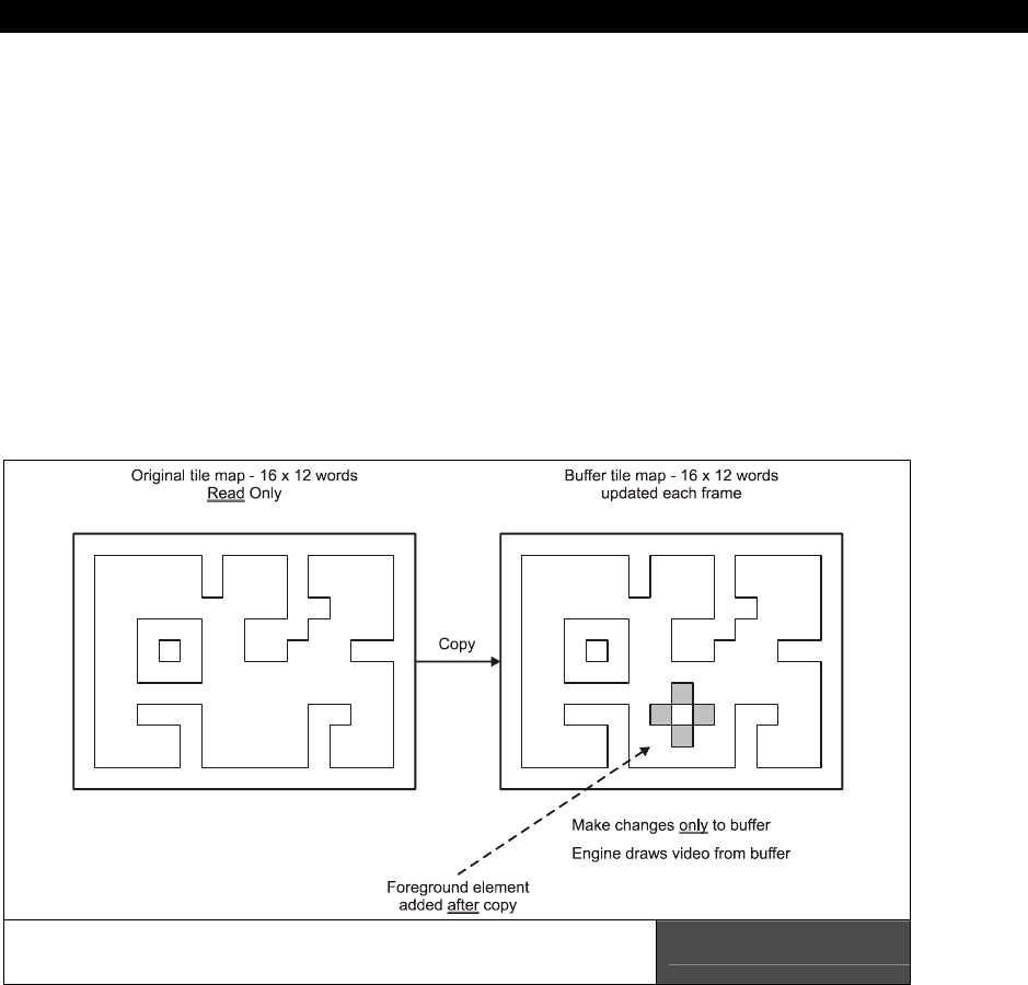
Tile Engines and Sprites 19
Game Programming for the Propeller Powered HYDRA Page 535
This is “ok” but it would be much nicer if it were smooth depending on your goals for
gameplay and taste. Nonetheless, without sprites, we have quite a powerful engine here
even with moving objects on tile boundaries. Also notice that as the ghost moves it
“destroys” the tiles under it. This is because I purposely didn’t “save” them, I simply
overwrote the actual tile map data itself with the ghost tile and when I move the ghost tile, I
put a blank in its last position. This is a destructive form of animation, and if it’s what you
want then great, otherwise, you have to use an another approach if you don’t want the tiles
disturbed. Basically, the destructive motion algorithm is:
Destructive Tile Map Motion
If player moves ghost then…
1. Draw a blank where ghost is right into tile map data.
2. Move ghost’s coordinates based on controller’s input.
3. Draw ghost at new position right into tile map data overwriting data there.
Using a Tile Map Buffer to Support
Non-Destructive Animation and Foreground Objects Figure 19:20
But, if you don’t want to disturb the tiles then you have to do something different. For
example, save the tile under the ghost, or maybe
copy
the entire tile map to a buffer each
frame, then draw on top of the buffer destructively with the ghost or whatever, then point
the tile map engine to the buffer instead of the source data. This way you never loose your

III Game Programming on the HYDRA
Page 536 Game Programming for the Propeller Powered HYDRA
source tile map or destroy or damage it in any way. The only cost of the method is the
memory for the tile map buffer (small) and the copy operation (small). All in all, this is the
easiest way to perform complex layered animation with tile engines. Simply create a tile
buffer, copy your source tile map into each frame, copy your foreground tiles onto it, then
point your tile map engine base point to it, and presto, perfect, flicker-free animation (we will
get to this later on with a demo as well). Figure 19:20 shows this architecture graphically.
Now that you know what we are doing, let’s see the important code changes. First, we are
simply going to use the 3rd tile map set, but the data is the same, so the tile map data is just
like it was in the last demo. The only addition really is the new ghost character; we need a
tile bitmap for it, which is down in the DAT section of the demo source. But, I have added a
little feature to make this demo a little more interesting and that is to have 4 different
bitmaps for the ghost, each with the ghost’s eyes pointing in one of four directions: right,
left, up and down (more or less), thus we need 4 bitmaps to make this happen, here they
are:
' a ghost with eyes to left
tile_ghost_lt long %%0_0_0_0_0_0_0_0_0_0_0_0_0_0_0_0 ' tile 4
long %%0_0_0_0_0_0_0_0_0_0_0_0_0_0_0_0
long %%0_0_0_0_0_2_2_2_2_2_2_0_0_0_0_0
long %%0_0_0_2_2_2_2_2_2_2_2_2_2_0_0_0
long %%0_0_0_2_2_2_2_2_2_2_2_2_2_0_0_0
long %%0_0_2_3_3_3_3_2_2_3_3_3_3_2_0_0
long %%0_0_2_3_3_3_3_2_2_3_3_3_3_2_0_0
long %%0_0_2_3_3_1_1_2_2_3_3_1_1_2_0_0
long %%0_0_2_3_3_1_1_2_2_3_3_1_1_2_0_0
long %%0_0_2_2_2_2_2_2_2_2_2_2_2_2_0_0
long %%0_2_2_2_2_2_2_2_2_2_2_2_2_2_2_0
long %%0_2_2_2_2_2_2_2_2_2_2_2_2_2_2_0
long %%0_2_2_2_2_2_2_2_2_2_2_2_2_2_2_0
long %%0_2_2_0_0_2_2_0_0_2_2_0_0_2_2_0
long %%0_2_2_0_0_2_2_0_0_2_2_0_0_2_2_0
long %%0_0_0_0_0_0_0_0_0_0_0_0_0_0_0_0
' a ghost with eyes to right
tile_ghost_rt long %%0_0_0_0_0_0_0_0_0_0_0_0_0_0_0_0 ' tile 5
long %%0_0_0_0_0_0_0_0_0_0_0_0_0_0_0_0
long %%0_0_0_0_0_2_2_2_2_2_2_0_0_0_0_0
long %%0_0_0_2_2_2_2_2_2_2_2_2_2_0_0_0
long %%0_0_0_2_2_2_2_2_2_2_2_2_2_0_0_0
long %%0_0_2_3_3_3_3_2_2_3_3_3_3_2_0_0
long %%0_0_2_3_3_3_3_2_2_3_3_3_3_2_0_0
long %%0_0_2_1_1_3_3_2_2_1_1_3_3_2_0_0
long %%0_0_2_1_1_3_3_2_2_1_1_3_3_2_0_0
long %%0_0_2_2_2_2_2_2_2_2_2_2_2_2_0_0
long %%0_2_2_2_2_2_2_2_2_2_2_2_2_2_2_0
long %%0_2_2_2_2_2_2_2_2_2_2_2_2_2_2_0
long %%0_2_2_2_2_2_2_2_2_2_2_2_2_2_2_0
long %%0_2_2_0_0_2_2_0_0_2_2_0_0_2_2_0
long %%0_2_2_0_0_2_2_0_0_2_2_0_0_2_2_0
long %%0_0_0_0_0_0_0_0_0_0_0_0_0_0_0_0
' a ghost with eyes up
tile_ghost_up long %%0_0_0_0_0_0_0_0_0_0_0_0_0_0_0_0 ' tile 6

Tile Engines and Sprites 19
Game Programming for the Propeller Powered HYDRA Page 537
long %%0_0_0_0_0_0_0_0_0_0_0_0_0_0_0_0
long %%0_0_0_0_0_2_2_2_2_2_2_0_0_0_0_0
long %%0_0_0_2_2_2_2_2_2_2_2_2_2_0_0_0
long %%0_0_0_2_2_2_2_2_2_2_2_2_2_0_0_0
long %%0_0_2_3_3_1_1_2_2_3_3_1_1_2_0_0
long %%0_0_2_3_3_1_1_2_2_3_3_1_1_2_0_0
long %%0_0_2_3_3_3_3_2_2_3_3_3_3_2_0_0
long %%0_0_2_3_3_3_3_2_2_3_3_3_3_2_0_0
long %%0_0_2_2_2_2_2_2_2_2_2_2_2_2_0_0
long %%0_2_2_2_2_2_2_2_2_2_2_2_2_2_2_0
long %%0_2_2_2_2_2_2_2_2_2_2_2_2_2_2_0
long %%0_2_2_2_2_2_2_2_2_2_2_2_2_2_2_0
long %%0_2_2_0_0_2_2_0_0_2_2_0_0_2_2_0
long %%0_2_2_0_0_2_2_0_0_2_2_0_0_2_2_0
long %%0_0_0_0_0_0_0_0_0_0_0_0_0_0_0_0
' a ghost with eyes down
tile_ghost_dn long %%0_0_0_0_0_0_0_0_0_0_0_0_0_0_0_0 ' tile 7
long %%0_0_0_0_0_0_0_0_0_0_0_0_0_0_0_0
long %%0_0_0_0_0_2_2_2_2_2_2_0_0_0_0_0
long %%0_0_0_2_2_2_2_2_2_2_2_2_2_0_0_0
long %%0_0_0_2_2_2_2_2_2_2_2_2_2_0_0_0
long %%0_0_2_3_3_3_3_2_2_3_3_3_3_2_0_0
long %%0_0_2_3_3_3_3_2_2_3_3_3_3_2_0_0
long %%0_0_2_1_1_3_3_2_2_1_1_3_3_2_0_0
long %%0_0_2_1_1_1_3_2_2_1_1_1_3_2_0_0
long %%0_0_2_2_2_2_2_2_2_2_2_2_2_2_0_0
long %%0_2_2_2_2_2_2_2_2_2_2_2_2_2_2_0
long %%0_2_2_2_2_2_2_2_2_2_2_2_2_2_2_0
long %%0_2_2_2_2_2_2_2_2_2_2_2_2_2_2_0
long %%0_2_2_0_0_2_2_0_0_2_2_0_0_2_2_0
long %%0_2_2_0_0_2_2_0_0_2_2_0_0_2_2_0
long %%0_0_0_0_0_0_0_0_0_0_0_0_0_0_0_0
Again, try blurring your eyes and starring at the page a moment and you will see the ghosts
and even their eyes! To make the ghost move around, we need some variable to track its tile
position along with a state variable to track which way the ghost is looking (or was moved
last). Then we simply take that state variable and add it to the base of tile index of the
ghost tiles (4 in this case), and write it right into the tile map data, and presto you will see
the ghost moving around the tile map maze. Lastly, to add a little more color, I added
another palette to the demo, so the ghost also destroys not only the tile index it is drawn on,
but purposely overwrites the tile’s palette index as well. Here are the new palettes:
' some pacman palettes...
palette_map long $07_5C_0C_02 ' palette 0 - background and wall tiles, 0-black,
' 1-blue, 2-red, 3-white
long $07_5C_BC_02 ' palette 1 - background and wall tiles, 0-black,
' 1-green, 2-red, 3-white
long $07_2C_0C_02 ' palette 2 - background and wall tiles, 0-black,
' 1-green, 2-voilet, 3-white
The ghost’s palette index is “$02”, so you will see this updates in the ghost data write as
well. Taking all this into consideration, here’s the main even loop that does everything:

III Game Programming on the HYDRA
Page 538 Game Programming for the Propeller Powered HYDRA
' enter main event loop...
repeat while 1
' main even loop code here...
' draw the ghost tile by overwriting the screen tile word destructively, both
' the palette index and the tile index
' note the add of "ghost_dir", this modifies the tiles, so we can see the ghost
' turn right, left, up, down as he moves.
' test if player is trying to move ghost, if so write a blank tile at current
' location overwriting tile index and palette, then move ghost
if (game_pad.button(NES0_RIGHT))
' clear tile
tile_map2[ghost_tx + ghost_ty << 4] := $02_00
' move ghost
ghost_tx++
' set eye direction, which affects tile selected during rendering.
ghost_dir := GHOST_TILE_RIGHT
if (game_pad.button(NES0_LEFT))
' clear tile
tile_map2[ghost_tx + ghost_ty << 4] := $02_00
' move ghost
ghost_tx--
' set eye direction, which affects tile selected during rendering.
ghost_dir := GHOST_TILE_LEFT
if (game_pad.button(NES0_UP))
' clear tile
tile_map2[ghost_tx + ghost_ty << 4] := $02_00
' move ghost
ghost_ty--
' set eye direction, which affects tile selected during rendering.
ghost_dir := GHOST_TILE_UP
if (game_pad.button(NES0_DOWN))
' clear tile
tile_map2[ghost_tx + ghost_ty << 4] := $02_00
' move ghost
ghost_ty++
' set eye direction, which affects tile selected during rendering.
ghost_dir := GHOST_TILE_DOWN
' bounds check ghost, keep it on screen, use SPIN operators for bounds testing
ghost_tx <#= 9 ' if (ghost_tx > 9) then ghost_tx = 9
ghost_tx #>= 0 ' if (ghost_tx < 0) then ghost_tx = 0
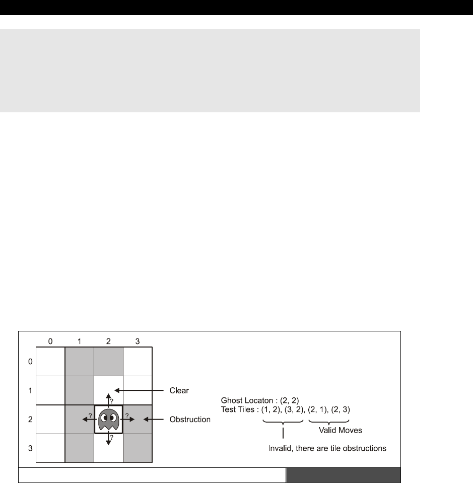
Tile Engines and Sprites 19
Game Programming for the Propeller Powered HYDRA Page 539
ghost_ty <#= 11 ' if (ghost_ty > 11) then ghost_tx = 11
ghost_ty #>= 0 ' if (ghost_ty < 0) then ghost_ty = 0
' draw ghost down
tile_map2[ghost_tx + ghost_ty << 4] := $02_04 + ghost_dir
' delay a moment, otherwise everything will blur!
repeat 20_000
The main loop is nothing more than a gamepad query, where each direction has a small code
body that updates the direction of the ghost, the tile map, and actual position of the ghost.
The last section of code does some bounds-checking and if the ghost is off the tile screen
wraps him around, lastly one last render pass is done and the ghost is drawn on the screen.
Also, there is a little time delay to slow the process down since moving a single tile around is
really
fast! Try commenting out the delay code and see how fast Spin moves the ghost.
Imagine all the tile based games you can make with Spin and this little tile engine!
Moving forward, the demo is pretty brutal to the poor maze. The next step is to add some
kind of collision detection with the ghost and the maze, and if the ghost is banging into a
wall of the maze we don’t want the ghost to go through it. On the other hand, if the ghost is
eating up dots or powerups, that is perfectly legitimate. Thus, we need to add some code to
make this happen that tests where the ghost is trying to go, and if there is a wall there, the
ghost is backed up. This is implement by simply saving the current tile position of the ghost,
then computing where the player is trying to move the ghost, and testing that tile; if the tile
is a wall, the move is disregarded, else the move is allowed.
Simple Tile-Based Collision Detection Algorithm Figure 19:21
Figure 19:21 shows this graphically. To see this algorithm in action take a look at the next
demo PACMAN_TILE_DEMO_003.SPIN. Go ahead and load it into the HYDRA and try

III Game Programming on the HYDRA
Page 540 Game Programming for the Propeller Powered HYDRA
moving the ghost around the game maze. As you can see, it can’t go through walls anymore,
but it eats the dots and powerups as it should. Of course, the ghost doesn’t “know” it’s
eating dots and powerups, but this is easy to code as well, you simply test the tile the ghost
is moving into and if it’s a dot, you give the player some points, and if it’s a powerup, you do
whatever the “powerup” does! The code that implements all this motion and collision control
from the demo is listed below for you reference:
' enter main event loop...
repeat while 1
' main even loop code here...
' draw the ghost tile by overwriting the screen tile word destructively, both
' the palette index and the tile index
' note the add of "ghost_dir", this modifies the tiles, so we can see the ghost
' turn right, left, up, down as he moves.
' test if player is trying to move ghost, if so write a blank tile at current
' location overwriting tile index and palette, then move ghost
' store old ghost position in case we need to back up
old_ghost_tx := ghost_tx
old_ghost_ty := ghost_ty
' now move ghost, ok to obliterate tile he is on always
if (game_pad.button(NES0_RIGHT))
' move ghost
ghost_tx++
' set eye direction, which affects tile selected during rendering.
ghost_dir := GHOST_TILE_RIGHT
if (game_pad.button(NES0_LEFT))
' move ghost
ghost_tx--
' set eye direction, which affects tile selected during rendering.
ghost_dir := GHOST_TILE_LEFT
if (game_pad.button(NES0_UP))
' move ghost
ghost_ty--
' set eye direction, which affects tile selected during rendering.
ghost_dir := GHOST_TILE_UP
if (game_pad.button(NES0_DOWN))
' move ghost
ghost_ty++
' set eye direction, which affects tile selected during rendering.

Tile Engines and Sprites 19
Game Programming for the Propeller Powered HYDRA Page 541
ghost_dir := GHOST_TILE_DOWN
{ we can add "PLAYFIELD" collision detection here, the idea is simple in tile
graphics test where the player is going and if he is going to intersect a solid
object then back him up to his previous position, a number of ways to code it, up
to you }
' test tile player is about to be rendered on, if background tile(s) is there
' back him up!
' retrieve tile only
test_tile := (tile_map2[ghost_tx + ghost_ty << 4] & $00_FF)
if (test_tile == $01) ' tile index of background tile
' reset position, player is trying to drive through a wall!
ghost_tx := old_ghost_tx
ghost_ty := old_ghost_ty
else
' clear the old tile position
tile_map2[old_ghost_tx + old_ghost_ty << 4] := $02_00
' bounds check ghost, keep it on screen, use SPIN operators for bounds testing
ghost_tx <#= 9 ' if (ghost_tx > 9) then ghost_tx = 9
ghost_tx #>= 0 ' if (ghost_tx < 0) then ghost_tx = 0
ghost_ty <#= 11 ' if (ghost_ty > 11) then ghost_tx = 11
ghost_ty #>= 0 ' if (ghost_ty < 0) then ghost_ty = 0
' draw ghost down at new position
tile_map2[ghost_tx + ghost_ty << 4] := $02_04 + ghost_dir
' delay a moment, otherwise everything will blur!
repeat 20_000
Well, that’s about it for basic tile graphics, later we will see scrolling and other special effects
as we need them through the book, but you have more than enough now to create a
multitude of tile based games. With that in mind, let’s move onto adding sprites into the
display.
19.4.3 Adding Sprites to the Tile Engine
Adding sprites to the tile engine is easy since they are already in there more or less, we
simply haven’t turned them on. The important data structure pointers are once again these
variables:
tile_map_sprite_cntrl_parm
tile_sprite_tbl_base_ptr_parm

III Game Programming on the HYDRA
Page 542 Game Programming for the Propeller Powered HYDRA
...where the first controls the tile / sprite itself, and the second is the pointer to the base of
the sprite bitmaps, so all we need to do is indicate there are 1 or more sprites via the
tile_map_sprite_cntrl_parm
variable, and point
tile_sprite_tbl_base_ptr_parm
to the
sprite records themselves (which are each two LONGs) and that’s about it. Of course, we
need one or more sprite bitmaps (and mask), but that’s it. So let’s do this step by step with
another demo as the platform. Take a look at demo PACMAN_TILE_DEMO_004.SPIN, go
ahead and run it and you will see the ghost sprite on the screen, try moving it around
now…see how smoothly it moves, and it clips to the edges of the screen. This is a sprite, and
they are pretty cool. Also, note that the “eyes” of the ghost use the same color as the
foreground objects, so as the ghost moves over tiles, you will see his eyes change colors.
This is unavoidable since each sprite only gets 3 colors, but I call it a “feature” ☺.
The sprite demo itself implements the changes discussed in the paragraph above, so let’s
take a look at the code elements one by one. First off we need the ghost bitmap
and
we
need the ghost mask. Here they are from the demo:
' sprite bitmap table
' each bitmap is 16x16 pixels, 1 long x 16 longs
' bitmaps are reflected left to right, so keep that in mind
' they are numbered for reference only and any bitmap can be assigned to any sprite through the use of
' the sprite pointer in the sprite header, this allows easy animation without data movement
' additionally, each sprite needs a "mask" to help the rendering engine, computation of the mask is
' too time sensitive, thus the mask must follow immediately after the sprite
sprite_bitmaps long
' bitmap for sprite use, uses the palette of the tile its rendered into
sprite_bitmap_0 long %%0_0_0_0_0_0_0_0_0_0_0_0_0_0_0_0
long %%0_0_0_0_0_0_0_0_0_0_0_0_0_0_0_0
long %%0_0_0_0_0_2_2_2_2_2_2_0_0_0_0_0
long %%0_0_0_2_2_2_2_2_2_2_2_2_2_0_0_0
long %%0_0_0_2_2_2_2_2_2_2_2_2_2_0_0_0
long %%0_0_2_3_3_3_3_2_2_3_3_3_3_2_0_0
long %%0_0_2_3_3_3_3_2_2_3_3_3_3_2_0_0
long %%0_0_2_1_1_3_3_2_2_1_1_3_3_2_0_0
long %%0_0_2_1_1_3_3_2_2_1_1_3_3_2_0_0
long %%0_0_2_2_2_2_2_2_2_2_2_2_2_2_0_0
long %%0_2_2_2_2_2_2_2_2_2_2_2_2_2_2_0
long %%0_2_2_2_2_2_2_2_2_2_2_2_2_2_2_0
long %%0_2_2_2_2_2_2_2_2_2_2_2_2_2_2_0
long %%0_2_2_0_0_2_2_0_0_2_2_0_0_2_2_0
long %%0_2_2_0_0_2_2_0_0_2_2_0_0_2_2_0
long %%0_0_0_0_0_0_0_0_0_0_0_0_0_0_0_0
' the mask needs to be a NEGATIVE of the bitmap, basically a stencil where we are going to write the
' sprite into, all the values are 0 (mask) or 3 (write thru) however, the algorithm needs a POSITIVE to
' make some of the shifting easier, so we only need to apply the rule to each pixel of the bitmap:
' if (p_source == 0) p_dest = 0, else p_dest = 3

Tile Engines and Sprites 19
Game Programming for the Propeller Powered HYDRA Page 543
sprite_bitmap_mask_0 long %%0_0_0_0_0_0_0_0_0_0_0_0_0_0_0_0
long %%0_0_0_0_0_0_0_0_0_0_0_0_0_0_0_0
long %%0_0_0_0_0_3_3_3_3_3_3_0_0_0_0_0
long %%0_0_0_3_3_3_3_3_3_3_3_3_3_0_0_0
long %%0_0_0_3_3_3_3_3_3_3_3_3_3_0_0_0
long %%0_0_3_3_3_3_3_3_3_3_3_3_3_3_0_0
long %%0_0_3_3_3_3_3_3_3_3_3_3_3_3_0_0
long %%0_0_3_3_3_3_3_3_3_3_3_3_3_3_0_0
long %%0_0_3_3_3_3_3_3_3_3_3_3_3_3_0_0
long %%0_0_3_3_3_3_3_3_3_3_3_3_3_3_0_0
long %%0_3_3_3_3_3_3_3_3_3_3_3_3_3_3_0
long %%0_3_3_3_3_3_3_3_3_3_3_3_3_3_3_0
long %%0_3_3_3_3_3_3_3_3_3_3_3_3_3_3_0
long %%0_3_3_0_0_3_3_0_0_3_3_0_0_3_3_0
long %%0_3_3_0_0_3_3_0_0_3_3_0_0_3_3_0
long %%0_0_0_0_0_0_0_0_0_0_0_0_0_0_0_0
Take a close look at the sprite bitmap at the top of the listing, this is the actual sprite data
where color 0 means transparent, and colors 1,2,3 mean use colors 1,2,3 from the palette
index entry for that tile. Thus a sprite can change colors as it moves based on the tiles it’s
on. Anyway, the sprite bitmap is straightforward, but the bitmap
mask
takes a bit of
explanation.
19.4.3.1 Bitmap Masks
When you write bitmapped graphics engines you very quickly come to the realization, that
computers aren’t magical, and they have no idea what you want, thus you have to do
everything
yourself, you are responsible literally for every pixel on the screen. This means
that such a seemingly simple operation as drawing a sprite on top of the tiles is very hard.
The reason why is that there is a lot of data there; we have the tile bitmap data, and the
sprite bitmap data, to combine them we just can’t overwrite the data. We first must make a
“hole”
where we want the sprite to go in the tile data. To make matters worse, this is all
happening line by line, tile by tile, plus throw in caching and speed requirements and you
end up with the Mensa entrance exam more or less!
Given that, one of the operations needed is to write one bitmap on another without
disturbing the bitmap underneath; in the areas that are supposedly transparent in the top
bitmap, you have to mask off the bitmap under the operation, then logically OR the new
bitmap data into the zero’ed out hole. Of course, you can do this with pure code and derive
the mask on the fly, but this takes a little more time than we have with this sprite engine,
plus I wanted you to see this since its very common on gaming consoles and graphics
hardware to have to supply you own masks. Even Microsoft Windows needs masks for
cursors and whatnot!
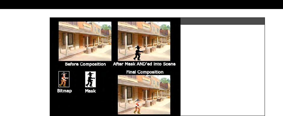
III Game Programming on the HYDRA
Page 544 Game Programming for the Propeller Powered HYDRA
Figure 19:22
Bitmap Mask Operations
Shown Graphically
Anyway, it’s best to start with a drawing so you can see what we need to do graphically, take
a look at Figure 19:22. Referring to the figure, you see a background that we want to draw a
sprite into, then you see a mask that looks like a shadow of the sprite. The mask is used to
cut the hole out via a logical AND operation, then once the hole is cut out, we logically OR
the sprite data into the background and everything looks correct. This is what the mask
bitmap is for, to cut a hole (if you are a Photoshop person then you do this all the time). The
format of the mask for this engine is simple: you copy your original bitmap, then anywhere
you have a non-zero value you make it 3, this more or less create a 2-bit positive mask
everyone there is color, and since 0 represents transparent this works fine. The engine take
the bitmap and the mask for the sprite and does the rest.
So the tradeoff is that for every 64-BYTE sprite we need a 64-BYTE mask. However, if I was
smarter in my data structures, then we could have a separate pointer for the bitmap and the
mask, thus we could reuse masks that were the same. That is, if the shape of a bitmap was
the same, but only the colors changed inside it, then the same mask would work, saving 64
BYTEs each time this was the case. Alas, not this time around, the sprite engine assumes
that each sprite is 64 BYTEs, followed by a 64-BYTE mask, thus a total of 128 BYTEs make
up each sprite data set. However, the good news you can at least point multiple sprite
records to the
same
sprite data and mask and reuse that at least.
Alright, now that we have the sprite data and mask under control, we need to define a sprite
record or structure. As outlined earlier in the chapter, each sprite record is composed of two
LONGs in the following format: the first is a control/state LONG (broken into 4 bytes),
followed by a LONG ptr to the bitmap data, the format of the control/state LONG is shown in
Figure 19:23. Note that only the enabled flag is supported currently, the other flags are for
future expansion and place holders. The 2nd LONG is simply a pointer to the bitmap data
followed by the mask.
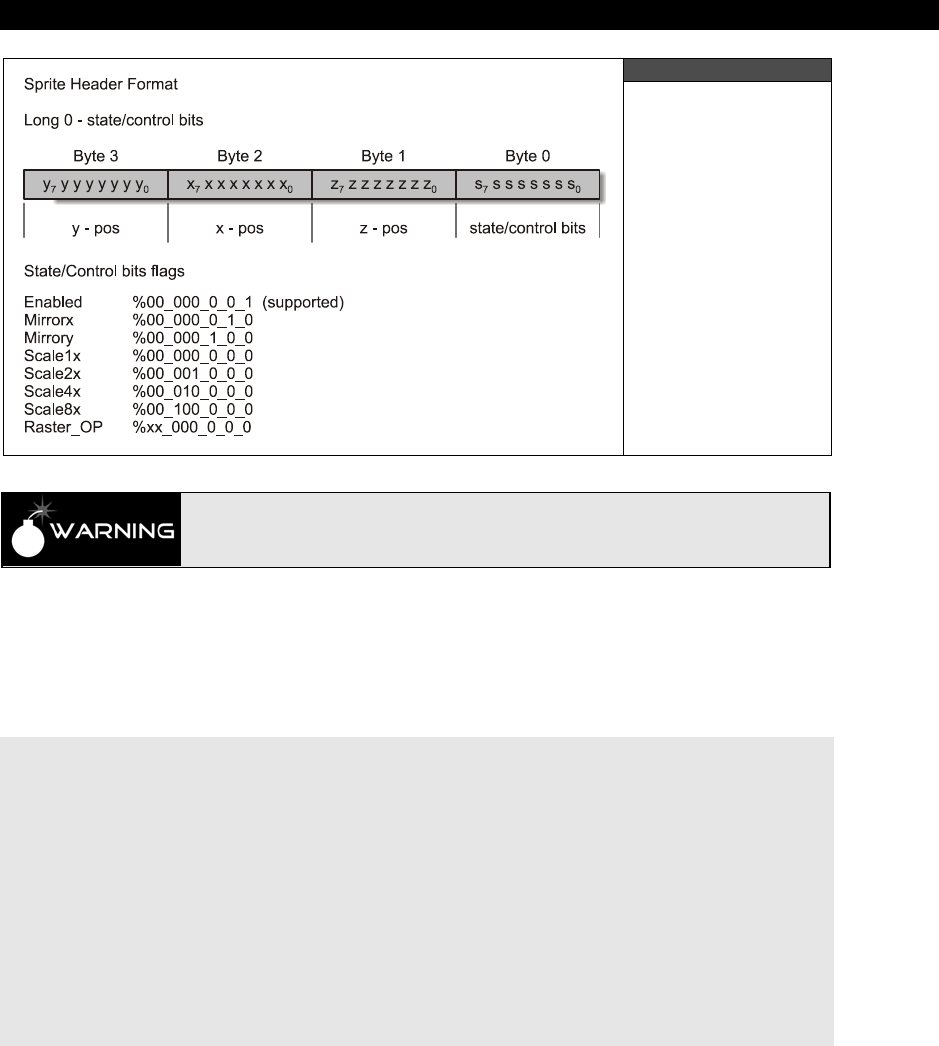
Tile Engines and Sprites 19
Game Programming for the Propeller Powered HYDRA Page 545
Figure 19:23
The Sprite
Record Format
Sprites have NO palette, they "use" the palette of the tile(s) that they are
rendered onto, thus your sprites will change colors as they move over tiles.
Considering the information in Figure 19:23, all we need to do is set the x,y bytes and enable
the sprite and we are good to go. Of course, we have to point the 2nd LONG of the sprite
record to the bitmap data itself so the engine can get to it, plus we have to tell the tile
engine there are some sprites to render with the general control variable. Here’s how you
would define the sprite records themselves in your DAT section:
' sprite table, 8 sprites, 2 LONGs per sprite, 8 LONGs total length
' sprite 0 header
sprite_tbl long $00_00_00_00 ' state/control word: y,x,z,state,
long $00_00_00_00 ' bitmap ptr
' sprite 1 header
long $00_00_00_00 ' state/control word: y,x,z,state
long $00_00_00_00 ' bitmap ptr
' sprite 2 header
long $00_00_00_00 ' state/control word: y,x,z,state
long $00_00_00_00 ' bitmap ptr
' sprite 3 header
long $00_00_00_00 ' state/control word: y,x,z,state

III Game Programming on the HYDRA
Page 546 Game Programming for the Propeller Powered HYDRA
long $00_00_00_00 ' bitmap ptr
' sprite 4 header
long $00_00_00_00 ' state/control word: y,x,z,state
long $00_00_00_00 ' bitmap ptr
' sprite 5 header
long $00_00_00_00 ' state/control word: y,x,z,state
long $00_00_00_00 ' bitmap ptr
' sprite 6 header
long $00_00_00_00 ' state/control word: y,x,z,state
long $00_00_00_00 ' bitmap ptr
' sprite 7 header
long $00_00_00_00 ' state/control word: y,x,z,state
long $00_00_00_00 ' bitmap ptr
' end sprite table
Then in your mainline you would actually write into these records the values you are
interested in, for example, in this demo we only need one sprite, so we only need to set up
sprite record 0, thus in the code you will see something like this:
' enable/initialize a sprite
sprite_tbl[0] := $70_50_00_01 ' sprite 0 state: y=xx, x=$xx, z=$xx,
' enabled/disabled
sprite_tbl[1] := @sprite_bitmap_0 ' sprite 0 bitmap ptr
...which enables the sprite (the $01 in the low BYTE), and sets the sprite’s position to x=$50,
y=$70 (about the middle of the screen). Then lastly, the only thing left is when we set up
the tile engine initially, we need to tell it there is 1 sprite rather than 0 as we have been
doing. Here’s the changes to the setup variables:
' points ptrs to actual memory storage for tile engine
tile_map_base_ptr_parm := @tile_map2
tile_bitmaps_base_ptr_parm := @tile_bitmaps
tile_palettes_base_ptr_parm := @palette_map
tile_map_sprite_cntrl_parm := $00_00_01_00 ' set for 1 sprites and width 16
' tiles (1 screens wide), 0 = 16
' tiles, 1 = 32 tiles, 2 = 64 tiles,
' 3 = 128 tiles, etc.
tile_sprite_tbl_base_ptr_parm := @sprite_tbl[0]
tile_status_bits_parm := 0
Notice how we set
tile_sprite_tbl_base_ptr_parm
to point to the base address of the
sprite table
@sprite_tbl[0]
. This is very important, don’t forget. But, also realize you can

Tile Engines and Sprites 19
Game Programming for the Propeller Powered HYDRA Page 547
on-the-fly change to another sprite table at will: the interface is totally programmable, it will
update within one frame of a change, so you can play all kinds of games with sprites, tiles,
etc. Now, that you have seen all the pieces, let’s review the steps to get sprites working with
the tile engine.
Steps to Setting up the Sprite Engine
Step 1: You need to define some actual sprite bitmap data along with a mask that follows it.
Step 2: You need to allocate a sprite record table with room for 8 sprites (even if you don’t
use them, this is a good idea).
Step 3: You need to set up your sprite table entries for each sprite you want to use. Each
entry is two LONGs: one for the state/control of the sprite, the other is a pointer to the
bitmap data for the sprite.
Step 4: You need to tell the tile engine there is 1 or more sprites and it will start rendering.
That’s it!
The demo does all this setup and then falls into the main loop which consists of even less
code than the tile engine demos to move an object:
' enter main event loop...
repeat while 1
' main even loop code here...
' move the sprite
if (game_pad.button(NES0_RIGHT))
ghost_x+=2
if (game_pad.button(NES0_LEFT))
ghost_x-=2
if (game_pad.button(NES0_DOWN))
ghost_y+=2
if (game_pad.button(NES0_UP))
ghost_y-=2
' update sprite record 0 to reflect new position, sprite updates on next frame
sprite_tbl[0] := (ghost_y << 24) + (ghost_x << 16) + (0 << 8) + ($01)
' delay a little bit, so you can see the sprite, they are VERY fast!!!
repeat 5000
The only action occurs at the bottom where we update the sprite 0 record’s first LONG which
is the control/state variable for the sprite, here is where we update the position of the sprite
with our globals tracking the position of the ghost. Notice the shift and logical operations to
move the values into their proper BYTE positions in the record – that’s it. Basically, a handful
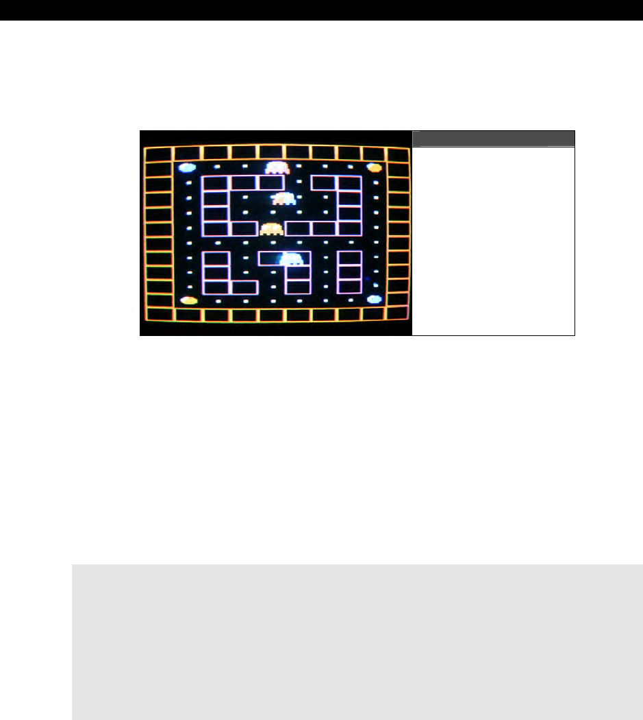
III Game Programming on the HYDRA
Page 548 Game Programming for the Propeller Powered HYDRA
of lines to move a sprite anywhere on the screen, plus the sprite comes with built in clipping
and screen wrap around since its position is encoded with a single BYTE. Try playing around
with the demo and see what you can change to make it better, then in the next section we
will add some more sprites.
Figure 19:24
A Multi-Sprite Demo
with Lots of Color
To show off, let’s put some more sprites in the demo; take a look at
PACMAN_TILE_DEMO_005.SPIN on the CD and run it. Figure 19:24 shows a screen
shot of it. More or less this is the previous demo with the addition of 3 more sprites on
autopilot that simply move across the screen and wrap around. Also, notice the weird color
effects that happen as the other sprites as well as when you move your sprite around. This is
accomplished through multiple palettes. In this demo there are 16 palettes; I keep the maze
colors the same, but change the colors used by the sprites in each tile, so as the sprites
move around they take on this palette’s colors. You can get all kinds of cool effects like this
such as a sprite walking into water (turns blue) or darkness (turns dark), and so on.
The source for this demo is nearly the same as the previous, the only big changes are the
addition of all the palettes themselves shown below:
' some pacman palettes...
palette_map long $07_0C_6C_02
long $07_FC_3C_02
long $07_EC_0C_02
long $07_DC_2C_02
long $07_CC_3C_02
long $07_BC_4C_02
long $07_AC_5C_02
long $07_9C_6C_02
long $07_8C_7C_02
long $07_7C_8C_02

Tile Engines and Sprites 19
Game Programming for the Propeller Powered HYDRA Page 549
long $07_6C_9C_02
long $07_5C_AC_02
long $07_4C_BC_02
long $07_3C_CC_02
long $07_2C_DC_02
long $07_1C_EC_02
long $07_0C_FC_02
The new tile map uses these palettes all over the place to create all the color effects, take a
look below at the first BYTE of each tile entry you will see the color palette index
incrementing all over the place:
' maze plus powerpills
tile_map2 word $00_01,$00_01,$00_01,$00_01,$00_01,$00_01,$00_01,$00_01,$00_01,$00_01,$00_01,$00_01,$00_01,$00_01,$00_01,$00_01 ' row 0
word $00_01,$00_03,$0F_02,$0E_02,$0D_02,$0C_02,$0B_02,$0A_02,$09_03,$00_01,$00_00,$00_00,$00_00,$00_00,$00_00,$00_00 ' row 1
word $00_01,$01_02,$01_01,$01_01,$01_01,$00_02,$01_01,$01_01,$08_02,$00_01,$00_00,$00_00,$00_00,$00_00,$00_00,$00_00 ' row 2
word $00_01,$02_02,$01_01,$00_02,$0B_02,$00_02,$03_02,$01_01,$07_02,$00_01,$00_00,$00_00,$00_00,$00_00,$00_00,$00_00 ' row 3
word $00_01,$03_02,$01_01,$00_02,$0A_02,$00_02,$02_02,$01_01,$06_02,$00_01,$00_00,$00_00,$00_00,$00_00,$00_00,$00_00 ' row 4
word $00_01,$04_02,$01_01,$01_01,$09_02,$01_01,$01_01,$01_01,$05_02,$00_01,$00_00,$00_00,$00_00,$00_00,$00_00,$00_00 ' row 5
word $00_01,$05_02,$06_02,$07_02,$08_02,$09_02,$0A_02,$0B_02,$04_02,$00_01,$00_00,$00_00,$00_00,$00_00,$00_00,$00_00 ' row 6
word $00_01,$06_02,$01_01,$00_02,$01_01,$01_01,$01_02,$01_01,$03_02,$00_01,$00_00,$00_00,$00_00,$00_00,$00_00,$00_00 ' row 7
word $00_01,$07_02,$01_01,$00_02,$02_02,$01_01,$00_02,$01_01,$02_02,$00_01,$00_00,$00_00,$00_00,$00_00,$00_00,$00_00 ' row 8
word $00_01,$08_02,$01_01,$01_01,$03_02,$01_01,$0F_02,$01_01,$01_02,$00_01,$00_00,$00_00,$00_00,$00_00,$00_00,$00_00 ' row 9
word $00_01,$09_03,$0A_02,$0B_02,$0C_02,$0D_02,$0E_02,$0F_02,$00_03,$00_01,$00_00,$00_00,$00_00,$00_00,$00_00,$00_00 ' row 10
word $00_01,$00_01,$00_01,$00_01,$00_01,$00_01,$00_01,$00_01,$00_01,$00_01,$00_01,$00_01,$00_01,$00_01,$00_01,$00_01 ' row 11
The other big addition to the core demo is simply enabling the first 4 sprites like so:
' enable/initialize a sprite
sprite_tbl[0] := $00_50_00_01 ' sprite 0 state: y=xx, x=$xx, z=$xx, enabled/disabled
sprite_tbl[1] := @sprite_bitmap_0 ' sprite 0 bitmap ptr
sprite_tbl[2] := $20_50_00_01 ' sprite 0 state: y=xx, x=$xx, z=$xx, enabled/disabled
sprite_tbl[3] := @sprite_bitmap_0 ' sprite 0 bitmap ptr
sprite_tbl[4] := $40_50_00_01 ' sprite 0 state: y=xx, x=$xx, z=$xx, enabled/disabled
sprite_tbl[5] := @sprite_bitmap_0 ' sprite 0 bitmap ptr
sprite_tbl[6] := $80_50_00_01 ' sprite 0 state: y=xx, x=$xx, z=$xx, enabled/disabled
sprite_tbl[7] := @sprite_bitmap_0 ' sprite 0 bitmap ptr
And the main event loop motion control for the automated sprites is nothing more than a
simple loop:
' now move all the other sprites on the x-axis, that is increment the 3rd byte in sprite record
repeat index from 1 to 3
' move sprite i, extract current x, increment, write back to record
bx := ((sprite_tbl[index*2] & $00_FF_00_00) >> 16) + index
sprite_tbl[index*2] := (sprite_tbl[index*2] & $FF_00_FF_FF) | (bx << 16)
Sorry if the loop is a little cryptic, but more or less it moves each sprite horizontally at a
different rate, then updates the sprite record for each, then on the frame update by the
engine the sprite is moved. Well, that’s it for basic sprite graphics, let’s end the chapter with
one more demo that shows some animation tricks.
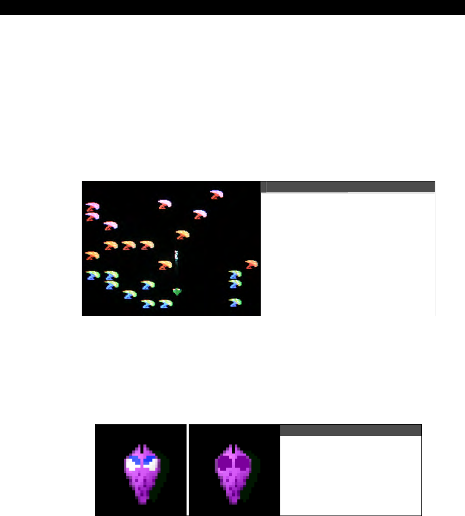
III Game Programming on the HYDRA
Page 550 Game Programming for the Propeller Powered HYDRA
19.4.4 Sprite Animation Primer
Creating games is about art just as much is it is about programming. The idea is to create a
world or environment that’s “alive” or interesting, and animation is one means to this end. As
noted, all art is being drawn manually with data statements, so we can’t go to crazy
artistically yet until we have more tools to import art, but we can do other things such as
simple animation and some other tricks. To show off some of these ideas, I created a little
Centipede-like demo which you can see in Figure 19:25. It is nothing more than the
mushrooms and the bug blaster (and a missile shortly), but it’s a good start and gives us a
platform to try some things out. Go ahead and load and try the demo, it’s called
CENTIPEDE_SPRITE_DEMO_001.SPIN. As usual, it uses the gamepad, just move the
“bug blaster” around, it can’t fire yet though. Notice the eyes blink on the little bug blaster –
cool huh?
Figure 19:25
Screen Shot of Centipede Demo
using Sprites,
Multiple Palettes,
and Ambient Animation
The first technique I wanted to show you was that with careful planning you can get color
effects for free. In this demo, we use tiles for the mushrooms, but only one bitmap per tile;
however, each tile gets its own randomly generated palette from a set of 16, so this gives us
a lot of color to play with. A little too much actually, so what I decided to do was create a
random palette for regions of the mushroom patch and break it into 3 vertical regions
covering the screen – this looks pretty good.
Figure 19:26
The Two Animation
Frames of the Bug Blaster

Tile Engines and Sprites 19
Game Programming for the Propeller Powered HYDRA Page 551
The next effect I wanted to show you was some sprite animation. Remember, each sprite
record has a pointer to the sprite bitmap (and mask) for that sprite. You can change this
pointer any time you wish, thus if you have an animated set of bitmaps like a monster
walking or an explosion or whatever then you can animate the sprite. So what I decided to
do was make the bug blaster (the character at the bottom of the screen) blink its eyes, so I
need two frames of animation, one for normal, one for the eyes blinked. Figure 19:26 shows
this graphically for my “ideal” sprite, then I had to convert it to less colors! Then all we need
to do is write some code and a state machine that blinks the eyes randomly and updates the
sprite record pointers. These are the main ideas in the demo. This demo is interesting
enough that I want you to see the main source of the initialization and the main event loop
which is below:
PUB Start
' This is the first entry point the system will see when the Propeller Chip starts,
' execution ALWAYS starts on the first PUB in the source code for
' the top level file
' star the game pad driver
game_pad.start
' initialize all vars
' bug blaster
blaster_x := 160/2 ' set sprite location of blaster to center of screen, bottom
blaster_y := 190
blaster_frame := 0 ' set to eyes open animation frame
blaster_blink_state := 0
' seed random number generator
random_seed := cnt + 172372371
' generate random palettes
repeat index from 1 to 15
random_seed := ?random_seed
' get random color nibbles
color_1 := ((random_seed & $00_00_00_F0) >> 0) | $0C ' add brightness to it
color_2 := ((random_seed & $00_00_F0_00) >> 8) | $0B ' add brightness to it
color_3 := ((random_seed & $00_F0_00_00) >> 16) | $0D ' add brightness to it
palette_map[index] := (color_3 << 24) | (color_2 << 16) | (color_1 << 8) | $02
' color 0 is always background
' generate a random mushroom field, everywhere a mushroom is placed it will have its own palette
' thus if player moves bug blaster over mushroom, he will change colors :)
' for now, there are 3 "zones" top to bottom, so the screen is broken 3 color regions top to bottom
repeat NUM_MUSHROOMS
random_seed := ?random_seed
' extract some data from random variable
x := (random_seed & $00_FF) / 26 ' limit to range 0..9
y := ((random_seed & $FF_00) >> 8) / 22 ' limit to range 0..11
' write to tile map
tile_map0[ x + y << 4] := ( ((y / 4) + 1) << 8) | $01
' points ptrs to actual memory storage for tile engine

III Game Programming on the HYDRA
Page 552 Game Programming for the Propeller Powered HYDRA
tile_map_base_ptr_parm := @tile_map0
tile_bitmaps_base_ptr_parm := @tile_bitmaps
tile_palettes_base_ptr_parm := @palette_map
tile_map_sprite_cntrl_parm := $00_00_01_00 ' set for 1 sprites and width 16 tiles (1 screens wide),
' 0 = 16 tiles, 1 = 32 tiles, 2 = 64 tiles, 3 = 128
tiles, etc.
tile_sprite_tbl_base_ptr_parm := @sprite_tbl[0]
tile_status_bits_parm := 0
' enable/initialize sprites
' bug blaster sprite
sprite_tbl[0] := $70_50_00_01 ' sprite 0 state: y=xx, x=$xx, z=$xx, enabled/disabled
sprite_tbl[1] := @sprite_bitmap_1 ' sprite 0 bitmap ptr
' launch a COG with ASM video driver
gfx.start(@tile_map_base_ptr_parm)
' enter main event loop...no need for game states, simple demo, one state - RUN
repeat while 1
' main even loop code here...
' update random number
random_seed := ?random_seed
' save current count to lock frame rate
curr_count := cnt
' get gamepad input and move the sprite
if (game_pad.button(NES0_RIGHT))
blaster_x+=1
if (game_pad.button(NES0_LEFT))
blaster_x-=1
if (game_pad.button(NES0_DOWN))
blaster_y+=1
if (game_pad.button(NES0_UP))
blaster_y-=1
' test if we want to fire blink animation
if (blaster_blink_state == 0)
if ((random_seed & $7F) == 1)
' start blink animation, basically change frames and count
blaster_blink_state := 1
blaster_frame := 1
else
if (++blaster_blink_state == 30) ' done with blink/wink?
blaster_blink_state := 0
blaster_frame := 0
' now update the bug blaster sprite record to reflect new position, sprite will update on next frame
sprite_tbl[0] := (blaster_y << 24) + (blaster_x << 16) + (0 << 8) + ($01)
sprite_tbl[1] := @sprite_bitmap_1 + (SPRITE_BITMAPMASK_SIZE)*blaster_frame
' lock frame rate
waitcnt(curr_count + 666_666)
' return back to repeat main event loop...

Tile Engines and Sprites 19
Game Programming for the Propeller Powered HYDRA Page 553
The listing starts off with the initialization section that sets up the tile engine and some other
working variables, then it falls into the random palette generation and the random mushroom
patch generation algorithms, both interesting code fragments, so check them out. Next we
enter into the main event loop and check for gamepad input and move the bug blaster if
there is motion. After the gamepad tests we fall into the animation section which is more or
less a simple state machine that works by testing if the bug blaster is blinking his eyes, if he
is then it continues counting up to 30 clocks then resets to normal. The state of the blink (0
or 1) is used as an index to point the sprite’s bitmap base pointer to either frame of
animation. Since we know they are 128 BYTEs from each other in the DAT section, it’s a
matter of a simple multiplication and addition to compute the base address of the normal and
blinking bitmap. Lastly, the frame rate is locked down, so the demo game runs smoothly.
Now, in a real game you would of course have all the game states in the main event loop,
and you would code the animation functionality into separate functions, but to save space
and keep you from jumping all over the place, I am doing things in place. Play around with
the demo a bit, notice that the bug blaster (initially green) takes on the tile palette colors of
the mushrooms as it moves over them, this is unavoidable as usual. Next, let’s add firing a
missile!
19.4.4.1 Adding Weapons to the Helpless Bug Blaster
Adding a missile is as simple as creating the missile sprite bitmap, setting up the sprite
record, then enabling/disabling the sprite as it’s fired, and of course controlling its trajectory.
There are a myriaid of ways to code this, so for a moment let’s forget about the sprite aspect
of it and focus on the missile itself. To control a single missile we need to know its position
and state, and potentially its velocity and other parameters. Since this is a simple model we
are only going to need to track the position of the missile and its state. By
“state”
I mean is
the missile
“dead,”
“alive,”
“dying,”
etc. These terms are context-sensitive, and simply
terms used by game developers to assign meaning to different states of existence of game
objects. Here are the variables we need to control a single missile:
' data structure for single missile
long missile_x, missile_y, missile_state, missile_counter
Typically, “state” will be encoded as an integer with the meanings outlined above, and the
“counter” variable helps track how long a state might be running, etc. In our case, the states
are encoded with constants to make the missile easier to code:
' states for missile
MISSILE_STATE_DEAD = 0
MISSILE_STATE_ALIVE = 1
MISSILE_STATE_DYING = 2
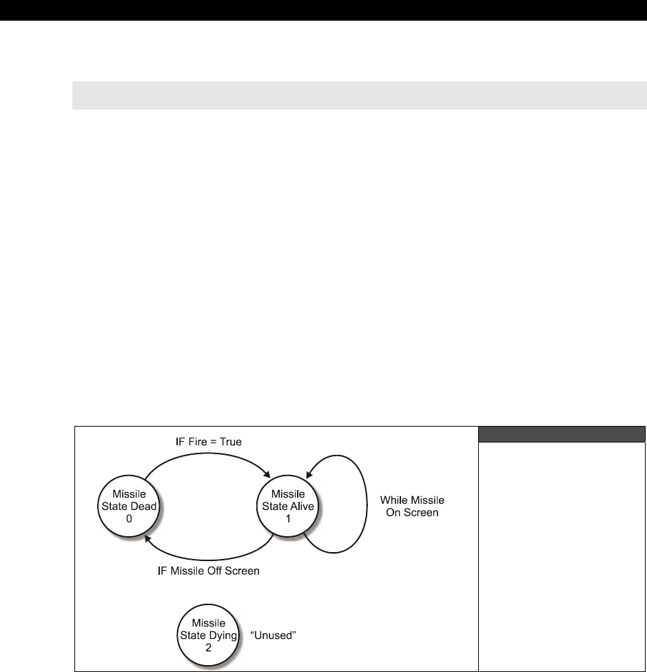
III Game Programming on the HYDRA
Page 554 Game Programming for the Propeller Powered HYDRA
And we are going to move the missile at a constant velocity of 2 pixels/frame, so here’s a
constant for that:
' missile constants
MISSILE_VEL = 2 ' velocity of missile in pixels/frame
Now that we have a data structure to hold relevant information about the missile, let’s
discuss the plan to implement it. At startup we will initialize the missile’s position to (0,0) and
its state to MISSILE_STATE_DEAD, then we will have a
case
or
if
block that tests if the
player is trying to fire the missile each frame. If the player is trying to fire the missile and the
missile state is dead, then we can start the missile up, else, we do nothing.
To start the missile up, we are going to copy the position of the player’s bug blaster into the
missile’s (x,y) position plus a little fudging to the position to make it look like the missile is
coming from the front of the bug blaster. Additionally, we are going to set the state of the
missile to MISSILE_STATE_ALIVE and reset the missile’s counter variable to 0. Now, each
time through the event loop, if the the missile’s state is MISSILE_STATE_ALIVE then we are
going to translate the missile vertically on the screen (upward) as it should be, and test if the
missile hits the top of the screen, if so we terminate the missile by setting its state to
MISSILE_STATE_DEAD. Now, if we wanted the missile to only operate for a few frames then
we could use the counter variable (and still might in the future) to count down or up and
when it reached a certain value the state would transition to dead. This way we can de-
couple the state termination to the top of the screen, but this is not needed in this demo.
Figure 19:27
The Missile Control
State Diagram

Tile Engines and Sprites 19
Game Programming for the Propeller Powered HYDRA Page 555
Figure 19:27 shows the complete state diagram for the missile control algorithm and. And of
course, if you wanted to add more missiles, then you would simply array the data structure
and loop through everything one by one. So that’s the missile. But, this is old news, I wanted
to show you something new here in this demo, not just another sprite, something to do with
animation. To this end,
“procedural animation
came to mind. Procedural animation is
animation where instead of using frames or pre-drawn animation art, we generate the
animation or effect procedurally or algorithmically. In this case, making the missile look like it
was made of plasma energy was the desired effect. Accomplishing this is easy if we look at
what we have to work with. First, here are the bitmap and mask for the missile sprite
bitmap:
' missile bitmap (will be animated in real time to look like plasma!)
sprite_bitmap_3 long %%0_0_0_0_0_0_0_0_0_0_0_0_0_0_0_0
long %%0_0_0_0_0_0_0_0_0_0_0_0_0_0_0_0
long %%0_0_0_0_0_0_0_3_3_0_0_0_0_0_0_0
long %%0_0_0_0_0_0_0_3_3_0_0_0_0_0_0_0
long %%0_0_0_0_0_0_0_3_3_0_0_0_0_0_0_0
long %%0_0_0_0_0_0_0_3_3_0_0_0_0_0_0_0
long %%0_0_0_0_0_0_0_3_3_0_0_0_0_0_0_0
long %%0_0_0_0_0_0_0_3_3_0_0_0_0_0_0_0
long %%0_0_0_0_0_0_0_3_3_0_0_0_0_0_0_0
long %%0_0_0_0_0_0_0_3_3_0_0_0_0_0_0_0
long %%0_0_0_0_0_0_0_3_3_0_0_0_0_0_0_0
long %%0_0_0_0_0_0_0_3_3_0_0_0_0_0_0_0
long %%0_0_0_0_0_0_0_3_3_0_0_0_0_0_0_0
long %%0_0_0_0_0_0_0_3_3_0_0_0_0_0_0_0
long %%0_0_0_0_0_0_0_0_0_0_0_0_0_0_0_0
long %%0_0_0_0_0_0_0_0_0_0_0_0_0_0_0_0
sprite_bitmap_mask_3 long %%0_0_0_0_0_0_0_0_0_0_0_0_0_0_0_0
long %%0_0_0_0_0_0_0_0_0_0_0_0_0_0_0_0
long %%0_0_0_0_0_0_0_3_3_0_0_0_0_0_0_0
long %%0_0_0_0_0_0_0_3_3_0_0_0_0_0_0_0
long %%0_0_0_0_0_0_0_3_3_0_0_0_0_0_0_0
long %%0_0_0_0_0_0_0_3_3_0_0_0_0_0_0_0
long %%0_0_0_0_0_0_0_3_3_0_0_0_0_0_0_0
long %%0_0_0_0_0_0_0_3_3_0_0_0_0_0_0_0
long %%0_0_0_0_0_0_0_3_3_0_0_0_0_0_0_0
long %%0_0_0_0_0_0_0_3_3_0_0_0_0_0_0_0
long %%0_0_0_0_0_0_0_3_3_0_0_0_0_0_0_0
long %%0_0_0_0_0_0_0_3_3_0_0_0_0_0_0_0
long %%0_0_0_0_0_0_0_3_3_0_0_0_0_0_0_0
long %%0_0_0_0_0_0_0_3_3_0_0_0_0_0_0_0
long %%0_0_0_0_0_0_0_0_0_0_0_0_0_0_0_0
long %%0_0_0_0_0_0_0_0_0_0_0_0_0_0_0_0
The sprite bitmap itself is made of 3’s, thus a 2-pixel-wide line of color 3 would be the sprite;
however, if we were actually go into the bitmap on-the-fly during run-time and alter this data
we could make it look like anything. For example, if we were to generate 16 random 32-bit
numbers and then logically AND them with the values in the original sprite bitmap this would
have the effect of turning on pixels in patterns 00b, 01b, 10b, and 11b wherever the missile
mask is, and presto we have our plasma effect. The code for this is shown below:

III Game Programming on the HYDRA
Page 556 Game Programming for the Propeller Powered HYDRA
' animate missile by rendering random pixels into sprite buffer to make it look like "plasma"
' star trek "beam out" effect!
repeat index from 2 to 13
sprite_bitmap_3[index] := %%0_0_0_0_0_0_0_3_3_0_0_0_0_0_0_0 & (?random_seed)
So, we only want to overwrite rows 2 to 13 with the random pixels, but the final effect is
pretty cool. If you wanted to make any shape make this energized effect, simply make the
mask look like the shape, then write into the bitmap each mask row logically AND’ed with the
random number like this:
' variant of algorithm uses the mask itself to energize any shape (a little slower)
repeat index from 0 to 15
sprite_bitmap_3[index] := sprite_bitmap_3[index+16] & (?random_seed)
The
sprite_bitmap_3[index+16]
accesses the mask data since we know it’s 16 LONGs
ahead of the bitmap data. That’s about all there is to the animation; the last thing to look at
is the missile control code itself which is below:
' run motion / animation state machine for missile, normally this would be in a seperate function
' but for brevity we are keeping everything in the main loop
case missile_state
MISSILE_STATE_DEAD: ' do nothing...
MISSILE_STATE_ALIVE: ' move and animate the missile, test for off screen
if ( (missile_y -= MISSILE_VEL) < 0 ) ' move missile upward...test for offscreen
missile_state := MISSILE_STATE_DEAD ' terminate missile
' animate missile by rendering random pixels into sprite buffer to make it look like "plasma"
' star trek "beam out" effect!
repeat index from 2 to 13
sprite_bitmap_3[index] := %%0_0_0_0_0_0_0_3_3_0_0_0_0_0_0_0 & (?random_seed)
MISSILE_STATE_DYING: ' not implemented, but maybe when the missile hits it has a death animation
' end case
That’s about all the changes to create the new demo. The complete source code can be
found in CENTIPEDE_SPRITE_DEMO_002.SPIN, go ahead and give it a try right now,
use the dpad on the gamepad to move and <B> to fire. Check out the plasma/energize
effect on the missile; if it moves too fast for you to see, try slowing it down by changing the
MISSILE_VEL to 1.
I leave it to you to add collision detection to the mushrooms, but as a hint simply compute
the tile coordinates of the missile by dividing by 16 (and offsetting by the coordinate system
of the sprites since 0,0 in sprite space is off the top corner of the screen), then test the tile to
see if a mushroom is there. If so, then erase it, or better yet, draw a new version of a
mushroom into the screen that has some part of it blown away! Make sure to terminate the
missile when it hits something as well.

Tile Engines and Sprites 19
Game Programming for the Propeller Powered HYDRA Page 557
19.5 Summary
This chapter hopefully has been a quantum leap for you and you can see how the pieces are
starting to fit together to make games. Bottom line, once you have a powerful tile/sprite
engine, then it’s just a matter of createing game art, and coding the logic for the game, and
that’s a video game! Of course, subjects like artificial intelligence and others are important,
but we are getting there. At this point, you can more or less make just about any 8-bit tile
based game you have ever seen (graphically at least). Before moving on to the next chapter,
try taking some of the demos and playing with them, and changing them around and see if
you can make any complete rudimentary games with them.

III Game Programming on the HYDRA
Page 558 Game Programming for the Propeller Powered HYDRA

Getting Input from the “User” World 20
Game Programming for the Propeller Powered HYDRA Page 559
Chapter 20:
Getting Input
from the
“User” World
I don’t think I have made a single reference to the movie
“TRON”
thus far, so this chapter’s
title changes all that! In this chapter, we are going to discuss some issues related to reading
input devices in the context of a game. We aren’t going to cover how the input devices work
in detail since we have already done that, but rather how they are used in games to control
characters, and also some of the techniques used to make a keyboard seem like a mouse, a
mouse like a gamepad, and other similar problems. Here’s what’s in store:
What is an input device “controller?”
Input device review
Selected examples of controller filtering and mapping
Game controller data input sequencing techniques
Universal input module architectural concerns for games
Final demo –
ZoneBall
20.1 What is an Input Device Controller?
You already know how to read the keyboard, mouse, and gamepad, so you might wonder
“What else is there?” Well, reading the input device is only the tip of the iceberg, what you
do
with that input is what counts. Thus far, for the demos we have reviewed, we have simply
read the input device in question (mouse, keyboard, gamepad) and then taken the raw data
without any processing and used it directly in conditionals to control the game/demo itself.
This is fine and works in cases where the control of the game characters is simple. However,
as games get more complex, you will need to
process
,
interpret
, and
transform
game
control inputs into multiple formats that better suit the needs of the game play.
The module that does this in a game is usually referred to as the “input device controller” or
“input module.” It’s is more or less a piece of software that takes one or more input devices
that are potentially connected to the game system (mouse, keyboard, gamepad, etc.) and
collects all of the heterogenous input data from the different controllers and APIs, and then
transforms the data into a nice stream of homogenous data packets that the game engine
can use and not care what controller(s) it came from. This is shown in Figure 20:1 on the
next page.
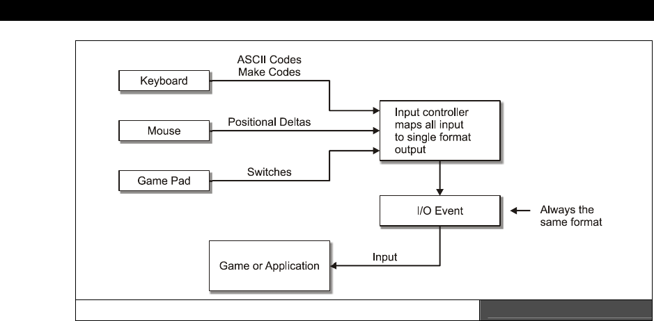
III Game Programming on the HYDRA
Page 560 Game Programming for the Propeller Powered HYDRA
The Input Controller Module Architecture Figure 20:1
When you think about this it makes good sense, since there is a lot of difference between a
mouse, keyboard, and gamepad. Sure, they have some things in common, but a mouse for
example can move instaneously to a different position, a keyboard can’t. A gamepad on the
other hand has a collection of buttons, not as many as a keyboard, but typically on a
gamepad you can press 2, 3, 4 or more buttons at once, whereas on a keyboard, only 1-2
keys can be pressed at the same time (usually a control key and one normal key), so there
isn’t a direct mapping.
Another problem with input device data is that sometimes it’s not in the format we want, that
is, maybe we need to “filter” it a bit and output what the player “meant” to do. For example,
say you have a running game; there is no way to “run” on a game controller, keyboard or
mouse, thus game developers come up with various physical actions to “represent” running.
For example, in Activision’s
“Summer”
and
“Winter Games”
from the early 80’s, you
would move the joystick rapidly back and forth from left to right as shown in Figure 20:2.
The faster you moved right and left, the faster the game character would run, but this has no
direct mapping to translation or speed, so a
filter
of sorts had to be employed. In this case,
the filter might be general speed of the running character, and a counter counts how many
complete “right-left” joystick cycles there are per second, this number is then scaled and
used to increase or decrease the virtual speed of the running. However, once in a while the
player might “miss” a left or right thrust, so the input “filter” might be reasonable and allow a
“miss” every 10 hits, that is, the controller realizes that the player and controller aren’t
perfect and once in a while the player might miss a cycle even though he made the motion,
so the “ input controller” helps the player out.
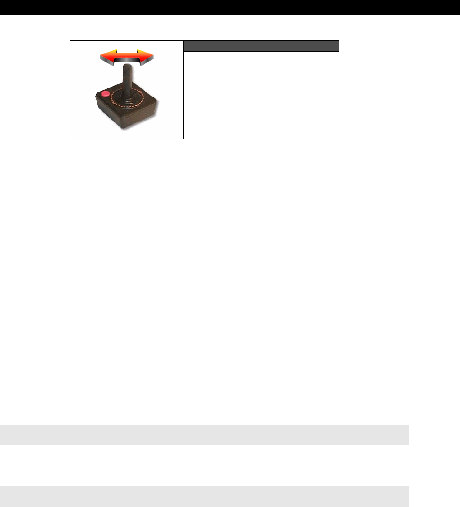
Getting Input from the “User” World 20
Game Programming for the Propeller Powered HYDRA Page 561
Figure 20:2
Running on an Atari Joystick
This is the idea of input controller software; depending on the game, the input controller
software might at very least allow the player to play with all input devices, and/or there
might be a lot of filtering and even crude “intelligence” in the input controller to help the
player out with what he “meant” to do based on what he has been doing. With that in mind,
in this chapter, we are going to look at a few examples that illustrate these concepts to get
you started, so you don’t end up kludging code to support multiple input devices, but rather
code cleanly with an
“input controller”
module. Before we get started, let’s briefly review
the gamepad, joystick, and mouse interfacing APIs, to refresh your memory.
20.2 Input Device Programming Review
The HYDRA supports three input devices currently: the mouse, keyboard, and gamepad. The
mouse is the most alien of the three since it only has a couple buttons and returns position in
packets as deltas or absolute position of the virtual mouse position. The keyboard and
gamepad on the other hand are very similar in functionality except that the keyboard of
course has over 100 keys while the controller only has a few, but the gamepad controller
supports multiple key presses simultaneosly, where the keyboard does not (usually). Now,
let’s quickly take a look at the objects and a little code to read each device, so you can have
it fresh in your mind as we move through the material ahead that uses the functions.
20.2.1 Reading the Mouse
The standard reference driver for the mouse is called MOUSE_IS0_010.SPIN. You simply
import it into your Spin program like so:
OBJ
mouse : "mouse_iso_010.spin" ' instantiate a mouse object
...then start it up with a single parameter (which is the port for the I/O’s which on the
HYDRA is 2):
'start mouse
mouse.start(2)

III Game Programming on the HYDRA
Page 562 Game Programming for the Propeller Powered HYDRA
The driver for the mouse can return both the delta from the last read mouse position or the
absolute mouse position with the functions:
' read delta from last position
dx := mouse.delta_x
dy := mouse.delta_x
' read absolute mouse position (9-bit accurate)
abs_x := mouse.abs_x
abs_y := mouse.abs_y
Next, to read the buttons, you call the button function as shown below:
' bit4 = right-side button
' bit3 = left-side button
' bit2 = center/scrollwheel button
' bit1 = right button
' bit0 = left button
button_state := mouse.buttons
...where the buttons are encoded as a bit vector as shown in the comments above. That’s all
there is to reading the mouse. The last function that is interesting to our discussion is a way
to determine if the mouse is present:
' 3 = five-button scrollwheel mouse
' 2 = three-button scrollwheel mouse
' 1 = two-button or three-button mouse
' 0 = no mouse connected
mouse_present := mouse.present
The function not only returns if the mouse is present or not, but the type of mouse installed
(if any). However, this takes approximately 1-2 seconds before it’s valid, thus you might not
want to wait for it in your application.
20.2.2 Reading the Keyboard
The reference keyboard driver is named KEYBOARD_ISO_010.SPIN and is much more
complex than the mouse as far as functionality goes. However, we only need to
communicate with the keyboard in a couple different ways. First, the keyboard driver knows
when a key is pressed, so this can be querried by a call, if the call is true then you can
retrieve the key that was pressed. The second way to read the keyboard is like a giant array
of switches (which is more common in game development). You simply access an array that
indicates the
“state”
of all the keys simulataneously.
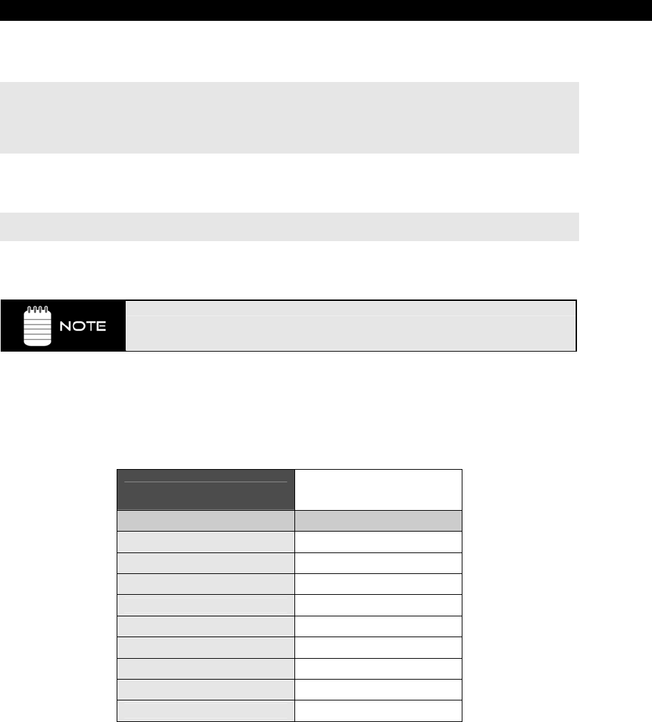
Getting Input from the “User” World 20
Game Programming for the Propeller Powered HYDRA Page 563
The code to import the keyboard object and start it up is shown below (the 3 parameter on
start means pingroup 3 which is the HYDRA’s keyboard port):
OBJ
key : "keyboard_iso_010.spin" ' instantiate a keyboard object
'start keyboard on pingroup
key.start(3)
Once the keyboard is started up, we can read single key events or the state of the keyboard.
To read the state of any key, we use the
keystate
function below along with a key constant:
key.keystate(KB_RIGHT_ARROW)
This returns a Boolean value if the key is pressed or not.
Remember, in Spin, 0 is FALSE, and anything else is TRUE, especially -1!
The constant “KB_RIGHT_ARROW” in this example is simply one of the constants defined in
the driver’s code itself, refer to KEYBOARD_ISO_010.SPIN at the end of the listing to see
the actual values of all the “key codes” which are more or less the
“make”
codes for
standard PC keyboards. Table 20:1 shows a short list of useful codes:
Table 20:1 Keycodes Commonly
Used in Games
Symbolic Name Driver Key Code
KB_LEFT_ARROW $C0
KB_RIGHT_ARROW $C1
KB_UP_ARROW $C2
KB_DOWN_ARROW $C3
KB_ESC $CB
KB_SPACE $20
KB_ENTER $0D
KB_LEFT_CTRL $F2
KB_RIGHT_CTRL $F3

III Game Programming on the HYDRA
Page 564 Game Programming for the Propeller Powered HYDRA
Next, if you are writing something more like a text input system or editor, you are more
interested in
when
a key is pressed, rather than
if
a key is pressed. Then you need the
gotkey
function which tests if a key is pressed, if so then you simply make another call to
read the key with
getkey
:
if (key.gotkey == TRUE)
key := mouse.getkey
...and that wraps it up for the keyboard interface. Also, the keyboard driver also has a
present function which returns a Boolean if the keyboard is present or not as shown below:
is_present := key.present
However, this takes approximately 1-2 seconds before it’s valid, thus, you might not want to
wait for it in your application.
20.2.3 Reading the Gamepad Controller
The Nintendo-compatible gamepad controller is more or less a set of digital switches, they
are read in as a single bit vector and then you simply logically AND mask bits to test if a
button is pressed. The reference driver for the gamepad is GAMEPAD_DRV_001.SPIN,
here’s how you load and start it up:
OBJ
game_pad : "gamepad_drv_001.spin"
' start the game pad driver
game_pad.start
The gamepad driver is even simpler than the keyboard and mouse. You read the “state” of
all the button bits at once with
read
:
' read all the button bits as WORD that represents both controllers
' (low byte is left controller, high byte right controller)
game_pad.read
...where the buttons are encoded in the following way:
' NES bit encodings for NES gamepad 0
NES0_RIGHT = %00000000_00000001
NES0_LEFT = %00000000_00000010
NES0_DOWN = %00000000_00000100
NES0_UP = %00000000_00001000
NES0_START = %00000000_00010000
NES0_SELECT = %00000000_00100000
NES0_B = %00000000_01000000
NES0_A = %00000000_10000000
Getting Input from the “User” World 20
Game Programming for the Propeller Powered HYDRA Page 565
' NES bit encodings for NES gamepad 1
NES1_RIGHT = %00000001_00000000
NES1_LEFT = %00000010_00000000
NES1_DOWN = %00000100_00000000
NES1_UP = %00001000_00000000
NES1_START = %00010000_00000000
NES1_SELECT = %00100000_00000000
NES1_B = %01000000_00000000
NES1_A = %10000000_00000000
Also, if you like, you can let the driver do a little work for you and “test” the buttons if a
specific button is down with a single call
button
like this:
if (game_pad.button(NES0_START)
' game code…
...which tests if the left most controller’s <START> button is down.
There is no “present” function in this version of the driver, but simply read the button state
and compare it to $FF for the controller, this means the controller is not plugged in, for
example to determine if the left controller is
not
plugged in you would use the following
code:
if ( (game_pad.read & $00FF) == $FF)
'.. not plugged in…
An $FF is returned since there is a pullup resistor on the controller’s serial data
stream, so without the controller plugged in the HYDRA reads all 1’s.
20.3 Input Device Filtering Demos
In this section, we are going to take a look at a few common examples of input device
filtering and controller architecture, and finish off with a universal input system and
command code tracker which will explained shortly. Now, like any demo in the book an effort
is made to put the demo in the context of game development with something that relates to
graphics, thus, I decided that we really need a single screen and some object to move
around to “see” our input algorithms at work. So I put together a little “arena” game field
demo that we will use to experiment with input devices. It’s shown in Figure 20:3 on the next
page; more or less the tile engine is being used here and a single sprite to create the
character which is supposed to be some kind of 4-directional tank or hover craft (hey you try
drawing with 1’s and 0’s).
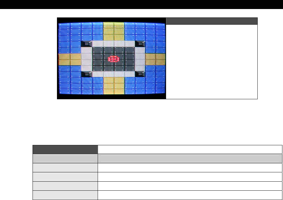
III Game Programming on the HYDRA
Page 566 Game Programming for the Propeller Powered HYDRA
Figure 20:3
The Game Arena Template
Used for Most of the Demos
Anyway, aside from the demos and algorithms we are about to see, there are some
interesting techniques going on with the arena demo, for example, the color mapping for the
tile engine is shown in Table 20:2 below:
Table 20:2 Arena Game Demo Tile Engine Color Usage
Color Index Usage
0 Used as bright background object color and transparent for sprites
1 Used as dark background object
2 Used solely for sprite primary color
3 Always white
As you can see, the sprites can use colors 1, 2, 3; color 2 is the sprite color, 3 is always
white, but color 1 is a “dark” version of the background tile color, so more or less the sprite
can use this for a “gray” color shade and you won’t notice the color of it for a pixel or two.
But, the interesting thing to note is as the sprite moves over the arena, I changed the two
background colors along with the sprite color, so the sprite actually changes colors over
some tiles. This is a cool effect to keep in mind if you need it. So with that in mind, let’s get
to the demos.
20.3.1 Unifying the Input Devices
One of the main problems with input devices is that they all tend to output different kinds of
data: button presses, mouse positions, ASCII keys, whatever, but in a game you don’t want
to ask if the “CTRL” key is pressed, you just want to know if the FIRE command has been
sent from the input devices. To accomplish this we need to unify the input device’s output
data into a common command language for processing downstream by the game logic. As a
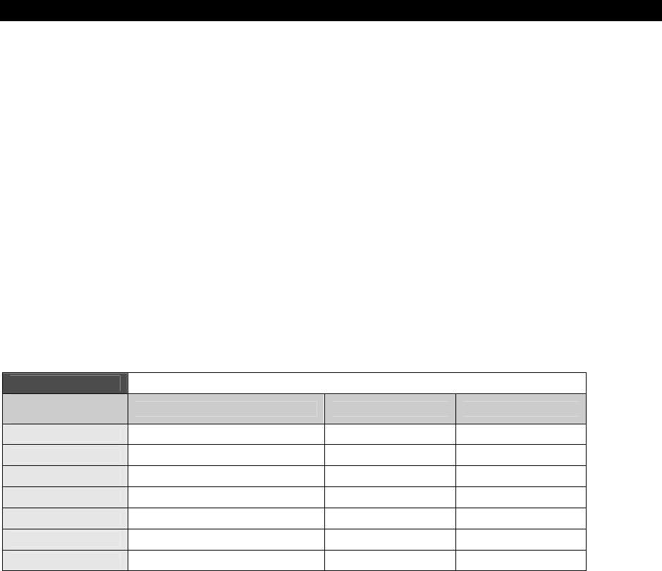
Getting Input from the “User” World 20
Game Programming for the Propeller Powered HYDRA Page 567
first attempt at this, let’s work from the game designer’s point of view rather than the guy
that has to write the driver (us in this case).
Let’s assume we are going to make a game(s) that needs the following inputs:
START
ESC
FIRE
RIGHT
LEFT
UP
DOWN
Let’s further assume that they are all digital in nature and will be represented by Boolean
values 1 and 0. The first step is to look at each of the input devices and decide on a universal
“mapping”
– that is, what control element (sometimes referred to as a widget or gadget)
on the input devices maps to these concepts (if at all) and assign control elements. Table
20:3 shows the mapping we are going to use (commas separate multiple control element
mapping):
Table 20:3 Universal Input Controller Mapping
Universal
Command ID Keyboard Mouse Gamepad
START <SPACE>, <CTRL>, <ENTER> Left Button <Start> Button
ESC <ESC> Right Button <Select> Button
FIRE <SPACE>, <CTRL> <Left Button> <A>, <B>
RIGHT <Right ARROW> Motion Right <Dpad Right>
LEFT <Left ARROW> Motion Left <Dpad Left>
UP <Up ARROW> Motion Up <Dpad Up>
DOWN <Down ARROW> Motion Down <Dpad Down>
That was simple enough. Ok, so counting up commands, there are 7, so we can encode them
all into a single BYTE. However, Spin does a lot of work with LONGs especially for parameters
and returns from function calls, so it doesn’t save any memory to use a BYTE when using
function calls to send or receive parms, thus we will use a LONG for command IDs, but
ignore the upper 24 bits (for now). This is a good idea since we can “grow” into the other
bits in the future, and this command code set can be compatible with a superset system
later!

III Game Programming on the HYDRA
Page 568 Game Programming for the Propeller Powered HYDRA
At this point, we need three functions to filter the input devices. For kicks, when we start up
each device we are going to set a global flag that indicates if the controller is present, then in
the read functions we are going query it, and if the particular input device is not plugged in
then the function will simply return. But, before we get to coding we have some
“arbitration”
issues to discuss.
When merging data from multiple input devices, it could be that on the keyboard you are
pressing
left
while your cat is walking on the gamepad and pressing
right
. How you want to
handle this depends on the game. In most cases you can simply logically OR everything
together and be done with it; however, maybe you are actually playing with a friend and he
is using the gamepad to control just the firing and you are steering. In this case,
collaborative play is the idea, so what if someone hits ESC at the same time someone hits
SELECT? Both are high-level commands, so should the game escape to the menu, or do
whatever SELECT fires off? This depends on the game. Thus, you might have to write extra
logic that tests for these cases and prioritizes them or possibly even queues them up?
However, in most cases, and most games, programming just OR’s it all together and that’s it.
Considering that, let’s write some example code to handle the startup of all the input devices
and then the query functions.
First off, let’s define the “input command ID’s” we are using in our example:
CON
' encode each as a bit
IID_START = $01
IID_ESC = $02
IID_FIRE = $04
IID_RIGHT = $08
IID_LEFT = $10
IID_UP = $20
IID_DOWN = $40
Then somewhere in the VAR section, let’s define some globals to track if the input devices
are even plugged in:
VAR
Long keyboard_present
long mouse_present
long gamepad_present
...and finally, let’s import all the objects:
OBJ
mouse : "mouse_iso_010.spin" ' instantiate a mouse object
key : "keyboard_iso_010.spin" ' instantiate a keyboard object
game_pad : "gamepad_drv_001.spin" ' instantiate game pad object

Getting Input from the “User” World 20
Game Programming for the Propeller Powered HYDRA Page 569
...and in the initialization section you would start them all up correctly and test for presence:
'start mouse
mouse.start(2)
repeat 250_000 ' give driver a moment to warm up
mouse_present := mouse.present
' start keyboard
key.start(3)
repeat 250_000 ‘ give driver a moment to warm up
keyboard_present := key.present
' start the gamepad
game_pad.start
repeat 1000 ' give driver a moment to warm up
if ( (game_pad.read & $00FF) <> $00FF)
gamepad_present := 1
else
gamepad_present := 0
20.3.1.1 Universal Input Controller Version 1.0
Now, we are ready to read each input device and collect all the data into a single global data
packet, so let’s write some universal controller interface (UCI) functions for each device that
performs the mapping, filtering, and construction of the data packet as a return value; here
they are:
PUB UCI_Read_Keyboard(device_present) : keyboard_state
' universal controller interface for keyboard
' make sure the device is present
if (device_present==FALSE)
return 0
' reset state var
keyboard_state := 0
' first control id's
' set ESC id
if (key.keystate(KB_ESC))
keyboard_state |= IID_ESC
' set start id
if (key.keystate(KB_SPACE) or key.keystate(KB_ENTER) or key.keystate(KB_LEFT_CTRL) or key.keystate(KB_RIGHT_CTRL) )
keyboard_state |= IID_START
' set fire id
if (key.keystate(KB_SPACE) or key.keystate(KB_LEFT_CTRL) or key.keystate(KB_RIGHT_CTRL) )
keyboard_state |= IID_FIRE

III Game Programming on the HYDRA
Page 570 Game Programming for the Propeller Powered HYDRA
' now directionals
if (key.keystate(KB_LEFT_ARROW))
keyboard_state |= IID_LEFT
if (key.keystate(KB_RIGHT_ARROW))
keyboard_state |= IID_RIGHT
if (key.keystate(KB_UP_ARROW))
keyboard_state |= IID_UP
if (key.keystate(KB_DOWN_ARROW))
keyboard_state |= IID_DOWN
return keyboard_state
' end UCI_Read_Keyboard
' /////////////////////////////////////////////////////////////////////////////
PUB UCI_Read_Mouse(device_present) : mouse_state | m_dx, m_dy
' universal controller interface for mouse
' make sure the device is present
if (device_present==FALSE)
return 0
' reset state var
mouse_state := 0
' set ESC id
if (mouse.button(1))
mouse_state |= IID_ESC
' set start id
if (mouse.button(0))
mouse_state |= IID_START
' set fire id
if (mouse.button(0))
mouse_state |= IID_FIRE
' get mouse deltas
m_dx := mouse.delta_x
m_dy := mouse.delta_y
' now, we need to convert the delta or absolute mouse position into digital output,
' thus thresholding and clamping them, notice the threshold of "2" used, this helps
' only move the mouse when the user is really moving and not an accidental nudge
if (m_dx > 2)
mouse_state |= IID_RIGHT
else
if (m_dx < -2)
mouse_state |= IID_LEFT
if (m_dy < -2)
mouse_state |= IID_DOWN
else
if (m_dy > 2)
mouse_state |= IID_UP

Getting Input from the “User” World 20
Game Programming for the Propeller Powered HYDRA Page 571
return mouse_state
' end UCI_Read_Mouse
' /////////////////////////////////////////////////////////////////////////////////
PUB UCI_Read_Gamepad(device_present) : gamepad_state
' universal controller interface for gamepad
' note the gamepad maps very naturally to the universal codes, we could use
' some really clever lookup or logic code to map the codes, but instead lets
' just keep it readable...
' make sure the device is present
if (device_present == 0)
return 0
' reset state var
gamepad_state := 0
' set ESC id
if (gamepad.button(NES0_SELECT))
gamepad_state |= IID_ESC
' set start id
if (gamepad.button(NES0_START))
gamepad_state |= IID_START
' set fire id
if (gamepad.button(NES0_A) or gamepad.button(NES0_B) )
gamepad_state |= IID_FIRE
' now directionals
if (gamepad.button(NES0_LEFT) )
gamepad_state |= IID_LEFT
if (gamepad.button(NES0_RIGHT) )
gamepad_state |= IID_RIGHT
if (gamepad.button(NES0_UP) )
gamepad_state |= IID_UP
if (gamepad.button(NES0_DOWN) )
gamepad_state |= IID_DOWN
return gamepad_state
' end UCI_Read_Gamepad
If any input device is not present then the function(s) simply returns a 0, assuming that the
caller is going to perform a logical OR with all the input devices at some point. This way, we
can minimize the conditional logic making calls to the filters and use a single statement to
read all devices like so:
player_input := UCI_Read_Keyboard(keyboard_present) | UCI_Read_Mouse(mouse_present) |
UCI_Read_Gamepad(gamepad_present)

III Game Programming on the HYDRA
Page 572 Game Programming for the Propeller Powered HYDRA
Each function is fairly straightforward, the only one that’s even remotely interesting is the
mouse function since it has to threshold and clamp the mouse movement and turn it into a
digital output. When you try the demo, you will see how this “feels” wrong, but for this
version it is exactly what we want. To see the new universal input system in action, go ahead
and run ARENA_INPUT_DEMO_001.SPIN from the CD, it uses the controls as we have
defined them. Try using each input device, plug them all in, pull them all out, etc.
Our code only detects if an input device is present during startup, thus if you
pull something after you start the demo up (or plug something in) the demo
won’t know about it and might not function properly. To test this, start the demo
with everything in, then unplug the gamepad, notice how the demo locks up,
what’s happening? Hint: the phantom gamepad is returning $FF which means all
buttons down!
20.3.1.2 Universal Input Controller Version 2.0
)At this point, we have a very simple system that works well. It supports keyboard, mouse,
and gamepad, detects devices present, and outputs a single data packet that is 8 bits (used
in a 32-bit word). The only problem is that during the “port” of all the input devices to a
single virtual game input stream, we lost something in the translation…specifically, the
mouse doesn’t work very well anymore. When people use the mouse as an input, they
expect the mouse to move the cursor, control, pointer or whatever as the mouse moves.
When we “digititized” the mouse, we got rid of this feature to make it more compatible with
the generic data stream we were creating for the system. This is a no-no in game
development, you never want to penalize the game player for using an input device with
special features, in fact, you want to take advantage of them if you can. For example, when
you buy a new graphics card would you expect games to look better? Sometimes they do,
but sometimes the programmers program for the lowest common denominator which is bad.
In any event, let’s see if we can augment our first data packet format with some new fields
and so on to help support more advanced devices like the mouse feel better.
Reviewing our universal controller mapping events, we have the following digital outputs bits:
START
ESC
FIRE
RIGHT
LEFT
UP
DOWN
All we need to support analog devices such as the mouse is a way to send back deltas for x,
y motion. This can easily be accomplished by adding some extra variables to our data packet.
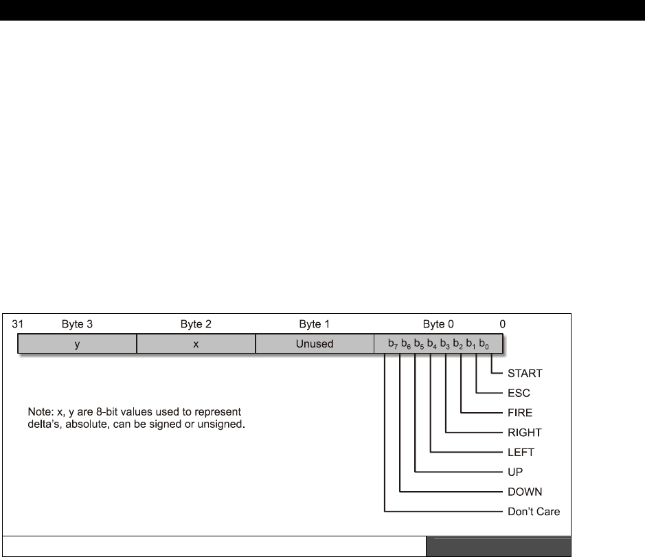
Getting Input from the “User” World 20
Game Programming for the Propeller Powered HYDRA Page 573
We could embed each the dx and dy into the LONG itself as a 8-bit 2’s complement number
which would give us the range of (-128 to +127) which is perfect. Luckily, we only used the
first 7 lower bits so far to encode the above commands, so we are going to place x,y
encoded in the upper WORD as shown in Figure 20:4.
Referring to Figure 20:4, the idea here is that “x” and “y” will go in BYTEs 2 and 3
respectively, their format is not restricted, they could be 2’s complement values for absolute
position or deltas, so we aren’t defining that in the specification, only that some kind of “x”
and “y” data will go there. This gives us the latitude to change the type of data in there if we
want. Also, notice we haven’t touched BYTE 1? This is perfect for more state information or
possibly command format codes, that is, we might later put a 4-bit field in there that defines
if the x,y are deltas or absolutes, in 2’s complement form and so forth. For example, a first
step might be to use bit 0 of BYTE 1 as a “digital/analog” bit, if it’s 0 then the format is
digital as before, if it’s 1 then the format is analog and we should take into consideration the
x,y fields in BYTEs 2 and 3, but for now we will just always assume that the packet output is
analog.
Universal Command Data Packet Encoding for Version 2.0 Figure 20:4
As you can see this little data format is really starting to take shape. Now, all we have to do
is code something that takes advantage of it and try and keep it as compatible as possible
with our previous system, so we don’t “break” too much of our software – what there is of it!
The idea will be to use the functions we wrote before and augment them to modify the x,y
fields. For example, the keyboard and game pad both are digital in nature, so they might set
the x,y fields to ±1’s; on the other hand, the mouse might actually stuff the dx, dy values for
its motion in the BYTEs, so if the player does have a mouse, he can take advantage of this

III Game Programming on the HYDRA
Page 574 Game Programming for the Propeller Powered HYDRA
functionality. In either case, we will still set the digital state bits always for RIGHT, LEFT, UP,
and DOWN to keep the data packet as “compatible” as we can.
Taking all this into consideration, the new universal input functions for version 2.0 are shown
below. I have only shown the mouse and gamepad to save space, the keyboard is similar
and you can always review it in the upcoming demo in a moment. The only work that had to
be done was that in the gamepad and keyboard in addition to setting the RIGHT, LEFT, UP,
DOWN flags in the data packet, they also put arbitrary values into the x,y fields, thus all data
packets all have the same format. Lastly, before moving on and reviewing the functions
below, be aware that Spin doesn’t do sign extension automatically, you have to use special
operators to make sure that 8 and 16 bit values sign-extend when you assign them to
LONGs, so keep that in mind when reviewing the code and trying to implement a similar
system. This is an issue since Spin only does 2’s complement math with 32-bit LONGs, so we
have to work with LONGs then down-convert to 8 bits, then up-convert to LONGs again, the
last step is the gotcha. Specifially, examples of the operators to sign-extend an 8-bit and 16-
bit value are:
8-bit Sign Extention
LONG x
BYTE y
x := ~y ‘ the 8th bit (sign bit) is sign extended into x
16-bit Sign Extention
LONG x
WORD y
x := ~y ‘ the 16th bit (sign bit) is sign extended into x
Without further ado, here are the version 2.0 universal input functions:
PUB UCI_Read_Mouse2(device_present) : mouse_state | m_dx, m_dy
' universal controller interface for mouse version 2.0
' now supports the x,y fields in bytes 2,3
' make sure the device is present
if (device_present==FALSE)
return 0
' reset state var
mouse_state := 0
' set ESC id
if (mouse.button(1))
mouse_state |= IID_ESC
' set start id
if (mouse.button(0))
mouse_state |= IID_START
' set fire id

Getting Input from the “User” World 20
Game Programming for the Propeller Powered HYDRA Page 575
if (mouse.button(0))
mouse_state |= IID_FIRE
' get mouse deltas
m_dx := mouse.delta_x
m_dy := -mouse.delta_y ' invert due to mouse coordinate mapping is inverted on y-axis
' now, we need to convert the delta or absolute mouse position into digital output,
if (m_dx > 0)
mouse_state |= IID_RIGHT
else
if (m_dx < 0)
mouse_state |= IID_LEFT
if (m_dy < 0)
mouse_state |= IID_DOWN
else
if (m_dy > 0)
mouse_state |= IID_UP
' merge x,y into packet
mouse_state := mouse_state |((m_dy & $00FF) << 24) | ((m_dx & $00FF) << 16)
return mouse_state
' end UCI_Read_Mouse2
' /////////////////////////////////////////////////////////////////////////////////
PUB UCI_Read_Gamepad2(device_present) : gamepad_state | gpx, gpy
' universal controller interface for gamepad versions 2.0
' now supports the x,y fields in bytes 2,3
' note the gamepad maps very naturally to the universal codes, we could use
' some really clever lookup or logic code to map the codes, but instead lets
' just keep it readable...
' make sure the device is present
if (device_present == 0)
return 0
' reset state var
gamepad_state := 0
gpx := 0
gpy := 0
' set ESC id
if (gamepad.button(NES0_SELECT))
gamepad_state |= IID_ESC
' set start id
if (gamepad.button(NES0_START))
gamepad_state |= IID_START
' set fire id
if (gamepad.button(NES0_A) or gamepad.button(NES0_B) )
gamepad_state |= IID_FIRE
' now directionals
if (gamepad.button(NES0_LEFT) )
gamepad_state |= IID_LEFT

III Game Programming on the HYDRA
Page 576 Game Programming for the Propeller Powered HYDRA
gpx := -2
if (gamepad.button(NES0_RIGHT) )
gamepad_state |= IID_RIGHT
gpx := 2
if (gamepad.button(NES0_UP) )
gamepad_state |= IID_UP
gpy := -2
if (gamepad.button(NES0_DOWN) )
gamepad_state |= IID_DOWN
gpy := 2
' merge x,y into packet
gamepad_state := gamepad_state |((gpy & $00FF) << 24) | ((gpx & $00FF) << 16)
return gamepad_state
' end UCI_Read_Gamepad2
Notice that in both cases we still set the state bits for RIGHT, LEFT, etc, this is to keep the
versions as compatible as possible. To see the new functions in action check out
ARENA_INPUT_DEMO_002.SPIN on the CD, go ahead and run it. Notice it takes a
second or two to boot up, this is to detect what devices are plugged in and takes a bit of
time. When the demo runs, try all the input devices, especially the mouse, and you will see
how now they all seem to do what they should do and “feel” good which is the point. The
demo is nearly the same as the first version, but a little code was added to read the packet
differently from the input funtions and extract the x,y fields; this code is shown below:
' retrieve all input from all devices
player_input := UCI_Read_Keyboard2(keyboard_present) | UCI_Read_Mouse2(mouse_present) | UCI_Read_Gamepad2(gamepad_present)
' extract out x,y fields, x is in byte 2, y is in byte 3 "~" only works on variable not expression???
player_input_x := (player_input >> 16)
player_input_y := (player_input >> 24)
' now perform sign extensions
player_input_x := ~player_input_x
player_input_y := ~player_input_y
' move the sprite
if ( (player_input & IID_RIGHT) or (player_input & IID_LEFT))
player_x += player_input_x
if ( (player_input & IID_DOWN) or (player_input & IID_UP))
player_y += player_input_y
Notice that first the x,y fields are extracted, then the sign extensions must be done
separately. Then we save a little code since in the conditionals we can test for right, left as
one statement and then move in the x-axis with a similar test on the y-axis, thus saving all
four directional tests that we needed with the totally digital packet format before.
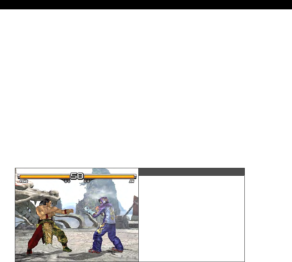
Getting Input from the “User” World 20
Game Programming for the Propeller Powered HYDRA Page 577
20.4 Input Device Sequence Tracking
If you have ever played any of the popular fighting games such as
Virtua
Fighter
,
Tekken
(shown in Figure 20:5),
Street
Fighter
, and so forth then you are probably a master at
multiple-button fight moves. The idea is that a standard controller only has so many buttons:
usually a directional keypad, select, start, and a couple action buttons. As fighting games in
particular got more and more complex, the number of fighting moves and defenses quickly
outnumbered the number of control buttons on the game interfaces, so programmers had to
come up with a way to add more controls to a controller or interface. The solution was rather
than adding more controls, the idea was to use
sequences
of button presses to create new
events. For example,
“round house kick”
might be
“down, down, punch,”
and
“flying
arm bar”
might be
“up, punch, punch, kick”
and so forth. This had two positive effects:
first it allowed the programmers to literally add hundreds of offensive and defensive moves,
plus it added another skill aspect to the game: the more moves a player remembered and
the faster he could key in the sequence the better his fighter fights! So, when you play these
games it’s like you are really fighting since you have to work so hard and hit the buttons so
fast to call up a specific move! This is why if you are in the arcade and you see some really
good gamers playing a fighting game, they are not just hitting random buttons’ they are both
feverishly trying to enter in offensive and defensive moves faster than their opponent.
Figure 20:5
A screen shot of Tekken 5
on the Playstation 2, one of my
favorite fighting games.
Having the ability to turn a few control inputs into hundreds is very desirable for more than
just fighting games, any game can take advantage of this, especially games that are played
on controllers with only a few buttons. If you have a keyboard handy then maybe you can
map many extra moves to the keys, but players tend to like to only have to keep their fingers
on a few controls and enter in sequences rather than use all the 101 keys of a keyboard.
Taking that into consideration, this technique is a very important in game development, so
we are going to take a practical look at it with an example.
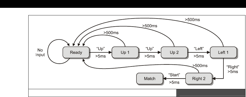
III Game Programming on the HYDRA
Page 578 Game Programming for the Propeller Powered HYDRA
State Diagram for a Button Sequence Figure 20:6
As usual, I like to take a problem and simplify it to its core, then you can always improve it or
generalize it later. So what we are interested in doing is simply to
“listen”
to the data
packets coming from the input controller for a specific sequence, if the sequence is found
then we should fire off the event that the sequence indicates. Figure 20:6 shows a state
diagram for the sequence “UP, UP, LEFT, RIGHT, START”. Now, this problem is deceptively
complex. At first glance, it seems like nothing more than a simple parser problem that you
might solve every day when comparing strings, for example it’s very easy to write an
algorithm that looks for a sub-string in a string, therefore, you might make an analogy that
the sub-string is the sequence you are looking for and the string is the packet data stream.
The problem is that we are talking about temporal events here and real time, when the
player is entering a sequence, there is more than the sequence we are concerned about. We
are concerned with:
How long is each button held down?
How long until the next button in the sequence is entered?
How close is the up and down time of all the buttons?
That is, the player can’t press UP for 1 sec then press the next button for 5 secs, then wait
10 secs and hit the next button, the player has to enter the sequence quickly and with timing
that is consistent with a video game’s tempo and speed. However, we have to give the player
some “window” of time, so he doesn’t have to be perfect every time. Thus, we might say
that given any sequence, once the first button in the sequence is detected then each button
must be held down for at least 5 ms and at most 500 ms, and when a button is released, no
more than 500 ms can elapse before the next button in the sequence is pressed, otherwise,
the player is too slow and the sequence is lost! Of course, if a wrong button is pressed then
the sequence is wrong as well. Hence, the devil is in the details of this one and the temporal
coupling is what makes the algorithm non-trivial. As an example, take a look at

Getting Input from the “User” World 20
Game Programming for the Propeller Powered HYDRA Page 579
ARENA_INPUT_DEMO_003.SPIN. Go ahead and run the program, and using the
gamepad try hiting the button sequence “UP, UP, LEFT, RIGHT, START.” Make sure to hit
the buttons and release them cleanly, and do it quickly and consistently. If you do it right
then you will see the tile background change! Then enter the sequence again and the
background will return to its normal artwork. Now, try and slow down your button sequence,
at some point you might take 1 second per button and this will be too slow and the
sequencer will not accept it, since what kind of fighting move takes 5 seconds to enter! On
the other hand, there is a minium time you must hold each button down, but I have it set so
short than no human could probably press the buttons too fast, but see if you can!
The code for the sequencer is in a single function called
Sequence_Matcher
, it is simply
called each game frame by the main event loop and it’s job is to test for the sequence. It
uses globals to retain state and only looks for one sequence. The sequence is encoded in the
exact same format as our data packets and is stored in an array in the initialization section of
the program. Here’s the constants the demo uses relating to the sequencer:
' sequence / pattern detector constants, with these rates you can enter the seqeunce as fast
' as your little primate fingers can enter it, and as slow as .5ish seconds per button
SEQ_COUNT_MIN = 1
SEQ_COUNT_MAX = 30
' states for sequence detector
SEQ_STATE_WAIT = 0
SEQ_STATE_READY = 1
SEQ_STATE_MATCH_SEQUENCE = 2
Nothing more than some constants for the timing variables and integers to represent the
state of the sequencer detector state machine. Next are the globals needed for the
sequencer:
' sequencer globals
long seq_state ' state of sequencer
long seq_counter ' used to count time a button is down or up
long seq_index ' index into sequence pattern data array
long seq_min_flag ' flags if the minimum time for a button to be held has elapsed
long seq_fire_event ' this the message that says "do it" whatever the "event" is that the sequence
' fires off
long sequence[32] ' storage for sequence
long seq_length ' how many buttons in sequence
The comments explain what each global does. Moving on, the main initialization simply needs
to set up a sequence and that’s it; here’s the setup code that looks for the sequence “UP, UP,
LEFT, RIGHT, START”:
' initialize input sequencer to detect the sequence "UP, UP, LEFT, RIGHT, START"
seq_state := SEQ_STATE_WAIT
seq_counter := 0
seq_index := 0
seq_min_flag := 0
seq_fire_event := 0

III Game Programming on the HYDRA
Page 580 Game Programming for the Propeller Powered HYDRA
' each button in the sequence is followed by "no button", and at the end is only the last button
' look for "UP, UP, LEFT, RIGHT, START"
sequence[0] := IID_UP
sequence[1] := IID_NULL
sequence[2] := IID_UP
sequence[3] := IID_NULL
sequence[4] := IID_LEFT
sequence[5] := IID_NULL
sequence[6] := IID_RIGHT
sequence[7] := IID_NULL
sequence[8] := IID_START
' total number of elements in sequence
seq_length := 9
The code starts by resetting all the globals (since Spin has no static initialization in VAR
sections), and then, array element by array element, assigning the sequence. Also, note that
“no button down” is also part of the sequence, since we want the player to release all
buttons in between the sequence buttons, this gives us more flexibility. Finally, a call is
made in the main event loop each cycle to the sequence matching-function which is shown
below:
PUB Sequence_Matcher | player_input_bits
' this function matches sequences of events from the input controller, it
' uses globals to make things simple, the sequence it tries to match is stored
' in the global sequence[] array, and when/if found it sends a message by
' setting seq_fire_event = 1
' extract the digital bits word only from the player_input
player_input_bits := (player_input & $FF)
case seq_state
SEQ_STATE_WAIT:
' wait until no key is pressed, then transition to ready state to try and catch another sequence
if (player_input_bits == IID_NULL)
if (++seq_counter > SEQ_COUNT_MIN)
' safe to transition into ready state and hunt for sequence
seq_state := SEQ_STATE_READY
seq_counter := 0
seq_index := 0
seq_min_flag := 0
SEQ_STATE_READY:
' this is the entry point to test the sequence whatever it may be, we know that the last
' command packet was empty so anything that comes through can potentially start the state
' transition to match sequence
' step 1: test for starting command in sequence if found then transition to match sequence
if (player_input_bits == sequence[seq_index])
' transition to match sequence and try and match this "potential"
seq_state := SEQ_STATE_MATCH_SEQUENCE
seq_counter := 0

Getting Input from the “User” World 20
Game Programming for the Propeller Powered HYDRA Page 581
' test for incorrect button press, if so reset to wait state
elseif (player_input_bits <> IID_NULL)
' send back to wait state, a wrong key was pressed
seq_state := SEQ_STATE_WAIT
seq_counter := 0
' else input was null, so its ok to stay in this state...
SEQ_STATE_MATCH_SEQUENCE:
' this is the primary matching logic, if we are here, the first button in the sequence is
' currently pressed, so we have to make sure the press is long enough, but not too long
' first increment the sequence time counter which is used to time how long buttons are down
++seq_counter
' test for minimum time for botton down satisfied
if ( (player_input_bits == sequence[seq_index]) and (seq_counter > SEQ_COUNT_MIN) and (seq_min_flag == 0))
' set minimum count satisfied flag
seq_min_flag := 1
' test for early withdrawel from button press
elseif ((player_input_bits <> sequence[seq_index]) and (seq_counter < SEQ_COUNT_MIN))
seq_state := SEQ_STATE_WAIT
seq_counter := 0
' test for next button in sequence pressed, or is this last button in sequence
elseif ((seq_counter > SEQ_COUNT_MIN) and (player_input_bits == sequence[seq_index+1]))
' two case: this button is in the middle of the sequence or its the last
if ((seq_index+1) == (seq_length-1))
' end of sequence, fire off event!
seq_fire_event := 1
' move to wait for next sequence
seq_state := SEQ_STATE_WAIT
seq_counter := 0
else
' middle of sequence, consume button event and move to next
seq_counter := 0
seq_index++
seq_min_flag := 0
' test if maximum time has expired, no matter what we are done..
elseif (seq_counter > SEQ_COUNT_MAX)
' player held button down too long, reset to wait state
seq_state := SEQ_STATE_WAIT
seq_counter := 0
The function is mostly comments, but is a little tricky; the general idea is that it sits in the
“waiting”
state waiting for the player to completely release the buttons, then it moves to
the
“ready”
state looking for the first button in the sequence. If it detects the first button
then the state machine moves to the
“matching”
state and looks for the remainder of the
buttons, but uses a timing element to make sure that they are entered in a temporal fashion
compliant with the min and max time limits. When and if the sequence is found then the
variable
seq_fire_event
is set TRUE which is monitored in the main event loop, if TRUE,
the main event loop toggles the background tile map with the following code:

III Game Programming on the HYDRA
Page 582 Game Programming for the Propeller Powered HYDRA
' if event was fired change tile map
if ( seq_fire_event == 1)
' reset event seq_fire_event
seq_fire_event := 0
' toggle tile map
if (tile_map_base_ptr_parm == @tile_map1)
tile_map_base_ptr_parm := @tile_map0
else
tile_map_base_ptr_parm := @tile_map1
And that’s about all there is to it! Of course, the next step is to make the function able to
read multiple sequences simultaneously, and be able to do more complex things like call
functions when a sequence was detected and so forth. Supporting multiple sequences is
best done with a linked list or a
“tree”
like data structure since many sequences will have
common
“roots.”
For example “LLR-UU” and “LLR-DRRD” both have “LLR” in common,
thus the sequences would follow the root and then make a decision based on the 4th button
press to which way to go in the tree on a linked list to continue testing.
You can have a lot of fun with this input technology; it’s great for sports and fighting games
to make the player perform more
“physical”
sequences than single key presses.
You will notice that the keyboard doesn’t seem to work when you enter the
sequence. The reason why is that START and FIRE overlap, so when you press
START on the keyboard it also sets the FIRE bit in the packet. Thus, to support
this some extra logic is needed to mask bits etc. to take this special case into
consideration. But, this is an input-mapping problem, not a problem with the
sequencer.
20.5 ZoneBall
As an example of taking some of these input device techniques and putting them to good
use, I put together a basic “Breakout” game skeleton called
“ZoneBall.”
This demo uses all
3 input devices based on the version 2.0 universal controller. The game play consists of a
number of tile levels each with a set of tiles that represent background art and the
foreground “blocks” that you need to hit with the ball via the paddle which is controlled by
the player. A screen shot of the game is shown in Figure 20:7.
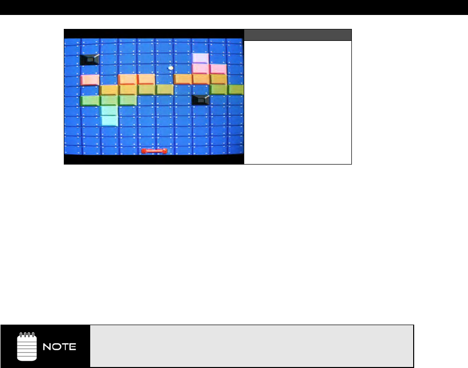
Getting Input from the “User” World 20
Game Programming for the Propeller Powered HYDRA Page 583
Figure 20:7
ZoneBall in Action
The rules of the game are simple; clear each level by hiting all the blocks with the ball and
go to the next level. The game is just a demo, so there is lots for you to add. Right now, the
game starts off by initializing everything then placing the paddle at the bottom of the screen
with the ball in it. To launch the ball into play press the “FIRE” or “START” button on any
input device and the ball will be fired. Control the ball by moving the paddle right and left
with the standard “RIGHT” and “LEFT” controls on any input device. If the ball gets past
you, it will load into the firing position again and you restart. This is where you would later
add in score, and the number of balls, so the game doesn’t let the player miss balls forever!
Anyway, when a level is cleared then the next level is started; there are a handful of levels
then they cycle. The source can be found in: ZONEBALL_INPUT_DEMO_001.SPIN.
The virtual keys “FIRE”, “START”, “RIGHT” and “LEFT” are the generic values
we assigned to the universal input controller’s data packet format. Depending on
what input device you are using, they map to different sub-controls, refer to
Table 20.3 to see the assignments.
The levels each consist of a tile set, the tile set is laid out to look cool with lots of color and
blocks to show off the tile engine. Also, there are immovable blocks that look like little
pyramids (dark gray) that the ball just bounces off to make things harder. Now, there are
lots of details to a game like this, but I am only going to talk about three of them:
Level Loading
End of Level Determination
Collision Detection

III Game Programming on the HYDRA
Page 584 Game Programming for the Propeller Powered HYDRA
20.5.1 Level Loading
In a game that is based on levels, each level must be represented by a record or data
structure of some kind. The level could be as simple as a few numbers or it could be as
complex as geometry data, character data, sounds, etc. In the case of
ZoneBall
, each level
is represented by a tile set which indirectly references tile data an palettes, thus, we need a
single index number to represent which tile set to use for the level. Additionally, we need to
know how many blocks the level has that the player needs to hit with the ball, of course we
could count them on the level load, but for fun, we are going to add this to our level format.
Thus, each level record only needs two pieces of data:
1. Level number 0..n
2. Number of blocks in level
The level number number is used to index into a table that contains a list of addresses to the
base memory of each tile, and the number of blocks is used by the game logic to determine
when the level is completed, so the game engine can load the next level. Thus, we need an
array of these records to control the entire level-loading process.
20.5.2 End of Level Determination
ZoneBall
is based on the rules of “Breakout” thus the idea is to clear off the level of any
blocks, this is done by striking the blocks with the ball. To determine the end of the level
there are a couple ways to do this: one way would be each game cycle to count up how
many blocks are left on the tile set, but this would be a waste of computation, a better
approach would simply be to keep a running count of how many blocks are left from the start
of the level. For example, say level 1 starts and there are 40 blocks on the screen, this is
stored in a counter, then when the balls hits a block, it is removed from the screen and the
counter is decremented. When the counter reaches 0 then the level has been cleared. This
technique works since the number of blocks is deterministic. Even if we
added
blocks during
game play we simply would increment the counter to represent this. As long as we don’t
loose track of the number of blocks on the game level, a simple counter works. Basically, it’s
like a
“reference counter”
in Windows COM-speak.
20.5.3 Collision Detection
When we cover physics modeling and collision detection later in the book we will discuss
many ideas about collision detection in games which itself is a huge subject and one can
easily write a 2000-3000 page book on! So our discussions are going to be very basic.
However, as an introduction this game is a great place to start for a common collision
problem found in any kind of breakout/pong game; that is, how to detect when the ball hits
something and what to do when it does?
The first thing to remember is we are making games here not NASA simulations, our collision
algorithms just have to work good enough for the game to be fun and playable, but they
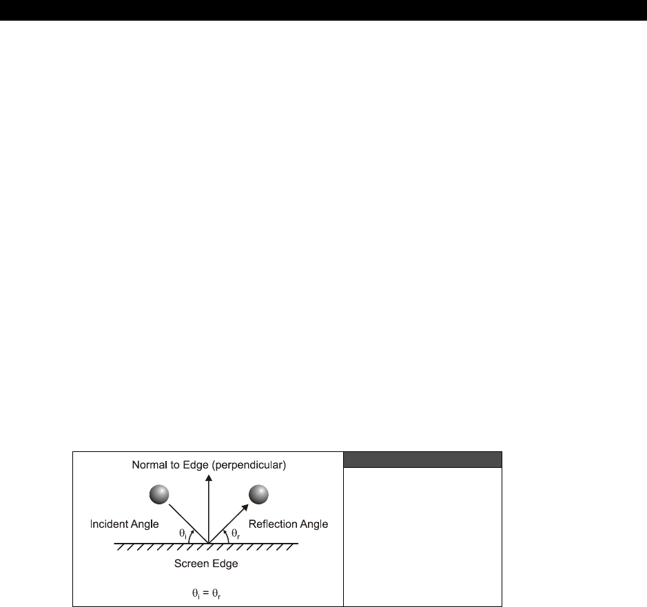
Getting Input from the “User” World 20
Game Programming for the Propeller Powered HYDRA Page 585
don’t have to be perfect. Computationally accurate collision detection is a complex field in
physics and advanced game programming that deals with complex mathematics that we
aren’t going to need. The idea here in video games is to base your collision detection on real
physics, but to simplify the algorithm considerably, so it’s feasible to implement with simple
math in a few lines of code. Also, how accurate you need the collision detection to be has a
lot to do with the complexity of the algorithms.
In the case of
ZoneBall
, we have a number of collision detection events we have to handle,
they are:
Ball-to-screen edge collsions
Ball-to-paddle collisions
Ball-to-block collisions
Each type of collision is handled slightly differently, so let’s take a look at each in increasing
order of difficulty.
20.5.3.1 Ball-to-Screen Edge Collisions
This is the easiest collision to deal with since all 4 sides of the screen are straight lines, thus
we can make a lot of assumptions about the math. We are going to simulate a
“perfectly
elastic collision”
which means that the angle of incidence that the ball strikes the wall is
the same as the angle of reflection and there is no energy lost, Figure 20:8 shows this
graphically. Of course perfectly elastic collisions only occur in video games and high school
physics tests, but we are ok here!
Figure 20:8
Ball to Screen
Edge Collision Setup
The math is simple to program this behavior, given that the ball’s velocity
is ball_xv
,
ball_yv
, all we need to do is reflect this vector along the path of incidence. But, we can
simpifly this even more with some information; if we hit the top or bottom edges of the
screen then we know that we need to reflect only the ball’s y-velocity since the x stays the
same. Similarly, if we hit the screen’s right or left edge then we simply reflect the ball’s x
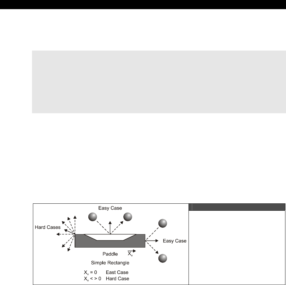
III Game Programming on the HYDRA
Page 586 Game Programming for the Propeller Powered HYDRA
velocity. Also, we need to add in the rules of the game which state that if the ball hits the
bottom edge of the screen (getting past the player’s paddle) then the game restarts with a
new ball. But, for now let’s forget the rule, and concentrate on the physics. The code/math is
shown below to create this behavior:
' test for ball collision with game playfield boundary
if ((ball_x > BALL_PLAYFIED_MAX_X) or (ball_x < BALL_PLAYFIED_MIN_X))
ball_xv := -ball_xv
ball_x += ball_xv
ball_y += ball_yv
if ((ball_y > BALL_PLAYFIED_MAX_Y) or (ball_y < BALL_PLAYFIED_MIN_Y) )
ball_yv := -ball_yv
ball_x += ball_xv
ball_y += ball_yv
...where the constants in the conditionals represent the various screen boundaries. Now, you
might like to note that when a collision occurs, the ball is translated once again. This is a
curious extra step, but it’s needed since by the time you detect a collision you are
already
past
the collision boundary, thus the object has pierced solid matter, so to make things
“look”
more realistic, a typical technique is to
back
the
object
up
either by reversing it or
to track the last known position, so when a collision does occur, we perform the changes in
trajectory then use the
old
position
to move the object back to the position right before the
collision took place which is “more” correct then after it took place.
20.5.3.2 Ball-to-Paddle Collisions
Figure 20:9
The Details of Ball/Paddle
Collisions
Now, here’s where things get really tricky depending on how realistic you want your breakout
game. In a real commercial breakout game, you might need hundreds of lines of code to
perform the ball paddle collision correctly to give the player the right “feel.” This is because a
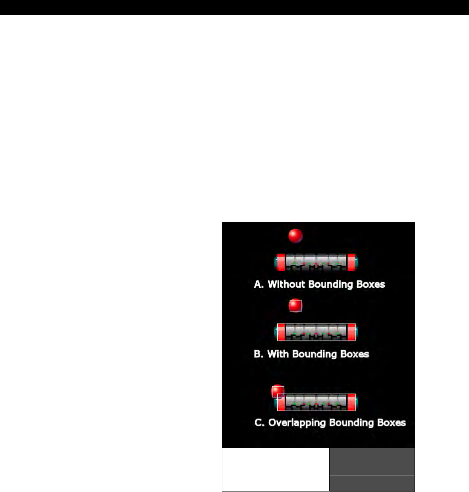
Getting Input from the “User” World 20
Game Programming for the Propeller Powered HYDRA Page 587
real ball and a real paddle have a lot of parameters to model even if you are cheating. For
example, in breakout games, many games give the ball a virtual “spin,” this is used along
with the velocity of the paddle to cause the ball to shoot off in another direction when you hit
it. For example, if you play a modern breakout game, and right when you hit the ball, you
apply some
“english”
to the paddle by moving it quickly, you can effect the reflection of the
ball and target it better. Also, if you have a paddle that has a square surface, what if the ball
hits the corner? For example, take a look at the “Hard Cases” in Figure 20:9 to see this, in
these cases the ball should do something different since it’s hitting a corner.
Alas, in our case, we aren’t going to deal with all these factors, we just want the ball to
refect off the paddle and look reasonable. We are going to only have a couple “english”
factors; if the paddle is moving when it hits the ball then we are going to factor this into the
ball’s response. Also, we are going to add a little bit of randomness to the response of the
ball on the paddle as well. However, as long as the ball hits the paddle then the entire
surface of the paddle is the same as far as we are concerned which brings us to another
problem. How to detect if the ball has hit the paddle at all?
This is really a problem in geometry
ultimately, the ball is a sprite with a certain
size, the paddle is a sprite with a certain size
(usually smaller than the sprite data which is
always 16×16), so step one is to simplify both
problems by placing
bounding
boxes
around the paddle and the sprite, since
squares are easier to test collision against one
another than arbitrary polygons or bitmaps,
this is shown in Figure 20:10. Referring to
Figure 20:10(B), see how the bounding boxes
surround the ball and paddle, and are smaller
than the actually sprite data (this makes for a
more certain collision). Thus, the bounding
boxes are mathematical in nature and you
have to store them in a secondary data
structure, either in a record or
programmatically via your collision
calculation’s conditional logic test via test
constraints. Either way you do it, at the end
of the day, the problem is to determine a
collision between two boxes as shown in
Figure 20:10(B).
Bounding Boxes
Simplify Collision
Detection
Figure 20:10

III Game Programming on the HYDRA
Page 588 Game Programming for the Propeller Powered HYDRA
There are hundreds of algorithms to do this, but one of the simplest is to transform the
problem from determining if two boxes intersect, to test a point and box intersection, this is
shown in Figure 20:10(C). Testing if a point is in a box is very simple, then to test if the
boxes intersect, we simply take the 4 points that make up box A and if none of them are
inside box B then there can’t possibly be a collision! As an example of the algorithm, let’s say
that box A is composed of 4 points: A1(x,y), A2(x,y), A3(x,y), and A4(x,y). Let’s call any
single test point (x,y), then let’s test it against box B which consists of B1(x,y), B2(x,y),
B3(x,y), and B4(x,y). The pseudo-code algorithm to test for containment is shown below:
if (x >= B1.x and x <= B2.x and y >= B1.y and y <= B2.y )
' ... the point is contained
else
' ... point not contained
Then you simply perform the test for all 4 points that make up Box A. However, if you really
want to simplify the problem even more then forget that the ball has a bounding box at all
and simply represent it as a
single
point
. This is viable since a ball is round anyway, and we
are interested in the center of the ball, since what the center does is mostly what the rest of
the ball does, therefore, we can simplify the ball paddle collision to a single point (the ball’s
center) tested against a bounding rectangle (box) of the paddle and then perform the
appropriate response for a perfectly elastic collision which is just to reflect the ball’s direction
about the paddle’s surface along with adding a little “english” based on the motion of the
paddle. The entire collision detection algorithm from the demo is shown below for reference:
' test for collision with ball and paddle, use center point of ball and test against bounding box of
' paddle
if ( (ball_x > (paddle_x - PADDLE_WIDTH_2) ) and (ball_x < (paddle_x + PADDLE_WIDTH_2) ) )
if ( (ball_y > (paddle_y - PADDLE_HEIGHT_2) ) and ( ball_y < (paddle_y + PADDLE_HEIGHT_2) ) )
' there's been a collision, now respond, the "response" depends on how accurate you want to be!
' first invert the y-velocity
ball_yv := -ball_yv
ball_yv += -3 + (?random_seed & $03)
' now add a little bit of english based on the movement of the paddle
if (||player_input_x > 0)
ball_xv -= player_input_x/2
' clamp velocity of ball
ball_xv #>= -4
ball_xv <#= 4
ball_yv #>= -4
ball_yv <#= 4
ball_x += ball_xv
ball_y += ball_yv
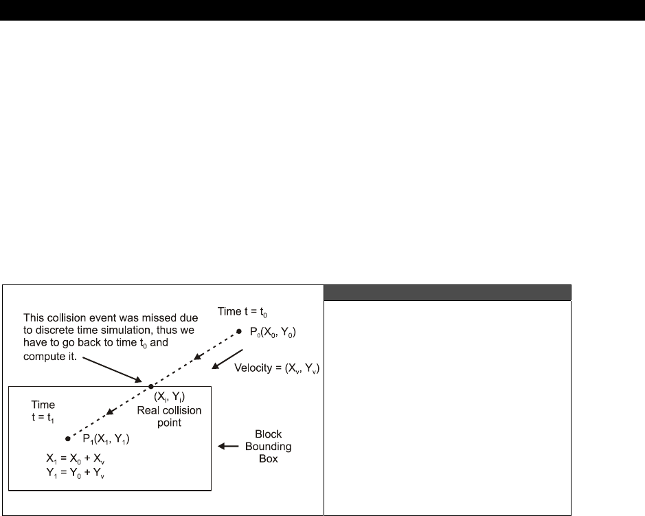
Getting Input from the “User” World 20
Game Programming for the Propeller Powered HYDRA Page 589
20.5.3.3 Ball-to Block-Collision
These collision are nearly identical to the ball-to-paddle collisions, but are slightly simplified
since the blocks aren’t moving and there are no “english” calculations to make. On the other
hand, to be accurate we have to consider that the ball can hit any block on all four sides, this
makes the collision calculation a little longer since we have to determine which side;
top
,
bottom
,
left
, or
right
of the block that the ball hit and reflect the ball. Thus, the problem
turns into the ball-to-paddle collision problem performed four times. Also, there is the
additional problem in collision detection that, depending on how you perform the
calculations, you might end up with more than one potential collision surface, thus you have
to further process to resolve this issue. For example, if the ball is moving very quickly from
one frame to another, it could be outside the block then all of a sudden inside the block! If
the ball’s trajectory was near the corner of the block we would have a hard time finding
where the ball
“would have”
intersected the block if we could go back in time.
Figure 20:11
Using Vector Trajectory of Ball
to Detect the “True” Point of
Intersection with Block
This is why in formal collision detection algorithms, you would use vectors, polygons, line
equations, and so forth to determine where the trajectory vector of the ball strikes the
collision surface as shown in Figure 20:11. In the figure at time t0, there is no collision, then
at time t1, the ball is inside the block, thus a collision must have occurred. The problem is
that we don’t know where the collision occurred. To compute this, we must project a vector
from the ball position at t0 to t1 and compute the intersection as shown in the figure.
This can be done surely, and isn’t that hard, but for now, I want to keep things a little
simpler, so in this case, we are just going to perform the four collision tests against all four
sides of the block and try and figure out which side the ball hit, then reflect it, if we are
wrong once in a while it doesn’t matter since it’s a game! The technique more or less is going

III Game Programming on the HYDRA
Page 590 Game Programming for the Propeller Powered HYDRA
to compute the distance from the ball to each of the edges, and the closest edge will be
assumed to be the edge the ball hit first. When we discuss physics and collision detection, we
will formally look a little closer at these math problems. However, in all truth many game
programmer that write simple 2D games rarely have to resort to formal algorithms, they
usually can
“hack”
it and make it work and that gives the game a more
“arcade”
feel
anyway.
Considering that, the math and techniques are the same as in the previous discussions, the
only difference is that when the block is hit we need to decrement the global block counter,
so the game engine knows that yet another block has been removed. This allows me to bring
a point to light and that’s how the physics engine can
“send messages”
to the game
engine: the decrement, as simple as it is, is really a “message” and this is an example of
message passing. However, good game programming keeps the rendering, physics, and
gameplay engines decoupled. The only coupling is saved strictly for messages. That is, the
renderer should render, the physics engine do physics, and the game engine do the game,
they shouldn’t be integrated and/or do each other’s work. By de-coupling each portion it
makes debugging, coding, and upgrading much easier. Please refer to the complete source
of ZONEBALL_INPUT_DEMO_001.SPIN to see the source for this since it’s very similar
to the ball-to-paddle collision listed in the paragraphs above.
20.5.4 Gameplay and Design Tricks
To play the game simply load up
ZONEBALL_INPUT_DEMO_001.SPIN, grab an input device and press “START” or “FIRE”
to launch the ball. Other than the basic game play there are some interesting things to note
about the use of the tile engine here. For example, on some levels you will see that the
paddle changes colors as it moves around right to left, this is by design, using different
primary paddle colors in the palettes for the tiles. Also, the sprite that makes up the paddle is
actually two sprites. One sprite wasn’t large enough, so I took two sprites and placed them
side by side, drew the proper art into their bitmaps and during each animation cycle made
sure to draw them next to each other. Here are the bitmaps for each sprite half (minus the
mask which you can look for in the source):
' bitmap for sprite use, uses the palette of the tile its rendered into
sprite_bitmap_0 long %%0_0_0_0_0_0_0_0_0_0_0_0_0_0_0_0 '0_0_0_0_0_0_0_0_0_0_0_0_0_0_0_0
long %%0_0_0_0_0_0_0_0_0_0_0_0_0_0_0_0 '0_0_0_0_0_0_0_0_0_0_0_0_0_0_0_0
long %%0_0_0_0_0_0_0_0_0_0_0_0_0_0_0_0 '0_0_0_0_0_0_0_0_0_0_0_0_0_0_0_0
long %%0_0_0_0_0_0_0_0_0_0_0_0_0_0_0_0 '0_0_0_0_0_0_0_0_0_0_0_0_0_0_0_0
long %%0_0_0_0_0_0_2_2_2_0_0_0_0_0_0_0 '0_0_0_0_0_0_0_0_2_2_0_0_0_0_0_0
long %%0_0_0_0_0_2_2_3_0_0_2_2_2_2_0_0 '3_3_3_3_3_3_3_0_2_2_2_0_0_0_0_0
long %%0_0_0_0_0_2_3_2_2_2_2_2_2_2_2_2 '2_2_2_2_2_2_2_2_2_2_2_0_0_0_0_0
long %%0_0_0_0_0_2_2_2_2_3_3_3_3_3_3_3 '2_2_2_2_2_2_2_2_2_2_2_0_0_0_0_0
long %%0_0_0_0_0_2_2_2_2_2_2_2_2_2_2_2 '2_2_2_2_2_2_2_2_2_2_2_0_0_0_0_0
long %%0_0_0_0_0_2_2_2_2_2_2_2_2_2_2_2 '2_2_2_2_2_2_2_2_2_2_2_0_0_0_0_0
long %%0_0_0_0_0_2_2_2_2_2_2_2_2_2_2_2 '2_2_2_2_2_2_2_2_2_2_2_0_0_0_0_0
long %%0_0_0_0_0_2_2_2_0_0_1_1_1_1_1_1 '1_1_1_1_1_1_0_0_2_2_2_0_0_0_0_0
long %%0_0_0_0_0_0_2_2_2_0_0_0_0_0_0_0 '0_0_0_0_0_0_0_0_2_2_2_0_0_0_0_0

Getting Input from the “User” World 20
Game Programming for the Propeller Powered HYDRA Page 591
long %%0_0_0_0_0_0_1_1_1_0_0_0_0_0_0_0 '0_0_0_0_0_0_0_0_0_0_0_0_0_0_0_0
long %%0_0_0_0_0_0_0_0_0_0_0_0_0_0_0_0 '0_0_0_0_0_0_0_0_0_0_0_0_0_0_0_0
long %%0_0_0_0_0_0_0_0_0_0_0_0_0_0_0_0 '0_0_0_0_0_0_0_0_0_0_0_0_0_0_0_0
Notice the right half of the sprite is commented out, I drew the sprite in the comments then
copied the right commented side out and made it
sprite_bitmap_1
(and then made small
changes to it). This way I had two sprites
sprite_bitmap_0
and
sprite_bitmap_1
that
represented the right and left halves of the paddle (mirrored of course). Then in the main
even loop whenever the paddle is moved, both sprite halves are moved and re-positioned, so
they stay in sync and look like one object. The following code peforms this update:
' now update the sprite records to reflect the position of the paddle
sprite_tbl[0] := (paddle_y << 24) + (paddle_x << 16) + (0 << 8) + ($01)
sprite_tbl[2] := (paddle_y << 24) + ((paddle_x+16) << 16) + (0 << 8) + ($01)
Also, you will notice that the ball has a little shadow in it, this is simply drawn there and isn’t
real.
Also, if you look closely at some of the palette color entries you will see color
values like:
$xF ' where “x” is 0..F
That is, the LUMA is $F. This is not supposed to work, since the color
modulation needs to have +-1 to toggle the chroma signal. The rule was no
LUMA value can be greater than 6, but in this case it’s 7 (remember the 8th bit has
to be on for color). This trick creates over-saturated colors!!! So you can get an
extra 16 colors on the HYDRA by using the colors $0F, $1F, $2F, …, $FF. The
only downside is depending on your TV, they may look a bit different.
20.6 Advanced Concepts
There are so many things you can do with input devices. For example, look a the Apple
Macintosh or PC, with a single mouse and 1 or 2 buttons, you can control entire networks!
This is due to the clever and creative use of the mouse. There is really no limit to how cool
you can make your input controllers, for example we talked about input sequence testing to
determine key presses, but what about the opposite? That is, pressing a button or sequence
of buttons that output another sequence of buttons? For example, you press
<START>+<SELECT> and instead of that firing off a single command, it
“plays”
a sequence
of commands out the input controller as if they were coming from the player, this way you
can do complex moves and sequences that would be impossible. Or as another example,
giving the player the ability to record sequences he/she wishes and then play them back
based on specific key sequences.

III Game Programming on the HYDRA
Page 592 Game Programming for the Propeller Powered HYDRA
Another thing you’re always hearing about is
“force feedback.”
This is easy to implement
with the HYDRA, all you need is a really tiny motor like that found in the vibrator circuit of a
cell phone or pager. Then you could crack open the NES controllers, add logic so that when
the latch is disabled, the data line is used as an output to the controller and gated to the
motor, then you can pulse the motor to make the controller vibrate during times in the game
that were appropriate.
20.7 Summary
This chapter hopefully has opened your eyes to what most people take for granted –
input
device
programming
. There is a lot to it if you want to do it right and support all devices
in the proper way. Also, filtering input devices through “software controllers” and sequencers
can help games and applications respond much better than they would with raw data, so
these concepts transfer to all kinds of programming in addition to game development. Alas,
we have only scratched the surface here, but hopefully you have have a new found respect
for input device programming!

Sound Design for Games 21
Game Programming for the Propeller Powered HYDRA Page 593
Chapter 21:
Sound Design
for Games
In this chapter, we are going to briefly discuss
“sound design”
techniques for games.
Sound design is the art of using sound in games to add richness and depth to a game. This
subject is huge on so many levels, thus it’s nearly impossible to do it justice without 500+
pages. Alas, we are simply going to review some of the technical aspects of sound
generation, take a look at a sound driver to get you started, and finally write an application
that plays RTTTL (Ring Tones Text Transfer Language) phone ringtone files. By the end of
the chapter you will have your hands on a very powerful sound engine that plays both FM
and PCM sounds along with a cool little RTTTL player you can use in your games. Here’s
what’s in store:
Sound generation techniques review
Working with sound and music for games, and problems to consider
FM/PCM sound driver overview
RTTTL (Ringtone) music player
21.1 Sound Techniques Review
If you haven’t read Chapter 9 then I highly suggest you do so now, as well as Chapter 16,
sub-section 6. This material covers the sound hardware and sound generation techniques
used on the HYDRA game system. To briefly review, the best way to create sounds on a
limited memory system like the HYDRA is to use PWM (pulse width modulation) synthesis to
generate analog time-varying waveforms in real-time to emulate the abilities you would find
on a standard FM synthesizer such as a Sound Blaster. This technology will allow you to play
musical notes and effects, and more or less create music and game sounds like lasers,
explosions, and so forth. The only problem is that most games these days use pre-recorded
digitized
sound effects rather than trying to synthesize them by using PCM (pulse coded
modulation) techniques, that is, sending out 8- or 16-bit samples to a D/A followed by the
speaker. This is a stretch for the Propeller chip since it only has 32K of RAM on board, thus
external memory like the HYDRA’s larger 128K EEPROM have to be streamed in potentially or
other memory added to get the megabytes needed to support large samples for games.
Nonetheless, even with a few K, one can digitize a handful of very short samples and use
them for key sound effects in a game: an explosion, a laser, a little bit of voice and so forth.
Not to mention if you want to start compressing your PCM sounds then you can make 8 to
16K of sound memory go a pretty long way!
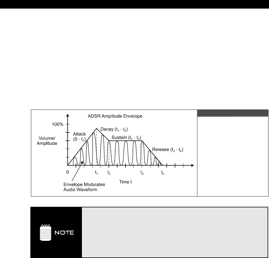
III Game Programming on the HYDRA
Page 594 Game Programming for the Propeller Powered HYDRA
Supporting music is rather easy as long as you have a sound driver that can play any
frequency in a selected waveform along with envelope control (desired, but not absolutely
necessary). For example, a simple sound API like this is more than enough for a savvy game
programmer to do a lot of damage:
Play_Sound(channel, frequency, envelope, duration, volume)
Additionally, the more channels you have, the more instruments or tracks you play at once,
adding to the richness of the musical piece. For example, most early game systems had four
sound channels where three of them were used for tonal sounds and one for white noise or
percussion. With the simple ability to play a tone along with the sound envelopes and some
sequencing software to play notes on the channels at specific times, you can make any
musical piece you wish.
Figure 21:1
Using an Amplitude
Envelope to Modulate
a Sound as a Function
of Time
The concept of “sound envelope” has been discussed in Chapter 9 and 16.
Sound envelopes are really amplitude modulation envelopes that give you the
ability to play a sound that doesn’t just abruptly turn on and off, but rather the
amplitude can slowly increase, then sustain a particular level, then fall off based
on the shape of the envelope. In sound programming, we use a simple ADSR
envelope which stands for “Attack-Decay- Sustain-Release” as shown in Figure
21:1. By modulating a pure tone’s amplitude or volume with the envelope, you
can get all kinds of effects that are similar to real instruments and how they
sound when struck, blown, drummed or plucked.
The MIDI (Musical Instruments Digital Interface) is just such as
“sequencing software”
standard. MIDI is a serial protocol used by electronic instruments to play (and record) music.
It consists of a number of commands that a MIDI device listens to and then plays the music
based on the command(s). Of course, not all devices support all MIDI commands, thus any

Sound Design for Games 21
Game Programming for the Propeller Powered HYDRA Page 595
MIDI device
tries
to do its best at reproducing the intended musical piece. Some of the
commands include instrument selection, channel selection, play note, turn notes off,
download instrument data, timing commands, and so forth. MIDI is very powerful, but a little
overkill for our needs, so later we will look at a simplified musical format called RTTTL (ring
tones text transfer language) which is used to play all those annoying cell phone ringtones
you heae all the time. RTTTL is very much like MIDI, but it’s only a single-channel format or
what’s called
“monophonic”
and has fewer commands to support. We will cover it in detail
later.
21.2 Working with Sound and Music for Games
Simply put, sound and music makes a game more fun. For example, take your favorite game
and play it with the sound turned off, I guarantee the experience with be 10% of what it is
with the sound on no matter how good the graphics are. On the other hand, take a game
with great sound and music and lower the resolution, decrease the color depth, and even
slow it down and the game will still be fun. This simple psychological fact is well known
among game developers. As another example, take a simple 2D game like asteroids, replace
the simple “electronic” sounds with digitized explosions with deep bass, realistic plasma
weapons sounds, and engines that roar, and that little game will put a smile on anyone’s
face! So the bottom line is that
games need sound
and the art of engineering the sounds for
a game is called
“sound design.”
Once again this is a very deep and complex field that is
both artistic and technical, but at very least the idea is to design a game and during the
design be thinking of all the sounds that game needs at very least: when, what, where, and
so forth. Also, what’s the “theme” of the sounds? Will your game sound “old,” “new,” “alien,”
“rough,” and so forth? These are all questions that you have to answer and get the hang of
as you design the sounds and music for your games.
In our case, we are going to be talking about very simple sounds and how to do things in a
practical manner. For example, let’s say that we want to make a simple space shooter game.
The first thing to do is make a list of what kinds of sounds the game will need:
1. Laser/plasma pulse when player fires (variations)
2. Explosions (various types)
3. New level sound effect
4. End of level sound effect
5. Player death sound
6. Boss level music track
7. Sounds of laser/plasma hitting various environmental objects: rocks, metal, glass etc.
As you can see, just off the top of my head we have quite a few sounds. Now, if we have
digital sound abilities then these sounds aren’t very hard to come by, you can make them,
license them, or a mixture of the two. However, on the HYDRA with limited memory, you

III Game Programming on the HYDRA
Page 596 Game Programming for the Propeller Powered HYDRA
would probably have to synthesize all of these sounds by playing waveforms through
channels and then playing with frequency, volume, etc. There is an entire art form to this.
But first let’s take an aside to some of the technical aspects of some common problems when
playing sounds on a game system. First off, as you can see there are 7 classes of sounds in
my little list, and there might be 1-10 instances of these sounds, that means something like
70 sound channels playing simultaneously! Well, even the XBOX doesn’t do this, so how can
a game as complex as Halo or Quake Arena with all the sound effects work? Well, first, there
are a lot of sound channels, but not enough to play every sound at once that the game might
throw at it.
Thus, when designing a sound engine, you have to think of the sound channels as
resources
. There might be 4-8 channels to choose from and each channel can play a simple
tone with a given frequency (that can change programmatically) along with a volume and
envelope. However, the problem is simple: let’s say the player fires his plasma cannon, the
sound algorithm for the plasma cannon starts running and allocates channel 0, then the
pulse fires and hits an alien which causes an explosion and 6 other secondary explosions, all
of a sudden there are 8 channels being used, the player tries to fire again and whoops a
plasma pulse comes out, but no sound!
21.2.1 Designing a Sound Playback Resource Allocator
The first thing you have to do when designing a sound engine is have a priority system that
basically will pre-empt a playing sound for other higher priority sounds. In the example
above, no matter what, when the player fires it
must
be heard. Also, when the player’s
plasma pulse hits something, that first explosion
must
be heard. Therefore, a typical
strategy is to design a sound engine that has each channel available, then when you play a
sound you assign a priority to the sound and a length to the sound. When the sound starts
playing, a timer counts along with the sound as it plays keeping track of how long more the
sound has to play, using this tracking system, you can tell if a sound is almost complete.
Having this knowledge helps in the construction of a pre-emptive sound resource selection
algorithm. A first pass at such an algorithm with the setup I have outlined would be
something like the pseudo-code algorithm below which finds an available sound channel
resource:
If there are any free channels, use that channel, assign priority, length, and
start timer. Done.
Else
For all channels with priority less than desired sound, find the sound that is
the most complete, pre-empt it, and use that channel, assign priority, and
start timer. Done.

Sound Design for Games 21
Game Programming for the Propeller Powered HYDRA Page 597
Else
For all channels with priority equal to desired sound, find the sound that is
most complete, pre-empt it, use that channel, assign priority, and start
timer. Done.
Else Can’t play sound right now, Queue sound up with “stale” count.
The algorithm tries to find a sound channel that it can use in the order of least disturbance to
sounds playing. Ultimately, if the sound can’t be played then its queued up in a timed queue
in the last step, let’s talk about this. The idea here is that if you can’t play the sound now,
then maybe you can in a few hundred milliseconds (or even a second or two). However,
most sounds need to happen right now if they are game-action sounds, but a few
milliseconds can be acceptable in most cases, thus a
“stale
” count is added to the queue
entry of the sound that basically says, “if you can’t play this sound in this many ticks, then
forget it, throw it away.”
The algorithm outlined above, as simple as it is, is very powerful and found in many games.
Of course the devil is in the details, but you get the idea hopefully; that is to allocate your
resources and pre-empt sound channels as need be, dictated by the game action.
21.2.2 Dealing with Real-Time in a Sound Engine
The next problem with designing a sound engine is the real-time nature of sound effects
synthesis. For example, let’s say that we have a sound API that has the simple sound call:
Sound(channel [0..3], frequency [0..255], volume [0..255])
...and all the sound function can do is play a square wave. Now, let’s say that through
experimentation, you find that you are trying to make a laser pulse and playing random
frequencies with an increasing volume to make a cool laser sound like this:
repeat volume from 0 to 255
Sound(0, random(255), volume)
repeat 10_000 ' add a little delay
This little chunk of code is a “sound effect algorithm” and is perfectly legitimate, in fact, this
is the exact way you engineer sound effects when you have an API you communicate
through. But, what’s the problem? The problem is that this is
not
real-time. If this algorithm
were called as a result of a player pressing the fire button, the game would pause, play the
sound then continue – that’s not good! So here we have yet another dilemma – we need the
sound engine to be real-time. This means that the sound engine has to be a function that is
called every animation frame (or multiple times a frame) and each sound effect that is
algorithmic must be updated, this means more complexity like state variables, timers, and so

III Game Programming on the HYDRA
Page 598 Game Programming for the Propeller Powered HYDRA
forth. Thus, as you can see this gets complex very quickly. Taking this into consideration, we
might have the following pseudo-code fragments:
Pub Sound_Engine(command, parm1, parm2, parm3)
{ called every frame by main event loop, inside this is every single sound effect
algorithm, the function iterates through all of them and any that are active are
updated… command tells engine what to do, and the generic parms are used based on
context of command }
' general command, simply to process all sound algorithms
if (command == PROCESS_SOUND_ALGORITHMS)
' begin process ALL sound algorithms here…
' laser blast algorithm
if (laser_sound_playing)
' update sound
Sound(0, random(255), laser_volume)
' update algorithm counter
if (++laser_volume > 255)
laser_volume := 0 ‘ reset volume for next user
laser_sound_player := 0 ‘ reset flag, so another call can use it
' turn sound channel off
Sound(0,0,0)
elseif (command == START_LASER_SOUND)
' request being made to start laser sound, high priority - start no matter what!
laser_sound_player := 1
laser_volume : =0 ' also used as counter
' end PROCESS_SOUND_ALGORITHMS /////////////////////////
This code allows the main event loop to start a laser blast with the following call:
Sound_Engine(START_LASER_SOUND, 0,0,0)
...and then in the main event loop each cycle, a call must be made to allow the engine to
process the sounds like so:
Sound_Engine(PROCESS_SOUND_ALGORITHMS,0,0,0)
...and this is the beginning of a complete sound engine! Of course, to do it right you would
want to use clean data structures, have many more commands, and so forth, but this
example illustrates the idea. The only problem with this real-time sound engine is that the
update rate is coupled to the game’s frame rate – this can be a problem.

Sound Design for Games 21
Game Programming for the Propeller Powered HYDRA Page 599
The problem with coupling the sound engine to the game’s frame rate is twofold: first, 30 to
60 frames per second is a typical game frame rate, this rate might not be nearly fast enough
to update the sound engine. Secondly, if the frame rate changes as the game slows down
due to complex calculations, then the rate at which the sound engine gets called, and
consequentially at which the sound functions will slow, will be very perceivable to the player
as the sounds slow down.
The solution to this problem is to use an interrupt to run the sound engine, so no matter
what the foreground is doing, the background task is processed(the sound engine in this
case is updated constantly), typically this might be 256 to 512 times a second if the sound
engine is making lots of changes per second. However, the Propeller has no interrupts, but it
does have multiple processors and the sound engine is a textbook example of what
should
be run as a separate process. Calls are made to the sound engine running on another cog,
and no matter what happens to the game logic and graphics, the sounds play cleanly and
consistently. That’s about all there is to getting up and running a first-class sound engine
that can handle all your needs. We don’t have enough time to build an entire sound engine,
but hopefully you have enough ideas to create one yourself, plus it’s a lot of fun. Next, we
are going to discuss the most important part of the sound engine, the sound driver, without
that there is no sound!
21.3 Sound Driver Object Overview
The sound drivers we are going to use for this discussion are:
NS_SOUND_DRV_051_22KHZ_16BIT.SPIN
NS_SOUND_DRV_051_11KHZ_16BIT.SPIN
.....which are the 22KHz and 11 KHz versions respectively and as usual are located on the CD
in CD_ROOT:\HYDRA\SOURCES\. The driver was written by Jedi Master demo coder
Nick Sabalausky
over a period of a couple months and is for educational use. The driver is
based directly on techniques from Chapter 9 and Chapter 16 section 6, so read those before
you try to understand the source code. However, we aren’t going to delve into the
complexities of the driver, we are simply going to use it as a foundation to get sound into
demos from here on our where needed. I highly suggest you review the code for the
driver(s) if you’re interested in how they work, be warned they are highly optimized ASM
code, but very well commented, so a few hours of review should give you a handle on the
internal workings of the drivers, so you can make your own and improve them. The drivers
are identical except for the PWM synthesis rate, one driver runs its PWM engine at 11 KHz,
the other at 22 KHz, meaning these are the highest frequencies that the driver can
synthesize without distortion. The difference is more calculations have to be done to maintain
the higher 22 KHz rate, thus that driver only supports 6 channels, while the 11 KHz supports
9 channels simultaneously. Taking that into consideration, we are going to use the 22 KHz
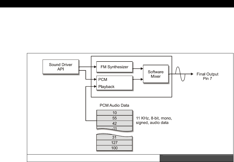
III Game Programming on the HYDRA
Page 600 Game Programming for the Propeller Powered HYDRA
version just to make things sound better since we don’t need 9 channels for anything we are
going to do here, but you might want the added channels and trade off the quality hit, so the
11 KHz is available as well. In any case, let’s take a look at the API interface to the driver
which couldn’t be simpler. Let’s start with a diagram of the driver’s architecture as shown in
Figure 21:2.
Sound Driver Architecture Figure 21:2
The sound driver has two components:
An FM sound module used to play standard waveforms (6-9 channels)
A PCM digital audio module used to play digitized 11 KHz, 8-bit, mono, signed audio
data
Between the two modules you can can create almost any sound(s) you might need for your
gaming needs. Of course, at a playback rate of 11 KHz, 8-bit mono, this means you use 11
Kbytes per second of recorded audio, so I suggest extreme conservation of samples – keep
them short and sweet!
21.3.1 Starting the Sound Driver Up
To start the audio driver up, you simply need to include the audio driver object and call its
start method with the Propeller pin you want the sound to stream from (Pin 7 on the HYDRA)
as follows:

Sound Design for Games 21
Game Programming for the Propeller Powered HYDRA Page 601
OBJ
snd : "NS_sound_drv_051_22khz_16bit.spin" 'Sound driver
...and somewhere in your main initialization or event loop, you simply need to call the
start( )
method:
' start sound driver on HYDRA’s audio out pin which is 7
snd.start(7)
...then the driver is ready for calls to play sounds. When you’re done with the driver if you
need to release the cog it allocated, simply make a call to
snd.stop
.
21.3.2 FM Audio Driver API
The FM driver is controlled through a handful of functions that allow you to start a sound on
any particular channel 0..n, stop the sound, release the sound (more on this later), and
finally modulate the frequency. The function names are respectively:
PlaySoundFM(...) Starts a continuous waveform on a specified channel with an envelope
and general amplitude.
StopSound(…) Stops a playing sound channel.
ReleaseSound(…) Releases a sound’s last “release” portion of ADSR envelope for infinite
duration sounds.
SetFreq(…) Updates the frequency of a playing sound.
SetVolume(…) Updates the volume of a playing sound.
Below is each API function with its parameters formally defined as well as an example use of
each:
Function Name:
PUBPlaySoundFM(arg_channel,arg_shape,arg_freq,arg_duration,arg_volume,arg_amp_env)
Description:
Starts playing a synthesized sound on the selected channel. If a sound is already playing,
then the old sound stops and the new sound is played.

III Game Programming on the HYDRA
Page 602 Game Programming for the Propeller Powered HYDRA
Parameters:
arg_channel: The channel on which to play the sound (0-5) for the 22 KHz
driver, (0-8) for the 11KHz driver.
arg_shape: The desired shape of the sound. Use any of the following
constants: SHAPE_SINE, SHAPE_SAWTOOTH, SHAPE_SQUARE,
SHAPE_TRIANGLE, SHAPE_NOISE. Note: Do
not
send a
SHAPE_PCM_* constant, use
PlaySoundPCM( )
instead.
arg_freq: The desired sound frequency. Can be a number or a NOTE_*
constant (Listed in Table 21:1 on page 605). A value of 0 leaves
the frequency unchanged.
arg_duration: Either a 31-bit duration to play sound for a specific length of time,
or (DURATION_INFINITE | "31-bit duration of amplitude
envelope") to play until
StopSound
,
ReleaseSound
or another
call to
PlaySound
is called. See section 21.3.2.1 Explanation of
Envelopes and Duration on page 605 below for important details.
arg_volume: The desired volume (1-255) inclusive. A value of 0 leaves the
volume unchanged.
arg_amp_env: The amplitude envelope, specified as eight 4-bit nibbles from $0
(0% of arg_volume, no sound) to $F. (100% of arg_volume, full
volume), to be applied least significant nibble first and most
significant nibble last, eg. $8765_4321 would modulate the
amplitude in the order of $1,2,3,4,5,6,7,8 as as function of note
length/duration and time. See section 21.3.2.1 Explanation of
Envelopes and Duration on page 605 below for important details.
Example(s):
' on channel 0 play middle C with a square wave that is 1 second long
' at a overall volume of 255 with envelope $2457_9DEF
snd.PlaySoundFM(0, snd#SHAPE_SQUARE, NOTE_C4, snd#SAMPLE_RATE, 255, $2457_9DEF)
' on channel 1 play middle D# with a sine wave that is 2 seconds long
' at a overall volume of 100 with envelope $2457_9DEF
snd.PlaySoundFM(1, snd#SHAPE_SINE, NOTE_Ds4, snd#SAMPLE_RATE*2, 100, $2457_9DEF)
' on channel 2 play middle F with a sawtooth wave that is infinitely long
' at a overall volume of 255 with envelope $2457_9DEF (note that the release portion, or last
' 4 nibbles "$2457" wont be played until the sound is "released" and of course will play in reverse
' order from low to high, that is, the release envelope will be 7,5,4,2…silence
snd.PlaySoundFM(2,snd#SHAPE_SAWTOOTH,NOTE_F4,snd#DURATION_INFINITE|(snd#SAMPLE_RATE/2),255,$28BE_F842)
Function Name:
PUB StopSound(arg_channel)

Sound Design for Games 21
Game Programming for the Propeller Powered HYDRA Page 603
Description:
Stops playing a sound.
Parameters:
channel: The channel number to stop.
Example(s):
'stop all channels
repeat channel from 0 to 5
StopSound(channel)
Function Name:
PUB ReleaseSound(arg_channel)
Description:
"Releases" an infinite duration sound, that is, starts the
release
portion of the sound's ADSR
amplitude envelope which formally was parameterized as 8 nibbles in reverse order on the
call to
PlaySoundFM
.
Parameters:
channel: The channel to "release".
Example(s):
' start an infinite sound on channel 2
snd.PlaySoundFM(2,snd#SHAPE_SAWTOOTH,NOTE_F4,snd#DURATION_INFINITE|(snd#SAMPLE_RATE/2),255,$28BE_F842)
' let sound play for a second or 2
repeat 1_000_000
' start the “release” portion of the amplitude envelope (the upper 4 nibbles)
ReleaseSound(2)
Function Name:
PUB SetFreq(arg_channel, arg_freq)
Description:
Changes the frequency of the playing sound. If called repeatedly, it can be used to create a
frequency sweep or pitch-bending effect.
Parameters:
channel: The channel to set the frequency of.

III Game Programming on the HYDRA
Page 604 Game Programming for the Propeller Powered HYDRA
Example(s):
' start a C note two octaves below middle C on sound channel 0 with infinite playback
snd.PlaySoundFM(0,snd#SHAPE_SQUARE,snd#NOTE_C2,snd#DURATION_INFINITE|(snd#SAMPLE_RATE),255,$28BE_F842)
' change frequencey of playing sound a total of 4 octaves and back down again
repeat freq from snd#NOTE_C2 to snd#NOTE_C6
snd.SetFreq(0, freq)
repeat 5_000 ' lets hear it for a moment
repeat freq from snd#NOTE_C6 to snd#NOTE_C2
snd.SetFreq(0, freq)
repeat 5_000 ' lets hear it for a moment
' release sound
snd.ReleaseSound(0)
Function Name:
PUB SetVolume(arg_channel, arg_volume)
Description:
Changes the volume of the playing sound. If called repetedly, it can be used to manually
create an envelope.
Parameters:
arg_channel: The channel to set the volume of.
arg_volume: The desired volume (1-255). A value of 0 leaves the volume
unchanged.
Example(s):
' ramp volume on channel 0 up and down on a triangular shaped envelope
repeat vol from 1 to 255
SetVolume(0, vol)
repeat 1000
repeat vol from 255 to 1
SetVolume(0, vol)
repeat 1000
Sound Design for Games 21
Game Programming for the Propeller Powered HYDRA Page 605
Table 21:1 Sound Driver Note/Pitch Constants (from Driver
CON Section)
NOTE_C4 262 NOTE_C5 523 NOTE_C6 1047
NOTE_Cs4 277 NOTE_Cs5 554 NOTE_Cs6 1109
NOTE_Db4 NOTE_Cs4 NOTE_Db5 NOTE_Cs5 NOTE_Db6 NOTE_Cs6
NOTE_D4 294 NOTE_D5 587 NOTE_D6 1175
NOTE_Ds4 311 NOTE_Ds5 622 NOTE_Ds6 1245
NOTE_Eb4 NOTE_Ds4 NOTE_Eb5 NOTE_Ds5 NOTE_Eb6 NOTE_Ds6
NOTE_E4 330 NOTE_E5 659 NOTE_E6 1319
NOTE_F4 349 NOTE_F5 698 NOTE_F6 1397
NOTE_Fs4 370 NOTE_Fs5 740 NOTE_Fs6 1480
NOTE_Gb4 NOTE_Fs4 NOTE_Gb5 NOTE_Fs5 NOTE_Gb6 NOTE_Fs6
NOTE_G4 392 NOTE_G5 784 NOTE_G6 1568
NOTE_Gs4 415 NOTE_Gs5 831 NOTE_Gs6 1661
NOTE_Ab4 NOTE_Gs4 NOTE_Ab5 NOTE_Gs5 NOTE_Ab6 NOTE_Gs6
NOTE_A4 440 NOTE_A5 880 NOTE_A6 1760
NOTE_As4 466 NOTE_As5 932 NOTE_As6 1865
NOTE_Bb4 NOTE_As4 NOTE_Bb5 NOTE_As5 NOTE_Bb6 NOTE_As6
NOTE_B4 494 NOTE_B5 988 NOTE_B6 1976
21.3.2.1 Explanation of Envelopes and Duration
Sound theory is always tricky since its not a science in the sense of chemistry or math. Music
was created by artists and thus there has always been a lot of confusion with the
terminology used to describe music theory and worst yet to describe technical applications
like this sound driver! So, the next paragraphs hopefully will shed a little light on some of the
terms used in the sound driver’s descriptions, so you can make sense of them.
To begin with, the
“duration”
parameters are specified in 11 KHz or 22 KHz "ticks"
(depending on which version of the sound driver you're using). So, use a duration of
SAMPLE_RATE (defined in the driver as a constant) to play for one second,
2*SAMPLE_RATE for two seconds, SAMPLE_RATE/2 for a half-second, etc. To make a
sound play for an infinite duration, you must "OR" the duration with DURATION_INFINITE
(which sets bit 31 to 1). You still need to specify an amount of time for the duration because
the sound driver needs to know how long the amplitude envelope (explained below) should
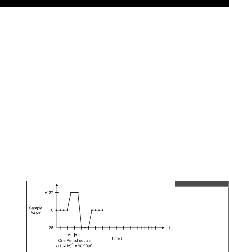
III Game Programming on the HYDRA
Page 606 Game Programming for the Propeller Powered HYDRA
take. For example, use
(INFINITE_DURATION | SAMPLE_RATE)
to play a never-ending
sound using an envelope length of one second.
The amplitude (ie. volume), envelope is a 32-bit value made up of eight 4-bit nibbles, with
each nibble representing one of eight “segments” of the envelope. Each segment plays for
1/8th of the sound's total duration. Each segment specifies a percentage of the sound's
desired volume, with $0 representing 0%, and $F representing 100%. For instance, if the
sound is played at a volume of 200, then a segment of $0 means “no volume,” $8 means
“volume 100,” and $F means “volume 200.” The eight envelope segments are specified in
reverse order. The first segment to be played (segment 0) is the least significant nibble and
the final segment (segment 7) is the most significant nibble. For example, $1346_ACEF starts
at full volume and ends at near-silence. An envelope of $FFFF_FFFF is effectively no
envelope. Sounds with an infinite duration may also use envelopes. In this case, the “attack”
and “decay” (ie. the first few segments) will play, and then the sound will remain indefinitely
at the “sustain” segment (segment 3 by default, but can be changed by adjusting the
AMP_ENV_SUSTAIN_SEG
constant anywhere from 1 to 6 (0 and 7 are untested)). When
ReleaseSound
is called, the “release” (ie. the last few segments) will play for the rest of the
specified envelope duration and then stop. PCM sounds may also use an envelope, although
for now you will have to modify
PlaySoundPCM
to do this. The next version of the driver
will have this modification built in.
21.3.3 PCM Audio Overview
The PCM driver plays back raw pulse code modulated sounds at a rate of 11 KHz, 8-bit
signed samples, 1-channel (mono). In another words, assuming that the output of the audio
driver is 0-1 Vpp, the following stream of data would generate a square wave pulse (shown
in Figure 21:3):
0,0,0,0,127,127,127,-128,-128,-128,0,0,0,0…
Figure 21:3
PCM Data Plotted
on a Time Graph

Sound Design for Games 21
Game Programming for the Propeller Powered HYDRA Page 607
Assuming you have an audio file that you want to play through the driver the first problem is
getting the audio data in a format that is readable by Spin. This is facilitated in two steps:
the first is to export sound in the “RAW” data format which is more or less nothing other
than PCM samples, there is no header, etc. So the data will literally look like the example
above. The export must be in in .RAW file format at 11 KHz, 8-bit, mono, signed format,
Then the second step is to enter these data elements into a Spin DAT statement, this is the
hard part of course. It was bad enough drawing bitmaps with 1’s and 0’s by hand, but there
is no way we are going to hand enter in thousands of numbers that represent a digital audio
sample, so we need a tool that simply converts these numbers into Spin code. You can write
the tool in C/C++, BASIC, PHP, PERL, or whatever. As an example, let’s say you wanted to
write some C/C++ code to output the data in Spin format, here’s a function that would do
the job:
int Raw2Spin(char *filename)
{
int index; // looping variable
FILE *fp; // file pointer
int filesize; // length of file
unsigned char rawbuffer[32768]; // 32K raw data buffer
// open file, if doesn't exist throw error and exit
if (!(fp = fopen(filename, "rb")))
{
printf("\nRAW To Spin Error: File not found.\n");
return(0);
} // end if
// read entire file at once, impossible to have file larger than 32K
filesize = fread((void *)rawbuffer, sizeof(UCHAR), 32768, fp);
// step 1: output header information comaptible with sound driver's API interface
printf("\n' Automated output from Raw2Spin.exe file conversion tool Version 1.0 Nurve
Networks LLC\n");
printf("\n' This getter function is used to retrieve the starting address of the sound
sample.");
printf("\nPUB ns_hydra_sound");
printf("\nRETURN @_ns_hydra_sound");
printf("\n\n' This getter function is used to retrieve the ending address of the sound
sample.");
printf("\nPUB ns_hydra_sound_end");
printf("\nRETURN @_ns_hydra_sound_end");
printf("\n\nDAT");
printf("\n' Data Type: RAW signed audio data");
printf("\n' Original filename - %s", filename);
printf("\n' Size: %d Bytes", filesize);
printf("\n' Range: 0 -> $%X\n", filesize-1);
printf("\n_ns_hydra_sound\n");
// step 2: output data statements 16 per line
for (index=0; index < filesize; index++)
{
// test if this is first element
if ((index % 16) == 0)

III Game Programming on the HYDRA
Page 608 Game Programming for the Propeller Powered HYDRA
{ printf("\n BYTE $%02X", rawbuffer[index]); }
else
{ printf(" ,$%02X", rawbuffer[index]); }
} // end for index
// step 3: output final closing header information
printf("\n\n_ns_hydra_sound_end\n");
// return the filesize
return(filesize);
} // end Raw2Spin
The C/C++ function takes as a single parameter the filename of the RAW format audio file
and prints to STDOUT the data in Spin friendly code. I wrote an actual console program
around this function called RAW2SPIN.CPP and compiled it into RAW2SPIN.EXE. Both
the source and the executable are on the CD in the source directory with all the other demos,
so you can run it right out of there using the following syntax:
RAW2SPIN inputsoundfile.raw > outputsoundfile.spin
...where
“inputsoundfile.raw”
and
“outputsoundfile.spin”
are whatever names you
want. The final output looks something like:
' This getter function is used to retrieve the starting address of the sound sample.
PUB ns_hydra_sound
RETURN @_ns_hydra_sound
' This getter function is used to retrieve the ending address of the sound sample.
PUB ns_hydra_sound_end
RETURN @_ns_hydra_sound_end
DAT
' Data Type: RAW signed audio data
' Original filename - gameover_11_8.raw
' Size: 15316 Bytes
' Range: 0 -> $3BD3
_ns_hydra_sound
BYTE $F4 ,$F4 ,$F4 ,$F4 ,$F4 ,$F4 ,$F4 ,$F4 ,$F4 ,$F4 ,$F8 ,$F8 ,$F8 ,$F8 ,$F8 ,$F8
BYTE $F8 ,$F8 ,$F8 ,$F8 ,$F8 ,$FC ,$FC ,$FC ,$FC ,$FC ,$FC ,$FC ,$FC ,$00 ,$FC ,$FC
BYTE $00 ,$00 ,$00 ,$00 ,$00 ,$00 ,$00 ,$00 ,$00 ,$00 ,$00 ,$00 ,$00 ,$00 ,$00 ,$00
BYTE $00 ,$00 ,$00 ,$00 ,$00 ,$00 ,$00 ,$00 ,$00 ,$00 ,$00 ,$00 ,$00 ,$00 ,$00 ,$00
BYTE $00 ,$00 ,$00 ,$00 ,$00 ,$00 ,$00 ,$00 ,$00 ,$00 ,$00 ,$00 ,$00 ,$00 ,$00 ,$00
.
.
_ns_hydra_sound_end
Then you simply include the file in your main Spin program like this in the OBJ section:
OBJ
sound_data: “outputsoundfile.spin”
Sound Design for Games 21
Game Programming for the Propeller Powered HYDRA Page 609
...and then use the address resolution “getter” functions embedded in the file itself to get the
starting and ending address:
' starting address
start := sound_data.ns_hydra_sound
' ending address
end := sound_data.ns_hydra_sound
Additionally, there is a more advanced tool supplied on the CD as well that is a general data
conversion tool written by Colin Phillips called XGSBMP.EXE, it too is on the CD in the
source directory along with its source in C/C++. This tool does much more and was designed
with graphics conversions in mind (which we will get to later), but you can use it to perform
RAW to Spin conversion as well with the following command line:
XGSBMP audiofile.raw audiofile.spin -op:copy -hydra
The trick here is that you can include pure data files with the OBJ directive then
return the address of the data statements via the “getter” trick above. This is a
good trick and a great way to emulate the ability to bring in data files and header
like information into your programs.
21.3.3.1 Creating Audio Samples
Creating audio samples is a whole other story and we don’t have time to go into it, but if you
aren’t sound savvy then you can simply use royalty-free or public domain sound effects that
you find on the web or purchase, to help you out, I have provided you with a number of
royalty free sound samples in 11 KHz, 8-bit, mono format that I have created over the years
for your own use. Copies are located in the directories:
CD_ROOT:\HYDRA\MEDIA\SOUNDS\
Simply look for all the files with the file extension .RAW on them, these are the originals, so
you can play with them if you wish; however, I have taken the liberty to save you some time
and converted all of them to Spin format files for you with the same root names, but with the
file extension .SPIN,
Also, in the CD_ROOT:\HYDRA\SOURCES\ directory you will find two particular files
named GAMEOVER_11_8.RAW and GAMEOVER_11_8_SPIN respectively, the Spin
version can be used immediately in your demo work as a test file.
If you want to experiment with audio design then you need a good sound editor that allows
you to import, record, modify, and save sounds in RAW format at very least. There are
hundreds of programs that do this, but there are two I like the best depending on your
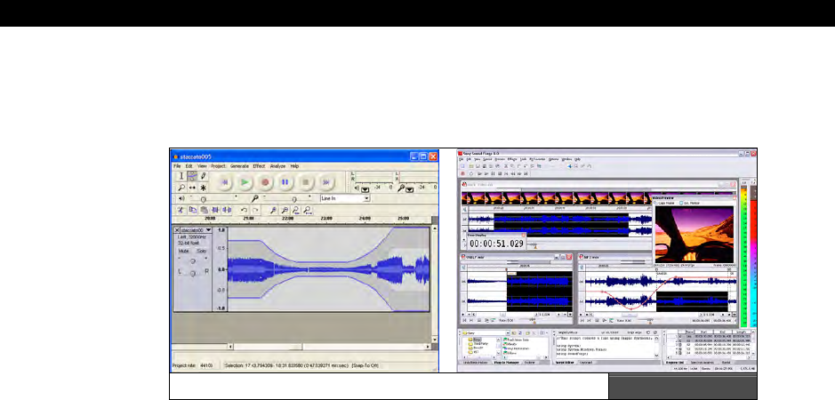
III Game Programming on the HYDRA
Page 610 Game Programming for the Propeller Powered HYDRA
budget:
SoundForge
is one of the premier sound effects programs available and is from
$69 to $299 depending on version, while
Audacity
is open source and free and runs on a lot
of platforms, both are shown in Figure 21:4. You can download both from the links below.
SoundForge (left) and Audacity (right) Figure 21:4
Sound Forge Audio Studio & Sound Forge 8 (30 day fully functional demos available)
http://psp.sonymediasoftware.com/products/soundforgefamily.asp
Audacity Open Source Audio Editor
http://audacity.sourceforge.net
I suggest reading through the online documentation a bit to figure them out, they have a lot
of features, but the bottom line is that you need to make sure whatever file you import,
when you export or save it you do so in RAW, 8-bit, 11 KHz, SIGNED, PCM, MONO format if
you want the RAW2SPIN or XGSBMP conversion tools to work.
21.3.3.2 PCM Driver API
Alright, assuming you have a sample that you have created and converted to Spin code (or
simply will use the GAME_OVER_11_8.SPIN file found in the source directory), then there
is a single API function you need to know to play PCM samples:
Function Name:
PUB PlaySoundPCM(arg_channel, arg_pcm_start, arg_pcm_end, arg_volume)
Description:
Plays an unsigned 8-bit 11KHz PCM sound once. If a sound is already playing, then the old
sound stops and the new sound is played.
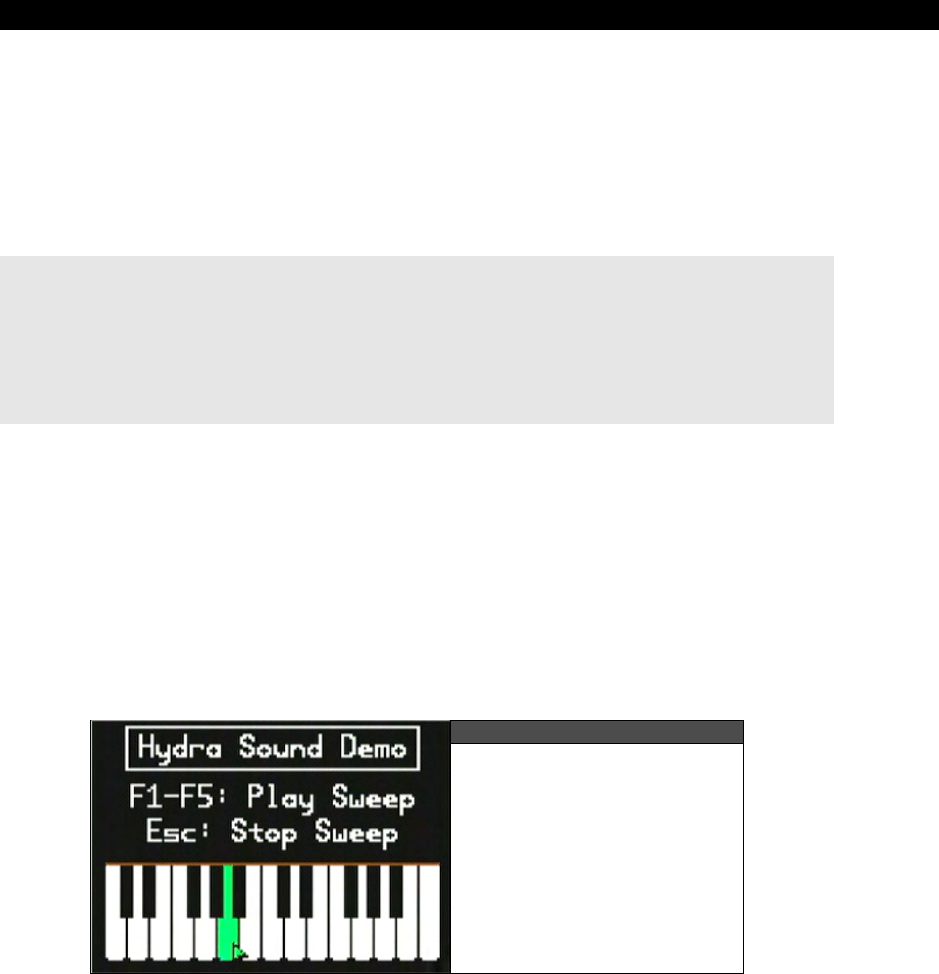
Sound Design for Games 21
Game Programming for the Propeller Powered HYDRA Page 611
Parameters:
arg_channel: The channel on which to play the sound (0-5).
arg_pcm_start: The address of the PCM buffer.
arg_pcm_end: The address of the end of the PCM buffer.
arg_volume: The desired volume (1-255).
Example(s):
OBJ
snd : "NS_sound_drv_050_22khz_16bit.spin" 'Sound driver
snd_data : "gameover_11_8.spin" 'PCM Sound Effect "Hydra"
' .. in the main event loop…
' play a PCM sound on channel 0 with a volume of 255
snd.PlaySoundPCM(0, snd_data.ns_hydra_sound, snd_data.ns_hydra_sound_end, 255)
That’s all there is to playing PCM sound! And you can play as many PCM sounds through as
many channels as you wish.
21.3.4 Piano Driver Demo
As a final example to put everything together, load and run NS_SOUND_DEMO_051.SPIN
located in SOURCE\. This demo was put together by
Nick
Sabalausky
to show off all the
features of the sound driver (including FM and PCM). It supports both the keyboard and the
mouse, so make sure to have them plugged in and the volume turned up. This demo shows
how to create an entire electronic organ and could be the basis of a much more advanced
sound synthesis program. Figure 21:5 is a screen shot of the demo in action.
Figure 21:5
The Piano Demo in Action
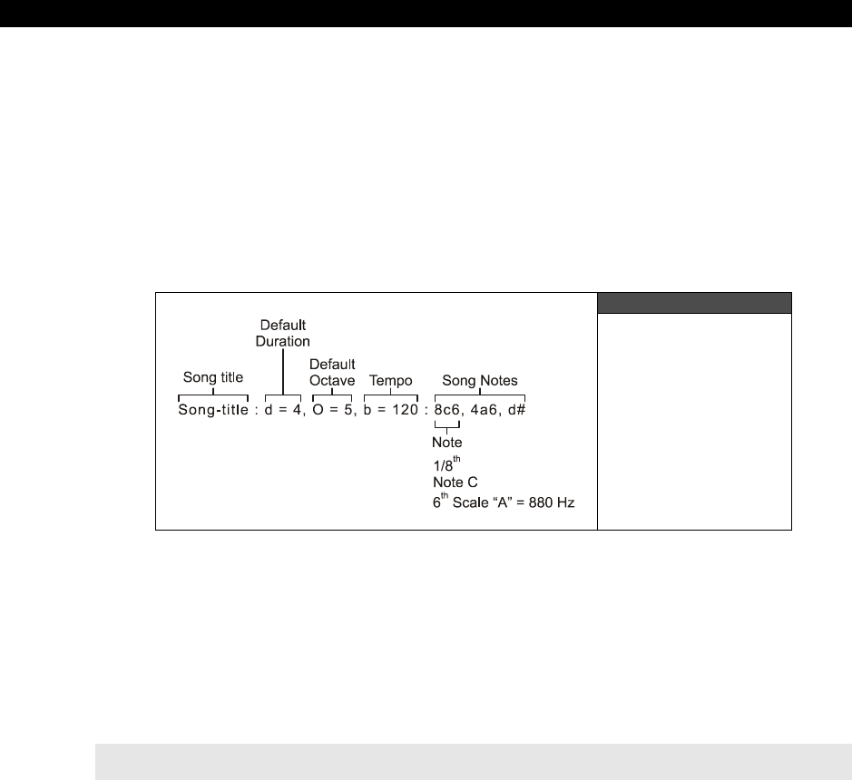
III Game Programming on the HYDRA
Page 612 Game Programming for the Propeller Powered HYDRA
21.4 Playing RTTTL Files
As mentioned earler, RTTTL stands for
Ring Tones Text Text Transfer Language
. It’s a
simple monophonic (single channel) music format that is used on cell phone to play music.
Originally invented by Nokia the format is very popular and there are millions of RTTTL files
free on internet. The reason it was invented was that although numerous music formats exist
such as MIDI, MIDI is very complex and designed for professional recording and playback.
Simple cell phones are lucky to be able to play music at all, so Nokia needed a format that
would work, was ASCII text, short, and single-channel, and RTTTL was the answer. In this
section, we will look at the format itself and then write a player and demo based on it.
Figure 21:6
Diagram of RTTTL
Music Format
21.4.1 RTTTL File Format
The RTTTL file format consists of ASCII text with a header section, followed the notes of the
musical score as shown in Figure 21:6. The format supports only a single channel, but does
support four octaves, timing support, and has no limit to musical piece length. Before
showing the format formally, it’s sometimes easier just to see an example, here’s one of the
Star Wars themes:
Star Wars Imperial Theme
Imperial:d=4, o=5, b=120:e, e, e, 8c, 16p, 16g, e, 8c, 16p, 16g, e,
p, b, b, b, 8c6, 16p, 16g, d#, 8c, 16p, 16g, e, 8p
This example illustrates the basic format of an RTTTL file (referring to Figure 21:6 for
reference), the format starts off with a text string that identifies the
name
of the song this is
supposed to be no longer than 10 characters; however, most RTTTL files hardly follow this
rule, so parsers must be able to handle longer names with embedded spaces and
punctuation. Moving on, the name is followed by a colon “:” delimeter, which indicates the
defaults
section which consists of three default settings:

Sound Design for Games 21
Game Programming for the Propeller Powered HYDRA Page 613
“d=duration [1|4|8|16|32]” – Default note duration.
“o=octave [4|5|6|7]” – Default octave/scale.
“b=beats per minute” – Default beats per minute.
The defaults section is delimited by another colon “:” and the song begins which is a
sequence of notes separated by commas “,”. Each note has three major parts as shown in
Figure 21:6.
Duration – How long to play the note (modifier, if omitted uses default).
Note (pitch) – The note frequency itself.
Octave (scale) – Which octave or “scale” to play the note in (modifier, if omitted uses
default).
If only the note is listed then the defaults from the default section will be used to play the
note, otherwise the optional modifiers modify the notes parameters for playback. The first
optional field is the duration of the note, where duration can be a whole note, half note,
quarter note, sixteenth note, and thirty-second note indicated by the numbers 1,2 ,4, 8, 16,
and 32 respectively. Next is the note itself, which consists of ASCII characters “C”, “D”, “E”,
“F”, “G”, “A”, “B”, along with “H” to represent “B” (don’t ask me), lastly the note can also be
a pause indicated by “P.” Pauses are used to help timing, if a lone “P” is in the data stream it
will have the length of the default duration set in the defaults section or the duration given to
it as if it were a note. For example, “8C” would mean play an eighth note “C” while “8P”
would mean pause for an eighth note, but make not sound.
Additionally, the notes “C”, “D”, “F”, “G”, and “A” can have sharps optionally concatened to
them resulting in ““C#”, “D#”, “F#”, “G#”, and “A#” respectively. The last part of the note
definition is the octave or scale modifier and can range from 4-7. If the scale is omitted then
the default scale previously defined in the header section’s “o=octave” section will be used.
The meaning of octave/scale “4” is middle C scale (A=440 Hz), “5” is one octave above, “6”
is the next octave and so forth. Thus, a song can range over four octaves.
I have seen many definitions of RTTTL, all “official” they all are more or less the
same, but there is confusion over some things like scale and some RTTTL songs
use octave “5” to indicate middle C scale. Thus, some songs you play might be
one octave off plus or minus, to remedy this simply change the default by 1 and
of course edit each note’s octave modifier as well.
The last part of the note definition is to support
“dotted rhythms”
which in musical theory
are a way to play a note duration for an extra half time of itself. For example, if you played
a quarter note dotted and the quarter note was 1 second, then the dotted quarter note
would be 1+(0.5)×1 = 1.5 seconds. So, by “dotting” a note you simply add a little more time

III Game Programming on the HYDRA
Page 614 Game Programming for the Propeller Powered HYDRA
to the note’s duration. A dotted note is indicated by a trailing period “.” For example, an 8th
note, C sharp, in octave 7, dotted would look like:
C sharp, 8th note, played in 7th octave and dotted
“8C#7.”
Be warned though, many RTTTL songs have the dot in the wrong place (which I
have supported in the parser for it), for example: “8C#.7”. Thus, once again, file
formats always get confused, thus write your parser such that is can handle
slightly erroneous formats and still “interpret” them as best it can with elements
out of order.
21.4.1.1 A Quick Note on Timing and Musical Theory
If you play music then you are very comfortable with the concepts of
beats per minute
,
duration
,
notes
,
scale
,
registers
,
quarter
notes
,
half
notes
,
syncopation
, and many
other music concepts. However, if this is the first time you are seeing some of these music
terms you are probably a little lost. Everyone is at first – I am still lost! I highly suggest
reading a little online about music theory and simply searching for “RTTTL specification”
online and reading a few articles to get a better understanding of these terms, and how it all
fits together. The only thing we are going to discuss is the math behind the timing since that
really is our only challenge, let me explain.
The format looks easy enough to understand, we read in the header, store the values, and
then parse the notes. The problem is playing the notes with correct timing. This is not as
easy as it seems. The fundamental problem is that music is not rigorous in its roots thus
there are a lot of assumptions about timing etc. and a lot of “chained” timings. The first thing
is that when a piece calls for a quarter note, half note, 8th note etc., what does it mean?
Well, it means to play the note for one quarter, one half, or 1/8th a normal note duration. Ok,
great, but what’s a normal note duration? Well, this has to do with the concept of
“tempo,”
that is, how fast a piece of music is played. Tempo is related to “beats per minute”, and if we
play a piece at 60 beats a minute then there is 1 beat a second. Given that, the magical
connection is between beats per minute and notes, and here it is:
Adhoc Musical Timing Law:
“A quarter note usually has the duration of a single beat in
music.”
This simple relationship helps us do everything. For example, if we have a song that we want
to play at 120 beats per minute, then this means there are 2 beats per second, or 500 ms
per beat. So far so good, then we take the law into consideration and we know that one
quarter note equals 1 beat time, in this case 500 ms, and presto we have our timing
relationship. Thus, when we parse a note to be played a quarter note, we play it for 500 ms,

Sound Design for Games 21
Game Programming for the Propeller Powered HYDRA Page 615
if we see one to play for an 8th note, we play it 250 ms. Similarly, if we see a half note then
that should be 2× as long as a quarter note or 1000 ms. This timing math is the fundamental
problem (other than parsing the file format) to writing the RTTTL player or any music player
for that matter. Your brain will not tolerate timing errors in music, trust me! With that in
mind, let’s take a look at the formal RTTTL specification.
21.4.2 RTTTL Specification
RTTTL was originally conceived by Nokia and like any computer language
“grammar”
is
described in a loose form of BNF (Backus Naur Form).
BNF grammer is commonly used to define grammers for computer languages
and is recursive in nature. Each line is called a production where the left hand
sides are recursively defined by the right hand sides and replaced by them more
or less until a final “terminal” symbol is the end of the replacement process.
Additionally, BNF takes from regular expression syntax, so common regular
expression symbols like “|” mean “or” and “+” means “one or more occurance
of”. Again, a quick online search will help you read the grammer if you are
having trouble.
Below is the RTTTL specification in rather compact BNF form:
<ringing-tones-text-transfer-language> := <name> <sep> [<defaults>] <sep> <note-command>+
<name> := <char>+
<sep> := ":"
<defaults> := <def-note-duration>|<def-note-scale>|<def-beats>
<def-note-duration> := "d=" <duration>
<def-note-scale> := "o=" <scale>
<def-beats> := "b=" <beats-per-minute>
<beats-per-minute> := integer value
<note-command> := [<duration>] <note> [<scale>] [<special-duration>] <delimiter>
<duration> := "1" | "2" | "4" | "8" | "16" | "32"
<note>1 := "P" | "C" | "C#" | "D" | "D#" | "E" | "F" | "F#" | "G" | "G#" | "A" | "A#" | "H"
<scale> := "4" | "5" | "6" | "7"
<special-duration> := "."
<delimiter> := ","
Now, all we need is a parser to read the specification.
21.4.3 RTTTL Demo Program
I have to admit that when I started this chapter, I wasn’t planning on using RTTTL format, I
was going to create a custom music format somewhat loosely based on MIDI concepts,
maybe something similar to “C-MIDI.” In any case, like most people I have a cell phone with
more computing power that all the computers combined from the late 60’s, but I never use
any of the features since all I want to do is make calls with it nor do I have a personal
ringtone for anything. Anyway, you can’t turn around these days without seeing a free
ringtone for something, so when I investigated ringtone technology, I was happily pleased
that there were a number of common formats available with thousands of songs for each,
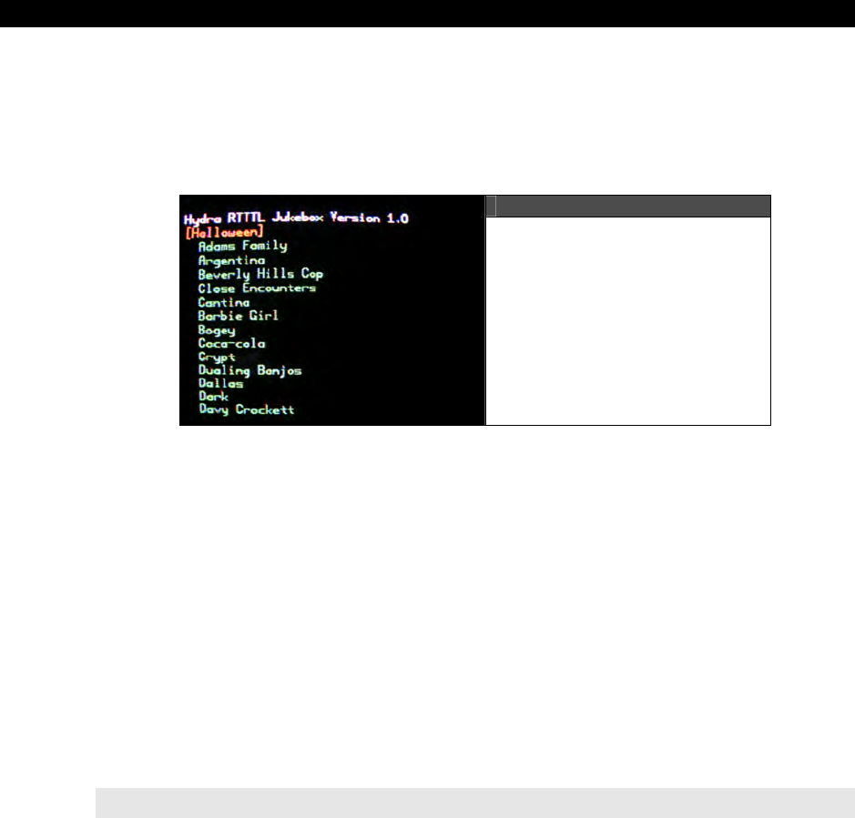
III Game Programming on the HYDRA
Page 616 Game Programming for the Propeller Powered HYDRA
especially RTTTL format. After doing some research, I found there were some really cool
songs in RTTTL, so I decided why make a simple demo that just plays one when I can make
a jukebox that lets you select one and play from a list? So, that’s exactly what I did. Figure
21:7 shows a screen shot of the demo program in action. The program’s name is
HYDRA_RTTTL_PLAYER_001.SPIN and is located in SOURCE\ directory on the CD.
Figure 21:7
A Screen Shot of the
“HYDRA RTTTL Jukebox 1.0”
Simply load the program into your HYDRA, make sure the volume is turned up and the
gamepad plugged into the left port and run the program. When the program starts it will play
the
“Halloween”
theme music on load then when the song is finished you can scroll up /
down and select any song to play with the game pad’s <START> button. It’s pretty cool and
a bit addictive.
The demo program is pretty straightforward other than the RTTTL parser and player. The
program is much too long to list, so make sure to review the source yourself. The parser was
written with a lot of little “helper” functions to make it easier to to understand and modify.
However, a clever programmer could shorten the parser quite a bit. The program works by
reading in a “play list” in the DAT section, each RTTTL song is stored as a stream of bytes
with a NULL terminator at the end, this way the program can scan for each song by looking
for the NULL terminator. Here’s and example of one of the songs in Spin format which
identical to the RTTTL format except with a NULL terminator at the end and placed into a
BYTE data statement:
byte "Close Encounters:d=16,o=5,b=125:d,p,e,p,c,p.,c4,p,g4,1p., d6,p,e6,p,c6,p.,c,p,g,1p.",0
Each song takes anywhere from a few dozen to a couple hundred bytes of ASCII text, so you
surprisingly run out of memory pretty fast with graphics support drivers loaded.
Nevertheless, I have choosen about 40 songs that most people have heard and can verify
with their own ears the player is working right. There are more songs in the source code

Sound Design for Games 21
Game Programming for the Propeller Powered HYDRA Page 617
commented out. Simply un-comment them and exchange them in the list, trying to keep the
number of songs to no more than 40 or so, otherwise you will run out of memory.
Lastly, don’t judge the sound driver by the demo. This file format is what’s driving the sound
engine and RTTTL is monophonic and thus sounds like a toy playing music. However, there
are polyphonic ringtone formats as well as real MIDI which can easily be accomadated by the
sound driver, so feel free to make better sound players based on the driver, but this is a
good start, so without further ado, I am going to search for
“Whoops I Did it Again”
– just
kidding, I am really trying to find
“Let the Bodies Hit the Floor”
by Drowning Pool! If
you find it or make it, email it to me!
You might notice that RTTTL files are pretty short and only fragments of songs,
this is not a limitation of the format, but simply that they are used for phone ring
tones and people usually answer in a few seconds, alas no need to have a
symphony recorded. However, there is no format-imposed limit on the length of
a RTTTL song, thus you can make them as large as possible. One good way to
get large RTTTL pieces is to use a MIDI-to-RTTTL conversion program which can
be found on the internet. This way you can use large complete songs in MIDI,
convert them to RTTTL and play them in the juke box and turn your computer
into the most expensive ringtone player on the planet!
21.5 Summary
Sound is probably one of the most important factors in a game, if not the
most
important.
By our very nature as humans, there is nothing that effects our emotions as much as music
and sound, they can excite us, make us angry, sad, lonely, scared, and give us anxiety.
Hopefully, with the sound driver in hand and some creativity some of the musically inclined
readers can really make the HYDRA and the Propeller shine musically! I challenge someone
to take the sound driver and based on its ideas construct a new version with 16-32 channels
supporting wave table synthesis and speech support and via the USB connection turn the
HYDRA into a sound card with commercial quality controlled via the PC – that would be a fun
project and/or a phone answering machine of some kind?

III Game Programming on the HYDRA
Page 618 Game Programming for the Propeller Powered HYDRA

Advanced Graphics and Animation 22
Game Programming for the Propeller Powered HYDRA Page 619
Chapter 22:
Advanced
Graphics and
Animation
In this chapter we are going to discuss the problems associated with video game asset
management along with animation and scrolling techniques. That is, given so much art,
sound, music, and so forth, how does one simplify the process of getting the media into the
HYDRA and doing something with it? This is the number one problem in writing games since
without assets you can’t make much of a game. Up to this point in the book we have
manually entered in bitmaps, palettes, and data by hand, but this isn’t going to cut it forever.
Therefore to advance in our discussions we need tools, which are what we are going to
develop in this chapter. Then with the tool chain in hand we are going to talk about scrolling
techniques as well as general character animation for games and how that’s done. So the
primary topics in this chapter are:
Using tool chains to build and import graphics
Tile map scrolling
Vector scrolling
Parallax scrolling
Framed animation
22.1 Using Tool Chains to Build and Import Graphics
Video game development is very demanding when it comes to asset generation and
management. Thus far, we have more or less entered bitmap data in binary data statements
that were hand drawn on graph paper or generated on the fly using a text editor. This
obviously isn’t going to cut it moving forward, so we need some simple tools to help us out
or I am going to lose all my hair! If you recall in the last chapter on sound programming
there was simply no way around building a tool to convert audio data into Spin code, it had
to be done. And we are at that same turning point in the development of our graphics
technology. So with that in mind, we need to develop a couple simple tools that allow us to
draw imagery on the PC using a graphics painting program like
Photoshop
or
Paint
Shop
Pro
and then convert the bitmap data to Spin code that is somehow compatible with our
current engines and technology. Secondly, we want to take advantage of the features of the
tile engine, such as scrolling. To accomplish this we need to use an external tool to generate
game field maps and then export them out and once again convert them to Spin-compliant
code somehow. Alas, lots to do, very complicated, and details count, so let’s get started!
III Game Programming on the HYDRA
Page 620 Game Programming for the Propeller Powered HYDRA
22.2 Bitmap to Spin Conversion
Figure 22:1
A Pitfall “Scorpion” Bitmap
The HEL graphics engine introduced a couple chapters ago is a tile-based engine with 4
colors per tile, where tiles are 16×16 pixels each represented by 2 bits per color, which index
into the 4-BYTE color palette assigned to that tile. Thus, each tile can have 4 individual
colors. The color palettes are in the form of a LONG each where BYTE 0 is Color 0, BYTE 1 is
Color 1, and so forth. As an example, take a look at Figure 22:1, it depicts a “scorpion”
bitmap from the classic 80’s game Pitfall (or at least it’s supposed to!) which I drew in Paint
Shop Pro/Photoshop. Now, if I wanted to add this bitmap to a game or demo then it would
have to be converted to our graphics tile bitmap format as shown below:
' a pitfall scorpion tile
scorpion_bitmap LONG %%0_0_0_0_0_0_0_0_0_0_0_0_0_0_0_0
LONG %%0_0_0_0_0_0_0_0_0_0_0_0_0_0_0_0
LONG %%0_0_0_0_0_0_0_0_0_0_0_0_0_0_0_0
LONG %%0_0_0_0_0_0_0_0_0_0_0_0_0_0_0_0
LONG %%0_0_0_0_0_0_0_0_0_0_0_0_0_0_0_0
LONG %%0_0_0_0_1_1_1_1_0_0_0_0_0_0_0_0
LONG %%0_0_1_1_1_0_0_1_1_1_0_0_0_0_0_0
LONG %%0_0_1_1_0_0_0_0_1_1_0_0_0_0_0_0
LONG %%0_0_1_1_0_0_0_1_0_0_0_0_0_0_0_0
LONG %%0_0_1_1_0_0_0_0_0_0_0_0_1_0_0_0
LONG %%0_0_1_1_1_0_0_0_0_0_1_1_1_0_0_0
LONG %%0_0_1_1_1_1_1_1_1_1_0_0_0_0_0_0
LONG %%0_0_0_0_1_1_1_1_1_1_0_0_0_0_0_0
LONG %%0_0_0_0_0_1_1_1_1_1_1_1_0_1_1_0
LONG %%0_0_0_0_0_1_1_1_0_0_0_0_1_0_0_0
LONG %%0_0_1_1_0_0_0_0_0_0_1_1_0_1_1_0

Advanced Graphics and Animation 22
Game Programming for the Propeller Powered HYDRA Page 621
...and the palette that goes along with this tile might look something like this:
scorpion_palette LONG $07_04_07_02 ' color 0 black, color 1 white
Notice the bitmap is mirrored on the x-axis. This is one of the quirks of the
engine, the art needs to be reflected or mirrored about the x-axis since the data
is read low bit to high bit when rendered on the screen. Tip: Blur your eyes to
see the image better.
Additionally, if we wanted to use the bitmap tile for a sprite, then we need a
mask
of the tile
which is nothing more than a copy of the tile bitmap where every entry that is non-zero is
mapped to 3, and all zero entries are mapped to 0. For the scorpion bitmap above, its sprite-
compliant mask would look like:
' a pitfall scorpion tile
scorpion_bitmap_mask LONG %%0_0_0_0_0_0_0_0_0_0_0_0_0_0_0_0
LONG %%0_0_0_0_0_0_0_0_0_0_0_0_0_0_0_0
LONG %%0_0_0_0_0_0_0_0_0_0_0_0_0_0_0_0
LONG %%0_0_0_0_0_0_0_0_0_0_0_0_0_0_0_0
LONG %%0_0_0_0_0_0_0_0_0_0_0_0_0_0_0_0
LONG %%0_0_0_0_3_3_3_3_0_0_0_0_0_0_0_0
LONG %%0_0_3_3_3_0_0_3_3_3_0_0_0_0_0_0
LONG %%0_0_3_3_0_0_0_0_3_3_0_0_0_0_0_0
LONG %%0_0_3_3_0_0_0_3_0_0_0_0_0_0_0_0
LONG %%0_0_3_3_0_0_0_0_0_0_0_0_3_0_0_0
LONG %%0_0_3_3_3_0_0_0_0_0_3_3_3_0_0_0
LONG %%0_0_3_3_3_3_3_3_3_3_0_0_0_0_0_0
LONG %%0_0_0_0_3_3_3_3_3_3_0_0_0_0_0_0
LONG %%0_0_0_0_0_3_3_3_3_3_3_3_0_3_3_0
LONG %%0_0_0_0_0_3_3_3_0_0_0_0_3_0_0_0
LONG %%0_0_3_3_0_0_0_0_0_0_3_3_0_3_3_0
As you can see, this is tricky work! What we need is a tool that takes as an input a bitmap
full of tiles regularly templated, then we can “extract” one or more tiles and the output is
Spin code, so we don’t have to do all this work by hand. Well, I have created such a tool
called BMP2SPIN.EXE which is located on the CD in the \SOURCE directory along with the
source C\C++ file BMP2SPIN.CPP. When writing a tool like this about a billion assumptions
have to be made, otherwise you will be writing tools for months and years and not writing
games. In other words, tools are hard to write and time consuming, so you have to pick your
battles. First, off when doing 2D games, artists typically will
“template”
their 2D artwork
into tiles that are 8×8, 16×16, 32×32 etc. This makes it easy to work with the art and of
course makes it easy for tools to extract the art. So the first rule of the tool is that it works
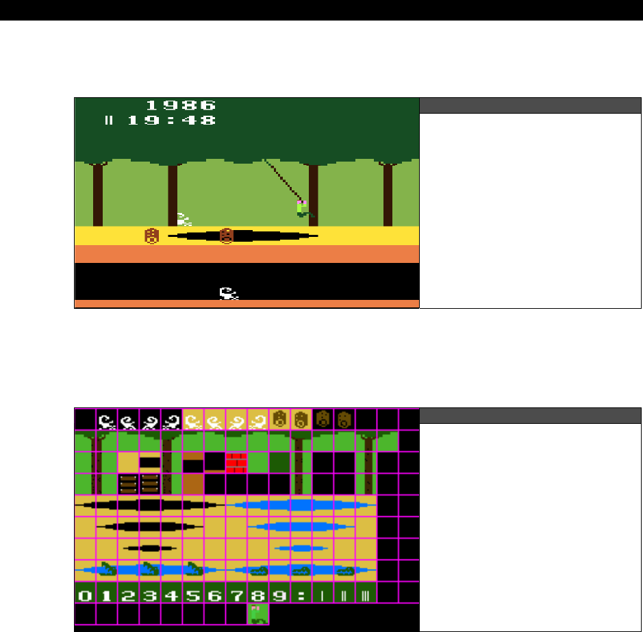
III Game Programming on the HYDRA
Page 622 Game Programming for the Propeller Powered HYDRA
with templated graphics. Let’s discuss the process of templating graphics assets using the
Pitfall
art as an example to work with.
Figure 22:2
A Screen Shot of Pitfall
Figure 22:2 shows a screen shot of Pitfall running on my Atari 2600. Based on this screen
shot, and playing the game for many years, I was able to draw all the graphics in the game
(roughly) and then place them into a template. Figure 22:3 shows the templated graphics.
Figure 22:3
The Pitfall Templated
Graphics
If course, what you see in Figure 22:3 is only a subset of the graphics from the game; I
would be here for ever trying to see every little sprite in the game and then recreating it. Of
course, you could always download the ROM of the game (if you own it) and pull the
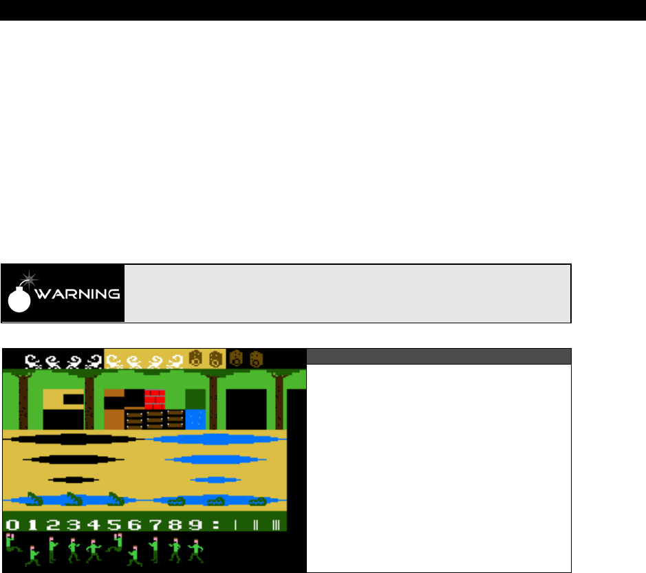
Advanced Graphics and Animation 22
Game Programming for the Propeller Powered HYDRA Page 623
graphics from it as long as it’s only for experimenting like we are. In any case, the actual
bitmap shown in Figure 22:3 is named PITFALL_TILES_WORK_03.BMP and is located in
the \SOURCE directory as well as in the \MEDIA\GRAPHICS directory on the CD. You can
open it up and view it in your favorite paint program. The first thing you will notice about the
art is that there is a 1-pixel border around each tile, this border is exactly 1-pixel wide and
common practice when tiling graphics. However, some programs do not like the 1-pixel
border and you must remove it. I suggest that as a convention you draw all your graphics on
a “work” bitmap where they are just all over the place since its your “art” workspace. Next,
you cut up your tiles into 16×16 blocks (or whatever the size is your engine uses) and tile
them into another file with a 1-pixel border. Finally, you create yet another file where the
border is removed, and slide all the bitmaps together. Figure 22:4 shows the same bitmaps
from Figure 22:3, but with the border removed (and a few extra tiles).
All bitmap files must have a width and height that are both an even multiple of 8
for all tools discussed to work correctly. Thus, when you make your templated
graphics resize the canvas around your bitmap data to make sure this rule is
followed.
Figure 22:4
The Pitfall Templated Graphics
Without the 1-Pixel Border
I personally prefer to work with a 1-pixel border to separate my tiles, but some third-party
tools you might want to use only work with bitmaps that have no border (Mappy is one of
them and we need to use it). As another example of templated art I have taken some of the
royalty free tiles from
Ari Feldman’s “Sprite Lib”
and tiled them as well. Figure 22:5(left)
shows the tiled graphics with border while Figure 22:5(right) shows without border. The
point is that you need to create your art, tile the art, and put it in a couple formats to make it
easy for tools to read. The actual filenames of the two Sprite Lib based tile sets are
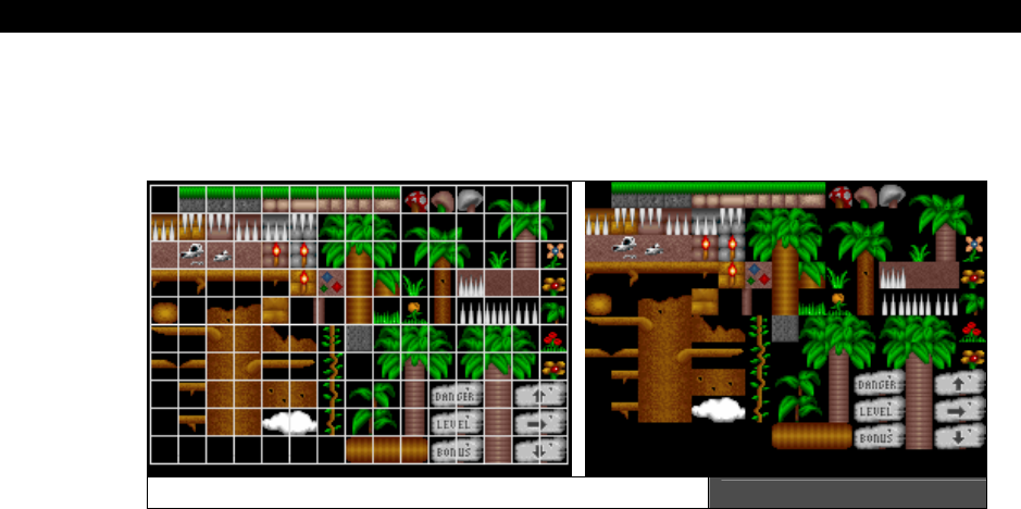
III Game Programming on the HYDRA
Page 624 Game Programming for the Propeller Powered HYDRA
SL_BLOCKS_02.BMP (with border) and SL_BLOCKS_03.BMP (without border); both files
are on the CD in the \SOURCE directory as well as in \MEDIA\GRAPHICS\SPRITELIB\
located on the CD.
Some Jungle Tile Templates Figure 22:5
Before moving on to the tool itself and it’s use, there are a couple more details we need to
cover. First, we haven’t mentioned anything about color! We know that the Propeller only
generates so many colors, so how can a 24-bit Truecolor image be represented by the
HYDRA? Well, it can’t, so we have to approximate colors and match or map them to the
HYDRA palette. This means that bitmaps converted to the HYDRA might not look at good or
vibrant as on the PC, but this is ok and standard for game graphics. To defend against
graphics degradation typically what an artist does is work in 24-bit color and now and then
reduce the color space to the target system’s graphics palette. Every paint tool has the ability
to reduce color space, so you can work with a nice 24-bit image then load the “HYDRA color
palette” and see how it looks. If it looks terrible, for example, you are losing a lot of browns,
then you know you need to lay off the browns and so forth. The question is, “What is the
HYDRA/Propeller’s palette?” It depends on the TV you hook the system up to, thus what had
to be done is 10-20 TVs with “general” settings had to be connected to the HYDRA and then
a complete palette rendered on the screen, then this was digitized and painstakingly ordered,
labeled and numbered. The results are two palettes which I call “Palette 0” (Figure 22:6) and
“Palette 1” (Figure 22:7) both of which contain 86 colors (including black). Palette 0 looks
best on most TVs without adjusting the tint, but Palette 1 looks better on older “composite
computer monitors” so you can take your pick.
Since this book is black and white you won’t be able to see the colors from the palette, but
you can look at the original bitmaps in files HEL_GRAPHICS_PALETTE_0.BMP and
HEL_GRAPHICS_PALETTE_1.BMP which are located on the CD in the directory
\MEDIA\GRAPHICS. Additionally, there are “color only” versions of these bitmaps with no
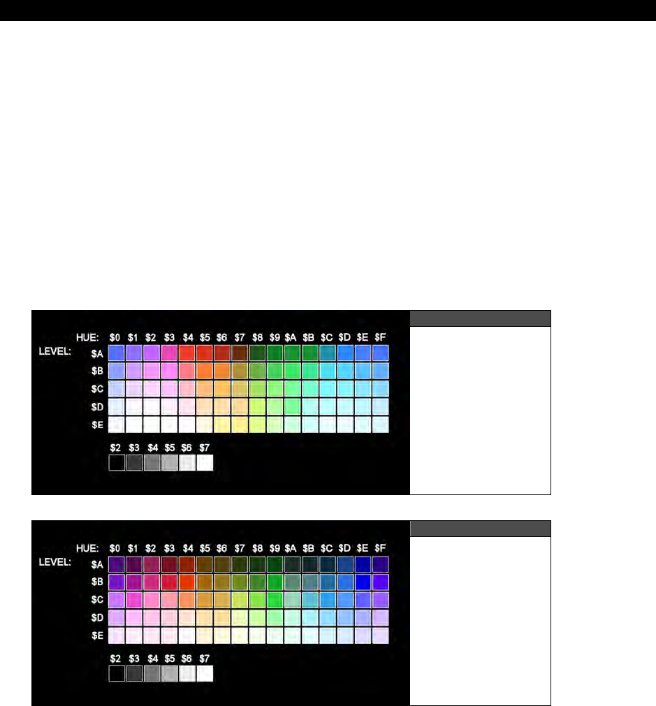
Advanced Graphics and Animation 22
Game Programming for the Propeller Powered HYDRA Page 625
text, annotation, or other colors, so you can use them to color reduce your art with, that is
use the “generate palette from bitmap function of your paint program.” Please use the
following bitmaps to generate a palette to test match your art within your painting tool:
HEL_GRAPHICS_PALETTE_0b.BMP
HEL_GRAPHICS_PALETTE_1b.BMP
For example, you might draw some underwater art in 24-bit color in Photoshop and you want
to see how well it will map to the HYDRA palette. So load in either palette “color only” image
HEL_GRAPHICS_PALETTE_0b.BMP or HEL_GRAPHICS_PALETTE_1b.BMP then
generate a palette from it and assign it to your art, instantly you will see the art change and
the colors reduce and you can focus on problem areas. When you are satisfied with your art
then you can leave it in 24-bit color mode or 256 color mode and save your artwork in
templated format. You will at least need the borderless version for the other tools in our tool
chain, but I suggest making both a 1-pixel border version as well as a borderless version.
Figure 22:6
HYDRA Palette 0
Figure 22:7
HYDRA Palette 1
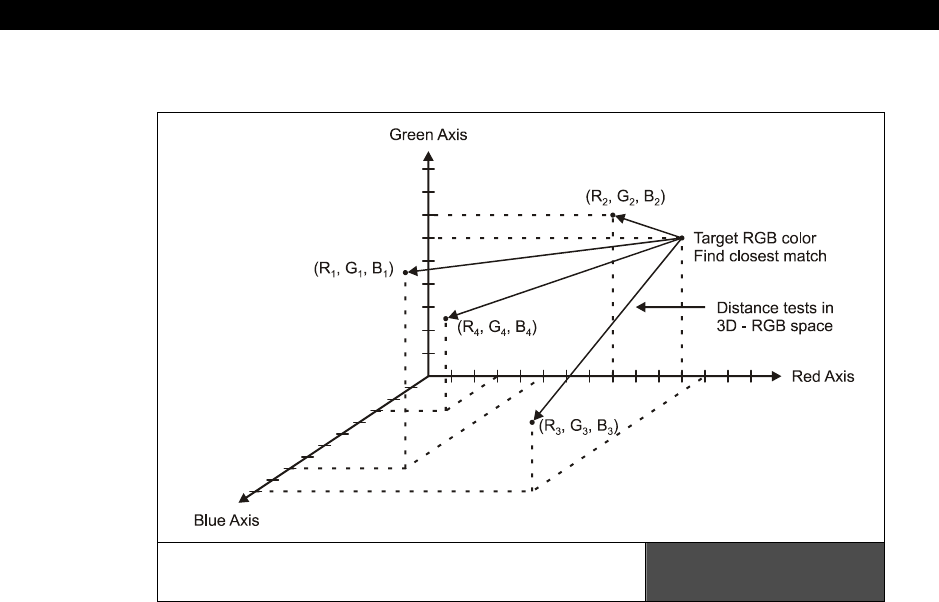
III Game Programming on the HYDRA
Page 626 Game Programming for the Propeller Powered HYDRA
22.2.1 3D RGB Space Color Reduction Algorithm
The 3D RGB Space Color Reduction
Algorithm Visualized Figure 22:8
Before moving on to the actual invocation of the tool and its parameters and use, let’s take a
brief aside to discuss how color matching is performed. As mentioned, the HYDRA only has
86 colors in its palette, so whatever art you want to map to the HYDRA must be mapped to
these 86 colors. Moreover, for each tile there can only be 4 colors, thus the tool has to
generate a histogram to select the 4 most predominant colors in each tile to build the palette
for the tile. Considering all that, the setup is as follows: there is a table which contains all 86
colors the HYDRA can generate in 24-bit RGB format (8 bits for each color). Then the bitmap
to be converted into Spin code first needs its colors analyzed and mapped, here are the steps
to the algorithm that does it:
Step 1: For all pixels in the source bitmap create a histogram table of each individual color
and how many times it occurs.
Step 2: Sort the color histogram.
Step 3: Select the top 4 occuring colors, If BLACK occurs at all in image, it’s so important it
must be part of the final palette, remove one of the top 4 colors and insert black.

Advanced Graphics and Animation 22
Game Programming for the Propeller Powered HYDRA Page 627
Step 4: The “target” palette for the tile bitmap in question now contains 4 RGB colors, next
step is to match each one of these RGB colors to its “best match” in the HYDRA color palette.
The color matching process then gets complex. The problem simply put is given a 3-tuple
number that represents an RGB color, compare it to 86 other 3-tuples and find the 3-tuple
that is the closest match. In other words, we can assume that the RGB color we are looking
for is a 3D point in RGB space, then each of the 86 colors that make up the HYDRA palette
are points in this space. All we need to do is find one of the 86 colors that is “closest” to the
target color and that’s the color we use to match. Figure 22:8 depicts this graphically (only a
few colors are shown with generic numbers assigned). So the idea is you simply run an
interative algorithm that computes the distance from your source desired color to all the
HYDRA colors and try and find the best match which is simply the “closest” color in 3D RGB
space. For example, here’s a snippet of code from the BMP2SPIN.EXE tool that illustrates
the matching algorithm:
// for each color in HYDRA color map test if its closer to target color in 3D
// colorspace
for (index2 = 0; index2 < num_hydra_colors; index2++)
{
// extract test r,g,b we are testing against for match?
r_test = hydra_color_map[ index2 ].peRed;
g_test = hydra_color_map[ index2 ].peGreen;
b_test = hydra_color_map[ index2 ].peBlue;
// compare test rgb to target rgb and if its closer update best match
int rgb_dist = (r_target - r_test)*(r_target - r_test) +
(g_target - g_test)*(g_target - g_test) +
(b_target - b_test)*(b_target - b_test);
if (rgb_dist < col_dist)
{
// update distance and index
col_dist = rgb_dist;
best_col_match = index2;
} // end if
} // end for index2
You might be asking, “How does the conversion work for 8-bit palettized bitmaps?” The tool
works in almost the same way, but instead of each pixel having its own RGB value, each pixel
is an index into the color lookup table which is in RGB format. There is one more step of
indirection to look up a pixel’s color then the matching process is the same. Hence, you are
free to use either palettized 8-bit graphics or full Truecolor bitmaps.
22.2.2 Using the BMP2SPIN.EXE Tool
Now that you have seen most of the conceptual aspects as well as the practical ones of
buiding a tool, let’s go ahead and take a look at the tool itself. The executable is once again
called BMP2SPIN.EXE, it has very little error handling, so if you try to break it, you won’t
have to try hard, so make sure to give it valid arguments. The tool takes as input a Windows

III Game Programming on the HYDRA
Page 628 Game Programming for the Propeller Powered HYDRA
BMP file in 8-bit palettized or 24-bit RGB format. The bitmap must not be compressed. The
usage of the tool is outlined below:
Usage:
BMP2SPIN.exe inputfilename [flags] > outputfilename
Where:
flags = -B -TW[1...255] -TH[1..255] -W[1..256] -H[1..256] - C[1..256] -XYx,y -M -FX -FY -V -I -P[0|1] -?
-B = Enable 1 pixel border for templated bitmaps, default no border
-TWxx = Width of tile set on x-axis, default = 1
-THxx = Height of tile set on y-axis, default = 1
-Wxx = Width of tile, default = 16 pixels
-Hxx = Height of tile, default = 16 pixels
-Cxx = Total count of tiles to be converted, if omitted assumed to be tw*th
-XYxx,yy = Coordinate of single tile to pull from bitmap, upper left (0,0) overrides -Cxx
-M = Enables mask write as well after each tile
-FX = Flips the output bitmap on the X axis (needed for hel engine 4.0)
-FY = Flips the output bitmap on the Y axis
-Px = Selects the color matching palette 0 or 1, 0 is default, 1 skews color hue 15
degrees approximately
-I = Enables interactive mode
-V = Verbose flag for debugging purposes
-? = Prints help
22.2.2.1 Extracting a Single Bitmap
The flags are self-explanatory, so let’s focus on using the tool in two different ways that are
the most common. The first way you might want to use the tool is to extract a single bitmap
from a larger bitmap full of templated graphics. The tool is mostly set up with defaults, so
you don’t have to give it many flags, but at very minimum you need to tell the tool the
template width and height of your tiles. For example, in the Pitfall art there are 16×10 tiles in
the template, these values get passed as “-TW16” and “-TH10” respectively. Also, we need to
mirror the output bitmaps on the X axis, so we need the “-FX” flag. Next, to extract a single
bitmap tile, we need to tell the tool the tile coordinates with the “-XYxx,yy” flag which doesn’t
tolerate spaces, so you must type everything right next to each other. Lastly, we need to
decide if we want to extract from a tile template with a 1-pixel border or not, let’s assume
there is a border, so we need the “-B” flag. Given all that, let’s “rip” tile x=1, y=0 from the
Pitfall tile set which is the scorpion if you refer to the tile bitmap artwork. The \SOURCE

Advanced Graphics and Animation 22
Game Programming for the Propeller Powered HYDRA Page 629
directory has both the tool in it already as well as the bitmap file we want to work with
named PITFALL_TILES_WORK_03.BMP, so run a DOS/CMD shell, change directory into
the HYDRA\SOURCE directory and run the following command line:
BMP2SPIN pitfall_tiles_work_03.bmp –B –TW16 –TH10 –FX –XY1,0
You should see the following output to the console:
' Automated output from Bmp2Spin.exe file conversion tool
' Version 1.0 Nurve Networks LLC
' This getter function is used to retrieve the starting address of tile bitmaps.
PUB tile_bitmaps
RETURN @_tile_bitmaps
' This getter function is used to retrieve the starting address of tile palettes.
PUB tile_palette_map
RETURN @_tile_palette_map
DAT
_tile_bitmaps LONG
' Extracted from file "pitfall_tiles_work_03.bmp" at tile=(1, 0), size=(16, 16),
palette index=(0)
pitfall_tile_tx1_ty0_bitmap LONG
LONG %%0_0_0_0_0_0_0_0_0_0_0_0_0_0_0_0
LONG %%0_0_0_0_0_0_0_0_0_0_0_0_0_0_0_0
LONG %%0_0_0_0_0_0_0_0_0_0_0_0_0_0_0_0
LONG %%0_0_0_0_0_0_0_0_0_0_0_0_0_0_0_0
LONG %%0_0_0_0_0_0_0_0_0_0_0_0_0_0_0_0
LONG %%0_0_0_0_0_0_0_0_1_1_1_1_0_0_0_0
LONG %%0_0_0_0_0_0_1_1_1_0_0_1_1_1_0_0
LONG %%0_0_0_0_0_0_1_1_0_0_0_0_1_1_0_0
LONG %%0_0_0_0_0_0_0_0_1_0_0_0_1_1_0_0
LONG %%0_0_0_1_0_0_0_0_0_0_0_0_1_1_0_0
LONG %%0_0_0_1_1_1_0_0_0_0_0_1_1_1_0_0
LONG %%0_0_0_0_0_0_1_1_1_1_1_1_1_1_0_0
LONG %%0_0_0_0_0_0_1_1_1_1_1_1_0_0_0_0
LONG %%0_1_1_0_1_1_1_1_1_1_1_0_0_0_0_0
LONG %%0_0_0_1_0_0_0_0_1_1_1_0_0_0_0_0
LONG %%0_1_1_0_1_1_0_0_0_0_0_0_1_1_0_0
' 1 palettes extracted from "pitfall_tiles_work_03.bmp" using palette color map 0
_tile_palette_map LONG
pitfall_tile_palette_map LONG
LONG $07_06_07_02 ' palette index 0

III Game Programming on the HYDRA
Page 630 Game Programming for the Propeller Powered HYDRA
As you can see the tool is fairly thorough. It begins by outputting some header information to
let you know what is what as well as some “getter” code if you want to import the file as a
whole into your programs. The two PUB functions
tile_bitmaps
and
tile_palette_map
always return the starting address of the data. The header is followed by the bitmap(s) data
and at the end is the palette. In this case, there will be only one bitmap and one palette. If
you want to do a little detective work then follow along: notice that if you blur your eyes, you
can indeed see the scorpion. It’s made up of two colors: 0 and 1. If you look at the single
palette entry, you will notice that the rightmost or low BYTE is $02 which is BLACK and
represents color index 0. Additionally, BYTE 1 which represents color 1 is $07 which if you
look at the HYDRA palette is indeed WHITE. Thus, the bitmap was scanned and converted
correctly and a billion calculations were done to give us this! Of course, we didn’t indicate
which palette to use, so the default Palette 0 was used. Lastly, to get the actual file output
into a .txt or .Spin file simply redirect the console output like this:
BMP2SPIN pitfall_tiles_work_03.bmp –B –TW16 –TH10 –FX –XY1,0 > TEST.SPIN
...then all the text would go to TEST.SPIN which you could edit, or import directly into your
main game program like this:
OBJ
bitmap_data: "test.spin" ' import external file and use getter functions.
Additionally, if you wanted to use this tile as a sprite, you would need its “mask.” To get
mask output as well after each tile, simply add the “-M” flag like this:
BMP2SPIN pitfall_tiles_work_03.bmp –B –TW16 –TH10 –FX –XY1,0 –M > TEST.SPIN
Flags can be in any order, but the source bitmap filename must always be the
first parameter.
22.2.2.2 Extracting Multiple Bitmaps
So far so good, now let’s try to use the tool to extract multiple bitmaps. We are going to use
almost the same flags, but instead of specifying an x,y tile to extract, we are going to
specificy a “count” of tiles to extract. The extraction process will proceed from left to right,
top to bottom in the tile template and extract however many tiles we indicate. Also, for fun,
let’s use no border, and let’s request Palette 1 for the match. Here’s the command line for
the multiple bitmap extraction:
BMP2SPIN pitfall_tiles_work_04.bmp –TW15 –TH11 –FX –C165 –P1
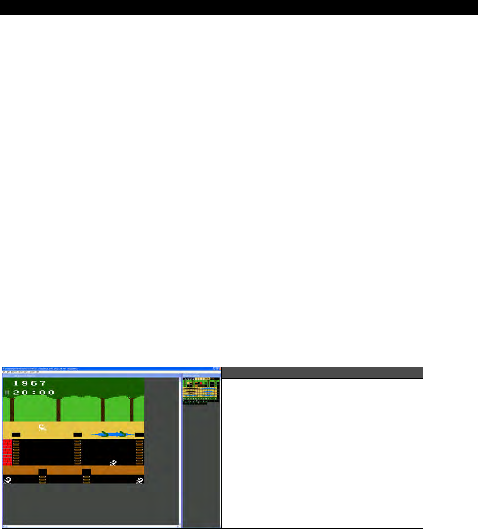
Advanced Graphics and Animation 22
Game Programming for the Propeller Powered HYDRA Page 631
Notice the “-TH15” and “-TW11” flags have changed. This is due to the fact that the graphics
template
without
the 1-pixel border is smaller and has fewer tiles horizontally, but more
vertically since the graphics are slightly different. Anyway, run the program and watch all the
data spew out! Of course, the HYDRA can barely hold all these 165 tiles since each tile is 16
LONGs, that’s 64 BYTEs or 64*165 = 10.5K, which is 30% of the memory. In any event, as
usual to get the output into a file you would simply redirect the console output to a file with
the “>” operator.
In summary, you can use this tool to generate both bitmaps and palettes from a source tile
bitmap file. The only rules are that the source file must be in .BMP format, a width and
height that is a multiple of 8, and finally 8- or 24-bit color are both supported. Once you have
the output from the tool in a text file you can cut and paste only the parts you need or
import the entire file into a demo. The only problem is that the BMP2SPIN tool is only half
the solution, what we really need is something that exports entire game maps.
22.3 Working with Tile Map Editors
Tile map editors or “map editors” are tools that allow you to use a set of bitmap tiles to
“draw” a tile map representation of your game level(s). These tools are typically custom
made by programmers developing their own game and usually for their own formats. You will
be hard pressed to find many generic tile editors. However, there are a few that you can find
on the market if you search. One such tool is called “Mappy” which is shown in Figure 22:9.
The interface doesn’t look like much, but the program is easy to use, semi-programmable
and supports a number of modes of operation and some advanced formats. You can find the
program in HYDRA\TOOLS\MAPPY on the CD and you can always download the latest
version of the program here:
http://www.tilemap.co.uk/
Figure 22:9
Mappy Tile Map Editor in Action
Working with the Pitfall Tiles

III Game Programming on the HYDRA
Page 632 Game Programming for the Propeller Powered HYDRA
22.3.1 Installing Mappy
The first step is to install Mappy and get it up and running. Simply download Mappy or use
the copy from the CD, the current version is around 1.4.11. There is currently no installer, so
just de-compress the .ZIP file onto your hardrive somewhere. In fact, on the CD in the
\TOOLS\MAPPY directory the program is already decompressed and ready to run. There is
a single .EXE for Mappy named MAPWIN.EXE, to launch the program you simply click on
this file. However, before you do, we need to confirm/change one thing in the MAPWIN.INI
file that controls how the map files are output. Open the MAPWIN.INI file up, and search
for the line:
maptype="LW1H1A1-0"
If
maptype
does not equal "LW1H1A1-0" then change it, so it does. You can save the old
setting above it with a comment. Once you have confirmed this, save the file, exit and you
are ready to use Mappy. Launch the program and the tool should start up with two blank
windows. The one on the left is the tile map area/editor, the window on the right is the
bitmap tiles area. Let’s start by loading in a MAP file. On the CD in the \SOURCES directory
there is a file name PITFALL_DEMO_MAP_04.MAP; using the
File
Open
menu item
on Mappy, load this file into the editor. Immediately, the editor will display a dialog that
allows you to enter in the tile bitmap size, it will default to 32 wide, 32 high. Change these
parameters to 16 wide and 16 high and click OK. The tool will then load the MAP file and
display yet another file dialog querying you to select the bitmap tile file; navigate in the
\SOURCES directory once again and select PITFALL_TILES_WORK_04.BMP and click
OK. The tool will then load everything up and you will see the tile map in the edit window
along with the tiles to the right in the tile bitmap window. Now, everything is a little too
small, so go to the main menu
MapTools
Zoom × 4
and select it. When you are done
you should see something similar to Figure 22:9. However, the bitmap tiles to the right might
look a little out of whack, try dragging the window back and forth horinzontally, and resizing
it until all the tile bitmaps look exactly as they do as laid out in this file:
PITFALL_TILES_WORK_04.BMP.
22.3.2 Using Mappy
Mappy is like any other graphics tool, the best way to learn it is to use it with the Help
handy. I suggest reading the online tutorials and so on, but more or less we are only going
to use Mappy in its most simple form. Here are some quick experiments to try to get the
hang of Mappy:
Experiment 1: Drag the mouse over the tile editing area.
Simply drag the mouse over the tile editing area (large window), as you do so you will see
the various statistics about the block that the mouse is selecting such as x,y, the block ID,
and the layer it’s in. Don’t click anything, just move around a bit.

Advanced Graphics and Animation 22
Game Programming for the Propeller Powered HYDRA Page 633
Experiment 2: Drag the mouse over the tile bitmaps area named “Still Blocks”.
Next, drag the mouse over the tile bitmaps on the right side of the screen. This time go
ahead and click on the tile bitmaps, as you do, you will see the “block ID” for the selected
block which will be highlighted. Think of this as the “brush” selected to paint with.
Experiment 3: Grab a scorpion and place it down on the map.
Go ahead and select one of the scorpion bitmap tiles by selecting it, then place it somewhere
on the tile map editor area. Presto! That’s all there is to making tile maps. You simply “draw”
the tile maps with the bitmap tiles (note you can erase with the right mouse button as well
as CTRL-Z to undo).
This is exactly how I drew the Pitfall scene, tile by tile. No wonder I am going crazy!
Experiment 4: Creating a new map.
Now, let’s create a new Mappy map. Considering that the HYDRA tile engine supports tile
maps that are 16, 32, 64, 128, and 256 wide these are our only options for width, but height
can be anything greater than or equal to 12 rows, so keep that in mind. Also, the tile size is
always 16×16 pixels. Keeping all that in mind, go ahead and select
File
New
Map
from
the main menu, the program will warn that you are about to loose your work, go ahead and
click OK. Mappy will pop up the tile map dialog which is slightly different than the one you
saw last time when opening a pre-existing file. In this case, we need to tell Mappy the size of
the tile map and the size of the tiles, so go ahead and enter 16×12 for the tile map and
16×16 for the size of the tiles. Don’t worry about advanced options, but do make sure the
color is set to truecolor mode then click OK. A little information pop-up will display and tell
you that you need to import some tiles, click OK.
We can import any tile bitmaps we wish, but they must not have any pixel border, they must
have an overall template size that is a multiple of 8 on width and height, and finally, so that
Mappy scans the tiles correctly, you don’t want to have extra black space all over, you want
the tiles to be packed as tightly as possible just like our examples. To load a bitmap tile file,
from the main menu go to
File
Import
and navigate into the \SOURCES directory and
load the SL_BLOCKS_03.BMP file. The file will load into the right “Still Blocks” window.
Make sure to adjust the window width with the resize bars, so the tile bitmaps all align up
and the “tree” is in one piece, this makes it easier for you to work. Now go ahead and make
any tile map you wish! When you are done, you can save your MAP file, but it will only save
the following pieces of data based on how we modified the MAPWIN.INI file:
.MAP files will contain the following information in binary format:
Header 2-bytes: Width, height of tile map.
Tile map indices: 1 BYTE per tile map in row major form, 0-based.
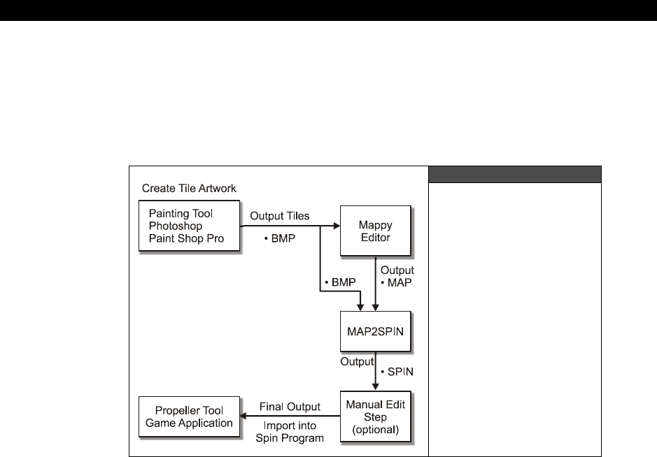
III Game Programming on the HYDRA
Page 634 Game Programming for the Propeller Powered HYDRA
Therefore, when you save your MAP file and try to reload it that’s why you have to tell the
tool what the bitmap size is again as well as telling it the name of the bitmap file you want to
load in to represent the tiles. Thus, the MAP file is a very simple abstract representation of
the tile map that only stores the original width × height of the tile map along with the indices
of the tiles that are stored in each tile map entry.
22.4 Mappy Format to Spin Conversion
Figure 22:10
Tool Chain Data Flow
What we are working toward is a “tool chain” that allows us to create art assets and then get
them into the HYDRA in a format that one or more engines understand. Take a look at Figure
22:10 to see what the grand scheme of things is. Referring to the figure, you see that we
want to draw bitmap art with a paint program in BMP format. Additionally, we want to import
this into the Mappy editor, then generate a MAP file which then goes into yet another
conversion tool that outputs everything we need for Spin and the HYDRA tile engine 4.0. The
tool that does all this is called MAP2SPIN.EXE and is located on the CD in the \SOURCES
directory along with its source file MAP2SPIN.CPP. The tool is based on the
BMP2SPIN.EXE tool, but adds the functionality of also taking a tile map from Mappy as part
of its input. The final output from the tool is a HYDRA-tile-engine-compliant tile map,
bitmaps, and palettes! And it generates all the header code, DAT sections, and everything
else we need, so we can literally import the file into our games and use it all. Thus, we have
a complete tool chain to make games!

Advanced Graphics and Animation 22
Game Programming for the Propeller Powered HYDRA Page 635
Of course, this is a very simple and basic tool chain and 1/100th as complex as something you
would see even for the most basic of modern games, but it’s a start. With that in mind, let’s
discuss using the MAP2SPIN tool and how it works.
22.4.1 Understanding the MAP2SPIN.EXE Conversion Tool.
We don’t have time to cover how the tool works internally since it’s like 2000 lines of code,
and not important since you will have to write many of these tools to make games, and this
tool is a specific example of one tool for one format for one output. You will typically write
dozens of tools when you develop games. Nevertheless, let’s at least cover what the inputs
to the tool are and how it works.
The MAP2SPIN tool is a complete solution to generating all the Spin code needed, so that
we can interface it with the HEL tile engine easily. If you recall, the HEL engine supports
tiles, sprites, and palettes. So the tool has to take as an input the Mappy MAP file, a BMP file
that represents the tile bitmap artwork and output the HEL compliant tile map, bitmaps,
sprites, and palettes. And the tool has to do all this in an organized manner with proper
headers, comments and formatting. The following is a general step-by-step explanation of
how the tool works internally at the conceptual level:
Step 1: The tile map in MAP format is loaded in and analyzed. Most tile maps will only use a
subset of every possible tile in the tile bitmap artwork, thus a table is generated that records
how many occurrences of each tile index is used. Tiles that are not used do not need to be
output as tile bitmap data later in the process.
Step 2: Once the Mappy tile map has been analyzed and processed it is converted to Spin-
compliant code and output along with labels and an address
“getter”
function.
Step 3: Next, the bitmaps must be processed that are referred to by the Mappy MAP file,
thus as part of the parameters to the tool the filename of the bitmap artwork file must be
passed, so the MAP2SPIN tool can use the exact same artwork as the Mappy tool did when
the tile map was generated. This is very important, otherwise the 1:1 relationship between
tile indices will be lost since they are indexed left to right, top to bottom in Mappy as well as
the MAP2SPIN tool, thus even if one tile is misplaced or the size of the graphics template
file is changed, everything will be off. As the bitmaps are processed they are output in Spin-
compliant code that is compatible with the HEL tile engine. At the top of the bitmaps a
header and “getter” function is output as well.
Step 4: As the last step, the palettes generated by the bitmap analysis phase are output. A
header is output along with a label once again for the “getter” function. There is a single
palette for every bitmap referenced in the tile map. The final output of the tool is complete.
For example, the file PITFALL_TILE_DATA.SPIN (located on the CD in the \SOURCES
directory) was generated by the tool (as you will see shortly) and contains everything for the

III Game Programming on the HYDRA
Page 636 Game Programming for the Propeller Powered HYDRA
HEL engine. Below is a partial listing (please look at the full listing on CD though, and view
the DAT tilemap section at a comfortable font size):
' Automated output from Map2Spin.exe file conversion tool Version 1.0 Nurve Networks LLC
' This getter function is used to retrieve the starting address of the tile map(s).
PUB tile_maps
RETURN @_tile_maps
' This getter function is used to retrieve the starting address of the tile bitmaps.
PUB tile_bitmaps
RETURN @_tile_bitmaps
' This getter function is used to retrieve the starting address of the tile palettes.
PUB tile_palette_map
RETURN @_tile_palette_map
DAT
_tile_maps LONG
' Tilemap based on file "pitfall_demo_map_04.map", dimensions 16x12
' 50 bitmap tiles extracted from bitmap tile set "pitfall_tiles_work_04.bmp"
pitfall_demo_tilemap WORD
WORD $00_00, $01_01, $02_02, $03_03, $04_04, $00_00, $00_00, $00_00, $00_00, $00_00, $00_00, $00_00, $00_00, $00_00, $00_00, $00_00 ' Row 0
WORD $05_05, $06_06, $07_07, $08_08, $07_07, $07_07, $00_00, $00_00, $00_00, $00_00, $00_00, $00_00, $00_00, $00_00, $00_00, $00_00 ' Row 1
WORD $09_09, $0A_0A, $0B_0B, $0B_0B, $0B_0B, $0C_0C, $0D_0D, $0E_0E, $0F_0F, $10_10, $11_11, $12_12, $13_13, $14_14, $15_15, $16_16 ' Row 2
WORD $17_17, $18_18, $0B_0B, $0B_0B, $0B_0B, $0B_0B, $19_19, $0B_0B, $0B_0B, $0B_0B, $0B_0B, $1A_1A, $0B_0B, $0B_0B, $1B_1B, $0B_0B ' Row 3
WORD $1C_1C, $1D_1D, $0B_0B, $0B_0B, $0B_0B, $0B_0B, $1E_1E, $0B_0B, $0B_0B, $0B_0B, $0B_0B, $1F_1F, $0B_0B, $0B_0B, $20_20, $0B_0B ' Row 4
WORD $21_21, $21_21, $21_21, $21_21, $22_22, $21_21, $21_21, $21_21, $21_21, $21_21, $21_21, $21_21, $21_21, $21_21, $21_21, $21_21 ' Row 5
WORD $21_21, $23_23, $21_21, $21_21, $21_21, $21_21, $21_21, $21_21, $23_23, $21_21, $24_24, $25_25, $26_26, $27_27, $28_28, $23_23 ' Row 6
WORD $29_29, $2A_2A, $2B_2B, $2B_2B, $2B_2B, $2B_2B, $2B_2B, $2B_2B, $2A_2A, $2B_2B, $2B_2B, $2B_2B, $2B_2B, $2B_2B, $2B_2B, $2A_2A ' Row 7
WORD $29_29, $2C_2C, $2B_2B, $2B_2B, $2B_2B, $2B_2B, $2B_2B, $2B_2B, $2C_2C, $2B_2B, $2B_2B, $2B_2B, $2B_2B, $2B_2B, $2B_2B, $2C_2C ' Row 8
WORD $29_29, $2D_2D, $2B_2B, $2B_2B, $2B_2B, $2B_2B, $2B_2B, $2B_2B, $2D_2D, $2B_2B, $2B_2B, $2B_2B, $2E_2E, $2B_2B, $2B_2B, $2D_2D ' Row 9
WORD $2F_2F, $2F_2F, $2F_2F, $2F_2F, $30_30, $2F_2F, $2F_2F, $2F_2F, $2F_2F, $30_30, $2F_2F, $2F_2F, $2F_2F, $2F_2F, $2F_2F, $2F_2F ' Row 10
WORD $31_31, $2B_2B, $2B_2B, $2B_2B, $2A_2A, $2B_2B, $2B_2B, $2B_2B, $2B_2B, $2A_2A, $2B_2B, $2B_2B, $2B_2B, $2B_2B, $2B_2B, $2E_2E ' Row 11
_tile_bitmaps LONG
' Extracted from file "pitfall_tiles_work_04.bmp" at tile=(9, 2), size=(16, 16), palette index=(0)
pitfall_tile_tx9_ty2_bitmap LONG
LONG %%1_1_1_1_1_1_1_1_1_1_1_1_1_1_1_1
LONG %%1_1_1_1_1_1_1_1_1_1_1_1_1_1_1_1
LONG %%1_1_1_1_1_1_1_1_1_1_1_1_1_1_1_1
LONG %%1_1_1_1_1_1_1_1_1_1_1_1_1_1_1_1
LONG %%1_1_1_1_1_1_1_1_1_1_1_1_1_1_1_1
LONG %%1_1_1_1_1_1_1_1_1_1_1_1_1_1_1_1
LONG %%1_1_1_1_1_1_1_1_1_1_1_1_1_1_1_1
LONG %%1_1_1_1_1_1_1_1_1_1_1_1_1_1_1_1
LONG %%1_1_1_1_1_1_1_1_1_1_1_1_1_1_1_1
LONG %%1_1_1_1_1_1_1_1_1_1_1_1_1_1_1_1
LONG %%1_1_1_1_1_1_1_1_1_1_1_1_1_1_1_1
LONG %%1_1_1_1_1_1_1_1_1_1_1_1_1_1_1_1
LONG %%1_1_1_1_1_1_1_1_1_1_1_1_1_1_1_1
LONG %%1_1_1_1_1_1_1_1_1_1_1_1_1_1_1_1
LONG %%1_1_1_1_1_1_1_1_1_1_1_1_1_1_1_1
LONG %%1_1_1_1_1_1_1_1_1_1_1_1_1_1_1_1
.
.
.
' 50 palettes extracted from file "pitfall_tiles_work_04.bmp" using palette color map 0
_tile_palette_map LONG

Advanced Graphics and Animation 22
Game Programming for the Propeller Powered HYDRA Page 637
pitfall_tile_palette_map LONG
LONG $07_06_9A_02 ' palette index 0
LONG $07_07_9A_02 ' palette index 1
LONG $07_1E_9A_02 ' palette index 2
LONG $1E_07_07_9A ' palette index 3
LONG $07_07_9A_02 ' palette index 4
.
.
.
With the right software template we could write a Spin program that imports this file as a
single object, then accesses the address getter functions to get the starting address of the
tile map, tile bitmaps as well as the palette map. With all those in hand they can be passed
to the HEL tile engine and instantly we have a game template up and running! We will see
this shortly, but now let’s take a detailed look at using the tool itself.
22.4.2 Using the MAP2SPIN.EXE Tool
The MAP2SPIN tool’s parameters are nearly identical to the BMP2SPIN tool’s, but with
some slight changes and omissions. Here’s the usage of the tool:
Usage:
MAP2SPIN.exe tilemapinputfile bitmapinputfile [flags] > outputfile
Where:
flags = -B -TW[1...255] -TH[1..255] -W[1..256] -H[1..256] -M -FX -FY -V -P[0|1] -?");
-B = Enable 1 pixel border for templated bitmaps, default no border.
-TWxx = Width of tile set on x-axis, default = 1.
-THxx = Height of tile set on y-axis, default = 1.
-Wxx = Width of tile, default = 16 pixels.
-Hxx = Height of tile, default = 16 pixels.
-M = Enables mask write as well after each tile.
-FX = Flips the output bitmap's on the X axis (needed for hel engine 4.0).
-FY = Flips the output bitmap on the Y axis.
-Px = Selects the color matching palette 0 or 1, 0 is default, 1 skews color hue 15
degrees approximately.
-V = Verbose flag.
-? = Prints help.
Since the MAP2SPIN tool has a much more specific purpose than the BMP2SPIN tool, the
map tool needs fewer flags since it can make more assumptions about what the user is
requesting. The the first two parameters are always the tilemap (Mappy MAP format) and the
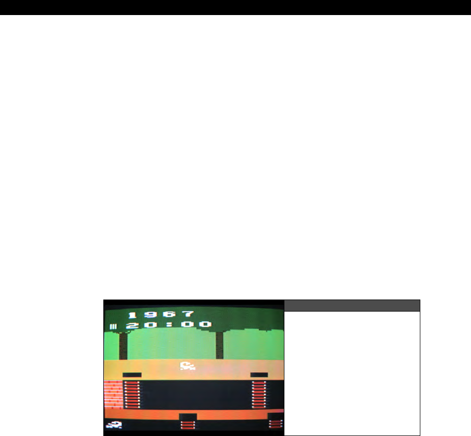
III Game Programming on the HYDRA
Page 638 Game Programming for the Propeller Powered HYDRA
bitmap (BMP format 8/24-bit) then are the optional flags; however, two flags are always
necessary which are the tile bitmap template’s width and height “-TWxx” and “”-THxx.”
These tell the tool how to extract the tiles from the bitmap that are referenced by the tile
map. As an example, let’s use the tool on the PITFALL_DEMO_MAP_04.MAP along with
the bitmap that goes along with it: PITFALL_TILES_WORK_04.BMP, and extract a single
file that contains the HEL/Spin-compliant tile map, bitmaps, and palettes. Here’s how:
MAP2SPIN.EXE pitfall_demo_map_04.map pitfall_tiles_work_04.bmp –FX –TW15 –TH11
Execute this command from your command line shell, make sure you are in the \SOURCES
directory, so all the files can be found. The tool should spew a ton of code out to the console
which contains exactly what’s in PITFALL_TILE_DATA.SPIN. Now, to get the data into a
file use the command shell redirection and output the file to MAP_TEST.SPIN like this:
MAP2SPIN.EXE pitfall_demo_map_04.map pitfall_tiles_work_04.bmp –FX –TW15 –TH11 >
MAP_TEST.SPIN
Open the MAP_TEST.SPIN file in the Propeller tool or your favorite editor and verify that at
the top is the header and getter coder followed by the tile map, the bitmaps (50 of them)
and the palettes (50 of them). Once you have done this, then it’s time to finally use this file
in a demo program.
22.5 Importing the MAP2SPIN Code into Demos
Figure 22:11
Screen Shot of Mappy
Demo Program in Action
Things are about to get really exciting now! Take a look at Figure 22:11, this is the first
Mappy-compatible demo program running showing all our hard work finally merged together.
Now, the first thing to notice is that if you review the Mappy editor version of the tile map
then does this image looks smaller? This is true, there are two things happening here: first
our tile engine only shows the first 10 tiles horizontally from the tile map (remember this was
to support a little bit of default scrolling), secondly the image looks stretched which is due to

Advanced Graphics and Animation 22
Game Programming for the Propeller Powered HYDRA Page 639
the TV having a non-square aspect ratio at the resolution we are running at. Both issues are
common to this kind of work, so just keep them in mind and draw your art slightly taller on
the PC, so when it comes out on the HYDRA it looks ok. Anyway, go ahead and load the
demo program into your HYDRA to see for yourself. The name of the file is
MAPPY_TEMPLATE_001.SPIN and is located in the \SOURCES directory as usual. It will
pull in the HEL graphics engine, the gamepad driver (for later use), as well as the
MAP2SPIN-generated tile data which by default is PITFALL_TILE_DATA.SPIN. The demo
program is rather short, here’s an abridged listing that shows the initialization and main
event loop:
OBJ
game_pad : "gamepad_drv_001.spin"
gfx: "HEL_GFX_ENGINE_040.SPIN"
tile_data: "pitfall_tile_data.spin" '<--MODIFY THIS LINE - INSERT YOUR OWN
' MAP2SPIN OUTPUT FILE HERE!!!
'//////////////////////////////////////////////////////////////////////////////
'PUBS SECTION /////////////////////////////////////////////////////////////////
'//////////////////////////////////////////////////////////////////////////////
' COG INTERPRETER STARTS HERE...@ THE FIRST PUB
PUB Start
' This is the first entry point the system will see when the Propeller Chip starts
' Execution ALWAYS starts on the first PUB in the source code for
' the top level file
' star the game pad driver (will need it later)
game_pad.start
' set up tile and sprite engine data before starting it, so no ugly startup
' points ptrs to actual memory storage for tile engine
' point everything to the "tile_data" object's data which are retrieved by
' "getter" functions
tile_map_base_ptr_parm := tile_data.tile_maps
tile_bitmaps_base_ptr_parm := tile_data.tile_bitmaps
tile_palettes_base_ptr_parm := tile_data.tile_palette_map
' these control the sprite engine, all 0 for now, no sprites
tile_map_sprite_cntrl_parm := $00_00 ' 0 sprites, tile map set to 0=16 tiles
' wide, 1=32 tiles, 2=64 tiles, etc.
tile_sprite_tbl_base_ptr_parm := 0
tile_status_bits_parm := 0
' launch a COG with ASM video driver

III Game Programming on the HYDRA
Page 640 Game Programming for the Propeller Powered HYDRA
gfx.start(@tile_map_base_ptr_parm)
' enter main event loop...
repeat while 1
' main even loop code here...
curr_count := cnt ' save current counter value
' lock frame rate to 30-60
waitcnt(cnt + 666_666)
' return back to repeat main event loop...
Notice there is no DAT section? This is because all the data is nicely tucked away in the
imported object PITFALL_TILE_DATA.SPIN. Also, so more or less we have an entire tile
engine working in about 20 lines of code! The only important thing to make sure you
understand is that the HEL tile engine needs the starting address of the:
Tile map
Tile bitmaps
Palettes
These are retrieved from the “tile_data” object via “getter” functions with similar names.
You can see this done in the assignment statements of the tile engine parmeters right under
the call
game_pad.start
. Furthermore, remember than you can change these pointers on
the fly to other tile maps, bitmaps, and palettes and the HEL engine will update the display
within 1/60th of a second, or one frame.
Alright, now that you have the template demo program working, let’s go ahead and try some
things out. First, edit MAPPY_TEMPLATE_001.SPIN and change the filename of the
imported Spin code loaded into the object “tile_data” in the OBJ section to
MAP_TEST.SPIN which you should have generated in the previous experiment. Basically,
it’s the exact same data as the PITFALL_TILE_DATA.SPIN file. Run the program again
and you should see the exact same image as before.
Now, go ahead and use the PITFALL_TILES_WORK_04.BMP tile bitmaps and Mappy to
create any number of 16×12 tile maps, export them and convert them to Spin code with the
MAP2SPIN tool, then try them in the template. Also, remember if the colors don’t look right
try using the other conversion palette with the “-P1” flag to the tool. This is where things get
really fun since you now have some tools to get things into the HYDRA from the PC within
seconds and “see” the results.
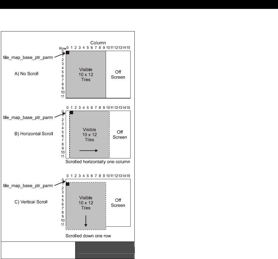
Advanced Graphics and Animation 22
Game Programming for the Propeller Powered HYDRA Page 641
22.6 Scrolling the Tile Map
In the next section, we are going to
discuss scrolling at a much more
technical and general level, but for
now, let’s see if we can get some
really basic scrolling working with what
we have. Scrolling, simply put, is
showing only a portion of a larger
game world / environment / data set
on the screen and moving this window
around in real-time. The screen
becomes the “window” to the larger
environment and can slide around
horizontally or vertically. In this case,
we want to look at a feature I built
into the HEL engine that by default
supports a little bit of scrolling
horizontally without much fuss. The
HEL tile engine maps we have been
using (including the ones we just
exported from MAP2SPIN) are all
16×12 tiles. However, the screen only
shows 10×12 of these tiles, the others
are off screen to the right. But, there
is no reason we can’t slide the tile
engine rendering over and see them.
This is so easy you aren’t going to
believe it. The trick is to realize that
the HEL tile engine uses the address
that is assigned to the parameter
tile_map_base_ptr_parm as the
starting address of the tile data for
rendering.
If we modify this address then the image will scroll around. If you recall each tile is
composed of a single WORD with the following format [tile palette index | tile bitmap index],
so we need to add or subtract a multiple of 2, since there are 2 BYTEs per WORD and the
memory is BYTE addressed. In any case, if we want to scroll horizontally we simply want to
shift the address over by 1 WORD, if we want to scroll vertically then we want to shift the
address over by an entire tile row or 16 WORDs, Figure 22:12 shows this.
Tile Map Scrolling
Mechanics Figure 22:12

III Game Programming on the HYDRA
Page 642 Game Programming for the Propeller Powered HYDRA
Of course, scrolling doesn’t work if there is nothing to scroll to; however, in our case the tile
data is 16×12 and we are only viewing a 10×12 window, so we can scroll horizontally. We
can also scroll vertically if we want, but there will be garbage there now since there are only
12 rows defined in the tile map. I have modified the Mappy template program to support
scrolling, the program is nearly identical, but now allows you to scroll the tile map
horizontally with the gamepad’s left and right directional buttons. The name of the program
is MAPPY_TEMPLATE_002.SPIN and is located on the CD in the \SOURCES directory.
Simple, load it up and give it a try.
Pretty cool huh? Of course, that’s not much scrolling, but remember tile maps can be any
size vertically, and can be 16, 32, 64, 128, or 256 columns horizontally, so that’s a lot of
scrolling room. But, we will get to that in more detail in the next section. For now, let’s take a
quick look at the scrolling code in the new demo to make sure you see what’s going on.
Here’s an excerpt from MAPPY_TEMPLATE_002.SPIN that shows how the horizontal
scrolling is performed:
PUB Start
' This is the first entry point the system sees when the Propeller chip starts,
' execution ALWAYS starts on the first PUB in the source code for
' the top level file
' start the game pad driver (will need it later)
game_pad.start
{ set up tile and sprite engine data before starting it, so no ugly startup
points ptrs to actual memory storage for tile engine
point everything to the "tile_data" object's data which are retrieved by
"getter" functions }
tile_map_base_ptr_parm := tile_data.tile_maps
tile_bitmaps_base_ptr_parm := tile_data.tile_bitmaps
tile_palettes_base_ptr_parm := tile_data.tile_palette_map
' these control the sprite engine, all 0 for now, no sprites
tile_map_sprite_cntrl_parm := $00_00 ' 0 sprites, tile map set to 0=16 tiles
' wide, 1=32 tiles, 2=64 tiles, etc.
tile_sprite_tbl_base_ptr_parm := 0
tile_status_bits_parm := 0
' initialize scrolling vars
scroll_x := 0
scroll_y := 0
' launch a COG with ASM video driver
gfx.start(@tile_map_base_ptr_parm)
' enter main event loop...

Advanced Graphics and Animation 22
Game Programming for the Propeller Powered HYDRA Page 643
repeat while 1
' main even loop code here...
curr_count := cnt ' save current counter value
' test for scroll
if (game_pad.button(NES0_RIGHT) and scroll_x < 5)
scroll_x++
if (game_pad.button(NES0_LEFT) and scroll_x > 0)
scroll_x--
' update tile base memory pointer
tile_map_base_ptr_parm := tile_data.tile_maps + scroll_x*2
' lock frame rate to 3-6 frames to slow this down
waitcnt(cnt + 10*666_666)
' return back to repeat main event loop...
The scrolling is implemented by simply testing the gamepad then updating a variable
scroll_x
which is in turn used to
offset
the base address of the tile map (notice the
multiplication by 2, since there are 2 BYTEs per tile entry WORD).
If you’re like me then this little demo probably gives you all kinds of ideas based on huge
scrolling worlds like
Nintendo’s Legend of Zelda
or racing games that scroll, or adventure
games, and much much more. Lastly, remember these tools are just that, “tools” and they
are not going to do everything, in fact, many times you will use them to output data and still
manually hack it up, change it, use a text find/replace to make global changes, nevertheless,
they save a ton of time.
22.7 Scrolling Techniques in Games
Scrolling is to game programming as recursion is to data structures and algorithms. No
matter what people always seem to have a really hard time with scrolling. I think the
problem is that in most people’s normal life experience nothing really scrolls? Sure computer
games scroll, and Windows applications, but most people don’t really have a physical analog
for scrolling, so the concept is always hard for people to grasp. However, it’s very easy if you
just draw the problem out and understand what you’re trying to do. Thus, we are going to
approach this from a very technical and geometrical point of view then simplify it to the
context of games and short cuts.
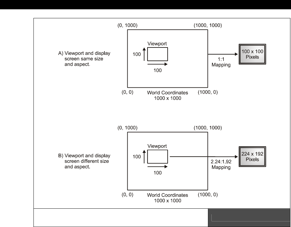
III Game Programming on the HYDRA
Page 644 Game Programming for the Propeller Powered HYDRA
The World, Viewport, Screen Coordinate
Mapping Conundrum Figure 22:13
Simply put, scrolling is nothing more than mapping a
“viewport”
from a large environment
to the screen. For example, say we had a world that was 10,000 x 10,000 pixels and the
screen (TV, monitor, whatever) is only 100x100 pixels. This means that we can only see a
“window” or “viewport” of 100x100 at any one time. Referring to Figure 22:13(A), we see
this graphically. Now, to help us describe the problem it’s nice to have some terminology to
refer to, so let’s call the larger 10,000×10,000 environment that we want to scroll around in
the
“world coordinates,”
that is the “world” is 10,000×10,000. Next, we are going to call
the little window that we scroll around that is 100×100 the “viewport” coordinates. Moreover,
in most cases for simple 2D the “viewport” coordinates are the same as screen coordinates;
however, this need not be the case for example, we could move the viewport around the
world coordinates and then map the viewport to the screen with yet another geometrical
configuration.
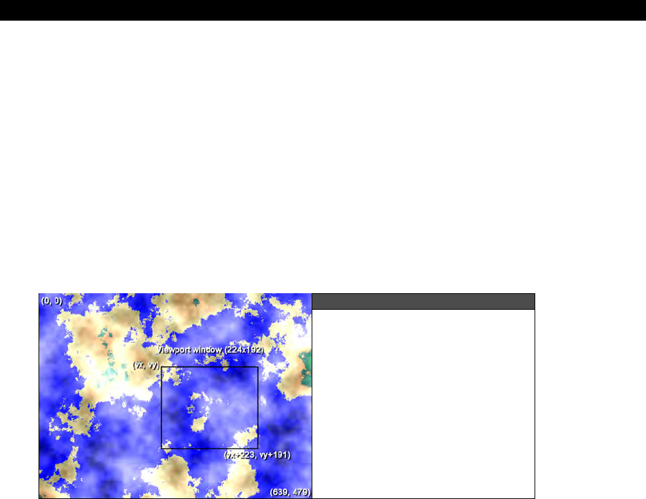
Advanced Graphics and Animation 22
Game Programming for the Propeller Powered HYDRA Page 645
For example, take a look at Figure 22:13(B), here we see the world coordinates, a viewport
window and the screen all with different sizes. The interesting thing is that if we want to map
the viewport to the screen and maintain all the image data then we must scale the image,
that is if the viewport window is 100×100 (for whatever reason), but the screen is 224×192
(NTSC for example) then we would need to map or scale the pixels from the viewport to the
screen with some math and or algorithms. But for now we will simply make sure the viewport
is the same size as the screen so the transformation is 1:1 and we don’t have to worry about
this. Nonetheless, in more advanced graphics systems you might want to have more of these
coordinate systems to help scale your imagery or make it work on any output device and so
forth.
Now that we have a little common vocabulary, let’s formally look at the math and
programming to implement scrolling using various technologies.
22.7.1 Bitmap Scrolling
Figure 22:14
The World is Our Playground
Bitmap scrolling is probably the simplest conceptually and practically since it’s nothing more
than tracking some coordinates and copying blocks of memory from one place to another.
For example, let’s assume that we want to make a war game of some kind and we have a
nice 640×480 bitmap of the world as shown in Figure 22:14, thus the world size is 640×480
and the coordinates are (0,0) to (639,479) inclusive. Now, let’s say that we want to create a
viewport than is 224×192 and we are going to map this viewport directly to the NTSC TV
screen at some point, thus no scaling is needed. Then we simply have a memory/math
problem to work out. The first calculation is how many “screenfulls” of data the viewport
window can scroll over:
screens_x = 640/224 = 2.85
screen_y = 480/192 = 2.5

III Game Programming on the HYDRA
Page 646 Game Programming for the Propeller Powered HYDRA
Something like this would be perfect for little 8×8 or 16×16 sprite army men to run around
on and kill each other, but at the same time not so big that the player couldn’t move the
viewport around quickly to get to the action. To scroll around the image, we need the
position of the viewport window, call it (vx,vy) which is the upper left hand corner of the
viewport and (vx+223, vy+191) is the lower right hand corner. Also, assuming that our
world
coordinates
range from (0,0) at the upper left hand corner to (639, 479) at the
lower right hand corner (remember computer graphics are usually up side down), Figure
22:14 shows the various coordinate labelings for reference. Given all that, what we need to
do is copy the contents of the viewport to the bitmap buffer for our game engine display
(usually the back buffer). Let’s assume that there is 1 byte per pixel to make things easy,
here’s some pseudo Spin code that would do it:
long vx, vy ' upper left hand corner of viewport
long world_bitmap ' assume this points to the world bitmap that is 640x480
long display_buffer ' assume this points to the display buffer (could be offscreen
' or onscreen, doesn’t matter)
' copy window contents from the world bitmap to the display buffer line by line
repeat y from vy to vy+191
bytemove(display_buffer + ((y-vy)*224), world_bitmap + (vx + y*224), 224)
The fragment assumes that
world_bitmap
and
display_buffer
have previously been
pointed to the starting memory address of the world bitmap and the video display buffer
respectively. The code then enters into a simple repeat loop that iterates over all 192 lines
that must be copied from the viewport to the display screen. We are using the
bytemove( )
function here to rapidly copy memory rather than copy each BYTE in yet another inner loop.
Also, notice the address calculations since they are tricky. The “source” data is coming from
the larger world map and the “destination” data is being copied to the display buffer, so we
must continually recompute the addresses so the lines of video can be copied. This code will
perfectly copy the viewport to the display buffer, however there is no error handling and
typically graphics algorithms don’t have any by design, thus you must make sure that (vx,
vy) would never push the viewport out of the world.
Everything looks good, but can we do better? Meaning computer graphics is about speed:
Spin is fast, but it will be brought to its knees if we use it to start processing bitmap data, so
we have to help it out. This is a perfect example of something we can optimize. First, we are
using the bytemove( ) function which only copies BYTEs at a time; however, if we use the
wordmove or longmove functions then we can speed up the copying process by 200-400%.
The only problem is that the pointers are BYTE based and not aligned to WORD or LONG
boundaries, so this won’t work. However, if we were copying an off-screen buffer to an
on-screen buffer, then as long as the the two buffers were LONG aligned we could use a
longmove and speed up the process, but not here. Ok, fine, is there anything else we can
do? Well, looking at the inner loop, there is a lot of math there. Normally, we wouldn’t care in

Advanced Graphics and Animation 22
Game Programming for the Propeller Powered HYDRA Page 647
an optimizing compiler, but Spin is not and it will continually recompute all the math, thus we
need to get the math out of the loop. This is easily done and with a little experience you can
“see” the solution very quickly. The question you ask yourself is “For every incremental
change in y, what is changing elsewhere?” Then take this knowledge and change the
algorithm to work incrementally. Here’s the final results of that thought experiment:
long vx, vy ' upper left hand corner of viewport
long world_bitmap ' assume this points to the world bitmap that is 640x480
long display_buffer ' assume this points to the display buffer
' (could be offscreen or onscreen, doesn't matter)
' get pointers ready for move
world_bitmap += vx + vy*224 ' now world bitmap points to upper left hand
'corner of viewport rather than larger world bitmap
' copy window contents from the world bitmap to the display buffer line by line
repeat y from vy to vy+191
bytemove(display_buffer, world_bitmap);
' update the pointers
display_buffer += 224 ' 224 bytes per line
world_bitmap += 224 ' 224 bytes per line
This new algorithm is nearly optimal. The next step in optimization would be to test for
source data WORD or LONG alignment and if so use a WORD or LONG copy to move the
data. Otherwise, its about as fast as its going to get in Spin. The only side-effect of the code
is that pointers are changed during the algorithm, thus if you wanted them to stay valid, you
would make copies of them before starting the algorithm.
Unfortunately, bitmap scrolling means bitmaps, and the HYDRA only has 32K of RAM memory
– not enough to make any large bitmap screens, thus we aren’t going to see any demos of
this technique. However, you can always make a bitmap that is single-screen size and then
scroll around a tiny window, maybe 64×64, and map it onto the screen. Of course, to do this
we would need a tool to convert full bitmaps into Spin code and an engine that supports
bitmaps. Right now we are going to stick to the HEL tile engine since it does tiles and sprites
with very little memory.
22.7.2 Vector Scrolling
Bitmap scrolling is fine for computers with huge amounts of memory so full resolution
bitmaps can be stored, but due to the memory limitation of the HYDRA we can’t really do
much with bitmap scrolling. However, there is a work-around that supports some other
effects and the idea is called
“vector scrolling.”
Vector scrolling is based on using
geometrical descriptions of objects to draw them on the fly rather than actual bitmaps of the
objects. For example, earlier in the book when experimenting with the Parallax refeference
graphics driver we drew lines, polygons, and other entities by making calls to functions. The
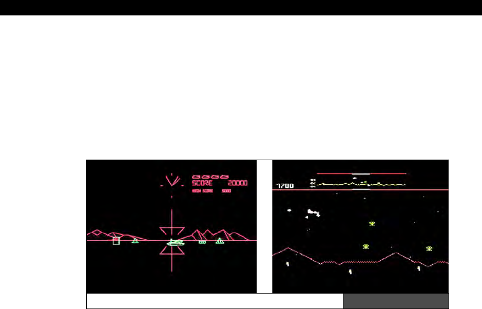
III Game Programming on the HYDRA
Page 648 Game Programming for the Propeller Powered HYDRA
only memory footprint was that we needed a double-buffered display, so an offscreen and
onscreen buffer. This is the idea of vector scrolling, we are going to use a bitmap display, but
instead of using bitmaps to represent game entities we are going to use vector descriptions
to describe the geometry of game objects and render them on the fly. Take a look at Figure
22:15, here we see two completely different games:
BattleZone
and
Defender
, both
games use radically different techniques to draw the imagery. BattleZone was in fact a 3D
wireframe game running on XY display hardware (not raster), and Defender was a tile-based
game believe it or not! The point is that as an artist, I want to get something that looks like
the mountains of each game and I want to do it with vector graphics.
Battlezone (left) and Defender (right) Figure 22:15
The effect is simple, we need a world coordinate system just as before, and to make it fun
let’s say it’s 2560×192, that is large enough to store a 10-screen-wide world at 256×192 per
screen. Of course, a bitmap this large with 8-bit color would be enormous:
2560 × 192 = 491,520 BYTEs.
However, the world coordinates are only virtual, we only need the memory for a back buffer
and a front buffer at 256×192 with 2 bits per pixel (Parallax graphics driver format) which
equals:
256 ×192 / 4 = 12,288 BYTEs per buffer.
Or 24576 BYTEs for both the on- and off-screen video buffers, leaving us with 32K−24,576 =
8K more or less for code which must support the Parallax reference graphics driver, along
with any input driver we need, plus the geometrical description of the mountains and the
program in Spin that makes it all happen.
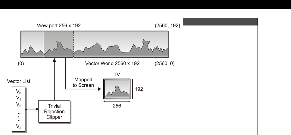
Advanced Graphics and Animation 22
Game Programming for the Propeller Powered HYDRA Page 649
Figure 22:16
The Vector Scrolling
Setup Illustrated
Graphically
The programming plan is that the mountain geometry will consist of an array-like data
structure than stores the endpoints of each line segment in the mountainscape as well as its
color index (0..3), this way we can draw anything we like. As the virtual viewport moves over
the world coordinates, the data structure will be scanned and any line segment where one or
both endpoints lie within the viewport will be passed to the renderer for rendering. Of
course, we can’t just draw lines that go off the edges of the screen, someone has to clip
them, but as you might recall the reference driver does this for us. Figure 22:16 shows the
setup for this. The important point to understand about this type of scrolling is that we are
moving the virtual viewport window over a “data set” that is purely mathematical in nature
and not bitmap nor tile data, thus it’s kind of an interesting setup. The viewport has
coordinates of (vx,vy) to (vx+255,vy+191) and we move this rectangle around
mathematically in the data set space only conceptually. All we really are going to do is test
the world coordinates of each line segment in the array against the rectangle of this
viewport. If any line segment is partially or wholly in then it’s passed to the renderer. But,
when it is passed we need to transform the data back to screen coordinates. That means
that for any line segment with coordinates p1(x1,y1) to p2(x2,y2) where one or both p1 and
p2 are within the viewport, we need to translate these points into screen space with the
following transformation:
x1_screen = x1 – vx,
y1_screen = y1 – vy
x2_screen = x2 – vx,
y2_screen = y2 – vy
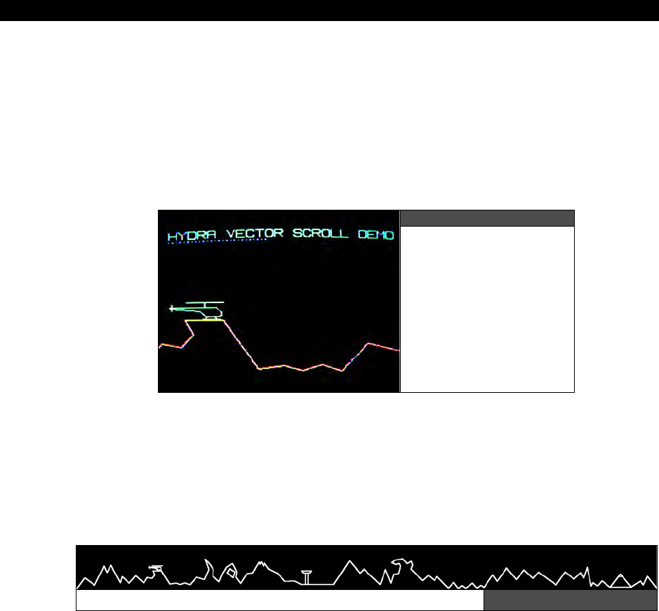
III Game Programming on the HYDRA
Page 650 Game Programming for the Propeller Powered HYDRA
It’s simple, but subtle. The point is that the viewport can be all over the place, but screen
coordinates must always be from (0,0) to (255, 191) with our proposed setup (technically,
the lines may extend beyond the screen’s coordinates, but the driver will clip them for us).
The last problem is how to create the actual vector landscape. There are two options: the
first option is to generate it randomly, the second option is to generate it by hand on paper
or using a graphics tool and draw it on the screen and record the coordinates and colors.
Either way, you need a list of 1 or more line segments that make up your mountainscape,
something like 50-200 lines will suffice.
Figure 22:17
A Screen Shot of the
Vector Scrolling Demo
A demo of the vector scrolling setup to create a mountainscape is shown in Figure 22:17.
The name of the demo is VECTOR_SCROLL_DEMO_001.SPIN and is located on the CD in
the \SOURCES directory, go ahead and load it up and run it on your HYDRA and give it a
whirl. Use the gamepad to scroll right and left (the blue dots indicated rendered segments
per frame). Note that the demo uses the Parallax reference graphics drivers, so the
coordinate system is (0,0) bottom left corner, (max_x, max_y) top right corner.
The Complete Vector Terrain Data (2560 ×192) Figure 22:18
Also, take a look at Figure 22:18 which is the entire vector terrain shown graphically; it is
composed of about 125 line segments. Concentrate your attention to the left and right ends
of the terrain, notice the terrain starts and ends at the bottom of the image, or in other
words, the right and left side of the scolling terrain are
“tileable,”
that is when you scroll
around the terrain and end up at the beginning again, you don’t see a
“discontinuity”
of

Advanced Graphics and Animation 22
Game Programming for the Propeller Powered HYDRA Page 651
the geometry. This is very important of you want to repeat your terrain or geometry, the
start and the end of the geometry must meet at the same place otherwise you will see a
“jump” in the image when you scroll through it if you want wrap around. Let’s now take a
look at the section of code that does the display list process and rendering:
vrendered := 0 ' reset number of vectors rendered
' process vector display list
repeat index from 0 to num_vectors
' do a bit of pre-computation, let's make this fast!
' extract vector line segment properties, format[color,x1,y1,x2,y2,]
' also, invert y-axis to match parallax reference driver's (0,0) origin
vbase_offset := 1 + index*5 ' pre-compute
vcolor := terrain_vector_list[vbase_offset + 0] ' color at offset 0
vx0 := terrain_vector_list[vbase_offset + 1] ' first point at offset 1,2
vy0 := SCREEN_HEIGHT - terrain_vector_list[vbase_offset + 2] - 1
vx1 := terrain_vector_list[vbase_offset + 3] ' second point at offset 3,4
vy1 := SCREEN_HEIGHT - terrain_vector_list[vbase_offset + 4] -1
' now we have the line, clip to viewport
' is this line segment partially or wholly within viewport? (no need to test y since they are ALWAYS
' within viewport)
if ((vx0 => view_x)and(vx0< view_x+SCREEN_WIDTH)or(vx1 => view_x)and(vx1 < view_x+SCREEN_WIDTH))
' line segment is within viewport, map it to screen coords and render
screen_x0 := vx0 - view_x
screen_y0 := vy0 - view_y
screen_x1 := vx1 - view_x
screen_y1 := vy1 - view_y
gr.colorwidth(vcolor,0)
gr.plot(screen_x0,screen_y0)
gr.line(screen_x1,screen_y1)
' show user how many vectors are rendered
gr.colorwidth(3,0)
gr.plot(10+vrendered*4, 175)
vrendered++
This fragment from the demo more or less scans the vector display list and then tests each
vector for inclusion in the viewport, vectors inside are rendered, otherwise discarded. Also,
notice the demo shows a number of blue dots at the top of the screen. These dots represent
the number of vectors rendered during each frame, these are tracked by
vrendered
. As the
number of vectors increases, the speed of the display slows down markedly. This is due to
the fact that the Parallax reference driver does per-pixel clipping instead of line-endpoint
clipping and thus the line draw is about 10-20× slower than need be, so lines really suck a
lot of time. Therefore, when using the reference driver the more lines you can remove from
the rendering pass the better. Also to increase speed notice the pre-computation and caching
of the array index
vbase_offset
.

III Game Programming on the HYDRA
Page 652 Game Programming for the Propeller Powered HYDRA
The vector display demo uses a “display list” of vectors to render. This
technique is a very powerful concept since a display list can be thought of as an
atomic object which can be copied, transformed, etc. Morover, a game could
have hundreds of display lists that represent simple objects, environments, or
even animations. Early “XY” vector games and many 3D rendering engines make
use of this concept.
22.7.2.1 The Helicopter Animation
The cool thing about vector data is how easy it is to manipulate. Since the image on the
screen is generated by a list of vectors each frame, there is no reason we can’t go into the
list and alter the data. For example, if you scroll to the right in the demo, you will see a
helicopter with its blade idling slowly. This simple animation effect was accomplished by
locating the vector that makes up the blade (index 24) then writing an “animation helper” to
update this vector each frame and animate the blade. The code that does this is below:
' animate the helicopter by going into the display list and manually updating
' the "blade" line segment index 24 of display list
' WORD 2, 334,87, 380,87
if (heli_blade_width > 30 or heli_blade_width < 2)
dx := -dx
heli_blade_width += dx
' update vector display list
terrain_vector_list[1+24*5 + 1] := 357-heli_blade_width
terrain_vector_list[1+24*5 + 3] := 357+heli_blade_width
' end animation of helicopter
See if you can use this same technique to animate other parts of the environment, maybe
the pyramid or the control tower to the right of the world? Or make the volcano erupt!
That’s about it for this demo, as a challenge see if you can add a player ship to the game
demo!
Hint:
the player’s ship is in world coordinates as well, and as the viewport moves
around, if the player’s ship is in the window then it’s drawn.
22.7.3 Advaned Tile Map Scrolling
Well, now we come full circle back to tile scrolling. Hopefully you have an understanding of
the mathematical underpinnings of scrolling and how world, viewport, and screen coordinates
all relate to each other. Now we are going to take a closer look at the HEL tile engine’s
scrolling support demo’ed earlier. If you recall the HEL tile normally uses a 16×12 tile screen
where only the first 10 columns of tiles are visible on screen, thus the physical screen is
10×12 and the logical screen in 16×12. This is shown in Figure 22:19 and thus far we have
only been using the first 10 columns in our demos and not defining the remaing 6 columns
that make up the whole tile screen (usually left as 0).
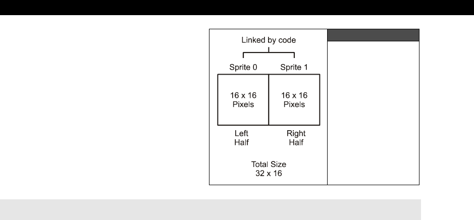
Advanced Graphics and Animation 22
Game Programming for the Propeller Powered HYDRA Page 653
However, if we did put tiles into these
locations and not just zero entries then we
could “scroll” horizontally by simply
adjusting the starting address of the tile
map by 1 WORD at a time, thus we have 6
tiles of scroll horizontally already. This was
shown off in:
MAPPY_TEMPLATE_002.SPIN
...which allowed scrolling right and left
with the gamepad, but only a few tiles
since the tile map was still only 16×12.
The code that did the scrolling was:
' update tile base memory pointer
tile_map_base_ptr_parm := tile_data.tile_maps + scroll_x*2
...nothing more than updating the tile map base pointer in the HEL engine by the number of
WORDs to scroll right/left. However, the HEL tile engine is capable of much larger tile worlds,
in fact it supports 16, 32, 64, 128, and 256 tile wide maps. The height of a tile map must be
at least 12 rows, but there is no limit to how many rows you can have. To tell the HEL tile
engine how wide your map data is (which really tells the engine how to address rows
ultimately) you need to set the proper control values in the tile map control parameter:
tile_map_sprite_cntrl_parm
. This variable is a pointer to the LONG value that holds
various “control” values for the tile map/sprite engine. Currently it encodes the width of map
and number of sprites to process up to 8 in the following format:
$xx_xx_ss_ww
Where,
ww = The number of “screens” or multiples of 16 that the tile map is. For example
0 would be 16 wide (standard), 1 would be 32 tiles wide, 2 would be 64 tiles
and so forth.
ss = Number of sprites to process 0..8
xx = Unused at this time
So to tell the HEL engine that the tile map is larger, the “ww” fields needs a 0,1,2,3,4… in it
which indicates the width of the tile map 16,32,64,128…
Figure 22:19
Default Engine
Tile Setup

III Game Programming on the HYDRA
Page 654 Game Programming for the Propeller Powered HYDRA
22.7.3.1 Horizontal Tile Scrolling
Scrolling the tile maps horizontally is accomplished by adjusting the starting address passed
into tile_map_base_ptr_parm. Given that each tile is one WORD, scrolling horizontally is
accomplished by “sliding” the starting address in WORD multiples. As the address is adjusted
the on-screen view will “scroll” to the right. If you scroll too much then you will wrap around
and start drawing the next row which, unless desired, would look wrong. Thus, if you have a
tile map that is 32 tiles wide then you never want to pass as the starting address any address
greater than the tile map width minus the number of tiles visible (which is 10). So to scroll
horizontally, in all cases you only need some code like this:
' update tile base memory pointer
tile_map_base_ptr_parm := tile_data.tile_maps + scroll_x*2
...along with some bounds checking.
22.7.3.2 Vertical Tile Scrolling
Vertical scrolling is nearly free with the HEL engine, we don’t even have to change the
tile_map_sprite_cntrl_parm at all. As far as the HEL engine is concerned it needs 12
rows of tile data, that’s it, so as long as from the starting address placed in
tile_map_base_ptr_parm there is enough data for 12 rows of tile rendering the engine
will be happy. So if you have 1000 rows of data, all you need to do to scroll vertically is
simply add to the base pointer the width of the row times the number of rows you want to
scroll like this:
' update tile base memory pointer for vertical scrolling
tile_map_base_ptr_parm := tile_data.tile_maps + scroll_y*TILES_PER_ROW*2
...where tiles per row is 16, 32, 64, etc. and the “2” factor is because each tile is 1 WORD or
2 BYTEs.
That’s all there is to scrolling with the HEL engine, so now let’s take a look at a couple demos
that take advantage of scrolling.
22.7.3.3 Large Tile Map Scrolling Demo
As a demo of large map scrolling, I took my Pitfall artwork tile bitmap file
PITFALL_TILES_WORK_04.BMP and created a 64×24 tile world with Mappy. After 20-30
minutes of moving things around, I came up with the world shown in Figure 22:20 and saved
it as PITFALL_DEMO_MAP_05.MAP. Then with map and bitmap data in hand I ran the
MAP2SPIN.exe tool with the following command line:
MAP2SPIN pitfall_demo_map_05.map pitfall_tiles_work_04.bmp –FX –TW15 –TH11 >
PITFALL_TILE_DATA2.SPIN
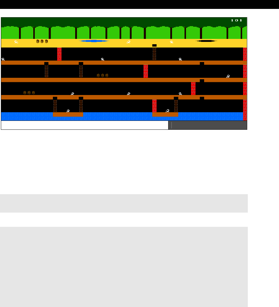
Advanced Graphics and Animation 22
Game Programming for the Propeller Powered HYDRA Page 655
Pitfall-based 64×24 Large Tile Map World Figure 22:20
The output along with all the files are located in \SOURCES as usual for your reference.
Then with the tile data file in hand, I modified MAPPY_TEMPLATE_002.SPIN to support
the 64×24 map and added some code to support 4-way scrolling, the resulting program is
TILE_MAP_SCROLL_DEMO_001.SPIN. Go ahead and load it up and then use the
gamepad to move around. Basically, this demo has a 10×12 “viewport” into the 64×24 tile
map world. The program is embarrassingly simple considering what it does. First in the OBJ
section we include the tile map data:
OBJ
tile_data: "pitfall_tile_data2.spin"
Then in the main code initializes the HEL tile engine and enters the main loop:
{ point everything to the "tile_data" object's data which are retrieved by
"getter" functions }
tile_map_base_ptr_parm := tile_data.tile_maps
tile_bitmaps_base_ptr_parm := tile_data.tile_bitmaps
tile_palettes_base_ptr_parm := tile_data.tile_palette_map
' these control the sprite engine, all 0 for now, no sprites
tile_map_sprite_cntrl_parm := $00_02 ' 0 sprites, tile map set to 2=64 tiles
' wide, 1=32 tiles, 2=64 tiles, etc.
tile_sprite_tbl_base_ptr_parm := 0 ' maps can always be any height >= 12 rows
tile_status_bits_parm := 0
' initialize scrolling vars

III Game Programming on the HYDRA
Page 656 Game Programming for the Propeller Powered HYDRA
scroll_x := 0
scroll_y := 0
' launch a COG with ASM video driver
gfx.start(@tile_map_base_ptr_parm)
' enter main event loop...
repeat while 1
' main even loop code here...
curr_count := cnt ' save current counter value
' test for scroll
if (game_pad.button(NES0_RIGHT) and scroll_x < 54)
scroll_x++
if (game_pad.button(NES0_LEFT) and scroll_x > 0)
scroll_x--
if (game_pad.button(NES0_UP) and scroll_y > 0)
scroll_y--
if (game_pad.button(NES0_DOWN) and scroll_y < 12)
scroll_y++
' update tile base memory pointer considering scroll_x and scroll_y
tile_map_base_ptr_parm := tile_data.tile_maps + (scroll_x + scroll_y*64)*2
' lock frame rate to 3-6 frames to slow this down
waitcnt(cnt + 5*666_666)
The scrolling and tile map base address update is literally a few lines of code and the results
are freely scrolling large worlds ready for game play logic and characters! Now, the demo is
pretty boring since nothing is moving around. As an exercise let’s animate one of the
scorpions and make it move right to left on one of the ledges. Looking at the game map, the
first scorpion under the entry point to the lower right hand (word tile coordinates (7,9) is
perfect for this.
22.7.3.4 Animating The Scorpion
Animating the scorpion has two elements: the “frame” or bitmap that represents the scorpion
and the postion or motion of the scorpion. Both of these aspects will be “animated” to create
the effect. To accomplish the animation, we need some tiles that represent the scorpion
walking right and left. A quick scan of the tile bitmaps in PITFALL_TILES_WORK_04.BMP
reveals that tiles 1,2,3 and 4 (top row, from left to right) represent the scorpion facing right
Advanced Graphics and Animation 22
Game Programming for the Propeller Powered HYDRA Page 657
and left respectively with 2 frames of animation each. Thus to animate the “walking”
animation set of the scorpion we need to cycle through the following frames:
Right motion: 1,2,1,2,…
Left motion: 3,4,3,4,…
Of course these tile numbers are only in the bitmap art itself, when the actual tile
data is finally exported via the MAP2SPIN tool, the tiles get arbitrary indices
based on their order of use, so we have to look up the correct final indices. For
example, if you view the PITFALL_TILE_DATA2.SPIN file that holds the large map
tile, bitmap, and palette data you will find that the scorpion tiles actually have tile
indices 57,62,64,61 which map to 1,2,3,4 in the original art, thus a lookup table is
needed or logic to map the tile bitmap indices from the artwork to the map tile
data. That is, if you want to show the 1st frame of the scorpion to the right, that
is tile index “1” counting left to right, top to bottom in the bitmap artwork of
PITFALL_TILES_WORK_04.BMP; however this tile gets mapped to “57” in the
final PITFALL_TILE_DATA2.SPIN data file after being processed by MAP2SPIN.
However, changing the tile at location (7,9) won’t translate the scorpion, thus we need to
actually move the tile as well and erase the previous tile as the scorpion moves. Furthermore,
we have to have a set of rules that control the animation, and “direct” the scorpion to
perform the animation we desire. For example, the animation might simply be to move right
or left while animating the frame each cycle, if a wall tile is collided with then reverse
direction. This type of rule results in a constant left right motion which is fine if we want the
scorpion to “patrol.” However, if we want the scorpion to look a little more realistic we might
create a simple finite state machine that has two states: WALKING and IDLE. In the
walking state, the scorpion just walks to the right or left and reverses direction when it
bumps into a wall (the tile is tested for collision); however, at some random or pre-
determined time the scorpion switches into the IDLE state and while there doesn’t do
anything, but sits still as if it were “thinking.”
Just some ideas, in a typical game you would create a number of these
“animation
behaviors”
that you could assign to your game characters. Moreover, a tool might be
created similar to the Mappy tile editor that not only lets you draw the tile world, but assign
behaviors or “scripts” to each game character. This way the work is taken out of the hands of
the programmer and put into the hands of the game designer where it should be. Anyway,
take a look at TILE_MAP_SCROLL_DEMO_002.SPIN, it is more or less identical to the
previous version except with the added scorpion animation (with state machine). The demo
is in the \SOURCES directory as usual, go ahead and load it up and watch the scorpion on
the start screen and follow it around with the scrolling control of the gamepad. The
animation logic is nearly identical to what is discussed in the previous paragraph, take a look
below for an excerpt from the guts of the animation state machine:

III Game Programming on the HYDRA
Page 658 Game Programming for the Propeller Powered HYDRA
' is it time to update scorpion?
if (++scorp_anim_count > 5)
' reset counter
scorp_anim_count := 0
' process animation
case scorp_state
SCORP_STATE_WALKING:
' move
if (scorp_dir == SCORP_RIGHT)
WORD[tile_map_base_addr][scorp_x + scorp_y*64] := $36_36 ' write black tile (erase)
scorp_x++ ' move scorpion
' test for wall collision
if ( WORD[tile_map_base_addr][scorp_x + scorp_y*64] == SCORP_WALL_TILE_INDEX)
scorp_x--
scorp_dir := SCORP_LEFT
else
WORD[tile_map_base_addr][scorp_x + scorp_y*64] := $36_36 ' write black tile (erase)
scorp_x-- ' move scorpion
' test for wall collision
if ( WORD[tile_map_base_addr][scorp_x + scorp_y*64] == SCORP_WALL_TILE_INDEX)
scorp_x++
scorp_dir := SCORP_RIGHT
' animate
if (++scorp_frame_index => 2)
scorp_frame_index := 0
SCORP_STATE_IDLE:
' do nothing or do something cool?
' update state counter
if (--scorp_state_count =< 0)
' select new state, direction, and counter values
scorp_state_count := ((?random) & $F) + 10
scorp_dir := ((?random) & $01)*2
scorp_state := ((?random) & $01)
' draw scorpion, notice palette index is same as tile index
' tile entry format: [palette_index | tile_index]
WORD[tile_map_base_addr][scorp_x + scorp_y*64] := scorp_anim_lookup[scorp_frame_index+scorp_dir]<<8+
scorp_anim_lookup[scorp_frame_index+scorp_dir]
(Note that the last instruction is intended to be on a single line.)
As you play with the demo
keep an eye on the scorpion by following it around with the scrolling control to verify the
state machine for yourself. As an exercise see if you can simplify the animation controller and
animate every single scorpion!
Of course, the motion of the scorpion is tile-based and rough. If we want the scorpion to
move smoothly we would have to make it a sprite. Additionally, since we are modifying the
tile memory directly, we have to “clean up” as we go, that is, we have to erase the old
scorpion, then move it, then draw it right into tile memory. Another approach might be to

Advanced Graphics and Animation 22
Game Programming for the Propeller Powered HYDRA Page 659
copy the current tile memory to a buffer then modify the buffer and let the engine draw it,
this way the original data is never destroyed.
There is another way to get smooth animation with tiles. For example, say we
wanted to make the scorpion walk to the right 4 steps smoothly. The trick is to
take two adjacent tiles and then animate the scorpion 4 different steps within the
tiles themselves. Thus the image of the scorpion actually shifts over each time.
Therefore, to move the scorpion one tile now takes 4 steps and 8 tiles. This uses
a lot of tile memory, but if you only have a few objects to move smoothly it’s a
good trick! We will see this in the framed animation section coming soon.
22.7.4 Parallax Scrolling
Parallax scrolling is a method of simulating 3D by moving different layers of a 2D image at
different rates based on their distances to the viewpoint. For example, when you drive in a
car and look outside the window you see the road go by very quickly, but the farther objects
like the mountains and clouds go by slowly. This is the “parallax” effect - near objects
translate faster, father objects translate slower. This observation is used in all kinds of 2D
games to create a 3D layer effect in the action. One of the most popular 2D games that has
a lot of parallax scrolling layers is
Sonic the Hedgehog
.
Figure 22:21 shows a screen shot
of Sonic so you can see the various layers: the spikes at the bottom of the screen, the
platforms Sonic is on, the water layer, the hill areas to the rear, and finally the cloud layer. If
you happen to have a copy of Sonic give the game a try so you can see how effective the
parallax 3D scrolling layers are. If you don’t have a copy then you can try this flash version
on the web here (very impressive I might add):
http://www.ebaumsworld.com/sonic.html
Figure 22:21
Sonic the Hedgehog
has a lot of parallax
scrolling layers.

III Game Programming on the HYDRA
Page 660 Game Programming for the Propeller Powered HYDRA
To implement parallax scrolling is theoretically trivial; you simply layer either overlapping or
non-overlapping y-regions and scroll them at different rates, thus creating the effect of 3D
parallax. Of course, you do this in such a way that the “art makes sense,” that is, you don’t
scroll the near objects slow and the far objects fast, that would make no sense. Of course,
the engine needs to support either overlapping layers or at least the ability to scroll “y-
bands” or regions on the screen. For example, take a look at the alien desert scene in Figure
22:22.
Figure 22:22
An Alien World –
Perfect for Simple
Layered Scrolling
The good thing about this image is that we could scroll the grass region, the mountain
region, and the sky with the planetoid in it and they don’t over lap on the y-axis. Thus, at
very least we can go into the memory or tiles that make up the image and scroll the data
horizontally to create the effect. However, if we are using a tile engine then we can only
scroll the images by 1 tile which may be much too much and look too rough, but that’s the
trade-off with tile graphics. As a demo of this technique of crude parallax scrolling take a
look at PARALLAX_SCROLL_DEMO_001.SPIN located on the CD in the \SOURCES
directory. Load it up and use the gamepad to scroll right and left. Notice that the image
simply repeats, and the idea is that each of the layers scroll at a rate slower/faster than the
others to create the effect. The scrolling is
“out of engine”
meaning we are not using the
engine to scroll, but manually going into the tile memory and scrolling the regions of the tiles
ourselves. Here’s an excerpt from the code that does the actual scrolling:
PUB Scroll_Layer(tile_map_ptr, width, ys, ye, dx)
' this function scrolls a layer or region of the sent tile map from ys to ye an amount dx (signed)
' tile_map_ptr - points to beginning of tile map, 16x12 WORDs usually
' width - number of WORDs per row, usually 16
' ys, ye - start and ending y-region to scroll
' dx - amount to scroll horizontally (+-1)
' do scroll in 3 steps as to not invoke built in "overlap logic" also so that as change occurs
' user doesn't see tiles moving around
dx := dx // width
Advanced Graphics and Animation 22
Game Programming for the Propeller Powered HYDRA Page 661
if (dx > 0)
repeat y from ys to ye
' copy left half of row to buffer
wordmove(@tile_buffer + (dx<<1), tile_map_ptr + (y*width<<1), width-dx)
' copy right half of row to buffer
wordmove(@tile_buffer, tile_map_ptr + ((y*width) + (width-dx))<<1, dx)
' finally copy buffer back to tile row
wordmove(tile_map_ptr + (y*width<<1), @tile_buffer, width)
elseif (dx < 0)
dx := -dx ' invert dx now
repeat y from ys to ye
' copy right half first
wordmove(@tile_buffer, tile_map_ptr + ((y*width) + (dx))<<1, width-dx)
' copy left half of row to buffer
wordmove(@tile_buffer + (width-dx)<<1, tile_map_ptr + (y*width<<1), dx)
' finally copy buffer back to tile row
wordmove(tile_map_ptr + (y*width*2), @tile_buffer, width)
As you can see, the function more or less is simply moving tile memory around rows at a
time. As an exercise see if you can optimize the function; you should be able to make it 2-3×
faster without much work. If you want to take a look at the Mappy MAP and the BMP file the
demo is based on check out ALIENPLANET_DEMO_MAP_01.MAP and
ALIENPLANET_TILES_02.BMP in the \SOURCES directory. Also, the command line to
generate the external Spin data file was simply:
MAP2SPIN.exe ALIENPLANET_DEMO_MAP_01.MAP ALIENPLANET_TILES_02.BMP –TW20 –TH8 –FX >
ALIENPLANET_TILE_DATA.SPIN
To implement full-blown parallax scrolling as in the Sonic demo, we would need to be able to
overlap tile maps and “layer” them and secondly, be able to scroll sub-tile accurate or pixels
at a time rather than tiles. Both of these are 100% doable on the HYDRA, but more complex
graphics engines would have to be developed that take up multiple cogs to do all the work
and layering.
When starting out on game development and graphics projects, one of the last
things you want to do is spend hours or days creating art to run simple tests.
With this in mind, I have provided you with a good selection of stock
bitmap/pixel art that I have created. Similar to Sprite Lib, my art is free for you to
use, but you can’t sell it or publish it, simply use it in your games and demos.
You can find it inside the two main directories on the CD; \SOURCES as well as
the assets directory \MEDIA\GRAPHICS.
22.8 Framed Animation
Animation is the magic that makes video games look like video games. One of my all-time
favorite 2D games with heavy animation is
“Earthworm Jim”
(1995) by
Shiny
Entertainment
shown in Figure 22:23 on the next page. The animation in this game was
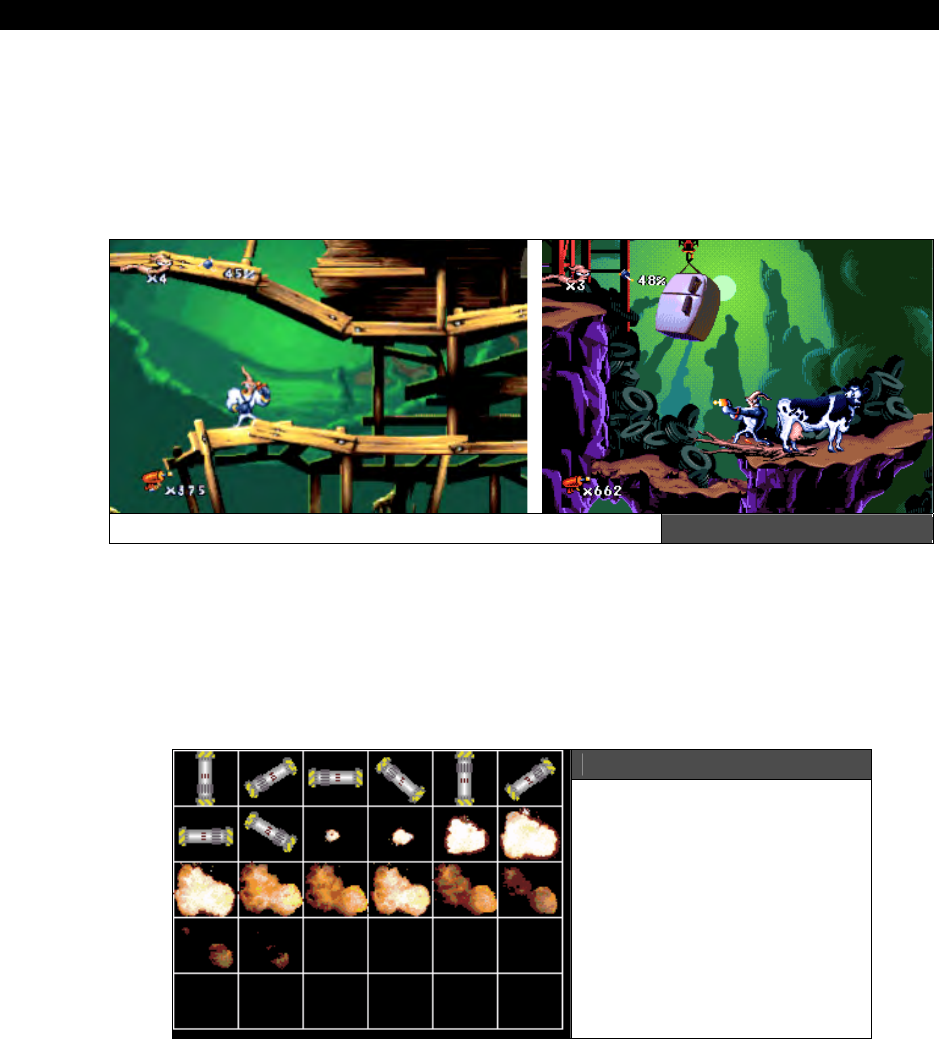
III Game Programming on the HYDRA
Page 662 Game Programming for the Propeller Powered HYDRA
gorgeous and better than cartoon quality which was a first at the time. Game developers
tended to leverage technology rather than art early on, but this game did both. I highly
recommend trying the game out on the PC or a game console of your choice. The point of
the example is to get an idea of just how much goes into animation. There are literally
thousands of frames of animation in this game, and hundreds of background sets. All this
had to be generated by an artist, so the point is animation is a lot of work!
Screen Shots of Earthworm Jim Figure 22:23
In this section, we are going to put together a couple demos that illustrate the idea of
“framed”
animation. Framed animation is nothing more than drawing a series of frames or
images of a game character than when rapidly cycled through animates the character. Many
of the demos thus far have done this to some extent, for example the scorpion had a couple
frames of animation in the previous tile demo. Also, the bug blaster in the Centipede demo
blinked its eyes, and so forth. Nonetheless, we are going to formalize the concept here.
Figure 22:24
A Plasma Bomb Animation
plus Explosion Frames
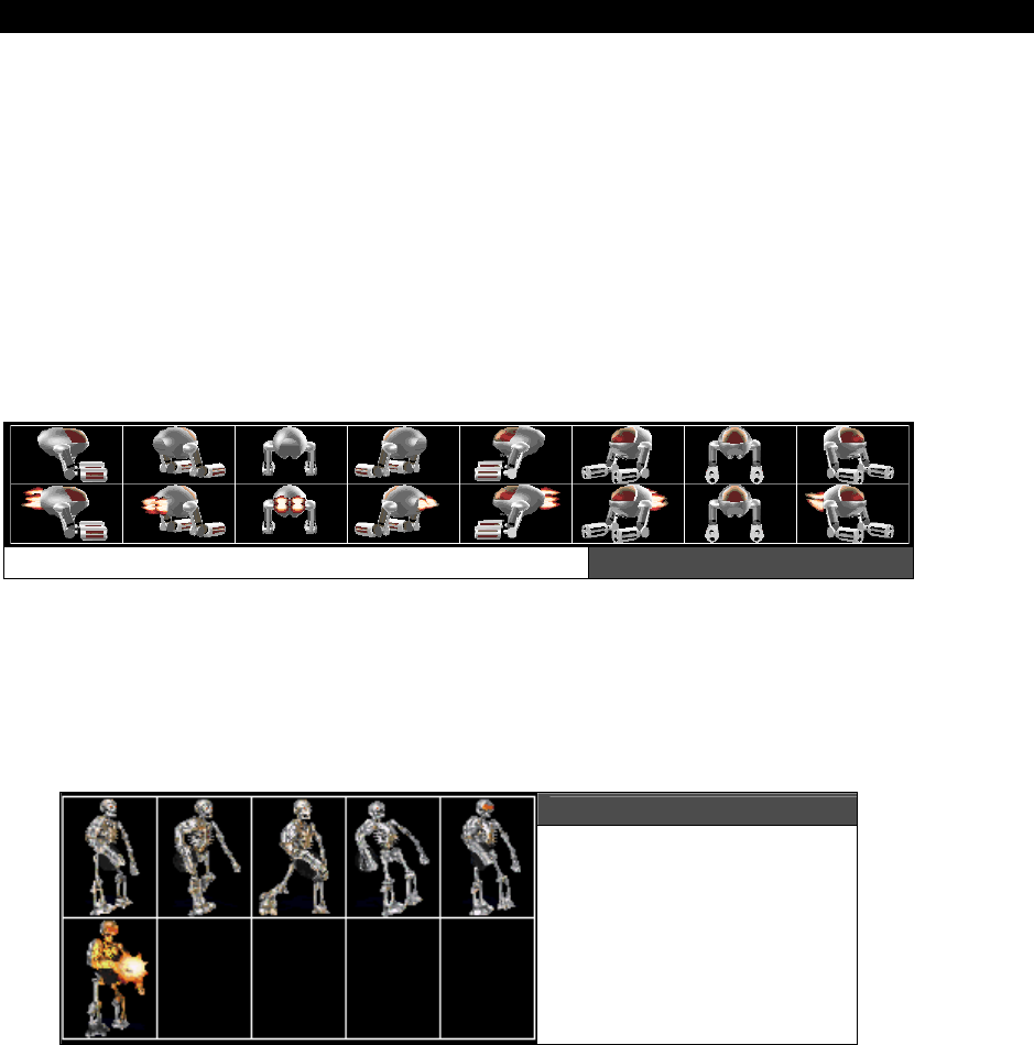
Advanced Graphics and Animation 22
Game Programming for the Propeller Powered HYDRA Page 663
The best thing to do is show some actual animation artwork to give you an idea of animation
techniques. The first plate is shown in Figure 22:24. Here I drew 8 frames of a plasma bomb
rotating about its center. Then following those animation frames is the actual explosion that
ensues when the plasma weapon hits its target. The size of each frame is 42×36, not exactly
a power-of-2 tile. However, this art was originally created for a PC game, thus I didn’t have
the constraints of power-of-2 math. Anyway, this example is typical for a game object, you
will have a single “plate” or graphics file that contains the artwork for that animation. Later,
you might merge them all into a master file, or database, etc., but as an artist, it’s a good
idea to keep things separate. Furthermore, the technique I used for this art was to render
the plasma bomb with a 3D modeler then in post processing tweak some of the details. Also,
the explosion is a real explosion from stock media that I have. However, there are programs
that generate explosion art, or you can try it yourself and draw it.
A 3D Drone Gunship Animation Figure 22:25
For the next example of framed animation take a look at Figure 22:25, it depicts a 3D drone
of sorts. This drone can be used in a 2D game or in a 3D game as a 3D sprite. In either case,
the top row of frames animate the drone rotating around the Y-axis, while the 2nd row
shows the same animation, but with the engines on. I did this animation with a 3D modeler
as well, but added the flames manually with a paint program.
Figure 22:26
A Skeleton “Stop Frame”
Animation Character
Sometimes when creating game art a technique used is to build miniature models and
photograph them. Sometimes this is cheaper and faster than rendering or manually drawing
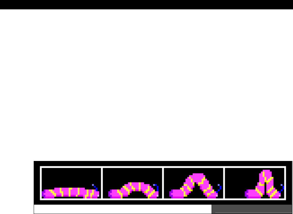
III Game Programming on the HYDRA
Page 664 Game Programming for the Propeller Powered HYDRA
the art. This is the case for the animation shown in Figure 22:26. This is one slide of a very
complex animation I created. Each slide shows the skeleton character walking in a certain
direction, and firing his weapon (notice the muzzle flash). There are 8 of these slides, each
with the skeleton walking in a different direction. Browse the \MEDIA\GRAPHICS directory
on the CD to see all the animation frames. The original model was build at about 6” high and
then mounted on a rotatabl- platform. Then the model was hand animated by myself and a
photo snapped of the model building up all the animation and angles of view. The raw
photography was then post processed by a paint program, lit, and cleaned up and resized.
Basically, this is the same technique used in movies where you see a lot of stop frame
animation. I highly recommend trying this technique since it gives you a good idea of how to
animate objects physically, where to place the feet, arms, torso, etc.
Alright, now that you see what animation is and how to generate the actual art (at least
theoretically), let’s make some demos that show these techniques with the HYDRA. Of
course, we are limited since we only have a tile engine that supports 4 colors per tile, plus
sprites. Moreover, tiles/sprites can only be 16×16 pixels. And we don’t have a ton of
memory, but if we use simple objects with few colors and “tile” sprites or tiles together to
form larger objects we can animate just about anything.
Fuzzy, Cute, Caterpillar Animation Frames Figure 22:27
Considering my philosophy of keeping things as simple as possible, for the first demo, we are
going to animate a little caterpillar (trust me it will look cool). Take a look at Figure 22:27, it
shows our source media for this grand project which consists of 4 frames of animation where
each frame is 32×16 pixels. The animation was drawn by hand with me using my finger as a
“model” and looking at some images of exotic caterpillars with lots of colors on them. This is
a good example for us for the following reasons: the image is larger than 16×16, so we have
to tile some sprites (or tiles together) to get the full image, next the caterpillar has few
colors, so it should convert well into palettized form, and lastly, the animation is something
fun to animate.
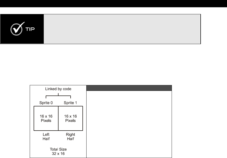
Advanced Graphics and Animation 22
Game Programming for the Propeller Powered HYDRA Page 665
When animating objects and characters in games, the trick is not to make them
look real as much as it is to make them look fun and interesting. Thus, many
animators including myself will always exaggerate the animation to make the
animation more visually interesting to the viewer. Also, the way something
moves helps the player identify what it is. So when animating game characters
make them “loud” and “obnoxious” visually – this will engage the player more!
The plan to animate this character is to use one of the templates that supports sprites that
we worked with earlier and then convert it over to animate this single object. We are going
to tile two sprites together side by side to fit the 32×16 image of the caterpillar frames into
the animation. This is shown in Figure 22:28.
Figure 22:28
Using Two Sprites to Animate
the Large 32×16 Pixel Character
Using two sprites means we have to keep them synced together as we move the sprite,
which brings me to my next topic – motion.
We are almost ready to animate the caterpillar sprite, but there is a question at hand and
that’s how to actually move the caterpillar sprite? The obvious answer is to move it by a few
pixels each animation frame. While surely will work, it might make the caterpillar look like its
“sliding”
rather than moving on the surface. Thus, a second aspect of animating characters
that goes hand in hand with the actual animation frames, is how to move or translate the
object as the frames of animation are playing or cycling? This is yet another form of art and
you have to get the hang of it. For example, looking at the frames of animation in Figure
22:27 and watching some video of caterpillars moving, you will see that the caterpillar does
not slide across a surface, but it arches its back then pushes off with its rear segments to
translate itself on the surface. To capture this or any non-linear motion of an object a more
advanced approach than simply moving objects by a constant rate each frame has to be
programmed. The solution is rather simple: a
translation-animation
lookup table. This
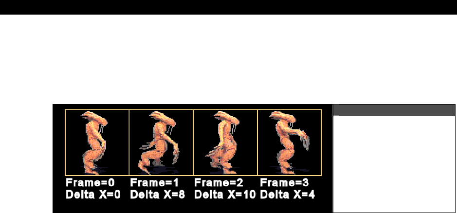
III Game Programming on the HYDRA
Page 666 Game Programming for the Propeller Powered HYDRA
table has a number of elements, usually one for each frame of animation, that indicates how
far to move the object being animated. The table might have dx values, or both dx, dy values
or whatever. The idea is that this table is part of the
animation-controller
software you
need to get realistic animation. A graphical depiction of the application of the system is
shown in Figure 22:29.
Figure 22:29
Translation Coupled
with Animation
Frames
Referring to the figure, each frame also has a delta translation factor assigned to it creating a
more realistic walk. Also, typically frames of animation are re-used in an animation to save
space, for example, in the caterpiller’s case, we might decide to start with the elongated
frames and play frames 0,1,2,3, then play 3,2,1 and repeat, thus the animation cycle might
be:
0,1,2,3,3,2,1 - repeat
If you wanted one frame to pause, you might play it twice, for example, the frame where the
caterpillar is elongated on frame 0:
0,0,1,2,3,3,2,1 - repeat
The idea is to try things, have fun, and make it look cool. Considering that, a translation-
animation lookup table might look like this (along with the animation frames table) in
pseudo-code:
animation_frames [6] = {0,1,2,3,3,2,1}
animation_translation [6] = {2,2,2,3,3,2,0}
Notice at first the caterpillar slowly inches forward then “springs” back and pushes itself off;
this is consistent with how a real one moves. The idea here is to show that no matter how
the data is ordered, we can use the lookup tables to get the animation frames and motion we
desire. Additionally, since the animation is
“data driven”
we can remove the programmer
from the loop and once again allow the artist or game designer to control the motion data
with a tool that is read by the game engine. Therefore, in a more advanced animation

Advanced Graphics and Animation 22
Game Programming for the Propeller Powered HYDRA Page 667
system a tool might be used that not only allowed the designer to draw the art, but to assign
motion and animation frames to it and then the data would be exported and loaded into the
game!
As a demo of all this check out CATERPILLAR_DEMO_001.SPIN on the CD located in
\SOURCES. Load the program up and watch the little caterpillar inch across the screen. The
gamepad will scroll the world a little, other than that there are no controls of the animation
itself. But, try going into the code and changing things. Specifically, here’s the part of the
main event loop that controls the animation:
' animate caterpiller if its time to do so
if (++cat_animation_counter > 1)
' reset counter
cat_animation_counter := 0
' update frame index
if (++cat_frame_index > cat_num_frames)
cat_frame_index := 1 ' reset
' fire sound at proper moment
if (cat_frame_index == 3)
' play a PCM sound on channel 0 with a volume of 255
snd.PlaySoundPCM(0, snd_data.ns_hydra_sound, snd_data.ns_hydra_sound_end, 255)
' extract first frame of animation
cat_anim_frame := animation_frames[ cat_frame_index ]
' translate caterpiller
cat_x += animation_translation [ cat_frame_index-1 ]
' test for wrap around
if (cat_x > 255)
cat_x -= 255
' end animation code block
' draw caterpiller, take into consideration scroll_x, that is "world view" position
‘ since sprites and tiles move indepedantly
sprite_tbl[0] := cat_y << 24 | (cat_x-scroll_x*16) << 16 | $01
sprite_tbl[1] := tile_data.sprite_bitmaps + (cat_anim_frame*256)
sprite_tbl[2] := cat_y << 24 | (cat_x-scroll_x*16+$10) << 16 | $01
sprite_tbl[3] := tile_data.sprite_bitmaps + (cat_anim_frame*256)+128
.
.
DAT
' animation lookup tables
' format {number of frames in sequence, sequence...}
animation_frames LONG 7, 0,1,2,3,3,2,1
{ list of translation factors for each frame of animation, must have same number of entries as
"animation_frames" }
animation_translation LONG 2,2,2,3,3,2,0

III Game Programming on the HYDRA
Page 668 Game Programming for the Propeller Powered HYDRA
Basically, the animation occurs whenever the animation counter overflows, at this point, the
animation logic updates the current frame, retrieves the animation frame and translation
factor from the lookups and then writes the sprite data to the sprite table. Also, notice the
use of sound in the demo. When the animation hits a certain point a “squishy” sound is
played that I recorded, processed with RAW2SPIN and included in the demo. The demo
was based on our previous work with tile map imports as well as sprites. The real work was
creating the art and using the tool chain to create a final compatible file. The steps I took
were to first use the ALIENPLANET_TILES_03.BMP file for the tile work and created a tile
map with Mappy named CATERPILLER_DEMO_MAP_01.MAP, then I used the
MAP2SPIN tool with the following command line:
MAP2SPIN CATERPILLAR_DEMO_MAP_01.MAP ALIENPLANET_TILES_03.BMP –FX –TW20 –TH8 >
CATERPILLAR_TILE_DATA.SPIN
The output file CATERPILLAR_TILE_DATA.SPIN was then put aside for a moment and I
generate sprite data with the graphic file CATERPILLER_TILES_WORK_02.BMP and
processed the sprites with out BMP2SPIN tool like so:
BMP2SPIN CATERPILLAR_TILES_WORK_02.BMP –FX –M –TW8 –TH1 –C8 >
CATERPILLAR_BITMAP_DATA.SPIN
Then with both output files in hand, I manually merged the sprite bitmap data (and the
palette(s)) used by the sprites into the CATERPILLER_TILE_DATA.SPIN file to create a
master file. With that in hand, I could load everything in and use getter functions to retrieve
the tile map, tile bitmaps, sprite bitmaps and palettes! Lastly, I made a digital sample called
CATERPILLAR_11_8.RAW and processed it with the RAW2SPIN tool with the following
command line:
RAW2SPIN.exe CATERPILLAR_11_8.RAW > CATERPILLAR_11_8.SPIN
This output was then included in the final demo. A lot of steps and a lot of work, but this is
what the tool chain is all about – there is simply no way to get around all these steps when
developing games. The only solution is to make complex tools that do everything which I
hope you do!
As usual all the assets for the demos are in the \SOURCES directory as well as in
the \MEDIA\GRAPHICS directory on the CD.
22.8.1 Sub-Tile Animation Techniques
“Sub-tile” animation or motion simply means performing the operation within the confines of
the tile itself. For example, one of the biggest problems with tile graphics is that you can only
move objects whole tiles at a time. However, if you instead represent a single 16×16 tile

Advanced Graphics and Animation 22
Game Programming for the Propeller Powered HYDRA Page 669
image say with a two 16×16 forming a 32×16 pixel image, then you can animate or move
the image within the tiles horizontally.
Spacecraft Tiles with Sub-Tile Motion within Tile Bitmaps Figure 22:30
Figure 22:30 helps clarify this visually. Referring to the figure, there are 8 tiles total, but
focus on adjacent pairs of tiles starting from the left. See how the bitmap within the tiles is
slowly moving to the right within the tile art itself? This is the crux of the trick. In this case,
there are 8 tiles making 4 pairs which are always rendered next to each other. If we number
the tiles from left to right 0,1,2,3,4,5,6,7 then to move the ship left right, we would draw the
following sequence of tiles:
Translation = 0 pixels
Draw tiles 0,1 at tile location x=0, x=1
Translation = 4 pixels
Draw tiles 2,3 at tile location x=0, x=1
Translation = 8 pixels
Draw tiles 4,5 at tile location x=0, x=1
Translation = 12 pixels
Draw tiles 6,7 at tile location x=0, x=1
Notice, that at no time are we moving where we draw the tiles, we are only changing
which
tiles we draw. The trick is that the tiles themselves are drawn to simulate motion. Then
here’s the tricky part, after all 4 pairs have been drawn in sequence (the ship is moving right
for example) we reset to Tiles 0,1 and move the rendering over a whole tile, so that
rendering then proceeds at x=1, x=2, and the process continues. This is all there is to sub-
tile animation and motion. With this technique you can make tiled games move very
smoothly and in fact is how many early arcade games worked that had a finite number of
sprites to work with.
For a change, I decided to draw some mechs and do more of a “space” based demo. I
created a number of “space invader” alien mechs 16×16 along with some barriers and the
player’s ship and then created smooth tile animation of the aliens and player’s ship. Take a
look at Figure 22:31 on the next page to see the art. The art is laid out such that there are 3
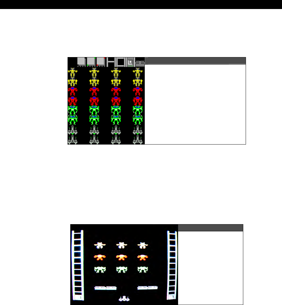
III Game Programming on the HYDRA
Page 670 Game Programming for the Propeller Powered HYDRA
double-rows of aliens; each row of aliens has two frames of animation (arms up, arms down)
and as you move to the right, the aliens move within the tile artwork 4 pixels at a time. Since
the artwork is 16×16, each motion pair is two tiles which results in a 32×16 space to move
the art within the tiles.
Figure 22:31
The Templated Mech Artwork
for the Demo
Now, working with sub-tile art and multiple tiles per character is a little tricky. For example,
when moving an object you have to first draw each tile pair, then at some point when the tile
pair has moved the object all the way to the right, left, up, down or whatever, then you have
to reset the tile pair and actually move the position the tiles are drawn at. This is really a lot
of housekeeping. Also, since all 16×16 tiles are now composed of 32×16 pixels, it’s harder to
draw objects right next to each other since everything is really 2× as large as the bitmap is
to support the extra tiles being drawn. These problems aren’t that hard to overcome and for
25 years people have done so!
Figure 22:32
The Invaders
Sub-Tile Animation
Demo

Advanced Graphics and Animation 22
Game Programming for the Propeller Powered HYDRA Page 671
Taking all this into consideration, take a look at INVADERS_DEMO_001.SPIN, its in the
\SOURCES directory, so load it up and give it a try. Figure 22:32 shows a screen shot of the
demo in action. The demo uses the gamepad as usual; press right and left to move the ship
around, notice that it collides with the walls and stays contained within the game field. Also,
notice the ambient flame animation playing on the ship. Alright, now try holding down
<SELECT> and using the dpad again, notice that you can scroll the world? Scroll all the way
to the right to see the artwork all laid out for your inspection. Of course, I could have hidden
another level over there as well.
The demo was generated with our tool chain primarily with Mappy and the MAP2SPIN
program. The artwork file is called MECH_TILES_WORK_01.BMP and the Mappy MAP file
is INVADERS_DEMO_MAP_01.MAP (both located in \SOURCES on the CD). The demo
is a fusion of the scrolling demo along with some sprite code from our previous work. The
good news is there are no “manual” steps in this demo, the final Spin tile data file was
generated with the simple command line:
MAP2SPIN INVADERS_DEMO_MAP_01.MAP MECH_TILES_WORK_01.BMP –FX –TW8 –TW9 >
INVADERS_TILE_DATA.SPIN
As usual, the code is rather simple since our tool chain and HEL graphics engine are doing all
the work. Below is an excerpt from the demo showing the main event loop that controls
everything:
' test for scroll
if ((game_pad.button(NES0_RIGHT) and game_pad.button(NES0_SELECT)) and scroll_x < 32-10)
scroll_x++
if ((game_pad.button(NES0_LEFT) and game_pad.button(NES0_SELECT)) and scroll_x > 0)
scroll_x--
' test for player movement right?
if (game_pad.button(NES0_RIGHT) and not game_pad.button(NES0_SELECT))
' erase ship first
WORD[tile_map_base_addr][ship_x + ship_y*32] := $01_01 ' this is the "black" tile
WORD[tile_map_base_addr][(ship_x+1) + ship_y*32] := $01_01 ' this is the "black" tile
' move player within tiles right, but first test if hitting edge?
if (not (ship_x == 7 and ship_sub_x == 3))
if (++ship_sub_x > 3)
' reset sub-tile and move whole tile
ship_sub_x := 0
ship_x++
' test for player movement left?
if (game_pad.button(NES0_LEFT) and not game_pad.button(NES0_SELECT))
' erase ship first
WORD[tile_map_base_addr][ship_x + ship_y*32] := $01_01 ' this is the "black" tile
WORD[tile_map_base_addr][(ship_x+1) + ship_y*32] := $01_01 ' this is the "black" tile
' move player within tiles left, but first test if hiting edge?
if (not (ship_x == 1 and ship_sub_x == 0))
if (--ship_sub_x < 0)
' reset sub-tile and move whole tile

III Game Programming on the HYDRA
Page 672 Game Programming for the Propeller Powered HYDRA
ship_sub_x := 3
ship_x--
' update animation of flame!
if (++ship_anim_count > 1)
' reset flame and frame
ship_anim_count := 0
if ( (ship_anim_frame+=8) > 8)
ship_anim_frame := 0
' draw player always, pay attention to how tiles are addressed and how the animation is
‘ performed by adding the offset to the 2nd row of tiles
WORD[tile_map_base_addr][ship_x+ship_y*32] := (SHIP_TILE_INDEX_BASE + ship_sub_x*2 + ship_anim_frame)
<< 8 |(SHIP_TILE_INDEX_BASE+ship_sub_x*2 +ship_anim_frame)
WORD[tile_map_base_addr][(ship_x+1) + ship_y*32] := (SHIP_TILE_INDEX_BASE + ship_sub_x*2 + 1 +
ship_anim_frame) << 8 |(SHIP_TILE_INDEX_BASE+ ship_sub_x*2+1+ship_anim_frame)
' update tile base memory pointer
tile_map_base_ptr_parm := tile_data.tile_maps + scroll_x*2
(Note that the WORD array assignments are each meant to be on a single line.) The code
more or less begins by testing for the gamepad buttons and updates either the scrolling
variable or moves the ship. If the ship is being moved, first the ship_sub_x variable tracks
sub-tile motion, when this overflows the animation is reset and the ship is moved a whole
tile. The tile map update code at the end of the loop is probably the most complex since it
has to update two tiles and do a lot of arithmetic; however, the code can be simplified with
shifts and pre-computations, but this would loose the steps, so I left it long and drawn out so
you can see what’s going on.
See if you can add a weapon to the player and/or move the alien mechs back and forth with
the same technique!
22.9 Summary
The hardest thing about this chapter is without a doubt the tools. Unfortuntely, we simply
don’t have the page count to go into their construction in depth, but the sources are
available for you to review and modify (in the \SOURCES directory). Hopefully though you
have enough to work with to use the tools along with the demos to start building your own
tool chains for the HYDRA and have an appreciation for all the steps needed to go from art
assets to final binary data on the HYDRA or any game system for that matter. Of course, we
also covered some more tricks with the graphics engine like scrolling both practically and
conceptually. There is so much more we could discuss, but the show must go on, so let’s
continue forward and talk about “AI”.
“Yes, Neo, Artificial Intelligence...”

AI, Physics Modeling and Collision Detection 23
Game Programming for the Propeller Powered HYDRA Page 673
Chapter 23: AI,
Physics Modeling,
and Collision
Detection - A
Crash Course!
In this chapter we are going to discuss the “glue” that ties everything we have been doing
together. This glue, which controls the behavior of game objects and characters as well as
makes video games what they are, is composed of
artificial
intelligence
and
physics
modeling
. Typically, these subjects are so vast that entire books (and graduate degrees)
are dedicated to each and even then it’s only a cursory coverage. However, since we are
building simple 2D games we can merge the topics together along with collision detection
and discuss them all together at an introductory level. Here’s what’s in store this chapter:
Vectors & matrices overview
Physical intelligence
Random motion
Chasing algorithms
Evading algorithms
State machines
Patterns and programmatic logic
Waypoints and driving games
Motion equations
Gravity and wind
Trajectory
Simple reflections
Collision detection techniques
23.1 Overview
As noted in the introductory paragraph, typically AI, physics, and collision detection are such
large topics that they need entire books to give them any justice. This is true for AAA title
development and state of the art technology, but for 2D games like Pac-Man and Asteroids
we can get by with merging the topics together. In reality for simple games there is a lot of
overlap between what one might call
artificial
intelligence
,
physics
, and
collision
. For
example, “AI” usually refers to the software that controls game objects whether they be
characters that are “animate” like enemy aliens or objects that are “inanimate” like rocks,

III Game Programming on the HYDRA
Page 674 Game Programming for the Propeller Powered HYDRA
debris and so forth. Racing games for example use physics models to control how the cars
move, but other techniques to “drive” the cars.
However, the bottom line is that from a programming point of view an “AI” might formally
use state machines, lookup tables, fuzzy logic and other exotic techniques or an “AI” might
be as simple as a deterministic rule based on physics modeling. Therefore, we are going to
take advantage of the fact that the games we are making are simple in nature and the
models needed to create the behaviors to control the objects are either programmatic or
physical. That is, an algorithm or technique can be used to come up with the desired
behavior, or the behavior is clearly physical and a crude physics model can be used. The trick
to building good “AI” in games is having an arsenal of techniques and layering them to
create believable and realistic models for your particular needs, thus we are going to cover a
number of techniques and ideas to give you some ideas that you can take further. Hopefully
you find this chapter the most fun so far!
23.2 Quick Vectors and Matrices Overview
Before getting started on the material at hand, we should briefly review
vectors
and
matrices
since vector/matrix operations will make our work shorter, especially when we talk
about physics modeling and collision detection. If you have never worked with vectors or
matrices then I suggest Googling for it, or get your hands on one of my favorite books on the
subject:
“Elementary Linear Algebra”
by Howard Anton. In any event, we are going to
briefly discuss these concepts, so at least you have some idea of what is going on if you’re
rusty or have never seen this material before. I will try to keep the explanations non-formal
and intuitive.
23.2.1 Understanding Vectors
A
vector
is simply a short-hand method of representing a collection of independent values
that relate to some object or concept. A
scalar
is a single value like 12 or 45.6 or -1/2 and
so forth. Thus a vector in mathematics is a collection of scalars where each item is called a
“component.”
Although, we are going to talk about mathematical vectors that mostly
represent things like
velocity
,
direction
, and
position
, vectors can represent other things
that are lists of abstract objects or symbols. Also, vectors can hold a single value and thus
are mapable to scalars in that case.
Typically, vectors are used to represent lists of numbers that relate to positions in 2D or 3D
space, velocities, or other mathematical concepts. Figure 23:1 shows a pair of vectors u and
v. The vector u starts at the origin and terminates at the point <5,6> while the vector v
starts at the origin and terminates at the point <3,2>. Where the vector starts is called the
“initial point”
and where the vector ends is called the
“terminal point”
and is usually
denoted with an arrow. The vectors u and v are written down computing the difference
between the terminal point minus the initial point, component by component:
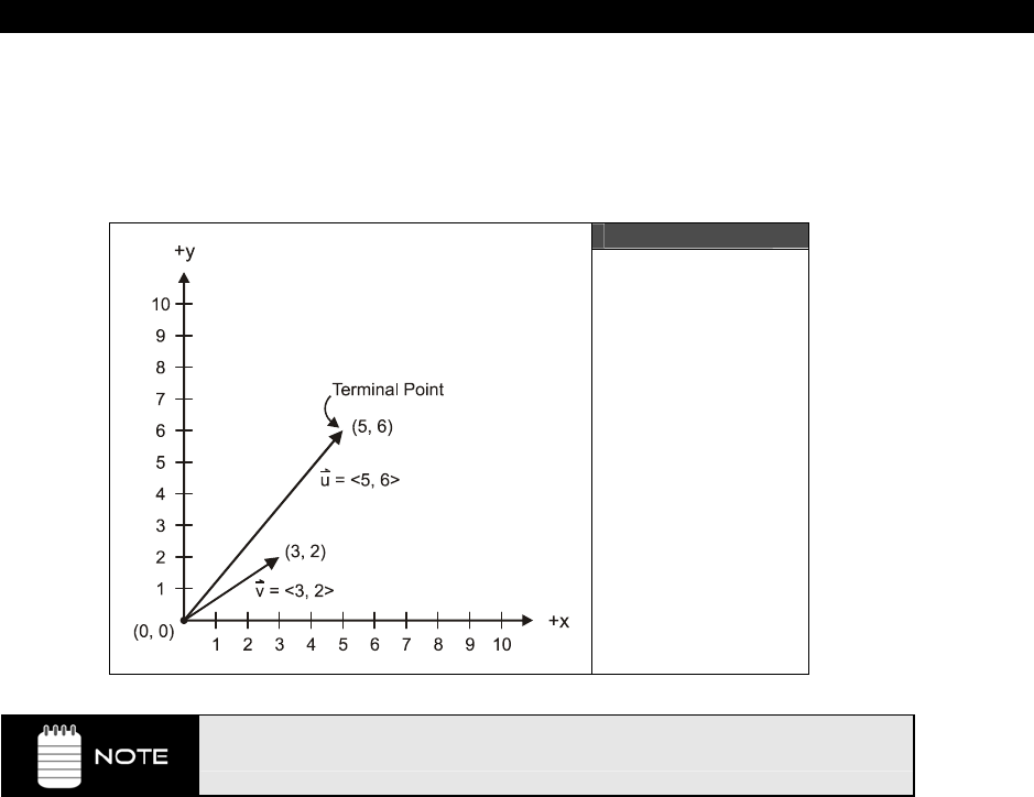
AI, Physics Modeling and Collision Detection 23
Game Programming for the Propeller Powered HYDRA Page 675
u=<5 - 0, 6 - 0> = <5, 6> = <ux, uy>
v=<3 - 0, 2 - 0> = <3, 2> = <vx, vy>
Where <ux, uy> are the
“components”
of u and <vx, vy> are the components of v
respectively.
Figure 23:1
Position Vectors
All vectors start at the origin (0,0) in 2D space or (0,0,0) in 3D space.
Notice that I am using “boldface” lower case letters to represent vectors, this is simply a
notational convention. Other conventions are to put an arrow above the vector identifier
(used in the figures). Later we will use uppercase boldface letters to represent matrices.
Anyway, moving on, the significance of u and v in Figure 23:1 is that u and v give us a
shorthand method to represent the points <5,6> and <3,2> (which might be positions or
velocities, whatever), so we can write u or v and not the coordinates themselves.
Also, you have probably heard people describe vectors as entities that represent magnitude
as well as direction. This can be true, but need not be true. That is, if the vectors you are
talking about are spatial vectors then yes, but if they are vectors of DNA or personal records
then there is no concept of “magnitude.” However, in our case these concepts
do
apply. So
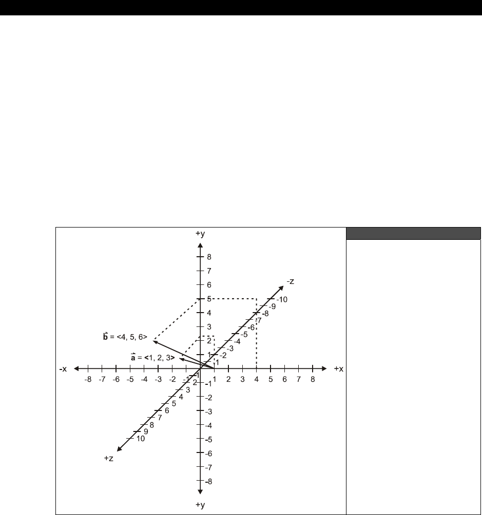
III Game Programming on the HYDRA
Page 676 Ë Game Programming for the Propeller Powered HYDRA
what if we wanted to know the length of the vector u? This is a common operation and
denoted by placing vertical bars on either side of the vector like so:
|u| = Length of u
The actual length of u can be computed by the
“Pythagorean theorem”
like so:
|u| = √(ux*ux + uy*uy) = √ (5*5 + 6*6) = √(25 + 36) = 7.81
In other words, the length or magnitude of
any
vector is the square root of the sum of the
squares of the components that make up the vector. It doesn’t matter if your vector has one
or one million components.
Alright hopefully you are starting to see that vectors can be visualized by drawing them on
graphs. In fact, we used a 2D X-Y graph to represent the vectors u,v in the example of
Figure 23:1. This is no accident; vectors are very helpful in problems of geometry and
typically people think of vectors as geometrical entities, either 2D or 3D.
Figure 23:2
_An Example of 3D
Vectors
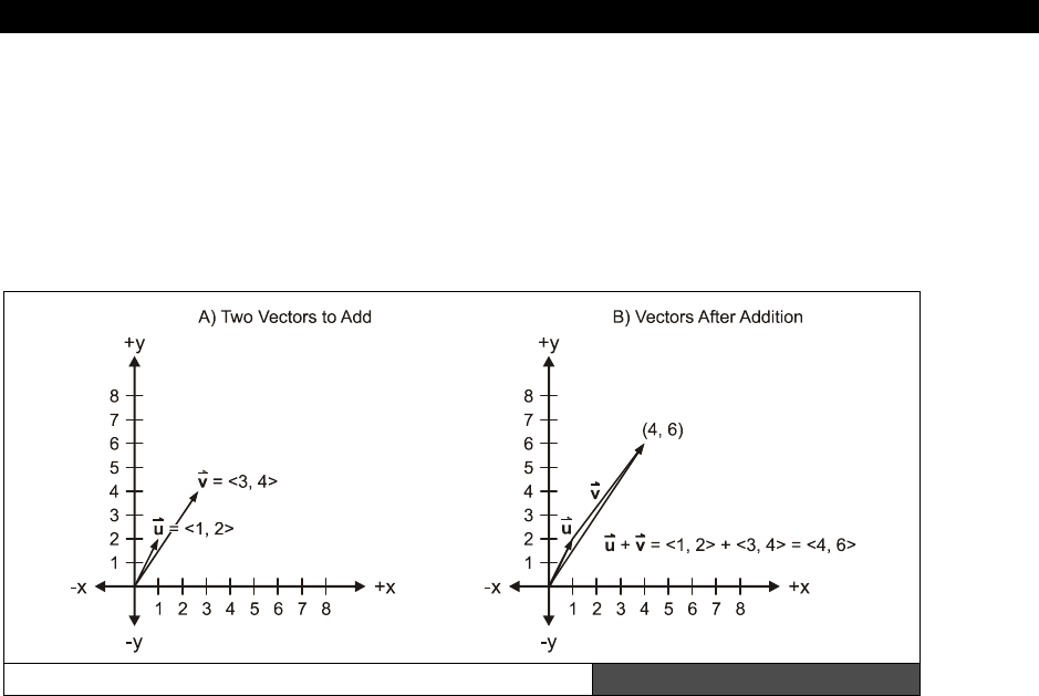
AI, Physics Modeling and Collision Detection 23
Game Programming for the Propeller Powered HYDRA Page 677
As an example of this, take a look at Figure 23:2, here we see two vectors a and b in 3D
space. Each is represented geometrically in the figure just as before. However, a little
imagination is needed to “see” the 3D vectors on the 2D page, but you get the idea. In this
case, if you look at the figure an imagine it in 3D you can see that a=<1,2,3> and
b=<4,5,6>. And of course each of these vectors has three components representing the x,y,
and z components of the vector respectively. So far so good, but next we need to learn how
to add, subtract, and multiply vectors to make them more useful. Let’s begin with addition.
Vector Addition Graphically Figure 23:3
Referring to Figure 23:3(A) we see two vectors u=<1,2> and v=<3,4>. To add these
vectors algebraically, simply add the components like so:
u + v = <1,2> + <3,4> = <4,6>
...which makes sense. But, what’s even cooler is that they add geometrically as well. Take a
look at Figure 23:3(B). Here we see the addition in action. A copy of vector v is placed at the
tip of vector u, then the result vector is the vector from the origin (0,0) to the tip of the copy
of u which is indeed <4,6> if you inspect the figure. Thus, to add vectors graphically you
simply translate the vector’s tail you want to add to the tip of another vector and then
wherever the tip of the addend vector winds up relative to the origin is the sum.
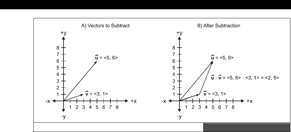
III Game Programming on the HYDRA
Page 678 Game Programming for the Propeller Powered HYDRA
Vector Subtraction Graphically Figure 23:4
Vector subtraction can be performed algebraically just like vector addition. Take a look at
Figure 23:4(A), here we see two vectors u=<5,6> and v=<3,1>. To subtract these vectors
we simply subtract components like so:
u − v = <5,6> − <3,1> = <2,5>
Now take a look at Figure 23:4(B). To subtract vectors geometrically you draw a new vector
between the vectors being subtracted with the terminal end at the first vector in the
difference and the initial end at the second vector in the difference. Thus, in this case to
subtract u – v, you draw a vector from v to u with the arrow at the end.
Vector addition and subtraction are useful to translate objects around. For example, let’s say
that an alien ship is located at position vector p=<px, py> and we want to move the alien
ship at a velocity of v=<vx, vy>; the vector operation is trivial:
p = p + v
...which then when we expand out into components is:
<px, py> = <px, py> + <vx, vy> = <px+vx, py+vy>
That is,
px = px + vx
py = py + vy
...which is indeed a translation. So vectors do not save you any computational effort, they
are simply a more compact format to perform calculations on points, velocities, geometries,
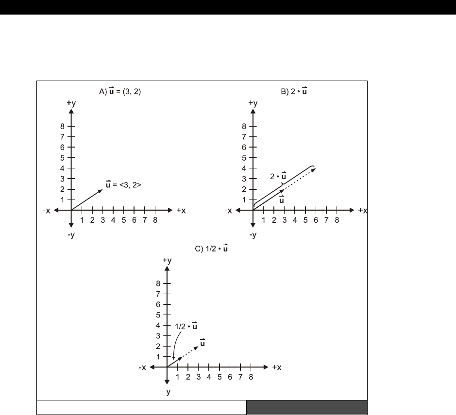
AI, Physics Modeling and Collision Detection 23
Game Programming for the Propeller Powered HYDRA Page 679
etc. And vectors follow many of the same rules that standard scalars do since vectors are just
collections of scalars. However, vectors have some other multiplicative rules that normal
scalars do not. Let’s take a look at these now.
Vector Scaling Graphically Figure 23:5
Vector multiplication is where the standard rules of scalar multiplication start to diverge. For
example, you might think that to multiply two vectors together you simply multiply the
components together, but this is not the case. The reason why is that multiplying the
numbers together doesn’t really result in anything interesting or helpful. However, if you
multiply the numbers together and sum the results, the resulting scalar is interesting, and we
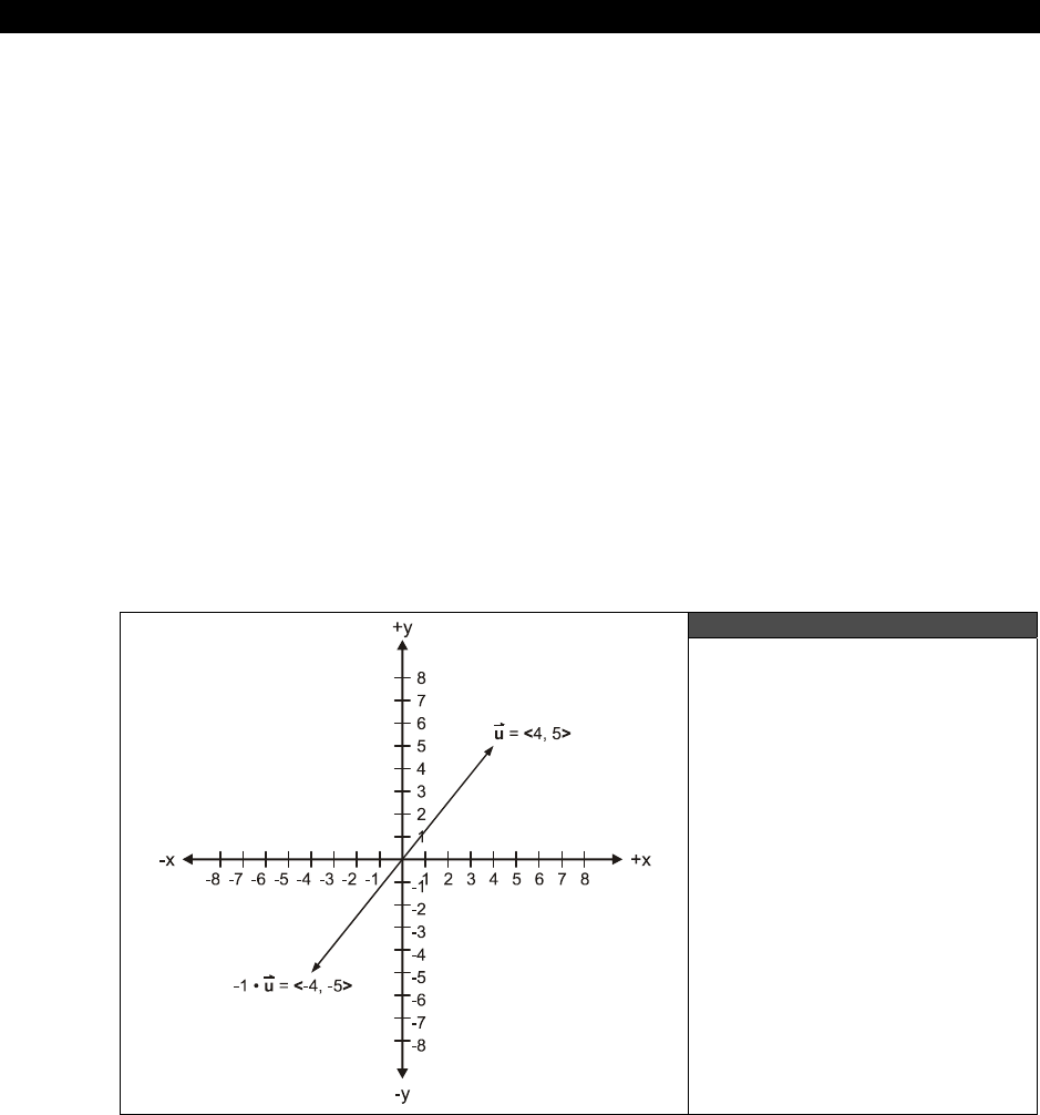
III Game Programming on the HYDRA
Page 680 Game Programming for the Propeller Powered HYDRA
will get to that in a moment, but before we do let’s look at what’s called
“scalar
multiplication.”
Scalar multiplication is performed by multiplying all the components of a vector by a single
scalar number as shown in Figure 23:5(A), (B) and (C). The operation is denoted by placing a
number in front of the vector with a multiplication sign like so:
k*u = k*<ux, uv> = <k*ux, k*uy>
Thus, you simply multiply the scalar times each component and the result is still a vector with
the same number of components. Figure 23:5 shows this for a vector in 2D space (3D space
is the same idea). As you can see the operation of scalar multiplication is more or less scaling
the vector, or its length. The direction stays the same, but its length or magnitude changes.
For example, say we have a velocity vector v = <1, 0> which on the X-Y plane is moving to
the right. If we were to scalar multiply this by 3 then the velocity vector would triple in
length; in other words the velocity would be 3× as much (if the vector represented velocity):
3*v = 3*<vx, vy> = 3*<1, 0> = <3, 0>
Thus, if we are using vectors to control the velocity of a ship we can simply scale them to
change speed or change direction. For example, multiplying a vector by -1 inverts its
direction, while maintaining its length or magnitude as shown in Figure 23:6.
Figure 23:6
Inverting a Vector
with Scalar Multiplication
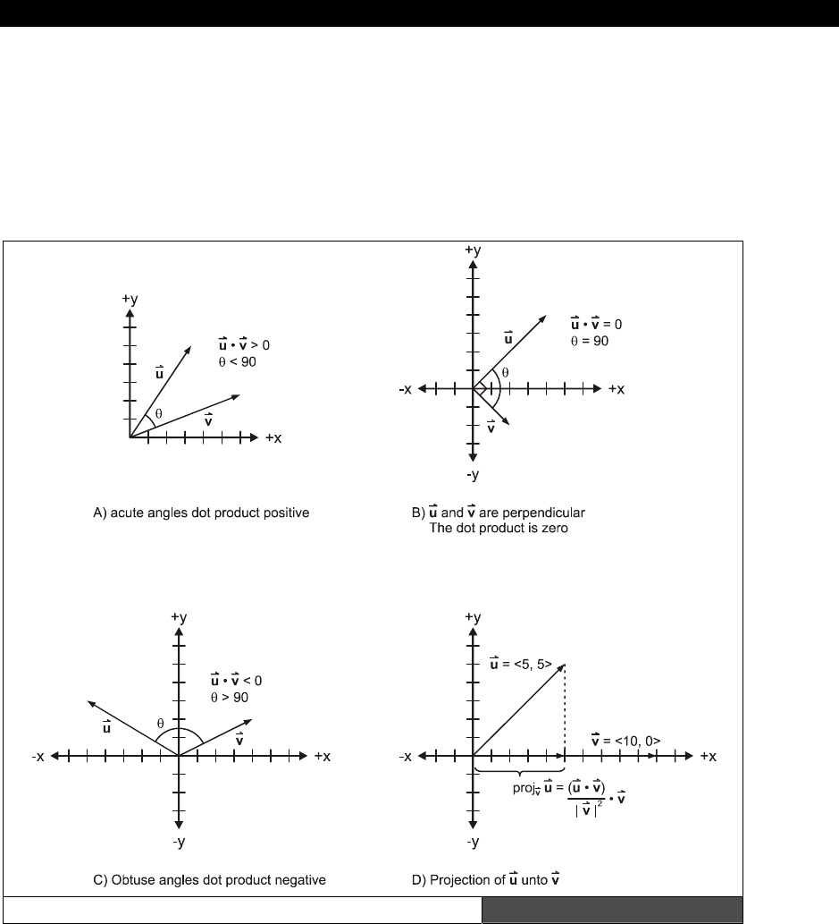
AI, Physics Modeling and Collision Detection 23
Game Programming for the Propeller Powered HYDRA Page 681
23.2.1.1 Advanced Vector Operations
Vectors are to computer graphics as words are to a writer, so knowing vector math inside
and out can make the most complex operation trivial. To that end, there are so many cool
things you can do with vectors that you could spend a lifetime studying them, but
“X-Files”
is on in 17 minutes, so I have to be brief. We are going to take a look at two more vector
operations that will come in handy in our work; the
“dot product”
and computing
“unit”
vectors.
The Dot Product Graphically Figure 23:7

III Game Programming on the HYDRA
Page 682 Ë Game Programming for the Propeller Powered HYDRA
The Dot Product
If there is one operation that pervades computer graphics then it would be the “dot product.”
Computer graphics is nothing more than billions of dot products, thus its good to know what
it is, how to do it, and how to do it fast! The dot product between two vectors u, v is:
u · v = <ux, uy> · <vx, vy> = ux*vx + uy*vy
Surprisingly, the result is a scalar which is the sum of the component by component products
of the vectors. The scalar result has a number of interesting properties as shown in Figure
23:7 which are:
Properties of the Dot Product
f If the angle between u and v is less than 90 degrees (acute) then the dot product
will be positive.
f If the angle between u and v is greater than 90 degrees (obtuse) then the dot
product will be negative.
f If the angle between u and v is 0 degrees then the dot product will be 0.
The dot product also has the additional property than given the vectors u and v, (u · v)/|v|
is the length of the vector projection of u onto v, this can be seen in Figure 23:7(D). Thus,
the dot product helps to compute how much one vector is
“pointing”
in the direction of
another vector which is a very useful operation. Lastly, the dot product can also be written in
terms of the lengths of u and v as well as the cosine between them like so:
u · v = |u|*|v|*cos θ
Combining both forms of dot product we get the equality:
u · v = |u|*|v|*cos θ = ux*vx + uy*vy
...which is useful if you want to compute the angle between two vectors.
Computing Unit Vectors
A unit vector is nothing more than a vector with length 1.0. In other words, given any vector
u, then its length |u| = 1.0. Many times its useful to convert a general vector into a unit
vector, so we can manipulate the unit vector. This can be accomplished by finding the length
of the vector and then dividing it into the vector’s components (scalar multiplication).
Referring to Figure 23:8(A) we see the vector u=<3, 4>, this is not a unit vector, it has the
length |u| = √(3*3 + 4*4) = 5. But, what if we wanted unit vector version of u with the
same direction, but a magnitude of 1.0? The following operations can be used to compute
this:
u'= u / |u| = <3, 4> / 5 = <3/5, 4/5>
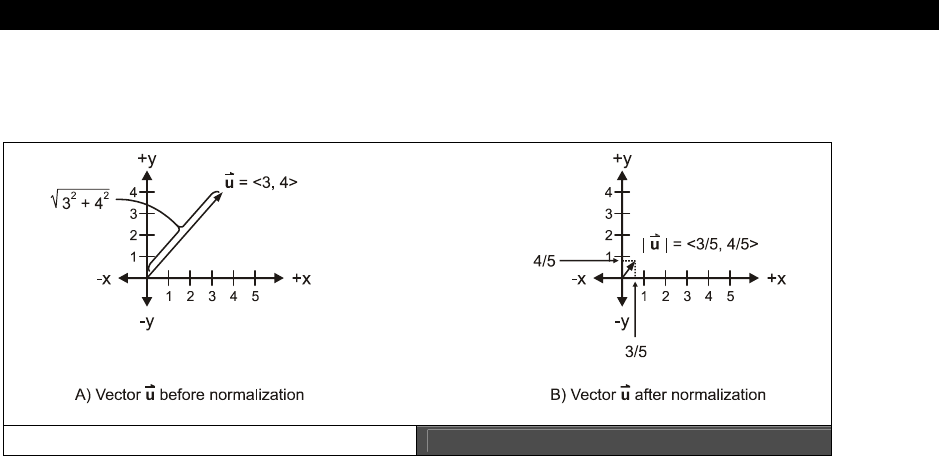
AI, Physics Modeling and Collision Detection 23
Game Programming for the Propeller Powered HYDRA Page 683
Notice the prime symbol “'” or single quote is used to denote unit vectors as our convention,
some texts use a hat on the vector “^”.
Unit Vectors Figure 23:8
23.2.2 Welcome to the Matrix
Matrices are the Holy Grail of higher mathematics. They allow extremely complex
mathematical operations and computations to be performed, and can represent all kinds of
abstract mathematical entities. We aren’t going to delve into all the uses of matrices, but
rather focus on a single use of them and that’s to represent geometrical transformations.
However, as an aside I want to briefly review where most people have seen matrices used
before.
Given a set of linear equations like this:
2x + 5y = 9
3x – 2y = 10
Solve for x and y. Does this ring any bells? Well, if you don’t do this for a living you might
have a bit of a time doing it. However, if you recall there are techniques like “substitution”
and “simplification” etc. to solve for x and y, here’s a quick solution for you:
Eq. 1: 2x + 5y = 9
Eq. 2 : 3x – 2y = 10
Rewrite Eq.1 in terms of x:
2x = 9 – 5y
x = (9/2 – 5y/2)

III Game Programming on the HYDRA
Page 684 Game Programming for the Propeller Powered HYDRA
Now, substitute x into Eq.2:
3 *(9/2 – 5y/2) – 2y = 10
27/2 – 15y/2 – 2y = 10
Collect like terms:
(15/2 + 2)y = -10 + 27/2
Solve for y:
y = (2/19) * (7/2) = 7/19 = 0.368
And Y can be plugged into Eq.1 or 2 to solve for x, let’s plug into Eq.1:
2x + 5*(7/19) = 9
x = (9 – (35/19) )/2 = 3.578
I bet that brings back horrible memories! Anyway, the point is that it’s a messy process, but
with matrices this process can be converted into a mechanical algorithm. The trick is to
represent all the coefficients of x and y with a matrix as well as the constants on the right
side of the “=” signs. Therefore, the linear system of equations above in matrix form is:
│2 5 │ │x│ = │9 │
│3 -2 │ │y│ │10│
A X B
...where, A is the
“coefficient”
matrix, X is the
“variable”
matrix, and B is the
“constant”
matrix as noted under each matrix. Now, for a moment let’s forget about the numbers in
each matrix and focus on the matrix variables themselves, A, B, and X (remember matrices
are written as uppercase bold) and write the linear system of equations once again in matrix
form alone:
A*X = B
See how compact the form is? No numbers, just matrices. Moreover, there are all kinds of
rules of matrix math, so we can solve for X without doing all that work. It’s simple, let’s just
multiple both sides of the matrix equation by the inverse of A, like this:
(A-1)*A*X = (A-1)*B
X = (A-1)*B
Thus, if we knew how to find the inverse of a matrix and how to “multiply” then we could
solve this matrix system and be done. This is just one way to use matrices, however, it’s not
the way we are going to use them, as that’s beyond the scope of our discussion.
Nonetheless, matrices are very useful for other types of operations like translation, rotation,
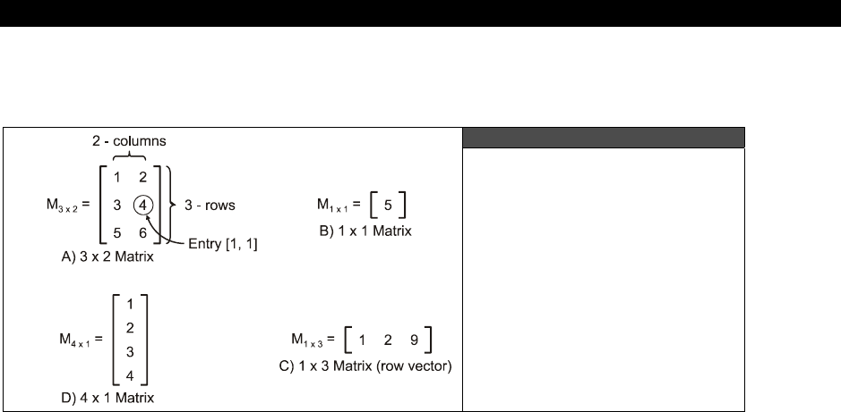
AI, Physics Modeling and Collision Detection 23
Game Programming for the Propeller Powered HYDRA Page 685
scaling, and other operations that we might want to apply to points or vectors that represent
things in our games, so let’s take a look at this use of matrices.
Figure 23:9
Some Annotated Matrices
To begin with all matrices are going to be represented by uppercase bold letters like A, B, X,
M, etc. Next, a matrix has a number of rows and a number of columns. Typically,
mathematicians refer to the row first then the column, so if someone said the matrix is “3×2”
that means it has 3 rows and 2 columns; however, this is just a convention and you can
surely refer to columns first then rows (as many programmers are used to). But for now we
will use the row×column format. Next, any element in a matrix is referred to by its (row,
column) in the matrix (either 0 or 1 based). For example, take a look at Figure 23:9(A), here
we see a 3×2 matrix, M3×2 (notice that I have put its dimensions as a subscript, another
common convention). The upper left hand entry (0,0) is 1, the upper right hand entry (0,1) is
2, and finally the lower right hand entry (1,2) is 6. One notation to locate entries is to use
the name of the matrix then subscripts i,j that are the row, column of the entry referred to.
For example, M3×2(1,1) means the element or entry located at row 1, column 1 (0 based of
course). Lastly, matrices do not need to be 2D, in fact they can be a single column or single
row for example 1×n, or n×1.
Matrices can be used to perform just about geometrical transformation you might want to do
to points, vectors, velocities, whatever. We just have to get everything in the proper format.
Then it’s a matter of “matrix multiplying” things together, thus before we can do anything,
we need to review matrix multiplying.
Similar to vectors, matrix multiplying isn’t as simple as multiplying elements against each,
that would be mostly meaningless. In fact, to multiply matrices we are going to break the
matrices down into vectors and perform dot products! Now, before you can multiply any two
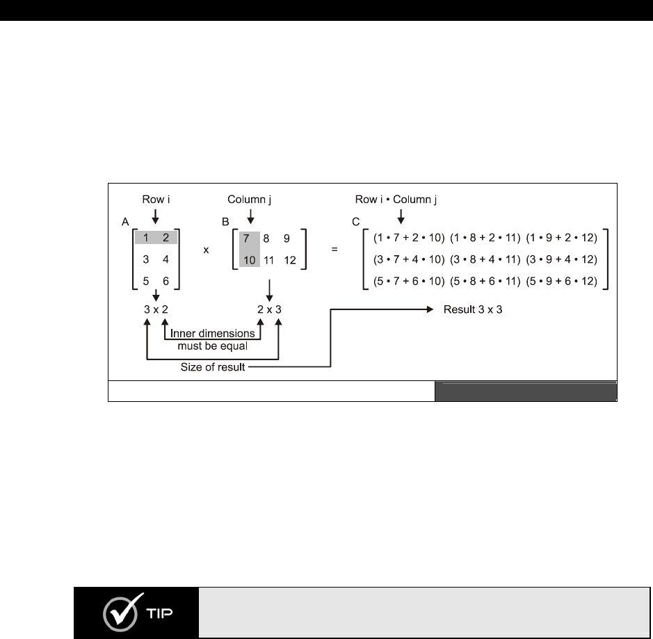
III Game Programming on the HYDRA
Page 686 Game Programming for the Propeller Powered HYDRA
matrices A and B, there are some constraints that the matrices must follow. Referring to
Figure 23:10, we see matrix A and B next to each other. A is 3×2 and B is 2×3, notice that
they have a “common inner dimension” that is the number of columns of A is equal to
the number of rows of B. This must
always
be true to multiply two matrices. Thus, we can
multiply A*B, but not B*A since their inner dimensions don’t match. Moreover, the
dimensions of the resulting product matrix is always the outer dimensions, thus A3×2 * B2×3 =
C3×3.
Matrix Multiplying Illustrated Figure 23:10
Matrix multiplication is best shown graphically, so take a look at Figure 23:10 to see an
example of a multiplication. In the figure a 3×2 matrix is multiplied against a 2×3 and the
resulting matrix is 3×3. Hopefully, you see the pattern to perform the matrix multiplication;
for every row of the first matrix you multiply it against every column in the second matrix.
The multiplication is a dot product operation actually. Thus if you were multiplying the
matrices A*B to compute the result matrix entry C(i,j) you would compute the dot product
between the ith row of A and jth column of B. It’s a little confusing at first, but after a while
you get the hang of it.
There is a cool interactive site that shows matrix multiplying here, you hover
over the matrices and it will show you how the results are computed:
http://www.mai.liu.se/~halun/matrix/.
23.2.2.1 Using Matrices for Geometrical Transformations
Now, that you know how to multiply matrices, what good is it? Well, if you have a vector that
represents something like position or velocity, you can use a matrix to perform very complex

AI, Physics Modeling and Collision Detection 23
Game Programming for the Propeller Powered HYDRA Page 687
operations on it. For example, say that you want to rotate a point around the origin defined
by the vector p(x,y), you crack open a math book and look up rotation and you will find
something like this:
x'= x*cos θ - y*sin θ
y'= x*sin θ + y*cos θ
What if you could write this with matrices? We would need a matrix R that when multiplied
by a point p = <x, y> gives us the results above, take a look below:
R = │ cos θ sin θ │
│ - sin θ cos θ │
And if we write the vector / matrix equation:
p' = p * R
Where p' is the rotated point, we get:
p' = <x, y> * │ cos θ sin θ │
│- sin θ cos θ │
And following the rules for matrix multiplication, p is really like a 1×2 matrix (called a row
vector), and the rotation matrix is 2×2, so it’s valid to multiply, moreover, the result should
be 1×2 which is also a row vector. Carrying out the multiplication we get:
p' = <x*cos θ – y*sin θ, x*sin θ + y*cos θ>
...which component for component is exactly what we want! Now, you might be saying so
what? We do the exact same amount of work – true. However, the cool thing about matrices
is they can represent almost any transformation, so we can not only use a simple
multiplication procedure to rotate, scale, translate, shear, etc. our data, we can also
concatenate
matrices together. That is pre-multiply a bunch of transformations together
off-line, then take our data vectors and multiply them by the concatenated matrix. This way
a single matrix can represent a number of transformations and the same algorithm can
compute the result in your code with a single matrix-multiply.
As a last example, let’s look at how to perform translation using a matrix. Say you have a
point p=<px, py> and you want to translate it by v=<vx, vy>, in other words:
px = px + vx
py = py + vy
This is trivially accomplished with the vector operation:
p = p + v

III Game Programming on the HYDRA
Page 688 Game Programming for the Propeller Powered HYDRA
But, what if we wanted to represent this operation with a matrix? Well, the first thing we
need to do is add a 1 to our points as a 3rd component. For example, if a vector p represents
a point <px, py>, we would simply add a “dummy” 1.0 to the vector making it <px, py,1>.
Now, to translate p by vector v = <vx, vy>, we use this matrix:
│ 1 0 0 │
T = | 0 1 0 │
| vx vy 1 |
...which is 3×2, this is why we need to add the dummy “1” to the point we want to translate.
Considering that, here’s the final vector/matrix math to translate the vector point p:
│ 1 0 0 │ │ 1 0 0 │
p’ = p * | 0 1 0 │ = <px, py, 1> * | 0 1 0 │
| vx vy 1 | | vx vy 1 |
Performing the matrix multiplication, we multiple the single row vector p against each column
of T, resulting in:
p' = <1*px + 1*vx, 1*py + 1*vy, px*0 + py*0 + 1*1> = <px+vx, py+vy, 1>
...which indeed is the translation of the point p by v. The extra 1 at the end can be ignored
and is only needed since we need a 3×3 transformation matrix. This tactic of adding 1 to the
coordinate is called making it
“homogenous,”
and is nothing more to facilitate these kinds
of transformations. Putting it all together, we can use a single matrix M to both translate and
rotate a point:
│ cos θ sin θ 0 │
M = |-sin θ cos θ 0 │
| vx vy 1 |
Well, that’s it for our little impromptu review of vectors and matrices. Hopefully, if you were
rusty it helped a bit, and if you have never seen this material before, at least you have some
insight into what vectors and matrices are. In either case, AI, physics and collision detection
rely heavily on using these ideas, so they are good to know. Otherwise, code tends to be
overly complicated to accomplish manually what can be represented more elegantly and
compactly with vectors and matrices. At least that’s what the brochure says!
23.3 Physical/Deterministic Intelligence
In simple 2D games there is a distinct blur between “artificial intelligence” and
“physics
modeling.”
For example, if you were to write an Asteroids-type game and were writing the
code to move the asteroids, you would use the following simple physics model:
asteroid_x := asteroid_x + dx
asteroid_y := asteroid_y + dy

AI, Physics Modeling and Collision Detection 23
Game Programming for the Propeller Powered HYDRA Page 689
Although this is a crude physics model, you might refer to it as the “asteroid AI” when
describing the code to a fellow programmer. You might say something like “the asteroids AI
is just a simple translation.” The point is that sometimes the “AI” needed for a games object
is so simple or deterministic that a simple physics model or analogy will suffice.
As an another example, say we wanted to make a Space Invaders-type game where the
invaders moved right to left and simply bounced off the edges of the screen and moved
down a line. This again is so basic that the combination of a very crude physical
interpretation of “collision and response” and some conditional logic can be used to arrive at
the following “AI”:
' move invader by constant velocity
invader_x := invader_x + invader_dx
' test for screen edge?
if (invader_x > SCREEN_RIGHT or invader_x < SCREEN_LEFT)
invader_dx := -invader_dx ' invert velocity
invader_y := invader_y + INVADER_HEIGHT ' move down a row
So the first tier of AI in games is to leverage very simple rules that are either physical in
nature or algorithmic and can be described in a few short lines. This type of AI is typically
used in a lot of “arcade shooters” to control enemies or to control background objects in
games that don’t have a lot to do with the game play. For example, a bird that flies across
the screen doesn’t need more AI than:
bird_x := bird_x + bird_speed
So the first weapon in your arsenal of AI techniques is simply to see if you can come up with
some simple rule(s) to control the game characters that result in the desired game play or
behavior. These rules might be deterministic and coded with a few conditionals, or might be
a couple lines of physics code. With that in mind, now we are going to cover a number of AI
techniques to complement your toolbox. With them in hand you should be able to code just
about any AI you need for you game characters.
23.4 Random Motion
Random motion is one of the most useful AI techniques around. Of course, you have to use it
appropriately, you can’t have objects just move around randomly all the time! However,
judicious use of random variables and random motions is exactly the behavior that’s desired
in many cases. For example, in the next section we will learn about tracking and evasion
algorithms. But these algorithms are pretty relentless and no fun since the player simply
doesn’t have a chance if they are used solely to control game characters. However, if
tracking and evasion is mixed with a little randomness, then characters start to take on a

III Game Programming on the HYDRA
Page 690 Game Programming for the Propeller Powered HYDRA
more realistic or
“organic”
set of behaviors. With that in mind, let’s take a look at the most
basic of random algorithms:
random
motion
.
To move an object randomly in the plane we can approach the problem in a couple ways. We
could simply select a random dx, dy each cycle and move the object:
object_x := object_x + rand(-2,2) ' rand( ) function returns a random integer from
' parm1 to parm2 inclusive
object_y := object_y + rand(-2,2) ' rand( ) function returns a random integer from
' parm1 to parm2 inclusive
This technique results in a motion that looks like molecules under an electron microscope;
useful, but not too exciting. Another more interesting method of random motion is to first
select a random direction vector and then apply this vector for some fixed or random amount
of time or frames.
' compute random vector
object_dx := rand(-2,2) ' rand( ) function returns a random integer from parm1 to
' parm2 inclusive
object_dy := rand(-2,2) ' rand( ) function returns a random integer from parm1 to
' parm2 inclusive
' compute number of times to perform motion
object_motion_iterations := rand(5,10)
In this case, a random vector direction (object_dx, object_dy) is selected then the
assumption is that the motion will occur
object_motion_iteration
s times which has been
selected to be from [5,10] iterations. Let’s go ahead and implement this algorithm with a
demo.
Figure 23:11
A Screen Shot of the
Random Motion Demo
Figure 23:11 shows the a screen shot of the demo BEE_DEMO_001.SPIN which
implements the ideas discussed above. The demo creates an array of “bee” records, where

AI, Physics Modeling and Collision Detection 23
Game Programming for the Propeller Powered HYDRA Page 691
each bee has position, velocity, current frame, and a timer. When the timer expires on any
particular bee, the a new random direction is selected along with a random time to fly in that
direction. The effect looks reasonably realistic. The demo uses the artwork found in
BEE_TILES_WORK_02.BMP as well as the Mappy map file BEE_DEMO_MAP_01.MAP,
both files as well as the source file itself are in the \SOURCES directory as usual. The tile
data file was exported with the following command line to the MAP2SPIN tool:
MAP2SPIN BEE_DEMO_MAP_01.MAP BEE_TILES_WORK_02.BMP –FX –TW6 –TH2 >
BEE_TILE_DATA.SPIN
Other than the AI implementation, which is rather trivial, there are a number of techniques
used in the demo that are of note. First and most importantly, the demo uses a true double-
buffered tile display for rendering to minimize flicker. The setup is as follows: the tile data is
loaded in as usual, then a tile buffer is allocated that is the same size as the tile map data,
then during each frame the original tile data is copied into the tile buffer, the tile buffer is
rendered on, manipulated and then passed to the tile engine for rendering. This way the
original tile data isn’t destroyed during rendering and we can have objects drawing on top of
the tile maps without worrying about losing the tile map data. Secondly, I had to write a
random number function that generates random numbers in a range, which is very useful
when you start doing AI programming:
Pub Rand_Range(rstart, rend) : r_delta
' returns a random number from [rstart to rend] inclusive
r_delta := rend - rstart + 1
result := rstart + ((?random_var & $7FFFFFFF) // r_delta)
return result
...and it’s initially seeded like this:
' initialize random variable
random_var := cnt*171732
random_var := ?random_var
The mod operator “//” is very slow and usually I don’t recommend it, but for these demos it
will suffice. However, if you need to compute thousands of random numbers at a time in a
particular range, more efficient means of bounds containment must be used. Lastly, the
demo uses fixed-point math for the position and velocity of the bees. The fixed-point math is
in 24.8 format. In other words, 24 bits of whole part and 8 bits of decimal part. If you’re not
familiar with fixed-point math, it’s rather simple actually: you scale all your numbers by some
factor (usually a power of 2), then do all the math in fixed-point format, and finally when you
need integers you shift the results destructively. For example, here’s how you would initialize
two fixed-point values for 1 and 100 in (24.8) format:

III Game Programming on the HYDRA
Page 692 Game Programming for the Propeller Powered HYDRA
long x, y, z
x := 1 << 8 ' same as 1*256 = 000000000000000000000001.00000000 base 2
y := 100 << 8 ' same as 100*256 = 000000000000000001100100.00000000 base 2
' ' compute result
z := x+y
At this point z will equal 1*256 + 100*256 which is not equal to 101, however, if we want to
convert the fixed-point number to an integer we reverse the process:
z := z >> 8 ' same as z / 256
...and since (101*256) / 256 = 101, the answer is correct. Similarly, if we were to divide x by
2 we should get 0.5:
x := x >> 1 ' same as x / 2
Now, if we convert x back to an integer it will be zero! So, what good is this? Well, if we
leave x in fixed point format it is:
000000000000000000000000.100000002
...and if we were to add x to y then we would get:
000000000000000001100100.100000002
...which, if you look to the right of the fixed point, is the number 1/2 (since the digits to the
right of the decimal are the 1/2, 1/4, 1/8, etc. place). And to the left of the decimal is 10110
which is the whole part of the number. So the fixed-point number retains the information.
And to extract the whole part you just need to shift to the right 8 times. Thus, to use fixed-
point math you convert all your numbers to a fixed point by shifting to the left, perform any
addition and subtraction you want as usual, and then when you want the whole part, you
shift back to the right and that’s it. To support multiplication is slightly more complex since
when you multiply two-fixed point numbers you are multiplying the scaling factors as well, so
the result either has to be pre-shifted down, or double-precision multiplication has to be used
and the result shifted back to 24.8 format (or whatever format you are using, eg. 16.16).
Division is a little more complex and requires shifting as well to place the dividend/divisor in
the right format. Anyway, we will use fixed-point math more and more, so it’s good to know.
Getting back to the random motion, there are a lot of things you can do with this demo to
experiment. For example, all the bees are moving randomly, but say you want some “wind”
to blow them from a certain direction, no problem, just add a wind factor to their position

AI, Physics Modeling and Collision Detection 23
Game Programming for the Propeller Powered HYDRA Page 693
each cycle, or to the velocity of each, and the wind will superimpose on their motion. This
way you can “layer” motions.
23.5 Tracking Algorithms
If there is a “hello world” of AI for games then it has to be the chasing/evasion algorithm
below:
if (player_x > alien_x)
alien_x++
elseif (player_x < alien_x)
alien_x—
if (player_y > alien_y)
alien_y++
elseif (player_y < alien_y)
alien_x—
This algorithm shadows the motion of the player, and the “alien” will track the player and
hunt him down constantly. Although this AI is very efficient, it’s not much fun since the alien
literally does whatever the player does. However, in some case this might be what you want.
For example, a homing missile or something of that sort. The interesting thing about this
algorithm is that if we flip the signs around then the algorithm turns into an “evasion”
algorithm like so:
if (player_x < alien_x)
alien_x++
elseif (player_x > alien_x)
alien_x—
if (player_y < alien_y)
alien_y++
elseif (player_y > alien_y)
alien_x—
Both algorithms on their own are too aggressive, but are very powerful when used as “tools”
in other algorithms. For an example of both algorithms in a single demo, check out
TRACKING_DEMO_001.SPIN located in the \SOURCES directory, its based on the
artwork from MECH_TILES_WORK_01.BMP and INVADERS_DEMO_MAP_02.MAP.
The assets were ran through the MAP2SPIN tool as usual, and then the output file
INVADERS_TILE_DATA2.SPIN was manually modified to allow using some of the tiles as
sprites (I manually added masks). In any event, give the demo a try and then lets discuss it.
Use the gamepad to control the player and the <SELECT> button to toggle the AI mode

III Game Programming on the HYDRA
Page 694 Game Programming for the Propeller Powered HYDRA
between chase and evade. The first thing you will notice about the demo is how fast the
alien locates and tracks the player (you).
The demo uses both tiles and sprites since I needed smooth motion for the player and alien
characters. Some things to note about the demo are that the sprites always use the tile
palette index they are on. In this case, all the tiles palettes in the game field use a “red”
palette of colors, so both game characters are made of reds. However, if you move into the
right and left extreme areas of the screen, you will see the characters take on the gray
palettes of the “space station superstructure.” The code is too long to list in its entirety, but
here’s a fragment from the main event loop where the most action happens:
' test player movement first?
if (game_pad.button(NES0_RIGHT))
player_x+=2
elseif (game_pad.button(NES0_LEFT))
player_x-=2
if (game_pad.button(NES0_UP))
player_y-=2
elseif (game_pad.button(NES0_DOWN))
player_y+=2
' test for ai mode change
if (game_pad.button(NES0_START))
repeat while game_pad.button(NES0_START) ' let use release button first
if (ai_mode == AI_MODE_EVADE)
ai_mode := AI_MODE_CHASE
else
ai_mode := AI_MODE_EVADE
' update animation frames
if (++player_frame_counter > 15)
player_frame_counter := 0
if (++player_frame > 1)
player_frame := 0
if (++alien_frame_counter > 15)
alien_frame_counter := 0
if (++alien_frame > 1)
alien_frame := 0
' now test ai mode and apply ai method
if (ai_mode == AI_MODE_CHASE)
' begin chase ai
if (player_x > alien_x)
alien_x++
elseif (player_x < alien_x)
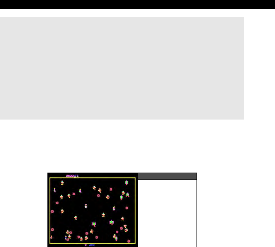
AI, Physics Modeling and Collision Detection 23
Game Programming for the Propeller Powered HYDRA Page 695
alien_x--
if (player_y > alien_y)
alien_y++
elseif (player_y < alien_y)
alien_y--
else
' begin evade ai
if (player_x > alien_x)
alien_x--
elseif (player_x < alien_x)
alien_x++
if (player_y > alien_y)
alien_y--
elseif (player_y < alien_y)
alien_y++
The code begins by testing the gamepad and moving the player, then checking for an AI
mode toggle, and finally moving into the actual algorithms themselves. The interesting thing
here is to realize that the
ai_mode
could potentially be anything, not just chasing and
evading modes. Keep this in mind when designing games, many times you want to keep the
AI code separated and pluggable so you can select which kind of AI drives the game
characters.
Figure 23:12
A Screen Shot of
Robotron 2084
Anyway, if you play with the demo for a few moments it gets boring really quick. This type of
AI is pure
“shooter”
AI, and not found in many games that have any strategy. One place
you will find an AI very similar to this is in the game
“Robotron 2084”
by
Williams
. This
was a great game, but really nothing more than run and gun! Figure 23:12 shows a screen
shot. If you have access to the game, give it a try, so you can see the AI in action. However,
there are a couple added features to the basic chase/evade algorithm in Robotron 2084
which are very useful for other games as well. Instead of relentlessly coming toward the
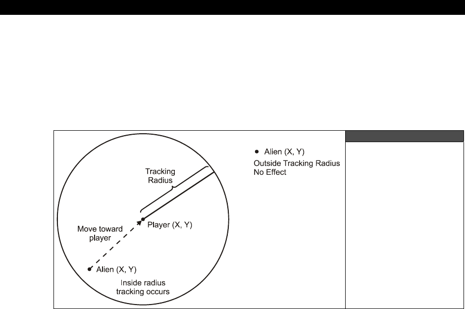
III Game Programming on the HYDRA
Page 696 Game Programming for the Propeller Powered HYDRA
player (or moving away), a timer is used that selects a direction to track the player and then
continues on that path until the time is up. This way, every couple seconds or so the bad
guys “re-evaluate” their trajectories toward the player and select a new targeting vector
(maybe on at 90 degree angles as well). This “loosens” the algorithm a little and gives the
player some time to react and get away. Secondly, another tactic is to only turn the tracking
“on” when the player and the bad guys are within some vicinity or some radius of influence.
Figure 23:13 shows these ideas graphically.
Figure 23:13
Adding More
Complexity to the
Tracking Algorithms
Adding these simple two features to the basic tracking (evasion algorithm) create a much
more interesting AI behavior than before. As an example of this, take a look at
TRACKING_DEMO_002.SPIN which implements these new ideas. When you run the
demo you will start at the middle of the screen and the alien (bad guy) starts somewhere
randomly. If he is too far away he won’t do anything, so get close to him and the moment
you get close enough (
MIN_AI_REACTION_DIST
) the alien will come charging toward
you! But, notice if you change directions, the alien will not react immediately, so you have
time to get away!
Now, there are some interesting things to note about this second implementation: first if you
come within range of the alien then the alien will attack, but you will notice it
“overshoots”
your position. This is because the trajectory is not constantly updated as before, thus there is
an
“oscillation”
effect that results. The amount of oscillation can be minimized by changing
the update rate to the trajectory. Of course, if the trajectory updates every frame then we
are back to we started and the tracking is dead on! So this new implementation lets you tune
the reaction rate. Also, if you do not like the oscillation effect, then you can add another

AI, Physics Modeling and Collision Detection 23
Game Programming for the Propeller Powered HYDRA Page 697
layer of software that tests if the alien is within a very close proximity of the player and if so,
then all motion is stopped. This way, the alien tracks the player (but not constantly) and
stops when it gets close enough to the player (maybe to fire weapons). Anyway, here’s the
new AI code augmented with the distance and motion control updates:
' update ai counter
if (--ai_counter =< 0)
' re-evaluate AI if player is within range
dx := player_x - alien_x
dy := player_y - alien_y
dist := (dx*dx + dy*dy) ' compute dist^2
' re-vector trajectory if player is close
if (dist < MIN_AI_REACTION_DIST)
' reset behavior counter
ai_counter := Rand_Range(5, 25)
' now test ai mode and apply ai method to compute trajectory vector
if (ai_mode == AI_MODE_CHASE)
' begin chase ai
if (player_x > alien_x)
alien_dx := 1
elseif (player_x < alien_x)
alien_dx := -1
if (player_y > alien_y)
alien_dy := 1
elseif (player_y < alien_y)
alien_dy := -1
else
' begin evade ai
if (player_x > alien_x)
alien_dx := -1
elseif (player_x < alien_x)
alien_dx := 1
if (player_y > alien_y)
alien_dy := -1
elseif (player_y < alien_y)
alien_dy := 1
else
' player not in reaction distance, kill trajectory vector, reset counter
alien_dx := 0
alien_dy := 0
ai_counter := 5
' move alien on last set trajectory vector
alien_x += alien_dx
alien_y += alien_dy
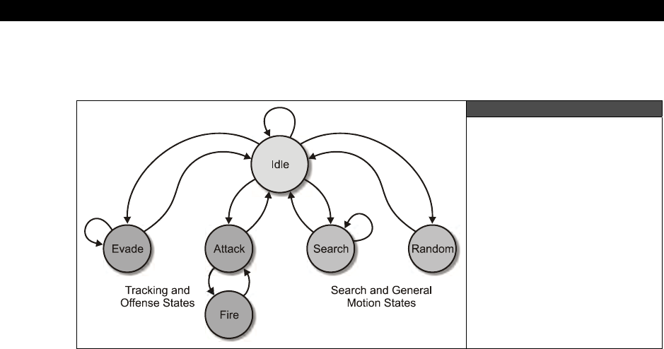
III Game Programming on the HYDRA
Page 698 Game Programming for the Propeller Powered HYDRA
See if you can add some code that tests if the player is within a second closer radius that
MIN_AI_REACTION_DIST
and if so, all motion is stopped.
Figure 23:14
Finite State Machine for
a Possible AI Model
23.6 Finite State Machines
Finite state machines
(FSM’s) are one of the most useful programming objects there are.
If you’re not an expert on them, finite state machines are an organized set of rules used to
transition from one
“state”
to another based on the current state and various inputs. At any
given state, the FSM can have one or more outputs associated with the state.
Even if you didn’t realize it, nearly all of the programming we have been doing thus far is
nothing more than FSM’s in one form on another, we simply haven’t formally made note of it.
However, to take the next step in AI, we want to start thinking of the AI in terms of states,
and then these states themselves can either be deterministic AI, physical AI, and so forth.
Thus, we are going to start to “layer” the AI techniques to build complex behavioral models
(at least complex for this beginners guide). Take a look at Figure 23:14; it depicts a potential
game character AI model FSM (the arcs are simply potential ideas, the final state machine
might be different). This AI is composed of a FSM with the following states:
ATTACK
EVADE
FIRE
SEARCH
IDLE
RANDOM

AI, Physics Modeling and Collision Detection 23
Game Programming for the Propeller Powered HYDRA Page 699
Each of the “states” can be implemented with simple deterministic logic, a physical algorithm,
random logic, a combination of techniques, or yet another finite state machine. The idea here
is to create a “model” of the character AI that has distinct states and then code each state.
Continuing with the example, let’s see how we might code an AI model with these states:
ATTACK Based on the coordinates of the player and the AI character, vector the
AI character toward the player. Additional inputs such as distance to
player and weapons status of player and AI might be taken into
consideration.
EVADE Based on the coordinates of the player and the AI character, vector the
AI character away from the player. Additional inputs such as distance to
player and weapons status of player and AI might be taken into
consideration.
FIRE Fire weapon at selected target.
SEARCH Search for selected target.
IDLE Do nothing, give player time to react.
RANDOM Select a random motion or state.
To code the state machine, any number of architectures can be used. For example, below is
a pseudo code framework you might use to implement your game AI character:
long ai_state ' current ai state
long ai_state_counter ' used to count how long a state is in
long ai_x, ai_y ' position of AI controlled character
long px, py ' position of player ai is working against
{ enter into state machine, process current state, make transitions to other
states potentially, etc. }
case ai_state
ATTACK:
' vector toward player until counter has timed out
if (--ai_counter > 0)
' run tracking code..
if (px > ai_x)
ai_x++
if (px < ai_x)
ai_x--
.
.
else
' attack state is over, select a new state
ai_state := New_State_Select

III Game Programming on the HYDRA
Page 700 Game Programming for the Propeller Powered HYDRA
EVADE:
' vector away from player until counter has timed out
if (--ai_counter > 0)
‘ run tracking code..
if (px > ai_x)
ai_x--
if (px < ai_x)
ai_x++
.
.
else
' evade state is over, select a new state
ai_state := New_State_Select
FIRE_WEAPON:
' fire weapon at player
Fire_Weapon
ai_state := New_State_Select
SEARCH:
' search for target
if (--ai_counter > 0)
Search
else
' search state is over, select a new state
ai_state := New_State_Select
IDLE:
if (--ai_counter > 0)
' do idle animation?
else
' idle state is over, select a new state
ai_state := New_State_Select
RANDOM:
if (--ai_counter > 0)
' move ai randomly
else
' random motion is, select a new state
ai_state := New_State_Select
As you can see, each state has its own code and in some cases calls other functions. For
example, each state runs for a period of time counted down by
ai_counter
(in this case),
and then a call is made to
New_State_Select
. This is completely arbitrary and need not be
the case, that is, the state control could be coded inline and the state termination could be
affected not only by the
ai_counter
but other external stimuli such as the state of the
AI, Physics Modeling and Collision Detection 23
Game Programming for the Propeller Powered HYDRA Page 701
player, other AIs’ in the game and so forth. But, for this simple example, the idea is that you
might need an external function that takes all that information in and selects a new state for
your AI.
The thing to remember about this type of architecture is that it must be real-time and that
the state machine must run a single cycle each time the game loop runs, so the AI isn’t
“starved.” Also, care must be taken that when one state transitions to another any loose
ends are tied up, meaning variables are reset or initialized and so forth. Considering all that,
I think you can see how powerful this technique is! You can literally build software brains
with layers and layers of complexity, embedded state machines within state machines where
each atomic AI element might be random, deterministic, physical, or use some other
technique. This is exactly how state-of-the-art AI is made in modern games, not with one
technique but a collection of them, and state machines are the glue to organizes it all.
Since Spin has no support for data structures and encapsulation of data, the
examples thus far have been using globals and very little parameter passing is
going on. These techniques are for illustration purposes only. If you are making
professional games and or systems, you should try to emulate data structures
with indexed arrays, and try to use functions that are totally parameter-driven so
as not to rely on globals as much as we are to keep things short and simple.
Now that we made a formal discussion of finite state machines, it’s just in time for our next
discussion on pattern following where we can put them to practical use.
23.7 Pattern/Programmatic Logic Control
Although the techniques we have outlined thus far are very useful, they are very simple as
well. We aren’t going to get any “intelligent” looking behavior out of a few lines of tracking
code. What we need is to take things to the next level with a very cool concept:
“programmable AI.”
In the realm of 2D games especially, the game AIs’ follow patterns
that are either randomly selected or triggered by some event. For example,
Pac-Man
is a
game full of nothing but patterns. The ghosts run around executing patterns most of the
time, unless the player gets too close which sometimes transitions the ghosts into chase
mode. Another example of patterns in 2D games are space shooters such as
Galaxians
which features waves of alien invaders that follow very specific attack/flight patterns when
attacking the player. These techniques all fall under
pattern
or
programmable logic
and
are the topic of this section.
A pattern is a pre-recorded sequence of states or instructions that the game AI’s or
characters
“read”
in some fashion and then execute.

III Game Programming on the HYDRA
Page 702 Game Programming for the Propeller Powered HYDRA
Setup for Pattern Processing Figure 23:15
For example, take a look at Figure 23:15, here we see a setup for motion control of game
characters. There are a set of pre-recorded flight or motion patterns, a
pattern processor
state machine that reads the patterns and then sends the information to the game AI’s. So in
essence the patterns themselves are really “
programs”
and the pattern processor logic is
really the
“interpreter.”
This is a very powerful paradigm as you might imagine. With it we
can basically through programatical control create huge arrays of patterns, motions, flights,
whatever, store them as patterns and, using some logic, select and play them through the
AI’s. This is exactly how 90% of all sports games work. For example, the designers of the
latest football, basketball, baseball, hockey, etc. games spend weeks, if not months,
recording “plays” for the game AI characters to execute. Of course, these plays are far more
complex than what we are going to do, but the ideas are the same: to come up with a
“language”
or instruction set of sorts that a pattern processor or interpreter reads and
executes. In essence, we are creating a
“virtual machine”
in software that has an
instruction set, program, and executes resulting in control of our game characters!
23.7.1 Pattern Languages Primer
There are no rules here, the idea is to come up with a simple language then write some code
that reads it and can control the motion/behavior of a game character. With that in mind,
let’s start with something really easy. Let’s say that we have a shooter game with enemies
that fly around in space; we don’t want to even try to code a bunch of flight patterns, so let’s
see if we can come up with a language and support software to do the job.
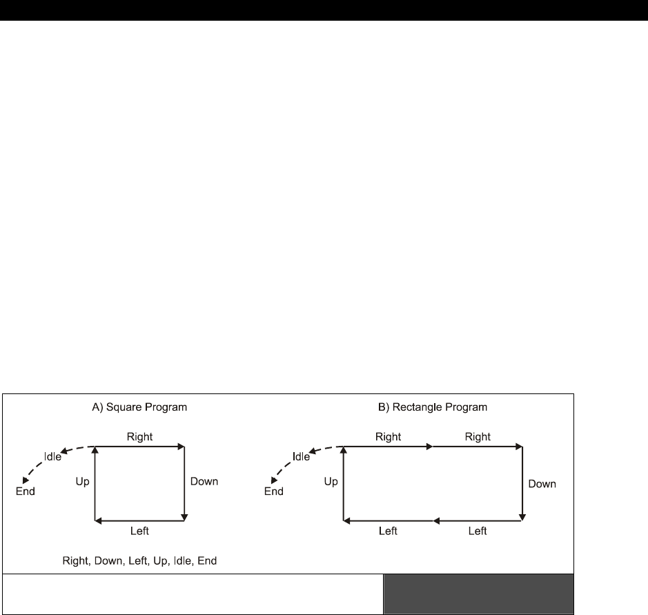
AI, Physics Modeling and Collision Detection 23
Game Programming for the Propeller Powered HYDRA Page 703
The first step is to outline what the language or control instruction set will be. Let’s say the
commands are: {RIGHT, LEFT, UP, DOWN, IDLE, END}. We will call the language or
instruction set “PL0” (Pattern Language 0), where each of the instructions has the following
meanings:
RIGHT – Move right some pre-determined distance
LEFT – Move left some pre-determined distance
UP – Move up some pre-determined distance
DOWN – Move down some pre-determined distance
IDLE – Sit idle and do nothing for some pre-determined amount of time
END – End of pattern program sentinel, must be placed at end of each pattern
program
The first thing you will notice is that PL0 has no operands, it’s a pure opcode-only instruction
set, thus its use is limited and not very flexible. For example, all the movements are fixed
since they are not parameterized, but as a start this is fine. Anyway, take a look at Figure
23:16, here we see couple patterns and behaviors coded with this language. The square
pattern in Figure 23:16(A) would be:
Square Program = “RIGHT, DOWN, LEFT, UP, IDLE, END”
Some Basic Patterns Generated with
Pattern Language “PL0” Figure 23:16
Of course, this is just one square program, there are an infinite number of them, say we
wanted a rectangle with width > height. That’s easy, we just use the RIGHT and LEFT
instructions more:
Rectangle Program = “RIGHT, RIGHT, DOWN, LEFT, LEFT, UP, IDLE, END”

III Game Programming on the HYDRA
Page 704 Game Programming for the Propeller Powered HYDRA
So as you can see, even with this simple language there are all kinds of cool possibilities.
But, we can do a lot more by supporting other types of instructions along with operands.
However, before getting to that, let’s take a stab at coding some of this software needed for
the language and pattern processing.
First, we have to decide on a format for the instruction set, so let’s represent each instruction
as a single BYTE with the following constant definitions:
' opcode definitions
OP_IDLE = 0
OP_END = 1
OP_RIGHT = 2
OP_LEFT = 3
OP_UP = 4
OP_DOWN = 5
Next, we need some kind of storage to store a pattern, let’s use a simple array that might
look like this:
DAT
' a simple square pattern
pattern byte OP_IDLE, OP_RIGHT, OP_UP, OP_LEFT, OP_DOWN, OP_IDLE, OP_END
With the constants in hand and the data for a pattern, we need some code that reads the
pattern and processes is, here’s a pseudo-code loop that handles the job:
' vars for pattern processing and alien position
long alien_x, alien_y ' position of alien controlled by pattern processor
byte opcode ' the opcode currently being processed
long opcode_index ' the index into the pattern program where the next opcode is
' being fetched (like instruction pointer)
long opcode_counter ' a general counter/timer that is used to control state
opcode_index := 0 ' initialize program fetch index to 0
opcode := pattern[ opcode_index ] ' fetch first instruction
opcode_index++ ' advance instruction index
opcode_counter := 0 ' reset counter, used to track state, time, etc.
repeat while 1
' somewhere in the main event loop..
case opcode ' process instruction
OP_IDLE:
if (++opcode_counter > 10) ' waits for 10 cycles/frames, fetches next instr.
Fetch ' fetch next instruction

AI, Physics Modeling and Collision Detection 23
Game Programming for the Propeller Powered HYDRA Page 705
OP_END:
' program is over, either restart program or do something else…
OP_RIGHT:
' move alien right some number of cycles, say 5
if (++opcode_counter < 5)
alien_x++
else
Fetch ' fetch next instruction
OP_LEFT:
' move alien left some number of cycles, say 5
if (++opcode_counter < 5)
alien_x--
else
Fetch ' fetch next instruction
OP_UP:
' move alien up some number of cycles, say 5
if (++opcode_counter < 5)
alien_y--
else
Fetch ' fetch next instruction
OP_DOWN:
' move alien down some number of cycles, say 5
if (++opcode_counter < 5)
alien_y++
else
Fetch ' fetch next instruction
PUB Fetch
' fetches next instruction from program
opcode := pattern[ opcode_index++ ] ' fetch instruction, advance pointer
opcode_counter := 0 ' reset counter, used to track state, time, etc.
Of course this is only pseudo-code and there is a lot missing, but the main idea is that the
pattern program is processed by a state machine of some sort and each of the actions are
executed. As noted, this technique is very powerful and gives the game designer the
flexibility to control the AI of characters using “programs” written in tools rather than
programmed in code. Once again, the idea is to move the design of a game into the
designer’s hands and not force a designer to have to actually program the AI. Also, if you
have say 100 different patterns or behaviors and then come up with a set of rules used to
select the patterns (maybe based on the state of the game, player, statistics, etc.) then the
behaviors of the game AI characters will virtually be indistinguishable from human opponents
for all intents and purposes.

III Game Programming on the HYDRA
Page 706 Game Programming for the Propeller Powered HYDRA
23.7.2 Advanced Concepts in Pattern Languages
Hopefully, you see how exciting the concept of AI characters processing little programs via
software virtual machines is! But let’s see if we can add some more functionality to our
pattern language “PL0” to make it more robust, so that more advanced and useful programs
can be written with it that do everything we need. First, let’s brainstorm a bit and list some
features and shortcomings that “PL0” currently has that we want to add and improve on.
Right now there are no operands; all opcodes have fixed implied operands. The ability to add
1 or more operands to opcodes is needed, so we can parameterize the instructions. Next, the
instruction set thus far only controls motion, why not add the ability to fire weapons, change
states to various tracking modes, and even fire off function calls? What about adding
conditionals? And even loops and/or gotos to the language? Also, it would be cool to have a
set of global values that could be used as operands as well. For example, giving the language
access to the player x,y position:
GBL_PLAY_X If used as an operand queries that x position of player which is then
uses as the operand of the instruction.
GBL_PLAY_Y Same.
With just these simple ideas we can create a new language “PL1” that can create almost any
behavior we might need. Of course, the language must relate to the functionality or control
of some in game characters, thus there is no need to have language elements that make no
sense to the characters themselves. For example, if we were to use the language to control
asteroids in a game that would be overkill since 4 lines of code can do that. The point is the
game objects controlled by the language should be appropriately selected. Considering that,
here’s a new version draft of the language PL1 shown in Table 23:1.
Referring to Table 23:1, you can see that there are a lot of things this new language can do
and a lot of details we would have to deal with to implement it. For example, the exact
implementation of the flow control and loop opcodes would have to be defined, such as how
to code the OP_GOTO opcode. One possible idea would be to simply allow a positive or
negative number as the operand, and then offset that number of instructions plus or minus
from the OP_GOTO instruction itself. Thus, this code would be an infinite loop back to itself:
OP_GOTO, -1, OP_END
Since “OP_GOTO, -1” means jump back 1 instruction, the instruction index is reset right
back to the OP_GOTO instruction again. But, keep in mind the offset is not how many
BYTEs, or WORDs, or LONGs, but how many “instructions.” The OP_GOTO has some brains
that know how to count forward and backward instructions.
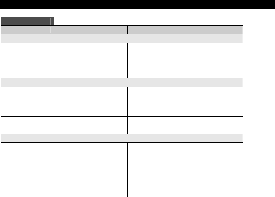
AI, Physics Modeling and Collision Detection 23
Game Programming for the Propeller Powered HYDRA Page 707
Table 23:1 Version 1.0 of Pattern Language “PL1”
Instruction Operand(s) Description
Directionals
OP_RIGHT velocity, time Moves right at given velocity for given time
OP_LEFT velocity, time Moves left at given velocity for given time
OP_UP velocity, time Moves up at given velocity for given time
OP_DOWN velocity, time Moves down at given velocity for given time
Actions
OP_FIRE target # Fires weapon at object identified by value
target#
OP_IDLE time Sit idle for given time
OP_ATTACK time Attack player for given time
OP_EVADE time Evade player for given time
OP_RANDOM time Move in random direction for given time
Flow Control and Loops
OP_LOOP iterations, # of instructions Execute the instructions immediately following
the loop instruction for the requested number
of iterations.
OP_GOTO instruction offset Goto instruction based on offset (+/-).
OP_IF_FUNC_EXE func index, # of instructions Execute function requested, if result is TRUE
execute the following # of instructions, else
jump them
OP_END none Ends program.
Another interesting instruction is the OP_IF_FUNC_EXE instruction. The idea here is that
you would use the instruction to call a list of global information “getter” functions that all
returned Boolean TRUE/FALSE values then, based on the result, the code block under the
instruction would be executed or jumped. Here’s an example:
OP_IF_FUNC_EXE, 3, 5
This would be interpreted as “call the global information function number 3, if the result if
TRUE then execute the next 5 instructions, else jump over them.” Moving on, the other
instructions more or less are “what you see is what you get.” The only thing that isn’t well-
defined is what “time” means in many of the instructions. Well, it could be real-time, or
frames, or cycles, or something in between. The idea is that it’s a parameter that represents
how long to perform the operation.
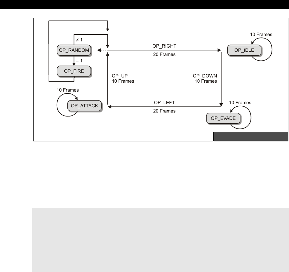
III Game Programming on the HYDRA
Page 708 Game Programming for the Propeller Powered HYDRA
A Graphic Depiction of our PL1 Rectangle Program Figure 23:17
Taking all that in, let’s write a little program with PL1 that does something. How about this:
we write a program that constantly moves a character in a rectangle, but at each corner we
want to attack, evade, idle, and move randomly. Also, we want the program to repeat over
and over, and once each cycle. We will make a call to one of the built-n functions which
returns a random TRUE/FALSE (say it’s index 4) and we will use this to fire the weapons at
the player which is target number 0! Figure 23:17 shows the program graphically for
reference. Here’s the program with some line numbers and comments to help sort it out:
0: OP_RIGHT, 1, 20 ; move right at speed of 1 pixel/frame for 20 frames
1: OP_IDLE, 10 ; do nothing for 10 frames
2: OP_DOWN, 1, 10 ; move down at a speed of 1 pixel/frame for 10 frames
3: OP_EVADE, 10 ; evade the player for 10 frames
4: OP_LEFT, 1, 20 ; move left at a speed of 1 pixel/frame for 20 frames
5: OP_ATTACK, 10 ; attack the player for 10 frames
6: OP_UP, 1, 10 ; move up at a speed of 1 pixel/frame for 20 frames
7: OP_RANDOM, 10 ; move randomly for 10 frames
8: OP_IF_FUNC_EXE, 4, 1 ; call random number function, if TRUE (1) then execute the
; next (1) instructions
9: OP_FIRE, 0 ; fire at the player (will be jumped if above call was FALSE)
10: OP_GOTO, -11 ; go back 11 instructions including the OP_GOTO
11: OP_END ; will never be reached
Reviewing the program, it does exactly what we want it to do. Moreover, it’s totally re-
locatable since the OP_GOTO and OP_IF_FUNC_EXE instructions use relative addressing.
Thus, with a little work, sub-routines can be added and a high-level tool can be written that
allows you to code either with text or graphically could be written to generate all these
“programs.” More or less you can literally create an entire programming language with the
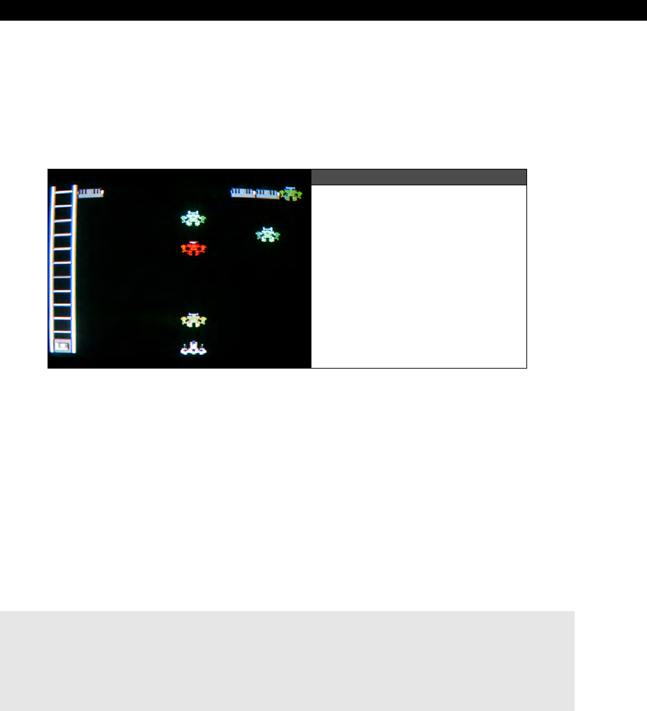
AI, Physics Modeling and Collision Detection 23
Game Programming for the Propeller Powered HYDRA Page 709
pattern language and at some point the programming language starts to blur with a full
blown “scripting language.” Nonetheless, the idea is to create an instruction set that is robust
enough to move your game characters around as well perform some rudimentary processing
once in a while. Let’s take everything now and build a simple demo that takes advantage of
some of our work here.
23.7.3 Pattern Following Demo
Figure 23:18
Alien Invader Demo
with Pattern-Following Code
As a demo of the pattern interpreter technology we have been discussing, take a look at
INVADERS_DEMO_002.SPIN. The gamepad is used to control the ship as usual, also you
can fire with the <A> or <B> action buttons. Figure 23:18 shows a screen shot of the demo
in action. The demo is based on the map file INVADERS_DEMO_MAP_03.MAP, and the
bitmap file MECH_TILES_WORK_02.BMP. The final Spin compliant data file was
generated with the following MAP2SPIN command line:
MAP2SPIN INVADERS_DEMO_MAP_03.MAP MECH_TILES_WORKS_02.BMP –FX –TW8 –TW10 >
INVADERS_TILE_DATA3.SPIN
The map and bmp files are nearly identical to the last invaders demo except that the art has
been augmented with some laser pulses, but that’s about it. All the files are located in
\SOURCES as usual. The demo more or less implements a pattern language similar to PL1,
but not as complete. The following is an excerpt from the opcode listing in the demo:
PCMD_IDLE = 0 ' format: {PCMD_IDLE, n} - idles for n frames.
PCMD_FIRE = 1 ' format: {PCMD_FIRE} - fires straight down.
PCMD_RIGHT = 2 ' format: {PCMD_RIGHT, n} - moves right n frames.
PCMD_LEFT = 3 ' format: {PCMD_LEFT, n} - moves left n frames.
PCMD_UP = 4 ' format: {PCMD_UP, n} - moves up n frames.
PCMD_DOWN = 5 ' format: {PCMD_DOWN, n} - moves down n frames.
PCMD_TRACK = 6 ' format: {PCMD_TRACK, n} - tracks player for n frames.

III Game Programming on the HYDRA
Page 710 Game Programming for the Propeller Powered HYDRA
PCMD_EVADE = 7 ' format: {PCMD_EVADE, n} - evades player for n frames.
PCMD_JMP = 8 ' format: {PCMD_JMP, n} - set pattern IP or index to n.
PCMD_END = 9 ' format: {PCMD_END} - ends program.
The demo consists of the invaders environment, a group of alien robots that are controlled
by the pattern interpreter along with the player’s ship. The program is totally dynamic, so
you can add more alien robots and patterns at will via constants and data. The pattern
interpreter is rather large and is very similar to what we have discussed, so I am not going to
list the complete code; however, here is the header into the interpreter along with “idle” and
“fire” instruction handlers:
repeat bot_index from 0 to NUM_BOTS - 1
' process each bot
if ( bot_state[ bot_index ] <> BOT_STATE_DEAD)
' process alive and dying states
' test state of bot vm - fetch or execute?
if (bot_vmstate[bot_index] == BOT_VMSTATE_FETCH)
' fetch next opcode, leave instruction index on opcode though
bot_opcode[bot_index] := byte[ bot_pattern_ptr[bot_index] ] [ bot_pattern_index[bot_index] ]
' now process (or continue processing current opcode)
case (bot_opcode[bot_index])
PCMD_IDLE: ' format: {PCMD_IDLE, n} - idles for n frames.
' if instruction was just fetched, then fetch operand and prepare to execute
if (bot_vmstate[bot_index] == BOT_VMSTATE_FETCH)
' fetch path
' need to retrieve parameter and store in counter
bot_counter[bot_index]:= byte[bot_pattern_ptr[bot_index]] [bot_pattern_index[bot_index]+1]
' set vmstate to execute
bot_vmstate[bot_index] := BOT_VMSTATE_EXECUTE
else
' execute path
' decrement frame counter
if (bot_counter[bot_index]-- < 1)
' time is up, done with instruction, fetch another, next time around
bot_vmstate[bot_index] := BOT_VMSTATE_FETCH
' advance instruction index past opcode and operand
bot_pattern_index[bot_index] += 2
PCMD_FIRE: ' format: {PCMD_FIRE} - fires straight down.
' if instruction was just fetched, then fetch operand and prepare to execute
if (bot_vmstate[bot_index] == BOT_VMSTATE_FETCH)
' fetch path
Fire_Missile(bot_x[bot_index], bot_y[bot_index], MISSILE_STATE_FIREDBYENEMY)
' advance instruction index past opcode, leave in fetch mode to get next instruction
' since we can immediately process the fire command
bot_pattern_index[bot_index] += 1

AI, Physics Modeling and Collision Detection 23
Game Programming for the Propeller Powered HYDRA Page 711
Upon inspection of the code you will see that the pattern interpreter “virtual machine” has
two states:
“fetch”
and
“execute.”
In the fetch state, the next pattern opcode is fetched
and passed to the appropriate instruction handler in the case statement. In the execute
state, the instruction handler processes the instruction and performs the requested logic and
controls the bot. Thus, each of the instruction handlers have both a “fetch” and “execute”
control path. This is a very clean way to do things and it keeps you from going crazy. Also,
notice that some instructions can be instantly executed like the “fire” handler while the “idle”
handler has to wait a number of frames before issuing another fetch request.
The next interesting thing about this demo is the way that the graphics are handled. This
demo uses a true page flipped double buffer system with the following setup: the original tile
graphics in a 32×12 WORD tile set, along with two 32×12 WORD buffers, call them
tile_map_buffer1
, and
tile_map_buffer2
. These two buffers are used as the off-screen
back buffer, and the on-screen front buffer. The animation loop works as follows:
Step 1: The original tile data is copied into the current back buffer (which could be
tile_map_buffer1 or tile_map_buffer2).
Step 2: All rendering is then done destructively on this back buffer.
Step 3: The back buffer and front buffer are swapped.
Step 4: The HEL engine is pointed to the front buffer and rasterizes it to the TV.
Thus, all graphics rendering is done on the off-screen buffer so there is no flicker, plus we
never see any of the updates to the tile map graphics and the animation is clean and stable.
The code that “flips” the pages and sets the HEL engines tile graphics pointer is as follows:
' flip pages
if (back_tile_buffer == @tile_map_buffer1)
back_tile_buffer := @tile_map_buffer2
front_tile_buffer := @tile_map_buffer1
else
back_tile_buffer := @tile_map_buffer1
front_tile_buffer := @tile_map_buffer2
' update tile base memory pointer
tile_map_base_ptr_parm := front_tile_buffer + scroll_x*2
The demo is a good starting point for a complete game. See if you can add more patterns,
explosions, and levels to the game.

III Game Programming on the HYDRA
Page 712 Game Programming for the Propeller Powered HYDRA
23.8 Waypoints, Pathing and Driving Games
Figure 23:19
A Race Track with
Waypoints Marked
So far the technologies we have looked at are perfect for most arcade games and even
sports games. However, racing games is one class of games that can benefit from yet
another technique –
“waypoint following.”
Take a look at Figure 23:19, here we see an
overhead view of a race track that is marked with what are called
“waypoints.”
These
waypoints are further annotated by lines or paths connecting each. Now, imagine you want
to write a racing game that has a bunch of race cars on a track that the player races against.
How would you approach it? Well, once approach would be to write a really complicated rule-
based AI that, based on the position of the car the AI is driving, the position of the other
cars, the geometry of the road, etc., controls the car and makes it drive on the road. This will
work of course, but is a ton of work. Instead, a simpler method is to create an “invisible”
track of waypoints that the AI car must follow. And to make it interesting we might have 10-
20 different tracks or lanes that the AI can drive in.
Thus we have turned what potentially could be a programming nightmare into nothing more
than making the AI car follow a path of points around a track. Wherever the points go, the
car should follow. The algorithm to perform the tracking is the only real challenge, but we
will get to that in a moment. For now, let’s talk about other ideas for waypoint and pathing
technology. The idea of having vector lists that compose “paths” for game AI characters to
follow is very powerful and one the primary technologies used in modern games. For
example, take a look at Figure 23:20, here is an image of a war game. The problem is that
we want to get our AI characters from the left side of the game world to the right side, but
we want them to go over the bridge and be able to end up at one of the three waypoints on
the right side. With waypoints and paths this is trivial. A set of vector lists or paths full of
waypoints is generated on paper or with a tool, then some code is written that instructs the
AI characters to select one of the paths, follow the waypoints until the AI character is over
the bridge and has reached the goal waypoint.
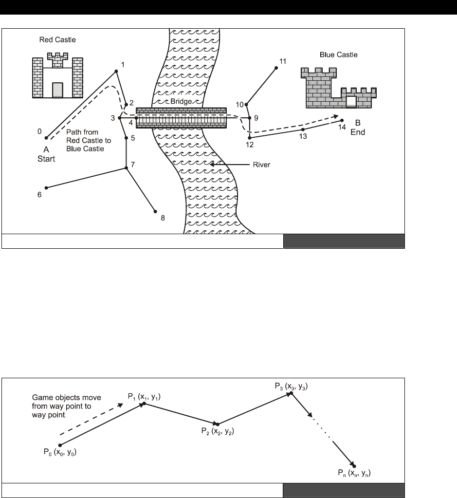
AI, Physics Modeling and Collision Detection 23
Game Programming for the Propeller Powered HYDRA Page 713
A Path from One Side of the Kingdom to Another Figure 23:20
Thus, under normal conditions maybe the game AI is simple evade, chase, random, pattern
code, but when an AI character needs to
get
somewhere
, the pathing code is executed
and the character gets from point A to B via a list of waypoints. Considering that, let’s re-visit
the simple driving game example. In this case, we want to get around a track via a single
path which consists of a set of waypoints. When the last waypoint is reached, we simply start
over again. So we have a number of considerations: first we need a data structure to
represent the waypoints, then we need a motion algorithm that moves the game character in
the appropriate manner. Let’s discuss these considering the data set shown in Figure 23:21.
A Waypoint Example Mathematically Annotated Figure 23:21

III Game Programming on the HYDRA
Page 714 Game Programming for the Propeller Powered HYDRA
The figure depicts a number of waypoints labeled as p0(x0,y0) , p1(x1, y1) , p2(x2,y2) ,…,
pn(xn, yn). We already have almost all we need to follow the waypoints from one to another,
but we need to discuss the details about how the “look and feel” of the motion should be
implemented for a racing game. For example, we could use a tracking algorithm that starts
the car off at p0 and then uses the tracking algorithm to move to p1, once at p1, the tracking
algorithm is used to move to p2 and so forth. This is a reasonable solution; however, the
dynamics of the results won’t look right since cars tend to turn, they don’t make 45° or 90°
sudden direction changes plus they slowly accelerate and decelerate. Therefore, we not only
have to come up with an algorithm to control the motion, but a physical
“model”
that we
plug the control input into.
In the case of a car or racing game, the “model” might be a crude representation of a car’s
position, velocity, and other attributes. For example, we might draw a car sprite that has 8
directions only, so visually it can look like its going in 8 different directions. Next, we need a
math model of the car which might consist of the following:
Position: p(x, y)
Direction: (theta)
Speed: (s)
With this model, we would map theta (the angle the car is pointing in) into the 8 visual
images of the car sprite. Thus, assuming a 360 circle, each directional change represents 45
degrees. We can compute the trajectory/velocity vector v(vx, vy) of the car with the
following math:
vx = s*cos(theta)
vy = s*sin(theta)
...and then each animation frame we could update the position vector of the car p(x,y) as
follows:
p = p + v = (px+vx, py+vy)
So far, so good. But, there are a lot of things missing. First, there is no friction, secondly, the
car can be pointed in 8 directions, but there is no modeling of the wheels turning to induce a
turn with the tail following and so forth. Thus, you can see a lot of work would have to be
done to make the car model very realistic (we will discuss modeling in more depth in the
physics discussion in the next section). The point is that, aside from the realistic nature of
the model, we at least have a model! Next, the question is can we “drive” the model with our
waypoints in a more realistic manner than just using the brute force tracking algorithm? The
answer is of course yes, with this new model we have the ability to turn the car, then we let
the math compute the trajectory of the car. Thus, we want to turn the car toward the
waypoint, let the math do its thing, then when we reach the waypoint, we turn the car
toward the next waypoint.
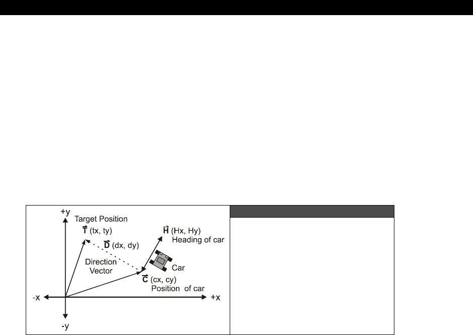
AI, Physics Modeling and Collision Detection 23
Game Programming for the Propeller Powered HYDRA Page 715
Considering that, the problem seems that we need a way to “turn” the car toward any
waypoint, which is more or less a vector geometry problem. We need some math that can
drive the turning algorithm based on the target waypoint, the current location of the car, and
its orientation. Referring to Figure 23:22, we see the setup in terms of vectors:
t(tx, ty) – The target position vector, in other words, the waypoint we want to get
to.
c(cx, cy) – The current position of our car that we want to drive to the target
position.
h(hx,hy) – The heading vector of the car, that is, what direction it is pointing in
currently.
d(dx, dy) – The direction vector from the car to the target point we are trying to
get to. Note that d is also equal to (t-c).
Figure 23:22
Determining Heading
based on Destination Position
and Orientation
Looking at the diagram for a moment, the idea is that we want to turn the car toward the
target, in other words, we want to make vectors h and d parallel. One solution to this is to
imagine d as an infinitely long line, and we want to determine which “side” h is pointing to
relative to this line, or technically speaking which “half space” or “half plane” h is in. For
example, in the figure, h is to the right, or pointing clockwise of d, so we want to turn the
car to the opposite direction. Similarly, if h was on the left side or counterclockwise side of d
then we would want to turn the car the other way. Therefore, it looks like if we could just
figure out which side of d the vector h was on, then we simply would turn the opposite way
and be done. There are a billion ways to compute this, but one operation that will compute
this result is called
“cross product”
denoted by “×” and whose
determinate
is defined by
the following formula in 2D space:
u × v = (ux, uy) × (vx, vy) = (ux*vy – uy*vx)

III Game Programming on the HYDRA
Page 716 Game Programming for the Propeller Powered HYDRA
...which is a scalar and the sign of which tells us which side u is relative to v! Take a look at
Figure 23:23 to see some examples to see this for yourself. Now, we take this information
and plug it back into our algorithm, so we only need to compute the cross product (h × d)
and look at its sign to determine which way to turn the car. Putting everything together, we
get the following algorithm:
Given we have a vector list of waypoints that make up the track and we have a car located at
c with a heading h that we want to follow the road.
Step 1: Create a vector list of waypoints p0…pn that make up the track .
Step 2: Find the nearest waypoint using a distance calculation, set it as the target vector t.
Step 3: Compute the cross product (h × d), then based on the sign turn the car clockwise or
counterclockwise.
Step 4: Move the car forward at speed s.
Step 5: Test how close car is to waypoint, once a threshold is reached select next waypoint
in list and target it, continue simulation until you run out of virtual gas!
Cross Product Results Figure 23:23
23.9 Advanced AI Topics
No discussion on AI is complete without some mention of the cutting-edge technologies used
in practice and in science fiction! So let’s briefly take a look conceptually at what some of the
more interesting technologies are.
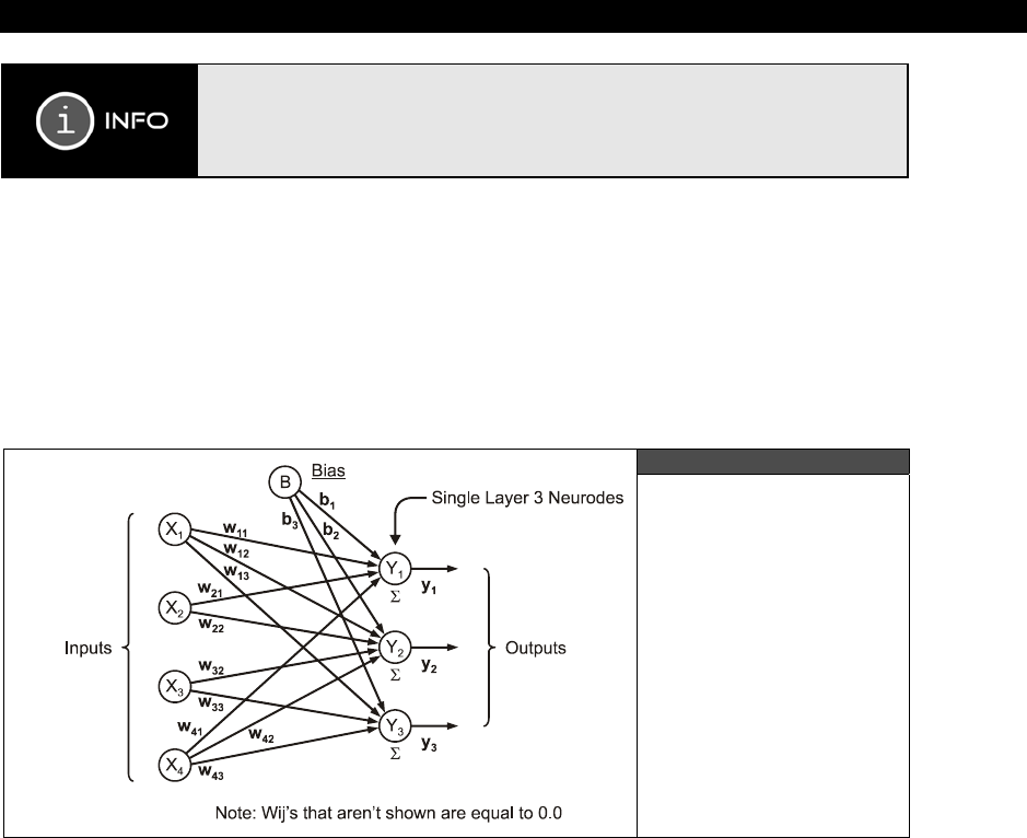
AI, Physics Modeling and Collision Detection 23
Game Programming for the Propeller Powered HYDRA Page 717
For interested readers, check out my book Tricks of the Windows Game
Programming Gurus 2nd Edition, it has one of the most detailed coverages of
general AI techniques applied to games including all the subjects below. Also,
on the CD in \DOCS\NETWARE, I have placed an introductory article on neural
networks you might be interested in perusing.
23.9.1 Neural Nets
If any AI technique gets the most press it’s
“neural nets”
otherwise known as
“artificial
neural networks.”
There is nothing artificial about them though. Neural nets or
NN
s as
they are called are models loosely (and I mean loosely) based on human neural pathways.
The idea behind NNs is to model how our brain cells process information rather than use
typical computational models based on predicate logic that computer programs are more
commonly based on.
Figure 23:24
A Simple Neural Net
Figure 23:24 shows a typical neural net. As you can see the neural net is represented by a
number of inputs and outputs. Each of the nodes or
“neurodes”
process information. But,
unlike a computer that performs logical or mathematical operations on the inputs, neural nets
take a much more organic point of view. If you have ever studied a little brain biology then
you know that each brain cell or
neuron
consists of a
soma
(the main processor), the
axon
(the interface or conduit), and
dendrites
(the I/O ports). Signals come in through the
dendrites and are processed by the soma, and sent out through the axon to other neurons.
The interesting thing about the entire process is that it’s of course electro-chemical in nature,
that is, concentrations of chemicals (primarily sodium, chloride, and potassium) are used to

III Game Programming on the HYDRA
Page 718 Game Programming for the Propeller Powered HYDRA
move charge and send the electrical signals. Information is encoded not as bits or voltages,
but by the frequency and concentration of these signals. Neurons process information by
thresholding data inputs and outputting data when the threshold is reached. For example,
you might have a million neurons that are all good at recognizing circles, and a million that
are good at recognizing squares in your visual cortex. Now, a signal comes in from your optic
nerve and starts getting processed by the visual cortex. There is no high-level cognition such
as “this is a square or circle” that you brain relies on, but it’s more of an accumulative
operation, the circle and square neurons are all excited and the output of the set with the
greatest signal wins. This process continues on adinfinitum until you realize that you are
looking at a
“Circle K Stop and Go”
and you are at your destination! So your cognition is
ultimately the sum of 10-100 billion little neurons, each without any knowledge of anything,
but themselves. Put, them all together and you have an conscious being – you. So we are
the sum of billions of nothings that make something – interesting?
Artificial neural nets try to make an analogy to this, but using computer models. The idea is
that we create a network in a computer with nothing more than math (using matrices and
vectors primarily), then we excite the network with an input, and then a lot of matrix
multiplying goes on (where the numbers in the matrices represent weights in the network
and its architecture), and the output of the operations are the “strength” of the results. Thus,
neural networks more or less are really good at
pattern
recognition
problems, and that’s
about it. They can take multidimensional data and “separate” it into results. One really
common example for artificial neural nets is character recognition. First, a neural net is
designed (which really means a lot of numbers and coefficients are arrived at) and that when
exciting by a target symbol (a bitmap of a letter for example) causes the network to output a
value. Then 26 of these networks are built, and for every input each network is excited, the
winner with the highest output is the result and the character is recognized.
23.9.2 Fuzzy Logic
Fuzzy logic
is one of those things that became popular a few years back by the media,
books, and even game programmers “discovering” it for the first time. But, like anything else
its like hundreds of years old! In fact, neural nets are half a century old! In any case, fuzzy
logic is simply a form of mathematics that deals with
“fuzzy set theory.”
Fuzzy set theory
is a very real method of performing set operations with mathematical objects that have
partial containment in the set.
For example, if I created three sets: raining, sunny, and snowing, and asked you to assign
today’s weather into one of those categories, maybe you could, maybe you couldn’t. What if
today was partially sunny with light showers? Well, then there is no exact insertion point,
thus we might say that today is 80% sunny, and 30% rainy, and 10% snowing, for a total of
120% - which is ok in fuzzy logic! Thus, the idea of fuzzy logic is to have partial set inclusion
for inputs and then based on a sequence of operations determine a final output that is crisp.
So fuzzy logic takes
“fuzzy”
non-exact inputs and outputs a
“crisp”
signal which can be
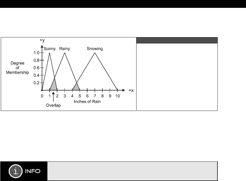
AI, Physics Modeling and Collision Detection 23
Game Programming for the Propeller Powered HYDRA Page 719
used as a final output. Figure 23:25 shows what’s called a
“fuzzy manifold”
that represents
how the various weather states might overlap.
Figure 23:25
A Fuzzy Manifold
Representing how Wet it is
Outside
Fuzzy logic is one of the most powerful AI techniques you can use in games since it’s simple
to implement and by building a fuzzy controller model you can use a tool(s) to create AI
behaviors that are very organic. Moreover, fuzzy controllers are everywhere – from your
transmission, to elevator controllers, to traffic lights. Some processors even have fuzzy logic
support opcodes like the
Motorola 68HC12
.
For interested readers, look on the CD in \DOCS\FUZZY, where I have placed an
introductory article on fuzzy logic and a PowerPoint presentation I made on the
subject.
23.9.3 Memory and Learning
Memory and learning
are nothing more than data logging when it comes to games. For
example, say you have an army of bad guys and they are running around in a world looking
for the player, food, weapons, whatever. If you don’t give them “god-like” knowledge of the
map, that is, they only know what they come close to, then memory and learning is very
easy to implement. As a simple example, let’s say we are making an adventure game, and
the game AI characters need to find ammo just like the player does. But, since we are not
allowing them to be “god” they can’t see through walls, or access the global data base, they
only “know” about the rooms they have visited. Thus, as the game AI characters run through
the world, they record the amount of ammo and the
time
that they recorded the ammo in
any particular room. Then when a game AI passes another game AI in the hallway, they can
communicate or
“share”
memories! This is done by summing their knowledge or potentially
randomly picking one element from each memory and adding it to the other AI’s memory.
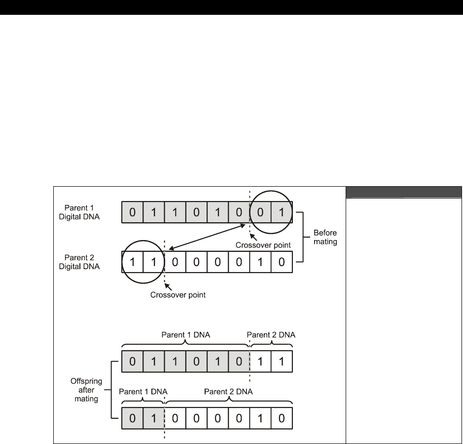
III Game Programming on the HYDRA
Page 720 Game Programming for the Propeller Powered HYDRA
However, during the sharing of knowledge, the time stamp on each individual memory is
used as a gauge of the validity of the memory. For example, if AI Character 1 saw some
ammo in the crystal chamber 5 minutes ago, but AI Character 2 saw that the ammo was
gone 1 minute ago, then the smart thing to do is to take the newer information as more
valid. Another method is to sum the knowledge using the time stamp as the weighting factor.
The possibilities are limitless.
Using this technique, the knowledge and experience of other game AI’s can be leverage by
each other even if the AI’s themselves haven’t had the experience. Many times the results of
implementing memories in game AI are
“emergent behaviors,”
that is, behaviors that
were not directly planned or programmed.
23.9.4 Genetic Algorithms
Figure 23:26
A Genetic Crossover
Algorithm Pictorially
Illustrated
Genetic algorithms are another exciting field of study. The idea is rather simple in theory:
computer programs or solutions to problems are looked at as genetic vectors or information.
If we have two good solutions to a computer program then isn’t it reasonable to think if we
“mate”
these solutions then potentially the offspring might be even better solutions? The

AI, Physics Modeling and Collision Detection 23
Game Programming for the Propeller Powered HYDRA Page 721
test of how good a solution is based on what’s called the
“fitness function”
which is a
measure of how well the solution solves the problem (whatever it may be). Sounds crazy?
Well, it’s one of the most important techniques in AI there are and everything from HALO to
your refrigerator cooling cycle might have some genetic algorithms in them. Figure 23:26
shows the process in action: just like in normal biological reproduction one information vector
from the father and one information vector from the mother are mated. The mating process
consists of selecting a random
crossover
point to snip the vectors apart and then re-
assembling them. Additionally, just like in nature, genetic algorithms on computers add in
random mutations and other disturbances, to give evolution a chance and not drive down the
“best”
path always since “best” sometimes might miss
“better.”
The problem though is mapping a “computer program” into some kind of information vector.
However, here’s a good example to show how this can be done with an Electrical Enineering-
based problem for fun. Imagine you have a very complex filter you have designed and the
filter has 4 stages. Each stage is constructed of 2 capacitors and 2 resistors. How they are
hooked up is irrelevant. All we know is that by experimentation we have found that we get
the desired results with the following two vectors a and b (that represent the values of the
capacitors and resistors for each filter solution):
a = ca1, ca2, ca3, ca4, ca5, ca6, ca7, ca8, ra1, ra2, ra3, ra4, ra5, ra6, ra7, ra8
b = cb1, cb2, cb3, cb4, cb5, cb6, cb7, cb8, rb1, rb2, rb3, rb4, rb5, rb6, rb7, rb8
Now, to mate a and b all we need to do is select a crossover point on one and then swap
genetic material. Of course, in this example, we have to select two crossover points, since we
don’t want to mix resistors with capacitors, so let’s select the following crossover points:
a = ca1, ca2, ca3,
ca4, ca5, ca6, ca7, ca8
, ra1, ra2, ra3, ra4, ra5, ra6,
ra7, ra8
b =
cb1, cb2, cb3,
cb4, cb5, cb6, cb7, cb8,
rb1, rb2, rb3, rb4, rb5, rb6
, rb7, rb8
Merging the data, we get two offspring:
ab =
cb1, cb2, cb3
,
ca4, ca5, ca6, ca7, ca8
,
rb1, rb2, rb3, rb4, rb5, rb6
,
ra7, ra8
ba = ca1, ca2, ca3, cb4, cb5, cb6, cb7, cb8, ra1, ra2, ra3, ra4, ra5, ra6, rb7, rb8
Let’s call ab
“Jimmy”
and ba
“Michelle.”
And then we might decide to mutate little Jimmy
and Michelle a little as well and come up with yet 2 more variants. Then these variants are
tested by the fitness function and, if above a certain threshold of performance, they are
saved, else, they are thrown back into the digital oblivion.
Genetic algorithms can be used in games to “learn.” Say that you vectorize a
parameterization that controls the various state machines of a fighting character AI in a
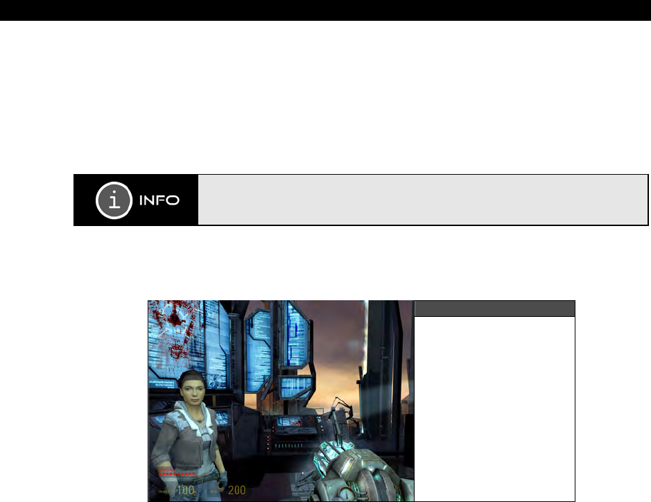
III Game Programming on the HYDRA
Page 722 Game Programming for the Propeller Powered HYDRA
game. Then you play the AI 1,000 times and let it learn from you by updating its control
vector by means of a genetic algorithm. Then after 1,000 plays or so, the evolved AI can
beat you, but you didn’t have to program it directly, you simply played it to learn! This is
exactly how many fighting games work. They come with a few dozen (or hundred) canned
AI’s and when you play the character many levels over and over, the AI will learn your
techniques and be able to adapt to your personal game play. Thus, the game experience is
different for everyone.
Check out Dr. Koza’s Genetic Programming as well as Turtles, Termites, and
Traffic Jams by Resnick. Both will blow your mind…
23.10 Physics Modeling
Figure 23:27
Half Life 2 in Action
“Physics modeling”
as it pertains to video game development is the modeling of game
object behaviors by using real-world physical models or approximations thereof. In the past,
computers didn’t have the horsepower needed to perform realistic physics models for games,
but today many games show off amazing physics. One of my favorites is
Half Life 2
by
Valve
. This game not only has some of the most realistic physics modeling in a video game,
but when objects have real physics, the game takes on a life of its own. Objects interact with
each other in permutations you could never imagine. Plus, it’s a lot of fun heaving
refrigerators at enemies using the “zero point energy” weapon!
We aren’t going to create physics engines even 1/100th as advanced as those seen in Half
Life 2 (since they took over 10 years and $25M in R&D), but we are going to create physics
models that are based on real-world physics and math. I have chosen a set of commonly

AI, Physics Modeling and Collision Detection 23
Game Programming for the Propeller Powered HYDRA Page 723
used physics models in games: motion, gravity, friction, and projectiles, to showcase some of
the ideas. Now, before we get started, here’s two things to remember: first these models are
quick and dirty to get the job done, and secondly we are simulating physics response in
discrete time, that is, time is continuous in the real-world, but in the computer it’s quantized.
More accurate physics simulators take this into consideration, but in our case we are going to
think of a single frame as a unit of “time” and our simulations will run accordingly. Before we
start let’s review a few physics concepts in case you are rusty. Although we don’t really care
about units of measure in a computer program (since it’s all virtual anyway), at least having
some review of these units and their relationships will help glue the concepts together as we
explore them.
23.10.1 Basic Units of Measure
Let’s briefly introduce the concepts of mass and time. Although everyone knows what time is,
many people don’t exactly know what “mass” is; they confuse it with weight. So just to make
sure we are all on the same page, let’s review these two important concepts and their
relationship to games.
23.10.1.1 Mass (m)
All matter has mass. Mass is a measure of how much matter is present. It doesn't have
anything to do with weight. Many people have mass and weight confused. For example, they
might incorrectly say that they weigh 75 kilograms (165 pounds on Earth). First, kilograms
(kg) are a metric measure of mass, that is, how much matter, while pounds (lbs.) is a
measure of force or more loosely weight (mass in a gravity field). The measure of weight or
force in the metric system is called a Newton (N). Furthermore, matter has no weight per se,
it only can be acted upon by a gravitational field to produce what we refer to as weight.
Hence, the concept of mass is a much more pure idea than weight (which changes from
planet to planet).
In games, the concept of mass is only used abstractly in most cases as a relative quantity.
For example, I might set the spaceship equal to 100 mass units and the asteroid equal to
10,000. I could use kilograms, but unless I am doing a real physics simulation then it really
doesn't matter. All I need to know is an object that has a mass of 100 has twice as much
matter as an object that has 50 mass units. I'll revisit mass in a bit when I talk about force
and gravity, but that should be enough to give you a feel for it. Mass is the measure of how
much matter an object is made of and is measured in kilograms in the metric system or –
ready for this –
“slugs”
in the English system!
23.10.1.2 Time (t)
Time is one of the most abstract concepts to comprehend. Think about it. How would you
explain time without using time itself in the explanation? Time is definitely an impossible
concept to convey without using circular definitions and a lot of hand waving. Luckily,
III Game Programming on the HYDRA
Page 724 Game Programming for the Propeller Powered HYDRA
everyone knows what time is, so I won't go into it, but I do want to talk about how to relate
to time in a game.
Time in real life is usually measured in seconds, minutes, hours, and so forth. Or if you need
to be really accurate then it's measured in milliseconds (ms, 10-3 seconds), microseconds (µs,
10-6), nano (10-9), pico (10-12), femto (10-15), etc. However, in most video games there isn't a
really close correlation to real time. Algorithms are designed more around the frame rate
than real-time seconds (except for time-modeled games). For example, most games consider
one frame to be one virtual second, or in other words, the smallest amount of time that can
transpire. Thus, most of the time you won't use real seconds in your games and your physics
models, but virtual seconds based on a single frame as the fundamental time step.
On the other hand, if you're creating a really sophisticated 3D game then you probably will
use real time. All the algorithms in the game track real-time and, invariant of the frame rate,
adjust the motion of the objects so that say a tank is moving 100 feet per second even if the
frame rate slows down to 2 fps or runs at 60 fps. Modeling time at this level of accuracy is
challenging, but absolutely necessary if you want to have ultra realistic motion and physical
events that are independent of frame rate changes. In any case, we'll measure time in
seconds (s) in the examples or in virtual seconds which simply means a single frame.
For the physics readers with us: if time was really continuous we could never
move forward in time, thus time must be discrete and quantum in nature similar
to matter and space. What do you think?
23.10.2 Kinematic Motion Concepts
The study of objects in motion is called “kinematics”. And this is what we are keenly
interested in when it comes to games. The three quantities that we want to really get a
handle on are
position
(s),
velocity
(v), and
acceleration
(a). Based on these concepts
we can introduce others in a civilized manner.
23.10.2.1 Velocity (v)
Velocity is the instantaneous rate of speed of an object and is usually measured in meters
per second m/s or in the case of the automobile miles per hour or mph. Whatever units you
prefer, velocity is the change in position s per change in time t or mathematically in a 1
dimensional case:
Velocity = v = ds/dt.
In other words the instantaneous change in position (ds) with respect to time (dt). As an
example, say you are driving down the road and you just drove 100 miles in one hour then
your average velocity would be:
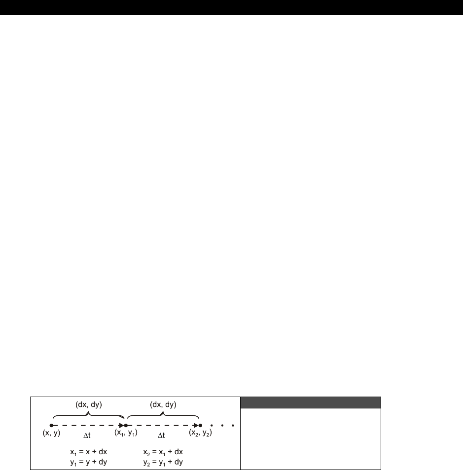
AI, Physics Modeling and Collision Detection 23
Game Programming for the Propeller Powered HYDRA Page 725
v = ds/dt = 100 miles/1 hour = 100 mph.
In a video game the concept of velocity is used all the time, but again the units are arbitrary
and relative. For example, in a number of the demos I have written thus far I usually move
objects at some rate, say v=(4,4) in the X and Y axis per frame, with code something like:
x_position := x_position + x_velocity;
y_position = y_position + y_velocity;
That translates to 4 pixels/frame. But frames aren't time are they? Actually, they are as long
as the frame rate stays constant. In the case of 30 fps which is equal to 1/30 seconds per
frame the 4 pixels/frame translates to:
Virtual Velocity = 4 pixel / (1/30) seconds
= 120 pixels per second.
Hence, the objects in our game have been moving with velocities that can be measured in
pixels/second if we wanted to work out the math. Then if you wanted to get crazy then you
could estimate how many virtual meters were in one pixel in your game world and do the
computation in meters/second in cyberspace. In either case, now you know how to gauge
where an object will be at any give time or frame if you know the velocity. For example, if an
object was currently at position x0 and it was moving at 4 pixels/frame, when 30 frames go
by the object will be at:
New Position = x0 + 4 * 30 = x0 + 120 pixels.
This leads us to our first important basic law:
New Position = Old Position + Velocity * Time
= xt = x0 + v*t.
...which states that an object moving with velocity v that starts at location x0 and moves for t
seconds will move to the position equal to its original position plus the velocity times the
time. Take a look at Figure 23:28 to see this more clearly.
Figure 23:28
Constant Velocity Motion

III Game Programming on the HYDRA
Page 726 Game Programming for the Propeller Powered HYDRA
23.10.2.2 Acceleration (a)
Velocity vs. Acceleration Figure 23:29
Acceleration is similar to velocity, but it is the measure of the rate of change of velocity
rather than the velocity itself. Take a look at Figure 23:29, it illustrates an object moving with
a constant velocity as well as with a changing velocity. The object moving with a constant
velocity has a flat line (slope of 0) for its velocity as a function of time, but accelerating
objects have non-zero slopes since thier velocities are changing as a function of time.
Figure 23:29(B) illustrates constant acceleration. There is also non-constant acceleration. In
this case the line would be a curve in Figure 23:29(C). Pressing the accelerator in your car
will give you the feeling of non-constant acceleration, while jumping off a cliff will give you
the feeling of constant acceleration (gravity). Mathematically, acceleration is the rate of
change of velocity with respect to time or:
Acceleration = a = dv/dt.
The units of acceleration are a little weird also. Since velocity is already in units of distance
per second, acceleration is in units of distance per second*second or in the metric system
m/s2. If you think about this it makes sense since acceleration is the change of velocity (m/s)
per second. Furthermore, our second motion law relates the velocity, time, and acceleration:
New Velocity = Old Velocity + Acceleration * Time
= vt = v0 + a*t.
...which states that the new velocity at some time t in the future equals the starting velocity
plus the acceleration times the amount of time the object has been accelerating for.
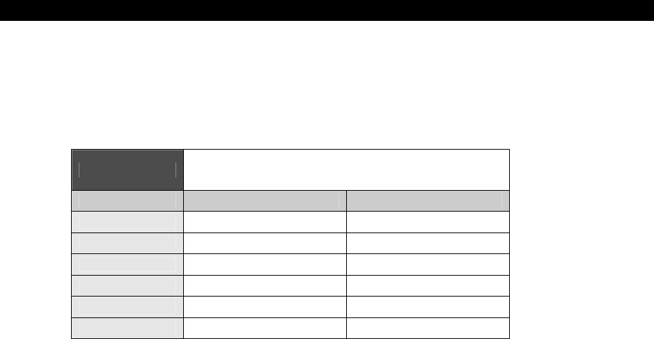
AI, Physics Modeling and Collision Detection 23
Game Programming for the Propeller Powered HYDRA Page 727
Acceleration is a fairly simple concept and can be modeled in a number of ways, but let's
take a look at a simple example. Imagine that an object is located at (0,0) and it has a
starting velocity of 0. If we were to accelerate it at a constant velocity of 2 m/s then were
could figure out the new velocity each second simply by adding the acceleration to the last
velocity as shown in Table 23:2.
Table 23:2 Velocity as a Function of Time for
Acceleration 2 m/s2
Time (t = s) Acceleration (a = m/s2) Velocity (v = m/s)
0 2 0
1 2 2
2 2 4
3 2 6
4 2 8
5 2 10
Taking the data in the table into consideration, the next step is to figure out the relationship
among position, velocity, acceleration, and time. This takes a bit of Calculus, but even if you
don’t know Calculus you should be able to follow along since the derivation makes a lot of
sense intuitively. Forgetting acceleration for a moment, we know that position is equal to
initial position plus velocity multiplied by time:
xt = x0 + v*t.
What this equation really does in the discrete case is “add up” the change in distance each
unit of time t. Thus, position is really the time sequence sum of changes in distance. In other
words this leads us to the fact that position is the integral of velocity. And we know that
velocity is equal to:
vt = v0 + a*t.
Thus,
xt = vt * dt = ( v0 + a*t )*dt
Integrating this, results in:
xt = x0 + v0*t + 1/2*a*t2.
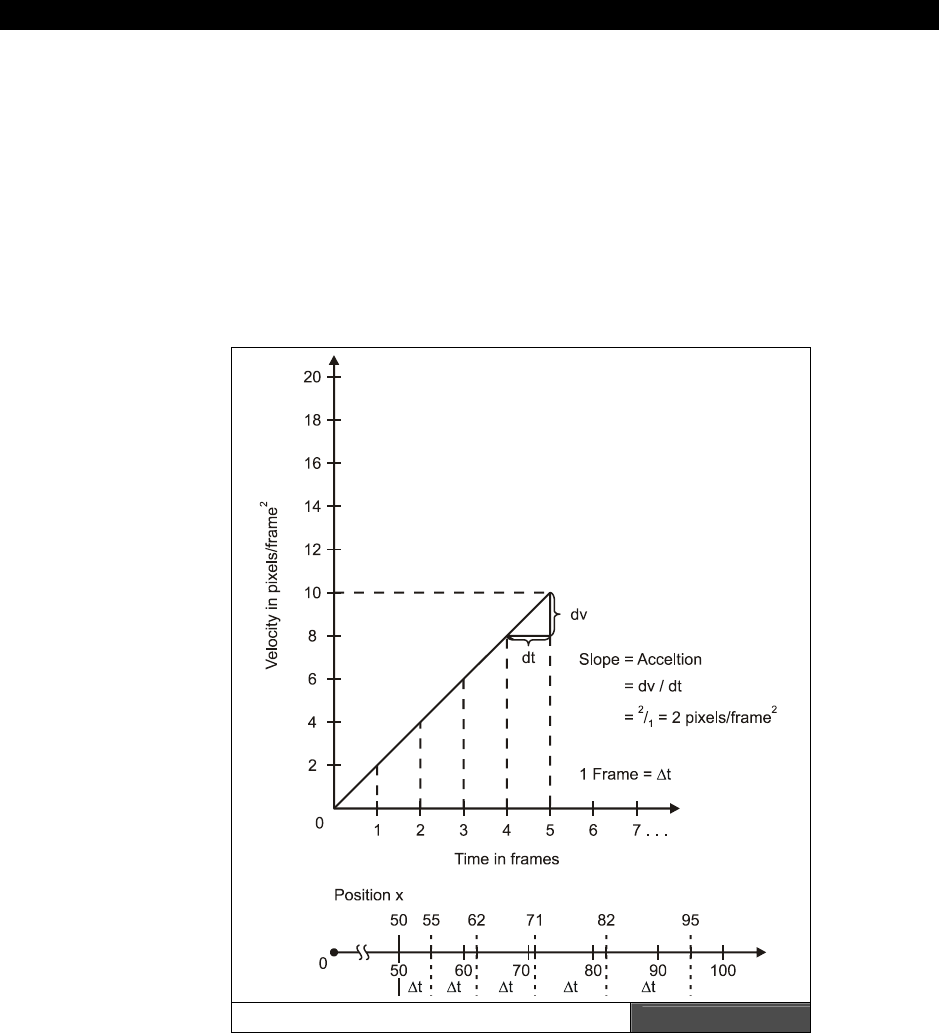
III Game Programming on the HYDRA
Page 728 Game Programming for the Propeller Powered HYDRA
...where x0 is technically the constant of integration which happens to the initial position of
the object. Thus, the formula above is the final piece of the puzzle that relates position,
velocity, and acceleration. This equation states that the position of an object at some time t
is equal to its initial position plus its initial velocity times time plus one half the acceleration
times time squared. The 1/2*a*t2 term is basically the time integral of the velocity. Also, we
don’t have to use the entire formula if some of the terms are 0. For example, if the
acceleration is 0, then the formula reduces to:
xt = x0 + v0*t
Let's see if we can use the equation in our game world of pixels and frames. Take a look at
Figure 23:20 for an example:
An Acceleration in Pixels/Frame2Figure 23:30
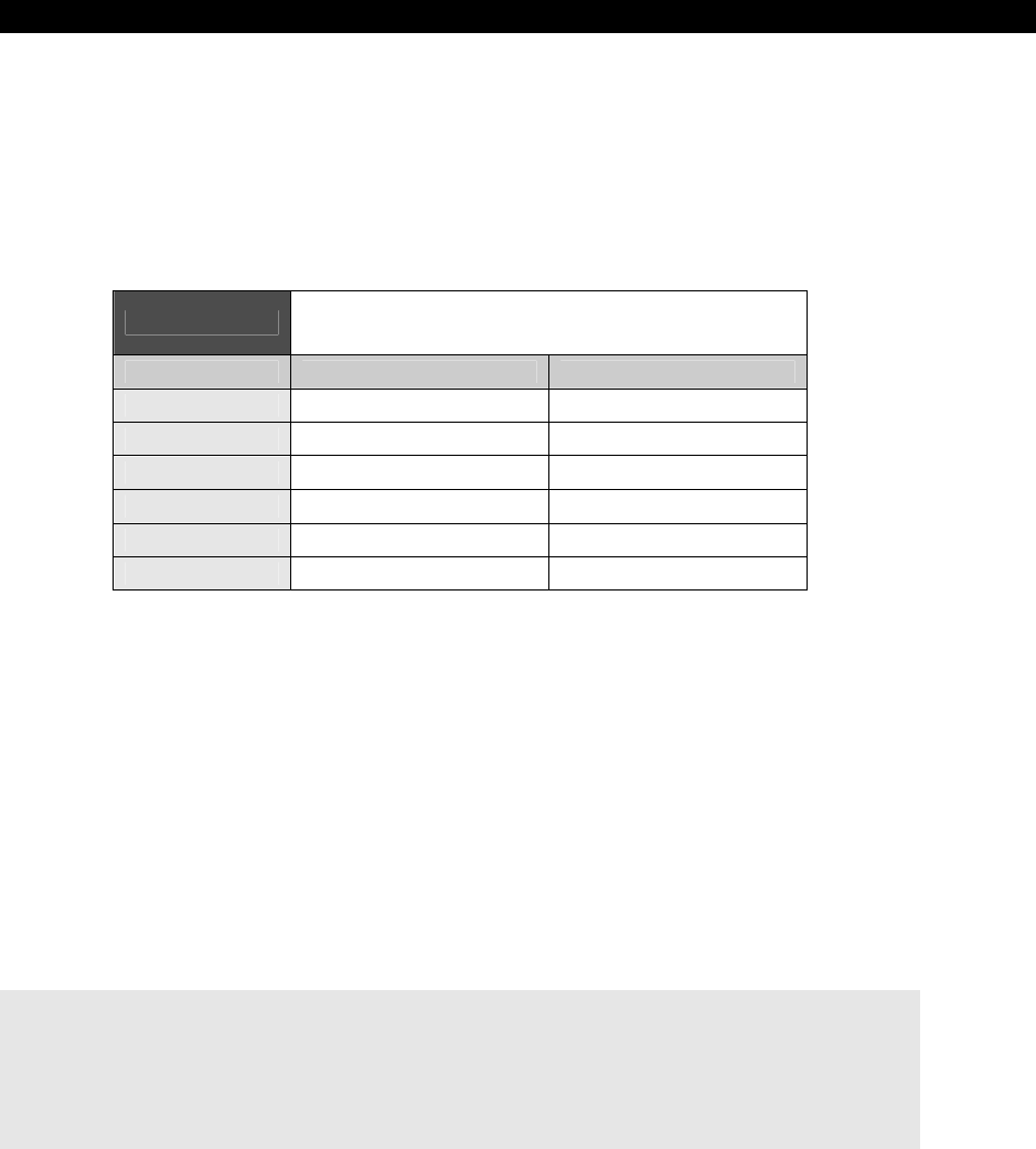
AI, Physics Modeling and Collision Detection 23
Game Programming for the Propeller Powered HYDRA Page 729
Assume these initial conditions: the object is at x=50 pixels, the initial velocity is 4
pixels/frame, and the acceleration is 2 pixels/frame2. Finally, assume that these are the
conditions at frame 0. Then to find the position of the object at any time in C/C++, here's
what you would do:
x = 50 + 4*t + (0.5)*2*t*t;
Where t is simply the frame number. Table 23:3 lists some examples for t = 0,1,2...5.
Table 23:3 An Object Moving With Constant
Acceleration
Time/Frame (t) Position (x) Delta(x)=xt - xt-1
0 50 0
1 50+4*1+(0.5)*2*12 = 55 5
2 50+4*2+(0.5)*2*22 = 62 7
3 50+4*3+(0.5)*2*32 = 71 9
4 50+4*4+(0.5)*2*42 = 82 11
5 50+4*5+(0.5)*2*52 = 95 13
There's a lot of interesting data in the table, but maybe the most interesting data is that the
change in position each time frame is constant and equal to 2. Now this doesn't mean that
the object moves 2 pixels per frame, it means that the change in motion each frame gets
larger by 2 pixels. Thus on the first frame the object moves 5 pixels, then on the next frame
it moves 7, then 9, 11, then 13, and so on. And the delta between each change in motion is
2 pixels which is simply the acceleration!
Although we have been modeling acceleration in many of our demos, let’s look at it more
formally and how we have been doing it. First, you set up an acceleration constant and then
each frame you add it to your velocity, basically modeling:
vt = v0 + a*t.
This way you don't have to use the long equation which is in terms of position. Then you
simply translate your object with the resulting velocity as a second step. Here's an example:
long acceleration, velocity, x
long acceleration = 2 ' 2 pixels per frame
long velocity = 0 ' start velocity off at 0
long x = 0 ' start x position of at 0 also
{ then you would execute this code each cycle to move your object with a constant
acceleration }
III Game Programming on the HYDRA
Page 730 Game Programming for the Propeller Powered HYDRA
' update velocity
velocity += acceleration
' update position
x += velocity
In essence, the program is integrating the position formula since it’s running in time and
computing 1 frame increments.
Of course this example is 1 dimensional. You can upgrade to 2 dimensions
simply by adding a y position (and y velocity and acceleration if you wish).
23.10.2.3 Force (F)
One of the most important concepts in physics is
Force
. Figure 23:31 depicts once way to
think of force. An object with mass m is sitting on a table with gravity pulling it toward the
center of the Earth; the acceleration is a=g (force of gravity). This gives the mass m weight
and hence if you try to pick it up then you will feel resistance. The relationship between
force, mass, and acceleration is defined by
Newton's Second Law
:
F=m*a.
In other words, the force exerted on an object is equal to its mass times the acceleration of
the object. Or rearranging terms:
a = F/m
...which states that an object will accelerate an amount equal to the force you place on it
divided by its mass. Now let's talk about the units of measure. But, instead of just blurting it
out, let's see where it comes from in the metric system at least. Force is equal to mass times
acceleration or kg's multiplied by m/s2 (m stands for meters not mass). Hence, a possible
unit of force is:
F = kg*m/s2 or “Force equals kilograms times meters per second squared”
This is a bit long, so after Isaac Newton, we just call it – Newton (N). As an example,
imagine that a mass m equal to 100 kg is accelerating at a rate of 2 m/s2 then the force that
is being applied to the mass is exactly equal to:
F = m*a = 100 kg * 2 m/s2 = 200 N.
This gives you a bit of a feel for a Newton. A 100 kg mass is roughly equivalent to the force
of 220 lbs. on Earth, and 1 m/s2 is the acceleration of a small motorized vehicle like a moped
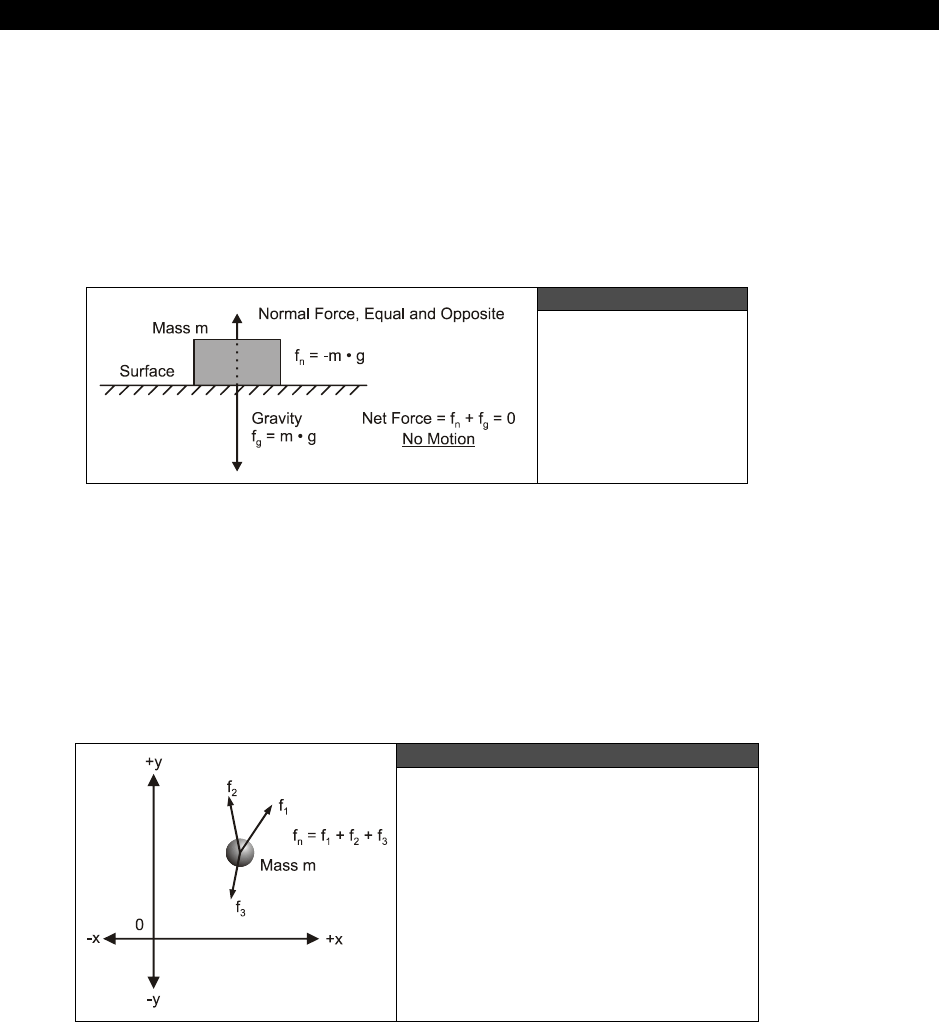
AI, Physics Modeling and Collision Detection 23
Game Programming for the Propeller Powered HYDRA Page 731
where anything over 3-4 m/s2 is like a race car accelerating away. In a video game the
concept of force is used for many reasons, but a few that come to mind are:
You want to apply artificial forces like explosions to an object and compute the
resulting acceleration.
Two objects collide and you want to compute the forces on each.
A game weapon only has a certain force, but it can fire different virtual mass shells
and you want to find the acceleration they would feel on firing.
Figure 23:31
Force and Weight
23.10.2.4 Forces in Higher Dimensions
Of course forces can act in all three dimensions, not just in a straight line. For example take
a look at Figure 23:32, it depicts 3 forces acting on a particle in a 2-D plane. The resulting
force that the particle p “feels” is simply the sum of the forces that are acting on it. However,
in this case it's not as simple as adding scalar numbers together since the forces are vectors.
Nevertheless, vectors can be de-composed into components and then the forces acting in
each axis can be computed. The result is the sum of the forces acting on the particle.
Figure 23:32
Forces Acting on a Particle in 2D

III Game Programming on the HYDRA
Page 732 Game Programming for the Propeller Powered HYDRA
In the example shown in Figure 23:32 there are 3 vector forces: F1, F2, F3. The final force
Ffinal=<fx, fy> that object p feels is simply the sum of these forces in component form:
fx = f1x + f2x + f3x
fy = f1y + f2y + f3y
With that in mind, it doesn't take much to deduce that in general; the final force F on an
object is just the vector sum of forces, or mathematically:
Ffinal = F1+F2+…+Fn
Where each force Fi can have 1,2, or 3 components, that is, each vector can be a 1D
(scalar), 2D, or 3D.
23.10.2.5 Momentum (P)
Momentum is one of those quantities that's hard to define verbally. It's basically the property
that objects in motion have. Momentum was invented as a measure of both the velocity and
mass of an object. Momentum is defined as the product of mass (m) and the velocity (v) of
an object:
p = m*v.
...and the units of measure are kg*m/s, kilogram times meters per second. Now the cool
thing about momentum is its relationship to force – watch this:
F = m*a
or substituting p for m:
F = (p*a)/v
But, a = dv/dt, thus:
p*dv/dt d(p)*v
F = ———————— = ——————— = dp/dt
v dt*v
Thus, force is the time rate change of momentum per unit time. Hmmm – interesting. That
means if the momentum of an object changes a lot then so must the force acting on the
object. Now, here's the clincher. An apple can have as much momentum as a train – how?
An average apple has mass of 0.200 kg while a train made of 20 cars might have the mass of
about 100,000 kg. But, if the train is going 1 m/s and the apple is moving 1,000,000 m/s
(that's one fast apple) then the apple will have more momentum:
mapple*vapple = 0.200 kg * 1,000,000 m/s = 200,000 kg*m/s
mtrain*vtrain = 100,000 kg * 1 m/s = 100,000 kg*m/s
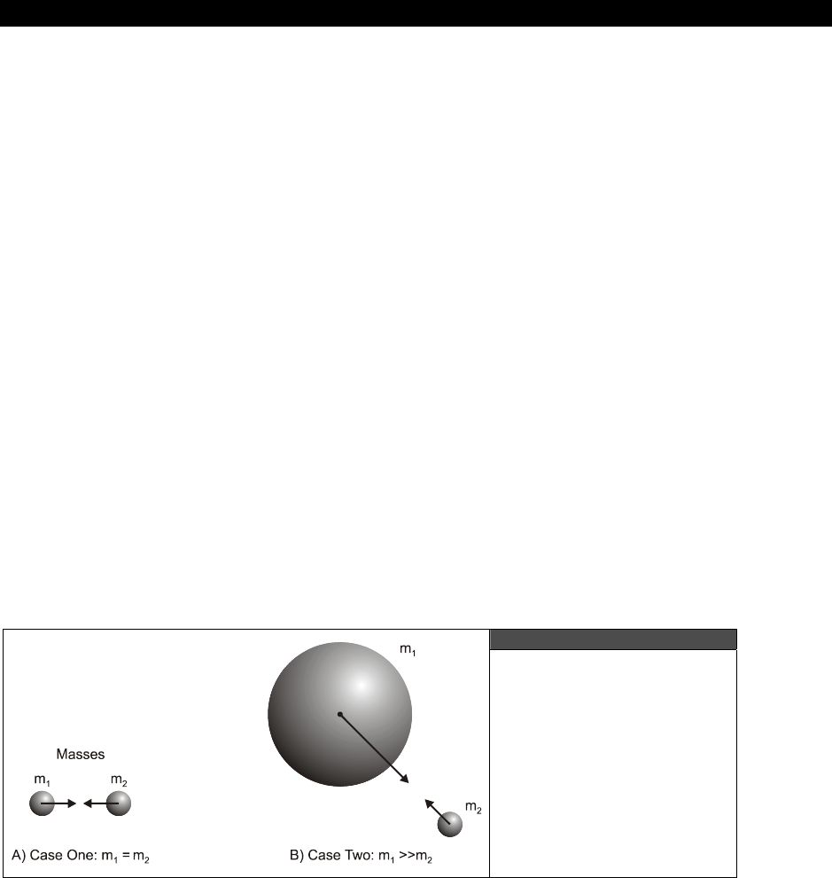
AI, Physics Modeling and Collision Detection 23
Game Programming for the Propeller Powered HYDRA Page 733
And thus if either of these objects came to an abrupt stop, hit something for example, that
object would feel a whole lot of force, in other words
energy transfer!
That's why a fat
bumblebee hitting you on a motorcycle is so dangerous. It's not the mass of the bee, but the
velocity of the bee that gets you (or rather the relative velocity of the bike). Combined the
momentum is huge and can literally throw a 200 lb. guy off the bike.
23.10.2.6 Kinetic Energy
This shotgun physics review wouldn’t be complete without some mention of
“kinetic
energy.”
To start, energy is the ability to perform
work
. Work is
force times distance
and
power
is
work done per unit time
. So the bottom line is “energy” is the ability to
transform a system, that’s the best I can put it. In any case, when objects are in motion,
they posses kinetic energy since if there were to ever stop it would result in energy transfer
(heat and friction usually). The equation for kinetic energy for a mass m moving at a velocity
v is:
ke = ½*m*v2
...and momentum was just m*v, so you see kinetic energy is very similar. In fact, it’s the
integral of momentum which makes sense. Additionally, “energy” is always positive and
measured in kg*m2/s2 which in the Meter-Kilogram-Second system we just call
Joules
(J).
Alright, now the cool part is that the kinetic energy of any closed system is always the same
before and after any collisions, changes, etc. This fact can help you compute velocities after
a collision for example since the total kinetic energy of a closed system must
never
change,
never. Well, that’s about it for our little physics review, let’s put the knowledge to use with
some cool demos!
23.10.3 Gravity and Friction (Demo)
Figure 23:33
The Two General Cases
of Gravity
III Game Programming on the HYDRA
Page 734 Game Programming for the Propeller Powered HYDRA
Gravity and friction are both forces, thus cause accelerations. Therefore, gravity and friction
are simply special cases of general forces that occur so commonly we simply named them.
Gravity in the general sense is what keeps us on the ground. It’s the force between the mass
of the planet Earth and each mass on the surface (like you). There are really two cases that
you need to consider when modeling gravity, these are shown in Figure 23:33:
Case 1: Two or more objects with relatively the same mass
Case 2: Two objects where the mass of one object is much greater than the other
Case 2 is really a sub-case of Case 1. For example, in school you may have learned that if
you drop a baseball and a refrigerator off a building they will both fall at the same rate. The
truth of the matter is they do
not!
But the difference is so infinitesimal (on the order 10-24)
that you could never see the difference. Of course, there are other forces that might make a
difference like wind shear and friction, hence, a baseball is going to fall faster than a piece of
paper since the paper is going to feel a lot of wind resistance. The gravitational force
between any two objects with mass m1 and m2 is:
F = G*m1*m2 / r2.
...where G is the gravitational constant of the universe equal to 6.67×10⁻¹¹ N*m2 * kg-2. Also,
the masses must be in kg and the distance r in meters. So let's try out an example, say that
you want to find out what the gravitational attraction is between two average sized people of
70 kg (155 lbs.) at a distance of 1 meter:
F = 6.67×10-11*70 kg*70 kg/(1 m)2 = 3.26×10⁻⁷ N.
Not even a micro Newton, that's not much is it? However, let's try the same experiment with
a person and the planet Earth at 1 meter given the Earth has a mass of 5.98×1024 kg:
F = 6.67×10-11*70 kg*5.98×1024 kg/(1 m)2 = 2.79×10¹⁶ N.
Obviously, 1016 Newtons would crush you into a pancake, so we must be doing something
wrong? The problem is that we are assuming that the Earth is a point mass that is 1.0
meters away. A better approximation would be to use the radius of the Earth (the center of
mass) as the distance which is 6.38×10⁶ m:
You may assume that any spherical mass of radius r is a point mass as long as
the matter the sphere is made of is homogenous and any calculations must
place the other object at a distance greater than or equal to r.
F = 6.67×10-11 * 70 kg * 5.98×1024 kg / (6.38×10⁶ m)2
= 685.93 N.
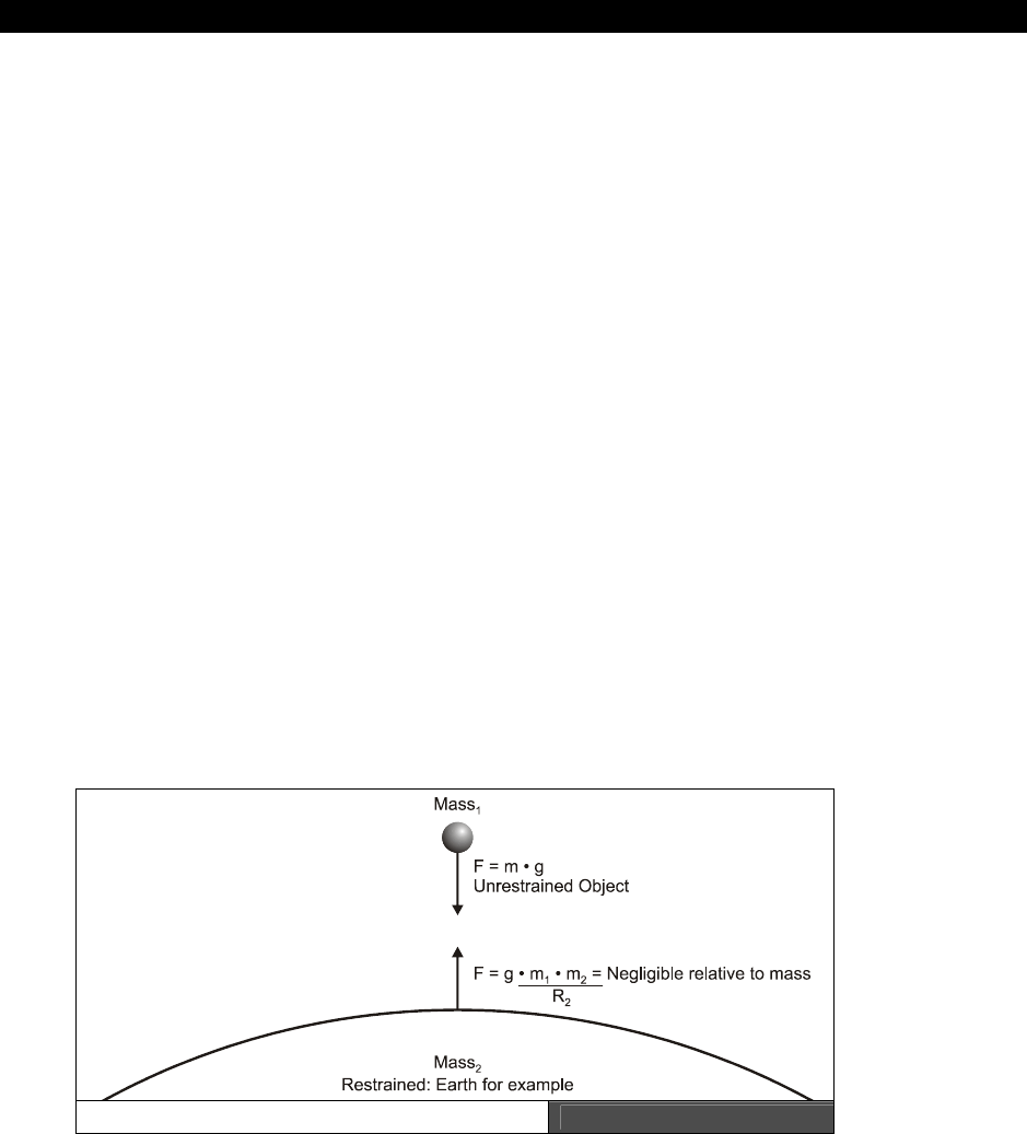
AI, Physics Modeling and Collision Detection 23
Game Programming for the Propeller Powered HYDRA Page 735
Now that seems more reasonable. As a sanity check, on Earth 1 lb. is equal to 4.45 N, so
converting the force to lbs., we have:
685.93 N / (4.45 N / 1 lb.) = 155 lb.
...which was the starting weight! Anyway, now that you know how to compute the force
between two objects you can use this simple model in games. Or course, you don't have to
use the real gravity constant G = 6.67×10⁻¹¹, you can use whatever you like – remember you
are “god” in your game world. The only thing that is important is the form of the equation
which states that the gravity between two objects is proportional to a constant times the
product of their masses divided by the distance squared between the objects’ centers, that’s
all the matters. Moreover, you can even simplify more by making G=1 in your calculations.
Using the above formulation is the key to modeling a black hole in a space game. For
example, you might have a ship that is flying around on the screen and you have black holes
(or planetoids) on the screen and you want the ship to get sucked in if it gets too close.
Using the above equation it’s a snap. You would make up a constant G that worked well in
the virtual game world (based on screen resolution, frame rate etc.) and then simply set an
arbitrary mass for the ship and one for the black hole that was much larger. Then you would
figure out the force and then convert the force to acceleration with F=m*a, that is, a = F/m.
Then you would simply vector the ship directly toward the black hole each frame. As the ship
got closer the force would increase until the player couldn't get free! We will actually see this
in a demo shortly.
The next use of gravity in games is to simply make things fall from the sky or off buildings at
the proper rate. This is really the special case that we talked about before, that is, one object
has a mass much greater than the other. However, there is one more constraint and that is
that one object is fixed – the ground. Take a look at Figure 23:34; it depicts the situation
that I am describing.
Gravitational Attraction Figure 23:34
III Game Programming on the HYDRA
Page 736 Game Programming for the Propeller Powered HYDRA
23.10.3.1 Modeling Gravity
In this case, there are a number of assumptions that we can make that will make the math
work out easier. The first is that the acceleration due to gravity is constant for the mass that
is being dropped which is equal to 9.8 m/s2 or 32 ft/s2. Of course, this isn't really true, but
true enough to about 23 decimal places. Hence, if we know that the acceleration of any
object is simply 9.8 m/s2 then we can just plug that into out old motion equation for velocity
or position. Thus, the formula for velocity as a function of time with Earth gravity is:
v(t) = v0 + 9.8 m/s2*t.
...and position is:
y(t) = y0 + v0*t + 1/2 * 9.8 m/s2 * t2.
In the case of a ball falling off a building we can let the initial position y0 be equal to 0 and
the initial velocity v0 also 0. This simplifies the falling object model to:
y(t) = 1/2 * 9.8 m/s2 * t2.
Furthermore, you are free to change the constant 9.8 to anything you like and t represents
the frame number (virtual time) in a game which is coupled to frame rate. Taking all that into
consideration, here's some pseudo-code showing how to make a ball fall from the top of the
screen:
long y_pos, y_velocity, gravity
y_pos := 0 ' top of screen
y_velocity := 0 ' initial y velocity
gravity := 1 ' do want to fall too fast (at 60 fps will be 1 pixel/sec*sec)
' perform gravity loop until object hits bottom of screen at SCREEN_BOTTOM
repeat while (y_pos < SCREEN_BOTTOM)
' update position
y_pos += y_velocity
' update velocity due to gravity by constant acceleration
y_velocity += gravity
I used the velocity to modify the position rather than modifying the position
directly with the position formula. This is an easier calculation.
You may be asking how to make the object fall with a curved trajectory? This is simple, just
move the x position at a constant rate each cycle and the object will seem as if it was thrown
off rather then just dropped. The code to do this is:
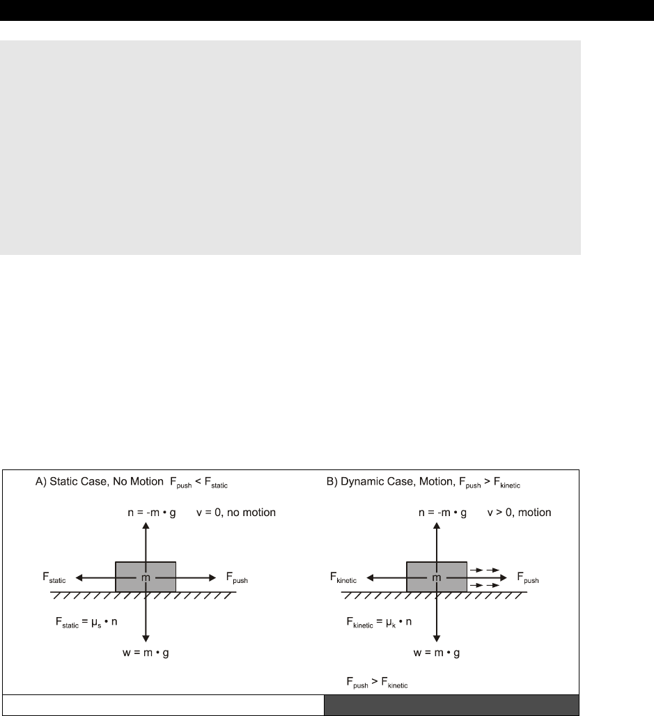
AI, Physics Modeling and Collision Detection 23
Game Programming for the Propeller Powered HYDRA Page 737
long y_pos, x_velocity, y_velocity, gravity
y_pos := 0 ' top of screen
y_velocity := 0 ' initial y velocity
x_velocity := 2 ' initial x velocity (constant)
gravity := 1 ' do want to fall too fast (at 60 fps will be 1 pixel/sec*sec)
' perform gravity loop until object hits bottom of screen at SCREEN_BOTTOM
repeat while (y_pos < SCREEN_BOTTOM)
' update position
x_pos += x_velocity
y_pos += y_velocity
' update velocity due to gravity by constant acceleration
y_velocity += gravity
Of course, sign convention is very important with these models. You have to keep track of
what is up, what is down, the coordinate system you are using, and be consistent!
23.10.3.2 Modeling Friction
The next topic of discussion is friction.
Friction
is any force that retards or consumes energy
from another system. For example, automobiles use internal combustion to operate;
however, a whopping 30-40% of the energy that is produced is eaten up by thermal
conversion or mechanical friction. On the other hand, a bicycle is about 80-90% efficient and
probably is the most efficient mode of transportation in existence. But, the most efficient
form of transportation is a significant other who drives you everywhere!
Basic Friction Model Figure 23:35

III Game Programming on the HYDRA
Page 738 Game Programming for the Propeller Powered HYDRA
Friction is basically resistance in the opposite direction of motion and hence can be modeled
with a force usually referred to as the frictional force. Take a look at Figure 23:35, it depicts
the standard frictional model of a mass m on a flat plane. If you try to push the mass in a
direction parallel to the plane you will encounter a resistance or frictional force that pushes
back against you. This force is defined mathematically as:
Ffstatic = m*g*µs
...where m is the mass of the object, g is the gravitational constant (9.8 m/s+) and µs is the
static frictional coefficient of the system which depends on the conditions and materials of
the mass and the plane. If the force F you apply to the object is greater than Ffstatic then the
object will begin to move. Once the object is in motion then its frictional coefficient usually
decreases to another value which is referred to as the coefficient of kinetic friction µk.
Ffkinetic = m*g*µk
Then when you release the force, the object will slowly decelerate and come to rest since
friction is always present. To model friction on a flat surface all you need to do is apply a
constant negative velocity to all your objects that is proportional to the friction that you want.
Mathematically, we have:
Velocity New = Velocity Old - friction
The results of this will be objects that slow down at a constant rate once you stop moving
them. Of course, you have to watch out for letting the sign of the velocity go negative or in
the other direction, but that's just a detail. Here's an example of an object that is moved to
the right with an initial velocity of 16 pixels per frame and then slowed down at a rate of 1
pixel per frame due to virtual friction:
long x_pos, x_velocity, friction
x_pos := 0 ' starting position
x_velocity := 16 ' starting velocity
friction := -1 ' frictional value
' move object until velocity <= 0
repeat while (x_velocity > 0)
' move object
x_pos += x_velocity;
' apply friction
x_velocity+=friction;
The first thing you should notice is how similar the model for friction is to gravity. They are
identical almost. This isn't luck. The truth is that both gravitational forces and frictional forces
act in the same way. In fact, all forces can be modeled in the exact same way, we just like to

AI, Physics Modeling and Collision Detection 23
Game Programming for the Propeller Powered HYDRA Page 739
name things! Also, you can apply as many frictional forces to an object as you wish. Just sum
them up vectorially.
23.10.3.3 Space Demo
As an example of modeling thrust, friction, gravity, and what we have learned thus far, take
a look at Figure 23:36, it depicts SPACE_DEMO_001.SPIN running. This demo can be
found in the \SOURCES directory and is based on the previous Parallaxaroids demo as a
starting point. The demo illustrates a number of concepts we have discussed and integrates
them all together. First, there is the ship which is controlled by the mouse. Move the mouse
right/left to rotate the ship, and use the <RIGHT> mouse button to engage the thrusters.
The <LEFT> mouse button toggles the asteroid field which is not part of the simulation and
the physics models don’t apply to them (they are in a quantum time flux).
Figure 23:36
The Space Demo in Action
As you play, you will notice 3 animating stars, these are actually black holes or suns, or
whatever you want to call them. But, the bottom line is they have really strong gravity
modeled with the gravity formula. Additionally, it’s assumed there is a bit of friction, so if you
fly the ship around and release the thruster, the ship will slowly come to a stop. The entire
model is executed each frame and the resulting response controls the ship’s motion. The
model is rather straightforward, but when converted to fixed-point math to support the
accuracy needed, the code becomes a little ugly. Nevertheless, it’s well commented and you
should be able to experiment with it. The entire program is too long to list, but below is an
excerpt of the physics modeling section.
' all calculations for ship thrust and position model are performed in fixed point math
if (mouse.button(THRUST_BUTTON_ID))
' compute thrust vector, scale down cos/sin a bit to slow ship's acceleration
thrust_dx := SinCos(COS, ship_angle) ~> 1
thrust_dy := SinCos(SIN, ship_angle) ~> 1
' apply thrust to ships current velocity
ship_dx += thrust_dx

III Game Programming on the HYDRA
Page 740 Game Programming for the Propeller Powered HYDRA
ship_dy += thrust_dy
' apply friction model, always in opposite direction of velocity
' frictional force is proportional to velocity, use power of 2 math to save time
friction_dx := -ship_dx ~> SPACE_FRICTION
friction_dy := -ship_dy ~> SPACE_FRICTION
' apply the friction against the ships current velocity
ship_dx += friction_dx
ship_dy += friction_dy
' now compute the acceleration toward the black hole, model based on F = (G*M1*M2)/r^2
' in other words, the force is equal to the product of the two masses times some constant G divided
' by the distance between the masses squared. Thus, we more or less need to accelerate the ship
' toward the black hole(s) proportional to some lumped constant divided by the distance to the
' black hole squared...
' sum the accelerations up (resulting in velocity changes to the ship)
repeat i from 0 to NUM_BLACK_HOLES-1
' compute each force direction vector d(dx,dy) toward black hole, so we can compute its length
dx := (black_x[i]) - (ship_x ~> 16)
dy := (black_y[i]) - (ship_y ~> 16)
r_squared:=(dx*dx+dy*dy) ' no need to compute length r, when we are going to use r^2 in a moment
' now compute the actual force itself, which is proportional to accel
' which in this sim will be used to change velocity each frame
f := ((GRAVITATIONAL_CONSTANT * black_gravity[i]) << 9 ) / r_squared
' f can be thought of as acceleration since its proportional to mass
' which is virtual and can be assumed to be 1
' thus we can use it to create a velocity vector toward the black hole now in the direction
' of the vector d(dx, dy)
dx := dx << 16 ' convert to fixed point
dy := dy << 16
' compute length of d which is just r, careful to compute fixed point values properly
r := (^^(r_squared << 16)) ' square root operation turns 16.16 into 24.8
' normalize the vector and scale by force magnityde
dx := f*((dx / r) << 8)
dy := f*((dy / r) << 8)
' update velocity with acceleration due to black hole
ship_dx += dx ~> 3
ship_dy += dy ~> 3
' clamp maximum velocity, otherwise ship will get going light speed due to black holes
‘ when the distance approaches 0!
dx := (ship_dx ~> 16)
dy := (ship_dy ~> 16)
' test if ship velocity greater than threshold
v := ^^(dx*dx + dy*dy)
' perform comparison (to squared max, to make math easier)
if (v > MAX_SHIP_VEL)
' scale velocity vector back approx 1/8th
ship_dx := MAX_SHIP_VEL*(ship_dx / v)
ship_dy := MAX_SHIP_VEL*(ship_dy / v)
' finally apply the velocity to the position of the ship

AI, Physics Modeling and Collision Detection 23
Game Programming for the Propeller Powered HYDRA Page 741
ship_x += ship_dx
ship_y += ship_dy
' screen bounds test for player
if (ship_x > (SCREEN_WIDTH/2)<< 16)
ship_x -= SCREEN_WIDTH<<16
elseif (ship_x < (-SCREEN_WIDTH/2)<<16)
ship_x += SCREEN_WIDTH<<16
if (ship_y > (SCREEN_HEIGHT/2)<<16)
ship_y -= SCREEN_HEIGHT<<16
elseif (ship_y < (-SCREEN_HEIGHT/2)<<16)
ship_y += SCREEN_HEIGHT<<16
The physics modeling section begins with applying the thrust from the engines. This is
modeled as increasing the velocity of the ship due to the thrust acceleration. Next, comes the
friction modeling section which is interesting since the frictional vector direction must be in
the opposite direction of the ship’s motion. Thus, first the ship’s velocity vector has to be
normalized and then this is used for the direction to apply the retarding frictional force
(which results in a decrease in velocity).
Next, comes the contribution of the black holes. A loop sums the forces up from each black
hole that is exerted on the ship. Then based on the vector from the ship to each black hole,
the acceleration is computed and then the velocity updated, driving the ship toward each
black hole the appropriate amount. Finally, at the end of the code we test for maximum
velocity and clamp it as well as test for off -the-screen boundaries and wrap the ship around.
This example physics model is rather complete and contains everything you need to model
quite a bit of interesting physical phenomena in your games (including racing games like
Atari Sprint
). Probably the most irritating thing is the support of fixed-point math to
perform the calculations and keeping track of all the shifting operations. This can lead to
errors. One important thing to remember in Spin is that when performing a shift right make
sure to use the “~>” or “~~>” operators to shift WORDs and BYTEs respectively and
maintain the sign bits. Anyway, play with the demo, try changing the simulation constants
and see what you can make happen.
23.10.4 Projectile Modeling
Falling objects are fairly exciting, but let's see if we can do something a little more
appropriate for video game programming. With that in mind, let’s work out how to compute
trajectory paths since shooting things is the main goal in most games! Take a look at Figure
23:37 on the next page, here you see the general setup for the problem. We have a ground
plane, call it y=0, and a tank located at x=0, y=0, with a barrel pointed at an angle of
inclination θ (theta) with the X-axis. The question is, if we fire a projectile with mass m at
with initial velocity vi then what will happen?
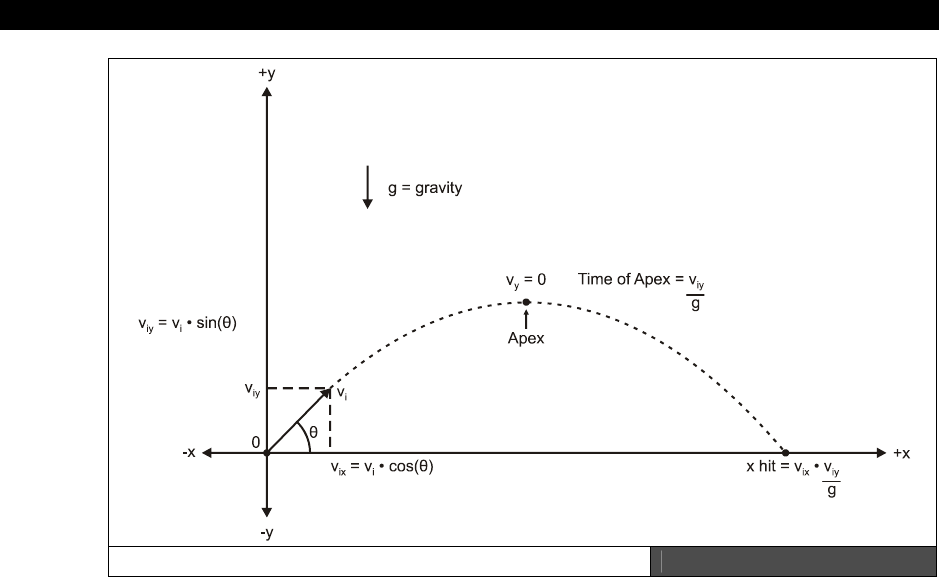
III Game Programming on the HYDRA
Page 742 Game Programming for the Propeller Powered HYDRA
The Projectile Trajectory Problem Figure 23:37
We can solve the problem by breaking it up into its X-Y components. First, let's break the
velocity into an (x,y) vector:
vix = v*cos θ
viy = v*sin θ
This is nothing more than using plane geometry and resolving the opposite and adjacent
sides of the triangle formed by the vector trajectory. Ok, now forget about the x part for a
minute, and think about the problem in the Y-axis alone. The projectile is going to go up and
down and hit the ground. How long will this take? Take a look at our previous gravity
equations:
v(t) = v0 + 9.8 m/s2*t.
And position for the Y-axis is:
y(t) = y0 + v0*t + ½* 9.8m/s2 * t2.
AI, Physics Modeling and Collision Detection 23
Game Programming for the Propeller Powered HYDRA Page 743
The first one tells us the velocity relative to time. That's what we need. We know that when
the projectile reaches its maximum height, the velocity will be equal to 0. Furthermore, the
amount of time that the projectile takes to reach this height will be the same amount of time
it takes to fall to the ground again (referring to Figure 23:37). Therefore, plugging in our
values for initial y velocity of our projectile and solving for time t, we have:
vy(t) = viy - 9.8 m/s2*t
Note, I flipped the sign of the acceleration due to gravity since down is negative and matters
in this case. And in general when the velocity equals 0:
0 = v*sin θ - a*t (a is just the acceleration)
Solving for time t:
t = viy * (sin θ)/a
Alright, now the total time of flight is simply the time up added to time down which equals
t+t = 2*t since the projectile must go up then down. Therefore, we can revisit the x
component now. We know that the total flight time is 2*t and we can compute t from
(viy * (sin θ)/a), therefore, the distance that the projectile travels in the X-axis is just:
x(t) = vix*t
...which plugging in our values is:
xhit = (v*cos θ) * (v*(sin θ)/a)
...or:
xhit = vix * viy / a
Of course, this is only helpful if you need to know where the trajectory will wind up.
However, there are many cases where this is important. Say you have an AI character that is
shooting at a player, the AI can instantly gauge where a projectile will hit and adjust its
weapons accordingly.
Note that I replaced the 9.8 value of acceleration with a. I did this to reinforce that
the acceleration is just a number, and you can make it whatever you wish.
Now, that's the physics behind everything, but how to model it in a program? Well, all you do
is apply constant X-axis velocity to the projectile and gravity in the Y-axis and test for when
the projectile hits the ground or something else. Of course, in real life the X and Y velocities
would diminish due to air resistance, but throwing that out the algorithm I just described

III Game Programming on the HYDRA
Page 744 Game Programming for the Propeller Powered HYDRA
works great. Here's some C/C++ pseudo-code to do it since Spin doesn’t support floating-
point directly and fixed-point makes the math so ugly for this example:
// Inputs
float x_pos = 0, // starting point of projectile
y_pos = SCREEN_BOTTOM, // bottom of screen
y_velocity = 0, // initial y velocity
x_velocity = 0, // constant x velocity
gravity = 1, // do want to fall too fast
velocity = INITIAL_VEL, // whatever
angle = INITIAL_ANGLE; // whatever, must be in radians
// compute velocities in x,y
x_velocity = velocity*cos(angle);
y_velocity = velocity*sin(angle);
// do projectile loop until object hits
// bottom of screen at SCREEN_BOTTOM
while(y_pos < SCREEN_BOTTOM)
{
// update position
x_pos += x_velocity;
y_pos += y_velocity;
// update velocity
y_velocity += gravity;
} // end while
That's all there is to it! And of course we can add more forces like “wind”. We would just
model it as a small acceleration in whatever direction we wanted (usually a crosswind in the
X-axis). Assuming that the wind force creates a constant acceleration against the projectile,
you simply need to add this line of code in the projectile loop:
x_velocity := x_velocity - wind_factor
Where
wind_factor
would be something like 0.01, something fairly small, so wind doesn’t
blow everything too much.
23.10.4.1 Projectile Demo
As a demo of the projectile implementation and modeling, check out the file
PROJECTILE_DEMO_001.SPIN located on the CD in \SOURCES. This demo is one of the
most impressive HYDRA demos in my opinion since it shows off real-time physics modeling
with the Propeller chip and simply looks really cool as shown in Figure 23:38. In the demo,
you are in control of a base turret that can move right to left as well as rotate the turret.
Additionally, you can control the initial velocity or energy of the projectiles as well. The demo
has some rather complex controls and uses the gamepad.
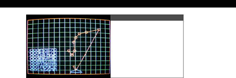
AI, Physics Modeling and Collision Detection 23
Game Programming for the Propeller Powered HYDRA Page 745
Figure 23:38
Projectile Demo in Action
Gamepad controls:
<RIGHT> Move turret base right
<LEFT> Move turret base left
<A> Rotate turret cannon clockwise (right)
<B> Rotate turret cannon counter-clockwise (left)
<START> Fire projectile
<UP> Increase initial velocity of projectile
<DOWN> Decrease initial velocity of projectile
<SELECT> Toggle through various display modes including velocity magnitudes,
and chain linked mode
The demo starts off in full display mode where it prints the magnitude of all projectiles
bottom to top, and chains all the projectiles together. To get the program to speed up,
toggle the display modes with <SELECT> until only the turret and the projectiles render.
Try increasing or decreasing the initial velocity of the projectiles with <UP>/<DOWN> as
well as firing them at the ground. It’s a lot of fun!
The demo itself contains a variety of interesting physics modeling including projectile
trajectory as well as collision, wind, and tactics to determine when objects are at rest. For
example, when you fire a projectile, how do you determine when it’s at rest? Your first
inclination might be to say when its x,y velocity are both equal to 0. This is
wrong!
This is
not necessarily an indication that the projectile is at rest on the ground. For example, when
the projectile is shot straight up, there is a moment when it is suspended in midair at the
apex of its trajectory. Thus, testing for zero total velocity or momentum isn’t enough, since
while suspended in the air with its net velocity equal to 0, the projectile has
“potential”
energy. Thus, the complete test strategy is to test that the projectile is on the ground (y=0)
and there is no momentum. These are the kinds of details that you have to work out when

III Game Programming on the HYDRA
Page 746 Game Programming for the Propeller Powered HYDRA
physics modeling. Many times your intuition might be wrong, but the physics never lie. Thus,
it’s counterintuitive that if the momentum is zero the projectile is at rest, but in the example
above we realized that the projectile has potential energy due to its position above the
ground at the apex of its trajectory straight up and down.
These types of problems are where the real fun of physics modeling comes in, that is,
making all the “corner cases” work in the simulation, so the model not only looks real, but
works and doesn’t get “stuck.” In any event, the simulation loop of the projectile is shown
below and it’s quite a bit simpler than the space demo physics model:
' projectile physics
repeat i from 0 to NUM_PROJS-1
' process each projectile
if (proj_state[i] == 1)
' apply acceleration of gravity to y component of velocity
proj_yv[i] := proj_yv[i] + GRAVITY
' apply accleration due to wind force to x component of velocity
proj_xv[i] := proj_xv[i] + WIND
' apply velocity to projectile
proj_x[i] := proj_x[i] + proj_xv[i]
proj_y[i] := proj_y[i] + proj_yv[i]
' test for collisions with walls, every collision absorbs some percentage of the energy that
' decreases the momentum of the ball. this is due to the inelastic collision, and heat that is
' produced to deform the ball and friction of the surfaces, this way the ball will
' come to rest, thus step 1 is to compute the collision, step 2 is to decrease velocity a bit
if ((proj_x[i] => SCREEN_WIDTH << 16) or (proj_x[i] =< 0))
' reflect ball
proj_xv[i] := -proj_xv[i]
' apply velocity to projectile
proj_x[i] := proj_x[i] + proj_xv[i]
proj_y[i] := proj_y[i] + proj_yv[i]
' now model energy loss due to collision, all of it will be lumped into "FRICTION"
proj_xv[i] := (proj_xv[i] * FRICTION) ~> 8
proj_yv[i] := (proj_yv[i] * FRICTION) ~> 8
if ((proj_y[i] => SCREEN_HEIGHT << 16) or (proj_y[i] =< (PROJ_MASS << 16)))
' reflect ball
proj_yv[i] := -proj_yv[i]
' apply velocity to projectile
proj_x[i] := proj_x[i] + proj_xv[i]
proj_y[i] := proj_y[i] + proj_yv[i]
' now model energy loss due to collision, all of it will be lumped into "FRICTION"
proj_xv[i] := (proj_xv[i] * FRICTION) ~> 8
proj_yv[i] := (proj_yv[i] * FRICTION) ~> 8
' test for "dead ball", we need to compute the magnitude of the velocity is 0 AND
' the ball is at rest at bottom of screen
if ( ||(proj_y[i] ~> 16) =< PROJ_MASS and
(((proj_xv[i]~>8 * proj_xv[i]~>8) + (proj_yv[i]~>8 * proj_yv[i]~>8)) < EPSILON) )
proj_state[i] := 0

AI, Physics Modeling and Collision Detection 23
Game Programming for the Propeller Powered HYDRA Page 747
The simulation loop begins by applying gravity to each projectile, then applying wind to the
projectile. Both of these forces are modeled as velocity changes per frame. Next, the velocity
of the projectile is used to translate it to its next location discretely. Let’s take a quick aside
for a moment. There is a problem with this approach and collision detection. The problem is
that we are moving the projectile discretely through space based on 1 second or 1 frame
intervals, but we are not examining what is happening “between” these discrete jumps. That
is, maybe the projectile hit something as it instantly warped through space. This is a serious
problem in high-end physics simulations! The trick is to
“project”
trajectories from each
discrete time step and compute if there is even the remote possibility of collision, if not, then
the discrete step can be taken. Otherwise, the point in between where the discrete step is
missing the event must be computed and dealt with.
Moving on, after the projectile is translated in the code, then the collision response tests are
made with the bounding box of the screen. If there is a collision then we simply invert the
velocity and then re-apply the translation transformation (this helps to “push back” the
projectile if it pierced the surface impossibly during its motion). Finally, the last test is a bit
nasty. It’s the “dead ball” test that checks if the projectile is not moving. We need to test
both the total velocity vector as well as the position of the ball. If the ball is at the bottom of
the screen and not moving, then it’s a “dead ball” and is removed from the simulation queue.
Finally, the initial conditions of the projectile are the position of the turret’s barrel base and
the initial velocity, calculated with the following code:
' find an available project
repeat i from 0 to NUM_PROJS-1
if (proj_state[i] == 0)
' initialize the projectile
proj_state[i] := 1 ' set to active
' compute initial position base/turret position, convert to fixed point as well
proj_x[i] := base_x << 16 ' since turret is mounted at base_x, base_y
' and projectile would start its trajectory at this interface
proj_y[i] := (base_y + base_yoff) << 16
' now compute initial trajectory (note sin/cos already in fixed point format)
proj_xv[i] := (turret_power+(11-PROJ_MASS))*SinCos(COS, turret_angle)
proj_yv[i] := (turret_power+(11-PROJ_MASS))*SinCos(SIN, turret_angle)
quit
elseif (gp.button(NES0_START)==0) ' debounce fire button
fire_debounce := 0
The code searches for an available projectile then initializes it to the physics model we
discussed in the sections above for trajectory velocity. Notice the use of the
turret_power
and
PROJ_MASS
in the model scaling. These are used to give “reasonable” initial results
visually. Note that the larger
turret_power
is, the faster the projectile, but the larger the
PROJ_MASS
the slower the projectile. These parameters as well as others can be found in
the constants section of the code.
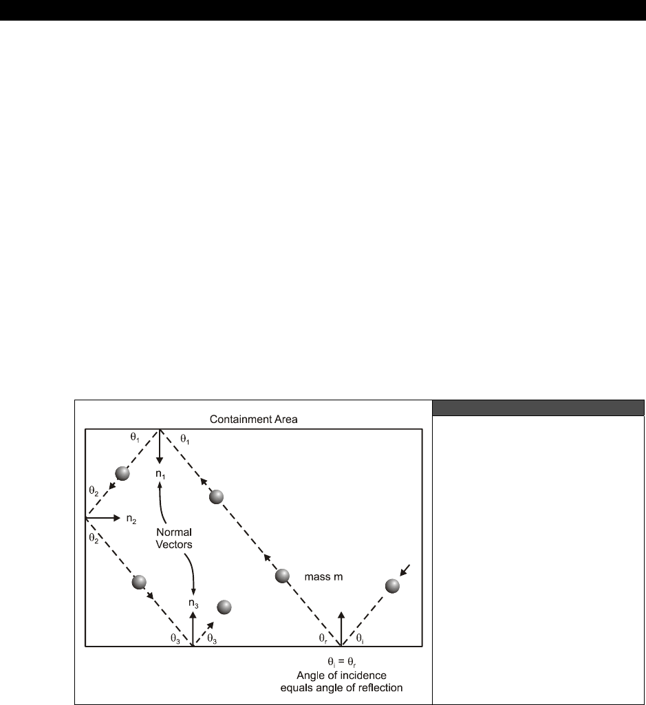
III Game Programming on the HYDRA
Page 748 Game Programming for the Propeller Powered HYDRA
Also, I apologize for all the fixed-point math, but it’s a necessary evil. I have tried to make
the calculations lengthy to show all steps, but some optimizations were necessary, thus some
steps of the physics simulation will be a little hard to follow. However, ignore scaling and
shifting, and try to focus on what the code is generally trying to accomplish by reading the
comments.
Lastly, the demo uses some interesting rendering techniques for the polygon meshes such as
vector lists that describe the shape of the base and turret. These polygon meshes are
transformed each frame, and linked together using relational positioning, thus the turret
moves with the base, the turret rotates relative to the base. But, both the base and the
turret cannon are defined in their own local coordinate system.
23.11 Collision Detection Techniques
Video games are about doing everything fast and collision is no exception. The problem is
that if you approach it in the wrong way you can easily hit a computational wall that is
quadratic or even cubic (in other words for n objects, on the order of up to n3 calculations
have to be performed!). So in this section we are going to look at some common methods
used in basic 2D collision detection algorithms and finish off with some advanced
“spatial
partitioning”
techniques for building “divide and conquer” algorithms to compute collisions.
23.11.1 Simple Reflections
Figure 23:39
The Bouncing Ball Example
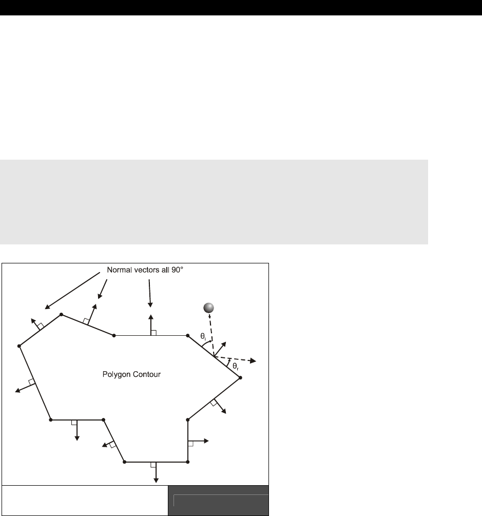
AI, Physics Modeling and Collision Detection 23
Game Programming for the Propeller Powered HYDRA Page 749
Take a look at Figure 23:39, it depicts a fairly common collision problem in games, that is
bouncing an object off the boundaries of the screen which we have done many times. Given
the object has initial velocity (xv,yv), the object can hit any of the 4 sides of the screen.
When a ball hits one of the sides then it always reflects off the side at an angle equal and
opposite to its initial trajectory as shown in Figure 23:39. Although we have just stated the
problem in terms of angles of incidence and reflection, the bottom line is if the object hits a
wall to the east or west then we want to reverse its X velocity while leaving its Y velocity
alone. And similarly on the north and south walls, we want to reverse the Y velocity and
leave the X velocity alone. Here's the code which we have seen in one form or another
before:
' given the object is at x,y with a velocity if xv,yv
' test for east and west wall collisions
if (x > EAST_EDGE || x < WEST_EDGE)
xv=-xv ' reverse x velocity
' now test for north and south wall collisions
if (y > SOUTH_EDGE || y < NORTH_EDGE)
yv=-yv ' reverse y velocity
Of course, this simplification
only works well for horizontal
and vertical barriers. You'll
have to use the more general
angle calculation for walls or
barriers that aren't co-linear
with the X and Y axes. This
brings us to the more general
problem of how to solve the
collision of a ball and a barrier
that has a surface at any
orientation.
For example, take a look at
Figure 23:40, it shows an
irregular shaped object with
the property that all the sides
are flat facets. The question is
how to bounce a ball off this
type of object?
Bouncing Ball and Irregular
Object with Flat Faces Figure 23:40
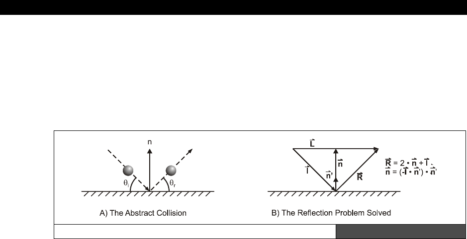
III Game Programming on the HYDRA
Page 750 Game Programming for the Propeller Powered HYDRA
To solve this problem we have to look macroscopically at one of the collisions at any
orientation. The ball comes in at the angle of incidence θI and reflects at the angle of
reflectance θr. Now, the interesting thing is that θI = θr relative to the
“normal”
of the
surface (which is the perpendicular). Thus, if we turn the problem into a general vector
problem and represent the trajectory of the ball as a vector and the plane of the surface as a
vector (flat on the screen in 2D), then we should be able to do some vector math to compute
the final trajectory for a ball hitting a surface on any orientation.
The Vector Reflection Problem Illustrated Figure 23:41
Figure 23:41 shows the setup for the solution of the problem at hand. Given that the ball is
traveling along the vector i and the normal to the surface is n and n' (unit vector) and we
want to find r, then a little vector algebra gives us the following results:
n = (-I · n')*n'
That is, the vector n in the diagram is equal to -i dot n' times n', then
r = 2*n + i
Let’s try this result for the X-axis. If we want to collide with the X-axis, then the normal to
the X-axis is the Y-axis, which means n'=<0,1>, and let’s say that our incidence or
trajectory vector i=<4,-2>, that is, moving right and down on a normal Cartesian coordinate
system. Common sense tells us that the trajectory vector’s Y-component would be inverted in
the collision resulting in <4,2>, let’s see what the math says:
The resulting reflectance vector r is:
r = 2*n + i
= 2*(-I . n')* n' + i
= -2*(<4,-2> . <0,1>) * <0,1> + <4,-2>
= -2*(4*0 + -2*1) * <0,1> + <4,-2>
= 4*<0,1> + <4,-2>
= <4,2>
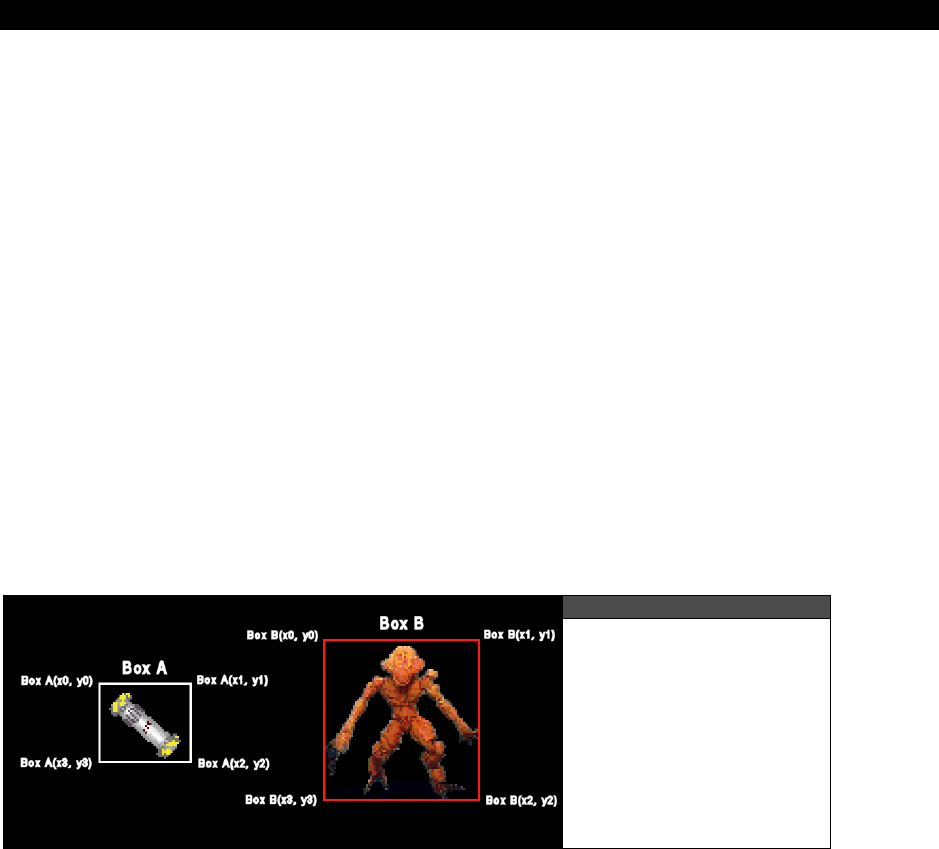
AI, Physics Modeling and Collision Detection 23
Game Programming for the Propeller Powered HYDRA Page 751
Therefore, you can use this construction when you want to collide a point mass with any
irregularly-shaped object. Of course, when balls hit balls the collision response is much more
complex, you have to take into consideration the mass of each ball, the trajectory and so
forth. This is beyond the scope of this book, but for most purposes in a video game when
two objects collide A and B you can momentarily represent object A by a bounding rectangle
with flat sides (or a multisided object), then represent object B as a single point, then
perform the collision calculation to find the response of A, then redo the problem with A and
B swapped to find the response of B. Furthermore, you can use the mass of A and B (virtual
mass) to adjust how much the trajectory of each will change. The object with larger mass
and larger momentum will not change trajectory as much as the object with smaller mass
and smaller momentum.
23.11.2 Rectangle/Bounding Box Collision Determination
If you play a lot of games, I am sure you have been blown up countless times by a missile
that didn’t hit you. Similarly, I am sure you have fired at something, hit it visually, but
missed. How can these things happen? Well, the problem with collision detection in games is
that true
pixel
accurate
collision detection is too costly computationally on small systems.
To perform pixel accurate collision detection with bitmap objects you would literally have to
logically AND the bitmaps together row by row and test if there was any overlap, this a huge
amount of computation. Thus, faster methods are usually employed such as bounding box
collision detection.
Figure 23:42
Bounding Box Collision
Detection
Referring to Figure 23:42, two game objects are shown with bounding boxes drawn around
them. Although the game objects themselves might have a lot of detail, the bounding boxes
are rough estimates of the area covered by each object. To test for collision the bounding
boxes themselves are tested for overlap. This is an easy operation and can be carried out in
a number of ways. For example, one method is to test each point from box A to see if it’s
within box B. This test might look like:
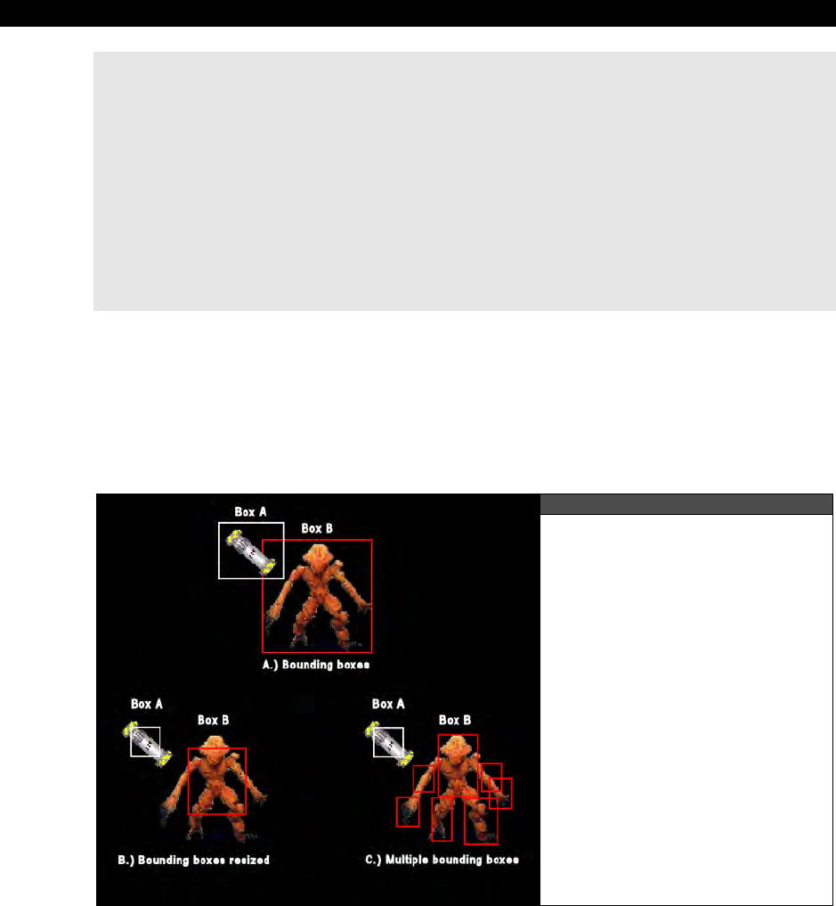
III Game Programming on the HYDRA
Page 752 Game Programming for the Propeller Powered HYDRA
long boxA_x[4], boxA_y[4] ' holds x,y coords of box A in clockwise order
long boxB_x[4], boxB_y[4] ' holds x,y coords of box B in clockwise order
' iterate through each vertex in box A and test if its within box B
repeat index from 0 to 3
' extract next vertex
test_x := boxA_x[index]
test_y := boxB_y[index]
' test if point (test_x, test_y) is within boxB
if (test_x > boxB_x[0] and test_x < boxB_x[1])
if (test_y > boxB_y[0] and test_y < boxB_x[2])
' collision detected process and quit…
quit
Of course there are numerous ways to optimize this, for example, if the bounding boxes are
represented by the upper left hand corner along with a width and a height then we can
subtract the positions of the bounding boxes to come up with a dx and dy. If dx and dy are
both less that the sum of the width and the height of each bounding box then the bounding
boxes must be overlapping. The important thing is to find a representation that is efficient
and fast for testing.
Figure 23:43
Worst-Case Scenario
Bounding Box Test
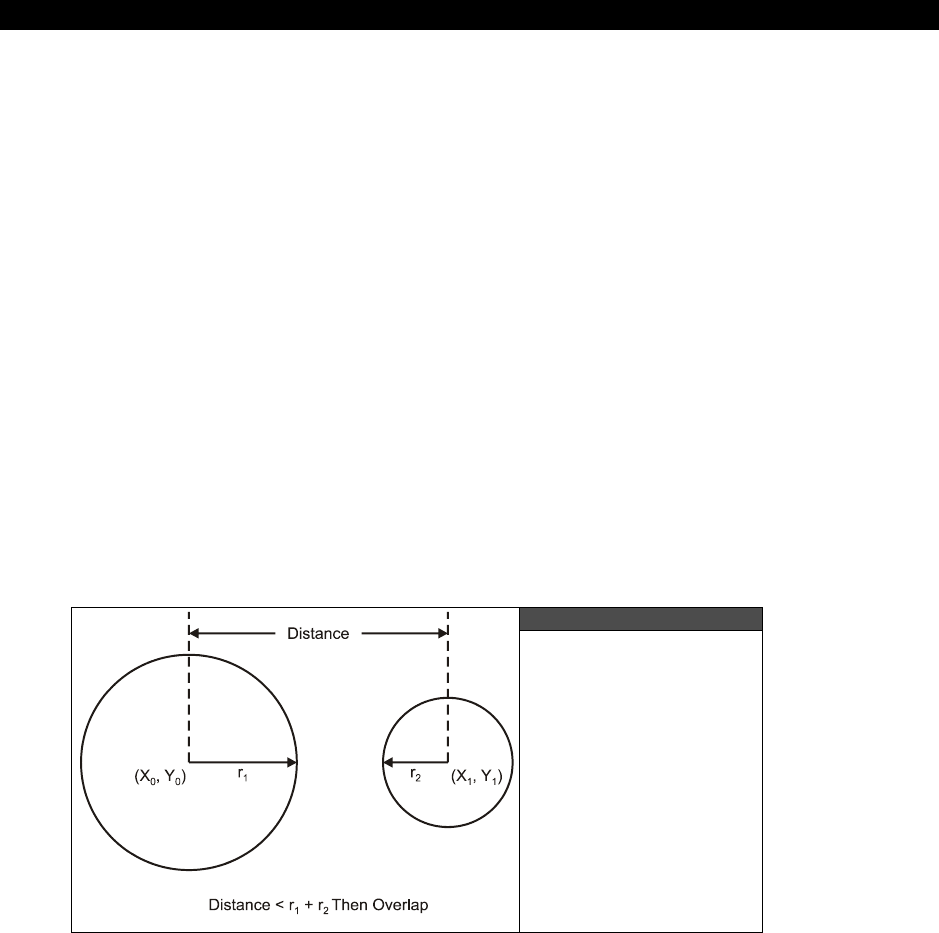
AI, Physics Modeling and Collision Detection 23
Game Programming for the Propeller Powered HYDRA Page 753
Lastly, the obvious problem with bounding boxes is that they will indicate a collision when
there is none. For example, Figure 23:43 shows a worst-case scenario using bounding box
collision detection. Referring to the Figure 23:43(A), object A is a small plasma bomb where
its bounding box is a good representation of object since the bomb spins around constantly;
however, the bounding box around the monster contains a lot of area that is not part of the
object. And as you can see the plasma bomb can be within the bounding box of object B and
not hitting it! This is definitely bad. Once solution is to artificially make the bounding box
smaller and concentrate on the centroid of the object as shown in Figure 23:43(B). This
solution is ok, but then collisions might not registered on the extremities like the arms, legs
and head. Yet another solution is to use multiple bounding boxes as shown in Figure
23:43(C). Here the most important parts of the monster have collision surfaces, so
everything can be hit. Moreover, the second advantage of this setup is that if the head, or
body etc. are hit it can be detected, so more accurate damage reporting can be done! The
dowe side of course is the computation needed for the added boxes.
As an aside, another possible solution is to first perform a gross bounding box collision test
as in Figure 23:43(A), which may or may not mean a true collision. Then if there is a
potential collision, that is, the bounding boxes have at least overlapped, then a pixel accurate
bitmap mask (or polygon mesh collision test) can be performed which is much more time
consuming, but doesn’t occur all the time, so it’s a trade off for accuracy.
23.11.3 Circle Collision Determination
Figure 23:44
Circle Collision Tests
Another collision surface that can be used other than the bounding box is a
bounding
circle
. The idea is the exact same, but the idea is that the object being tested has more of a
circular geometry, thus the circle is a better collision surface to represent the collidable

III Game Programming on the HYDRA
Page 754 Game Programming for the Propeller Powered HYDRA
region. Figure 23:44 shows the setup, and of course the circles are only imaginary. The
collision test simply performs the following operation:
' compute distance from center of each circle
dx := (x1-x0)
dy := (y1-y0)
dist := ^^(dx*dx + dy*dy) ' note in Spin “^^” is the square root operator
' test dist against radii
if (dist < (r1+r2))
' collision!
else
' no collision
The square root operation is computationally very expensive, but there is a trick
to get rid of it. Instead of computing the distance between two objects, one can
always compute the square of the distance. That is, leave out the square root
operation and if you wanted to test the distance less than say 100, instead you
square the 100 (which is a constant usually or a simple multiply) and then test
again 100*100 = 10,000 instead. The code in the block below shows this.
' fast collision test using squared distances
dx := (x1-x0)
dy := (y1-y0)
r12 := r1+r2
dist := (dx*dx + dy*dy) ' this is the distance squared
' test dist^2 against radii sum ^ 2
if (dist < (r12*r12))
' collision!
else
' no collision
23.11.4 Tile Space Collision Detection
When developing games that mix tile, pixel, and sprite graphics, simple collision tests
become difficult since you have to deal with multiple geometrical representations. For
example, the tile engine demos that we have been working with represent the screen as a
matrix of tiles; 10×12, 16×16, or whatever, where each tile is usually 8×8 or 16×16 in most
cases. The problem is how to integrate sprite graphics and tile graphics collisions when you
have both systems on the screen at once. A common example is the top-down adventure
game as shown in Figure 23:45.
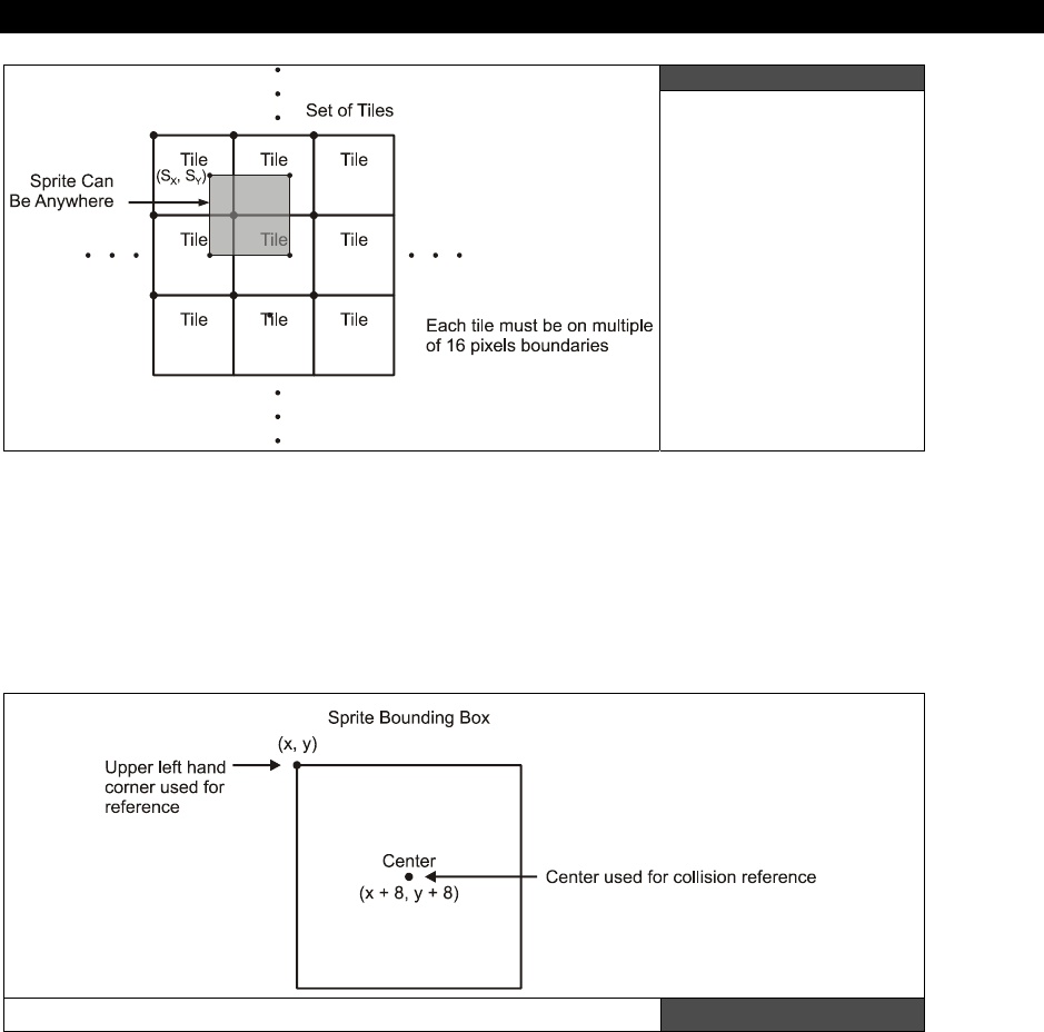
AI, Physics Modeling and Collision Detection 23
Game Programming for the Propeller Powered HYDRA Page 755
Figure 23:45
Setup for Tile Space
Collision Detection
Here, the screen is represented by 16×16 tiles, but the player and game objects might all be
sprites and thus can be drawn anywhere. So the question is how to perform collision
detection between the sprites and the tile world? The solution is very simple; first you have
to decide on the center of the sprite representation, that is, do you want to use the center of
the sprite or the top-left corner or the bottom-right corner etc. as the collision detection
point? This is shown in Figure 23:46.
Selecting Collision Detection Points for a Sprite Figure 23:46
In many cases, the best approach will be to use the 4 points of the bounding box of the
sprite, but for a quick example, let’s use the center of the sprite as the collision point. With
this setup the sprite is 16×16 pixels, the tiles are 16×12 (16×16 each), and the coordinate
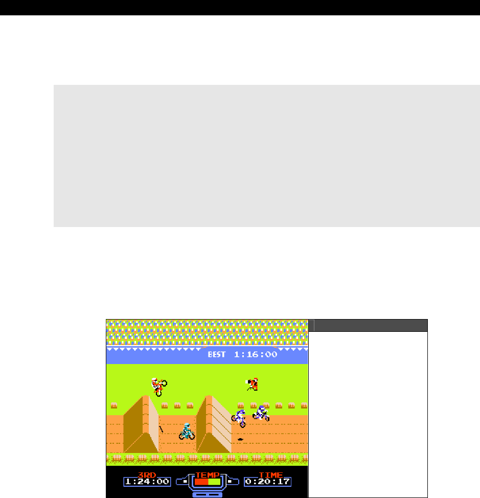
III Game Programming on the HYDRA
Page 756 Game Programming for the Propeller Powered HYDRA
system is (0,0) at the top left corner for the tile space and (16,16) for the top left corner for
the sprite space (if we are talking about the HEL tile engine, other tile engines would be
similar). The problem to solve is to determine where the center of the sprite is in tile space.
Here’s the math:
long sprite_x, sprite_y ' the upper left hand corner of the sprite
word tile_map[16*12] ' tile map memory in format where each WORD entry = b15
[palette index | tile index] b0
' compute tile coordinates that sprite is sitting on
tile_x := (sprite_x – 16) / 16
tile_y := (sprite_y – 16) / 16
' extract tile index that sprite is sitting on
tile_index := tile_map[tile_x + tile_y*16] ' 16 columns per row, but only 10 are
' visible currently (leaves scrolling room)
' perform collision tests with this tile index…
With this technique all kinds of cool tricks can be used. For example, you can draw 10
different “road” tiles with different inclinations, then you can test what tile the sprite is on
and adjust its trajectory based on the virtual angle of the bitmap that represents the tile. This
is how
“terrain following”
can be accomplished in tile games. The NES game
“ExciteBike”
shown in Figure 23:47 uses this very technique to follow the road.
Figure 23:47
ExciteBike in Action

AI, Physics Modeling and Collision Detection 23
Game Programming for the Propeller Powered HYDRA Page 757
23.11.5 Divide and Conquer Techniques for Collision Determination
When you start writing collision detection algorithms for your games, the first problem is
simply testing two objects to see if they collide. However, once that problem is solved you
quickly realize that if you have 100 alien ships and the player, and alien ships can each fire
100 bullets, then potentially you have to compute 300 object-to-object collision tests! This is
a really big number, in fact it’s “300 choose 2” which is 44850! This is totally unacceptable.
Moreover, even if we decreased the number of aliens and bullets the number of tests is still
large. For example, let’s say there are 10 aliens, the player, and only 10 bullets that can be in
flight. Moreover, we are only going to test bullets against the player and aliens, and aliens
against player, but not bullets against bullets. This computation still has the following number
of tests:
Alien/Player collision tests: 10*1 = 10
Alien/Bullet collision tests: 10*10 = 100
Player/Bullet collision tests: 10*1 = 10
Total = 120
And if each test takes 100-1000 assembly language instructions (depending if you are
programming directly in ASM or Spin) then this is a huge number of cycles. Luckily, there is a
way out of this seemingly impossible situation and that is based on the concept of “
spatial
partitioning.”
The idea behind spatial partitioning is that you break the space of the world
and position of objects into cells or cubes (in 3D) and then only the objects that fall within
each cell can potentially collide and thus need to be tested! This can reduce the collisions
down to nearly nothing.
Figure 23:48
Spatial Partitioning
of Objects Illustrated
Figure 23:48 shows an abstract representation of a the spatial partitioning problem. In on
the left of Figure 23:48 we see a number of white dots representing objects we want to test
for collision. Assuming every single object must be tested against every other, this would be
a lot of tests. However, now take a look on the right of Figure 23:48. In this case, we have

III Game Programming on the HYDRA
Page 758 Game Programming for the Propeller Powered HYDRA
partitioned the 2D space into regular cells where each cell contains a specific set of objects.
Only objects in each cell can potentially collide with each, thus the tests are reduced to the
maximum number of objects per cell. The algorithm can be stated as follows:
Step 1: For every object in the collision list partition it into a cell size m×n, this is done
simply by dividing the coordinates of each objects by m,n and using the results as the cell
index. Insert the object index or pointer into the cell’s container.
Step 2: For every cell in the partition, test all objects against each other for collision.
The algorithm is very straightforward, and very fast. You can tune it by performing some
experimentation to find the optimal cell size to organize the objects into. And of course if the
cell size becomes the size of the game world then you have the original problem and all
objects must be tested against each other. Now, before moving on, there is something I
want to bring your attention to and that’s Step 2 of the algorithm. In this step, for every cell
in the spatial partition we test all the objects against each other. However, there is no reason
why we can’t further divide individual cells up even more in a recursive manner. This addition
to the algorithm is referred to as the
“quadtree algorithm”
and the 3D version is
“octree.”
In any case, the advantage further partitioning has is that if there are too many
objects in any one cell you further divide the cell up more to reduce the objects that must be
tested against each other for collision to a manageable number.
23.12 Summary
AI and physics are one of my personal favorite subjects in Computer Science. They are
literally the key to the universe. If you can model AI and physics with near-reality precision
then you can not only create machines that can think, but potentially virtual simulations that
are near reality ala
“The Matrix.”
The possibilities are endless! Hopefully, this chapter has
given you some basic ideas of just how simple AI can be, and more importantly, it’s not a
“single solution”
science, but more of an organic science where you layer and apply the
techniques you need in your game, thus creating
“brains”
for you game characters that
exhibit all the behaviors your need. For interested readers, I suggest reading
“The Age of
Spiritual Machines”
by
Ray Kurzweil
. It’s an exposition on a number of possiblities
relating to AI, computing, nanotechnology, and other cutting edge technologies that within
the next 20-30 years are going to change everything about the human race, so check it out!

Graphics Engine Development on the HYDRA 24
Game Programming for the Propeller Powered HYDRA Page 759
Chapter 24:
Graphics Engine
Development on
the HYDRA
In this chapter we are going to discuss the inner workings of the HEL tile and sprite engine
that we have been using in the demos throughout the book. The HEL engine is a very
complex, high-performance assembly language program and to explain every bit of it would
take a couple hundred pages of text. Alas, what I am going to try to do is discuss
architectural decisions, overall design, and important techniques used within the engine.
Along with these discussions we will look at fragments of the code, but readers are urged to
review the source itself which is heavily commented and located in the source file
HEL_GFX_ENGINE_040.SPIN. Hopefully this chapter gives you an idea of the thought
process that went into the engine, so you can take it to the next level. Here’s what’s in store:
Design goals of the HEL engine
Engine Architecture overview
Engine code analysis and deconstruction
Advanced engine design concepts
24.1 Design Goals of the HEL Engine
The HEL engine was designed to be the simplest possible graphics engine that could be
written on the Propeller and that could support both tiles and sprites. Moreover, I wanted to
fit it into a single cog and support a
memory mapped
interface rather than a complex API.
Thus, the HEL engine looks like a piece of virtual hardware to the programmer rather than a
software API coupled with some hardware.
These constraints meant that a lot of tricks and clever organization of data had to be used to
make things work with the confines of a single cog, but some concessions had to be made.
First, due to the complex scanline setup calculations, this version of the engine uses an
unusually long Hsync pulse. This works fine on CRT-based displays, but on modern LCD and
plasma displays, the display might have a hard time syncing to the engine’s timing.
Nonetheless, I have tested the engine on 50 or so CRTs from different manufacturers and it
works fine. Additionally, I have found that if you are willing to sacrifice some of the sprite
processing, you can adjust the timing parameters at the header of the code and the engine
will work fine on LCDs and plasmas as well.
Next, using a single cog and doing both tiles and sprites means that a lot of computation has
to be done each scanline and pixel this means that its nearly impossible to support
high
III Game Programming on the HYDRA
Page 760 Game Programming for the Propeller Powered HYDRA
color
modes
per pixel. That is, it’s possible to support all 86 colors or 256 different pixel
values per pixel (as you will see in the advanced demos next chapter). But, to accomplish
this takes at least 2 cogs and most of the time 3 or 4 to get the job done right. And since I
wanted to stick with a single cog, the HEL engine supports only 4 colors per tile.
Nonetheless, each tile
does
support its own palette of any 4 colors. Furthermore, the sprites
must use the palettes of the tiles they overlap.
At the end of the day, the HEL engine is short, fast, runs on virtually every CRT-based TV
and is a great starting point for you to make your own engines. It supports tiles, sprites,
paging, and scrolling. Those features pretty much sum it up for most circa 80’s hardware
which means anything you see on your Atari 800, Commodore 64, or Apple II you should be
able to pull off with the HEL engine with a little work! On the other hand, it’s really easy to
modify the engine for higher resolution, more or less sprites, and different tile sizes.
The HEL engine is 100% assembly language, so readers not familiar with ASM
will have a tough time following the code, but the explanations should give you
an idea of what’s going on theoretically, so you can follow along. Not to mention,
the code is heavily commented.
24.2 Engine Architecture Overview
The HEL engine is a good example of a
“memory mapped”
I/O device. In other words,
there are no API calls, you simply change memory locations and pointers in global memory
and the engine reacts to it and draws what you tell it to. This is the best setup since you can
always write an API on top of it. With that in mind, let’s look at the overall architecture of the
engine in relationship to the client cog (running your game), main memory, and the driver
cog (that the engine runs on). Since we already covered the use of the engine in Chapter 19
(which you should review), our discussion here is going to focus on more the internals of the
engine rather than using the engine. However, let’s review the different pieces of the engine
before we get started. Take a look at Figure 24:1 for the discussion that follows.
The HEL engine is composed of the following components/assets:
Parameter passing area
Tile map
Palette map
Tile bitmaps
Sprite records
Sprite bitmaps
Sprite masks
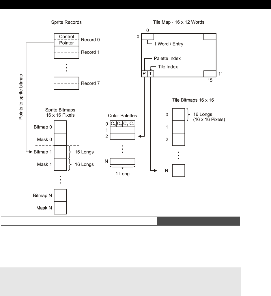
Graphics Engine Development on the HYDRA 24
Game Programming for the Propeller Powered HYDRA Page 761
The HEL Engine Architecture Figure 24:1
The
parameter passing area
is the interface to the outside world. This is where the HEL
engine gets its information to do what it does. The parameter passing area is defined in main
memory and is composed on the following 6 variables in the following order (from the engine
code itself):
long tile_map_base_ptr_parm ' parm 0: ptr to tile map (16x12 array, row major, 2-bytes per entry)
long tile_bitmaps_base_ptr_parm ' parm 1: ptr to the base of the bitmap data, each 16x16
long tile_palettes_base_ptr_parm ' parm 2: ptr to the base of the palettes array, each palette 1 long
long tile_map_sprite_cntrl_parm ' parm 3: ptr to various control values for the tile map/sprite engine
long tile_sprite_tbl_base_ptr_parm ' parm 4: ptr to the base of the "sprite table"
long tile_status_bits_parm ' parm 5: ptr to status word - vsync, hsync, etc.
III Game Programming on the HYDRA
Page 762 Game Programming for the Propeller Powered HYDRA
The base of the table is passed to the HEL engine on startup and the PAR assembly register
is used to index into the values.
The
tile map
is the 16×12 array of tiles that the engine renders each frame. Each tile is 2
BYTEs and consists of a palette index and a tile index into the tile bitmaps themselves. The
tile map itself is in row-major form and can actually be 16, 32, 64, 128, or 256 tiles wide to
support horizontal course scrolling. Only 10 tiles are visible each scanline to keep color
aliasing down to a minimum (since there are only 160 true color clocks per line for active
video).
The
palette map
is an array of 1 to 256 LONG palette entries that each represent a set of 4
colors. These are indexed by the tile palette indices in each tile entry.
The
tile bitmaps
are the bitmaps that are drawn for each tile. They are 16×16 pixels
represented by 16 LONGs and horizontally mirrored to make access of the tile engine faster.
The
sprite records
are an array of 8 entries that define each sprite, one record per sprite.
The engine refers to these records for the position of each sprite as well as the pointer to the
sprite bitmap data itself.
The
sprite bitmaps
are 16×16 pixel bitmaps that represent each sprite. Similar to tiles, they
are 16 LONGs each flipped horizontally. Additionally, each sprite bitmap has a
sprite mask
that goes along with it to help render the sprite faster.
The operation of the engine is straightforward: you set up the parameters passing area, start
the tile engine and then the tile engine starts processing the data. Each frame, the
parameters are read from main memory which instructs the engine where to get all the
assets. Let’s begin by reviewing the engine’s operation at the level of information flow then
we will drill down and look at the code elements section by section.
For all the discussions that follow, you might want to keep track in the source
with the Propeller Tool. Line numbers help to do this. To toggle line numbers
press <CTRL+N> in the Propeller Tool.
24.2.1 HEL Engine Frame Processing
Referring to Figure 24:1, the engine begins by caching the main memory sprite records into a
local cog memory
sprite
cache
. It does this regardless if sprites are in the scene or enabled.
This step is necessary since anything inside the inner loops of the engine we want to cache in
local cog memory (if possible), so we don’t have to go to main memory. Once the sprite
records are cached the frame begins and the blank scanlines are rendered which isn’t very
interesting; however, during this time one could perform many calculations since there is a

Graphics Engine Development on the HYDRA 24
Game Programming for the Propeller Powered HYDRA Page 763
lot of dead time. The frame processing then begins in earnest and is composed of two major
components:
Sprite processing
Tile processing and rendering
24.2.1.1 Sprite Processing
The sprite processing is the most complex of the two phases and where all the performance
and cycles are needed. The problem simply put is that we have up to 8 sprites that need to
be rendered on the current scanline. This is where things get complicated. The problem with
sprites is that they are supposed to be magical, that is, you position them and they simply
show up on the screen at the proper location without disturbing anything under them. This is
quite challenging to code. The problem is that the sprites ultimately have to be drawn on top
of the tile maps, moreover, sprites can overlap with each other, so all these issues have to be
considered. The solution is to create what’s commonly known as a
“scanline buffer”
to
perform the processing. A scanline buffer is really a 1-dimensional bitmap that represents a
single scanline on the screen. Thus, if we perform our rendering algorithms a scanline at a
time, we can think of the screen as a collection of scanlines. And if we can solve the
rendering problem for a single scanline, then we simply loop to draw the screen. The HEL
engine uses this approach.
Sprite Scanline Buffers Figure 24:2
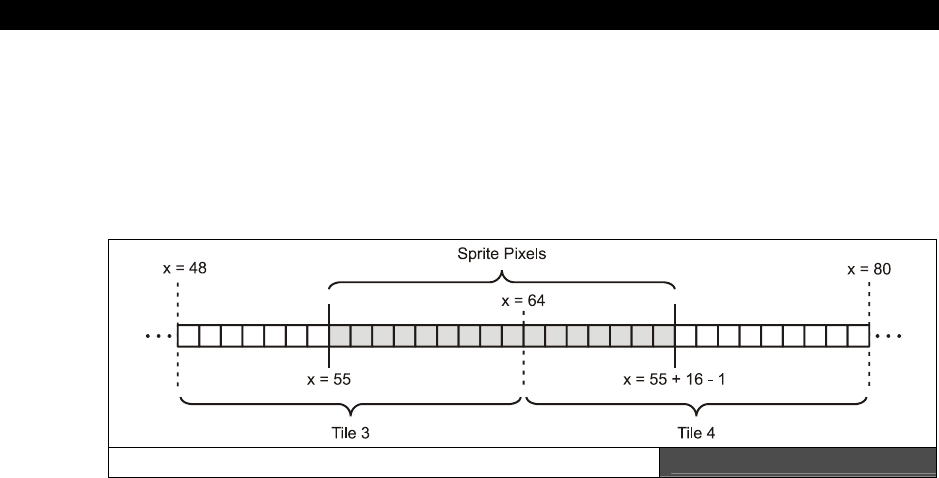
III Game Programming on the HYDRA
Page 764 Game Programming for the Propeller Powered HYDRA
The sprite processing algorithm begins by setting aside two scanline buffers: one to hold the
actual bitmap data for the sprite on that scanline and another buffer which is used as a
mask
or
stencil
for the sprite scanline, these buffers are shown in Figure 24:2. Once the
buffers are initialized the sprite list is looped through. For any sprite in the list from 0..n that
is on the current scanline, that sprite is processed, sprites that are not intersected by the
scanline are discarded.
Sprite Positioning on a Scanline Figure 24:3
The sprite processing begins by locating where the sprite is in tile space, that is, the sprite
bitmap data must ultimately be rendered with the tile data, so the sprite location has to be
ascertained relative to a 16 tile (or 32, 64, 128, 256) wide screen. So say the sprite was at
x=55 (y is irrelevant), then 55/16 = 3 with a remainder of 7. This means that the sprite is
located on tiles 3 and 4 (0 based) straddling them by 7 pixels. This is shown in Figure 24:3.
Thus, the trick is to read the sprite bitmap and write half of it on tile 2 and the other half of it
on tile 3. This is accomplished by first taking the sprite bitmap’s 32-bit pixel definition for the
16-pixel line and performing a 64-bit shift to position it. The two LONGs that make up the
results can be written into the scanline buffer at position 3,4. Then we would have the sprite
data buffered in the correct position. But, not so fast! The problem is that when we process
the next sprite, what happens if it ends up overlapping the current sprite? We can’t just OR
the color data, we can’t AND it, we can’t XOR it. All of those operations would manipulate the
color index bits since they are 2-bit pairs. What we need to do is cut a
“hole”
out of the
sprite scanline buffer first, then OR the sprite bitmap data into it. This is what the scanline
mask buffer is for, shown in Figure 24:2.
The scanline mask buffer accumulates the total mask that indicates where sprite data is on a
scanline. This is where the sprite bitmap masks come into play. As the sprite is being
processed, not only is the bitmap data being shifted but the mask data for the particular line
is as well. Then before the sprite bitmap is written to the scanline buffer, the sprite mask is
used to cut a hole in the scanline buffer for the sprite bitmap data itself, and the mask is
OR’ed with the scanline buffer mask. This way the sprite can be written into the scanline
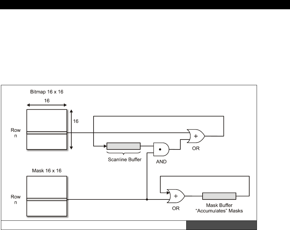
Graphics Engine Development on the HYDRA 24
Game Programming for the Propeller Powered HYDRA Page 765
bitmap buffer with a final OR operation and the scanline buffer mask becomes an
accumulation of all sprite masks.
This process continues until all the sprites have been processed. The results are a single
scanline that represents the sprite data for the scanline. Additionally, there is the scanline
mask buffer that can be used as an AND mask to clear out the target tile bitmap data to
make the hole for the sprite scanline data to be OR’ed in. Figure 24:4 shows the sprite
processing of bitmaps and masks as a flowchart.
The Sprite Bitmap/Mask Processing Flow Chart Figure 24:4
24.2.1.2 Tile Processing
The tile processing part of the engine is the easy part. To render the tiles, more or less the
algorithm is as follows:
For the current scanline compute the tile row.
For the current tile row access the tile indices for each tile as well as palettes.
For each tile, draw 16 pixels of tile and loop until tile row is complete.
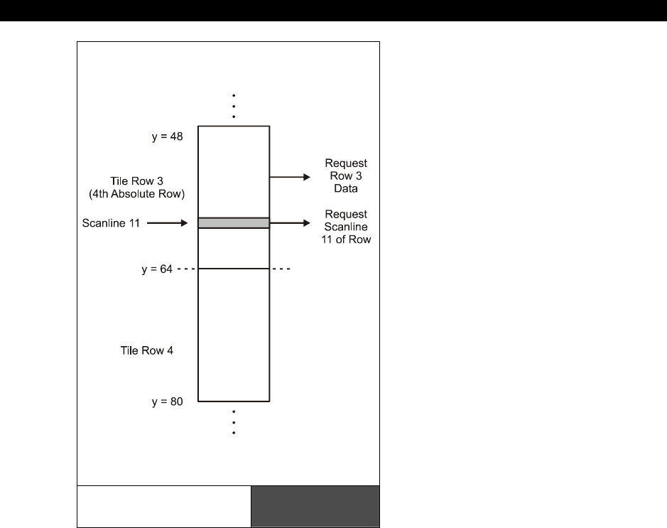
III Game Programming on the HYDRA
Page 766 Game Programming for the Propeller Powered HYDRA
So the tile processing more or less works
scanline by scanline just like the sprite
engine. Thus we can resolve the problem
into solving single scanlines once again.
For example, let’s say that the next
scanline to be drawn is 59 and we are
starting at the left edge of the screen.
First we need to compute the tile row
which is 59/16 = 3 (4th absolute row)
with a remainder of 11. Thus, we need to
access the 4th row in the tile map, and
the 11th scanline of that row. This is
shown in Figure 24:5. The first step is to
retrieve the actual bitmap data and
palette data for the tile. Thus, we use the
tile row to access the tile map along and
retrieve the tile palette and bitmap
indices which are then used to retrieve
the palette for the tile and to locate the
actual bitmap for the tile. The bitmap for
the tile is found by multiplying the tile
index by 64 BYTEs (since there are 64
BYTEs per tile bitmap) and adding this
value to the base memory of the tile
bitmaps themselves. Then the last step is
to grab the 11th row of the tile bitmap
data. At this point, we have the palette
entry and the pixel data to render the 16-
pixel span.
If there were no sprites, then the 16-pixel span could be rendered by setting up the pixels
and colors and passing them to the
waitvid
instruction, then moving to the next tile on the
X-axis and repeating the process until the entire scanline was processed. However, the
sprites add a whole other dimension of pain. We need to overlay the sprites onto the tile
bitmap data; this is where the sprite scanline buffer and scanline mask come into play. For
every tile row we render from left to right on the screen we simply need to merge the sprite
data into each row of 16 pixels. Referring to Figure 24:6, the merging process begins with
retrieving the mask from the scanline buffer mask and logically ANDing it with the tile pixels.
This creates the hole for the sprite data itself. Once the hole is created, the scanline buffer is
accessed and the actual sprite bits are retrieved and logically OR’ed into the tile bits and
Locating the Tile
Bitmap and Scanline Figure 24:5
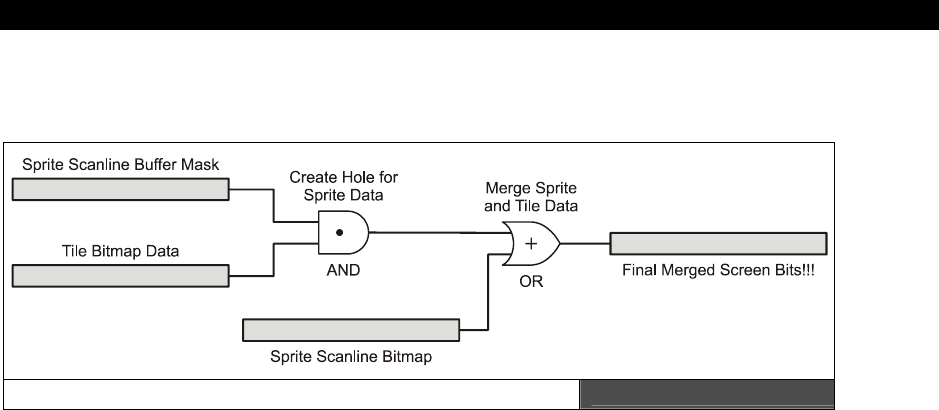
Graphics Engine Development on the HYDRA 24
Game Programming for the Propeller Powered HYDRA Page 767
finally the data is written to the screen. The results are exactly what is desired: tiles in the
background, sprites in the foreground without any color distortion.
The Final Sprite and Tile Merging Process Figure 24:6
Summing up, the process of rendering both sprites and tiles is rather complex in a single cog.
However, by judicious use of caching and accessing the main memory efficiently, it
is
possible. The only downside is that the engine uses an extended horizontal sync pulse which
may be incompatible with some LCD/plasma sets, but on CRT based monitors you should
have no problem. With all that in mind, let’s briefly review some of the code itself.
24.3 Engine Code Analysis and Deconstruction
In this section we are going to more or less review each important section of the code, list
code fragments, and discuss important parts of the ASM code itself. This won’t be a complete
listing since the code is over 1000 lines long (including comments). Therefore, please make
sure to review the complete code for the HEL engine HEL_GFX_ENGINE_040.SPIN
located on the CD in the \SOURCES directory. I am going to leave simple things out like
the blanking lines and vertical sync in the deconstruction. Also, in the listings to save space I
am going to remove 20-30% of the vertical comments, so once again the full annotated
listing is on the CD.
24.3.1 Setup
The first thing that happens when the HEL engine starts up is that it must set up the VSU
with the proper counter modes and settings. This is performed on entry into the driver based
on the constants in the driver’s CON section. Here’s the code listing that sets up the timing
chain:

III Game Programming on the HYDRA
Page 768 Game Programming for the Propeller Powered HYDRA
HEL_GFX_Driver_Entry
' VCFG: setup Video Configuration register and 3-bit TV DAC pins to outputs
movs vcfg, #VIDEO_PINMASK ' vcfg S = pinmask (pin31 ->0000_0111<-pin24), only want lower 3-bits
movd vcfg, #VIDEO_PINGROUP ' vcfg D = pingroup (HYDRA uses group 3, pins 24-31)
movi vcfg, #VIDEO_SETUP ' vcfg I = controls overall setting, want baseband video on bottom nib
' 2-bit color, enable chroma on broadcast & baseband
or dira, tvport_mask ' set DAC pins to output 24, 25, 26
' CTRA: setup Frequency to Drive Video
movi ctra, #VIDEO_CNTR_SETUP ' pll internal routed to Video, PHSx+=FRQx (mode 1) + pll(16x)
' needn't set D,S fields since they set pin A/B I/Os, but mode 1 is
' internal, thus irrelvant
' compute the value to place in FREQ, so final counter is NTSC and PLL output is 16*NTSC
mov r1, v_freq ' r1 <- TV color burst frequency in Hz, eg. 3_579_545
rdlong r2, #CLKFREQ_REG ' r2 <- CLKFREQ is register 0, eg. 80_000_000
call #Dividefract ' perform r3 = 2^32 * r1 / r2
mov frqa, r3 ' set freq for counter, so bit 31 is toggling at rate of
' color burst (2x actually)
mov r0, par ' copy boot parm value and read in parms from main memory
add r0, #20 ' status bit is 5 longs out or 20 bytes
mov tile_status_bits_ptr, r0 ' ptr to status bits, so tile engine can pass out status
24.3.2 Starting the Next Frame and Retrieving the Parameters
Once the timing chain is set up, the engine immediately begins drawing the next frame of
video. To do this, the engine needs to retrieve the pointers to all the assets such as the tile
map, the bitmaps, sprites, palettes, and sprite records. This is done in real-time each frame.
Thus, the engine updates everything at 60 fps always. Below is the listing showing the
beginning of the frame and the retrieval on the parameters from main memory:
Next_Frame ' start of new frame of 262 scanlines
' read run-time parameters from main memory, user can change these values every frame
mov r0, par ' copy boot parm value and read in parms from main memory
rdlong tile_map_base_ptr, r0 ' base ptr to tile map itself
add r0, #4
rdlong tile_bitmaps_base_ptr, r0 ' base pointer to array of 16x16 bitmaps, each 64 bytes
add r0, #4
rdlong tile_palettes_base_ptr, r0 ' base pointer to array of palettes, each 4 bytes/1 long
add r0, #4
rdlong tile_map_sprite_cntrl, r0 ' read tile map/sprite engine control word, format xx_xx_ss_ww
' copy control words into width and number of sprites
mov tile_map_width, tile_map_sprite_cntrl
mov tile_num_sprites, tile_map_sprite_cntrl
and tile_map_width, #$FF ' map width encoded in byte 0 (lowest byte), $xx_xx_ss_WW
shr tile_num_sprites, #$08 ' number of active sprites to render encoded in byte 1
' (2nd from right most low byte), $xx_xx_SS_ww
add r0, #4
rdlong tile_sprite_tbl_base_ptr, r0 ' base pointer to sprite table

Graphics Engine Development on the HYDRA 24
Game Programming for the Propeller Powered HYDRA Page 769
24.3.3 Caching the Sprite Records
When writing graphics engines and algorithms, the more data you can cache in local fast
memory the better! Thus, as an example of this technique, the HEL engine caches the sprite
records so they don’t have to be accessed from memory to be interrogated. Actually, much
more data could have been cached locally, for example a few sprites, or tiles, or palettes.
But, although that would have sped the engine up considerably, it would have limited the
amount of graphics. However, a demand page caching system that scanned the sprites and
tiles needed each frame could potentially cache them during the vertical blank for the next
frame, as long as the cache wasn’t overflowed. In any case, the HEL engine only caches the
sprite records themselves which is a good starting point. Here’s the code:
' read the sprite table into the local cog memory sprite table cache
mov r1, tile_sprite_tbl_base_ptr ' r1 = tile_sprite_tbl_base_ptr, byte ptr, main memory
mov r2, #sprite_table_cache ' r2 = @sprite_table_cache, long ptr, cog memory
mov r3, #16 ' 16 Longs to copy from main memory to cog memory to fill
' the sprite table cache, 8 sprites, each sprite 2 longs
Sprite_Table_Cache_Loop
movd Write_Cache, r2 ' overwrite destination on rdlong instruction
nop ' wait for pre-fetch, so we don't execute
' self modifying code too quickly
Write_Cache rdlong 0, r1 ' *r2 = *r1
add r1, #4 ' r1+=4, move to next LONG, byte addressing in main memory
add r2, #1 ' r2++, move to next LONG, long addressing in cog memory
djnz r3, #Sprite_Table_Cache_Loop ' if (--r3 > 0) then loop
24.3.4 Sprite Processing
The next part of the code is where all the action happens and the sprites are processed. The
code is rather complex, has a lot of self-modifying going on, and all kinds of tricks, so take
your time reviewing it. The code more or less begins by testing if a sprite is on the current
scanline and if the sprite is enabled. If both statements are true, then the sprite is processed
beginning with locating the sprite in tile space, then shifting the sprite and mask into
position, and finally writing out the sprite data and mask data to the scanline buffers. Here’s
the code (full annotation is on the CD source file as usual):
mov r2, tile_num_sprites ' the more sprites to process, the more time it takes to render
test r2, #$FF wz
if_z jmp #Tile_Map_Processor
mov r3, #sprite_table_cache ' r3 = @sprite_table_cache, local cog memory
' clear scanline buffers out, no memory fill!!!!!
' first clear out 12 LONGs of scanline bitmap buffer since only 10 tiles are visible, plus 1
' extra on either side
mov sprite_scanline_bitmap+0, #0
mov sprite_scanline_bitmap+1, #0
mov sprite_scanline_bitmap+2, #0
mov sprite_scanline_bitmap+3, #0
mov sprite_scanline_bitmap+4, #0
mov sprite_scanline_bitmap+5, #0

III Game Programming on the HYDRA
Page 770 Game Programming for the Propeller Powered HYDRA
mov sprite_scanline_bitmap+6, #0
mov sprite_scanline_bitmap+7, #0
mov sprite_scanline_bitmap+8, #0
mov sprite_scanline_bitmap+9, #0
mov sprite_scanline_bitmap+10, #0
mov sprite_scanline_bitmap+11, #0
' now clear out the scanline mask buffer (Set to $FFFFFFFF)
mov sprite_scanline_mask+0, MAX_INT
mov sprite_scanline_mask+1, MAX_INT
mov sprite_scanline_mask+2, MAX_INT
mov sprite_scanline_mask+3, MAX_INT
mov sprite_scanline_mask+4, MAX_INT
mov sprite_scanline_mask+5, MAX_INT
mov sprite_scanline_mask+6, MAX_INT
mov sprite_scanline_mask+7, MAX_INT
mov sprite_scanline_mask+8, MAX_INT
mov sprite_scanline_mask+9, MAX_INT
mov sprite_scanline_mask+10, MAX_INT
mov sprite_scanline_mask+11, MAX_INT
mov r7, r1 ' copy scanline # into r7
add r7, #16 ' add 16 to support sprite clipping
' r1 holds "real" scanline, r7 holds offset scanline by 16
Sprite_Processing_Loop
' extract the nth sprite state/ptr from sprite_table_cache
movs Read_State, r3 ' r3 is pointing at sprite record's offset 0 field for nth
' sprite - the state/control word
add r3, #1 ' advance to ptr field of sprite record, plus give self modify
' time to complete
Read_State mov sprite_state, 0 ' read the sprite_state out of this sprites record
' next read the sprite pointer in prep for processing algorithm, eventhough we may pass on it
movs Read_Ptr, r3 ' r3 is pointing at sprite records offset 1 field for nth sprite -
' the bitmap pointer
add r3, #1 ' advance to ptr field of sprite record, plus give self modify time to complete
Read_Ptr mov sprite_bitmap_ptr, 0 ' read the sprite_bitmap_ptr out of this sprite record
' now we've encoded sprite_state, sprite_x, sprite_y and r3 pointing to NEXT sprite record
' r2 is the sprite index, r1 is scanline
test sprite_state, #%00000001 wc, wz ' test enabled bit?
if_z jmp #Next_Sprite ' this sprite is disabled, ignore!
' else sprite is enabled, continue processing....
' at this point we have everything, we can start interogating...
' copy the sprite_state into x,y since they are encoded within
mov sprite_x, sprite_state ' x is encoded in 2nd byte of state
shr sprite_x, #16 ' now yx are in lower 16-bits
and sprite_x, #$FF ' mask lower byte which is x position
mov sprite_y, sprite_state ' y is encoded in 3rd byte of state
shr sprite_y, #24 ' now y is in lower 8-bits
' if sprite intersects current scanline then process it...
mov r4, sprite_y ' r4 = sprite_y
add r4, #16 ' r4 = sprite_y+16, bottom of sprite since it's 16x16 pixels
' perform bounds test

Graphics Engine Development on the HYDRA 24
Game Programming for the Propeller Powered HYDRA Page 771
Test_Sprite_Top
cmp r7, sprite_y wc, wz ' compare scanline to sprite_y, if (scanline>=sprite_y) then
' test bottom
' r7 is used tho (r1+16) to support sprite clip at top of screen
if_ae jmp #Test_Sprite_Bottom ' compare scanline to sprite_y+16
jmp #Next_Sprite ' scanline not within sprite process next sprite
Test_Sprite_Bottom
cmp r7, r4 wc, wz ' compare scanline to sprite_y+16
' r7 is used tho (r1+16) to support sprite clip at top of screen
if_ae jmp #Next_Sprite ' if (scanline >= sprite_y+16) then sprite is NOT on this
' scanline, process next sprite
' else, sprite IS on scanline, here comes the really icky part...extracting its data and mask
' first compute the sprite tile and offset
mov sprite_tile_x, sprite_x ' compute tile offset, or 16 pixel boundary
shr sprite_tile_x, #4 ' sprite_tile_x = sprite_x/16
mov sprite_offset_x, sprite_x ' compute pixel offset to shift sprite data within tile
and sprite_offset_x, #$0F ' sprite_offset_x = sprite_x mod 16
' compute the row of the sprite we need to render, that is the (current line - sprite_y), this
' would fail if we hadn't already determined
' the current scanline is intersecting the sprite at some y
mov r5, r7 ' r1 holds current scanline (r7 is used though which is
' r1+16 to support sprite clip at top of screen)
sub r5, sprite_y ' r5 = r1 - sprite_y, equals dy or intersection row from 0-15
' retrieve row of sprite from bitmap
shl r5, #2 ' r5 = (r1 - sprite_y)*4, 1 long per line, 4 bytes per long, byte
' offset from top of sprite
add r5, sprite_bitmap_ptr ' r5 = sprite_bitmap_ptr + (r1 - sprite_y)*4, ptr to long that
' holds bitmap line
' read 16 pixels / 32-bit data row of sprite from memory into local bitmap buffer
rdlong sprite_bitmap_buffer, r5 ' sprite_bitmap_buffer[0] = mm[r5] = mm[sprite_bitmap_ptr
' + (r1 - sprite_y)*4]
mov sprite_bitmap_buffer+1, #0 ' sprite_bitmap_buffer[1] = 0
' get mask from memory.... rather than construct it, it is precomputed by us, and exists 16 longs
' after the bitmap itself, or 64 bytes down
add r5, #16*4
rdlong sprite_mask_buffer, r5 ' sprite_mask_buffer[0] = mm[r5] = mm[sprite_bitmap_ptr +
' (r1 - sprite_y)*4 + 16]
mov sprite_mask_buffer+1, #0 ' sprite_mask_buffer[1] = $00000000
' now we have the sprite's 16 pixels in sprite_bitmap_buffer[0] and
' and the positive sprite mask in sprite_mask_buffer[0]
' now we need to shift these to make them pixel accurate based on offset of sprite within a tile
cmp sprite_offset_x, #0 wz, wc
if_z jmp #Sprite_No_Shift ' if (sprite_offset_x ==0 ) then jump out...
Sprite_Do_Shift
mov r6, sprite_offset_x ' we need to perform a 64-bit shift, do in two parts...
shl r6, #1 ' r6 = sprite_offset_x*2 (# of bits to shift rather than pixels)
mov r0, #32 ' again another 64-bit shift is needed
sub r0, r6 ' r0 = 32 - sprite_offset_x*2
mov sprite_bitmap_buffer+1, sprite_bitmap_buffer ' copy sprite bitmap buffer
shl sprite_bitmap_buffer, r6 ' shift 16 pixels to the left via two seperate shifts
shr sprite_bitmap_buffer+1, r0

III Game Programming on the HYDRA
Page 772 Game Programming for the Propeller Powered HYDRA
mov sprite_mask_buffer+1, sprite_mask_buffer ' copy sprite mask buffer
shl sprite_mask_buffer, r6 ' shift 16 pixels to the left via two seperate shifts
shr sprite_mask_buffer+1, r0
Sprite_No_Shift
' now that the mask shift operation is complete we can invert the mask to a NEGATIVE, we needed
' to keep in POSTIVE form
' since shift operations shift in 0's not 1's, and the shifting would alter our mask erroneously
xor sprite_mask_buffer, MAX_INT
xor sprite_mask_buffer+1, MAX_INT
' and now merge the final data into the screen sized scanline buffers!!! Its about time!
Sprite_Merge_Data
' step 1: AND the mask into scanline bitmap buffer and overwrite any pixels that are there
' and make a "hole" for new sprite data
' sprite_scanline_bitmap[sprite_tile_x] &= sprite_mask_buffer[0]
' sprite_scanline_bitmap[sprite_tile_x+1] &= sprite_mask_buffer[1]
mov r0, #sprite_scanline_bitmap ' r0 = @sprite_scanline_bitmap
add r0, sprite_tile_x ' r0 = @sprite_scanline_bitmap + sprite_tile_x
movd :Write0, r0 ' modify destination address of AND opcode downstream to hold address in r0
nop ' wait for pre-fetch, so we don't execute self modifying code too quickly
:Write0 and 0, sprite_mask_buffer ' AND the mask against the scanline buffer
add r0, #1 ' r0 = @sprite_scanline_bitmap + sprite_tile_x + 1
movd :Write1, r0 ' modify destination address of AND opcode downstream to hold address in r0
nop ' wait for pre-fetch, so we don't execute self modifying code too quickly
:Write1 and 0, sprite_mask_buffer+1 ' AND the mask against the scanline buffer
' step 2: now write the bitmap bits into the scanline buffer by ORing the source data from sprite
' into the scanline buffer
' sprite_scanline_bitmap[sprite_x] |= sprite_bitmap_buffer[0]
' sprite_scanline_bitmap[sprite_x+1] |= sprite_bitmap_buffer[1]
mov r0, #sprite_scanline_bitmap ' r0 = @sprite_scanline_bitmap
add r0, sprite_tile_x ' r0 = @sprite_scanline_bitmap + sprite_tile_x
movd :Write2, r0 ' modify destination address of the OR opcode downstream
' to hold address in r0
nop ' wait for pre-fetch, so we don't execute self modifying code too quickly
:Write2 or 0, sprite_bitmap_buffer ' OR the bitmap data into scanline buffer (in hole created
' by the mask, so color bits dont get yucky)
add r0, #1 ' r0 = @sprite_scanline_bitmap + sprite_tile_x + 1
movd :Write3, r0 ' modify destination address of the OR opcode downstream
' to hold address in r0
nop ' wait for pre-fetch, so we don't execute self modifying
' code too quickly
:Write3 or 0, sprite_bitmap_buffer+1 ' OR the bitmap data into scanline buffer (in hole created
' by mask, so color bits dont get yucky)
' step 3: now write the mask to the scanline mask buffer, so it can be used to make a "hole" in
' the tiles to write the sprite data into
' and sprite_scanline_mask[sprite_tile_x], sprite_mask_buffer[0]
' and sprite_scanline_mask[sprite_tile_x+1], sprite_mask_buffer[1]
mov r0, #sprite_scanline_mask ' r0 = @sprite_scanline_mask
add r0, sprite_tile_x ' r0 = @sprite_scanline_mask + sprite_tile_x
movd :Write4, r0 ' modify destination address of the AND opcode downstream
' to hold address in r0
nop ' wait for pre-fetch, so we don't execute self modifying code too quickly
:Write4 and 0, sprite_mask_buffer
add r0, #1 ' r0 = @sprite_scanline_mask+ sprite_tile_x + 1

Graphics Engine Development on the HYDRA 24
Game Programming for the Propeller Powered HYDRA Page 773
movd :Write5, r0 ' modify destination address of the AND opcode downstream
' to hold address in r0
nop ' wait for pre-fetch, so we don't execute self modifying code too quickly
:Write5 and 0, sprite_mask_buffer+1
' at this point the sprite data has been written into the scanline buffer as well as the mask
' been written to the mask scanline buffer
' when this loop finishes then the sprite_scaline_bitmap will hold the entire scanline of the
' sprite data and the scanline mask will hold the AND mask to AND into the destination tile data
' to make a "hole" for the sprite data
Next_Sprite
djnz r2, #Sprite_Processing_Loop ' if (- -r2 > 0) the loop
24.3.5 Tile Map Processing
The last step in the processing and rendering of a single scanline is of course the tile map
itself. This is actually easy compared to the sprite processing step. The tile map processing
draws a single scanline of tiles while at the same time overlaying the sprite data for the
scanline. Here’s the main code that performs this step:
Tile_Map_Processor
' select proper sub-tile row address
mov r2, r1 ' r1 holds current video line of active video (0..191)
and r2, #$0F ' r2 = r1 mod 16, this is the sub-row in the tile we want to render
' access main memory can get the bitmap data
shl r2, #2 ' r2 = r2*4, convert to BYTE based row offset of pixels
add r2, tile_bitmaps_base_ptr ' r2 = tile_bitmaps_base_ptr + r2
' compute tile index itself for left edge of tile row, inner loop will index across as the
' scanline is rendered
' new code with support for playfields 16, 32, 64, 128... in size which then allows scrolling to
' be supported
mov tile_map_index_ptr, r1 ' r1 = line, copy it
and tile_map_index_ptr, #$1F0 ' tile_map_index_ptr = [(r1 / 16) * 16..256], this is the
' starting tile index for a row
' , 0, 16, 32, ...
shl tile_map_index_ptr, tile_map_width
shl tile_map_index_ptr, #1 ' tile_map_index_ptr = tile_index*2, since each tile is 2
' bytes, we need to convert index to byte address
add tile_map_index_ptr, tile_map_base_ptr ' tile_map_index_ptr = [(r1 / 16) * 16..256] +
' tile_map_base_ptr
' this is a byte address in main memory now
' at this point we have everything we need for the pixels rendering aspect of the 16 tiles that
' will be rendered, the inner loop logic will retrieve the time map indexes, and access the 16
' pixels that make up each row of each tile, BUT we need to get the palette(s)
' for each tile as well, each tile has its own palette, but the palette will change each group of
' 16-pixels across the screen since each 16-pixels represents a single line from a different
' tile. we could cache all the palettes into the local cache if we wanted.
' render the 16 tile lines (10 on screen only), r2 is holding proper row address, but we need to
' add base of actual tile we want rendered
mov r4, #1 ' r4 = tile_index, offset to 1, so we can index into scanline buffer one tile
' to the right which makes the sprites able to scan off the left edge
Pixel_Render_Loop

III Game Programming on the HYDRA
Page 774 Game Programming for the Propeller Powered HYDRA
' read next tile index and palette index from main memory
rdword tile_map_word, tile_map_index_ptr
' retrieve 16-pixels of current row from proper bitmap referenced by tile
mov r3, tile_map_word
and r3, #$FF ' mask off upper 8-bits they hold the palette index, we aren't interested in
shl r3, #6 ' r3 = tile_map_index*64 (bytes per tile)
add r3, r2 ' r3 = tile_map_index*64 + tile_bitmaps_base_ptr + video_line mod 16
rdlong r3, r3 ' r3 = main_memory[r3], retrieve 32 bits of pixel data
' 16 clocks until hub comes around, try and be ready, move a couple
' instructions that aesthically should be in one place between the hub reads
' to maximize processing/memory bandwith
' at this point we can bring in the sprite data and mask data, we need to first mask the current
' pixels with AND mask to make a hole then simply OR the sprite scanline data into the tile data
' to make the "composition"
' v_pixels_buffer = (v_pixels_buffer & sprite_scanline_mask[r4=tile_index] ) |
' sprite_scanline_bitmap[r4=tile_index]
mov r0, #sprite_scanline_mask ' r0 = @sprite_scanline_mask
add r0, r4 ' r0 = @sprite_scanline_mask+tile_index (0..15), long address
movs :ReadMask, r0 ' modify source operand in mov instruction downstream
nop ' give self modify a moment to catch up...later put something here useful other than NOP
:ReadMask mov sprite_mask_buffer, 0 ' sprite_mask_buffer = sprite_scanline_mask[tile_index]
mov r0, #sprite_scanline_bitmap ' r0 = @sprite_scanline_bitmap
add r0, r4 ' r0 = @sprite_scanline_bimtap+tile_index 0..15),long address
movs :ReadBitmap, r0 ' modify source operand in mov instruction downstream
nop ' give self modify a moment to catch up...later put something here useful other than NOP
:ReadBitmap mov sprite_bitmap_buffer, 0 ' sprite_bitmap_buffer = sprite_scanline_bitmap[tile_index]
' now merge sprite bitmap with tile bitmap
and r3, sprite_mask_buffer ' AND mask first with tile pixel data in r3
or r3, sprite_bitmap_buffer ' OR bitmap data into pixels
mov v_pixels_buffer, r3 ' r3 holds pixels now, copy to pixel out buffer
' retrieve palette for current tile
mov r5, tile_map_word
shr r5, #8 ' r5 now holds palette index, we shifted out tile index into oblivion
shl r5, #2 ' multiple by 4, since there ar 4-bytes per palette entry
' r5 = palette_map_index*4
add r5, tile_palettes_base_ptr ' r5 = palette_map_base_ptr +palette_map_index*4
' this line moved from top of loop to eat time after previous memory read!
add tile_map_index_ptr, #2 ' advance pointer 2 bytes to next tile map index entry, for
' next pass
rdlong v_colors_buffer, r5 ' read the palette data into the buffer
'draw the pixels with the selected palette
waitvid v_colors_buffer, v_pixels_buffer
' reset hsync output status bit and set region and active line
' this code is NOT needed, can be commented out for more time in inner pixel processing loop
mov r0, r1
shl r0, #16 ' set the current line
or r0, #TSB_REGION_ACTIVE_VIDEO ' set region to active video reset hsync
wrlong r0, tile_status_bits_ptr ' write out status bits to main memory
add r4, #1 ' r4++
cmp r4, #11 wc, wz
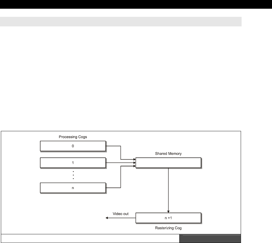
Graphics Engine Development on the HYDRA 24
Game Programming for the Propeller Powered HYDRA Page 775
if_ne jmp #Pixel_Render_Loop ' loop until we draw 16 tiles (single pixel row of each)
' only 10 are viewable, so we loop until a net of 10
24.4 Advanced Engine Design Concepts
The HEL engine is a good baseline engine to start experimenting with. However, to take the
engine to the next level it needs a couple more features, such as every single pixel can be
any color you desire and many more sprites with scaling and other effects. Let’s talk for a
moment about how these effects might be achieved. First off, as you can see the problem
with writing graphics engines is the vast amount of computation needed per pixel/line/frame.
There are never enough clock cycles to do all the processing that we would like to do. The
HEL engine more or less pushes a single cog near its limits, although with some optimization
you could definitely get more out of it. However, we are talking about 10-50% more at max,
not 3 to 5× more. Thus, another approach has to be taken to get more color, higher
resolution, and more sprites on the screen.
The Multiple Cog Rendering Engine Setup Figure 24:7
The approach is simple: use multiple cogs to process the graphics information as shown in
Figure 24:7. The idea is to separate the
processing
of tile, sprites, and geometry and
rasterization
into two different processes, then this is the perfect division of labor. For
example, the Parallax reference drivers work in this fashion. There is one driver for the TV
and one driver for the graphics. But, the idea is to take this to the extreme (which is done in
the demos in the next chapter) and use one cog whose sole mission is life is to draw frames
of video from a shared scanline memory buffer a line at a time. This shared scanline buffer is

III Game Programming on the HYDRA
Page 776 Game Programming for the Propeller Powered HYDRA
“fed”
by one or more cogs. For example, let’s say we have one cog to rasterize the scanline
buffer and one cog to generate the scanline data. So the rasterization cog only has to wait in
a loop for the scanline to become “ready,” read it in, and then write it out to the video
stream with waitvid instructions. Moreover, since this producer-consumer arrangement
unloads the video generation cog, you can draw only 4 pixels at a time rather than 16 and
get full color since normally you pass 16 pixels and 4 colors. But, there is no reason you can’t
draw 4 pixels with 4 different colors, it’s just that you have to feed the
waitvid
instruction
constantly. But, if another processor is doing all the work then the cog that is generating
video more or less is just reading from a buffer and not doing anything.
Moving back to the processing cog, we started with one. This means that by the time the
video cog is done rendering a single scanline, the processing cog has to have the next
scanline ready in the buffer. This means that more or less you get 64 µs to process a line.
That’s a good amount of time. However, by adding cogs we can double, triple, quadruple,
etc. this number. For example. if Cog 1 and 2 are processing video data and Cog 3 is
generating video, the processing cycle might start like this:
System Start…
T0: Cog 1 – Generate line n
T1: Cog 2 – Generate line n+1
Start Cog 3 Up….
T2: Cog 3 – Start reading and rasterizing line buffer generated by Cog 1
T3: Cog 3 – Start reading and rasterizing line buffer generated by Cog 2
T4: Cog 3 – Start reading and rasterizing line buffer generated by Cog 1
As you can see, now each processing cog has two time slices to build a scanline, since while
either Cog 1 or 2 is generating a line, the rendering cog is reading from the other cog’s
scanline buffer. So basically, with 2-3 processing cogs and a single video cog you can more
or less do anything you want with the Propeller chip graphically! Of course, the devil is in the
details, and issues like double-buffering the scanlines, synchronization, and moving the
buffers from cog to cog through shared global memory can be tricky. The point is that it’s
possible and you will see numerous demos of it in the next chapter.
24.5 Summary
Hopefully, you have learned your way around the HEL engine and have a starting point to
either write a graphics driver from scratch or modify the engine to your needs. I have to
admit that writing the engine was one of the most fun aspects of programming the HYDRA,
since the engine code along with a single cog is like a “soft-GPU” and thus a very powerful
paradigm (like the Atari 800/Amiga graphics
display
lists
). I suggest trying to optimize the
engine more, make it more compliant to LCD and plasma screens, and see if you can add

Graphics Engine Development on the HYDRA 24
Game Programming for the Propeller Powered HYDRA Page 777
more sprites and more resolution to it. When you have mastered that then a multi-cog
engine would be the next logical step. And to get you going there, in the next chapter you
will see numerous graphics engines that you can use and modify yourself that are much
more advanced than the HEL tutorial engine.

III Game Programming on the HYDRA
Page 778 Game Programming for the Propeller Powered HYDRA
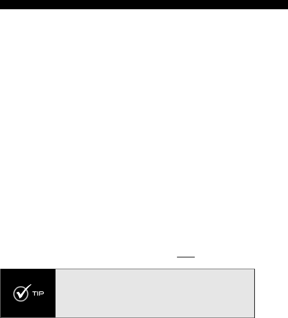
HYDRA Demo Showcase 25
Game Programming for the Propeller Powered HYDRA Page 779
Chapter 25:
HYDRA Demo
Showcase
Well, this is it, the end of a long journey. If you read this book cover to cover, I applaud you!
In this last chapter, we are going to take a look a number of demos written by the
“HYDRA
Demo Coder Team.”
If you know anything about computer graphics and games, you
might have heard the term “demo coder” before. Demo coders are people that write “demos”
for computers. So what? Well, demo coders typically write demos on computers and game
systems that are simply impossible to do. That is, if you to ask an above average
programmer, if it’s possible to do something really crazy on some very limited computer they
will always say no. A demo coder will not only say “Yes!” but have it to you by the end of the
night. Bottom line, demo coders are Jedi knights of programming, so there is a lot that can
be learned by examining their code. On the other hand, their code is so advanced, so
complex, it might as well be in an alien computer language! However, if you are patient you
should be able to figure out how these demos work by playing with them and reviewing the
code and comments therein.
25.1 The Demo Showcase
First off, the demo coders spent a lot of time working on all these demos, so I would like to
once again thank them for contributing (in no particular order):
Rémi
Veilleux
,
Colin
Phillips
,
Robert
Woodring
,
Jay
T.
Cook
,
Nick
Sabalausky
,
Rainer
Blessing
,
Matthew
Kanwisher
and
Michael
Thompson
. If you would like to learn more about any
particular demo coder, you can read about them in “About the Demo Coders” on page 795 at
the end this chapter. I am going to present each demo and/or piece of software in a
template form. All of the demos will run right out of the \SOURCES directory, simply load
the top level source file indicated. Additionally, you will find additional sources, readme files,
and other tools in the \DEMOS directory on the CD. The “additional sources” directory noted
in each demo is the path to these files for each particular demo. Also, there will be a screen
shot of each demo for reference, so you can see what the demo
should
look like.
If you find that the colors of a demo don’t seem correct (or there is no color at
all) you can either adjust the hue on your TV set or you can try adjusting the
crystal frequency value in the setup of each demo. Look at the top of the main
file for the demo in question and locate the line that looks like:
“_xinfreq = 10_000_000 + offset. ” The offset value added to the base frequency
of 10_000_000 helps offset the xtal manufacturing variances. So try adding
multiples of 1000 to the base of 10_000_000 eg. 0, 1000, 2000, 3000, 4000, or 5000
until the display looks good. Or, use negative numbers as well.
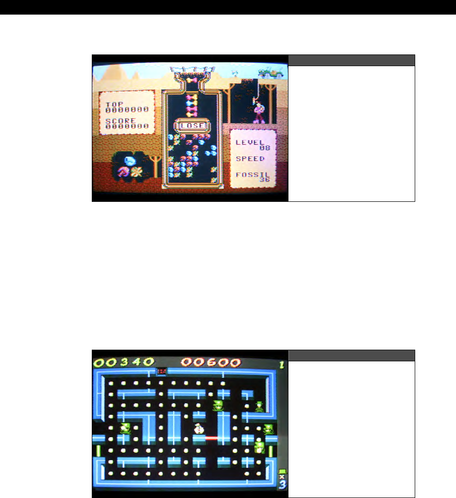
III Game Programming on the HYDRA
Page 780 Game Programming for the Propeller Powered HYDRA
25.1.1 Dr. HYDRA
Figure 25:1
Dr. HYDRA in Action
Author: Rémi Veilleux
Top level filename: REM_dr_hydra_018.spin
Additional sources in: \DEMOS\Remi_Veilleux\REM_dr_hydra_05_11_06
“Dr. HYDRA”
is based on the popular
“Dr. Mario”
Nintendo puzzle game which is similar to
a standard block drop game. Supports keyboard and gamepad play. Also, the game uses a
high color graphics engine and assembly language overlay loader.
25.1.2 HYDRA Lock N Chase
Figure 25:2
HYDRA Lock N Chase
in Action
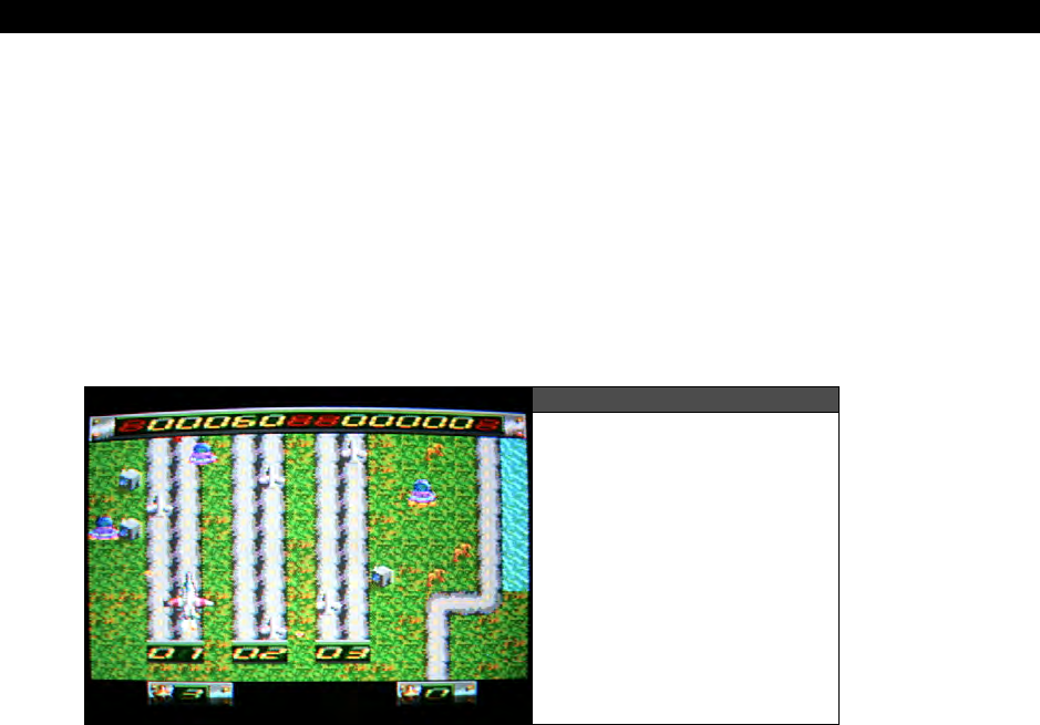
HYDRA Demo Showcase 25
Game Programming for the Propeller Powered HYDRA Page 781
Author: Rémi Veilleux
Top level filename: REM_LockNChase_012.spin
Additional sources in: \DEMOS\ Remi_Veilleux\REM_lock_n_chase_02_12_06
“HYDRA Lock n Chase”
is a retro remake of the popular 1980’s game
“Lock N Chase.”
The player controls an escaped criminal and the police try to catch him. Supports keyboard
and mouse. The game uses the standard Parallax reference driver TV_DRV_010.SPIN to
generate the TV signal, but a custom graphics engine.
25.1.3 Alien Invaders
Figure 25:3
Alien Invaders in Action
Author: Rémi Veilleux
Top level filename: REM_AlienInvader_013.spin
Additional sources in: \DEMOS\Remi_Veilleux\REM_AlienInvader_02_14_06
“Alien Invaders”
is a two-player shooter that pushes the limits of Propeller chip to its
absolute maximum. The game uses both a custom multi-cog graphics engine, overlay loader,
and is in pure assembly language. Supports keyboard and both gamepads. There is no sound
due to memory constraints.
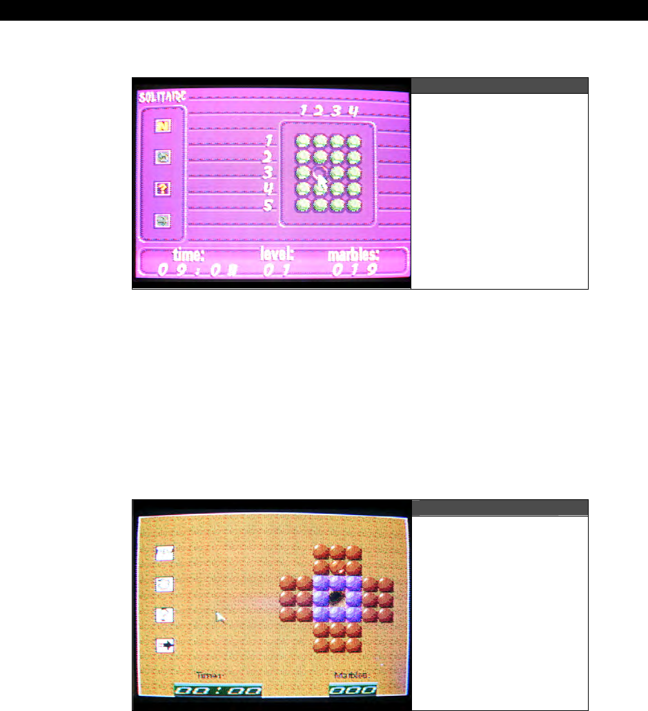
III Game Programming on the HYDRA
Page 782 Game Programming for the Propeller Powered HYDRA
25.1.4 Peg Solitaire
Figure 25:4
Peg Solitaire in Action
Author: Rémi Veilleux
Top level filename: REM_PegSolitaire_016.spin
Additional sources in: \DEMOS\Remi_Veilleux\REM_peg_solitaire_02_28_06
“Peg Solitaire”
is a computer implementation of the classic board game of the same name.
Supports keyboard, mouse, and gamepad controls. The game is based on a custom multi-cog
graphics engine and overlay loader.
25.1.5 GFX Engine Demo and Tutorial
Figure 25:5
GFX Engine Demo
in Action
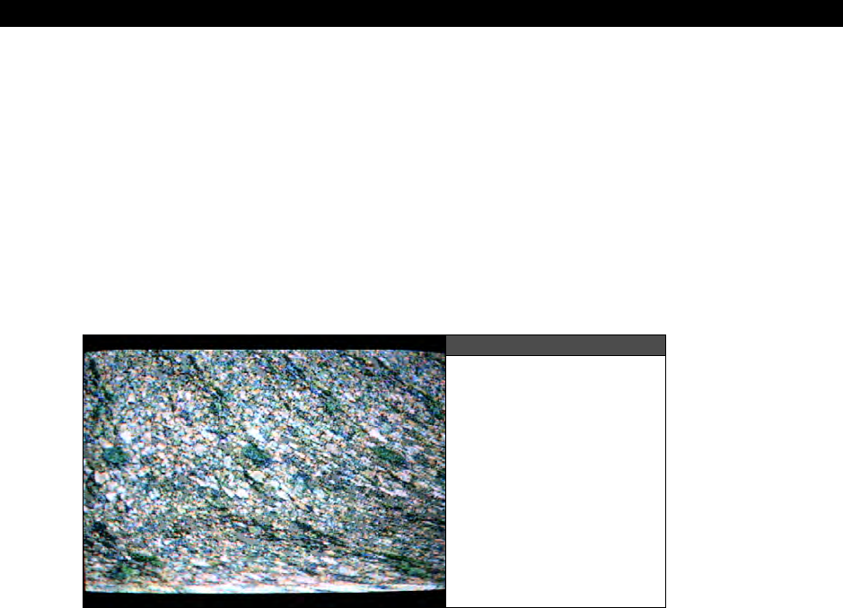
HYDRA Demo Showcase 25
Game Programming for the Propeller Powered HYDRA Page 783
Author: Rémi Veilleux
Top level filename: REM_Tutorial_017.spin
Additional sources in: \DEMOS\Remi_Veilleux\REM_tutorial_03_01_06
This graphics engine demo illustrates
Rémi Veilleux’s “GFX”
graphics engine. The demo
source file itself is heavily commented in tutorial style and guides you through the use of all
aspects of the state-of-the-art engine for your games and applications. The demo directory
contains other support source and files that you will need to use the engine in your own
applications. Supports mouse, keyboard, and gamepads.
25.1.6 Floor Demo
Figure 25:6
Floor Demo in Action
Author: Rémi Veilleux
Top level filename: REM_FloorDemo_010.spin
Additional sources in: \DEMOS\Remi_Veilleux\REM_Floor_02_19_06
The “
Floor Demo”
illustrates a pseudo-3D parallax scrolling technique with a large bitmap.
Use the mouse to adjust various sampling rates in the demo to see how they affect the
image.
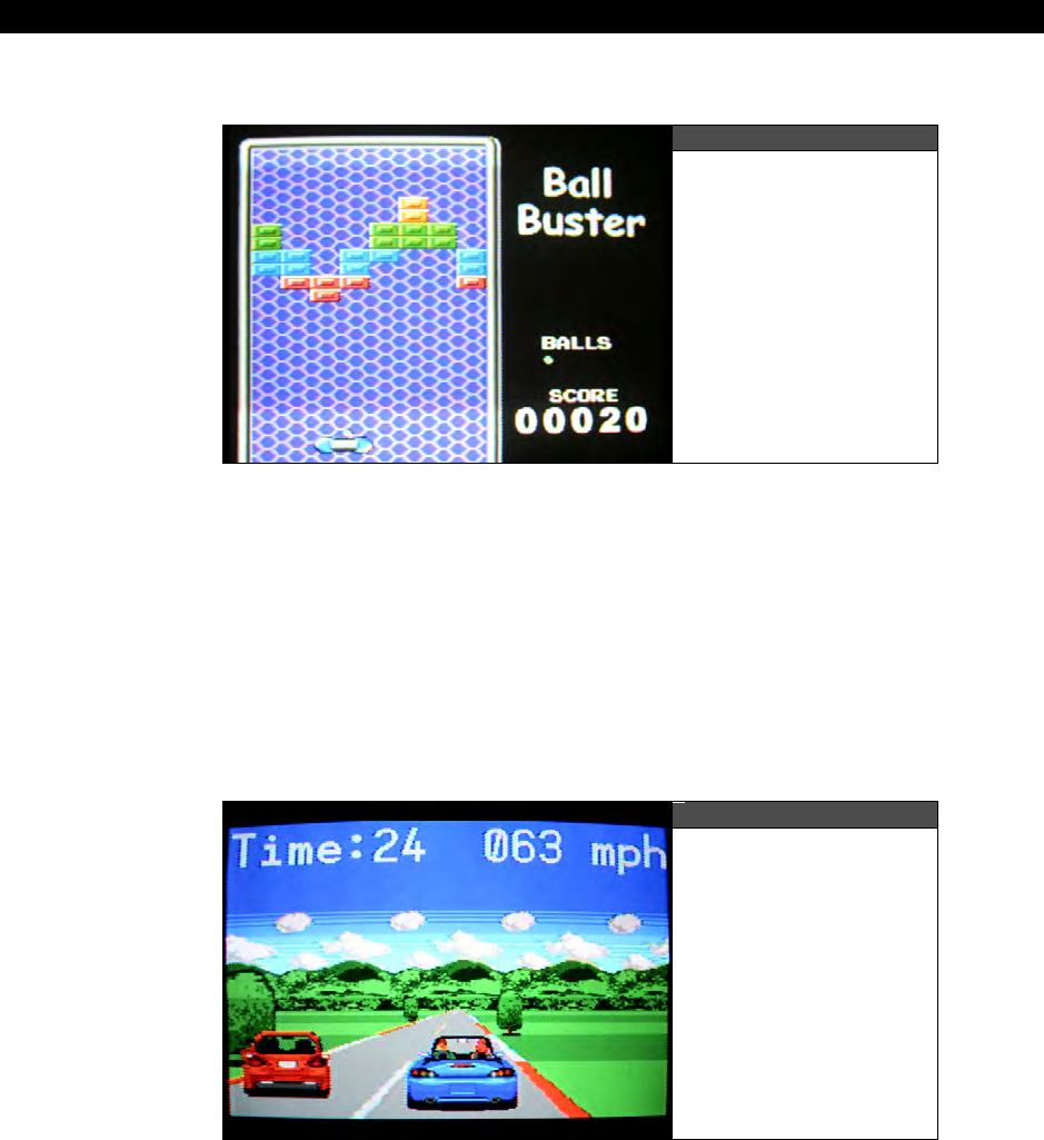
III Game Programming on the HYDRA
Page 784 Game Programming for the Propeller Powered HYDRA
25.1.7 Ball Buster
Figure 25:7
Ball Buster in Action
Author: Jay T. Cook
Top level filename: JTC_B_Buster_005.spin
Additional sources in: \DEMOS\JT_Cook\JTC_B_Buster_03_09_06
“Ball Buster”
is an implementation of the classic game
“Breakout.”
The game uses the
“COP”
graphics engine developed by Colin Phillips as the driver. Supports mouse and
gamepad inputs.
25.1.8 X-Racer
Figure 25:8
X-Racer in Action

HYDRA Demo Showcase 25
Game Programming for the Propeller Powered HYDRA Page 785
Author: Jay T. Cook
Top level filename: JTC_XRacer_010.spin
Additional sources in: \DEMOS\JT_Cook\JTC_XRacer_08_21_06
“X-Racer”
is a 3D racing game that uses ray casting (sampling technique) and scaled sprites
to create the illusion of 3D graphics reminiscient of
“Pole Position.”
This game is probably
the most visually impressive of any of the demos for the HYDRA. The game’s graphics engine
is based on
Rémi Veilleux’s
GFX engines. Supports gamepad controls.
25.1.9 HYDRA Intro
Figure 25:9
HYDRA Intro in Action
Author: Colin Phillips
Top level filename: CP_HIADEMO_001.spin
Additional sources in: \DEMOS\Colin_Phillips\demos\CP_HIADEMO_02_15_06
“HYDRA Intro”
was written as a simple demo to test the
“COP”
graphics engine as well as
give the HYDRA something to do when it boots from its on-board EEPROM. No controls, just
looks pretty.

III Game Programming on the HYDRA
Page 786 Game Programming for the Propeller Powered HYDRA
25.1.10 HydraMan
Figure 25:10
HydraMan in Action
Author: Colin Phillips
Top level filename(s): CP_HYDRAMAN_005.spin
CP_HYDRAMAN_005b.spin
CP_HYDRAMAN_005c.spin
Additional sources in: \DEMOS\Colin_Phillips\GAMES\CP_HYDRAMAN_02_14_06
“HydraMan”
is based on the popular game
“BomberMan.”
There are three versions of
the game with various game play options up to 8 players. The graphics are based on the
“COP”
graphics engine. Support keyboard and both gamepads.
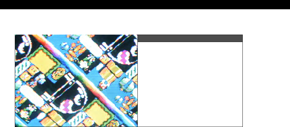
HYDRA Demo Showcase 25
Game Programming for the Propeller Powered HYDRA Page 787
25.1.11 COP Graphics Engine Tests and Tutorials
Figure 25:11
COP Graphics Engine in Action
Author: Colin Phillips
Top level filename(s): CP_COP_test_010.spin,
CP_COPGFXTEST_001.spin,
CP_COPGFXTEST_003.spin,
CP_COPTUT_001.spin
Additional sources in: \DEMOS\Colin_Phillips\graphics\
Colin Phillips experimented a great deal with the Propeller chip’s graphics abilities and tried
numerous performance experiments resulting in a slew of graphics engines. These engines
were then later used by many of the demo coders to create their own demos on. Make sure
to review all of the engines within the directory \DEMOS\Colin_Phillips\graphics\. There
are two classes of engines in there: the “COP” engines, and the second generation
“COP-GFX” engines. Even though you could concentrate on the latest versions of each
engine, I highly recommend reviewing the engines as they were developed (they are all
dated) since this gives you a better chance of following how they work. The engines can be
found in this directory:
\DEMOS\Colin_Phillips\graphics\CP_COP_01_24_06
\DEMOS\Colin_Phillips\graphics\CP_COP_02_03_06
\DEMOS\Colin_Phillips\graphics\CP_COPGFXTEST_03_10_06
\DEMOS\Colin_Phillips\graphics\CP_COPGFXTEST_06_07_06
Finally, there is a complete tutorial on using the graphics engine which is composed of a
sample demo along with sources. This can be found on the CD here:
\DEMOS\Colin_Phillips\graphics\CP_COPTUT_03_02_06
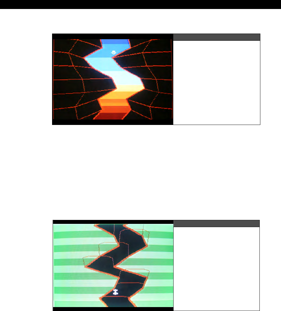
III Game Programming on the HYDRA
Page 788 Game Programming for the Propeller Powered HYDRA
25.1.12 Deep Cavern 3D
Figure 25:12
Deep Cavern 3D in Action
Author: Nick Sabalausky
Top level filename: NS_deep_cavern_020.spin
Additional sources in: \DEMOS\Nick_Sabalausky\NS_deep_cavern_02_14_06
“Deep Cavern 3D”
is a simple pseudo-3D demo based on perspective tricks and wireframe
graphics. You control a ship which descends into the darkness. Supports keyboard and
gamepad.
25.1.13 HYDRA Rally
Figure 25:13
HYDRA Rally in Action

HYDRA Demo Showcase 25
Game Programming for the Propeller Powered HYDRA Page 789
Author: Nick Sabalausky
Top level filename: NS_hydra_rally_021.spin
Additional sources in: \DEMOS\Nick_Sabalausky\NS_hydra_rally_02_15_06
“HYDRA Rally”
is a pseudo-3D experiment using wireframe graphics and perspective. You
control a race car which you must keep from hitting the sides of the road. Supports keyboard
and gamepad.
25.1.14 Piano Demo
Figure 25:14
Piano Demo in Action
Author: Nick Sabalausky
Top level filename: NS_sound_demo_052.spin
Additional sources in: \DEMOS\Nick_Sabalausky\NS_sound_07_21_06
Nick Sabalausky did a lot of work on a full ADSR multi-channel sound driver for the HYDRA.
The
“Piano Demo”
shows off the driver and what it can do. Also, the demo is a good place
to start to see how to use the driver. The latest version of the driver at the time the book
was printed was 5.2; however, make sure to check the CD for updates within Nick’s directory
as well as to see numerous other sound drivers and the development of the final product.
The demo itself is more or less a piano that you can play using the keyboard and mouse.
Also, <SPACEBAR> on the keyboard invokes the speech sample. Additionally, make sure to
read:
\DEMOS\Nick_Sabalausky\NS_sound_07_21_06\NS_sound_drv_writeup.doc
...which is a rough draft of the design of the sound driver from the author’s notes.
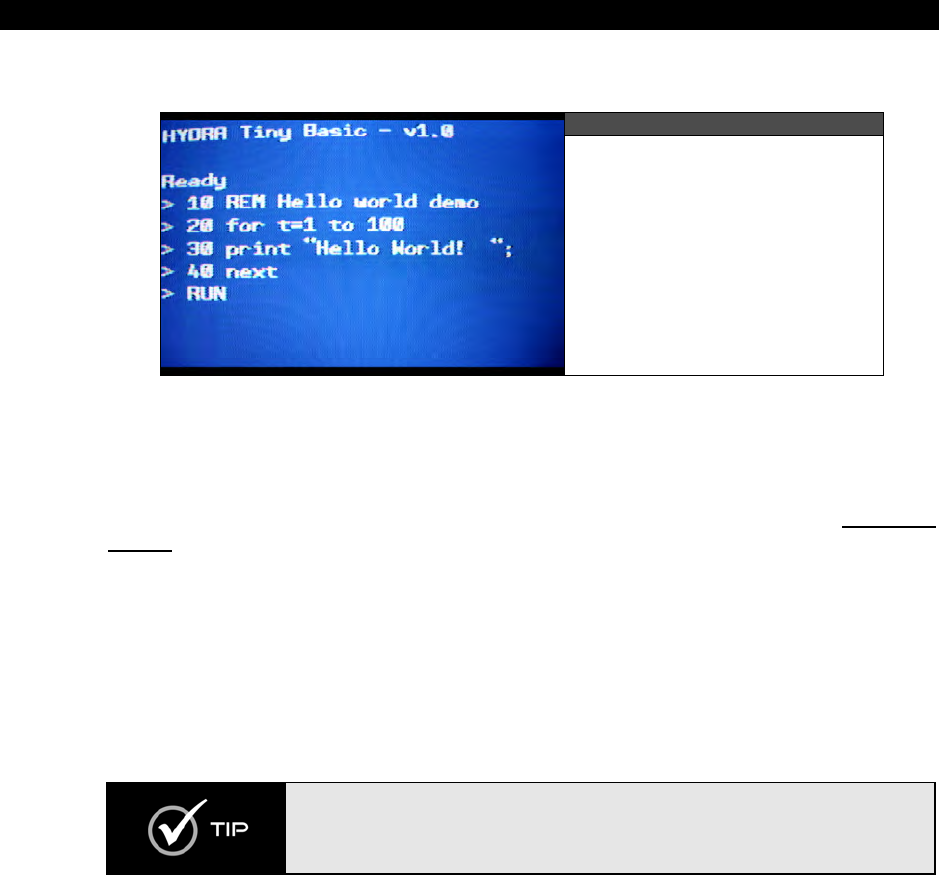
III Game Programming on the HYDRA
Page 790 Game Programming for the Propeller Powered HYDRA
25.1.15 HYDRA Tiny BASIC
Figure 25:15
HYDRA Tiny BASIC in Action
Author: Robert Woodring
Top level filename: RGW_TinyBasic_010.spin
Additional sources in: \DEMOS\Robert_Woodring\RGW_HTBasic_08_03_06
“HYDRA Tiny BASIC”
is an implementation of
“Tiny BASIC”
first presented in Dr. Dobb’s
Journal in 1976. The HYDRA implementation is more or less complete with its various quirks.
However, it’s a good example of a complete interpreter running on the HYDRA in assembly
language and fun to program with a TV and keyboard and no PC. You could do worse things
than review the source code line by line and figure it out. There is a document on the
language itself and the keywords and so forth which can be found here:
\DEMOS\Robert_Woodring\RGW_HTBasic_08_03_06\Hydra_Tiny_Basic.doc
This demo is probably one of the coolest things about the HYDRA since you can actually
write programs with it. Moreover, the interpreter is
very
fast.
There is also a “mod” version of the language by Jay T. Cook that supports more
characters per line. The top filename is: RGW_JTC_TinyBasic_010.spin and the
complete source files can be found in:
\DEMOS\Robert_Woodring\T_Basic_Mod_08_06_07\
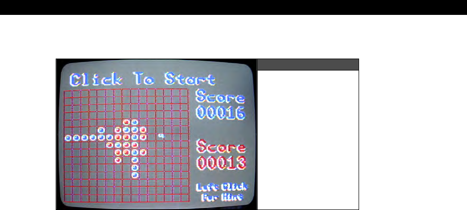
HYDRA Demo Showcase 25
Game Programming for the Propeller Powered HYDRA Page 791
25.1.16 Reversi
Figure 25:16
Reversi in Action
Author: Robert Woodring
Top level filename: RGW_Reversi_018.spin
Additional sources in: \DEMOS\Robert_Woodring\RGW_Reversi_02_15_06
“Reversi”
is an implementation of the classic board game by the same name. Use the
mouse to make your moves. See if you can beat the built-in artificial intelligence (which isn’t
easy). Supports mouse only.
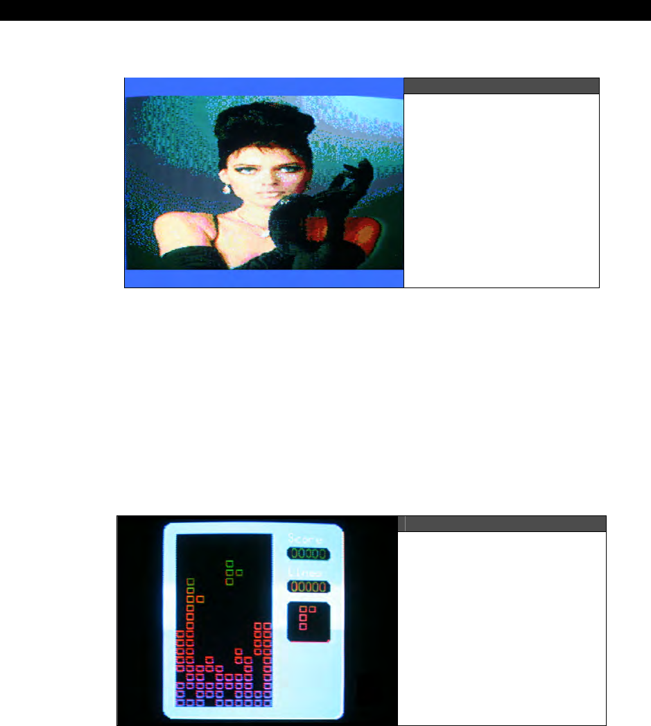
III Game Programming on the HYDRA
Page 792 Game Programming for the Propeller Powered HYDRA
25.1.17 Glass Demo
Figure 25:17
Glass Demo 3D in Action
Author: Robert Woodring
Top level filename: RGW_Glass1_.spin, RGW_Glass2_.spin
Additional sources in: \DEMOS\Robert_Woodring\RGW_glass_sample_05_15_06
“Glass Demo”
demonstrates a glass lensing effect that is a favorite of demo coders to
implement. These demos are not 100% correct and thus a work in progress. Each demos
tries a slightly different approach to obtain the lensing effect. Still they are interesting since
they use large bitmaps and warp the image in real-time. No input devices supported.
25.1.18 Hydris
Figure 25:18
Hydris 3D in Action
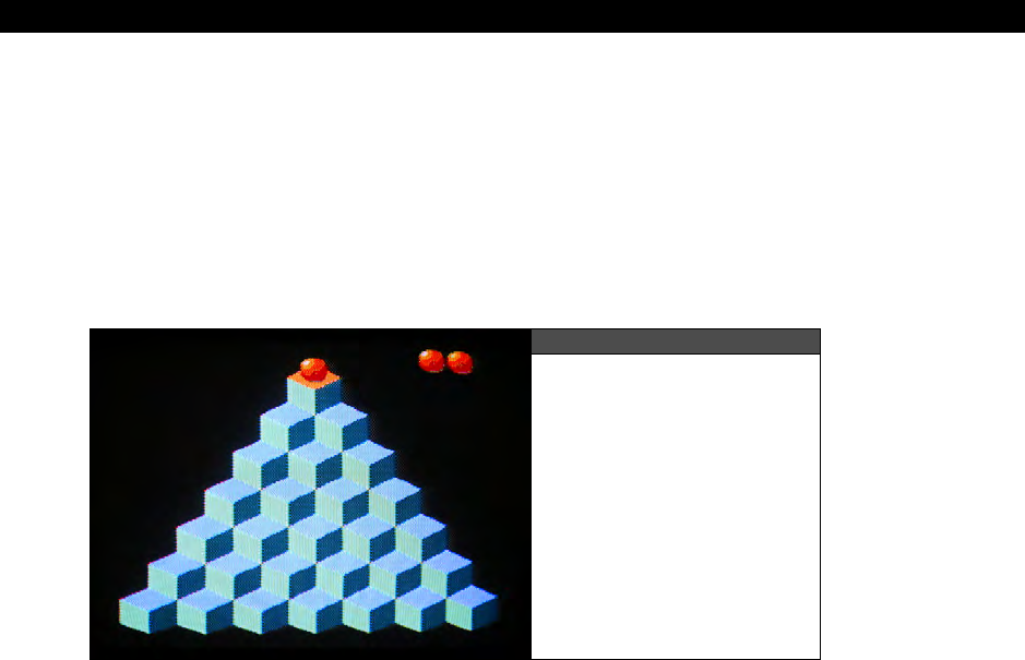
HYDRA Demo Showcase 25
Game Programming for the Propeller Powered HYDRA Page 793
Author: Rainer Blessing
Top level filename: RB_Hydrabert_100.spin
Additional sources in: \DEMOS\Rainer_Blessing\RB_Hydrabert_02_14_06
“Hydris”
is a variant of
“Tetris.”
You rotate blocks and try to fit them together. Supports
keyboard and mouse.
25.1.19 Hydrabert
Figure 25:19
Hydrabert 3D in Action
Author: Rainer Blessing
Top level filename: RB_Hydrabert_100.spin
Additional sources in: \DEMOS\Rainer_Blessing\RB_Hydrabert_02_14_06
“Hydrabert”
is based on the idea of
“Q-bert,”
that is, a 3D isometric game field that you
move a character around on. This demo is in the early stages and no game play is in, but it’s
a good start for you to add some more elements to. Supports keyboard and gamepad.
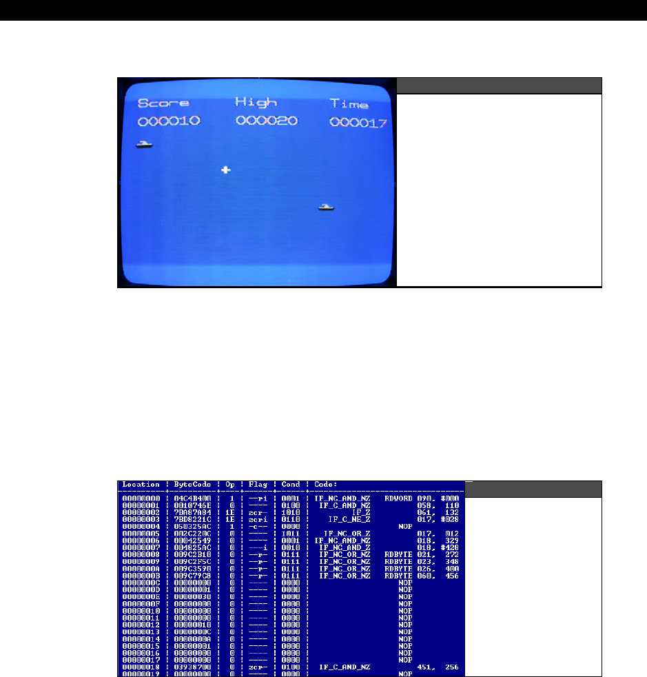
III Game Programming on the HYDRA
Page 794 Game Programming for the Propeller Powered HYDRA
25.1.20 Sub-Hunt
Figure 25:20
Sub-Hunt in Action
Author: Matthew Kanwisher
Top level filename: MK_SUB-HUNT_013.spin
Additional sources in: \DEMOS\Matthew_Kanwisher\MK_SUB-HUNT_02_17_2006
“Sub-Hunt”
is based on the very old arcade game
“Sea Wolf.”
You control a cross-hair
and can fire infinite velocity projectiles at subs. Very simple game, all in Spin.
25.1.21 PDasm
Figure 25:21
PDasm in Action

HYDRA Demo Showcase 25
Game Programming for the Propeller Powered HYDRA Page 795
Author: Michael Thompson
Top level filename: pdasm.exe (Windows command line executable)
Additional sources in: \DEMOS\Michael_Thompson\MT_PDasm_02_15_06
“PDasm”
is a simple tool that disassembles Propeller binary files. It’s a work in progress, but
a good start if you need a dissassembler. The C/C++ source files are all included, so you can
modify and enhance the program.
25.2 Additional Demos and Sources
The demos presented are for the most part the most complete and impressive demos.
However, as the demo coders were developing their software many of them experimented
and created various tools to help their work out. Thus, make sure to take your time and look
through all the sub-directories in the \DEMOS directory, read all the readme’s, try all the
tools out and so forth. There is a gold mine of additional information in there! For example,
in Colin Phillips’ directories under \APPS\ you will find a PC-to-HYDRA communications
application. In Nick Sabalausky’s directory you will find an EEPROM driver under
\NS_eeprom_drv_02_26_06\.
25.3 About the Demo Coders
In the early days of game development it was customary to give credit on the packaging to
the actual developers that created the games. Sadly, companies rarely give credit to the
developers of games these days. They want us to think the CEO or marketing department
made them I guess? Ya right! Typically, the developers’ names are buried in the final credits
of the game after it’s solved. However, I want everyone to know the names and a little bit
about the demo coders that created the awesome demos on the HYDRA that not only add
value to the product, but have pushed the Propeller chip to its absolute limits and they
deserve to be recognized.
Rémi Veilleux — Rémi Veilleux, born near Montreal, Canada, started programming with an
Apple II and a Tandy TRS-80. Since then, he has collected numerous game consoles and old
computers. He worked professionally for Ludus Design (Quadra), Microids Canada (Syberia
series) and Electronic Arts (Medal of Honor, Golden Eye: Rogue Agent). Still being a
passionate old-school developer, he coded games for the XGameStation Micro and more
recently for the new HYDRA project.
Colin Phillips — Colin Phillips’ interest in designing and programming games started as far
back as when he was 5 years old when he was introduced to the QL Sinclair and it's
SuperBasic. So, he has been programming for the best part of 20 years now. Highlights
include developing an Assembler and C compiler for the Nintendo 64 at age 16, winning the
Xtreme Games 128k game programming contest, and developing and maintaining numerous
online gaming sites such as www.thesnookerclub.com, www.thepoolclub.com and the

III Game Programming on the HYDRA
Page 796 Game Programming for the Propeller Powered HYDRA
recently launched www.playonlinesoccer.com. His company, Memir Software
(www.memirsoftware.com) is based in London, UK.
Robert Woodring — Robert Woodring lives, works and plays in Virginia Beach, VA. Robert
has been a programming for more years than he can remember. Carbon dating results have
yet to pin down his age conclusively. The latest gig for Robert for the past 15 years has been
programming for route distribution handheld computers and trying to remember where he
put his car keys. His passions are virtual machines, languages, and of course video games.
Jay T. Cook — “JT” Cook has been a longtime video game junkie which inspired his
fascination of programming. He has been programming on various hobby projects since the
late 90's with the HYDRA as his first commercial project. He currently resides in Des Moines
Iowa and you can visit his website at www.avalondreams.com.
Nick Sabalausky — Nick Sabalausky is interested in nearly all aspects of entertainment and
computer technology, but his first passion is programming. Since grade school, he has
worked with numerous languages and platforms, ranging from the common to the obscure.
He is the author of the best-selling value PC breakout clones “Hyperball” and “Zarkanoid”
both developed with Xtreme Games. Additionally, he runs www.twistedpairgaming.com
as well as serving as "official household system administrator" at his home in Cleveland,
Ohio.
Rainer Blessing — Rainer Blessing is from Stuttgart/Germany. He studied computer science
with a focus on networking. His day job is a Java/Database developer concentrating on
application programming rather than game development. Rainer has been programming for
over 20 years. The first game he wrote was Pong on the Atari 800XL, and he thinks
gamewise he hasn’t made much progress since then! But, he wrote a Linux IDE for the XGS
ME and a complete emulator, so he is more of a system software game developer. His work
can be found on www.rainerblessing.com.
Matthew Kanwisher — Matthew Kanwisher lives in Atlanta, Georgia. Currently he is
attending Georgia State for a B.A in Computer Science. Matthew has worked on projects
ranging from Telecommunications, Home Automation, and DJ Software. Currently he is
working for BellSouth as a Senior Software developer on their Business Voice over Ip
offerings.
Michael Thompson — Michael Thompson began programming at age 11 when he got his
start in Apple IIe BASIC at an after-school program. After graduating high school he perused
studies at DigiPen Institute of Technology from which he graduated in 2005 with an
Associate's of Science in Real-Time Interactive Simulation. He now makes a living as a
software developer in Bellevue, Washington and pursues his gaming interests in his spare
time.

HYDRA Demo Showcase 25
Game Programming for the Propeller Powered HYDRA Page 797
25.4 Summary
Well, hopefully you are sufficiently impressed. I know I am! The demos range from relatively
simple Spin examples, to state-of-the-art, pedal-to-the-metal 3D games. If you take the time
to reverse engineer every single demo and figure out the tricks and secrets of them, not only
will you have mastered graphics on the HYDRA and Propeller chip, but you will have an edge
against everyone else.

III Game Programming on the HYDRA
Page 798 Game Programming for the Propeller Powered HYDRA

Installing the CD A
Game Programming for the Propeller Powered HYDRA Page 799
ppendices
B
a
ck
Matter
Appendices
B
a
ck
Matter
Appendice
ter Appendices Back Matter Appendices Back
Matter
Appe
k Matter Appendices Back Matter Appendices Back
Matter
s Back Matter Appendices Back Matter Appendices Back
M
ndices Back Matter Appendices Back Matter Appendices
Appendices Back Matter Appendices Back
Matter
Appendi
atter Appendices Back Matter Appendices Back
Matter
Ap
ack Matter Appendices Back Matter Appendices Back
Matt
ces Back Matter Appendices Back Matter Appendices Ba
ck
pendices Back Matter Appendices Back
Matter
Appendices
er Appendices Back Matter Appendices Back
Matter
Appen
endice
B
a
ck
Matter Appendices
B
a
ck
B
a
ck
Matter Append
Back Matter

Back Matter
Page 800 Game Programming for the Propeller Powered HYDRA
Epilog
It was a long time ago when I wrote my first computer program. I think it was about 1977
when I strolled into a Radio Shack and was instantly engrossed with the TRS-80. I spent
many months driving my Mongoose BMX bike to play with it each day (in fact my bike was
stolen one day while in the computer store programming!) I would draw my programs and
graphics on graph paper, and then painstakingly type them in. Back then I was really into
D&D, so all my games were D&D based. Then a few years later my parents bought be an
Atari 800 (after years of lobbying for one). I doubt I left my bedroom even once during junior
high or high school while I was learning the mysteries of graphics programming.
These 8-bit machines were magic. They were powerful enough to do anything you wanted
them to – if you were clever enough. And all you needed to program was a TV, the computer
and maybe a tape recorder. It was a lot of fun, I miss those days. It was like exploring a new
planet, each day you would learn something new and everyone around was just as interested
in programming as you were.
The HYDRA game console kit and book is my attempt to try and re-create this for others who
can never live through those days. The ability to program in a simple language with a simple
tool and see something on the screen is somehow magical to me even today. Sure, I like to
keep up with the latest and greatest 3D graphics technology and shader programming, but
there is something pure about programming simple computers and seeing your results
instantly on the screen. Hopefully, everyone has fun with the HYDRA and all the components
of it!
André LaMothe, 2006
ceo@nurve.net / ceo@xgames3d.com
www.xgamestation.com

Index
Game Programming for the Propeller Powered HYDRA Page 801
Index
2D paint programs, 433
3D modeling programs, 435
3D Studio Max, 435
3dB point, 127
abscissa, 462
acceleration, 726
Adobe software
After Effects, 437
Audition, 436
Premier, 437
ADSR (attack-decay-sustain-release), 139
Alcorn, Al, 16
Alien Invaders, 49
Allen, Paul, 19
ambient animation, 550
Andy Capp’s Tavern, 16
animation
3D drone, 663
ambient, 550
color rotation, 504
controller software, 666
data-driven, 666
exaggeration, 665
explosions, 662
flicker, 338, 485
framed, 661
glowing effect, 502
helicopter, 652
parallax scrolling, 659
procedural, 555
sprite, 550
stop-frame, 663
sub-tile, 668
translation, 665
two-frame, 551
two-sprite, 665
walking, 666
anti-log table, 211
Apple, 17
arbitration, 568
arcade games, 428
Arkanoid, 31
arrays, 259
artificial intelligence, 688
and finite state machines, 698
emergent behaviors, 720
fitness function, 721
fuzzy logic, 718
genetic algorithms, 720
learning, 719
neural networks, 717
programmable, 701
waypoint following, 712
ASM, 253
assembler directives, 190
assembly language
ALU flags/modifiers (table), 183
assembler directives, 190
basic math instructions, 198
branching instructions, 196
cog control instructions, 298
instruction execution condition (table), 182
instruction format, 180
instruction set, 186
lock instructions, 296
opcodes, 188
parameter passing, 420
virtual machine, 420
Asteroids, 30
Atari, 15, 16
back porch, 108
Baer, Ralph, 13, 15, 16
Ball Buster, 31
BASIC, 37, 253
BattleZone, 648
BellSouth, 796
Beveridge, Jim, 294
binary
binary image, 39
Binary Space Partition (BSP), 20
semaphore, 296
bitmap

Back Matter
Page 802 Game Programming for the Propeller Powered HYDRA
bitmap to spin conversion, 620
buffer, 331
mask, 543
scaling, 494
scrolling, 645
blank experimenter card, 162
blanking
and buffers, 485
blanking level, 106
horizontal blanking period, 107
vertical blanking period, 109
Blessing, Rainer, 796
block group indicators, 254
board games, 430
Boolean constants, 261
boot loader, 213
bouncing ball motion, 497
bounding box, 587
collision detection, 751
multiple box collision detection, 752
bounding circle, 753
Brawer, Steven, 294
Breakout, 31
breezeway, 108
Bresenham, Jack, 475
Brookhaven National Laboratory, 14
Brown Box, 13, 15
BSP trees, 20
buffer
bitmap, 331
double buffering, 105, 338, 485
off-screen, 338
on-screen, 331
scanline, 763
tile map, 535
Builder, 438
Burnout Revenge, 431
Bushnell, Nolan, 13, 16
BYTE, 257
byte code, 245
C, 253
C++, 253
caching, 762, 769
Caligari, 435
Carmack, John, 19
Cartesian coordinates
2D, 462
Cartesian to Polar conversion, 468
inverted Quatrant I, 464
standard Quadrant I, 465
Castle Wolfenstein, 19
cathode ray tube (CRT), 105
CD directory, 41
Cell processor, 11
Centipede, 428
character chart, 67
character map, 336, 510
chroma, 113, 236, 240, 591
circle collision detection, 753
clipping, 475
clock modes, 314
selection constants (table), 314
CLUT (color lookup table), 501
code block designators, 250
cog, 33, 177
cog control instructions, 194, 298
cog/hub interaction (diagram), 294
cog-to-cog comunication, 295
instruction set, 186
opcodes, 188
program execution, 304
register space, 179
registers, 184, 284
registers (table), 180
stack space allocation, 302
collision detection, 498, 539, 584
ball to block, 589
ball to screen edge, 585
bouncing ball, 748
bounding box, 587, 751
bounding circle, 753
elastic, 585
irregular objects, 749
multiple bounding boxes, 752
pixel accurate, 751

Index
Game Programming for the Propeller Powered HYDRA Page 803
simple reflection, 748
spatial partitioning, 757
tile space, 754
tile-based algorithm, 539
color
3D RGB space, 626
adding to NTSC, 111
animation, 501
burst, 108, 112
burst frequency, 113
burst signal encoding, 113
chroma, 113, 236, 240, 591
clocks, 113
color look-up table (CLUT), 501
color matching, 626
color reduction, 626
color rotation animation, 504
color sets, 334
encoding (table), 240
glowing effect, 502
luma, 108, 236, 240, 591
palettes, 625
two-region system, 346
Commander Keen, 19
conditionals, 267
conventions
filename, 320
variable names, 440
Cook, Jay, 796
Cool Edit Pro, 436
coordinate, 490
Cartesian 2D, 462
Cartesian/Polar conversion, 468
coordinate mapping, 350
frames, 489
local coordinates, 490
local coordinates and scaling, 495
screen coordinates, 492
system types, 461
translation, 493
viewport coordinates, 644
world coordinates, 490, 644
Corel Paint, 433
counter configuration mode (table), 219
counters, 215
Crash Bandicoot, 429
cross product, 715
crossover point, 721
debug indicator hardware, 91
debugging techniques, 92
Defender, 648
Delphi, 438
Demos
About the Coders, 795
Additional Demos, 795
Alien Invader, 709
Arena Game, 565
Ball Buster, 31, 784
Bee, 690
Caterpillar, 667
Centipede, 550
Demo Showcase, 779
Floor, 783
Function Plotting, 473
Gamepad, 395
GFX Engine, 782
Glass, 792
Gravity and Friction, 733
Hepburn, Audrey, 792
Hydrabert, 793
HYDRA-NET, 171
Hydris, 792
Input Device Filtering, 565
Invaders, 668
Keyboard, 388
Large Tile Map Scrolling, 654
Line Drawing, 360
Mappy, 638
Mars Lander, 457
Master Graphics, 325
Mouse, 382
Multiple Page Tile Engine, 529
Networking, 172
PACMAN, 530
Page Flipping, 488
Parallaxaroids, 30
Pattern Following, 709
PDasm, 794

Back Matter
Page 804 Game Programming for the Propeller Powered HYDRA
Piano, 789
Piano Driver, 611
Pitfall, 654
Plot Pixel, 356
Polygon, 368
Projectile Demo, 744
PWM-Engine Sounds, 415
PWM-Sine Wave, 411
Random Motion, 690
Reversi, 791
RTTTL Player, 615
Screen Saver, 477
Space, 739
Square Wave Sound, 409
Sub-Hunt, 794
Text, 376
Tiny BASIC, 790
Tracking Demo, 696
Triangle, 364
Vector Scrolling, 650
VGA, 406
X-Racer, 784
ZoneBall, 582, 590
dendrites, 717
Destructive Tile Map Motion, 535
developer tagging, 322
Dig Dug, 450
direct memory access, 281
DOOM, 20, 430
dot product, 681, 682
double buffering, 105, 338, 485
driving, 712
duty cycle, 216, 218, 411
(diagrams), 131
modes, 225
Earthworm Jim, 661
Edwards, Dan, 14
EEPROM
accessing, 417
asset storage, 419
operation, 418
serial interface pinout, 418
electron gun, 105
emergent behaviors, 720
english (virtual spin), 587
erase-move-draw, 484
evasion algorithms, 693
ExciteBike, 756
expansion port, 159
explosions, 133, 436, 593, 662, 731
Feldman, Ari’, 623
filenaming conventions, 320
filter,input device, 560
finite state machine (FSM), 441, 657, 698
and artificial intelligence, 698
first-person shooter (FPS) games, 430
fitness function, 721
fixed-point math, 691
floating-point compile-time operators
(table), 266
floating-point support, 265
force, 730
and higher dimensions, 731
force feedback, 592
FORTH, 38, 420
Fractal Paint, 433
framed animation, 661
friction, 734, 737
modeling, 737
front porch, 108
FTDI FT232R block diagram, 85
FTDI USB driver installation, 43
function declarations and calls, 271, 272
fuzzy logic, 718
fuzzy manifold, 719
fuzzy set theory, 718
Galaxians, 428, 701
game
architectures, 449
data structures, 451
end of level determination, 584
game states, 443
level loading, 584
loops, 445
modes, 447
object states, 553

Index
Game Programming for the Propeller Powered HYDRA Page 805
player records, 452
program organization, 439
scrolling techniques, 643
gamepad
classic NES controller, 96
driver, 564
Gamepad Demo, 395
HYDRA interface ports, 98
input device controller, 559
interface (table), 395
reading input, 564
universal input controller mapping (table),
567
games
arcade, 428
board, 430
categories, 428
first-person shooter (FPS), 430
platform, 429
role-playing, 428
simulation, 430
Gates, Bill, 19
genetic algorithms, 720
global CLK register bit encodings (table),
214
global counter CNT register, 285
glowing effect, 502
Gracey, Chip, 33, 245, 265
Graetz, Martin, 14
graphics
graphics tile (drawing), 331
templated, 622
graphics driver, 349
architecture, 350
coordinate mapping, 350
initialization and use, 350
graphics programming, 324
gravity, 734
gravity, modeling, 736
Half Life, 21
Half Life 2, 722
Halo, 11, 21, 430
HEL GFX
API and data strucutres, 526
code analysis, 767
color table, 523
engine frame processing, 762
Multiple Page Demo, 529
parameter passing area, 761
parameters, 527
specifications, 519
sprite processing, 763
theory of operation, 521
tile bitmap format, 524
tile pProcessing, 765
helicopter animation, 652
Higginbotham, William, 14
High-Level Interpreted Language (HLL),
37
horizontal blanking period, 107
horizontal sync, 106
Hsync, 106
Hub
cog control instructions, 194
cog/hub interaction (diagram), 294
Hub instructions, 192
lock instructions, 196
main memory access, 194
HYDRA
analog audio hardware, 125
CD directory, 41
debug indicator hardware, 91
expansion port, 159
gamepad interface ports, 98
HYDRA Kit package contents, 29
HYDRA-NET interface, 168
networking port, 170
onboard 128 K EEPROM design, 165
PCB(labeled photo), 27
PCBfeature list), 28
power requirements, 78
PS/2 keyboard/mouse interface, 141
reset circuit, 81
setup and quick start, 30
USB interface, 89
VGA Enable switch, 119
VGA hardware, 115

Back Matter
Page 806 Game Programming for the Propeller Powered HYDRA
video hardware, 103
id Software, 19, 430
indentation, in Spin code, 247
input device
controller, 559
filter, 560, 565
Input Device Filtering Demos, 565
obtaining data, 559
sequence tracking, 577
universal input controller mapping, 567
input/output, 286
Institute of Radio Engineers (IRE), 109
Iwatani, Toru, 18
Jack, Keith, 114
Java, 253
Javascript, 253
Jobs, Steve, 17
Joules, 733
Kanwisher, Matthew, 796
Kent, Steven, 12
keyboard, 142
commands (table), 149
default scan codes (table), 145
input device controller, 559
interface design, 142
Keyboard Demo, 388
keycodes for games, 563
odd parity error detection, 148
port (photo), 146
protocol, 144
read algorithm, 147
reading input, 562
serial data packet (diagram), 147
universal input controller mapping (table),
567
write algorithm, 148
keyframe animation, 496, 501
kilograms, 723
kinematics, 724
kinetic energy, 733
Kings Quest, 428
Kotok, Alan, 14
Kurzweil, Ray, 758
Kushner, David, 12
Laplace Transform, 126
learning, 719
Legend of Zelda, 428
level editing programs, 434
level loading, 584
Levy, Steven, 12
library names, 322
line clipping, 475
line drawing, 474
literals, 261
little endian processor, 257
local coordinates, 490
lock
lock instructions, 196
locks, 296
definition, 195
lock instructions, 296
methodologies, 297
synchronizing access, 296
log table, 208
logarithm review, 205
LONG, 257
lookup table and set, 287
looping constructs, 270
Lord of the Rings, 435
Lost in Space, 436
low-pass filter, 125
luma, 108, 236, 240, 591
Lunar Lander, 456
LUT logic mode, 230
Magnavox, 13, 15
Magnavox Odyssey, 13, 15
main memory, 33, 105, 179, 192, 194,
195, 289, 297, 760, 761
access, 194
map, 203
make scan code, 147
mapping input device, 567
Mappy, 435, 631
Mappy to Spin conversion, 634

Index
Game Programming for the Propeller Powered HYDRA Page 807
mask, 543, 764
mass, 723, 734
math operators, 263, 264
matirix
components, 684
matrix
annotation, 685
brief review, 683
common inner dimension, 686
geometric transformations, 686
multiplication, 686
Maya, 435
Memir Software, 796
memory expansion card
(photo), 163
design (diagram), 164
memory mapped device, 760
memory mapping, video, 338
memory movement and filling, 289
methods, 253
Microsoft Visual BASIC, 438
MIDI, 594
missile, 553
Modula, 253
momentum (P), 732
monochrome, 105
motion
acceleration, 726
ambient animation, 550
bouncing ball, 497
constant velocity, 725
destructive tile map, 535
english (virtual spin), 587
evasion, 693
friction modeling, 737
gravity modeling, 736
kinematic, 723
momentum, 732
organic, 690
parametric, 499
procedural animation, 555
projectile trajectory modeling, 741
random, 689
resolution and tile size, 512
simple motion, 496
tile-based character, 534
tracking, 693
wind modeling, 744
wrap-around, 496
mouse, 142
basic operation, 151
command set (table), 155
communication protocol, 151
data packet format, 152
initialization, 157
input device controller, 559
interface design, 142
modes of operation, 153
Mouse Demo, 382
port (photo), 146
reading input, 561
reading movement, 157
universal input controller mapping (table),
567
Ms Pacman, 515
multiple execution units, 21
Multiple Instruction Multiple Data (MIMD),
177, 295
multiprocessing, 21, 294
multi-room game world, 489
NES controllers, 95
data format, 100
interface, 99
networking port, 170
neural networks, 717
neuron, 717
Newton (N), 730
Newton, Issac, 730
Newton's Second Law, 730
Nintendo Entertainment System (NES), 95
NTSC (National Television Systems
Committee), 105
adding color, 111
NTSC standard, 105
NTSC/PAL TV driver, 326
video line signal (diagram), 107

Back Matter
Page 808 Game Programming for the Propeller Powered HYDRA
Numerically Controlled Oscillator (NCO)
modes, 224
objects, 306
octree, 758
odd parity, 148
Odyssey, 13, 15, 16
off-screen buffer, 338
on-screen buffer, 331, 338
opcodes (table), 188
Operator Precedence Table, 263
operators, 264
ordinate, 462
origin, 462
Over G Fighters, 431
overscan, 111
Pac-Man, 18, 428
page flipping, 487
Page Flipping Demo, 488
Paint Shop Pro, 433
palette table, 522
Parallax font character set, 205
Parallax Inc., 28, 33
parallax scrolling, 659
Parallaxaroids, 31, 38
parameter-passing, 312
parameters, 421
parametric formula, 493
parametric motion, 499
parity bit, 147
Pascal, 37, 253
patent infringement, 16
pattern
languages, 702
logic, 701
recognition, 718
PERL, 438
Phase-Locked Loop (PLL) modes, 220
Phillips, Colin, 795
phone jack interface, 169
Photoshop, 433
PHP, 438
physics modeling, 431, 688, 722
Pitfall, 512
pixel accurate collision detection, 751
pixels, 106
pixels, plotting, 472
Platform games, 429
playfield, 511
Playstation III, 11
Plot Pixel Algorithm,
339
,
343
polar coordinates, 466
Polar coordinates, 481
Polar to Cartesian conversion, 468
vector sprite, 368
polygon, 479
Polygon Demo, 368
scaling, 494
vector sprite, 369
PONG, 13, 15
post-equalization pulses, 111
pounds, 723
power, 733
power supply design, 77
pre-equalization pulses, 110
primitives, 469
procedural animation, 555
program execution, 304
program template, 315
programmable logic, 701
projectile modeling, 741
Prolog, 253
Propeller chip, 28, 177
anti-log table, 211
architecture, 33
block diagram, 33
boot, 245
little endian processor, 257
log table, 208
memory structure, 36
package types, 34
pin descriptions, 35
reset, 179
ROM character set, 205

Index
Game Programming for the Propeller Powered HYDRA Page 809
sine table, 212
startup and reset, 38
voltage requirements, 78
Propeller Tool
block group indicators, 254
character chart, 67
menus, 59
primer, 50
software installation, 47
software testing, 48
syntax highlighting, 40
troubleshooting, 50
PS/2 keyboard and mouse interface
hardware, 141
pseudo-multiprocessing, 21
PUC-MAN, 18
pulse code modulation (PCM), 129
PWM
and audio setup, 134
PWM Demos, 411, 415
Pythagorean theorem, 676
Python, 253, 438
quadtree algorithm, 758
Quake, 21, 430
random motion, 689
random number generation, 262
raster, 105
raster screen (drawing), 106
rasterization, 775
ray casting, 19
records, 452
reset, 179
reset circuit, 81
resolution, 463
RJ-11 phone jack interface, 169
Robotron 2084, 695
role-playing games (RPGs), 428
ROM character set, 205
Romero, John, 19
Russell, Stephen, 13, 14
Russell, Steve, 10
Sabalausky, Nick, 796
Samson, Peter, 14
scalar, 674
multiplication, 680
scaling, 494, 518
scanline buffer, 763
screen coordinates, 492
screen update, 484
scrolling, 641
advanced tile map, 652
bitmap, 645
horizontal tile, 654
Large Tile Map Demo, 654
parallax, 659
Scrolling Text Demo, 378
techniques, 643
vector, 647
vertical tile, 654
viewport, 644
sequence tracking, 577
sequencing software, 594
serration pulses, 111
Shakey’s Pizza, 18
shared memory, 295
accessing, 297
Shiny Entertainment, 661
simulation games, 430
sine table, 212
sine wave, 411
single-pole RC filter, 126
skeleton, 663
slope formula, 475
slugs, 723
SNES data format, 101
Softdisk Publishing, 19
soma, 717
Sonic the Hedgehog, 659
sound
editing programs, 436
priority system, 596
programming, 409
PWM Engine Sound Demo, 415
sound design techniques, 593

Back Matter
Page 810 Game Programming for the Propeller Powered HYDRA
square wave, 409
Sound Forge Audio Studio, 436
Space War!
, 13, 14
SpaceWar!, 9
spatial partitioning, 757
Spin interpreter, 213, 245, 295
Spin language, 37, 177, 245
arrays, 259
Boolean constants, 261
code block designators, 250
cog control instructions, 298
commenting, 254
conditionals, 267
DAT blocks, 281
data types and structures, 257
direct memory access, 281
floating-point support, 265
function declarations and calls, 271, 272
general syntax, 253
indenting, 247, 254
input/output, 286
literals, 261
lock instructions, 296
looping constructs, 270
math operators, 263
memory layout, 276
memory movement and filling, 289
object oriented, 246, 249
objects, 306
operators, 264
parameters, 422
program organization, 249
program template, 315
random number generation, 262
reserved words, 256
statements, 267
string functions, 290
table and set lookup, 287
tricks and tips, 316
varaible modifiers, 262
variable and function names, 261
variable modifiers, 279
wait functions, 291
Splash Down!, 431
Sprint, 741
sprite, 434, 515
and tile merging, 767
animation, 550
bitmap, 541
bitmap mask, 543
cache, 762
colors, 517
processing, 763, 769
record caching, 769
record format (diagram), 545
scaling, 518
scanline buffers, 763
sizes, 516
sprite engine specs, 520
transparency, 517
two-sprite animation, 665
vector, 368
Z-ordering, 519
SpriteLib, 434, 518, 623
square wave, 409
stack space allocation, 302
Star Wars, 504
state
finite state machine (FSM), 441, 657, 698
object states, 553
state diagram, 554, 578
statements, 267
stencil, 764
stop-frame animation, 663
Street Fighter, 577
string functions, 290
subpixel accurate rendered problem
(drawing), 463
sub-tile animation, 668
SummerGames, 560
super frame, 110
Super Mario Brothers, 429
Super NES controller interface, 101
Super Nintendo (SNES), 100
Super Video, 236
super-global, 271
sync tip, 108

Index
Game Programming for the Propeller Powered HYDRA Page 811
syntax highlighting, 40, 254
system requirements, 23
table and set lookup, 287
Table Tennis for Two, 14
tagging, 322
Tekken, 577
template
graphics, single-buffered, 469
grapics, double-buffered, 472
Spin program, 315
templated graphics and tile artwork, 621,
623
terrain following, 756
Text Demo, 377
The Matrix, 441, 758
Thompson, Michael, 796
tile
pointer map as a character map, 336
tile bitmap memory (TBM), 332
tile colorset table (TCT), 333
tile pointer map (TPM), 333
tile engine specs, 520
tile engines, 509, 513
adding sprites, 541
HEL GFX, 519
modern, 513
multiple cogs, 775
tile processing, 765
tile graphics, 511
tile map buffer, 535
tile map processing, 773
tile space, 516
tile space collision detection, 754
Tile Studio, 435
tiles, 331
time, 723
frame rate as virtual time, 724
real-time, 724
tracking algorithms, 693
trajectory modeling, 741
translation, 493
transparency, 517
TRON, 559
Truespace, 435
two-region color system, 346
unit vector, 681, 682
universal controller interface (UCI), 569,
572
USB driver installation, 43
USB interface, 89
USB2SER, 86
variable and function names, 261
variable modifiers, 262, 279
VCFG register, 234
vector, 674
3D vectors, 676
addition, 677
components, 675
cross products, 715
dot products, 681
initial and terminal points, 674
inversion, 680
multiplication, 679
scrolling, 647
sprite, 368
subtraction, 678
unit vectors, 681, 682
Vector Scrolling Demo, 650
vector trajectory, 589
Veilleux, Rémi, 795
velocity, 724
vs. Acceleration, 726
vertical blanking period, 109
vertical sync, 106
vertical sync pulse, 110
vertices, 480
VGA
Enable switch, 119
female port pinout, 120
hardware, 115
horizontal timing, 122
input voltages, 119
interface, 117
mode configuration, 241
standard, 120

Back Matter
Page 812 Game Programming for the Propeller Powered HYDRA
timing specifications, 121
vertical timing, 122
VGA Demo, 406
video
buffering, 338
buffers (drawing),
339
editing software, 437
hardware, 103
memory mapping, 338
streaming unit, 104
Video Electronics Standard Association
(VESA), 115
video graphics array (VGA), 115
Video Scale Register (VSCL), 237
video line signal (drawing), 107
viewport, 644
Virtua Fighter, 577
virtual machine, 420, 702
virtual seconds, 724
virtual spin (english), 587
Vsync, 106
wait functions, 291
walking animation, 666
waypoint following, 712
Weiner, Robert, 294
wind modeling, 744
Wing Commander, 518
Winter Games, 560
wireframe geometry, 474
Witanen, Wayne, 14
Wolfenstein 3D, 19, 430
Woodring, Robert, 796
WORD, 257
work, 733
world coordinates, 490
Wozniak, Steve, 17
wrap-around motion, 496
XBOX 360, 11
ZoneBall, 582, 585
Z-ordering, 519
