3.2TFT Manual
User Manual: Pdf
Open the PDF directly: View PDF ![]() .
.
Page Count: 4
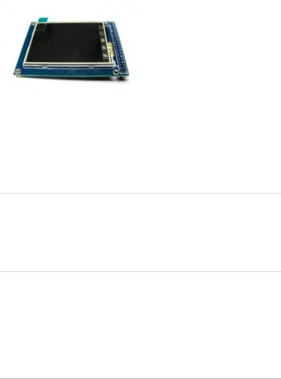
HY-TFT320 is a 3.2 inch TFT LCD Screen module, 320*240 (resolution), 65K color, 40pins interface ,
not just a LCD breakout, but include the Touch screen, SD card. So it’s a powerful extension module
for your project.
This Screen includes a controller SSD1289, it’s 16bit data interface, easy to drive by many MCU like
STM32 ,AVR and 8051.HY-TFT320 is designed with a touch controller in it . The touch IC is XPT2046 ,
and touch interface is included in the 40 pins breakout. Another useful extension in this module is the
SD Card socket . It use the SPI mode to operate the SD card, the SPI interface include in the 40pins
breakout.
Application Ideas
Digital Photo Frame (DPF)
Video terminals
Instrumentation
GPS
Game consoles
Video phones and Portable VCD, DVD
Specification:
3.2" Color TFT LCD
320 x 240 Resolution
65,536 Colors (16 Bit)
Powerful 16 Bit Microcontroller(SSD1289)
Built-in video RAM buffer
Integrated Resistive Touchscreen
Integrated SD card
5V Operating Voltage
LED Backlight
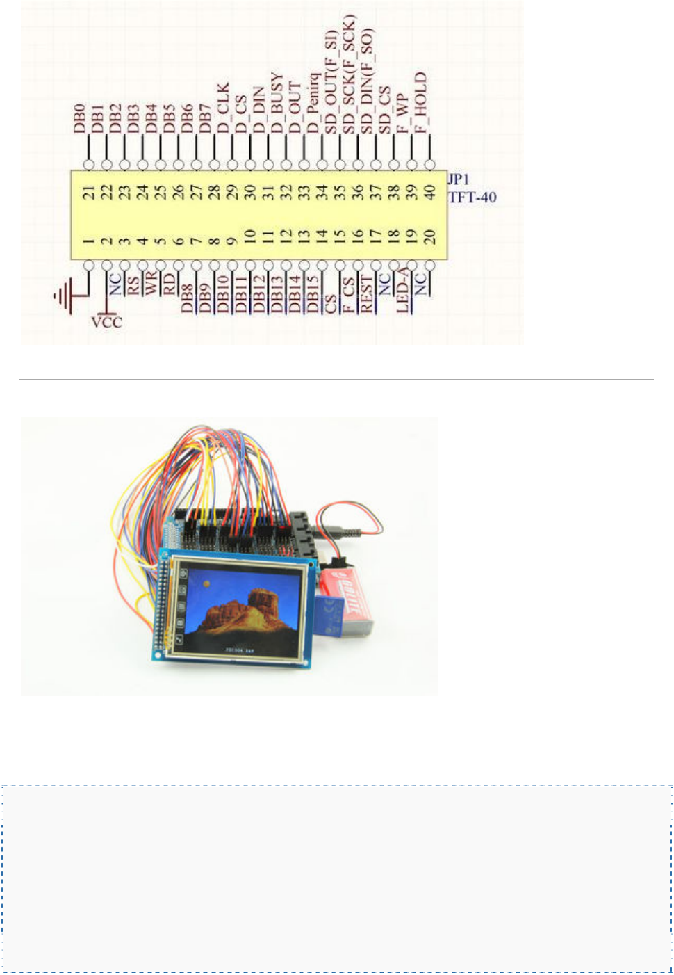
pin difinition
Usage:
Display:
The UTFT library is required to be installed to get this screen model display. This library is especially
designed for 3.2” TFT LCD screen using 16 bit mode. The library require the following connections.
Connect HY-TFT320 to Arduino Mega2560:
LEDA -> 5V
VCC -> 5V
RD -> 3.3V
GND -> GND
DB0->DB7 to pin D37->D30
DB8->DB15 to pin D22->D29
RS -> D38
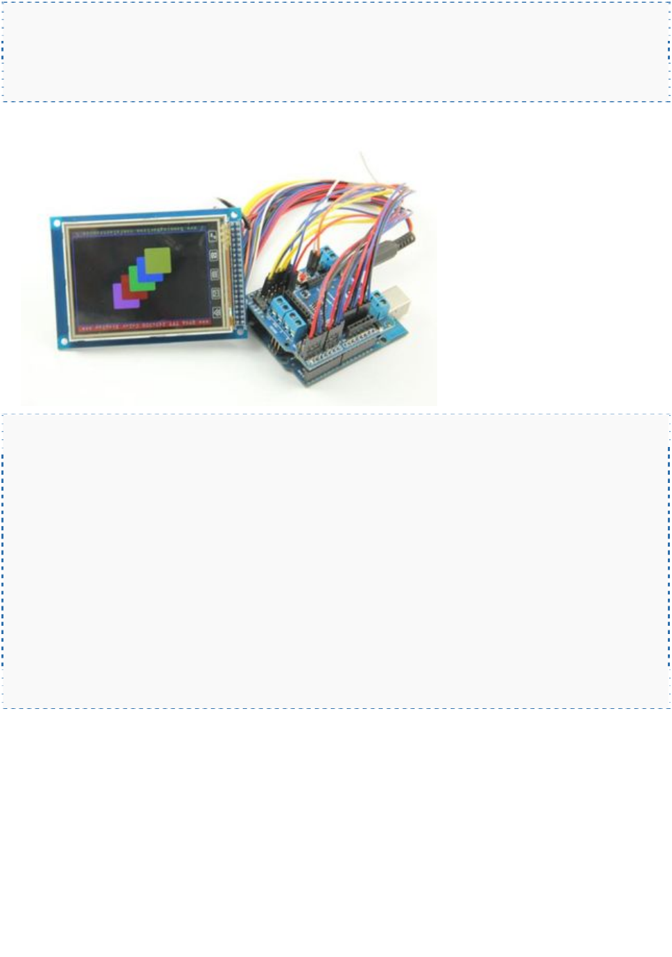
WR -> D39
CS(pin6) -> D40
RSET-> D41
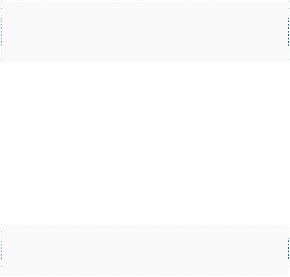
Connect HY-TFT320 to Arduino UNO
LEDA -> 5V
VCC -> 5V
RD -> 3.3V
GND -> GND
DB0->DB5 to D8->D13
DB6->A0
DB7->A1
DB8->DB15 to D0->D7
RSET->A2
CS->A3
WR->A4
RS->A5
Note: The TFT controller model needs to be declared in the initializing statement. ITDB02
myGLCD(38,39,40,41) needs to be modified as myGLCD(38,39,40,41,ITDB32S) when using Arduino
Mega2560.ITDB02 myGLCD(19,18,17,16,ITDB32S) needs to be commented when using Aduino UNO.
Otherwise it just show a blank screen. In practice, RS, WR, CS, RSET can be connected to any free
pin. But the pin number must be in accord with myGLCD(RS,WR,CS,RST).
Touch Screen:
The LCD has a 3.2" 4-wire resistive touch screen lying over it. The Touch libraryneeds to be installed
to get it works. This library is designed for 2.4’’ TFT, 3.2” TFT LCD screen module.
Interface the touchscreen to Arduino Mega2560:
Default pin number in example code:
DCLK-> D6
CS(pin30) -> D5
IN -> D4
OUT-> D3
IRQ -> D2
Note:TCLK, TCS, TDIN, TDOUT, IRQ also can be connected to any free pin. But the pin number must
be in accord with the touch screen initializing statement myTouch(DCLK,CS,IN,OUT,IRQ).
Calibrate the touch screen: The default setting is accurate for 2.4” TFT module, but you need to
calibrate when using 3.2” TFT module. A program to calibrate the touch screen is included in the
example. If you touch screen is inaccurate, you need to run touch_calibration. Follow the on-screen
instruction to calibrate the touch screen. Better not use your finger to calibrate it, use your accessory
touch pen to pressure the frontsight with stength. Then record the calibration parameters and apply
them in ITDB02_Touch.cpp in your touch screen library.
SD Card:
There is built-in SD card slot in the shield, so we can use it to upload images. But the images need to
be converted RAW format first. SD libraries tinyFAT and tinyFAT_16 need to be preinstalled for
displaying the image.
Note: The library only supports FAT16 fomatted SD card up to 2GB, so you need to fomat your SD
card to FAT16. 4GB FAT16 fomatted SD card is tested not working. Long file names are not supported.
Keep your file names compliant with 8.3 standard.
Interface SD card to Arduino mega:
SCK -> D52
MISO -> D50
MOSI-> D51
CS -> D53
