3DTouch Auto Leveling Sensor User Manual
3DTouch%20auto%20leveling%20sensor%20%20User%20Manual
3DTouch%20auto%20leveling%20sensor%20%20User%20Manual
User Manual: Pdf
Open the PDF directly: View PDF ![]() .
.
Page Count: 28
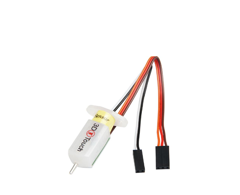
3DTouch Auto Leveling Sensor
User Manual
1. Introduction
3DTouch is an auto leveling sensor for 3D Printers that can precisely measure the tilt
of your print surface. It can greatly improve the printing precision of your 3D Printer.
3DTouch features simple, smart and precise. It could work with nearly any kind of
bed materials, such as glasses, woods, metals and so on.
The main functions and controls of 3DTouch are the same as most auto bed leveling
sensors, which consists of a RC servo and a micro switch, thus, 3DTouch can be used
on almost every 3D printer control board.
By using progressively designed solenoid and hall sensor, 3DTouch can integrate high
precision in such a simple structure. To make it more user-friendly and to bring you
more enjoyable printing experience we add many smart functions such as self-test,
false alarm, alarm release and test mode for M119.
Features:
1 Simple
3DTouch can be easily applied, since it has a small and simple structure. Gathering
information & firmware setting will be an easy task, because 3DTouch works as usual
auto bed leveling sensor.

www.geeetech.com
SHENZHEN GETECH TECHNOLOGY CO,.LTD
2 Smart
Self-test: The push pin is operated two times to test when the power is on
Alarm: The LED light blinks if a problem found on a self-test or on an operation
3 High-precision
3DTouch’s Standard Deviation in repeatability is around 0.005mm, at that precise.
If you choose 3DTouch, your 3D printer will be high-class masterpiece, giving you an
enjoyable experience.
4. Innovative Solenoid: Ultra Power Saving
On idle state, while the push-pin is whether pulled out or retracted, there are not any
electric current flowing on solenoid, and standby electric current in the whole device
is below 15mA on average, whereas on working state, while the pin is moving in
sudden about 100ms, under 300mA flows in the device.
Low power consumption even further drops joule heating, preventing from heat
problem.
5 Technologies
3DTouch consists of Atmel ATtiny13A, solenoid, and a push pin.
6 wide Selection of Bed
3DTouch does not uses either optical, nor proximity (inductive/capacitive) sensor.
3DTouch is controlled by Hall Effect, providing high precision. Thus the bed material
can be selected freely.
7 Optimized structure: Larger Build Size
3DTouch is a small and technology-intensive one. Build size can be set larger than
other existing auto bed leveling sensor.
3DTouch uses existing RC Servo motor signal intactly, so just plug 3DTouch on the
same pins after removing servo motor.
Specifications:
Voltage: 5V
Current: 15mA
Max. Current: 300mA
Cable length: 150mm
Net Weight: 10g
Shipping weight: 25g

www.geeetech.com
SHENZHEN GETECH TECHNOLOGY CO,.LTD
Wiring
3-pin: Brown (-, GND), Red (+5V), Orange (control signal)
2-pin: Black (-, GND), White (Z min)
2. How to use it
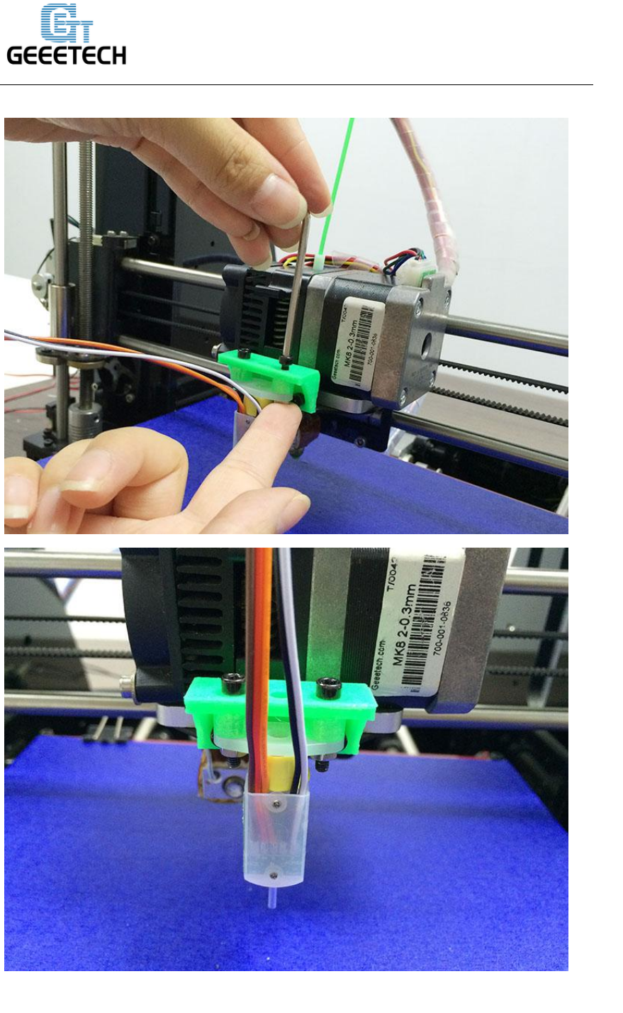
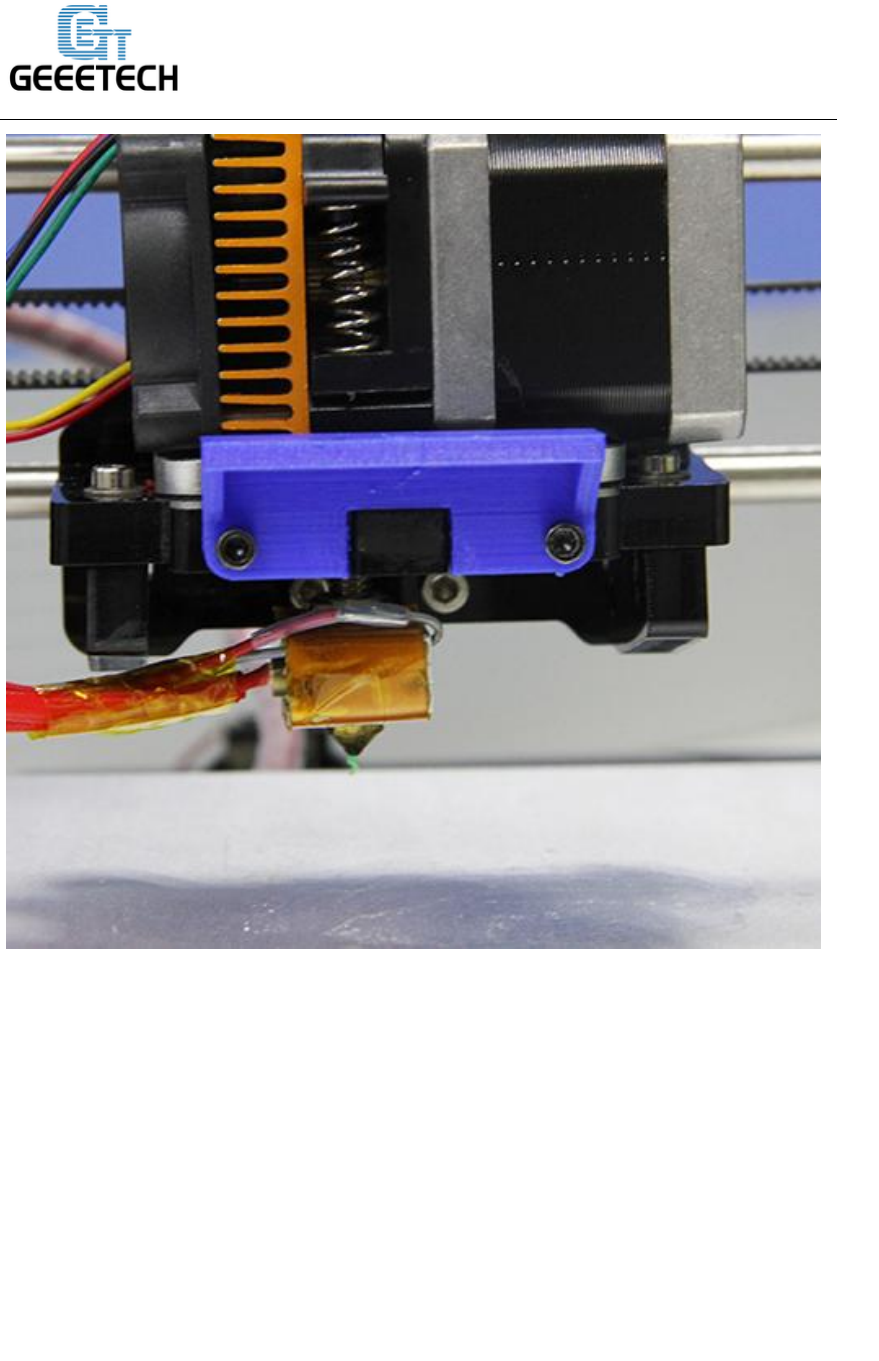
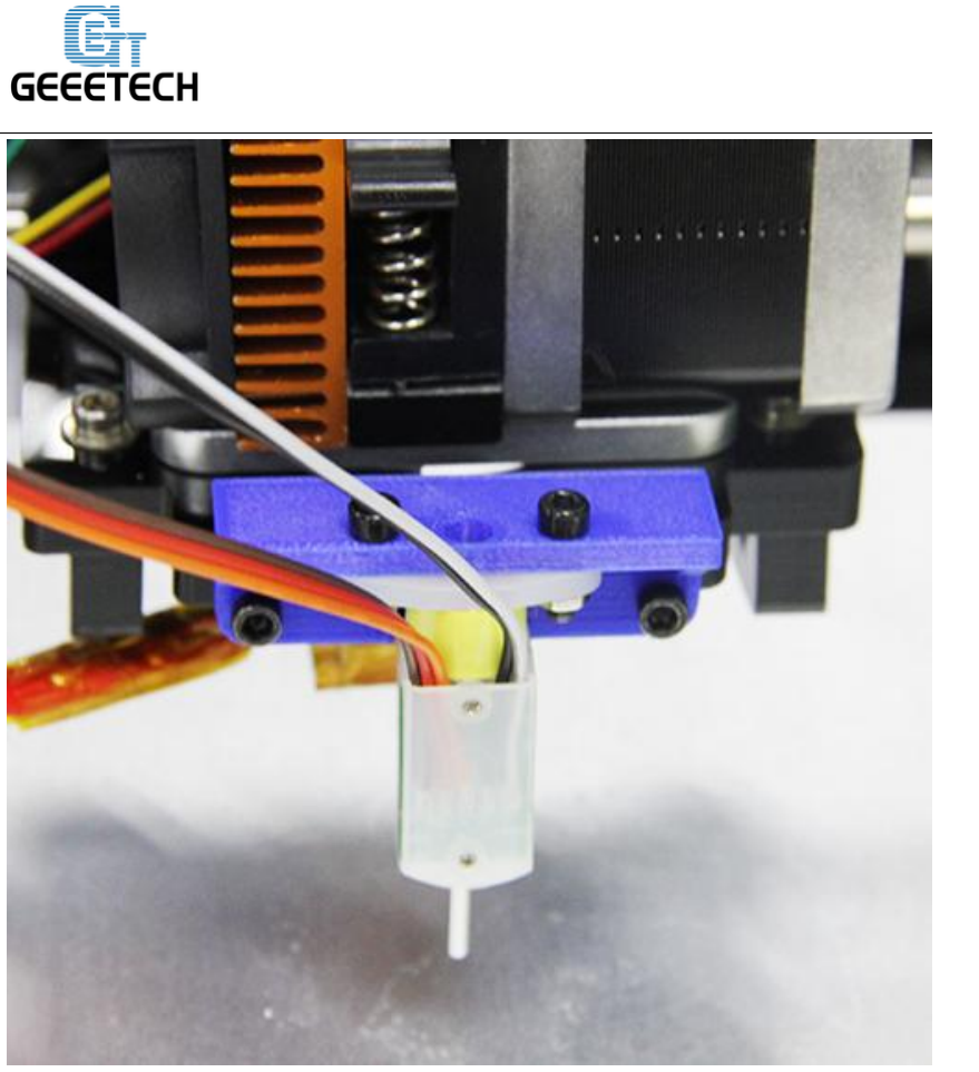
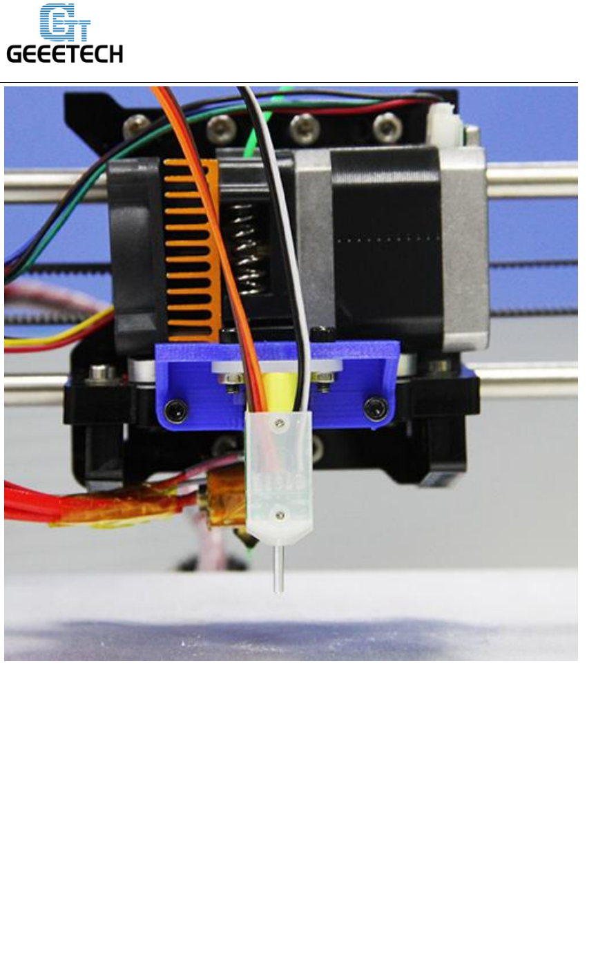
2.1 mount the 3DTouch sensor
So far we have successfully tested our 3DTouch sensor on Geeetech Prusa I3 pro B,
Pro C and Pro X.
Here is a detailed instructions on how to use the 3DTouch sensor to your geeetech pro
B. For pro C and pro X, the steps are the same.
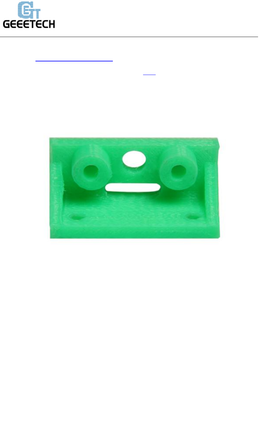
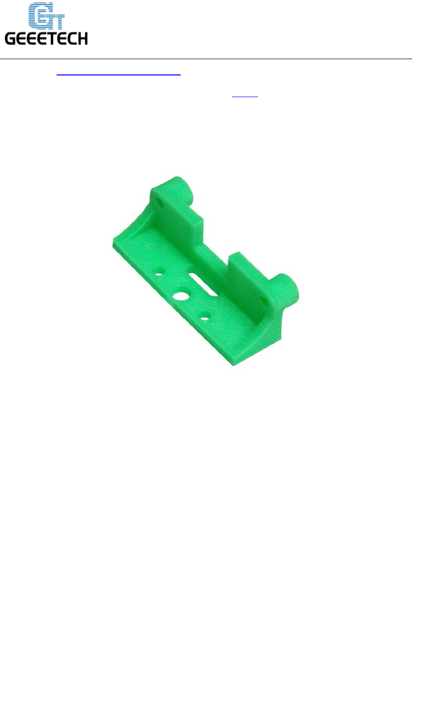
You will need a suitable mount to attach the 3DTouch sensor to your printer.Here is a
3DTouch sensor mount:

www.geeetech.com
SHENZHEN GETECH TECHNOLOGY CO,.LTD
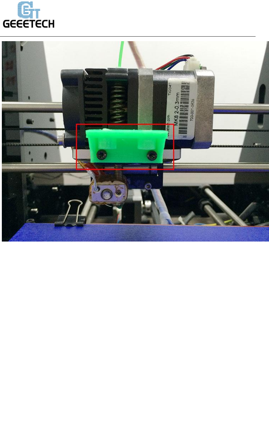
3. Fix the 3DTouch sensor on the sensor mount with 2 M3*16mm screws and 2 M3
nuts.
www.geeetech.com
SHENZHEN GETECH TECHNOLOGY CO,.LTD
www.geeetech.com
SHENZHEN GETECH TECHNOLOGY CO,.LTD
2.2 Wiring
The 3DTouch Auto Leveling sensor has 5 wires, 3 for the first servo connection and
5v and 2 for the Z min end stop, negative and signal pins.
3DTouch can be operated in the following condition.
One I/O for control (PWM or Software PWM)
One I/O for Z min (Z Probe)
GND and +5V power
www.geeetech.com
SHENZHEN GETECH TECHNOLOGY CO,.LTD
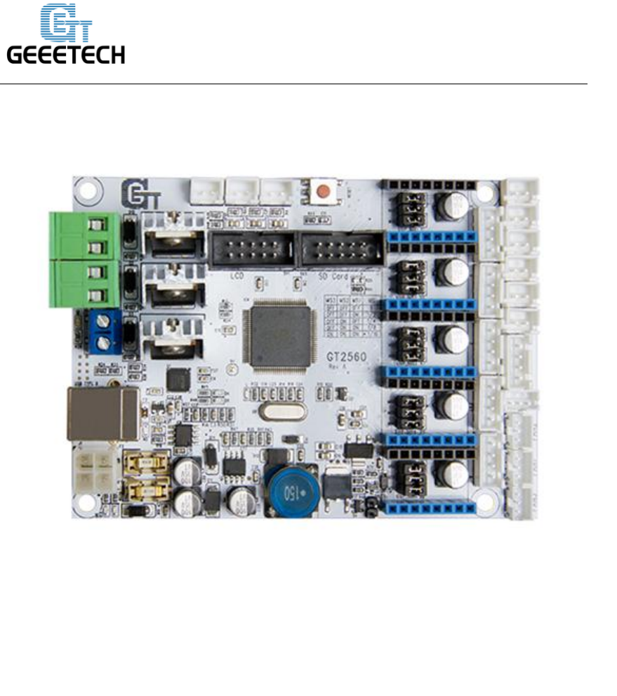
GT2560 Rev A
There are several ways to connect the 3DTouch Auto Leveling sensor to GT2560,
here is the easiest way.
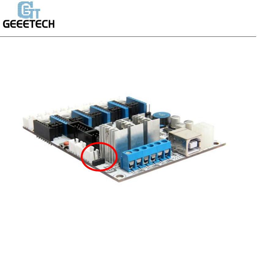
Step1. Remove the Z max connector from the board and replace it with a 3Pin
Straight Pin. You need to use soldering iron here.
www.geeetech.com
SHENZHEN GETECH TECHNOLOGY CO,.LTD
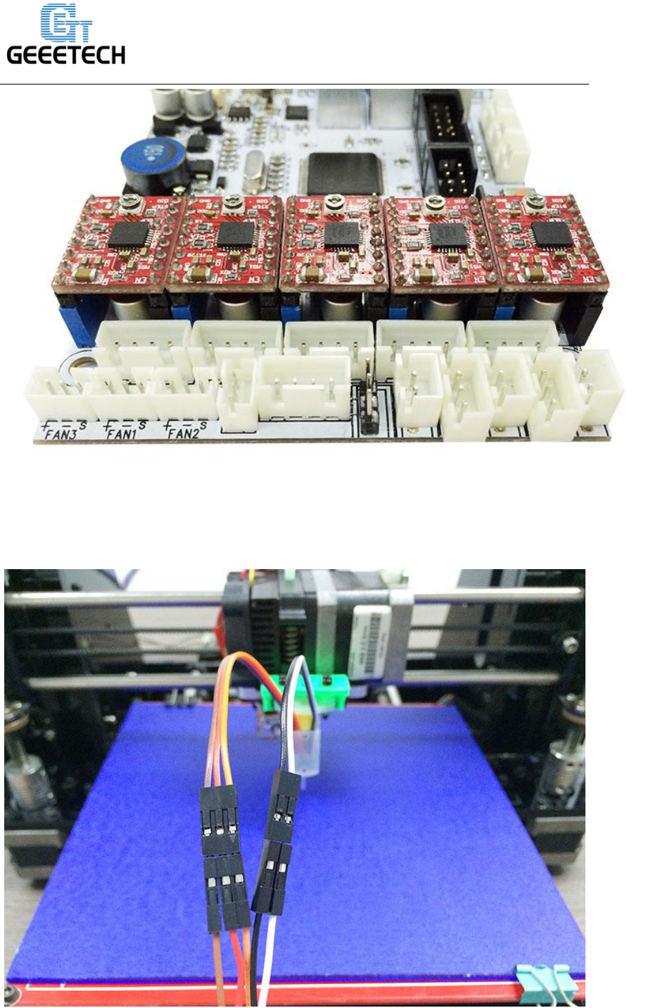
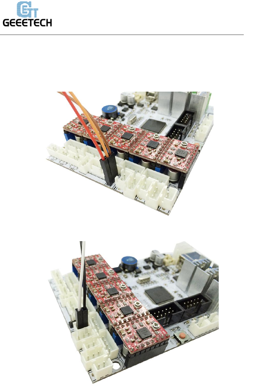
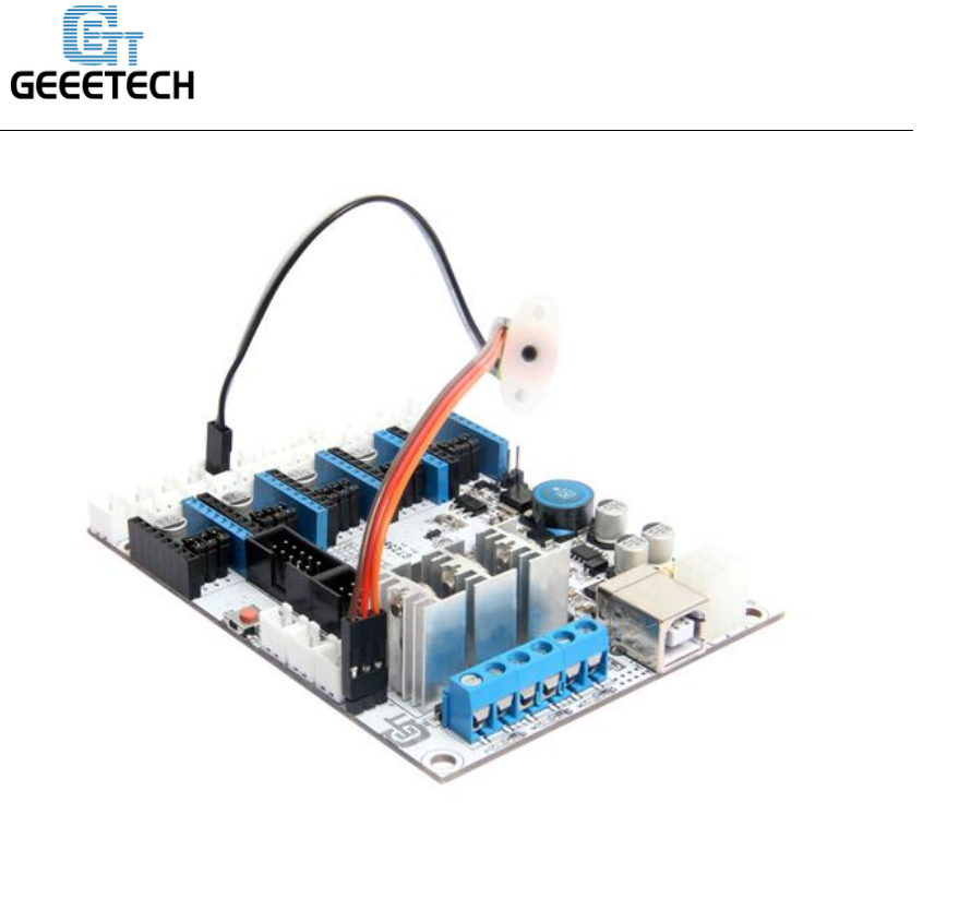
Step3. Connect the extended wire to the GT2560 control board.
Connect the 3 pin wire to the Z max pin.
3-pin: Brown (-, GND) Red (+5V) Orange (control signal)
Connect the 2 pin wire to the Z min pin.
www.geeetech.com
SHENZHEN GETECH TECHNOLOGY CO,.LTD
Note the wire order.
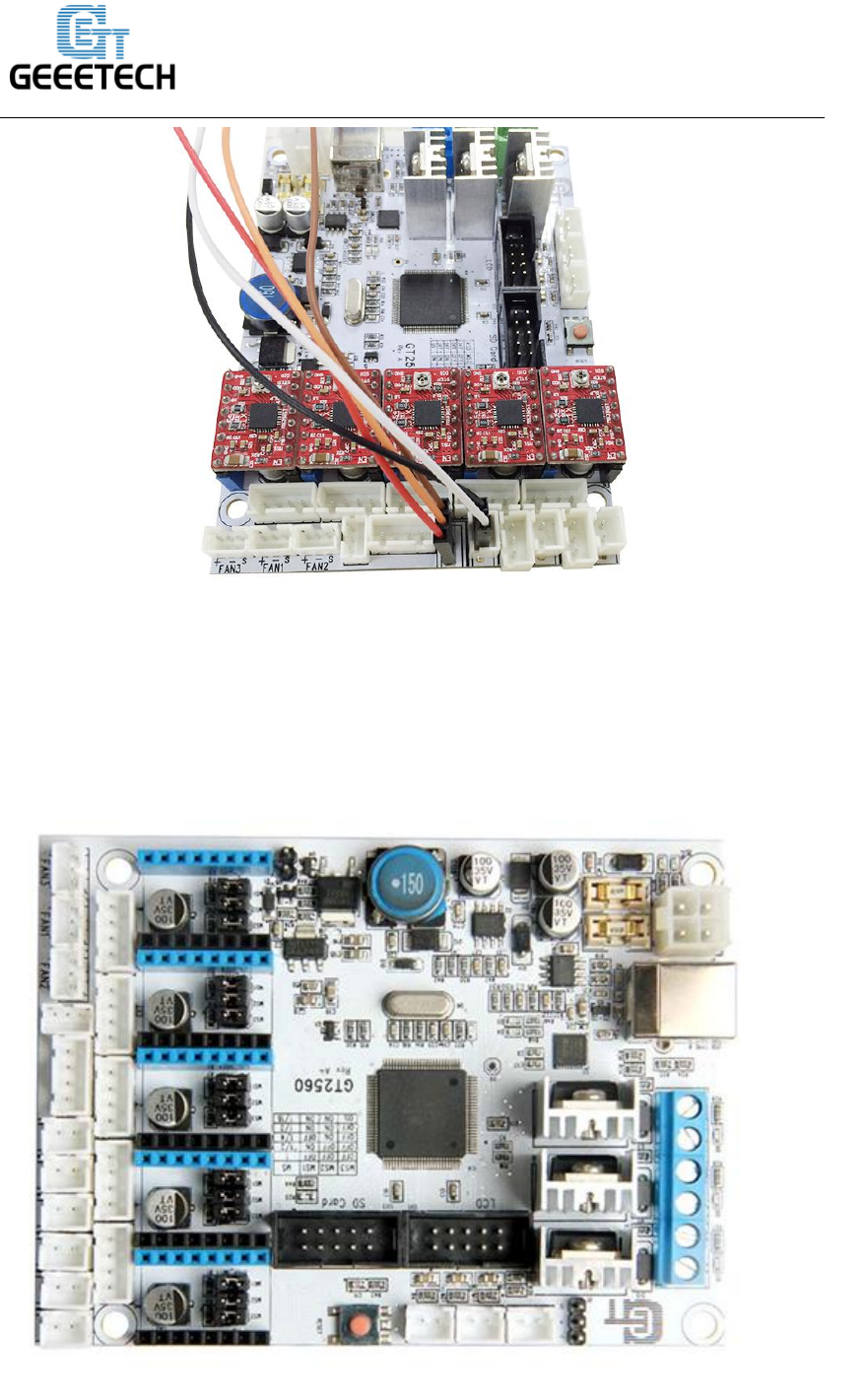
GT2560 rev A+
www.geeetech.com
SHENZHEN GETECH TECHNOLOGY CO,.LTD
Update:
1. A 3-pin straight servo pin is added to connect with 3D touch auto leveling sensor
which saves you from soldering.
1. Connect the 2 pin to servo. Note the wire order: it is Brown-Red-Orange from
Outside-to-inside.
www.geeetech.com
SHENZHEN GETECH TECHNOLOGY CO,.LTD
2. Connect the 2-pin wire to Z-min. Note the wire order: it is White-Black from
Outside-to-inside.

www.geeetech.com
SHENZHEN GETECH TECHNOLOGY CO,.LTD
When using 3DTouch Auto Leveling sensor, you do not need to connect the
original Z min end stop wires.
That's all for the wiring of the 3DTouch Auto Leveling sensor and GT2560.
2.3. Firmware setting
Changes need to be made for the configuration file in the Marlin source code for 3DTouch. The
required changes are similar to how you would setup a mechanical servo sensor.
The firmware setting for the Prusa I3 pro B, pro C and pro X are most the same. To download the
firmware, please visit here.
Step1. Open the firmware in ArduinoIDE, find the following code in Configuration.h:

www.geeetech.com
SHENZHEN GETECH TECHNOLOGY CO,.LTD
Step2. Change the content in the red box as follow:
// Number of servos
//
// If you select a configuration below, this will receive a default value and does not
need to be set manually
// set it manually if you have more servos than extruders and wish to manually control
some
// leaving it undefined or defining as 0 will disable the servo subsystem
// If unsure, leave commented / disabled
//
#define NUM_SERVOS 1 // Servo index starts with 0 for M280 command
// Servo Endstops
//
// This allows for servo actuated endstops, primary usage is for the Z Axis to eliminate
www.geeetech.com
SHENZHEN GETECH TECHNOLOGY CO,.LTD
calibration or bed height changes.
// Use M206 command to correct for switch height offset to actual nozzle height.
Store that setting with M500.
//
#define SERVO_ENDSTOPS {-1, -1, 0} // Servo index for X, Y, Z. Disable with -1
#define SERVO_ENDSTOP_ANGLES {0,0, 0,0, 10,90} // X,Y,Z Axis Extend and
Retract angles
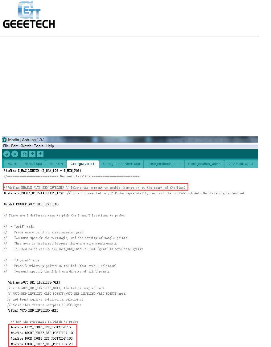
Step2. Find the codes regarding to Bed Auto Leveling in Configuration.h.
www.geeetech.com
SHENZHEN GETECH TECHNOLOGY CO,.LTD
=============================BedAutoLeveling==================
#define ENABLE_AUTO_BED_LEVELING // Delete the comment to enable
(remove // at the start of the line)
#define Z_PROBE_REPEATABILITY_TEST // If not commented out, Z-Probe
Repeatability test will be included if Auto Bed Leveling is Enabled.
#ifdef ENABLE_AUTO_BED_LEVELING
…
#define AUTO_BED_LEVELING_GRID
…
#ifdef AUTO_BED_LEVELING_GRID
www.geeetech.com
SHENZHEN GETECH TECHNOLOGY CO,.LTD
// set the rectangle in which to probe
#define LEFT_PROBE_BED_POSITION 30
#define RIGHT_PROBE_BED_POSITION 200
#define BACK_PROBE_BED_POSITION 147
#define FRONT_PROBE_BED_POSITION 20
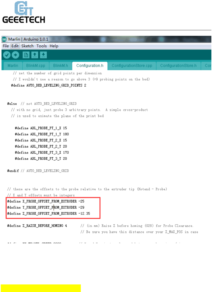
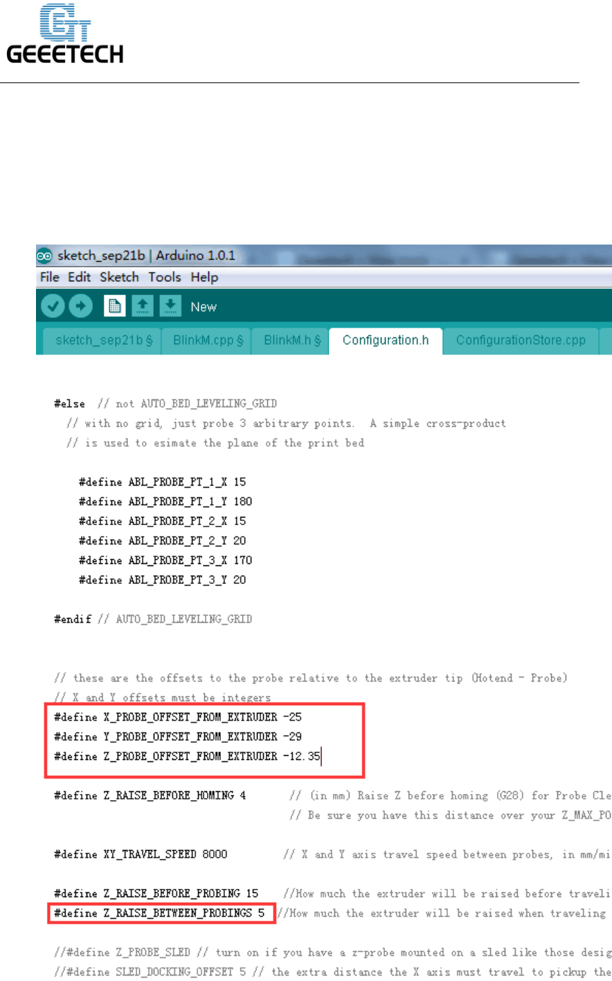
Step3: scroll down to find the codes to Define the probe offset

www.geeetech.com
SHENZHEN GETECH TECHNOLOGY CO,.LTD
Step4. Change the content in the red box as follow:
#define AUTO_BED_LEVELING_GRID_POINTS 2
#else // not AUTO_BED_LEVELING_GRID
…
#define X_PROBE_OFFSET_FROM_EXTRUDER 4
#define Y_PROBE_OFFSET_FROM_EXTRUDER -43
#define Z_PROBE_OFFSET_FROM_EXTRUDER -1.4
#define Z_RAISE_BETWEEN_PROBINGS 10
*Note please: if your printer is pro X, you need put different numbers as shown
below:
#define LEFT_PROBE_BED_POSITION 20
#define RIGHT_PROBE_BED_POSITION 190
#define BACK_PROBE_BED_POSITION 165
#define FRONT_PROBE_BED_POSITION 30
#define X_PROBE_OFFSET_FROM_EXTRUDER 4
#define Y_PROBE_OFFSET_FROM_EXTRUDER -50
#define Z_PROBE_OFFSET_FROM_EXTRUDER -3.26
#define Z_RAISE_BETWEEN_PROBINGS 10
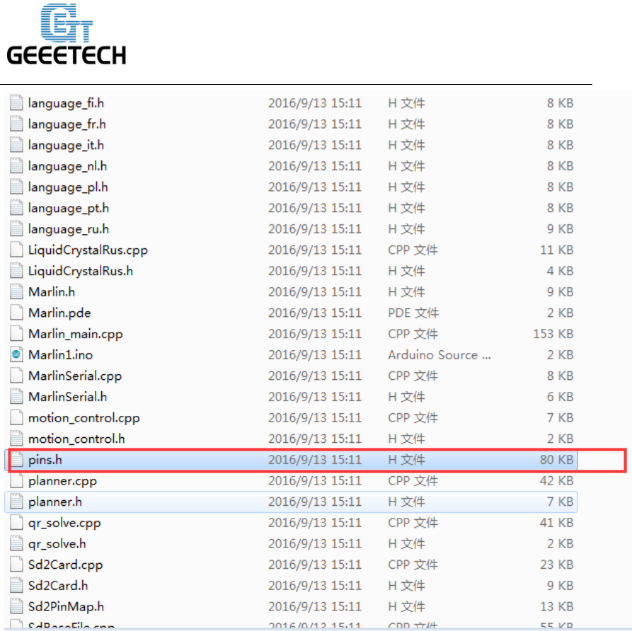
Step4. Find the following code in pins.h
If you do not find the pins.h tab on Arduino IDE, please open it separately, after the
modification, please save it.
www.geeetech.com
SHENZHEN GETECH TECHNOLOGY CO,.LTD
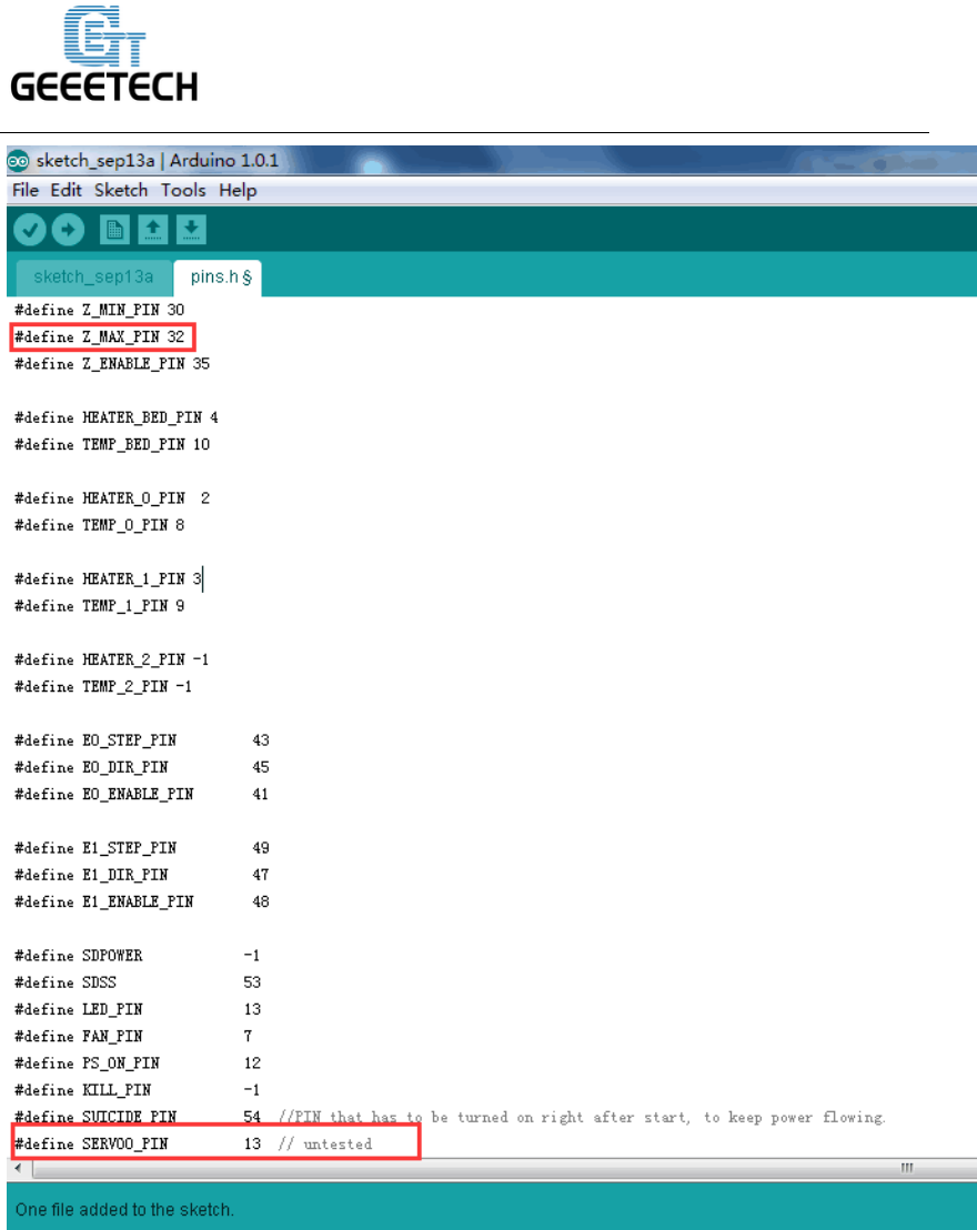
Find the following code as shown in the red box:
www.geeetech.com
SHENZHEN GETECH TECHNOLOGY CO,.LTD
Change the content in the red box as follow:
/*****************************************************************
* Ultimaker pin assignment
******************************************************************/
#if MB(ULTIMAKER)
#define KNOWN_BOARD

www.geeetech.com
SHENZHEN GETECH TECHNOLOGY CO,.LTD
#define Z_MAX_PIN -1//32
#define Z_ENABLE_PIN 35
…
#define SUICIDE_PIN 54 //PIN that has to be turned on right after start, to keep
power flowing.
#define SERVO0_PIN 32//13 // untested
*Note: For GT2560 Rev A+, #define SERVO0_PIN 11//13 // untested
Now, we have finished the firmware; please upload the modified firmware to your
control board.
3. Testing
When the 3DTouch is first powered up it does a self test – Starting with the pin up it
them goes down/up 3 times and ends up the LED on solid. Continuous flashing means
that there is an obstruction or fault.
The 3DTouch acts on the following g.code that can be used manually to diagnose
faults etc but you don’t need to normally worry about them.
M280 P0 S10 ; pushes the pin down
M280 P0 S90 ; pulls the pin up
M280 P0 S120 ; Self test – keeps going until you do pin up/down or release alarm
M280 P0 S160 ; Release alarm
Alarm – The 3DTouch can sense when something is wrong and then goes into alarm
mode which is continuous flashing. Alarm can be triggered like an obstruction that
stops the pin going up and down freely, it could be dirt etc.
www.geeetech.com
SHENZHEN GETECH TECHNOLOGY CO,.LTD
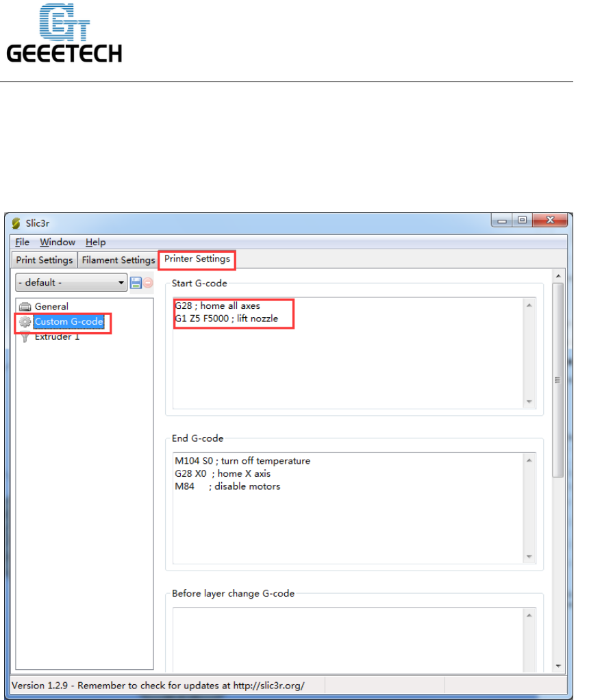
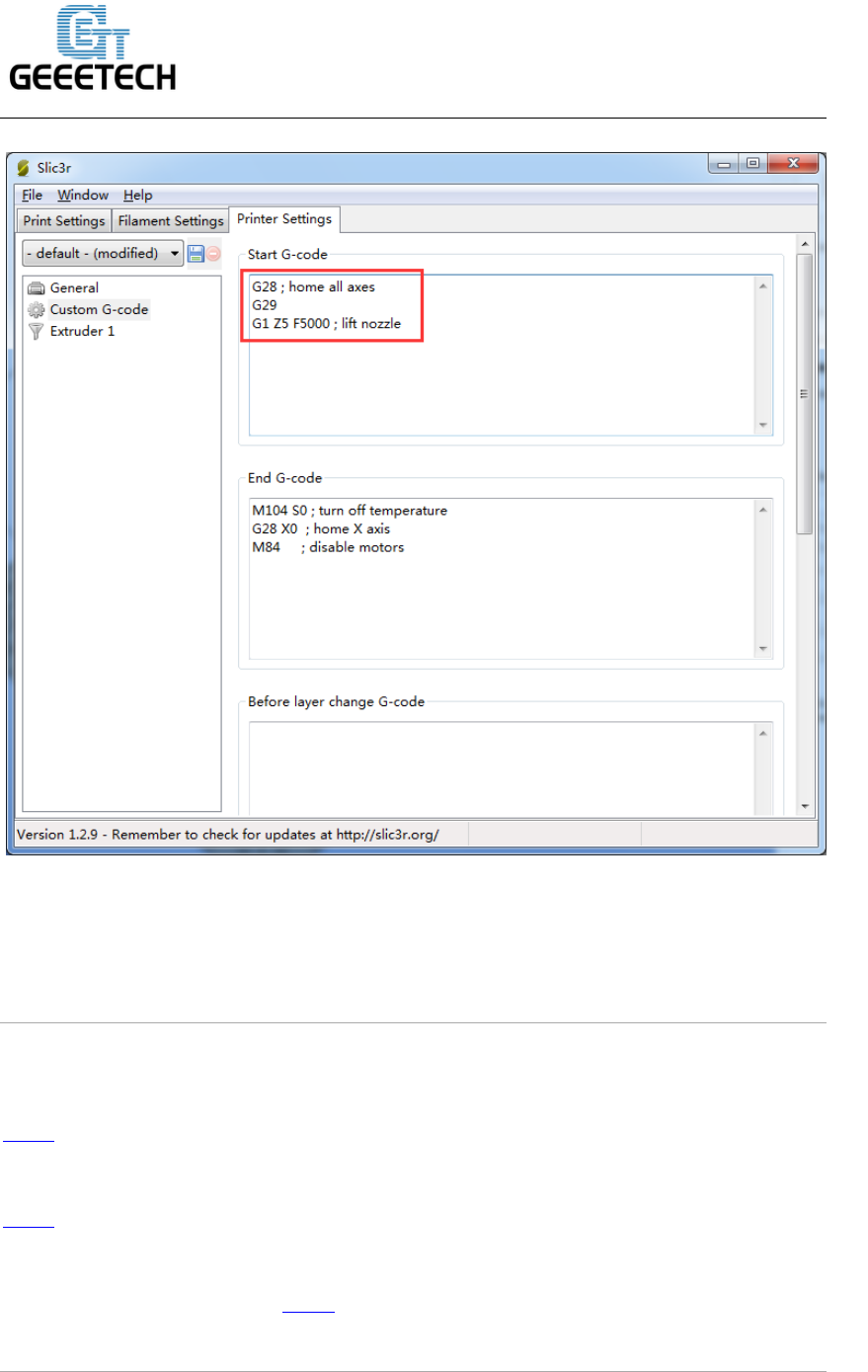
4. Printer setting
Providing the firmware is correctly configured, the sensor responds to the same codes
as any other sensor e.g. inductive, capacitive or IR. The Start Code in you slicer
should contain the sequence G28 followed by G29 to do the auto bed leveling.
Open Slicer>printer setting
www.geeetech.com
SHENZHEN GETECH TECHNOLOGY CO,.LTD
Add G29 command right after G28
*Don’t put another G28 after the G29 as it will just remove the G29 results.
The G29 command should be added every time.
5. Videos
Here is a video of using the 3DTouch Auto Leveling Sensor on Geeetech Prusa I3 pro
B 3d printer.
Here is a video of using the 3DTouch Auto Leveling Sensor on Geeetech Prusa I3 pro
X 3d printer.
For more videos, please visit here
