3DKnee Surgical Technique
2015-06-09
: Pdf 3Dknee Surgical Technique 3DKnee_Surgical_Technique 6 2015 pdf
Open the PDF directly: View PDF ![]() .
.
Page Count: 15
Surgical Technique
3DKnee™
TM

Contributing Surgeon
W. Andrew Hodge, M.D., FACS
DJO Surgical
9800 Metric Boulevard
Austin, TX
(800) 456-8696
www.djosurgical.com
www.3D-knee.com
Table of Contents
Design Rationale 2
Femoral Component 2
Tibial Component 3
Modular 3DKnee Tibial Inserts 4
Patellar Component 5
Indications and Contraindications 5
Preoperative Planning 6
Minimally Invasive Surgical Exposure 7
Femoral Technique 8
Open the Femoral Canal 8
Establish Femoral Alignment 8
Distal Femoral Resection 9
Tibial Alignment 10
Tibial Alignment 10
Tibial Slope Alignment 11
Total Leg Alignment 12
Tibial Alignment (Intramedullary Option) 13
Femoral Sizing 15
Posterior Reference 15
Femoral Preparation: 4-in-1 Speed Blocks 16
Tibia Cut 17
Tibial Sizing 18
Tibial Keel Preparation 19
Patella Preparation 20
Resurfaced Patellar Peg Preparation 20
Patellar Peg Preparation 20
Recessed Patella Preparation 21
Patellar Sizing for Recessing 21
Recessing 21
Patellar Peg Preparation 21
Trial Reduction 22
Tibial Component 23
Tibial Insert 23
Component Implantation 24
Femoral Component 24
Patellar Component 24
Wound Closure 24
This brochure is presented to demonstrate
the surgical technique utilized by the surgeon
listed above. DJO Surgical, as the manufacturer
of this device, does not practice medicine and
cannot recommend this or any other surgical
technique for use on a specific patient. The
choice of the appropriate surgical technique
is the responsibility of the surgeon performing
the operation.

Surgical Technique
3DKnee™
Design Rationale
The 3DKnee is design driven by in-vivo and in-vitro data on a wide
variety of existing total knee systems.
The 3DKnee was designed as a primary tri-compartmental knee
replacement system. The main objective of the femoral component
is to resurface the distal femur with minimum bone removal.
The femoral component has an 8-10mm distal and posterior thickness
in order to conserve the amount of bone removed from the femur and
to maintain the joint line position through full ROM. The femur is made
of CoCr.
The 3DKnee femoral component comes in 9 sizes in both lefts and
rights to provide versatility in matching the patient’s anatomy. Each
femoral component size selected will determine the insert size. This
will provide an exact match between articulating surfaces.
The dimensions of the femoral components are illustrated below:
Surgical Technique
3DKnee ™
3
Tibial Component
The 3DKnee tibial components are color coded in
coordination with the appropriate femoral matched insert.
The 3DKnee tibial components will modularly connect to
the femoral matched tibial insert. If the optimal size tibia
component is smaller than the femur, the respective
size Foundation/3D down stemmed baseplate can be used
with the femoral matched size 3DKnee insert, as indicated
in the chart below. For example, if a size 8 left 3DKnee
femoral component is selected with a size 8 left 3DKnee
tibia insert, then either a size 8 left 3DKnee tibia component,
a size 6 left Foundation tibia component, or a size FK6/3DKnee
down 8 left tibia component can be used. The size 8 3DKnee
tibia insert will modularly connect to either size baseplate
(see also color-coded sizing chart in the front of the
technique).The 3DKnee inserts are available in 9mm,
11mm, 13mm, 15mm and 19mm thicknesses.
The tibial baseplate has an asymmetric tibial profile.
A posterior notch allows for retention of the posterior cruciate
Ligament if desired.
The tibial design comes in six sizes, left and right.
Combining the Foundation Tibia with the 3DKnee Tibia
options oers 24 components to the system.
The dimensions of the tibial baseplates are illustrated below:
2
Femoral Component
Size A-P Dims Box Dims M-L Dims Distal Condyle Dims Posterior Condyle Dims
(left/right) (mm) (mm) (mm) (mm) (mm)
2 52 37 58 8 8
3 54 39 61 9 8
4 56.5 41 63.5 9 8
5 59 43 66 10 9
6 62 45 68.5 10 9
7 64 47 71 10 9
8 67 49 73.5 10 9
10 72 53 79 10 10
12 76 57 84 10 10
Tibial Component
Size (left/right) Lateral A-P Dims (mm) Medial A-P Dims (mm) M-L Dims (mm)
3D Down 2 (special order) 34 39 60
3D 2/3D Down 4 38 41 63
3D 4/3D Down 6 42 45 69
3D 6/3D Down 8 44 48 74
3D 8/3D Down 10 47 51 79
3D 10/3D Down 12 50 54 84
3D 12 53 58 89

Surgical Technique
3DKnee™
Modular 3DKnee Tibial Inserts
The 3DKnee Tibial Insert comes in 9 sizes and is oered in pure ultra-high
molecular weight polyethylene (UHMWPE) as well as vitamin E blended
UHMWPE. Each insert size is oered in 5 standard thicknesses, resulting
in tibial assemblies of 9mm, 11mm, 13mm, 15mm and 19mm. The minimum
poly thickness for the 9mm insert is 6mm (the label for the insert thickness
refers to the overall thickness of the insert/baseplate assembly).
The tibial baseplate and insert assemble via a locking mechanism
that utilizes posterior feet and an anterior snap on the inside pocket of
the baseplate. In addition, the inserts are secured with a self-locking
attachment screw.
Trials are available for the tibial inserts and are color coded for
reference intraoperatively. The sizing chart is located with the
surgical technique.
Patellar Components
The Patellar Components for the 3DKnee system are domed shaped
to match the geometry of the 3DKnee Femoral Component.
Three pegs and grooves are present on the inferior surface of the
patella. The shape of the patella is a symmetrical dome and the
symmetrical geometry requires no rotational alignment.
The domed patellae are available in 5 resurfacing and recessing
diameters (26mm, 29mm, 32mm, 35mm, 38mm). Trials are available for
the dome patellae and are color coded for easy reference intraoperatively.
The color codes are illustrated below:
Surgical Technique
3DKnee ™
5
Indications
Joint replacement is indicated for patients suering
from disability due to:
• degenerative, post-traumatic or rheumatoid
arthritis;
• avascular necrosis of the femoral condyle;
• post-traumatic loss of joint conguration,
particularly when there is patellofemoral erosion,
dysfunction or prior patellectomy;
• moderate valgus, varus or exion deformities;
• treatment of fractures that are unmanageable using
other techniques.
This device may also be indicated in the salvage of
previously failed surgical attempts.
All devices are intended for cemented applications
except for the 3DKnee Porous Coated Femur which is
intended for cementless applications.
Contraindications
Total joint replacement is contraindicated where
there is:
• infection (or a history of infection), acute or chronic,
local or systemic;
• insucient bone quality which may aect the
stability of the implant;
• muscular, neurological or vascular deciencies,
which compromise the aected extremity;
• obesity;
• alcoholism or other addictions;
• materials sensitivity;
• loss of ligamentous structures;
• high levels of physical activity (e.g. competitive
sports, heavy physical labor).
Intended Use
DJO Surgical knee devices are intended for treatment of
patients who are candidates for knee arthroplasty per
the indications for use. While total knee replacements
are not intended to withstand activity levels and loads
of normal healthy bone, they are a means of restoring
mobility and reducing pain for many patients.
4
Style Trial Color
Size 26 - 8mm Thick Yellow
Size 29 - 8mm Thick Rust
Size 32 - 8mm Thick Green
Size 35 - 9mm Thick Blue
Size 38 - 9mm Thick Black
Style Trial Color
Size 26 - 10mm Thick Lt. Purple
Size 29 - 10mm Thick Lt. Purple
Size 32 - 10mm Thick Lt. Purple
Size 35 - 10mm Thick Lt. Purple
Size 38 - 10mm Thick Lt. Purple
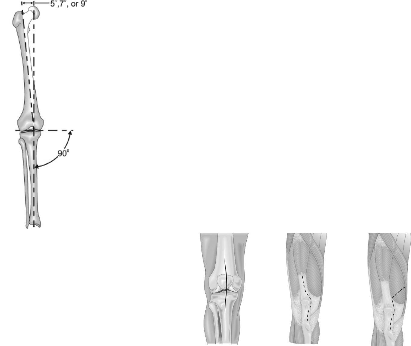
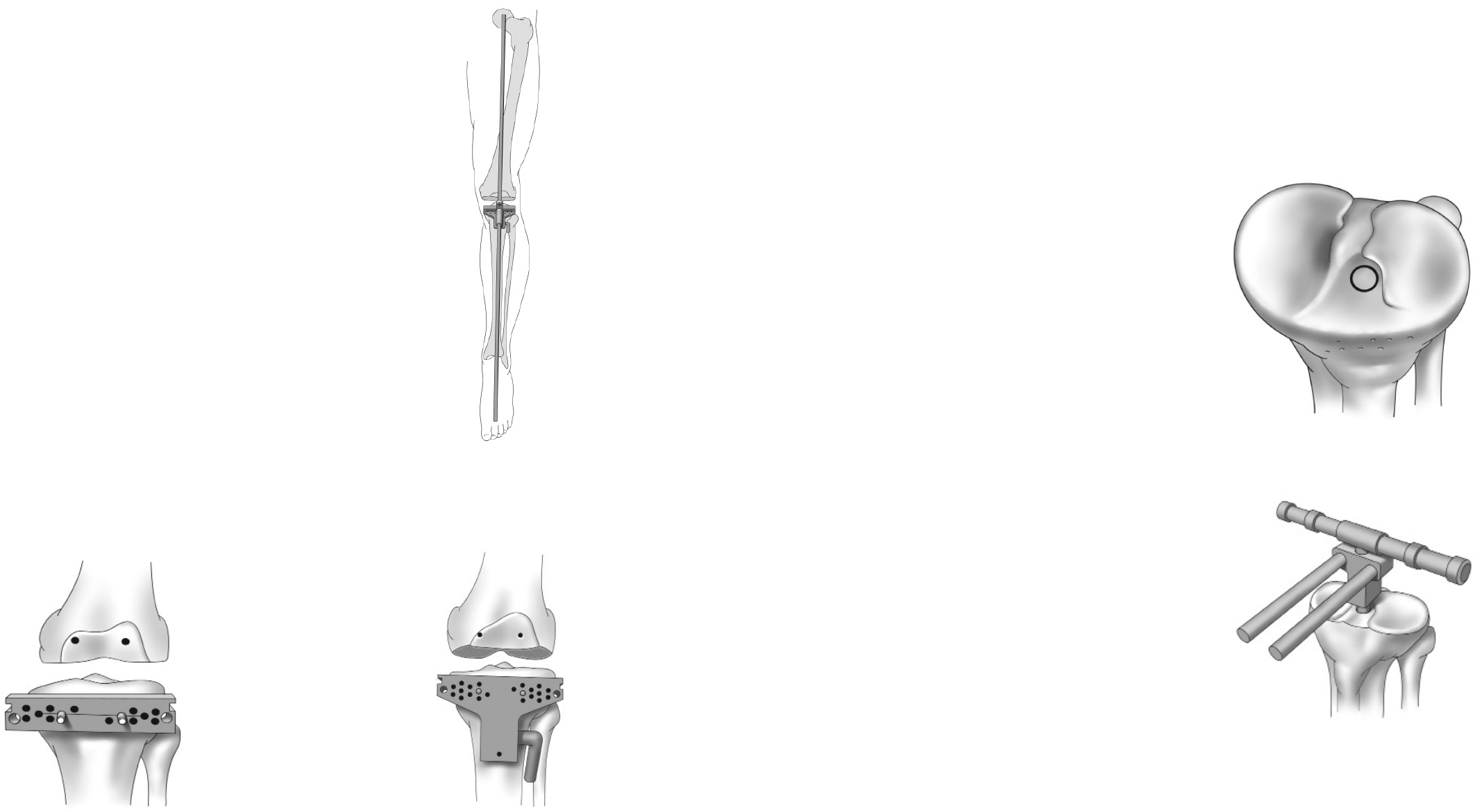
Preoperative Planning
Standing 14x17 x-rays are usually adequate for
templating. With significant bony deformity, use a
longstanding radiograph to evaluate the angle between
the mechanical axis of the leg and the anatomic axis of
the femur. The normal mechanical axis is formed by a
straight line which begins at the center of the femoral
head, passes through the center of the knee joint and
ends at the center of the ankle. The mechanical axis will
not be normal in the face of femoral, tibial, or joint space
deformities. With this in mind, take care to reconstruct
the normal mechanical axis on the radiograph. The
angle measured between this normal mechanical axis
and the axis of the femur will determine which of the
IM Femoral Bushings should be used with the Distal
Femoral Resection Guide (5°, 7°, or 9°) to obtain a
distal femoral cut which will be perpendicular to the
mechanical axis of the joint (Figure 1). The goal of this
preoperative planning exercise is to demonstrate the
correct mechanical axis of the leg, promote minimal
bone stock removal, and optimize collateral ligament
balance in reconstruction.
Templates for the 3DKnee System are available to aid
in preoperative implant sizing.
Figure 1
Minimally Invasive Surgical Exposure
Sucient surgical exposure is critical in total knee
arthroplasty. Minimally invasive exposure can be optimized
based on patient size and muscle mass. Adequate
exposure allows bony landmarks, component alignment
and soft tissue evaluation to be assessed more thoroughly
and therefore, will contribute to more successful results.
Make a longitudinal anterior skin incision. The incision will
vary 3-6 inches in length depending on soft tissue and
bony deformity (Figure 2). Careful attention should be paid
to old incisions about the knee and, generally, the lateral
most usable scar should be targeted (for vascular
reasons). Occasionally, pre-incision and skin expanders
may be needed to prevent skin loss. Enter the knee joint
through a medial parapatellar joint capsule incision (Figure
3) or by splitting the vastus medialis (intravastus approach
Figure 4). Both incisions continue inferiorly along the
medial side of the tibial tubercle to allow sucient patella
mobilization and adequate knee exposure.
Complete menisectomy is essential for obtaining optimum
exposure of the posterior tibia and also aids in clearing the
joint space for adequate trialing of the implants. Likewise,
removing osteophytes from the intercondylar notch aids in
identifying accurate placement of the femoral intramedullary
drill hole. Removing all periarticular osteophytes on both
the femoral and tibial sides should reduce the possibility of
soft tissue impingement and provide the best conditions for
accurate implant sizing.
Figure 2
Skin Incision
Figure 3
Medial Parapellar
Figure 4
Intravastus
6Surgical Technique
3DKnee ™
7
Surgical Technique
3DKnee™
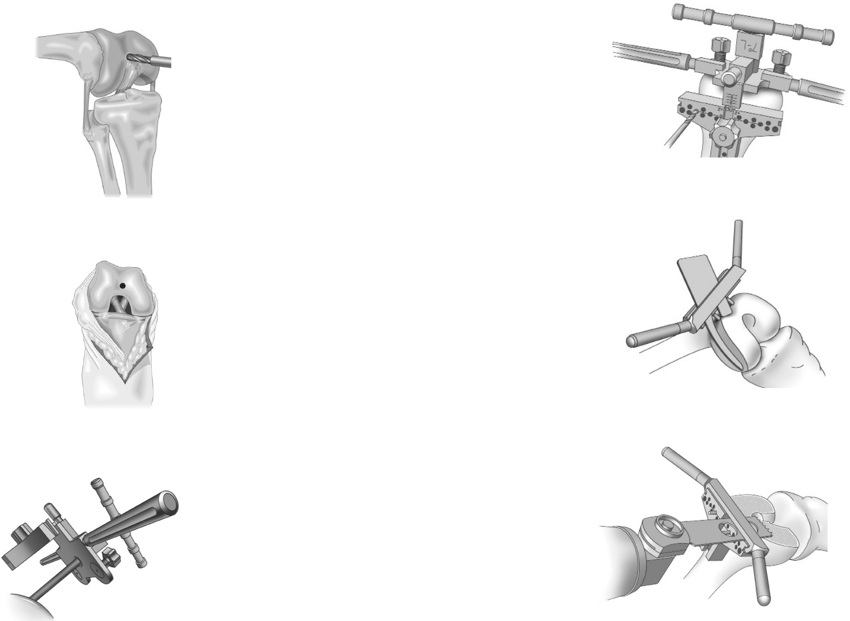
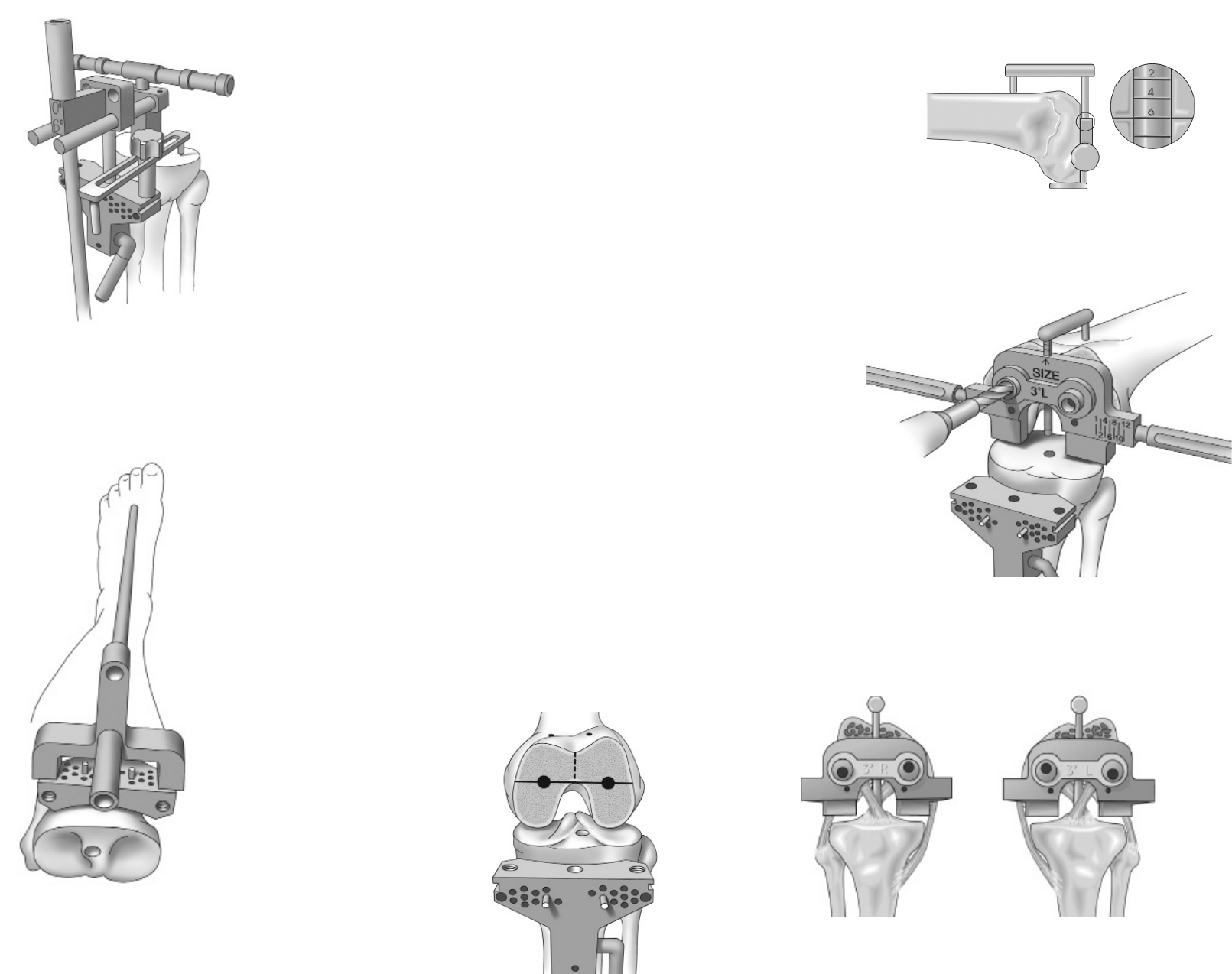
Open the Femoral Canal
Using the 8mm (5/16 inch) IM Femoral Drill, locate and
drill a pilot hole into the intramedullary femoral canal
(Figure 5). The inferior edge of this hole should be
positioned just anterior to the intercondylar notch
(Figure 6). Make the hole larger by toggling the bit
inside the canal. This reduces fat emboli risk and allows
the guide rod to seek the proper position in the canal.
Irrigate and suction the canal to further decrease the
risk of fat embolization.
Slowly insert the T-Handle IM Rod into the pilot hole
created by the IM Femoral Drill until it passes through
the isthmus of the femoral canal.
Establish Femoral Alignment
Select the appropriate Femoral IM Bushing (5°, 7°, or
9°) based on the preoperative measurement of valgus
for the distal cut and lock the bushing into the Distal
Femoral Resection Guide. The bushing should indicate
the proper setting for a left or right knee with appropriate
“L” and “R” markings on the bushing facing anteriorly.
When correctly assembled, the rod will have a valgus
indication to the distal surface of the resection guide.
Assemble the T-Handle IM Rod into the bushing
selected and insert the assembly slowly into the femoral
canal (Figure 7). The feet on the Distal Femoral
Resection Guide should be ush with the back side of
the guide by turning each knob on the front surface of
the guide counterclockwise until the knob stops. Once
the guide is placed in contact with the femur, one of the
feet can be extended to contact the femur and provide
increased stability of the instrument. Take care not to
extend the feet so far that the instrument is lifted o the
distal end of the femur. This will result in an inaccurate
distal resection.
Figure 5
Figure 6
Figure 7
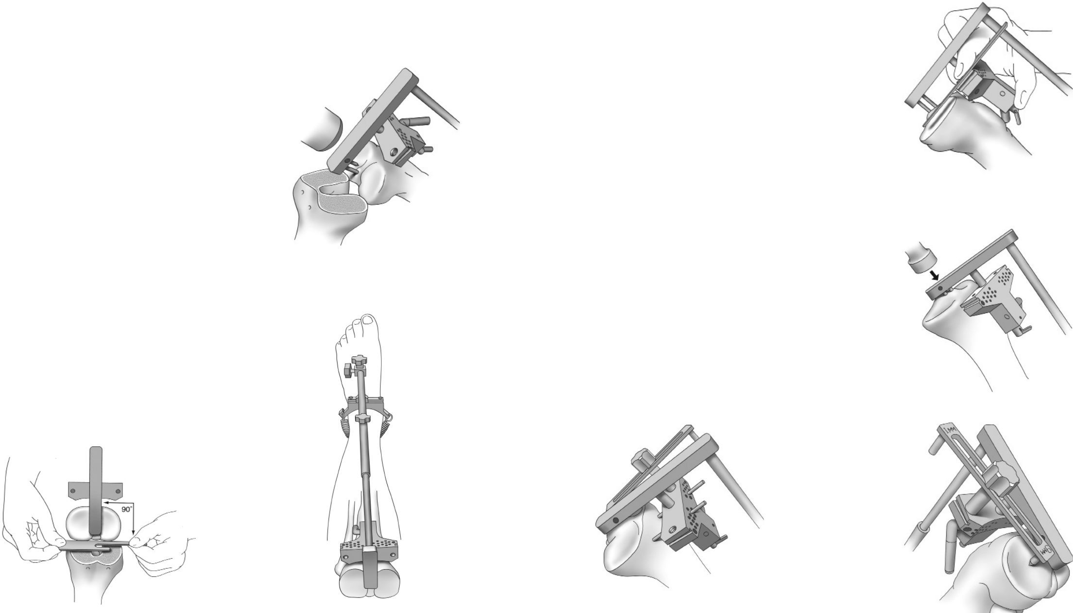
Secure the Distal Femoral Cutting Block at the 11mm
resection line on the indicator bar (Figure 8). More distal
resection may be considered for knees with exion
contractures and less may be considered for very small knees.
Holes for the External Alignment Tower are present on the
Distal Femoral Cutting Block so that an External Alignment
Rod may be used to assess alignment prior to making the
distal femoral cut. Proper alignment should result in the
rod passing over the center of the femoral head.
Distal Femoral Resection
Fix the position of the cutting block by drilling two holes
through the holes marked “0” and placing pins through the
holes into the femur. Holes placed in 2mm increments
above and below the holes marked “0” allow for readjustment
of the cutting block to remove more or less bone as
determined necessary. Loosen the securing knob, remove
the Distal Femoral Resection Guide, and attach the Saw
Capture to the cutting block. A general guideline for the
distal femoral resection is to remove the same amount of
bone that will be replaced with metal. Use a sawguide
(Anterior Cut Reference Guide) to check the thickness
before cutting (Figure 9).
Using a saw blade that is 1mm thick (.040 inches) and an
oscillating saw, cut the distal femur (Figure 10).
Figure 10
Figure 9
Figure 8
8Surgical Technique
3DKnee ™
9
Surgical Technique
3DKnee™
Tibial Alignment (Extramedullary Option)
Adjust the overall length of the Extramedullary Tibial
Resection Guide to the appropriate tibial length.
Remove any remnant of the ACL. Using a PCL retractor,
sublux the tibia forward for a complete view of the tibial
plateau. Lightly anchor the proximal end of the resection
guide onto the central tibial plateau at the tibial spines
by tapping in the long pin (Figure 11). Strap the ankle
spring around the ankle to provide stability of the
instrument distally. To establish alignment:
• Position the center of the Tibial Cut Block just
medial to the tibial tubercle and the perpendicular
center through the medial 1/3 of the ankle.
• With the foot in neutral position, align the rod
with the second toe. This is accomplished by
the M/L adjustment at the ankle (Figure 12).
• Place the tibial cutting block parallel to the
posterior aspect of the tibial plateau (Figure 13).
Figure 13
Figure 11
Figure 14
Figure 15
Figure 16
Figure 17
Figure 12
Tibial Slope Alignment and Securing the
Cutting Block
Adjust the slope of the cutting block by sliding the
Extramedullary Tube along the length of the Ankle Bar until
the sawguide (Anterior Cut Reference Guide) runs parallel
with the surface of the tibial plateau (Figure 14).
Once rotational alignment and slope have been established,
tap the proximal end of the resection guide and fully seat
the pins in the tibial plateau (Figure 15).
Place the Tibial Stylus on the cutting block and adjust the
block until the tip of the stylus marked “9mm”, denoting a
9mm resection, touches the lowest point of the least
involved compartment of the tibial plateau (Figure 16).
An alternative method is to adjust the block until the tip of
the stylus marked “1mm” touches the lowest point of the
most involved compartment of the tibial plateau.
Caution: This alternative method should be used in cases of severe
bone loss, where augmentation blocks would be appropriate.
Likewise, in cases where the defect is minimal, using the
1mm stylus tip may not indicate the removal of sucient
bone stock to accommodate the tibial component. The surgeon
should use their discretion to determine which technique is
appropriate for the patient.
Secure the position of the cutting block by drilling two holes
through the holes marked “0” and placing pins through the
holes into the tibia. Holes placed in 2mm increments above
and below the holes marked “0” allow for readjustment of
the cutting block to remove more or less bone as
determined necessary (Figure 17).
10 Surgical Technique
3DKnee ™
11
Surgical Technique
3DKnee™
Total Leg Alignment Confirmation
Now extend the knee and align the tibial resection guide
with the distal femoral cut. This will give you an estimate
of the total leg alignment for the positioned tibia cut and
can be checked with the long alignment rods over the
hip and ankle for verification of the correct mechanical
axis (Figure 18). The proximal surface of the tibia cut
block should be parallel to the distal femoral cut (Figure 19).
Verifying alignment at these specific check points can
make a significant dierence in the final outcome.
Consider the fact that the femoral and tibia alignment
guides can each independently allow for 1-2° of error.
A combined error in the same direction could add an
extra 4° of varus or valgus malalignment. Taking a few
minutes to correct positioning prior to cutting can save
time later.
To correct malalignment, use the same pins that were
used to anchor the Tibial Cut Block and secure the 2°
Varus / Valgus Cut Block in place. This cutting block will
provide a cutting surface that will correct the malalignment
by 2° (Figure 20). The 2° Varus / Valgus Cut Block can
also be fitted with the Alignment Tower and External
Alignment Rod to verify the correction.
12
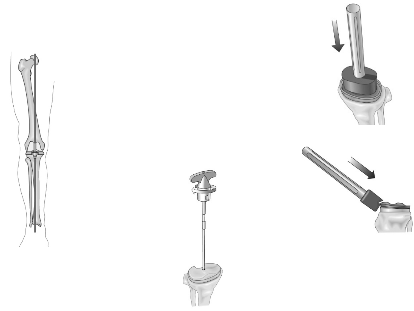
Tibial Alignment (Intramedullary Option)
Using the IM Femoral Drill, locate and drill a pilot hole into
the intramedullary tibial canal. The inferior edge of this hole
should be positioned 3-5mm anterior to the pinnacle of the
proximal tibial spine (Figure 21). Insert the T- Handle into
the pilot hole created by the IM drill. Slowly introduce the
rod beyond the depth of the pilot hole to open the
intramedullary canal.
Assemble the T-Handle Rod and the IM Tibia Resection
Guide so the slope indicators on the guide face away from
the patient when the guide is in position and insert the
apparatus into the tibial canal (Figure 22).
Figure 20
Figure 18
Figure 19
Figure 21
Figure 22
Surgical Technique
3DKnee ™
13
Surgical Technique
3DKnee™
Tibial Alignment
Assemble the Tibia Cut Block to the IM Resection Guide
with the stylus connected to the selected side for
determining resection thickness. The alignment drop rod
can also be assembled prior to passing to the surgeon
for assembly. Assemble the complete IM Resection Guide
to achieve 6° of posterior slope (Figure 23). Establish
rotational alignment by positioning the center of the T-shaped
Tibial Cut Block just medial to the tibial tubercle and the
perpendicular center through the medial 1/3 of the ankle.
Place the Tibial Stylus on the cutting block and adjust
the block until the tip of the stylus marked “9mm”,
denoting a 9mm resection, touches the lowest point
of the least involved compartment of the tibial plateau.
An alternative method is to adjust the block until the tip
of the stylus marked “1mm” touches the lowest point of
the most involved compartment of the tibial plateau.
Caution: This method should be used in cases of
severe bone loss, where augmentation blocks
would be appropriate. Likewise, in cases where
the defect is minimal, using the 1mm stylus tip may
not indicate the removal of sucient bone stock to
accommodate the tibial component.
Secure the position of the cutting block by drilling two
holes through the holes marked “0” and placing pins
through the holes into the tibia. Holes placed in 2mm
increments above and below the holes marked “0” allow
for readjustment of the cutting block to remove more or
less bone as determined necessary. Unlock the cutting
block from the resection guide. Remove the guide from
the tibia, leaving the tibial cutting block against the
anterior tibia. Holes for the External Alignment Tower
are present in the Tibial Cut Block so that alignment
may be assessed prior to making the tibial cut. When
using the alignment tower, proper alignment is indicated
by the alignment rod pointing at the second toe and
medial 1/3 of the ankle with the knee extended as well
as aligning with the center of the hip joint to assure
correct mechanical axis (Figure 24).
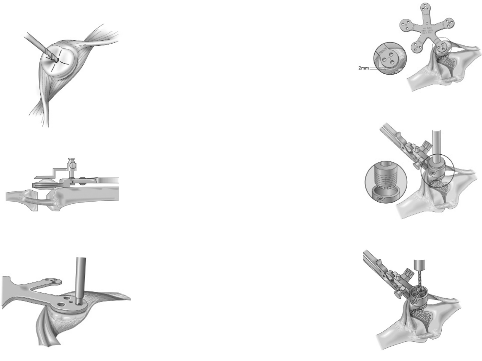
Femoral Alignment
Posterior Reference
Seat the Femoral Sizer on the distal femur using the sizer
feet to reference the posterior condyles. Position the stylus
tip on the lateral aspect of the anterior cortex of the femur
and read the measurement indicator to determine the
appropriate size femoral component (Figure 25). For
measurements falling less than half way between sizes,
select the smaller size; for measurements falling more than
half way between sizes select the larger size. Markings are
available on the medial and lateral arms of the sizer to
indicate the M-L width of each size femoral component and
to aid in the proper medial-lateral positioning of the femoral
component. Whiteside’s line, at the depth of the patellar
sulcus, can also be used for M/L positioning and should be
perpendicular to the femoral fixation holes.
Allow the anterior portion of the guide to oat with the stylus
tip until it is positioned on the lateral aspect of the anterior
cortex of the femur. Keeping the femoral fixation holes
perpendicular to Whiteside’s line and parallel to the
transepicondylar line is important. If rotating is unclear, bring
the knee to 90° of exion and pick the alignment which most
closely parallels the tibial cut plane (Figure 26).
The correct “3° L” or “3° R” markings should always be
facing the surgeon when the bushing is in place (Figure 27).
An upside down 3° bushing will result in the holes being
incorrect. Hold the Femoral Peg Bushing in place with a
femoral peg lug and drill the other hole using the 6.4mm
(1/4 inch) drill marked “Femoral Peg”.
Verify fixation holes are perpendicular to Whiteside’s line
and parallel to the transepicondylar axis (Figure 28).
Figure 28
Figure 25
Figure 26
Figure 27
Figure 23
Figure 24
14 Surgical Technique
3DKnee ™
15
Surgical Technique
3DKnee™
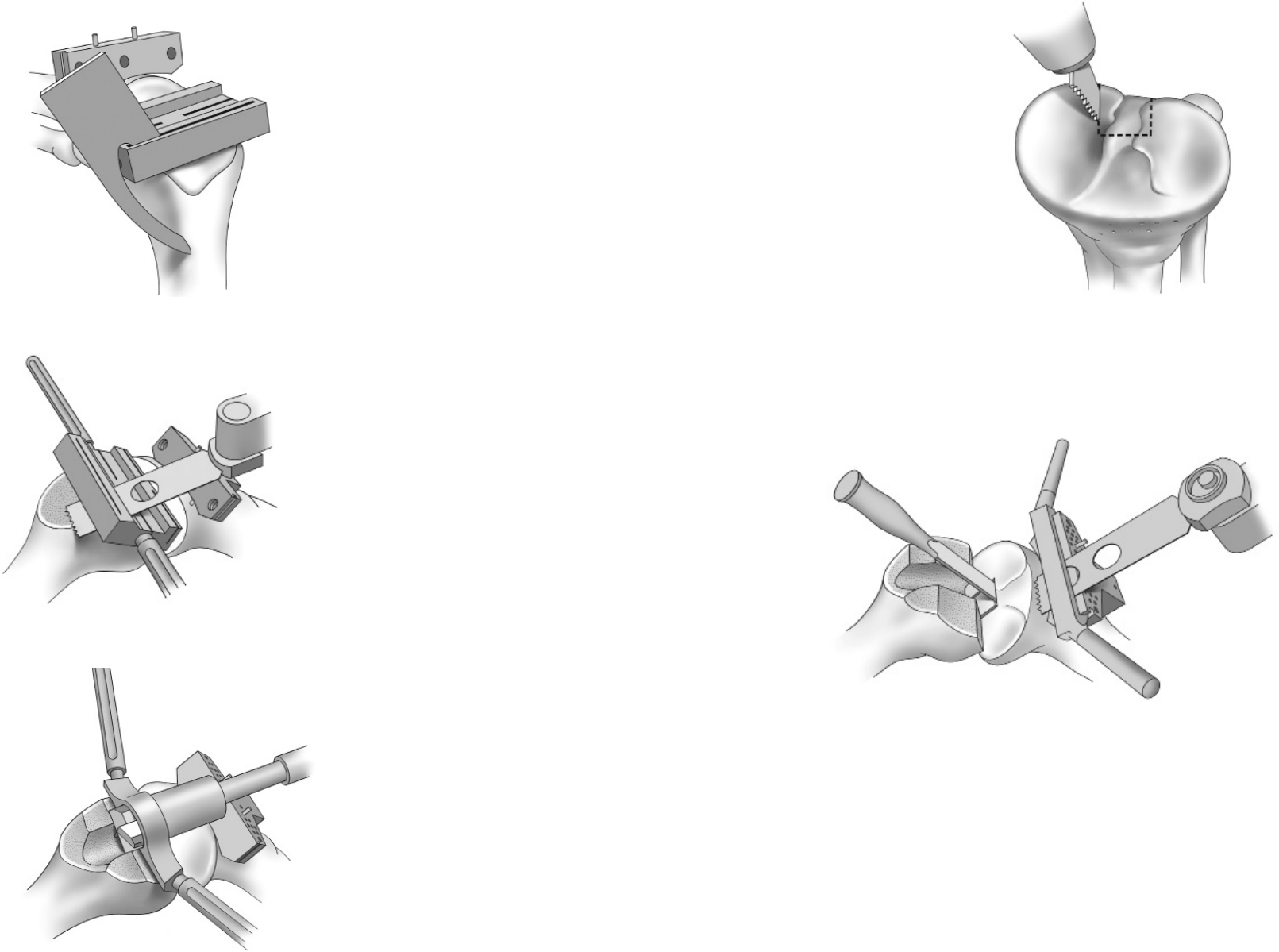
Femoral Preparation:
4-in-1 Speed Blocks
Place the appropriate size 4-in-1 Speed Block on the
distal femur. Check the appropriate size by placing the
saw guide (Anterior Cut Reference Guide) in the
anterior slot to check for notching (Figure 29). If the
anterior cutting plane appears excessively notched but
the next size up jig is too large, then the femoral fixation
hole can be moved up 2mm by using a special auxiliary
sizer. Quick lock handles can be attached to the block for
stabilization. As an alternative, the block may be pinned
in place using short bone pins.
Make the anterior cut, posterior cut, and anterior and
posterior chamfer cuts using a 1mm thick saw blade
(Figure 30).
Place the appropriate size Trochlear Groove Guide in
place on the distal femur (the size of the guide should
match that of the 4-in-1 Speed Block used). Ream the
trochlear groove area with the drill marked “Trochlear”
(Figure 31). To facilitate reaming, balance the drill
through the guide and initiate reaming prior to engaging
the bone.
Impact the femoral trial on the prepared distal femur.
Now fully extend the knee and apply the tower and
alignment rod to the Tibial Cutting Block. Make sure that
the cutting block is aligned perpendicluar to the distal
femoral component and that the alignment rod passes
through the hip center and ankle center. This is the
final varus/valgus alignment check before proceeding
with the tibial cut. If this total leg alignment to the
mechanical axis needs adjusting, then apply the 2° tibial
correction block. Also, test the ligament stability
through range of motion, correcting for bone loss by
keeping the cutting block parallel to the femoral
articular surface.
Tibia Cut
With the PCL retractor in place, use a reciprocating saw
to cut a groove medial, lateral and 4mm anterior to the
PCL (Figure 32). This prevents undermining or cracking
the bone block. Place a ½” osteotome in the anterior
groove to protect the PCL if following a cruciate retaining
technique. Alternatively, the 3DKnee can also be used
with a compromised or absent PCL. Place the saw
capture guide on the tibial cutting block. Using a 1mm
sawblade with the oscillating saw, complete the tibial
resection (Figure 33). Using a laminar spreader with the
knee at 90° will aid in removing posterior osteophytes
and any meniscal remnants or loose bodies.
Figure 29 Figure 32
Figure 30
Figure 33
Figure 31
16 Surgical Technique
3DKnee ™
17
Surgical Technique
3DKnee™
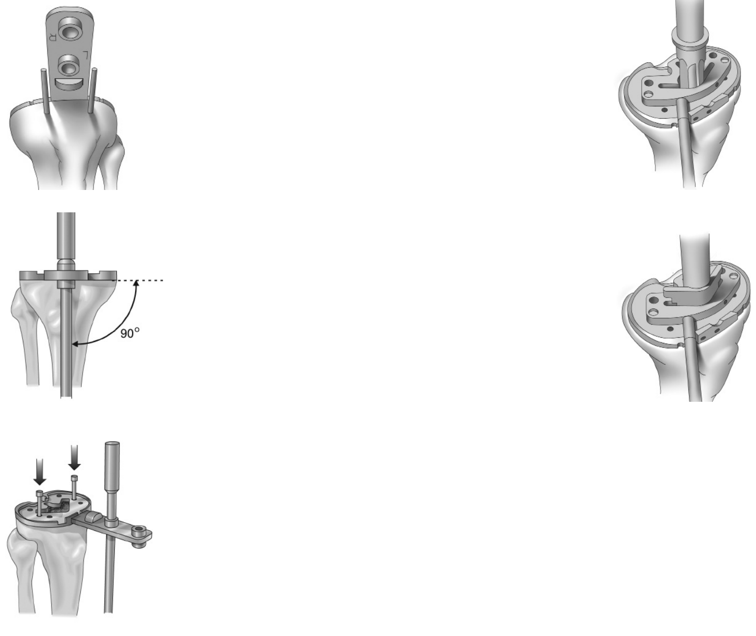
Tibial Sizing
Completely remove all tibial osteophytes prior to tibial
sizing to avoid false coverage of osteophyte formation.
Size the proximal tibia by matching a Tibial Trial to the
profile of the resected tibial plateau and align so the
handle closely follows the fixation pins of the tibial
cutting block (Figure 34). The External Alignment Rod
is used with the Tibial Trial Handle to confirm tibial
perpendicular alignment (Figure 35). Using a 3.2mm
drill bit, drill two holes perpendicular to the Tibial Sizing
Template through the two countersunk holes on the
template. Each hole should be drilled approximately
2cm deep. Insert a Headed Tibial Bone Pin through
each of the holes to secure the tibial template in place
(Figure 36).
Alternatively, determine correct rotational alignment for
the tibial trial by performing a trial reduction with the
femoral trial component. Mark the position of the tibial
plate in full extension and then pin it in this position.
Tibial Keel Preparation
Assemble the Broach Guide Handle to the appropriate
size Tibial Broach Guide and place the guide into the
central detail on the tibial template. An optional Tibial
Stem Reamer can be used to ream the tibial canal prior
to broaching (Figure 37). Center the appropriate size
Tibial Broach in the hole and broach the tibial canal until
the broach is fully seated (Figure 38). Broaching without
reaming leaves a nice bone plug by impacting the
cancellous tibia bone. This bone plug is good for blocking
any cement from the tibial canal and allowing good
cement pressurization.
Figure 34 Figure 37
Figure 35 Figure 38
Figure 36
18 Surgical Technique
3DKnee ™
19
Surgical Technique
3DKnee™
Patella Preparation: Resurfaced Patellar Peg
Measure the overall patellar thickness using calipers.
Mark the center of the patellar crest with electrocautery
and, using the 1/8” drill bit, drill a hole to mark the center,
deep to the cut plane (Figure 39). Place the Patella
Osteotomy Guide on the patella and set the stylus to
indicate an amount of bone equal to the thickness of
the patellar component to be used (Figure 40). It is
recommended that at least 13mm of bone be
remaining following the osteotomy. Using a 1mm thick
saw blade, resect the patella.
Patellar Peg Preparation
Position the Patellar Sizer on the resected patella to
align with previously drilled 1/8” centering hole. Press
the sharp pin on the Patellar/Sizer/Drill Guide into the
resected patella and drill for the patella pegs using the
Patella Peg Stop Drill (Figure 41).
Recessed Patella Preparation
Measure the overall patellar thickness using calipers. Place
the Patella Osteotomy Guide on the patella and set the
stylus to indicate an amount of bone equal to 2mm less
than the thickness of the patellar component to be used
(i.e.; if a 9mm Patella is to be used, resect
7mm of bone). Using an oscillating saw and a 1mm thick
saw blade, resect the patella. It is recommended that at
least 15mm of bone be remaining following this osteotomy.
Patellar Sizing for Recessing
Size the patella using the Patellar Sizer. The center of the
appropriate size patella should be positioned medial so
that the highest point of the normal patella is replaced by
the highest point of the patellar dome. To ensure sucient
rim following countersinking, size the patella such that
2mm of bone will remain beyond the periphery of the
patellar diameter (Figure 42).
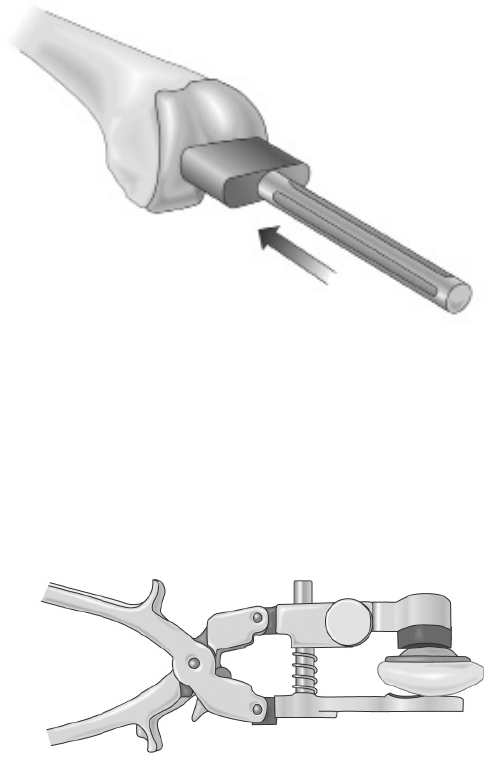
Recessing
Based on the size of patella chosen, assemble the
appropriate Patellar Bushing into the Patellar Clamp and
position the clamp over the resected surface of the patella.
Care should be taken to position the center of the bushing
medially so that the highest point of the patellar component
will be correctly postioned. Using the corresponding Patella
Reamer, countersink the patella by 2mm by reaming the
patella until the top surface of the reamer meets the first
engraved line on the inside of the patellar bushing (Figure
43). To facilitate reaming, initiate power to the reamer fully
before engaging bone. Apply gentle, uniform pressure to
the patellar surface while reaming. This should prevent
over reaming and provide a concentric inset cavity for the
patellar component.
Patellar Peg Preparation
After reaming, and without removing the Patellar Clamp,
place the appropriate Patellar Drill Guide into the Patellar
Bushing. Tap the drill guide into place to anchor the sharp
pin into the patellar bone. Using the appropriate Patella
Peg Stop Drill, drill the three peg holes (Figure 44).
Figure 39
Figure 40
Figure 41
Figure 42
Figure 43
Figure 44
20 Surgical Technique
3DKnee ™
21
Surgical Technique
3DKnee™
Trial Reduction
Evaluation of implant fit can be accomplished by placing
an appropriate size Femoral Trial, Patellar Trial, Tibial
Sizing Template, and Tibial Insert Trial into the prepared
joint space. This should be done with the tibial trial first
to allow ease of femoral trial placement. Sometimes a
retractor used to elevate the posterior femur o the tibia
makes it easier. The Axial Alignment Rods can then be
used to assess the alignment of the joint (Figure 45).
Tibial Component
Place a layer of bone cement on the proximal tibia
pressing the cement into the broached keel area. Using the
Tibial Impactor and a mallet, impact the tibial component
into the tibia until it is fully seated on the tibia (Figure 46).
Remove any excess bone cement paying particular
attention to area where the tibial insert will be installed.
Bone cement remaining near the locking mechanism of the
tibial component will prohibit the insert from properly
seating in the tibial tray.
Tibial Insert
Place the insert into the tibial baseplate making sure that
the posterior feet on the insert catch under the posterior
lips on the baseplate. Using the Insert Impactor at a 45°
angle, impact the insert into the tray. One impact should
be adequate to secure the anterior locking mechanism on
the implant (see Figure 47). Tighten the tibial insert
attachment screw (captured in the tibial insert) into the
tibial baseplate. The recommended applied torque to
properly attach the locking screw is 45”lbs. A torquelimiting
driver is provided as a minimal value torque (Figure
48). Torque applied is 45”lbs at nominal when the handle
gives way and an audible click is heard.
Figure 45
Figure 46
Figure 47
Figure 48
22 Surgical Technique
3DKnee ™
23
Surgical Technique
3DKnee™
Component Implantation
Femoral Component
Place a thin layer of cement on the internal surfaces of
the posterior condyles and posterior chamfer of the
femoral component. Then place a layer of cement on the
distal femur anterior chamfer and anterior ange area.
Using the Femoral Impactor and a mallet, impact the
femoral component onto the femur until it is fully seated
on the end of the femur (Figure 49). Remove any excess
bone cement paying particular attention to the polished
articulating surface of the implant and intercondylar
area. Now irrigate the joint thoroughly to remove any
cement particles.
Patellar Component
Place a layer of bone cement on the underside of the
patellar component and on the prepared patella surface.
Using the appropriate size Patella Inserter in the Patella
Clamp, secure the patellar component in position and
tighten the clamp (Figure 50). You may leave the clamp
in the secured position until the cement is hard but this
is not always necessary. While the cement cures
remove any excess cement from around the component.
Wound Closure
After cement polymerization has occurred, the knee
should be taken through a range of motion to ensure
proper function before closure of the knee. The
tourniquet need not be released before closure as long
as the lateral geniculate artery has been cauterized.
This has been shown to lessen total blood loss. One
may choose to employ a closed wound suction device
for the immediate recovery period. A standard closure
should now be completed. The deep closure proximal
and distal to the patella should be closed with an
absorbable #1 suture in a running fashion. The capsule
around the patella should be closed with interrupted
figure of eight non-absorbable #1 sutures. The
subcutaneous layer can be closed with 2-0 absorbable
sutures either running or interrupted. The skin can be
closed with a 3-0 subcutaneous absorbable followed
with optional reinforcing skin staples. Verify the final
range of motion to ensure complete exion capabilities
and the integrity of the sutures.
References
1. Harman, M.K., Markovich, G.D., Banks, S.A., Hodge, W.A.: Wear Patterns on Tibial
Plateaus From Varus and Valgus Osteoarthritic Knees. Clinical Orthopaedics and
Related Research, No. 352, July 1998.
2. Hodge, W.A., Banks, S.A., Riley, P.O., Spector, C.: In Vivo Kinematics of a Meniscal
Bearing TKR During Constrained Stair Rising. Annual Meeting of the Association of
Bone and Joint Surgeons, Florida, April 1991.
3. Banks, S. A., Riley, P.O., Spector, C., Hodge, W.A.: In Vivo Bearing Motion with
Meniscal Bearing TKR. Orthop. Trans., Vol. 15, No. 2, p. 544, 1991.
4. Hodge, W.A., Banks, S.A., Riley, P.O.: In Vivo Meniscal Bearing Motion after Mobile
Bearing Total Knee Replacement (TKR). Orthop. Trans., Vol. 16, No. 2, p. 367, 1992.
5. Banks, S.A., Markovich, G.D., Hodge, W.A.: In Vivo Kinematics of Cruciate Retaining
and Substituting Knee Replacements. Journal of Arthroplasty Vol. 12, No. 3, 1997.
6. Banks, S.A., Otis, J.C., Backus, S.I., Furman, G.L., Haas, S.B.: Function of Total Knee
Replacements During Activities of Daily Living. 67th Annual Meeting of the American
Academy of Orthopaedic Surgeons, Orlando, FL, March 15-19, 2000.
7. Harman, M.K., Banks, S.A., Natarajan, R.A., Andriacchi, T.P., Hodge, W.A.: Comparison
of In-Vivo Kinematics and Polyethylene Wear in Retrieved Total Knee Replacements. Annual
Meeting, Orthopaedic Research Society, New Orleans, LA, March 1998.
8. Leslie, Chris, The Best of Both Worlds: Sacrificing the PCL, Orthopedic Educational
Summit, Park City, UT, 2008.
9. Harman, M., Banks, S., Natarajan, R., Andriacchi, T., Hodge, W.A.: Direct Comparison
of In-Vivo Kinematics and Wear on Retrieved TKA Polyethylene Inserts from the Same
Subject Group. 66th Annual Meeting American Academy of Orthopaedic Surgeons,
Anaheim, CA., February 4-8, 1999.
10. van Kampen, A., Huiskes, R.: The Three-Dimensional Tracking Pattern of the Human
Patella. J. Orthop. Res., Vol. 8, pp 372-382, 1990.
11. Banks, S.A., Banks, A.Z., Cook, F.F., Hodge, W.A.: Markerless Three Dimensional
Measurement of Knee Kinematics Using Single-Plane Fluoroscopy. 20th Annual
Meeting, American Society of Biomechanics, Atlanta, GA, October 17-19, 1996.
12. Banks, AZ, TVS Klos, SA Banks: Quantitative radiographic assessment of dynamic
tibio-femoral motions before and after anterior cruciate ligament reconstruction: A pilot
study. Submitted to Clinical Biomechanics, November, 1999.
13. Kanisawa, I, AZ Banks, SA Banks, H Moriya, A Tsuchiya: Weight Bearing Knee
Kinematics in Subjects with Two Types of Anterior Cruciate Ligament Reconstructions.
Submitted to American Journal of Sports Medicine, November, 1999.
14. Draganich, L.F., Andriacchi, T.P., Andersson, G.B.J.: Interaction Between Intrinsic Knee
Mechanics and the Knee Extensor Mechanism. J. Orthop. Res., Vol. 5, pp 539-547, 1987.
15. Banks, S.A., G. D. Markovich, W.A. Hodge: The Mechanics of Knee Replacements
During Gait: In Vivo Fluoroscopic Analysis of Two Designs. American Journal of Knee
Surgery, Vol 10 No. 4, Fall 1997.
16. Banks, S.A., Hodge, W.A.: Accurate Measurement of Three-Dimensional Knee
Replacement Kinematics Using Single-Plane Fluoroscopy. IEEE Transactions on
Biomedical Engineering, Vol. 43, No. 6, June 1996.
17. Banks, S.A., Harman, M.K., Hodge, W.A., Markovich, G.D., Kester, M.A.: Kinematics of
the Medial Unicondylar Knee Replacement. Chapter 4, Unicompartmental Knee Replacement,
J.A. Epinette, P. Cartier, G. Deschamps, and P. Hernigou (Eds.), Sofcot Publishers, 1997.
18. Banks, S.A., Backus, S.I., Otis, J.C., Haas, S. B., Laskin, R.S.: Intrinsic and extrinsic
mechanics of total knee replacements during gait. Submitted to Journal of Arthroplasty, July, 1999.
19. Banks, S., Otis, Backus, S., J., Laskin, R., Campbell, D., Lenho, M., Furman, G.,
Haas, S.: Integrated Analysis of Knee Arthroplasty Mechanics Using Simultaneous
Fluoroscopy, Force Plates, and Motion Analysis. 66th Annual Meeting of the
Orthopaedic Research Society, Anaheim, CA., February 4-8, 1999.
20. Harman, M., Banks, S., Hodge, W.A.: Inuence of Femoral Geometry on In-Vivo
Kinematics and Wear in Two Designs of PCL-Retaining Total Knee Arthroplasty. 66th
Annual Meeting American Academy of Orthopaedic Surgeons, Anaheim, CA.,
February 4-8, 1999.
21. Harman, MK, SA Banks, WA Hodge: Do in vivo kinematics predict polyethylene damage
after total knee replacement? Submitted to the Journal of Arthroplasty, September, 1999.
22. Mitchell K, Banks SA, Rawlins J, Wood SA, Hodge WA. Strenth of Intrinsically Stable
TKA During Stair-Climbing. The Biomotion Foundation, White paper. 2004.
23. Banks SA, Harman MK, Bellemans J, Hodge WA. Making Sense of Knee Arthroplasty
Kinematics: News You Can Use. The Journal of Bone and Joint Surgery. 2003;85:64-72.
24. Bellemans J, Banks S, Victor J, Vandenneucker H, Moemans A. Fluoroscopic Analysis
of the Kinematics of Deep Flexion in Total Knee Arthroplasty: Inuence of Posterior
Condylar Oset. The Journal of Bone and Joint Surgery. 2002;84:50-d3.
Figure 49
Figure 50
24 Surgical Technique
3DKnee ™
25
Surgical Technique
3DKnee™

0010302-001 Rev F 04/12©2011 Encore Medical, L.P.
CAUTION: Federal Law (USA)
restricts this device to sale by
or on the order of a physician.
See package insert
for a complete listing of
indications, contraindications,
warnings, and precautions.
TM
DJO Surgical I A DJO Global Company
T 800.456.8696 D 512.832.9500 F 512.834.6300
9800 Metric Blvd. I Austin, TX 78758 I U.S.A.
djosurgical.com
