TMAA04 04 Crossband Linking Cable Installation Instructions TM8000/TM8000 402 00030 00 Cable/402
TM8000/TM8000 402-00030-00 Crossband Linking Cable/402-00030-00 Crossband Linking Cable 402-00030-00 Crossband Linking Cable
User Manual: Pdf TM8000/TM8000 402-00030-00 Crossband Linking Cable/402-00030-00 Crossband Linking Cable
Open the PDF directly: View PDF ![]() .
.
Page Count: 4
402-00030-00 www.taitworld.com
Tait accessories
TMAA04-04 Crossband Linking Cable
Installation Instructions
Introduction
The TMAA04-04 crossband linking cable is used to
connect the auxiliary connectors of two radios
configured as a crossband repeater. Components in the
TMAA04-04 are optomized for voice applications.
Important: The radio does not meet the IP54
protection standard once the auxiliary
connector rubber bung has been removed and a
crossband linking cable has been installed. Care
must be taken when the radio is being operated in an environment where there
is water, dust or other environmental hazards.
Installation
1. Remove the rubber bung that covers the auxiliary connector on each of the radios.
2. Plug each end of the crossband linking cable into the auxiliary connector on
each radio.
Radio Programming
After the transmit and receive channels have been programmed for both radios, settings
in the following forms must also be configured:
■PTT form (refer to Table 1)
■Programmable I/O form — Digital tab (refer to Table 2)
■Programmable I/O form — Audio tab (refer to Table 3).
If a repeater transmit tail is required, settings in the following forms must be configured
in both radios:
■PTT form (TM8100 radios only) (refer to Table 4)
■Basic Settings form—Subaudible Signalling tab (TM8200 radios and optional for
TM8100 radios) (refer to Table 5 and Table 6).
Some of the settings shown in the tables are default settings and may not need to be changed.
In all cases, refer to the online help of the programming application for more information.

2TMAA04-04 Crossband Linking Cable
© Tait Electronics Limited September 2005
Crossband Settings in the PTT Form
The following table shows the crossband linking settings required in the External PTT
(1) tab of the PTT form.
Programmable I/O Form—Digital Tab
The following table shows the crossband linking settings required in the Digital tab of
the Programmable I/O form.
Programmable I/O Form—Audio Tab
The following table shows the crossband linking settings required in the Audio tab of
the Programmable I/O form.
Table 1 Crossband settings in the PTT form, External PTT (1) tab
Field Setting
Advanced EPTT1 PTT Transmission Type Voice
Audio Source Audio Tap In
Table 2 Crossband settings in the Programmable I/O form, Digital tab
Pin Direction Label Action Active Debounce
Signal State Mirrored
To
AUX_GPI1
Input
PTT_INS External PTT 1
Low 10 None None
AUX_GPIO5
Output
BUSY Busy Status
a
a. To transmit only when the signalling is valid, set this field to Signalling Audio Mute Status.
Low None None None
Table 3 Crossband settings in the Programmable I/O form, Audio tab
Pin Tap In
Tap I n Typ e Tap I n Unm u t e Tap Out Tap Out Ty pe Tap Ou t Un mu t e
Rx None A-Bypass In On PTT R7 D-Split Busy Detecta
a. This can be set to
Busy Detect + Sub
if the mute is to open only when valid subaudible sig-
nalling is present with the transmission.
EPTT1 T5 A-Bypass In On PTT None C-Bypass 0 On PTT
TMAA04-04 Crossband Linking Cable 3
© Tait Electronics Limited September 2005
Repeater Transmit Tail Settings
TM8100 Radios
If the transmitter requires a “tail”, then this can be set in the External PTT (1) tab of
the PTT form. During the PTT deactivation delay period, any signalling, such as
CTCSS or DCS, is still present.
If a further transmitter tail is required, then this can be configured in the Subaudible
Signalling tab of the Basic Settings form. During the lead-out delay period, no
signalling, such as CTCSS or DCS, is present.
TM8200 Radios
If the transmitter requires a “tail”, then this can be configured in the Subaudible
Signalling tab of the Basic Settings form. During the lead-out delay period, no
signalling, such as CTCSS or DCS, is present.
Table 4 Transmit tail settings in the PTT form, External PTT (1) tab (TM8100)
Field Setting
Advanced EPTT1 PTT Deactivation Delay up to 1000ms
Table 5 Additional Transmit tail in the Basic Settings form, Subaudible
Signalling tab (TM8100)
Field Setting
CTCSS Settings Lead-Out Delay any duration, up to 1000ms
DCS Settings Lead-Out Delay any duration, up to 1000ms
Table 6 Transmit tail in the Basic Settings form, Subaudible Signalling tab (TM8200)
Field Setting
CTCSS Settings Lead-Out Delay any duration, up to 1000ms
DCS Settings Lead-Out Delay any duration, up to 1000ms
4TMAA04-04 Crossband Linking Cable
© Tait Electronics Limited September 2005
Operational Testing
1. On the receiving radio, inject an on-channel RF signal at a level of -70dBm, mod-
ulated to ±3kHz deviation (wide bandwidth channel) or ±1.5kHz (narrow band-
width channel), at 1kHz AF.
2. On the transmitting radio, the resulting deviation should be:
■±3kHz (with a tolerance of ±200Hz) on a 25kHz wide bandwidth channel.
■±1.5kHz (with a tolerance of ±200Hz) on a 12.5kHz narrow
bandwidth channel.
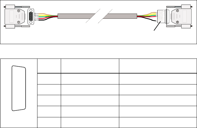
Interface Specification
The following table and diagram summarizes the signals used for the crossband linking
cable on the radios’ auxiliary connectors and shows the interface between the cable and
the radios.
More Information
Refer to your radio provider for more information about this product.
TMAA04-04 crossband linking cable
Auxiliary connectors—pins and signals
Pin Signal name Description
2 AUX_GPIO5 busy (output)
7 AUD_TAP_IN audio tap input
12 AUX_GPI1 PTT (input)
13 AUD_TAP_OUT audio tap output
15 AGND analogue ground
auxiliary connector
radio 1
auxiliary connector
radio 2
crossband linking board
rear view
J
B
C
D
E
F
G
H
I
1)
1!
1@
1#
1$
1%
