41382LF2 90(C)
User Manual: Pdf 41382LF2-90(C)
Open the PDF directly: View PDF ![]() .
.
Page Count: 2
R. M. YOUNG COMPANY 2801 Aero Park Drive , Traverse City, Michigan 49686 USA
TEL (231) 946-3980 FAX (231) 946-4772
INSTRUCTION SHEET 41382LF2-90
REV C111215
SPECIFICATIONS
RELATIVE HUMIDITY:
Measuring range: 0-100% RH
Accuracy at 73°F: ±1%
Stability: Better than ±1%RH per year
Response Time: 10 seconds (Without Filter)
Sensor type: Rotronic Hygromer
TEMPERATURE:
Measuring Range: -50 to +150°F
Accuracy at 73°F: ±0.5°F
Response Time: 10 seconds (Without Filter)
Sensor type: Platinum RTDW
Output signal: 4-20 mA
Power Required: 5-30 VDC, 46 mA max
Recommended Cable: 2 Pair shielded 22AWG, Young 18723
Recommended Radiation Shields:
Model 43502 Aspirated Radiation Shield
Model 41003P Multi-Plate Radiation Shield
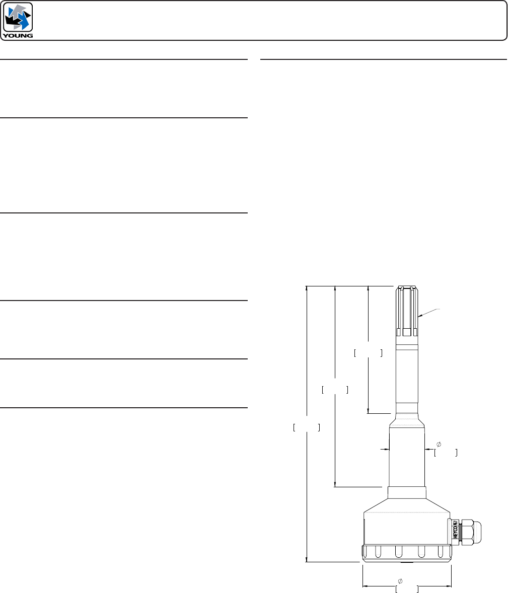
MODEL 41382LF2
RELATIVE HUMIDITY/TEMPERATURE PROBE w/4-20mA OUTPUT
INTRODUCTION
The Model 41382LF2 Relative Humidity/Temperature Probe combines
high accuracy humidity and temperature sensors in a single probe. The
output signal is 4-20 mA. RH range is 0-100%. Temperature range is
-50 to +150°F.
INSTALLATION
The Relative Humidity/Temperature probe should always be installed in
a protective radiation shield to ensure accurate data. Use of the probe
without a radiation shield may result in large errors. The probe installs
easily in YOUNG naturally ventilated or motor aspirated shields. For
best performance, the probe and shield should be placed in a location
with good air circulation clear of large masses (buildings, pavement,
solar panels...), Exhaust vents, electrical machinery and motors, water
fountains and sprinklers.
MAINTENANCE
The Relative Humidity/Temperature probe is designed to offer years
of service with minimal maintenance. As with most humidity sensors,
humidity calibration may drift slightly with time, and can be checked
or restored at the factory. Periodically clean the humidity sensor lter
when used in areas of high dust or contamination (smokestacks,
seawater, etc.) Remove from sensor and soak in clean water or use
a mild soap solution. DO NOT USE SOLVENTS.
WARRANTY
This product is warranted to be free of defects in materials and
construction for a period of 12 months from date of initial purchase.
Liability is limited to repair or replacement of defective item. A copy
of the warranty policy may be obtained from R. M. Young Company.
CE COMPLIANCE
This product has been tested and complies with European CE
Requirements for the EMC Directive. Please note that shielded cable
must be used.
EMC COMPLIANCE
This device complies with Part 15 of the FCC Rules. Operation is
subject to the following two conditions: (1) this device may not cause
harmful interference, and (2) this device must accept any interference
received, including interference that may cause undesired operation.
This equipment has been tested and found to comply with the limits
for a Class A digital device, pursuant to part 15 of the FCC Rules.
These limits are designed to provide reasonable protection against
harmful interference when the equipment is operated in a commercial
environment. This equipment generates, uses, and can radiate radio
frequency energy and, if not installed and used in accordance with
the instruction manual, may cause harmful interference to radio
communications. Operation of this equipment in a residential area
is likely to cause harmful interference in which case the user will be
required to correct the interference at his own expense.
This ISM device complies with Canadian ICES-001.
Cet appareil ISM est conforme à Ia norme NMB-001 du Canada.
EN55011/CISPR 11, Group 1, Class B device.
Class B equipment is suitable for use in domestic establishments and
in establishments directly connected to a low voltage power supply
network which supplies buildings used for domestic purposes.
7.4in
188mm
5.4in
136mm
.94in
24mm
2.5in
62mm
3.4in
86.5mm
FILTER
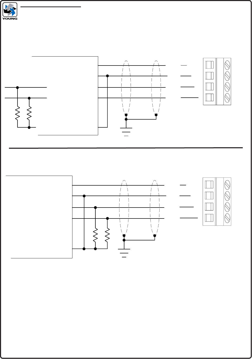
WIRING INFORMATION
MODEL 41382LF2 TEMPERATURE SENSOR
+PWR
GND
RH
T
(WHT)
(BLK)
(GRN)
(RED)
CURRENT INPUT 1 (+)
CURRENT INPUT 2 (+)
+24VDC PWR
PWR COMMON
SHIELDED CABLE
EARTH GROUND
4-20 mA CURRENT INPUT
MEASURING INSTRUMENT SENSOR TERMINALS
CURRENT INPUT COMMON
250 Ohms Typical
R R
+PWR
GND
RH
T
(WHT)
(BLK)
(GRN)
(RED)
VOLTAGE INPUT 1 (+)
VOLTAGE INPUT 2 (+)
+24VDC PWR
PWR COMMON
SHIELDED CABLE
EARTH GROUND
VOLTAGE INPUT
MEASURING INSTRUMENT
VOLTAGE INPUT COMMON
50 to 250 Ohms
Typical
R R
SENSOR TERMINALS
30VDC at 46 mA Max Supply
Total Current Consumption = T mA + RH mA + 6 mA
Min Supply V = 4 + 0.02R
Max Load R = (Vsupply - 4) / 0.02
