430413 Catalog
101184-Attachment 101184-Attachment 101184-Attachment 782114 Batch7 unilog cesco-content
100836-Catalog 100836-Catalog 100836-Catalog 782113 Batch7 unilog cesco-content
430413-Catalog 430413-Catalog 430413-Catalog 782113 Batch5 unilog cesco-content
430413-Catalog 430413-Catalog 430413-Catalog 786685 Batch5 unilog cesco-content
101184-Attachment 101184-Attachment 101184-Attachment 782113 Batch7 unilog cesco-content
2014-07-05
: Pdf 430413-Catalog 430413-Catalog 782114 Batch5 unilog
Open the PDF directly: View PDF ![]() .
.
Page Count: 739 [warning: Documents this large are best viewed by clicking the View PDF Link!]
Product Guide 2012
Product Guide 2012 Logic Control Products
Logic Control Products
© 2012 Eaton Corporation
All Rights Reserved
Printed in Canada
Pub No. CA08100001K
June 2012
Eaton Corporation
1111 Superior Ave.
Cleveland, OH 44114
United States
877-ETN-CARE (877-386-2273)
Eaton.com
Canadian Operations
5050 Mainway
Burlington, ON L7L 5Z1
Canada
1-800-268-3578
EatonCanada.ca
Eaton is a registered trademark
of Eaton Corporation.
All trademarks are property of their
respective owners.
Eaton Corporation is a diversified power management company
with more than 100 years of experience providing energy-
efficient solutions that help our customers effectively manage
electrical, hydraulic and mechanical power. With 2011 sales of
$16.0 billion, Eaton is a global technology leader in electrical
components, systems and services for power quality, distribution
and control; hydraulics components, systems and services for
industrial and mobile equipment; aerospace fuel, hydraulics
and pneumatic systems for commercial and military use; and
truck and automotive drivetrain and powertrain systems for
performance, fuel economy and safety. Eaton has approximately
72,000 employees and sells products to customers in more than
150 countries. For more information, visit www.eaton.com.
CA08100001K LCP 2012 Canada.indd 1 5/15/12 9:33:33 PM
There’s a certain energy at Eaton. It’s the power of
uniting some of the world’s most respected names to
build a brand you can trust to meet your every power
management need. The energy created supports our
commitment to powering business worldwide.
From power distribution to power quality and control,
Eaton allows you to proactively manage your complete
power system by providing electrical solutions that
make your applications more reliable, effi cient and
safe. Visit Eaton.ca.
All of the above are trademarks of Eaton Corporation or its affiliates. Eaton has
a license to use the Westinghouse name in Asia Pacific. ©2010 Eaton Corporation.
The power of fusion.
1874 1886 1911 19901893 19831962 19991976190819061899 19631934
Brand inception dates:
Product
Name
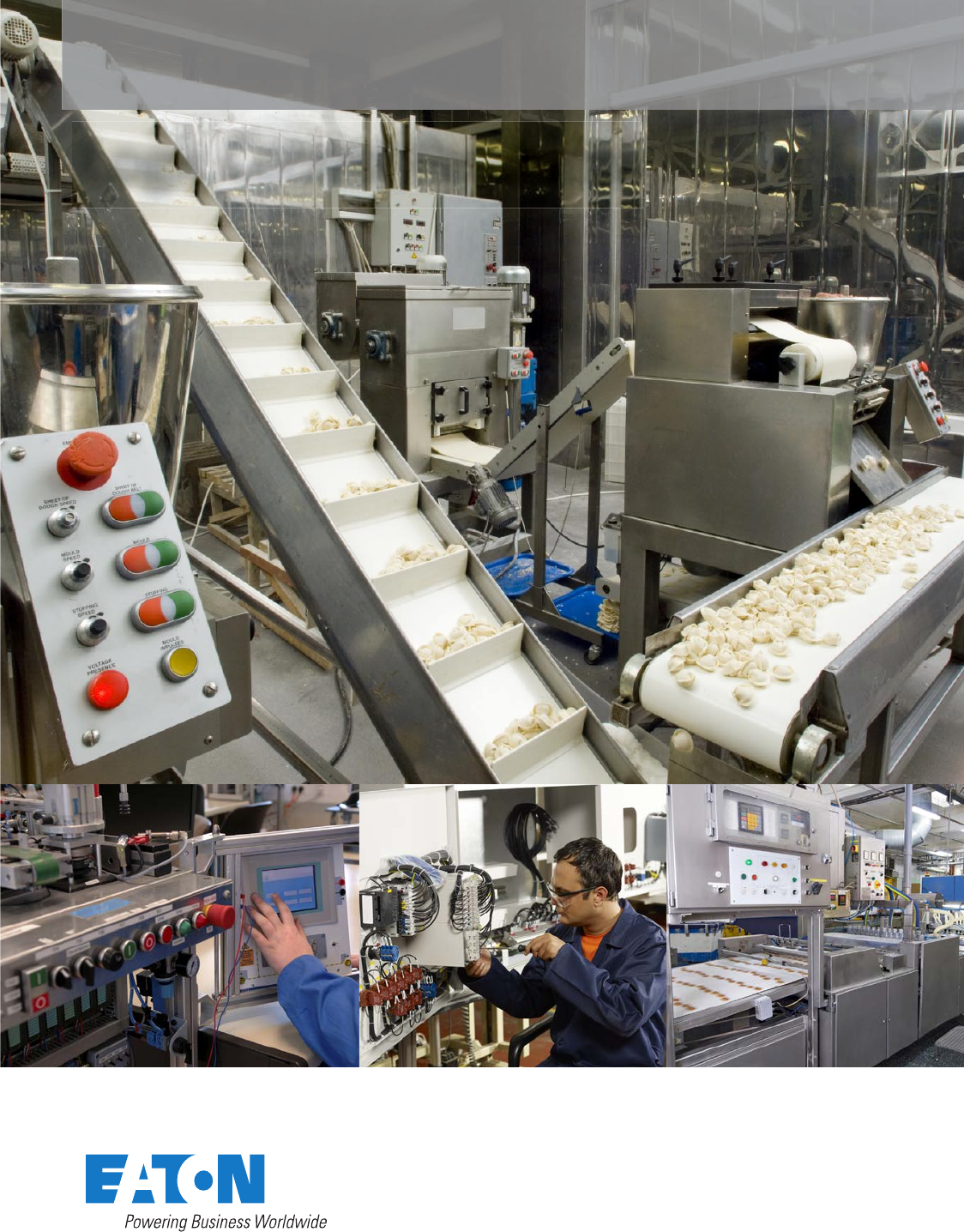
Meeting demands
from packaging
to processing
Electrical solutions
that streamline
control
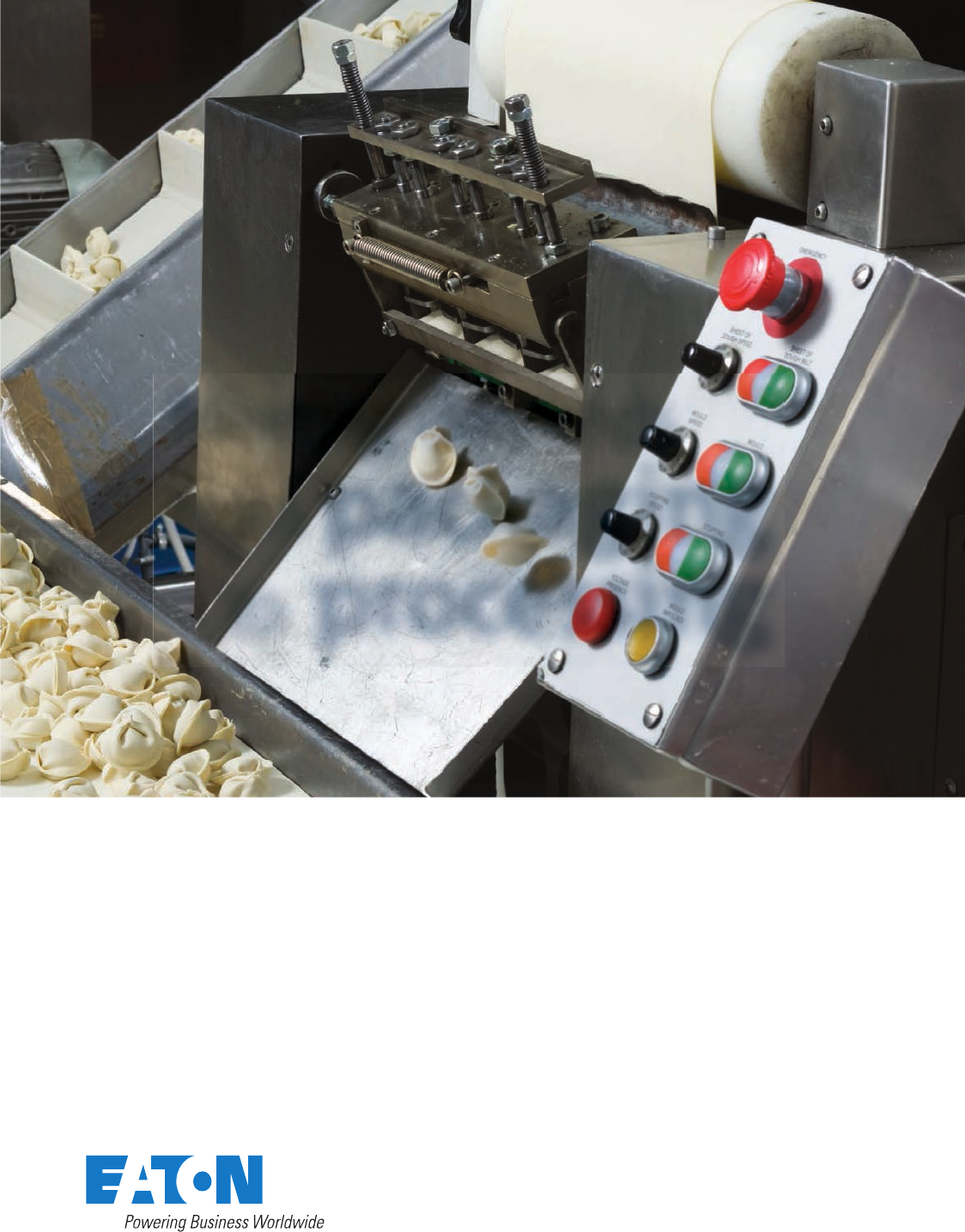
In order to improve
competitive strength and
reduce costs, today’s machine
builders require state-of-
the-art automation systems.
Eaton can help you achieve
this through industry-leading
solutions that increase
throughput, improve uptime
and improve quality
that lower your total cost
of development.
We recognize the challenges
faced by this industry. There
is a demand for intelligence,
operator guidance, presence
sensing, advanced protection
and diagnostic functions of
machines, and the reduction
in overall machine size.
No matter what your needs
entail, Eaton will provide
component solutions to help
you run a more energy-
efficient business.
For more information, visit
us at Eaton.ca
CA08100001K LCP 2012 Canada.indd 2 5/15/12 9:34:24 PM
Volume 1—Residential and Light Commercial
Volume 2—Commercial Distribution
Volume 3—Power Distribution and Control Assemblies
Volume 4—Circuit Protection
Volume 5—Motor Control and Protection
Volume 6—Solid-State Motor Control
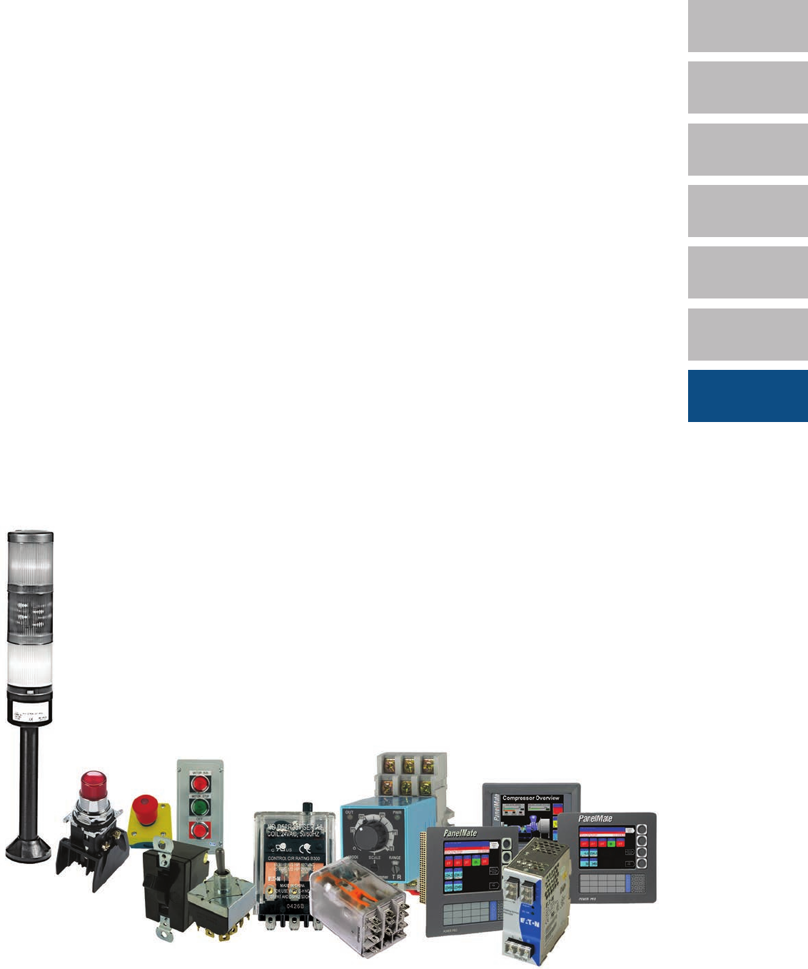
Volume 7—Logic Control Products
Tab 37—Pushbuttons and Indicating Lights . . . . . . . . . . . . . . . . . . . . . . . . T37-1
Tab 38—Stacklights . . . . . . . . . . . . . . . . . . . . . . . . . . . . . . . . . . . . . . . . . . . T38-1
Tab 40—Control Relays and Timers . . . . . . . . . . . . . . . . . . . . . . . . . . . . . . . T40-1
Tab 42—Terminal Blocks, Fuse Blocks and Fuse Holders . . . . . . . . . . . . . T42-1
Appendix 1—Alphabetical Catalogue Number Index . . . . . . . . . . . . . . . . I-1
Appendix 2—Alphabetical Parent Number Index . . . . . . . . . . . . . . . . . . . I-55
Appendix 3—Alphabetical Product Index . . . . . . . . . . . . . . . . . . . . . . . . . . I-59
Appendix 4 . . . . . . . . . . . . . . . . . . . . . . . . . . . . . . . . . . . . . . . . . . . . . . . . . . . I-63
1
2
3
4
5
6
7
MainTOC_Vol07.fm Page 1 Wednesday, June 6, 2012 9:05 PM

Copyright
Dimensions, Weights and Ratings
Dimensions, weights and ratings given in this catalogue
are approximate and should not
be used for construction purposes
. Drawings containing exact dimensions are available
upon request. All listed product specifications and ratings are subject to change without
notice. Photographs are representative of production units.
Terms and Conditions
All prices and discounts are subject to change without notice. When price changes
occur, they are published in the
Eaton Corporation Price and Availability Digest
(PAD).
For pricing consult with your local Eaton Representative. All orders accepted by Eaton
are subject to Eaton’s general terms and conditions.
Technical and Descriptive Publications
This catalogue contains brief technical data for proper selection of products. Further
information is available in the form of technical information publications and illustrated
brochures. If additional product information is required, contact your local Eaton Products
Distributor, call
1-800-268-3578
or visit our Web site at
www.eatoncanada.ca
.
Compliance with Nuclear Regulation 10 CFR 21
Eaton products are sold as commercial grade products not intended for application in
facilities or activities licensed by the United States Nuclear Regulatory Commission for
atomic purposes, under 10 CFR 21. Further certification will be required for use of these
products in a safety-related application in any nuclear facility licensed by the U.S. Nuclear
Regulatory Commission.
WARNING
The installation and use of Eaton products should be in accordance with the provisions of
the Canadian Electrical Code and/or other local codes or industry standards that are
pertinent to the particular end use. Installation or use not in accordance with these codes
and standards could be hazardous to personnel and/or equipment.
Copyright ©2012, Eaton Corporation, All Rights Reserved.
These catalogue pages do not purport to cover all details or variations in equipment, nor to provide
for every possible contingency to be met in connection with installation, operation or maintenance.
Should further information be desired or should particular problems arise which are not covered
sufficiently for the purchaser’s purposes, the matter should be referred to the local Eaton Products
Distributor or Sales Office. The contents of this catalogue shall not become part of or modify any
prior or existing agreement, commitment or relationship. The sales contract contains the entire
obligation of Eaton’s electrical sector. The warranty contained in the contract between the parties
is the sole warranty of Eaton. Any statements contained herein do not create new warranties or
modify the existing warranty.
MainTOC_Vol07.fm Page 2 Wednesday, June 6, 2012 9:05 PM
Logic Control Products
CA08100001K—June 2012 www.eatoncanada.ca
T37-1
37
37
37
37
37
37
37
37
37
37
37
37
37
37
37
37
37
37
37
37
37
37
37
37
37
37
37
37
37
37
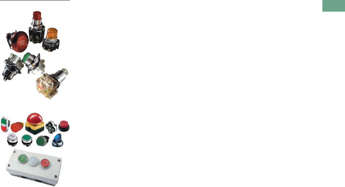
Pushbuttons and Indicating Lights
10250T Pushbuttons
M22 Modular Pushbuttons
37.1 Toggle Switches—E10
Product Description . . . . . . . . . . . . . . . . . . . . . . . . . . . . . . . . . . . . . . . . . .
T37-2
Product Selection . . . . . . . . . . . . . . . . . . . . . . . . . . . . . . . . . . . . . . . . . . . .
T37-4
Technical Data and Specifications . . . . . . . . . . . . . . . . . . . . . . . . . . . . . . .
T37-6
37.2 Environmentally Sealed Toggle Switches—E10E
Product Description . . . . . . . . . . . . . . . . . . . . . . . . . . . . . . . . . . . . . . . . . .
T37-8
Product Selection . . . . . . . . . . . . . . . . . . . . . . . . . . . . . . . . . . . . . . . . . . . .
T37-9
Technical Data and Specifications . . . . . . . . . . . . . . . . . . . . . . . . . . . . . . .
T37-10
37.3 Pushbutton Control Stations—Assembled
Product Description . . . . . . . . . . . . . . . . . . . . . . . . . . . . . . . . . . . . . . . . . .
T37-14
Product Selection . . . . . . . . . . . . . . . . . . . . . . . . . . . . . . . . . . . . . . . . . . . .
T37-16
Technical Data and Specifications . . . . . . . . . . . . . . . . . . . . . . . . . . . . . . .
T37-28
37.4 22.5 mm Modular Pushbuttons—M22
Product Description . . . . . . . . . . . . . . . . . . . . . . . . . . . . . . . . . . . . . . . . . .
T37-35
Product Selection . . . . . . . . . . . . . . . . . . . . . . . . . . . . . . . . . . . . . . . . . . .
T37-36
Technical Data and Specifications . . . . . . . . . . . . . . . . . . . . . . . . . . . . . . .
T37-104
37.5 22.5 mm Compact Pushbuttons—C22
Product Selection Guide . . . . . . . . . . . . . . . . . . . . . . . . . . . . . . . . . . . . . .
T37-124
Product Selection . . . . . . . . . . . . . . . . . . . . . . . . . . . . . . . . . . . . . . . . . . .
T37-126
Technical Data and Specifications . . . . . . . . . . . . . . . . . . . . . . . . . . . . . . .
T37-144
37.6 30.5 mm Square Multifunction Watertight/Oiltight—E30
Product Description . . . . . . . . . . . . . . . . . . . . . . . . . . . . . . . . . . . . . . . . . .
T37-149
Product Selection . . . . . . . . . . . . . . . . . . . . . . . . . . . . . . . . . . . . . . . . . . .
T37-151
Technical Data and Specifications . . . . . . . . . . . . . . . . . . . . . . . . . . . . . . .
T37-165
37.7 30.5 mm Heavy-Duty Watertight/Oiltight—10250T
Product Description . . . . . . . . . . . . . . . . . . . . . . . . . . . . . . . . . . . . . . . . . .
T37-167
Product Selection . . . . . . . . . . . . . . . . . . . . . . . . . . . . . . . . . . . . . . . . . . .
T37-172
Technical Data and Specifications . . . . . . . . . . . . . . . . . . . . . . . . . . . . . . .
T37-227
37.8 30.5 mm Corrosion Resistant Watertight/Oiltight—E34
Product Description . . . . . . . . . . . . . . . . . . . . . . . . . . . . . . . . . . . . . . . . . .
T37-240
Product Selection . . . . . . . . . . . . . . . . . . . . . . . . . . . . . . . . . . . . . . . . . . .
T37-246
Technical Data and Specifications . . . . . . . . . . . . . . . . . . . . . . . . . . . . . . .
T37-275
37.10 30.5 mm Class I Division 2 Hazardous Locations—10250T/E34
Product Description . . . . . . . . . . . . . . . . . . . . . . . . . . . . . . . . . . . . . . . . . .
T37-283
Product Selection . . . . . . . . . . . . . . . . . . . . . . . . . . . . . . . . . . . . . . . . . . . .
T37-286
Technical Data and Specifications . . . . . . . . . . . . . . . . . . . . . . . . . . . . . . .
T37-319
Ratings . . . . . . . . . . . . . . . . . . . . . . . . . . . . . . . . . . . . . . . . . . . . . . . . . . . .
T37-322
Tab37book.fm Page 1 Tuesday, July 3, 2012 10:46 PM
T37-2 Logic Control Products
CA08100001K—June 2012 www.eatoncanada.ca
37
37
37
37
37
37
37
37
37
37
37
37
37
37
37
37
37
37
37
37
37
37
37
37
37
37
37
37
37
37
37.1
Pushbuttons and Indicating Lights
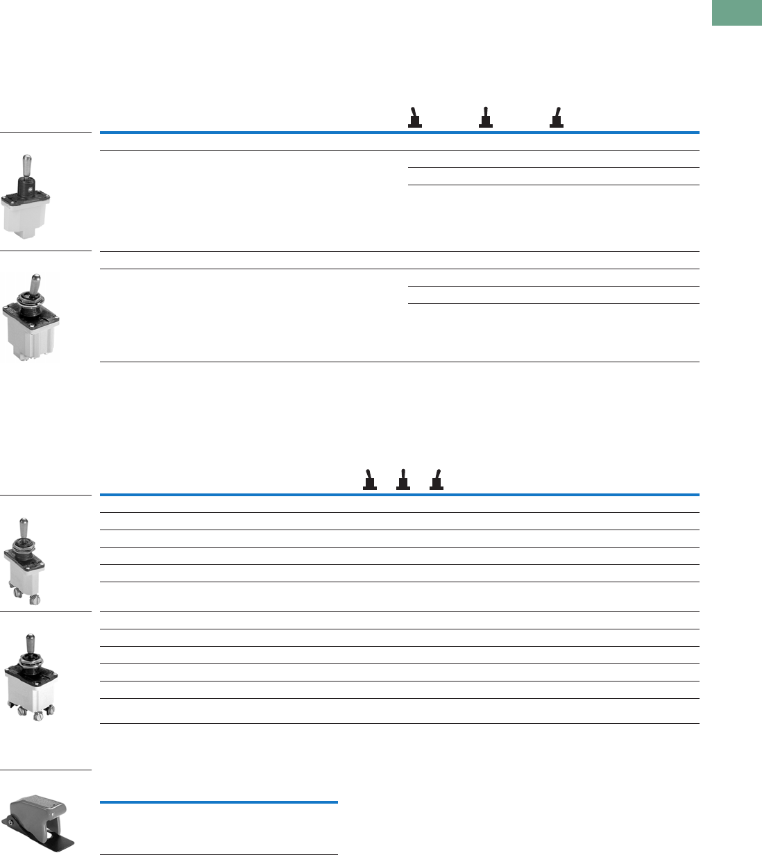
Toggle Switches—E10
Toggle Switches—E10
Contents
Description Page
Toggle Switches—E10
Standards and Certifications . . . . . . . . . . . . . . . . . . . .
T37-3
Catalogue Number Selection . . . . . . . . . . . . . . . . . . . .
T37-3
Product Selection
Toggle Switches . . . . . . . . . . . . . . . . . . . . . . . . . . .
T37-4
Hesitation Switches . . . . . . . . . . . . . . . . . . . . . . . .
T37-5
Pushbuttons . . . . . . . . . . . . . . . . . . . . . . . . . . . . . .
T37-5
Accessories . . . . . . . . . . . . . . . . . . . . . . . . . . . . . . . . .
T37-5
Technical Data and Specifications . . . . . . . . . . . . . . . .
T37-6
Circuit Diagrams . . . . . . . . . . . . . . . . . . . . . . . . . . . . . .
T37-6
Dimensions . . . . . . . . . . . . . . . . . . . . . . . . . . . . . . . . .
T37-7
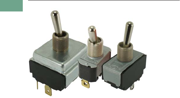
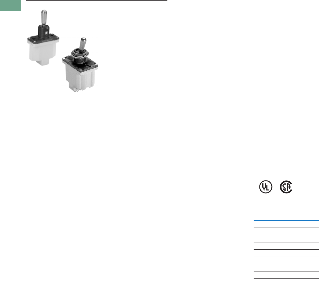
Product Description
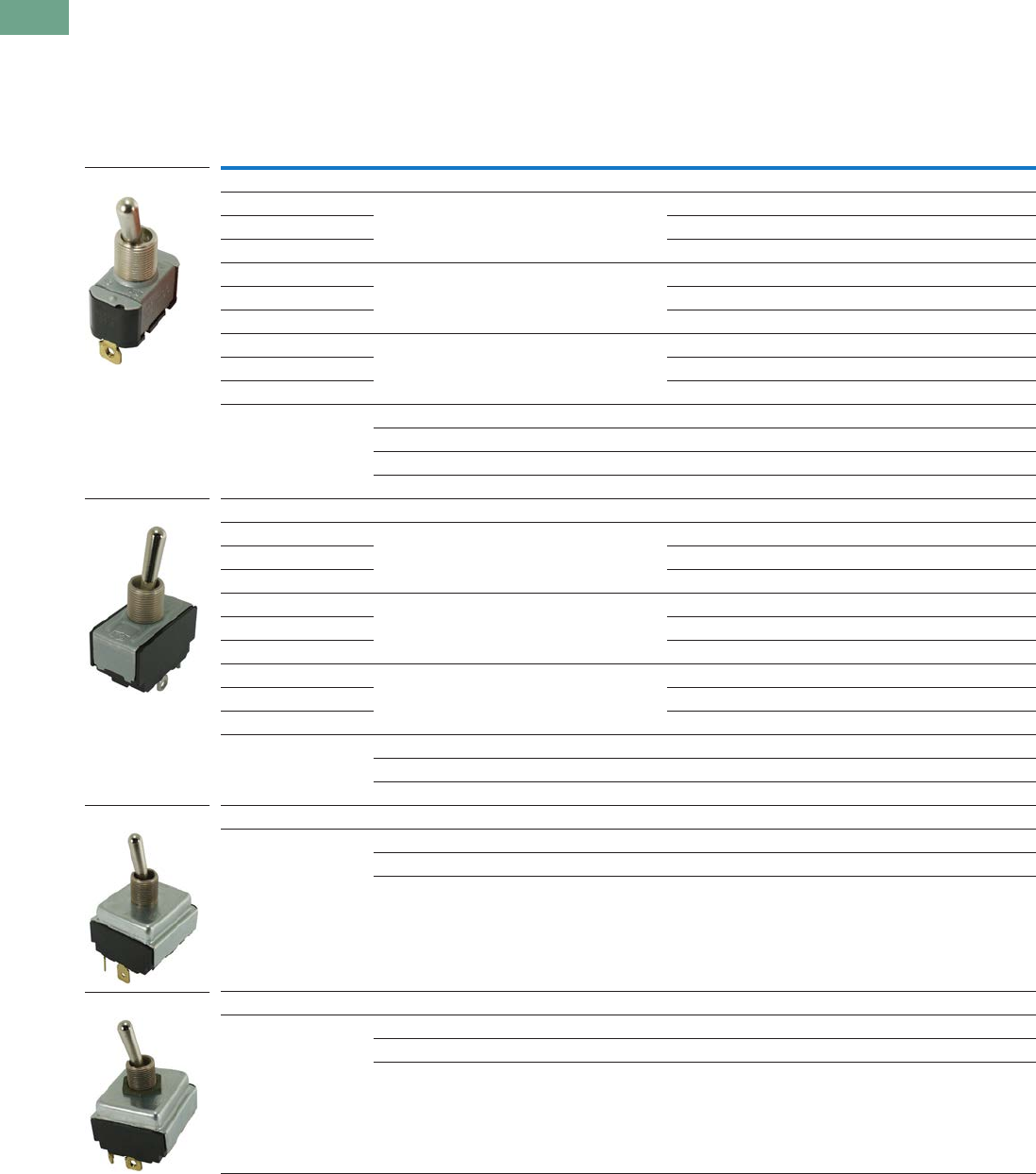
The E10 switches from
Eaton’s electrical sector are
intended for general purpose
light industrial use. Designed
for retrofit and OEM
applications.
Features
General Purpose Toggles
●
Various circuit functions
include maintained and
momentary
●
Poles include from single-
pole single-throw to four-
pole double-throw
●
Spade, screw, and solder
terminations available
●
Numerous ratings
●
Short 11/32 in and tall
15/32 in bat lever available
●
Standard 15/32–32 thd.
●
Hardware furnished
assembled
Heavy-Duty Hesitation
Switches
●
One-hole panel mount
●
Three position switch
offers unique positive
centre stop feature to
assure lever cannot be
thrown from one side
through the centre OFF
position without stopping
●
Design feature is a
major acceptance for
motor reversing and
speed control
applications
●
Prevents motor damage
resulting from high
current generation by
counter EMF of the
armature at the time of
reversing
●
Known as anti-plugging,
hesitation, positive stop
or positive off switch
Non-Illuminated AC Rated
Pushbuttons
●
One-hole panel mount
●
Medium-duty
●
Spade and screw
terminations available
●
Various bushing lengths
and button extensions
●
Numerous ampere ratings
with horsepower ratings
Tab37book.fm Page 2 Tuesday, July 3, 2012 10:46 PM
Logic Control Products
CA08100001K—June 2012 www.eatoncanada.ca
T37-3
37
37
37
37
37
37
37
37
37
37
37
37
37
37
37
37
37
37
37
37
37
37
37
37
37
37
37
37
37
37
37.1
Pushbuttons and Indicating Lights
Toggle Switches—E10
Standards and Certifications
●
UL Recognized
●
CSA—File No. LR40068
Catalogue Number Selection
Catalogue Number Selection is for illustrative purposes only and not to be used to create new catalogue numbers.
Toggle Switches—E10 Series
Not to be used for ordering purposes
E10 T 1 06 A S = E10T106AS
Poles
1 = Single-pole
2 = Two-pole
3 = Three-pole
4 = Four-pole
Ratings—125V
06 = 6 Amperes
15 = 15 Amperes
20 = 20 Amperes
Function
A = ON—None—OFF
B = OFF—None—(ON)
D = ON—OFF—ON
E = ON—None—ON
F = ON—OFF—(ON)
G = (ON)—OFF—(ON)
H = ON—None—(ON)
Termination
S= Screw
L= Solder lug
P= Spade
Series
Lever Length
T= 0.563 in (14.3 mm) lever
E= 0.688 in (17.5 mm) lever
Complete Cat. No.
0.563 in (14.3 mm)
Single-pole
6 Amperes
ON—None—OFF
Screw terminal
Tab37book.fm Page 3 Tuesday, July 3, 2012 10:46 PM
T37-4 Logic Control Products
CA08100001K—June 2012 www.eatoncanada.ca
37
37
37
37
37
37
37
37
37
37
37
37
37
37
37
37
37
37
37
37
37
37
37
37
37
37
37
37
37
37
37.1
Pushbuttons and Indicating Lights
Toggle Switches—E10
Product Selection
Toggle Switches
E10 Series—AC Rated—Minimum Order Quantity 10 Pieces
Note
See Circuit Diagrams on
Page T37-6
.
Nominal AC Ratings Poles
and
Throw
Function—Circuit with Lever In
Screw Terminal
Catalogue Number
0.250 in (6.4 mm)
Spade Terminal
Catalogue Number
Solder Lug
Catalogue Number
UP
Position
CENTRE
Position
DOWN
Position—
Keyway
Amperes
125V 250V
hp
50V
Single-Pole
6 3 — 1 P.S.T. ON None OFF
E10T106AS E10T106AP E10T106AL
15 10 3/4
E10T115AS E10T115AP E10T115AL
20 10 3/4
E10E120AS E10E120AP E10E120AL
6 3 — 1 P.D.T. ON OFF ON
E10T106DS E10T106DP —
15 10 3/4
E10T115DS E10T115DP E10T115DL
20 10 3/4
E10E120DS — —
6 3 — 1 P.D.T. ON None ON
E10T106ES — —
15 10 3/4
E10T115ES E10T115EP E10T115EL
20 10 3/4
E10E120ES — —
— 10 1/2 1 P.S.T. OFF None (ON)
E10T115BS E10T115BP —
1 P.D.T. ON OFF (ON)
E10T115FS E10T115FP —
1 P.D.T. ON None (ON)
E10T115HS E10T115HP —
1 P.D.T. (ON) OFF (ON)
E10T115GS E10T115GP —
Two-Pole
6 3 — 2 P.S.T. ON None OFF
E10T206AS E10T206AP —
15 10 3/4
E10T215AS E10T215AP E10T215AL
20 10 3/4
E10E220AS E10E220AP E10E220AL
6 3 — 2. P.D.T. ON OFF ON
E10T206DS E10T206DP —
15 10 3/4
E10T215DS E10T215DP E10T215DL
20 10 3/4
E10E220DS E10E220DP —
6 3 — 2 P.D.T. ON None ON
E10T206ES — —
15 10 3/4
E10T215ES E10T215EP E10T215EL
20 10 3/4
E10E220ES — —
15 10 1/2 2 P.S.T. OFF None (ON)
E10T215BS — —
2 P.D.T. ON None (ON)
E10T215HS E10T215HP —
2 P.D.T. (ON) OFF (ON)
E10T215GS E10T215GP —
Three-Pole
15 10 3/4 3 P.S.T. ON None OFF
E10E315AS E10E315AP —
3 P.D.T. ON OFF ON
E10E315DS E10E315DP E10E315DL
3 P.D.T. ON None ON
E10E315ES E10E315EP E10E315EL
Four-Pole
15 10 3/4 4 P.S.T. ON None OFF
E10E415AS — E10E415AL
4 P.D.T. ON OFF ON
E10E415DS — E10E415DL
4 P.D.T. ON None ON
E10E415ES — E10E415EL
Two-Pole
Single-Pole
Three-Pole
Four-Pole
Tab37book.fm Page 4 Tuesday, July 3, 2012 10:46 PM
Logic Control Products
CA08100001K—June 2012 www.eatoncanada.ca
T37-5
37
37
37
37
37
37
37
37
37
37
37
37
37
37
37
37
37
37
37
37
37
37
37
37
37
37
37
37
37
37
37.1
Pushbuttons and Indicating Lights
Toggle Switches—E10
Hesitation Switches
E10 Series—Special Purpose—Minimum Order Quantity 10 Pieces
Pushbuttons
E10 Series—Minimum Order Quantity 10 Pieces
Accessories
Toggle Switches Accessories—Minimum Order Quantity 100 Pieces
Notes
Interlock mechanism prevents operation of lever through the centre position until pressure is momentarily relieved.
Designed for control and protection of reversing motors.
See Circuit Diagrams on Page T37-6.
Rated 1/4 hp at 125V, 1/2 hp at 250V.
Nominal Ratings
Operation
Function—Circuit with Lever In…
Poles
and
Throw
Screw Terminal
Catalogue Number
Amperes hp
UP
Position
CENTRE
Position
DOWN
Position—
Keyway
28
Vdc
125
Vac
250
Vac
250
Vac
15 15 10 3/4 Maintained ON OFF ON 2 P.D.T. E10E215SS
3 P.D.T. E10E315SS
4 P.D.T. E10E415SS
Nominal Ratings
Poles
and
Throw Contacts
Bushing
Length
in (mm)
Dim. “A”
Button
Extension
in (mm)
Dim. “B”
Typical
Maximum
Operating
Force
Screw Terminal
Catalogue Number
Spade Terminal
0.250 in (6.4 mm)
Catalogue Number
Amperes hp
125 Vac 250 Vac 125–
250VNO NC NO NC
6 — 3 — — 1 P.S.T. NO 0.69 (17.5) 0.53 (13.5) 0.9 lbs E10P106RS E10P106RP
0.34 (8.6) 0.25 (6.4) E10P106JS —
15 — 10 — 1/3 1 P.S.T. NO 0.69 (17.5) 0.53 (13.5) 0.9 lbs E10P115RS E10P115RP
0.34 (8.6) 0.25 (6.4) E10P115JS —
15 10 10 5 1/4 1 P.D.T. NO, NC 0.69 (17.5) 0.53 (13.5) 1.0 lbs E10P115LS —
Description Material/Notes Catalogue Number
Hexagon locknut Zinc-chromate treated steel E10TA101
Knurled face nut Zinc-chromate treated steel E10TA102
Internal tooth lockwasher Cadmium plated steel E10TA103
Terminal screws #6-32 x 3/16 in binding head E10TA201
Spade terminal adapter—0.250 in (6.4 mm) Assembles to screw terminals E10TA202
ON-OFF indicating plate—vertical orientation Burnished nickel finish steel E10TA301
OFF-ON indicating plate—horizontal orientation Burnished nickel finish steel E10TA302
Flip-up guard for toggle switches E10TA104
Fixed shroud for toggle switches E10TA105
Heavy-Duty Hesitation
Switch
One-Hole Mounted
Medium-Duty, Mom.
Contact
E10TA104
E10TA105
Tab37book.fm Page 5 Tuesday, July 3, 2012 10:46 PM
T37-6 Logic Control Products CA08100001K—June 2012 www.eatoncanada.ca
37
37
37
37
37
37
37
37
37
37
37
37
37
37
37
37
37
37
37
37
37
37
37
37
37
37
37
37
37
37
37.1
Pushbuttons and Indicating Lights
Toggle Switches—E10
Technical Data and Specifications
Toggle Switches
Hesitation Switches
Pushbutton Actuators
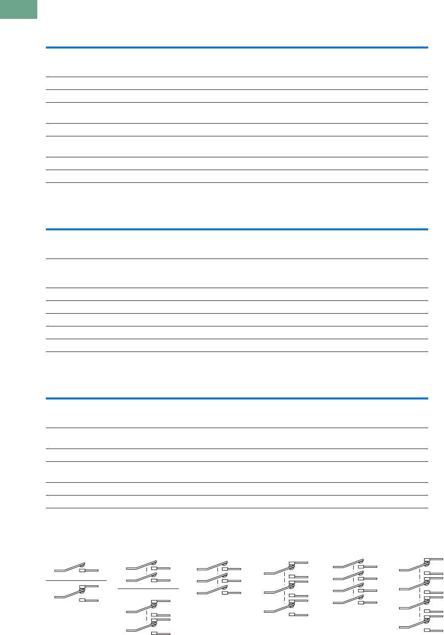
Circuit Diagrams
Description Specification
AC ratings 6–20A, 125 Vac
3–10A, 250 Vac
Max. 3/4 hp at 250 Vac
DC ratings 6–20A, 28 Vdc
Electrical life 6,000 cycles make/break at switch ampere rating
Operation Slow make/slow break mechanism with butt action for AC and low voltage DC applications
Maintained and momentary contacts
Poles/throws 1 through 4, single and double throw
Mounting One hole with threaded 0.468 in-32 bushing and 0.068 x 0.035 in (1.7 x 0.9 mm) deep keyway
that serves as anti-rotational feature
Lever lengths 0.563 in (14.3 mm) or 0.688 in (17.5 mm), bright nickel plated
Terminals Screw, 0.250 in (6.4 mm) spade and solder lug
Description Specification
Operation Slow make/slow break mechanism with butt action for AC and low voltage DC applications; maintained contacts; ideal
for reversing motor applications; interlock mechanism prevents operation of lever through centre position until manual
pressure is momentarily relieved
AC ratings 15A, 125 Vac
10A, 250 Vac
Max. 3/4 hp at 250 Vac
DC ratings 15A, 28 Vdc
Poles/throws 2, 3 and 4, double throw only
Mounting Single-pole with threaded 0.468 in-32 bushing and 0.068 x 0.049 in (1.7 x 1.2 mm) deep keyway
Lever length 0.687 in (17.4 mm), stainless steel
Terminals Screw
Description Specification
AC ratings 6–15A, 125 Vac (NO)
3–10A, 250 Vac (NO)
Max. 1/3 hp at 125/250 Vac
Operation Slow make/slow break mechanism
Normally open contacts
Poles/throws Single, single and double throw
Mounting One hole with 0.468 in-32 threaded bushing and 0.068 x 0.035 in (1.7 x 0.9 mm) deep keyway
Two bushing heights: 11/16 in (17.5 mm) and 11/32 in (8.7 mm)
Button extensions 17/32 in (13.5 mm) and 1/4 in (6.4 mm), bright nickel plated
Terminals Screw
SPST DPST
SPDT
DPDT
4PST3PDT 4PDT3PST
Tab37book.fm Page 6 Tuesday, July 3, 2012 10:46 PM
Logic Control Products CA08100001K—June 2012 www.eatoncanada.ca T37-7
37
37
37
37
37
37
37
37
37
37
37
37
37
37
37
37
37
37
37
37
37
37
37
37
37
37
37
37
37
37
37.1
Pushbuttons and Indicating Lights
Toggle Switches—E10
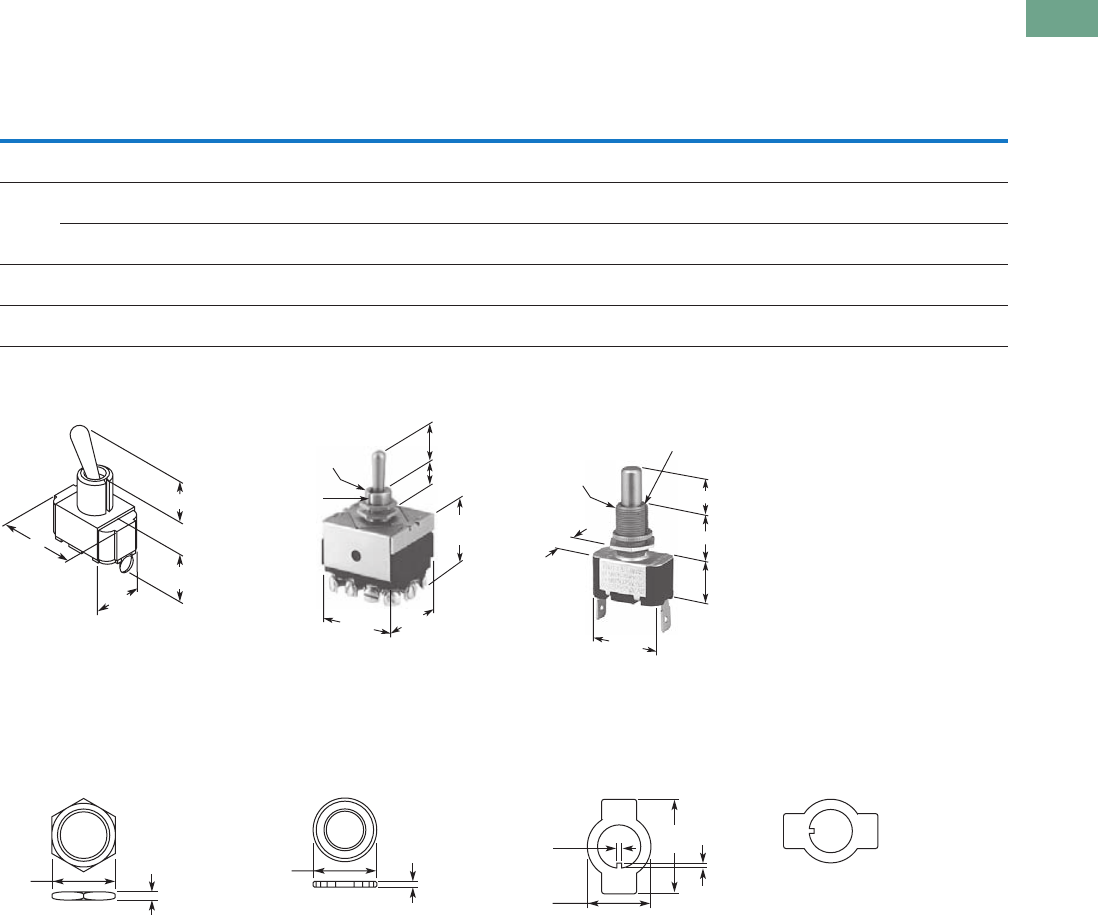
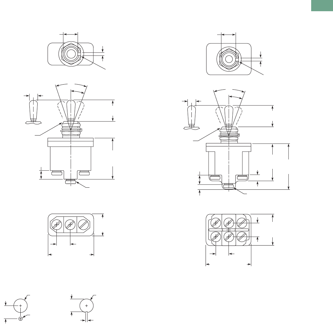
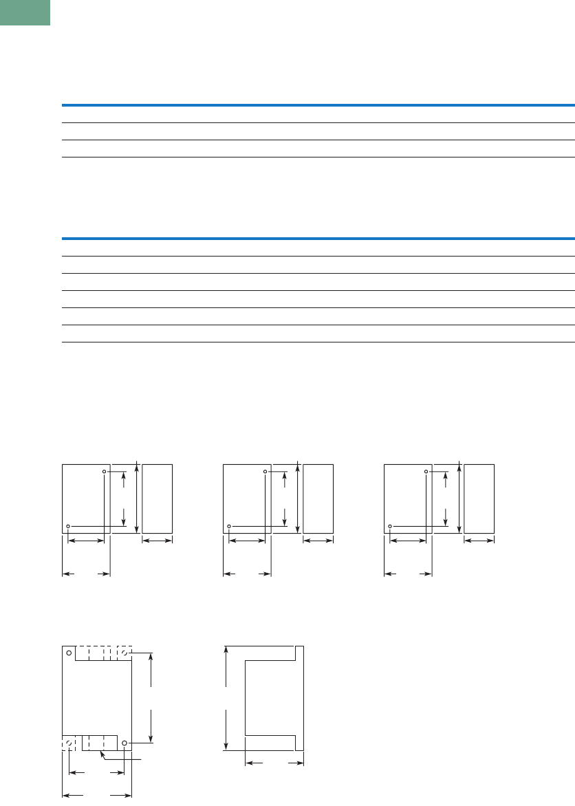
Dimensions
Approximate Dimensions in Inches (mm)
Toggle Switch Dimensions
Toggle Switch Hesitation Switch Pushbutton Actuator
Accessories
E10TA101
Hexagon Locknut
E10TA102
Knurled Face Nut
E10TA301
ON-OFF Indicating Plate—
Vertical Orientation
E10TA302
ON-OFF Indicating Plate—
Horizontal Orientation
Note
Spade terminal adapters are used on 6 ampere and momentary screw terminal switches, adding 0.42 in (10.7 mm) to dimension C.
No. of
Poles Operation
Bushing
Length
A
Lever
Length
B
Screw Terminals Spade Terminals Solder Lug
CDEC
DECDE
1 Momentary
and maintained
0.47
(11.9)
0.56
(14.2)
1.00
(25.4)
1.17
(29.7)
0.63
(16.0)
1.13
(28.7)
1.13
(28.7)
0.63
(16.0)
1.00
(25.4)
1.13
(28.7)
0.63
(16.0)
2 Maintained 0.47
(11.9)
0.56
(14.2)
1.06
(26.9)
1.31
(33.3)
0.75
(19.1)
1.19
(30.2)
1.31
(33.3)
0.75
(19.1)
1.06
(26.9)
1.31
(33.3)
0.75
(19.1)
Momentary 0.47
(11.9)
0.56
(14.2)
1.25
(31.8)
1.31
(33.3)
0.75
(19.1)
1.31
(33.3)
1.31
(33.3)
0.75
(19.1)
1.25
(31.8)
1.31
(33.3)
0.75
(19.1)
3 Maintained 0.47
(11.9)
0.69
(17.5)
1.27
(32.3)
1.34
(34.0)
1.44
(36.6)
1.37
(34.8)
1.34
(34.0)
1.44
(36.6)
1.23
(31.2)
1.34
(34.0)
1.44
(36.6)
4 Maintained 0.47
(11.9)
0.69
(17.5)
1.20
(30.5)
1.30
(33.0)
1.40
(35.6)
1.30
(33.0)
1.34
(34.0)
1.40
(35.6)
1.23
(31.2)
1.34
(34.0)
1.44
(36.6)
D
E
C
A
B
1.47
(37.3)
0.47-32
Thread
0.07 (1.8) x
0.05 (1.3)
Keyway
1.34
(34)
1.25
(31.8)
0.47
(11.9)
0.69
(17.5)
1.13
(28.7)
0.47-32
Thread
0.04 (1) x 0.07 (1.8)
Keyway
1.13
(28.7)
A
B
0.63
(16)
0.63
(16)
0.08
(2) 0.63
(16)
0.07
(1.8)
0.63
(16)
0.06
(1.5)
0.03
(.8)
1.0
(25.4)
ON
OFF
O
N
O
F
F
Tab37book.fm Page 7 Tuesday, July 3, 2012 10:46 PM
T37-8 Logic Control Products CA08100001K—June 2012 www.eatoncanada.ca
37
37
37
37
37
37
37
37
37
37
37
37
37
37
37
37
37
37
37
37
37
37
37
37
37
37
37
37
37
37
37.2
Pushbuttons and Indicating Lights
Environmentally Sealed Toggle Switches—E10E
Toggle Switches—E10E Contents
Description Page
Environmentally Sealed Toggle Switches—E10E
Product Selection
Molded-In Screw Terminal . . . . . . . . . . . . . . . . . T37-9
Econoswitch . . . . . . . . . . . . . . . . . . . . . . . . . . . . T37-9
Switch Guard . . . . . . . . . . . . . . . . . . . . . . . . . . . T37-9
Technical Data and Specifications . . . . . . . . . . . . . . T37-10
Dimensions . . . . . . . . . . . . . . . . . . . . . . . . . . . . . . . T37-11
Product Description
Designed for general purpose
and OEM applications, this
line of toggle switches
provides a high IP68 rating for
demanding environments.
Features
Molded-In Screw Terminal
●Completely sealed against
dust, moisture and other
contaminants
●One-hole mounted bushing
for easy installation
●Multi-circuits offered
●Two- and three-position
with maintained and
momentary action
●Molded-in terminal inserts
and terminals numbers
●Single- and two-pole
circuitry
Econoswitch
●Environmentally sealed
●Single- and two-pole
circuitry
●One-hole mounting for
easy installation
●Multi-circuits
●Two- and three-position
with maintained and
momentary action
●Three types of termination
offered as standard
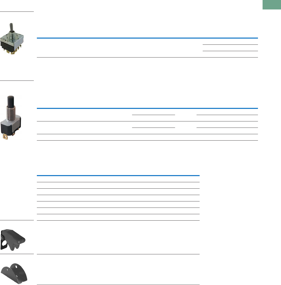
Switch Guard
●For use with two-position
switch
●Cover closure transfers
switch toggle lever to OFF
position
●One-hole mounted
mounting style
●Cover is molded out of red
thermoset molding
material
●Guard cover is spring-
loaded to either close or
lock in open position
●Prevents accidental
operation at switches
Options
Note: Contact your local Eaton
Sales Representative for more
information.
●Non-UL Recognized
devices
●Alternate toggle levers
●Locking toggle levers
●Rocker buttons
●Special mounting hardware
●Mounting hardware
furnished assembled
●Terminal screws furnished
assembled
●Special circuits
●Panel seal, part number
32-341
●Spade terminal adapters
available
Standards and
Certifications
●UL—File number E15346;
Guide card number is
WOYR2
●CSA—LR40068, class
number 6241
UL and CSA Nominal
Ratings
Catalogue Number 125 Vac 250 Vac
Amperes
E10E118xx 18 9
E10E218xx 18 9
Single-Phase hp
E10E118xx 1/4 1/2
E10E218xx 1/2 1
Three-Phase hp
E10E118xx ——
E10E218xx ——
Tab37book.fm Page 8 Tuesday, July 3, 2012 10:46 PM
Logic Control Products CA08100001K—June 2012 www.eatoncanada.ca T37-9
37
37
37
37
37
37
37
37
37
37
37
37
37
37
37
37
37
37
37
37
37
37
37
37
37
37
37
37
37
37
37.2
Pushbuttons and Indicating Lights
Environmentally Sealed Toggle Switches—E10E
Product Selection
Molded-In Screw Terminal
E10E Series—Molded-In Screw Terminal
Econoswitch
E10E Series—Econoswitch
Switch Guard
E10E Series—Switch Guard
Note
Momentary contact.
Circuit with Lever Position
Catalogue Number
Up Centre
Down
(Keyway)
Nominal AC Ratings
Amperes Single-Phase hp Three-Phase hp
125V 250V 125V 250V 125/250V
Single-Pole
18 9 1/4 1/2 — ON OFF ON E10E118DM
ON NONE OFF E10E118AM
ON NONE ON E10E118EM
Two-Pole
18 9 1/2 1 — ON OFF ON E10E218DM
ON NONE OFF E10E218AM
ON NONE ON E10E218EM
Type of
Operation
Circuit with Lever Position
Screw Terminal
Catalogue Number
Solder Lug
Terminal
Catalogue Number
Spade Terminal
Catalogue Number
Current Ratings—Amperes
Up Centre
Down
(Keyway)
28 Vdc 115 Vac, 60 or 400 Hz
Lamp
Load
Resistive
Load
Inductive
Load
Lamp
Load
Resistive
Load
Inductive
Load
Single-Pole
Maintained 5 20 15 3 15 10 ON OFF ON E10E118DS E10E118DL E10E118DP
Maintained 5 20 15 3 15 10 ON NONE OFF E10E118AS E10E118AL E10E118AP
Maintained 5 20 15 3 15 10 ON NONE ON E10E118ES E10E118EL E10E118EP
Momentary 4 15 10 2 15 7 ON OFF ON E10E118GS E10E118GL E10E118GP
Momentary 4 15 10 2 15 7 OFF NONE ON E10E118BS E10E118BL E10E118BP
Two-Pole
Maintained 7 20 15 4 15 15 ON OFF ON E10E218DS E10E218DL E10E218DP
Maintained 7 20 15 4 15 15 ON NONE OFF E10E218AS E10E218AL E10E218AP
Maintained 7 20 15 4 15 15 ON NONE ON E10E218ES E10E218EL E10E218EP
Momentary 5 18 10 2 11 8 ON OFF ON E10E218GS E10E218GL E10E218GP
Momentary 5 18 10 2 11 8 OFF NONE ON E10E218BS E10E218BL E10E218BP
Catalogue Number
Switch Guard E10TA104
Single-Pole
Two-Pole
Single-Pole
Two-Pole
Switch Guard
Tab37book.fm Page 9 Tuesday, July 3, 2012 10:46 PM

T37-10 Logic Control Products CA08100001K—June 2012 www.eatoncanada.ca
37
37
37
37
37
37
37
37
37
37
37
37
37
37
37
37
37
37
37
37
37
37
37
37
37
37
37
37
37
37
37.2
Pushbuttons and Indicating Lights
Environmentally Sealed Toggle Switches—E10E
Technical Data and Specifications
E10E Series—Molded-In Screw Terminal
E10E Series—Econoswitch
Description Specification
Watertight seal Per MIL-STD-108E and designed to meet IP68
Thermoset molding materials Meet flame retardant requirements
Temperature range –50° to 150°F (–46° to 66°C)
Life 20,000 operations at rated load; 40,000 operations mechanical life;
6,000 operations at hp ratings per UL and CSA requirements
Bushings 15/32 in-32 thread
Description Specification
Watertight seal Per MIL-STD-108E and designed to meet IP68
Type of terminal Screws—6-32 UNC-22A
Solder lug—0.125 in (3.17 mm) dia. hole
Spade—0.250 in (6.35 mm) x 0.032 in (0.81 mm) thick
Life 50,000 operations at rated load; 100,000 operations mechanical life
Temperature range –50° to 150°F (–46° to 66°C)
Tab37book.fm Page 10 Tuesday, July 3, 2012 10:46 PM
Logic Control Products CA08100001K—June 2012 www.eatoncanada.ca T37-11
37
37
37
37
37
37
37
37
37
37
37
37
37
37
37
37
37
37
37
37
37
37
37
37
37
37
37
37
37
37
37.2
Pushbuttons and Indicating Lights
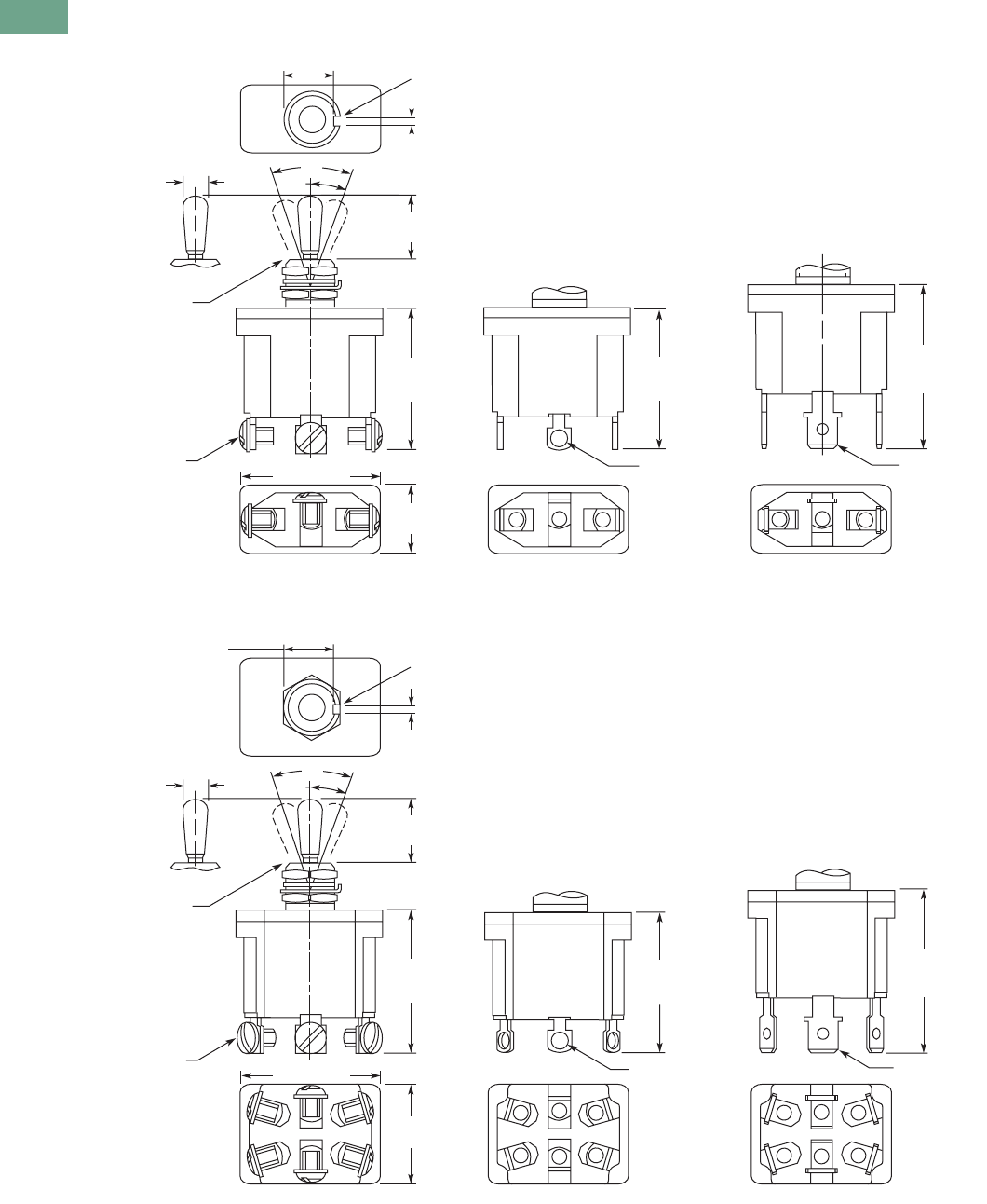
Environmentally Sealed Toggle Switches—E10E
Dimensions
Approximate Dimensions in Inches (mm)
Single-Pole Molded-In Screw Terminal E10E Series
Toggle Switch Panel Cutout
Two-Pole Molded-In Screw Terminal E10E Series
0.432
(10.97) 0.076
(1.93)
Keyway
1.18
(29.9)
Max.
0.250
(6.35)
#6-32 Terminal Screw
with Internal Tooth
Lockwasher (SEMS)
0.635
(16.13)
Max.
0.380
(9.65)
Typ.
1.270 (32.26) Max.
15/32-32 UN-2A
Thread to Within
0.060 (1.52)
of Shoulder
123
16.5°
33°
0.240 (6.10)
Dia.
0.690
(17.53)
0.470
(11.94)
15/32 Dia. Bushing
0.375
(9.52) 0.130
(3.30) 0.062
(1.57)
0.480 (12.19)
Dia. Hole
Locking Ring Keyway
0.445
(11.30)
0.480 (12.19)
Dia. Hole
0.690
(17.53)
0.470
(11.94)
1.10 0
(27.94)
Max.
0.130
(3.30)
0.250
(6.35)
0.130
(3.30)
0.380
(9.65)
0.910
(23.11)
Max.
1.370
(34.80)
Max.
0.076
(1.93)
Keyway
#6-32 Terminal Screw
with Internal Tooth
Lockwasher (SEMS)
15/32-32 UN-2A
Thread to Within
0.060 (1.52)
of Shoulder
123
456
0.432
(10.97)
16.5°
33°
0.240 (6.10)
Dia.
0.380
(9.65)
Typ.
1.340 (34.04) Max.
Tab37book.fm Page 11 Tuesday, July 3, 2012 10:46 PM
T37-12 Logic Control Products CA08100001K—June 2012 www.eatoncanada.ca
37
37
37
37
37
37
37
37
37
37
37
37
37
37
37
37
37
37
37
37
37
37
37
37
37
37
37
37
37
37
37.2
Pushbuttons and Indicating Lights
Environmentally Sealed Toggle Switches—E10E
Approximate Dimensions in Inches (mm)
Single-Pole Econoswitch E10E Series
Two-Pole Econoswitch E10E Series
#6-32 UNC-2A
Terminal Screw,
SEMS 0.125 (3.17)
Dia. Hole
0.250 x 0.032
(6.35) x (0.81)
Thick
15/32-32 UN-2A
Thread to Within
0.060 (1.52)
of Shoulder
0.240 (6.10)
Dia.
0.432
(10.97)
0.076
(1.93)
Keyway
2
132
132
13
Screw Terminal Solder Lug Spade Terminal
0.690
(17.53)
0.470
(11.94)
1.30
(33.0)
Max.
1.28
(32.5)
Max.
1.51
(38.4)
Max.
0.594
(15.09)
1.25 (31.75)
33°
16.5°
0.432
(10.97)
0.076
(1.93)
Keyway
33°
0.125 (3.17)
Dia. Hole
0.250 x 0.032
(6.35) x (0.81)
Thick
1.55
(39.4)
Max.
Screw Terminal Solder Lug Spade Terminal
0.89
(22.6)
1.32 (33.5)
#6-32 UNC-2A
Terminal Screw,
SEMS
15/32-32 UN-2A
Thread to Within
0.060 (1.52)
of Shoulder
0.240 (6.10)
Dia. 16.5°
0.690
(17.53)
0.468
(11.89)
1.34
(34.1)
Max.
1.32
(33.5)
Max.
Tab37book.fm Page 12 Tuesday, July 3, 2012 10:46 PM
Logic Control Products CA08100001K—June 2012 www.eatoncanada.ca T37-13
37
37
37
37
37
37
37
37
37
37
37
37
37
37
37
37
37
37
37
37
37
37
37
37
37
37
37
37
37
37
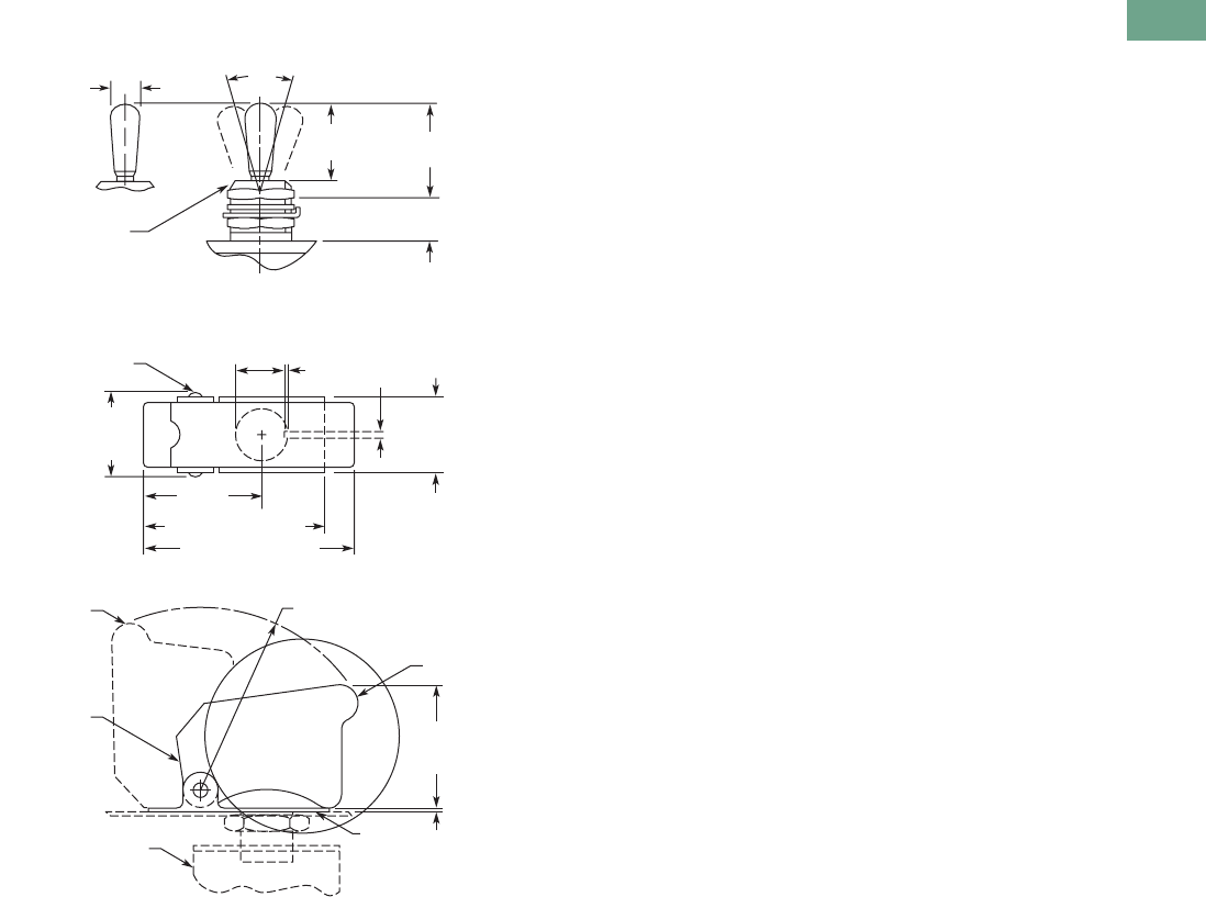
37.2
Pushbuttons and Indicating Lights
Environmentally Sealed Toggle Switches—E10E
Approximate Dimensions in Inches (mm)
Switch Guard
15/32-32 UN-2A
Thread to Within
0.060 (1.52)
of Shoulder
Rivet
Switch
(Ref.)
Red-Molded
Plastic
Closed
Steel
Open
0.240 (6.10)
Dia.
33°
0.840
(21.34)
0.468
(11.89)
0.688
(17.48)
Max.
0.062
(1.57)
0.031
(0.79)
1.062
(26.97)
1.547 (39.29)
Rad.
0.475
(12.07)
Dia.
0.688
(17.48)
1.093
(27.76)
Max.
0.032
(0.81)
1.635 (41.53) Max.
1.830 (46.48) Max.
0.750
(19.05)
Max.
Tab37book.fm Page 13 Tuesday, July 3, 2012 10:46 PM
T37-14 Logic Control Products CA08100001K—June 2012 www.eatoncanada.ca
37
37
37
37
37
37
37
37
37
37
37
37
37
37
37
37
37
37
37
37
37
37
37
37
37
37
37
37
37
37
37.3
Pushbuttons and Indicating Lights
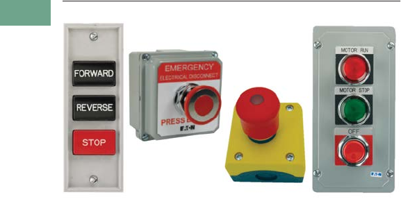
Pushbutton Control Stations—Assembled
Pushbutton Control Stations Contents
Description Page
Pushbutton Control Stations—Assembled
Features . . . . . . . . . . . . . . . . . . . . . . . . . . . . . . . . . . T37-15
Product Selection
M22 Assembled Control Stations . . . . . . . . . . . . T37-16
Commercial Control Stations . . . . . . . . . . . . . . . T37-17
General Purpose Control Stations . . . . . . . . . . . . T37-18
Special Purpose Control Stations . . . . . . . . . . . . T37-19
10250H Series Heavy-Duty Control Stations . . . T37-20
10250T Series Heavy-Duty 30.5 mm
Control Stations . . . . . . . . . . . . . . . . . . . . . . . . T37-21
Class I Division 2 10250T Series Heavy-Duty
30.5 mm Control Stations . . . . . . . . . . . . . . . . T37-22
Class I Division 2 E34 Series Corrosion Resistant
30.5 mm Control Stations . . . . . . . . . . . . . . . . T37-23
Accessories . . . . . . . . . . . . . . . . . . . . . . . . . . . . . . . T37-23
Custom Assembled Stations Specification Form . . . T37-24
Renewal Parts . . . . . . . . . . . . . . . . . . . . . . . . . . . . . T37-26
Technical Data and Specifications . . . . . . . . . . . . . . T37-28
Dimensions . . . . . . . . . . . . . . . . . . . . . . . . . . . . . . . . T37-28
Product Description
M22 Assembled Control
Stations
●M22 series operators
●Available in horizontal and
vertical configurations
●Impact resistant
polycarbonate enclosures
●Optional yellow covers
●Base mounting contact
blocks and light units for
quick wiring and vibration
resistance
Commercial Control Stations
●10250T series operators
●Full front label
●Specific function labels on
front of enclosure
General Purpose Control
Stations
●Construction grade
●General purpose wall
mount
●Popular with contractors
●UL (NEMA) Type 1
Special Purpose Control
Stations
●Standard grade
●Polyester enclosure
●UL (NEMA) Type 3, 3R, 4,
4X, 13
10250H Series Heavy-Duty
Control Stations
●10250H Series operators
●Dark brown polyester
enclosure
●Protective rubber gaskets
provide NEMA 3S rating on
pushbuttons
●Top and bottom 3/4 in NPT
conduit entrances
●Includes alternate legend
plates and spare mounting
screws
10250T Series Heavy-Duty
30.5 mm Control Stations
●10250T Series operators
●ASA 61 gray die-cast zinc
enclosures
●Surface or flush mounting
●Single 3/4 in NPT conduit
entrance on one and two
element stations
●Single 1 in NPT conduit
entrance on three element
stations
Class I Division 2 10250T
Series Heavy-Duty 30.5 mm
Control Stations
●10250T Series operators
●Factory sealed contact
blocks
●Die-cast, polyester or
stainless steel enclosures
●Approved for NEC Class I
Division 2, Groups B, C and
D or Class I Zone 2 Group
IIB plus Hydrogen type
hazardous locations
Class I Division 2 E34 Series
Corrosion Resistant 30.5 mm
Control Stations
●E34 Series operators
●Factory sealed contact
blocks
●Die-cast, polyester or
stainless steel enclosures
●Approved for NEC Class I
Division 2 Groups B, C and
D or Class I Zone 2 Group
IIB plus Hydrogen type
hazardous locations
Tab37book.fm Page 14 Tuesday, July 3, 2012 10:46 PM

Logic Control Products CA08100001K—June 2012 www.eatoncanada.ca T37-15
37
37
37
37
37
37
37
37
37
37
37
37
37
37
37
37
37
37
37
37
37
37
37
37
37
37
37
37
37
37
37.3
Pushbuttons and Indicating Lights
Pushbutton Control Stations—Assembled
Features
M22 Assembled Control
Stations
●IP66, UL (NEMA) Type 4X,
13
●Impact resistant
polycarbonate enclosures
●Optional yellow cover
●25% smaller depth than
most competitor
enclosures
●Base mounting contact
blocks and light units for
faster wiring and vibration
resistance
Commercial Control Stations
●ASA 61 gray die-cast zinc
enclosures
●Pre-assembled and labeled
for functions such as “Fuel
Shut-Off”
●Great for commercial
applications
General Purpose Control
Stations
●Construction grade
●General purpose wall
mount
●Popular with contractors
●UL (NEMA) Type 1
Special Purpose Control
Stations
●Standard grade
●Polyester enclosure
●UL (NEMA) Type 3, 3R, 4,
4X, 13
10250H Series Heavy-Duty
Control Stations
●Industrial grade
●Extra heavy-duty
●Polyester enclosure
●Booted buttons
●Outdoor installation
●UL (NEMA) Type 3, 3R, 3S,
4, 4X, 12, 13
10250T Series Heavy-Duty
30.5 mm Control Stations
●30.5 mm operators
●Industrial grade
●Zinc die cast enclosure
●Popular with industrial end
users
●UL (NEMA) Type 4, 4X, 12,
13
Class I Division 2 Control
Stations
●Available with 10250T or
E34 30.5 mm operators
●Zinc die cast, polyester or
stainless steel enclosures
●Factory-sealed contact
blocks
●Popular with industrial end
users
●UL (NEMA) Type 4, 4X, 12,
13
●NEC Class I Division 2
Groups B, C and D
Tab37book.fm Page 15 Tuesday, July 3, 2012 10:46 PM
T37-16 Logic Control Products CA08100001K—June 2012 www.eatoncanada.ca
37
37
37
37
37
37
37
37
37
37
37
37
37
37
37
37
37
37
37
37
37
37
37
37
37
37
37
37
37
37
37.3
Pushbuttons and Indicating Lights
Pushbutton Control Stations—Assembled
Product Selection
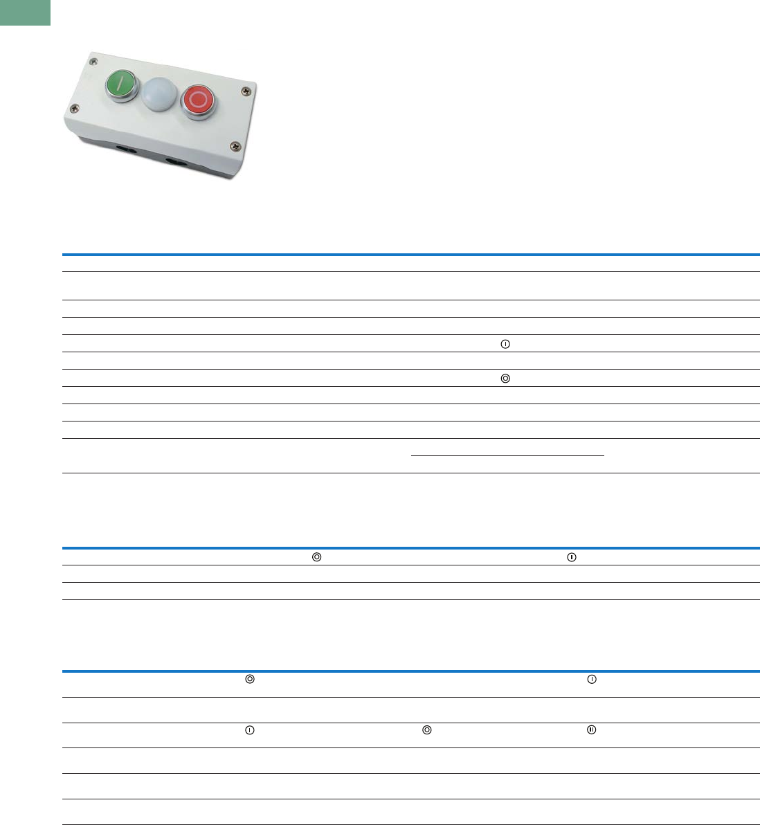
M22 Assembled Control Stations
One Element Control Stations
Two Element Control Stations
Three Element Control Stations
Notes
For assembled control stations not found in this selection, please contact the Eaton Customer Service Centre
at 1-800-268-3578 or cscanada@eaton.com.
Contact block configuration.
Orientation Description Colour Inscription
Enclosure
Cover Colour
Catalogue
Number
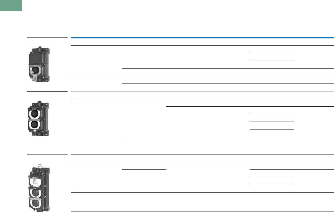
Horizontal 40 mm mushroom head push-pull emergency stop operator Red NC — Yellow M22-C1-M1H
Horizontal 40 mm illuminated mushroom head push-pull emergency stop
operator, 85–264 Vac
Red NO-NC — Yellow M22-C1-M2H
Horizontal 40 mm mushroom head twist-to-release emergency stop operator Red NC — Yellow M22-C1-M3H
Horizontal 40 mm mushroom head key-release emergency stop operator Red NC — Yellow M22-C1-M4H
Horizontal Flush pushbutton Green NO Gray M22-C1-M5H
Horizontal Flush pushbutton Green NO START Gray M22-C1-M6H
Horizontal Extended pushbutton Red NC Gray M22-C1-M7H
Horizontal Extended pushbutton Red NC STOP Gray M22-C1-M8H
Horizontal Key-operated selector switch, two-position maintained — NO OFF-ON Gray M22-C1-M9H
Horizontal Knob type selector switch, three-position maintained — 2NO HAND 0 AUTO Gray M22-C1-M10H
Horizontal Double pushbutton Green NO START Gray M22-C1-M11H
Red NC STOP
Orientation
Element 1
Description Colour Inscription
Element 2
Description Colour Inscription
Enclosure
Cover Colour
Catalogue
Number
Horizontal Extended pushbutton Red NC Flush pushbutton Green NO Gray M22-C2-M1H
Vertical Flush pushbutton Green NO START Extended pushbutton Red NC STOP Gray M22-C2-M2V
Vertical Flush pushbutton Black NO FORWARD Flush pushbutton Black NO REVERSE Gray M22-C2-M3V
Orientation
Element 1
Description Colour Inscription
Element 2
Description Colour Inscription
Element 3
Description Colour Inscription
Enclosure
Cover Colour
Catalogue
Number
Horizontal Extended
pushbutton
Red NC Indicating
light
White 85–264
Vac
— Flush
pushbutton
Green NO Gray M22-C3-M1H
Vertical Indicating
light
White 85–264
Vac
— Flush
pushbutton
Green NO START Extended
pushbutton
Red NC STOP Gray M22-C3-M2V
Horizontal Flush
pushbutton
Green NO Extended
pushbutton
Red NC Flush
pushbutton
Green NO Gray M22-C3-M3H
Vertical Flush
pushbutton
Black NO OPEN Extended
pushbutton
Red NC STOP Flush
pushbutton
Black NO CLOSE Gray M22-C3-M4V
Vertical Flush
pushbutton
Black NO FORWARD Flush
pushbutton
Red NC STOP Flush
pushbutton
Black NO REVERSE Gray M22-C3-M5V
Vertical Flush
pushbutton
Black NO UP Flush
pushbutton
Red NC STOP Flush
pushbutton
Black NO DOWN Gray M22-C3-M6V
Tab37book.fm Page 16 Tuesday, July 3, 2012 10:46 PM
Logic Control Products CA08100001K—June 2012 www.eatoncanada.ca T37-17
37
37
37
37
37
37
37
37
37
37
37
37
37
37
37
37
37
37
37
37
37
37
37
37
37
37
37
37
37
37
37.3
Pushbuttons and Indicating Lights
Pushbutton Control Stations—Assembled
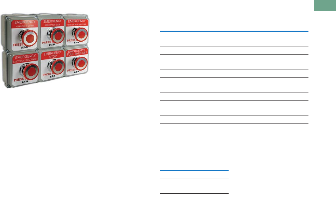
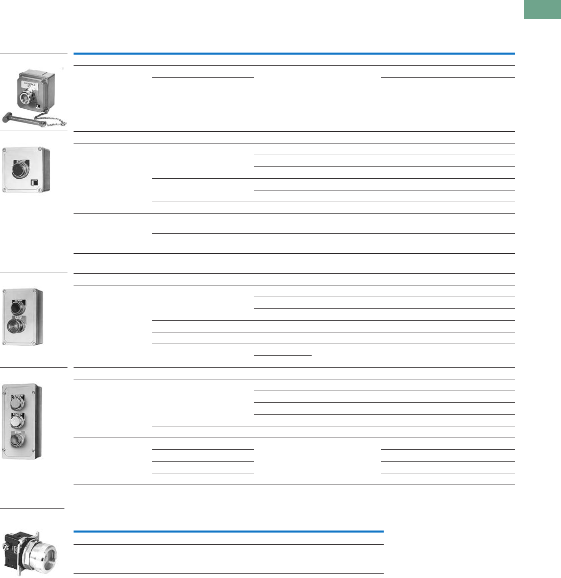
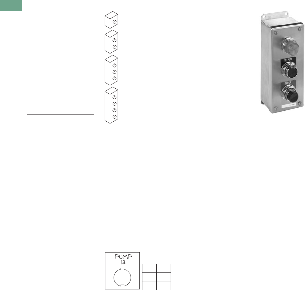
Commercial Control Stations
Key Specifications
●30.5 mm (10250T series)
operators
●ASA 61 gray die-cast zinc
enclosures
●Industrial grade
●UL® Type 4, 4X, 12, 13
●Single 3/4 in NPT conduit
entrance
●Dimensions—in (mm)
●Enclosure:
3.88 W x 4.00 H x 3.00 D
(98.6 x 101.6 x 76.3)
●Operator:
1.63 D (to enclosure) x
1.50 diameter
(41.4 x 38.1)
What is included?
Eaton’s pre-assembled,
enclosed emergency stop
pushbutton stations include
an operator, an enclosure,
contact blocks and a variety
of unique labels. Each label
has white lettering on a red
background indicating the
function and red lettering on a
white background indicating
the operator type.
Available Catalogue Numbers
Additional Contact Blocks
(Sold Separately)
Note
Includes 1NO-1NC contact block.
Catalogue
Number Operator
Enclosure
Colour Label
10250T5B62-S101 Pushbutton Gray EMERGENCY STOP
10250T5B62-S102 Pushbutton Gray EMERGENCY SHUT-OFF
10250T5B62-S103 Pushbutton Gray EMERGENCY GENERATOR STOP
10250T5B62-S104 Pushbutton Gray EMERGENCY HVAC SHUT-DOWN
10250T5B62-S105 Pushbutton Gray EMERGENCY ELECTRICAL DISCONNECT
10250T5B62-S106 Pushbutton Gray EMERGENCY BOILER SHUT-DOWN
10250T5B62-S107 Pushbutton Gray EMERGENCY CHILLER STOP
10250T5B62-S108 Pushbutton Gray EMERGENCY FUEL SHUT-OFF
10250T5B62-S109 Pushbutton Gray EMERGENCY REFRIGERATION STOP
10250T5B62-S110 Pushbutton Gray EMERGENCY POWER OFF
10250T5B62-S111 Pushbutton Gray EMERGENCY GAS SHUT-OFF
10250T5B62-S121 Pushbutton Gray EMERGENCY VENTILATION SHUT-DOWN
10250T5B62-S131 Pushbutton Gray GENERATOR
Catalogue Number
Circuit
Configuration
10250T51 1NC
10250T53 1NO
10250T1 NO-NC
10250T3 2NC
10250T2 2NO
Tab37book.fm Page 17 Tuesday, July 3, 2012 10:46 PM
T37-18 Logic Control Products CA08100001K—June 2012 www.eatoncanada.ca
37
37
37
37
37
37
37
37
37
37
37
37
37
37
37
37
37
37
37
37
37
37
37
37
37
37
37
37
37
37
37.3
Pushbuttons and Indicating Lights
Pushbutton Control Stations—Assembled
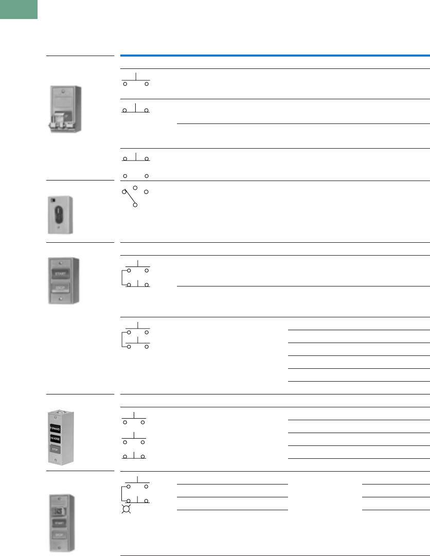
General Purpose Control Stations
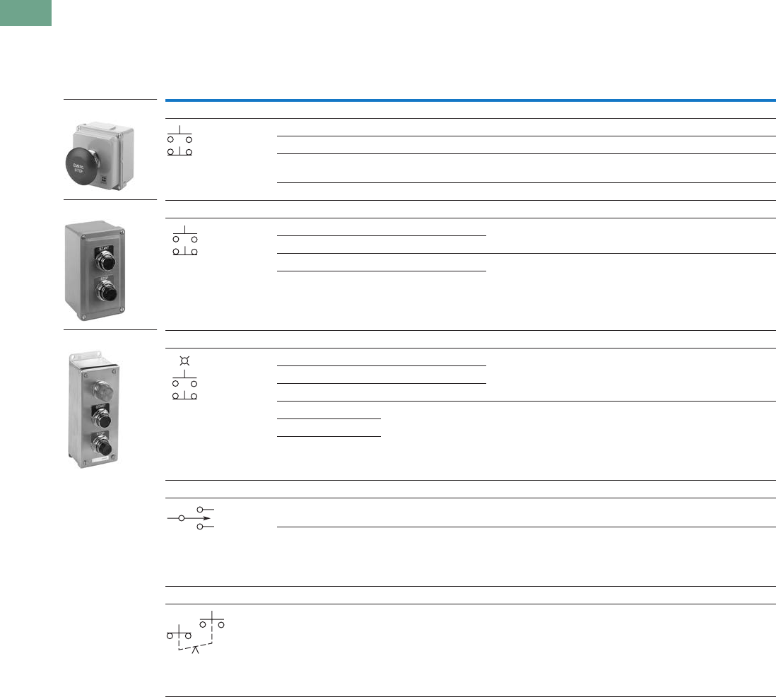
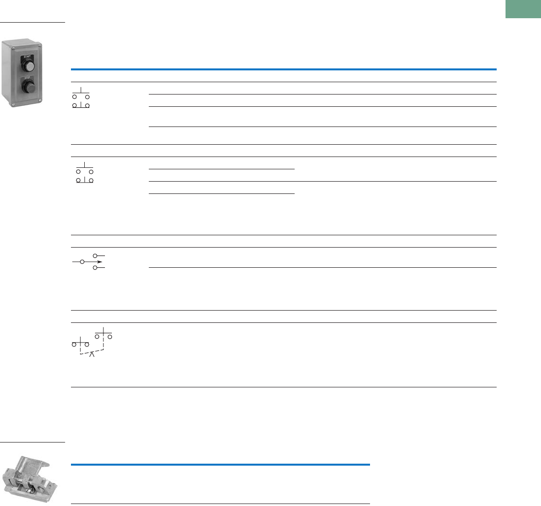
Type N Control Stations—UL (NEMA) Type 1
Note
Round button.
Contact
Symbol Button Type/Colour Legends Catalogue Number
One Element Enclosure Type
Flush/green START 10250H5100
Flush/red STOP 10250H5101
Extended/red STOP 10250H5104
Palm operated/black None 10250H89
Three-position selector
switch/black knob
RUN/OFF/AUTO 10250H289
Two Element Enclosure Type
Flush/red START/STOP 10250H5200
Flush/green
extended/red
START/STOP 10250H5207
Flush/black (all) RAISE/LOWER 10250H5201
FOR/REV 10250H5202
OPEN/CLOSE 10250H5203
UP/DOWN 10250H5204
HIGH/LOW 10250H5205
FAST/SLOW 10250H5208
Three Element Enclosure Type
Flush/black (all) FOR/REV/STOP 10250H5300
UP/DOWN/STOP 10250H5301
RAISE/LOWER/STOP 10250H5302
OPEN/CLOSE/STOP 10250H5303
FAST/SLOW/STOP 10250H5304
110/220V neon indicating light START/STOP
Clear—flush/green; flush/red 10250H5310
Red—flush/green; flush/red 10250ED853
Amber—flush/green; flush/red 10250ED853-2
Selector Switch
Two Button Station
Three Button Station
Three Button Station
with Indicating Light
Single Button Station
with Padlock
Attachment Accessory
Tab37book.fm Page 18 Tuesday, July 3, 2012 10:46 PM
Logic Control Products CA08100001K—June 2012 www.eatoncanada.ca T37-19
37
37
37
37
37
37
37
37
37
37
37
37
37
37
37
37
37
37
37
37
37
37
37
37
37
37
37
37
37
37
37.3
Pushbuttons and Indicating Lights
Pushbutton Control Stations—Assembled
Type N Control Stations—Open Type Construction (No Cover)
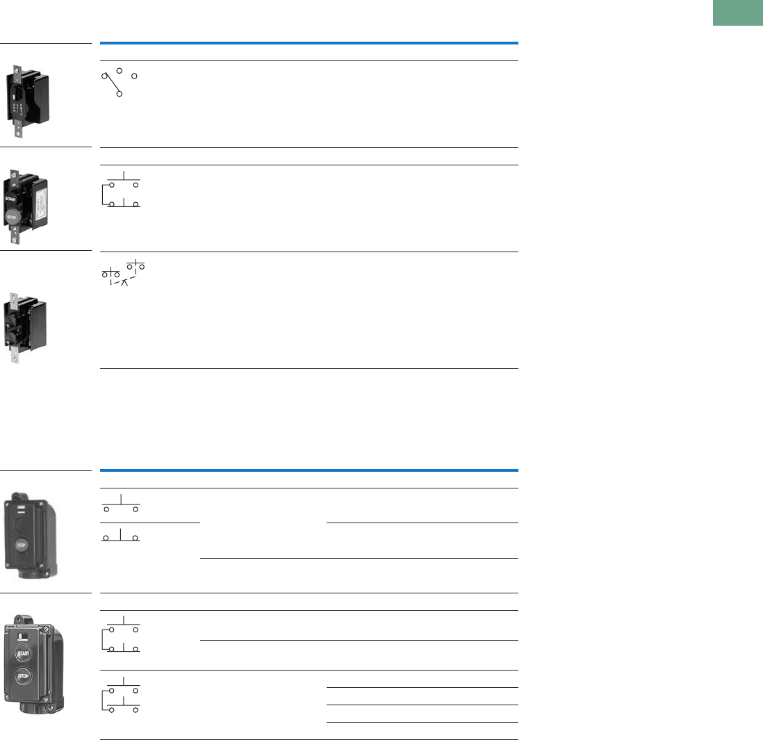
Special Purpose Control Stations
Special Purpose Control Stations—UL (NEMA) Type 3, 3R, 4, 4X, 13
Note
No legend on buttons. Specify any standard legend.
Contact
Symbol Button Type/Colour Legends Catalogue Number
One Element Enclosure Type
Three-position selector
switch/black knob
RUN/OFF/AUTO 10250H2538
Two Element Enclosure Type
Flush/green START/STOP 10250H2747
Flush/black (all)
mech. interlocked
None 10250H2544
Contact
Symbol Feature Legends Catalogue Number
One Element Pushbutton Type
Flush START 10250H2738
STOP 10250H658
With lock hasp STOP 10250H665
Two Element Pushbutton Type
Flush START/STOP 10250H364
With lock hasp START/STOP 10250H671
Buttons interlocked FAST/SLOW 10250ED664
FOR/REV 10250H2740
UP/DOWN 10250H2741
OPEN/CLOSE 10250H2742
Mechanically
Interlocked
Pushbuttons
Two Button Station
Selector Switch
10250H_
10250H_
Tab37book.fm Page 19 Tuesday, July 3, 2012 10:46 PM
T37-20 Logic Control Products CA08100001K—June 2012 www.eatoncanada.ca
37
37
37
37
37
37
37
37
37
37
37
37
37
37
37
37
37
37
37
37
37
37
37
37
37
37
37
37
37
37
37.3
Pushbuttons and Indicating Lights
Pushbutton Control Stations—Assembled
10250H Series Heavy-Duty Control Stations
Type H Control Stations—UL (NEMA) Type 3, 3S, 4, 4X, 12, 13
Element Type Feature Circuit
Assembled
Legend
Plate
Unassembled
Alternate
Legend Plate Catalogue Number
One Element
Pushbuttons Without padlock hasp 1NO-1NC JOG START 10250H1881
STOP
RUN
With padlock hasp 1NC STOP — 10250H4239
Knob selector
switch
Two-position 1NO-1NC OFF/ON — 10250H4526
Three-position 1NO-1NC MAN/OFF/AUTO — 10250H4527
Two Element
Pushbuttons Standard 1NO-2NC START/STOP — 10250H1884
2NO-2NC RAISE/LOWER FORWARD 10250H1885
REVERSE
OPEN
CLOSE
Standard and
standard with
padlock hasp
1NO-2NC START/STOP — 10250H4240
Three Element
Pushbuttons Standard 2NO-3NC FOR/REV/STOP START OPEN 10250H1890
Two standard and
standard with
padlock hasp
JOG CLOSE 10250H4241
RAISE FAST
LOWER SLOW
Indicating
light and
pushbuttons
120V Light-red lens
and two plain
1NO-2NC MOTOR
RUNNING
START/STOP
—10250H1913
10250H_
10250H_
10250H_
Tab37book.fm Page 20 Tuesday, July 3, 2012 10:46 PM
Logic Control Products CA08100001K—June 2012 www.eatoncanada.ca T37-21
37
37
37
37
37
37
37
37
37
37
37
37
37
37
37
37
37
37
37
37
37
37
37
37
37
37
37
37
37
37
37.3
Pushbuttons and Indicating Lights
Pushbutton Control Stations—Assembled
10250T Series Heavy-Duty 30.5 mm Control Stations
Complete Assembled Stations—UL (NEMA) Type 4, 4X, 12, 13
Break Glass Kit
Notes
Stop buttons are red—all others are black.
NEMA 4–13, if properly mounted on a flat surface. Consists of front plate, legend, operator and contact blocks.
Breaking glass closes contact.
Lock is 10250TA2.
Uses deep cover instead of shallow cover. Switch component is 10250TA67.
Shown assembled to contact block (contact block supplied separately).
Element Type Features
Contact
Block(s) Legend
Surface Mounting
Catalogue Number
Flush Mounting
Catalogue Number
Break Glass Station
Break glass station Gray enclosure NC (logic level) EMERG. OFF 10250TGS —
Red enclosure 10250TGR —
One Element
Pushbutton Standard NO-NC START 10250T3516 10250T3573
NC STOP 10250T3518 10250T3575
NO-NC None 10250T3540 10250T3597
Mushroom head NO-NC START 10250T3517 10250T3574
NC STOP 10250T3519 10250T3576
With lock hasp NC STOP 10250T3520 10250T3577
Selector switch Two-position
black knob
NO-NC OFF/ON 10250T3523 10250T3580
Three-position
black knob
2NO MAN/OFF/AUTO 10250T3524 10250T3581
Push-pull
three-position
Momentary
red button
2NC START/STOP 10250T3545 10250T3602
Two Element
Pushbuttons Standard 1NO-2NC START/STOP 10250T3525 10250T3582
2NO-2NC RAISE/LOWER 10250T3672 10250T3673
2NO-2NC None 10250T3541 10250T3598
With lock hasp 1NO-2NC START/STOP 10250T3542 10250T3599
Standard and mushroom head 1NO-2NC START/STOP 10250T3526 10250T3583
Standard with
maintained contact
NO-NC START/STOP 10250T3528 10250T3585
Plus NC
Three Element
Pushbuttons Standard 2NO-3NC FOR, REV, STOP 10250T3532 10250T3589
2NO-3NC UP, DOWN, STOP 10250T3615 —
2NO-3NC OPEN, CLOSE, STOP 10250T3614 —
2NO-3NC None, None, STOP 10250T3543 10250T3600
Two standard and with lock hasp 2NO-3NC None, None, STOP 10250T3544 10250T3601
Indicating light
(transformer type)
and pushbuttons
Red lens — 120V 1NO-2NC MOTOR RUN,
START/STOP
10250T3536 10250T3593
Red lens — 240V 10250T3537 10250T3594
Red lens — 480V 10250T3538 10250T3595
Red lens — 600V 10250T3539 10250T3596
Description Catalogue Number
Operator with hammer and five glass discs 10250TBG
Glass discs only (5) 10250TGL
Break Glass Station
One Element
Two Element
Three Element
Break Glass
Operator
Tab37book.fm Page 21 Tuesday, July 3, 2012 10:46 PM
T37-22 Logic Control Products CA08100001K—June 2012 www.eatoncanada.ca
37
37
37
37
37
37
37
37
37
37
37
37
37
37
37
37
37
37
37
37
37
37
37
37
37
37
37
37
37
37
37.3
Pushbuttons and Indicating Lights
Pushbutton Control Stations—Assembled
Class I Division 2 10250T Series Heavy-Duty 30.5 mm Control Stations
Complete Assembled Stations—
UL (NEMA) Type 4, 4X, 12, 13; NEC Class I Division 2, Groups B, C and D
Contact
Symbol
Button
Type/Colour
Legend
Marking
Die Cast
Enclosure
Catalogue Number
Polyester Molded
Enclosure
Catalogue Number
Stainless Steel
Enclosure
Catalogue Number
Single Pushbutton
Flush/green START 10250T7003 10250T7003P 10250T7003S
Extended/red STOP 10250T7005 10250T7005P 10250T7005S
Alum. jumbo
mushroom/red
EMER. STOP
(engraved button)
10250T7007 10250T7007P 10250T7007S
Flush/black No legend 10250T7009 10250T7009P 10250T7009S
Two Pushbuttons
Flush/green START 10250T7023 10250T7023P 10250T7023S
Extended/red STOP
Flush/black No legend 10250T7025 10250T7025P 10250T7025S
Flush/black No legend
Single Pilot Light—Two Pushbuttons
120 Vac red No legend 10250T7033 10250T7033P 10250T7033S
Flush/green START
Extended/red STOP
120 Vac red No legend 10250T7035 10250T7035P 10250T7035S
Flush/black
Flush/black
Three-Position Selector Switch
Maintained
knob/black
HAND/OFF/AUTO 10250T7011 10250T7011P 10250T7011S
Maintained
knob/black
No legend 10250T7013 10250T7013P 10250T7013S
Single Pushbutton Maintained
Push-pull
with jumbo
mushroom/red
EMER. STOP
(engraved button)
10250T7019 10250T7019P 10250T7019S
10250T7007
10250T7023P
10250T7033S
1NO
1NC
Each Button
1NC
1NO
Each Button
1NC
1NO
2NC
2NO
Pull
O
X
Push
X
O
1NO
1NC
Tab37book.fm Page 22 Tuesday, July 3, 2012 10:46 PM
Logic Control Products CA08100001K—June 2012 www.eatoncanada.ca T37-23
37
37
37
37
37
37
37
37
37
37
37
37
37
37
37
37
37
37
37
37
37
37
37
37
37
37
37
37
37
37
37.3
Pushbuttons and Indicating Lights
Pushbutton Control Stations—Assembled
Class I Division 2 E34 Series Corrosion Resistant 30.5 mm Control Stations
Complete Assembled Stations—
UL (NEMA) Type 4, 4X, 12, 13; NEC Class I Division 2, Groups B, C and D
Accessories
Type N Control Stations
Note
Use NEMA 4X 10250T operators where exposed to ultraviolet light, see Page T37-22.
Contact
Symbol
Button
Type/Colour
Legend
Marking
Die Cast
Enclosure
Catalogue Number
Polyester Molded
Enclosure
Catalogue Number
Stainless Steel
Enclosure
Catalogue Number
Single Pushbutton
Flush/green START E34EX7003 E34EX7003P E34EX7003S
Extended/red STOP E34EX7005 E34EX7005P E34EX7005S
Alum. jumbo
mushroom/red
EMER. STOP
(engraved button)
E34EX7007 E34EX7007P E34EX7007S
Flush/black No legend E34EX7009 E34EX7009P E34EX7009S
Two Pushbuttons
Flush/green START E34EX7023 E34EX7023P E34EX7023S
Extended/red STOP
Flush/black No legend E34EX7025 E34EX7025P E34EX7025S
Flush/black No legend
Three-Position Selector Switch
Maintained
knob/black
HAND/OFF/AUTO E34EX7011 E34EX7011P E34EX7011S
Maintained
knob/black
No legend E34EX7013 E34EX7013P E34EX7013S
Single Pushbutton Maintained
Push-pull with jumbo
mushroom/red
EMER. STOP
(engraved button)
E34EX7019 E34EX7019P E34EX7019S
Description Catalogue Number
Padlock attachment—For field assembly on square button type
(except extended button types)
10250H5110
E34EX_
1NO
1NC
Each Button
1NC
1NO
2NC
2NO
Pull
O
X
Push
X
O
1NO
1NC
Padlock Attachment
Tab37book.fm Page 23 Tuesday, July 3, 2012 10:46 PM
T37-24 Logic Control Products CA08100001K—June 2012 www.eatoncanada.ca
37
37
37
37
37
37
37
37
37
37
37
37
37
37
37
37
37
37
37
37
37
37
37
37
37
37
37
37
37
37
37.3
Pushbuttons and Indicating Lights
Pushbutton Control Stations—Assembled
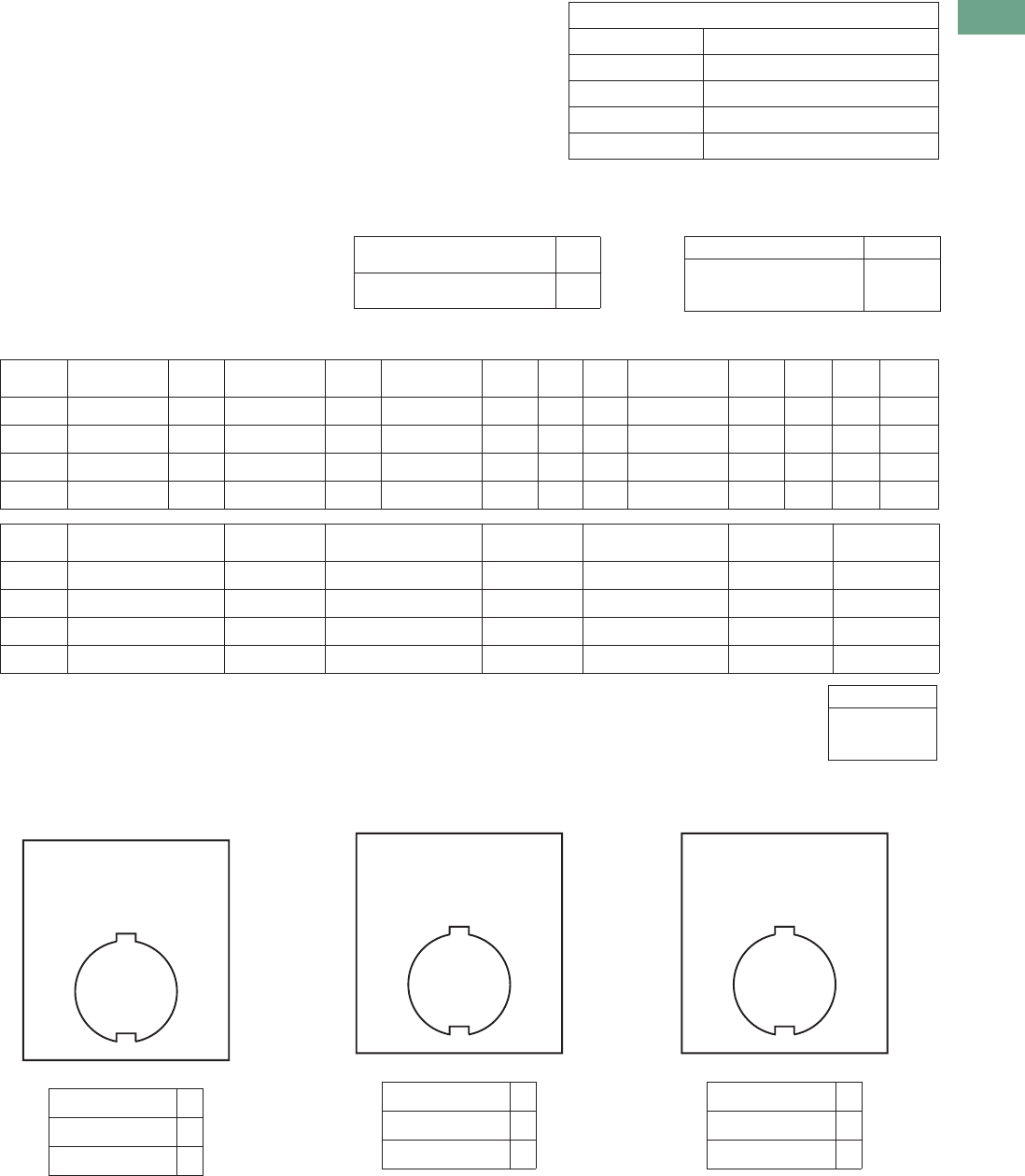
Custom Assembled Stations Specification Form
Ordering Instructions
Step 1
Copy this ordering guide from
catalogue.
Step 2
Specify 10250T or E34
pushbutton lines in the
corresponding box on the
following page.
Step 3
Check back of panel
dimensions—specify single
or double depth enclosure in
the corresponding box on the
following page.
Step 4
Specify enclosure catalogue
number and price in the
corresponding box on the
following page. Enclosures
can be found on Pages T37-
219, T37-269 and T37-318.
For pricing, reference the
most recent PAD or VISTA-
line.
Step 5
Specify catalogue numbers
for desired operator, legend
plate, light unit, accessory
and contact block(s) for each
location in the enclosure in
the corresponding box on the
following page. (See position
locations on this page.)
Position Locations
Step 6
For non-standard legends,
specify legend desired, letter
size and location on the
layout sketches on the
following page. For
limitations see Page T37-
218. For pricing, use the
blank legend catalogue
number and “STAMP” Suffix
(Ex.: 10250TS36STAMP) and
reference the most recent
PAD or VISTA-line.
Example: 10250TS36
Special
Legend
for Position #_______
Step 7
Fax Sheet 2 of this form to
Eaton’s TRC, Technical
Resource Centre, at 828-651-
0549 to the attention of—
Custom Stations Order or
email to TRC@eaton.com.
Within a few days you will
receive a confirmation fax
with the custom station part
number and price.
Step 8
Place your order over the
VISTA System.
For Selector and Roto-Push
Operators
10250T or E34
For single contact blocks or
1NO-1NC contact blocks, the
mounting position of contacts
must be specified. For
example: If a 1NO-1NC
contact block is required,
specify if NO is to be
mounted in Top A position or
Bottom B position.
10250T Pages T37-167–
T37-239
E34 Pages T37-240–
T37-282
10250T and E34
Class I Div. 2
Pages T37-283–
T37-324
Position 1
Position 2
Position 3
Position 1
Position 2
Position 1
Position 2
Position 3
Position 4
Position 1
LETTER
SIZE
3/32 in
1/8 in ✔
3/16 in
Tab37book.fm Page 24 Tuesday, July 3, 2012 10:46 PM
Logic Control Products CA08100001K—June 2012 www.eatoncanada.ca T37-25
37
37
37
37
37
37
37
37
37
37
37
37
37
37
37
37
37
37
37
37
37
37
37
37
37
37
37
37
37
37
37.3
Pushbuttons and Indicating Lights
Pushbutton Control Stations—Assembled
FACTORY USE ONLY
Part Number
Product Code
Suffix
Date
Engineer
Step 3) ✔
Single Depth Enclosure
Double Depth Enclosure
Step 4)
Enclosure Catalogue Number Price
Step 2)
10250T ❏ STD ❏ Class I Division 2
E34 ❏ STD ❏ Class I Division 2
Step 5)
Position Operator
Price
CDN $ Light Unit
Price
CDN $
Contact
Block
Price
CDN $ A/L B/R
Contact
Block
Price
CDN $ A/L B/R
Total
Price
1
2
3
4
Total:
Step 6) Non-standard Legends
Special Legend for Position #_______ Special Legend for Position #_______ Special Legend for Position #_______
LETTER SIZE ✔
3/32 inch (2.4 mm)
1/8 inch (3.2 mm)
3/16 inch (4.8 mm)
Position Legend Plate
Price
CDN $ Lens or Caps
Price
CDN $ Accessory
Price
CDN $
Total
Price
1
2
3
4
To — Eaton’s Customer Support Centre,
(905) 631-4284 FAX, or email to escanada@eaton.com
From — Customer Name ___________________________________________
Customer Contact __________________________________________
Phone Number_____________________________________________
Fax Number _______________________________________________
Email Address _____________________________________________
10% Added
for Assembled Stations
LETTER SIZE ✔
3/32 inch (2.4 mm)
1/8 inch (3.2 mm)
3/16 inch (4.8 mm)
LETTER SIZE ✔
3/32 inch (2.4 mm)
1/8 inch (3.2 mm)
3/16 inch (4.8 mm)
Tab37book.fm Page 25 Tuesday, July 3, 2012 10:46 PM
T37-26 Logic Control Products CA08100001K—June 2012 www.eatoncanada.ca
37
37
37
37
37
37
37
37
37
37
37
37
37
37
37
37
37
37
37
37
37
37
37
37
37
37
37
37
37
37
37.3
Pushbuttons and Indicating Lights
Pushbutton Control Stations—Assembled
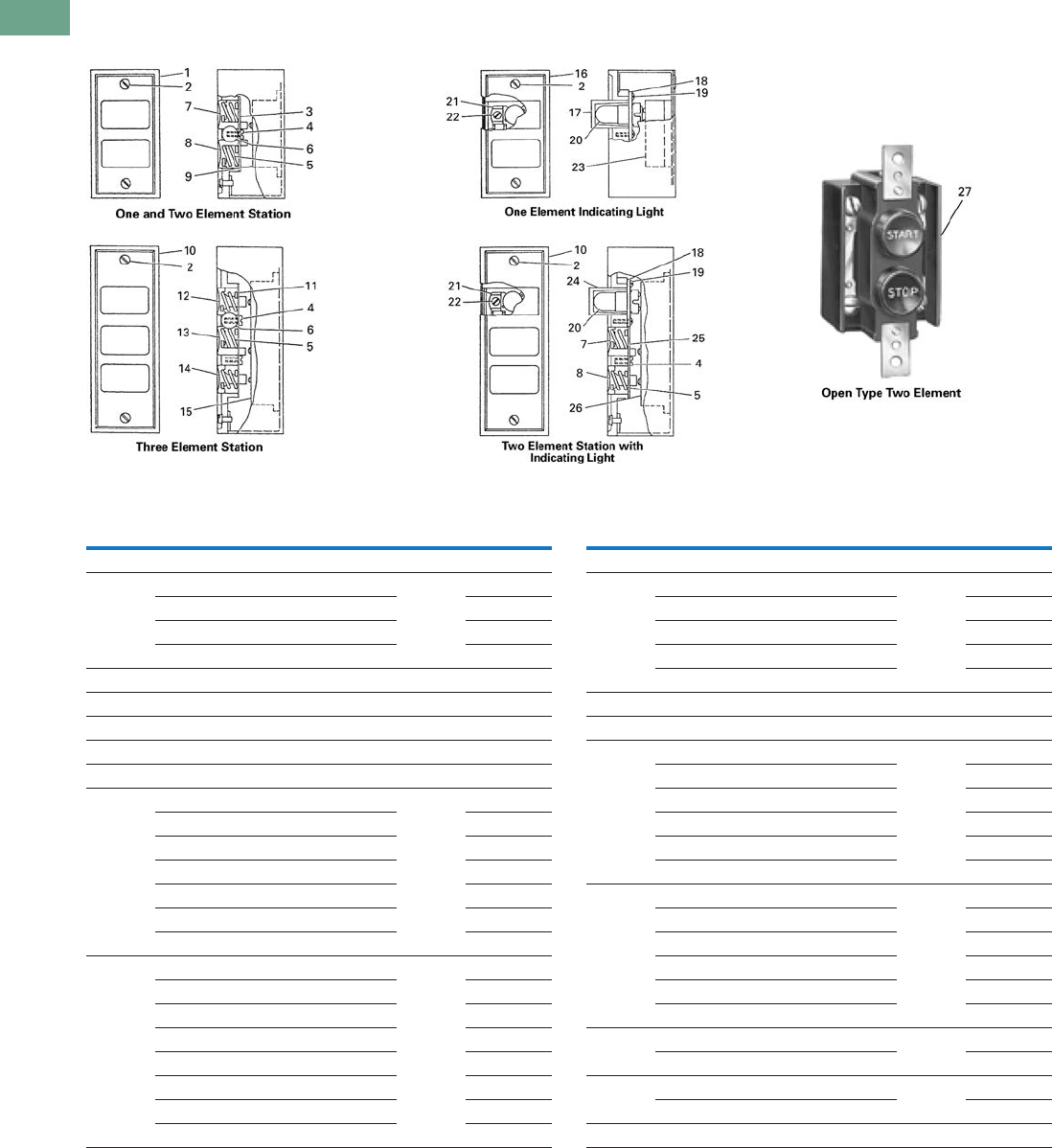
Renewal Parts
Type N Renewal Parts
Assembled Stations—Type N
Item
No. Description
No.
Req. Part Number
Type N—Square Buttons
1 Cover 1
Two element 49-3524
One element—top button 49-3524-2
One element—bottom button 49-3524-3
2 Cover screw 2 11-2168
3 Pushbutton support bracket 1 79-6649
4 Pushbutton support bracket screw 1 11-2090
5 Pushbutton spring 2 69-2571
6 Disc (when used—two element assembly) 2 16-1960
7 Pushbutton—top position 1
START/green 53-1169-3
RAISE/black 53-1169-66
FORWARD/black 53-1169-7
OPEN/black 53-1169-9
UP/blank 53-1169-11
Blank/green 53-1169
8 Pushbutton—bottom position 1
STOP/red 53-1202-2
Extended STOP/red 53-1202-5
REVERSE/black 53-1169-8
CLOSE/black 53-1169-10
DOWN/black 53-1169-12
LOWER/black 53-1169-6
Blank/red 53-1202
Item
No. Description
No.
Req. Part Number
Type N—Square Buttons, continued
9 Pushbutton element 1
1NO-1NC 86-2588
2NO 86-2588-2
1NO 86-2588-3
1NC 86-2588-4
10 Cover 1 49-3464
11 Pushbutton support bracket 1 79-6650
12 Pushbutton—top position 1
FORWARD/black 53-1170-7
UP/black 53-1170-4
RAISE/black 53-1170-5
OPEN/black 53-1170-9
FAST/black 53-1170-6
13 Pushbutton middle position 1
REVERSE/black 53-1169-15
DOWN/black 53-1169-18
LOWER/black 53-1169-16
CLOSE/black 53-1169-17
SLOW/black 53-1169-13
14 Pushbutton—bottom position 1
STOP/red 53-1201-2
15 Pushbutton element 1
2NO-3NC 86-2593
16 Cover 1 49-3524-4
Tab37book.fm Page 26 Tuesday, July 3, 2012 10:46 PM
Logic Control Products CA08100001K—June 2012 www.eatoncanada.ca T37-27
37
37
37
37
37
37
37
37
37
37
37
37
37
37
37
37
37
37
37
37
37
37
37
37
37
37
37
37
37
37
37.3
Pushbuttons and Indicating Lights
Pushbutton Control Stations—Assembled
Assembled Stations—Type N, continued
Type H Renewal Parts
Assembled Stations—Type H
Item
No. Description
No.
Req. Part Number
Type N—Square Buttons, continued
17 Lens 1
Clear 28-494
Red 28-887-2
Amber 28-887-3
18 Shield 1 73-1337
19 Shield screws 4 11-2012
20 Lamp (neon NE48) 1 28-494
21 Lamp receptacle 1 28-902
22 Lamp receptacle screw 1 911-330F1
23 Pilot light terminal base 1 86-2586
24 Lens 1
Clear 28-887
Red 28-887-2
Amber 28-887-3
25 Pushbutton support bracket 1 79-6650-2
26 Pushbutton element 1
1NO-1NC 86-2594
Item
No. Description
No.
Req. Part Number
Type N—Round Buttons
Similar
to 27
Pushbutton assembly and element for:
10250H289 1 10250H2538
10250H364 1 86-353
10250H685 1 86-353-8
10250H665 1 86-353-8
10250H671 1 86-353
10250H2738 1 86-353-3
10250H2740 1 86-356
10250H2741 1 86-356
10250H2742 1 86-356
1
Pushbutton Indicating Light
2
3
5
4
6
3
4
5
9
78
12
7
12 1
Selector Switch
2
11
10
10
5
4
7
Item
No. Description
No.
Req. Part Number
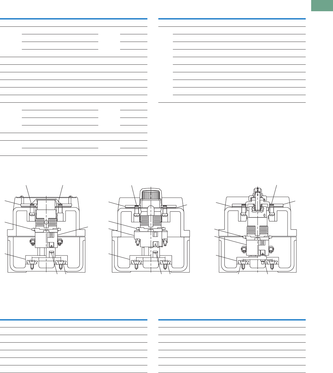
Type H—Assembled Stations
1 Screw 2 11-4654
2 Screw 2 11-5719
3 Base 1 17-16560
4 Contact blocks See Page T37-222
5 10250T operator See Pages T37-173 – T37-239
6 Mounting plate 1 17-19524
Item
No. Description
No.
Req. Part Number
Type H—Assembled Stations
7 Screw 4 11-953
8 Diaphragm 1 32-253-2
9 Mounting plate 1 17-19522
10 Gasket 1 32-254
11 Base 1 17-16561
12 Mounting plate 1 17-19523
Tab37book.fm Page 27 Tuesday, July 3, 2012 10:46 PM
T37-28 Logic Control Products CA08100001K—June 2012 www.eatoncanada.ca
37
37
37
37
37
37
37
37
37
37
37
37
37
37
37
37
37
37
37
37
37
37
37
37
37
37
37
37
37
37
37.3
Pushbuttons and Indicating Lights
Pushbutton Control Stations—Assembled
Technical Data and Specifications
Ratings
Maximum Ampere Ratings for Type N Control Stations
Maximum Ampere Ratings for Type H Control Stations
Dimensions
Approximate Dimensions in Inches (mm)
Type N Control Stations
Special Purpose Control Stations
Note
2.38 (60.5) for neon indicating light.
Volts AC Volts DC
Description 110 220 440 550 120 240 600
Make and emergency interrupt capacity 30 15 7.5 6 1.0 0.5 0.1
Normal load break 3 1.5 0.75 0.6 1.0 0.5 0.1
Continuous current 10 10 10 10 10 10 10
Description
Volts AC 50/60 Hz Volts DC
120 240 480 600 125 250
Make and emergency interrupt capacity 60 30 15 12 1.1 0.55
Normal load break 6 3 1.5 1.2 1.1 0.55
Continuous amperes 10 10 10 10 10 10
Voltamperes —
Make and emergency interrupt capacity 7200 7200 7200 7200 138 138
Normal load break 720 720 720 720 138 138
3.25
(82.6)
4.00
(101.6)
2.25
(57.2)
a
1.50
(38.1)
2.25
(57.2)
3.25
(82.6)
4.00
(101.6)
2.25
(57.2)
a
1.50
(38.1)
2.25
(57.2)
Single Button Station
5.00
(127.0)
6.00
(152.4)
2.25
(57.2)
a
1.50
(38.1)
2.25
(57.2)
Two Button Station Three Button Station
3.13
(79.5)
0.75 (19.1)
Pipe Tap
2.25
(57.2)
3.38
(85.9)
6.25
(158.8)
5.50
(139.7)
Ship Wt.
2.5 Lb (1.1 kg)
Tab37book.fm Page 28 Tuesday, July 3, 2012 10:46 PM
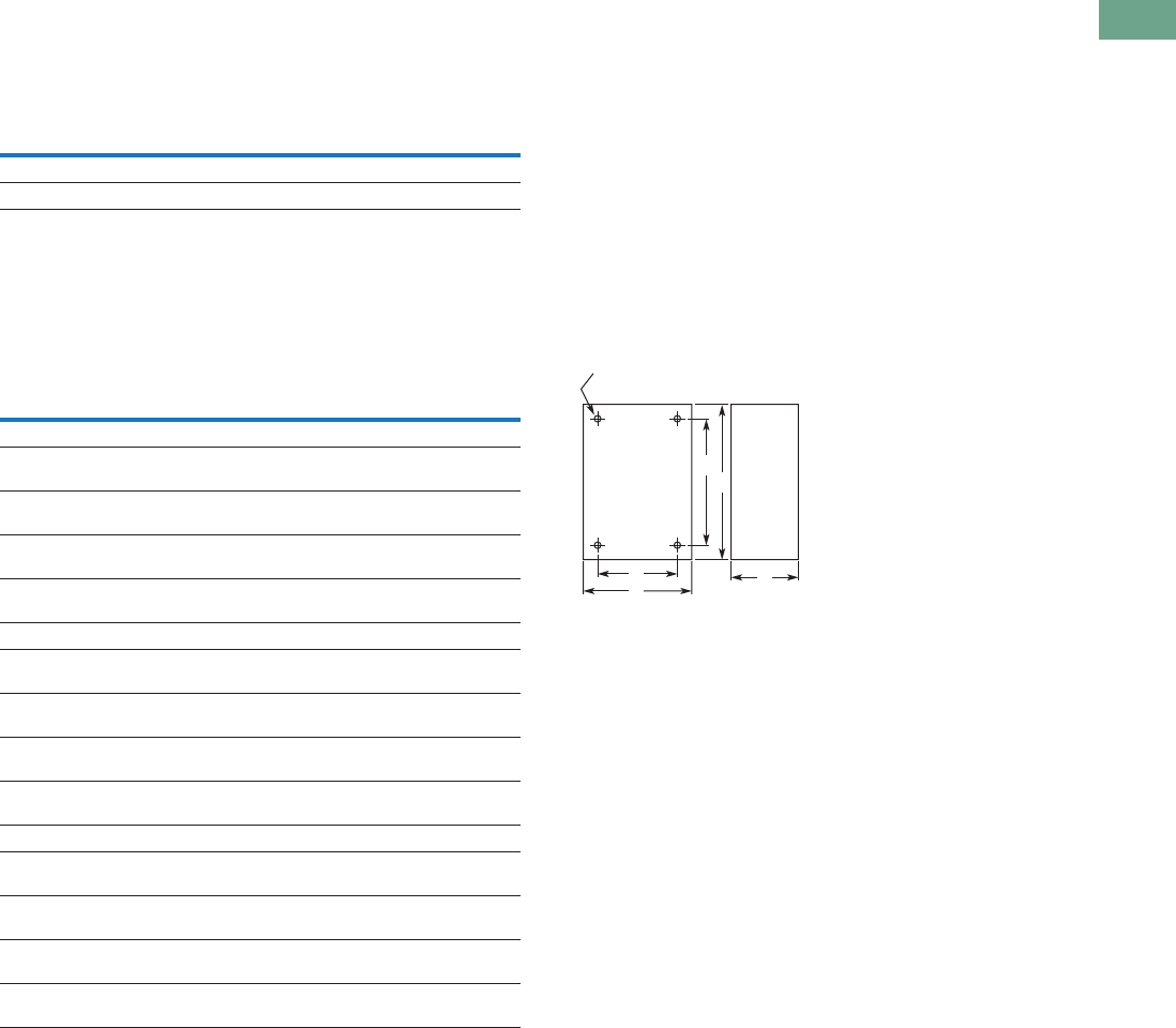
Logic Control Products CA08100001K—June 2012 www.eatoncanada.ca T37-29
37
37
37
37
37
37
37
37
37
37
37
37
37
37
37
37
37
37
37
37
37
37
37
37
37
37
37
37
37
37
37.3
Pushbuttons and Indicating Lights
Pushbutton Control Stations—Assembled
Approximate Dimensions in Inches (mm)
Type H Control Stations
NEMA Type 3, 3R, 3S, 4, 4X, 13
10250T and E34
Approximate Enclosure Dimensions
Note
No conduit entrance holes provided. Drill as required.
No. of
Elements
Dimensions
Wide High Deep
1 and 2 4.50 (114.3) 8.25 (209.6) 4.50 (114.3)
3 4.50 (114.3) 10.75 (273.1) 4.25 (108.0)
Number
of
Elements
Surface Mounting
Conduit
Entrance
Dimensions in In (mm)
Wide
A
High
B
Deep
C
Mounting
DE
Cast
1 3.88
(98.6)
4.0
(101.6)
3.0
(76.3)
2.69
(68.3)
3.25
(82.6)
3/4
2 3.88
(98.6)
5.88
(149.4)
3.0
(76.3)
2.69
(68.3)
5.13
(130.3)
3/4
3 3.88
(98.6)
7.75
(196.9)
3.0
(76.3)
2.69
(68.3)
7.0
(177.8)
1
4 33.88
(98.6)
9.63
(244.6)
3.0
(76.3)
2.69
(68.3)
8.88
(225.6)
1
Polyester
1 3.81
(96.8)
6.63
(168.4)
3.38
(85.9)
2.94
(74.7)
4.88
(124.0)
2 3.81
(96.8)
6.63
(168.4)
3.38
(85.9)
2.94
(74.7)
4.88
(124.0)
3 3.81
(96.8)
8.88
(225.6)
3.38
(85.9)
2.94
(74.7)
7.13
(181.1)
4 3.81
(96.8)
6.63
(168.4)
3.38
(85.9)
2.94
(74.7)
4.88
(124.0)
Stainless Steel
1 3.00
(76.2)
3.50
(88.9)
3.00
(76.2)
1.50
(38.1)
4.25
(108.0)
2 3.50
(88.9)
6.75
(171.5)
3.00
(76.2)
1.50
(38.1)
7.50
(190.5)
3 3.50
(88.9)
9.00
(228.6)
3.00
(76.2)
1.50
(38.1)
9.00
(228.6)
4 3.50
(88.9)
11.25
(285.8)
3.00
(76.2)
1.50
(38.1)
12.00
(304.8)
A
Surface
DC
B
E
4 Mtg. Holes — 10-32 Screw Size for
1 – 4 Element Die Cast/
Stainless Steel Enclosure
7/32 Screw Size for
Polyester
Tab37book.fm Page 29 Tuesday, July 3, 2012 10:46 PM

Logic Control Products CA08100001K—June 2012 www.eatoncanada.ca T37-35
37
37
37
37
37
37
37
37
37
37
37
37
37
37
37
37
37
37
37
37
37
37
37
37
37
37
37
37
37
37
37.4
Pushbuttons and Indicating Lights
22.5 mm Modular Pushbuttons—M22
Pushbuttons—Non-Illuminated and Illuminated Contents
Description Page
Pushbuttons—Non-Illuminated and Illuminated
Non-Illuminated, Flush, Momentary . . . . . . . . . . . . T37-36
Non-Illuminated, Flush, Maintained . . . . . . . . . . . . T37-39
Non-Illuminated, Extended, Momentary . . . . . . . . T37-41
Non-Illuminated, Extended, Maintained . . . . . . . . . T37-43
Illuminated, Flush, Momentary . . . . . . . . . . . . . . . . T37-46
Illuminated, Flush, Maintained . . . . . . . . . . . . . . . . T37-49
Illuminated, Extended, Momentary . . . . . . . . . . . . T37-51
Illuminated, Extended, Maintained . . . . . . . . . . . . . T37-53
Pushbuttons—Non-Illuminated and Illuminated
Product Description
Eaton’s M22 pushbutton
line is a complete, modular
and versatile offering. From
field-convertible maintained
operators to customizable
laser engraved buttons, the
M22 pushbutton line provides
endless opportunity for
flexibility and reduced
inventory. Each operator
type provides options for
ordering as complete or
component parts allowing
for a perfect fit for each
application. All of this
flexibility comes in a very
rugged design.
Features
●Field convertible from
maintained to momentary
(available on maintained
pushbuttons only)
●Customizable laser
engraving on all buttons
●LED offering only for
improved brightness
quality and up to 100,000
hours of operation
●More than five million
mechanical operations on
momentary and 1 million
on maintained pushbuttons
●Modular construction
makes assembly fast and
simplifies stocking of
components and complete
devices
●Capable of communicating
via ASi protocol with ASi
adapter modules
Protection Type
●IP67, IP69K
●NEMA 4X, 13
Tab37book.fm Page 35 Tuesday, July 3, 2012 10:46 PM
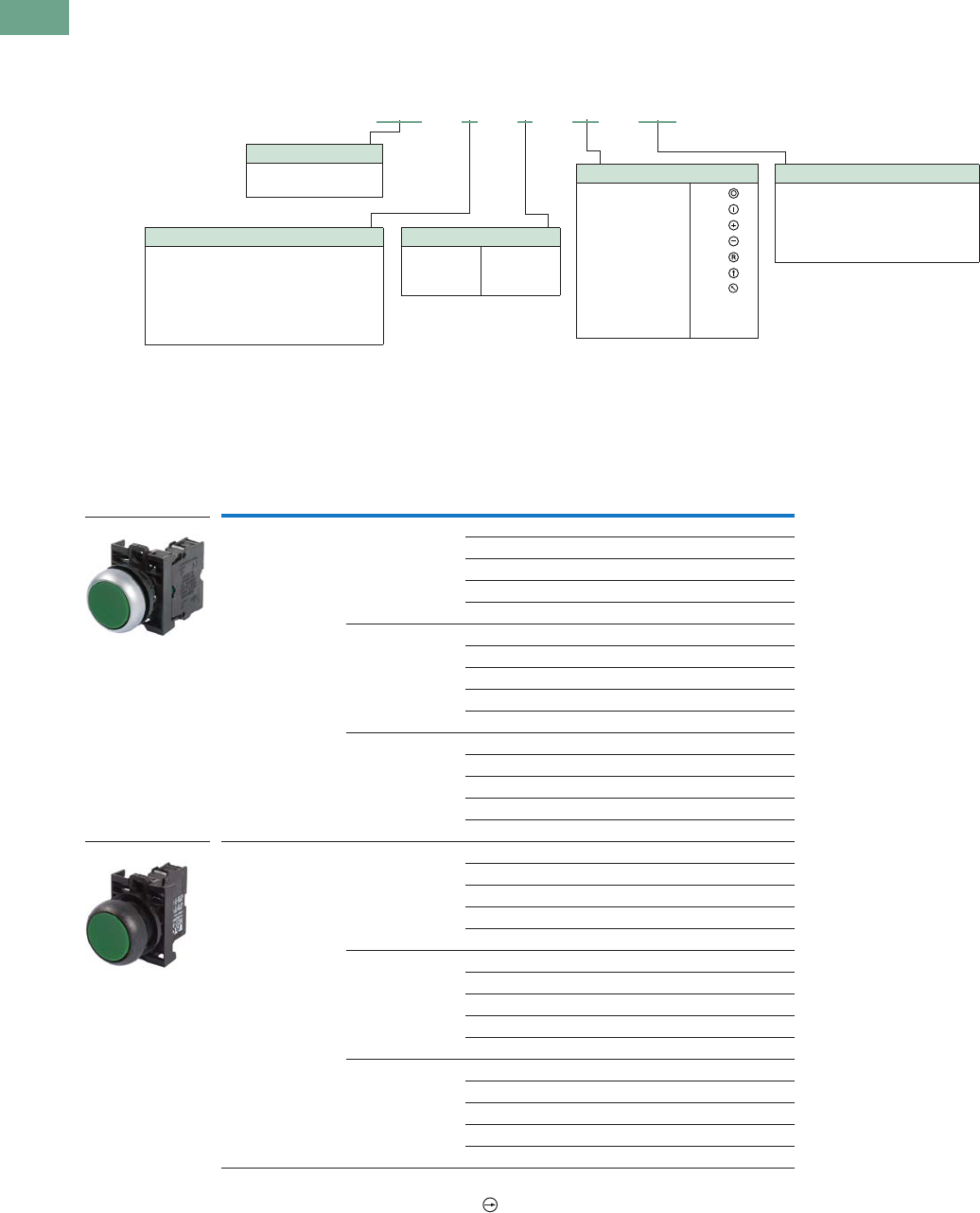
T37-36 Logic Control Products CA08100001K—June 2012 www.eatoncanada.ca
37
37
37
37
37
37
37
37
37
37
37
37
37
37
37
37
37
37
37
37
37
37
37
37
37
37
37
37
37
37
37.4
Pushbuttons and Indicating Lights
22.5 mm Modular Pushbuttons—M22
Catalogue Number Selection
Catalogue Number Selection is for illustrative purposes only and not to be used to create new catalogue numbers.
Non-Illuminated Pushbuttons
Product Selection
Non-Illuminated Pushbuttons, Flush, Momentary
Complete Devices
Note
All NC contact blocks are positively driven contact.
Bezel Button Colour
Contact Block
Configuration Catalogue Number
Silver Black NO M22-D-S-K10
NC M22-D-S-K01
2NO M22-D-S-K20
2NC M22-D-S-K02
1NO-1NC M22-D-S-K11
Red NO M22-D-R-K10
NC M22-D-R-K01
2NO M22-D-R-K20
2NC M22-D-R-K02
1NO-1NC M22-D-R-K11
Green NO M22-D-G-K10
NC M22-D-G-K01
2NO M22-D-G-K20
2NC M22-D-G-K02
1NO-1NC M22-D-G-K11
Black Black NO M22S-D-S-K10
NC M22S-D-S-K01
2NO M22S-D-S-K20
2NC M22S-D-S-K02
1NO-1NC M22S-D-S-K11
Red NO M22S-D-R-K10
NC M22S-D-R-K01
2NO M22S-D-R-K20
2NC M22S-D-R-K02
1NO-1NC M22S-D-R-K11
Green NO M22S-D-G-K10
NC M22S-D-G-K01
2NO M22S-D-G-K20
2NC M22S-D-G-K02
1NO-1NC M22S-D-G-K11
Bezel
M22 = Silver
M22S = Black
M22 –D–S–X0– K10
Silver bezel only.
Operator Type
D = Flush momentary
DH = Extended momentary
DG = Flush with guard
DR = Flush maintained
DGH = Extended momentary with guard
DRH = Extended maintained
Button Plate Colour
G = Green
Y = Yellow
B = Blue
S = Black
R = Red
W = White
Inscription
GB0 = STOP
GB1 = START
GB2 = CLOSE
GB3 =UP
GB4 = DOWN
GB5 = OFF
GB6 =ON
GB14 = RESET
GB15 = FORWARD
GB16 = REVERSE
X0 =
X1 =
X4 =
X5 =
X6 =
X7 =
X8 =
Contact Blocks
K10 = 1NO
K01 = 1NC
K20 = 2NO
K02 = 2NC
K11 = 1NO-1NC
K30 = 3NO
K03 = 3NC
K21 = 2NO-1NC
K12 = 1NO-2NC
M22-D-G-K10
M22S-D-G-K10
Tab37book.fm Page 36 Tuesday, July 3, 2012 10:46 PM
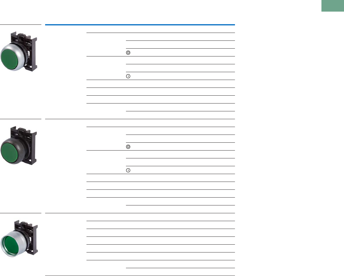
Logic Control Products CA08100001K—June 2012 www.eatoncanada.ca T37-37
37
37
37
37
37
37
37
37
37
37
37
37
37
37
37
37
37
37
37
37
37
37
37
37
37
37
37
37
37
37
37.4
Pushbuttons and Indicating Lights
22.5 mm Modular Pushbuttons—M22
Non-Illuminated Pushbuttons, Flush, Momentary
Operators Only
Notes
Includes contact block mounting adapter.
Buttonless operator comes with three colour buttons (black, red, green).
Buttonless operator comes with all six colour buttons (black, white, red, green, yellow, blue).
Bezel Button Colour Inscription Catalogue Number
Silver Black — M22-D-S
Red — M22-D-R
STOP M22-D-R-GB0
M22-D-R-X0
Green — M22-D-G
START M22-D-G-GB1
M22-D-G-X1
White — M22-D-W
Blue — M22-D-B
Yellow — M22-D-Y
—— M22-D-X-SRG
—M22-D-X-SWRGYB
Black Black — M22S-D-S
Red — M22S-D-R
STOP M22S-D-R-GB0
M22S-D-R-X0
Green — M22S-D-G
START M22S-D-G-GB1
M22S-D-G-X1
White — M22S-D-W
Blue — M22S-D-B
Yellow — M22S-D-Y
—— M22S-D-X-SRG
—M22S-D-X-SWRGYB
Silver guarded Black — M22-DG-S
Red — M22-DG-R
Green — M22-DG-G
White — M22-DG-W
Blue — M22-DG-B
Yellow — M22-DG-Y
—— M22-DG-X-SRG
—M22-DG-X-SWRGYB
M22-D-G
M22S-D-G
M22-DG-G
Tab37book.fm Page 37 Tuesday, July 3, 2012 10:46 PM
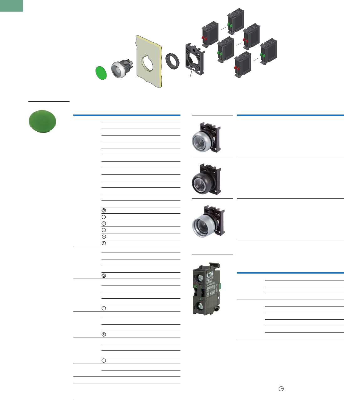
T37-38 Logic Control Products CA08100001K—June 2012 www.eatoncanada.ca
37
37
37
37
37
37
37
37
37
37
37
37
37
37
37
37
37
37
37
37
37
37
37
37
37
37
37
37
37
37
37.4
Pushbuttons and Indicating Lights
22.5 mm Modular Pushbuttons—M22
Non-Illuminated Pushbuttons, Flush, Momentary
Components
Button Plates Buttonless Operator
Contact Blocks
Notes
For complete listing of available button plates and contact blocks, see Accessories,
Pages V7-T37-96 to V7-T37-101.
Minimum order quantity of (10).
When ordering, specify inscription per catalogue number suffix from the Symbols
Library (see Pages V7-T37-114 to V7-T37-121) into the Order Notes.
For example, M22-XD-S-ETCH; Order Notes: Mark with symbol X91, Line item #_.
Includes contact block mounting adapter.
All NC contact blocks are positively driven contact.
max. 5mm
thickness
Note: Included
with operator.
Colour Inscription Catalogue Number
Black — M22-XD-S
Custom M22-XD-S-ETCH
STOP M22-XD-S-GB0
START M22-XD-S-GB1
CLOSE M22-XD-S-GB2
UP M22-XD-S-GB3
DOWN M22-XD-S-GB4
OFF M22-XD-S-GB5
ON M22-XD-S-GB6
TEST M22-XD-S-GB9
FORWARD M22-XD-S-GB15
REVERSE M22-XD-S-GB16
RAISE M22-XD-S-GB17
LOWER M22-XD-S-GB18
M22-XD-S-X0
M22-XD-S-X1
M22-XD-S-X2
M22-XD-S-X4
M22-XD-S-X5
M22-XD-S-X7
Red — M22-XD-R
Custom M22-XD-R-ETCH
STOP M22-XD-R-GB0
OFF M22-XD-R-GB5
M22-XD-R-X0
Green — M22-XD-G
Custom M22-XD-G-ETCH
START M22-XD-G-GB1
ON M22-XD-G-GB6
M22-XD-G-X1
Blue — M22-XD-B
Custom M22-XD-B-ETCH
RESET M22-XD-B-GB14
M22-XD-B-X6
White — M22-XD-W
Custom M22-XD-W-ETCH
START M22-XD-W-GB1
M22-XD-W-X1
Yellow — M22-XD-Y
Custom M22-XD-Y-ETCH
Black, red, green — M22-XD-SRG
Black, white,
red, green,
yellow, blue
—M22-XD-SWRGYB
M22-XD-G
Bezel Catalogue Number
Silver M22-D-X
Black M22S-D-X
Silver guarded M22-DG-X
Terminal
Type
Contact
Configuration Catalogue Number
Screw NO M22-K10
NO, early-make M22-K10P
NC M22-K01
NC, late-break M22-K01D
Spring-cage NO M22-CK10
NC M22-CK01
NC, late-break M22-CK01D
2NO M22-CK20
2NC M22-CK02
NO-NC M22-CK11
M22-D-X
M22S-D-X
M22-DG-X
M22-K10
Tab37book.fm Page 38 Tuesday, July 3, 2012 10:46 PM
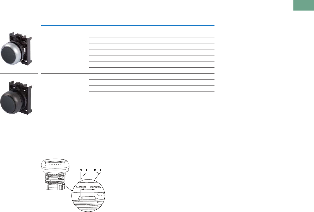
Logic Control Products CA08100001K—June 2012 www.eatoncanada.ca T37-39
37
37
37
37
37
37
37
37
37
37
37
37
37
37
37
37
37
37
37
37
37
37
37
37
37
37
37
37
37
37
37.4
Pushbuttons and Indicating Lights
22.5 mm Modular Pushbuttons—M22
Non-Illuminated Pushbuttons, Flush, Maintained
Operators Only
Notes
Maintained pushbuttons can be converted in the field to momentary operation by switching the locking ring,
which is accessible through the side of the operator body.
Includes contact block mounting adapter.
Buttonless operator comes with three colour buttons (black, red, green).
Buttonless operator comes with all six colour buttons (black, white, red, green, yellow, blue).
Note: This pilot device features a selectable function switch that enables the device
to be set to either maintained or momentary operation.
Bezel Button Colour Catalogue Number
Silver Black M22-DR-S
Red M22-DR-R
Green M22-DR-G
White M22-DR-W
Blue M22-DR-B
Yellow M22-DR-Y
M22-DR-X-SRG
M22-DR-X-SWRGYB
Black Black M22S-DR-S
Red M22S-DR-R
Green M22S-DR-G
White M22S-DR-W
Blue M22S-DR-B
Yellow M22S-DR-Y
M22S-DR-X-SRG
M22S-DR-X-SWRGYB
M22-DR-S
M22S-DR-S
Tab37book.fm Page 39 Tuesday, July 3, 2012 10:46 PM
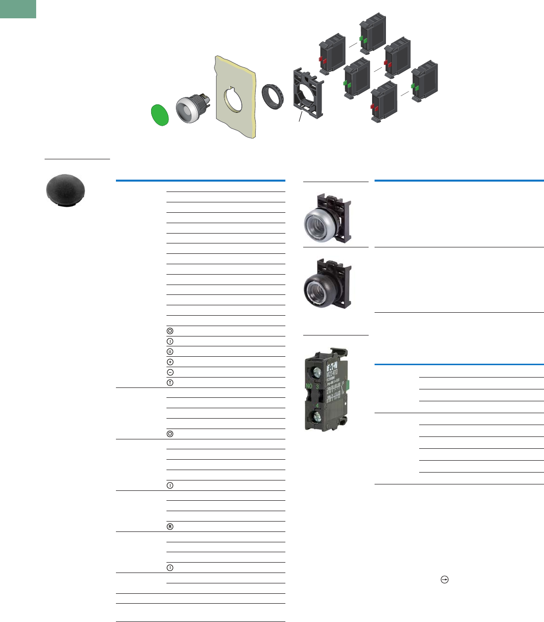
T37-40 Logic Control Products CA08100001K—June 2012 www.eatoncanada.ca
37
37
37
37
37
37
37
37
37
37
37
37
37
37
37
37
37
37
37
37
37
37
37
37
37
37
37
37
37
37
37.4
Pushbuttons and Indicating Lights
22.5 mm Modular Pushbuttons—M22
Non-Illuminated Pushbuttons, Flush, Maintained
Components
Button Plates Buttonless Operator
Contact Blocks
Notes
Maintained pushbuttons can be converted in the field to momentary operation by switching
the locking ring, which is accessible through the side of the operator body.
For complete listing of available button plates and contact blocks, see Accessories,
Pages V7-T37-96 to V7-T37-101.
Minimum order quantity of (10).
When ordering, specify inscription per catalogue number suffix from the Symbols
Library (see Pages V7-T37-114 to V7-T37-121) into the Order Notes.
For example, M22-XD-S-ETCH; Order Notes: Mark with symbol X91, Line item #_.
Includes contact block mounting adapter.
All NC contact blocks are positively driven contact.
max. 5mm
thickness
Note: Included
with operator.
Colour Inscription Catalogue Number
Black — M22-XD-S
Custom M22-XD-S-ETCH
STOP M22-XD-S-GB0
START M22-XD-S-GB1
CLOSE M22-XD-S-GB2
UP M22-XD-S-GB3
DOWN M22-XD-S-GB4
OFF M22-XD-S-GB5
ON M22-XD-S-GB6
TEST M22-XD-S-GB9
FORWARD M22-XD-S-GB15
REVERSE M22-XD-S-GB16
RAISE M22-XD-S-GB17
LOWER M22-XD-S-GB18
M22-XD-S-X0
M22-XD-S-X1
M22-XD-S-X2
M22-XD-S-X4
M22-XD-S-X5
M22-XD-S-X7
Red — M22-XD-R
Custom M22-XD-R-ETCH
STOP M22-XD-R-GB0
OFF M22-XD-R-GB5
M22-XD-R-X0
Green — M22-XD-G
Custom M22-XD-G-ETCH
START M22-XD-G-GB1
ON M22-XD-G-GB6
M22-XD-G-X1
Blue — M22-XD-B
Custom M22-XD-B-ETCH
RESET M22-XD-B-GB14
M22-XD-B-X6
White — M22-XD-W
Custom M22-XD-W-ETCH
START M22-XD-W-GB1
M22-XD-W-X1
Yellow — M22-XD-Y
Custom M22-XD-Y-ETCH
Black, red, green — M22-XD-SRG
Black, white, red,
green, yellow, blue
—M22-XD-SWRGYB
M22-XD-S
Bezel Catalogue Number
Silver M22-DR-X
Black M22S-DR-X
Terminal
Type
Contact
Configuration Catalogue Number
Screw NO M22-K10
NO, early-make M22-K10P
NC M22-K01
NC, late-break M22-K01D
Spring-cage NO M22-CK10
NC M22-CK01
NC, late-break M22-CK01D
2NO M22-CK20
2NC M22-CK02
NO-NC M22-CK11
M22-DR-X
M22S-DR-X
M22-K10
Tab37book.fm Page 40 Tuesday, July 3, 2012 10:46 PM
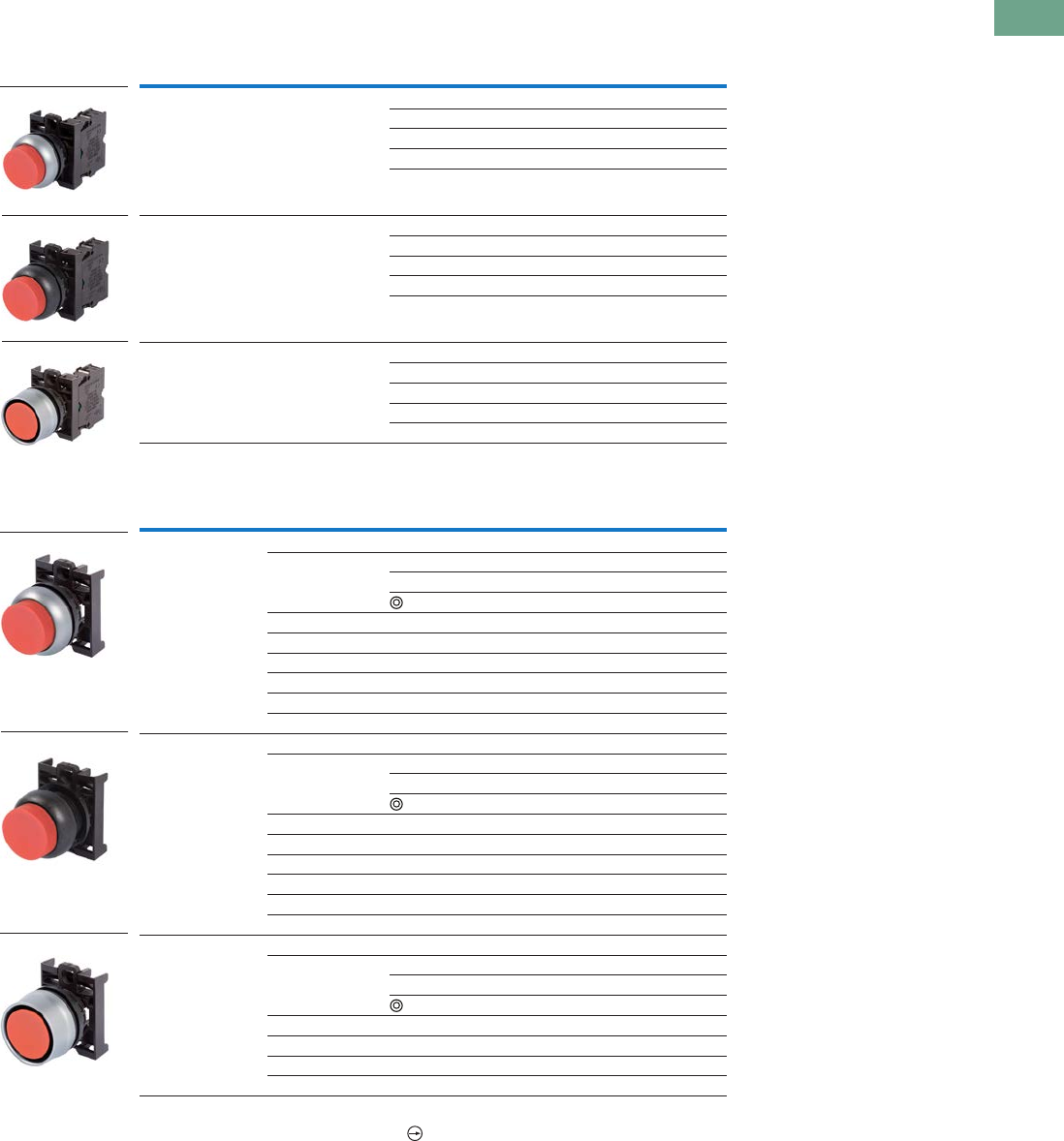
Logic Control Products CA08100001K—June 2012 www.eatoncanada.ca T37-41
37
37
37
37
37
37
37
37
37
37
37
37
37
37
37
37
37
37
37
37
37
37
37
37
37
37
37
37
37
37
37.4
Pushbuttons and Indicating Lights
22.5 mm Modular Pushbuttons—M22
Non-Illuminated Pushbuttons, Extended, Momentary
Complete Devices
Operators Only
Notes
All NC contact blocks are positively driven contact.
Includes contact block mounting adapter.
Buttonless operator comes with three colour buttons (black, red, green).
Buttonless operator comes with all six colour buttons (black, white, red, green, yellow, blue).
Bezel Button Colour
Contact Block
Configuration Catalogue Number
Silver Red NO M22-DH-R-K10
NC M22-DH-R-K01
2NO M22-DH-R-K20
2NC M22-DH-R-K02
1NO-1NC M22-DH-R-K11
Black Red NO M22S-DH-R-K10
NC M22S-DH-R-K01
2NO M22S-DH-R-K20
2NC M22S-DH-R-K02
1NO-1NC M22S-DH-R-K11
Silver guarded Red NO M22-DGH-R-K10
NC M22-DGH-R-K01
2NO M22-DGH-R-K20
2NC M22-DGH-R-K02
1NO-1NC M22-DGH-R-K11
Bezel Button Colour Inscription Catalogue Number
Silver Black — M22-DH-S
Red — M22-DH-R
STOP M22-DH-R-GB0
M22-DH-R-X0
Green — M22-DH-G
White — M22-DH-W
Blue — M22-DH-B
Yellow — M22-DH-Y
—M22-DH-X-SRG
—M22-DH-X-SWRGYB
Black Black — M22S-DH-S
Red — M22S-DH-R
STOP M22S-DH-R-GB0
M22S-DH-R-X0
Green — M22S-DH-G
White — M22S-DH-W
Blue — M22S-DH-B
Yellow — M22S-DH-Y
—M22S-DH-X-SRG
—M22S-DH-X-SWRGYB
Silver guarded Black — M22-DGH-S
Red — M22-DGH-R
STOP M22-DGH-R-GB0
M22-DGH-R-X0
Green — M22-DGH-G
White — M22-DGH-W
Blue — M22-DGH-B
Yellow — M22-DGH-Y
M22-DH-R-K10
M22S-DH-R-K10
M22-DGH-R-K10
M22-DH-R
M22S-DH-R
M22-DGH-R
Tab37book.fm Page 41 Tuesday, July 3, 2012 10:46 PM
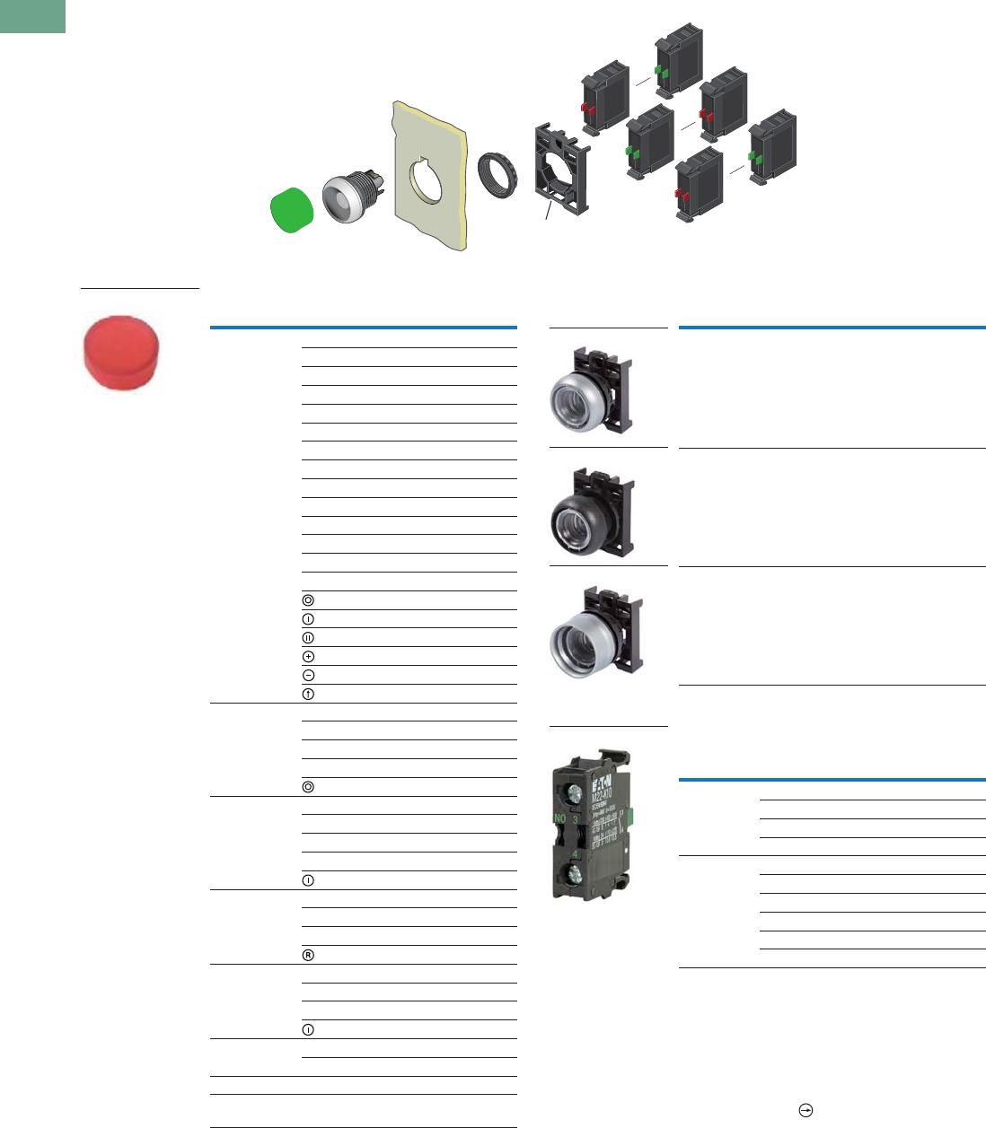
T37-42 Logic Control Products CA08100001K—June 2012 www.eatoncanada.ca
37
37
37
37
37
37
37
37
37
37
37
37
37
37
37
37
37
37
37
37
37
37
37
37
37
37
37
37
37
37
37.4
Pushbuttons and Indicating Lights
22.5 mm Modular Pushbuttons—M22
Non-Illuminated Pushbuttons, Extended, Momentary
Components
Button Plates Buttonless Operator
Contact Blocks
Notes
For complete listing of available button plates and contact blocks, see Accessories,
Pages V7-T37-96 to V7-T37-101.
Minimum order quantity of (10).
When ordering, specify inscription per catalogue number suffix from the Symbols
Library (see Pages V7-T37-114 to V7-T37-121) into the Order Notes.
For example, M22-XDH-S-ETCH; Order Notes: Mark with symbol X91, Line item #_.
Includes contact block mounting adapter.
All NC contact blocks are positively driven contact.
max. 5mm
thickness
Note: Included
with operator.
Colour Inscription Catalogue Number
Black — M22-XDH-S
Custom M22-XDH-S-ETCH
STOP M22-XDH-S-GB0
START M22-XDH-S-GB1
CLOSE M22-XDH-S-GB2
UP M22-XDH-S-GB3
DOWN M22-XDH-S-GB4
OFF M22-XDH-S-GB5
ON M22-XDH-S-GB6
TEST M22-XDH-S-GB9
FORWARD M22-XDH-S-GB15
REVERSE M22-XDH-S-GB16
RAISE M22-XDH-S-GB17
LOWER M22-XDH-S-GB18
M22-XDH-S-X0
M22-XDH-S-X1
M22-XDH-S-X2
M22-XDH-S-X4
M22-XDH-S-X5
M22-XDH-S-X7
Red — M22-XDH-R
Custom M22-XDH-R-ETCH
STOP M22-XDH-R-GB0
OFF M22-XDH-R-GB5
M22-XDH-R-X0
Green — M22-XDH-G
Custom M22-XDH-G-ETCH
START M22-XDH-G-GB1
ON M22-XDH-G-GB6
M22-XDH-G-X1
Blue — M22-XDH-B
Custom M22-XDH-B-ETCH
RESET M22-XDH-B-GB14
M22-XDH-B-X6
White — M22-XDH-W
Custom M22-XDH-W-ETCH
START M22-XDH-W-GB1
M22-XDH-W-X1
Yellow — M22-XDH-Y
Custom M22-XDH-Y-ETCH
Black, red, green — M22-XDH-SRG
Black, white, red,
green, yellow, blue
—M22-XDH-SWRGYB
M22-XDH-R
Bezel Catalogue Number
Silver M22-D-X
Black M22S-D-X
Silver guarded M22-DG-X
Terminal
Type
Contact
Configuration Catalogue Number
Screw NO M22-K10
NO, early-make M22-K10P
NC M22-K01
NC, late-break M22-K01D
Spring-cage NO M22-CK10
NC M22-CK01
NC, late-break M22-CK01D
2NO M22-CK20
2NC M22-CK02
NO-NC M22-CK11
M22-D-X
M22S-D-X
M22-DG-X
M22-K10
Tab37book.fm Page 42 Tuesday, July 3, 2012 10:46 PM
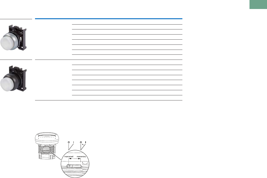
Logic Control Products CA08100001K—June 2012 www.eatoncanada.ca T37-43
37
37
37
37
37
37
37
37
37
37
37
37
37
37
37
37
37
37
37
37
37
37
37
37
37
37
37
37
37
37
37.4
Pushbuttons and Indicating Lights
22.5 mm Modular Pushbuttons—M22
Non-Illuminated Pushbuttons, Extended, Maintained
Operators Only
Notes
Maintained pushbuttons can be converted in the field to momentary operation by switching the locking ring,
which is accessible through the side of the operator body.
Includes contact block mounting adapter.
Buttonless operator comes with three colour buttons (black, red, green).
Buttonless operator comes with all six colour buttons (black, white, red, green, yellow, blue).
Note: This pilot device features a selectable function switch that enables the device
to be set to either maintained or momentary operation.
Bezel Button Colour Catalogue Number
Silver Black M22-DRH-S
Red M22-DRH-R
Green M22-DRH-G
White M22-DRH-W
Blue M22-DRH-B
Yellow M22-DRH-Y
M22-DRH-X-SRG
M22-DRH-X-SWRGYB
Black Black M22S-DRH-S
Red M22S-DRH-R
Green M22S-DRH-G
White M22S-DRH-W
Blue M22S-DRH-B
Yellow M22S-DRH-Y
M22S-DRH-X-SRG
M22S-DRH-X-SWRGYB
M22-DRH-W
M22S-DRH-W
Tab37book.fm Page 43 Tuesday, July 3, 2012 10:46 PM

T37-44 Logic Control Products CA08100001K—June 2012 www.eatoncanada.ca
37
37
37
37
37
37
37
37
37
37
37
37
37
37
37
37
37
37
37
37
37
37
37
37
37
37
37
37
37
37
37.4
Pushbuttons and Indicating Lights
22.5 mm Modular Pushbuttons—M22
Non-Illuminated Pushbuttons, Extended, Maintained
Components
Button Plates Buttonless Operator
Contact Blocks
Notes
Maintained pushbuttons can be converted in the field to momentary operation by
switching the locking ring, which is accessible through the side of the operator body.
For complete listing of available button plates and contact blocks, see Accessories,
Pages V7-T37-96 to V7-T37-101.
Minimum order quantity of (10).
When ordering, specify inscription per catalogue number suffix from the Symbols
Library (see Pages V7-T37-114 to V7-T37-121) into the Order Notes.
For example, M22-XDH-S-ETCH; Order Notes: Mark with symbol X91, Line item #_.
Includes contact block mounting adapter.
All NC contact blocks are positively driven contact.
max. 5mm
thickness
Note: Included
with operator.
Colour Inscription Catalogue Number
Black — M22-XDH-S
Custom M22-XDH-S-ETCH
STOP M22-XDH-S-GB0
START M22-XDH-S-GB1
CLOSE M22-XDH-S-GB2
UP M22-XDH-S-GB3
DOWN M22-XDH-S-GB4
OFF M22-XDH-S-GB5
ON M22-XDH-S-GB6
TEST M22-XDH-S-GB9
FORWARD M22-XDH-S-GB15
REVERSE M22-XDH-S-GB16
RAISE M22-XDH-S-GB17
LOWER M22-XDH-S-GB18
M22-XDH-S-X0
M22-XDH-S-X1
M22-XDH-S-X2
M22-XDH-S-X4
M22-XDH-S-X5
M22-XDH-S-X7
Red — M22-XDH-R
Custom M22-XDH-R-ETCH
STOP M22-XDH-R-GB0
OFF M22-XDH-R-GB5
M22-XDH-R-X0
Green — M22-XDH-G
Custom M22-XDH-G-ETCH
START M22-XDH-G-GB1
ON M22-XDH-G-GB6
M22-XDH-G-X1
Blue — M22-XDH-B
Custom M22-XDH-B-ETCH
RESET M22-XDH-B-GB14
M22-XDH-B-X6
White — M22-XDH-W
Custom M22-XDH-W-ETCH
START M22-XDH-W-GB1
M22-XDH-W-X1
Yellow — M22-XDH-Y
Custom M22-XDH-Y-ETCH
Black, red, green — M22-XDH-SRG
Black, white,
red, green, yellow,
blue
—M22-XDH-SWRGYB
M22-XDH-W
Bezel Catalogue Number
Silver M22-DR-X
Black M22S-DR-X
Terminal
Type
Contact
Configuration Catalogue Number
Screw NO M22-K10
NO, early-make M22-K10P
NC M22-K01
NC, late-break M22-K01D
Spring-cage NO M22-CK10
NC M22-CK01
NC, late-break M22-CK01D
2NO M22-CK20
2NC M22-CK02
NO-NC M22-CK11
M22-DR-X
M22S-DR-X
M22-K10
Tab37book.fm Page 44 Tuesday, July 3, 2012 10:46 PM
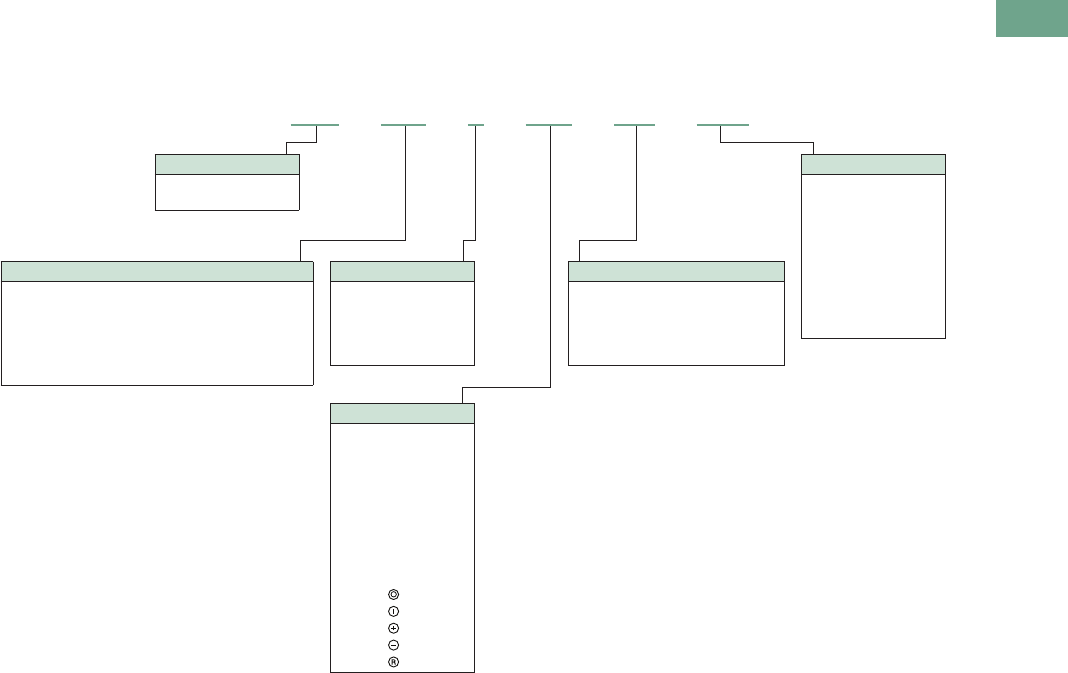
Logic Control Products CA08100001K—June 2012 www.eatoncanada.ca T37-45
37
37
37
37
37
37
37
37
37
37
37
37
37
37
37
37
37
37
37
37
37
37
37
37
37
37
37
37
37
37
37.4
Pushbuttons and Indicating Lights
22.5 mm Modular Pushbuttons—M22
Catalogue Number Selection
Catalogue Number Selection is for illustrative purposes only and not to be used to create new catalogue numbers.
Illuminated Pushbuttons
Bezel
M22 = Silver
M22S = Black
M22 – DRL –R– GB0 – K10 – 230R
Silver bezel only.
Operator Type
DL = Illuminated flush momentary
DLH = Illuminated extended momentary
DGL = Illuminated flush momentary with guard
DRL = Illuminated flush maintained
DGLH = Illuminated extended momentary with guard
DRLH = Illuminated extended maintained
Light Units
12–30 Vac/Vdc
W = White
R = Red
G = Green
B = Blue
85–264 Vac
230W = White
230R = Red
230G = Green
230B = Blue
Inscription
GB0 = STOP
GB1 = START
GB2 = CLOSE
GB3 =UP
GB4 = DOWN
GB5 = OFF
GB6 =ON
GB14 = RESET
GB15 = FORWARD
GB16 = REVERSE
X0 =
X1 =
X4 =
X5 =
X6 =
Contact Blocks
K10 = 1NO
K01 = 1NC
K20 = 2NO
K02 = 2NC
K11 = 1NO-1NC
K30 = 3NO
K03 = 3NC
K21 = 2NO-1NC
K12 = 1NO-2NC
Lens Colour
W = White
R = Red
G = Green
Y = Yellow
B = Blue
Tab37book.fm Page 45 Tuesday, July 3, 2012 10:46 PM
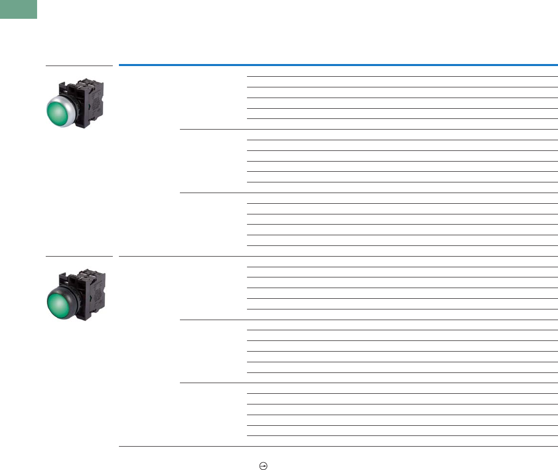
T37-46 Logic Control Products CA08100001K—June 2012 www.eatoncanada.ca
37
37
37
37
37
37
37
37
37
37
37
37
37
37
37
37
37
37
37
37
37
37
37
37
37
37
37
37
37
37
37.4
Pushbuttons and Indicating Lights
22.5 mm Modular Pushbuttons—M22
Product Selection
Illuminated Pushbuttons, Flush, Momentary
Complete Devices
Note
All NC contact blocks are positively driven contact.
Bezel Button Colour
Contact Block
Configuration Light Unit Voltage Catalogue Number
Silver Red NC 12–30 Vac/Vdc M22-DL-R-K01-R
NC 85–264 Vac M22-DL-R-K01-230R
2NC 12–30 Vac/Vdc M22-DL-R-K02-R
2NC 85–264 Vac M22-DL-R-K02-230R
1NO/1NC 12–30 Vac/Vdc M22-DL-R-K11-R
1NO/1NC 85–264 Vac M22-DL-R-K11-230R
Green NO 12–30 Vac/Vdc M22-DL-G-K10-G
NO 85–264 Vac M22-DL-G-K10-230G
2NO 12–30 Vac/Vdc M22-DL-G-K20-G
2NO 85–264 Vac M22-DL-G-K20-230G
1NO/1NC 12–30 Vac/Vdc M22-DL-G-K11-G
1NO/1NC 85–264 Vac M22-DL-G-K11-230G
White NO 12–30 Vac/Vdc M22-DL-W-K10-W
NO 85–264 Vac M22-DL-W-K10-230W
2NO 12–30 Vac/Vdc M22-DL-W-K20-W
2NO 85–264 Vac M22-DL-W-K20-230W
1NO/1NC 12–30 Vac/Vdc M22-DL-W-K11-W
1NO/1NC 85–264 Vac M22-DL-W-K11-230W
Black Red NC 12–30 Vac/Vdc M22S-DL-R-K01-R
NC 85–264 Vac M22S-DL-R-K01-230R
2NC 12–30 Vac/Vdc M22S-DL-R-K02-R
2NC 85–264 Vac M22S-DL-R-K02-230R
1NO/1NC 12–30 Vac/Vdc M22S-DL-R-K11-R
1NO/1NC 85–264 Vac M22S-DL-R-K11-230R
Green NO 12–30 Vac/Vdc M22S-DL-G-K10-G
NO 85–264 Vac M22S-DL-G-K10-230G
2NO 12–30 Vac/Vdc M22S-DL-G-K20-G
2NO 85–264 Vac M22S-DL-G-K20-230G
1NO/1NC 12–30 Vac/Vdc M22S-DL-G-K11-G
1NO/1NC 85–264 Vac M22S-DL-G-K11-230G
White NO 12–30 Vac/Vdc M22S-DL-W-K10-W
NO 85–264 Vac M22S-DL-W-K10-230W
2NO 12–30 Vac/Vdc M22S-DL-W-K20-W
2NO 85–264 Vac M22S-DL-W-K20-230W
1NO/1NC 12–30 Vac/Vdc M22S-DL-W-K11-W
1NO/1NC 85–264 Vac M22S-DL-W-K11-230W
M22-DL-G-K01-G
M22S-DL-G-K01-G
Tab37book.fm Page 46 Tuesday, July 3, 2012 10:46 PM

Logic Control Products CA08100001K—June 2012 www.eatoncanada.ca T37-47
37
37
37
37
37
37
37
37
37
37
37
37
37
37
37
37
37
37
37
37
37
37
37
37
37
37
37
37
37
37
37.4
Pushbuttons and Indicating Lights
22.5 mm Modular Pushbuttons—M22
Illuminated Pushbuttons, Flush, Momentary
Operators Only
Note
Includes contact block mounting adapter.
Bezel Button Colour Catalogue Number
Silver Red M22-DL-R
Green M22-DL-G
White M22-DL-W
Blue M22-DL-B
Yellow M22-DL-Y
Black Red M22S-DL-R
Green M22S-DL-G
White M22S-DL-W
Blue M22S-DL-B
Yellow M22S-DL-Y
Silver guarded Red M22-DGL-R
Green M22-DGL-G
White M22-DGL-W
Blue M22-DGL-B
Yellow M22-DGL-Y
M22-DL-G
M22S-DL-G
M22-DGL-G
Tab37book.fm Page 47 Tuesday, July 3, 2012 10:46 PM
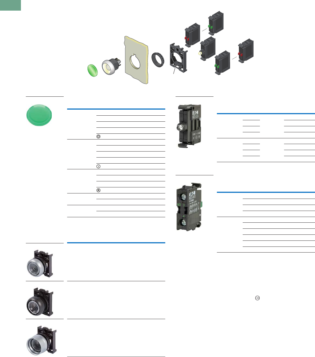
T37-48 Logic Control Products CA08100001K—June 2012 www.eatoncanada.ca
37
37
37
37
37
37
37
37
37
37
37
37
37
37
37
37
37
37
37
37
37
37
37
37
37
37
37
37
37
37
37.4
Pushbuttons and Indicating Lights
22.5 mm Modular Pushbuttons—M22
Illuminated Pushbuttons, Flush, Momentary
Components
Button Lenses
Buttonless Operator
Light Units
Contact Blocks
Notes
For complete listing of available button lenses, light units and contact blocks, see
Accessories, Pages V7-T37-96 to V7-T37-101.
Minimum order quantity of (10).
When ordering, specify inscription per catalogue number suffix from the Symbols
Library (see Pages V7-T37-114 to V7-T37-121) into the Order Notes.
For example, M22-XDL-R-ETCH; Order Notes: Mark with symbol X91, Line item #_.
Includes contact block mounting adapter.
All NC contact blocks are positively driven contact.
max. 5mm
thickness
Note: Included
with operator.
Colour Inscription Catalogue Number
Red — M22-XDL-R
Custom M22-XDL-R-ETCH
STOP M22-XDL-R-GB0
OFF M22-XDL-R-GB5
M22-XDL-R-X0
Green — M22-XDL-G
Custom M22-XDL-G-ETCH
START M22-XDL-G-GB1
ON M22-XDL-G-GB6
M22-XDL-G-X1
Blue — M22-XDL-B
Custom M22-XDL-B-ETCH
RESET M22-XDL-B-GB14
M22-XDL-B-X6
White — M22-XDL-W
Custom M22-XDL-W-ETCH
Yellow — M22-XDL-Y
Custom M22-XDL-Y-ETCH
Bezel Catalogue Number
Silver M22-DL-X
Black M22S-DL-X
Silver guarded M22-DGL-X
M22-XDL-G
M22-DL-X
M22S-DL-X
M22-DGL-X
Terminal
Type
LED
Colour
Light Unit
Voltage Catalogue Number
Screw White 12–30
Vac/Vdc
M22-LED-W
Red M22-LED-R
Green M22-LED-G
Blue M22-LED-B
Screw White 85–264
Vac
M22-LED230-W
Red M22-LED230-R
Green M22-LED230-G
Blue M22-LED230-B
Terminal
Type
Contact
Configuration Catalogue Number
Screw NO M22-K10
NO, early-make M22-K10P
NC M22-K01
NC, late-break M22-K01D
Spring-cage NO M22-CK10
NC M22-CK01
NC, late-break M22-CK01D
2NO M22-CK20
2NC M22-CK02
NO-NC M22-CK11
M22-LED-W
M22-K10
Tab37book.fm Page 48 Tuesday, July 3, 2012 10:46 PM
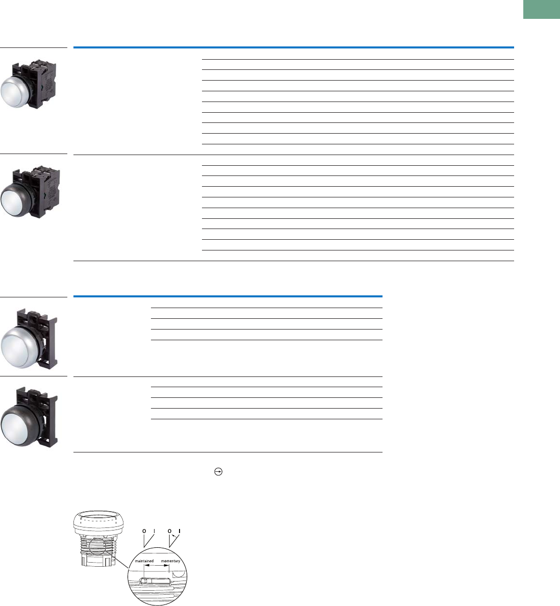
Logic Control Products CA08100001K—June 2012 www.eatoncanada.ca T37-49
37
37
37
37
37
37
37
37
37
37
37
37
37
37
37
37
37
37
37
37
37
37
37
37
37
37
37
37
37
37
37.4
Pushbuttons and Indicating Lights
22.5 mm Modular Pushbuttons—M22
Illuminated Pushbuttons, Flush, Maintained
Complete Devices
Operators Only
Notes
All NC contact blocks are positively driven contact.
Maintained pushbuttons can be converted in the field to momentary operation by switching the locking ring,
which is accessible through the side of the operator body.
Includes contact block mounting adapter.
Note: This pilot device features a selectable function switch that enables the device
to be set to either maintained or momentary operation.
Bezel Button Colour
Contact Block
Configuration Light Unit Voltage Catalogue Number
Silver White NO 12–30 Vac/Vdc M22-DRL-W-K10-W
NO 85–264 Vac M22-DRL-W-K10-230W
NC 12–30 Vac/Vdc M22-DRL-W-K01-W
NC 85–264 Vac M22-DRL-W-K01-230W
2NO 12–30 Vac/Vdc M22-DRL-W-K20-W
2NO 85–264 Vac M22-DRL-W-K20-230W
2NC 12–30 Vac/Vdc M22-DRL-W-K02-W
2NC 85–264 Vac M22-DRL-W-K02-230W
1NO/1NC 12–30 Vac/Vdc M22-DRL-W-K11-W
1NO/1NC 85–264 Vac M22-DRL-W-K11-230W
Black White NO 12–30 Vac/Vdc M22S-DRL-W-K10-W
NO 85–264 Vac M22S-DRL-W-K10-230W
NC 12–30 Vac/Vdc M22S-DRL-W-K01-W
NC 85–264 Vac M22S-DRL-W-K01-230W
2NO 12–30 Vac/Vdc M22S-DRL-W-K20-W
2NO 85–264 Vac M22S-DRL-W-K20-230W
2NC 12–30 Vac/Vdc M22S-DRL-W-K02-W
2NC 85–264 Vac M22S-DRL-W-K02-230W
1NO/1NC 12–30 Vac/Vdc M22S-DRL-W-K11-W
1NO/1NC 85–264 Vac M22S-DRL-W-K11-230W
Bezel Button Colour Catalogue Number
Silver Red M22-DRL-R
Green M22-DRL-G
White M22-DRL-W
Blue M22-DRL-B
Yellow M22-DRL-Y
Black Red M22S-DRL-R
Green M22S-DRL-G
White M22S-DRL-W
Blue M22S-DRL-B
Yellow M22S-DRL-Y
M22-DRL-W-K10-W
M22S-DRL-W-K10-W
M22-DRL-W
M22S-DRL-W
Tab37book.fm Page 49 Tuesday, July 3, 2012 10:46 PM
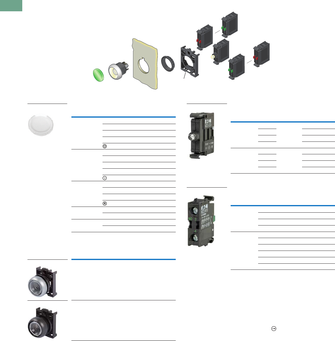
T37-50 Logic Control Products CA08100001K—June 2012 www.eatoncanada.ca
37
37
37
37
37
37
37
37
37
37
37
37
37
37
37
37
37
37
37
37
37
37
37
37
37
37
37
37
37
37
37.4
Pushbuttons and Indicating Lights
22.5 mm Modular Pushbuttons—M22
Illuminated Pushbuttons, Flush, Maintained
Components
Button Lenses
Buttonless Operator
Light Units
Contact Blocks
Notes
Maintained pushbuttons can be converted in the field to momentary operation by
switching the locking ring, which is accessible through the side of the operator body.
For complete listing of available button lenses, light units and contact blocks, see
Accessories, Pages V7-T37-96 to V7-T37-101.
Minimum order quantity of (10).
When ordering, specify inscription per catalogue number suffix from the Symbols
Library (see Pages V7-T37-114 to V7-T37-121) into the Order Notes.
For example, M22-XDL-R-ETCH; Order Notes: Mark with symbol X91, Line item #_.
Includes contact block mounting adapter.
All NC contact blocks are positively driven contact.
max. 5mm
thickness
Note: Included
with operator.
Colour Inscription Catalogue Number
Red — M22-XDL-R
Custom M22-XDL-R-ETCH
STOP M22-XDL-R-GB0
OFF M22-XDL-R-GB5
M22-XDL-R-X0
Green — M22-XDL-G
Custom M22-XDL-G-ETCH
START M22-XDL-G-GB1
ON M22-XDL-G-GB6
M22-XDL-G-X1
Blue — M22-XDL-B
Custom M22-XDL-B-ETCH
RESET M22-XDL-B-GB14
M22-XDL-B-X6
White — M22-XDL-W
Custom M22-XDL-W-ETCH
Yellow — M22-XDL-Y
Custom M22-XDL-Y-ETCH
Bezel Catalogue Number
Silver M22-DRL-X
Black M22S-DRL-X
M22-XDL-W
M22-DRL-X
M22S-DRL-X
Terminal
Type
LED
Colour
Light Unit
Voltage Catalogue Number
Screw White 12–30
Vac/Vdc
M22-LED-W
Red M22-LED-R
Green M22-LED-G
Blue M22-LED-B
Screw White 85–264
Vac
M22-LED230-W
Red M22-LED230-R
Green M22-LED230-G
Blue M22-LED230-B
Terminal
Type
Contact
Configuration Catalogue Number
Screw NO M22-K10
NO, early-make M22-K10P
NC M22-K01
NC, late-break M22-K01D
Spring-cage NO M22-CK10
NC M22-CK01
NC, late-break M22-CK01D
2NO M22-CK20
2NC M22-CK02
NO-NC M22-CK11
M22-LED-W
M22-K10
Tab37book.fm Page 50 Tuesday, July 3, 2012 10:46 PM
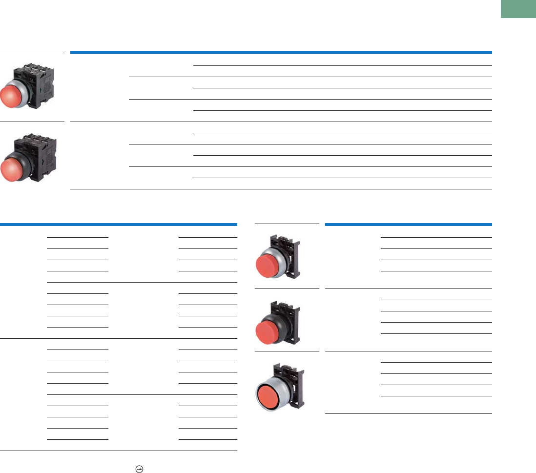
Logic Control Products CA08100001K—June 2012 www.eatoncanada.ca T37-51
37
37
37
37
37
37
37
37
37
37
37
37
37
37
37
37
37
37
37
37
37
37
37
37
37
37
37
37
37
37
37.4
Pushbuttons and Indicating Lights
22.5 mm Modular Pushbuttons—M22
Illuminated Pushbuttons, Extended, Momentary
Complete Devices
Complete Press-to-Test Units Operators Only
Notes
All NC contact blocks are positively driven contact.
Includes contact block mounting adapter.
Bezel Button Colour
Contact Block
Configuration Light Unit Voltage Catalogue Number
Silver Red 1NO/1NC 12–30 Vac/Vdc M22-DLH-R-K11-R
1NO/1NC 85–264 Vac M22-DLH-R-K11-230R
Green 2NO 12–30 Vac/Vdc M22-DLH-G-K20-G
2NO 85–264 Vac M22-DLH-G-K20-230G
White 2NO 12–30 Vac/Vdc M22-DLH-W-K20-W
2NO 85–264 Vac M22-DLH-W-K20-230W
Black Red 1NO/1NC 12–30 Vac/Vdc M22S-DLH-R-K11-R
1NO/1NC 85–264 Vac M22S-DLH-R-K11-230R
Green 2NO 12–30 Vac/Vdc M22S-DLH-G-K20-G
2NO 85–264 Vac M22S-DLH-G-K20-230G
White 2NO 12–30 Vac/Vdc M22S-DLH-W-K20-W
2NO 85–264 Vac M22S-DLH-W-K20-230W
M22-DLH-R-K11-R
M22S-DLH-R-K11-R
Bezel Button Colour Light Unit Voltage Catalogue Number
Silver Red 12–30 Vac/Vdc M22-T-R-R
Blue M22-T-B-B
Yellow M22-T-Y-W
Green M22-T-G-G
White M22-T-W-W
Red 85–264 Vac M22-T-R-230R
Blue M22-T-R-230B
Yellow M22-T-Y-230W
Green M22-T-G-230G
White M22-T-W-230W
Black Red 12–30 Vac/Vdc M22S-T-R-R
Blue M22S-T-B-B
Yellow M22S-T-Y-W
Green M22S-T-G-G
White M22S-T-W-W
Red 85–264 Vac M22S-T-R-230R
Blue M22S-T-B-230B
Yellow M22S-T-Y-230W
Green M22S-T-G-230G
White M22S-T-W-230W
Bezel Button Colour Catalogue Number
Silver Red M22-DLH-R
Green M22-DLH-G
White M22-DLH-W
Blue M22-DLH-B
Yellow M22-DLH-Y
Black Red M22S-DLH-R
Green M22S-DLH-G
White M22S-DLH-W
Blue M22S-DLH-B
Yellow M22S-DLH-Y
Silver guarded Red M22-DGLH-R
Green M22-DGLH-G
White M22-DGLH-W
Blue M22-DGLH-B
Yellow M22-DGLH-Y
M22-DLH-R
M22S-DLH-R
M22-DGLH-R
Tab37book.fm Page 51 Tuesday, July 3, 2012 10:46 PM
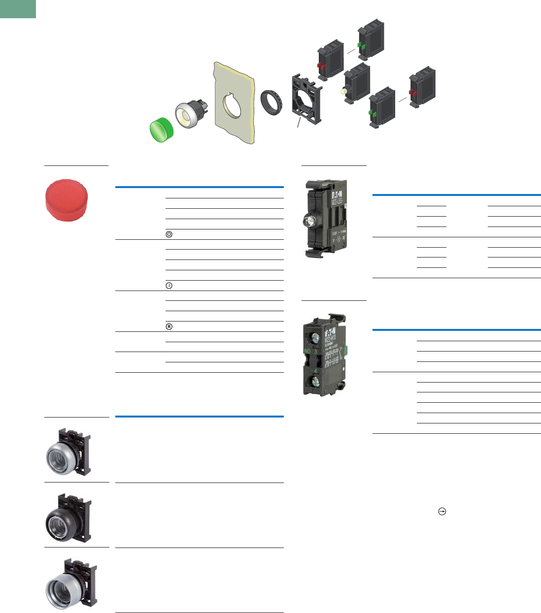
T37-52 Logic Control Products CA08100001K—June 2012 www.eatoncanada.ca
37
37
37
37
37
37
37
37
37
37
37
37
37
37
37
37
37
37
37
37
37
37
37
37
37
37
37
37
37
37
37.4
Pushbuttons and Indicating Lights
22.5 mm Modular Pushbuttons—M22
Illuminated Pushbuttons, Extended, Momentary
Components
Button Lenses
Buttonless Operator
Light Units
Contact Blocks
Notes
For complete listing of available button lenses, light units and contact blocks, see
Accessories, Pages V7-T37-96 to V7-T37-101.
Minimum order quantity of (10).
When ordering, specify inscription per catalogue number suffix from the Symbols
Library (see Pages V7-T37-114 to V7-T37-121) into the Order Notes.
For example, M22-XDH-S-ETCH; Order Notes: Mark with symbol X91, Line item #_.
Includes contact block mounting adapter.
All NC contact blocks are positively driven contact.
max. 5mm
thickness
Note: Included
with operator.
Colour Inscription Catalogue Number
Red — M22-XDLH-R
Custom M22-XDLH-R-ETCH
STOP M22-XDLH-R-GB0
OFF M22-XDLH-R-GB5
M22-XDLH-R-X0
Green — M22-XDLH-G
Custom M22-XDLH-G-ETCH
START M22-XDLH-G-GB1
ON M22-XDLH-G-GB6
M22-XDLH-G-X1
Blue — M22-XDLH-B
Custom M22-XDLH-B-ETCH
RESET M22-XDLH-B-GB14
M22-XDLH-B-X6
White — M22-XDLH-W
Custom M22-XDLH-W-ETCH
Yellow — M22-XDLH-Y
Custom M22-XDLH-Y-ETCH
Bezel Catalogue Number
Silver M22-DL-X
Black M22S-DL-X
Silver guarded M22-DGL-X
M22-XDH-R
M22-DL-X
M22S-DL-X
M22-DGL-X
Terminal
Type
LED
Colour
Light Unit
Voltage Catalogue Number
Screw White 12–30
Vac/Vdc
M22-LED-W
Red M22-LED-R
Green M22-LED-G
Blue M22-LED-B
Screw White 85–264
Vac
M22-LED230-W
Red M22-LED230-R
Green M22-LED230-G
Blue M22-LED230-B
Terminal
Type
Contact
Configuration Catalogue Number
Screw NO M22-K10
NO, early-make M22-K10P
NC M22-K01
NC, late-break M22-K01D
Spring-cage NO M22-CK10
NC M22-CK01
NC, late-break M22-CK01D
2NO M22-CK20
2NC M22-CK02
NO-NC M22-CK11
M22-LED-W
M22-K10
Tab37book.fm Page 52 Tuesday, July 3, 2012 10:46 PM
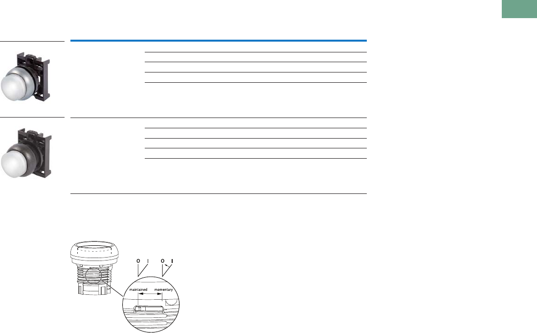
Logic Control Products CA08100001K—June 2012 www.eatoncanada.ca T37-53
37
37
37
37
37
37
37
37
37
37
37
37
37
37
37
37
37
37
37
37
37
37
37
37
37
37
37
37
37
37
37.4
Pushbuttons and Indicating Lights
22.5 mm Modular Pushbuttons—M22
Illuminated Pushbuttons, Extended, Maintained
Operators Only
Notes
Maintained pushbuttons can be converted in the field to momentary operation by switching the locking ring,
which is accessible through the side of the operator body.
Includes contact block mounting adapter.
Note: This pilot device features a selectable function switch that enables the device
to be set to either maintained or momentary operation.
Bezel Button Colour Catalogue Number
Silver Red M22-DRLH-R
Green M22-DRLH-G
White M22-DRLH-W
Blue M22-DRLH-B
Yellow M22-DRLH-Y
Black Red M22S-DRLH-R
Green M22S-DRLH-G
White M22S-DRLH-W
Blue M22S-DRLH-B
Yellow M22S-DRLH-Y
M22-DRLH-W
M22S-DRLH-W
Tab37book.fm Page 53 Tuesday, July 3, 2012 10:46 PM
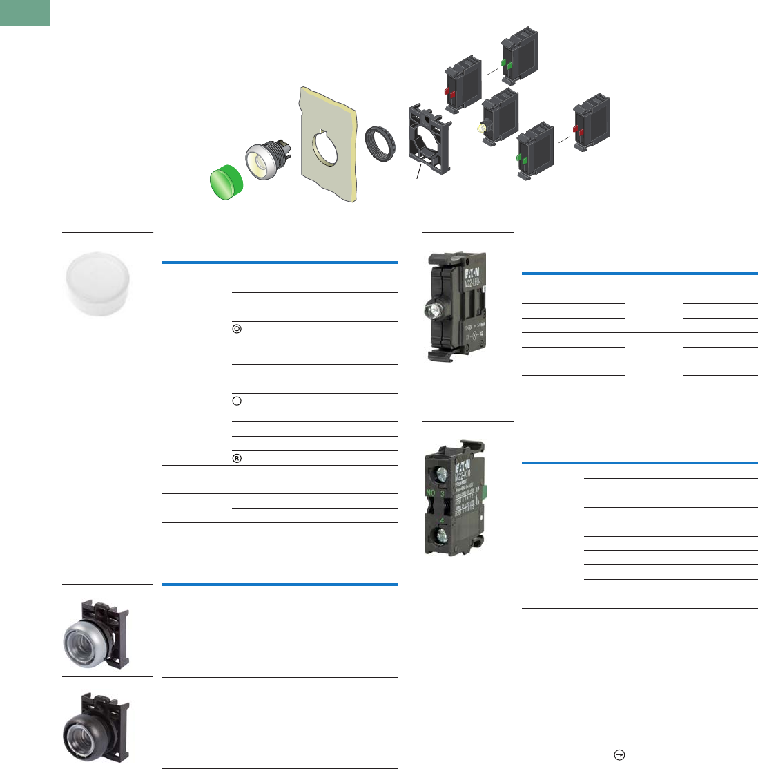
T37-54 Logic Control Products CA08100001K—June 2012 www.eatoncanada.ca
37
37
37
37
37
37
37
37
37
37
37
37
37
37
37
37
37
37
37
37
37
37
37
37
37
37
37
37
37
37
37.4
Pushbuttons and Indicating Lights
22.5 mm Modular Pushbuttons—M22
Illuminated Pushbuttons, Extended, Maintained
Components
Button Lenses
Buttonless Operator
Light Units
Contact Blocks
Notes
Maintained pushbuttons can be converted in the field to momentary operation by
switching the locking ring, which is accessible through the side of the operator body.
For complete listing of available button lenses, light units and contact blocks, see
Accessories, Pages V7-T37-96 to V7-T37-101.
Minimum order quantity of (10).
When ordering, specify inscription per catalogue number suffix from the Symbols
Library (see Pages V7-T37-114 to V7-T37-121) into the Order Notes.
For example, M22-XDLH-S-ETCH; Order Notes: Mark with symbol X91, Line item #_.
Includes contact block mounting adapter.
All NC contact blocks are positively driven contact.
max. 5mm
thickness
Note: Included
with operator.
Colour Inscription Catalogue Number
Red — M22-XDLH-R
Custom M22-XDLH-R-ETCH
STOP M22-XDLH-R-GB0
OFF M22-XDLH-R-GB5
M22-XDLH-R-X0
Green — M22-XDLH-G
Custom M22-XDLH-G-ETCH
START M22-XDLH-G-GB1
ON M22-XDLH-G-GB6
M22-XDLH-G-X1
Blue — M22-XDLH-B
Custom M22-XDLH-B-ETCH
RESET M22-XDLH-B-GB14
M22-XDLH-B-X6
White — M22-XDLH-W
Custom M22-XDLH-W-ETCH
Yellow — M22-XDLH-Y
Custom M22-XDLH-Y-ETCH
Bezel Catalogue Number
Silver M22-DRL-X
Black M22S-DRL-X
M22-XDLH-W
M22-DRL-X
M22S-DRL-X
Terminal
Type
LED
Colour
Light Unit
Voltage Catalogue Number
White 12–30
Vac/Vdc
M22-LED-W
Red M22-LED-R
Green M22-LED-G
Blue M22-LED-B
White 85–264
Vac
M22-LED230-W
Red M22-LED230-R
Green M22-LED230-G
Blue M22-LED230-B
Terminal
Type
Contact
Configuration Catalogue Number
Screw NO M22-K10
NO, early-make M22-K10P
NC M22-K01
NC, late-break M22-K01D
Spring-cage NO M22-CK10
NC M22-CK01
NC, late-break M22-CK01D
2NO M22-CK20
2NC M22-CK02
NO-NC M22-CK11
M22-LED-W
M22-K10
Tab37book.fm Page 54 Tuesday, July 3, 2012 10:46 PM
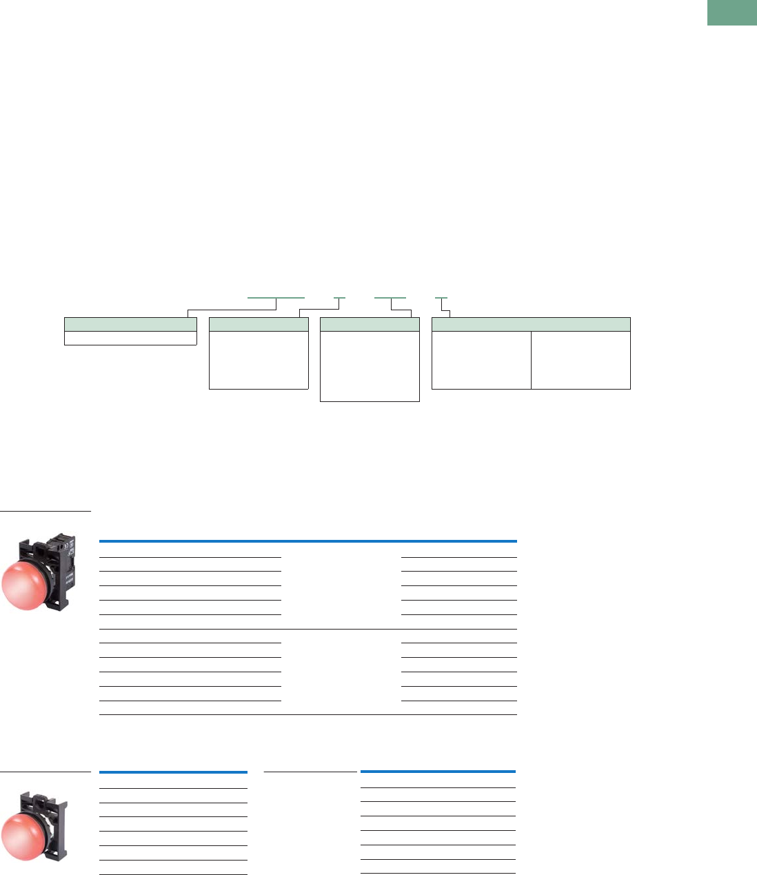
Logic Control Products CA08100001K—June 2012 www.eatoncanada.ca T37-55
37
37
37
37
37
37
37
37
37
37
37
37
37
37
37
37
37
37
37
37
37
37
37
37
37
37
37
37
37
37
37.4
Pushbuttons and Indicating Lights
22.5 mm Modular Pushbuttons—M22
Indicating Lights
Product Description
Eaton’s M22 indicating lights
use the combination of a
durable, bright LED unit and
modern lenses designed
specifically for this type of
LED to create a bright and
visible indicating light.
As with the pushbuttons, the
indicating light lenses can be
laser engraved. Indicating
lights can be ordered as
complete devices, including
lens and LED unit, or as
modular components.
Features
●Customizable laser
engraving on all lenses
●LED offering only for
improved brightness
quality and up to 100,000
hours of operation
●Lenses designed
specifically for LED
illumination
●Modular construction
makes assembly fast and
simplifies stocking of
components and complete
devices
●Capable of communicating
via ASi protocol with ASi
adapter modules
Protection Type
●IP67, IP69K
●NEMA 4X, 13
Catalogue Number Selection
Catalogue Number Selection is for illustrative purposes only and not to be used to create new catalogue numbers.
Indicating Lights
Product Selection
Indicating Lights, Flush
Complete Devices
Operators Only
Note
Includes contact block mounting adapter.
Lens Colour Light Colour Light Unit Voltage Catalogue Number
White White 12–30 Vac/Vdc M22-L-W-W
Red Red M22-L-R-R
Green Green M22-L-G-G
Yellow White M22-L-Y-W
Blue Blue M22-L-B-B
Amber White M22-L-A-W
White White 85–264 Vac M22-L-W-230W
Red Red M22-L-R-230R
Green Green M22-L-G-230G
Yellow White M22-L-Y-230W
Blue Blue M22-L-B-230B
Amber White M22-L-A-230W
Lens Colour Catalogue Number
Flat
White M22-L-W
Red M22-L-R
Green M22-L-G
Yellow M22-L-Y
Blue M22-L-B
Amber M22-L-A
Note: Light unit should match colour of lens.
Use white light unit with yellow lens.
Lens Colour
W = White
R = Red
G = Green
Y = Yellow
B = Blue
M22 - L –B– GB8 –B
Operator Type
M22-L = Flush indicating light
When ordering, specify inscription per catalogue number suffix from the Symbols
Library (see Pages V7-T37-114 to V7-T37-121) into the Order Notes.
For example, M22-L-B-ETCH; Order Notes: Mark with symbol X91, Line item #_.
Plate Inscription
ETCH = Custom
GB5 = OFF
GB6 =ON
GB8 = FAULT
GB15 = FORWARD
GB16 = REVERSE
Light Units
12–30 Vac/Vdc
W = White
R = Red
G = Green
B = Blue
85–264 Vac
230W = White
230R = Red
230G = Green
230B = Blue
M22-L-R-R
M22-L-R
Lens Colour Catalogue Number
Conical
White M22-LH-W
Red M22-LH-R
Green M22-LH-G
Yellow M22-LH-Y
Blue M22-LH-B
Amber M22-LH-A
M22-LH-R
Tab37book.fm Page 55 Tuesday, July 3, 2012 10:46 PM
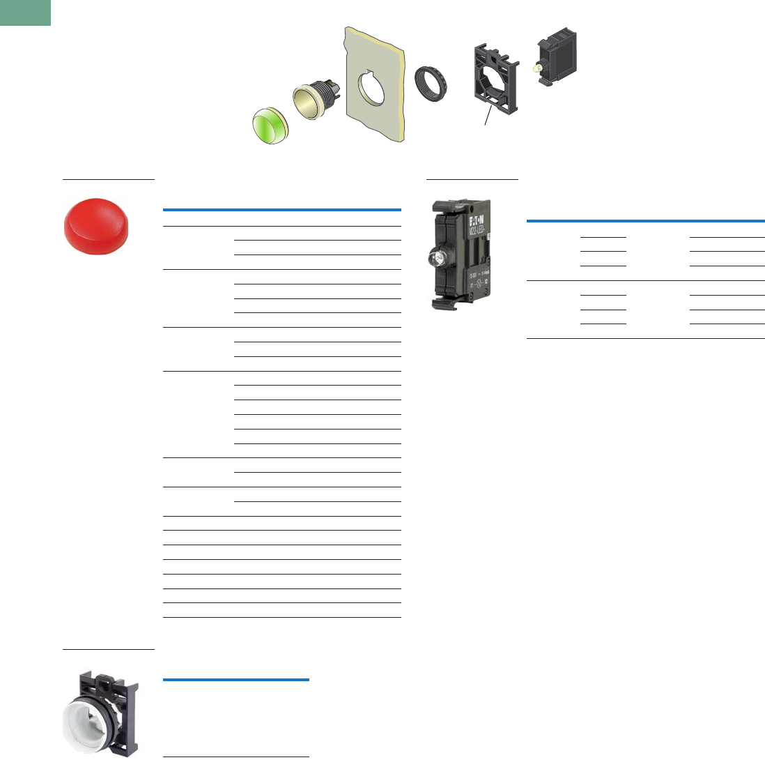
T37-56 Logic Control Products CA08100001K—June 2012 www.eatoncanada.ca
37
37
37
37
37
37
37
37
37
37
37
37
37
37
37
37
37
37
37
37
37
37
37
37
37
37
37
37
37
37
37.4
Pushbuttons and Indicating Lights
22.5 mm Modular Pushbuttons—M22
Indicating Lights, Flush
Components
Lenses
Lensless Indicating Light
Light Units
Notes
For complete listing of available lenses and light units, see Accessories,
Pages V7-T37-96 to V7-T37-101.
Minimum order quantity of (10).
When ordering, specify inscription per catalogue number suffix from the Symbols
Library (see Pages V7-T37-114 to V7-T37-121) into the Order Notes.
For example, M22-XL-R-ETCH; Order Notes: Mark with symbol X91, Line item #_.
Select the same colour LED element as lens colour; for yellow and amber lenses,
choose a white LED.
max. 5mm
thickness
Note: Included
with operator.
Colour Inscription Catalogue Number
Flat
Red — M22-XL-R
Custom M22-XL-R-ETCH
OFF M22-XL-R-GB5
Green — M22-XL-G
Custom M22-XL-G-ETCH
ON M22-XL-G-GB6
REVERSE M22-XL-G-GB16
Blue — M22-XL-B
Custom M22-XL-B-ETCH
FAULT M22-XL-B-GB8
White — M22-XL-W
Custom M22-XL-W-ETCH
OFF M22-XL-W-GB5
ON M22-XL-W-GB6
FAULT M22-XL-W-GB8
FORWARD M22-XL-W-GB15
Yellow — M22-XL-Y
Custom M22-XL-Y-ETCH
Amber — M22-XL-A
Custom M22-XL-A-ETCH
Conical
Red – M22-XLH-R
Green – M22-XLH-G
Blue – M22-XLH-B
White – M22-XLH-W
Yellow – M22–XLH-Y
Amber – M22-XLH-A
Catalogue Number
M22-L-X
M22-XL-R
M22-L-X
Terminal
Type
LED
Colour
Light Unit
Voltage Catalogue Number
Screw White 12–30
Vac/Vdc
M22-LED-W
Red M22-LED-R
Green M22-LED-G
Blue M22-LED-B
Screw White 85–264
Vac
M22-LED230-W
Red M22-LED230-R
Green M22-LED230-G
Blue M22-LED230-B
M22-LED-W
Tab37book.fm Page 56 Tuesday, July 3, 2012 10:46 PM
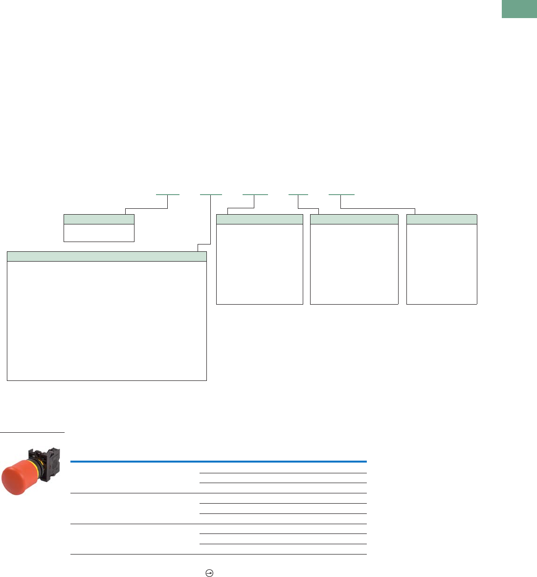
Logic Control Products CA08100001K—June 2012 www.eatoncanada.ca T37-57
37
37
37
37
37
37
37
37
37
37
37
37
37
37
37
37
37
37
37
37
37
37
37
37
37
37
37
37
37
37
37.4
Pushbuttons and Indicating Lights
22.5 mm Modular Pushbuttons—M22
Emergency Stops
Product Description
Eaton’s M22 emergency
stops are a durable and
reliable solution to a variety of
e-stop applications. With
standard push-pull, as well as
twist-to-release and key-
release, illuminated options
and red or black operators,
the M22 e-stop is a robust
solution. As with all
operators, they can be
ordered as a ready to install
complete device or as
modular components for the
perfect fit.
Features
●Push-pull and twist to
release options available as
well as illuminated and
keyed release
●LED offering only for
improved brightness
quality and up to 100,000
hours of operation
●More than 100,000
mechanical operations
●Capable of communicating
via ASi protocol with ASi
adapter modules
Protection Type
●IP67, IP69K
(IP66 key-release)
●NEMA 4X, 13
Catalogue Number Selection
Catalogue Number Selection is for illustrative purposes only and not to be used to create new catalogue numbers.
Emergency Stops
Product Selection
Non-Illuminated Emergency Stops
Complete Devices
Note
All NC contact blocks are positively driven contact.
Type Colour
Contact Block
Configuration Catalogue Number
Push-pull Red NC M22-PV-K01
2NC M22-PV-K02
1NO-2NC M22-PV-K12
Twist-to-release Red NC M22-PVT-K01
2NC M22-PVT-K02
1NO-2NC M22-PVT-K12
Key release Red NC M22-PVS-K01
2NC M22-PVS-K02
1NO-2NC M22-PVS-K12
M22 – PVT – MS2 – K10 – 230R
Operator Colour
M22 = Silver
M22S = Black
Contact Blocks
K10 =NO
K10P = NO, early-make
K01 =NC
K01D = NC, late-break
CK10 =NO
CK01 =NC
CK01D = NC, late-break
Ck20 = 2NO
CK02 = 2NC
CK11 = NO-NC
Key Release Code
Blank = MS1
MS2 = MS2
MS3 = MS3
MS4 = MS4
MS5 = MS5
MS6 = MS6
MS7 = MS7
MS8 = MS8
RS = Ronis
(45 and 60 mm only)
Light Units
12–30 Vac/Vdc
W = White
R = Red
G = Green
B = Blue
85–264 Vac
230W = White
230R = Red
230G = Green
230B = Blue
Operator Type
PV = Non-illuminated push-pull emergency stop
PVT = Non-illuminated twist-to-release emergency stop
PVT45P = Non-illuminated twist-to-release 45 mm emergency stop
PVT60P = Non-illuminated twist-to-release 60 mm emergency stop
PVT45P-MPI = Non-illuminated twist-to-release with mechanical
indication, 45 mm
PVT60P-MPI = Non-illuminated twist-to-release with mechanical
indication, 60 mm
PVS = Non-illuminated keyed release (red operator only)
PVS45P = Non-illuminated keyed release 45 mm (red only)
PVS60P = Non-illuminated keyed release 60 mm (red only)
PVL = Illuminated push-pull emergency stop
PVLT = Illuminated twist-to-release emergency stop
PVLT45P = Illuminated twist-to-release 45 mm emergency stop
PVLT60P = Illuminated twist-to-release 60 mm emergency stop
M22-PV-K01
Tab37book.fm Page 57 Tuesday, July 3, 2012 10:46 PM
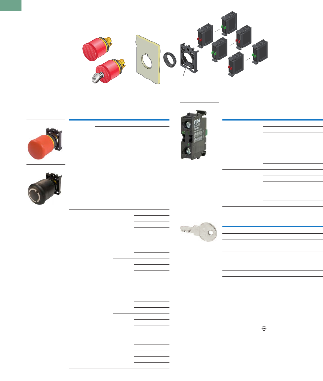
T37-58 Logic Control Products CA08100001K—June 2012 www.eatoncanada.ca
37
37
37
37
37
37
37
37
37
37
37
37
37
37
37
37
37
37
37
37
37
37
37
37
37
37
37
37
37
37
37.4
Pushbuttons and Indicating Lights
22.5 mm Modular Pushbuttons—M22
Non-Illuminated Emergency Stops
Components
Operators Only Contact Blocks
Extra Keys
Notes
Includes contact block mounting adapter.
Key included. For identical locks and keys, use the same key code. One key is included with
actuator; additional keys are available as accessories.
Includes Key Code MS1.
For complete listing of available contact blocks, see Accessories,
Pages V7-T37-96 to V7-T37-101.
Self-monitoring contact blocks (SMCB type) cannot be used with illuminated emergency
stops.
All NC contact blocks are positively driven contact.
For use with key release operators only. One key included with operator.
max. 5mm
thickness
Note: Included
with operator.
Type Colour
Actuator
Size Catalogue Number
Push-pull Red 35 mm M22-PV
Black 35 mm M22S-PV
Twist-to-
release
Red 35 mm M22-PVT
45 mm M22-PVT45P
60 mm M22-PVT60P
Black M22S-PVT
Key release Red 35 mm M22-PVS
M22-PVS-MS2
M22-PVS-MS3
M22-PVS-MS4
M22-PVS-MS5
M22-PVS-MS6
M22-PVS-MS7
M22-PVS-MS8
45 mm M22-PVS45P
M22-PVS45P-MS2
M22-PVS45P-MS3
M22-PVS45P-MS4
M22-PVS45P-MS5
M22-PVS45P-MS6
M22-PVS45P-MS7
M22-PVS45P-MS8
M22-PVS45P-RS
60 mm M22-PVS60P
M22-PVS60P-MS2
M22-PVS60P-MS3
M22-PVS60P-MS4
M22-PVS60P-MS5
M22-PVS60P-MS6
M22-PVS60P-MS7
M22-PVS60P-MS8
M22-PVS60P-RS
Mechanical
indication
Red 45 mm M22-PVT45P-MPI
60 mm M22-PVT60P-MPI
M22-PV
M22S-PVT
Terminal
Type
Mounting
Location
Contact
Configuration
Catalogue
Number
Screw Front NO M22-K10
NO, early-make M22-K10P
NC M22-K01
NC, late-break M22-K01D
SMCB, NC M22-K01SMC10
SMCB, 2NC M22-K02SMC10
Base SMCB, NC M22-KC01SMC10
SMCB, 2NC M22-KC02SMC10
Spring-
cage
Front NO M22-CK10
NC M22-CK01
NC, late-break M22-CK01D
2NO M22-CK20
2NC M22-CK02
NO-NC M22-CK11
For Key Code Catalogue Number
MS1 M22-ES-MS1
MS2 M22-ES-MS2
MS3 M22-ES-MS3
MS4 M22-ES-MS4
MS5 M22-ES-MS5
MS6 M22-ES-MS6
MS7 M22-ES-MS7
MS8 M22-ES-MS8
M22-K10
M22-ES-MS1
Tab37book.fm Page 58 Tuesday, July 3, 2012 10:46 PM
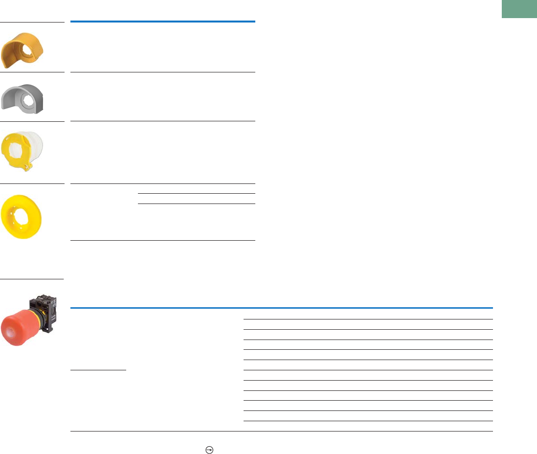
Logic Control Products CA08100001K—June 2012 www.eatoncanada.ca T37-59
37
37
37
37
37
37
37
37
37
37
37
37
37
37
37
37
37
37
37
37
37
37
37
37
37
37
37
37
37
37
37.4
Pushbuttons and Indicating Lights
22.5 mm Modular Pushbuttons—M22
Accessories
Illuminated Emergency Stops
Complete Devices
Note
All NC contact blocks are positively driven contact.
Description Voltage Catalogue Number
Yellow guard ring — M22-XGPV
Gray guard ring — M22G-XGPV
Sealing shroud — M22-PL-PV
Illuminated ring 24 Vac/Vdc M22-XPV60-Y-24
120 Vac M22-XPV60-Y-120
230 Vac M22-XPV60-Y-230
Type Button Colour LED Colour
Contact Block
Configuration Light Unit Voltage Catalogue Number
Push-pull Red Red NC 12–30 Vac/Vdc M22-PVL-K01-R
2NC 12–30 Vac/Vdc M22-PVL-K02-R
1NO-2NC 12–30 Vac/Vdc M22-PVL-K12-R
NC 85–264 Vac M22-PVL-K01-230R
2NC 85–264 Vac M22-PVL-K02-230R
1NO-2NC 85–264 Vac M22-PVL-K12-230R
Twist-to-release NC 12–30 Vac/Vdc M22-PVLT-K01-R
2NC 12–30 Vac/Vdc M22-PVLT-K02-R
1NO-2NC 12–30 Vac/Vdc M22-PVLT-K12-R
NC 85–264 Vac M22-PVLT-K01-230R
2NC 85–264 Vac M22-PVLT-K02-230R
1NO-2NC 85–264 Vac M22-PVLT-K12-230R
M22-XGPV
M22G-XGPV
M22-PL-PV
M22-XPV60-Y-120
M22-PVL-K01-R
Tab37book.fm Page 59 Tuesday, July 3, 2012 10:46 PM
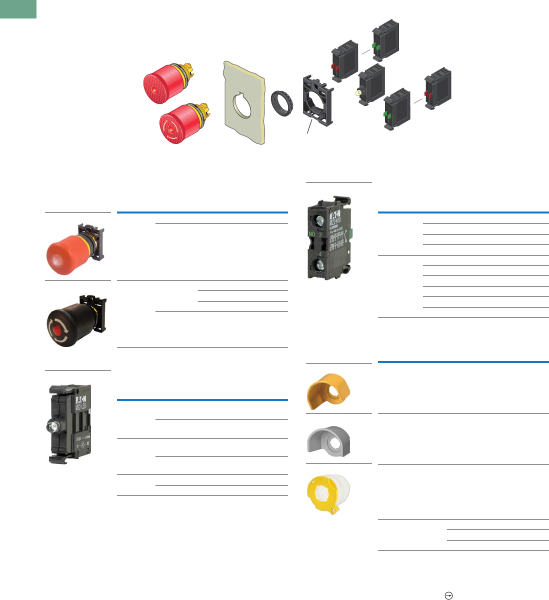
T37-60 Logic Control Products CA08100001K—June 2012 www.eatoncanada.ca
37
37
37
37
37
37
37
37
37
37
37
37
37
37
37
37
37
37
37
37
37
37
37
37
37
37
37
37
37
37
37.4
Pushbuttons and Indicating Lights
22.5 mm Modular Pushbuttons—M22
Illuminated Emergency Stops
Components
Operators Only
Light Units
Contact Blocks
Accessories
Notes
Includes contact block mounting adapter.
For complete listing of available light units and contact blocks, see Accessories,
Pages V7-T37-96 to V7-T37-101.
All NC contact blocks are positively driven contact.
max. 5mm
thickness
Note: Included
with operator.
Type Colour
Actuator
Size Catalogue Number
Push-pull Red 35 mm M22-PVL
Black 35 mm M22S-PVL
Twist-to-
release
Red 35 mm M22-PVLT
45 mm M22-PVLT45P
60 mm M22-PVLT60P
Black 35 mm M22S-PVLT
Terminal
Type
LED
Colour
Light Unit
Voltage Catalogue Number
Screw White 12–30
Vac/Vdc
M22-LED-W
Red 12–30
Vac/Vdc
M22-LED-R
Screw White 85–264
Vac
M22-LED230-W
Red 85–264
Vac
M22-LED230-R
Screw White 207–264 Vac M22-LED230H-W
Red 207–264 Vac M22-LED230H-R
M22-PVL
M22S-PVLT
M22-LED-W
Terminal
Type
Contact
Configuration Catalogue Number
Screw NO M22-K10
NO, early-make M22-K10P
NC M22-K01
NC, late-break M22-K01D
Spring-cage NO M22-CK10
NC M22-CK01
NC, late-break M22-CK01D
2NO M22-CK20
2NC M22-CK02
NO-NC M22-CK11
Description Voltage Catalogue Number
Yellow guard ring — M22-XGPV
Gray guard ring — M22G-XGPV
Sealing shroud — M22-PL-PV
Illuminated ring 24 Vac/Vdc M22-XPV60-Y-24
120 Vac M22-XPV60-Y-120
230 Vac M22-XPV60-Y-230
M22-K10
M22-XGPV
M22G-XGPV
M22-PL-PV
Tab37book.fm Page 60 Tuesday, July 3, 2012 10:46 PM

Logic Control Products CA08100001K—June 2012 www.eatoncanada.ca T37-61
37
37
37
37
37
37
37
37
37
37
37
37
37
37
37
37
37
37
37
37
37
37
37
37
37
37
37
37
37
37
37.4
Pushbuttons and Indicating Lights
22.5 mm Modular Pushbuttons—M22
Selector Switches Contents
Description Page
Selector Switches
Non-Illuminated Switches . . . . . . . . . . . . . . . . . . . . T37-62
Illuminated Switches . . . . . . . . . . . . . . . . . . . . . . . T37-67
Key Operated . . . . . . . . . . . . . . . . . . . . . . . . . . . . . T37-71
Selector Switches
Product Description
Eaton’s M22 selector switch
line offers an almost endless
variety of options in
maintained/momentary, key-
removal and illuminated
devices. The coding adapters
used for maintained/
momentary and key removal
positions make the M22
stand out from competitive
devices. By simply adding or
removing a coding adapter
from inside the operator,
the end-user can change
the function of the button.
Operator options include
standard knob, rotary head,
illuminated and keyed
versions. As with all
operators, they can be
ordered as a ready to install
complete device or as
modular components to
meet application specific
requirements.
Features
●Adding or removing coding
adapters allows for field
convertibility of
maintained/momentary
and key removal positions
●LED offering only for
improved brightness
quality and up to 100,000
hours of operation
●More than 100,000
mechanical operations
●Coding adapter options
make assembly fast and
simplify stocking of
different configurations of
selector switches
●Capable of communicating
via ASi protocol with ASi
adapter modules
Protection Type
●IP66
●NEMA 4X, 13
Tab37book.fm Page 61 Tuesday, July 3, 2012 10:46 PM
T37-62 Logic Control Products CA08100001K—June 2012 www.eatoncanada.ca
37
37
37
37
37
37
37
37
37
37
37
37
37
37
37
37
37
37
37
37
37
37
37
37
37
37
37
37
37
37
37.4
Pushbuttons and Indicating Lights
22.5 mm Modular Pushbuttons—M22
Catalogue Number Selection
Catalogue Number Selection is for illustrative purposes only and not to be used to create new catalogue numbers.
Non-Illuminated Selector Switches
Contact Blocks
K10 =NO
K10P = NO, early-make
Options
K11 = NO-NC
K22 = 2NO-2NC
K20 = 2NO
K02 = 2NC
Rotary type only.
Inscription
X91 = AUTO-HAND
X92 = II-I
Bezel Colour
M22 = Silver
M22S = Black
All momentary selector switches can
be converted in the field to maintained
operation with the removal of a colour-
coded adapter.
Handle Type
W = Momentary rotary
WK = Momentary knob
WKV = Maintained V-position knob
WR = Maintained rotary
WRK = Maintained knob
Number of Positions
Blank = Two-position
3 = Three-position
4 = Four-position
M22 – WRK – X91 – K10
—
Tab37book.fm Page 62 Tuesday, July 3, 2012 10:46 PM
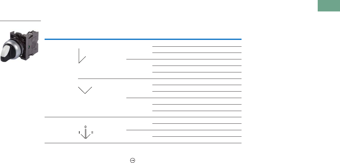
Logic Control Products CA08100001K—June 2012 www.eatoncanada.ca T37-63
37
37
37
37
37
37
37
37
37
37
37
37
37
37
37
37
37
37
37
37
37
37
37
37
37
37
37
37
37
37
37.4
Pushbuttons and Indicating Lights
22.5 mm Modular Pushbuttons—M22
Product Selection
Non-Illuminated Selector Switches
Complete Devices, Knob Type
Notes
Includes contact block mounting adapter.
All NC contact blocks are positively driven contact.
Type Switching Position Bezel
Contact Block
Configuration Catalogue Number
Two-position Maintained Silver NO M22-WRK-K10
1NO-1NC M22-WRK-K11
2NO-2NC M22-WRK-K22
Black NO M22S-WRK-K10
1NO-1NC M22S-WRK-K11
2NO-2NC M22S-WRK-K22
Maintained V Silver NO M22-WKV-K10
1NO-1NC M22-WKV-K11
2NO-2NC M22-WKV-K22
Black NO M22S-WKV-K10
1NO-1NC M22S-WKV-K11
2NO-2NC M22S-WKV-K22
Three-position Maintained Silver 2NO M22-WRK3-K20
2NO-2NC M22-WRK3-K22
Black 2NO M22S-WRK3-K20
2NO-2NC M22S-WRK3-K22
M22-WKV-K10
Tab37book.fm Page 63 Tuesday, July 3, 2012 10:46 PM
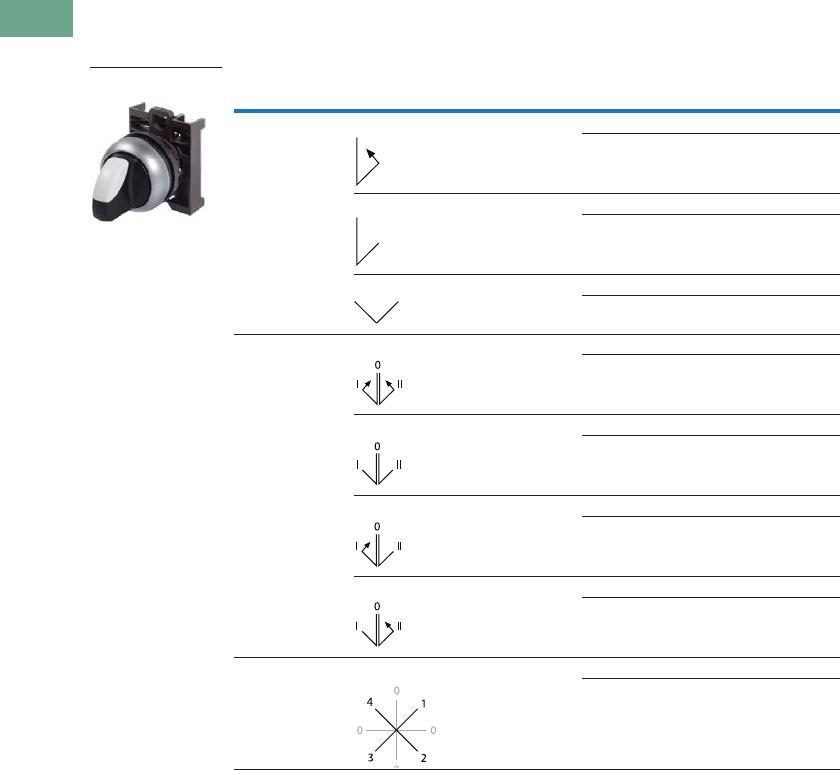
T37-64 Logic Control Products CA08100001K—June 2012 www.eatoncanada.ca
37
37
37
37
37
37
37
37
37
37
37
37
37
37
37
37
37
37
37
37
37
37
37
37
37
37
37
37
37
37
37.4
Pushbuttons and Indicating Lights
22.5 mm Modular Pushbuttons—M22
Non-Illuminated Selector Switches
Components
Operators Only, Knob Type
Notes
Includes contact block mounting adapter.
Momentary selector switches can be converted in the field to maintained operation with the removal of a colour
coded adapter. See Page V7-T37-103.
Type Switching Position Bezel Catalogue Number
Two-position Momentary Silver M22-WK
Black M22S-WK
Maintained Silver M22-WRK
Black M22S-WRK
Maintained V Silver M22-WKV
Black M22S-WKV
Three-position Momentary Silver M22-WK3
Black M22S-WK3
Maintained Silver M22-WRK3
Black M22S-WRK3
Maintained, return from left Silver M22-WRK3-2
Black M22S-WRK3-2
Maintained, return from right Silver M22-WRK3-1
Black M22S-WRK3-1
Four-position Maintained Silver M22-WRK4
Black M22S-WRK4
M22-WK
Tab37book.fm Page 64 Tuesday, July 3, 2012 10:46 PM
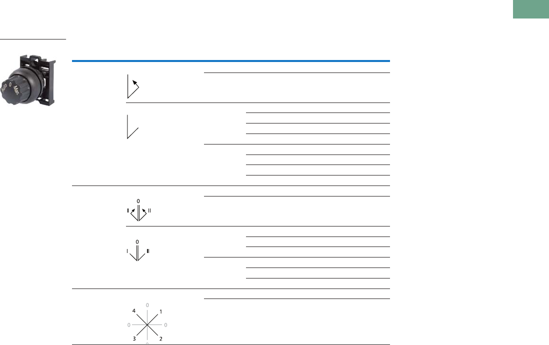
Logic Control Products CA08100001K—June 2012 www.eatoncanada.ca T37-65
37
37
37
37
37
37
37
37
37
37
37
37
37
37
37
37
37
37
37
37
37
37
37
37
37
37
37
37
37
37
37.4
Pushbuttons and Indicating Lights
22.5 mm Modular Pushbuttons—M22
Non-Illuminated Selector Switches
Components
Operators Only, Rotary Type
Notes
Includes contact block mounting adapter.
Momentary selector switches can be converted in the field to maintained operation with the removal of a colour
coded adapter. See Page V7-T37-103.
When ordering, specify inscription per catalogue number suffix from the Symbols Library
(see
Pages
V7-T37-114
to
V7-T37-121
)
into the Order Notes. For example, M22-WR3-ETCH; Order Notes: Mark with symbol X88, Line item #_.
Type Switching Position Bezel Inscription Catalogue Number
Two-position Momentary Silver I-O M22-W
Black I-O M22S-W
Maintained Silver I-O M22-WR
Custom M22-WR-ETCH
AUTO-HAND M22-WR-X91
II-I M22-WR-X92
Black I-O M22S-WR
Custom M22S-WR-ETCH
AUTO-HAND M22S-WR-X91
II-I M22S-WR-X92
Three-position Momentary Silver I-O-II M22-W3
Black I-O-II M22S-W3
Maintained Silver I-O-II M22-WR3
Custom M22-WR3-ETCH
AUTO-O-MAN M22-WR3-X94
Black I-O-II M22S-WR3
Custom M22S-WR3-ETCH
AUTO-O-MAN M22S-WR3-X94
Four-position Maintained Silver 0-1-0-2-0-3-0-4 M22-WR4
Black 0-1-0-2-0-3-0-4 M22S-WR4
M22S-WR3-X94
Tab37book.fm Page 65 Tuesday, July 3, 2012 10:46 PM
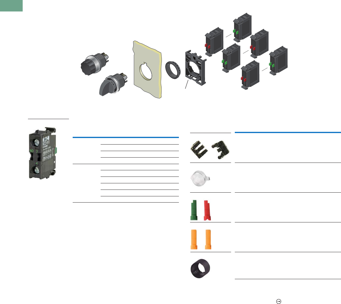
T37-66 Logic Control Products CA08100001K—June 2012 www.eatoncanada.ca
37
37
37
37
37
37
37
37
37
37
37
37
37
37
37
37
37
37
37
37
37
37
37
37
37
37
37
37
37
37
37.4
Pushbuttons and Indicating Lights
22.5 mm Modular Pushbuttons—M22
Non-Illuminated Selector Switches
Components
Contact Blocks Accessories
Notes
For complete listing of available contact blocks, see Accessories,
Pages V7-T37-96 to V7-T37-101.
All NC contact blocks are positively driven contact.
Plunger needed to actuate centre-mounted contact blocks. Used for non-illuminated
three-position selector switches only.
Enables a keyed selector switch to be set to user-selected key withdraw position.
max. 5mm
thickness
Note: Included
with operator.
Terminal
Type
Contact
Configuration Catalogue Number
Screw NO M22-K10
NO, early-make M22-K10P
NC M22-K01
NC, late-break M22-K01D
Spring-cage NO M22-CK10
NC M22-CK01
NC, late-break M22-CK01D
2NO M22-CK20
2NC M22-CK02
NO-NC M22-CK11
M22-K10
Description Catalogue Number
Plunger bridge M22-XW
Key cover M22-XWS
Key withdraw adapter M22-XC-R
Coding adapter M22-XC-Y
Guard ring M22-XGWK
M22-XC-Y
M22-XWS
M22-XC-R
M22-XW
M22-XGWK
Tab37book.fm Page 66 Tuesday, July 3, 2012 10:46 PM
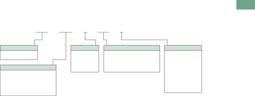
Logic Control Products CA08100001K—June 2012 www.eatoncanada.ca T37-67
37
37
37
37
37
37
37
37
37
37
37
37
37
37
37
37
37
37
37
37
37
37
37
37
37
37
37
37
37
37
37.4
Pushbuttons and Indicating Lights
22.5 mm Modular Pushbuttons—M22
Catalogue Number Selection
Catalogue Number Selection is for illustrative purposes only and not to be used to create new catalogue numbers.
Illuminated Selector Switches
Bezel Colour
M22 = Silver
M22S = Black
Handle Type
WLK = Illuminated knob type
momentary, two-position
WLKV = Illuminated Knob type
momentary, V-position
WLK3 = Illuminated knob type
momentary, three-position
M22 – WLK –R– K10 –R
Light Units
12–30 Vac/Vdc
W = White
R = Red
G = Green
B = Blue
85–264 Vac
230W = White
230R = Red
230G = Green
230B = Blue
Contact Blocks
K10 = 1NO
K01 = 1NC
K20 = 2NO
K02 = 2NC
K11 = 1NO-1NC
K30 = 3NO
K03 = 3NC
K21 = 2NO-1NC
K12 = 1NO-2NC
Handle Colour
W = White
R = Red
G = Green
Y = Yellow
B = Blue
Tab37book.fm Page 67 Tuesday, July 3, 2012 10:46 PM
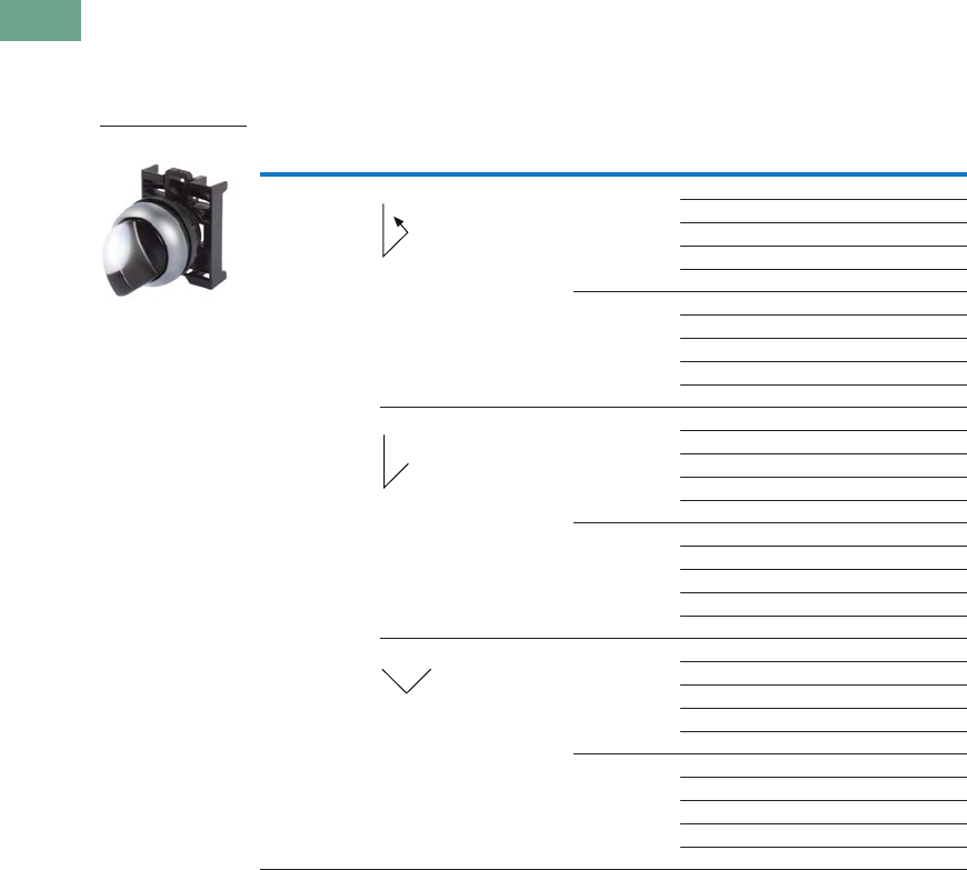
T37-68 Logic Control Products CA08100001K—June 2012 www.eatoncanada.ca
37
37
37
37
37
37
37
37
37
37
37
37
37
37
37
37
37
37
37
37
37
37
37
37
37
37
37
37
37
37
37.4
Pushbuttons and Indicating Lights
22.5 mm Modular Pushbuttons—M22
Product Selection
Illuminated Selector Switches
Components
Operators Only, Knob Type
Notes
Includes contact block mounting adapter.
Momentary selector switches can be converted in the field to maintained operation with the removal of a colour coded
adapter. See Page V7-T37-103.
Type Switching Position Bezel Button Colour Catalogue Number
Two-position Momentary Silver White M22-WLK-W
Red M22-WLK-R
Green M22-WLK-G
Yellow M22-WLK-Y
Blue M22-WLK-B
Black White M22S-WLK-W
Red M22S-WLK-R
Green M22S-WLK-G
Yellow M22S-WLK-Y
Blue M22S-WLK-B
Maintained Silver White M22-WRLK-W
Red M22-WRLK-R
Green M22-WRLK-G
Yellow M22-WRLK-Y
Blue M22-WRLK-B
Black White M22S-WRLK-W
Red M22S-WRLK-R
Green M22S-WRLK-G
Yellow M22S-WRLK-Y
Blue M22S-WRLK-B
Maintained V Silver White M22-WLKV-W
Red M22-WLKV-R
Green M22-WLKV-G
Yellow M22-WLKV-Y
Blue M22-WLKV-B
Black White M22S-WLKV-W
Red M22S-WLKV-R
Green M22S-WLKV-G
Yellow M22S-WLKV-Y
Blue M22S-WLKV-B
M22-WLK-W
Tab37book.fm Page 68 Tuesday, July 3, 2012 10:46 PM
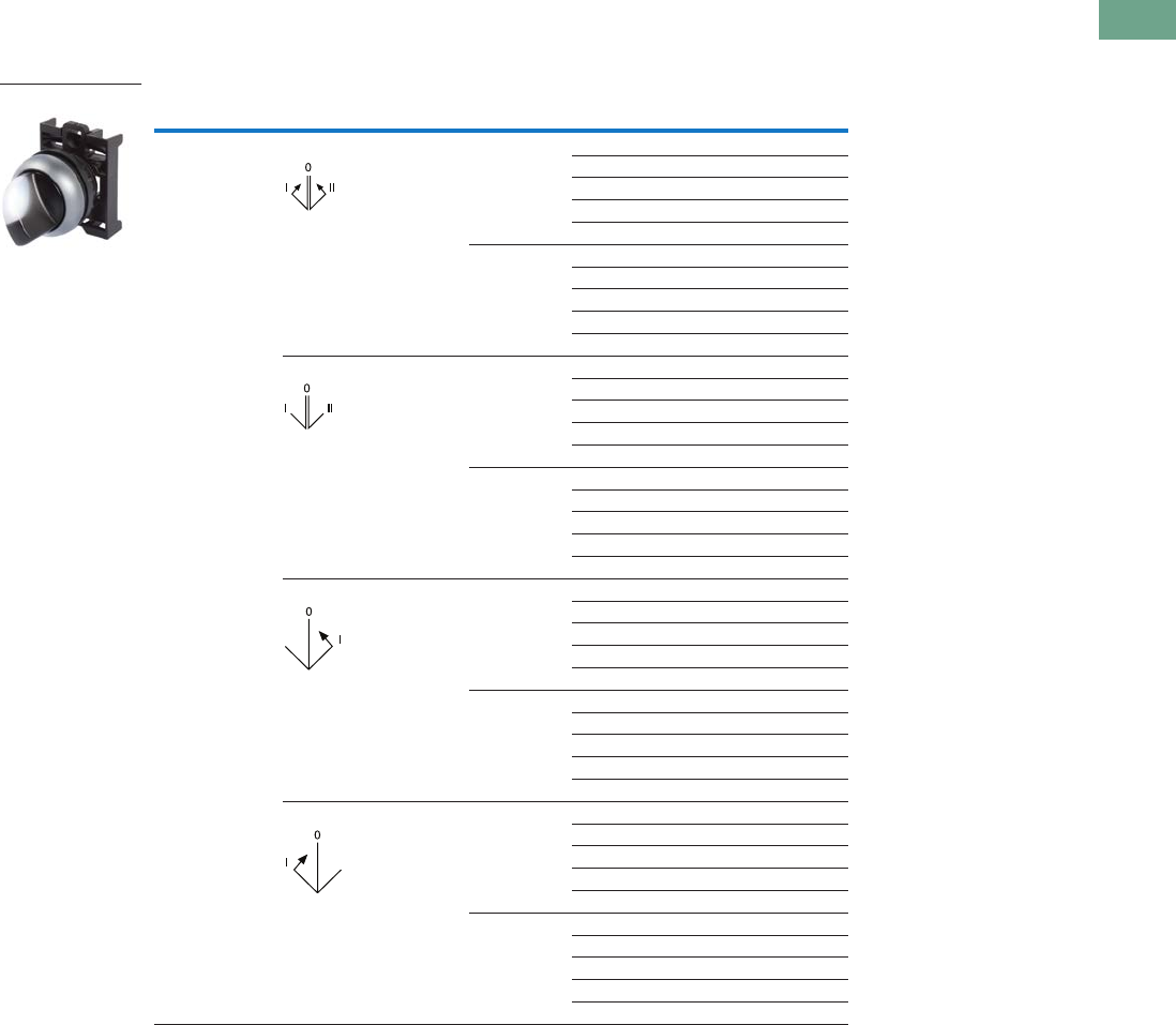
Logic Control Products CA08100001K—June 2012 www.eatoncanada.ca T37-69
37
37
37
37
37
37
37
37
37
37
37
37
37
37
37
37
37
37
37
37
37
37
37
37
37
37
37
37
37
37
37.4
Pushbuttons and Indicating Lights
22.5 mm Modular Pushbuttons—M22
Illuminated Selector Switches
Components
Operators Only, Knob Type
Notes
Includes contact block mounting adapter.
Momentary selector switches can be converted in the field to maintained operation with the removal of a colour coded
adapter. See Page V7-T37-103.
Type Switching Position Bezel Button Colour Catalogue Number
Three-position Momentary Silver White M22-WLK3-W
Red M22-WLK3-R
Green M22-WLK3-G
Yellow M22-WLK3-Y
Blue M22-WLK3-B
Black White M22S-WLK3-W
Red M22S-WLK3-R
Green M22S-WLK3-G
Yellow M22S-WLK3-Y
Blue M22S-WLK3-B
Maintained Silver White M22-WRLK3-W
Red M22-WRLK3-R
Green M22-WRLK3-G
Yellow M22-WRLK3-Y
Blue M22-WRLK3-B
Black White M22S-WRLK3-W
Red M22S-WRLK3-R
Green M22S-WRLK3-G
Yellow M22S-WRLK3-Y
Blue M22S-WRLK3-B
Maintained, return from right Silver White M22-WRLK3-1-W
Red M22-WRLK3-1-R
Green M22-WRLK3-1-G
Yellow M22-WRLK3-1-Y
Blue M22-WRLK3-1-B
Black White M22S-WRLK3-1-W
Red M22S-WRLK3-1-R
Green M22S-WRLK3-1-G
Yellow M22S-WRLK3-1-Y
Blue M22S-WRLK3-1-B
Maintained, return from left Silver White M22-WRLK3-2-W
Red M22-WRLK3-2-R
Green M22-WRLK3-2-G
Yellow M22-WRLK3-2-Y
Blue M22-WRLK3-2-B
Black White M22S-WRLK3-2-W
Red M22S-WRLK3-2-R
Green M22S-WRLK3-2-G
Yellow M22S-WRLK3-2-Y
Blue M22S-WRLK3-2-B
M22-WLK3-W
Tab37book.fm Page 69 Tuesday, July 3, 2012 10:46 PM
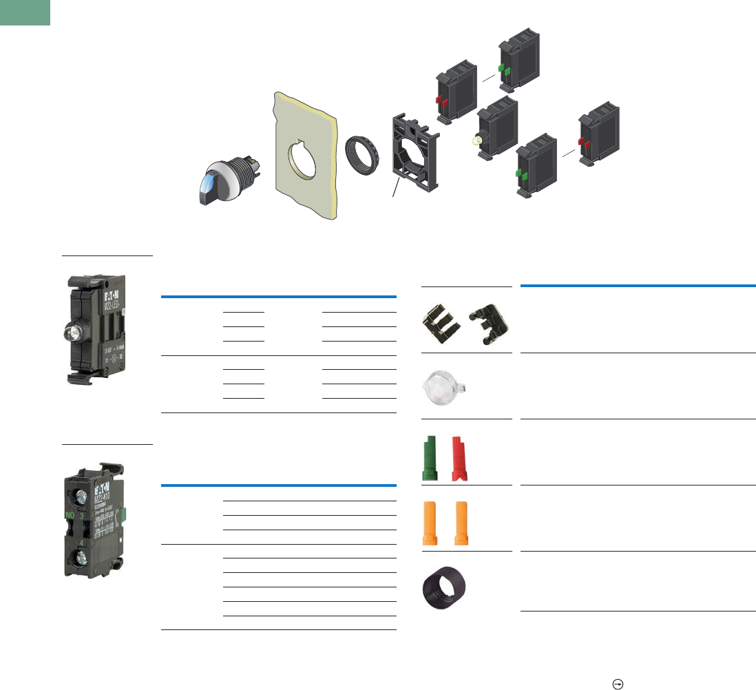
T37-70 Logic Control Products CA08100001K—June 2012 www.eatoncanada.ca
37
37
37
37
37
37
37
37
37
37
37
37
37
37
37
37
37
37
37
37
37
37
37
37
37
37
37
37
37
37
37.4
Pushbuttons and Indicating Lights
22.5 mm Modular Pushbuttons—M22
Illuminated Selector Switches
Light Units
Contact Blocks
Accessories
Notes
For complete listing of available light units and contact blocks, see Accessories,
Pages V7-T37-96 to V7-T37-101.
Plunger needed to actuate centre-mounted contact blocks. Used for non-illuminated
three-position selector switches only.
All NC contact blocks are positively driven contact.
Enables a keyed selector switch to be set to user-selected key withdraw position.
Select the same colour LED element as lens colour; for yellow lens, choose a white LED.
max. 5mm
thickness
Note: Included
with operator.
Terminal
Type
LED
Colour
Light Unit
Voltage Catalogue Number
Screw White 12–30
Vac/Vdc
M22-LED-W
Red M22-LED-R
Green M22-LED-G
Blue M22-LED-B
Screw White 85–264
Vac
M22-LED230-W
Red M22-LED230-R
Green M22-LED230-G
Blue M22-LED230-B
Terminal
Type
Contact
Configuration Catalogue Number
Screw NO M22-K10
NO, early-make M22-K10P
NC M22-K01
NC, late-break M22-K01D
Spring-cage NO M22-CK10
NC M22-CK01
NC, late-break M22-CK01D
2NO M22-CK20
2NC M22-CK02
NO-NC M22-CK11
M22-LED-W
M22-K10
Description Catalogue Number
Plunger bridge M22-XW
Key cover M22-XWS
Key withdraw adapter M22-XC-R
Coding adapter M22-XC-Y
Guard ring M22-XGWK
M22-XC-Y
M22-XWS
M22-XC-R
M22-XW
M22-XGWK
Tab37book.fm Page 70 Tuesday, July 3, 2012 10:46 PM
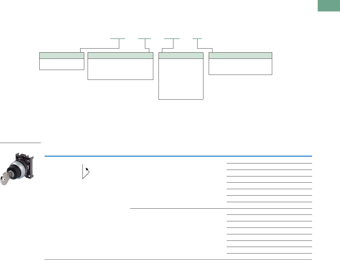
Logic Control Products CA08100001K—June 2012 www.eatoncanada.ca T37-71
37
37
37
37
37
37
37
37
37
37
37
37
37
37
37
37
37
37
37
37
37
37
37
37
37
37
37
37
37
37
37.4
Pushbuttons and Indicating Lights
22.5 mm Modular Pushbuttons—M22
Catalogue Number Selection
Catalogue Number Selection is for illustrative purposes only and not to be used to create new catalogue numbers.
Key-Operated Selector Switches
Product Selection
Key-Operated Selector Switches
Components
Operators Only
Notes
Includes one key.
Key removal positions can be modified in the field using coding adapters; see chart on Page V7-T37-103.
Includes contact block mounting adapter.
Momentary selector switches can be converted in the field to maintained operation with the removal of a colour coded adapter. See Page V7-T37-103.
Bezel Colour
M22 = Silver
M22S = Black
M22 –WS– MS2 –A1
Key Code
Blank = MS1
MS2 = MS2
MS3 = MS3
MS4 = MS4
MS5 = MS5
MS6 = MS6
MS7 = MS7
MS8 = MS8
Handle Type
WS = Two-position, momentary
WS3 = Three-position, momentary
WRS = Two-position, maintained
WRS3 = Three-position, maintained
Key Removal Position
Refer to coding adapter assembly
and functional test guide on Page
V7-T37-103.
Type Switching Position Bezel Key Removal Position Key Code Catalogue Number
Two-position Momentary Silver Return from right, key
removable left
MS1 M22-WS
MS2 M22-WS-MS2
MS3 M22-WS-MS3
MS4 M22-WS-MS4
MS5 M22-WS-MS5
MS6 M22-WS-MS6
MS7 M22-WS-MS7
MS8 M22-WS-MS8
Black Return from right, key
removable left
MS1 M22S-WS
MS2 M22S-WS-MS2
MS3 M22S-WS-MS3
MS4 M22S-WS-MS4
MS5 M22S-WS-MS5
MS6 M22S-WS-MS6
MS7 M22S-WS-MS7
MS8 M22S-WS-MS8
M22-WS
Tab37book.fm Page 71 Tuesday, July 3, 2012 10:46 PM
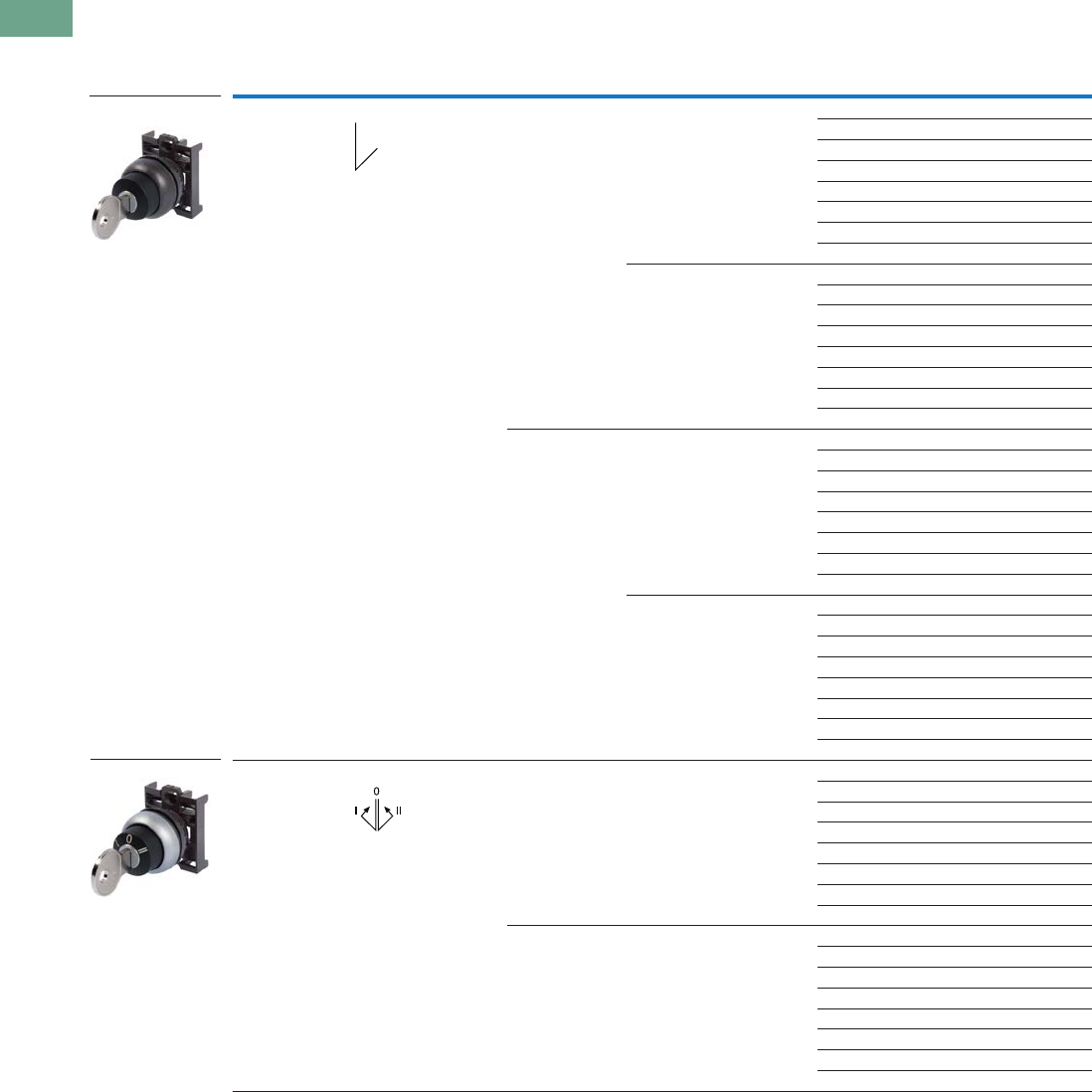
T37-72 Logic Control Products CA08100001K—June 2012 www.eatoncanada.ca
37
37
37
37
37
37
37
37
37
37
37
37
37
37
37
37
37
37
37
37
37
37
37
37
37
37
37
37
37
37
37.4
Pushbuttons and Indicating Lights
22.5 mm Modular Pushbuttons—M22
Key-Operated Selector Switches
Components
Operators Only, continued
Notes
Includes one key.
Key removal positions can be modified in the field using coding adapters; see chart on Page V7-T37-103.
Includes contact block mounting adapter.
Momentary selector switches can be converted in the field to maintained operation with the removal of a colour coded adapter. See Page V7-T37-103.
Type Switching Position Bezel Key Removal Position Key Code Catalogue Number
Two-position Maintained Silver Key removable left MS1 M22-WRS-A1
MS2 M22-WRS-MS2-A1
MS3 M22-WRS-MS3-A1
MS4 M22-WRS-MS4-A1
MS5 M22-WRS-MS5-A1
MS6 M22-WRS-MS6-A1
MS7 M22-WRS-MS7-A1
MS8 M22-WRS-MS8-A1
Key removable left/right MS1 M22-WRS
MS2 M22-WRS-MS2
MS3 M22-WRS-MS3
MS4 M22-WRS-MS4
MS5 M22-WRS-MS5
MS6 M22-WRS-MS6
MS7 M22-WRS-MS7
MS8 M22-WRS-MS8
Black Key removable left MS1 M22S-WRS-A1
MS2 M22S-WRS-MS2-A1
MS3 M22S-WRS-MS3-A1
MS4 M22S-WRS-MS4-A1
MS5 M22S-WRS-MS5-A1
MS6 M22S-WRS-MS6-A1
MS7 M22S-WRS-MS7-A1
MS8 M22S-WRS-MS8-A1
Key removable left/right MS1 M22S-WRS
MS2 M22S-WRS-MS2
MS3 M22S-WRS-MS3
MS4 M22S-WRS-MS4
MS5 M22S-WRS-MS5
MS6 M22S-WRS-MS6
MS7 M22S-WRS-MS7
MS8 M22S-WRS-MS8
Three-position Momentary Silver Return from left/right,
key removable centre
MS1 M22-WS3
MS2 M22-WS3-MS2
MS3 M22-WS3-MS3
MS4 M22-WS3-MS4
MS5 M22-WS3-MS5
MS6 M22-WS3-MS6
MS7 M22-WS3-MS7
MS8 M22-WS3-MS8
Black Return from left/right,
key removable centre
MS1 M22S-WS3
MS2 M22S-WS3-MS2
MS3 M22S-WS3-MS3
MS4 M22S-WS3-MS4
MS5 M22S-WS3-MS5
MS6 M22S-WS3-MS6
MS7 M22S-WS3-MS7
MS8 M22S-WS3-MS8
M22S-WRS
M22-WS3-X93
Tab37book.fm Page 72 Tuesday, July 3, 2012 10:46 PM
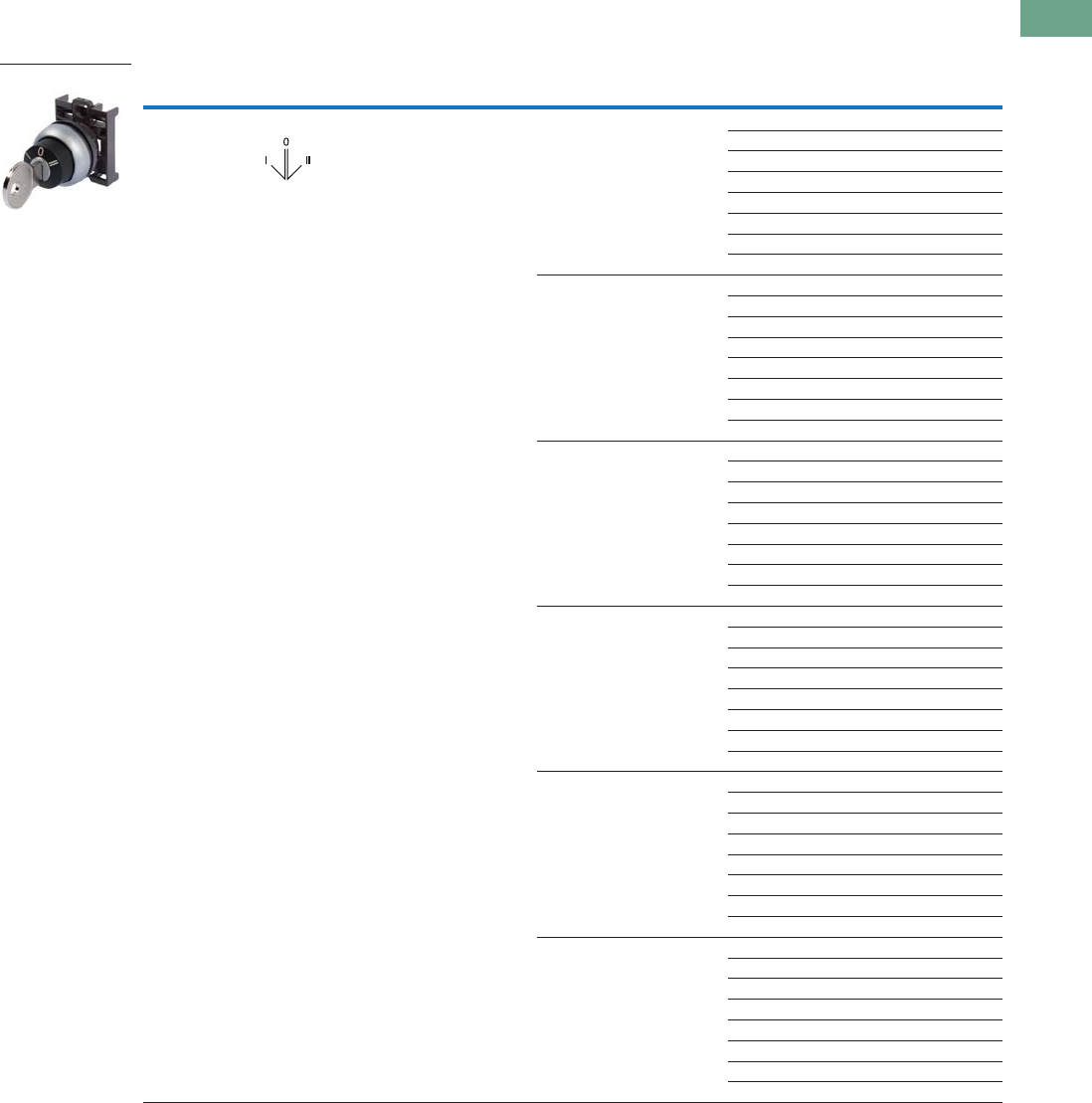
Logic Control Products CA08100001K—June 2012 www.eatoncanada.ca T37-73
37
37
37
37
37
37
37
37
37
37
37
37
37
37
37
37
37
37
37
37
37
37
37
37
37
37
37
37
37
37
37.4
Pushbuttons and Indicating Lights
22.5 mm Modular Pushbuttons—M22
Key-Operated Selector Switches
Components
Operators Only, continued
Notes
Includes one key.
Key removal positions can be modified in the field using coding adapters; see chart on Page V7-T37-103.
Includes contact block mounting adapter.
Type Switching Position Bezel Key Removal Position Key Code Catalogue Number
Three-position Maintained Silver Key removable centre MS1 M22-WRS3-A1
MS2 M22-WRS3-MS2-A1
MS3 M22-WRS3-MS3-A1
MS4 M22-WRS3-MS4-A1
MS5 M22-WRS3-MS5-A1
MS6 M22-WRS3-MS6-A1
MS7 M22-WRS3-MS7-A1
MS8 M22-WRS3-MS8-A1
Key removable
centre/left
MS1 M22-WRS3-A2
MS2 M22-WRS3-MS2-A2
MS3 M22-WRS3-MS3-A2
MS4 M22-WRS3-MS4-A2
MS5 M22-WRS3-MS5-A2
MS6 M22-WRS3-MS6-A2
MS7 M22-WRS3-MS7-A2
MS8 M22-WRS3-MS8-A2
Key removable
centre/right
MS1 M22-WRS3-A3
MS2 M22-WRS3-MS2-A3
MS3 M22-WRS3-MS3-A3
MS4 M22-WRS3-MS4-A3
MS5 M22-WRS3-MS5-A3
MS6 M22-WRS3-MS6-A3
MS7 M22-WRS3-MS7-A3
MS8 M22-WRS3-MS8-A3
Key removable left/right MS1 M22-WRS3
MS2 M22-WRS3-MS2
MS3 M22-WRS3-MS3
MS4 M22-WRS3-MS4
MS5 M22-WRS3-MS5
MS6 M22-WRS3-MS6
MS7 M22-WRS3-MS7
MS8 M22-WRS3-MS8
Return from left,
key removable centre
MS1 M22-WRS3-A7
MS2 M22-WRS3-MS2-A7
MS3 M22-WRS3-MS3-A7
MS4 M22-WRS3-MS4-A7
MS5 M22-WRS3-MS5-A7
MS6 M22-WRS3-MS6-A7
MS7 M22-WRS3-MS7-A7
MS8 M22-WRS3-MS8-A7
Return from left,
key removable centre/right
MS1 M22-WRS3-A6
MS2 M22-WRS3-MS2-A6
MS3 M22-WRS3-MS3-A6
MS4 M22-WRS3-MS4-A6
MS5 M22-WRS3-MS5-A6
MS6 M22-WRS3-MS6-A6
MS7 M22-WRS3-MS7-A6
MS8 M22-WRS3-MS8-A6
M22-WS3-X93
Tab37book.fm Page 73 Tuesday, July 3, 2012 10:46 PM
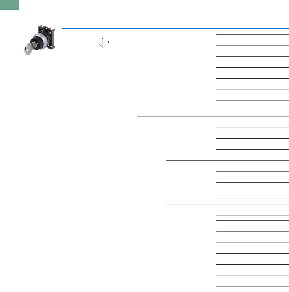
T37-74 Logic Control Products CA08100001K—June 2012 www.eatoncanada.ca
37
37
37
37
37
37
37
37
37
37
37
37
37
37
37
37
37
37
37
37
37
37
37
37
37
37
37
37
37
37
37.4
Pushbuttons and Indicating Lights
22.5 mm Modular Pushbuttons—M22
Key-Operated Selector Switches
Components
Operators Only, continued
Notes
Includes one key.
Key removal positions can be modified in the field using coding adapters; see chart on Page V7-T37-103.
Includes contact block mounting adapter.
Type Switching Position Bezel Key Removal Position Key Code Catalogue Number
Three-position Maintained Silver Return from right,
key removable left/centre
MS1 M22-WRS3-A4
MS2 M22-WRS3-MS2-A4
MS3 M22-WRS3-MS3-A4
MS4 M22-WRS3-MS4-A4
MS5 M22-WRS3-MS5-A4
MS6 M22-WRS3-MS6-A4
MS7 M22-WRS3-MS7-A4
MS8 M22-WRS3-MS8-A4
Return from right,
key removable centre
MS1 M22-WRS3-A5
MS2 M22-WRS3-MS2-A5
MS3 M22-WRS3-MS3-A5
MS4 M22-WRS3-MS4-A5
MS5 M22-WRS3-MS5-A5
MS6 M22-WRS3-MS6-A5
MS7 M22-WRS3-MS7-A5
MS8 M22-WRS3-MS8-A5
Black Key removable centre MS1 M22S-WRS3-A1
MS2 M22S-WRS3-MS2-A1
MS3 M22S-WRS3-MS3-A1
MS4 M22S-WRS3-MS4-A1
MS5 M22S-WRS3-MS5-A1
MS6 M22S-WRS3-MS6-A1
MS7 M22S-WRS3-MS7-A1
MS8 M22S-WRS3-MS8-A1
Key removable
centre/left
MS1 M22S-WRS3-A2
MS2 M22S-WRS3-MS2-A2
MS3 M22S-WRS3-MS3-A2
MS4 M22S-WRS3-MS4-A2
MS5 M22S-WRS3-MS5-A2
MS6 M22S-WRS3-MS6-A2
MS7 M22S-WRS3-MS7-A2
MS8 M22S-WRS3-MS8-A2
Key removable
centre/right
MS1 M22S-WRS3-A3
MS2 M22S-WRS3-MS2-A3
MS3 M22S-WRS3-MS3-A3
MS4 M22S-WRS3-MS4-A3
MS5 M22S-WRS3-MS5-A3
MS6 M22S-WRS3-MS6-A3
MS7 M22S-WRS3-MS7-A3
MS8 M22S-WRS3-MS8-A3
Key removable
left/right/centre
MS1 M22S-WRS3
MS2 M22S-WRS3-MS2
MS3 M22S-WRS3-MS3
MS4 M22S-WRS3-MS4
MS5 M22S-WRS3-MS5
MS6 M22S-WRS3-MS6
MS7 M22S-WRS3-MS7
MS8 M22S-WRS3-MS8
M22-WS3-X93
Tab37book.fm Page 74 Tuesday, July 3, 2012 10:46 PM
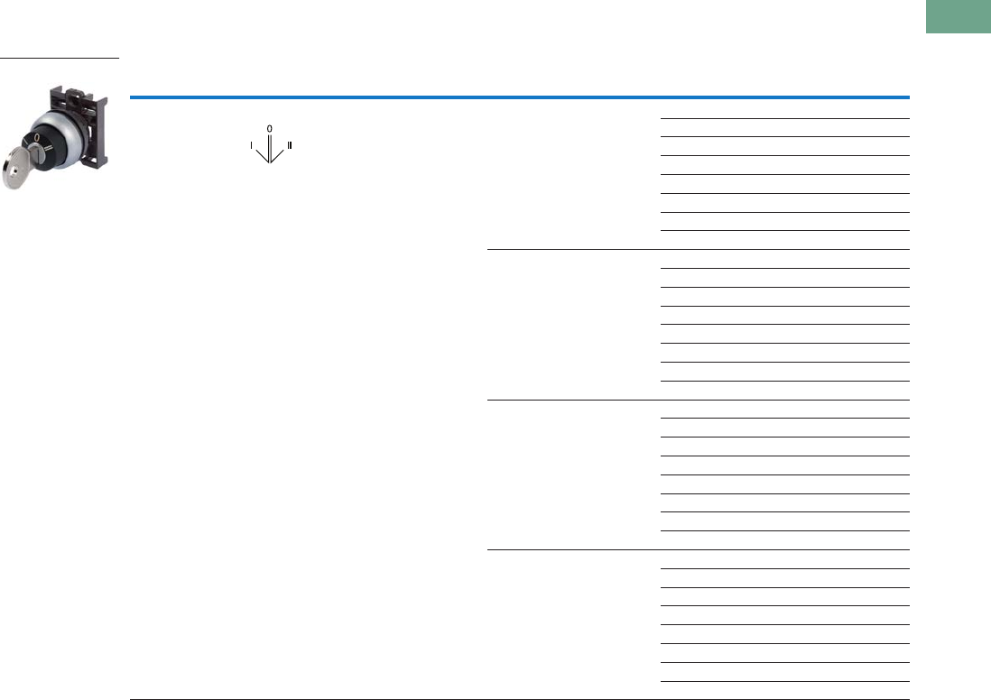
Logic Control Products CA08100001K—June 2012 www.eatoncanada.ca T37-75
37
37
37
37
37
37
37
37
37
37
37
37
37
37
37
37
37
37
37
37
37
37
37
37
37
37
37
37
37
37
37.4
Pushbuttons and Indicating Lights
22.5 mm Modular Pushbuttons—M22
Key-Operated Selector Switches
Components
Operators Only, continued
Notes
Includes one key.
Key removal positions can be modified in the field using coding adapters; see chart on Page V7-T37-103.
Includes contact block mounting adapter.
Type Switching Position Bezel Key Removal Position Key Code Catalogue Number
Three-position Maintained Black Return from left,
key removable centre
MS1 M22S-WRS3-A7
MS2 M22S-WRS3-MS2-A7
MS3 M22S-WRS3-MS3-A7
MS4 M22S-WRS3-MS4-A7
MS5 M22S-WRS3-MS5-A7
MS6 M22S-WRS3-MS6-A7
MS7 M22S-WRS3-MS7-A7
MS8 M22S-WRS3-MS8-A7
Return from left,
key removable centre/right
MS1 M22S-WRS3-A6
MS2 M22S-WRS3-MS2-A6
MS3 M22S-WRS3-MS3-A6
MS4 M22S-WRS3-MS4-A6
MS5 M22S-WRS3-MS5-A6
MS6 M22S-WRS3-MS6-A6
MS7 M22S-WRS3-MS7-A6
MS8 M22S-WRS3-MS8-A6
Return from right,
key removable left/centre
MS1 M22S-WRS3-A4
MS2 M22S-WRS3-MS2-A4
MS3 M22S-WRS3-MS3-A4
MS4 M22S-WRS3-MS4-A4
MS5 M22S-WRS3-MS5-A4
MS6 M22S-WRS3-MS6-A4
MS7 M22S-WRS3-MS7-A4
MS8 M22S-WRS3-MS8-A4
Return from right,
key removable centre
MS1 M22S-WRS3-A5
MS2 M22S-WRS3-MS2-A5
MS3 M22S-WRS3-MS3-A5
MS4 M22S-WRS3-MS4-A5
MS5 M22S-WRS3-MS5-A5
MS6 M22S-WRS3-MS6-A5
MS7 M22S-WRS3-MS7-A5
MS8 M22S-WRS3-MS8-A5
M22-WS3-X93
Tab37book.fm Page 75 Tuesday, July 3, 2012 10:46 PM

T37-76 Logic Control Products CA08100001K—June 2012 www.eatoncanada.ca
37
37
37
37
37
37
37
37
37
37
37
37
37
37
37
37
37
37
37
37
37
37
37
37
37
37
37
37
37
37
37.4
Pushbuttons and Indicating Lights
22.5 mm Modular Pushbuttons—M22
Key-Operated Selector Switches
Components
Contact Blocks
Extra Keys
Accessories
Notes
For complete listing of available contact blocks, see Accessories,
Pages V7-T37-96 to V7-T37-101.
All NC contact blocks are positively driven contact.
Plunger needed to actuate centre-mounted contact blocks. Used for non-illuminated
three-position selector switches only.
Enables a keyed selector switch to be set to user-selected key withdraw position.
max. 5mm
thickness
Note: Included
with operator.
Terminal
Type
Contact
Configuration Catalogue Number
Screw NO M22-K10
NO, early-make M22-K10P
NC M22-K01
NC, late-break M22-K01D
Spring-cage NO M22-CK10
NC M22-CK01
NC, late-break M22-CK01D
2NO M22-CK20
2NC M22-CK02
NO-NC M22-CK11
Key Code Catalogue Number
MS1 M22-ES-MS1
MS2 M22-ES-MS2
MS3 M22-ES-MS3
MS4 M22-ES-MS4
MS5 M22-ES-MS5
MS6 M22-ES-MS6
MS7 M22-ES-MS7
MS8 M22-ES-MS8
M22-K10
M22-ES-MS1
Description Catalogue Number
Plunger bridge M22-XW
Key cover M22-XWS
Key withdraw adapter M22-XC-R
Coding adapter M22-XC-Y
Guard ring M22-XGWK
M22-XC-Y
M22-XWS
M22-XC-R
M22-XW
M22-XGWK
Tab37book.fm Page 76 Tuesday, July 3, 2012 10:46 PM

Logic Control Products CA08100001K—June 2012 www.eatoncanada.ca T37-77
37
37
37
37
37
37
37
37
37
37
37
37
37
37
37
37
37
37
37
37
37
37
37
37
37
37
37
37
37
37
37.4
Pushbuttons and Indicating Lights
22.5 mm Modular Pushbuttons—M22
Mushroom Head Pushbuttons
Product Description
Eaton’s M22 mushroom head
operators are a durable and
unique way to include
standard pushbutton
functionality. Like the
standard pushbutton line,
the maintained pushbuttons
are field convertible to
momentary. They also offer
laser engraving and a robust
five million mechanical
operations on the standard
momentary operator. As with
all operators, they can be
ordered as a ready to install
complete device or as
modular components.
Features
●Field convertible from
maintained to momentary
(available on maintained
pushbuttons only)
●Customizable laser
engraving on all buttons
●More than five million
mechanical operations on
momentary and one million
on maintained pushbuttons
●Modular construction
makes assembly fast and
simplifies stocking of
components and complete
devices
●Capable of communicating
via ASi protocol with ASi
adapter modules
Protection Type
●IP67, IP69K
●NEMA 4X, 13
Tab37book.fm Page 77 Tuesday, July 3, 2012 10:46 PM
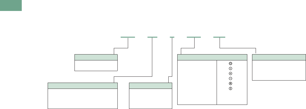
T37-78 Logic Control Products CA08100001K—June 2012 www.eatoncanada.ca
37
37
37
37
37
37
37
37
37
37
37
37
37
37
37
37
37
37
37
37
37
37
37
37
37
37
37
37
37
37
37.4
Pushbuttons and Indicating Lights
22.5 mm Modular Pushbuttons—M22
Catalogue Number Selection
Catalogue Number Selection is for illustrative purposes only and not to be used to create new catalogue numbers.
Mushroom Head Pushbuttons
Bezel
M22 = Silver
M22S = Black
Operator Type
DP = Non-illuminated momentary
mushroom head pushbutton
DRP = Non-illuminated maintained
mushroom head pushbutton
Operator Colour
R = Red
S = Black
G = Green
Y = Yellow When ordering, specify inscription
per catalogue number suffix from
the Symbols Library (see Pages
V7-T37-114 to V7-T37-121) into the
Order Notes.
For example, M22-DP-R-ETCH;
Order Notes: Mark with symbol X91,
Line item #_.
Plate Inscription
ETCH = Custom
GB0 = STOP
GB1 = START
GB3 =UP
GB4 = DOWN
GB5 = OFF
GB6 =ON
GB15 = FORWARD
GB16 = REVERSE
X0 =
X1 =
X4 =
X5 =
X6 =
X7 =
M22 –DP–R– GB4 – K01
Contact Blocks
K01 =NC
K10 =NO
K11 = NO-NC
K12 = 1NO-2NC
Tab37book.fm Page 78 Tuesday, July 3, 2012 10:46 PM
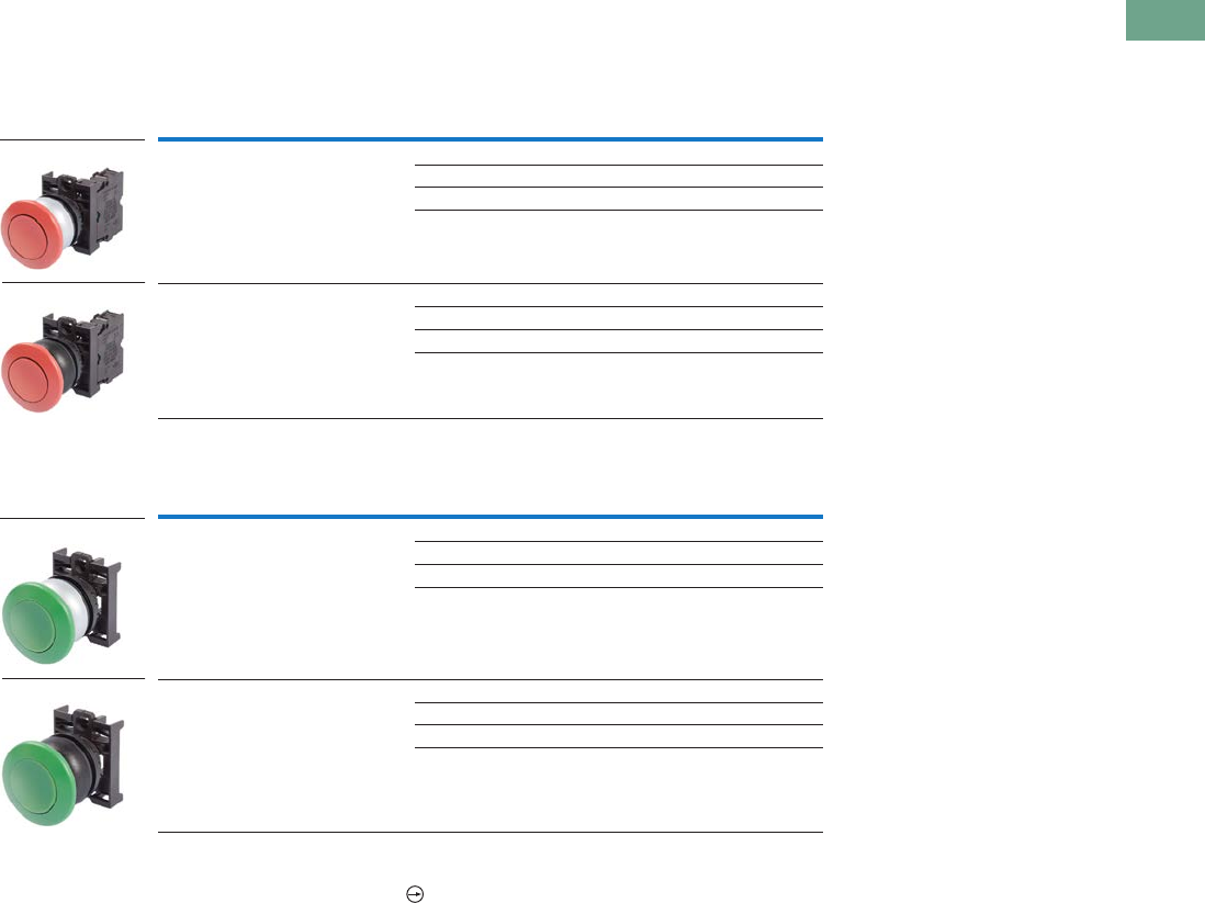
Logic Control Products CA08100001K—June 2012 www.eatoncanada.ca T37-79
37
37
37
37
37
37
37
37
37
37
37
37
37
37
37
37
37
37
37
37
37
37
37
37
37
37
37
37
37
37
37.4
Pushbuttons and Indicating Lights
22.5 mm Modular Pushbuttons—M22
Product Selection
Mushroom Head Pushbuttons, Momentary
Complete Devices
Operators Only
Notes
35 mm diameter mushroom head button.
Includes contact block mounting adapter.
Bezel Button Colour
Contact Block
Configuration Catalogue Number
Silver Red NC M22-DP-R-K01
2NC M22-DP-R-K02
1NO-2NC M22-DP-R-K12
1NO-1NC M22-DP-R-K11
Black Red NC M22S-DP-R-K01
2NC M22S-DP-R-K02
1NO-2NC M22S-DP-R-K12
1NO-1NC M22S-DP-R-K11
Bezel Button Colour Catalogue Number
Silver Black M22-DP-S
Red M22-DP-R
Green M22-DP-G
Yellow M22-DP-Y
Black Black M22S-DP-S
Red M22S-DP-R
Green M22S-DP-G
Yellow M22S-DP-Y
M22-DP-R-K01
M22S-DP-R-K01
M22-DP-G
M22S-DP-G
Tab37book.fm Page 79 Tuesday, July 3, 2012 10:46 PM
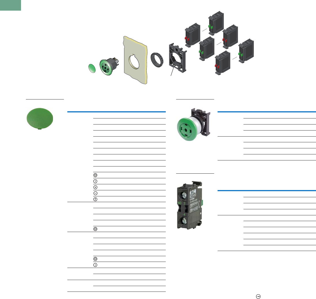
T37-80 Logic Control Products CA08100001K—June 2012 www.eatoncanada.ca
37
37
37
37
37
37
37
37
37
37
37
37
37
37
37
37
37
37
37
37
37
37
37
37
37
37
37
37
37
37
37.4
Pushbuttons and Indicating Lights
22.5 mm Modular Pushbuttons—M22
Non-Illuminated Mushroom Head Pushbuttons, Momentary
Components
Mushroom Head Plates Insertless Mushroom Head Operators
Contact Blocks
Notes
35 mm diameter mushroom head button.
Minimum order quantity of (10).
When ordering, specify inscription per catalogue number suffix from the Symbols
Library (see Pages V7-T37-114 to V7-T37-121) into the Order Notes.
For example, M22-XDP-S-ETCH; Order Notes: Mark with symbol X91, Line item #_.
For complete listing of available contact blocks, see Accessories,
Pages V7-T37-96 to V7-T37-101.
All NC contact blocks are positively driven contact.
Note: Included
with operator.
Colour Inscription Catalogue Number
Black -— M22-XDP-S
Custom M22-XDP-S-ETCH
STOP M22-XDP-S-GB0
START M22-XDP-S-GB1
FORWARD M22-XDP-S-GB15
REVERSE M22-XDP-S-GB16
UP M22-XDP-S-GB3
DOWN M22-XDP-S-GB4
OFF M22-XDP-S-GB5
ON M22-XDP-S-GB6
M22-XDP-S-X0
M22-XDP-S-X1
M22-XDP-S-X4
M22-XDP-S-X5
M22-XDP-S-X7
Red — M22-XDP-R
Custom M22-XDP-R-ETCH
STOP M22-XDP-R-GB0
OFF M22-XDP-R-GB5
M22-XDP-R-X0
Green — M22-XDP-G
Custom M22-XDP-G-ETCH
START M22-XDP-G-GB1
ON M22-XDP-G-GB6
M22-XDP-G-X0
M22-XDP-G-X1
White — M22-XDP-W
Custom M22-XDP-W-ETCH
Yellow — M22-XDP-Y
Custom M22-XDP-Y-ETCH
M22-XDP-G
Bezel Colour Catalogue Number
Silver Black M22-DP-S-X
Red M22-DP-R-X
Green M22-DP-G-X
Yellow M22-DP-Y-X
Black Black M22S-DP-S-X
Red M22S-DP-R-X
Green M22S-DP-G-X
Yellow M22S-DP-Y-X
Terminal
Type
Contact
Configuration Catalogue Number
Screw NO M22-K10
NO, early-make M22-K10P
NC M22-K01
NC, late-break M22-K01D
Spring-cage NO M22-CK10
NC M22-CK01
NC, late-break M22-CK01D
2NO M22-CK20
2NC M22-CK02
NO-NC M22-CK11
M22-DP-G-X
M22-K10
Tab37book.fm Page 80 Tuesday, July 3, 2012 10:46 PM
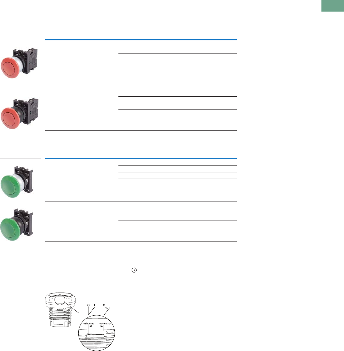
Logic Control Products CA08100001K—June 2012 www.eatoncanada.ca T37-81
37
37
37
37
37
37
37
37
37
37
37
37
37
37
37
37
37
37
37
37
37
37
37
37
37
37
37
37
37
37
37.4
Pushbuttons and Indicating Lights
22.5 mm Modular Pushbuttons—M22
Product Selection
Non-Illuminated Mushroom Head Pushbuttons, Maintained
Complete Devices
Operators Only
Notes
35 mm diameter mushroom head button.
Maintained pushbuttons can be converted in the field to momentary operation by switching the locking ring,
which is accessible through the side of the operator body.
All NC contact blocks are positively driven contact.
Note: This pilot device features a selectable function switch that enables the device
to be set to either maintained or momentary operation.
Bezel Button Colour
Contact Block
Configuration Catalogue Number
Silver Red NC M22-DRP-R-K01
2NC M22-DRP-R-K02
1NO-2NC M22-DRP-R-K12
1NO-1NC M22-DRP-R-K11
Black Red NC M22S-DRP-R-K01
2NC M22S-DRP-R-K02
1NO-2NC M22S-DRP-R-K12
1NO-1NC M22S-DRP-R-K11
Bezel Button Colour Catalogue Number
Silver Black M22-DRP-S
Red M22-DRP-R
Green M22-DRP-G
Yellow M22-DRP-Y
Black Black M22S-DRP-S
Red M22S-DRP-R
Green M22S-DRP-G
Yellow M22S-DRP-Y
M22-DRP-R-K01
M22S-DRP-R-K01
M22-DRP-G
M22S-DRP-G
Tab37book.fm Page 81 Tuesday, July 3, 2012 10:46 PM
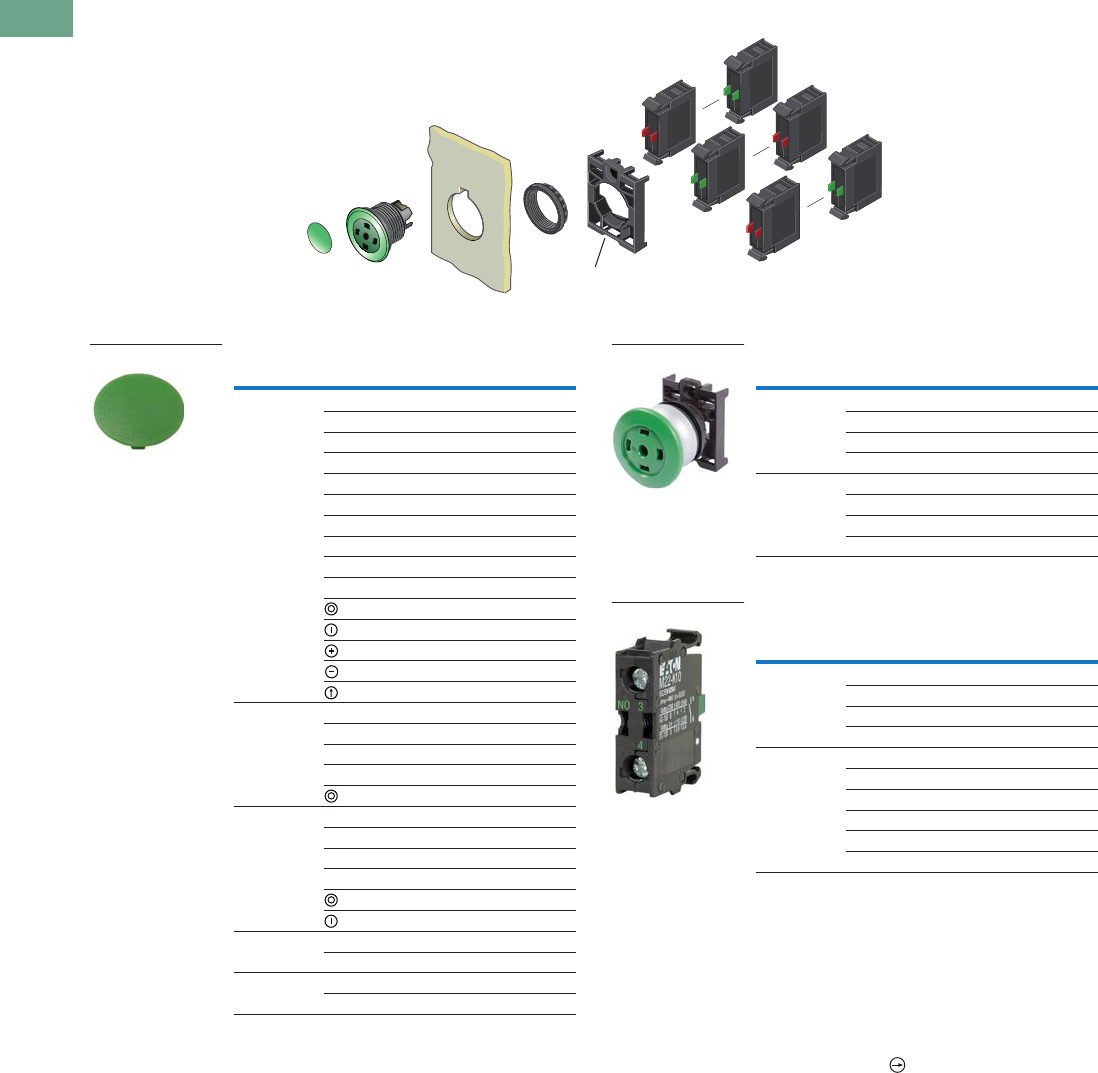
T37-82 Logic Control Products CA08100001K—June 2012 www.eatoncanada.ca
37
37
37
37
37
37
37
37
37
37
37
37
37
37
37
37
37
37
37
37
37
37
37
37
37
37
37
37
37
37
37.4
Pushbuttons and Indicating Lights
22.5 mm Modular Pushbuttons—M22
Non-Illuminated Mushroom Head Pushbuttons, Maintained
Components
Mushroom Head Plates Insertless Mushroom Head Operators
Contact Blocks
Notes
35 mm diameter mushroom head button.
Maintained pushbuttons can be converted in the field to momentary operation by
switching the locking ring, which is accessible through the side of the operator body.
Minimum order quantity of (10).
When ordering, specify inscription per catalogue number suffix from the Symbols
Library (see Pages V7-T37-114 to V7-T37-121) into the Order Notes.
For example, M22-XDP-S-ETCH; Order Notes: Mark with symbol X91, Line item #_.
For complete listing of available button plates and contact blocks, see Accessories,
Pages V7-T37-96 to V7-T37-101.
All NC contact blocks are positively driven contact.
Note: Included
with operator.
Colour Inscription Catalogue Number
Black — M22-XDP-S
Custom M22-XDP-S-ETCH
STOP M22-XDP-S-GB0
START M22-XDP-S-GB1
FORWARD M22-XDP-S-GB15
REVERSE M22-XDP-S-GB16
UP M22-XDP-S-GB3
DOWN M22-XDP-S-GB4
OFF M22-XDP-S-GB5
ON M22-XDP-S-GB6
M22-XDP-S-X0
M22-XDP-S-X1
M22-XDP-S-X4
M22-XDP-S-X5
M22-XDP-S-X7
Red — M22-XDP-R
Custom M22-XDP-R-ETCH
STOP M22-XDP-R-GB0
OFF M22-XDP-R-GB5
M22-XDP-R-X0
Green — M22-XDP-G
Custom M22-XDP-G-ETCH
START M22-XDP-G-GB1
ON M22-XDP-G-GB6
M22-XDP-G-X0
M22-XDP-G-X1
White — M22-XDP-W
Custom M22-XDP-W-ETCH
Yellow — M22-XDP-Y
Custom M22-XDP-Y-ETCH
M22-XDP-G
Bezel Colour Catalogue Number
Silver Black M22-DRP-S-X
Red M22-DRP-R-X
Green M22-DRP-G-X
Yellow M22-DRP-Y-X
Black Black M22S-DRP-S-X
Red M22S-DRP-R-X
Green M22S-DRP-G-X
Yellow M22S-DRP-Y-X
Terminal
Type
Contact
Configuration Catalogue Number
Screw NO M22-K10
NO, early-make M22-K10P
NC M22-K01
NC, late-break M22-K01D
Spring-cage NO M22-CK10
NC M22-CK01
NC, late-break M22-CK01D
2NO M22-CK20
2NC M22-CK02
NO-NC M22-CK11
M22-DRP-G-X
M22-K10
Tab37book.fm Page 82 Tuesday, July 3, 2012 10:46 PM
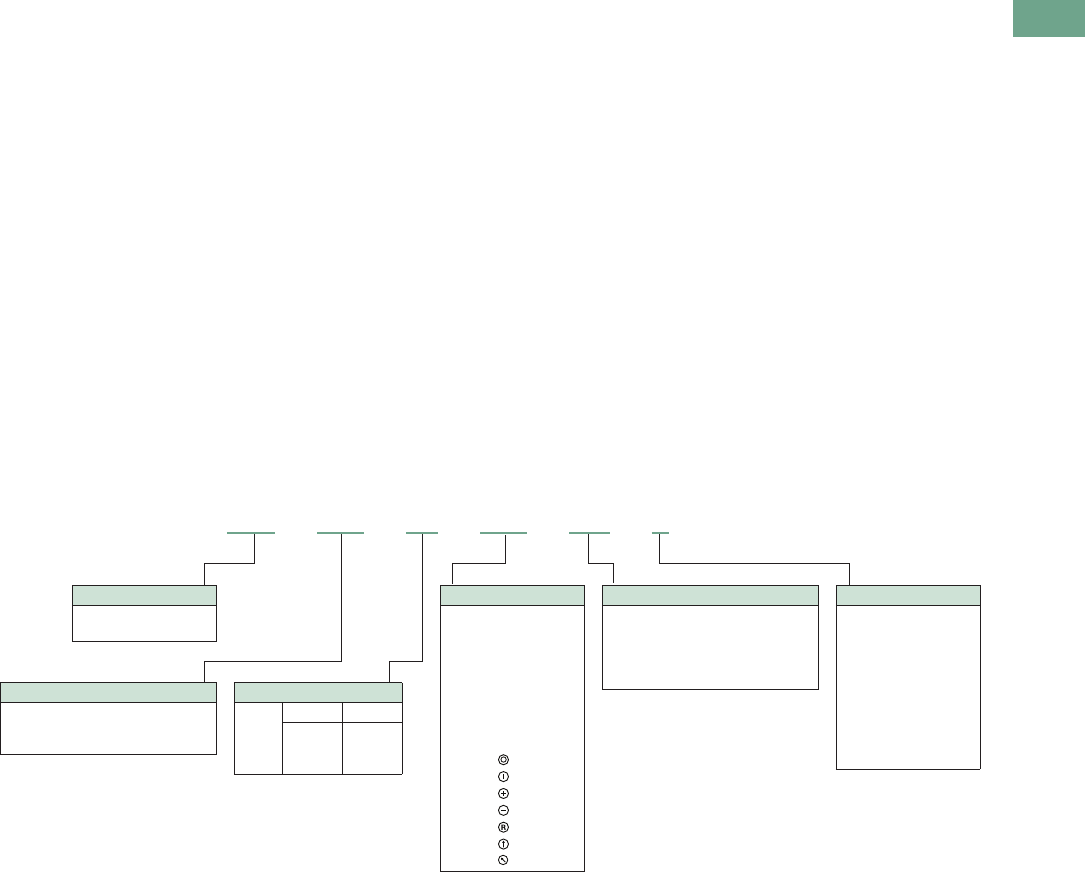
Logic Control Products CA08100001K—June 2012 www.eatoncanada.ca T37-83
37
37
37
37
37
37
37
37
37
37
37
37
37
37
37
37
37
37
37
37
37
37
37
37
37
37
37
37
37
37
37.4
Pushbuttons and Indicating Lights
22.5 mm Modular Pushbuttons—M22
Double Pushbuttons
Product Description
Eaton’s M22 double
pushbutton line is perfect for
applications such as motor
and pump starting, as well as
anytime space is limited. In
addition to the two buttons
that fit in one 22 mm hole is
the integrated white
indicating light between
them. These three operators
allow for multiple functions to
occur in a single space.
Green/red, black/white and
black/black colour options
along with laser engraving
allow for further custom
applications.
Features
●Flush and extended, as
well as colour options
allow for the perfect
combination button
●Integrated indicating light
adds even more
functionality in one
standard 22 mm hole
●Customizable laser
engraving on all buttons
●LED offering only for
improved brightness
quality and up to 100,000
hours of operation
●More than 200,000
mechanical operations
●Capable of communicating
via ASi protocol with ASi
adapter modules
Protection Type
●IP66
●NEMA 4X, 13
Catalogue Number Selection
Catalogue Number Selection is for illustrative purposes only and not to be used to create new catalogue numbers.
Double Pushbuttons
Bezel
M22 = Silver
M22S = Black
M22 – DDL –GR– GB5 – K10 –G
Operator Type
DDL = Extended buttons and light
DDLF = Flush buttons and light
DDLM = Extended bottom button
Light Units
12–30 Vac/Vdc
W = White
R = Red
G = Green
B = Blue
85–264 Vac
230W = White
230R = Red
230G = Green
230B = Blue
Inscription
GB0 = STOP
GB1 = START
GB3 =UP
GB4 = DOWN
GB5 = OFF
GB6 =ON
GB14 = RESET
GB15 = FORWARD
GB16 = REVERSE
X0 =
X1 =
X5 =
X5 =
X6 =
X7 =
X5 =
Contact Blocks
K10 = 1NO
K01 = 1NC
K20 = 2NO
K02 = 2NC
K11 = 1NO-1NC
K30 = 3NO
K03 = 3NC
K21 = 2NO-1NC
K12 = 1NO-2NC
Button Plate Colour
Top Bottom
GR =
WS =
S =
Green
White
Black
Red
Black
Black
Tab37book.fm Page 83 Tuesday, July 3, 2012 10:46 PM
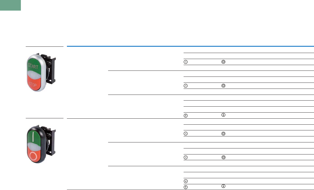
T37-84 Logic Control Products CA08100001K—June 2012 www.eatoncanada.ca
37
37
37
37
37
37
37
37
37
37
37
37
37
37
37
37
37
37
37
37
37
37
37
37
37
37
37
37
37
37
37.4
Pushbuttons and Indicating Lights
22.5 mm Modular Pushbuttons—M22
Product Selection
Components
Double Pushbuttons, Extended Pushbuttons and Centre Light, Momentary
Operators Only
Notes
Includes contact block mounting adapter.
When ordering, specify inscription per catalogue number suffix from the Symbols Library
(see
Pages
V7-T37-114 to V7-T37-121
)
into the Order Notes.
For example, M22-DDL-S-ETCH; Order Notes: Mark with symbol X91, Line item #_.
Colour Inscription
Catalogue NumberBezel Top Bottom Top Bottom
Silver Green Red — — M22-DDL-GR
Custom Custom M22-DDL-GR-ETCH
M22-DDL-GR-X1-X0
START STOP M22-DDL-GR-GB1-GB0
White Black — — M22-DDL-WS
Custom Custom M22-DDL-WS-ETCH
M22-DDL-WS-X1-X0
START STOP M22-DDL-WS-GB1-GB0
Black Black — — M22-DDL-S
Custom Custom M22-DDL-S-ETCH
——M22-DDL-S-X4-X5
M22-DDL-S-X7-X7
Black Green Red — — M22S-DDL-GR
Custom Custom M22S-DDL-GR-ETCH
M22S-DDL-GR-X1-X0
START STOP M22S-DDL-GR-GB1-GB0
White Black — — M22S-DDL-WS
Custom Custom M22S-DDL-WS-ETCH
M22S-DDL-WS-X1-X0
START STOP M22S-DDL-WS-GB1-GB0
Black Black — — M22S-DDL-S
Custom Custom M22S-DDL-S-ETCH
—M22S-DDL-S-X4-X5
M22S-DDL-S-X7-X7
M22-DDL-GR-GB1-GB0
M22S-DDL-GR-X1-X0
Tab37book.fm Page 84 Tuesday, July 3, 2012 10:46 PM
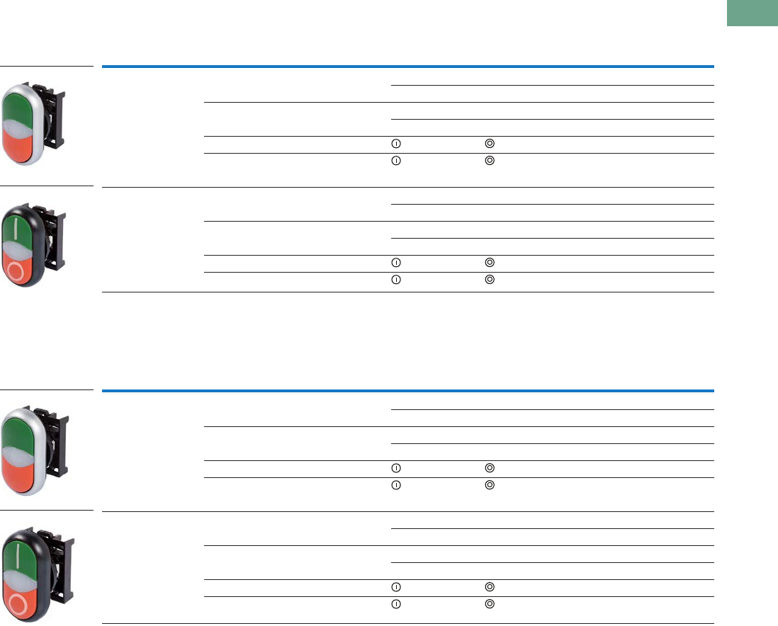
Logic Control Products CA08100001K—June 2012 www.eatoncanada.ca T37-85
37
37
37
37
37
37
37
37
37
37
37
37
37
37
37
37
37
37
37
37
37
37
37
37
37
37
37
37
37
37
37.4
Pushbuttons and Indicating Lights
22.5 mm Modular Pushbuttons—M22
Double Pushbuttons, Flush Top Pushbuttons and Centre Light, Momentary
Operators Only
Double Pushbuttons, Flush Top Pushbutton and Centre Light, Extended Bottom Pushbutton, Momentary
Operators Only
Notes
Includes contact block mounting adapter.
When ordering, specify inscription per catalogue number suffix from the Symbols Library
(see
Pages
V7-T37-114 to V7-T37-121
)
into the Order Notes.
For example, M22-DDLM-GR-ETCH; Order Notes: Mark with symbol X91, Line item #_.
Colour Inscription
Catalogue NumberBezel Top Bottom Top Bottom
Silver Green Red — — M22-DDLF-GR
Custom Custom M22-DDLF-GR-ETCH
White Black — — M22-DDLF-WS
Custom Custom M22-DDLF-WS-ETCH
Green Red M22-DDLF-GR-X1-X0
White Black M22-DDLF-WS-X1-X0
Black Green Red — — M22S-DDLF-GR
Custom Custom M22S-DDLF-GR-ETCH
White Black — — M22S-DDLF-WS
Custom Custom M22S-DDLF-WS-ETCH
Green Red M22S-DDLF-GR-X1-X0
White Black M22S-DDLF-WS-X1-X0
Colour Inscription
Catalogue NumberBezel Top Bottom Top Bottom
Silver Green Red — — M22-DDLM-GR
Custom Custom M22-DDLM-GR-ETCH
White Black — — M22-DDLM-WS
Custom Custom M22-DDLM-WS-ETCH
Green Red M22-DDLM-GR-X1-X0
White Black M22-DDLM-WS-X1-X0
Black Green Red — — M22S-DDLM-GR
Custom Custom M22S-DDLM-GR-ETCH
White Black — — M22S-DDLM-WS
Custom Custom M22S-DDLM-WS-ETCH
Green Red M22S-DDLM-GR-X1-X0
White Black M22S-DDLM-WS-X1-X0
M22-DDLF-GR
M22S-DDLF-GR-X1-X0
M22-DDLM-GR
M22-DDLM-GR-X1-X0
Tab37book.fm Page 85 Tuesday, July 3, 2012 10:46 PM
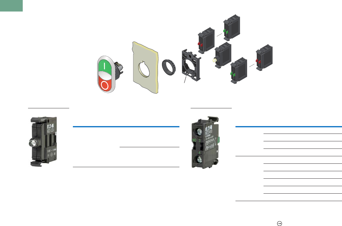
T37-86 Logic Control Products CA08100001K—June 2012 www.eatoncanada.ca
37
37
37
37
37
37
37
37
37
37
37
37
37
37
37
37
37
37
37
37
37
37
37
37
37
37
37
37
37
37
37.4
Pushbuttons and Indicating Lights
22.5 mm Modular Pushbuttons—M22
Double Pushbuttons
Light Units Contact Blocks
Notes
For complete listing of available light units and contact blocks, see Accessories,
Pages V7-T37-96 to V7-T37-101.
All NC contact blocks are positively driven contact.
max. 5mm
thickness
Note: Included
with operator.
Terminal
Type
LED
Colour
Light Unit
Voltage Catalogue Number
Screw White 12–30
Vac/Vdc
M22-LED-W
85–264
Vac
M22-LED230-W
M22-LED-W
Terminal
Type
Contact
Configuration Catalogue Number
Screw NO M22-K10
NO, early-make M22-K10P
NC M22-K01
NC, late-break M22-K01D
Spring-cage NO M22-CK10
NC M22-CK01
NC, late-break M22-CK01D
2NO M22-CK20
2NC M22-CK02
NO-NC M22-CK11
M22-K10
Tab37book.fm Page 86 Tuesday, July 3, 2012 10:46 PM
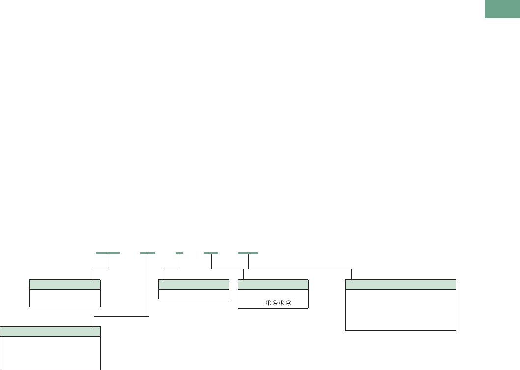
Logic Control Products CA08100001K—June 2012 www.eatoncanada.ca T37-87
37
37
37
37
37
37
37
37
37
37
37
37
37
37
37
37
37
37
37
37
37
37
37
37
37
37
37
37
37
37
37.4
Pushbuttons and Indicating Lights
22.5 mm Modular Pushbuttons—M22
Four-Way Pushbuttons
Product Description
Eaton’s M22 four-way push-
button is a truly unique
offering. A four-way
pushbutton offers four
different buttons mounted
in a single 22 mm hole. This
is ideal not only for an
application with limited
space, but also directional
applications (when ordered
with the four arrow engraving
option). Another unique
option is the interlocked
version, which prevents two
opposite buttons from being
actuated at the same time.
Features
●Four buttons in one
operator allows for
increased functionality in
limited space
●Optional interlocking
option, which prevents two
buttons from being
actuated at the same time
●Customizable laser
engraving on all buttons for
directional or other
applications
●Capable of communicating
via ASi protocol with ASi
adapter modules
Protection Type
●IP66
Catalogue Number Selection
Catalogue Number Selection is for illustrative purposes only and not to be used to create new catalogue numbers.
Four-Way Pushbuttons
Bezel
M22 = Silver
M22S = Black
M22 –D4–S–X7– K01
Operator Type
D4 = Four-way pushbutton,
momentary, non-interlocked
DI4 = Four-way pushbutton,
momentary, interlocked
When ordering, specify
inscription per catalogue
number suffix from the Symbols
Library (see Pages V7-T37-114
to V7-T37-121) into the Order
Notes.
For example, M22-D4-S-ETCH;
Order Notes: Mark with symbol
X91, Line item #_.
Inscription
ETCH = Custom
X7 =
Contact Blocks
K10 = 1NO
K01 = 1NC
K20 = 2NO
K02 = 2NC
K11 = 1NO-1NC
K30 =3NO
K03 =3NC
K21 =2NO-1NC
K12 =1NO-2NC
Button Colour
S = Black
Tab37book.fm Page 87 Tuesday, July 3, 2012 10:46 PM
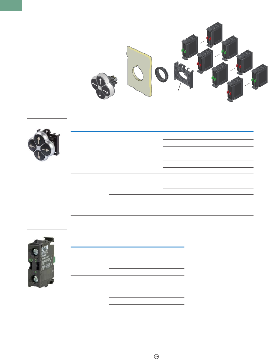
T37-88 Logic Control Products CA08100001K—June 2012 www.eatoncanada.ca
37
37
37
37
37
37
37
37
37
37
37
37
37
37
37
37
37
37
37
37
37
37
37
37
37
37
37
37
37
37
37.4
Pushbuttons and Indicating Lights
22.5 mm Modular Pushbuttons—M22
Product Selection
Four-Way Pushbuttons, Momentary
Components
Operators Only
Contact Blocks
Notes
Includes contact block mounting adapter.
For complete listing of available contact blocks, see Accessories, Pages
V7-T37-96 to V7-T37-101.
When ordering, specify inscription per catalogue number suffix from the Symbols Library
(see
Pages
V7-T37-114 to V7-T37-121
)
into the Order Notes.
For example, M22-D4-S-ETCH; Order Notes: Mark with symbol X91, Line item #_.
All NC contact blocks are positively driven contact.
Type Bezel Colour Inscription Catalogue Number
Non-interlocked Silver Black — M22-D4-S
Custom M22-D4-S-ETCH
Directional arrows M22-D4-S-X7
Black Black — M22S-D4-S
Custom M22S-D4-S-ETCH
Directional arrows M22S-D4-S-X7
Interlocked Silver Black — M22-DI4-S
Custom M22-DI4-S-ETCH
Directional arrows M22-DI4-S-X7
Black Black — M22S-DI4-S
Custom M22S-DI4-S-ETCH
Directional arrows M22S-DI4-S-X7
Terminal
Type
Contact
Configuration Catalogue Number
Screw NO M22-K10
NO, early-make M22-K10P
NC M22-K01
NC, late-break M22-K01D
Spring-cage NO M22-CK10
NC M22-CK01
NC, late-break M22-CK01D
2NO M22-CK20
2NC M22-CK02
NO-NC M22-CK11
max. 5mm
thickness
Note: Included
with operator.
M22-D4-S-X7
M22-K10
Tab37book.fm Page 88 Tuesday, July 3, 2012 10:46 PM

Logic Control Products CA08100001K—June 2012 www.eatoncanada.ca T37-89
37
37
37
37
37
37
37
37
37
37
37
37
37
37
37
37
37
37
37
37
37
37
37
37
37
37
37
37
37
37
37.4
Pushbuttons and Indicating Lights
22.5 mm Modular Pushbuttons—M22
Joysticks
Product Description
Eaton’s M22 joystick line
comes in a wide variety of
options. From vertical and
horizontal two-position
switches to the maintained
four-position, these operators
fit a variety of applications. An
additional option, two switch
points, allows for eight
isolated circuits to be
actuated individually on a
single operator.
Features
●Available in four-position
and two-position
●Two switch point option
allows for two contacts in
each direction (up to eight
total contacts in one
operator)
●Capable of communicating
via ASi protocol with ASi
adapter modules
Protection Type
●IP66
Product Selection
Joysticks
Components
Operators
Note
Includes contact block mounting adapter.
Bezel
Number of
Directions
Switching
Position Catalogue Number
Silver Two-position horizontal Momentary M22-WJ2H
Two switch points M22-WJ2H-2P
Two-position horizontal Maintained M22-WRJ2H
Two-position vertical Momentary M22-WJ2V
Two switch points M22-WJ2V-2P
Two-position vertical Maintained M22-WRJ2V
Four-position Momentary M22-WJ4
Two switch points M22-WJ4-2P
Four-position Maintained M22-WRJ4
Black Two-position horizontal Momentary M22S-WJ2H
Two switch points M22S-WJ2H-2P
Two-position horizontal Maintained M22S-WRJ2H
Two-position vertical Momentary M22S-WJ2V
Two switch points M22S-WJ2V-2P
Two-position vertical Maintained M22S-WRJ2V
Four-position Momentary M22S-WJ4
Two switch points M22S-WJ4-2P
Four-position Maintained M22S-WRJ4
M22-WJ2H
Tab37book.fm Page 89 Tuesday, July 3, 2012 10:46 PM
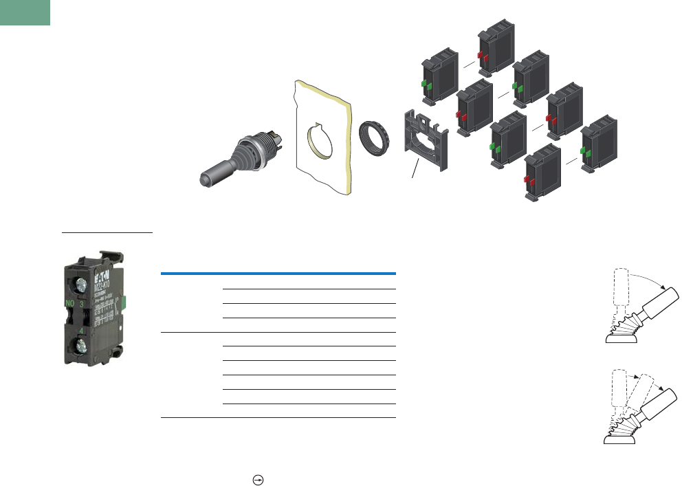
T37-90 Logic Control Products CA08100001K—June 2012 www.eatoncanada.ca
37
37
37
37
37
37
37
37
37
37
37
37
37
37
37
37
37
37
37
37
37
37
37
37
37
37
37
37
37
37
37.4
Pushbuttons and Indicating Lights
22.5 mm Modular Pushbuttons—M22
Joysticks
Contact Blocks
Notes
Includes contact block mounting adapter.
For complete listing of available contact blocks, see Accessories,
Pages V7-T37-96 to V7-T37-101.
All NC contact blocks are positively driven contact.
Joystick with Double Contact
The joystick allows the control
of up to four directions of
movement on machines.
Different variants of the
joystick have two/four-
positions and other variants
have two settings for each
position. This allows, for
example, two-speed settings
for each direction. For this
application, a standard
normally open contact and an
early-make contact are fitted
in series. Momentary contact
and latching contact versions
are available.
max. 5mm
thickness
Note: Included
with operator.
Terminal
Type
Contact
Configuration Catalogue Number
Screw NO M22-K10
NO, early-make M22-K10P
NC M22-K01
NC, late-break M22-K01D
Spring-cage NO M22-CK10
NC M22-CK01
NC, late-break M22-CK01D
2NO M22-CK20
2NC M22-CK02
NO-NC M22-CK11
M22-K10
0
1
01
2
Tab37book.fm Page 90 Tuesday, July 3, 2012 10:46 PM

Logic Control Products CA08100001K—June 2012 www.eatoncanada.ca T37-91
37
37
37
37
37
37
37
37
37
37
37
37
37
37
37
37
37
37
37
37
37
37
37
37
37
37
37
37
37
37
37.4
Pushbuttons and Indicating Lights
22.5 mm Modular Pushbuttons—M22
Potentiometers
Product Description
Eaton’s M22 potentiometers allow for a ready to use operator in
a conveniently sized package. M22 potentiometers include the
resistive element, instead of just a knob, and a built in legend
surrounding the knob. The slim design, with integrated contacts
and the range of resistances available, allows for a quick install.
Features
●Scale markings on the knob allows the operator to be used
without an additional legend plate
●Oversized knob option available
●Slim design allows for space saving and simple wiring and
installation
Protection Type
●IP66
●NEMA 4X, 13
Product Selection
Potentiometers
Complete Devices
Acoustic Devices
Product Description
Eaton’s M22 acoustic devices are a simple and aesthetic way to
add a buzzer or indicator to any application. Fitting in the same
22 mm hole, these devices can be ordered in continuous or
pulsed tone and with or without the IP40 enclosure.
Features
●Continuous or pulsed tone available
●83dB/10 cm decibel rating
●Slim design allows for space saving and simple wiring and
installation
Protection Type
●IP40
●NEMA 12
Product Selection
Acoustic Devices
Complete Devices
Buzzers
Bezel
Resistance
Rk Catalogue Number
Silver 1 M22-R1K
4.7 M22-R4K7
10 M22-R10K
47 M22-R47K
100 M22-R100K
470 M22-R470K
Black 1 M22S-R1K
4.7 M22S-R4K7
10 M22S-R10K
47 M22S-R47K
100 M22S-R100K
470 M22S-R470K
Oversized Knob
Silver 1 M22-R1K-RH
4.7 M22-R4K7-RH
10 M22-R10K-RH
47 M22-R47K-RH
100 M22-R100K-RH
470 M22-R470K-RH
Black 1 M22S-R1K-RH
4.7 M22S-R4K7-RH
10 M22S-R10K-RH
47 M22S-R47K-RH
100 M22S-R100K-RH
470 M22S-R470K-RH
M22-R10K
Description
Decibel
Rating Catalogue Number
Indicator with buzzer,
black continuous tone,
24 Vac/Vdc
83 dB/
10 cm
M22-AMC-XAM
Indicator with buzzer,
black pulsed tone,
24 Vdc
83 dB/
10 cm
M22-AMC-XAMP
Description
Decibel
Rating Catalogue Number
Indicator without
buzzer, black
83 dB/
10 cm
M22-AMC
Buzzer only,
continuous tone,
24 Vac/Vdc
83 dB/
10 cm
M22-XAM
Buzzer only, pulsed
tone, 24 Vdc
83 dB/
10 cm
M22-XAMP
M22-AMC-XAM
M22-XAM
Tab37book.fm Page 91 Tuesday, July 3, 2012 10:46 PM
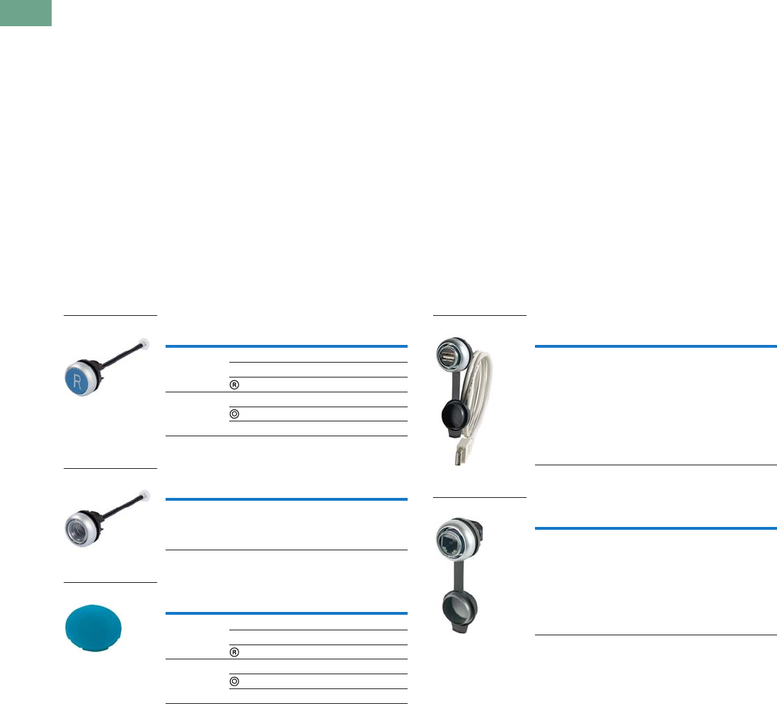
T37-92 Logic Control Products CA08100001K—June 2012 www.eatoncanada.ca
37
37
37
37
37
37
37
37
37
37
37
37
37
37
37
37
37
37
37
37
37
37
37
37
37
37
37
37
37
37
37.4
Pushbuttons and Indicating Lights
22.5 mm Modular Pushbuttons—M22
Through-the-Door Operators
Product Description
Eaton’s M22 through-the-door operators use the same familiar
flush pushbutton look with the addition of a cut-to-length rod
that allows for a simple reset operator.
Features
●Customizable laser engraving on all buttons
●More than five million mechanical operations
●Pushrod can be cut to length
Protection Type
●IP67, IP69K
●NEMA 4X, 13
Product Selection
Through-the-Door Operators
Complete Devices
Buttonless Operator
Button Plates
Bulkhead Interfaces
Product Description
Eaton’s M22 bulkhead interfaces are another unique offering in
the M22 line. This device allows for a secure connection to any
USB or RJ45 connected device within an enclosure or panel.
With an IP66 rating when closed, these devices are not only
convenient, but robust and reliable.
Features
●Convenient and safe way to make a data connection to inside
of the panel without opening the panel door
Protection Type
●IP66 when closed, IP20 when connected
Product Selection
Bulkhead Interfaces
USB Socket
RJ45 Socket
Notes
The pushrod is 3.24 in long and can be cut to length.
Any combination of plate colour and inscription is available.
Minimum order quantity of (10).
USB interface is complete with 2-ft-long USB cable.
UL and CSA pending.
RJ45 interface is an eight-wire connector.
Colour Inscription Catalogue Number
Blue — M22-DZ-B
RESET M22-DZ-B-GB14
M22-DZ-B-X6
Red — M22-DZ-R
M22-DZ-R-X0
STOP M22-DZ-R-GB0
Bezel Catalogue Number
Silver M22-DZ-X
Colour Inscription Catalogue Number
Blue — M22-XD-B
RESET M22-XD-B-GB14
M22-XD-B-X6
Red — M22-XD-R
M22-XD-R-X0
STOP M22-XD-R-GB0
M22-DZ-B-X6
M22-DZ-X
M22-XD-B
Description Catalogue Number
Used for USB connection
USB 2.0 Type A plug
IP65 when closed
IP20 when connected
M22-USB-SA
Description Catalogue Number
Used for RJ45 Ethernet
connection IP65 when
closed IP20 when connected
M22-RJ45-SA
M22-USB-SA
M22-RJ45-SA
Tab37book.fm Page 92 Tuesday, July 3, 2012 10:46 PM

Logic Control Products CA08100001K—June 2012 www.eatoncanada.ca T37-93
37
37
37
37
37
37
37
37
37
37
37
37
37
37
37
37
37
37
37
37
37
37
37
37
37
37
37
37
37
37
37.4
Pushbuttons and Indicating Lights
22.5 mm Modular Pushbuttons—M22
ASi Adapter Modules
Product Description
Eaton’s M22 ASi adapter modules add functionality to every
operator in the M22 line. These devices can be connected to any
operator that uses contact blocks or LED units. The simple snap-
on design allows for a quick integration of an entire application of
operators to a communicating network.
Features
●Allows compatible operators to communicate on an ASi
network
●Not only can the status of a contact block be read, but LEDs
can be illuminated by an ASi adapter
●ASi adapters simply clip on to the back of the contact blocks
and LEDs
●Insulation displacement connectors allow for installation of
adapters without any tools
●Two integrated LEDs indicate status of communications
Protection Type
●IP20
Product Selection
ASi Adapter Modules
Complete Devices
Description Catalogue Number
ASi adapter module M22-ASI
ASi adapter module for
base mounting
M22-ASI-C
ASi adapter module for
E-stop
M22-ASI-S
ASi adapter module for
E-stop base mounting
M22-ASI-CS
M22-ASI
Tab37book.fm Page 93 Tuesday, July 3, 2012 10:46 PM
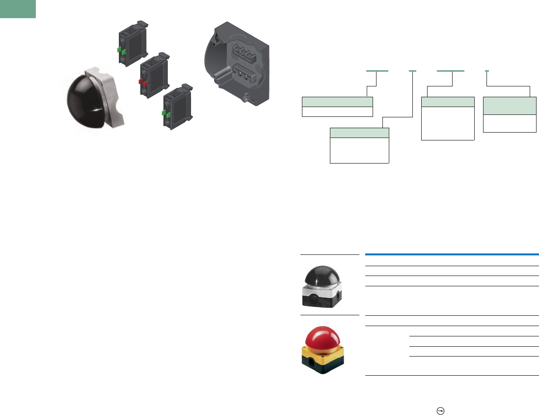
T37-94 Logic Control Products CA08100001K—June 2012 www.eatoncanada.ca
37
37
37
37
37
37
37
37
37
37
37
37
37
37
37
37
37
37
37
37
37
37
37
37
37
37
37
37
37
37
37.4
Pushbuttons and Indicating Lights
22.5 mm Modular Pushbuttons—M22
Palm Switches
Product Description
Eaton’s M22 palm switches are an oversized button that mount
directly to an enclosure base. This allows for a standalone button
that can be mounted anywhere. The enclosure uses base-
mounted contact blocks, which allows for quick wiring and
mounting. The palm switches come in momentary or maintained
versions. As with other M22 operators, the palm switches are
available as complete devices, including the enclosure and
contact blocks or as modular components.
Features
●Oversized operator in black, red and yellow colour options
●Button integrated directly into an enclosure
●Base mounting contact blocks allow for simple wiring and
installation
●More than one million mechanical operations on momentary
and 100,000 on maintained operators
Protection Type
●IP67, IP69K
●NEMA 4X, 13
Catalogue Number Selection
Catalogue Number Selection is for illustrative purposes only and
not to be used to create new catalogue numbers.
Palm Switches, Type 4X/13 Enclosure
Product Selection
Complete Devices
Operator, Base and Contact Blocks
Notes
For complete listing of available contact blocks, see Accessories,
Pages V7-T37-96 to V7-T37-101.
All NC contact blocks are positively driven contact.
Button
Colour
Contact Block
Configuration Catalogue Number
Momentary
Black 1NO-1NC FAK-S-KC11-I
Red 1NO-1NC FAK-R-KC11-I
Yellow 1NO-1NC FAK-Y-KC11-I
Maintained
Red NC FAK-R-V-KC01-IY
2NC FAK-R-V-KC02-IY
1NO-2NC FAK-R-V-KC12-IY
1NO-1NC FAK-R-V-KC11-IY
Operator Type
FAK = Palm switch
Contact Blocks
KC10 =NO
KC01 =NC
CKC10 =NO
CKC01 =NC
Operator Colour
S = Black
R = Red
Y = Yellow
Enclosure
Top Colour
I = Gray
IY = Yellow
FAK –S– KC10 –I
FAK-S-KC11-I
FAK-R-V-KC01-IY
Tab37book.fm Page 94 Tuesday, July 3, 2012 10:46 PM

Logic Control Products CA08100001K—June 2012 www.eatoncanada.ca T37-95
37
37
37
37
37
37
37
37
37
37
37
37
37
37
37
37
37
37
37
37
37
37
37
37
37
37
37
37
37
37
37.4
Pushbuttons and Indicating Lights
22.5 mm Modular Pushbuttons—M22
Components
Operators Only
Palm Switch Enclosure Base
Contact Blocks
Notes
For complete listing of available contact blocks, see Accessories, Pages
V7-T37-96 to V7-T37-101.
All NC contact blocks are positively driven contact.
Type Button Colour Catalogue Number
Momentary Black FAK-S
Red FAK-R
Yellow FAK-Y
Maintained Red FAK-R-V-Y
Catalogue Number
FAK-IU
Terminal
Type
Contact
Configuration Catalogue Number
Screw NO M22-KC10
NC M22-KC01
Spring-cage NO M22-CKC10
NC M22-CKC01
FAK-S
FAK-IU
M22-KC10
Tab37book.fm Page 95 Tuesday, July 3, 2012 10:46 PM

T37-96 Logic Control Products CA08100001K—June 2012 www.eatoncanada.ca
37
37
37
37
37
37
37
37
37
37
37
37
37
37
37
37
37
37
37
37
37
37
37
37
37
37
37
37
37
37
37.4
Pushbuttons and Indicating Lights
22.5 mm Modular Pushbuttons—M22
Accessories
Button Plates
Note
Refer to the Symbols Library,
(see
Pages
V7-T37-114 to V7-T37-121
)
, for symbol image.
Colour Inscription
Catalogue Number
Flush Pushbutton
Catalogue Number
Extended Pushbutton
Catalogue Number
Mushroom Head Button
Black — M22-XD-S M22-XDH-S M22-XDP-S
White — M22-XD-W M22-XDH-W M22-XDP-W
Red — M22-XD-R M22-XDH-R M22-XDP-R
Green — M22-XD-G M22-XDH-G M22-XDP-G
Yellow — M22-XD-Y M22-XDH-Y M22-XDP-Y
Blue — M22-XD-B M22-XDH-B —
Black, white, red, green, yellow, blue — M22-XD-SWRGYB M22-XDH-SWRGYB —
Black, red, green — M22-XD-SRG M22-XDH-SRG —
Black Custom M22-XD-S-ETCH M22-XDH-S-ETCH M22-XDP-S-ETCH
White Custom M22-XD-W-ETCH M22-XDH-W-ETCH M22-XDP-W-ETCH
Red Custom M22-XD-R-ETCH M22-XDH-R-ETCH M22-XDP-R-ETCH
Green Custom M22-XD-G-ETCH M22-XDH-G-ETCH M22-XDP-G-ETCH
Yellow Custom M22-XD-Y-ETCH M22-XDH-Y-ETCH M22-XDP-Y-ETCH
Blue Custom M22-XD-B-ETCH M22-XDH-B-ETCH —
Black STOP M22-XD-S-GB0 M22-XDH-S-GB0 M22-XDP-S-GB0
Red STOP M22-XD-R-GB0 M22-XDH-R-GB0 M22-XDP-R-GB0
Black START M22-XD-S-GB1 M22-XDH-S-GB1 M22-XDP-S-GB1
White START M22-XD-W-GB1 M22-XDH-W-GB1 —
Green START M22-XD-G-GB1 M22-XDH-G-GB1 M22-XDP-G-GB1
Black CLOSE M22-XD-S-GB2 M22-XDH-S-GB2 —
Black UP M22-XD-S-GB3 M22-XDH-S-GB3 M22-XDP-S-GB3
Black DOWN M22-XD-S-GB4 M22-XDH-S-GB4 M22-XDP-S-GB4
Black OFF M22-XD-S-GB5 M22-XDH-S-GB5 M22-XDP-S-GB5
Red OFF M22-XD-R-GB5 M22-XDH-R-GB5 M22-XDP-R-GB5
Black ON M22-XD-S-GB6 M22-XDH-S-GB6 M22-XDP-S-GB6
Green ON M22-XD-G-GB6 M22-XDH-G-GB6 M22-XDP-G-GB6
Black TEST M22-XD-S-GB9 M22-XDH-S-GB9 —
Blue RESET M22-XD-B-GB14 M22-XDH-B-GB14 —
Black FORWARD M22-XD-S-GB15 M22-XDH-S-GB15 M22-XDP-S-GB15
Black REVERSE M22-XD-S-GB16 M22-XDH-S-GB16 M22-XDP-S-GB16
Black RAISE M22-XD-S-GB17 M22-XDH-S-GB17 —
Black LOWER M22-XD-S-GB18 M22-XDH-S-GB18 —
Black M22-XD-S-X0 M22-XDH-S-X0 M22-XDP-S-X0
Red M22-XD-R-X0 M22-XDH-R-X0 M22-XDP-R-X0
Green — — M22-XDP-G-X0
Black M22-XD-S-X1 M22-XDH-S-X1 M22-XDP-S-X1
White M22-XD-W-X1 M22-XDH-W-X1 —
Green M22-XD-G-X1 M22-XDH-G-X1 M22-XDP-G-X1
Black M22-XD-S-X2 M22-XDH-S-X2 —
Green M22-XD-G-X2 M22-XDH-G-X2 —
Black M22-XD-S-X4 M22-XDH-S-X4 M22-XDP-S-X4
Black M22-XD-S-X5 M22-XDH-S-X5 M22-XDP-S-X5
Blue M22-XD-B-X6 M22-XDH-B-X6 —
Black M22-XD-S-X7 M22-XDH-S-X7 M22-XDP-S-X7
Black M22-XD-S-X8 M22-XDH-S-X8 —
Black See below M22-XD-S-X9 M22-XDH-S-X9 —
Black See below M22-XD-S-X10 M22-XDH-S-X10 —
Black See below M22-XD-S-X11 M22-XDH-S-X11 —
Black See below M22-XD-S-X12 M22-XDH-S-X12 —
Black See below M22-XD-S-X13 M22-XDH-S-X13 —
Black See below M22-XD-S-X14 M22-XDH-S-X14 —
Black See below M22-XD-S-X15 M22-XDH-S-X15 —
Black See below M22-XD-S-X16 M22-XDH-S-X16 —
Black See below M22-XD-S-X17 M22-XDH-S-X17 —
M22-XDH-R
M22-XDP-G
M22-XD-S
Tab37book.fm Page 96 Tuesday, July 3, 2012 10:46 PM
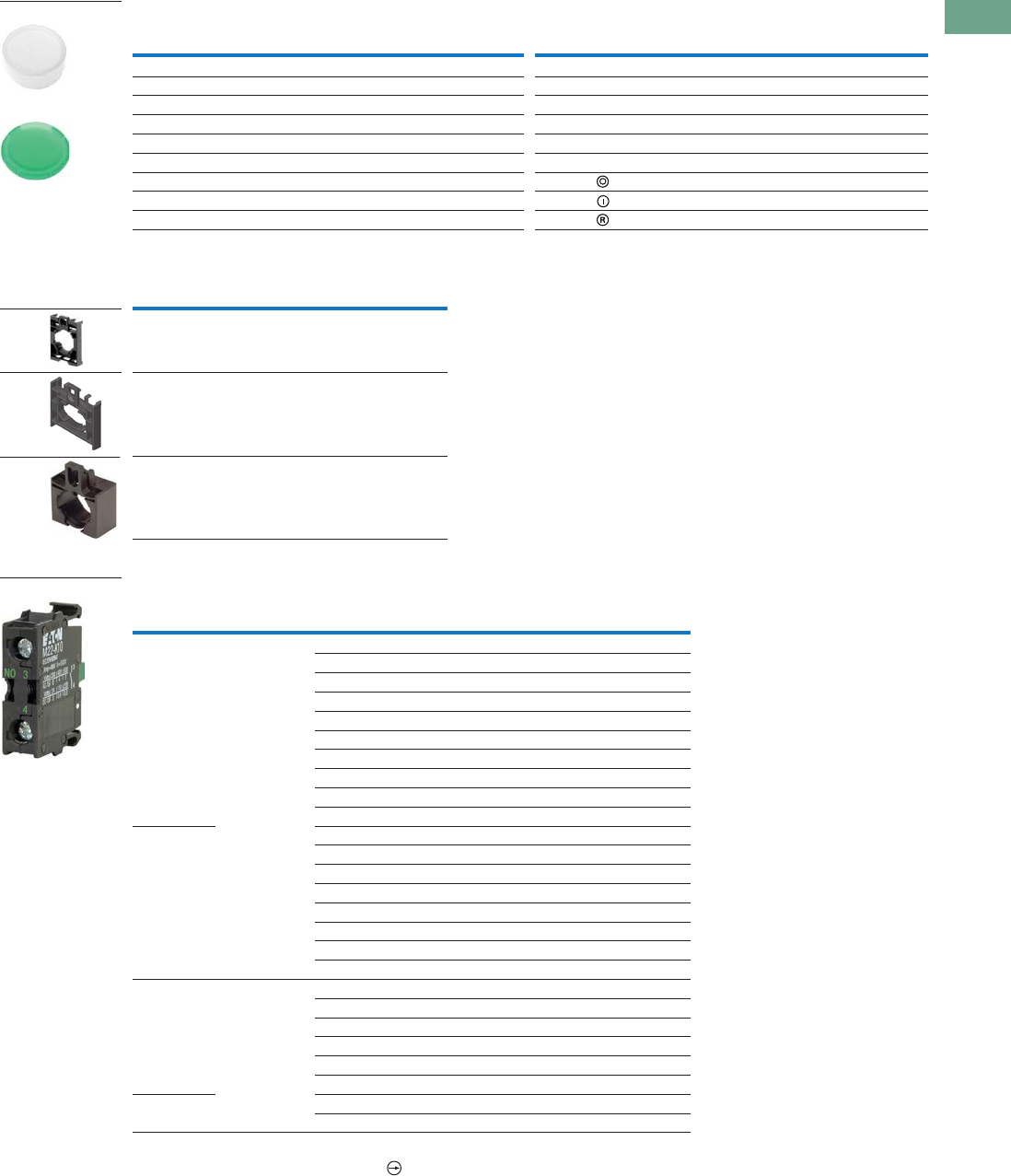
Logic Control Products CA08100001K—June 2012 www.eatoncanada.ca T37-97
37
37
37
37
37
37
37
37
37
37
37
37
37
37
37
37
37
37
37
37
37
37
37
37
37
37
37
37
37
37
37.4
Pushbuttons and Indicating Lights
22.5 mm Modular Pushbuttons—M22
Button Lenses
Mounting Adapters
Contact Blocks
Notes
All NC contact blocks are positively driven contact.
Not stackable.
Colour Inscription
Catalogue Number
Flush
Catalogue Number
Extended Colour Inscription
Catalogue Number
Flush
Catalogue Number
Extended
White — M22-XDL-W M22-XDLH-W Blue Custom M22-XDL-B-ETCH M22-XDLH-B-ETCH
Red — M22-XDL-R M22-XDLH-R Red STOP M22-XDL-R-GB0 M22-XDLH-R-GB0
Green — M22-XDL-G M22-XDLH-G Green START M22-XDL-G-GB1 M22-XDLH-G-GB1
Yellow — M22-XDL-Y M22-XDLH-Y Red OFF M22-XDL-R-GB5 M22-XDLH-R-GB5
Blue — M22-XDL-B M22-XDLH-B Green ON M22-XDL-G-GB6 M22-XDLH-G-GB6
White Custom M22-XDL-W-ETCH M22-XDLH-W-ETCH Blue RESET M22-XDL-B-GB14 M22-XDLH-B-GB14
Red Custom M22-XDL-R-ETCH M22-XDLH-R-ETCH Red M22-XDL-R-X0 M22-XDLH-R-X0
Green Custom M22-XDL-G-ETCH M22-XDLH-G-ETCH Green M22-XDL-G-X1 M22-XDLH-G-X1
Yellow Custom M22-XDL-Y-ETCH M22-XDLH-Y-ETCH Blue M22-XDL-B-X6 M22-XDLH-B-X6
Description Catalogue Number
Contact block mounting adapter M22-A
Contact block mounting adapter,
four-position (for use with
four-way pushbuttons, joysticks
and four-position selector switches
only).
M22-A4
Allows mounting of M22 pushbuttons
to LS-Titan limit switch bodies
(for the full LS-Titan catalogue section,
see CA08100010E/MSC).
M22-LS
Mounting
Location Terminal Type
Contact
Configuration
Package
Qty. Catalogue Number
Front Screw NO 1 M22-K10
NO 25 M22-K10-B25
NO 100 M22-K10-B100
NO, early-make 1 M22-K10P
NC 1 M22-K01
NC 25 M22-K01-B25
NC 100 M22-K01-B100
NC, late-break 1 M22-K01D
SMCB, NC 1 M22-K01SMC10
SMCB, 2NC 1 M22-K02SMC10
Base NO 1 M22-KC10
NO 25 M22-KC10-B25
NO 100 M22-KC10-B100
NC 1 M22-KC01
NC 25 M22-KC01-B25
NC 100 M22-KC01-B100
SMCB, NC 1 M22-KC01SMC10
SMCB, 2NC 1 M22-KC02SMC10
Front Spring-cage NO 1 M22-CK10
NC 1 M22-CK01
NC, late-break 1 M22-CK01D
2NO 1M22-CK20
2NC 1M22-CK02
NO-NC 1M22-CK11
Base NO 1 M22-CKC10
NC 1 M22-CKC01
M22-XDLH-W
M22-XDL-G
M22-A
M22-A4
M22-LS
M22-K10
Tab37book.fm Page 97 Tuesday, July 3, 2012 10:46 PM
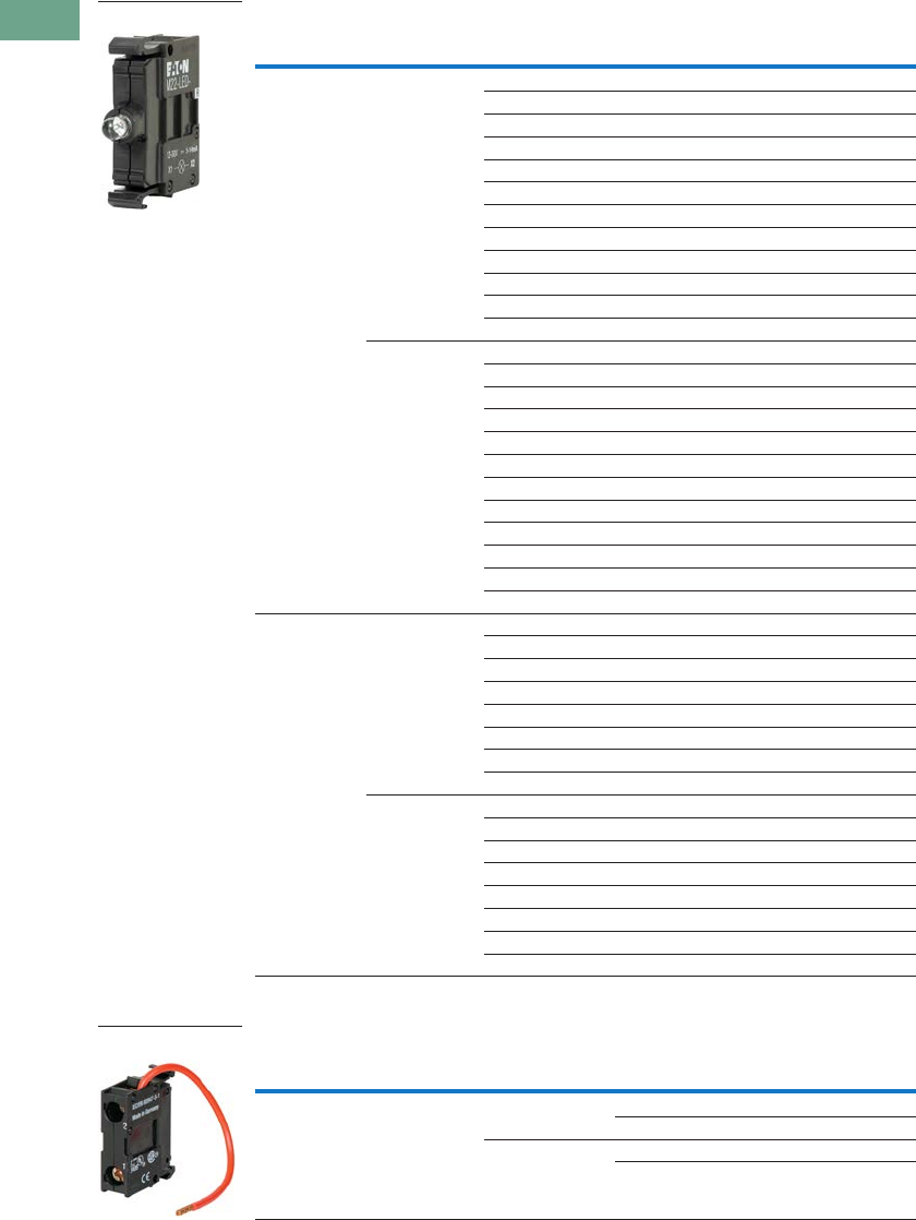
T37-98 Logic Control Products CA08100001K—June 2012 www.eatoncanada.ca
37
37
37
37
37
37
37
37
37
37
37
37
37
37
37
37
37
37
37
37
37
37
37
37
37
37
37
37
37
37
37.4
Pushbuttons and Indicating Lights
22.5 mm Modular Pushbuttons—M22
Light Units
LED Resistor and Test Elements
Notes
Resistor units to be used with 12–30V light units.
Refer to IL04716002E for use of resistor elements in series for higher DC voltage.
Terminal Type
Mounting
Location LED Colour Light Unit Voltage Catalogue Number
Screw Front White 12–30 Vac/Vdc M22-LED-W
Red M22-LED-R
Green M22-LED-G
Blue M22-LED-B
White 85–264 Vac M22-LED230-W
Red M22-LED230-R
Green M22-LED230-G
Blue M22-LED230-B
White 207–264 Vac M22-LED230H-W
Red M22-LED230H-R
Green M22-LED230H-G
Blue M22-LED230H-B
Base White 12–30 Vac/Vdc M22-LEDC-W
Red M22-LEDC-R
Green M22-LEDC-G
Blue M22-LEDC-B
White 85–264 Vac M22-LEDC230-W
Red M22-LEDC230-R
Green M22-LEDC230-G
Blue M22-LEDC230-B
White 207–264 Vac M22-LEDC230H-W
Red M22-LEDC230H-R
Green M22-LEDC230H-G
Blue M22-LEDC230H-B
Spring-cage Front White 12–30 Vac/Vdc M22-CLED-W
Red M22-CLED-R
Green M22-CLED-G
Blue M22-CLED-B
White 85–264 Vac M22-CLED230-W
Red M22-CLED230-R
Green M22-CLED230-G
Blue M22-CLED230-B
Base White 12–30 Vac/Vdc M22-CLEDC-W
Red M22-CLEDC-R
Green M22-CLEDC-G
Blue M22-CLEDC-B
White 85–264 Vac M22-CLEDC230-W
Red M22-CLEDC230-R
Green M22-CLEDC230-G
Blue M22-CLEDC230-B
Terminal Type
Mounting
Location
Element
Type Voltage Catalogue Number
Screw Front Resistor 42–60 Vac/Vdc M22-XLED60
220 Vdc M22-XLED220
Test 12–240 Vac/Vdc M22-XLED-T
85–264 Vac M22-XLED230-T
M22-LED-W
M22-XLED60
Tab37book.fm Page 98 Tuesday, July 3, 2012 10:46 PM

Logic Control Products CA08100001K—June 2012 www.eatoncanada.ca T37-99
37
37
37
37
37
37
37
37
37
37
37
37
37
37
37
37
37
37
37
37
37
37
37
37
37
37
37
37
37
37
37.4
Pushbuttons and Indicating Lights
22.5 mm Modular Pushbuttons—M22
Legend Plate Holders and Inserts, Pushbuttons and Double Pushbuttons
Notes
When ordering, specify inscription per catalogue number suffix from the Symbols Library
(see
Pages
V7-T37-114 to V7-T37-121
)
into the Order Notes.
For example, M22-XD-S-ETCH; Order Notes: Mark with symbol X91, Line item #_.
Legend plates are IP66 and NEMA 4X/13.
Example
To order a legend plate for a pushbutton with non-standard markings (FORWARD):
1. Select legend plate holder—M22S-ST-X.
2. Select legend plate insert—M22-XST-ETCH.
3. Select FORWARD from the Symbols Library, Pages V7-T37-114 to V7-T37-121, identified by GB15 suffix.
4. Indicate on the order form in the order notes—suffix GB15, line item # ___ .
Description Inscription Catalogue Number
Legend plate holder, without legend plate insert,
for pushbuttons
—M22S-ST-X
Legend plate holder, without legend plate insert,
for double pushbuttons
—M22S-STDD-X
Legend plate insert — M22-XST
Custom M22-XST-ETCH
STOP M22-XST-GB0
START M22-XST-GB1
OFF M22-XST-GB5
ON M22-XST-GB6
RUN M22-XST-GB7
FAULT M22-XST-GB8
OFF ON M22-XST-GB10
MAN. AUTO M22-XST-GB11
MAN. O AUTO M22-XST-GB12
HAND AUTO M22-XST-D11
HAND O AUTO M22-XST-D12
1M22-XST-X52
2M22-XST-X53
O I M22-XST-X88
O - I M22-XST-X89
I O II M22-XST-X93
M22S-ST-X
M22-XST-GB0
Tab37book.fm Page 99 Tuesday, July 3, 2012 10:46 PM
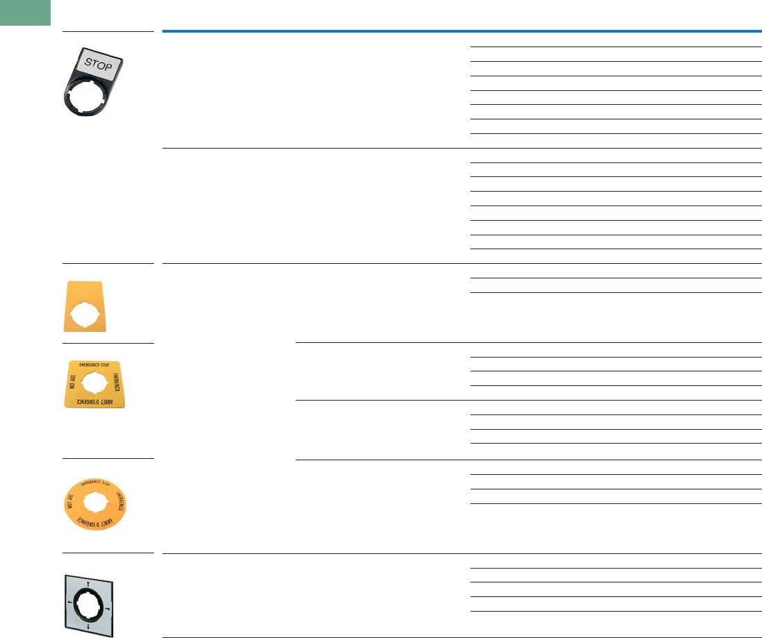
T37-100 Logic Control Products CA08100001K—June 2012 www.eatoncanada.ca
37
37
37
37
37
37
37
37
37
37
37
37
37
37
37
37
37
37
37
37
37
37
37
37
37
37
37
37
37
37
37.4
Pushbuttons and Indicating Lights
22.5 mm Modular Pushbuttons—M22
Legend Plates, Complete
Notes
When ordering, specify inscription per catalogue number suffix from the Symbols Library
(see
Pages
V7-T37-114 to V7-T37-121
)
into the Order Notes.
For example, M22-XD-S-ETCH; Order Notes: Mark with symbol X91, Line item #_.
Legend plates are IP66 and NEMA 4X/13.
Description Inscription Catalogue Number
For use with pushbuttons
and indicating lights
Legend plate holder with insert STOP M22S-ST-GB0
START M22S-ST-GB1
OFF M22S-ST-GB5
ON M22S-ST-GB6
RUN M22S-ST-GB7
FAULT M22S-ST-GB8
1M22S-ST-X52
2M22S-ST-X53
Selector switches — OFF ON M22S-ST-GB10
MAN. AUTO M22S-ST-GB11
MAN. O AUTO M22S-ST-GB12
HAND AUTO M22S-ST-D11
HAND O AUTO M22S-ST-D12
O I M22S-ST-X88
O - I M22S-ST-X89
I O II M22S-ST-X93
Emergency-stop operators Rectangular yellow legend plate — M22-XZK
Custom M22-XZK-ETCH
EMERGENCY-STOP M22-XZK-GB99
Square yellow legend plate — M22-XYK
—M22-XYK-ETCH
EMERGENCY-STOP four-language M22-XYK1
EMERGENCY-STOP (top and bottom) M22-XYK5
Round yellow legend plate, 90 mm — M22-XAK
Custom M22-XAK-ETCH
EMERGENCY-STOP four-language M22-XAK1
EMERGENCY-STOP (top and bottom) M22-XAK5
Round yellow legend plate, 60 mm — M22-XBK
Custom M22-XBK-ETCH
EMERGENCY-STOP four-language M22-XBK1
EMERGENCY-STOP (top and bottom) M22-XBK5
Four-way pushbutton,
joystick and four-position
selector switches
Silver square legend plate — M22-XCK
Custom M22-XCK-ETCH
Four directional arrows M22-XCK1
0-1-0-2-0-3-0-4 M22-XCK2
Two directional arrows M22-XCK3
M22S-ST-GB0
M22-XZK
M22-XBK1
M22-XCK1
M22-XYK
Tab37book.fm Page 100 Tuesday, July 3, 2012 10:46 PM
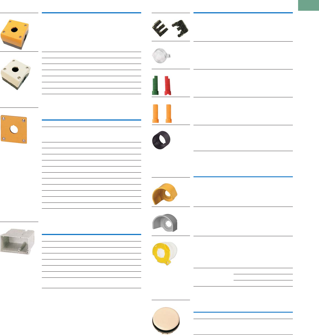
Logic Control Products CA08100001K—June 2012 www.eatoncanada.ca T37-101
37
37
37
37
37
37
37
37
37
37
37
37
37
37
37
37
37
37
37
37
37
37
37
37
37
37
37
37
37
37
37.4
Pushbuttons and Indicating Lights
22.5 mm Modular Pushbuttons—M22
Surface Mounting Enclosures
Flush Mounting Plates, Aluminum
Shrouds, Plastic
Selector Switch Accessories
Emergency Stop Operator Accessories
Blanking Plugs
Notes
Requires use of base mounted contact blocks.
Plunger needed to actuate centre-mounted contact blocks. Used for non-illuminated
three-position selector switches only.
Enables a keyed selector switch to be set to user-selected key withdraw position.
Description Catalogue Number
Yellow top, black base for
emergency-stop operators
M22-IY1-PG
One-element enclosure M22-I1-PG
Two-element enclosure M22-I2-PG
Three-element enclosure M22-I3-PG
Four-element enclosure M22-I4-PG
Six-element enclosure M22-I6-PG
M20 connecting screw M22-XI
M20 cord grip V-M20
Finish Rating Catalogue Number
One Hole
Yellow paint for
emergency-stop
operators
—M22-EY1
Gray anodized IP65 M22-E1
Two Holes
Gray anodized IP65 M22-E2
Three Holes
Gray anodized IP65 M22-E3
Four Holes
Gray anodized IP65 M22-E4
Five Holes
Gray anodized IP65 M22-E5
Six Holes
Anodized IP40 M22-E6
Description Rating Catalogue Number
One-element IP55 M22-H1
Two-element IP55 M22-H2
Three-element IP55 M22-H3
Four-element IP40 M22-H4
Five-element IP40 M22-H5
Six-element IP40 M22-H6
Mounting plate — M22-XE5
Plaster keys for
flush mounting
—M22-UPE
M22-IY1-PG
M22-IY-PG
M22-EY1
M22-H1
Description Catalogue Number
Plunger bridge M22-XW
Key cover M22-XWS
Key withdraw adapter M22-XC-R
Coding adapter M22-XC-Y
Guard ring M22-XGWK
Description Voltage Catalogue Number
Yellow guard ring — M22-XGPV
Gray guard ring — M22G-XGPV
Sealing shroud — M22-PL-PV
Illuminated ring 24 Vac/Vdc M22-XPV60-Y-24
120 Vac M22-XPV60-Y-120
230 Vac M22-XPV60-Y-230
Colour Catalogue Number
Gray M22-B
Black M22S-B
M22-XC-Y
M22-XWS
M22-XC-R
M22-XW
M22-XGWK
M22-XGPV
M22G-XGPV
M22-PL-PV
M22-B
Tab37book.fm Page 101 Tuesday, July 3, 2012 10:46 PM
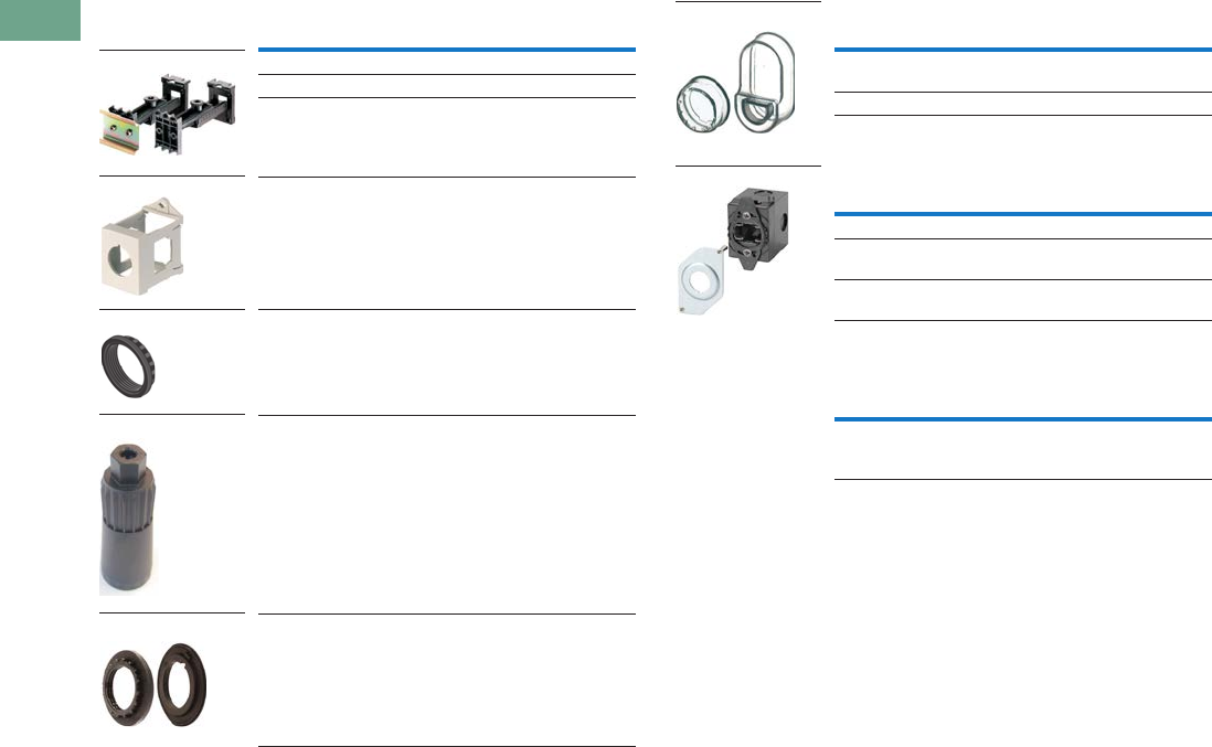
T37-102 Logic Control Products CA08100001K—June 2012 www.eatoncanada.ca
37
37
37
37
37
37
37
37
37
37
37
37
37
37
37
37
37
37
37
37
37
37
37
37
37
37
37
37
37
37
37.4
Pushbuttons and Indicating Lights
22.5 mm Modular Pushbuttons—M22
Mounting Accessories Protective Diaphragm
Dust Covers
Kits
Description Catalogue Number
Telescopic clip with top-hat rail M22-TC
Telescopic clip M22-TA
Telescopic clip extension M22-TCV
DIN rail mounting adapter M22-IVS
Mounting ring M22-GR
Mounting ring tool M22-MS
Adapter ring set for
30 mm holes
M22S-R30
M22-TC and M22-TA
M22-IVS
M22-GR
M22-MS
M22S-R30
For Use with … Catalogue Number
Flush pushbuttons and
indicating lights
M22-T-D
Double pushbuttons M22-T-DD
Description Catalogue Number
Contact block dust cover M22-XKDP
Operator dust cover,
max three contact blocks
M22-ADC
Operator dust cover,
max four contact blocks
M22-ADC4
Description Catalogue Number
Includes one each: M22-XW,
M22-XC-R, M22-XC-Y, M22S-B,
M22-A, M22-XD-SWRGYB
M22-KT1
M22-T-D and
M22-T-DD
M22-ADC4
Tab37book.fm Page 102 Tuesday, July 3, 2012 10:46 PM
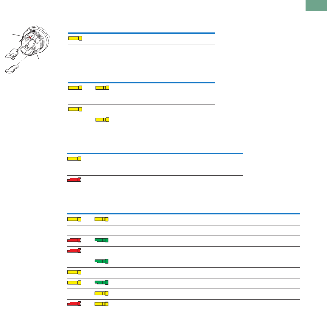
Logic Control Products CA08100001K—June 2012 www.eatoncanada.ca T37-103
37
37
37
37
37
37
37
37
37
37
37
37
37
37
37
37
37
37
37
37
37
37
37
37
37
37
37
37
37
37
37.4
Pushbuttons and Indicating Lights
22.5 mm Modular Pushbuttons—M22
Coding Adapter Guide
Selector Switches
Two-Position Selector Switch
Three-Position Selector Switch
Two-Position Key-Operated Selector Switch
Three-Position Key-Operated Selector Switch
Top (B) Bottom (A) Catalogue Number Function
M22(S)-W(L)(K) Momentary
M22(S)-WR(L)(K) Maintained
Top (B) Bottom (A) Catalogue Number
Function
Left Right
M22(S)-W(L)(K)3 Momentary Momentary
M22(S)-WR(L)(K)3 Maintained Maintained
M22(S)-WR(L)(K)3-1 Maintained Momentary
M22(S)-WR(L)(K)3-2 Momentary Maintained
Top (B) Bottom (A) Catalogue Number
Centre
Key Withdraw
Right
Function Key Withdraw
M22(S)-WS Yes Momentary No
M22(S)-WRS Yes Maintained Yes
M22(S)-WRS-A1 Yes Maintained No
Top (B) Bottom (A) Catalogue Number
Left
Function Key Withdraw
Centre
Key Withdraw
Right
Function Key Withdraw
M22(S)-WS3 Momentary No Yes Momentary No
M22(S)-WRS3 Maintained Yes Yes Maintained Yes
M22(S)-WRS3-A1 Maintained No Yes Maintained No
M22(S)-WRS3-A2 Maintained Yes Yes Maintained No
M22(S)-WRS3-A3 Maintained No Yes Maintained Yes
M22(S)-WRS3-A4 Maintained Yes Yes Momentary No
M22(S)-WRS3-A5 Maintained No Yes Momentary No
M22(S)-WRS3-A6 Momentary No Yes Maintained Yes
M22(S)-WRS3-A7 Momentary No Yes Maintained No
Top (B)
Bottom (A)
Tab37book.fm Page 103 Tuesday, July 3, 2012 10:46 PM

T37-104 Logic Control Products CA08100001K—June 2012 www.eatoncanada.ca
37
37
37
37
37
37
37
37
37
37
37
37
37
37
37
37
37
37
37
37
37
37
37
37
37
37
37
37
37
37
37.4
Pushbuttons and Indicating Lights
22.5 mm Modular Pushbuttons—M22
Technical Data and Specifications
Pushbuttons, Indicating Lights, Selector Switches and Emergency-Stop Operators
Description
Momentary
Pushbuttons
Maintained
Pushbuttons
Indicating Lights,
Buzzers and
Potentiometers
Emergency-Stop
Operators
Selector
Switches
Key-Operated
Operators
Double
Pushbuttons
General
Standards IEC/EN 60947
VDE 0660
UL #E29184
IEC/EN 60947
VDE 0660
UL #E29184
IEC/EN 60947
VDE 0660
UL #E29184
IEC/EN 60947
VDE 0660
UL #340491
IEC/EN 60947
VDE 0660
UL #E29184
IEC/EN 60947
VDE 0660
UL #E29184
IEC/EN 60947
VDE 0660
UL #E29184
Lifespan, mechanical Operations x 106>5 >1 — >0.1 >0.1 >0.1 >0.2
Operating frequency Operations/h >3600 >1800 — >600 >2000 >100 >3600
Actuating force n >5>5— >50 – — >5
Operating torque
(screw terminals)
Nm——— —>0.3 >0.5 —
Protection Type
IP IP67, IP69K IP67, IP69K Indicating lights: IP67, 69K
Buzzers: IP40
Potentiometers: IP66
IP67, IP69K IP66 IP66 IP66
UL type 4X, 13 4X, 13 Indicating lights: 4X/13
Buzzers: 12
Potentiometers: 4X/13
4X, 13 4X, 13 4X, 13 4X, 13
Climatic proofing Damp heat, constant, according to IEC 60068-2-78
Damp heat, cyclical to IEC 60068-2-30
Ambient temperature,
operating
˚F
(˚C)
–13 to 158
(–25 to 70)
–13 to 158
(–25 to 70)
–13 to 158
(–25 to 70)
–13 to 158
(–25 to 70)
–13 to 158
(–25 to 70)
–13 to 158
(–25 to 70)
–13 to 158
(–25 to 70)
Mounting position As required As required As required As required As required As required As required
Mechanical shock
resistance to
IEC 60068-2-27
shock duration 11 ms,
half-sinusoidal
g >30 >30 >30 >50 >30 >30 >30
Terminal Capacities
Solid AWG — — 20-16 ————
mm2— 0.5–1.5 — —
Stranded AWG — — 20-16 ————
mm2— 0.5–1.5 — —
Contacts
Rated impulse withstand
voltage
Uimp Vac — — 4000 ————
Rated insulation voltage UiV — — 2500 ————
Overvoltage category/
pollution degree
— — III/3 ————
Tab37book.fm Page 104 Tuesday, July 3, 2012 10:46 PM

Logic Control Products CA08100001K—June 2012 www.eatoncanada.ca T37-105
37
37
37
37
37
37
37
37
37
37
37
37
37
37
37
37
37
37
37
37
37
37
37
37
37
37
37
37
37
37
37.4
Pushbuttons and Indicating Lights
22.5 mm Modular Pushbuttons—M22
Contact Blocks and Light Units
Description
Contact
Blocks
LED
Light Units
General
Standards IEC/EN 60947
VDE 0660
UL #E29184
IEC/EN 60947
VDE 0660
UL #E29184
Lifespan, mechanical Operations x 106>5 —
Operating frequency Operations/h >3600 —
Actuating force n >5—
Operating torque (screw terminals) Nm <0.8 —
Protection Type
IP IP20 IP20
UL type — —
Climatic proofing Damp heat, constant, according to IEC 60068-2-78
Damp heat, cyclical to IEC 60068-2-30
Ambient temperature, operating ˚F (˚C) –13 to 158 (–25 to 70) –13 to 158 (–25 to 70)
Mounting position As required As required
Mechanical shock resistance to
IEC 60068-2-27 shock duration
11 ms, half-sinusoidal
g >30 >30
Terminal Capacities
Solid AWG 18–14 18–14
mm20.75–2.5 0.75–2.5
Stranded AWG 20–14 20–14
mm20.5–2.5 0.5–2.5
Contacts
Rated impulse withstand voltage Uimp Vac 6000 6000
Rated insulation voltage UiV 500 500
Overvoltage category/
pollution degree
III/3 III/3
NEMA contact ratings A600, Q300 —
Current draw — 5–15 mA
Control Circuit Reliability
at 24 Vdc/5 mA HFFault probability <10-7, <1 fault in 107 operations —
at 5 Vdc/1 mA HFFault probability <5 x 10⁻⁶, <1 fault in 5 x 10⁶ operations —
Max. Short-Circuit Protective Device
Fuse gG/gL A 10 —
Switching Capacity
Rated Operational Current
AC-15
115V IeA6 —
230V IeA6 —
400V IeA4 —
500V IeA2 —
DC-13
24V IeA3 —
42V IeA 1.7 —
60V IeA 1.2 —
110V IeA 0.8 —
220V IeA 0.3 —
Lifespan, Electrical
AC-15
230V/0.5A Operations x 1061.6 —
230V/1.0A Operations x 1061—
230V/3.0A Operations x 1060.7 —
DV-13
12V/2.8A Operations x 1061.2 —
Contact Element Note: >200 Vac/60 Hz: –25/55˚C
Tab37book.fm Page 105 Tuesday, July 3, 2012 10:46 PM

T37-106 Logic Control Products CA08100001K—June 2012 www.eatoncanada.ca
37
37
37
37
37
37
37
37
37
37
37
37
37
37
37
37
37
37
37
37
37
37
37
37
37
37
37
37
37
37
37.4
Pushbuttons and Indicating Lights
22.5 mm Modular Pushbuttons—M22
Palm Switches
ASi Adapter Modules
Description Momentary Maintained FAK-R-V-KC11-I
General
Standards IEC/EN 60947
VDE 0660
IEC/EN 60947
VDE 0660
IEC/EN 60947
VDE 0660
Lifespan, mechanical Operations x 106>1 >0.1 >0.1
Operating frequency Operations/h >3600 >600 >600
Actuating force n 20–40 40–60 15–25
Operating torque Nm — — —
Degree of protection, IEC/EN 60529 IP IP67, IP69K IP67, IP69K IP65
UL Type 4X, 13 4X, 13 4X, 13
Climatic proofing Damp heat, constant, to IEC 60068-2-78
Damp heat, cyclic, to IEC 60068-2-30
Ambient temperature, operating ˚F (˚C) –73 to 104 (–25 to 40) –73 to 104 (–25 to 40) –73 to 104 (–25 to 40)
Mounting position As required
Mechanical shock resistance to
IEC 60068-2-27
shock duration 11 ms, half-sinusoidal
g >15 >15 >15
Description M22-ASI M22-ASI-C
General
Standards IEC/EN 60947,
DIN EN 50295
IEC/EN 60947,
DIN EN 50295
Radio interference suppression EN 55011,
EN 55022
EN 55011,
EN 55022
Limit value class — —
Protection type IP20 IP00
Climatic proofing Damp heat, constant, to IEC 60068-2-78, cyclical, to IEC 60068-2-30
Ambient temperature, operating ˚F (˚C) –13 to 131 (–25 to 55) –13 to 131 (–25 to 55)
Shock resistance shock duration 11 ms g >30 >30
Vibration to IEC 60068-2-27
(amplitude 1 mm)
Hz — —
Dimensions mm — —
Weight kg — —
Mounting Front mounting Front mounting
Mounting position As required As required
Power Supply
Rated voltage to AS-interface
specification
Vdc 26.5–31.6 26.5–31.6
Connection technique Yellow plug-in terminal as insulation
piercing terminal
Two cables onboard
Power supply Completely from the AS-interface cable
Addressing Via connection to AS-interface cable
Total power consumption of
the AS-interface
mA >40 >40
AS-interface — —
Rated operational current at full load mA — —
Rated operational current when idle
(no I, O set)
mA — —
Status LEDs POWER AS-interface cable:
green LED on the rear side of the element
ERROR AS-interface, AS-interface master
failure: red LED on the rear side of the element
POWER AS-interface cable:
green LED on the board
ERROR AS-interface, AS-interface master
failure: red LED on the board
Tab37book.fm Page 106 Tuesday, July 3, 2012 10:46 PM

Logic Control Products CA08100001K—June 2012 www.eatoncanada.ca T37-107
37
37
37
37
37
37
37
37
37
37
37
37
37
37
37
37
37
37
37
37
37
37
37
37
37
37
37
37
37
37
37.4
Pushbuttons and Indicating Lights
22.5 mm Modular Pushbuttons—M22
ASi-S Adapter Modules
Description M22-ASI-S M22-ASI-CS
Inputs
Inputs, protected against
short-circuit
Number Two (normally 22V/5 mA) Two (normally 22V/5 mA)
Voltage range Vdc — —
Rated current per input mA — —
High signal level V — —
Low signal mA — —
Length of connecting cables cm — —
Outputs
Outputs, protected against
short-circuit
Number One (normally 19V/8 mA) One (normally 19V/8 mA)
Voltage range Vdc — —
Max. Current Carrying Capacity
All outputs — —
three external outputs — —
Length of connecting cables cm — —
Profile S-3.A.E S-3.A.E
Specification 2.1 2.1
Addresses Number 62 62
Emergency-Stop Circuits
Connection of the AS-interface line Yellow plug terminal with insulation
piercing
Two cables on the circuit board
Power supply Complete from AS-interface,
cable 26.5–31.6 Vdc
Complete from AS-interface,
cable 26.5–31.6 Vdc
Fixing Front mounted Base mounted
Addressing Via AS-interface cable Via AS-interface cable
Max. total current A 45 mA 45 mA
Ambient temperature, operating ˚F (˚C) –13 to 131 (–25 to 55) –13 to 131 (–25 to 55)
Shock resistance 30g/11 ms as per IEC 60068-2-27 30g/11 ms as per IEC 60068-2-27
Protection type IP20 IP00
Climatic proofing Damp heat, constant, to IEC 60068-2-78,
cyclical, to IEC 60068-2-30
Damp heat, constant, to IEC 60068-2-78,
cyclical, to IEC 60068-2-30
Mounting position As required As required
Standards EN 50178
EN 50 295
EN 50178
EN 50 295
Inputs Two-channel input (22V/5 mA)
(moduled by code sequence)
(two break contact sets M22-K01)
Two-channel input (22V/5 mA)
(moduled by code sequence)
(two break contact sets M22-K01)
Outputs One output, typically 19V/8 mA,
short-circuit proof
One output, typically 19V/8 mA,
short-circuit proof
Status Displays
Power, AS-interface cable Green LED on the back Green LED on the back
AS-interface error,
AS-interface master failure
Red LED on the back Red LED on the back
Profile S-7.B.E S-7.B.E
Tab37book.fm Page 107 Tuesday, July 3, 2012 10:46 PM

T37-108 Logic Control Products CA08100001K—June 2012 www.eatoncanada.ca
37
37
37
37
37
37
37
37
37
37
37
37
37
37
37
37
37
37
37
37
37
37
37
37
37
37
37
37
37
37
37.4
Pushbuttons and Indicating Lights
22.5 mm Modular Pushbuttons—M22
Dimensions
Approximate Dimensions in Inches (mm)
Operators and Indicating Lights
Pushbuttons Selector Switches Operators
Key-Operated Selector Switches
Indicating Light
0.75 (19)
M22 x 0.06 (1.5)
0.39 (10)
Ø 1.17 (29.7)
Ø 1.16 (29.5)
0.04 (1)–0.24 (6)
1.17 (29.7)
0.39 (10) 0.65 (16.4)
M22…-D-_ M22…-DH-_
M22-DG(L)-_ M22…-DD-_
Ø1.17 (29.7)
0.65 (16.5) 0.52 (13.2)
2.15 (54.7)
M22-D, Base Mounted
>0.01 (0.3)
1.78 (45.3)
0.04 (1)
1.47 (37.2)
0.93 (23.7) 1.06 (26.9)
M22…-W-_ M22…-WL-_
1.88 (47.75)
Ø1.17 (29.7)
0.81 (20.6)
M22…-W(R)S-_
0.45 (11.5)
M22-L_
Tab37book.fm Page 108 Tuesday, July 3, 2012 10:46 PM
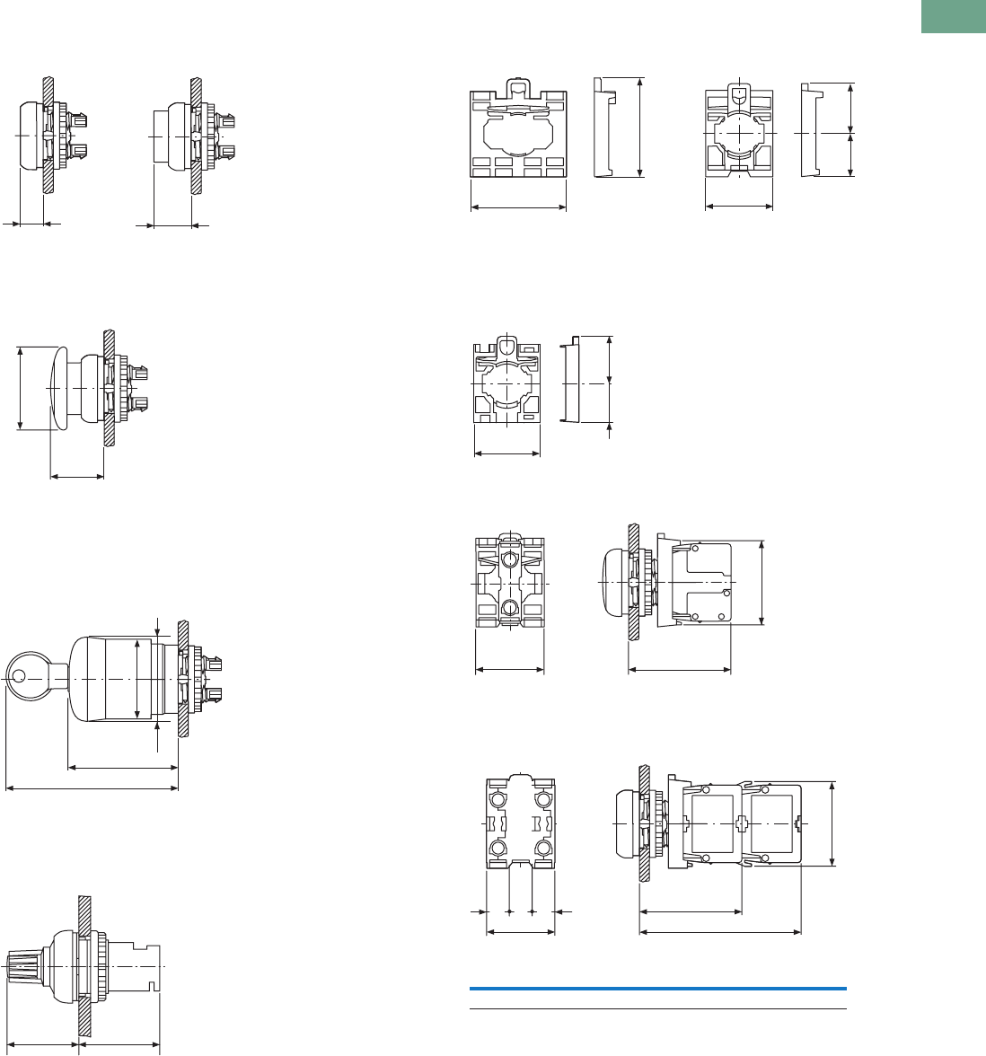
Logic Control Products CA08100001K—June 2012 www.eatoncanada.ca T37-109
37
37
37
37
37
37
37
37
37
37
37
37
37
37
37
37
37
37
37
37
37
37
37
37
37
37
37
37
37
37
37.4
Pushbuttons and Indicating Lights
22.5 mm Modular Pushbuttons—M22
Approximate Dimensions in Inches (mm)
Illuminated Pushbuttons
Mushroom Head Pushbutton
Emergency-Stop Operators
Potentiometer
Contact Block Mounting Adapter
Front Mounted Centering Adapter
Front Mounted Indicating Light
Pushbutton, Complete Devices
0.39 (10) 0.65 (16.4)
M22…-DL-_ M22…-DLH_
M22…-DP-_
Ø1.44 (36.5)
0.93 (23.6)
2.96 (75.1)
1.89 (47.9)
1.5 (38)
1.38 (35)
M22-PV_
M22S-PV_
M22-PVL_
M22-PVS_
1.15 (29.2) 1.3 (32.9)
M22(S)-R_
1.73 (44)
1.77 (45)
1.18 (30)
0.76 (19.3)
0.85 (21.5)
M22-A_ M22S-A…
1.18 (30) 0.7 (17.8)
0.84 (21.4)
M22-ZA
1.18 (30) 1.77 (45)
1.46 (37)
0.39 (10)
0.39 (10)
0.39 (10)
1.18 (30)
2.8 (71)
1.77 (45)
A
1 x M22-K_ 2 x M22-K_ 1 x M22-CK_ 2 x M22-CK_
A1.46 (37.2) 1.46 (37.2) 1.54 (39.0) 1.54 (39.0)
Tab37book.fm Page 109 Tuesday, July 3, 2012 10:46 PM
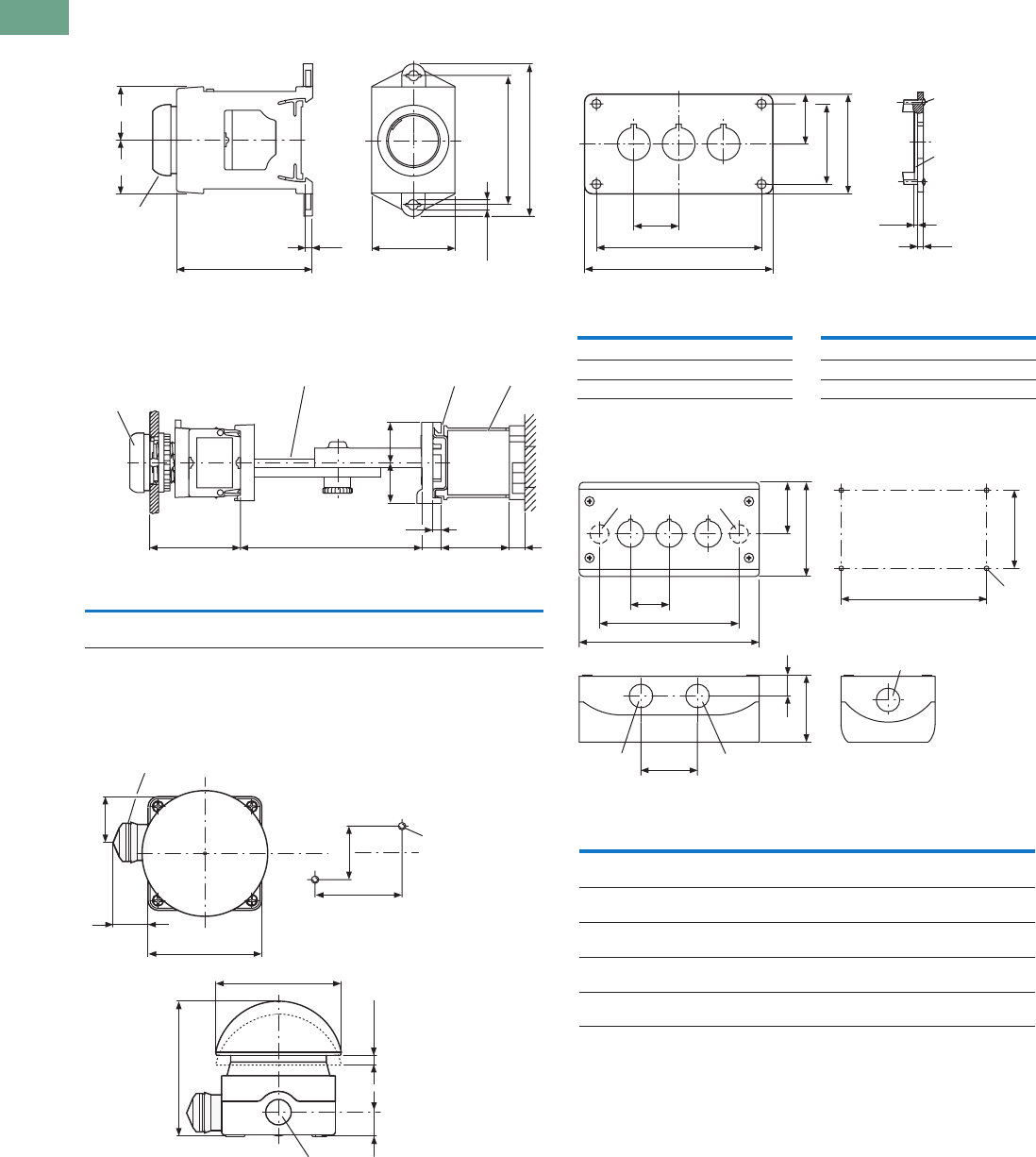
T37-110 Logic Control Products CA08100001K—June 2012 www.eatoncanada.ca
37
37
37
37
37
37
37
37
37
37
37
37
37
37
37
37
37
37
37
37
37
37
37
37
37
37
37
37
37
37
37.4
Pushbuttons and Indicating Lights
22.5 mm Modular Pushbuttons—M22
Approximate Dimensions in Inches (mm)
DIN-Rail Mounting Adapter
Pushbuttons and Indicating Lights with M22-TC Telescopic
Clip and M22-TVC Extension
Palm Switches
Front Mounted Mounting Plate
Base Mounted Surface Mounting Enclosure
0.88 (22.4)
2.23 (56.7) 0.12 (3.1)
1.39 (35.2)
0.18 (4.5 (M4))
2.15 (54.5)
2.54 (64.5)
M22-D...
M22-L...
M22-W...
M22-P...
0.88 (22.4)
AB
F
G
E
C
D
H
Top-hat rail to IEC/EN 60715.
AB CDE FGH
1.77
(45)
2.36–3.94
(60–100)
0.79
(20)
0.79
(20)
0.18
(4.5)
0.39
(10)
154
(39)
0.39
(10)
M22-D_
M22-L_
M22-W_
M22-P_
M22-TC M22-TCV
L-...
1.36 (34.5)
1.42 (36)
M5 x 20
2.56 (65)
1.57 (40)
0.71 (18)
3.98 (101)
Ø94
0.26 (6.5) – 0.3 (7.5)
3.35 (85)
FAK_
3 x M20 lateral, 1 x M16 in bottom.
1.42 (36)
0.12 (3)
0.1 (2.5)
4 x M4 x 16
2.2 (56)
e
a1
1.3 (33)
2.83 (72)
M22-E_
Catalogue
Number a1 e
Catalogue
Number a1 e
M22-E(Y) 2.83 (72) 2.21 (56) M22-E4 6.73 (171) 6.10 (155)
M22-E2 4.13 (105) 3.50 (89) M22-E5 8.03 (204) 7.40 (188)
M22-E3 5.43 (138) 4.80 (122) M22-E6 9.33 (237) 8.70 (221)
3.15 (80)
1.73 (44)
M20
a
b
1.3 (33)
1.89 (48)
2.2 (56)
M20/M25
eM4
2.62 (66.5)
0.7 (17.8)
M20 M20
M20
M22-I_
Catalogue
Number
Mounting
Locations a b e Cable Entries
M22-I(Y)1 1 2.83
(72.0)
1.68
(42.6)
2.30
(58.5)
2 x M16 3 x M20 2 x M25
M22-I2 2 4.72
(120.0)
3.37
(85.6)
4.19
(106.5)
2 x M20 3 x M20 2 x M25
M22-I3 3 6.02
(153.0)
4.67
(118.6)
5.49
(139.5)
2 x M20 2 x M25 4 x M20
M22-I4 4 7.32
(186.0)
5.97
(151.6)
6.79
(172.5)
2 x M20 2 x M25 4 x M20
M22-I6 6 9.92
(252.0)
8.57
(217.6)
9.39
(238.5)
2 x M20 2 x M25 4 x M20
Tab37book.fm Page 110 Tuesday, July 3, 2012 10:46 PM
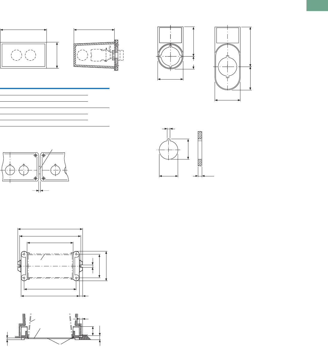
Logic Control Products CA08100001K—June 2012 www.eatoncanada.ca T37-111
37
37
37
37
37
37
37
37
37
37
37
37
37
37
37
37
37
37
37
37
37
37
37
37
37
37
37
37
37
37
37.4
Pushbuttons and Indicating Lights
22.5 mm Modular Pushbuttons—M22
Approximate Dimensions in Inches (mm)
Covers
Connecting Screw
Shroud with Plaster Keys
Legend Plates
Mounting Hole with Lug Slot
a2
M20 M20 M20
2.32 (59)
3.74 (95)
M22-H_
Catalogue
Number a2 Cable Entry Style
M22-H1 1.65 (42) 3 x M20 One-piece
M22-H2 2.95 (75) 4 x M20
M22-H3 4.25 (108) 4 x M20
M22-H4 5.55 (141) 4 x M20 Split
M22-H5 6.85 (174) 5 x M20
M22-HE6 8.15 (207) 6 x M20
0.04 (1)
M22-XI
Gasket.
a2 +1.65 (42)
a2 +1.26 (32)
0.16 (4)
2.2 (56)
2.76 (70)
a2
M22-H...
M22-H...
M22-UPE
0.31 (8)
0.31 (8)
1.02 (26)
e
e + 0.51 (13)
0.35 (9)
0.35 (9)
M22-UPE
Box for closing off when plastering.
Plaster thickness less than 8 mm.
Plaster thickness more than 8 mm
1.18 (30)
0.59 (15)
1.38 (35)
1.18 (30)
1.08 (27.5) 1.85 (47)
M22S-ST-_ M22S-STDD-X
0.13 (3.2)
0.88 (22.3)
0.95 (24.1)
0.04 (1)–0.24 (6)
Tab37book.fm Page 111 Tuesday, July 3, 2012 10:46 PM
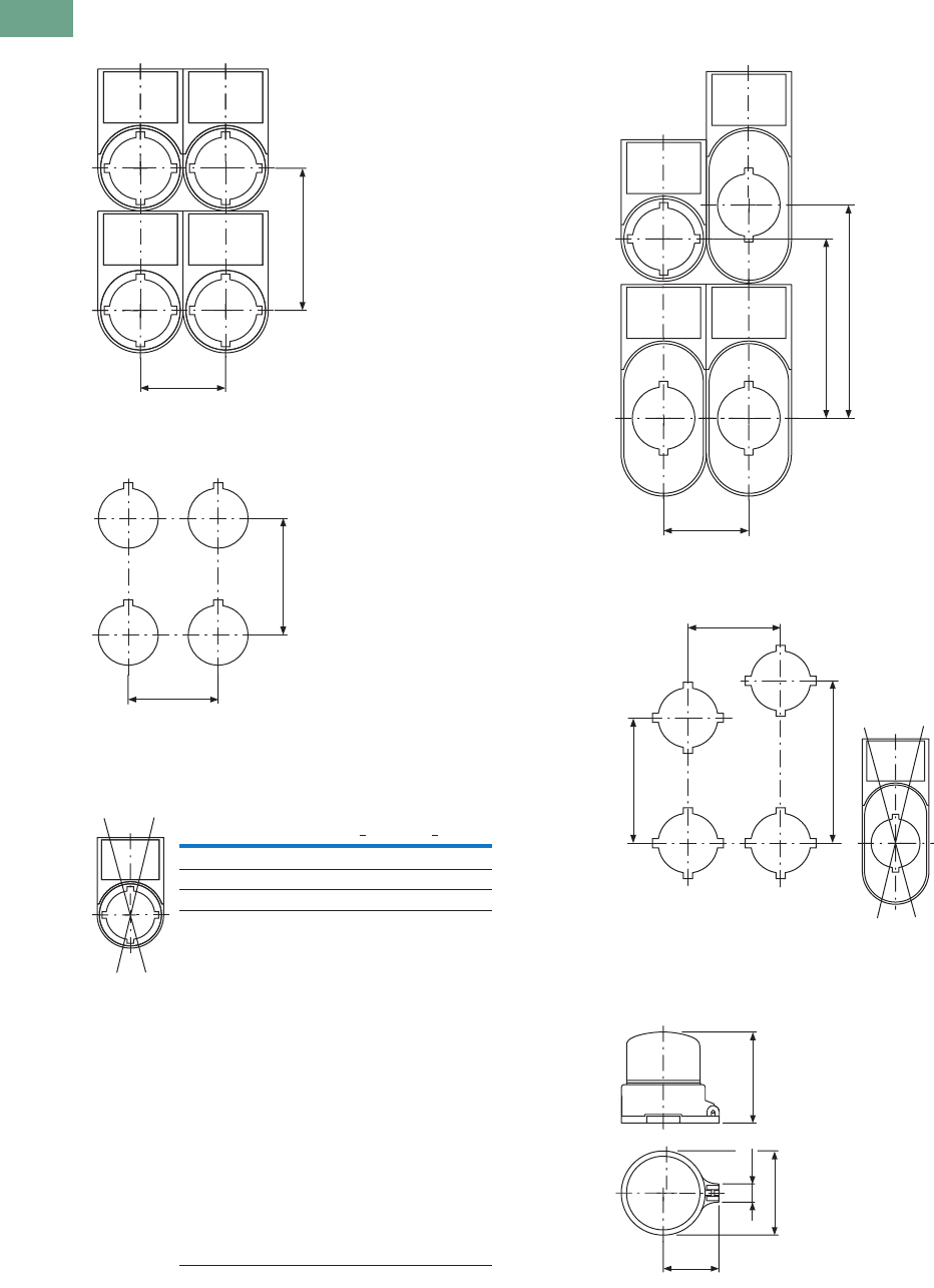
T37-112 Logic Control Products CA08100001K—June 2012 www.eatoncanada.ca
37
37
37
37
37
37
37
37
37
37
37
37
37
37
37
37
37
37
37
37
37
37
37
37
37
37
37
37
37
37
37.4
Pushbuttons and Indicating Lights
22.5 mm Modular Pushbuttons—M22
Approximate Dimensions in Inches (mm)
Grid Dimension to IEC/EN 60947
Grid Dimension for Various Combinations
Pushbutton Diaphragm
Grid Dimension for M22-DD_
Grid Dimension for M22-DDL_
Emergency Stop Sealing Cover
1.18 (30)
1.97 (50)
A
B
Pushbutton diaphragm cannot be combined with label mount.
Catalogue Number A >B >
M22(S)-_(IEC/EN 60947) 1.18 (30.0) 1.97 (50.0)
RMQ-Titan min. 1.18 (30.0) 1.58 (40.0)
M22-D_ + M22-T-D 1.30 (33.0) 1.58 (40.0)
M22-D(R)P_ 1.50 (38.0) 1.58 (40.0)
M22-PV_ 1.50 (38.0) 1.58 (40.0)
M22-PV(L) + M22-PL-PV 1.89 (48.0) 2.20 (56.0)
M22-PV(L)(S_) + M22-D_ 1.30 (33.0) 1.58 (40.0)
M22-DDL_ 1.18 (30.0) 2.17 (55.0)
M22-DDL_ + M22-T-DD 1.30 (33.0) 2.28 (58.0)
M22-ST_ 1.18 (30.0) 1.97 (50.0)
M22-STDD_ 1.18 (30.0) 2.95 (75.0)
M22-CK_ 1.18 (30.0) 1.77 (45.0)
M22-CLED_ 1.18 (30.0) 1.77 (45.0)
M22-XAK_ 3.54 (90.0) 3.54 (90.0)
M22-XZK_ 1.30 (33.0) 2.04 (52.0)
M22-XBK_ 2.36 (60.0) 2.36 (60.0)
M22-XYK_ 1.97 (50.0) 1.97 (50.0)
M22-D4 2.17 (55.0) 2.17 (55.0)
M22-WR…4 1.97 (50.0) 1.97 (50.0)
M22-W…J4 1.97 (50.0) 1.97 (50.0)
1.18 (30)
2.95 (75)
2.48 (63)
b 1.73 (44)
b 2.28 (58)
a 1.18 (30)
Pushbutton
Diaphragm
M22-T-DD
Pushbutton diaphragm cannot be combined with label mount.
1.26 (32)
1.89 (48)
0.41 (10.4) 2.03 (51.6)
M22-PL-PV
Tab37book.fm Page 112 Tuesday, July 3, 2012 10:46 PM
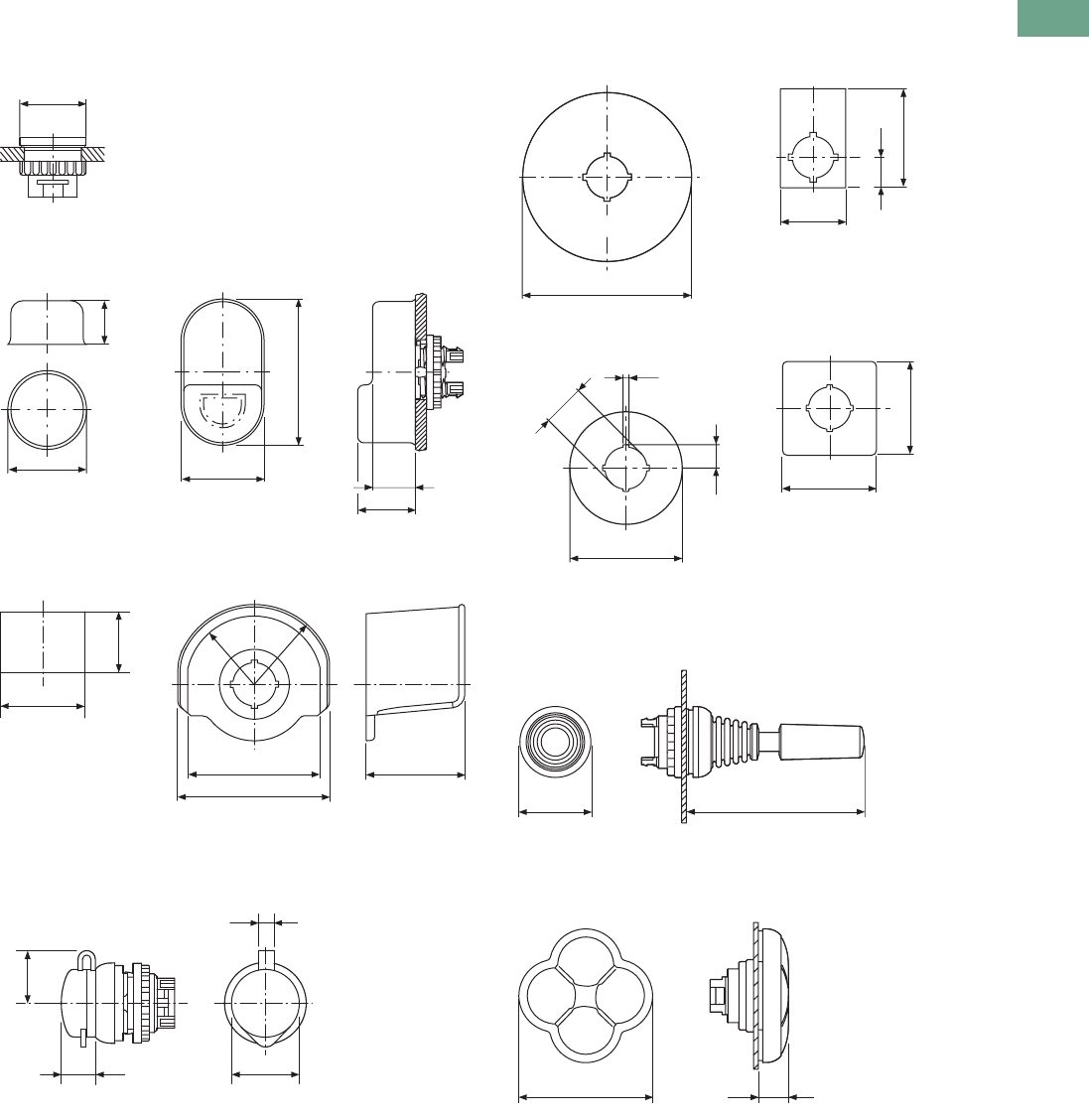
Logic Control Products CA08100001K—June 2012 www.eatoncanada.ca T37-113
37
37
37
37
37
37
37
37
37
37
37
37
37
37
37
37
37
37
37
37
37
37
37
37
37
37
37
37
37
37
37.4
Pushbuttons and Indicating Lights
22.5 mm Modular Pushbuttons—M22
Approximate Dimensions in Inches (mm)
Blanking Plugs
Pushbutton Diaphragm
Guard Ring
Key Cover
Emergency Stop Legend Plate
Joystick
Four-Way Pushbutton
1.16 (29.5)
M22…B-_
1.3 (33)
0.67 (17)
1.3 (33)
0.67 (17)
0.91 (23)
2.28 (58)
M22-T-D M22-T-D
Ø 1.42 (36)
0.98 (25)
3.07 (78)
2.68 (68)
R35 R41
1.97 (50)
M22-XGWK M22-XGPV
0.47 (12)
0.2 (5)
Ø 0.98 (25)
0.79 (20)
M22-XWS
3.54 (90)
d= 0.03 (0.8)
1.3 (33)
0.65 (16.5)
1.97 (50)
M22-XAK_ M22-X(Y)ZK_
0.13 (3.2)
0.49 (12.5)
Ø 2.36 (60)
Ø 0.89 (22.5)
1.97 (50)
1.97 (50)
M22-XBK-_ M22-XYK-_
1.18 (30)
2.95 (75)
M22…W…J_
2.17 (55)
0.45 (11.5)
M22…-D…4-_
Tab37book.fm Page 113 Tuesday, July 3, 2012 10:46 PM

T37-114 Logic Control Products CA08100001K—June 2012 www.eatoncanada.ca
37
37
37
37
37
37
37
37
37
37
37
37
37
37
37
37
37
37
37
37
37
37
37
37
37
37
37
37
37
37
37.4
Pushbuttons and Indicating Lights
22.5 mm Modular Pushbuttons—M22
Symbols Library
Instructions for Ordering Laser Inscriptions
1. Identify part number to be inscribed.
2. Pick symbol from library and identify suffix code associated with the symbol.
3. Order part number already listed in the catalogue with -ETCH suffix.
4. When placing an order by fax or Vistaline on the Web, reference order item number and
indicate appropriate suffix code.
Example
To order a green flush button plate with the inscription AUTO HAND:
Order Catalogue Number: M22-XD-G-ETCH (see Page V7-T37-38).
AUTO HAND inscription is found on Page V7-T37-118 in the Symbols Library, suffix code is X91.
In the order notes, reference item number and suffix X91.
Letter height 3 mm: max three lines, max. 12 characters per line.
Letter height 5 mm: max. two lines, max. eight characters per line.
Note: For symbols or text not found in the Symbols Library, please contact the
Eaton Customer Support Centre at 1-800-268-3578.
Tab37book.fm Page 114 Tuesday, July 3, 2012 10:46 PM
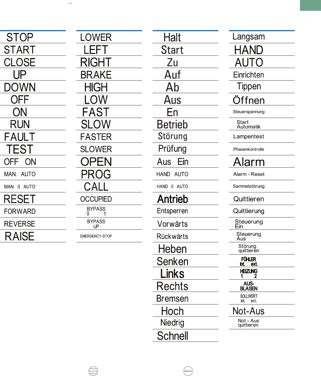
Logic Control Products CA08100001K—June 2012 www.eatoncanada.ca T37-115
37
37
37
37
37
37
37
37
37
37
37
37
37
37
37
37
37
37
37
37
37
37
37
37
37
37
37
37
37
37
37.4
Pushbuttons and Indicating Lights
22.5 mm Modular Pushbuttons—M22
Letter Height Specifications: < five characters; letter height = 0.197 in (5 mm). > five characters; letter height = 0.118 in (3 mm).
Text—English
Text—German
Inscription
Catalogue
Number Suffix
GB0
GB1
GB2
GB3
GB4
GB5
GB6
GB7
GB8
GB9
GB10
GB11
GB12
GB14
GB15
GB16
GB17
Text Size: 3 mm—Max. eight characters in first line;
10 characters in second line; eight characters in third line.
Text Size: 5 mm—Max. five characters per line.
Inscription
Catalogue
Number Suffix
GB18
GB19
GB20
GB21
GB22
GB23
GB24
GB25
GB26
GB27
GB32
GB62
GB63
GB64
GB65
GB66
GB99
Inscription
Catalogue
Number Suffix
D0
D1
D2
D3
D4
D5
D6
D7
D8
D9
D10
D11
D12
D13
D14
D15
D16
D17
D18
D19
D20
D21
D22
D23
D24
Inscription
Catalogue
Number Suffix
D25
D28
D29
D30
D31
D32
D33
D34
D35
D36
D37
D38
D39
D40
D41
D42
D43
D44
D72
D73
D74
D75
D99
D100
Tab37book.fm Page 115 Tuesday, July 3, 2012 10:46 PM
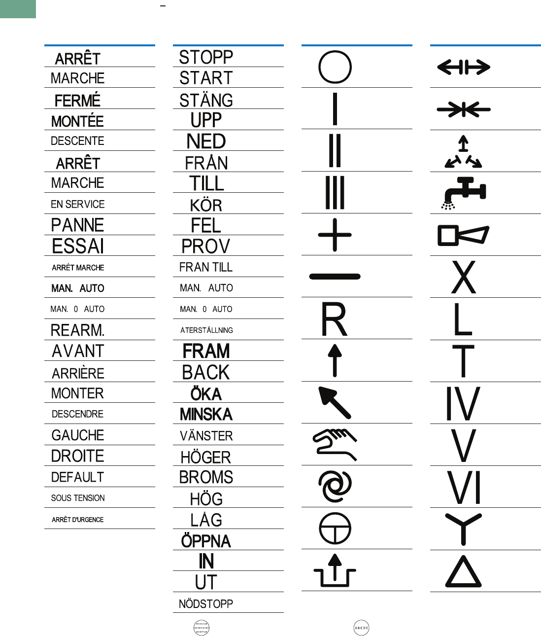
T37-116 Logic Control Products CA08100001K—June 2012 www.eatoncanada.ca
37
37
37
37
37
37
37
37
37
37
37
37
37
37
37
37
37
37
37
37
37
37
37
37
37
37
37
37
37
37
37.4
Pushbuttons and Indicating Lights
22.5 mm Modular Pushbuttons—M22
Letter Height Specifications: < five characters; letter height = 0.197 in (5 mm). > five characters; letter height = 0.118 in (3 mm).
Text—French Text—Swedish
Symbols
Inscription
Catalogue
Number Suffix
F0
F1
F2
F3
F4
F5
F6
F7
F8
F9
F10
F11
F12
F14
F15
F16
F17
F18
F19
F20
F67
F68
F99
Text Size: 3 mm—Max. eight characters in first line;
10 characters in second line; eight characters in third line.
Text Size: 5 mm—Max. five characters per line.
Inscription
Catalogue
Number Suffix
S0
S1
S2
S3
S4
S5
S6
S7
S8
S9
S10
S11
S12
S14
S15
S16
S17
S18
S19
S20
S21
S22
S23
S32
S45
S46
S99
Inscription
Catalogue
Number Suffix
X0
X1
X2
X3
X4
X5
X6
X7
X8
X9
X10
X11
X12
Inscription
Catalogue
Number Suffix
X13
X14
X15
X16
X17
X18
X19
X20
X21
X22
X23
X24
X25
Tab37book.fm Page 116 Tuesday, July 3, 2012 10:46 PM
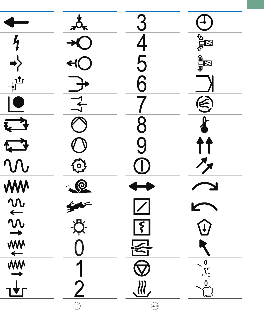
Logic Control Products CA08100001K—June 2012 www.eatoncanada.ca T37-117
37
37
37
37
37
37
37
37
37
37
37
37
37
37
37
37
37
37
37
37
37
37
37
37
37
37
37
37
37
37
37.4
Pushbuttons and Indicating Lights
22.5 mm Modular Pushbuttons—M22
Inscription
Catalogue
Number Suffix
X26
X27
X28
X29
X30
X31
X32
X33
X34
X35
X36
X37
X38
X39
Text Size: 3 mm—Max. eight characters in first line;
10 characters in second line; eight characters in third line.
Text Size: 5 mm—Max. five characters per line.
Inscription
Catalogue
Number Suffix
X40
X41
X42
X43
X44
X45
X46
X47
X48
X49
X50
X51
X52
X53
Inscription
Catalogue
Number Suffix
X54
X55
X56
X57
X58
X59
X60
X61
X62
X63
X64
X65
X66
X67
Inscription
Catalogue
Number Suffix
X68
X69
X70
X71
X72
X73
X74
X75
X76
X77
X78
X79
X80
X81
Tab37book.fm Page 117 Tuesday, July 3, 2012 10:46 PM
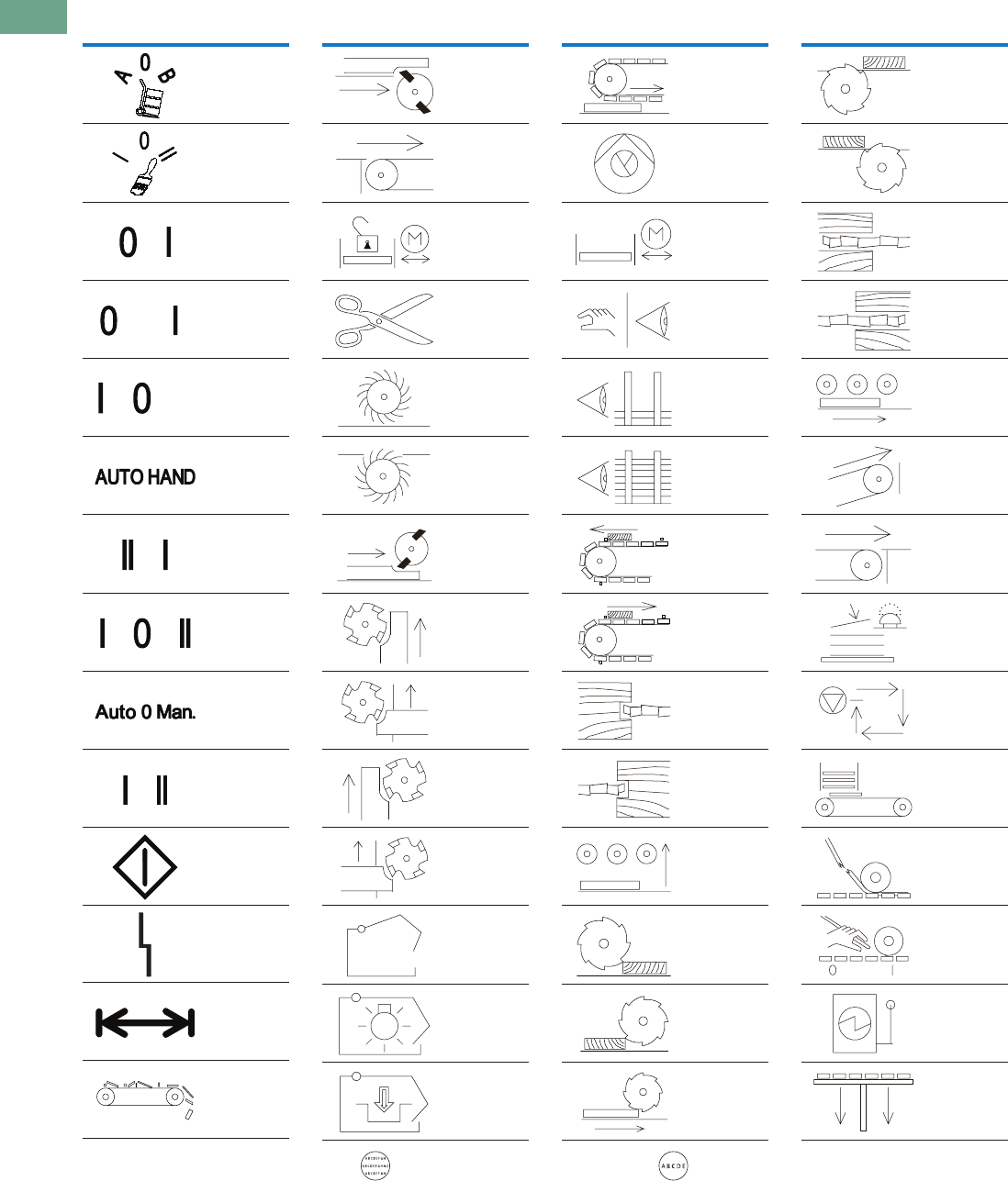
T37-118 Logic Control Products CA08100001K—June 2012 www.eatoncanada.ca
37
37
37
37
37
37
37
37
37
37
37
37
37
37
37
37
37
37
37
37
37
37
37
37
37
37
37
37
37
37
37.4
Pushbuttons and Indicating Lights
22.5 mm Modular Pushbuttons—M22
Inscription
Catalogue
Number Suffix
X82
X83
X88
X89
X90
X91
X92
X93
X94
X95
X100
X101
X102
X103
Text Size: 3 mm—Max. eight characters in first line;
10 characters in second line; eight characters in third line.
Text Size: 5 mm—Max. five characters per line.
Inscription
Catalogue
Number Suffix
X104
X105
X106
X107
X108
X109
X110
X111
X112
X113
X114
X115
X116
X117
Inscription
Catalogue
Number Suffix
X118
X119
X120
X121
X122
X123
X124
X125
X126
X127
X128
X129
X130
X131
Inscription
Catalogue
Number Suffix
X132
X133
X134
X135
X136
X137
X138
X139
X140
X141
X142
X143
X144
X145
Tab37book.fm Page 118 Tuesday, July 3, 2012 10:46 PM
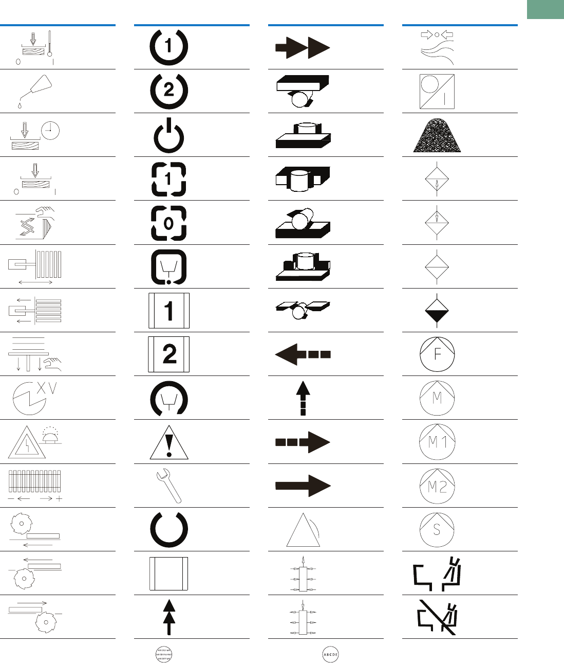
Logic Control Products CA08100001K—June 2012 www.eatoncanada.ca T37-119
37
37
37
37
37
37
37
37
37
37
37
37
37
37
37
37
37
37
37
37
37
37
37
37
37
37
37
37
37
37
37.4
Pushbuttons and Indicating Lights
22.5 mm Modular Pushbuttons—M22
Inscription
Catalogue
Number Suffix
X146
X147
X148
X149
X150
X151
X152
X153
X154
X155
X156
X157
X158
X159
Text Size: 3 mm—Max. eight characters in first line;
10 characters in second line; eight characters in third line.
Text Size: 5 mm—Max. five characters per line.
Inscription
Catalogue
Number Suffix
X160
X161
X162
X163
X164
X165
X166
X167
X168
X169
X170
X171
X172
X173
Inscription
Catalogue
Number Suffix
X174
X175
X176
X177
X178
X179
X180
X181
X182
X183
X184
X185
X186
X187
Inscription
Catalogue
Number Suffix
X188
X189
X190
X191
X192
X193
X194
X195
X196
X197
X198
X199
X200
X201
Tab37book.fm Page 119 Tuesday, July 3, 2012 10:46 PM
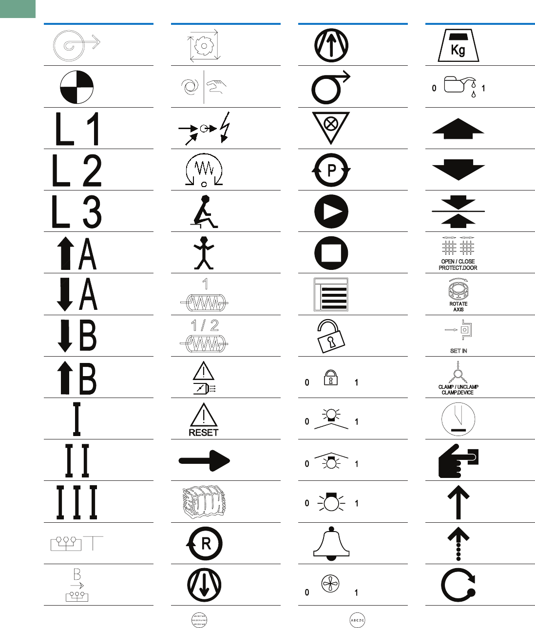
T37-120 Logic Control Products CA08100001K—June 2012 www.eatoncanada.ca
37
37
37
37
37
37
37
37
37
37
37
37
37
37
37
37
37
37
37
37
37
37
37
37
37
37
37
37
37
37
37.4
Pushbuttons and Indicating Lights
22.5 mm Modular Pushbuttons—M22
Inscription
Catalogue
Number Suffix
X202
X203
X204
X205
X206
X207
X208
X209
X210
X211
X212
X213
X214
X215
Text Size: 3 mm—Max. eight characters in first line;
10 characters in second line; eight characters in third line.
Text Size: 5 mm—Max. five characters per line.
Inscription
Catalogue
Number Suffix
X216
X217
X218
X219
X220
X221
X222
X223
X224
X225
X226
X227
X228
X229
Inscription
Catalogue
Number Suffix
X230
X231
X232
X233
X234
X235
X236
X237
X238
X239
X240
X241
X242
X243
Inscription
Catalogue
Number Suffix
X244
X245
X246
X247
X248
X249
X250
X251
X252
X253
X254
X255
X256
X257
Tab37book.fm Page 120 Tuesday, July 3, 2012 10:46 PM
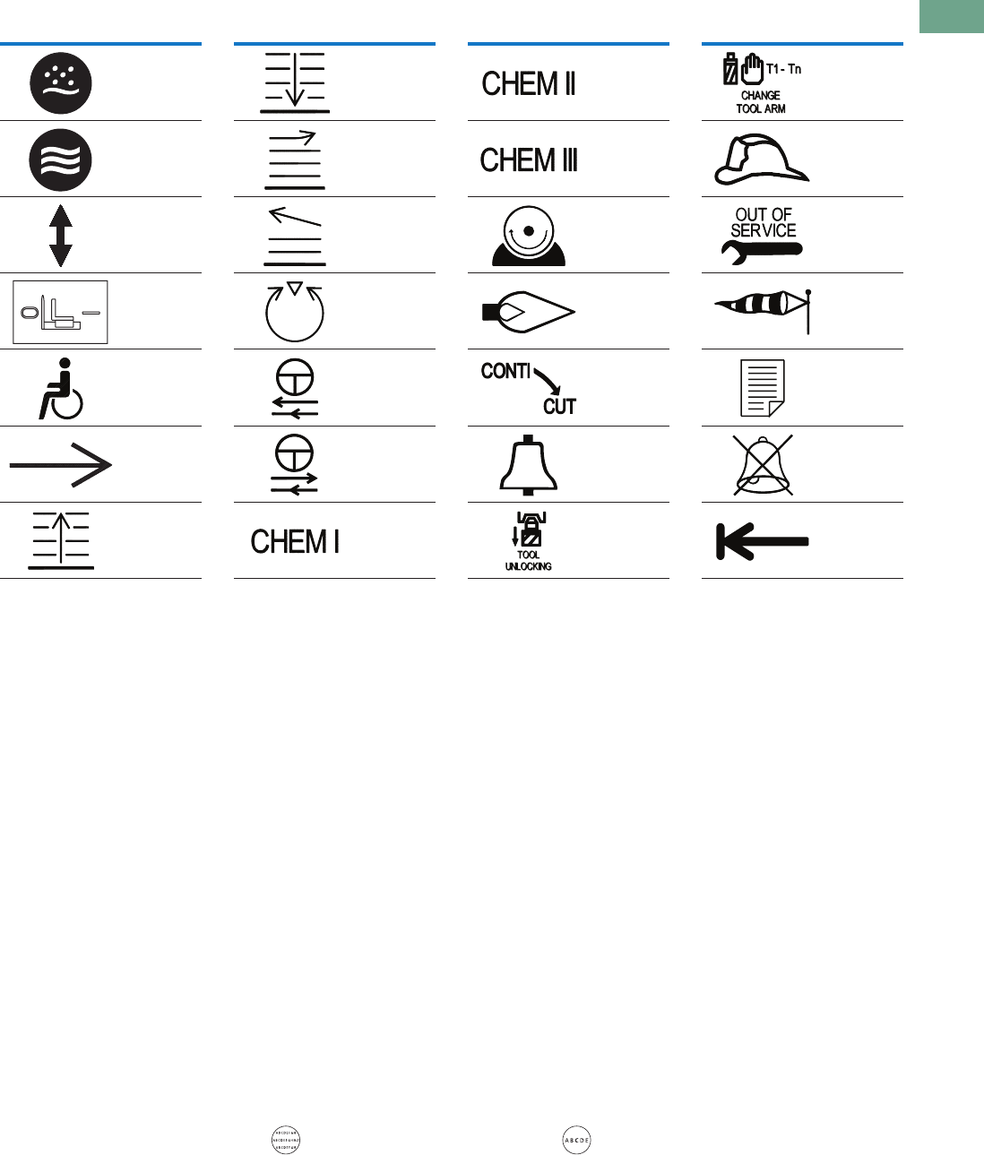
Logic Control Products CA08100001K—June 2012 www.eatoncanada.ca T37-121
37
37
37
37
37
37
37
37
37
37
37
37
37
37
37
37
37
37
37
37
37
37
37
37
37
37
37
37
37
37
37.4
Pushbuttons and Indicating Lights
22.5 mm Modular Pushbuttons—M22
Inscription
Catalogue
Number Suffix
X258
X259
X260
X261
X262
X263
X264
Text Size: 3 mm—Max. eight characters in first line;
10 characters in second line; eight characters in third line.
Text Size: 5 mm—Max. five characters per line.
Inscription
Catalogue
Number Suffix
X265
X266
X267
X268
X269
X270
X271
Inscription
Catalogue
Number Suffix
X272
X273
X274
X275
X276
X277
X278
Inscription
Catalogue
Number Suffix
X279
X280
X281
X282
X283
X284
X285
Tab37book.fm Page 121 Tuesday, July 3, 2012 10:46 PM
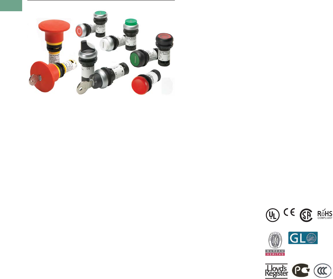
T37-122 Logic Control Products CA08100001K—June 2012 www.eatoncanada.ca
37
37
37
37
37
37
37
37
37
37
37
37
37
37
37
37
37
37
37
37
37
37
37
37
37
37
37
37
37
37
37.5
Pushbuttons and Indicating Lights
22.5 mm Compact Pushbuttons—C22
22.5 mm Compact Pushbuttons—C22 Contents
Description Page
22.5 mm Compact Pushbuttons—C22
Product Selection Guide . . . . . . . . . . . . . . . . . . . . T37-124
Pushbuttons—Non-Illuminated and
Illuminated . . . . . . . . . . . . . . . . . . . . . . . . . . . . . . T37-125
Indicating Lights . . . . . . . . . . . . . . . . . . . . . . . . . . . T37-134
Emergency Stops . . . . . . . . . . . . . . . . . . . . . . . . . . T37-136
Selector Switches . . . . . . . . . . . . . . . . . . . . . . . . . T37-139
Technical Data and Specifications . . . . . . . . . . . . . T37-144
Dimensions . . . . . . . . . . . . . . . . . . . . . . . . . . . . . . T37-146
Product Overview
Product Description
Eaton’s C22 compact
pushbutton line offers an
industry leading array of
functional, attractive, and
ergonomically designed
“all-in-one” illuminated and
non-illuminated pushbuttons,
selector switches, emergency
stops and indicating lights.
The complete illuminated line
is only offered in LED light
units to ensure high-quality
brightness and up to 100,000
hours of LED illumination.
C22 operators are available
with either a silver or black
bezel and share the exact
same front of the panel
look and feel as Eaton’s
M22 line. The C22’s compact,
“all-in-one” design with the
contact block(s) and
operators integral provides
the user with a simple solution.
Wide Product Breadth
●In addition to the standard
compact offering of
indicating lights and
pushbuttons, Eaton’s
C22 offers keyed and
non-keyed operators
and emergency stops
●Hundreds of styles with
standard laser etch
markings with the ability
to use custom M22 laser
etched buttons in
conjunction with C22
buttonless operators
LED Indicators
●100,000 hours of life
in high-vibration
environments
●Lenses specifically
designed for LED
illumination
Rugged Design
●Pushbuttons (momentary)
rated for 5 million
mechanical operations
and selector switches
(non-keyed) rated for
1 million mechanical
operations
●All components have IP65
rating, and some carry IP67
and IP69K for wash-down
environment
Standards and Certifications
All operators are IEC/EN
60947 VDE 0660, UL Listed,
and CSA Certified.
All operators carry an IP65,
IP66, IP67 or IP69K rating.
All products carry ratings of
NEMA 1, 3R, 4X, 12 and 13
Tab37book.fm Page 122 Tuesday, July 3, 2012 10:46 PM

Logic Control Products CA08100001K—June 2012 www.eatoncanada.ca T37-123
37
37
37
37
37
37
37
37
37
37
37
37
37
37
37
37
37
37
37
37
37
37
37
37
37
37
37
37
37
37
37.5
Pushbuttons and Indicating Lights
22.5 mm Compact Pushbuttons—C22
Features
●Field convertible
maintained pushbuttons
from maintained to
momentary
●Field convertible selector
switches from momentary
to maintained operation
and vice versa
●LED offering only for all
illuminated operators
●Laser engraved
pushbuttons and lenses
●Heavy-duty construction
with a minimum of IP65
and UL NEMA® Type 4X/13
on front of panel operators.
Many operators even carry
IP67 and IP69K, for the
toughest applications
●Silver or black colored
nylon bezels
●Notched hole mounting
with anti-rotation tab and
central nut mounting on
each operator
●Pushbuttons (momentary)
rated for 5 million
mechanical operations
and selector switches
(non-keyed) rated for
1 million mechanical
operations
●Unique compact offerings,
including keyed and non-
keyed operators and
emergency stops
Benefits
●Compact, “all-in-one”
operator and contact block
design simplifies product
selection, inventory, and
installation
●Field convertibility of
pushbuttons and selector
switches helps distributors
and customers reduce
inventory and increase
functionality
●LED offering only for
improved brightness
quality and up to 100,000
hours of operation
●Plastic construction is
corrosion resistant
●Operators are designed
for rugged environments,
ideal for wash-down
applications (reference
each operator’s IP ratings
for ingress protection
definition)
●Anti-rotation tab saves
installation time and
prevents operator rotation
●High mechanical and
electrical life allows for
use in tough and
challenging applications
●Laser inscription
capabilities allow for high
quality, wear-resistant
markings
●By having a compact
design emergency stop, the
C22 design eliminates the
need for self-monitoring
contact blocks
Tab37book.fm Page 123 Tuesday, July 3, 2012 10:46 PM

T37-124 Logic Control Products CA08100001K—June 2012 www.eatoncanada.ca
37
37
37
37
37
37
37
37
37
37
37
37
37
37
37
37
37
37
37
37
37
37
37
37
37
37
37
37
37
37
37.5
Pushbuttons and Indicating Lights
22.5 mm Compact Pushbuttons—C22
Product Selection Guide
Pushbuttons
Indicating Lights
Emergency Stops
Selector Switches
Description Non-illuminated, flush Non-illuminated, extended Illuminated, flush Illuminated, extended
Operator Momentary Maintained Momentary Maintained Momentary Maintained Momentary Maintained
Product Selection Page V7-T37-126 Page V7-T37-127 Page V7-T37-128 Page V7-T37-129 Page V7-T37-130 Page V7-T37-131 Page V7-T37-132 Page V7-T37-133
Description Indicating lights
Product Selection Page V7-T37-135
Description Twist release Keyed-release
Product Selection Page V7-T37-137 Page V7-T37-137
Description Non-illuminated, knob type Key-operated
Product Selection Page V7-T37-140 Page V7-T37-141
Tab37book.fm Page 124 Tuesday, July 3, 2012 10:46 PM

Logic Control Products CA08100001K—June 2012 www.eatoncanada.ca T37-125
37
37
37
37
37
37
37
37
37
37
37
37
37
37
37
37
37
37
37
37
37
37
37
37
37
37
37
37
37
37
37.5
Pushbuttons and Indicating Lights
22.5 mm Compact Pushbuttons—C22
Pushbuttons—Non-Illuminated and Illuminated Contents
Description Page
Pushbuttons—Non-Illuminated and Illuminated
Non-Illuminated, Flush, Momentary . . . . . . . . . . . . T37-126
Non-Illuminated, Flush, Maintained . . . . . . . . . . . . T37-127
Non-Illuminated, Extended, Momentary . . . . . . . . T37-128
Non-Illuminated, Extended, Maintained . . . . . . . . . T37-129
Illuminated, Flush, Momentary . . . . . . . . . . . . . . . . T37-130
Illuminated, Flush, Maintained . . . . . . . . . . . . . . . . T37-131
Illuminated, Extended, Momentary . . . . . . . . . . . . T37-132
Illuminated, Extended, Maintained . . . . . . . . . . . . . T37-133
Indicating Lights . . . . . . . . . . . . . . . . . . . . . . . . . . . . . T37-134
Emergency Stops . . . . . . . . . . . . . . . . . . . . . . . . . . . . T37-136
Selector Switches . . . . . . . . . . . . . . . . . . . . . . . . . . . . T37-139
Technical Data and Specifications . . . . . . . . . . . . . . . . T37-144
Dimensions . . . . . . . . . . . . . . . . . . . . . . . . . . . . . . . . . T37-146
Pushbuttons—Non-Illuminated and Illuminated
Product Description
Eaton’s C22 Compact
Pushbuttons are a complete
line of monoblock type
pushbuttons with the contact
blocks, mounting adapter,
and operator all-in-one. The
C22 pushbuttons offer the
same look and feel as their
modular counterpart, the
M22. They also carry many of
the same rugged ratings and
options, such as laser
etching, field convertibility,
and LED technology.
Note: For additional accessories,
please see Volume 7—Motor
Controls, Logic and Connectivity,
CA08100008E, Tab 37, section
37.4, 22.5 mm Modular
Pushbuttons—M22.
Features
●Field convertible
maintained pushbuttons
from maintained to
momentary
●LED offering only for
improved brightness
quality and up to 100,000
hours of operation
●Laser engraved
pushbuttons and lenses
●Pushbuttons (momentary)
rated for 5 million
mechanical operations
Protection Type
●IP67/IP69K
●NEMA 4X, 13
Tab37book.fm Page 125 Tuesday, July 3, 2012 10:46 PM
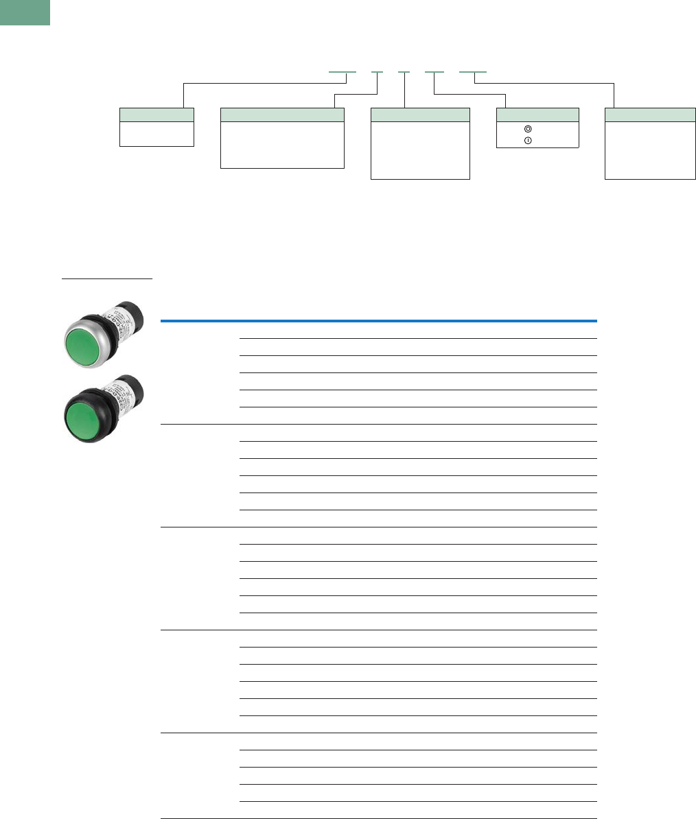
T37-126 Logic Control Products CA08100001K—June 2012 www.eatoncanada.ca
37
37
37
37
37
37
37
37
37
37
37
37
37
37
37
37
37
37
37
37
37
37
37
37
37
37
37
37
37
37
37.5
Pushbuttons and Indicating Lights
22.5 mm Compact Pushbuttons—C22
Catalogue Number Selection
Catalogue Number Selection is for illustrative purposes only and not to be used to create new catalogue numbers.
Non-Illuminated Pushbuttons
Product Selection
Non-Illuminated, Flush, Momentary
Non-Illuminated Pushbuttons, Flush, Momentary
Button
Colour
Button
Etching
Contact Block
Configuration
Silver Bezel
Catalogue Number
Black Bezel
Catalogue Number
Green — 1NO C22-D-G-K10 C22S-D-G-K10
— 2NO C22-D-G-K20 C22S-D-G-K20
— 1NO/1NC C22-D-G-K11 C22S-D-G-K11
X1 1NO C22-D-G-X1-K10 C22S-D-G-X1-K10
X1 2NO C22-D-G-X1-K20 C22S-D-G-X1-K20
X1 1NO/1NC C22-D-G-X1-K11 C22S-D-G-X1-K11
Red — 1NC C22-D-R-K01 C22S-D-R-K01
— 2NC C22-D-R-K02 C22S-D-R-K02
— 1NO/1NC C22-D-R-K11 C22S-D-R-K11
X0 1NC C22-D-R-X0-K01 C22S-D-R-X0-K01
X0 2NC C22-D-R-X0-K02 C22S-D-R-X0-K02
X0 1NO/1NC C22-D-R-X0-K11 C22S-D-R-X0-K11
Black — 1NC C22-D-S-K01 C22S-D-S-K01
— 2NC C22-D-S-K02 C22S-D-S-K02
— 1NO/1NC C22-D-S-K11 C22S-D-S-K11
X0 1NC C22-D-S-X0-K01 C22S-D-S-X0-K01
X0 2NC C22-D-S-X0-K02 C22S-D-S-X0-K02
X0 1NO/1NC C22-D-S-X0-K11 C22S-D-S-X0-K11
White — 1NO C22-D-W-K10 C22S-D-W-K10
— 2NO C22-D-W-K20 C22S-D-W-K20
— 1NO/1NC C22-D-W-K11 C22S-D-W-K11
X1 1NO C22-D-W-X1-K10 C22S-D-W-X1-K10
X1 2NO C22-D-W-X1-K20 C22S-D-W-X1-K20
X1 1NO/1NC C22-D-W-X1-K11 C22S-D-W-X1-K11
Buttonless — 1NO C22-D-X-K10 C22S-D-X-K10
— 2NO C22-D-X-K20 C22S-D-X-K20
— 1NC C22-D-X-K01 C22S-D-X-K01
— 2NC C22-D-X-K02 C22S-D-X-K02
— 1NO/1NC C22-D-X-K11 C22S-D-X-K11
C22 - D - G - X1 - K10
Bezel
C22 = Silver
C22S = Black
Operator Type
D = Flush, momentary
DR = Flush, maintained
DH = Extended, momentary
DRH = Extended, maintained
Button Plate Colour
G = Green
R = Red
S = Black
W = White
X = Buttonless
Button Etching
X0 =
X1 =
Contact Blocks
K10 = 1NO
K20 = 2NO
K01 = 1NC
K02 = 2NC
K11 = 1NO/1NC
C22(S)-D-_
Tab37book.fm Page 126 Tuesday, July 3, 2012 10:46 PM

Logic Control Products CA08100001K—June 2012 www.eatoncanada.ca T37-127
37
37
37
37
37
37
37
37
37
37
37
37
37
37
37
37
37
37
37
37
37
37
37
37
37
37
37
37
37
37
37.5
Pushbuttons and Indicating Lights
22.5 mm Compact Pushbuttons—C22
Non-Illuminated, Flush, Maintained
Non-Illuminated Pushbuttons, Flush, Maintained
Note: Maintained pushbuttons can be converted in the field to momentary operation by
switching the locking ring, which is accessible through the side of the operator body.
Button
Colour
Button
Etching
Contact Block
Configuration
Silver Bezel
Catalogue Number
Black Bezel
Catalogue Number
Green — 1NO C22-DR-G-K10 C22S-DR-G-K10
— 2NO C22-DR-G-K20 C22S-DR-G-K20
— 1NO/1NC C22-DR-G-K11 C22S-DR-G-K11
X1 1NO C22-DR-G-X1-K10 C22S-DR-G-X1-K10
X1 2NO C22-DR-G-X1-K20 C22S-DR-G-X1-K20
X1 1NO/1NC C22-DR-G-X1-K11 C22S-DR-G-X1-K11
Red — 1NC C22-DR-R-K01 C22S-DR-R-K01
— 2NC C22-DR-R-K02 C22S-DR-R-K02
— 1NO/1NC C22-DR-R-K11 C22S-DR-R-K11
X0 1NC C22-DR-R-X0-K01 C22S-DR-R-X0-K01
X0 2NC C22-DR-R-X0-K02 C22S-DR-R-X0-K02
X0 1NO/1NC C22-DR-R-X0-K11 C22S-DR-R-X0-K11
Black — 1NC C22-DR-S-K01 C22S-DR-S-K01
— 2NC C22-DR-S-K02 C22S-DR-S-K02
— 1NO/1NC C22-DR-S-K11 C22S-DR-S-K11
X0 1NC C22-DR-S-X0-K01 C22S-DR-S-X0-K01
X0 2NC C22-DR-S-X0-K02 C22S-DR-S-X0-K02
X0 1NO/1NC C22-DR-S-X0-K11 C22S-DR-S-X0-K11
White — 1NO C22-DR-W-K10 C22S-DR-W-K10
— 2NO C22-DR-W-K20 C22S-DR-W-K20
— 1NO/1NC C22-DR-W-K11 C22S-DR-W-K11
X1 1NO C22-DR-W-X1-K10 C22S-DR-W-X1-K10
X1 2NO C22-DR-W-X1-K20 C22S-DR-W-X1-K20
X1 1NO/1NC C22-DR-W-X1-K11 C22S-DR-W-X1-K11
Buttonless — 1NO C22-DR-X-K10 C22S-DR-X-K10
— 2NO C22-DR-X-K20 C22S-DR-X-K20
— 1NC C22-DR-X-K01 C22S-DR-X-K01
— 2NC C22-DR-X-K02 C22S-DR-X-K02
— 1NO/1NC C22-DR-X-K11 C22S-DR-X-K11
C22(S)-DR-_
Tab37book.fm Page 127 Tuesday, July 3, 2012 10:46 PM
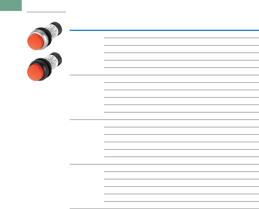
T37-128 Logic Control Products CA08100001K—June 2012 www.eatoncanada.ca
37
37
37
37
37
37
37
37
37
37
37
37
37
37
37
37
37
37
37
37
37
37
37
37
37
37
37
37
37
37
37.5
Pushbuttons and Indicating Lights
22.5 mm Compact Pushbuttons—C22
Non-Illuminated, Extended, Momentary
Non-Illuminated Pushbuttons, Extended, Momentary
Button
Colour
Button
Etching
Contact Block
Configuration
Silver Bezel
Catalogue Number
Black Bezel
Catalogue Number
Green — 1NO C22-DH-G-K10 C22S-DH-G-K10
— 2NO C22-DH-G-K20 C22S-DH-G-K20
— 1NO/1NC C22-DH-G-K11 C22S-DH-G-K11
X1 1NO C22-DH-G-X1-K10 C22S-DH-G-X1-K10
X1 2NO C22-DH-G-X1-K20 C22S-DH-G-X1-K20
X1 1NO/1NC C22-DH-G-X1-K11 C22S-DH-G-X1-K11
Red — 1NC C22-DH-R-K01 C22S-DH-R-K01
— 2NC C22-DH-R-K02 C22S-DH-R-K02
— 1NO/1NC C22-DH-R-K11 C22S-DH-R-K11
X0 1NC C22-DH-R-X0-K01 C22S-DH-R-X0-K01
X0 2NC C22-DH-R-X0-K02 C22S-DH-R-X0-K02
X0 1NO/1NC C22-DH-R-X0-K11 C22S-DH-R-X0-K11
Black — 1NC C22-DH-S-K01 C22S-DH-S-K01
— 2NC C22-DH-S-K02 C22S-DH-S-K02
— 1NO/1NC C22-DH-S-K11 C22S-DH-S-K11
X0 1NC C22-DH-S-X0-K01 C22S-DH-S-X0-K01
X0 2NC C22-DH-S-X0-K02 C22S-DH-S-X0-K02
X0 1NO/1NC C22-DH-S-X0-K11 C22S-DH-S-X0-K11
White — 1NO C22-DH-W-K10 C22S-DH-W-K10
— 2NO C22-DH-W-K20 C22S-DH-W-K20
— 1NO/1NC C22-DH-W-K11 C22S-DH-W-K11
X1 1NO C22-DH-W-X1-K10 C22S-DH-W-X1-K10
X1 2NO C22-DH-W-X1-K20 C22S-DH-W-X1-K20
X1 1NO/1NC C22-DH-W-X1-K11 C22S-DH-W-X1-K11
C22(S)-DH-_
Tab37book.fm Page 128 Tuesday, July 3, 2012 10:46 PM
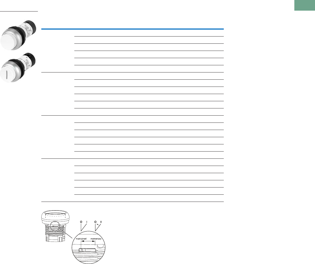
Logic Control Products CA08100001K—June 2012 www.eatoncanada.ca T37-129
37
37
37
37
37
37
37
37
37
37
37
37
37
37
37
37
37
37
37
37
37
37
37
37
37
37
37
37
37
37
37.5
Pushbuttons and Indicating Lights
22.5 mm Compact Pushbuttons—C22
Non-Illuminated, Extended, Maintained
Non-Illuminated Pushbuttons, Extended, Maintained
Note: Maintained pushbuttons can be converted in the field to momentary operation by
switching the locking ring, which is accessible through the side of the operator body.
Button
Colour
Button
Etching
Contact Block
Configuration
Silver Bezel
Catalogue Number
Black Bezel
Catalogue Number
Green — 1NO C22-DRH-G-K10 C22S-DRH-G-K10
— 2NO C22-DRH-G-K20 C22S-DRH-G-K20
— 1NO/1NC C22-DRH-G-K11 C22S-DRH-G-K11
X1 1NO C22-DRH-G-X1-K10 C22S-DRH-G-X1-K10
X1 2NO C22-DRH-G-X1-K20 C22S-DRH-G-X1-K20
X1 1NO/1NC C22-DRH-G-X1-K11 C22S-DRH-G-X1-K11
Red — 1NC C22-DRH-R-K01 C22S-DRH-R-K01
— 2NC C22-DRH-R-K02 C22S-DRH-R-K02
— 1NO/1NC C22-DRH-R-K11 C22S-DRH-R-K11
X0 1NC C22-DRH-R-X0-K01 C22S-DRH-R-X0-K01
X0 2NC C22-DRH-R-X0-K02 C22S-DRH-R-X0-K02
X0 1NO/1NC C22-DRH-R-X0-K11 C22S-DRH-R-X0-K11
Black — 1NC C22-DRH-S-K01 C22S-DRH-S-K01
— 2NC C22-DRH-S-K02 C22S-DRH-S-K02
— 1NO/1NC C22-DRH-S-K11 C22S-DRH-S-K11
X0 1NC C22-DRH-S-X0-K01 C22S-DRH-S-X0-K01
X0 2NC C22-DRH-S-X0-K02 C22S-DRH-S-X0-K02
X0 1NO/1NC C22-DRH-S-X0-K11 C22S-DRH-S-X0-K11
White — 1NO C22-DRH-W-K10 C22S-DRH-W-K10
— 2NO C22-DRH-W-K20 C22S-DRH-W-K20
— 1NO/1NC C22-DRH-W-K11 C22S-DRH-W-K11
X1 1NO C22-DRH-W-X1-K10 C22S-DRH-W-X1-K10
X1 2NO C22-DRH-W-X1-K20 C22S-DRH-W-X1-K20
X1 1NO/1NC C22-DRH-W-X1-K11 C22S-DRH-W-X1-K11
C22(S)-DRH-_
Tab37book.fm Page 129 Tuesday, July 3, 2012 10:46 PM
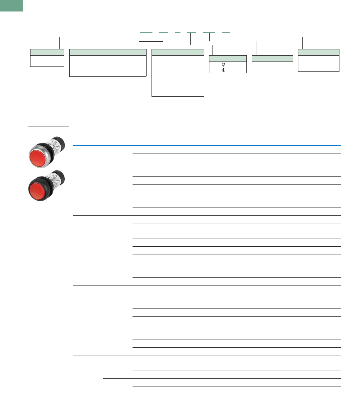
T37-130 Logic Control Products CA08100001K—June 2012 www.eatoncanada.ca
37
37
37
37
37
37
37
37
37
37
37
37
37
37
37
37
37
37
37
37
37
37
37
37
37
37
37
37
37
37
37.5
Pushbuttons and Indicating Lights
22.5 mm Compact Pushbuttons—C22
Catalogue Number Selection
Catalogue Number Selection is for illustrative purposes only and not to be used to create new catalogue numbers.
Illuminated Pushbuttons
Product Selection
Illuminated, Flush, Momentary
Illuminated Pushbuttons, Flush, Momentary
LED Colour
Button
Colour Voltage
Button
Etching
Contact Block
Configuration
Silver Bezel
Catalogue Number
Black Bezel
Catalogue Number
Green Green 24 Vac/Vdc — 1NO C22-DL-G-K10-24 C22S-DL-G-K10-24
120 Vac — 1NO C22-DL-G-K10-120 C22S-DL-G-K10-120
230 Vac — 1NO C22-DL-G-K10-230 C22S-DL-G-K10-230
24 Vac/Vdc X1 1NO C22-DL-G-X1-K10-24 C22S-DL-G-X1-K10-24
120 Vac X1 1NO C22-DL-G-X1-K10-120 C22S-DL-G-X1-K10-120
230 Vac X1 1NO C22-DL-G-X1-K10-230 C22S-DL-G-X1-K10-230
Buttonless 24 Vac/Vdc — 1NO C22-DL-XG-K10-24 C22S-DL-XG-K10-24
120 Vac — 1NO C22-DL-XG-K10-120 C22S-DL-XG-K10-120
230 Vac — 1NO C22-DL-XG-K10-230 C22S-DL-XG-K10-230
Red Red 24 Vac/Vdc — 1NC C22-DL-R-K01-24 C22S-DL-R-K01-24
120 Vac — 1NC C22-DL-R-K01-120 C22S-DL-R-K01-120
230 Vac — 1NC C22-DL-R-K01-230 C22S-DL-R-K01-230
24 Vac/Vdc X0 1NC C22-DL-R-X0-K01-24 C22S-DL-R-X0-K01-24
120 Vac X0 1NC C22-DL-R-X0-K01-120 C22S-DL-R-X0-K01-120
230 Vac X0 1NC C22-DL-R-X0-K01-230 C22S-DL-R-X0-K01-230
Buttonless 24 Vac/Vdc — 1NC C22-DL-XR-K01-24 C22S-DL-XR-K01-24
120 Vac — 1NC C22-DL-XR-K01-120 C22S-DL-XR-K01-120
230 Vac — 1NC C22-DL-XR-K01-230 C22S-DL-XR-K01-230
White White 24 Vac/Vdc — 1NO C22-DL-W-K10-24 C22S-DL-W-K10-24
120 Vac — 1NO C22-DL-W-K10-120 C22S-DL-W-K10-120
230 Vac — 1NO C22-DL-W-K10-230 C22S-DL-W-K10-230
24 Vac/Vdc X1 1NO C22-DL-W-X1-K10-24 C22S-DL-W-X1-K10-24
120 Vac X1 1NO C22-DL-W-X1-K10-120 C22S-DL-W-X1-K10-120
230 Vac X1 1NO C22-DL-W-X1-K10-230 C22S-DL-W-X1-K10-230
Buttonless 24 Vac/Vdc — 1NO C22-DL-XW-K10-24 C22S-DL-XW-K10-24
120 Vac — 1NO C22-DL-XW-K10-120 C22S-DL-XW-K10-120
230 Vac — 1NO C22-DL-XW-K10-230 C22S-DL-XW-K10-230
Blue Blue 24 Vac/Vdc — 1NO C22-DL-B-K10-24 C22S-DL-B-K10-24
120 Vac — 1NO C22-DL-B-K10-120 C22S-DL-B-K10-120
230 Vac — 1NO C22-DL-B-K10-230 C22S-DL-B-K10-230
Buttonless 24 Vac/Vdc — 1NO C22-DL-XB-K10-24 C22S-DL-XB-K10-24
120 Vac — 1NO C22-DL-XB-K10-120 C22S-DL-XB-K10-120
230 Vac — 1NO C22-DL-XB-K10-230 C22S-DL-XB-K10-230
C22 - DL - G - X1 - K10 - 24
Bezel
C22 = Silver
C22S = Black
Operator Type
DL = Illuminated, flush, momentary
DRL = Illuminated, flush, maintained
DHL = Illuminated, extended, momentary
DRHL = Illuminated, extended, maintained
Lens Etching
X0 =
X1 =
Contact Blocks
K10 = 1NO
K01 = 1NC
LED Voltage
24 = 24 Vac/Vdc
120 = 120 Vac
230 = 230 Vac
LED/Lens Colour
G = Green
R = Red
W = White
B = Blue
XG = Green without lens
XR = Red without lens
XW = White without lens
XB = Blue without lens
C22(S)-DL-_
Tab37book.fm Page 130 Tuesday, July 3, 2012 10:46 PM
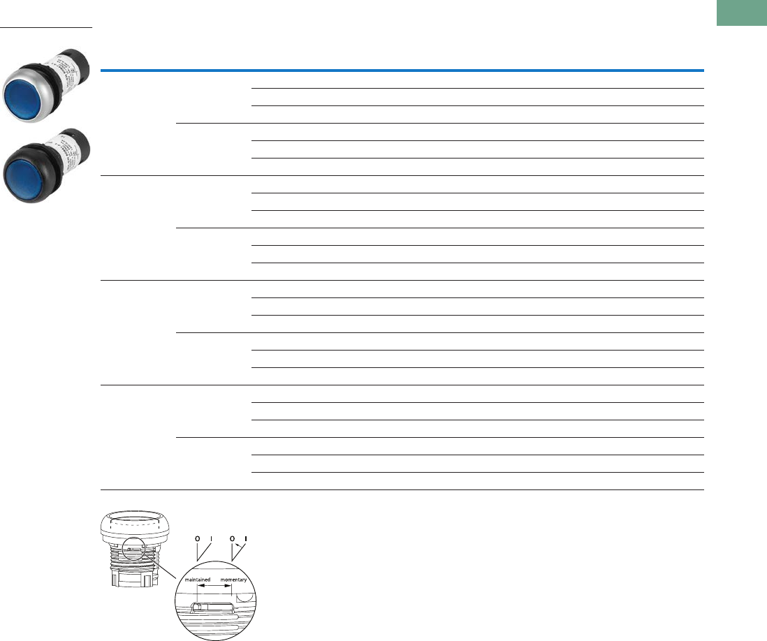
Logic Control Products CA08100001K—June 2012 www.eatoncanada.ca T37-131
37
37
37
37
37
37
37
37
37
37
37
37
37
37
37
37
37
37
37
37
37
37
37
37
37
37
37
37
37
37
37.5
Pushbuttons and Indicating Lights
22.5 mm Compact Pushbuttons—C22
Illuminated, Flush, Maintained
Illuminated Pushbuttons, Flush, Maintained
Note: Maintained pushbuttons can be converted in the field to momentary operation by
switching the locking ring, which is accessible through the side of the operator body.
LED Colour
Button
Colour Voltage
Contact Block
Configuration
Silver Bezel
Catalogue Number
Black Bezel
Catalogue Number
Green Green 24 Vac/Vdc 1NO C22-DRL-G-K10-24 C22S-DRL-G-K10-24
120 Vac 1NO C22-DRL-G-K10-120 C22S-DRL-G-K10-120
230 Vac 1NO C22-DRL-G-K10-230 C22S-DRL-G-K10-230
Buttonless 24 Vac/Vdc 1NO C22-DRL-XG-K10-24 C22S-DRL-XG-K10-24
120 Vac 1NO C22-DRL-XG-K10-120 C22S-DRL-XG-K10-120
230 Vac 1NO C22-DRL-XG-K10-230 C22S-DRL-XG-K10-230
Red Red 24 Vac/Vdc 1NC C22-DRL-R-K01-24 C22S-DRL-R-K01-24
120 Vac 1NC C22-DRL-R-K01-120 C22S-DRL-R-K01-120
230 Vac 1NC C22-DRL-R-K01-230 C22S-DRL-R-K01-230
Buttonless 24 Vac/Vdc 1NC C22-DRL-XR-K01-24 C22S-DRL-XR-K01-24
120 Vac 1NC C22-DRL-XR-K01-120 C22S-DRL-XR-K01-120
230 Vac 1NC C22-DRL-XR-K01-230 C22S-DRL-XR-K01-230
White White 24 Vac/Vdc 1NO C22-DRL-W-K10-24 C22S-DRL-W-K10-24
120 Vac 1NO C22-DRL-W-K10-120 C22S-DRL-W-K10-120
230 Vac 1NO C22-DRL-W-K10-230 C22S-DRL-W-K10-230
Buttonless 24 Vac/Vdc 1NO C22-DRL-XW-K10-24 C22S-DRL-XW-K10-24
120 Vac 1NO C22-DRL-XW-K10-120 C22S-DRL-XW-K10-120
230 Vac 1NO C22-DRL-XW-K10-230 C22S-DRL-XW-K10-230
Blue Blue 24 Vac/Vdc 1NO C22-DRL-B-K10-24 C22S-DRL-B-K10-24
120 Vac 1NO C22-DRL-B-K10-120 C22S-DRL-B-K10-120
230 Vac 1NO C22-DRL-B-K10-230 C22S-DRL-B-K10-230
Buttonless 24 Vac/Vdc 1NO C22-DRL-XB-K10-24 C22S-DRL-XB-K10-24
120 Vac 1NO C22-DRL-XB-K10-120 C22S-DRL-XB-K10-120
230 Vac 1NO C22-DRL-XB-K10-230 C22S-DRL-XB-K10-230
C22(S)-DRL-_
Tab37book.fm Page 131 Tuesday, July 3, 2012 10:46 PM
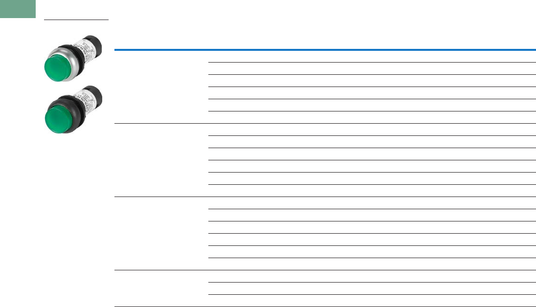
T37-132 Logic Control Products CA08100001K—June 2012 www.eatoncanada.ca
37
37
37
37
37
37
37
37
37
37
37
37
37
37
37
37
37
37
37
37
37
37
37
37
37
37
37
37
37
37
37.5
Pushbuttons and Indicating Lights
22.5 mm Compact Pushbuttons—C22
Illuminated, Extended, Momentary
Illuminated Pushbuttons, Extended, Momentary
LED Colour
Button
Colour Voltage
Button
Etching
Contact Block
Configuration
Silver Bezel
Catalogue Number
Black Bezel
Catalogue Number
Green Green 24 Vac/Vdc — 1NO C22-DLH-G-K10-24 C22S-DLH-G-K10-24
120 Vac — 1NO C22-DLH-G-K10-120 C22S-DLH-G-K10-120
230 Vac — 1NO C22-DLH-G-K10-230 C22S-DLH-G-K10-230
24 Vac/Vdc X1 1NO C22-DLH-G-X1-K10-24 C22S-DLH-G-X1-K10-24
120 Vac X1 1NO C22-DLH-G-X1-K10-120 C22S-DLH-G-X1-K10-12
230 Vac X1 1NO C22-DLH-G-X1-K10-230 C22S-DLH-G-X1-K10-23
Red Red 24 Vac/Vdc — 1NC C22-DLH-R-K01-24 C22S-DLH-R-K01-24
120 Vac — 1NC C22-DLH-R-K01-120 C22S-DLH-R-K01-120
230 Vac — 1NC C22-DLH-R-K01-230 C22S-DLH-R-K01-230
24 Vac/Vdc X0 1NC C22-DLH-R-X0-K01-24 C22S-DLH-R-X0-K01-24
120 Vac X0 1NC C22-DLH-R-X0-K01-120 C22S-DLH-R-X0-K01-12
230 Vac X0 1NC C22-DLH-R-X0-K01-230 C22S-DLH-R-X0-K01-23
White White 24 Vac/Vdc — 1NO C22-DLH-W-K10-24 C22S-DLH-W-K10-24
120 Vac — 1NO C22-DLH-W-K10-120 C22S-DLH-W-K10-120
230 Vac — 1NO C22-DLH-W-K10-230 C22S-DLH-W-K10-230
24 Vac/Vdc X1 1NO C22-DLH-W-X1-K10-24 C22S-DLH-W-X1-K10-24
120 Vac X1 1NO C22-DLH-W-X1-K10-120 C22S-DLH-W-X1-K10-12
230 Vac X1 1NO C22-DLH-W-X1-K10-230 C22S-DLH-W-X1-K10-23
Blue Blue 24 Vac/Vdc — 1NO C22-DLH-B-K10-24 C22S-DLH-B-K10-24
120 Vac — 1NO C22-DLH-B-K10-120 C22S-DLH-B-K10-120
230 Vac — 1NO C22-DLH-B-K10-230 C22S-DLH-B-K10-230
C22(S)-DLH-_
Tab37book.fm Page 132 Tuesday, July 3, 2012 10:46 PM
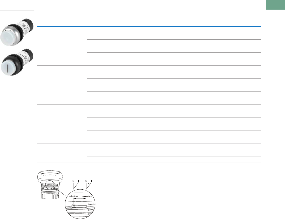
Logic Control Products CA08100001K—June 2012 www.eatoncanada.ca T37-133
37
37
37
37
37
37
37
37
37
37
37
37
37
37
37
37
37
37
37
37
37
37
37
37
37
37
37
37
37
37
37.5
Pushbuttons and Indicating Lights
22.5 mm Compact Pushbuttons—C22
Illuminated, Extended, Maintained
Illuminated Pushbuttons, Flush, Maintained
Note: Maintained pushbuttons can be converted in the field to momentary operation by
switching the locking ring, which is accessible through the side of the operator body.
LED Colour
Button
Colour Voltage
Button
Etching
Contact Block
Configuration
Silver Bezel
Catalogue Number
Black Bezel
Catalogue Number
Green Green 24 Vac/Vdc — 1NO C22-DRLH-G-K10-24 C22S-DRLH-G-K10-24
120 Vac — 1NO C22-DRLH-G-K10-120 C22S-DRLH-G-K10-120
230 Vac — 1NO C22-DRLH-G-K10-230 C22S-DRLH-G-K10-230
24 Vac/Vdc X1 1NO C22-DRLH-G-X1-K10-24 C22S-DRLH-G-X1-K10-24
120 Vac X1 1NO C22-DRLH-G-X1-K10-120 C22S-DRLH-G-X1-K10-120
230 Vac X1 1NO C22-DRLH-G-X1-K10-230 C22S-DRLH-G-X1-K10-230
Red Red 24 Vac/Vdc — 1NC C22-DRLH-R-K01-24 C22S-DRLH-R-K01-24
120 Vac — 1NC C22-DRLH-R-K01-120 C22S-DRLH-R-K01-120
230 Vac — 1NC C22-DRLH-R-K01-230 C22S-DRLH-R-K01-230
24 Vac/Vdc X0 1NC C22-DRLH-R-X0-K01-24 C22S-DRLH-R-X0-K01-24
120 Vac X0 1NC C22-DRLH-R-X0-K01-120 C22S-DRLH-R-X0-K01-120
230 Vac X0 1NC C22-DRLH-R-X0-K01-230 C22S-DRLH-R-X0-K01-230
White White 24 Vac/Vdc — 1NO C22-DRLH-W-K10-24 C22S-DRLH-W-K10-24
120 Vac — 1NO C22-DRLH-W-K10-120 C22S-DRLH-W-K10-120
230 Vac — 1NO C22-DRLH-W-K10-230 C22S-DRLH-W-K10-230
24 Vac/Vdc X1 1NO C22-DRLH-W-X1-K10-24 C22S-DRLH-W-X1-K10-24
120 Vac X1 1NO C22-DRLH-W-X1-K10-120 C22S-DRLH-W-X1-K10-120
230 Vac X1 1NO C22-DRLH-W-X1-K10-230 C22S-DRLH-W-X1-K10-230
Blue Blue 24 Vac/Vdc — 1NO C22-DRLH-B-K10-24 C22S-DRLH-B-K10-24
120 Vac — 1NO C22-DRLH-B-K10-120 C22S-DRLH-B-K10-120
230 Vac — 1NO C22-DRLH-B-K10-230 C22S-DRLH-B-K10-230
C22(S)-DRLH-_
Tab37book.fm Page 133 Tuesday, July 3, 2012 10:46 PM
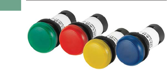
T37-134 Logic Control Products CA08100001K—June 2012 www.eatoncanada.ca
37
37
37
37
37
37
37
37
37
37
37
37
37
37
37
37
37
37
37
37
37
37
37
37
37
37
37
37
37
37
37.5
Pushbuttons and Indicating Lights
22.5 mm Compact Pushbuttons—C22
Indicating Lights Contents
Description Page
Pushbuttons—Non-Illuminated and
Illuminated . . . . . . . . . . . . . . . . . . . . . . . . . . . . . . . . T37-125
Indicating Lights
Catalogue Number Selection . . . . . . . . . . . . . . . . . T37-135
Product Selection . . . . . . . . . . . . . . . . . . . . . . . . . . T37-135
Emergency Stops . . . . . . . . . . . . . . . . . . . . . . . . . . . . T37-136
Selector Switches . . . . . . . . . . . . . . . . . . . . . . . . . . . . T37-139
Technical Data and Specifications . . . . . . . . . . . . . . . . T37-144
Dimensions . . . . . . . . . . . . . . . . . . . . . . . . . . . . . . . . . T37-146
Indicating Lights
Product Description
C22 indicating lights use a
combination of a durable,
bright LED unit and modern
lenses designed specifically
for this type of LED to create
a bright and visible indicating
light. As with the
pushbuttons, the indicating
light lenses can be laser
etched, simply order without
lens and order M22/C22
custom etched lenses
to attach.
Note: For additional accessories,
please see section 37.4 Modular
Pushbuttons—M22 of this
catalogue.
Features
●LED offering only for
improved brightness
quality and up to 100,000
hours of operation
●Lenses specifically
designed for LED
illumination
●Lenses capable of being
laser etched for custom
solutions that last
Protection Type
●IP67/IP69K
●NEMA 4X, 13
Tab37book.fm Page 134 Tuesday, July 3, 2012 10:46 PM
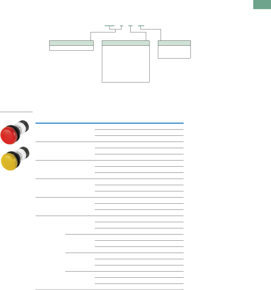
Logic Control Products CA08100001K—June 2012 www.eatoncanada.ca T37-135
37
37
37
37
37
37
37
37
37
37
37
37
37
37
37
37
37
37
37
37
37
37
37
37
37
37
37
37
37
37
37.5
Pushbuttons and Indicating Lights
22.5 mm Compact Pushbuttons—C22
Catalogue Number Selection
Catalogue Number Selection is for illustrative purposes only and not to be used to create new catalogue numbers.
Indicating Lights
Product Selection
Indicating Lights
Indicating Lights
Note
Use white LED for both white and yellow lenses.
Lens Colour LED Colour Voltage Catalogue Number
Green Green 24 Vac/Vdc C22-L-G-24
120 Vac C22-L-G-120
230 Vac C22-L-G-230
Red Red 24 Vac/Vdc C22-L-R-24
120 Vac C22-L-R-120
230 Vac C22-L-R-230
White White 24 Vac/Vdc C22-L-W-24
120 Vac C22-L-W-120
230 Vac C22-L-W-230
Yellow White 24 Vac/Vdc C22-L-Y-24
120 Vac C22-L-Y-120
230 Vac C22-L-Y-230
Blue Blue 24 Vac/Vdc C22-L-B-24
120 Vac C22-L-B-120
230 Vac C22-L-B-230
Without Lens Green 24 Vac/Vdc C22-L-XG-24
120 Vac C22-L-XG-120
230 Vac C22-L-XG-230
Red 24 Vac/Vdc C22-L-XR-24
120 Vac C22-L-XR-120
230 Vac C22-L-XR-230
White 24 Vac/Vdc C22-L-XW-24
120 Vac C22-L-XW-120
230 Vac C22-L-XW-230
Blue 24 Vac/Vdc C22-L-XB-24
120 Vac C22-L-XB-120
230 Vac C22-L-XB-230
C22 - L - G - 24
Bezel
C22-L = Flush indicating light
LED Voltage
24 = 24 Vac/Vdc
120 = 120 Vac
230 = 230 Vac
LED/Lens Colour
G = Green
R = Red
W = White
Y = Yellow
B = Blue
XG = Green without lens
XR = Red without lens
XW = White without lens
XB = Blue without lens
C22-L-_
Tab37book.fm Page 135 Tuesday, July 3, 2012 10:46 PM

T37-136 Logic Control Products CA08100001K—June 2012 www.eatoncanada.ca
37
37
37
37
37
37
37
37
37
37
37
37
37
37
37
37
37
37
37
37
37
37
37
37
37
37
37
37
37
37
37.5
Pushbuttons and Indicating Lights
22.5 mm Compact Pushbuttons—C22
Emergency Stops Contents
Description Page
Pushbuttons—Non-Illuminated and
Illuminated . . . . . . . . . . . . . . . . . . . . . . . . . . . . . . . . T37-125
Indicating Lights . . . . . . . . . . . . . . . . . . . . . . . . . . . . . T37-134
Emergency Stops
Non-Illuminated, Twist-Release . . . . . . . . . . . . . . . T37-137
Non-Illuminated, Keyed-Release . . . . . . . . . . . . . . T37-137
Selector Switches . . . . . . . . . . . . . . . . . . . . . . . . . . . . T37-139
Technical Data and Specifications . . . . . . . . . . . . . . . . T37-144
Dimensions . . . . . . . . . . . . . . . . . . . . . . . . . . . . . . . . . T37-146
Emergency Stops
Product Description
C22 emergency stops are a
durable and reliable solution
to a variety of e-stop
applications. This compact
e-stop, available as twist-to-
release and keyed-release,
is a simple product that
eliminates the need for self-
monitoring contact blocks,
all while still meeting almost
all of the industry safety
standards.
Note: For additional accessories,
please see section 37.4 Modular
Pushbuttons—M22 of this
catalogue.
Features
●Available in both twist-
release and keyed-release
with either 45 mm or
60 mm operators
Protection Type
●Twist-Release
●IP67/IP69K
●Keyed-Release
●IP66
●NEMA 4X, 13
Tab37book.fm Page 136 Tuesday, July 3, 2012 10:46 PM
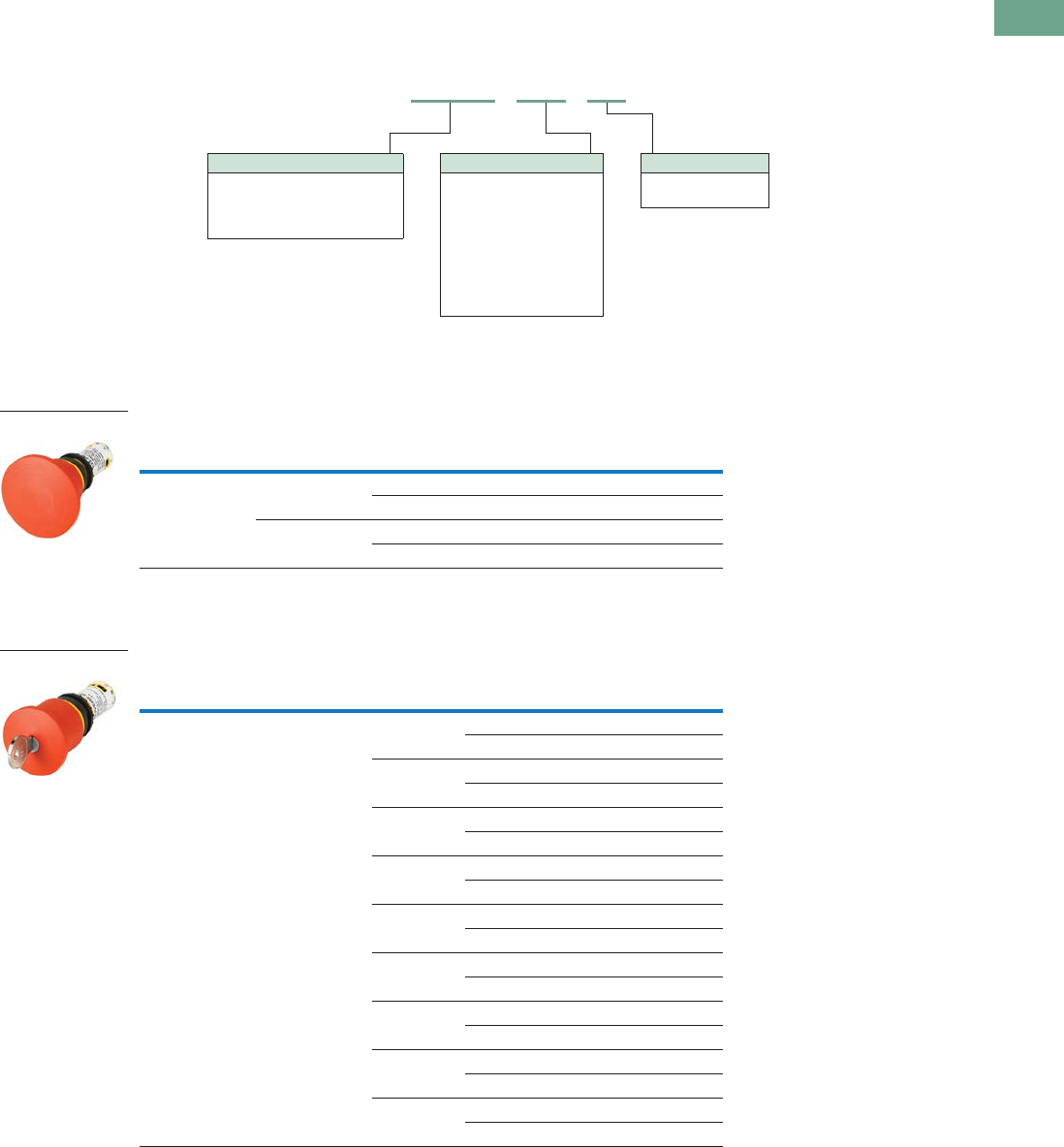
Logic Control Products CA08100001K—June 2012 www.eatoncanada.ca T37-137
37
37
37
37
37
37
37
37
37
37
37
37
37
37
37
37
37
37
37
37
37
37
37
37
37
37
37
37
37
37
37.5
Pushbuttons and Indicating Lights
22.5 mm Compact Pushbuttons—C22
Catalogue Number Selection
Catalogue Number Selection is for illustrative purposes only and not to be used to create new catalogue numbers.
Emergency Stops
Product Selection
Non-Illuminated, Twist-Release
Non-Illuminated Emergency Stops, Twist-Release
Non-Illuminated, Keyed-Release
Non-Illuminated Emergency Stops, Keyed-Release
Release Method Operator Size
Contact Block
Configuration Catalogue Number
Twist-release 45 mm 2NC C22-PVT45P-K02
1NO/1NC C22-PVT45P-K11
60 mm 2NC C22-PVT60P-K02
1NO/1NC C22-PVT60P-K11
Release Method Operator Size Key Code
Contact Block
Configuration Catalogue Number
Keyed-release 45 mm MS1 2NC C22-PVS45P-MS1-K02
1NO/1NC C22-PVS45P-MS1-K11
MS2 2NC C22-PVS45P-MS2-K02
1NO/1NC C22-PVS45P-MS2-K11
MS3 2NC C22-PVS45P-MS3-K02
1NO/1NC C22-PVS45P-MS3-K11
MS4 2NC C22-PVS45P-MS4-K02
1NO/1NC C22-PVS45P-MS4-K11
MS5 2NC C22-PVS45P-MS5-K02
1NO/1NC C22-PVS45P-MS5-K11
MS6 2NC C22-PVS45P-MS6-K02
1NO/1NC C22-PVS45P-MS6-K11
MS7 2NC C22-PVS45P-MS7-K02
1NO/1NC C22-PVS45P-MS7-K11
MS8 2NC C22-PVS45P-MS8-K02
1NO/1NC C22-PVS45P-MS8-K11
Ronis 2NC C22-PVS45P-RS-K02
1NO/1NC C22-PVS45P-RS-K11
C22 - PVS45P - MS1 - K01
Operator Type
PVT45P = Twist-release, 45 mm
PVT60P = Twist-release, 60 mm
PVS45P = Key-release, 45 mm
PVS60P = Key-release, 60 mm
Key Code
MS1 = MS1
MS2 = MS2
MS3 = MS3
MS4 = MS4
MS5 = MS5
MS6 = MS6
MS7 = MS7
MS8 = MS8
RS = Ronis-445
Contact Blocks
K02 = 2NC
K11 = 1NO/1NC
C22-PVT_
C22-PVS_
Tab37book.fm Page 137 Tuesday, July 3, 2012 10:46 PM
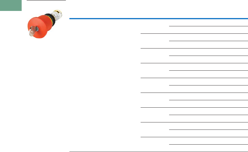
T37-138 Logic Control Products CA08100001K—June 2012 www.eatoncanada.ca
37
37
37
37
37
37
37
37
37
37
37
37
37
37
37
37
37
37
37
37
37
37
37
37
37
37
37
37
37
37
37.5
Pushbuttons and Indicating Lights
22.5 mm Compact Pushbuttons—C22
Non-Illuminated Emergency Stops, Keyed-Release, continued
Release Method Operator Size Key Code
Contact Block
Configuration Catalogue Number
Keyed-release 60 mm MS1 2NC C22-PVS60P-MS1-K02
1NO/1NC C22-PVS60P-MS1-K11
MS2 2NC C22-PVS60P-MS2-K02
1NO/1NC C22-PVS60P-MS2-K11
MS3 2NC C22-PVS60P-MS3-K02
1NO/1NC C22-PVS60P-MS3-K11
MS4 2NC C22-PVS60P-MS4-K02
1NO/1NC C22-PVS60P-MS4-K11
MS5 2NC C22-PVS60P-MS5-K02
1NO/1NC C22-PVS60P-MS5-K11
MS6 2NC C22-PVS60P-MS6-K02
1NO/1NC C22-PVS60P-MS6-K11
MS7 2NC C22-PVS60P-MS7-K02
1NO/1NC C22-PVS60P-MS7-K11
MS8 2NC C22-PVS60P-MS8-K02
1NO/1NC C22-PVS60P-MS8-K11
Ronis 2NC C22-PVS60P-RS-K02
1NO/1NC C22-PVS60P-RS-K11
C22-PVS_
Tab37book.fm Page 138 Tuesday, July 3, 2012 10:46 PM

Logic Control Products CA08100001K—June 2012 www.eatoncanada.ca T37-139
37
37
37
37
37
37
37
37
37
37
37
37
37
37
37
37
37
37
37
37
37
37
37
37
37
37
37
37
37
37
37.5
Pushbuttons and Indicating Lights
22.5 mm Compact Pushbuttons—C22
Selector Switches Contents
Description Page
Pushbuttons—Non-Illuminated and
Illuminated . . . . . . . . . . . . . . . . . . . . . . . . . . . . . . . . T37-125
Indicating Lights . . . . . . . . . . . . . . . . . . . . . . . . . . . . . T37-134
Emergency Stops . . . . . . . . . . . . . . . . . . . . . . . . . . . . T37-136
Selector Switches
Non-Illuminated, Knob Type . . . . . . . . . . . . . . . . . . T37-140
Non-Illuminated, Key Operated . . . . . . . . . . . . . . . T37-141
Technical Data and Specifications . . . . . . . . . . . . . . . . T37-144
Dimensions . . . . . . . . . . . . . . . . . . . . . . . . . . . . . . . . . T37-146
Selector Switches
Product Description
With over 20 variations of
operation and 8 varieties of
key codes, the C22 line offers
a very complete line of
selector switches.
Note: For additional accessories,
please see section 37.4 Modular
Pushbuttons—M22 of this
catalogue.
Features
●Selector switch (non-
keyed) rated for 1 million
mechanical operations
●Momentary selector
switches are field
convertible from
momentary to maintained
Protection Type
●IP65
●NEMA 4X, 13
Tab37book.fm Page 139 Tuesday, July 3, 2012 10:46 PM

T37-140 Logic Control Products CA08100001K—June 2012 www.eatoncanada.ca
37
37
37
37
37
37
37
37
37
37
37
37
37
37
37
37
37
37
37
37
37
37
37
37
37
37
37
37
37
37
37.5
Pushbuttons and Indicating Lights
22.5 mm Compact Pushbuttons—C22
Catalogue Number Selection
Catalogue Number Selection is for illustrative purposes only and not to be used to create new catalogue numbers.
Selector Switches—Non-Keyed
Product Selection
Non-Illuminated, Knob Type
Non-Illuminated Selector Switches, Knob Type
Note: Momentary selector switches can be field converted to maintained.
Type
Switching
Position
Contact Block
Configuration
Silver Bezel
Catalogue Number
Black Bezel
Catalogue Number
Two-position Momentary 1NO C22-WK-K10 C22S-WK-K10
2NO C22-WK-K20 C22S-WK-K20
1NC C22-WK-K01 C22S-WK-K01
2NC C22-WK-K02 C22S-WK-K02
1NO/1NC C22-WK-K11 C22S-WK-K11
Momentary 1NO C22-WKV-K10 C22S-WKV-K10
2NO C22-WKV-K20 C22S-WKV-K20
1NC C22-WKV-K01 C22S-WKV-K01
2NC C22-WKV-K02 C22S-WKV-K02
1NO/1NC C22-WKV-K11 C22S-WKV-K11
Maintained 1NO C22-WRK-K10 C22S-WRK-K10
2NO C22-WRK-K20 C22S-WRK-K20
1NC C22-WRK-K01 C22S-WRK-K01
2NC C22-WRK-K02 C22S-WRK-K02
1NO/1NC C22-WRK-K11 C22S-WRK-K11
Maintained 1NO C22-WRKV-K10 C22S-WRKV-K10
2NO C22-WRKV-K20 C22S-WRKV-K20
1NC C22-WRKV-K01 C22S-WRKV-K01
2NC C22-WRKV-K02 C22S-WRKV-K02
1NO/1NC C22-WRKV-K11 C22S-WRKV-K11
Three-position Momentary 2NO C22-WK3-K20 C22S-WK3-K20
2NC C22-WK3-K02 C22S-WK3-K02
1NO/1NC C22-WK3-K11 C22S-WK3-K11
Maintained 2NO C22-WRK3-K20 C22S-WRK3-K20
2NC C22-WRK3-K02 C22S-WRK3-K02
1NO/1NC C22-WRK3-K11 C22S-WRK3-K11
C22 - WK - K10
Bezel
C22 = Silver
C22S = Black
Operator Type
WK = 2-position, momentary
WKV = 2-position, momentary, “V” position
WRK = 2-position, maintained
WRKV = 2-position, maintained, “V” position
WK3 = 3-position, momentary
WRK3 = 3-position, maintained
Contact Blocks
K10 = 1NO
K20 = 2NO
K01 = 1NC
K02 = 2NC
K11 = 1NO/1NC
C22(S)-WK-_/
C22(S)-WRK_
40˚
60˚
40˚
60˚
40˚40˚
60˚ 60˚
Tab37book.fm Page 140 Tuesday, July 3, 2012 10:46 PM
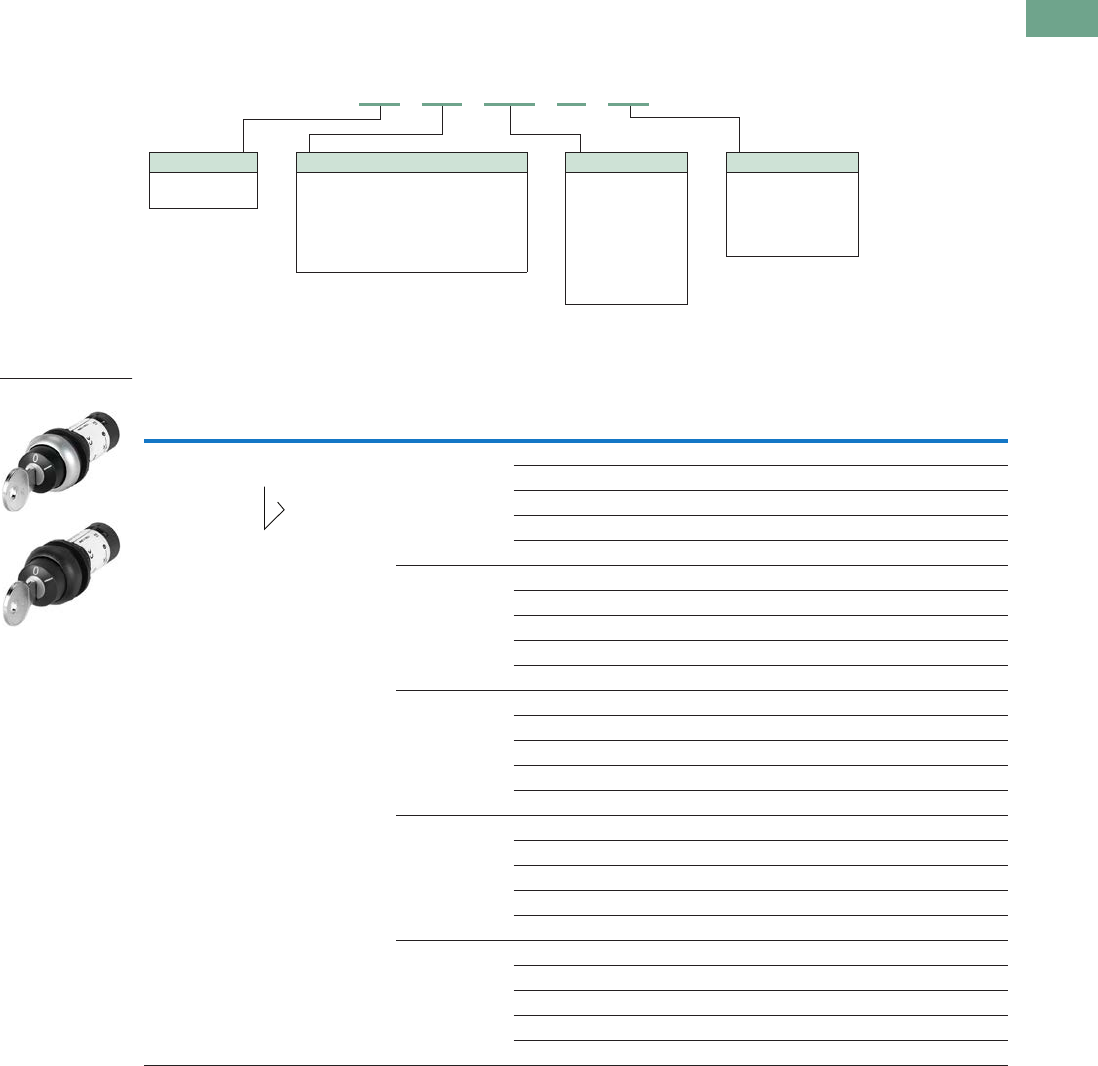
Logic Control Products CA08100001K—June 2012 www.eatoncanada.ca T37-141
37
37
37
37
37
37
37
37
37
37
37
37
37
37
37
37
37
37
37
37
37
37
37
37
37
37
37
37
37
37
37.5
Pushbuttons and Indicating Lights
22.5 mm Compact Pushbuttons—C22
Catalogue Number Selection
Catalogue Number Selection is for illustrative purposes only and not to be used to create new catalogue numbers.
Selector Switches—Keyed
Non-Illuminated, Key Operated
Non-Illuminated Selector Switches, Key Operated
Note: Momentary selector switches can be field converted to maintained.
Position Type Key Code
Contact Block
Configuration
Silver Bezel
Catalogue Number
Black Bezel
Catalogue Number
Two-position Momentary
key removal left
MS1 1NO C22-WS-MS1-K10 C22S-WS-MS1-K10
2NO C22-WS-MS1-K20 C22S-WS-MS1-K20
1NC C22-WS-MS1-K01 C22S-WS-MS1-K01
2NC C22-WS-MS1-K02 C22S-WS-MS1-K02
1NO/1NC C22-WS-MS1-K11 C22S-WS-MS1-K11
MS2 1NO C22-WS-MS2-K10 C22S-WS-MS2-K10
2NO C22-WS-MS2-K20 C22S-WS-MS2-K20
1NC C22-WS-MS2-K01 C22S-WS-MS2-K01
2NC C22-WS-MS2-K02 C22S-WS-MS2-K02
1NO/1NC C22-WS-MS2-K11 C22S-WS-MS2-K11
MS3 1NO C22-WS-MS3-K10 C22S-WS-MS3-K10
2NO C22-WS-MS3-K20 C22S-WS-MS3-K20
1NC C22-WS-MS3-K01 C22S-WS-MS3-K01
2NC C22-WS-MS3-K02 C22S-WS-MS3-K02
1NO/1NC C22-WS-MS3-K11 C22S-WS-MS3-K11
MS4 1NO C22-WS-MS4-K10 C22S-WS-MS4-K10
2NO C22-WS-MS4-K20 C22S-WS-MS4-K20
1NC C22-WS-MS4-K01 C22S-WS-MS4-K01
2NC C22-WS-MS4-K02 C22S-WS-MS4-K02
1NO/1NC C22-WS-MS4-K11 C22S-WS-MS4-K11
MS5 1NO C22-WS-MS5-K10 C22S-WS-MS5-K10
2NO C22-WS-MS5-K20 C22S-WS-MS5-K20
1NC C22-WS-MS5-K01 C22S-WS-MS5-K01
2NC C22-WS-MS5-K02 C22S-WS-MS5-K02
1NO/1NC C22-WS-MS5-K11 C22S-WS-MS5-K11
C22 - WS - MS1 - A1 - K10
Bezel
C22 = Silver
C22S = Black
Operator Type
WS = 2-position, momentary
WRS = 2-position, maintained
WRS-…-A1 = 2-position, maintained,
key removal left
WS3 = 3-position, momentary
WRS3 = 3-position, maintained
Contact Blocks
K10 = 1NO
K20 = 2NO
K01 = 1NC
K02 = 2NC
K11 = 1NO/1NC
Key Code
MS1 = MS1
MS2 = MS2
MS3 = MS3
MS4 = MS4
MS5 = MS5
MS6 = MS6
MS7 = MS7
MS8 = MS8
C22(S)-WS-MS_
40˚
Tab37book.fm Page 141 Tuesday, July 3, 2012 10:46 PM
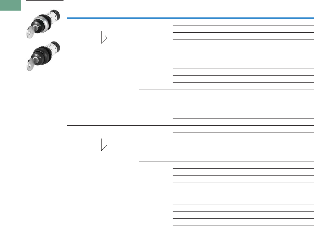
T37-142 Logic Control Products CA08100001K—June 2012 www.eatoncanada.ca
37
37
37
37
37
37
37
37
37
37
37
37
37
37
37
37
37
37
37
37
37
37
37
37
37
37
37
37
37
37
37.5
Pushbuttons and Indicating Lights
22.5 mm Compact Pushbuttons—C22
Non-Illuminated Selector Switches, Key Operated, continued
Note: Momentary selector switches can be field converted to maintained.
Position Type Key Code
Contact Block
Configuration
Silver Bezel
Catalogue Number
Black Bezel
Catalogue Number
Two-position,
continued
Momentary
key removal left
MS6 1NO C22-WS-MS6-K10 C22S-WS-MS6-K10
2NO C22-WS-MS6-K20 C22S-WS-MS6-K20
1NC C22-WS-MS6-K01 C22S-WS-MS6-K01
2NC C22-WS-MS6-K02 C22S-WS-MS6-K02
1NO/1NC C22-WS-MS6-K11 C22S-WS-MS6-K11
MS7 1NO C22-WS-MS7-K10 C22S-WS-MS7-K10
2NO C22-WS-MS7-K20 C22S-WS-MS7-K20
1NC C22-WS-MS7-K01 C22S-WS-MS7-K01
2NC C22-WS-MS7-K02 C22S-WS-MS7-K02
1NO/1NC C22-WS-MS7-K11 C22S-WS-MS7-K11
MS8 1NO C22-WS-MS8-K10 C22S-WS-MS8-K10
2NO C22-WS-MS8-K20 C22S-WS-MS8-K20
1NC C22-WS-MS8-K01 C22S-WS-MS8-K01
2NC C22-WS-MS8-K02 C22S-WS-MS8-K02
1NO/1NC C22-WS-MS8-K11 C22S-WS-MS8-K11
Two-position Maintained
key removal left/right
MS1 1NO C22-WRS-MS1-K10 C22S-WRS-MS1-K10
2NO C22-WRS-MS1-K20 C22S-WRS-MS1-K20
1NC C22-WRS-MS1-K01 C22S-WRS-MS1-K01
2NC C22-WRS-MS1-K02 C22S-WRS-MS1-K02
1NO/1NC C22-WRS-MS1-K11 C22S-WRS-MS1-K11
MS2 1NO C22-WRS-MS2-K10 C22S-WRS-MS2-K10
2NO C22-WRS-MS2-K20 C22S-WRS-MS2-K20
1NC C22-WRS-MS2-K01 C22S-WRS-MS2-K01
2NC C22-WRS-MS2-K02 C22S-WRS-MS2-K02
1NO/1NC C22-WRS-MS2-K11 C22S-WRS-MS2-K11
MS3 1NO C22-WRS-MS3-K10 C22S-WRS-MS3-K10
2NO C22-WRS-MS3-K20 C22S-WRS-MS3-K20
1NC C22-WRS-MS3-K01 C22S-WRS-MS3-K01
2NC C22-WRS-MS3-K02 C22S-WRS-MS3-K02
1NO/1NC C22-WRS-MS3-K11 C22S-WRS-MS3-K11
C22(S)-WRS-MS_
40˚
40˚
Tab37book.fm Page 142 Tuesday, July 3, 2012 10:46 PM
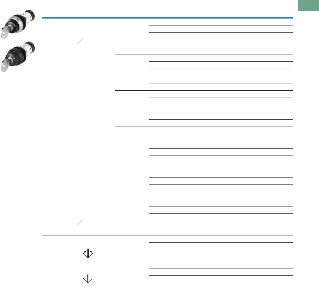
Logic Control Products CA08100001K—June 2012 www.eatoncanada.ca T37-143
37
37
37
37
37
37
37
37
37
37
37
37
37
37
37
37
37
37
37
37
37
37
37
37
37
37
37
37
37
37
37.5
Pushbuttons and Indicating Lights
22.5 mm Compact Pushbuttons—C22
Non-Illuminated Selector Switches, Key Operated, continued
Note: Momentary selector switches can be field converted to maintained.
Position Type Key Code
Contact Block
Configuration
Silver Bezel
Catalogue Number
Black Bezel
Catalogue Number
Two-position,
continued
Maintained
key removal left/right
MS4 1NO C22-WRS-MS4-K10 C22S-WRS-MS4-K10
2NO C22-WRS-MS4-K20 C22S-WRS-MS4-K20
1NC C22-WRS-MS4-K01 C22S-WRS-MS4-K01
2NC C22-WRS-MS4-K02 C22S-WRS-MS4-K02
1NO/1NC C22-WRS-MS4-K11 C22S-WRS-MS4-K11
MS5 1NO C22-WRS-MS5-K10 C22S-WRS-MS5-K10
2NO C22-WRS-MS5-K20 C22S-WRS-MS5-K20
1NC C22-WRS-MS5-K01 C22S-WRS-MS5-K01
2NC C22-WRS-MS5-K02 C22S-WRS-MS5-K02
1NO/1NC C22-WRS-MS5-K11 C22S-WRS-MS5-K11
MS6 1NO C22-WRS-MS6-K10 C22S-WRS-MS6-K10
2NO C22-WRS-MS6-K20 C22S-WRS-MS6-K20
1NC C22-WRS-MS6-K01 C22S-WRS-MS6-K01
2NC C22-WRS-MS6-K02 C22S-WRS-MS6-K02
1NO/1NC C22-WRS-MS6-K11 C22S-WRS-MS6-K11
MS7 1NO C22-WRS-MS7-K10 C22S-WRS-MS7-K10
2NO C22-WRS-MS7-K20 C22S-WRS-MS7-K20
1NC C22-WRS-MS7-K01 C22S-WRS-MS7-K01
2NC C22-WRS-MS7-K02 C22S-WRS-MS7-K02
1NO/1NC C22-WRS-MS7-K11 C22S-WRS-MS7-K11
MS8 1NO C22-WRS-MS7-K10 C22S-WRS-MS7-K10
2NO C22-WRS-MS7-K20 C22S-WRS-MS7-K20
1NC C22-WRS-MS7-K01 C22S-WRS-MS7-K01
2NC C22-WRS-MS7-K02 C22S-WRS-MS7-K02
1NO/1NC C22-WRS-MS7-K11 C22S-WRS-MS7-K11
Two-position Maintained
key removal left
MS1 1NO C22-WRS-MS1-A1-K10 C22S-WRS-MS1-A1-K10
2NO C22-WRS-MS1-A1-K20 C22S-WRS-MS1-A1-K20
1NC C22-WRS-MS1-A1-K01 C22S-WRS-MS1-A1-K01
2NC C22-WRS-MS1-A1-K02 C22S-WRS-MS1-A1-K02
1NO/1NC C22-WRS-MS1-A1-K11 C22S-WRS-MS1-A1-K11
Three Position Momentary
Key Removal Centre
MS1 2NO C22-WS3-MS1-K20 C22S-WS3-MS1-K20
2NC C22-WS3-MS1-K02 C22S-WS3-MS1-K02
1NO/1NC C22-WS3-MS1-K11 C22S-WS3-MS1-K11
Maintained
Key Removal Left/Right
MS1 2NO C22-WRS3-MS1-K20 C22S-WRS3-MS1-K20
2NC C22-WRS3-MS1-K02 C22S-WRS3-MS1-K02
1NO/1NC C22-WRS3-MS1-K11 C22S-WRS3-MS1-K11
C22(S)-WRS…-MS1_
40˚
40˚
40˚
40˚
60˚60˚
Tab37book.fm Page 143 Tuesday, July 3, 2012 10:46 PM

T37-144 Logic Control Products CA08100001K—June 2012 www.eatoncanada.ca
37
37
37
37
37
37
37
37
37
37
37
37
37
37
37
37
37
37
37
37
37
37
37
37
37
37
37
37
37
37
37.5
Pushbuttons and Indicating Lights
22.5 mm Compact Pushbuttons—C22
Technical Data and Specifications
22.5 mm Compact Pushbuttons—C22
Pushbutton Actuators
Illuminated Pushbuttons C22 Indicator
Lights C22
Selector Switch
Actuators C22
Key-Operated
Buttons C22
Emergency Stop/
Emergency Switching
OFF Pushbuttons C22Description Unit Momentary Maintained
General
Standards IEC/EN 60947 VDE 0660
Lifespan, mechanical Operations x 1065 1 — 1 0.1 0.05
Operating frequency Operations/h >3600 >3600 — >2000 >100 >300
Actuating force N >5>5———>50
Operating torque Nm — — — >0.3 >0.5 —
Terminal screw tightening torque Nm 0.8 0.8 0.8 0.8 0.8 0.8
Threaded ring tightening torque Nm 2 2 2222
Protection type IP67, IP69K IP67, IP69K IP67, IP69K IP65 IP66 IP67, IP69K
Climatic proofing Damp heat, constant, to IEC 60068-2-78
Damp heat, cyclic, to IEC 60068-2-30
Ambient temperature
Open ˚C –25˚ to 70˚ –25˚ to 70˚ –25˚ to 70˚ –25˚ to 70˚ –25˚ to 70˚ –25˚ to 70˚
Storage ˚C –30˚ to 80˚ –30˚ to 80˚ –30˚ to 80˚ –30˚ to 80˚ –30˚ to 80˚ –30˚ to 80˚
Mounting position As required As required As required As required As required As required
Mechanical shock resistance to
IEC 60068-2-27 Shock duration
11 ms, half-sinusoidal
g303030303030
Terminal capacities
Solid mm22 x 0.5–1.5 2 x 0.5–1.5 2 x 0.5–1.5 2 x 0.5–1.5 2 x 0.5–1.5 2 x 0.5–1.5
Flexible with ferrule mm22 x 0.5–1.5 2 x 0.5–1.5 2 x 0.5–1.5 2 x 0.5–1.5 2 x 0.5–1.5 2 x 0.5–1.5
Contacts
Rated impulse withstand voltage Uimp Vac 4000 4000 4000 4000 4000 4000
Rated insulation voltage UiV 250 250 250 250 250 250
Overvoltage category/pollution
degree
III/3 III/3 III/3 III/3 III/3 III/3
Control circuit reliability
at 5 Vdc/1 mA HFFault
probability
Values follow Values follow — Values follow Values follow Values follow
at 17 Vdc/7 mA HFFault
probability
N/O contact: statistically determined
1 failure per 17 x 106 operations
N/C contact: statistically determined
1 failure per 0.9 x 10⁶ operations
— N/O contact: statistically determined 1 failure per
17 x 106 operations
N/C contact: statistically determined 1 failure per
0.9 x 10⁶ operations
at 24 Vdc/5 mA HFFault
probability
Values follow Values follow — Values follow Values follow Values follow
Max. short-circuit protective device
Fuse gG/gL A 10 10 — 10 10 10
Tab37book.fm Page 144 Tuesday, July 3, 2012 10:46 PM
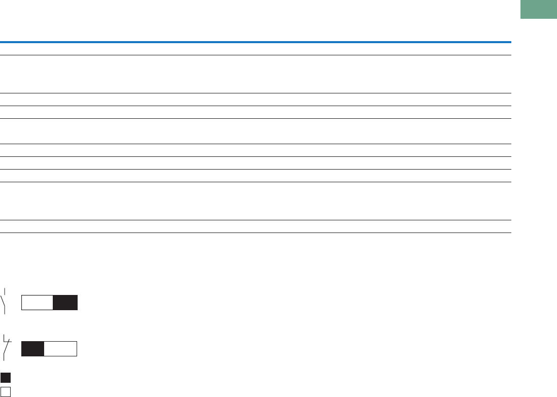
Logic Control Products CA08100001K—June 2012 www.eatoncanada.ca T37-145
37
37
37
37
37
37
37
37
37
37
37
37
37
37
37
37
37
37
37
37
37
37
37
37
37
37
37
37
37
37
37.5
Pushbuttons and Indicating Lights
22.5 mm Compact Pushbuttons—C22
22.5 mm Compact Pushbuttons—C22, continued
Contact Travel
Contact Travel Diagram
Push-button Actuators
Illuminated Pushbuttons C22 Indicator
Lights C22
Selector Switch
Actuators C22
Key-Operated
Buttons C22
Emergency Stop/
Emergency Switching
OFF Pushbuttons C22Description Unit Momentary Maintained
Switching Capacity
Rated operational current
AC-15
24V IeA44— 4 4 4
110V IeA22— 2 2 2
230V IeA 1.5 1.5 — 1.5 1.5 1.5
DC-13
24V IeA33— 3 3 3
60V IeA11— 1 1 1
110V IeA 0.6 0.6 — 0.6 0.6 0.6
220V IeA 0.3 0.3 — 0.3 0.3 0.3
Lifespan, electrical
AC-15
230V/0.5A Operations x 1060.4 0.4 — 0.4 0.4 0.4
230V/1.0A x 1060.6 0.6 — 0.6 0.6 0.6
0
0
3.15 5.5
5.52.2
3
4
2
1
Contact closed
Contact open
Tab37book.fm Page 145 Tuesday, July 3, 2012 10:46 PM
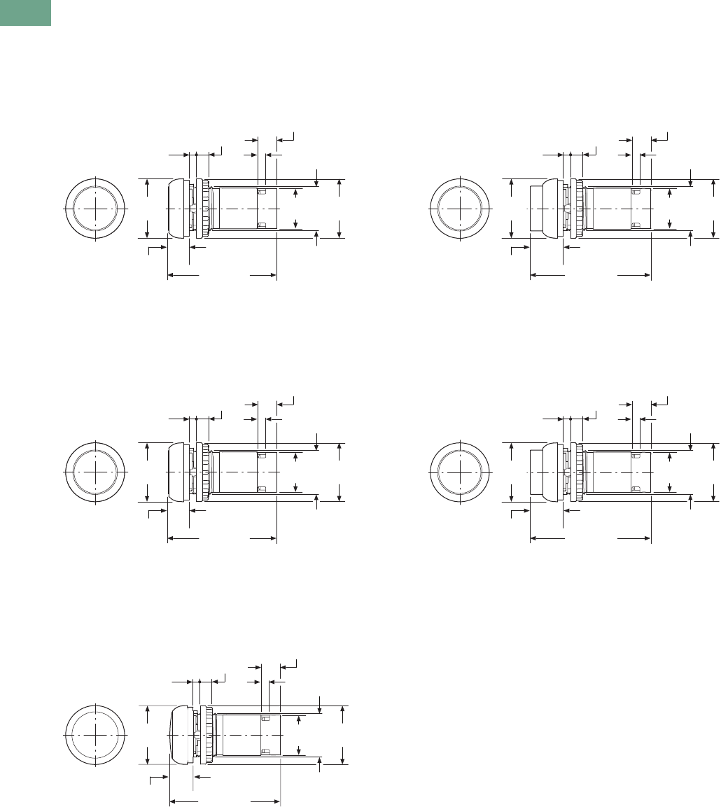
T37-146 Logic Control Products CA08100001K—June 2012 www.eatoncanada.ca
37
37
37
37
37
37
37
37
37
37
37
37
37
37
37
37
37
37
37
37
37
37
37
37
37
37
37
37
37
37
37.5
Pushbuttons and Indicating Lights
22.5 mm Compact Pushbuttons—C22
Dimensions
Approximate Dimensions in mm [in]
Illuminated Pushbuttons
Flat
C22(S)-DRL_/C22(S)-DL_
Extended
C22(S)-DRLH_/C22(S)-DLH_
Pushbutton Actuators
Flat
C22(S)-DR_/C22(S)-D_
Extended
C22(S)-DRH_/C22(S)-DH_
Indicating Lights
Flat
C22-L_
Ø29.7
[1.17]
M22 x 1.5
54.6 [2.15]
1.0–6.0
[0.04–0.24]
6.0
[0.24]
4.0
[0.16]
Ø29.5
[1.16]
9.6
[0.38]
20.2
[0.80]
10.4
[0.41]
Ø29.7
[1.17]
M22 x 1.5
60.9 [2.40]
1.0–6.0
[0.04–0.24]
6.0
[0.24]
4.0
[0.16]
Ø29.5
[1.16]
9.6
[0.38]
20.2
[0.80]
16.7
[0.66]
Ø29.7
[1.17]
M22 x 1.5
54.6 [2.15]
1.0–6.0
[0.04–0.24]
6.0
[0.24]
4.0
[0.16]
Ø29.5
[1.16]
9.6
[0.38]
20.2
[0.80]
10.4
[0.41]
Ø29.7
[1.17]
M22 x 1.5
60.9 [2.40]
1.0–6.0
[0.04–0.24]
6.0
[0.24]
4.0
[0.16]
Ø29.5
[1.16]
9.6
[0.38]
20.2
[0.80]
16.7
[0.66]
Ø29.7
[1.17]
M22 x 1.5
55.9 [2.20]
1.0–6.0
[0.04–0.24]
6.0
[0.24]
4.0
[0.16]
Ø29.5
[1.16]
9.6
[0.38]
Ø20.2
[0.80]
11.7
[0.46]
Tab37book.fm Page 146 Tuesday, July 3, 2012 10:46 PM
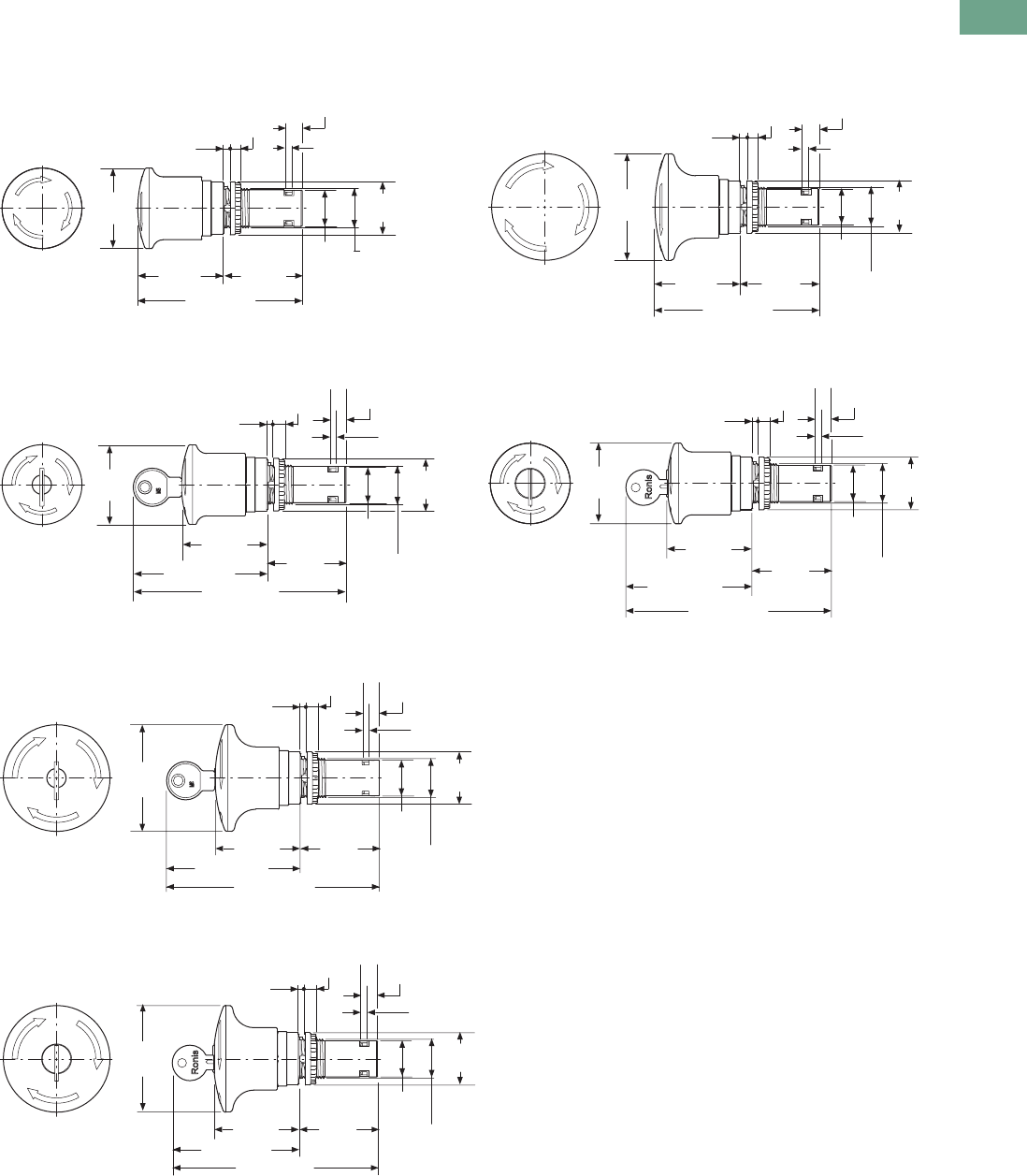
Logic Control Products CA08100001K—June 2012 www.eatoncanada.ca T37-147
37
37
37
37
37
37
37
37
37
37
37
37
37
37
37
37
37
37
37
37
37
37
37
37
37
37
37
37
37
37
37.5
Pushbuttons and Indicating Lights
22.5 mm Compact Pushbuttons—C22
Approximate Dimensions in mm [in]
Emergency Stop/Emergency Switching OFF Pushbuttons
C22-PVT45P_
C22-PVT45P-MS_
C22-PVT60P_
C22-PVT45P-RS_
C22-PVT60P-MS_
C22-PVT60P-MS_
Ø45.0
[1.77]
93.0 [3.66]
1.0–6.0
[0.04–0.24]
6.0
[0.24]
4.0
[0.16]
9.3
[0.37]
M22 x 1.5
Ø29.5
[1.16]
Ø20.4
[0.80]
48.0
[1.89]
45.0
[1.77]
M22 x 1.5
1.0–6.0
[0.04–0.24]
6.0
[0.24]
4.0
[0.16]
Ø29.5
[1.16]
9.3
[0.37]
Ø20.4
[0.80]
Ø45.0
[1.17]
120.0 [4.72]
75.0 [2.95]
48.0
[1.89] 45.0
[1.77]
Ø60.0
[2.36]
92.0 [3.62]
1.0–6.0
[0.04–0.24]
6.0
[0.24]
4.0
[0.16]
9.3
[0.37]
M22 x 1.5
Ø29.5
[1.16]
Ø20.4
[0.80]
48.0
[1.89]
45.0
[1.77]
M22 x 1.5
1.0–6.0
[0.04–0.24]
6.0
[0.24]
4.0
[0.16]
Ø29.5
[1.16]
9.3
[0.37]
Ø20.4
[0.80]
Ø45.0
[1.77]
116.0 [4.57]
71.0 [2.80]
48.0
[1.89] 45.0
[1.77]
M22 x 1.5
1.0–6.0
[0.04–0.24]
6.0
[0.24]
4.0
[0.16]
Ø29.5
[1.16]
9.3
[0.37]
Ø20.4
[0.80]
Ø60.0
[2.36]
120.0 [4.72]
75.0 [2.95]
48.0
[1.89]
45.0
[1.77]
M22 x 1.5
1.0–6.0
[0.04–0.24]
6.0
[0.24]
4.0
[0.16]
Ø29.5
[1.16]
9.3
[0.37]
Ø20.4
[0.80]
Ø60.0
[2.36]
116.0 [4.57]
71.0 [2.80]
48.0
[1.89]
45.0
[1.77]
Tab37book.fm Page 147 Tuesday, July 3, 2012 10:46 PM
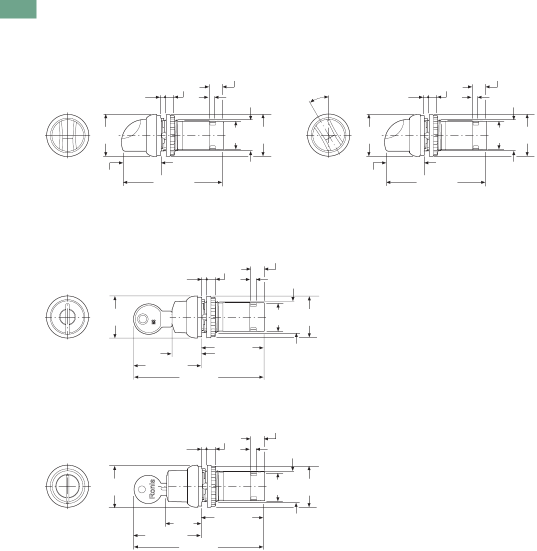
T37-148 Logic Control Products CA08100001K—June 2012 www.eatoncanada.ca
37
37
37
37
37
37
37
37
37
37
37
37
37
37
37
37
37
37
37
37
37
37
37
37
37
37
37
37
37
37
37.5
Pushbuttons and Indicating Lights
22.5 mm Compact Pushbuttons—C22
Approximate Dimensions in mm [in]
Selector Switch Actuators
C22(S)-W(R)K_
Selector Switch Actuators/V Position
C22(S)-W(R)KV_
Key Operated Actuators
C22(S)-WS(3)-MS_/C22(S)-WRS(3)-MS_
C22(S)-WS(3)-RS_/C22(S)-WRS(3)-RS_
Ø29.7
[1.17]
M22 x 1.5
72.0 [2.83]
1.0–6.0
[0.04–0.24]
6.0
[0.24]
4.0
[0.16]
Ø29.5
[1.16]
9.6
[0.38]
20.2
[0.80]
27.8
[1.09]
Ø29.7
[1.17]
M22 x 1.5
72.0 [2.83]
1.0–6.0
[0.04–0.24]
6.0
[0.24]
4.0
[0.16]
Ø29.5
[1.16]
9.6
[0.38]
20.2
[0.80]
27.8
[1.09]
30°
M22 x 1.5
1.0–6.0
[0.04–0.24]
6.0
[0.24]
4.0
[0.16]
Ø29.5
[1.16]
9.6
[0.38]
20.2
[0.80]
Ø29.7
[1.17]
92.1 [3.63]
20.8
[0.82]
47.9 [1.89]
44.2 [1.74]
M22 x 1.5
1.0–6.0
[0.04–0.24]
6.0
[0.24]
4.0
[0.16]
Ø29.5
[1.16]
9.6
[0.38]
20.2
[0.80]
Ø29.7
[1.17]
92.1 [3.63]
24.9
[0.98]
47.9 [1.89]
44.2 [1.74]
Tab37book.fm Page 148 Tuesday, July 3, 2012 10:46 PM
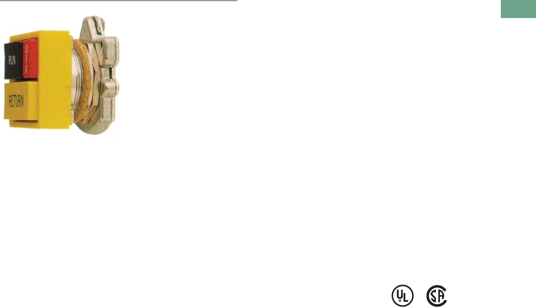
Logic Control Products CA08100001K—June 2012 www.eatoncanada.ca T37-149
37
37
37
37
37
37
37
37
37
37
37
37
37
37
37
37
37
37
37
37
37
37
37
37
37
37
37
37
37
37
37.6
Pushbuttons and Indicating Lights
30.5 mm Square Multifunction Watertight/Oiltight—E30
30.5 mm Square Multifunction Watertight/Oiltight—E30 Contents
Description Page
30.5 mm Square Multifunction
Watertight/Oiltight—E30
Product Identification . . . . . . . . . . . . . . . . . . . . . . . T37-150
Product Selection
Operators . . . . . . . . . . . . . . . . . . . . . . . . . . . . . T37-151
Operator Components . . . . . . . . . . . . . . . . . . . . T37-154
Accessories . . . . . . . . . . . . . . . . . . . . . . . . . . . . . . T37-160
Options . . . . . . . . . . . . . . . . . . . . . . . . . . . . . . . . . . T37-161
Replacement Parts . . . . . . . . . . . . . . . . . . . . . . . . . T37-164
Technical Data and Specifications . . . . . . . . . . . . . T37-165
Dimensions . . . . . . . . . . . . . . . . . . . . . . . . . . . . . . T37-166
Product Description
The E30 industrial pushbutton
and indicating light line from
Eaton’s electrical sector
features a wide selection of
square, multifunction
operators which conveniently
mount in a standard 30.5 mm
(1-13/64 in) diameter panel
hole. Up to six input and
indicating functions can be
grouped into a single
operating head, saving
valuable panel space.
Attractive square operator
styling, coupled with custom
legending of colored buttons
and lenses and many special
function accessories, makes
E30 components ideally
suited for use on control
consoles and for a variety of
industrial OEM applications.
Features
Type E30 control units consist
of a basic operator with one
or more buttons and lenses
and contact block selection
dependent on the specific
operator configuration.
●Pushbutton operators
will accommodate up to
four single depth stackable
contact blocks behind each
operating button, up to
eight circuits maximum.
●Indicating lights are
supplied complete with
either a transformer light
unit up to 600 Vac supply
line voltage or full voltage
light unit up to 120 Vac/Vdc
supply line voltage.
●Combination pushbutton
with indicating light
operators are supplied
complete with a
transformer or full voltage
unit. Contact blocks must
be ordered separately, up to
four circuits maximum.
Die Cast Construction
Each operator has high
pressure type seals to
prevent the passage of oil
and other contaminants
through the operator into the
contact structure or panel
interior. Each operator uses a
Buna N cork gasket between
the mounting flange on the
operator and the panel to
maintain oiltightness.
Standards and
Certifications
●UL Listed—File No.
E131568
●CSA Certified—File No.
LR68551
Ingress Protection
●Single and dual indicating
lights
●UL (NEMA) Type 1, 2, 3,
3R, 3S, 4, 4X, 12, 13
●All other operators
●UL (NEMA) Type 3, 3R,
4, 4X, 12, 13
Tab37book.fm Page 149 Tuesday, July 3, 2012 10:46 PM
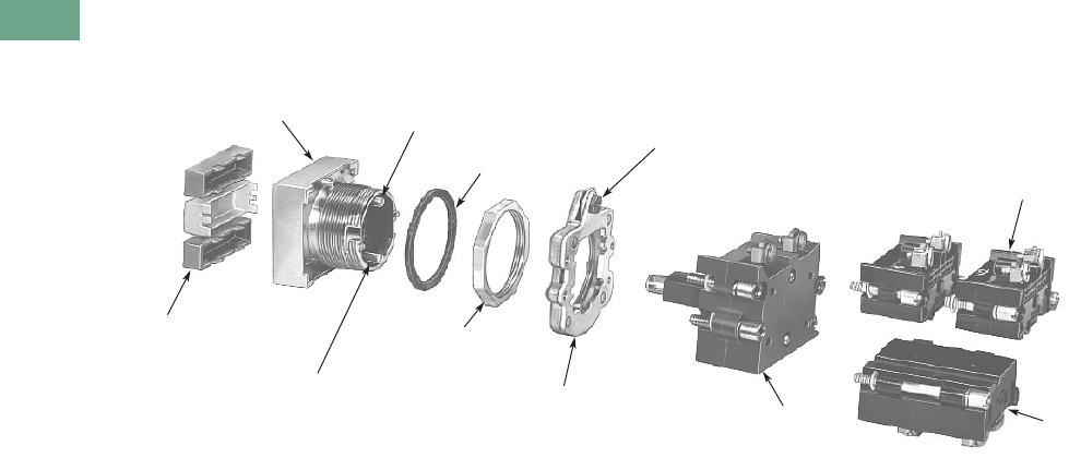
T37-150 Logic Control Products CA08100001K—June 2012 www.eatoncanada.ca
37
37
37
37
37
37
37
37
37
37
37
37
37
37
37
37
37
37
37
37
37
37
37
37
37
37
37
37
37
37
37.6
Pushbuttons and Indicating Lights
30.5 mm Square Multifunction Watertight/Oiltight—E30
Product Identification
30.5 mm Square Multifunction Watertight/Oiltight
Two Circuit
Contact Block
Transformer or
Full Voltage Light
Element—Supplied
with Operator
Locking Ring—Supplied with
Operator—Serves as Mount
for Light Element and
Contact Blocks
Retaining Nut
Secures Operator
to Panel
Lower Contact
Block Operating
Plunger
Buttons and Lenses Supplied
Blank or with Custom
Legend(s)
(see Pages T37-154 to
T37-158)
Multifunction Operator
(see Pages T37-151 to T37-153) Upper Contact Block
Operating Plunger
Gasket
Quarter Turn Screw—
Mounts Locking Ring to Operator
Single Circuit
Contact Block
Tab37book.fm Page 150 Tuesday, July 3, 2012 10:46 PM
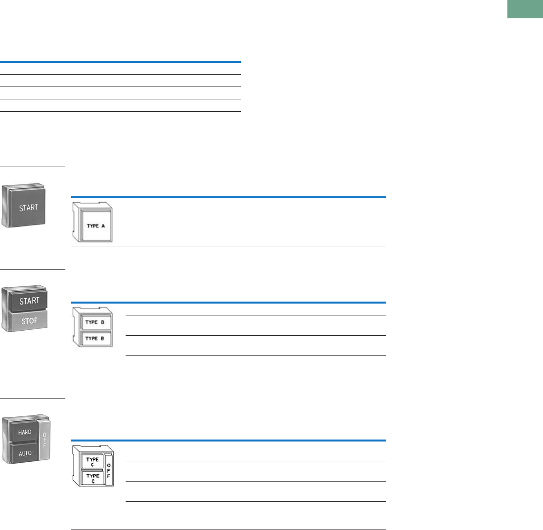
Logic Control Products CA08100001K—June 2012 www.eatoncanada.ca T37-151
37
37
37
37
37
37
37
37
37
37
37
37
37
37
37
37
37
37
37
37
37
37
37
37
37
37
37
37
37
37
37.6
Pushbuttons and Indicating Lights
30.5 mm Square Multifunction Watertight/Oiltight—E30
Product Selection
Operators
When Ordering a Complete E30 Control Unit Specify
Square Multifunction Operators
UL (NEMA) Type 3, 3R, 4, 4X, 12, 13
Single Button Operator/without Button (Order Button Separately)
Two Button Operator/without Buttons (Order Buttons Separately)
Two Button Operator with Long (OFF) Release Bar—Includes OFF Bar/Button
(Order Other Buttons Separately)
Notes
Order from table on Page T37-154.
Limited to two single circuit, one double circuit 600V or two 120V (E30KLA9) contact blocks behind each button.
Buttons are interlocked so that one of the two is maintained at all times.
Depressing the other button releases the maintained button and maintains the depressed button.
Operators are supplied as standard with red extended bar(s) marked “OFF” as shown in sketch.
For other colours or markings, contact your nearest Eaton Distributor or call our Customer Service Centre 1-800-268-3578.
For replacement of standard red release bar, order E30KR100.
Order from table on Page T37-155.
Limited to two single circuit, one double circuit 600V or two 120V (E30KLA9) contact blocks behind each button.
Catalogue Number of … Ordering Example (E30AB)
Operator E30KB130 “START”
Button(s) E30KB231 “STOP”
Contact block(s) E30KLA1 1NO
Accessories (if required) E30KLA2 1NC
Button Type
Required Operation Special Features Catalogue Number
Momentary — E30AA
Button Types
Required
Operation
Special Features Catalogue NumberTop Button Bottom Button
Momentary Momentary — E30AB
Momentary Momentary With mechanical
interlock
E30AC
Maintained
(all contacts)
Release
(all contacts)
—E30AD
Maintained
(all contacts)
Release
(all contacts)
With mechanical
interlock
E30AP
Button Types
Required
Operation
Special Features Catalogue NumberTop Button Bottom Button
Maintained Maintained — E30AF
Maintained Maintained With mechanical
interlock
E30AG
Maintained Momentary With mechanical
interlock
E30AH
Maintained
(all contacts)
Maintained
(bottom contacts only)
Top button operates
both top and
bottom contacts
E30AK
Shown with
Extended Button
Single Button Operator
Two Button Operator
Shown with
Extended Buttons
Two Button Operator
Shown with Long
Release Bar
Tab37book.fm Page 151 Tuesday, July 3, 2012 10:46 PM
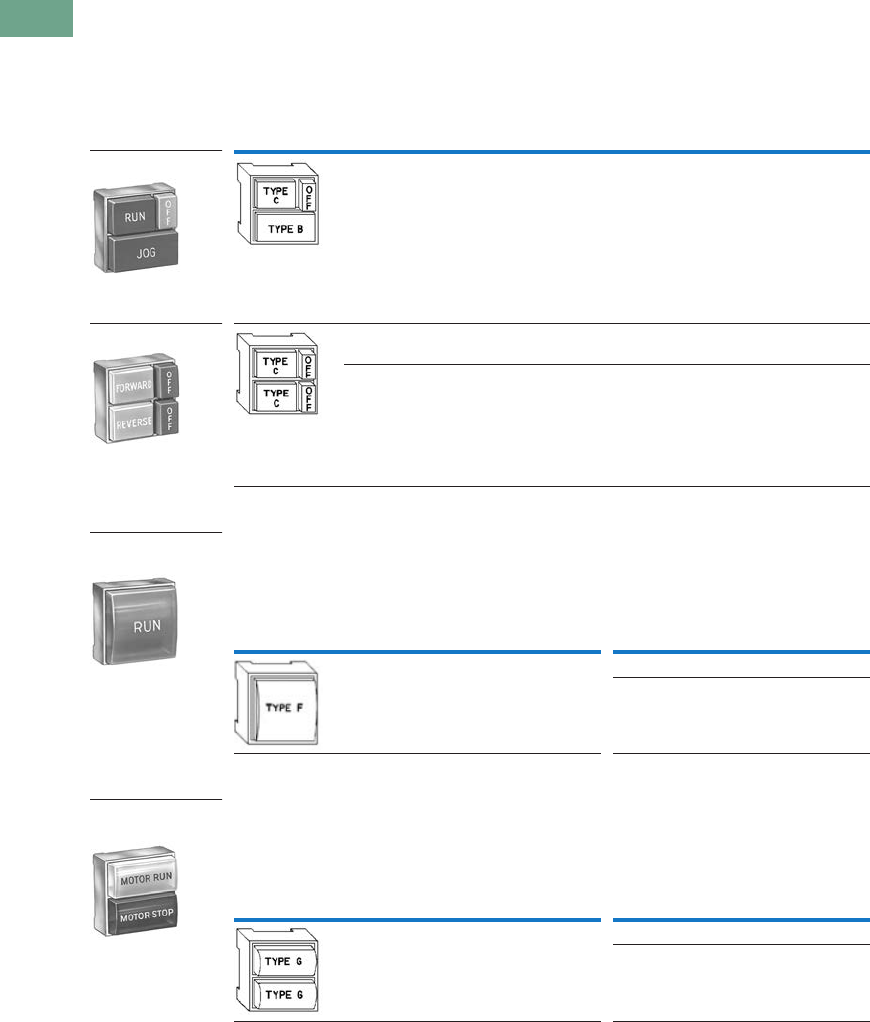
T37-152 Logic Control Products CA08100001K—June 2012 www.eatoncanada.ca
37
37
37
37
37
37
37
37
37
37
37
37
37
37
37
37
37
37
37
37
37
37
37
37
37
37
37
37
37
37
37.6
Pushbuttons and Indicating Lights
30.5 mm Square Multifunction Watertight/Oiltight—E30
Square Multifunction Operators and Indicating Lights
UL (NEMA) Type 3, 3R, 4, 4X, 12, 13
Two Button Operator with (OFF) Release—Includes OFF Bar/Button(s)
(Order Other Buttons Separately)
Single Indicating Light Unit/without Lens (Order Lens Separately)
Dual Indicating Light Unit/without Lenses (Order Lenses Separately)
Notes
Order from table on Page T37-155.
Operators are supplied as standard with red extended release bar(s) marked “OFF” as shown in sketch. For other colours or
markings, contact your nearest Eaton Distributor or call our Customer Service Centre 1-800-268-3578. For replacement of
standard red release bar, order E30KR101.
Order from table on Page T37-156.
Light units will also accept LED lamps. For LED part numbers, see table on Page T37-164.
Order from table on Page T37-157.
Button Types
Required
Operation
Special Features Catalogue NumberTop Button Bottom Button
Maintained Momentary Release bar for
top button
E30AL
Maintained Maintained Individual release
bars for each button
E30AN
Maintained
with interlock
Maintained
with interlock
Individual release
bars for each button
E30AM
Lens Type
Required
Type of Light Element
Transformer
(60/50 Hertz AC)
Full Voltage
(60/50 Hertz AC or DC)
Voltage
Lamp
Number Catalogue Number Voltage
Lamp
Number Catalogue Number
120 6PSB E30BA 24 24PSB E30BJ
120 120PSB E30BM
Lens Types
Required
Type of Light Element
Transformer
(60/50 Hertz AC)
Full Voltage
(60/50 Hertz AC or DC)
Voltage
Lamp
Number Catalogue Number Voltage
Lamp
Number Catalogue Number
120 6PSB E30CA 24 24PSB E30CJ
120 120PSB E30CM
Shown with Release
Bar for Top Button
Two Button Operator
Shown with Release
Bars for Each Button
Two Button Operator
Shown with Lens
Single Indicating
Light Unit
Shown with Lens
Dual Indicating
Light Unit
Tab37book.fm Page 152 Tuesday, July 3, 2012 10:46 PM
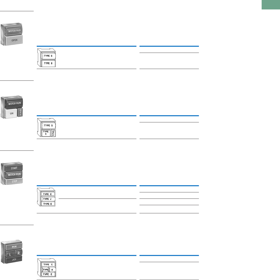
Logic Control Products CA08100001K—June 2012 www.eatoncanada.ca T37-153
37
37
37
37
37
37
37
37
37
37
37
37
37
37
37
37
37
37
37
37
37
37
37
37
37
37
37
37
37
37
37.6
Pushbuttons and Indicating Lights
30.5 mm Square Multifunction Watertight/Oiltight—E30
UL (NEMA) Type 3, 3R, 4, 4X, 12, 13
Single Button Operator with Indicating Light/without Button or Lens
(Order Button and Lens Separately)
Single Button Operator with (OFF) Release Bar and Indicating Light—
Includes OFF Bar/Button (Order Other Button and Lens Separately)
Two Button Operator with Indicating Light/without Buttons or Lens
(Order Buttons and Lens Separately)
Two Button Operator with Dual Indicating Lights/without Buttons and Lens
Notes
Order from tables on Pages T37-154 to T37-158.
Light units will also accept LED lamps. For LED part numbers, see table on Page T37-164.
Operators are supplied as standard with red extended release bar(s) marked “OFF” as shown in sketch. For other colours or
markings, contact your nearest Eaton Distributor or call our Customer Service Centre 1-800-268-3578. For replacement of
standard red release bar, order E30KR101.
Order from tables on Pages T37-156 and T37-157.
Button and
Lens Types
Required
Operation
(Bottom
Button)
Type of Light Element
Transformer
(60/50 Hertz AC)
Full Voltage
(60/50 Hertz AC or DC)
Voltage
Lamp
Number
Catalogue
Number Voltage
Lamp
Number
Catalogue
Number
Momentary 120 6PSB E30DA 24 24PSB E30DX3
120 120PSB E30DF
Button and
Lens Types
Required
Operation
(Bottom
Button)
Type of Light Element
Transformer
(60/50 Hertz AC)
Full Voltage
(60/50 Hertz AC or DC)
Voltage
Lamp
Number
Catalogue
Number Voltage
Lamp
Number
Catalogue
Number
Maintained 120 6PSB E30DG 24 24PSB E30DX13
120 120PSB E30DM
Button and
Lens Types
Required
Button
Operation
Type of Light Element
Transformer
(60/50 Hertz AC)
Full Voltage
(60/50 Hertz AC or DC)
Voltage
Lamp
Number
Catalogue
Number Voltage
Lamp
Number
Catalogue
Number
Momentary 120 6PSB E30EA 24 24PSB E30EX3
120 120PSB E30EF
Momentary
with
interlock
120 6PSB E30EG 24 24PSB E30EX13
120 120PSB E30EM
Button and
Lens Types
Required
Button
Operation
Type of Light Element
Transformer
(60/50 Hertz AC)
Full Voltage
(60/50 Hertz AC or DC)
Voltage
Lamp
Number
Catalogue
Number Voltage
Lamp
Number
Catalogue
Number
Momentary 120 6PSB E30JA 24 24PSB E30JX3
120 120PSB E30JF
Shown with Button
and Lens
Single Button Operator
and Indicating Light
Shown with Button
and Lens
Single Button Operator
with Release Bar and
Indicating Light
Shown with Button
and Lens
Two Button Operator
with Indicating Light
Shown with Button
and Lens
Two Button Operator
with Dual Indicating
Lights
Tab37book.fm Page 153 Tuesday, July 3, 2012 10:46 PM
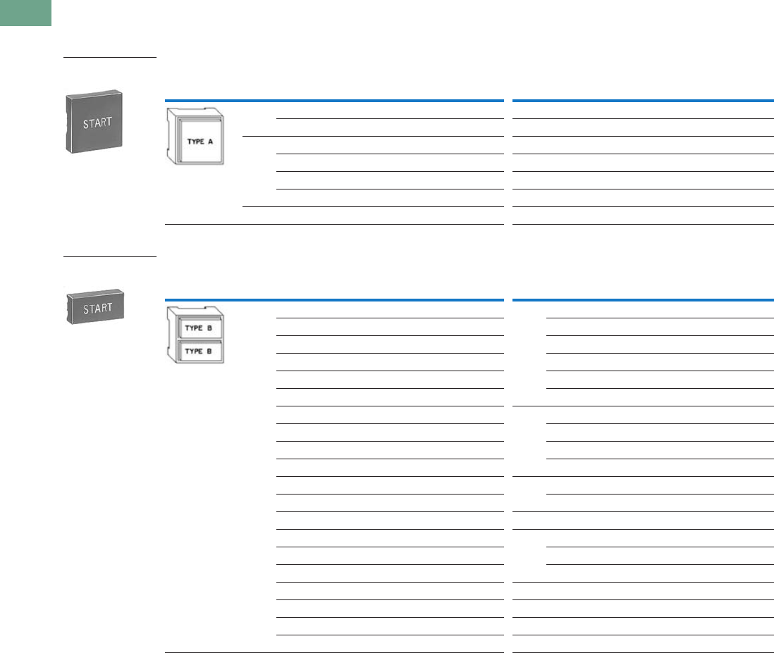
T37-154 Logic Control Products CA08100001K—June 2012 www.eatoncanada.ca
37
37
37
37
37
37
37
37
37
37
37
37
37
37
37
37
37
37
37
37
37
37
37
37
37
37
37
37
37
37
37.6
Pushbuttons and Indicating Lights
30.5 mm Square Multifunction Watertight/Oiltight—E30
Operator Components
Operating Buttons Only
Type A Buttons with Standard Markings
Type B Buttons with Standard Markings
Notes
Use with operator E30AA, legend characters 3/16 in (4.8 mm) high.
Use with operators E30AB thru AE, AL and DA thru DF, legend characters 3/16 in (4.8 mm) high.
See Appendix 4 for French engraving.
Button
Application Colour Marking
Extended Button
Catalogue Number
Short Button
Catalogue Number Colour Marking
Extended Button
Catalogue Number
Short Button
Catalogue Number
Black Blank E30KA100 E30KA150 Green START E30KA330 E30KA380
START — E30KA180 Yellow Blank E30KA400 E30KA450
Red Blank E30KA200 E30KA250 White Blank E30KA500 E30KA550
EMERG. STOP E30KA204 — Gray Blank E30KA600 E30KA650
OFF E30KA218 E30KA268 Brown Blank E30KA700 E30KA750
STOP E30KA231 E30KA281 Orange Blank E30KA800 E30KA950
Green Blank E30KA300 E30KA350 Blue Blank E30KA900 E30KA950
Button
Application Colour Marking
Extended Button
Catalogue Number
Short Button
Catalogue Number Colour Marking
Extended Button
Catalogue Number
Short Button
Catalogue Number
Black Blank E30KB100 E30KB150 Black REVERSE E30KB125 E30KB175
AUTO E30KB101 E30KB151 RUN E30KB126 E30KB176
CLOSE E30KB102 E30KB152 SLOW E30KB128 E30KB178
DOWN E30KB103 E30KB153 START E30KB130 E30KB180
FAST E30KB105 E30KB155 TEST E30KB132 E30KB182
FORWARD E30KB107 E30KB157 UP E30KB134 E30KB184
HIGH E30KB109 E30KB159 Red Blank E30KB200 E30KB250
IN E30KB110 E30KB160 EMERG. STOP E30KB204 —
INCH E30KB111 E30KB161 OFF E30KB218 E30KB268
JOG E30KB112 E30KB162 STOP E30KB231 E30KB281
JOG FOR. E30KB113 E30KB163 Green Blank E30KB300 E30KB350
JOG REV. E30KB114 E30KB164 START E30KB330 E30KB380
LOW E30KB115 E30KB165 Yellow Blank E30KB400 E30KB450
LOWER E30KB116 E30KB166 White Blank E30KB500 E30KB550
MAN E30KB117 E30KB167 AUTO E30KB501 —
ON E30KB119 E30KB169 HAND E30KB508 —
OPEN E30KB120 E30KB170 Gray Blank E30KB600 E30KB650
OUT E30KB121 E30KB171 Brown Blank E30KB700 E30KB750
RAISE E30KB122 E30KB172 Orange Blank E30KB800 E30KB850
RESET E30KB124 E30KB174 Blue Blank E30KB900 E30KB950
Type A Extended
Button
Type B Extended
Button
Tab37book.fm Page 154 Tuesday, July 3, 2012 10:46 PM
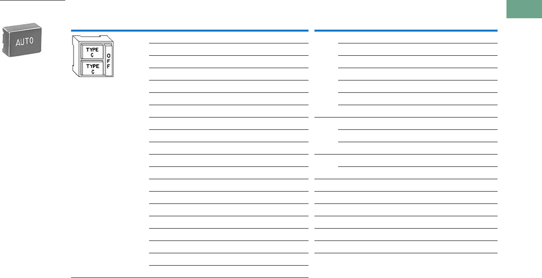
Logic Control Products CA08100001K—June 2012 www.eatoncanada.ca T37-155
37
37
37
37
37
37
37
37
37
37
37
37
37
37
37
37
37
37
37
37
37
37
37
37
37
37
37
37
37
37
37.6
Pushbuttons and Indicating Lights
30.5 mm Square Multifunction Watertight/Oiltight—E30
Type C Buttons with Standard Markings
Note
Use with operators E30AF thru AK, AL thru AM and DG thru DM, legend characters 1/8 in (3.2 mm) high.
See Appendix 4 for French engraving.
Button
Application Colour Marking
Extended Button
Catalogue Number
Short Button
Catalogue Number Colour Marking
Extended Button
Catalogue Number
Short Button
Catalogue Number
Black Blank E30KC100 E30KC150 Black RESET E30KC124 E30KC174
AUTO E30KC101 E30KC151 REVERSE E30KC125 E30KC175
CLOSE E30KC102 E30KC152 RUN E30KC126 E30KC176
DOWN E30KC103 E30KC153 SLOW E30KC128 E30KC178
FAST E30KC105 E30KC155 START E30KC130 E30KC180
FORWARD E30KC107 E30KC157 TEST E30KC132 E30KC182
HAND E30KC108 E30KC158 UP E30KC134 E30KC184
HIGH E30KC109 E30KC159 Red Blank E30KC200 E30KC250
IN E30KC110 E30KC160 OFF E30KC218 —
INCH E30KC111 E30KC161 STOP E30KC231 E30KC281
JOG E30KC112 E30KC162 Green Blank E30KC300 E30KC350
JOG FOR. E30KC113 E30KC163 START E30KC330 E30KC380
JOG REV. E30KC114 E30KC164 Yellow Blank E30KC400 E30KC450
LOW E30KC115 E30KC165 White Blank E30KC500 E30KC550
LOWER E30KC116 E30KC166 Gray Blank E30KC600 E30KC650
MAN E30KC117 E30KC167 Brown Blank E30KC700 E30KC750
ON E30KC119 E30KC169 Orange Blank E30KC800 E30KC850
OPEN E30KC120 E30KC170 Blue Blank E30KC900 E30KC950
OUT E30KC121 E30KC171
RAISE E30KC122 E30KC172
Type C Extended
Button
Tab37book.fm Page 155 Tuesday, July 3, 2012 10:46 PM

T37-156 Logic Control Products CA08100001K—June 2012 www.eatoncanada.ca
37
37
37
37
37
37
37
37
37
37
37
37
37
37
37
37
37
37
37
37
37
37
37
37
37
37
37
37
37
37
37.6
Pushbuttons and Indicating Lights
30.5 mm Square Multifunction Watertight/Oiltight—E30
Operating Buttons and Lens Only
Standard Colour Buttons and Lens Marking
Black lettering on — White, Amber, Yellow and Clear.
White lettering on — Green, Red, Blue, Brown, Black, Orange and Gray.
Type E Buttons with Standard Markings
Type F Lenses with Standard Markings
Notes
For lenses with special markings or with standard markings but in a different colour, refer to instructions on
Pages T37-161 to T37-163.
Use with operators E30EA thru EM, FA thru FM and JA thru JM, legend characters 1/8 in (3.2 mm) high.
Use with operators E30BA thru BY, legend characters 3/16 in (4.8 mm) high.
See Appendix 4 for French engraving.
Button
Application Colour Marking
Extended Button
Catalogue Number Colour Marking
Extended Button
Catalogue Number
Black Blank E30KE100 Black RESET E30KE124
CLOSE E30KE102 REVERSE E30KE125
DOWN E30KE103 RUN E30KE126
FAST E30KE105 SLOW E30KE128
FORWARD E30KE107 START E30KE130
HIGH E30KE109 TEST E30KE132
IN E30KE110 UP E30KE134
INCH E30KE111 Red Blank E30KE200
JOG E30KE112 OFF E30KE218
JOG FOR. E30KE113 STOP E30KE231
JOG REV. E30KE114 Green Blank E30KE300
LOW E30KE115 START E30KE330
LOWER E30KE116 Yellow Blank E30KE400
ON E30KE119 White Blank E30KE500
OPEN E30KE120 Gray Blank E30KE600
OUT E30KE121 Brown Blank E30KE700
PHASE E30KE122 Orange Blank E30KE800
Blue Blank E30KE900
Button
Application Colour MarkingCatalogue Number Colour MarkingCatalogue Number
Red Blank E30KF10 Green OFF E30KF22
MOTOR RUN E30KF11 Amber Blank E30KF30
ON E30KF12 Blue Blank E30KF40
POWER ON E30KF13 Clear Blank E30KF50
Green Blank E30KF20 White Blank E30KF60
MOTOR STOP E30KF21
MOTOR RUN E30KF23
Type E Button
Type F Lens
Tab37book.fm Page 156 Tuesday, July 3, 2012 10:46 PM
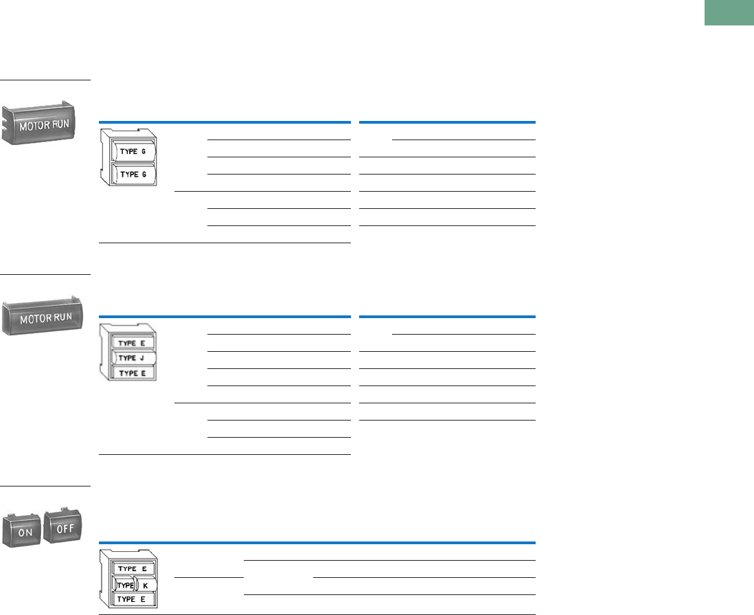
Logic Control Products CA08100001K—June 2012 www.eatoncanada.ca T37-157
37
37
37
37
37
37
37
37
37
37
37
37
37
37
37
37
37
37
37
37
37
37
37
37
37
37
37
37
37
37
37.6
Pushbuttons and Indicating Lights
30.5 mm Square Multifunction Watertight/Oiltight—E30
Operating Lens Only
Standard Colour Buttons and Lens Marking
Black lettering on — White, Amber, Yellow and Clear.
White lettering on — Green, Red, Blue, Brown, Black, Orange and Gray.
Type G Lenses with Standard Markings
Type J Lenses with Standard Markings
Type K Lenses with Standard Markings (Sold in Pairs Only)
Notes
For lenses with special markings or with standard markings but in a different colour, refer to instructions on
Pages T37-161 to T37-163.
Use with operators E30CA thru CM and DA thru DM, legend characters 3/16 in (4.8 mm) high except MOTOR RUN,
POWER ON and MOTOR STOP are 1/8 in (3.2 mm) high.
Use with operators E30EA thru EM, FA thru FM and GA thru GM, legend characters 1/8 in (3.2 mm) high.
Use with operators E30JA thru JW, legend characters 1/8 in (3.2 mm) high
See Appendix 4 for French engraving.
Lens
Application Colour MarkingCatalogue Number Colour MarkingCatalogue Number
Red Blank E30KG10 Green OFF E30KG22
MOTOR RUN E30KG11 READY E30KG23
ON E30KG12 Amber Blank E30KG30
POWER ON E30KG13 Blue Blank E30KG40
Green Blank E30KG20 Clear Blank E30KG50
MOTOR RUN E30KG24 White Blank E30KG60
MOTOR STOP E30KG21
Lens
Application Colour MarkingCatalogue Number Colour MarkingCatalogue Number
Red Blank E30KJ10 Green OFF E30KJ22
MOTOR RUN E30KJ11 ON E30KJ24
ON E30KJ12 Amber Blank E30KJ30
POWER ON E30KJ13 Blue Blank E30KJ40
MOTOR STOP E30KJ14 Clear Blank E30KJ50
Green Blank E30KJ20 White Blank E30KJ60
MOTOR STOP E30KJ21
MOTOR RUN E30KJ23
Lens
Application
Colour Marking
Catalogue Number
Left Hand
Lens
Right Hand
Lens
Left Hand
Lens
Right Hand
Lens
Red Red ON ON E30KK12
Green ON OFF E30KK13
Green OFF OFF E30KK22
Red OFF ON E30KK23
Type G Lens
Type J Lens
Type K Lenses
Tab37book.fm Page 157 Tuesday, July 3, 2012 10:46 PM
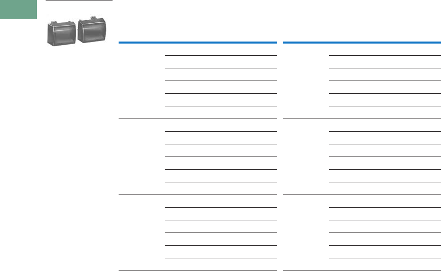
T37-158 Logic Control Products CA08100001K—June 2012 www.eatoncanada.ca
37
37
37
37
37
37
37
37
37
37
37
37
37
37
37
37
37
37
37
37
37
37
37
37
37
37
37
37
37
37
37.6
Pushbuttons and Indicating Lights
30.5 mm Square Multifunction Watertight/Oiltight—E30
Type K Lenses—Blank (Sold in Pairs Only)
Colour Colour
Left Hand
Lens
Right Hand
Lens Catalogue Number
Left Hand
Lens
Right Hand
Lens Catalogue Number
Red Red E30KK10 Blue Red E30KK41
Green E30KK11 Green E30KK42
Amber E30KK17 Amber E30KK43
Blue E30KK14 Blue E30KK40
Clear E30KK15 Clear E30KK45
White E30KK16 White E30KK46
Green Red E30KK21 Clear Red E30KK51
Green E30KK20 Green E30KK52
Amber E30KK27 Amber E30KK53
Blue E30KK24 Blue E30KK54
Clear E30KK25 Clear E30KK50
White E30KK26 White E30KK56
Amber Red E30KK31 White Red E30KK61
Green E30KK32 Green E30KK62
Amber E30KK30 Amber E30KK63
Blue E30KK34 Blue E30KK64
Clear E30KK35 Clear E30KK65
White E30KK36 White E30KK60
Type K Lenses
Tab37book.fm Page 158 Tuesday, July 3, 2012 10:46 PM

Logic Control Products CA08100001K—June 2012 www.eatoncanada.ca T37-159
37
37
37
37
37
37
37
37
37
37
37
37
37
37
37
37
37
37
37
37
37
37
37
37
37
37
37
37
37
37
37.6
Pushbuttons and Indicating Lights
30.5 mm Square Multifunction Watertight/Oiltight—E30
Contact Blocks
Standard Contact Blocks—Molded, phenolic construction.
Enclosed silver contacts with reliability “nibs” that improve the
reliability of switching performance under dry circuit, corrosive
atmosphere and fine dust conditions. For more extreme
conditions, the logic level contact blocks described below are
recommended.
Logic Level Contact Blocks—Feature palladium contacts.
Palladium, which is more inert than gold, is well suited for
voltages and currents approaching zero. When mounted in an
enclosure rated for highly corrosive environments, logic level
contact blocks can be used where exposure to chemicals may
cause failure to other types of materials.
Mounting Limitations
See the contact block mounting limitations for Type E30
pushbutton and combination pushbutton and light operators on
this page. Mounting positions 1 thru 8 indicate single depth
contact blocks. Each of these positions can represent either a
single circuit 600 volt block or a two-circuit 120 volt block. The
two-circuit 600 volt block requires two of the numbered
positions shown.
Mounting Positions
Contact Block Selection
Notes
Except operator E30AD, AJ or AK which will accommodate contact blocks 1, 2, 5 and 6 only. (See Mounting Positions above.)
Individually boxed contact blocks master packed 10 per carton.
Supplied with non-stacking screws. Limited to 2 contact blocks mounted in positions 1 and 5.
Do not use with maintained operators.
Contacts must be same polarity.
Catalogue Number
of Operator
Contact Blocks Can Be Mounted in
Positions Listed Below
Upper Stack Lower Stack
E30AA thru E30AM 1-2-3-4 5-6-7-8
E30BA thru E30CM None None
E30DA thru E30DM None 5-6-7-8
E30EA thru E30GM 2-3-4 6-7-8
E30JA thru E30JM 3-4 7-8
Contact Block
Mounting
Positions
Upper Contact
Block Stack
Upper Contact Block Stack Operating Plunger
Lower Contact Block Stack
Operating Plunger
Lower Contact
Block Stack
1
5678
234
Circuit
Pressure Terminals Quick Connect Terminals
Standard Logic Level Standard
Catalogue Number Catalogue Number Catalogue Number
1NO 600 Vac, 250 Vdc—Single Circuit
E30KLA1 E30KLAE1 E30KLB1
1NC E30KLA2 E30KLAE2 E30KLB2
1NO-1NC 600 Vac, 250 Vdc—Two Circuit
E30KLA3 E30KLAE3 E30KLB3
2NO E30KLA4 E30KLAE4 E30KLB4
2NC E30KLA5 E30KLAE5 E30KLB5
Special Contact Operation
1NO-1NC
Overlapping
E30KLA6 — E30KLB6
2NO
(One early closing)
E30KLA7 — E30KLB7
2NC
(One late opening)
E30KLA8 — E30KLB8
1NO-1NC 120 Vac Only—Two Circuit
E30KLA9 — E30KLB9
Single Circuit,
Screw Terminals
Two Circuit,
Screw Terminals
Two Circuit, Quick
Connect Terminals
120 Vac Only—
Two Circuit
Contact Block Type
Tab37book.fm Page 159 Tuesday, July 3, 2012 10:46 PM
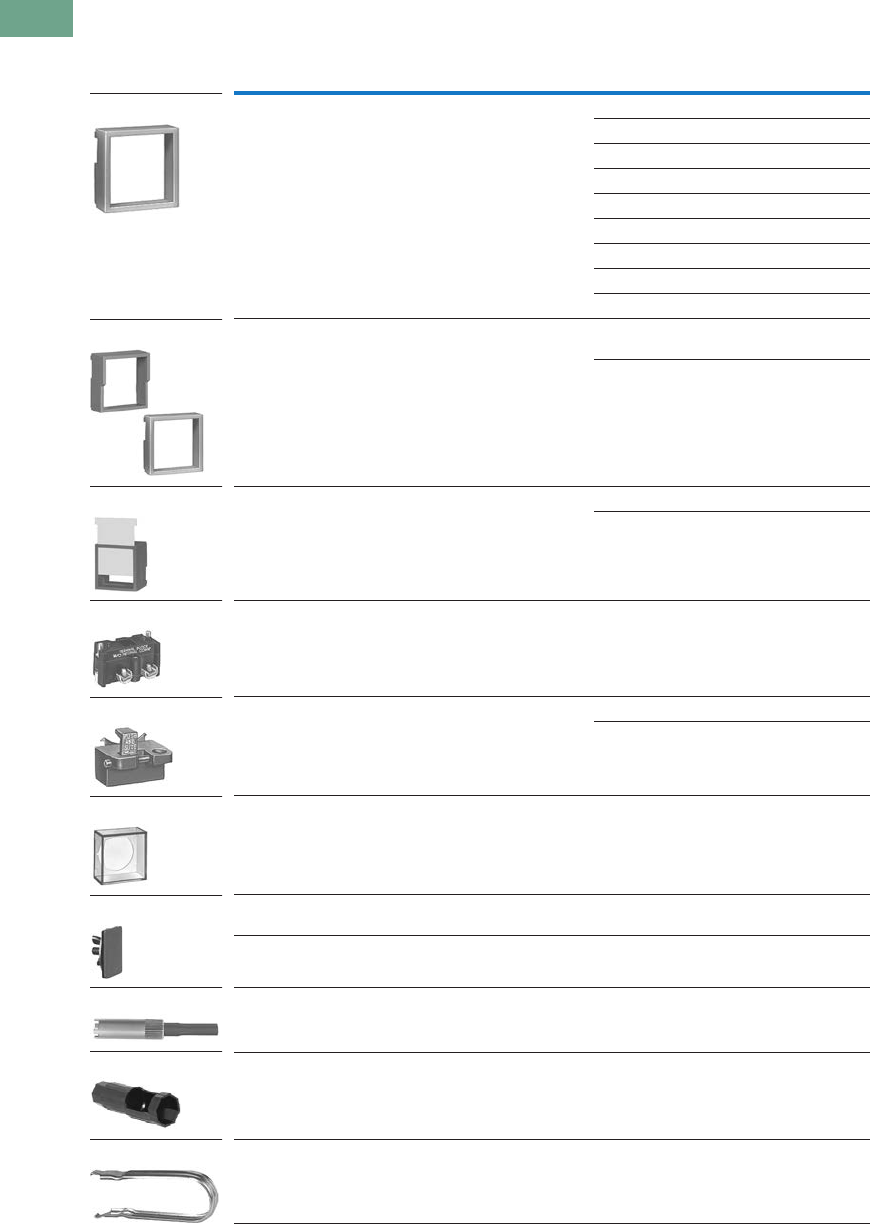
T37-160 Logic Control Products CA08100001K—June 2012 www.eatoncanada.ca
37
37
37
37
37
37
37
37
37
37
37
37
37
37
37
37
37
37
37
37
37
37
37
37
37
37
37
37
37
37
37.6
Pushbuttons and Indicating Lights
30.5 mm Square Multifunction Watertight/Oiltight—E30
Accessories
Accessories
Note
Colour coordinating collars, padlock attachments or legend plates cannot be used with operators equipped with a
transparent boot.
Description Colour/Type Catalogue Number
Collar—Snap on mounting for assembly in the field. Permits
colour coding of operator heads. Size: 1-19/32 x 1-19/32 x 9/16 in.
Black E30KR1
Red E30KR2
Green E30KR3
Yellow E30KR4
White E30KR5
Gray E30KR6
Orange E30KR8
Blue E30KR9
Brown E30KR10
Shroud—Similar to collar above except for extension above
the face of button to prevent accidental actuation of button.
Half shroud with an extension on only half the collar may be
positioned to protect top or bottom button.
Full shroud
(gray)
E30KT6
Half shroud
(gray)
E30KT7
Guard—Two collars deep, removable slide prevents accidental
operation. White slide can be marked with grease pencil.
Red with white slide E30KR31
Red with clear slide E30KR32
Terminal Block—2 terminals, each will accommodate 2-wire
terminations.
E30KR30
Padlock Attachment for locking single button and bottom button
of multi-function operators in the depressed position. Locks NC
contacts open or early closing NO contacts closed. Cannot be used
in conjunction with collar, shroud or boot.
Short button E30KT1
Extended button E30KT2
Transparent Boot—Guards against ingress of foreign material
and freezing rain. Note: If this boot is used in conjunction with
operator types AD or AE, an extended type button must be used
in the top position and a short button in the lower position.
E30KT3
Square Hole Plug—
Gray enameled E30KT4
Stainless steel E30KT5
Lamp and Lens Removal Tool—Will not fit Cat. No. E30B light units
listed on Page T37-152.
E30KV1
Octagonal Wrench for mounting operators to panel. E22CW
Button and Lens Removal Tool E30KV2
E30KR_
Full
Shrou
d
Half
Shroud
E30KT_
E30KR3_
E30KR30
E30KT_
E30KT3
E30KT_
E30KV1
E22CW
E30KV2
Tab37book.fm Page 160 Tuesday, July 3, 2012 10:46 PM
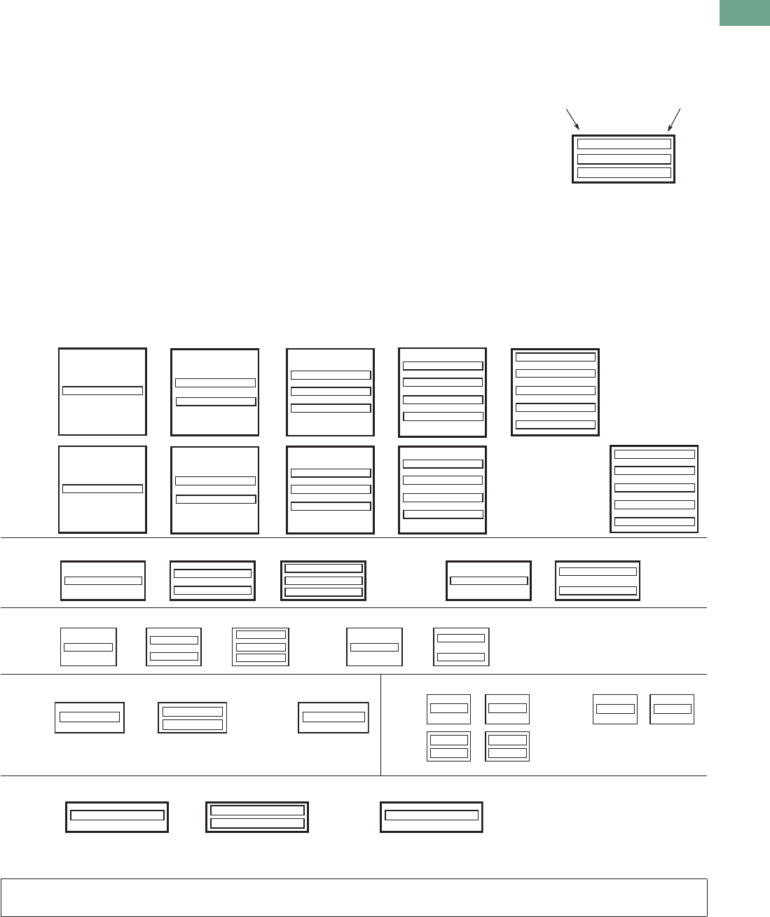
Logic Control Products CA08100001K—June 2012 www.eatoncanada.ca T37-161
37
37
37
37
37
37
37
37
37
37
37
37
37
37
37
37
37
37
37
37
37
37
37
37
37
37
37
37
37
37
37.6
Pushbuttons and Indicating Lights
30.5 mm Square Multifunction Watertight/Oiltight—E30
Options
Markings and Legend Plates
Buttons or Lenses with Non-
Standard Horizontal Markings
Markings not listed as
Standard Markings below are
considered non-standard. If
more than one marking is
required on a button or lens,
order non-standard markings.
Ordering Instructions
●Specify catalogue number
of blank button or lens of
desired colour, plus suffix
“STAMP” for non-standard
or “STD” for standard
markings in order notes.
See Pages T37-154 to
T37-158.
●Specify size, legend desired
and location in order notes
by alphas as shown in
example.
●Do not exceed maximum
number of legend
characters per line.
Ordering Example
Green Type B button to be
marked with non-standard
legend “ALL
ELEVATORS DOWN.”
Catalogue No.:
E30KB300STAMP
Letter Size: 1/8 in
Pos. A—ALL
Pos. C—ELEVATORS
Pos. F—DOWN
How to Use the Legend
Location Figure
Legend Locations
Standard Markings
Buttons Lenses
Line Position
7
9
A
C
E
7
8
8
8
No. of Characters per Line
AUTO
CLOSE
DOWN
EMERG. STOP
FAST
FORWARD
HAND
HIGH
IN
INCH
JOG
JOG FOR.
JOG REV.
LOW
LOWER
MAN.
OFF
ON
OPEN
OUT
RAISE
RESET
REVERSE
RUN
SLOW
START
STOP
TEST
UP
MOTOR RUN
MOTOR STOP
POWER ON
READY
7
7
A
C
8
8
99
BB
88
5
56
A
CB
6
B
4
4
A
C
4
B
4
E
4
4
D
F
4
E
4
B
545
5
66
BAB
D
CC
ED
45
6
C
978
9
99
BAB
D
CC
FD
78
888
8
88
88
9
C
8
9
9
9
99
9
9
9
9
D
A
B
E
G
D
E
J
G
K
N
G
K
J
M
9
9
9
9
9
9
8
8
8
88
8
8
8
8
8
8
8
8
8
8
9
9
99
9
9
9
B
B
D
F
E
H
F
K
J
K
9
9
9
8
8
88
8
8
8
8
8
8
A
C
L
F
J
8
8
8
8
8
1/8 in
(3 mm)
High
Char.
Type A buttons and Type F lenses
Type B buttons and Type G lenses
1/8 in
(3 mm)
High
Char.
Type C buttons
1/8 in
(3 mm)
High
Char.
Type D buttons
1/8 in
(3 mm)
High
Char.
Type K buttons
Type E buttons and Type J lenses
1/8 in
(3 mm)
High
Char.
1/8 in
(3 mm)
High
Char.
3/16 in
(5 mm)
High
Char.
Type F lens only
3/16 in
(5 mm)
High
Char.
3/16 in
(5 mm)
High
Char.
3/16 in
(5 mm)
High
Char.
3/16 in
(5 mm)
High
Char.
3/16 in
(5 mm)
High
Char.
Tab37book.fm Page 161 Tuesday, July 3, 2012 10:46 PM
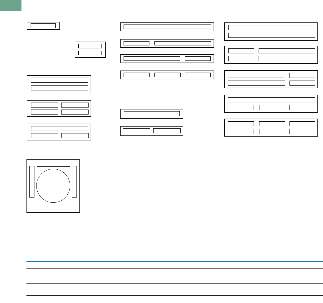
T37-162 Logic Control Products CA08100001K—June 2012 www.eatoncanada.ca
37
37
37
37
37
37
37
37
37
37
37
37
37
37
37
37
37
37
37
37
37
37
37
37
37
37
37
37
37
37
37.6
Pushbuttons and Indicating Lights
30.5 mm Square Multifunction Watertight/Oiltight—E30
Legend Arrangements and Legend Locations
Legend Plates E30KN76 or KN76B
Maximum Number and Size of Permissible Legend Characters of Custom Stamped Legend Plates
Legend plates
E30KM1 or KM11
Legend plates
E30KM4 or KM14
Legend plates
E30KM2 or KM12
Legend plates
E30KM5 or KM15
Legend plates
E30KM3 or KM13
Legend plates
E30KM6 or KM16
H
G
KB
JA
DM
CL
BFM
G
B
A
F
E
M
L
H
B
M
M
K
D
BF
E
F
F
A
B
B
D
C
C
D
BF
A
B
B
Type
No.of
Lines
Size and Maximum Number of Characters Per Line
One Span Two Span Three Span
3/32 in
(2.5 mm)
1/8 in
(3 mm)
3/16 in
(5 mm)
3/32 in
(2.5 mm)
1/8 in
(3 mm)
3/16 in
(5 mm)
3/32 in
(2.5 mm)
1/8 in
(3 mm)
3/16 in
(5 mm)
Standard 1 13 10 10 30 22 22 47 34 34
Large 1 13 10 10 30 23 23 47 36 36
2 13 101030 232347 3636
Characters available for non-standard markings
3/32 in (2.5 mm)—1/8 in (3 mm)—3/16 in (5 mm)
A B C D E F G H I J K L M N O P Q R S T U V W X Y Z . / — , 1 2 3 4 5 6 7 8 9 0
Legend plates
E30KN76 or KN76B
1/8 in character
size only with a maximum
of six characters.
LINE B
L
I
N
E
A
L
I
N
E
C
Tab37book.fm Page 162 Tuesday, July 3, 2012 10:46 PM

Logic Control Products CA08100001K—June 2012 www.eatoncanada.ca T37-163
37
37
37
37
37
37
37
37
37
37
37
37
37
37
37
37
37
37
37
37
37
37
37
37
37
37
37
37
37
37
37.6
Pushbuttons and Indicating Lights
30.5 mm Square Multifunction Watertight/Oiltight—E30
Buttons or Lenses with Non-Standard Vertical Markings
Ordering Instructions
●Specify catalogue number
of blank button or lens of
desired colour, selected
from listings on Pages
T37-154 to T37-158.
●Specify size, legend
desired, location and state
“vertically marked” in
order notes.
Note: Specify either 1/8 or 3/16 in
(3.2 or 4.8 mm) character height.
Do not exceed maximum number
of characters as outlined in table
below.
Ordering Example:
Green Type K button to be
marked with “RUN” “ON.”
Catalogue No.:
E30KK20STAMP
Letter Size: 3/16 in (4.8 mm)
Vertically Marked
Pos. B—RUN
Pos. E—ON
Legend Plates
Legend plates for Type E30
compact pushbutton and
indicating light operators
hook directly onto the
operator and are clamped in
place when the operator
locking nut behind the panel
is secured.
Two and three span plates
are designed for use where
two or more operators are
mounted adjacent to each
other on minimum
horizontal mounting
centers. These legend plates
mount in the same manner as
single span units.
Maximum Number of Characters
Description Type
Maximum Number of Characters
1/8 in (3.2 mm) 3/16 in (4.8 mm)
Buttons A 7 5
B7 5
C4 3
D5 3
E7 5
Lenses F 7 5
G7 5
J7 5
K3 2
When Ordering Legend Plates
with Markings
●Catalogue number of blank
legend plate
●Insert the following in
order notes:
●Legends required
●Size of characters—
3/32, 1/8, 3/16 in (2.4,
3.2, 4.8 mm)
●Positions of legends on
one line standard and
two line large legend
plates by alphas as
shown in sketches on
following page.
Ordering Example:
Three span legend plate to be
marked “MASTER
CONTROL”, “STATION A”
and “STATION B.”
Catalogue No.:
E30KM3STAMP
Letter Size: 1/8 in (3.2 mm)
Pos. C—MASTER CONTROL
Pos. B—STATION A
Pos. F—STATION B
Blank Legend Plates and Legend Plates
with Markings
Type
One Span
Catalogue Number
Black
Standard E30KM1
Large E30KM4
Standard— One Span
Large—One Span
Tab37book.fm Page 163 Tuesday, July 3, 2012 10:46 PM

T37-164 Logic Control Products CA08100001K—June 2012 www.eatoncanada.ca
37
37
37
37
37
37
37
37
37
37
37
37
37
37
37
37
37
37
37
37
37
37
37
37
37
37
37
37
37
37
37.6
Pushbuttons and Indicating Lights
30.5 mm Square Multifunction Watertight/Oiltight—E30
Replacement Parts
Replacement Light Units for E30 Components
Replacement Lamps for E30 Illuminated Operators
Replacement Lamps—Incandescent and LED
Note
E30 blue LED bulbs may not provide sufficient intensity for some applications.
Voltage
AC and DC
Part Numbers—Receptacles without Lamps
Single
Indicating Light
Dual
Indicating Light
Single Light
Single Pushbutton
Single Light
Dual Pushbutton
Dual Light
Dual Pushbutton
Full Voltage Type
6V 57-2579-3A 57-2568A 57-2568A 57-2579-3A 57-2567
12V 57-2579-3A 57-2568A 57-2568A 57-2579-3A 57-2567
18/24V 57-2579-3A 57-2568A 57-2568A 57-2579-3A 57-2567
28V 57-2579-3A 57-2568A 57-2568A 57-2579-3A 57-2567
32V 57-2579-3A 57-2568-2A 57-2568-2A — 57-2567
48V 57-2579-3A 57-2568A 57-2568A 57-2579-3A 57-2567
120V 57-2579-3A 57-2568A 57-2568A 57-2579-3A 57-2567
Transformer Type
120V 42-2672A 42-2663A 42-2663A 42-2671A 42-2664A
208V 42-2672-2A 42-2663-2A 42-2663-2A 42-2671-2A 42-2664-2A
240V 42-2672-3A 42-2663-3A 42-2663-3A 42-2671-3A 42-2664-3A
380V 42-2672-4A 42-2663-4A 42-2663-4A 42-2671-4A 42-2664-4A
480V 42-2672-5A 42-2663-5A 42-2663-5A 42-2671-5A 42-2664-5A
600V 42-2672-6A 42-2663-6A 42-2663-6A 42-2671-6A 42-2664-6A
Description and Part Numbers—Related Parts
Inner lens 28-1008 28-1010 28-1010 28-1010 28-1010
Retaining nut 15-1885 15-1885 15-1885 15-1885 15-1885
Gasket 16-2092 16-2092 16-2092 16-2092 16-2092
Locking ring 52-1116 52-1116 52-1116 52-1116 52-1116
Mfg. Lamp Type Voltage Base Style Application Part Number
6PSB 6V T2 slide E30 transformer and full voltage 28-1022
12PSB 12V T2 slide E30 full voltage 28-1025
24PSB 24V T2 slide E30 full voltage 28-1026
28PSB 28V T2 slide E30 full voltage 28-1027
48PSB 48V T2 slide E30 full voltage 28-1028
60PSB 60V T2 slide E30 full voltage 28-1598
120PSB 120V T2 slide E30 full voltage 28-1029
#259 6.3V T3-1/4 wedge E30 single transformer 28-949
Lamp
Voltage
Incandescent Lamps LED Lamps
Manufacturer’s
Part Number
Base
Style
Eaton’s
Part Number
Eaton’s Part Number
Red Green Yellow Blue
6 6PSB T2 slide 28-1022 35-1523 35-1523-2 35-1523-3 35-1523-17
12 12PSB T2 slide 28-1025 35-1523-11 35-1523-12 35-1523-13 35-1523-18
24 24PSB T2 slide 28-1026 35-1523-4 35-1523-5 35-1523-6 35-1523-19
28 28PSB T2 slide 28-1027 35-1523-4 35-1523-5 35-1523-6 35-1523-19
48 48PSB T2 slide 28-1028 35-1523-14 35-1523-15 35-1523-16 35-1523-20
120 120PSB T2 slide 28-1029 35-1523-7 35-1523-8 35-1523-9 35-1523-21
Tab37book.fm Page 164 Tuesday, July 3, 2012 10:46 PM
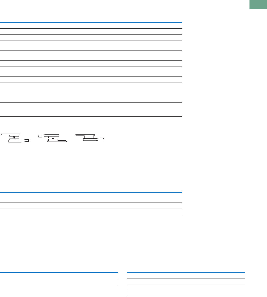
Logic Control Products CA08100001K—June 2012 www.eatoncanada.ca T37-165
37
37
37
37
37
37
37
37
37
37
37
37
37
37
37
37
37
37
37
37
37
37
37
37
37
37
37
37
37
37
37.6
Pushbuttons and Indicating Lights
30.5 mm Square Multifunction Watertight/Oiltight—E30
Technical Data and Specifications
Operator Specifications
Reliability Nibs
Electrical Ratings
Contact Blocks
●UL A600/P300 nominal connect 10A
●1NO, 1NC, 2NO, 2NC, 1NO-1NC, early make, late break and
overlapping configurations
●Mechanical positive drive operation on NC contacts
●Palladium alloy contact for logic level or highly corrosive
environments
Maximum Ratings for Logic Level and
Hostile Atmosphere Application Light Unit
Note
Logic level contact blocks are UL A600/P500 rated per table above.
Description Specification
Climate Conditions
Operating –20˚ to 150˚F (–29˚ to 65˚C)
Terminals
Light units Terminals are saddle clamp type for 2 stranded or solid wires up to 12 AWG (4.0 mm2)
Torque—7 lb-in (0.8 Nm)
Contact block Terminals are saddle clamp type for 2 stranded or solid wires up to 12 AWG (4.0 mm2)
Torque—7 lb-in (0.8 Nm)
Materials
Operator Zinc base die casting with a copper-nickel-chrome plated finish
Withstands the 200 hr. salt spray test in accordance with MIL Spec. QQ-M-151A and NEMA 4X testing.
Internal parts Including shafts, washers and springs, are made of stainless steel
Buttons and lenses Colorfast, wear resistant, molded acetal resin
Contact blocks Made of molded, heat resistant, mineral filled phenolic
Contact block plungers are molded of nylon filled phenolic
Contacts are silver
Reliability nibs These nibs combine a scrubbing action with high pressure density when the contacts are closed
They push through particles and films found on contact surfaces in industrial environments
Reliability nibs self-adjust to the application—dry circuit, normal or heavy-duty
Meet or Exceed NEMA Contact Rating Designation A600 and P300
Vac A600 Vdc P300
Description 120V 240V 480V 600V 24/28V 125V 250V
Make and emergency
interrupting capacity (Amps)
60 30 15 12 5.73 1.1 0.55
Normal load break (Amps) 6 3 1.5 1.2 5.73 1.1 0.55
Continuous current (Amps) 10 10 10 10 5 5 5
Heavy-Duty
Dry Circuit Medium Duty
Description Specification
Maximum amperes 0.5A
Maximum volts 120 Vac/Vdc
Description Specification
Bulbs—Average Life
Transformer type 20,000 hrs.
Resistor/direct voltage type 2,500 hrs. min. at rated voltage
LED 60,000 to 100,000 hrs.
Tab37book.fm Page 165 Tuesday, July 3, 2012 10:46 PM
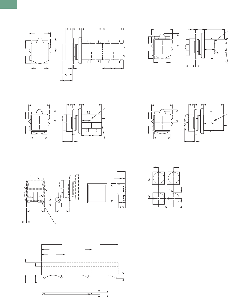
T37-166 Logic Control Products CA08100001K—June 2012 www.eatoncanada.ca
37
37
37
37
37
37
37
37
37
37
37
37
37
37
37
37
37
37
37
37
37
37
37
37
37
37
37
37
37
37
37.6
Pushbuttons and Indicating Lights
30.5 mm Square Multifunction Watertight/Oiltight—E30
Dimensions
Approximate Dimensions in Inches (mm)
Pushbutton Operators
Combination Pushbutton and Indicating Light Operators
Padlocking Attachment and Half Shroud E30KT7
Legend Plates
Combination Pushbutton and Indicating Light Operators
Indicating Light Operators
Drilling Dimensions—Minimum Spacing
Notes
Dimensions shown allow adequate space for the addition of one or two high legend plates
and colour coordinating collars.
Locating nib hole or notch is 0.136 in (3.5 mm) drill. Alternate to drilling mounting holes use
Greenlee Tool Co. punch (No. 730-S) to punch the hole and (No. 730-K) to punch the notch.
1.75
(44.5)
0.53
(13.5)
0.81
(20.6) 1.72
(43.7) 1.72
(43.7)
1.47
(37.3)
Square 0.88
(22.4) 0.88
(22.4)
1.13
(28.7)
1.88
(47.8)
Panel
0.06 (1.5) Min.
0.25 (6.4) Max.
0.78 (19.8) Ext. Button
0.63 (16)
Std.
Button 1 Circ.
Cont. Blocks
2 Circ.
Cont. Blocks
Plunger
Extends to
0.25 (6.4)
0.88
(22.4)
0.88 (22.4) 0.88 (22.4)
Full Voltage
Types DF,
DM and DX
Plunger Extends
to 0.25 (6.4) on
Contact Blocks
Transformer
Types DA – DL
1.75
(44.5)
0.53
(13.5)
0.84
(21.3)
0.81
(20.6) 1.72
(43.7)
1.47
(37.3)
Square
1.13
(28.7)
1.88
(47.8)
Panel
0.06 (1.5) Min.
0.25 (6.4) Max.
0.69
(17.5)
1.13
(28.7)
0.31 (7.9)
Dia. Hole
0.5 (12.7)
0.56
(14.2)
1.59
(40.4)
0.75
(19.1)
1.44
(36.6)
0.11 (2.8)
Max.
1.44
(36.6)
0.02
(0.5)
0.78
(19.8) 0.39
(9.9)
Standard
3.06 (77.7) Two Span
0.05 (1.3)
0.08 (1.9)
One Span
4.69 (119.1) Three Span
Large
0.88
(22.4)
Operator
Types E30JA–
E30JW
Operator
Types E30EA–
E30GM
Plungers
Extended
to 0.25 (6.4)
Transformer
or Full Voltage
Light Element
1.75
(44.5)
0.53
(13.5)
0.84
(21.3)
0.81
(20.6) 1.72
(43.7)
1.47
(37.3)
Square
1.13
(28.7)
1.88
(47.8)
Panel
0.06 (1.5) Min.
0.25 (6.4) Max.
1.75
(44.5)
0.53
(13.5)
0.84
(21.3)
0.81
(20.6) 1.72
(43.7)
1.47
(37.3)
Square
1.13
(28.7)
1.88
(47.8)
0.88
(22.4)
Panel
0.06 (1.5) Min.
0.25 (6.4) Max.
Operator
Types E30BA–
E30BM
Operator
Types E30CA
–
E30CM
1.63 a
(41.3)
2.25 a
(57) 0.6
(15)
Drill .14
(3.5)
ø 1.20 (30.5)
Tab37book.fm Page 166 Tuesday, July 3, 2012 10:46 PM
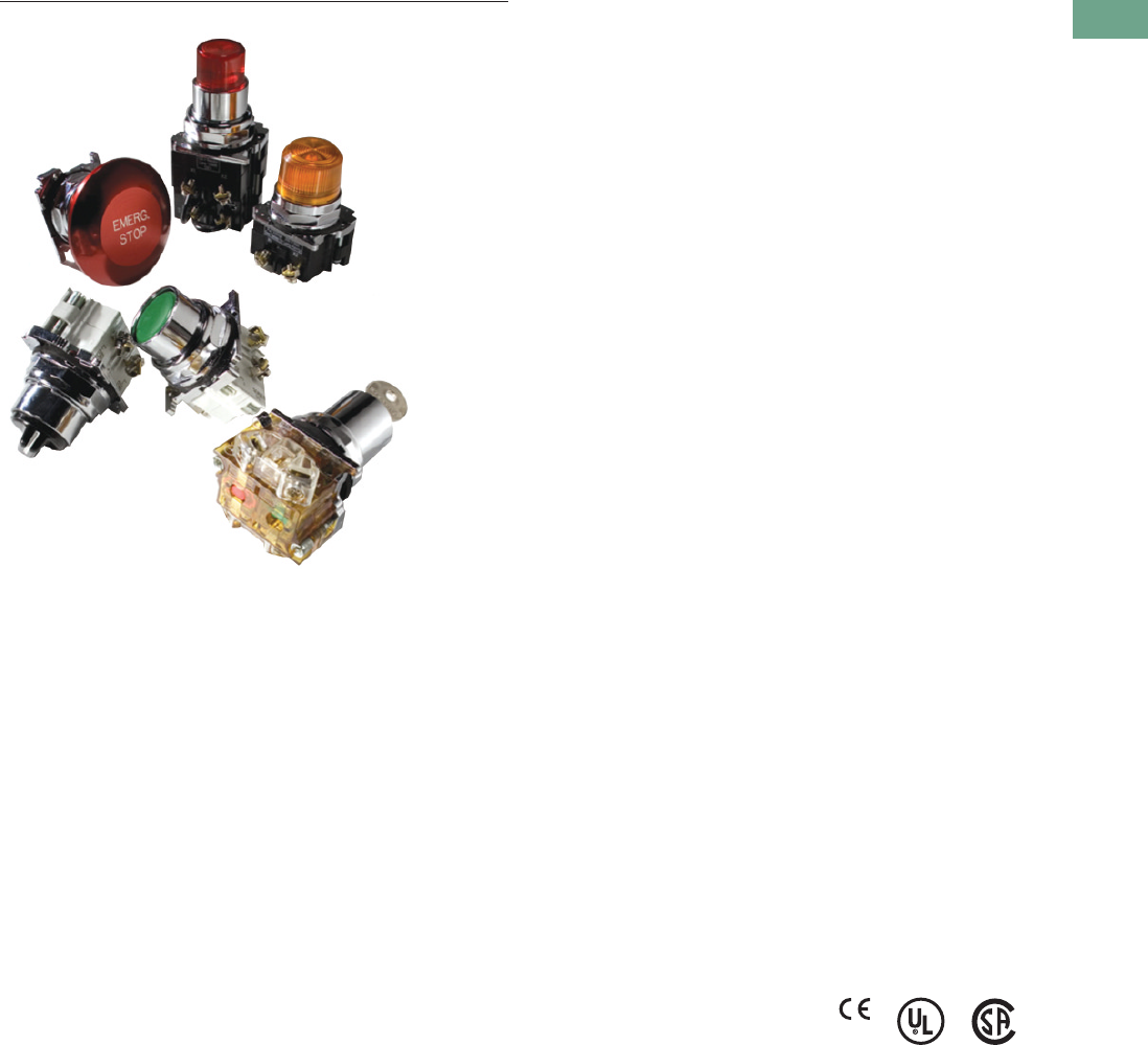
Logic Control Products CA08100001K—June 2012 www.eatoncanada.ca T37-167
37
37
37
37
37
37
37
37
37
37
37
37
37
37
37
37
37
37
37
37
37
37
37
37
37
37
37
37
37
37
37.7
Pushbuttons and Indicating Lights
30.5 mm Heavy-Duty Watertight/Oiltight—10250T
30.5 mm Heavy-Duty Watertight/Oiltight—10250T Contents
Description Page
30.5 mm Heavy-Duty Watertight/Oiltight—10250T
Product Overview . . . . . . . . . . . . . . . . . . . . . . . . . . T37-168
Product Identification . . . . . . . . . . . . . . . . . . . . . . . T37-169
Catalogue Number Selection. . . . . . . . . . . . . . . . . . T37-170
Product Selection
Point-of-Purchase Packaging . . . . . . . . . . . . . . . T37-172
Non-Illuminated Momentary
Pushbutton Units . . . . . . . . . . . . . . . . . . . . . . T37-173
Pushbuttons . . . . . . . . . . . . . . . . . . . . . . . . . . . T37-174
Illuminated Momentary Pushbutton Units . . . . T37-178
Indicating Light Units . . . . . . . . . . . . . . . . . . . . . T37-179
Illuminated Pushbuttons and
Indicating Lights . . . . . . . . . . . . . . . . . . . . . . . T37-180
Push-Pull Emergency Stop . . . . . . . . . . . . . . . . T37-182
Illuminated Push-Pull Units . . . . . . . . . . . . . . . . T37-185
Potentiometers . . . . . . . . . . . . . . . . . . . . . . . . . T37-188
Push-Pull Operators . . . . . . . . . . . . . . . . . . . . . . T37-189
Selector Switch Units . . . . . . . . . . . . . . . . . . . . T37-193
Selector Switch Selection . . . . . . . . . . . . . . . . . T37-194
Selector Switch Operators . . . . . . . . . . . . . . . . T37-197
Illuminated Selector Switch Operators . . . . . . . T37-200
Joystick Units . . . . . . . . . . . . . . . . . . . . . . . . . . T37-201
Joysticks . . . . . . . . . . . . . . . . . . . . . . . . . . . . . . T37-202
Roto-Push Units . . . . . . . . . . . . . . . . . . . . . . . . T37-205
Roto-Push Operators . . . . . . . . . . . . . . . . . . . . . T37-206
AccessoriesAccessories . . . . . . . . . . . . . . . . . . . . . T37-211
Options . . . . . . . . . . . . . . . . . . . . . . . . . . . . . . . . . . T37-216
Replacement Parts . . . . . . . . . . . . . . . . . . . . . . . . . T37-225
Technical Data and Specifications . . . . . . . . . . . . . T37-227
Dimensions . . . . . . . . . . . . . . . . . . . . . . . . . . . . . . T37-230
Product Description
The 30.5 mm pushbutton line
features a zinc die cast
construction with chrome-
plated housing and mounting
nut. The same durable
construction is also available
with the corrosive resistant
E34 line of pushbuttons.
See E34 section on Pages
T37-240 to T37-274.
Features
●Heavy-duty zinc die cast
construction
●Enclosed silver contacts
with reliability nibs
●Diaphragm seals with
drainage holes
●Grounding nibs on the
operator casing
Benefits
●Reliability nibs improve
contact reliability even
under dry circuit and fine
dust conditions
●Drainage holes prevent
buildup of liquid inside the
operator which can prevent
operation in freezing
environments
●Grounding nibs bit through
paint and other coatings to
provide secure ground
Application Description
Contact Operation
Slow make and break. All
normally closed contacts
have positive opening
operation, i.e., normally closed
contacts are forced open in
the event of contact weld or
spring breakage.
Standards and
Certifications
●CE EN 60947-5-1 and
60947-5-5
●UL 508—File No. 131568
●CSA C22.2 No. 14—File
No. LR68551
Ingress Protection
When mounted in similarly
rated enclosure—
●Standard indicating lights
●UL (NEMA) Type 1, 2, 3,
3R, 3S, 4, 4X, 12, 13
●IEC IP65
●All other operators
●UL (NEMA) Type 1, 2, 3,
3R, 4, 4X, 12, 13
●IEC IP65
Tab37book.fm Page 167 Tuesday, July 3, 2012 10:46 PM
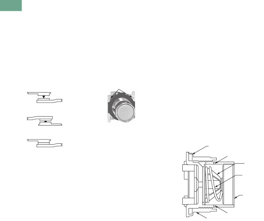
T37-168 Logic Control Products CA08100001K—June 2012 www.eatoncanada.ca
37
37
37
37
37
37
37
37
37
37
37
37
37
37
37
37
37
37
37
37
37
37
37
37
37
37
37
37
37
37
37.7
Pushbuttons and Indicating Lights
30.5 mm Heavy-Duty Watertight/Oiltight—10250T
Product Overview
Reliability Nibs
Eaton’s contact blocks
feature enclosed silver
contacts with pointed
“reliability nibs” for reliable
performance from logic level
up to 600V. To ensure reliable
switching, nibs bite through
oxide which can form on silver
contacts, eliminating the
need for expensive logic level
blocks for most applications.
Reliability Nibs
Reliability nibs improve
performance in dry circuit,
corrosive, fine dust and other
contaminated atmospheres.
Under normal environmental
conditions, the minimum
operational voltage is 5V and
the minimum operational
current is 1 mA, AC/DC. For
operation under a wider
range of environmental
conditions, logic level contact
blocks with inert palladium
tipped contacts are
recommended.
Grounding Nibs
10250T line operators have
“grounding nibs”—four
metal points on the operator
casting designed to bite
through most paints and
other coatings on metal
panels to enhance the ground
connection when the operator
is securely tightened.
Grounding Nibs
Dry Circuit
Medium Duty
Heavy-Duty
Grounding
Nibs
Diaphragm Seal with
Drainage Holes
Liquid Drainage
Eaton’s pushbutton operators
offer front of panel drainage
via holes in the operator
bushing. Hidden from view
by the mounting nut, these
holes prevent buildup of
liquid inside the operator,
which can prevent operation
in freezing environments.
The holes also provide a
route for escaping liquid in
high pressure washdowns,
effectively relieving pressure
from the internal diaphragm
seal, ensuring reliable sealing
in applications even beyond
NEMA 4.
Diaphragm Seal
Foam Neoprene
Panel Sealing Gasket
Drainage Hole
Drainage Hole
Flexible
Diaphragm
Stainless
Steel
Operating
Spring
Mounting Nut
Colorfast
Molded
Button
Tab37book.fm Page 168 Tuesday, July 3, 2012 10:46 PM
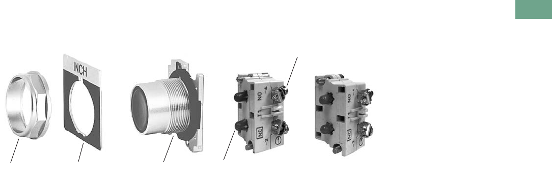
Logic Control Products CA08100001K—June 2012 www.eatoncanada.ca T37-169
37
37
37
37
37
37
37
37
37
37
37
37
37
37
37
37
37
37
37
37
37
37
37
37
37
37
37
37
37
37
37.7
Pushbuttons and Indicating Lights
30.5 mm Heavy-Duty Watertight/Oiltight—10250T
Product Identification
30.5 mm Heavy-Duty Watertight/Oiltight—10250T Series
Mounting Nut Legend Plate Operator
Terminal Clamps
Shipped Ready to Wire
Stackable Contact
Blocks up to 12
Circuits per Operator
Colour Coded Plungers
Red = NC Green = NO
Tab37book.fm Page 169 Tuesday, July 3, 2012 10:46 PM
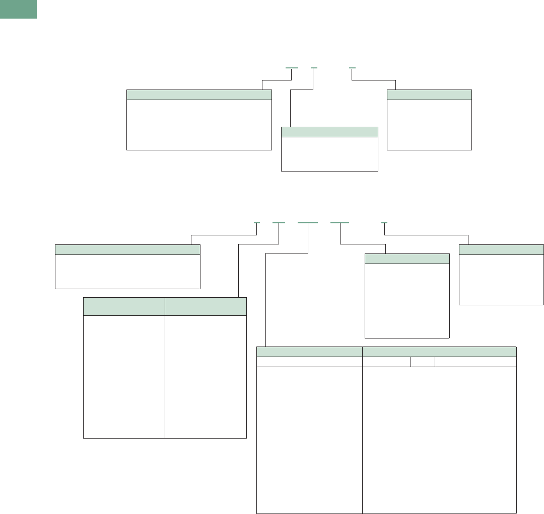
T37-170 Logic Control Products CA08100001K—June 2012 www.eatoncanada.ca
37
37
37
37
37
37
37
37
37
37
37
37
37
37
37
37
37
37
37
37
37
37
37
37
37
37
37
37
37
37
37.7
Pushbuttons and Indicating Lights
30.5 mm Heavy-Duty Watertight/Oiltight—10250T
Catalogue Number Selection
Catalogue Number Selection is for illustrative purposes only and not to be used to create new catalogue numbers.
Non-Illuminated Pushbuttons
Illuminated and Non-Illuminated Push-Pulls
Note
Add X at end of catalogue number to receive parts assembled from factory.
10250T 10 1 –1
Operator
10 = Flush
11 = Extended
12 = 40 mm mushroom
17 = 65 mm mushroom
50 = 1/2 shroud vertical mount
51 = 1/2 shroud horizontal mount
Circuit
Blank = Operator only
1= 1NO-1NC
2 = 2NO
3 = 2NC
51 = 1NC
53 = 1NO
Button Colour
1 = Black
2 = Red
3 = Green
4 = Yellow
5 = Gray
6 = White
8 = Blue
9 = Orange
10250T 5 63 C47 –1
Circuit
Blank = Operator only
1 = 1NO-1NC
2 = 2NO
3 = 2NC
51 = 1NC
53 = 1NO
Incandescent
Light Unit
LED
Light Unit
Blank = Non-illuminated
89 = 24V/XFR
63 = 120V/XFR
64 = 208V/XFR
65 = 240V/XFR
82 = 277V/XFR
66 = 380V/XFR
67 = 480V/XFR
68 = 600V/XFR
69 = 6V/FV
70 = 12V/FV
79 = 24V/FV
83 = 32V/FV
80 = 120V/RES
81 = 240V/RES
Blank = Non-illuminated
89L = 24V/XFR
63L = 120V/XFR
64L = 208V/XFR
65L = 240V/XFR
82L = 277V/XFR
66L = 380V/XFR
67L = 480V/XFR
68L = 600V/XFR
97L = Full voltage
Non-illuminated Illuminated
Button Incandescent LED Lens Type
B60 = Black 40 mm
B62 = Red 40 mm
B63 = Red 40 mm—“E” STOP
B61 = Green 40 mm
B64 = Blue 40 mm
J60 = Black 65 mm
J62 = Red 65 mm
J63 = Red 65 mm—“E” STOP
J61 = Green 65 mm
J64 = Yellow 65 mm
C47 =
C53 =
C48 =
C49 =
C50 =
C51 =
C52 =
C57 =
C63 =
C58 =
C59 =
C64 =
C60 =
C61 =
C62 =
C65 =
C66 =
C67 =
RD =
ED =
GD =
LD =
AD =
WD =
— =
RS =
ES =
GS =
LS =
AS =
YS =
WS =
— =
RH =
GH =
AH =
Red 40 mm
Red 40 mm—“E” STOP
Green 40 mm
Blue 40 mm
Amber 40 mm
White 40 mm
Clear 40 mm
Red side light
Red side light—“E” STOP
Green side light
Blue side light
Amber side light
Yellow side light
White side light
Clear side light
Red heavy-duty
Green heavy-duty
Amber heavy-duty
LED Voltage
Blank = Non-illuminated
Blank = Incandescent
06 = 6 Vac/Vdc
12 = 12 Vac/Vdc
24 = 24 Vac/Vdc
48 = 48 Vac/Vdc
60 = 60 Vac/Vdc
2A = 120 Vac
2D = 120 Vdc
Operator
5 = Two-position maintained
4 = Three-position mom push-mom pull
9 = Three-position mt push-mom pull
10 = Three-position mom push-mom pull
Tab37book.fm Page 170 Tuesday, July 3, 2012 10:46 PM
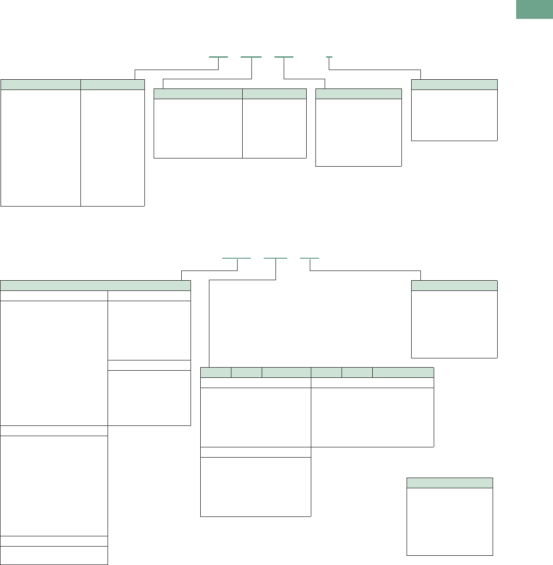
Logic Control Products CA08100001K—June 2012 www.eatoncanada.ca T37-171
37
37
37
37
37
37
37
37
37
37
37
37
37
37
37
37
37
37
37
37
37
37
37
37
37
37
37
37
37
37
37.7
Pushbuttons and Indicating Lights
30.5 mm Heavy-Duty Watertight/Oiltight—10250T
Catalogue Number Selection is for illustrative purposes only and not to be used to create new catalogue numbers.
Illuminated Pushbuttons
Standard Indicating Lights, PresTest and Master Test
Note
Add X at end of catalogue number to receive parts assembled from factory.
10250T 416 C21 –1
Circuit
Blank = Operator only
1 = 1NO-1NC
2 = 2NO
3 = 2NC
51 = 1NC
53 = 1NO
Incandescent Lens Colour LED Lens Colour
C21 = Red
C22 = Green
C23 = Yellow
C26 = White
C24 = Blue
C43 = Amber
C25 = Clear
RD = Red
GD = Green
YD = Yellow
WD = White
LD = Blue
AD = Amber
LED Voltage
Blank = Incandescent
06 = 6 Vac/Vdc
12 = 12 Vac/Vdc
24 = 24 Vac/Vdc
48 = 48 Vac/Vdc
60 = 60 Vac/Vdc
2A = 120 Vac
2D = 120 Vdc
Incandescent Light Unit LED Light Unit
416 = 24V/XFR
412 = 120V/XFR
412 = 240V/XFR
419 = 277V/XFR
413 = 380V/XFR
414 = 480V/XFR
415 = 600V/XFR
473 = 6V/FV
474 = 12V/FV
476 = 24V/FV
477 = 32V/FV
478 = 48V/FV
471 = 120V/RES
472 = 240V/RES
416L = 24V/XFR
411L = 120V/XFR
412L = 240V/XFR
419L = 277V/XFR
413L = 380V/XFR
414L = 480V/XFR
415L = 600V/XFR
497L = Full voltage
LED Voltage
Blank = Incandescent
06 = 6 Vac/Vdc
12 = 12 Vac/Vdc
24 = 24 Vac/Vdc
48 = 48 Vac/Vdc
60 = 60 Vac/Vdc
2A = 120 Vac
2D = 120 Vdc
Plastic Glass Lens Colour Plastic Glass Lens Colour
Standard/Master—Incandescent Standard/Master/PresTest—LED
C1N =
C2N =
C3N =
C6N =
C4N =
C19N =
C5N =
C7N =
C8N =
— =
C12N =
C10N =
C9N =
C11N =
Red
Green
Yellow
White
Blue
Amber
Clear
RP =
GP =
YP =
WP =
LP =
AP =
RG =
GG =
— =
WG =
LG =
AG =
Red
Green
Yellow
White
Blue
Amber
PresTest—Incandescent
C21 =
C22 =
C23 =
C26 =
C24 =
C43 =
C25 =
C13N =
C14N =
— =
C18N =
C16N =
C15N =
C17N =
Red
Green
Yellow
White
Blue
Amber
Clear
Light Unit Type
Standard—Incandescent Standard—LED
181N =
182N =
198N =
183N =
184N =
185N =
203N =
204N =
206N =
207N =
208N =
201N =
202N =
226N =
227N =
120V/XFR
240V/XFR
277V/XFR
380V/XFR
480V/XFR
600V/XFR
6V/FV
12V/FV
24V/FV
32V/FV
48V/FV
120V/RES
240V/RES
120V/neon
240V/neon
181L =
182L =
198L =
183L =
184L =
185L =
197L =
120V/XFR
240V/XFR
277V/XFR
380V/XFR
480V/XFR
600V/XFR
Full voltage
PresTest—LED
221L =
222L =
223L =
224L =
225L =
297L =
120V/XFR
240V/XFR
380V/XFR
480V/XFR
600V/XFR
Full voltage
PresTest—Incandescent
221N =
222N =
223N =
224N =
225N =
232N =
233N =
235N =
238N =
239N =
231N =
240N =
120V/XFR
240V/XFR
380V/XFR
480V/XFR
600V/XFR
6V/FV
12V/FV
24V/FV
32V/FV
48V/FV
120V/RES
240V/RES
Master Test—Incandescent
187N =
189N =
120V/XFR
240 Vac—SS
10250T 203N C1N
LED Voltage
Blank = Incandescent
06 = 6 Vac/Vdc
12 = 12 Vac/Vdc
24 = 24 Vac/Vdc
48 = 48 Vac/Vdc
60 = 60 Vac/Vdc
2A
Tab37book.fm Page 171 Tuesday, July 3, 2012 10:46 PM
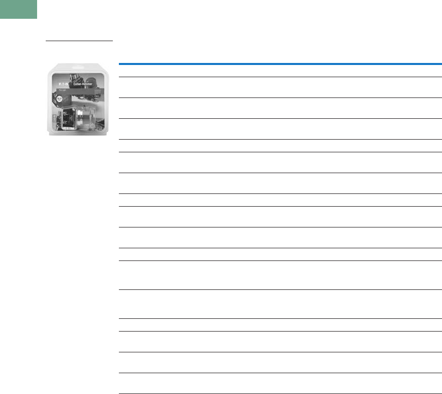
T37-172 Logic Control Products CA08100001K—June 2012 www.eatoncanada.ca
37
37
37
37
37
37
37
37
37
37
37
37
37
37
37
37
37
37
37
37
37
37
37
37
37
37
37
37
37
37
37.7
Pushbuttons and Indicating Lights
30.5 mm Heavy-Duty Watertight/Oiltight—10250T
Product Selection
Point-of-Purchase Packaging
10250T Point-of-Purchase Packaged Pilot Devices
Product Description Catalogue Number
Emergency Stop Operators
Red non-illuminated
push-pull
1NO-1NC contact block. Also includes two square engraved
legend plates: EMERG. STOP and STOP.
10250T5B62-1-POP
Red mushroom
pushbutton
1NO-1NC contact block. Also includes two square engraved
legend plates: EMERG. STOP and STOP.
10250T32R-POP
Red jumbo
mushroom pushbutton
Engraved EMERG. STOP with 1NO-1NC contact block. 10250T33-POP
Momentary Pushbuttons
Black flush
pushbutton
1NO-1NC contact block. Also includes two square engraved
legend plates: START and JOG.
10250T30B-POP
Red extended
pushbutton
1NO-1NC contact block. Also includes one square engraved
legend plate: STOP.
10250T31R-POP
Indicating Lights
Red indicating light Full voltage 24 Vac/Vdc with two extra lenses: Green and amber.
Also includes two square engraved legend plates: RUN and JOG.
10250T206NC1N-POP
Red indicating light Resistor 120 Vac/Vdc with two extra lenses: Green and Amber.
Also includes one square engraved legend plate: RUN and JOG.
10250T34R-POP
Illuminated Pushbuttons
Red illuminating
pushbutton
Full voltage 24 Vac/Vdc with 1NO-1NC contact block and two
extra lenses: Green and amber. Also includes one square
engraved legend plate: POWER ON.
10250T476C21-1-POP
Red illuminating
pushbutton
Resistor 120 Vac/Vdc with 1NO-1NC contact block and two
extra lenses: Green and amber. Also includes one square
engraved legend plate: POWER ON.
10250T411C21-1-POP
Selector Switches
Black knob two-position
selector switch
1NO-1NC contact block. Also includes three square engraved
legend plates: OFF/ON, HAND/AUTO and RUN/JOG.
10250T20KB-POP
Black knob three-position
selector switch
2NO-2NC contact blocks. Also includes 1 square engraved
legend plate: HAND/OFF/AUTO.
10250T22KB-POP
Black knob three-position
selector switch
1NO-1NC contact block. Also includes legend plate:
HAND/OFF/AUTO
10250T21KB-POP
Point-of-Purchase
Packaged Pilot Device
Tab37book.fm Page 172 Tuesday, July 3, 2012 10:46 PM
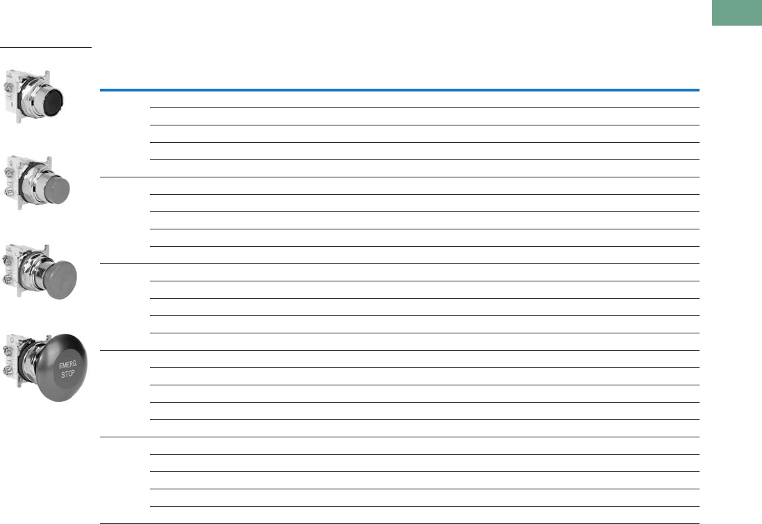
Logic Control Products CA08100001K—June 2012 www.eatoncanada.ca T37-173
37
37
37
37
37
37
37
37
37
37
37
37
37
37
37
37
37
37
37
37
37
37
37
37
37
37
37
37
37
37
37.7
Pushbuttons and Indicating Lights
30.5 mm Heavy-Duty Watertight/Oiltight—10250T
Non-Illuminated Momentary Pushbutton Units
UL (NEMA) Type 3, 3R, 4, 4X, 12, 13
Pushbutton Units—Flush, Extended, Mushroom Head or Jumbo Mushroom Head Operators
Note
Anodized aluminum head is not suitable for use in ultraviolet light applications.
Contact
Type Button Colour
Flush Button
Catalogue Number
Extended Button
Catalogue Number
Mushroom Button
Catalogue Number
Jumbo Mushroom
Catalogue Number
1NO Black 10250T23B 10250T25B 10250T26B 10250T27B
Red 10250T23R 10250T112-53 10250T122-53 10250T172-53
Green 10250T23G 10250T25G 10250T26G 10250T27G
Yellow 10250T23Y 10250T25Y 10250T26Y 10250T27Y
Red—Engraved EMERG. STOP — — — 10250T17213-53
1NC Black 10250T101-51 10250T111-51 10250T121-51 10250T171-51
Red 10250T102-51 10250T25R 10250T26R 10250T27R
Green 10250T103-51 10250T113-51 10250T123-51 10250T173-51
Yellow 10250T104-51 10250T120-51 10250T124-51 10250T174-51
Red—Engraved EMERG. STOP — — — 10250T29
1NO-1NC Black 10250T30B 10250T31B 10250T32B 10250T33B
Red 10250T30R 10250T31R 10250T32R 10250T33R
Green 10250T30G 10250T31G 10250T32G 10250T33G
Yellow 10250T30Y 10250T31Y 10250T32Y 10250T33Y
Red—Engraved EMERG. STOP — — — 10250T33
2NO Black 10250T101-2 10250T111-2 10250T121-2 10250T171-2
Red 10250T102-2 10250T112-2 10250T122-2 10250T172-2
Green 10250T103-2 10250T113-2 10250T123-2 10250T173-2
Yellow 10250T104-2 10250T120-2 10250T124-2 10250T174-2
Red—Engraved EMERG. STOP — — — 10250T17213-2
2NC Black 10250T101-3 10250T111-3 10250T121-3 10250T171-3
Red 10250T102-3 10250T112-3 10250T122-3 10250T172-3
Green 10250T103-3 10250T113-3 10250T123-3 10250T173-3
Yellow 10250T104-3 10250T120-3 10250T124-3 10250T174-3
Red—Engraved EMERG. STOP — — — 10250T17213-3
Flush Button
Extended Button
Mushroom Button
Jumbo Mushroom
Tab37book.fm Page 173 Tuesday, July 3, 2012 10:46 PM
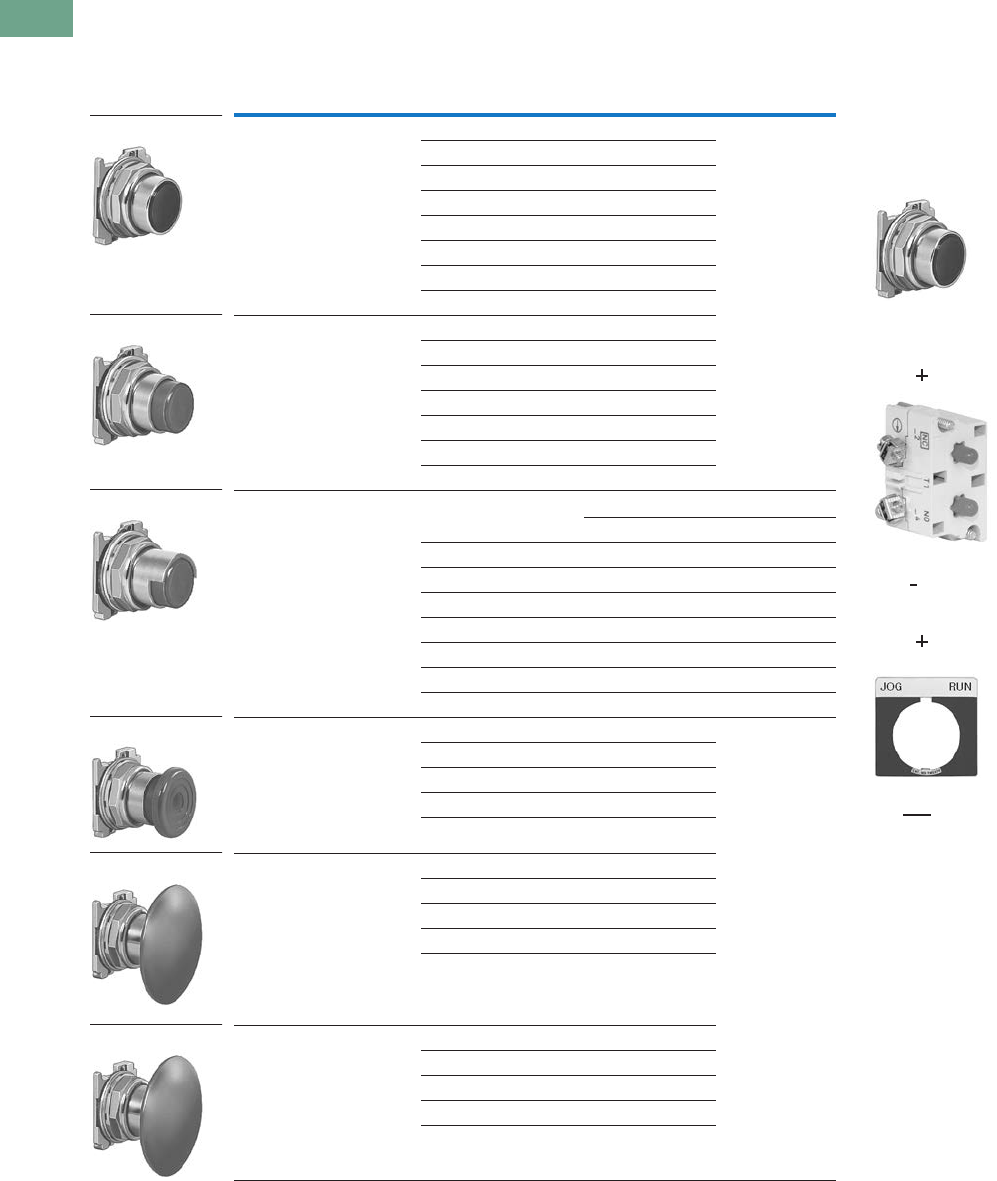
T37-174 Logic Control Products CA08100001K—June 2012 www.eatoncanada.ca
37
37
37
37
37
37
37
37
37
37
37
37
37
37
37
37
37
37
37
37
37
37
37
37
37
37
37
37
37
37
37.7
Pushbuttons and Indicating Lights
30.5 mm Heavy-Duty Watertight/Oiltight—10250T
Pushbuttons
UL (NEMA) Type 3, 3R, 4, 4X, 12, 13
Momentary Pushbutton Operators, Non-illuminated
Notes
To order operator with factory assembled extended retaining nut, 10250TA12, for thick panel applications,
add suffix letter E to listed catalogue number. Example: 10250T101E.
Anodized aluminum head is not suitable for use in ultraviolet light applications.
Operating force—Standard = 2.4 lb; low force = 1.6 lb.
Button Colour Catalogue Number Note: To order complete assembled unit
using one composite catalogue number,
add contact block and legend plate suffix
to the end of operator catalogue number.
Example: 10250T101-1TS33
Flush button Black 10250T101
Red 10250T102
Green 10250T103
Yellow 10250T104
Gray 10250T105
White 10250T106
Blue 10250T108
Orange 10250T109
Extended button Black 10250T111
Red 10250T112
Green 10250T113
Yellow 10250T120
White 10250T116
Blue 10250T118
Orange 10250T119
Half shrouded button Vertical Horizontal
Black 10250T501 10250T511
Red 10250T502 10250T512
Green 10250T503 10250T513
Yellow 10250T504 10250T514
Gray 10250T505 10250T515
White 10250T506 10250T516
Blue 10250T508 10250T518
Orange 10250T509 10250T519
Mushroom button Black 10250T121
Red 10250T122
Green 10250T123
Yellow 10250T124
Blue 10250T129
Jumbo mushroom button Black 10250T171
Red 10250T172
Red (EMERG. STOP) 10250T17213
Green 10250T173
Yellow 10250T174
Low operating force—
jumbo mushroom
Black 10250ED1164-2
Red 10250ED1164-3
Green 10250ED1164-4
Yellow 10250ED1164-5
Clear 10250ED1164
10250T10_
10250T11_
10250T5_
10250T17_
10250T12_
10250ED1164_
Operator
10250T101
Contact Block
10250T1
Legend Plate
10250TS33
Tab37book.fm Page 174 Tuesday, July 3, 2012 10:46 PM

Logic Control Products CA08100001K—June 2012 www.eatoncanada.ca T37-175
37
37
37
37
37
37
37
37
37
37
37
37
37
37
37
37
37
37
37
37
37
37
37
37
37
37
37
37
37
37
37.7
Pushbuttons and Indicating Lights
30.5 mm Heavy-Duty Watertight/Oiltight—10250T
UL (NEMA) Type 3, 3R, 4, 4X, 12, 13
Mechanically Interlocked Pushbutton Operators
Note
NC contacts must be mounted behind lock-down mushroom head operator to ensure lockout.
Description Catalogue Number
Black flush and green flush 10250TA66
Black flush and long red 10250TA67
Black flush and red mushroom head 10250TA68
Black flush and lock-down red mushroom head 10250TA69
Black flush and red jumbo mushroom head 10250TA76
Green flush and long red 10250TA72
Black long and long red 10250TA73
Green flush and red mushroom head 10250TA77
Green flush and black flush 10250TA75
10250TA_
Tab37book.fm Page 175 Tuesday, July 3, 2012 10:46 PM
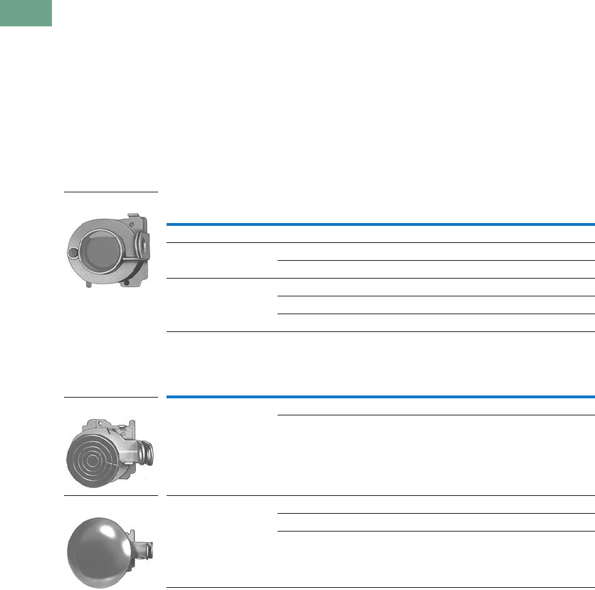
T37-176 Logic Control Products CA08100001K—June 2012 www.eatoncanada.ca
37
37
37
37
37
37
37
37
37
37
37
37
37
37
37
37
37
37
37
37
37
37
37
37
37
37
37
37
37
37
37.7
Pushbuttons and Indicating Lights
30.5 mm Heavy-Duty Watertight/Oiltight—10250T
Lockout Pushbutton Operators with Padlock Attachments
UL (NEMA) Type 3, 3R, 4, 4X, 12, 13
The following pushbutton and
mushroom operators include
an integral padlock
attachment for applications
requiring lockout/tagout of
specific machine functions.
They are available in styles
which allow locking of a
button in the down position
(stopped position) or locking a
button in the up position (to
prevent starting). Select the
“Hand” latch type which
functions as a momentary
pushbutton until the operator
presses the button and
moves the padlock
attachment into position for
locking, or choose the
“Spring Loaded” latch type
where the padlock
attachment springs into place
when the button is pressed.
Units accept a customer
supplied 1/4 in padlock.
Padlockable in the Down Position
Padlockable in the Up Position
Notes
Hand attachment must be manually moved into place for locking. Spring loaded: when operator is pressed—
attachment springs into place. Must be moved manually to release button.
Operators can be latched down without a padlock. Padlock not included.
Jumbo mushroom heads are not recommended for use in applications where exposure to ultraviolet light exists.
Operator Type Colour Latch Type Catalogue Number
Flush head Red Hand 10250TA16
Mushroom head Red Hand 10250TA42
Red Spring loaded 10250TA45
Jumbo head Red Hand 10250TA52
Red Spring loaded 10250TA55
Red (EMERG. STOP) Spring loaded 10250ED952
Operator Type Colour Latch Type Catalogue Number
Mushroom head Black Hand 10250TA41
Green Hand 10250TA43
Jumbo mushroom
head
Black Hand 10250TA51
Green Hand 10250TA53
Yellow Hand 10250TA54
10250TA16
10250TA4_
10250TA5_
Tab37book.fm Page 176 Tuesday, July 3, 2012 10:46 PM
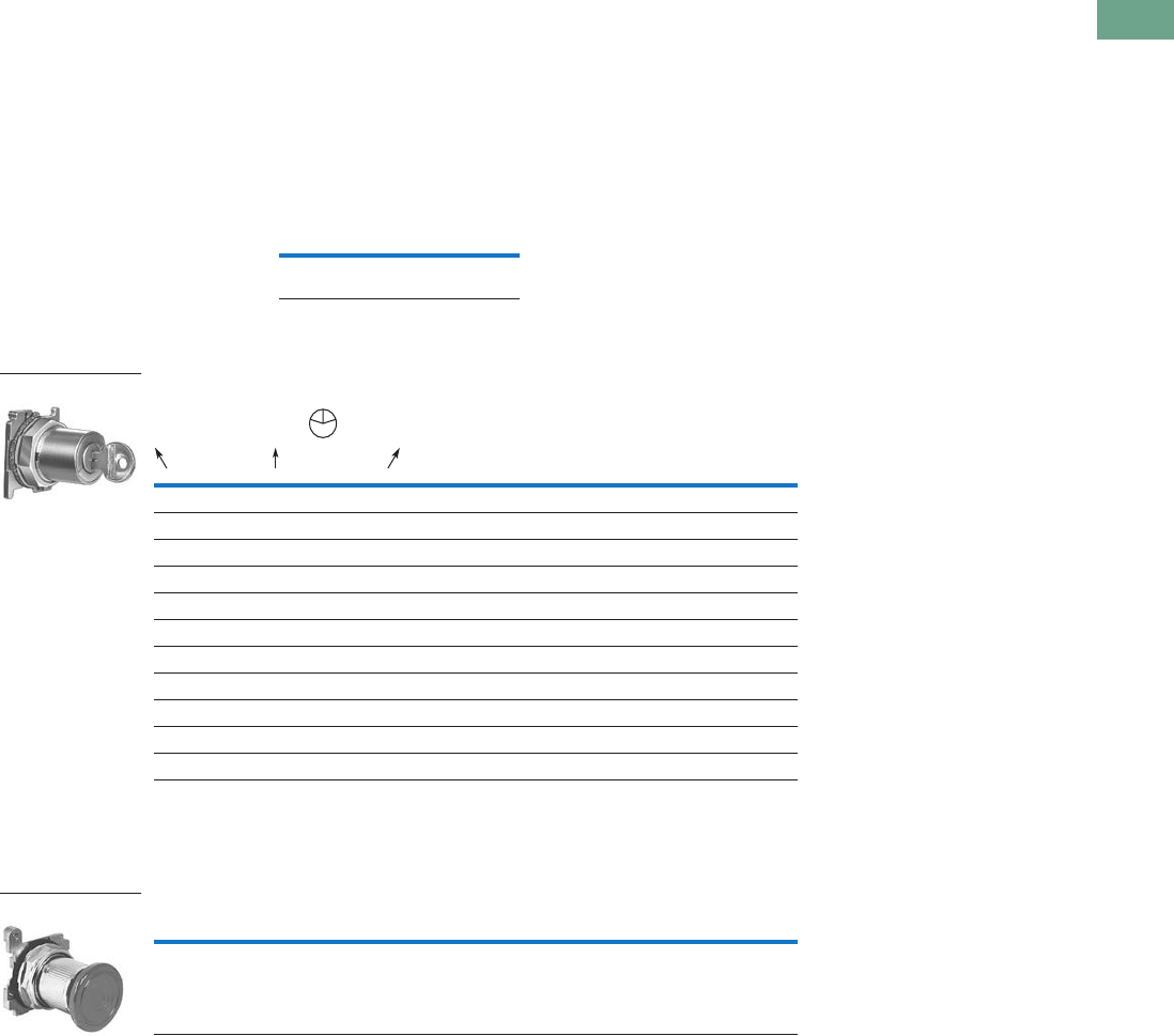
Logic Control Products CA08100001K—June 2012 www.eatoncanada.ca T37-177
37
37
37
37
37
37
37
37
37
37
37
37
37
37
37
37
37
37
37
37
37
37
37
37
37
37
37
37
37
37
37.7
Pushbuttons and Indicating Lights
30.5 mm Heavy-Duty Watertight/Oiltight—10250T
Key Pushbutton Operator
UL (NEMA) Type 3, 3R, 4, 4X, 12, 13
These devices incorporate an
integral locking mechanism
which enables locking units in
various positions (Locked
Down), locking units to
prevent operation (Locked
Up) or setting unit to lock
when the button is pressed
(Push to Lock), requiring the
key to be inserted to return to
normal operation. With the
key in the centre position,
these operators function as a
normal momentary
pushbutton (Free).
Replacement Keys or Dissimilar Locks for Key Operators Below
Listed operators have
identical locks and keys
(Key Code H661) Catalogue
Number 10250ED824. For
dissimilar lock and key
combinations, see listing on
Page T37-198.
Replacement Keys
Key Pushbutton Operator
Latch-In, Twist-to-Release Operator
UL (NEMA) Type 3, 3R, 4, 4X, 12, 13
Operator Only with Button
Note
Horizontal mounting available on request.
Description Catalogue Number
Replacement keys
(code H661)
10250ED824
Key Position and
Pushbutton Operations
Key Removal
Positions Vertical Mounting
Catalogue Number
Three-Position
Lock up Free Lock down All 10250T430
Lock up Free Lock down L and R 10250T431
Lock up Free Lock down C and R 10250T432
Two-Position
Lock up Free — L and C 10250T433
Lock up Free — L 10250T434
— Free Lock down C and R 10250T435
— Free Lock down R 10250T436
— Free Push to lock C and R 10250T437
— Free Push to lock R 10250T438
Description Catalogue Number
Latch-in, twist-to-release operator with red mushroom head button 10250ED1043-4
10250T43_
L
C
R
10250ED1043-4
Tab37book.fm Page 177 Tuesday, July 3, 2012 10:46 PM

T37-178 Logic Control Products CA08100001K—June 2012 www.eatoncanada.ca
37
37
37
37
37
37
37
37
37
37
37
37
37
37
37
37
37
37
37
37
37
37
37
37
37
37
37
37
37
37
37.7
Pushbuttons and Indicating Lights
30.5 mm Heavy-Duty Watertight/Oiltight—10250T
Illuminated Momentary Pushbutton Units
UL (NEMA) Type 3, 3R, 4, 4X, 12, 13
●LED or incandescent
●Full voltage, resistor or transformer type
●Plastic lenses
Illuminated Pushbutton Units
Note
For flashing module catalogue number 10250TFL1, add suffix code FM to listed catalogue number. Example: 10250T75RFM.
Type Voltage Colour
LED/Lamp
Number
Illuminated Pushbutton
1NO 1NO-1NC 1NC
Catalogue Number Catalogue Number Catalogue Number
LED Lamp
Full voltage 24 Vac/Vdc Red Bayonet
base
10250T397LRD24-53 10250T397LRD24-1 10250T397LRD24-51
Green 10250T397LGD24-53 10250T397LGD24-1 10250T397LGD24-51
Amber 10250T397LAD24-53 10250T397LAD24-1 10250T397LAD24-51
Yellow 10250T397LYD24-53 10250T397LYD24-1 10250T397LYD24-51
Blue 10250T397LLD24-53 10250T397LLD24-1 10250T397LLD24-51
White 10250T397LWD24-53 10250T397LWD24-1 10250T397LWD24-51
120 Vac Red 10250T397LRD2A-53 10250T397LRD2A-1 10250T397LRD2A-51
Green 10250T397LGD2A-53 10250T397LGD2A-1 10250T397LGD2A-51
Amber 10250T397LAD2A-53 10250T397LAD2A-1 10250T397LAD2A-51
Yellow 10250T397LYD2A-53 10250T397LYD2A-2 10250T397LYD2A-51
Blue 10250T397LLD2A-53 10250T397LLD2A-1 10250T397LLD2A-51
White 10250T397LWD2A-53 10250T397LWD2A-1 10250T397LWD2A-51
Transformer 120 Vac Red 10250T411LRD06-53 10250T411LRD06-1 10250T411LRD06-51
Green 10250T411LGD06-53 10250T411LGD06-1 10250T411LGD06-51
Amber 10250T411LAD06-53 10250T411LAD06-1 10250T411LAD06-51
Yellow 10250T411LYD06-53 10250T411LYD06-1 10250T411LYD06-51
Blue 10250T411LLD06-53 10250T411LLD06-1 10250T411LLD06-51
White 10250T411LWD06-53 10250T411LWD06-1 10250T411LWD06-51
Incandescent Lamp
Full voltage 24 Vac/Vdc Red #757 10250T476C21-53 10250T476C21-1 10250T476C21-51
Green 10250T476C22-53 10250T476C22-1 10250T476C22-51
Amber 10250T476C43-53 10250T476C43-1 10250T476C43-51
Yellow 10250T476C23-53 10250T476C23-1 10250T476C23-51
Blue 10250T476C24-53 10250T476C24-1 10250T476C24-51
Clear 10250T476C25-53 10250T476C25-1 10250T476C25-51
White 10250T476C26-53 10250T476C26-1 10250T476C26-51
Resistor 120 Vac/Vdc Red 120MB 10250T471C21-53 10250T471C21-1 10250T471C21-51
Green 10250T471C22-53 10250T471C22-1 10250T471C22-51
Amber 10250T471C43-53 10250T471C43-1 10250T471C43-51
Yellow 10250T471C23-53 10250T471C23-1 10250T471C23-51
Blue 10250T471C24-53 10250T471C24-1 10250T471C24-51
Clear 10250T471C25-53 10250T471C25-1 10250T471C25-51
White 10250T471C26-53 10250T471C26-1 10250T471C26-51
Transformer 120 Vac Red #755 10250T75R 10250T76R 10250T77R
Green 10250T75G 10250T76G 10250T77G
Amber 10250T75A 10250T76A 10250T77A
Yellow 10250T75Y 10250T76Y 10250T77Y
Blue 10250T75B 10250T76B 10250T77B
Clear 10250T75C 10250T76C 10250T77C
White 10250T75W 10250T76W 10250T77W
24V Full Voltage
Illuminated Pushbutton
Tab37book.fm Page 178 Tuesday, July 3, 2012 10:46 PM

Logic Control Products CA08100001K—June 2012 www.eatoncanada.ca T37-179
37
37
37
37
37
37
37
37
37
37
37
37
37
37
37
37
37
37
37
37
37
37
37
37
37
37
37
37
37
37
37.7
Pushbuttons and Indicating Lights
30.5 mm Heavy-Duty Watertight/Oiltight—10250T
Indicating Light Units
UL (NEMA) Type 3, 3R, 4, 4X, 12, 13
●LED or incandescent
●Full voltage, resistor or
transformer type
●Standard and PresTest
types
●Plastic lenses
PresTest—This device
incorporates a press-to-test
feature whereby depressing
the lens disconnects the light
from the source being
monitored and connects
the lamp to a continuously
energized circuit for
immediate detection of
faulty lamps.
Indicating Light Units
Notes
Standard indicating lights are rated UL (NEMA) 3S as well.
For flashing lamp add letter F to listed catalogue number. Example: 10250T34RF.
Type Voltage Colour
LED/Lamp
Number
Indicating Light
Catalogue Number
PresTest
Catalogue Number
LED Lamp
Full voltage 24 Vac/Vdc Red Bayonet
base
10250T197LRP24 10250T297LRP24
Green 10250T197LGP24 10250T297LGP24
Amber 10250T197LAP24 10250T297LAP24
Yellow 10250T197LYP24 10250T297LYP24
Blue 10250T197LLP24 10250T297LLP24
White 10250T197LWP24 10250T297LWP24
120 Vac Red 10250T197LRP2A 10250T297LRP2A
Green 10250T197LGP2A 10250T297LGP2A
Amber 10250T197LAP2A 10250T297LAP2A
Yellow 10250T197LYP2A 10250T297LYP2A
Blue 10250T197LLP2A 10250T297LLP2A
White 10250T197LWP2A 10250T297LWP2A
Transformer 120 Vac Red 10250T181LRP06 10250T221LRP06
Green 10250T181LGP06 10250T221LGP06
Amber 10250T181LAP06 10250T221LAP06
Yellow 10250T181LYP06 10250T221LYP06
Blue 10250T181LLP06 10250T221LLP06
White 10250T181LWP06 10250T221LWP06
Incandescent Lamp
Full voltage 24 Vac/Vdc Red #757 10250T206NC1N 10250T235NC21
Green 10250T206NC2N 10250T235NC22
Amber 10250T206NC19N 10250T235NC43
Yellow 10250T206NC3N 10250T235NC23
Blue 10250T206NC4N 10250T235NC24
Clear 10250T206NC5N 10250T235NC25
White 10250T206NC6N 10250T235NC26
Resistor 120 Vac/Vdc Red 120MB 10250T201NC1N 10250T231NC21
Green 10250T201NC2N 10250T231NC22
Amber 10250T201NC19N 10250T231NC43
Yellow 10250T201NC3N 10250T231NC23
Blue 10250T201NC4N 10250T231NC24
Clear 10250T201NC5N 10250T231NC25
White 10250T201NC6N 10250T231NC26
Transformer 120 Vac Red #755 10250T34R 10250T74NR
Green 10250T34G 10250T74NG
Amber 10250T34A 10250T74NA
Yellow 10250T34Y 10250T74NY
Blue 10250T34B 10250T74NB
Clear 10250T34C 10250T74NC
White 10250T34W 10250T74NW
24V Full Voltage
Illuminated Light
120 Vac Transformer
PresTest
Tab37book.fm Page 179 Tuesday, July 3, 2012 10:46 PM

T37-180 Logic Control Products CA08100001K—June 2012 www.eatoncanada.ca
37
37
37
37
37
37
37
37
37
37
37
37
37
37
37
37
37
37
37
37
37
37
37
37
37
37
37
37
37
37
37.7
Pushbuttons and Indicating Lights
30.5 mm Heavy-Duty Watertight/Oiltight—10250T
Illuminated Pushbuttons and Indicating Lights
●LED or incandescent
●Full voltage, resistor or transformer type
Operators without Lens
Notes
These units do not include lamps. Order LED separately to match lens colour. See Page T37-225 for LED Selection and Page T37-171 for Catalogue Numbering System.
Resistor units are not available for use with LEDs, choose either transformer or full voltage LED style.
For flashing lamp, add letter F to listed catalogue number. Example: 10250T181NF.
Resistant to shock and vibration. For best illumination use amber, yellow or clear lens.
Type Voltage
LED/Lamp
Number
Illuminated
Pushbutton
Catalogue Number
Indicating Light
Catalogue Number
PresTest
Catalogue Number
Master Test
Catalogue Number
Incandescent Unit
Full voltage AC/DC 6 #755 10250T473 10250T203N 10250T232N —
12 #756 10250T474 10250T204N 10250T233N —
24 #757 10250T476 10250T206N 10250T235N —
32 #1828 10250T477 10250T207N 10250T238N —
48 #1835 10250T478 10250T208N 10250T239N —
Resistor AC/DC 120 120MB 10250T47 10250T201N 10250T231N —
240 120MB 10250T472 10250T202N 10250T240N —
Transformer AC only 24 #755 10250T416 — — —
120 10250T411 10250T181N 10250T221N —
240 10250T422 10250T182N 10250T222N —
277 10250T419 10250T198N — —
380 10250T413 10250T183N 10250T223N —
480 10250T414 10250T184N 10250T224N —
600 10250T415 10250T185N 10250T225N —
Neon AC/DC 120 NE51H-R22 — 10250T226N — —
240 NE51H-R68 — 10250T227N — —
Solid-state 50/60 Hz only 120 120MB — — — 10250T189N
LED (LEDs not included)
Full voltage — Bayonet
base
10250T397L 10250T197L 10250T297L —
Transformer AC only 24 10250T416L — — —
120 10250T411L 10250T181L 10250T221L —
240 10250T412L 10250T182L 10250T222L —
277 10250T419L 10250T198L — —
380 10250T413L 10250T183L 10250T223L —
480 10250T414L 10250T184L 10250T224L —
600 10250T415L 10250T185L 10250T225L —
Illuminated Pushbutton
Indicating Light
PresTest
Master Test
Tab37book.fm Page 180 Tuesday, July 3, 2012 10:46 PM
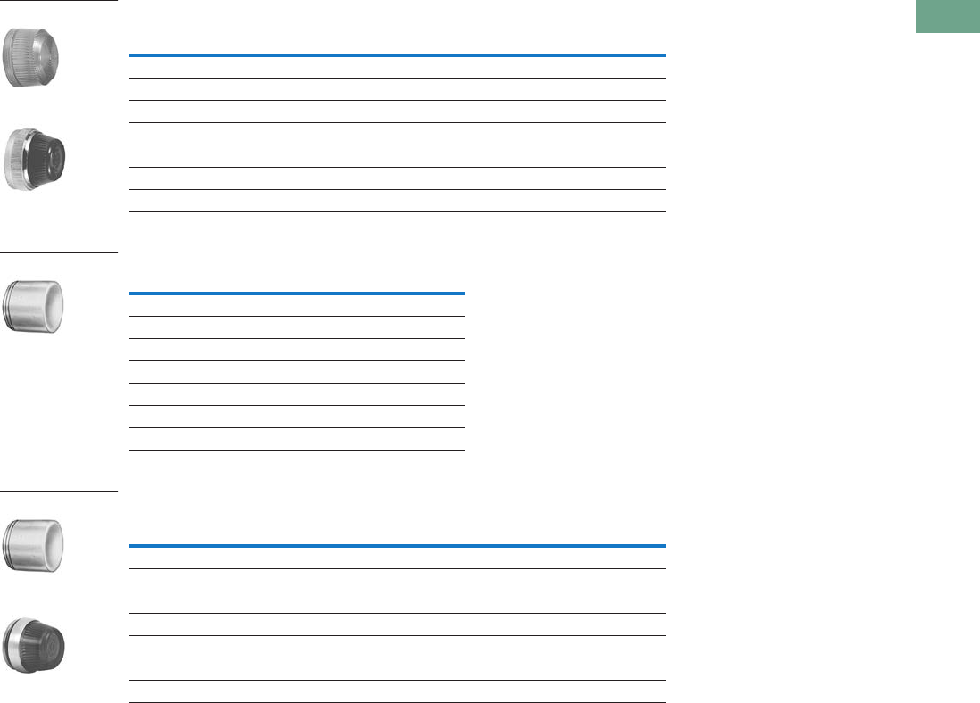
Logic Control Products CA08100001K—June 2012 www.eatoncanada.ca T37-181
37
37
37
37
37
37
37
37
37
37
37
37
37
37
37
37
37
37
37
37
37
37
37
37
37
37
37
37
37
37
37.7
Pushbuttons and Indicating Lights
30.5 mm Heavy-Duty Watertight/Oiltight—10250T
Indicating and Master Test Lenses
Illuminated Pushbutton Lenses
PresTest Lenses
Colour
Plastic
Catalogue Number
Glass
Catalogue Number
Red 10250TC1N 10250TC7N
Green 10250TC2N 10250TC8N
Amber 10250TC19N 10250TC9N
Yellow 10250TC3N —
Blue 10250TC4N 10250TC10N
Clear 10250TC5N 10250TC11N
White 10250TC6N 10250TC12N
Colour Catalogue Number
Red 10250TC21
Green 10250TC22
Yellow 10250TC23
Amber 10250TC43
Blue 10250TC24
Clear 10250TC25
White 10250TC26
Colour
Plastic
Catalogue Number
Glass
Catalogue Number
Red 10250TC21 10250TC13N
Green 10250TC22 10250TC14N
Amber 10250TC43 10250TC15N
Yellow 10250TC23 —
Blue 10250TC24 10250TC16N
Clear 10250TC25 10250TC17N
White 10250TC26 10250TC18N
Plastic
Glass
10250TC2_
Plastic
Glass
Tab37book.fm Page 181 Tuesday, July 3, 2012 10:46 PM
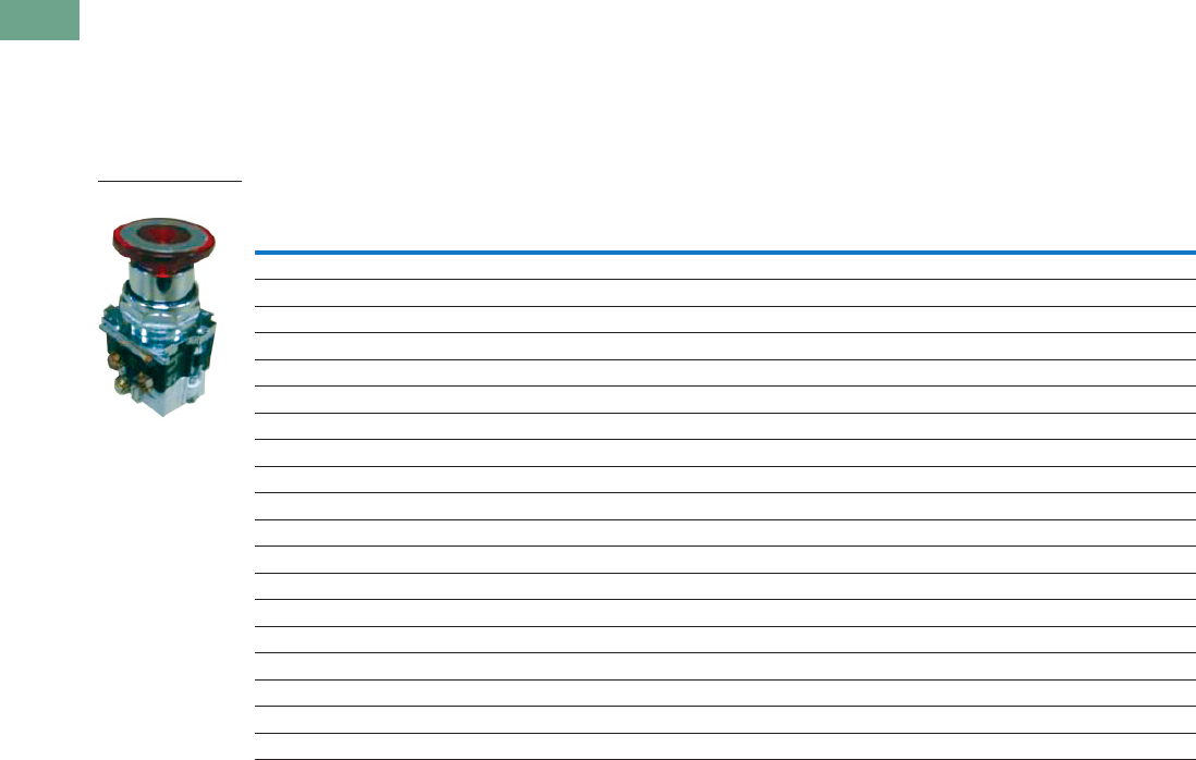
T37-182 Logic Control Products CA08100001K—June 2012 www.eatoncanada.ca
37
37
37
37
37
37
37
37
37
37
37
37
37
37
37
37
37
37
37
37
37
37
37
37
37
37
37
37
37
37
37.7
Pushbuttons and Indicating Lights
30.5 mm Heavy-Duty Watertight/Oiltight—10250T
Push-Pull Emergency Stops (Compliant with IEC 60947-5-5)
UL (NEMA) Type 3, 3R, 4, 4X, 12, 13
●Two- and three-position
●Non-illuminated
●LONC contact block
Two-Position Push-Pull Units
Note
X = closed circuit, O = open circuit.
Operator Position
Button Type/Colour Lamp Type Voltage Catalogue NumberPull Push
X O 40 mm red—illuminated Incandescent Transformer 120 Vac/Vdc 10250T563C47-71X
X O 40 mm red—illuminated EMERG. STOP Incandescent Transformer 120 Vac/Vdc 10250T563C53-71X
X O 40 mm red—illuminated EMERG. STOP LED Transformer 120 Vac/Vdc 10250T563LED06-71X
X O 40 mm red—illuminated Incandescent Full voltage 24 Vdc 10250T579C47-71X
X O 40 mm red—illuminated EMERG. STOP Incandescent Full voltage 24 Vdc 10250T579C53-71X
X O 40 mm red—illuminated Incandescent Resistor 120 Vac/Vdc 10250T580C47-71X
X O 40 mm red—illuminated EMERG. STOP Incandescent Resistor 120 Vac/Vdc 10250T580C53-71X
X O 40 mm red—illuminated Incandescent Transformer 24 Vdc 10250T589C47-71X
X O 40 mm red—illuminated EMERG. STOP Incandescent Transformer 24 Vdc 10250T589C53-71X
X O 40 mm red—illuminated EMERG. STOP LED Transformer 24 Vdc 10250T589LED06-71X
X O 40 mm red—illuminated LED Transformer 24 Vdc 10250T589LRD06-71X
X O 40 mm red—illuminated EMERG. STOP LED Full voltage 24 Vdc 10250T597LED24-71X
X O 40 mm red—illuminated EMERG. STOP LED Full voltage 120 Vac/Vdc 10250T597LED2A-71X
X O 40 mm red—illuminated LED Full voltage 24 Vdc 10250T597LRD24-71X
X O 40 mm red—illuminated LED Full voltage 120 Vac/Vdc 10250T597LRD2A-71X
X O 40 mm red — — — 10250T5B62-71X
X O 40 mm red — — — 10250T5B63-71X
X O 65 mm red — — — 10250T5J62-71X
X O 65 mm red — — — 10250T5J63-71X
10250T579C47-71X
Tab37book.fm Page 182 Tuesday, July 3, 2012 10:46 PM
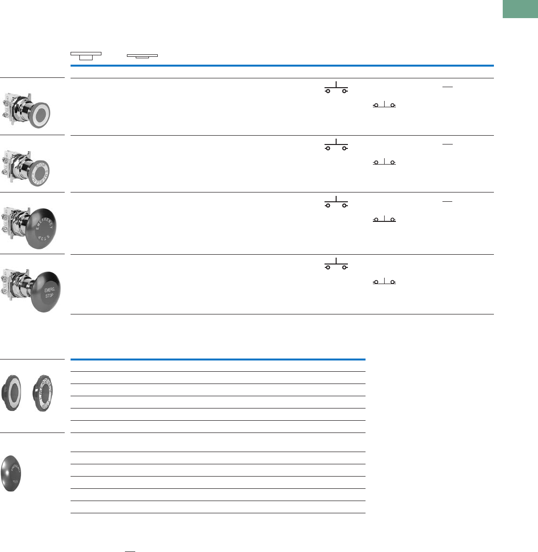
Logic Control Products CA08100001K—June 2012 www.eatoncanada.ca T37-183
37
37
37
37
37
37
37
37
37
37
37
37
37
37
37
37
37
37
37
37
37
37
37
37
37
37
37
37
37
37
37.7
Pushbuttons and Indicating Lights
30.5 mm Heavy-Duty Watertight/Oiltight—10250T
UL (NEMA) Type 3, 3R, 4, 4X, 12, 13
Two-Position Push-Pull Units
Button and Colour Selection
Notes
X = closed circuit, O = open circuit.
To order different type or colour buttons, substitute the underlined characters with appropriate suffix code from the table.
Example: 10250T5B64-1X.
Anodized aluminum head is not suitable for use in ultraviolet light applications.
Operator Position
Button Type/Colour Contact
Type Catalogue Number
Pull Push Mounting Location
AB
Two-Position Maintained Push, Maintained Pull
O
X
X
O
40 mm/red 1NO 10250T5B62-1X
1NC
O
X
X
O
40 mm engraved
EMERG. STOP/red
1NO 10250T5B63-1X
1NC
O
X
X
O
65 mm aluminum engraved
EMERG. STOP/red
1NO 10250T5J63-1X
1NC
O
X
X
O
65 mm aluminum engraved
EMERG. STOP/red
1NO 10250ED1080-2
Special security
jumbo mushroom head
1NC
Colour Suffix Code Catalogue Number
Standard—40 mm
Red B62 10250TB62
Red (EMERG. STOP) B63 10250TB63
Green B61 10250TB61
Black B60 10250TB60
Blue B64 10250TB64
Jumbo Mushroom Head
(Anodized) Aluminum—65 mm
Red J62 10250TJ62
Red (EMERG. STOP) J63 10250TJ63
Green J61 10250TJ61
Black J60 10250TJ60
Yellow J64 10250TJ64
10250T5B63-1X
10250T5J63-1X
10250T5B62-1X
10250ED1080-2
Standard
Jumbo Mushroom
Head
Tab37book.fm Page 183 Tuesday, July 3, 2012 10:46 PM
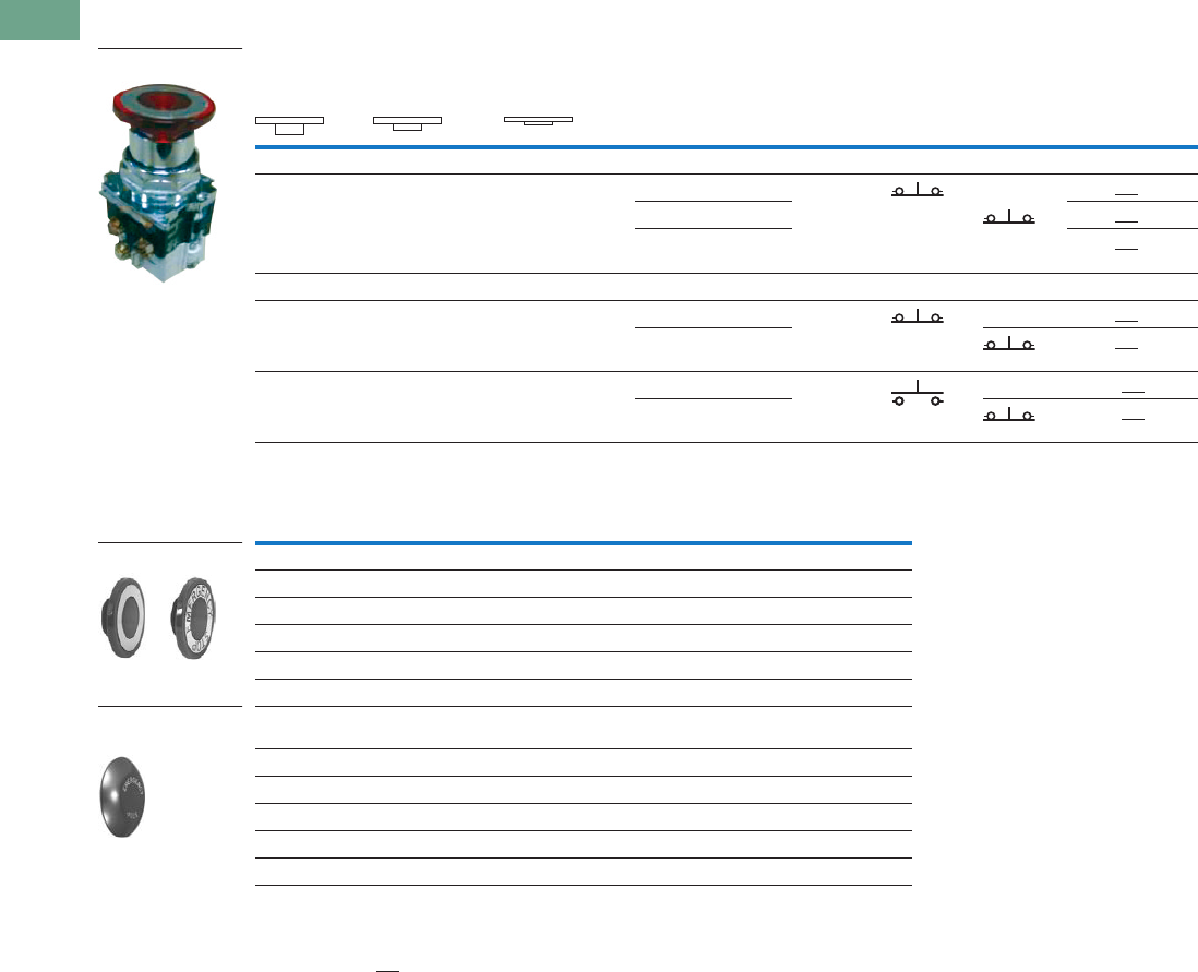
T37-184 Logic Control Products CA08100001K—June 2012 www.eatoncanada.ca
37
37
37
37
37
37
37
37
37
37
37
37
37
37
37
37
37
37
37
37
37
37
37
37
37
37
37
37
37
37
37.7
Pushbuttons and Indicating Lights
30.5 mm Heavy-Duty Watertight/Oiltight—10250T
UL (NEMA) Type 3, 3R, 4, 4X, 12, 13
Three-Position Push-Pull Units
Button and Colour Selection
Notes
X = closed circuit, O = open circuit.
To order different type or colour buttons, substitute the underlined characters with appropriate suffix code from the table.
Example: 10250T5B64-1X.
Anodized aluminum head is not suitable for use in ultraviolet light applications.
Operator Position
Button Type/Colour
Contact
Type Catalogue Number
Pull Intermediate Push Mounting Location
AB
Maintained Push, Momentary Pull
X
X
O
X
O
O
40 mm/black 1NC 10250T9B60-3X
1NC40 mm/red 10250T9B62-3X
40 mm engraved
EMERG. STOP/red
10250T9B63-3X
Momentary Push, Momentary Pull
X
X
O
X
O
O
40 mm/black 1NC 10250T4B60-3X
1NC40 mm/red 10250T4B62-3X
O
X
O
O
X
O
40 mm/black 1NO 10250T10B60-1X
1NC40 mm/red 10250T10B62-1X
Colour Suffix Code Catalogue Number
Standard—40 mm
Red B62 10250TB62
Red (EMERG. STOP) B63 10250TB63
Green B61 10250TB61
Black B60 10250TB60
Blue B64 10250TB64
Jumbo Mushroom Head
(Anodized) Aluminum—65 mm
Red J62 10250TJ62
Red (EMERG. STOP) J63 10250TJ63
Green J61 10250TJ61
Black J60 10250TJ60
Yellow J64 10250TJ64
10250T_
Standard
Jumbo Mushroom
Head
Tab37book.fm Page 184 Tuesday, July 3, 2012 10:46 PM

Logic Control Products CA08100001K—June 2012 www.eatoncanada.ca T37-185
37
37
37
37
37
37
37
37
37
37
37
37
37
37
37
37
37
37
37
37
37
37
37
37
37
37
37
37
37
37
37.7
Pushbuttons and Indicating Lights
30.5 mm Heavy-Duty Watertight/Oiltight—10250T
Illuminated Push-Pull Units
UL (NEMA) Type 3, 3R, 4, 4X, 12, 13
●LED or incandescent
●Full voltage, resistor or transformer type
●Two-position maintained
Two-Position Illuminated Maintained Push, Maintained Pull
Jumbo Lens Illuminated E-Stops
Notes
X = closed circuit, O = open circuit.
To order different type or colour lens, substitute the underlined characters with appropriate suffix code from table on next page. Example: 10250T579C63-1X.
For LEDs with different voltages see ordering example on Page T37-191.
Operator Position
Lamp Type Voltage
Contact
Type
LED/Lamp
Number
Red Standard
Push-Pull
Catalogue Number
Maintained—
Pull
Maintained—
Push Mounting Location
AB
O
X
X
O
LED Full Voltage 24 Vac/Vdc 1NO Bayonet
base
10250T597LRD24-1X
1NC120 Vac/Vdc 10250T597LRD2A-1X
Transformer 24 Vac 10250T589LRD06-1X
120 Vac 10250T563LRD06-1X
O
X
X
O
Incandescent Full voltage 24 Vac/Vdc 1NO #757 10250T579C47-1X
1NCResistor 120 Vac/Vdc 120MB 10250T580C47-1X
Transformer 24 Vac #755 10250T589C47-1X
120 Vac 10250T563C47-1X
Lamp Button Type/Colour Type Voltage
Contact
Type Catalogue Number
LED Two-position illuminated maintained push/pull—
50 mm jumbo lens/red
Full voltage 24 Vac/Vdc 1NO
1NC
10250ED1375
LED Three-position illuminated momentary push/pull—
50 mm jumbo lens/red
Full voltage 24 Vac/Vdc 1NC
1NC
10250ED1376
LED Three-position illuminated momentary push/pull—
50 mm jumbo lens/red
Full voltage 24 Vac/Vdc 1NO
1NC
10250ED1377
LED Three-position illuminated maintained push/momentary pull—
50 mm lens/red
Full voltage 1NO
1NC
10250ED1378
Two-Position Push-
Pull Operator
10250ED137_
Tab37book.fm Page 185 Tuesday, July 3, 2012 10:46 PM
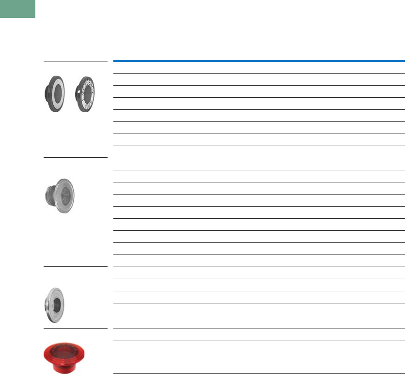
T37-186 Logic Control Products CA08100001K—June 2012 www.eatoncanada.ca
37
37
37
37
37
37
37
37
37
37
37
37
37
37
37
37
37
37
37
37
37
37
37
37
37
37
37
37
37
37
37.7
Pushbuttons and Indicating Lights
30.5 mm Heavy-Duty Watertight/Oiltight—10250T
UL (NEMA) Type 3, 3R, 4, 4X, 12, 13
Lens and Colour Selection
Note
Clear anodized aluminum and colored lens.
Colour
Incandescent
Suffix Code
LED
Suffix Code Catalogue Number
Standard—40 mm
Red C47 RD 10250TC47
Red (EMERG. STOP) C53 ED 10250TC53
Green C48 GD 10250TC48
Blue C49 LD 10250TC49
Amber C50 AD 10250TC50
White C51 WD 10250TC51
Clear C52 CD 10250TC52
Side-Lighted Aluminum—40 mm
Red C57 RS 10250TC57
Red (EMERG. STOP) C63 ES 10250TC63
Green C58 GS 10250TC58
Blue C59 LS 10250TC59
Amber C64 AS 10250TC64
Yellow C60 YS 10250TC60
White C61 WS 10250TC61
Clear C62 CS 10250TC62
Aluminum Transparent Centre—40 mm
Red C65 RH 10250TC65
Green C66 GH 10250TC66
Amber C67 AH 10250TC67
Jumbo Lens—50 mm
Red — — 10250TC77
Standard
Side-Lighted
Aluminum
Aluminum Transparent
Centre
Jumbo Lens
Tab37book.fm Page 186 Tuesday, July 3, 2012 10:46 PM
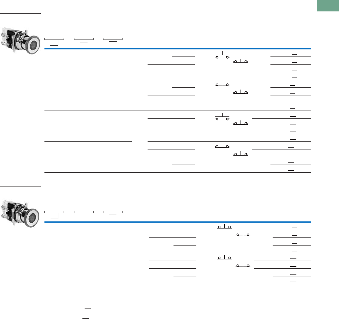
Logic Control Products CA08100001K—June 2012 www.eatoncanada.ca T37-187
37
37
37
37
37
37
37
37
37
37
37
37
37
37
37
37
37
37
37
37
37
37
37
37
37
37
37
37
37
37
37.7
Pushbuttons and Indicating Lights
30.5 mm Heavy-Duty Watertight/Oiltight—10250T
UL (NEMA) Type 3, 3R, 4, 4X, 12, 13
Three-Position Illuminated Momentary Push, Momentary Pull
Three-Position Illuminated Maintained Push, Momentary Pull
Notes
X = closed circuit, O = open circuit.
To order different type or colour lens, substitute the underlined characters with appropriate suffix code from table on Page T37-186.
Example: 10250T1079C53-1X. For LEDs with different voltages see ordering example on Page T37-191.
To order different type or colour lens, substitute the underlined characters with appropriate suffix code from table on Page T37-186.
Example: 10250T979C53X. For LEDs with different voltages see ordering example on Page T37-191.
Operator Position
Lamp Type Voltage
Contact
Type
LED/
Lamp
Number
Red Standard
Push-Pull
Catalogue Number
Momentary—
Pull
Maintained—
Intermediate
Momentary—
Push Mounting Location
AB
O
X
O
O
X
O
LED Full voltage 24 Vac/Vdc 1NO Bayonet
base
10250T1097LRD24-1X
1NC120 Vac 10250T1097LRD2A-1X
Transformer 24 Vac 10250T1089LRD06-1X
120 Vac 10250T1063LRD06-1X
X
X
O
X
O
O
Full voltage 24 Vac/Vdc 1NC Bayonet
base
10250T497LRD24-3X
1NC120 Vac 10250T497LRD2A-3X
Transformer 24 Vac 10250T489LRD06-3X
120 Vac 10250T463LRD06-3X
O
X
O
O
X
O
Incan-
descent
Full voltage 24 Vac/Vdc 1NO #757 10250T1079C47-1X
1NCResistor 120 Vac 120MB 10250T1080C47-1X
Transformer 24 Vac #755 10250T1089C47-1X
120 Vac 10250T1063C47-1X
X
X
O
X
O
O
Full voltage 24 Vac/Vdc 1NC #757 10250T479C47-3X
1NCResistor 120 Vac 120MB 10250T480C47-3X
Transformer 24 Vac #755 10250T489C47-3X
120 Vac 10250T463C47-3X
Operator Position
Lamp Type Voltage
Contact
Type
LED/
Lamp
Number
Red Standard
Push-Pull
Catalogue Number
Momentary—
Pull
Maintained—
Intermediate
Momentary—
Push Mounting Location
AB
X
X
O
X
O
O
LED Full voltage 24 Vac/Vdc 1NC Bayonet
base
10250T997LRD24-3X
1NC120 Vac 10250T997LRD2A-3X
Transformer 24 Vac 10250T989LRD06-3X
120 Vac 10250T963LRD06-3X
X
X
O
X
O
O
Incan-
descent
Full voltage 24 Vac/Vdc 1NC #757 10250T979C47-3X
1NCResistor 120 Vac 120MB 10250T980C47-3X
Transformer 24 Vac #755 10250T989C47-3X
120 Vac 10250T963C47-3X
Three-Position Push-
Pull Operator
Three-Position Push-
Pull Operator
Tab37book.fm Page 187 Tuesday, July 3, 2012 10:46 PM
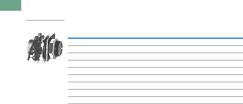
T37-188 Logic Control Products CA08100001K—June 2012 www.eatoncanada.ca
37
37
37
37
37
37
37
37
37
37
37
37
37
37
37
37
37
37
37
37
37
37
37
37
37
37
37
37
37
37
37.7
Pushbuttons and Indicating Lights
30.5 mm Heavy-Duty Watertight/Oiltight—10250T
Potentiometers
UL (NEMA) Type 3, 3R, 4, 12, 13
Potentiometer with Knob and Standard Dial Plate—Linear Type ±10%
Notes
Shown with standard aluminum dial plate.
Large dial plate with space for legend is available at no charge. To order, add suffix 36 to catalogue number.
Example: 10250T33136. To order separately, see footnote below.
Large dial plate has space at top for 15 letters. 3/32 in high. For custom stamped legend plates,
order legend plate as separate item 10250TR30 and specify stamping.
For use with commercially purchased potentiometers having shaft dimensions per dimension drawing
on Page T37-235.
Potentiometer
Ohms Catalogue Number
2 Watt (60V Max.) Single Potentiometer with Standard Aluminum Dial Plate
1000 10250T331
2500 10250T332
5000 10250T338
10000 10250T333
25000 10250T334
50000 10250T335
Operator only 10250T330
Alternative—black plastic large legend with standard markings E34LP99
Vertical or Horizontal
One-Hole Mounting
Tab37book.fm Page 188 Tuesday, July 3, 2012 10:46 PM
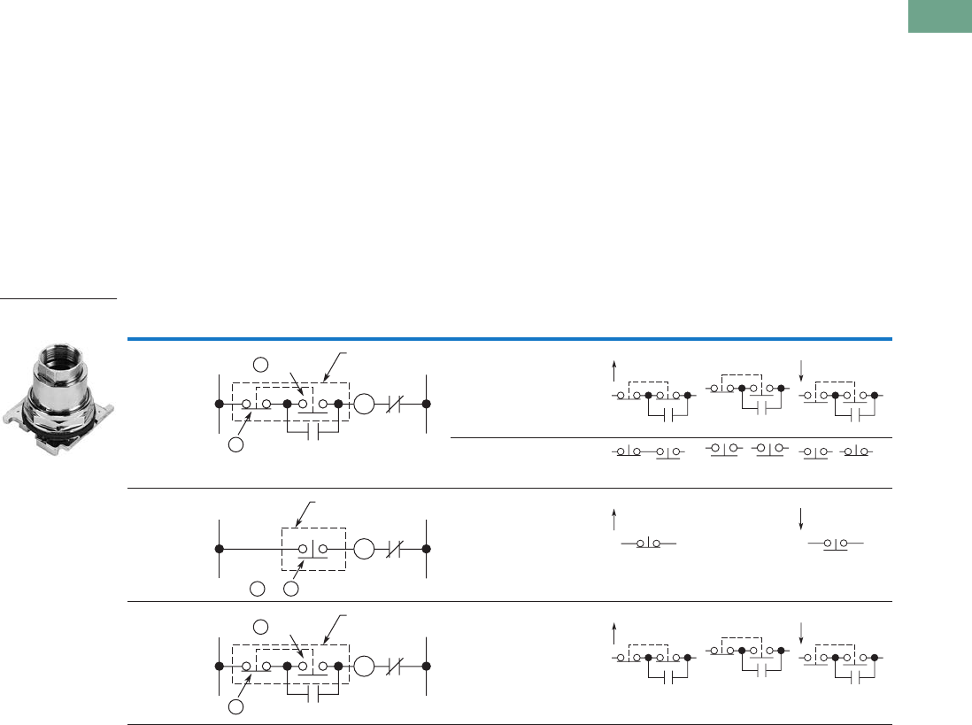
Logic Control Products CA08100001K—June 2012 www.eatoncanada.ca T37-189
37
37
37
37
37
37
37
37
37
37
37
37
37
37
37
37
37
37
37
37
37
37
37
37
37
37
37
37
37
37
37.7
Pushbuttons and Indicating Lights
30.5 mm Heavy-Duty Watertight/Oiltight—10250T
Push-Pull Operators
An illuminated push-pull
pushbutton unit, arranged for
one-hole mounting, can
replace two pushbuttons and
a pilot light or the non-
illuminated form can replace
two pushbuttons. These units
are available in three basic
types:
●Maintained—(Two-
position). Maintains in the
pulled or pushed position
until manually actuated to
the opposite mode.
●Momentary—(Three-
position). Spring returns to
an intermediate position
when pulled or pushed and
released.
●Momentary Pull,
Maintained Push—(Three-
position). Spring returns to
intermediate position
when pulled. Maintains in
pushed position until
manually returned to
intermediate (ready to
reset) position. Maintained
stop holds circuit open and
will prevent other series
connected operators from
starting the system.
The operators, buttons,
contact blocks, etc., are
offered as building block
components that can be
intermixed to satisfy many
requirements. This minimizes
the need for a varied and
costly inventory.
Typical Applications
Notes
A and B circuits shown in the application illustrations are defined in the “Application Guide” on the following page.
Shown without button on lens.
Control Line—Diagram Operator Circuits Operator Mode
Three-wire
three-position
momentary
Momentary
push and pull
10250T4
2NC
contact block
10250T3
START (mom.) Normal pos.
(maint.)
STOP (mom.)
Momentary
push and pull
10250T10
1NO-1NC
contact block
10250T1
Two-wire
two-position
maintained
Maintained
push and pull
10250T5
1NC
contact block
10250T51
START (maint.) No
intermediate
position
STOP (maint.)
Three-wire
momentary pull
maintained push
Maintained
push and
momentary
pull
10250T9
2NC
contact block
10250T3
START (mom.) Normal pos.
(maint.)
STOP (maint.)
Two-Position
Maintained Push-Pull
M
L2L1
OL
M
B Circuit
ACircuit Push-Pull
Operator
M
L2L1
OL
B Circuitor
A
Push-Pull
Operator
M
L2L1
OL
M
B Circuit
ACircuit Push-Pull
Operator
Tab37book.fm Page 189 Tuesday, July 3, 2012 10:46 PM

T37-190 Logic Control Products CA08100001K—June 2012 www.eatoncanada.ca
37
37
37
37
37
37
37
37
37
37
37
37
37
37
37
37
37
37
37
37
37
37
37
37
37
37
37
37
37
37
37.7
Pushbuttons and Indicating Lights
30.5 mm Heavy-Duty Watertight/Oiltight—10250T
Application Guide
To assist in the selection of
contact blocks, the sketch to
the right shows pictorially by
symbols A and B locations of
contact circuits after
assembly of contact blocks
and adapter to the operator.
The table below shows the
effect of the push and pull
operations on either NO or
NC contacts. (X = contact
closed, O = contact open).
Contact Circuit Locations
Push-Pull Operator Components
Note
Maximum of two blocks, four circuits. Special function contact blocks shown on Page T37-221 CANNOT be used with three-position push-pull operators 10250T4,
10250T9 or 10250T10.
Locating Nib
A
B
Type of Operator
Operator Position and Circuit Arrangement
Contact Block Catalogue Number
Out—Pull Intermediate In—Push
Contact Block Mounting Location
ABABAB
Two-Position Operator without Lens
Maintained push-pull O
Xor O
X
No intermediate
position
X
Oor X
O
1NO
1NC
10250T5
O
X
O
X
X
O
X
O
2NO
2NC
Maintained push-pull with
anti-theft jumbo mushroom
O
Xor O
X
No intermediate
position
X
Oor X
O
1NO
1NC
10250ED1080
O
X
O
X
X
O
X
O
2NO
2NC
Three-Position Operator without Lens
Momentary push-pull O
Xor O
X
O
Oor O
X
X
Oor O
O
1NO
1NC
10250T4
O
X
O
X
O
O
O
X
X
O
O
O
2NO
2NC
Maintained push-momentary pull O
Xor O
X
O
Oor O
X
X
Oor O
O
1NO
1NC
10250T9
O
X
O
X
O
O
O
X
X
O
O
O
2NO
2NC
Momentary push-pull O
Xor O
X
O
Oor O
O
X
Oor X
O
1NO
1NC
10250T10
O
X
O
X
O
O
O
O
X
O
X
O
2NO
2ND
10250T579C47-71X
Tab37book.fm Page 190 Tuesday, July 3, 2012 10:46 PM

Logic Control Products CA08100001K—June 2012 www.eatoncanada.ca T37-191
37
37
37
37
37
37
37
37
37
37
37
37
37
37
37
37
37
37
37
37
37
37
37
37
37
37
37
37
37
37
37.7
Pushbuttons and Indicating Lights
30.5 mm Heavy-Duty Watertight/Oiltight—10250T
Push-Pull Light Units, Lenses and Buttons
Ordering Example with One Composite Number
Non-illuminated:
10250T5 + 10250TB62 + 10250T1 = 10250T5B62-1X
Incandescent:
10250T5 + 10250T79 + 10250TC47 + 10250T1 = 10250T579C47-1X
LED:
10250T5 + 10250T97L + 10250TC47 + Voltage code + 10250T1 = 10250T597LRD24-1X
06—6 Vac/Vdc
12—12 Vac/Vdc
24—24 Vac/Vdc
48—48 Vac/Vdc
60—60 Vac/Vdc
2A—120 Vac
2D—120 Vdc
Light Units for Illuminated Push-Pull Devices
Note
These units do not include lamps. Order LED separately to match lens colour, see Page T37-225.
Light Unit
Type Type Voltage
LED/Lamp
Number Catalogue Number
LED
(LEDs not included) Full voltage — Bayonet
base
10250T97L
Transformer
AC only
50/60 Hz
24
120
208
240
277
380
480
600
10250T89L
10250T63L
10250T64L
10250T65L
10250T82L
10250T66L
10250T67L
10250T68L
Incandescent Full voltage
AC or DC
6
12
24/28
32
10250T69
10250T70
10250T79
10250T83
Resistor
AC or DC
120
240
120MB 10250T80
10250T81
Transformer
AC only
50/60 Hz
24
120
208
240
277
380
480
600
#755 10250T89
10250T63
10250T64
10250T65
10250T82
10250T66
10250T67
10250T68
Tab37book.fm Page 191 Tuesday, July 3, 2012 10:46 PM
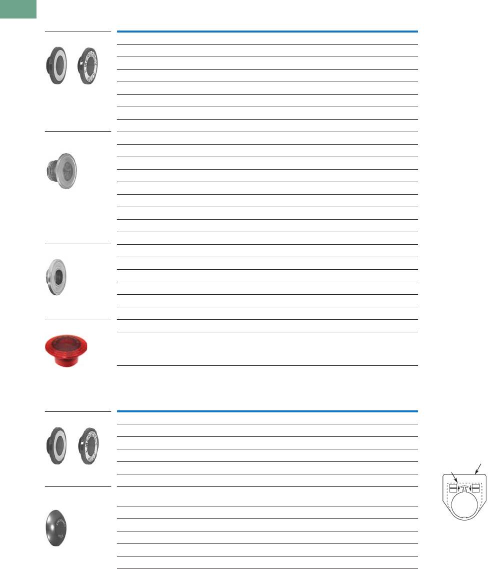
T37-192 Logic Control Products CA08100001K—June 2012 www.eatoncanada.ca
37
37
37
37
37
37
37
37
37
37
37
37
37
37
37
37
37
37
37
37
37
37
37
37
37
37
37
37
37
37
37.7
Pushbuttons and Indicating Lights
30.5 mm Heavy-Duty Watertight/Oiltight—10250T
Alternate Lenses for Illuminated Push-Pull Devices
Buttons for Non-Illuminated Push-Pull Devices
Notes
Suffix codes should only be used for assembling composite catalogue numbers. To order lens above, order by catalogue number.
Anodized aluminum head is not suitable for use in ultraviolet light applications.
Lens Colour
Incandescent
Suffix Code
LED
Suffix Code Catalogue Number
Standard
Red C47 RD 10250TC47
Red (EMERG. STOP) C53 ED 10250TC53
Green C48 GD 10250TC48
Blue C49 LD 10250TC49
Amber C50 AD 10250TC50
White C51 WD 10250TC51
Clear C52 CD 10250TC52
Side-Lighted Anodized Aluminum Ring
Red C57 RS 10250TC57
Red (EMERG. STOP) C63 ES 10250TC63
Green C58 GS 10250TC58
Blue C59 LS 10250TC59
Amber C64 AS 10250TC64
Yellow C60 YS 10250TC60
White C61 WS 10250TC61
Clear C62 CS 10250TC62
Heavy-Duty Aluminum with Transparent Centre
Red C65 RH 10250TC65
Green C66 GH 10250TC66
Amber C67 AH 10250TC67
Blue C69 — 10250TC69
White C68 — 10250TC68
Jumbo Lens—50 mm
Red — — 10250TC77
Colour Suffix Code Catalogue Number Legend Plates
For a complete listing
of available legend plates
see Pages T37-216 to
T37-218.
Standard
Red B62 10250TB62
Red (EMERG. STOP) B63 10250TB63
Green B61 10250TB61
Black B60 10250TB60
Blue B64 10250TB64
Jumbo Mushroom Head
(Anodized) Aluminum
Red J62 10250TJ62
Red (EMERG. STOP) J63 10250TJ63
Green J61 10250TJ61
Black J60 10250TJ60
Yellow J64 10250TJ64
Standard
Side-Lighted Anodized
Aluminum Ring
Heavy-Duty Aluminum
Jumbo Lens
Standard
Jumbo Mushroom
Head
Standard
Jumbo
P
S
R
T
Tab37book.fm Page 192 Tuesday, July 3, 2012 10:46 PM
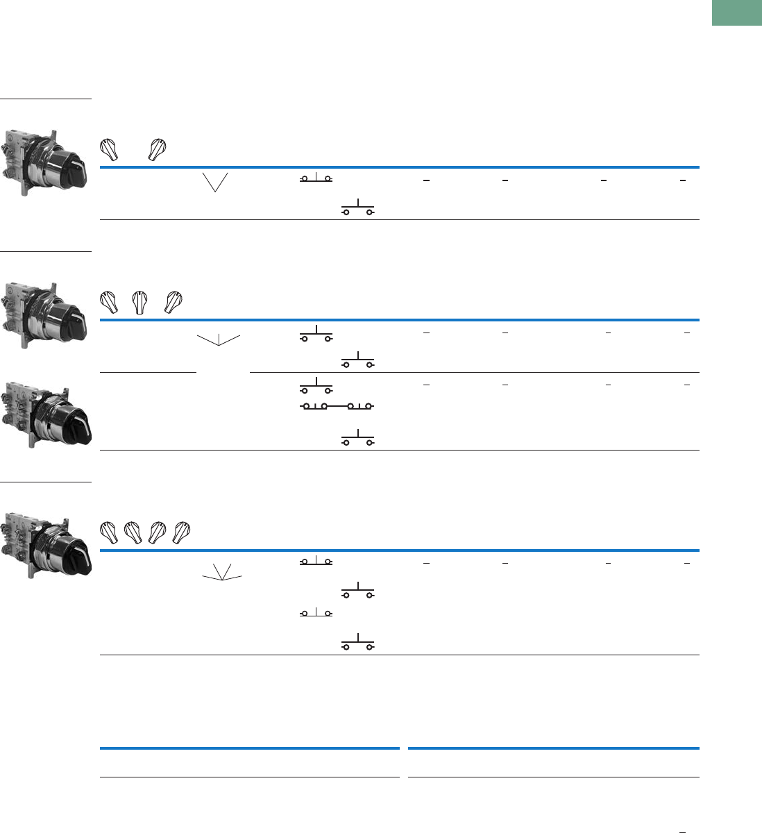
Logic Control Products CA08100001K—June 2012 www.eatoncanada.ca T37-193
37
37
37
37
37
37
37
37
37
37
37
37
37
37
37
37
37
37
37
37
37
37
37
37
37
37
37
37
37
37
37.7
Pushbuttons and Indicating Lights
30.5 mm Heavy-Duty Watertight/Oiltight—10250T
Selector Switch Units
UL (NEMA) Type 3, 3R, 4, 4X, 12, 13
●Two-, three- and four-position maintained
●Non-illuminated and illuminated
Two-Position Selector Switch
Three-Position Selector Switch
Four-Position Selector Switch
Colour Selection
Notes
X = closed circuit, O = open circuit.
M = Maintained.
To order different type or colour selector switch, substitute the underlined character with appropriate suffix code from the Colour Selection table. Example: 10250T20KG.
Operator Position
Operator
Action
Contact
Type
Non-Illuminated Illuminated—120V Transformer
Mounting Location Black Knob
Catalogue Number
Black Lever
Catalogue Number
Red Knob
Catalogue Number
Red Lever
Catalogue Number
AB
X O 1NC 10250T20KB 10250T20LB 10250ED1117-KR 10250ED1117-LR
O X 1NO
Operator Position
Operator
Action
Contact
Type
Non-Illuminated Illuminated—120V Transformer
Mounting Location Black Knob
Catalogue Number
Black Lever
Catalogue Number
Red Knob
Catalogue Number
Red Lever
Catalogue Number
AB
X O O 1NO 10250T21KB 10250T21LB 10250ED1117-2KR 10250ED1117-2LR
OOX 1NO
X O O 1NO 10250T22KB 10250T22LB 10250ED1117-3KR 10250ED1117-3LR
O X O 2NC (Series)
OOX 1NO
Operator Position
Operator
Action
Contact
Type
Non-Illuminated Illuminated—120V Transformer
Mounting Location Black Knob
Catalogue Number
Black Lever
Catalogue Number
Red Knob
Catalogue Number
Red Lever
Catalogue Number
AB
XOOO 1NC 10250T46KB 10250T46LB 10250ED1117-4KR 10250ED1117-4LR
OXOO 1NO
OOXO 1NO
OOOX 1NC
Illuminated Non-Illuminated
Colour
Code
Letter Colour
Code
Letter Colour
Code
Letter Colour
Code
Letter Colour
Code
Letter Colour
Code
Letter
Red
Green
R
G
White
Blue
W
B
Amber
Clear
A
C
Black
Red
B
R
Green
White
G
W
Blue
Orange
L
O
Two-Position
Maintained Switch
MM
Three-Position
Maintained Switch
Three-Position
Maintained Switch
MM
M
T
hree-Position
Maintained Switch
MM
MM
Tab37book.fm Page 193 Tuesday, July 3, 2012 10:46 PM
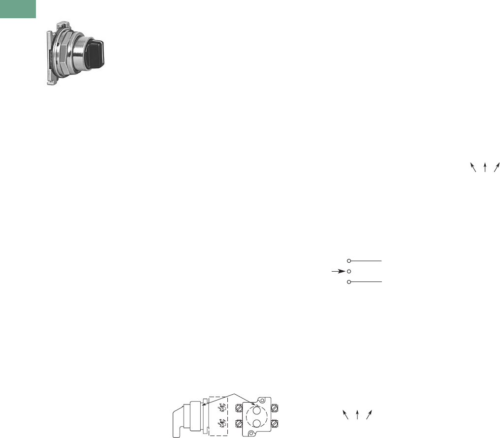
T37-194 Logic Control Products CA08100001K—June 2012 www.eatoncanada.ca
37
37
37
37
37
37
37
37
37
37
37
37
37
37
37
37
37
37
37
37
37
37
37
37
37
37
37
37
37
37
37.7
Pushbuttons and Indicating Lights
30.5 mm Heavy-Duty Watertight/Oiltight—10250T
Selector Switch Selection
Cam and Contact Block Selection
Selector switches in their
varied forms (two-position,
three-position and four-
position) are a big factor
contributing to the great
flexibility of control that a well
rounded line of “pushbuttons”
can achieve. Because of their
flexibility, they tend to cause
difficulty with product
selection and application.
The following systematic
approach should simplify
that task.
Cam and contact block
selection is better understood
if you:
●Work with each incoming
and outgoing wire/circuit
separately.
●Recognize the terms NO
and NC only identify the
type of contact by its mode
before mounting to the
operator. The “X-O” table
(Page T37-196) shows
how that contact will act
after assembly to the
operator with the selected
cam shape. X = closed
circuit, O = open circuit.
●Up to six NO or NC
contacts may be mounted
behind each plunger
location for a total of
twelve contacts. Single
circuit contact blocks have
only one plunger with the
other side of the block
“open.” Therefore, single
circuit contact blocks
transmit motion to blocks
behind them only for the
position containing the
circuit.
●Each cam has two
separate lobes, each of
which operates one of the
two contact block plungers
independently of each
other. Those are identified
as position A (locating nib
side) and position B
(opposite of locating nib).
The position designations
give direction in selecting
and mounting of the
contact blocks.
Contact Circuit Locations
Locating Nib
A
B
Systematic Approach
Application: HAND-OFF-
AUTO selector switch. In this
circuit, one incoming line is
distributed to two other
outgoing circuits by the
switch. The two circuits can
be looked at individually.
Step 1: Elementary
Diagram.
Construct on paper, or in your
mind, a simple elementary
diagram of the switching
scheme as follows:
Step 2: “X-O” Pattern.
From the elementary
diagram, you can construct
an “X-O” diagram which
describes when the contacts
are to be closed (X) or open
(O) in the various positions of
the switch. The “X-O” for the
HAND circuit looks like this:
In this circuit, you want a
contact closed on the left
(HAND) but open in the
centre and right.
For the AUTO circuit, the
“X-O” diagram would look like
this:
Putting them together, the
complete “X-O” diagram is:
Once the “X-O” diagram has
been generated the next step
is to select the cam and
contact block, or blocks,
needed to perform the
desired “X-O” functions.
The selection tables on the
following pages list the
various types (shapes) of
cams by number to choose
from and the type of contact
and position to achieve the
function outlined in your
“X-O” diagram.
OFF
HAND Outgoing
Circuit
AUTO
Outgoing
Circuit
Incoming
Line
HAND OFF AUTO
XOO
HAND OFF AUTO
OOX
X O O
O O X
Tab37book.fm Page 194 Tuesday, July 3, 2012 10:46 PM
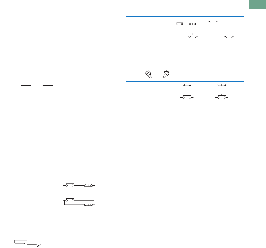
Logic Control Products CA08100001K—June 2012 www.eatoncanada.ca T37-195
37
37
37
37
37
37
37
37
37
37
37
37
37
37
37
37
37
37
37
37
37
37
37
37
37
37
37
37
37
37
37.7
Pushbuttons and Indicating Lights
30.5 mm Heavy-Duty Watertight/Oiltight—10250T
Step 3: Cam Selection.
The cam you select
determines the operation of
all contact blocks mounted to
the operator. It is selected on
the basis that it provides the
simplest circuitry for the
desired “X-O” diagram. The
selection tables show all the
“X-O” combinations. For the
purpose of this example, the
applicable portion of those
tables is shown on this page.
Now to make the cam
selection, make a simple
worksheet such as:
It becomes immediately
obvious that cam 3 is the
better choice for two
reasons, (1) the series
combination can be avoided
making it simpler to wire, (2)
only two contacts are
required, which is less
expensive than the three
contacts required by cam 2.
Step 4: Contact Block
Selection.
Having selected the cam,
contact block selection is
simply a matter of gathering
the A position and B position
circuits into pairs which make
up the most convenient contact
block arrangement. If there is
an imbalance in the number of
circuits under A or B, then
single circuit blocks must be
selected for these leftover
circuits.
Back to the worksheet,
having selected cam 3 do
this:
Step 5: Selector Switch
Operator.
Lastly, you have to choose
from the many types of
operators—knob and lever
in various colors or keyed.
Also what combinations of
maintained and spring
return functions are
required. Selection of these
operators can be found on
Page T37-198. For the
example in step 4 you may
want a three-position
maintained black knob,
cam 3—Catalogue Number
10250T1323.
The Complete Switch:
10250T1323 with one
10250T2 or, for one
composite catalogue number,
10250T21KB found on
Page T37-193.
Diagrams
Circuits shown illustrate
connections to obtain a
selector switch circuit
combination and are shown
with their appropriate line
diagrams. Field wiring of
jumper connections required
as shown.
X = Closed circuit
O = Open circuit
Wiring of Jumper
Connections
Four-position selector
switches are limited to four
contact blocks.
Contact Blocks
For selection and number
of available contact blocks
per operator, see Pages
T37-221 to T37-224.
Cam 2 Cam 3
X O O
O O X
(A)NO-(B)NC
(B)NO
(A)NO
(B)NO
X O X
O O X
ANO
BNO 10250T2
Parallel Connection
Series Connection
Example Selection Table
Two-Position Selector Switch Contact Block Selection
Note
Wired in series.
No. “X-O” Pattern
Cam Code #2 Cam Code #3
Top A Bottom B Top A Bottom B
1XOO
NO NC NO
—
4 OOX—
NO
—
NO
No.
Desired Circuit and
Operator Position
Contact Blocks Required to
Accomplish Circuit Function
Top Plunger A Bottom Plunger B
1XO
NC or NC
2OX
NO
or
NO
a
Tab37book.fm Page 195 Tuesday, July 3, 2012 10:46 PM
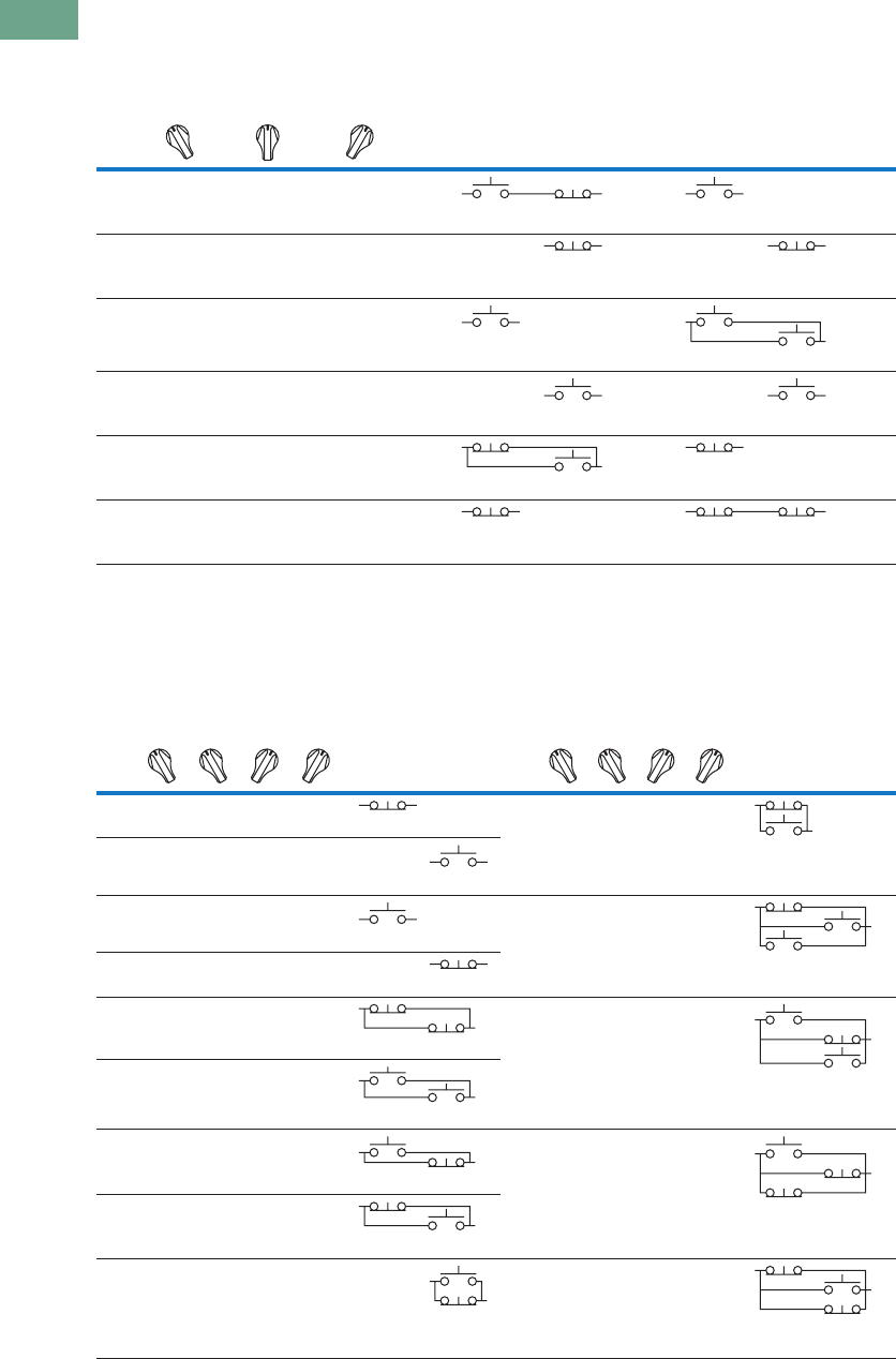
T37-196 Logic Control Products CA08100001K—June 2012 www.eatoncanada.ca
37
37
37
37
37
37
37
37
37
37
37
37
37
37
37
37
37
37
37
37
37
37
37
37
37
37
37
37
37
37
37.7
Pushbuttons and Indicating Lights
30.5 mm Heavy-Duty Watertight/Oiltight—10250T
Three-Position Switch—Cam and Contact Block Selection
Four-Position Switch—Contact Block Selection
No.
Desired Circuit and
Operator Position
Contact Blocks Required to Accomplish Circuit Function
(Jumpers must be installed where indicated)
Operator with Cam Code #2 Operator with Cam Code #3
Mounting Location Mounting Location
Top
Plunger
A
Bottom
Plunger
B
Top
Plunger
A
Bottom
Plunger
B
1X O O
NO NC NO
2XXO
NC NC
3X O X
NO
NO NO
4OOX
NO NO
5O X X
NC NO
NC
6O X O
NC NC NC
No.
Contact Blocks
Required to
Accomplish Circuit
Function
No.
Contact Blocks
Required to
Accomplish Circuit
Function
Desired Circuit and
Operator Position
Mounting Location Desired Circuit and
Operator Position
Mounting Location
Top
Plunger
A
Bottom
Plunger
B
Top
Plunger
A
Bottom
Plunger
B
1XOOO
NC
10XOXO
NC
NO
2OXOO
NO
3OOXO
NO
11XXXO
NC
NO NO
4OOOX
NC
5XOOX
NC NC
12 O X X X
NO NC
NO
6OXXO
NO NO
7OOXX
NO NC
13XOXX
NO
NC NC
8XXOO
NC NO
9OXOX
NO
NC
14 X X O X
NC NO
NC
Tab37book.fm Page 196 Tuesday, July 3, 2012 10:46 PM
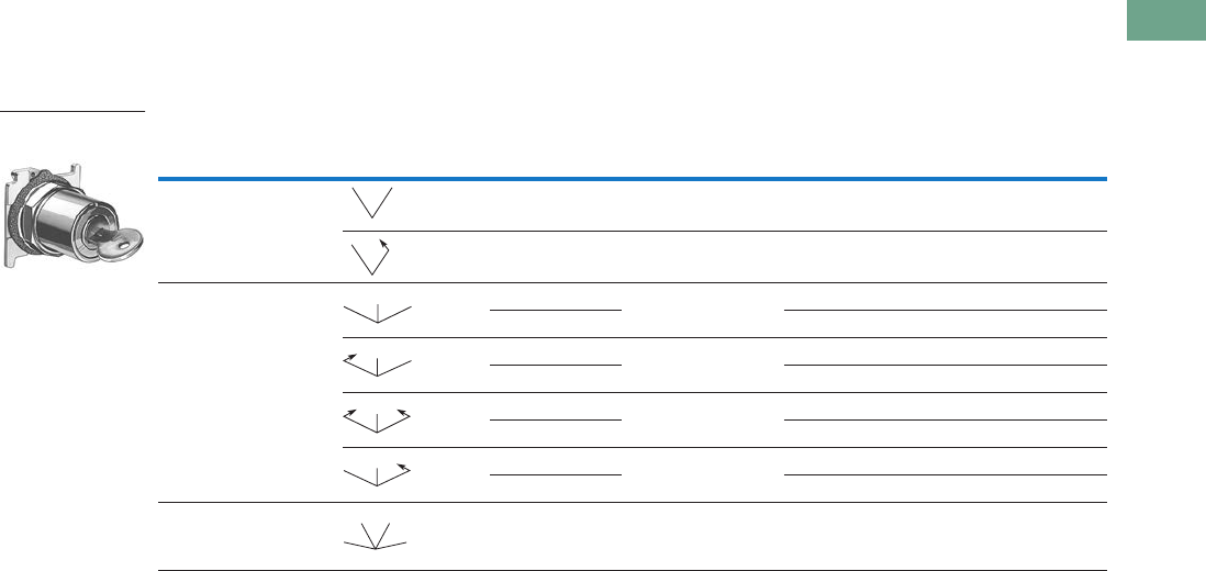
Logic Control Products CA08100001K—June 2012 www.eatoncanada.ca T37-197
37
37
37
37
37
37
37
37
37
37
37
37
37
37
37
37
37
37
37
37
37
37
37
37
37
37
37
37
37
37
37.7
Pushbuttons and Indicating Lights
30.5 mm Heavy-Duty Watertight/Oiltight—10250T
Selector Switch Operators
Key Operators
UL (NEMA) Type 3, 3R, 4, 4X, 12, 13
Key Operators with Cam
Notes
Horizontal mount, key removal #1 keyed selector switch, cam 1 shown.
M = Maintained. S = Spring return in direction of arrow (R).
For selection of the proper cam and contact block to obtain the proper circuit sequence, see selection instructions and tables on
Pages T37-194, T37-195 and T37-196.
Choose key removal position required for application from table on Page T37-198. Add key removal code no. to listed catalogue number.
Example: 10250T15112.
Positions Operator Action Cam Code
Optional Key
Removal Positions
Vertical Mounting
Catalogue Number
Horizontal Mounting
Catalogue Number
Two-position—60˚ throw 1 1, 2, 3 10250T1511_ 10250T1611_
12 10250T1571_ 10250T1581_
Three-position—60˚ throw 2 1–7 10250T1522_ 10250T1622_
310250T1523_ 10250T1623_
2 1, 4, 5 10250T1532_ 10250T1632_
310250T1533_ 10250T1633_
24 10250T1542_ 10250T1642_
310250T1543_ 10250T1643_
2 2, 4, 6 10250T1652_ 10250T1662_
310250T1653_ 10250T1663_
Four-position—40˚ throw 7 7 10250T1677_ 10250T1687_
Two-Position
Maintained
MM
MS
MM
M
MS
M
SS
M
MS
M
MM
MM
Tab37book.fm Page 197 Tuesday, July 3, 2012 10:46 PM
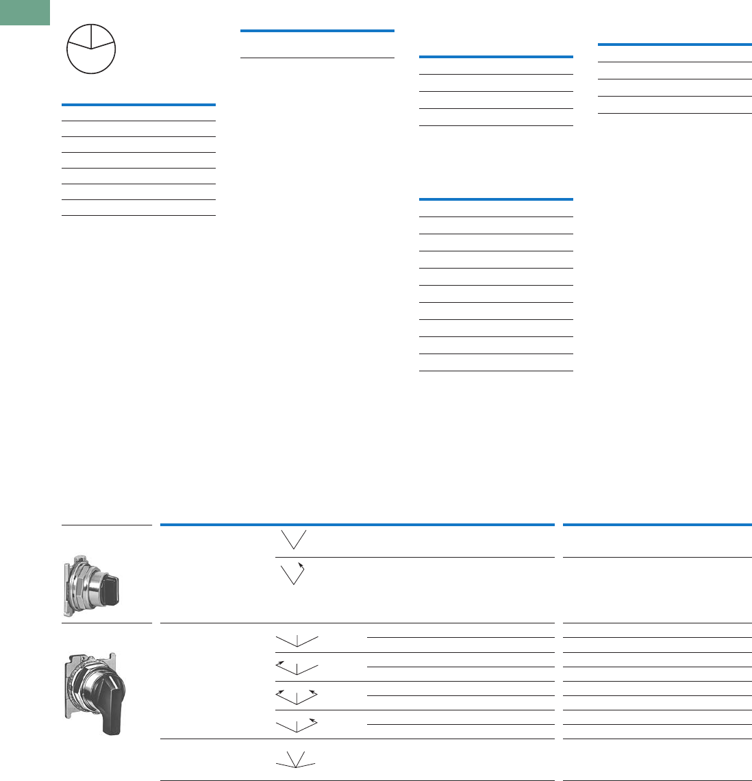
T37-198 Logic Control Products CA08100001K—June 2012 www.eatoncanada.ca
37
37
37
37
37
37
37
37
37
37
37
37
37
37
37
37
37
37
37
37
37
37
37
37
37
37
37
37
37
37
37.7
Pushbuttons and Indicating Lights
30.5 mm Heavy-Duty Watertight/Oiltight—10250T
Key Removal Positions
Note: Key removal in “spring
return from” positions not
recommended.
Replacement Keys or Dissimilar
Locks for Key Operators
Operators listed on Page
T37-198 have identical locks
and keys (Key Code H661)
Catalogue Number
10250ED824. For dissimilar
lock and key combinations,
see listing on this page.
Replacement Key
Selector Switch Operators with
Dissimilar Locks and Keys
(UL [NEMA] 4, 4X and 13)
The locks in all key operators
listed on Pages T37-177,
T37-198 and T37-311 are
identical and use key code
number H661. Two keys are
supplied with every lock. For
additional code number H661
keys, order Catalogue
Number 10250ED824. For
others, order 10250ED1130
and designate lock number.
When dissimilar locks for
each operator or each group
of operators are required,
select from the lock and key
combination listed below.
When Ordering Operator
Only or a complete control
unit with a substitute lock,
order from table below and
add “except Lock and Key
Code No. …”
“H” Series Locks without
Master Key—with Key Slot
Cover
“M” Series Locks with
Master Key—with Key Slot
Cover
Master Keys for Above
Locks
Selector Switch Operators with Caps
UL (NEMA) Type 3, 3R, 4, 4X, 12, 13
Selector Switch Operators with Caps
Notes
Black knob selector switch, cam 1 shown.
M = Maintained. S = Spring return in direction of arrow (R).
Field convertible to horizontal mounting or order operator only and separate operator cap.
For selection of the proper cam and contact block to obtain the proper circuit sequence, see selection instructions and
tables on Pages T37-194, T37-195 and T37-196.
Black lever selector switch, cam 3 shown.
Code
Suffix
Key Removal
Position
1Right only
2Left only
3Right and left
4Centre only
5Right and centre
6Left and centre
7All positions
L
C
R
Description Catalogue Number
Replacement keys
(code H661)
10250ED824 Lock and Key Code Numbers
H501 H635 H663
H620 H639 H675
H621 H643 H683
H634 H654 H688
Lock and Key Code Numbers
MD1 MD14 ME8 MJ6
MD2 MD15 ME11 MJ10
MD3 MD16 ME16 MJ11
MD4 MD19 ME17 MJ13
MD5 MD20 ME18 MJ15
MD7 ME2 ME19 MJ16
MD9 ME3 MJ1 MD17
MD10 ME5 MJ3
MD11 ME6 MJ4
MD13 ME7 MJ5
Application Catalogue Number
For code:
MD1–MD20 10250ED825-3
ME2–ME18 10250ED825-4
MJ1–MJ16 10250ED825-5
Positions Operator Action
Black Knob Selector Switch—
Vertical Mounting
Black Lever Selector Switch—
Vertical Mounting
Cam Code Catalogue Number Cam Code Catalogue Number
Two-position—60˚ throw 1 10250T1311 110250T3011
110250T1371 110250T3071
Three-position—60˚ throw 2 10250T1322 210250T3022
310250T1323 310250T3023
210250T1332 210250T3032
310250T1333 310250T3033
210250T1342 210250T304
310250T1343 310250T3043
210250T1352 210250T3052
310250T1353 310250T3053
Four-position—40˚ throw 7 10250T1367 710250T3067
Two-Position
Maintained
Three-Position
Maintained
MM
MS
MM
M
MS
M
SS
M
MS
M
MM
MM
Tab37book.fm Page 198 Tuesday, July 3, 2012 10:46 PM
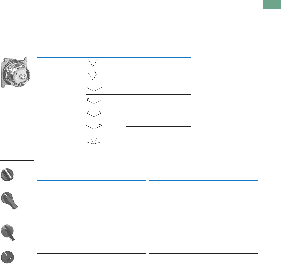
Logic Control Products CA08100001K—June 2012 www.eatoncanada.ca T37-199
37
37
37
37
37
37
37
37
37
37
37
37
37
37
37
37
37
37
37
37
37
37
37
37
37
37
37
37
37
37
37.7
Pushbuttons and Indicating Lights
30.5 mm Heavy-Duty Watertight/Oiltight—10250T
Selector Switch Operators without Caps
Operators can be ordered
with caps assembled to
them by adding the code
number from the table on
this page to the end of
catalogue number below.
Example: 10250T4011KB
Selector Switch Operators without Caps
Operating Caps
Notes
M = Maintained. S = Spring return in direction of arrow (R).
For selection of the proper cam and contact block to obtain the proper circuit sequence, see selection instructions and
tables on Pages T37-194, T37-195 and T37-196.
Designed for added ingress protection. For use in maintained operators only.
Positions Operator Action Cam Code Catalogue Number
Two-position—60˚ throw 1 10250T4011
110250T4081
Three-position—60˚ throw 2 10250T4022
310250T4023
210250T4032
310250T4033
210250T4042
310250T4043
210250T4052
310250T4053
Four-position—40˚ throw 7 10250T4067
Colour
Knob
Catalogue and
Code Number
Lever
Catalogue and
Code Number Colour
Lever
Catalogue and
Code Number
Coin Slot
Catalogue and
Code Number
Black 10250TKB 10250TLB Black 10250TSB 10250TCB
Red 10250TKR 10250TLR Red 10250TSR 10250TCR
Green 10250TKG 10250TLG Green 10250TSG 10250TCG
Yellow 10250TKY 10250TLY Yellow 10250TSY 10250TCY
White 10250TKW 10250TLW White 10250TSW 10250TCW
Gray 10250TKA 10250TLA Gray 10250TSA 10250TCA
Blue 10250TKL 10250TLL Blue 10250TSL 10250TCL
Orange 10250TKD 10250TLO Orange 10250TSO 10250TCO
Two-Position Selector
Switch Maintained
MM
MS
MM
M
MS
M
SS
M
MS
M
MM
MM
Knob
Lever
Lever for Use with
Maintained Operators
Coin Slot
Tab37book.fm Page 199 Tuesday, July 3, 2012 10:46 PM
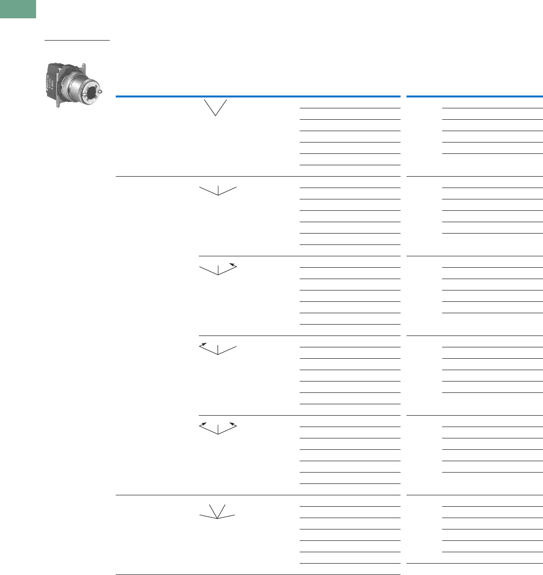
T37-200 Logic Control Products CA08100001K—June 2012 www.eatoncanada.ca
37
37
37
37
37
37
37
37
37
37
37
37
37
37
37
37
37
37
37
37
37
37
37
37
37
37
37
37
37
37
37.7
Pushbuttons and Indicating Lights
30.5 mm Heavy-Duty Watertight/Oiltight—10250T
Illuminated Selector Switch Operators
Illuminated Selector Switches without Caps
Operator without Knob or Lever
Notes
M = Maintained. S = Spring return in direction of arrow (R).
For selection of the proper cam and contact block, to obtain the proper circuit sequence, see selection tables on Pages T37-194, T37-195 and T37-196.
Operator includes lens gasket and lens attachment screws.
Full voltage light units can be used at other than listed voltages by changing lamp. Replacement lamps are listed on Page T37-225.
Resistor type. May generate excess heat if used in high density.
Positions Operator Action
Transformer Type—50/60 Hz
6 Volt #755 Lamp
Full Voltage Type—AC or DC
Lamps: 6V—#755, 12V—#756, 24V—#757,
48V—#1835, 120/240V—120MB
Cam
Code Voltage
Code Number and
Catalogue Number
Cam
Code Voltage
Code Number and
Catalogue Number
Two-position—60˚ throw 1 24 10250T5961 1610250T6201
120 10250T5971 12 10250T6211
208 10250T6511 24 10250T6221
240 10250T5981 48 10250T6231
380 10250T5991 120 10250T6361
480 10250T6001 240 10250T6371
600 10250T6011
Three-position—60˚ throw + 2 or 3 24 10250T602_ + 2 or 3 6 10250T624_
120 10250T603_ 12 10250T625_
208 10250T652_ 24 10250T626_
240 10250T604_ 48 10250T627_
380 10250T605_ 120 10250T638_
480 10250T606_ 240 10250T639_
600 10250T607_
+ 2 or 3 24 10250T654_ + 2 or 3 6 10250T612_
120 10250T620_ 12 10250T632_
208 10250T655_ 24 10250T642_
240 10250T656_ 48 10250T672_
380 10250T657_ 120 10250T622_
480 10250T658_ 240 10250T682_
600 10250T659_
+ 2 or 3 24 10250T660_ + 2 or 3 6 10250T613_
120 10250T621_ 12 10250T633_
208 10250T661_ 24 10250T643_
240 10250T662_ 48 10250T673_
380 10250T663_ 120 10250T623_
480 10250T664_ 240 10250T683_
600 10250T665_
+ 2 or 3 24 10250T614_ + 2 or 3 6 10250T628_
120 10250T615_ 12 10250T629_
208 10250T653_ 24 10250T630_
240 10250T616_ 48 10250T631_
380 10250T617_ 120 10250T640_
480 10250T618_ 240 10250T641_
600 10250T619_
Four-position—40˚ throw 7 24 10250T6087 7610250T6327
120 10250T6097 12 10250T6337
208 10250T6547 24 10250T6347
240 10250T6107 48 10250T6357
380 10250T6117 120 10250T6427
480 10250T6127 240 10250T6437
600 10250T6137
Two-Position Selector
Switch Maintained
MM
MM
M
MS
M
MS
M
SS
M
MM
MM
Tab37book.fm Page 200 Tuesday, July 3, 2012 10:46 PM
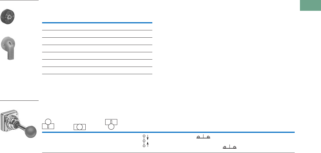
Logic Control Products CA08100001K—June 2012 www.eatoncanada.ca T37-201
37
37
37
37
37
37
37
37
37
37
37
37
37
37
37
37
37
37
37
37
37
37
37
37
37
37
37
37
37
37
37.7
Pushbuttons and Indicating Lights
30.5 mm Heavy-Duty Watertight/Oiltight—10250T
Illuminated Knobs and Levers
Joystick Units
Joystick Units—UL (NEMA) Type 3, 3R, 4, 4X, 12, 13
Notes
Amber, clear and white lenses have a black arrow (pointer), red, green and blue lenses have a white arrow (pointer).
X = closed circuit, O = open circuit.
M = Maintained. S = Spring return in direction of arrow (R).
Field convertible momentary to maintained or vice versa.
Colour
Knob
Code Number and
Catalogue Number
Lever
Code Number and
Catalogue Number
Red 10250TER 10250TFR
Green 10250TEG 10250TFG
Yellow 10250TEA 10250TFA
Blue 10250TEL 10250TFL
Clear 10250TEC 10250TFC
White 10250TEW 10250TFW
Amber 10250TEM 10250TFM
Operator Position
Operator
Action
Contact
Type
Two-Position
Assembled Unit
Catalogue Number
Up
Centre
Down
Mounting Location
AB
X O O 1NC 10250T452-3X
OOX 1NC
Knob
Lever
Two-Position Joystick
M
S
S
Tab37book.fm Page 201 Tuesday, July 3, 2012 10:46 PM
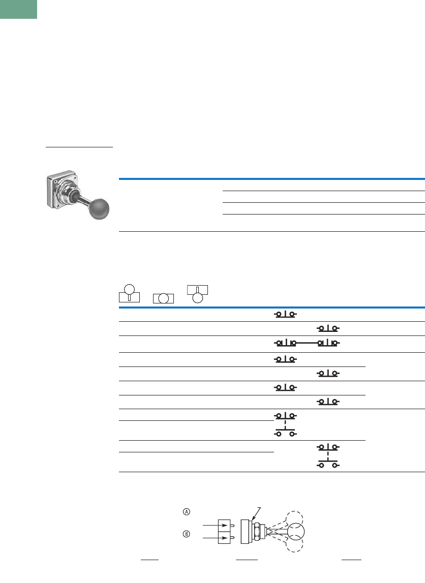
T37-202 Logic Control Products CA08100001K—June 2012 www.eatoncanada.ca
37
37
37
37
37
37
37
37
37
37
37
37
37
37
37
37
37
37
37
37
37
37
37
37
37
37
37
37
37
37
37.7
Pushbuttons and Indicating Lights
30.5 mm Heavy-Duty Watertight/Oiltight—10250T
Joysticks
Two-Position Joystick Operators
The device mounts in the
standard 30.5 mm mounting
hole. Allow sufficient panel
space for lever movement.
The maximum travel of the
knob operator (full up to full
down) is 2.2 in (24˚)
momentary, 2.5 in (30˚)
maintained, but ample space
for lever operation must be
allowed. These operators are
field convertible from
momentary to maintained
operation or vice versa.
The use of NC contacts is
preferred because they
provide positive drive contact
opening and a direct
relationship between lever
movement and affected
terminal, i.e., up movement
affects the top terminals.
Application Caution
Joystick operators are not
recommended on certain DC
applications above 24 Vdc
which may involve lightly
engaging the contacts
(teasing) to achieve speed
control, positioning, jogging,
etc. Excessive arcing and
deterioration of the contacts
will occur.
Two-Position Joystick Operators—UL (NEMA) Type 3, 3R, 4, 4X, 12, 13
Contact Block Operation and Selection
A and B Mounting Location
Notes
Field convertible momentary to maintained or vice versa. To expedite shipment of maintained types,
order momentary operator 10250T452 which is a stocked device.
Bolded circuit corresponds to “X-O” circuit selection. X = closed circuit, O = open circuit.
See above for “A” and “B” mounting location.
NO = normally open, NC = normally closed, LONC = late opening normally closed.
Four circuits in single block depth—rated 300V max.
Contact Block Limitations
Two-Position Operator Only—AC Applications Only
Description Catalogue Number
Momentary Mode
4NC contact blocks max.
3NO contact blocks max.
Maintained Mode
2 contact blocks max.
Momentary up and down 10250T452
Maintained up—momentary down 10250T4521
Maintained down—momentary up 10250T4522
Maintained up and down 10250T4525
Handle Position
Contact Block
Type Catalogue Number
Up
Centre
Down
Mounting Location
Top A Bottom B
X O O 1NC 10250T51
O O X 1NC 10250T51
O X O 2LONC (Series) 10250T45
X O O 1NC 10250T3
O O X 1NC
X X O 1LONC 10250T45
O X X 1LONC
X O O 1NC 10250T44
O O X 1NO
O O X 1NC
X O O 1NO
Two-Position Joystick
Operator
Up
Center
Down
Locating Nib
Top
Contacts
Bottom
Contacts
Center
All NC and NO Contacts
Are Open (1/2 Way),
Late Opening NC Is Closed
Down
NC Contact at Bottom
Is Closed, NO at
Top Is Closed
Up
NC Contact at Top
Is Closed, NO at
Bottom Is Closed
Tab37book.fm Page 202 Tuesday, July 3, 2012 10:46 PM
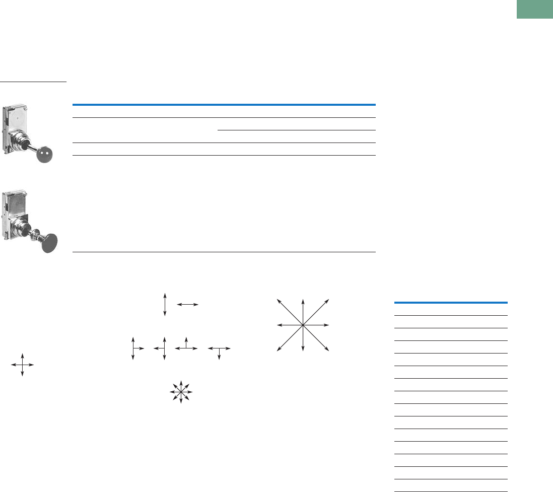
Logic Control Products CA08100001K—June 2012 www.eatoncanada.ca T37-203
37
37
37
37
37
37
37
37
37
37
37
37
37
37
37
37
37
37
37
37
37
37
37
37
37
37
37
37
37
37
37.7
Pushbuttons and Indicating Lights
30.5 mm Heavy-Duty Watertight/Oiltight—10250T
Four-Position Joystick Operators
The joystick operated control
unit is intended for AC
application only. For other
use, see Application
Caution on preceding page.
The panel area required for
the four-position operator is
equivalent to two standard
pushbutton operators.
The latch holds the lever in
the centre position. The
trigger latch must be released
before lever can moved into
any position.
Four-Position Joystick Operators—UL (NEMA) Type 3, 3R, 4, 4X, 12, 13
Field Conversion—Gate
The factory assembled four-
position operator is
assembled with a gate
arranged for four handle
positions.
Handle Positions
Three additional gates,
supplied with every operator,
allow on the job conversion to
three- or eight-position
operation as illustrated.
Two-, Three- or Eight-
Position Operation
The eight-position gate
controls the four functions
shown as “Up,” “Down,”
“Left” and “Right.” The
remaining four diagonal
positions each actuate two
adjacent functions; for
example, “Left Down”
actuates both “Left” and
“Down.” The operator may
be arranged for spring return
of handle to centre position,
or maintained in up to eight
positions (see description of
maintained position operator).
Adjacent Functions
Maintained Position
For maintained position (non-
spring return), locate required
maintained position or
positions of operating lever
and add appropriate suffix
number to the catalogue
number selected from the
table above.
Maintained Positions
On an eight-position gate,
when an adjacent vertical and
horizontal position are both
maintained, the included
diagonal position is also
maintained.
Note
Momentary operators—spring return to centre. For maintained operators add suffix code from table on this page.
Example: 10250T45110. Operator without latch, maintained in left and right positions.
Contact Block Limitations Description Catalogue Number
Operator Only—AC Application Only
Four contact blocks max.—two in each position Four-position—without latch 10250T451_
Four-position—with latch 10250T461_
Hole Plug
Four contact blocks max.—two in each position To plug unused hole 10250TA7
Four-Position Joystick
Operator
Four-Position Joystick
Operator with Latch
Four-Position
Gate
or
Two-Position
Gate
Eight-Position
Gate
Three-Position
Gate
or or or
Up
Right
Up
Left
Up
Down Right
Down
RightLeft
Left
Down
Maintained Positions Suffix
NumberUp Down Left Right
X— —— 1
—— — — 2
—X — — 3
—— X — 4
—— — — 5
X— X — 6
X— —X 7
—X X — 8
—X — X 9
—— X X 10
XX X — 11
XX —X 12
X— X X 13
—X X X 14
XX X X 15
Tab37book.fm Page 203 Tuesday, July 3, 2012 10:46 PM

T37-204 Logic Control Products CA08100001K—June 2012 www.eatoncanada.ca
37
37
37
37
37
37
37
37
37
37
37
37
37
37
37
37
37
37
37
37
37
37
37
37
37
37
37
37
37
37
37.7
Pushbuttons and Indicating Lights
30.5 mm Heavy-Duty Watertight/Oiltight—10250T
Contact Block Operation
Contact blocks mount directly to the back of the operator. For
reliable operation, the maximum number of contact blocks that
should be installed behind each operator lever is two (four total).
The figure below identifies the circuits activated by each of the
eight possible lever positions. Contact block plungers 1, 2, 3, 4
are depressed (change state) when handle is in the position
indicated by arrows below.
Circuit Activation
Note: Joystick in its resting state, centre position, does not activate
contact block plungers.
Ordering Example:
Suppose you are looking for a four-position momentary joystick
without a latch and the following circuit arrangements.
X = Closed Circuit, O = Open Circuit.
Example Circuit Arrangements
The contact blocks and their mounting locations would be as
follows:
Example Contact Blocks and Locations
A complete bill of material for this example would include:
Example Order
Blank Legend Plates for Joystick Operators
When ordering engraved legend plates, order by catalogue
number and insert the following into order notes:
●Legend required
●Size of characters: 3/16,
1/8, 3/32 in (4.8, 3.2, 2.4 mm)
●Location by letter (A–N)
Locations K and M can accommodate up to two lines
horizontally; L and N up to two lines vertically.
Maximum number of characters:
●Horizontal
3/16 in—13, 1/8 in—14, 3/32 in—19
●Vertical
3/16 in—10, 1/8 in—13, 3/32 in—14
Ordering Example:
Two-position legend plate to be marked “UP” “DOWN.”
Catalogue No. 10250TJ2S4STAMP
Letter Size: 3/16 in (4.8 mm)
Pos. K—UP
Pos. M—DOWN
Two-Position
Four-Position
Circuit Up Down Left Right
1st X X X X
2nd X O O X
Qty. Catalogue Number
110250T4
210250T2
210250T1
1
2
3
4
NO
2nd
Circuit 1st
Circuit
10250T1 10250T2
NC
NC
NO
10250T1 10250T2
NO
NO
NO
NO
Catalogue Number Catalogue Number
Blank Plate
10250TJS3 10250TJS4
Engraved Plate
10250TJS3STAMP 10250TJS4STAMP
Catalogue Number Catalogue Number
Blank Plate
10250TJS1 10250TJS2
Engraved Plate
10250TJS1STAMP 10250TJS2STAMP
K
M
2.19
(55.6)
Sq.
NL
K
M
A
B
J
D
F
E
C
HG
A
B
J
D
F
E
C
HG
Tab37book.fm Page 204 Tuesday, July 3, 2012 10:46 PM
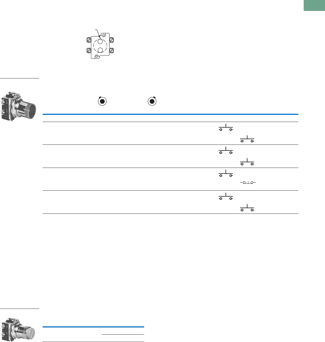
Logic Control Products CA08100001K—June 2012 www.eatoncanada.ca T37-205
37
37
37
37
37
37
37
37
37
37
37
37
37
37
37
37
37
37
37
37
37
37
37
37
37
37
37
37
37
37
37.7
Pushbuttons and Indicating Lights
30.5 mm Heavy-Duty Watertight/Oiltight—10250T
Roto-Push Units
Two-Position Momentary
Complete assembled two-
position Roto-Push® Units are
listed below. These operators
have black flush buttons and
are arranged for vertical
mounting. Order legend
plates separately.
Mounting Location
Roto-Push Units—UL (NEMA) Type 3, 3R, 4, 4X, 12, 13
Two-Position Latched
The two-position Roto-Push
Latch Unit is fully assembled
and only requires a legend
plate for a great variety of
applications. When the
selector collar is in the
extreme left position, the
button is in the free or normal
position and can be operated
as a standard pushbutton.
Rotating the collar to the
extreme right position
automatically depresses and
latches the button in the
depressed position. The
white filled groove in the
button indicates the selector
collar position. The selector
collar has spring return to the
left position except when in
the extreme right latched
position.
Rotates to a Latch-Out Mode
Notes
X = closed circuit, O = open circuit.
Roto-Push assembled with contact blocks.
Locating
Nib
A
B
Typical Applications
(Most Common Examples)
Operator Position
Contact
Type Catalogue Number
Collar Left Collar Right
Mounting Location
Normal Depressed Normal Depressed A B
Two-Position
FORWARD/REVERSE;
HIGH/LOW; OPEN/CLOSE;
UP/DOWN; etc.
O
O
O
X
O
O
X
O
1NO 10250T2411-2
1NO
JOG/RUN; MAN./AUTO;
etc.
O
O
X
O
O
X
X
X
1NO 10250T24111-2
1NO
RUN/JOG; START/JOG;
etc.
O
X
X
X
O
O
X
O
1NO 10250T24111-1
1NC
SAFE/RUN; etc. O
O
O
O
O
X
X
X
1NO 10250T2415-2
1NO
Roto-Push—Black
Flush Button
Colour and Type
of Button
Contact
Block
Vertical Mounting
Catalogue Number
Red long 1NC
2NC
10250T72
10250T73
Red Long
Tab37book.fm Page 205 Tuesday, July 3, 2012 10:46 PM
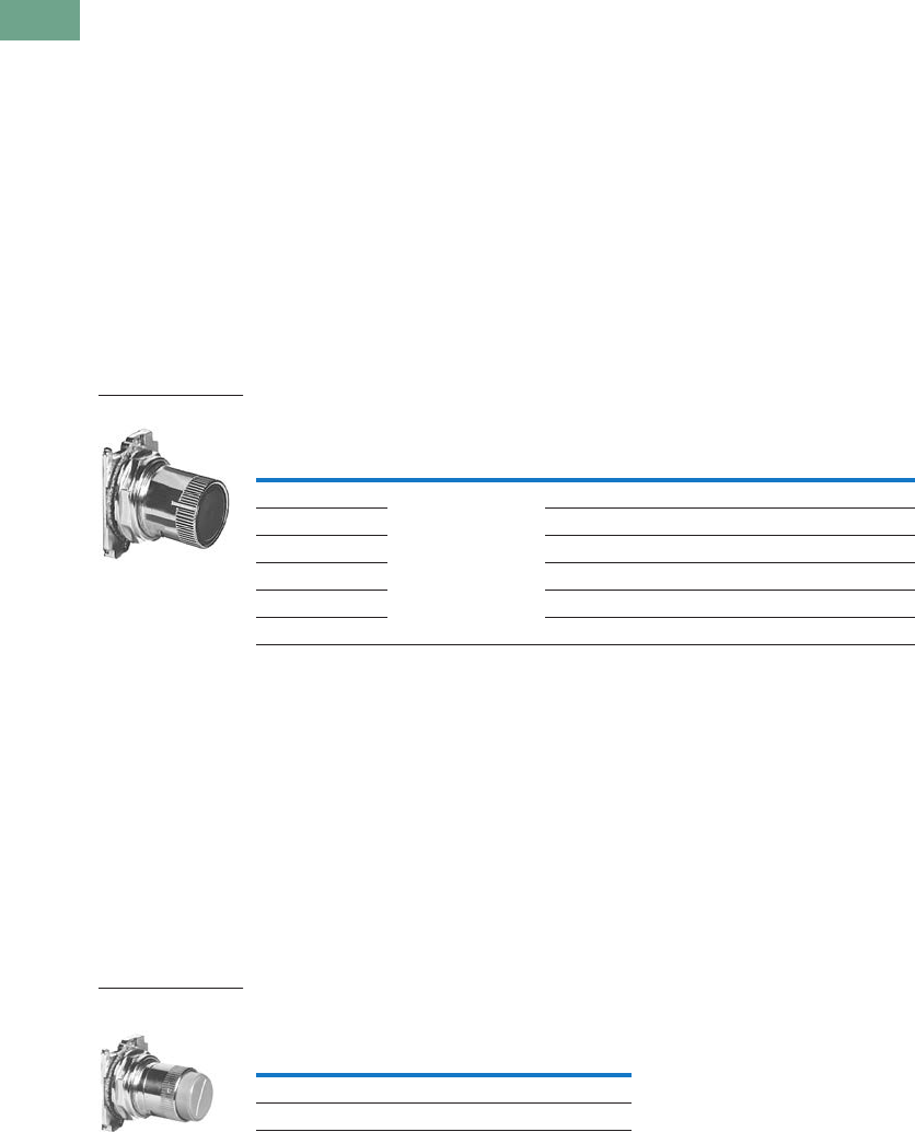
T37-206 Logic Control Products CA08100001K—June 2012 www.eatoncanada.ca
37
37
37
37
37
37
37
37
37
37
37
37
37
37
37
37
37
37
37
37
37
37
37
37
37
37
37
37
37
37
37.7
Pushbuttons and Indicating Lights
30.5 mm Heavy-Duty Watertight/Oiltight—10250T
Roto-Push Operators
Roto-Push Components
A Roto-Push control unit
combines the function of a
pushbutton and a selector
switch. The contacts are
operated by the combined
action of rotating the outer
collar and pushing a button
contained in the collar.
In selecting the cam and
contact blocks for the listed
function, the analysis involves
considering the function with
the collar rotated to the given
position with the button free
(designated as “N”) and then
in that same position with
the button depressed
(designated “D”). This is
done for each rotational
position of the collar.
When Ordering Specify
●Catalogue number of
operator with cam code
suffix from tables below
and on following pages,
Example: 10250T2411.
●Catalogue number(s) for
contact blocks and legend
plates if required.
●To select the cam and
contact blocks needed for
two-position and three-
position switches, use the
tables on following pages.
Operator and Cam
Two-Position Roto-Push Operator—Rotates to a Latch-Out Mode
Special Rotor Latch
This differs from the other
Roto-Push operators in that
as the collar is rotated to the
right it depresses the button
and releases the button when
rotated left. But the button in
the released position can be
momentarily pushed
independent of the collar or
its position. As the button is
depressed by rotating the
collar, the button also rotates
and indicates its mode by a
white line on the button face.
This button can be used as an
emergency stop or latched
stop.
Special Rotor Latch—
UL (NEMA) Type 3, 3R, 4, 4X, 12, 13
Note
Not to be used for emergency stop application.
Colour and
Type of
Button
Cam Code No.
Select from Tables
Vertical Mounting
Catalogue and
Code Number
Horizontal Mounting
Catalogue and
Code Number
Black flush + 1 to 18 10250T241_ 10250T251_
Red flush 10250T242_ 10250T252_
Green flush 10250T243_ 10250T253_
Black long 10250T261_ 10250T271_
Red long 10250T262_ 10250T272_
Green long 10250T263_ 10250T273_
Operator and Cam
Colour and Type
of Button
Vertical Mounting
Catalogue Number
Red long 10250T3213
Black long 10250T3214
Special Roto Latch—
Red Long Button
Tab37book.fm Page 206 Tuesday, July 3, 2012 10:46 PM
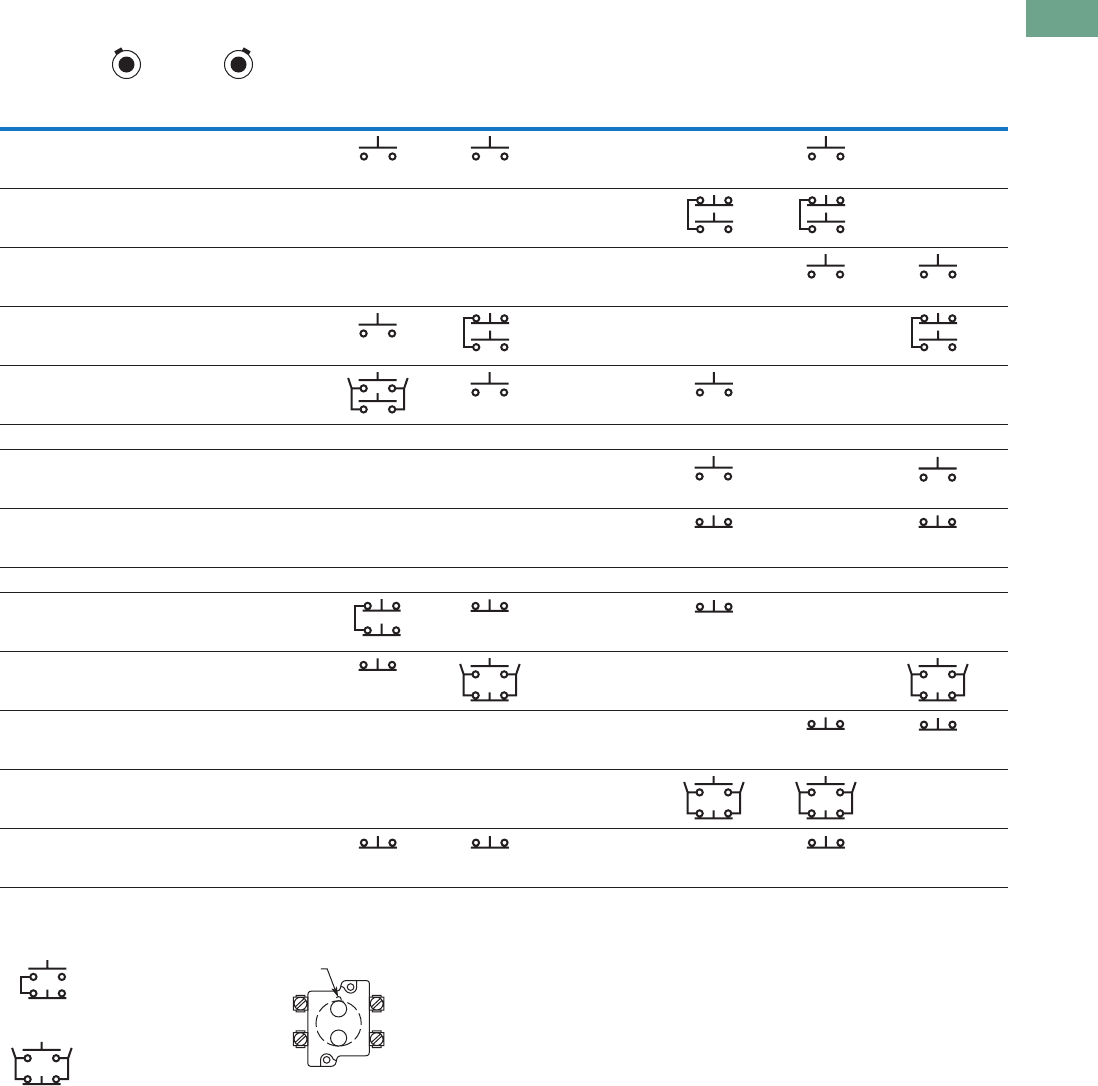
Logic Control Products CA08100001K—June 2012 www.eatoncanada.ca T37-207
37
37
37
37
37
37
37
37
37
37
37
37
37
37
37
37
37
37
37
37
37
37
37
37
37
37
37
37
37
37
37.7
Pushbuttons and Indicating Lights
30.5 mm Heavy-Duty Watertight/Oiltight—10250T
Cam and Contact Block Selection for Two-Position Roto-Push
Series and Parallel
Connections
The connections are not
made at the factory. They are
illustrated in the selection
table as requirements, but
must be made on the job.
Circuit Location
Letters “A” and “B”
represent the locations which
the two circuits of a contact
block will occupy in relation
to the locating nib of the
operator.
Note
N = Button in free or normal position. D = Button depressed.
Combination
Number
Collar Position
Cam Code 1 Cam Code 2 Cam Code 3 Cam Code 4 Cam Code 5 Cam Code 6
Circuit Sequence
NDND
1 OOOX — — —
2 OOXO— — — —
3 OOXX————
4 OXOO ———
5OXOX — ——
6 OXXO——————
7 O X X X — — A or B NO —
8 X O O O — — A or B NC —
9 XOOX——————
10 XOXO — — —
11 XOXX — — —
12XXOO————
13XXOO——— —
14 XXXO — — —
ANOANO ANO
BNO
ANC
BNO
ANC
BNOANO
BNO
BNO
ANC
BNO
ANC
BNO
ANO
BNO ANO
BNO
BNO
BNC BNC
BNC
ANC
BNC ANC
BNC
BNC
ANO
BNC
ANO
BNCANC
BNC
ANO
BNC
ANO
ANCANC ANC
Series Connection
Parallel Connection
BNC
ANO
BNC
ANO
Locating
Nib
A
B
Tab37book.fm Page 207 Tuesday, July 3, 2012 10:46 PM
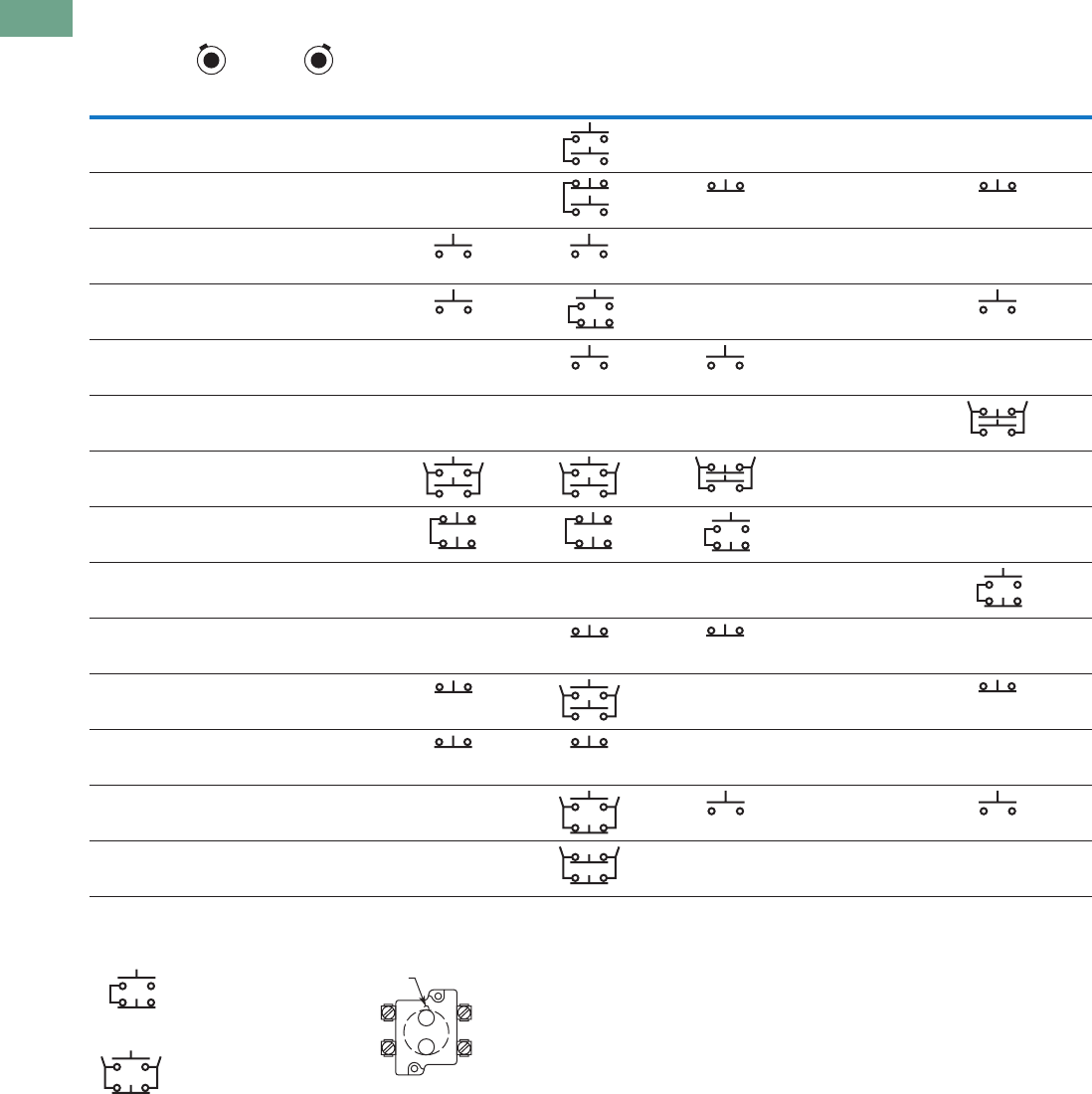
T37-208 Logic Control Products CA08100001K—June 2012 www.eatoncanada.ca
37
37
37
37
37
37
37
37
37
37
37
37
37
37
37
37
37
37
37
37
37
37
37
37
37
37
37
37
37
37
37.7
Pushbuttons and Indicating Lights
30.5 mm Heavy-Duty Watertight/Oiltight—10250T
Cam and Contact Block Selection for Two-Position Roto-Push, continued
Series and Parallel
Connections
The connections are not
made at the factory. They are
illustrated in the selection
table as requirements, but
must be made on the job.
Circuit Location
Letters “A” and “B”
represent the locations which
the two circuits of a contact
block will occupy in relation
to the locating nib of the
operator.
Note
N = Button in free or normal position. D = Button depressed.
Combination
Number
Collar Position
Cam Code 10 Cam Code 11 Cam Code 12 Cam Code 13 Cam Code 14
Circuit Sequence
NDND
15 OOOX— — — —
16 O O X O — A or B NC
17 OOXX — — —
18 OXOO — —
19 OXOX— — —
20 OXXO— — — —
21 OXXX ——
22 XOOO ——
23 XOOX— — — —
24 XOXO— — —
25 XOXX — —
26 XXOO — — —
27 X X O O — A or B NO
28 XXXO— — — —
BNO
ANO
BNO
ANC
ANC ANC
BNOBNO
ANO
BNC
ANO BNO
ANOBNO
BNO
ANC
BNO
ANO
BNO
ANO
BNO
ANC
BNC
ANC
BNC
ANC
BNC
ANO
BNC
ANO
ANCBNC
ANC
BNO
ANO BNC
BNCBNC
BNC
ANO
ANO ANO
BNC
ANC
Series Connection
Parallel Connection
BNC
ANO
BNC
ANO
Locating
Nib
A
B
Tab37book.fm Page 208 Tuesday, July 3, 2012 10:46 PM
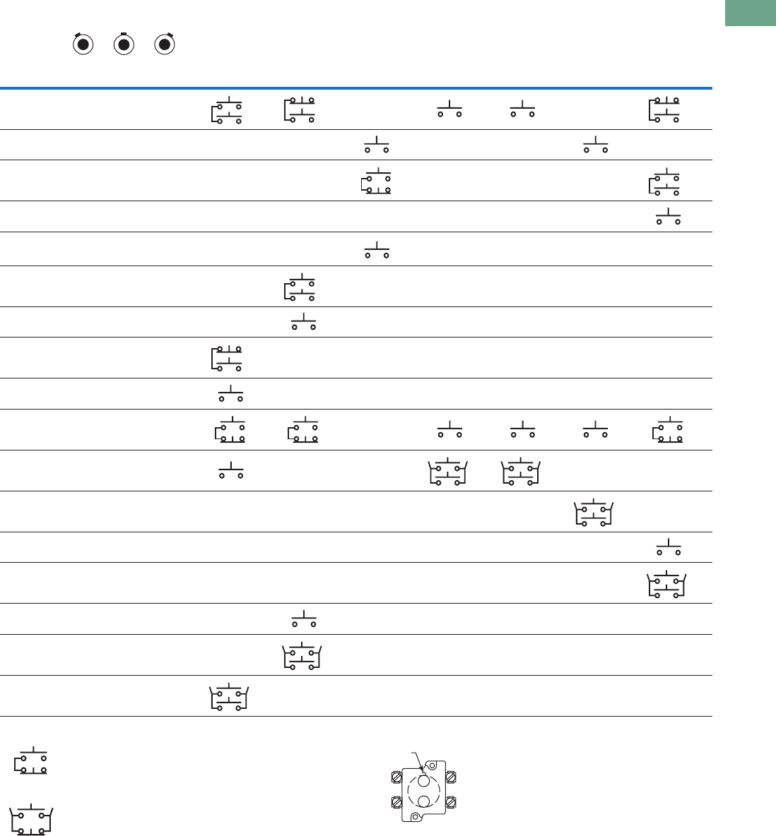
Logic Control Products CA08100001K—June 2012 www.eatoncanada.ca T37-209
37
37
37
37
37
37
37
37
37
37
37
37
37
37
37
37
37
37
37
37
37
37
37
37
37
37
37
37
37
37
37.7
Pushbuttons and Indicating Lights
30.5 mm Heavy-Duty Watertight/Oiltight—10250T
Cam and Contact Block Selection for Three-Position Roto-Push
Series and Parallel Connections
The connections are not made at the factory.
They are illustrated in the selection table as
requirements, but must be made on the job.
Circuit Location
Letters “A” and “B” represent the locations
which the two circuits of a contact block will
occupy in relation to the locating nib of the
operator.
Notes
N = Button in free or normal position. D = Button depressed.
Limited to 4 contact blocks. See Note on Page T37-222.
Combination
Number
Collar Position
Cam Code 7 Cam Code 8 Cam Code 9 Cam Code 15 Cam Code 16 Cam Code 17 Cam Code 18
Circuit Sequence
NDNDND
1 OOOOOX — —
2 OOOOXX — — — — —
3 OOOXOO — — — — —
4 OOOXOX ——————
5 OOOXXX — — ————
6 OOXXOO— —————
7 OOXXOX— —————
8 OOXXXO ——————
9 OOXXXX ——————
10 OXOOOO —
11 OXOOOX — — — —
12OXOOXX————— —
13OXOXOO——————
14OXOXOX——————
15 OXXXOO — —————
16 OXXXOX — —————
17 OXXXXX ——————
BNO
A
NO
BNO
A
NC
BNO
BNO
BNO
A
NC
BNO ANO
BNC
A
NO
BNO
A
NO
BNO
ANO
BNO
A
NO
BNO
BNO
A
NC
BNO
BNC
A
NO
BNC
A
NO
ANO
ANOBNO
BNC
A
NO
ANO
BNO
A
NO
BNO
A
NO
BNO
A
NO
ANO
BNO
A
NO
ANO
BNO
A
NO
BNO
A
NO
Series Connection
Parallel Connection
BNC
ANO
BNC
ANO
Locating
Nib
A
B
Tab37book.fm Page 209 Tuesday, July 3, 2012 10:46 PM
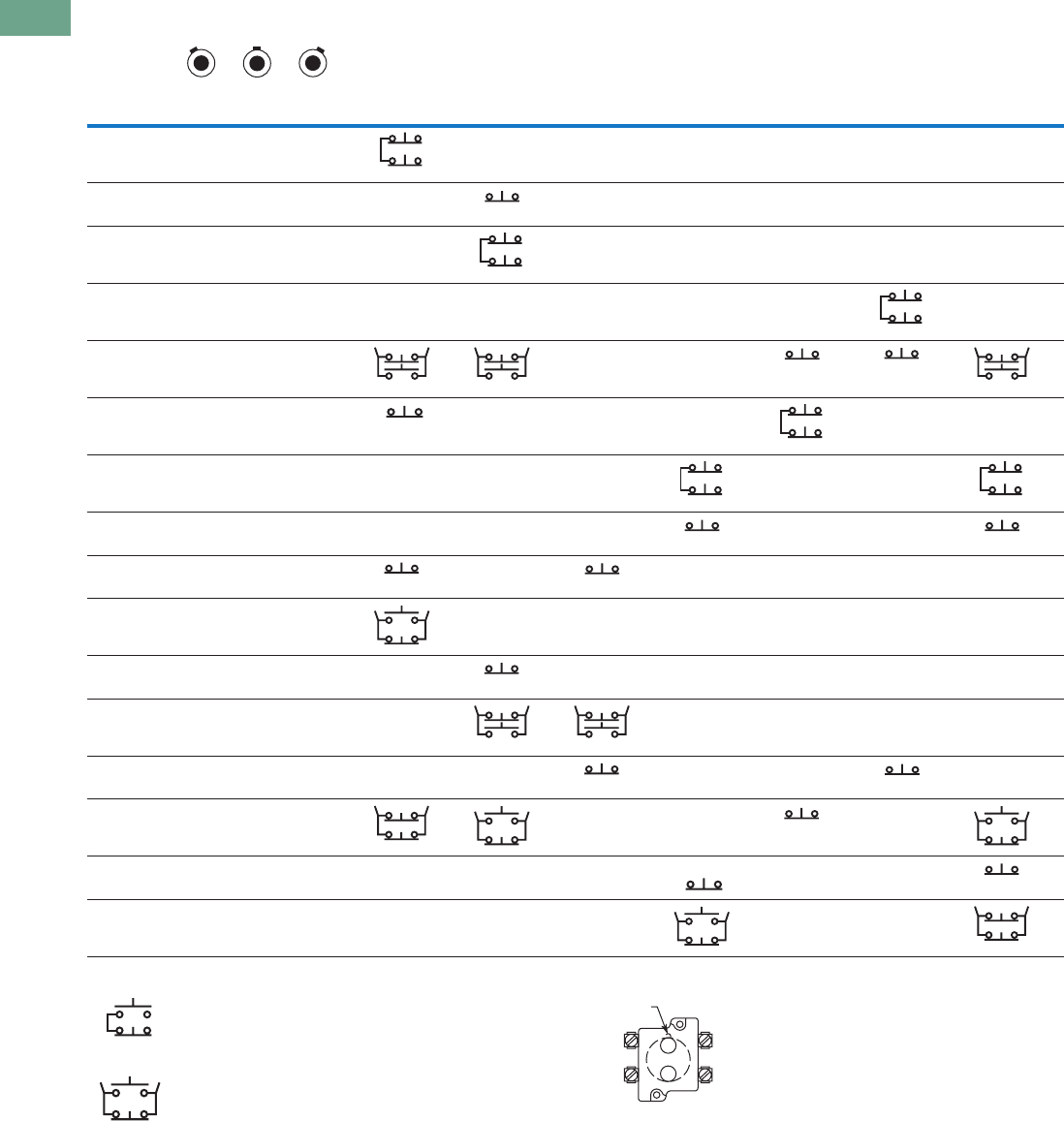
T37-210 Logic Control Products CA08100001K—June 2012 www.eatoncanada.ca
37
37
37
37
37
37
37
37
37
37
37
37
37
37
37
37
37
37
37
37
37
37
37
37
37
37
37
37
37
37
37.7
Pushbuttons and Indicating Lights
30.5 mm Heavy-Duty Watertight/Oiltight—10250T
Cam and Contact Block Selection for Three-Position Roto-Push, continued
Series and Parallel Connections
The connections are not made at the factory.
They are illustrated in the selection table as
requirements, but must be made on the job.
Circuit Location
Letters “A” and “B” represent the locations
which the two circuits of a contact block will
occupy in relation to the locating nib of the
operator.
Notes
N = Button in free or normal position. D = Button depressed.
Limited to 4 contact blocks. See Note on Page T37-222.
Combination
Number
Collar Position
Cam Code 7 Cam Code 8 Cam Code 9 Cam Code 15 Cam Code 16 Cam Code 17 Cam Code 18
Circuit Sequence
NDNDND
18 XOOOOO ——————
19 XOOOXX — —————
20 XOOOXO — —————
21XOXXOO————— —
22 XOXXXX — —
23 XOXXXO — — — — —
24 XOXOXO — — — — —
25 XOXOXX — — — — —
26 XXOOOO — ————
27 XXOOOX ——————
28XXOOXO— —————
29XXOOXX— ————
30 XXXXOO — — — — —
31 XXXXXO — — —
32XXXOXO——— ——
33XXXOXX——— ——
BNC
ANC
ANC
BNC
ANC
BNC
ANC
BNO
ANC
BNO
ANC
ANC
BNC
BNO
ANC
ANC
BNC
ANC
BNC
ANC
BNC
ANC
ANC
ANC
BNC
ANC
BNC
ANO
BNC
BNO
ANC
BNO
ANC
BNC
ANC
BNC
ANC
BNC
ANO
BNC
BNC
ANO
BNC
BNC
BNC
ANO
BNC
ANC
Series Connection
Parallel Connection
BNC
ANO
BNC
ANO
Locating
Nib
A
B
Tab37book.fm Page 210 Tuesday, July 3, 2012 10:46 PM
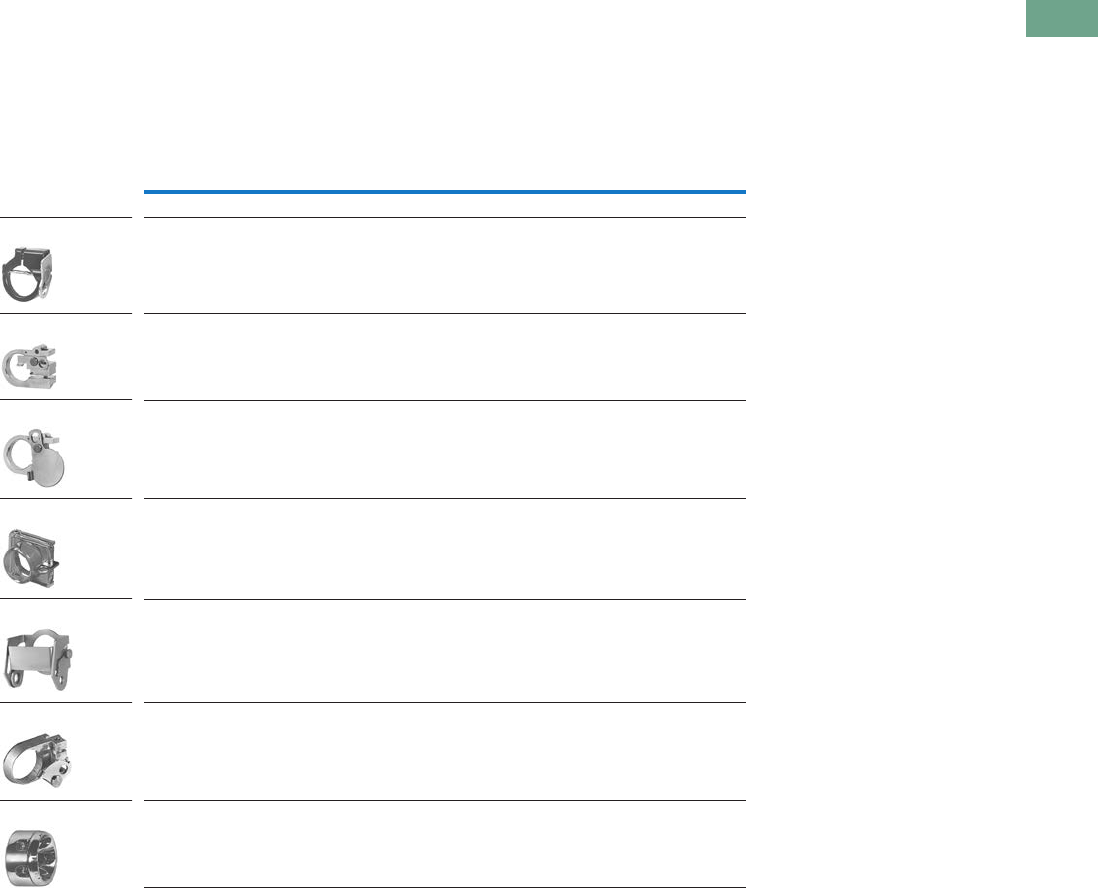
Logic Control Products CA08100001K—June 2012 www.eatoncanada.ca T37-211
37
37
37
37
37
37
37
37
37
37
37
37
37
37
37
37
37
37
37
37
37
37
37
37
37
37
37
37
37
37
37.7
Pushbuttons and Indicating Lights
30.5 mm Heavy-Duty Watertight/Oiltight—10250T
Accessories
Padlocks not included with
padlocking attachments. For
operators with built-in
padlock attachment, see
Page T37-176.
Accessories
Description Catalogue Number
Padlock Attachments
Padlocking Attachment for Flush Pushbutton Operators
Permits locking NC contacts in open position with 1/4 in padlock.
Will not lock NO contact.
10250TA2
Padlocking Attachment for Use with Extended Pushbutton
Permits locking NC contacts in open position with 1/4 in padlock.
10250TA26
Padlocking Cover Guard
Cover locked over flush button makes it unaccessible or on extended button
locks NC contacts open. Takes 1/4 in shank size padlock.
10250TA36
Padlock Hasp or Flip-Up Guard
When used with a 1/4 in padlock, makes flush and long button and knob selector
switch unaccessible, but not locked down. Without the padlock, it is a flip-up guard.
Padlock hasp can be removed before assembly.
10250TA38
Padlocking Attachment for Use with Flexible Weather Resistant Boot
Used on long button operators. Stainless steel. Use only for locking NC contacts open.
10250TA63
Padlock Attachment
For use with illuminated pushbuttons and maintained push-pull operators having
standard button or lens only. Use 1/4 in padlock. Locks in down position only.
10250TA64
Padlocking Attachment for Non-Illuminated Knob Selector Switches
Provision for up to 5, 1/4 in padlocks.
10250TA11
10250TA2
10250TA26
10250TA36
10250TA38
10250TA63
10250TA64
10250TA11
Tab37book.fm Page 211 Tuesday, July 3, 2012 10:46 PM
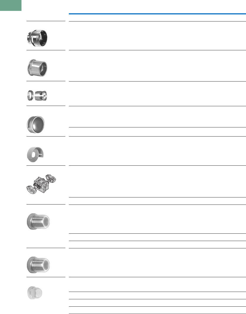
T37-212 Logic Control Products CA08100001K—June 2012 www.eatoncanada.ca
37
37
37
37
37
37
37
37
37
37
37
37
37
37
37
37
37
37
37
37
37
37
37
37
37
37
37
37
37
37
37.7
Pushbuttons and Indicating Lights
30.5 mm Heavy-Duty Watertight/Oiltight—10250T
Accessories, continued
Notes
Should not be used on flush button for STOP function.
Not suitable for single contact block depth cast enclosure. Cover is too thick.
Description Catalogue Number
Shrouds and Guards
Shroud for Mushroom Head Operator
Prevents accidental operation. (Not for push-pull operators.)
10250TA6
Extended Retaining Nut
Replaces standard nut and provides guard for flush head pushbutton operators.
10250TA12
Guard for Illuminated Pushbutton 10250TA15
Shroud
For jumbo mushroom head operator.
Gray 10250TA56
Yellow 10250TA56Y
Half Shroud—Yellow
For jumbo mushroom head operator.
10250ED1241
Fingerproof Shroud—10 per package
Fits new style contact blocks and light units.
10250TA101
Boots
Flexible Weather Resistant Boot
For use with button operators (extended buttons preferred).
Temperature to –25˚F (–32˚C).
(See Page T37-215 for 10250TA96 Tightening Tool.)
Black 10250TA3
Red 10250TA4
Green 10250TA10
Transparent Boot
For regular illuminated pushbutton operators and PresTest—
Temperature to –38˚F (–39˚C).
10250TA25
Boot for Flush Pushbutton
Clear 10250TA46
Black 10250TA47
Red 10250TA48
Green 10250TA49
10250TA6
10250TA12
10250TA15
10250TA56_
10250ED1241
10250TA101
10250TA_
10250TA25
10250TA4_
Tab37book.fm Page 212 Tuesday, July 3, 2012 10:46 PM
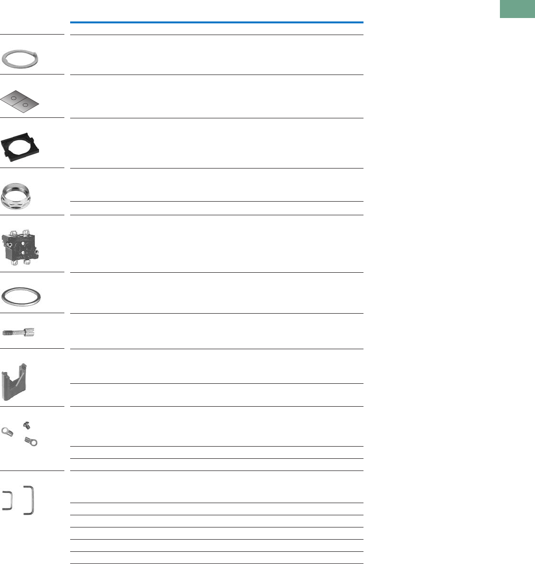
Logic Control Products CA08100001K—June 2012 www.eatoncanada.ca T37-213
37
37
37
37
37
37
37
37
37
37
37
37
37
37
37
37
37
37
37
37
37
37
37
37
37
37
37
37
37
37
37.7
Pushbuttons and Indicating Lights
30.5 mm Heavy-Duty Watertight/Oiltight—10250T
Accessories, continued
Notes
Component only. Not to be used for custom built (factory assembled) stations.
Not suitable for single contact block depth cast enclosure. Cover is too thick.
Description Catalogue Number
Hardware and Kits
Thrust Washers—
To meet Ford Motor Co. mounting specifications.
10250TK3
Contact Block Tape Seal—
Seals plunger openings on last contact block. Order in multiples of 10 pieces.
10250TK5
Selector Switch Operator Gasket—
Seals out dust from getting in-between the cam and contact block plungers.
Supplied as standard with all selector switches.
56-9337
Special Retaining Nut—
To accommodate thick panel:
Indicating lights 10250TA30
PresTest, pushbuttons and selector switches 10250TA31
Terminal Block—
Two terminals, each will accommodate two wire terminations.
10250TA62
Spacer Ring—
Used when legend plate is not required.
10250TA8
Stacking Screw—
Replaces transformer mounting screws on indicating light so terminal block
10250TA62 can be mounted to light to support and connect a series resistor.
This screw also fits all contact blocks. Order in multiples of 10.
10250TA79
Base Mounting Spacers —
Equivalent to contact block in depth
(one block deep).
10250TA22
Complete with screws, washers, etc.
(two block deep).
10250TA23
Grounding Kits—
Kits consist of a ring connector and a #6 screw for mounting connector to rear
of contact block mounting screw.
All components except standard indicating lights and PresTest indicating lights. 10250TKG1
Standard indicating lights 10250TKG2
PresTest indicating lights 10250TKG3
Contact Block Terminal Jumpers—
Available in multiples of 100 only.
Terminal to terminal—within block (short)
100 per pkg. 10250TA70
1000 per pkg. 10250TA70-2
Terminal to terminal—block to block (long)
100 per pkg. 10250TA71
1000 per pkg. 10250TA71-2
10250TA79
10250TK3
10250TK5
56-9337
10250TA3_
10250TA62
10250TA8
10250TA2_
10250TKG_
10250TA7_
Tab37book.fm Page 213 Tuesday, July 3, 2012 10:46 PM
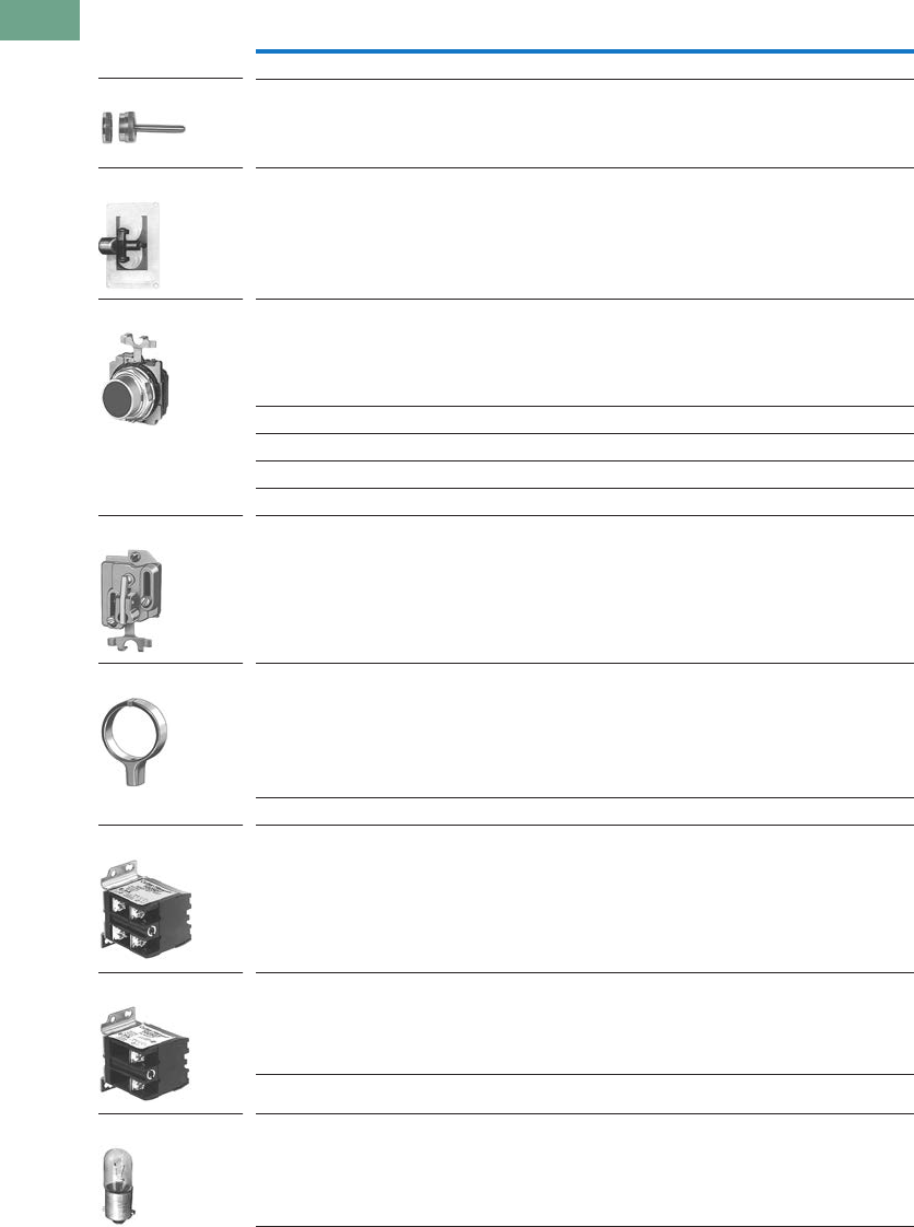
T37-214 Logic Control Products CA08100001K—June 2012 www.eatoncanada.ca
37
37
37
37
37
37
37
37
37
37
37
37
37
37
37
37
37
37
37
37
37
37
37
37
37
37
37
37
37
37
37.7
Pushbuttons and Indicating Lights
30.5 mm Heavy-Duty Watertight/Oiltight—10250T
Accessories, continued
Note
Not suitable for single contact block depth cast enclosure. Cover is too thick.
Description Catalogue Number
Special Operators and Attachments
Wobble Stick
Complete with retaining nut—fits standard button.
10250TA5
Lever Operator
For use with two vertically mounted flush pushbuttons.
10250TA14
Maintained Contact Attachment Release Button Assembly
Mechanically interlocks with another pushbutton and contact block (not included).
Provides mode indication. Minimum hole centers 1.62 in (41.1 mm), maximum
2.313 in (58.8 mm).
Black 10250TA17
Red 10250TA18
Green 10250TA19
Yellow 10250TA20
Same with Long Button—Black 10250TA39
Maintained Contact Attachment
Mechanically interlocks two buttons and provides position indication for one.
Use with two pushbutton operators and one or more contact blocks.
10250TA1
Roto-Push Lever Operator—
Used to provide lever operation for Roto-Push operators.
10250TA13
Special Light Modules
Master Test (Dual Input) Module—
Internal Form C relay suitable for either AC or DC applications. Total electrical isolation
between monitored and test circuit. Fits all illuminated 10250T, E22, E30 and E34 devices.
48 Vdc 10250TMT8
Flasher Module—
Changes any AC illuminated device to a controlled flashing light.
Fits 10250T, E30 and E34 devices.
24V 10250TFL2
120V 10250TFL1
Flashing Incandescent Lamp—
For use with 120V transformer type or 6V full voltage type indicating lights including
PresTest and most E29 devices.
10250ED986-4
10250TA5
10250TA14
10250TA_
10250TA1
10250TA13
10250TA79
10250TFL_
10250ED986-4
Tab37book.fm Page 214 Tuesday, July 3, 2012 10:46 PM

Logic Control Products CA08100001K—June 2012 www.eatoncanada.ca T37-215
37
37
37
37
37
37
37
37
37
37
37
37
37
37
37
37
37
37
37
37
37
37
37
37
37
37
37
37
37
37
37.7
Pushbuttons and Indicating Lights
30.5 mm Heavy-Duty Watertight/Oiltight—10250T
Accessories, continued
Description Catalogue Number
Hole Plugs
Plug—
For unused holes—steel, painted gray (stainless steel, use E30KT5, see Page T37-160)
10250TA7
Tools
Octagonal 10250T (notched to fit over selector switch lever), E29 and E30 10250TA95
E22, E30, E34 and octagonal 10250T (will not fit over selector switch levers) E22CW
Tool for Tightening Boots—
Used to install boot Catalogue Numbers 10250TA3, A4, A10 and A25.
10250TA96
10250T, E34 Allen Wrench—
Used for removal of jumbo mushroom head.
10250TA102
Lamp Removal Tools—
For transformer type illuminated pushbuttons, push-pull and selector switches.
Fits #12 lamp.
10250TA74
For full voltage and resistor type illuminated pushbuttons, push-pull and
selector switches and E30.
E30KV1
Standard indicating lights. Fits #44, #755, #6S6 and #10S6. E29KLT
10250TA7
10250TA95
E22CW
10250TA96
10250TA102
10250TA74
E30KV1
E29KLT
Tab37book.fm Page 215 Tuesday, July 3, 2012 10:46 PM

T37-216 Logic Control Products CA08100001K—June 2012 www.eatoncanada.ca
37
37
37
37
37
37
37
37
37
37
37
37
37
37
37
37
37
37
37
37
37
37
37
37
37
37
37
37
37
37
37.7
Pushbuttons and Indicating Lights
30.5 mm Heavy-Duty Watertight/Oiltight—10250T
Options
Legend Plates
Legend Plates with Standard Markings
The legend plates listed
below are sized for all
standard commercial
enclosures and Eaton’s cast
enclosures. For vertical
spacing less than 1.75 in,
replace the S in the catalogue
number with MS, or the M
with P (except push-pull). No
change in price. The smaller
size legend plates, “MS” or
“P” size, have limited space
for legend.
For Pushbutton Operators and Indicating Lights—Standard
Blank Plastic Legend Plates—Square
Notes
Square legend plates have a satin aluminum field. Colour is on lower portion.
Cannot be used on cast enclosures except for top row. Suitable for most sheet metal enclosures.
If legend plate is to be engraved, specify field colour required.
See Appendix 4 for French engraving.
Legend
Colour of
Field
Square
Catalogue Number
1/2 Round
Catalogue Number Legend
Colour of
Field
Square
Catalogue Number
1/2 Round
Catalogue Number
Blank—see table on Page T37-218.
Letters on Legend Plates Below are 3/16 in High
CLAMP Black 10250TS90 10250TM90 OFF Red 10250TS24 10250TM24
CLOSE 10250TS73 10250TM11 ON Black 10250TS25 10250TM25
DOWN 10250TS74 10250TM12 OPEN 10250TS26 10250TM26
EMERG. STOP Red 10250TS13 10250TM13 OUT 10250TS27 10250TM27
FAST Black 10250TS75 10250TM14 POWER ON 10250TS80 10250TM80
FASTER 10250TS87 10250TM87 RAISE 10250TS28 10250TM28
FEEDER ON 10250TS94 10250TM94 READY 10250TS86 10250TM86
FEEDER OFF 10250TS95 10250TM95 RESET 10250TS29 10250TM29
FORWARD 10250TS15 10250TM15 REVERSE 10250TS30 10250TM30
HIGH 10250TS16 10250TM16 RUN 10250TS31 10250TM31
IN 10250TS17 10250TM17 SAFE 10250TS85 10250TM85
INCH 10250TS18 10250TM18 SLOW 10250TS32 10250TM32
JOG 10250TS19 10250TM19 SLOWER 10250TS88 10250TM88
JOG FOR. 10250TS20 10250TM20 START 10250TS33 10250TM33
JOG REV. 10250TS21 10250TM21 STOP Red 10250TS34 10250TM34
LOW 10250TS22 10250TM22 TEST Black 10250TS83 10250TM83
LOWER 10250TS23 10250TM23 TRANSFER 10250TS93 10250TM93
LUBE-FAIL 10250TS92 10250TM92 TRIP 10250TS84 10250TM84
MOTOR RUN 10250TS81 10250TM81 UNCLAMP 10250TS91 10250TM91
MOTOR STOP 10250TS82 10250TM82 UP 10250TS35 10250TM35
Colour Standard
Catalogue Number
Jumbo
Catalogue Number
Extra Large
Catalogue NumberLettering Field
Black White or silver 10250TSP76 10250TLP76 10250TEP76
White Red or black 10250TSP77 10250TLP77 10250TEP77
Square Legend Plate
1/2 Round Legend Plate
Tab37book.fm Page 216 Tuesday, July 3, 2012 10:46 PM

Logic Control Products CA08100001K—June 2012 www.eatoncanada.ca T37-217
37
37
37
37
37
37
37
37
37
37
37
37
37
37
37
37
37
37
37
37
37
37
37
37
37
37
37
37
37
37
37.7
Pushbuttons and Indicating Lights
30.5 mm Heavy-Duty Watertight/Oiltight—10250T
For Selector Switch and Roto-Push Operators—Standard Size
45 mm and 70 mm Plastic—Round
For Push-Pull Units
Notes
Square legend plates have a satin aluminum field. Colour is on lower portion.
If legend plate is to be engraved, specify field colour required.
All push-pull legend plates include the symbols in the centre of the plate.
See Appendix 4 for French engraving.
Legend
Colour of
Field
Square
Catalogue Number
1/2 Round
Catalogue Number Legend
Colour of
Field
Square
Catalogue Number
1/2 Round
Catalogue Number
Blank—see table on Page T37-218.
2-Position—5/32 in High Lettering 3-Position—1/8 in High Lettering
FOR. REV. Black 10250TS38 10250TM38 AUTO OFF HAND Black 10250TS49 10250TM49
HAND AUTO 10250TS39 10250TM39 FOR. OFF REV. 10250TS50 10250TM50
HIGH LOW 10250TS40 10250TM40 FOR. SAFE REV. 10250TS69 10250TM69
JOG RUN 10250TS41 10250TM41 HAND OFF AUTO 10250TS51 10250TM51
MAN. AUTO 10250TS67 10250TM67 MAN. OFF AUTO 10250TS68 10250TM68
OFF ON 10250TS42 10250TM42 OPEN OFF CLOSE 10250TS53 10250TM53
OPEN CLOSE 10250TS43 10250TM43 RUN SAFE JOG 10250TS70 10250TM70
RUN JOG 10250TS44 10250TM44 UP OFF DOWN 10250TS54 10250TM54
SAFE RUN 10250TS45 10250TM45 ON STOP SAFE Red 10250TS71 10250TM71
START JOG 10250TS46 10250TM46
START STOP 10250TS47 10250TM47
UP DOWN 10250TS48 10250TM48
Colour
Lettering Field Catalogue Number
45 mm
Blank Yellow or red 10250TRP78
70 mm
Blank Yellow or red 10250TRP76
Red EMERG. STOP Yellow 10250TRP79
Legend
Colour of
Field
Square
Catalogue Number
1/2 Round
Catalogue Number
Standard Size—Letters on Legend Plates Below are 3/32 in High
PULL START/PUSH STOP Green/red 10250TPP2 10250TR2
PUSH ON/PULL OFF Black 10250TPP5 10250TR5
PULL OPEN/PUSH CLOSE Black 10250TPP8 10250TR8
PULL UP/PUSH DOWN Black 10250TPP11 10250TR11
Jumbo Size—Letters on Legend Plates Below are 1/8 in High
PULL START/PUSH STOP Green/red 10250TPP3 10250TR3
PULL ON/PUSH OFF Black 10250TPP6 10250TR6
PULL OPEN/PUSH CLOSE Black 10250TPP9 10250TR9
PULL UP/PUSH DOWN Black 10250TPP12 10250TR12
Square Legend Plate
1/2 Round Legend Plate
70 mm Round—Plastic
Legend Plate
Tab37book.fm Page 217 Tuesday, July 3, 2012 10:46 PM
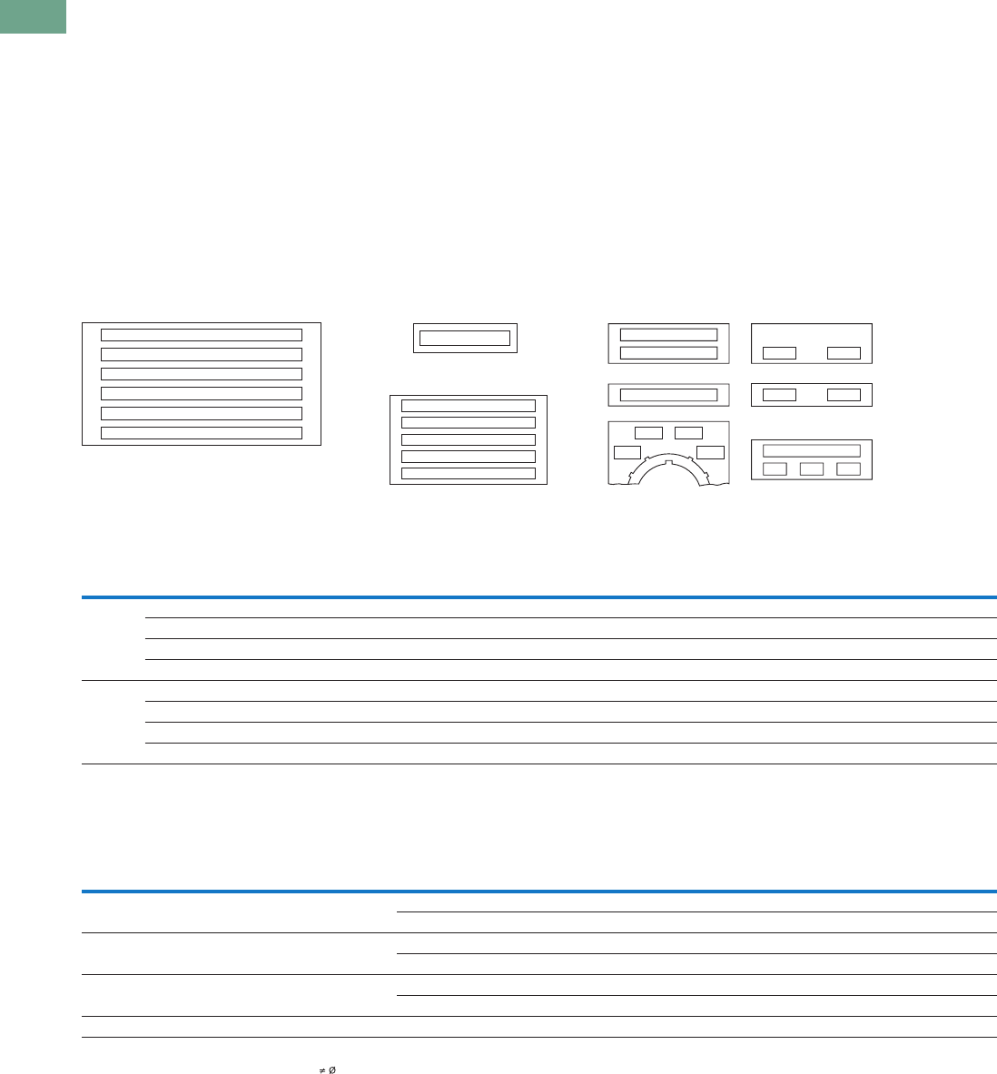
T37-218 Logic Control Products CA08100001K—June 2012 www.eatoncanada.ca
37
37
37
37
37
37
37
37
37
37
37
37
37
37
37
37
37
37
37
37
37
37
37
37
37
37
37
37
37
37
37.7
Pushbuttons and Indicating Lights
30.5 mm Heavy-Duty Watertight/Oiltight—10250T
Legend Plates with Non-Standard Markings
When Ordering Specify
●Catalogue number of blank
plate phase plus Suffix
“STAMP.”
●Insert the following into
Order Notes: legend, letter
size and locations (letters
A–W)—combine letters for
definitive locations as
shown.
Ordering Example:
Catalogue No.:
10250TS36STAMP
Letter Size: 3/32 in (2.4 mm)
Pos. A—POWER HOUSE
Pos. B—START PUMP 1
Legend Characters
Available
A B C D E F G H I J K L M N
O P Q R S T U V W X Y Z / - . ,
1 2 3 4 5 6 7 8 9 0
Legend characters on black
and red plates are white—
on satin aluminum plates,
characters are black.
Blackening Kit
Solution blackens aluminum
exposed by engraving
process. Must be applied
immediately after engraving.
0.3 oz. bottle—sufficient for
approximately 1100 legend
plates.
Catalogue Number:
10250TBK
Legend Positions
Blank and Custom Engraved Legend Plates
Maximum Characters per Legend Plate and Approximate Dimensions
Notes
All push-pull legend plates include the symbols in the centre of the plate.
Cannot be used on cast enclosures except for top row. Suitable for most sheet metal enclosures.
When used to meet Ford Motor Co. specifications, specify engraved legend. Cannot be used on standard cast or sheet metal enclosures.
Slightly larger than standard size for legends requiring more space—fits cast enclosures.
Square legend plates have a satin aluminum field. Colour is on lower portion.
Recommended only when mounting on minimum centers (less than 1-3/4 in [44.5 mm] vertical centers).
Can be used on top row only of any enclosure.
Style Colour
Small
Catalogue Number
Standard
Catalogue Number
Jumbo
Catalogue Number
Extra Large
Catalogue Number
Four-Position Selector Switch Push-Pull with Symbols
Custom
Catalogue Number
Standard
Catalogue Number
Standard
Catalogue Number
Jumbo
Catalogue Number
Square Black 10250TMS36 10250TS36 10250TL36 — 10250TS76 10250TS72 10250TPP17 10250TPP18
Red 10250TMS37 10250TS37 10250TL37 —————
Green/red ——————10250TPP20 10250TPP21
Satin alum. — — — 10250TNP99 ————
1/2 Round Black 10250TP36 10250TM36 10250TJ36 — — 10250TM72 10250TR17 10250TR18
Red 10250TP37 10250TM37 10250TJ37 —————
Green/red ——————10250TR20 10250TR21
Satin alum. — 10250TM89 10250TJ89 —————
Top
(Aluminum
and Plastic) Style
Character Size
Approximate Dimensions
in Inches (mm)
3/32 in High 1/8 in High 3/16 in High
Number
of Lines
Number of
Characters
Number
of Lines
Number of
Characters
Number
of Lines
Number of
CharactersWidth Height
Small 1.59 (40.4) 1.59 (40.4) Square 1 17 — — — —
1/2 Round 1 15 1 12 1 9
Standard and
custom
1.75 (44.5) 1.75 (44.5) Square 2 18 2 13 1 9
1/2 Round 2 15 2 12 1 9
Jumbo 2.19 (55.6) 2.19 (55.6) Square 5 23 3 18 2 12
1/2 Round 5 19 4 15 2 11
Extra large 2.44 (62) 2.44 (62) Square 6 25 3 18 3 12
L
K
D
C
B
A
Extra Large Size
Cat. No. 10250TNP99
Jumbo Size
10250TL or TJ Series
Small Size
10250TMS or TP Series
A
A
C
K
D
B
Standard Size
10250TS or TM Series
AB
B
A
GF
AE
GH
A
I
AF
D4
C4B4
A4
Tab37book.fm Page 218 Tuesday, July 3, 2012 10:46 PM
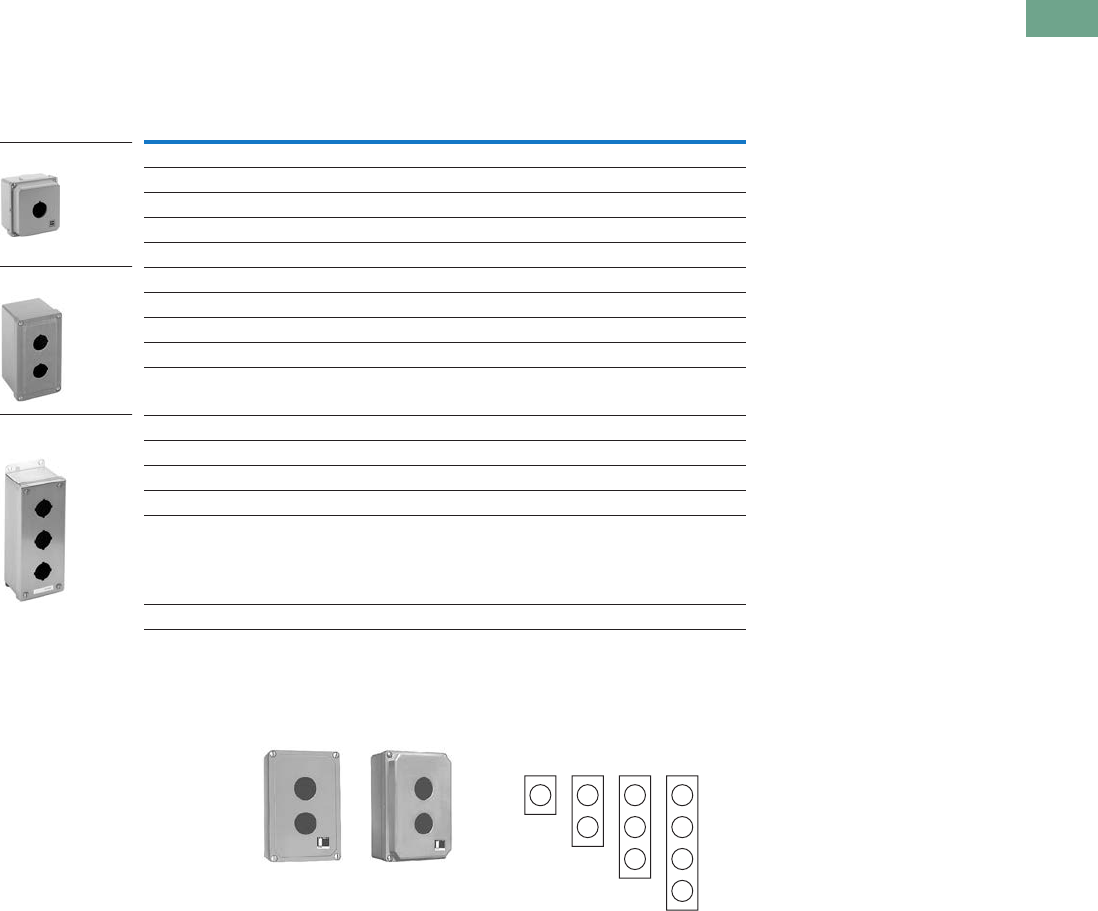
Logic Control Products CA08100001K—June 2012 www.eatoncanada.ca T37-219
37
37
37
37
37
37
37
37
37
37
37
37
37
37
37
37
37
37
37
37
37
37
37
37
37
37
37
37
37
37
37.7
Pushbuttons and Indicating Lights
30.5 mm Heavy-Duty Watertight/Oiltight—10250T
Enclosures
Die Cast, Polyester and Stainless Steel Enclosures
Enclosures (Case and Cover)—Surface Mounting
Mounting Instructions
Two-position joystick must be
used with two contact block
deep enclosures (maximum
number of contact blocks = 1).
Four-position joysticks cannot
be used within these
enclosures.
One and Two Contact Block
Depth Enclosures Enclosure Layouts
Notes
For spacing increments, see Page T37-220.
All die cast enclosures can be converted to base mounting of contact blocks, with spacers 10250TA22 or 10250TA23.
See listing on Page T37-213.
When used with E30 pushbuttons, only the one element enclosure can be used.
When used with resistor light units, only the 2 contact block depth enclosure can be used.
14 gauge, type 304.
Number of
Elements
One Contact Block Depth
Catalogue Number
Two Contact Block Depth
Catalogue Number
Die Cast Enclosure—In-Line NEMA 4, 4X, 12, 13
110250TN1 10250TN11
210250TN2 10250TN12
310250TN3 10250TN13
4— 10250TN14
Polyester—In-Line NEMA 3, 4X, 12
1— E34N51
2— E34N52
3— E34N53
4— E34N54
Stainless Steel —In-Line NEMA 4, 4X, 12
1— 10250TN33
2— 10250TN34
3— 10250TN35
4— 10250TN36
Dimensions, see Page T37-232.
Die Cast Enclosure
Polyester Enclosure
Stainless Steel
Enclosure
One Contact
Block Depth
Enclosure
Two Contact
Block Depth
Enclosure
111
Top – For Vertical Mounting
Top – For Horizontal
Mounting
1
222
33
4
Tab37book.fm Page 219 Tuesday, July 3, 2012 10:46 PM

T37-220 Logic Control Products CA08100001K—June 2012 www.eatoncanada.ca
37
37
37
37
37
37
37
37
37
37
37
37
37
37
37
37
37
37
37
37
37
37
37
37
37
37
37
37
37
37
37.7
Pushbuttons and Indicating Lights
30.5 mm Heavy-Duty Watertight/Oiltight—10250T
Die Cast and Stainless Steel—Flush Mount, Covers Only
Covers Only—Flush Mounting
Spacing Increments
Approximate Dimensions in Inches (mm)
Spacing Increments for
Enclosures Enclosure Layouts
Note
Not oiltight. NEMA 1 applications only.
Number of
Elements Catalogue Number Catalogue Number
Flush Die Cast Covers
In-Line Deep
Cover
In-Line Flat
Cover
110250TF11 10250TF1
210250TF12 10250TF2
310250TF13 10250TF3
410250TF14 10250TF4
In-Line Stainless Steel Flush Plates
With Pullbox Without Pullbox
110250TS10 10250TS1
210250TS11 10250TS2
310250TS12 10250TS3
410250TS14 10250TS4
Dimensions, see Page T37-233.
Type F G H
Die cast 2.44 (62) 2.5 (63.5) 1.88 (47.8)
Polyester 1.88 (47.8) Min. 2.13 (54.1) 2.25 (57.2)
Stainless steel 1.69 (42.9) Min. 1.73 (43.9) 2.25 (57.2)
Flush Mounting Covers
F
G
H
111
Top – For Vertical Mounting
Top – For Horizontal
Mounting
1
222
33
4
Tab37book.fm Page 220 Tuesday, July 3, 2012 10:46 PM

Logic Control Products CA08100001K—June 2012 www.eatoncanada.ca T37-221
37
37
37
37
37
37
37
37
37
37
37
37
37
37
37
37
37
37
37
37
37
37
37
37
37
37
37
37
37
37
37.7
Pushbuttons and Indicating Lights
30.5 mm Heavy-Duty Watertight/Oiltight—10250T
Contact Blocks
Standard Contact Blocks
●UL A600/P600 rated
●Colour-coded plungers—
red/green for NC/NO
circuits
●Silver contact tips with
“reliability nibs”
●Gray (opaque) or amber
(translucent) housings
●Pressure plate or spade
terminals
●Fingerproof shrouds (for
pressure terminals only)
Logic Level Contact Blocks
●UL A600/P600 rated
●Colour-coded plungers
●Inert palladium knife-blade
contacts
●Gray (opaque) housings
●Pressure plate or spade
terminals
Special Function Contact Blocks
●UL A600/P600 rated
●Colour-coded plungers
●Silver contact tips with
“reliability nibs”
●Gray (opaque) housings
●Pressure plate terminals
only
Special Purpose Contact Block
●Maximum 300V rated
●Black plungers
●Silver contact tips with
“reliability nibs”
●Black (opaque) housings
●Pressure plate terminals
only
●Fingerproof shrouds not
available
Reliability Nibs
Reliability nibs are the
hallmark of Eaton’s contact
blocks. A pointed silver nib on
the contact tip ensures
reliable switching from logic
level (5V) up to 600V
applications. Therefore
standard contact blocks can
be used for most logic level
applications where the
contacts are not exposed to
any harsh environmental
conditions.
Palladium Contacts
Palladium, which is more
inert than gold, is well suited
for voltages and currents
approaching zero and is
recommended for applications
where environmental
conditions are a factor.
Maximum Contact Block
Mounting per Operator Type
Operator
Max.
Stack
Pushbuttons 6
Push-pull operators 2
Roto-push operators 4
Two- or three-position
selector switches
6
Four-position selector
switches
4
Joysticks 4
Tab37book.fm Page 221 Tuesday, July 3, 2012 10:46 PM
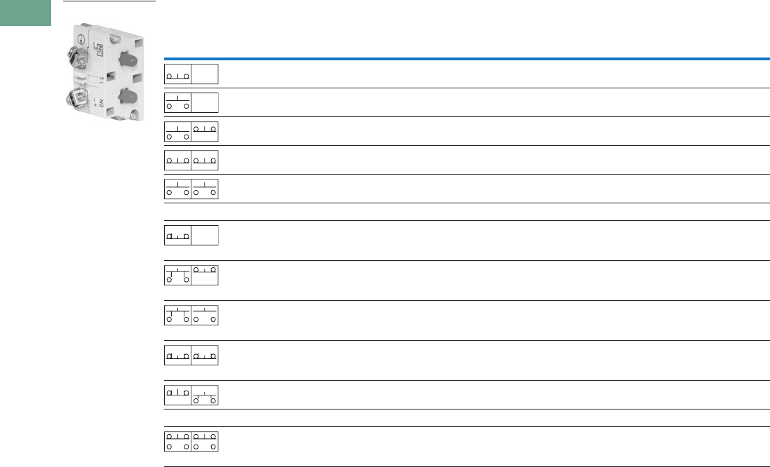
T37-222 Logic Control Products CA08100001K—June 2012 www.eatoncanada.ca
37
37
37
37
37
37
37
37
37
37
37
37
37
37
37
37
37
37
37
37
37
37
37
37
37
37
37
37
37
37
37.7
Pushbuttons and Indicating Lights
30.5 mm Heavy-Duty Watertight/Oiltight—10250T
Contact Blocks
Notes
All 10250T contact blocks shown are suitable for use on standard 10250T and E34 operators. These contact blocks are not suitable for Class I Division 2
type 10250T or E34 devices.
Contact blocks with spade terminals are limited to a maximum of one contact block per operator and minimum spacing between devices is 2.5 in (63.5 mm).
Not suitable for use in 10250T or E34 enclosures. Also available in amber housing. Not available with fingerproof shrouds.
Special function contact blocks are not suitable for use with roto-push operators, three-position push-pull operators, or four-position selector switches.
ECNO contact blocks are not suitable for use with two-position joysticks or when operators are used with padlock attachments.
Special purpose 10250T44 contact blocks are not suitable on selector switches or roto-push operators. Okay to use with three-position push-pull operators only
on low voltage (30V or less) circuits. Fingerproof shrouds not available.
Symbol Circuit Description
Standard Logic Level
Pressure Terminal
Catalogue Number
Spade Terminal
Catalogue Number
Pressure Terminal
Catalogue Number
Spade Terminal
Catalogue Number
1NC Stack up to six blocks (six circuits)
unless otherwise noted.
10250T51 10250T59 10250T51E 10250T59E
1NO Stack up to six blocks six circuits)
unless otherwise noted.
10250T53 10250T60 10250T53E 10250T60E
NO-NC Stack up to six blocks (12 circuits)
unless otherwise noted.
10250T1 10250T40 10250T1E 10250T40E
2NC Stack up to six blocks (12 circuits)
unless otherwise noted.
10250T3 10250T42 10250T3E 10250T42E
2NO Stack up to six blocks (12 circuits)
unless otherwise noted.
10250T2 10250T41 10250T2E 10250T41E
Special Function Blocks
LONC Late opening NC. Stack up to six
blocks (six circuits) unless
otherwise noted.
10250T71 — 10250T71E —
ECNO-
NC
Early closing NO and standard NC.
Stack up to six blocks unless
otherwise noted.
10250T47 — 10250T47E —
ECNO-
NO
Early closing NO and standard NO.
Stack up to four blocks unless
otherwise noted.
10250T57 — 10250T57E —
2LONC Two late opening NC contacts.
Stack up to six blocks unless
otherwise noted.
10250T45 — 10250T45E —
LONC-
ECNO
Overlapping contacts. Stack up to
four blocks unless otherwise noted.
10250T55 — 10250T55E —
Special Purpose Blocks
2NO-
2NC
Four circuits in single block depth.
Rated 300V max. Stack up to four
blocks unless otherwise noted.
10250T44 —
10250T1
Blank
No
Plunger
Blank
No
Plunger
Blank
No
Plunger
Tab37book.fm Page 222 Tuesday, July 3, 2012 10:46 PM
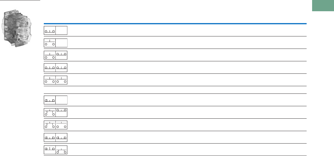
Logic Control Products CA08100001K—June 2012 www.eatoncanada.ca T37-223
37
37
37
37
37
37
37
37
37
37
37
37
37
37
37
37
37
37
37
37
37
37
37
37
37
37
37
37
37
37
37.7
Pushbuttons and Indicating Lights
30.5 mm Heavy-Duty Watertight/Oiltight—10250T
Contact Blocks with Fingerproof Shrouds
Notes
All 10250T contact blocks shown are suitable for use on standard 10250T and E34 operators. These contact blocks are not suitable for Class I Division 2
type 10250T or E34 devices.
To order contact blocks with translucent amber housing, change suffix P to CP in catalogue number e.g. 10250T51CP.
ECNO contact blocks are not suitable for use with two-position joysticks or when operators are used with padlock attachments.
Special function contact blocks are not suitable for use with roto-push operators, three-position push-pull operators, or four-position selector switches.
Symbol Circuit Description
Standard
Pressure Terminal
Catalogue Number
Logic Level
Pressure Terminal
Catalogue Number
1NC Stack up to six blocks (six circuits) unless otherwise noted. 10250T51P 10250T51EP
1NO Stack up to six blocks (six circuits) unless otherwise noted. 10250T53P 10250T53EP
NO-NC Stack up to six blocks (12 circuits) unless otherwise noted. 10250T1P 10250T1EP
2NC Stack up to six blocks (12 circuits) unless otherwise noted. 10250T3P 10250T3EP
2NO Stack up to six blocks (12 circuits) unless otherwise noted. 10250T2P 10250T2EP
Special Function Blocks
LONC Late opening NC. Stack up to six blocks (six circuits) unless
otherwise noted.
10250T71P 10250T71EP
ECNO-NC Early closing NO and standard NC. Stack up to six blocks
unless otherwise noted.
10250T47P 10250T47EP
ECNO-NO Early closing NO and standard NO. Stack up to four blocks
unless otherwise noted.
10250T57P 10250T57EP
2LONC Two late opening NC contacts. Stack up to six blocks unless
otherwise noted.
10250T45P 10250T45EP
LONC-ECNO Overlapping contacts. Stack up to four blocks unless
otherwise noted.
10250T55P 10250T55EP
10250T1CP
Blank
No
Plunger
Blank
No
Plunger
Blank
No
Plunger
Tab37book.fm Page 223 Tuesday, July 3, 2012 10:46 PM
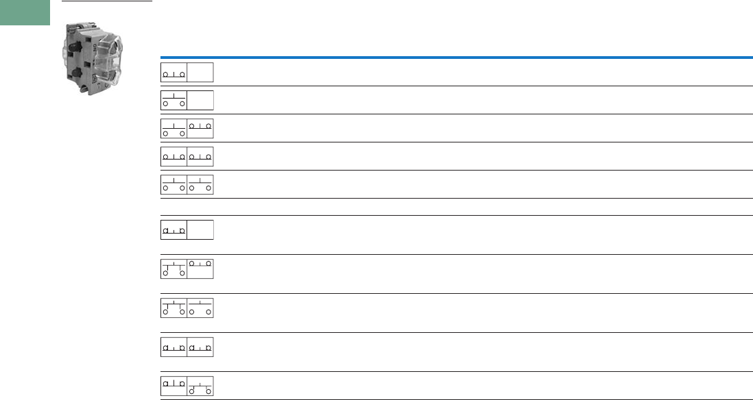
T37-224 Logic Control Products CA08100001K—June 2012 www.eatoncanada.ca
37
37
37
37
37
37
37
37
37
37
37
37
37
37
37
37
37
37
37
37
37
37
37
37
37
37
37
37
37
37
37.7
Pushbuttons and Indicating Lights
30.5 mm Heavy-Duty Watertight/Oiltight—10250T
Amber Contact Blocks
Notes
All 10250T contact blocks shown are suitable for use on standard 10250T and E34 operators. These contact blocks are not suitable for Class I Division 2
type 10250T or E34 devices.
To order amber contact blocks with fingerproof shrouds, change suffix to CP in the catalogue number e.g. 10250T51CP. Not available with spade terminals.
Contact blocks with spade terminals are limited to a maximum of one contact block per operator and minimum spacing between devices is 2.5 in (63.5 mm).
Not suitable for use in 10250T or E34 enclosures. Also available in amber housing. Not available with fingerproof shrouds.
Special function contact blocks are not suitable for use with roto-push operators, three-position push-pull operators, or four-position selector switches.
ECNO contact blocks are not suitable for use with two-position joysticks or when operators are used with padlock attachments.
Symbol Circuit Description
Standard Logic Level
Pressure Terminal
Catalogue Number
Spade Terminal
Catalogue Number
Pressure Terminal
Catalogue Number
Spade Terminal
Catalogue Number
1NC Stack up to six blocks (six circuits)
unless otherwise noted.
10250T51C 10250T59C 10250T51EC 10250T59EC
1NO Stack up to six blocks (six circuits)
unless otherwise noted.
10250T53C 10250T60C 10250T53EC 10250T60EC
NO-NC Stack up to six blocks (12 circuits)
unless otherwise noted.
10250T1C 10250T40C 10250T1EC 10250T40EC
2NC Stack up to six blocks (12 circuits)
unless otherwise noted.
10250T3C 10250T42C 10250T3EC 10250T42EC
2NO Stack up to six blocks (12 circuits)
unless otherwise noted.
10250T2C 10250T41C 10250T2EC 10250T41EC
Special Function Blocks
LONC Late opening NC. Stack up to six
blocks (six circuits) unless otherwise
noted.
10250T71C — 10250T71EC —
ECNO-
NC
Early closing NO and standard NC.
Stack up to six blocks unless
otherwise noted.
10250T47C — 10250T47EC —
ECNO-
NO
Early closing NO and standard NO.
Stack up to four blocks unless
otherwise noted.
10250T57C — 10250T57EC —
2LONC Two late opening NC contacts.
Stack up to six blocks unless
otherwise noted.
10250T45C — 10250T45EC —
LONC-
ECNO
Overlapping contacts. Stack up to
four blocks unless otherwise noted.
10250T55C — 10250T55EC —
10250T1C
Blank
No
Plunger
Blank
No
Plunger
Blank
No
Plunger
Tab37book.fm Page 224 Tuesday, July 3, 2012 10:46 PM
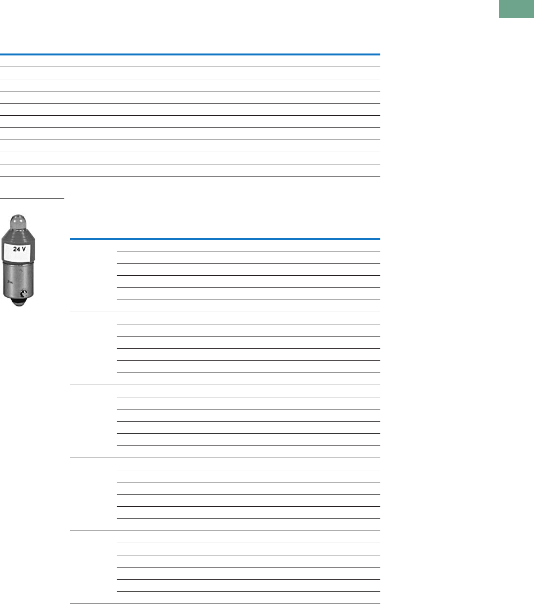
Logic Control Products CA08100001K—June 2012 www.eatoncanada.ca T37-225
37
37
37
37
37
37
37
37
37
37
37
37
37
37
37
37
37
37
37
37
37
37
37
37
37
37
37
37
37
37
37.7
Pushbuttons and Indicating Lights
30.5 mm Heavy-Duty Watertight/Oiltight—10250T
Replacement Parts
Replacement Lamps—For 10250T Illuminated Operators
Replacement LED Lamps—For 10250T, E34 and E22 Units
Mfg. Lamp Type Voltage Base Style Application Part Number
120MB 120V T 3-1/4 bayonet 10250T resistor indicating light 28-3044
#267 6.3V T 3-1/4 bayonet 10250T flasher 10250ED986-4
#755 6.3V T 3-1/4 bayonet 10250T transformer, PresTest and full voltage 28-2202
#756 12V T 3-1/4 bayonet 10250T full voltage 28-5184
#757 24V T 3-1/4 bayonet 10250T full voltage 28-5185
#1828 32V T 3-1/4 bayonet 10250T full voltage 28-5186
#1835 55V T 3-1/4 bayonet 10250T resistor 28-5185
NE48 120V T 4-1/2 bayonet 10250T neon 28-494
NE51H-R22 120V T 3-1/4 bayonet 10250T neon 28-3754
NE51H-R68 240V T 3-1/4 bayonet 10250T neon 28-3755
Voltage Colour
Continuous Flashing
AC/DC
Catalogue Number
AC
Catalogue Number
DC
Catalogue Number
6–12V Red E22LED612RN E22LED006RAF E22LED006RDF
Orange E22LED612ON E22LED006OAF E22LED006ODF
Yellow E22LED612YN E22LED006YAF E22LED006YDF
Green E22LED612GN E22LED006GAF E22LED006GDF
Blue E22LED612BN E22LED006BAF E22LED006BDF
White E22LED612WN E22LED006WAF E22LED006WDF
24V Red E22LED024RN E22LED024RAF E22LED024RDF
Orange E22LED024ON E22LED024OAF E22LED024ODF
Yellow E22LED024YN E22LED024YAF E22LED024YDF
Green E22LED024GN E22LED024GAF E22LED024GDF
Blue E22LED024BN E22LED024BAF E22LED024BDF
White E22LED024WN E22LED024WAF E22LED024WDF
48V Red E22LED048RN E22LED048RAF E22LED048RDF
Orange E22LED048ON E22LED048OAF E22LED048ODF
Yellow E22LED048YN E22LED048YAF E22LED048YDF
Green E22LED048GN E22LED048GAF E22LED048GDF
Blue E22LED048BN E22LED048BAF E22LED048BDF
White E22LED048WN E22LED048WAF E22LED048WDF
60V Red E22LED060RN E22LED060RAF E22LED060RDF
Orange E22LED060ON E22LED060OAF E22LED060ODF
Yellow E22LED060YN E22LED060YAF E22LED060YDF
Green E22LED060GN E22LED060GAF E22LED060GDF
Blue E22LED060BN E22LED060BAF E22LED060BDF
White E22LED060WN E22LED060WAF E22LED060WDF
120V Red E22LED120RN E22LED120RAF E22LED120RDF
Orange E22LED120ON E22LED120OAF E22LED120ODF
Yellow E22LED120YN E22LED120YAF E22LED120YDF
Green E22LED120GN E22LED120GAF E22LED120GDF
Blue E22LED120BN E22LED120BAF E22LED120BDF
White E22LED120WN E22LED120WAF E22LED120WDF
Standard LED Lamp
Tab37book.fm Page 225 Tuesday, July 3, 2012 10:46 PM

T37-226 Logic Control Products CA08100001K—June 2012 www.eatoncanada.ca
37
37
37
37
37
37
37
37
37
37
37
37
37
37
37
37
37
37
37
37
37
37
37
37
37
37
37
37
37
37
37.7
Pushbuttons and Indicating Lights
30.5 mm Heavy-Duty Watertight/Oiltight—10250T
10250T Style Operator Replacement Parts
Two-Position
Joystick Operator
Flush Head
Pushbutton
Operator
Mushroom Head
Pushbutton
Operator
Four-Position Joystick
Operator (without Latch) Illuminated
Pushbutton Operator Full Voltage, Resistor
and Transformer Type
Illuminated Selector Switch
Transformer Type
Indicating Light
Mushroom Head
Operator with
Padlock Attachment
Jumbo Mushroom
Head Operator Knob-Operated
Selector Switch
Operator
Potentiometers
Item
No. Description
No.
Req. Part Number
1 Gasket 1 16-1548
2 Mounting nut 1 15-1530
3 Handle 1 24-5045
4 Knob 1 53-3157
Knob (not shown) for joystick operator with latch 1 53-3159
5 Common gate (supplied with operator) 2 16-3400
6 Set screw (#6-32 x 0.250 in long hollow hex) 2 11-2014
7 Mushroom head button (includes [2] Item 6) 1 As Req. Below
Black — 53-1317
Red — 53-1317-2
Yellow — 53-1317-3
Green — 53-1317-4
Blue — 53-1317-22
8 Set screw (#10-32 x 0.250 in long hollow hex) 2 11-544
9 Jumbo mushroom head button
(aluminum—includes [2] Item 8)
1As Req. Below
Red — 53-1317-9
Black — 53-1317-10
Yellow — 53-1317-11
Green — 53-1317-12
10 Jumbo mushroom head button
(aluminum—red EMERG. STOP)
does not include Item 8
153-1349-18
11 Position gate:
Two-position 1 54-7278
Three-position 1 54-7173
Four-position 1 54-12278
Eight-position 1 54-12279
12 Mounting screw (#6-32 x 0.710 in long) 2 10250TA79
Washer 2 16-2038
13 Terminal screw and lug (captive) Req. 80-5502KIT
Item
No. Description
No.
Req. Part Number
14 Gasket (supplied with basic unit) 1 32-803
15 Round head screw (#4-40 x 0.344 in long)
(supplied with basic unit)
211-4553
16 Mounting screw 2 11-1632
17 Simple potentiometer
(does not include items 18, 28 or 29)
1As Req. Below
1,000 ohms — 41-782-2
2,500 ohms — 41-782-3
5,000 ohms — 41-782-10
10,000 ohms — 41-782-4
25,000 ohms — 41-782-5
50,000 ohms — 41-782-6
18 Connector (includes screw and lug) 2 25-1851
19 Indicating plate 1 As Req. Above
Standard size (without legend) — 30-4460
Large size (specify legend) — 10250TR30
20 Retaining nut 1 15-1547
21 Knob 1 53-1314
Socket set screw (#6-32 x 0.250 in long) 2 11-2014
22 Coupling 1 29-3749-2
23 Set screw (#6-32 x 0.188 in long) 1 11-1199
24 Spacer 2 56-1066-18
25 Connector (includes screw and lug) 1 25-1851-2
26 Mounting nut 1 15-1938
27 Four-position joystick operating mechanism
(complete)
124-6565
28 Four-position joystick operating mechanism
(not shown) (with latch) complete
124-6565-2
29 Spring loaded latch 1 52-1214-2
30 Hand operated latch 1 52-913-3
Tab37book.fm Page 226 Tuesday, July 3, 2012 10:46 PM

Logic Control Products CA08100001K—June 2012 www.eatoncanada.ca T37-227
37
37
37
37
37
37
37
37
37
37
37
37
37
37
37
37
37
37
37
37
37
37
37
37
37
37
37
37
37
37
37.7
Pushbuttons and Indicating Lights
30.5 mm Heavy-Duty Watertight/Oiltight—10250T
Technical Data and Specifications
Mechanical Ratings
General Specifications
Description Specification
Frequency of Operation
All pushbuttons 6000 operations/hr.
Key and lever selection switches 3000 operations/hr.
Auto-latch devices 1200 operations/hr.
Life
Pushbuttons 10 x 106 operations
Contact blocks 10 x 106 operations
PresTest units 10 x 106 operations
Lever and key selector switches 0.25 x 10⁶ operations
Twist to release pushbuttons 0.3 x 10⁶ operations
Shock Resistance
Duration 20 ms >5g
Description Specification
Climate Conditions
Operating temperature 1˚ to 150˚F (–17˚ to 66˚C)
Storage temperature –40˚ to 176˚F (–40˚ to 80˚C)
Altitude 6,562 ft (2,000m)
Humidity Max. 95% RH at 60˚C
Terminals
Marking NC-NO on the contact block to meet the NEMA requirements. Dual marking system 1–2
for normally closed, 3–4 for normally open to meet BS5472 (Cenelec EN50 005).
Clamps Terminals are saddle clamp type for 1 x 22 AWG (0.34 mm2) to 2 x 14 AWG (2.5 mm2)
conductors
Torque 7 lb-in (0.8 Nm)
Degree of protection against direct electrical contact IP2X with fingerproof shroud
Light Units
Transformers Will withstand short-circuit for 1 hour per IEC 60997-5-1
Bulbs—average life:
Transformer type 20,000 hrs.
Resistor/direct voltage type 2500 hrs. minimum at rated voltage
LED 60,000 to 100,000 hrs.
Tab37book.fm Page 227 Tuesday, July 3, 2012 10:46 PM

T37-228 Logic Control Products CA08100001K—June 2012 www.eatoncanada.ca
37
37
37
37
37
37
37
37
37
37
37
37
37
37
37
37
37
37
37
37
37
37
37
37
37
37
37
37
37
37
37.7
Pushbuttons and Indicating Lights
30.5 mm Heavy-Duty Watertight/Oiltight—10250T
Electrical Ratings
Electrical Ratings—Contact Block
Description Specification
Insulation Ui = 660 Vac or Vdc
Thermal Ith = 10A
Short Circuit Coordination to IEC/EN 60947-5-1
Rated conditional short circuit current 1 kA
Fuse type GE power controls TIA 10, red spot type gG, 10A, 660 Vac, 460 Vdc, BS88-2,
IEC 60269-2-1
UL rating A600, P600
AC load life duty cycle 1200 operations/hour
10A 110V pf 0.4—1 x 10⁶ operations
5A 250V pf 0.4—1 x 10⁶ operations
2A 600V pf 0.4—1 x 10⁶ operations
Switching capacity
AC 15 rated make/break (11 x le at 1.1 x Ue)
6A 120V pf 0.3
4A 240V pf 0.3
2A 660V pf 0.3
DC13 rated make/break (1.1 x le at 1.1 x Ue)
1.0A 125V L/R >0.95 at 300 ms
0.55A 250V L/R >0.95 at 300 ms
0.1A 660V L/R >0.95 at 300 ms
10A 110V pure resistive
Maximum ratings for logic level and
hostile atmosphere application
Maximum amperes 0.5A
Maximum volts 120 Vac/Vdc
Description
50 Vac or 60 Hz Vdc
120 240 480 600 24/28 125 250
Meet or Exceed NEMA Rating Designations A600, A300 and B300 for AC and P600 for DC
Make and emerg. interrupting capacity (amp) 60 30 15 12 5.7 1.1 0.55
Normal load break (amp) 6 3 1.5 1.2 5.7 1.1 0.55
Thermal current (amp) 10 10 10 10 5.0 5.0 5.0
Voltamperes:
Make and emerg. interrupting capacity 7200 7200 7200 7200 138 138 138
Normal load break 720 720 720 720 138 138 138
Tab37book.fm Page 228 Tuesday, July 3, 2012 10:46 PM
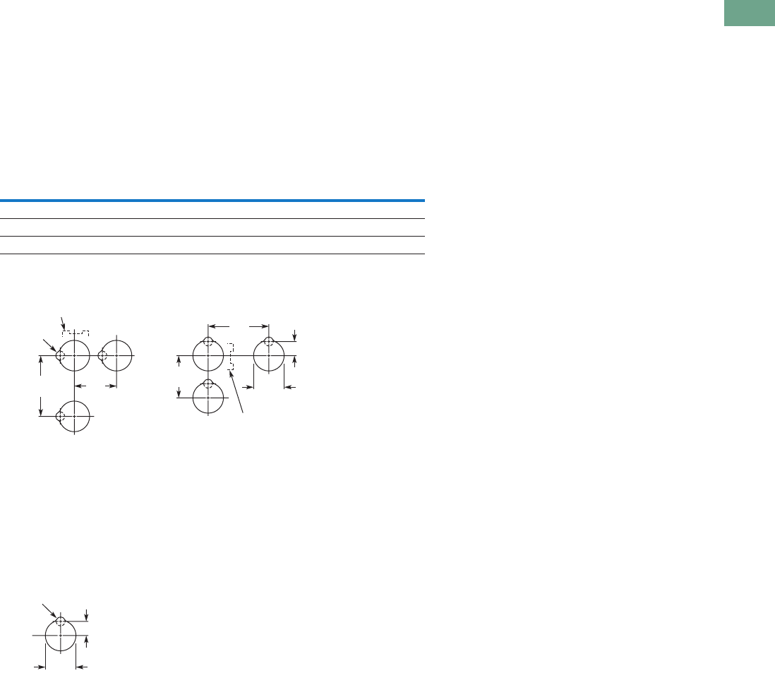
Logic Control Products CA08100001K—June 2012 www.eatoncanada.ca T37-229
37
37
37
37
37
37
37
37
37
37
37
37
37
37
37
37
37
37
37
37
37
37
37
37
37
37
37
37
37
37
37.7
Pushbuttons and Indicating Lights
30.5 mm Heavy-Duty Watertight/Oiltight—10250T
Mounting Options
Panel Thickness
●Minimum: 0.06 in (1.6 mm)
●Maximum: 0.25 in (8 mm) including legend plate
●Maximum can be increased to 0.375 in (15.9 mm) using optional retaining nut
●Indicating light: 10250TA30
●Pushbutton/selector switch: 10250TA31
Mounting Matrix
Mounting Options in Inches (mm)
Horizontal mounting means terminals are located top and bottom of contact block.
Vertical mounting means terminals are left and right of contact block.
This allows close spacing of adjacent operators with easy access to terminals.
Locating nib hole or notch is 0.14 in (3.6 mm) #29 drill.
Drilling Dimensions in Inches (mm)
Legend
Plate
Dimensions in Inches (mm)
ABCD
Small 1.63 (41.3) 2.25 (57.2) 2.25 (57.2) 1.63 (41.3)
Medium 1.75 (44.5) 2.25 (57.2) 2.25 (57.2) 1.75 (44.5)
Large 2.25 (57.2) 2.25 (57.2) 2.25 (57.2) 2.25 (57.2)
B
Min.
C
Min.
0.6
(15.2)
A
Min. 1.22
(31)
D
Min.
Horizontal Mounting Vertical Mounting
0.14 (3.6)
Dia.
Terminals on Top
Terminals at Side
0.6
(15.2)
1.20
(30.5)
0.14 (3.6)
Dia.
Tab37book.fm Page 229 Tuesday, July 3, 2012 10:46 PM
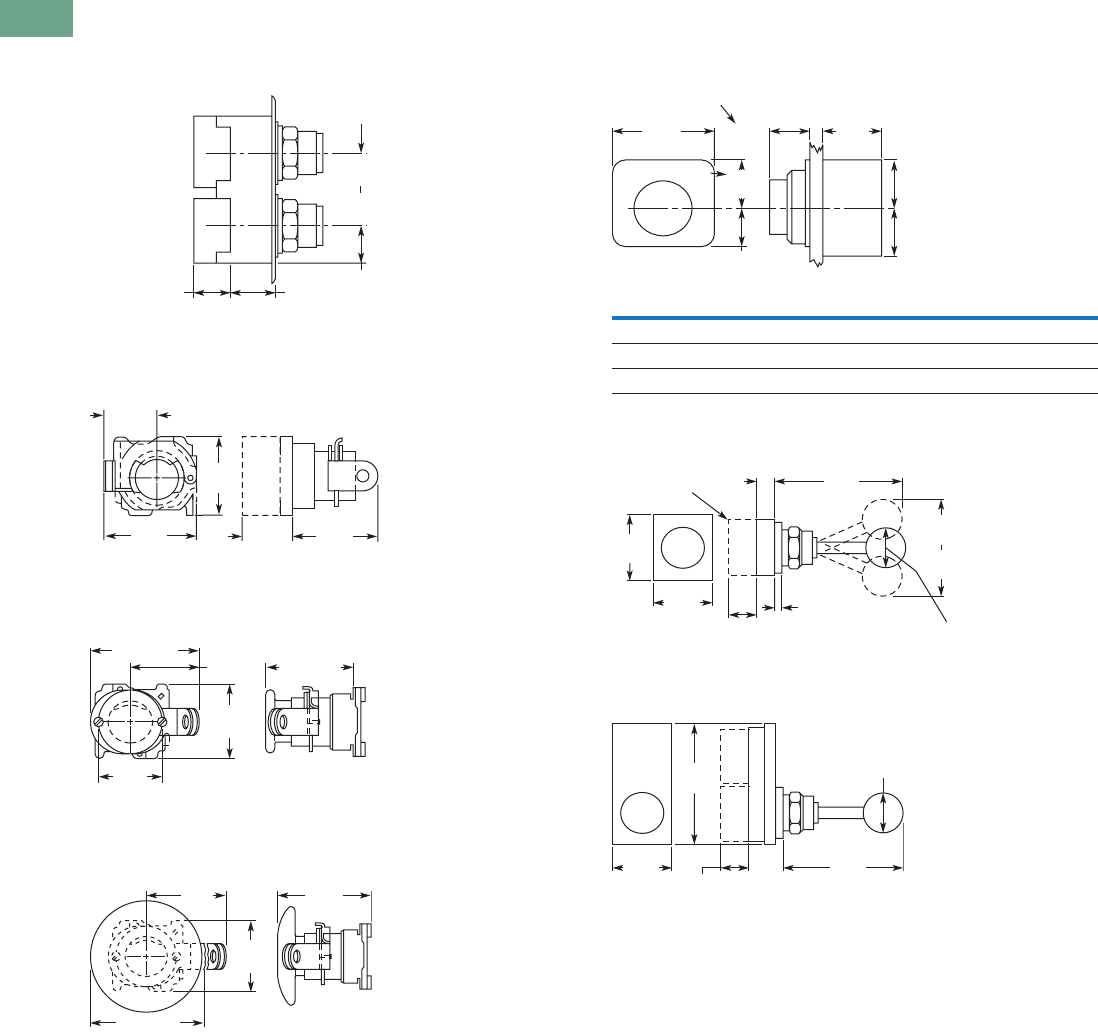
T37-230 Logic Control Products CA08100001K—June 2012 www.eatoncanada.ca
37
37
37
37
37
37
37
37
37
37
37
37
37
37
37
37
37
37
37
37
37
37
37
37
37
37
37
37
37
37
37.7
Pushbuttons and Indicating Lights
30.5 mm Heavy-Duty Watertight/Oiltight—10250T
Dimensions
Approximate Dimensions in Inches (mm)
Mechanically Interlocked Pushbutton Operators
Lockout Pushbutton Operator Padlockable
in the Down Position
Lockout Pushbutton Operator Padlockable
in the Up Position—Mushroom Head
Lockout Pushbutton Operator Padlockable
in the Up Position—Jumbo Mushroom Head
Potentiometer
Two-Position Joystick Operator
Four-Position Joystick Operator
0.89
(22.6)
Adjustable
0.88 (22.4)
for Each
Additional
Contact Block 1.07
(27.2)
1.62 (41.1)
Min.
2.5 (63.5)
Max.
2.03
(51.6)
2.0
(50.8)
1.09
(27.7)
1.13
(28.7)
1.78
(45.2)
1.5
(38.1)
1.63
(41.4)
2.5 (63.5)
2.0 (50.8)
1.75
(44.5)
2.5 (63.5)
2.31
(58.7)
2.38
(60.5)
1.75
(44.5)
Potentiometer A B C
2 watt single 1.31 (33.3) 0.94 (23.9) 0.94 (23.9)
25 watt—up to 25 mohms 2.38 (60.5) 1.19 (30.2) 0.81 (20.6)
50 mohms 2.56 (65) 1.69 (42.9) 1.25 (31.8)
1.88
(47.8)
1.31
(33.3)
1.09
(27.7) 1.0
(25.4)
0.75
(19.1)
0.94
(23.9)
0.94
(23.9)
0.94
(23.9)
Std. Dial Plate
Large Dial Plate
2.06
(52.3) 2.5 (63.5)
main.
2.2 (55.9)
mom.
2.13
(54.1)
1.25
(31.8)
3.88
(98.6)
0.89
(22.6)
0.88 (22.4)
per Block
0.06 (1.5) to
0.26 (6.6)
Panel Thickness
Contact
Block
4.0
(101.6)
1.88
(47.8) 3.75
(95.3)
1.25
(31.8)
1.19
(30.2)
0.88 (22.4)
Per Unit
Tab37book.fm Page 230 Tuesday, July 3, 2012 10:46 PM
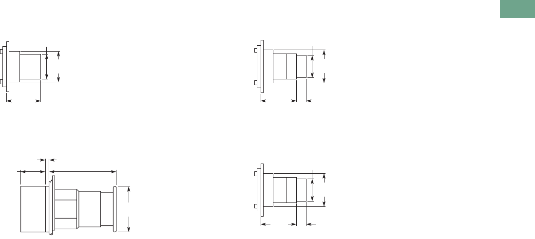
Logic Control Products CA08100001K—June 2012 www.eatoncanada.ca T37-231
37
37
37
37
37
37
37
37
37
37
37
37
37
37
37
37
37
37
37
37
37
37
37
37
37
37
37
37
37
37
37.7
Pushbuttons and Indicating Lights
30.5 mm Heavy-Duty Watertight/Oiltight—10250T
Approximate Dimensions in Inches (mm)
Key Operated Pushbutton Operator
Latch-In, Twist-to-Release Operator
Only with Button
Operator and Cam
Special Rotor Latch
1.38
(35.1)
1.13
(28.7)
1.5
(38.1)
1.5
(38.1)
0.86
(21.8)
0.24 (6) 1.55 (39.3)
Spring Return
2.37 (60.3)
Auto-Latch
1.38
(35.1)
1.13
(28.7)
1.53
(38.9)
0.38 (9.7)
Long
Button
Only
1.38
(35.1)
1.13
(28.7)
1.53
(38.9)
0.38 (9.7)
Long
Button
Only
Tab37book.fm Page 231 Tuesday, July 3, 2012 10:46 PM
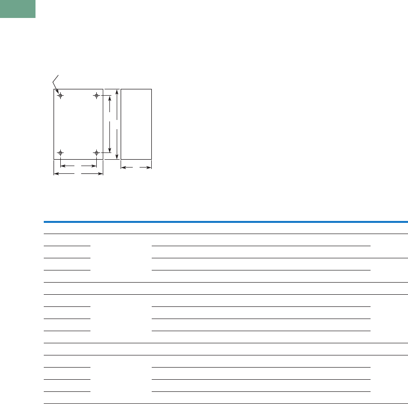
T37-232 Logic Control Products CA08100001K—June 2012 www.eatoncanada.ca
37
37
37
37
37
37
37
37
37
37
37
37
37
37
37
37
37
37
37
37
37
37
37
37
37
37
37
37
37
37
37.7
Pushbuttons and Indicating Lights
30.5 mm Heavy-Duty Watertight/Oiltight—10250T
Approximate Dimensions in Inches (mm)
Surface Mounting
Die Cast, Polyester and Stainless Steel Enclosures
Notes
Depth given is for two contact block deep stations. One contact block deep stations subtract 3/4 in (19.1 mm).
No conduit entrance holes provided. Drill as required.
A
Surface
DC
B
E
4 Mtg. Holes — 10-32 Screw Size for
1 – 4 Element Die Cast/
Stainless Steel Enclosure
7/32 Screw Size for
Polyester
Number of
Elements
Element
Arrangement
Wide
A
High
B
Deep
C
Mounting Conduit
EntranceDE
Die Cast
1 In-line 3.88 (98.6) 4.0 (101.6) 3.0 (76.3) 2.69 (68.3) 3.25 (82.6) 3/4
2 3.88 (98.6) 5.88 (149.4) 3.0 (76.3) 2.69 (68.3) 5.13 (130.3)
3 3.88 (98.6) 7.75 (196.9) 3.0 (76.3) 2.69 (68.3) 7.0 (177.8) 1
4 3.88 (98.6) 9.63 (244.6) 3.0 (76.3) 2.69 (68.3) 8.88 (225.6)
Polyester
1 In-line 3.81 (96.8) 6.63 (168.4) 3.38 (85.9) 2.94 (74.7) 4.88 (124.0)
2 3.81 (96.8) 6.63 (168.4) 3.38 (85.9) 2.94 (74.7) 4.88 (124.0)
3 3.81 (96.8) 8.88 (225.6) 3.38 (85.9) 2.94 (74.7) 7.13 (181.1)
4 3.81 (96.8) 11.13 (282.7) 3.38 (85.9) 2.94 (74.7) 9.38 (238.3)
Stainless Steel
1 In-line 3.00 (76.2) 3.50 (88.9) 3.00 (76.2) 1.50 (38.1) 4.25 (108.0)
2 3.50 (88.9) 6.75 (171.5) 3.00 (76.2) 1.50 (38.1) 7.50 (190.5)
3 3.50 (88.9) 9.00 (228.6) 3.00 (76.2) 1.50 (38.1) 9.00 (228.6)
4 3.50 (88.9) 11.25 (285.8) 3.00 (76.2) 1.50 (38.1) 12.00 (304.8)
Tab37book.fm Page 232 Tuesday, July 3, 2012 10:46 PM

Logic Control Products CA08100001K—June 2012 www.eatoncanada.ca T37-233
37
37
37
37
37
37
37
37
37
37
37
37
37
37
37
37
37
37
37
37
37
37
37
37
37
37
37
37
37
37
37.7
Pushbuttons and Indicating Lights
30.5 mm Heavy-Duty Watertight/Oiltight—10250T
Approximate Dimensions in Inches (mm)
Flush Mounting
Die Case and Stainless Steel Covers Only
Notes
Depth given includes pull box.
Depth given is for flat cover. Deep cover is 3/4 in (19.1 mm) deeper.
A
Surface or Pendant
DC
B
E
4 Mtg. Holes - 10-32 Screw Size
for 1-11 Element Encl, 1/4-20
Screw Size for 12 Element
and Larger
Number of
Elements
Wide
A
High
B
Deep
C
Mounting
DE
Die Cast
1 3.88 (98.6) 4.0 (101.6) 0.25 (6.4) 3.50 (88.9) 3.63 (92.2)
2 3.88 (98.6) 5.88 (149.4) 0.25 (6.4) 3.50 (88.9) 5.50 (139.7)
3 3.88 (98.6) 7.75 (196.9) 0.25 (6.4) 3.50 (88.9) 6.0 (152.4)
4 3.88 (98.6) 9.63 (244.6) 0.25 (6.4) 3.50 (88.9) 9.25 (235)
Stainless Steel
1 5.00 (127) 5.0 (127 2.50 (63.5) 3.25 (82.6) 1.88 (47.8)
2 5.00 (127) 6.88 (174.8) 2.50 (63.5) 3.25 (82.6) 3.63 (92.2)
3 5.00 (127) 8.63 (219.2) 2.50 (63.5) 3.25 (82.6) 5.50 (139.7)
4 5.00 (127) 10.50 (266.7) 2.50 (63.5) 3.25 (82.6) 7.25 (184.2)
Tab37book.fm Page 233 Tuesday, July 3, 2012 10:46 PM
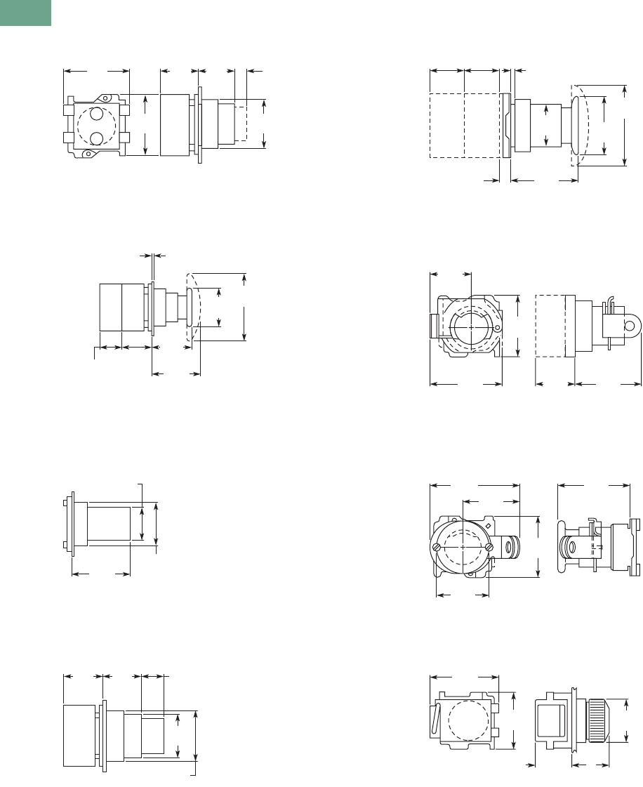
T37-234 Logic Control Products CA08100001K—June 2012 www.eatoncanada.ca
37
37
37
37
37
37
37
37
37
37
37
37
37
37
37
37
37
37
37
37
37
37
37
37
37
37
37
37
37
37
37.7
Pushbuttons and Indicating Lights
30.5 mm Heavy-Duty Watertight/Oiltight—10250T
Approximate Dimensions in Inches (mm)
Flush and Long Pushbutton Half Shroud
Mushroom and Jumbo Head Pushbutton
Pushbutton with Cylinder Lock
Illuminated Pushbutton
Push-Pull Switch
Flush Pushbutton Operator with
Padlock Attachment
Mushroom Head Pushbutton Operator
with Padlock Attachment
Indicating Light—Transformer Type
1.81
(46) 1.09
(27.7)
1.06
(26.9)
0.38
(9.7)
1.38
(35.1)
1.78
(45.2)
Long
Button
Only
Half Shroud Is Same as Long Pushbutton with
Lower Half of Guard Ring Cut Back
1.13
(28.7)
0.88 (22.4)
for Each
Additional
Contact Block
1.75
(44.5)
1.63
(41.4)
1.5
(38.1)
2.5
(63.5)
0.06 (1.5) to 0.25 (6.4)
Panel Thickness
1.91
(48.5)
1.13
(28.7)
1.38
(35.1)
1.09
(27.7)
1.09
(27.7)
0.69
(17.5)
1.13
(28.7)
1.38
(35.1)
2.63
(66.8)
1.65
(41.9)
1.78
(45.2)
0.25
(6.4)
0.06 (1.5) to 0.25 (6.4)
Panel Thickness
0.88
(22.4)
0.88
(22.4)
1.13
(28.7)
2.03
(51.6)
2.0
(50.8)
1.09
(27.7)
1.13
(28.7)
1.78
(45.2)
1.5
(38.1)
1.63
(41.4)
2.5
(63.5)
2.0
(50.8)
1.75
(44.5)
1.8
(45.7)
A
1.78
(45.2)
1.1
(27.9)
1.38
(35.1)
Tab37book.fm Page 234 Tuesday, July 3, 2012 10:46 PM
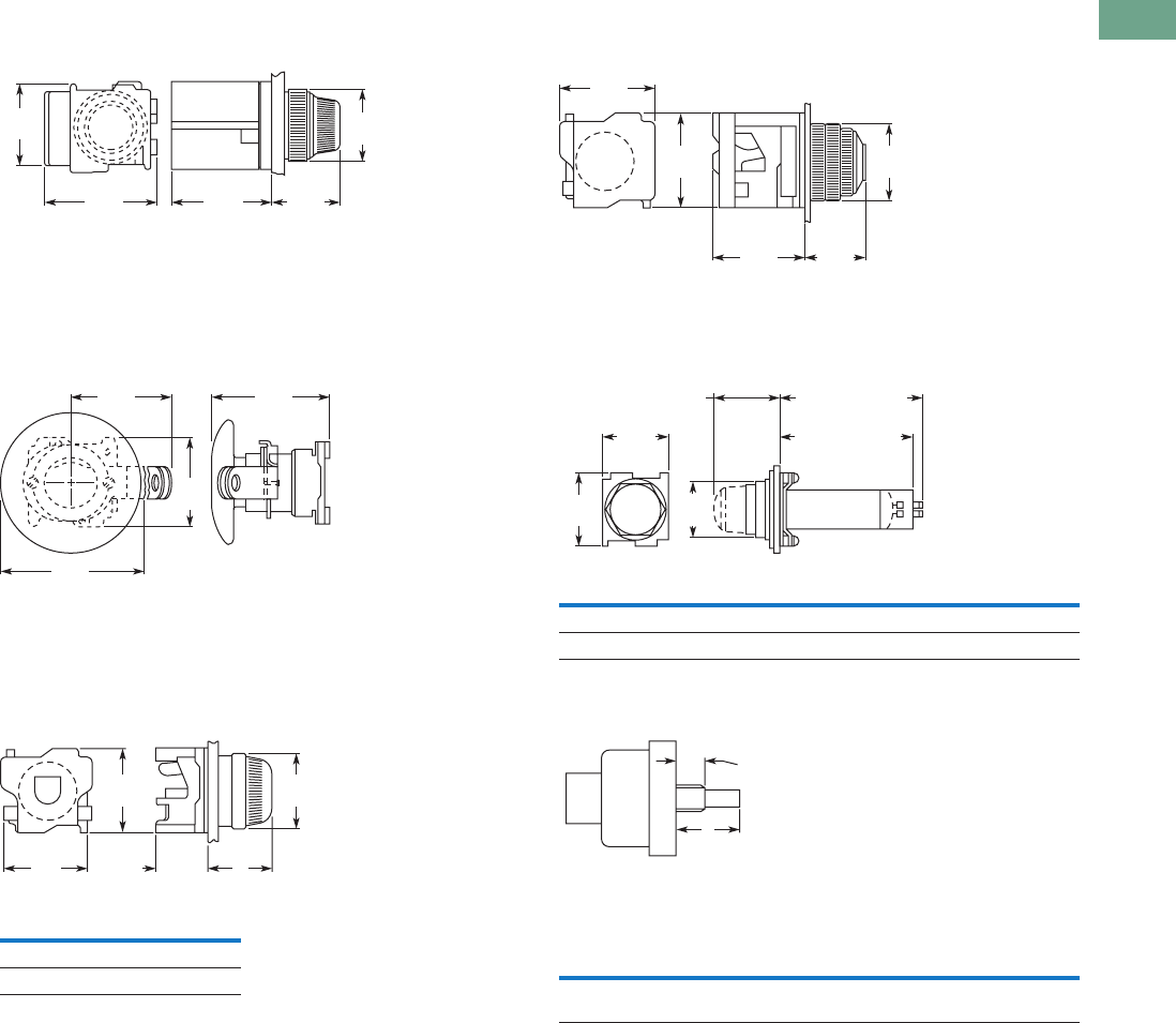
Logic Control Products CA08100001K—June 2012 www.eatoncanada.ca T37-235
37
37
37
37
37
37
37
37
37
37
37
37
37
37
37
37
37
37
37
37
37
37
37
37
37
37
37
37
37
37
37.7
Pushbuttons and Indicating Lights
30.5 mm Heavy-Duty Watertight/Oiltight—10250T
Approximate Dimensions in Inches (mm)
PresTest Indicating Light—Transformer Type
Jumbo Mushroom Head Pushbutton Operator
with Padlock Attachment
Indicating Light—Resistor and Neon Type
PresTest Indicating Light—Resistor Type
Master Test Indicating Light
Potentiometer Shaft
Lens A
Plastic 1.38 (35.1)
Glass 1.56 (39.6)
2.19
(55.6)
1.94
(49.3)
1.56
(39.6)
1.38
(35.1)
1.78
(45.2)
2.5
(63.5)
2.31
(58.7)
2.38
(60.5)
1.75
(44.5)
1.81
(46) A
1.1
(27.9)
1.78
(45.2)
1.38
(35.1)
Description B C
Relay type 4.38 (111.2) 4.28 (108.7)
Solid-state type 2.94 (74.7) 2.88 (73.2)
Operator
Catalogue Number A B
10250T330 0.38 (9.7) dia. x
0.38 (9.7) long
0.25 (6.4) dia. x
0.63 (16) long
1.88
(47.8)
1.88
(47.8)
1.56
(39.6)
1.78
(45.2)
1.38
(35.1)
1.63
(41.4)
B
Spade Terminal
A
Screw Terminal
1.78
(45.2)
1.38
(35.1)
Plastic 1.38 (35.1)
Glass 1.59 (40.4)
Shaft Dimensions of Potentiometer
That C-H Operator Will Accept
A
B
Shaft
Threaded
Bushing
Tab37book.fm Page 235 Tuesday, July 3, 2012 10:46 PM
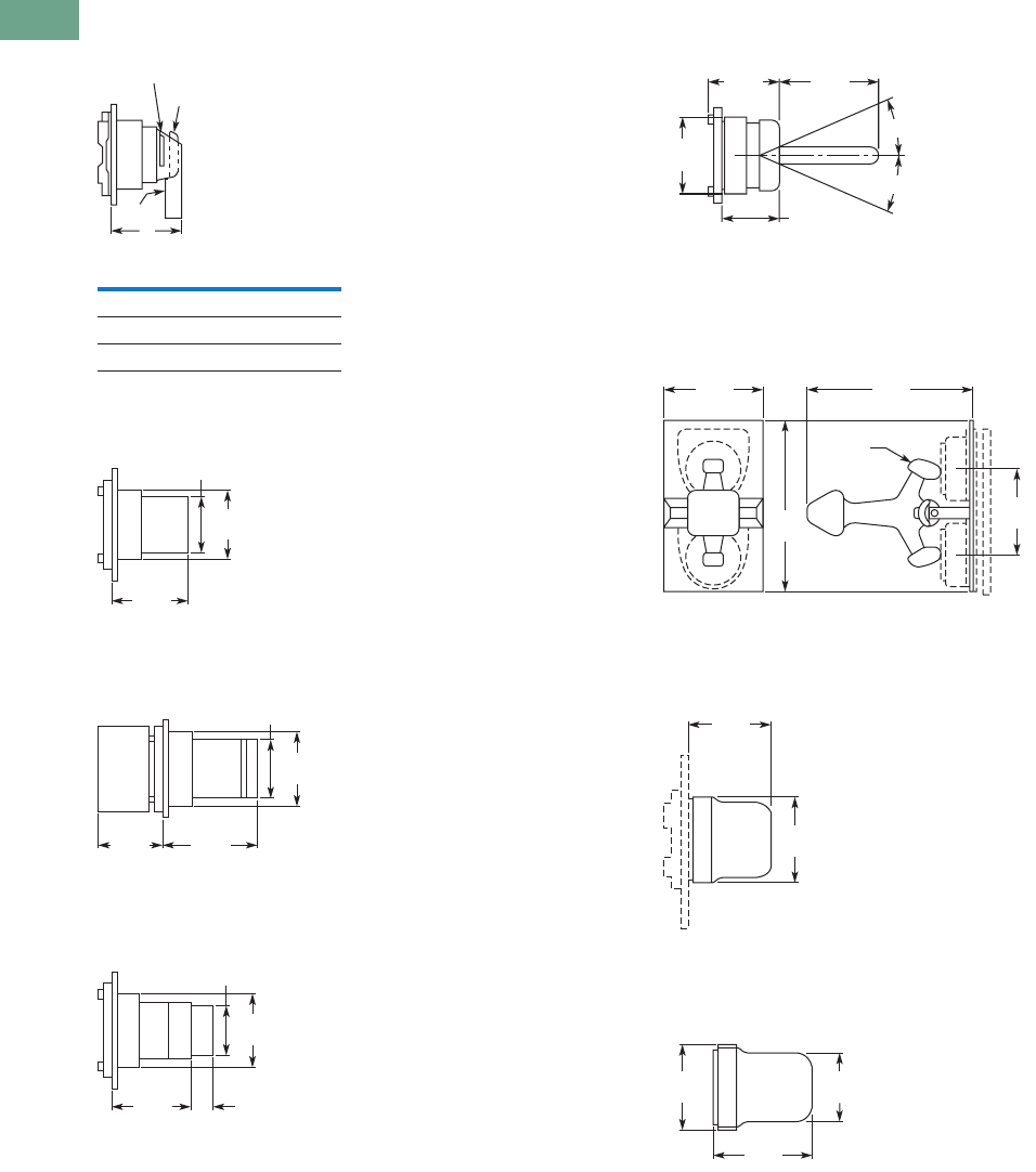
T37-236 Logic Control Products CA08100001K—June 2012 www.eatoncanada.ca
37
37
37
37
37
37
37
37
37
37
37
37
37
37
37
37
37
37
37
37
37
37
37
37
37
37
37
37
37
37
37.7
Pushbuttons and Indicating Lights
30.5 mm Heavy-Duty Watertight/Oiltight—10250T
Approximate Dimensions in Inches (mm)
Coin Operated Selector Switch
Key Operated Selector Switch
Illuminated Selector Switch
Roto-Push
Wobble Stick Catalogue No. 10250TA5
Lever Operator—For Use with Two
Vertically Mounted Flush Pushbuttons
Catalogue No. 10250TA14
Flexible Boot—For Protecting
Flush or Long Pushbutton
Catalogue No. 10250TA3 Typical
Transparent Flexible Boot—
For Illuminated Pushbutton
Catalogue No. 10250TA25
Operator Dim. A
Knob 1.38 (35.1)
Lever 1.50 (38.1)
Coin slot 1.38 (35.1)
A
Lever
Knob
Coin Slot
1.38
(35.1)
1.13
(28.7)
1.75
(44.5)
1.38
(35.1)
1.13
(28.7)
1.09
(27.7) 1.96
(49.8)
1.38
(35.1)
1.13
(28.7)
1.53
(38.9)
0.38 (9.7)
Long
Button
Only
1.38
(35.1)
1.44
(36.6)
1.22
(31)
2.44
(62)
21°
21°
1.88
(47.8)
3.75
(95.3)
2.19
(55.6) 3.59
(91.2)
Cam
1.59
(40.4)
1.47
(37.3)
1.33
(33.8)
1.59
(40.4)
1.88
(47.8)
Tab37book.fm Page 236 Tuesday, July 3, 2012 10:46 PM
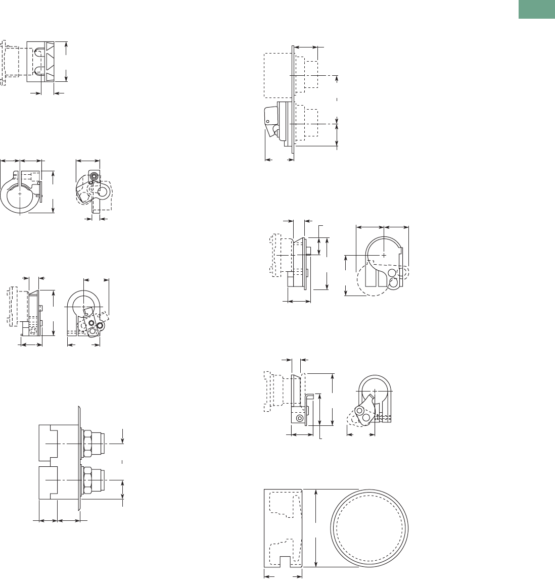
Logic Control Products CA08100001K—June 2012 www.eatoncanada.ca T37-237
37
37
37
37
37
37
37
37
37
37
37
37
37
37
37
37
37
37
37
37
37
37
37
37
37
37
37
37
37
37
37.7
Pushbuttons and Indicating Lights
30.5 mm Heavy-Duty Watertight/Oiltight—10250T
Approximate Dimensions in Inches (mm)
Padlock Attachment—For Knob Selector Switch
Catalogue No. 10250TA11
Padlock Attachment—For Flush Pushbutton
Catalogue No. 10250TA2
Padlock Attachment—For Extended Pushbutton
Catalogue No. 10250TA26
Maintained Pushbutton
Catalogue No. 10250TA66 Typical
Maintained Contact Attachment
Catalogue No. 10250TA17 Typical
Padlock Cover Guard for Flush Pushbutton
Catalogue No. 10250TA36
Padlock Attachment for Maintained Push-Pull Operator
Catalogue No. 10250TA64
Protecting Shroud for Jumbo Mushroom Head Button
Catalogue No. 10250TA56
1.63
(41.4)
0.44
(11.2)
0.75
(19.1) 0.84
(21.3)
0.94
(23.9)
1.63
(41.4)
0.25
(6.4)
2.06
(52.3)
0.38
(9.7)
0.84
(21.3) 1.5
(38.1)
1.06
(26.9)
0.89
(22.6)
Adjustable
0.88
(22.4)
for Each
Additional
Contact
Block
1.07
(27.2)
1.62 (41.1)
Min.
2.5 (63.5)
Max.
0.97
(24.6)
0.91
(23.1)
1.63 (41.4)
Min.
2.31 (58.7)
Max.
1.13
(28.7)
0.38
(9.7)
1.16
(29.5) 1.0
(25.4)
1.91
(48.5)
2.19
(55.6)
0.75
(19.1)
0.91
(23.1)
2.19
(55.6)
1.47
(37.3)
1.25
(31.8)
0.38
(9.7)
0.94
(23.9)
1.65
(41.9)
3.25
(82.6)
Tab37book.fm Page 237 Tuesday, July 3, 2012 10:46 PM

T37-238 Logic Control Products CA08100001K—June 2012 www.eatoncanada.ca
37
37
37
37
37
37
37
37
37
37
37
37
37
37
37
37
37
37
37
37
37
37
37
37
37
37
37
37
37
37
37.7
Pushbuttons and Indicating Lights
30.5 mm Heavy-Duty Watertight/Oiltight—10250T
Approximate Dimensions in Inches (mm)
Protecting Shroud for
Mushroom Head Button
Catalogue No. 10250TA6
Protecting Shroud for
Illuminated Pushbutton
Catalogue No. 10250TA15
Padlock Hasp or
Flip-Up Guard
Catalogue No. 10250TA38
Extended Retaining Nut
Catalogue No. 10250TA12
Lever for
Roto-Push Operator
Catalogue No. 10250TA13
1.53
(38.9)
1.69
(42.9)
1.75
(44.5)
1.50
(38.1)
0.84
(21.3) 1.50
(38.1)
1.75
(44.5)
1.38
(35.1)
1.31
(33.3)
1.25
(31.8)
0.44
(11.2)
1.81
(46)
Panel Drilling and Minimum Spacing
Notes
Locating nib hole or notch is 1.36–1.4 in (34.5–35.6 mm) #29 drill.
If jumbo plates are to be placed one above the other vertically, add 0.13 (3.3) to minimum
dimensions listed.
Legend
Plate
A
Min.
B
Min.
1 or 2 Circuit Contact Blocks
Small or none 1.63 (41.4) 2.25 (57.2)
Standard 1.75 (44.5) 2.25 (57.2)
Jumbo 2.25 (57.2) 2.25 (57.2)
Extra large 2.50 (63.5) 2.60 (66)
4 Circuit Contact Block 10250T44
Small or none 1.88 (47.8) 2.25 (57.2)
Standard 1.88 (47.8) 2.25 (57.2)
Jumbo 2.25 (57.2) 2.25 (57.2)
Extra large 2.50 (63.5) 2.60 (66)
B
Min.
A
Min.
0.6
(15.2)
A
Min. 1.22
(31)
B
Min.
Horizontal Rows Vertical Rows
Terminals on Top
Terminals at
Side
Tab37book.fm Page 238 Tuesday, July 3, 2012 10:46 PM
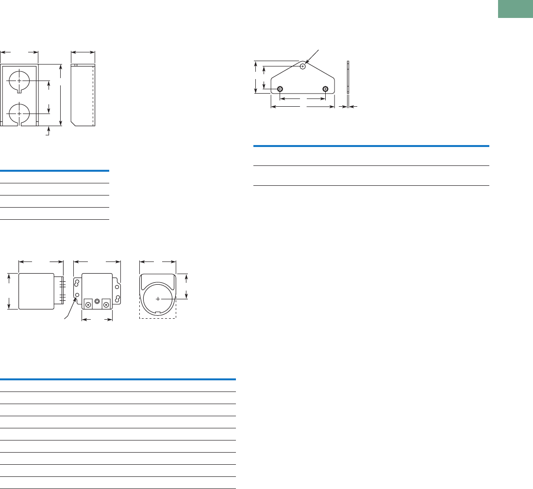
Logic Control Products CA08100001K—June 2012 www.eatoncanada.ca T37-239
37
37
37
37
37
37
37
37
37
37
37
37
37
37
37
37
37
37
37
37
37
37
37
37
37
37
37
37
37
37
37.7
Pushbuttons and Indicating Lights
30.5 mm Heavy-Duty Watertight/Oiltight—10250T
Approximate Dimensions in Inches (mm)
Multiple Button Guard
Master Test Module, Flasher Module and Legend Plate
Notes
Locating nib hole or notch is 1.36–1.4 in (34.5–35.6 mm) #29 drill.
For plastic legend plate, Dimension B is 1.12 (28.4).
Chain Hook Bracket
Number of
Elements A
2 4.0 (101.6)
3 5.88 (149.4)
4 7.88 (200.2)
7 13.38 (339.9)
Legend
Plate AB
1/2 Round Legend Plates
Small 1.56 (39.6) 0.91 (23.1)
Standard 1.59 (40.4) 1.07 (27.2)
Jumbo 2.06 (52.3) 1.53 (38.9)
Square Legend Plates
Small 1.59 (40.4) sq. 0.90 (22.9)
Standard 1.75 (44.5) sq. 1.06 (26.9)
Jumbo 2.19 (55.6) sq. 1.50 (38.1)
Extra large 2.44 (62.0) sq. 1.63 (41.4)
2.16
(54.9)
1.31
(33.3)
1.88
(47.8)
0.75
(19.1)
A
1.63
(41.4)
1.14
(29)
6 Mounting Holes
1.78
(45.2) A
1.31
(33.3)
Master Test Module,
Flasher Module
Legend Plate
B
Enclosure Size
(No. of Elements)
Wide
A
High
B
Deep
C
Mounting
DE
2, 3 and 4 3.75
(95.3)
1.94
(49.3)
0.13
(3.3)
2.69
(68.3)
1.38
(35.1)
6 and 7 4.0
(101.6)
2.19
(55.6)
0.13
(3.3)
2.88
(73.2)
1.63
(41.4)
A C
D
BE
0.38 (9.7)
Dia. Hole
Tab37book.fm Page 239 Tuesday, July 3, 2012 10:46 PM
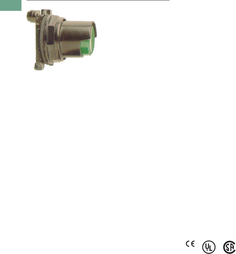
T37-240 Logic Control Products CA08100001K—June 2012 www.eatoncanada.ca
37
37
37
37
37
37
37
37
37
37
37
37
37
37
37
37
37
37
37
37
37
37
37
37
37
37
37
37
37
37
37.8
Pushbuttons and Indicating Lights
30.5 mm Corrosion Resistant Watertight/Oiltight—E34
30.5 mm Corrosion Resistant Watertight/Oiltight—E34 Contents
Description Page
30.5 mm Corrosion Resistant Watertight/Oiltight—E34
Product Overview . . . . . . . . . . . . . . . . . . . . . . . . . T37-241
Product Identification . . . . . . . . . . . . . . . . . . . . . . . T37-242
Catalogue Number Selection . . . . . . . . . . . . . . . . . T37-243
Ordering Complete Devices . . . . . . . . . . . . . . . . . . T37-245
Product Selection
Non-Illuminated Momentary
Pushbutton Units . . . . . . . . . . . . . . . . . . . . . . T37-246
Plastic Lens Indicating Light Units . . . . . . . . . . T37-246
Pushbuttons . . . . . . . . . . . . . . . . . . . . . . . . . . . T37-247
Illuminated Pushbuttons and
Indicating Lights . . . . . . . . . . . . . . . . . . . . . . . T37-248
Push-Pull Units . . . . . . . . . . . . . . . . . . . . . . . . . T37-250
Illuminated Push-Pull Units . . . . . . . . . . . . . . . . T37-251
Potentiometers . . . . . . . . . . . . . . . . . . . . . . . . . T37-253
Push-Pull Operators . . . . . . . . . . . . . . . . . . . . . T37-254
Selector Switch Units . . . . . . . . . . . . . . . . . . . . T37-258
Selector Switch Selection . . . . . . . . . . . . . . . . . T37-259
Selector Switch Operators . . . . . . . . . . . . . . . . T37-262
Key Operators . . . . . . . . . . . . . . . . . . . . . . . . . . T37-262
Illuminated Selector Switch Operators . . . . . . . T37-264
Accessories . . . . . . . . . . . . . . . . . . . . . . . . . . . . . . T37-265
Options . . . . . . . . . . . . . . . . . . . . . . . . . . . . . . . . . T37-267
Replacement Parts . . . . . . . . . . . . . . . . . . . . . . . . . T37-273
Technical Data and Specifications . . . . . . . . . . . . . T37-275
Dimensions . . . . . . . . . . . . . . . . . . . . . . . . . . . . . . T37-278
Product Description
Eaton’s E34 Series 30.5 mm
pushbutton line features the
same rugged die cast
construction of our 10250T
line with an additional
two-layer 100% solid
thermosetting cathodic epoxy
coating. This coating provides
a flat black smooth,
consistent, corrosion
resistant surface that has
passed a demanding 600
hour salt spray test. (The
industry standard for this 4X
test requires only 200 hours.)
Features
●Epoxy-coated metal
operators
●Corrosion resistant
●Integral ground screw
terminal on operators
●FDA approved for sanitary
chemical resistance
requirements
Standards and
Certifications
●CE EN60947-5-1 and
60947-5-5
●UL 508—File No. E131568
●CSA C22.2 No. 14—File
No. LR68551
●FDA 3-A Sanitary
Standards
Ingress Protection
When mounted in similarly
rated enclosure—
●Standard indicating lights
●UL (NEMA) Type 1, 2, 3,
3R, 3S, 4, 4X, 12, 13
●IEC IP65
●All other operators
●UL (NEMA) Type 1, 2, 3,
3R, 4, 4X, 12, 13
●IEC IP65
Tab37book.fm Page 240 Tuesday, July 3, 2012 10:46 PM
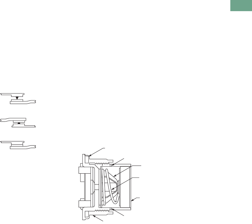
Logic Control Products CA08100001K—June 2012 www.eatoncanada.ca T37-241
37
37
37
37
37
37
37
37
37
37
37
37
37
37
37
37
37
37
37
37
37
37
37
37
37
37
37
37
37
37
37.8
Pushbuttons and Indicating Lights
30.5 mm Corrosion Resistant Watertight/Oiltight—E34
Product Overview
Ultraviolet Light
E34 cathodic coating is not
recommended for use in
applications where exposure
to ultraviolet light exists—use
NEMA 4X 10250T operators.
Reliability Nibs
Eaton’s contact blocks
feature enclosed silver
contacts with pointed
“reliability nibs” for reliable
performance from logic level
up to 600V. To ensure reliable
switching, nibs bite through
oxide which can form on silver
contacts, eliminating the
need for expensive logic level
blocks for most applications.
Reliability Nibs
Dry Circuit
Medium Duty
Heavy-Duty
Diaphragm Seal with
Drainage Holes
Liquid Drainage
Eaton’s pushbutton operators
offer front of panel drainage
via holes in the operator
bushing. Hidden from view
by the mounting nut, these
holes prevent buildup of
liquid inside the operator,
which can prevent operation
in freezing environments. The
holes also provide a route for
escaping liquid in high
pressure washdowns,
effectively relieving pressure
from the internal diaphragm
seal, ensuring reliable sealing
in applications even beyond
NEMA 4.
Diaphragm Seal
Foam Neoprene
Panel Sealing Gasket
Drainage Hole
Drainage Hole
Flexible
Diaphragm
Stainless
Steel
Operating
Spring
Mounting Nut
Colorfast
Molded
Button
Tab37book.fm Page 241 Tuesday, July 3, 2012 10:46 PM
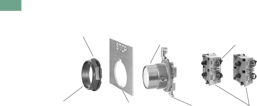
T37-242 Logic Control Products CA08100001K—June 2012 www.eatoncanada.ca
37
37
37
37
37
37
37
37
37
37
37
37
37
37
37
37
37
37
37
37
37
37
37
37
37
37
37
37
37
37
37.8
Pushbuttons and Indicating Lights
30.5 mm Corrosion Resistant Watertight/Oiltight—E34
Product Identification
30.5 mm Corrosion Resistant Watertight/Oiltight—E34 Series
Octagonal Mounting Nut Self-Adjusts to
Panel Thickness—Eliminates Spacer Washers
and Set Screws
Internal Sealing Diaphragm
for Excellent Sealing
Terminal Clamps Shipped
Open Ready to Wire
Three Styles of Legend Plates
in Four Sizes Wide Variety of Operator
Types and Colors
Die Cast Construction with Thick,
Tough Corrosion Resistant Coating Stackable Contact Blocks up
to 12 Circuits per Operator
Tab37book.fm Page 242 Tuesday, July 3, 2012 10:46 PM
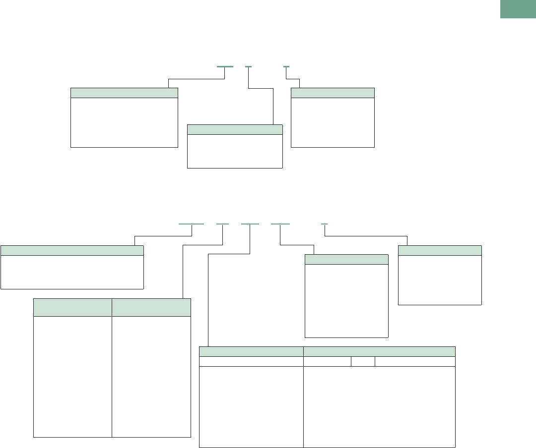
Logic Control Products CA08100001K—June 2012 www.eatoncanada.ca T37-243
37
37
37
37
37
37
37
37
37
37
37
37
37
37
37
37
37
37
37
37
37
37
37
37
37
37
37
37
37
37
37.8
Pushbuttons and Indicating Lights
30.5 mm Corrosion Resistant Watertight/Oiltight—E34
Catalogue Number Selection
Catalogue Number Selection is for illustrative purposes only and not to be used to create new catalogue numbers.
Non-Illuminated Pushbuttons
Illuminated and Non-Illuminated Push-Pulls
Note
Add X at end of catalogue number to receive parts assembled from factory.
E34 PB 1 –1
Operator
PB = Flush
EB = Extended
LB = 40 mm mushroom
JB = 65 mm mushroom
EVB = 1/2 shroud vertical mount
EHB = 1/2 shroud horizontal mount
Circuit
Blank = Operator only
1 = 1NO-1NC
2 = 2NO
3 = 2NC
51 = 1NC
53 = 1NO
Button Colour
1 = Black
2 = Red
3 = Green
4 = Yellow
7 = Gray
5 = White
6 = Blue
8 = Orange
E34 GDB 63 M2 –1
Circuit
Blank = Operator only
1 = 1NO-1NC
2 = 2NO
3 = 2NC
51 = 1NC
53 = 1NO
Incandescent
Light Unit
LED
Light Unit
Blank = Non-illuminated
89 = 24V/XFR
63 = 120V/XFR
64 = 208V/XFR
65 = 240V/XFR
82 = 277V/XFR
66 = 380V/XFR
67 = 480V/XFR
68 = 600V/XFR
69 = 6V/FV
70 = 12V/FV
79 = 24V/FV
83 = 32V/FV
80 = 120V/RES
81 = 240V/RES
Blank = Non-illuminated
89L = 24V/XFR
63L = 120V/XFR
64L = 208V/XFR
65L = 240V/XFR
82L = 277V/XFR
66L = 380V/XFR
67L = 480V/XFR
68L = 600V/XFR
97L = Full voltage
Non-Illuminated Illuminated
Button Incandescent LED Lens Type
C1 = Black 40 mm
C2 = Red 40 mm
C2N8 = Red 40 mm—“E” STOP
C3 = Green 40 mm
C6 = Blue 40 mm
— = Black 65 mm
J2 = Red 65 mm
J2N8 = Red 65 mm—“E” STOP
— = Green 65 mm
— = Yellow 65 mm
M2 =
M2N8 =
M3 =
M6 =
M9 =
M5 =
M0 =
RD =
ED =
GD =
LD =
AD =
WD =
— =
Red 40 mm
Red 40 mm—“E” STOP
Green 40 mm
Blue 40 mm
Amber 40 mm
White 40 mm
Clear 40 mm
LED Voltage
Blank = Non-illuminated
Blank = Incandescent
06 = 6 Vac/Vdc
12 = 12 Vac/Vdc
24 = 24 Vac/Vdc
48 = 48 Vac/Vdc
60 = 60 Vac/Vdc
2A = 120 Vac
2D = 120 Vdc
Operator
GDB = Two-position maintained
GEB = Three-position mom push-mom pull
GFB = Three-position mt push-mom pull
GHB = Three-position mom push-mom pull
Tab37book.fm Page 243 Tuesday, July 3, 2012 10:46 PM
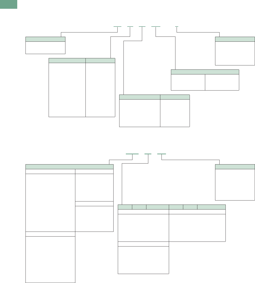
T37-244 Logic Control Products CA08100001K—June 2012 www.eatoncanada.ca
37
37
37
37
37
37
37
37
37
37
37
37
37
37
37
37
37
37
37
37
37
37
37
37
37
37
37
37
37
37
37.8
Pushbuttons and Indicating Lights
30.5 mm Corrosion Resistant Watertight/Oiltight—E34
Catalogue Number Selection is for illustrative purposes only and not to be used to create new catalogue numbers.
Illuminated Pushbuttons
Standard Indicating Lights, PresTest and Master Test
Note
Add X at end of catalogue number to receive parts assembled from factory.
Circuit
Blank = Operator only
1 = 1NO-1NC
2 = 2NO
3 = 2NC
51 = 1NC
53 = 1NO
Light Unit Type
XB = Transformer
CB = Full voltage
SB = Resistor
Incandescent Light Unit LED Light Unit
024 = 24V/XFR
120 = 120V/XFR
240 = 240V/XFR
277 = 277V/XFR
380 = 380V/XFR
480 = 480V/XFR
600 = 600V/XFR
06 = 6V/FV
12 = 12V/FV
24 = 24V/FV
32 = 32V/FV
48 = 48V/FV
120 = 120V/RES
240 = 240V/RES
024L = 24V/XFR
120L = 120V/XFR
240L = 240V/XFR
277L = 277V/XFR
380L = 380V/XFR
480L = 480V/XFR
600L = 600V/XFR
397L = Full voltage
LED Voltage
Blank = Incandescent
06 = 6 Vac/Vdc
12 = 12 Vac/Vdc
24 = 24 Vac/Vdc
48 = 48 Vac/Vdc
60 = 60 Vac/Vdc
2A = 120 Vac
2D = 120 Vdc
Incandescent Lens Colour LED Lens Colour
V2 = Red
V3 = Green
V4 = Yellow
V5 = White
V6 = Blue
V9 = Amber
V0 = Clear
RD = Red
GD = Green
YD = Yellow
WD = White
LD = Blue
AD = Amber
E34 XB 24 V2 –1
LED Voltage
Blank = Incandescent
06 = 6 Vac/Vdc
12 = 12 Vac/Vdc
24 = 24 Vac/Vdc
48 = 48 Vac/Vdc
60 = 60 Vac/Vdc
2A = 120 Vac
2D = 120 Vdc
Plastic Glass Lens Colour Plastic Glass Lens Colour
Standard/Master—Incandescent Standard/Master/PresTest—LED
H2 =
H3 =
H4 =
H5 =
H6 =
H9 =
H0 =
G2 =
G3 =
G4 =
G5 =
G6 =
G9 =
G0 =
Red
Green
Yellow
White
Blue
Amber
Clear
RP =
GP =
YP =
WP =
LP =
AP =
RG =
GG =
YG =
WG =
LG =
AG =
Red
Green
Yellow
White
Blue
Amber
PresTest—Incandescent
V2 =
V3 =
V4 =
V5 =
V6 =
V9 =
V0 =
P2 =
P3 =
P4 =
P5 =
P6 =
P9 =
P0 =
Red
Green
Yellow
White
Blue
Amber
Clear
Light Unit Type
Standard—Incandescent Standard—LED
TB120 =
TB240 =
TB277 =
TB380 =
TB480 =
TB600 =
FB06 =
FB12 =
FB24 =
FB32 =
FB48 =
RB120 =
RB240 =
NB120 =
NB240 =
120V/XFR
240V/XFR
277V/XFR
380V/XFR
480V/XFR
600V/XFR
6V/FV
12V/FV
24V/FV
32V/FV
48V/FV
120V/RES
240V/RES
120V/neon
240V/neon
TB120L =
TB240L =
TB277L =
TB380L =
TB480L =
TB600L =
FB197L =
120V/XFR
240V/XFR
277V/XFR
380V/XFR
480V/XFR
600V/XFR
Full voltage
PresTest—LED
TPB120L =
TPB240L =
TPB380L =
TPB480L =
TPB600L =
FPB297L =
120V/XFR
240V/XFR
380V/XFR
480V/XFR
600V/XFR
Full voltage
PresTest—Incandescent
TPB120 =
TPB240 =
TPB380 =
TPB480 =
TPB600 =
FPB06 =
FPB12 =
FPB24 =
FPB32 =
FPB48 =
RPB120 =
RPB240 =
120V/XFR
240V/XFR
380V/XFR
480V/XFR
600V/XFR
6V/FV
12V/FV
24V/FV
32V/FV
48V/FV
120V/RES
240V/RES
E34 FB06 H2
Tab37book.fm Page 244 Tuesday, July 3, 2012 10:46 PM

Logic Control Products CA08100001K—June 2012 www.eatoncanada.ca T37-245
37
37
37
37
37
37
37
37
37
37
37
37
37
37
37
37
37
37
37
37
37
37
37
37
37
37
37
37
37
37
37.8
Pushbuttons and Indicating Lights
30.5 mm Corrosion Resistant Watertight/Oiltight—E34
Catalogue Number Selection is for illustrative purposes only and not to be used to create new catalogue numbers.
Ordering Complete Devices
Complete E34 pushbuttons,
indicating lights and/or
selector switch operators
including contact block(s) and
legend plate can be ordered
using a single composite
catalogue number. The
individually packaged
components will be shipped
unassembled in a single
overpack carton marked with
the composite catalogue
number.
Ordering Example
Illuminated Pushbutton
Device—Catalogue Number
E34XB120V2-153SP90
For a complete Catalogue
Number breakdown, see
Pages T37-243 to
T37-244.
For Complete E34 Device Ordering
Operator Legend Plate
E34;SP90
Insert Hyphen Before
Contact Block(s)
Lens
E34V2 Contact Blocks
10250T1 and 10250T53
E34XB120 V2 – 153 SP90
Tab37book.fm Page 245 Tuesday, July 3, 2012 10:46 PM
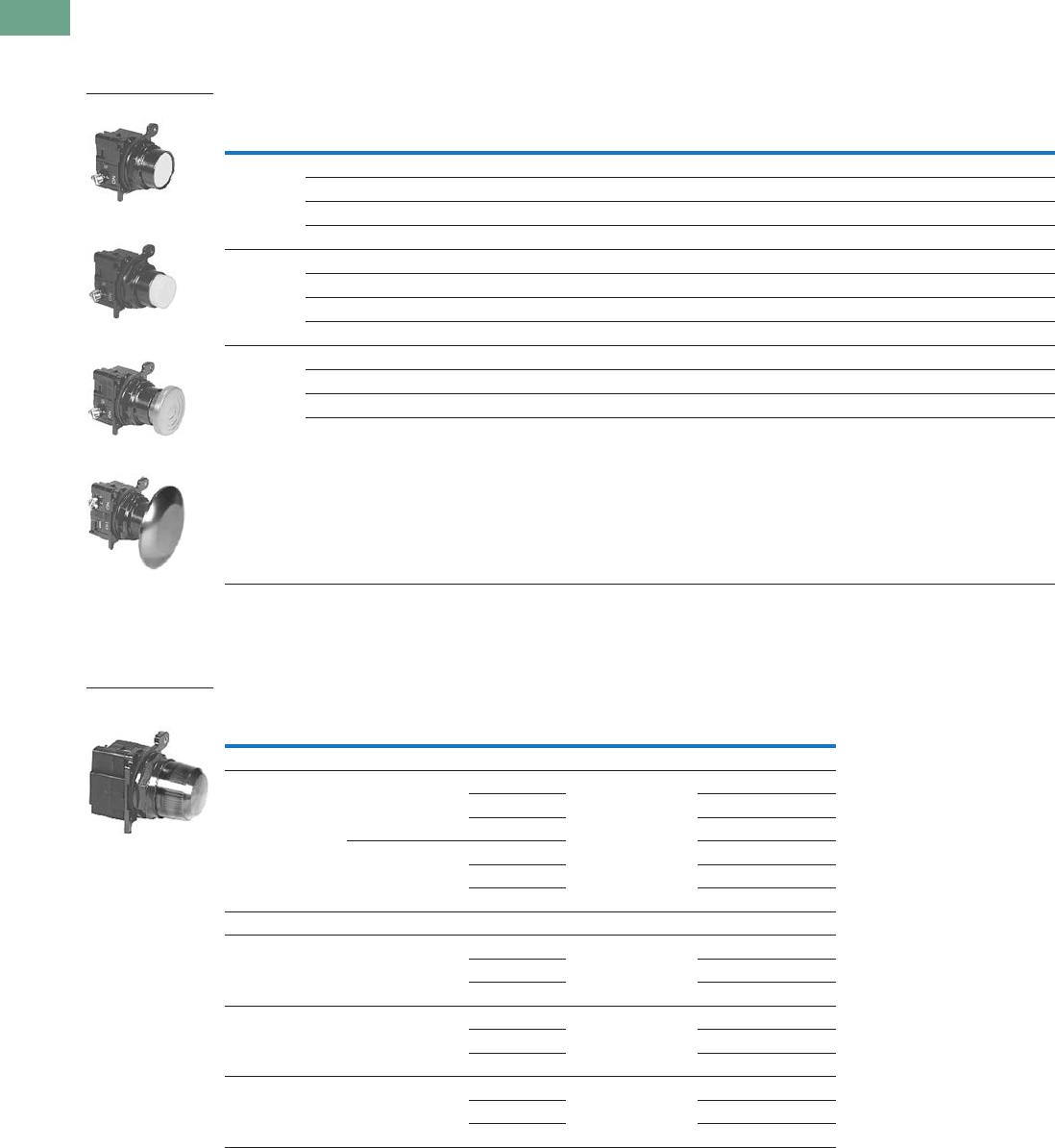
T37-246 Logic Control Products CA08100001K—June 2012 www.eatoncanada.ca
37
37
37
37
37
37
37
37
37
37
37
37
37
37
37
37
37
37
37
37
37
37
37
37
37
37
37
37
37
37
37.8
Pushbuttons and Indicating Lights
30.5 mm Corrosion Resistant Watertight/Oiltight—E34
Product Selection
Non-Illuminated Momentary Pushbutton Units
UL (NEMA) Type 3, 3R, 4, 4X, 12, 13
Pushbutton Units
Plastic Lens Indicating Light Units
UL (NEMA) Type 3, 3R, 4, 4X, 12, 13
Indicating Light Units
Notes
Use NEMA 4X 10250T operators where exposed to ultraviolet light, see Pages T37-167 to T37-239.
Anodized aluminum head—may not be suitable for some corrosive environments.
Contact
Type Button Colour
Flush Button
Catalogue Number
Extended Button
Catalogue Number
Mushroom Button
Catalogue Number
Jumbo Mushroom
Catalogue Number
1NO Black E34PB1-53X E34EB1-53X E34LB1-53X E34JB1-53X
Red E34PB2-53X E34EB2-53X E34LB2-53X E34JB2-53X
Green E34PB3-53X E34EB3-53X E34LB3-53X E34JB3-53X
Red—Engraved EMERG. STOP — — — E34JB2N8-53X
1NC Black E34PB1-51X E34EB1-51X E34LB1-51X E34JB1-51X
Red E34PB2-51X E34EB2-51X E34LB2-51X E34JB2-51X
Green E34PB3-51X E34EB3-51X E34LB3-51X E34JB3-51X
Red—Engraved EMERG. STOP — — — E34JB2N8-51X
1NO-1NC Black E34PB1-1X E34EB1-1X E34LB1-1X E34JB1-1X
Red E34PB2-1X E34EB2-1X E34LB2-1X E34JB2-1X
Green E34PB3-1X E34EB3-1X E34LB3-1X E34JB3-1X
Red—Engraved EMERG. STOP — — — E34JB2N8-1X
Type Voltage Colour
LED/Lamp
Number
Indicating Light
Catalogue Number
LED Lamp;
Full voltage 24 Vac/Vdc Red Bayonet base E34FB197LRP24
Green E34FB197LGP24
Amber E34FB197LAP24
120 Vac Red E34FB197LRP2A
Green E34FB197LGP2A
Amber E34FB197LAP2A
Incandescent Lamp
Full voltage 24 Vac/Vdc Red #757 E34FB24H2X
Green E34FB24H3X
Amber E34FB24H9X
Resistor 120 Vac/Vdc Red 120MB E34RB120H2X
Green E34RB120H3X
Amber E34RB120H9X
Transformer 120 Vac
50/60 Hz
Red #755 E34TB120H2X
Green E34TB120H3X
Amber E34TB120H9X
Flush Button
Extended Button
Mushroom Button
Jumbo Mushroom
24V Full Voltage
Indicating Light
Tab37book.fm Page 246 Tuesday, July 3, 2012 10:46 PM
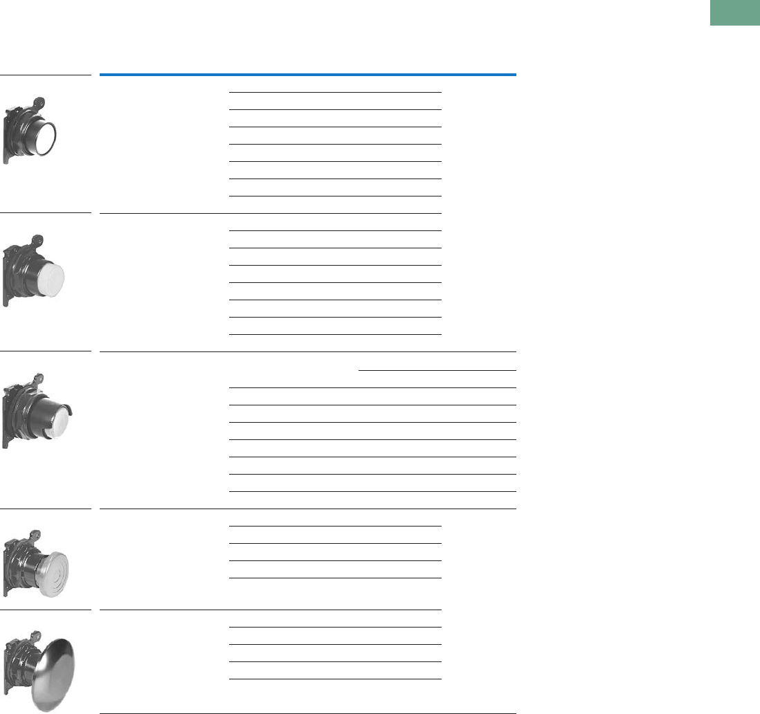
Logic Control Products CA08100001K—June 2012 www.eatoncanada.ca T37-247
37
37
37
37
37
37
37
37
37
37
37
37
37
37
37
37
37
37
37
37
37
37
37
37
37
37
37
37
37
37
37.8
Pushbuttons and Indicating Lights
30.5 mm Corrosion Resistant Watertight/Oiltight—E34
Pushbuttons
UL (NEMA) Type 3, 3R, 4, 4X, 12, 13
Momentary Pushbutton Operators, Non-Illuminated
Notes
Use NEMA 4X 10250T operators where exposed to ultraviolet light, see Pages T37-167 to T37-239.
Anodized aluminum head—may not be suitable for some corrosive environments.
Button Colour Catalogue Number
Flush button Black E34PB1
Red E34PB2
Green E34PB3
Yellow E34PB4
White E34PB5
Blue E34PB6
Gray E34PB7
Orange E34PB8
Extended button Black E34EB1
Red E34EB2
Green E34EB3
Yellow E34EB4
White E34EB5
Blue E34EB6
Gray E34EB7
Orange E34EB8
Half shrouded button Vertical Horizontal
Black E34EVB1 E34EHB1
Red E34EVB2 E34EHB2
Green E34EVB3 E34EHB3
Yellow E34EVB4 E34EHB4
White E34EVB5 E34EHB5
Blue E34EVB6 E34EHB6
Gray E34EVB7 E34EHB7
Orange E34EVB8 E34EHB8
Mushroom button Black E34LB1
Red E34LB2
Green E34LB3
Yellow E34LB4
Blue E34LB6
Anodized aluminum jumbo
mushroom button
Black E34JB1
Red E34JB2
Red (Engraved EMERG. STOP) E34JB2N8
Green E34JB3
Yellow E34JB4
E34PB_
E34EB_
E34EHB_
E34LB_
E34JB_
Tab37book.fm Page 247 Tuesday, July 3, 2012 10:46 PM
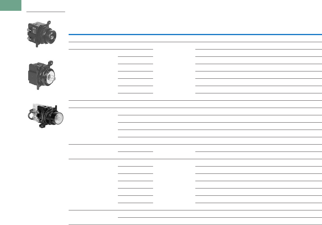
T37-248 Logic Control Products CA08100001K—June 2012 www.eatoncanada.ca
37
37
37
37
37
37
37
37
37
37
37
37
37
37
37
37
37
37
37
37
37
37
37
37
37
37
37
37
37
37
37.8
Pushbuttons and Indicating Lights
30.5 mm Corrosion Resistant Watertight/Oiltight—E34
Illuminated Pushbuttons and Indicating Lights
Operators without Lens
Notes
Use NEMA 4X 10250T operators where exposed to ultraviolet light, see Pages T37-167 to T37-239.
These units do not include lamps. Order LED separately to match lens colour, see Page T37-225 for LED Selection and Pages T37-243 to T37-244 for Catalogue Numbering
Selection.
Resistor units are not available for use with LEDs, choose either transformer or full voltage LED style.
Type Voltage Lamp Number
Illuminated
Pushbutton
Catalogue Number
Indicating
Light
Catalogue Number
PresTest
Catalogue Number
LED Lamp (LEDs not included)
Full voltage — Bayonet
base
E34CB497L E34FB197L E34FPB297L
Transformer AC only 24 E34XB024L — —
120 E34XB120L E34TB120L E34TPB120L
240 E34XB240L E34TB240L E34TPB240L
277 E34XB277L E34TB277L —
380 E34XB380L E34TB380L E34TPB380L
480 E34XB480L E34TB480L E34TPB480L
600 E34XB600L E34TB600L E34TPB600L
Incandescent Lamp
Full voltage AC/DC 6 #755 E34CB06 E34FB06 E34FPB06
12 #756 E34CB12 E34FB12 E34FPB12
24 #757 E34CB24 E34FB24 E34FPB24
32 #1828 E34CB32 E34FB32 E34FPB32
48 #1835 E34CB48 E34FB48 E34FPB48
Resistor AC/DC 120 120MB E34SB120 E34RB120 E34RPB120
240 E34SB240 E34RB240 E34RPB240
Transformer AC only 24 #755 E34XB024 — —
120 E34XB120 E34TB120 E34TPB120
240 E34XB240 E34TB240 E34TPB240
277 E34XB277 E34TB277 —
380 E34XB380 E34TB380 E34TPB380
480 E34XB480 E34TB480 E34TPB480
600 E34XB600 E34TB600 E34TPB600
Neon AC/DC 120 NE51H-R-22 — E34NB120 —
240 NE51H-4-68 — E34NB240 —
Illuminated Pushbutton
Indicating Light
PresTest
Tab37book.fm Page 248 Tuesday, July 3, 2012 10:46 PM
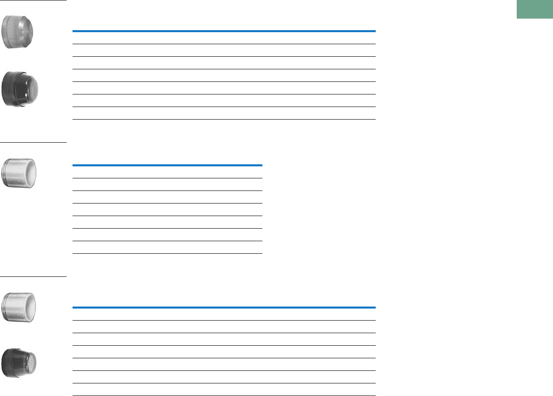
Logic Control Products CA08100001K—June 2012 www.eatoncanada.ca T37-249
37
37
37
37
37
37
37
37
37
37
37
37
37
37
37
37
37
37
37
37
37
37
37
37
37
37
37
37
37
37
37.8
Pushbuttons and Indicating Lights
30.5 mm Corrosion Resistant Watertight/Oiltight—E34
Indicating Light Lens
Illuminated Pushbutton Lens
PresTest Lens
Note
Glass lens has black anodized aluminum bezel.
Colour
Plastic
Catalogue Number
Glass
Catalogue Number
Red E34H2 E34G2
Green E34H3 E34G3
Yellow E34H4 E34G4
White E34H5 E34G5
Blue E34H6 E34G6
Ambler E34H9 E34G9
Clear E34H0 E34G0
Colour Catalogue Number
Red E34V2
Green E34V3
Yellow E34V4
White E34V5
Blue E34V6
Ambler E34V9
Clear E34V0
Colour
Plastic
Catalogue Number
Glass
Catalogue Number
Red E34V2 E34P2
Green E34V3 E34P3
Yellow E34V4 E34P4
White E34V5 E34P5
Blue E34V6 E34P6
Ambler E34V9 E34P9
Clear E34V0 E34P0
Plastic
Glass
E34V_
Plastic
Glass
Tab37book.fm Page 249 Tuesday, July 3, 2012 10:46 PM
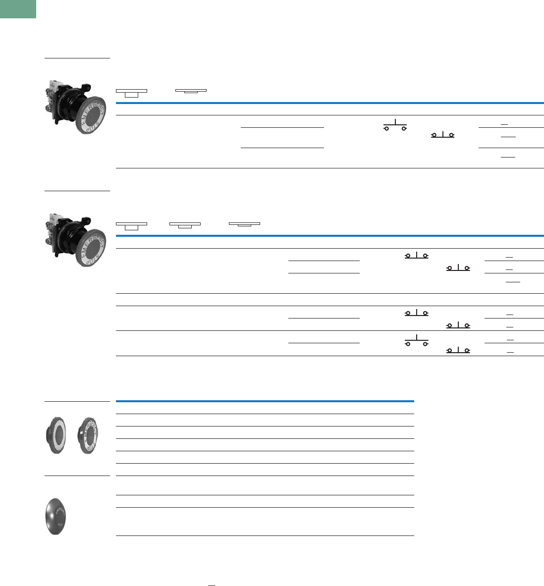
T37-250 Logic Control Products CA08100001K—June 2012 www.eatoncanada.ca
37
37
37
37
37
37
37
37
37
37
37
37
37
37
37
37
37
37
37
37
37
37
37
37
37
37
37
37
37
37
37.8
Pushbuttons and Indicating Lights
30.5 mm Corrosion Resistant Watertight/Oiltight—E34
Push-Pull Units
UL (NEMA) Type 3, 3R, 4, 4X, 12, 13
●Two- and three-position
●Non-illuminated
Two-Position Push-Pull Units, Non-Illuminated
Three-Position Push-Pull Units, Non-Illuminated
Button and Colour Selection
Notes
Use NEMA 4X 10250T operators where exposed to ultraviolet light, see Pages T37-167 to T37-239.
X = closed circuit, O = open circuit.
To order different type or colour buttons, substitute the underlined characters with appropriate suffix code
from the table. Example: E34GDBC6-1X.
Anodized aluminum may not be suitable for use on some corrosive applications.
Operator Position
Button Type/Colour
Contact
Type Catalogue Number
Pull Push Mounting Location
AB
Maintained Push, Maintained Pull
O
X
X
O
40 mm/red 1NO E34GDBC2-1X
40 mm engraved
EMERG. STOP/red
1NC E34GDBC2N8-1X
65 mm aluminum engraved
EMERG. STOP/red
E34GDBJ2N8-1X
Operator Position
Button Type/Colour
Contact
Type Catalogue Number
Pull Intermediate Push Mounting Location
AB
Maintained Push, Momentary Pull
X
X
O
X
O
O
40 mm/black 1NC E34GFBC1-3X
40 mm/red 1NC E34GFBC2-3X
40 mm engraved
EMERG. STOP/red
E34GFBC2N8-3X
Momentary Push, Momentary Pull
X
X
O
X
O
O
40 mm/black 1NC E34GEBC1-3X
40 mm/red 1NC E34GEBC2-3X
O
X
O
O
X
O
40 mm/black 1NO E34GHBC1-1X
40 mm/red 1NC E34GHBC2-1X
Colour Suffix Code Catalogue Number
Standard—40 mm
Black C1 E34C1
Red C2 E34C2
Red (EMERG. STOP) C2N8 E34C2N8
Green C3 E34C3
Blue C6 E34C6
Jumbo Mushroom Head
(Anodized) Aluminum—65 mm
Red J2 E34J2
Red (EMERG. STOP) J2N8 E34J2N8
Two-Position
Push-Pull Unit
Three-Position
Push-Pull Unit
Standard
Jumbo Mushroom
Head
Tab37book.fm Page 250 Tuesday, July 3, 2012 10:46 PM
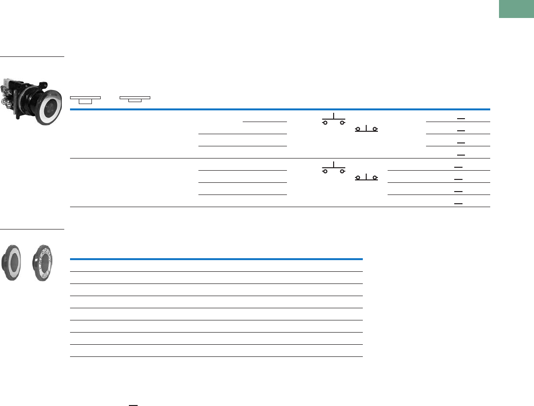
Logic Control Products CA08100001K—June 2012 www.eatoncanada.ca T37-251
37
37
37
37
37
37
37
37
37
37
37
37
37
37
37
37
37
37
37
37
37
37
37
37
37
37
37
37
37
37
37.8
Pushbuttons and Indicating Lights
30.5 mm Corrosion Resistant Watertight/Oiltight—E34
Illuminated Push-Pull Units
UL (NEMA) Type 3, 3R, 4, 4X, 12, 13
●Two-position maintained
●Illuminated
Two-Position Illuminated Maintained Push, Maintained Pull
Lens and Colour Selection
Notes
Use NEMA 4X 10250T operators where exposed to ultraviolet light, see Pages T37-167 to T37-239.
X = closed circuit, O = open circuit.
To order different type or colour lens, substitute the underlined characters with appropriate suffix code from Lens and Colour Selection table above.
Example: E34GDB79M3 -1X. For LEDs with different voltages see ordering example on Page T37-257.
Operator Position
Lamp Type Voltage
Contact
Type
LED/Lamp
Number
Red Standard
Push-Pull
Catalogue Number
Maintained—
Pull
Maintained—
Intermediate Mounting Location
AB
O
X
X
O
LED Full voltage 24 Vac/Vdc 1NO Bayonet
base
E34GDB97LRD24-1X
120 Vac/Vdc 1NC E34GDB97LRD2A-1X
Transformer 24 Vac E34GDB89LRD06-1X
120 Vac E34GDB63LRD06-1X
O
X
X
O
Incan-
descent
Full voltage 24 Vac/Vdc 1NO #757 E34GDB79M2-1X
Resistor 120 Vac/Vdc 1NC 120MB E34GDB80M2-1X
Transformer 24 Vac #755 E34GDB89M2-1X
120 Vac E34GDB63M2-1X
Colour
Incandescent
Suffix Code
LED
Suffix Code Catalogue Number
Standard
Red M2 RD E34M2
Red (EMER. STOP) M2N8 ED E34M2N8
Green M3 GD E34M3
Blue M6 LD E34M6
Amber M9 AD E34M9
White M5 WD E34M5
Clear M0 CD E34M0
Illuminated Push-Pull
Unit
Standard
Tab37book.fm Page 251 Tuesday, July 3, 2012 10:46 PM
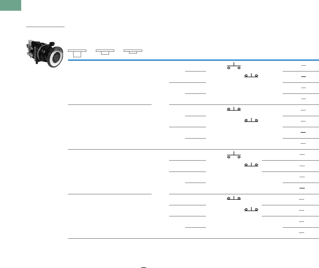
T37-252 Logic Control Products CA08100001K—June 2012 www.eatoncanada.ca
37
37
37
37
37
37
37
37
37
37
37
37
37
37
37
37
37
37
37
37
37
37
37
37
37
37
37
37
37
37
37.8
Pushbuttons and Indicating Lights
30.5 mm Corrosion Resistant Watertight/Oiltight—E34
UL (NEMA) Type 3, 3R, 4, 4X, 12, 13
●Three-position maintained
●Illuminated
Three-Position Illuminated Momentary Push, Momentary Pull
Notes
Use NEMA 4X 10250T operators where exposed to ultraviolet light, see Pages T37-167 to T37-239.
X = closed circuit, O = open circuit.
To order different type or colour lens, substitute the underlined characters with appropriate suffix code from Lens and Colour Selection table on the
bottom of Page T37-251. Example: E34GEB79M3-3X. For LEDs with different voltages see ordering example on Page T37-257.
Operator Position
Lamp Type Voltage
Contact
Type
LED/Lamp
Number
Red Standard
Push-Pull
Catalogue Number
Momentary—
Pull
Maintained—
Intermediate
Momentary—
Push Mounting Location
AB
O
X
O
O
X
O
LED Full
voltage
24 Vac/Vdc 1NO Bayonet
base
E34GHB97LRD24-1X
120 Vac 1NC E34GHB97LRD2A-1X
Trans-
former
24 Vac E34GHB89LRD06-1X
120 Vac E34GHB63LRD06-1X
X
X
O
X
O
O
Full
voltage
24 Vac/Vdc 1NC Bayonet
base
E34GEB97LRD24-3X
120 Vac 1NC E34GEB97LRD2A-3X
Trans-
former
24 Vac E34GEB89LRD06-3X
120 Vac E34GEB63LRD06-3X
O
X
O
O
X
O
Incan-
descent
Full
voltage
24 Vac/Vdc 1NO #757 E34GHB79M2-1X
Resistor 120 Vac 1NC 120MB E34GHB80M2-1X
Trans-
former
24 Vac #755 E34GHB89M2-1X
120 Vac E34GHB63M2-1X
X
X
O
X
O
O
Full
voltage
24 Vac/Vdc 1NC #757 E34GEB79M2-3X
Resistor 120 Vac 1NC 120MB E34GEB80M2-3X
Trans-
former
24 Vac #755 E34GEB89M2-3X
120 Vac E34GEB63M2-3X
Illuminated Push-Pull
Unit
Tab37book.fm Page 252 Tuesday, July 3, 2012 10:46 PM
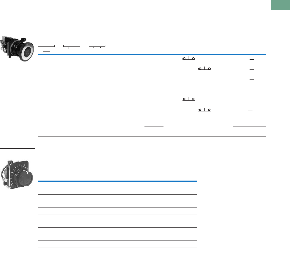
Logic Control Products CA08100001K—June 2012 www.eatoncanada.ca T37-253
37
37
37
37
37
37
37
37
37
37
37
37
37
37
37
37
37
37
37
37
37
37
37
37
37
37
37
37
37
37
37.8
Pushbuttons and Indicating Lights
30.5 mm Corrosion Resistant Watertight/Oiltight—E34
UL (NEMA) Type 3, 3R, 4, 4X, 12, 13
●Three-position—maintained push, momentary pull
●Illuminated
Three-Position Illuminated Maintained Push, Momentary Pull
Potentiometers
UL (NEMA) Type 3, 3R, 4, 4X, 12, 13
Potentiometer with Knob and Standard Dial Plate—Linear Type ±10%
Notes
Use NEMA 4X 10250T operators where exposed to ultraviolet light, see Pages T37-167 to T37-239.
X = closed circuit, O = open circuit.
To order different type or colour lens, substitute the underlined characters with appropriate suffix code from table
on the bottom of Page T37-251.
Example: E34GFB79M3-3X. For LEDs with different voltages see ordering example on Page T37-257.
Shown with standard aluminum dial plate.
Large dial plate with space for legend is available at no charge. To order, add suffix 36 to catalogue number.
Example: E34PDB1F136. To order separately, see footnote below.
Large dial plate has space at top for 15 letters. 3/32 in high. For custom stamped legend plates, order legend plate
as separate item 10250TR30 and specify stamping.
For use with commercially purchased potentiometers having shaft dimensions per dimension drawing on Page T37-230.
Operator Position
Lamp Type Voltage
Contact
Type
LED/Lamp
Number
Red Standard
Push-Pull
Catalogue Number
Momentary—
Pull
Maintained—
Intermediate
Maintained—
Push Mounting Location
AB
X
X
O
X
O
O
LED Full
voltage
24 Vac/Vdc 1NC Bayonet
base
E34GFB97LRD24-3X
120 Vac 1NC E34GFB97LRD2A-3X
Trans-
former
24 Vac E34GFB89LRD06-3X
120 Vac E34GFB63LRD06-3X
X
X
O
X
O
O
Incan-
descent
Full
voltage
24 Vac/Vdc 1NC #757 E34GFB79M2-3X
Resistor 120 Vac 1NC 120MB E34GFB80M2-3X
Trans-
former
24 Vac #755 E34GFB89M2-3X
120 Vac E34GFB63M2-3X
Potentiometer
Ohms Catalogue Number
2 Watt (60V Max.) Single Potentiometer with Standard Aluminum Dial Plate
1000 E34PDB1F1
2500 E34PDB1F2
5000 E34PDB1F5
10000 E34PDB1F10
25000 E34PDB1F25
50000 E34PDB1F50
Operator only E34PDB1A0
Alternative—black plastic large legend with standard markings E34LP99
Dimensions, see Page T37-278.
Illuminated Push-Pull
Unit
Vertical or Horizontal
One-Hole Mounting
Tab37book.fm Page 253 Tuesday, July 3, 2012 10:46 PM
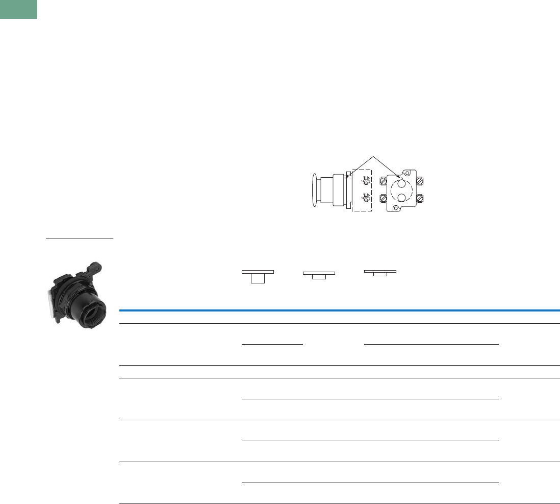
T37-254 Logic Control Products CA08100001K—June 2012 www.eatoncanada.ca
37
37
37
37
37
37
37
37
37
37
37
37
37
37
37
37
37
37
37
37
37
37
37
37
37
37
37
37
37
37
37.8
Pushbuttons and Indicating Lights
30.5 mm Corrosion Resistant Watertight/Oiltight—E34
Push-Pull Operators
An illuminated push-pull
pushbutton unit, arranged for
one-hole mounting, can
replace two pushbuttons and
a pilot light or the non-
illuminated form can replace
two pushbuttons. These units
are available in three basic
types:
●Maintained—(Two-
position). Maintains in the
pulled or pushed position
until manually actuated to
the opposite mode.
●Momentary—(Three-
position). Spring returns to
an intermediate position
when pulled or pushed and
released.
●Momentary Pull,
Maintained Push—(Three-
position). Spring returns to
intermediate position when
pulled. Maintains in pushed
position until manually
returned to intermediate
(ready to reset) position.
Maintained stop holds
circuit open and will
prevent other series
connected operators from
starting the system.
The operators, buttons,
contact blocks, etc., are
offered as building block
components that can be
intermixed to satisfy many
requirements. This minimizes
the need for a varied and
costly inventory.
Application Guide
To assist in the selection of
contact blocks, the sketch
below shows pictorially by
symbols A and B locations of
contact circuits after
assembly of contact blocks
and adapter to the operator.
The table below shows the
effect of the push and pull
operations on either NO or
NC contacts. (X = contact
closed, O = contact open).
Contact Circuit Locations
Push-Pull Operator Components
Notes
Use NEMA 4X 10250T operators where exposed to ultraviolet light, see Pages T37-167 to T37-239.
See Typical Applications on Page T37-189.
Shown without button on lens.
Maximum of two blocks, four circuits. Special function contact blocks shown on Page T37-272 CANNOT be used with
three-position push-pull operators E34GEB, E34GFB or E34GHB.
Locating Nib
A
B
Type of Operator
Operator Position and Circuit Arrangement
Contact Block Catalogue Number
Out—Pull Intermediate In—Push
Contact Block Mounting Location
ABABAB
Two-Position Operator without Lens
Maintained push-pull O
Xor O
X
No intermediate
position
X
Oor X
O
1NO
1NC
E34GDB
O
X
O
X
X
O
X
O
2NO
2NC
Three-Position Operator without Lens
Momentary push-pull O
Xor O
X
O
Oor O
X
X
Oor O
O
1NO
1NC
E34GEB
O
X
O
X
O
O
O
X
X
O
O
O
2NO
2NC
Maintained push-momentary pull O
Xor O
X
O
Oor O
X
X
Oor O
O
1NO
1NC
E34GFB
O
X
O
X
O
O
O
X
X
O
O
O
2NO
2NC
Momentary push-pull O
Xor O
X
O
Oor O
O
X
Oor X
O
1NO
1NC
E34GHB
O
X
O
X
O
O
O
O
X
O
X
O
2NO
2NC
Two-Position Maint.
Push-Pull
Tab37book.fm Page 254 Tuesday, July 3, 2012 10:46 PM

Logic Control Products CA08100001K—June 2012 www.eatoncanada.ca T37-255
37
37
37
37
37
37
37
37
37
37
37
37
37
37
37
37
37
37
37
37
37
37
37
37
37
37
37
37
37
37
37.8
Pushbuttons and Indicating Lights
30.5 mm Corrosion Resistant Watertight/Oiltight—E34
Push-Pull Light Units, Lenses and Buttons
Ordering Example with One Composite Number
Non-illuminated:
E34GDB + E34C2 + 10250T1 = E34GDBC2-1X
Incandescent:
E34GDB + 10250T79 + E34M2 + 10250T1 = E34GDB79M2-1X
LED:
E34GDB + 10250T97L + E34M2 + Voltage Code + 10250T1 = E34GDB97LRD24-1X
06—6 Vac/Vdc
12—12 Vac/Vdc
24—24 Vac/Vdc
48—48 Vac/Vdc
60—60 Vac/Vdc
2A—120 Vac
2D—120 Vdc
Light Units for Illuminated Push-Pull Devices
Notes
Use NEMA 4X 10250T operators where exposed to ultraviolet light, see Pages T37-167 to T37-239.
These units do not include lamps. Order LED separately to match lens colour from chart on Page T37-257.
Light Unit
Type Type Voltage
LED/Lamp
Number Catalogue Number
LED
(LEDs not included)
Full voltage — Bayonet
base
10250T97L
Transformer
AC only
50/60 Hz
24 10250T89L
120 10250T63L
208 10250T64L
240 10250T65L
277 10250T82L
380 10250T66L
480 10250T67L
600 10250T68L
Incandescent Full voltage
AC or DC
6 #755
#756
#757
#1828
10250T69
12 10250T70
24/28 10250T79
32 10250T83
Resistor
AC or DC
120 120MB 10250T80
240 10250T81
Transformer
AC only
50/60 Hz
24 #755 10250T89
120 10250T63
208 10250T64
240 10250T65
277 10250T82
380 10250T66
480 10250T67
600 10250T68
Tab37book.fm Page 255 Tuesday, July 3, 2012 10:46 PM

T37-256 Logic Control Products CA08100001K—June 2012 www.eatoncanada.ca
37
37
37
37
37
37
37
37
37
37
37
37
37
37
37
37
37
37
37
37
37
37
37
37
37
37
37
37
37
37
37.8
Pushbuttons and Indicating Lights
30.5 mm Corrosion Resistant Watertight/Oiltight—E34
Buttons for Non-Illuminated Push-Pull Devices
Alternate Lenses for Illuminated Push-Pull Devices
Notes
Use NEMA 4X 10250T operators where exposed to ultraviolet light, see Pages T37-167 to T37-239.
Anodized aluminum may not be suitable for use on some corrosive applications.
Suffix codes should only be used for assembling composite catalogue numbers. To order lens, order by catalogue number.
Colour
Incandescent
Suffix Code Catalogue Number
Standard Button
Black C1 E34C1
Red C2 E34C2
Red (EMERG. STOP) C2N8 E34C2N8
Green C3 E34C3
Blue C6 E34C6
Jumbo Mushroom Head
Red J2 E34J2
Red (EMERG. STOP) J2N8 E34J2N8
Colour
Incandescent
Suffix Code
LED
Suffix Code Catalogue Number
Red M2 RD E34M2
Red (EMERG. STOP) M2N8 ED E34M2N8
Green M3 GD E34M3
Blue M6 LD E34M6
Amber M9 AD E34M9
White M5 WD E34M5
Clear M0 — E34M0
Standard
Jumbo Mushroom
Head
E34M_
Tab37book.fm Page 256 Tuesday, July 3, 2012 10:46 PM

Logic Control Products CA08100001K—June 2012 www.eatoncanada.ca T37-257
37
37
37
37
37
37
37
37
37
37
37
37
37
37
37
37
37
37
37
37
37
37
37
37
37
37
37
37
37
37
37.8
Pushbuttons and Indicating Lights
30.5 mm Corrosion Resistant Watertight/Oiltight—E34
LED Selection
Voltage Colour Catalogue Number Voltage Colour Catalogue Number
6 Vac/Vdc
suitable for
use with
transformers
Red E22LED006RN 60 Vac/Vdc Red E22LED060RN
Orange E22LED006ON Orange E22LED060ON
Yellow E22LED006YN Yellow E22LED060YN
Green E22LED006GN Green E22LED060GN
Blue E22LED006BN Blue E22LED060BN
White E22LED006WN White E22LED060WN
12 Vac/Vdc Red E22LED012RN 120 Vac Red E22LED120RA
Orange E22LED012ON Orange E22LED120OA
Yellow E22LED012YN Yellow E22LED120YA
Green E22LED012GN Green E22LED120GA
Blue E22LED012BN Blue E22LED120BA
White E22LED012WN White E22LED120WA
24 Vac/Vdc Red E22LED024RN 120 Vdc Red E22LED120RD
Orange E22LED024ON Orange E22LED120OD
Yellow E22LED024YN Yellow E22LED120YD
Green E22LED024GN Green E22LED120GD
Blue E22LED024BN Blue E22LED120BD
White E22LED024WN White E22LED120WD
48 Vac/Vdc Red E22LED048RN
Orange E22LED048ON
Yellow E22LED048YN
Green E22LED048GN
Blue E22LED048BN
White E22LED048WN
Standard LED Lamp
Tab37book.fm Page 257 Tuesday, July 3, 2012 10:46 PM
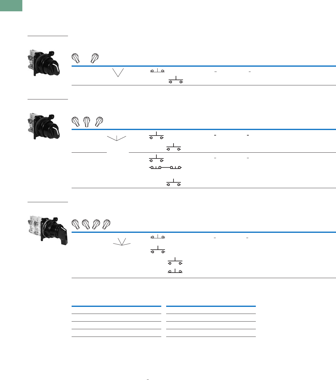
T37-258 Logic Control Products CA08100001K—June 2012 www.eatoncanada.ca
37
37
37
37
37
37
37
37
37
37
37
37
37
37
37
37
37
37
37
37
37
37
37
37
37
37
37
37
37
37
37.8
Pushbuttons and Indicating Lights
30.5 mm Corrosion Resistant Watertight/Oiltight—E34
Selector Switch Units
UL (NEMA) Type 3, 3R, 4, 4X, 12, 13
●Two-, three- and four-position—maintained
●Non-illuminated and illuminated
Two-Position Selector Switch
Three-Position Selector Switch
Four-Position Selector Switch
Colour Selection, Non-Illuminated
Notes
For Light Unit Voltage Suffix and Knobs, Levers tables, see Page T37-264.
Use NEMA 4X 10250T operators where exposed to ultraviolet light, see Pages T37-167 to T37-239.
X = closed circuit, O = open circuit.
M = Maintained.
To order different type or colour selector switch, substitute the underlined character with appropriate suffix code from
the Colour Selection table. Example: E34VFBK2-X1.
Operator Position
Operator
Action
Contact
Type
Cam
Code
Non-Illuminated Illuminated—120V Transformer
Mounting Location Black Knob
Catalogue Number
Black Lever
Catalogue Number
Red Knob
Catalogue Number
Red Lever
Catalogue Number
AB
X
O
O
X
1NC 1 E34VFBK1-1X E34VFBL1-1X E34VFB120ER-1X E34VFB120FR-1X
1NO
Operator Position
Operator
Action
Contact
Type
Cam
Code
Non-Illuminated Illuminated—120V Transformer
Mounting Location Black Knob
Catalogue Number
Black Lever
Catalogue Number
Red Knob
Catalogue Number
Red Lever
Catalogue Number
AB
X
O
O
O
O
X
1NO 3 E34VHBK1-2X E34VHBL1-2X E34VHB120TER-2X E34VHB120TFR-2X
1NO
X
O
O
O
X
O
O
O
X
1NO 3 E34VHBK1-23X E34VHBL1-23X E34VHB120TER-23X E34VHB120TFR-23X
2NC
(Series)
1NO
Operator Position
Operator
Action
Contact
Type
Cam
Code
Non-Illuminated Illuminated—120V Transformer
Mounting Location Black Knob
Catalogue Number
Black Lever
Catalogue Number
Red Knob
Catalogue Number
Red Lever
Catalogue Number
AB
X
O
O
O
O
X
O
O
O
O
X
O
O
O
O
X
1NC 7 E34VTBK1-23X E34VTBL1-23X E34VRB120TER-23X E34VRB120TFR-23X
1NO
1NO
1NC
Colour Code Letter Colour Code Letter
Black 1White 5
Red 2Blue 6
Green 3Gray 7
Yellow 4Orange 8
Two-Position Maint.
Switch Knob
MM
Three-Position Maint.
Switch Knob
MM
M
Four-Position Maint.
Switch Lever
MM
MM
Tab37book.fm Page 258 Tuesday, July 3, 2012 10:46 PM
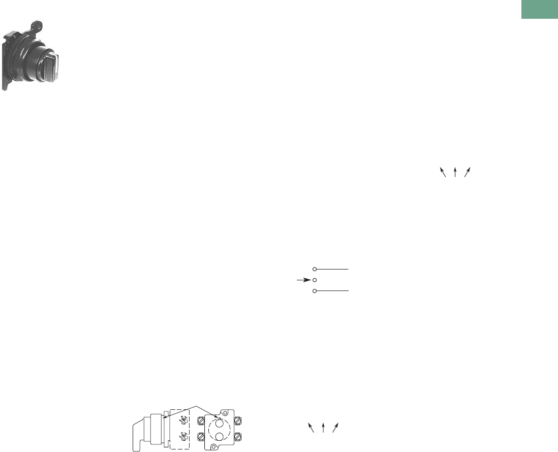
Logic Control Products CA08100001K—June 2012 www.eatoncanada.ca T37-259
37
37
37
37
37
37
37
37
37
37
37
37
37
37
37
37
37
37
37
37
37
37
37
37
37
37
37
37
37
37
37.8
Pushbuttons and Indicating Lights
30.5 mm Corrosion Resistant Watertight/Oiltight—E34
Selector Switch Selection
Cam and Contact Block Selection
Selector switches in their
varied forms (two-position,
three-position and four-
position) are a big factor
contributing to the great
flexibility of control that a well
rounded line of “pushbuttons”
can achieve. Because of their
flexibility, they tend to cause
difficulty with product
selection and application.
The following systematic
approach should simplify
that task.
Cam and contact block
selection is better understood
if you:
●Work with each incoming
and outgoing wire/circuit
separately.
●Recognize the terms NO
and NC only identify the
type of contact by its mode
before mounting to the
operator. The “X-O” chart
(Page T37-261) shows
how that contact will act
after assembly to the
operator with the selected
cam shape. X = closed
circuit, O = open circuit.
●Up to six NO or NC
contacts may be mounted
behind each plunger
location for a total of
twelve contacts. Single
circuit contact blocks have
only one plunger with the
other side of the block
“open.” Therefore, single
circuit contact blocks
transmit motion to blocks
behind them only for the
position containing the
circuit.
●Each cam has two
separate lobes, each of
which operates one of the
two contact block plungers
independently of each
other. Those are identified
as position A (locating nib
side) and position B
(opposite of locating nib).
The position designations
give direction in selecting
and mounting of the
contact blocks.
Contact Circuit Locations
Locating Nib
A
B
Systematic Approach
Application: HAND-OFF-
AUTO selector switch. In this
circuit, one incoming line is
distributed to two other
outgoing circuits by the
switch. The two circuits can
be looked at individually.
Step 1: Elementary
Diagram.
Construct on paper, or in your
mind, a simple elementary
diagram of the switching
scheme as follows:
Step 2: “X-O” Pattern.
From the elementary
diagram, you can construct
an “X-O” diagram which
describes when the contacts
are to be closed (X) or open
(O) in the various positions of
the switch. The “X-O” for the
HAND circuit looks like this:
In this circuit, you want a
contact closed on the left
(HAND) but open in the
centre and right.
For the AUTO circuit, the
“X-O” diagram would look like
this:
Putting them together, the
complete “X-O” diagram is:
Once the “X-O” diagram has
been generated, the next
step is to select the cam
and contact block, or blocks,
needed to perform the
desired “X-O” functions.
The selection tables on the
following pages list the
various types (shapes) of
cams by number to choose
from and the type of contact
and position to achieve the
function outlined in your
“X-O” diagram.
OFF
HAND Outgoing
Circuit
AUTO
Outgoing
Circuit
Incoming
Line
HAND OFF AUTO
XOO
HAND OFF AUTO
OOX
X O O
O O X
Tab37book.fm Page 259 Tuesday, July 3, 2012 10:46 PM
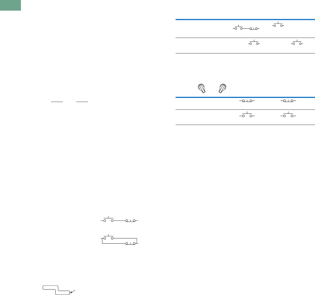
T37-260 Logic Control Products CA08100001K—June 2012 www.eatoncanada.ca
37
37
37
37
37
37
37
37
37
37
37
37
37
37
37
37
37
37
37
37
37
37
37
37
37
37
37
37
37
37
37.8
Pushbuttons and Indicating Lights
30.5 mm Corrosion Resistant Watertight/Oiltight—E34
Step 3: Cam Selection.
The cam you select
determines the operation of
all contact blocks mounted to
the operator. It is selected on
the basis that it provides the
simplest circuitry for the
desired “X-O” diagram. The
selection tables show all the
“X-O” combinations. For the
purpose of this example, the
applicable portion of those
tables is shown on this page.
Now to make the cam
selection, make a simple
worksheet such as:
It becomes immediately
obvious that cam 3 is the
better choice for two
reasons, (1) the series
combination can be avoided
making it simpler to wire,
(2) only two contacts are
required, which is less
expensive than the three
contacts required by cam 2.
Step 4: Contact Block
Selection.
Having selected the cam,
contact block selection is
simply a matter of gathering
the A position and B position
circuits into pairs which make
up the most convenient contact
block arrangement. If there is
an imbalance in the number of
circuits under A or B, then
single circuit blocks must be
selected for these leftover
circuits.
Back to the worksheet,
having selected cam 3 do
this:
Step 5: Selector Switch
Operator.
Lastly, you have to choose
from the many types of
operators—knob and lever
in various colors or keyed.
Also what combinations
of maintained and spring
return functions are
required. Selection of these
operators can be found on
Page T37-262. For the
example in step 4, you
may want a three-position
maintained black knob,
cam 3—Catalogue Number
E34VHBK1.
The Complete Switch:
E34VHBK1 with one
10250T2 or, for one
composite catalogue number,
E34VHBK1-Y1 found on
Page T37-259.
Diagrams
Circuits shown illustrate
connections to obtain a
selector switch circuit
combination and are shown
with their appropriate line
diagrams. Field wiring of
jumper connections required
as shown.
X = Closed circuit
O = Open circuit
Wiring of Jumper
Connections
Four-position selector
switches are limited to four
contact blocks.
Contact Blocks
For selection and number
of available contact blocks
per operator, see Page
T37-271.
Cam 2 Cam 3
X O O
O O X
(A)NO-(B)NC
(B)NO
(A)NO
(B)NO
X O X
O O X
ANO
BNO 10250T2
Parallel Connection
Series Connection
Example Selection Table
Two-Position Selector Switch Contact Block Selection
Note
Wired in series.
No. “X-O” Pattern
Cam Code #2 Cam Code #3
Top A Bottom B Top A Bottom B
1XOO
NO NC NO
—
4 OOX—
NO
—
NO
No.
Desired Circuit and
Operator Position
Contact Blocks Required to
Accomplish Circuit Function
Top Plunger A Bottom Plunger B
1XO
NC or NC
2OX
NO
or
NO
a
Tab37book.fm Page 260 Tuesday, July 3, 2012 10:46 PM
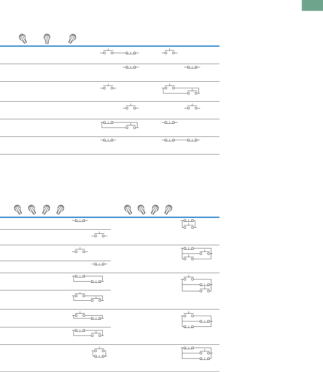
Logic Control Products CA08100001K—June 2012 www.eatoncanada.ca T37-261
37
37
37
37
37
37
37
37
37
37
37
37
37
37
37
37
37
37
37
37
37
37
37
37
37
37
37
37
37
37
37.8
Pushbuttons and Indicating Lights
30.5 mm Corrosion Resistant Watertight/Oiltight—E34
Three-Position Switch—Cam and Contact Block Selection
Four-Position Switch—Contact Block Selection
No.
Desired Circuit and
Operator Position
Contact Blocks Required to Accomplish Circuit Function
(Jumpers must be installed where indicated)
Operator with Cam Code #2 Operator with Cam Code #3
Mounting Location Mounting Location
Top
Plunger
A
Bottom
Plunger
B
Top
Plunger
A
Bottom
Plunger
B
1X O O
NO NC NO
2XXO
NC NC
3X O X
NO
NO NO
4OOX
NO NO
5O X X
NC NO
NC
6O X O
NC NC NC
No.
Contact Blocks
Required to
Accomplish Circuit
Function
No.
Contact Blocks
Required to
Accomplish Circuit
Function
Desired Circuit and
Operator Position
Mounting Location Desired Circuit and
Operator Position
Mounting Location
Top
Plunger
A
Bottom
Plunger
B
Top
Plunger
A
Bottom
Plunger
B
1XOOO
NC
10 X O X O
NC
NO
2OXOO
NO
3OOXO
NO
11XXXO
NC
NO NO
4OOOX
NC
5XOOX
NC NC
12OXXX
NO NC
NO
6OXXO
NO NO
7OOXX
NO NC
13 X O X X
NO
NC NC
8XXOO
NC NO
9OXOX
NO
NC
14 X X O X
NC NO
NC
Tab37book.fm Page 261 Tuesday, July 3, 2012 10:46 PM
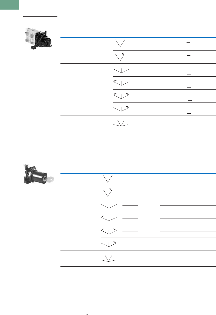
T37-262 Logic Control Products CA08100001K—June 2012 www.eatoncanada.ca
37
37
37
37
37
37
37
37
37
37
37
37
37
37
37
37
37
37
37
37
37
37
37
37
37
37
37
37
37
37
37.8
Pushbuttons and Indicating Lights
30.5 mm Corrosion Resistant Watertight/Oiltight—E34
Selector Switch Operators
UL (NEMA) Type 3, 3R, 4, 4X, 12, 13
Operators with Knob Assembled
Key Operators
Key Operators with Cam and Cap
Notes
Use NEMA 4X 10250T operators where exposed to ultraviolet light, see Pages T37-167 to T37-239.
M = Maintained. S = Spring return in direction of arrow (R).
Field convertible to horizontal mounting.
For selection of the proper cam and contact block to obtain the proper circuit sequence, see selection instructions and
tables on Pages T37-259 to T37-261.
For other colors of either the knob or lever, replace the underlined characters of the catalogue number with the
appropriate suffix code from Alternate Knob and Lever table on Page T37-263. Example: E34VFBL2.
Choose key removal position required for application from table on Page T37-263. Add key removal code number to listed catalogue number.
Example: E34KFB2.
Positions
Operator
Action
Black Knob Selector Switch—
Vertical Mounting
Cam Code Catalogue Number
Two-position—60˚ throw 1 E34VFBK1
1E34VEBK1
Three-position—60˚ throw 2 E34VGBK1
3E34VHBK1
2E34VJBK1
3E34VKBK1
2E34VLBK1
3E34VMBK1
2E34VNBK1
3E34VPBK1
Four-position—40˚ throw 7 E34VTBK1
Positions
Operator
Action
Cam
Code
Key
Removal
Positions
Vertical
Mounting
Catalogue Number
Horiz.
Mounting
Catalogue Number
Two-position—60˚ throw 1 1, 2, 3 E34KFB_ E34KFHB_
12 E34KEB_ E34KEHB_
Three-position—60˚ throw 2 1–7 E34KGB_ E34KGHB_
3E34KHB_ E34KHHB_
2 1, 4, 5 E34KJB_ E34KJHB_
3E34KKB_ E34KKHB_
24 E34KLB_ E34KLHB_
3E34KMB_ E34KMHB_
2 2, 4, 6 E34KNB_ E34KNHB_
3E34KPB_ E34KPHB_
Four-position—40˚ throw 7 7 E34KTB_ E34KTHB_
Two-Position Knob
Selector Switch
MM
MS
MM
M
MS
M
SS
M
MS
M
MM
MM
Three-Position Keyed
Selector Switch
MM
MS
MM
M
MS
M
SS
M
MS
M
MM
MM
Tab37book.fm Page 262 Tuesday, July 3, 2012 10:46 PM
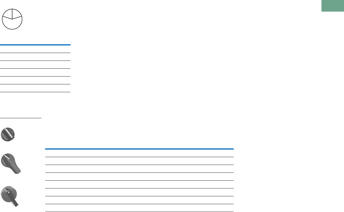
Logic Control Products CA08100001K—June 2012 www.eatoncanada.ca T37-263
37
37
37
37
37
37
37
37
37
37
37
37
37
37
37
37
37
37
37
37
37
37
37
37
37
37
37
37
37
37
37.8
Pushbuttons and Indicating Lights
30.5 mm Corrosion Resistant Watertight/Oiltight—E34
Key Removal Positions Dissimilar Locks and Keys
Listed operators have
identical locks and keys (Key
Code H661), Catalogue
Number 10250ED824. For
dissimilar lock and key
combinations, see Page T37-
198.
Alternate Knobs and Levers for Operators
Notes
Key removal in “spring return from” positions not recommended.
See operators on Page T37-262.
For use on maintained operators only.
Code
Suffix
Key Removal
Position
1Right only
2Left only
3Right and left
4Centre only
6Left and centre
7All positions
L
C
R
Colour
Knob Lever
Lever Designed for
Added Ingress Protection
Suffix
Code Catalogue Number
Suffix
Code Catalogue Number
Suffix
Code Catalogue Number
Black K1 E34K1 L1 E34L1 A1 E34A1
Red K2 E34K2 L2 E34L2 A2 E34A2
Green K3 E34K3 L3 E34L3 A3 E34A3
Yellow K4 E34K4 L4 E34L4 A4 E34A4
White K5 E34K5 L5 E34L5 A5 E34A5
Blue K6 E34K6 L6 E34L6 A6 E34A6
Gray K7 E34K7 L7 E34L7 A7 E34A7
Orange K8 E34K8 L8 E34L8 A8 E34A8
E34K_
E34L_
E34A_
Tab37book.fm Page 263 Tuesday, July 3, 2012 10:46 PM
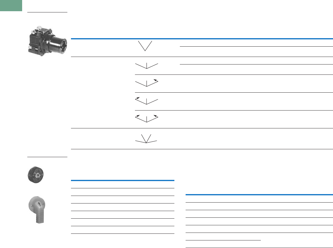
T37-264 Logic Control Products CA08100001K—June 2012 www.eatoncanada.ca
37
37
37
37
37
37
37
37
37
37
37
37
37
37
37
37
37
37
37
37
37
37
37
37
37
37
37
37
37
37
37.8
Pushbuttons and Indicating Lights
30.5 mm Corrosion Resistant Watertight/Oiltight—E34
Illuminated Selector Switch Operators
Operator without Knob or Lever
Knobs and Levers Light Unit Voltage Suffix
Add to operator Catalogue Number listed in table above.
Notes
Use NEMA 4X 10250T operators where exposed to ultraviolet light, see Pages T37-167 to T37-239.
Full voltage light units can be used at other than listed voltages by changing lamp. Replacement lamps are listed on Page T37-225.
120MB lamps are used on both 120V and 240V operators.
Operator includes lens gasket and lens attachment screws.
Add suffix code for light unit voltage to listed catalogue number from Light Unit Voltage Suffix table above.
Example: For 24V transformer type light unit, order E34VFB024.
For selection of the proper cam and contact block required to obtain a specific circuit sequence, see selection tables on Pages T37-259 to T37-261.
120 and 240V transformer only.
120 full voltage only.
Resistor type. May generate excess heat if used in high density.
Amber, clear and white lenses have a black arrow (R). Red, green and blue lenses have a white arrow (R).
Positions Operator Action
Transformer Type—50/60 Hz Full Voltage Type—AC or DC
6V #755 Lamp Lamps—#755, #757, #1835, 120MB
Catalogue Number Catalogue Number
Two-position—60˚ throw Cam Code 1 Cam Code 1
E34VFB_ E34SFB_
Three-position—60˚ throw Cam Code 2 Cam Code 3 Cam Code 2 Cam Code 3
E34VGB_ E34VHB_ E34SGB_ E34SHB_
E34VNB_ E34VPB_ E34SNB_ E34SPB_
E34VJB_ E34VKB_ E34SJB_ E34SKB_
E34VLB_ E34VMB_ E34SLB_ E34SMB_
Four-position—40˚ throw E34VRB_ — E34SRB_ —
120 Vac Transformer
Selector Switch, Cam 1
MM
MM
M
MS
M
MS
M
SS
M
MM
MM
Colour
Knob
Catalogue Number
and Code Number
Lever
Catalogue Number
and Code Number
Red 10250TER 10250TFR
Green 10250TEG 10250TFG
Yellow 10250TEA 10250TFA
Blue 10250TEL 10250TFL
Clear 10250TEC 10250TFC
White 10250TEW 10250TFW
Amber 10250TEM 10250TFM
Knob
Lever
Type of Light Unit
Transformer Type
50/60 Hz
Full Voltage Type
AC or DC
Voltage Suffix Code Voltage Suffix Code
24 024 606
120 120 12 12
208 208 24 24
240 240 48 48
380 380 120 120
480 480 240 240
600 600
Tab37book.fm Page 264 Tuesday, July 3, 2012 10:46 PM
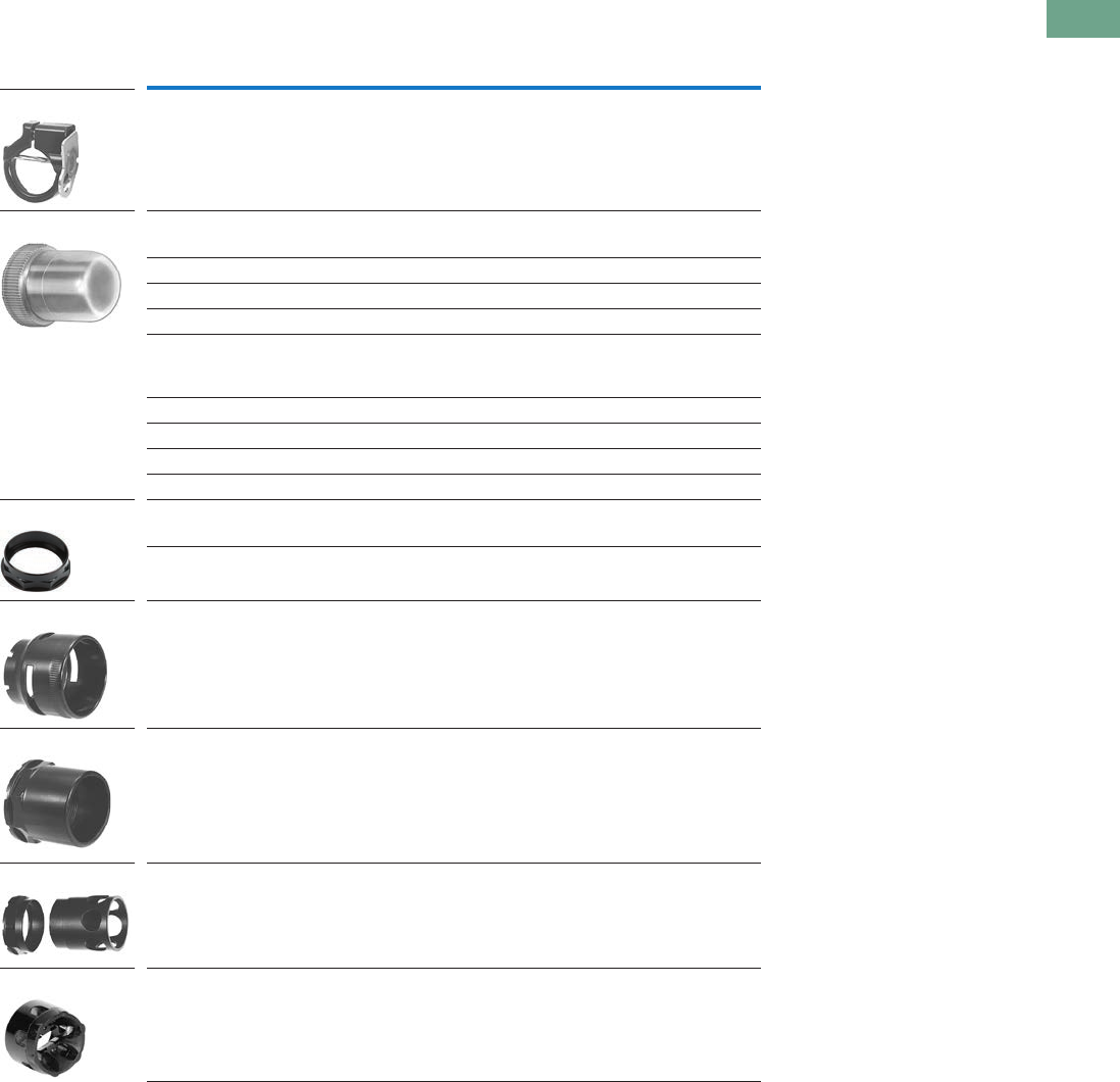
Logic Control Products CA08100001K—June 2012 www.eatoncanada.ca T37-265
37
37
37
37
37
37
37
37
37
37
37
37
37
37
37
37
37
37
37
37
37
37
37
37
37
37
37
37
37
37
37.8
Pushbuttons and Indicating Lights
30.5 mm Corrosion Resistant Watertight/Oiltight—E34
Accessories
Accessories
Notes
Should not be used on flush button for STOP function.
Not suitable for single contact block depth cast enclosure. Cover is too thick.
Description Catalogue Number
Padlocking Attachment for Flush Pushbutton Operators.
Permits locking NC contacts in open position with 1/4 in padlock.
Will not lock NO contact.
E34TA2
Flexible Weather Resistant Boot for use with flush pushbutton operators.
Clear 10250TA46
Black 10250TA47
Red 10250TA48
Green 10250TA49
Flexible Weather Resistant Boot for use with button operators (extended
buttons preferred).
Black 10250TA3
Red 10250TA4
Green 10250TA10
Clear 10250TA85
Transparent Boot for regular, illuminated pushbutton operators and PresTest. 10250TA25
Special Retaining Nut—to accommodate thick panel.
Indicating light E34TA30
PresTest, pushbuttons and selector switches E34TA31
Shroud for Mushroom Head Operator—prevents accidental operation.
(Not for push-pull operators.)
E34TA6
Extended Retaining Nut—replaces standard nut and provides guard for
flush type pushbutton operators.
E34TA12
Guard for illuminated pushbutton E34TA15
Padlocking Attachment for non-illuminated knob selector switches—
accommodates up to five, 1/4 in padlocks.
E34TA11
E34TA2
10250TA_
E34TA3_
E34TA6
E34TA12
E34TA15
E34TA11
Tab37book.fm Page 265 Tuesday, July 3, 2012 10:46 PM
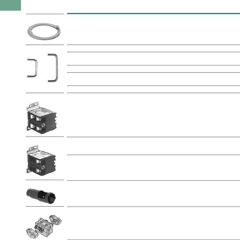
T37-266 Logic Control Products CA08100001K—June 2012 www.eatoncanada.ca
37
37
37
37
37
37
37
37
37
37
37
37
37
37
37
37
37
37
37
37
37
37
37
37
37
37
37
37
37
37
37.8
Pushbuttons and Indicating Lights
30.5 mm Corrosion Resistant Watertight/Oiltight—E34
Accessories, continued
Description Catalogue Number
Thrust Washer—To meet Ford Motor Company mounting specifications. E34TK3
Contact Block Terminal Jumps—Available in multiples of 100 only.
Terminal to terminal—within block (short):
100 per package 10250TA70
1000 per package 10250TA70-2
Terminal to terminal—block to block (long):
100 per package 10250TA71
1000 per package 10250TA71-2
Master Test (Dual Input) Module—Internal Form C relay suitable for either
AC or DC applications. Total electrical isolation between monitored and test circuit.
Fits all illuminated 10250T, E22, E30 and E34 devices.
48 Vdc 10250TMT8
Flasher Module—Internal Form C relay suitable for AC applications.
One unit required for each operator in master test circuit.
24 Vac 10250TFL2
120 Vac 10250TFL1
Panel Mounting Nut Wrench—E22, E30, E34 and octagonal 10250T. E22CW
Fingerproof Shroud—10 per package
Fits new style contact blocks and light units.
10250TA101
E34TK3
10250TA7_
10250TMT8
10250TFL_
E22CW
10250TA101
Tab37book.fm Page 266 Tuesday, July 3, 2012 10:46 PM
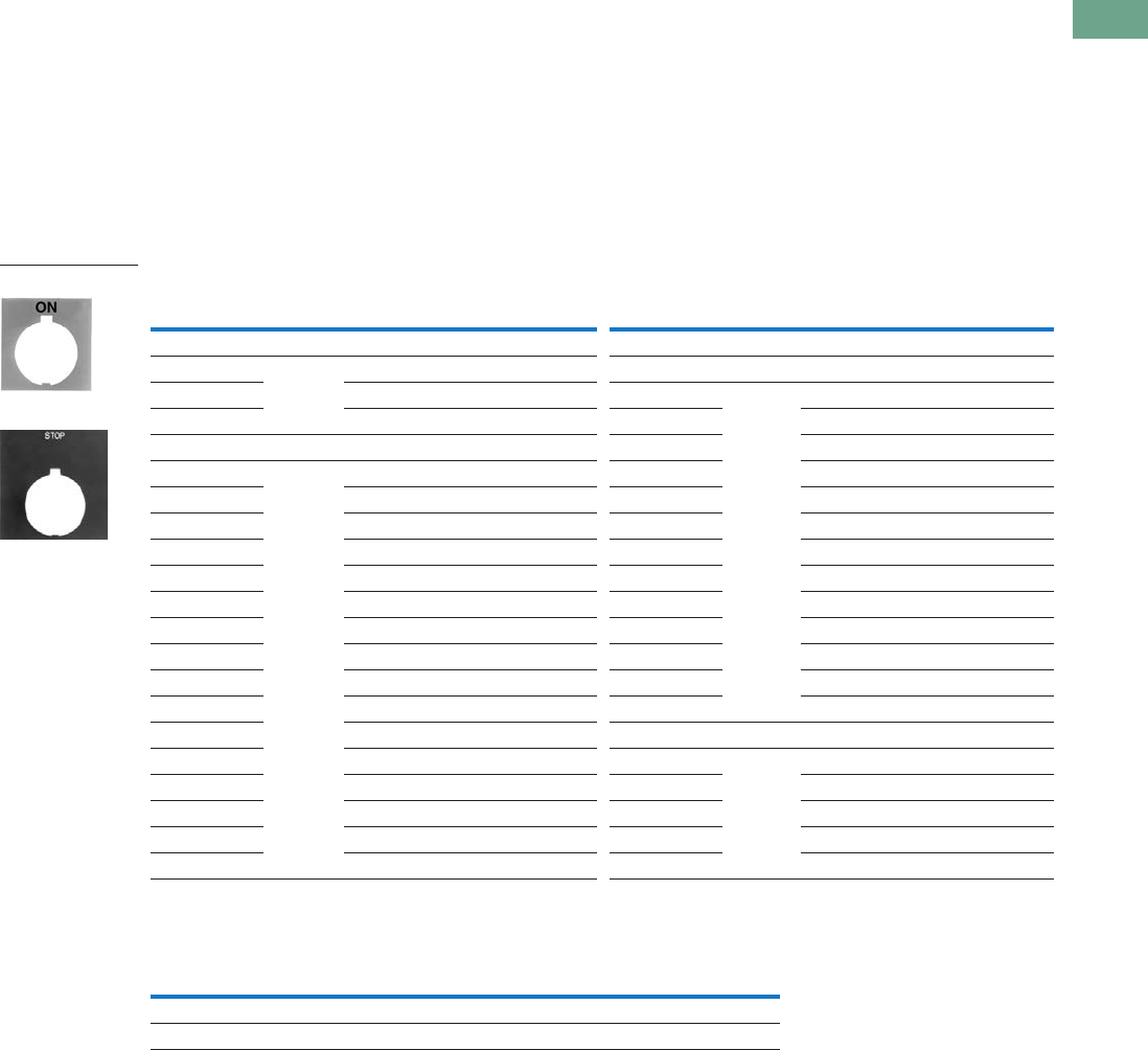
Logic Control Products CA08100001K—June 2012 www.eatoncanada.ca T37-267
37
37
37
37
37
37
37
37
37
37
37
37
37
37
37
37
37
37
37
37
37
37
37
37
37
37
37
37
37
37
37.8
Pushbuttons and Indicating Lights
30.5 mm Corrosion Resistant Watertight/Oiltight—E34
Options
Legend Plates
Field Colour
Legend plates can be
supplied printed on black,
red, silver or white field. To
order legend printed on a
colour other than indicated—
add suffix code to the end of
the catalogue number as
follows:
“R” for Red field;
“W” for White field; or
“S” for Silver field.
Example: E34SP26R—
Standard plate with red field
marked OPEN.
For Pushbutton Operators and Indicating Lights
Blank Plastic Legend Plates—Square
Notes
For dimensions, see Page T37-244.
3/32 in high lettering.
Legend plates with non-standard markings or aluminum legend plates see 10250T listing on Page T37-218.
See Appendix 4 for French engraving.
Legend
Colour of
Field
Standard
Catalogue Number
Jumbo
Catalogue Number Legend
Colour of
Field
Standard
Catalogue Number
Jumbo
Catalogue Number
Letters on Legend Plates Below are 3/16 in High
CLAMP Black E34SP90 E34LP90 OFF Red E34SP24 E34LP24
CLOSE E34SP73 E34LP73 ON Black E34SP25 E34LP25
DOWN E34SP74 E34LP74 OPEN E34SP26 E34LP26
EMERG. STOP Red E34SP13 E34LP13 OUT E34SP27 E34LP27
FAST Black E34SP75 E34LP75 POWER ON E34SP80 E34LP80
FASTER E34SP87 E34LP87 RAISE E34SP28 E34LP28
FEEDER ON E34SP94 E34LP94 READY E34SP86 E34LP86
FEEDER OFF E34SP95 E34LP95 RESET E34SP29 E34LP29
FORWARD E34SP15 E34LP15 REVERSE E34SP30 E34LP30
HIGH E34SP16 E34LP16 RUN E34SP31 E34LP31
IN E34SP17 E34LP17 SAFE E34SP85 E34LP85
INCH E34SP18 E34LP18 SLOW E34SP32 E34LP32
JOG E34SP19 E34LP19 SLOWER E34SP88 E34LP88
JOG FOR. E34SP20 E34LP20 START E34SP33 E34LP33
JOG REV. E34SP21 E34LP21 STOP Red E34SP34 E34LP34
LOW E34SP22 E34LP22 TEST Black E34SP83 E34LP83
LOWER E34SP23 E34LP23 TRANSFER E34SP93 E34LP93
LUBE-FAIL E34SP92 E34LP92 TRIP E34SP84 E34LP84
MOTOR RUN E34SP81 E34LP81 UNCLAMP E34SP91 E34LP91
MOTOR STOP E34SP82 E34LP82 UP E34SP35 E34LP35
Colour Field Standard
Catalogue Number
Jumbo
Catalogue Number
Extra Large
Catalogue NumberLettering Side 1 Side 2
Black White Silver 10250TSP76 10250TLP76 10250TEP76
White Red Black 10250TSP77 10250TLP77 10250TEP77
Standard
Jumbo
Tab37book.fm Page 267 Tuesday, July 3, 2012 10:46 PM
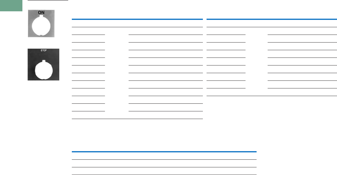
T37-268 Logic Control Products CA08100001K—June 2012 www.eatoncanada.ca
37
37
37
37
37
37
37
37
37
37
37
37
37
37
37
37
37
37
37
37
37
37
37
37
37
37
37
37
37
37
37.8
Pushbuttons and Indicating Lights
30.5 mm Corrosion Resistant Watertight/Oiltight—E34
For Selector Switch Operators
For Push-Pull Units
Notes
3/32 in (2.4 mm) high lettering.
1/8 in (3.2 mm) high lettering.
See Appendix 4 for French engraving.
Legend
Colour of
Field
Standard
Catalogue Number
Jumbo
Catalogue Number Legend
Colour of
Field
Standard
Catalogue Number
Jumbo
Catalogue Number
Two-Position—3/16 in High Lettering Three-Position—3/16 in High Lettering
FOR. REV. Black E34SP38 E34LP38 AUTO OFF HAND Black E34SP49 E34LP49
HAND AUTO E34SP39 E34LP39 FOR. OFF REV. E34SP50 E34LP50
HIGH LOW E34SP40 E34LP40 FOR. SAFE REV. E34SP69 E34LP69
JOG RUN E34SP41 E34LP41 HAND OFF AUTO E34SP51 E34LP51
MAN. AUTO E34SP67 E34LP67 MAN. OFF AUTO E34SP68 E34LP68
OFF ON E34SP42 E34LP42 OPEN OFF CLOSE E34SP53 E34LP53
OPEN CLOSE E34SP43 E34LP43 RUN SAFE JOG E34SP70 E34LP70
RUN JOG E34SP44 E34LP44 UP OFF DOWN E34SP54 E34LP54
SAFE RUN E34SP45 E34LP45 ON STOP SAFE E34SP71 E34LP71
START JOG E34SP46 E34LP46
START STOP E34SP47 E34LP47
UP DOWN E34SP48 E34LP48
Legend
Colour of
Field
Standard
Catalogue Number
Jumbo
Catalogue Number
PULL ON/PUSH OFF Black E34PP5 E34R5
PULL OPEN/PUSH CLOSE Black E34PP8 E34R8
PULL UP/PUSH DOWN Black E34PP11 E34R11
Standard
Jumbo
Tab37book.fm Page 268 Tuesday, July 3, 2012 10:46 PM
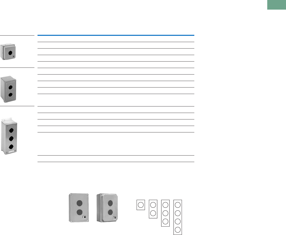
Logic Control Products CA08100001K—June 2012 www.eatoncanada.ca T37-269
37
37
37
37
37
37
37
37
37
37
37
37
37
37
37
37
37
37
37
37
37
37
37
37
37
37
37
37
37
37
37.8
Pushbuttons and Indicating Lights
30.5 mm Corrosion Resistant Watertight/Oiltight—E34
Enclosures
Die Cast, Polyester and Stainless Steel Enclosures
Enclosures (Case and Cover)—Surface Mounting
Mounting Instructions
These E34 Die Cast
Enclosures feature a
corrosion resistant coating
identical to finish on the E34
operators except gray in
colour. Not for use in
ultraviolet light applications.
One and Two Contact Block
Depth Enclosures Enclosure Layouts
Notes
For spacing increments, see Page T37-270.
All die cast enclosures can be converted to base mounting of contact blocks with spacers 10250TA22 or 10250TA23.
See listing on Page T37-213.
When used with E30 pushbuttons, only the one element enclosure can be used.
14 gauge, type 304.
Number of
Elements
One Contact Block Depth
Catalogue Number
Two Contact Block Depth
Catalogue Number
Die Cast Enclosure—In-Line NEMA 4, 4X, 12, 13
1E34N1 E34N11
2E34N2 E34N12
3E34N3 E34N13
4— E34N14
Polyester—In-Line NEMA 3, 4X, 12
1— E34N51
2— E34N52
3— E34N53
4— E34N54
Stainless Steel —In-Line NEMA 4, 4X, 12
1— 10250TN33
2— 10250TN34
3— 10250TN35
4— 10250TN36
Dimensions, see Page T37-278.
Die Cast Enclosure
Polyester Enclosure
Stainless Steel
Enclosure
One Contact
Block Depth
Enclosure
Two Contact
Block Depth
Enclosure
111
Top – For Vertical Mounting
Top – For Horizontal
Mounting
1
222
33
4
Tab37book.fm Page 269 Tuesday, July 3, 2012 10:46 PM
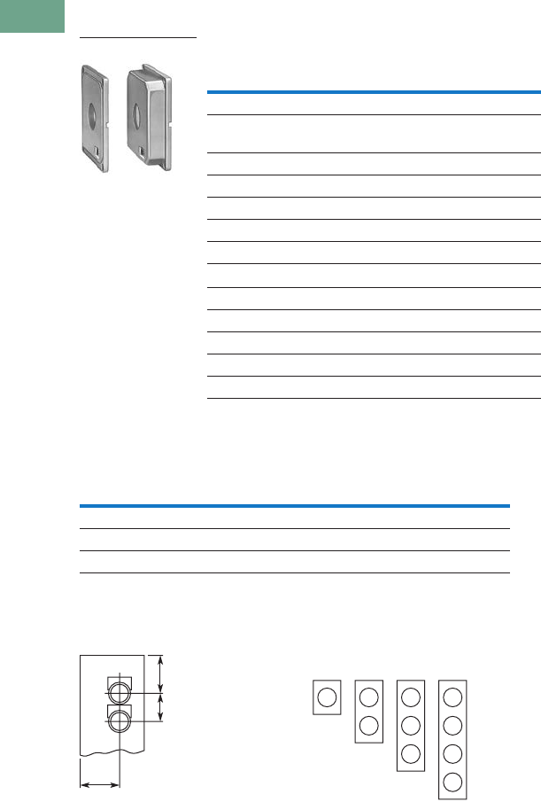
T37-270 Logic Control Products CA08100001K—June 2012 www.eatoncanada.ca
37
37
37
37
37
37
37
37
37
37
37
37
37
37
37
37
37
37
37
37
37
37
37
37
37
37
37
37
37
37
37.8
Pushbuttons and Indicating Lights
30.5 mm Corrosion Resistant Watertight/Oiltight—E34
Die Cast and Stainless Steel—Flush Mount, Covers Only
Covers Only—Flush Mounting
Spacing Increments
Approximate Dimensions in Inches (mm)
Spacing Increments for
Enclosures Enclosure Layouts
Notes
These E34 die cast covers feature a corrosion resistant coating identical to the finish on the E34 operators except gray in colour.
Not oiltight. NEMA 1 applications only.
Number of
Elements Catalogue Number Catalogue Number
Flush Die Cast Covers
In-Line Deep
Cover
In-Line Flat
Cover
1E34F11 E34F1
2E34F12 E34F2
3E34F13 E34F3
4E34F14 E34F4
In-Line Stainless Steel Flush Plates
With Pullbox Without Pullbox
110250TS10 10250TS1
210250TS11 10250TS2
310250TS12 10250TS3
410250TS14 10250TS4
Dimensions, see Page T37-279.
Type F G H
Die cast 2.44 (62) 2.5 (63.5) 1.88 (47.8)
Polyester 1.88 (47.8) Min. 2.13 (54.1) 2.25 (57.2)
Stainless steel 1.69 (42.9) Min. 1.73 (43.9) 2.25 (57.2)
Flush Mounting Covers
F
G
H
111
Top – For Vertical Mounting
Top – For Horizontal
Mounting
1
222
33
4
Tab37book.fm Page 270 Tuesday, July 3, 2012 10:46 PM

Logic Control Products CA08100001K—June 2012 www.eatoncanada.ca T37-271
37
37
37
37
37
37
37
37
37
37
37
37
37
37
37
37
37
37
37
37
37
37
37
37
37
37
37
37
37
37
37.8
Pushbuttons and Indicating Lights
30.5 mm Corrosion Resistant Watertight/Oiltight—E34
Contact Blocks
Standard Contact Blocks
●UL A600/P600 rated
●Colour-coded plungers—
red/green for NC/NO
circuits
●Silver contact tips with
“reliability nibs”
●Black (opaque) or amber
(translucent) housings
●Pressure plate or spade
terminals
●Fingerproof shrouds (for
pressure terminals only)
Logic Level Contact Blocks
●UL A600/P600 rated
●Black plungers
●Inert palladium knife-blade
contacts
●Black (opaque) housings
●Pressure plate or spade
terminals
●Fingerproof shrouds not
available
Special Function Contact Blocks
●UL A600/P600 rated
●Black plungers
●Silver contact tips with
“reliability nibs”
●Black (opaque) housings
●Pressure plate terminals
only
●Fingerproof shrouds not
available
Special Purpose Contact Block
●Maximum 300V rated
●Black plungers
●Silver contact tips with
“reliability nibs”
●Black (opaque) housings
●Pressure plate terminals
only
●Fingerproof shrouds not
available
Reliability Nibs
Reliability nibs are the
hallmark of Eaton’s contact
blocks. A pointed silver nib on
the contact tip ensures
reliable switching from logic
level (5V) up to 600V
applications. Therefore
standard contact blocks can
be used for most logic level
applications where the
contacts are not exposed to
any harsh environmental
conditions.
Palladium Contacts
Palladium, which is more
inert than gold, is well suited
for voltages and currents
approaching zero and is
recommended for
applications where
environmental conditions are
a factor.
Maximum Contact Block
Mounting per Operator Type
Operator
Max.
Stack
Pushbuttons 6
Push-pull operators 2
Roto-push operators 4
Two- or three-position
selector switches
6
Four-position selector
switches
4
Joysticks 4
Tab37book.fm Page 271 Tuesday, July 3, 2012 10:46 PM

T37-272 Logic Control Products CA08100001K—June 2012 www.eatoncanada.ca
37
37
37
37
37
37
37
37
37
37
37
37
37
37
37
37
37
37
37
37
37
37
37
37
37
37
37
37
37
37
37.8
Pushbuttons and Indicating Lights
30.5 mm Corrosion Resistant Watertight/Oiltight—E34
Contact Blocks
Notes
All 10250T contact blocks shown are suitable for use on standard 10250T and E34 operators. These contact blocks are not suitable for Class I Division 2
type 10250T or E34 devices.
Contact blocks with spade terminals are limited to a maximum of one contact block per operator and minimum spacing between devices is 2.5 in (63.5 mm).
Not suitable for use in 10250T or E34 enclosures. Also available in amber housing. Not available with fingerproof shrouds.
Special function contact blocks are not suitable for use with roto-push operators, three-position push-pull operators, or four-position selector switches.
ECNO contact blocks are not suitable for use with two-position joysticks or when operators are used with padlock attachments.
Special purpose 10250T44 contact blocks are not suitable on selector switches or roto-push operators. Okay to use with three-position push-pull operators only
on low voltage (30V or less) circuits.
Symbol Circuit Description
Standard Logic Level
Pressure Terminal
Catalogue Number
Spade Terminal
Catalogue Number
Pressure Terminal
Catalogue Number
Spade Terminal
Catalogue Number
1NC Stack up to six blocks (six circuits)
unless otherwise noted.
10250T51 10250T59 10250T51E 10250T59E
1NO Stack up to six blocks six circuits)
unless otherwise noted.
10250T53 10250T60 10250T53E 10250T60E
NO-NC Stack up to six blocks (12 circuits)
unless otherwise noted.
10250T1 10250T40 10250T1E 10250T40E
2NC Stack up to six blocks (12 circuits)
unless otherwise noted.
10250T3 10250T42 10250T3E 10250T42E
2NO Stack up to six blocks (12 circuits)
unless otherwise noted.
10250T2 10250T41 10250T2E 10250T41E
Special Function Blocks
LONC Late opening NC. Stack up to six
blocks (six circuits) unless
otherwise noted.
10250T71 — 10250T71E —
ECNO-
NC
Early closing NO and standard NC.
Stack up to six blocks unless
otherwise noted.
10250T47 — 10250T47E —
ECNO-
NO
Early closing NO and standard NO.
Stack up to four blocks unless
otherwise noted.
10250T57 — 10250T57E —
2LONC Two late opening NC contacts.
Stack up to six blocks unless
otherwise noted.
10250T45 — 10250T45E —
LONC-
ECNO
Overlapping contacts. Stack up to
four blocks unless otherwise noted.
10250T55 — 10250T55E —
Special Purpose Blocks
2NO-
2NC
Four circuits in single block depth.
Rated 300V max. Stack up to four
blocks unless otherwise noted.
10250T44 —
10250T1
Blank
No
Plunger
Blank
No
Plunger
Blank
No
Plunger
Tab37book.fm Page 272 Tuesday, July 3, 2012 10:46 PM
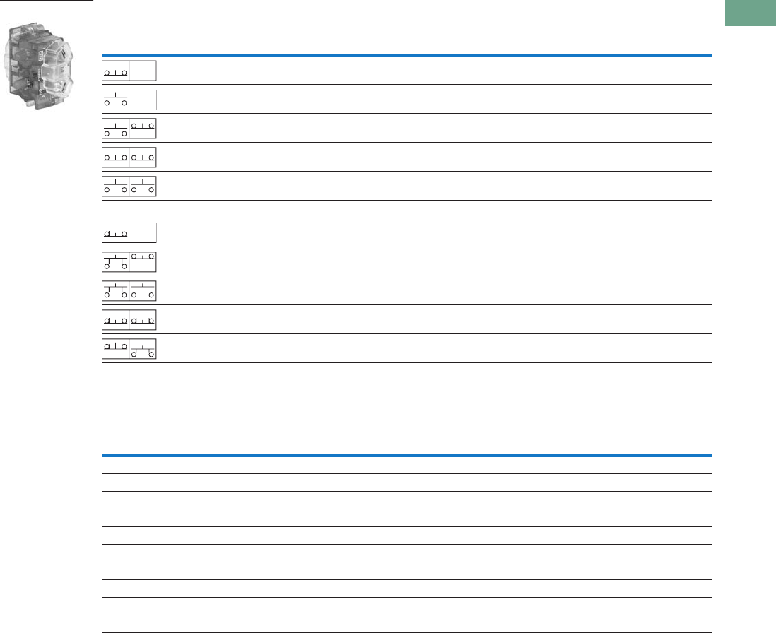
Logic Control Products CA08100001K—June 2012 www.eatoncanada.ca T37-273
37
37
37
37
37
37
37
37
37
37
37
37
37
37
37
37
37
37
37
37
37
37
37
37
37
37
37
37
37
37
37.8
Pushbuttons and Indicating Lights
30.5 mm Corrosion Resistant Watertight/Oiltight—E34
Contact Blocks with Fingerproof Shrouds
Replacement Parts
Replacement Lamps—For E34 Illuminated Operators
Notes
All 10250T contact blocks shown are suitable for use on standard 10250T and E34 operators. These contact blocks are not suitable for Class I Division 2
type 10250T or E34 devices.
To order contact blocks with translucent amber housing, change suffix P to CP in catalogue number e.g. 10250T51CP.
ECNO contact blocks are not suitable for use with two-position joysticks or when operators are used with padlock attachments.
Special function contact blocks are not suitable for use with roto-push operators, three-position push-pull operators, or four-position selector switches.
Symbol Circuit Description
Standard
Pressure Terminal
Catalogue Number
Logic Level
Pressure Terminal
Catalogue Number
1NC Stack up to six blocks (six circuits) unless otherwise noted. 10250T51P 10250T51EP
1NO Stack up to six blocks (six circuits) unless otherwise noted. 10250T53P 10250T53EP
NO-NC Stack up to six blocks (12 circuits) unless otherwise noted. 10250T1P 10250T1EP
2NC Stack up to six blocks (12 circuits) unless otherwise noted. 10250T3P 10250T3EP
2NO Stack up to six blocks (12 circuits) unless otherwise noted. 10250T2P 10250T2EP
Special Function Blocks
LONC Late opening NC. Stack up to six blocks (six circuits) unless
otherwise noted.
10250T71P 10250T71EP
ECNO-NC Early closing NO and standard NC. Stack up to six blocks
unless otherwise noted.
10250T47P 10250T47EP
ECNO-NO Early closing NO and standard NO. Stack up to four blocks
unless otherwise noted.
10250T57P 10250T57EP
2LONC Two late opening NC contacts. Stack up to six blocks unless
otherwise noted.
10250T45P 10250T45EP
LONC-ECNO Overlapping contacts. Stack up to four blocks unless
otherwise noted.
10250T55P 10250T55EP
Mfg. Lamp Type Voltage Base Style Application Part Number
120MB 120V T 3-1/4 bayonet 10250T resistor indicating light 28-3044
#267 6.3V T 3-1/4 bayonet 10250T flasher 10250ED986-4
#755 6.3V T 3-1/4 bayonet 10250T transformer, PresTest and full voltage 28-2202
#756 12V T 3-1/4 bayonet 10250T full voltage 28-5184
#757 24V T 3-1/4 bayonet 10250T full voltage 28-5185
#1828 32V T 3-1/4 bayonet 10250T full voltage 28-5186
#1835 55V T 3-1/4 bayonet 10250T resistor 28-5187
NE48 120V T 4-1/2 bayonet 10250T neon 28-494
NE51H-R22 120V T 3-1/4 bayonet 10250T neon 28-3754
NE51H-R68 240V T 3-1/4 bayonet 10250T neon 28-3755
10250T1CP
Blank
No
Plunger
Blank
No
Plunger
Blank
No
Plunger
Tab37book.fm Page 273 Tuesday, July 3, 2012 10:46 PM
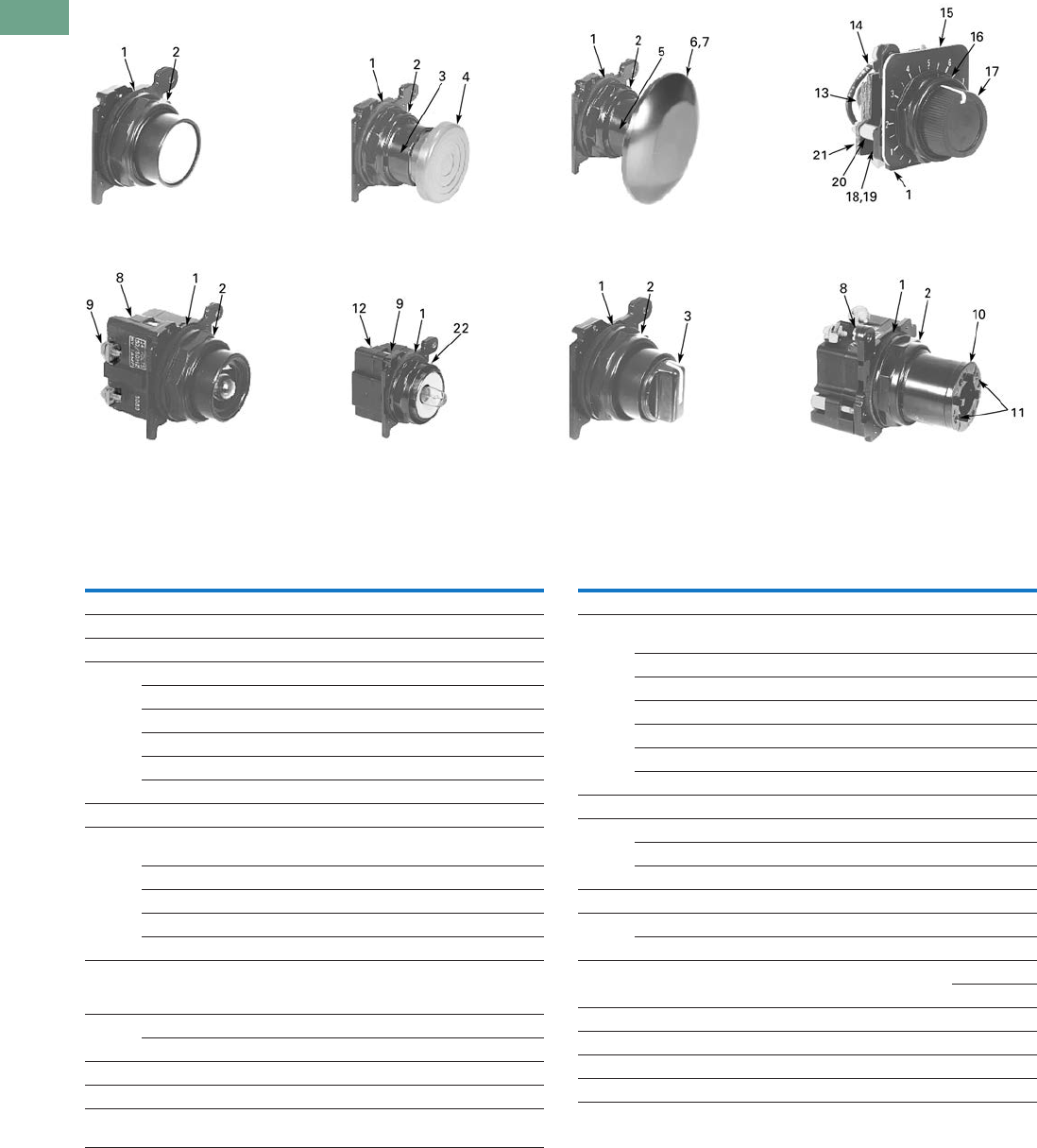
T37-274 Logic Control Products CA08100001K—June 2012 www.eatoncanada.ca
37
37
37
37
37
37
37
37
37
37
37
37
37
37
37
37
37
37
37
37
37
37
37
37
37
37
37
37
37
37
37.8
Pushbuttons and Indicating Lights
30.5 mm Corrosion Resistant Watertight/Oiltight—E34
E34 Style Operator Replacement Parts
Flush Head
Pushbutton Operator Mushroom Head
Pushbutton Operator Jumbo Mushroom
Head Operator
Illuminated
Pushbutton Operator Transformer Type
Indicating Light Knob-Operated
Selector Switch
Operator
Full Voltage, Resistor
and Transformer Type
Illuminated Selector Switch
Potentiometers
Item
No. Description
No.
Req.
Part
Number
1 Gasket 1 16-1548
2 Mounting nut 1 15-1530-4
3 Set screw (#6-32 x 0.250 in long hollow hex) 2 11-2014
4 Mushroom head button (includes [2] item 5) 1 As Req. Below
Black — 53-1317
Red — 53-1317-2
Yellow — 53-1317-3
Green — 53-1317-4
Blue — 53-1317-22
5 Set screw (#10-32 x 0.250 in long hollow hex) 2 11-544
6 Jumbo mushroom head button
(aluminum—includes [2] item 5)
1As Req. Below
Red — 53-1317-9
Black — 53-1317-10
Yellow — 53-1317-11
Green — 53-1317-12
7 Jumbo mushroom head button
(aluminum—red EMERG. STOP)
does not include item 5
153-1349-18
8 Mounting screw (#6-32 x 0.710 in long) 2 10250TA79
Washer 2 16-2038
9 Terminal screw and lug (captive) Req. 80-5502
10 Gasket (supplied with basic unit) 1 32-803
11 Round head screw (#4-40 x 0.344 in long)
(supplied with basic unit)
211-4553
Item
No. Description
No.
Req.
Part
Number
12 Mounting screw 2 11-1632
13 Simple potentiometer
(does not include items 18, 28 or 29)
1As Req. Below
1,000 ohms — 41-782-2
2,500 ohms — 41-782-3
5,000 ohms — 41-782-10
10,000 ohms — 41-782-4
25,000 ohms — 41-782-5
50,000 ohms — 41-782-6
14 Connector (includes screw and lug) 2 25-1851
15 Indicating plate 1 As Req. Above
Standard size (without legend) — 30-4460
Large size (specify legend) — 10250TR30
16 Retaining nut 1 15-1547-3
17 Knob 1 53-1314
Socket set screw (#6-32 x 0.250 in long) 1 11-2014
18 Coupling 1 11-2014
29-3749-2
19 Set screw (#6-32 x 0.188 in long) 1 11-1199
20 Spacer 2 56-1066-18
21 Connector (includes screw and lug) 1 25-1851-2
22 Mounting nut 1 15-1938-2
Tab37book.fm Page 274 Tuesday, July 3, 2012 10:46 PM

Logic Control Products CA08100001K—June 2012 www.eatoncanada.ca T37-275
37
37
37
37
37
37
37
37
37
37
37
37
37
37
37
37
37
37
37
37
37
37
37
37
37
37
37
37
37
37
37.8
Pushbuttons and Indicating Lights
30.5 mm Corrosion Resistant Watertight/Oiltight—E34
Technical Data and Specifications
Mechanical Ratings
General Specifications
Description Specification
Frequency of Operation
All pushbuttons 6000 operations/hr.
Key and lever selector switches 3000 operations/hr.
Auto-latch devices 1200 operations/hr.
Life
Pushbuttons 10 x 106 operations
Contact blocks 10 x 106 operations
PresTest units 10 x 106 operations
Lever and key selector switches 0.25 x 10⁶ operations
Twist to release pushbuttons 0.3 x 10⁶ operations
Shock Resistance
Duration 210 ms >5g
Description Specification
Climate Conditions
Operating temperature 1˚ to 150˚F (–17˚ to 66˚C)
Storage temperature –40˚ to 176˚F (–40˚ to 80˚C)
Altitude 6,562 ft (2,000m)
Humidity Max. 95% RH at 60˚C
Terminals
Marking NC-NO on the contact block to meet the NEMA requirements. Dual marking system 1–2
for normally closed, 3–4 for normally open to meet BS5472 (Cenelec EN50 005).
Clamps Terminals are saddle clamp type for 1 x 22 AWG (0.34 mm2) to 2 x 14 AWG (2.5 mm2)
conductors
Torque 7 lb-in (0.8 Nm)
Degree of protection against direct electrical contact IP2X with fingerproof shroud
Light Units
Transformers Will withstand short-circuit for 1 hour per IEC 60947-5-1
Bulbs—average life:
Transformer type 20,000 hrs.
Resistor/direct voltage type 2500 hrs. minimum at rated V
LED 60,000 to 100,000 hrs.
Tab37book.fm Page 275 Tuesday, July 3, 2012 10:46 PM

T37-276 Logic Control Products CA08100001K—June 2012 www.eatoncanada.ca
37
37
37
37
37
37
37
37
37
37
37
37
37
37
37
37
37
37
37
37
37
37
37
37
37
37
37
37
37
37
37.8
Pushbuttons and Indicating Lights
30.5 mm Corrosion Resistant Watertight/Oiltight—E34
Electrical Ratings
Electrical Ratings—Contact Block
Description Specification
Insulation Ui = 660 Vac or Vdc
Thermal Ith = 10A
Short Circuit Coordination to IEC/EN 60947-5-1
Rated conditional short circuit current 1 kA
Fuse type GE power controls TIA 10, red spot type gG, 10A, 660 Vac, 460 Vdc, BS88-2,
IEC 60269-2-1
UL rating A600, P600
AC load life duty cycle 1200 operations/hour
10A 110V pf 0.4—1 x 10⁶ operations
5A 250V pf 0.4—1 x 10⁶ operations
2A 600V pf 0.4—1 x 10⁶ operations
Switching capacity
AC 15 rated make/break (11 x le at 1.1 x Ue)
6A 120V pf 0.3
4A 240V pf 0.3
2A 660V pf 0.3
DC13 rated make/break (1.1 x le at 1.1 x Ue)
1.0A 125V L/R >0.95 at 300 ms
0.55A 250V L/R >0.95 at 300 ms
0.1A 660V L/R >0.95 at 300 ms
10A 110V pure resistive
Maximum ratings for logic level and
hostile atmosphere application
Maximum amperes 0.5A
Maximum volts 120 Vac/Vdc
Low voltage switching Conical shaped points or “reliability nibs” improve performance in dry circuit,
corrosive, fine dust and other contaminated atmospheres. Under normal
environmental conditions, the minimum operational voltage is 5V and the minimum
operational current is 1 mA, Vac/Vdc.
Contact operation Slow make and break. All normally closed contacts have positive opening operation,
i.e., normally closed contacts are forced open in the event of contact weld or spring
breakage.
Meet or Exceed NEMA Rating Designations A600, A300 and B300 for AC and P600 for DC
Description
50 Vac or 60 H Vdc
120 240 480 600 24/28 125 250
Meet or Exceed NEMA Rating Designations A600, A300 and B300 for AC and P600 for DC
Make and emerg. interrupting capacity (amp) 60 30 15 12 5.7 1.1 0.55
Normal load break (amp) 6 3 1.5 1.2 5.7 1.1 0.55
Thermal current (amp) 10 10 10 10 5.0 5.0 5.0
Voltamperes:
Make and emerg. interrupting capacity 7200 7200 7200 7200 138 138 138
Normal load break 720 720 720 720 138 138 138
Tab37book.fm Page 276 Tuesday, July 3, 2012 10:46 PM

Logic Control Products CA08100001K—June 2012 www.eatoncanada.ca T37-277
37
37
37
37
37
37
37
37
37
37
37
37
37
37
37
37
37
37
37
37
37
37
37
37
37
37
37
37
37
37
37.8
Pushbuttons and Indicating Lights
30.5 mm Corrosion Resistant Watertight/Oiltight—E34
Mounting Options
Panel Thickness
●Minimum: 0.06 in (1.6 mm)
●Maximum: 0.25 in (8 mm) including legend plate
●Maximum can be increased to 0.375 in (15.9 mm) using optional retaining nut
●Indicating light: 10250TA30
●Pushbutton/selector switch: 10250TA31
Mounting Matrix
Mounting Options in Inches (mm)
Horizontal mounting means terminals are located top and bottom of contact block.
Vertical mounting means terminals are left and right of contact block.
This allows close spacing of adjacent operators with easy access to terminals.
Locating nib hole or notch is 0.14 in (3.6 mm) #29 drill.
Drilling Dimensions in Inches (mm)
Legend
Plate
Dimensions in Inches (mm)
ABCD
Small 1.63 (41.3) 2.25 (57.2) 2.25 (57.2) 1.63 (41.3)
Medium 1.75 (44.5) 2.25 (57.2) 2.25 (57.2) 1.75 (44.5)
Large 2.25 (57.2) 2.25 (57.2) 2.25 (57.2) 2.25 (57.2)
B
Min.
C
Min.
0.6
(15.2)
A
Min. 1.22
(31)
D
Min.
Horizontal Mounting Vertical Mounting
0.14 (3.6)
Dia.
Terminals on Top
Terminals at Side
0.6
(15.2)
1.20
(30.5)
0.14 (3.6)
Dia.
Tab37book.fm Page 277 Tuesday, July 3, 2012 10:46 PM

T37-278 Logic Control Products CA08100001K—June 2012 www.eatoncanada.ca
37
37
37
37
37
37
37
37
37
37
37
37
37
37
37
37
37
37
37
37
37
37
37
37
37
37
37
37
37
37
37.8
Pushbuttons and Indicating Lights
30.5 mm Corrosion Resistant Watertight/Oiltight—E34
Dimensions
Approximate Dimensions in Inches (mm)
Potentiometer Legend Plates
Surface Mounting
Die Cast, Polyester and Stainless Steel Enclosures
Notes
Depth given is for two contact block deep stations. One contact block deep stations subtract 3/4 in (19.1 mm).
No conduit entrance holes provided. Drill as required.
1.88
(47.8)
1.31
(33.3)
1.09
(27.7) 1.0
(25.4)
0.75
(19.1)
0.94
(23.9)
0.94
(23.9)
0.94
(23.9)
Std. Dial Plate
Large Dial Plate 2.19
(55.6)
Jumbo
2.19
(55.6)
1.77
(45)
Standard
1.77
(45)
A
Surface
DC
B
E
4 Mtg. Holes — 10-32 Screw Size for
1 – 4 Element Die Cast/
Stainless Steel Enclosure
7/32 Screw Size for
Polyester
Number of
Elements
Element
Arrangement
Wide
A
High
B
Deep
C
Mounting Conduit
EntranceDE
Die Cast
1 In-line 3.88 (98.6) 4.0 (101.6) 3.0 (76.3) 2.69 (68.3) 3.25 (82.6) 3/4
2 3.88 (98.6) 5.88 (149.4) 3.0 (76.3) 2.69 (68.3) 5.13 (130.3)
3 3.88 (98.6) 7.75 (196.9) 3.0 (76.3) 2.69 (68.3) 7.0 (177.8) 1
4 3.88 (98.6) 9.63 (244.6) 3.0 (76.3) 2.69 (68.3) 8.88 (225.6)
Polyester
1 In-line 3.81 (96.8) 6.63 (168.4) 3.38 (85.9) 2.94 (74.7) 4.88 (124.0)
2 3.81 (96.8) 6.63 (168.4) 3.38 (85.9) 2.94 (74.7) 4.88 (124.0)
3 3.81 (96.8) 8.88 (225.6) 3.38 (85.9) 2.94 (74.7) 7.13 (181.1)
4 3.81 (96.8) 11.13 (282.7) 3.38 (85.9) 2.94 (74.7) 9.38 (238.3)
Stainless Steel
1 In-line 3.00 (76.2) 3.50 (88.9) 3.00 (76.2) 1.50 (38.1) 4.25 (108.0)
2 3.50 (88.9) 6.75 (171.5) 3.00 (76.2) 1.50 (38.1) 7.50 (190.5)
3 3.50 (88.9) 9.00 (228.6) 3.00 (76.2) 1.50 (38.1) 9.00 (228.6)
4 3.50 (88.9) 11.25 (285.8) 3.00 (76.2) 1.50 (38.1) 12.00 (304.8)
Tab37book.fm Page 278 Tuesday, July 3, 2012 10:46 PM
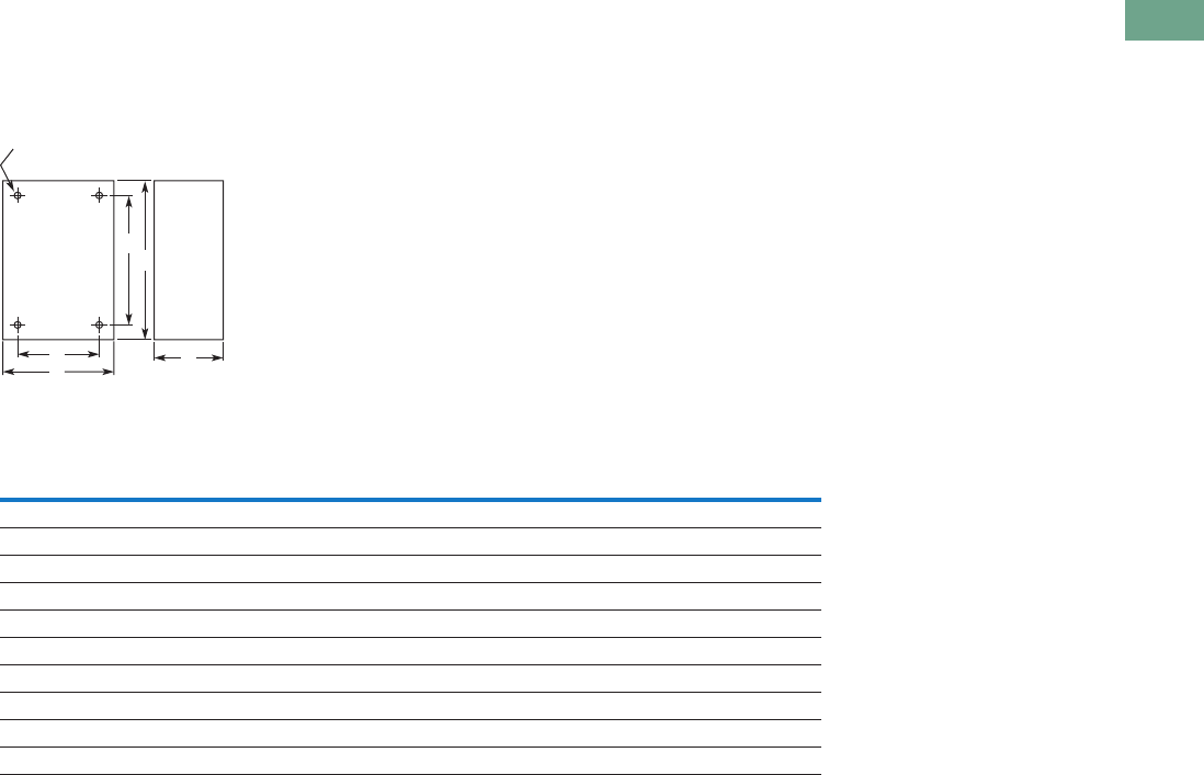
Logic Control Products CA08100001K—June 2012 www.eatoncanada.ca T37-279
37
37
37
37
37
37
37
37
37
37
37
37
37
37
37
37
37
37
37
37
37
37
37
37
37
37
37
37
37
37
37.8
Pushbuttons and Indicating Lights
30.5 mm Corrosion Resistant Watertight/Oiltight—E34
Approximate Dimensions in Inches (mm)
Flush Mounting
Die Case and Stainless Steel Covers Only
Notes
Depth given is for flat cover. Deep cover is 3/4 in (19.1 mm) deeper.
Depth given includes pull box.
A
Surface or Pendant
DC
B
E
4 Mtg. Holes - 10-32 Screw Size
for 1-11 Element Encl, 1/4-20
Screw Size for 12 Element
and Larger
Number of
Elements
Wide
A
High
B
Deep
C
Mounting
DE
Die Cast
1 3.88 (98.6) 4.0 (101.6) 0.25 (6.4) 3.50 (88.9) 3.63 (92.2)
2 3.88 (98.6) 5.88 (149.4) 0.25 (6.4) 3.50 (88.9) 5.50 (139.7)
3 3.88 (98.6) 7.75 (196.9) 0.25 (6.4) 3.50 (88.9) 6.0 (152.4)
4 3.88 (98.6) 9.63 (244.6) 0.25 (6.4) 3.50 (88.9) 9.25 (235)
Stainless Steel
1 5.00 (127) 5.0 (127 2.50 (63.5) 3.25 (82.6) 1.88 (47.8)
2 5.00 (127) 6.88 (174.8) 2.50 (63.5) 3.25 (82.6) 3.63 (92.2)
3 5.00 (127) 8.63 (219.2) 2.50 (63.5) 3.25 (82.6) 5.50 (139.7)
4 5.00 (127) 10.50 (266.7) 2.50 (63.5) 3.25 (82.6) 7.25 (184.2)
Tab37book.fm Page 279 Tuesday, July 3, 2012 10:46 PM
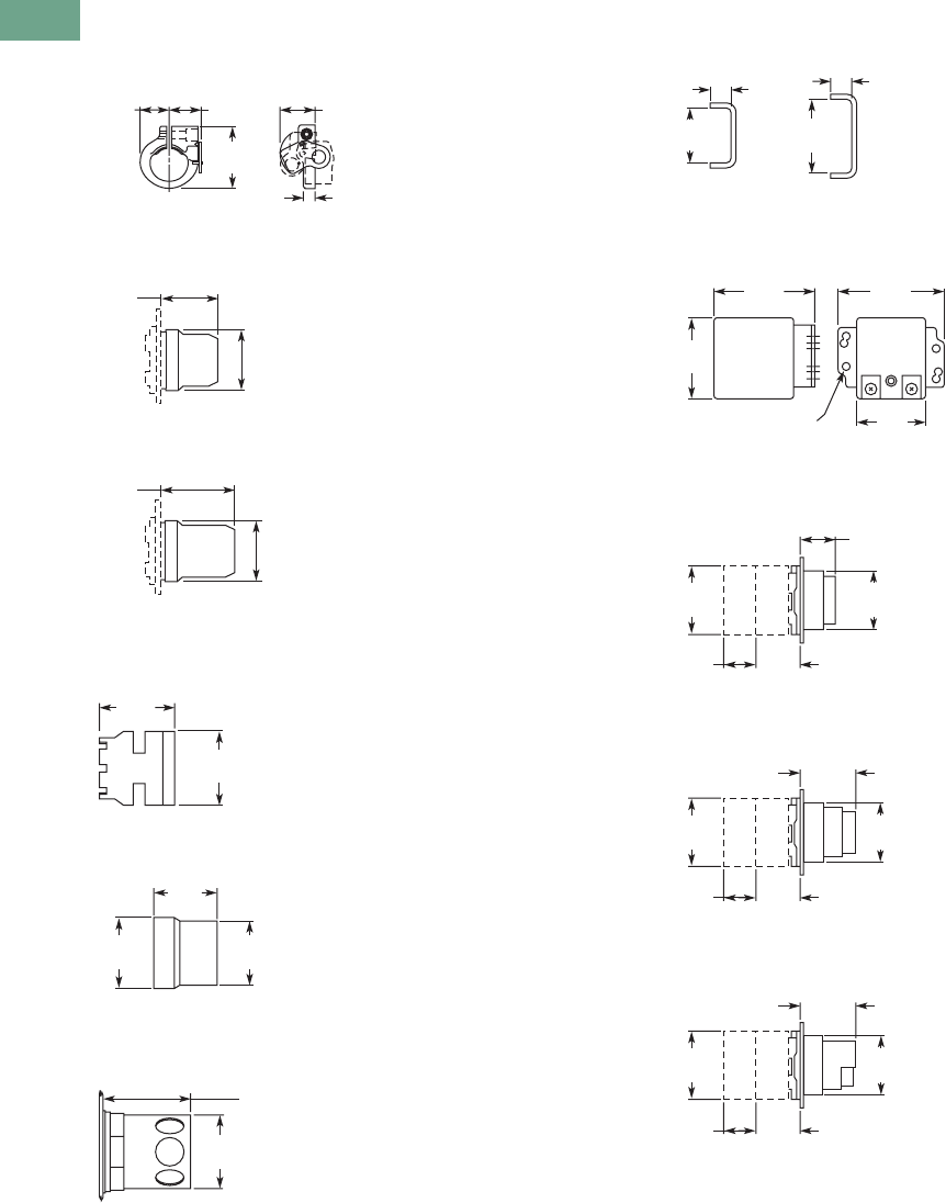
T37-280 Logic Control Products CA08100001K—June 2012 www.eatoncanada.ca
37
37
37
37
37
37
37
37
37
37
37
37
37
37
37
37
37
37
37
37
37
37
37
37
37
37
37
37
37
37
37.8
Pushbuttons and Indicating Lights
30.5 mm Corrosion Resistant Watertight/Oiltight—E34
Approximate Dimensions in Inches (mm)
Padlocking Attachment for Flush
Pushbutton Operators
Flexible Weather Resistant Boot
Transparent Boot
Shroud for Mushroom
Head Operator
Extended Retaining Nut
Guard for Illuminated
Pushbutton
Contact Block Terminal Jumps
Master Test Module and
Flasher Module
Flush Pushbutton
Extended Pushbutton
Half Shroud Pushbutton
0.75
(19.1)
0.84
(21.3) 0.94
(23.9)
1.63
(41.4)
0.25
(6.4)
1.47
(37.3)
1.59
(40.4)
1.92
(48.8)
1.59
(40.4)
1.53
(38.9)
1.50
(38.1)
1.25
(31.8)
1.31
(33.3)
1.38
(35.1)
1.63
(41.4)
1.50
(38.1)
0.25
(6.4)
0.25
(6.4)
0.86
(21.8)
0.45
(11.4)
1.63
(41.4)
1.14
(29)
6 Mounting Holes
1.78
(45.2)
1.31
(33.3)
0.88
(22.4) 1.09
(27.7)
1.06
(26.9)
1.78
(45.2) 1.38
(35.1)
Contact
Blk.
Each Addl.
Contact Blk.
0.88
(22.4) 1.09
(27.7)
1.44
(36.6)
1.78
(45.2) 1.38
(35.1)
Contact
Blk.
Each Addl.
Contact Blk.
0.88
(22.4) 1.09
(27.7)
1.44
(36.6)
1.78
(45.2) 1.38
(35.1)
Contact
Blk.
Each Addl.
Contact Blk.
Tab37book.fm Page 280 Tuesday, July 3, 2012 10:46 PM
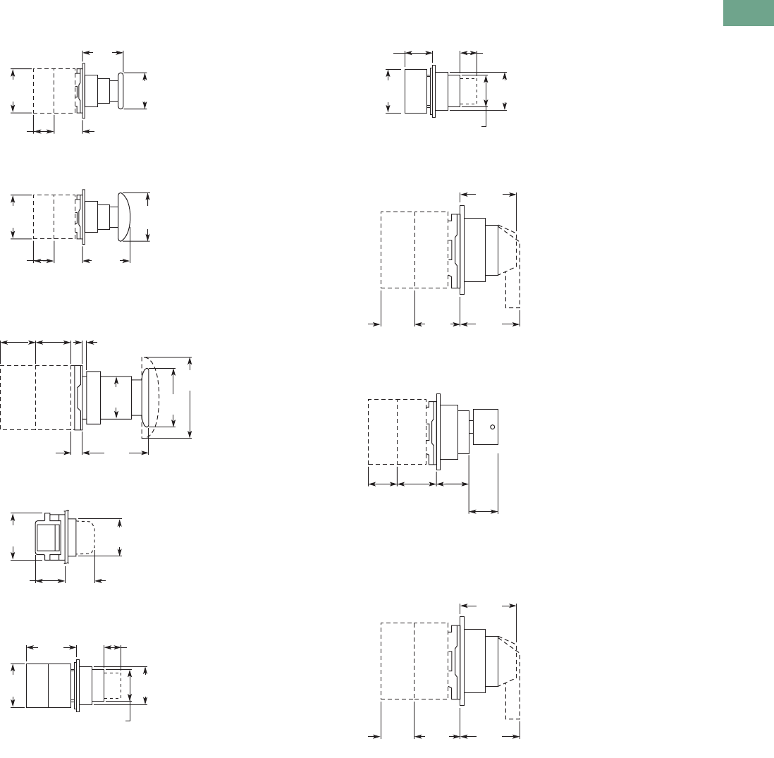
Logic Control Products CA08100001K—June 2012 www.eatoncanada.ca T37-281
37
37
37
37
37
37
37
37
37
37
37
37
37
37
37
37
37
37
37
37
37
37
37
37
37
37
37
37
37
37
37.8
Pushbuttons and Indicating Lights
30.5 mm Corrosion Resistant Watertight/Oiltight—E34
Approximate Dimensions in Inches (mm)
Mushroom Pushbutton
Jumbo Mushroom Pushbutton
Push-Pull Switch
Indicating Light
PresTest Indicating Light
Illuminated Pushbutton
Selector Switch
Key Selector Switch
Illuminated Selector Switch
0.88
(22.4) 1.09
(27.7)
1.63
(41.4)
1.78
(45.2)
1.50
(38.1)
Contact
Blk.
Each Addl.
Contact Blk.
0.88
(22.4) 1.09
(27.7)
1.75
(44.5)
1.78
(45.2)
2.50
(63.5
)
Contact
Blk.
Each Addl.
Contact Blk.
2.63
(66.8)
1.65
(41.9)
1.78
(45.2)
0.25
(6.4)
0.06 (1.5) to 0.25 (6.4)
Panel Thickness
0.88
(22.4)
0.88
(22.4)
1.13
(28.7)
Light
Unit
Contact
Block
1.38
(35.1)
1.1
(27.9)
1.78
(45.2) 1.38
(35.1)
1.9
(48.3) 1.09
(27.7) 0.69
(17.5)
1.78
(45.2) 1.38
(35.1)
1.13
(28.7)
Contact
Blk.
Each Addl.
Contact Blk.
1.09
(27.7)
1.09
(27.7) 0.69
(17.5)
1.78
(45.2) 1.38
(35.1)
1.13
(28.7)
Light
Unit
1.58
(40.1)
Knob
1.58
(40.1)
Lever
1.09
(27.7)
0.88
(22.4)
Contact
Block
Each Additional
Contact Block
1.5
(38.1)
1.58 (40.1)
to Remove
Key
1.09
(27.7)
0.88
(22.4)
Contact
Block
Each Addl.
Contact Blk.
1.58
(40.1)
Knob
1.58
(40.1)
Lever
1.09
(27.7)
0.88
(22.4)
Light
Unit
Each Additional
Contact Block
Tab37book.fm Page 281 Tuesday, July 3, 2012 10:46 PM

T37-282 Logic Control Products CA08100001K—June 2012 www.eatoncanada.ca
37
37
37
37
37
37
37
37
37
37
37
37
37
37
37
37
37
37
37
37
37
37
37
37
37
37
37
37
37
37
37.8
Pushbuttons and Indicating Lights
30.5 mm Corrosion Resistant Watertight/Oiltight—E34
This page left intentionally blank
Tab37book.fm Page 282 Tuesday, July 3, 2012 10:46 PM
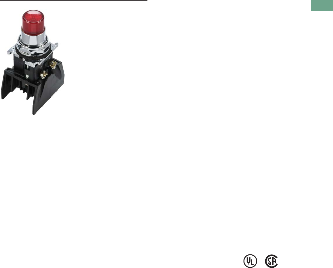
Logic Control Products CA08100001K—June 2012 www.eatoncanada.ca T37-283
37
37
37
37
37
37
37
37
37
37
37
37
37
37
37
37
37
37
37
37
37
37
37
37
37
37
37
37
37
37
37.10
Pushbuttons and Indicating Lights
30.5 mm Class I Division 2 Hazardous Locations—10250T/E34
30.5 mm Class I Division 2 Hazardous Locations—10250T/E34 Contents
Description Page
30.5 mm Class I Division 2 Hazardous Locations—
10250T/E34
Product Overview . . . . . . . . . . . . . . . . . . . . . . . . . . T37-284
Product Identification . . . . . . . . . . . . . . . . . . . . . . . T37-285
Catalogue Number Selection . . . . . . . . . . . . . . . . . T37-285
Product Selection
Momentary Pushbutton Units . . . . . . . . . . . . . . T37-286
Non-Illuminated Pushbutton Units . . . . . . . . . . T37-290
Illuminated Pushbutton Units . . . . . . . . . . . . . . T37-292
Guarded Illuminated Pushbutton Units . . . . . . . T37-293
Indicating Light Units . . . . . . . . . . . . . . . . . . . . . T37-294
Illuminated Pushbuttons and
Indicating Lights . . . . . . . . . . . . . . . . . . . . . . . T37-295
Push-Pull Units . . . . . . . . . . . . . . . . . . . . . . . . . T37-297
Illuminated Push-Pull Units . . . . . . . . . . . . . . . . T37-299
Push-Pull Operators . . . . . . . . . . . . . . . . . . . . . . T37-302
Selector Switch Units . . . . . . . . . . . . . . . . . . . . T37-306
Selector Switch Selection . . . . . . . . . . . . . . . . . T37-308
Selector Switch Operators . . . . . . . . . . . . . . . . T37-311
Illuminated Selector Switch Operators . . . . . . . T37-314
Options . . . . . . . . . . . . . . . . . . . . . . . . . . . . . . . . . . T37-316
Technical Data and Specifications . . . . . . . . . . . . . T37-319
Dimensions . . . . . . . . . . . . . . . . . . . . . . . . . . . . . . T37-321
Ratings . . . . . . . . . . . . . . . . . . . . . . . . . . . . . . . . . . T37-322
Product Description
All the Industry-Proven
Quality of Eaton’s 10250T and
E34 Series of Logic Devices,
plus Class I Division 2
Certification
The 10250T1H consists of a
normally open-normally
closed factory sealed contact
block that is UL Listed for use
in Class I, Division 2, Groups
B, C and D (NEC 500–503)—
Class I, Zone 2, IIB + H2 (NEC
505) hazardous locations and
is rated for both NEMA A600
and NEMA Q300. 10250T
and E34 illuminated
components have also been
UL Listed for use in Class I,
Division 2, Groups B, C and D
(NEC 500–503)—Class I,
Zone 2, IIB + H2 (NEC 505).
This, combined with the
industry-proven Eaton
10250T 30.5 mm pushbutton
line, offers a complete
solution to Division 2
hazardous location
requirements.
Single composite catalogue
numbers for complete
assembled stations and
operators for use in Division 2
hazardous locations are
featured throughout this
section.
Features
●Factory sealed contact
blocks
●Heavy-duty zinc die cast
construction
●NEMA rated 1, 2, 3, 3R, 4,
4X, 12, 13
●Front-of-panel drainage
holes
●Grounding nibs on the
operator casing
●Solid thermosetting
cathodic epoxy coating on
E34
●Corrosion resistance in
E34
Benefits
●Pushbutton for hazardous
locations
●Drainage holes prevent
buildup of liquid inside the
operator which can prevent
operation in freezing
environments
●Grounding nibs bite
through paint and other
coatings to provide secure
ground
●Suitable for corrosive
environments (E34 only)
●Earth terminal provides
additional grounding point
and allows for daisy chain
grounding (E34 line)
Standards and
Certifications
●UL 508—File No. E131568
●UL 1604—File No. E10323
●CSA Certified C22.2
No.14—File No. LR 68551
●CSA Certified C22.2 No.
213-M1987—File No. LR
20713
Ingress Protection
●Standard indicating lights
●UL (NEMA) Type 3, 3R,
3S, 4, 4X, 12, 13
●IEC IP65
●All other operators
●UL (NEMA) Type 3, 3R,
4, 4X, 12, 13
●IEC IP65
Tab37book.fm Page 283 Tuesday, July 3, 2012 10:46 PM
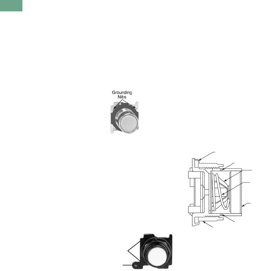
T37-284 Logic Control Products CA08100001K—June 2012 www.eatoncanada.ca
37
37
37
37
37
37
37
37
37
37
37
37
37
37
37
37
37
37
37
37
37
37
37
37
37
37
37
37
37
37
37.10
Pushbuttons and Indicating Lights
30.5 mm Class I Division 2 Hazardous Locations—10250T/E34
Product Overview
Operator
The 30.5 mm 10250T
pushbutton line features a
zinc die cast construction with
chrome-plated housing and
mounting nut.
Eaton’s E34 Series 30.5 mm
pushbutton line features the
same rugged die cast
construction of our 10250T
line with an additional two-
layer 100% solid thermosetting
cathodic epoxy coating. This
coating provides a flat black
smooth, consistent, corrosion
resistant surface that has
passed a demanding 600 hour
salt spray test. (The industry
standard for this 4X test
requires only 200 hours.)
Ultraviolet Light
E34 epoxy coating is not
recommended for use in
applications where exposure
to ultraviolet light exists—use
NEMA 4X 10250T operators.
Ratings
Our Class I Division 2 line of
pushbuttons are UL Listed
(NEMA type) 1, 2, 3, 3R, 4,
4X, 12 and 13. Our Class I
Division 2 E34 line meets IEC
947-1 IP66 standards and the
cathodic coating meets FDA
3A sanitary chemical
resistance requirements.
For a complete listing of all
applicable ratings see
Pages T37-319 to
T37-320.
10250T Grounding Nibs
10250T line operators have
“grounding nibs”—four metal
points on the operator casting
designed to bite through
most paints and other
coatings on metal panels to
enhance the grounding
connection when the
operator is securely
tightened.
10250T Grounding Nibs
E34 Grounding Nibs
E34 line of operators is
equipped with a ground
screw terminal as part of its
die cast construction. This
earthing terminal provides an
easily accessible point for
grounding operators when
used in a painted or
nonmetallic enclosure and
eliminates the need for extra
kits when daisy chain
grounding is required.
E34 Grounding Nibs
Nib
Earth
Terminal
Diaphragm Seal with
Drainage Holes
Liquid Drainage
Eaton’s pushbutton operators
offer front of panel drainage
via holes in the operator
bushing. Hidden from view
by the mounting nut, these
holes prevent buildup of
liquid inside the operator,
which can prevent operation
in freezing environments. The
holes also provide a route for
escaping liquid in high
pressure washdowns,
effectively relieving pressure
from the internal diaphragm
seal, ensuring reliable sealing
in applications even beyond
NEMA 4.
Diaphragm Seal
Foam Neoprene
Panel Sealing Gasket
Drainage Hole
Drainage Hole
Flexible
Diaphragm
Stainless
Steel
Operating
Spring
Mounting Nut
Colourfast
Molded
Button
Tab37book.fm Page 284 Tuesday, July 3, 2012 10:46 PM
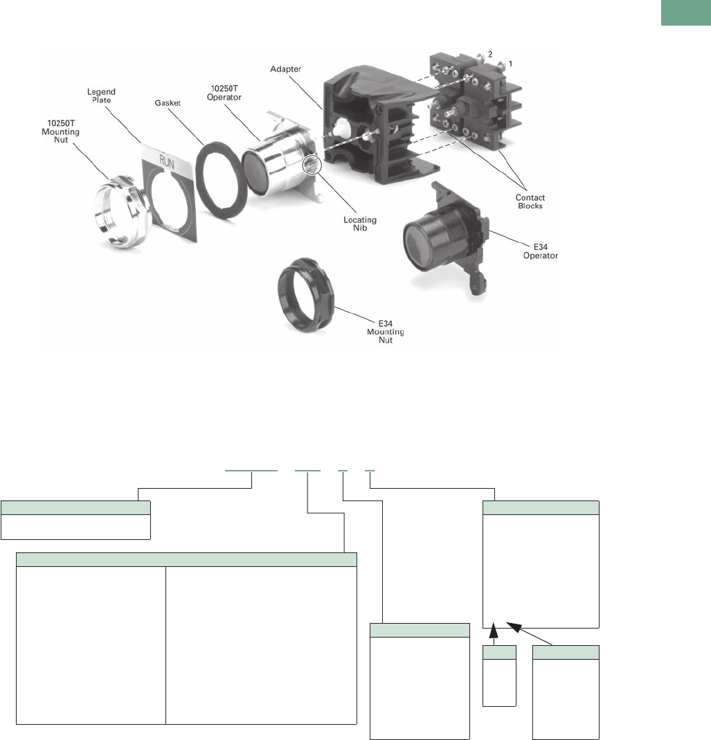
Logic Control Products CA08100001K—June 2012 www.eatoncanada.ca T37-285
37
37
37
37
37
37
37
37
37
37
37
37
37
37
37
37
37
37
37
37
37
37
37
37
37
37
37
37
37
37
37.10
Pushbuttons and Indicating Lights
30.5 mm Class I Division 2 Hazardous Locations—10250T/E34
Product Identification
30.5 mm Class I Division 2 Hazardous Locations
Catalogue Number Selection
Catalogue Number Selection is for illustrative purposes only and not to be used to create new catalogue numbers.
Non-Illuminated Assembled Operators
ACC/SS Type
Blank = None
J = JMB push-pull
B = Booted-FL/EXT
G = Guarded-FL
K = Knob-SS
L = Lever-SS
A = Lever W/IP-SS
C = Coin-SS
Keyed-SS
— —
Cam
1
2
3
7
Button Colour
B= Black
R= Red
G= Green
Y= Yellow
W= White
L= Blue
N= Orange
E= Red EMERG. STOP
T= Keyed-SS
Key Removal
1 = RT only
2 = LT only
3 = RT and LT
4 = CT only
5 = RT and CT
6 = LT and CT
7 = All
Operator and Contact Block
706 = Flush 1NO-1NC
707 = Flush 2NO-2NC
708 = Extended 1NO-1NC
709 = Extended 2NO-2NC
710 = Mushroom 1NO-1NC
711 = Mushroom 2NO-2NC
712 = JMB mushroom 1NO-1NC
713 = JMB mushroom 2NO-2NC
714 = 2P MT push-pull 1NO-1NC
715 = 2P MT push-pull 2NO-2NC
716 = 3P MT push-mom pull 1NO-1NC
717 = 3P MT push-mom pull 2NO-2NC
718 = 3P mom push-pull 1NO-1NC
721 = 3P mom push-pull 2NO-2NC
722 = 2P SS MT XO,OX-CAM1
723 = 2P SS MT XO,OX,XO,OX-CAM1
724 = 2P SS SPR-R XO,OX-CAM1
725 = 2P SS SPR-R XO,OX,XO,OX-CAM1
726 = 3P SS MT XOO,OOX-CAM3
727 = 3P SS MT XOO,OXO,OOX-CAM3
728 = 3P SS SPR-L XOO,OOX-CAM3
729 = 3P SS SPR-L XOO,OXO,OOX-CAM3
730 = 3P SS SPR-L&R XOO,OOX-CAM3
731 = 3P SS SPR-L&R XOO,OXO,OOX-CAM3
732 = 3P SS SPR-R XOO,OOX-CAM3
733 = 3P SS SPR-R XOO,OXO,OOX-CAM3
743 = 4P SS MT XOOO,OXOO,OOXO,OOOX-CAM7
Operator Type
10250T = Heavy-duty oiltight
E34EX = Corrosion resistant oiltight
10250T 718 E J
Tab37book.fm Page 285 Tuesday, July 3, 2012 10:46 PM
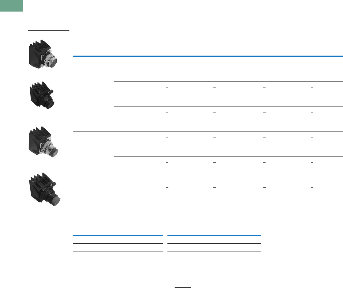
T37-286 Logic Control Products CA08100001K—June 2012 www.eatoncanada.ca
37
37
37
37
37
37
37
37
37
37
37
37
37
37
37
37
37
37
37
37
37
37
37
37
37
37
37
37
37
37
37.10
Pushbuttons and Indicating Lights
30.5 mm Class I Division 2 Hazardous Locations—10250T/E34
Product Selection
Momentary Pushbutton Units
UL (NEMA) Type 3, 3R, 4, 4X, 12, 13, NEC Class I Division 2, Groups B, C and D
Non-Illuminated Flush and Extended Pushbuttons
Colour Selection
Notes
Use NEMA 4X 10250T operators where exposed to ultraviolet light.
To order different colour guarded button, simply substitute the underlined character in catalogue number with
appropriate suffix code from Colour Selection table above. Example: 10250T710Y.
Blue not available on jumbo mushroom pushbutton.
Orange is only available on flush or extended pushbuttons.
Red with EMERG. STOP engraved on button head for jumbo mushroom pushbutton only.
Contact Type
Button
Colour
Flush Button Extended Button
10250T
Catalogue Number
E34
Catalogue Number
10250T
Catalogue Number
E34
Catalogue Number
1NO-1NC Black 10250T706B E34EX706B 10250T708B E34EX708B
Red 10250T706R E34EX706R 10250T708R E34EX708R
Green 10250T706G E34EX706G 10250T708G E34EX708G
2NO-2NC Black 10250T707B E34EX707B 10250T709B E34EX709B
Red 10250T707R E34EX707R 10250T709R E34EX709R
Green 10250T707G E34EX707G 10250T709G E34EX709G
Colour Suffix Code Colour Suffix Code
Black BWhite W
Red RBlue L
Green GOrange N
Yellow YRed (EMERG. STOP) E
10250T Flush Button
E34 Flush Button
10250T Extended
Button
E34 Extended Button
Tab37book.fm Page 286 Tuesday, July 3, 2012 10:46 PM

Logic Control Products CA08100001K—June 2012 www.eatoncanada.ca T37-287
37
37
37
37
37
37
37
37
37
37
37
37
37
37
37
37
37
37
37
37
37
37
37
37
37
37
37
37
37
37
37.10
Pushbuttons and Indicating Lights
30.5 mm Class I Division 2 Hazardous Locations—10250T/E34
UL (NEMA) Type 3, 3R, 4, 4X, 12, 13, NEC Class I Division 2, Groups B, C and D
Non-Illuminated Mushroom and Jumbo Mushroom Pushbuttons
Colour Selection
Notes
Use NEMA 4X 10250T operators where exposed to ultraviolet light.
To order different colour guarded button, simply substitute the underlined character in catalogue number with
appropriate suffix code from Colour Selection table above. Example: 10250T710Y.
Anodized aluminum head is not suitable for use in ultraviolet applications.
Blue not available on jumbo mushroom pushbutton.
Orange is only available on flush or extended pushbuttons.
Red with EMERG. STOP engraved on button head for jumbo mushroom pushbutton only.
Contact Type
Button
Colour
Mushroom Button Jumbo Mushroom Button
10250T
Catalogue Number
E34
Catalogue Number
10250T
Catalogue Number
E34
Catalogue Number
1NO-1NC Black 10250T710B E34EX710B 10250T712B E34EX712B
Red 10250T710R E34EX710R 10250T712R E34EX712R
Green 10250T710G E34EX710G 10250T712G E34EX712G
2NO-2NC Black 10250T711B E34EX711B 10250T713B E34EX713B
Red 10250T711R E34EX711R 10250T713R E34EX713R
Green 10250T711G E34EX711G 10250T713G E34EX713G
Colour Suffix Code Colour Suffix Code
Black BWhite W
Red RBlue L
Green GOrange N
Yellow YRed (EMERG. STOP) E
10250T Mushroom
Button
E34 Mushroom Button
10250T Jumbo
Mushroom Button
E34 Jumbo Mushroom
Button
Tab37book.fm Page 287 Tuesday, July 3, 2012 10:46 PM
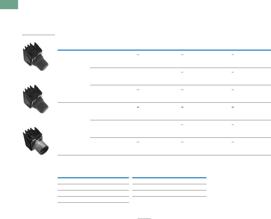
T37-288 Logic Control Products CA08100001K—June 2012 www.eatoncanada.ca
37
37
37
37
37
37
37
37
37
37
37
37
37
37
37
37
37
37
37
37
37
37
37
37
37
37
37
37
37
37
37.10
Pushbuttons and Indicating Lights
30.5 mm Class I Division 2 Hazardous Locations—10250T/E34
UL (NEMA) Type 3, 3R, 4, 4X, 12, 13, NEC Class I Division 2, Groups B, C and D
●Momentary contact
●Non-illuminated
●Booted or guarded
10250T Pushbuttons Booted and Guarded
Colour Selection
Notes
Use NEMA 4X 10250T operators where exposed to ultraviolet light.
To order different colour guarded button, simply substitute the underlined character in catalogue number with
appropriate suffix code from Colour Selection table above. Example: 10250T706YG.
Red booted flush pushbutton is not recommended for STOP function.
Contact Type Button Colour
Booted Flush Button
Catalogue Number
Booted Extended Button
Catalogue Number
Guarded Extended Button
Catalogue Number
1NO-1NC Black 10250T706BB 10250T708BB 10250T706BG
Red 10250T706RB 10250T708RB 10250T706RG
Green 10250T706GB 10250T708GB 10250T706GG
2NO-2NC Black 10250T707BB 10250T709BB 10250T707BG
Red 10250T707RB 10250T709RB 10250T707RG
Green 10250T707GB 10250T709GB 10250T707GG
Colour Suffix Code Colour Suffix Code
Black BWhite W
Red RBlue L
Green GOrange N
Yellow Y
Guarded Extended
Button
Booted Extended
Button
Booted Flush Button
Tab37book.fm Page 288 Tuesday, July 3, 2012 10:46 PM
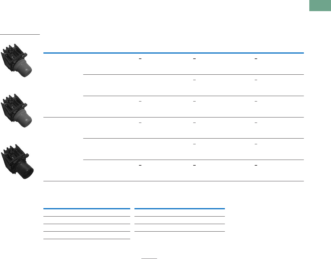
Logic Control Products CA08100001K—June 2012 www.eatoncanada.ca T37-289
37
37
37
37
37
37
37
37
37
37
37
37
37
37
37
37
37
37
37
37
37
37
37
37
37
37
37
37
37
37
37.10
Pushbuttons and Indicating Lights
30.5 mm Class I Division 2 Hazardous Locations—10250T/E34
UL (NEMA) Type 3, 3R, 4, 4X, 12, 13, NEC Class I Division 2, Groups B, C and D
●Momentary contact
●Non-illuminated
●Booted or guarded
E34 Pushbuttons Booted and Guarded
Colour Selection
Notes
Use NEMA 4X 10250T operators where exposed to ultraviolet light.
To order different colour guarded button, simply substitute the underlined character in catalogue number with
appropriate suffix code from Colour Selection table above. Example: 10250T706YG.
Red booted flush pushbutton is not recommended for STOP function.
Contact Type Button Colour
Booted Flush Button
Catalogue Number
Booted Extended Button
Catalogue Number
Guarded Extended Button
Catalogue Number
1NO-1NC Black E34EX706BB E34EX708BB E34EX706BG
Red E34EX706RB E34EX708RB E34EX706RG
Green E34EX706GB E34EX708GB E34EX706GG
2NO-2NC Black E34EX707BB E34EX709BB E34EX707BG
Red E34EX707RB E34EX709RB E34EX707RG
Green E34EX707GB E34EX709GB E34EX707GG
Colour Suffix Code Colour Suffix Code
Black BWhite W
Red RBlue L
Green GOrange N
Yellow Y
Booted Flush Button
Booted Extended
Button
Guarded Extended
Button
Tab37book.fm Page 289 Tuesday, July 3, 2012 10:46 PM
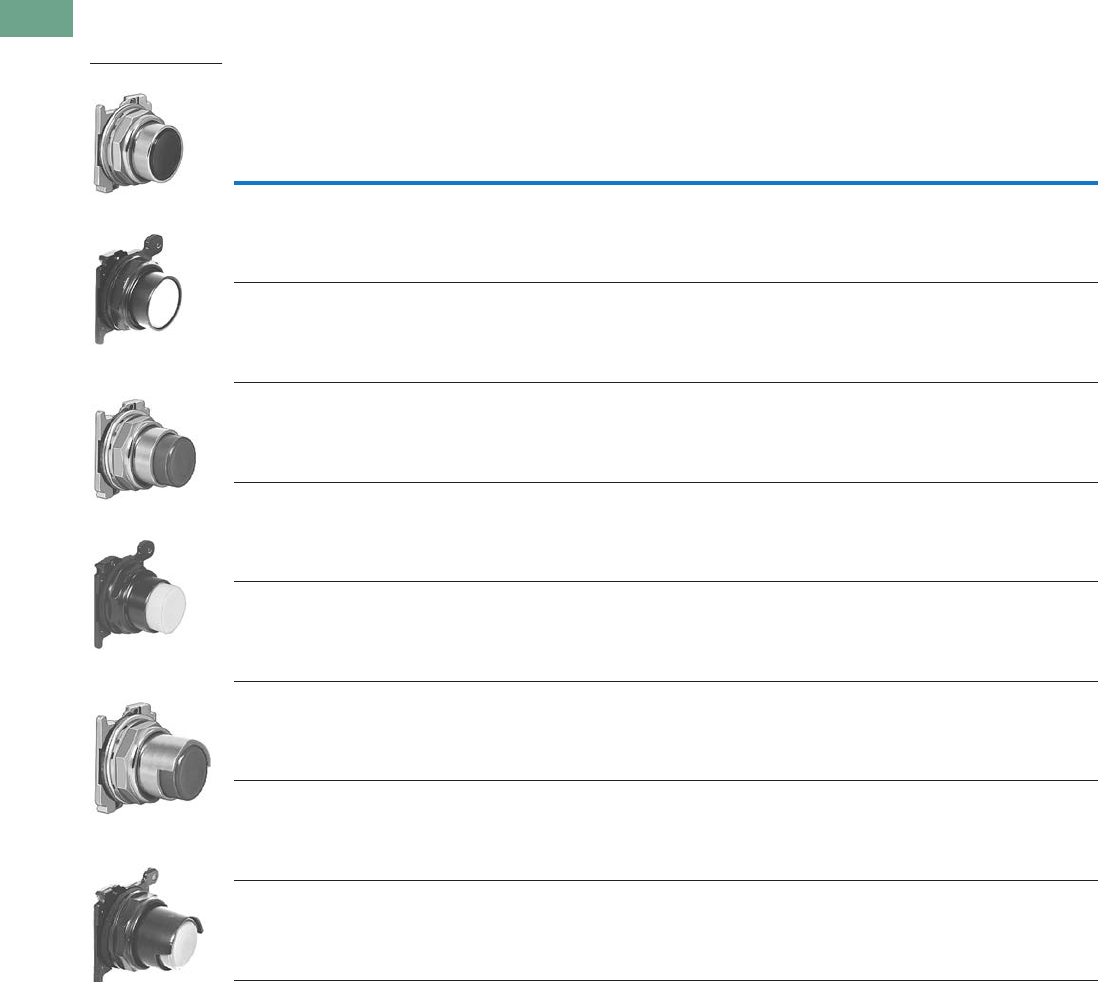
T37-290 Logic Control Products CA08100001K—June 2012 www.eatoncanada.ca
37
37
37
37
37
37
37
37
37
37
37
37
37
37
37
37
37
37
37
37
37
37
37
37
37
37
37
37
37
37
37.10
Pushbuttons and Indicating Lights
30.5 mm Class I Division 2 Hazardous Locations—10250T/E34
Non-Illuminated Pushbutton Units
UL (NEMA) Type 3, 3R, 4, 4X, 12, and 13
Non-Illuminated Pushbuttons, Momentary Contact
Notes
Use NEMA 4X 10250T operators where exposed to ultraviolet light.
To order operator with factory assembled extended retaining nut, 10250TA12, for thick panel applications, add suffix letter E to listed catalogue number.
Colour
Half Shrouded Button
Flush Button Extended Button 10250T E34
10250T
Catalogue
Number
E34
Catalogue
Number
10250T
Catalogue
Number
E34
Catalogue
Number
Vertical
Catalogue
Number
Horizontal
Catalogue
Number
Vertical
Catalogue
Number
Horizontal
Catalogue
Number
Black 10250T101 E34PB1 10250T111 E34EB1 10250T501 10250T511 E34EVB1 E34EHB1
Red 10250T102 E34PB2 10250T112 E34EB2 10250T502 10250T512 E34EVB2 E34EHB2
Green 10250T103 E34PB3 10250T113 E34EB3 10250T503 10250T513 E34EVB3 E34EHB3
Yellow 10250T104 E34PB4 10250T120 E34EB4 10250T504 10250T514 E34EVB4 E34EHB4
Gray 10250T105 E34PB5 — E34EB5 10250T505 10250T515 E34EVB5 E34EHB5
White 10250T106 E34PB6 10250T116 E34EB6 10250T506 10250T516 E34EVB6 E34EHB6
Blue 10250T108 E34PB7 10250T118 E34EB7 10250T508 10250T518 E34EVB7 E34EHB7
Orange 10250T109 E34PB8 10250T119 E34EB8 10250T509 10250T519 E34EVB8 E34EHB8
10250T Flush Button
E34 Flush Button
10250T Extended
Button
E34 Extended Button
10250T Half Shrouded
Button
E34 Half Shrouded
Button
Tab37book.fm Page 290 Tuesday, July 3, 2012 10:46 PM
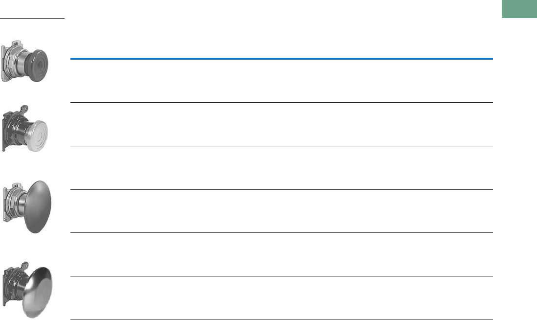
Logic Control Products CA08100001K—June 2012 www.eatoncanada.ca T37-291
37
37
37
37
37
37
37
37
37
37
37
37
37
37
37
37
37
37
37
37
37
37
37
37
37
37
37
37
37
37
37.10
Pushbuttons and Indicating Lights
30.5 mm Class I Division 2 Hazardous Locations—10250T/E34
UL (NEMA) Type 3, 3R, 4, 4X, 12, and 13
Mushroom Head Non-Illuminated Pushbuttons, Momentary Contact
Notes
Use NEMA 4X 10250T operators where exposed to ultraviolet light.
Anodized aluminum head is not suitable for use in ultraviolet light applications.
Anodized aluminum head may not be suitable for some corrosive environments.
Colour
Mushroom Button Anodized Aluminum Jumbo Mushroom Button
10250T
Catalogue Number
E34
Catalogue Number
10250T
Catalogue Number
E34
Catalogue Number
Black 10250T121 E34LB1 10250T171 E34JB1
Red 10250T122 E34LB2 10250T172 E34JB2
Red (EMERG. STOP) — — 10250T17213 E34JB2N8
Green 10250T123 E34LB3 10250T173 E34JB3
Yellow 10250T124 E34LB4 10250T174 E34JB4
Blue 10250T129 E34LB6 — —
10250T Mushroom
Button
E34 Mushroom Button
10250T Jumbo
Mushroom Button
E34 Jumbo Mushroom
Button
Tab37book.fm Page 291 Tuesday, July 3, 2012 10:46 PM
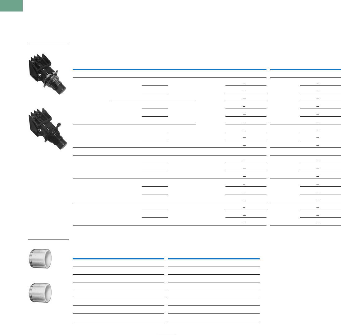
T37-292 Logic Control Products CA08100001K—June 2012 www.eatoncanada.ca
37
37
37
37
37
37
37
37
37
37
37
37
37
37
37
37
37
37
37
37
37
37
37
37
37
37
37
37
37
37
37.10
Pushbuttons and Indicating Lights
30.5 mm Class I Division 2 Hazardous Locations—10250T/E34
Illuminated Pushbutton Units
UL (NEMA) Type 3, 3R, 4, 4X, 12, 13, NEC Class I Division 2, Groups B, C and D
●Momentary contact
●Illuminated
●Plastic lenses
Illuminated Pushbuttons
Lens Selection
Note
To order different colour lens, simply substitute the underlined character in the catalogue number with appropriate
suffix code from Lens Selection table above. Example: 10250T828YD24.
Type Voltage Colour Contact
10250T E34
LED/Lamp
Number Catalogue Number
LED/Lamp
Number Catalogue Number
LED Lamp
Full voltage 24 Vac/Vdc Red 1NO-1NC Bayonet
base
10250T828RD24 Bayonet
base
E34EX828RD24
Green 10250T828GD24 E34EX828GD24
Amber 10250T828AD24 E34EX828AD24
120 Vac Red 1NO-1NC 10250T828RD2A E34EX828RD2A
Green 10250T828GD2A E34EX828GD2A
Amber 10250T828AD2A E34EX828AD2A
Transformer 120 Vac Red 1NO-1NC 10250T802RD06 Bayonet
base
6 Vac
E34EX802RD06
Green 10250T802GD06 E34EX802GD06
Amber 10250T802AD06 E34EX802AD06
Incandescent Lamp
Full voltage 24 Vac/Vdc Red 1NO-1NC #757 10250T818RD#757 E34EX818RD
Green 10250T818GD E34EX818GD
Amber 10250T818AD E34EX818AD
Resistor 120 Vac/Vdc Red 1NO-1NC 120MB 10250T824RD120MB E34EX824RD
Green 10250T824GD E34EX824GD
Amber 10250T824AD E34EX824AD
Transformer 120 Vac Red 1NO-1NC #755 10250T802RD#755
6 Vac
E34EX802RD
Green 10250T802GD E34EX802GD
Amber 10250T802AD E34EX802AD
Colour
Suffix
Code Catalogue Number Colour
Suffix
Code Catalogue Number
10250T E34
Red R 10250TC21 Red R E34V2
Green G 10250TC22 Green G E34V3
Yellow Y 10250TC23 Yellow Y E34V4
Amber A 10250TC43 Amber A E34V9
Blue L 10250TC24 Blue L E34V6
Clear C 10250TC25 Clear C E34V0
White W 10250TC26 White W E34V5
10250T8_
E34EX8_
10250TC_
E34V _
Tab37book.fm Page 292 Tuesday, July 3, 2012 10:46 PM
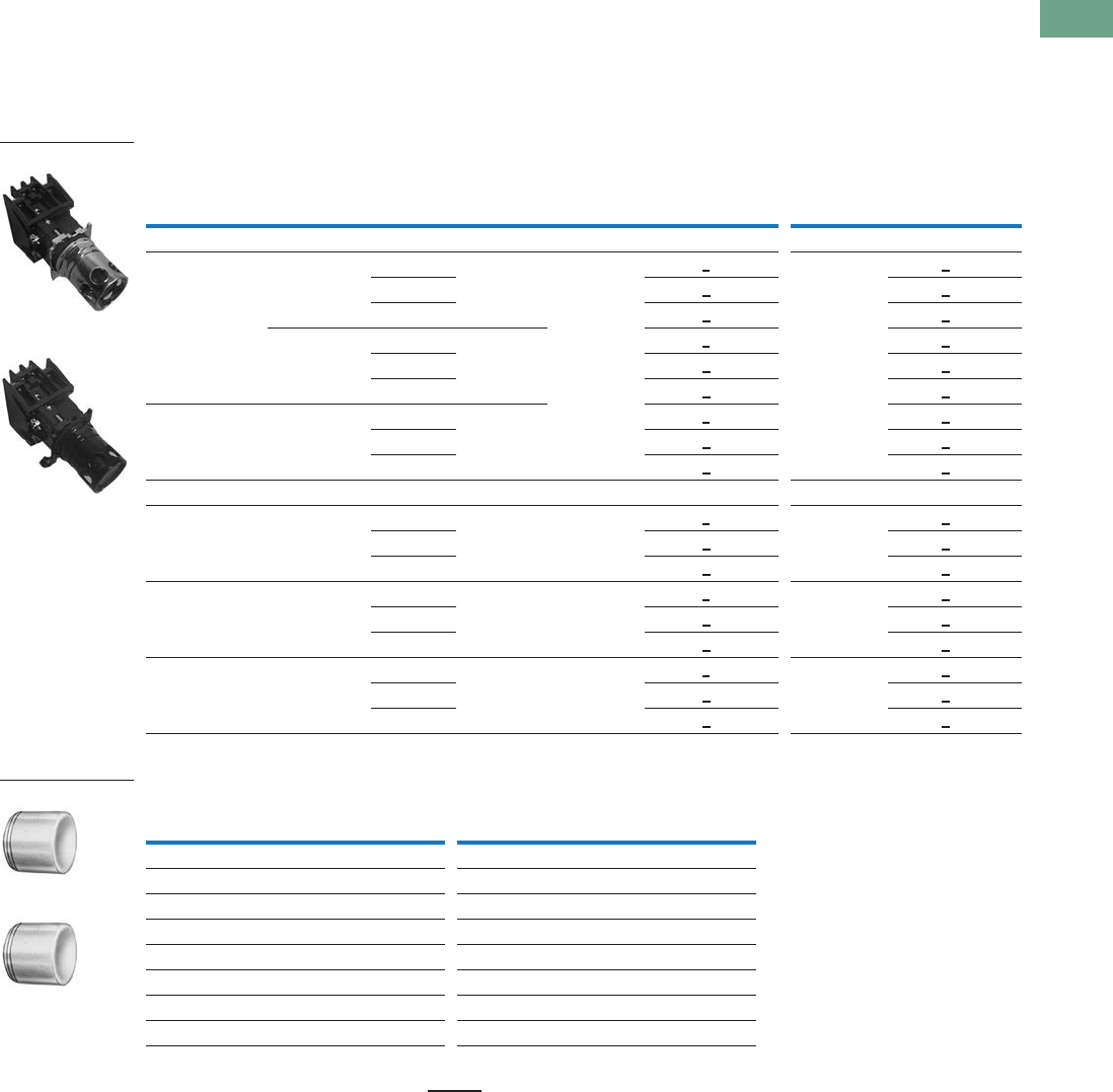
Logic Control Products CA08100001K—June 2012 www.eatoncanada.ca T37-293
37
37
37
37
37
37
37
37
37
37
37
37
37
37
37
37
37
37
37
37
37
37
37
37
37
37
37
37
37
37
37.10
Pushbuttons and Indicating Lights
30.5 mm Class I Division 2 Hazardous Locations—10250T/E34
Guarded Illuminated Pushbutton Units
UL (NEMA) Type 3, 3R, 4, 4X, 12, 13, NEC Class I Division 2, Groups B, C and D
●Momentary contact
●Guarded illuminated
●Plastic lenses
Guarded Illuminated Pushbuttons
Lens Selection
Note
To order different colour lens, simply substitute the underlined character in the catalogue number with appropriate
suffix code from Lens Selection table above. Example: 10250T828YD24.
Type Voltage Colour Contact
10250T E34
LED/Lamp
Number Catalogue Number
LED/Lamp
Number Catalogue Number
LED Lamp
Full voltage 24 Vac/Vdc Red 1NO-1NC Bayonet
base
10250T828RG24 Bayonet
base
E34EX828RG24
Green 10250T828GG24 E34EX828GG24
Amber 10250T828AG24 E34EX828AG24
120 Vac Red 1NO-1NC 10250T828RG2A E34EX828RG2A
Green 10250T828GG2A E34EX828GG2A
Amber 10250T828AG2A E34EX828AG2A
Transformer 120 Vac Red 1NO-1NC 10250T802RG06 E34EX802RG06
Green 10250T802GG06 E34EX802GG06
Amber 10250T802AG06 E34EX802AG06
Incandescent Lamp
Full voltage 24 Vac/Vdc Red 1NO-1NC #757 10250T818RG#757 E34EX818RG
Green 10250T818GG E34EX818GG
Amber 10250T818AG E34EX818AG
Resistor 120 Vac/Vdc Red 1NO-1NC 120MB 10250T824RG120MB E34EX824RG
Green 10250T824GG E34EX824GG
Amber 10250T824AG E34EX824AG
Transformer 120 Vac Red 1NO-1NC #755 10250T802RG#755
6 Vac
E34EX802RG
Green 10250T802GG E34EX802GG
Amber 10250T802AG E34EX802AG
Colour
Suffix
Code Catalogue Number Colour
Suffix
Code Catalogue Number
10250T E34
Red R 10250TC21 Red R E34V2
Green G 10250TC22 Green G E34V3
Yellow Y 10250TC23 Yellow Y E34V4
Amber A 10250TC43 Amber A E34V9
Blue L 10250TC24 Blue L E34V6
Clear C 10250TC25 Clear C E34V0
White W 10250TC26 White W E34V5
10250T8_
E34EX8_
10250TC2_
E34V_
Tab37book.fm Page 293 Tuesday, July 3, 2012 10:46 PM
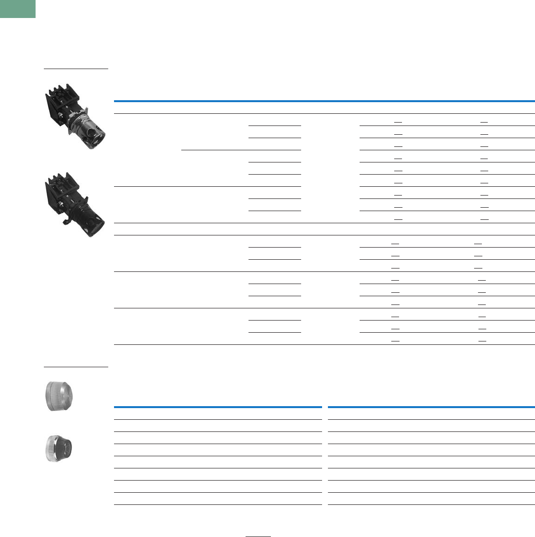
T37-294 Logic Control Products CA08100001K—June 2012 www.eatoncanada.ca
37
37
37
37
37
37
37
37
37
37
37
37
37
37
37
37
37
37
37
37
37
37
37
37
37
37
37
37
37
37
37.10
Pushbuttons and Indicating Lights
30.5 mm Class I Division 2 Hazardous Locations—10250T/E34
Indicating Light Units
UL (NEMA) Type 3, 3R, 3S, 4, 4X, 12, 13, NEC Class I Division 2, Groups B, C and D
●Standard
●Plastic lenses
Indicating Lights
Lens Selection
Notes
Use NEMA 4X 10250T operators where exposed to ultraviolet light.
To order different colour lens, simply substitute the underlined characters in the catalogue number with appropriate suffix code from the Lens Selection table above.
Example: 10250T201HYP.
Type Voltage Colour
LED/Lamp
Number
10250T E34
Catalogue Number Catalogue Number
LED Lamp
Full voltage 24 Vac/Vdc Red Bayonet
base
10250T197HLRP24 E34FB197HLRP24
Green 10250T197HLGP24 E34FB197HLGP24
Amber 10250T197HLAP24 E34FB197HLAP24
120 Vac Red 10250T197HLRP2A E34FB197HLRP2A
Green 10250T197HLGP2A E34FB197HLGP2A
Amber 10250T197HLAP2A E34FB197HLAP2A
Transformer 120 Vac Red 10250T181HLRP06 E34TB120HLRP06
Green 10250T181HLGP06 E34TB120HLGP06
Amber 10250T181HLAP06 E34TB120HLAP06
Incandescent Lamp
Full voltage 24 Vac/Vdc Red #757 10250T206HRP E34FB24HRP
Green 10250T206HGP E34FB24HGP
Amber 10250T206HAP E34FB24HAP
Resistor 120 Vac/Vdc Red 120MB 10250T201HRP E34RB120HRP
Green 10250T201HGP E34RB120HGP
Amber 10250T201HAP E34RB120HAP
Transformer 120 Vac Red #755 10250T181HRP E34HB120HRP
Green 10250T181HGP E34HB120HGP
Amber 10250T181HAP E34HB120HAP
Colour
Plastic Glass
Colour
Plastic Glass
Suffix
Code Catalogue Number
Suffix
Code Catalogue Number
Suffix
Code Catalogue Number
Suffix
Code Catalogue Number
10250T E34
Red RP 10250TC1N RG 10250TC7N Red RP E34H2 RG E34G2
Green GP 10250TC2N GG 10250TC8N Green GP E34H3 GG E34G3
Amber AP 10250TC19N AG 10250TC9N Amber AP E34H9 AG E34G9
Yellow YP 10250TC3N — — Yellow YP E34H4 YG E34G4
Blue LP 10250TC4N LG 10250TC10N Blue LP E34H6 LG E34G6
Clear CP 10250TC5N CG 10250TC11N Clear CP E34H0 CG E34G0
White WP 10250TC6N WG 10250TC12N White WP E34H5 WG E34G5
10250T_
E34_
Glass
Plastic
Tab37book.fm Page 294 Tuesday, July 3, 2012 10:46 PM
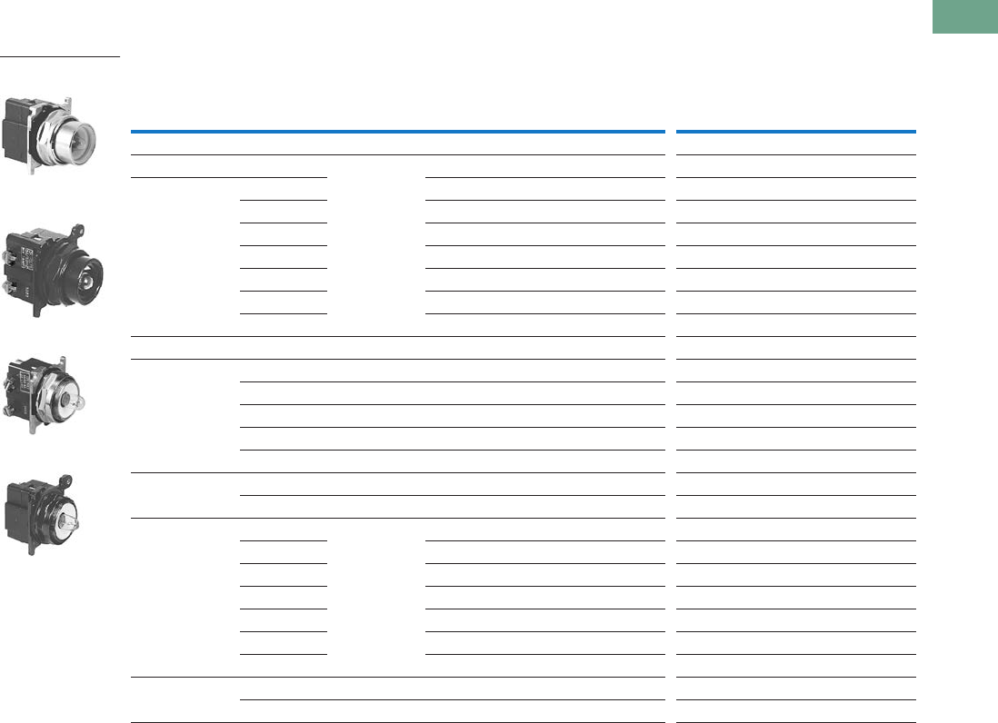
Logic Control Products CA08100001K—June 2012 www.eatoncanada.ca T37-295
37
37
37
37
37
37
37
37
37
37
37
37
37
37
37
37
37
37
37
37
37
37
37
37
37
37
37
37
37
37
37.10
Pushbuttons and Indicating Lights
30.5 mm Class I Division 2 Hazardous Locations—10250T/E34
Illuminated Pushbuttons and Indicating Lights
NEC Class I Division 2, Groups B, C and D
Operators without Lenses
Notes
Use NEMA 4X 10250T operators where exposed to ultraviolet light.
These units do not include lamps. Order LED separately to match lens colour from the LED Selection table on Page T37-305.
Resister units are not available for use with LEDs, choose either transformer or full voltage LED style.
Illuminated Pushbutton Indicating Light
Type Voltage
LED/Lamp
Number
10250T
Catalogue Number
E34
Catalogue Number
10250T
Catalogue Number
E34
Catalogue Number
LED Light Unit Type (LEDs not included)
Full voltage — Bayonet
base
10250T397HL E34CB497HL 10250T197HL E34FB197HL
Transformer
AC only
24 10250T416HL E34XB024HL — —
120 10250T411HL E34XB120HL 10250T181HL E34TB120HL
240 10250T412HL E34XB240HL 10250T182HL E34TB240HL
277 10250T419HL E34XB277HL 10250T198HL E34TB277HL
380 10250T413HL E34XB380HL 10250T183HL E34TB380HL
480 10250T414HL E34XB480HL 10250T184HL E34TB480HL
600 10250T415HL E34XB600HL 10250T185HL E34TB600HL
Incandescent Light Unit Type
Full voltage
AC/DC
6 #755 10250T473H E34CB06H 10250T203H E34FB06H
12 #756 10250T474H E34CB12H 10250T204H E34FB12H
24 #757 10250T476H E34CB24H 10250T206H E34FB24H
32 #1828 10250T477H E34CB32H 10250T207H E34FB32H
48 #1835 10250T478H E34CB48H 10250T208H E34FB48H
Resistor
AC/DC
120 120MB 10250T471H E34SB120H 10250T201H E34RB120H
240 120MB 10250T472H E34SB240H 10250T202H E34RB240H
Transformer
AC only
24 #755 10250T416H E34XB024H — —
120 10250T411H E34XB120H 10250T181H E34TB120H
240 10250T412H E34XB240H 10250T182H E34TB240H
277 10250T419H E34XB277H 10250T198H E34TB277H
380 10250T413H E34XB380H 10250T183H E34TB380H
480 10250T414H E34XB480H 10250T184H E34TB480H
600 10250T415H E34XB600H 10250T185H E34TB600H
Neon
AC/DC
120 NE51H-R-22 — — 10250T226H E34NB120H
240 NE51H-4-68 — — 10250T227H E34NB240H
10250T Illuminated
Pushbutton
E34 Illuminated
Pushbutton
10250T Indicating Light
E34 Indicating Light
Tab37book.fm Page 295 Tuesday, July 3, 2012 10:46 PM
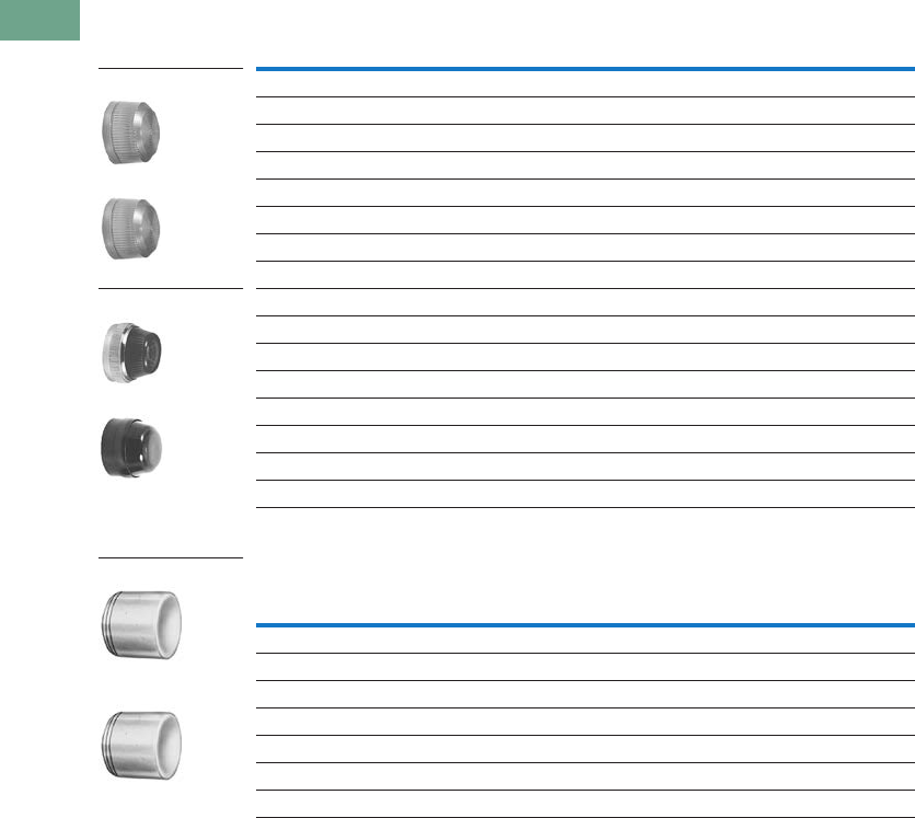
T37-296 Logic Control Products CA08100001K—June 2012 www.eatoncanada.ca
37
37
37
37
37
37
37
37
37
37
37
37
37
37
37
37
37
37
37
37
37
37
37
37
37
37
37
37
37
37
37.10
Pushbuttons and Indicating Lights
30.5 mm Class I Division 2 Hazardous Locations—10250T/E34
Indicating Light Lenses
Illuminated Pushbutton Lenses
Colour
10250T
Catalogue Number
E34
Catalogue Number
Plastic
Red 10250TC1N E34H2
Green 10250TC2N E34H3
Amber 10250TC19N E34H9
Yellow 10250TC3N E34H4
Blue 10250TC4N E34H6
Clear 10250TC5N E34H0
White 10250TC6N E34H5
Glass
Red 10250TC7N E34G2
Green 10250TC8N E34G3
Amber 10250TC9N E34G9
Yellow — E34G4
Blue 10250TC10N E34G6
Clear 10250TC11N E34G0
White 10250TC12N E34G5
Colour
10250T
Catalogue Number
E34
Catalogue Number
Red 10250TC21 E34V2
Green 10250TC22 E34V3
Yellow 10250TC23 E34V4
Amber 10250TC43 E34V9
Blue 10250TC24 E34V6
Clear 10250TC25 E34V0
White 10250TC26 E34V5
Plastic
Glass
10250TC_
E34H_
10250TC_
E34G_
10250TC_
E34V_
Tab37book.fm Page 296 Tuesday, July 3, 2012 10:46 PM
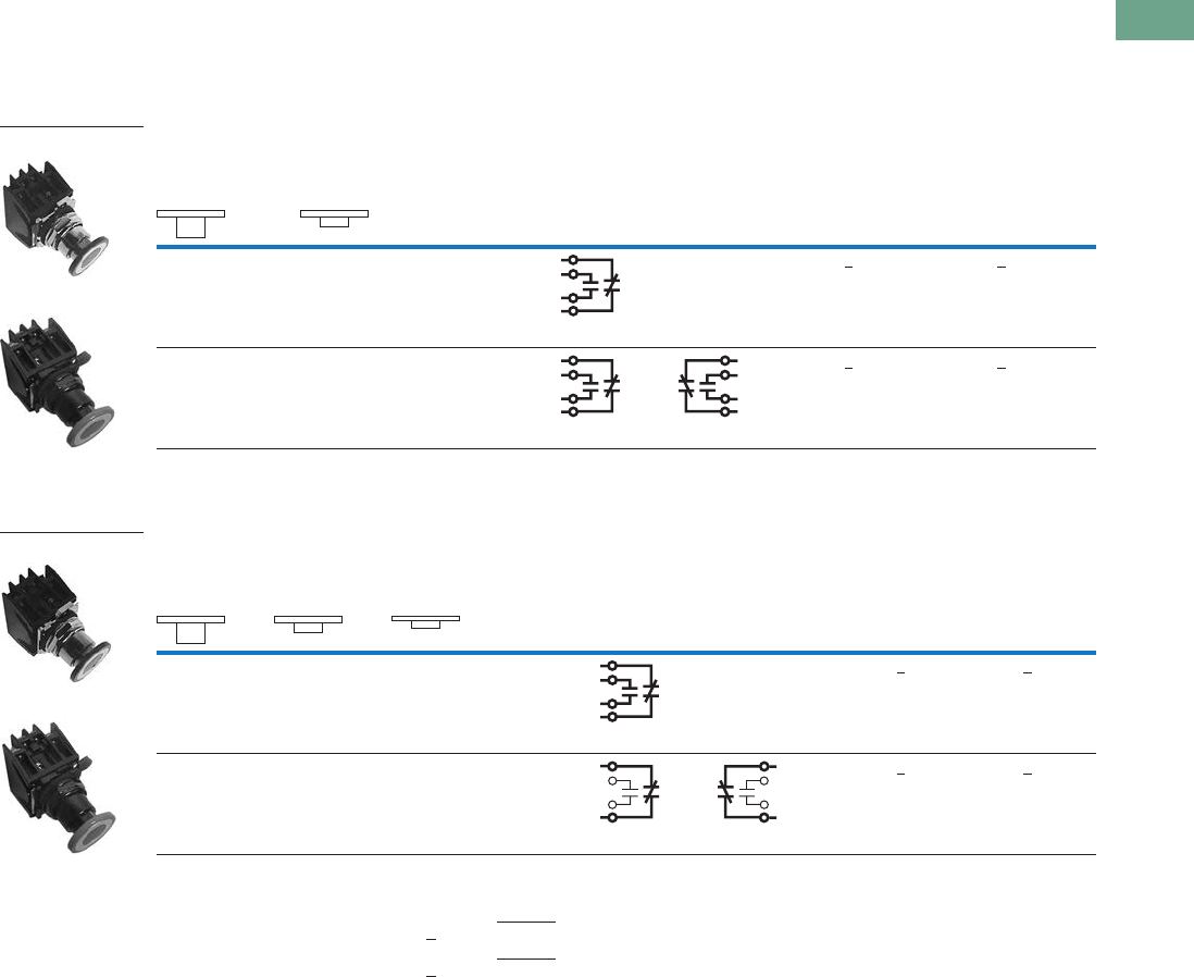
Logic Control Products CA08100001K—June 2012 www.eatoncanada.ca T37-297
37
37
37
37
37
37
37
37
37
37
37
37
37
37
37
37
37
37
37
37
37
37
37
37
37
37
37
37
37
37
37.10
Pushbuttons and Indicating Lights
30.5 mm Class I Division 2 Hazardous Locations—10250T/E34
Push-Pull Units
UL (NEMA) Type 3, 3R, 4, 4X, 12, 13, NEC Class I Division 2, Groups B, C and D
●Two- and three-position
●Non-illuminated
Two-Position Maintained Push, Maintained Pull
Three-Position Maintained Push, Momentary Pull
Notes
Bolded circuit corresponds to “X-O” circuit selection. X = closed circuit, O = open circuit.
To order different type or colour buttons, simply substitute underlined character with appropriate suffix code from the Button and Colour Selection
table on Page T37-298. Example: 10250T714G.
To order different type or colour buttons, simply substitute underlined character with appropriate suffix code from the Button and Colour Selection
table on Page T37-298. Example: 10250T716G.
Operator Function (Position)
Contact
Type
Maintained—
Pull
Maintained—
Push Red Standard Push-Pull
Mounting Location 10250T
Catalogue Number
E34
Catalogue Number12
O
X
X
O
1NO
1NC
10250T714R E34EX714R
O
X
O
X
X
O
X
O
2NO
2NC
10250T715R E34EX715R
10250T71_
E34EX71_
Operator Function (Position)
Contact
Type
Momentary—
Pull
Maintained—
Intermediate
Maintained—
Push Red Standard Push-Pull
Mounting Location 10250T
Catalogue Number
E34
Catalogue Number12
O
X
O
O
X
O
1NO
1NC
10250T716R E34EX716R
X
X
O
X
O
O
1NC
1NC
10250T717R E34EX717R
10250T71_
E34EX71_
Tab37book.fm Page 297 Tuesday, July 3, 2012 10:46 PM
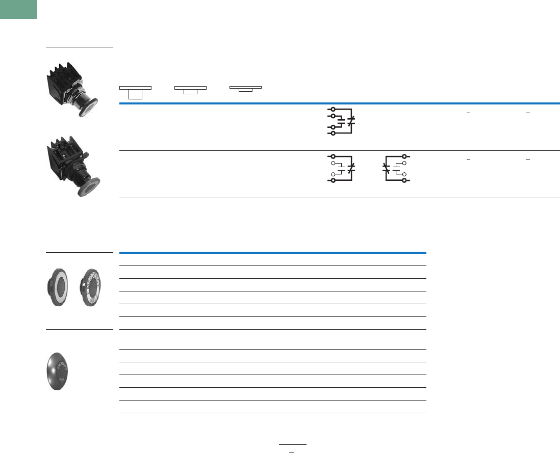
T37-298 Logic Control Products CA08100001K—June 2012 www.eatoncanada.ca
37
37
37
37
37
37
37
37
37
37
37
37
37
37
37
37
37
37
37
37
37
37
37
37
37
37
37
37
37
37
37.10
Pushbuttons and Indicating Lights
30.5 mm Class I Division 2 Hazardous Locations—10250T/E34
UL (NEMA) Type 3, 3R, 4, 4X, 12, 13, NEC Class I Division 2, Groups B, C and D
●Two- and three-position
●Non-illuminated
Three-Position Momentary Push, Momentary Pull
Button and Colour Selection
Notes
Bolded circuit corresponds to “X-O” circuit selection. X = closed circuit, O = open circuit.
To order different type or colour buttons, simply substitute underlined character with appropriate suffix code from the
Button and Colour Selection table above. Example: 10250T718G.
Operator Function (Position)
Contact
Type
Momentary—
Pull
Maintained—
Intermediate
Momentary—
Push Red Standard Push-Pull
Mounting Location 10250T
Catalogue Number
E34
Catalogue Number12
O
X
O
O
X
O
1NO
1NC
10250T718R E34EX718R
X
X
O
X
O
O
1NC
1NC
10250T721R E34EX721R
Colour
Suffix
Code
10250T
Catalogue Number
E34
Catalogue Number
Standard
Red R 10250TB62 E34C2
Red (EMERG. STOP) E 10250TB63 E34C2N8
Green G 10250TB61 E34C3
Black B 10250TB60 E34C1
Blue L 10250TB64 E34C6
Jumbo Mushroom Head
(Anodized) Aluminum
Red RJ 10250TJ62 E34J2
Red (EMERG. STOP) EJ 10250TJ63 E34J2N8
Green GJ 10250TJ61 —
Black BJ 10250TJ60 —
Yellow YJ 10250TJ64 —
10250T7_
E34EX7_
Standard
Jumbo Mushroom
Head
Tab37book.fm Page 298 Tuesday, July 3, 2012 10:46 PM
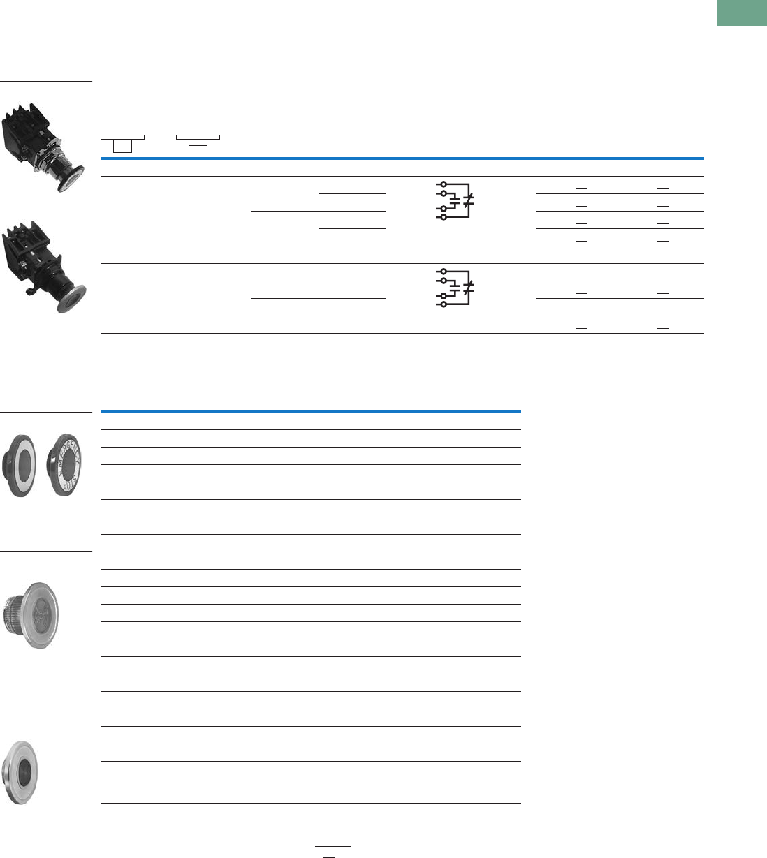
Logic Control Products CA08100001K—June 2012 www.eatoncanada.ca T37-299
37
37
37
37
37
37
37
37
37
37
37
37
37
37
37
37
37
37
37
37
37
37
37
37
37
37
37
37
37
37
37.10
Pushbuttons and Indicating Lights
30.5 mm Class I Division 2 Hazardous Locations—10250T/E34
Illuminated Push-Pull Units
UL (NEMA) Type 3, 3R, 4, 4X, 12, 13, NEC Class I Division 2, Groups B, C and D
●Two-position maintained
●Illuminated
Two-Position Illuminated Maintained Push, Maintained Pull
Lens and Colour Selection
Notes
Bolded circuit corresponds to “X-O” circuit selection. X = closed circuit, O = open circuit.
To order different type or colour lens, simply substitute the underlined characters with appropriate suffix code from the
Lens and Colour Selection table above. Example: 10250T851GS.
Operator Function (Position)
Type Voltage
Contact
Type
Maintained—
Pull
Maintained—
Push Red Standard Push-Pull
Mounting Location 10250T
Catalogue Number
E34
Catalogue Number12
LED Lamp
O
X
X
O
Full voltage 24 Vac/Vdc 1NO
1NC
10250T853RD24 E34EX853RD24
120 Vac 10250T853RD2A E34EX853RD2A
Transformer 24 Vac 10250T843RD06 E34EX843RD06
120 Vac 10250T844RD06 E34EX844RD06
Incandescent Lamp
O
X
X
O
Full voltage 24 Vac/Vdc 1NO
1NC
10250T849RD E34EX849RD
Resistor 120 Vac/Vdc 10250T851RD E34EX851RD
Transformer 24 Vac 10250T843RD E34EX843RD
120 Vac 10250T844RD E34EX844RD
10250T E34
Colour Suffix Code Catalogue Number Suffix Code Catalogue Number
Standard
Red RD 10250TC47 RD E34M2
Red (EMERG. STOP) ED 10250TC53 ED E34M2N8
Green GD 10250TC48 GD E34M3
Blue LD 10250TC49 LD E34M6
Amber AD 10250TC50 AD E34M9
White WD 10250TC51 WD E34M5
Clear CD 10250TC52 CD E34M0
Side-Lighted (Anodized) Aluminum
Red RS 10250TC57 — —
Red (EMERG. STOP) ES 10250TC63 — —
Green GS 10250TC58 — —
Blue LS 10250TC59 — —
Amber AS 10250TC64 — —
Yellow YS 10250TC60
White WS 10250TC61 — —
Clear CS 10250TC62 — —
Heavy-Duty Aluminum with Transparent Centre
Red RH 10250TC65 — —
Green GH 10250TC66 — —
Amber AH 10250TC67 — —
10250T8_
E34EX8_
Standard
Side-Lighted
(Anodized) Aluminum
HD Aluminum with
Transparent Centre
Tab37book.fm Page 299 Tuesday, July 3, 2012 10:46 PM
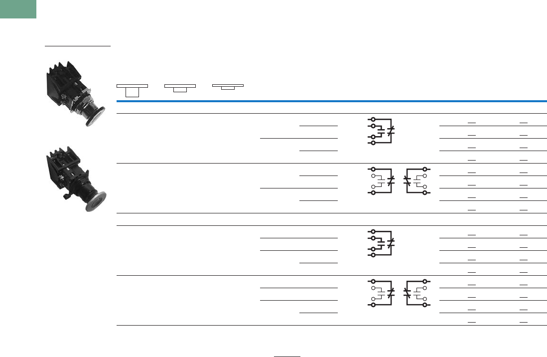
T37-300 Logic Control Products CA08100001K—June 2012 www.eatoncanada.ca
37
37
37
37
37
37
37
37
37
37
37
37
37
37
37
37
37
37
37
37
37
37
37
37
37
37
37
37
37
37
37.10
Pushbuttons and Indicating Lights
30.5 mm Class I Division 2 Hazardous Locations—10250T/E34
UL (NEMA) Type 3, 3R, 4, 4X, 12, 13, NEC Class I Division 2, Groups B, C and D
●Three-position—maintained push, momentary pull
●Illuminated
Three-Position Illuminated Maintained Push, Momentary Pull
Notes
Bolded circuit corresponds to “X-O” circuit selection. X = closed circuit, O = open circuit.
To order different type or colour lens, simply substitute the underlined characters with appropriate suffix code from the Lens and
Colour Selection table on the bottom of Page T37-299. Example: 10250T862AS.
Operator Function (Position)
Type Voltage
Contact
Type
Momentary—
Pull
Maintained—
Intermediate
Maintained—
Push Red Standard Push-Pull
Mounting Location 10250T
Catalogue Number
E34
Catalogue Number12
LED Lamp
O
X
O
O
X
O
Full voltage 24 Vac/Vdc 1NO
1NC
10250T864RD24 E34EX864RD24
120 Vac 10250T864RD2A E34EX864RD2A
Transformer 24 Vac 10250T854RD06 E34EX854RD06
120 Vac 10250T855RD06 E34EX855RD06
X
X
O
X
O
O
Full voltage 24 Vac/Vdc 1NC
1NC
10250T875RD24 E34EX875RD24
120 Vac 10250T875RD2A E34EX875RD2A
Transformer 24 Vac 10250T865RD06 E34EX865RD06
120 Vac 10250T866RD06 E34EX866RD06
Incandescent Lamp
O
X
O
O
X
O
Full voltage 24 Vac/Vdc 1NO
1NC
10250T860RD E34EX860RD
Resistor 120 Vac 10250T862RD E34EX862RD
Transformer 24 Vac 10250T854RD E34EX854RD
120 Vac 10250T855RD E34EX855RD
X
X
O
X
O
O
Full voltage 24 Vac/Vdc 1NC
1NC
10250T871RD E34EX871RD
Resistor 120 Vac 10250T873RD E34EX873RD
Transformer 24 Vac 10250T865RD E34EX865RD
120 Vac 10250T866RD E34EX866RD
E34EX8_
10250T8_
Tab37book.fm Page 300 Tuesday, July 3, 2012 10:46 PM
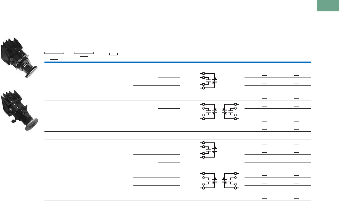
Logic Control Products CA08100001K—June 2012 www.eatoncanada.ca T37-301
37
37
37
37
37
37
37
37
37
37
37
37
37
37
37
37
37
37
37
37
37
37
37
37
37
37
37
37
37
37
37.10
Pushbuttons and Indicating Lights
30.5 mm Class I Division 2 Hazardous Locations—10250T/E34
UL (NEMA) Type 3, 3R, 4, 4X, 12, 13, NEC Class I Division 2, Groups B, C and D
●Three-position—momentary
●Illuminated
Three-Position Illuminated Momentary Push, Momentary Pull
Notes
Bolded circuit corresponds to “X-O” circuit selection. X = closed circuit, O = open circuit.
To order different type or colour lens, simply substitute the underlined characters with appropriate suffix code from the Lens and
Colour Selection table on the bottom of Page T37-299. Example: 10250T862AS.
Operator Function (Position)
Type Voltage
Contact
Type
Momentary—
Pull
Maintained—
Intermediate
Maintained—
Push Red Standard Push-Pull
Mounting Location 10250T
Catalogue Number
E34
Catalogue Number12
LED Lamp
O
X
O
O
X
O
Full voltage 24 Vac/Vdc 1NO
1NC
10250T886RD24 E34EX886RD24
120 Vac 10250T886RD2A E34EX886RD2A
Transformer 24 Vac 10250T876RD06 E34EX876RD06
120 Vac 10250T877RD06 E34EX877RD06
X
X
O
X
O
O
Full voltage 24 Vac/Vdc 1NC
1NC
10250T897RD24 E34EX897RD24
120 Vac 10250T897RD2A E34EX897RD2A
Transformer 24 Vac 10250T887RD06 E34EX887RD06
120 Vac 10250T888RD06 E34EX888RD06
Incandescent Lamp
O
X
O
O
X
O
Full voltage 24 Vac/Vdc 1NO
1NC
10250T882RD E34EX882RD
Resistor 120 Vac 10250T884RD E34EX884RD
Transformer 24 Vac 10250T876RD E34EX876RD
120 Vac 10250T877RD E34EX877RD
X
X
O
X
O
O
Full voltage 24 Vac/Vdc 1NC
1NC
10250T893RD E34EX893RD
Resistor 120 Vac 10250T895RD E34EX895RD
Transformer 24 Vac 10250T887RD E34EX887RD
120 Vac 10250T888RD E34EX888RD
E34EX8_
10250T8_
Tab37book.fm Page 301 Tuesday, July 3, 2012 10:46 PM
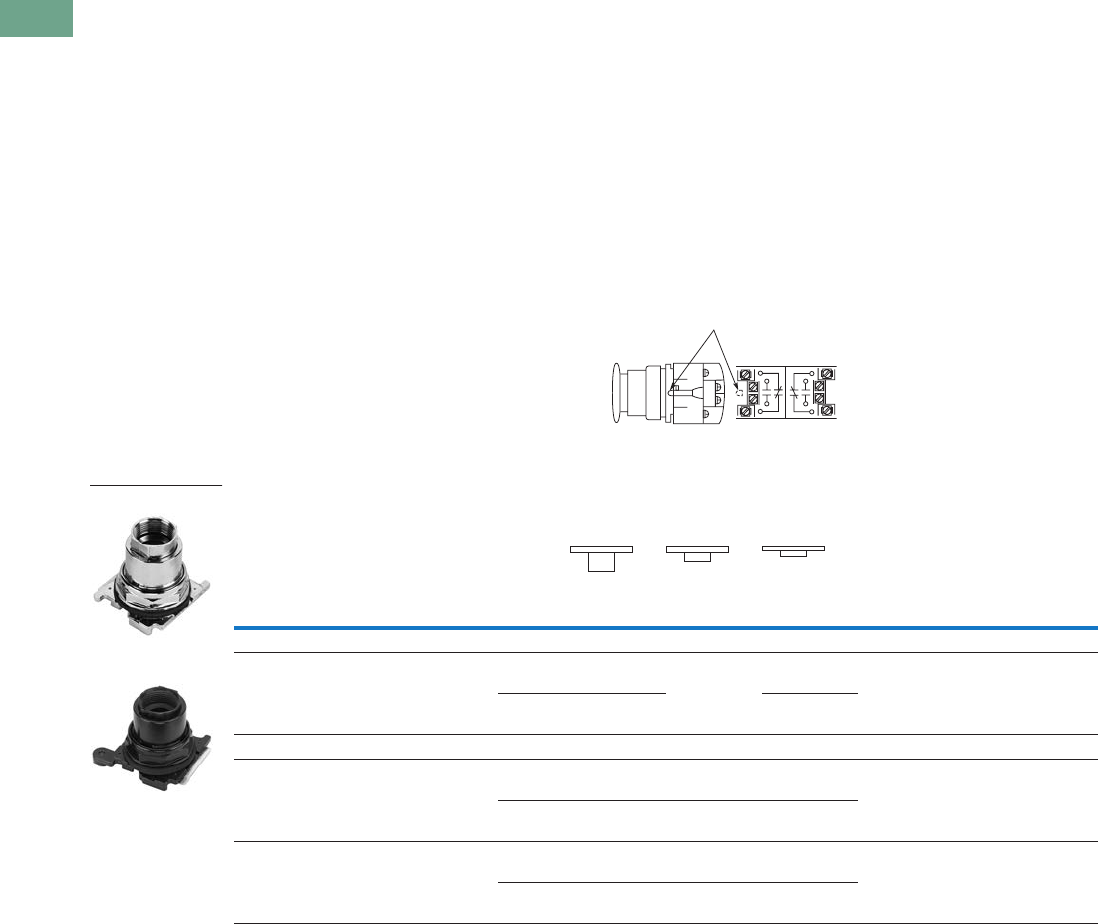
T37-302 Logic Control Products CA08100001K—June 2012 www.eatoncanada.ca
37
37
37
37
37
37
37
37
37
37
37
37
37
37
37
37
37
37
37
37
37
37
37
37
37
37
37
37
37
37
37.10
Pushbuttons and Indicating Lights
30.5 mm Class I Division 2 Hazardous Locations—10250T/E34
Push-Pull Operators
An illuminated push-pull
pushbutton unit, arranged for
one-hole mounting, can
replace two pushbuttons and
a pilot light or the non-
illuminated form can replace
two pushbuttons. These units
are available in three basic
types:
●Maintained—(Two-
position). Maintains in the
pulled or pushed position
until manually actuated to
the opposite mode.
●Momentary—(Three-
position). Spring returns to
an intermediate position
when pulled or pushed and
released.
●Momentary Pull,
Maintained Push—(Three-
position). Spring returns to
intermediate position when
pulled. Maintains in pushed
position until manually
returned to intermediate
(ready to reset) position.
Maintained stop holds
circuit open and will
prevent other series
connected operators from
starting the system.
The operators, buttons,
contact blocks, etc., are
offered as building block
components that can be
intermixed to satisfy many
requirements. This minimizes
the need for a varied and
costly inventory.
Application Guide
To assist in the selection of
contact blocks, the sketch
below shows pictorially by
symbols 1 and 2 locations of
contact circuits after
assembly of contact blocks
and adapter to the operator.
The table below shows the
effect of the push and pull
operations on either NO or
NC contacts. (X = contact
closed, O = contact open).
Locating Nibs
Push-Pull Operator Components
Note
Use NEMA 4X 10250T operators where exposed to ultraviolet light.
Locating Nib
12
Type of Operator
Contact
Block
Operator Position and Circuit Arrangement
10250T
Catalogue Number
E34
Catalogue Number
Out—Pull Intermediate In—Push
Contact Block Mounting Location
121212
Two-Position Operator without Lens
Maintained push-pull 1NO
1NC
O
Xor O
X
No intermediate
position
X
Oor X
O
10250T5 E34GDB
2NO
2NC
O
X
O
X
X
O
X
O
Three-Position Operator without Lens
Momentary push-pull
Maintained push-momentary pull
1NO
1NC
O
Xor O
X
O
Oor O
X
X
Oor O
O
10250T4
10250T9
E34GEB
E34GFB
2NO
2NC
O
X
O
X
O
O
O
X
X
O
O
O
Momentary push-pull 1NO
1NC
O
Xor O
X
O
Oor O
O
X
Oor X
O
10250T10 E34GHB
2NO
2NC
O
X
O
X
O
O
O
O
X
O
X
O
10250T_
E34G_
Tab37book.fm Page 302 Tuesday, July 3, 2012 10:46 PM

Logic Control Products CA08100001K—June 2012 www.eatoncanada.ca T37-303
37
37
37
37
37
37
37
37
37
37
37
37
37
37
37
37
37
37
37
37
37
37
37
37
37
37
37
37
37
37
37.10
Pushbuttons and Indicating Lights
30.5 mm Class I Division 2 Hazardous Locations—10250T/E34
Push-Pull Light Units, Lenses and Buttons
NEC Class I Division 2 Groups B, C and D
Light Units for Illuminated Push-Pull Devices
Note
These units do not include lamps. Order LED separately to match lens colour from table on Page T37-305.
Light Unit
Type Type Voltage
LED/Lamp
Number Catalogue Number
LED
(LEDs not included)
Full voltage — Bayonet
base
10250T97HL
Transformer
AC only
50/60 Hz
24 10250T89HL
120 10250T63HL
208 10250T64HL
240 10250T65HL
277 10250T82HL
380 10250T66HL
480 10250T67HL
600 10250T68HL
Incandescent Full voltage
AC or DC
6 #755
#756
#757
#1828
10250T69H
12 10250T70H
24/28 10250T79H
32 10250T83H
Resistor
AC or DC
120 120MB 10250T80H
240 10250T81H
Transformer
AC only
50/60 Hz
24 #755 10250T89H
120 10250T63H
208 10250T64H
240 10250T65H
277 10250T82H
380 10250T66H
480 10250T67H
600 10250T68H
Tab37book.fm Page 303 Tuesday, July 3, 2012 10:46 PM
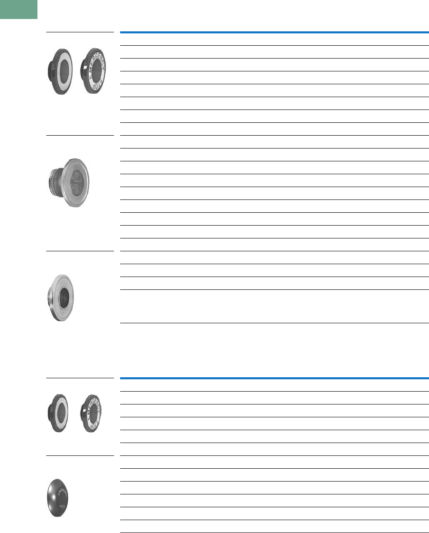
T37-304 Logic Control Products CA08100001K—June 2012 www.eatoncanada.ca
37
37
37
37
37
37
37
37
37
37
37
37
37
37
37
37
37
37
37
37
37
37
37
37
37
37
37
37
37
37
37.10
Pushbuttons and Indicating Lights
30.5 mm Class I Division 2 Hazardous Locations—10250T/E34
Alternate Lenses for Illuminated Push-Pull Devices
Buttons for Non-Illuminated Push-Pull Devices
Notes
Use NEMA 4X 10250T operators where exposed to ultraviolet light.
Anodized aluminum head is not suitable for use with ultraviolet light applications.
Colour
10250T
Catalogue Number
E34
Catalogue Number
Standard
Red 10250TC47 E34M2
Red (EMERG. STOP) 10250TC53 E34M2N8
Green 10250TC48 E34M3
Blue 10250TC49 E34M6
Amber 10250TC50 E34M9
White 10250TC51 E34M5
Clear 10250TC52 E34M0
Side-Lighted Anodized Aluminum Ring
Red 10250TC57 —
Red (EMERG. STOP) 10250TC63 —
Green 10250TC58 —
Blue 10250TC59 —
Amber 10250TC64 —
Yellow 10250TC60 —
White 10250TC61 —
Clear 10250TC62 —
Heavy-Duty Aluminum with Transparent Centre
Red 10250TC65 —
Green 10250TC66 —
Amber 10250TC67 —
Colour
10250T
Catalogue Number
E34
Catalogue Number
Standard
Red 10250TB62 E34C2
Red (EMERG. STOP) 10250TB63 E34C2N8
Green 10250TB61 E34C3
Black 10250TB60 E34C1
Blue 10250TB64 E34C6
Jumbo Mushroom Head (Anodized) Aluminum
Red 10250TJ62 E34J2
Red (EMERG. STOP) 10250TJ63 E34J2N8
Green 10250TJ61 —
Black 10250TJ60 —
Yellow 10250TJ64 —
Standard
Side-Lighted
(Anodized) Aluminum
HD Aluminum with
Transparent Centre
Standard
Jumbo Mushroom
Head
Tab37book.fm Page 304 Tuesday, July 3, 2012 10:46 PM
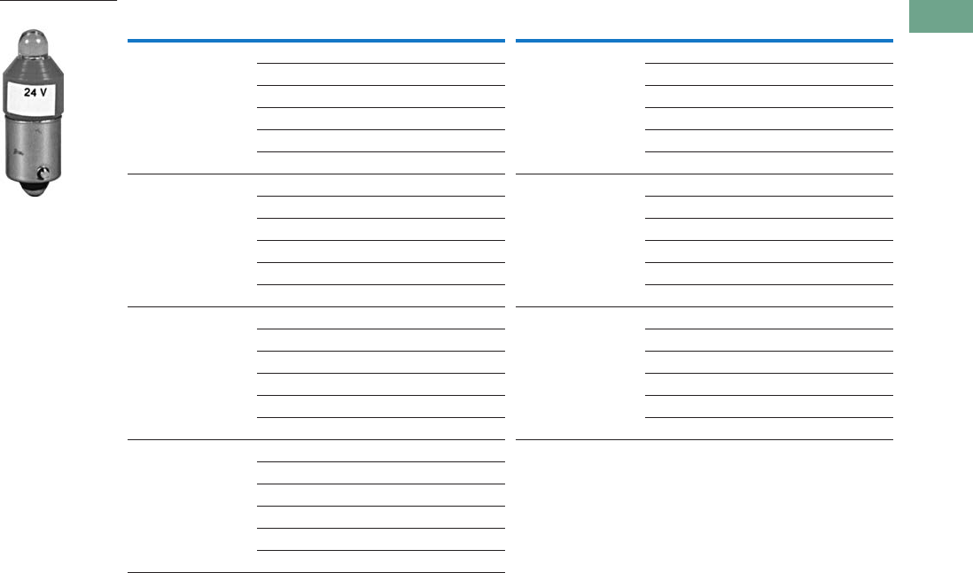
Logic Control Products CA08100001K—June 2012 www.eatoncanada.ca T37-305
37
37
37
37
37
37
37
37
37
37
37
37
37
37
37
37
37
37
37
37
37
37
37
37
37
37
37
37
37
37
37.10
Pushbuttons and Indicating Lights
30.5 mm Class I Division 2 Hazardous Locations—10250T/E34
LED Selection
Note
For a complete listing of all LEDs available, see Page T37-225.
Voltage Colour Catalogue Number Voltage Colour Catalogue Number
6 Vac/Vdc
suitable for
use with
transformers
Red E22LED006RN 60 Vac/Vdc Red E22LED060RN
Orange E22LED006ON Orange E22LED060ON
Yellow E22LED006YN Yellow E22LED060YN
Green E22LED006GN Green E22LED060GN
Blue E22LED006BN Blue E22LED060BN
White E22LED006WN White E22LED060WN
12 Vac/Vdc Red E22LED012RN 120 Vac Red E22LED120RA
Orange E22LED012ON Orange E22LED120OA
Yellow E22LED012YN Yellow E22LED120YA
Green E22LED012GN Green E22LED120GA
Blue E22LED012BN Blue E22LED120BA
White E22LED012WN White E22LED120WA
24 Vac/Vdc Red E22LED024RN 120 Vdc Red E22LED120RD
Orange E22LED024ON Orange E22LED120OD
Yellow E22LED024YN Yellow E22LED120YD
Green E22LED024GN Green E22LED120GD
Blue E22LED024BN Blue E22LED120BD
White E22LED024WN White E22LED120WD
48 Vac/Vdc Red E22LED048RN
Orange E22LED048ON
Yellow E22LED048YN
Green E22LED048GN
Blue E22LED048BN
White E22LED048WN
Standard LED Lamp
Tab37book.fm Page 305 Tuesday, July 3, 2012 10:46 PM
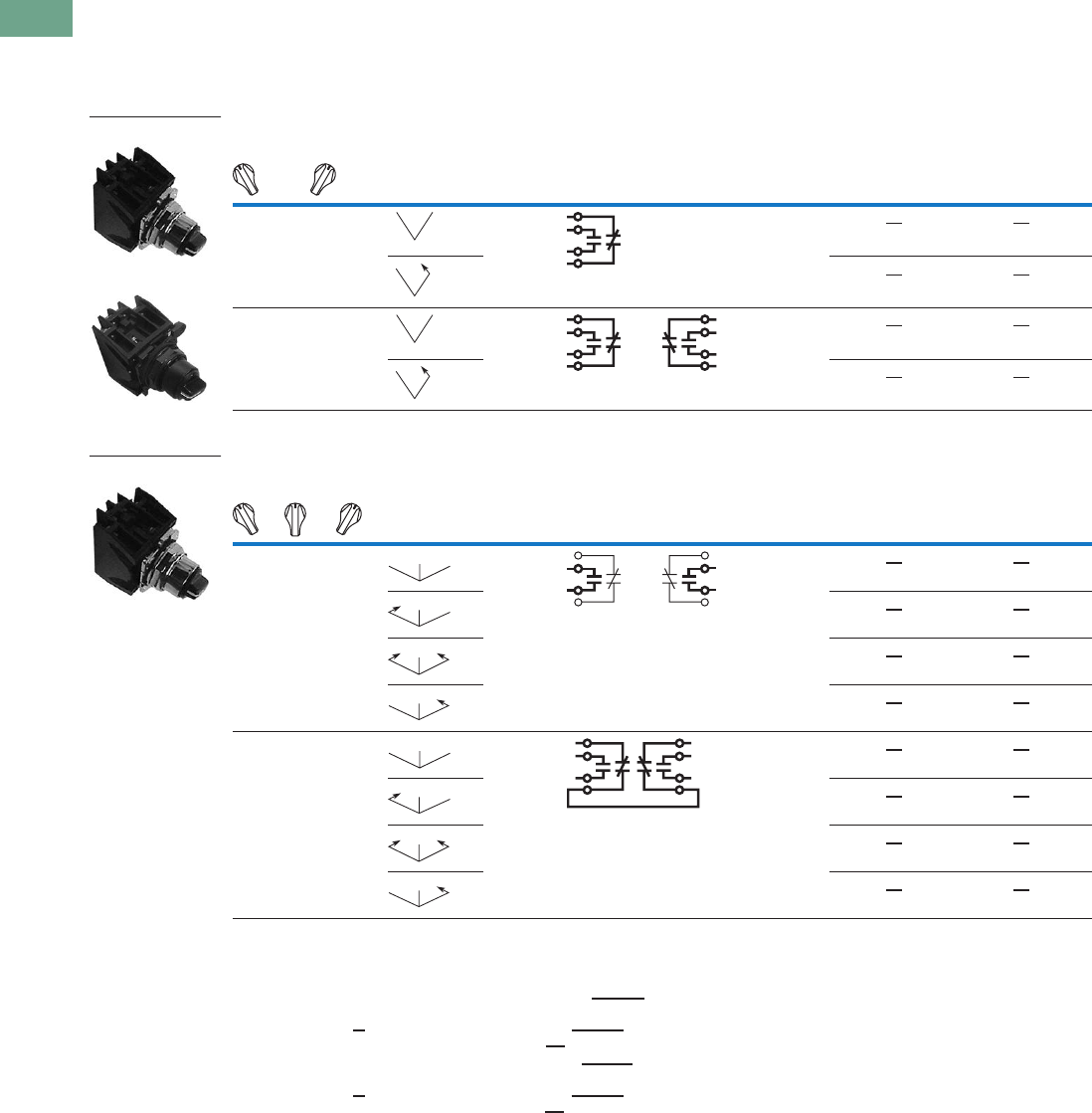
T37-306 Logic Control Products CA08100001K—June 2012 www.eatoncanada.ca
37
37
37
37
37
37
37
37
37
37
37
37
37
37
37
37
37
37
37
37
37
37
37
37
37
37
37
37
37
37
37.10
Pushbuttons and Indicating Lights
30.5 mm Class I Division 2 Hazardous Locations—10250T/E34
Selector Switch Units
UL (NEMA) Type 3, 3R, 4, 4X, 12, 13, NEC Class I Division 2, Groups B, C and D
●Two- and three-position
●Non-illuminated
Two-Position Selector Switch—Non-Illuminated
Three-Position Selector Switch—Non-Illuminated
Notes
Bolded circuit corresponds to “X-O” circuit selection. X = closed circuit, O = open circuit.
M = Maintained. S = Spring return in direction of arrow ().
To order different type or colour selector switch, simply substitute the underlined characters with appropriate
suffix code from the table on Page T37-307.
Example: 10250T722LL. For keyed selector switch, substitute the underlined characters with
T_ (cam)+_ (key removal position). Example: 10250T722T13.
To order different type or colour selector switch, simply substitute the underlined characters with appropriate
suffix code from the Switch and Colour Selection table on Page T37-307.
Example: 10250T726LL. For keyed selector switch, substitute the underlined characters with
T_ (cam)+_ (key removal position). Example: 10250T726T13.
Operator Position
Operator
Action
Contact
Type
Cam
Code
Black Knob—Selector Switch
Mounting Location 10250T
Catalogue Number
E34
Catalogue Number12
X
O
O
X
1NC
1NO
110250T722BK E34EX722BK
10250T724BK E34EX724BK
X
O
X
O
O
X
O
X
1NC
1NO
1NC
1NO
110250T723BK E34EX723BK
10250T725BK E34EX725BK
Operator Position
Operator
Action
Contact
Type
Cam
Code
Black Knob—Selector Switch
Mounting Location 10250T
Catalogue Number
E34
Catalogue Number12
X
O
O
O
O
X
1NO
1NO
310250T726BK E34EX726BK
10250T728BK E34EX728BK
10250T730BK E34EX730BK
10250T732BK E34EX732BK
X
O
O
O
X
O
O
O
X
1NO
1NC-1NC
(Series)
1NO
310250T727BK E34EX727BK
10250T729BK E34EX729BK
10250T731BK E34EX731BK
10250T733BK E34EX733BK
10250T72_
E34EX72_
MM
MS
MM
MS
10250T_
MM
M
MS
M
SS
M
MS
M
MM
M
MS
M
SS
M
MS
M
Tab37book.fm Page 306 Tuesday, July 3, 2012 10:46 PM
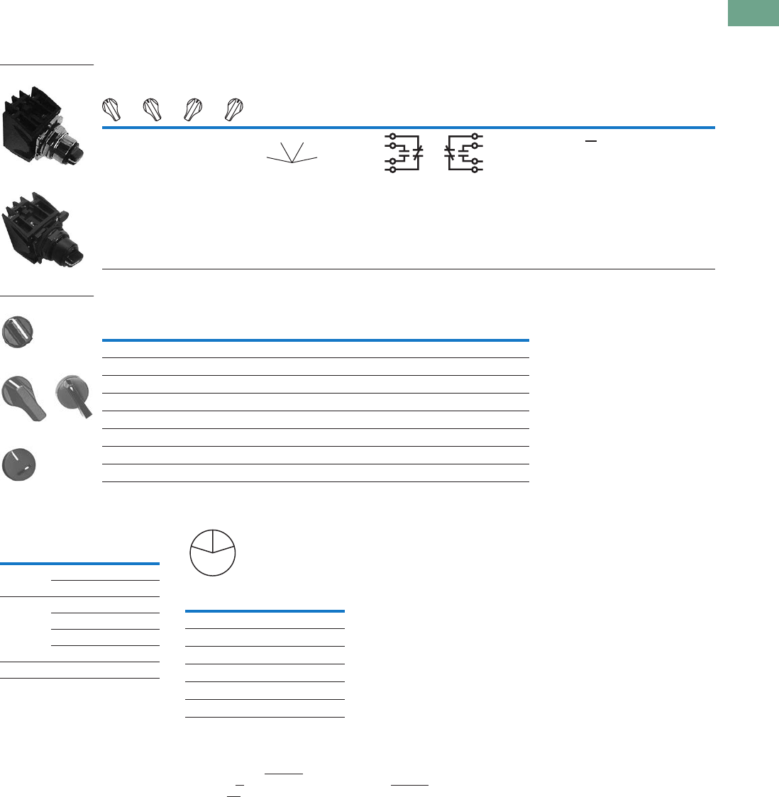
Logic Control Products CA08100001K—June 2012 www.eatoncanada.ca T37-307
37
37
37
37
37
37
37
37
37
37
37
37
37
37
37
37
37
37
37
37
37
37
37
37
37
37
37
37
37
37
37.10
Pushbuttons and Indicating Lights
30.5 mm Class I Division 2 Hazardous Locations—10250T/E34
UL (NEMA) Type 3, 3R, 4, 4X, 12, 13, NEC Class I Division 2, Groups B, C and D
●Four-position maintained
●Non-illuminated
Four-Position Selector Switch—Non-Illuminated
Switch and Colour Selection
Key Operated Selection Key Removal Positions
Notes
Bolded circuit corresponds to “X-O” circuit selection. X = closed circuit, O = open circuit.
M = Maintained.
To order different type or colour selector switch, simply substitute the underlined characters with appropriate suffix code from the
Switch and Colour Selection table above. Example: 10250T743LL. For keyed selector switch, substitute the underlined characters with
T_ (cam) + _ (key removal position). Example: 10250T743T77.
Designed for added ingress protection. For use in maintained operators only.
10250T only.
M = Maintained. S = Spring return in direction of arrow ().
Key removal in “spring return from” positions not recommended.
Operator Position
Operator
Action
Contact
Type
Cam
Code
Black Knob—Selector Switch
Mounting Location 10250T
Catalogue Number
E34
Catalogue Number12
X
O
O
O
O
X
O
O
O
O
X
O
O
O
O
X
1NC
1NO
1NO
1NC
710250T743BK E34EX743BK
Colour
Knob
Suffix Code
Lever
Suffix Code
Lever
Suffix Code
Coin Slot
Suffix Code
Black BK BL BA BC
Red RK RL RA RC
Green GK GL GA GC
Yellow YK YL YA YC
White WK WL WA WC
Gray AK AL AA AC
Blue LK LL LA LC
Orange NK NL NA NC
10250T743_
E34EX743_
MM
MM
Knob
Lever
Coin Slot
Number of
Position
Operator
Action
Suffix and
Removal
Position
2 M M T1 + 1, 2, 3
M S T1 + 2
3 M M M T3 + 1–7
S M M T3 + 1, 4, 5
S M S T3 + 4
M M S T3 + 2, 4, 6
4 MMMM T7 + 7
Code
Suffix
Key Removal
Position
1Right only
2Left only
3Right and left
4Centre only
6Left and centre
7All positions
L
C
R
Tab37book.fm Page 307 Tuesday, July 3, 2012 10:46 PM
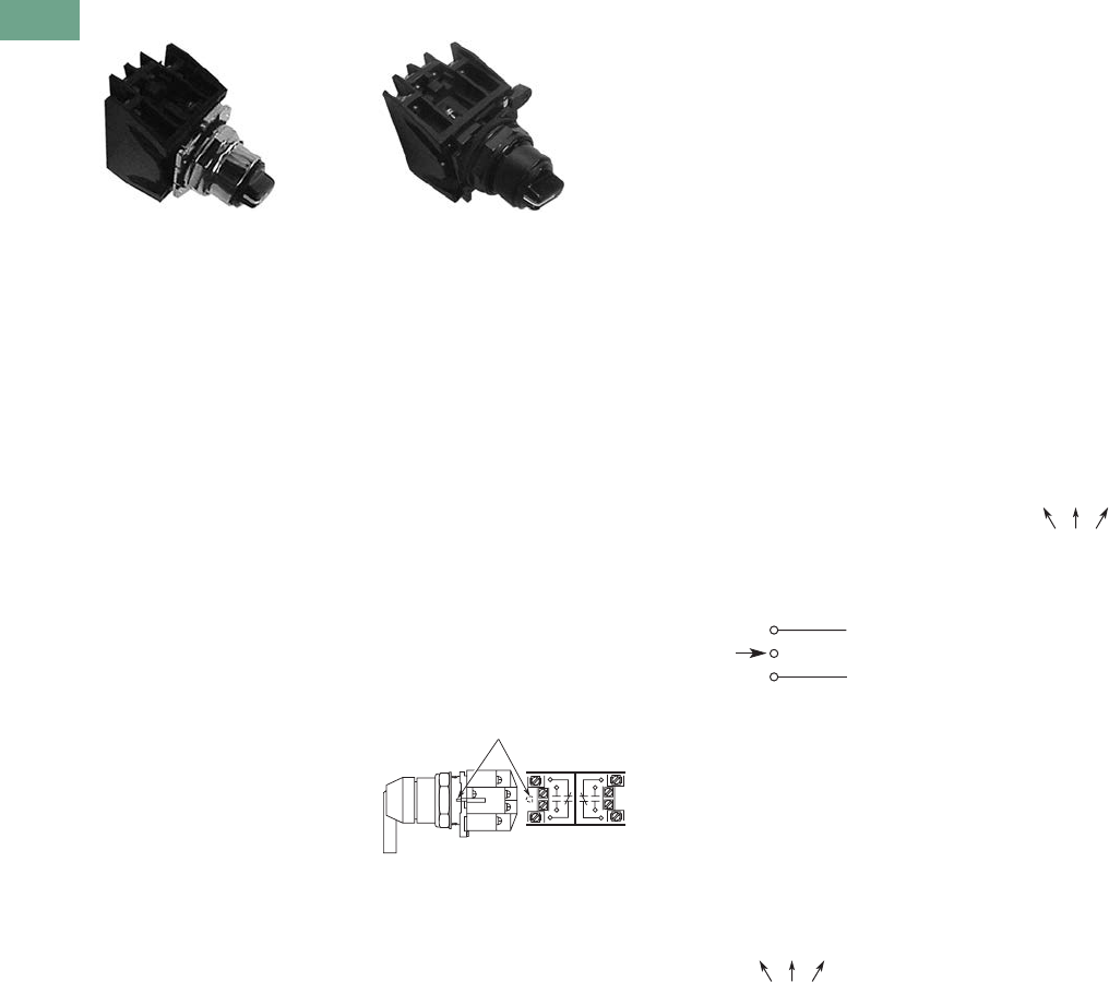
T37-308 Logic Control Products CA08100001K—June 2012 www.eatoncanada.ca
37
37
37
37
37
37
37
37
37
37
37
37
37
37
37
37
37
37
37
37
37
37
37
37
37
37
37
37
37
37
37.10
Pushbuttons and Indicating Lights
30.5 mm Class I Division 2 Hazardous Locations—10250T/E34
Selector Switch Selection
Cam and Contact Block Selection
Selector switches in their
varied forms (two-position,
three-position, and four-
position) are a big factor
contributing to the great
flexibility of control that a well
rounded line of “pushbuttons”
can achieve. Because of their
flexibility, they tend to cause
difficulty with product
selection and application.
The following systematic
approach should simplify
that task.
Cam and contact block
selection is better understood
if you:
●Work with each incoming
and outgoing wire/circuit
separately.
●Recognize the terms NO
and NC only identify the
type of contact by its mode
before mounting to the
operator. The “X-O” table
(Page T37-310) shows
how that contact will act
after assembly to the
operator with the selected
cam shape. X = closed
circuit, O = open circuit.
●One NO-NC contact block
may be mounted behind
each plunger of the
mounting adapter for a
total of four circuits.
●Each cam has two
separate lobes, each of
which operates one of the
two contact block plungers
independently of each
other. Those are identified
as position 1 (locating nib
side) and position 2
(opposite of locating nib).
The position designations
give direction in selecting
and mounting of the
contact blocks.
Contact Circuit Locations
10250T E34
Locating Nib
12
Systematic Approach
Application: HAND-OFF-
AUTO selector switch. In this
circuit, one incoming line is
distributed to two other
outgoing circuits by the
switch. The two circuits can
be looked at individually.
Step 1: Elementary
Diagram.
Construct on paper, or in your
mind, a simple elementary
diagram of the switching
scheme as follows:
Step 2: “X-O” Pattern.
From the elementary
diagram, you can construct
an “X-O” diagram which
describes when the contacts
are to be closed (X) or open
(O) in the various positions of
the switch. The “X-O” for the
HAND circuit looks like this:
In this circuit, you want a
contact closed on the left
(HAND) but open in the
centre and right.
For the AUTO circuit, the “X-
O” diagram would look like
this:
Putting them together, the
complete “X-O” diagram is:
Once the “X-O” diagram has
been generated, the next
step is to select the cam and
contact block, or blocks,
needed to perform the
desired “X-O” functions. The
selection tables on the
following pages list the
various types (shapes) of
cams by number to choose
from and the type of contact
and position to achieve the
function outlined in your
“X-O” diagram.
OFF
HAND Outgoing
Circuit
AUTO
Outgoing
Circuit
Incoming
Line
HAND OFF AUTO
XOO
HAND OFF AUTO
OOX
X O O
O O X
Tab37book.fm Page 308 Tuesday, July 3, 2012 10:46 PM
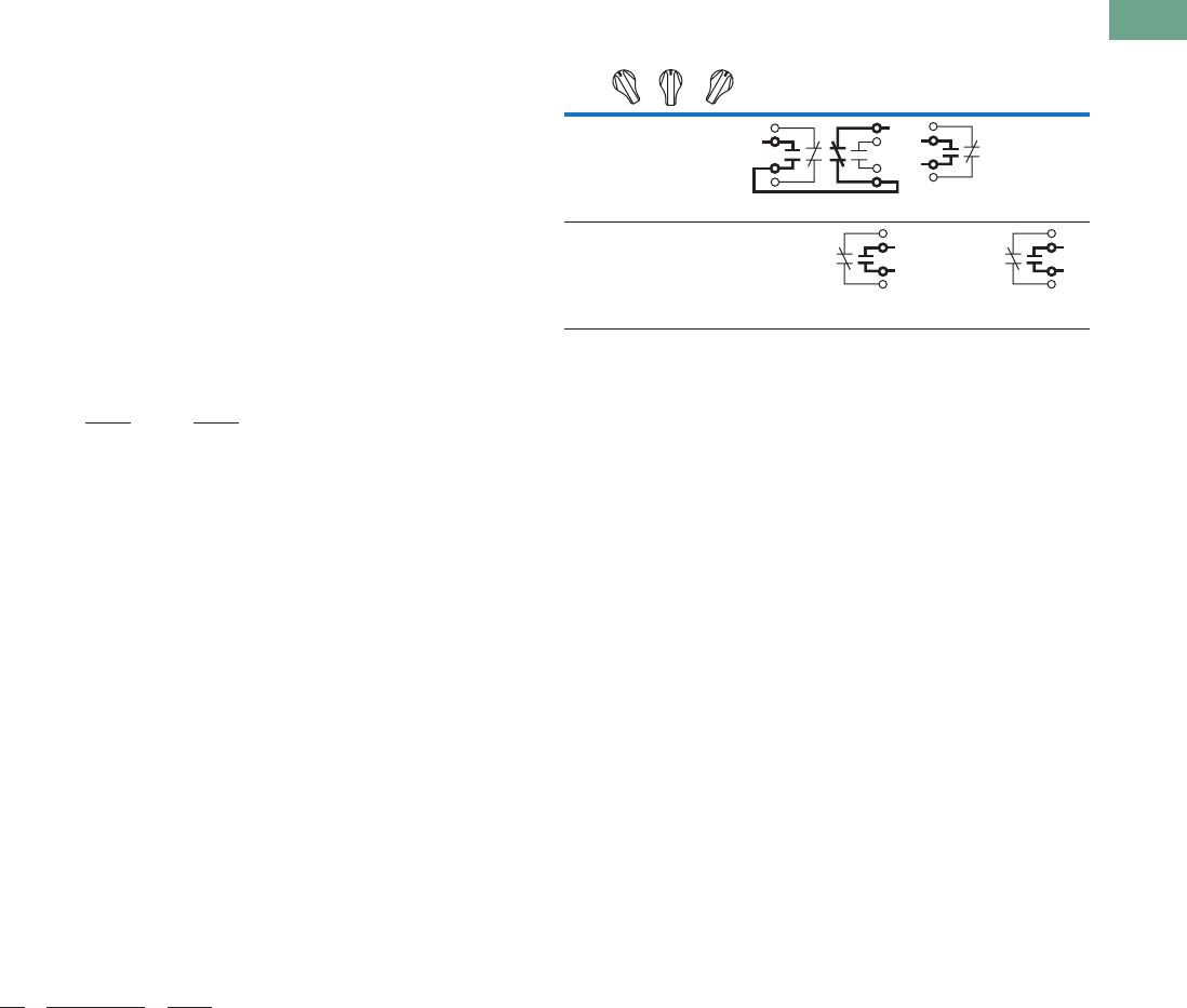
Logic Control Products CA08100001K—June 2012 www.eatoncanada.ca T37-309
37
37
37
37
37
37
37
37
37
37
37
37
37
37
37
37
37
37
37
37
37
37
37
37
37
37
37
37
37
37
37.10
Pushbuttons and Indicating Lights
30.5 mm Class I Division 2 Hazardous Locations—10250T/E34
Step 3: Cam Selection.
The cam you select
determines the operation of
all contact blocks mounted to
the operator. It is selected on
the basis that it provides the
simplest circuitry for the
desired “X-O” diagram. The
selection tables show all the
“X-O” combinations. For the
purpose of this example, the
applicable portion of those
tables is shown on this page.
Now to make the cam
selection, make a simple
worksheet such as below.
(1) or (2) = mounting location
from chart above:
It becomes obvious that
cam 3 is the better choice
because the series
connection can be avoided,
making it simpler to wire.
Step 4: Contact Block
Selection.
Having selected the cam,
contact block selection is
simply a matter of
determining if you require one
NO-NC contact block (Cat. No
10250T1H) or two. Given the
limitations of the factory
sealed contact block and the
desired “X-O” application,
you may have circuits that
will not be needed—as seen
here with the two additional
NC circuits. (1) or (2) =
mounting location from chart
above.
Step 5: Selector Switch
Operator.
Lastly, you have to choose
from the many types of
operators—knob and lever
in various colors or keyed.
Also what combinations of
maintained and spring
return functions are
required. Selection of these
operators can be found on
Page T37-311. For the
example in step 4, you may
want a three-position
maintained black knob,
cam 3—Catalogue Number
10250T1323 (or 34VHBK1).
The Complete Switch:
10250T1323 (or 34VHBK1)
with two 10250T1H or for
one composite catalogue
number—10250T726BK (or
E34EX726BK) found on
Page T37-306.
Diagrams
Circuits shown illustrate
connections to obtain a
selector circuit combination
and are shown with their
appropriate line diagrams in
BOLD. Field wiring of jumper
connections required as
shown.
X = Closed circuit
O = Open circuit
Cam 2 Cam 3
X O O
O O X
(1)NO-(2)NC
(2)NO
(1)NO
(2)NO
Qty Catalogue No. Cam 3
2 10250TIH (1)NO (2)NC
(1)NC (2)NO
Example Selection Table
Note
Wired in series.
No.
Desired Circuit and
Operator Position
Cam Code #2
Contact Blocks and
Mounting Location
Cam Code #3
Contact Blocks and
Mounting Location
1212
1XOO
NO NC NO
—
4 OOX—
NO
—
NO
Tab37book.fm Page 309 Tuesday, July 3, 2012 10:46 PM
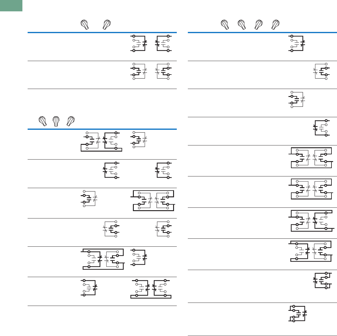
T37-310 Logic Control Products CA08100001K—June 2012 www.eatoncanada.ca
37
37
37
37
37
37
37
37
37
37
37
37
37
37
37
37
37
37
37
37
37
37
37
37
37
37
37
37
37
37
37.10
Pushbuttons and Indicating Lights
30.5 mm Class I Division 2 Hazardous Locations—10250T/E34
Two-Position Selector Switch
Three-Position Selector Switch
Four-Position Selector Switch
Number
Desired Circuit and
Operator Position
Cam Code #1
Contact Blocks and
Mounting Location
12
1XO
NC NC
2OX
NO NO
No.
Desired Circuit and
Operator Position
Cam Code #2
Contact Blocks and
Mounting Location
Cam Code #3
Contact Blocks and
Mounting Location
12 1 2
1X O O
NO (Series) NC NO
—
2X X O —
NC
—
NC
3X O X
NO
—
NO (Parallel) NO
4OOX—
NO
—
NO
5O X X
NC (Parallel) NO NC
—
6O X O
NC
—
NC (Series) NC
Number
Desired Circuit and
Operator Position
Cam Code #7
Contact Blocks and
Mounting Location
12
1 XOOO
NC
—
2 OXOO—
NO
3 OOXO
NO
—
4 OOOX—
NC
5 XOOX
NC (Parallel) NC
6OXXO
NO (Parallel) NO
7 OOXX
NO (Parallel) NC
8 XXOO
NC (Parallel) NO
9OXOX—
NO/NC
(Parallel)
10 XOXO
NO/NC
(Parallel)
—
Tab37book.fm Page 310 Tuesday, July 3, 2012 10:46 PM
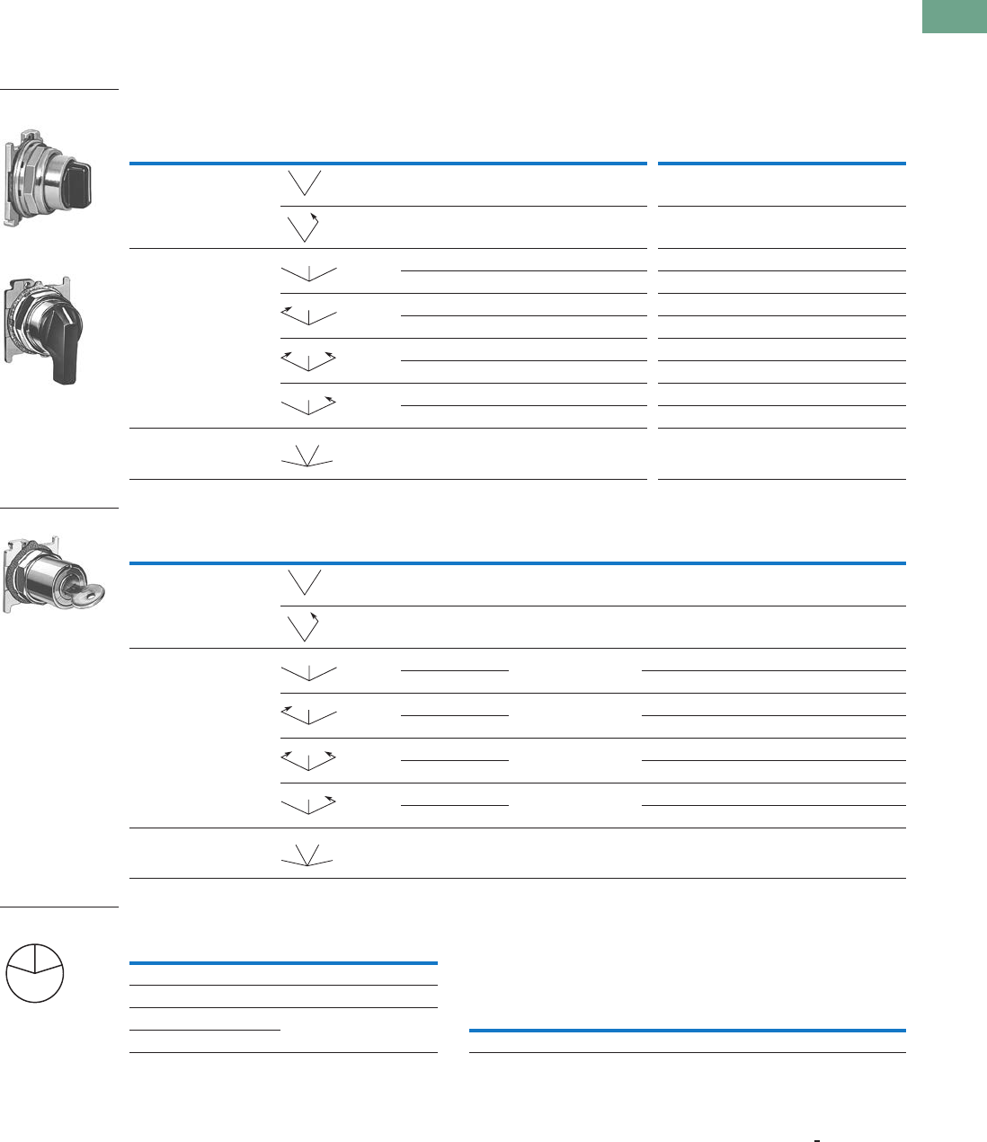
Logic Control Products CA08100001K—June 2012 www.eatoncanada.ca T37-311
37
37
37
37
37
37
37
37
37
37
37
37
37
37
37
37
37
37
37
37
37
37
37
37
37
37
37
37
37
37
37.10
Pushbuttons and Indicating Lights
30.5 mm Class I Division 2 Hazardous Locations—10250T/E34
Selector Switch Operators
10250T Selector Switch Operators with Caps
UL (NEMA) Type 3, 3R, 4, 4X, 12, 13
10250T Selector Switch Operators with Caps
10250T Key Operators with Cam
Key Removal Positions Replacement Keys or Dissimilar Locks for Above Key Operators
Listed operators have identical locks and keys (Key Code H661)
Catalogue Number 10250ED824.
Replacement Keys
Notes
M = Maintained. S = Spring return in direction of arrow ().
Field convertible to horizontal mounting or order operator only and separate operator cap.
For selection of the proper cam and contact block to obtain the proper circuit sequence, see selection instructions and table on Pages T37-308 to T37-310.
Choose key removal position required for application from table above. Add key removal code no. to listed catalogue number. Example: 10250T15112.
Key removal in “spring return from” positions not recommended.
Positions Operator Action
Black Knob Selector Switch—
Vertical Mounting
Black Lever Selector Switch—
Vertical Mounting
Cam Code Catalogue Number Cam Code Catalogue Number
Two-position—60˚ throw 1 10250T1311 110250T3011
110250T1371 110250T3071
Three-position—60˚ throw 2 10250T1322 210250T3022
310250T1323 310250T3023
210250T1332 210250T3032
310250T1333 310250T3033
210250T1342 210250T3042
310250T1343 310250T3043
210250T1352 210250T3052
310250T1353 310250T3053
Four-position—40˚ throw 7 10250T1367 710250T3067
Positions Operator Action Cam Code
Optional Key
Removal Positions
Vertical Mounting
Catalogue Number
Horizontal Mounting
Catalogue Number
Two-position—60˚ throw 1 1, 2, 3 10250T1511_ 10250T1611_
12 10250T1571_ 10250T1581_
Three-position—60˚ throw 2 1–7 10250T1522_ 10250T1622_
310250T1523_ 10250T1623_
2 1, 4, 5 10250T1532_ 10250T1632_
310250T1533_ 10250T1633_
24 10250T1542_ 10250T1642_
310250T1543_ 10250T1643_
2 2, 4, 6 10250T1652_ 10250T1662_
310250T1653_ 10250T1663_
Four-position—40˚ throw 7 7 10250T1677_ 10250T1687_
Black Knob Selector
Switch
Black Lever Selector
Switch
MM
MS
MM
M
MS
M
SS
M
MS
M
MM
MM
Horizontal Mounting
MM
MS
MM
M
MS
M
SS
M
MS
M
MM
MM
Code
Suffix
Key Removal
Position
Code
Suffix
Key Removal
Position
1Right only 5Right and centre
2Left only 6Left and centre
3Right and left 7All positions
4Centre only
L
C
R
Key Removal Positions
Description Catalogue Number
Replacement keys (code H661)10250ED824
Tab37book.fm Page 311 Tuesday, July 3, 2012 10:46 PM
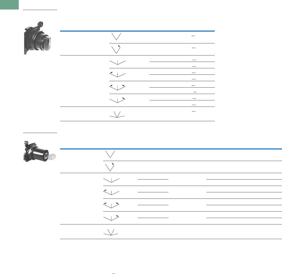
T37-312 Logic Control Products CA08100001K—June 2012 www.eatoncanada.ca
37
37
37
37
37
37
37
37
37
37
37
37
37
37
37
37
37
37
37
37
37
37
37
37
37
37
37
37
37
37
37.10
Pushbuttons and Indicating Lights
30.5 mm Class I Division 2 Hazardous Locations—10250T/E34
UL (NEMA) Type 3, 3R, 4, 4X, 12, 13
E34 Selector Switch Operators with Knob Assembled
E34 Key Operators with Cam and Cap
Notes
Use NEMA 4X 10250T operators where exposed to ultraviolet light, see Page T37-311.
M = Maintained. S = Spring return in direction of arrow ().
Field convertible to horizontal mounting.
For selection of the proper cam and contact block to obtain the proper circuit sequence, see selection instructions and table on Pages T37-308 to T37-310.
For other colors of either knob or lever, replace the underlined characters of the catalogue number with the appropriate suffix code from Alternate Knobs and Levers table
on Page T37-313. Example: E34VFBL2.
Choose key removal position required for application from table on Page T37-313. Add key removal code no. to listed catalogue number. Example: E34KFB2.
Positions Operator Action
Black Knob Selector Switch—
Vertical Mounting
Cam Code Catalogue Number
Two-position—60˚ throw 1 E34VFBK1
1E34VEBK1
Three-position—60˚ throw 2 E34VGBK1
3E34VHBK1
2E34VJBK1
3E34VKBK1
2E34VLBK1
3E34VMBK1
2E34VNBK1
3E34VPBK1
Four-position—40˚ throw 7 E34VTBK1
Positions Operator Action Cam Code
Key Removal
Positions
Vertical Mounting
Catalogue Number
Horizontal Mounting
Catalogue Number
Two-position—60˚ throw 1 1, 2, 3 E34KFB_ E34KFHB_
12 E34KEB_ E34KEHB_
Three-position—60˚ throw 2 1–7 E34KGB_ E34KGHB_
3E34KHB_ E34KHHB_
2 1, 4, 5 E34KJB_ E34KJHB_
3E34KKB_ E34KKHB_
24 E34KLB_ E34KLHB_
3E34KMB_ E34KMHB_
2 2, 4, 6 E34KNB_ E34KNHB_
3E34KPB_ E34KPHB_
Four-position—40˚ throw 7 7 E34KTB_ E34KTHB_
Black Knob Selector
Switch
MM
MS
MM
M
MS
M
SS
M
MS
M
MM
MM
E34KFB_
MM
MS
MM
M
MS
M
SS
M
MS
M
MM
MM
Tab37book.fm Page 312 Tuesday, July 3, 2012 10:46 PM
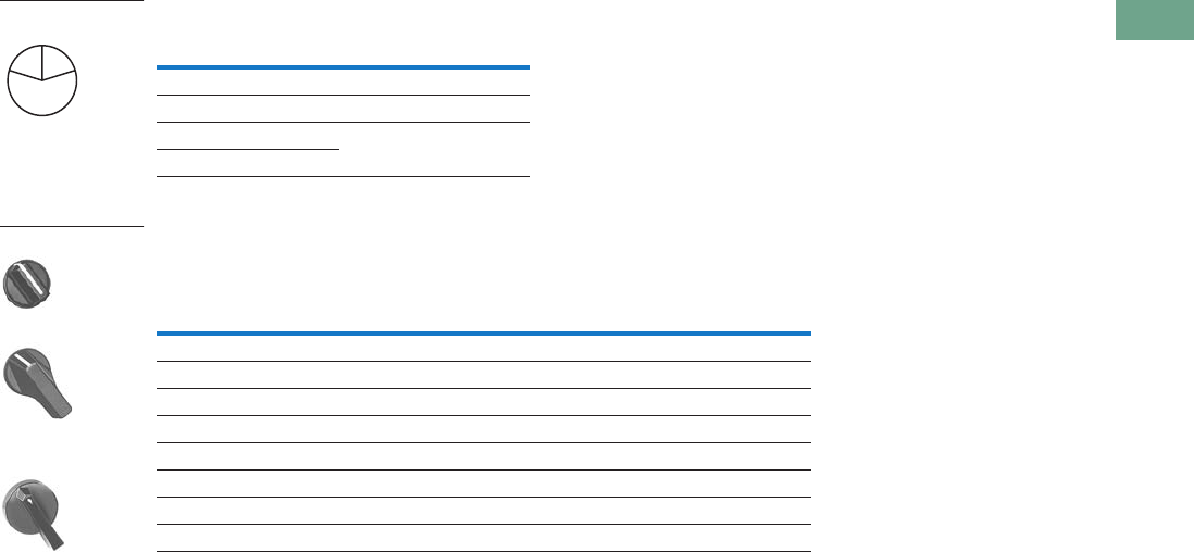
Logic Control Products CA08100001K—June 2012 www.eatoncanada.ca T37-313
37
37
37
37
37
37
37
37
37
37
37
37
37
37
37
37
37
37
37
37
37
37
37
37
37
37
37
37
37
37
37.10
Pushbuttons and Indicating Lights
30.5 mm Class I Division 2 Hazardous Locations—10250T/E34
Key Removal Positions
Alternate Knobs and Levers for Operators
Notes
Key removal in “spring return from” positions not recommended.
For use on maintained operators only.
Code
Suffix
Key Removal
Position
Code
Suffix
Key Removal
Position
1Right only 5Right and centre
2Left only 6Left and centre
3Right and left 7All positions
4Centre only
Colour
Knob Lever
Lever Designed for
Added Ingress Protection
Suffix
Code Catalogue Number
Suffix
Code Catalogue Number
Suffix
Code Catalogue Number
Black K1 E34K1 L1 E34L1 A1 E34A1
Red K2 E34K2 L2 E34L2 A2 E34A2
Green K3 E34K3 L3 E34L3 A3 E34A3
Yellow K4 E34K4 L4 E34L4 A4 E34A4
White K5 E34K5 L5 E34L5 A5 E34A5
Blue K6 E34K6 L6 E34L6 A6 E34A6
Gray K7 E34K7 L7 E34L7 A7 E34A7
Orange K8 E34K8 L8 E34L8 A8 E34A8
L
C
R
Key Removal Positions
Knob
Lever
Lever for Added
Ingress Protection
Tab37book.fm Page 313 Tuesday, July 3, 2012 10:46 PM
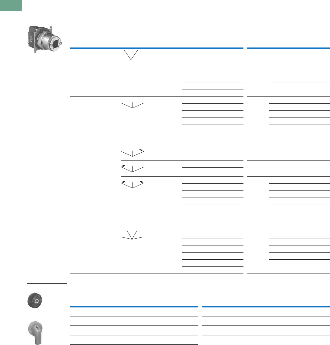
T37-314 Logic Control Products CA08100001K—June 2012 www.eatoncanada.ca
37
37
37
37
37
37
37
37
37
37
37
37
37
37
37
37
37
37
37
37
37
37
37
37
37
37
37
37
37
37
37.10
Pushbuttons and Indicating Lights
30.5 mm Class I Division 2 Hazardous Locations—10250T/E34
Illuminated Selector Switch Operators
10250T Illuminated Selector Switch Operator Only without Knob or Lever
Knobs and Levers
Notes
M = Maintained. S = Spring return in direction of arrow ().
For selection of the proper cam and contact block, to obtain the proper circuit sequence, see selection table on Page T37-310.
Operator includes lens gasket and lens attachment screws.
Full voltage light units can be used at other than listed voltages by changing lamp. Replacement lamps are listed on Page T37-225.
Resistor type. May generate excess heat if used in high density.
Amber, clear and white lenses have a black arrow (pointer), red, green and blue lenses have a white arrow (pointer).
Position Operator Action
Full Voltage Type—AC or DC
Transformer Type—50/60 Hz
6V #755 Lamp
Lamps: 6V—#755, 12V—#756, 24V—#757,
48V—#1835, 120/240V—120MB
Cam
Code Voltage
Catalogue and
Code Number
Cam
Code Voltage
Catalogue and
Code Number
Two-position—60˚ throw 1 24 10250T5961H 1610250T6201H
120 10250T5971H 12 10250T6211H
208 10250T6511H 24 10250T6221H
240 10250T5981H 48 10250T6231H
380 10250T5991H 120 10250T6361H
480 10250T6001H 240 10250T6371H
600 10250T6011H
Three-position—60˚ throw + 2 or 3 24 10250T602_H + 2 or 3 6 10250T624_H
120 10250T603_H 12 10250T625_H
208 10250T652_H 24 10250T626_H
240 10250T604_H 48 10250T627_H
380 10250T605_H 120 10250T638_H
480 10250T607_H 240 10250T639_H
600 10250T607_H
+ 2 or 3 120 10250T620_H + 2 or 3 120 10250T622_H
240 10250T656_H
+ 2 or 3 120 10250T621_H + 2 or 3 120 10250T623_H
240 10250T662_H
+ 2 or 3 24 10250T614_H + 2 or 3 6 10250T628_H
120 10250T615_H 12 10250T629_H
208 10250T653_H 24 10250T630_H
240 10250T616_H 48 10250T631_H
380 10250T617_H 120 10250T640_H
480 10250T618_H 240 10250T641_H
600 10250T619_H
Four-position—40˚ throw 7 24 10250T6087H 7610250T6327H
120 10250T6097H 12 10250T6337H
208 10250T6547H 24 10250T6347H
240 10250T6107H 48 10250T6357H
380 10250T6117H 120 10250T6427H
480 10250T6127H 240 10250T6437H
600 10250T6137H
Colour
Knob
Catalogue and
Code Number
Lever
Catalogue and
Code Number Colour
Knob
Catalogue and
Code Number
Lever
Catalogue and
Code Number
Red 10250TER 10250TFR Clear 10250TEC 10250TFC
Green 10250TEG 10250TFG White 10250TEW 10250TFW
Yellow 10250TEA 10250TFA Amber 10250TEM 10250TFM
Blue 10250TEL 10250TFL
Two-Position Maint.
Selector Switch
MM
MM
M
MS
M
MS
M
SS
M
MM
MM
Knob
Lever
Tab37book.fm Page 314 Tuesday, July 3, 2012 10:46 PM
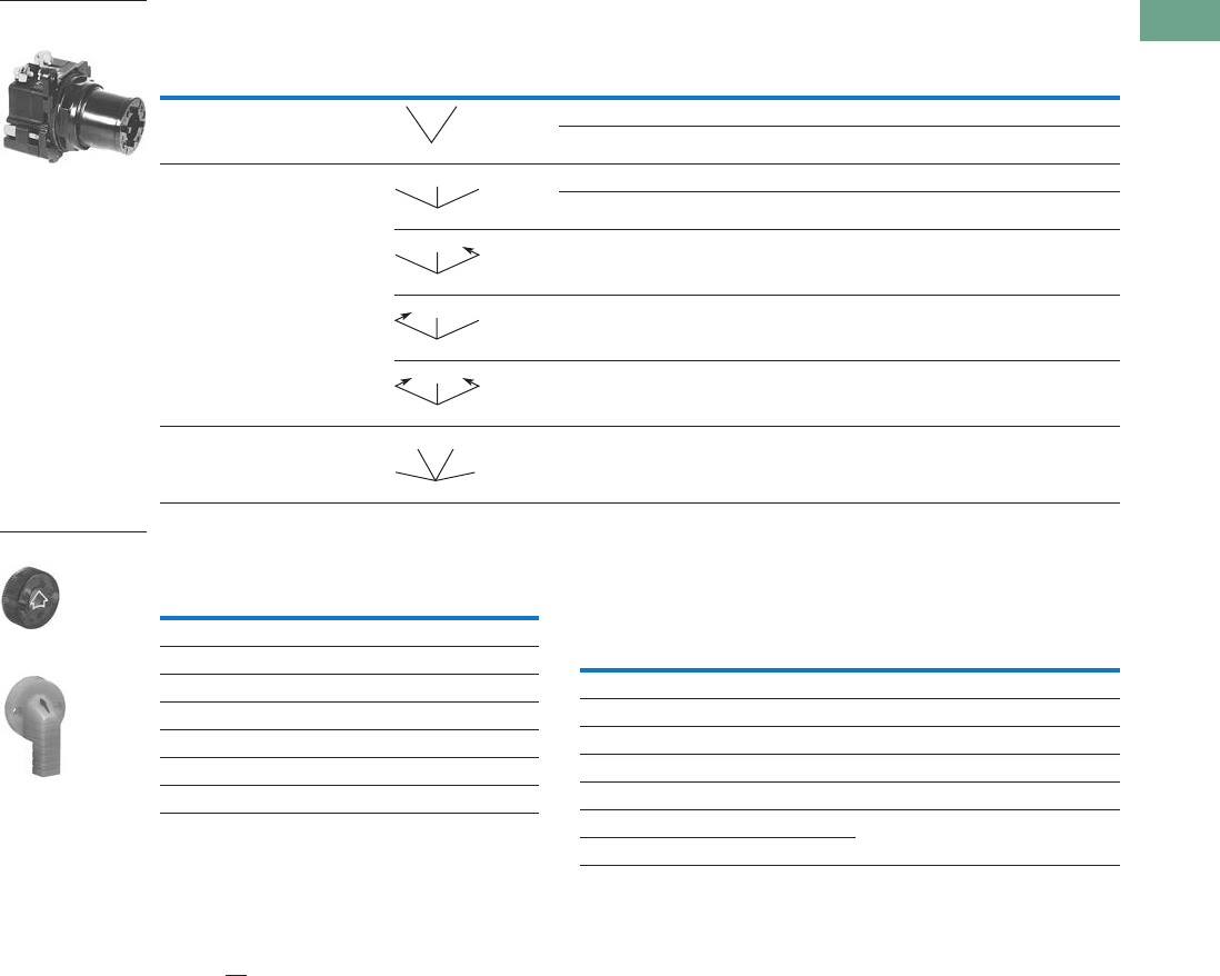
Logic Control Products CA08100001K—June 2012 www.eatoncanada.ca T37-315
37
37
37
37
37
37
37
37
37
37
37
37
37
37
37
37
37
37
37
37
37
37
37
37
37
37
37
37
37
37
37.10
Pushbuttons and Indicating Lights
30.5 mm Class I Division 2 Hazardous Locations—10250T/E34
Illuminated Selector Switch Operator Only without Knob or Lever
Knobs and Levers Light Unit Voltage Suffix
Add to operator catalogue number listed in table above.
Notes
Use NEMA 4X 10250T operators where exposed to ultraviolet light, see Page T37-314.
Operator includes lens gasket and lens attachment screws.
Replace underscore with proper voltage suffix code from Light Unit Voltage Suffix table above. Example: three-position maintained with 120V transformer type light unit:
E34VGB120H.
Full voltage light units can be used at other than listed voltages by changing lamp. Replacement lamps are listed on Page T37-225.
120MB lamps are used on both 120V and 240V operators.
For selection of the proper cam and contact block required to obtain a specific circuit sequence, see selection table on Page T37-310.
120 and 240V transformer only.
120 full voltage only.
Resistor type. May generate excess heat if used in high density.
Amber, clear and white lenses have a black arrow (pointer). Red, green and blue lenses have a white arrow (pointer).
Positions Operator Action
Transformer Type—50/60 Hz Full Voltage Type—AC or DC
6V #755 Lamp Lamps—#755, #757, #1835, 120MB
Catalogue Number Catalogue Number
Two-position—60˚ throw Cam Code 1 Cam Code 1
E34VFB_H E34SFB_H
Three-position—60˚ throw Cam Code 2 Cam Code 3 Cam Code 2 Cam Code 3
E34VGB_H E34VHB_H E34SGB_H E34SHB_H
E34VNB_H E34VPB_H E34SNB_H E34SPB_H
E34VJB_H E34VKB_H E34SJB_H E34SKB_H
E34VLB_H E34VMB_H E34SLB_H E34SMB_H
Four-position—40˚ throw E34VRB_H — E34SRB_H —
120 Vac Transformer
Selector Switch, Cam 1
MM
MM
M
MS
M
MS
M
SS
M
MM
MM
Colour
Knob
Catalogue Number
and Code Number
Lever
Catalogue Number
and Code Number
Red 10250TER 10250TFR
Green 10250TEG 10250TFG
Yellow 10250TEA 10250TFA
Blue 10250TEL 10250TFL
Clear 10250TEC 10250TFC
White 10250TEW 10250TFW
Amber 10250TEM 10250TFM
Knob
Lever
Type of Light Unit
Transformer Type
50/60 Hz
Full Voltage Type
AC or DC
Voltage Suffix Code Voltage Suffix Code
24 024 606
120 120 12 12
208 208 24 24
240 240 48 48
380 380 120 120
480 480 240 240
600 600
Tab37book.fm Page 315 Tuesday, July 3, 2012 10:46 PM
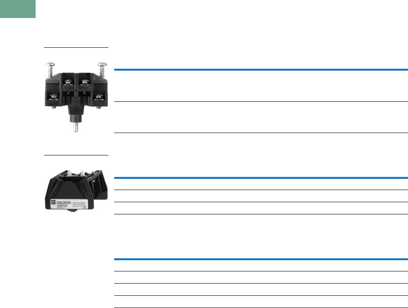
T37-316 Logic Control Products CA08100001K—June 2012 www.eatoncanada.ca
37
37
37
37
37
37
37
37
37
37
37
37
37
37
37
37
37
37
37
37
37
37
37
37
37
37
37
37
37
37
37.10
Pushbuttons and Indicating Lights
30.5 mm Class I Division 2 Hazardous Locations—10250T/E34
Options
Contact Blocks and Mounting Adapters
NEC Class I Division 2, Groups B, C and D
Contact Block
Mounting Adapter
Mounting Adapters with Contact Block(s)—Overpacked
Description Catalogue Number
Class I Division 2 factory sealed contact block with 1NO-1NC 10250T1H
Dimensions, see Page T37-321.
Description Catalogue Number
Mounting adapter for pushbuttons 10250TD2
Mounting adapter for selector switches 10250TD3
Dimensions, see Page T37-321.
Description Catalogue Number
Pushbutton adapter with 1NO-1NC 10250TD21H
Pushbutton adapter with 2 (1NO-1NC) 10250TD21H1H
Selector switch adapter with 1NO-1NC 10250TD31H
Selector switch adapter with 2 (1NO-1NC) 10250TD31H1H
Contact Block
Mounting Adapter
Tab37book.fm Page 316 Tuesday, July 3, 2012 10:46 PM
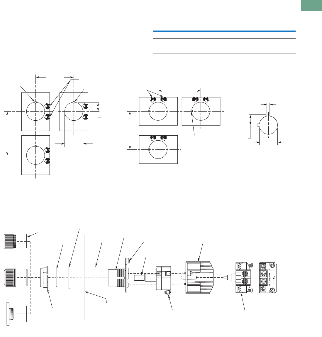
Logic Control Products CA08100001K—June 2012 www.eatoncanada.ca T37-317
37
37
37
37
37
37
37
37
37
37
37
37
37
37
37
37
37
37
37
37
37
37
37
37
37
37
37
37
37
37
37.10
Pushbuttons and Indicating Lights
30.5 mm Class I Division 2 Hazardous Locations—10250T/E34
Mounting and Assembly
Panel Thickness
●Minimum: 0.06 in (1.6 mm)
●Maximum: 0.25 in (8 mm) including legend plate
●Maximum can be increased to 0.375 in (15.9 mm) using
optional retaining nut
●Indicating light: 10250TA30/E34TA30
●Pushbutton/selector switch: 10250TA31/E34TA31
Mounting Matrix
Panel Spacing and Drilling
Operator Assembly
Legend
Plate
Dimensions in Inches (mm)
ABCD
Small 2.87 (72.6) 2.25 (57.2) 2.25 (57.2) 2.87 (72.6)
Jumbo 2.87 (72.6) 2.32 (58.6) 2.32 (58.6) 2.87 (72.6)
Extra large 2.87 (72.6) 2.56 (65.2) 2.52 (64.1) 2.87 (72.6)
Notch for
Locating Nib
Notch for
Locating Nib
.60
(15.2)
ø.14
(ø3.4)
ø1.2
(ø30.5)
“B” Min.
“A” Min.
Terminals for
Light Unit
Drilling for One Hole Mounting
and Dimensions for Minimum
Spacing in Vertical Rows.
“D” Min.
“C” Min.
Terminals for
Light Unit
Drilling for One Hole Mounting
and Dimensions for Minimum
Spacing in Horizontal Rows.
.19
(5.0)
.67
(17.0) ø1.2
(ø30.5)
NOTE: Suitable for Use
in This Alternate
Mounting Hole.
Nameplate
Retaining Nut
5 lb-ft (6.8 Nm)
Panel
0.06" – 0.25"
(1.6 – 8 mm)
with Optional
Retaining Nut
Up to 0.375"
(15.9 mm)
Thrust
Washer
(Optional)
Lens
Washer
Illuminated
Pushbutton
Indicator
Light
Push/Pull
Light Unit
Lamp
E34 Earth
Terminal
Operator
Gasket
Operator
Terminal Clamp:
One or Two Copper Conductors
22 – 12 AWG (0.34 – 4.0 mm2)
7 lb-in (0.8 Nm)
Contact Block
Mounting Adapter
RATINGS ARE STAMPED
ON LIGHT UNIT
AND CONTACT BLOCK
Terminal Clamp:
Single Copper Conductor
18 – 14 AWG (0.75 – 2.5 mm2)
9 lb-in (1.0 Nm)
Contact Block
Tab37book.fm Page 317 Tuesday, July 3, 2012 10:46 PM
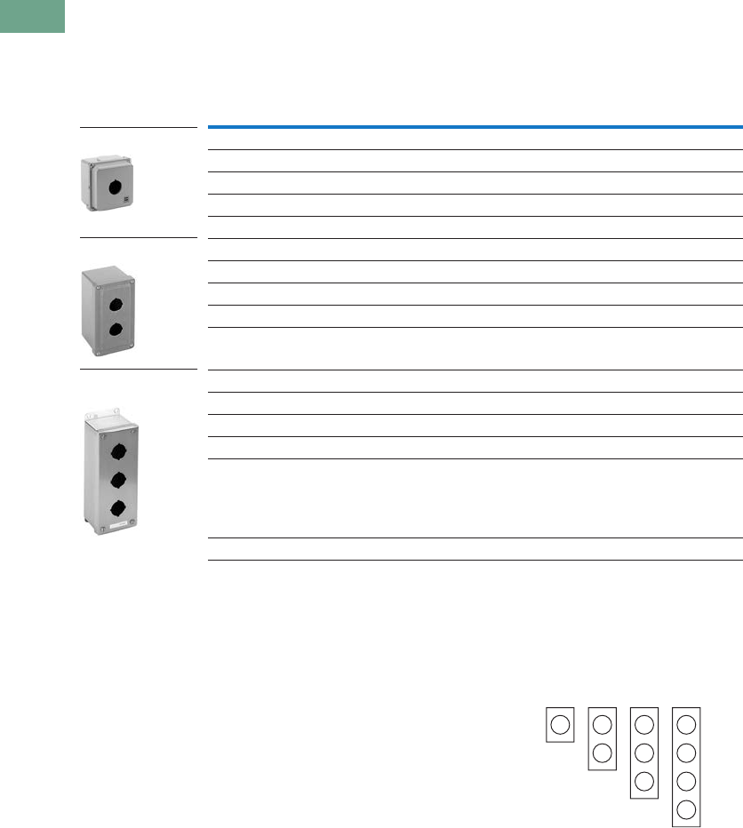
T37-318 Logic Control Products CA08100001K—June 2012 www.eatoncanada.ca
37
37
37
37
37
37
37
37
37
37
37
37
37
37
37
37
37
37
37
37
37
37
37
37
37
37
37
37
37
37
37.10
Pushbuttons and Indicating Lights
30.5 mm Class I Division 2 Hazardous Locations—10250T/E34
Enclosures
Die Cast, Polyester and Stainless Steel Enclosures
Enclosures (Case and Cover)—Surface Mounting
Notes
For spacing increments, see Page T37-220.
14 gauge, type 304.
Application Notes:
1. Operators need to be
mounted in their
horizontal orientation for
all enclosures. For die
cast enclosures remove
locating nib on operators
and use thrust washer
(Catalogue Number
10250TK3).
2. Polyester enclosures
must be used when
mounting illuminated
operators.
Enclosure Layouts
Number of
Elements
10250T
Catalogue Number
E34
Catalogue Number
Die Cast Enclosure—Deep Cover—In-Line NEMA 4, 4X, 12, 13
110250TN11 E34N11
210250TN12 E34N12
310250TN13 E34N13
410250TN14 E34N14
Polyester—In-Line NEMA 3, 4X, 12
1— E34N51
2— E34N52
3— E34N53
4— E34N54
Stainless Steel —In-Line NEMA 4, 4X, 12
1— 10250TN33
2— 10250TN34
3— 10250TN35
4— 10250TN36
Dimensions, see Page T37-321.
Die Cast Enclosure
Polyester Enclosure
Stainless Steel
Enclosure
111
Top – For Vertical Mounting
Top – For Horizontal
Mounting
1
222
33
4
Tab37book.fm Page 318 Tuesday, July 3, 2012 10:46 PM

Logic Control Products CA08100001K—June 2012 www.eatoncanada.ca T37-319
37
37
37
37
37
37
37
37
37
37
37
37
37
37
37
37
37
37
37
37
37
37
37
37
37
37
37
37
37
37
37.10
Pushbuttons and Indicating Lights
30.5 mm Class I Division 2 Hazardous Locations—10250T/E34
Technical Data and Specifications
Mechanical Ratings
Climatic Conditions
Terminals
Electrical Ratings
Description Specification
Frequency of Operation
All pushbuttons 6000 operations/hr.
Key and lever selector switches 3000 operations/hr.
Life
Pushbuttons 10 x 106 operations
Contact block 10 x 106 operations
Key and lever selector switches 0.25 x 10⁶ operations
Shock Resistance
Duration/force 20 ms >5g
Description Specification
Operating temperature 32˚ to 140˚F (0˚ to 66˚C)
Storage temperature –40˚ to 176˚F (–40˚ to 80˚C)
Altitude 6,562 ft (2,000m)
Humidity Max. 95% RH at 60˚C
Description Specification
Light Units
Clamps Terminals are saddle clamp type for 1 x 22 AWG (0.34 mm2) to 2 x 14 AWG (4.0 mm2)
conductors
Torque 7 lb-in (0.8 Nm)
Degree of protection against direct electrical contact IP2X with fingerproof shroud
Contact Blocks
Clamps Terminals are stainless steel saddle clamp type for 1 x 18–14 AWG (0.75–2.5 mm2)
solid or stranded copper conductor
Torque 9 lb-in (1.0 Nm) with size 2 Phillips screwdriver
Degree of protection against direct electrical contact IP2X with fingerproof shroud
Description Specification
Light Units
Bulbs—average life:
Transformer type 20,000 hrs.
Resistor/direct voltage type 2500 hrs. minimum at rated voltage
LED 60,000 to 100,000 hrs.
Tab37book.fm Page 319 Tuesday, July 3, 2012 10:46 PM

T37-320 Logic Control Products CA08100001K—June 2012 www.eatoncanada.ca
37
37
37
37
37
37
37
37
37
37
37
37
37
37
37
37
37
37
37
37
37
37
37
37
37
37
37
37
37
37
37.10
Pushbuttons and Indicating Lights
30.5 mm Class I Division 2 Hazardous Locations—10250T/E34
Electrical Ratings—Contact Block
Temperature Codes
All illuminated devices have operating temperatures below
100˚C except for the following catalogue numbers with
temperature codes per NEC table 500-5(d) and UL 1604:
Note: For additional technical information, see Publication Number
TD.7.4.T.E.04.
Meet or Exceed NEMA Contact Rating Designations A600 and Q300
Description
A600 (AC) Q300 (DC)
120V 240V 480V 600V 125V 250V
Make and emerg. interrupting capacity (amps) 60 30 15 12 0.55 0.27
Normal load break (amps) 6 3 1.5 1.2 0.55 0.27
Thermal current (amps) 10 10 10 10 2.5 2.5
Voltamperes:
Maximum make 7200 7200 7200 7200 69 69
Maximum break 720 720 720 720 69 69
10250T E34 Temp. Code
10250T201H E34RB120H T3C
10250T202H E34RB240H T3A
10250T471H E34SB120H TC3
10250T472H E34SB240H T3B
10250T80H — T3C
10250T81H — T3B
All selector switches w/120MB lamp T3C
All illuminated devices with lamp 1835 T4A
Tab37book.fm Page 320 Tuesday, July 3, 2012 10:46 PM
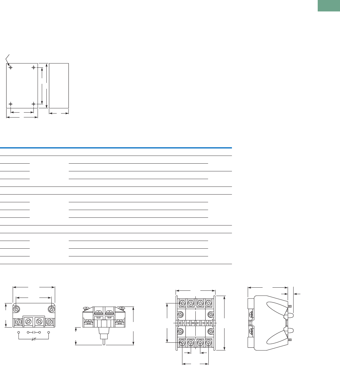
Logic Control Products CA08100001K—June 2012 www.eatoncanada.ca T37-321
37
37
37
37
37
37
37
37
37
37
37
37
37
37
37
37
37
37
37
37
37
37
37
37
37
37
37
37
37
37
37.10
Pushbuttons and Indicating Lights
30.5 mm Class I Division 2 Hazardous Locations—10250T/E34
Dimensions
Approximate Dimensions in Inches (mm)
Surface Mounting
Die Cast, Polyester and Stainless Steel Enclosures
Contact Block Mounting Adapter
Note
No conduit entrance holes provided. Drill as required.
A
Surface
DC
B
E
4 Mtg. Holes — 10-32 Screw Size for
1 – 4 Element Die Cast/
Stainless Steel Enclosure
7/32 Screw Size for
Polyester
Number of
Elements
Element
Arrangement
Wide
A
High
B
Deep
C
Mounting Conduit
EntranceDE
Die Cast
1 In-line 3.88 (98.6) 4.0 (101.6) 3.0 (76.3) 2.69 (68.3) 3.25 (82.6) 3/4
2 3.88 (98.6) 5.88 (149.4) 3.0 (76.3) 2.69 (68.3) 5.13 (130.3)
3 3.88 (98.6) 7.75 (196.9) 3.0 (76.3) 2.69 (68.3) 7.0 (177.8) 1
4 3.88 (98.6) 9.63 (244.6) 3.0 (76.3) 2.69 (68.3) 8.88 (225.6)
Polyester
1 In-line 3.81 (96.8) 6.63 (168.4) 3.38 (85.9) 2.94 (74.7) 4.88 (124.0)
2 3.81 (96.8) 6.63 (168.4) 3.38 (85.9) 2.94 (74.7) 4.88 (124.0)
3 3.81 (96.8) 8.88 (225.6) 3.38 (85.9) 2.94 (74.7) 7.13 (181.1)
4 3.81 (96.8) 11.13 (282.7) 3.38 (85.9) 2.94 (74.7) 9.38 (238.3)
Stainless Steel
1 In-line 3.00 (76.2) 3.50 (88.9) 3.00 (76.2) 1.50 (38.1) 4.25 (108.0)
2 3.50 (88.9) 6.75 (171.5) 3.00 (76.2) 1.50 (38.1) 7.50 (190.5)
3 3.50 (88.9) 9.00 (228.6) 3.00 (76.2) 1.50 (38.1) 9.00 (228.6)
4 3.50 (88.9) 11.25 (285.8) 3.00 (76.2) 1.50 (38.1) 12.00 (304.8)
1.43
(36.3)
1.70
(43.2)
1.02
(25.9)
1.72
(43.7)
0.84
(21.3)
0.44
(11.2)
1.23
(31.2)
1.85
(47.0)
1.86
(47.2)
1.88
(47.8) 0.25
(6.4)
2.57
(65.3)
Tab37book.fm Page 321 Tuesday, July 3, 2012 10:46 PM
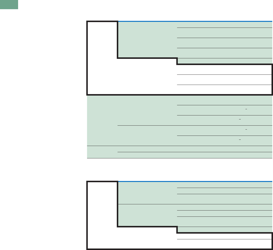
T37-322 Logic Control Products CA08100001K—June 2012 www.eatoncanada.ca
37
37
37
37
37
37
37
37
37
37
37
37
37
37
37
37
37
37
37
37
37
37
37
37
37
37
37
37
37
37
37.10
Pushbuttons and Indicating Lights
30.5 mm Class I Division 2 Hazardous Locations—10250T/E34
Ratings
Summary of NEC Article 500
The NEC Article 500 explains
in great detail the
requirements for the
installation of wiring and
electrical equipment in
hazardous locations. The
purpose of this summary is
for general reference only,
the National Electric Code
along with other applicable
authorities having jurisdiction
over the site should be the
installer’s guidelines when
wiring or installing electrical
equipment in any hazardous
or potentially hazardous
location.
Class I, Division 2 Definition
Class I, Division 2 covers
hazardous locations where
flammable gases, vapors or
volatile liquids are handled
either in a closed system, or
confined within suitable
enclosures, or where
hazardous concentrations are
normally prevented by
positive mechanical
ventilation. Areas adjacent to
Division 1 locations, into
which gases might
occasionally flow, would
also belong to Division 2
(NEC (500-5[b])).
Hazardous Location
Any area where there is the
possibility of explosion and
fire resulting from the
presence of flammable
vapors, liquids or gas, or
combustible dust or fibers.
Summary of NEC Article 505
The NEC also classifies
hazardous locations for
flammable gases and vapors
into zones under NEC 505.
This system is more in line
with the European
Standards, CENELEC and
IEC, with the major
difference being that NEC
505 only classifies gases and
vapors while CENELEC and
IEC also include dusts.
Summary of Classifications
NEC 500–503
NEC 505
Note
For additional information on grouping of compounds, see NFPA 497M-1991 and NFPA 325-1994.
Class Division Group
I. Gas 1. Hazard may exist—May exist in
atmosphere under normal operating
conditions
A. Acetylene
B. Hydrogen and manufactured gases containing 30% hydrogen by
volume (e.g. butadiene, ethylene oxide, propylene oxide)
C. Petrochemicals (e.g. carbon monoxide, ether, ethylene, hydrogen
sulfide, morpholine, cyclopropane)
D. Petrochemicals (e.g. gasoline, benzene, butane, propane, acetone,
ammonia, vinyl chloride)
2. Potential hazard—May be present in
atmosphere only under abnormal
circumstances OR location adjacent to
Class I, Division 1 location
A. Acetylene
B. Hydrogen and manufactured gases containing 30% hydrogen by
volume (e.g. butadiene, ethylene oxide, propylene oxide)
C. Petrochemicals (e.g. carbon monoxide, ether, ethylene, hydrogen
sulfide, morpholine, cyclopropane)
D. Petrochemicals (e.g. gasoline, benzene, butane, propane, acetone,
ammonia, vinyl chloride)
II. Dust 1. Hazard may exist—May exist in
atmosphere under normal operating
conditions
E. Conductive and combustible dust (resistivity <105 ohm/cm)
(metal dusts)
F. Carbonaceous dusts (resistivity >102 ohms/cm but <108 ohms/cm) (e.g.
carbon black, coke dust, coal)
G. Non-conductive combustible dust (resistivity >105 ohms/cm)
(e.g. grain dust, flour, starch, sugar, plastics)
2. Potential hazard—May be present in
atmosphere only under abnormal
circumstances
F. Carbonaceous dusts (resistivity >102 ohms/cm but <108 ohms/cm) (e.g.
carbon black, coke dust, coal)
G. Non-conductive combustible dust (resistivity >105 ohms/cm)
(e.g. grain dust, flour, starch, sugar, plastics)
III. Fibers 1. Production areas Easily ignitable fibers or flyings
2. Handling and storage areas Easily ignitable fibers or flyings
Class Zone Group
I. Gas 0. Continuously present or present for long
periods of time
IIC. Acetylene, hydrogen or equivalent hazard
IIB. Acetaldehyde, ethylene or equivalent hazard
IIA. Acetone, ammonia, ethyl alcohol, gasoline, methane, propane or
equivalent hazard
IIC. Acetylene, hydrogen or equivalent hazard1. Likely to exist under normal operating or
maintenance conditions or adjacent to
Zone 0 IIB. Acetaldehyde, ethylene or equivalent hazard
IIA. Acetone, ammonia, ethyl alcohol, gasoline, methane, propane or
equivalent hazard
2. Not likely to occur in normal operation
and if they do occur will only exist for
short period or adjacent to Zone 1
IIC. Acetylene, hydrogen or equivalent hazard
IIB. Acetaldehyde, ethylene or equivalent hazard
IIA. Acetone, ammonia, ethyl alcohol, gasoline, methane, propane or
equivalent hazard
Tab37book.fm Page 322 Tuesday, July 3, 2012 10:46 PM
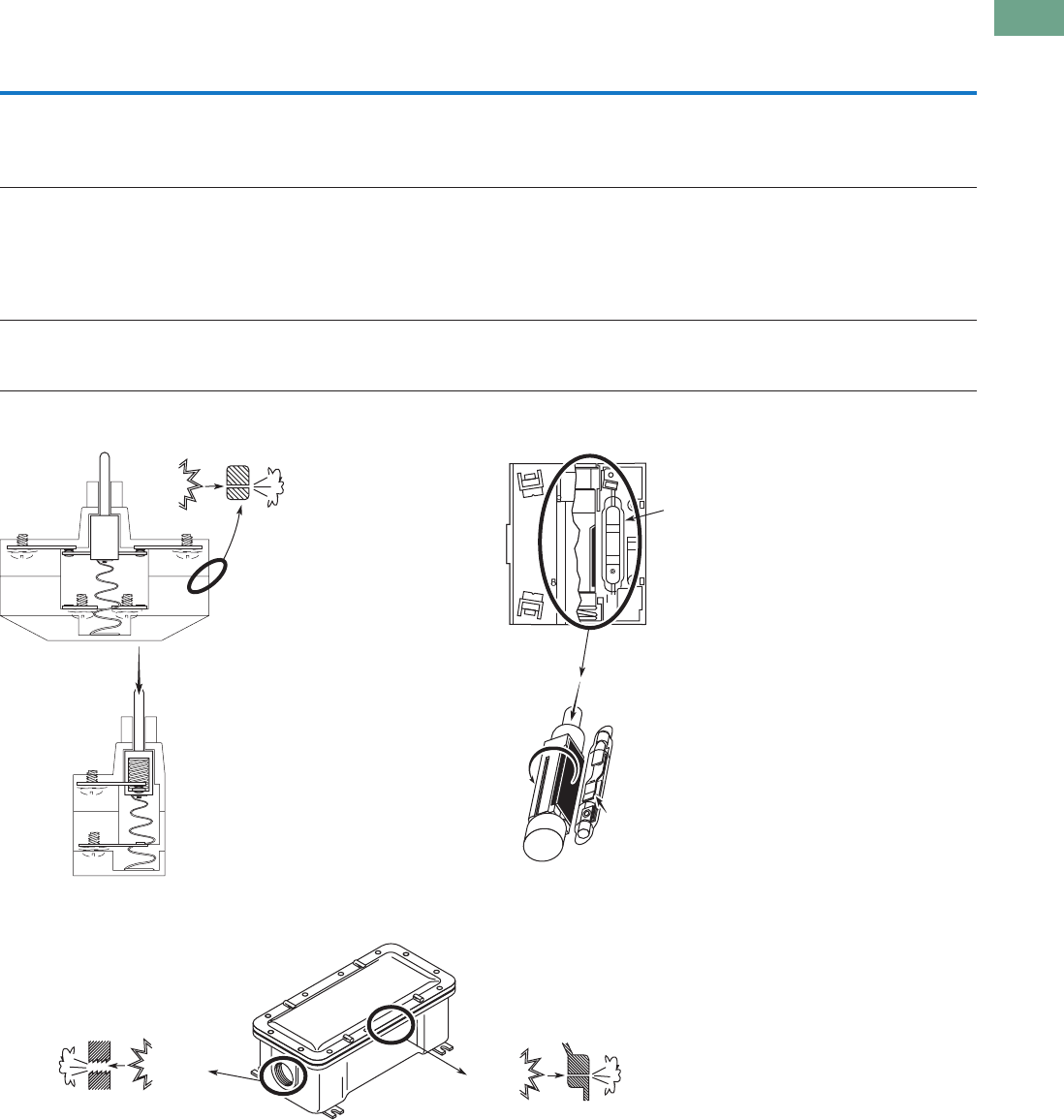
Logic Control Products CA08100001K—June 2012 www.eatoncanada.ca T37-323
37
37
37
37
37
37
37
37
37
37
37
37
37
37
37
37
37
37
37
37
37
37
37
37
37
37
37
37
37
37
37.10
Pushbuttons and Indicating Lights
30.5 mm Class I Division 2 Hazardous Locations—10250T/E34
Summary of Basic Methods Available for Class I, Division 2 Locations
Factory Sealed Contact Blocks Hermetically Sealed Reed Contact Block
Explosion Proof Enclosure
Method
Features
Configuration Advantages Disadvantages
Factory sealed contact block Closed-ended labyrinth contact block with an
incendive circuit incapable of external ignition
Higher continuous carrying amperages—up to 10A
Direct drive contacts—contacts can be forced open
Suitable for use in all enclosures
Best suited for motor control applications
May not be suitable for logic level circuits
Hermetically sealed block Reed switch sealed against an external
atmosphere
Suitable for low energy level circuits
Suitable for use in all enclosures
Lower continuous carrying amperages are not
suitable for motor control applications
(typically 3A to 5A rated)
Contacts cannot be forced open
Permanent magnet attracts metallic dust and
filings that can reduce the electrical creepage
distance between live terminals
Explosion proof enclosures
(Class I, Division 1 and 2)
Enclosures capable of withstanding an internal
explosion while preventing external ignition.
Enclosures designed for Class I, Division 1 can
safely be used in Class I, Division 2
Higher level of protection than required for Class I
Division 2
Higher material and installation costs
Conduit sealing is still required
Time consuming maintenance
Direct Drive Contacts
Contacts can be
mechanically forced
apart if subject to an
arch/fault current.
Cooled
Escaping
Gas
Internal
Ignition
•
Hermetically sealed
reed does not allow
external atmosphere to
enter switching chamber.
Depression of plunger
rotates magnet and either
opens/closes contacts.
Contacts can not be
forced apart if subject to
arch/fault current, because no
mechanical connection exists.
Cooled
Escaping
Gas
Threaded Joint Flat Joint
Internal
Ignition Internal
Ignition Cooled
Escaping
Gas
Tab37book.fm Page 323 Tuesday, July 3, 2012 10:46 PM

T37-324 Logic Control Products CA08100001K—June 2012 www.eatoncanada.ca
37
37
37
37
37
37
37
37
37
37
37
37
37
37
37
37
37
37
37
37
37
37
37
37
37
37
37
37
37
37
37.1
Pushbuttons and Indicating Lights
30.5 mm Class I Division 2 Hazardous Locations—10250T/E34
This page left intentionally blank
Tab37book.fm Page 324 Tuesday, July 3, 2012 10:46 PM

Logic Control Products
CA08100001K—June 2012 www.eatoncanada.ca
T38-1
38
38
38
38
38
38
38
38
38
38
38
38
38
38
38
38
38
38
38
38
38
38
38
38
38
38
38
38
38
38
Stacklights
Three-Light Unit Stacklight
with 60 mm Extension
38.1 E26 Series
Product Description . . . . . . . . . . . . . . . . . . . . . . . . . . . . . . . . . . . . . . . . . . . .
T38-2
Features . . . . . . . . . . . . . . . . . . . . . . . . . . . . . . . . . . . . . . . . . . . . . . . . . . . . .
T38-2
Benefits . . . . . . . . . . . . . . . . . . . . . . . . . . . . . . . . . . . . . . . . . . . . . . . . . . . . .
T38-2
Standards and Certifications. . . . . . . . . . . . . . . . . . . . . . . . . . . . . . . . . . . . . .
T38-2
Product Identification . . . . . . . . . . . . . . . . . . . . . . . . . . . . . . . . . . . . . . . . . . .
T38-3
Catalogue Number Selection . . . . . . . . . . . . . . . . . . . . . . . . . . . . . . . . . . . . .
T38-4
Product Selection . . . . . . . . . . . . . . . . . . . . . . . . . . . . . . . . . . . . . . . . . . . . . .
T38-5
Replacement Parts . . . . . . . . . . . . . . . . . . . . . . . . . . . . . . . . . . . . . . . . . . . . .
T38-10
Technical Data and Specifications . . . . . . . . . . . . . . . . . . . . . . . . . . . . . . . . .
T38-11
Ratings . . . . . . . . . . . . . . . . . . . . . . . . . . . . . . . . . . . . . . . . . . . . . . . . . . . . . .
T38-12
Mounting Instructions . . . . . . . . . . . . . . . . . . . . . . . . . . . . . . . . . . . . . . . . . .
T38-13
Dimensions. . . . . . . . . . . . . . . . . . . . . . . . . . . . . . . . . . . . . . . . . . . . . . . . . . .
T38-14
Tab38book.fm Page 1 Wednesday, July 4, 2012 9:22 PM
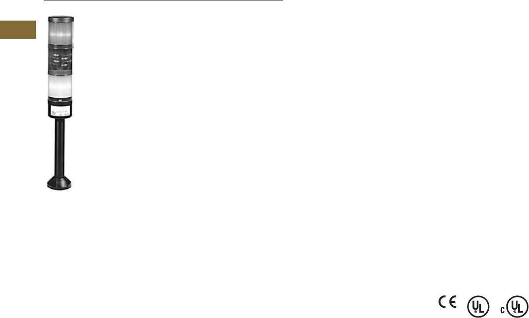
T38-2 Logic Control Products
CA08100001K—June 2012 www.eatoncanada.ca
38
38
38
38
38
38
38
38
38
38
38
38
38
38
38
38
38
38
38
38
38
38
38
38
38
38
38
38
38
38
38.1
Stacklights
E26 Series
Stacklights—E26 Series
Contents
Description Page
E26 Series
Product Identification . . . . . . . . . . . . . . . . . . . . . . . . .
T38-3
Catalogue Number Selection . . . . . . . . . . . . . . . . . . .
T38-4
Product Selection . . . . . . . . . . . . . . . . . . . . . . . . . . . .
T38-5
Replacement Parts . . . . . . . . . . . . . . . . . . . . . . . . . . .
T38-10
Technical Data and Specifications . . . . . . . . . . . . . . .
T38-11
Ratings . . . . . . . . . . . . . . . . . . . . . . . . . . . . . . . . . . . .
T38-12
Mounting Instructions . . . . . . . . . . . . . . . . . . . . . . . .
T38-13
Dimensions . . . . . . . . . . . . . . . . . . . . . . . . . . . . . . . .
T38-14
Product Description
The E26 stacklight unit is a
modular system that provides
illuminated and audible status
indication in all directions.
Easily assembled plug-in
modular units include
constant, flashing and strobe
light units, as well as mono-
tonal, bi-tonal, intermittent
audible alarms. Stacklights
may be assembled in a
variety of configurations,
which are identified in the
Maximum Configurations
table on
Page T38-3
. Several
lamp, colour and mounting
options further enhance the
stacklight’s versatility.
Features
●
Modular construction
●
Six lens colours
●
Variety of lamp types and
voltages
●
Mono-tonal, bi-tonal and
intermittent audible alarms
Benefits
●
Combination of visible and
audible alarms
●
Modular components
reduce inventory
requirements, increase
flexibility
●
Steady and flashing modes
allow one light to signal
multiple conditions
●
No-tools assembly permits
easy lamp replacement
Standards and
Certifications
●
CE 60947-5-1
●
UL 508—File No. E131568
●
cUL C22.2 No. 14—File
No. E131568
Ingress Protection
●
Stacklight base and light
units: IP65, NEMA 4, 4X
and 13
●
Alarm units: IP20, NEMA 1
Electrical Shock Protection
●
Stacklight base and light
unit: IP2X
●
Alarm units: IP0X
Tab38book.fm Page 2 Wednesday, July 4, 2012 9:22 PM
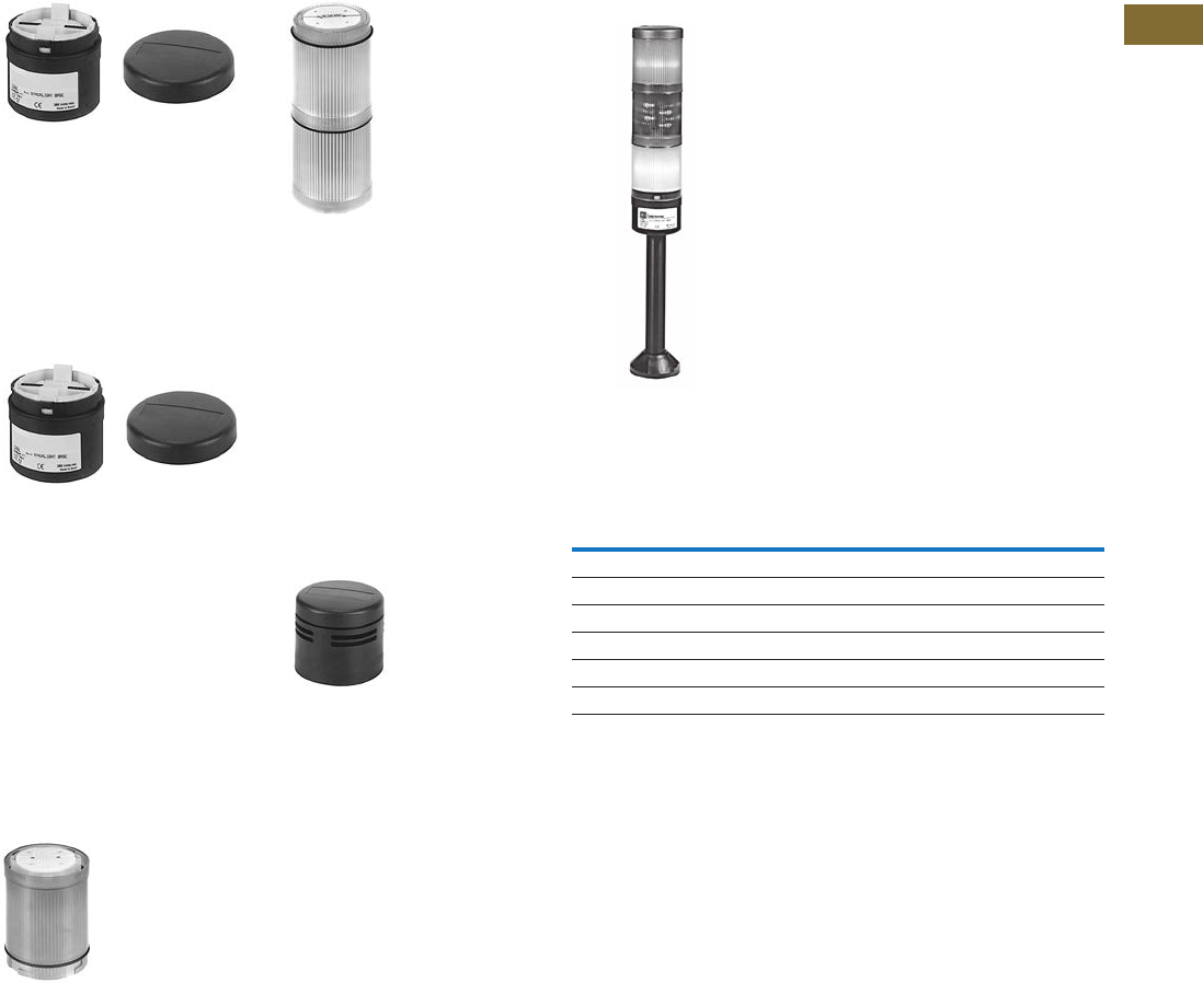
Logic Control Products
CA08100001K—June 2012 www.eatoncanada.ca
T38-3
38
38
38
38
38
38
38
38
38
38
38
38
38
38
38
38
38
38
38
38
38
38
38
38
38
38
38
38
38
38
38.1
Stacklights
E26 Series
Product Identification
Standard Stacklight Base
For use with incandescent or
standard LEDs for steady,
non-flashing illumination or
with flashing LEDs for
flashing illumination. Bases
include terminal block for
wiring, stacklight cover and
gasket. See
Page T38-8
.
Flashing Stacklight Base
Allows configuration of each
light in the stack for either
steady or 60 times per
minute flashing illumination.
Flashing circuit for use with
incandescent lamps only.
(Maximum allowable number
of light modules is 2 at 12V, 4
at 24V and 6 at 48V and
above.) See
Page T38-8.
For flashing LEDs use
standard base with flashing
LED light module.
Light Modules
Available in a variety of colours
for both incandescent lamps
and LED lamps. To maximize
illumination and light dispersion,
i
ncandescent units include an
opal white diffuser while LED
diffusers are clear. See
Page
T38-6.
Xenon Strobe
Sets are similar to standard
lens/diffuser units, except
each set consists of two lens
units. The lower unit includes
the electronics and is
permanently fused to the
upper unit which contains the
Xenon lamp. Xenon units may
be placed in any position in a
complete stacklight unit.
They will flash 60 times per
minute when used with a
standard or flashing base.
See
Page T38-6.
Alarms
May be fitted to the top of a
complete stacklight unit or
directly to the stacklight
bases, if desired. Available in
three versions, each with
adjustable sound levels. See
Page T38-9.
Complete Stacklight Modules
●
Stacklights accept a
maximum of six
incandescent or LED light
modules or two Xenon
Flasher modules and can
be mounted in any position
on the stack.
●
Alarm units are mounted in
the top most position only.
Maximum Configurations
Level
3
Level
2
Level
1
Extension
Tube
Mounting
Base
Stack-
light
Base
Incandescent
or
LED Modules
Xenon
Modules
Alarm
Modules
Max. Number
of Modules
6 ——6
5—16
41—5
3 115
22—4
1 214
Tab38book.fm Page 3 Wednesday, July 4, 2012 9:22 PM
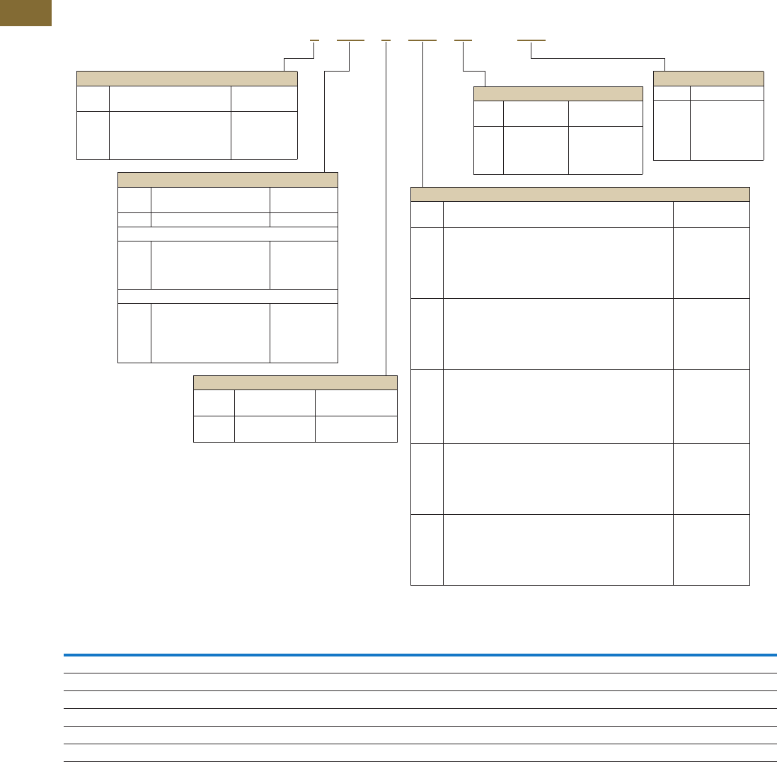
T38-4 Logic Control Products
CA08100001K—June 2012 www.eatoncanada.ca
38
38
38
38
38
38
38
38
38
38
38
38
38
38
38
38
38
38
38
38
38
38
38
38
38
38
38
38
38
38
38.1
Stacklights
E26 Series
Catalogue Number Selection
Stacklight Catalogue Numbering System
Voltage Codes
Notes
Unless base mount is specified, an extension tube must be selected for a complete unit.
Component catalogue numbers for flashing bases, alarm units and light modules are incomplete and require the addition of a suffix code to specify the required voltage rating. See table above.
If no voltage is specified, assembled stacklight will be supplied without lamps or LEDs.
240V not available for cylindrical LEDs.
For complete length (extension tube and base), see
Page T38-9
.
Flashing base is for use with incandescent lamps.
Voltage Code Incandescent Lamp Cluster LED Cylindrical LED Xenon Flasher Flasher Base/Alarm
(Blank) No lamp supplied No LED supplied No LED supplied — —
V1
12 Vac/Vdc 12 Vac/Vdc 12 Vac/Vdc 12 Vac/Vdc 12 Vac/Vdc
V2
24 Vac/Vdc 24 Vac/Vdc 24 Vac/Vdc 24 Vac/Vdc 24 Vac/Vdc
V3
48 Vac/Vdc 48 Vac/Vdc 48 Vac/Vdc 48 Vac/Vdc 48 Vac/Vdc
V4
120 Vac/Vdc 120 Vac 120 Vac 120 Vac 120 Vac/Vdc
V5
240 Vac/Vdc 240 Vac — 240 Vac 240 Vac/Vdc
Voltage
Code Description
V1
V2
V3
V4
V5
12V
24V
48V
120V
240V
Alarm
Code Description Component
Catalogue No.
W
Q
N
P
None
Mono-tonal
Bi-tonal
Intermittent
—
E26BQ_
E26BN_
E26BP_
Light Module
Code Description Component
Catalogue No.
0
2
3
4
6
9
Clear incandescent
Red incandescent
Green incandescent
Yellow incandescent
Blue incandescent
Amber incandescent
E26B0_
E26B2_
E26B3_
E26B4_
E26B6_
E26B9_
W
R
G
Y
B
A
White cluster LED with clear lens
Red cluster LED with red lens
Green cluster LED with green lens
Yellow cluster LED with yellow lens
Blue cluster LED with blue lens
Amber cluster LED with amber lens
E26BW_
E26BR_
E26BG_
E26BY_
E26BB_
E26BA_
W1
R1
G1
Y1
B1
A1
White cylindrical LED with clear lens
Red cylindrical LED with red lens
Green cylindrical LED with green lens
Yellow cylindrical LED with yellow lens
Blue cylindrical LED with blue lens
Amber cylindrical LED with amber lens
E26BW1_
E26BR1_
E26BG1_
E26BY1_
E26BB1_
E26BA1_
M
E
U
V
K
Z
Flashing white cluster LED with clear lens
Flashing red cluster LED with red lens
Flashing green cluster LED with green lens
Flashing yellow cluster LED with yellow lens
Flashing blue cluster LED with blue lens
Flashing amber cluster LED with amber lens
E26BM_
E26BE_
E26BU_
E26BV_
E26BK_
E26BZ_
X0
X2
X3
X4
X6
X9
Xenon flasher with clear lens
Xenon flasher with red lens
Xenon flasher with green lens
Xenon flasher with yellow lens
Xenon flasher with blue lens
Xenon flasher with amber lens
E26BX0_
E26BX2_
E26BX3_
E26BX4_
E26BX6_
E26BX9_
Extension Tube
Code Description Component
Catalogue No.
WNone (base mount) —
Gray Aluminum
HM
JM
KM
MM
20 mm 3/4 in NPT
160 mm 3/4 in NPT
360 mm 3/4 in NPT
760 mm 3/4 in NPT
E26BHM
E26BJM
E26BKM
E26BMM
Black Aluminum
HU
JU
KU
MU
RU
20 mm 3/4 in NPT
160 mm 3/4 in NPT
360 mm 3/4 in NPT
760 mm 3/4 in NPT
Right angle 3/4 in NPT
E26BHU
E26BJU
E26BKU
E26BMU
E26BRU
Mounting Base
Code Description Component
Catalogue No.
W
4
8
9
None (base mount)
3/4 in NPT hub, chrome
Standard three-hole
Standard four-hole
—
E26S104
E26S108
E26S109
Stacklight Base
Code Description Component
Catalogue No.
L
F
Standard
Flashing
E26BL
E26BF_
E26X 9 KM L 39R W – V 4
Tab38book.fm Page 4 Wednesday, July 4, 2012 9:22 PM

Logic Control Products
CA08100001K—June 2012 www.eatoncanada.ca
T38-5
38
38
38
38
38
38
38
38
38
38
38
38
38
38
38
38
38
38
38
38
38
38
38
38
38
38
38
38
38
38
38.1
Stacklights
E26 Series
Product Selection
Assembled Units
One-, Two- and Three-Light Assembled Stacklights
●
Base mountable
●
Incandescent or LED versions
●
24V and 120V versions
One-Light Unit Stacklight
Two-Light Unit Stacklight
Three-Light Unit Stacklight
Note
LED modules have very low current draw and should not be used with triac output devices like PLC triac output modules.
It is recommended that dry contact outputs be used to switch 120 Vac modules.
Volts
AC/DC Alarm
First Level
Colour Illumination Type Catalogue Number
24V None Red Incandescent—steady
E26XWWL2W-V2
24V None Red Cylindrical LED—steady
E26XWWLR1W-V2
24V None Green Incandescent—steady
E26XWWL3W-V2
24V None Green Cylindrical LED—steady
E26XWWLG1W-V2
24V None Amber Incandescent—steady
E26XWWL9W-V2
24V None Amber Cylindrical LED—steady E26XWWLA1W-V2
120V None Red Incandescent—steady E26XWWL2W-V4
120V None Red Cylindrical LED—steady E26XWWLR1W-V4
120V None Green Incandescent—steady E26XWWL3W-V4
120V None Green Cylindrical LED—steady E26XWWLG1W-V4
120V None Amber Incandescent—steady E26XWWL9W-V4
120V None Amber Cylindrical LED—steady E26XWWLA1W-V4
Volts
AC/DC Alarm
First Level
Colour Illumination Type
Second Level
Colour Illumination Type Catalogue Number
24V None Green Incandescent—steady Red Incandescent—steady E26XWWL32W-V2
24V None Green Cylindrical LED—steady Red Cylindrical LED—steady E26XWWLG1R1W-V2
120V None Green Incandescent—steady Red Incandescent—steady E26XWWL32W-V4
120V None Green Cylindrical LED—steady Red Cylindrical LED—steady E26XWWLG1R1W-V4
Volts
AC/DC Alarm
First
Level
Colour Illumination Type
Second
Level
Colour Illumination Type
Third
Level
Colour Illumination Type Catalogue Number
24V None Green Incandescent—steady Amber Incandescent—steady Red Incandescent—steady E26XWWL392W-V2
24V None Green Cylindrical LED—steady Amber Cylindrical LED—steady Red Cylindrical LED—steady E26XWWLG1A1R1W-V2
120V None Green Incandescent—steady Amber Incandescent—steady Red Incandescent—steady E26XWWL392W-V4
120V None Green Cylindrical LED—steady Amber Cylindrical LED—steady Red Cylindrical LED—steady E26XWWLG1A1R1W-V4
Tab38book.fm Page 5 Wednesday, July 4, 2012 9:22 PM

T38-6 Logic Control Products CA08100001K—June 2012 www.eatoncanada.ca
38
38
38
38
38
38
38
38
38
38
38
38
38
38
38
38
38
38
38
38
38
38
38
38
38
38
38
38
38
38
38.1
Stacklights
E26 Series
Light and Xenon Strobe Modules
●Light modules include lens
diffusers which provide
even illumination and
eliminate hot spots.
●Xenon strobes emit a
bright attention-getting
white flashing light. Flash
rate = 60/min.
●Xenon strobe modules
occupy two positions in the
stacklight assembly.
Light and Xenon Strobe Modules
Notes
Include lens, diffusers and lamps unless otherwise noted.
Incandescent bulbs are AC/DC rated, LEDs are AC rated only.
LED/Lamp
Voltage Lens Colour
Incandescent Cylindrical LED Cluster LED Cluster LED Xenon
Steady or Flashing
Catalogue Number
Steady Only
Catalogue Number
Steady
Catalogue Number
Flashing
Catalogue Number
Flashing
Catalogue Number
Without bulb
or LED
Red E26B2 E26B E26BR E26BR —
Green E26B3 E26BG E26BG E26BG —
Yellow E26B4 E26BY E26BY E26BY —
Blue E26B6 E26BB E26BB E26BB —
Amber E26B9 E26BA E26BA E26BA —
Clear E26B0 E26BW E26BW E26BW —
12 Vac/Vdc Red E26B2V1 E26BR1V1 E26BRV1 E26BEV1 E26BX2V1
Green E26B3V1 E26BG1V1 E26BGV1 E26BUV1 E26BX3V1
Yellow E26B4V1 E26BY1V1 E26BYV1 E26BVV1 E26BX4V1
Blue E26B6V1 E26BB1V1 E26BBV1 E26BKV1 E26BX6V1
Amber E26B9V1 E26BA1V1 E26BAV1 E26BZV1 E26BX9V1
Clear E26B0V1 E26BW1V1 E26BWV1 E26BMV1 E26BX0V1
24 Vac/Vdc Red E26B2V2 E26BR1V2 E26BRV2 E26BEV2 E26BX2V2
Green E26B3V2 E26BG1V2 E26BGV2 E26BUV2 E26BX3V2
Yellow E26B4V2 E26BY1V2 E26BYV2 E26BVV2 E26BX4V2
Blue E26B6V2 E26BB1V2 E26BBV2 E26BKV2 E26BX6V2
Amber E26B9V2 E26BA1V2 E26BAV2 E26BZV2 E26BX9V2
Clear E26B0V2 E26BW1V2 E26BWV2 E26BMV2 E26BX0V2
48 Vac/Vdc Red E26B2V3 E26BR1V3 E26BRV3 E26BEV3 E26BX2V3
Green E26B3V3 E26BG1V3 E26BGV3 E26BUV3 E26BX3V3
Yellow E26B4V3 E26BY1V3 E26BYV3 E26BVV3 E26BX4V3
Blue E26B6V3 E26BB1V3 E26BBV3 E26BKV3 E26BX6V3
Amber E26B9V3 E26BA1V3 E26BAV3 E26BZV3 E26BX9V3
Clear E26B0V3 E26BW1V3 E26BWV3 E26BMV3 E26BX0V3
120 Vac Red E26B2V4 E26BR1V4 E26BRV4 E26BEV4 E26BX2V4
Green E26B3V4 E26BG1V4 E26BGV4 E26BUV4 E26BX3V4
Yellow E26B4V4 E26BY1V4 E26BYV4 E26BVV4 E26BX4V4
Blue E26B6V4 E26BB1V4 E26BBV4 E26BKV4 E26BX6V4
Amber E26B9V4 E26BA1V4 E26BAV4 E26BZV4 E26BX9V4
Clear E26B0V4 E26BW1V4 E26BWV4 E26BMV4 E26BX0V4
240 Vac Red E26B2V5 — E26BRV5 E26BEV5 E26BX2V5
Green E26B3V5 — E26BGV5 E26BUV5 E26BX3V5
Yellow E26B4V5 — E26BYV5 E26BVV5 E26BX4V5
Blue E26B6V5 — E26BBV5 E26BKV5 E26BX6V5
Amber E26B9V5 — E26BAV5 E26BZV5 E26BX9V5
Clear E26B0V5 — E26BWV5 E26BMV5 E26BX0V5
Light/LED Module
Xenon Strobe Module
Tab38book.fm Page 6 Wednesday, July 4, 2012 9:22 PM
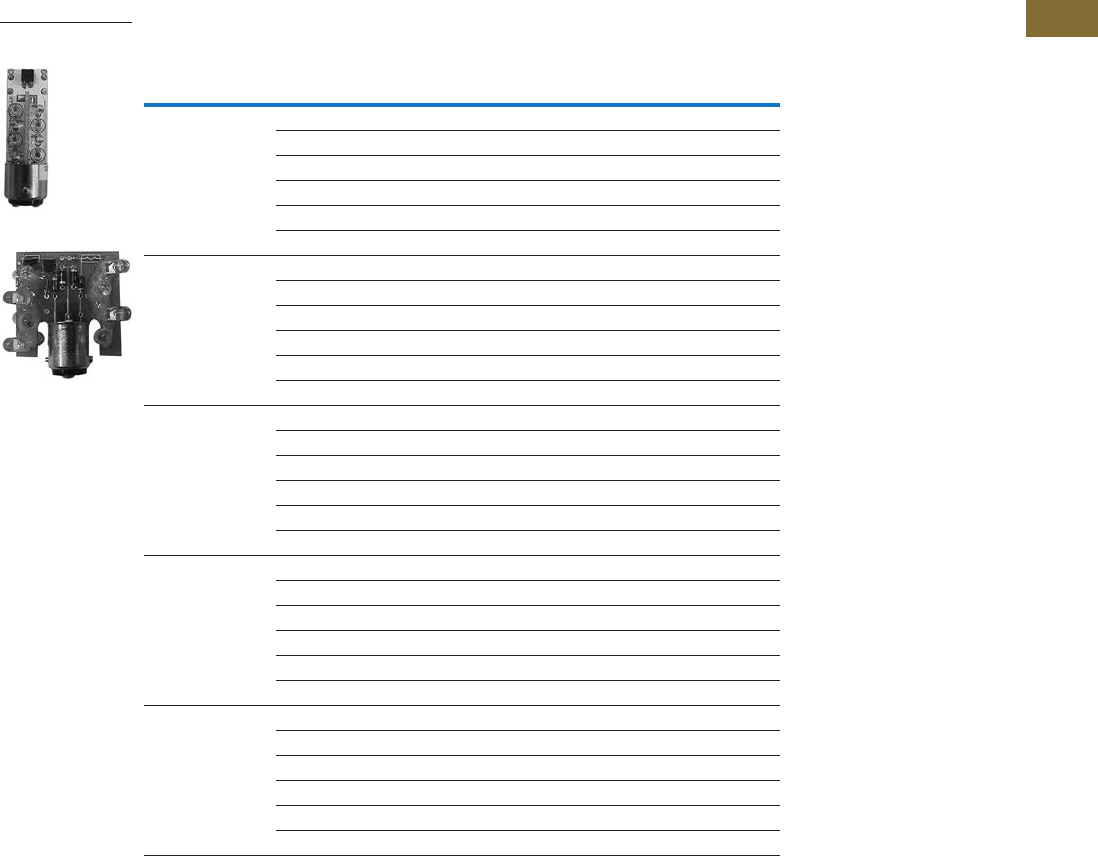
Logic Control Products CA08100001K—June 2012 www.eatoncanada.ca T38-7
38
38
38
38
38
38
38
38
38
38
38
38
38
38
38
38
38
38
38
38
38
38
38
38
38
38
38
38
38
38
38.1
Stacklights
E26 Series
LEDs—Cylindrical or Cluster
Cylindrical or Cluster LEDs
Voltage Colour
Cylindrical LED Cluster LED Cluster LED
Steady Only
Catalogue Number
Steady
Catalogue Number
Flashing
Catalogue Number
12 Vac/Vdc Red E26S110 E26S15 E26S48
Green E26S114 E26S19 E26S53
Yellow E26S112 E26S23 E26S58
Blue E26S115 E26S27 E26S63
White E26S116 E26S71 E26S75
Amber E26S111 E26S79 E26S84
24 Vac/Vdc Red E26S117 E26S16 E26S49
Green E26S121 E26S20 E26S54
Yellow E26S119 E26S24 E26S59
Blue E26S122 E26S28 E26S64
White E26S123 E26S72 E26S76
Amber E26S118 E26S80 E26S85
48 Vac/Vdc Red E26S124 E26S17 E26S50
Green E26S128 E26S21 E26S55
Yellow E26S126 E26S25 E26S60
Blue E26S129 E26S29 E26S65
White E26S130 E26S73 E26S77
Amber E26S125 E26S81 E26S86
120 Vac/Vdc Red E26S138 E26S18 E26S51
Green E26S142 E26S22 E26S56
Yellow E26S140 E26S26 E26S61
Blue E26S143 E26S30 E26S66
White — E26S74 E26S78
Amber E26S139 E26S82 E26S87
240 Vac/Vdc Red — E26S44 E26S52
Green — E26S45 E26S57
Yellow — E26S46 E26S62
Blue — E26S47 E26S67
White — E26S101 E26S102
Amber — E26S83 E26S88
Cluster LED
Cylindrical
Stacklight LED
Tab38book.fm Page 7 Wednesday, July 4, 2012 9:22 PM
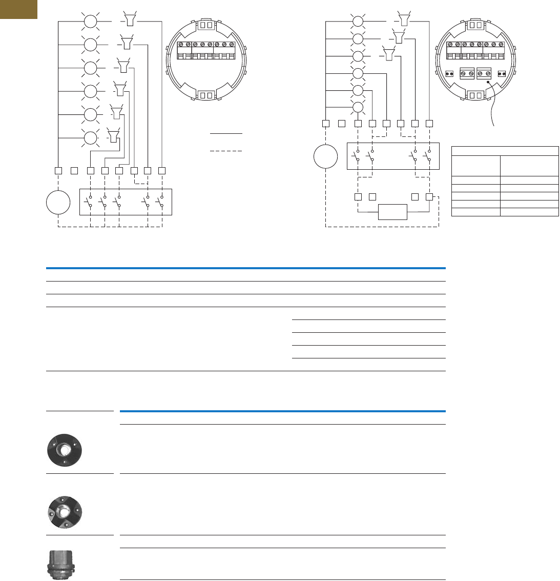
T38-8 Logic Control Products CA08100001K—June 2012 www.eatoncanada.ca
38
38
38
38
38
38
38
38
38
38
38
38
38
38
38
38
38
38
38
38
38
38
38
38
38
38
38
38
38
38
38.1
Stacklights
E26 Series
Mounting Bases Components
Standard Base Flashing Base
Mounting Bases and Hubs
Notes
Audible alarm units must be wired via the steady circuit on flashing base units.
Audible alarm units can be wired in positions as shown but only one unit is permitted on each stack and unit must occupy
the last or top mounting position.
65432
1
2
3
4
5
6
1
C
External
Switching
Devices
-
Supply
Factory
Wiring
Field
Wiring
C 123456
or
or
or
or
or
or
Flasher
Flasher
Base Voltage
Max. Allowable
No. of Light
Modules
6240 Vac/Vdc
6120 Vac/Vdc
648 Vac/Vdc
424 Vac/Vdc
212 Vdc
Orange Flasher
Wire
C1
78 910
23456
65432
1
2
3
4
5
6
1
10
9
Flashing
Module
8
7
C
External
Switching
Devices
Steady
Circuit
Flashing
Circuit
Orange
Wire
-
Supply
or
or
or
Description Voltage Catalogue Number
Standard Base
For use with steady incandescent or steady/flashing LED 12 Vac/Vdc to 240 Vac/Vdc E26BL
Flashing Base
Enables configuration of incandescent light modules for steady or flashing operation 12 Vdc E26BFV1
24 Vac/Vdc E26BFV2
48 Vac/Vdc E26BFV3
120 Vac/Vdc E26BFV4
240 Vac/Vdc E26BFV5
Description Voltage Catalogue Number
Mounting Base
Standard three-hole mounting base — E26S108
Standard four-hole mounting base — E26S109
Myers Type Hub
3/4 in NPT threaded hub — E26S104
Standard Three-Hole
Mounting Base
Standard Four-Hole
Mounting Base
Myers Type Hub
Tab38book.fm Page 8 Wednesday, July 4, 2012 9:22 PM
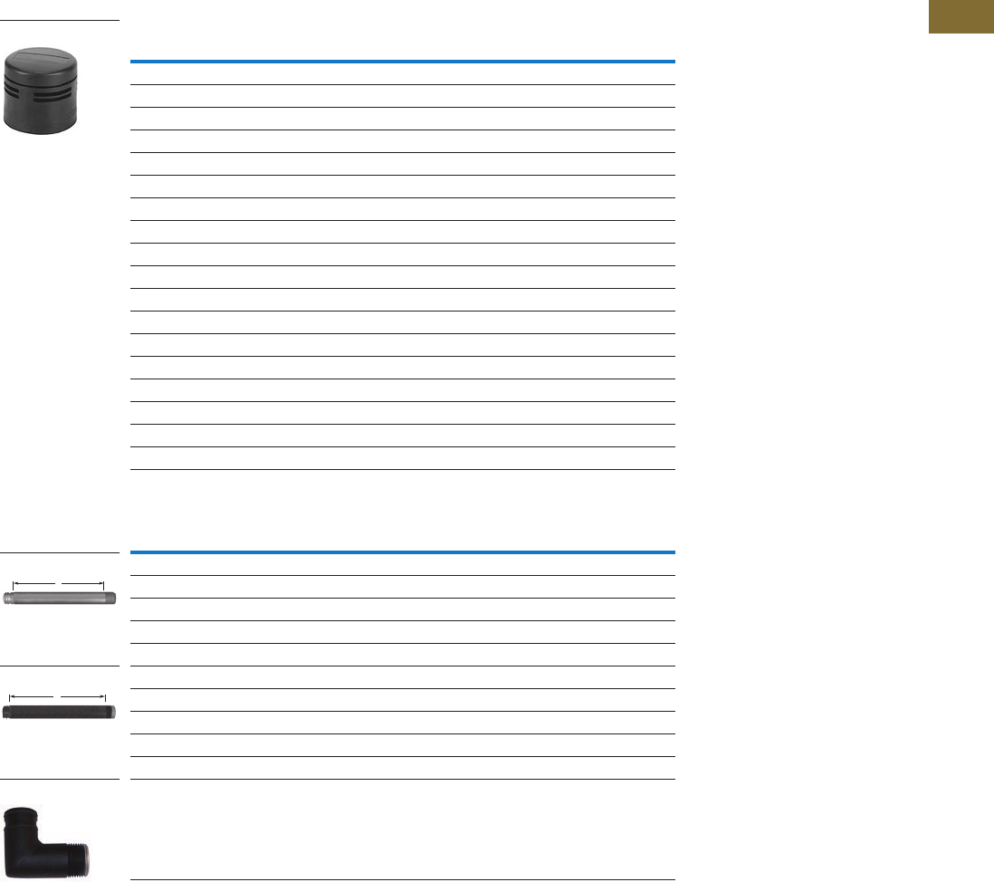
Logic Control Products CA08100001K—June 2012 www.eatoncanada.ca T38-9
38
38
38
38
38
38
38
38
38
38
38
38
38
38
38
38
38
38
38
38
38
38
38
38
38
38
38
38
38
38
38.1
Stacklights
E26 Series
Alarm Units and Extension Tubes Components
Audible Alarm Units-NEMA Type 1 (IP20)
Extension Tubes
Notes
Volume adjustment range: 64 dB to 90 dB typical current draw (mA).
For use with standard mounting base or 3/4 in NPT threaded hub—gray aluminum.
For use with standard mounting base or 3/4 in NPT threaded hub—black aluminum.
Description Voltage Catalogue Number
Mono-Tonal
4.5 mA 12 Vac/Vdc E26BQV1
12.6 mA 24 Vac/Vdc E26BQV2
9.4 mA 48 Vac/Vdc E26BQV3
11.5 mA 120 Vac/Vdc E26BQV4
5.1 mA 240 Vac/Vdc E26BQV5
Bi-Tonal
4.5 mA 12 Vac/Vdc E26BNV1
12.6 mA 24 Vac/Vdc E26BNV2
9.4 mA 48 Vac/Vdc E26BNV3
11.5 mA 120 Vac/Vdc E26BNV4
5.1 mA 240 Vac/Vdc E26BNV5
Intermittent
4.5 mA 12 Vac/Vdc E26BPV1
12.6 mA 24 Vac/Vdc E26BPV2
9.4 mA 48 Vac/Vdc E26BPV3
11.5 mA 120 Vac/Vdc E26BPV4
5.1 mA 240 Vac/Vdc E26BPV5
Description Voltage Catalogue Number
Extension “A”
0.79 in (20 mm) extension — E26BHM
6.30 in (160 mm) extension — E26BJM
14.17 in (360 mm) extension — E26BKM
29.92 in (760 mm) extension — E26BMM
Extension “A”
0.79 in (20 mm) extension — E26BHU
6.30 in (160 mm) extension — E26BJU
14.17 in (360 mm) extension — E26BKU
29.92 in (760 mm) extension — E26BMU
Right angle extension tube — E26BRU
E26B_
A
A
Extension Tube
Extension Tube
E26BRU
Tab38book.fm Page 9 Wednesday, July 4, 2012 9:22 PM
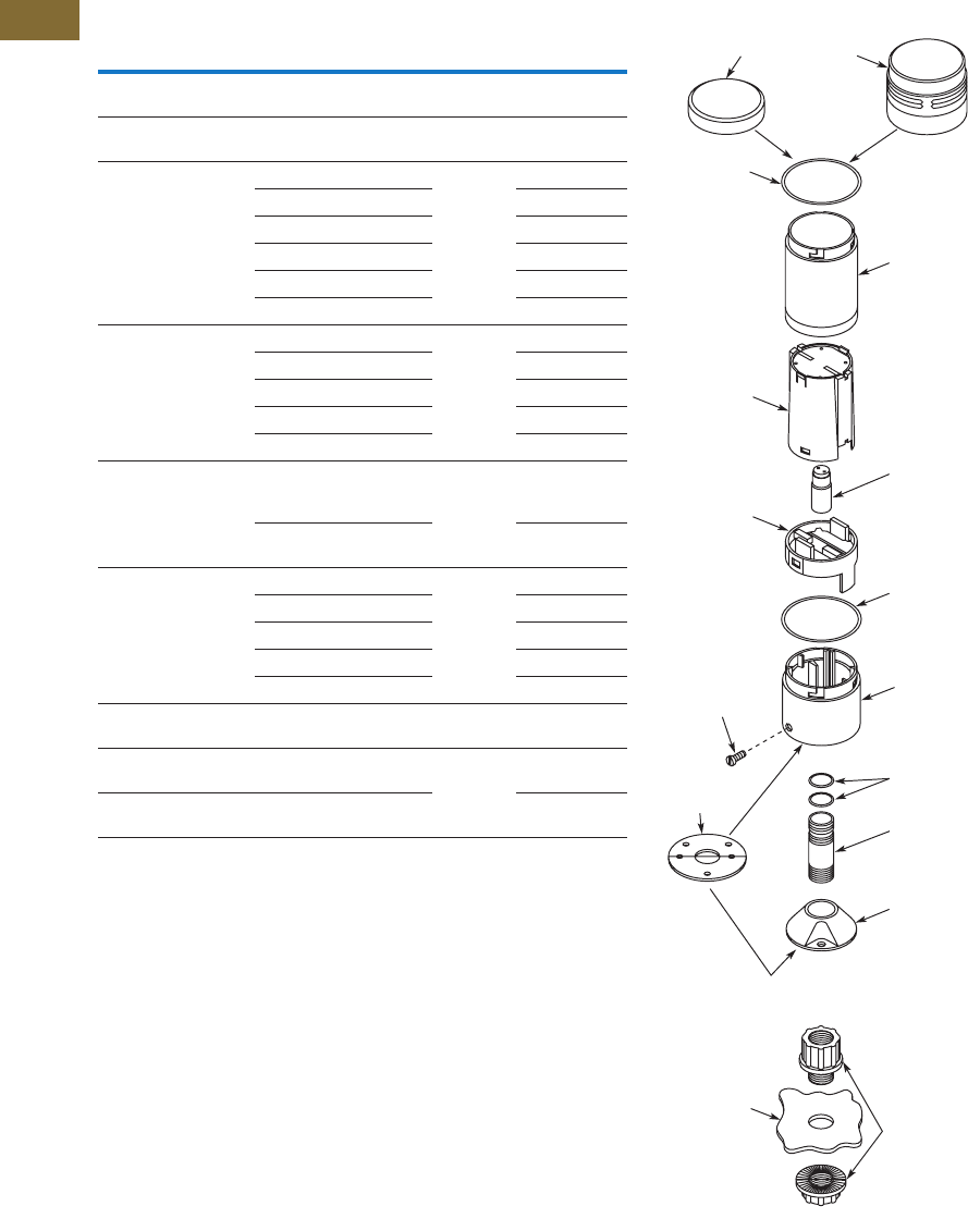
T38-10 Logic Control Products CA08100001K—June 2012 www.eatoncanada.ca
38
38
38
38
38
38
38
38
38
38
38
38
38
38
38
38
38
38
38
38
38
38
38
38
38
38
38
38
38
38
38.1
Stacklights
E26 Series
Replacement Parts
Stacklight Replacement Parts Typical Stacklight Assemblies
Notes
Sold in packages of 5 pieces.
For replacement LEDs, see table on Page T38-7.
Sold in packages of 10 pieces.
Mounting gaskets have two sets of mounting holes—one set with centre-to-centre spacing of
1.75 in (44.5 mm) and another set with centre-to-centre spacing of 1.65 in (42 mm).
Description Notes
Number in
Diagram
Catalogue
Number
Replacement
cover
Normally included with
stacklight base
1 E26S68
Replacement
lens O-ring
Normally included with light
modules
2 E26S106
Replacement lenses Clear 3 E26S38
Red E26S39
Green E26S40
Yellow E26S41
Blue E26S42
Amber E26S43
Replacement Xenon
strobe dual high
(does not include lenses)
12 Vac/Vdc 4 E26S33
24 Vac/Vdc E26S34
48 Vac/Vdc E26S35
120 Vac E26S36
240 Vac E26S37
Replacement diffusers White — normally supplied
with incandescent light
modules
4 E26S31
Clear — normally supplied
with LED light modules
E26S32
Replacement lamps 12V 5 E26S8
24V E26S9
48V E26S10
120V E26S11
240V E26S12
Replacement extension
tube O-rings
Normally included with
extension tubes
6 E26S107
Replacement mounting
gasket
Normally included with
stacklight base
7 E26S105
Lamp removal tool For E26 and E22
incandescent lamps
E22BA3
1 Cover Alarm
2 O-Ring
4
Light
Diffuser
Terminal
Board
Set Screw
Recommended
Tightening
Torque
Is 7 in-lb
(0.79 Nm)
7
Mounting
Gasket
Lens 3
Lamp 5
O-Ring 2
Mounting
Base
Stacklight
Base
Typical Stacklight Assembly
(Exploded View)
Alternate Conduit Hub
Myers Type
ST-2 or
ST-2CP Hub
Panel
Extension
Tube
O-Rings 6
Tab38book.fm Page 10 Wednesday, July 4, 2012 9:22 PM

Logic Control Products CA08100001K—June 2012 www.eatoncanada.ca T38-11
38
38
38
38
38
38
38
38
38
38
38
38
38
38
38
38
38
38
38
38
38
38
38
38
38
38
38
38
38
38
38.1
Stacklights
E26 Series
Technical Data and Specifications
General Specifications
Description Specification
Mechanical Ratings
Shock (IEC 68-2-27) 11 ms, 15g
Vibration (IEC 68-2-6) 10 sweeps 10–150 Hz, 2g
Bump (IEC 68-2-29) 1000 pulses, 6 ms, 15g
Climate Conditions
Operating Maximum 104˚F (40˚C) at 95% RH,
Temperature –4˚ to 140˚F (–20˚ to 60˚C)
Storage Temperature –40˚ to 176˚F (–40˚ to 80˚C)
Materials
Cover Polycarbonate
Lenses Polycarbonate
Stacklight base Nylon
Extension tubes Aluminum
Mounting base Zinc die cast
Terminals
Single conductor 14–30 AWG (2.5–0.05 mm2)
Two conductors (same size)) 18–26 AWG (0.75–0.14 mm2)
Do not mix solid and stranded wire in the same terminal
Recommended tightening torque 4.4–5.3 lb-in (0.5–0.6 Nm)
Electrical Ratings
Insulation voltage (Ui) 690V
Operational voltage (Ue) 250V
Impulse withstand voltage (Uimp) 1.5 kV
Bulb Specifications
Incandescent lamp type BA15d
Maximum lamp wattage 6W
Bulbs—average life
Incandescent 7,000 to 12,000 hrs. (based on voltage)
Xenon flasher 20,000 hrs.
LED 60,000 to 100,000 hrs. (based on colours)
LED/Incandescent Comparison
Incandescent lamps Average operating life of 7,000 hours
Each lamp can be used with any colour lens
Low cost results in short term savings
LED lamps Average operating life of 60,000 to 100,000 hours
Low power consumption
Extended life results in long-term savings
Tab38book.fm Page 11 Wednesday, July 4, 2012 9:22 PM

T38-12 Logic Control Products CA08100001K—June 2012 www.eatoncanada.ca
38
38
38
38
38
38
38
38
38
38
38
38
38
38
38
38
38
38
38
38
38
38
38
38
38
38
38
38
38
38
38.1
Stacklights
E26 Series
Ratings
Published theoretical lamp lives are based on ideal laboratory
conditions and should be used for comparison only.
Actual life may be shorter due to various application conditions.
Stacklight Incandescent Application Data
Xenon Flasher Application Data
LED Application Data
Note
Represents average current draw, 1.6A peak for 120V and 0.8A peak at 240V.
Type
of Light
Lamp
Used
Approximate Current,
mA per Light
Theoretical Lamp Life,
Hours as Applied
12V BA15d 417 7,000
24V BA15d 208 7,000
48V BA15d 104 7,000
110–140V BA15d 36–50 7,000
220–260V BA15d 23–27 12,000
Type
of Light
Lamp
Used
Approximate Current,
mA per Light
Theoretical Lamp Life,
Hours as Applied
12V DC 460 mA 20,000
AC 780 mA 20,000
24V DC 190 mA 20,000
AC 320 mA 20,000
48V DC 100 mA 20,000
AC 150 mA 20,000
120V AC 60 mA 20,000
240V AC 30 mA 20,000
Type of
Light Colour
Cluster LED
Approximate
Current, mA
at Rated Volts
Cylindrical LED
Approximate
Current, mA
at Rated Volts
Theoretical
Lamp Life,
Hours as Applied
Continuous/Flashing Stacklight LED
12
Vac/Vdc
Red 92 92 100,000
Amber 92 92 100,000
Yellow 92 92 100,000
Green 60 60 80,000
Blue 60 60 60,000
White 60 60 60,000
24
Vac/Vdc
Red 47 47 100,000
Amber 47 47 100,000
Yellow 47 47 100,000
Green 59 59 80,000
Blue 59 59 60,000
White 59 59 60,000
48
Vac/Vdc
Red 25 25 100,000
Amber 25 25 100,000
Yellow 25 25 100,000
Green 18 18 80,000
Blue 31 31 60,000
White 31 31 60,000
60
Vac/Vdc
Red 25 25 100,000
Amber 25 25 100,000
Yellow 25 25 100,000
Green 18 18 80,000
Blue 17 17 60,000
White 17 17 60,000
120
Vac/Vdc
Red 24 24 100,000
Amber 24 24 100,000
Yellow 24 24 100,000
Green 17 17 80,000
Blue 16 16 60,000
White 16 16 60,000
Tab38book.fm Page 12 Wednesday, July 4, 2012 9:22 PM
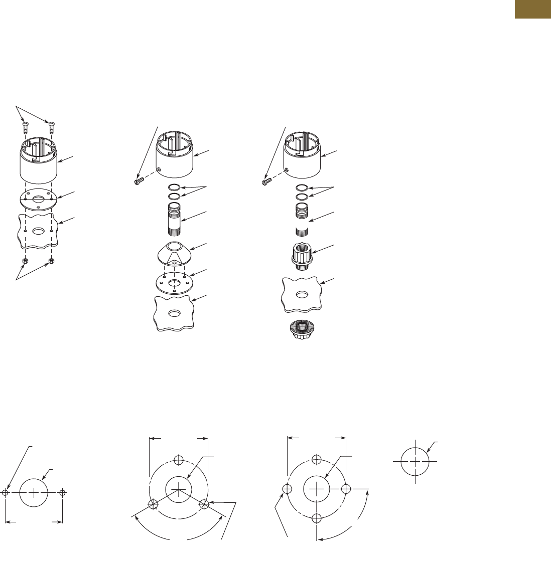
Logic Control Products CA08100001K—June 2012 www.eatoncanada.ca T38-13
38
38
38
38
38
38
38
38
38
38
38
38
38
38
38
38
38
38
38
38
38
38
38
38
38
38
38
38
38
38
38.1
Stacklights
E26 Series
Mounting Instructions
Stacklight bases may be
mounted without the use of
an extension tube or
mounting base. If additional
height is required, choose
0.8–30 in (20–760 mm)
extension tubes that fit
between the mounting base
and stacklight base. The
extension tubes are threaded
with 3/4 in NPT threads,
allowing for direct connection
to conduit fittings or threaded
holes without the use of a
mounting base.
Base Mounting
Utilizing Extension Tube
and Mounting Base
Utilizing Extension Tube
and 3/4 In (19.1 mm)
Conduit Hub
Mounting Dimensions
Approximate Dimensions in Inches (mm)
Base Mounting
Three-Hole Mounting for
E26S108
Four-Hole Mounting for
E26S109
Conduit Hub for E26S104—
3/4 In (19.1 mm)
Note
Stacklight base and gasket are supplied as standard with two sets of base mount holes.
One set with centre-to-centre spacing of 1.75 in (44.5 mm) and another set with centre-to-centre spacing of 1.65 in (42 mm).
Stacklight
Base
Customer
Supplied
Customer
Supplied
Mounting
Gasket
Panel
Set Screw
Recommended
Tightening Torque
Is 7 in-lb
(0.79 Nm)
Mounting
Base
Mounting
Gasket
Panel
Stacklight
Base
Extension
Tube
O-Rings
Extension
Tube
O-Rings
Myers Type
ST-2 or
ST-2CP Hub
Panel
Stacklight
Base
(Use Rubber-Jawed Pliers for
Installation to Avoid Scratching
the Black Anodized Coating)
Set Screw
Recommended
Tightening Torque
Is 7 in-lb
(0.79 Nm)
1.75 (44.5)
or 1.65 (42.0) a
0.18 (4.6) Dia.
or #8–32 Thread
or (M4 x 0.7)
0.87
(22.1) Dia.
120°
0.87
(22.1)
Dia.
1.92 (48.8)
Dia.
0.18 (4.6) Dia.
or #8–32 Thread
or (M4 x 0.7)
90°
0.87
(22.1)
Dia.
2.12 (53.8)
Dia.
0.20 (5.08) Dia.
or #10–32 Thread
or (M5 x 0.7)
1.06
(27) Dia.
Tab38book.fm Page 13 Wednesday, July 4, 2012 9:22 PM
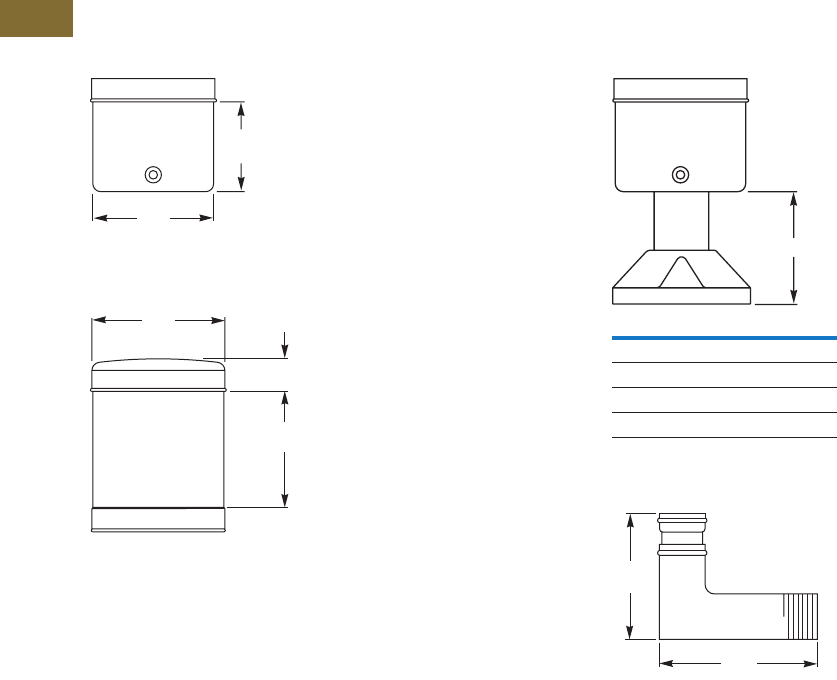
T38-14 Logic Control Products CA08100001K—June 2012 www.eatoncanada.ca
38
38
38
38
38
38
38
38
38
38
38
38
38
38
38
38
38
38
38
38
38
38
38
38
38
38
38
38
38
38
38.1
Stacklights
E26 Series
Dimensions
Approximate Dimensions in Inches (mm)
Standard and Flashing Bases
Alarm Units
Assembled Extension Tubes
Right Angle Extension Tubes
Notes
Bases also suitable for mounting with extension tubes listed on Page T38-9.
Mounting gasket and cover are supplied as standard with stacklight bases.
1.75
(44)
2.32
(59)
2.56
(65)
0.59
(15)
1.69
(42.9)
A
Tube Extension Height A
0.79 (20) 1.77 (45)
6.30 (160) 7.28 (185)
14.17 (360) 15.16 (385)
29.92 (760) 30.91 (785)
2.50
(63.5)
2.00
(50.8)
Tab38book.fm Page 14 Wednesday, July 4, 2012 9:22 PM
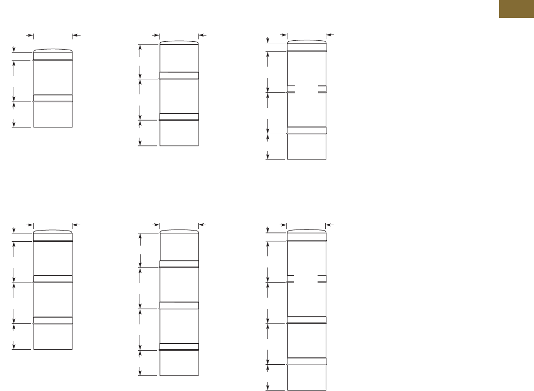
Logic Control Products CA08100001K—June 2012 www.eatoncanada.ca T38-15
38
38
38
38
38
38
38
38
38
38
38
38
38
38
38
38
38
38
38
38
38
38
38
38
38
38
38
38
38
38
38.1
Stacklights
E26 Series
Approximate Dimensions in Inches (mm)
One-Light Unit Stacklight
Standard With Alarm With Xenon Flasher
Two-Light Unit Stacklight
Standard With Alarm With Xenon Flasher
2.56 (65)
Light
Unit
Base
0.59 (15)
2.72 (69)
1.73 (44)
Light
Unit
Base
2.56 (65)
Alarm
2.24 (57)
2.72 (69)
1.73 (44)
Base
2.56 (65)
2.72 (69)
0.59 (15)
2.72 (69)
1.73 (44)
Xenon
Light
Unit
(2 High)
2.72 (69)
0.59 (15)
2.72 (69)
1.73 (44)
2.56 (65)
Light
Unit
Light
Unit
Base
2.72 (69)
1.73 (44)
2.72 (69)
Light
Unit
Light
Unit
Base
2.56 (65)
Alarm
2.24 (57)
2.72 (69)
0.59 (15)
2.72 (69)
1.73 (44)
2.72 (69)
Base
2.56 (65)
Xenon
Light
Unit
(2 High)
Light
Unit
Tab38book.fm Page 15 Wednesday, July 4, 2012 9:22 PM
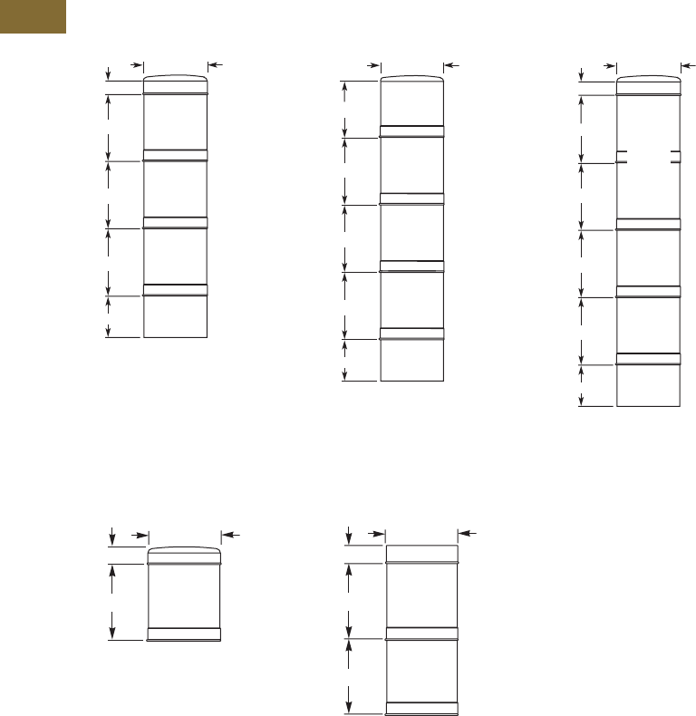
T38-16 Logic Control Products CA08100001K—June 2012 www.eatoncanada.ca
38
38
38
38
38
38
38
38
38
38
38
38
38
38
38
38
38
38
38
38
38
38
38
38
38
38
38
38
38
38
38.1
Stacklights
E26 Series
Approximate Dimensions in Inches (mm)
Three-Light Unit Stacklight
Standard With Alarm With Xenon Flasher
Light Modules
Standard Xenon
Note
Cover included with stacklight base.
0.59 (15)
2.72 (69)
1.73 (44)
2.72 (69)
2.72 (69)
Base
2.56 (65)
Light
Unit
Light
Unit
Light
Unit
2.72 (69)
1.73 (44)
2.72 (69)
2.72 (69)
Base
2.56 (65)
Light
Unit
Light
Unit
Light
Unit
Alarm
2.24 (57)
2.72 (69)
0.59 (15)
2.72 (69)
1.73 (44)
2.72 (69)
2.72 (69)
Base
2.56 (65)
Xenon
Light
Unit
(2 High)
Light
Unit
Light
Unit
2.56 (65)
a
0.59 (15)
2.72 (69.1)
2.56 (65)
0.59 (15)
a
2.72 (69.1)
2.72 (69.1)
Tab38book.fm Page 16 Wednesday, July 4, 2012 9:22 PM
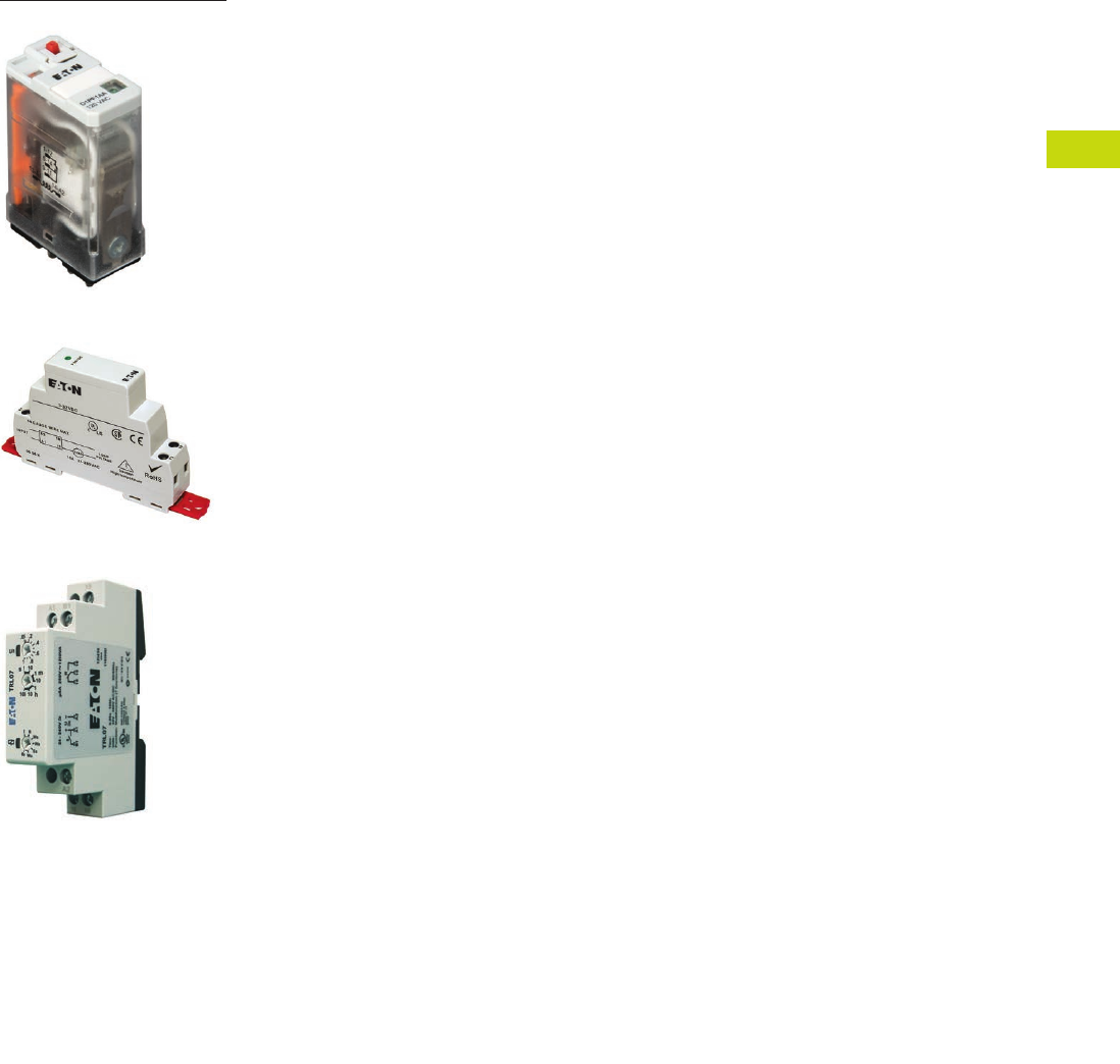
Logic Control Products
CA08100001K—June 2012 www.eatoncanada.ca
T40-1
40
40
40
40
40
40
40
40
40
40
40
40
40
40
40
40
40
40
40
40
40
40
40
40
40
40
40
40
40
40
Control Relays and Timers
D1 Series General Purpose Relay
D
96 Series Solid-State Relay
U
niversal TR Series Timing Relay
40.1 Relay Products
Control Relays and Timers Comparison . . . . . . . . . . . . . . . . . . . . . . . . . .
T40-2
40.2
XR
Series Terminal Block Relays
Standard, OptoCoupler and High Current
Catalogue Number Selection . . . . . . . . . . . . . . . . . . . . . . . . . . . . . . . . . .
T40-3
40.3 EASY Intelligent Relays
Relays, Modules, Power Supplies, Accessories and Software
Product Overview . . . . . . . . . . . . . . . . . . . . . . . . . . . . . . . . . . . . . . . . . .
T40-19
40.4 General Purpose Plug-In Relays
General Purpose Relays
Product Selection Guide. . . . . . . . . . . . . . . . . . . . . . . . . . . . . . . . . . . . . .
T40-42
40.5 General Purpose Relays—Type AA
9575H Series 3000 Relay
9575H Series 3000—Type AA, AC and DC . . . . . . . . . . . . . . . . . . . . . . .
T40-116
40.6 Solid-State Relays
D93, D96 and D99 Series
Product Overview . . . . . . . . . . . . . . . . . . . . . . . . . . . . . . . . . . . . . . . . . .
T40-120
40.7 Machine Tool Relays
Freedom Multipole, Industrial Control, and
Multipole with Convertible Contacts
Product Overview. . . . . . . . . . . . . . . . . . . . . . . . . . . . . . . . . . . . . . . . . . .
T40-139
40.8 Timing Relays
Universal TR, TR and TMR Series
Product Selection Guide. . . . . . . . . . . . . . . . . . . . . . . . . . . . . . . . . . . . . .
T40-165
40.9 Alternating Relays
D85 Series
Product Description . . . . . . . . . . . . . . . . . . . . . . . . . . . . . . . . . . . . . . . . .
T40-187
40.10 Safety Relays
Product Description . . . . . . . . . . . . . . . . . . . . . . . . . . . . . . . . . . . . . . . . .
T40-192
Product Selection . . . . . . . . . . . . . . . . . . . . . . . . . . . . . . . . . . . . . . . . . .
T40-193
Technical Data and Specifications . . . . . . . . . . . . . . . . . . . . . . . . . . . . . .
T40-194
Dimensions . . . . . . . . . . . . . . . . . . . . . . . . . . . . . . . . . . . . . . . . . . . . . . .
T40-197
Learn
Online
Tab40book.fm Page 1 Wednesday, July 4, 2012 10:05 PM
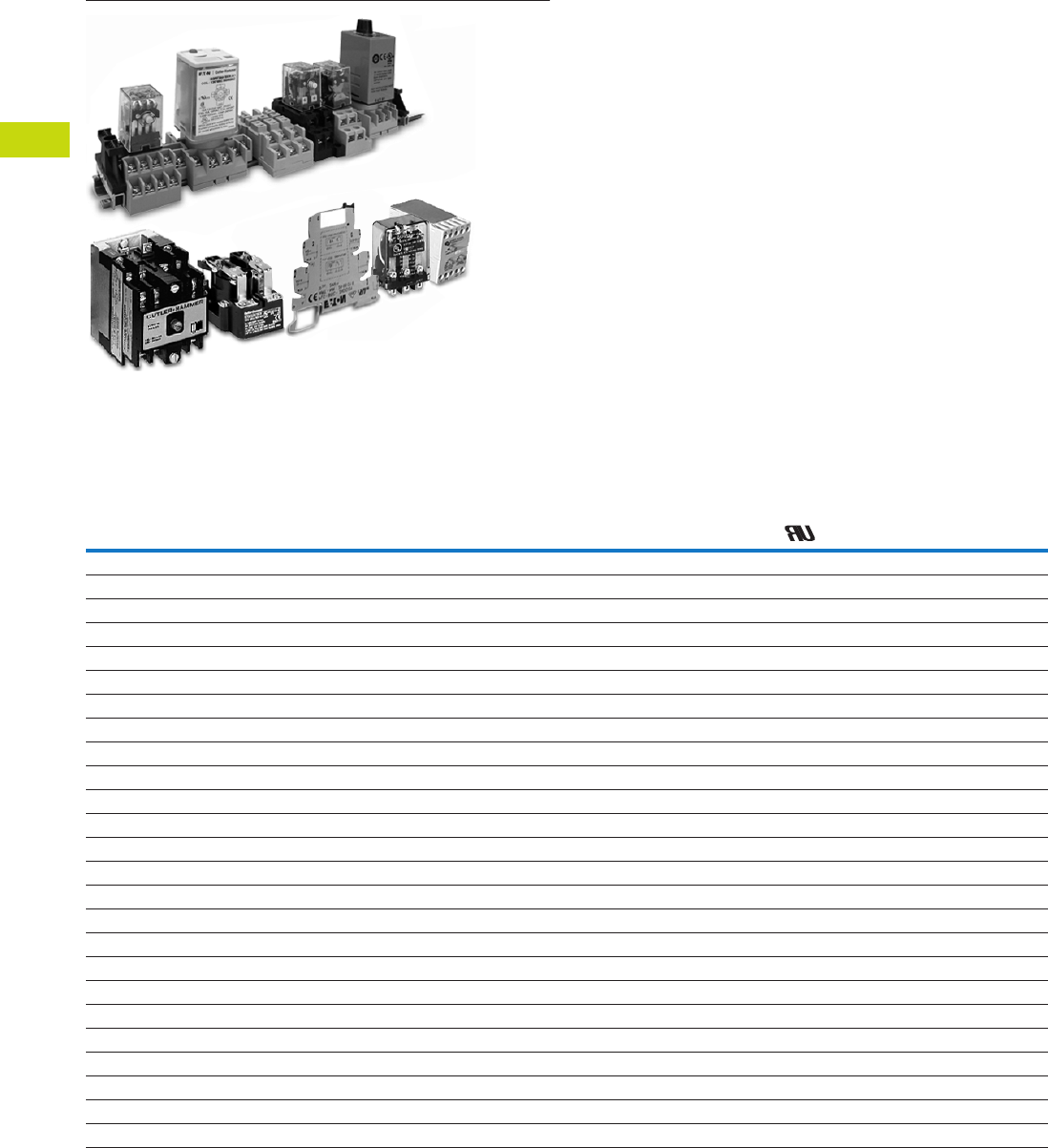
T40-2 Logic Control Products
CA08100001K—June 2012 www.eatoncanada.ca
40
40
40
40
40
40
40
40
40
40
40
40
40
40
40
40
40
40
40
40
40
40
40
40
40
40
40
40
40
40
40.1
Control Relays and Timers
Relay Product Overview
Relay Products
Contents
Description Page
XR
Series Terminal Block Relays . . . . . . . . . . . . . . . . .
T40-3
EASY Intelligent Relays . . . . . . . . . . . . . . . . . . . . . . . .
T40-19
General Purpose Plug-In Relays . . . . . . . . . . . . . . . . . .
T40-42
General Purpose Relays—Type AA . . . . . . . . . . . . . . .
T40-116
Solid-State Relays . . . . . . . . . . . . . . . . . . . . . . . . . . . .
T40-120
Machine Tool Relays . . . . . . . . . . . . . . . . . . . . . . . . . .
T40-139
Timing Relays . . . . . . . . . . . . . . . . . . . . . . . . . . . . . . .
T40-165
Alternating Relays . . . . . . . . . . . . . . . . . . . . . . . . . . . .
T40-187
Control Relays and Timers Comparison
Selection Guide by Catalogue Number Prefix
Relays Type Mounting Contacts
Maximum
Amperage
(AC) UL CSA CE
Page
Number
9575H3 General purpose Panel mount Fixed 40A — X X X
T40-117
AR/ARD Machine tool Panel mount Convertible 10A — X X —
T40-152
BF/BFD Machine tool Panel mount Fixed 10A X — X —
T40-146
D2PF Full featured plug-in DIN rail/panel mount Fixed 10A X — X X
T40-53
D2PR Standard plug-in DIN rail/panel mount/flange Fixed 10A X — X X
T40-53
D3PF Full featured plug-in DIN rail/panel mount Fixed 16A X — X X
T40-63
D3PR Standard plug-in DIN rail/panel mount Fixed 16A X — X X
T40-63
D4PR Standard plug-in DIN rail/panel mount Fixed 10A X — X X
T40-72
D5PF Full featured plug-in DIN rail/panel mount Fixed 16A X — X X
T40-77
D5PR Standard plug-in DIN rail/panel mount/PC board Fixed 16A X — X X
T40-77
D7PF Full featured plug-in DIN rail/panel mount Fixed 20A X — X X
T40-87
D7PR Standard plug-in DIN rail/panel mount/flange Fixed 20A X — X X
T40-88
D8PR Standard plug-in DIN rail/panel mount/flange Fixed 30A X — X X
T40-101
D9PR Standard plug-in Panel mounting Fixed 25A X — X —
T40-107
D15 Machine tool DIN rail/panel mount Fixed 10A — X X X
T40-141
D26 Machine tool Panel or channel mount Convertible 10A — X X —
T40-157
D85 Alternating relays DIN rail/panel mount Fixed 10A X X — X
T40-188
D1PF Full featured plug-in DIN rail/panel mount Fixed 20A X — X X
T40-47
D1PR Standard plug-in DIN rail/panel mount Fixed 20A X — X X
T40-47
EASY Intelligent relay DIN rail Fixed 8A X — X X
T40-21
TMR5 Timing relay (non-programmable) DIN rail/panel mount Fixed 10A X X — X
T40-178
TMR6 Timing relay (non-programmable) DIN rail/panel mount Fixed 10A X X — X
T40-182
TR Timing relay (programmable) DIN rail/panel mount Fixed 10A — X X —
T40-175
Universal TR Timing relay (programmable) DIN rail Fixed 8A — X X X
T40-171
XR Terminal block relay DIN rail Fixed 6A, 10A X — — X
T40-5
Tab40book.fm Page 2 Wednesday, July 4, 2012 10:05 PM
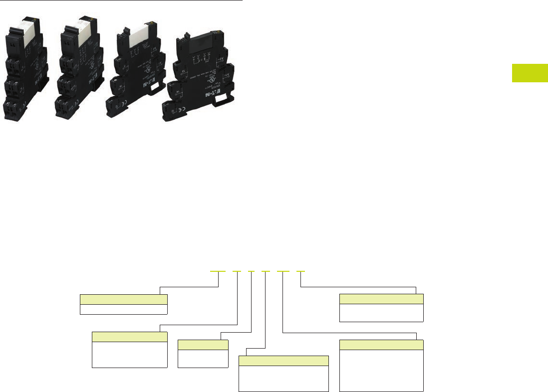
Logic Control Products
CA08100001K—June 2012 www.eatoncanada.ca
T40-3
40
40
40
40
40
40
40
40
40
40
40
40
40
40
40
40
40
40
40
40
40
40
40
40
40
40
40
40
40
40
40.2
Control Relays and Timers
Relay Product Overview
XR Series Terminal Block Relays
Contents
Description Page
XR
Series Terminal Block Relays
Standard Terminal Block Relays . . . . . . . . . . . . . . .
T40-4
OptoCoupler Terminal Block Relays . . . . . . . . . . . .
T40-12
High Current Terminal Block Relays . . . . . . . . . . . .
T40-15
XR
Series Accessories . . . . . . . . . . . . . . . . . . . . . .
T40-18
Catalogue Number Selection
XR
Series—Overview
Description
XR = XR terminal block relay
XR U 1 D 12 G
Poles
1 = 1PDT
2 = 2PDT
Connection Type
U = Screw
P = Spring
R = Replacement relay
Gold-Flashed Contacts
Blank =No
G = Yes
Type
D = Standard relay
S = Octocoupler (solid-state)
H = High current
Voltage
12 = 12 Vdc
24 = 24 Vdc
24U = 24 Vac/Vdc
120U = 120 Vac/110 Vdc
230U = 230 Vac/220 Vdc
Tab40book.fm Page 3 Wednesday, July 4, 2012 10:05 PM
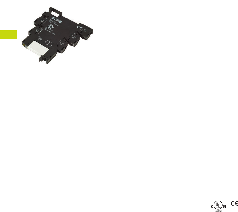
T40-4 Logic Control Products
CA08100001K—June 2012 www.eatoncanada.ca
40
40
40
40
40
40
40
40
40
40
40
40
40
40
40
40
40
40
40
40
40
40
40
40
40
40
40
40
40
40
40.2
Control Relays and Timers
XR Series Terminal Block Relays
Standard Terminal Block Relay
Contents
Description Page
Standard Terminal Block Relays
Product Selection . . . . . . . . . . . . . . . . . . . . . . . . . .
T40-5
Technical Data and Specifications . . . . . . . . . . . . .
T40-6
Electrical Schematics . . . . . . . . . . . . . . . . . . . . . . .
T40-11
Dimensions . . . . . . . . . . . . . . . . . . . . . . . . . . . . . .
T40-11
OptoCoupler Terminal Block Relays . . . . . . . . . . . . . .
T40-12
High Current Terminal Block Relays . . . . . . . . . . . . . .
T40-15
XR
Series Accessories . . . . . . . . . . . . . . . . . . . . . . . .
T40-18
Standard Terminal Block Relays
Product Description
The
XR
Series Terminal
Block Relays are ideal for
applications that require a
high switching capacity and
long electrical service life.
The relays are plug-in
interfaces that connect to
basic terminal blocks. The
XR
Series uses screw or
spring-cage technology, as
well as offers quick system
wiring, superior safety
features, clear labeling and
a high level of modularity.
Application Description
Used in automation systems,
electromechanical relays
guarantee a safe connection
between process I/O and
electronic controls. The
following functions are
covered by relay coupling
elements:
●
Electrical isolation
between the input and
output circuits
●
Independence of the type
of switching current (AC
and DC)
●
High short-term overload
resistance in the event of
short circuits or voltage
peaks
●
Low switching losses
●
Ease of operation
Features
●
Pluggable relay allows for
field replacement
●
Functional plug-in bridges
●
Choice of screw
connections or spring-cage
connection
●
LED status indication
●
DIN rail mount
●
Only 6.2 mm wide for
single-pole versions,
14 mm wide for double-
pole
●
All common input
voltages between
12 Vdc to 120 Vac
●
Gold-plated contacts
available
●
Equipped with a robust,
miniature relay:
●
IP67 protection
●
Environmentally friendly,
cadmium-free contact
material
●
Easy, cost-effective
installation and
replacement using the
engagement lever
Standards and Certifications
●
cULus listed
●
CE
Tab40book.fm Page 4 Wednesday, July 4, 2012 10:05 PM
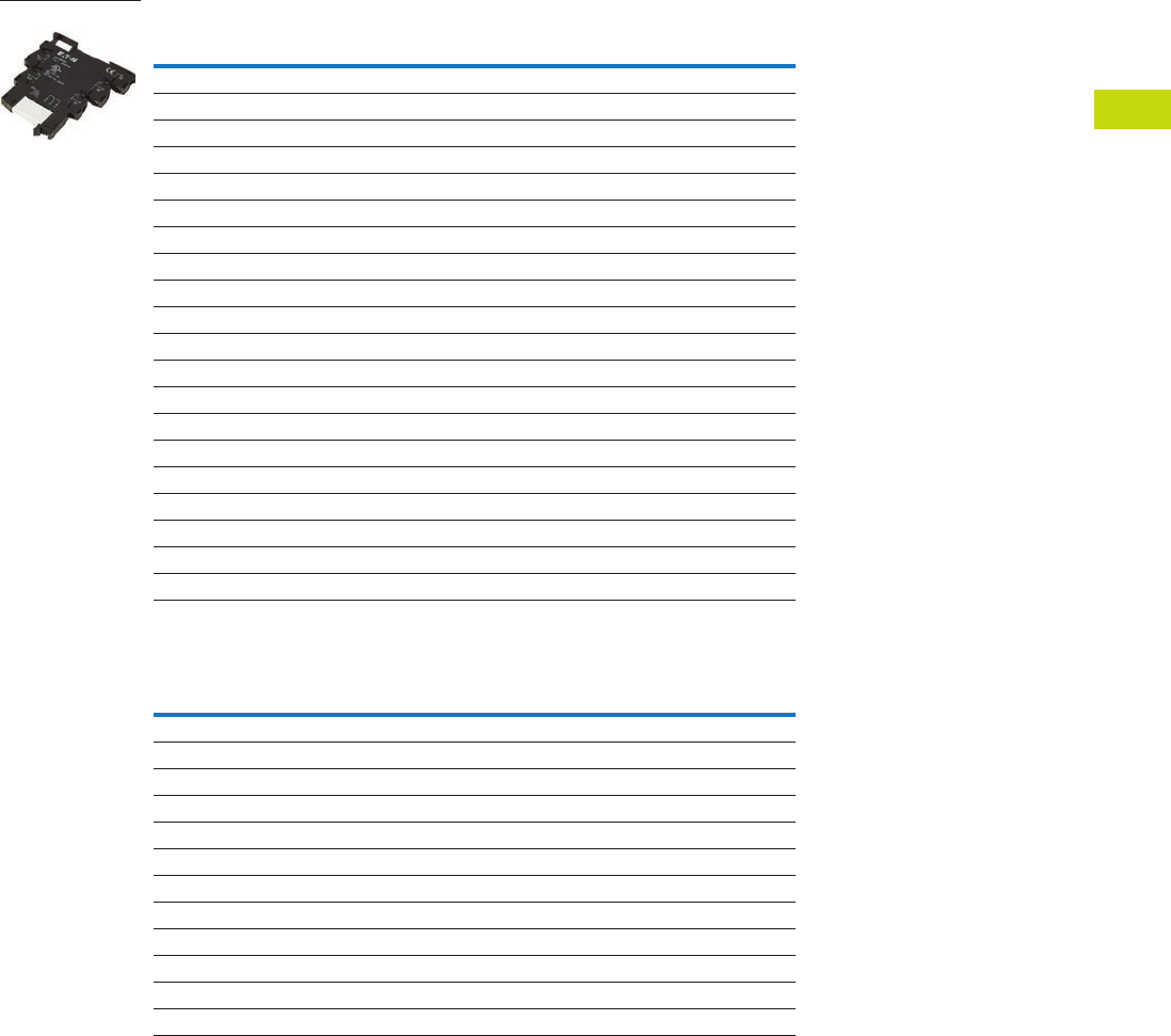
Logic Control Products
CA08100001K—June 2012 www.eatoncanada.ca
T40-5
40
40
40
40
40
40
40
40
40
40
40
40
40
40
40
40
40
40
40
40
40
40
40
40
40
40
40
40
40
40
40.2
Control Relays and Timers
XR Series Terminal Block Relays
Product Selection
Standard Terminal Block Relays
Standard Replacement Relays
Gold-Plated
Contacts
Rated
Current
Supply
Voltage
Standard
Pack
Catalogue
Number
1PDT Screw Connection
No 6A 12 Vdc 10
XRU1D12
No 6A 120 Vac/110 Vdc 10
XRU1D120U
Yes 6A 120 Vac/110 Vdc 10
XRU1D120UG
No 6A 24 Vdc 10
XRU1D24
No 6A 24 Vac/Vdc 10
XRU1D24U
Yes 6A 24 Vac/Vdc 10
XRU1D24UG
No 6A 230 Vac/220 Vdc 10
XRU1D230U
1PDT Spring Cage Connection
No 6A 12 Vdc 10
XRP1D12
No 6A 120 Vac/110 Vdc 10
XRP1D120U
No 6A 24 Vdc 10
XRP1D24
No 6A 24 Vac/Vdc 10
XRP1D24U
No 6A 230 Vac/220 Vdc 10 XRP1D230U
DPDT Screw Connection
No 6A 12 Vdc 10 XRU2D12
No 6A 120 Vac/110 Vdc 10 XRU2D120U
No 6A 24 Vdc 10 XRU2D24
No 6A 24 Vac/Vdc 10 XRU2D24U
No 6A 230 Vac/220 Vdc 10 XRU2D230U
Gold-Plated
Contacts
Rated
Current
Supply
Voltage
Standard
Pack
Catalogue
Number
1PDT
No 6A 12 Vdc 10 XRR1D12
No 6A 120 Vac/110 Vdc 10 XRR1D120U
Yes 6A 120 Vac/110 Vdc 10 XRR1D120UG
No 6A 24 Vdc 10 XRR1D24
Yes 6A 24 Vdc 10 XRR1D24G
No 6A 230 Vac/220 Vdc 10 XRR1D230U
DPDT
No 6A 12 Vdc 10 XRR2D12
No 6A 120 Vac/110 Vdc 10 XRR2D120U
No 6A 24 Vdc 10 XRR2D24
No 6A 230 Vac/220 Vdc 10 XRR2D230U
XRU1D 24U
Tab40book.fm Page 5 Wednesday, July 4, 2012 10:05 PM

T40-6 Logic Control Products CA08100001K—June 2012 www.eatoncanada.ca
40
40
40
40
40
40
40
40
40
40
40
40
40
40
40
40
40
40
40
40
40
40
40
40
40
40
40
40
40
40
40.2
Control Relays and Timers
XR Series Terminal Block Relays
Technical Data and Specifications
Standard 1PDT Screw Connection Terminal Block Relays
Note
The separating plate, XRAPLCESK, should be installed for voltages greater than 250V (L1, L2, L3) between identical terminal points of adjacent modules.
Potential bridging is then possible with the XRAFBST bridge system.
Catalogue Number XRU1D12 XRU1D24 XRU1D24U XRU1D120U
Replacement Relay XRR1D12 XRR1D24 XRR1D24 XRR1D120U
Input voltage 12 Vdc 24 Vdc 24 Vac/Vdc 120 Vac/110 Vdc
Connection Data
Rigid solid AWG (mm2) 26–14 (0.14–2.5) 26–14 (0.14–2.5) 26–14 (0.14–2.5) 26–14 (0.14–2.5)
Flexible stranded AWG (mm2) 26–14 (0.14–2.5) 26–14 (0.14–2.5) 26–14 (0.14–2.5) 26–14 (0.14–2.5)
Input Data for 1PDT Screw Connection Versions
Input voltage 12 Vdc 24 Vdc 24 Vac/Vdc 120 Vac/110 Vdc
Permissible range See Page T40-10 See Page T40-10 See Page T40-10 See Page T40-10
Typical input current 15.3 mA 9 mA 11 mA (24 Vac)/8.5 mA (24 Vdc) 3.5 mA (120 Vac)/3 mA (110 Vdc)
Typical response time 5 ms 5 ms 6 ms 6 ms
Typical release time 8 ms 8 ms 15 ms 15 ms
Input protection Polarity protection diode,
free-wheeling diode
Polarity protection diode,
free-wheeling diode
Bridge rectifier Bridge rectifier
Output Data
Contact type 1PDT 1PDT 1PDT 1PDT
Contact material AgSnO AgSnO AgSnO AgSnO
Max. switching voltage 250 Vac/Vdc 250 Vac/Vdc 250 Vac/Vdc 250 Vac/Vdc
Min. switching voltage 12 Vac/Vdc 12 Vac/Vdc 12 Vac/Vdc 12 Vac/Vdc
Limiting continuous current 6A 6A 6A 6A
Min. switching current 10 mA 10 mA 10 mA 10 mA
Min. switching power 120 mW 120 mW 120 mW 120 mW
Miscellaneous Data
Ambient temp range –4˚ to 140˚F (–20˚ to 60˚C) –4˚ to 140˚F (–20˚ to 60˚C) –4˚ to 140˚F (–20˚ to 60˚C) –4˚ to 140˚F (–20˚ to 60˚C)
Rated operating mode 100% operating factor 100% operating factor 100% operating factor 100% operating factor
Inflammability class V0, in accordance with UL 94 V0, in accordance with UL 94 V0, in accordance with UL 94 V0, in accordance with UL 94
Mechanical service life 2 x 10⁷ cycles 2 x 10⁷ cycles 2 x 10⁷ cycles 2 x 10⁷ cycles
Tab40book.fm Page 6 Wednesday, July 4, 2012 10:05 PM

Logic Control Products CA08100001K—June 2012 www.eatoncanada.ca T40-7
40
40
40
40
40
40
40
40
40
40
40
40
40
40
40
40
40
40
40
40
40
40
40
40
40
40
40
40
40
40
40.2
Control Relays and Timers
XR Series Terminal Block Relays
Standard 1PDT Screw Connection Terminal Block Relays with Gold Contacts
Notes
The separating plate, XRAPLCESK, should be installed for voltages greater than 250V (L1, L2, L3) between identical terminal
points of adjacent modules. Potential bridging is then possible with the XRAFBST bridge system.
If the maximum values are exceeded, the gold layer is destroyed and the values in parentheses apply.
Catalogue Number XRU1D24UG XRU1D120UG
Replacement Relay XRR1D24G XRR1D120UG
Input voltage 24 Vac/Vdc 120 Vac/110 Vdc
Connection Data
Rigid solid AWG (mm2) 26–14 (0.14–2.5) 26–14 (0.14–2.5)
Flexible stranded AWG (mm2) 26–14 (0.14–2.5) 26–14 (0.14–2.5)
Input Data for 1PDT Screw Connection Versions with Gold Contacts
Input voltage 24 Vac/Vdc 120 Vac/110 Vdc
Permissible range See Page T40-10 See Page T40-10
Typical input current 11 mA (24 Vac)/8.5 mA (24 Vdc) 3.5 mA (120 Vac)/3 mA (110 Vdc)
Typical response time 6 ms 6 ms
Typical release time 15 ms 15 ms
Input protection Bridge rectifier Bridge rectifier
Output Data
Contact type 1PDT 1PDT
Contact material AgSnO, gold plated AgSnO, gold plated
Max. switching voltage 30 Vac/36 Vdc (250 Vac/Vdc) 30 Vac/36 Vdc (250 Vac/Vdc)
Min. switching voltage 100 mV (12 Vac/Vdc) 100 mV (12 Vac/Vdc)
Limiting continuous current 50 mA (6A) 50 mA (6A)
Min. switching current 1 mA (10 mA) 1 mA (10 mA)
Min. switching power 100 mW (120 mW) 100 mW (120 mW)
Miscellaneous Data
Ambient temp range –4˚ to 140˚F (–20˚ to 60˚C) –40˚ to 131˚F (–20˚ to 55˚C)
Rated operating mode 100% operating factor 100% operating factor
Inflammability class V0, in accordance with UL 94 V0, in accordance with UL 94
Mechanical service life 2 x 10⁷ cycles 2 x 10⁷ cycles
Tab40book.fm Page 7 Wednesday, July 4, 2012 10:05 PM

T40-8 Logic Control Products CA08100001K—June 2012 www.eatoncanada.ca
40
40
40
40
40
40
40
40
40
40
40
40
40
40
40
40
40
40
40
40
40
40
40
40
40
40
40
40
40
40
40.2
Control Relays and Timers
XR Series Terminal Block Relays
Standard 1PDT Spring Cage Terminal Block Relays
Note
The separating plate, XRAPLCESK, should be installed for voltages greater than 250V (L1, L2, L3) between identical terminal points of adjacent modules.
Potential bridging is then possible with the XRAFBST bridge system.
Catalogue Number XRP1D12 XRP1D24 XRP1D24U XRP1D120U
Replacement Relay XRR1D12 XRR1D24 XRR1D24 XRR1D120U
Input voltage 12 Vdc 24 Vdc 24 Vac/Vdc 120 Vac/110 Vdc
Connection Data
Rigid solid AWG (mm2) 26–14 (0.14–2.5) 26–14 (0.14–2.5) 26–14 (0.14–2.5) 26–14 (0.14–2.5)
Flexible stranded AWG (mm2) 26–14 (0.14–2.5) 26–14 (0.14–2.5) 26–14 (0.14–2.5) 26–14 (0.14–2.5)
Input Data for 1PDT Spring Cage Versions
Input voltage 12 Vdc 24 Vdc 24 Vac/Vdc 120 Vac/110 Vdc
Permissible range See Page T40-10 See Page T40-10 See Page T40-10 See Page T40-10
Typical input current 15.3 mA 9 mA 11 mA (24 Vac)/8.5 mA (24 Vdc) 3.5 mA (120 Vac)/3 mA (110 Vdc)
Typical response time 5 ms 5 ms 6 ms 6 ms
Typical release time 8 ms 8 ms 15 ms 15 ms
Input protection Polarity protection diode,
free-wheeling diode
Polarity protection diode,
free-wheeling diode
Bridge rectifier Bridge rectifier
Output Data
Contact type 1PDT 1PDT 1PDT 1PDT
Contact material AgSnO AgSnO AgSnO AgSnO
Max. switching voltage 250 Vac/Vdc 250 Vac/Vdc 250 Vac/Vdc 250 Vac/Vdc
Min. switching voltage 12 Vac/Vdc 12 Vac/Vdc 12 Vac/Vdc 12 Vac/Vdc
Limiting continuous current 6A 6A 6A 6A
Min. switching current 10 mA 10 mA 10 mA 10 mA
Min. switching power 120 mW 120 mW 120 mW 120 mW
Miscellaneous Data
Ambient temp range –4˚ to 140˚F (–20˚ to 60˚C) –4˚ to 140˚F (–20˚ to 60˚C) –4˚ to 140˚F (–20˚ to 60˚C) –4˚ to 131˚F (–20˚ to 55˚C)
Rated operating mode 100% operating factor 100% operating factor 100% operating factor 100% operating factor
Inflammability class V0, in accordance with UL 94 V0, in accordance with UL 94 V0, in accordance with UL 94 V0, in accordance with UL 94
Mechanical service life 2 x 10⁷ cycles 2 x 10⁷ cycles 2 x 10⁷ cycles 2 x 10⁷ cycles
Tab40book.fm Page 8 Wednesday, July 4, 2012 10:05 PM

Logic Control Products CA08100001K—June 2012 www.eatoncanada.ca T40-9
40
40
40
40
40
40
40
40
40
40
40
40
40
40
40
40
40
40
40
40
40
40
40
40
40
40
40
40
40
40
40.2
Control Relays and Timers
XR Series Terminal Block Relays
Standard DPDT Screw Connection Terminal Block Relays
Note
The separating plate, XRAPLCESK, should be installed for voltages greater than 250V (L1, L2, L3) between identical terminal points of adjacent modules.
Potential bridging is then possible with the XRAFBST bridge system.
Catalogue Number XRU2D12 XRU2D24 XRU2D24U XRU2D120U
Replacement Relay XRR2D12 XRR2D24 XRR2D24 XRR2D120U
Input voltage 12 Vdc 24 Vdc 24 Vac/Vdc 120 Vac/110 Vdc
Connection Data
Rigid solid AWG (mm2) 26–14 (0.14–2.5) 26–14 (0.14–2.5) 26–14 (0.14–2.5) 26–14 (0.14–2.5)
Flexible stranded AWG (mm2) 26–14 (0.14–2.5) 26–14 (0.14–2.5) 26–14 (0.14–2.5) 26–14 (0.14–2.5)
Input Data for 1PDT Spring Cage Versions
Input voltage 12 Vdc 24 Vdc 24 Vac/Vdc 120 Vac/110 Vdc
Permissible range See Page T40-10 See Page T40-10 See Page T40-10 See Page T40-10
Typical input current 33 mA 18 mA 17.5 mA 4.5 mA (120 Vac)/4.2 mA (110 Vdc)
Typical response time 8 ms 8 ms 8 ms 7 ms
Typical release time 10 ms 10 ms 10 ms 10 ms
Input protection Polarity protection diode,
free-wheeling diode
Polarity protection diode,
free-wheeling diode
Bridge rectifier Bridge rectifier
Output Data
Contact type 2PDT Single contact, 2PDT Single contact, 2PDT Single contact, 2PDT
Contact material AgNi AgNi AgNi AgNi
Max. switching voltage 250 Vac/Vdc 250 Vac/Vdc 250 Vac/Vdc 250 Vac/Vdc
Min. switching voltage 5V 5V 5V 5V
Limiting continuous current 6A 6A 6A 6A
Max. inrush current 15A (300 ms) 15A (300 ms) 15A (300 ms) 15A (300 ms)
Min. switching current 10 mA 10 mA 10 mA 10 mA
Min. switching power 50 mW 50 mW 50 mW 50 mW
General Data
Ambient temp range –4˚ to 140˚F (–20˚ to 60˚C) –4˚ to 140˚F (–20˚ to 60˚C) –4˚ to 140˚F (–20˚ to 60˚C) –4˚ to 140˚F (–20˚ to 60˚C)
Rated operating mode 100% operating factor 100% operating factor 100% operating factor 100% operating factor
Inflammability class V0, in accordance with UL 94 V0, in accordance with UL 94 V0, in accordance with UL 94 V0, in accordance with UL 94
Mechanical service life 3 x 10⁷ cycles 3 x 10⁷ cycles 3 x 10⁷ cycles 3 x 10⁷ cycles
Tab40book.fm Page 9 Wednesday, July 4, 2012 10:05 PM
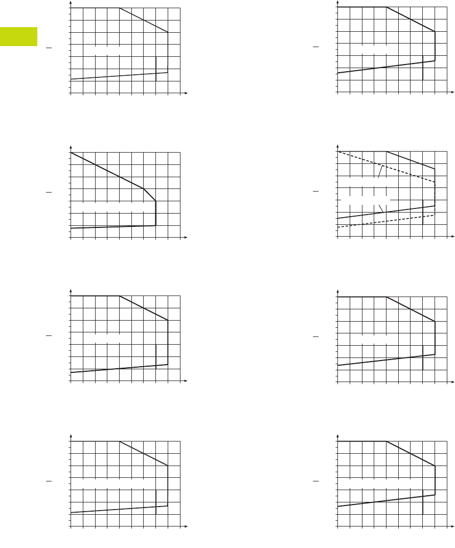
T40-10 Logic Control Products CA08100001K—June 2012 www.eatoncanada.ca
40
40
40
40
40
40
40
40
40
40
40
40
40
40
40
40
40
40
40
40
40
40
40
40
40
40
40
40
40
40
40.2
Control Relays and Timers
XR Series Terminal Block Relays
Permissible Range Diagrams
1PDT Relay Modules
Operating Range Voltage for 12 Vdc
Operating Range Voltage for 120 Vac/110 Vdc
Operating Range Voltage for 24 Vdc
Operating Range Voltage for 24 Vac/Vdc
DPDT Relay Modules
Operating Range Voltage for 12 Vdc
Operating Range Voltage for 120 Vac/110 Vdc
Operating Range Voltage for 24 Vdc
Operating Range Voltage for 24 Vac/Vdc
Notes
General Conditions — Direct alignment in the block, all devices 100% operating factor, horizontal or vertical mounting.
Curve A — Maximum permissible continuous operating voltage Umax with limiting continuous current on the contact side (see respective technical data).
Curve B — Minimum permissible relay operate voltage Uop after pre-excitation ) (see respective technical data).
Pre-excitation: Relay has been operated in a thermally steady state at the ambient temperature TU with nominal voltage UN and limiting continuous current on the contact side (see respective
technical data) (warm coil). After being switched off for a short time, the relay must reliably pick up again at Uop.
1.4
1.3
1.2
1.1
1.0
0.9
0.8
0.7
20 25 30
A
B
35 40 45 50 55 60 65
U
UN
TN [°C]
UN = 12 Vdc
1.4
1.3
1.2
1.1
1.0
0.9
0.8
0.7
20 25 30
A
B
35 40 45 50 55 60 65
U
UN
TN [°C]
UN = 110 Vdc/120 Vac
1.4
1.3
1.2
1.1
1.0
0.9
0.8
0.7
20 25 30
A
B
35 40 45 50 55 60 65
U
UN
TN [°C]
UN = 24 Vdc
1.4
1.3
1.2
1.1
1.0
0.9
0.8
0.7
20 25 30
A
B
35 40 45 50 55 60 65
U
UN
TN [°C]
UN = 24 Vdc/24 Vac
1.4
1.3
1.2
1.1
1.0
0.9
0.8
0.7
20 25 30
A
B
35 40 45 50 55 60 65
U
UN
TN [°C]
UN = 12 Vdc
1.4
1.3
1.2
1.1
1.0
0.9
0.8
0.7
20 25 30
A
B
35 40 45 50 55 60 65
U
UN
TN [°C]
UN = 120 Vac
UN = 110 Vdc
1.4
1.3
1.2
1.1
1.0
0.9
0.8
0.7
20 25 30
A
B
35 40 45 50 55 60 65
U
UN
TN [°C]
UN = 24 Vdc
1.4
1.3
1.2
1.1
1.0
0.9
0.8
0.7
20 25 30
A
B
35 40 45 50 55 60 65
U
UN
TN [°C]
UN = 24 Vdc/24 Vac
Tab40book.fm Page 10 Wednesday, July 4, 2012 10:05 PM

Logic Control Products CA08100001K—June 2012 www.eatoncanada.ca T40-11
40
40
40
40
40
40
40
40
40
40
40
40
40
40
40
40
40
40
40
40
40
40
40
40
40
40
40
40
40
40
40.2
Control Relays and Timers
XR Series Terminal Block Relays
Electrical Schematics
1PDT Terminal Block Relays DPDT Terminal Block Relays
Dimensions
Approximate Dimensions in Inches (mm)
Standard 1PDT Terminal Block Relays Standard DPDT Terminal Block Relays
11
14
12
A2
A1
12
22
24
21
A2
A1
11
14
3.70 (94.0)
0.24 (6.2)
3.15 (80.0)
3.70 (94.0)
0.55 (14.0)
3.15 (80.0)
Tab40book.fm Page 11 Wednesday, July 4, 2012 10:05 PM
T40-12 Logic Control Products CA08100001K—June 2012 www.eatoncanada.ca
40
40
40
40
40
40
40
40
40
40
40
40
40
40
40
40
40
40
40
40
40
40
40
40
40
40
40
40
40
40
40.2
Control Relays and Timers
XR Series Terminal Block Relays
OptoCoupler Terminal Block Relay Contents
Description Page
Standard Terminal Block Relays . . . . . . . . . . . . . . . . . T40-4
OptoCoupler Terminal Block Relays
Product Selection . . . . . . . . . . . . . . . . . . . . . . . . . . T40-13
Technical Data and Specifications . . . . . . . . . . . . . . T40-13
Electrical Schematic . . . . . . . . . . . . . . . . . . . . . . . . T40-14
Dimensions . . . . . . . . . . . . . . . . . . . . . . . . . . . . . . T40-14
High Current Terminal Block Relays . . . . . . . . . . . . . . T40-15
XR Series Accessories . . . . . . . . . . . . . . . . . . . . . . . . T40-18
OptoCoupler Terminal Block Relays
Product Description
The XR Series OptoCoupler
Terminal Block Relays can be
used in all applications and
consist of a pluggable
miniature OptoCoupler and a
basic terminal block. The XR
Series uses screw or spring-
cage technology, as well as
offers quick system wiring,
superior safety features, clear
labeling and a high level of
modularity.
Application Description
The XR Series OptoCoupler
relays can be used as an
input or output interface.
They provide the typical
reliability of OptoCouplers
and are especially suited for
high operating frequencies.
Features
●Pluggable relay allows for
field replacement
●Functional plug-in bridges
●LED status indication
●DIN rail mount
●Only 6.2 mm wide
●Switching capacity up to
24 Vdc/3A
●IP67-protected optical
electronics
●Wear-resistant and
bounce-free switching
●Insensitive to shock and
vibration
●Integrated protection
circuit
●Zero voltage switch at AC
output
Standards and Certifications
●cULus listed
●CE
Tab40book.fm Page 12 Wednesday, July 4, 2012 10:05 PM
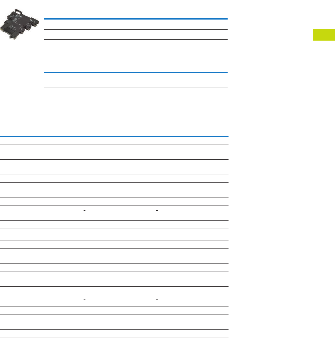
Logic Control Products CA08100001K—June 2012 www.eatoncanada.ca T40-13
40
40
40
40
40
40
40
40
40
40
40
40
40
40
40
40
40
40
40
40
40
40
40
40
40
40
40
40
40
40
40.2
Control Relays and Timers
XR Series Terminal Block Relays
Product Selection
OptoCoupler Terminal Block Relays
OptoCoupler Replacement Relays
Technical Data and Specifications
Pluggable Power OptoCoupler (Solid-State) Terminal Block Relays
Rated Current Supply Voltage Standard Pack
Catalogue
Number
2A 120 Vac/110 Vdc 10 XRU1S120U
2A 24 Vdc 10 XRU1S24
Rated Current Supply Voltage Standard Pack
Catalogue
Number
2A 24 Vdc 18 XRR1S24
2A 120 Vac/110 Vdc 10 XRR1S120U
XRU1S24
Catalogue Number XRU1S24 XRU1S120U
Replacement Relay XRR1S24 XRR1S120U
Input voltage 24 Vdc 120 Vac/110 Vdc
Connection Data
Rigid solid AWG (mm2) 26–14 (0.14–2.5) 26–14 (0.14–2.5)
Flexible stranded AWG (mm2) 26–14 (0.14–2.5) 26–14 (0.14–2.5)
Input Data
Input voltage 24 Vdc 120 Vac/110 Vdc
Permissible range 0.8–1.2 0.8 –1.1
Typical input current 9 mA 4 mA
Switching level 1 signal (“H”) >0.8 >0.8
Switching level 0 signal (“L”) <0.4 <0.25
Typical switch-on time 20 µS 6 ms
Typical turn-off time 500 µS 10 ms
Input protection Polarity protection diode,
free-wheeling diode
Bridge rectifier
Output Data
Max. switching voltage 33 Vdc 33 Vdc
Min. switching voltage 3 Vdc 3 Vdc
Limiting continuous current 3A (See derating curve) 3A (See derating curve)
Max. inrush current 15A (10 ms) 15A (10 ms)
Output circuit 2-conductor floating 2-conductor floating
Output protection Polarity protection, surge protection Polarity protection, surge protection
Voltage drop at maximum
limiting continuous current
< 200 mV < 200 mV
General Data
Ambient temp range –4˚ to 140˚F (–20˚ to 60˚C) –4˚ to 140˚F (–20˚ to 60˚C)
Rated operating mode 100% operating factor 100% operating factor
Inflammability class V0, in accordance with UL 94 V0, in accordance with UL 94
Mechanical service life 2 x 10⁷ cycles 2 x 10⁷ cycles
Tab40book.fm Page 13 Wednesday, July 4, 2012 10:05 PM
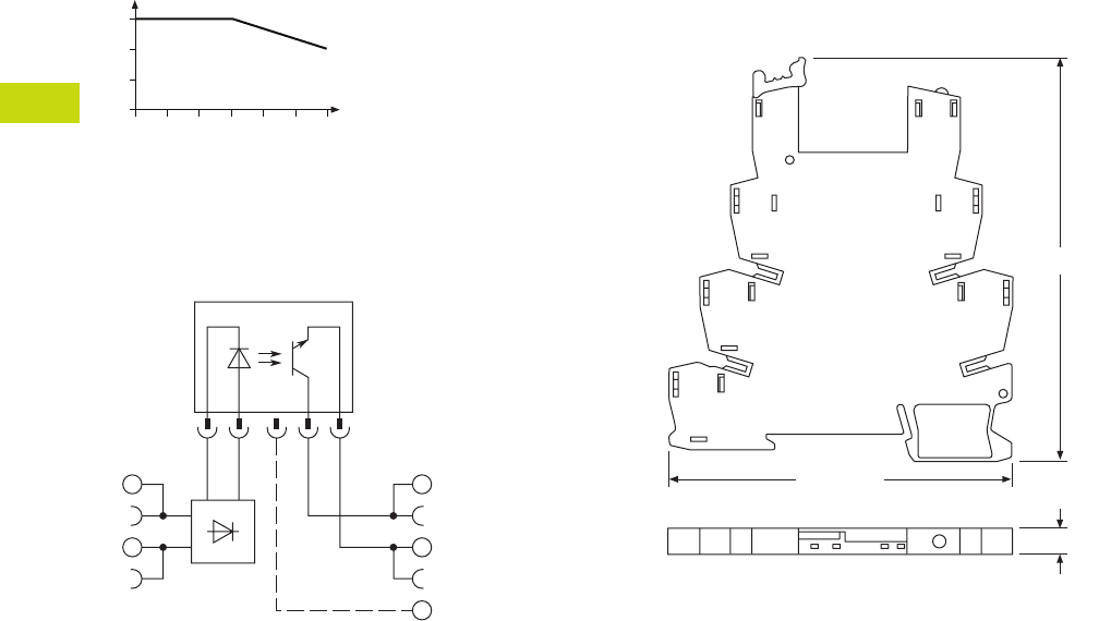
T40-14 Logic Control Products CA08100001K—June 2012 www.eatoncanada.ca
40
40
40
40
40
40
40
40
40
40
40
40
40
40
40
40
40
40
40
40
40
40
40
40
40
40
40
40
40
40
40.2
Control Relays and Timers
XR Series Terminal Block Relays
Derating Curve
OptoCoupler
Electrical Schematic
Pluggable Power OptoCoupler (Solid-State)
Terminal Block Relays
Dimensions
Approximate Dimensions in Inches (mm)
Pluggable Power OptoCoupler (Solid-State)
Terminal Block Relays
0
0
1
2
3
10 20 30
Ambient Temperature (°C)
Load Current (A)
40 50 60
13+
14
A2
A1
3.70 (94.0)
0.24 (6.2)
3.15 (80.0)
Tab40book.fm Page 14 Wednesday, July 4, 2012 10:05 PM
Logic Control Products CA08100001K—June 2012 www.eatoncanada.ca T40-15
40
40
40
40
40
40
40
40
40
40
40
40
40
40
40
40
40
40
40
40
40
40
40
40
40
40
40
40
40
40
40.2
Control Relays and Timers
XR Series Terminal Block Relays
High Current Terminal Block Relay Contents
Description Page
Standard Terminal Block Relays . . . . . . . . . . . . . . . . . T40-4
OptoCoupler Terminal Block Relays . . . . . . . . . . . . . . T40-12
High Current Terminal Block Relays
Product Selection . . . . . . . . . . . . . . . . . . . . . . . . . . T40-16
Technical Data and Specifications . . . . . . . . . . . . . T40-16
Electrical Schematic . . . . . . . . . . . . . . . . . . . . . . . . T40-17
Dimensions . . . . . . . . . . . . . . . . . . . . . . . . . . . . . . T40-17
XR Series Accessories . . . . . . . . . . . . . . . . . . . . . . . . T40-18
High Current Terminal Block Relays
Product Description
The XR Series Relays include
products designed to meet
high continuous current and/
or long electrical service life
applications. The XR Series
Relays are plug-in interfaces
that connect to basic terminal
blocks that use screw
connection technology.
Overall width is 14 mm.
Application Description
These relays are best suited
for applications that require
higher continuous load
currents than miniature
relays can carry and switch.
They can withstand inrush
currents or brief overloads
without damage, and allow
for continuous load currents
of up to 10A. The XR Series
Relay boasts an average
service life of the contacts
that is two or three times
the normal life of a less
powerful relay, resulting in
service cost savings.
Features
●14 mm wide
●Pluggable relay allows for
field replacement
●Convenient plug-in bridge
system
●LED status indication
●DIN Rail Mount
●IP67-protected optical
electronics
●Wear-resistant and
bounce-free switching
●Insensitive to shock and
vibration
●Integrated protection
circuit
●Zero voltage switch at AC
output
●Environmentally friendly,
cadmium-free contact
material
●Electrical isolation
between input and output
Standards and Certifications
●cULus listed
●CE
Tab40book.fm Page 15 Wednesday, July 4, 2012 10:05 PM
T40-16 Logic Control Products CA08100001K—June 2012 www.eatoncanada.ca
40
40
40
40
40
40
40
40
40
40
40
40
40
40
40
40
40
40
40
40
40
40
40
40
40
40
40
40
40
40
40.2
Control Relays and Timers
XR Series Terminal Block Relays
Product Selection
High Current Terminal Block Relays
High Current Replacement Relays
Technical Data and Specifications
High Current Terminal Block Relays (1PDT)
Notes
The separating plate, XRAPLCESK, should be installed for voltages greater than 250V (L1, L2, L3) between identical terminal points of adjacent modules.
Potential bridging is then possible with the XRAFBST bridge system.
The current rating for the normally open contact (#14) is 10A. The current rating for the normally closed contact (#12) is 6A and can be increased to 10A by bridging the
two #12 contact connections.
Rated Current Supply Voltage Standard Pack
Catalogue
Number
10A 12 Vdc 10 XRU1H12
10A 120 Vac/110 Vdc 10 XRU1H120U
10A 24 Vdc 10 XRU1H24
10A 24 Vac/Vdc 10 XRU1H24U
Rated Current Supply Voltage Standard Pack
Catalogue
Number
10A 24 Vdc 10 XRR1H24
10A 24 Vac/Vdc 10 XRR1H24U
10A 12 Vdc 10 XRR1H12
10A 120 Vac/110 Vdc 10 XRR1H120U
Catalogue Number XRU1H12 XRU1H24 XRU1H24U XRU1H120U
Replacement Relay XRR1H12 XRR1H24 XRR1H24U XRR1H120U
Input voltage 12 Vdc 24 Vdc 24 Vac/Vdc 120 Vac/110 Vdc
Connection Data
Rigid solid AWG (mm2) 26–14 (0.14–2.5) 26–14 (0.14–2.5) 26–14 (0.14–2.5) 26–14 (0.14–2.5)
Flexible stranded AWG (mm2) 26–14 (0.14–2.5) 26–14 (0.14–2.5) 26–14 (0.14–2.5) 26–14 (0.14–2.5)
Input Data for 1PDT Spring Cage Versions
Input voltage 12 Vdc 24 Vdc 24 Vac/Vdc 120 Vac/110 Vdc
Permissible range See Page T40-10 See Page T40-10 See Page T40-10 See Page T40-10
Typical input current 33 mA 18 mA 17.5 mA 4.5 mA (120 Vac)/4.2 mA (110 Vdc)
Typical response time 8 ms 8 ms 8 ms 7 ms
Typical release time 10 ms 10 ms 10 ms 10 ms
Input protection Polarity protection diode,
free-wheeling diode
Polarity protection diode,
free-wheeling diode
Bridge rectifier Bridge rectifier
Output Data
Contact type Single contact, 1PDT Single contact, 1PDT Single contact, 1PDT Single contact, 1PDT
Contact material AgNi AgNi AgNi AgNi
Max. switching voltage 250 Vac/Vdc 250 Vac/Vdc 250 Vac/Vdc 250 Vac/Vdc
Min. switching voltage 12 Vac/Vdc 12 Vac/Vdc 12 Vac/Vdc 12 Vac/Vdc
Limiting continuous current 10A 10A 10A 10A
Max. inrush current 30A (300 ms) 30A (300 ms) 30A (300 ms) 30A (300 ms)
Min. switching current 100 mA 100 mA 100 mA 100 mA
Min. switching power 1.2W 1.2W 1.2W 1.2W
Miscellaneous Data
Ambient temp range –4˚ to 140˚F (–20˚ to 60˚C) –4˚ to 140˚F (–20˚ to 60˚C) –4˚ to 140˚F (–20˚ to 60˚C) –4˚ to 140˚F (–20˚ to 60˚C)
Rated operating mode 100% operating factor 100% operating factor 100% operating factor 100% operating factor
Inflammability class V0, in accordance with UL 94 V0, in accordance with UL 94 V0, in accordance with UL 94 V0, in accordance with UL 94
Mechanical service life 3 x 10⁷ cycles 3 x 10⁷ cycles 3 x 10⁷ cycles 3 x 10⁷ cycles
XRU1H24
Tab40book.fm Page 16 Wednesday, July 4, 2012 10:05 PM

Logic Control Products CA08100001K—June 2012 www.eatoncanada.ca T40-17
40
40
40
40
40
40
40
40
40
40
40
40
40
40
40
40
40
40
40
40
40
40
40
40
40
40
40
40
40
40
40.2
Control Relays and Timers
XR Series Terminal Block Relays
Electrical Schematic
High Current Terminal Block Relays
Dimensions
Approximate Dimensions in Inches (mm)
High Current Terminal Block Relays
11
14
12
A2
A1
3.70 (94.0)
0.55 (14.0)
3.15 (80.0)
Tab40book.fm Page 17 Wednesday, July 4, 2012 10:05 PM

T40-18 Logic Control Products CA08100001K—June 2012 www.eatoncanada.ca
40
40
40
40
40
40
40
40
40
40
40
40
40
40
40
40
40
40
40
40
40
40
40
40
40
40
40
40
40
40
40.2
Control Relays and Timers
XR Series Terminal Block Relays
XR Series Accessories
Product Description
Power Terminal Block
The XRAPLCESK power
terminal block has the same
shape as the relay modules
and is used to feed in the
bridging potentials. The
nominal current is 32A. When
the total current is less than
or equal to 6A, supply can
take place directly at the
connecting terminal blocks of
one of the connected relays.
End Cover
The XRAATPBK end cover
is required at the start and
stop of a relay strip. It can
also be used for visual
separation of groups of
relays as well as separating
relays with voltages greater
than 250V and separating
neighboring bridges with
different potentials. It is
equipped with pre-scored
break out points at the
bridging positions so that
individual bridges can be
passed through as needed.
It may also be necessary to
use the end cover between
adjacent relays when three
phases (L1, L2, L3) are
used on the contact side
of the relay.
Bridges
The XRAFBST colored,
insulated plug-in bridge
system reduces wiring
time by up to 70% compared
to conventionally wired
relays. The XRAFBST2,
2-position bridges, are
suited for bridging a smaller
number of relays and total
currents <6A. When a circuit
is supplied from both sides,
the circuit can be opened at
any point, allowing all other
modules to continue being
supplied at the same time.
The XRAFBST500 allow up
to 80 modules to be bridged
at one time. If bridges with
different potentials meet in
neighboring modules, the
end cover XRAATPBK
should be used. All bridges
are equipped with a groove
for removal with a standard
screwdriver.
Standards and Certifications
●cRUus
Product Selection
XR Series Accessories
Technical Data and Specifications
Power Terminal Block
Note
The separating plate, XRAPLCESK, should be installed for voltages greater than 250V
(L1, L2, L3) between identical terminal points of adjacent modules. Potential bridging is
then possible with the XRAFBST bridge system.
Colour
Standard
Pack
Catalogue
Number
2-Position Snap-In Jumper
Red 10 XRAFBST2RD
Blue 10 XRAFBST2BU
Gray 10 XRAFBST2GY
80-Position Snap-In Jumper
Red 5 XRAFBST500RD
Blue 5 XRAFBST500BU
Gray 5 XRAFBST500GY
Power Terminal Block
Gray 5 XRAPLCESK
End Cover
Black 5 XRAATPBK
Description Specification
Connection Data
Rigid solid AWG (mm2) 24–10 (0.2–4)
Flexible stranded AWG (mm2) 24–10 (0.2–4)
Miscellaneous Data
Max. current 32A
Max. voltage 250 Vac
Tab40book.fm Page 18 Wednesday, July 4, 2012 10:05 PM

Logic Control Products CA08100001K—June 2012 www.eatoncanada.ca T40-19
40
40
40
40
40
40
40
40
40
40
40
40
40
40
40
40
40
40
40
40
40
40
40
40
40
40
40
40
40
40
40.3
Control Relays and Timers
EASY Intelligent Relays
EASY Intelligent Relays Contents
Description Page
EASY Intelligent Relays
EASY500/700/800 Intelligent Relays . . . . . . . . . . . T40-20
EASY/MFD Expansion Modules . . . . . . . . . . . . . . . T40-25
MFD Intelligent Relays . . . . . . . . . . . . . . . . . . . . . . T40-28
EASY/MFD Communication Modules . . . . . . . . . . T40-33
EASY/MFD Power Supplies, Accessories
and Software . . . . . . . . . . . . . . . . . . . . . . . . . . . . T40-36
Product Overview
The EASY Intelligent Relays
combine timers, relays,
counters, special functions,
inputs and outputs into one
compact device that is easily
programmed.
The EASY
family of
products provides an
exception
level of flexibility
together with substantial
savings of commissioning
time and effort.
The EASY Intelligent Relays
are available in more than
35 styles that support from
12 I/O up to a network of up
to 320 I/O points providing
the ideal solution for lighting,
energy management,
industrial control, irrigation,
pump control, HVAC and
home automation.
Once EASY products are
installed, changes are
easily accomplished through
front panel programming,
eliminating the need
to change wiring and
minimizing downtime.
Application Description
The EASY Intelligent Relays
excel in traditional applications
where multiple relays, timers
and pushbuttons are used.
Applications span residential,
commercial and industrial
installations.
Typical control
applications are:
●Car washes
●Automatic doors
●Commercial and
residential lighting
●Pump control
●12 Vdc automotive
●Greenhouse
●Machinery
●Irrigation
●Heating and air conditioning
Tab40book.fm Page 19 Wednesday, July 4, 2012 10:05 PM
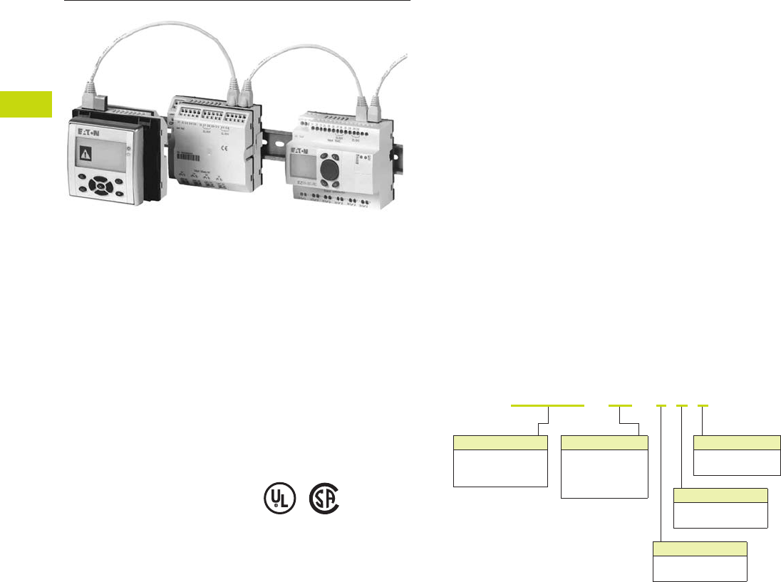
T40-20 Logic Control Products CA08100001K—June 2012 www.eatoncanada.ca
40
40
40
40
40
40
40
40
40
40
40
40
40
40
40
40
40
40
40
40
40
40
40
40
40
40
40
40
40
40
40.3
Control Relays and Timers
EASY Intelligent Relays
EASY500/700/800 Intelligent Relays Contents
Description Page
EASY500/700/800 Intelligent Relays
Product Selection . . . . . . . . . . . . . . . . . . . . . . . . . . T40-21
Technical Data and Specifications . . . . . . . . . . . . . . T40-22
Dimensions . . . . . . . . . . . . . . . . . . . . . . . . . . . . . . T40-23
EASY/MFD Expansion Modules . . . . . . . . . . . . . . . . . T40-25
MFD Intelligent Relays . . . . . . . . . . . . . . . . . . . . . . . . T40-28
EASY/MFD Communication Modules . . . . . . . . . . T40-33
EASY/MFD Power Supplies, Accessories
and Software . . . . . . . . . . . . . . . . . . . . . . . . . . . . . . T40-36
EASY500/700/800 Intelligent Relays
Product Description
Three families make up
the EASY Intelligent Relay
product line.
EASY500 Series—for
controlling small applications
with up to 12 input/output
signals. Models are available
with and without displays.
DIN rail mounted.
EASY700 Series—for
controlling medium-sized
applications with 20 I/O points
(expandable to 40 I/O points).
DIN rail mounted.
EASY800 Series—for
controlling large-scale
applications with 20 points,
expandable to 40 points
locally, and expandable using
the EASY-NET network up to
320 I/O points. Models are
available with and without
displays. DIN rail mounted.
The EASY-NET integrated
network provides easy and
inexpensive linking of up
to eight EASY800 devices
over a distance of up to
1000 meters. Each EASY800
device can run its own
program, or be used as a
distributed input/output
module. Connect up to
eight controllers with up
to 40 I/O to obtain 320 I/O.
Standards and Certifications
●EN 50178
●IEC/EN 60947
●UL
●CSA
●CSA Class I, Div. 2,
Groups A, B, C, D;
Temp. Code T3C
Catalogue Number Selection
EASY500/700/800
Note: Not all combinations are possible. See selection tables.
Display
Blank = Display
X = No display
Digital Outputs
R = Relay
T = Transistor
Clock
C = Clock
Blank = No clock
Digital Inputs
AB = 24 Vac
AC = 110–240 Vdc
DA = 12 Vdc
DC = 24 Vdc
EASY
7xx -
AC
-
T C X
Module Type
EASY5xx = 500 Series
EASY7xx = 700 Series
EASY8xx = 800 Series
Tab40book.fm Page 20 Wednesday, July 4, 2012 10:05 PM
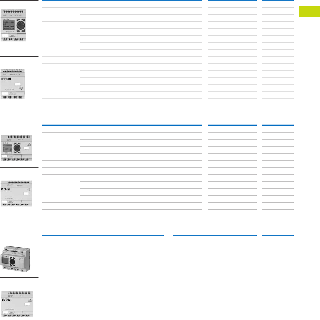
Logic Control Products CA08100001K—June 2012 www.eatoncanada.ca T40-21
40
40
40
40
40
40
40
40
40
40
40
40
40
40
40
40
40
40
40
40
40
40
40
40
40
40
40
40
40
40
40.3
Control Relays and Timers
EASY Intelligent Relays
Product Selection
EASY500 Intelligent Relays
EASY700 Intelligent Relays
EASY800 Intelligent Relays
Note
Analogue inputs optional. Use of analogue inputs will result in a decrease in the same number of available digital inputs.
Inputs Outputs Catalogue
NumberDescription 24 Vac 110–240 Vac 12 Vdc 24 Vdc Analogue Relay Transistor
Display
12 I/O, no clock — 8 — — — 4 — EASY512-AC-R
———8 2 4 — EASY512-DC-R
12 I/O, clock 8 ———2 4 — EASY512-AB-RC
—8 ——— 4 — EASY512-AC-RC
——8 —2 4 — EASY512-DA-RC
———8 2 4 — EASY512-DC-RC
———8 2 —4 EASY512-DC-TC
No Display
12 I/O, clock 8 ———2 4 — EASY512-AB-RCX
—8 ——— 4 — EASY512-AC-RCX
——8 —2 4 — EASY512-DA-RCX
———8 2 4 — EASY512-DC-RCX
———8 2 —4 EASY512-DC-TCX
Inputs Outputs Catalogue
NumberDescription 24 Vac 110–240 Vac 12 Vdc 24 Vdc Analogue Relay Transistor
Display
18 I/O, clock 12 ———4 6 — EASY719-AB-RC
—12——— 6 — EASY719-AC-RC
——12—4 6 — EASY719-DA-RC
———124 6 — EASY719-DC-RC
20 I/O, clock ———124 —8 EASY721-DC-TC
No Display
18 I/O, clock 12 ———4 6 — EASY719-AB-RCX
—12——— 6 — EASY719-AC-RCX
——12—4 6 — EASY719-DA-RCX
———124 6 — EASY719-DC-RCX
20 I/O, clock ———124 —8 EASY721-DC-TCX
Inputs Outputs Catalogue
NumberDescription 110–240 Vac 24 Vdc Analogue Relay Transistor Analogue
Display
18 I/O, clock 12 — — 6 — — EASY819-AC-RC
—124 6 —— EASY819-DC-RC
19 I/O, clock — 12 4 6 — 1 EASY820-DC-RC
20 I/O, clock — 12 4 — 8 — EASY821-DC-TC
21 I/O, clock — 12 4 — 8 1 EASY822-DC-TC
No Display
18 I/O, clock 12 — — 6 — — EASY819-AC-RCX
—124 6 —— EASY819-DC-RCX
19 I/O, clock — 12 4 6 — 1 EASY820-DC-RCX
20 I/O, clock — 12 4 — 8 — EASY821-DC-TCX
21 I/O, clock — 12 4 — 8 1 EASY822-DC-TCX
EASY500 with Display
EASY500 without
Display
EASY700 with Display
EASY700 without
Display
EASY800 with Display
EASY800 without
Display
Tab40book.fm Page 21 Wednesday, July 4, 2012 10:05 PM

T40-22 Logic Control Products CA08100001K—June 2012 www.eatoncanada.ca
40
40
40
40
40
40
40
40
40
40
40
40
40
40
40
40
40
40
40
40
40
40
40
40
40
40
40
40
40
40
40.3
Control Relays and Timers
EASY Intelligent Relays
Technical Data and Specifications
EASY500 Series
EASY700 Series
EASY800 Series
Note
Relay = 8A (10A to UL) with resistive load, 3A with inductive load. Transistor outputs = 0.5A/24 Vdc, maximum four outputs switchable in parallel.
Type EASY512-AB… EASY512-AC… EASY512-DA… EASY512-DC-R… EASY512-DC-TC.
Supply voltage 24 Vac 100–240 Vac 12 Vdc 24 Vdc 24 Vdc
Heat dissipation 5 VA 5 VA 2W 2W 2W
Continuous current outputs 8A 8A 8A 8A 0.5A
Short-circuit proof with power factor 1 Line protection B16, 600 A —
Short-circuit proof with power factor 0.7…0.7 Line protection B16, 900 A —
Mounting On top-hat rail to DIN 50022, 35 mm or screw mounting with ZB4-101-GF1 fixing brackets
Connection cables
Solid 0.2–4.0 mm2 (AWG 22-12) 0.2–4.0 mm2 (AWG 22-12) 0.2–4.0 mm2 (AWG 22-12) 0.2–4.0 mm2 (AWG 22-12) 0.2–4.0 mm2 (AWG 22-12)
Flexible 0.2–2.5 mm2 (AWG 22-12) 0.2–2.5 mm2 (AWG 22-12) 0.2–2.5 mm2 (AWG 22-12) 0.2–2.5 mm2 (AWG 22-12) 0.2–2.5 mm2 (AWG 22-12)
Degree of protection IP 20 IP 20 IP 20 IP 20 IP 20
RFI suppression EN 55011, EN 55022 Class B, IEC 61000-6-1, 2, 3, 4
Ambient operating temperature –25 to 55˚C –25 to 55˚C –25 to 55˚C –25 to 55˚C –25 to 55˚C
Transport and storage temperature –40 to 70˚C –40 to 70˚C –40 to 70˚C –40 to 70˚C –40 to 70˚C
Hazardous location CSA Class I, Div. 2, Groups A, B, C, D; Temp. Code T3C
Type EASY719-AB… EASY719-AC… EASY719-DA… EASY719-DC-RC… EASY721-DC-TC.
Supply voltage 24 Vac 100–240 Vac 12 Vdc 24 Vdc 24 Vdc
Heat dissipation 7 VA 10 VA 3.5W 3.5W 3.5W
Continuous current outputs 8A 8A 8A 8A 0.5A
Short-circuit proof with power factor 1 Line protection B16, 600A Line protection B16, 600A Line protection B16, 600A Line protection B16, 600A —
Short-circuit proof with power factor 0.7…0.7 Line protection B16, 900A Line protection B16, 900A Line protection B16, 900A Line protection B16, 900A —
Mounting On top-hat rail to DIN 50022, 35 mm or screw mounting with ZB4-101-GF1 fixing brackets
Connection cables
Solid 0.2–4.0 mm2 (AWG 22-12) 0.2–4.0 mm2 (AWG 22-12) 0.2–4.0 mm2 (AWG 22-12) 0.2–4.0 mm2 (AWG 22-12) 0.2–4.0 mm2 (AWG 22-12)
Flexible 0.2–2.5 mm2 (AWG 22-12) 0.2–2.5 mm2 (AWG 22-12) 0.2–2.5 mm2 (AWG 22-12) 0.2–2.5 mm2 (AWG 22-12) 0.2–2.5 mm2 (AWG 22-12)
Degree of protection IP 20 IP 20 IP 20 IP 20 IP 20
RFI suppression EN 55011, EN 55022 Class B, IEC 61000-6-1, 2, 3, 4
Ambient operating temperature –25 to 55˚C –25 to 55˚C –25 to 55˚C –25 to 55˚C –25 to 55˚C
Transport and storage temperature –40 to 70˚C –40 to 70˚C –40 to 70˚C –40 to 70˚C –40 to 70˚C
Hazardous location CSA Class I, Div. 2, Groups A, B, C, D; Temp. Code T3C
Type EASY819-AC… EASY819-DC-RC… EASY820-DC-RC… EASY821-DC-TC… EASY822-DC-TC.
Supply voltage 100–240 Vac 24 Vdc 24 Vdc 24 Vdc 24 Vdc
Heat dissipation 10 VA 3.4W 3.4W 3.4W 3.4W
Continuous current outputs 8A 8A 8A 8A 0.5A
Short-circuit proof with power factor 1 Line protection B16, 600A Line protection B16, 600A Line protection B16, 600A Line protection B16, 600A —
Short-circuit proof with power factor 0.7…0.7 Line protection B16, 900A Line protection B16, 900A Line protection B16, 900A Line protection B16, 900A —
Mounting On top-hat rail to DIN 50022, 35 mm or screw mounting with ZB4-101-GF1 fixing brackets
Connection cables
Solid 0.2–4.0 mm2 (AWG 22-12) 0.2–4.0 mm2 (AWG 22-12) 0.2–4.0 mm2 (AWG 22-12) 0.2–4.0 mm2 (AWG 22-12) 0.2–4.0 mm2 (AWG 22-12)
Flexible 0.2–2.5 mm2 (AWG 22-12) 0.2–2.5 mm2 (AWG 22-12) 0.2–2.5 mm2 (AWG 22-12) 0.2–2.5 mm2 (AWG 22-12) 0.2–2.5 mm2 (AWG 22-12)
Degree of protection IP 20 IP 20 IP 20 IP 20 IP 20
RFI suppression EN 55011, EN 55022 Class B, IEC 61000-6-1, 2, 3, 4
Ambient operating temperature –25 to 55˚C –25 to 55˚C –25 to 55˚C –25 to 55˚C –25 to 55˚C
Transport and storage temperature –40 to 70˚C –40 to 70˚C –40 to 70˚C –40 to 70˚C –40 to 70˚C
Hazardous location CSA Class I, Div. 2, Groups A, B, C, D; Temp. Code T3C
Tab40book.fm Page 22 Wednesday, July 4, 2012 10:05 PM
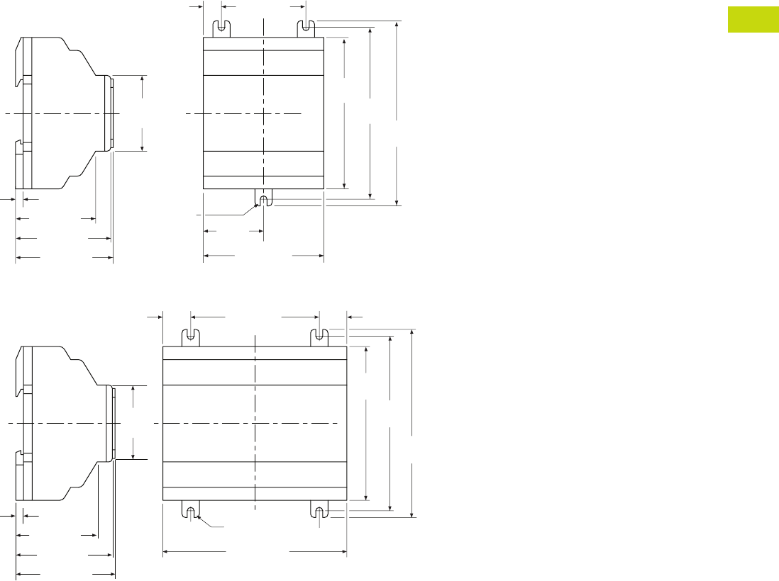
Logic Control Products CA08100001K—June 2012 www.eatoncanada.ca T40-23
40
40
40
40
40
40
40
40
40
40
40
40
40
40
40
40
40
40
40
40
40
40
40
40
40
40
40
40
40
40
40.3
Control Relays and Timers
EASY Intelligent Relays
Dimensions
Approximate Dimensions in Inches (mm)
EASY500 Series, Drawing Number MD05013001E
EASY700 Series, Drawing Number MD05013002E
2.81 (71.5)
1.41
(35.8)
3.54
(90.0) 4.02
(102.0)
4.33
(110.0)
1.97 (50.0)0.42 (10.8)
(M4) 0.157
(3.9) Dia.
2.28 (58.0)
1.77
(45.0)
0.18 (4.5)
2.22 (56.5)
1.87 (47.5)
EASY500
4.23 (107.5)
3.54
(90.0)
4.02
(102.0)
4.33
(110.0)
2.96 (75.0)0.64 (16.3)
(M4) 0.157
(3.9) Dia.
0.64 (16.3)
EASY600
2.28 (58.0)
0.18 (4.5)
2.22 (56.5)
1.87 (47.5)
1.77
(45.0)
Tab40book.fm Page 23 Wednesday, July 4, 2012 10:05 PM
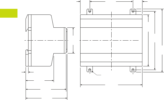
T40-24 Logic Control Products CA08100001K—June 2012 www.eatoncanada.ca
40
40
40
40
40
40
40
40
40
40
40
40
40
40
40
40
40
40
40
40
40
40
40
40
40
40
40
40
40
40
40.3
Control Relays and Timers
EASY Intelligent Relays
Approximate Dimensions in Inches (mm)
EASY800 Series, Drawing Number MD05013003E
4.23
(107.5)
3.54
(90.0)
4.02
(102.0)
4.33
(110.0)
2.96
(75.0)
0.64
(16.3)
(M4) 0.157
(3.9) Dia.
2.83
(72.0)
1.77
(45.0)
0.18
(4.5)
2.78
(70.5)
1.91
(48.5)
0.64
(16.3)
EASY800
Tab40book.fm Page 24 Wednesday, July 4, 2012 10:05 PM
Logic Control Products CA08100001K—June 2012 www.eatoncanada.ca T40-25
40
40
40
40
40
40
40
40
40
40
40
40
40
40
40
40
40
40
40
40
40
40
40
40
40
40
40
40
40
40
40.3
Control Relays and Timers
EASY Intelligent Relays
EASY/MFD Expansion Modules Contents
Description Page
EASY500/700/800 Intelligent Relays . . . . . . . . . . . . . . T40-20
EASY/MFD Expansion Modules
Technical Data and Specifications . . . . . . . . . . . . . T40-26
Dimensions . . . . . . . . . . . . . . . . . . . . . . . . . . . . . . T40-27
MFD Intelligent Relays . . . . . . . . . . . . . . . . . . . . . . . . T40-28
EASY/MFD Communication Modules . . . . . . . . . . T40-33
EASY/MFD Power Supplies, Accessories
and Software . . . . . . . . . . . . . . . . . . . . . . . . . . . . . . . T40-36
EASY/MFD Expansion
Modules
Product Description
Expansion modules are
available for increasing the
input/output of the EASY700/
800 and MFD intelligent
relays to 24 inputs and up to
16 outputs. Expansion
modules can be mounted
directly to the EASY/MFD
unit or up to 98 ft. (30 m)
away using coupling module
EASY200-EASY.
Product Selection
EASY700/800/MFD I/O Expansion Modules
Note
All expansion modules include one EASY-LINK-DS.
Description
Inputs Outputs Catalogue
Number110–240 Vac 24 Vdc Relay Transistor
2 I/O expansion — — 2 — EASY202-RE
18 I/O expansion 12 — 6 — EASY618-AC-RE
—126—EASY618-DC-RE
20 I/O expansion — 12 — 8 EASY620-DC-TE
Coupling module for remote mounting of expansion modules EASY200-EASY
EASY202-RE
Tab40book.fm Page 25 Wednesday, July 4, 2012 10:05 PM

T40-26 Logic Control Products CA08100001K—June 2012 www.eatoncanada.ca
40
40
40
40
40
40
40
40
40
40
40
40
40
40
40
40
40
40
40
40
40
40
40
40
40
40
40
40
40
40
40.3
Control Relays and Timers
EASY Intelligent Relays
Technical Data and Specifications
EASY700/800/MFD I/O Expansion Modules
Type EASY202-RE EASY618-AC-RE EASY618-DC-RE EASY620-DC-TE EASY200-EASY
Supply voltage — 100 – 240 Vac 24
Vac
24
Vac
—
Heat dissipation 1W 10 VA 4W 4W 1W
Continuous current outputs 8A 8A 8A 0.5A —
Short-circuit proof with
power factor 1
Line protection
B16, 600A
Line protection
B16, 600A
Line protection
B16, 600A
Line protection
B16, 600A
—
Short-circuit proof with
power factor 0.7…0.7
Line protection
B16, 900A
Line protection
B16, 900A
Line protection
B16, 900A
Line protection
B16, 900A
—
Connection cables
Solid 0.2–4.0 mm2 (AWG 22-12) 0.2–4.0 mm2 (AWG 22-12) 0.2–4.0 mm2 (AWG 22-12) 0.2–4.0 mm2 (AWG 22-12) 0.2–4.0 mm2 (AWG 22-12)
Flexible 0.2–2.5 mm2 (AWG 22-12) 0.2–2.5 mm2 (AWG 22-12) 0.2–2.5 mm2 (AWG 22-12) 0.2–2.5 mm2 (AWG 22-12) 0.2–2.5 mm2 (AWG 22-12)
Degree of protection IP20 IP20 IP20 IP20 IP20
RFI suppression EN 55011, EN 55022 Class B, IEC 61000-6-1,2,3,4
Ambient operating temperature –25˚ to 55ºC –25˚ to 55ºC –25˚ to 55ºC –25˚ to 55ºC –25˚ to 55ºC
Transport and storage temperature –40˚ to 70ºC –40˚ to 70ºC –40˚ to 70ºC –40˚ to 70ºC –40˚ to 70ºC
Certification, standards
EN 50178, IEC/EN 60947, UL, CSA
Mounting On top-hat rail to DIN 50022, 35 mm or screw mounting with ZB4-101-GF1 fixing brackets
Tab40book.fm Page 26 Wednesday, July 4, 2012 10:05 PM
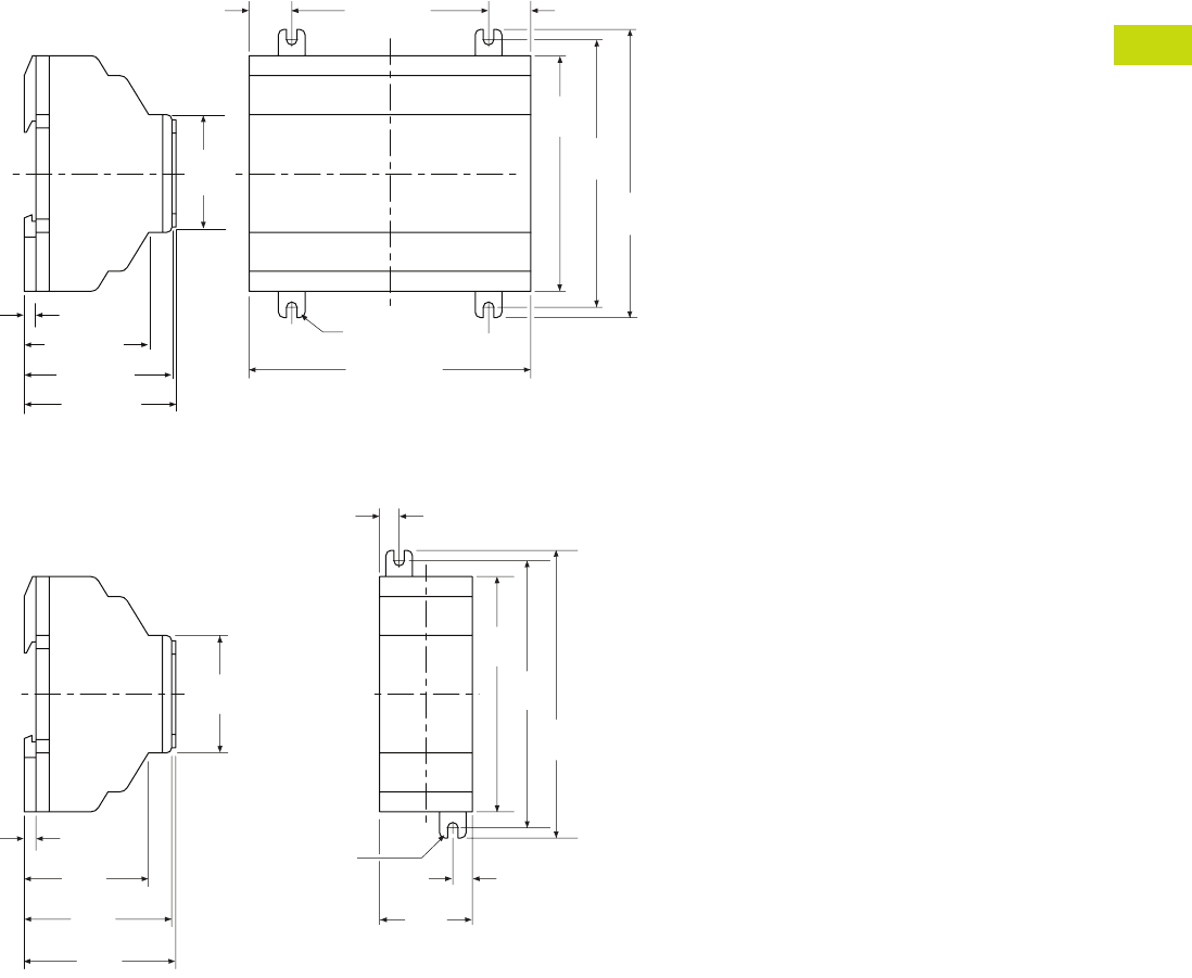
Logic Control Products CA08100001K—June 2012 www.eatoncanada.ca T40-27
40
40
40
40
40
40
40
40
40
40
40
40
40
40
40
40
40
40
40
40
40
40
40
40
40
40
40
40
40
40
40.3
Control Relays and Timers
EASY Intelligent Relays
Dimensions
Approximate Dimensions in Inches (mm)
EASY600 Series, Drawing Number MD05013002E
EASY202-RE/EASY200-EASY/EASY205-ASI Series, Drawing Number MD05013012E
4.23 (107.5)
3.54
(90.0)
4.02
(102.0)
4.33
(110.0)
2.96 (75.0)0.64 (16.3)
(M4) 0.157
(3.9) Dia.
0.64 (16.3)
EASY600
2.28 (58.0)
0.18 (4.5)
2.22 (56.5)
1.87 (47.5)
1.77
(45.0)
(M4) 0.157
(3.9) Dia.
0.30
(7.5)
4.33
(110.0)
4.02
(102.0)
3.54
(90.0)
0.30
(7.5)
1.40
(35.5)
1.87
(47.5)
2.22
(56.5)
0.18
(4.5)
1.77
(45.0)
2.28
(58.0)
EASY202-RE
EASY200-EASY
EASY205-ASI
Tab40book.fm Page 27 Wednesday, July 4, 2012 10:05 PM
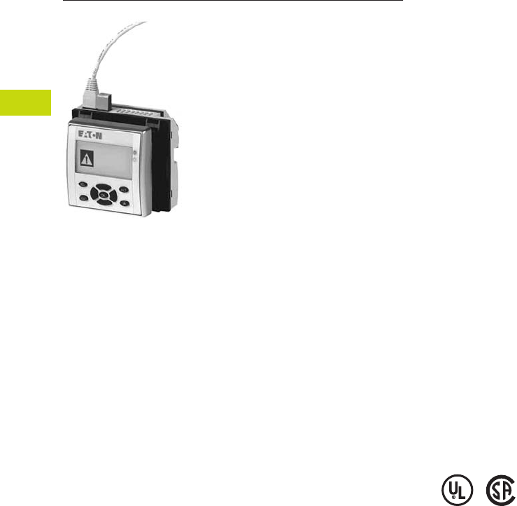
T40-28 Logic Control Products CA08100001K—June 2012 www.eatoncanada.ca
40
40
40
40
40
40
40
40
40
40
40
40
40
40
40
40
40
40
40
40
40
40
40
40
40
40
40
40
40
40
40.3
Control Relays and Timers
EASY Intelligent Relays
MFD Intelligent Relays Contents
Description Page
EASY500/700/800 Intelligent Relays . . . . . . . . . . . . . . T40-20
EASY/MFD Expansion Modules . . . . . . . . . . . . . . . . . T40-25
MFD Intelligent Relays
Product Selection . . . . . . . . . . . . . . . . . . . . . . . . . . T40-29
Technical Data and Specifications . . . . . . . . . . . . . T40-30
Dimensions . . . . . . . . . . . . . . . . . . . . . . . . . . . . . . T40-31
EASY/MFD Communication Modules . . . . . . . . . . . . . T40-33
EASY/MFD Power Supplies, Accessories
and Software . . . . . . . . . . . . . . . . . . . . . . . . . . . . . . T40-36
MFD Intelligent Relays
Product Description
MFD Intelligent Relays are
comprised of three parts, a
display, a controller, and an
I/O module. Match each
piece to the needs of your
application. If you need to
both monitor and modify
parameters within your
application, choose the MFD-
80-B. The preprogrammed
and user programmable
buttons give you the
capability to make small
changes to the way your
application is running, start
or stop a process, or change
your program completely.
Select a controller with or
without EASY-NET support,
and with AC or DC power.
Finally, add the MFD I/O
module that best suits your
application.
MFD Series—for controlling
small applications that require
graphic visualization and for
large-scale applications with
20 points, expandable to 40
points locally, and expandable
using the EASY-NET network
up to 320 I/O points. The
MFD display can be linked to
the EASY500/700/800
models to provide an
enhanced text based operator
interface. Panel mounted.
The EASY-NET integrated
network provides easy and
inexpensive linking of up to
eight MFD devices over a
distance of up to 1000
meters. Each MFD device
can run its program, or be
used as a distributed input/
output module. Connect up
to eight controllers with up to
40 I/O to obtain 320 I/O.
Standards and Certifications
●EN 50178
●IEC/EN 60947
●UL
●CSA
●CSA Class I, Div. 2,
Groups A, B, C, D;
Temp. Code T3C
Tab40book.fm Page 28 Wednesday, July 4, 2012 10:05 PM
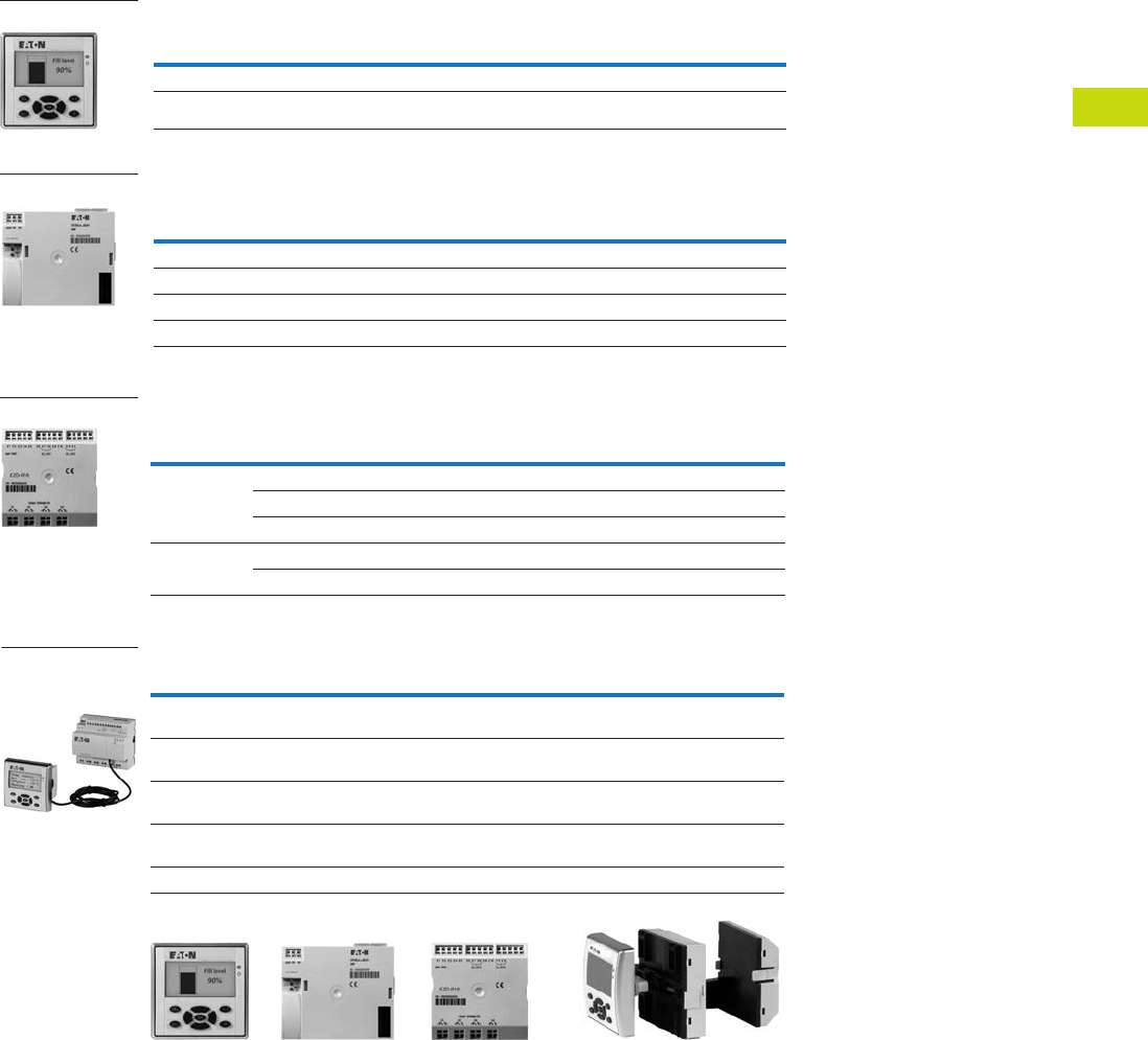
Logic Control Products CA08100001K—June 2012 www.eatoncanada.ca T40-29
40
40
40
40
40
40
40
40
40
40
40
40
40
40
40
40
40
40
40
40
40
40
40
40
40
40
40
40
40
40
40.3
Control Relays and Timers
EASY Intelligent Relays
Product Selection
MFD Displays (MFD-80)
MFD Controllers (MFD-CP8)
MFD I/O Modules
MFD Display to EASY Communication Modules (MFD-CP4)
Notes
For additional expansion, see EASY/MFD Expansion Modules on Page T40-26.
Analogue inputs optional.
Link MFD displays to EASY 500/700 or 800 intelligent relays for text only cabinet door installations.
Description
Catalogue
Number
MFD, no buttons MFD-80
MFD, buttons (shown) MFD-80-B
Description
Catalogue
Number
MFD CPU with 24 Vdc, power supply, clock MFD-CP8-ME
MFD CPU with 24 Vdc, power supply, clock, EASY-NET MFD-CP8-NT
MFD CPU with 100–240 Vac, power supply, clock MFD-AC-CP8-ME
MFD CPU with 100–240 Vac, power supply, clock, EASY-NET MFD-AC-CP8-NT
Description
Inputs Outputs Catalogue
Number110–240 Vac 24 Vdc Analogue Relay Transistor Analogue
16 I/O 12 — — 4 — — MFD-AC-R16
—1244——MFD-R16
—124—4—MFD-T16
17 I/O — 12 4 4 — 1 MFD-RA17
—124—41MFD-TA17
Description Catalogue Number
MFD display to EASY500/700 DC communication module with EASY500/700 communication
cable (MFD-CP4-500-CAB5)
MFD-CP4-500
MFD display to EASY500/700 AC communication module with EASY500/700 communication
cable (MFD-CP4-500-CAB5)
MFD-AC-CP4-500
MFD display to EASY800 DC communication module with EASY800 communication cable
(MFD-CP4-800-CAB5)
MFD-CP4-800
MFD display to EASY800 AC communication module with EASY800 communication cable
(MFD-CP4-800-CAB5)
MFD-AC-CP4-800
Replacement communication module (all controllers—no cable) MFD-CP4
MFD-80-B
MFD-CP8
MFD-R16
MFD-CP4-800 Attached
to EASY-80 Display and
EASY800 Unit
MFD-80 MFD-CP8 MFD-I/O MFD Assembly++=
Tab40book.fm Page 29 Wednesday, July 4, 2012 10:05 PM

T40-30 Logic Control Products CA08100001K—June 2012 www.eatoncanada.ca
40
40
40
40
40
40
40
40
40
40
40
40
40
40
40
40
40
40
40
40
40
40
40
40
40
40
40
40
40
40
40.3
Control Relays and Timers
EASY Intelligent Relays
Technical Data and Specifications
MFD-80, MFD-CP4, MFD-CP8
MFD I/O Modules
MFD-CP4 and CP8 Communication Modules
Note
Relay = 8A with resistive load, 3A with inductive load.
Transistor outputs = 0.5A/24 Vdc, maximum four outputs switchable in parallel.
Type MFD-80… MFD-CP4/CP8
Connection cables
Solid — 0.2–4.0 mm2 (AWG 22-12)
Flexible — 0.2–2.5 mm2 (AWG 22-12)
Degree of protection IP 65 IP 20
RFI suppression EN 55011, EN 55022 Class B, IEC 61000-6-1, 2, 3, 4 EN 55011, EN 55022 Class B, IEC 61000-6-1, 2, 3, 4
Ambient operating temperature Clearly legible at –5 to 50˚C –25 to 55˚C
Transport and storage temperature –40 to 70˚C –40 to 70˚C
Hazardous location CSA Class I, Div. 2, Groups A, B, C, D; Temp. Code T3C CSA Class I, Div. 2, Groups A, B, C, D; Temp. Code T3C
Type MFD-AC-R16 MFD-R16 MFD-RA17 MFD-T16 MFD-TA17
Supply voltage Supply via
MFD-CP8 module
Supply via
MFD-CP8 module
Supply via
MFD-CP8 module
Supply via
MFD-CP8 module
Supply via
MFD-CP8 module
Heat dissipation 0.5W 0.5W 0.5W 0.5W 0.5W
Continuous current outputs 8A 8A 8A 0.5A 0.5A
Short-circuit proof with
power factor 1
Line protection
B16, 600A
Line protection
B16, 600A
Line protection
B16, 600A
——
Short-circuit proof with
power factor 0.7…0.7
Line protection
B16, 600A
Line protection
B16, 600A
Line protection
B16, 600A
——
Connection cables
Solid 0.2–4.0 mm2 (AWG 22-12) 0.2–4.0 mm2 (AWG 22-12) 0.2–4.0 mm2 (AWG 22-12) 0.2–4.0 mm2 (AWG 22-12) 0.2–4.0 mm2 (AWG 22-12)
Flexible 0.2–2.5 mm2 (AWG 22-12) 0.2–2.5 mm2 (AWG 22-12) 0.2–2.5 mm2 (AWG 22-12) 0.2–2.5 mm2 (AWG 22-12) 0.2–2.5 mm2 (AWG 22-12)
Degree of protection IP20 IP20 IP20 IP20 IP20
RFI suppression EN 55011, EN 55022 Class B, IEC 61000-6-1,2,3,4
Ambient operating temperature –25 to 55˚C –25 to 55˚C –25 to 55˚C –25 to 55˚C –25 to 55˚C
Transport and storage temperature –40 to 70˚C –40 to 70˚C –40 to 70˚C –40 to 70˚C –40 to 70˚C
Mounting Snap fitted to
MFD-CP8 module
Snap fitted to
MFD-CP8 module
Snap fitted to
MFD-CP8 module
Snap fitted to
MFD-CP8 module
Snap fitted to
MFD-CP8 module
Type MFD-80… MFD-CP4-… MFD-CP8… MFD-AC-CP8…
Supply voltage Supply from -CP 24 Vdc 24 Vdc 100–240 Vac
Heat dissipation 3W 1.5W 3W 8 VA
Mounting Front mounting in 2 x 22.5 mm
Standard drill holes
Snap fitted to MFD-80 Snap fitted to MFD-80 or on top-hat rail to DIN 50022, 35 mm or screw
Mounting with ZB4-101-GF1 fixing brackets
Tab40book.fm Page 30 Wednesday, July 4, 2012 10:05 PM
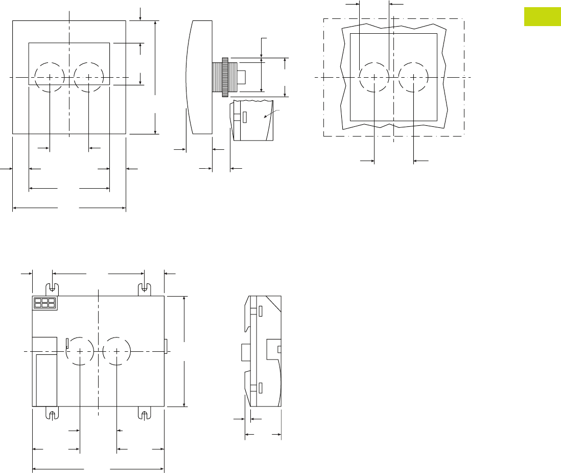
Logic Control Products CA08100001K—June 2012 www.eatoncanada.ca T40-31
40
40
40
40
40
40
40
40
40
40
40
40
40
40
40
40
40
40
40
40
40
40
40
40
40
40
40
40
40
40
40.3
Control Relays and Timers
EASY Intelligent Relays
Dimensions
Approximate Dimensions in Inches (mm)
MFD-80 Series, Drawing Number MD05013005E
MFD-CP8 Series, Drawing Number MD05013006E
3.41
(86.5)
2.44
(62.0)
1.11
(28.3)
1.18 ± 0.01
(30.0) ± 0.2
3.41
(86.5)
1.26
(32.0)
0.67
(17.0)
1.18
(30.0)
0.88 + 0.02
(22.3) + 0.4
0.54
(13.7)
0.79
(20.0)
1.11
(28.3)
0.89
(22.5)
1.18
(30.0)
Template for Holes, Scale 1:1
MFD-80
MFD-CP…
MFD-80
0.640
(16.3)
2.95
(75.0)
3.54
(90.0)
4.23
(107.5)
0.64
(16.3)
0.18
(4.5)
1.53
(38.8)
1.16
(29.5)
1.53
(38.8)
1.18 ± 0.01
(30.0 ± 0.2)
MFD-CP8
Tab40book.fm Page 31 Wednesday, July 4, 2012 10:05 PM
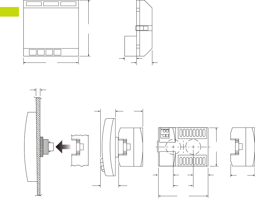
T40-32 Logic Control Products CA08100001K—June 2012 www.eatoncanada.ca
40
40
40
40
40
40
40
40
40
40
40
40
40
40
40
40
40
40
40
40
40
40
40
40
40
40
40
40
40
40
40.3
Control Relays and Timers
EASY Intelligent Relays
Approximate Dimensions in Inches (mm)
MFD-R/MFD-T I/O Module, Drawing Number MD05013007E
MFD-CP4, MFD-80 and MFD-CP4 Series Combined, Drawing Number MD013013E
3.47
(88.1)
3.54
(90.0)
0.75
(19.0) 0.98
(25.0)
MFD-R and MFD-T I/O
2.28
(58.0)
1.18
(30.0)
2.95
(75.0)
0.89
(22.5)
1.43
(36.2)
1.70
(43.2)
1-6 -0.24
(0.04)
1.08
(27.5)
0.81
(20.5)
0.89
(22.5)
MFD-CP4
MFD-80
MFD-CP4
MFD-CP4
Tab40book.fm Page 32 Wednesday, July 4, 2012 10:05 PM
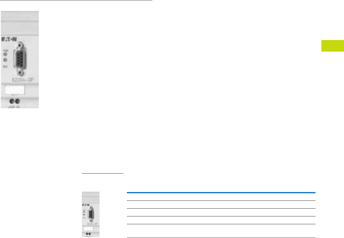
Logic Control Products CA08100001K—June 2012 www.eatoncanada.ca T40-33
40
40
40
40
40
40
40
40
40
40
40
40
40
40
40
40
40
40
40
40
40
40
40
40
40
40
40
40
40
40
40.3
Control Relays and Timers
EASY Intelligent Relays
EASY/MFD Communication Modules Contents
Description Page
EASY500/700/800 Intelligent Relays . . . . . . . . . . . . . . T40-20
EASY/MFD Expansion Modules . . . . . . . . . . . . . . . . . T40-25
MFD Intelligent Relays . . . . . . . . . . . . . . . . . . . . . . . . T40-28
EASY/MFD Communication Modules
Technical Data and Specifications . . . . . . . . . . . . . T40-34
Dimensions . . . . . . . . . . . . . . . . . . . . . . . . . . . . . . T40-35
EASY/MFD Power Supplies, Accessories
and Software . . . . . . . . . . . . . . . . . . . . . . . . . . . . . . . T40-36
EASY/MFD
Communication Modules
Product Description
Five modules are available for
easily connecting to world-
standard networks. The
communication modules can
be used with the EASY700/
800 and MFD intelligent
relays.
Available communication
modules support:
●PROFIBUS-DP
●AS-I (Actuator Sensor
Interface) networks
●CANopen
●DeviceNet
●Ethernet (also compatible
with EASY500)
All modules act as a gateway
and operate exclusively as a
slave station on the network.
Product Selection
EASY Communication Interface Modules
Description
Catalogue
Number
PROFIBUS-DP slave interface module EASY204-DP
AS-Interface slave with 4 in and 4 out interface module EASY205-ASI
CANopen interface module EASY221-CO
DeviceNet slave interface module EASY222-DN
Ethernet Gateway EASY209-SE
EASY204-DP
Communication
Module
Tab40book.fm Page 33 Wednesday, July 4, 2012 10:05 PM

T40-34 Logic Control Products CA08100001K—June 2012 www.eatoncanada.ca
40
40
40
40
40
40
40
40
40
40
40
40
40
40
40
40
40
40
40
40
40
40
40
40
40
40
40
40
40
40
40.3
Control Relays and Timers
EASY Intelligent Relays
Technical Data and Specifications
EASY700/800/MFD Communication Interface Modules
EASY204-DP, EASY205-ASI, EASY221-CO, EASY222-DN, EASY209-SE
Notes
EASY209-SE is also compatible with EASY500 Intelligent Relays.
EASY204-DP dissipates 2W.
Description Specification
Supply voltage 24 Vdc
Heat dissipation 1W
Connection cables
Solid 0.2 – 4.0 mm2 (AWG 22-12)
Flexible 0.2 – 2.5 mm2 (AWG 22-12)
Degree of protection IP20
RFI suppression EN 55011, EN 55022 Class B, IEC 61000-6-1,2,3,4
Ambient operating temperature –25˚ to 55ºC
Transport and storage temperature –40˚ to 70ºC
Certification, standards EN 50178, IEC/EN 60947, UL, CSA
Mounting On top-hat rail to DIN 50022, 35 mm or screw mounting with ZB4-101-GF1 fixing brackets
Tab40book.fm Page 34 Wednesday, July 4, 2012 10:05 PM

Logic Control Products CA08100001K—June 2012 www.eatoncanada.ca T40-35
40
40
40
40
40
40
40
40
40
40
40
40
40
40
40
40
40
40
40
40
40
40
40
40
40
40
40
40
40
40
40.3
Control Relays and Timers
EASY Intelligent Relays
Dimensions
Approximate Dimensions in Inches (mm)
EASY202-RE/EASY200-EASY/EASY205-ASI/
EASY209-SE Series, Drawing Number MD05013012E
EASY221-CO/EASY222-DN Series,
Drawing Number MD05013010E
EASY204-DP Series,
Drawing Number MD05013011E
(M4) 0.157
(3.9) Dia.
0.30
(7.5)
4.33
(110.0)
4.02
(102.0)
3.54
(90.0)
0.30
(7.5)
1.40
(35.5)
1.87
(47.5)
2.22
(56.5)
0.18
(4.5)
1.77
(45.0)
2.28
(58.0)
EASY202-RE
EASY200-EASY
EASY205-ASI
2.64
(67.0)
1.77
(45.0)
0.18
(4.5)
2.22
(56.5)
1.87
(47.5)
(M4) 0.157
(3.9) Dia.
0.30
(7.5)
4.33
(110.0)
4.02
(102.0)
3.54
(90.0)
0.30
(7.5)
1.40
(35.5)
EASY222-DN
EASY221-CO
2.44
(62.0)
1.77
(45.0)
0.18
(4.5)
2.22
(56.5)
1.87
(47.5)
(M4) 0.157
(3.9) Dia.
0.30
(7.5)
4.33
(110.0)
4.02
(102.0)
3.54
(90.0)
0.30
(7.5)
1.40
(35.5)
EASY204-DP
Tab40book.fm Page 35 Wednesday, July 4, 2012 10:05 PM
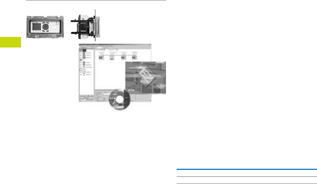
T40-36 Logic Control Products CA08100001K—June 2012 www.eatoncanada.ca
40
40
40
40
40
40
40
40
40
40
40
40
40
40
40
40
40
40
40
40
40
40
40
40
40
40
40
40
40
40
40.3
Control Relays and Timers
EASY Intelligent Relays
EASY/MFD Power Supplies, Accessories and Software Contents
Description Page
EASY500/700/800 Intelligent Relays . . . . . . . . . . . . . . T40-20
EASY/MFD Expansion Modules . . . . . . . . . . . . . . . . . T40-25
MFD Intelligent Relays . . . . . . . . . . . . . . . . . . . . . . . . T40-28
EASY/MFD Communication Modules . . . . . . . . . . . . . T40-33
EASY/MFD Power Supplies, Accessories
and Software
Accessories . . . . . . . . . . . . . . . . . . . . . . . . . . . . . . T40-37
Technical Data and Specifications . . . . . . . . . . . . . T40-38
Wiring Diagram . . . . . . . . . . . . . . . . . . . . . . . . . . . T40-38
Dimensions . . . . . . . . . . . . . . . . . . . . . . . . . . . . . . T40-39
EASY/MFD Power Supplies, Accessories and
Software
Product Description
EASY/MFD Power Supplies
12 Vdc and 24 Vdc power
supplies for applications
where only 100–240 Vac
is available.
EASY/MFD Accessories
Memory modules, cables
and other components to
complete your automation
solutions.
EASYSoft Software
The EASYSoft software is
used to program all of the
EASY and MFD controllers
and displays. The Windows®-
based software provides
straightforward circuit
diagram input and editing
and the diagrams can be
displayed in the format
desired. When EASY800
and MFD controllers are
connected using EASY-NET,
all connected devices can
be accessed and their
programs loaded from a
single controller.
EASYSoft includes an
integrated offline simulation
tool that allows users to
test a circuit diagram
before commissioning.
Product Selection
EASY Power Supplies
Note
See Technical Data and Specifications on Page T40-38 for more information.
Description
Catalogue
Number
100–240 Vac input to 12 Vdc at 20 mA/24 Vdc at 250 mA EASY200-POW
100–240 Vac input to 24 Vdc at 1.25A EASY400-POW
Tab40book.fm Page 36 Wednesday, July 4, 2012 10:05 PM
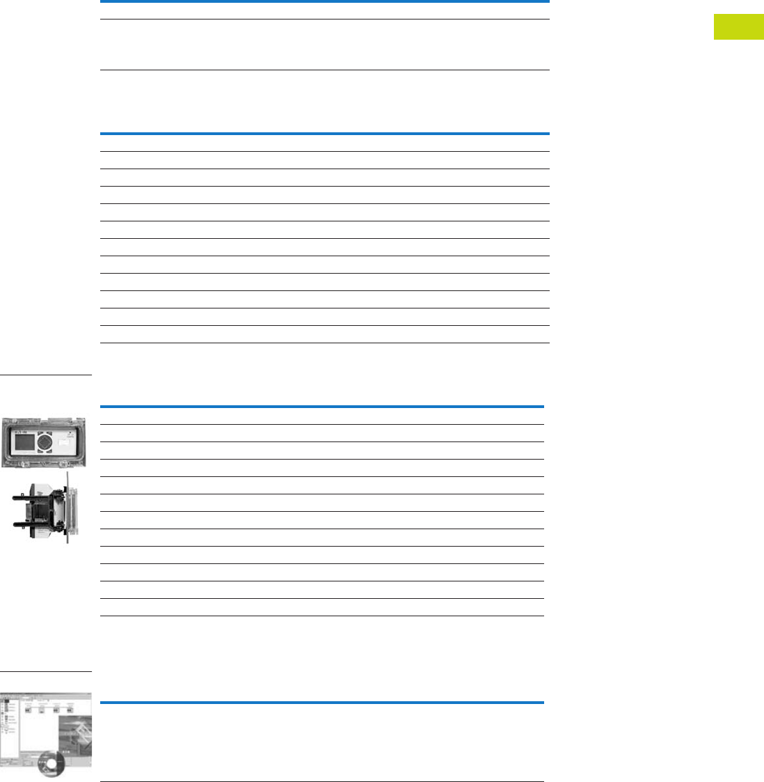
Logic Control Products CA08100001K—June 2012 www.eatoncanada.ca T40-37
40
40
40
40
40
40
40
40
40
40
40
40
40
40
40
40
40
40
40
40
40
40
40
40
40
40
40
40
40
40
40.3
Control Relays and Timers
EASY Intelligent Relays
Accessories
EASY/MFD Memory Storage Modules
EASY/MFD Cables and Connectors
EASY/MFD Miscellaneous Parts
EASY Software
EASY/MFD Software
Note
See Technical Data and Specifications on Page T40-38 for more information.
Description Catalogue Number
EASY500/700 32K memory storage module EASY-M-32K
EASY800/MFD 256K memory storage module EASY-M-256K
Description Catalogue Number
EASY500/700 to PC programming cable RS-232 from PC EASY-PC-CAB
EASY800/MFD to PC programming cable RS-232 from PC EASY800-PC-CAB
EASY500/700 to MFD-CP4 communication cable, 5m MFD-CP4-500-CAB5
EASY800 to MFD-CP8 communication cable, 2m MFD-800-CAB
EASY800 to MFD-CP8 communication cable, 5m MFD-800-CAB5
EASY800 to MFD-CP4 communication cable, 5m MFD-CP4-800-CAB5
EASY800/MFD EASY-NET cable, 0.3m networking cable EASY-NT-30
EASY800/MFD EASY-NET cable, 0.8m networking cable EASY-NT-80
EASY800/MFD EASY-NET cable, 1.5m networking cable EASY-NT-150
EASY800/MFD network termination resistor, 2/pack EASY-NT-R
EASY800/MFD EASY-NET cable (cable only, no connectors, see EASY-NT-RJ45), 100m EASY-NT-CAB
RJ45 network connectors for EASY-NET cable (EASY-NT-CAB), 10/pack EASY-NT-RJ45
Description Catalogue Number
EASY500 relay simulator EASY412-DC-SIM-NA
EASY500 panel window SKF-FF4
EASY700/800 panel window SKF-FF6
EASY500/700/800 panel window mounting kit to front mount units SKF-HA
EASY/MFD panel mount brackets, 9/pack ZB4-101-GF1
EASY/MFD grounding kit ZB4-102-KS1
MFD display DIN rail mount kit MFD-TS144
MFD display protective membrane cover MFD-XM-80
MFD display protective plastic cover MFD-XS-80
EASY/MFD six-channel high current input adapter EASY256-HCI
EASY/MFD spare interface connector, base to expander EASY-LINK-DS
EASY starter kit (includes EASY512-DC-RC, EASY-PC-CAB, EASY412-DC-SIM-NA, EASYSoft) EASYSTARTKIT1
Description Catalogue Number
Programming software for EASY500/700/800 and MFD EASYSOFT
EASY700/500
Panel Window
and Mounting Kit
EASY Software
Tab40book.fm Page 37 Wednesday, July 4, 2012 10:05 PM
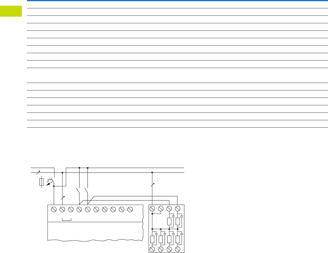
T40-38 Logic Control Products CA08100001K—June 2012 www.eatoncanada.ca
40
40
40
40
40
40
40
40
40
40
40
40
40
40
40
40
40
40
40
40
40
40
40
40
40
40
40
40
40
40
40.3
Control Relays and Timers
EASY Intelligent Relays
Technical Data and Specifications
EASY Power Supplies
Wiring Diagram
EASY256-HCI
Type EASY200-POW EASY400-POW
Supply voltage 100–240 Vac 100–240 Vac
Maximum range 85–264 Vac 85–264 Vac
Output voltage 24 Vdc (±3%) 24 Vdc (±3%)
Output current (rated value) 0.25A 1.25A
Overcurrent limitation form 0.3A 1.4A
Short-circuit proof (secondary) Yes Yes
Overload proof Yes Yes
Potential isolation (prim/sec.) Yes, SELV, (to EN 600950, VDE 805) Yes, SELV, (to EN 600950, VDE 805)
Others Additional output voltage 12 DC, 20 mA Additional output voltage 12 DC, 20 mA
Connection cables
Solid 0.2–4.0 mm2 (AWG 22-12) 0.2–4.0 mm2 (AWG 22-12)
Flexible 0.2–2.5 mm2 (AWG 22-12) 0.2–2.5 mm2 (AWG 22-12)
Degree of protection IP20 IP 20
RFI suppression EN 55011, EN 55022 Class B, IEC 61000-6-1, 2, 3, 4 EN 55011, EN 55022 Class B, IEC 61000-6-1, 2, 3, 4
Ambient operating temperature –25 to 55˚C –25 to 55˚C
Transport and storage temperature –40 to 70˚C –40 to 70˚C
Mounting On top-hat rail to DIN 50022, 35 mm or screw mounting with ZB4-101-GF1 fixing brackets
L
N
> 1 A
S..S..
L
115/230 Vh Input 115/230 Vh
N N I1 I2 I3 I4 I5 NN1 2
3456
.....
EASY5..-AC-..
EASY7..-AC-..
EASY256-HCI
Tab40book.fm Page 38 Wednesday, July 4, 2012 10:05 PM
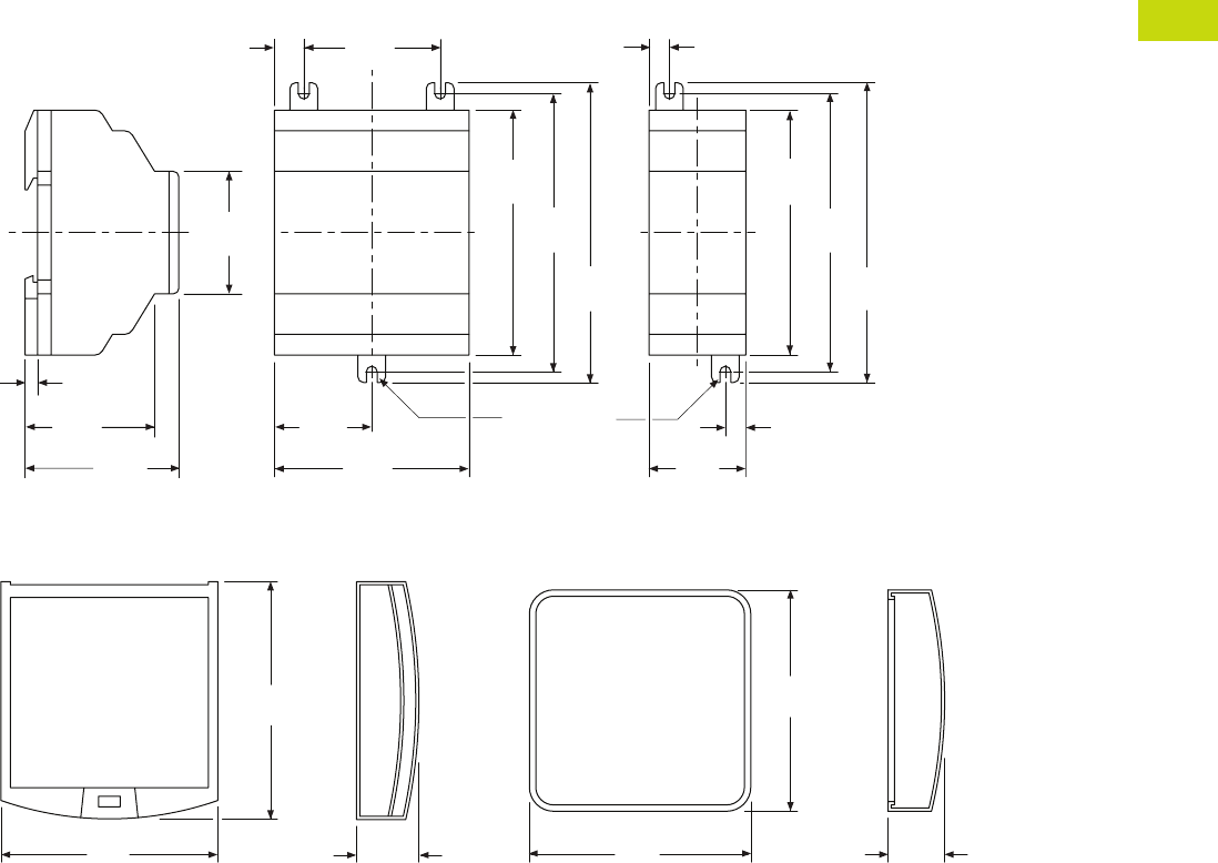
Logic Control Products CA08100001K—June 2012 www.eatoncanada.ca T40-39
40
40
40
40
40
40
40
40
40
40
40
40
40
40
40
40
40
40
40
40
40
40
40
40
40
40
40
40
40
40
40.3
Control Relays and Timers
EASY Intelligent Relays
Dimensions
Approximate Dimensions in Inches (mm)
EASY200-POW/EASY256-HCI and EASY400-POW Series, Drawing Number MD05013004E
MFD-XS-80 and MFD-XM-80 Series, Drawing Number MD05013009E
2.81
(71.5)
1.41
(35.8)
3.54
(90.0)
4.02
(102.0)
4.33
(110.0)
1.97
(50.0)
0.42
(10.8)
1.77
(45.0)
0.18
(4.5)
2.22
(56.5)
1.87
(47.5)
(M4) .157
(3.9) Dia.
0.30
(7.5)
0.30
(7.5)
1.40
(35.5)
3.54
(90.0)
4.02
(102.0)
4.33
(110.0)
EASY400-POW EASY256-HCI
EASY200-POW
0.98
(25.0)
3.74
(95.0)
3.41
(86.5)
3.48
(88.5)
3.48
(88.5)
0.89
(22.5)
MFD-XS-80 MFD-XM-80
Tab40book.fm Page 39 Wednesday, July 4, 2012 10:05 PM

T40-40 Logic Control Products CA08100001K—June 2012 www.eatoncanada.ca
40
40
40
40
40
40
40
40
40
40
40
40
40
40
40
40
40
40
40
40
40
40
40
40
40
40
40
40
40
40
40.3
Control Relays and Timers
EASY Intelligent Relays
Approximate Dimensions in Inches (mm)
SKF-FF4 and SKF-FF6 Series, Drawing Number MD05013014E
SKF-HA Series, Drawing Number MD05013015E
ZB4-101-GF1 Series
3.70
(94.0)
2.99
(76.0)
0.98
(25.0)
0.63
(16.0)
0.63
(16.0)
5.12
(130.0)
2.99
(76.0)
0.98
(25.0)
SKF-FF4 SKF-FF6
2.60
(66.0)
0.43
(11.0)
3.23
(82.0)
1.89
(48.0)
SKF-HA
Fitting on 35 mm Top-Hat Rail Fitting on Mounting Plate (Horizontal)
ZB4-101-GF1
* 3 xing feet sufcient
**
**
Tab40book.fm Page 40 Wednesday, July 4, 2012 10:05 PM
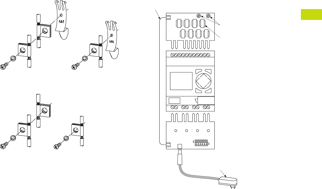
Logic Control Products CA08100001K—June 2012 www.eatoncanada.ca T40-41
40
40
40
40
40
40
40
40
40
40
40
40
40
40
40
40
40
40
40
40
40
40
40
40
40
40
40
40
40
40
40.3
Control Relays and Timers
EASY Intelligent Relays
Approximate Dimensions in Inches (mm)
ZB4-102-KS1 Series—
Grounding the Screen for Top-Hat Rail
ZB4-102-KS1 Series—
Grounding the Screen for Mounting Plate
EASY412-DC-SIM-NA Series
ESC OK
DEL ALT
Digital
Inputs
Connection
Cable
Power
Supply
Unit
Connect
Outputs
Tab40book.fm Page 41 Wednesday, July 4, 2012 10:05 PM
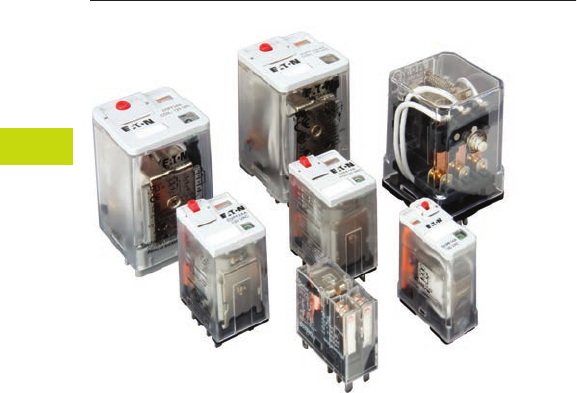
T40-42 Logic Control Products CA08100001K—June 2012 www.eatoncanada.ca
40
40
40
40
40
40
40
40
40
40
40
40
40
40
40
40
40
40
40
40
40
40
40
40
40
40
40
40
40
40
40.4
Control Relays and Timers
General Purpose Plug-In Relays
General Purpose Plug-In Relay Contents
Description Page
D1PR/D1PF Series . . . . . . . . . . . . . . . . . . . . . . . . . . . . T40-46
D2PR/D2PF Series . . . . . . . . . . . . . . . . . . . . . . . . . . . . T40-51
D3PR/D3PF Series . . . . . . . . . . . . . . . . . . . . . . . . . . . . T40-61
D4 Series . . . . . . . . . . . . . . . . . . . . . . . . . . . . . . . . . . . T40-71
D5PR/D5PF Series . . . . . . . . . . . . . . . . . . . . . . . . . . . . T40-75
D7PR/D7PF Series . . . . . . . . . . . . . . . . . . . . . . . . . . . . T40-85
D8 Series . . . . . . . . . . . . . . . . . . . . . . . . . . . . . . . . . . . T40-100
D9 Series . . . . . . . . . . . . . . . . . . . . . . . . . . . . . . . . . . . T40-106
Accessories . . . . . . . . . . . . . . . . . . . . . . . . . . . . . . . . . T40-110
Product Selection Guide
General Purpose Relay Selection Characteristics
●Current rating: 1A–30A
●Contact arrangement:
SPDT, DPDT, 3PDT, 4PDT,
etc.
●Coil voltage: 6V–240 Vac/
6V–110 Vdc
●Mounting options: socket,
flange, DIN rail, panel
●Specifications: CSA, CE,
IEC, NEMA, UL, etc.
●Other: Physical
dimensions, maximum
voltage, mechanical/
electrical life, etc.
Tab40book.fm Page 42 Wednesday, July 4, 2012 10:05 PM

Logic Control Products CA08100001K—June 2012 www.eatoncanada.ca T40-43
40
40
40
40
40
40
40
40
40
40
40
40
40
40
40
40
40
40
40
40
40
40
40
40
40
40
40
40
40
40
40.4
Control Relays and Timers
General Purpose Plug-In Relays
General Purpose Plug-In Relays
Relay Series D1PR/D1PF D2PR/D2PF D3PR/D3PF
Approvals
Features
Polycarbonate cover Polycarbonate cover Polycarbonate cover
Indicator lamp and pushbutton available Indicator lamp and pushbutton available Indicator lamp and pushbutton available
Panel and DIN mounting Panel, DIN and flange mounting Panel and DIN mounting
Latching 8- or 11-pin octal plug-in
Latching (D3PR version)
Contact Data
Configuration SPDT DPDT DPDT Latching 4PDT DPDT 3PDT
Max. allowable load 20A 10A 10A 10A 16A 16A 16A
Material Silver alloy Silver alloy Silver alloy
Dielectric strength
between poles
1500V 1500V 1500V
Coil Data
AC 6 to 240 Vac 6 to 240 Vac 6 to 240 Vac
DC 6 to 110 Vdc 6 to 110 Vdc 6 to 110 Vdc
Power
VA (Vac) 0.9 VA 1.2 VA 3 VA 1.4W (D3PR and D3PF)
Watts (Vdc) 0.7W 0.9W 2 VA 1.64W (D3PR5 latching)
General Data
Ambient temperature
Storage –40˚ to 185˚F (–40˚ to 85˚C) –40˚ to 185˚F (–40˚ to 85˚C) –40˚ to 185˚F (–40˚ to 85˚C)
Operational –40˚ to 131˚F (–40˚ to 55˚C) –40˚ to 131˚F (–40˚ to 55˚C) –40˚ to 131˚F (–40˚ to 55˚C)
Response time 20 milliseconds 20 milliseconds 20 milliseconds
Life
Mechanical operations 10 million 10 million 5 million (D3PR and D3PF)
10 million (D3PR5 latching)
Electrical operations 100,000 200,000 100,000
Page Numbers T40-46 to T40-50 T40-51 to T40-60 T40-61 to T40-70
Tab40book.fm Page 43 Wednesday, July 4, 2012 10:05 PM
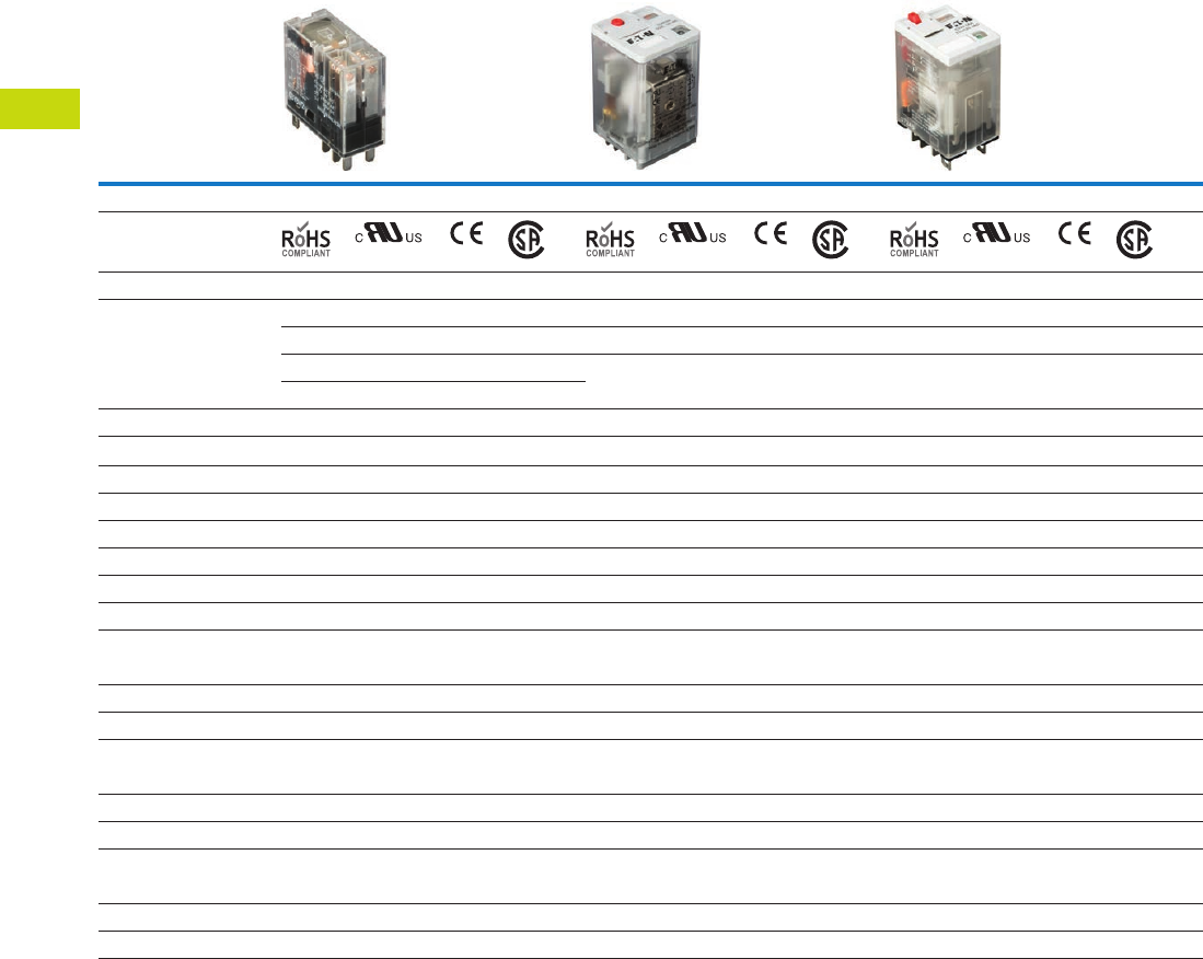
T40-44 Logic Control Products CA08100001K—June 2012 www.eatoncanada.ca
40
40
40
40
40
40
40
40
40
40
40
40
40
40
40
40
40
40
40
40
40
40
40
40
40
40
40
40
40
40
40.4
Control Relays and Timers
General Purpose Plug-In Relays
General Purpose Plug-In Relays, continued
Relay Series D4 D5PR/D5PF D7PR/D7PF
Approvals
Features
Polycarbonate cover Polycarbonate cover Polycarbonate cover
Indicator lamp available Indicator lamp and pushbutton available Indicator lamp and pushbutton available
Panel and DIN mounting Panel, DIN and flange mounting Panel and DIN mounting
Socket has built-in hold-down spring
Contact Data
Configuration SPDT DPDT DPDT 3PDT SPDT DPDT 3PDT 4PDT
Max. allowable load 10A at 250 Vac 5A at 240 Vac 16A 16A 20A 15A 15A 15A
Material AgCdO Silver alloy Silver alloy
Dielectric strength 5000V 1500V 1500V 1500V 2500V 2500V
Coil Data
AC 6 to 240 Vac 6 to 240 Vac 6 to 240 Vac
DC 6 to 110 Vdc 6 to 110 Vdc 6 to 110 Vdc
Power
VA (Vac) 0.9 VA 3 VA 1.2 VA 1.2 VA 1.5 VA 1.5 VA
Watts (Vdc) 0.5W 1.4W 0.9W 0.9W 1.4W 1.5W
General Data
Ambient temperature
Storage –40˚ to 158˚F (–40˚ to 70˚C) –40˚ to 185˚F (–40˚ to 85˚C) –40˚ to 185˚F (–40˚ to 85˚C)
Operational –40˚ to 158˚F (–40˚ to 70˚C) –40˚ to 131˚F (–40˚ to 55˚C) –40˚ to 131˚F (–40˚ to 55˚C)
Response time 15 milliseconds 20 milliseconds 20 milliseconds (30 milliseconds for latching)
Life
Mechanical operations 10 million 5 million 10 million
Electrical operations 100,000 100,000 100,000 100,000 200,000 200,000
Page Numbers T40-71 to T40-74 T40-75 to T40-84 T40-85 to T40-99
Tab40book.fm Page 44 Wednesday, July 4, 2012 10:05 PM
Logic Control Products CA08100001K—June 2012 www.eatoncanada.ca T40-45
40
40
40
40
40
40
40
40
40
40
40
40
40
40
40
40
40
40
40
40
40
40
40
40
40
40
40
40
40
40
40.4
Control Relays and Timers
General Purpose Plug-In Relays
General Purpose Plug-In Relays, continued
Relay Series D8 D9
Approvals
Features
Dust cover Dust cover
Panel, DIN and flange mounting Pushbutton available
Quick-connect and screw terminals Panel mounting
Screw terminals
Contact Data
Configuration
SPST-NO DPST-NO
4PST
NO NC
Max. allowable load 30A at
220 Vac
25A at
220 Vac
25A at
220 Vac
8A at
220 Vac
Material AgCdO AgCdO
Dielectric strength 4000V 4000V
Coil Data
AC 6 to 240 Vac 24 to 240 Vac
DC 12 to 24 Vdc 12 to 110 Vdc
Power
VA (Vac) 2.5 VA 2.6 VA
Watts (Vdc) 1.9W 2.0W
General Data
Ambient temperature
Storage –4˚ to 185˚F (–20˚ to 85˚C) –13˚ to 140˚F (–25˚ to 60˚C)
Operational –4˚ to 131˚F (–20˚ to 55˚C) –13˚ to 140˚F (–25˚ to 60˚C)
Response time 30 milliseconds 50 milliseconds
Life
Mechanical operations 5 million 1 million
Electrical operations 100,000 100,000
Page Numbers T40-100 to T40-105 T40-106 to T40-109
Tab40book.fm Page 45 Wednesday, July 4, 2012 10:05 PM
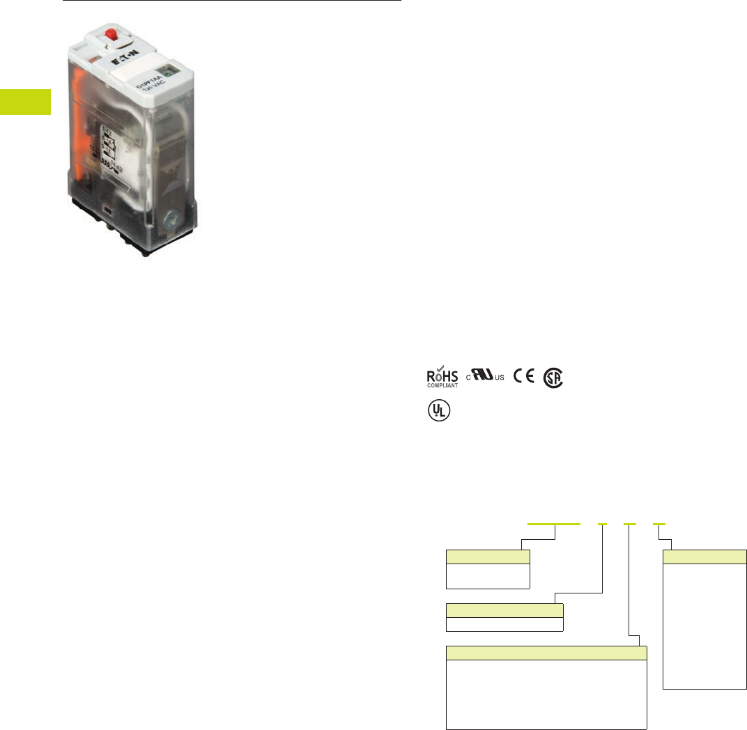
T40-46 Logic Control Products CA08100001K—June 2012 www.eatoncanada.ca
40
40
40
40
40
40
40
40
40
40
40
40
40
40
40
40
40
40
40
40
40
40
40
40
40
40
40
40
40
40
40.4
Control Relays and Timers
General Purpose Plug-In Relays
D1 Series Relay Contents
Description Page
D1PR/D1PF Series
Product Selection . . . . . . . . . . . . . . . . . . . . . . . . . . T40-47
Accessories. . . . . . . . . . . . . . . . . . . . . . . . . . . . . . . T40-48
Technical Data and Specifications . . . . . . . . . . . . . . T40-49
Wiring Diagram . . . . . . . . . . . . . . . . . . . . . . . . . . . . T40-50
Dimensions . . . . . . . . . . . . . . . . . . . . . . . . . . . . . . . T40-50
D2PR/D2PF Series . . . . . . . . . . . . . . . . . . . . . . . . . . . . T40-51
D3PR/D3PF Series . . . . . . . . . . . . . . . . . . . . . . . . . . . . T40-61
D4 Series . . . . . . . . . . . . . . . . . . . . . . . . . . . . . . . . . . . T40-71
D5PR/D5PF Series . . . . . . . . . . . . . . . . . . . . . . . . . . . . T40-75
D7PR/D7PF Series . . . . . . . . . . . . . . . . . . . . . . . . . . . . T40-85
D8 Series . . . . . . . . . . . . . . . . . . . . . . . . . . . . . . . . . . . T40-100
D9 Series . . . . . . . . . . . . . . . . . . . . . . . . . . . . . . . . . . . T40-106
Accessories . . . . . . . . . . . . . . . . . . . . . . . . . . . . . . . . . T40-110
D1PR/D1PF Series
Product Description
The D1 Series of relay
provides a compact single-
pole relay capable of handling
20A. Multiple feature and
voltage options allow for the
perfect fit for any application.
Features
D1PR
●Compact relay capable of
breaking relatively large
load currents
●Panel and DIN rail
mounting
D1PF
●The contact operation
can be easily checked by
Push-to-Test button
●Flag indicator shows relay
status in manual or
powered condition
●LED status lamp shows
coil ON or OFF status—
ideal for use in low light
applications
●Push-to-Test button allows
for manual operation of
relay without the need for
coil power
●Lock-down door holds
pushbutton and contacts in
the operate position when
activated
●Finger-grip cover allows
operator to remove relays
from sockets easily
●ID tag/write label to
identify relays in multiple-
relay circuits
●Bipolar LED allows for
reverse polarity
applications
Standards and Certifications
When used with
accompanying Eaton
screw terminal socket.
Catalogue Number Selection
D1PR/D1PF Series
UL Listed
D
1
P
F
1
A A
Family Type
D1PF
D1PR
Contact Configuration
1 = SPDT
Standard Features
Blank = Mechanical flag indicator
(only with D1PR)
A = LED test button, flag indicator,
lock-down door, finger-grip cover,
ID tag (only with D1PF)
1 = LED and mechanical flag indicator
Coil Voltage
A = 120 Vac
A1 = 110 Vdc
B = 240 Vac
P = 6 Vac
P1 = 6 Vdc
R = 12 Vac
R1 = 12 Vdc
T = 24 Vac
T1 = 24 Vdc
W = 48 Vac
W1 = 48 Vdc
Tab40book.fm Page 46 Wednesday, July 4, 2012 10:05 PM
Logic Control Products CA08100001K—June 2012 www.eatoncanada.ca T40-47
40
40
40
40
40
40
40
40
40
40
40
40
40
40
40
40
40
40
40
40
40
40
40
40
40
40
40
40
40
40
40.4
Control Relays and Timers
General Purpose Plug-In Relays
Product Selection
D1PR/D1PF Relay/Socket Quick Reference
D1PR/D1PF Series
Relay
Type Socket Clip
Module
Type
ID
Tag Jumper
D1PR1 D1PAA PMC-1781 B — —
D1PF1 D1PAA PMC-1781 B — —
Coil
Voltage
Contact
Configuration
Coil Resistance
(Ohms)
Catalogue
Number
Full Featured
6 Vac SPDT 12.2 D1PF1AP
6 Vdc SPDT 47 D1PF1AP1
12 Vac SPDT 46 D1PF1AR
12 Vdc SPDT 188 D1PF1AR1
24 Vac 50/60 Hz SPDT 180 D1PF1AT
24 Vdc SPDT 750 D1PF1AT1
48 Vac SPDT 720 D1PF1AW
48 Vdc SPDT 2600 D1PF1AW1
110 Vdc SPDT 13,800 D1PF1AA1
120 Vac 50/60 Hz SPDT 4430 D1PF1AA
240 Vac 50/60 Hz SPDT 15,720 D1PF1AB
Plain Cover with LED Indicator
6 Vac SPDT 12.2 D1PR11P
6 Vdc SPDT 47 D1PR11P1
12 Vac SPDT 46 D1PR11R
12 Vdc SPDT 188 D1PR11R1
24 Vac 50/60 Hz SPDT 180 D1PR11T
24 Vdc SPDT 750 D1PR11T1
48 Vac SPDT 720 D1PR11W
48 Vdc SPDT 2600 D1PR11W1
240 Vac 50/60 Hz SPDT 15,720 D1PR11B
110 Vdc SPDT 13,800 D1PR11A1
120 Vac SPDT 4430 D1PR11A
24 Vac 50/60 Hz SPDT 180 D1PR1T
Plain Cover
6 Vac SPDT 12.2 D1PR1P
6 Vdc SPDT 47 D1PR1P1
12 Vac SPDT 46 D1PR1R
12 Vdc SPDT 188 D1PR1R1
24 Vdc SPDT 750 D1PR1T1
48 Vac SPDT 720 D1PR1W
48 Vdc SPDT 2600 D1PR1W1
110 Vdc SPDT 13,800 D1PR1A1
120 Vac 50/60 Hz SPDT 4430 D1PR1A
240 Vac SPDT 15,270 D1PR1B
D1PF Series Relay
Tab40book.fm Page 47 Wednesday, July 4, 2012 10:05 PM

T40-48 Logic Control Products CA08100001K—June 2012 www.eatoncanada.ca
40
40
40
40
40
40
40
40
40
40
40
40
40
40
40
40
40
40
40
40
40
40
40
40
40
40
40
40
40
40
40.4
Control Relays and Timers
General Purpose Plug-In Relays
Accessories
D1PR/D1PF Sockets and Accessories
Note
Protection Category (Finger Safe), EN 60529: IP20.
Type
Module
Size
Nominal Voltage
(Max. for Sockets)
Nominal
Current Mounting Style Wire Size
Wire
Connection
Standard
Pack
Catalogue
Number
Socket B 300 20 Panel/DIN rail 12 /14 (2) AWG, 4 /2.5 (2) mm2Screw clamping 10 D1PAA
Flange mount adapter — — — Flange — — 25 PFC-D11
Metal spring clip — — — — — — 25 PMC-1781
Protection diode B 6 to 250 Vdc — — — — 20 MOD-BD250
LED indicator B 24 Vac/Vdc — — — — 20 MOD-BLG24
B 120/240 Vac/Vdc — — — — 20 MOD-BLG240
MOV suppressor B 120 Vac/Vdc — — — — 20 MOD-BMV120
B 24 Vac/Vdc — — — — 20 MOD-BMV24
B 240 Vac/Vdc — — — — 20 MOD-BMV240
Plastic DIN rail end stop — — — — — — 25 PFP-P
Tab40book.fm Page 48 Wednesday, July 4, 2012 10:05 PM

Logic Control Products CA08100001K—June 2012 www.eatoncanada.ca T40-49
40
40
40
40
40
40
40
40
40
40
40
40
40
40
40
40
40
40
40
40
40
40
40
40
40
40
40
40
40
40
40.4
Control Relays and Timers
General Purpose Plug-In Relays
Technical Data and Specifications
D1PF/D1PR Relay Specifications
Description D1PR D1PF
Contact Characteristics
Contact rating 20A 20A
Terminal style Plug-in Plug-in
Contact materials Silver alloy Silver alloy
Maximum switching voltage 300V 300V
Switching current at voltage—resistive 20A at 120 Vac 50/60 Hz 20A at 120 Vac 50/60 Hz
20A at 277 Vac 50/60 Hz 20A at 277 Vac 50/60 Hz
20A at 28 Vdc 20A at 28 Vdc
Switching current at voltage 1/2 hp at 120 Vac 1/2 hp at 120 Vac
1 hp at 277 Vac 1 hp at 277 Vac
Pilot duty B300 B300
Minimum switching requirement 100 mA at 5 Vdc (0.5W) 100 mA at 5 Vdc (0.5W)
Coil Characteristics
Operating range
% of nominal (AC) 85 to 110% 85 to 110%
% of nominal (DC) 80 to 110% 80 to 110%
Average consumption 0.9 VA 0.9 VA
0.7W 0.7W
Dropout voltage threshold 15% (AC) 15% (AC)
10% (DC) 10% (DC)
Performance
Electrical life (UL 508) operations at rated current 100,000 operations 100,000 operations
Mechanical life operations unpowered 10,000,000 operations 10,000,000 operations
Response time 20 ms 20 ms
Dielectric strength
Between coil and contact Vac (rms) 2500V (rms) 2500V (rms)
Between poles Vac (rms) 1500V (rms) 1500V (rms)
Environment
Ambient air temperature around the device
Storage –40˚ to 131˚F (–40˚ to 55ºC) –40˚ to 131˚F (–40˚ to 55˚C)
Operation –40˚ to 185˚F (–40˚ to 85ºC) –40˚ to 185˚F (–40˚ to 85˚C)
Vibration resistance—operational 3 g-n at 10–55 Hz 3 g-n at 10–55 Hz
Shock resistance 10 g-n 10 g-n
Degree of protection IP40 IP40
Features
Cover options Plain cover Full featured
Features Mechanical flag indicator (optional LED) Locking pushbutton/
Bipolar LED/
Removable ID tag/
Mechanical flag indicator
Product certifications RoHS/UL/CE/CSA RoHS/UL/CE/CSA
Tab40book.fm Page 49 Wednesday, July 4, 2012 10:05 PM
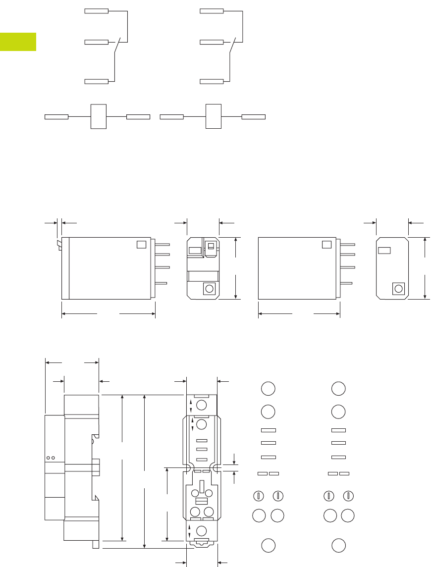
T40-50 Logic Control Products CA08100001K—June 2012 www.eatoncanada.ca
40
40
40
40
40
40
40
40
40
40
40
40
40
40
40
40
40
40
40
40
40
40
40
40
40
40
40
40
40
40
40.4
Control Relays and Timers
General Purpose Plug-In Relays
Wiring Diagram
D1PF/D1PR
Dimensions
Approximate Dimensions in Inches (mm)
D1PF/D1PR
D1PAA
NEMA
1
5
9
13 14
IEC
12
14
11
A1 A2
0.10
(2.1)
0.53
(14.0)
1.10
(27.9)
1.60
(40.6)
0.53
(14.0)
1.10
(27.9)
1.40
(35.5)
1.57
(40.0)
1.18
(30.0)
0.74
(19.0)
0.67
(17.0)
3.33
(84.0)
3.14
(80.0)
0.82
(21.0)
0.16
(4.0)
9
14 13
1
5
COM
N.C.
N.O.
14 13
Module
Input
Input
1
5
Input
9
Input
NEMA
11
A2 A1
12
14
COM
N.C.
N.O.
14 13
Module
Input
Input
1
5
Input
9
Input
IEC
Tab40book.fm Page 50 Wednesday, July 4, 2012 10:05 PM
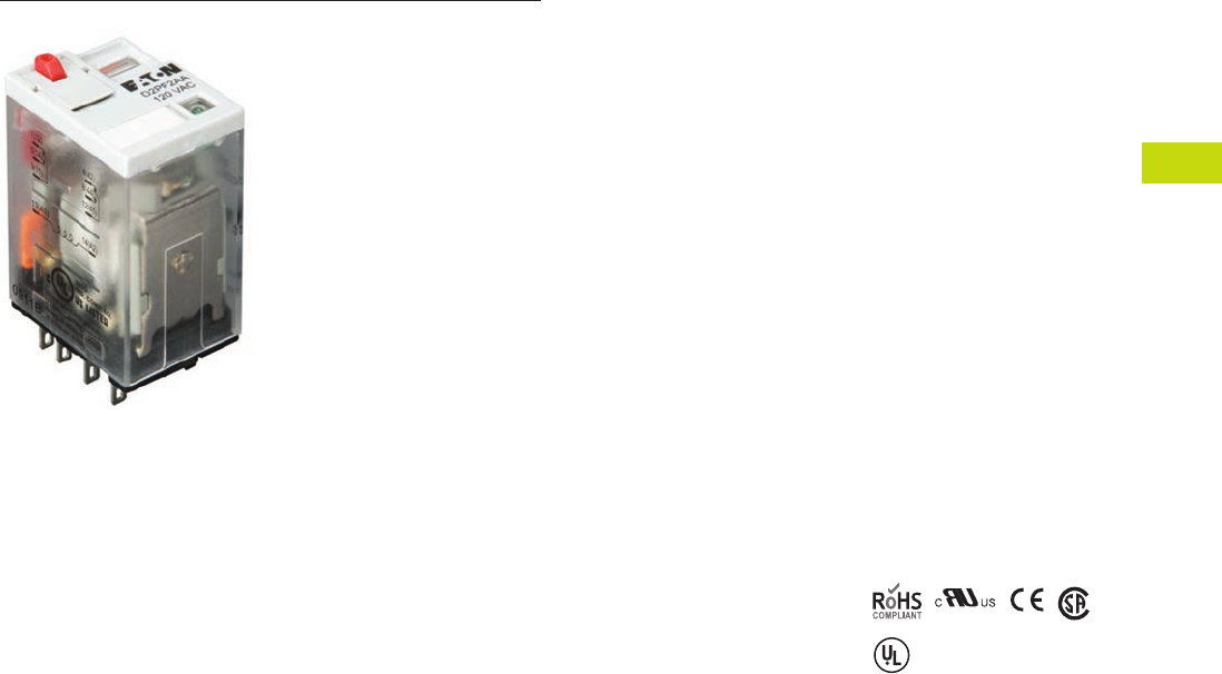
Logic Control Products CA08100001K—June 2012 www.eatoncanada.ca T40-51
40
40
40
40
40
40
40
40
40
40
40
40
40
40
40
40
40
40
40
40
40
40
40
40
40
40
40
40
40
40
40.4
Control Relays and Timers
General Purpose Plug-In Relays
D2 Series Relay Contents
Description Page
D1PR/D1PF Series . . . . . . . . . . . . . . . . . . . . . . . . . . . . T40-46
D2PR/D2PF Series
Catalogue Number Selection. . . . . . . . . . . . . . . . . . T40-52
Product Selection . . . . . . . . . . . . . . . . . . . . . . . . . . T40-52
Accessories . . . . . . . . . . . . . . . . . . . . . . . . . . . . . . . T40-54
Technical Data and Specifications . . . . . . . . . . . . . . T40-55
Wiring Diagrams . . . . . . . . . . . . . . . . . . . . . . . . . . . T40-56
Dimensions . . . . . . . . . . . . . . . . . . . . . . . . . . . . . . . T40-57
D3PR/D3PF Series . . . . . . . . . . . . . . . . . . . . . . . . . . . . T40-61
D4 Series . . . . . . . . . . . . . . . . . . . . . . . . . . . . . . . . . . . T40-71
D5PR/D5PF Series . . . . . . . . . . . . . . . . . . . . . . . . . . . . T40-75
D7PR/D7PF Series . . . . . . . . . . . . . . . . . . . . . . . . . . . . T40-85
D8 Series . . . . . . . . . . . . . . . . . . . . . . . . . . . . . . . . . . . T40-100
D9 Series . . . . . . . . . . . . . . . . . . . . . . . . . . . . . . . . . . . T40-106
Accessories . . . . . . . . . . . . . . . . . . . . . . . . . . . . . . . . . T40-110
D2PR/D2PF Series
Product Description
The D2 Series is a compact
line of relays with quick
response time and long life.
Available in DPDT, 4PDT and
DPDT latching configurations.
Features
D2PR
●Ultra-high sensitivity relay
with quick response
●High reliability, long life
●Panel, DIN rail and flange
mounting
●Small size
D2PF
●
Flag indicator shows relay
status in manual or powered
condition
●
Bipolar LED status lamp
allows for reverse polarity
applications
●
Shows coil ON or OFF
status
●
Ideal in low light
conditions
●
Colour-coded pushbutton
identifies AC coils with red
or DC coils with blue
pushbuttons
●
Allows for manual
operation of relay without
the need for coil power
●
Ideal for field service
personnel to test control
circuits
●
Lock-down door, when
activated, holds pushbutton
and contacts in the operate
position
●
Excellent for analyzing
circuit problems
●
Finger-grip cover allows
operator to remove relays
from sockets more easily
than conventional relays
●
White plastic ID tag/write
label used for identification
of relays in multi-relay
circuits
Standards and Certifications
When used with
accompanying Eaton
screw terminal socket.
UL Listed
Tab40book.fm Page 51 Wednesday, July 4, 2012 10:05 PM
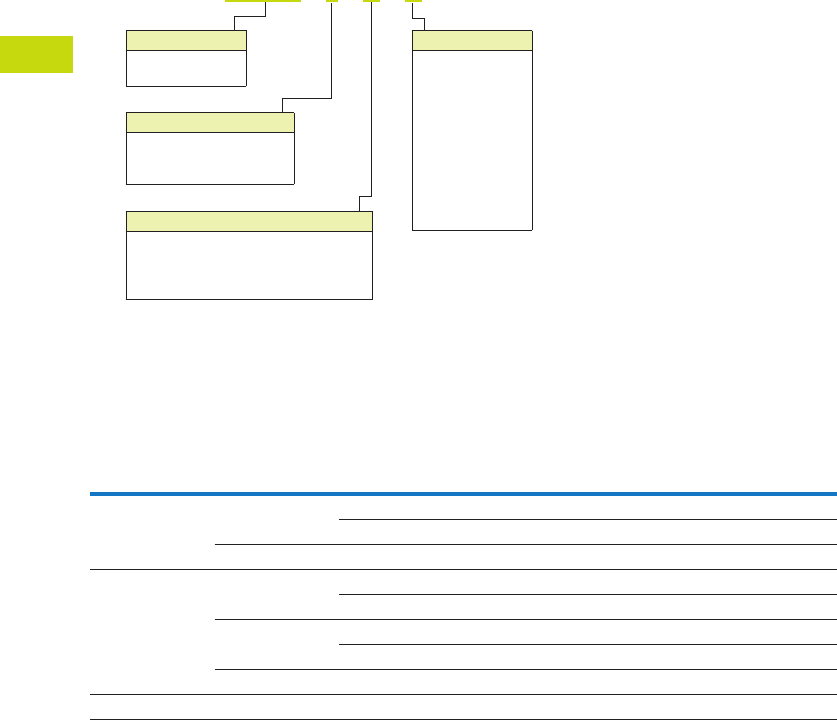
T40-52 Logic Control Products CA08100001K—June 2012 www.eatoncanada.ca
40
40
40
40
40
40
40
40
40
40
40
40
40
40
40
40
40
40
40
40
40
40
40
40
40
40
40
40
40
40
40.4
Control Relays and Timers
General Purpose Plug-In Relays
Catalogue Number Selection
D2PF/D2PR
Product Selection
D2PF/D2PR Relay/Socket Quick Reference
Note
For deciphering catalogue numbers. Do not use for ordering as not all combinations are readily available.
Relay
Type Socket Clip
Module
Type
ID
Tag Jumper
D2PR2, D2PF2 D2PAL PWC-D24 B PWF-D2P D2PJ1
PQC-1782 — — —
D2PA6 PQC-1342 None — —
D2PR4, D2PF4 D2PAP PWC-D24 B PWF-D2P D2PJ1
PQC-1782 — — —
D2PA7 PWC-D24 B — —
PQC-1782 B — —
D2PA6 PQC-1342 None — —
D2PR5 D2PA4 PYC-A1 None — —
Family Type
D2PF
D2PR
Contact Configuration
2 = DPDT
4 = 4PDT
5 = DPDT latching
Standard Features
Blank = Plain cover (only with D2PR)
A = LED test button, flag indicator,
lock-down door, finger-grip cover,
ID tag (only with D2PF)
D 2 P F 2 A A
Coil Voltage
A = 120 Vac
A1 = 110 Vdc
B = 240 Vac
P = 6 Vac
P1 = 6 Vdc
R = 12 Vac
R1 = 12 Vdc
T = 24 Vac
T1 = 24 Vdc
W = 48 Vac
W1 = 48 Vdc
Tab40book.fm Page 52 Wednesday, July 4, 2012 10:05 PM
Logic Control Products CA08100001K—June 2012 www.eatoncanada.ca T40-53
40
40
40
40
40
40
40
40
40
40
40
40
40
40
40
40
40
40
40
40
40
40
40
40
40
40
40
40
40
40
40.4
Control Relays and Timers
General Purpose Plug-In Relays
D2PF/D2PR Series
Coil
Voltage
Contact
Configuration
Coil Resistance
(Ohms)
Catalogue
Number
Full Featured Style
6 Vac DPDT 9.6 D2PF2AP
6 Vdc DPDT 40 D2PF2AP1
12 Vac DPDT 46 D2PF2AR
12 Vdc DPDT 160 D2PF2AR1
24 Vac DPDT 180 D2PF2AT
24 Vdc DPDT 650 D2PF2AT1
48 Vdc DPDT 2600 D2PF2AW1
110/125 Vdc DPDT 11,000 D2PF2AA1
120 Vac DPDT 4430 D2PF2AA
220/240 Vac DPDT 15,720 D2PF2AB
12 Vac 4PDT 46 D2PF4AR
12 Vdc 4PDT 160 D2PF4AR1
24 Vac 4PDT 180 D2PF4AT
24 Vdc 4PDT 650 D2PF4AT1
48 Vdc 4PDT 2600 D2PF4AW1
110/125 Vdc 4PDT 11,000 D2PF4AA1
120 Vac 4PDT 4430 D2PF4AA
220/240 Vac 4PDT 15,720 D2PF4AB
Plain Cover Style
6 Vdc DPDT 40 D2PR2P1
12 Vdc DPDT 160 D2PR2R1
24 Vac DPDT 180 D2PR2T
24 Vdc DPDT 650 D2PR2T1
48 Vdc DPDT 2600 D2PR2W1
110/125 Vdc DPDT 11,000 D2PR2A1
120 Vac DPDT 4430 D2PR2A
220/240 Vac DPDT 15,720 D2PR2B
6 Vac 4PDT 9.6 D2PR4P
6 Vdc 4PDT 40 D2PR4P1
12 Vac 4PDT 46 D2PR4R
12 Vdc 4PDT 160 D2PR4R1
24 Vac 4PDT 180 D2PR4T
24 Vdc 4PDT 650 D2PR4T1
110/125 Vdc 4PDT 11,000 D2PR4A1
120 Vac 4PDT 4430 D2PR4A
220/240 Vac 4PDT 15,720 D2PR4B
Latching Style
24 Vac DPDT 180 D2PR5T
24 Vdc DPDT 650 D2PR5T1
110 Vac DPDT 11,000 D2PR5A
D2PF Series Relay
Tab40book.fm Page 53 Wednesday, July 4, 2012 10:05 PM

T40-54 Logic Control Products CA08100001K—June 2012 www.eatoncanada.ca
40
40
40
40
40
40
40
40
40
40
40
40
40
40
40
40
40
40
40
40
40
40
40
40
40
40
40
40
40
40
40.4
Control Relays and Timers
General Purpose Plug-In Relays
Accessories
D2PF/D2PR Sockets and Accessories
Note
Protection category (finger safe), EN 60529: IP20.
Type
Module
Size
Nominal Voltage
(Max. for Sockets)
Nominal
Current Mounting Style Wire Size
Wire
Connection
Standard
Pack
Catalogue
Number
Socket B 300 12 DIN rail/panel 14/16 (2) AWG, 2.5/1.5 (2) mm2Elevator 1 D2PAL
None 300 10 DIN rail/panel 12/14 (2) AWG, 4/2.5 (2) mm2Screw clamping 10 D2PA6
B 300 10 DIN rail/panel 14/16 (2) AWG, 2.5/1.5 (2) mm2Elevator 1 D2PAP
B 300 10 DIN rail/panel 12/14 (2) AWG, 4/2.5 (2) mm2Screw clamping 10 D2PA7
None 300 10 DIN rail/panel 12/14 (2) AWG, 4/2.5 (2) mm2Screw clamping 5 D2PA4
Flange mount adapter — — — Flange — — 25 PFC-D2D72
Plastic ejector clip — — — — — — 10 PWC-D24
Metal spring clip — — — — — — 25 PQC-1782
—— —— — — 25 PQC-1342
Hold-down spring — — — — — — 100 PYC-A1
Protection diode B 6 to 250 Vdc — — — — 20 MOD-BD250
LED indicator B 24 Vac/Vdc — — — — 20 MOD-BLG24
B 120/240 Vac/Vdc — — — — 20 MOD-BLG240
MOV suppressor B 120 Vac/Vdc — — — — 20 MOD-BMV120
B 24 Vac/Vdc — — — — 20 MOD-BMV24
B 240 Vac/Vdc — — — — 20 MOD-BMV240
Coil bus jumpers — — — — — — 10 D2PJ1
Plastic DIN rail end stop — — — — — — 25 PFP-P
Tab40book.fm Page 54 Wednesday, July 4, 2012 10:05 PM

Logic Control Products CA08100001K—June 2012 www.eatoncanada.ca T40-55
40
40
40
40
40
40
40
40
40
40
40
40
40
40
40
40
40
40
40
40
40
40
40
40
40
40
40
40
40
40
40.4
Control Relays and Timers
General Purpose Plug-In Relays
Technical Data and Specifications
D2PF/D2PR Relay Specifications
Description D2PR2/D2PR4 D2PR5 D2PF
Contact Characteristics
Contact rating 10A 5A 10A
Terminal style Plug-in Plug-in Plug-in
Contact materials Silver alloy Silver (gold flashed) Silver alloy
Maximum switching voltage 300V 250 Vac/125 Vdc 300V
Switching current at voltage—resistive 10A at 120 Vac
50/60 Hz
3A at 250 Vac 10A at 277 Vac
50/60 Hz|
8A at 277 Vac
50/60 Hz
— 8A at 120 Vac
50/60 Hz
8A at 28 Vdc 5A at 30 Vdc 8A at 28 Vdc
Switching current at voltage 1/3 hp at 120 Vac
1 hp at 277 Vac
1/8 hp at 250 Vac 1/3 hp at 120 Vac
1 hp at 277 Vac
Pilot duty B300 — B300
Minimum switching requirement 100 mA at 5 Vdc
(0.5W)
100 mA, 1 Vdc 100 mA at 5 Vdc
(0.5W)
Coil Characteristics
Operating range
% of nominal (AC) 85 to 110% 80 to 110% 85 to 110%
% of nominal (DC) 80 to 110% 80 to 110% 80 to 110%
Average consumption 1.2 VA — 1.2 VA
0.9W — 0.9W
Dropout voltage threshold 15% (AC) 30% (AC) 15% (AC)
10% (DC) 10% (DC) 10% (DC)
Performance
Electrical life (UL 508) operations at rated current 200,000 200,000 200,000
Mechanical life operations unpowered 10,000,000 100,000,000 10,000,000
Response time 20 ms — 20 ms
Dielectric strength
Between coil and contact Vac (rms) 1500 rms — 1500 rms
Between poles Vac (rms) 1500 rms — 1500 rms
Environment
Ambient air temperature around the device
Operation –40˚ to 131˚F (–40˚ to 55˚C) — –40˚ to 131˚F (–40˚ to 55˚C)
Storage –40˚ to 185˚F (–40˚ to 85˚C) — –40˚ to 185˚F (–40˚ to 85˚C)
Vibration resistance—operational 3 g-n at 10–55 Hz — 3 g-n at 10–55 Hz
Shock resistance 10 g-n — 10 g-n
Degree of protection IP40 — IP40
Features
Cover options Plain cover Plain cover Full featured
Features Mechanical flag indicator Latching Locking pushbutton/
Bipolar LED/
Removable ID tag/
Mechanical flag indicator
Product certifications RoHS/UL/CE/CSA UL/CE/CSA RoHS/UL/CE/CSA
Tab40book.fm Page 55 Wednesday, July 4, 2012 10:05 PM

T40-56 Logic Control Products CA08100001K—June 2012 www.eatoncanada.ca
40
40
40
40
40
40
40
40
40
40
40
40
40
40
40
40
40
40
40
40
40
40
40
40
40
40
40
40
40
40
40.4
Control Relays and Timers
General Purpose Plug-In Relays
Wiring Diagrams
D2PF2/D2PR2
D2PF4/D2PR4
NEMA
1
5
9
4
8
12
13 14
IEC
42
44
41
12
14
11
A1 A2
IEC
42
44
41
32
34
31
22
24
21
12
14
11
A1 A2
NEMA
4
8
12
3
7
11
2
6
10
1
5
9
13 14
Tab40book.fm Page 56 Wednesday, July 4, 2012 10:05 PM
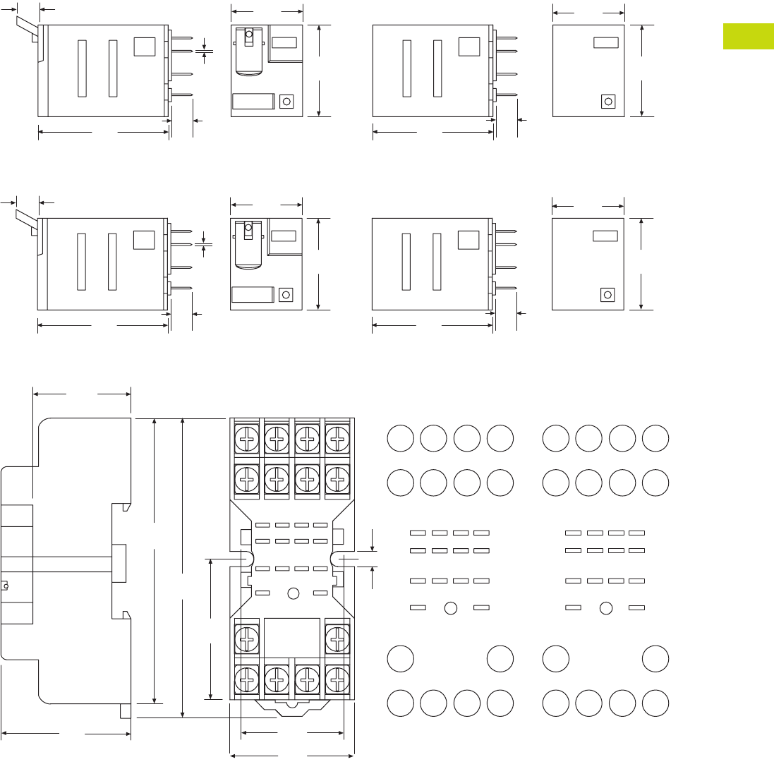
Logic Control Products CA08100001K—June 2012 www.eatoncanada.ca T40-57
40
40
40
40
40
40
40
40
40
40
40
40
40
40
40
40
40
40
40
40
40
40
40
40
40
40
40
40
40
40
40.4
Control Relays and Timers
General Purpose Plug-In Relays
Dimensions
Approximate Dimensions in Inches (mm)
D2PF2/D2PR2
D2PF4/D2PR4
D2PA6
1.10
(27.9)
1.54
(39.1)
0.27
(7.0) 0.02
(0.5)
0.24
(6.0)
0.83
(21.0)
1.40
(35.5)
1.10
(27.9)
0.83
(21.0)
0.24
(6.0)
1.10
(27.9)
1.54
(39.1)
0.27
(7.0) 0.02
(0.5)
0.24
(6.0)
0.83
(21.0)
1.40
(35.5)
1.10
(27.9)
0.83
(21.0)
0.24
(6.0)
2.71
(69.0)
2.51
(64.0)
1.0 0
(25.4)
9
5
14
8
3
7
6
2
1
1
4
1
2
1
3
1
0
1
0.89
(22.7)
1.20
(30.7)
0.17
(4.3)
Dia.
Typ.
1.25
(32.0)
41 31 21 11
A2 A1
42 32 22 12
44 34 24 14
N.C.
N.O.
COM
INPUT
8765
4321
14 13
9
10
11
12
0.71
(18.0)
INPUT
8
4
75
6
31
2
10
11
12
14 13
9
N.C.
N.O.
COM
INPUT
8765
4321
14 13
9
10
11
12
NEMAIEC
INPUT
Tab40book.fm Page 57 Wednesday, July 4, 2012 10:05 PM
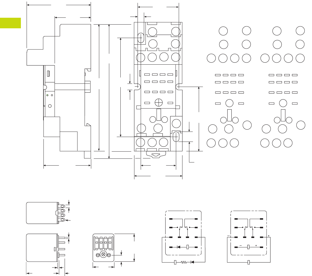
T40-58 Logic Control Products CA08100001K—June 2012 www.eatoncanada.ca
40
40
40
40
40
40
40
40
40
40
40
40
40
40
40
40
40
40
40
40
40
40
40
40
40
40
40
40
40
40
40.4
Control Relays and Timers
General Purpose Plug-In Relays
Approximate Dimensions in Inches (mm)
D2PA7
D2PR5
A2
41
A1
31 21
11
42
24
34
14
44
12
22
32
INPUT
COM
N.O.
N.C.
4321
5
86
7
12 11 10
14 13
9
0.14
(3.8)
1.0 0
(25.4)
1.55
(39.5)
0.25
(6.4)
0.82
(21.0)
0.14
(3.80)
3.30
(84.0)
3.11
(79.0)
1.57
(40.0)
1.18
(30.0)
2.40
(61.0)
1.18
(30.0)
44 14
11
12 10
INPUT
INPUT
31
14
A2
41
13 9
A1
21
11
3
4 2 1
8
32
42
5
22 12
34
7
24
6
0.74
(19.0)
MODULE
INPUT
IEC
INPUT
14
12
9
13
11 10
41
2
3
6
7
5
8
INPUT
COM
N.O.
N.C.
4321
5
86
7
12 11 10
14 13
9
MODULE
INPUT
NEMA
INPUT
0.10
(2.5)
0.02
(0.5)
0.24
(6.1)
0.25
(6.4)
0.85
(21.6)
Max.
1.10
(27.9)
Max.
14 – 0.05 (1.3) Dia. x 0.09 (2.3)
Elliptic Holes
0.02 (0.5)
1.42 (36.1)
Max.
1
5
9
13
4
8
121110
14
RESET R
1
5
9
13
4
8
121110
14
RESET
SET
Terminal Arrangement/Internal Connections (Bottom View)
AC DC
Tab40book.fm Page 58 Wednesday, July 4, 2012 10:05 PM

Logic Control Products CA08100001K—June 2012 www.eatoncanada.ca T40-59
40
40
40
40
40
40
40
40
40
40
40
40
40
40
40
40
40
40
40
40
40
40
40
40
40
40
40
40
40
40
40.4
Control Relays and Timers
General Purpose Plug-In Relays
Approximate Dimensions in Inches (mm)
D2PAP
A2 INPUTA1
44
41
42 32 22 12
14
34 24
21
31 11
1
2
3
4
5
6
7
8
9
10
11
12
14 13
0.90
(22.0)
1.06
(26.9)
2.40
(61.0) 0.74
(19.0)
3.11
(79.0)
3.34
(85.0)
1.49
(38.0)
0.20
(5.6)
MODULE
INPUT
COM
INPUT
N.O.
N.C.
1
A1
12
5
9
11
14
INPUT
A2
14
3
4
7
8
11
12
32
42
41 31
34
44
13
2
6
10
22
21
24
NEMA:
IEC:
IEC
14 13
INPUT
4
8
12
2
31
6
75
10
11 9
1
2
3
4
5
6
7
8
9
10
11
12
14 13
MODULE
INPUT
COM
INPUT
N.O.
N.C.
NEMA
Tab40book.fm Page 59 Wednesday, July 4, 2012 10:05 PM
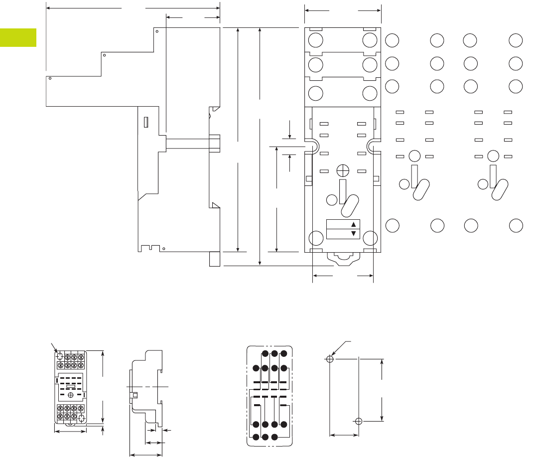
T40-60 Logic Control Products CA08100001K—June 2012 www.eatoncanada.ca
40
40
40
40
40
40
40
40
40
40
40
40
40
40
40
40
40
40
40
40
40
40
40
40
40
40
40
40
40
40
40.4
Control Relays and Timers
General Purpose Plug-In Relays
Approximate Dimensions in Inches (mm)
D2PAL
D2PA4 Socket for D2PR5 DPDT Latching Relays Only
A1
12
11
14
INPUT
A2
42
41
44
N.O.
INPUT
COM
N.C.
41
5
8
9
12
14 13
1.49
(38.0)
0.20
(5.6)
0.92
(23.5)
1.06
(27.0)
3.11
(79.0)
3.34
(85.0)
2.40
(61.0) 0.74
(19.0)
A1
INPUT
A2
14 13
12
5
9
11
14
41
8
12
42
41
44
NEMA:
IEC:
MODULE
INPUT
IEC
1
5
9
INPUT
14
4
8
12
13
N.O.
INPUT
COM
N.C.
41
5
8
9
12
14 13
MODULE
INPUT
NEMA
Two 0.17 (4.3) x 0.20 (5.1)
Mounting Holes
2.83
(71.9)
Max.
0.16
(4.1)
1.18
(30.0)
0.65 (16.5)
(22.09 0.20)
0.0080.870 +
–
+
–
(58.92 0.10)
0.0042.320 +
–
+
–
0.24 (6.1)
8 7 6 5
12 11 10
414 13
9
321
Mounting Holes
Two 0.18 (4.6) Dia. or M4
(Two 0.16 (4.1) Dia. or M3)
Terminal Arrangement
(Top View)
1.16
(29.5)
Max.
Max.
Tab40book.fm Page 60 Wednesday, July 4, 2012 10:05 PM
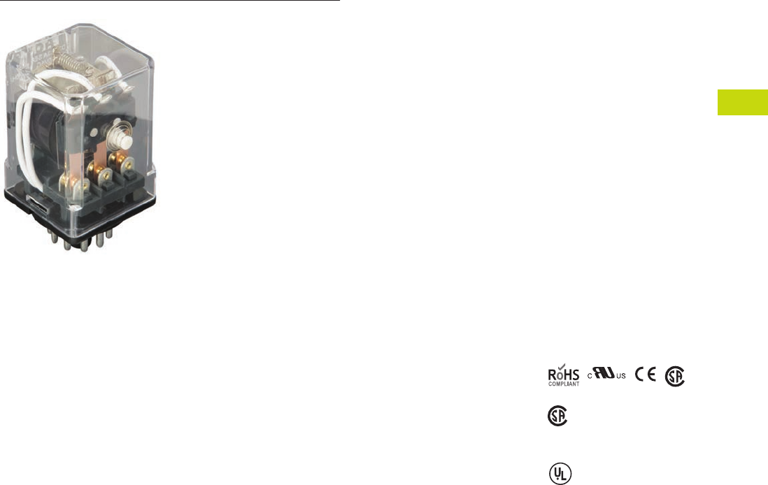
Logic Control Products CA08100001K—June 2012 www.eatoncanada.ca T40-61
40
40
40
40
40
40
40
40
40
40
40
40
40
40
40
40
40
40
40
40
40
40
40
40
40
40
40
40
40
40
40.4
Control Relays and Timers
General Purpose Plug-In Relays
D3 Series Relay Contents
Description Page
D1PR/D1PF Series . . . . . . . . . . . . . . . . . . . . . . . . . . . . T40-46
D2PR/D2PF Series . . . . . . . . . . . . . . . . . . . . . . . . . . . . T40-51
D3PR/D3PF Series
Catalogue Number Selection. . . . . . . . . . . . . . . . . . T40-62
Product Selection . . . . . . . . . . . . . . . . . . . . . . . . . . T40-62
Accessories . . . . . . . . . . . . . . . . . . . . . . . . . . . . . . . T40-64
Technical Data and Specifications . . . . . . . . . . . . . . T40-65
Dimensions . . . . . . . . . . . . . . . . . . . . . . . . . . . . . . . T40-66
D4 Series . . . . . . . . . . . . . . . . . . . . . . . . . . . . . . . . . . . T40-71
D5PR/D5PF Series . . . . . . . . . . . . . . . . . . . . . . . . . . . . T40-75
D7PR/D7PF Series . . . . . . . . . . . . . . . . . . . . . . . . . . . . T40-85
D8 Series . . . . . . . . . . . . . . . . . . . . . . . . . . . . . . . . . . . T40-100
D9 Series . . . . . . . . . . . . . . . . . . . . . . . . . . . . . . . . . . . T40-106
Accessories . . . . . . . . . . . . . . . . . . . . . . . . . . . . . . . . . T40-110
D3PR/D3PF Series
Product Description
The D3 Series of relays
provides excellent
functionality in a popular
octal base design. Rigid
pins and guide allow for
quick and easy installation
with little risk of damage.
Features
D3PR
●Compact relay capable of
breaking relatively large
load currents
●Panel and DIN rail
mounting
●8- or 11-pin octal plug-in
D3PF
●The contact operation can
be easily checked by Push-
to-Test button
●Flag indicator shows relay
status in manual or
powered condition
●LED status lamp shows
coil ON or OFF status—
ideal for use in low light
applications
●Push-to-Test button allows
for manual operation of
relay without the need for
coil power
●Lock-down door holds
pushbutton and contacts in
the operate position when
activated
●Finger-grip cover allows
operator to remove relays
from sockets easily
●ID tag/write label to
identify relays in multiple-
relay circuits
●Bipolar LED allows for
reverse polarity
applications
Standards and Certifications
When used with
accompanying Eaton
screw terminal socket
(for D3PF only)
(C
S
A approval
not applicable to
D3PR5 Relays)
UL Listed
Tab40book.fm Page 61 Wednesday, July 4, 2012 10:05 PM
T40-62 Logic Control Products CA08100001K—June 2012 www.eatoncanada.ca
40
40
40
40
40
40
40
40
40
40
40
40
40
40
40
40
40
40
40
40
40
40
40
40
40
40
40
40
40
40
40.4
Control Relays and Timers
General Purpose Plug-In Relays
Catalogue Number Selection
D3PR/D3PF Series
Product Selection
D3 Relay/Socket Quick Reference
Notes
For deciphering catalogue numbers. Do not use for ordering as not all combinations are readily available.
D3PR only.
Relay
Type Socket Clip
Module
Type
ID
Tag Jumper
D3PR2, D3PF2 D3PA6 PQC-1332 A — D3PJ1
D3PAL8 PQC-1351 A PWF-D3D5 —
D3PA2 PQC-1351 None — —
D3PR3, D3PF3 D3PA7 PQC-1332 A — D3PJ1
D3PAL11 PQC-1351 A PWF-D3D5 —
D3PA3 PQC-1351 None — —
D3PR5 D3PA7 PQC-1351 A — D3PJ1
D3PAL11 PQC-1351 A PWF-D3D5 —
D3PA3 PQC-1351 None — —
D
3
P
R 2
1
A
Family Type
D3PR = Standard relay
D3PF = Full featured relay
Coil Voltage
A = 120 Vac
A1 = 110 Vdc
B = 240 Vac
P = 6 Vac
P1 = 6 Vdc
R = 12 Vac
R1 = 12 Vdc
T = 24 Vac
T1 = 24 Vdc
W = 48 Vac
W1 = 48 Vdc
Contact Configuration
2 = DPDT (8-pin)
3 = 3PDT (11-pin)
5 = DPDT latching (11-pin)
Options
Blank = Plain cover relay (D3PR only)
A = LED test button, flag indicator,
lock-down door, finger-grip cover,
ID tag (D3PF only)
1 =
Indicating light (D3PR only)
Tab40book.fm Page 62 Wednesday, July 4, 2012 10:05 PM

Logic Control Products CA08100001K—June 2012 www.eatoncanada.ca T40-63
40
40
40
40
40
40
40
40
40
40
40
40
40
40
40
40
40
40
40
40
40
40
40
40
40
40
40
40
40
40
40.4
Control Relays and Timers
General Purpose Plug-In Relays
D3PR/D3PF Series
Coil
Voltage
Contact
Configuration
Coil Resistance
(Ohms)
Catalogue
Number
Full Featured Style
120 Vac DPDT 1700 D3PF2AA
240 Vac DPDT 7200 D3PF2AB
12 Vdc DPDT 120 D3PF2AR1
24 Vdc DPDT 470 D3PF2AT1
48 Vdc DPDT 1800 D3PF2AW1
120 Vac 3PDT 1700 D3PF3AA
220/240 Vac 3PDT 7200 D3PF3AB
6 Vdc 3PDT 32 D3PF3AP1
24 Vac 3PDT 72 D3PF3AT
24 Vdc 3PDT 470 D3PF3AT1
48 Vdc 3PDT 1800 D3PF3AW1
Latching Style
120 Vac DPDT 10,000 D3PR5A
110/125 Vdc DPDT 9000 D3PR5A1
240 Vac DPDT 36,000 D3PR5B
12 Vdc DPDT 90 D3PR5R1
24 Vac DPDT 470 D3PR5T
24 Vdc DPDT 350 D3PR5T1
48 Vdc DPDT 1400 D3PR5W1
Plain Cover with LED Indicator
120 Vac DPDT 1700 D3PR21A
24 Vac DPDT 72 D3PR21T
24 Vdc DPDT 470 D3PR21T1
220/240 Vac 3PDT 7200 D3PR31B
24 Vac 3PDT 72 D3PR31T
24 Vdc 3PDT 470 D3PR31T1
Plain Cover Style
120 Vac DPDT 1700 D3PR2A
110/125 Vdc DPDT 10,000 D3PR2A1
220/240 Vac DPDT 7200 D3PR2B
6 Vac DPDT 4.2 D3PR2P
6 Vdc DPDT 32 D3PR2P1
12 Vac DPDT 18 D3PR2R
12 Vdc DPDT 120 D3PR2R1
24 Vac DPDT 72 D3PR2T
24 Vdc DPDT 470 D3PR2T1
48 Vac DPDT 290 D3PR2W
48 Vdc DPDT 1800 D3PR2W1
120 Vac 3PDT 1700 D3PR3A
110/125 Vdc 3PDT 10,000 D3PR3A1
220/240 Vac 3PDT 7200 D3PR3B
12 Vac 3PDT 18 D3PR3R
12 Vdc 3PDT 120 D3PR3R1
24 Vac 3PDT 72 D3PR3T
24 Vdc 3PDT 470 D3PR3T1
48 Vdc 3PDT 1800 D3PR3W1
D3 Series Relay
Tab40book.fm Page 63 Wednesday, July 4, 2012 10:05 PM

T40-64 Logic Control Products CA08100001K—June 2012 www.eatoncanada.ca
40
40
40
40
40
40
40
40
40
40
40
40
40
40
40
40
40
40
40
40
40
40
40
40
40
40
40
40
40
40
40.4
Control Relays and Timers
General Purpose Plug-In Relays
Accessories
D3PR/D3PF Series Sockets and Accessories
Note
Protection category (finger safe), EN 60529: IP20.
Type
Module
Size
Nominal Voltage
(Max. for Sockets)
Nominal
Current Mounting Style Wire Size
Wire
Connection
Standard
Pack
Catalogue
Number
Socket A 300 16 DIN rail/panel 12/14 (2) AWG, 4/2.5 (2) mm2Screw clamping 1 D3PA6
A 300 12 DIN rail/panel 12/14 (2) AWG, 4/2.5 (2) mm2Elevator 10 D3PAL8
None 300/600 15/10 DIN rail/panel 12/14 (2) AWG, 4/2.5 (2) mm2Screw clamping 10 D3PA2
A 600 5 DIN rail/panel 12/14 (2) AWG, 4/2.5 (2) mm2Screw clamping 1 D3PA7
A 300 12 DIN rail/panel 12/14 (2) AWG, 4/2.5 (2) mm2Elevator 10 D3PAL11
None 300/600 15/5 DIN rail/panel 12/14 (2) AWG, 4/2.5 (2) mm2Screw clamping 10 D3PA3
Metal spring clip — — — — — — 25 PQC-1332
—— —— — — 10PQC-1351
Protection diode A 6 to 250 Vdc — — — — 20 MOD-AD250
LED indicator A 24 Vac/Vdc — — — — 20 MOD-ALG24
A 120/240 Vac/Vdc — — — — 20 MOD-ALG240
MOV suppressor A 120 Vac/Vdc — — — — 20 MOD-AMV120
A 24 Vac/Vdc — — — — 20 MOD-AMV24
A 240 Vac/Vdc — — — — 20 MOD-AMV240
R/C suppressor A 6 to 24 Vac/Vdc — — — — 20 MOD-RC24
A 110 to 240 Vac/Vdc — — — — 20 MOD-RC240
Write-on plastic labels — — — — — — 10 PWF-D3D5
Coil bus jumpers — — — — — — 10 D3PJ1
Plastic DIN rail end stop — — — — — — 25 PFP-P
Tab40book.fm Page 64 Wednesday, July 4, 2012 10:05 PM

Logic Control Products CA08100001K—June 2012 www.eatoncanada.ca T40-65
40
40
40
40
40
40
40
40
40
40
40
40
40
40
40
40
40
40
40
40
40
40
40
40
40
40
40
40
40
40
40.4
Control Relays and Timers
General Purpose Plug-In Relays
Technical Data and Specifications
D3PR/D3PF Series Relay Specifications
Description D3PR D3PF
D3PR5
(Latching)
Contact Characteristics
Contact rating 16A 16A 16A
Terminal style Octal Octal 11-pin octal
Contact materials Silver alloy Silver alloy Silver alloy
Maximum switching voltage 300V 300V 300V
Switching current at voltage—resistive 16A at 277 Vac
50/60 Hz
16A at 277 Vac
50/60 Hz
16A at 277 Vac
50/60 Hz
16A at 120 Vac
50/60 Hz
16A at 120 Vac
50/60 Hz
—
16A at 28 Vdc 16A at 28 Vdc 16A at 28 Vdc
Switching current at voltage 1/2 hp at 240 Vac 1/2 hp at 240 Vac 1/2 hp at 240 Vac
1/3 hp at 120 Vac 1/3 hp at 120 Vac 1/3 hp at 120 Vac
Pilot duty B300 B300 B300
Minimum switching requirement 100 mA at 5 Vdc
(0.5W)
100 mA at 5 Vdc
(0.5W)
100 mA at 5 Vdc
(0.5W)
Coil Characteristics
Operating range
% of nominal (AC) 85 to 110% 85 to 110% 85 to 110%
% of nominal (DC) 80 to 110% 80 to 110% 80 to 110%
Average consumption 3 VA 3 VA 2 VA
1.4W 1.4W 1.64W
Dropout voltage threshold 15% (AC) 15% (AC) 15% (AC)
10% (DC) 10% (DC) 10% (DC)
Performance
Electrical life (UL 508) operations at rated current 100,000 operations 100,000 operations 100,000 operations
Mechanical life operations unpowered 5,000,000 operations 5,000,000 operations 10,000,000 operations
Response time 20 ms 20 ms 30 ms
Dielectric strength
Between coil and contact Vac (rms) 1500V (rms) 1500V (rms) 2500V (rms)
Between poles Vac (rms) 1500V (rms) 1500V (rms) 1500V (rms)
Environment
Ambient air temperature around the device
Storage –40˚ to 185˚F (–40˚ to 85˚C) –40˚ to 185˚F (–40˚ to 85˚C) –40˚ to 185˚F (–40˚ to 85˚C)
Operation –40˚ to 131˚F (–40˚ to 55˚C) –40˚ to 131˚F (–40˚ to 55˚C) –40˚ to 131˚F (–40˚ to 55˚C)
Vibration resistance—operational 3 g-n at 10–55 Hz 3 g-n at 10–55 Hz 3 g-n at 10–55 Hz
Shock resistance 10 g-n 10 g-n 10 g-n
Degree of protection IP40 IP40 IP40
Features
Cover options Plain cover Full Featured Latching
Features Mechanical flag indicator Bipolar LED/
Locking pushbutton/
Removable ID tag/
Mechanical flag indicator
—
Product certifications RoHS/UL/CE/CSA RoHS/UL/CE/CSA RoHS/UL/UR
Tab40book.fm Page 65 Wednesday, July 4, 2012 10:05 PM
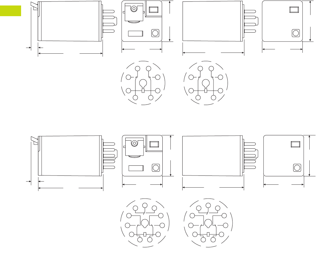
T40-66 Logic Control Products CA08100001K—June 2012 www.eatoncanada.ca
40
40
40
40
40
40
40
40
40
40
40
40
40
40
40
40
40
40
40
40
40
40
40
40
40
40
40
40
40
40
40.4
Control Relays and Timers
General Purpose Plug-In Relays
Dimensions
Approximate Dimensions in Inches (mm)
D3PR2/D3PF2
D3PR3/D3PF3
2.10
(50.3)
2.20
(55.2)
0.24
(6.1) 1.37
(34.8)
1.39
(35.3)
14
11
A1
12 22
24
A2
31
1.39
(35.3)
1.37
(34.8)
IEC
1
2
3
45
6
7
8
NEMA
2.10
(50.3)
2.20
(55.2)
0.24
(6.1) 1.37
(34.8)
1.39
(35.3)
1
2
3
4
567
8
9
10
11
1.39
(35.3)
1.37
(34.8)
NEMA
11
A1
14
12
22 21 24
32
34
A2
31
IEC
Tab40book.fm Page 66 Wednesday, July 4, 2012 10:05 PM
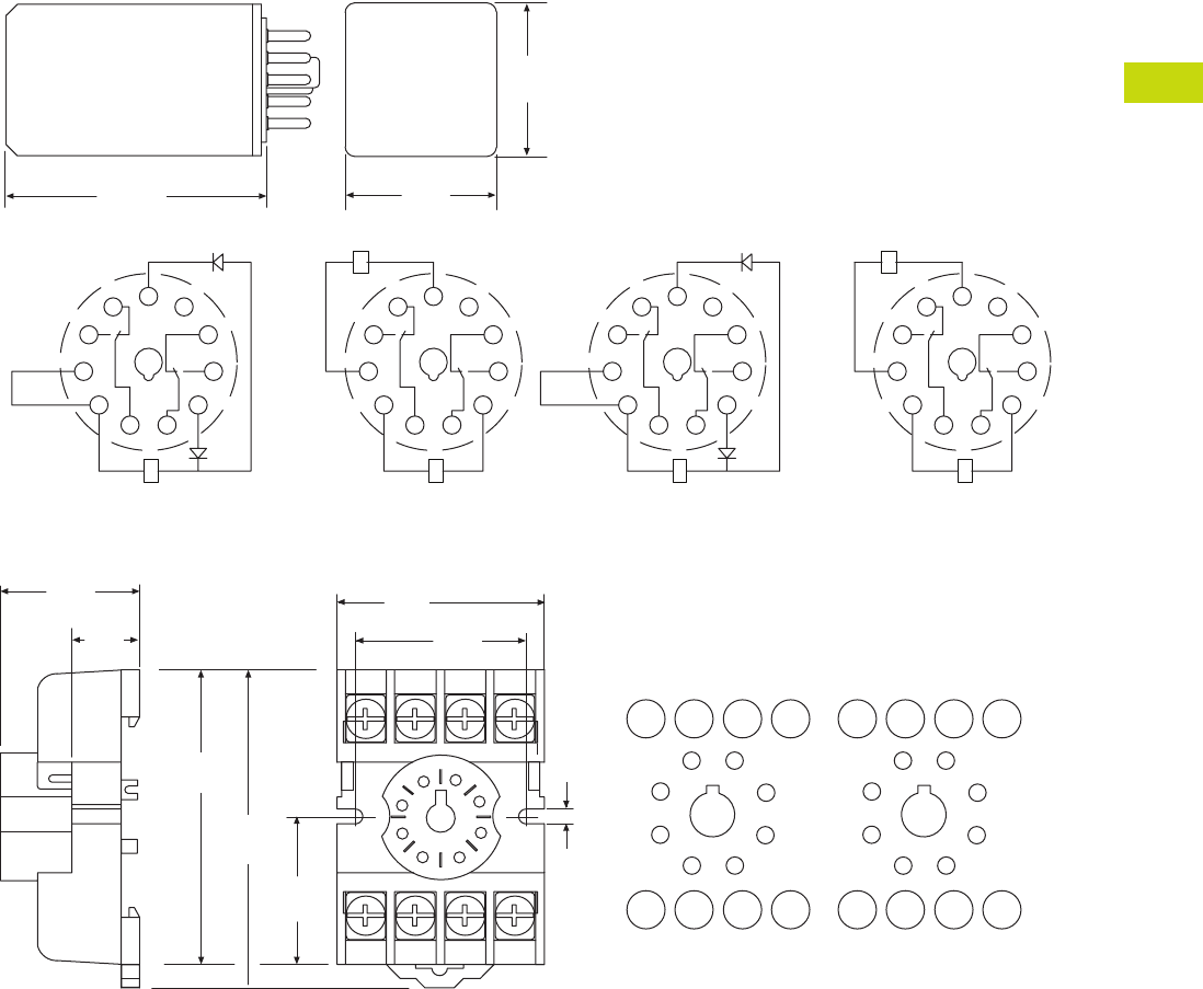
Logic Control Products CA08100001K—June 2012 www.eatoncanada.ca T40-67
40
40
40
40
40
40
40
40
40
40
40
40
40
40
40
40
40
40
40
40
40
40
40
40
40
40
40
40
40
40
40.4
Control Relays and Timers
General Purpose Plug-In Relays
Approximate Dimensions in Inches (mm)
D3PR5—Octal Base Latching Relay
D3PA2
)CD( lioC lauD)CA( lioC elgniS
2.40
(61.0)
11
A1
14
12
22 21 24
32
34
A2
31
1.39
(35.3)
1.37
(34.8)
COMMON
RESET
SET
11
A1
14
12
22 21 24
32
34
A2
31
SET
RESET
COIL
COIL
2
1
IEC
)CD( lioC lauD)CA( lioC elgniS
1
2
3
4
567
8
9
10
11
COMMON
RESET
SET
1
2
3
4
567
8
9
10
11
SET
RESET
COIL
COIL
2
1
NEMA
3546
8 21
0.16
(4.2)
7
1.29
(33.0)
1.60
(40.0)
2.12
(54.0)
2.02
(51.0)
0.97
(24.6)
14 12 22 24
A1 11 21 A2
3
4
2
1
6
5
8
7
INPUT
1.01
(25.6)
INPUT
0.59
(15.0)
IEC
34
21
6
87
3
4
2
1
6
5
8
7
INPUTINPUT
NEMA
5
Tab40book.fm Page 67 Wednesday, July 4, 2012 10:05 PM
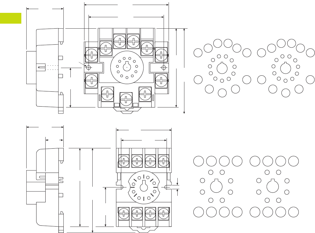
T40-68 Logic Control Products CA08100001K—June 2012 www.eatoncanada.ca
40
40
40
40
40
40
40
40
40
40
40
40
40
40
40
40
40
40
40
40
40
40
40
40
40
40
40
40
40
40
40.4
Control Relays and Timers
General Purpose Plug-In Relays
Approximate Dimensions in Inches (mm)
D3PA3
3
4
5
6
7
11
2
1
10
8
9
2.06
(52.0)
2.32
(59.0)
2.16
(54.8)
2.05
(52.0)
0.97
(24.6)
1.60 Dia.
(40.0)
1.02
(25.0)
5
14
A1 A2
11 31
34
12
22 24
21
32
11
1
39
10
2
48
67
INPUTINPUT
IEC
5
4
57
6
3
210
111
8
9
11
1
39
10
2
48
67
INPUTINPUT
NEMA
3 54 6
8 21
0.16
(4.2)
7
1.29
(33.0)
1.60
(40.0)
2.12
(54.0)
2.02
(51.0)
0.97
(24.6)
14 12 22 24
A1 11 21 A2
3
4
2
1
6
5
8
7
INPUT
1.01
(25.6)
INPUT
0.59
(15.0)
IEC
34
21
65
87
3
4
2
1
6
5
8
7
INPUTINPUT
NEMA
Tab40book.fm Page 68 Wednesday, July 4, 2012 10:05 PM
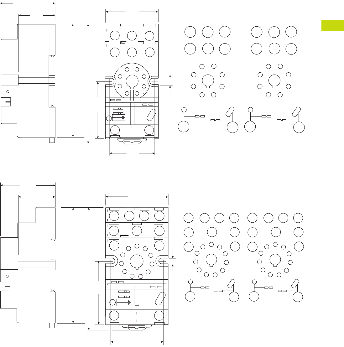
Logic Control Products CA08100001K—June 2012 www.eatoncanada.ca T40-69
40
40
40
40
40
40
40
40
40
40
40
40
40
40
40
40
40
40
40
40
40
40
40
40
40
40
40
40
40
40
40.4
Control Relays and Timers
General Purpose Plug-In Relays
Approximate Dimensions in Inches (mm)
D3PA6
D3PA7
1.42
(36.0)
0.15
(3.8)
1.10
(27.9)
11
41
12
14
3
A2
7
5
22
21
24
68
A1
2
2.86
(72.0)
1.45
(37.0)
INPUT
INPUT
3.00
(76.0)
1.58
(40.0)
1.20
(30.0)
Coil Jumper Buss
A1
A2
54
7
81
2
63
21 14
24
11 1 2
22
MODULE
INPUT
INPUT
NEMA:
IEC:
IEC
2
7Coil Jumper Buss
54
7
81
2
63
63
8
514
MODULE
INPUT
INPUT
NEMA
1.50
(38.0)
0.15
(3.8)
5
3.01
(76.0)
1.45
(37.0)
3.18
(81.0)
1.58
(40.0)
1.35
(34.2)
34 14
31 21
32 22
24
11
12
11
1
3
9
10
2
4
8
6
7
A1
A2
Coil Jumper Buss
MODULE
INPUT
INPUT
11
4
1
12
14
3
A2
10
5
22
21
24
6
7
A1
2
INPUT
INPUT
34
9
31
11
32
8
1.10
(27.9)
IEC
NEMA:
IEC:
5
93
11
6
5
7
8
1
4
11
1
3
9
10
2
4
8
6
7
10 Coil Jumper Buss 2
MODULE
INPUT
INPUT
NEMA
Tab40book.fm Page 69 Wednesday, July 4, 2012 10:05 PM
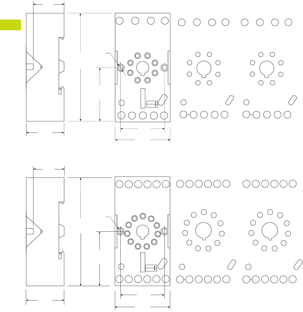
T40-70 Logic Control Products CA08100001K—June 2012 www.eatoncanada.ca
40
40
40
40
40
40
40
40
40
40
40
40
40
40
40
40
40
40
40
40
40
40
40
40
40
40
40
40
40
40
40.4
Control Relays and Timers
General Purpose Plug-In Relays
Approximate Dimensions in Inches (mm)
D3PAL8
D3PAL11
11
7
7
INPUT A1INPUT A2
A2
7
A2
8
21
21
A1
12
56
24
4
22
3
14
2
12
24 22 14
11
A2 21 A1A2
1
2
8
7
3
4
5
6
2.95
(75.0)
1.45
(37.0)
0.12
(30.0)
1.49
(38.0)
0.12
(3.10)
0.86
(22.0)
1.06
(27.0)
INPUTINPUT
MODULE
INPUT
IEC
465 3
17782
1
2
8
7
3
4
5
6
INPUTINPUT
MODULE
INPUT
NEMA
NEMA:
IEC:
INPUT A1
10
INPUT A2
2
A1
A2 A2 31 21 11
10 11
10 612
14
34 24
32 22 12
97
84
3
5
11
A2 31 21 A1
14
34 24 22 12
32
A2
4
3
9
8
75
6
1
10
11
2
4
3
9
8
75
6
1
10
11
2
2.95
(75.0)
INPUT
INPUT
0.86
(22.0)
1.06
(27.0)
1.45
(37.0)
1.49
(38.0)
0.12
(30.0)
NEMA:
IEC:
0.12
(3.1)
MODULE
INPUT
IEC
10 1
11 62
3
9754
10
8
INPUT
INPUT
MODULE
INPUT
NEMA
Tab40book.fm Page 70 Wednesday, July 4, 2012 10:05 PM
Logic Control Products CA08100001K—June 2012 www.eatoncanada.ca T40-71
40
40
40
40
40
40
40
40
40
40
40
40
40
40
40
40
40
40
40
40
40
40
40
40
40
40
40
40
40
40
40.4
Control Relays and Timers
General Purpose Plug-In Relays
D4 Series Relay Contents
Description Page
D1PR/D1PF Series . . . . . . . . . . . . . . . . . . . . . . . . . . . . T40-46
D2PR/D2PF Series . . . . . . . . . . . . . . . . . . . . . . . . . . . . T40-51
D3PR/D3PF Series . . . . . . . . . . . . . . . . . . . . . . . . . . . . T40-61
D4 Series
Technical Data and Specifications . . . . . . . . . . . . . . T40-73
Dimensions . . . . . . . . . . . . . . . . . . . . . . . . . . . . . . . T40-74
D5PR/D5PF Series . . . . . . . . . . . . . . . . . . . . . . . . . . . . T40-75
D7PR/D7PF Series . . . . . . . . . . . . . . . . . . . . . . . . . . . . T40-85
D8 Series . . . . . . . . . . . . . . . . . . . . . . . . . . . . . . . . . . . T40-100
D9 Series . . . . . . . . . . . . . . . . . . . . . . . . . . . . . . . . . . . T40-106
Accessories . . . . . . . . . . . . . . . . . . . . . . . . . . . . . . . . . T40-110
D4 Series
Product Description
The D4 Series is a slim-form
relay designed to fit into tight
spaces. The retaining clip is
built in to the socket to
provide easy and secure
assembly.
Features
●Slim-styled power relay
●Socket has built-in hold-
down clip
●Panel or DIN rail mounting
Standards and Certifications
File # E1491, E65657
File # LR701519
Catalogue Number Selection
D4 Series
Product Selection
D4 Relay/Socket Quick Reference
Notes
For deciphering catalogue numbers. Do not use for ordering as not all combinations are
readily available.
Socket has built-in hold-down spring.
D 4 P R 1 1 A
Family Type
D4PR
Contact Configuration
1 = SPDT
2 = DPDT
Options
Blank = Plain cover
1 =
Indicating light
Coil Voltage
A = 120 Vac
A1 = 110 Vdc
B = 240 Vac
P = 6 Vac
P1 = 6 Vdc
R = 12 Vac
R1 = 12 Vdc
T = 24 Vac
T1 = 24 Vdc
W = 48 Vac
W1 = 48 Vdc
Relay Type Socket Hold-Down Clip
D4PR1 D4PA1
D4PR2 D4PA2
Tab40book.fm Page 71 Wednesday, July 4, 2012 10:05 PM
T40-72 Logic Control Products CA08100001K—June 2012 www.eatoncanada.ca
40
40
40
40
40
40
40
40
40
40
40
40
40
40
40
40
40
40
40
40
40
40
40
40
40
40
40
40
40
40
40.4
Control Relays and Timers
General Purpose Plug-In Relays
D4 Series
Voltage/Poles
Standard
Pack
Catalogue
Number Voltage/Poles
Standard
Pack
Catalogue
Number
DIN Rail Sockets DPDT with Indicating Light
Single-pole 10 D4PA1 120 Vac 1 D4PR21A
Two-pole 10 D4PA2 110 Vdc 1 D4PR21A1
SPDT with Indicating Light 240 Vac 1 D4PR21B
120 Vac 1 D4PR11A 6 Vac 50 D4PR21P
110 Vdc 1 D4PR11A1 6 Vdc 1 D4PR21P1
240 Vac 1 D4PR11B 12 Vac 50 D4PR21R
6 Vac 50 D4PR11P 12 Vdc 1 D4PR21R1
6 Vdc 50 D4PR11P1 24 Vac 1 D4PR21T
12 Vac 50 D4PR11R 24 Vdc 1 D4PR21T1
12 Vdc 1 D4PR11R1 48 Vdc 50 D4PR21W1
24 Vac 1 D4PR11T Standard DPDT
24 Vdc 1 D4PR11T1 120 Vac 1 D4PR2A
48 Vdc 50 D4PR11W1 110 Vdc 50 D4PR2A1
Standard SPDT 240 Vac 50 D4PR2B
120 Vac 1 D4PR1A 6 Vac 50 D4PR2P
110 Vdc 50 D4PR1A1 6 Vdc 1 D4PR2P1
240 Vac 50 D4PR1P 12 Vac 50 D4PR2R
6 Vac 1 D4PR1P1 12 Vdc 1 D4PR2R1
6 Vdc 50 D4PR1R 24 Vac 1 D4PR2T
12 Vac 1 D4PR1R1 24 Vdc 1 D4PR2T1
12 Vdc 1 D4PR1R1-A2 48 Vdc 1 D4PR2W1
24 Vac 1 D4PR1T
24 Vdc 1 D4PR1T1
48 Vdc 1 D4PR1W1
D4 Series Relay
Tab40book.fm Page 72 Wednesday, July 4, 2012 10:05 PM

Logic Control Products CA08100001K—June 2012 www.eatoncanada.ca T40-73
40
40
40
40
40
40
40
40
40
40
40
40
40
40
40
40
40
40
40
40
40
40
40
40
40
40
40
40
40
40
40.4
Control Relays and Timers
General Purpose Plug-In Relays
Technical Data and Specifications
D4 Series
Description
Resistive Load
(p.f. = 1)
Inductive Load
(p.f. = 0.4, L/R = 7 ms)
D4PR1
Rated load 250 Vac 10A 250 Vac 7.5A
30 Vdc 10A 30 Vdc 5A
Carry current 10A 10A
Max. operating voltage 380 Vac/125 Vdc 380 Vac/125 Vdc
Max. operating current 10A 10A
Contact material AgCdO AgCdO
Max. switching capacity 2500 VA 1875 VA
300W 150W
Min. permissible load 100 mA, 5 Vdc 100 mA, 5 Vdc
Pickup voltage (max.) 80% AC/70% DC 80% AC/70% DC
Dropout voltage (min.) 30% AC/15% DC 30% AC/15% DC
Voltage (max.) 110% 110%
Mechanical life (min.) 10,000,000 AC/20,000,000 DC 10,000,000 AC/20,000,000 DC
Electrical life at all contact ratings (min.) 100,000 100,000
Maximum hp ratings 1/3 hp (125 Vac) 1/3 hp (125 Vac)
1/2 hp (250 Vac) 1/2 hp (250 Vac)
1/2 hp (277 Vac) 1/2 hp (277 Vac)
D4PR2
Rated load 240 Vac 5A 250 Vac 2A
30 Vdc 5A 30 Vdc 3A
Carry current 5A 5A
Max. operating voltage 380 Vac/125 Vdc 380 Vac/125 Vdc
Max. operating current 5A 5A
Contact material AgCdO AgCdO
Max. switching capacity 1250 VA 500 VA
150W 90W
Min. permissible load 10 mA, 5 Vdc 10 mA, 5 Vdc
Pickup voltage (max.) 80% AC/70% DC 80% AC/70% DC
Dropout voltage (min.) 30% AC/15% DC 30% AC/15% DC
Voltage (max.) 110% 110%
Mechanical life (min.) 10,000,000 AC/20,000,000 DC 10,000,000 AC/20,000,000 DC
Electrical life at all contact ratings (min.) 100,000 100,000
Maximum hp ratings 1/6 hp (120 Vac) 1/6 hp (120 Vac)
1/3 hp (240 Vac) 1/3 hp (240 Vac)
1/3 hp (265 Vac) 1/3 hp (265 Vac)
Tab40book.fm Page 73 Wednesday, July 4, 2012 10:05 PM
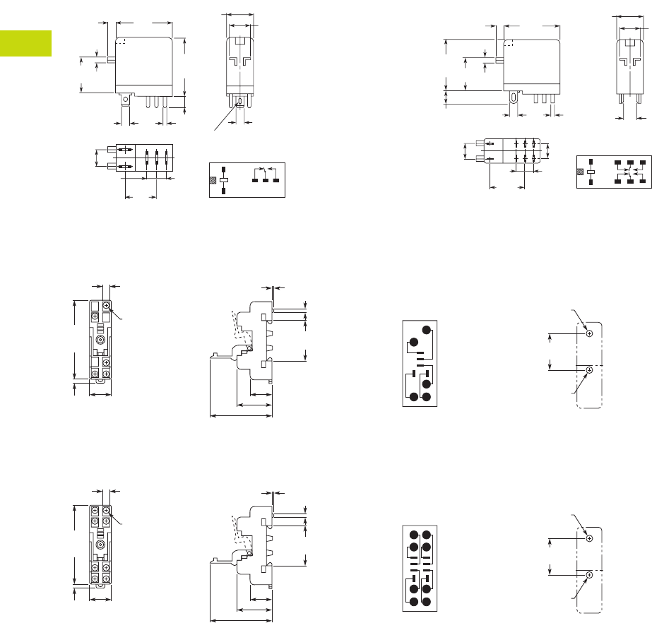
T40-74 Logic Control Products CA08100001K—June 2012 www.eatoncanada.ca
40
40
40
40
40
40
40
40
40
40
40
40
40
40
40
40
40
40
40
40
40
40
40
40
40
40
40
40
40
40
40.4
Control Relays and Timers
General Purpose Plug-In Relays
Dimensions
Approximate Dimensions in Inches (mm)
D4PR1 D4PR2
D4PA1
D4PA2
1
243
5
1.14
(29.0)
Max.
1.14
(29.0)
Max.
0.51
(13.0)
Max.
0.10
(2.5) 0.39
(10.0)
0.16
(4.0)
0.08
(2.0)
0.79
(20.0)
0.19
(4.8)
0.30
(7.5)
0.20
(5.2)
0.69
(17.5)
0.20
(5.2)
Terminal Arrangement/
Internal Connections
(Bottom View)
0.02
(0.5)
0.02
(0.5)
5 – 0.035 x 0.12
(0.9 x 3)
Elliptic Holes
1.14
(29.0)
Max.
1.10
(28.0)
Max.
0.01
(2.5)
0.24
(6.0)
0.79
(20.0) 0.08
(2.0)
0.10
(2.6)
0.02
(0.5)
0.30
(7.5)
0.35
(8.9)
0.02
(0.5)
0.02
(0.5)
1
8765
234
0.76
(19.4) Terminal Arrangement/
Internal Connections
(Bottom View)
0.16
(4.0)
0.51
(13.0)
Max.0.39
(10.0)
0.28
(7.1) 0.08
(2.0)
Five
3.5 x 0.32
(88.9 x 8.0)
2.82
(71.6)
Max.
0.16
(4.1)
0.77
(19.6)
Max.
0.77 (19.6)
1.18 (30.0)
2.13 (54.1) Max.
1.180 0.002
(29.97 0.05)
1.40
(35.6)
0.16
(4.1)
Dia. Holes
15
3
2
4
M3 or
3.30 (0.13)
Dia. Holes
0.17 (4.2)
Dia. Holes
Mounting HolesTerminal Arrangement
0.28
(7.1) 0.08
(2.0)
Eight
3.5 x 0.32
(88.9 x 8.0)
2.82
(71.6)
Max.
0.16
(4.1)
0.77
(19.6)
Max.
0.77 (19.6)
1.18 (30.0)
2.13 (54.1) Max.
1.180 0.002
(29.97 0.05)
1.40
(35.6)
0.16
(4.1)
Dia. Holes
18
5
72
3
4
6
M3 or
0.13 (3.30)
Dia. Holes
0.17 (4.2)
Dia. Holes
Mounting HolesTerminal Arrangement
Tab40book.fm Page 74 Wednesday, July 4, 2012 10:05 PM
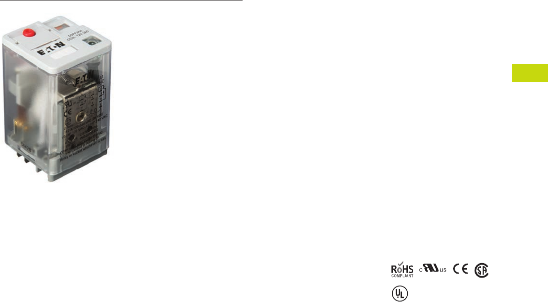
Logic Control Products CA08100001K—June 2012 www.eatoncanada.ca T40-75
40
40
40
40
40
40
40
40
40
40
40
40
40
40
40
40
40
40
40
40
40
40
40
40
40
40
40
40
40
40
40.4
Control Relays and Timers
General Purpose Plug-In Relays
D5 Series Relay Contents
Description Page
D1PR/D1PF Series . . . . . . . . . . . . . . . . . . . . . . . . . . . . T40-46
D2PR/D2PF Series . . . . . . . . . . . . . . . . . . . . . . . . . . . . T40-51
D3PR/D3PF Series . . . . . . . . . . . . . . . . . . . . . . . . . . . . T40-61
D4 Series . . . . . . . . . . . . . . . . . . . . . . . . . . . . . . . . . . . T40-71
D5PR/D5PF Series
Catalogue Number Selection. . . . . . . . . . . . . . . . . . T40-76
Product Selection . . . . . . . . . . . . . . . . . . . . . . . . . . T40-76
Accessories . . . . . . . . . . . . . . . . . . . . . . . . . . . . . . . T40-79
Technical Data and Specifications . . . . . . . . . . . . . . T40-80
Wiring Diagrams . . . . . . . . . . . . . . . . . . . . . . . . . . . T40-81
Dimensions . . . . . . . . . . . . . . . . . . . . . . . . . . . . . . T40-82
D7PR/D7PF Series . . . . . . . . . . . . . . . . . . . . . . . . . . . . T40-85
D8 Series . . . . . . . . . . . . . . . . . . . . . . . . . . . . . . . . . . . T40-100
D9 Series . . . . . . . . . . . . . . . . . . . . . . . . . . . . . . . . . . . T40-106
Accessories . . . . . . . . . . . . . . . . . . . . . . . . . . . . . . . . . T40-110
D5PR/D5PF Series
Product Description
The D5 Series is rated at
16A and is available in full-
featured and plain cover
styles.
Features
D5PR
●Industrial rated 300V, 16A
relay in two-pole and three-
pole configurations
●Compact design can be
panel or DIN rail mounted
D5PF
●Flag indicator shows relay
status in manual or
powered condition
●LED status lamp shows
coil ON or OFF status—
ideal for use in low light
applications
●Push-to-Test button allows
for manual operation of
relay without the need for
coil power
●Lock-down door holds
pushbutton and contacts in
the operate position when
activated
●Finger-grip cover allows
operator to remove relays
from sockets easily
●ID tag/write label to
identify relays in multiple-
relay circuits
●Bipolar LED allows for
reverse polarity
applications
Standards and Certifications
When used with
accompanying Eaton
screw terminal socket
(D5PF only)
UL Listed
Tab40book.fm Page 75 Wednesday, July 4, 2012 10:05 PM
T40-76 Logic Control Products CA08100001K—June 2012 www.eatoncanada.ca
40
40
40
40
40
40
40
40
40
40
40
40
40
40
40
40
40
40
40
40
40
40
40
40
40
40
40
40
40
40
40.4
Control Relays and Timers
General Purpose Plug-In Relays
Catalogue Number Selection
D5 Series
Product Selection
D5 Relay/Socket Quick Reference
Family Type
D5PR = Standard relay
D5PF = Full featured relay
Contact Configuration
2 = DPDT
3 = 3PDT
D 5 P R 3 1 A
Coil Voltage
A = 120 Vac
A1 = 110 Vdc
B = 240 Vac
G1 = 74 Vdc
P = 6 Vac
P1 = 6 Vdc
R = 12 Vac
R1 = 12 Vdc
T = 24 Vac
T1 = 24 Vdc
W = 48 Vac
W1 = 48 Vdc
Options
Blank = Plain cover (D5PR only)
A = LED test button, flag indicator,
lock-down door, finger-grip cover,
ID tag (D5PF only)
1 = Indicating light (D5PR only)
Relay
Type Socket Clip
Module
Type
ID
Tag Jumper
D5PR2, D5PF2,
D5PR3, D5PF3
D5PAL PQC-1351 A PWF-D3D5 D3PJ1
D5PA2 PQC-1351 None — —
D5PA3L PQC-1351 None — —
D5PA3S PQC-1351 None — —
Tab40book.fm Page 76 Wednesday, July 4, 2012 10:05 PM
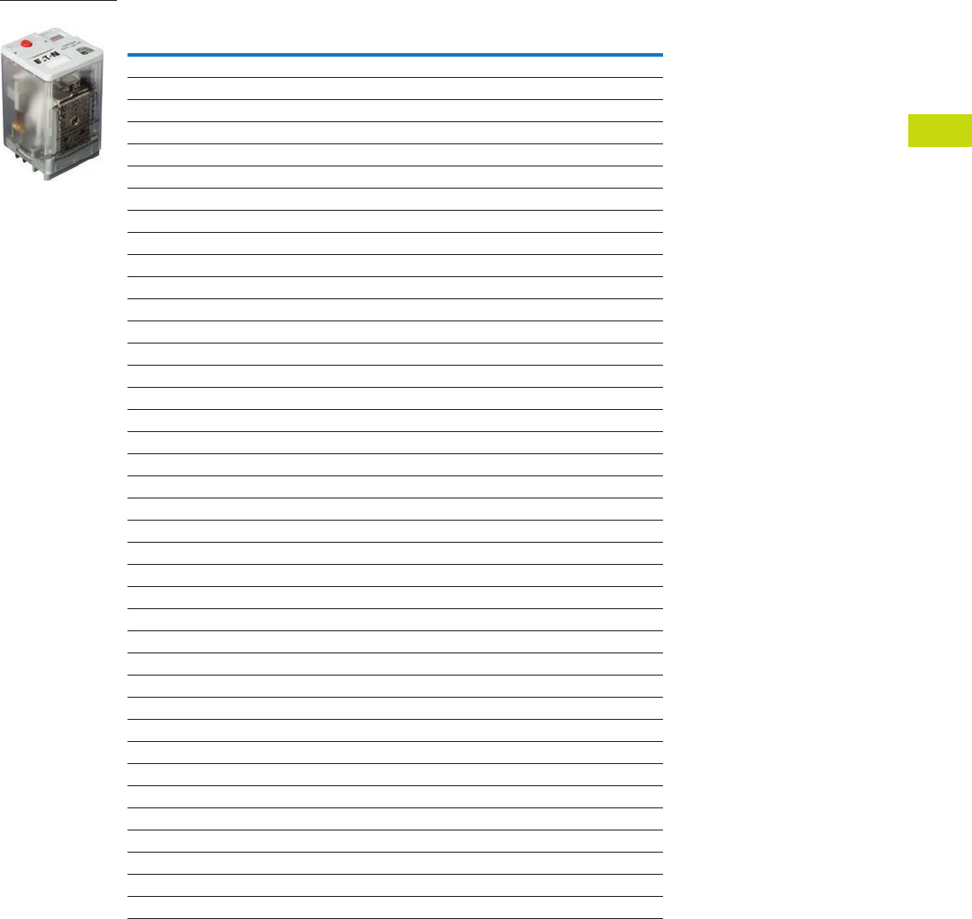
Logic Control Products CA08100001K—June 2012 www.eatoncanada.ca T40-77
40
40
40
40
40
40
40
40
40
40
40
40
40
40
40
40
40
40
40
40
40
40
40
40
40
40
40
40
40
40
40.4
Control Relays and Timers
General Purpose Plug-In Relays
D5 Series
Coil
Voltage
Contact
Configuration
Coil Resistance
(Ohms)
Catalogue
Number
Full Featured
120 Vac DPDT 1700 D5PF2AA
110/125 Vdc DPDT 10,000 D5PF2AA1
220/240 Vac DPDT 7200 D5PF2AB
12 Vdc DPDT 120 D5PF2AR1
24 Vac DPDT 72 D5PF2AT
24 Vdc DPDT 470 D5PF2AT1
48 Vdc DPDT 1800 D5PF2AW1
120 Vac 3PDT 1700 D5PF3AA
110/125 Vdc 3PDT 10,000 D5PF3AA1
220/240 Vac 3PDT 7200 D5PF3AB
12 Vdc 3PDT 120 D5PF3AR1
24 Vac 3PDT 72 D5PF3AT
24 Vdc 3PDT 470 D5PF3AT1
Plain Cover with LED
110/125 Vdc DPDT 10,000 D5PR21A1
6 Vac DPDT 4.2 D5PR21P
6 Vdc DPDT 32 D5PR21P1
12 Vac DPDT 18 D5PR21R
12 Vdc DPDT 120 D5PR21R1
24 Vdc DPDT 470 D5PR21T1
48 Vac DPDT 290 D5PR21W
48 Vdc DPDT 1800 D5PR21W1
120 Vac 3PDT 1700 D5PR31A
110/125 Vdc 3PDT 10,000 D5PR31A1
6 Vdc 3PDT 32 D5PR31P1
12 Vac 3PDT 18 D5PR31R
12 Vdc 3PDT 120 D5PR31R1
24 Vdc 3PDT 470 D5PR31T1
48 Vdc 3PDT 1800 D5PR31W1
Side Flange Cover
220/240 Vac DPDT 7200 D5PR24B
6 Vac DPDT 4.2 D5PR24P
6 Vdc DPDT 32 D5PR24P1
12 Vac DPDT 18 D5PR24R
12 Vdc DPDT 120 D5PR24R1
24 Vac DPDT 72 D5PR24T
24 Vdc DPDT 470 D5PR24T1
48 Vac DPDT 290 D5PR24W
D5 Series Relay
Tab40book.fm Page 77 Wednesday, July 4, 2012 10:05 PM
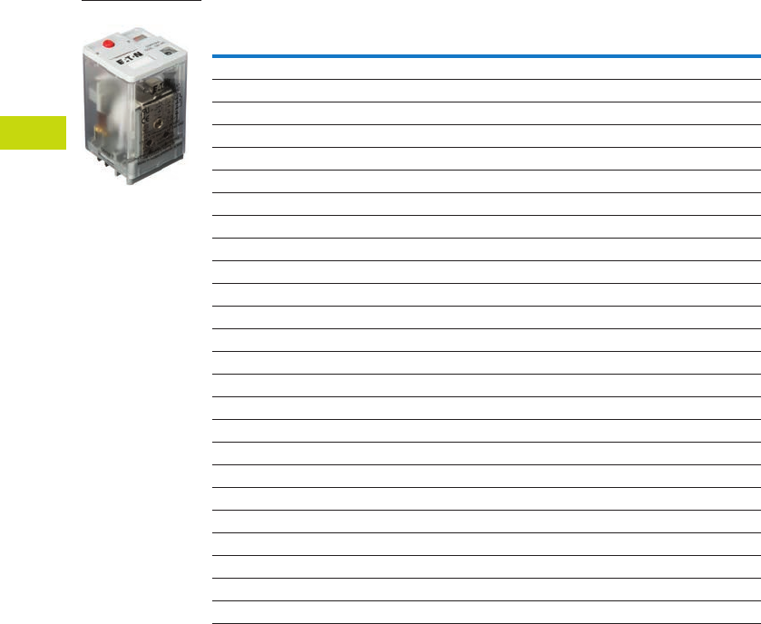
T40-78 Logic Control Products CA08100001K—June 2012 www.eatoncanada.ca
40
40
40
40
40
40
40
40
40
40
40
40
40
40
40
40
40
40
40
40
40
40
40
40
40
40
40
40
40
40
40.4
Control Relays and Timers
General Purpose Plug-In Relays
D5 Series, continued
Coil
Voltage
Contact
Configuration
Coil Resistance
(Ohms)
Catalogue
Number
Plain Cover
120 Vac DPDT 1700 D5PR2A
110/125 Vdc DPDT 10,000 D5PR2A1
220/240 Vac DPDT 7200 D5PR2B
74 Vdc DPDT 4800 D5PR2G1
6 Vac DPDT 4.2 D5PR2P
6 Vdc DPDT 32 D5PR2P1
12 Vac DPDT 18 D5PR2R
12 Vdc DPDT 120 D5PR2R1
24 Vac DPDT 72 D5PR2T
24 Vdc DPDT 470 D5PR2T1
48 Vac DPDT 290 D5PR2W
48 Vdc DPDT 1800 D5PR2W1
120 Vac 3PDT 1700 D5PR3A
110/125 Vdc 3PDT 10,000 D5PR3A1
220/240 Vac 3PDT 7200 D5PR3B
74 Vdc 3PDT 4800 D5PR3G1
6 Vac 3PDT 4.2 D5PR3P
6 Vdc 3PDT 32 D5PR3P1
12 Vac 3PDT 18 D5PR3R
12 Vdc 3PDT 120 D5PR3R1
24 Vac 3PDT 72 D5PR3T
24 Vdc 3PDT 470 D5PR3T1
48 Vdc 3PDT 1800 D5PR3W
48 Vdc 3PDT 1800 D5PR3W1
D5 Series Relay
Tab40book.fm Page 78 Wednesday, July 4, 2012 10:05 PM

Logic Control Products CA08100001K—June 2012 www.eatoncanada.ca T40-79
40
40
40
40
40
40
40
40
40
40
40
40
40
40
40
40
40
40
40
40
40
40
40
40
40
40
40
40
40
40
40.4
Control Relays and Timers
General Purpose Plug-In Relays
Accessories
D5 Sockets and Accessories
Note
Protection category (finger safe), EN 60529: IP20.
Type
Module
Size
Nominal Voltage
(Max. for Sockets)
Nominal
Current Mounting Style Wire Size
Wire
Connection
Standard
Pack
Catalogue
Number
Socket A 300 25 DIN rail 10 /14 (2) AWG, 6/2.5 (2) mm2Elevator 10 D5PAL
None 300 15 DIN rail/panel 12/14 (2) AWG, 4/2.5 (2) mm2Screw clamping 10 D5PA2
None 300 15 Chassis (Output): 16 AWG, 1 mm2Solder 10 D5PA3L
None 300 15 Chassis (Output): 16 AWG, 1 mm2Solder 10 D5PA3S
Metal spring clip — — — — — — 10 PQC-1351
Protection diode A 6 to 250 Vdc — — — — 20 MOD-AD250
LED indicator A 24 Vac/Vdc — — — — 20 MOD-ALG24
A 120/240 Vac/Vdc — — — — 20 MOD-ALG240
MOV suppressor A 120 Vac/Vdc — — — — 20 MOD-AMV120
A 24 Vac/Vdc — — — — 20 MOD-AMV24
A 240 Vac/Vdc — — — — 20 MOD-AMV240
R/C suppressor A 6 to 24 Vac/Vdc — — — — 20 MOD-RC24
A 110 to 240 Vac/Vdc — — — — 20 MOD-RC240
Write-on plastic labels — — — — — — 10 PWF-D3D5
Coil bus jumpers — — — — — — 10 D3PJ1
Plastic DIN rail end stop — — — — — — 25 PFP-P
Tab40book.fm Page 79 Wednesday, July 4, 2012 10:05 PM

T40-80 Logic Control Products CA08100001K—June 2012 www.eatoncanada.ca
40
40
40
40
40
40
40
40
40
40
40
40
40
40
40
40
40
40
40
40
40
40
40
40
40
40
40
40
40
40
40.4
Control Relays and Timers
General Purpose Plug-In Relays
Technical Data and Specifications
D5 Series
Description D5PR D5PF
Contact Characteristics
Contact rating 16A 16A
Terminal style Plug-in Plug-in
Contact materials Silver alloy Silver alloy
Maximum switching voltage 300V 300V
Switching current at voltage—resistive
16A at 277 Vac 50/60 Hz 16A at 277 Vac 50/60 Hz
16A at 120 Vac 50/60 Hz 16A at 120 Vac 50/60 Hz
16A at 28 Vdc 16A at 28 Vdc
Switching current at voltage 1/2 hp at 240 Vac 1/2 hp at 240 Vac
1/3 hp at 120 Vac 1/3 hp at 120 Vac
Pilot duty B300 B300
Minimum switching requirement 100 mA at 5 Vdc (0.5W) 100 mA at 5 Vdc (0.5W)
Coil Characteristics
Operating range
% of nominal (AC) 85 to 110% 85 to 110%
% of nominal (DC) 80 to 110% 80 to 110%
Average consumption 3 VA
1.4W
3 VA
1.4W
Drop-out voltage threshold 10%/15% (AC)
10% (DC)
10%/15% (AC)
10% (DC)
Performance
Electrical life (UL 508) operations at rated current 100,000 operations 100,000 operations
Mechanical life operations unpowered 5,000,000 operations 5,000,000 operations
Response time 20 ms 20 ms
Dielectric strength
Between coil and contact Vac (rms) 1500V (rms) 1500V (rms)
Between poles Vac (rms) 1500V (rms) 1500V (rms)
Environment
Ambient air temperature around the device
Storage –40˚ to 185˚F (–40˚ to 85˚C) –40˚ to 185˚F (–40˚ to 85˚C)
Operation –40˚ to 131˚F (–40˚ to 55˚C) –40˚ to 131˚F (–40˚ to 55˚C)
Vibration resistance—operational 3 g-n at 10–55 Hz 3 g-n at 10–55 Hz
Shock resistance 10 g-n 10 g-n
Degree of protection IP40 IP40
Features
Cover options Flange/plain cover with LED Full featured
Features Mechanical flag indicator
(LED optional)
Bipolar LED/
Mechanical flag indicator/
Locking pushbutton/
Removable ID tag
Product certifications RoHS/UL/CE/CSA RoHS/UL/CE/CSA
Tab40book.fm Page 80 Wednesday, July 4, 2012 10:05 PM
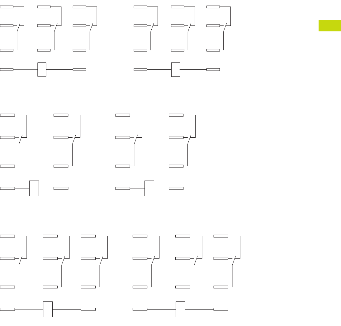
Logic Control Products CA08100001K—June 2012 www.eatoncanada.ca T40-81
40
40
40
40
40
40
40
40
40
40
40
40
40
40
40
40
40
40
40
40
40
40
40
40
40
40
40
40
40
40
40.4
Control Relays and Timers
General Purpose Plug-In Relays
Wiring Diagrams
D5PA3L and D5PA3S
D5PR2/D5PF2 DPDT
D5PR3/D5PF3 3PDT
COM
N.O.
N.C.
INPUT
A1 A2
11
12
31 21
34 24
32 22
14
IEC
COM
N.O.
N.C.
INPUT
B
A
7
4
1
9
8
56
23
NEMA
A1
11
14
12
A2
21
24
22
IEC
A
7
4
1
B
9
6
3
NEMA
A1 A2
11
12
31 21
34 24
32 22
14
IEC
B
A
7
4
1
9
8
56
23
NEMA
Tab40book.fm Page 81 Wednesday, July 4, 2012 10:05 PM
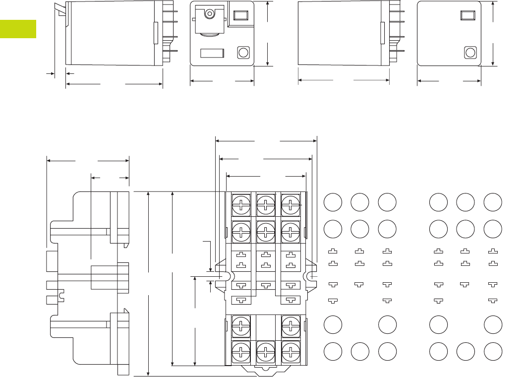
T40-82 Logic Control Products CA08100001K—June 2012 www.eatoncanada.ca
40
40
40
40
40
40
40
40
40
40
40
40
40
40
40
40
40
40
40
40
40
40
40
40
40
40
40
40
40
40
40.4
Control Relays and Timers
General Purpose Plug-In Relays
Dimensions
Approximate Dimensions in Inches (mm)
D5PR and D5PF
D5PA2
1.97
(50.0)
0.20
(6.1) 1.37
(34.9)
1.40
(35.4)
2.10
(53.1)
1.37
(34.9)
1.40
(35.4)
3.14
(80.0)
0.15
(3.8)
9 8
B
3.00
(76.0)
32
7
A
1
1.69
(43.0)
1.53
(39.0)
65
1.37
(35.0)
4
1.03
(26.0)
21 31 11
22 32 12
24 34 14
A2 A1
6
32
54
1
B
987
AINPUT
COM
N.C.
N.O.
1.50
(38.0)
0.40
(10.0)
IEC
INPUT
BA
79 8
21
3
45
6
6
32
54
1
B
987
AINPUT
COM
N.C.
N.O.
NEMA
INPUT
Tab40book.fm Page 82 Wednesday, July 4, 2012 10:05 PM
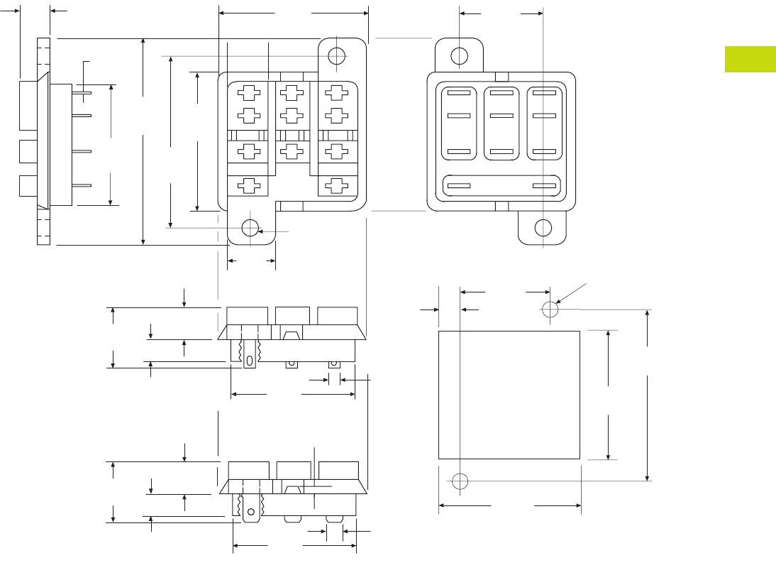
Logic Control Products CA08100001K—June 2012 www.eatoncanada.ca T40-83
40
40
40
40
40
40
40
40
40
40
40
40
40
40
40
40
40
40
40
40
40
40
40
40
40
40
40
40
40
40
40.4
Control Relays and Timers
General Purpose Plug-In Relays
Approximate Dimensions in Inches (mm)
D5PA3L and D5PA3S
0.63
(16.2)
2.03
(51.0)
Solder Type Terminals
0.24
(6.1)
0.29
(7.5)
1.37
(34.7)
0.50
(2.5)
1.37
(34.7)
1.68
(42.8)
1.50
(38.1)
0.13
(3.3)
0.16 Dia.
(4.2)
2 Holes
0.30
(7.5)
0.02
(0.5)
1.25
(31.7)
4
7
1
A B
5
8
2
0.87
(22.2)
6
9
3
0.28
(5.3)
1.39
(35.4)
1.27
(32.3)
1.68
(42.6)
Recommended
Chassis Cutout 0.87
(22.2)
0.16 (3.9)
Dia. Holes
3/16 Q.C. Type Terminals 0.19 (4.7)
0.18
(4.7)
Typ.
1.37
(34.7)
0.63
(16.2)
0.24
(6.1)
0.29
(7.5)
Tab40book.fm Page 83 Wednesday, July 4, 2012 10:05 PM
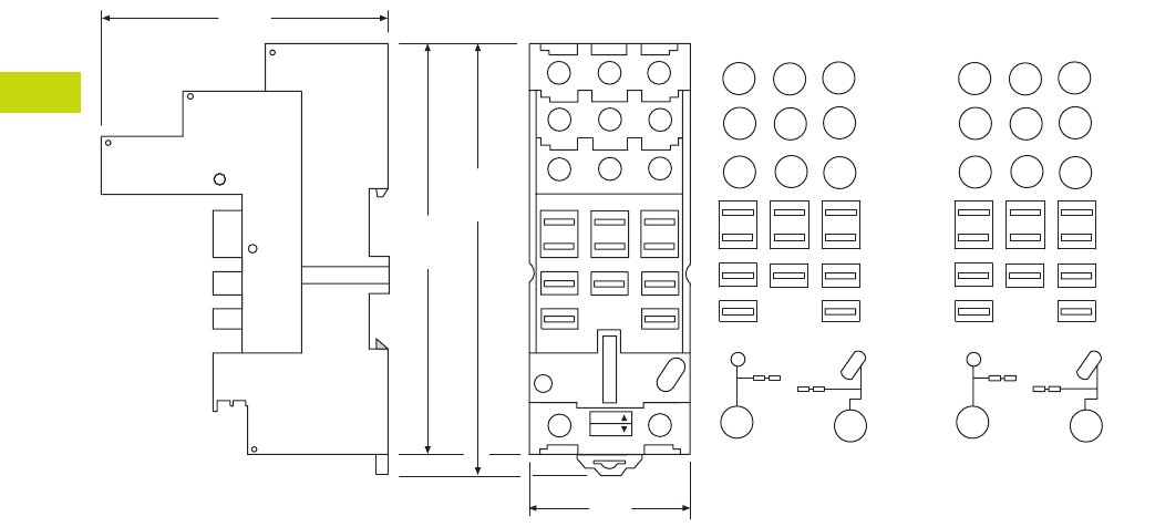
T40-84 Logic Control Products CA08100001K—June 2012 www.eatoncanada.ca
40
40
40
40
40
40
40
40
40
40
40
40
40
40
40
40
40
40
40
40
40
40
40
40
40
40
40
40
40
40
40.4
Control Relays and Timers
General Purpose Plug-In Relays
Approximate Dimensions in Inches (mm)
D5PAL
A2 A1
72
INPUT
12
1
14
4
11
7
22
3
32
2
21
24
9
34
5
6
31
8
12
14
11
22 32
21
24 34
31
A2 A1
Coil Jumper
Buss
BA
987
654
1
2
3
INPUT
MODULE
INPUT
COM
N.O.
N.C.
1.40
(36.0)
2.48
(63.0)
3.62
(92.0)
3.70
(96.0)
NEMA:
IEC:
IEC
INPUTINPUT
1
4
7
32
9
5
6
8
BA
Coil Jumper
Buss
BA
987
654
1
2
3
INPUT
MODULE
INPUT
COM
N.O.
N.C.
NEMA
INPUTINPUT
Tab40book.fm Page 84 Wednesday, July 4, 2012 10:05 PM
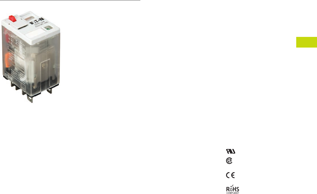
Logic Control Products CA08100001K—June 2012 www.eatoncanada.ca T40-85
40
40
40
40
40
40
40
40
40
40
40
40
40
40
40
40
40
40
40
40
40
40
40
40
40
40
40
40
40
40
40.4
Control Relays and Timers
General Purpose Plug-In Relays
D7 Series Relay Contents
Description Page
D1PR/D1PF Series . . . . . . . . . . . . . . . . . . . . . . . . . . . . T40-46
D2PR/D2PF Series . . . . . . . . . . . . . . . . . . . . . . . . . . . . T40-51
D3PR/D3PF Series . . . . . . . . . . . . . . . . . . . . . . . . . . . . T40-61
D4 Series . . . . . . . . . . . . . . . . . . . . . . . . . . . . . . . . . . . T40-71
D5PR/D5PF Series . . . . . . . . . . . . . . . . . . . . . . . . . . . . T40-75
D7PR/D7PF Series
Catalogue Number Selection. . . . . . . . . . . . . . . . . . T40-86
Product Selection . . . . . . . . . . . . . . . . . . . . . . . . . . T40-86
Accessories . . . . . . . . . . . . . . . . . . . . . . . . . . . . . . . T40-89
Technical Data and Specifications . . . . . . . . . . . . . . T40-90
Wiring Diagrams . . . . . . . . . . . . . . . . . . . . . . . . . . . T40-92
Dimensions . . . . . . . . . . . . . . . . . . . . . . . . . . . . . . . T40-93
D8 Series . . . . . . . . . . . . . . . . . . . . . . . . . . . . . . . . . . . T40-100
D9 Series . . . . . . . . . . . . . . . . . . . . . . . . . . . . . . . . . . . T40-106
Accessories . . . . . . . . . . . . . . . . . . . . . . . . . . . . . . . . . T40-110
D7PR/D7PF Series
Product Description
The D7 Series is a cost-
effective control relay with
high dielectric strength and
high current-carrying
capacity.
Features
D7PR
●Arc barrier equipped relay
with high dielectric
strength
●Panel and DIN rail
mounting
D7PF
●Flag indicator shows relay
status in manual or
powered condition
●Bipolar LED status lamp
allows for reverse polarity
applications
●Shows coil ON or OFF
status
●Ideal in low light
conditions
●Colour-coded pushbutton
identifies AC coils with red
or DC coils with blue
pushbuttons
●Allows for manual
operation of relay
without the need for
coil power
●Ideal for field service
personnel to test
control circuits
●Lock-down door, when
activated, holds
pushbutton and contacts in
the operate position
●Excellent for analyzing
circuit problems
●Finger-grip cover allows
operator to remove relays
from sockets more easily
than conventional relays
●White plastic ID tag/write
label used for identification
of relays in multi-relay
circuits
Standards and Certifications
File # E37317, E65657
File # LR217017,
LR217069
Tab40book.fm Page 85 Wednesday, July 4, 2012 10:05 PM
T40-86 Logic Control Products CA08100001K—June 2012 www.eatoncanada.ca
40
40
40
40
40
40
40
40
40
40
40
40
40
40
40
40
40
40
40
40
40
40
40
40
40
40
40
40
40
40
40.4
Control Relays and Timers
General Purpose Plug-In Relays
Catalogue Number Selection
D7 Series
Product Selection
D7 Relay/Socket Quick Reference
D
7
P
R
1 1
A
Contact Configuration
1 = SPDT
2 = DPDT
3 = 3PDT
4 = 4PDT
Options
Blank = Plain cover (D7PR only)
A = LED test button, flag indicator,
lock-down door, finger-grip cover,
ID tag (D7PF only)
1 = Indicating light (D7PR only)
Family Type
D7PR = Standard relay
D7PF = Full featured relay
Coil Voltage
A = 120 Vac
A1 = 110 Vdc
B = 240 Vac
P = 6 Vac
P1 = 6 Vdc
R = 12 Vac
R1 = 12 Vdc
T = 24 Vac
T1 = 24 Vdc
W = 48 Vac
W1 = 48 Vdc
Relay
Type Socket/Adapter Clip
Module
Type ID Tag Jumper
D7PR1, D7PR2,
D7PF1, D7PF2
D7PAA PQC-1342 B — —
PQC-1349 B — —
D7PA9 PQC-1342 None — —
PFC-D2D72 — None — —
D7PR3, D7PF3 D7PAB PQC-1783 A — —
PMC-1783 A — —
PFC-D73 — None — —
D7PR4, D7PF4 D7PAD PQC-1784 A — —
PMC-1784 A — —
PFC-D74 — None — —
Tab40book.fm Page 86 Wednesday, July 4, 2012 10:05 PM
Logic Control Products CA08100001K—June 2012 www.eatoncanada.ca T40-87
40
40
40
40
40
40
40
40
40
40
40
40
40
40
40
40
40
40
40
40
40
40
40
40
40
40
40
40
40
40
40.4
Control Relays and Timers
General Purpose Plug-In Relays
D7 Series
Coil
Voltage
Contact
Configuration
Coil Resistance
(Ohms)
Catalogue
Number
Full Featured
120 Vac SPDT 4430 D7PF1AA
6 Vac SPDT 9.6 D7PF1AP
6 Vdc SPDT 40 D7PF1AP1
12 Vac SPDT 46 D7PF1AR
24 Vdc SPDT 650 D7PF1AT1
48 Vac SPDT 788 D7PF1AW
48 Vdc SPDT 2600 D7PF1AW1
120 Vac DPDT 4430 D7PF2AA
110/125 Vdc DPDT 11,000 D7PF2AA1
220/240 Vac DPDT 15,720 D7PF2AB
6 Vac DPDT 9.6 D7PF2AP
6 Vdc DPDT 40 D7PF2AP1
12 Vac DPDT 46 D7PF2AR
12 Vdc DPDT 160 D7PF2AR1
24 Vac DPDT 180 D7PF2AT
24 Vdc DPDT 650 D7PF2AT1
48 Vac DPDT 788 D7PF2AW
48 Vdc DPDT 2600 D7PF2AW1
120 Vac 3PDT 2770 D7PF3AA
6 Vac 3PDT 6 D7PF3AP
6 Vdc 3PDT 25 D7PF3AP1
12 Vac 3PDT 25.3 D7PF3AR
24 Vac 3PDT 103 D7PF3AT
24 Vdc 3PDT 400 D7PF3AT1
48 Vac 3PDT 412 D7PF3AW
48 Vdc 3PDT 1600 D7PF3AW1
120 Vac 4PDT 2220 D7PF4AA
110/125 Vdc 4PDT 7340 D7PF4AA1
240 Vac 4PDT 9120 D7PF4AB
6 Vac 4PDT 5.4 D7PF4AP
6 Vdc 4PDT 24 D7PF4AP1
12 Vac 4PDT 21.2 D7PF4AR
12 Vdc 4PDT 96 D7PF4AR1
24 Vac 4PDT 84.5 D7PF4AT
24 Vdc 4PDT 388 D7PF4AT1
48 Vdc 4PDT 1550 D7PF4AW
48 Vac 4PDT 410 D7PF4AW1
D7 Series Relay
Tab40book.fm Page 87 Wednesday, July 4, 2012 10:05 PM
T40-88 Logic Control Products CA08100001K—June 2012 www.eatoncanada.ca
40
40
40
40
40
40
40
40
40
40
40
40
40
40
40
40
40
40
40
40
40
40
40
40
40
40
40
40
40
40
40.4
Control Relays and Timers
General Purpose Plug-In Relays
D7 Series, continued
Coil
Voltage
Contact
Configuration
Coil Resistance
(Ohms)
Catalogue
Number
Plain Cover with LED
120 Vac SPDT 4430 D7PR11A
110/125 Vdc SPDT 11,000 D7PR11A1
6 Vac SPDT 9.6 D7PR11P
12 Vac SPDT 46 D7PR11R
12 Vdc SPDT 160 D7PR11R1
24 Vac SPDT 180 D7PR11T
24 Vdc SPDT 650 D7PR11T1
48 Vdc SPDT 2600 D7PR11W1
120 Vac 3PDT 2770 D7PR31A
240 Vac 3PDT 12100 D7PR31B
24 Vac 3PDT 103 D7PR31T
24 Vdc 3PDT 400 D7PR31T1
48 Vdc 3PDT 1600 D7PR31W1
120 Vac 4PDT 2220 D7PR41A
12 Vdc 4PDT 100 D7PR41R1
24 Vdc 4PDT 388 D7PR41T1
Plain Cover
120 Vac SPDT 4430 D7PR1A
110/125 Vdc SPDT 11000 D7PR1A1
220/240 Vac SPDT 15720 D7PR1B
6 Vac SPDT 9.6 D7PR1P
12 Vdc SPDT 160 D7PR1R1
24 Vac SPDT 180 D7PR1T
24 Vdc SPDT 650 D7PR1T1
48 Vdc SPDT 2600 D7PR1W1
120 Vac DPDT 4430 D7PR2A
110/125 Vdc DPDT 11000 D7PR2A1
220/240 Vac DPDT 15720 D7PR2B
6 Vac DPDT 9.6 D7PR2P
6 Vdc DPDT 40 D7PR2P1
12 Vac DPDT 46 D7PR2R
12 Vdc DPDT 160 D7PR2R1
24 Vac DPDT 180 D7PR2T
24 Vdc DPDT 650 D7PR2T1
120 Vac 3PDT 2770 D7PR3A
240 Vac 3PDT 12100 D7PR3B
6 Vac 3PDT 6 D7PR3P
12 Vac 3PDT 25.3 D7PR3R
12 Vdc 3PDT 100 D7PR3R1
24 Vac 3PDT 103 D7PR3T
24 Vdc 3PDT 400 D7PR3T1
48 Vdc 3PDT 1600 D7PR3W1
120 Vac 4PDT 2220 D7PR4A
110/125 Vdc 4PDT 7340 D7PR4A1
240 Vac 4PDT 9120 D7PR4B
6 Vac 4PDT 5.4 D7PR4P
24 Vac 4PDT 84.5 D7PR4T
24 Vdc 4PDT 388 D7PR4T1
48 Vdc 4PDT 1550 D7PR4W1
D7 Series Relay
Tab40book.fm Page 88 Wednesday, July 4, 2012 10:05 PM

Logic Control Products CA08100001K—June 2012 www.eatoncanada.ca T40-89
40
40
40
40
40
40
40
40
40
40
40
40
40
40
40
40
40
40
40
40
40
40
40
40
40
40
40
40
40
40
40.4
Control Relays and Timers
General Purpose Plug-In Relays
Accessories
D7 Sockets and Accessories
Note
Protection category (finger safe), EN 60529: IP20.
Type
Module
Size
Nominal Voltage
(Max. for Sockets)
Nominal
Current Mounting Style Wire Size
Wire
Connection
Standard
Pack
Catalogue
Number
Socket B 300 16 DIN rail/panel 12/14 (2) AWG, 4/2.5 (2) mm2Screw clamping — D7PAA
None 300 10 DIN rail/panel 12/14 (2) AWG, 4/2.5 (2) mm2Screw clamping 1 D7PA9
A 300 16 DIN rail/panel 12/14 (2) AWG, 4/2.5 (2) mm2Screw clamping — D7PAD
A 300 16 DIN rail/panel 12/14 (2) AWG, 4/2.5 (2) mm2Screw clamping — D7PAB
Flange mount adapter — — — Flange — — 25 PFC-D2D72
— — — Flange — — 25 PFC-D73
— — — Flange — — 25 PFC-D74
Metal spring clip — — — — — — 25 PQC-1342
Plastic ID clip — — — — — — 10 PQC-1349
Metal spring clip — — — — — — 25 PQC-1784
Plastic ID clip — — — — — — 10 PMC-1784
Hold-down spring — — — — — — 25 PYC-B2
Metal spring clip — — — — — — 10 PQC-1783
Plastic ID clip — — — — — — 10 PMC-1783
Protection diode A 6 to 250 Vdc — — — — 20 MOD-AD250
LED indicator A 24 Vac/Vdc — — — — 20 MOD-ALG24
A 120/240 Vac/Vdc — — — — 20 MOD-ALG240
MOV suppressor A 120 Vac/Vdc — — — — 20 MOD-AMV120
A 24 Vac/Vdc — — — — 20 MOD-AMV24
A 240 Vac/Vdc — — — — 20 MOD-AMV240
R/C suppressor A 6 to 24 Vac/Vdc — — — — 20 MOD-RC24
A 110 to 240 Vac/Vdc — — — — 20 MOD-RC240
Protection diode B 6 to 250 Vdc — — — — 20 MOD-BD250
LED indicator B 24 Vac/Vdc — — — — 20 MOD-BLG24
B 120/240 Vac/Vdc — — — — 20 MOD-BLG240
MOV suppressor B 120 Vac/Vdc — — — — 20 MOD-BMV120
B 24 Vac/Vdc — — — — 20 MOD-BMV24
B 240 Vac/Vdc — — — — 20 MOD-BMV240
Plastic DIN rail end stop — — — — — — 25 PFP-P
Tab40book.fm Page 89 Wednesday, July 4, 2012 10:05 PM

T40-90 Logic Control Products CA08100001K—June 2012 www.eatoncanada.ca
40
40
40
40
40
40
40
40
40
40
40
40
40
40
40
40
40
40
40
40
40
40
40
40
40
40
40
40
40
40
40.4
Control Relays and Timers
General Purpose Plug-In Relays
Technical Data and Specifications
D7PR Relay
Description D7PR (SPDT) D7PR (DPDT) D7PR (3PDT) D7PR (4PDT)
Contact Characteristics
Contact rating 20A 15A 15A 15A
Terminal style Plug-in Plug-in Plug-in Plug-in
Contact materials Silver alloy Silver alloy Silver alloy Silver alloy
Maximum switching voltage 300V 300V 300V 300V
Switching current at voltage—resistive 20A at 277 Vac 50/60 Hz 15A at 120 Vac 50/60 Hz 15A at 120 Vac 50/60 Hz 15A at 120 Vac 50/60 Hz
20A at 120 Vac 50/60 Hz 12A at 277 Vac 50/60 Hz 12A at 277 Vac 50/60 Hz 12A at 277 Vac 50/60 Hz
— 10A at 277 Vac 50/60 Hz — —
20A at 28 Vdc 12A at 28 Vdc 12A at 28 Vdc 12A at 28 Vdc
Switching current at voltage 1/2 hp at 120 Vac 1/2 hp at 120 Vac 1/2 hp at 120 Vac 1/2 hp at 120 Vac
1 hp at 250 Vac 1 hp at 250 Vac 3/4 hp at 250 Vac 3/4 hp at 250 Vac
Pilot duty B300 B300 B300 B300
Minimum switching requirement 100 mA at 5 Vdc (0.5W) 100 mA at 5 Vdc (0.5W) 100 mA at 5 Vdc (0.5W) 100 mA at 5 Vdc (0.5W)
Coil Characteristics
Operating range
% of nominal (AC) 85 to 110% 85 to 110% 85 to 110% 85 to 110%
% of nominal (DC) 80 to 110% 80 to 110% 80 to 110% 80 to 110%
Average consumption 1.2 VA 1.2 VA 1.5 VA 1.5 VA
0.9W 0.9W 1.4W 1.5W
Dropout voltage threshold 15% (AC) 15% (AC) 15% (AC) 15% (AC)
10% (DC) 10% (DC) 10% (DC) 10% (DC)
Performance
Electrical life (UL 508) operations at rated current 100,000 operations 100,000 operations 200,000 operations 200,000 operations
Mechanical life operations unpowered 10,000,000 operations 10,000,000 operations 10,000,000 operations 10,000,000 operations
Response time 20 ms 20 ms 20 ms 20 ms
Dielectric strength
Between coil and contact Vac (rms) 2500V (rms) 2500V (rms) 2500V (rms) 2500V (rms)
Between poles Vac (rms) 1500V (rms) 1500V (rms) 2500V (rms) 2500V (rms)
Environment
Ambient air temperature around the device
Operation –40˚ to 131˚F (–40˚ to 55˚C) –40˚ to 131˚F (–40˚ to 55˚C) –40˚ to 131˚F (–40˚ to 55˚C) –40˚ to 131˚F (–40˚ to 55˚C)
Storage –40˚ to 185˚F (–40˚ to 85˚C) –40˚ to 185˚F (–40˚ to 85˚C) –40˚ to 185˚F (–40˚ to 85˚C) –40˚ to 185˚F (–40˚ to 85˚C)
Vibration resistance—operational 3 g-n at 10–55 Hz 3 g-n at 10–55 Hz 3 g-n at 10–55 Hz 3 g-n at 10–55 Hz
Shock resistance 10 g-n 10 g-n 10 g-n 10 g-n
Degree of protection IP40 IP40 IP40 IP40
Features
Cover options Plain cover Plain cover Plain cover Plain cover
Features Mechanical flag indicator
(optional LED)
Mechanical flag indicator
(optional LED)
Mechanical flag indicator
(optional LED)
Mechanical flag indicator
(optional LED)
Product certifications RoHS/UL/CE/CSA RoHS/UL/CE/CSA RoHS/UL/CE/CSA RoHS/UL/CE/CSA
Tab40book.fm Page 90 Wednesday, July 4, 2012 10:05 PM

Logic Control Products CA08100001K—June 2012 www.eatoncanada.ca T40-91
40
40
40
40
40
40
40
40
40
40
40
40
40
40
40
40
40
40
40
40
40
40
40
40
40
40
40
40
40
40
40.4
Control Relays and Timers
General Purpose Plug-In Relays
D7PF Relay
Description D7PF (SPDT) D7PF (DPDT) D7PF (3PDT) D7PF (4PDT)
Contact Characteristics
Contact rating 20A 15A 15A 15A
Terminal style Plug-in Plug-in Plug-in Plug-in
Contact materials Silver alloy Silver alloy Silver alloy Silver alloy
Maximum switching voltage 300V 300V 300V 300V
Switching current at voltage—resistive
20A at 277 Vac 50/60 Hz 15A at 120 Vac 50/60 Hz 15A at 120 Vac 50/60 Hz 15A at 120 Vac 50/60 Hz
20A at 277 Vac 50/60 Hz 12A at 277 Vac 50/60 Hz 12A at 277 Vac 50/60 Hz 12A at 277 Vac 50/60 Hz
— 10A at 277 Vac 50/60 Hz — —
20A at 28 Vdc 12A at 28 VDC 12A at 28 Vdc 12A at 28 Vdc
Switching current at voltage 1/2 hp at 120 Vac 1/2 hp at 120 Vac 3/4 hp at 250 Vac 1/2 hp at 120 Vac
1 hp at 250 Vac 1 hp at 250 Vac 1/2 hp at 120 Vac 3/4 hp at 250 Vac
Pilot duty B300 B300 B300 B300
Minimum switching requirement 100 mA at 5 Vdc (0.5W) 100 mA at 5 Vdc (0.5W) 100 mA at 5 Vdc (0.5W) 100 mA at 5 Vdc (0.5W)
Coil Characteristics
Operating range
% of nominal (AC) 85 to 110% 85 to 110% 85 to 110% 85 to 110%
% of nominal (DC) 80 to 110% 80 to 110% 80 to 110% 80 to 110%
Average consumption 1.2 VA 1.2 VA 1.5 VA 1.5 VA
0.9W 0.9W 1.4W 1.5W
Dropout voltage threshold 15% (AC) 15% (AC) 15% (AC) 15% (AC)
10% (DC) 10% (DC) 10% (DC) 10% (DC)
Performance
Electrical life (UL 508) operations at rated current 100,000 operations 100,000 operations 200,000 operations 200,000 operations
Mechanical life operations unpowered 10,000,000 operations 10,000,000 operations 10,000,000 operations 10,000,000 operations
Response time 20 ms 20 ms 20 ms 20 ms
Dielectric strength
Between coil and contact Vac (rms) 2500V (rms) 2500V (rms) 2500V (rms) 2500V (rms)
Between poles Vac (rms) 1500V (rms) 1500V (rms) 2500V (rms) 2500V (rms)
Environment
Ambient air temperature around the device
Operation –40˚ to 131˚F (–40˚ to 55˚C) –40˚ to 131˚F (–40˚ to 55˚C) –40˚ to 131ºF (–40˚ to 55˚C) –40˚ to 131˚F (–40˚ to 55˚C)
Storage –40˚ to 185˚F (–40˚ to 85˚C) –40˚ to 185˚F (–40˚ to 85˚C) –40˚ to 185ºF (–40˚ to 85˚C) –40˚ to 185˚F (–40˚ to 85˚C)
Vibration resistance—operational 3 g-n at 10–55 Hz 3 g-n at 10–55 Hz 3 g-n at 10–55 Hz 3 g-n at 10–55 Hz
Shock resistance 10 g-n 10 g-n 10 g-n 10 g-n
Degree of protection IP40 IP40 IP40 IP40
Features
Cover options Full featured Full featured Full featured Full featured
Features Locking pushbutton/
Bipolar LED/
Removable ID tag/
Mechanical flag indicator
Locking pushbutton/
Bipolar LED/
Removable ID tag/
Mechanical flag indicator
Locking pushbutton/
Bipolar LED/
Removable ID tag/
Mechanical flag indicator
Locking pushbutton/
Bipolar LED/
Removable ID tag/
Mechanical flag indicator
Product certifications RoHS/UL/CE/CSA RoHS/UL/CE/CSA RoHS/UL/CE/CSA RoHS/UL/CE/CSA
Tab40book.fm Page 91 Wednesday, July 4, 2012 10:05 PM
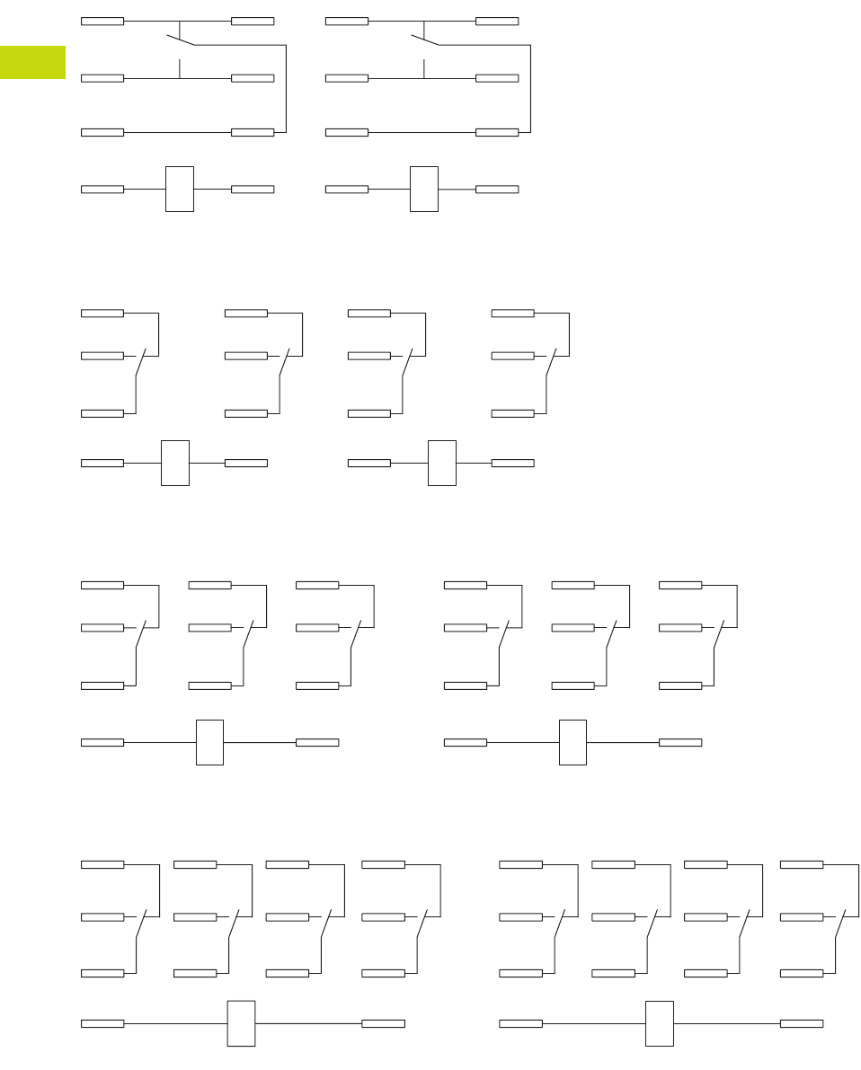
T40-92 Logic Control Products CA08100001K—June 2012 www.eatoncanada.ca
40
40
40
40
40
40
40
40
40
40
40
40
40
40
40
40
40
40
40
40
40
40
40
40
40
40
40
40
40
40
40.4
Control Relays and Timers
General Purpose Plug-In Relays
Wiring Diagrams
D7PR1/D7PF1
D7PR2/D7PF2
D7PR3/D7PF3
D7PR4/D7PF4
A2
A1
11
14
12
41
44
42
IEC
5
13
9
1
8
12
14
4
NEMA
42
44
12
14
A1
11
A2
41
IEC
4
8
1
5
13
12
14
9
NEMA
11
A1
14
21
24
12 22
41
44
42
A2
IEC
9
13
5
10
6
12
12
8
4
14
NEMA
A1 A2
11 21
14 24
31
34
22
12 32
44
41
42
IEC
13 14
10
911
56
12
7
3
12
4
8
NEMA
Tab40book.fm Page 92 Wednesday, July 4, 2012 10:05 PM
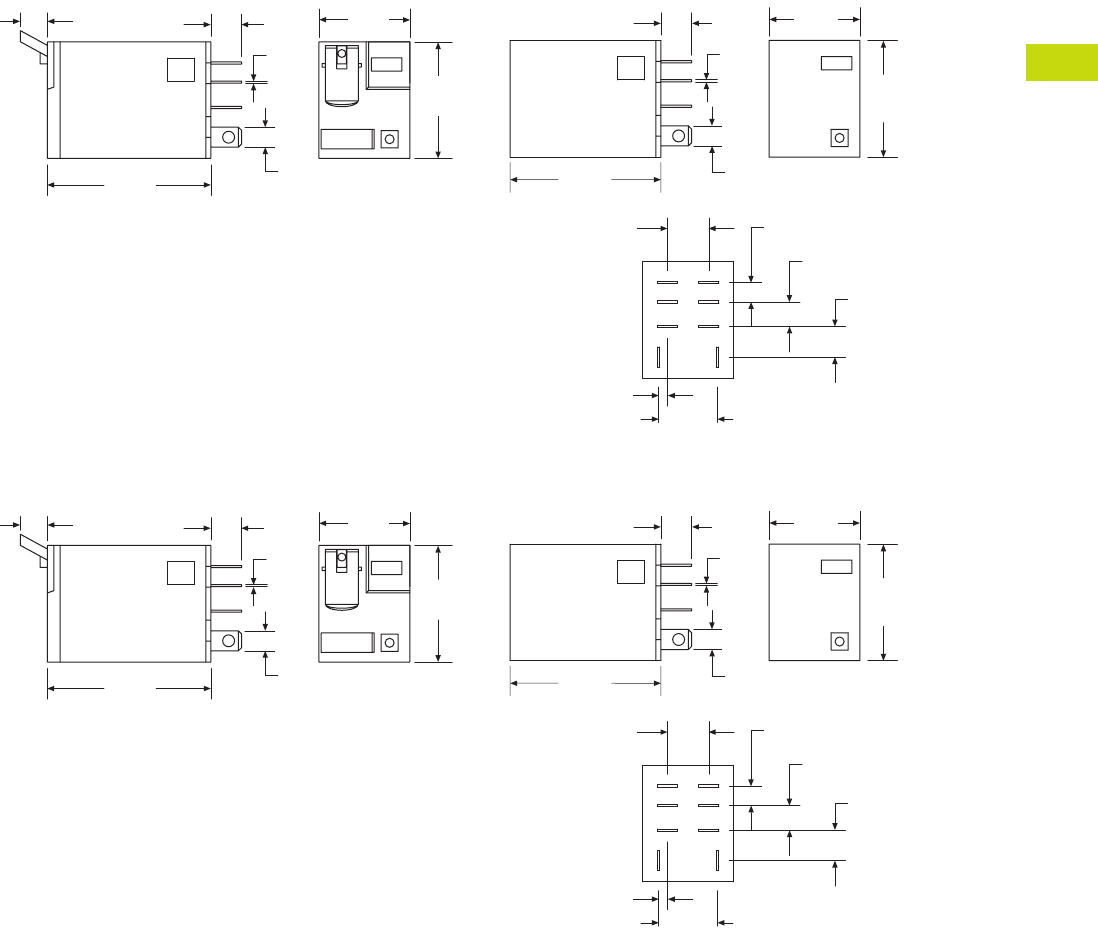
Logic Control Products CA08100001K—June 2012 www.eatoncanada.ca T40-93
40
40
40
40
40
40
40
40
40
40
40
40
40
40
40
40
40
40
40
40
40
40
40
40
40
40
40
40
40
40
40.4
Control Relays and Timers
General Purpose Plug-In Relays
Dimensions
Approximate Dimensions in Inches (mm)
D7PR1/D7PF1
D7PR2/D7PF2
0.16
(4.7)
0.23
(5.9)
0.30
(7.5)
0.38
(9.9)
0.55
(14.1)
0.08
(2.1)2X
0.83
(21.0)
1.10
(27.9)
0.19
(4.8)
0.02
(0.5)
0.29
(7.4)
1.40
(35.5)
0.83
(21.0)
1.10
(27.9)
1.54
(39.1)
0.29
(7.4)
0.02
(0.5)
0.19
(4.8)
0.27
(7.0)
0.16
(4.7)
0.23
(5.9)
0.30
(7.5)
0.38
(9.9)
0.55
(14.1)
0.08
(2.1)2X
0.83
(21.0)
1.10
(27.9)
0.19
(4.8)
0.02
(0.5)
0.29
(7.4)
1.40
(35.5)
0.83
(21.0)
1.10
(27.9)
1.54
(39.1)
0.29
(7.4)
0.02
(0.5)
0.19
(4.8)
0.27
(7.0)
Tab40book.fm Page 93 Wednesday, July 4, 2012 10:05 PM
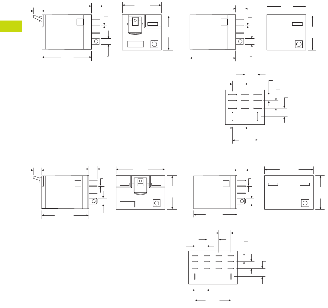
T40-94 Logic Control Products CA08100001K—June 2012 www.eatoncanada.ca
40
40
40
40
40
40
40
40
40
40
40
40
40
40
40
40
40
40
40
40
40
40
40
40
40
40
40
40
40
40
40.4
Control Relays and Timers
General Purpose Plug-In Relays
Approximate Dimensions in Inches (mm)
D7PR3/D7PF3
D7PR4/D7PF4
1.60
(40.0)
1.10
(27.9)
1.20
(30.8)
0.27
(7.0)
0.26
(6.6)
0.79
(20.0)
0.19
(4.7)
0.23
(5.9)0.26
(6.7)
0.39
(9.9)2X
0.19
(4.8)
0.02
(0.5)
0.39
(9.9)
0.39
(9.9)
1.20
(30.8)
1.10
(27.9)
0.02
(0.5)
0.19
(4.8)
0.29
(7.4)
1.40
(35.5)
1.60
(40.6)
1.60
(40.6)
1.54
(39.1)
0.02
(0.5)
0.19
(4.8)
0.38
(9.9)
0.16
(4.7)
0.23
(5.9) 0.26
(6.7)
1.18
(29.9)
0.38
(9.9)2X
1.10
(27.9)
0.38
(9.9)
0.38
(9.9)
0.26
(6.6)
1.10
(27.9)
1.40
(35.5)
0.19
(4.8)
0.29
(7.4) 0.02
(0.5)
0.27
(7.0)
Tab40book.fm Page 94 Wednesday, July 4, 2012 10:05 PM
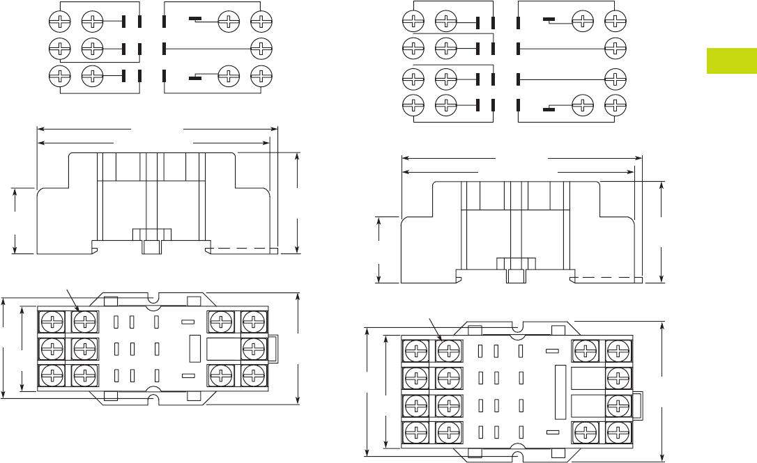
Logic Control Products CA08100001K—June 2012 www.eatoncanada.ca T40-95
40
40
40
40
40
40
40
40
40
40
40
40
40
40
40
40
40
40
40
40
40
40
40
40
40
40
40
40
40
40
40.4
Control Relays and Timers
General Purpose Plug-In Relays
Approximate Dimensions in Inches (mm)
D7PA3 D7PA4
1.44
(36.6)
1.27
(32.5)
1
2
3
4
5
7
8
911
10
6
Combination Slotted/Phillips
Head Screws 6-32 x 5/16"
2.58 (67.5) Max.
2.74 (69.8)
0.65
(16.6)
1.59
(40.5)
Max.
1.09
(27.8)
Max.
Wiring Diagram (Top View)
1
2
3
4
6
10
11
7
58
9
1
2
5
6
3
4
7
8
9
1214
11
13
10
1.83
(46.5)
1.63
(41.4)
2.58 (67.5) Max.
2.74 (69.8)
Combination Slotted/Phillips
Head Screws 6-32 x 5/16"
0.65
(16.6)
1.98
(50.5)
Max.
1.09
(27.8)
Max.
Wiring Diagram (Top View)
2
3
4
6
1
5
8
7
13
9
10
11
14
12
Tab40book.fm Page 95 Wednesday, July 4, 2012 10:05 PM
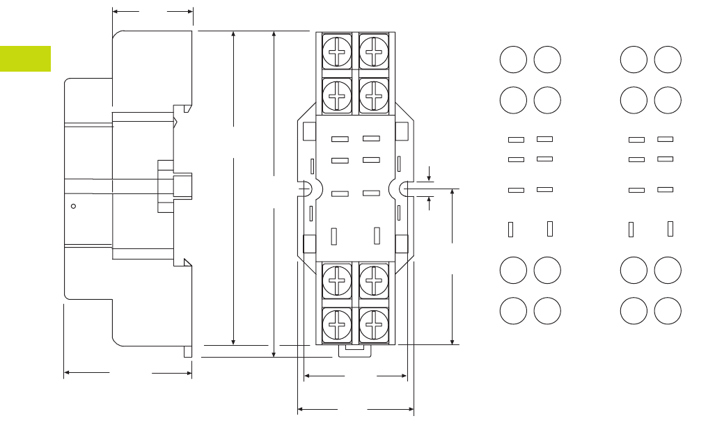
T40-96 Logic Control Products CA08100001K—June 2012 www.eatoncanada.ca
40
40
40
40
40
40
40
40
40
40
40
40
40
40
40
40
40
40
40
40
40
40
40
40
40
40
40
40
40
40
40.4
Control Relays and Timers
General Purpose Plug-In Relays
Approximate Dimensions in Inches (mm)
D7PA9 Standard Mount
8
5
1.02
(26.0)
1.17
(29.0)
4
14
12
1.03
(26.0)
0.16
(4.0)
1
13
1.26
(32.0)
9
2.73
(69.0)
2.52
(64.0)
44
42
14
12
41 11
A2 A1
N.C.
N.O.
COM
INPUT
85
4
1
14 13 14 13
12 9
0.71
(18.0)
IEC
INPUT
8
4
14
5
1
13
12 9
N.C.
N.O.
COM
INPUT
85
4
1
12 9
NEMA
INPUT
Tab40book.fm Page 96 Wednesday, July 4, 2012 10:05 PM
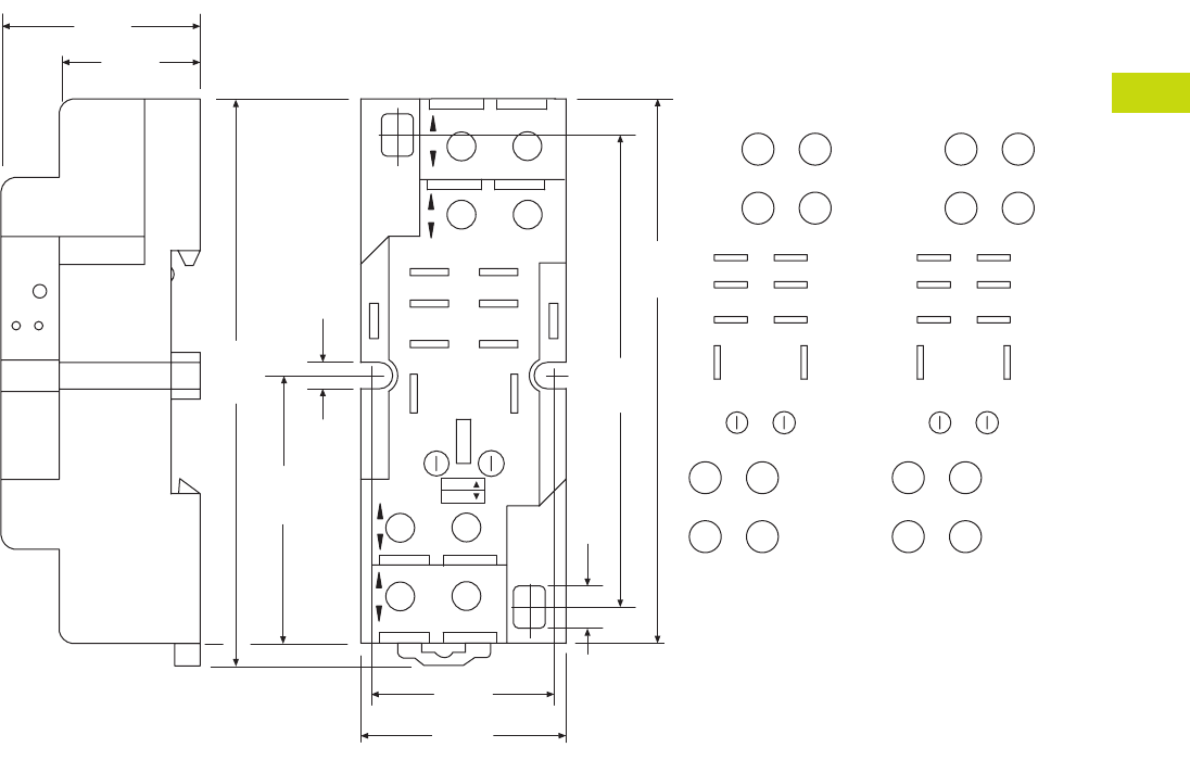
Logic Control Products CA08100001K—June 2012 www.eatoncanada.ca T40-97
40
40
40
40
40
40
40
40
40
40
40
40
40
40
40
40
40
40
40
40
40
40
40
40
40
40
40
40
40
40
40.4
Control Relays and Timers
General Purpose Plug-In Relays
Approximate Dimensions in Inches (mm)
D7PAA
COM
N.O.
N.C.
INPUT
INPUT
1.18
(30.0)
0.24
(6.0)
2.67
(68.0)
3.14
(80.0)
1.18
(30.0)
3.33
(84.0)
1.57
(40.0)
11
41
A1
A2
12
42
14
44
1.06
(26.0)
12 9
14 13
41
85
41 11
A2 A1
42 12
14
44
85
41
14 13
12 9
INPUT INPUT
0.16
(4.0)
0.74
(19.0)
NEMA:
IEC:
MODULE
INPUT
IEC
COM
N.O.
N.C.
INPUT
INPUT
912
13
14
41
8 5
85
41
14 13
12 9
MODULE
INPUT
NEMA
Tab40book.fm Page 97 Wednesday, July 4, 2012 10:05 PM
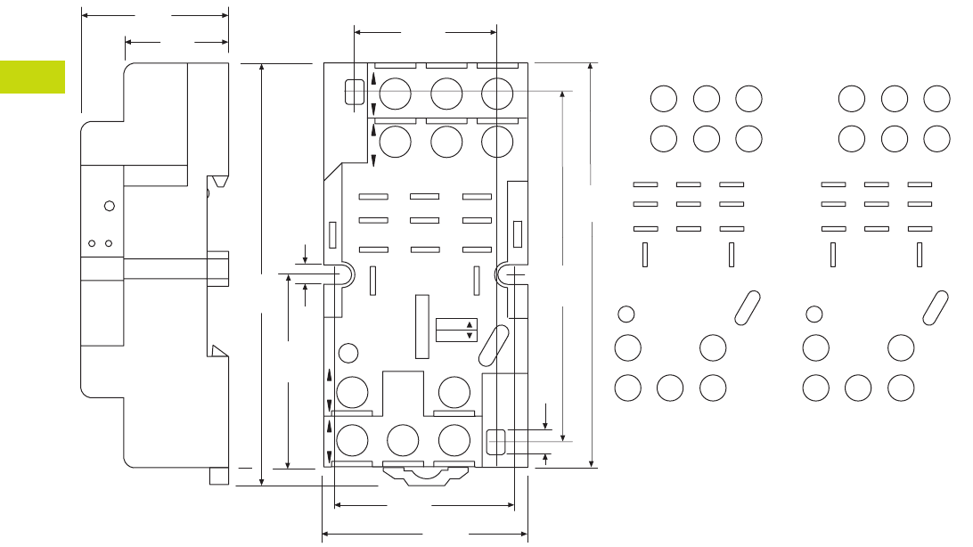
T40-98 Logic Control Products CA08100001K—June 2012 www.eatoncanada.ca
40
40
40
40
40
40
40
40
40
40
40
40
40
40
40
40
40
40
40
40
40
40
40
40
40
40
40
40
40
40
40.4
Control Relays and Timers
General Purpose Plug-In Relays
Approximate Dimensions in Inches (mm)
D7PAB
N.C.
N.O.
COM
INPUT
0.16
(4.0)
0.24
(6.0)
2.67
(68.0)
3.14
(80.0)
1.18
(30.0)
3.33
(84.0)
1.57
(40.0)
21 1141
12 10 9
INPUT
14
A2
13
A1
INPUT
8
4
42 22
65
21
44 24
12
14
A2
21
41
A1
11
44
42
14
12
24
22
421
865
12 10 9
14 13
1.57
(40.0)
1.45
(37.0)
1.10
(28.0)
0.74
(19.0)
MODULE
INPUT
IEC
NEMA:
IEC:
INPUT
N.C.
N.O.
COM
INPUT
1314
10 9
12
4
8
2
6
1
5
421
865
12 10 9
14 13
MODULE
INPUT
NEMA
INPUT
Tab40book.fm Page 98 Wednesday, July 4, 2012 10:05 PM
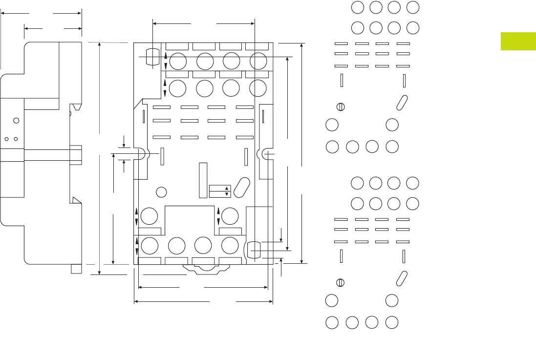
Logic Control Products CA08100001K—June 2012 www.eatoncanada.ca T40-99
40
40
40
40
40
40
40
40
40
40
40
40
40
40
40
40
40
40
40
40
40
40
40
40
40
40
40
40
40
40
40.4
Control Relays and Timers
General Purpose Plug-In Relays
Approximate Dimensions in Inches (mm)
D7PAD
INPUT
N.O.
N.C.
COM
1.96
(50.0)
0.24
(6.0)
2.67
(68.0)
3.14
(80.0)
1.18
(30.0)
A2
14
12
41
INPUTINPUT
A1
13
9
10
11
21
31
11
6
7
24
34
8
44
2
3
4
42 22
32
5
14
1
12
41
A2
11
21
A1
31
223242 12
34 2444 14
4321
8765
12 11 10 9
1.81
(46.0)
1.41
(36.0)
0.74
(19.0)
NEMA:
IEC:
MODULE
INPUT
IEC
INPUT
INPUT
N.O.
N.C.
COM
14
12
13
9
10
11
6
7
8
2
3
4
5
1
4321
8765
12 11 10 9
MODULE
INPUT
NEMA
INPUT
0.16
(4.0)
3.33
(84.0)
1.57
(40.0)
Tab40book.fm Page 99 Wednesday, July 4, 2012 10:05 PM
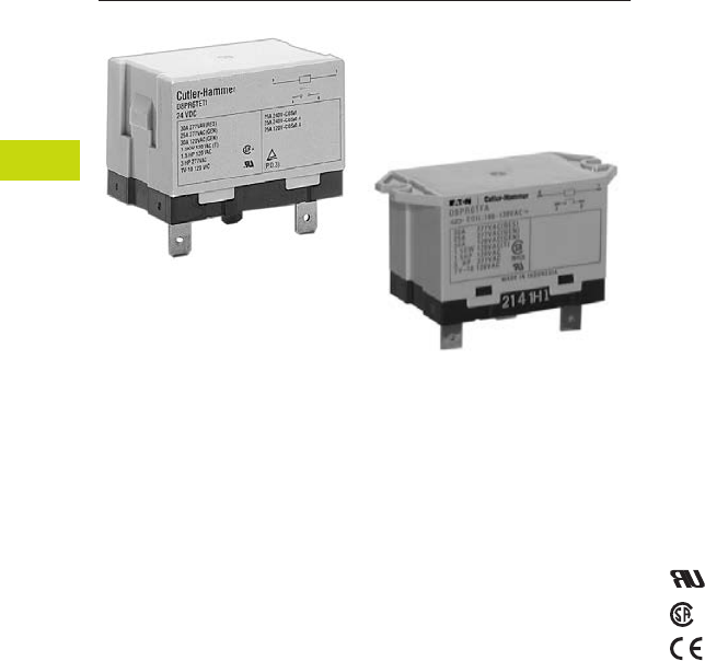
T40-100 Logic Control Products CA08100001K—June 2012 www.eatoncanada.ca
40
40
40
40
40
40
40
40
40
40
40
40
40
40
40
40
40
40
40
40
40
40
40
40
40
40
40
40
40
40
40.4
Control Relays and Timers
General Purpose Plug-In Relays
D8 Series Relay Contents
Description Page
D1PR/D1PF Series . . . . . . . . . . . . . . . . . . . . . . . . . . . . T40-46
D2PR/D2PF Series . . . . . . . . . . . . . . . . . . . . . . . . . . . . T40-51
D3PR/D3PF Series . . . . . . . . . . . . . . . . . . . . . . . . . . . . T40-61
D4 Series . . . . . . . . . . . . . . . . . . . . . . . . . . . . . . . . . . . T40-71
D5PR/D5PF Series . . . . . . . . . . . . . . . . . . . . . . . . . . . . T40-75
D7PR/D7PF Series . . . . . . . . . . . . . . . . . . . . . . . . . . . . T40-85
D8 Series
Catalogue Number Selection . . . . . . . . . . . . . . . . . T40-101
Product Selection . . . . . . . . . . . . . . . . . . . . . . . . . . T40-101
Technical Data and Specifications . . . . . . . . . . . . . . T40-102
Dimensions . . . . . . . . . . . . . . . . . . . . . . . . . . . . . . . T40-103
D9 Series . . . . . . . . . . . . . . . . . . . . . . . . . . . . . . . . . . . T40-106
Accessories . . . . . . . . . . . . . . . . . . . . . . . . . . . . . . . . . T40-110
D8 Series
Product Description
The D8 Series power relays
are perfect for loads up to
30A, with versions for flange
mounting and e-clip mounting
available.
Features
●Allows switching of 25A
and 30A loads
●A high-capacity, high-
withstand voltage relay
compatible with
momentary voltage drops
●No contact chattering for
momentary voltage drops
up to 50% of rated voltage
●UL Class B construction
standard
●Wide-range AC-activated
coil that handles 100 to
120 Vac at either 50
or 60 Hz
●Panel, DIN rail and flange
mounting
Standards and Certifications
File # E1491
File # LR701520
Tab40book.fm Page 100 Wednesday, July 4, 2012 10:05 PM
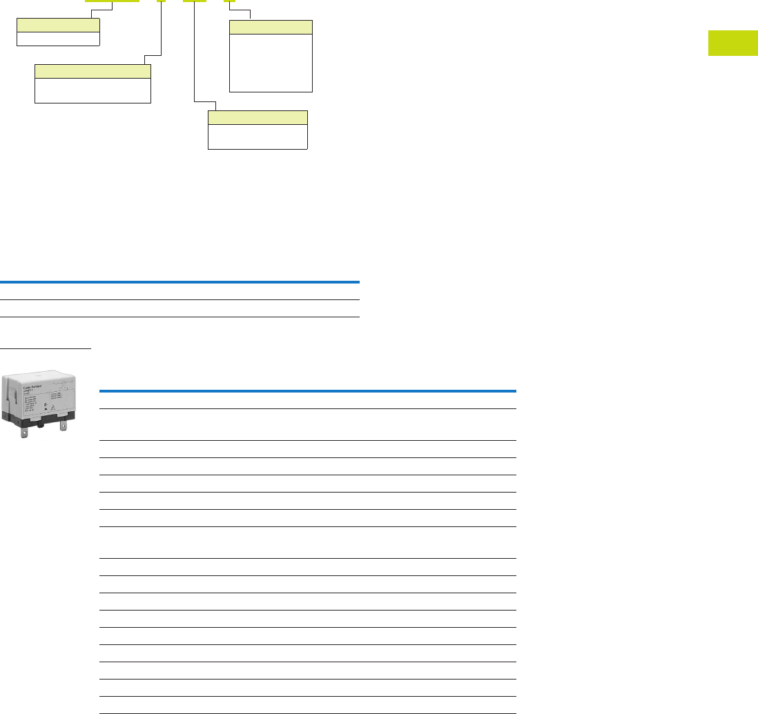
Logic Control Products CA08100001K—June 2012 www.eatoncanada.ca T40-101
40
40
40
40
40
40
40
40
40
40
40
40
40
40
40
40
40
40
40
40
40
40
40
40
40
40
40
40
40
40
40.4
Control Relays and Timers
General Purpose Plug-In Relays
Catalogue Number Selection
D8 Series
Product Selection
D8 Relay/Socket Quick Reference
D8 Series
Notes
For deciphering catalogue numbers. Do not use for ordering as not all combinations are readily available.
Additional coil voltages available—consult Sales Office or Customer Support Centre.
Relay
Type
Mounting
Bracket
Adapter Track/
Panel Mount
Front Connecting
Sockets Track/
Panel Mount
D8PR6TE D8PA5 D8PA1 D8PA2
D8PR7TE D8PA5 D8PA1 D8PA2
Type
Standard
Pack
Catalogue
Number
SPST E-Bracket
Coil voltage
24 Vac 1 D8PR6TET
24 Vdc 1 D8PR6TET1
SPST Flange Mount
120 Vac 1 D8PR6TFA
24 Vdc 1 D8PR6TFT1
DPST E-Bracket
Coil voltage
120 Vac 1 D8PR7TEA
DPST Flange Mount
120 Vac 1 D8PR7TFA
24 Vdc 1 D8PR7TFT1
Sockets
DIN rail adapter 10 D8PA1
Screw terminal adapter 10 D8PA2
Bracket adapter 10 D8PA5
Accessory
DIN rail end stop 100 PFP-M
D
8
P
R 6 T
E A
Family Type
D8PR
Contact Configuration
6 = SPST-NO
7 = DPST-NO
Options
TE = E-bracket
TF = Flange mount
Coil Voltage
A = 120 Vac
B = 240 Vac
R1 = 12 Vdc
T = 24 Vac
T1 = 24 Vdc
D8 Series Relay
Tab40book.fm Page 101 Wednesday, July 4, 2012 10:05 PM

T40-102 Logic Control Products CA08100001K—June 2012 www.eatoncanada.ca
40
40
40
40
40
40
40
40
40
40
40
40
40
40
40
40
40
40
40
40
40
40
40
40
40
40
40
40
40
40
40.4
Control Relays and Timers
General Purpose Plug-In Relays
Technical Data and Specifications
Coil Resistance
D8 Relays
Coil Data
Coil Voltage Ohms mA
24 Vac 303 71
110/120 Vac 5260 20.4
220/240 Vac 21,000 10.2
12 Vdc 75 158
24 Vdc 303 79
Description D8PR6 D8PR7
Rated load 220 Vac 30A 220 Vac 25A
Carry current 30A 25A
Max. operating voltage 250 Vac 250 Vac
Max. switching current 30A 25A
Contact material AgCdO AgCdO
Max. switching capacity 6600 VA 5500 VA
Min. permissible load 100 mA at 5 Vdc 100 mA at 5 Vdc
Mechanical life (min.) 5,000,000 operations 5,000,000 operations
Electrical life at all contact ratings (min.) 100,000 operations 100,000 operations
Maximum hp ratings 1-1/2 hp (120 Vac)
3 hp (240/265/277 Vac)
1-1/2 hp (120 Vac)
3 hp (240/265/277 Vac)
Coil Voltage Must Operate Must Release Maximum Voltage
24 Vdc/Vac, 12 Vdc 75% maximum 15% minimum 110%
120 Vac 75V 18V 132V
240 Vac 150V 36V 264V
Tab40book.fm Page 102 Wednesday, July 4, 2012 10:05 PM
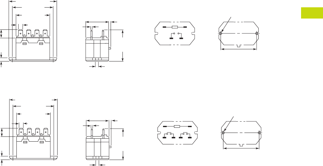
Logic Control Products CA08100001K—June 2012 www.eatoncanada.ca T40-103
40
40
40
40
40
40
40
40
40
40
40
40
40
40
40
40
40
40
40
40
40
40
40
40
40
40
40
40
40
40
40.4
Control Relays and Timers
General Purpose Plug-In Relays
Dimensions
Approximate Dimensions in Inches (mm)
D8PR6TF
D8PR7TF
Two 0.18 (4.5) Dia. Holes
or M4 Tapped Holes
2.70 (68.5) Max.
1.32 (33.5)
Max.0.08 (2.0)
1.85
(47.0)
Max.
0.18
(4.5)
0.03
(0.8)
2.36 (60.0)
1.99 (50.5)
Max.
0.25 (6.4)
0.43
(11.0)
0.12 (3.0)
01
46
2.362 0.007
(60.0 0.2)
Mounting Holes
(Bottom View)
Terminal Arrangement/
Internal Connections
(Top View)
Two 0.18 (4.5) Dia. Holes
or M4 Tapped Holes
2.70 (68.5) Max.
1.32 (33.5)
Max.0.08 (2.0)
1.85
(47.0)
Max.
0.18
(4.5)
0.03
(0.8)
2.36 (60.0)
1.99 (50.5)
Max.
0.25 (6.4)
0.43
(11.0)
0.12
(3.0)
01
2468
2.362 0.007
(60.0 0.2)
Mounting Holes
(Bottom View)
Terminal Arrangement/
Internal Connections
(Top View)
Tab40book.fm Page 103 Wednesday, July 4, 2012 10:05 PM
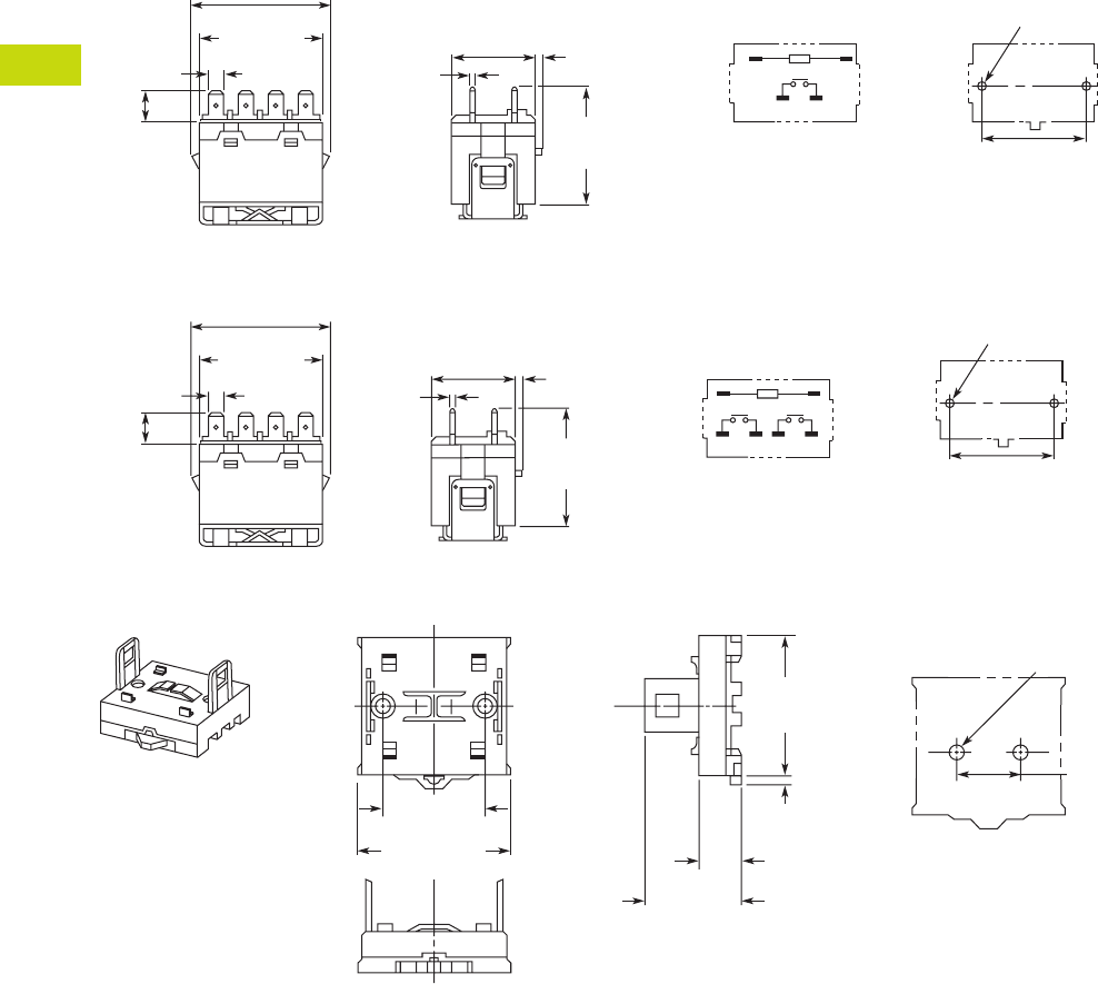
T40-104 Logic Control Products CA08100001K—June 2012 www.eatoncanada.ca
40
40
40
40
40
40
40
40
40
40
40
40
40
40
40
40
40
40
40
40
40
40
40
40
40
40
40
40
40
40
40.4
Control Relays and Timers
General Purpose Plug-In Relays
Approximate Dimensions in Inches (mm)
D8PR6TE with D8PA5 Bracket Attached
D8PR7TE with D8PA5 Bracket Attached
D8PA1
Note: Minimum spacing around relay = 0.20 inches (5 mm).
Two 0.18 (4.5) Dia. Holes
or M4 Tapped Holes
1.32 (33.5)
Max.0.08 (2.0)
2.09
(53.0)
Max.
0.03
(0.8)
2.07 (52.5) Max.
1.99
(50.5) Max.
0.25 (6.4)
0.43
(11.0)
01
46
1.574 0.003
(40.0 0.1)
Mounting Holes
(Bottom View)
Terminal Arrangement/
Internal Connections
(Top View)
Two 0.18 (4.5) Dia. Holes
or M4 Tapped Holes
1.32 (33.5)
Max0.08 (2.0)
2.09
(53.0)
Max.
0.03
(0.8)
2.07 (52.5) Max.
1.99
(50.5) Max.
0.25 (6.4) 01
24
68
1.574 0.003
(40.0 0.1)
Mounting Holes
(Bottom View)
Terminal Arrangement/
Internal Connections
(Top View)
0.43
(11.0)
2.19 (55.5)
Max.
2.03
(51.5)
Max.
0.20
(5.0)
1.574 0.003
(40.0 0.1)
1.39 (35.2)
Max.
0.57
(14.5)
1.574 0.003
(40.0 0.1)
Two M4 or
0.18 (4.5) Dia. Holes
Mounting Holes
(Bottom View)
Tab40book.fm Page 104 Wednesday, July 4, 2012 10:05 PM
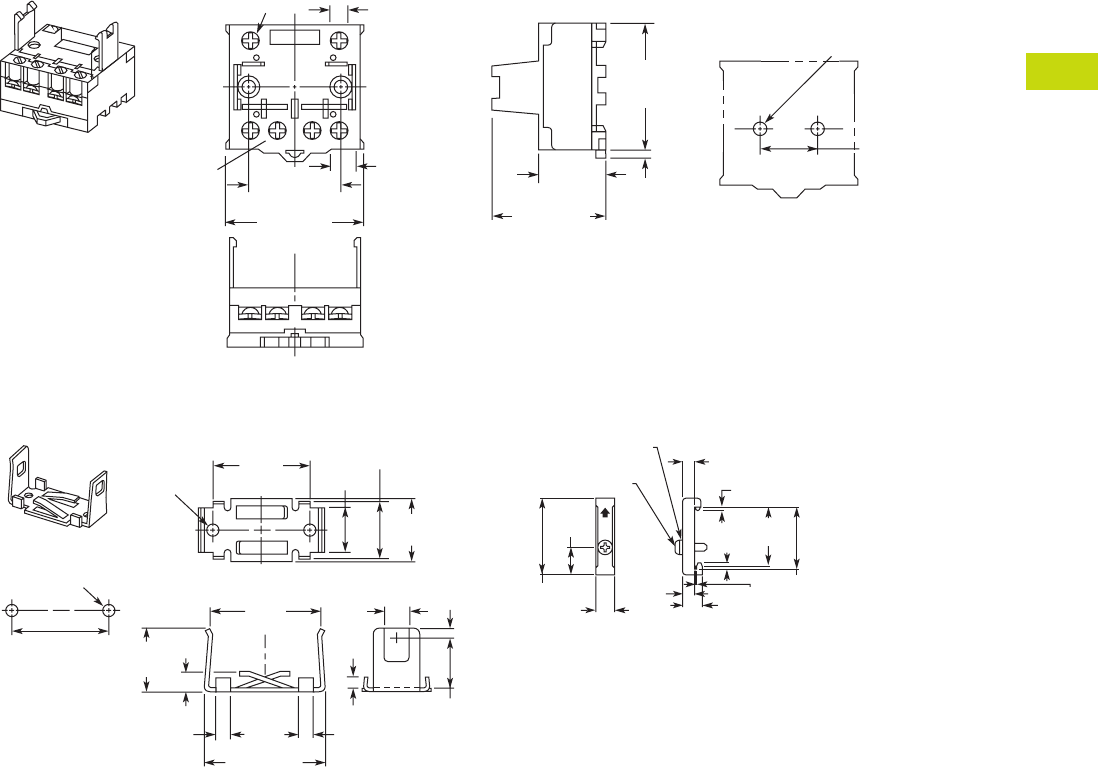
Logic Control Products CA08100001K—June 2012 www.eatoncanada.ca T40-105
40
40
40
40
40
40
40
40
40
40
40
40
40
40
40
40
40
40
40
40
40
40
40
40
40
40
40
40
40
40
40.4
Control Relays and Timers
General Purpose Plug-In Relays
Approximate Dimensions in Inches (mm)
D8PA2
D8PA5 PFP-M DIN Rail End Stop
2.19 (55.5)
Max.
0.36 (9.2)
2.03
(51.5)
Max.
0.20
(5.0)
1.574 0.003
(40.0 0.1) 1.81 (46.0)
Max.
0.98
(25.0)
1.574 0.003
(40.0 0.1)
Two M4 or
0.18 (4.5) Dia. Holes
Two M3.5 Screws
for Coil
Four M4 Screws
for Contact
0.31 (8.0)
Mounting Holes
(Bottom View)
0.78
(19.7)
0.12
(3.0)
0.17
(4.4)
0.20
(5.0)
0.20
(5.0)
1.20 (50.0)
1.18
(30.0)
1.81
(46.0)
1.57
(40.0)
1.02
(26.0)
0.94
(24.0)
0.70
(17.8)
0.94
(24.0)
0.27
(7.0)
0.39
(10.0)
Two
0.18 (4.5)
Dia. Holes
1.574 0.003
(40.0 0.1)
Mounting
Holes
(Bottom View)
Two M4 or 0.18 (4.5)
Dia. Holes 1.97
(50.0)
0.45
(11.5)
1.47
(37.3)
1.39
(35.3)
0.39
(10.0)
0.39
(10.0)
0.19
(4.8) 0.05
(1.3)
0.24
(6.2)
0.07
(1.8)
0.07
(1.8)
M4 x 8 Pan
Head Screw
M4 Spring Washer
Tab40book.fm Page 105 Wednesday, July 4, 2012 10:05 PM
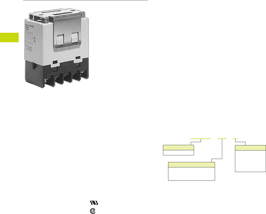
T40-106 Logic Control Products CA08100001K—June 2012 www.eatoncanada.ca
40
40
40
40
40
40
40
40
40
40
40
40
40
40
40
40
40
40
40
40
40
40
40
40
40
40
40
40
40
40
40.4
Control Relays and Timers
General Purpose Plug-In Relays
D9 Series Relay Contents
Description Page
D1PR/D1PF Series . . . . . . . . . . . . . . . . . . . . . . . . . . . . T40-46
D2PR/D2PF Series . . . . . . . . . . . . . . . . . . . . . . . . . . . . T40-51
D3PR/D3PF Series . . . . . . . . . . . . . . . . . . . . . . . . . . . . T40-61
D4 Series . . . . . . . . . . . . . . . . . . . . . . . . . . . . . . . . . . . T40-71
D5PR/D5PF Series . . . . . . . . . . . . . . . . . . . . . . . . . . . . T40-75
D7PR/D7PF Series . . . . . . . . . . . . . . . . . . . . . . . . . . . . T40-85
D8 Series . . . . . . . . . . . . . . . . . . . . . . . . . . . . . . . . . . . T40-100
D9 Series
Product Selection . . . . . . . . . . . . . . . . . . . . . . . . . . T40-107
Technical Data and Specifications . . . . . . . . . . . . . . T40-107
Dimensions . . . . . . . . . . . . . . . . . . . . . . . . . . . . . . . T40-108
Accessories . . . . . . . . . . . . . . . . . . . . . . . . . . . . . . . . . T40-110
D9 Series
Product Description
The four-pole D9 Series is
ideal for three-phase motor
applications. Various contact
configurations are available.
Features
●Ideal for three-phase motor
control applications
●No contact chattering for
momentary voltage drops
up to 50% of rated voltage
●Push-to-Test button is a
standard feature to check
contact operation
●Mounting bracket is
supplied with relay
Standards and Certifications
File # E1491
File # LR701520
Catalogue Number Selection
Contact Configuration
8B = 4PST-NO
9B = 3PST-NO/SPST-NC
10B = DPST-NO/DPST-NC
Family Type
D9PR
D 9 P R 8 B A
Coil Voltage
A = 120 Vac
B = 240 Vac
R1 = 12 Vdc
T = 24 Vac
T1 = 24 Vdc
Tab40book.fm Page 106 Wednesday, July 4, 2012 10:05 PM

Logic Control Products CA08100001K—June 2012 www.eatoncanada.ca T40-107
40
40
40
40
40
40
40
40
40
40
40
40
40
40
40
40
40
40
40
40
40
40
40
40
40
40
40
40
40
40
40.4
Control Relays and Timers
General Purpose Plug-In Relays
Product Selection
D9 Series
Technical Data and Specifications
Coil Resistance
D9PR Specifications
Catalogue
Number
Catalogue
Number
4PST-NO Power Relay DPST-NO/DPST-NC Power Relay
Coil voltage Coil voltage
24 Vac D9PR8BT 24 Vac D9PR10BT
120 Vac D9PR8BA 120 Vac D9PR10BA
240 Vac D9PR8BB 24 Vac D9PR10BT1
24 Vdc D9PR8BT1
3PST-NO/SPST-NC Power Relay
120 Vac D9PR9BA
Coil Voltage Ohms mA Coil Voltage Ohms mA
24 Vac — 75 12 Vdc 72 167
120 Vac — 21.6 24 Vdc 288 83
240 Vac — 10.8 110 Vdc 6050 18
Description
NO Contacts
Resistive Load (p.f. = 1)
NC Contacts
Resistive Load (p.f. = 1)
Rated load 220 Vac 25A
30 Vdc 25A
220 Vac 8A
30 Vdc 8A
Carry current 25A 8A
Max. operating voltage 250 Vac/125 Vdc 250 Vac/125 Vdc
Max. switching current 25A 8A
Max. switching capacity 5500 VA
750W
1760 VA
240 W
Min. permissible load 100 mA at 24 Vdc 100 mA at 24 Vdc
Mechanical life (min.) 1,000,000 operations 1,000,000 operations
Electrical life at all contact ratings (min.) 100,000 operations 100,000 operations
Maximum hp ratings 1-1/2 hp (120 Vac)
3 hp (240/265/277 Vac)
Three-phase 3 hp (240/265/277 Vac) 30,000 cycles
Three-phase 5 hp (240/265/277 Vac) 30,000 cycles
1-1/2 hp (120 Vac)
3 hp (240/265/277 Vac)
Three-phase 3 hp (240/265/277 Vac) 30,000 cycles
Three-phase 5 hp (240/265/277 Vac) 30,000 cycles
Tab40book.fm Page 107 Wednesday, July 4, 2012 10:05 PM
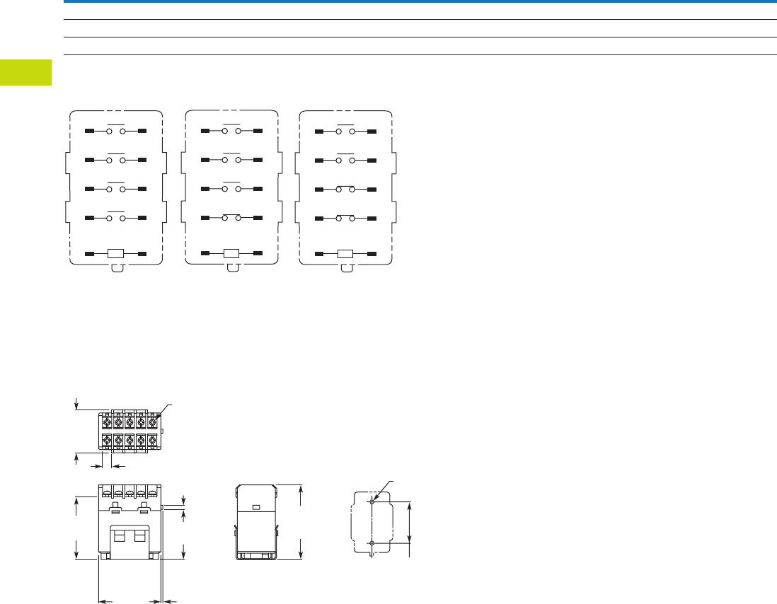
T40-108 Logic Control Products CA08100001K—June 2012 www.eatoncanada.ca
40
40
40
40
40
40
40
40
40
40
40
40
40
40
40
40
40
40
40
40
40
40
40
40
40
40
40
40
40
40
40.4
Control Relays and Timers
General Purpose Plug-In Relays
Coil Data
Terminal Arrangements
Dimensions
Approximate Dimensions in Inches (mm)
D9PR
Coil Voltage Must Operate Must Release Maximum Voltage
24 Vdc/Vac, 12 Vdc, 110 Vdc 75% maximum 10% minimum 110%
120 Vac 75V 18V 132V
240 Vac 150V 36V 264V
A2 A1
44 43
34 33
24 23
14 13
A2 A1
42 41
34 33
24 23
14 13
A2 A1
42 41
34 33
24 23
14 13
D9PR8 D9PR9 D9PR10
2.03
(51.5)
Max.
1.70
(43.2)
2.52
(64.0)
Max.
1.378 0.004
(35.0 0.1)
0.08
(2.0)
0.30
(7.6)
2.17
(55.2)
1.36
(34.5)
Max.
0.17
(4.3)
Two M4 or
0.18 (4.5) Dia.
Ten M3.5
Screw Terminal Brackets
Mounting Holes
(Bottom View)
Tab40book.fm Page 108 Wednesday, July 4, 2012 10:05 PM
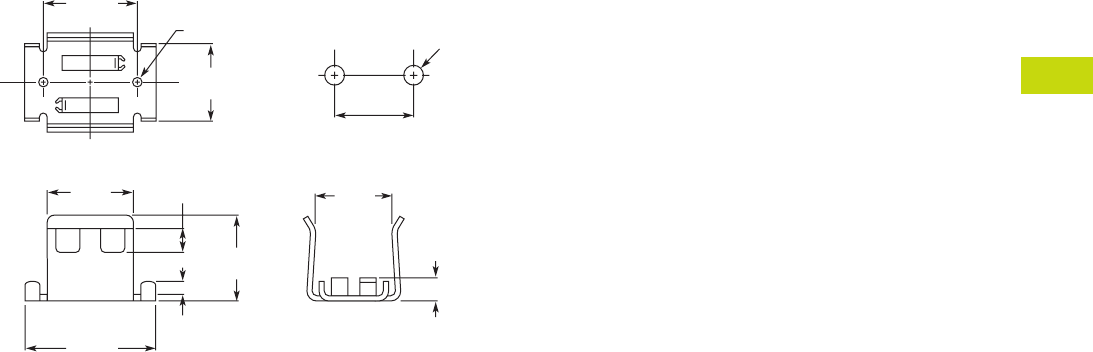
Logic Control Products CA08100001K—June 2012 www.eatoncanada.ca T40-109
40
40
40
40
40
40
40
40
40
40
40
40
40
40
40
40
40
40
40
40
40
40
40
40
40
40
40
40
40
40
40.4
Control Relays and Timers
General Purpose Plug-In Relays
Approximate Dimensions in Inches (mm)
Mounting Bracket
Mounting Holes
1.37
(35.0)
0.95
(24.0)
1.18
(30.0)
1.73
(44.0)
1.14
(29.0)
0.35
(9.0)
0.17
(4.4)
1.10
(28.0)
0.28
(7.0)
1.378 0.004
(35.0 1.0)
Two M4 or
0.18 (4.5) Dia. Two M4
Tab40book.fm Page 109 Wednesday, July 4, 2012 10:05 PM
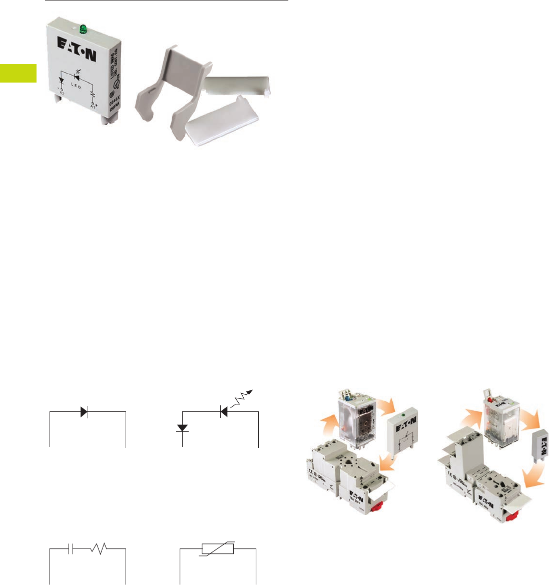
T40-110 Logic Control Products CA08100001K—June 2012 www.eatoncanada.ca
40
40
40
40
40
40
40
40
40
40
40
40
40
40
40
40
40
40
40
40
40
40
40
40
40
40
40
40
40
40
40.4
Control Relays and Timers
General Purpose Plug-In Relays
Accessories Contents
Description Page
D1PR/D1PF Series . . . . . . . . . . . . . . . . . . . . . . . . . . . . T40-46
D2PR/D2PF Series . . . . . . . . . . . . . . . . . . . . . . . . . . . . T40-51
D3PR/D3PF Series . . . . . . . . . . . . . . . . . . . . . . . . . . . . T40-61
D4 Series . . . . . . . . . . . . . . . . . . . . . . . . . . . . . . . . . . . T40-71
D5PR/D5PF Series . . . . . . . . . . . . . . . . . . . . . . . . . . . . T40-75
D7PR/D7PF Series . . . . . . . . . . . . . . . . . . . . . . . . . . . . T40-85
D8 Series . . . . . . . . . . . . . . . . . . . . . . . . . . . . . . . . . . . T40-100
D9 Series . . . . . . . . . . . . . . . . . . . . . . . . . . . . . . . . . . . T40-106
Accessories
MOD Modules . . . . . . . . . . . . . . . . . . . . . . . . . . . . T40-111
Relay Clips . . . . . . . . . . . . . . . . . . . . . . . . . . . . . . . T40-112
Coil Bus Jumpers . . . . . . . . . . . . . . . . . . . . . . . . . . T40-114
Write-On Plastic Labels/ID Tags . . . . . . . . . . . . . . . T40-114
Flange Mount Adapters . . . . . . . . . . . . . . . . . . . . . T40-115
Accessories
Accessories Selection Guide
Eaton offers a variety of
simple-to-install relay
accessories that allow you to
customize the features of a
relay system to meet your
exact needs.
The MOD Module System
Eaton’s plug-in modules are a
simple way to add
functionality to your relay
without the hassle of messy
wiring and additional
mounting of external
electronics. They are available
in a variety of configurations
to meet the needs of almost
any application.
Circuit Diagrams
Diode Circuit
The diode module protects
external drive circuitry from
inductive voltages generated
when removing coil voltages.
RC Circuit
Snubs back EMF of relay coil.
LED Circuit
The LED status lamp verifies
that power is being supplied
to the coil. Ideal for both AC
and DC applications. Polarity
sensitive for DC applications.
Metal Oxide Varistor (MOV)
Circuit
The MOV circuit protects
by shunting potentially
damaging electrical spikes
away from the relay coil. Ideal
for AC and DC applications.
A2 A1
+
A2 A1
A2 A1
+
A2 A1
System Diagrams
The MOD Module System
Tab40book.fm Page 110 Wednesday, July 4, 2012 10:05 PM
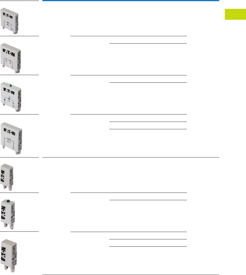
Logic Control Products CA08100001K—June 2012 www.eatoncanada.ca T40-111
40
40
40
40
40
40
40
40
40
40
40
40
40
40
40
40
40
40
40
40
40
40
40
40
40
40
40
40
40
40
40.4
Control Relays and Timers
General Purpose Plug-In Relays
MOD Modules
Eaton’s relay accessories
provide a complete solution
for add-on modules and
identification tags.
MOD Modules
Module
Size Description Nominal Voltage
Catalogue
Number
Mating
Sockets
A Protection diode 6–250 Vdc MOD-AD250 D3PA6, D3PAL8,
D3PA7, D3PAL11,
D5PAL, D7PAB,
D7PAD
R/C suppressor 6–24 Vac MOD-RC24
110–240 Vac MOD-RC240
LED indicator 24 Vac MOD-ALG24
120/240 Vac MOD-ALG240
MOV suppressor 24 Vac MOD-AMV24
120 Vac MOD-AMV120
240 Vac MOD-AMV240
B Protection diode 6–250 Vdc MOD-BD250 D1PAA, D2PAL,
D2PAP, D2PA7,
D7PAA
LED indicator 24 Vac MOD-BLG24
120/240 Vac MOD-BLG240
MOV suppressor 24 Vac MOD-BMV24
120 Vac MOD-BMV120
240 Vac MOD-BMV240
MOD-AD250
MOD-ALG_
MOD-RC_
MOD-AMV_
MOD-BD250
MOD-BLG_
MOD-BMV_
Tab40book.fm Page 111 Wednesday, July 4, 2012 10:05 PM
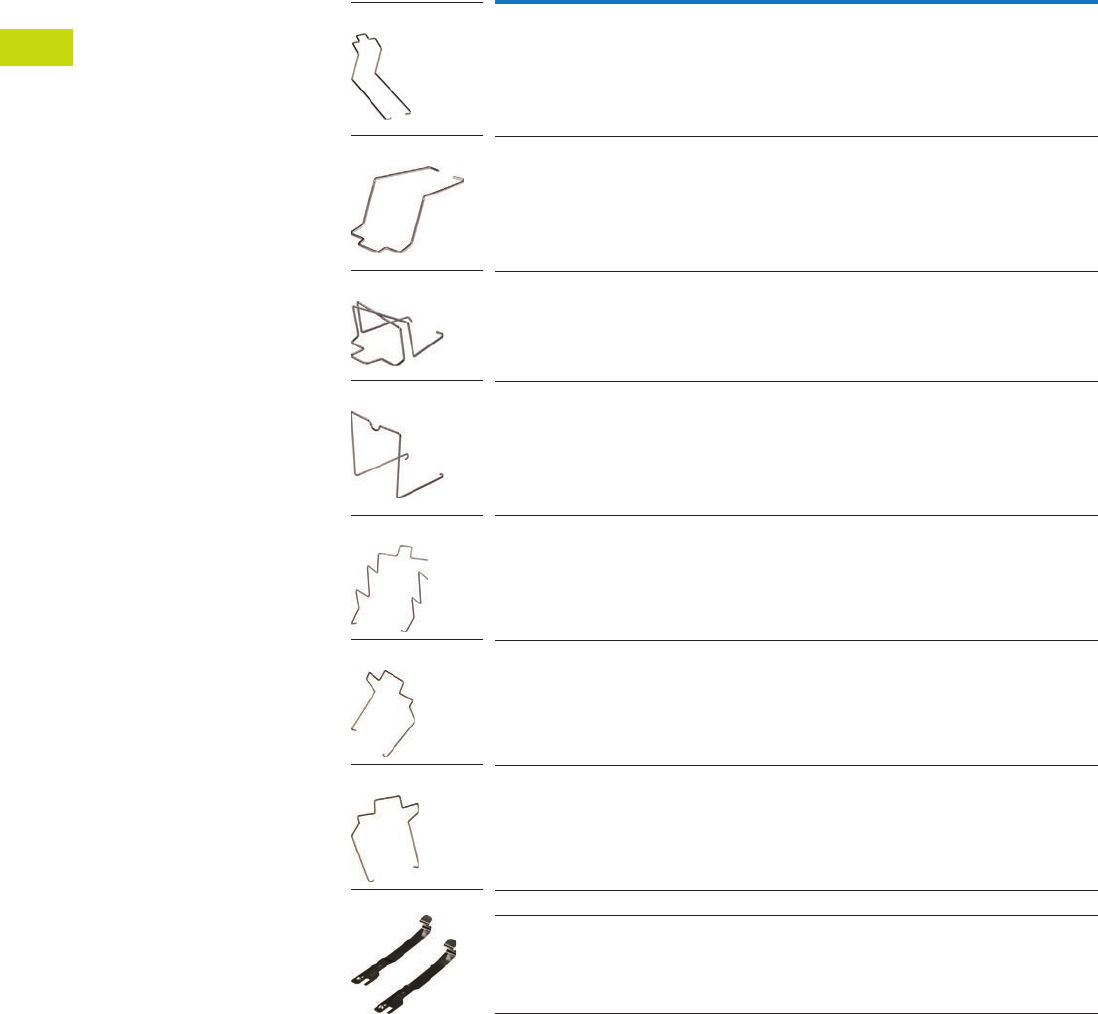
T40-112 Logic Control Products CA08100001K—June 2012 www.eatoncanada.ca
40
40
40
40
40
40
40
40
40
40
40
40
40
40
40
40
40
40
40
40
40
40
40
40
40
40
40
40
40
40
40.4
Control Relays and Timers
General Purpose Plug-In Relays
Relay Clips
Eaton offers a variety of relay
clips designed to improve the
performance and
functionality within an
electrical panel.
Metal Hold-Down Clips
Metal hold-down clips, or
spring clips, are ideal for use
where high heat or humid
conditions are a factor. These
clips hold their shape and
tension and are designed
to withstand harsh
environments. All clips
are made of corrosion-
resistant stainless steel.
Metal Hold-Down Clips
Catalogue
Number Mating Sockets Mating Relays
PMC-1781 D1PAA D1PR, D1PF
PQC-1782 D2PAL, D2PAP, D2PA7 D2PR2, D2PF2, D2PR3, D2PF4
PQC-1342 D2PA6, D7PAA, D7PA9 D2PR4, D2PF4
PQC-1332 D3PA6, D3PA7 D3PR2, D3PF2, D3PR3, D3PF3
PQC-1351 D3PAL8, D3PA2, D3PAL11, D3PA3,
D5PAL, D5PA2, D5PA3L, D5PA3S
D3PR2, D3PF2, D3PR3, D3PF4, D5PR, D5PF
PQC-1783 D7PAB D7PR1, D7PF1, D7PR2, D7PF3
PQC-1784 D7PAD D7PR4, D7PF4
PYC-A1 D2PA4 D2PR5
PYC-B2 D7PA3, D7PA4 D7PR1, D7PR2, D7PR4
PMC-1781
PQC-1782
PQC-1342
PQC-1332
PQC-1351
PQC-1783
PQC-1784
PYC- _
Tab40book.fm Page 112 Wednesday, July 4, 2012 10:05 PM
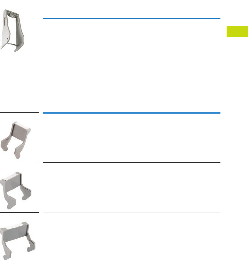
Logic Control Products CA08100001K—June 2012 www.eatoncanada.ca T40-113
40
40
40
40
40
40
40
40
40
40
40
40
40
40
40
40
40
40
40
40
40
40
40
40
40
40
40
40
40
40
40.4
Control Relays and Timers
General Purpose Plug-In Relays
Plastic Ejector/
Hold-Down Clips
These clips are great for
applications where sockets
are located in dense or tight
areas. They allow for quick,
safe and firm securing of
relays in the sockets with the
added benefit that the relay
can be ejected with one
finger. Plastic clips also aid in
keeping operators’ fingers
away from live circuits. The
optional snap-in identification
tag allows for custom
marking of sockets when
used in multi-socket
applications.
Plastic ID Clips
Plastic ID clips allow for easy
circuit identification in multi-
relay applications. They are
designed for labeling and
are not ideal for securing
the relay in the socket.
Plastic Ejector/Hold-Down Clips
Plastic ID Clips
Catalogue
Number Mating Sockets Mating Relays
PWC-D24 D2PAL, D2PAP, D2PA7 D2PF2, D2PF4
Catalogue
Number Mating Sockets Mating Relays
PQC-1349 D7PAA D7PF1, D7PF2
PMC-1783 D7PAB D7PF1, D7PF2
PMC-1784 D7PAD D7PF4
PWC-D24
PQC-1349
PMC-1783
PMC-1784
Tab40book.fm Page 113 Wednesday, July 4, 2012 10:05 PM
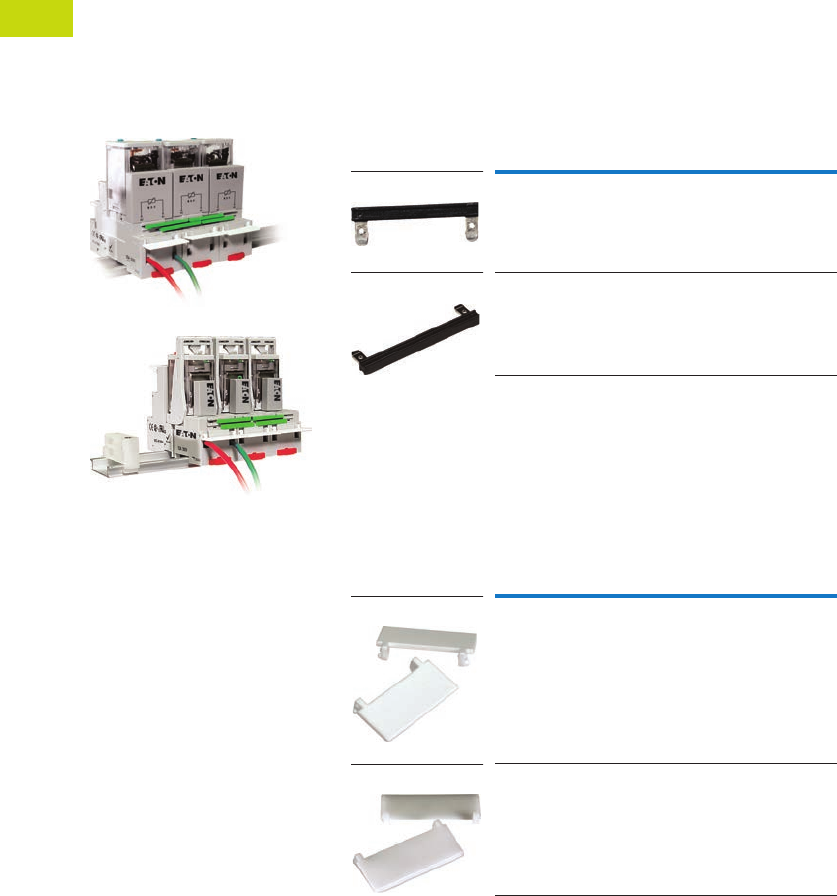
T40-114 Logic Control Products CA08100001K—June 2012 www.eatoncanada.ca
40
40
40
40
40
40
40
40
40
40
40
40
40
40
40
40
40
40
40
40
40
40
40
40
40
40
40
40
40
40
40.4
Control Relays and Timers
General Purpose Plug-In Relays
Coil Bus Jumpers
Eaton’s coil bus jumpers
allow inputs to be bridged
to adjacent sockets without
additional wiring, making
multi-relay connections quick
and easy. The easy-to-install
design requires no tools and
can be complete in a matter
of seconds.
System Diagrams
Coil Bus Jumpers
Write-On Plastic Labels/ID Tags
These convenient plastic
labels snap easily onto
the relay socket for clear
identification in multi-relay
panels. The hinged design
makes wiring simple and
allows for angular adjustment
of the tag to improve
readability in the panel.
Marking with a standard
permanent marker creates
a smudge-free surface.
Coil Bus Jumpers
Write-On Plastic Labels/ID Tags
Note
Jumpers in photo are colored green to improve visibility,
actual jumpers are black.
Catalogue
Number Mating Sockets
D2PJ1 D2PAL, D2PAP
D3PJ1 D3PA6, D3PA7, D5PAL
Catalogue
Number Mating Sockets
PWF-D2P D2PAL, D2PAP
PWF-D3D5 D3PAL8, D3PAL11, D5PAL
D2PJ1
D3PJ1
PWF-D2P
PWF-D3D5
Tab40book.fm Page 114 Wednesday, July 4, 2012 10:05 PM
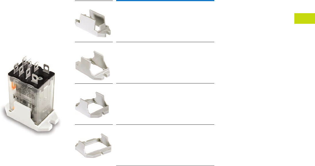
Logic Control Products CA08100001K—June 2012 www.eatoncanada.ca T40-115
40
40
40
40
40
40
40
40
40
40
40
40
40
40
40
40
40
40
40
40
40
40
40
40
40
40
40
40
40
40
40.4
Control Relays and Timers
General Purpose Plug-In Relays
Flange Mount Adapters
Eaton’s relay flange mount
adapters create a modular
approach to flexible
mounting options. Each low-
cost adapter allows for panel
mounting of a standard
control relay and can
eliminate the need for
a socket.
Unit with Flange Mount
Adapter
Flange Mount Adapters
Catalogue
Number Mating Relay
PFC-D11 D1PF1, D1PR1
PFC-D2D72 D2P, D7PF2, D7PR2
PFC-D73 D7PF3, D7PR3
PFC-D74 D7PF4, D7PR4
PFC-D11
PFC-D2D72
PFC-D73
PFC-D74
Tab40book.fm Page 115 Wednesday, July 4, 2012 10:05 PM
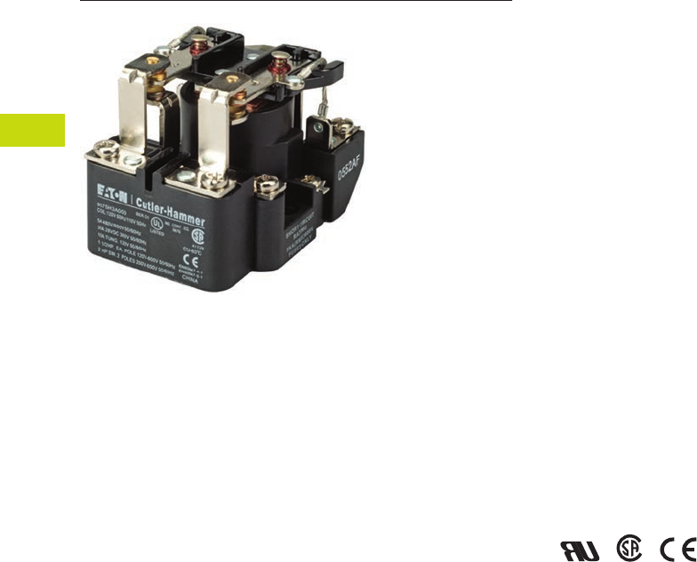
T40-116 Logic Control Products CA08100001K—June 2012 www.eatoncanada.ca
40
40
40
40
40
40
40
40
40
40
40
40
40
40
40
40
40
40
40
40
40
40
40
40
40
40
40
40
40
40
40.5
Control Relays and Timers
General Purpose Relays—Type AA
9575H Series 3000 Relay Contents
Description Page
9575H Series 3000—Type AA, AC and DC
Product Selection . . . . . . . . . . . . . . . . . . . . . . . . . . T40-117
Accessories. . . . . . . . . . . . . . . . . . . . . . . . . . . . . . . T40-117
Technical Data and Specifications . . . . . . . . . . . . . . T40-118
Dimensions . . . . . . . . . . . . . . . . . . . . . . . . . . . . . . . T40-119
9575H Series 3000—Type AA, AC and DC
Product Description
Type AA panel-mounted
relays are rated (each pole)
40A up to 300 Vac, 50/60 Hz;
5A at 480/600 Vac, 50/60 Hz
and 40A at 28 Vdc.
Application Description
9575H Series 3000 relays are
ideal for applications when
controlling smaller loads,
such as single-phase motors.
Standards and Certifications
●UL listed, E1491
●CSA 41729
●CE: EN60947-4-1,
EN60947-5-1
Tab40book.fm Page 116 Wednesday, July 4, 2012 10:05 PM
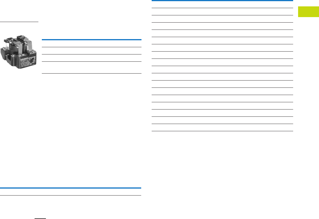
Logic Control Products CA08100001K—June 2012 www.eatoncanada.ca T40-117
40
40
40
40
40
40
40
40
40
40
40
40
40
40
40
40
40
40
40
40
40
40
40
40
40
40
40
40
40
40
40.5
Control Relays and Timers
General Purpose Relays—Type AA
Product Selection
When Ordering, Specify
Catalogue number and
magnet coil code letter.
Example: for DPDT relay with
auxiliary switch and a 120V
50/60 Hz coil, order
Catalogue Number
9575H3A010.
Type AA Relays
Accessories
Enclosure
Notes
There are no “repair parts” available for these relays.
Underscore indicates missing code suffix for magnet coil—see Selection table above.
Only 9575H3 relays without an auxiliary switch should be mounted in the 9575H2449
enclosure.
Relay Style
Catalogue
Number
Relay (DPDT) 9575H3_000
Relay with auxiliary switch 9575H3_010
Relay with blowout magnets 9575H3_100
Relay with auxiliary switch and
blowout magnets
9575H3_110
9575H Series 3000
Relay
Description
Catalogue
Number
NEMA 1 Enclosure 9575H2449
Coil Voltage Selection
Coil Voltage Hz Suffix Code
Volts AC
120 50/60 A
240 50/60 B
480/440 60/50 C
600/550 60/50 D
208 50/60 E
277 50/60 H
6 50/60 J
12 50/60 K
24 50/60 L
48 50/60 M
Volts DC
110 — P
220 — Q
6—R
12 — S
24 — T
48 — W
Tab40book.fm Page 117 Wednesday, July 4, 2012 10:05 PM

T40-118 Logic Control Products CA08100001K—June 2012 www.eatoncanada.ca
40
40
40
40
40
40
40
40
40
40
40
40
40
40
40
40
40
40
40
40
40
40
40
40
40
40
40
40
40
40
40.5
Control Relays and Timers
General Purpose Relays—Type AA
Technical Data and Specifications
Relay Specifications
Coil
●Pull-in voltage: 80%
DC coils, 85% AC coils
of nominal voltage
or less at 25ºC
●Dropout voltage: 10%
of nominal voltage
or more at 25ºC
●Coil resistance: ±10%
measured at 25ºC
●Max. DC coil dissipation
capability: 4 watts DC
continuous at 25ºC
Contacts
●Contact combination:
DPDT
●Contact rating each pole
(main contacts): Each pole
rated 40 amps up to 300
Vac, 50/60 Hz, 5 amps at
480/600 Vac 50/60 Hz,
0.75 PF load. 1-1/2 hp
motor load (each pole) at
120–600 Vac, 50/60 Hz.
2 hp motor load at
200–600 Vac, 50/60 Hz
only when using both
poles to switch both sides
of load, 40 amps at 28 Vdc
resistive load each pole.
NEMA A 600 pilot duty
50/60 Hz
●Additional contact ratings
for relays with blowout
magnets: 10A at 110 Vdc
resistive, 4A at 225 Vdc
resistive, 2A at 325 Vdc
resistive. For inductive
loads, contacts must be
derated accordingly.
●Contact material: Silver
cadmium oxide, gold
flashed. 5/16 in
(7.9 mm) diameter
standard
Dielectric Withstanding Voltage
●Between open contacts:
1500 Vrms
●All other mutually insulated
conductive elements:
2200 Vrms
Miscellaneous
●Coil terminals: 6–32
screws
●Contact terminals: 8-–32
screws
●Main base material:
Molded phenolic, UL
recognized (QMFZ2)
●Weight (DPDT Relay):
11 oz (311 grams)
approximately
●Weight (DPDT Relay with
auxiliary switch) 14.5 oz
(411 grams) approximately
Auxiliary Switch Specifications
●Contact combination:
SPDT
●Contact rating: Auxiliary
switch rated 10 amps at
125 or 250 Vac, resistive
load; 1/4 hp at 125 or 250
Vac, motor load; 0.4 amps
at 125 Vdc or 0.20 amps at
250 Vdc, resistive load; 3
amps at 125 Vac lamp load.
All AC ratings are 50/60 Hz
●Dielectric withstanding
voltage: 500 Vac rms
between open contacts,
1500 Vac rms between all
other mutually insulated
conductive elements
●Terminals: 4–40 round
head screws for auxiliary
contacts standard
Average Operating Times (Milliseconds)
Temperature Ranges
Operation DPDT Relay DPDT Relay with Auxiliary Switch
Pickup 40 50
Dropout 35 35
Temperature AC DC
Operating range –30º to 55ºC –30º to 55ºC
Non-operating range –30º to 100ºC –30º to 100˚C
Tab40book.fm Page 118 Wednesday, July 4, 2012 10:05 PM
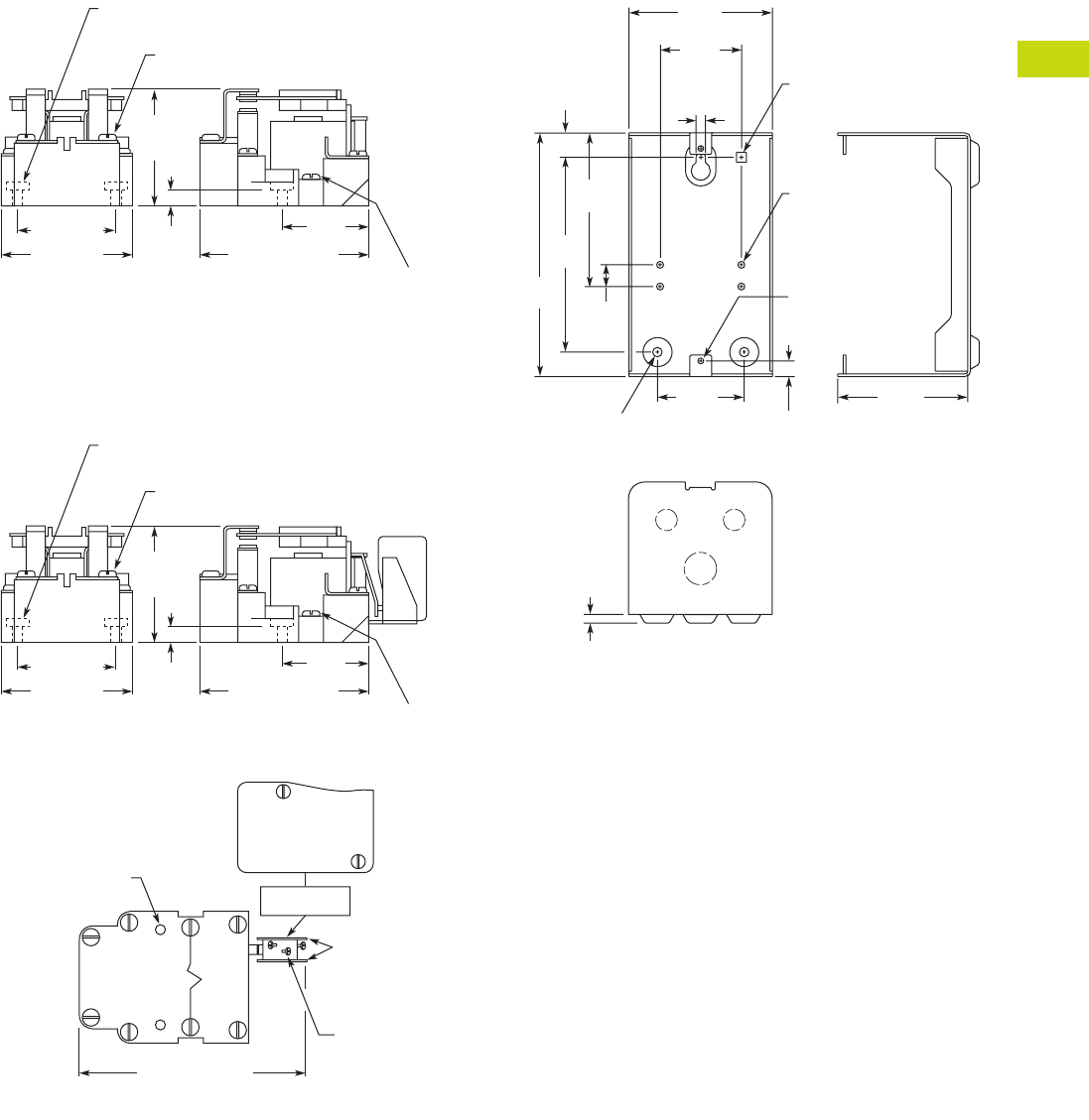
Logic Control Products CA08100001K—June 2012 www.eatoncanada.ca T40-119
40
40
40
40
40
40
40
40
40
40
40
40
40
40
40
40
40
40
40
40
40
40
40
40
40
40
40
40
40
40
40.5
Control Relays and Timers
General Purpose Plug-In Relays—Type AA
Dimensions
Approximate Dimensions in Inches (mm)
9575H3 DPDT Relay
9575H3 DPDT Relay with Auxiliary SPDT Switch
9575H2449
2.25
(58.7)
Max.
8-32 Machine Screw on
Contact Terminals (6 Places)
Mounting Holes 0.187 (4.75) Dia. (2 Places)
0.38
(9.5)
1.87 (47.5) 1.62
(41.1)
6-32
Machine Screw
on Coil
Terminals
(2 Places)
2.50 (63.5) 3.12 (79.2) Max.
2.25
(58.7)
Max.
8-32 Machine Screw on
Contact Terminals (6 Places)
Mounting Holes 0.187 (4.75) Dia. (2 Places)
0.38
(9.5)
1.87 (47.5) 1.62
(41.1)
6-32
Machine Screw
on Coil
Terminals
(2 Places)
AUX. SWITCH
MARKING SURFACE
2.50 (63.5) 3.12 (79.2) Max.
Mounting Holes (2)
Screw Terminals
(4-40) RHMS
with External
Tooth Lockwashers
(3 Places)
Insulators
(2 Sides)
4.44 (112.7) Max.
NC
10A 1/4 hp 125 OR 250 Vac
0.4A at 125 Vdc, 0.2A at 250 Vdc
3A 125 Vac “LAMP”
278 VA 125/250 Vac P.D.
NOCOM
RELAY TOP VIEW
0.159" (4) Dia.
10-32 Tap
Typ. 4 Places
0.36" (9.1)
Typ. 2 Places
0.218" (5.5) Dia.
Typ. 2 Places
0.218"
(5.5)
Dia.
0.56"
(4.3)
3.55"
(90.1)
4.50"
(114.3)
5.63"
(142.9) 0.50"
(2.7)
3.31"
(84.2)
1.88"
(47.6)
0.136" (3.4) Dia.
8-32 Tap
Typ. 2 Places
2.00"
(50.8)
3.00"
(76.2)
0.20"
(5.1)
0.230" (5.8)
Square Hole
Tab40book.fm Page 119 Wednesday, July 4, 2012 10:05 PM
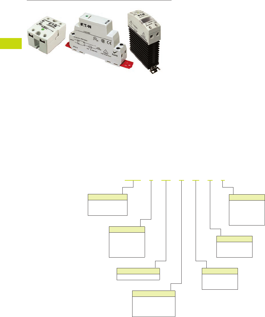
T40-120 Logic Control Products CA08100001K—June 2012 ww.eatoncanada.ca
40
40
40
40
40
40
40
40
40
40
40
40
40
40
40
40
40
40
40
40
40
40
40
40
40
40
40
40
40
40
40.6
Control Relays and Timers
Solid-State Relays
Solid-State Relays Contents
Description Page
Solid-State Relays
D93 Series . . . . . . . . . . . . . . . . . . . . . . . . . . . . . . . T40-121
D96 Series . . . . . . . . . . . . . . . . . . . . . . . . . . . . . . . T40-128
D99 Series . . . . . . . . . . . . . . . . . . . . . . . . . . . . . . . T40-133
Product Overview
Catalogue Number Selection
Solid-State Relays—D93, D96 and D99 Series
Input Voltage
1 = 90–280 Vac
2 = 3–32 Vdc
3 = 3.5–32 Vdc
4 = 4–15 Vdc
5 = 20–50 Vdc
Output Type
C = SCR
T = Triac
M = MOSFET
Turn On Type
Z = Zero cross
R = Random
D = DC switch
Output Voltage
1 = 2–60 Vdc
2 = 24–280 Vac
3 = 3–200 Vdc
4 = 48–480 Vac
6 = 48–600 Vac
Current
Output current in amps
Contact Configuration
A = SPST-NO
B = SPST-NC
C = DPST-NO
D = DPST-NC
Description
D93 = Hockey puck
D96 = Compact
D99 = DIN rail
D 9 3 3 2 5 A M D 2
Tab40book.fm Page 120 Wednesday, July 4, 2012 10:05 PM
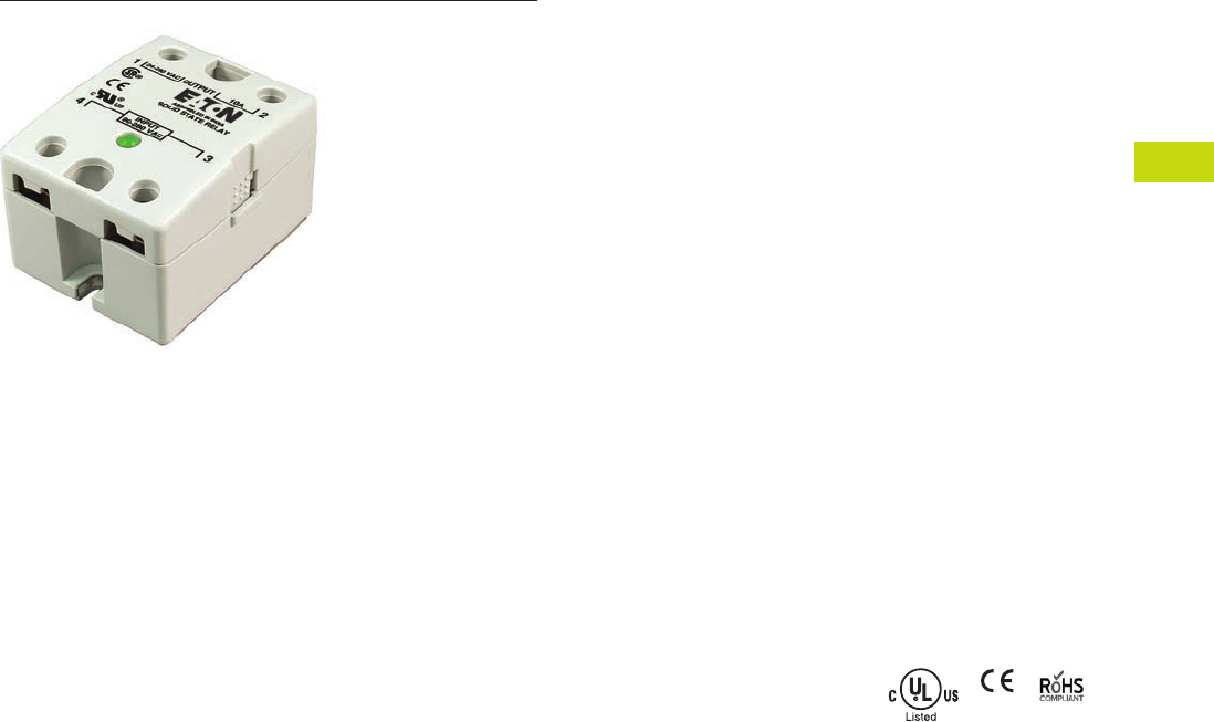
Logic Control Products CA08100001K—June 2012 ww.eatoncanada.ca T40-121
40
40
40
40
40
40
40
40
40
40
40
40
40
40
40
40
40
40
40
40
40
40
40
40
40
40
40
40
40
40
40.6
Control Relays and Timers
Solid-State Relays
D93 Series—Solid-State Relays Contents
Description Page
D93 Series
Product Selection . . . . . . . . . . . . . . . . . . . . . . . . T40-122
Accessories . . . . . . . . . . . . . . . . . . . . . . . . . . . . . . T40-122
Technical Data and Specifications . . . . . . . . . . . . . T40-123
Dimensions . . . . . . . . . . . . . . . . . . . . . . . . . . . . . . T40-127
D96 Series . . . . . . . . . . . . . . . . . . . . . . . . . . . . . . . . . . T40-128
D99 Series . . . . . . . . . . . . . . . . . . . . . . . . . . . . . . . . . . T40-133
D93 Series
Product Description
Eaton’s D93 series of solid-
state relays is a line of heavy-
duty industrial relays in the
common “hockey puck”
package. The removable,
finger-safe cover and optional
accessories make the D93
safe and easy to install in a
variety of applications.
Models are available in a
variety of input voltages and
switch types up to 75A.
Application Description
A solid-state relay (SSR) can
perform many applications
that an electromechanical
relay can perform. The SSR
differs in that it has no
moving mechanical parts
within it and has some
distinct advantages over an
electromechanical relay.
When used correctly in the
intended application, the SSR
provides a high degree of
reliability, a long service life,
significantly reduced
electromagnetic interference,
fast response and high
vibration resistance.
Applications for the SSR
typically include equipment
that requires high cycling
rates, low acoustical or
electrical noise, or high
vibration resistance. Some
examples are medical
equipment, heating/cooling
equipment, lighting control
and pumps/compressors,
among others.
Features and Benefits
●All solid-state circuitry with
no moving parts to wear
●Compact, panel mounting
for flexible installation
●Isolated input and output
terminals to protect the
system from electrical
noise
●Internal snubber circuitry
to protect the SSR from
transients
Standards and Certifications
●UL/cUL listed—UL 508
●CSA certified
●CE marked
●RoHS compliant
Tab40book.fm Page 121 Wednesday, July 4, 2012 10:05 PM

T40-122 Logic Control Products CA08100001K—June 2012 ww.eatoncanada.ca
40
40
40
40
40
40
40
40
40
40
40
40
40
40
40
40
40
40
40
40
40
40
40
40
40
40
40
40
40
40
40.6
Control Relays and Timers
Solid-State Relays
Product Selection
D93 Series
Accessories
D93 Series—Heat Sink
Eaton’s D93HS1 heat sink is
specifically designed to be
used with D93 solid-state
relays. It is pre-drilled and
tapped, and matches the heat
dissipation requirements for
relays up to 50A.
Heat Sink Accessory
Note: Always ensure that all
details of the application are
considered when determining
heat dissipation requirements,
including ambient temperature.
The D93 relays must be firmly
mounted to the heat sink using a
suitable thermally conductive
grease or thermal transfer pad.
D93 Series—Thermal
Transfer Pad
The D93TP1 is a self-
adhesive transfer pad
designed for use with
Eaton’s D93 solid-state
relays. When used properly,
it will adequately conduct the
heat to a heat sink without
the use of grease.
Input Voltage Output Voltage
Contact
Configuration Switching Type
Rated Current
Load (Amps) Catalogue Number
90–280 Vac 24–280 Vac SPST-NO Zero cross 10 D93210ACZ1
3–32 Vdc 24–280 Vac SPST-NO Zero cross 10 D93210ACZ2
3–32 Vdc 24–280 Vac SPST-NO Triac 10 D93210ATZ2
90–280 Vac 24–280 Vac SPST-NO Zero cross 25 D93225ACZ1
3–32 Vdc 24–280 Vac SPST-NO Zero cross 25 D93225ACZ2
3–32 Vdc 24–280 Vac SPST-NO Triac 25 D93225ATZ2
90–280 Vac 24–280 Vac SPST-NO Zero cross 40 D93240ACZ1
3–32 Vdc 24–280 Vac SPST-NO Zero cross 40 D93240ACZ2
3–32 Vdc 24–280 Vac SPST-NO Triac 40 D93240ATZ2
90–280 Vac 24–280 Vac SPST-NO Zero cross 50 D93250ACZ1
3–32 Vdc 24–280 Vac SPST-NO Zero cross 50 D93250ACZ2
90–280 Vac 24–280 Vac SPST-NO Zero cross 75 D93275ACZ1
3–32 Vdc 24–280 Vac SPST-NO Zero cross 75 D93275ACZ2
3–32 Vdc 3–200 Vdc SPST-NO MOSFET 12 D93312AMD2
3–32 Vdc 3–200 Vdc SPST-NO MOSFET 25 D93325AMD2
3–32 Vdc 3–200 Vdc SPST-NO MOSFET 40 D93340AMD2
D93210ACZ1
D93HS1
Description
Catalogue
Number
Heat sink D93HS1
D93TP1
Tab40book.fm Page 122 Wednesday, July 4, 2012 10:05 PM

Logic Control Products CA08100001K—June 2012 ww.eatoncanada.ca T40-123
40
40
40
40
40
40
40
40
40
40
40
40
40
40
40
40
40
40
40
40
40
40
40
40
40
40
40
40
40
40
40.6
Control Relays and Timers
Solid-State Relays
Technical Data and Specifications
D93 Series
Description Units D93210ACZ1 D93210ACZ2 D93210ATZ2 D93225ACZ1 D93225ACZ2 D93225ATZ2
Output Characteristics
Contact configuration SPST-NO SPST-NO SPST-NO SPST-NO SPST-NO SPST-NO
Switching device SCR SCR Triac SCR SCR Triac
Current rating A 10 10 10 25 25 25
Switching type Zero cross Zero cross Zero cross Zero cross Zero cross Zero cross
Maximum rate of rise off state voltage (DV/DT) V/us 200 250 700 500 500 250
Incandescent lamp ampere rating (rms) A 8 16 16 16 16 16
Motor load rating (rms) A 4.5 8 8 8 8 8
Min. load current to maintain on mA 50 120 250 120 120 120
Non-repetitive surge current (1 cycle) A 83 250 1000 250 250 250
Max. rms overload current (1 second) A 24 80 50 40 40 80
Max. off state leakage current (rms) mA 8 10 10 8 10 10
Peak blocking voltage Vpk 600 300 — 600 600 —
Typical on state voltage drop (rms) Vac 1.6 1.6 1.35 1.6 1.6 1.6
Max. on state voltage drop (rms) Vac 1.6 1.6 1.6 1.6 1.6 1.6
Max. I2t for fusing (A2) 72 300 1700 312 250 300
Input Characteristics
Must release voltage V 10 AC 1 DC 10 AC 10 AC 1 DC 1 DC
Typical input impedance ohms 13k Current regulator 16–25k 13k Current regulator 1.5k
Nominal input current at 5 Vdc or 240 Vac mA 20 2 12 20 16 2
Reverse polarity protection NA Yes NA NA Yes Yes
Performance Characteristics
Operating time (response time)
ON ms 8.3 8.3 8.3 8.3 8.3 8.3
OFF ms 8.3 8.3 8.3 8.3 8.3 8.3
Rated insulation voltage—input to input Vac 4000 4000 4000 4000 4000 4000
Dielectric strength—terminal to chassis Vac 4000 4000 4000 4000 4000 4000
Environment
Product certifications UR, CSA, CE UR, CSA, CE UR, CSA, CE UR, CSA, CE UR, CSA, CE UR, CSA, CE
Ambient air temperature
Storage ˚C –40 to 100 –40 to 100 –40 to 100 –40 to 100 –40 to 100 –40 to 100
Operating ˚C –40 to 80 –40 to 80 –40 to 80 –40 to 80 –40 to 80 –40 to 80
Degree of protection IP20 IP20 IP20 IP20 IP20 IP20
Miscellaneous Characteristics
Thermal resistance (junction to case) ˚C/W 3.5 3.5 1.45 1.02 1.02 1.45
Weight g (oz) 100 (3.5) 100 (3.5) 100 (3.5) 100 (3.5) 100 (3.5) 100 (3.5)
LED—input Green Green Green Green Green Green
Input terminals M3.5 M3.5 M3.5 M3.5 M3.5 M3.5
Output terminals M4 M4 M4 M4 M4 M4
Terminal torque (max.) Nm 1.0 1.0 1.0 1.0 1.0 1.0
Tab40book.fm Page 123 Wednesday, July 4, 2012 10:05 PM

T40-124 Logic Control Products CA08100001K—June 2012 ww.eatoncanada.ca
40
40
40
40
40
40
40
40
40
40
40
40
40
40
40
40
40
40
40
40
40
40
40
40
40
40
40
40
40
40
40.6
Control Relays and Timers
Solid-State Relays
D93 Series, continued
Description Units D93240ACZ1 D93240ACZ2 D93240ATZ2 D93250ACZ1 D93250ACZ2
Output Characteristics
Contact configuration SPST-NO SPST-NO SPST-NO SPST-NO SPST-NO
Switching device SCR SCR Triac SCR SCR
Current rating A 40 40 40 50 50
Switching type Zero cross Zero cross Zero cross Zero cross Zero cross
Maximum rate of rise off state voltage (DV/DT) V/us 500 500 250 500 500
Incandescent lamp ampere rating (rms) A 30 30 20 39 39
Motor load rating (rms) A 14 14 14 14 14
Min. load current to maintain on mA 250 250 50 250 250
Non-repetitive surge current (1 cycle) A 625 625 250 520 520
Max. rms overload current (1 second) A 80 80 80 100 100
Max. off state leakage current (rms) mA 10 10 10 10 8
Peak blocking voltage Vpk 600 600 600 600 600
Typical on state voltage drop (rms) Vac 1.6 1.6 1.6 1.1 1.8
Max. on state voltage drop (rms) Vac 1.6 1.6 1.6 1.8 1.8
Max. I2t for fusing (A2) 1250 1250 438 1250 1250
Input Characteristics
Must release voltage V 10 AC 1 DC 1 DC 10 AC 1 DC
Typical input impedance ohms 13k ACL 1.5k 13k Current regulator
Nominal input current at 5 Vdc or 240 Vac mA 20 16 2 20 16
Reverse polarity protection N/A Yes Yes NA Yes
Performance Characteristics
Operating time (response time)
ON ms 8.3 8.3 8.3 8.3 8.3
OFF ms 8.3 8.3 8.3 8.3 8.3
Rated insulation voltage—input to input Vac 4000 4000 4000 4000 4000
Dielectric strength—terminal to chassis Vac 4000 4000 4000 4000 4000
Environment
Product certifications UR, CSA, CE UR, CSA, CE UR, CSA, CE UR, CSA, CE UR, CSA, CE
Ambient air temperature
Storage ˚C –40 to 100 –40 to 100 –40 to 100 –40 to 100 –40 to 100
Operating ˚C –40 to 80 –40 to 80 –40 to 80 –40 to 80 –40 to 80
Degree of protection IP20 IP20 IP20 IP20 IP20
Miscellaneous Characteristics
Thermal resistance (junction to case) ˚C/W 0.9 0.9 0.95 0.63 0.63
Weight g (oz) 100 100 100 135 (4.8) 135 (4.8)
LED—input Green Green Green Green Green
Input terminals M3.5 M3.5 M3.5 M3.5 M3.5
Output terminals M6 M6 M6 M6 M6
Terminal torque (max.) Nm 1.0 1.0 1.0 1.0 1.0
Tab40book.fm Page 124 Wednesday, July 4, 2012 10:05 PM

Logic Control Products CA08100001K—June 2012 ww.eatoncanada.ca T40-125
40
40
40
40
40
40
40
40
40
40
40
40
40
40
40
40
40
40
40
40
40
40
40
40
40
40
40
40
40
40
40.6
Control Relays and Timers
Solid-State Relays
D93 Series, continued
Description Units D93275ACZ1 D93275ACZ2 D93312AMD2 D93325AMD2 D93340AMD2
Output Characteristics
Contact configuration SPST-NO SPST-NO SPST-NO SPST-NO SPST-NO
Switching device SCR SCR MOSFET MOSFET MOSFET
Current rating A 75 75 12 25 40
Switching type Zero cross Zero cross DC switching DC switching DC switching
Maximum rate of rise off state voltage (DV/DT) V/us 500 500 NA NA NA
Incandescent lamp ampere rating (rms) A 39 39 NA NA NA
Motor load rating (rms) A 25 25 NA NA NA
Min. load current to maintain on mA 250 250 20 20 20
Non-repetitive surge current (1 cycle) A 1150 1150 27 50 90
Max. rms overload current (1 second) A 150 150 NA NA NA
Max. off state leakage current (rms) mA 10 10 8 8 8
Peak blocking voltage Vpk 600 600 — — —
Typical on state voltage drop (rms) Vac 1.8 1.8 1.6 1.6 1.6
Max. on state voltage drop (rms) Vac 1.8 1.8 2.83 2.83 2.83
Max. I2t for fusing (A2) 5000 5000 NA NA NA
Input Characteristics
Must release voltage V 10 AC 1 DC 1 DC 1 DC 1 DC
Typical input impedance ohms 13k Current regulator 1k 1k 1k
Nominal input current at 5 Vdc or 240 Vac mA 20 16 10 10 10
Reverse polarity protection NA Yes No No No
Performance Characteristics
Operating time (response time)
ON ms 8.3 8.3 300 µs 600 µs 600 µs
OFF ms 8.3 8.3 1 2.6 2.6
Rated insulation voltage—input to input Vac 4000 4000 4000 4000 4000
Dielectric strength—terminal to chassis Vac 4000 4000 2500 2500 2500
Environment
Product certifications UR, CSA, CE UR, CSA, CE UR, CSA, CE UR, CSA, CE UR, CSA, CE
Ambient air temperature
Storage ˚C –40 to 100 –40 to 100 –40 to 100 –40 to 100 –40 to 100
Operating ˚C –40 to 80 –40 to 80 –40 to 80 –40 to 80 –40 to 80
Degree of protection IP20 IP20 IP20 IP20 IP20
Miscellaneous Characteristics
Thermal resistance (junction to case) ˚C/W 0.6 0.63 1.06 1.06 0.63
Weight g (oz) 200 135 (4.8) 110 (3.9) 110 (3.9) 135 (4.8)
LED—input Green Green Green Green Green
Input terminals M3.5 M3.5 M3.5 M3.5 M3.5
Output terminals M6 M6 M4 M4 M6
Terminal torque (max.) Nm 1.0 1.0 1.0 1.0 1.0
Tab40book.fm Page 125 Wednesday, July 4, 2012 10:05 PM
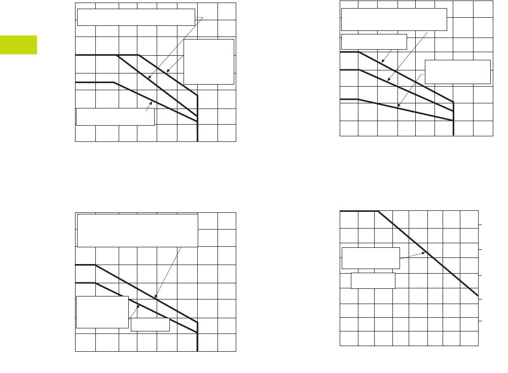
T40-126 Logic Control Products CA08100001K—June 2012 ww.eatoncanada.ca
40
40
40
40
40
40
40
40
40
40
40
40
40
40
40
40
40
40
40
40
40
40
40
40
40
40
40
40
40
40
40.6
Control Relays and Timers
Solid-State Relays
Temperature Derating Curves
10 Amp Styles
25 Amp Styles
40 and 50 Amp Styles
75 Amp Styles
Load Current (amps rms)
16
14
12
10
8
6
4
2
20°40°60°80°100°
Max. Ambient Temperature (°C)
6" x 6" x 1/8" aluminum plate
Free air mounting
0
Heat sink
with 1°C/W
thermal
resistance
Load Current (amps rms)
40
35
30
25
20
15
10
5
20°40°60°80°100°
Max. Ambient Temperature (°C)
Mounted on heat sink with
1°C/W thermal resistance
(sink to ambient)
5" x 6" x 1/8"
aluminum
plate 1.5°C/W
Load Current (amps rms)
90
80
70
50
40
30
20
10
20°40°60°80°100°
Max. Ambient Temperature (°C)
Mounted on heat sink with
1°C/W thermal resistance
0
0.14°C/W (50A)
5" x 6" x 1/8"
aluminum plate
Load Current (amps rms)
75
60
45
40
30
20
10
20°40°60°80°
Max. Ambient Temperature (°C)
030°0°10°70°
50°
90
95
100
105
110
Max. Allowable Temperature
5" x 6" x 1/8"
aluminum plate
0.14°C/W
Tab40book.fm Page 126 Wednesday, July 4, 2012 10:05 PM
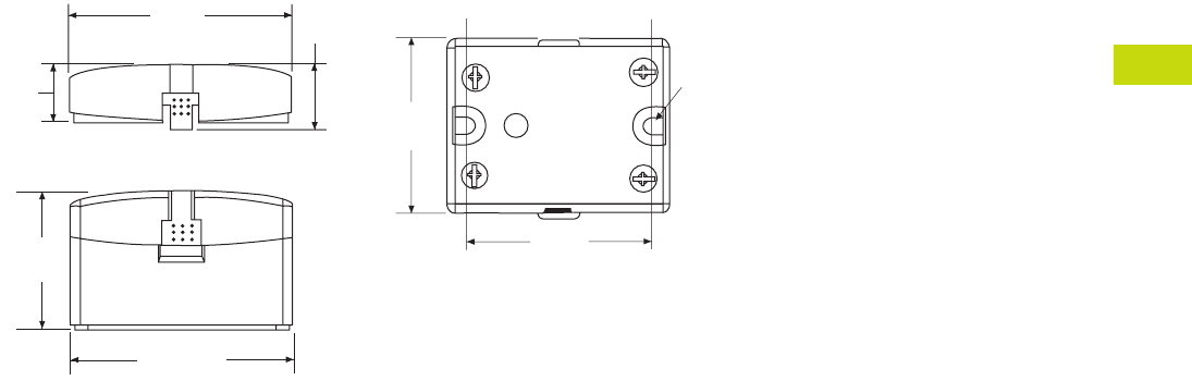
Logic Control Products CA08100001K—June 2012 ww.eatoncanada.ca T40-127
40
40
40
40
40
40
40
40
40
40
40
40
40
40
40
40
40
40
40
40
40
40
40
40
40
40
40
40
40
40
40.6
Control Relays and Timers
Solid-State Relays
Dimensions
Approximate Dimensions in Inches (mm)
D93 Series
2.28
(57.9) 0.66
(16.8)
0.6
(15.1)
1.4
(35.9)
2.28
(57.9)
Screw Terminals
1.74
(44.1)
0.18
(4.4)
1.87
(47.5)
Tab40book.fm Page 127 Wednesday, July 4, 2012 10:05 PM
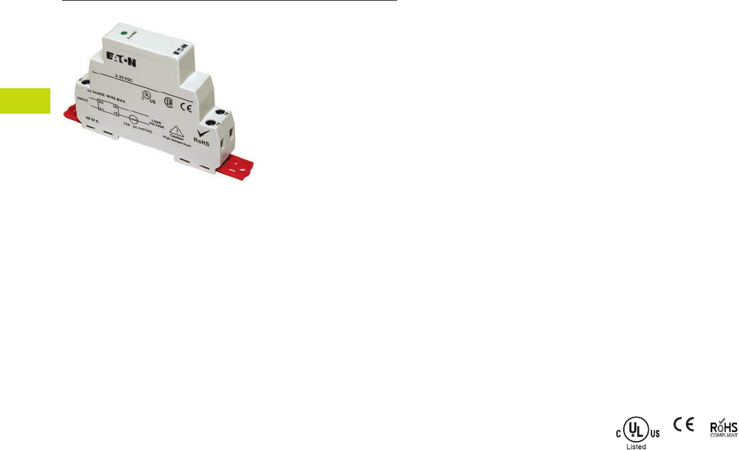
T40-128 Logic Control Products CA08100001K—June 2012 ww.eatoncanada.ca
40
40
40
40
40
40
40
40
40
40
40
40
40
40
40
40
40
40
40
40
40
40
40
40
40
40
40
40
40
40
40.6
Control Relays and Timers
Solid-State Relays
D96 Series—Solid-State Relays Contents
Description Page
D93 Series . . . . . . . . . . . . . . . . . . . . . . . . . . . . . . . . . . T40-121
D96 Series
Product Selection . . . . . . . . . . . . . . . . . . . . . . . T40-129
Technical Data and Specifications . . . . . . . . . . . . . T40-130
Dimensions . . . . . . . . . . . . . . . . . . . . . . . . . . . . . . T40-132
D99 Series . . . . . . . . . . . . . . . . . . . . . . . . . . . . . . . . . . T40-133
D96 Series
Product Description
Eaton’s D96 series of
solid-state relays is a
technologically advanced set
of electronic relays for tough
applications and harsh
environments. The compact
17.5 mm wide package
with an integrated heat sink
provides easy mounting
in tight spaces.
Application Description
A solid-state relay (SSR) can
perform many applications
that an electromechanical
relay can perform. The SSR
differs in that it has no
moving mechanical parts
within it and has some
distinct advantages over an
electromechanical relay.
When used correctly in the
intended application, the SSR
provides a high degree of
reliability, a long service life,
significantly reduced
electromagnetic interference,
fast response and high
vibration resistance.
Applications for the SSR
typically include equipment
that requires high cycling
rates, low acoustical or
electrical noise, or high
vibration resistance. Some
examples are medical
equipment, heating/cooling
equipment, lighting control
and pumps/compressors,
among others.
Features and Benefits
●All solid-state circuitry has
no moving parts to wear
●Integral heat sink
eliminates the need for
added accessories and
installation
●Flexible mounting allows
DIN rail or panel mounting
without additional
hardware or tools
●Isolated input and output
terminals protect the
system from electrical
noise
●Internal snubber circuitry
protects the SSR from
transients
Standards and Certifications
●UL/cUL listed—UL 508
●CSA certified
●CE marked
●RoHS compliant
Tab40book.fm Page 128 Wednesday, July 4, 2012 10:05 PM
Logic Control Products CA08100001K—June 2012 ww.eatoncanada.ca T40-129
40
40
40
40
40
40
40
40
40
40
40
40
40
40
40
40
40
40
40
40
40
40
40
40
40
40
40
40
40
40
40.6
Control Relays and Timers
Solid-State Relays
Product Selection
D96 Series
Input Voltage Output Voltage
Contact
Configuration Switching Type
Rated Current
Load (Amps) Catalogue Number
3.5–32 Vdc 3–50 Vdc SPST-NO DC switch 15 D96115ACZ3
3.5–32 Vdc 3–150 Vdc SPST-NO DC switch 8 D96208ACZ3
90–280 Vac 24–280 Vac SPST-NO Random 10 D96210ACR1
3–32 Vdc 24–280 Vac SPST-NO Random 10 D96210ACR2
90–280 Vac 24–280 Vac SPST-NO Zero cross 10 D96210ACZ1
3–32 Vdc 24–280 Vac SPST-NO Zero cross 10 D96210ACZ2
3–32 Vdc 24–280 Vac SPST-NC Random 10 D96210BCR2
90–280 Vac 48–480 Vac SPST-NO Random 10 D96410ACR1
3–32 Vdc 48–480 Vac SPST-NO Random 10 D96410ACR2
90–280 Vac 48–480 Vac SPST-NO Zero cross 10 D96410ACZ1
3–32 Vdc 48–480 Vac SPST-NO Zero cross 10 D96410ACZ2
90–280 Vac 48–600 Vac SPST-NO Random 10 D96610ACR1
90–280 Vac 48–600 Vac SPST-NO Zero cross 10 D96610ACZ1
3–32 Vdc 48–600 Vac SPST-NO Zero cross 10 D96610ACZ2
D96115ACZ3
Tab40book.fm Page 129 Wednesday, July 4, 2012 10:05 PM

T40-130 Logic Control Products CA08100001K—June 2012 ww.eatoncanada.ca
40
40
40
40
40
40
40
40
40
40
40
40
40
40
40
40
40
40
40
40
40
40
40
40
40
40
40
40
40
40
40.6
Control Relays and Timers
Solid-State Relays
Technical Data and Specifications
D96 Series
Description Units D96210ACZ1 D96210ACZ2 D96210ACR1 D96210ACR2 D96115ACZ3 D96208ACZ3 D96210BCR2
Output Characteristics
Contact configuration SPST-NO SPST-NO SPST-NO SPST-NO SPST-NO SPST-NO SPST-NC
Switching device SCR SCR SCR SCR MOSFET MOSFET SCR
Current rating A 10 10 10 10 15 8 10
Switching type Zero cross Zero cross Random turn on Random turn on DC switching DC switching Random turn on
Maximum zero turn-on voltage (Vpk) V 35 35 35 35 NA NA 35
Maximum rate of rise off state voltage (DV/DT) V/us 500 500 500 500 NA NA 500
Incandescent lamp ampere rating (rms) A 8888NANA8
Motor load rating (rms) A 4.5 4.5 4.5 4.5 NA NA 4.5
Min. load current to maintain on mA 50 50 50 50 20 20 50
Non-repetitive surge current (1 cycle) A 500 500 500 500 50 35 500
Max. rms overload current (1 second) A 24 24 24 24 24 17 24
Max. off state leakage current (rms) mA 10 10 10 10 10 10 10
Typical on state voltage drop (rms) V 1.25 AC 1.25 AC 1.25 AC 1.25 AC 1.25 DC 1.25 DC 1.25 AC
Max. on state voltage drop (rms) V 1.6 AC 1.6 AC 1.6 AC 1.6 AC 1.6 DC 1.6 DC 1.6 AC
Max. I2t for fusing (A2) 1250 1250 1250 1250 NA NA 1250
Input Characteristics
Must release voltage V 10 AC 1 DC 10 AC 1 DC 1 DC 1 DC 1 DC
Typical input impedance ohms 16–25k Current regulator 16–25k ACL Current regulator Current regulator ACL
Nominal input current at 5 Vdc or 240 Vac mA 12 16 12 16 12 12 12
Reverse polarity protection NA Yes NA Yes Yes Yes Yes
Performance Characteristics
Operating time (response time)
ON ms 40 8.3 8.3 8.3 5 5 8.3
OFF ms 80 8.3 8.3 8.3 5 5 8.3
Rated insulation voltage—input to input Vac 2500 2500 4000 4000 2500 2500 4000
Dielectric strength—terminal to chassis Vac 2500 2500 2500 2500 2500 2500 2500
Environment
Product certifications UL, CSA, CE UL, CSA, CE UL, CSA, CE UL, CSA, CE UL, CSA, CE UL, CSA, CE UL, CSA, CE
Ambient air temperature
Storage ˚C –40 to 100 –40 to 100 –40 to 100 –40 to 100 –40 to 100 –40 to 100 –40 to 100
Operating ˚C –30 to 80 –30 to 80 –30 to 80 –30 to 80 –30 to 80 –30 to 80 –30 to 80
Degree of protection IP20 IP20 IP20 IP20 IP20 IP20 IP20
Miscellaneous Characteristics
Thermal resistance (junction to case) ˚C/W 0.66 0.66 0.66 0.66 0.66 0.66 0.66
Integral heat sink ˚C/W 4.0 4.0 4.0 4.0 4.0 4.0 4.0
Weight g (oz) 127 (4.1) 127 (4.1) 127 (4.1) 127 (4.1) 127 (4.1) 127 (4.1) 127 (4.1)
LED—input Green Green Green Green Green Green Green
Terminal wire capacity AWG (mm2) 14 (2.1) 14 (2.1) 14 (2.1) 14 (2.1) 14 (2.1) 14 (2.1) 14 (2.1)
Terminal torque (max.) in-lb (Nm) 7.1 (0.8) 7.1 (0.8) 7.1 (0.8) 7.1 (0.8) 7.1 (0.8) 7.1 (0.8) 7.1 (0.8)
Tab40book.fm Page 130 Wednesday, July 4, 2012 10:05 PM
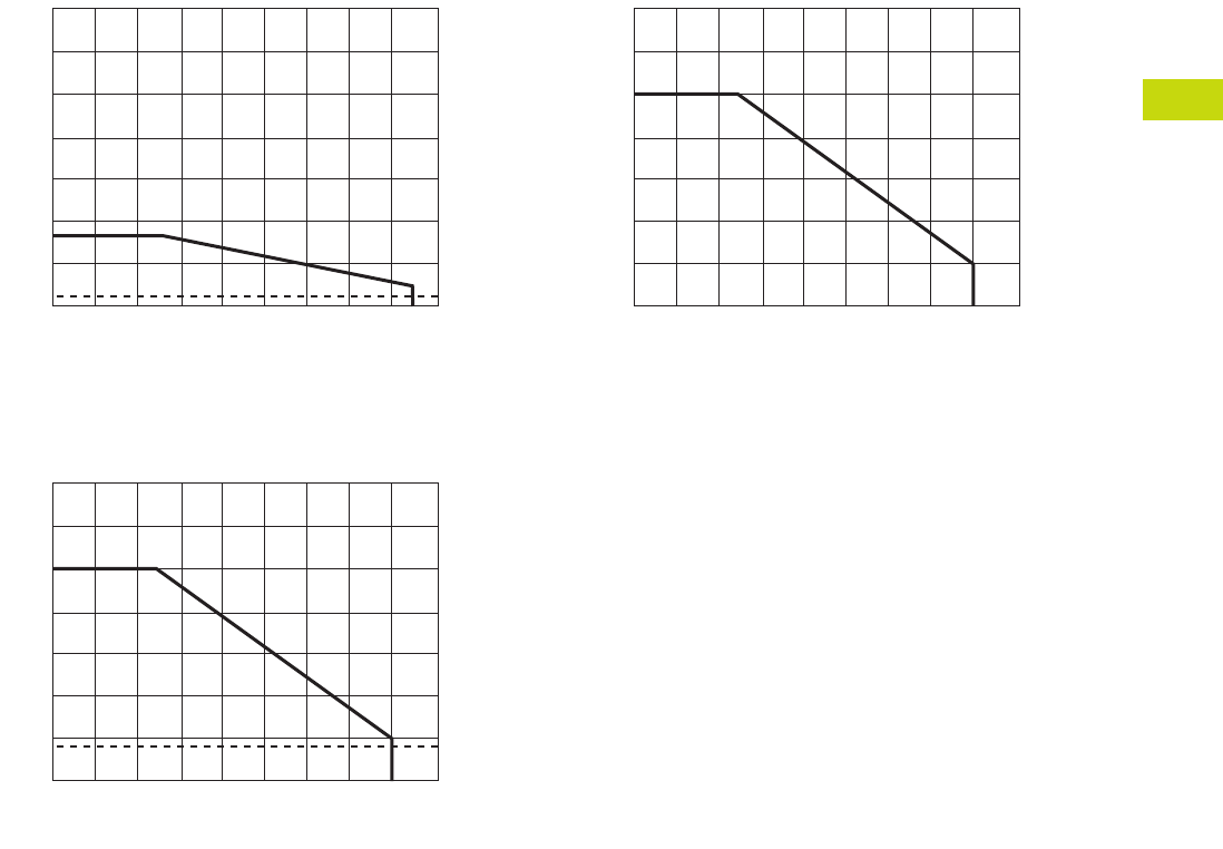
Logic Control Products CA08100001K—June 2012 ww.eatoncanada.ca T40-131
40
40
40
40
40
40
40
40
40
40
40
40
40
40
40
40
40
40
40
40
40
40
40
40
40
40
40
40
40
40
40.6
Control Relays and Timers
Solid-State Relays
Temperature Derating Curves
8 Amp Style
10 Amp Style
15 Amp Style
Max. Ambient Temperature (°C)
0° 10° 20° 30° 40° 50° 60° 70° 80° 90°
85°
35
30
25
20
15
10
8
5
0
Load Current (amps rms)
1.5
Max. Ambient Temperature (°C)
0° 10° 20° 30° 40° 50° 60° 70° 80° 90°
14
12
10
8
6
4
2
0
Load Current (amps rms)
1.8
Ambient Temperature (°C)
0° 10° 20° 30° 40° 50° 60° 70° 80° 90°
24
18
15
12
9
6
3
0
Current (amps DC)
Tab40book.fm Page 131 Wednesday, July 4, 2012 10:05 PM
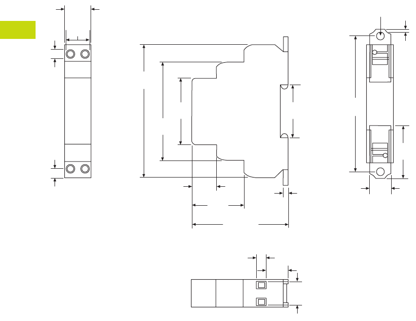
T40-132 Logic Control Products CA08100001K—June 2012 ww.eatoncanada.ca
40
40
40
40
40
40
40
40
40
40
40
40
40
40
40
40
40
40
40
40
40
40
40
40
40
40
40
40
40
40
40.6
Control Relays and Timers
Solid-State Relays
Dimensions
Approximate Dimensions in Inches (mm)
D96 Series
0.69
(17.6)
1.40
(35.6)
1.78
(45.3)
0.20
(5.0)
0.56
(14.2)
0.27
(6.9)
0.55
(14.9)
0.62
(15.8)
0.24
(6.0)
2.63
(66.8)
3.54
(90.0)
2.56 Max.
(65.0)
0.63
(16.0)
1.36
(34.6)
0.13
(3.4)
1.39
(35.2)
3.64
(92.4)
0.20
(5.0)
0.07
(1.7)
0.56
(14.3)
Tab40book.fm Page 132 Wednesday, July 4, 2012 10:05 PM
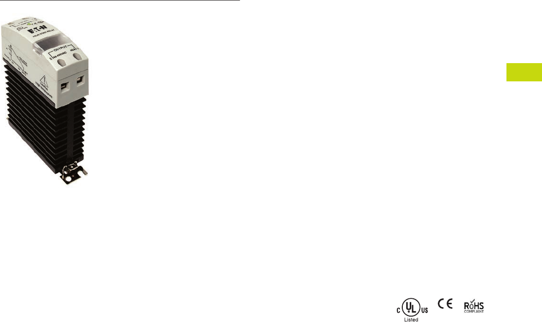
Logic Control Products CA08100001K—June 2012 ww.eatoncanada.ca T40-133
40
40
40
40
40
40
40
40
40
40
40
40
40
40
40
40
40
40
40
40
40
40
40
40
40
40
40
40
40
40
40.6
Control Relays and Timers
Solid-State Relays
D99 Series—Solid-State Relays Contents
Description Page
D93 Series . . . . . . . . . . . . . . . . . . . . . . . . . . . . . . . . . . T40-121
D96 Series . . . . . . . . . . . . . . . . . . . . . . . . . . . . . . . . . . T40-128
D99 Series
Product Selection . . . . . . . . . . . . . . . . . . . . . . . . T40-134
Technical Data and Specifications . . . . . . . . . . . . . T40-135
Dimensions . . . . . . . . . . . . . . . . . . . . . . . . . . . . . . T40-138
D99 Series
Product Description
Eaton’s D99 series of solid-
state relays is a line of
heavy-duty industrial relays
with an integrated heat sink.
The attached metal hardware
can be used for DIN rail or
panel mounting.
Models are available in a
variety of input voltages in
10A, 25A and 40A sizes.
Application Description
A solid-state relay (SSR) can
perform many applications
that an electromechanical
relay can perform. The SSR
differs in that it has no
moving mechanical parts
within it and has some
distinct advantages over an
electromechanical relay.
When used correctly in the
intended application, the SSR
provides a high degree of
reliability, a long service life,
significantly reduced
electromagnetic interference,
fast response and high
vibration resistance.
Applications for the SSR
typically include equipment
that requires high cycling
rates, low acoustical or
electrical noise, or high
vibration resistance. Some
examples are medical
equipment, heating/cooling
equipment, lighting control
and pumps/compressors,
among others.
Features and Benefits
●All solid-state circuitry has
no moving parts to wear
●Integral heat sink
eliminates the need for
added accessories and
installation
●Flexible mounting allows
DIN rail or panel mounting
without additional
hardware or tools
●Isolated input and output
terminals protect the
system from electrical
noise
●Internal snubber circuitry
protects the SSR from
transients
Standards and Certifications
●UL/cUL listed—UL 508
●CSA certified
●CE marked
●RoHS compliant
Tab40book.fm Page 133 Wednesday, July 4, 2012 10:05 PM
T40-134 Logic Control Products CA08100001K—June 2012 ww.eatoncanada.ca
40
40
40
40
40
40
40
40
40
40
40
40
40
40
40
40
40
40
40
40
40
40
40
40
40
40
40
40
40
40
40.6
Control Relays and Timers
Solid-State Relays
Product Selection
D99 Series
Input Voltage Output Voltage
Contact
Configuration Switching Type
Rated Current
Load (Amps) Catalogue Number
90–280 Vac 24–280 Vac SPST-NO Zero cross 10 D99210ACZ1
3–32 Vdc 24–280 Vac SPST-NO Zero cross 10 D99210ACZ2
90–280 Vac 24–280 Vac SPST-NO Zero cross 25 D99225ACZ1
3–32 Vdc 24–280 Vac SPST-NO Zero cross 25 D99225ACZ2
90–280 Vac 24–280 Vac SPST-NO Zero cross 40 D99240ACZ1
3–32 Vdc 24–280 Vac SPST-NO Zero cross 40 D99240ACZ2
90–280 Vac 48–600 Vac SPST-NO Zero cross 10 D99610ACZ1
3–32 Vdc 48–600 Vac SPST-NO Zero cross 10 D99610ACZ2
90–280 Vac 48–600 Vac SPST-NO Zero cross 25 D99625ACZ1
3–32 Vdc 48–600 Vac SPST-NO Zero cross 25 D99625ACZ2
90–280 Vac 48–600 Vac SPST-NO Zero cross 40 D99640ACZ1
3–32 Vdc 48–600 Vac SPST-NO Zero cross 40 D99640ACZ2
D99210ACZ1
Tab40book.fm Page 134 Wednesday, July 4, 2012 10:05 PM

Logic Control Products CA08100001K—June 2012 ww.eatoncanada.ca T40-135
40
40
40
40
40
40
40
40
40
40
40
40
40
40
40
40
40
40
40
40
40
40
40
40
40
40
40
40
40
40
40.6
Control Relays and Timers
Solid-State Relays
Technical Data and Specifications
D99 Series
Description Units D99210ACZ1 D99210ACZ2 D99225ACZ1 D99225ACZ2 D99240ACZ1 D99240ACZ2
Output Characteristics
Contact configuration SPST-NO SPST-NO SPST-NO SPST-NO SPST-NO SPST-NO
Switching device SCR SCR SCR SCR SCR SCR
Current rating A 10 10 25 25 40 40
Switching type Zero cross Zero cross Zero cross Zero cross Zero cross Zero cross
Maximum zero turn-on voltage (Vpk) V 35 35 35 35 35 35
Maximum rate of rise off state voltage (DV/DT) V/us 500 200 500 500 500 500
Incandescent lamp ampere rating (rms) A 8 8 16 16 20 20
Motor load rating (rms) A 4.5 4.5 8 8 14 14
Min. load current to maintain on mA 50 50 120 120 250 250
Non-repetitive surge current (1 cycle) A 83 83 800 800 800 800
Max. rms overload current (1 second) A 24 24 40 40 100 100
Max. off state leakage current (rms) mA 10 10 10 10 10 10
Typical on state voltage drop (rms) Vac 1.25 1.25 1.35 1.35 1.6 1.6
Max. on state voltage drop (rms) Vac 1.6 1.6 1.8 1.8 1.6 1.6
Max. I2t for fusing (A2) 83 83 3700 3700 3700 83
Input Characteristics
Must release voltage V 10 AC 1 DC 10 AC 1 DC 10 AC 1 DC
Typical input impedance ohms 16–25k Current regulator 16–25k Current regulator 13k Current regulator
Nominal input current at 5 Vdc or 240 Vac mA 12 12 12 12 16 16
Reverse polarity protection NA Yes NA Yes NA Yes
Performance Characteristics
Operating time (response time)
ON ms 8.3 8.3 8.3 8.3 8.3 10
OFF ms 8.3 8.3 8.3 8.3 8.3 10
Rated insulation voltage—input to input Vac 4000 4000 4000 4000 4000 4000
Dielectric strength—terminal to chassis Vac 4000 4000 4000 4000 4000 4000
Environment
Product certifications UL, CSA, CE UL, CSA, CE UL, CSA, CE UL, CSA, CE UL, CSA, CE UL, CSA, CE
Ambient air temperature
Storage ˚C –40 to 100 –40 to 100 –40 to 100 –40 to 100 –40 to 100 –40 to 100
Operating ˚C –30 to 80 –30 to 80 –30 to 80 –30 to 80 –30 to 80 –30 to 80
Degree of protection IP20 IP20 IP20 IP20 IP20 IP20
Miscellaneous Characteristics
Thermal resistance (junction to case) ˚C/W 1.5 1.5 1.5 0.43 1.5 0.43
Integral heat sink ˚C/W 2.2 2.2 2.2 2.2 2.2 2.2
Weight g (oz) 320 (11.3) 320 (11.3) 320 (11.3) 326 (11.5) 320 (11.3) 332 (11.7)
LED—input Green Green Green Green Green Green
Terminal wire capacity AWG (mm2) 8 (10) 8 (10) 8 (10) 8 (10) 8 (10) 8 (10)
Terminal torque (max.) in-lb (Nm) 12.5 (1.4) 12.5 (1.4) 12.5 (1.4) 12.5 (1.4) 12.5 (1.4) 12.5 (1.4)
Tab40book.fm Page 135 Wednesday, July 4, 2012 10:05 PM

T40-136 Logic Control Products CA08100001K—June 2012 ww.eatoncanada.ca
40
40
40
40
40
40
40
40
40
40
40
40
40
40
40
40
40
40
40
40
40
40
40
40
40
40
40
40
40
40
40.6
Control Relays and Timers
Solid-State Relays
D99 Series, continued
Description Units D99610ACZ1 D99610ACZ2 D99625ACZ1 D99625ACZ2 D99640ACZ1 D99640ACZ2
Output Characteristics
Contact configuration SPST-NO SPST-NO SPST-NO SPST-NO SPST-NO SPST-NO
Switching device SCR SCR SCR SCR SCR SCR
Current rating A 10 10 25 10 40 40
Switching type Zero cross Zero cross Zero cross Zero cross Zero cross Zero cross
Maximum zero turn-on voltage (Vpk) V 35 35 35 35 35 35
Maximum rate of rise off state voltage (DV/DT) V/us 200 200 700 700 500 500
Incandescent lamp ampere rating (rms) A 8 8 16 16 20 20
Motor load rating (rms) A 4.5 4.5 8 8 14 14
Min. load current to maintain on mA 80 80 250 250 250 250
Non-repetitive surge current (1 cycle) A 83 83 1000 1000 800 800
Max. rms overload current (1 second) A 24 24 50 50 100 100
Max. off state leakage current (rms) mA 10 10 10 10 10 10
Typical on state voltage drop (rms) Vac 1.25 1.25 1.35 1.35 1.6 1.6
Max. on state voltage drop (rms) Vac 1.6 1.6 1.6 1.6 1.6 1.6
Max. I2t for fusing (A2) 83 83 1700 1700 3700 3700
Input Characteristics
Must release voltage V 10 AC 1 DC 10 AC 1 DC 10 AC 1 DC
Typical input impedance ohms 16–25k Current regulator 16–25k Current regulator 13k Current regulator
Nominal input current at 5 Vdc or 240 Vac mA 12 16 12 16 16 16
Reverse polarity protection NA Yes NA Yes NA Yes
Performance Characteristics
Operating time (response time)
ON ms 8.33 8.3 8.33 8.3 10 10
OFF ms 8.33 8.3 8.33 8.3 10 10
Rated insulation voltage—input to input Vac 4000 4000 4000 4000 4000 4000
Dielectric strength—terminal to chassis Vac 4000 4000 4000 4000 4000 4000
Environment
Product certifications UL, CSA, CE UL, CSA, CE UL, CSA, CE UL, CSA, CE UL, CSA, CE UL, CSA, CE
Ambient air temperature
Storage ˚C –40 to 100 –40 to 100 –40 to 100 –40 to 100 –40 to 100 –40 to 100
Operating ˚C –30 to 80 –30 to 80 –30 to 80 –30 to 80 –30 to 80 –30 to 80
Degree of protection IP20 IP20 IP20 IP20 IP20 IP20
Miscellaneous Characteristics
Thermal resistance (junction to case) ˚C/W 1.8 1.8 0.43 0.43 0.43 0.43
Integral heat sink ˚C/W 2.2 2.2 2.2 2.2 2.2 2.2
Weight g (oz) 320 (11.3) 321 (11.3) 326 (11.5) 326 (11.5) 332 (11.7) 332 (11.7)
LED—input Green Green Green Green Green Green
Terminal wire capacity AWG (mm2) 8 (10) 9 (10) 8 (10) 8 (10) 8 (10) 8 (10)
Terminal torque (max.) in-lb (Nm) 12.5 (1.4) 12.5 (1.4) 12.5 (1.4) 12.5 (1.4) 12.5 (1.4) 12.5 (1.4)
Tab40book.fm Page 136 Wednesday, July 4, 2012 10:05 PM
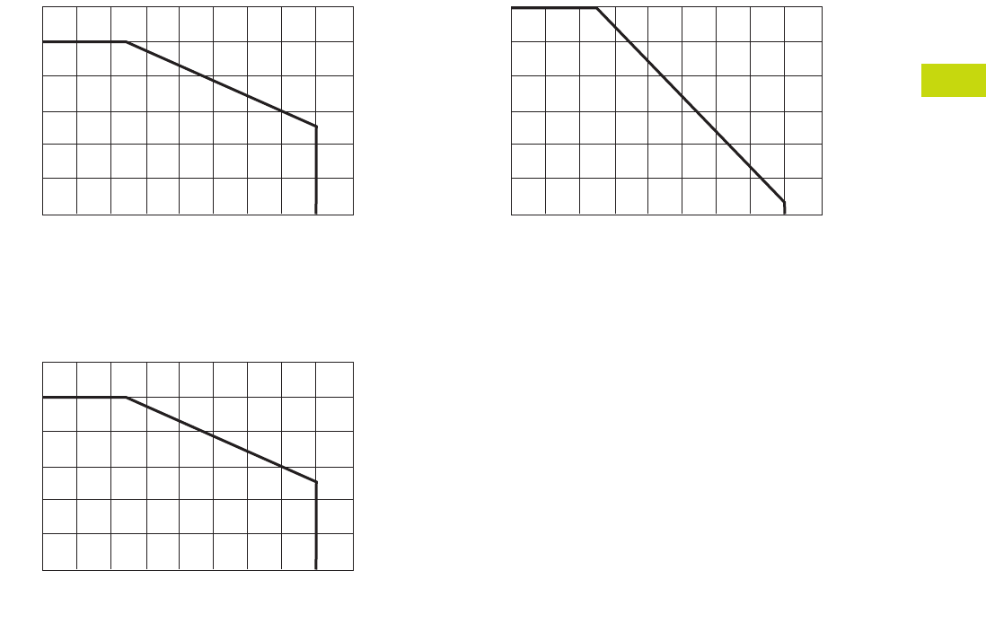
Logic Control Products CA08100001K—June 2012 ww.eatoncanada.ca T40-137
40
40
40
40
40
40
40
40
40
40
40
40
40
40
40
40
40
40
40
40
40
40
40
40
40
40
40
40
40
40
40.6
Control Relays and Timers
Solid-State Relays
Temperature Derating Curves
10 Amp Styles
25 Amp Styles
40 Amp Styles
Ambient Temperature (°C)
0° 10° 20° 30° 40° 50° 60° 70° 80° 90°
12
10
8
6
4
2
0
Current in amps
Ambient Temperature (°C)
0° 10° 20° 30° 40° 50° 60° 70° 80° 90°
25
20
15
10
5
0
Current in amps
Ambient Temperature (°C)
0° 10° 20° 30° 40° 50° 60° 70° 80° 90°
40
30
25
20
15
10
0
Current in amps
Tab40book.fm Page 137 Wednesday, July 4, 2012 10:05 PM
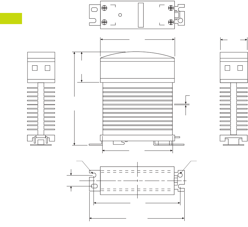
T40-138 Logic Control Products CA08100001K—June 2012 ww.eatoncanada.ca
40
40
40
40
40
40
40
40
40
40
40
40
40
40
40
40
40
40
40
40
40
40
40
40
40
40
40
40
40
40
40.6
Control Relays and Timers
Solid-State Relays
Dimensions
Approximate Dimensions in Inches (mm)
D99 Series
1.20
(30.0)
4.20
(107.0)
0.50 (11.9)
0.05
(1.20)
1.20
(30.0)
3.20
(80.0)
Input
Output
+
21
–
3.10
(77.5)
3.70
(92.9)
4.00
(102.0)
0.20 (5.0)
Radius
0.20 (5.0)
Radius
Tab40book.fm Page 138 Wednesday, July 4, 2012 10:05 PM
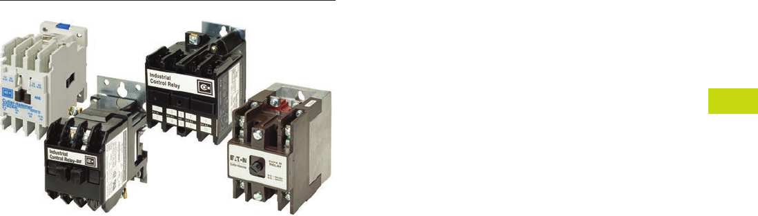
Logic Control Products CA08100001K—June 2012 ww.eatoncanada.ca T40-139
40
40
40
40
40
40
40
40
40
40
40
40
40
40
40
40
40
40
40
40
40
40
40
40
40
40
40
40
40
40
40.7
Control Relays and Timers
Machine Tool Relays
Machine Tool Relays Contents
Description Page
Machine Tool Relays
D15 Series—Freedom 600V Multipole . . . . . . . . . . T40-140
BF/BFD Series—Fixed Contact
Industrial Control . . . . . . . . . . . . . . . . . . . . . . . . . T40-145
AR/ARD Series—Convertible Contact
Industrial Control . . . . . . . . . . . . . . . . . . . . . . . . . T40-151
D26 Series—Type M, 600 Vac Multipole
with Convertible Contacts . . . . . . . . . . . . . . . . . . T40-156
D26 Series—Type M, DC Multipole
with Convertible Contacts . . . . . . . . . . . . . . . . . . T40-161
Product Overview
Eaton’s machine tool relay
offering includes a variety of
NEMA type relays. Included
in this are open style relays
and relays with convertible
or side-mount contacts. Also
included in this family are a
variety of accessories to
match the application,
including suppressors, timing
contacts and enclosures. The
relay coils are available in a
variety of line and control
level voltages.
Tab40book.fm Page 139 Wednesday, July 4, 2012 10:05 PM
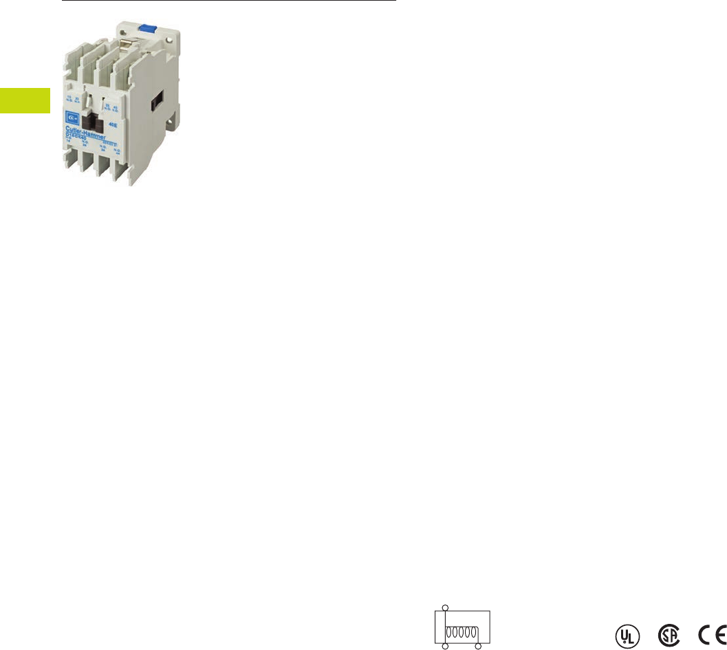
T40-140 Logic Control Products CA08100001K—June 2012 ww.eatoncanada.ca
40
40
40
40
40
40
40
40
40
40
40
40
40
40
40
40
40
40
40
40
40
40
40
40
40
40
40
40
40
40
40.7
Control Relays and Timers
Machine Tool Relays
D15 Series—Freedom 600V Multipole Contents
Description Page
D15 Series—Freedom 600V Multipole
Product Selection . . . . . . . . . . . . . . . . . . . . . . . . . . T40-141
Accessories . . . . . . . . . . . . . . . . . . . . . . . . . . . . . . T40-142
Technical Data and Specifications . . . . . . . . . . . . . T40-143
Dimensions . . . . . . . . . . . . . . . . . . . . . . . . . . . . . . T40-144
BF/BFD Series—Fixed Contact
Industrial Control . . . . . . . . . . . . . . . . . . . . . . . . . . . . T40-145
AR/ARD Series—Convertible Contact
Industrial Control . . . . . . . . . . . . . . . . . . . . . . . . . . . . T40-151
D26 Series—Type M, 600 Vac Multipole
with Convertible Contacts . . . . . . . . . . . . . . . . . . . . T40-156
D26 Series—Type M, DC Multipole
with Convertible Contacts . . . . . . . . . . . . . . . . . . . . T40-161
D15 Series—Freedom 600V Multipole
Product Description
Contact poles on the D15
relay are of the fixed design
and are not convertible. The
basic four-pole relay will
accept a front-mounted
contact pole deck and/or side-
mounted contact blocks (one
per side). In addition, a side-
mounted solid-state timer or
a front-mounted pneumatic
timer can be added to the
relay. Only one front-
mounted attachment can be
added to the basic relay.
Application Description
Side-mounted contact
blocks can be used to
provide additional poles
in applications where a
pneumatic timer is installed
on the front of the relay.
They can also be used where
panel depth is restricted.
The maximum number of
contacts recommended per
relay is eight, six of which can
be NC. When a pneumatic
timer is used, the maximum
recommended number of
NC contacts is three.
Relays with DC coils are
supplied with a coil clearing
NC contact mounted on the
side of the relay.
Features and Benefits
●600V, 10A continuous
thermal current
●State indicator visually
shows relay ON or OFF
status
●Relay base has mounting
holes on 35 x 60 mm
centers, permitting direct
replacement of
competitive relays
●Relay also mounts on
35 mm DIN rail as standard
●Magnet coil has three
terminals, permitting either
top or diagonal wiring—
easy to replace European
or U.S. relays without
changing wiring layout
●Contact pole terminals
have captive, backed-out,
self-lifting pressure plates
with ± screws—reduced
wiring time
●All terminals are shrouded
or
“finger-proofed” to
reduce possibility
of
electrical shock
●Designed to meet or
exceed UL, NEMA, IEC,
CSA, VDE, BS and other
international standards
Standards and Certifications
●UL
●CSA certified
●CE marked
Tab40book.fm Page 140 Wednesday, July 4, 2012 10:05 PM
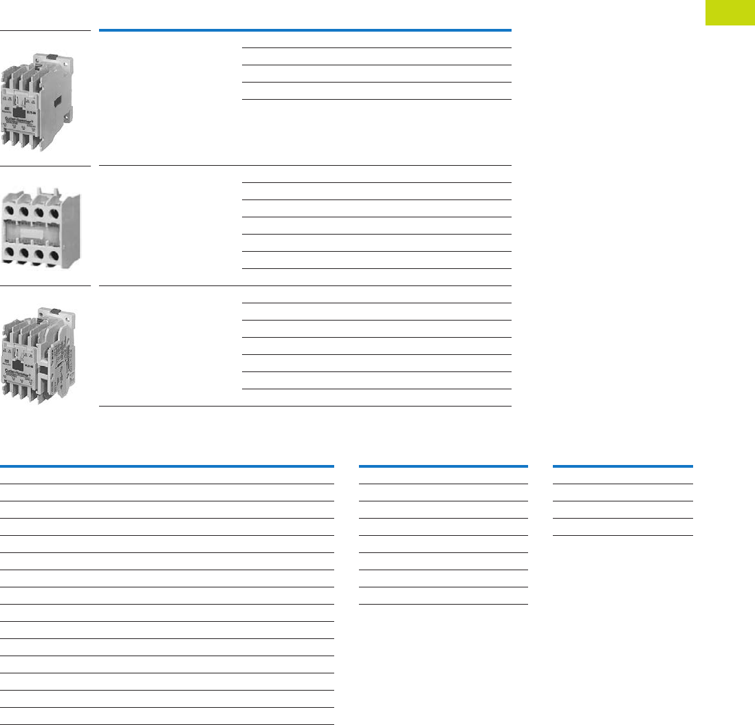
Logic Control Products CA08100001K—June 2012 ww.eatoncanada.ca T40-141
40
40
40
40
40
40
40
40
40
40
40
40
40
40
40
40
40
40
40
40
40
40
40
40
40
40
40
40
40
40
40.7
Control Relays and Timers
Machine Tool Relays
Product Selection
When Ordering, Specify
Catalogue number and magnet coil code letter. Example: For a four-pole relay having
4NO contacts with a 120V 60 Hz coil, order Catalogue Number D15CR40AB.
Factory-Assembled Multipole Relays
Additional Contact Poles Magnet Coil Selection
Notes
Underscore indicates missing code suffix for magnet coil—see Magnet Coil Selection table above.
Not all suffix codes available: consult Customer Support Centre.
Number of
Poles
Type of Contacts Open Type
NO NC Catalogue Number
440D15CR40_B
31D15CR31_B
22D15CR22_B
13D15CR13_B
04D15CR04_B
6
(four-pole relay with two-pole
front-mounted deck)
60D15CR60_B
51D15CR51_B
42D15CR42_B
33D15CR33_B
24D15CR24_B
15D15CR15_B
06D15CR06_B
8
(four-pole relay with four-pole
front-mounted deck)
80D15CR80_B
71D15CR71_B
62D15CR62_B
53D15CR53_B
44D15CR44_B
35D15CR35_B
26D15CR26_B
D15CR40_B
D15CR60_B
D15CR80_B
Description
Catalogue
Number
Front Contact Pole Deck
1NO-1NC C320KGT3
2NO C320KGT4
2NC C320KGT5
1NO (early closing)–1NC (late opening) C320KGT7
4NO C320KGT13
3NO-1NC C320KGT14
2NO-2NC C320KGT15
1NO-3NC C320KGT16
4NC C320KGT17
Side-Mounted Contact Blocks
1NO-1NC C320KGS3
2NO C320KGS4
2NC C320KGS5
1NO (early closing)–1NC (late opening) C320KGS7
AC Coils
Volts and Hertz
Code
Suffix
DC Coils
Volts
Code
Suffix
120/60 or 110/50 A12 R1
240/60 or 220/50 B24 T1
480/60 or 440/50 C48 W1
600/60 or 550/50 D120 A1
208/60 E
277/60 H
208–240/60 J
24/60 T
Tab40book.fm Page 141 Wednesday, July 4, 2012 10:05 PM
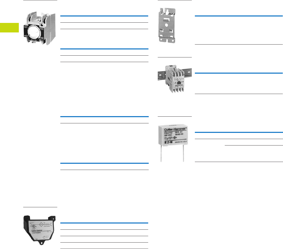
T40-142 Logic Control Products CA08100001K—June 2012 ww.eatoncanada.ca
40
40
40
40
40
40
40
40
40
40
40
40
40
40
40
40
40
40
40
40
40
40
40
40
40
40
40
40
40
40
40.7
Control Relays and Timers
Machine Tool Relays
Accessories
Pneumatic Timer Attachment
Maximum Ampere Ratings
Attachment mounts on top of
any Freedom Series relay
(top-mounted auxiliary
contacts can not be installed
on device when timer is
used). Timer unit has DPST
timed contacts—circuits in
each pole must be the same
polarity. Units are convertible
from OFF to ON delay or
vice-versa.
Finger Protection Shields
Snap-on shields for both
contactors and starters
provide IEC Type IP20
Finger Protection. Prevents
accidental contact with line/
load terminals.
Adhesive Dust Cover
These adhesive stickers
come 25 to a package and
provide extra protection from
contaminants when applied
to the sides of Freedom D15.
Adhesive covers are easily
applied to side opening
where auxiliaries are not
installed and provide extra
protection from metal filings
and other debris.
Solid-State ON DELAY Timer
This timer is designed to be
wired in series with the
load (typically a coil). When
the START button is pushed
(power applied to timer), the
ON delay timing function
starts. At the completion of
the set timing period, timer
and series wired load will
both be energized.
Timing Range
Catalogue
Number
0.1 to 30 seconds C320TP1
10 to 180 seconds C320TP2
Volts AC
Description 120 240 480 600
Make 30 15 7.5 6
Break 3 1.5 0.75 0.6
C320 Pneumatic
Timer Attachment
Application
Catalogue
Number
D15 C320LS1
Description
Catalogue
Number
25 to a package C320DSTCVR
Timing Range
Catalogue
Number
0.1 to 1.0 seconds C320TDN1_
1 to 30 seconds C320TDN30_
30 to 300 seconds C320TDN300_
5 to 30 minutes C320TDN3000_
Solid-State Timer
Metal Mounting Plate
Fits all D15 multipole relays.
Mounting Channel (DIN Rail)
Designed for DIN rail
mounting of Freedom
Series relays.
Transient Suppressor Kits
These kits limit high voltage
transients produced in the
control circuit when power is
removed from the contactor
or starter coil. There are three
separate suppressors for use
on 24–120V, 208–240V or
27–480V coils respectively.
These devices mount directly
to the coil terminals.
Notes
Side mounted on Freedom Series NEMA 00–2, D15, IECA-K and C25D, C25E and C25F frame.
Add operating voltage suffix to catalogue number; A = 120V, B = 240V, E = 208V.
Rated 0.5 ampere pilot duty—not to be used on larger contactors.
Terminal connections are quick connects only. Two per side.
Suppressor is compatible with coil voltages/ranges as shown, both 50 and 60 Hz.
Description
Catalogue
Number
Metal mounting plate C321MP1
C32MP1
Description
Catalogue
Number
1 meter length XBANS3575P
DIN Rail
Description
Coil Voltage
50/60 Hz
Catalogue
Number
Transient 24/120V C320TS1
Suppressor 208/240V C320TS2
277/480V C320TS3
C320TS2
Tab40book.fm Page 142 Wednesday, July 4, 2012 10:05 PM
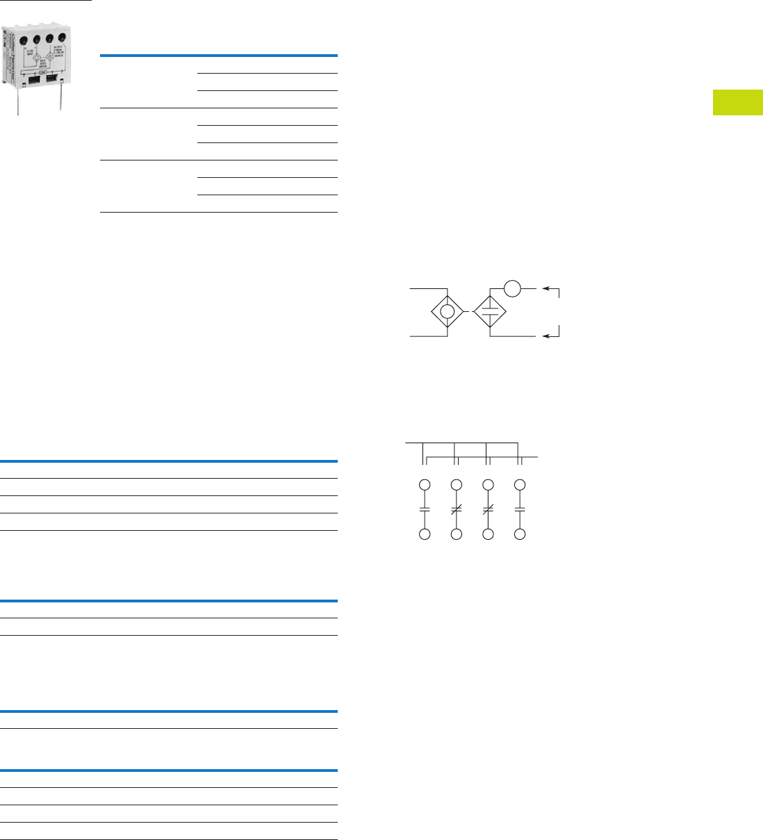
Logic Control Products CA08100001K—June 2012 ww.eatoncanada.ca T40-143
40
40
40
40
40
40
40
40
40
40
40
40
40
40
40
40
40
40
40
40
40
40
40
40
40
40
40
40
40
40
40.7
Control Relays and Timers
Machine Tool Relays
AC/DC Interface Module—
Controller Coil Voltage Ranges
Technical Data and Specifications
Contact Ratings—NEMA A600
Contact Ratings—NEMA P300
Magnet Coil Data
Controller Catalogue
Number Prefix
Controller
Size or Rating
Coil Range
Volts AC
AE16, AE17, AE56,
AE57, CE15, CE55
A–F 24–240
G–K 48–240
L–N 110–240
AN16, AN56,
CN15, CN55
00–0 24–240
1–2 48–240
3 110–240
CN35 10–30A 24–240
60A 48–240
100A 110–240
C320DC
Continuous Thermal Rating: 10A
AC Volts Make Break
120 60 6.0
240 30 3.0
480 15 1.5
600 12 1.2
Continuous Thermal Rating: 5A
DC Volts Make/Break Amperes
125 1.1
250 0.55
AC
Voltage
Pickup Sealed
VA Watts VA Watts
12–600V 80 49 7.5 2.4
DC
Voltage
Pickup Sealed
Amps Watts VA Watts
12 6.4 76.8 0.28 3.36
24 3.2 76.8 0.14 3.36
48 1.6 76.8 0.07 3.36
120 0.64 76.8 0.028 3.36
The Catalogue Number
C320DC Interface Module is
an optically isolated solid-state
switch that provides a means
of operating AC coils with a
24 Vdc control signal. It acts
as a space-saving interposing
relay that can switch a
specified 50/60 Hz AC source
to the contactor or starter coil.
The module may be directly
attached to the coil terminals
of any Freedom Series
contactor or starter—NEMA
Sizes 00–3, D15, IEC Sizes
A–N and lighting contactors
10–100A. It also has
provisions for DIN rail
mounting.
The module will operate coils
within the voltage ranges
shown in the table to the left.
Design Characteristics
●DC input: 24V ±10% at
mA nominal
●AC operating voltage:
24–240 Vac ±10%
50/60 Hz
●AC current rating:
10A make (inrush),
1A break (sealed)
Typical Application—Solid-State Switch
Example of Terminal Marking with 2NO and 2NC Contacts
Relay terminals are identified
by a two-digit number in
accordance with International
Standards approved by
CENELEC (European
Committee for Electro-
technical Standardization).
The number is marked on
the relay and is used to
identify location and status
of the contacts.
The first digit indicates the
location of the contact on the
relay. The numbering begins
with 1 and continues without
a break from left to right.
The second digit indicates
the status of the contacts
(NO or NC). Terminal marking
1 and 2 mean NC and 3 and
4 mean NO.
24 Vdc
Input
Observe
Polarity on
Module
24–240 Vac
50/60 Hz
Contactor Coil
Location
13 21 31 43
14 22 32 44
Status
(NO or NC)
Tab40book.fm Page 143 Wednesday, July 4, 2012 10:05 PM
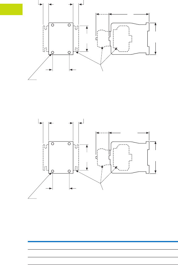
T40-144 Logic Control Products CA08100001K—June 2012 ww.eatoncanada.ca
40
40
40
40
40
40
40
40
40
40
40
40
40
40
40
40
40
40
40
40
40
40
40
40
40
40
40
40
40
40
40.7
Control Relays and Timers
Machine Tool Relays
Dimensions
Approximate Dimensions in Inches (mm)
D15 Four-Pole Relay
D15 Six- and Eight-Pole Relays
Dimensions and Shipping Weights
Description Dimension C
Shipping Weights
Lbs (kg)
Relay only 3.30 (83.8) 1.3 (0.6)
Relay with timer attachment 5.55 (141.0) 1.5 (0.7)
Relay with front contact pole deck 4.66 (118.4) 1.7 (0.8)
2.36
(59.9)
2.96
(75.2)
1.36
(34.5) Optional Additional
Contact Poles
or Accessories
Mtg. Holes for
M4 or #8 Screws
1.8
(45.7)
C
0.54
(13.7)
0.54
(13.7)
Side
Mtd.
Blk.
Frt.
Mtd.
Acc.
4.66
(118.4)
2.36
(59.9)
2.96
(75.2)
1.36
(34.5) Optional Additional
Contact Poles
or Accessories
Mtg. Holes for
M4 or #8 Screws
1.8
(45.7)
0.54
(13.7)
0.54
(13.7)
Side
Mtd.
Blk.
Frt.
Mtd.
Acc.
Tab40book.fm Page 144 Wednesday, July 4, 2012 10:05 PM
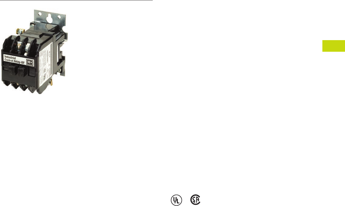
Logic Control Products CA08100001K—June 2012 ww.eatoncanada.ca T40-145
40
40
40
40
40
40
40
40
40
40
40
40
40
40
40
40
40
40
40
40
40
40
40
40
40
40
40
40
40
40
40.7
Control Relays and Timers
Machine Tool Relays
BF/BFD Series—Fixed Contact Industrial Control Contents
Description Page
D15 Series—Freedom 600V Multipole. . . . . . . . . . . . . T40-140
BF/BFD Series—Fixed Contact Industrial
Control
Product Selection . . . . . . . . . . . . . . . . . . . . . . . . . . T40-146
Options . . . . . . . . . . . . . . . . . . . . . . . . . . . . . . . . . . T40-148
Technical Data and Specifications . . . . . . . . . . . . . T40-149
Dimensions . . . . . . . . . . . . . . . . . . . . . . . . . . . . . . T40-150
AR/ARD Series—Convertible Contact
Industrial Control . . . . . . . . . . . . . . . . . . . . . . . . . . . . T40-151
D26 Series—Type M, 600 Vac Multipole
with Convertible Contacts . . . . . . . . . . . . . . . . . . . . . T40-156
D26 Series—Type M, DC Multipole
with Convertible Contacts . . . . . . . . . . . . . . . . . . . . . T40-161
BF/BFD Series—Fixed Contact Industrial Control
Product Description
Type BF is AC operated, 300V
maximum, and the BFD is DC
operated, 250V. Fixed contact
relays are available in any
combination of NO and NC
from two to 12 poles. BF and
BFD relays have captive
clamp terminals fully
accessible from the front,
a molded coil with low
operating temperature and
silver alloy contacts suitable
for low voltage circuits.
Features and Benefits
Wiring to Relay
●In parallel with coil—one
timed and up to 12
instantaneous contacts, or
●In series with coil—up
to 12 timed contacts in
one relay
Permanent Magnet Latch
●Field mountable on
Catalogue Number BF;
factory installed on BFD
●Latch coil continuously
rated
●Latch plunger adjustable
for optimum performance
Standards and Certifications
●UL recognized, UL File No.
E19223 (AC relays only)
●CSA certified, File No.
LR39402-6, LR28548-10,
11 (AC and DC relays)
Tab40book.fm Page 145 Wednesday, July 4, 2012 10:05 PM
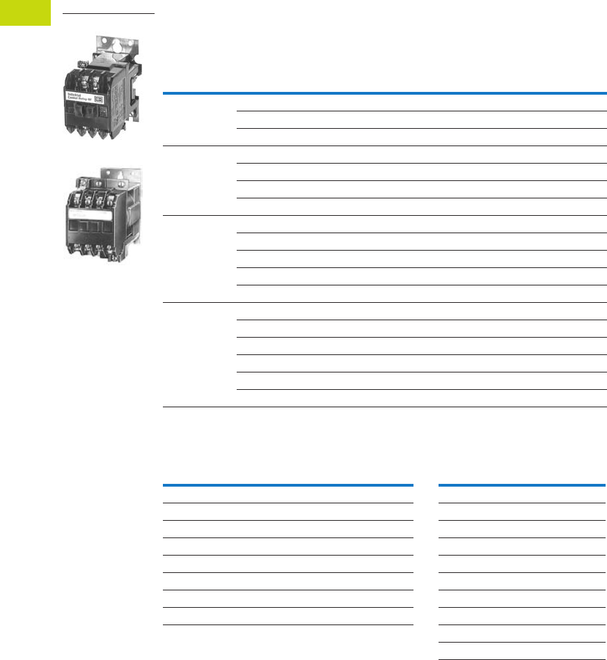
T40-146 Logic Control Products CA08100001K—June 2012 ww.eatoncanada.ca
40
40
40
40
40
40
40
40
40
40
40
40
40
40
40
40
40
40
40
40
40
40
40
40
40
40
40
40
40
40
40.7
Control Relays and Timers
Machine Tool Relays
Product Selection
When Ordering, Specify
●Catalogue number of basic relay
●If a coil voltage other than listed is required, select the suffix code from the Coil Voltage table and
substitute it for the last letter in the catalogue number. Example: BF80V for a 110/60 AC coil
Complete Relay—Type BF and BFD, Two-, Three-, Four- and Six-Pole
Coil Voltage
Notes
Relays listed above with equal number of NO and NC contact poles are specially priced—1NO and 1NC pole
are supplied at no additional charge.
Consult Customer Support Centre for availability.
Number
of Poles
Type of Contact
BF 300 Vac Basic Relays
120/60, 110/50 AC Coil
BFD 250 Vdc Basic
Relays
120 DC Coil
NO (Form A) NC (Form B)
Catalogue
Number
Catalogue
Number
22 0 BF20F BFD20S
11BF11F BFD11S
02BF02F BFD02S
33 0 BF30F BFD30S
21BF21F BFD21S
12BF12F BFD12S
03BF03F BFD03S
44 0 BF40F BFD40S
31BF31F BFD31S
22BF22F BFD22S
13BF13F BFD13S
04BF04F BFD04S
66 0 BF60F BFD60S
51BF51F BFD51S
42BF42F BFD42S
33BF33F BFD33S
24BF24F BFD24S
06BF06F BFD06S
BF Coils BFD Coils
Volts AC Hz Suffix Code Volts DC Suffix Code
12 60 H6C
24 60 I12 D
48 60 J24 L
110 60 V38 N
110/120 50/60 F48 M
208 60 K72 E
220/240 50/60 G95 B
440 60 C120 S
130 U
240 T
Type BF
Type BFD
Tab40book.fm Page 146 Wednesday, July 4, 2012 10:05 PM
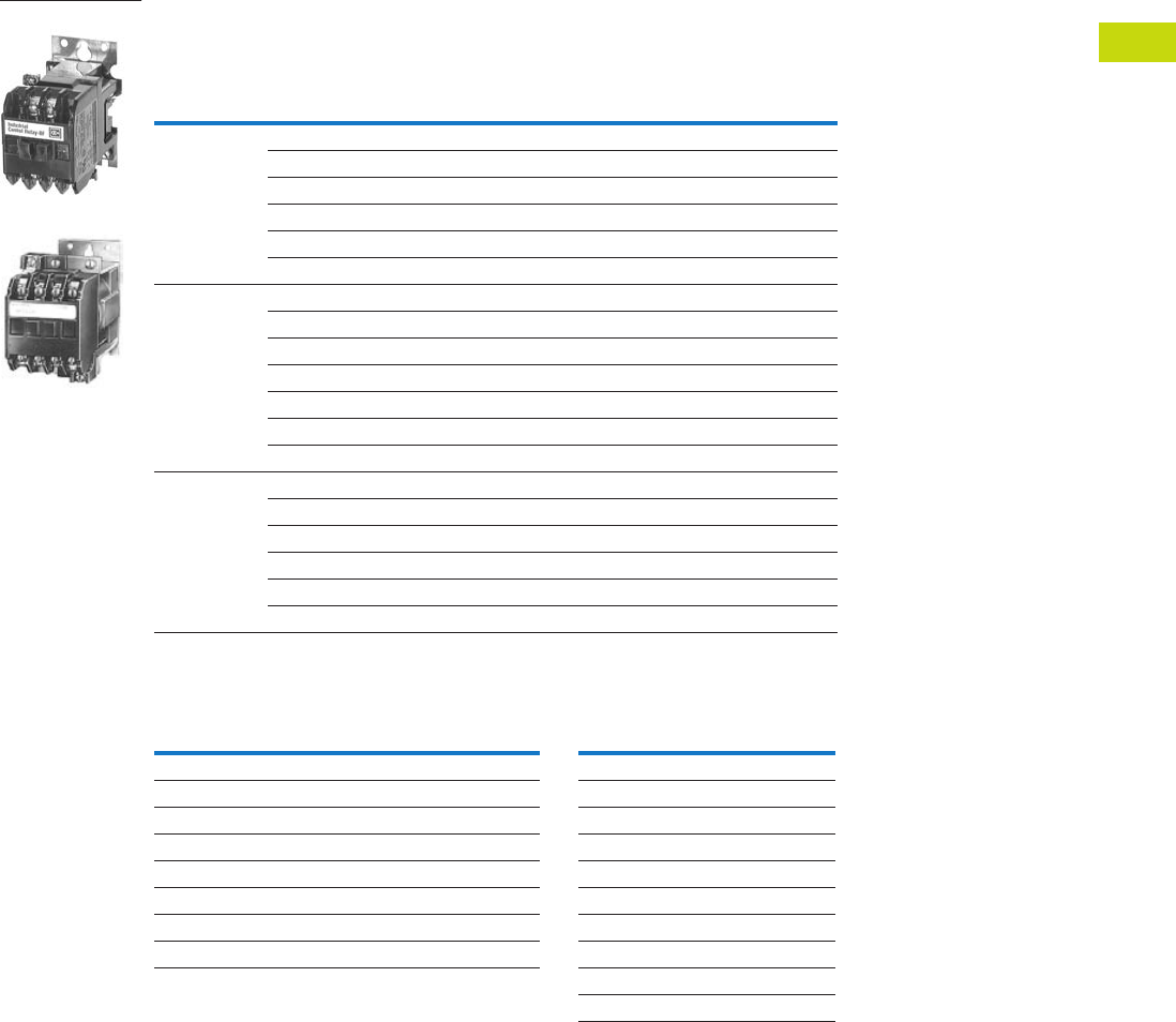
Logic Control Products CA08100001K—June 2012 ww.eatoncanada.ca T40-147
40
40
40
40
40
40
40
40
40
40
40
40
40
40
40
40
40
40
40
40
40
40
40
40
40
40
40
40
40
40
40.7
Control Relays and Timers
Machine Tool Relays
When Ordering, Specify
●Catalogue number of basic relay
●If a coil voltage other than listed is required, select the suffix code from the Coil Voltage table and
substitute it for the last letter in the catalogue number. Example: BF80V for a 110/60 AC coil
Complete Relay—Type BF and BFD, Eight-, 10- and 12-Pole
Coil Voltage
Notes
Relays listed above with equal number of NO and NC contact poles are specially priced—1NO and 1NC pole
are supplied at no additional charge.
Consult Customer Support Centre for availability.
Number
of Poles
Type of Contact
BF 300 Vac Basic Relays
120/60, 110/50 AC Coil
BFD 250 Vdc Basic
Relays
120 DC Coil
NO (Form A) NC (Form B)
Catalogue
Number
Catalogue
Number
88 0 BF80F BFD80S
71BF71F BFD71S
62BF62F BFD62S
53BF53F BFD53S
44BF44F BFD44S
08BF08F BFD08S
10 10 0 BF100F BFD100S
82BF82F BFD82S
73BF73F BFD73S
64BF64F BFD64S
55BF55F BFD55S
46BF46F BFD46S
28BF28F BFD28S
12 12 0 BF120F BFD120S
84BF84F BFD84S
75BF75F BFD75S
66BF66F BFD66S
57BF57F BFD57S
48BF48F BFD48S
BF Coils BFD Coils
Volts AC Hz Suffix Code Volts DC Suffix Code
12 60 H6C
24 60 I12 D
48 60 J24 L
110 60 V38 N
110/120 50/60 F48 M
208 60 K72 E
220/240 50/60 G95 B
440 60 C120 S
130 U
240 T
Type BF
Type BFD
Tab40book.fm Page 147 Wednesday, July 4, 2012 10:05 PM
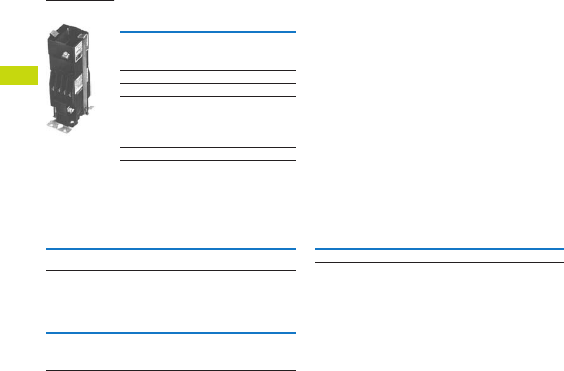
T40-148 Logic Control Products CA08100001K—June 2012 ww.eatoncanada.ca
40
40
40
40
40
40
40
40
40
40
40
40
40
40
40
40
40
40
40
40
40
40
40
40
40
40
40
40
40
40
40.7
Control Relays and Timers
Machine Tool Relays
Permanent Magnet Latch
Options
FASTON Push-On Terminals
Overlapping Contacts
NEMA 1 Enclosure for Relay Types
Notes
For panel mount, add Suffix F.
Consult Customer Support Centre for availability.
Coil
Volts Coil Hz
Catalogue
Number
AC Relays
24 60 BFMLI
48 60 BFMLJ
110/120 50/60 BFMLF
220/240 50/60 BFMLG
DC Relays
24 — BFMLL
48 — BFMLM
120 — BFMLS
240 — BFMLT
Permanent Magnet
Latch, Relay Mounted
Description
Code
Letter
Catalogue
Number
Insert letter F after relay type designation in listed catalogue
number. Example: BFF20F or BFDF20S
F—
Description
Code
Letter
Catalogue
Number
NO contact closes before corresponding NC contact opens—
supplied as NO/NC set(s). Insert letter A after relay
type designation in listed catalogue number. Example: BFA22F
or BFDAF22S
A—
Description
Code
Letter
Catalogue
Number
BF, AR—all poles — 4977D40G04
BFD—4–8 poles — 4977D40G04
ARD—4–8 poles — 4977D40G04
Tab40book.fm Page 148 Wednesday, July 4, 2012 10:05 PM

Logic Control Products CA08100001K—June 2012 ww.eatoncanada.ca T40-149
40
40
40
40
40
40
40
40
40
40
40
40
40
40
40
40
40
40
40
40
40
40
40
40
40
40
40
40
40
40
40.7
Control Relays and Timers
Machine Tool Relays
Technical Data and Specifications
General Specifications
Permanent Magnet Latch Specifications
BF Relay Electrical Ratings—NEMA A300
Maximum Current Maximum VA
Volts Cont. Make Break Make Break
120 10 60 6 7200 720
240 10 30 3 7200 720
Horsepower Ratings (UL Recognized) DC Rating—NEMA P300
AC Volts Maximum Current Max. Make
or Break (VA)Phase 115 230 Volts Cont. Make Break
1 1/6 1/2 125 5.0 1.1 1.1 138
3 — 1 250 5.0 0.55 0.55 138
Resistive Rating
125 Vdc 3A
250 Vdc 1.5A
Coil Power Requirements
AC 72 VA open, 22 VA closed
DC 12 watts (nominal), 250V max.
Item Specification
Unlatching power requirements Open gap: 24 VA AC
Closed gap: 7 VA
Burden: 4 watts (AC)
Tab40book.fm Page 149 Wednesday, July 4, 2012 10:05 PM
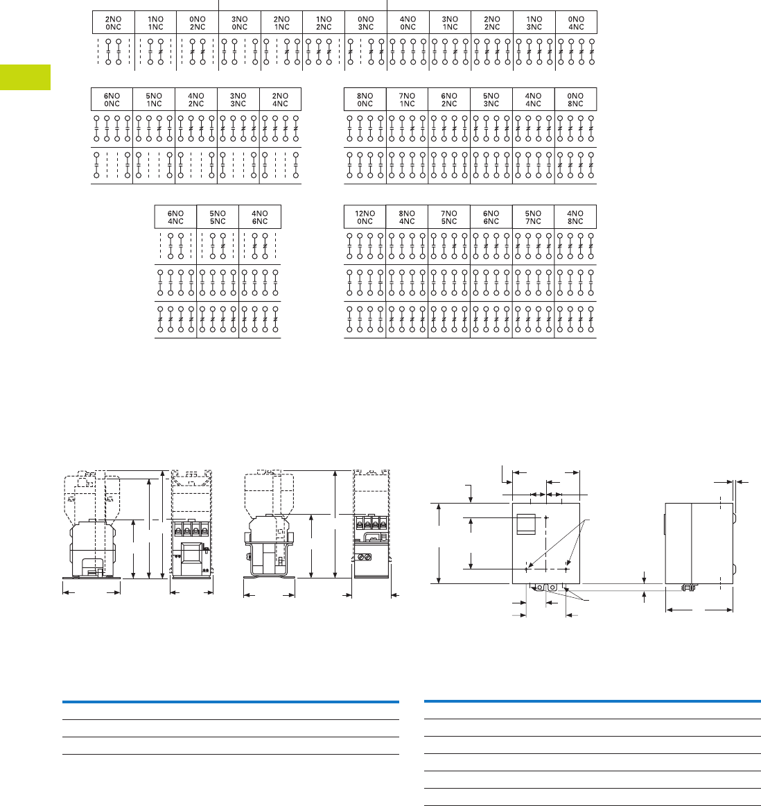
T40-150 Logic Control Products CA08100001K—June 2012 ww.eatoncanada.ca
40
40
40
40
40
40
40
40
40
40
40
40
40
40
40
40
40
40
40
40
40
40
40
40
40
40
40
40
40
40
40.7
Control Relays and Timers
Machine Tool Relays
Contact Arrangements—BF and BFD Relays
Note: NO = Normally Open NC = Normally Closed
Dimensions
Approximate Dimensions in Inches (mm)
BF Relay with Permanent
Magnet Latch and Solid-
State Timer
BFD Relay with Solid-State
Timer
BF and BFD Relay Dimensions
2 Poles 3 Poles 4 Poles
6 Poles
Rear
Front
Rear
Center
12 Poles
Rear
Center
Front Front
8 Poles
Rear
Front
10 Poles
A
BC
3.13
(79.5)
1.97
(50)
D
E
3.13
(79.5)
1.69
(42.9)
Number
of Poles
A
BF Only
B
BF w/Latch
C
BF w/Timer
D
BFD Only
E
BFD w/Timer
4 3.22 (81.8) 6.22 (158.0) 5.88 (149.4) 4.03 (102.4) 7.06 (179.3)
8 4.19 (106.4) 7.19 (182.6) 6.88 (174.8) 4.97 (126.2) 8.00 (203.2)
12 4.81 (122.2) 7.81 (198.4) 7.50 (190.5) 5.63 (143.0) 8.66 (220.0)
Enclosures—NEMA 1 for BF, BFD, AR and ARD
NEMA 1 for BF, BFD, AR and ARD Dimensions
Poles
Catalogue
Number
A
NEMA 1
Relays without Attachments
All BF, AR, ARD 5.34 (135.6)
4 – 8 BFD 5.34 (135.6)
10, 12 BFD 7.97 (202.4)
Relays with Attachments
All BF, AR, ARD 7.97 (202.4)
5.66
(143.8)
3.38 (85.9)
2.83
(71.9)
1.72
(43.7)
0.25 (6.4) Dia.
Mtg. Holes (3)
0.19 (4.8)
A
1.69 (42.9) 0.38 x 0.5
(9.7 x 12.7)
Conduit
(2 Top, 2 Bottom)
6.59
(167.4) 4.5
(114.3) 0.63
(16)
1.05
(26.7)
KO KO KO
KO KO KO
KO
KO
1.72
(43.7)
Tab40book.fm Page 150 Wednesday, July 4, 2012 10:05 PM

Logic Control Products CA08100001K—June 2012 ww.eatoncanada.ca T40-151
40
40
40
40
40
40
40
40
40
40
40
40
40
40
40
40
40
40
40
40
40
40
40
40
40
40
40
40
40
40
40.7
Control Relays and Timers
Machine Tool Relays
AR/ARD Series—Convertible Contact Industrial Control Contents
Description Page
D15 Series—Freedom 600V Multipole. . . . . . . . . . . . . T40-140
BF/BFD Series—Fixed Contact Industrial
Control . . . . . . . . . . . . . . . . . . . . . . . . . . . . . . . . . . . . T40-145
AR/ARD Series—Convertible Contact
Industrial Control
Product Selection . . . . . . . . . . . . . . . . . . . . . . . . . . T40-152
Accessories . . . . . . . . . . . . . . . . . . . . . . . . . . . . . . T40-153
Options . . . . . . . . . . . . . . . . . . . . . . . . . . . . . . . . . . T40-153
Technical Data and Specifications . . . . . . . . . . . . . T40-154
Dimensions . . . . . . . . . . . . . . . . . . . . . . . . . . . . . . T40-155
D26 Series—Type M, 600 Vac Multipole
with Convertible Contacts . . . . . . . . . . . . . . . . . . . . . T40-156
D26 Series—Type M, DC Multipole
with Convertible Contacts . . . . . . . . . . . . . . . . . . . . . T40-161
AR/ARD Series—Convertible Contact Industrial Control
Product Description
The AR/ARD relays are
electromechanical convertible
contact relays. AR relays are
AC devices and the ARD is
for DC applications.
Application Description
Type AR and ARD relays are
designed for use on machine
tools, process lines,
conveyors and similar
automatic and semi-
automatic equipment.
Features and Benefits
Permanent Magnet Latch
By energizing the relay coil,
the latch attachment “sets”
(when the base relay’s
armature/crossbar assembly
has closed) holding the relay
ON, even after the relay coil
has been de-energized. The
clearing coil on the latch is
energized to release the
armature/crossbar assembly.
●Field mountable to four-
and six-pole
●Latch plunger is adjustable
●Latch coil continuously
rated
●Unlatching power
requirements
●Open gap: 24 VA
●Closed gap: 7 VA
●Burden: 4 watts AC, 6
watts DC
Surge Suppressor
●Mounts in contact cavity of
AR relays
●Limits high transient
voltages resulting from de-
energizing relay coil or
other electromechanical
devices
●Protects sensitive
instruments and solid-state
devices
●120 Vac maximum, not
used on Vdc
●For noise suppression, see
Catalogue Number SS-56
starter mounted surge
suppressor.
Operation
AR relays are available in
either
four- or six-pole
configurations.
AR relays are
easily converted
to eight- or
10-poles simply by adding a
four-pole deck. In addition,
mechanical latch attachments
are available with four- and
six-pole relays.
Contacts are convertible from
NO to NC, to provide any
combination desired up to a
maximum of 10. For the ARD,
the number of poles cannot
exceed four NC in any pole
configuration. Wide spacing
of contacts simplifies
installation, contact testing and
maintenance. Contacts are
electrically and mechanically
isolated from each other.
Overlap contacts are also
available in one or two sets.
These contacts should be
mounted in the centre pole
positions. AC and DC contact
cartridges should not be used
in the same relay.
Standards and Certifications
●UL File No. E19223
●CSA File No. LR39402-6,
LR54517 and LR54520
Reference Information
●ART, ARTD: IL 14510,
IL 14485
Tab40book.fm Page 151 Wednesday, July 4, 2012 10:05 PM
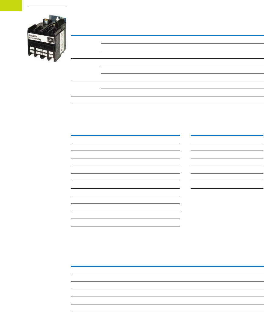
T40-152 Logic Control Products CA08100001K—June 2012 ww.eatoncanada.ca
40
40
40
40
40
40
40
40
40
40
40
40
40
40
40
40
40
40
40
40
40
40
40
40
40
40
40
40
40
40
40.7
Control Relays and Timers
Machine Tool Relays
Product Selection
When Ordering, Specify
●Catalogue number of basic relay with 120/60, 110/50 AC coil from AR/ARD Relays table.
●If a coil voltage other than listed is required, select the suffix code from the Coil Voltage table below
and substitute it for the last letter in the catalogue number. Example: AR64V for a 110/60 AC coil.
AR/ARD Relays
Coil Voltage
Contact Cartridges—600V
Notes
Will not accept top-mounted latch or timers.
Contact Customer Support Centre for availability.
Standard cartridges are sold in cartons of four cartridges. Catalogue number is for single cartridge.
Overlap contact cartridges are sold in sets of two cartridges. Catalogue number is for sets of two.
Number
of Poles
Contact
AR 600 Vac Relays
120/60, 110/50 AC Coil
ARD 600 Vdc Relays
120 DC Coil
NO NC
Blank
Cavities
Catalogue
Number
Catalogue
Number
4 004AR4A ARD4S
202AR420A ARD420S
400AR440A ARD440S
6 006AR6A ARD6S
402AR640A —
600AR660A ARD660S
8 602AR860A ARD860S
800AR880A ARD880S
10 10 0 0 AR10100A ARD10100S
AR Coils ARD Coils
Volts AC Hz Suffix Code Volts DC Suffix Code
12 60 F12 D
24 60 I24 L
48 60 G48 M
110 60 V95 B
110/120 50/60 A120 S
208 60 B130 U
220/240 50/60 W240 T
277 60 C
380/440 50/60 H
440/480 50/60 X
550 60 D
550/600 50/60 E
Terminal
Type
Standard Contact
Cartridge
Overlap Contact
Cartridge
Catalogue
Number
Catalogue
Number
AC Cartridges
With clamp terminals ARC AROC
With screw terminals ARCR AROCR
DC Cartridges
With clamp terminals ARDC ARDOC
With screw terminals ARDCR ARDOCR
AR/ARD Relays
Tab40book.fm Page 152 Wednesday, July 4, 2012 10:05 PM
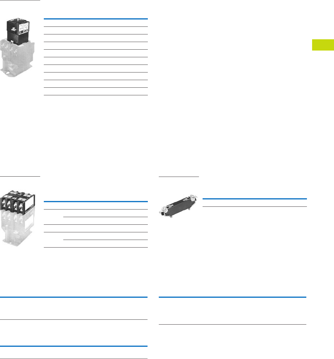
Logic Control Products CA08100001K—June 2012 ww.eatoncanada.ca T40-153
40
40
40
40
40
40
40
40
40
40
40
40
40
40
40
40
40
40
40
40
40
40
40
40
40
40
40
40
40
40
40.7
Control Relays and Timers
Machine Tool Relays
Permanent Magnet Latch
Accessories
Four-Pole Top Deck Adder
●
Increases contact capacity from four/six-poles to eight/10-poles
●Mounts on top of basic relay using three screws
●Will not interfere with wiring, testing or convertible cartridges
●Screw terminals for ring connectors available; to order, add
Suffix R to catalogue number listed below
Four-Pole Top Deck Adder Surge Suppressor
Options
Convertible Contacts
Screw Terminals
Overlapping Contacts
Note
Consult Customer Support Centre for availability.
Operating
Volts Coil Hz
Catalogue
Number
For AC Control Circuits
24 60 ARMLI
48 60 ARMLG
120 60/50 ARMLA
240 60/50 ARMLW
For DC Control Circuits
24 — ARMLL
48 — ARMLM
120 — ARMLS
240 — ARMLT
ARML Permanent
Magnet Latch for
AR/ARD Relays
No. of
Poles
Contacts
Catalogue
Number NO NC
Blank
Cavities
With 600 Vac Cartridges
4 202 ARA20
400 ARA40
With 600 Vdc Cartridges
4 202 ARDA20
400 ARDA40
Four-Pole Top
Deck Adder
Catalogue
Number
Surge Suppressor ARSS
ARSS Surge
Suppressor for
AR Relays
Description
Code
Letter
Catalogue
Number
AR and ARD relays listed are supplied with NO contacts that
are easily converted to NC. If both NO and NC poles are
required, order by catalogue number. Example: four-pole relay
with 1NO and 3NC contacts, order AR413A.
—
Description
Code
Letter
Catalogue
Number
For ring-type connectors, add suffix R to the catalogue number.
Example: AR420AR.
R—
Description
Code
Letter
Catalogue
Number
NO contact closes before corresponding NC contact opens —
supplied as NO/NC sets of two cartridges. Insert letter S after
relay type designation in listed catalogue number. Example:
AR402AS. Specify the number of sets required: S for one set
and S2 for two sets.
S or
S2
—
Tab40book.fm Page 153 Wednesday, July 4, 2012 10:05 PM

T40-154 Logic Control Products CA08100001K—June 2012 ww.eatoncanada.ca
40
40
40
40
40
40
40
40
40
40
40
40
40
40
40
40
40
40
40
40
40
40
40
40
40
40
40
40
40
40
40.7
Control Relays and Timers
Machine Tool Relays
Technical Data and Specifications
General
Contact Ratings—600 Vac Cartridge NEMA A600
Maximum Current Maximum VA
Volts Cont. Make Break Make Break
120 10 60 6 7200 720
240 10 30 3 7200 720
480 10 15 1.5 7200 720
600 10 12 1.2 7200 720
DC Cartridges—NEMA P600
Maximum Current Maximum VA
Volts Continuous
Make or
Break
Make or
Break
125 5 1.10 138
250 5 0.55 138
600 5 0.20 138
Resistive Rating
125 Vdc 3A
250 Vdc 1.5A
Coil Power Requirements
AC 96 VA open, 14 VA closed
DC 14 watts open, 250V max.
Voltage AR Relays ARD Relays
Pickup voltage (max.) 85% 65%
Dropout voltage (min.) 60% 15%
Voltage (max.) 110% 110%
Tab40book.fm Page 154 Wednesday, July 4, 2012 10:05 PM
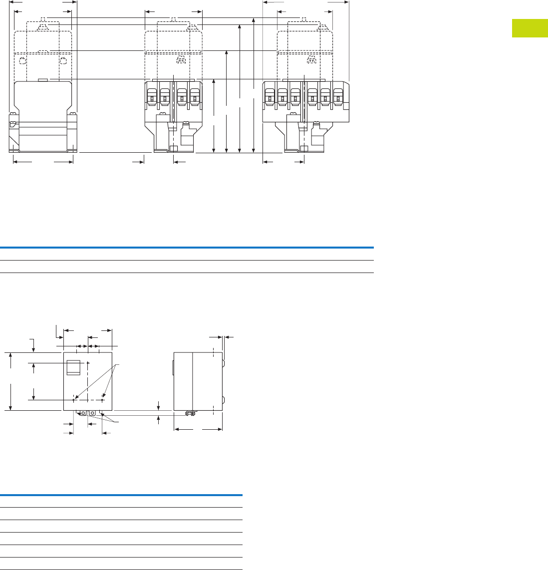
Logic Control Products CA08100001K—June 2012 ww.eatoncanada.ca T40-155
40
40
40
40
40
40
40
40
40
40
40
40
40
40
40
40
40
40
40
40
40
40
40
40
40
40
40
40
40
40
40.7
Control Relays and Timers
Machine Tool Relays
Dimensions
Approximate Dimensions in Inches (mm)
Four- and Six-Pole with Four-Pole Adder, Solid-State Timer and Mechanical Latch
Four- and Six-Pole with Four-Pole Adder, Solid-State Timer and Mechanical Latch
Enclosures—NEMA 1 for BF, BFD, AR and ARD
Enclosures—NEMA 1 for BF, BFD, AR and ARD
Relay
Catalogue
Number
A
Four-, Six-Pole Relays
B
Relay Adder
C
Relay with Timer
D
Relay with Latch
AR 3.56 (90.4) 4.94 (125.5) 6.00 (152.4) 6.39 (162.3)
ARD 4.63 (117.6) 6.00 (152.4) 7.06 (179.3) 7.45 (189.2)
Poles
Catalogue
Number
Dimension A
NEMA 1
Relays without Attachments
All BF, AR, ARD 5.34 (135.6)
4–8 BFD 5.34 (135.6)
10, 12 BFD 7.97 (202.4)
Relays with Attachments
All BF, AR, ARD 7.97 (202.4)
A
Base Relay
Adder Deck
S.S. Timer
Latch
B
C
D
1.44 (36.6)
End View, 4- and 6-Pole Side View, 4-Pole Side View, 6-Pole
3.13
(79.5)
2.75 (69.9) 2.88 (73.2)
3.44 (87.4)
2.88 (73.2)
4.09 (103.9)
2.05
(52.1) C
L
C
L
C
L of Mounting Slots
(2) for 0.164 Screws
of Mounting Slots
(2) for 0.164 Screws
of Mounting Slots
(2) for 0.164 Screws
5.66
(143.8)
3.38 (85.9)
2.83
(71.9)
1.72
(43.7)
0.25 (6.4) Dia.
Mtg. Holes (3)
0.19 (4.8)
A
1.69 (42.9) 0.38 x 0.5
(9.7 x 12.7)
Conduit
(2 Top, 2 Bottom)
6.59
(167.4) 4.5
(114.3) 0.63
(16)
1.05
(26.7)
KO KO KO
KO KO KO
KO
KO
1.72
(43.7)
Tab40book.fm Page 155 Wednesday, July 4, 2012 10:05 PM
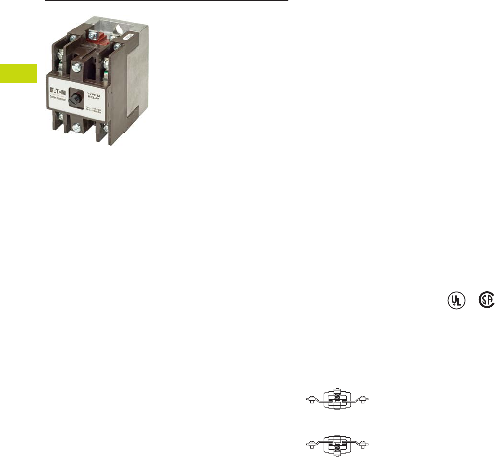
T40-156 Logic Control Products CA08100001K—June 2012 ww.eatoncanada.ca
40
40
40
40
40
40
40
40
40
40
40
40
40
40
40
40
40
40
40
40
40
40
40
40
40
40
40
40
40
40
40.7
Control Relays and Timers
Machine Tool Relays
D26 Series—Type M, 600 Vac Multipole with Convertible Contacts Contents
Description Page
D15 Series—Freedom 600V Multipole . . . . . . . . . . . . T40-140
BF/BFD Series—Fixed Contact Industrial
Control . . . . . . . . . . . . . . . . . . . . . . . . . . . . . . . . . . . . T40-145
AR/ARD Series—Convertible Contact
Industrial Control . . . . . . . . . . . . . . . . . . . . . . . . . . . . T40-151
D26 Series—Type M, 600 Vac Multipole
with Convertible Contacts
Product Selection . . . . . . . . . . . . . . . . . . . . . . . . . . T40-157
Technical Data and Specifications . . . . . . . . . . . . . T40-159
Dimensions . . . . . . . . . . . . . . . . . . . . . . . . . . . . . . T40-160
D26 Series—Type M, DC Multipole
with Convertible Contacts . . . . . . . . . . . . . . . . . . . . T40-161
D26 Series—Type M, 600 Vac Multipole with Convertible Contacts
Product Description
Relays can be ordered as
complete devices in any pole
combination up to a
maximum of 12NO or 8NC
and 4NO poles, or can be
assembled from components
shown on Page T40-158.
Relay base assembly
(D26MB) will accept from 1
to 4 rear poles (D26MPR,
D26MPS and/or D26MPL).
Features
Contact poles D26MPR and
D26MPF in 2- through 8-pole
relays are convertible NO to
NC or vice versa. Simply
reverse the terminal screws
and rotate the unit pole 180˚
(in either direction).
Options
Adding a front deck, the total
number of poles can be
increased to 8, all convertible
NO to NC.
Adding a D26MF, 4-pole fixed
NO attachment, builds a 12-
pole relay with 8 convertible
poles and 4 fixed NO poles.
Relays with mechanical latch
are available in any
convertible pole combination
up to eight poles maximum.
To obtain overlapping
contacts, use D26MPS (NO
early closing) and D26MPL
(NC late opening) rear poles,
in related circuits.
Standards and Certifications
●UL listed—Class No.
NKCR2, File E1230(N)
●CSA certified—File LR353
Normally Closed
Contact
Normally Open
Contact
Tab40book.fm Page 156 Wednesday, July 4, 2012 10:05 PM
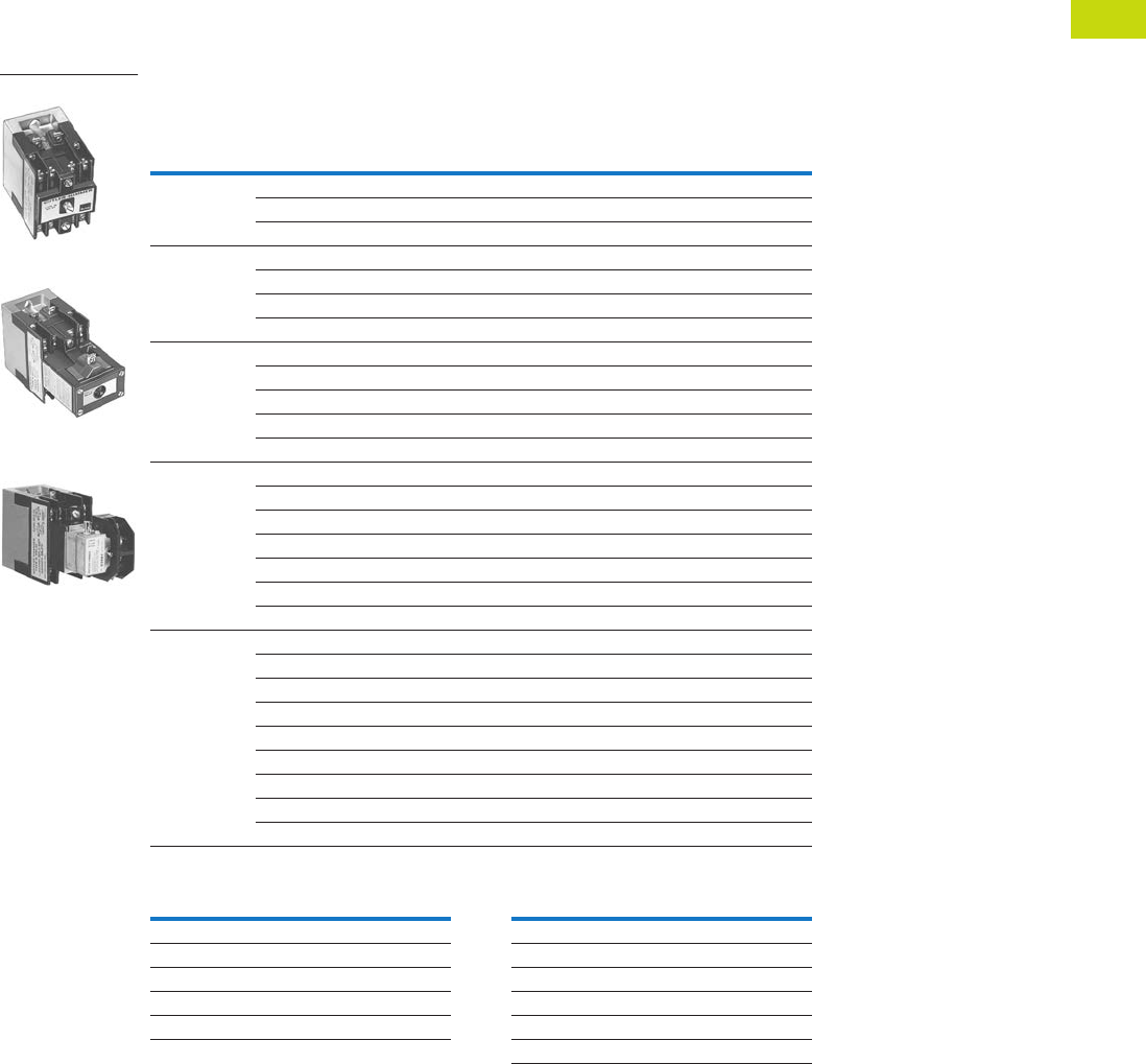
Logic Control Products CA08100001K—June 2012 ww.eatoncanada.ca T40-157
40
40
40
40
40
40
40
40
40
40
40
40
40
40
40
40
40
40
40
40
40
40
40
40
40
40
40
40
40
40
40.7
Control Relays and Timers
Machine Tool Relays
Product Selection
Complete AC Relays
When Ordering, Specify
●Catalogue number and magnet coil suffix letter.
●Example: For a 4-pole relay having 4NO contacts, order Catalogue Number D26MR40, with a 120V,
60 Hz coil, order D26MR40A.
●For fast delivery and minimum inventory, it is recommended that component parts or complete
relays with NO poles be ordered.
Complete AC Relays—Open Type
Magnet Coil Selection
Notes
10- and 12-Poles: The 6 and 8 contact relays (without mechanical latch only) listed above can be provided
with four additional NO non-convertible contacts. Add suffix number 4 to above listed catalogue number plus
magnet coil suffix. Example: For a 12 contact relay, order D26MR804A.
Consult Customer Support Centre for availability.
Number
of Contacts
Type of Contact Relay Only
Relay with
Mechanical Latch
NO (Form A) NC (Form B)
Catalogue
Number
Catalogue
Number
22 0 D26MR20 D26MR202
11D26MR11 D26MR112
02D26MR02 D26MR022
33 0 D26MR30 D26MR302
21D26MR21 D26MR212
12D26MR12 D26MR122
03D26MR03 D26MR032
44 0 D26MR40 D26MR402
31D26MR31 D26MR312
22D26MR22 D26MR222
13D26MR13 D26MR132
04D26MR04 D26MR042
6 60D26MR60 D26MR602
51D26MR51 D26MR512
42D26MR42 D26MR422
33D26MR33 D26MR332
24D26MR24 D26MR242
15D26MR15 D26MR152
06D26MR06 D26MR062
8 80D26MR80 D26MR802
71D26MR71 D26MR712
62D26MR62 D26MR622
53D26MR53 D26MR532
44D26MR44 D26MR442
35D26MR35 D26MR352
26D26MR26 D26MR262
17D26MR17 D26MR172
08D26MR08 D26MR082
Volts/Hertz Suffix Code Volts/Hertz Suffix Code
120/60–110/50 A32/60 V
240/60–220/50 B12/60 R
208/60 E6/60 P
24/60 T380/50 L
277/60 H480/60 or 440/50 C
600/60 or 550/50 D
4-Pole
4-Pole with Latch
4-Pole with Pneumatic
Timer Attachment
Tab40book.fm Page 157 Wednesday, July 4, 2012 10:05 PM
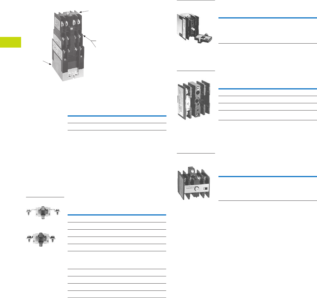
T40-158 Logic Control Products CA08100001K—June 2012 ww.eatoncanada.ca
40
40
40
40
40
40
40
40
40
40
40
40
40
40
40
40
40
40
40
40
40
40
40
40
40
40
40
40
40
40
40.7
Control Relays and Timers
Machine Tool Relays
Relay Component Parts Location
Relay with Pneumatic Timer Attachment
Factory Installed (without Relay Contacts)
The relays listed above will
accept up to four catalogue
number D26MPR contacts
(convertible—NO or NC) for
instantaneous operation.
Order contacts separately.
For additional information
on timer attachment, see
Page T40-159.
For assembly of relays from
component parts and relay
accessories, see components
tables below.
Separate Contacts
Contact
Positions
Timer
Operation
Catalogue
Number
4 ON delay D26MR005
4 OFF delay D26MR006
D26MB
Relay Base
Assembly
D26MF
Front Attachment
Timer Attachments or
Mechanical Latch
D26MD10
Front Deck
Pneumatic Timer or
Mechanical Latch
D26MF
Front Attachment
Description
Catalogue
Number
Convertible Contacts
Rear pole—NO D26MPR
Rear pole—NC D26MPR02
Front pole—NO D26MPF
Front pole—NC D26MPF02
Gold plated
(for low power circuits)
Rear pole—NO D26MPR03
Front pole—NO D26MPF03
Non-Convertible Contacts
Rear pole NO early closing D26MPS
Rear pole NC late opening D26MPL
Rear Pole
Front Pole
Relay Base Assembly (without Poles)
Basic four-pole D26 relay
without contacts. Provision
for adding one to four poles
as needed, D26MPR,
D26MPL and/or D26MPS
rear pole type.
Front Deck (Convertible Contact Poles)
Provides up to four additional
front pole type D26MPF
contacts. Convertible, NO
to NC.
Four-Pole Front Attachment
(4NO Fixed Circuit)
Can be added to any two- to
eight-pole Type M, D26 relay
to provide up to a 12-pole
relay. Four NO, non-
convertible contacts are
included in this assembly.
Notes
Number of available instantaneous contact positions (order contacts
separately—Catalogue Number D26MPR).
Consult Customer Support Centre for availability.
To obtain overlapping contacts, these two special poles must be used in related circuits.
Add magnet coil suffix letter, see Page T40-157. Example: D26MBA.
Description
Catalogue
Number
Relay base assembly D26MB
Relay Base
Assembly
Description
Catalogue
Number
Front Deck with …
1NO contact pole D26MD10
2NO contact poles D26MD20
4NO contact poles D26MD40
Rear Pole
Description
Catalogue
Number
Front attachment D26MF
Four-Pole Front
Attachment
Tab40book.fm Page 158 Wednesday, July 4, 2012 10:05 PM
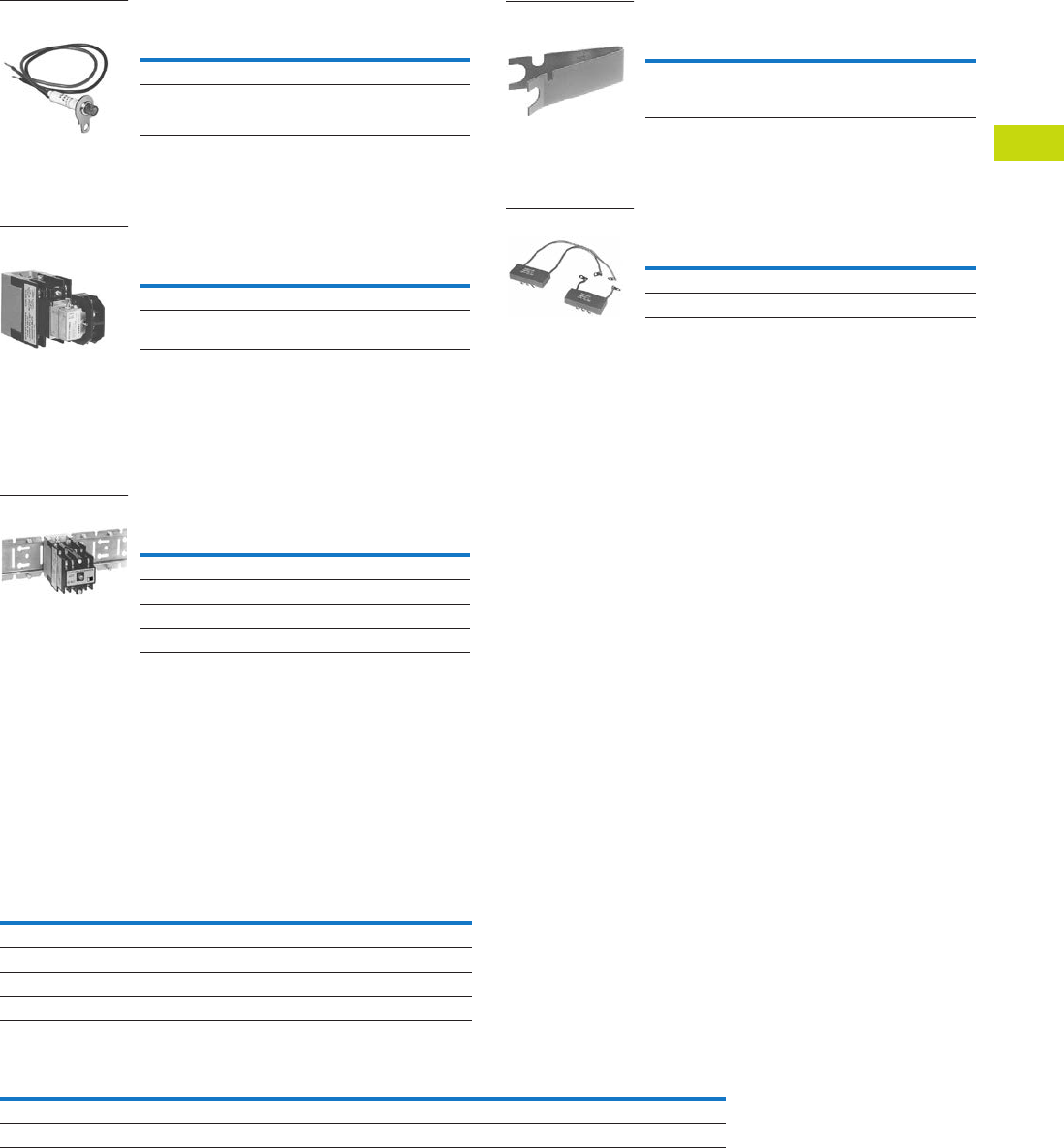
Logic Control Products CA08100001K—June 2012 ww.eatoncanada.ca T40-159
40
40
40
40
40
40
40
40
40
40
40
40
40
40
40
40
40
40
40
40
40
40
40
40
40
40
40
40
40
40
40.7
Control Relays and Timers
Machine Tool Relays
Relay State Indicating Light
Light provided with leads and
bracket for mounting on two-
to 12-pole relays. May be
used to monitor state
of magnet coil or relay
contact operation.
Pneumatic Timer Attachment
Attachment mounts on any 0-
to four-pole D26 relay without
latch. Timer unit has DPDT
timed contacts (circuits in
each pole must be the same
polarity). Adjustable timing
range—0.1 to 180 seconds,
repeat accuracy ±10%.
Units are convertible from
OFF delay to ON delay or
vice versa.
Mounting Channel
Pre-spaced mounting for
adjacent relay installation.
Indexed for cutting to desired
length. Captive mounting
screws provided in channel
for easier installation.
Technical Data and Specifications
General
Note
For DC contact ratings, see Page T40-163.
Description
Catalogue
Number
120 Vac, 50/60 Hz D26MAP120
240 Vac, 50/60 Hz D26MAP240
Relay State
Indicating Light
Description
Catalogue
Number
ON delay D26MTE
OFF delay D26MTD
Pneumatic Timer
Attachment
Description
Catalogue
Number
10 in length for 4 relays D26MC4
20 in length for 8 relays D26MC8
30 in length for 12 relays D26MC12
40 in length for 16 relays D26MC16
Mounting Channel
Contact Ratings (Amperes) A600
AC Volts
Make and
Emergency
Interrupting
Capacity Break
Continuous
Thermal Rating
120 60 6 10
240 30 3 10
480 15 1.5 10
600 12 1.2 10
Coil Power Operating Time
Watts VA Range in
MillisecondsRelay Inrush Sealed Inrush Sealed
Two- to 12-pole 95.0 9 155 22 Pickup: 6–13
Latch coil 18.5 11 41 17 Dropout: 8–26
Manual Test Accessory
Tool to manually hold relays
in the energized position for
circuitry testing on completed
panel. (10 per box, order in
multiples of 10.)
Transient Suppressor
May be mounted on any
120 Vac relay magnet coil
or latch coil or 120 Vdc latch
coil—connects directly across
coil terminals. All DC magnet
coils have a built-in varistor
for transient suppression.
Limits high voltage transients
produced in the circuit when
power is removed from the
coil.
Description
Catalogue
Number
Manual test accessory D26MTA
Manual Test
Accessory
Description
Catalogue
Number
Magnet coil transient suppressor D26MAS1
Latch coil transient suppressor D26MAS2
Transient Suppressor
Tab40book.fm Page 159 Wednesday, July 4, 2012 10:05 PM
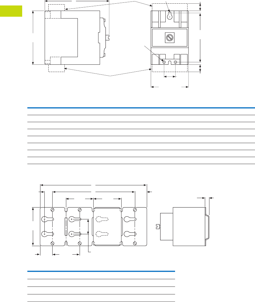
T40-160 Logic Control Products CA08100001K—June 2012 ww.eatoncanada.ca
40
40
40
40
40
40
40
40
40
40
40
40
40
40
40
40
40
40
40
40
40
40
40
40
40
40
40
40
40
40
40.7
Control Relays and Timers
Machine Tool Relays
Dimensions
Approximate Dimensions in Inches (mm)
AC and DC D26 Relays
Mounting Channel
Note: Channel mounts through keyholes with #10 screws
(two each end and one every fourth relay). Relays mount with screws
captive in channel. All screws must be tightened firmly.
AC Relay
D26
DC Relay
D26 Dimension A
Ship. Wt.
Lbs (kg)
1–4 poles 1–3 poles 4.00 (101.6) 2.5 (1.1)
1–4 poles with timer D26 or D87 1–3 poles with timer D26 or D87 6.00 (152.4) 3.3 (1.5)
1–4 poles with latch 1–2 poles with latch 6.13 (155.7) 3.5 (1.6)
1–4 poles with d26mf 1–3 poles with D26MF 5.81 (147.6) 2.8 (1.3)
5–8 poles 4–7 poles 5.25 (133.4) 2.8 (1.3)
5–8 poles with timer D87 4–7 poles with timer D87 7.25 (184.2) 3.5 (1.6)
5–8 poles with latch 3–6 poles with latch 7.31 (185.7) 3.8 (1.7)
9–12 poles 8–11 poles 7.00 (177.8) 3.0 (1.4)
Catalogue
Number Dimension A Dimension B
D26MC16 40 (1016) 37.5 (952.5)
D26MC12 30 (762) 27.5 (698.5)
D26MC8 20 (508) 17.5 (444.5)
D26MC4 10 (254) 7.5 (190.5)
2.38 (60.5)
Max.
D26MAS2
D26MAS1
0.75
(19.1)
3.13
(79.5)
0.44
(11.2)
0.44
(11.2)
3.50
(88.9)
A
1 Slot
#10 Screw
2 Holes
#10 Screw
2.50
(63.5)
2.50
(63.5)
2.38
(60.5)
B
0.69
(17.5)
1.06
(26.9)
A
1.25
(31.8)
3.63
(92.2)
1.38
(35.1)
0.38
(9.7)
Type
M
Relay
D26
Tab40book.fm Page 160 Wednesday, July 4, 2012 10:05 PM
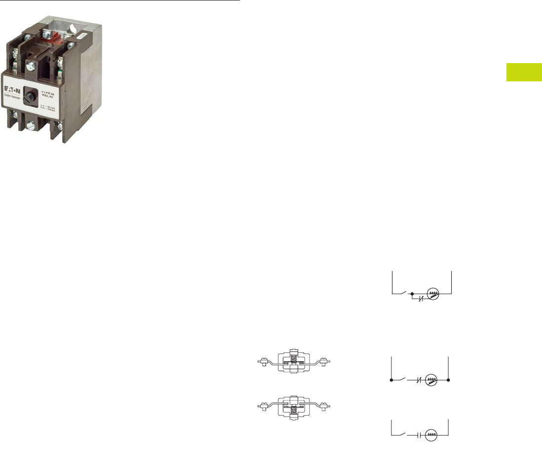
Logic Control Products CA08100001K—June 2012 ww.eatoncanada.ca T40-161
40
40
40
40
40
40
40
40
40
40
40
40
40
40
40
40
40
40
40
40
40
40
40
40
40
40
40
40
40
40
40.7
Control Relays and Timers
Machine Tool Relays
D26 Series—Type M, DC Multipole with Convertible Contacts Contents
Description Page
D15 Series—Freedom 600V Multipole. . . . . . . . . . . . . T40-140
BF/BFD Series—Fixed Contact Industrial
Control . . . . . . . . . . . . . . . . . . . . . . . . . . . . . . . . . . . . T40-145
AR/ARD Series—Convertible Contact
Industrial Control . . . . . . . . . . . . . . . . . . . . . . . . . . . . T40-151
D26 Series—Type M, 600 Vac Multipole
with Convertible Contacts . . . . . . . . . . . . . . . . . . . . . T40-156
D26 Series—Type M, DC Multipole
with Convertible Contacts
Product Selection . . . . . . . . . . . . . . . . . . . . . . . . . . T40-162
Technical Data and Specifications . . . . . . . . . . . . . T40-163
Dimensions . . . . . . . . . . . . . . . . . . . . . . . . . . . . . . T40-164
D26 Series—Type M, DC Multipole with Convertible Contacts
Product Description
Type M, DC multipole
relays are physically and
mechanically similar to
the (D26) Type M AC
relays described on Page
T40-157. They differ only in
the electrical ratings and
available pole combinations
due to the use of a normally
closed late opening, coil
clearing contact, factory
wired to the pickup winding
of the magnet coil. (Contact is
shown as L in figure to the
right.) Magnet coil has built-in
varistor for transient
suppression.
The mechanically latched
relay has one extra contact,
normally open early closing,
factory wired in series with
the winding of the
intermittent rated latch coil.
(Contact is shown as S in
figure to the right.)
Component parts for
these relays are the same
as those listed for the (D26)
Type M AC relays on Page
T40-157, except for the
Indicating Light, which is not
applicable to a DC relay.
Contact poles D26MPR and
D26MPF in 2- to 7-pole relays
are convertible NO to NC or
vice versa. Simply reverse the
terminal screws and rotate
the unit pole 180˚ (in either
direction).
Latch Operation
With the latch coil de-
energized, energizing the
relay coil will pick up the relay
and mechanically latch it in
the pickup position. With the
relay coil de-energized,
energizing the latch coil will
allow the relay to drop out.
Convertible Contacts
Normally Closed
Contact
Normally Open
Contact
LS1
LS1
LS1 L
S
DC Input
DC Input
DC Type M Relay
DC Type M Relay
with Latch
Pick-Up
Pick-Up
L = NC Late Opening
L = NC Late Opening
S = NO Early Closing
Relay
Coil
Latch
Coil
Hold
(Not Used)
Release
Tab40book.fm Page 161 Wednesday, July 4, 2012 10:05 PM
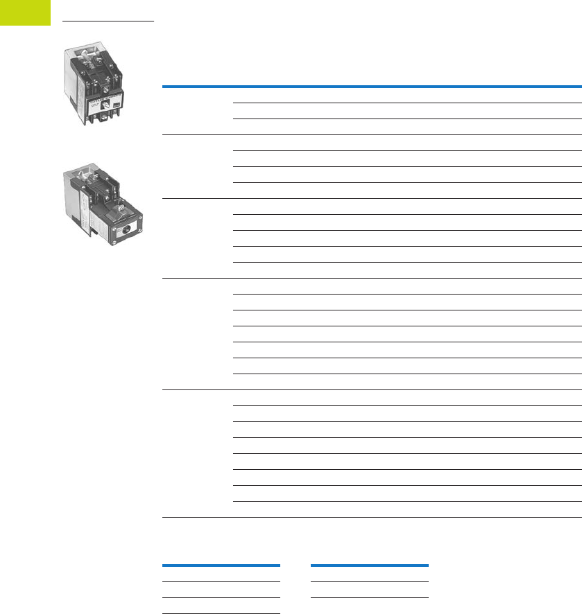
T40-162 Logic Control Products CA08100001K—June 2012 ww.eatoncanada.ca
40
40
40
40
40
40
40
40
40
40
40
40
40
40
40
40
40
40
40
40
40
40
40
40
40
40
40
40
40
40
40.7
Control Relays and Timers
Machine Tool Relays
Product Selection
Complete DC Relays
When Ordering, Specify
●Catalogue number and magnet coil suffix letter.
●Example: For a 4-pole relay having 4NO contacts, order Catalogue Number D26MRD40, with a
120 Vdc coil, order D26MRD40A1.
Complete DC Relays—Open Type
Magnet Coil Selection
Notes
Relay has additional factory wired normally closed coil clearing contact (see diagram).
10- and 11-Poles: The 6 and 7 contact relays (without mechanical latch only) listed above can be provided with four
additional NO non-convertible contacts. Add suffix number 4 to above listed catalogue number plus magnet coil suffix.
Example: For an 11 contact relay, order D26MRD704A1.
Number
of Contacts
Type of Contact Relay Only
Relay with
Mechanical Latch
NO (Form A) NC (Form B)
Catalogue
Number
Catalogue
Number
22 0 D26MRD20 D26MRD202
11D26MRD11 D26MRD112
02D26MRD02 D26MRD022
33 0 D26MRD30 D26MRD302
21D26MRD21 D26MRD212
12D26MRD12 D26MRD122
03D26MRD03 D26MRD032
44 0 D26MRD40 D26MRD402
31D26MRD31 D26MRD312
22D26MRD22 D26MRD222
13D26MRD13 D26MRD132
04D26MRD04 D26MRD042
6 60D26MRD60 D26MRD602
51D26MRD51 D26MRD512
42D26MRD42 D26MRD422
33D26MRD33 D26MRD332
24D26MRD24 D26MRD242
15D26MRD15 D26MRD152
06D26MRD06 D26MRD062
7 70D26MRD70 —
61D26MRD61 —
52D26MRD52 —
43D26MRD43 —
34D26MRD34 —
25D26MRD25 —
16D26MRD16 —
07D26MRD07 —
Volts/Hertz Suffix Code Volts/Hertz Suffix Code
12 R1 120 A1
24 T1 240 B1
48 W1
3-Pole
3-Pole with Latch
Tab40book.fm Page 162 Wednesday, July 4, 2012 10:05 PM
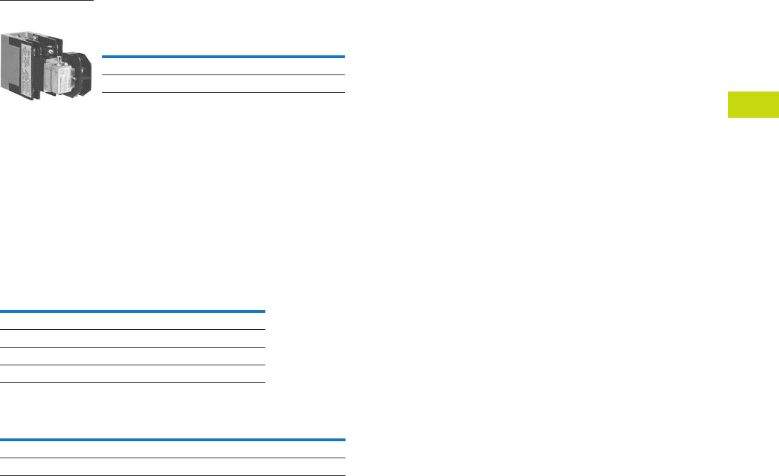
Logic Control Products CA08100001K—June 2012 ww.eatoncanada.ca T40-163
40
40
40
40
40
40
40
40
40
40
40
40
40
40
40
40
40
40
40
40
40
40
40
40
40
40
40
40
40
40
40.7
Control Relays and Timers
Machine Tool Relays
Relay with Pneumatic Timer Attachment
(without Relay Contacts)
The relays listed above will
accept up to three catalogue
number D26MPR contacts
(convertible—NO or NC) for
instantaneous operation.
Order contacts separately.
For additional information
on timer attachment, see
Page T40-159.
Technical Data and Specifications
General
Notes
Number of available instantaneous contact positions (order contacts
separately—Catalogue Number D26MPR).
Contact ratings do not apply to contacts D26MPL and D26MPS.
For AC contact ratings, see Page T40-159.
Contact
Positions
Timer
Operation
Catalogue
Number
3 ON delay D26MRD005
3 OFF delay D26MRD006
3-Pole with Timer
Attachment
Contact Ratings (Amperes)
DC Volts
Inductive
Make/Break
Resistive
Make/Break
28 7.0 10.0
48 2.5 10.0
120 1.1 2.0
240 0.2 0.4
Coil Power Operating Time
Watts Average
MillisecondsRelay Inrush Sealed
Two- to 11-pole 168 13.2 Pickup: 10
Latch coil 21.6 intermittent 21.6 intermittent Dropout: 16
Tab40book.fm Page 163 Wednesday, July 4, 2012 10:05 PM
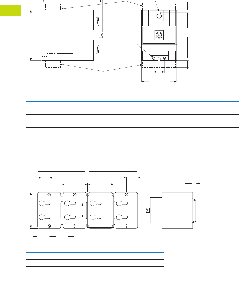
T40-164 Logic Control Products CA08100001K—June 2012 ww.eatoncanada.ca
40
40
40
40
40
40
40
40
40
40
40
40
40
40
40
40
40
40
40
40
40
40
40
40
40
40
40
40
40
40
40.7
Control Relays and Timers
Machine Tool Relays
Dimensions
Approximate Dimensions in Inches (mm)
AC and DC D26 Relays
Mounting Channel
Note: Channel mounts through keyholes with #10 screws
(two each end and one every fourth relay). Relays mount with screws
captive in channel. All screws must be tightened firmly.
AC Relay
D26
DC Relay
D26 Dimension A
Ship. Wt.
Lbs (kg)
1–4 poles 1–3 poles 4.00 (101.6) 2.5 (1.1)
1–4 poles with timer D26 or D87 1–3 poles with timer D26 or D87 6.00 (152.4) 3.3 (1.5)
1–4 poles with latch 1–2 poles with latch 6.13 (155.7) 3.5 (1.6)
1–4 poles with D26MF 1–3 poles with D26MF 5.81 (147.6) 2.8 (1.3)
5–8 poles 4–7 poles 5.25 (133.4) 2.8 (1.3)
5–8 poles with timer D87 4–7 poles with timer D87 7.25 (184.2) 3.5 (1.6)
5–8 poles with latch 3–6 poles with latch 7.31 (185.7) 3.8 (1.7)
9–12 poles 8–11 poles 7.00 (177.8) 3.0 (1.4)
Catalogue
Number Dimension A Dimension B
D26MC16 40 (1016) 37.5 (952.5)
D26MC12 30 (762) 27.5 (698.5)
D26MC8 20 (508) 17.5 (444.5)
D26MC4 10 (254) 7.5 (190.5)
2.38 (60.5)
Max.
D26MAS2
D26MAS1
0.75
(19.1)
3.13
(79.5)
0.44
(11.2)
0.44
(11.2)
3.50
(88.9)
A
1 Slot
#10 Screw
2 Holes
#10 Screw
2.50
(63.5)
2.50
(63.5)
2.38
(60.5)
B
0.69
(17.5)
1.06
(26.9)
A
1.25
(31.8)
3.63
(92.2)
1.38
(35.1)
0.38
(9.7)
Type
M
Relay
D26
Tab40book.fm Page 164 Wednesday, July 4, 2012 10:05 PM
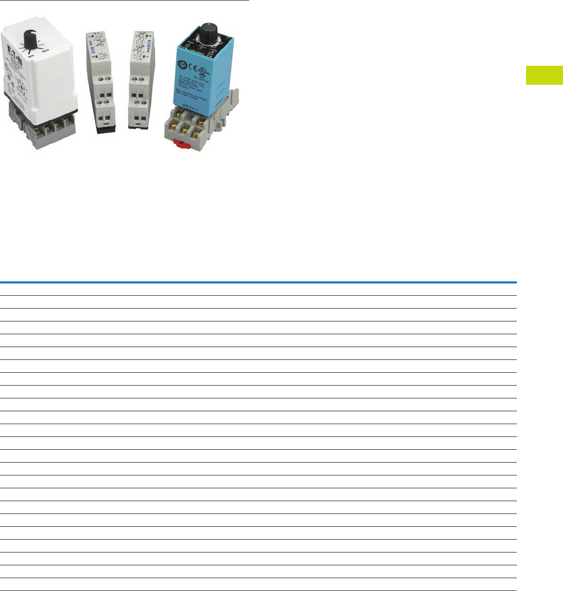
Logic Control Products CA08100001K—June 2012 ww.eatoncanada.ca T40-165
40
40
40
40
40
40
40
40
40
40
40
40
40
40
40
40
40
40
40
40
40
40
40
40
40
40
40
40
40
40
40.8
Control Relays and Timers
Timing Relays
Timing Relays Contents
Description Page
Timing Relays
Universal TR Series . . . . . . . . . . . . . . . . . . . . . . . . T40-170
TR Series . . . . . . . . . . . . . . . . . . . . . . . . . . . . . . . . T40-174
TMR5 Series . . . . . . . . . . . . . . . . . . . . . . . . . . . . . . T40-177
TMR6 Series . . . . . . . . . . . . . . . . . . . . . . . . . . . . . . T40-181
TMRP Series . . . . . . . . . . . . . . . . . . . . . . . . . . . . . T40-183
E5-248—Battery-Powered LCD
Time Control . . . . . . . . . . . . . . . . . . . . . . . . . . . . . T40-186
Product Selection Guide
Function Code Cross-Reference Guide
Notes
Applies to TRN model only.
Applies to TRF model only.
The E5-248 is battery powered and has three programmable trigger functions.
This product may perform somewhat differently from the standard timing relays.
Refer to the operator instructions for details.
Timer Series
Function Description Universal TR TR TMR5 TMR6 TMRP E5-248
1 Asymmetrical flasher, pause first lp — R/P — — RC DLY
2 Asymmetrical flasher, pulse first li — Y — — RC
3 ON delay and OFF delay with control contact ER — ————
4 ON delay and single shot leading edge voltage controlled EWu — ————
5 ON delay and single shot leading edge control contact EWs — ————
6 Single shot leading and single shot trailing edge with control contact WsWa — ————
7 Pulse sequence monitoring Wt — ————
8 ON delay, power triggered E A N—A—
9 Single shot leading edge voltage controlled Wu B T—C—
10 OFF delay/signal OFF delay R E F — D OFF DLY
11 Single shot leading edge with control input Ws F C/G — H SS
12 Single shot trailing edge with control input Wa — ————
13 ON delay control signal start, trailing edge OFF Es — ————
14 Flasher, pause first Bp C L—B—
15 Retriggerable single shot — — W/D — E SS
16 Flasher, ON first — D ——F —
17 ON delay control signal start, leading edge OFF — A — — — ON DLY
18 Flasher—control signal start, pause first — B — — — RC DLY
19 Flasher—control signal start, ON first — C ———RC
20 Signal ON/OFF delay — D ————
21 ON/OFF delay — — — — I —
22 Single pulse generator — — — — G OS
23 Memory latch — — — — J —
24 True OFF delay — — — X — —
Tab40book.fm Page 165 Wednesday, July 4, 2012 10:05 PM
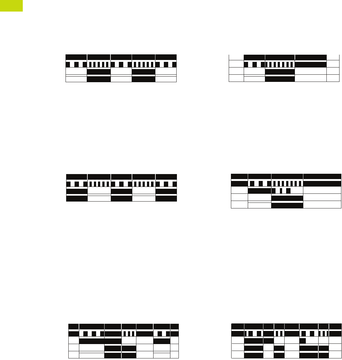
T40-166 Logic Control Products CA08100001K—June 2012 ww.eatoncanada.ca
40
40
40
40
40
40
40
40
40
40
40
40
40
40
40
40
40
40
40
40
40
40
40
40
40
40
40
40
40
40
40.8
Control Relays and Timers
Timing Relays
Product Overview
Timer Function Descriptions
Function #1—Universal TR, TMR5, E5-248
Asymmetrical Flasher, Pause First
Repeat Cycle, OFF/ON Delay
When the supply voltage U
is applied, the set interval t1
begins. After the interval t1
has expired, the output relay
R switches into ON position
and the set interval t2 begins.
After the interval t2 has
expired, the output relay
switches into OFF position.
The output relay is triggered
at the ratio of t1:t2 until the
supply voltage is interrupted.
Function #2—Universal TR, TMR5, E5-248
Asymmetrical Flasher, Pulse First
Repeat Cycle, ON/OFF Delay
When the supply voltage U
is applied, the output relay R
switches into the ON position
and the set interval t1 begins.
After the interval t1 has
expired, the output relay R
switches into OFF position
and the set interval t2 begins.
After the interval t2 has
expired, the output relay
switches into ON position.
The output relay is triggered
at the ratio of t1:t2 until the
supply voltage is interrupted.
Function #3—Universal TR
ON Delay and OFF Delay with Control Contact
The supply voltage U must
be constantly applied to the
device. When the control
contact S is closed, the set
interval t1 begins. After the
interval t1 has expired, the
output relay R switches into
ON position. If the control
contact is opened, the set
interval t2 begins. After the
interval t2 has expired, the
output relay R switches into
OFF position. If the control
contact is opened before the
interval t1 has expired, the
interval already expired is
erased and is restarted with
the next cycle.
Input Power (U)
LED U/t*
Output LED**
Output Relay (R) t2t1 t1 t1t2
Input Power (U)
LED U/t*
Output LED**
Output Relay (R) t2t1 t1 t1t2
Input Power (U)
LED U/t*
Trigger Signal (S)
Output LED**
Output Relay (R) t1 <t1t2
Function #4—Universal TR
ON Delay and Single Shot Leading Edge Voltage Controlled
When the supply voltage U
is applied, the set interval t1
begins. After the interval t1
has expired, the output relay
R switches into ON position
and the set interval t2 begins.
After the interval t2 has
expired, the output relay
switches into OFF position. If
the supply voltage is
interrupted before the interval
t1 + t2 has expired, the
interval already expired is
erased and is restarted
when the supply voltage is
next applied.
Function #5—Universal TR
ON Delay and Single Shot Leading Edge Control Contact
The supply voltage U must
be constantly applied to the
device. When the control
contact S is closed, the set
interval t1 begins. After the
interval t1 has expired, the
output relay R switches into
ON position and the set
interval t2 begins. After the
interval t2 has expired, the
output relay R switches into
OFF position. During the
interval, the control contact is
ignored. A new cycle can only
be initiated when the cycle
has been completed.
Function #6—Universal TR
Single Shot Leading and Single Shot Trailing Edge
with Control Contact
Asymmetrical Signal ON/OFF Delay
The supply voltage U must
be constantly applied to the
device. When the control
contact S is closed, the
output relay R switches to
the ON position and the set
interval t1 begins. After the
interval t1 has expired, the
output relay R switches into
OFF position. If the control
contact S is opened, the
output relay again switches
to the ON position and the
set interval t2 begins. After
the interval t2 has expired,
the output relay R switches
into OFF position. During
the interval, the control
contact is ignored. During
the interval, the control
contact can be operated
any number of times.
Input Power (U)
LED U/t*
Output LED**
Output Relay (R) t1 t2
Input Power (U)
LED U/t*
Trigger Signal (S)
Output LED**
Output Relay (R) t1 t2
t2t2t1 t1
Input Power (U)
LED U/t*
Trigger Signal (S)
Output LED**
Output Relay (R)
Tab40book.fm Page 166 Wednesday, July 4, 2012 10:05 PM
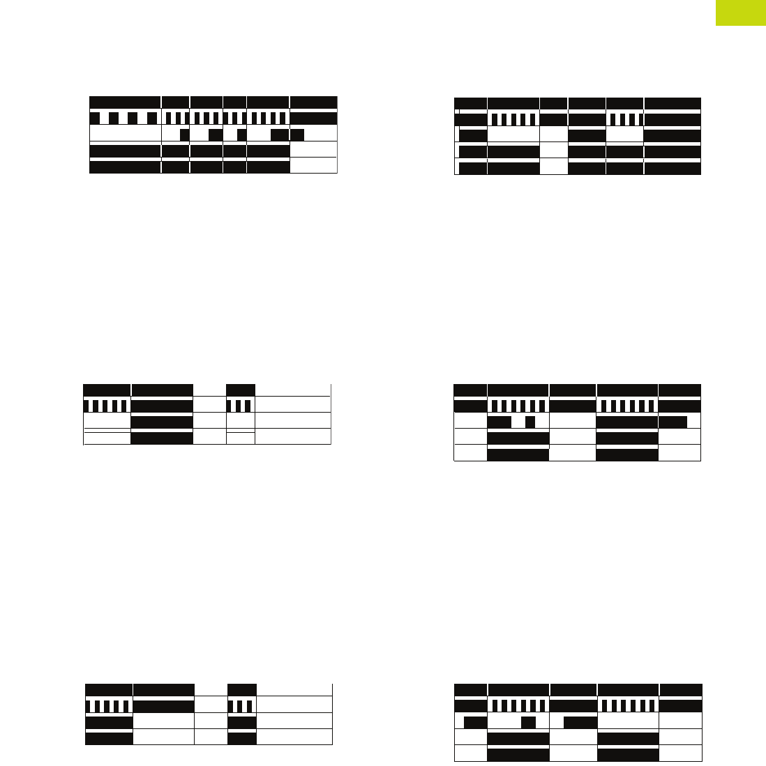
Logic Control Products CA08100001K—June 2012 ww.eatoncanada.ca T40-167
40
40
40
40
40
40
40
40
40
40
40
40
40
40
40
40
40
40
40
40
40
40
40
40
40
40
40
40
40
40
40.8
Control Relays and Timers
Timing Relays
Function #7—Universal TR
Pulse Sequence Monitoring
When the supply voltage U
is applied, the set interval t1
begins and the output relay
R switches to the ON
position. After the interval
t1 has expired, the interval
t2 begins. As long as the
control switch S is closed
and opened within the
interval t2, the relay will
remain in the ON position.
If the control switch is not
closed and opened within
the interval t2, the relay
will change to the OFF
position until supply
voltage U is interrupted
and reapplied.
Function #8—Universal TR, TRN, TMR5, TMRP
ON Delay, Power Triggered
Delay ON Make
When the supply voltage U
is applied, the set interval t
begins. After the interval t
has expired, the output relay
R switches to the ON
position. The relay will remain
in that position until supply
voltage U is interrupted.
Function #9—Universal TR, TRN, TMR5, TMRP
Single Shot Leading Edge Voltage Controlled
Interval ON/Interval (Power Start)
When the supply voltage U
is applied, the output relay R
switches to the ON position
and set interval t begins.
After the interval t has
expired, the output relay R
switches to the OFF position.
The relay will remain in that
position until supply voltage
U is interrupted. If the supply
voltage is interrupted prior to
interval t timing out, the relay
will immediately switch to
the OFF position.
Input Power (U)
LED U/t*
Trigger Signal (S)
Output LED**
Output Relay (R) t1 <t2 <t2 t2<t2
Input Power (U)
LED U/t*
Output LED**
Output Relay (R) t<t
Input Power (U)
LED U/t*
Output LED**
Output Relay (R) t<t
Function #10—Universal TR, TRF, TMR5, TMRP, E5-248
OFF Delay/Signal OFF Delay
Delay ON Release
The supply voltage U must
be constantly applied to the
device. When the control
contact S is closed, the
output relay R switches to
the ON position. When the
control contact is opened,
interval t begins. After the
interval t has expired, the
output relay R switches
to the OFF position. If the
control contact S is closed
before interval t expires,
the output relay will remain
in the ON position until the
control switch opens, at
which time the interval t
will begin again.
Function #11—Universal TR, TRF, TMR5, TMRP, E5-248
Single Shot Leading Edge with Control Input
Single Shot/One Shot (Signal Start)/Momentary Interval
The supply voltage U must
be constantly applied to the
device. When the control
contact S is closed, the
output relay R switches to
the ON position and the set
interval t begins. After the
interval t has expired, the
output relay R switches to
the OFF position. The control
contact is ignored during the
interval t, and a new cycle
cannot be started until the
set interval t has timed out.
Function #12—Universal TR
Single Shot Trailing Edge with Control Input
The supply voltage U must
be constantly applied to the
device. When the control
contact S is closed and
reopened, the output relay
R switches to the ON
position and the set interval t
begins. After the interval t
has expired, the output
relay R switches to the
OFF position. The control
contact is ignored during
the interval t, and a new
cycle must be started
after the set interval t has
timed out.
Input Power (U)
LED U/t*
Trigger Signal (S)
Output LED**
Output Relay (R) <tt
Input Power (U)
LED U/t*
Trigger Signal (S)
Output LED**
Output Relay (R) tt
Input Power (U)
LED U/t*
Trigger Signal (S)
Output LED**
Output Relay (R) tt
Tab40book.fm Page 167 Wednesday, July 4, 2012 10:05 PM
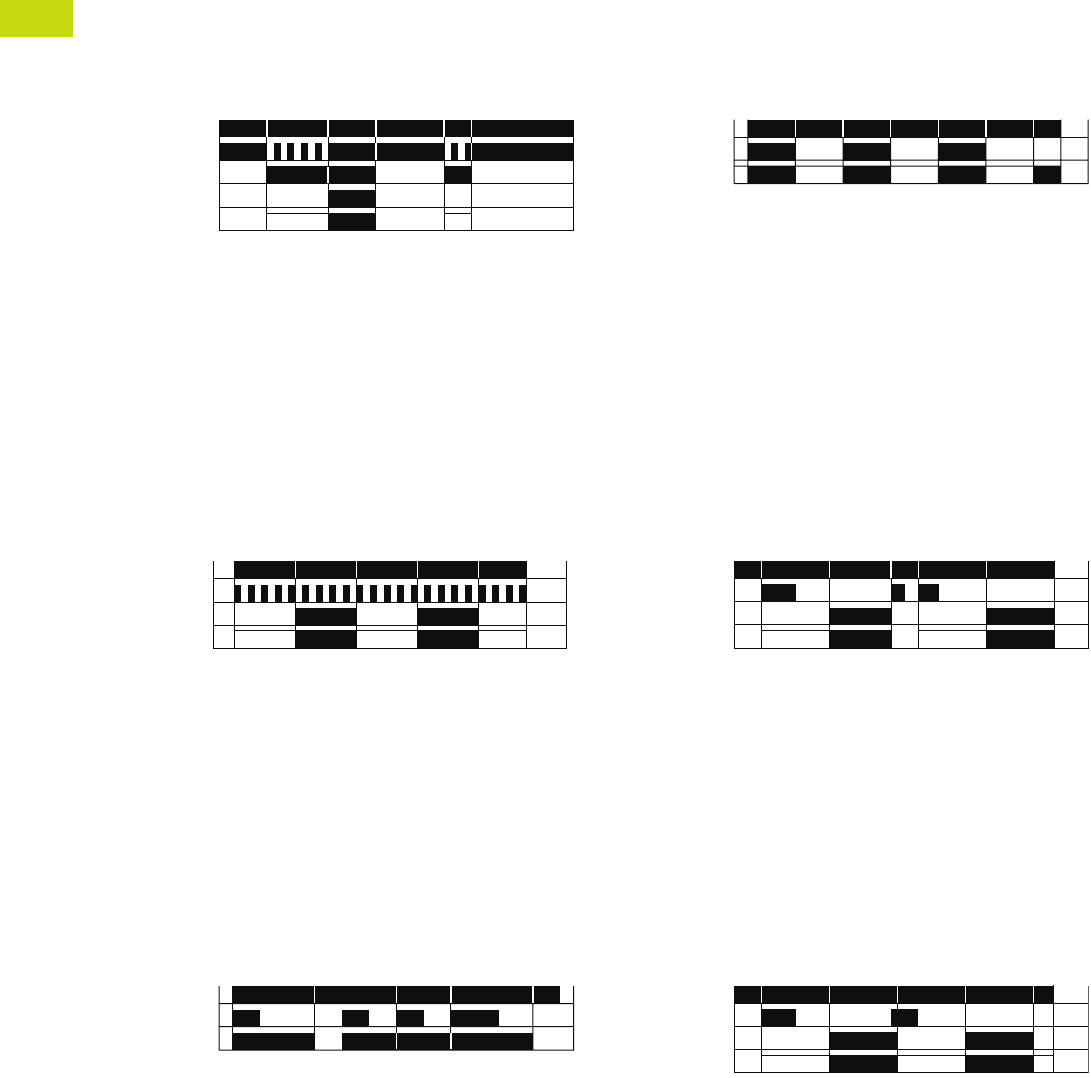
T40-168 Logic Control Products CA08100001K—June 2012 ww.eatoncanada.ca
40
40
40
40
40
40
40
40
40
40
40
40
40
40
40
40
40
40
40
40
40
40
40
40
40
40
40
40
40
40
40.8
Control Relays and Timers
Timing Relays
Function #13—Universal TR
ON Delay Control Signal Start, Trailing Edge OFF
The supply voltage U must
be constantly applied to the
device. When the control
switch S is applied, the set
interval t begins. After the
interval t has expired, the
output relay R switches to
the ON position. The relay
will remain in that position
until the control switch
opens. If the control switch is
opened prior to interval t
timing out, the relay will
remain in the OFF position
and any elapsed time will be
erased.
Function #14—Universal TR, TRN, TMR5, TMRP
Flasher, Pause First
Cycle 1 (Power Start, OFF First)
When the supply voltage U
is applied, the set interval t
begins. After the interval t
has expired, the output relay
R switches to the ON
position and set interval t will
begin again. After interval t
has expired, the relay will
switch to the OFF position
for the set interval t. This
cycle will repeat at a 1:1
ratio until supply voltage U
is interrupted.
Function #15—TMR5, TMRP, E5-248
Watchdog
Retriggerable Single Shot
The supply voltage U must
be constantly applied to the
device. When the control
switch S is applied, the relay
switches to the ON position
and the set interval t begins.
After the interval t has
expired, the output relay R
switches to the OFF position.
Closing the control switch
during interval t will reset the
time. Continuous cycling of
the trigger signal at a rate
faster than the preset time
will cause the relay to remain
in the ON position.
Input Power (U)
LED U/t*
Trigger Signal (S)
Output LED**
Output Relay (R) t<t
Input Power (U)
LED U/t*
Output LED**
Output Relay (R) t<ttttt
Input Power (U)
Trigger Signal (S)
Output Relay (R) t<t<tt
Function #16—TRN, TMRP
Flasher, ON First
Cycle 3 (Power Start, ON First)
When the supply voltage U
is applied, the relay switches
to the ON position and set
interval t begins. After the
interval t has expired, the
output relay R switches to
the OFF position and set
interval t will begin again.
After interval t has expired,
the relay will again switch to
the ON position for the set
interval t. This cycle will
repeat at a 1:1 ratio until
supply voltage U is
interrupted.
Function #17—TRF, E5-248
ON Delay Control Signal Start, Leading Edge OFF
The supply voltage U must
be constantly applied to the
device. When the control
switch S is applied, the set
interval t begins. After the
interval t has expired, the
output relay R switches to
the ON position. The relay
will remain in that position
until the control switch has
opened and closed. If the
control switch is opened and
closed prior to interval t
timing out, the relay will
remain in the OFF position
and any elapsed time will be
erased.
Function #18—TRF, E5-248
Flasher—Control Signal Start, Pause First
The supply voltage U must
be constantly applied to the
device. When the control
switch S is closed, the set
interval t begins. After the
interval t has expired, the
output relay R switches to
the ON position and set
interval t will begin again.
After interval t has expired,
the relay will switch to the
OFF position for the set
interval t. This cycle will
repeat at a 1:1 ratio until
supply voltage U is
interrupted. The control
switch is ignored during
the cycle.
Input Power (U)
Output LED**
Output Relay (R) ttttt<tt
Input Power (U)
Trigger Signal
Output LED**
Output Relay (R) tt
Input Power (U)
Trigger Signal
Output LED**
Output Relay (R) tttt<t
Tab40book.fm Page 168 Wednesday, July 4, 2012 10:05 PM
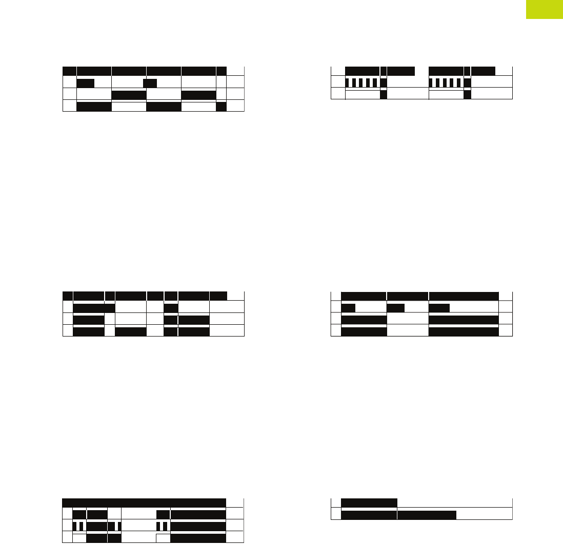
Logic Control Products CA08100001K—June 2012 ww.eatoncanada.ca T40-169
40
40
40
40
40
40
40
40
40
40
40
40
40
40
40
40
40
40
40
40
40
40
40
40
40
40
40
40
40
40
40.8
Control Relays and Timers
Timing Relays
Function #19—TRF, E5-248
Flasher—Control Signal Start, ON First
The supply voltage U must
be constantly applied to the
device. When the control
switch S is closed, the relay
switches to the ON position
and set interval t begins.
After the interval t has
expired, the output relay R
switches to the OFF position
and set interval t will begin
again. After interval t has
expired, the relay will again
switch to the ON position
for the set interval t. This
cycle will repeat at a 1:1
ratio until supply voltage U
is interrupted. The control
switch is ignored during
the cycle.
Function #20—TRF
Signal ON/OFF Delay
The supply voltage U must
be constantly applied to the
device. When the control
switch S is closed, the relay
switches to the ON position
and set interval t begins.
After the interval t has
expired with the control
switch still closed, the output
relay R switches to the OFF
position. When the control
switch is opened, the relay
will switch to the ON position
again and the interval t will
begin. If the control switch is
closed and opened within the
interval t, the relay will remain
in the ON position until
interval t has timed out after
the control switch is opened.
Function #21—TMRP
ON/OFF Delay
Make/Break with Control Switch Trigger
The supply voltage U must
be constantly applied to the
device. When the control
switch S is closed, the set
interval t begins. After the
interval t has expired, the
output relay R switches to
the ON position. When the
control switch is opened,
interval t will begin again.
After interval t has timed out,
the relay will switch to the
OFF position. If supply
voltage U is removed at any
time, the relay will return to
the OFF position.
Input Power (U)
Trigger Signal
Output LED**
Output Relay (R) <tt ttt
Input Power (U)
Trigger Signal
Output LED**
Output Relay (R) tt<tt
Input Power (U)
Trigger Signal
Output LED**
Output Relay (R) tt t
Function #22—TMRP, E5-248
Single Pulse Generator, Voltage Controlled
When the supply voltage U
is applied, the set interval t
begins. After the interval t
has expired, the relay will
switch to the ON position for
0.5 seconds before returning
to the OFF position. Supply
voltage U must be removed
and reapplied to repeat the
pulse.
Function #23—N/A
Memory Latch
Control Switch Make
The supply voltage U must
be constantly applied to the
device. Output changes state
with every closure of the
control switch S (leading
edge).
Function #24—TMR6
True OFF Delay
When the supply voltage U
is applied, the relay switches
to the ON position. When
supply power is removed, set
time interval t begins. After
interval t has expired, the
relay switches to the OFF
position and will remain there
until supply power U is
applied again.
Input Power (U)
Output LED**
Output Relay (R) tt
Input Power (U)
Trigger Signal
Output LED**
Output Relay (R)
Input Power (U)
Output Relay (R) t
Tab40book.fm Page 169 Wednesday, July 4, 2012 10:05 PM
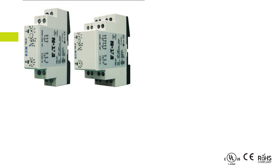
T40-170 Logic Control Products CA08100001K—June 2012 ww.eatoncanada.ca
40
40
40
40
40
40
40
40
40
40
40
40
40
40
40
40
40
40
40
40
40
40
40
40
40
40
40
40
40
40
40.8
Control Relays and Timers
Timing Relays
Universal TR Series Contents
Description Page
Universal TR Series
Product Selection . . . . . . . . . . . . . . . . . . . . . . . . . . T40-171
Technical Data and Specifications . . . . . . . . . . . . . T40-171
Wiring Diagrams . . . . . . . . . . . . . . . . . . . . . . . . . . . T40-172
Dimensions . . . . . . . . . . . . . . . . . . . . . . . . . . . . . . T40-173
TR Series . . . . . . . . . . . . . . . . . . . . . . . . . . . . . . . . . . . T40-174
TMR5 Series . . . . . . . . . . . . . . . . . . . . . . . . . . . . . . . . T40-177
TMR6 Series . . . . . . . . . . . . . . . . . . . . . . . . . . . . . . . . T40-181
TMRP Series . . . . . . . . . . . . . . . . . . . . . . . . . . . . . . . . T40-183
E5-248—Battery-Powered LCD Time Control . . . . . . . T40-186
Universal TR Series
Product Description
Eaton’s Universal TR Series
timers are our most flexible
and cost-effective timing
relays available. Products are
available with up to seven
user-selectable functions and
seven user-selectable time
ranges. Each unit is DIN rail
mountable with a direct
connection, eliminating the
need for additional sockets.
The Universal TR Series
timers are available in SPDT
and DPDT contact
configurations, and have a
compact IEC-style footprint
and a universal input voltage
range for AC and DC
applications.
Application Description
A timing relay is a simple
form of time-based control,
allowing the user to open or
close the contacts based on
a specified timing function.
The Universal TR Series
timers are equipped with a
set of selector switches,
which can easily be set to a
specific function and time,
thereby reducing the number
of product variations required.
The universal input voltage
(either 12–240 Vac/Vdc or
24–240 Vac/Vdc, depending
on the model) further
reduces the number of
product variations.
The Universal TR Series
timers are ideal for high-
variability operations, such
as systems integrators,
distributors, and small
equipment manufacturers.
The compact design saves
panel space, and the low
cost and high flexibility of
the units reduce inventory
requirements.
Features
●Multiple user-selectable
timing functions and timing
ranges in a single unit
reduce product variations
and stock keeping units
(SKUs)
●Universal input voltages
from 12 or 24 to 240 Vac or
Vdc eliminate the need to
order and stock separate
coil voltages
●Compact, DIN rail
mountable case reduces
panel size
●Advanced LED indication
makes troubleshooting
easy
●Staggered terminal
locations allow access
to lower-level terminals
after wiring
●SPDT or DPDT contacts
with 8A ratings
Standards and Certifications
●cULus listed
●CE marked
●RoHS compliant
●IEC/EN 61812
Tab40book.fm Page 170 Wednesday, July 4, 2012 10:05 PM
Logic Control Products CA08100001K—June 2012 ww.eatoncanada.ca T40-171
40
40
40
40
40
40
40
40
40
40
40
40
40
40
40
40
40
40
40
40
40
40
40
40
40
40
40
40
40
40
40.8
Control Relays and Timers
Timing Relays
Product Selection
Universal TR Timing Relays
Technical Data and Specifications
Universal TR Timing Relays
Note
Refer to Function Code Cross-Reference Guide on Page T40-165 for function details.
Supply Voltage Description
Catalogue
Number
4-Function
24–240 Vac/Vdc Compact DIN rail mount, SPDT TRL04
7-Function
24–240 Vac/Vdc Compact DIN rail mount, SPDT TRL07
12–240 Vac/Vdc Compact DIN rail mount, DPDT TRL27
Asymmetrical pulse generator, DPDT TRW27
Single-Pole Model
Description TRL04 TRL07 TRL27 TRW27
Functions E, R, Wu, Bp E, R, Wu, Bp, Ws, Wa, Es E, R, Wu, Bp, Ws, Wa, Es Ii, Ip, ER, Ewu, Ews, WsWa, Wt
Time range 0.05 sec to 100 hours 0.05 sec to 100 hours 0.05 sec to 100 hours 0.05 sec to 100 hours
Input
Supply voltage 24–240 Vac/Vdc 24–240 Vac/Vdc 12–240 Vac/Vdc 12–240 Vac/Vdc
Rated supply frequency +10% /–15% +10% /–15% ±10% ±10%
Rated consumption 4 VA (1.5W) 4 VA (1.5W) 6 VA (2W) 6 VA (2W)
Duty cycle 100% 100% 100% 100%
Reset time 100 ms 100 ms 100 ms 100 ms
Residual ripple for DC 10% 10% 10% 10%
Dropout voltage >30% of rated supply voltage >30% of rated supply voltage >30% of rated supply voltage >30% of rated supply voltage
Overvoltage category III (in accordance with IEC 60664-1) III (in accordance with IEC 60664-1) III (in accordance with IEC 60664-1) III (in accordance with IEC 60664-1)
Rated surge voltage 4 kV 4 kV 4 kV 4 kV
Output
Contact configuration SPDT (one changeover contact) SPDT (one changeover contact) DPDT (two changeover contacts) DPDT (two changeover contacts)
Rated voltage 250 Vac 250 Vac 250 Vac 250 Vac
Switching capacity 2000 VA (8A/250V) 2000 VA (8A/250V) 2000 VA (8A/250V) 2000 VA (8A/250V)
Fusing 8A fast acting 8A fast acting 8A fast acting 8A fast acting
Mechanical life 20 x 10^6 operations 20 x 10^6 operations 20 x 10^6 operations 20 x 10^6 operations
Electrical life 2 x 10^5 operations at 1000 VA load,
resistive
2 x 10^5 operations at 1000 VA load,
resistive
2 x 10^5 operations at 1000 VA load,
resistive
2 x 10^5 operations at 1000 VA load,
resistive
Switching frequency Max. 6/min. at 1000 VA resistive load
(in accordance with IEC 60947-5-1)
Max. 6/min. at 1000 VA resistive load
(in accordance with IEC 60947-5-1)
Max. 6/min. at 1000 VA resistive load
(in accordance with IEC 60947-5-1)
Max. 6/min. at 1000 VA resistive load
(in accordance with IEC 60947-5-1)
Overvoltage category III (in accordance with IEC 60664-1) III (in accordance with IEC 60664-1) III (in accordance with IEC 60664-1) III (in accordance with IEC 60664-1)
Rated surge voltage 4 kV 4 kV 4 kV 4 kV
Control Signal
Loadable Yes Yes Yes Yes
Maximum cable length 10m 10m 10m 10m
Trigger level (sensitivity) Automatic adaption to
supply voltage
Automatic adaption to
supply voltage
Automatic adaption to
supply voltage
Automatic adaption to
supply voltage
Minimum control pulse length DC 50 ms/AC 100 ms DC 50 ms/AC 100 ms DC 50 ms/AC 100 ms DC 50 ms/AC 100 ms
Tab40book.fm Page 171 Wednesday, July 4, 2012 10:05 PM
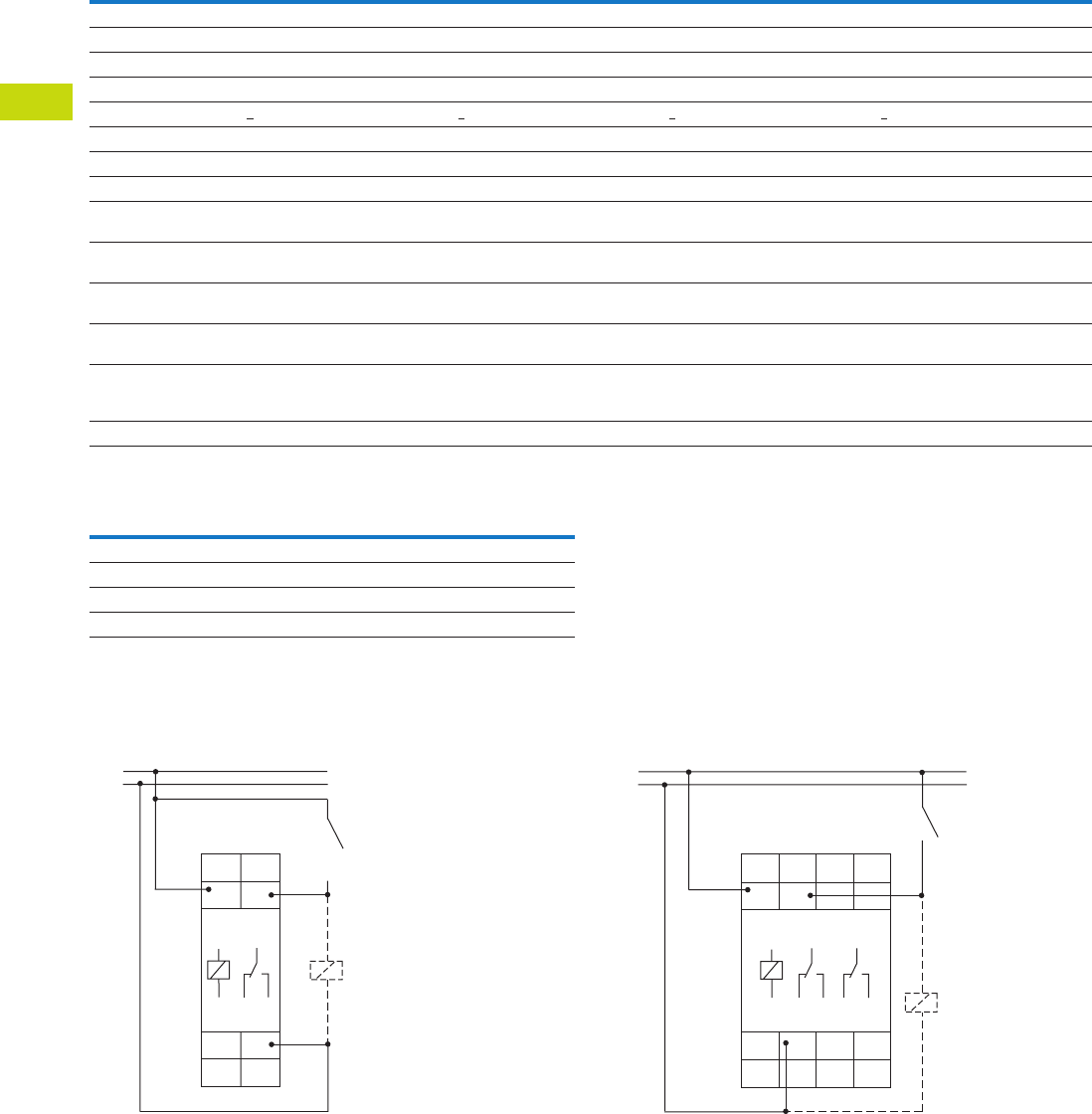
T40-172 Logic Control Products CA08100001K—June 2012 ww.eatoncanada.ca
40
40
40
40
40
40
40
40
40
40
40
40
40
40
40
40
40
40
40
40
40
40
40
40
40
40
40
40
40
40
40.8
Control Relays and Timers
Timing Relays
Universal TR Timing Relays, continued
Terminal Capacity
Wiring Diagrams
Single-Pole, Double-Throw Units (SPDT)—
TRL04 and TRL07
Double-Pole, Double-Throw Units (DPDT)—
TRL27 and TRW27
Description TRL04 TRL07 TRL27 TRW27
Accuracy
Base accuracy ±1% of maximum scale value ±1% of maximum scale value ±1% of maximum scale value ±1% of maximum scale value
Adjustment accuracy <5% of maximum scale value <5% of maximum scale value <5% of maximum scale value <5% of maximum scale value
Repetition accuracy <0.5% or ±5 ms <0.5% or ±5 ms <0.5% or ±5 ms <0.5% or ±5 ms
Temperature influence <0.01% /˚C <0.01% /˚C <0.01% /˚C <0.01% /˚C
Physical
Ambient temperature –25 to 55˚C –25 to 55˚C –25 to 55˚C –25 to 55˚C
Storage temperature –25 to 70˚C –25 to 70˚C –25 to 70˚C –25 to 70˚C
Relative humidity 15% to 85% (in accordance
with IEC 60721-3-3 Class 3K3)
15% to 85% (in accordance
with IEC 60721-3-3 Class 3K3)
15% to 85% (in accordance
with IEC 60721-3-3 Class 3K3)
15% to 85% (in accordance
with IEC 60721-3-3 Class 3K3)
Pollution degree 2, if built in 3 (in accordance
with IEC 60664-1)
2, if built in 3 (in accordance
with IEC 60664-1)
2, if built in 3 (in accordance
with IEC 60664-1)
2, if built in 3 (in accordance
with IEC 60664-1)
Housing material Self-extinguishing plastic housing,
IP40 rating
Self-extinguishing plastic housing,
IP40 rating
Self-extinguishing plastic housing,
IP40 rating
Self-extinguishing plastic housing,
IP40 rating
Mounting Mounted on DIN rail TS 35 according
to EN 60715, any position
Mounted on DIN rail TS 35 according
to EN 60715, any position
Mounted on DIN rail TS 35 according
to EN 60715, any position
Mounted on DIN rail TS 35 according
to EN 60715, any position
Terminal rating Shockproof terminal connection
according to VBG 4 (PZ1 required),
IP20 rating
Shockproof terminal connection
according to VBG 4 (PZ1 required),
IP20 rating
Shockproof terminal connection
according to VBG 4 (PZ1 required),
IP20 rating
Shockproof terminal connection
according to VBG 4 (PZ1 required),
IP20 rating
Tightening torque Max. 1 Nm Max. 1 Nm Max. 1 Nm Max. 1 Nm
Description
1 x 0.5 to 2.5 mm2 with/without multicore cable end
1 x 4 mm2 without multicore cable end
2 x 0.5 to 1.5 mm2 with/without multicore cable end
2 x 2.5 mm2 flexible without multicore cable end
15
16 18
A2
A1 B1
A1
A2
15
16 18
R
U =
(+)
(–)
S (Used only for
control switch
triggered functions) 15
16 18
25
26 28
A2
A1 B1
A1
A2
15
16 18
R
25
26 28
R
U =
(+)
(–)
S(Used only for
control switch
triggered functions)
Tab40book.fm Page 172 Wednesday, July 4, 2012 10:05 PM
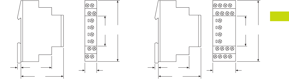
Logic Control Products CA08100001K—June 2012 ww.eatoncanada.ca T40-173
40
40
40
40
40
40
40
40
40
40
40
40
40
40
40
40
40
40
40
40
40
40
40
40
40
40
40
40
40
40
40.8
Control Relays and Timers
Timing Relays
Dimensions
Approximate Dimensions in Inches (mm)
17.5 mm (TRL04 and TRL07) 35 mm (TRL27 and TRW27)
0.20
(5.0)
1.73
(44.0)
2.36
(60.0)
0.69
(17.5)
1.77
(45.0)
3.43
(87.0)
0.20
(5.0)
1.73
(44.0)
2.36
(60.0)
1.38
(35.0)
1.77
(45.0)
3.43
(87.0)
Tab40book.fm Page 173 Wednesday, July 4, 2012 10:05 PM

T40-174 Logic Control Products CA08100001K—June 2012 ww.eatoncanada.ca
40
40
40
40
40
40
40
40
40
40
40
40
40
40
40
40
40
40
40
40
40
40
40
40
40
40
40
40
40
40
40.8
Control Relays and Timers
Timing Relays
TR Series Contents
Description Page
Universal TR Series . . . . . . . . . . . . . . . . . . . . . . . . . . . T40-170
TR Series
Catalogue Number Selection . . . . . . . . . . . . . . . . . T40-175
Product Selection . . . . . . . . . . . . . . . . . . . . . . . . . . T40-175
Accessories . . . . . . . . . . . . . . . . . . . . . . . . . . . . . . T40-175
Technical Data and Specifications . . . . . . . . . . . . . T40-176
Dimensions . . . . . . . . . . . . . . . . . . . . . . . . . . . . . . T40-176
TMR5 Series . . . . . . . . . . . . . . . . . . . . . . . . . . . . . . . . T40-177
TMR6 Series . . . . . . . . . . . . . . . . . . . . . . . . . . . . . . . . T40-181
TMRP Series . . . . . . . . . . . . . . . . . . . . . . . . . . . . . . . . T40-183
E5-248—Battery-Powered LCD Time Control . . . . . . . T40-186
TR Series
Product Description
The upgraded TR Series
Timing Relays are designed
to meet most timing
requirements by offering
more flexibility in range of
input voltage, timing range
and functionality. Use a rotary
switch to choose from
20 selectable time ranges
from 0.1 second to 600
hours. We offer both a power
triggered and signal triggered
model—each with expanded
operation modes. There is a
green LED to indicate when
power is ON and an orange
LED when output is ON.
Features
●20 time ranges and 10
timing functions
●Time delays from 0.1 sec
to 600 hrs
●Space-saving, compact
package
●High repeat accuracy of
± 0.2%
●LED indication
●Standard 8- or 11-pin and
11-blade termination
●2 Form C DPDT delayed
output contacts
●10A contact rating
Operation
TRNP and TRNB
TRFP and TRFB
Standards and Certifications
●cULus listed
●CSA
●CE marked
●TUV
Internal Connections
2
36
7
45
18
(
–
/
–
)(
–
/+)
1
(
–
/
–
)
2 3
4 5 6
7 8 9
A B
(
–
/+)
TRNBTRNP
Internal Connections
210
(
–
/+)
3
67
45
111
8
9
(
–
/
–
)
2
(
–
/+)
1
(
–
/
–
)
3
4 5 6
7 8 9
A B
Start
Start
TRFP TRFB
External
Control
Signal
External
Control
Signal
TUV
Tab40book.fm Page 174 Wednesday, July 4, 2012 10:05 PM

Logic Control Products CA08100001K—June 2012 ww.eatoncanada.ca T40-175
40
40
40
40
40
40
40
40
40
40
40
40
40
40
40
40
40
40
40
40
40
40
40
40
40
40
40
40
40
40
40.8
Control Relays and Timers
Timing Relays
Catalogue Number Selection
Product Selection
TR Plug-In Timing Relays—Power Triggered
TR Plug-In Timing Relays—Signal Triggered
Accessories
Sockets for Use with TR Timers—Standard Pack of 10
Operational Mode
N = Power Triggered
A = ON delay
B = Interval
C = Flasher (pause first)
D = Flasher (ON first)
F = Signal Triggered
A = ON delay, control signal start
(leading edge OFF)
B = Flasher, control signal start
(pause first)
C = Flasher, control signal Start
(ON first)
D = Signal ON/OFF delay
E = OFF delay
F = Single shot leading edge with
control input
Input Voltage
24AD = 24 Vac
(50/60 Hz)/24 Vdc
240AC = 100–240 Vac
(50/60 Hz)
Model Type
P = Pin/octal
B = Blade style
Family Type
TR
TR N P 240 AC
Octal Blade
Coil Voltage
Catalogue
Number
Catalogue
Number
24 Vac/Vdc TRNP24AD TRNB24AD
100–240 Vac TRNP240AC TRNB240AC
Octal Blade
Coil Voltage
Catalogue
Number
Catalogue
Number
24 Vac/Vdc TRFP24AD TRFB24AD
100–240 Vac TRFP240AC TRFB240AC
Timing Relay Terminal Style
Catalogue
Number
TRNP 8-pin octal D3PA2
TRFP 11-pin octal D3PA3
TRNB, TRFB 0.187 in solder/QC terminals
(blade style)
D5PA2
Tab40book.fm Page 175 Wednesday, July 4, 2012 10:05 PM
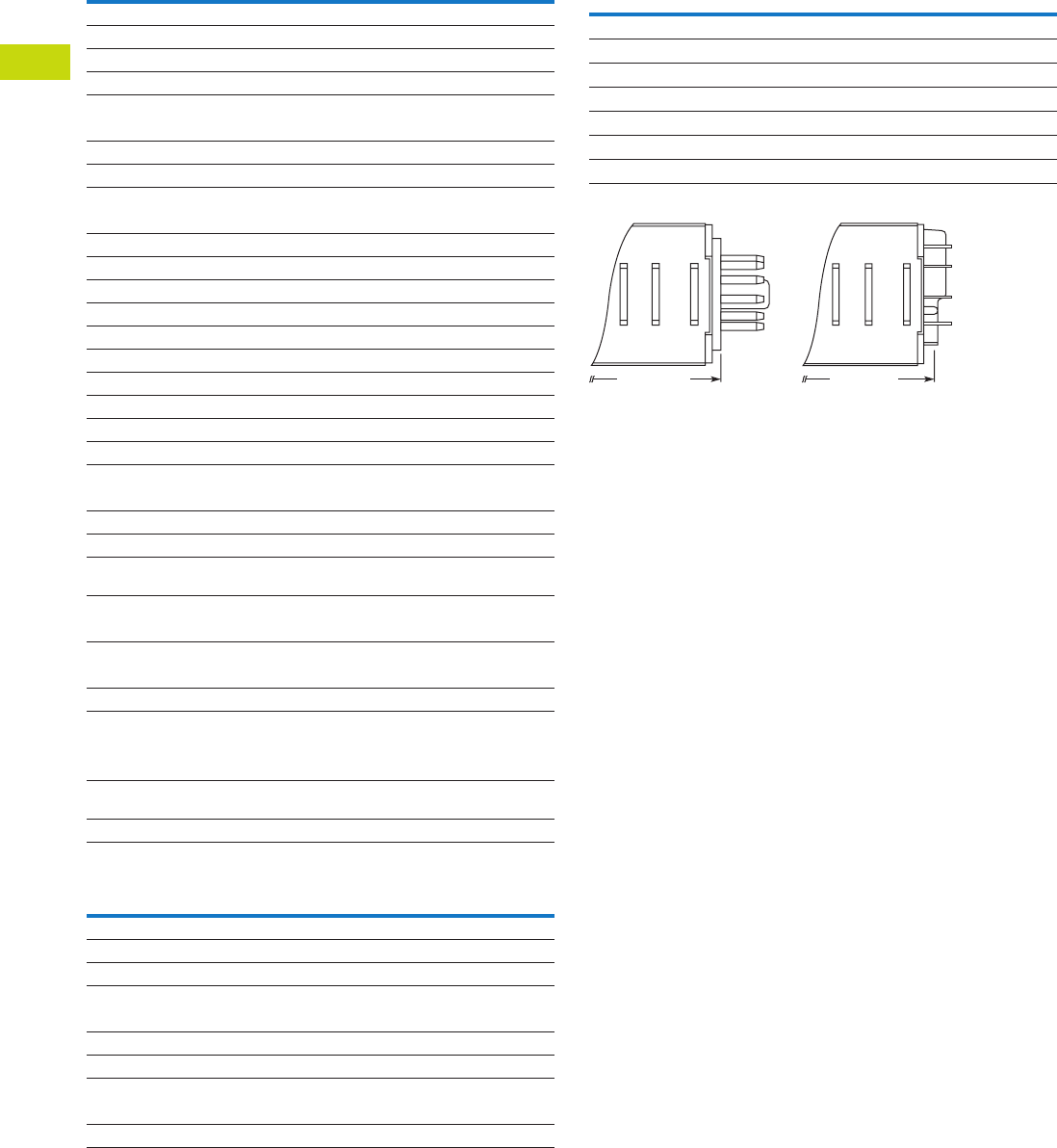
T40-176 Logic Control Products CA08100001K—June 2012 ww.eatoncanada.ca
40
40
40
40
40
40
40
40
40
40
40
40
40
40
40
40
40
40
40
40
40
40
40
40
40
40
40
40
40
40
40.8
Control Relays and Timers
Timing Relays
Technical Data and Specifications
General
TR Series Contact Ratings
Dimensions
Approximate Dimensions in Inches (mm)
TR Series Dimensions and Weights
Note
For the value of the error against a preset time, whichever value is larger should apply.
Description Specification
Operation system Solid-state CMOS circuit
Time range 0.1 sec to 600 hours
Pollution degree 2 (IE60664-1)
Overvoltage category III (IE60664-1)
Rated operational voltage
240 AC 100–240 Vac (50/60 Hz)
24 AC 24 Vac (50/60 Hz)/24 Vdc
12 DC 12 Vdc
Voltage tolerance
240 AC 85–264 Vac (50/60 Hz)
24 AC 20.4–26.4 Vac (50/60 Hz)/21.6–26.4 Vdc
12 DC 10.8–13.2 Vdc
Input OFF voltage Rated voltage x 10% minimum
Ambient operating temperature –4 to 149˚F (–20 to 65˚C)
Reset time 100 ms maximum
Repeat error ± 0.2%, ± 20 ms
Voltage error ± 0.2%, ± 20 ms
Temperature error ± 0.5%, ± 20 ms
Setting error ± 10% maximum
Insulation resistance 100M ohm minimum (500 Vdc)
Dielectric strength
Between power and output terminals 2000 Vac, 1 minute
Between contacts of different poles 2000 Vac, 1 minute
Between contacts of same pole 1000 Vac, 1 minute
Vibration resistance 10–55 Hz amplitude 0.5 mm;
2 hrs in each of 3 axes
Shock resistance
Operating extremes 10G
Damage limits —
TRNP, TRFP 40G (3x in each of 3 axes)
TRNB, TRFB 10G (3x in each of 3 axes)
Power consumption (approx.)
240 AC 6.5 VA TRNP, TRNB/6.6 VA TRFP, TRFB
240 Vac/60 Hz 11.6 VA TRNP, TRNB/12.1 VA TRFP, TRFB
24 AC (AC/DC) 3.4 VA–1.7W TRNP, TRNB/3.5 VA–1.7W TRFP,
TRFB
12 DC 1.6W
Description Specification
Contact configuration 2 Form C, DPDT (delayed output)
Allowable voltage/current 240 Vac, 30 Vdc/10A
Max. permissible operating frequency 1800 cycles per hour
Rated load
Resistive 10A, 240 Vac/30 Vdc
Inductive 7A, 240 Vac/30 Vdc
Horsepower rating 1/6 hp 120 Vac, 1/3 hp 240 Vac
Life
Electrical 500,000 operations minimum (resistive)
Mechanical 50,000,000 operations minimum
Description Specification
Dimensions
TRNP, TRFP 1.58H x 1.42W x 3.07D in. (40H x 36W x 77.9D mm)
TRNB, TRFB 1.58H x 1.42W x 2.95D in. (40H x 36W x 74.9D mm)
Weights
TRNP 87g
TRFP 89g
TRNB, TRFB 85g
3.07 (77.9)
Pin (P) Type Blade (B) Type
2.95 (74.9)
Tab40book.fm Page 176 Wednesday, July 4, 2012 10:05 PM

Logic Control Products CA08100001K—June 2012 ww.eatoncanada.ca T40-177
40
40
40
40
40
40
40
40
40
40
40
40
40
40
40
40
40
40
40
40
40
40
40
40
40
40
40
40
40
40
40.8
Control Relays and Timers
Timing Relays
TMR5 Series Contents
Description Page
Universal TR Series . . . . . . . . . . . . . . . . . . . . . . . . . . . T40-170
TR Series . . . . . . . . . . . . . . . . . . . . . . . . . . . . . . . . . . . T40-174
TMR5 Series
Catalogue Number Selection . . . . . . . . . . . . . . . . . T40-178
Product Selection . . . . . . . . . . . . . . . . . . . . . . . . . . T40-178
Accessories . . . . . . . . . . . . . . . . . . . . . . . . . . . . . . T40-178
Technical Data and Specifications . . . . . . . . . . . . . T40-179
Wiring Diagrams . . . . . . . . . . . . . . . . . . . . . . . . . . . T40-179
Dimensions . . . . . . . . . . . . . . . . . . . . . . . . . . . . . . T40-180
TMR6 Series . . . . . . . . . . . . . . . . . . . . . . . . . . . . . . . . T40-181
TMRP Series . . . . . . . . . . . . . . . . . . . . . . . . . . . . . . . . T40-183
E5-248—Battery-Powered LCD Time Control . . . . . . . T40-186
TMR5 Series
Product Description
The TMR5 Series Time
Delay Relays are designed
for a broad range of
OEM applications. The
TMR5 Series offers
non-programmable plug-in
style timers with a variety
of functions available. Each
unit offers a single function
and single input voltage, and
operates over a defined time
delay range. Units with fixed
time delays are also available.
Eaton also offers customization
capabilities for these timers—
remote adjustments, special
pin configurations, and more.
Contact us to discuss your
specific application and
design of a custom timer.
Features
●Single timing range for
each unit
●Ranges available from
0.02 sec to 24 hours
●Wide variety of functions
available
●Plugs into standard 8- or
11-pin socket
●10A DPDT output contacts
●Can be easily customized
to meet your needs
Standards and Certifications
●cRUus
●UL listed (with Eaton socket)
●RoHS compliant
●CE marked
with
Eaton
socket
Tab40book.fm Page 177 Wednesday, July 4, 2012 10:05 PM
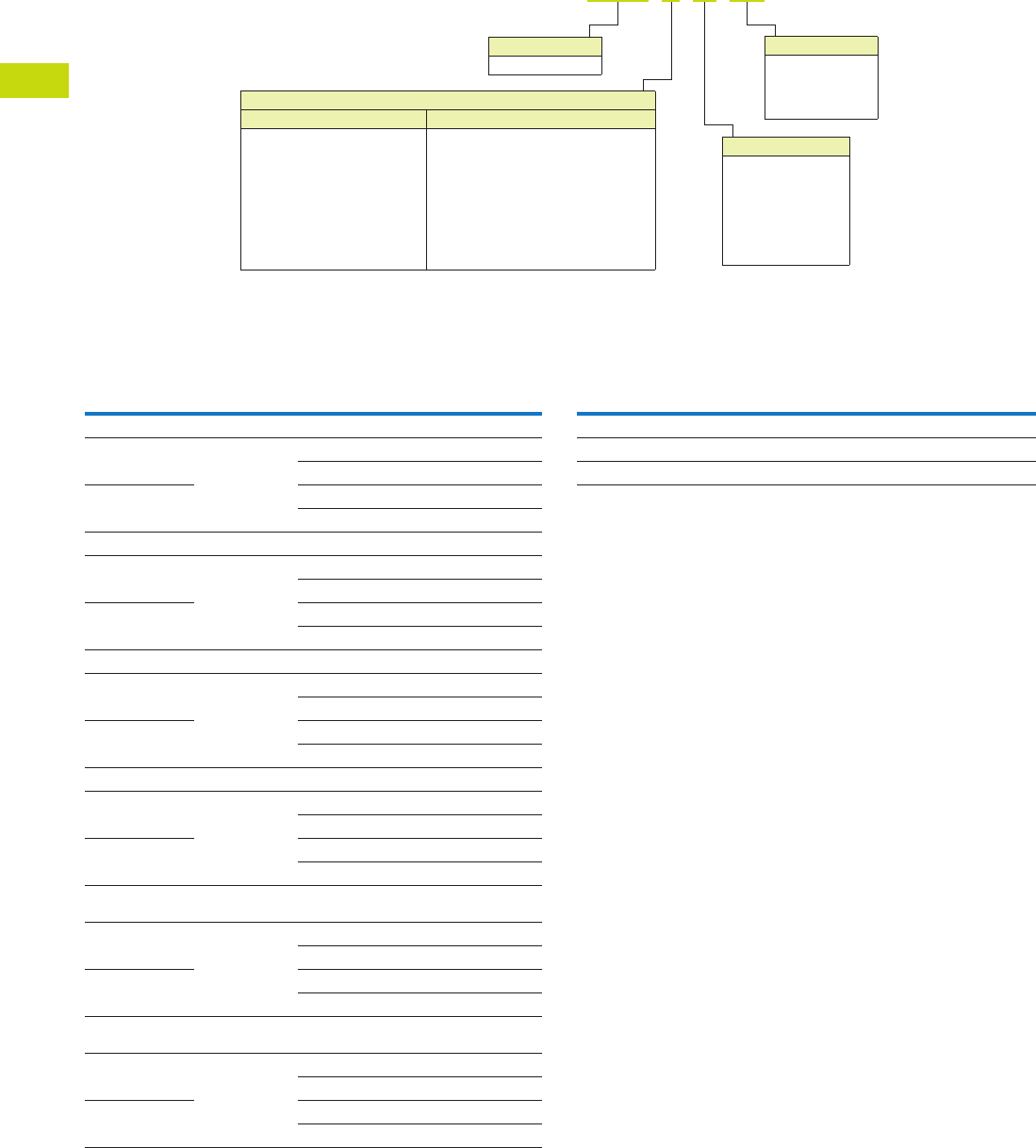
T40-178 Logic Control Products CA08100001K—June 2012 ww.eatoncanada.ca
40
40
40
40
40
40
40
40
40
40
40
40
40
40
40
40
40
40
40
40
40
40
40
40
40
40
40
40
40
40
40.8
Control Relays and Timers
Timing Relays
Catalogue Number Selection
Product Selection
TMR5 Time Delay Relays
Accessories
Accessories for Use with TMR5 Time Delay Relays
Notes
Indicates DUAL knob unit. All dual knob units can have independently selectable and
adjustable ON and OFF times. If different ON and OFF times are desired, add two codes for
time ranges in the part number. The first code listed indicates the first timing range of the
unit (OFF time for R, ON time for Y) and the second code indicates the second timing range
(ON time for R, OFF Time for Y).
Fixed time delay settings are available for orders of 50 pieces or more. Contact EatonCare for
additional information at 877-ETN-CARE (386-2273).
Operational Mode
8-Pin Octal Sockets 11-Pin Octal Sockets
N= ON delay
T= Interval ON
L= Flasher-pause-first
R = Repeat cycle
(OFF time first followed by
ON time and repeating)
Y = Repeat cycle
(ON time first followed by
OFF time and repeating)
F= OFF delay, control switch trigger
C= Single shot, control switch trigger
W= Watchdog, control switch trigger
(retriggerable single shot)
P= OFF delay, power trigger
G= Single shot, power trigger
D= Watchdog, power trigger (retriggerable
single shot)
TMR5 N 05 120
Input Voltage
120 = 120 Vac/Vdc
24 = 24 Vac/Vdc
12 = 12 Vac/Vdc
240 = 240 Vac/Vdc
Timing Range
04 = 0.05–5 sec
05 = 0.1–10 sec
08 = 0.6–60 sec
12 = 3–300 sec
15 = 0.3–30 min
16 = 0.6–60 min
22 = 6 sec–10 min
Family Type
TMR5
All configurations from Catalogue Number Selection are available.
Input
Voltage Socket
Timing
Range
Catalogue
Number
ON Delay
120 Vac/Vdc 8-pin 0.1–10 sec TMR5N05120
0.6–60 sec TMR5N08120
24 Vac/Vdc 0.1–10 sec TMR5N0524
0.6–60 sec TMR5N0824
OFF Delay, Control Switch Trigger
120 Vac/Vdc 11-pin 0.1–10 sec TMR5F05120
0.6–60 sec TMR5F08120
24 Vac/Vdc 0.1–10 sec TMR5F0524
0.6–60 sec TMR5F0824
Interval ON
120 Vac/Vdc 8-pin 0.1–10 sec TMR5T05120
0.6–60 sec TMR5T08120
24 Vac/Vdc 0.1–10 sec TMR5T0524
0.6–60 sec TMR5T0824
Single Shot, Control Switch Trigger
120 Vac/Vdc 11-pin 0.1–10 sec TMR5C05120
0.6–60 sec TMR5C08120
24 Vac/Vdc 0.1–10 sec TMR5C0524
0.6–60 sec TMR5C0824
Repeat Cycle
(OFF Time First Followed by ON Time and Repeating)
120 Vac/Vdc 8-pin 0.1–10 sec TMR5R05120
0.6–60 sec TMR5R08120
24 Vac/Vdc 0.1–10 sec TMR5R0524
0.6–60 sec TMR5R0824
Repeat Cycle
(ON Time First Followed by OFF Time and Repeating)
120 Vac/Vdc 8-pin 0.1–10 sec TMR5Y05120
0.6–60 sec TMR5Y08120
24 Vac/Vdc 0.1–10 sec TMR5Y0524
0.6–60 sec TMR5Y0824
Description Standard Pack
Catalogue
Number
8-pin socket 10 D3PA2
11-pin socket 10 D3PA3-A2
Hold-down spring 10 D65CHDS
Tab40book.fm Page 178 Wednesday, July 4, 2012 10:05 PM
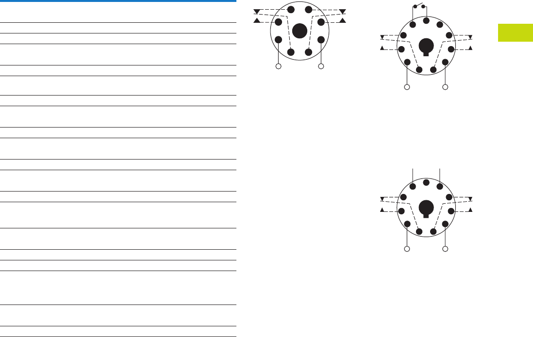
Logic Control Products CA08100001K—June 2012 ww.eatoncanada.ca T40-179
40
40
40
40
40
40
40
40
40
40
40
40
40
40
40
40
40
40
40
40
40
40
40
40
40
40
40
40
40
40
40.8
Control Relays and Timers
Timing Relays
Technical Data and Specifications
TMR5 Time Delay Relays
Description Specification
Voltage tolerance
AC operation +10/–15% of nominal at 50/60 Hz
DC operation +10/–15% of nominal
Load burden 2 VA
Setting accuracy
Maximum setting (adjustable) +5%, –0%
Minimum setting (adjustable) +0%, –50%
Fixed time delay
< 2 seconds +1%
0.1–2 seconds ±5%
Repeat accuracy (constant voltage and temperature)
> 2 seconds delay ±0.1%
0.1–2 seconds delay ±2%
Reset time
ON Delay/interval/repeat cycle 0.1 second
OFF Delay/single shot/watchdog 0.04 second
Startup time (time from when power is applied until unit is timing)
120 and 240V units 0.05 second
12, 24 and 48V units 0.08 second
Maintain function time (time unit
continues to time after power is
removed)
0.01 second
Temperature
12–120V input voltage –18 to 150˚F (–28 to 65˚C)
240V input voltage –18 to 122˚F (–28 to 50˚C)
Insulation voltage 2000V
Output contacts DPDT 10A @ 240 Vac/30 Vdc,
1/2 hp @ 120/240 Vac (NO contacts)
1/3 hp @ 120/240 Vac (NC contacts)
B300 and R300; AC-15 and DC-13
Life
Mechanical 10,000,000 operations
Full load 100,000 operations
Wiring Diagrams
Wiring for 8-Pin Units Wiring for 11-Pin Control
Switch Trigger Units
Wiring for 11-Pin Power
Trigger Units
1
(DC)+
L1
−(DC)
L2
8
Input Voltage
4
36
27
5
1
(DC)+
L1
(DC)−
L2
11
Input Voltage
Control
Switch
48
39
6
210
75
1
(DC)+
L1
(DC)−
L2
−+
11
Input Voltage
* Should Be Same Voltage
as Input Voltage
Power
Trigger *
48
39
6
210
75
Tab40book.fm Page 179 Wednesday, July 4, 2012 10:05 PM

T40-180 Logic Control Products CA08100001K—June 2012 ww.eatoncanada.ca
40
40
40
40
40
40
40
40
40
40
40
40
40
40
40
40
40
40
40
40
40
40
40
40
40
40
40
40
40
40
40.8
Control Relays and Timers
Timing Relays
Dimensions
Approximate Dimensions in Inches (mm)
TMR5
D3PA2 Socket D3PA3 Socket
2.40
(61.0)
Dual Knob
Only
1.70
(43.2)
2.90 (73.7)
3.50 (88.9)
0.97
(24.6)
Max.
0.82 (20.8)
0.58 (14.7)
2.03
(51.6)
Two 0.165
(4.2) Dia.
Slots
2.14
(54.3)
1.60
(40.6)
Max.
1.30
(33.0)
6–32 x 0.312 Combination
Head Screw and Pressure Clamping Plate
(8 places)
Tolerances: ± 0.010
± (0.25)
Unless Otherwise Shown
6–32 x 0.312 Combination
Head Screw and Pressure Clamp
(11 places)
2.05
(52.1)
Max.
2.33 (59.2)
Max.
2.06
(52.3)
0.97
(24.6)
0.77 (19.6)
0.58 (14.7)
0.15 (3.8)
0.13–0.16
(3.2–4.0)
Two 0.17
(4.3) Dia.
Holes
Tolerances: ± 0.010
± (0.25)
Unless Otherwise Shown
Tab40book.fm Page 180 Wednesday, July 4, 2012 10:05 PM
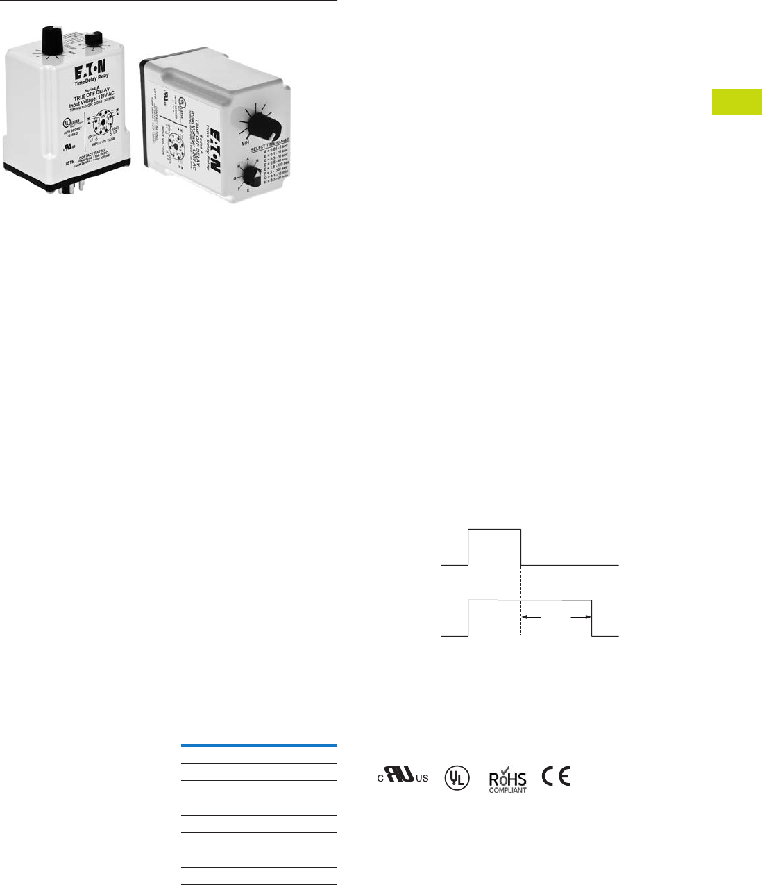
Logic Control Products CA08100001K—June 2012 ww.eatoncanada.ca T40-181
40
40
40
40
40
40
40
40
40
40
40
40
40
40
40
40
40
40
40
40
40
40
40
40
40
40
40
40
40
40
40.8
Control Relays and Timers
Timing Relays
TMR6 Series Contents
Description Page
Universal TR Series . . . . . . . . . . . . . . . . . . . . . . . . . . . T40-170
TR Series . . . . . . . . . . . . . . . . . . . . . . . . . . . . . . . . . . . T40-174
TMR5 Series . . . . . . . . . . . . . . . . . . . . . . . . . . . . . . . . T40-177
TMR6 Series
Catalogue Number Selection . . . . . . . . . . . . . . . . . T40-182
Product Selection . . . . . . . . . . . . . . . . . . . . . . . . . . T40-182
Accessories . . . . . . . . . . . . . . . . . . . . . . . . . . . . . . T40-182
Technical Data and Specifications . . . . . . . . . . . . . T40-182
Wiring Diagram . . . . . . . . . . . . . . . . . . . . . . . . . . . . T40-182
Dimensions . . . . . . . . . . . . . . . . . . . . . . . . . . . . . . T40-182
TMRP Series . . . . . . . . . . . . . . . . . . . . . . . . . . . . . . . . T40-183
E5-248—Battery-Powered LCD Time Control . . . . . . . T40-186
TMR6 Series
Product Description
Most electronic time delay
relays with an OFF delay
function require input voltage
to be applied continuously
in order to operate correctly.
However, there are many
applications where this is
not possible—-keeping a
relay energized for some
amount of time after input
voltage has been removed.
Eaton’s TMR6 true OFF
delay product provides
this function even when
input voltage is removed.
It duplicates the operation
of the older OFF delay
pneumatic time delay relays.
Features
●Provides OFF delay
function without requiring
input voltage during OFF
time delay
●Duplicates operation of
pneumatic OFF delay
timers
●Each unit has eight timing
ranges built in, covering
0.05 seconds to
30 minutes
●Selecting a range is easy
using a rotary switch
(no math is required or
DIP switches to set)
●Uses industry-standard
8-pin octal socket
●10A DPDT output contacts
Timing Ranges
Select one of the eight timing
ranges using the selector
knob, and then adjust the
time within that range for an
accurate delay setting.
Timing Ranges
Dial Setting Timing Range
A 0.05–5 sec.
B 0.1–10 sec.
C 0.3–30 sec.
D 0.6–60 sec.
E 1.8–180 sec.
F 3–300 sec.
G 0.1–10 min.
H 0.3–30 min
Operation
True OFF Delay
Upon application of input
voltage, the relay is
energized. When the input
voltage is removed, the
preset time begins. At the
end of the preset time, the
relay is de-energized.
Voltage must be applied for
a minimum of 0.1 second to
assure proper operation.
Any application of the input
voltage during the preset
time will keep the relay
energized and reset the time
delay. No external trigger
switch is required.
True OFF Delay
Standards and Certifications
●cRUus
●UL listed (with Eaton socket)
●RoHS compliant
●CE marked
Delay
Input
Power
(Voltage)
Output
(Load)
ON
OFF
ON
OFF
with
Eaton
socket
Tab40book.fm Page 181 Wednesday, July 4, 2012 10:05 PM
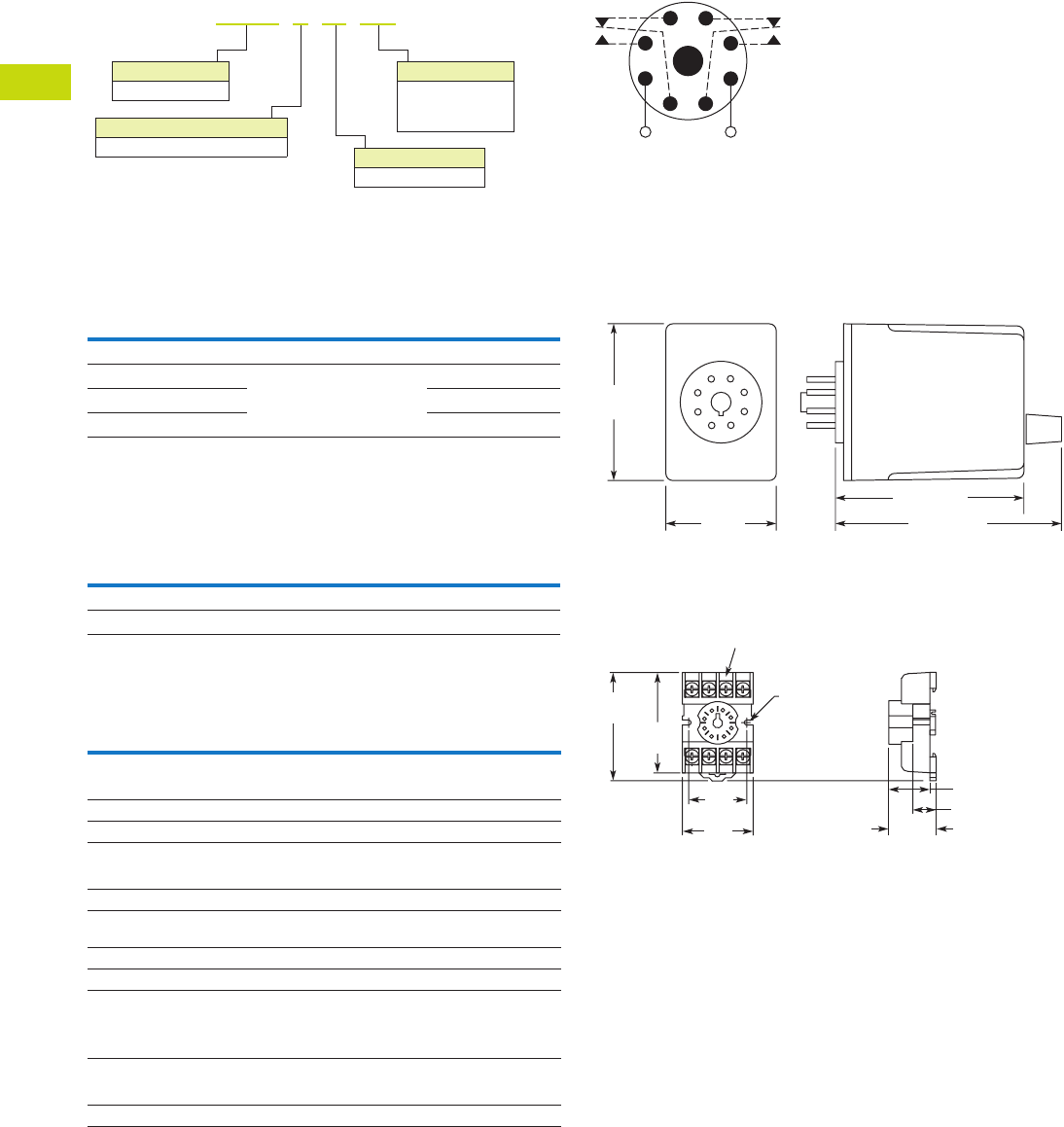
T40-182 Logic Control Products CA08100001K—June 2012 ww.eatoncanada.ca
40
40
40
40
40
40
40
40
40
40
40
40
40
40
40
40
40
40
40
40
40
40
40
40
40
40
40
40
40
40
40.8
Control Relays and Timers
Timing Relays
Catalogue Number Selection
Product Selection
TMR6 True OFF Delay Relays
Accessories
Accessories for Use with TMR6 Time Delay Relays
Technical Data and Specifications
TMR6 Time Delay Relays
Wiring Diagram
Wiring for 8-Pin Units
Dimensions
Approximate Dimensions in Inches (mm)
TMR6
D3PA2 Socket
Input
Voltage
Timing
Range
Catalogue
Number
True OFF Delay
120 Vac/Vdc 0.05 sec–30 min
(user selectable, 8 ranges)
TMR6X00120
24 Vac/Vdc TMR6X0024
240 Vac/Vdc TMR6X00240
Description Standard Pack
Catalogue
Number
8-pin socket 10 D3PA2
Hold-down spring 10 D65CHDS
Description Specification
Voltage tolerance
AC operation +10/–15% of nominal at 50/60 Hz
DC operation +10/–15% of nominal
Load burden 2 VA
Setting accuracy
Maximum setting (adjustable) +5%, –0%
Minimum setting (adjustable) +0%, –50%
Repeat accuracy (constant voltage
and temperature)
±0.1% or 50 ms, whichever is greater
Temperature –18 to 150˚F (–28 to 65˚C)
Insulation voltage 2,000V
Output contacts DPDT 10A @ 240 Vac/30 Vdc,
1/2 hp @ 120/240 Vac (NO contacts)
1/3 hp @ 120/240 Vac (NC contacts)
B300 and R300; AC-15 and DC-13
Life
Mechanical 2,000,000 operations
Full load 100,000 operations
Operational Mode
X= True OFF delay
TMR6 X 00 120
Input Voltage
120 = 120 Vac/Vdc
24 = 24 Vac/Vdc
240 = 240 Vac/Vdc
Timing Range
00 = Programmable
Family Type
TMR6
All configurations from Catalogue Number Selection are availabl
e
1
(DC)+
L1
−(DC)
L2
8
Input Voltage
4
36
27
5
2.40
(61.0)
1.70
(43.2)
2.90 (73.7)
3.50 (88.9)
0.97
(24.6)
Max.
0.82 (20.8)
0.58 (14.7)
2.03
(51.6)
Two 0.165
(4.2) Dia.
Slots
2.14
(54.3)
1.60
(40.6)
Max.
1.30
(33.0)
6–32 x 0.312 Combination
Head Screw and Pressure Clamping Plate
(8 places)
Tolerances: ± 0.010
± (0.25)
Unless Otherwise Shown
Tab40book.fm Page 182 Wednesday, July 4, 2012 10:05 PM
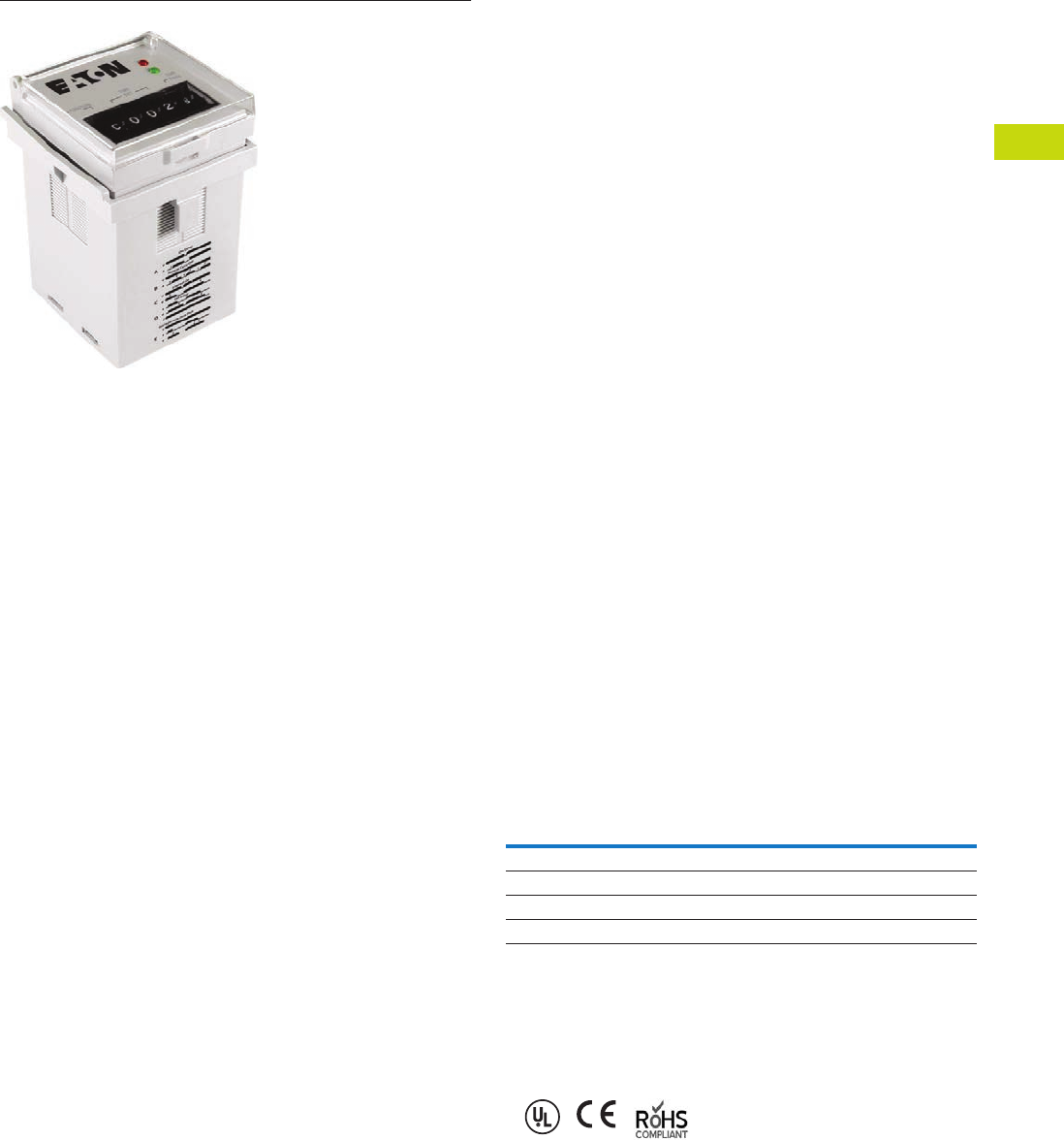
Logic Control Products CA08100001K—June 2012 ww.eatoncanada.ca T40-183
40
40
40
40
40
40
40
40
40
40
40
40
40
40
40
40
40
40
40
40
40
40
40
40
40
40
40
40
40
40
40.8
Control Relays and Timers
Timing Relays
TMRP Series Contents
Description Page
Universal TR Series . . . . . . . . . . . . . . . . . . . . . . . . . . . T40-170
TR Series . . . . . . . . . . . . . . . . . . . . . . . . . . . . . . . . . . . T40-174
TMR5 Series . . . . . . . . . . . . . . . . . . . . . . . . . . . . . . . . T40-177
TMR6 Series . . . . . . . . . . . . . . . . . . . . . . . . . . . . . . . . T40-181
TMRP Series
Product Selection . . . . . . . . . . . . . . . . . . . . . . . . . . T40-184
Technical Data and Specifications . . . . . . . . . . . . . T40-184
Wiring Diagrams . . . . . . . . . . . . . . . . . . . . . . . . . . . T40-185
Dimensions . . . . . . . . . . . . . . . . . . . . . . . . . . . . . . T40-185
E5-248—Battery-Powered LCD Time Control . . . . . . . T40-186
TMRP Series
Product Description
Eaton’s TMRP Series timers
combine flexibility with ease
of use and installation to
make the most versatile
timer in our offering. The
thumb-wheel setting design
allows for quick selection and
review of up to 10 timing
functions and seven timing
ranges. The TMRP units can
be mounted in a 1/16 DIN
cutout or on a DIN rail with
our D3 series sockets. Input
voltage is 12–240 Vac/Vdc to
work with all popular control
voltages.
Application Description
A timing relay is a simple
form of time-based control,
allowing the user to open or
close the contacts based on
a specified timing function.
The TMRP series is equipped
with a set of thumb-wheel
style selector switches, which
can easily be set to a specific
function and time, thereby
reducing the number of
product variations required.
The universal input voltage
of 12–240 Vac/Vdc further
reduces the number of
product variations.
The TMRP timers are ideal
for high-variability operations,
such as systems integrators,
distributors, and small equip-
ment manufacturers. The
flexible enclosure design
allows for back-panel mounting,
through-panel mounting, or
DIN rail mounting.
Features
●Multiple user-selectable
timing functions and timing
ranges in a single unit
reduce product variations
and stock keeping units
(SKUs)
●Universal input voltages
from 12–240 Vac/Vdc
eliminate the need to
order and stock separate
coil voltages
●Timing ranges up to 9990
hours
●Dual LED indication makes
troubleshooting easy
●Flexible design for back-
panel, through-panel
(45 mm x 45 mm cutout),
or DIN rail mounting
●SPDT or DPDT contacts
with 12A ratings
●Plastic dust cover keeps
out contaminants and
eliminates accidental set
point changes
●Use with standard Eaton
D3 sockets—see Technical
Data and Specifications
LED Indicator
Standards and Certifications
●UL recognized
●CE marked
●RoHS compliant
LED Description Function
Solid green “Input” Supply voltage present
Solid red “Output” Relay energized
Slowly flashing red “Output” Timing cycle activated, relay not energized
Rapidly flashing red “Output” Timing cycle activated, relay energized
Tab40book.fm Page 183 Wednesday, July 4, 2012 10:05 PM

T40-184 Logic Control Products CA08100001K—June 2012 ww.eatoncanada.ca
40
40
40
40
40
40
40
40
40
40
40
40
40
40
40
40
40
40
40
40
40
40
40
40
40
40
40
40
40
40
40.8
Control Relays and Timers
Timing Relays
Product Selection
TMRP Timing Relays
Technical Data and Specifications
TMRP Timing Relays
Note
Refer to Function Code Cross-Reference Guide on Page T40-165 for function details.
Supply Voltage Description
Catalogue
Number
10-Function
12–240 Vac/Vdc Control switch trigger, DPDT TMRP5100
Control switch trigger, SPDT TMRP5101
Power trigger, DPDT TMRP5102
TMRP5100
Description TMRP5100 TMRP5101 TMRP5102
Functions A, B, C, D, E, F, G, H, I, J A, B, C, D, E, F, G, H, I, J A, B, C
Time range 0.1 sec to 9,990 hours 0.1 sec to 9,990 hours 0.1 sec to 9,990 hours
Input
Supply voltage 12–240 Vac/Vdc 12–240 Vac/Vdc 12–240 Vac/Vdc
Supply voltage tolerance ±15% ±15% ±15%
Rated consumption 2.5 VA (2W) maximum 2.5 VA (2W) maximum 2.5 VA (2W) maximum
Reset time 150 ms 150 ms 150 ms
Reverse polarity protection Yes Yes Yes
Operate time 25 ms maximum 25 ms maximum 25 ms maximum
Release time 25 ms maximum 25 ms maximum 25 ms maximum
Rated surge voltage 4 kV 4 kV 4 kV
Output
Contact configuration DPDT SPDT DPDT
Contact rating (AC) 12A resistive at 120, 240 UL 508 12A resistive at 120, 240 UL 508 12A resistive at 120, 240 UL 508
Contact rating (DC) 12A resistive at 30 UL 508 12A resistive at 30 UL 508 12A resistive at 30 UL 508
Contact rating horsepower 1/2 at 120 Vac, 1 at 240 Vac 1/2 at 120 Vac, 1 at 240 Vac 1/2 at 120 Vac, 1 at 240 Vac
Contact rating pilot duty A300, 720 VA at 240 Vac A300, 720 VA at 240 Vac A300, 720 VA at 240 Vac
Minimum load 12V/100 mA 12V/100 mA 12V/100 mA
Contact material Silver-nickel 90/10 Silver-nickel 90/10 Silver-nickel 90/10
Contact resistance 100 milliohms max. at 1A 12 Vdc 100 milliohms max. at 1A 12 Vdc 100 milliohms max. at 1A 12 Vdc
Mechanical life—full load 10 million operations 10 million operations 10 million operations
Electrical life—full load 100,000 operations 100,000 operations 100,000 operations
Control Signal
Minimum control pulse length 50 ms minimum 50 ms minimum 50 ms minimum
Accuracy
Repetition accuracy 0.10% at constant voltage and temperature 0.10% at constant voltage and temperature 0.10% at constant voltage and temperature
Physical
Ambient temperature –10 to 55˚C –10 to 55˚C –10 to 55˚C
Storage temperature –40 to 85˚C –40 to 85˚C –40 to 85˚C
Mounting Use with D3PA3 socket Use with D3PA2 socket Use with D3PA2 socket
Tab40book.fm Page 184 Wednesday, July 4, 2012 10:05 PM
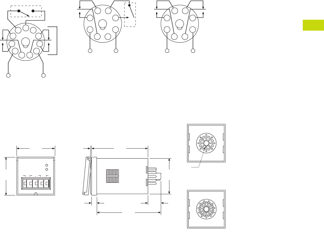
Logic Control Products CA08100001K—June 2012 ww.eatoncanada.ca T40-185
40
40
40
40
40
40
40
40
40
40
40
40
40
40
40
40
40
40
40
40
40
40
40
40
40
40
40
40
40
40
40.8
Control Relays and Timers
Timing Relays
Wiring Diagrams
TMRP5100 TMRP5101 TMRP5102
Dimensions
Approximate Dimensions in Inches (mm)
TMRP Series
External Control Switch
Instant if 6–7 Shorted
INPUT
5
111
2
3
4
67
8
9
10
External Control Switch
INPUT
4
1
2
3
5
8
7
6
INPUT
4
1
2
3
5
8
7
6
0.06
(1.5)
1.88
(47.8)
1.88
(47.8)
FUNCTION
A 0 0 0 S
TIME
SET
TIME
BASE
OUTPUT
INPUT
2.83
(71.9)
1.76
(44.7)
0.25
(6.4)
0.64
(16.3)
3.15
(80.0)
1
2
3
4
5
6
7
8
R.045
8-Pin Octal Base
1
2
3
4
5
6
7
8
11-Pin Octal Base
9
10
11
Tab40book.fm Page 185 Wednesday, July 4, 2012 10:05 PM
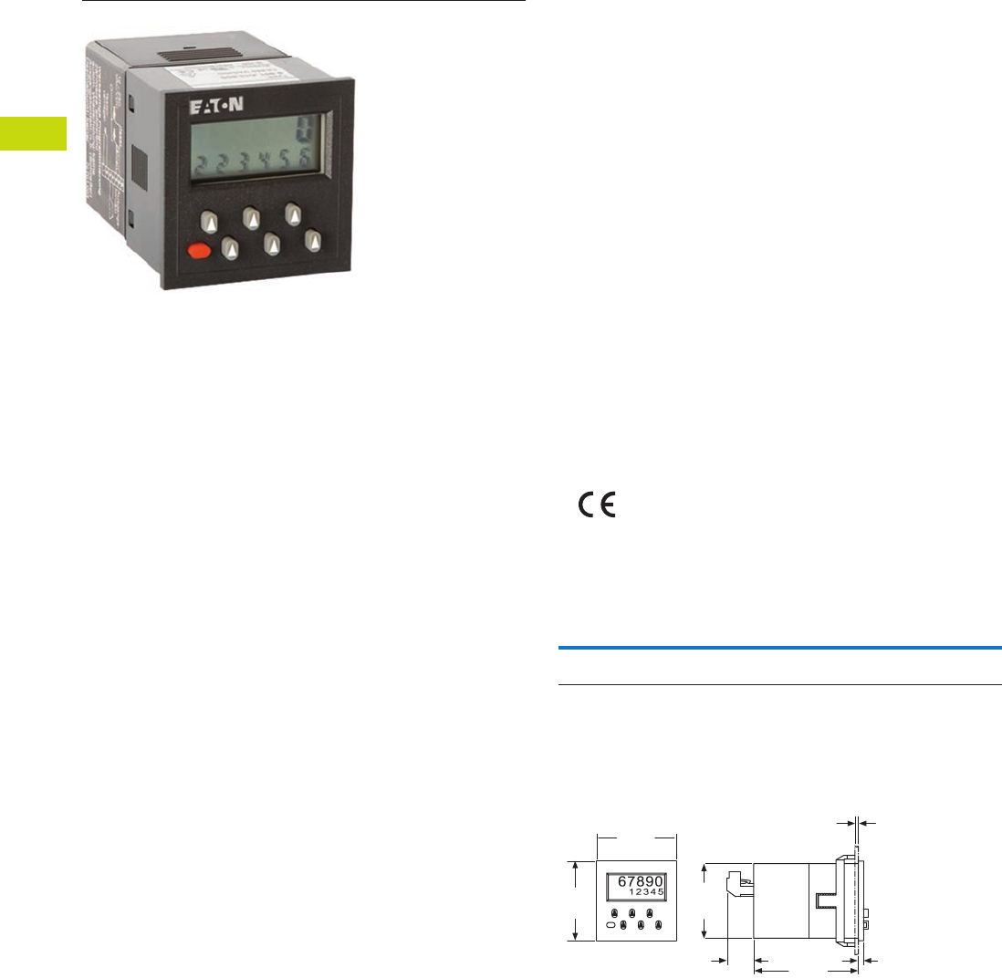
T40-186 Logic Control Products CA08100001K—June 2012 ww.eatoncanada.ca
40
40
40
40
40
40
40
40
40
40
40
40
40
40
40
40
40
40
40
40
40
40
40
40
40
40
40
40
40
40
40.8
Control Relays and Timers
Timing Relays
E5-248—Battery-Powered LCD Time Control Contents
Description Page
Universal TR Series . . . . . . . . . . . . . . . . . . . . . . . . . . . T40-170
TR Series . . . . . . . . . . . . . . . . . . . . . . . . . . . . . . . . . . . T40-174
TMR5 Series . . . . . . . . . . . . . . . . . . . . . . . . . . . . . . . . T40-177
TMR6 Series . . . . . . . . . . . . . . . . . . . . . . . . . . . . . . . . T40-181
TMRP Series . . . . . . . . . . . . . . . . . . . . . . . . . . . . . . . . T40-183
E5-248—Battery-Powered LCD Time Control
Product Selection . . . . . . . . . . . . . . . . . . . . . . . . . . T40-186
Dimensions . . . . . . . . . . . . . . . . . . . . . . . . . . . . . . T40-186
E5-248—Battery-Powered LCD Time Control
Product Description
The E5-248-C1420 is an
advanced timing relay
capable of performing a wide
variety of timing functions
without the need for external
power. The through-panel
mount design and LCD
display allow easy access
for set-point and function
changes. Programmable
activation modes effectively
triple the functionality, and
the relay can be configured
for normally open or normally
closed operation.
Features
●No external voltage supply,
because of internal
replaceable lithium battery
●High contrast, 2-line LCD
display, 5-digit with many
symbols for easy operation
and reading
●Nine programmable time
ranges from 0.20 seconds
up to 99.999 hours
●Resolution up to 0.01
seconds
●Inputs for start and
reset; universal inputs for
12–260 Vac/Vdc
●Eight timing modes—
●ON Delay, OFF Delay,
One Shot and Single
Shot
●Repeat cycle modes:
Delay, Cycle,
Symmetrical delay
●Three programmable
activation modes
●Relay contacts rated at
8A programmable to
NO or NC
●Protection IP65
●Plug-in connector
Standards and Certifications
●CE marked
Product Selection
Battery-Powered LCD Time Control
Dimensions
Approximate Dimensions in Inches (mm)
Battery-Powered LCD Time Control
Panel cutout is 1.77 + 0.02 in sq. (45 + 0.6 mm sq.).
Description
Catalogue
Number
Battery-powered LCD time control,
1.89 x 1.89 in (48.0 x 48.0 mm)
E5-248-C1420
1.89
(48.0)
1.89
(48.0)
1.77
(45.0)
0.63
(16.0) 2.49
(63.2)
0.12
(3.0)
0.41 (10.5) Max.;
0.37 (9.5)
at Front Panel
Tab40book.fm Page 186 Wednesday, July 4, 2012 10:05 PM
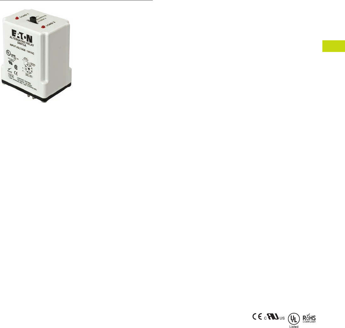
Logic Control Products CA08100001K—June 2012 www.eatoncanada.ca T40-187
40
40
40
40
40
40
40
40
40
40
40
40
40
40
40
40
40
40
40
40
40
40
40
40
40
40
40
40
40
40
40.9
Control Relays and Timers
Alternating Relays
D85 Series—Alternating Relays Contents
Description Page
D85 Series—Alternating Relays
Product Selection . . . . . . . . . . . . . . . . . . . . . . . . . . T40-188
Accessories . . . . . . . . . . . . . . . . . . . . . . . . . . . . . . T40-188
Technical Data and Specifications . . . . . . . . . . . . . T40-189
Wiring Diagrams . . . . . . . . . . . . . . . . . . . . . . . . . . . T40-189
Dimensions . . . . . . . . . . . . . . . . . . . . . . . . . . . . . . T40-191
Product Description
Alternating relays are used
in applications where the
optimization of load usage is
required by equalizing the run
time of two loads. They are
also used where additional
capacity is required in case
of excess load requirements.
This alternating action is
initiated by a control switch—
such as a float switch, manual
switch, timing relay, pressure
switch or other isolated
contact. Each time the
initiating switch is opened,
the output relay contacts will
change state, thus alternating
the two loads. Two LED
indicators show the status of
the output relay.
The D851 and D852 Series
Relays are used with one
control switch and are
available in either SPDT or
DPDT output configurations
with or without a selector
switch to lock in one
sequence. The D852X Series
Relays are available in DPDT
cross-wired output
configurations for use with
one or two control switches
(LEAD and LAG).
The D853 Series is designed
for use with three-switch
applications (LEAD, LAG and
STOP). The D853 Series
combines a standard DPDT
Cross-Wired alternating relay,
contactor auxiliary contacts,
and a control relay into one
compact and economical
product. This saves space
and labor, while reducing the
number of components
needed. The D853 Series
uses Sequence On–
Simultaneous Off (S.O.S.O.)
operation, where the two
loads are energized
sequentially, but remain on
together until the STOP
switch is opened. This device
also protects against failure
of the STOP and LEAD
switches. If both switches
fail, the two pump motors will
be energized simultaneously
when the LAG switch is
closed.
Each of the D85 Series
alternating relays is available
with an optional three-
position selector switch,
which allows the unit to
alternate the two loads as
normal, or lock the relay to
one load or the other. By
locking the alternating relay
to one load, the other load
can be removed for service
without rewiring the first load
for continuous operation. The
selector switch has a low
profile to prevent any
accidental actuation.
Features
●For duplex loads
●Works with one-, two-, or
three-switch applications
●Compact plug-in design
using industry standard
sockets
●10A SPDT or DPDT output
configurations
●Optional low profile
selector switch to lock in
one sequence
●Two LEDs indicate relay
status
●D853 Series replaces
separate components in
duplex panel—saving
space and reducing labor
Standards and
Certifications
●CE
●cRUus
●UL listed
●RoHS compliant
Note
When used with appropriate Eaton
socket.
Tab40book.fm Page 187 Wednesday, July 4, 2012 10:05 PM

T40-188 Logic Control Products CA08100001K—June 2012 www.eatoncanada.ca
40
40
40
40
40
40
40
40
40
40
40
40
40
40
40
40
40
40
40
40
40
40
40
40
40
40
40
40
40
40
40.9
Control Relays and Timers
Alternating Relays
Product Selection
D85 Series—Alternating Relays
Accessories
D85 Series—Alternating Relays
Note
Contact Eaton for relays for 3-switch applications (Lead-Lag-Stop).
Output Contacts
Control
Voltage Socket
Catalogue
Number
SPDT 12 Vac 8-pin D851NR
SPDT 24 Vac 8-pin D851NT
SPDT 120 Vac 8-pin D851NA
SPDT 240 Vac 8-pin D851NB
SPDT w/selector switch 12 Vac 8-pin D851LR
SPDT w/selector switch 24 Vac 8-pin D851LT
SPDT w/selector switch 120 Vac 8-pin D851LA
SPDT w/selector switch 240 Vac 8-pin D851LB
DPDT 12 Vac 11-pin D852NR
DPDT 24 Vac 11-pin D852NT
DPDT 120 Vac 11-pin D852NA
DPDT 240 Vac 11-pin D852NB
DPDT w/selector switch 12 Vac 11-pin D852LR
DPDT w/selector switch 24 Vac 11-pin D852LT
DPDT w/selector switch 120 Vac 11-pin D852LA
DPDT w/selector switch 240 Vac 11-pin D852LB
DPDT cross-wired 12 Vac 8-pin D852XNR
DPDT cross-wired 24 Vac 8-pin D852XNT
DPDT cross-wired 120 Vac 8-pin D852XNA
DPDT cross-wired 240 Vac 8-pin D852XNB
DPDT cross-wired w/selector switch 12 Vac 8-pin D852XLR
DPDT cross-wired w/selector switch 24 Vac 8-pin D852XLT
DPDT cross-wired w/selector switch 120 Vac 8-pin D852XLA
DPDT cross-wired w/selector switch 240 Vac 8-pin D852XLB
Description
Standard
Pack
Catalogue
Number
8-pin socket 10 D3PA2
11-pin socket 10 D3PA3-A2
Hold-down spring 10 D65CHDS
Tab40book.fm Page 188 Wednesday, July 4, 2012 10:05 PM
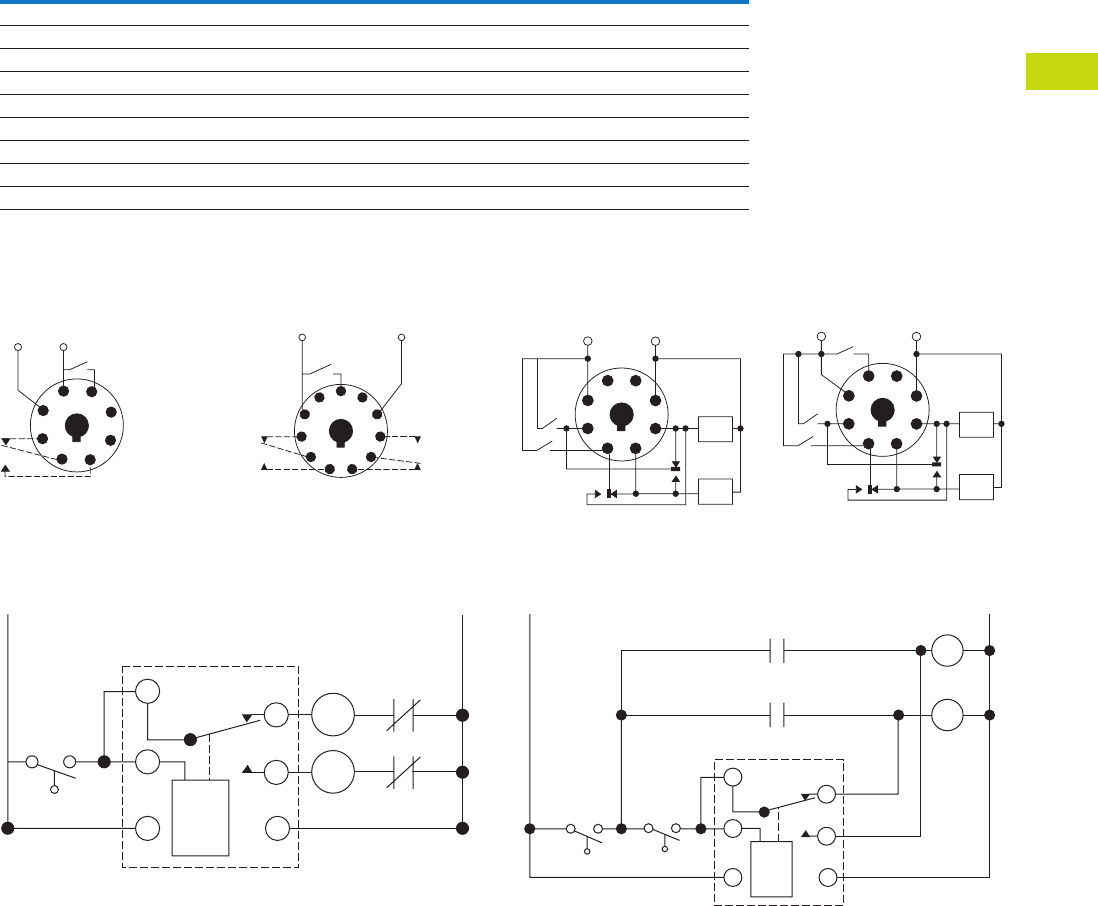
Logic Control Products CA08100001K—June 2012 www.eatoncanada.ca T40-189
40
40
40
40
40
40
40
40
40
40
40
40
40
40
40
40
40
40
40
40
40
40
40
40
40
40
40
40
40
40
40.9
Control Relays and Timers
Alternating Relays
Technical Data and Specifications
D85 Series—Alternating Relays
Wiring Diagrams
D851 Series Relays, SPDT D852 Series Relays, DPDT
Typical Installations for SPDT and DPDT Alternating Relays,
Standard Installation
In the OFF state (standard
installation), the control
switch is open, the
alternating relay is in the
LOAD A position, and both
loads (M1 and M2) are off.
When the control switch
closes, it energizes the first
load (M1). The red LED
marked “LOAD A” glows. As
long as the control switch
remains closed, M1 remains
energized.
When the control switch
opens, the first load (M1) is
turned off and the alternating
relay toggles to the LOAD B
position. When the control
switch closes again, it
energizes the second load
(M2). The red LED marked
“LOAD B” glows.
Description Specification
Voltage tolerance +10%/-15% of control voltage at 50/60 Hz
Load (burden) Less than 3 VA
Output contacts 10A resistive at 240 Vac / 30 Vdc, 1/2 hp at 120/240 Vac (NO), 1/3 hp at 120/240 Vac (NC)
Mechanical life 10,000,000 operations
Electrical life 100,000 operations
Temperature –20˚ to 150˚F (–28˚ to 65˚C)
Transient protection 10,000 volts for 20 microseconds
Indicator LEDs 2 LEDs marked LOAD A and LOAD B
Optional selector switch settings ALTERNATE, LOCK LOAD A, LOCK LOAD B
Load A: Pin 2
Load B: Pin 8
1
4
Input
Voltage
Control
Switch
L2 L1
36
27
8
5
1
Load A: Pins 3 or 11
Load B: Pins 1 or 9
L2L1
11
Input
Voltage
Control
Switch
48
39
6
210
75
L1
SPDT
Control
Switch
O/L
O/L
1
2
8
3
4
5
L2
M1
M2
D852X Series Relays,
DPDT Cross-Wired
D853 Series Relays,
Three-Switch Applications
Typical Installations for SPDT and DPDT Alternating Relays,
Anti-Bounce Installation
When the control switch
opens, the second load (M2)
is turned off, the alternating
relay toggles back to the
LOAD A position, and the
process can be repeated
again. On relays with DPDT
contacts, two pilot lights can
be used for remote indication
of LOAD A or LOAD B status.
To eliminate any bounce
condition of the control
switch, the addition of a
second switch (OFF) along
with two auxiliary contacts is
recommended as shown in
the Anti-Bounce Installation.
1
Lead
Lag
Load
B
Load
A
L1 L2
8
Input
Voltage
4
36
27
5
1
Lead
Lag
Load
B
Load
A
L1 L2
Stop
8
Input Voltage
4
36
27
5
SPDT
Control
Switch
L1
1
2
3
4
5
Off
M1
M1
M2
L2
M2
8
Tab40book.fm Page 189 Wednesday, July 4, 2012 10:05 PM
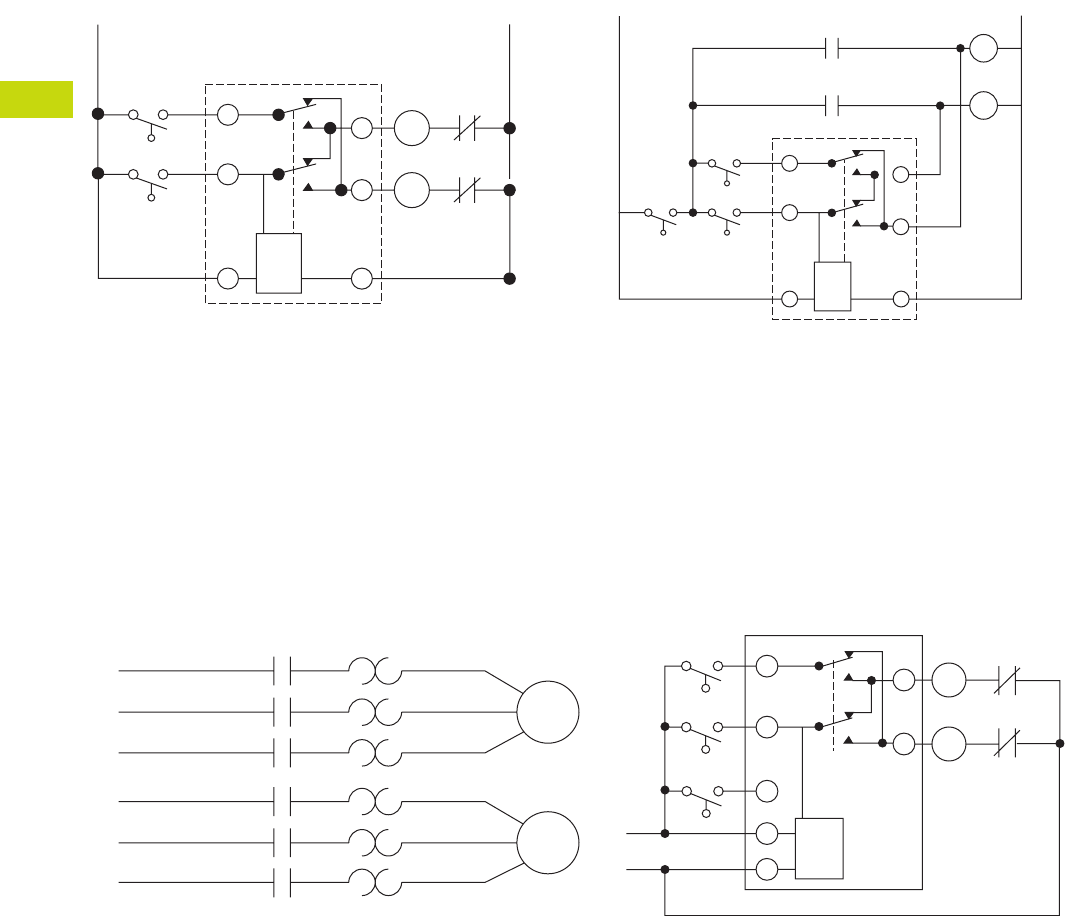
T40-190 Logic Control Products CA08100001K—June 2012 www.eatoncanada.ca
40
40
40
40
40
40
40
40
40
40
40
40
40
40
40
40
40
40
40
40
40
40
40
40
40
40
40
40
40
40
40.9
Control Relays and Timers
Alternating Relays
Typical Installations for DPDT Cross-Wired Alternating
Relays, Standard Installation
In the OFF state, both the LEAD control switch and the LAG
control switch are open, the alternating relay is in the LOAD A
position, and both loads are off. When the LEAD control switch
closes, it energizes the first load (M1). The red LED marked
“LOAD A” glows. As long as the LEAD control switch remains
closed, M1 remains energized. If the LAG control switch closes,
it energizes the second load (M2).
When the LAG control switch opens, the second load (M2) is
turned off. When the LEAD control switch opens, the first load
(M1) is turned off and the alternating relay toggles to the LOAD
B position.
Typical Installations for DPDT Cross-Wired Alternating
Relays, Anti-Bounce Installation
When the LEAD control switch closes, it turns on the second
load (M2). The red LED marked “LOAD B” glows. If the LAG
control switch closes, it will energize the first load (M1). When
the LAG control switch opens, the first load (M1) is turned off.
When the LEAD control switch opens, the second load (M2) is
turned off, the alternating relay toggles back to the LOAD A
position, and the process can be repeated again.
To eliminate any bounce condition of the control switch, the
addition of a second switch (OFF) along with two auxiliary
contacts is recommended as shown in the Anti-Bounce
Installation.
Typical Installations for DPDT Cross-Wired Relays for Three-Switch Applications
In the OFF state, all three switches are open, the alternating relay
is in the LOAD A position, and both loads are off. No action
happens with the alternating relay or either load when the STOP
switch closes. When the LEAD switch closes, Load #1 (M1) turns
on. When the LAG switch closes, Load #2 (M2) turns on. Both
loads remain on as long as all three switches are closed.
When the LAG switch opens, Load #2 (M2) remains on because
the STOP switch is still closed. When the LEAD switch opens,
Load #1 (M1) remains on because the STOP switch is still
closed. When the STOP switch opens, both Load #1 (M1) and
Load #2 (M2) are turned off simultaneously.
The alternating relay toggles to the LOAD B position. The entire
cycle is then repeated, but with Load #2 (M2) energized first
followed by Load #1 (M1). This type of operation is known as
“Sequence On–Simultaneously Off (S.O.S.O.)”—the two loads
are energized sequentially, but remain on together until the
STOP switch is opened.
If both the STOP switch and LEAD switch fail to close and turn
on the first load, both loads will be turned on simultaneously
when the LAG switch is closed.
L1
Lag
Lead
Cross-Wired
O/L
O/L
1
2
8
3
7
6
L2
M1
M2
Lag
Off Lead
L2
L1
M1
Cross-Wired
M2
1
2
3
7
6
M1
M2
8
L1
Motor
1
Motor
2
L2
L3
L1
M1
M1
M1
M2
M2
M2
M2
M1
L2 L1
Lag
Switch
Lead
Switch
Stop
Switch
L2
L3
1
2
4
8
7
3
6
O/L
O/L
Tab40book.fm Page 190 Wednesday, July 4, 2012 10:05 PM
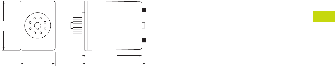
Logic Control Products CA08100001K—June 2012 www.eatoncanada.ca T40-191
40
40
40
40
40
40
40
40
40
40
40
40
40
40
40
40
40
40
40
40
40
40
40
40
40
40
40
40
40
40
40.9
Control Relays and Timers
Alternating Relays
Dimensions
Approximate Dimensions in Inches (mm)
D85 Series—Alternating Relays
2.4
(60)
1.7
(43)
2.9
(74) 3.1
(79)
Tab40book.fm Page 191 Wednesday, July 4, 2012 10:05 PM
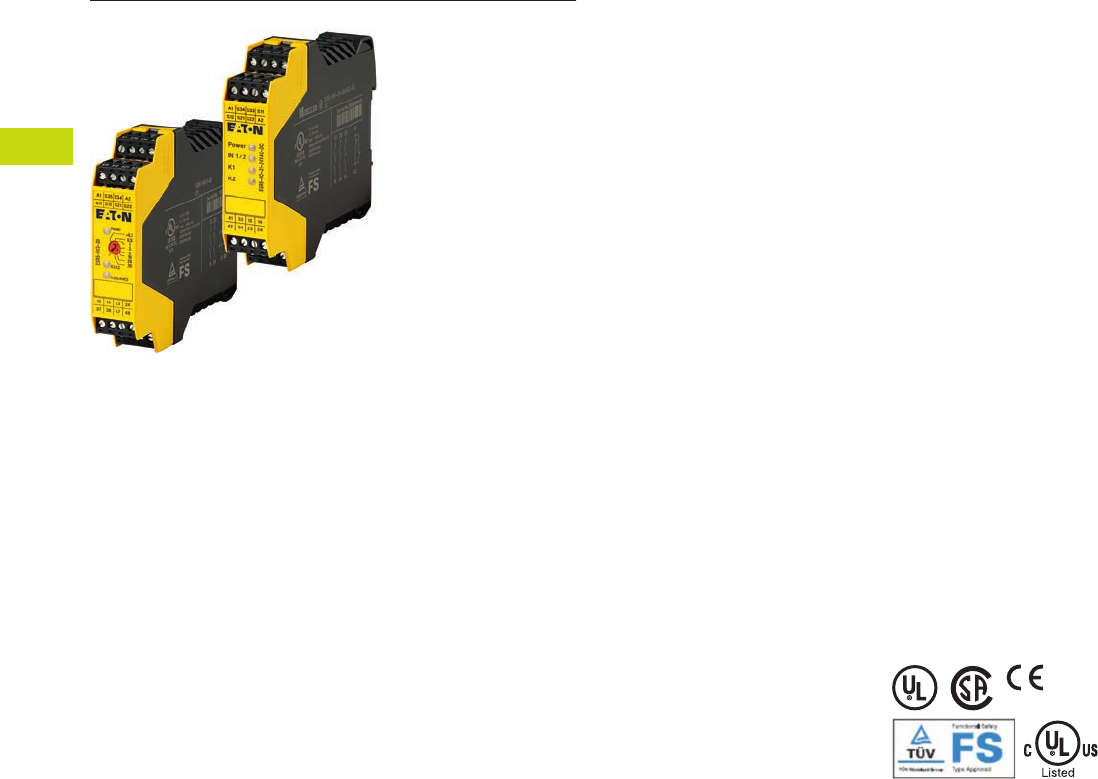
T40-192 Logic Control Products CA08100001K—June 2012 www.eatoncanada.ca
40
40
40
40
40
40
40
40
40
40
40
40
40
40
40
40
40
40
40
40
40
40
40
40
40
40
40
40
40
40
40.10
Control Relays and Timers
Safety Relays
Safety Relays Contents
Description Page
Safety Relays
Product Selection . . . . . . . . . . . . . . . . . . . . . . . . . . T40-193
Technical Data and Specifications . . . . . . . . . . . . . T40-194
Dimensions . . . . . . . . . . . . . . . . . . . . . . . . . . . . . . T40-197
Product Description
Safety relays are intended to
reliably monitor the signals
from safety devices at all
times and switch off quickly
and reliably in an emergency.
Single-channel and dual
channel versions are available
for the construction of safety
applications. The internal
logic of the safety relays
monitors the safety circuits
(emergency stop, guard door,
and so on) and activates the
enable paths in a fault-free
condition. Upon actuation of
the safety device or in the
event of a fault, the enable
paths are switched off. Any
faults that occur in the control
circuit, such as ground fault,
cross connection fault or wire
breakage are also detected.
Application Description
Eaton’s ESR5 safety relays
provide optimal safety and a
high degree of reliability on
plant machinery. Applications
that meet the highest
safety requirements in
accordance with EN 954-1,
EN ISO 13849-1 up to PL e
and accordance with
IEC 62061 up to SILCL 3
can be realized with the
ESR5 safety relay.
Compatible with a wide
variety of safety devices:
●Emergency stops
●Rope pulls
●Two-hand control stations
●Light curtain (OSSD)
●Gate enable device
●Safety switches
Features
●Use for the highest
safety requirements in
accordance with EN 954-1
EN ISO 13849-1,
IEC 62061 and EC 61508
●Suitable for the world
market with UL, cUL
certifications and TÜV
Rhineland functional
safety certifications
●Applicable for EN 60204
stop categories 0 or 1
●Plug-in screw terminals
for fast and fault-free
replacement
●Multi-voltage versions
(24–230 Vac/Vdc) for a
flexible range of application
●Delayed and non-delayed
contact expansions
accommodate a wide
variety of applications
Standards and
Certifications
●UL 508; CSA-C22.2 No
14-95; CE Marked
●UL/cUL file number:
E29184
●Degree of protection: IP20
●TÜV Rhineland certified
●UL/cULus listed
Tab40book.fm Page 192 Wednesday, July 4, 2012 10:05 PM
Logic Control Products CA08100001K—June 2012 www.eatoncanada.ca T40-193
40
40
40
40
40
40
40
40
40
40
40
40
40
40
40
40
40
40
40
40
40
40
40
40
40
40
40
40
40
40
40.10
Control Relays and Timers
Safety Relays
Product Selection
Technical Overview
Application Overview
Application Overview, continued
Notes
Laser scanners or light curtains with OSSD outputs.
All main units can also be reset automatically or manually.
Single
Channel
Dual
Channel
Safety
Output (NO)
Safety
Output (NO)
(Delayed)
Output
Delay
Signal
Output
(NC)
Feedback
Output
Control
Voltage
Removable
Terminal
Blocks
Type of
Unit Catalogue Number
■ — 4 — — 1 — 24 Vac/Vdc ■ Main ESR5-NO-41-24VAC-DC
■ ■ 2 — — 1 — 24 Vac/Vdc ■ Main ESR5-NO-21-24VAC-DC
■ ■ 3 — — 1 — 24 Vac/Vdc ■ Main ESR5-NO-31-24VAC-DC
■ ■ 3 — — 1 — 230 Vac ■ Main ESR5-NO-31-230VAC
■ ■ 3 — — 1 — 24–230 Vac/Vdc ■ Main ESR5-NO-31-AC-DC
■ ■ 2 2 0.1–30s — — 24 Vdc ■ Main ESR5-NV3-30
—■ 2 — — 1 — 24 Vac/Vdc ■ Main ESR5-NZ-21-24VAC-DC
■ — 5 — — 1 1 24 Vac/Vdc ■ Expansion ESR5-NE-51-24VAC-DC
■ — — 4 0.3–3s 1 1 24 Vdc ■ Expansion ESR5-VE3-42
Emergency
Stop
Safety
Switches
Light Curtain/
OSSD
Two-Hand Control
(EN 574 Type III C)
Contact
Expansion Off-Delayed
Cross Circuit
Recognition
Monitored
Manual Reset Catalogue Number
■ ■ —— ——— — ESR5-NO-41-24VAC-DC
■ ■ —— ——■ — ESR5-NO-21-24VAC-DC
■ ■ —— ——■ — ESR5-NO-31-24VAC-DC
■ ■ —— ——■ ■ ESR5-NO-31-230VAC
■ ■ —— ——■ ■ ESR5-NO-31-AC-DC
■ ■ ■ ——■ ■ ■ ESR5-NV3-30
—■ — ■ —— ■ — ESR5-NZ-21-24VAC-DC
——— — ■ —— — ESR5-NE-51-24VAC-DC
——— — ■ ■ —— ESR5-VE3-42
Single
Channel
Dual
Channel
Stop Category
EN 60204
Control Category
to EN 954-1
Achievable PL per
ISO 13849-1
Achievable SIL per
EN IEC 62061 Catalogue Number
■ — 0 2 PL d SIL 3 ESR5-NO-41-24VAC-DC
■ ■ 0 4 PL e SIL 3 ESR5-NO-21-24VAC-DC
■ ■ 0 4 PL e SIL 3 ESR5-NO-31-24VAC-DC
■ ■ 0 4 PL e SIL 3 ESR5-NO-31-230VAC
■ ■ 0 4 PL e SIL 3 ESR5-NO-31-AC-DC
■ ■ 0/1 4 PL e SIL 3 ESR5-NV3-30
—■ 0 4 PL e SIL 3 ESR5-NZ-21-24VAC-DC
■ — 0 4 PL e SIL 3 ESR5-NE-51-24VAC-DC
■ — 1 3 PL d SIL 2 ESR5-VE3-42
Safety Relays
Tab40book.fm Page 193 Wednesday, July 4, 2012 10:05 PM

T40-194 Logic Control Products CA08100001K—June 2012 www.eatoncanada.ca
40
40
40
40
40
40
40
40
40
40
40
40
40
40
40
40
40
40
40
40
40
40
40
40
40
40
40
40
40
40
40.10
Control Relays and Timers
Safety Relays
Technical Data and Specifications
Safety Relay
Description Unit ESR5-NO-21_ ESR5-NO-41_ ESR5-NO-31-24VAC-DC ESR5-NZ-21_
General
Standards EN ISO 13849-1, IEC 62061,
IEC 61508, DIN EN 50178,
UL/CUL listed
EN ISO 13849-1, IEC 62061,
IEC 61508, DIN EN 50178,
UL/CUL listed
EN ISO 13849-1, IEC 62061,
IEC 61508, DIN EN 50178,
UL/CUL listed
EN ISO 13849-1, IEC 62061,
IEC 61508, DIN EN 50178,
UL/CUL listed
Type-dependent standards — — — EN 574 Part no. IIIC
Lifespan, mechanical—c (contacts) x 10610 10 10 10
Maximum operating frequency Ops/h 3600 3600 3600 3600
Climatic proofing Cold according to
EN 60068-2-1, dry heat
according to EN60068-2-2,
damp heat according to
EN 60068-2-3
Dry heat according to
EN60068-2-2, damp heat
according to EN 60068-2-3
Cold according to
EN 60068-2-1, dry heat
according to EN60068-2-2,
damp heat according to
EN 60068-2-3
Dry heat according to
EN60068-2-2, damp heat
according to EN 60068-2-3
Ambient temperature ˚F (˚C) –4˚ to 131˚ (–20˚ to 55˚) –4˚ to 131˚ (–20˚ to 55˚) –4˚ to 131˚ (–20˚ to 55˚) –4˚ to 131˚ (–20˚ to 55˚)
Ambient temperature storage ˚F (˚C) –13˚ to 167˚ (–25˚ to 75˚) –13˚ to 167˚ (–25˚ to 75˚) –13˚ to 167˚ (–25˚ to 75˚) –13˚ to 167˚ (–25˚ to 75˚)
Mounting position Any Any Any Any
Vibration resistance (IEC/EN 60068-2-6) 2g, frequency: 10–150 Hz,
amplitude: 0.15 mm
2g, frequency: 10–150 Hz,
amplitude: 0.15 mm
2g, frequency: 10–150 Hz,
amplitude: 0.15 mm
2 g, frequency: 10–150 Hz,
amplitude: 0.15 mm
Shock resistance (IEC 60068-2-27) ————
Protection type
Housing IP20 IP20 IP20 IP20
Terminals IP20 IP20 IP20 IP20
Protection against direct contact when
actuated from front (IEC 0106 Part 100)
Finger- and back-of-hand
proof
Finger- and back-of-hand
proof
Finger- and back-of-hand
proof
Finger- and back-of-hand
proof
Weight kg 0.17 0.22 0.17 0.22
Terminal capacity
Solid or flexible mm21 x (0.2–2.5)
2 x (0.2–1)
1 x (0.2–2.5)
2 x (0.2–1)
1 x (0.2–2.5)
2 x (0.2–1)
1 x (0.2–2.5)
2 x (0.2–1)
Flexible with ferrule mm21 x (0.25–2.5)
2 x (0.25–1)
1 x (0.25–2.5)
2 x (0.25–1)
1 x (0.25–2.5)
2 x (0.25–1)
1 x (0.25–2.5)
2 x (0.25–1)
Solid or stranded AWG 24–12 24–12 24–12 24–12
Terminal screw
Pozidriv screwdriver Size 2 2 2 2
Flat-blade screwdriver mm 0.6 x 3.5 0.6 x 3.5 0.6 x 3.5 0.6 x 3.5
Max. tightening torque Nm 0.6 0.6 0.6 0.6
Main Contacts
Rated impulse withstand voltage—Uimp Vac 6000 4000 4000 6000
Overvoltage category/pollution degree
Outside III/2 III/2 III/2 III/2
Inside ————
Rated insulation voltage—UiVac 250 250 250 250
Rated operating voltage—UeVac 230 230 230 230
Rated operation current
AC-15
230V (360 ops./h)—IeA5454
230V (3600 ops./h)—IeA3333
DC-13
24V (360 ops./h)—IeA6464
24V (3600 ops./h)—IeA 3 2.5 3 2.5
Max. summation current of all poles
24 Vac/Vdc devices A 72 72 72 72
230 Vac devices A ————
Square of the total current
(and total current)
of all current paths
72 A2 (6 + 6) 72 A2 (4.2 + 4.2 + 4.2 + 4.2) 72 A2 (4.9 + 4.9 + 4.9) 72 A2 (6 + 6)
Short-circuit protection
Max. fuse A gG/gL 10 6 10 6
Tab40book.fm Page 194 Wednesday, July 4, 2012 10:05 PM

Logic Control Products CA08100001K—June 2012 www.eatoncanada.ca T40-195
40
40
40
40
40
40
40
40
40
40
40
40
40
40
40
40
40
40
40
40
40
40
40
40
40
40
40
40
40
40
40.10
Control Relays and Timers
Safety Relays
Safety Relay, continued
Description Unit ESR5-NO-21_ ESR5-NO-41_ ESR5-NO-31-24VAC-DC ESR5-NZ-21_
Power Supply Circuit
Actuating voltage 50/60 Hz Vac 24 24 24 24
Actuating voltage—UsVdc 24 24 24 24
Voltage tolerance pick-up voltage x e0.85–1.1 0.85–1.1 0.85–1.1 0.85–1.1
Power consumption
AC operated 50/60 Hz VA ————
AC operated 50/60 Hz W 3.4 3.4 3.4 3
DC operated W 1.6 1.6 1.6 1.5
Fuse for control circuit supply
24V Short-circuit proof Short-circuit proof Short-circuit proof Short-circuit proof
115/230V ————
Control Circuit
Rated output voltage Vdc 24 24 24 24
Rated operational current mA S12, S22: 30, S34: 45 S12: 65, S34: 40 S12, S22: 30, S34: 45 S11, S21: 60, Y2: 45
Resistance—R 50 22 50 22
Short-circuit current A 2.3 2.3 2.3 2.3
Response time ms 100 65 100 50
Recovery time ms ————
Response time with reset monitoring—tA1 ms————
Response time without reset monitoring—tA2 ms 100 65 100 50
Reset time—tR/tR1 ms Single-channel 45;
dual-channel 10
45 Single-channel 45;
dual-channel 10
20
Minimum on duration—tMms————
Recovery time—tWms Approx. 1000 Approx. 1000 Approx. 1000 Approx. 1000
Synchronous monitoring time—tSms — — — 500
Electromagnetic Compatibility (EMC)
Emitted interference EN 61000-6-4 EN 61000-6-4 EN 61000-6-4 EN 61000-6-4
Interference immunity According to EN 61000-6-2,
EN 62061
According to EN 61000-6-2 According to EN 61000-6-2,
EN 62061
According to EN 61000-6-2
Tab40book.fm Page 195 Wednesday, July 4, 2012 10:05 PM

T40-196 Logic Control Products CA08100001K—June 2012 www.eatoncanada.ca
40
40
40
40
40
40
40
40
40
40
40
40
40
40
40
40
40
40
40
40
40
40
40
40
40
40
40
40
40
40
40.10
Control Relays and Timers
Safety Relays
Safety Relay, continued
Description Unit ESR5-NO-31-230VAC
ESR5-NO-31-24V-
230VAC-DC ESR5-NV3_ ESR5-VE3_ ESR5-NE-51_
General
Standards EN ISO 13849-1, IEC 62061,
IEC 61508, DIN EN 50178,
UL/CUL listed
EN ISO 13849-1, IEC 62061,
IEC 61508, DIN EN 50178,
UL/CUL listed
EN ISO 13849-1, IEC 62061,
IEC 61508, DIN EN 50178,
UL/CUL listed
EN ISO 13849-1, IEC 62061,
IEC 61508, DIN EN 50178,
UL/CUL listed
EN ISO 13849-1, IEC 62061,
IEC 61508, DIN EN 50178,
UL/CUL listed
Type-dependent standards EN 60204
(if applicable)
EN 60204
(if applicable)
EN 60204
(if applicable)
——
Lifespan, mechanical—c (contacts) x 10610 10 10 10 10
Maximum operating frequency Ops/h 3600 3600 3600 900 3600
Climatic proofing Dry heat according to
EN60068-2-2, damp heat
according to EN 60068-2-3
Dry heat according to
EN60068-2-2, damp heat
according to EN 60068-2-3
Cold in accordance with:
EN 60068-2-1, dry heat in
accordance with EN
60068-2-2, humidity
storage test in accordance
with 60068-2-78
Dry heat according to
EN60068-2-2, damp heat
according to EN 60068-2-3
Dry heat according to
EN60068-2-2, damp heat
according to EN 60068-2-3
Ambient temperature ˚F (˚C) –4˚ to 131˚ (–20˚ to 55˚) –4˚ to 131˚ (–20˚ to 55˚) –4˚ to 113˚ (–20˚ to 45˚) –4˚ to 131˚ (–20˚ to 55˚) –4˚ to 131˚ (–20˚ to 55˚)
Ambient temperature storage ˚F (˚C) –13˚ to 167˚ (–25˚ to 75˚) –13˚ to 167˚ (–25˚ to 75˚) –13˚ to 167˚ (–25˚ to 75˚) –13˚ to 167˚ (–25˚ to 75˚) –13˚ to 167˚ (–25˚ to 75˚)
Mounting position Any Any Any Any Any
Vibration resistance (IEC/EN 60068-2-6) 2g, frequency: 10–150 Hz,
amplitude: 0.15 mm
2g, frequency: 10–150 Hz,
amplitude: 0.15 mm
2g, frequency: 10–150 Hz,
amplitude: 0.15 mm
2g, frequency: 10–150 Hz,
amplitude: 0.15 mm
2g, frequency: 10–150 Hz,
amplitude: 0.15 mm
Shock resistance (IEC 60068-2-27) —————
Protection type
Housing IP40 IP40 IP20 IP20 IP20
Terminals IP20 IP20 IP20 IP20 IP20
Protection against direct contact when
actuated from front (IEC 0106 Part 100)
Finger- and back-of-hand
proof
Finger- and back-of-hand
proof
Finger- and back-of-hand
proof
Finger- and back-of-hand
proof
Finger- and back-of-hand
proof
Weight kg 0.3 0.3 0.17 0.17 0.22
Terminal capacity
Solid or flexible mm21 x (0.2–2.5)
2 x (0.2–1)
1 x (0.2–2.5)
2 x (0.2–1)
1 x (0.2–2.5)
2 x (0.2–1)
1 x (0.2–2.5)
2 x (0.2–1)
1 x (0.2–2.5)
2 x (0.2–1)
Flexible with ferrule mm21 x (0.25–2.5)
2 x (0.25–1)
1 x (0.25–2.5)
2 x (0.25–1)
1 x (0.25–2.5)
2 x (0.25–1)
1 x (0.25–2.5)
2 x (0.25–1)
1 x (0.25–2.5)
2 x (0.25–1)
Solid or stranded AWG 24–12 24–12 24–12 24–12 24–12
Terminal screw
Pozidriv screwdriver Size 22222
Flat-blade screwdriver mm 0.6 x 3.5 0.6 x 3.5 0.6 x 3.5 0.6 x 3.5 0.6 x 3.5
Max. tightening torque Nm 0.6 0.6 0.6 0.6 0.6
Main Contacts
Rated impulse withstand voltage—Uimp Vac 6000 6000 4000 4000 4000
Overvoltage category/pollution degree
Outside III/2 III/2 III/2 III/2 III/2
Inside —————
Rated insulation voltage—UiVac 250 250 250 250 250
Rated operating voltage—UeVac 230 230 230 230 230
Rated operation current
AC-15
230V (360 ops./h)—IeA44—54
230V (3600 ops./h)—IeA33333
DC-13
24V (360 ops./h)—IeA44—64
24V (3600 ops./h)—IeA 2.5 2.5 3 3 2.5
Max. summation current of all poles
24 Vac/Vdc devices A 50 50 49 50 50
230 Vac devices A 50 50 — — —
Square of the total current
(and total current)
of all current paths
50 A2 (4 + 4 + 4) 50 A2 (4 + 4 + 4) 50 A2 (4 + 4 + 4) 49 A2
(3.5 + 3.5 + 3.5 + 3.5)
50 A2
(3.7 + 3.7 + 3.7 + 3.7
+ 3.7)
Short-circuit protection
Max. fuse A gG/gL 6 6 10 10 6
Tab40book.fm Page 196 Wednesday, July 4, 2012 10:05 PM
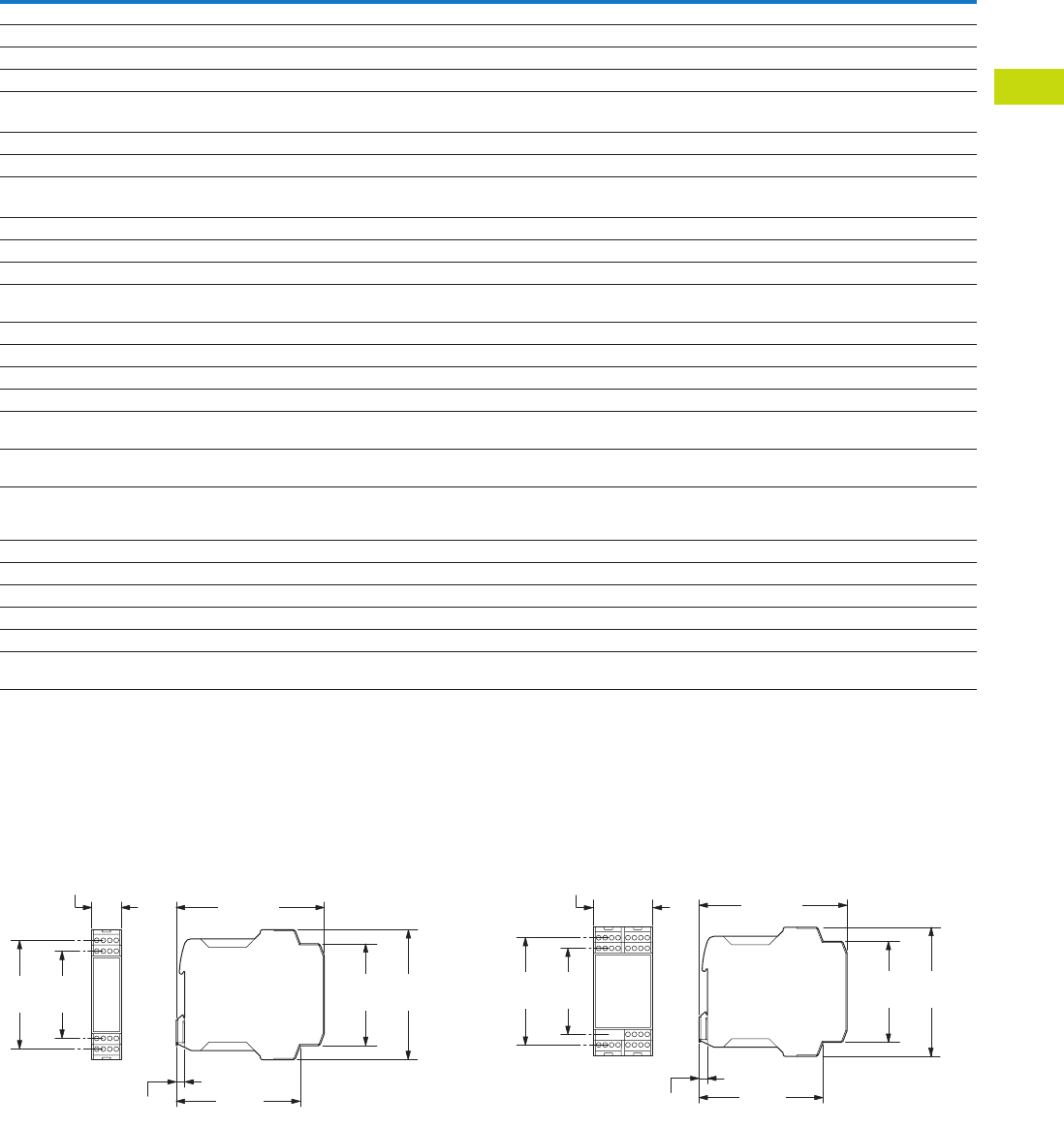
Logic Control Products CA08100001K—June 2012 www.eatoncanada.ca T40-197
40
40
40
40
40
40
40
40
40
40
40
40
40
40
40
40
40
40
40
40
40
40
40
40
40
40
40
40
40
40
40.10
Control Relays and Timers
Safety Relays
Safety Relay, continued
Dimensions
Approximate Dimensions in Inches (mm)
Safety Relays, Contact Expansion Modules
ESR5_ 24 Vac/Vdc ESR5_ 230 Vac
Description Unit ESR5-NO-31-230VAC
ESR5-NO-31-24V-
230VAC-DC ESR5-NV3_ ESR5-VE3_ ESR5-NE-51_
Power Supply Circuit
Actuating voltage 50/60 Hz Vac 230 24–230 — — 24
Actuating voltage—UsVdc — 230 24 24 24
Voltage tolerance pick-up voltage x e0.85–1.1 0.85–1.1 0.85–1.1 0.85–1.1 0.8–1.1
Power consumption
AC operated 50/60 Hz VA —————
AC operated 50/60 Hz W 5.8 5.8 — — 2.2
DC operated W 2.9 2.9 1.8 2 2.2
Fuse for control circuit supply
24V — Short-circuit proof — — —
115/230V Short-circuit proof Short-circuit proof — — —
Control Circuit
Rated output voltage Vdc 24 24 24 24 24
Rated operational current mA S10, S12, S22: 35, S34,
S35: 45
S10, S12, S22: 35, S34,
S35: 45
S12, S22: 3.5, S34, S35: 7 A1, A2: 84, K1/K2: 5 A1, A2: 92
Resistance—R 11 11 500 — —
Short-circuit current A 0.7 0.7 0.1 — —
Response time ms 250 250 150 20 20
Recovery time ms —————
Response time with reset
monitoring—tA1
ms 60 60 150 20 20
Response time without reset
monitoring—tA2
ms 250 250 150 20 20
Reset time—tR/tR1 ms 20 20 20 (non-delayed enable
paths); 100 (min. delayed
enable paths)
0.3–3 s (+50%)
adjustable
20
Minimum on duration—tMms—————
Recovery time—tWms Approx. 1000 Approx. 1000 Approx. 330 Approx. 1000 —
Synchronous monitoring time—tSms—————
Electromagnetic Compatibility (EMC)
Emitted interference EN 61000-6-4 EN 61000-6-4 EN 61000-6-4 EN 61000-6-4 EN 61000-6-4
Interference immunity According to
EN 61000-6-2
According to
EN 61000-6-2
According to EN 61000-6-2,
EN 62061
According to
EN 61000-6-2
According to
EN 61000-6-2
0.88
(22.5)
0.26
(6.6)
4.51
(114.5)
3.74
(95.1)
3.26
(82.8)
2.62
(66.5)
3.06
(77.6)
3.90
(99.0)
0.26
(6.6)
4.51
(114.5)
3.74
(95.1)
3.06
(77.6)
3.90
(99.0)
3.26
(82.8)
2.62
(66.5)
1.77
(45.0)
Tab40book.fm Page 197 Wednesday, July 4, 2012 10:05 PM

T40-198 Logic Control Products CA08100001K—June 2012 www.eatoncanada.ca
40
40
40
40
40
40
40
40
40
40
40
40
40
40
40
40
40
40
40
40
40
40
40
40
40
40
40
40
40
40
40.10
Control Relays and Timers
Safety Relays
This page left intentionally blank
Tab40book.fm Page 198 Wednesday, July 4, 2012 10:05 PM

Logic Control Products
CA08100001K—June 2012 www.eatoncanada.ca
T42-1
42
42
42
42
42
42
42
42
42
42
42
42
42
42
42
42
42
42
42
42
42
42
42
42
42
42
42
42
42
42
Terminal Blocks, Fuse Blocks
and Fuse Holders
Screw Connection
Spring Cage
Insulation Displacement Connection
42.1 IEC—
XB
Series
IEC—
XB
Series Overview . . . . . . . . . . . . . . . . . . . . . . . . . . . . . . . . . . . . .
T42-2
Screw Connection Terminal Blocks . . . . . . . . . . . . . . . . . . . . . . . . . . . . . .
T42-4
Spring Cage Terminal Blocks . . . . . . . . . . . . . . . . . . . . . . . . . . . . . . . . . . .
T42-31
Pluggable Spring Cage Connection Terminal Blocks . . . . . . . . . . . . . . . . .
T42-58
IDC Terminal Blocks . . . . . . . . . . . . . . . . . . . . . . . . . . . . . . . . . . . . . . . . . .
T42-67
Miniature Circuit Breakers . . . . . . . . . . . . . . . . . . . . . . . . . . . . . . . . . . . . .
T42-82
XB
Series Accessories . . . . . . . . . . . . . . . . . . . . . . . . . . . . . . . . . . . . . . . .
T42-90
42.2 NEMA
NEMA Overview . . . . . . . . . . . . . . . . . . . . . . . . . . . . . . . . . . . . . . . . . . . .
T42-106
C381 Series Terminal Blocks, Rail Mounted . . . . . . . . . . . . . . . . . . . . . . .
T42-107
TB Series Terminal Blocks, Modular. . . . . . . . . . . . . . . . . . . . . . . . . . . . . .
T42-111
42.3 Power Distribution
Power Distribution Overview . . . . . . . . . . . . . . . . . . . . . . . . . . . . . . . . . .
T42-116
CHDB Series—Power Distribution Blocks . . . . . . . . . . . . . . . . . . . . . . . . .
T42-117
CH160 Series—Power Terminal Blocks . . . . . . . . . . . . . . . . . . . . . . . . . .
T42-123
Power Terminal Block Accessories . . . . . . . . . . . . . . . . . . . . . . . . . . . . . .
T42-126
42.4 Fuse Blocks and Fuse Holders
Fuse Blocks and Fuse Holders Overview . . . . . . . . . . . . . . . . . . . . . . . . .
T42-128
C383 Series Disconnect Fuse Holders. . . . . . . . . . . . . . . . . . . . . . . . . . . .
T42-129
C350 Series Fuse Blocks and W Series Fuse Holders . . . . . . . . . . . . . . .
T42-131
Tab42book.fm Page 1 Thursday, July 5, 2012 8:03 PM
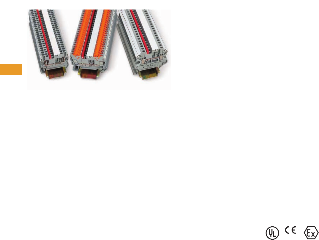
T42-2 Logic Control Products
CA08100001K—June 2012 www.eatoncanada.ca
42
42
42
42
42
42
42
42
42
42
42
42
42
42
42
42
42
42
42
42
42
42
42
42
42
42
42
42
42
42
42.1
Terminal Blocks, Fuse Blocks and Fuse Holders
IEC—
XB
Series
IEC—XB Series
Contents
Description Page
IEC—
XB
Series
Screw Connection Terminal Blocks . . . . . . . . . . . .
T42-4
Spring Cage Terminal Blocks . . . . . . . . . . . . . . . . .
T42-31
Pluggable Spring Cage Connection
Terminal Blocks . . . . . . . . . . . . . . . . . . . . . . . . . .
T42-58
IDC Terminal Blocks . . . . . . . . . . . . . . . . . . . . . . . .
T42-67
Miniature Circuit Breakers. . . . . . . . . . . . . . . . . . . .
T42-82
XB
Series Accessories . . . . . . . . . . . . . . . . . . . . . .
T42-90
IEC—
XB
Series Overview
Product Description
The
XB
Series from Eaton
offers a complete terminal
block system with a universal
range of accessories.
Marking, bridging and testing
accessories are standardized
across the different
termination technologies—
reducing inventory and
logistics costs. The modular
terminal block design allows
for use of the different
terminal block types together
or individually, providing the
highest degree of flexibility.
Application Description
The metal portion of the
XB
Series terminal blocks are
made from high-grade, strain-
crack and corrosion-proof
copper alloys. They won’t
experience any electrolytic
corrosion or rusting, even
when moisture is present.
The metal surfaces are
protected with a lead-free,
galvanic nickel or tin plating.
The good electrical
conductivity permits only a
low temperature rise. The
Polyamide 6.6 housings
allow for operating
temperatures up to 257˚F
(125˚C) and are certified for
inflammability Class V0 in
accordance with UL 94.
Features
Global acceptance
—The
XB
Series terminal blocks are
designed to worldwide
standards and meet the latest
international requirements.
Flexible Plug-in bridge
system
—All three
technologies (screw, spring
and IDC) use the same bridge
system, allowing for
individual potential
distribution and quickly
bridged connections among
the same terminal block type
or across different types. The
XB
Series terminal blocks
have two bridge shafts
arranged in one line, making
flexible chain bridging and
skip bridging between non-
adjacent terminal blocks
possible. Plug-in bridges are
available from 2 to 50
positions. Reducing bridges
are also available to connect a
larger terminal block to a
smaller one.
Large surface area for
marking
—All
XB
Series
terminal blocks have
generously sized surface
areas for labeling. This allows
for clearly labeled wiring that
results in reduced startup
time and simplifies activities
such as testing and
maintenance. There are
provisions for marking
individual terminal blocks and
end stops, strips of terminal
blocks, and large groups of
terminal blocks.
Standardized testing
system
—All test plugs make
contact in one of the easily
accessible bridge shafts. A
2.3 mm diameter test plug is
available for individual
measuring wires. Modular
test plugs are also available
for more advanced testing.
Standards and Certifications
●
UL
®
and cUL
®
recognized—File No.
E67464
●
CE approved
●
LVD
●
EN 60947-7-1
●
EN 60947-7-2
●
EN 60998-2-3
●
EN 60352-4/A1
●
ATEX approval
(Eex e applications)
Note
Not all standards apply to all terminal
blocks. Contact Eaton for details.
Tab42book.fm Page 2 Thursday, July 5, 2012 8:03 PM

Logic Control Products
CA08100001K—June 2012 www.eatoncanada.ca
T42-3
42
42
42
42
42
42
42
42
42
42
42
42
42
42
42
42
42
42
42
42
42
42
42
42
42
42
42
42
42
42
42.1
Terminal Blocks, Fuse Blocks and Fuse Holders
IEC—
XB
Series
Technical Data and Specifications
IEC—
XB
Series
Modular Terminal Blocks for Potentially Explosive Environments
The standard modular
terminal blocks from Eaton
are approved for potentially
explosive environments. In
addition to the usual
approvals, they also have
been approved by a testing
centre authorized by the EU.
No extra approval is required
in Intrinsic Safety type
applications.
Modular terminal blocks on
www.eaton.com fulfill the
requirements for “Increased
Safety” protection type when
installation instructions are
followed, and have a type
examination certificate
in accordance with the
Ex directive Ex-RL 94/9/EU.
These test certificates are
recognized in all the EU
member states and beyond.
The modular terminal blocks
are approved for fitting in
Zone 1, the Ex environment,
as well as Zone 2. Zone 1
fitting is conditional upon
terminal blocks being used in
connection boxes approved
for EEx e type protection and
having the equivalent of at
least IP54 protection.
The EEx approved modular
terminal blocks can be
divided into the following
groups:
●
Screw connection
terminal blocks
●
Spring-cage connection
terminal blocks
●
Insulation Displacement
Connection terminal blocks
●
Mini terminal blocks
●
Terminal blocks for
specialized applications
More detailed information
on modular terminal
blocks in the EEx e area is
available on the Internet
at www.eaton.com for
downloading.
Here you will find the
following:
●
Technical data in accordance
with EN 50 019
●
Approved accessories
●
Important installation
instructions and mounting
diagrams
●
EU type examination
certificates
●
General information on
Ex protection
Identifications
Explosion protected electrical
equipment must be marked
so that the safety
characteristics are
identifiable. The identification
of electrical equipment is
described in the harmonized
standard EN 50014, as
shown in the following
example:
EN 50014
Standard Example
Identification in Accordance
with ATEX-RL
Electrical equipment that is
certified in accordance with
the ATEX 100a guideline also
receives identification
describing the site for use.
ATEX
Guideline Example
Description Specification
Insulation material Polyamide 6.6
Dielectric strength 600 kV/cm
Creep resistance 600 CTI
Internal insulation resistance 10
12
ohms cm
Surface resistance 10
10
ohms
Flammability rating UL 94 V0
Continuous operating temperature –40 to 257˚F (–40 to 125˚C)
Description Identification
Manufacturer or
trademark
Eaton
Type designation XBUT25
Abbreviation of
explosion protection
EEx e ll
Protection type
increased safety “e”
e
Equipment group II
Mark of the
testing body
KEMA
Approval number 05ATEX2158 U
Description Identification
Manufacturing data 02.01.2004
Address of the
manufacturer
Duncan, SC
Number of the
appointed dept.
344
Common marking Ex symbol
Equipment group II
Category 2
Use in gas and/or
dust atmospheres
G D
Tab42book.fm Page 3 Thursday, July 5, 2012 8:03 PM
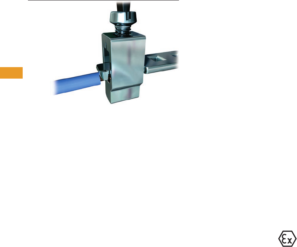
T42-4 Logic Control Products
CA08100001K—June 2012 www.eatoncanada.ca
42
42
42
42
42
42
42
42
42
42
42
42
42
42
42
42
42
42
42
42
42
42
42
42
42
42
42
42
42
42
42.1
Terminal Blocks, Fuse Blocks and Fuse Holders
IEC—
XB
Series
Screw Connection
Contents
Description Page
Screw Connection Terminal Blocks
Single Level—Through-Feed. . . . . . . . . . . . . . . . . .
T42-5
Single Level—Ground Blocks . . . . . . . . . . . . . . . . .
T42-10
Multi-Conductor Terminal Blocks . . . . . . . . . . . . . .
T42-12
Multi-Conductor Ground Blocks . . . . . . . . . . . . . . .
T42-14
Double Level . . . . . . . . . . . . . . . . . . . . . . . . . . . . . .
T42-16
Triple Level Sensor/Actuator . . . . . . . . . . . . . . . . .
T42-18
Fuse Terminal Blocks . . . . . . . . . . . . . . . . . . . . . . .
T42-21
Disconnect and Component Terminal
Blocks . . . . . . . . . . . . . . . . . . . . . . . . . . . . . . . . .
T42-24
High Current Blocks . . . . . . . . . . . . . . . . . . . . . . . .
T42-27
Mini Screw Connection . . . . . . . . . . . . . . . . . . . . .
T42-29
Screw Connection Terminal Blocks Overview
Product Description
The XBUT Series uses a
screw connection system
that is accepted worldwide
and is suitable in most
applications. The
maintenance-free connection
provides the reliability you
expect from Eaton.
Application Description
Designed for applications with
high demands, the XBUT
Series screw terminal block
has a maintenance-free wire
connection. re-tightening of
the terminal screws is not
necessary to ensure proper
operation. The screw locking
technique prevents the
screws from backing out.
Copper wires can be clamped
without pre-treatment or
ferrules can be used for
splicing protection. Multiple
conductors can be connected
in the same clamping
mechanism, saving space.
Features
●
Maintenance-free
connections
●
Global acceptance
●
Multi-conductor
connections
●
Flexible Plug-in bridge
system
●
Large surface area for
marking
●
Standardized testing
system
●
Metal parts made of tin-
plated copper alloy
Standards and Certifications
●
UL and cUL recognized—
File No. E67464
●
CE approved
●
LVD
:
●
EN 60947-7-1
●
EN 60947-7-2
●
EN 60998-2-3
●
EN 60352-4/A1
●
ATEX approval
(Eex e applications)
Note
Not all standards apply to all terminal
blocks. Contact Eaton for details.
Tab42book.fm Page 4 Thursday, July 5, 2012 8:03 PM

Logic Control Products
CA08100001K—June 2012 www.eatoncanada.ca
T42-5
42
42
42
42
42
42
42
42
42
42
42
42
42
42
42
42
42
42
42
42
42
42
42
42
42
42
42
42
42
42
42.1
Terminal Blocks, Fuse Blocks and Fuse Holders
IEC—
XB
Series
Single Level—Through-Feed
Contents
Description Page
Single Level—Through-Feed
Product Selection . . . . . . . . . . . . . . . . . . . . . . . . . .
T42-6
Accessories . . . . . . . . . . . . . . . . . . . . . . . . . . . . . .
T42-7
Technical Data and Specifications . . . . . . . . . . . . .
T42-9
Dimensions . . . . . . . . . . . . . . . . . . . . . . . . . . . . . .
T42-9
Single Level—Ground Blocks . . . . . . . . . . . . . . . . . . .
T42-10
Multi-Conductor Terminal Blocks . . . . . . . . . . . . . . . . . T42-12
Multi-Conductor Ground Blocks . . . . . . . . . . . . . . . . . T42-14
Double Level. . . . . . . . . . . . . . . . . . . . . . . . . . . . . . . . . T42-16
Triple Level Sensor/Actuator . . . . . . . . . . . . . . . . . . . . T42-18
Fuse Terminal Blocks . . . . . . . . . . . . . . . . . . . . . . . . . . T42-21
Disconnect and Component Terminal Blocks . . . . . . . T42-24
High Current Blocks . . . . . . . . . . . . . . . . . . . . . . . . . . . T42-27
Mini Screw Connection . . . . . . . . . . . . . . . . . . . . . . . . T42-29
Single Level—Through-Feed
Product Description
The XBUT terminal blocks
feature a compact design and
maintenance-free screw
connection. There is a double
bridge shaft providing
maximum flexibility.
The double bridge shaft can
accommodate individual
chain bridging and step-down
bridging from other terminal
blocks. There are numerous
options for accessories,
including those for testing
and marking. Terminal blocks
are available for wire cross-
sections ranging from
12 AWG (2.5 mm2) to
2/0 AWG (150 mm2).
Tab42book.fm Page 5 Thursday, July 5, 2012 8:03 PM
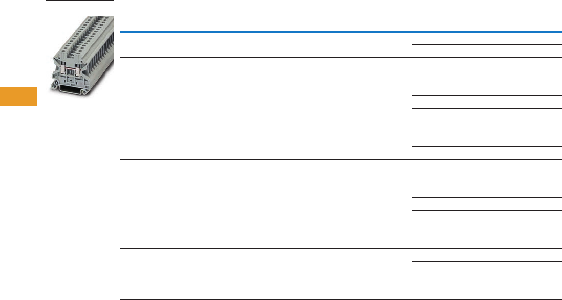
T42-6 Logic Control Products CA08100001K—June 2012 www.eatoncanada.ca
42
42
42
42
42
42
42
42
42
42
42
42
42
42
42
42
42
42
42
42
42
42
42
42
42
42
42
42
42
42
42.1
Terminal Blocks, Fuse Blocks and Fuse Holders
IEC—
XB
Series
Product Selection
Screw Connection Single Level—Through-Feed
Note
EU type—examination certificate number: KEMA 05ATEX2158 U.
Terminal
Width
Maximum
Wire Size
IEC 60 947-7-1
in V/A/AWG
EN 50 019
in V/A/AWG
UL-cUL Ratings
in V/A/AWG Colour
Standard
Pack
Catalogue
Number
5.2 mm 12 AWG/2.5 mm2800/32/26–12 750/22/28/26–12 600/20/26–12 Gray 50 XBUT25
Blue 50 XBUT25BU
6.2 mm 10 AWG/4 mm2800/41/26–10 750/30/38/26–10 600/30/26–10 Gray 50 XBUT4
Blue 50 XBUT4BU
Orange 50 XBUT4OR
Yellow 50 XBUT4YE
Red 50 XBUT4RD
White 50 XBUT4WH
Black 50 XBUT4BK
Green 50 XBUT4GN
8.2 mm 8 AWG/6 mm2800/57/24–8 750/40/50/24–8 600/50/24–8 Gray 50 XBUT6
Blue 50 XBUT6BU
10.2 mm 6 AWG/10 mm21000/76/20–6 750/54/69/20–6 600/65/20–6 Gray 50 XBUT10
Blue 50 XBUT10BU
Orange 50 XBUT10OR
Yellow 50 XBUT10YE
Red 50 XBUT10RD
12 mm 4 AWG/16 mm21000/101/17–4 — 600/85/16–4 Gray 50 XBUT16
Blue 50 XBUT16BU
16 mm 0 AWG/35 mm21000/150/15–0 — 600/150/14–1/0 Gray 50 XBUT35
Blue 50 XBUT35BU
XBUT4
Tab42book.fm Page 6 Thursday, July 5, 2012 8:03 PM

Logic Control Products CA08100001K—June 2012 www.eatoncanada.ca T42-7
42
42
42
42
42
42
42
42
42
42
42
42
42
42
42
42
42
42
42
42
42
42
42
42
42
42
42
42
42
42
42.1
Terminal Blocks, Fuse Blocks and Fuse Holders
IEC—
XB
Series
Accessories
Screw Connection Single Level—Through-Feed
Notes
For ordering information, see Page T42-105.
For information on Printed Marking Tag Options, see Page T42-98.
For additional accessories, see Page T42-90.
Description Colour
Number of
Positions
Standard
Pack
XBUT25 XBUT4 XBUT6 XBUT10 XBUT16 XBUT35
Catalogue
Number
Catalogue
Number
Catalogue
Number
Catalogue
Number
Catalogue
Number
Catalogue
Number
End cover Gray — 10 XBACUT10 XBACUT10 XBACUT10 XBACUT10 XBACUT16
Partition plate Gray — 10 XBATUT10 XBATUT10 XBATUT10 XBATUT10 — —
Plug-in bridge—
for cross connections
in the bridge shaft
Red 2 10 XBAFBS25 XBAFBS26 XBAFBS28 XBAFBS210 XBAFBS212 XBAFBS216
310XBAFBS35 XBAFBS36 — — — —
510XBAFBS55 XBAFBS56 — — — —
10 10 XBAFBS105 XBAFBS106 — — — —
50 10 XBAFBS505 XBAFBS506 — — — —
Test adapter — — 10 XBATSPAI4 XBATSPAI4 XBATSPAI4 — — —
2.3 mm diameter test plug — — — XBATSMPS-_ XBATSMPS-_ ————
Modular test plug — — 10 XBATSPS5 XBATSPS6 XBATSPS8 — — —
Blank marker strip (strip of 10) White — 10 XBMZB5 XBMZB6 XBMZB8 XBMZB10 XBMZB12 XBMZB15
Tab42book.fm Page 7 Thursday, July 5, 2012 8:03 PM
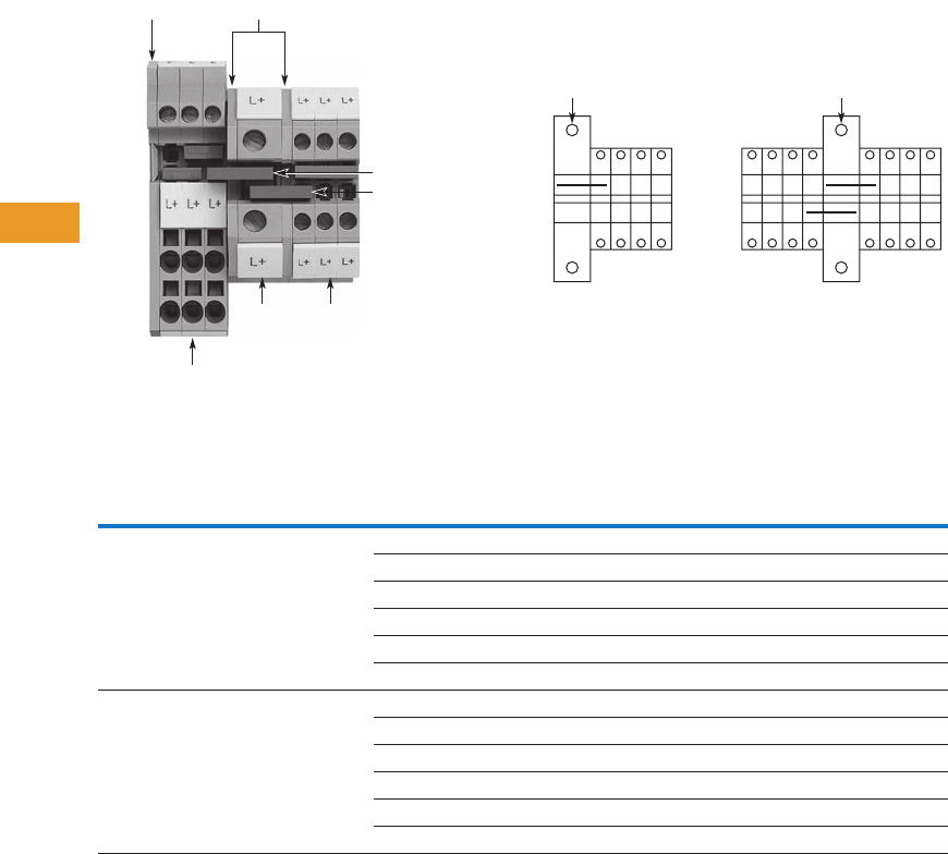
T42-8 Logic Control Products CA08100001K—June 2012 www.eatoncanada.ca
42
42
42
42
42
42
42
42
42
42
42
42
42
42
42
42
42
42
42
42
42
42
42
42
42
42
42
42
42
42
42.1
Terminal Blocks, Fuse Blocks and Fuse Holders
IEC—
XB
Series
XBUT with Reducing Bridge
Step-Down Bridge with Standard Feed-Through Terminal Blocks
Input Pick-Off
One-Sided
Input Imax
Central
Input Imax
Bridge
Terminal
Blocks Cross-Section
Terminal
Blocks
Cross-Section
AWG (mm2)
Catalogue
Number
XBUT10 6 AWG (10 mm2) XBUT25 12 (2.5) 40 65 XBARBUT10
XBUT4 10 (4) 45 65 XBARBUT10
XBPT25 12 (2.5) 40 65 XBARBUT10ST
XBPT4 10 (4) 45 65 XBARBUT10ST
XBQT15 14 (1.5) 35 65 XBARBUT10ST
XBQT25 12 (2.5) 40 65 XBARBUT10ST
XBUT16 4 AWG (16 mm2) XBUT25 12 (2.5) 40 80 XBARBUT16
XBUT4 10 (4) 45 90 XBARBUT16
XBPT25 12 (2.5) 40 80 XBARBUT16ST
XBPT4 10 (4) 45 90 XBARBUT16ST
XBQT15 14 (1.5) 35 70 XBARBUT16ST
XBQT25 12 (2.5) 40 80 XBARBUT16ST
XBPU25D12
lmax
One-Sided Input Central Input
lmax
XBACUT10
XBARBUT10ST
XBARBUT10
XBUT10 XBUT25
XBACPU25D12
Tab42book.fm Page 8 Thursday, July 5, 2012 8:03 PM

Logic Control Products CA08100001K—June 2012 www.eatoncanada.ca T42-9
42
42
42
42
42
42
42
42
42
42
42
42
42
42
42
42
42
42
42
42
42
42
42
42
42
42
42
42
42
42
42.1
Terminal Blocks, Fuse Blocks and Fuse Holders
IEC—
XB
Series
Technical Data and Specifications
Screw Connection Single Level—Through-Feed
Dimensions
Approximate Dimensions in Inches (mm)
Screw Connection Single Level—Through-Feed
Notes
XBUT35 has an enclosed design. The use of an end cover is not required.
For information on Printed Marking Tag Options, see Page T42-98.
Description XBUT25 XBUT4 XBUT6 XBUT10 XBUT16 XBUT35
Technical Data in Accordance with IEC
Maximum load current in A/cross-section in mm232/4 41/6 57/10 76/16 101/25 150/50
Rated surge voltage in kV/contamination class 8/3 8/3 8/3 8/3 8/3 8/3
Surge voltage category/insulating material group III/II III/I III/I III/I III/I III/I
Connection Capacity
Stranded with ferrule/with ferrule and
plastic sleeve in mm2
0.25–2.5/0.25–2.5 0.25–4/0.25–4 0.25–6/0.25–6 0.5–10/0.5–10 1.0–16/1.0–16 1.5–35/1.5–35
Multi-Conductor Connection
(same cross-section)
Solid/stranded in mm20.14–1.5/0.14–1.5 0.14–1.5/0.14–1.5 0.2–2.5/0.2–2.5 0.5–4/0.5–4 1.0–6/1.0–4 1.5–16/1.5–10
Stranded with ferrules without plastic sleeve in mm20.25–1.5 0.25–1.5 0.25–1.5 0.5–2.5 1.0–4 1.5–10
Stranded with twin ferrule with plastic sleeve in mm20.5–1.5 0.5–2.5 0.5–4 0.5–6 0.75–10 1.5–10
Stripping length in inches (mm) 0.35 (9) 0.35 (9) 0.39 (10) 0.39 (10) 0.39 (10) 0.63 (16)
Thread M3 M3 M4 M4 M5 M6
Torque in in-lb (Nm) 5.3–7.1 (0.6–0.8) 5.3–7.1 (0.6–0.8) 13.3–15.9 (1.5–1.8) 13.3–15.9 (1.5–1.8) 22.1–26.6 (2.5–3) 28.3–32.7 (3.2–3.7)
Catalogue
Number Width Length
Cover
Width
Height for—
35 x 7.5 in 35 x 15 in
XBUT25 0.20 (5.2) 1.85 (46.9) 0.09 (2.2) 1.87 (47.5) 2.17 (55.0)
XBUT4 0.24 (6.2) 1.85 (46.9) 0.09 (2.2) 1.87 (47.5) 2.17 (55.0)
XBUT6 0.32 (8.2) 1.85 (46.9) 0.09 (2.2) 1.87 (47.5) 2.17 (55.0)
XBUT10 0.40 (10.2) 1.85 (46.9) 0.09 (2.2) 1.87 (47.5) 2.17 (55.0)
XBUT16 0.47 (12.0) 2.08 (52.8) 0.09 (2.2) 2.16 (54.8) 2.45 (62.3)
XBUT35 0.63 (16.0) 2.37 (60.2) — 2.59 (65.7) 2.88 (73.2)
Tab42book.fm Page 9 Thursday, July 5, 2012 8:03 PM
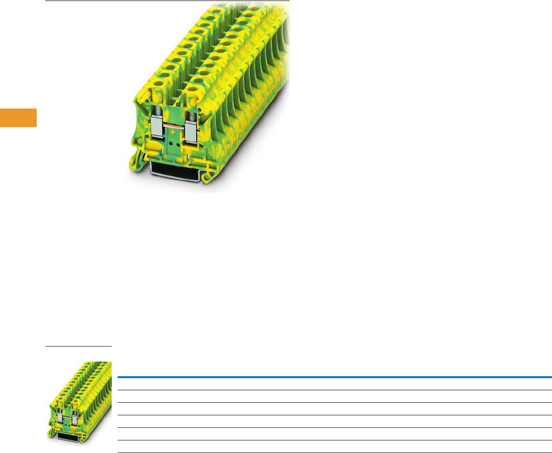
T42-10 Logic Control Products CA08100001K—June 2012 www.eatoncanada.ca
42
42
42
42
42
42
42
42
42
42
42
42
42
42
42
42
42
42
42
42
42
42
42
42
42
42
42
42
42
42
42.1
Terminal Blocks, Fuse Blocks and Fuse Holders
IEC—
XB
Series
Single Level—Ground Blocks Contents
Description Page
Single Level—Through-Feed . . . . . . . . . . . . . . . . . . . . T42-5
Single Level—Ground Blocks
Accessories . . . . . . . . . . . . . . . . . . . . . . . . . . . . . . T42-11
Technical Data and Specifications . . . . . . . . . . . . . T42-11
Dimensions . . . . . . . . . . . . . . . . . . . . . . . . . . . . . . T42-11
Multi-Conductor Terminal Blocks . . . . . . . . . . . . . . . . T42-12
Multi-Conductor Ground Blocks . . . . . . . . . . . . . . . . . T42-14
Double Level . . . . . . . . . . . . . . . . . . . . . . . . . . . . . . . . T42-16
Triple Level Sensor/Actuator . . . . . . . . . . . . . . . . . . . . T42-18
Fuse Terminal Blocks . . . . . . . . . . . . . . . . . . . . . . . . . T42-21
Disconnect and Component Terminal Blocks . . . . . . . T42-24
High Current Blocks . . . . . . . . . . . . . . . . . . . . . . . . . . T42-27
Mini Screw Connection . . . . . . . . . . . . . . . . . . . . . . . . T42-29
Single Level—Ground Blocks
Product Description
The ground terminal blocks
have the same shape and
pitch as the standard terminal
block, in a green-yellow
housing. They easily snap
onto the DIN rail to make a
reliable mechanical and
electrical contact that meets
all requirements of IEC 60-
947-7-2.
Product Selection
Screw Connection Single Level—Ground Blocks
Note
EU type—examination certificate number: KEMA 05ATEX2158 U.
Terminal
Width
Maximum
Wire Size
IEC 60 947-7-1
in V/A/AWG
EN 50 019
in V/A/AWG
UL-cUL Ratings
in V/A/AWG Colour
Standard
Pack
Catalogue
Number
5.2 mm 12 AWG/2.5 mm2—/—/26–12 —/—/26–12 —/—/26–12 Green/Yellow 50 XBUT25PE
6.2 mm 10 AWG/4 mm2—/—/26–10 —/—/26–10 —/—/26–10 Green/Yellow 50 XBUT4PE
8.2 mm 8 AWG/6 mm2—/—/24–8 —/—/24–8 —/—/24–8 Green/Yellow 50 XBUT6PE
10.2 mm 6 AWG/10 mm2—/76/20–6 —/54/69/20–6 —/—/20–6 Green/Yellow 50 XBUT10PE
12 mm 4 AWG/16 mm2—/101/15–4 — —/—/16–4 Green/Yellow 50 XBUT16PE
16 mm 2 AWG/35 mm2—/125/15–2 — —/—/14–1/0 Green/Yellow 50 XBUT35PE
XBUT6PE
Tab42book.fm Page 10 Thursday, July 5, 2012 8:03 PM

Logic Control Products CA08100001K—June 2012 www.eatoncanada.ca T42-11
42
42
42
42
42
42
42
42
42
42
42
42
42
42
42
42
42
42
42
42
42
42
42
42
42
42
42
42
42
42
42.1
Terminal Blocks, Fuse Blocks and Fuse Holders
IEC—
XB
Series
Accessories
Screw Connection Single Level—Ground Blocks
Technical Data and Specifications
Screw Connection Single Level—Ground Blocks
Dimensions
Approximate Dimensions in Inches (mm)
Screw Connection Single Level—Ground Blocks
Notes
For ordering information, see Page T42-105.
For information on Printed Marking Tag Options, see Page T42-98.
XBUT35PE has an enclosed design. The use of an end cover is not required.
For additional accessories, see Page T42-90.
Description Colour
Number of
Positions
Standard
Pack
XBUT25PE XBUT4PE XBUT6PE XBUT10PE XBUT16PE XBUT35PE
Catalogue
Number
Catalogue
Number
Catalogue
Number
Catalogue
Number
Catalogue
Number
Catalogue
Number
End cover Gray — 10 XBACUT10 XBACUT10 XBACUT10 XBACUT10 XBACUT16
Partition plate — — 10 XBATUT10 XBATUT10 XBATUT10 XBATUT10 — —
Plug-in bridge—
for cross connections
in the bridge shaft
Red 2 10 XBAFBS25 XBAFBS26 XBAFBS28 XBAFBS210 XBAFBS212 XBAFBS212
310XBAFBS35 XBAFBS36 — — — —
510XBAFBS55 XBAFBS56 — — — —
10 10 XBAFBS105 XBAFBS106 — — — —
50 10 XBAFBS505 XBAFBS506 — — — —
Test adapter — — 10 XBATSPAI4 XBATSPAI4 XBATSPAI4 — — —
2.3 mm diameter test plug — — — XBATSMPS-_ XBATSMPS-_ —— ——
Modular test plug — — 10 XBATSPS5 XBATSPS6 XBATSPS8 — — —
Blank marker strip (strip of 10) White — 10 XBMZB5 XBMZB6 XBMZB8 XBMZB10 XBMZB12 XBMZB15
Description XBUT25PE XBUT4PE XBUT6PE XBUT10PE XBUT16PE XBUT35PE
Technical Data in Accordance with IEC
Maximum load current in A/cross-section in mm2— — — 76/16 101/25 125/50
Rated surge voltage in kV/contamination class 8/3 8/3 8/3 8/3 8/3 8/3
Surge voltage category/insulating material group III/II III/I III/I III/I III/I III/I
Connection Capacity
Stranded with ferrule/with ferrule and
plastic sleeve in mm2
0.25–2.5/0.25–2.5 0.25–4/0.25–4 0.25–6/0.25–6 0.5–10/0.5–10 1.0–16/1.0–16 1.5–35/1.5–35
Multi-Conductor Connection
(same cross-section)
Solid/stranded in mm20.14–1.5/0.14–1.5 0.14–1.5/0.14–1.5 0.2–2.5/0.2–2.5 0.5–4/0.5–4 1.0–6/1.0–4 1.5–16/1.5–10
Stranded with ferrules without plastic sleeve in mm20.25–1.5 0.25–1.5 0.25–1.5 0.5–2.5 1.0–4 1.5–10
Stranded with twin ferrule with plastic sleeve in mm20.5–1.5 0.5–2.5 0.5–4 0.5–6 0.75–10 1.5–10
Stripping length in inches (mm) 0.35 (9) 0.35 (9) 0.39 (10) 0.39 (10) 0.39 (10) 0.63 (16)
Thread M3 M3 M4 M4 M5 M6
Torque in in-lb (Nm) 5.3–7.1 (0.6–0.8) 5.3–7.1 (0.6–0.8) 13.3–15.9 (1.5–1.8) 13.3–15.9 (1.5–1.8) 22.1–26.6 (2.5–3) 28.3–32.7 (3.2–3.7)
Catalogue
Number Width Length
Cover
Width
Height for—
35 x 7.5 in 35 x 15 in
XBUT25PE 0.20 (5.2) 1.85 (46.9) 0.09 (2.2) 1.87 (47.5) 2.17 (55.0)
XBUT4PE 0.24 (6.2) 1.85 (46.9) 0.09 (2.2) 1.87 (47.5) 2.17 (55.0)
XBUT6PE 0.32 (8.2) 1.85 (46.9) 0.09 (2.2) 1.87 (47.5) 2.17 (55.0)
XBUT10PE 0.40 (10.2) 1.85 (46.9) 0.09 (2.2) 1.87 (47.5) 2.17 (55.0)
XBUT16PE 0.47 (12.0) 2.08 (52.8) 0.09 (2.2) 2.16 (54.8) 2.45 (62.3)
XBUT35PE 0.63 (16.0) 2.37 (60.2) — 2.59 (65.7) 2.88 (73.2)
Tab42book.fm Page 11 Thursday, July 5, 2012 8:03 PM
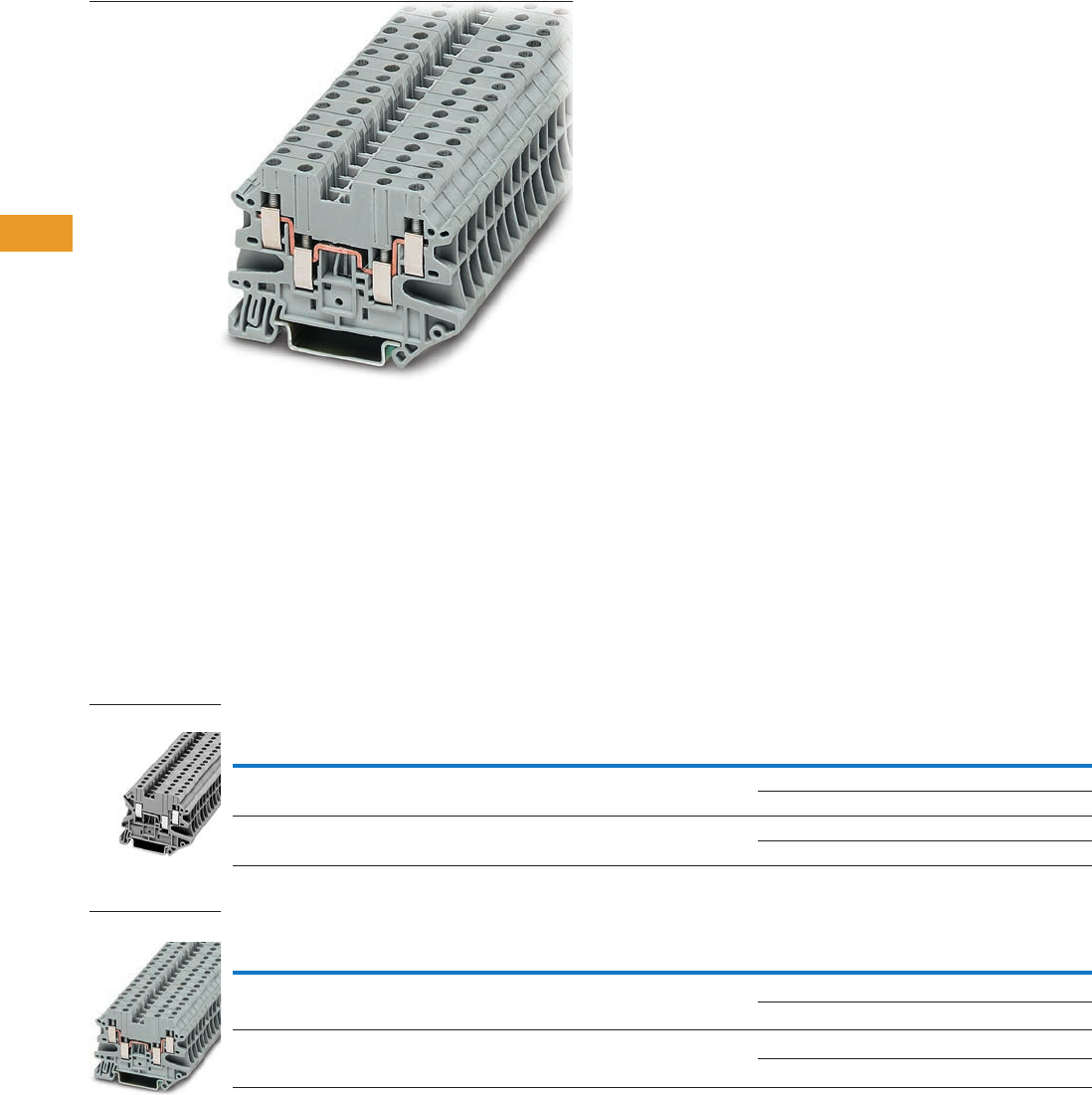
T42-12 Logic Control Products CA08100001K—June 2012 www.eatoncanada.ca
42
42
42
42
42
42
42
42
42
42
42
42
42
42
42
42
42
42
42
42
42
42
42
42
42
42
42
42
42
42
42.1
Terminal Blocks, Fuse Blocks and Fuse Holders
IEC—
XB
Series
Multi-Conductor Terminal Blocks Contents
Description Page
Single Level—Through-Feed . . . . . . . . . . . . . . . . . . . . T42-5
Single Level—Ground Blocks . . . . . . . . . . . . . . . . . . . T42-10
Multi-Conductor Terminal Blocks
Accessories . . . . . . . . . . . . . . . . . . . . . . . . . . . . . . T42-13
Technical Data and Specifications . . . . . . . . . . . . . T42-13
Dimensions . . . . . . . . . . . . . . . . . . . . . . . . . . . . . . T42-13
Multi-Conductor Ground Blocks . . . . . . . . . . . . . . . . . T42-14
Double Level . . . . . . . . . . . . . . . . . . . . . . . . . . . . . . . . T42-16
Triple Level Sensor/Actuator . . . . . . . . . . . . . . . . . . . . T42-18
Fuse Terminal Blocks . . . . . . . . . . . . . . . . . . . . . . . . . T42-21
Disconnect and Component Terminal Blocks . . . . . . . T42-24
High Current Blocks . . . . . . . . . . . . . . . . . . . . . . . . . . T42-27
Mini Screw Connection . . . . . . . . . . . . . . . . . . . . . . . . T42-29
Multi-Conductor Terminal Blocks
Product Description
The multi-conductor terminal
blocks offer a space-saving
alternative to standard feed-
through terminal blocks
allowing for high density
wiring. Often, three
connections have to be led
to one terminal block. The
XBUT…D12 terminal block
accomplishes this without
any additional terminal blocks
or bridging required.
The XBUT…D22 terminal
blocks allow four wires to be
connected to one potential—
and can therefore be used as
compact power distributors.
Product Selection
Screw Connection Multi-Conductor Terminal Blocks, Three-Wire
Screw Connection Multi-Conductor Terminal Blocks, Four-Wire
Terminal
Width
Maximum
Wire Size
IEC 60 947-7-1
in V/A/AWG
UL-cUL Ratings
in V/A/AWG Colour
Standard
Pack
Catalogue
Number
5.2 mm 12 AWG/2.5 mm2500/28/26–12 150/20/26–12 Gray 50 XBUT25D12
Blue 50 XBUT25D12BU
6.2 mm 10 AWG/4 mm2500/39/26–10 150/30/26–10 Gray 50 XBUT4D12
Blue 50 XBUT4D12BU
Terminal
Width
Maximum
Wire Size
IEC 60 947-7-1
in V/A/AWG
UL-cUL Ratings
in V/A/AWG Colour
Standard
Pack
Catalogue
Number
5.2 mm 12 AWG/2.5 mm2500/28/26–12 150/20/26–12 Gray 50 XBUT25D22
Blue 50 XBUT25D22BU
6.2 mm 10 AWG/4 mm2500/39/26–10 150/30/26–10 Gray 50 XBUT4D22
Blue 50 XBUT4D22BU
XBUT25D12
XBUT4D22
Tab42book.fm Page 12 Thursday, July 5, 2012 8:03 PM

Logic Control Products CA08100001K—June 2012 www.eatoncanada.ca T42-13
42
42
42
42
42
42
42
42
42
42
42
42
42
42
42
42
42
42
42
42
42
42
42
42
42
42
42
42
42
42
42.1
Terminal Blocks, Fuse Blocks and Fuse Holders
IEC—
XB
Series
Accessories
Screw Connection Multi-Conductor Terminal Blocks
Technical Data and Specifications
Screw Connection Multi-Conductor Terminal Blocks
Dimensions
Approximate Dimensions in Inches (mm)
Screw Connection Multi-Conductor Terminal Blocks
Notes
For ordering information, see Page T42-105.
For information on Printed Marking Tag Options, see Page T42-98.
For additional accessories, see Page T42-90.
Description Colour
Number of
Positions
Standard
Pack
XBUT25D12 XBUT4D12 XBUT25D22 XBUT4D22
Catalogue
Number
Catalogue
Number
Catalogue
Number
Catalogue
Number
End cover Gray — 10 XBACUT4D12 XBACUT4D12 XBACUT4D22 XBACUT4D22
End cover segment Gray — 10 XBASUT4 XBASUT4 XBASUT4 XBASUT4
Partition plate — — 10 XBATUTD12 XBATUTD12 XBATUTD22 XBATUTD22
Plug-in bridge—for cross
connections in the bridge shaft
Red 2 10 XBAFBS25 XBAFBS26 XBAFBS25 XBAFBS26
310XBAFBS35 XBAFBS36 XBAFBS35 XBAFBS36
510XBAFBS55 XBAFBS56 XBAFBS55 XBAFBS56
10 10 XBAFBS105 XBAFBS106 XBAFBS105 XBAFBS106
50 10 XBAFBS505 XBAFBS506 XBAFBS505 XBAFBS506
Test adapter — — 10 XBATSPAI4 XBATSPAI4 XBATSPAI4 XBATSPAI4
2.3 mm diameter test plug — — — XBATSMPS-_ XBATSMPS-_ XBATSMPS-_ XBATSMPS-_
Modular test plug — — 10 XBATSPS5 XBATSPS6 XBATSPS5 XBATSPS6
Blank marker strip (strip of 10) White — 10 XBMZB5 XBMZB6 XBMZB5 XBMZB6
Description XBUT25D12 XBUT4D12 XBUT25D22 XBUT4D22
Technical Data in Accordance with IEC
Maximum load current in A/cross-section in mm228/4 39/6 28/4 39/6
Rated surge voltage in kV/contamination class 6/3 6/3 6/3 6/3
Surge voltage category/insulating material group III/I III/I III/I III/I
Connection Capacity
Stranded with ferrule/with ferrule and
plastic sleeve in mm2
0.25–2.5/0.25–2.5 0.25–4/0.25–4 0.25–2.5/0.25–2.5 0.25–4/0.25–4
Multi-Conductor Connection
(same cross-section)
Solid/stranded in mm20.14–1.0/0.14–1.0 0.14–1.0/0.14–1.5 0.14–1.0/0.14–1.0 0.14–1/0.14–1.5
Stranded with ferrules without plastic sleeve in mm20.25–1.0 0.25–1.5 0.25–1.0 0.25–1.5
Stranded with twin ferrule with plastic sleeve in mm20.5–1.0 0.5–1.0 0.5–1.0 0.5–1.0
Stripping length in inches (mm) 0.31 (8) 0.31 (8) 0.31 (8) 0.31 (8)
Thread M3 M3 M3 M3
Torque in in-lb (Nm) 5.3–7.1 (0.6–0.8) 5.3–7.1 (0.6–0.8) 5.3–7.1 (0.6–0.8) 5.3–7.1 (0.6–0.8)
Catalogue
Number Width Length
Cover
Width
Height for—
35 x 7.5 in 35 x 15 in
XBUT25D12 0.20 (5.2) 2.24 (56.8) 0.09 (2.2) 1.87 (47.5) 2.17 (55.0)
XBUT4D12 0.24 (6.2) 2.24 (56.8) 0.09 (2.2) 1.87 (47.5) 2.17 (55.0)
XBUT25D22 0.20 (5.2) 2.52 (64.1) 0.09 (2.2) 1.87 (47.5) 2.17 (55.0)
XBUT4D22 0.24 (6.2) 2.52 (64.1) 0.09 (2.2) 1.87 (47.5) 2.17 (55.0)
Tab42book.fm Page 13 Thursday, July 5, 2012 8:03 PM
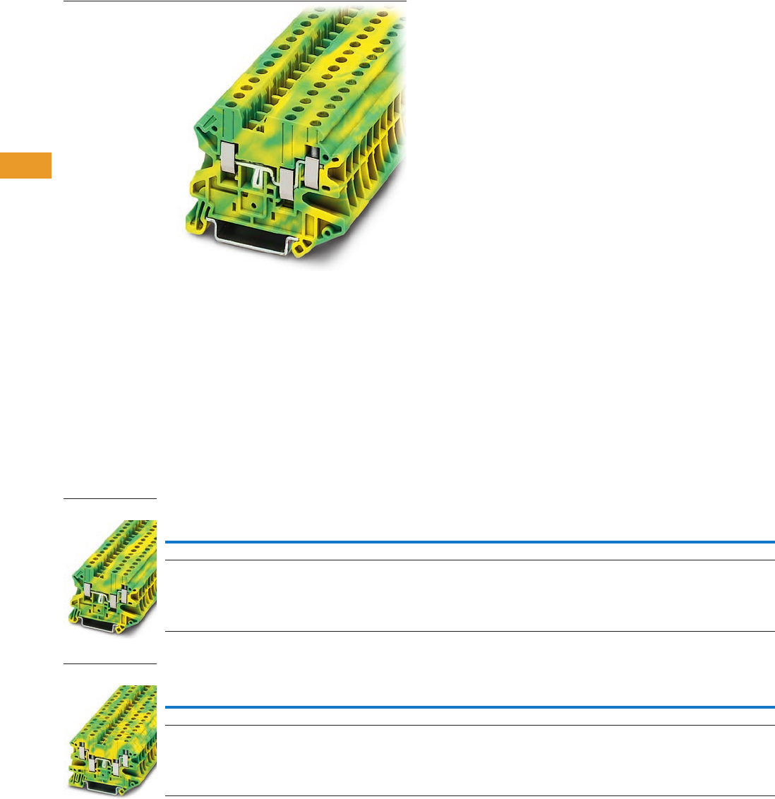
T42-14 Logic Control Products CA08100001K—June 2012 www.eatoncanada.ca
42
42
42
42
42
42
42
42
42
42
42
42
42
42
42
42
42
42
42
42
42
42
42
42
42
42
42
42
42
42
42.1
Terminal Blocks, Fuse Blocks and Fuse Holders
IEC—
XB
Series
Multi-Conductor Ground Blocks Contents
Description Page
Single Level—Through-Feed . . . . . . . . . . . . . . . . . . . . T42-5
Single Level—Ground Blocks . . . . . . . . . . . . . . . . . . . T42-10
Multi-Conductor Terminal Blocks . . . . . . . . . . . . . . . . T42-12
Multi-Conductor Ground Blocks
Accessories . . . . . . . . . . . . . . . . . . . . . . . . . . . . . . T42-15
Technical Data and Specifications . . . . . . . . . . . . . T42-15
Dimensions . . . . . . . . . . . . . . . . . . . . . . . . . . . . . . T42-15
Double Level . . . . . . . . . . . . . . . . . . . . . . . . . . . . . . . . T42-16
Triple Level Sensor/Actuator . . . . . . . . . . . . . . . . . . . . T42-18
Fuse Terminal Blocks . . . . . . . . . . . . . . . . . . . . . . . . . T42-21
Disconnect and Component Terminal Blocks . . . . . . . T42-24
High Current Blocks . . . . . . . . . . . . . . . . . . . . . . . . . . T42-27
Mini Screw Connection . . . . . . . . . . . . . . . . . . . . . . . . T42-29
Multi-Conductor Ground Blocks
Product Description
The ground terminal blocks
have the same shape and
pitch as the standard terminal
block, in a green-yellow
housing. They easily snap
onto the DIN rail to make
a reliable mechanical and
electrical contact that
meets all requirements
of IEC 60-947-7-2.
Product Selection
Screw Connection Multi-Conductor Ground Blocks—Three-Wire
Screw Connection Multi-Conductor Ground Blocks—Four-Wire
Terminal
Width
Maximum
Wire Size
IEC 60 947-7-1
in V/A/AWG
UL-cUL Ratings
in V/A/AWG Colour
Standard
Pack
Catalogue
Number
5.2 mm 12 AWG/2.5 mm2—/—/26–12 —/—/26–12 Green/Yellow 50 XBUT25D12PE
6.2 mm 10 AWG/4 mm2—/—/26–10 —/—/26–10 Green/Yellow 50 XBUT4D12PE
Terminal
Width
Maximum
Wire Size
IEC 60 947-7-1
in V/A/AWG
UL-cUL Ratings
in V/A/AWG Colour
Standard
Pack
Catalogue
Number
5.2 mm 12 AWG/2.5 mm2—/—/26–12 —/—/26–12 Green/Yellow 50 XBUT25D22PE
6.2 mm 10 AWG/4 mm2—/—/26–10 —/—/26–10 Green/Yellow 50 XBUT4D22PE
XBUT4D12PE
XBUT25D22PE
Tab42book.fm Page 14 Thursday, July 5, 2012 8:03 PM

Logic Control Products CA08100001K—June 2012 www.eatoncanada.ca T42-15
42
42
42
42
42
42
42
42
42
42
42
42
42
42
42
42
42
42
42
42
42
42
42
42
42
42
42
42
42
42
42.1
Terminal Blocks, Fuse Blocks and Fuse Holders
IEC—
XB
Series
Accessories
Screw Connection Multi-Conductor Ground Blocks
Technical Data and Specifications
Screw Connection Multi-Conductor Ground Blocks
Dimensions
Approximate Dimensions in Inches (mm)
Screw Connection Multi-Connector Ground Blocks
Notes
For ordering information, see Page T42-105.
For information on Printed Marking Tag Options, see Page T42-98.
For additional accessories, see Page T42-90.
Description Colour
Number of
Positions
Standard
Pack
XBUT25D12PE XBUT4D12PE XBUT25D22PE XBUT4D22PE
Catalogue
Number
Catalogue
Number
Catalogue
Number
Catalogue
Number
End cover Gray — 10 XBACUT4D12 XBACUT4D12 XBACUT4D22 XBACUT4D22
End cover segment Gray — 10 XBASUT4 XBASUT4 XBASUT4 XBASUT4
Partition plate — — 10 XBATUTD12 XBATUTD12 XBATUTD22 XBATUTD22
Plug-in bridge—for cross
connections in the bridge shaft
Red 2 10 XBAFBS25 XBAFBS26 XBAFBS25 XBAFBS26
310XBAFBS35 XBAFBS36 XBAFBS35 XBAFBS36
510XBAFBS55 XBAFBS56 XBAFBS55 XBAFBS56
10 10 XBAFBS105 XBAFBS106 XBAFBS105 XBAFBS106
50 10 XBAFBS505 XBAFBS506 XBAFBS505 XBAFBS506
Test adapter — — 10 XBATSPAI4 XBATSPAI4 XBATSPAI4 XBATSPAI4
2.3 mm diameter test plug — — — XBATSMPS-_ XBATSMPS-_ XBATSMPS-_ XBATSMPS-_
Modular test plug — — 10 XBATSPS5 XBATSPS6 XBATSPS5 XBATSPS6
Blank marker strip (strip of 10) White — 10 XBMZB5 XBMZB6 XBMZB5 XBMZB6
Description XBUT25D12PE XBUT4D12PE XBUT25D22PE XBUT4D22PE
Technical Data in Accordance with IEC
Maximum load current in A/cross-section in mm2————
Rated surge voltage in kV/contamination class 6/3 6/3 6/3 6/3
Surge voltage category/insulating material group III/I III/I III/I III/I
Connection Capacity
Stranded with ferrule/with ferrule and
plastic sleeve in mm2
0.25–2.5/0.25–2.5 0.25–4/0.25–4 0.25–2.5/0.25–2.5 0.25–4/0.25–4
Multi-Conductor Connection
(same cross-section)
Solid/stranded in mm20.14–1.0/0.14–1.0 0.14–1.0/0.14–1.5 0.14–1.0/0.14–1.0 0.14–1.0/0.14–1.5
Stranded with ferrules without plastic sleeve in mm20.25–1.0 0.25–1.5 0.25–1.0 0.25–1.5
Stranded with twin ferrule with plastic sleeve in mm20.5–1.0 0.5–1.0 0.5–1 0.5–1
Stripping length in inches (mm) 0.31 (8) 0.31 (8) 0.31 (8) 0.31 (8)
Thread M3 M3 M3 M3
Torque in in-lb (Nm) 5.3–7.1 (0.6–0.8) 5.3–7.1 (0.6–0.8) 5.3–7.1 (0.6–0.8) 5.3–7.1 (0.6–0.8)
Catalogue
Number Width Length
Cover
Width
Height for—
35 x 7.5 in 35 x 15 in
XBUT25D12PE 0.20 (5.2) 2.24 (56.8) 0.09 (2.2) 1.87 (47.5) 2.17 (55.0)
XBUT4D12PE 0.20 (5.2) 2.24 (56.8) 0.09 (2.2) 1.87 (47.5) 2.17 (55.0)
XBUT25D22PE 0.20 (5.2) 2.52 (64.1) 0.09 (2.2) 1.87 (47.5) 2.17 (55.0)
XBUT4D22PE 0.24 (6.2) 2.52 (64.1) 0.09 (2.2) 1.87 (47.5) 2.17 (55.0)
Tab42book.fm Page 15 Thursday, July 5, 2012 8:03 PM
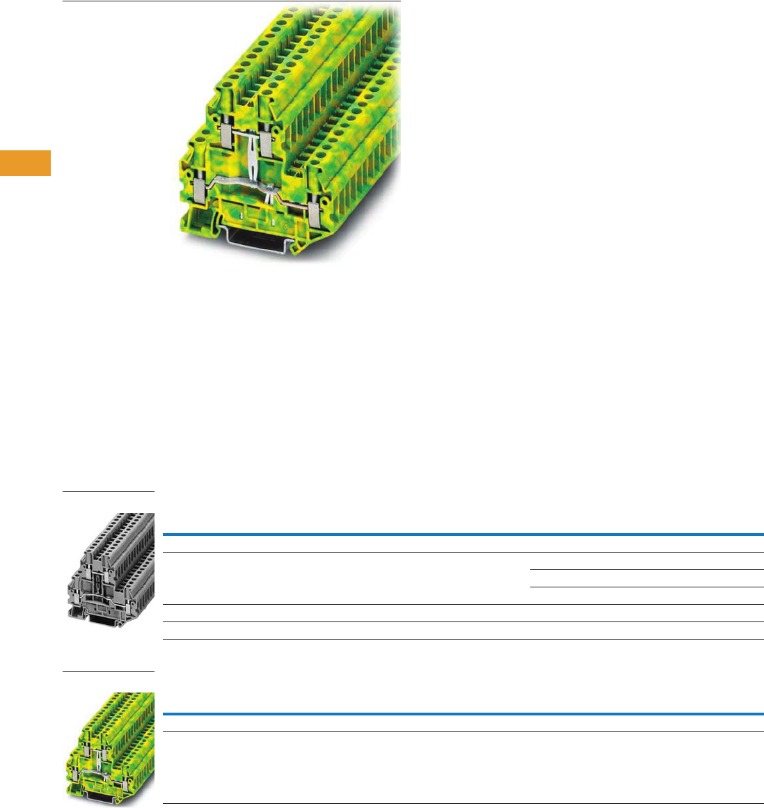
T42-16 Logic Control Products CA08100001K—June 2012 www.eatoncanada.ca
42
42
42
42
42
42
42
42
42
42
42
42
42
42
42
42
42
42
42
42
42
42
42
42
42
42
42
42
42
42
42.1
Terminal Blocks, Fuse Blocks and Fuse Holders
IEC—
XB
Series
Double Level Contents
Description Page
Single Level—Through-Feed . . . . . . . . . . . . . . . . . . . . T42-5
Single Level—Ground Blocks . . . . . . . . . . . . . . . . . . . T42-10
Multi-Conductor Terminal Blocks . . . . . . . . . . . . . . . . T42-12
Multi-Conductor Ground Blocks . . . . . . . . . . . . . . . . . T42-14
Double Level
Accessories . . . . . . . . . . . . . . . . . . . . . . . . . . . . . . T42-17
Technical Data and Specifications . . . . . . . . . . . . . T42-17
Dimensions . . . . . . . . . . . . . . . . . . . . . . . . . . . . . . T42-17
Triple Level Sensor/Actuator . . . . . . . . . . . . . . . . . . . . T42-18
Fuse Terminal Blocks . . . . . . . . . . . . . . . . . . . . . . . . . T42-21
Disconnect and Component Terminal Blocks . . . . . . . T42-24
High Current Blocks . . . . . . . . . . . . . . . . . . . . . . . . . . T42-27
Mini Screw Connection . . . . . . . . . . . . . . . . . . . . . . . . T42-29
Double Level
Product Description
The potentials of the XBUTT
double-level terminal blocks
are on two levels to reduce
space requirements by 50%
over single-level terminal
blocks. The XBUTT Series
can be bridged on both levels
for maximum flexibility.
Marking can be provided at
each termination point.
Product Selection
Screw Connection Double Level Blocks, XBUTT4
Screw Connection Double Level Ground Block, XBUTT4PE
Terminal
Width
Maximum
Wire Size
IEC 60 947-7-1
in V/A/AWG
UL-cUL Ratings
in V/A/AWG Colour
Standard
Pack
Catalogue
Number
Screw Connection Double Level Blocks
6.2 mm 10 AWG/4 mm2800/36/26–10 300/30/26–10 Gray 50 XBUTT4
Blue 50 XBUTT4BU
Red 50 XBUTT4RD
Screw Connection Double Level Block (terminal block with potential distribution between the levels)
6.2 mm 10 AWG/4 mm2800/36/26–10 300/30/26–10 Gray 50 XBUTT4PV
Terminal
Width
Maximum
Wire Size
IEC 60 947-7-1
in V/A/AWG
UL-cUL Ratings
in V/A/AWG Colour
Standard
Pack
Catalogue
Number
Screw Connection Double Level—Ground Blocks
6.2 mm 10 AWG/4 mm2—/—/26–10 —/—/26–10 Green/Yellow 50 XBUTT4PE
XBUTT4
XBUTT4PE
Tab42book.fm Page 16 Thursday, July 5, 2012 8:03 PM

Logic Control Products CA08100001K—June 2012 www.eatoncanada.ca T42-17
42
42
42
42
42
42
42
42
42
42
42
42
42
42
42
42
42
42
42
42
42
42
42
42
42
42
42
42
42
42
42.1
Terminal Blocks, Fuse Blocks and Fuse Holders
IEC—
XB
Series
Accessories
Screw Connection Terminal/Ground Blocks, Double Level
Technical Data and Specifications
Screw Connection Double Level
Dimensions
Approximate Dimensions in Inches (mm)
Screw Connection Double Level
Notes
For ordering information, see Page T42-105.
For information on Printed Marking Tag Options, see Page T42-98.
For additional accessories, see Page T42-90.
Description Colour
Number of
Positions
Standard
Pack
XBUTT4 XBUTT4PE
Catalogue
Number
Catalogue
Number
End cover Gray — 10 XBACUTT4 XBACUTT4
End cover segment Gray — 10 XBDPUTT4 XBDPUTT4
Partition plate — — 10 XBATUTT4 XBATUTT4
Plug-in bridge—for cross connections in
the bridge shaft
Red 2 10 XBAFBS26 XBAFBS26
310 XBAFBS36 XBAFBS36
510 XBAFBS56 XBAFBS56
10 10 XBAFBS106 XBAFBS106
50 10 XBAFBS506 XBAFBS506
Test adapter — — 10 XBATSPAI4 XBATSPAI4
2.3 mm diameter test plug — — — XBATSMPS-_ XBATSMPS-_
Modular test plug — — 10 XBATSPS6 XBATSPS6
Blank marker strip (strip of 10) White — 10 XBMZB6 XBMZB6
Description XBUTT4 XBUTT4PE
Technical Data in Accordance with IEC
Maximum load current in A/cross-section in mm230/6 —/6
Rated surge voltage in kV/contamination class 8/3 6/3
Surge voltage category/insulating material group III/I III/I
Connection Capacity
Stranded with ferrule/with ferrule and
plastic sleeve in mm2
0.25–4/0.25–4 0.25–4/0.25–4
Multi-Conductor Connection
(same cross-section)
Solid/stranded in mm20.14–1.5/0.14–1.5 0.14–1.5/0.14–1.5
Stranded with ferrules without plastic sleeve in mm20.25–1.5 0.25–1.5
Stranded with twin ferrule with plastic sleeve in mm20.5–2.5 0.5–2.5
Stripping length in inches (mm) 0.35 (9) 0.35 (9)
Thread M3 M3
Torque in in-lb (Nm) 5.3–7.1 (0.6–0.8) 5.3–7.1 (0.6–0.8)
Catalogue
Number Width Length
Cover
Width
Height for—
35 x 7.5 in 35 x 15 in
XBUTT4 0.24 (6.2) 2.75 (69.9) 0.09 (2.2) 2.56 (65.0) 2.85 (72.5)
XBUTT4PE 0.24 (6.2) 2.75 (69.9) 0.09 (2.2) 2.56 (65.0) 2.85 (72.5)
Tab42book.fm Page 17 Thursday, July 5, 2012 8:03 PM
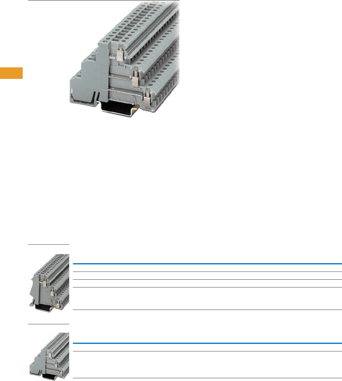
T42-18 Logic Control Products CA08100001K—June 2012 www.eatoncanada.ca
42
42
42
42
42
42
42
42
42
42
42
42
42
42
42
42
42
42
42
42
42
42
42
42
42
42
42
42
42
42
42.1
Terminal Blocks, Fuse Blocks and Fuse Holders
IEC—
XB
Series
Triple Level Sensor/Actuator Contents
Description Page
Single Level—Through-Feed . . . . . . . . . . . . . . . . . . . . T42-5
Single Level—Ground Blocks . . . . . . . . . . . . . . . . . . . T42-10
Multi-Conductor Terminal Blocks . . . . . . . . . . . . . . . . T42-12
Multi-Conductor Ground Blocks . . . . . . . . . . . . . . . . . T42-14
Double Level . . . . . . . . . . . . . . . . . . . . . . . . . . . . . . . . T42-16
Triple Level Sensor/Actuator
Accessories . . . . . . . . . . . . . . . . . . . . . . . . . . . . . . T42-19
Technical Data and Specifications . . . . . . . . . . . . . T42-20
Dimensions . . . . . . . . . . . . . . . . . . . . . . . . . . . . . . T42-20
Fuse Terminal Blocks . . . . . . . . . . . . . . . . . . . . . . . . . T42-21
Disconnect and Component Terminal Blocks . . . . . . . T42-24
High Current Blocks . . . . . . . . . . . . . . . . . . . . . . . . . . T42-27
Mini Screw Connection . . . . . . . . . . . . . . . . . . . . . . . . T42-29
Triple Level Sensor/Actuator
Product Description
The XB3UK sensor terminal
blocks reduce installation
time by terminating three-
wire devices such as
photoelectric and proximity
sensors in a single terminal
block. The XB3UK Series
accommodates a design
where the positive and
negative connections are
grouped so that only the
signal lines and one pair of
wires for the power supply
need to be wired between
the terminal box and the
control. The upper level
accommodates the markable
feed-through terminals for
the signal line. The two lower
terminal points can be
bridged. These are used for
the sensor power supply.
The positive and negative
potential can be fed into the
bridges with XB3UKF25. The
first sensor can also be
connected to this three-wire
feed-through block.
Product Selection
Screw Connection Triple Level Sensor/Actuator
Screw Connection Triple Level Sensor/Actuator
Terminal
Width
Maximum
Wire Size
Connection Data
in V/A/AWG
IEC 60 947-7-1
in V/A/AWG
UL-cUL Ratings
in V/A/AWG Colour
Standard
Pack
Catalogue
Number
Screw Connection Triple Level
6.2 mm 14 AWG/2.5 mm2250/26/24–12 — 300/15/30–14 Gray 50 XB3UKA25
Screw Connection Triple Level with Red LED, 15–30 Vdc, 2.5–7.5A
6.2 mm 14 AWG/2.5 mm2250/26/24–12 — 300/15/30–14 Gray 50 XB3UKA25L24
Terminal
Width
Maximum
Wire Size
Connection Data
in V/A/AWG
IEC 60 947-7-1
in V/A/AWG
UL-cUL Ratings
in V/A/AWG Colour
Standard
Pack
Catalogue
Number
Screw Connection Triple Level
6.2 mm 14 AWG/2.5 mm2— 250/30/24–12 300/15/30–14 Gray 50 XB3UKF25
XB3UKA25
XB3UKF25
Tab42book.fm Page 18 Thursday, July 5, 2012 8:03 PM
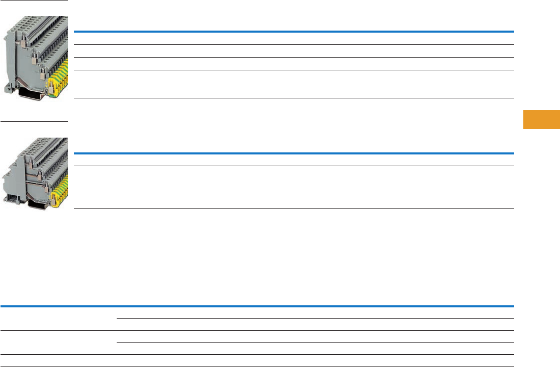
Logic Control Products CA08100001K—June 2012 www.eatoncanada.ca T42-19
42
42
42
42
42
42
42
42
42
42
42
42
42
42
42
42
42
42
42
42
42
42
42
42
42
42
42
42
42
42
42.1
Terminal Blocks, Fuse Blocks and Fuse Holders
IEC—
XB
Series
Screw Connection Triple Level Sensor/Actuator
Screw Connection Triple Level Sensor/Actuator
Accessories
Screw Connection Triple Level Sensor/Actuator
Notes
For information on Printed Marking Tag Options, see Page T42-98.
For additional accessories, see Page T42-90.
Terminal
Width
Maximum
Wire Size
Connection Data
in V/A/AWG
UL-cUL Ratings
in V/A/AWG Colour
Standard
Pack
Catalogue
Number
Screw Connection Triple Level
6.2 mm 14 AWG/2.5 mm2250/26/24–12 300/15/30–14 Gray 50 XB3UKA25PE
Screw Connection Triple Level with Red LED, 15–30 Vdc, 2.5–7.5A
6.2 mm 14 AWG/2.5 mm2250/26/24–12 300/15/30–14 Gray 50 XB3UKA25PEL24
Terminal
Width
Maximum
Wire Size
Connection Data
in V/A/AWG
UL-cUL Ratings
in V/A/AWG Colour
Standard
Pack
Catalogue
Number
Screw Connection Triple Level
6.2 mm 14 AWG/2.5 mm2— 300/15/30–14 Gray 50 XB3UKF25PE
Description Colour
Number of
Positions
Standard
Pack
XB3UKA25 XB3UKF25 XB3UKA25PE XB3UKF25PE
Catalogue
Number
Catalogue
Number
Catalogue
Number
Catalogue
Number
Insertion bridge Blue 80 1 XBAEB80DIKB XBAEB80DIKB XBAEB80DIKB XBAEB80DIKB
Red 80 1 XBAEB80DIKR XBAEB80DIKR XBAEB80DIKR XBAEB80DIKR
Insertion bridge Blue 10 10 XBAEB10DIKB XBAEB10DIKB XBAEB10DIKB XBAEB10DIKB
Red 10 10 XBAEB10DIKR XBAEB10DIKR XBAEB10DIKR XBAEB10DIKR
Blank marker strip (strip of 10) White — 10 XBMZB6 XBMZB6 XBMZB6 XBMZB6
XB3UKA25PE
XB3UKF25PE
Tab42book.fm Page 19 Thursday, July 5, 2012 8:03 PM
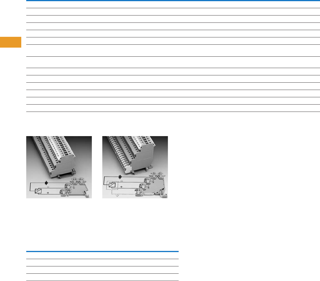
T42-20 Logic Control Products CA08100001K—June 2012 www.eatoncanada.ca
42
42
42
42
42
42
42
42
42
42
42
42
42
42
42
42
42
42
42
42
42
42
42
42
42
42
42
42
42
42
42.1
Terminal Blocks, Fuse Blocks and Fuse Holders
IEC—
XB
Series
Technical Data and Specifications
Screw Connection Triple Level Sensor/Actuator
Wiring for Three-Level
Sensor Terminal Blocks
Wiring for Four-Level
Sensor Terminal Blocks
Dimensions
Approximate Dimensions in Inches (mm)
Screw Connection Triple Level Sensor/Actuator
Description XB3UKA25 XB3UKF25 XB3UKA25PE XB3UKF25PE
Technical Data in Accordance with IEC
Maximum load current in A/cross-section in mm226/2.5 30/4 26/2.5 26/2.5
Maximum cross section with insertion bridge solid/stranded in mm24/2.5 4/2.5 4/2.5 4/2.5
Rated surge voltage in kV/contamination class 4/3 4/3 4/3 6/3
Surge voltage category/insulating material group III/I III/I III/I III/I
Connection Capacity
Stranded with ferrule/with ferrule and
plastic sleeve in mm2
0.25–2.5/0.25–2.5 0.25–2.5/0.25–2.5 0.25–2.5/0.25–2.5 0.25–2.5/0.25–2.5
Multi-Conductor Connection
(same cross-section)
Solid/stranded in mm20.2–1.0/0.2–1.0 0.2–1.0/0.2–1.0 0.2–1.0/0.2–1.0 0.2–1.0/0.2–1.0
Stranded with ferrules without plastic sleeve in mm20.25–1.0 0.25–1.0 0.25–1.0 0.25–1.0
Stranded with twin ferrule with plastic sleeve in mm20.5–1.0 0.5–1.0 0.5–1.0 0.5–1.0
Stripping length in inches (mm) 0.31 (8) 0.31 (8) 0.31 (8) 0.31 (8)
Thread M3 M3 M3 M3
Torque in in-lb (Nm) 4.4–5.3 (0.5–0.6) 4.4–5.3 (0.5–0.6) 4.4–5.3 (0.5–0.6) 4.4–5.3 (0.5–0.6)
Catalogue
Number Width Length
Height for—
35 x 7.5 in 35 x 15 in
XB3UKA25 0.24 (6.2) 2.17 (55.0) 2.15 (54.5) 2.44 (62.0)
XB3UKF25 0.24 (6.2) 2.85 (72.5) 2.15 (54.5) 2.44 (62.0)
XB3UKA25PE 0.24 (6.2) 2.46 (62.5) 2.76 (70.0) 3.05 (77.5)
XB3UKF25PE 0.24 (6.2) 3.25 (82.5) 2.76 (70.0) 3.05 (77.5)
Tab42book.fm Page 20 Thursday, July 5, 2012 8:03 PM
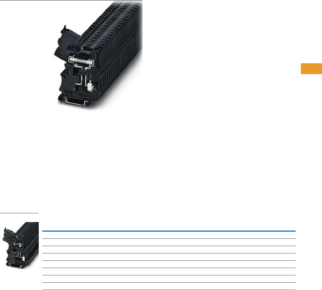
Logic Control Products CA08100001K—June 2012 www.eatoncanada.ca T42-21
42
42
42
42
42
42
42
42
42
42
42
42
42
42
42
42
42
42
42
42
42
42
42
42
42
42
42
42
42
42
42.1
Terminal Blocks, Fuse Blocks and Fuse Holders
IEC—
XB
Series
Fuse Terminal Blocks Contents
Description Page
Single Level—Through-Feed . . . . . . . . . . . . . . . . . . . . T42-5
Single Level—Ground Blocks . . . . . . . . . . . . . . . . . . . T42-10
Multi-Conductor Terminal Blocks . . . . . . . . . . . . . . . . . T42-12
Multi-Conductor Ground Blocks . . . . . . . . . . . . . . . . . T42-14
Double Level. . . . . . . . . . . . . . . . . . . . . . . . . . . . . . . . . T42-16
Triple Level Sensor/Actuator . . . . . . . . . . . . . . . . . . . . T42-18
Fuse Terminal Blocks
Accessories . . . . . . . . . . . . . . . . . . . . . . . . . . . . . . T42-23
Technical Data and Specifications . . . . . . . . . . . . . T42-23
Dimensions . . . . . . . . . . . . . . . . . . . . . . . . . . . . . . T42-23
Disconnect and Component Terminal Blocks . . . . . . . T42-24
High Current Blocks . . . . . . . . . . . . . . . . . . . . . . . . . . . T42-27
Mini Screw Connection . . . . . . . . . . . . . . . . . . . . . . . . T42-29
Fuse Terminal Blocks
Product Description
The UT Series fuse terminal
blocks come in two varieties—
lever type and cap. Each
performs two functions. They
act as a fuse carrier for most
common North American and
European fuses and they
allow for potential distribution
with the double bridge shaft.
The terminal blocks therefore
allow bypass routing of two
separate potentials next to
each other. This has the
advantage of a time-saving
potential infeed and a correct,
functional configuration of the
terminal strip. For signaling a
triggered fuse, fuse terminal
blocks with light indicators
are available (for both AC and
DC voltage).
Product Selection
Screw Connection Fuse Terminal Blocks, for 5 x 20 mm Fuse
Note
As disconnect terminal block 400V, as fuse terminal block 250V.
Terminal
Width
Maximum
Wire Size
IEC 60 947-7-3
in V/A/AWG
UL-cUL Ratings
in V/A/AWG Colour
Standard
Pack
Catalogue
Number
Fuse Terminal Blocks
6.2 mm 10 AWG/4 mm2/6.3/26–10 600/6.3/26–10 Black 50 XBUT4FBE
Fuse Terminal Blocks with LED 12–30V, 1–2.5 mA
6.2 mm 10 AWG/4 mm2/6.3/26–10 600/6.3/26–10 Black 50 XBUT4FBEL24
Fuse Terminal Blocks with LED 30–60V, 0.8–2.0 mA
6.2 mm 10 AWG/4 mm2/6.3/26–10 600/6.3/26–10 Black 50 XBUT4FBEL60
Fuse Terminal Blocks with LED 110–250V, 0.5–2.5 mA
6.2 mm 10 AWG/4 mm2/6.3/26–10 600/6.3/26–10 Black 50 XBUT4FBEL250
XBUT4FBE
Tab42book.fm Page 21 Thursday, July 5, 2012 8:03 PM
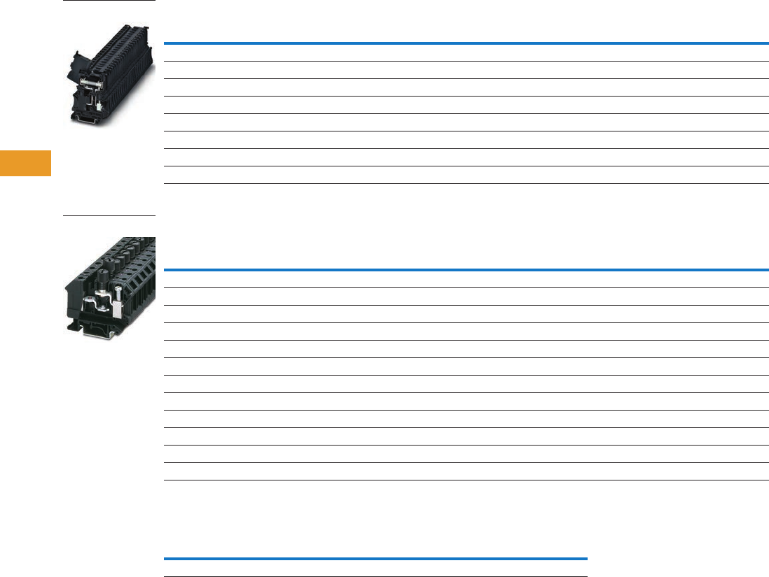
T42-22 Logic Control Products CA08100001K—June 2012 www.eatoncanada.ca
42
42
42
42
42
42
42
42
42
42
42
42
42
42
42
42
42
42
42
42
42
42
42
42
42
42
42
42
42
42
42.1
Terminal Blocks, Fuse Blocks and Fuse Holders
IEC—
XB
Series
Screw Connection Fuse Terminal Blocks for 6.3 x 32 mm (1/4 in x 1–1/4 in) Fuse
Screw Connection Fuse Terminal Blocks, XBUK10FBC
Cartridge Fuse Inserts 5 x 20 mm Based on DIN EN 60 947-7-3: 2003-7
Notes
Max. power dissipation at 73.4˚F (23˚C) based on DIN EN 60 947-7-3: 2003-7.
When selecting cartridge fuse inserts, please ensure that the maximum power dissipation specified above
is not exceeded. Details can be obtained from the fuse suppliers.
If the fuse is defective, the downstream circuit is not off load.
As disconnect terminal block 500V, as fuse terminal block 400V.
Terminal
Width
Maximum
Wire Size
IEC 60 947-7-3
in V/A/AWG
UL-cUL Ratings
in V/A/AWG Colour
Standard
Pack
Catalogue
Number
Fuse Terminal Blocks
8.2 mm 8 AWG/6 mm2/10/24–8 400/10/24–8 Black 50 XBUT6FBN
Fuse Terminal Blocks with LED 12–30V, 1–2.5 mA
8.2 mm 8 AWG/6 mm2/10/24–8 400/10/24–8 Black 50 XBUT6FBNL24
Fuse Terminal Blocks with LED 30–60V, 0.8–2.0 mA
8.2 mm 8 AWG/6 mm2/10/24–8 400/10/24–8 Black 50 XBUT6FBNL60
Fuse Terminal Blocks with LED 110–250V, 0.5–2.5 mA
8.2 mm 8 AWG/6 mm2/10/24–8 400/10/24–8 Black 50 XBUT6FBNL250
Terminal
Width
Maximum
Wire Size
IEC 60 947-7-3
with Fuse in
V/A/AWG
IEC 60 947-7-3
as Disconnected
t.b. in V/A/AWG
UL-cUL Ratings
in V/A/AWG Colour
Standard
Pack
Catalogue
Number
Fuse Terminal Blocks for 5 x 20 mm fuse
12 mm 6 AWG/16 mm2//20–4 800/10/20–6 300/20/22–6 Black 50 XBUK10FBCE
Fuse Terminal Blocks for 6.3 x 32 mm (1/4 in x 1–1/4 in) fuse
12 mm 6 AWG/16 mm2//20–4 800/10/20–6 300/20/22–6 Black 50 XBUK10FBCN
Fuse Terminal Blocks with Light Indicator 15–30V, 1–2.5 mA, 5 x 20 mm
12 mm 6 AWG/16 mm2//20–4 800/10/20–6 300/20/22–6 Black 50 XBUK10FBCEL24
Fuse Terminal Blocks with Light Indicator 15–30V, 1–2.5 mA, 6.3 x 32 mm
12 mm 6 AWG/16 mm2//20–4 800/10/20–6 300/20/22–6 Black 50 XBUK10FBCNL24
Fuse Terminal Blocks with Light Indicator 110–250V, 0.5–1.1A, 5 x 20 mm
12 mm 6 AWG/16 mm2//20–4 800/10/20–6 300/20/22–6 Black 50 XBUK10FBCEL250
Fuse Terminal Blocks with Light Indicator 110–250V, 0.5–1.1A, 6.3 x 32 mm
12 mm 6 AWG/16 mm2//20–4 800/10/20–6 300/20/22–6 Black 50 XBUK10FBCNL250
Terminal
Blocks U (V)
Overload Protection Short-Circuit Protection Only
Individual Interconnected Individual Interconnected Imax. (A)
XBUT4FBE 250 1.6W 1.6W 4W 2.5W 6.3
XBUT6FBN
XBUK10FBCE
Tab42book.fm Page 22 Thursday, July 5, 2012 8:03 PM

Logic Control Products CA08100001K—June 2012 www.eatoncanada.ca T42-23
42
42
42
42
42
42
42
42
42
42
42
42
42
42
42
42
42
42
42
42
42
42
42
42
42
42
42
42
42
42
42.1
Terminal Blocks, Fuse Blocks and Fuse Holders
IEC—
XB
Series
Accessories
Screw Connection Fuse Terminal Blocks
Technical Data and Specifications
Screw Connection Fuse Terminal Blocks
Dimensions
Approximate Dimensions in Inches (mm)
Screw Connection Fuse Terminal Blocks
Notes
XBUT4FBE and XBUT6FBN have an enclosed design. The use of an end cover is not required.
For information on Printed Marking Tag Options, see Page T42-98.
For additional accessories, see Page T42-90.
Description Colour
Number of
Positions
Standard
Pack
XBUT4FBE XBUT6FBN XBUK10FBCE
Catalogue
Number
Catalogue
Number
Catalogue
Number
End cover — — — —
Plug-in bridge—for cross connections in
the bridge shaft
Red 2 10 XBAFBS26 XBAFBS28 —
310XBAFBS36 XBAFBS38 —
510XBAFBS56 XBAFBS58 —
10 10 XBAFBS106 XBAFBS108 —
50 10 XBAFBS506 — —
Blank marker strip centre labeling (strip of 10) White — — XBMZB5 XBMZB6 —
Blank marker strip external labeling (strip of 10) White — — XBMZB6 XBMZB8 —
Fixed bridge — 2 10 — — XBAFBI212
Screw heads with insulating collar — 10 10 — — XBAFBI1012
Blank marker strip (strip of 10) White — 10 — — XBMZB6
Description XBUT4FBE XBUT4FBN XBUK10FBCE
Technical Data in Accordance with IEC
Fuse type/dimensions in (mm) — — G/5 x 20/5 x 25/6.3 x 32
Maximum cross section with insertion bridge solid/stranded in mm26.3/6 10/10 10/10
Rated surge voltage in kV/contamination class 4/3 4/3 4/3
Surge voltage category/insulating material group III/II III/II III/I
Connection Capacity
Stranded with ferrule/with ferrule and plastic sleeve in mm20.25–4/0.25–4 0.25–6/0.25–6 0.5–10/0.5–10
Multi-Conductor Connection (same cross-section)
Solid/stranded in mm20.14–1.5/0.14–1.5 — 0.5–4/0.5–4
Stranded with ferrules without plastic sleeve in mm20.25–1.5 — 0.5–4
Stranded with twin ferrule with plastic sleeve in mm20.5–2.5 0.5–4 0.5–10
Stripping length in inches (mm) 0.35 (9) 0.39 (10) 0.43 (11)
Thread M3 M4 M4
Torque in in-lb (Nm) 5.3–7.1 (0.6–0.8) 13.3–15.9 (1.5–1.8) 13.3–15.9 (1.5–1.8)
Catalogue
Number Width Length
Height for—
35 x 7.5 in 35 x 15 in 32 in
XBUT4FBE 0.24 (6.2) 2.24 (56.8) 2.87 (73.0) 3.17 (80.5) —
XBUT4FBN 0.32 (8.2) 2.24 (56.8) 2.87 (73.0) 3.17 (80.5) —
XBUK10FBCE 0.47 (12.0) 2.44 (62.0) 2.32 (59.0) 2.62 (66.5) 2.52 (64.0)
Tab42book.fm Page 23 Thursday, July 5, 2012 8:03 PM

T42-24 Logic Control Products CA08100001K—June 2012 www.eatoncanada.ca
42
42
42
42
42
42
42
42
42
42
42
42
42
42
42
42
42
42
42
42
42
42
42
42
42
42
42
42
42
42
42.1
Terminal Blocks, Fuse Blocks and Fuse Holders
IEC—
XB
Series
Disconnect and Component Terminal Blocks Contents
Description Page
Single Level—Through-Feed . . . . . . . . . . . . . . . . . . . . T42-5
Single Level—Ground Blocks . . . . . . . . . . . . . . . . . . . T42-10
Multi-Conductor Terminal Blocks . . . . . . . . . . . . . . . . T42-12
Multi-Conductor Ground Blocks . . . . . . . . . . . . . . . . . T42-14
Double Level . . . . . . . . . . . . . . . . . . . . . . . . . . . . . . . . T42-16
Triple Level Sensor/Actuator . . . . . . . . . . . . . . . . . . . . T42-18
Fuse Terminal Blocks . . . . . . . . . . . . . . . . . . . . . . . . . T42-21
Disconnect and Component Terminal Blocks
Product Selection . . . . . . . . . . . . . . . . . . . . . . . . . . T42-25
Accessories . . . . . . . . . . . . . . . . . . . . . . . . . . . . . . T42-26
Technical Data and Specifications . . . . . . . . . . . . . T42-26
Dimensions . . . . . . . . . . . . . . . . . . . . . . . . . . . . . . T42-26
High Current Blocks . . . . . . . . . . . . . . . . . . . . . . . . . . T42-27
Mini Screw Connection . . . . . . . . . . . . . . . . . . . . . . . . T42-29
Disconnect and Component Terminal Blocks
Product Description
The XB Series includes
application specific terminal
blocks like the XBUT4TG
disconnect block that
accommodates disconnect
component and fuse terminal
blocks. It can also be bridged
with standard terminal blocks
via the double bridge shaft.
The component plug XBPCO
serves to accommodate
different components such
as resistors or capacitors.
5 x 20 mm fuses can be
inserted into the fuse plug
XBPFU, also available with
light indication. The XBUT4MT
knife disconnect terminal
block features a compact
design and a high current
carrying capacity of 16A.
Versions with test socket
screws provide a test option
for 2.3 mm diameter test
plugs on both sides of the
disconnect point.
Tab42book.fm Page 24 Thursday, July 5, 2012 8:03 PM

Logic Control Products CA08100001K—June 2012 www.eatoncanada.ca T42-25
42
42
42
42
42
42
42
42
42
42
42
42
42
42
42
42
42
42
42
42
42
42
42
42
42
42
42
42
42
42
42.1
Terminal Blocks, Fuse Blocks and Fuse Holders
IEC—
XB
Series
Product Selection
Screw Connection Disconnect and Component Terminal Blocks
Screw Connection Thermoelectric Voltage Terminal Blocks
Terminal
Width
Maximum
Wire Size
Connection Data
in V/A/AWG
UL-cUL Ratings
for Disconnect
in V/A/AWG
UL-cUL Ratings
for Disconnect
with Test Sockets
in V/A/AWG Colour
Standard
Pack
Catalogue
Number
Screw Connection Disconnect
6.2 mm 10 AWG/4 mm2500/16/26–10 600/16/26–10 300/16/26–10 Gray 50 XBUT4TG
Screw Connection Disconnect with Test Sockets
6.2 mm 10 AWG/4 mm2500/16/26–10 600/16/26–10 300/16/26–10 Gray 50 XBUT4TGP
Component Plug
6.2 mm 10 AWG/4 mm2500/16/26–10 600/16/26–10 300/16/26–10 Gray 10 XBPCO
Fuse Plug
6.2 mm 10 AWG/4 mm2500/16/26–10 600/16/26–10 300/16/26–10 Black 10 XBPFU
Fuse Plug with Light Indicator for 12–30V, 1–2.5 mA
6.2 mm 10 AWG/4 mm2500/16/26–10 600/16/26–10 300/16/26–10 Black 10 XBPFUL24
Fuse Plug with Light Indicator for 110–250V, 0.5–2.5 mA
6.2 mm 10 AWG/4 mm2500/16/26–10 600/16/26–10 300/16/26–10 Black 10 XBPFUL250
Screw Connection Disconnect Knife Disconnect
6.2 mm 10 AWG/4 mm2500/16/26–10 600/16/26–10 300/16/26–10 Gray 50 XBUT4MT
Screw Connection Disconnect Knife Disconnect with Test Sockets
6.2 mm 10 AWG/4 mm2500/16/26–10 600/16/26–10 300/16/26–10 Gray 50 XBUT4MTP
Screw Connection Terminal Blocks with Integrated Diodes
6.2 mm 12 AWG/4 mm2500/32/24–10 600/30/26–10 — Gray 50 XBUKK4DIO
Terminal
Width
Maximum
Wire Size
Connection Data
in V/A/AWG
UL-cUL Ratings
in V/A/AWG Colour
Standard
Pack
Catalogue
Number
Copper/Constantan (CU/CUNI44)
10.4 mm 12 AWG/2.5 mm2400/—/24–12 300/10/28–12 Gray 50 XBTKT25 (Type T)
Iron/Constantan (FE/CUNI44)
10.4 mm 12 AWG/2.5 mm2400/—/24–12 300/10/28–12 Gray 50 XBTKJ25 (Type J)
Nickel-Chrome/Constantan (NICR/CUNI44)
10.4 mm 12 AWG/2.5 mm2400/—/24–12 300/10/28–12 Gray 50 XBTKE25 (Type E)
Nickel-Chrome/Nickel (NICRNI)
10.4 mm 12 AWG/2.5 mm2400/—/24–12 300/10/28–12 Gray 50 XBTKK25 (Type K)
Copper/Copper Nickel (E-CU/A-CU)
10.4 mm 12 AWG/2.5 mm2400/—/24–12 300/10/28–12 Gray 50 XBTKR25 (Type R)
XBUT4TG
Disconnect
XBTKT25 Thermal
Electric Voltage
Tab42book.fm Page 25 Thursday, July 5, 2012 8:03 PM

T42-26 Logic Control Products CA08100001K—June 2012 www.eatoncanada.ca
42
42
42
42
42
42
42
42
42
42
42
42
42
42
42
42
42
42
42
42
42
42
42
42
42
42
42
42
42
42
42.1
Terminal Blocks, Fuse Blocks and Fuse Holders
IEC—
XB
Series
Accessories
Screw Connection Disconnect and Component Terminal Blocks
Technical Data and Specifications
Screw Connection Disconnect and Component Terminal Blocks
Dimensions
Approximate Dimensions in Inches (mm)
Screw Connection Disconnect and Component Terminal Blocks
Notes
For ordering information, see Page T42-105.
For information on Printed Marking Tag Options, see Page T42-98.
For additional accessories, see Page T42-90.
Description Colour
Number of
Positions
Standard
Pack
XBUT4TG XBUT4MT XBUKK4DI0 XBTKT25
Catalogue
Number
Catalogue
Number
Catalogue
Number
Catalogue
Number
Plug-in bridge—for cross connections in
the bridge shaft
Red 2 10 XBAFBS26 XBAFBS26 — —
310XBAFBS36 XBAFBS36 — —
510XBAFBS56 XBAFBS56 — —
10 10 XBAFBS106 XBAFBS106 — —
50 10 XBAFBS506 XBAFBS506 — —
Test adapter — — 10 XBATSPAI4 XBATSPAI4 — —
2.3 mm diameter test plug — — — XBATSMPS-_ XBATSMPS-_ ——
Modular test plug — — 10 XBATSDPPS6 XBATSDPPS6 — —
Blank marker strip (strip of 10) White — 10 XBMZB6 XBMZB6 XBMZB6 XBMZB10
End cover Gray — 10 — — XBACUKK35 XBACTK4
Spacer cover Gray — 10 — — XBADGUKK35 —
Spacer plate — — 10 — — XBADPUKK35 —
Partition plate — — — — — — XBATTK4
Fixed bridge — 10 10 — — XBAFBI106 —
Description XBUT4TG XBUT4MT XBUKK4DI0 XBTK
Technical Data in Accordance with IEC
Maximum load current in A/cross-section in mm216/6 16/6 32/4 —
Rated surge voltage in kV/contamination class 6/3 6/3 6/3 —
Surge voltage category/insulating material group III/I III/I III/I —
Connection Capacity
Stranded with ferrule/with ferrule and
plastic sleeve in mm2
0.25–4/0.25–4 0.25–4/0.25–4 0.25–4/0.25–2.5 —
Multi-Conductor Connection
(same cross-section)
Solid/stranded in mm20.14–1.5/0.14–1.5 0.14–1.5/0.14–1.5 0.2–1.5/0.2–1.5 —
Stranded with ferrules without plastic sleeve in mm20.25–1.5 0.25–1.5 0.25–1.5 —
Stranded with twin ferrule with plastic sleeve in mm20.5–2.5 0.5–2.5 0.5–1.5 —
Stripping length in inches (mm) 0.35 (9) 0.35 (9) 0.31 (8) 0.28 (7)
Thread M3 M3 M3 M3
Torque in in-lb (Nm) 5.3–7.1 (0.6–0.8) 5.3–7.1 (0.6–0.8) 5.3–7.1 (0.6–0.8) 5.3–7.1 (0.6–0.8)
Catalogue
Number Width Length
Cover
Width
Height for—
35 x 7.5 in 35 x 15 in 32 in
XBUT4TG 0.24 (6.2) 2.24 (56.8) — 1.87 (47.5) 2.17 (55.0) —
XBUT4MT 0.24 (6.2) 2.24 (56.8) — 1.87 (47.5) 2.17 (55.0) —
XBUKK4DI0 0.24 (6.2) 2.20 (56.0) 0.10 (2.5) 2.44 (62.0) 2.74 (69.5) 2.64 (67.0)
XBTK 0.20 (5.2) 1.81 (46.0) 0.04 (1.0) 1.57 (40.0) 1.87 (47.5) 1.77 (45.0)
Tab42book.fm Page 26 Thursday, July 5, 2012 8:03 PM
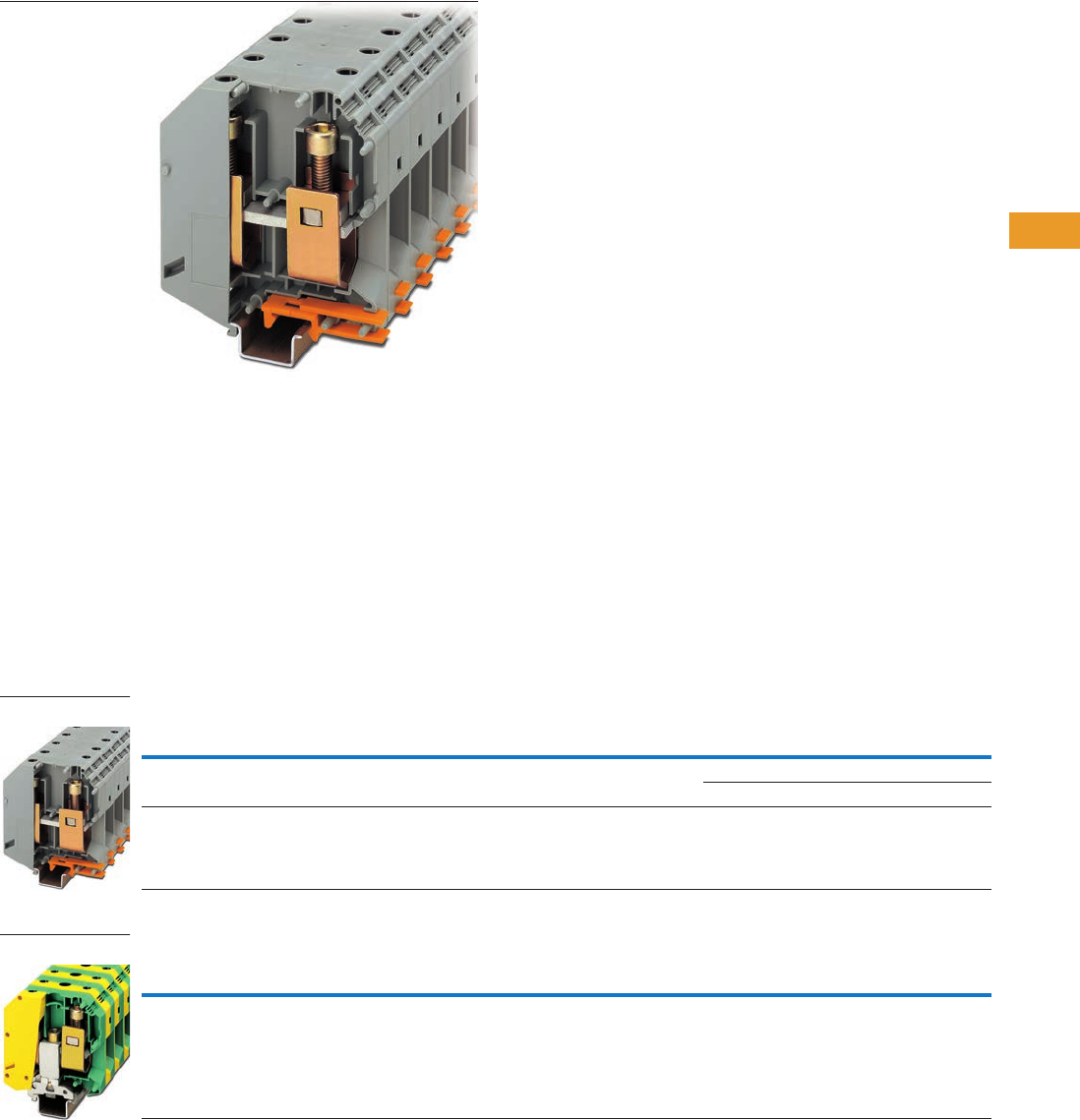
Logic Control Products CA08100001K—June 2012 www.eatoncanada.ca T42-27
42
42
42
42
42
42
42
42
42
42
42
42
42
42
42
42
42
42
42
42
42
42
42
42
42
42
42
42
42
42
42.1
Terminal Blocks, Fuse Blocks and Fuse Holders
IEC—
XB
Series
High Current Blocks Contents
Description Page
Single Level—Through-Feed . . . . . . . . . . . . . . . . . . . . T42-5
Single Level—Ground Blocks . . . . . . . . . . . . . . . . . . . T42-10
Multi-Conductor Terminal Blocks . . . . . . . . . . . . . . . . . T42-12
Multi-Conductor Ground Blocks . . . . . . . . . . . . . . . . . T42-14
Double Level. . . . . . . . . . . . . . . . . . . . . . . . . . . . . . . . . T42-16
Triple Level Sensor/Actuator . . . . . . . . . . . . . . . . . . . . T42-18
Fuse Terminal Blocks . . . . . . . . . . . . . . . . . . . . . . . . . . T42-21
Disconnect and Component Terminal Blocks . . . . . . . T42-24
High Current Blocks
Accessories . . . . . . . . . . . . . . . . . . . . . . . . . . . . . . T42-28
Technical Data and Specifications . . . . . . . . . . . . . T42-28
Dimensions . . . . . . . . . . . . . . . . . . . . . . . . . . . . . . T42-28
Mini Screw Connection . . . . . . . . . . . . . . . . . . . . . . . . T42-29
High Current Blocks
Product Description
Eaton’s XBUK high current
terminal blocks offer a
reliable connection via
the superior construction that
includes three-point centering
of the wire in the
prism-shaped sleeve base,
a fluted contact surface
for low contact resistance,
and screws secured with
spring-loaded elements.
The terminal blocks have
an enclosed housing made
from polyamide 6.6. Green-
yellow ground terminal blocks
are also available.
Product Selection
Screw Connection High Current Blocks
Screw Connection High Current Ground Blocks
Note
U type—examination certificate number: KEMA 05ATEX2170 U (XBUK50), KEMA 05ATEX2171 U (XBUK150).
Terminal
Width
Maximum
Wire Size
IEC 60 947-7-1
in V/A/AWG
EN 50 019
in V/A/AWG
UL-cUL Ratings
in V/A/AWG Colour
Standard
Pack
Catalogue
Number
20.0 mm 1/0/50 mm21000/150/1/0 750/135/1/0 600/150/1/0 Gray 10 XBUK50
Blue 10 XBUK50BU
31.0 mm 300 kcmil/150 mm21000/309/2–300 726/265/2–300 600/285/
2 AWG–300 kcmil
Gray 10 XBUK150
Terminal
Width
Maximum
Wire Size
IEC 60 947-7-1
in V/A/AWG
EN 50 019
in V/A/AWG
UL-cUL Ratings
in V/A/AWG Colour
Standard
Pack
Catalogue
Number
25.0 mm 000 AWG/95 mm2—/232/4–000 —/—/4–000 —/—/2–4/0 Green/Yellow 10 XBUK95PE
XBUK150
XBUK95PE
Tab42book.fm Page 27 Thursday, July 5, 2012 8:03 PM

T42-28 Logic Control Products CA08100001K—June 2012 www.eatoncanada.ca
42
42
42
42
42
42
42
42
42
42
42
42
42
42
42
42
42
42
42
42
42
42
42
42
42
42
42
42
42
42
42.1
Terminal Blocks, Fuse Blocks and Fuse Holders
IEC—
XB
Series
Accessories
Screw Connection High Current Blocks
Technical Data and Specifications
Screw Connection High Current Blocks
Dimensions
Approximate Dimensions in Inches (mm)
Screw Connection High Current Blocks
Notes
For information on Printed Marking Tag Options, see Page T42-98.
For additional accessories, see Page T42-90.
Description Colour
Number of
Positions
Standard
Pack
XBUK50 XBUK150 XBUK95PE
Catalogue
Number
Catalogue
Number
Catalogue
Number
Fixed bridge, screw heads with insulating colour — 2 10 XBAFBI220 — —
Insertion bridge — 2 10 — XBAEB231 —
Blank marker strip external labeling (strip of 10) White — 10 XBMZB10 XBMZB10 XBMZB10
Description XBUK50 XBUK150 XBUK95PE
Technical Data in Accordance with IEC
Maximum load current in A/cross-section in mm2150/50 309/150 232/95
Maximum cross-section with insertion bridge
solid/stranded in mm2
—/— 150/120 —/—
Rated surge voltage in kV/contamination class 8/3 8/3 8/3
Surge voltage category/insulating material group III/I III/I III/I
Connection Capacity
Stranded with ferrule/with ferrule and
plastic sleeve in mm2
25–50/25–50 50–150/50–150 35–95/35–95
Multi-Conductor Connection
(same cross-section)
Solid/stranded in mm210–16/10–16 25–50/35–50 25–35/25–35
Stranded with ferrules without plastic sleeve in mm210–16 25–50 16–35
Stripping length in inches (mm) 0.94 (24) 1.57 (40) 1.18 (30)
Thread M6 M10 M8
Terminal point—thread/torque in in-lb (Nm) 53–71 (6–8) 221–267 (25–30) 133–177 (15–20)
Fastening—thread/torque in in-lb (Nm) 53–71 (6–8) 221–267 (25–30) 133–177 (15–20)
Catalogue
Number Width Length
Height for—
35 x 7.5 in 35 x 15 in 32 in
XBUK50 0.79 (20.0) 2.78 (70.5) 3.29 (83.5) 3.21 (81.5) —
XBUK150 1.22 (31.0) 3.94 (100.0) 4.67 (118.5) 4.57 (116.0) —
XBUK95PE 0.98 (25.0) 3.27 (83.0) — 3.90 (99.0) 3.80 (96.5)
Tab42book.fm Page 28 Thursday, July 5, 2012 8:03 PM
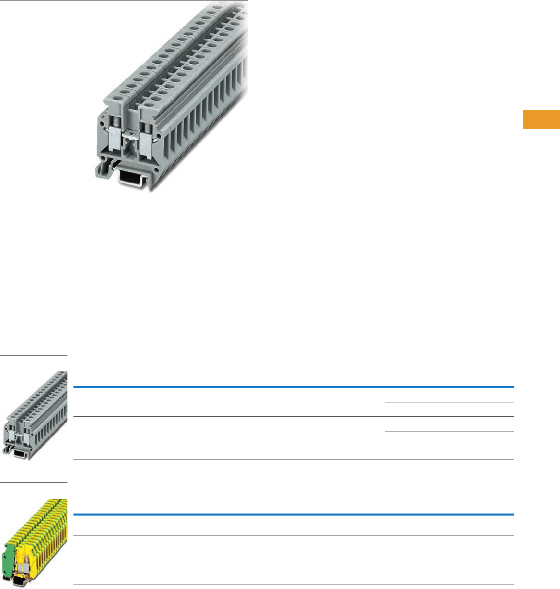
Logic Control Products CA08100001K—June 2012 www.eatoncanada.ca T42-29
42
42
42
42
42
42
42
42
42
42
42
42
42
42
42
42
42
42
42
42
42
42
42
42
42
42
42
42
42
42
42.1
Terminal Blocks, Fuse Blocks and Fuse Holders
IEC—
XB
Series
Mini Screw Connection Terminal Blocks Contents
Description Page
Single Level—Through-Feed . . . . . . . . . . . . . . . . . . . . T42-5
Single Level—Ground Blocks . . . . . . . . . . . . . . . . . . . T42-10
Multi-Conductor Terminal Blocks . . . . . . . . . . . . . . . . . T42-12
Multi-Conductor Ground Blocks . . . . . . . . . . . . . . . . . T42-14
Double Level. . . . . . . . . . . . . . . . . . . . . . . . . . . . . . . . . T42-16
Triple Level Sensor/Actuator . . . . . . . . . . . . . . . . . . . . T42-18
Fuse Terminal Blocks . . . . . . . . . . . . . . . . . . . . . . . . . . T42-21
Disconnect and Component Terminal Blocks . . . . . . . T42-24
High Current Blocks . . . . . . . . . . . . . . . . . . . . . . . . . . . T42-27
Mini Screw Connection
Accessories . . . . . . . . . . . . . . . . . . . . . . . . . . . . . . T42-30
Technical Data and Specifications . . . . . . . . . . . . . T42-30
Dimensions . . . . . . . . . . . . . . . . . . . . . . . . . . . . . . T42-30
Mini Screw Connection
Product Description
The XB miniature terminal
blocks have a connection
cross-section from 2 mm2
through 4 mm2 and mount on
15 mm DIN rail. There is an
opening for bridging with a
fixed bridge in the centre of
the terminal blocks. These
miniature terminal blocks also
offer the same accessories
that you would find with the
larger blocks—including
marking tags, end covers,
end stop and ground blocks.
Product Selection
Mini Screw Connection Terminal Blocks
Mini Screw Connection Ground Blocks
Note
EU type—examination certificate number: KEMA 05ATEX2169 U (XBMUK25).
Terminal
Width
Maximum
Wire Size
IEC 60 947-7-1
in V/A/AWG
EN 50 019
in V/A/AWG
UL-cUL Ratings
in V/A/AWG Colour
Standard
Pack
Catalogue
Number
5.2 mm 12 AWG/2.5 mm2400/32/24–12 275/28/21/24–12 600/20/28–12 Gray 50 XBMUK25
Blue 50 XBMUK25BU
6.2 mm 10 AWG/4 mm2500/41/24–10 —/—/— 600/10/26–10 Gray 50 XBMUK4
Blue 50 XBMUK4BU
Terminal
Width
Maximum
Wire Size
IEC 60 947-7-2
in V/A/AWG
UL-cUL Ratings
in V/A/AWG Colour
Standard
Pack
Catalogue
Number
5.2 mm 12 AWG/2.5 mm2—/—/24–12 —/—/30–12 Green/
Yellow
50 XBMUK25PE
6.2 mm 10 AWG/2.4 mm2—/—/24–10 —/—/26–14 Green/
Yellow
50 XBMUK4PE
XBMUK4
XBMUK25PE
Tab42book.fm Page 29 Thursday, July 5, 2012 8:03 PM

T42-30 Logic Control Products CA08100001K—June 2012 www.eatoncanada.ca
42
42
42
42
42
42
42
42
42
42
42
42
42
42
42
42
42
42
42
42
42
42
42
42
42
42
42
42
42
42
42.1
Terminal Blocks, Fuse Blocks and Fuse Holders
IEC—
XB
Series
Accessories
Mini Screw Connection Terminal/Ground Blocks
Technical Data and Specifications
Mini Spring Cage Terminal/Ground Blocks
Dimensions
Approximate Dimensions in Inches (mm)
Mini Spring Cage Terminal/Ground Blocks
Notes
For information on Printed Marking Tag Options, see Page T42-98.
For additional accessories, see Page T42-90.
Description Colour
Number of
Positions
Standard
Pack
XBMUK25 XBMUK4 XBMUK25PE XBMUK4PE
Catalogue
Number
Catalogue
Number
Catalogue
Number
Catalogue
Number
End cover Gray — 10 XBACMU254 XBACMU254 — —
Blue — 10 XBACMU254B XBACMU254B — —
Partition plate — — 10 XBATMU254 XBATMU254 — —
Fixed bridge — 10 10 XBAFBR105N — — —
Separating plate — — 10 XBATMPKK15 XBATMPKK15 — —
Blank marker strip (strip of 10) White — 10 XBMZB5 XBMZB6 XBMZB5 XBMZB6
Description XBMUK25 XBMUK4 XBMUK25PE XBMUK4PE
Technical Data in Accordance with IEC
Maximum load current in A/cross-section in mm232/4 41/6 — —
Maximum cross-section with insertion bridge (solid/stranded) 2.5/2.5 4/4 — —
Rated surge voltage in kV/contamination class 6/3 6/3 6/3 6/3
Surge voltage category/insulating material group III/I III/I III/I III/I
Connection Cross-Section
Stranded with ferrule with plastic sleeve in mm20.25–1.5 0.25–2.5 0.25–1.5 0.25–2.5
Stranded with ferrule without plastic sleeve in mm20.25–2.5 0.25–4 0.25–2.5 0.25–4
Multi-Conductor Connection (same cross-section)
Solid/stranded in mm20.2–1.0/0.2–1.5 0.2–1.5/0.2–1.5 0.2–1.0/0.2–1.5 0.2–1.5/0.2–1.5
Stranded with ferrule without plastic sleeve in mm20.25–1.5 0.25–1.5 0.25–1.5 0.25–1.5
Stranded with ferrule with plastic sleeve in mm20.5–1.0 0.5–2.5 0.5–1.5 0.5–2.5
Stripping length in Inches (mm) 0.31 (8) 0.31 (8) 0.31 (8) 0.31 (8)
Thread M3 M3 M3 M3
Torque in in-lb (Nm) 5.3–7.1 (0.6–0.8) 4.4–5.3 (0.5–0.6) 5.3–7.1 (0.6–0.8) 5.3–7.1 (0.6–0.8)
Catalogue
Number Width Length
Cover
Length
Height for—
15 in
XBMUK25 0.20 (5.2) 1.10 (28.0) 0.04 (1.0) 1.26 (32.0)
XBMUK4 0.24 (6.2) 1.10 (28.0) 0.04 (1.0) 1.26 (32.0)
XBMUK25PE 0.20 (5.2) 1.10 (28.0) — 1.24 (31.5)
XBMUK4PE 0.24 (6.2) 1.10 (28.0) — 1.26 (32.0)
Tab42book.fm Page 30 Thursday, July 5, 2012 8:03 PM
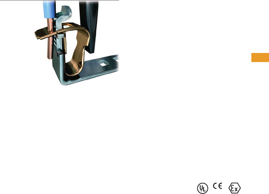
Logic Control Products CA08100001K—June 2012 www.eatoncanada.ca T42-31
42
42
42
42
42
42
42
42
42
42
42
42
42
42
42
42
42
42
42
42
42
42
42
42
42
42
42
42
42
42
42.1
Terminal Blocks, Fuse Blocks and Fuse Holders
IEC—
XB
Series
Spring Cage Connection Contents
Description Page
Spring Cage Terminal Blocks
Single Level—Through-Feed . . . . . . . . . . . . . . . . . T42-32
Single Level—Ground Blocks . . . . . . . . . . . . . . . . . T42-37
Multi-Conductor Terminal Blocks . . . . . . . . . . . . . . T42-39
Multi-Conductor Ground Blocks . . . . . . . . . . . . . . . T42-42
Double Level Blocks . . . . . . . . . . . . . . . . . . . . . . . . T42-44
Triple Level Blocks . . . . . . . . . . . . . . . . . . . . . . . . . T42-46
Fuse Terminal Blocks . . . . . . . . . . . . . . . . . . . . . . . T42-48
Disconnect and Component Terminal Blocks . . . . . T42-51
Hybrid Terminal Blocks . . . . . . . . . . . . . . . . . . . . . . T42-54
Mini Spring Cage . . . . . . . . . . . . . . . . . . . . . . . . . . . T42-56
Spring Cage Terminal Blocks Overview
Product Description
The XBPT Series incorporates
a spring cage connection
system proven in applications
that are sensitive to vibration.
The spring mechanism
always exerts the same
constant force on the wire,
resulting in a vibration-
proof, gas-tight connection,
independent of the user.
The space-saving front
connection, with the wire
and screwdriver coming in
parallel from the same
direction, allows for simple
wiring in places where there
is little space available.
Application Description
The connection point is
opened with a standard
screwdriver. After the wire
has been inserted into the
wire guide of the terminal
block, the screwdriver is
removed and the wire
automatically makes contact.
Features
●Vibration-resistance
●Global acceptance
●Multi-conductor
connections
●Flexible Plug-in bridge
system
●Large surface area for
marking
●Standardized testing
system
Standards and Certifications
●UL recognized—File No.
E67464
●CE approved
●LVD :
●EN 60947-7-1
●EN 60947-7-2
●EN 60998-2-3
●EN 60352-4/A1
●ATEX approval
(Eex e applications)
Note
Not all standards apply to all terminal
blocks. Contact Eaton for details.
Tab42book.fm Page 31 Thursday, July 5, 2012 8:03 PM
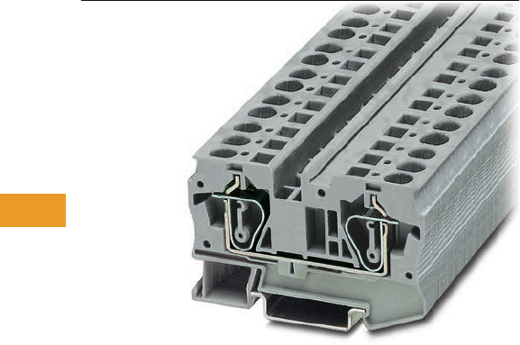
T42-32 Logic Control Products CA08100001K—June 2012 www.eatoncanada.ca
42
42
42
42
42
42
42
42
42
42
42
42
42
42
42
42
42
42
42
42
42
42
42
42
42
42
42
42
42
42
42.1
Terminal Blocks, Fuse Blocks and Fuse Holders
IEC—
XB
Series
Single Level—Through-Feed Contents
Description Page
Single Level—Through-Feed
Accessories . . . . . . . . . . . . . . . . . . . . . . . . . . . . . . T42-34
Technical Data and Specifications . . . . . . . . . . . . . T42-36
Dimensions . . . . . . . . . . . . . . . . . . . . . . . . . . . . . . T42-36
Single Level—Ground Blocks . . . . . . . . . . . . . . . . . . . T42-37
Multi-Conductor Terminal Blocks . . . . . . . . . . . . . . . . T42-39
Multi-Conductor Ground Blocks . . . . . . . . . . . . . . . . . T42-42
Double Level Blocks . . . . . . . . . . . . . . . . . . . . . . . . . . T42-44
Triple Level Blocks . . . . . . . . . . . . . . . . . . . . . . . . . . . T42-46
Fuse Terminal Blocks . . . . . . . . . . . . . . . . . . . . . . . . . T42-48
Disconnect and Component Terminal Blocks . . . . . . . T42-51
Hybrid Terminal Blocks . . . . . . . . . . . . . . . . . . . . . . . . T42-54
Mini Spring Cage . . . . . . . . . . . . . . . . . . . . . . . . . . . . . T42-56
Single Level—Through-Feed
Product Description
The space-saving design and
front entry design make the
XBPT Series ideal for control
systems where there is little
space. Even so, they offer
maximum connection
space, resulting in fast
wiring of stranded and
solid conductors with or
without ferrules.
XBPT terminal blocks are
available with cross-sections
from 2.5 mm2 up to 35 mm2.
The double bridge shaft can
accommodate individual
chain bridging and step-
down bridging from other
terminal blocks.
Tab42book.fm Page 32 Thursday, July 5, 2012 8:03 PM
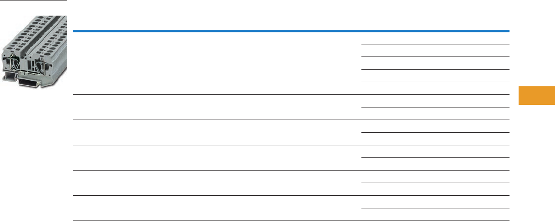
Logic Control Products CA08100001K—June 2012 www.eatoncanada.ca T42-33
42
42
42
42
42
42
42
42
42
42
42
42
42
42
42
42
42
42
42
42
42
42
42
42
42
42
42
42
42
42
42.1
Terminal Blocks, Fuse Blocks and Fuse Holders
IEC—
XB
Series
Product Selection
Spring Cage Connection Single Level—Through-Feed
Note
EU type—examination certificate number: KEMA 05ATEX2158 U.
Terminal
Width
Maximum
Wire Size
IEC 60 947-7-1
in V/A/AWG
EN 50 019
in V/A/AWG
UL-cUL Ratings
in V/A/AWG Colour
Standard
Pack
Catalogue
Number
5.2 mm 12 AWG/2.5 mm2800/31/28–12 550/25/21/24–12 600/20/26–12 Gray 50 XBPT25
Blue 50 XBPT25BU
White 50 XBPT25WH
Red 50 XBPT25RD
Black 50 XBPT25BK
6.2 mm 10 AWG/4 mm2800/40/28–10 550/34/30/24–10 600/30/20–10 Gray 50 XBPT4
Blue 50 XBPT4BU
8.2 mm 8 AWG/6 mm2800/52/24–8 550/45/36/20–8 600/50/20–8 Gray 50 XBPT6
Blue 50 XBPT6BU
10.2 mm 6 AWG/10 mm2800/65/24–6 550/50/63/16–6 600/65/16–6 Gray 50 XBPT10
Blue 50 XBPT10BU
12 mm 4 AWG/16 mm2800/90/24–4 550/65/82/16–4 600/50/16–4 Gray 50 XBPT16
Blue 50 XBPT16BU
16 mm 2 AWG/35 mm2800/125/14–2 750/108/14–2 600/115/14–2 Gray 50 XBPT35
Blue 50 XBPT35BU
XBPT6
Tab42book.fm Page 33 Thursday, July 5, 2012 8:03 PM

T42-34 Logic Control Products CA08100001K—June 2012 www.eatoncanada.ca
42
42
42
42
42
42
42
42
42
42
42
42
42
42
42
42
42
42
42
42
42
42
42
42
42
42
42
42
42
42
42.1
Terminal Blocks, Fuse Blocks and Fuse Holders
IEC—
XB
Series
Accessories
Spring Cage Connection Single Level—Through-Feed, XBPT25, XBPT4 an d XBPT6
Spring Cage Connection Single Level—Through-Feed, XBPT10, XBPT16 and XBPT35
Notes
For ordering information, see Page T42-105.
For information on Printed Marking Tag Options, see Page T42-98.
XBPT35 has an enclosed design. The use of an end cover is not required.
For additional accessories, see Page T42-90.
XBPT25 XBPT4 XBPT6
Description Colour
Number of
Positions
Standard
Pack
Catalogue
Number
Catalogue
Number
Catalogue
Number
End cover Gray — 10 XBACPT25 XBACPT4 XBACPT6
Partition plate Gray — 10 XBATPT4 XBATPT4 XBATPT6
Plug-in bridge—for cross connections
in the bridge shaft
Red 2 10 XBAFBS25 XBAFBS26 XBAFBS28
310XBAFBS35 XBAFBS36 —
510XBAFBS55 XBAFBS56 —
10 10 XBAFBS105 XBAFBS106 —
50 10 XBAFBS505 XBAFBS506 —
Test adapter — — 10 XBATSPAI4 XBATSPAI4 XBATSPAI4
2.3 mm diameter test plug — — — XBATSMPS-_ XBATSMPS-_ XBATSMPS-_
Modular test plug — — 10 XBATSPS5 XBATSPS6 XBATSPS8
Blank marker strip external labeling White — 10 XBMZBF5 XBMZBF6 XBMZF8
Blank marker strip centre labeling (strip of 10) White — 10 XBMZB5 XBMZB6 XBMZB8
Description Colour
Number of
Positions
Standard
Pack
XBPT10 XBPT16 XBPT35
Catalogue
Number
Catalogue
Number
Catalogue
Number
End cover Gray — 10 XBACPT10 XBACPT16
Plug-in bridge—for cross connections in
the bridge shaft
Red 2 10 XBAFBS210 XBAFBS212 XBAFBS216
2.3 mm diameter test plug — — 10 XBATSMPS-_ XBATSMPS-_ XBATSMPS-_
Blank marker strip external labeling White — 10 XBMZF10 XBMZBF12 XBMZBF15
Blank marker strip centre labeling (strip of 10) White — 10 XBMZB10 XBMZB12 XBMZB15
Tab42book.fm Page 34 Thursday, July 5, 2012 8:03 PM
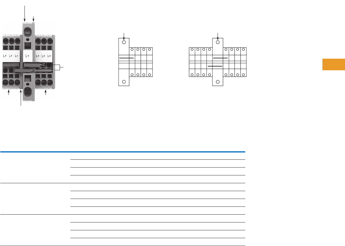
Logic Control Products CA08100001K—June 2012 www.eatoncanada.ca T42-35
42
42
42
42
42
42
42
42
42
42
42
42
42
42
42
42
42
42
42
42
42
42
42
42
42
42
42
42
42
42
42.1
Terminal Blocks, Fuse Blocks and Fuse Holders
IEC—
XB
Series
XBPT with Reducing Bridge
Step-Down Bridge with Standard Feed-Through Terminal Blocks
Input Pick-Off One-Sided
Input
Imax
Central
Input
Imax
Bridge
Terminal
Blocks Cross-Section
Terminal
Blocks
Cross-Section
AWG (mm2)
Catalogue
Number
XBPT6 8 AWG (6 mm2) XBPT25 12 (2.5) 40 56 XBARBST6
XBPT4 10 (4) 45 56 XBARBST6
XBQT15 14 (1.5) 35 56 XBARBST6
XBQT25 12 (2.5) 40 56 XBARBST6
XBPT10 6 AWG (10 mm2) XBPT25 12 (2.5) 40 65 XBARBST10
XBPT4 10 (4) 45 65 XBARBST10
XBQT15 14 (1.5) 35 65 XBARBST10
XBQT25 12 (2.5) 40 65 XBARBST10
XBPT16 4 AWG (16 mm2) XBPT25 12 (2.5) 40 80 XBARBST16
XBPT4 10 (4) 45 90 XBARBST16
XBQT15 14 (1.5) 35 70 XBARBST16
XBQT25 12 (2.5) 40 80 XBARBST16
lmax
One-Sided Input Central Input
lmax
XBACPT6
XBARBST6
XBPT25XBPT25
XBPT6
XBACPT25
Tab42book.fm Page 35 Thursday, July 5, 2012 8:03 PM

T42-36 Logic Control Products CA08100001K—June 2012 www.eatoncanada.ca
42
42
42
42
42
42
42
42
42
42
42
42
42
42
42
42
42
42
42
42
42
42
42
42
42
42
42
42
42
42
42.1
Terminal Blocks, Fuse Blocks and Fuse Holders
IEC—
XB
Series
Technical Data and Specifications
Spring Cage Connection Single Level—Through-Feed
Dimensions
Approximate Dimensions in Inches (mm)
Spring Cage Connection Single Level—Through-Feed
Note
XBPT35 has an enclosed design. The use of an end cover is not required.
Description XBPT25 XBPT4 XBPT6 XBPT10 XBPT16 XBPT35
Technical Data in Accordance with IEC
Maximum load current in A/cross-section in mm231/4 40/6 52/10 65/16 90/25 125/35
Rated surge voltage in kV/contamination class 8/3 8/3 8/3 8/3 8/3 8/3
Surge voltage category/insulating material group III/I III/I III/I III/I III/I III/I
Connection Capacity
Stranded with ferrule/with ferrule and
plastic sleeve in mm2
0.25–2.5 0.25–4 0.25–6 0.25–10 0.25–16 2.5–35
Stranded with ferrules without plastic sleeve in mm20.25–2.5 0.25–4 0.25–6 0.25–10 0.25–16 2.5–35
Stranded with twin ferrule with plastic sleeve in mm20.5 0.5–1 0.5–1.5 1.5–2.5 1.5–4 2.5–10
Stripping length in inches (mm) 0.39 (10) 0.39 (10) 0.47 (12) 0.71 (18) 0.71 (18) 0.98 (25)
Catalogue
Number Width Length
Cover
Width
Height for—
35 x 7.5 in 35 x 15 in
XBPT25 0.20 (5.2) 1.91 (48.5) 0.09 (2.2) 1.45 (36.8) 1.73 (44.0)
XBPT4 0.24 (6.2) 2.20 (56.0) 0.09 (2.2) 1.45 (36.8) 1.73 (44.0)
XBPT6 0.32 (8.2) 2.74 (69.5) 0.09 (2.2) 1.71 (43.5) 2.01 (51.0)
XBPT10 0.39 (10.0) 2.81 (71.5) 0.09 (2.2) 1.99 (50.5) 2.30 (58.5)
XBPT16 0.47 (12.0) 3.15 (80.0) 0.09 (2.2) 2.01 (51.0) 2.30 (58.5)
XBPT35 0.63 (16.0) 3.94 (100.0) 2.32 (59.0) 2.62 (66.5)
Tab42book.fm Page 36 Thursday, July 5, 2012 8:03 PM
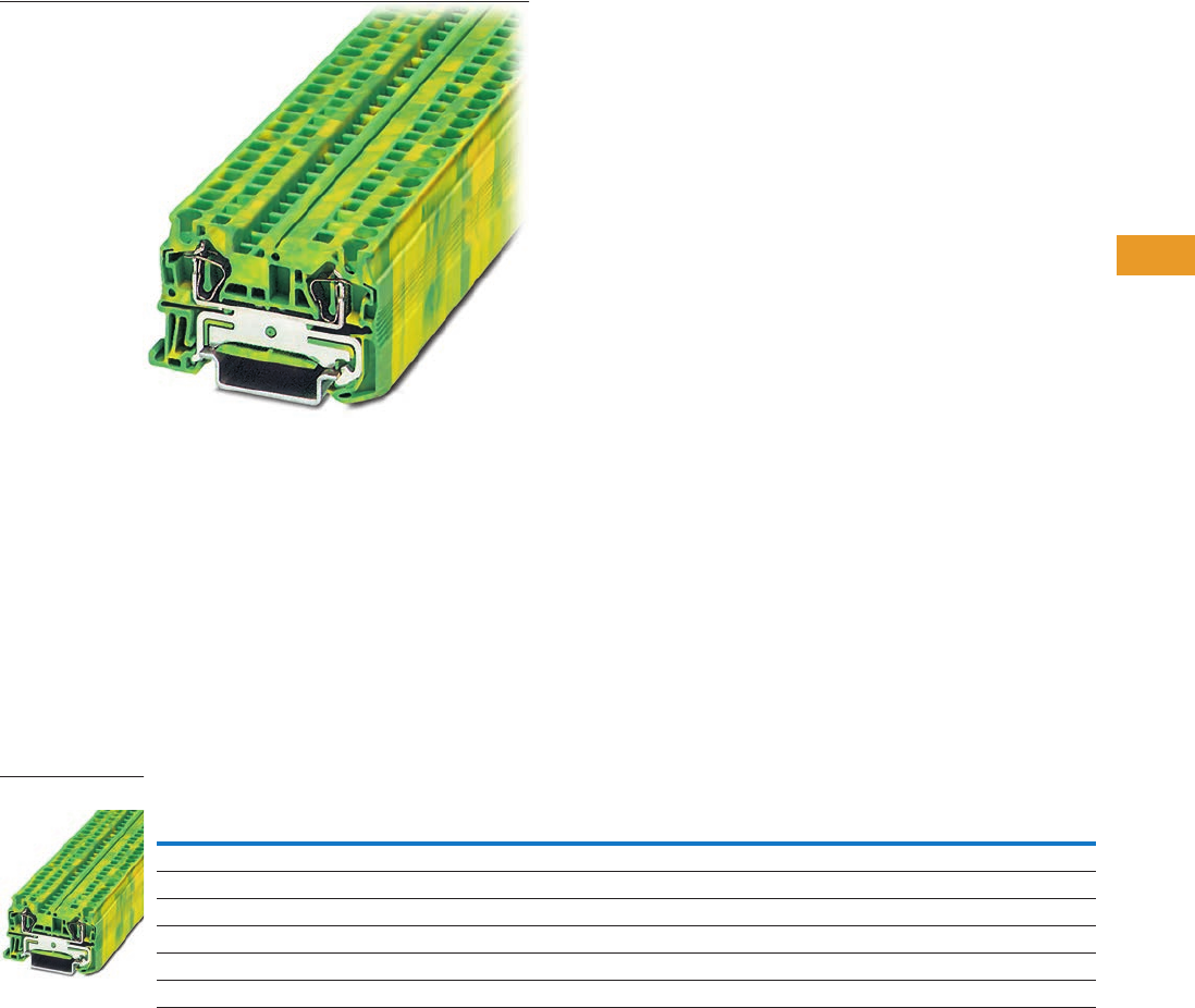
Logic Control Products CA08100001K—June 2012 www.eatoncanada.ca T42-37
42
42
42
42
42
42
42
42
42
42
42
42
42
42
42
42
42
42
42
42
42
42
42
42
42
42
42
42
42
42
42.1
Terminal Blocks, Fuse Blocks and Fuse Holders
IEC—
XB
Series
Single Level—Ground Blocks Contents
Description Page
Single Level—Through-Feed . . . . . . . . . . . . . . . . . . . . T42-32
Single Level—Ground Blocks
Accessories . . . . . . . . . . . . . . . . . . . . . . . . . . . . . . T42-38
Technical Data and Specifications . . . . . . . . . . . . . T42-38
Dimensions . . . . . . . . . . . . . . . . . . . . . . . . . . . . . . T42-38
Multi-Conductor Terminal Blocks . . . . . . . . . . . . . . . . . T42-39
Multi-Conductor Ground Blocks . . . . . . . . . . . . . . . . . T42-42
Double Level Blocks . . . . . . . . . . . . . . . . . . . . . . . . . . T42-44
Triple Level Blocks . . . . . . . . . . . . . . . . . . . . . . . . . . . . T42-46
Fuse Terminal Blocks . . . . . . . . . . . . . . . . . . . . . . . . . . T42-48
Disconnect and Component Terminal Blocks . . . . . . . T42-51
Hybrid Terminal Blocks . . . . . . . . . . . . . . . . . . . . . . . . T42-54
Mini Spring Cage . . . . . . . . . . . . . . . . . . . . . . . . . . . . . T42-56
Single Level—Ground Blocks
Product Description
The XBPT ground blocks are
the same shape as the feed-
through terminal blocks with
the same wide range of
cross-sections available.
They easily snap onto the
DIN rail to make a reliable
mechanical and electrical
contact that meets all
requirements of
IEC 60-947-7-2.
Product Selection
Spring Cage Connection Single Level—Ground Blocks
Notes
EU type—examination certificate number: KEMA 05ATEX2154 U (XBPT25PE), KEMA 05ATEX2155 U (XBPT4PE).
EU type—examination certificate number: KEMA 05ATEX2156 U.
Terminal
Width
Maximum
Wire Size
IEC 60 947-7-2
in V/A/AWG
EN 50 019
in V/A/AWG
UL-cUL Ratings
in V/A/AWG Colour
Standard
Pack
Catalogue
Number
5.2 mm 12 AWG/2.5 mm2—/—/28–12 —/—/24–12 —/—/26–12 Green/Yellow 50 XBPT25PE
6.2 mm 10 AWG/4 mm2—/—/28–10 —/—/24–10 —/—/20–10 Green/Yellow 50 XBPT4PE
8.2 mm 8 AWG/6 mm2—/—/24–8 —/—/20–8 —/—/20–8 Green/Yellow 50 XBPT6PE
10.2 mm 6 AWG/10 mm2—/65/24–6 —/—/16–6 —/—/16–6 Green/Yellow 50 XBPT10PE
12 mm 4 AWG/16 mm2—/90/24–4 —/—/16–4 —/—/16–4 Green/Yellow 25 XBPT16PE
16 mm 2 AWG/35 mm2—/125/14–2 —/—/14–2 —/—/14–2 Green/Yellow 10 XBPT35PE
XBPT4PE
Tab42book.fm Page 37 Thursday, July 5, 2012 8:03 PM

T42-38 Logic Control Products CA08100001K—June 2012 www.eatoncanada.ca
42
42
42
42
42
42
42
42
42
42
42
42
42
42
42
42
42
42
42
42
42
42
42
42
42
42
42
42
42
42
42.1
Terminal Blocks, Fuse Blocks and Fuse Holders
IEC—
XB
Series
Accessories
Spring Cage Connection Single Level Ground Blocks, XBPT25PE, XBPT4PE and XBPT6PE
Spring Cage Connection Single Level Ground Blocks, XBPT10PE, XBPT16PE and XBPT35PE
Technical Data and Specifications
Spring Cage Connection Single Level Ground Blocks
Dimensions
Approximate Dimensions in Inches (mm)
Spring Cage Connection Single Level Ground Blocks
Notes
For information on Printed Marking Tag Options, see Page T42-98.
XBPT35PE has an enclosed design. The use of an end cover is not required.
For additional accessories, see Page T42-90.
Description Colour
Number of
Positions
Standard
Pack
XBPT25PE XBPT4PE XBPT6PE
Catalogue
Number
Catalogue
Number
Catalogue
Number
End cover Gray — 10 XBACPT25 XBACPT4 XBACPT6
Blank marker strip external labeling White — 10 XBMZBF5 XBMZBF6 XBMZBF8
Blank marker strip centre labeling (strip of 10) White — 10 XBMZB5 XBMZB6 XBMZB8
Description Colour
Number of
Positions
Standard
Pack
XBPT10PE XBPT16PE XBPT35PE
Catalogue
Number
Catalogue
Number
Catalogue
Number
End cover Gray — 10 XBACPT10 XBACPT16
Plug-in bridge—for cross connections in
the bridge shaft
—2 10XBAFBS210 XBAFBS212 XBAFBS216
Blank marker strip external labeling White — 10 XBMZBF10 XBMZBF12 XBMZBF15
Blank marker strip centre labeling (strip of 10) White — 10 XBMZB10 XBMZB12 XBMZB15
Description XBPT25PE XBPT4PE XBPT6PE XBPT10PE XBPT16PE XBPT35PE
Technical Data in Accordance with IEC
Maximum load current in A/cross-section in mm2— — — 65/16 90/25 125/35
Rated surge voltage in kV/contamination class 8/3 8/3 8/3 8/3 8/3 8/3
Surge voltage category/insulating material group III/I III/I III/I III/I III/I III/I
Connection Capacity
Stranded with ferrule with plastic sleeve in mm20.25–2.5 0.25–4 0.25–6 0.25–10 0.25–16 2.5–35
Stranded with ferrules without plastic sleeve in mm20.25–2.5 0.25–4 0.25–6 0.25–10 0.25–16 2.5–35
Stranded with twin ferrule with plastic sleeve in mm20.5 0.5–1 0.5–1.5 1.5–2.5 1.5–4 2.5–10
Stripping length in inches (mm) 0.39 (10) 0.39 (10) 0.47 (12) 0.71 (18) 0.71 (18) 0.98 (25)
Catalogue
Number Width Length
Cover
Width
Height for—
35 x 7.5 in 35 x 15 in
XBPT25PE 0.20 (5.2) 1.91 (48.5) 0.09 (2.2) 1.45 (36.8) 1.73 (44.0)
XBPT4PE 0.24 (6.2) 2.20 (56.0) 0.09 (2.2) 1.45 (36.8) 1.73 (44.0)
XBPT6PE 0.32 (8.2) 2.74 (69.5) 0.09 (2.2) 1.71 (43.5) 2.01 (51.0)
XBPT10PE 0.39 (10.0) 2.81 (71.5) 0.09 (2.2) 1.99 (50.5) 2.28 (58.0)
XBPT16PE 0.47 (12.0) 3.15 (80.0) 0.09 (2.2) 2.01 (51.0) 2.30 (58.5)
XBPT35PE 0.63 (16.0) 3.94 (100.0) — 2.32 (59.0) 2.62 (66.5)
Tab42book.fm Page 38 Thursday, July 5, 2012 8:03 PM
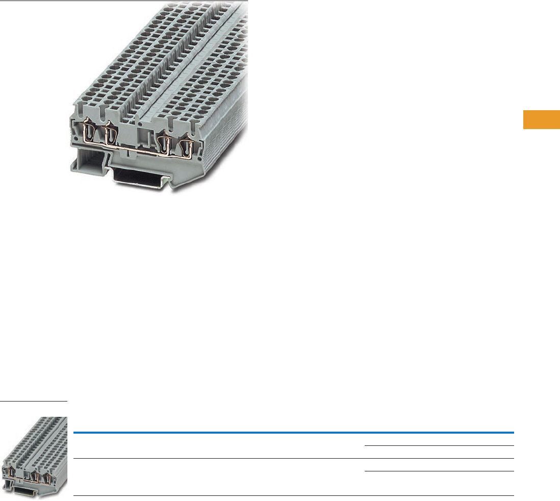
Logic Control Products CA08100001K—June 2012 www.eatoncanada.ca T42-39
42
42
42
42
42
42
42
42
42
42
42
42
42
42
42
42
42
42
42
42
42
42
42
42
42
42
42
42
42
42
42.1
Terminal Blocks, Fuse Blocks and Fuse Holders
IEC—
XB
Series
Multi-Conductor Terminal Blocks Contents
Description Page
Single Level—Through-Feed . . . . . . . . . . . . . . . . . . . . T42-32
Single Level—Ground Blocks . . . . . . . . . . . . . . . . . . . . T42-37
Multi-Conductor Terminal Blocks
Accessories . . . . . . . . . . . . . . . . . . . . . . . . . . . . . . T42-40
Technical Data and Specifications . . . . . . . . . . . . . T42-41
Dimensions . . . . . . . . . . . . . . . . . . . . . . . . . . . . . . T42-41
Multi-Conductor Ground Blocks . . . . . . . . . . . . . . . . . T42-42
Double Level Blocks . . . . . . . . . . . . . . . . . . . . . . . . . . T42-44
Triple Level Blocks . . . . . . . . . . . . . . . . . . . . . . . . . . . . T42-46
Fuse Terminal Blocks . . . . . . . . . . . . . . . . . . . . . . . . . . T42-48
Disconnect and Component Terminal Blocks . . . . . . . T42-51
Hybrid Terminal Blocks . . . . . . . . . . . . . . . . . . . . . . . . T42-54
Mini Spring Cage . . . . . . . . . . . . . . . . . . . . . . . . . . . . . T42-56
Multi-Conductor Terminal Blocks
Product Description
The multi-conductor terminal
blocks offer a space-saving
alternative to standard feed-
through terminal blocks,
allowing for high-density
wiring. Often, three
connections have to be led
to one terminal block. The
XBPT…D12 terminal block
accomplishes this without
any additional terminal blocks
or bridging required. The
XBPT…D22 terminal blocks
allow four wires to be
connected to one potential—
and can therefore be used as
compact power distributors.
There is also a version,
XBPT25D22U or XBPT4D22U,
with an interrupted bus bar in
the terminal centre. This
makes two feed-through
terminal blocks available in
one level. One side of this
block can be bridged using
the standard Plug-in bridges.
Double marker carriers are
available for clear marking of
the feed-through levels.
Product Selection
Spring Cage Connection Multi-Conductor Terminal Blocks, Three-Wire
Note
EU type—examination certificate number: KEMA 05ATEX2154 U (XBPT25D12), KEMA 05ATEX2155 U (XBPT4D12).
Terminal
Width
Maximum
Wire Size
IEC 60 947-7-1
in V/A/AWG
EN 50 019
in V/A/AWG
UL-cUL Ratings
in V/A/AWG Colour
Standard
Pack
Catalogue
Number
5.2 mm 12 AWG/2.5 mm2800/28/28–12 550/25/21/24–12 600/20/26–12 Gray 50 XBPT25D12
Blue 50 XBPT25D12BU
6.2 mm 10 AWG/4 mm2800/40/28–10 550/34/29/24–10 600/30/20–10 Gray 50 XBPT4D12
Blue 50 XBPT4D12BU
XBPT4D12
Tab42book.fm Page 39 Thursday, July 5, 2012 8:03 PM
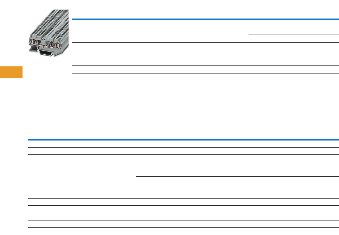
T42-40 Logic Control Products CA08100001K—June 2012 www.eatoncanada.ca
42
42
42
42
42
42
42
42
42
42
42
42
42
42
42
42
42
42
42
42
42
42
42
42
42
42
42
42
42
42
42.1
Terminal Blocks, Fuse Blocks and Fuse Holders
IEC—
XB
Series
Spring Cage Connection Multi-Conductor Terminal Blocks, Four-Wire
Accessories
Spring Cage Connection Multi-Conductor Terminal Blocks
Notes
EU type—examination certificate number: KEMA 05ATEX2154 U (XBPT25D22), KEMA 05ATEX2155 (XBPT4D22).
For ordering information, see Page T42-105.
For information on Printed Marking Tag Options, see Page T42-98.
For additional accessories, see Page T42-90.
Terminal
Width
Maximum
Wire Size
IEC 60 947-7-1
in V/A/AWG
EN 50 019
in V/A/AWG
UL-cUL Ratings
in V/A/AWG Colour
Standard
Pack
Catalogue
Number
Spring Cage Multi-Conductor
5.2 mm 12 AWG/2.5 mm2800/28/28–12 550/24/21/24–12 600/20/26–12 Gray 50 XBPT25D22
Blue 50 XBPT25D22BU
6.2 mm 10 AWG/4 mm2800/40/28–10 550/34/25/24–10 600/30/20–10 Gray 50 XBPT4D22
Blue 50 XBPT4D22BU
Spring Cage Multi-Conductor with Interrupted Bus Bar
5.2 mm 12 AWG/2.5 mm2800/28/28–12 550/24/21/24–12 600/20/26–12 Blue 50 XBPT25D22U
6.2 mm 10 AWG/4 mm2800/40/28–10 550/34/25/24–10 600/30/20–10 Blue 50 XBPT4D22U
Description Colour
Number of
Positions
Standard
Pack
XBPT25D12 XBPT4D12 XBPT25D22 XBPT4D22
Catalogue
Number
Catalogue
Number
Catalogue
Number
Catalogue
Number
End cover Gray — 10 XBACPT25D12 XBACPT4D12 XBACPT25D22 XBACPT4D22
End cover segment Gray — 10 XBASPT25 XBASPT4 XBASPT25 XBASPT4
Partition plate — — 10 XBATPTD12 XBATPTD12 XBATPTD22 XBATPTD22
Plug-in bridge—for cross connections in
the bridge shaft
Red 2 10 XBAFBS25 XBAFBS26 XBAFBS25 XBAFBS26
310XBAFBS35 XBAFBS36 XBAFBS35 XBAFBS36
510XBAFBS55 XBAFBS56 XBAFBS55 XBAFBS56
10 10 XBAFBS105 XBAFBS106 XBAFBS105 XBAFBS106
50 10 XBAFBS505 XBAFBS506 XBAFBS505 XBAFBS506
Test adapter — — 10 XBATSPAI4 XBATSPAI4 XBATSPAI4 XBATSPAI4
2.3 mm diameter test plug — — — XBATSMPS-_ XBATSMPS-_ XBATSMPS-_ XBATSMPS-_
Modular test plug — — 10 XBATSPS5 XBATSPS6 XBATSPS5 XBATSPS6
Blank marker strip external labeling White — 10 XBMZBF5 XBMZBF6 XBMZBF5 XBMZBF6
Blank marker strip centre labeling (strip of 10) White — 10 XBMZB5 XBMZB6 XBMZB5 XBMZB6
XBPT25D22
Tab42book.fm Page 40 Thursday, July 5, 2012 8:03 PM

Logic Control Products CA08100001K—June 2012 www.eatoncanada.ca T42-41
42
42
42
42
42
42
42
42
42
42
42
42
42
42
42
42
42
42
42
42
42
42
42
42
42
42
42
42
42
42
42.1
Terminal Blocks, Fuse Blocks and Fuse Holders
IEC—
XB
Series
Technical Data and Specifications
Spring Cage Connection Multi-Conductor Terminal Blocks
Dimensions
Approximate Dimensions in Inches (mm)
Spring Cage Connection Multi-Conductor Terminal Blocks
Description XBPT25D12 XBPT4D12 XBPT25D22 XBPT4D22
Technical Data in Accordance with IEC
Maximum load current in A/cross-section in mm228/4 40/6 28/4 40/6
Rated surge voltage in kV/contamination class 8/3 8/3 8/3 8/3
Surge voltage category/insulating material group III/I III/I III/I III/I
Connection Capacity
Stranded with ferrule with plastic sleeve in mm20.25–2.5 0.25–4 0.25–2.5 0.25–4
Stranded with ferrules without plastic sleeve in mm20.25–2.5 0.25–4 0.25–2.5 0.25–4
Stranded with twin ferrule with plastic sleeve in mm20.5 0.5–1 0.5 0.5–1
Stripping length in inches (mm) 0.39 (10) 0.39 (10) 0.39 (10) 0.39 (10)
Catalogue
Number Width Length
Cover
Width
Height for—
35 x 7.5 in 35 x 15 in
XBPT25D12 0.20 (5.2) 2.38 (60.5) 0.09 (2.2) 1.44 (36.5) 1.73 (44.0)
XBPT4D12 0.24 (6.2) 2.81 (71.5) 0.09 (2.2) 1.44 (36.5) 1.73 (44.0)
XBPT25D22 0.20 (5.2) 2.83 (72.0) 0.09 (2.2) 1.44 (36.5) 1.73 (44.0)
XBPT4D22 0.24 (6.2) 3.43 (87.0) 0.09 (2.2) 1.44 (36.5) 1.73 (44.0)
Tab42book.fm Page 41 Thursday, July 5, 2012 8:03 PM
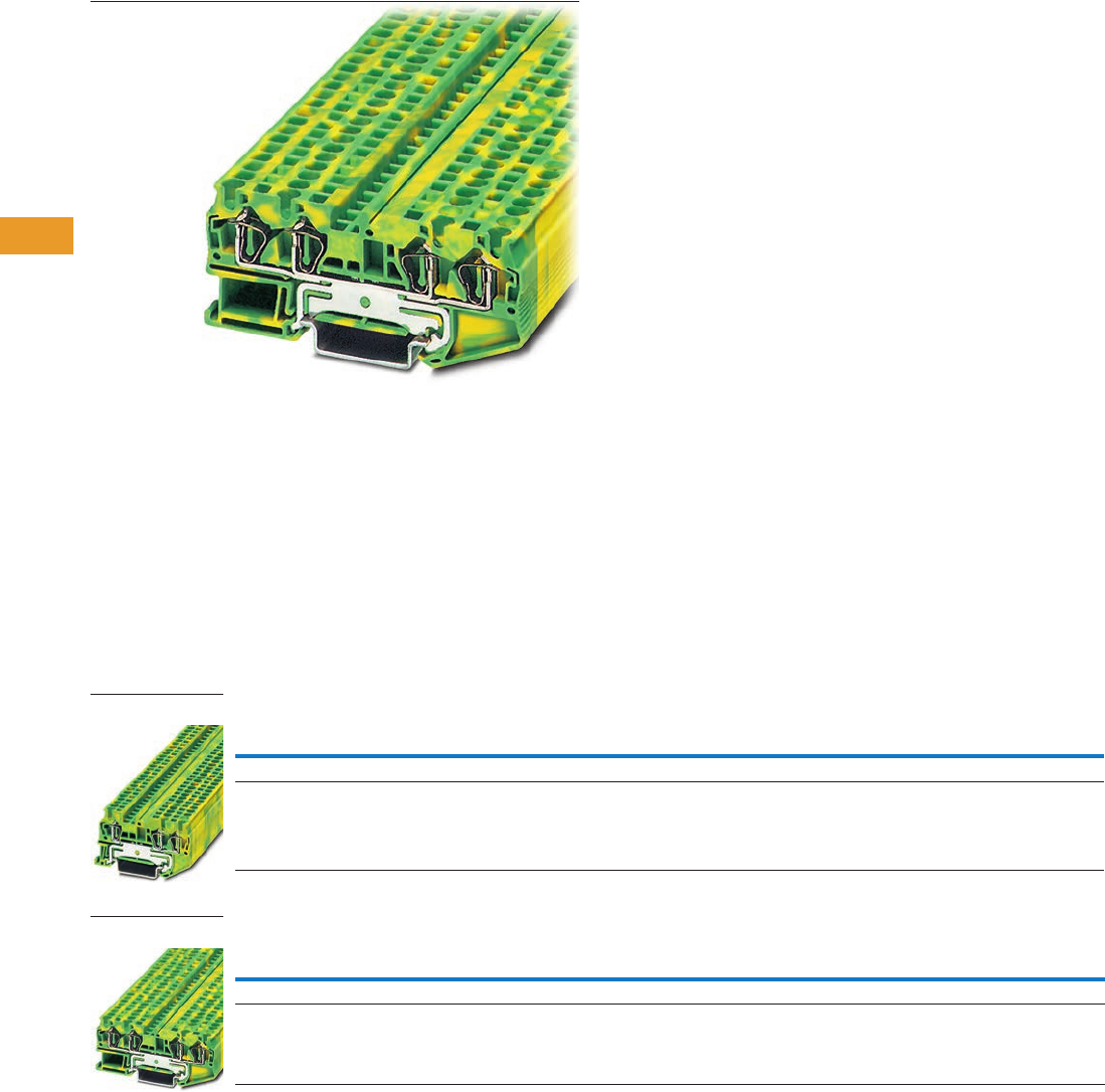
T42-42 Logic Control Products CA08100001K—June 2012 www.eatoncanada.ca
42
42
42
42
42
42
42
42
42
42
42
42
42
42
42
42
42
42
42
42
42
42
42
42
42
42
42
42
42
42
42.1
Terminal Blocks, Fuse Blocks and Fuse Holders
IEC—
XB
Series
Multi-Conductor Terminal Blocks Contents
Description Page
Single Level—Through-Feed . . . . . . . . . . . . . . . . . . . . T42-32
Single Level—Ground Blocks. . . . . . . . . . . . . . . . . . . . T42-37
Multi-Conductor Terminal Blocks . . . . . . . . . . . . . . . . T42-39
Multi-Conductor Ground Blocks
Accessories . . . . . . . . . . . . . . . . . . . . . . . . . . . . . . T42-43
Technical Data and Specifications . . . . . . . . . . . . . T42-43
Dimensions . . . . . . . . . . . . . . . . . . . . . . . . . . . . . . T42-43
Double Level Blocks . . . . . . . . . . . . . . . . . . . . . . . . . . T42-44
Triple Level Blocks . . . . . . . . . . . . . . . . . . . . . . . . . . . T42-46
Fuse Terminal Blocks . . . . . . . . . . . . . . . . . . . . . . . . . T42-48
Disconnect and Component Terminal Blocks . . . . . . . T42-51
Hybrid Terminal Blocks . . . . . . . . . . . . . . . . . . . . . . . . T42-54
Mini Spring Cage . . . . . . . . . . . . . . . . . . . . . . . . . . . . . T42-56
Multi-Conductor Ground Blocks
Product Description
The ground terminal blocks
have the same shape and
pitch as the standard terminal
block, in a green-yellow
housing. They easily snap
onto the DIN rail to make
a reliable mechanical and
electrical contact that
meets all requirements
of IEC 60-947-7-2.
Product Selection
Spring Cage Connection Multi-Conductor Ground Blocks, Three-Wire
Spring Cage Connection Multi-Conductor Ground Blocks, Four-Wire
Note
EU type—examination certificate number: KEMA 05ATEX2154 U (XBPT25D12PE), KEMA 05ATEX2155 U (XBPT4D12PE).
Terminal
Width
Maximum
Wire Size
IEC 60 947-7-2
in V/A/AWG
EN 50 019
in V/A/AWG
UL-cUL Ratings
in V/A/AWG Colour
Standard
Pack
Catalogue
Number
5.2 mm 12 AWG/2.5 mm2—/—/28–12 —/—/24–12 —/—/26–12 Green/Yellow 50 XBPT25D12PE
6.2 mm 10 AWG/4 mm2—/—/28–10 —/—/24–10 —/—/20–10 Green/Yellow 50 XBPT4D12PE
Terminal
Width
Maximum
Wire Size
IEC 60 947-7-2
in V/A/AWG
EN 50 019
in V/A/AWG
UL-cUL Ratings
in V/A/AWG Colour
Standard
Pack
Catalogue
Number
5.2 mm 12 AWG/2.5 mm2—/—/28–12 —/—/24–12 —/—/26–12 Green/Yellow 50 XBPT25D22PE
6.2 mm 10 AWG/4 mm2—/—/28–10 —/—/24–10 —/—/20–10 Green/Yellow 50 XBPT4D22PE
XBPT25D12PE
XBPT4D22PE
Tab42book.fm Page 42 Thursday, July 5, 2012 8:03 PM

Logic Control Products CA08100001K—June 2012 www.eatoncanada.ca T42-43
42
42
42
42
42
42
42
42
42
42
42
42
42
42
42
42
42
42
42
42
42
42
42
42
42
42
42
42
42
42
42.1
Terminal Blocks, Fuse Blocks and Fuse Holders
IEC—
XB
Series
Accessories
Spring Cage Connection Multi-Conductor Ground Blocks
Technical Data and Specifications
Spring Cage Connection Multi-Conductor Ground Blocks
Dimensions
Approximate Dimensions in Inches (mm)
Spring Cage Connection Multi-Conductor Ground Blocks
Notes
For information on Printed Marking Tag Options, see Page T42-98.
For additional accessories, see Page T42-90.
Description Colour
Number of
Positions
Standard
Pack
XBPT25D12PE XBPT4D12PE XBPT25D22PE XBPT4D22PE
Catalogue
Number
Catalogue
Number
Catalogue
Number
Catalogue
Number
End cover Gray — 10 XBACPT25D12 XBACPT4D12 XBACPT25D22 XBACPT4D22
End cover segment Gray — 10 XBASPT25 XBASPT4 XBASPT25 XBASPT4
Blank marker strip external labeling White — 10 XBMZBF5 XBMZBF6 XBMZBF5 XBMZBF6
Blank marker strip centre
labeling (strip of 10)
White — 10 XBMZB5 XBMZB6 XBMZB5 XBMZB6
Description XBPT25D12PE XBPT4D12PE XBPT25D22PE XBPT4D22PE
Technical Data in Accordance with IEC
Maximum load current in A/cross-section in mm2————
Rated surge voltage in kV/contamination class 8/3 8/3 8/3 8/3
Surge voltage category/insulating material group III/I III/I III/I III/I
Connection Capacity
Stranded with ferrule with plastic sleeve in mm20.25–2.5 0.25–4 0.25–2.5 0.25–4
Stranded with ferrules without plastic sleeve in mm20.25–2.5 0.25–4 0.25–2.5 0.25–4
Stranded with twin ferrule with plastic sleeve in mm20.5 0.5–1 0.5 0.5–1
Stripping length in inches (mm) 0.39 (10) 0.39 (10) 0.39 (10) 0.39 (10)
Catalogue
Number Width Length
Cover
Width
Height for—
35 x 7.5 in 35 x 15 in
XBPT25D12PE 0.20 (5.2) 2.38 (60.5) 0.09 (2.2) 1.44 (36.5) 1.73 (44.0)
XBPT4D12PE 0.24 (6.2) 2.81 (71.5) 0.09 (2.2) 1.44 (36.5) 1.73 (44.0)
XBPT25D22PE 0.20 (5.2) 2.83 (72.0) 0.09 (2.2) 1.44 (36.5) 1.73 (44.0)
XBPT4D22PE 0.24 (6.2) 3.43 (87.0) 0.09 (2.2) 1.44 (36.5) 1.73 (44.0)
Tab42book.fm Page 43 Thursday, July 5, 2012 8:03 PM
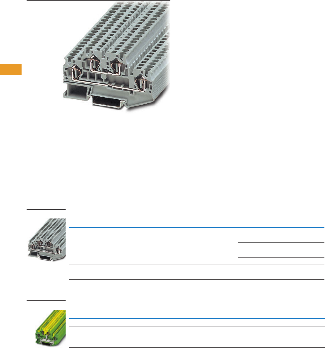
T42-44 Logic Control Products CA08100001K—June 2012 www.eatoncanada.ca
42
42
42
42
42
42
42
42
42
42
42
42
42
42
42
42
42
42
42
42
42
42
42
42
42
42
42
42
42
42
42.1
Terminal Blocks, Fuse Blocks and Fuse Holders
IEC—
XB
Series
Double Level Blocks Contents
Description Page
Single Level—Through-Feed . . . . . . . . . . . . . . . . . . . . T42-32
Single Level—Ground Blocks. . . . . . . . . . . . . . . . . . . . T42-37
Multi-Conductor Terminal Blocks . . . . . . . . . . . . . . . . T42-39
Multi-Conductor Ground Blocks . . . . . . . . . . . . . . . . . T42-42
Double Level Blocks
Accessories . . . . . . . . . . . . . . . . . . . . . . . . . . . . . . T42-45
Technical Data and Specifications . . . . . . . . . . . . . T42-45
Dimensions . . . . . . . . . . . . . . . . . . . . . . . . . . . . . . T42-45
Triple Level Blocks . . . . . . . . . . . . . . . . . . . . . . . . . . . T42-46
Fuse Terminal Blocks . . . . . . . . . . . . . . . . . . . . . . . . . T42-48
Disconnect and Component Terminal Blocks . . . . . . . T42-51
Hybrid Terminal Blocks . . . . . . . . . . . . . . . . . . . . . . . . T42-54
Mini Spring Cage . . . . . . . . . . . . . . . . . . . . . . . . . . . . . T42-56
Double Level Blocks
Product Description
The potentials of the XB
double level terminal blocks
routed on two levels reduce
space requirements by 50%
compared with single level
terminal blocks.
The XBPTT blocks can be
bridged on both levels with
the Plug-in bridge system and
labeling options are available
for each terminal point,
resulting in maximum
customization for each
application. The XBPTT25PV
and XBPTT4PV terminal
blocks have two
interconnected levels.
Equipotential bonding is
marked by an imprint on
the housing. These terminal
blocks can also be bridged and
used to construct compact
potential distributor blocks.
Product Selection
Spring Cage Connection Double Level Blocks
Spring Cage Connection Double Level Ground Blocks
Note
EU type—examination certificate number: KEMA 05ATEX2154 U (XBPTT25), KEMA 05ATEX2155 U (XBPTT4).
Terminal
Width
Maximum
Wire Size
IEC 60 947-7-1
in V/A/AWG
EN 50 019
in V/A/AWG
UL-cUL Ratings
in V/A/AWG Colour
Standard
Pack
Catalogue
Number
Spring Cage Connection Double Level Blocks
5.2 mm 12 AWG/2.5 mm2500/26/28–12 420/23/19/24–12 600/20/26–12 Gray 50 XBPTT25
Blue 50 XBPTT25BU
6.2 mm 10 AWG/4 mm2500/32/28–10 420/32/27/24–10 300/30/20–10 Gray 50 XBPTT4
Blue 50 XBPTT4BU
Spring Cage Connection Double Level Blocks (terminal block with potential distribution between the levels)
5.2 mm 112 AWG/2.5 mm2500/26/28–12 420/23/19/24–12 600/20/26–12 Gray 50 XBPTT25PV
6.2 mm 10 AWG/4 mm2500/32/28–10 420/32/27/24–10 300/30/20–10 Gray 50 XBPTT4PV
Terminal
Width
Maximum
Wire Size
IEC 60 947-7-2
in V/A/AWG
EN 50 019
in V/A/AWG
UL-cUL Ratings
in V/A/AWG Colour
Standard
Pack
Catalogue
Number
5.2 mm 12 AWG/2.5 mm2—/—/28–12 —/—/24–12 —/—/26–12 Green/Yellow 50 XBPTT25PE
6.2 mm 10 AWG/4 mm2—/—/28–10 —/—/24–10 —/—/20–10 Green/Yellow 50 XBPTT4PE
XBPTT4
XBPTT25PE
Tab42book.fm Page 44 Thursday, July 5, 2012 8:03 PM

Logic Control Products CA08100001K—June 2012 www.eatoncanada.ca T42-45
42
42
42
42
42
42
42
42
42
42
42
42
42
42
42
42
42
42
42
42
42
42
42
42
42
42
42
42
42
42
42.1
Terminal Blocks, Fuse Blocks and Fuse Holders
IEC—
XB
Series
Accessories
Spring Cage Connection Double Level Blocks
Technical Data and Specifications
Spring Cage Connection Double Level Blocks
Dimensions
Approximate Dimensions in Inches (mm)
Spring Cage Connection Double Level Blocks
Notes
For information on Printed Marking Tag Options, see Page T42-98.
For additional accessories, see Page T42-90.
Description Colour
Number of
Positions
Standard
Pack
XBPTT25 XBPTT4 XBPTT25PE XBPTT4PE
Catalogue
Number
Catalogue
Number
Catalogue
Number
Catalogue
Number
End cover Gray — 10 XBACPTT25 XBACPTT4 XBACPTT25 XBACPTT4
Partition plate — — 10/50 XBATPTT4 XBATPTT4 — —
Plug-in bridge—for cross connections in
the bridge shaft
Red 2 10 XBAFBS25 XBAFBS26 XBAFBS25 XBAFBS26
310 XBAFBS35 XBAFBS36 XBAFBS35 XBAFBS36
510 XBAFBS55 XBAFBS56 XBAFBS55 XBAFBS56
10 10 XBAFBS105 XBAFBS106 XBAFBS105 XBAFBS106
50 10 XBAFBS505 XBAFBS506 XBAFBS505 XBAFBS506
Test adapter — — 10 XBATSPAI4 XBATSPAI4 — —
Modular test plug — — 10 XBATSPS5 XBATSPS6 — —
Blank marker strip (strip of 10) White — 10 XBMZBF5 XBMZBF6 XBMZBF5 XBMZBF6
Description XBPTT25 XBPTT4 XBPTT25PE XBPTT4PE
Technical Data in Accordance with IEC
Maximum load current in A/cross-section in mm226/4 32/6 — —
Rated surge voltage in kV/contamination class 6/3 6/3 6/3 6/3
Surge voltage category/insulating material group III/I III/I III/I III/I
Connection Capacity
Stranded with ferrule with plastic sleeve in mm20.25–2.5 0.25–4 0.25–2.5 0.25–4
Stranded with ferrules without plastic sleeve in mm20.25–2.5 0.25–4 0.25–2.5 0.25–4
Stranded with twin ferrule with plastic sleeve in mm20.5 0.5–1 0.5 0.5–1
Stripping length in inches (mm) 0.39 (10) 0.39 (10) 0.39 (10) 0.39 (10)
Catalogue
Number Width Length
Cover
Width
Height for—
35 x 7.5 in 35 x 15 in
XBPTT25 0.20 (5.2) 2.66 (67.5) 0.09 (2.2) 1.87 (47.5) 2.17 (55.0)
XBPTT4 0.24 (6.2) 3.29 (83.5) 0.09 (2.2) 1.87 (47.5) 2.17 (55.0)
XBPTT25PE 0.20 (5.2) 2.66 (67.5) 0.09 (2.2) 1.87 (47.5) 2.17 (55.0)
XBPTT4PE 0.24 (6.2) 3.29 (83.5) 0.09 (2.2) 1.87 (47.5) 2.17 (55.0)
Tab42book.fm Page 45 Thursday, July 5, 2012 8:03 PM
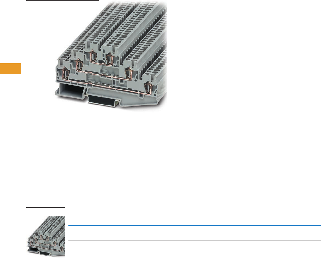
T42-46 Logic Control Products CA08100001K—June 2012 www.eatoncanada.ca
42
42
42
42
42
42
42
42
42
42
42
42
42
42
42
42
42
42
42
42
42
42
42
42
42
42
42
42
42
42
42.1
Terminal Blocks, Fuse Blocks and Fuse Holders
IEC—
XB
Series
Triple Level Blocks Contents
Description Page
Single Level—Through-Feed . . . . . . . . . . . . . . . . . . . . T42-32
Single Level—Ground Blocks. . . . . . . . . . . . . . . . . . . . T42-37
Multi-Conductor Terminal Blocks . . . . . . . . . . . . . . . . T42-39
Multi-Conductor Ground Blocks . . . . . . . . . . . . . . . . . T42-42
Double Level Blocks . . . . . . . . . . . . . . . . . . . . . . . . . . T42-44
Triple Level Blocks
Accessories . . . . . . . . . . . . . . . . . . . . . . . . . . . . . . T42-47
Technical Data and Specifications . . . . . . . . . . . . . T42-47
Dimensions . . . . . . . . . . . . . . . . . . . . . . . . . . . . . . T42-47
Fuse Terminal Blocks . . . . . . . . . . . . . . . . . . . . . . . . . T42-48
Disconnect and Component Terminal Blocks . . . . . . . T42-51
Hybrid Terminal Blocks . . . . . . . . . . . . . . . . . . . . . . . . T42-54
Mini Spring Cage . . . . . . . . . . . . . . . . . . . . . . . . . . . . . T42-56
Triple Level Blocks
Product Description
The spring cage triple level
terminal block incorporates
three feed-through levels
in a 5.2 mm wide housing.
This is ideal for high density
wiring, especially important
when switchgear space is
restricted. There is a bridge
shaft on each level allowing
use of this block as a compact
potential distributor or as
a sensor terminal.
The XBPTK25PV has
all six terminal points
interconnected. All the
triple level blocks can be
labeled on each level.
Product Selection
Spring Cage Connection Triple Level Blocks
Note
Terminal block with potential distribution between the levels.
Terminal
Width
Maximum
Wire Size
IEC 60 947-7-1
in V/A/AWG
UL-cUL Ratings
in V/A/AWG Colour
Standard
Pack
Catalogue
Number
5.2 mm 12 AWG/2.5 mm2500/28/28–12 600/20/26–12 Gray 50 XBPTK25
5.2 mm 12 AWG/2.5 mm2500/28/28–12 600/20/26–12 Gray 50 XBPTK25PV
XBPTK25
Tab42book.fm Page 46 Thursday, July 5, 2012 8:03 PM

Logic Control Products CA08100001K—June 2012 www.eatoncanada.ca T42-47
42
42
42
42
42
42
42
42
42
42
42
42
42
42
42
42
42
42
42
42
42
42
42
42
42
42
42
42
42
42
42.1
Terminal Blocks, Fuse Blocks and Fuse Holders
IEC—
XB
Series
Accessories
Spring Cage Connection Triple Level Blocks
Technical Data and Specifications
Spring Cage Connection Triple Level Blocks
Dimensions
Approximate Dimensions in Inches (mm)
Spring Cage Connection Triple Level Blocks
Notes
For information on Printed Marking Tag Options, see Page T42-98.
For additional accessories, see Page T42-90.
Description Colour
Number of
Positions
Standard
Pack
XBPTK25 XBPTK25PV
Catalogue
Number
Catalogue
Number
End cover Gray — 10 XBACPT25K XBACPT25K
Plug-in bridge—for cross connections in
the bridge shaft
Red 2 10 XBAFBS25 XBAFBS25
310 XBAFBS35 XBAFBS35
510 XBAFBS55 XBAFBS55
10 10 XBAFBS105 XBAFBS105
50 10 XBAFBS505 XBAFBS505
Test adapter — — 10 XBATSPAI4 XBATSPAI4
Modular test plug — — 10 XBATSPS5 XBATSPS5
Blank marker strip (strip of 10) White — 10 XBMZBF5 XBMZBF5
Description XBPTK25 XBPTK25PV
Technical Data in Accordance with IEC
Maximum load current in A/cross-section in mm228/4 28/4
Rated surge voltage in kV/contamination class 6/3 6/3
Surge voltage category/insulating material group III/I III/I
Connection Capacity
Stranded with ferrule with plastic sleeve in mm20.25–2.5 0.25–2.5
Stranded with ferrules without plastic sleeve in mm20.25–2.5 0.25–2.5
Stranded with twin ferrule with plastic sleeve in mm20.5 0.5
Stripping length in inches (mm) 0.39 (10) 0.39 (10)
Catalogue
Number Width Length
Cover
Length
Height for—
35 x 7.5 in 35 x 15 in
XBPTK25 0.20 (5.2) 3.92 (99.5) 0.09 (2.2) 2.28 (58.0) 2.58 (65.5)
XBPTK25PV 0.20 (5.2) 3.92 (99.5) 0.09 (2.2) 2.28 (58.0) 2.58 (65.5)
Tab42book.fm Page 47 Thursday, July 5, 2012 8:03 PM
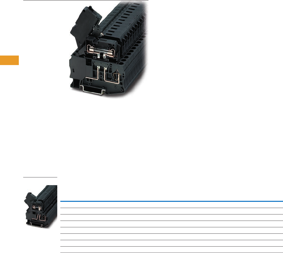
T42-48 Logic Control Products CA08100001K—June 2012 www.eatoncanada.ca
42
42
42
42
42
42
42
42
42
42
42
42
42
42
42
42
42
42
42
42
42
42
42
42
42
42
42
42
42
42
42.1
Terminal Blocks, Fuse Blocks and Fuse Holders
IEC—
XB
Series
Fuse Terminal Blocks Contents
Description Page
Single Level—Through-Feed . . . . . . . . . . . . . . . . . . . . T42-32
Single Level—Ground Blocks. . . . . . . . . . . . . . . . . . . . T42-37
Multi-Conductor Terminal Blocks . . . . . . . . . . . . . . . . T42-39
Multi-Conductor Ground Blocks . . . . . . . . . . . . . . . . . T42-42
Double Level Blocks . . . . . . . . . . . . . . . . . . . . . . . . . . T42-44
Triple Level Blocks . . . . . . . . . . . . . . . . . . . . . . . . . . . T42-46
Fuse Terminal Blocks
Accessories . . . . . . . . . . . . . . . . . . . . . . . . . . . . . . T42-49
Technical Data and Specifications . . . . . . . . . . . . . T42-50
Dimensions . . . . . . . . . . . . . . . . . . . . . . . . . . . . . . T42-50
Disconnect and Component Terminal Blocks . . . . . . . T42-51
Hybrid Terminal Blocks . . . . . . . . . . . . . . . . . . . . . . . . T42-54
Mini Spring Cage . . . . . . . . . . . . . . . . . . . . . . . . . . . . . T42-56
Fuse Terminal Blocks
Product Description
The spring cage fuse terminal
blocks act as a fuse carrier for
5 x 20 mm or 6.3 x 32 mm
fuses. They also allow for
potential distribution with the
double bridge shaft. For
signaling a triggered fuse,
fuse terminal blocks with
light indicators are available
(for both AC and DC voltage).
Product Selection
Spring Cage Connection Fuse Terminal Blocks, for 5 x 20 mm Fuse
Notes
The cartridge fuse holders should be selected according to the maximum power dissipation (self-heating) of the cartridge
fuse inserts. The thermal conditions in closed fuse holes should be checked according to the application and installation.
Higher ambient temperatures are an additional strain on fuse inserts. In applications of this kind, the shift of the rated
current should be taken into consideration accordingly.
Maximum power dissipation at 73.4˚F (23˚C) (in accordance with IEC 60 947-7-3).
When selecting cartridge fuse inserts, please ensure that the maximum power dissipation specified at right is not exceeded.
Details can be obtained from the fuse suppliers.
Cartridge Fuse Inserts 5 x 20 and 6.3 x 32 mm in accordance. with IEC 60 947-7-3.
The current is determined by the fuse used, the voltage by the selected light indicator. See Page T42-49.
Terminal
Width
Maximum
Wire Size
IEC 60 947-7-3
with Fuse
in V/A/AWG
IEC 60 947-7-3
as Disconnect
Terminal Blocks
in V/A/AWG
UL-cUL Ratings
in V/A/AWG Colour
Standard
Pack
Catalogue
Number
Fuse Terminal Blocks
6.2 mm 10 AWG/4 mm2//28–10 250/6.3/28–10 300/6.3/24–10 Black 50 XBPT4FBE
Fuse Terminal Blocks with LED 15–30V, 3.5–8.1A
6.2 mm 10 AWG/4 mm2//28–10 250/6.3/28–10 300/6.3/24–10 Black 50 XBPT4FBEL24
Fuse Terminal Blocks with LED 30–60V, 0.8–2.0A
6.2 mm 10 AWG/4 mm2//28–10 250/6.3/28–10 300/6.3/24–10 Black 50 XBPT4FBEL60
Fuse Terminal Blocks with LED 110–250V, 0.5–1.0A
6.2 mm 10 AWG/4 mm2//28–10 250/6.3/28–10 300/6.3/24–10 Black 50 XBPT4FBEL250
XBPT4FBE
Tab42book.fm Page 48 Thursday, July 5, 2012 8:03 PM
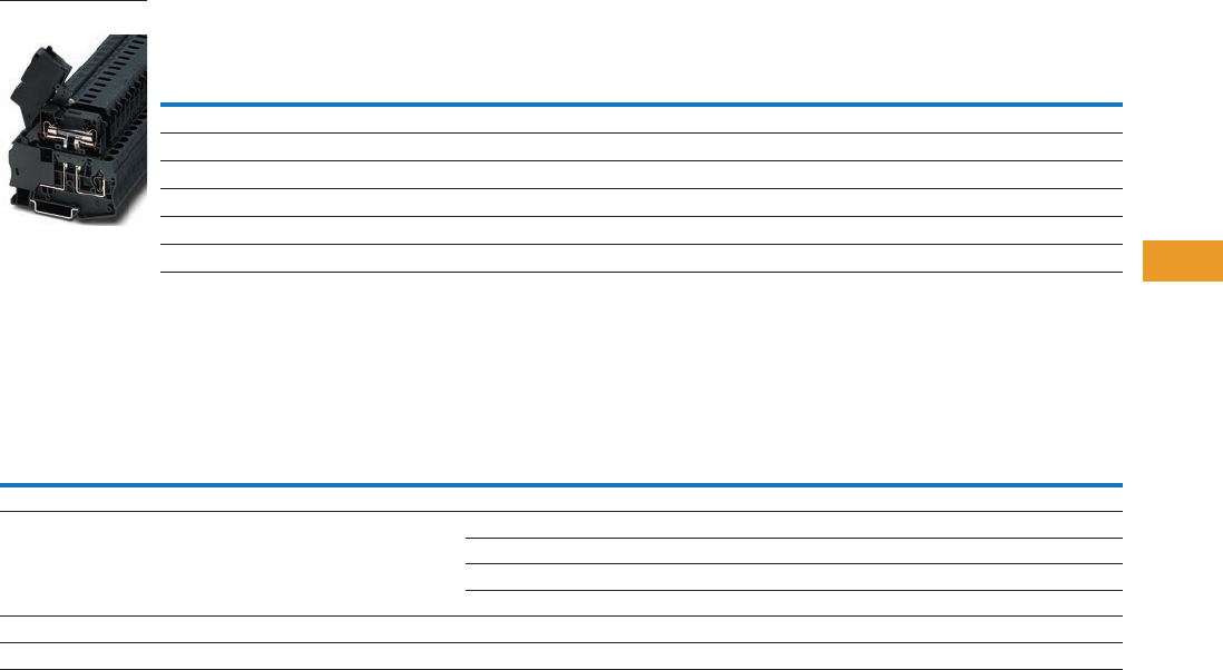
Logic Control Products CA08100001K—June 2012 www.eatoncanada.ca T42-49
42
42
42
42
42
42
42
42
42
42
42
42
42
42
42
42
42
42
42
42
42
42
42
42
42
42
42
42
42
42
42.1
Terminal Blocks, Fuse Blocks and Fuse Holders
IEC—
XB
Series
Spring Cage Connection Fuse Terminal Blocks, for 6.3 x 32 mm (1/4 in x 1–1/4 in) Fuse
Accessories
Spring Cage Connection Fuse Terminal Blocks
Notes
The cartridge fuse holders should be selected according to the maximum power dissipation (self-heating) of the cartridge
fuse inserts. The thermal conditions in closed fuse holes should be checked according to the application and installation.
Higher ambient temperatures are an additional strain on fuse inserts. In applications of this kind, the shift of the rated
current should be taken into consideration accordingly.
Maximum power dissipation at 73.4˚F (23˚C) (in accordance with IEC 60 947-7-3).
When selecting cartridge fuse inserts, please ensure that the maximum power dissipation specified at right is not exceeded.
Details can be obtained from the fuse suppliers.
Cartridge Fuse Inserts 5 x 20 and 6.3 x 32 mm in accordance. with IEC 60 947-7-3.
For information on Printed Marking Tag Options, see Page T42-98.
For additional accessories, see Page T42-90.
Terminal
Width
Maximum
Wire Size
IEC 60 947-7-3
with Fuse
in V/A/AWG
IEC 60 947-7-3
as Disconnect
Terminal Blocks
in V/A/AWG
UL-cUL Ratings
in V/A/AWG Colour
Standard
Pack
Catalogue
Number
Fuse Terminal Blocks
8.2 mm 10 AWG/4 mm2400/10/28–10 400/10/28–10 300/10/24–10 Black 50 XBPT4FBN
Fuse Terminal Blocks with LED 12–30V, 1.0–2.5 mA
8.2 mm 10 AWG/4 mm2400/10/28–10 400/10/28–10 300/10/24–10 Black 50 XBPT4FBNL24
Fuse Terminal Blocks with LED 110–250V, 0.5–2.5 mA
8.2 mm 10 AWG/4 mm2400/10/28–10 400/10/28–10 300/10/24–10 Black 50 XBPT4FBNL250
Description Colour
Number of
Positions
Standard
Pack
XBPT4FBE XBPT4FBN
Catalogue
Number
Catalogue
Number
Partition plate — — 10 XBATPT4 XBATQTD12
Plug-in bridge—for cross connections in
the bridge shaft
Red 2 10 XBAFBS26 XBAFBS28
310 XBAFBS36 —
510 XBAFBS56 —
10 10 XBAFBS106 —
Blank marker strip external labeling White — 10 XBMZBF6 XBMZBF8
Blank marker strip centre labeling (strip of 10) White — 10 XBMZB5 XBMZB6
XBPT4FBN
Tab42book.fm Page 49 Thursday, July 5, 2012 8:03 PM

T42-50 Logic Control Products CA08100001K—June 2012 www.eatoncanada.ca
42
42
42
42
42
42
42
42
42
42
42
42
42
42
42
42
42
42
42
42
42
42
42
42
42
42
42
42
42
42
42.1
Terminal Blocks, Fuse Blocks and Fuse Holders
IEC—
XB
Series
Technical Data and Specifications
Overload and Short-Circuit Protection
Spring Cage Connection Fuse Terminal Blocks
Dimensions
Approximate Dimensions in Inches (mm)
Spring Cage Connection Fuse Terminal Blocks
Note
The current is determined by the fuse used, the voltage by the selected light indicator. See Page T42-49.
Terminal
Blocks
Overload Protection Short-Circuit Protection Only
U (V) Individual Interconnected Individual Interconnected Imax. (A)
XBPT4FBN 400 1.6W 1.6W 4W 2.5W 10.0
XBPT4FBE 250 1.6W 1.6W 4W 2.5W 6.3
Description XBPT4FBE XBPT4FBN
Technical Data in Accordance with IEC
Fuse type/dimensions in mm2G/5 x 20 G/6.3 x 32
Maximum current with single arrangement in A 6.3 10
Maximum Power Dissipation
At 73.4˚F (23˚C) in accordance with IEC 60 947-7-3 in W
Rated surge voltage in kV/contamination class 4/3 6/3
Surge voltage category/insulating material group III/I III/I
Connection Capacity
Stranded with ferrule/with ferrule and plastic sleeve in mm20.25–4/0.25–4 0.25–4/0.25–4
Stranded with twin ferrule and plastic sleeve in mm20.5 0.5
Stripping length in inches (mm) 0.39 (10) 0.39 (10)
Catalogue
Number Width Length
Height for—
35 x 7.5 in 35 x 15 in
XBPT4FBE 0.24 (6.2) 2.42 (61.5) 2.46 (62.5) 2.76 (70.0)
XBPT4FBN 0.32 (8.2) 3.01 (76.5) 2.72 (69.0) 3.01 (76.5)
Tab42book.fm Page 50 Thursday, July 5, 2012 8:03 PM
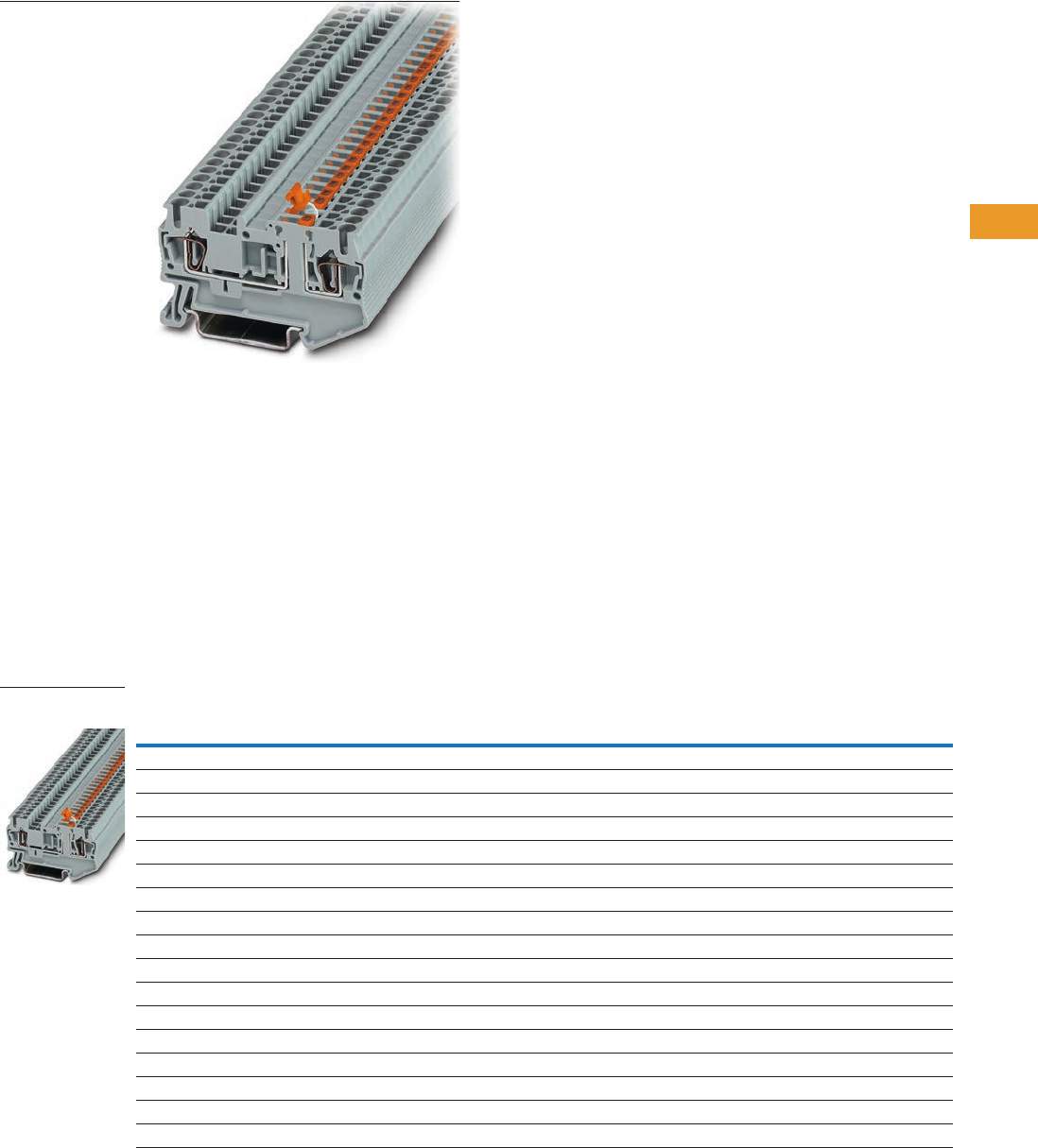
Logic Control Products CA08100001K—June 2012 www.eatoncanada.ca T42-51
42
42
42
42
42
42
42
42
42
42
42
42
42
42
42
42
42
42
42
42
42
42
42
42
42
42
42
42
42
42
42.1
Terminal Blocks, Fuse Blocks and Fuse Holders
IEC—
XB
Series
Disconnect and Component Terminal Blocks Contents
Description Page
Single Level—Through-Feed . . . . . . . . . . . . . . . . . . . . T42-32
Single Level—Ground Blocks . . . . . . . . . . . . . . . . . . . . T42-37
Multi-Conductor Terminal Blocks . . . . . . . . . . . . . . . . . T42-39
Multi-Conductor Ground Blocks . . . . . . . . . . . . . . . . . T42-42
Double Level Blocks . . . . . . . . . . . . . . . . . . . . . . . . . . T42-44
Triple Level Blocks . . . . . . . . . . . . . . . . . . . . . . . . . . . . T42-46
Fuse Terminal Blocks . . . . . . . . . . . . . . . . . . . . . . . . . . T42-48
Disconnect and Component Terminal Blocks
Accessories . . . . . . . . . . . . . . . . . . . . . . . . . . . . . . T42-52
Technical Data and Specifications . . . . . . . . . . . . . T42-53
Dimensions . . . . . . . . . . . . . . . . . . . . . . . . . . . . . . T42-53
Hybrid Terminal Blocks . . . . . . . . . . . . . . . . . . . . . . . . T42-54
Mini Spring Cage . . . . . . . . . . . . . . . . . . . . . . . . . . . . . T42-56
Disconnect and Component Terminal Blocks
Product Description
The XBPT knife disconnect
terminal blocks feature
narrow construction and high
current carrying capacity.
They also have a test
connection parallel to the
disconnect point for a 2.3 mm
diameter test plug. Potential
distribution is easily
accomplished with the Plug-
in bridges. There are front
connection spring cage
terminal blocks available for
multi-conductor connections
in the smallest possible
space. The XBPT4TG
disconnect terminal block
accommodates component
plugs for resistors, diodes,
or capacitors, and fuse plugs
with or without indication.
Product Selection
Disconnect and Component Terminal Blocks
Terminal
Width
Maximum
Wire Size
IEC 60 947-7-1
in V/A/AWG
UL-cUL Ratings
in V/A/AWG Colour
Standard
Pack
Catalogue
Number
Single Level Knife Disconnect
5.2 mm 12 AWG/2.5 mm2400/16/28–12 600/16/26–12 Gray 50 XBPT25MT
6.2 mm 10 AWG/4 mm2400/16/28–10 300/6.3/24–10 Gray 50 XBPT4MT
Three-Wire Knife Disconnect
5.2 mm 12 AWG/2.5 mm2400/16/28–12 600/16/26–12 Gray 50 XBPT25D12MT
Four-Wire Knife Disconnect
5.2 mm 12 AWG/2.5 mm2400/16/28–12 600/16/26–12 Gray 50 XBPT25D22MT
Spring Cage Disconnect/Component Plug
6.2 mm 10 AWG/4 mm2400/16/28–10 300/6.3/24–10 Gray 50 XBPT4TG
Component Plug
6.2 mm 10 AWG/4 mm2400/16/28–10 300/6.3/24–10 Gray 10 XBPCO
Fuse Plug
6.2 mm 10 AWG/4 mm2400/16/28–10 300/6.3/24–10 Black 10 XBPFU
Fuse Plug with Light Indicator for 12–30V, 1–2.5 mA
6.2 mm 10 AWG/4 mm2400/16/28–10 300/6.3/24–10 Black 10 XBPFUL24
Fuse Plug with Light Indicator for 110–250V, 0.5–2.5 mA
6.2 mm 10 AWG/4 mm2400/16/28–10 300/6.3/24–10 Black 10 XBPFUL250
XBPT25MT
Knife Disconnect
Tab42book.fm Page 51 Thursday, July 5, 2012 8:03 PM

T42-52 Logic Control Products CA08100001K—June 2012 www.eatoncanada.ca
42
42
42
42
42
42
42
42
42
42
42
42
42
42
42
42
42
42
42
42
42
42
42
42
42
42
42
42
42
42
42.1
Terminal Blocks, Fuse Blocks and Fuse Holders
IEC—
XB
Series
Accessories
Spring Cage Connection Disconnect and Component Terminal Blocks
Notes
For ordering information, see Page T42-105.
For information on Printed Marking Tag Options, see Page T42-98.
XBPT4MT and XBPT4TG have an enclosed design. The use of an end cover is not required.
For additional accessories, see Page T42-90.
Description Colour
Number of
Positions
Standard
Pack
XBPT25MT XBPT25D12MT XBPT25D22MT XBPT4MT XBPT4TG
Catalogue
Number
Catalogue
Number
Catalogue
Number
Catalogue
Number
Catalogue
Number
End cover Gray — 10 XBACPT25D12 XBACPT25D22 XBACPT25D22MT
End cover segment Gray — 10 — XBACPT25 XBACPT25 — —
Partition plate — — — XBATPTD12 XBATPTD22 — XBATPT4 XBATPT4
Plug-in bridge—for cross connections
in the terminal centre
Red 2 10 XBAFBS25 XBAFBS25 XBAFBS25 XBAFBS26 XBAFBS26
310XBAFBS35 XBAFBS35 XBAFBS35 XBAFBS36 XBAFBS36
510XBAFBS55 XBAFBS55 XBAFBS55 XBAFBS56 XBAFBS56
10 10 XBAFBS105 XBAFBS105 XBAFBS105 XBAFBS106 XBAFBS106
50 10 XBAFBS505 XBAFBS505 XBAFBS505 XBAFBS506 XBAFBS506
Test adapter — — 10 XBATSPAI4 XBATSPAI4 XBATSPAI4 XBATSPAI4 XBATSPAI4
2.3 mm diameter test plug — — — XBATSMPS-_ XBATSMPS-_ XBATSMPS-_ XBATSMPS-_ XBATSMPS-_
Modular test plug — — 10 XBATSPS5 XBATSPS5 XBATSPS5 XBATSPS6 XBATSPS6
Blank marker strip external labeling White — 10 XBMZBF5 XBMZBF5 XBMZBF5 XBMZBF6 XBMZBF6
Blank marker strip centre labeling
(strip of 10)
White — 10 XBMZB5 XBMZB5 XBMZB5 XBMZB6 XBMZB6
Tab42book.fm Page 52 Thursday, July 5, 2012 8:03 PM

Logic Control Products CA08100001K—June 2012 www.eatoncanada.ca T42-53
42
42
42
42
42
42
42
42
42
42
42
42
42
42
42
42
42
42
42
42
42
42
42
42
42
42
42
42
42
42
42.1
Terminal Blocks, Fuse Blocks and Fuse Holders
IEC—
XB
Series
Technical Data and Specifications
Spring Cage Connection Disconnect and Component Terminal Blocks,
XBPT25MT, XBPT25D12MT and XBPT25D22MT
Spring Cage Connection Disconnect and Component Terminal Blocks,
XBPT25D12MT and XBPT4TG
Dimensions
Approximate Dimensions in Inches (mm)
Spring Cage Connection Disconnect and Component Terminal Blocks
Description XBPT25MT XBPT25D12MT XBPT25D22MT
Technical Data in Accordance with IEC
Maximum load current in A/cross-section in mm216/4 16/4 16/4
Rated surge voltage in kV/contamination class 6/3 6/3 6/3
Surge voltage category/insulating material group III/I III/I III/I
Connection Capacity
Stranded with ferrule with plastic sleeve in mm20.25–2.5 0.25–2.5 0.25–2.5
Stranded with ferrules without plastic sleeve in mm20.25–2.5 0.25–2.5 0.25–2.5
Stranded with twin ferrule with plastic sleeve in mm20.5 0.5 0.5
Stripping length in inches (mm) 0.39 (10) 0.39 (10) 0.39 (10)
Description XBPT4MT XBPT4TG
Technical Data in Accordance with IEC
Maximum load current in A/cross-section in mm216/6 16/6
Rated surge voltage in kV/contamination class 6/3 6/3
Surge voltage category/insulating material group III/I III/I
Connection Capacity
Stranded with ferrule with plastic sleeve in mm20.25–4 0.25–4
Stranded with ferrules without plastic sleeve in mm20.25–4 0.25–4
Stranded with twin ferrule with plastic sleeve in mm20.5 0.5
Stripping length in inches (mm) 0.39 (10) 0.39 (10)
Catalogue
Number Width Length
Cover
Length
Height for—
35 x 7.5 in 35 x 15 in
XBPT25MT 0.20 (5.2) 2.38 (60.5) 0.09 (2.2) 1.44 (36.5) 1.73 (44.0)
XBPT25D12MT 0.20 (5.2) 2.83 (72.0) 0.09 (2.2) 1.44 (36.5) 1.73 (44.0)
XBPT25D22MT 0.20 (5.2) 3.31 (84.0) 0.09 (2.2) 1.44 (36.5) 1.73 (44.0)
XBPT4MT 0.24 (6.2) 2.42 (61.5) — 1.44 (36.5) 1.73 (44.0)
XBPT4TG 0.24 (6.2) 2.42 (61.5) — 1.44 (36.5) 1.73 (44.0)
Tab42book.fm Page 53 Thursday, July 5, 2012 8:03 PM
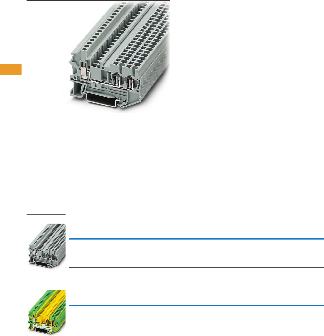
T42-54 Logic Control Products CA08100001K—June 2012 www.eatoncanada.ca
42
42
42
42
42
42
42
42
42
42
42
42
42
42
42
42
42
42
42
42
42
42
42
42
42
42
42
42
42
42
42.1
Terminal Blocks, Fuse Blocks and Fuse Holders
IEC—
XB
Series
Hybrid Terminal Blocks Contents
Description Page
Single Level—Through-Feed . . . . . . . . . . . . . . . . . . . . T42-32
Single Level—Ground Blocks. . . . . . . . . . . . . . . . . . . . T42-37
Multi-Conductor Terminal Blocks . . . . . . . . . . . . . . . . T42-39
Multi-Conductor Ground Blocks . . . . . . . . . . . . . . . . . T42-42
Double Level Blocks . . . . . . . . . . . . . . . . . . . . . . . . . . T42-44
Triple Level Blocks . . . . . . . . . . . . . . . . . . . . . . . . . . . T42-46
Fuse Terminal Blocks . . . . . . . . . . . . . . . . . . . . . . . . . T42-48
Disconnect and Component Terminal Blocks . . . . . . . T42-51
Hybrid Terminal Blocks
Accessories . . . . . . . . . . . . . . . . . . . . . . . . . . . . . . T42-55
Technical Data and Specifications . . . . . . . . . . . . . T42-55
Dimensions . . . . . . . . . . . . . . . . . . . . . . . . . . . . . . T42-55
Mini Spring Cage . . . . . . . . . . . . . . . . . . . . . . . . . . . . . T42-56
Hybrid Terminal Blocks
Product Description
The XBPU spring cage hybrid
terminal blocks offer the best
of both worlds. One side
offers a spring cage
connection and the other side
offers the universal screw
connection. Use the spring
cage connection on the
internal (factory) control
cabinet side and the screw
connection on the end
customer (field) side. Ground
terminal blocks of the same
shape are also available.
Product Selection
Spring Cage Hybrid Terminal Blocks
Spring Cage Hybrid Ground Blocks
Terminal
Width
Maximum
Wire Size
IEC 60 947-7-1 with … IEC 60 947-7-2 with … UL-cUL Ratings with …
Colour
Std.
Pack
Catalogue
Number
Spring in
V/A/AWG
Screw in
V/A/AWG
Spring in
V/A/AWG
Screw in
V/A/AWG
Spring in
V/A/AWG
Screw in
V/A/AWG
5.2 mm 12 AWG/
2.5 mm2
800/28/28–12 800/28/26–14 — — 600/15/28–12 600/15/26–12 Gray 50 XBPU25D12
Terminal
Width
Maximum
Wire Size
IEC 60 947-7-1 with … IEC 60 947-7-2 with … UL-cUL Ratings with …
Colour
Std.
Pack
Catalogue
Number
Spring in
V/A/AWG
Screw in
V/A/AWG
Spring in
V/A/AWG
Screw in
V/A/AWG
Spring in
V/A/AWG
Screw in
V/A/AWG
5.2 mm 12 AWG/
2.5 mm2
— — —/—/28–12 —/—/26–14 —/—/28–12 —/—/28–12 Green/
Yellow
50 XBPU25D12PE
XBPU25D12
XBPU25D12PE
Tab42book.fm Page 54 Thursday, July 5, 2012 8:03 PM

Logic Control Products CA08100001K—June 2012 www.eatoncanada.ca T42-55
42
42
42
42
42
42
42
42
42
42
42
42
42
42
42
42
42
42
42
42
42
42
42
42
42
42
42
42
42
42
42.1
Terminal Blocks, Fuse Blocks and Fuse Holders
IEC—
XB
Series
Accessories
Spring Cage Hybrid Terminal/Ground Blocks
Technical Data and Specifications
Spring Cage Hybrid Blocks
Dimensions
Approximate Dimensions in Inches (mm)
Spring Cage Hybrid Blocks
Notes
For ordering information, see Page T42-105.
For information on Printed Marking Tag Options, see Page T42-98.
For additional accessories, see Page T42-90.
Description Colour
Number of
Positions
Standard
Pack
XBPU25D12 XBPU25D12PE
Catalogue
Number
Catalogue
Number
End cover Gray — 10 XBACPU25D12 XBACPU25D12
Plug-in bridge—for cross connections
in the terminal centre
Red 2 10 XBAFBS25 XBAFBS25
310XBAFBS35 XBAFBS35
510XBAFBS55 XBAFBS55
10 10 XBAFBS105 XBAFBS105
50 10 XBAFBS505 XBAFBS505
Test adapter — — 10 XBATSPAI4 —
2.3 mm diameter test plug — — — XBATSMPS-_ —
Modular test plug — — 10 XBATSPS5 —
Blank marker strip external labeling White — 10 XBMZBF5 XBMZBF5
Blank marker strip centre labeling
(strip of 10)
White — 10 XBMZB5 XBMZB5
Description XBPU25D12 XBPU25D12PE
Technical Data in Accordance with IEC
Maximum load current in A/cross-section in mm228/4 —
Rated surge voltage in kV/contamination class 8/3 8/3
Surge voltage category/insulating material group III/I III/I
Connection Capacity
Stranded with ferrule with plastic sleeve in mm20.25–2.5 0.25–2.5
Stranded with ferrules without plastic sleeve in mm20.25–2.5 0.25–2.5
Stranded with twin ferrule with plastic sleeve in mm20.5–1 0.5–1
Stripping length in inches (mm) 0.39 (10) 0.39 (10)
Catalogue
Number Width Length
Cover
Length
Height for—
35 x 7.5 in 35 x 15 in
XBPU25D12 0.20 (5.2) 2.57 (65.3) 0.09 (2.2) 1.69 (42.8) 1.98 (50.3)
XBPU25D12PE 0.20 (5.2) 2.57 (65.3) 0.09 (2.2) 1.69 (42.8) 1.98 (50.3)
Tab42book.fm Page 55 Thursday, July 5, 2012 8:03 PM

T42-56 Logic Control Products CA08100001K—June 2012 www.eatoncanada.ca
42
42
42
42
42
42
42
42
42
42
42
42
42
42
42
42
42
42
42
42
42
42
42
42
42
42
42
42
42
42
42.1
Terminal Blocks, Fuse Blocks and Fuse Holders
IEC—
XB
Series
Mini Spring Cage Contents
Description Page
Single Level—Through-Feed . . . . . . . . . . . . . . . . . . . . T42-5
Single Level—Ground Blocks . . . . . . . . . . . . . . . . . . . T42-10
Multi-Conductor Terminal Blocks . . . . . . . . . . . . . . . . T42-12
Multi-Conductor Ground Blocks . . . . . . . . . . . . . . . . . T42-14
Double Level . . . . . . . . . . . . . . . . . . . . . . . . . . . . . . . . T42-16
Triple Level Sensor/Actuator . . . . . . . . . . . . . . . . . . . . T42-18
Fuse Terminal Blocks . . . . . . . . . . . . . . . . . . . . . . . . . T42-21
Disconnect and Component Terminal Blocks . . . . . . . T42-24
High Current Blocks . . . . . . . . . . . . . . . . . . . . . . . . . . T42-27
Mini Spring Cage
Accessories . . . . . . . . . . . . . . . . . . . . . . . . . . . . . . T42-57
Technical Data and Specifications . . . . . . . . . . . . . T42-57
Dimensions . . . . . . . . . . . . . . . . . . . . . . . . . . . . . . T42-57
Mini Spring Cage
Product Description
The XB miniature terminal
blocks have a connection
cross-section from 1.5 mm2
through 4 mm2 and mount on
15 mm DIN rail. There is an
opening for bridging with a
fixed bridge in the centre of
the terminal blocks. These
miniature terminal blocks also
offer the same accessories
that you would find with the
larger blocks—including
marking tags, end covers,
end stop and ground blocks.
Product Selection
Mini Spring Cage Terminal Blocks
Mini Spring Cage Ground Blocks
Mini Spring Cage Terminal Blocks—Double Level
Terminal
Width
Maximum
Wire Size
IEC 60 947-7-1
in V/A/AWG
IEC 60 947-7-2
in V/A/AWG
UL-cUL Ratings
in V/A/AWG Colour
Standard
Pack
Catalogue
Number
5.2 mm 14 AWG/1.5 mm2800/24/26–14 — 600/15/26–14 Gray 50 XBMPK15
Blue 50 XBMPK15BU
Terminal
Width
Maximum
Wire Size
IEC 60 947-7-1
in V/A/AWG
IEC 60 947-7-2
in V/A/AWG
UL-cUL Ratings
in V/A/AWG Colour
Standard
Pack
Catalogue
Number
5.2 mm 14 AWG/1.5 mm2— —/—/26–14 —/—/26–14 Green/
Yellow
50 XBMPK15PE
Terminal
Width
Maximum
Wire Size
IEC 60 947-7-1
in V/A/AWG
UL-cUL Ratings
in V/A/AWG Colour
Standard
Pack
Catalogue
Number
5.2 mm 14 AWG/1.5 mm2500/20/26–14 600/15/26–14 Gray 50 XBMPKK15
XBMPK15
XBMPK15PE
XBMPKK15
Tab42book.fm Page 56 Thursday, July 5, 2012 8:03 PM

Logic Control Products CA08100001K—June 2012 www.eatoncanada.ca T42-57
42
42
42
42
42
42
42
42
42
42
42
42
42
42
42
42
42
42
42
42
42
42
42
42
42
42
42
42
42
42
42.1
Terminal Blocks, Fuse Blocks and Fuse Holders
IEC—
XB
Series
Accessories
Mini Spring Cage Terminal/Ground Blocks
Technical Data and Specifications
Mini Spring Cage Terminal/Ground Blocks
Dimensions
Approximate Dimensions in Inches (mm)
Mini Spring Cage Terminal/Ground Blocks
Notes
For information on Printed Marking Tag Options, see Page T42-98.
For additional accessories, see Page T42-90.
Description Colour
Number of
Positions
Standard
Pack
XBMPK15 XBMPK15PE XBMPKK15
Catalogue
Number
Catalogue
Number
Catalogue
Number
End cover Gray — 10 XBACMPK15 XBACMPK15 XBACMPKK15
Fixed bridge — 2 10 XBAFBR25N — XBAFBR25N
Separating plate — — 10 XBATMPKK15 — XBATMPKK15
Blank marker strip White — 10 XBMZBF5 XBMZBF5 XBMZBF5
Description XBMPK15 XBMPK15PE XBMPKK15
Technical Data in Accordance with IEC
Maximum load current in A/cross-section in mm224/2.5 — 20/2.5
Rated surge voltage in kV/contamination class 8/3 8/3 6/3
Surge voltage category/insulating material group III/I III/I III/I
Connection Cross-Section
Stranded with ferrule with plastic sleeve in mm20.25–1.5 0.25–1.5 0.25–1.5
Stranded with ferrule without plastic sleeve in mm20.25–1.5 0.25–1.5 0.25–1.5
Stranded with twin ferrule with plastic sleeve in mm2———
Stripping length in Inches (mm) 0.35 (9) 0.35 (9) 0.35 (9)
Catalogue
Number Width Length
Cover
Length
Height for—
15 x 5.5 in 35 x 7.5 in 35 x 15 in
XBMPK15 0.20 (5.2) 1.57 (40.0) 0.04 (1.1) 1.36 (34.5) — —
XBMPK15PE 0.20 (5.2) 1.57 (40.0) 0.04 (1.1) 1.36 (34.5) — —
XBMPKK15 0.20 (5.2) 3.35 (85.0) 0.04 (1.1) 1.65 (42.0) 1.67 (42.5) 1.97 (50.0)
Tab42book.fm Page 57 Thursday, July 5, 2012 8:03 PM
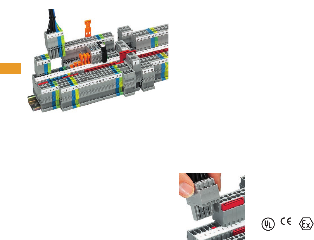
T42-58 Logic Control Products CA08100001K—June 2012 www.eatoncanada.ca
42
42
42
42
42
42
42
42
42
42
42
42
42
42
42
42
42
42
42
42
42
42
42
42
42
42
42
42
42
42
42.1
Terminal Blocks, Fuse Blocks and Fuse Holders
IEC—
XB
Series
Pluggable Spring Cage Terminal Blocks Contents
Description Page
Pluggable Spring Cage Terminal Blocks
Connection Terminal Blocks . . . . . . . . . . . . . . . . . . T42-59
Connection Plugs . . . . . . . . . . . . . . . . . . . . . . . . . . T42-62
Connection Receptacles . . . . . . . . . . . . . . . . . . . . T42-64
Connection Accessories . . . . . . . . . . . . . . . . . . . . T42-66
Pluggable Spring Cage Terminal Blocks Overview
Product Description
The pluggable spring cage
connection terminal blocks
allow signal and power wiring
to be made pluggable. This
complete pluggable system
has a spring that provides
maximum connection space
in a space-saving design.
The pluggable system
accommodates stranded
conductors with a nominal
cross-section of 2.5 mm2,
with or without ferrules.
Application Description
For applications requiring
pluggable wiring up to a rated
current of 32A and a rated
voltage of 800V. The
integrated overspring meets
the most stringent vibration
requirements. Also ideal
where safety is a concern and
flexibility is required. The
basic terminal blocks and the
plugs are finger-safe, which
also means the supply
voltage can be input via either
the terminal blocks or the
plugs. With the XBAPSC
receptacles, plug-in contacts
can be accommodated safely
in cable ducts and distributor
shafts using minimal space.
A test hole can accommodate
a 2.3 mm diameter test plug
in each receptacle, providing
a practical solution. The
XBAPSP plugs are intended
for connecting one wire,
while the XBAPSPDB plugs
are designed to connect
two wires and provide an
optional bridge.
Features
●Space-saving design
●Powerful contact
●Finger-safe
Pluggability
Standards and Certifications
●UL recognized—File No.
E67464
●CE approved
●LVD :
●EN 60947-7-1
●EN 60947-7-2
●EN 60998-2-3
●EN 60352-4/A1
●ATEX approval
(Eex e applications)
Note
Not all standards apply to all terminal
blocks. Contact Eaton for details.
Tab42book.fm Page 58 Thursday, July 5, 2012 8:03 PM
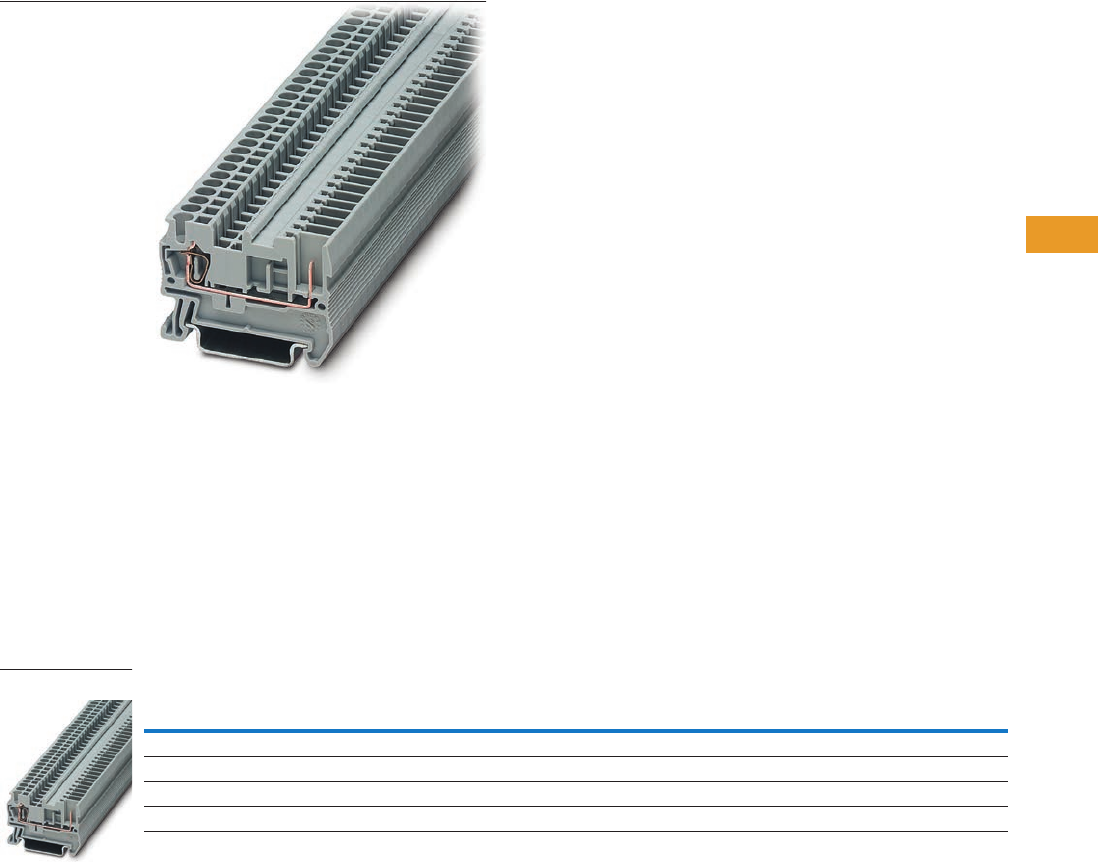
Logic Control Products CA08100001K—June 2012 www.eatoncanada.ca T42-59
42
42
42
42
42
42
42
42
42
42
42
42
42
42
42
42
42
42
42
42
42
42
42
42
42
42
42
42
42
42
42.1
Terminal Blocks, Fuse Blocks and Fuse Holders
IEC—
XB
Series
Connection Terminal Blocks Contents
Description Page
Connection Terminal Blocks
Accessories . . . . . . . . . . . . . . . . . . . . . . . . . . . . . . T42-60
Technical Data and Specifications . . . . . . . . . . . . . T42-60
Dimensions . . . . . . . . . . . . . . . . . . . . . . . . . . . . . . T42-61
Connection Plugs . . . . . . . . . . . . . . . . . . . . . . . . . . . . . T42-62
Connection Receptacles . . . . . . . . . . . . . . . . . . . . . . . T42-64
Connection Accessories . . . . . . . . . . . . . . . . . . . . . . . T42-66
Connection Terminal Blocks
Product Description
Contact to the DIN rail is
made by simply snapping the
terminal block onto the rail.
These blocks act as the
stationary position of the
pluggable terminal blocks.
Product Selection
Pluggable Spring Cage Connection Terminal Blocks
Terminal
Width
Maximum
Wire Size
IEC 61 984
in V/A/AWG
UL-cUL Ratings
in V/A/AWG Colour
Standard
Pack
Catalogue
Number
Single Level
5.2 mm 12 AWG/2.5 mm2500/24/28–12 300/20/26–12 Gray 50 XBPT25P
Three-Wire
5.2 mm 12 AWG/2.5 mm2500/24/28–12 300/20/26–12 Gray 50 XBPT25PD12
XBPT25P
Tab42book.fm Page 59 Thursday, July 5, 2012 8:03 PM
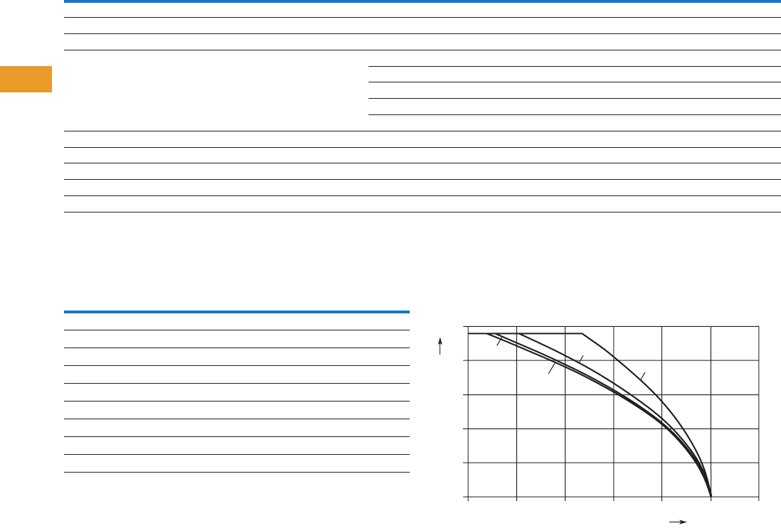
T42-60 Logic Control Products CA08100001K—June 2012 www.eatoncanada.ca
42
42
42
42
42
42
42
42
42
42
42
42
42
42
42
42
42
42
42
42
42
42
42
42
42
42
42
42
42
42
42.1
Terminal Blocks, Fuse Blocks and Fuse Holders
IEC—
XB
Series
Accessories
Pluggable Spring Cage Connection Terminal Blocks
Technical Data and Specifications
Pluggable Spring Cage Connection Terminal Blocks Derating Curve for Pluggable Terminal Blocks
XBPT25P and XBPT25PD12
Notes
For ordering information, see Page T42-105.
For information on Printed Marking Tag Options, see Page T42-98.
For additional accessories, see Page T42-90.
Description Colour
Number of
Positions
Standard
Pack
XBPT25P XBPT25PD12
Catalogue
Number
Catalogue
Number
End cover Gray — 10 XBACPT25 XBACPT25D12
End cover segment Gray — 10 — XBASPT25
Partition plate — — 10 XBATPT4 XBATPTD12
Plug-in bridge—for cross connections
in the terminal centre
Red 2 10 XBAFBS25 XBAFBS25
310XBAFBS35 XBAFBS35
510XBAFBS55 XBAFBS55
10 10 XBAFBS105 XBAFBS105
50 10 XBAFBS505 XBAFBS505
Test adapter — — 10 XBATSPAI4 XBATSPAI4
2.3 mm diameter test plug — — — XBATSMPS-_ XBATSMPS-_
Modular test plug — — 10 XBATSPS5 XBATSPS5
Blank marker strip external labeling White — 10 XBMZBF5 XBMZBF5
Blank marker strip centre labeling (strip of 10) White — 10 XBMZB5 XBMZB5
Description XBPT25P XBPT25PD12
Technical Data in Accordance with IEC
Maximum load current in A/cross-section in mm224/4 24/4
Rated surge voltage in kV/contamination class 6/3 6/3
Surge voltage category/insulating material group III/I III/I
Connection Capacity
Stranded with ferrule with plastic sleeve in mm20.25–2.5 0.25–2.5
Stranded with ferrules without plastic sleeve in mm20.25–2.5 0.25–2.5
Stranded with twin ferrule with plastic sleeve in mm20.5 0.5
Stripping length in inches (mm) 0.39 (10) 0.39 (10)
25
15 pos.
5 pos.
20
15
10
5
0
Ambient Temperature – °C
Maximum Load Current – A
020406080100120
10 pos.
2 pos.
Tab42book.fm Page 60 Thursday, July 5, 2012 8:03 PM
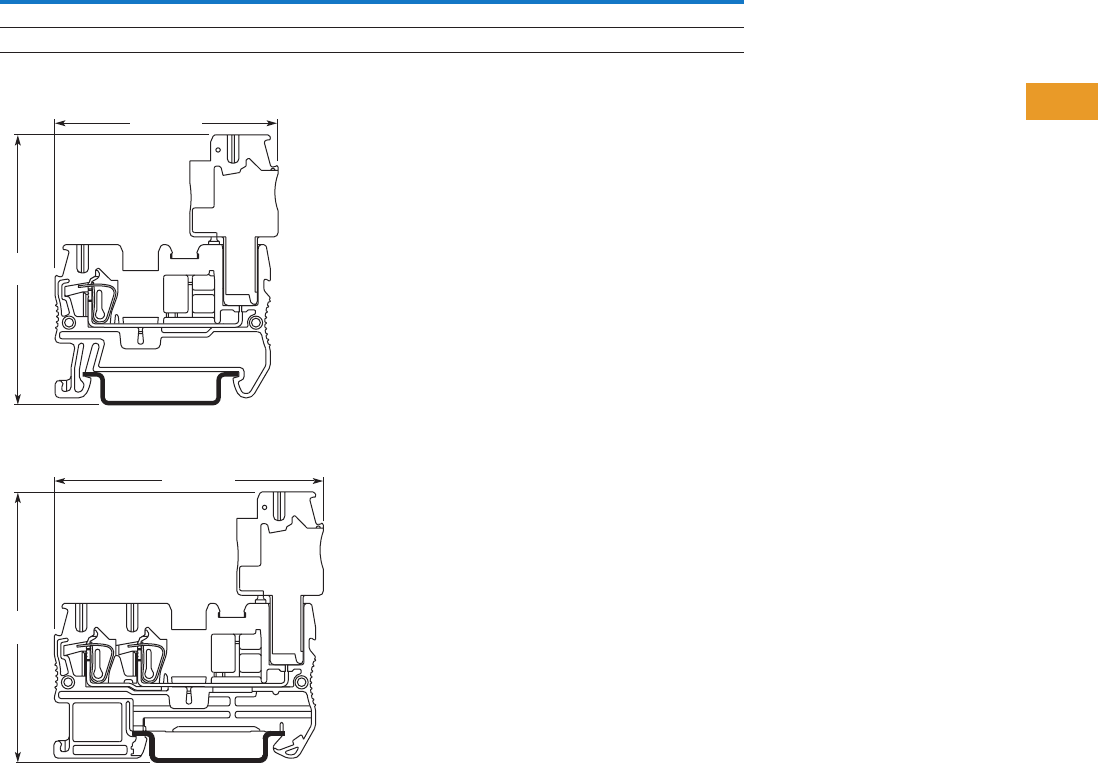
Logic Control Products CA08100001K—June 2012 www.eatoncanada.ca T42-61
42
42
42
42
42
42
42
42
42
42
42
42
42
42
42
42
42
42
42
42
42
42
42
42
42
42
42
42
42
42
42.1
Terminal Blocks, Fuse Blocks and Fuse Holders
IEC—
XB
Series
Dimensions
Approximate Dimensions in Inches (mm)
Pluggable Spring Cage Connection Terminal Blocks—Without Plug
XBPT25P
XBPT25PD12
Catalogue
Number Width Length
Cover
Length
Height for—
35 x 7.5 in 35 x 15 in
XBPT25P 0.20 (5.2) 1.91 (48.5) 0.09 (2.2) 1.44 (36.5) 1.73 (44.0)
XBPT25PD12 0.20 (5.2) 2.38 (60.5) 0.09 (2.2) 1.44 (36.5) 1.73 (44.0)
1.99 (50.5)
2.42
(61.5)
2.42 (61.5)
2.42
(61.5)
Tab42book.fm Page 61 Thursday, July 5, 2012 8:03 PM
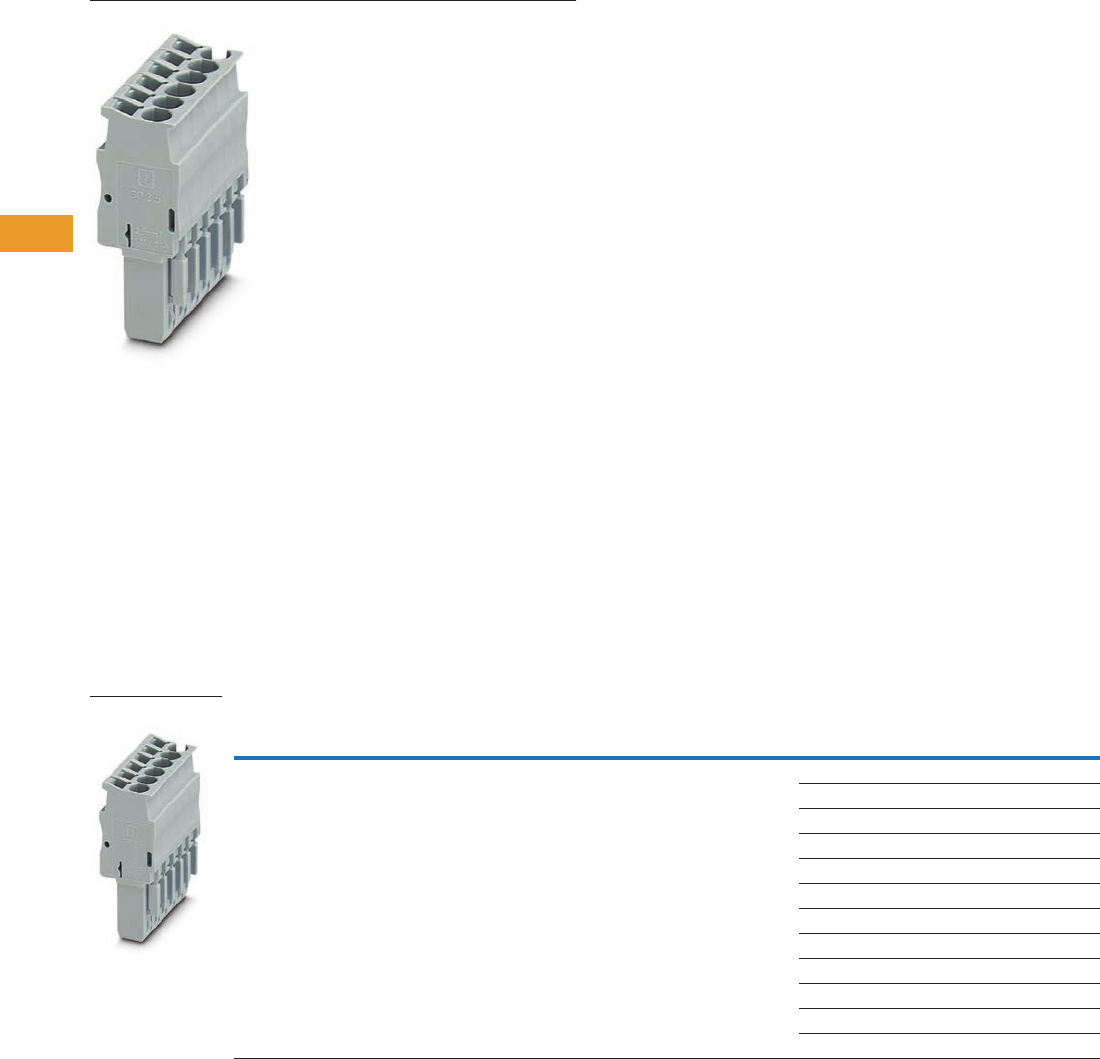
T42-62 Logic Control Products CA08100001K—June 2012 www.eatoncanada.ca
42
42
42
42
42
42
42
42
42
42
42
42
42
42
42
42
42
42
42
42
42
42
42
42
42
42
42
42
42
42
42.1
Terminal Blocks, Fuse Blocks and Fuse Holders
IEC—
XB
Series
Connection Plugs Contents
Description Page
Connection Terminal Blocks . . . . . . . . . . . . . . . . . . . . T42-59
Connection Plugs
Accessories . . . . . . . . . . . . . . . . . . . . . . . . . . . . . . T42-63
Technical Data and Specifications . . . . . . . . . . . . . T42-63
Dimensions . . . . . . . . . . . . . . . . . . . . . . . . . . . . . . T42-63
Connection Receptacles . . . . . . . . . . . . . . . . . . . . . . . T42-64
Connection Accessories . . . . . . . . . . . . . . . . . . . . . . . T42-66
Connection Plugs
Product Description
Just like the basic terminal
blocks, the plugs also offer
the perfect solution for every
application. The XBAPSP25_
plugs are designed for
connecting one conductor.
The XBAPSPDB25_ plug is
designed for connecting two
conductors and provides an
additional bridging option.
Product Selection
Spring Cage Connection Plugs, Single, Not Bridgeable
Terminal
Width
Maximum
Wire Size
Connection Data
in V/A/AWG
UL-cUL Ratings
in V/A/AWG Colour
Number of
Positions
Standard
Pack
Catalogue
Number
5.2 mm 12 AWG/2.5 mm2500/24/28–12 300/20/26–12 Gray 1 25 XBAPSP251
225XBAPSP252
325XBAPSP253
425XBAPSP254
525XBAPSP255
625XBAPSP256
725XBAPSP257
825XBAPSP258
925XBAPSP259
10 25 XBAPSP2510
11 10 XBAPSP2511
12 10 XBAPSP2512
XBAPSP25_
Tab42book.fm Page 62 Thursday, July 5, 2012 8:03 PM
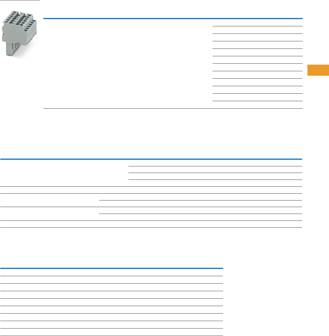
Logic Control Products CA08100001K—June 2012 www.eatoncanada.ca T42-63
42
42
42
42
42
42
42
42
42
42
42
42
42
42
42
42
42
42
42
42
42
42
42
42
42
42
42
42
42
42
42.1
Terminal Blocks, Fuse Blocks and Fuse Holders
IEC—
XB
Series
Spring Cage Connection Plugs, Double, Bridgeable
Accessories
Spring Cage Connection Plugs
Technical Data and Specifications
Spring Cage Connection Plugs
Dimensions
See Page T42-61 for dimensions.
Notes
For information on Printed Marking Tag Options, see Page T42-98.
For additional accessories, see Page T42-90.
Terminal
Width
Maximum
Wire Size
Connection Data
in V/A/AWG
UL-cUL Ratings
in V/A/AWG Colour
Number of
Positions
Standard
Pack
Catalogue
Number
5.2 mm 12 AWG/2.5 mm2500/24/28–12 300/20/26–12 Gray 1 25 XBAPSPDB251
225XBAPSPDB252
325XBAPSPDB253
425XBAPSPDB254
525XBAPSPDB255
625XBAPSPDB256
725XBAPSPDB257
825XBAPSPDB258
925XBAPSPDB259
10 25 XBAPSPDB2510
11 10 XBAPSPDB2511
12 10 XBAPSPDB2512
Description Colour
Number of
Positions
Standard
Pack
XBAPSP25_ XBAPSPDB25_
Catalogue
Number
Catalogue
Number
Plug-in bridge—for cross connections
in the terminal centre
Red 2 10 — XBAFBS25
310— XBAFBS35
510— XBAFBS55
10 10 — XBAFBS105
Snap-lock fitting and strain relief Orange 2 10 XBAPPRZ XBAPPRZ
Snap-lock fitting Orange 1 10 XBAPPR XBAPPR
Orange 2 10 XBAPPR2 XBAPPR2
Strain relief Black 2 10 XBAPPZ2 XBAPPDZ2
Black 4 10 XBAPPZ4 XBAPPDZ4
Blank marker strip White — 10 XBMZBF5 XBMZBF5
Description XBAPSP25_ XBAPSPDB25_
Technical Data in Accordance with IEC
Maximum load current in A/cross-section in mm224/4 24/4
Rated surge voltage in kV/contamination class 6/3 6/3
Surge voltage category/insulating material group III/I III/I
Connection Capacity
Stranded with ferrule with plastic sleeve in mm20.25–2.5 0.25–2.5
Stranded with ferrules without plastic sleeve in mm20.25–2.5 0.25–2.5
Stranded with twin ferrule with plastic sleeve in mm20.5 0.5
Stripping length in inches (mm) 0.39 (10) 0.39 (10)
XBAPSPDB25_
Tab42book.fm Page 63 Thursday, July 5, 2012 8:03 PM
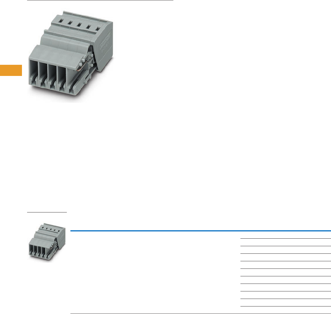
T42-64 Logic Control Products CA08100001K—June 2012 www.eatoncanada.ca
42
42
42
42
42
42
42
42
42
42
42
42
42
42
42
42
42
42
42
42
42
42
42
42
42
42
42
42
42
42
42.1
Terminal Blocks, Fuse Blocks and Fuse Holders
IEC—
XB
Series
Connection Receptacles Contents
Description Page
Connection Terminal Blocks . . . . . . . . . . . . . . . . . . . . T42-59
Connection Plugs . . . . . . . . . . . . . . . . . . . . . . . . . . . . T42-62
Connection Receptacles
Accessories . . . . . . . . . . . . . . . . . . . . . . . . . . . . . . T42-65
Technical Data and Specifications . . . . . . . . . . . . . T42-65
Dimensions . . . . . . . . . . . . . . . . . . . . . . . . . . . . . . T42-65
Connection Accessories . . . . . . . . . . . . . . . . . . . . . . . T42-66
Connection Receptacles
Product Description
With the XBAPSC25_,
Plug-in contacts can be
accommodated safely in
cable ducts and distributor
shafts without using much
space. The standard strain
reliefs can also be used.
Large-surface labeling makes
it possible to mark the
terminal points and the entire
receptacle. A test hole can
accommodate a 2.3 mm
diameter test plug in each
receptacle element, providing
a practical solution.
Product Selection
Pluggable Spring Connection Receptacles
Terminal
Width
Maximum
Wire Size
Connection Data
in V/A/AWG
UL-cUL Ratings
in V/A/AWG Colour
Number of
Positions
Standard
Pack
Catalogue
Number
5.2 mm 12 AWG/2.5 mm2500/24/28–12 300/20/26–12 Gray 2 25 XBAPSC252
325XBAPSC253
425XBAPSC254
525XBAPSC255
625XBAPSC256
725XBAPSC257
825XBAPSC258
925XBAPSC259
10 25 XBAPSC2510
11 10 XBAPSC2511
12 10 XBAPSC2512
XBAPSC25_
Tab42book.fm Page 64 Thursday, July 5, 2012 8:03 PM

Logic Control Products CA08100001K—June 2012 www.eatoncanada.ca T42-65
42
42
42
42
42
42
42
42
42
42
42
42
42
42
42
42
42
42
42
42
42
42
42
42
42
42
42
42
42
42
42.1
Terminal Blocks, Fuse Blocks and Fuse Holders
IEC—
XB
Series
Accessories
Pluggable Spring Connection Receptacles
Technical Data and Specifications
Spring Cage Connection Plugs
Dimensions
Approximate Dimensions in Inches (mm)
Spring Cage Connection Plugs
Receptacle Widths
Notes
For ordering information, see Page T42-105.
For information on Printed Marking Tag Options, see Page T42-98.
For additional accessories, see Page T42-90.
Description Colour
Number of
Positions
Standard
Pack
XBAPSC25_
Catalogue
Number
2.3 mm diameter test plug Red — — XBATSMPS-_
Strain relief Black 2 10 XBAPPDZ2
Black 4 10 XBAPPDZ4
Blank marker strip White — 10 XBMZBF5
Description XBAPSP25_
Technical Data in Accordance with IEC
Maximum load current in A/cross-section in mm224/4
Rated surge voltage in kV/contamination class 6/3
Surge voltage category/insulating material group III/I
Connection Capacity
Stranded with ferrule with plastic sleeve in mm20.25–2.5
Stranded with ferrules without plastic sleeve in mm20.25–2.5
Stranded with twin ferrule with plastic sleeve in mm20.5
Stripping length in inches (mm) 0.39 (10)
Catalogue
Number Width Length
Cover
Length Height
XBAPSP25_ 0.20 (5.2) 1.46 (37.2) 0.09 (2.2) 0.71 (18.0)
Catalogue
Number Width
Catalogue
Number Width
XBAPSC252 0.41 (10.4) XBAPSC258 1.64 (41.6)
XBAPSC253 0.61 (15.6) XBAPSC259 1.84 (46.8)
XBAPSC254 0.82 (20.8) XBAPSC2510 2.05 (52.0)
XBAPSC255 1.02 (26.0) XBAPSC2511 2.25 (57.2)
XBAPSC256 1.23 (31.2) XBAPSC2512 2.46 (62.4)
XBAPSC257 1.43 (36.4)
Tab42book.fm Page 65 Thursday, July 5, 2012 8:03 PM
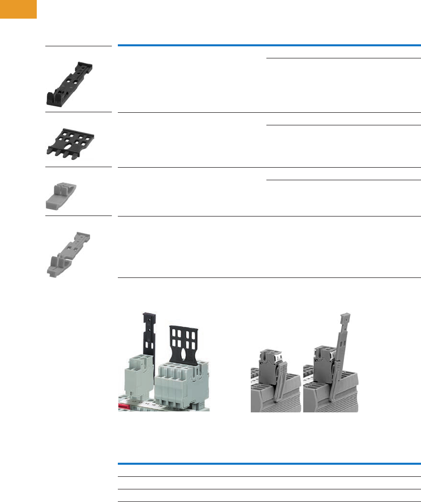
T42-66 Logic Control Products CA08100001K—June 2012 www.eatoncanada.ca
42
42
42
42
42
42
42
42
42
42
42
42
42
42
42
42
42
42
42
42
42
42
42
42
42
42
42
42
42
42
42.1
Terminal Blocks, Fuse Blocks and Fuse Holders
IEC—
XB
Series
Connection Accessories
Product Description
The pluggable XBPT series
features an extensive range
of application-oriented
accessories. Strain reliefs are
available for the plugs and
can be snapped on at the
required points as an option.
The snap-lock fitting can be
used for all plug variants. It is
snapped into the outside of
the plug housing as an option
and hooks onto the terminal
block housing when the plug
is snapped on.
Product Selection
Pluggable Spring Cage Connection Accessories
Strain Relief Snap-Lock Fitting
Optional Accessory Recommendations
Description
Number of
Positions
Standard
Pack
Catalogue
Number
Strain relief for single plugs 2 10 XBAPPZ2
410XBAPPZ4
Strain relief for double plugs and receptacles 2 10 XBAPPDZ2
410XBAPPDZ4
Snap-lock fitting for plugs 1 10 XBAPPR
210XBAPPR2
Snap-lock fitting and strain relief for plugs 2 10 XBAPPRZ
Number of Positions
Receptacle Strain Relief
2–4 XBAPPZ2
5–10 XBAPPZ4 or (2) XBAPPZ2
11–15 (2) XBAPPZ4 or (4) XBAPPZ2
XBAPPZ2
XBAPPDZ4
XBAPPR2
XBAPPRZ
Tab42book.fm Page 66 Thursday, July 5, 2012 8:03 PM
Logic Control Products CA08100001K—June 2012 www.eatoncanada.ca T42-67
42
42
42
42
42
42
42
42
42
42
42
42
42
42
42
42
42
42
42
42
42
42
42
42
42
42
42
42
42
42
42.1
Terminal Blocks, Fuse Blocks and Fuse Holders
IEC—
XB
Series
IDC Terminal Blocks Contents
Description Page
IDC Terminal Blocks
Single Level . . . . . . . . . . . . . . . . . . . . . . . . . . . . . . T42-68
Multi-Conductor . . . . . . . . . . . . . . . . . . . . . . . . . . . T42-70
Double Level . . . . . . . . . . . . . . . . . . . . . . . . . . . . . T42-73
Fuse Terminal Blocks . . . . . . . . . . . . . . . . . . . . . . . T42-75
Disconnect and Component Terminal Blocks . . . . . T42-77
Hybrid Terminal Blocks . . . . . . . . . . . . . . . . . . . . . . T42-79
IDC (Insulation Displacement Connection) Terminal Blocks Overview
Product Description
The superior design of
Eaton’s Insulation
Displacement Connection
(IDC) technology terminal
blocks reduces wiring
installation time and labor,
especially in high-volume
applications. IDC terminal
blocks are suited for
applications in automated
equipment and machine
tools, packaging and material
handling machinery, railway/
mass transit systems, petro-
chemical, and any other
application requiring high-
volume connections for low-
voltage control and signal
circuitry where labor cost
reduction and ease of
assembly is desired. These
terminal blocks are designed
for long-term use under
demanding conditions.
The XBQT Series allows for
wire to be connected without
any prior stripping. The quick
connection provides up to
60% reduction in wiring time.
One turn of a standard
screwdriver results in a
simple, fast and reliable
connection.
Application Description
The XBQT is operated with a
standard screwdriver. The
switching states are clearly
signaled by engagement
points in the start and end
positions. Solid and stranded
wires of 0.25 to 2.5 mm2 can
be wired without the use of
ferrules. Stripping the wire is
not required—the wire's
insulation is cut open when it
is properly connected. The
wire is securely placed in the
end position where it makes
large-area, gas-tight contact.
Connections are made in
seconds!
Features
●Quick connection capability
●Global acceptance
●Flexible plug-in bridge
system
●Large surface area for
marking
●Standardized testing
system
Standards and Certifications
●UL recognized—File No.
E67464
●CE approved
●LVD
●EN 60947-7-1
●EN 60947-7-2
●EN 60998-2-3
●EN 60352-4/A1
●ATEX approval
(Eex e applications)
Note
Not all standards apply to all terminal
blocks. Contact Eaton for details.
Tab42book.fm Page 67 Thursday, July 5, 2012 8:03 PM
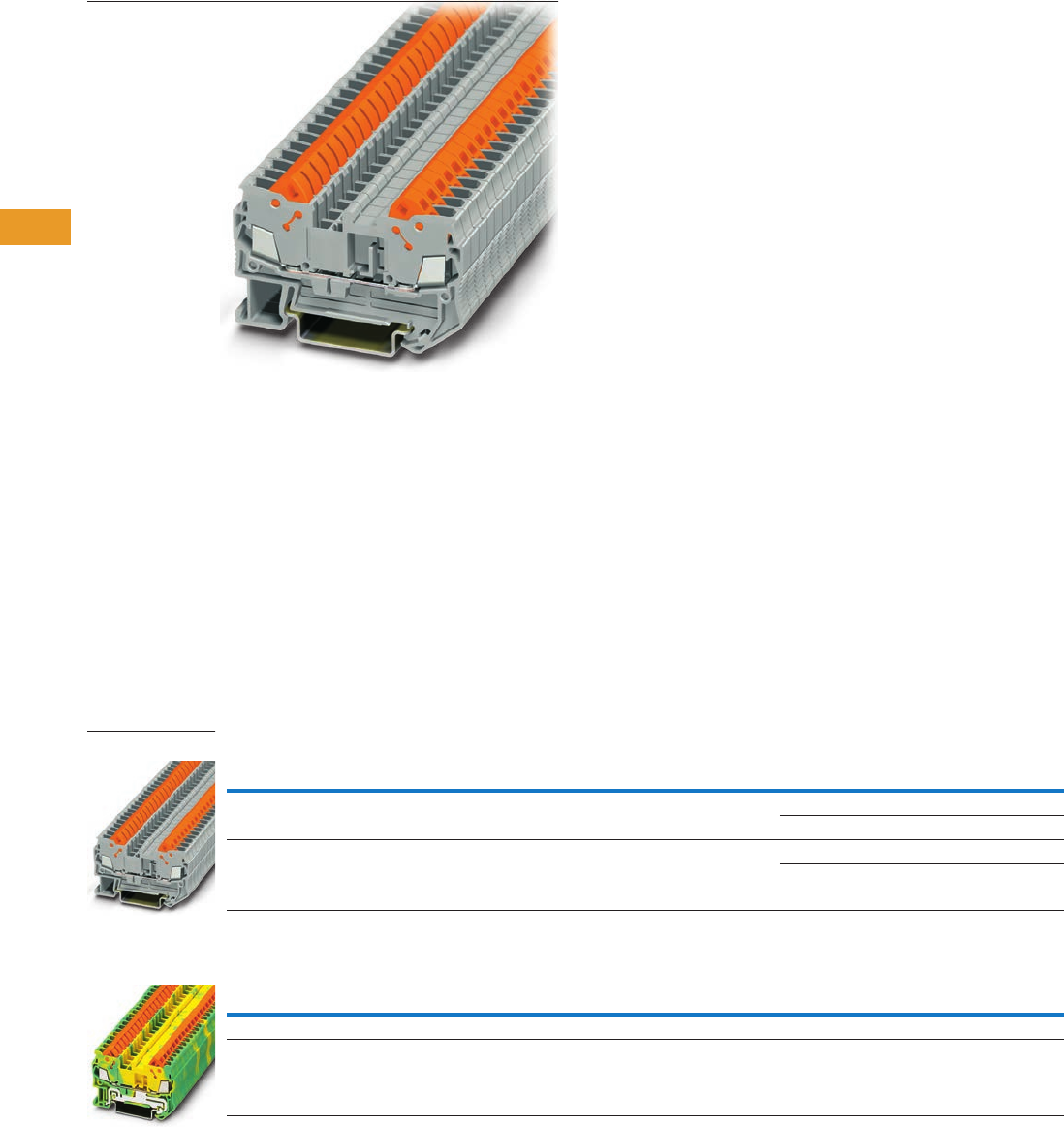
T42-68 Logic Control Products CA08100001K—June 2012 www.eatoncanada.ca
42
42
42
42
42
42
42
42
42
42
42
42
42
42
42
42
42
42
42
42
42
42
42
42
42
42
42
42
42
42
42.1
Terminal Blocks, Fuse Blocks and Fuse Holders
IEC—
XB
Series
Single Level Contents
Description Page
Single Level
Accessories . . . . . . . . . . . . . . . . . . . . . . . . . . . . . . T42-69
Technical Data and Specifications . . . . . . . . . . . . . T42-69
Dimensions . . . . . . . . . . . . . . . . . . . . . . . . . . . . . . T42-69
Multi-Conductor . . . . . . . . . . . . . . . . . . . . . . . . . . . . . T42-70
Double Level . . . . . . . . . . . . . . . . . . . . . . . . . . . . . . . . T42-73
Fuse Terminal Blocks . . . . . . . . . . . . . . . . . . . . . . . . . T42-75
Disconnect and Component Terminal Blocks . . . . . . . T42-77
Hybrid Terminal Blocks . . . . . . . . . . . . . . . . . . . . . . . . T42-79
Single Level
Product Description
The XBQT IDC terminal block
has the fastest connection
time in a compact design.
The space-saving front
connection design offers
additional space for wiring
between the cable ducts.
The double bridge shaft can
accommodate individual
chain bridging and step-down
bridging from other terminal
blocks. The XBQT ground
blocks are the same shape
as the feed-through terminal
blocks with the same wide
range of cross-sections
available. They easily snap
onto the DIN rail to make
a reliable mechanical and
electrical contact that
meets all requirements
of IEC 60-947-7-2.
Product Selection
IDC—Single Level Terminal Blocks
IDC—Single Level Terminal Ground Blocks
Note
EU type—examination certificate number: KEMA 05ATEX2157 U (XBQT15), KEMA 05ATEX2160 U (XBQT25).
Terminal
Width
Maximum
Wire Size
Connection Data
in V/A/AWG
EN 50 019
in V/A/AWG
UL-cUL Ratings
in V/A/AWG Colour
Standard
Pack
Catalogue
Number
5.2 mm 16 AWG/1.5 mm2800/17.5/24–16 550/16/24–16 600/10/24–16 Gray 50 XBQT15
Blue 50 XBQT15BU
6.2 mm 14 AWG/2.5 mm2800/24/20–14 — 600/15/20–14 Gray 50 XBQT25
Blue 50 XBQT25BU
Terminal
Width
Maximum
Wire Size
Connection Data
in V/A/AWG
EN 50 019
in V/A/AWG
UL-cUL Ratings
in V/A/AWG Colour
Standard
Pack
Catalogue
Number
5.2 mm 16 AWG/1.5 mm2—/—/24–16 —/—/24–16 —/—/24–16 Green/Yellow 50 XBQT15PE
6.2 mm 14 AWG/2.5 mm2—/—/20–14 — —/—/20–14 Green/Yellow 50 XBQT25PE
XBQT25
XBQT15PE
Tab42book.fm Page 68 Thursday, July 5, 2012 8:03 PM

Logic Control Products CA08100001K—June 2012 www.eatoncanada.ca T42-69
42
42
42
42
42
42
42
42
42
42
42
42
42
42
42
42
42
42
42
42
42
42
42
42
42
42
42
42
42
42
42.1
Terminal Blocks, Fuse Blocks and Fuse Holders
IEC—
XB
Series
Accessories
IDC—Single Level Terminal/Ground Blocks
Technical Data and Specifications
IDC—Single Level Terminal/Ground Blocks
Dimensions
Approximate Dimensions in Inches (mm)
IDC—Single Level Terminal/Ground Blocks
Notes
For ordering information, see Page T42-105.
For information on Printed Marking Tag Options, see Page T42-98.
For additional accessories, see Page T42-90.
Description Colour
Number of
Positions
Standard
Pack
XBQT15 XBQT25 XBQT15PE XBQT25PE
Catalogue
Number
Catalogue
Number
Catalogue
Number
Catalogue
Number
End cover Gray — 10 XBACQT15 XBACQT25 XBACQT15 XBACQT25
Partition plate — — 10 XBATQT25 XBATQT25 XBATQT25 XBATQT25
Plug-in bridge Red 2 10 XBAFBS25 XBAFBS26 XBAFBS25 XBAFBS26
310XBAFBS35 XBAFBS36 XBAFBS35 XBAFBS36
510XBAFBS55 XBAFBS56 XBAFBS55 XBAFBS56
10 10 XBAFBS105 XBAFBS106 XBAFBS105 XBAFBS106
50 10 XBAFBS505 XBAFBS506 XBAFBS505 XBAFBS506
Test adapter — — 10 XBATSPAI4 XBATSPAI4 XBATSPAI4 XBATSPAI4
2.3 mm diameter test plug — — — XBATSMPS-_ XBATSMPS-_ XBATSMPS-_ XBATSMPS-_
Modular test plug — — 10 XBATSPS5 XBATSPS6 XBATSPS5 XBATSPS6
Blank marker strip centre
and external marking
White — 10 XBMZBF5 XBMZBF6 XBMZBF5 XBMZBF6
Blank marker strip centre
labeling (strip of 10)
White — 10 XBMZB5 XBMZB6 XBMZB5 XBMZB6
Description XBQT15 XBQT25 XBQT15PE XBQT25PE
Technical Data in Accordance with IEC
Maximum load current in A/cross-section in mm217.5/1.5 24/2.5 — —
Rated surge voltage in kV/contamination class 8/3 8/3 8/3 8/3
Surge voltage category/insulating material group III/I III/I III/I III/I
Connection Cross-Section
Core insulation PVC/PE PVC/PE PVC/PE PVC/PE
Single/multiple/fine strand in mm21.5 2.5 1.5 2.5
Halogen-free in mm21.5 2.5 1.5 2.5
Fine strand/superfine strand in AWG (mm2) 24–16 (0.25–0.34) 20–14 (—) 24–16 (0.25–0.34) 20–14 (—)
Repeated connections minimum 100 x in mm20.25–1.5 0.5–2.5 0.25–1.5 0.5–2.5
Catalogue
Number Width Length
Cover
Length
Height for—
35 x 7.5 in 35 x 15 in
XBQT15 0.20 (5.2) 2.31 (58.8) 0.09 (2.2) 1.55 (39.3) 1.84 (46.8)
XBQT25 0.24 (6.2) 2.46 (62.6) 0.09 (2.2) 1.55 (39.3) 1.84 (46.8)
XBQT15PE 0.20 (5.2) 2.31 (58.8) 0.09 (2.2) 1.55 (39.3) 1.84 (46.8)
XBQT25PE 0.24 (6.2) 2.46 (62.6) 0.09 (2.2) 1.55 (39.3) 1.84 (46.8)
Tab42book.fm Page 69 Thursday, July 5, 2012 8:03 PM
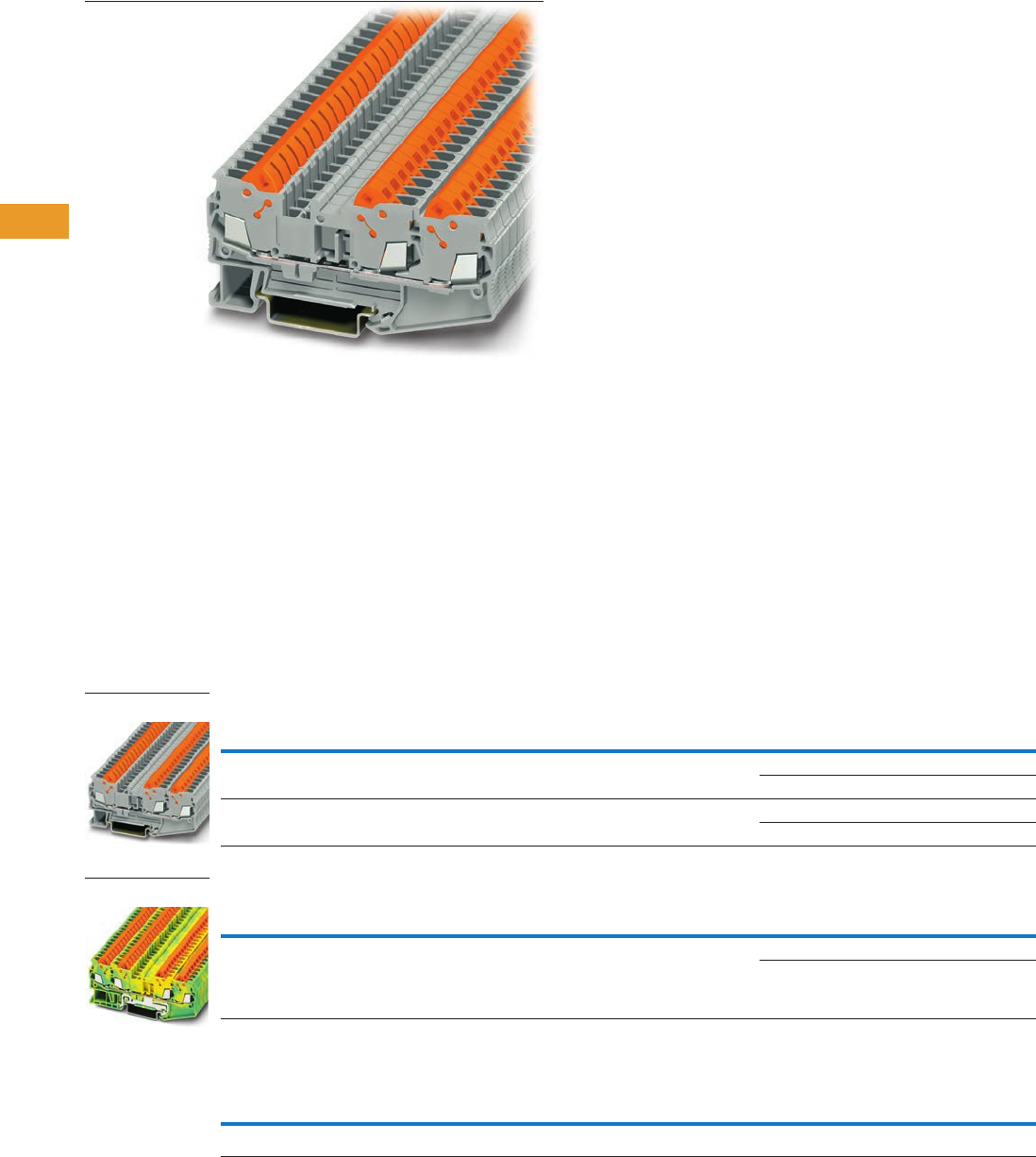
T42-70 Logic Control Products CA08100001K—June 2012 www.eatoncanada.ca
42
42
42
42
42
42
42
42
42
42
42
42
42
42
42
42
42
42
42
42
42
42
42
42
42
42
42
42
42
42
42.1
Terminal Blocks, Fuse Blocks and Fuse Holders
IEC—
XB
Series
Multi-Conductor Contents
Description Page
Single Level . . . . . . . . . . . . . . . . . . . . . . . . . . . . . . . . . T42-68
Multi-Conductor
Accessories . . . . . . . . . . . . . . . . . . . . . . . . . . . . . . T42-71
Technical Data and Specifications . . . . . . . . . . . . . T42-72
Dimensions . . . . . . . . . . . . . . . . . . . . . . . . . . . . . . T42-72
Double Level . . . . . . . . . . . . . . . . . . . . . . . . . . . . . . . . T42-73
Fuse Terminal Blocks . . . . . . . . . . . . . . . . . . . . . . . . . T42-75
Disconnect and Component Terminal Blocks . . . . . . . T42-77
Hybrid Terminal Blocks . . . . . . . . . . . . . . . . . . . . . . . . T42-79
Multi-Conductor
Product Description
The XBQT IDC terminal block
has the fastest connection
time in a compact design.
The space-saving front
connection design offers
additional space for wiring
between the cable ducts.
The double bridge shaft can
accommodate individual
chain bridging and step-down
bridging from other terminal
blocks. The XBQT ground
blocks are the same shape
as the feed-through terminal
blocks with the same wide
range of cross-sections
available. They easily snap
onto the DIN rail to make
a reliable mechanical and
electrical contact that
meets all requirements
of IEC 60-947-7-2.
Product Selection
IDC—Multi-Conductor Terminal Blocks, Three-Wire
IDC—Multi-Conductor Terminal Blocks, Four-Wire
IDC—Multi-Conductor Terminal Blocks, Four-Wire Ground Blocks
Note
EU type—examination certificate number: KEMA 05ATEX2157 U (XBQT15), KEMA 05ATEX2160 U (XBQT25).
Terminal
Width
Maximum
Wire Size
Connection Data
in V/A/AWG
EN 50 019
in V/A/AWG
UL-cUL Ratings
in V/A/AWG Colour
Standard
Pack
Catalogue
Number
5.2 mm 16 AWG/1.5 mm2800/17.5/24–16 550/16/24–16 600/10/24–16 Gray 50 XBQT15D12
Blue 50 XBQT15D12BU
6.2 mm 14 AWG/2.5 mm2800/24/20–14 — 600/15/20–14 Gray 50 XBQT25D12
Blue 50 XBQT25D12BU
Terminal
Width
Maximum
Wire Size
Connection Data
in V/A/AWG
EN 50 019
in V/A/AWG
UL-cUL Ratings
in V/A/AWG Colour
Standard
Pack
Catalogue
Number
5.2 mm 16 AWG/1.5 mm2800/17.5/24–16 550/16/24–16 600/10/24–16 Gray 50 XBQT15D22
Blue 50 XBQT15D22BU
Terminal
Width
Maximum
Wire Size
Connection Data
in V/A/AWG
EN 50 019
in V/A/AWG
UL-cUL Ratings
in V/A/AWG Colour
Standard
Pack
Catalogue
Number
5.2 mm 16 AWG/1.5 mm2—/—/24–16 —/—/24–16 —/—/24–16 Green/Yellow 50 XBQT15D22PE
XBQT25D12
XBQT15D22PE
Tab42book.fm Page 70 Thursday, July 5, 2012 8:03 PM
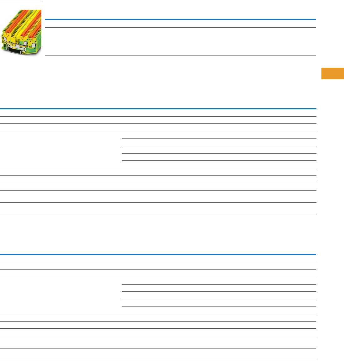
Logic Control Products CA08100001K—June 2012 www.eatoncanada.ca T42-71
42
42
42
42
42
42
42
42
42
42
42
42
42
42
42
42
42
42
42
42
42
42
42
42
42
42
42
42
42
42
42.1
Terminal Blocks, Fuse Blocks and Fuse Holders
IEC—
XB
Series
IDC—Multi-Conductor Terminal Blocks, Three-Wire Ground Blocks
Accessories
IDC—Multi-Conductor Terminal Blocks
IDC—Multi-Conductor Terminal/Ground Blocks
Notes
EU type—examination certificate number: KEMA 05ATEX2157 U (XBQT15PE), KEMA 05ATEX2160 U (XBQT25PE).
For ordering information, see Page T42-105.
For information on Printed Marking Tag Options, see Page T42-98.
For additional accessories, see Page T42-90.
Terminal
Width
Maximum
Wire Size
Connection Data
in V/A/AWG
EN 50 019
in V/A/AWG
UL-cUL Ratings
in V/A/AWG Colour
Standard
Pack
Catalogue
Number
5.2 mm 16 AWG/1.5 mm2—/—/24–16 —/—/24–16 —/—/24–16 Green/Yellow 50 XBQT15D12PE
6.2 mm 14 AWG/2.5 mm2—/—/20–14 — —/—/20–14 Green/Yellow 50 XBQT25D12PE
Description Colour
Number of
Positions
Standard
Pack
XBQT15D12 XBQT25D12 XBQT15D22
Catalogue
Number
Catalogue
Number
Catalogue
Number
End cover Gray — 10 XBACQT15D12 XBACQT25D12 XBACQT15D22
End cover segment Gray — 10 XBASQT15 XBASQT25 XBASQT15
Partition plate — — 10 XBATQTD12 XBATQTD12 XBATQTD22
Plug-in bridge—for cross connections
in the terminal centre
Red 2 10 XBAFBS25 XBAFBS26 XBAFBS25
310XBAFBS35 XBAFBS36 XBAFBS35
510XBAFBS55 XBAFBS56 XBAFBS55
10 10 XBAFBS105 XBAFBS106 XBAFBS105
50 10 XBAFBS505 XBAFBS506 XBAFBS505
Test adapter — — 10 XBATSPAI4 XBATSPAI4 XBATSPAI4
2.3 mm diameter test plug — — — XBATSMPS-_ XBATSMPS-_ XBATSMPS-_
Modular test plug — — 10 XBATSPS5 XBATSPS6 XBATSPS5
Blank marker strip centre
and external marking
White — 10 XBMZBF5 XBMZBF6 XBMZBF5
Blank marker strip centre
labeling (strip of 10)
White — 10 XBMZB5 XBMZB6 XBMZB5
Description Colour
Number of
Positions
Standard
Pack
XBQT15D12PE XBQT25D12PE XBQT15D22PE
Catalogue
Number
Catalogue
Number
Catalogue
Number
End cover Gray — 10 XBACQT15D12 XBACQT25D12 XBACQT15D22
End cover segment Gray — 10 XBASQT15 XBASQT25 XBASQT15
Partition plate — — 10 XBATQTD12 XBATQTD12 XBATQTD22
Plug-in bridge—for cross connections
in the terminal centre
Red 2 10 XBAFBS25 XBAFBS26 XBAFBS25
310XBAFBS35 XBAFBS36 XBAFBS35
510XBAFBS55 XBAFBS56 XBAFBS55
10 10 XBAFBS105 XBAFBS106 XBAFBS105
50 10 XBAFBS505 XBAFBS506 XBAFBS505
Test adapter — — 10 XBATSPAI4 XBATSPAI4 XBATSPAI4
2.3 mm diameter test plug — — — XBATSMPS-_ XBATSMPS-_ XBATSMPS-_
Modular test plug — — 10 XBATSPS5 XBATSPS6 XBATSPS5
Blank marker strip centre
and external marking
White — 10 XBMZBF5 XBMZBF6 XBMZBF5
Blank marker strip centre
labeling (strip of 10)
White — 10 XBMZB5 XBMZB6 XBMZB5
XBQT15D12PE
Tab42book.fm Page 71 Thursday, July 5, 2012 8:03 PM

T42-72 Logic Control Products CA08100001K—June 2012 www.eatoncanada.ca
42
42
42
42
42
42
42
42
42
42
42
42
42
42
42
42
42
42
42
42
42
42
42
42
42
42
42
42
42
42
42.1
Terminal Blocks, Fuse Blocks and Fuse Holders
IEC—
XB
Series
Technical Data and Specifications
IDC—Multi-Conductor Terminal Blocks
Dimensions
Approximate Dimensions in Inches (mm)
IDC—Multi-Conductor Terminal Blocks
Description XBQT15D12 XBQT25D12 XBQT15D12PE XBQT25D12PE XBQT15D22 XBQT15D22PE
Technical Data in Accordance with IEC
Maximum load current in A/cross-section in mm217.5/1.5 24/2.5 — — 17.5/1.5 —
Rated surge voltage in kV/contamination class 8/3 8/3 8/3 8/3 8/3 8/3
Surge voltage category/insulating material group III/I III/I III/I III/I III/I III/I
Connection Cross-Section
Core insulation PVC/PE PVC/PE PVC/PE PVC/PE PVC/PE PVC/PE
Single/multiple/fine strand in mm21.5 2.5 1.5 2.5 1.5 1.5
Halogen-free in mm21.5 2.5 1.5 2.5 1.5 1.5
Fine strand/superfine strand in AWG (mm2) 24–16 (0.25–0.34) 20–14 (—) 24–16 (0.25–0.34) 20–14 (—) 24–16 (0.25–0.34) 24–16 (0.25–0.34)
Repeated connections minimum 100 x in mm20.25–1.5 0.5–2.5 0.25–1.5 0.5–2.5 0.25–1.5 0.25–1.5
Catalogue
Number Width Length
Cover
Length
Height for—
35 x 7.5 in 35 x 15 in
XBQT15D12 0.20 (5.2) 3.01 (76.4) 0.09 (2.2) 1.55 (39.3) 1.84 (46.8)
XBQT25D12 0.24 (6.2) 3.25 (82.5) 0.09 (2.2) 1.69 (42.8) 1.98 (50.3)
XBQT15D12PE 0.20 (5.2) 3.01 (76.4) 0.09 (2.2) 1.55 (39.3) 1.84 (46.8)
XBQT25D12PE 0.20 (5.2) 3.25 (82.5) 0.09 (2.2) 1.69 (42.8) 1.98 (50.3)
XBQT15D22 0.20 (5.2) 3.70 (94.0) 0.09 (2.2) 1.55 (39.3) 1.84 (46.8)
XBQT15D22PE 0.20 (5.2) 3.70 (94.0) 0.09 (2.2) 1.55 (39.3) 1.84 (46.8)
Tab42book.fm Page 72 Thursday, July 5, 2012 8:03 PM
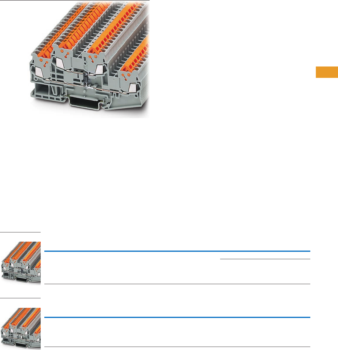
Logic Control Products CA08100001K—June 2012 www.eatoncanada.ca T42-73
42
42
42
42
42
42
42
42
42
42
42
42
42
42
42
42
42
42
42
42
42
42
42
42
42
42
42
42
42
42
42.1
Terminal Blocks, Fuse Blocks and Fuse Holders
IEC—
XB
Series
Double Level Contents
Description Page
Single Level . . . . . . . . . . . . . . . . . . . . . . . . . . . . . . . . . T42-68
Multi-Conductor . . . . . . . . . . . . . . . . . . . . . . . . . . . . . . T42-70
Double Level
Accessories . . . . . . . . . . . . . . . . . . . . . . . . . . . . . . T42-74
Technical Data and Specifications . . . . . . . . . . . . . T42-74
Dimensions . . . . . . . . . . . . . . . . . . . . . . . . . . . . . . T42-74
Fuse Terminal Blocks . . . . . . . . . . . . . . . . . . . . . . . . . . T42-75
Disconnect and Component Terminal Blocks . . . . . . . T42-77
Hybrid Terminal Blocks . . . . . . . . . . . . . . . . . . . . . . . . T42-79
Double Level
Product Description
The XBQTT IDC terminal
block has the fastest
connection time in a compact
design. The space-saving
front connection design
offers additional space for
wiring between the cable
ducts. The double bridge
shaft, found in each level, can
accommodate individual
chain bridging and step-down
bridging from other terminal
blocks. The XBQTT ground
blocks are the same shape as
the feed-through terminal
blocks with the same wide
range of cross-sections
available. They easily snap
onto the DIN rail to make a
reliable mechanical and
electrical contact that
meets all requirements of
IEC 60-947-7-2.
Product Selection
IDC—Double Level Terminal Blocks
IDC—Double Level Ground Blocks
Note
EU type—examination certificate number: KEMA 05ATEX2157 U (XBQT15), KEMA 05ATEX2160 U (XBQT25).
Terminal
Width
Maximum
Wire Size
Connection Data
in V/A/AWG
EN 50 019
in V/A/AWG
UL-cUL Ratings
in V/A/AWG Colour
Standard
Pack
Catalogue
Number
5.2 mm 16 AWG/1.5 mm2800/17.5/24–16 420/15/24–16 600/10/24–16 Gray 50 XBQTT15
Blue 50 XBQTT15BU
Terminal
Width
Maximum
Wire Size
Connection Data
in V/A/AWG
EN 50 019
in V/A/AWG
UL-cUL Ratings
in V/A/AWG Colour
Standard
Pack
Catalogue
Number
6.2 mm 14 AWG/2.5 mm2—/—/24–16 —/—/24–16 —/—/24–16 Green/Yellow 50 XBQTT15PE
XBQTT15
XBQTT15PE
Tab42book.fm Page 73 Thursday, July 5, 2012 8:03 PM

T42-74 Logic Control Products CA08100001K—June 2012 www.eatoncanada.ca
42
42
42
42
42
42
42
42
42
42
42
42
42
42
42
42
42
42
42
42
42
42
42
42
42
42
42
42
42
42
42.1
Terminal Blocks, Fuse Blocks and Fuse Holders
IEC—
XB
Series
Accessories
IDC—Double Level Terminal/Ground Blocks
Technical Data and Specifications
IDC—Double Level Terminal/Ground Blocks
Dimensions
Approximate Dimensions in Inches (mm)
IDC—Double Level Terminal/Ground Blocks
Notes
For ordering information, see Page T42-105.
For information on Printed Marking Tag Options, see Page T42-98.
For additional accessories, see Page T42-90.
Description Colour
Number of
Positions
Standard
Pack
XBQTT15 XBQTT15PE
Catalogue
Number
Catalogue
Number
End cover Gray — 10 XBACQTT15 XBACQTT15
Partition plate — — 10 XBATQTT15 XBATQTT15
Plug-in bridge—for cross connections
in the terminal centre
Red 2 10 XBAFBS25 XBAFBS25
310 XBAFBS35 XBAFBS35
510 XBAFBS55 XBAFBS55
10 10 XBAFBS105 XBAFBS105
20 10 XBAFBS505 XBAFBS505
Test adapter — — 10 XBATSPAI4 XBATSPAI4
2.3 mm diameter test plug — — — XBATSMPS-_ XBATSMPS-_
Modular test plug — — 10 XBATSPS5 XBATSPS5
Blank marker strip White — 10 XBMZBF5 XBMZBF5
Description XBQTT15 XBQTT15PE
Technical Data in Accordance with IEC
Maximum load current in A/cross-section in mm217.5/1.5 —
Rated surge voltage in kV/contamination class 6/3 6/3
Surge voltage category/insulating material group III/I III/I
Connection Cross-Section
Core insulation PVC/PE PVC/PE
Single/multiple/fine strand in mm21.5 1.5
Halogen-free in mm21.5 1.5
Fine strand/superfine strand in AWG (mm2) 24–16 (0.25–0.34) 24–16 (0.25–0.34)
Repeated connections minimum 100 x in mm20.25–1.5 0.25–1.5
Catalogue
Number Width Length
Cover
Length
Height for—
35 x 7.5 in 35 x 15 in
XBQTT15 0.20 (5.2) 3.92 (99.6) 0.09 (2.2) 1.96 (49.9) 2.26 (57.4)
XBQTT15PE 0.20 (5.2) 3.92 (99.6) 0.09 (2.2) 1.96 (49.9) 2.26 (57.4)
Tab42book.fm Page 74 Thursday, July 5, 2012 8:03 PM
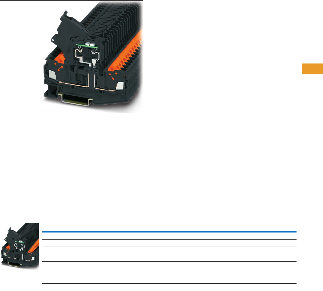
Logic Control Products CA08100001K—June 2012 www.eatoncanada.ca T42-75
42
42
42
42
42
42
42
42
42
42
42
42
42
42
42
42
42
42
42
42
42
42
42
42
42
42
42
42
42
42
42.1
Terminal Blocks, Fuse Blocks and Fuse Holders
IEC—
XB
Series
Fuse Terminal Blocks Contents
Description Page
Single Level . . . . . . . . . . . . . . . . . . . . . . . . . . . . . . . . . T42-68
Multi-Conductor . . . . . . . . . . . . . . . . . . . . . . . . . . . . . . T42-70
Double Level . . . . . . . . . . . . . . . . . . . . . . . . . . . . . . . . T42-73
Fuse Terminal Blocks
Accessories . . . . . . . . . . . . . . . . . . . . . . . . . . . . . . T42-76
Technical Data and Specifications . . . . . . . . . . . . . T42-76
Dimensions . . . . . . . . . . . . . . . . . . . . . . . . . . . . . . T42-76
Disconnect and Component Terminal Blocks . . . . . . . T42-77
Hybrid Terminal Blocks . . . . . . . . . . . . . . . . . . . . . . . . T42-79
Fuse Terminal Blocks
Product Description
The XBQT lever-type fuse
terminal blocks perform two
main functions. It is a carrier
for a 5 x 20 mm cartridge
fuse insert and can also
allow for potential distribution
via the double bridge shaft.
This means that two
potentials can be carried
separately alongside each
other. Versions with light
indication (AC and DC
voltage) are available to
signal a triggered fuse.
Product Selection
IDC—Fuse Terminal Blocks
Note
As disconnect terminal block, 400V; as fuse terminal blocks 250V.
Terminal
Width
Maximum
Wire Size
Connection Data
in V/A/AWG
UL-cUL Ratings
in V/A/AWG Colour
Standard
Pack
Catalogue
Number
IDC Fuse Terminal Blocks
6.2 mm 14 AWG/2.5 mm2/6.3/20–14 300/15/20–14 Black 50 XBQT25FBE
IDC Fuse Terminal Blocks with LED 12–30V, 1–2.5 mA
6.2 mm 14 AWG/2.5 mm2/6.3/20–14 300/15/20–14 Black 50 XBQT25FBEL24
IDC Fuse Terminal Blocks with LED 30–60V, 0.8–2.0 mA
6.2 mm 14 AWG/2.5 mm2/6.3/20–14 300/15/20–14 Black 50 XBQT25FBEL60
IDC Fuse Terminal Blocks with LED 110–250V, 0.5–2.5 mA
6.2 mm 14 AWG/2.5 mm2/6.3/20–14 300/15/20–14 Black 50 XBQT25FBEL250
XBQT25FB
Tab42book.fm Page 75 Thursday, July 5, 2012 8:03 PM

T42-76 Logic Control Products CA08100001K—June 2012 www.eatoncanada.ca
42
42
42
42
42
42
42
42
42
42
42
42
42
42
42
42
42
42
42
42
42
42
42
42
42
42
42
42
42
42
42.1
Terminal Blocks, Fuse Blocks and Fuse Holders
IEC—
XB
Series
Accessories
IDC—Fuse Terminal Blocks
Technical Data and Specifications
IDC—Fuse Terminal Blocks
Dimensions
Approximate Dimensions in Inches (mm)
IDC—Fuse Terminal Blocks
Notes
For ordering information, see Page T42-105.
For information on Printed Marking Tag Options, see Page T42-98.
For additional accessories, see Page T42-90.
Description Colour
Number of
Positions
Standard
Pack
XBQT25FBE
Catalogue
Number
End cover Gray — 10 XBACQT25D12
Partition plate — — 10 XBATQTD12
Plug-in bridge—for cross connections
in the terminal centre
Red 2 10 XBAFBS26
310XBAFBS36
510XBAFBS56
10 10 XBAFBS106
Test adapter — — 10 XBATSPAI4
2.3 mm diameter test plug — — — XBATSMPS-_
Modular test plug — — 10 XBATSPS5
Blank marker strip centre
and external marking
White — 10 XBMZBF6
Blank marker strip lever labeling White — 10 XBMZB5
Blank marker strip centre
labeling (strip of 10)
White — 10 XBMZB6
Description XBQT25FBE
Technical Data in Accordance with IEC
Maximum load current in A/cross-section in mm26.3/2.5
Rated surge voltage in kV/contamination class 4/3
Surge voltage category/insulating material group III/I
Connection Cross-Section
Core insulation PVC/PE
Single/multiple/fine strand in mm22.5
Halogen-free in mm22.5
Fine strand/superfine strand in AWG (mm2) 24–14 (—)
Repeated connections minimum 100 x in mm20.5–2.5
Catalogue
Number Width Length
Cover
Length
Height for—
35 x 7.5 in 35 x 15 in
XBQT25FBE 0.24 (6.2) 3.25 (82.5) 0.09 (2.2) 1.69 (42.8) 1.98 (50.3)
Tab42book.fm Page 76 Thursday, July 5, 2012 8:03 PM
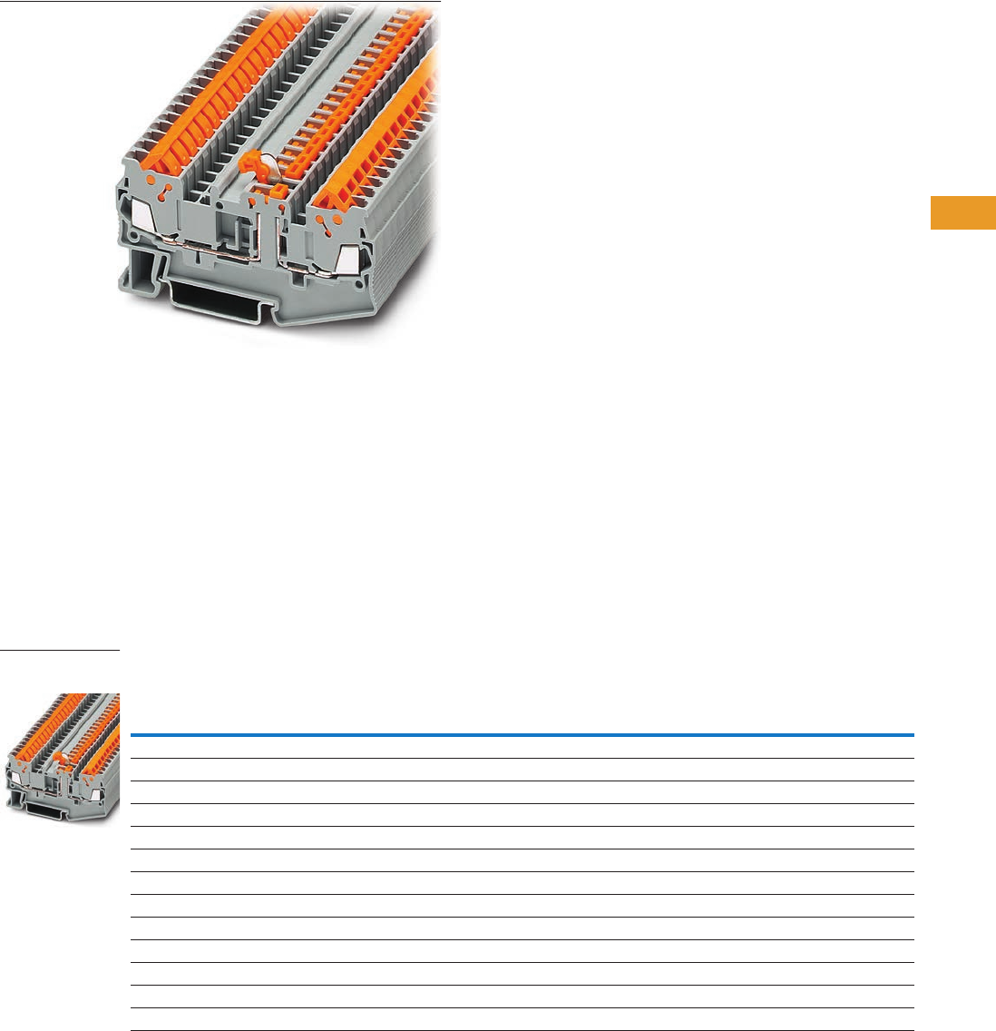
Logic Control Products CA08100001K—June 2012 www.eatoncanada.ca T42-77
42
42
42
42
42
42
42
42
42
42
42
42
42
42
42
42
42
42
42
42
42
42
42
42
42
42
42
42
42
42
42.1
Terminal Blocks, Fuse Blocks and Fuse Holders
IEC—
XB
Series
Disconnect and Component Terminal Blocks Contents
Description Page
Single Level . . . . . . . . . . . . . . . . . . . . . . . . . . . . . . . . . T42-68
Multi-Conductor . . . . . . . . . . . . . . . . . . . . . . . . . . . . . . T42-70
Double Level . . . . . . . . . . . . . . . . . . . . . . . . . . . . . . . . T42-73
Fuse Terminal Blocks . . . . . . . . . . . . . . . . . . . . . . . . . . T42-75
Disconnect and Component Terminal Blocks
Accessories . . . . . . . . . . . . . . . . . . . . . . . . . . . . . . T42-78
Technical Data and Specifications . . . . . . . . . . . . . T42-78
Dimensions . . . . . . . . . . . . . . . . . . . . . . . . . . . . . . T42-78
Hybrid Terminal Blocks . . . . . . . . . . . . . . . . . . . . . . . . T42-79
Disconnect and Component Terminal Blocks
Product Description
The XB Series includes
application specific terminal
blocks like disconnect blocks.
The knife disconnect terminal
blocks (XBQT15MT) has a
fitted knife. The XBQT15TG
can accommodate component
plugs for resistors or
capacitors and fuse plugs
for 5 x 20 mm fuses with or
without a light indicator for
signaling a triggered fuse.
Both terminal blocks have
three bridge shafts—two in
the standard positions and
one on the other side of the
disconnect point.
Product Selection
IDC—Disconnect and Component Terminal Blocks
Terminal
Width
Maximum
Wire Size
Connection Data
in V/A/AWG
UL-cUL Ratings
in V/A/AWG
UL-cUL Ratings
for Disconnect
in V/A/AWG
UL-cUL Ratings
for Disconnect
with Test Sockets
in V/A/AWG Colour
Standard
Pack
Catalogue
Number
Knife Disconnect
5.2 mm 16 AWG/1.5 mm2400/16/24–16 600/10/24–16 — — Gray 50 XBQT15MT
Component Disconnect
5.2 mm 16 AWG/1.5 mm2400/16/24–16 600/10/24–16 — — Gray 50 XBQT15TG
6.2 mm 14 AWG/2.5 mm2400/16/20–14 300/10/20–14 — — Gray 50 XBQT25TG
Component Plug
6.2 mm 10 AWG/4 mm2500/16/26–10 — 600/16/26–10 300/16/26–10 Gray 10 XBPCO
Fuse Plug
6.2 mm 10 AWG/4 mm2500/16/26–10 — 600/16/26–10 300/16/26–10 Black 10 XBPFU
Fuse Plug with Light Indicator for 12–30V, 1–2.5 mA
6.2 mm 10 AWG/4 mm2500/16/26–10 — 600/16/26–10 300/16/26–10 Black 10 XBPFUL24
Fuse Plug with Light Indicator for 110–250V, 0.5–2.5 mA
6.2 mm 10 AWG/4 mm2500/16/26–10 — 600/16/26–10 300/16/26–10 Black 10 XBPFUL250
XBQT15MT
Knife Disconnect
Tab42book.fm Page 77 Thursday, July 5, 2012 8:03 PM

T42-78 Logic Control Products CA08100001K—June 2012 www.eatoncanada.ca
42
42
42
42
42
42
42
42
42
42
42
42
42
42
42
42
42
42
42
42
42
42
42
42
42
42
42
42
42
42
42.1
Terminal Blocks, Fuse Blocks and Fuse Holders
IEC—
XB
Series
Accessories
IDC—Disconnect and Component Terminal Blocks
Technical Data and Specifications
IDC—Disconnect and Component Terminal Blocks
Dimensions
Approximate Dimensions in Inches (mm)
IDC—Disconnect and Component Terminal Blocks
Notes
For ordering information, see Page T42-105.
For information on Printed Marking Tag Options, see Page T42-98.
For additional accessories, see Page T42-90.
Description Colour
Number of
Positions
Standard
Pack
XBQT15MT XBQT15TG XBQT25TG
Catalogue
Number
Catalogue
Number
Catalogue
Number
End cover Gray — 10 XBACQT15D12 XBACQT15D12 XBACQT25D12
End cover segment Gray — 10 XBASQT15 XBASQT15 XBASQT25
Partition plate — — 10 XBATQTD12 XBATQTD12 XBATQTD12
Plug-in bridge Red 2 10 XBAFBS25 XBAFBS25 XBAFBS26
310XBAFBS35 XBAFBS35 XBAFBS36
510XBAFBS55 XBAFBS55 XBAFBS56
10 10 XBAFBS105 XBAFBS105 XBAFBS106
Test adapter — — 10 XBATSPAI4 XBATSPAI4 XBATSPAI4
2.3 mm diameter test plug — — — XBATSMPS-_ XBATSMPS-_ XBATSMPS-_
Modular test plug — — 10 XBATSPS5 XBATSPS5 XBATSPS5
Blank marker strip centre and
external marking
White — 10 XBMZBF5 XBMZBF5 XBMZBF6
Blank marker strip centre labeling
(strip of 10)
White — 10 XBMZB5 XBMZB5 XBMZB6
Description XBQT15MT XBQT15TG XBQT25TG
Technical Data in Accordance with IEC
Maximum load current in A/cross-section in mm216/1.5 16/1.5 16/2.5
Rated surge voltage in kV/contamination class 6/3 6/3 6/3
Surge voltage category/insulating material group III/I III/I III/I
Connection Cross-Section
Core insulation PVC/PE PVC/PE PVC/PE
Single/multiple/fine strand in mm21.5 1.5 2.5
Halogen-free in mm21.5 1.5 2.5
Fine strand/superfine strand in AWG (mm2) 24–16 (0.25–0.34) 24–16 (0.25–0.34) 20–14 (—)
Repeated connections minimum 100 x in mm20.25–1.5 0.25–1.5 0.5–2.5
Catalogue
Number Width Length
Cover
Length
Height for—
35 x 7.5 in 35 x 15 in
XBQT15MT 0.20 (5.2) 3.01 (76.4) 0.09 (2.2) 1.55 (39.3) 1.84 (46.8)
XBQT15TG 0.20 (5.2) 3.01 (76.4) 0.09 (2.2) 1.55 (39.3) 1.84 (46.8)
XBQT25TG 0.24 (6.2) 3.25 (82.5) 0.09 (2.2) 1.69 (42.8) 1.98 (50.3)
Tab42book.fm Page 78 Thursday, July 5, 2012 8:03 PM
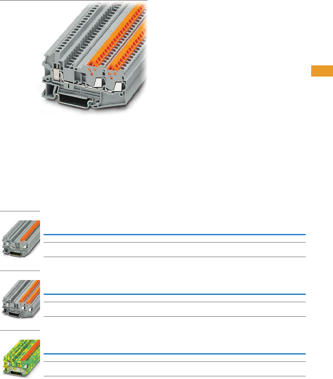
Logic Control Products CA08100001K—June 2012 www.eatoncanada.ca T42-79
42
42
42
42
42
42
42
42
42
42
42
42
42
42
42
42
42
42
42
42
42
42
42
42
42
42
42
42
42
42
42.1
Terminal Blocks, Fuse Blocks and Fuse Holders
IEC—
XB
Series
Hybrid Terminal Blocks Contents
Description Page
Single Level . . . . . . . . . . . . . . . . . . . . . . . . . . . . . . . . . T42-68
Multi-Conductor . . . . . . . . . . . . . . . . . . . . . . . . . . . . . . T42-70
Double Level . . . . . . . . . . . . . . . . . . . . . . . . . . . . . . . . T42-73
Fuse Terminal Blocks . . . . . . . . . . . . . . . . . . . . . . . . . . T42-75
Disconnect and Component Terminal Blocks . . . . . . . T42-77
Hybrid Terminal Blocks
Accessories . . . . . . . . . . . . . . . . . . . . . . . . . . . . . . T42-80
Technical Data and Specifications . . . . . . . . . . . . . T42-81
Dimensions . . . . . . . . . . . . . . . . . . . . . . . . . . . . . . T42-81
Hybrid Terminal Blocks
Product Description
The XBQT hybrid terminal
blocks offer the best of both
worlds. One side offers the
time-saving advantage of our
insulation displacement
connection technology,
while the other side offers a
universal screw connection.
Use the IDC side on the
internal (factory) control
cabinet side and the screw
connection on the end
customer (field) side. Ground
terminal blocks of the same
shape are also available
Product Selection
IDC—Hybrid Terminal Blocks, Single Level
IDC—Hybrid Terminal Blocks, Three-Wire
IDC—Hybrid Terminal/Ground Blocks
Terminal
Width
Maximum
Wire Size
IEC Screw
Connection
in V/A/AWG
IEC IDC
Connection
in V/A/AWG
UL-cUL Screw
Connection
in V/A/AWG
UL-cUL IDC
Connection
in V/A/AWG Colour
Standard
Pack
Catalogue
Number
5.2 mm 12 AWG/2.5 mm2800/17.5/26–12 800/17.5/24–16 600/10/26–12 600/10/24–16 Gray 50 XBQU15
6.2 mm 10 AWG/4 mm2800/24/26–10 800/24/20–14 600/15/26–10 600/15/20–14 Gray 50 XBQU25
Terminal
Width
Maximum
Wire Size
IEC Screw
Connection
in V/A/AWG
IEC IDC
Connection
in V/A/AWG
UL-cUL Screw
Connection
in V/A/AWG
UL-cUL IDC
Connection
in V/A/AWG Colour
Standard
Pack
Catalogue
Number
5.2 mm 12 AWG/2.5 mm2800/17.5/26–12 800/17.5/24–16 800/10/26–12 800/10/24–16 Gray 50 XBQU15D12
6.2 mm 10 AWG/4 mm2800/24/26–10 800/24/20–14 600/15/26–10 600/15/20–14 Gray 50 XBQU25D12
Terminal
Width
Maximum
Wire Size
IEC Screw
Connection
in V/A/AWG
IEC IDC
Connection
in V/A/AWG
UL-cUL Screw
Connection
in V/A/AWG
UL-cUL IDC
Connection
in V/A/AWG Colour
Standard
Pack
Catalogue
Number
5.2 mm 12 AWG/2.5 mm2—/—/26–12 —/—/24–16 —/—/26–12 —/—/24–16 Gray 50 XBQU15PE
6.2 mm 10 AWG/4 mm2—/—/26–10 —/—/20–14 —/—/26–10 —/—/20–14 Gray 50 XBQU25PE
XBQU25
XBQU15D12
XBQU25PE
Tab42book.fm Page 79 Thursday, July 5, 2012 8:03 PM

T42-80 Logic Control Products CA08100001K—June 2012 www.eatoncanada.ca
42
42
42
42
42
42
42
42
42
42
42
42
42
42
42
42
42
42
42
42
42
42
42
42
42
42
42
42
42
42
42.1
Terminal Blocks, Fuse Blocks and Fuse Holders
IEC—
XB
Series
Accessories
IDC—Hybrid Terminal Blocks
IDC—Hybrid Terminal/Ground Blocks
Notes
For ordering information, see Page T42-105.
For information on Printed Marking Tag Options, see Page T42-98.
For additional accessories, see Page T42-90.
Description Colour
Number of
Positions
Standard
Pack
XBQU15 XBQU25 XBQU15D12 XBQU25D12
Catalogue
Number
Catalogue
Number
Catalogue
Number
Catalogue
Number
End cover Gray — 10 XBACQU15 XBACQU25 XBACQU15D12 XBACQU25D12
End segment Gray — 10 — — XBASQT15 XBASQT25
Partition plate — — 10 XBATQT25 XBATQT25 XBATQTD12 XBATQTD12
Plug-in bridge—for cross
connections in the bridge shaft
Red 2 10 XBAFBS25 XBAFBS26 XBAFBS25 XBAFBS26
310XBAFBS35 XBAFBS36 XBAFBS35 XBAFBS36
510XBAFBS55 XBAFBS56 XBAFBS55 XBAFBS56
10 10 XBAFBS105 XBAFBS106 XBAFBS105 XBAFBS106
50 10 XBAFBS505 XBAFBS506 XBAFBS505 XBAFBS506
Test adapter — — 10 XBATSPAI4 XBATSPAI4 XBATSPAI4 XBATSPAI4
2.3 mm diameter test plug — — — XBATSMPS-_ XBATSMPS-_ XBATSMPS-_ XBATSMPS-_
Modular test plug — — 10 XBATSPS5 XBATSPS6 XBATSPS5 XBATSPS6
Blank marker strip centre
and external marking
White — 10 XBMZBF5 XBMZBF6 XBMZBF5 XBMZBF6
Blank marker strip centre
labeling (strip of 10)
XBMZB5 XBMZB6 XBMZB5 XBMZB6
Description Colour
Number of
Positions
Standard
Pack
XBQU15PE XBQU25PE
Catalogue
Number
Catalogue
Number
End cover Gray — 10 XBACQU15 XBACQU25
Partition plate — — 10 XBATQT25 XBATQT25
Plug-in bridge—for cross
connections in the bridge shaft
Red 2 10 XBAFBS25 XBAFBS26
310XBAFBS35 XBAFBS36
510XBAFBS55 XBAFBS56
10 10 XBAFBS105 XBAFBS106
50 10 XBAFBS505 XBAFBS506
Test adapter — — 10 XBATSPAI4 XBATSPAI4
2.3 mm diameter test plug — — — XBATSMPS-_ XBATSMPS-_
Modular test plug — — 10 XBATSPS5 XBATSPS6
Blank marker strip centre
and external marking
White — 10 XBMZBF5 XBMZBF6
Blank marker strip centre
labeling (strip of 10)
XBMZB5 XBMZB6
Tab42book.fm Page 80 Thursday, July 5, 2012 8:03 PM

Logic Control Products CA08100001K—June 2012 www.eatoncanada.ca T42-81
42
42
42
42
42
42
42
42
42
42
42
42
42
42
42
42
42
42
42
42
42
42
42
42
42
42
42
42
42
42
42.1
Terminal Blocks, Fuse Blocks and Fuse Holders
IEC—
XB
Series
Technical Data and Specifications
Screw Connection Single Level—Through-Feed
Dimensions
Approximate Dimensions in Inches (mm)
Screw Connection Single Level—Through-Feed
Description XBQU15 XBQU25 XBQU15PE XBQU25PE XBQU15D12 XBQU25D12
Technical Data in Accordance with IEC
Maximum load current in A/cross-section in mm217.5/1.5 24/2.5 — — 17.5/1.5 24/2.5
Rated surge voltage in kV/contamination class 8/3 8/3 8/3 8/3 8/3 8/3
Surge voltage category/insulating material group III/I III/I III/I III/I III/I III/I
Connection Cross-Section
Core insulation PVC/PE PVC/PE PVC/PE PVC/PE PVC/PE PVC/PE
Single/multiple/fine strand in mm21.5 2.5 1.5 2.5 1.5 2.5
Halogen-free in mm21.5 2.5 1.5 2.5 1.5 2.5
Fine strand/superfine strand in AWG (mm2) 24–16 (0.25–0.34) 20–14 (—) 24–16 (0.25–0.34) 20–14 (—) 24–16 (0.25–0.34) 20–14 (—)
Repeated connections minimum 100 x in mm20.25–1.5 0.5–2.5 0.25–1.5 0.5–2.5 0.25–1.5 0.5–2.5
Connection Capacity—Screw Connection
Stranded with ferrule/with ferrule and
plastic sleeve in mm2
0.25–2.5/0.25–2.5 0.25–4/0.25–4 0.25–2.5/0.25–2.5 0.25–4/0.25–4 0.25–2.5/0.25–2.5 0.25–4/0.25–4
Multi-Conductor Connection
(same cross-section)
Solid/stranded in mm20.14–1.5/0.14–1.5 0.14–1.5/0.14–1.5 0.14–1.5/0.14–1.5 0.14–1.5/0.14–1.5 0.14–1.5/0.14–1.5 0.14–1.5/0.14–1.5
Stranded with ferrules without plastic sleeve in mm20.25–1.5 0.25–1.5 0.25–1.5 0.25–1.5 0.25–1.5 0.25–1.5
Stranded with twin ferrule with plastic sleeve in mm20.5–1.5 0.5–2.5 0.5–1.5 0.5–2.5 0.5–1.5 0.5–2.5
Stripping length in inches (mm) 0.35 (9) 0.35 (9) 0.35 (9) 0.35 (9) 0.35 (9) 0.35 (9)
Thread M3 M3 M3 M3 M3 M3
Torque in in-lb (Nm) 5.3–7.1 (0.6–0.8) 5.3–7.1 (0.6–0.8) 5.3–7.1 (0.6–0.8) 5.3–7.1 (0.6–0.8) 5.3–7.1 (0.6–0.8) 5.3–7.1 (0.6–0.8)
Catalogue
Number Width Length
Cover
Width
Height for—
35 x 7.5 in 35 x 15 in
XBQU15 0.20 (5.2) 2.31 (58.8) 0.09 (2.2) 1.69 (42.8) 1.98 (50.3)
XBQU25 0.24 (6.2) 2.46 (62.6) 0.09 (2.2) 1.69 (42.8) 1.98 (50.3)
XBQU15PE 0.20 (5.2) 2.31 (58.8) 0.09 (2.2) 1.69 (42.8) 1.98 (50.3)
XBQU25PE 0.24 (6.2) 2.46 (62.6) 0.09 (2.2) 1.69 (42.8) 1.98 (50.3)
XBQU15D12 0.20 (5.2) 3.01 (76.4) 0.09 (2.2) 1.69 (42.8) 1.98 (50.3)
XBQU25D12 0.24 (6.2) 3.25 (82.5) 0.09 (2.2) 1.69 (42.8) 1.98 (50.3)
Tab42book.fm Page 81 Thursday, July 5, 2012 8:03 PM

T42-82 Logic Control Products CA08100001K—June 2012 www.eatoncanada.ca
42
42
42
42
42
42
42
42
42
42
42
42
42
42
42
42
42
42
42
42
42
42
42
42
42
42
42
42
42
42
42.1
Terminal Blocks, Fuse Blocks and Fuse Holders
IEC—
XB
Series
Miniature Circuit Breakers Contents
Description Page
Miniature Circuit Breakers
Circuit Breakers. . . . . . . . . . . . . . . . . . . . . . . . . . . . T42-83
Flat-Type Fuse Terminal Blocks . . . . . . . . . . . . . . . . T42-86
Spring Cage Fuse Terminal Blocks . . . . . . . . . . . . . T42-88
Miniature Circuit Breakers Overview
Product Description
The new XB Series thermal
miniature circuit breaker
offers convenient overload
protection. This space-saving
single-pole circuit breaker,
available up to 10 amps,
can be inserted into a screw
connection fuse terminal
block, XBUK6FSI, or a spring
cage fuse terminal block,
XBPT4FSI, which is available
with or without light indication.
The XBATCP combines the
reclosing capability of a circuit
breaker with the overload
protection of a fuse. The
integrated switching function
makes it possible to switch
the circuit breaker back on
immediately, guaranteeing
system availability. The
device can also be used for
switching purposes, as an
ON/OFF switch. The Plug-in
design allows for quick and
efficient replacement.
Standards and Certifications
●UL and cUL recognized
●UL 1077—File No.
E301915
●CE approved
Tab42book.fm Page 82 Thursday, July 5, 2012 8:03 PM
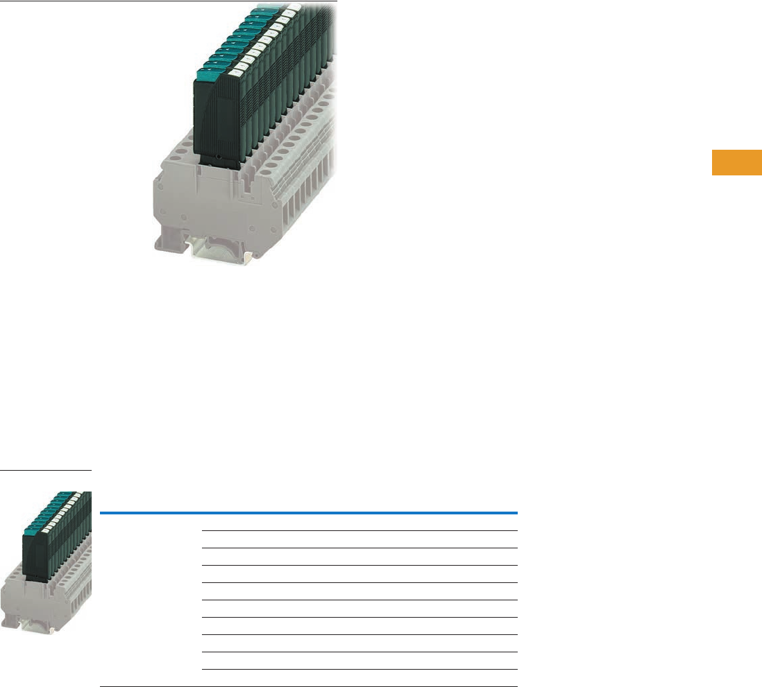
Logic Control Products CA08100001K—June 2012 www.eatoncanada.ca T42-83
42
42
42
42
42
42
42
42
42
42
42
42
42
42
42
42
42
42
42
42
42
42
42
42
42
42
42
42
42
42
42.1
Terminal Blocks, Fuse Blocks and Fuse Holders
IEC—
XB
Series
Circuit Breakers Contents
Description Page
Circuit Breakers
Accessories . . . . . . . . . . . . . . . . . . . . . . . . . . . . . . T42-84
Technical Data and Specifications . . . . . . . . . . . . . T42-84
Time/Current Curve . . . . . . . . . . . . . . . . . . . . . . . . T42-85
Dimensions . . . . . . . . . . . . . . . . . . . . . . . . . . . . . . T42-85
Flat-Type Fuse Terminal Blocks . . . . . . . . . . . . . . . . . . T42-86
Spring Cage Fuse Terminal Blocks . . . . . . . . . . . . . . . T42-88
Circuit Breakers
Product Description
The thermal miniature circuit
breaker can be switched back
on again, has a compact
design, and is available
in 10 finely graded steps
for nominal currents from
0.1 to 10A.
Product Selection
Thermal Miniature Circuit Breaker
Connection Data
in Vac/Vdc
Nominal
Current Colour
Standard
Pack
Catalogue
Number
250/65 0.1A Black 20 XBATCPT
0.25A Black 20 XBATCPQ
0.5A Black 20 XBATCPH
1.0A Black 20 XBATCP1
2.0A Black 20 XBATCP2
3.0A Black 20 XBATCP3
4.0A Black 20 XBATCP4
6.0A Black 20 XBATCP6
8.0A Black 20 XBATCP8
10.0A Black 20 XBATCP10
XBAT
Tab42book.fm Page 83 Thursday, July 5, 2012 8:03 PM

T42-84 Logic Control Products CA08100001K—June 2012 www.eatoncanada.ca
42
42
42
42
42
42
42
42
42
42
42
42
42
42
42
42
42
42
42
42
42
42
42
42
42
42
42
42
42
42
42.1
Terminal Blocks, Fuse Blocks and Fuse Holders
IEC—
XB
Series
Accessories
Thermal Miniature Circuit Breaker
Technical Data and Specifications
Thermal Miniature Circuit Breaker
Nominal Currents and Internal Resistances
Note
For information on Printed Marking Tag Options, see Page T42-98.
Description Colour
Number of
Positions
Standard
Pack
XBAT
Catalogue
Number
Blank marker strip White — 10 XBMZBF5
Flat type terminal blocks — — — XBUK6FSI
XBUK6FSIL12
XBUK6FSIL24
XBPT4FSI
XBPT4FSIL12
XBPT4FSIL24
Description XBAT
Technical Data in Accordance with IEC
Nominal voltage in Vac/Vdc 250/65
Nominal current in A 0.25–10
Ambient temperature –4 to 140˚F (–20 to 60˚C)
Maximum Power Dissipation
Rated surge voltage in kV/contamination class 2.5/2
Surge voltage category/insulating material group III/I
Switching Capacity
Cycles with 1 x IN (low-induction) 6000
Cycles with 1 x IN (induction) 3000
Cycles with 2 x IN (induction) 500
Switching Capacity I CN
For nominal currents of 0.25–4A/6–10A 6 x IN/8 x IN
Switching capacity (UL 1077) 250 Vac/65 Vdc 2000/200
Nominal
Current (A)
Internal
Resistance (3/4)
0.25 14
0.5 3.4
1.0 0.9
2.0 0.25
3.0 0.11
4.0 0.07
6.0 <0.05
8.0 <0.05
10.0 <0.05
Tab42book.fm Page 84 Thursday, July 5, 2012 8:03 PM

Logic Control Products CA08100001K—June 2012 www.eatoncanada.ca T42-85
42
42
42
42
42
42
42
42
42
42
42
42
42
42
42
42
42
42
42
42
42
42
42
42
42
42
42
42
42
42
42.1
Terminal Blocks, Fuse Blocks and Fuse Holders
IEC—
XB
Series
Time/Current Curve
Total Switch-Off Period for Nominal Current, 73.4˚F (23˚C)
Note: When mounted in rows, the nominal current of
the devices can only be transmitted at 80% or must
be correspondingly over-dimensioned.
Temperature Factor
Dimensions
Approximate Dimensions in Inches (mm)
XBUK6FSI with XBAT XBPT4FSI with XBAT
10,000
Multiples of IN
Response Time in Seconds
56 810 2043210.8
1000
100
10
1
0.1
0.25A - 4A
6A- 10A
Ambient Temperature Temperature Factor
–4˚F (–20˚C) 0.76
14˚F (–10˚C) 0.84
32˚F (0˚C) 0.91
73.4˚F (23˚C) 1.00
104˚F (40˚C) 1.08
122˚F (50˚C) 1.16
140˚F (60˚C) 1.24
0.96
(24.4)
2.52
(64) 0.32
(8.2)
1.73
(44)
1.75
(44.5)
1.93
(49)
2.03
(51.5)
0.96
(24.4)
3.39
(86.2)
3.41
(86.5) 0.32
(8.2)
1.72
(43.7)
Tab42book.fm Page 85 Thursday, July 5, 2012 8:03 PM
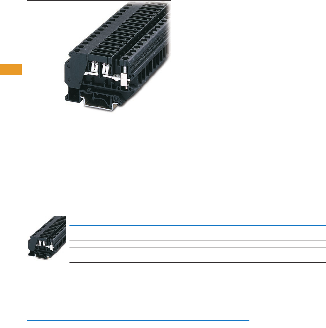
T42-86 Logic Control Products CA08100001K—June 2012 www.eatoncanada.ca
42
42
42
42
42
42
42
42
42
42
42
42
42
42
42
42
42
42
42
42
42
42
42
42
42
42
42
42
42
42
42.1
Terminal Blocks, Fuse Blocks and Fuse Holders
IEC—
XB
Series
Flat-Type Fuse Terminal Blocks Contents
Description Page
Circuit Breakers . . . . . . . . . . . . . . . . . . . . . . . . . . . . . . T42-83
Flat-Type Fuse Terminal Blocks
Accessories . . . . . . . . . . . . . . . . . . . . . . . . . . . . . . T42-86
Technical Data and Specifications . . . . . . . . . . . . . T42-87
Dimensions . . . . . . . . . . . . . . . . . . . . . . . . . . . . . . T42-87
Spring Cage Fuse Terminal Blocks . . . . . . . . . . . . . . . T42-88
Flat-Type Fuse Terminal Blocks
Product Description
The fuse terminal blocks can
be used as a basic terminal
blocks for the XBAT overload
miniature circuit breaker, see
Page T42-83.
Product Selection
Screw Connection Flat-Type Fuse Terminal Blocks
Accessories
Flat-Type Fuse Terminal Blocks
Note
For information on Printed Marking Tag Options, see Page T42-98.
Terminal
Width
Maximum
Wire Size
Connection Data
in V/A/AWG
UL-cUL Ratings
in V/A/AWG Colour
Standard
Pack
Catalogue
Number
Flat-Type Fuse Terminal Block
8.2 mm 8 AWG/6 mm2250/—/24–8 300/30/26–8 Black 50 XBUK6FSI
Flat-Type Fuse Terminal Block with LED, Red 12 Vdc, 2.0 mA
8.2 mm 8 AWG/6 mm2250/—/24–8 300/30/26–8 Black 50 XBUK6FSIL12
Flat-Type Fuse Terminal Block with LED, Red 24 Vdc, 2.0 mA
8.2 mm 8 AWG/6 mm2250/—/24–8 300/30/26–8 Black 50 XBUK6FSIL24
Description Colour
Number of
Positions
Standard
Pack
XBUK6FSI XBUK6FSIL_
Catalogue
Number
Catalogue
Number
Blank marker strip White — 10 XBMZB8 XBMZB8
XBUK6FSI
Tab42book.fm Page 86 Thursday, July 5, 2012 8:03 PM

Logic Control Products CA08100001K—June 2012 www.eatoncanada.ca T42-87
42
42
42
42
42
42
42
42
42
42
42
42
42
42
42
42
42
42
42
42
42
42
42
42
42
42
42
42
42
42
42.1
Terminal Blocks, Fuse Blocks and Fuse Holders
IEC—
XB
Series
Technical Data and Specifications
Flat-Type Fuse Terminal Blocks
Dimensions
Approximate Dimensions in Inches (mm)
Flat-Type Fuse Terminal Blocks
Description XBUK6FSI XBUK6FSIL_
Technical Data in Accordance with IEC
Fuse type ISO C C
Maximum current with single arrangement in A 30 30
Maximum Power Dissipation
Rated surge voltage in kV/contamination class 4/3 4/3
Surge voltage category/insulating material group III/I III/I
Connection Capacity
Stranded with ferrule with plastic sleeve in mm20.25–4 0.25–4
Stranded with ferrule without plastic sleeve in mm20.25–6 0.25–6
Stranded with twin ferrule with plastic sleeve in mm2——
Multi-Conductor Connection
(same cross-section)
Solid/stranded in mm20.2–2.5/0.2–2.5 0.2–2.5/0.2–2.5
Stranded with ferrules without plastic sleeve in mm20.25–2.5 0.25–2.5
Stranded with twin ferrule with plastic sleeve in mm20.5–4.0 0.5–4.0
Stripping length in inches (mm) 0.39 (10) 0.39 (10)
Thread M4 M4
Torque in in-lb (Nm) 13.3–14.2 (1.5–1.6) 13.3–14.2 (1.5–1.6)
Catalogue
Number Width Length
Height for—
32 in 35 x 7.5 in 35 x 15 in
XBUK6FSI 0.32 (8.2) 2.91 (74.0) 2.24 (57.0) 2.05 (52.0) 2.34 (59.5)
XBUK6FSIL12 0.32 (8.2) 2.91 (74.0) 2.24 (57.0) 2.05 (52.0) 2.34 (59.5)
XBUK6FSIL24 0.32 (8.2) 2.91 (74.0) 2.24 (57.0) 2.05 (52.0) 2.34 (59.5)
Tab42book.fm Page 87 Thursday, July 5, 2012 8:03 PM
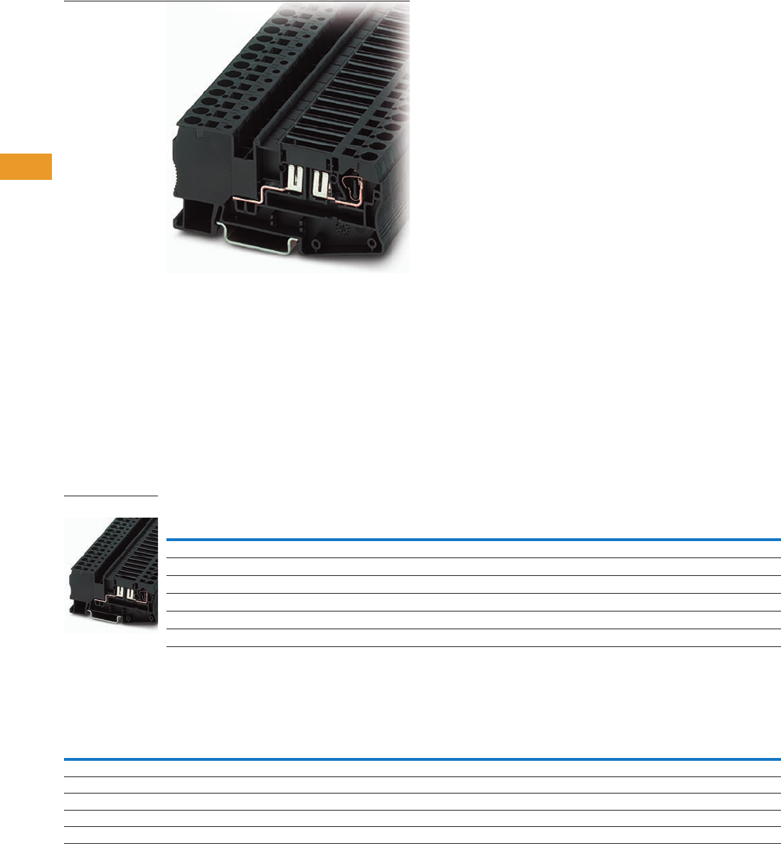
T42-88 Logic Control Products CA08100001K—June 2012 www.eatoncanada.ca
42
42
42
42
42
42
42
42
42
42
42
42
42
42
42
42
42
42
42
42
42
42
42
42
42
42
42
42
42
42
42.1
Terminal Blocks, Fuse Blocks and Fuse Holders
IEC—
XB
Series
Spring Cage Fuse Terminal Blocks Contents
Description Page
Circuit Breakers . . . . . . . . . . . . . . . . . . . . . . . . . . . . . . T42-83
Flat-Type Fuse Terminal Blocks . . . . . . . . . . . . . . . . . . T42-86
Spring Cage Fuse Terminal Blocks
Accessories . . . . . . . . . . . . . . . . . . . . . . . . . . . . . . T42-88
Technical Data and Specifications . . . . . . . . . . . . . T42-89
Dimensions . . . . . . . . . . . . . . . . . . . . . . . . . . . . . . T42-89
Spring Cage Fuse Terminal Blocks
Product Description
Flat-type fuses or the XBAT
miniature circuit breaker (see
Page T42-83) can be used as
the fuse element in these
XBPT
Spring Cage Fuse Terminal
Blocks. Terminal blocks with
a light indicator are available
for quick error diagnosis.
Product Selection
Spring Cage Fuse Terminal Blocks
Accessories
Flat-Type Fuse Terminal Blocks
Notes
For ordering information, see Page T42-105.
For information on Printed Marking Tag Options, see Page T42-98.
Terminal
Width
Maximum
Wire Size
Connection Data
in V/A/AWG
UL-cUL Ratings
in V/A/AWG Colour
Standard
Pack
Catalogue
Number
Spring Cage Fuse Terminal Block
8.2 mm 10 AWG/4 mm2400/30/28–10 300/30/24–10 Black 50 XBPT4FSI
Spring Cage Fuse Terminal Block with LED, Red 12 Vdc, 2.0 mA
8.2 mm 10 AWG/4 mm2400/30/28–10 300/30/24–10 Black 50 XBPT4FSIL12
Spring Cage Fuse Terminal Block with LED, Red 24 Vdc, 2.0 mA
8.2 mm 10 AWG/4 mm2400/30/28–10 300/30/24–10 Black 50 XBPT4FSIL24
Description Colour
Number of
Positions
Standard
Pack
XBPT4FSI XBPT4FSIL_
Catalogue
Number
Catalogue
Number
Test adapter — — 10 XBATSPAI4 XBATSPAI4
2.3 mm diameter test plug — — — XBATSMPS-_ XBATSMPS-_
Modular test plug — — 10 XBATSPS8 XBATSPS8
Blank marker strip centre and external marking White — 10 XBMZBF8 XBMZBF8
Blank marker strip centre labeling (strip of 10) White — 10 XBMZB8 XBMZB8
XBPT4FSI
Tab42book.fm Page 88 Thursday, July 5, 2012 8:03 PM

Logic Control Products CA08100001K—June 2012 www.eatoncanada.ca T42-89
42
42
42
42
42
42
42
42
42
42
42
42
42
42
42
42
42
42
42
42
42
42
42
42
42
42
42
42
42
42
42.1
Terminal Blocks, Fuse Blocks and Fuse Holders
IEC—
XB
Series
Technical Data and Specifications
Flat-Type Fuse Terminal Blocks
Dimensions
Approximate Dimensions in Inches (mm)
Flat-Type Fuse Terminal Blocks
Description XBPT4FSI XBPT4FSIL_
Technical Data in Accordance with IEC
Fuse type ISO C C
Maximum current with single arrangement in A 30 30
Maximum Power Dissipation
Rated surge voltage in kV/contamination class 6/3 6/3
Surge voltage category/insulating material group III/I III/I
Connection Capacity
Stranded with ferrule with plastic sleeve in mm20.25–4 0.25–4
Stranded with ferrule without plastic sleeve in mm20.25–4 0.25–4
Stranded with twin ferrule with plastic sleeve in mm20.5 0.5
Stripping length in inches (mm) 0.39 (10) 0.39 (10)
Catalogue
Number Width Length
Height for—
35 x 7.5 in 35 x 15 in
XBPT4FSI 0.32 (8.2) 3.41 (86.5) 1.71 (43.5) 2.01 (51.0)
XBPT4FSIL12 0.32 (8.2) 3.41 (86.5) 1.71 (43.5) 2.01 (51.0)
XBPT4FSIL24 0.32 (8.2) 3.41 (86.5) 1.71 (43.5) 2.01 (51.0)
Tab42book.fm Page 89 Thursday, July 5, 2012 8:03 PM
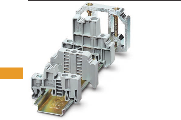
T42-90 Logic Control Products CA08100001K—June 2012 www.eatoncanada.ca
42
42
42
42
42
42
42
42
42
42
42
42
42
42
42
42
42
42
42
42
42
42
42
42
42
42
42
42
42
42
42.1
Terminal Blocks, Fuse Blocks and Fuse Holders
IEC—
XB
Series
XB Series Accessories Contents
Description Page
XB Series Accessories
End Stops . . . . . . . . . . . . . . . . . . . . . . . . . . . . . . . . T42-91
DIN Rails . . . . . . . . . . . . . . . . . . . . . . . . . . . . . . . . T42-92
Angled Mounting Brackets . . . . . . . . . . . . . . . . . . T42-93
Ferrules . . . . . . . . . . . . . . . . . . . . . . . . . . . . . . . . . T42-94
Hand Tools . . . . . . . . . . . . . . . . . . . . . . . . . . . . . . . T42-97
Marking Accessories . . . . . . . . . . . . . . . . . . . . . . . T42-98
Testing Accessories . . . . . . . . . . . . . . . . . . . . . . . . T42-105
Separating Plates, Covers and Bridges . . . . . . . . . T42-105
XB Series Accessories Overview
End Stops
The end stop provides an
anchor point at each end of
the rail assembly by attaching
directly to the DIN rail. A wide
range of end stop options are
available, including those that
mount with one or multiple
screws and those that do not
require screws for mounting.
End stops also have a
location for marking material
to be placed.
DIN Rail
Eaton offers ways for time-
saving and secure mounting
of components needed for
electrical connections. DIN
rail provides the basis for the
inner design of the control
cabinet and ensures a firm
hold of the rail-mountable
components. Eaton offers a
wide range of standard DIN
rails sizes and materials,
solid or slotted. Or, contact
us about custom lengths of
pre-cut rail or ordering pre-
drilled rail. The DIN rails are
designed in accordance with
the European standard
EN 60715.
Angled Mounting Brackets
Angled mounting brackets
are used to mount DIN rail at
a more accessible angle for
wiring and troubleshooting.
Ferrules
Ferrules are available with or
without an insulating sleeve.
The plastic insulating sleeve
simplifies the fitting of the
conductor and the colour
indicates the size of the
cross-section. The closer the
connections are, the more
reliable the insulation is and
the less likely the wires are to
splice. Twin ferrules are also
available allowing two wires
to be easily compressed in
one ferrule. Chain bridging,
frequently used in industry,
becomes easier with twin
ferrules.
Hand Tools
Eaton offers an array of hand
tools to make it easier to work
with our terminal blocks. The
XBTCUTSTP tool is
recommended for cutting and
stripping PVC insulated wires.
The ergonomically shaped
crimping pliers, XBTCRMP66,
result in fatigue-free work by
spreading the manual force
equally between the six jaws.
The XBTDVR screwdrivers
have a rotating cap that
prevents user discomfort
even at high torques and
allows rapid rotation. The
ergonomically shaped handle
further aids the user’s
comfort. The blade is made
from CVM steel, hardened
and chrome-plated.
Marking Accessories
The marking system provides
logical and clear identification
of the modular terminal
blocks and interface modules.
The blank marker strip is
designed for marking terminal
blocks, equipment and
smaller modules with marker
grooves. The marker strip is
available in all common
pitches in printed and
unprinted versions.
Testing Accessories
The range of test accessories
available includes different
test plugs, so that an
optimum solution can be
realized for every application.
In addition to pre-assembled
test plugs, plugs are also
available that can be
configured individually to
form test adapters.
Tab42book.fm Page 90 Thursday, July 5, 2012 8:03 PM
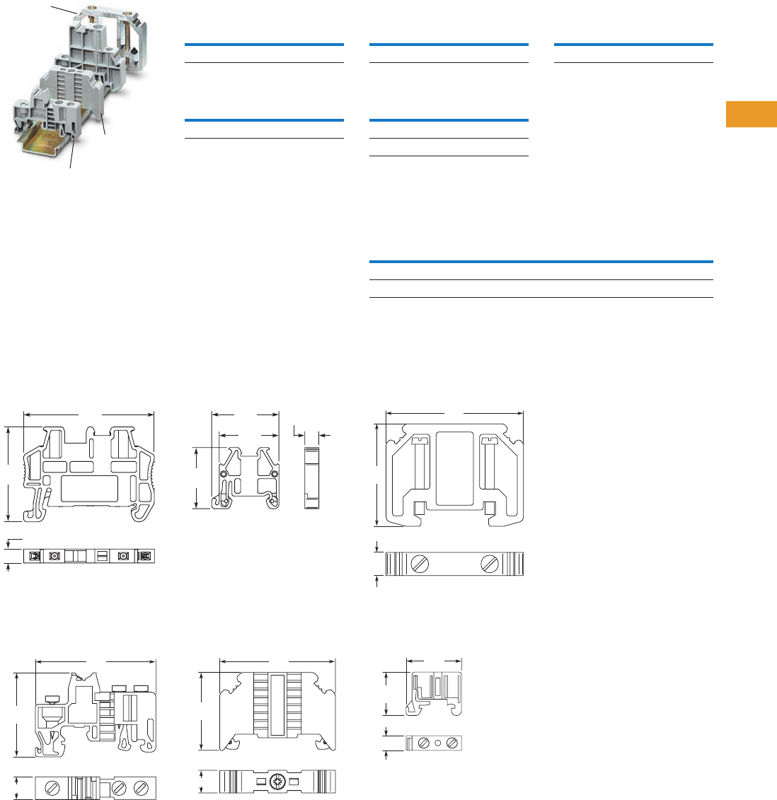
Logic Control Products CA08100001K—June 2012 www.eatoncanada.ca T42-91
42
42
42
42
42
42
42
42
42
42
42
42
42
42
42
42
42
42
42
42
42
42
42
42
42
42
42
42
42
42
42.1
Terminal Blocks, Fuse Blocks and Fuse Holders
IEC—
XB
Series
End Stops
Product Selection
Snap-On End Stop (15 mm)
Snap-On End Stop (35 mm)
Snap-on end stops for 35 mm
and 15 mm DIN rails can
be fitted with blank marker
strips and adjustable terminal
strip markers, parking facility
for bridges and testing
accessories.
Dimensions
Approximate Dimensions in Inches (mm)
Snap-On End Stop
XBAES35N XBAES15N
Universal End Stop
XBAES35T XBAES35C
XBAES35AL
XBAES35C
XBAES35T
Standard
Pack
Catalogue
Number
50 XBAES15N
Standard
Pack
Catalogue
Number
50 XBAES35N
1.3 8
(35)
0.20
(5)
1.9 1
(48.5)
0.89
(22.6)
0.87
(22)
0.20
(5.2)
0.98
(24.8)
1.3 9
(35.3)
0.37 (9.5)
1.9 9
(50.5)
1.2 9
(32.8)
0.37 (9.5)
1.9 1
(48.6)
Universal End Stop (15 mm)
Universal End Stop (35 mm)
Screwed on, labeling with
blank marker strips and
terminal strip markers.
Aluminum End
Snaps on, for end support of
50–240 mm terminal blocks,
labeling with XBMZB10.
Cross-Reference of Terminal Blocks Marking, End Stops
Aluminum End Stop
XBAES35AL
XBAES15C
Standard
Pack
Catalogue
Number
50 XBAES15C
Standard
Pack
Catalogue
Number
50 XBAES35T
50 XBAES35C
Standard
Pack
Catalogue
Number
10 XBAES35AL
Catalogue
Number XBMKLM2 XBMGLMA XBMUBE
XBAES35N X——
XBAES35T —X X
1.7 3
(44)
0.39
(10)
2.32
(59)
0.71
(18)
0.24 (6.1)
0.83
(21.2)
Tab42book.fm Page 91 Thursday, July 5, 2012 8:03 PM
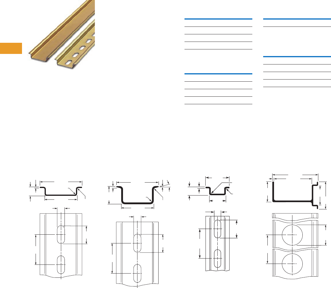
T42-92 Logic Control Products CA08100001K—June 2012 www.eatoncanada.ca
42
42
42
42
42
42
42
42
42
42
42
42
42
42
42
42
42
42
42
42
42
42
42
42
42
42
42
42
42
42
42.1
Terminal Blocks, Fuse Blocks and Fuse Holders
IEC—
XB
Series
DIN Rails
Product Selection
Perforated and unperforated
DIN rails in accordance with
E 60715.
Features
●High dimensional accuracy
●Restricted tolerances
●Double surface tempering,
galvanized and chromated
●All 2m in length
●Customization available
35 x 7.5 mm x 2m
35 x 15 mm x 2m
15 x 5.5 mm x 2m
Aluminum DIN Rails
(Perforated)
Dimensions
Approximate Dimensions in Inches (mm)
35 x 7.5 mm DIN Rail 35 x 15 mm DIN Rail 15 x 5.5 mm x 2m DIN Rail XBANS35PL Raised Rail
Standard
Pack
Catalogue
Number
Slotted
25 XBANS3575P
Solid
25 XBANS3575U
Standard
Pack
Catalogue
Number
Slotted
25 XBANS3515P
Solid
25 XBANS3515U
Standard
Pack
Catalogue
Number
25 XBANS15P
Standard
Pack
Catalogue
Number
35/7.5/2m
25 XBANS3575PL
35/58/2m
6XBANS35PL
0.24
(6.2)
1.06 (27)
0.03 (0.8)
Rad.
0.03 (0.8)
Rad.
1.38 (35)
0.98
(25)
0.30
(7.5)
0.04
(1)
0.59
(15)
0.05 (1.25)
Rad.
0.05 (1.25)
Rad.
0.24
(6.2)
0.98
(25)
0.59
(15)
0.03
(0.8)
15°
1.38 (35)
0.59
(15)
0.06
(1.5)
1.06 (27)
0.02 (0.5)
Rad.
0.01 (0.2)
Rad.
0.17
(4.2)
0.59
(15)
0.41
(10.5)
0.22
(5.5)
0.04
(1)
0.48
(12.2)
0.79
(20) 5.00
(127)
1.38
(35)
0.08
(2)
0.95
(24)
1.0 2
(26)
1.0 2
(26)
2.28 (58)
1.89 (48)
Tab42book.fm Page 92 Thursday, July 5, 2012 8:03 PM
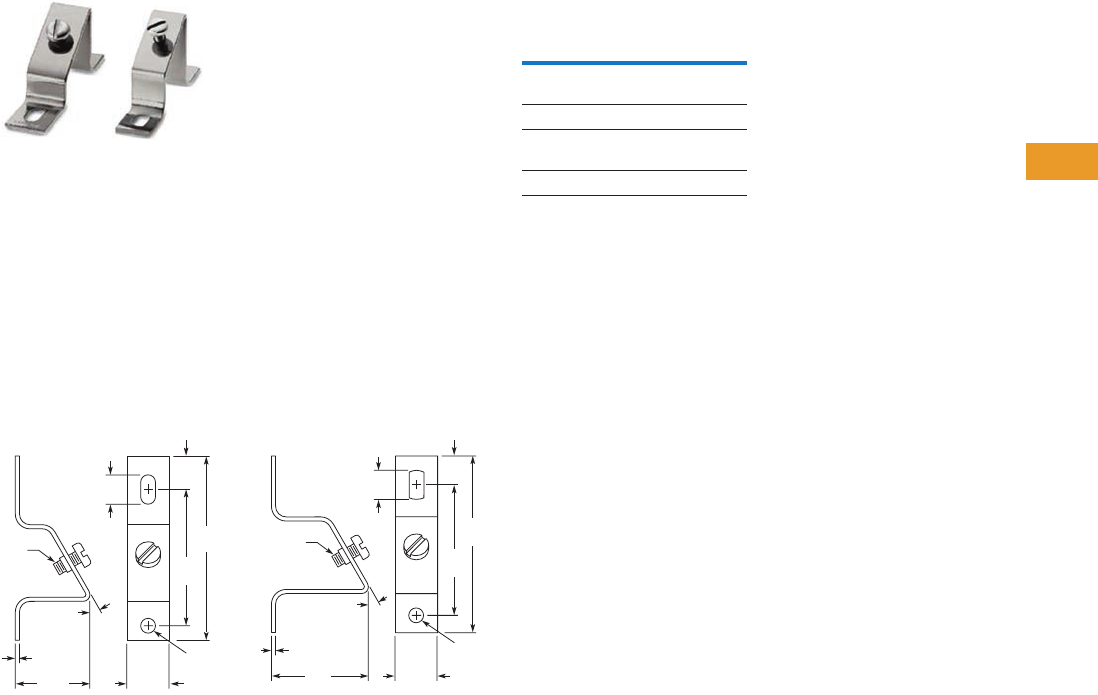
Logic Control Products CA08100001K—June 2012 www.eatoncanada.ca T42-93
42
42
42
42
42
42
42
42
42
42
42
42
42
42
42
42
42
42
42
42
42
42
42
42
42
42
42
42
42
42
42.1
Terminal Blocks, Fuse Blocks and Fuse Holders
IEC—
XB
Series
Angled Mounting Brackets
Product Selection
The angled brackets enable
the DIN rail to be mounted
with a spacing or at an angle
of 30˚.
Features
●For mounting DIN rail at
30˚ angle
●For use with M6 screw
●Chromated steel
●Provides better visibility
Angled Mounting Bracket
Dimensions
Approximate Dimensions in Inches (mm)
XBANBGS XBANBGSH
Standard
Pack
Catalogue
Number
Height Inches (mm)
1.39 (35.4)
10 XBANBGS
Height Inches (mm)
1.81 (46)
10 XBANBGSH
3.43
(87)
0.08
(2)
2.54
(64.5)
0.61
(15.4)
0.65
(16.5)
1.39
(35.4) 0.79
(20)
0.28 (7)
Dia.
M6
Screw
30°
3.31
(84)
0.08
(2)
30°
2.44
(62)
0.54
(13.7)
0.55
(14)
1.81
(46) 0.79
(20)
0.28 (7)
Dia.
M6
Screw
Tab42book.fm Page 93 Thursday, July 5, 2012 8:03 PM
T42-94 Logic Control Products CA08100001K—June 2012 www.eatoncanada.ca
42
42
42
42
42
42
42
42
42
42
42
42
42
42
42
42
42
42
42
42
42
42
42
42
42
42
42
42
42
42
42.1
Terminal Blocks, Fuse Blocks and Fuse Holders
IEC—
XB
Series
Ferrules
Product Selection
Ferrules are offered in two
basic designs—an insulated
style available in models for
wire sizes 20 through 4 AWG
and a non-insulated type
available in models for wire
sizes 22 through 6 AWG.
Note: UL Ratings do not typically
pertain to the use of Ferrules—
Ferrules are covered under
DIN VDE 0611.
Insulated
●Tube: soft electrolytic copper (E-CU), tin plated
●Plastic sleeve: polypropylene
●Long-term temperature 105˚C
●Short-term temperature 120˚C
Insulated Ferrules
Wire Size
AWG (mm2) Colour
Standard
Pack
Catalogue
Number
20 (0.5) White 100 XBAF1
18 (0.75) Gray 100 XBAF3
18 (1) Red 100 XBAF4
16 (1.5) Black 100 XBAF6
14 (2.5) Blue 100 XBAF9
14 (2.5) Blue 100 XBAF10
12 (4) Gray 100 XBAF11
12 (4) Gray 100 XBAF12
10 (6) Yellow 100 XBAF13
10 (6) Yellow 100 XBAF14
8 (10) Red 100 XBAF15
8 (10) Red 100 XBAF16
6 (16) Blue 100 XBAF17
6 (16) Blue 100 XBAF18
4 (25) Yellow 50 XBAF19
XBAF1
Non-Insulated
●Tube: soft electrolytic copper (E-CU), tin plated
Non-Insulated Ferrules
Special Applications
The twin ferrules allow two
conductors to be compressed
practically in one ferrule.
The colored coding of the
various cross sections
corresponds to DIN 46 228-4.
Non-Insulated Twin Ferrules
Notes
The colored coding of the various cross-sections corresponds to DIN 46 228-4.
Standard pack is the number of ferrules that come in each bag. Must order in
multiples of standard pack.
Example: XBAF1—an order for 200 pieces will receive 2 bags of ferrules,
each with 100 pieces.
Wire Size
AWG (mm2)
Standard
Pack
Catalogue
Number
20 (0.5) 100 XBAF20
18 (0.75) 100 XBAF21
18 (1) 100 XBAF23
16 (1.5) 100 XBAF24
14 (2.5) 100 XBAF25
12 (4) 100 XBAF26
10 (6) 100 XBAF27
8 (10) 100 XBAF28
6 (16) 100 XBAF29
XBAF20
Wire Size
AWG (mm2) Colour
Standard
Pack
Catalogue
Number
20 (0.5) White 100 XBAFT1
18 (0.75) Gray 100 XBAFT3
18 (1) Red 100 XBAFT4
16 (1.5) Black 100 XBAFT6
14 (2.5) Blue 100 XBAFT9
12 (4) Gray 100 XBAFT11
10 (6) Yellow 100 XBAFT13
8 (10) Red 100 XBAFT15
6 (16) Blue 50 XBAFT18
XBAFT1
Tab42book.fm Page 94 Thursday, July 5, 2012 8:03 PM
Logic Control Products CA08100001K—June 2012 www.eatoncanada.ca T42-95
42
42
42
42
42
42
42
42
42
42
42
42
42
42
42
42
42
42
42
42
42
42
42
42
42
42
42
42
42
42
42.1
Terminal Blocks, Fuse Blocks and Fuse Holders
IEC—
XB
Series
Dimensions
Approximate Dimensions in Inches (mm)
Ferrules with Insulating Collar
Ferrules without Insulating Collar
Catalogue
Number
Approximate Dimensions
D1 D2 L1 L2 S1 S2
XBAF1 0.04 (1.1) 0.10 (2.5) 0.55 (14.0) 0.31 (8.0) 0.006 (0.15) 0.010 (0.25)
XBAF3 0.05 (1.3) 0.11 (2.8) 0.55 (14.0) 0.31 (8.0) 0.006 (0.15) 0.010 (0.25)
XBAF4 0.06 (1.5) 0.12 (3.0) 0.55 (14.0) 0.31 (8.0) 0.006 (0.15) 0.012 (0.30)
XBAF6 0.07 (1.8) 0.13 (3.4) 0.55 (14.0) 0.31 (8.0) 0.006 (0.15) 0.012 (0.30)
XBAF9 0.09 (2.3) 0.17 (4.2) 0.55 (14.0) 0.31 (8.0) 0.006 (0.15) 0.012 (0.30)
XBAF10 0.09 (2.3) 0.17 (4.2) 0.94 (24.0) 0.71 (18.0) 0.006 (0.15) 0.012 (0.30)
XBAF11 0.11 (2.8) 0.19 (4.8) 0.67 (17.0) 0.39 (10.0) 0.008 (0.20) 0.012 (0.30)
XBAF12 0.11 (2.8) 0.19 (4.8) 1.02 (26.0) 0.71 (18.0) 0.008 (0.20) 0.012 (0.30)
XBAF13 0.14 (3.5) 0.24 (6.2) 0.79 (20.0) 0.47 (12.0) 0.008 (0.20) 0.012 (0.30)
XBAF14 0.14 (3.5) 0.24 (6.2) 1.02 (26.0) 0.71 (18.0) 0.008 (0.20) 0.012 (0.30)
XBAF15 0.18 (4.6) 0.30 (7.5) 0.87 (22.0) 0.47 (12.0) 0.008 (0.20) 0.012 (0.30)
XBAF16 0.18 (4.6) 0.30 (7.5) 1.10 (28.0) 0.71 (18.0) 0.008 (0.20) 0.012 (0.30)
XBAF17 0.23 (5.8) 0.35 (8.8) 0.94 (24.0) 0.47 (12.0) 0.008 (0.20) 0.016 (0.40)
XBAF18 0.23 (5.8) 0.35 (8.8) 1.10 (28.0) 0.71 (18.0) 0.008 (0.20) 0.016 (0.40)
XBAF19 0.29 (7.3) 0.43 (11.0) 1.26 (32.0) 0.71 (18.0) 0.008 (0.20) 0.020 (0.50)
Catalogue
Number
Approximate Dimensions
D1 D2 L1 L2 S
XBAF20 0.04 (1.0) 0.08 (2.1) 0.24 (6.0) 0.21 (5.3) 0.006 (0.15)
XBAF21 0.05 (1.2) 0.09 (2.3) 0.24 (6.0) 0.21 (5.3) 0.006 (0.15)
XBAF23 0.06 (1.4) 0.10 (2.5) 0.24 (6.0) 0.21 (5.3) 0.006 (0.15)
XBAF24 0.07 (1.7) 0.11 (2.8) 0.28 (7.0) 0.24 (6.0) 0.006 (0.15)
XBAF25 0.09 (2.2) 0.13 (3.4) 0.28 (7.0) 0.24 (6.0) 0.006 (0.15)
XBAF26 0.11 (2.8) 0.16 (4.0) 0.35 (9.0) 0.31 (8.0) 0.008 (0.20)
XBAF27 0.14 (3.5) 0.19 (4.7) 0.47 (12.0) 0.35 (9.0) 0.008 (0.20)
XBAF28 0.18 (4.5) 0.23 (5.8) 0.47 (12.0) 0.43 (10.8) 0.008 (0.20)
XBAF29 0.23 (5.8) 0.30 (7.5) 0.47 (12.0) 0.41 (10.5) 0.008 (0.20)
D2
S2
L2
L1
S1 D1
D2
D1
L2
L1
S
Tab42book.fm Page 95 Thursday, July 5, 2012 8:03 PM

T42-96 Logic Control Products CA08100001K—June 2012 www.eatoncanada.ca
42
42
42
42
42
42
42
42
42
42
42
42
42
42
42
42
42
42
42
42
42
42
42
42
42
42
42
42
42
42
42.1
Terminal Blocks, Fuse Blocks and Fuse Holders
IEC—
XB
Series
Approximate Dimensions in Inches (mm)
Twin Ferrules
Catalogue
Number
Approximate Dimensions
D1 D2 L1 L2 S1 S2
XBAFT1 0.06 (1.5) 0.10 (2.5) 0.59 (15.0) 0.31 (8.0) 0.006 (0.15) 0.010 (0.25)
XBAFT3 0.07 (1.8) 0.11 (2.8) 0.59 (15.0) 0.31 (8.0) 0.006 (0.15) 0.010 (0.25)
XBAFT4 0.08 (2.1) 0.13 (3.4) 0.59 (15.0) 0.31 (8.0) 0.006 (0.15) 0.012 (0.30)
XBAFT6 0.09 (2.3) 0.14 (3.6) 0.63 (16.0) 0.31 (8.0) 0.006 (0.15) 0.012 (0.30)
XBAFT9 0.11 (2.9) 0.17 (4.2) 0.73 (18.5) 0.39 (10.0) 0.008 (0.20) 0.012 (0.30)
XBAFT11 0.15 (3.8) 0.19 (4.9) 0.91 (23.0) 0.47 (12.0) 0.008 (0.20) 0.012 (0.30)
XBAFT13 0.19 (4.9) 0.23 (5.9) 0.98 (25.0) 0.55 (14.0) 0.008 (0.20) 0.016 (0.40)
XBAFT15 0.26 (6.5) 0.28 (7.2) 1.02 (26.0) 0.55 (14.0) 0.008 (0.20) 0.016 (0.40)
XBAFT18 0.33 (8.5) 0.35 (8.8) 1.22 (31.0) 0.63 (16.0) 0.008 (0.20) 0.020 (0.50)
D2
S2
L2
L1
D1
S1
Tab42book.fm Page 96 Thursday, July 5, 2012 8:03 PM

Logic Control Products CA08100001K—June 2012 www.eatoncanada.ca T42-97
42
42
42
42
42
42
42
42
42
42
42
42
42
42
42
42
42
42
42
42
42
42
42
42
42
42
42
42
42
42
42.1
Terminal Blocks, Fuse Blocks and Fuse Holders
IEC—
XB
Series
Hand Tools
Stripping Tools
Product Selection
Stripping Tools
Technical Data and Specifications
Conductor/Cable Stripping Range
Dimensions
Approximate Dimensions in Inches (mm)
Stripping Tools
Crimping Pliers
The crimping pliers deform the ferrules hexagonally.
For 0.25–6 mm2 ferrules in accordance with
DIN 46 228-1: 1992-08 and DIN 46 228-4: 1990-09.
Product Selection
Crimping Pliers
Technical Data and Specifications
Areas of Application
Dimensions
Approximate Dimensions in Inches (mm)
Crimping Pliers
Slotted Screwdrivers
Product Selection
Slotted Screwdrivers
Standard
Pack
Catalogue
Number
1XBTCUTSTP
Description Specification
Conductor/cable 0.2–6 mm2/24–10 AWG
Wire cutter 6 mm2/10 AWG
Length
Stripping
Length
Weight
In lbs (g)
8.07 (205) Up to 18 mm 0.44 (200)
Standard
Pack
Catalogue
Number
1XBTCRMP66
Description Specification
Conductor 0.25–6 mm2
Conductor 23–10 AWG
Length
Weight
In lbs (g)
6.85 (175) 0.79 (360)
Standard
Pack
Catalogue
Number
3.5 mm
1XBTDVR35
4.0 mm
1XBTDVR40
Tab42book.fm Page 97 Thursday, July 5, 2012 8:03 PM
T42-98 Logic Control Products CA08100001K—June 2012 www.eatoncanada.ca
42
42
42
42
42
42
42
42
42
42
42
42
42
42
42
42
42
42
42
42
42
42
42
42
42
42
42
42
42
42
42.1
Terminal Blocks, Fuse Blocks and Fuse Holders
IEC—
XB
Series
Marking Accessories
Printed Marking Tag Options
Horizontally Printed Marking Tags and Marking Directions
Marking Tags for 5.2 mm Wide Terminal Blocks Marking Tags for 6.2 mm Wide Terminal Blocks
Note
For text printed horizontally, change “V” in catalogue number to “H.”
12345678910
Marking Direction: Horizontal
1
2
3
4
5
6
7
8
9
10
Marking Direction: Vertical
Standard
Pack
Number
Sequence
Catalogue
Number
ZB5 Tags Vertically Numbered
10 1–10 XBMZB5V/1
10 11–20 XBMZB5V/11
10 21–30 XBMZB5V/21
10 31–40 XBMZB5V/31
10 41–50 XBMZB5V/41
10 51–60 XBMZB5V/51
10 61–70 XBMZB5V/61
10 71–80 XBMZB5V/71
10 81–90 XBMZB5V/81
10 91–100 XBMZB5V/91
ZBF5 Tags Vertically Numbered
10 1–10 XBMZBF5V/1
10 11–20 XBMZBF5V/11
10 21–30 XBMZBF5V/21
10 31–40 XBMZBF5V/31
10 41–50 XBMZBF5V/41
10 51–60 XBMZBF5V/51
10 61–70 XBMZBF5V/61
10 71–80 XBMZBF5V/71
10 81–90 XBMZBF5V/81
10 91–100 XBMZBF5V/91
Standard
Pack
Number
Sequence
Catalogue
Number
ZB6 Tags Vertically Numbered
10 1–10 XBMZB6V/1
10 11–20 XBMZB6V/11
10 21–30 XBMZB6V/21
10 31–40 XBMZB6V/31
10 41–50 XBMZB6V/41
10 51–60 XBMZB6V/51
10 61–70 XBMZB6V/61
10 71–80 XBMZB6V/71
10 81–90 XBMZB6V/81
10 91–100 XBMZB6V/91
ZBF6 Tags Vertically Numbered
10 1–10 XBMZBF6V/1
10 11–20 XBMZBF6V/11
10 21–30 XBMZBF6V/21
10 31–40 XBMZBF6V/31
10 41–50 XBMZBF6V/41
10 51–60 XBMZBF6V/51
10 61–70 XBMZBF6V/61
10 71–80 XBMZBF6V/71
10 81–90 XBMZBF6V/81
10 91–100 XBMZBF6V/91
Tab42book.fm Page 98 Thursday, July 5, 2012 8:03 PM

Logic Control Products CA08100001K—June 2012 www.eatoncanada.ca T42-99
42
42
42
42
42
42
42
42
42
42
42
42
42
42
42
42
42
42
42
42
42
42
42
42
42
42
42
42
42
42
42.1
Terminal Blocks, Fuse Blocks and Fuse Holders
IEC—
XB
Series
Marking Tags for 8.2 mm Wide Terminal Blocks
Marking Tags for 10.2 mm Wide Terminal Blocks
Marking Tags for 12 mm Wide Terminal Blocks
Marking Tags for 16 mm Wide Terminal Blocks
Note
For text printed horizontally, change “V” in catalogue number to “H.”
Standard
Pack
Number
Sequence
Catalogue
Number
ZB8 Tags Vertically Numbered
10 1–10 XBMZB8V/1
10 11–20 XBMZB8V/11
10 21–30 XBMZB8V/21
10 31–40 XBMZB8V/31
10 41–50 XBMZB8V/41
10 51–60 XBMZB6V/51
10 61–70 XBMZB8V/61
10 71–80 XBMZB8V/71
10 81–90 XBMZB8V/81
10 91–100 XBMZB8V/91
ZBF8 Tags Vertically Numbered
10 1–10 XBMZBF8V/1
10 11–20 XBMZBF8V/11
10 21–30 XBMZBF8V/21
10 31–40 XBMZBF8V/31
10 41–50 XBMZBF8V/41
10 51–60 XBMZBF8V/51
10 61–70 XBMZBF8V/61
10 71–80 XBMZBF8V/71
10 81–90 XBMZBF8V/81
10 91–100 XBMZBF8V/91
Standard
Pack
Number
Sequence
Catalogue
Number
ZB10 Tags Vertically Numbered
10 1–10 XBMZB10V/1
10 11–20 XBMZB10V/11
10 21–30 XBMZB10V/21
ZBF10 Tags Vertically Numbered
10 1–10 XBMZBF10V/1
10 11–20 XBMZBF10V/11
10 21–30 XBMZBF10V/21
Standard
Pack
Number
Sequence
Catalogue
Number
ZB12 Tags Vertically Numbered
10 1–10 XBMZB12V/1
10 11–20 XBMZB12V/11
10 21–30 XBMZB12V/21
ZBF12 Tags Vertically Numbered
10 1–10 XBMZBF12V/1
10 11–20 XBMZBF12V/11
10 21–30 XBMZBF12V/21
Standard
Pack
Number
Sequence
Catalogue
Number
ZB15 Tags Vertically Numbered
10 1–10 XBMZB15V/1
10 11–20 XBMZB15V/11
10 21–30 XBMZB15V/21
ZBF15 Tags Vertically Numbered
10 1–10 XBMZBF15V/1
10 11–20 XBMZBF15V/11
10 21–30 XBMZBF15V/21
Tab42book.fm Page 99 Thursday, July 5, 2012 8:03 PM

T42-100 Logic Control Products CA08100001K—June 2012 www.eatoncanada.ca
42
42
42
42
42
42
42
42
42
42
42
42
42
42
42
42
42
42
42
42
42
42
42
42
42
42
42
42
42
42
42.1
Terminal Blocks, Fuse Blocks and Fuse Holders
IEC—
XB
Series
Pre-Printed Marking Tags
Terminal Blocks Marking Tags
The tags are made of white self-extinguishing polyamide 6.6 and the imprint is hot stamped
with rubproof black ink.
●White marking strip
available preprinted. Strip
covers 10 terminals.
Marking 1 – 10, 11–20, up
to 991–999. Contact Eaton
for more options.
●XBMZB5 or XBMZBF5
for terminal blocks
5.2 mm wide
●XBMZB6 or XBMZBF6
for terminal blocks
6.2 mm wide
●XBMZB8 or XBMZBF8
for terminal blocks
8.2 mm wide
●XBMZB10 or
XBMZBF10 for terminal
blocks 10.2 mm wide
●XBMZB12 or
XBMZBF12 for terminal
blocks 12 mm wide
●XBMZB15 or
XBMZBF15 for terminal
blocks 16 mm wide
Marking Tag Sizes
Note: Marking Tag Sizes are for all catalogue numbers starting with given prefix, EXCEPT FUSE TERMINAL Blocks.
Proper Marking Tag Size
Notes
For centre labeling.
For external labeling.
For centre and outside labeling.
For lever labeling.
Two (2) XBMZB10 tags fit in one (1) XBMKLMZ.
XBMZB5 XBMZBF5 XBMZB6 XBMZBF6 XBMZB8 XBMZBF8 XBMZB10 XBMZBF10 XBMZB12 XBMZBF12 XBMZB15 XBMZBF15 XBMSSZB
XBUT25 XBPT25 XBUT4 XBPT4 XBUT6 XBPT6 XBUT10 XBPT10 XBPT16 XBPT16 XBUT35 XBPT35 XBMKLMZ
XBUT4FBE XBPTT25 XBUTT4 XBPTT4 XBPT6 XBPT4FBN XBUT16 — — — XBPT35 ——
XBUT6FBN XBPTK XB3UKA XBPT4FBE XBUK6 XBPT4FSI XBTK — — — — — —
XBPT25 XBPU25 XB3UKF XBQT25 XBPT4FSI — XBUK50 — — — — — —
XBPT4FBE XBAP … XBUT4FBE XBQT25FBE — — XBUK150 — — — — — —
XBPU25 XBQT15 XBUT6FBN XBQU25 — — XBUK95 — — — — — —
XBQT15 XBQTT15 XBUK10 — — — XBPT10 ——————
XBQT25FBE XBQU15 XBUKK4 — — — XBMKLMZ ——————
XBQU15 XBMPK15 XBPT4 — — — — — —— —— —
XBMUK25 XBMPKK15 XBPT4FBN — — — — — —— —— —
— XBATCP… XBQT25 — — — — — —— —— —
— — XBQT25FBE — — — — — —— —— —
— — XBQU25 — — — — — —— —— —
— — XBMUK4 — — — — — — — — — —
Tab42book.fm Page 100 Thursday, July 5, 2012 8:03 PM

Logic Control Products CA08100001K—June 2012 www.eatoncanada.ca T42-101
42
42
42
42
42
42
42
42
42
42
42
42
42
42
42
42
42
42
42
42
42
42
42
42
42
42
42
42
42
42
42.1
Terminal Blocks, Fuse Blocks and Fuse Holders
IEC—
XB
Series
Marker Strips and Sheets (for use with XBAPLT2006K1 plotter)
The XB Series marking system provides logical and clear
identification of the modular terminal blocks and interface
modules.
Product Selection
Marker Strips (Strip of 10)
Label Sheets for Laser Printers
The XBM labels have been specially developed for laser printers
and have considerable advantages:
●Can be printed on all commercially available laser printers
●Or can use plotter or pen for printing
●Good adhesive properties
●A4 size
●XBMKL25X12WH designed to fit XBGBS2512 group marker
●XBMLMAL447 is perforated for terminal strip marker
XBMGLMA and is 44 x 7 mm
Marker Sheets (Strip of 10)
Product Selection
Label Sheets
Note
All markers are strips of 10, except XBMZB15, which is a strip of 5.
Terminal
Width
Standard
Pack
Catalogue
Number
Blank Strips
5.2 mm 10 XBMZB5
6.2 mm 10 XBMZB6
8.2 mm 10 XBMZB8
10.2 mm 10 XBMZB10
12 mm 10 XBMZB12
16 mm 10 XBMZB15
Flat Strips
5.2 mm 10 XBMZBF5
6.2 mm 10 XBMZBF6
8.2 mm 10 XBMZBF8
10.2 mm 10 XBMZBF10
12 mm 10 XBMZBF12
16 mm 10 XBMZBF15
XBMZB_
Terminal
Width) Colour
Stnd.
Pack
Catalogue
Number
Marker Sheets (10 rows of 12)
5.2 mm White 50 XBMPZB5
Blue 50 XBMPZB5BU
Red 50 XBMPZB5RD
Yellow 50 XBMPZB5YE
Green 50 XBMPZB5GN
Marker Sheets (10 rows of 10)
6.2 mm White 50 XBMPZB6
Blue 50 XBMPZB6BU
Red 50 XBMPZB6RD
Yellow 50 XBMPZB6YE
Green 50 XBMPZB6GN
Flat Marker Sheets (10 rows of 10)
5.2 mm White 10 XBMPZBF5
Orange 10 XBMPZBF5OG
White 10 XBMPZBF6
Orange 10 XBMPZBF6OG
White 10 XBMPZBF8
Standard
Pack
Catalogue
Number
10 XBMKL25X12WH
10 XBMLMAL447
XBMPZB_
XBMPZBF_
XBM_
Tab42book.fm Page 101 Thursday, July 5, 2012 8:03 PM
T42-102 Logic Control Products CA08100001K—June 2012 www.eatoncanada.ca
42
42
42
42
42
42
42
42
42
42
42
42
42
42
42
42
42
42
42
42
42
42
42
42
42
42
42
42
42
42
42.1
Terminal Blocks, Fuse Blocks and Fuse Holders
IEC—
XB
Series
Terminal Block Group Marking
Terminal block groups are marked using marking labels that are
snapped into the marker strip groove of the terminal blocks. The
group is marked using either labels or insert markers.
Product Selection
Terminal Block Group Marking
Terminal Strip Markers
Adjustable height for end bracket labeling.
Product Selection
Terminal Strip Markers
Terminal Strip Marker Carriers
For labeling terminal groups, for mounting on DIN rail. Lettering
field is 40 x 17 mm.
Product Selection
Terminal Strip Marker Carriers
Insert Markers for Laser Printers
One sheet = 56 labels. Lettering field is 40 x 17 mm.
Product Selection
Insert Markers for XBMUBE(D)
Refillable Marker Pen
Refillable marker pen for manual labeling, line thickness
0.35 mm.
Product Selection
Terminal Strip Markers
Non-Refillable Marker Pen
For manual labeling, line thickness 0.5 mm.
Product Selection
Non-Refillable Marker Pen
Note
See Page T42-101 for insert labels.
Standard
Pack
Catalogue
Number
100 XBGBS2512
Standard
Pack
Catalogue
Number
20 x 8 mm Wide
10 XBMKLM2
44 x 7 mm Wide
10 XBMGLMA
Standard
Pack
Catalogue
Number
10 XBMUBE
10 XBMUBED
XBGBS2512
XBM_
XBMUB_
Standard
Pack
Catalogue
Number
10 XBMUBEL4017
Standard
Pack
Catalogue
Number
Pen
1XBMXPEN
Ink Cartridge
1XBMINK
Standard
Pack
Catalogue
Number
1XBMBSTIFT
XBMUBEL4017
XBMXPEN
XBMUBE
Tab42book.fm Page 102 Thursday, July 5, 2012 8:03 PM

Logic Control Products CA08100001K—June 2012 www.eatoncanada.ca T42-103
42
42
42
42
42
42
42
42
42
42
42
42
42
42
42
42
42
42
42
42
42
42
42
42
42
42
42
42
42
42
42.1
Terminal Blocks, Fuse Blocks and Fuse Holders
IEC—
XB
Series
Marking Plotter
The automatic Prepare Pen
function ensures optimum
marking results right from the
first character.
Pens can remain in the pen
station even for prolonged
intervals without drying out.
Custom Marking Tag System
This plotter system uses
Windows®-based software to
interface with a PC, allowing
custom printing on standard
terminal blocks marking tags.
These standard marking tags
provide circuit identification
for Eaton DIN rail mount
terminal blocks.
Features
●Enter tag text directly into
EMARK software program
or import file from
AutoCAD or Excel®
●Selectable font sizes, types
and colors including
common symbols for
circuit identification
(ground, ~ etc.)
●Various text formatting
options including copy,
paste, increment functions,
text alignment, etc.
●Durable templates allow
printing of four different
tag sizes at the same time
●Automatic prepare pen
function for optimum
results
Technical Data and Specifications
Marking Plotter
Dimensions
Approximate Dimensions in Inches (mm)
Marking Plotter
Description Specification
Plotter
Plotter type Flatbed plotter
Maximum plotting surface 440 mm x 296 mm
Maximum material height 10.5 mm
Maximum plotting speed 40 cm/sec
Pen station Four depots with double sealing
Drive Two-phase impulse-driven motor
Interfaces Parallel (Centronics)/USB Level 1.1
Electronics
Command language Based on HP-GL 7475A
Data buffer 16 MB
Addressable resolution 0.01 mm
Repeat accuracy 0.05 mm
Repeat accuracy on pen change 0.05 mm with optimum pen
Power Supply
Power supply Via separate power supply unit with
exchangeable mains feeder cable
Power supply unit input voltage 100–240 Vac/50–60 Hz
Power supply unit input current (maximum) 0.3A at 230V~
Power supply unit output voltage 24 Vdc
Power supply unit output current (maximum) 1.4A
Environmental conditions
Operation 50˚ to 95˚F (10˚ to 35˚C)
35% to 75% relative humidity
Storage 14˚ to 122˚F (–10˚ to 50˚C)
10% to 90% relative humidity
Approx. Weight
L W H In Lbs (kg)
25.98 (660) 17.32 (440) 4.92 (125) 18 (8)
Tab42book.fm Page 103 Thursday, July 5, 2012 8:03 PM

T42-104 Logic Control Products CA08100001K—June 2012 www.eatoncanada.ca
42
42
42
42
42
42
42
42
42
42
42
42
42
42
42
42
42
42
42
42
42
42
42
42
42
42
42
42
42
42
42.1
Terminal Blocks, Fuse Blocks and Fuse Holders
IEC—
XB
Series
Marking Plotter
EMARK Software
Eaton’s EMARK software makes labeling your terminal blocks quick and simple.
You can import your data from ECHART, any other CAD/CAE program, or enter
text directly into EMARK. The software allows marking tags to be printed on the
PLT2006 plotter in a professional manner.
Note
Plotter kit includes PLT2006 plotter system with EMARK software and user manual, starter ink and cleaning
sets, and templates for marking all XBMZB and XBMZBF tags.
Description
Standard
Pack
Catalogue
Number
Plotter kit 1XBAPLT2006K1
Pen station sealing set 1 XBMP1PENDEPOT
Plotter pen preparation plate 1 XBMP1PREPLATES
Template for marker strips 1 XBMP1MZB
Template for flat marker strips 1 XBMP1MZBF
Template for XBMPZB marker sheets 1 XBMP1MPZB
Template for XBMPZBF marker sheets 1 XBMP1MPZBF
Template for Weidmuller multicard sheet 1 XBMP1MCSF46
Template for Weidmuller multicard sheet universal 1 XBMP1MCU
Template for Entrelec sheets 1 XBMP1MRC
0.25 mm disposal pen 1 XBMDPEN25R
0.35 mm disposal pen 1 XBMDPEN35R
0.25 mm pen 1 XBMPEN25
0.35 mm pen 1 XBMPEN35
Ink Cartridge 2 XBMINK
Pen cleaning set 1 XBMRSET
Cleaning cartridges 2 XBMRMEKFC2
Tab42book.fm Page 104 Thursday, July 5, 2012 8:03 PM
Logic Control Products CA08100001K—June 2012 www.eatoncanada.ca T42-105
42
42
42
42
42
42
42
42
42
42
42
42
42
42
42
42
42
42
42
42
42
42
42
42
42
42
42
42
42
42
42.1
Terminal Blocks, Fuse Blocks and Fuse Holders
IEC—
XB
Series
Testing Accessories
Test Adapter
For 4 mm diameter test plug and 4 mm diameter safety test
plug. Makes contact in the bridge shaft.
Product Selection
Test Adapter
Modular Test Plugs
For individual assembly of test plug strips.
Product Selection
Modular Test Plugs
Test Plugs
Consisting of metal part for socket hole and insulating sleeve.
Product Selection
Test Plugs
Separating Plates, Covers and Bridges
End Cover
Used to cover an open end of terminal block
when changing sizes within an assembly
and/or for last terminal block in a row.
Partition Plate
Protrudes over the terminal block and is used
to increase electrical clearance between
terminals. Also provides visual indications of
the functions of terminal blocks. For
example, terminal blocks between two
partition plates may provide an exact location
for test points.
End Cover Segment
Covers protruding terminal block segments
of three- and four-wire terminal blocks when
next to a two wire blocks. This ensures that
all is touch-proof and saves space over using
a standard end cover.
Jumper/Bridge
Provides the ability to electrically connect
terminal blocks. Non-adjacent blocks may be
bridged by snapping off the contact tabs of
the standard bridge. The reducing bridge
permits simple connection of terminal blocks
with different nominal cross-sections.
Note
See these accessories as listed with terminal blocks for more information.
Standard
Pack
Catalogue
Number
1XBATSPAI4
Standard
Pack
Catalogue
Number
Test Plugs
10 XBATSPS5
10 XBATSPS6
10 XBATSPS8
Spacer Plate
10 XBATSDPPS5
10 XBATSDPPS6
10 XBATSDPPS8
Standard
Pack
Catalogue
Number
2.3 mm
10 — XBATSMPSMT
10 Blue XBATSMPSIHBU
10 White XBATSMPSIHWH
10 Red XBATSMPSIHRD
10 Black XBATSMPSIHBK
4 mm
10 — XBATSPSMT
10 Blue XBATSPSIHBU
10 White XBATSPSIHWH
10 Red XBATSPSIHRD
10 Black XBATSPSIHBK
XBATSPAI4
XBATS_
XBATSMP_
XBATSMP_
Tab42book.fm Page 105 Thursday, July 5, 2012 8:03 PM
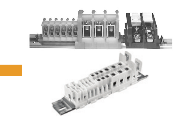
T42-106 Logic Control Products CA08100001K—June 2012 www.eatoncanada.ca
42
42
42
42
42
42
42
42
42
42
42
42
42
42
42
42
42
42
42
42
42
42
42
42
42
42
42
42
42
42
42.2
Terminal Blocks, Fuse Blocks and Fuse Holders
NEMA
NEMA Contents
Description Page
NEMA
C381 Series Terminal Blocks, Rail Mounted . . . . . T42-107
TB Series Terminal Blocks, Modular . . . . . . . . . . . . T42-111
NEMA Overview
Product Description
NEMA terminal blocks
provide a panel or DIN rail
mount block that can be
assembled from modular
pieces. These blocks
accommodate wire from
22 to 1/0 AWG and up to
175A and 600V.
Standards and Certifications
●UL File #E67464 and
#E56797
Tab42book.fm Page 106 Thursday, July 5, 2012 8:03 PM
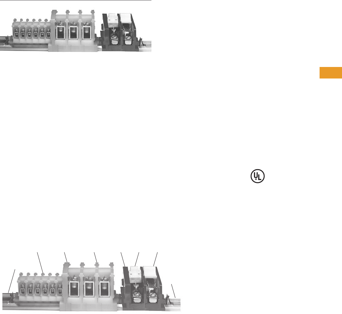
Logic Control Products CA08100001K—June 2012 www.eatoncanada.ca T42-107
42
42
42
42
42
42
42
42
42
42
42
42
42
42
42
42
42
42
42
42
42
42
42
42
42
42
42
42
42
42
42.2
Terminal Blocks, Fuse Blocks and Fuse Holders
NEMA
C381 Series Terminal Blocks, Rail Mounted Contents
Description Page
C381 Series Terminal Blocks, Rail Mounted
Product Selection . . . . . . . . . . . . . . . . . . . . . . . . . . T42-108
Accessories . . . . . . . . . . . . . . . . . . . . . . . . . . . . . . T42-109
Modifications . . . . . . . . . . . . . . . . . . . . . . . . . . . . . T42-109
Technical Data and Specifications . . . . . . . . . . . . . T42-110
Dimensions . . . . . . . . . . . . . . . . . . . . . . . . . . . . . . T42-110
TB Series Terminal Blocks, Modular. . . . . . . . . . . . . . . T42-111
C381 Series Terminal Blocks, Rail Mounted
Product Description
●600V
●Snap-fit nylon sections
●Control circuit blocks
●Power circuit blocks
●Fuse blocks
●Switch blocks
●Sections can be
interlocked in any quantity
and any mixture for direct
panel mounting or channel
mounting
●Three terminal choices in
control circuit blocks, up to
32 circuits per foot
●Power circuit blocks for
heavy-duty applications, up
to 16 circuits per foot
●Fuse blocks accommodate
any 0.406 x 1.5 in (10.3 x
38.1 mm) ferrule type
cartridge fuse up to 30A
●Switch blocks have
removable blade for extra
safety
Standards and Certifications
●UL File #E67464
A Typical Mixture of Control Circuit Blocks, Power Blocks, Switch and
Fuse Blocks in a Mounting Channel
C381PEC381TP C381PT C381EF C381SB C381FB
C381MC
C381CC
Tab42book.fm Page 107 Thursday, July 5, 2012 8:03 PM
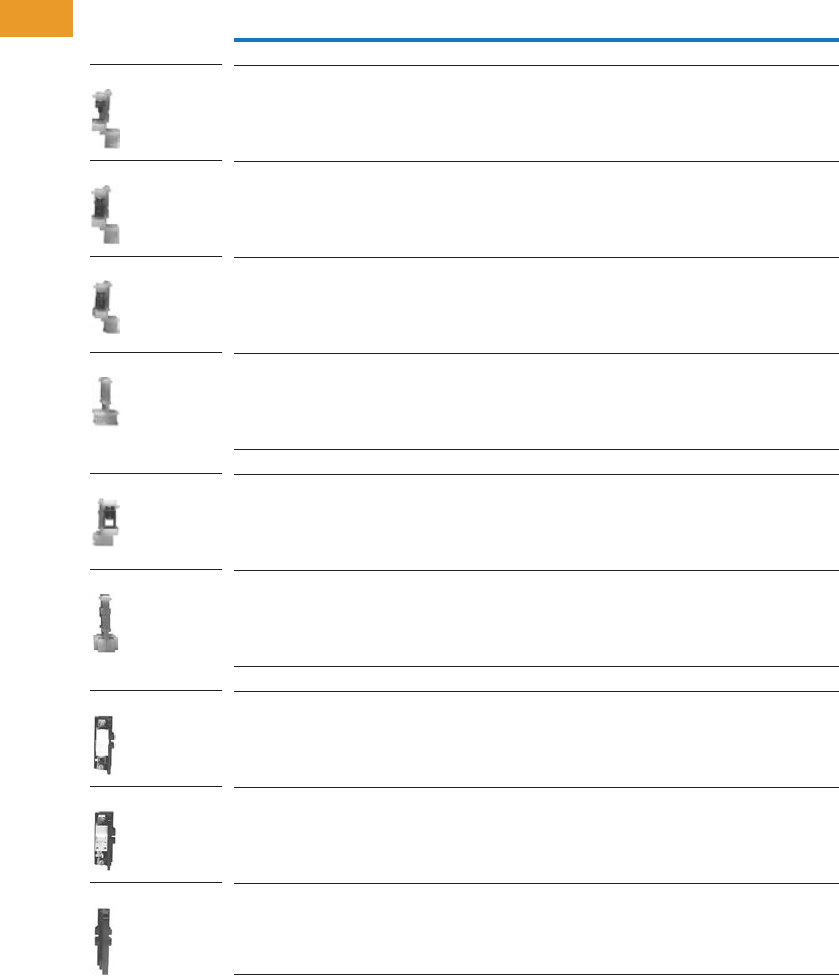
T42-108 Logic Control Products CA08100001K—June 2012 www.eatoncanada.ca
42
42
42
42
42
42
42
42
42
42
42
42
42
42
42
42
42
42
42
42
42
42
42
42
42
42
42
42
42
42
42.2
Terminal Blocks, Fuse Blocks and Fuse Holders
NEMA
Product Selection
When Ordering Specify
Catalogue number and
quantity, which must be in a
multiple of the available
minimum standard package.
Examples:
●200 Cat. No. C381ST
●20 Cat. No. C381PT
●100 Cat. No. C381CC
Catalogue number and
quantity of end sections also
in minimum quantity standard
package.
Example:
●25 Cat. No. C381ES.
Control, Power, Switch and Fuse Blocks
Notes
Available only in minimum quantity standard packages.
Must be ordered in standard package quantity or in multiples of these quantities.
Description
AWG
Wire Size
Standard
Pack
Catalogue
Number
Control Circuit Terminal Blocks—Rated 50A
Type ST (screw terminal) 22–14 AWG 100 C381ST
Type TP (tubular pressure plt) 22–10 100 C381TP
Type TS (tubular screw) end section 18–8 100 C381TS
End section — 25 C381ES
Power Circuit Terminal Blocks—Rated 155A
Type PT (tubular screw) 10–1/0 10 C381PT
End section — 10 C381PE
Switch Blocks—Rated 15A and Fuse Blocks—Rated 30A
Switch blocks 18–8 10 C381SB
Fuse blocks 18–8 10 C381FB
End section — 10 C381EF
C381ST
C381TP
C381TS
C381ES
C381PT
C381PE
C381SB
C381FB
C381EF
Tab42book.fm Page 108 Thursday, July 5, 2012 8:03 PM
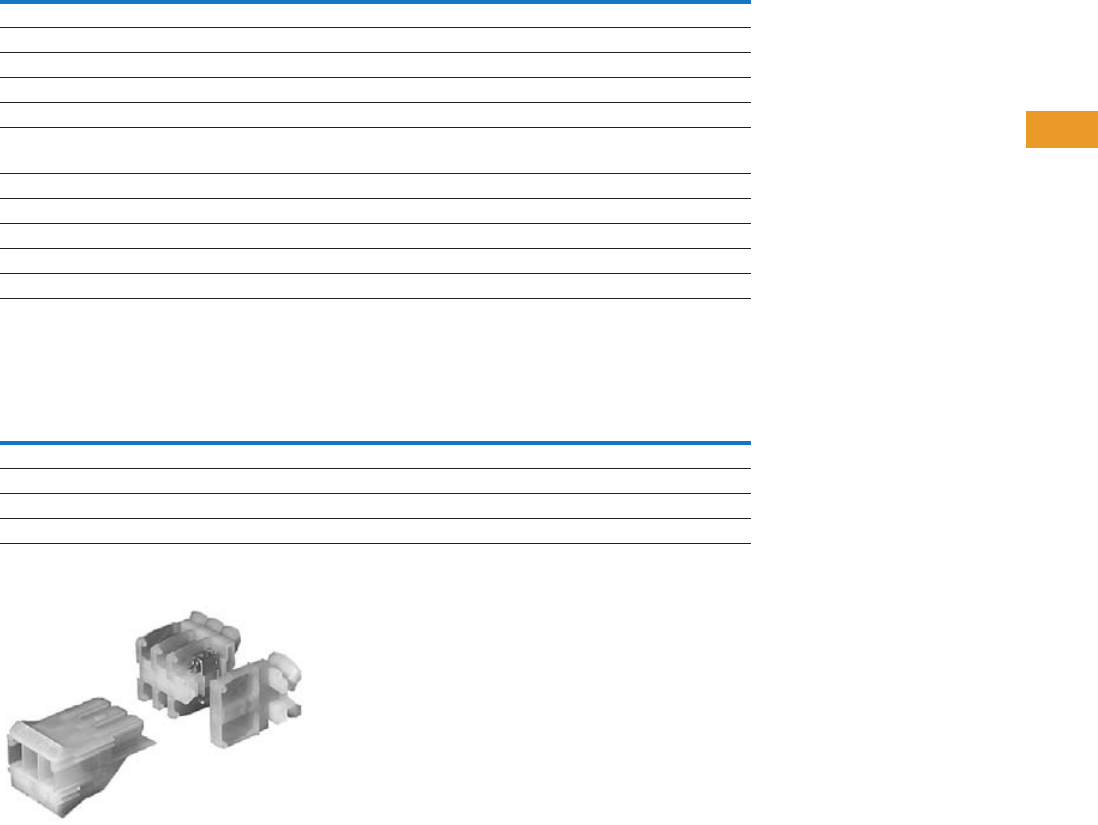
Logic Control Products CA08100001K—June 2012 www.eatoncanada.ca T42-109
42
42
42
42
42
42
42
42
42
42
42
42
42
42
42
42
42
42
42
42
42
42
42
42
42
42
42
42
42
42
42.2
Terminal Blocks, Fuse Blocks and Fuse Holders
NEMA
Accessories
C381 Series Terminal Blocks, Rail Mounted
Modifications
Pull Apart Terminal Blocks
Pull Apart Terminal Blocks
Illustrates: One–Three-Pole Movable Section,
Three–One-Pole Stationary Sections and One–End Piece
Notes
Available only in minimum quantity standard packages.
Must be ordered in standard package quantity or in multiples of these quantities.
C381CC is a snap-in, one time use disposable type. C381VC can be readjusted or reused as desired.
For use on adjacent Type TP and/or TS control circuit sections.
May be used on section covers or to gang fuse and/or switch blocks.
L shaped plug installs in end of stationary section, Catalogue Number C381PS, and prevents incorrect installation of movable section, Catalogue Number C381PM.
Description
Standard
Pack
Catalogue
Number
Aluminum mounting channel—6 ft (1.8m) lengths 25 C381MC
Screw type channel clamp (one required each end) 100 C381VC
Spring type channel clamp (one required each end) 100 C381CC
Vinyl marking strip—3/8 in x 25 ft (9.5 mm x 7.6m) coil 1 C381MS
Marking paper—pressure sensitive—5/16 x 11-11/16 in (7.9 x 296.9 mm), 24 strips/sheet 5 sheets C381MP
Marking strip retainer (one required/grouping)
For use on control circuit blocks 100 C381SR
For use on power circuit blocks 100 C381SP
Fanning strip—for type TP and/or TS 50 C381TF
Fanning strip—for type ST 50 C381SF
Terminal jumper (two-pole) 100 C381TJ
Ganging rod—1/8 in x 6 in (3.2 mm x 152.4 mm) 10 C381GR
Description
AWG
Wire Size
Standard
Pack
Catalogue
Number
One-pole stationary section (tubular pressure plt) 22–10 100 C381PS
Three-pole movable section (tubular pressure plt) 22–10 12 C381PM
End section — 25 C381ES
Polarizing plug (promotes alignment of poles) — 100 C381PP
Tab42book.fm Page 109 Thursday, July 5, 2012 8:03 PM
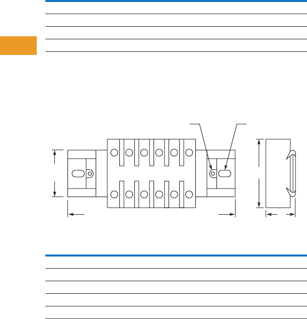
T42-110 Logic Control Products CA08100001K—June 2012 www.eatoncanada.ca
42
42
42
42
42
42
42
42
42
42
42
42
42
42
42
42
42
42
42
42
42
42
42
42
42
42
42
42
42
42
42.2
Terminal Blocks, Fuse Blocks and Fuse Holders
NEMA
Technical Data and Specifications
Formulas for Calculating Blocks and Channel Lengths
N = Number of Blocks
C381 Series Terminal Blocks, Rail Mounted
Dimensions
Approximate Dimensions in Inches (mm)
C381 Series Terminal Blocks, Rail Mounted
Description Blocks Length
Control blocks and pull apart blocks 0.762 + (0.375 x N)
Power circuit blocks 0.812 + (0.750 x N)
Fuse and switch blocks 0.812 + (0.755 x N)
Mounting channel (minimum channel length) 0.75 + blocks length
Block A B
Control circuit blocks 1.25 (31.8) 1.55 (39.4)
Power circuit blocks 1.75 (44.5) 2.00 (50.8)
Fuse blocks 2.75 (69.9) 2.00 (50.8)
Switch blocks 2.75 (69.9) 2.00 (50.8)
Pull apart blocks 1.88 (47.8) 2.75 (69.9)
A
1.19
(30.2)
Channel
Mounting
Terminal Block Mounting
Without Channel
B
Mounting Channel in 6' (1.8m) Lengths,
Can Be Cut to Desired Length
Tab42book.fm Page 110 Thursday, July 5, 2012 8:03 PM
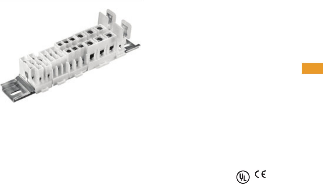
Logic Control Products CA08100001K—June 2012 www.eatoncanada.ca T42-111
42
42
42
42
42
42
42
42
42
42
42
42
42
42
42
42
42
42
42
42
42
42
42
42
42
42
42
42
42
42
42.2
Terminal Blocks, Fuse Blocks and Fuse Holders
NEMA
TB Series Terminal Blocks, Modular Contents
Description Page
C381 Series Terminal Blocks, Rail Mounted . . . . . . . . T42-107
TB Series Terminal Blocks, Modular
Product Selection . . . . . . . . . . . . . . . . . . . . . . . . . . T42-112
Accessories . . . . . . . . . . . . . . . . . . . . . . . . . . . . . . T42-113
Technical Data and Specifications . . . . . . . . . . . . . T42-114
Dimensions . . . . . . . . . . . . . . . . . . . . . . . . . . . . . . T42-115
TB Series Terminal Blocks, Modular
Product Description
TBA and TBD modular terminal
blocks are designed to
conserve space, while
allowing maximum flexibility
and ease of installation.
Available as one-, two- and
three-pole circuits, simple
and uniform installation is
possible because their
design is based on 5/8 in
(15.9 mm) modules. Standard
blocks are white nylon.
Breathing Action
Clamping Collar
The unique design of the
clamping collar permits the
collar to breathe as the wire
expands and contracts,
maintaining a constant
and permanent clamping
pressure. This eliminates
loose connections resulting
from the gradual flattening
of conductors and joint
deterioration caused by
heating and cooling cycles.
Features
Blocks—Design Features
●Compact design permits
mounting 48–600V or
90–300V terminals per foot
●Fully shielded construction,
600V spacings
●Nylon construction
provides anti-tracking and
impact resistance
●TBA types are available
in rail mounted, base
mounted and power
distribution types
●Terminal blocks easily snap
on or off mounting rails;
not necessary to disturb
adjacent units
●No end pieces or backing
plates are needed when
rail mounting
●A 12 circuit subminiature
blocks, rated 20A at 300V,
is available for “high
density” applications
●Popular blocks are also
available in dual mount for
use with standard TBA or
35 mm DIN rails
Terminals—Design Features
●Insulated walls of lug
guide wire into lug
●Blocks are shipped
with clamping screw
backed out
●Constant locking torque
keeps terminal screws in
position
●Terminal screws are captive;
cannot be lost in shipment
or handling
●Hardened stainless steel
clamping collar eliminates
stripped threads
●Large opening in clamping
collar accommodates
oversized conductors;
smallest collar will accept
three 14 AWG stranded
conductors
Standards and Certifications
●UL recognized: File No.
E56797
●CE approved
Tab42book.fm Page 111 Thursday, July 5, 2012 8:03 PM
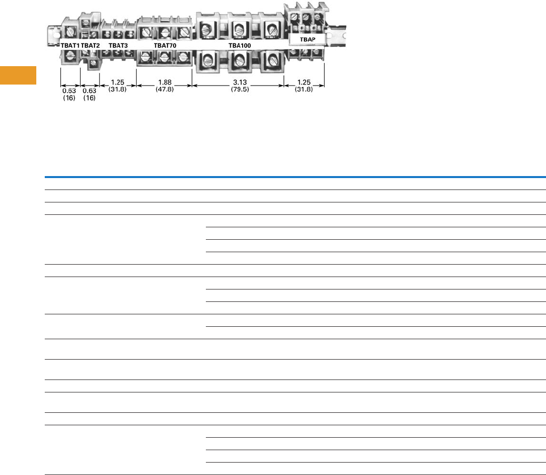
T42-112 Logic Control Products CA08100001K—June 2012 www.eatoncanada.ca
42
42
42
42
42
42
42
42
42
42
42
42
42
42
42
42
42
42
42
42
42
42
42
42
42
42
42
42
42
42
42.2
Terminal Blocks, Fuse Blocks and Fuse Holders
NEMA
Product Selection
TBA Modular Terminal Blocks
Rail and Base Mounted Terminal Blocks
Notes
Based on 50˚C rise, test at 25˚C ambient while using maximum wire size.
Must be ordered in standard package quantity or in multiples of these quantities.
Dual mounting blocks—mount on either TMR/TBA rail or 35 mm DIN rail.
May also be mounted on mini-DIN rail (15 mm). Catalogue Number C383TS15.
May also be base mounted.
TBU Series = 60A with crimped wire.
Description
AWG
Wire Size
Number
of Poles
Ampacity
(per Circuit)
Carton
Quantity
TBA Rail DIN Rail
Catalogue
Number
Catalogue
Number
Rail Mounted—600V
Subminiature blocks (2) 14–12 12 5A 100 TBDSM12 TBDSM12
Miniature blocks 22–10 4 30A 100 TBDV4 TBDV4
Standard blocks—screw terminals
with tang clamping collars
18–2 1 90A 100 — TBDT1
22–8 2 40A 100 TBAT2 —
22–8 3 40A 20 TBAT3-20 TBDT3-20
18–4 3 90A 100 TBDT70 TBDT70
High current blocks 14–2/0 3 175A 12 TBA100 —
Standard blocks—plug-in terminals 22–8 3 40A 20 TBAP —
18–4 3 70A 20 TBAP70 —
14–8 3 40A 20 TBAPL70 —
Panel mount blocks 22–10 3 30A 100 TBAL30 —
8–4 3 115A 12 TBAL90 —
Disconnect blocks—for 1/4 in (6.4 mm) dia.
by 1–1-7/16 in (25.4–36.5 mm) fuse
22–8 1 30A 50 TBAD —
Fuse blocks—for 13/32 in (10.3 mm) dia.
by 1-1/2 in (38.1 mm) fuse
22–8 1 30A 50 TBDTF TBDTF
Base Mounted—600V
Miniature blocks—screw terminals
with tang clamping collars
22–10 4 30A (600V) 90 TBBT4 —
Standard blocks—standard screw terminals 22–8 3 40A 80 TBABT3 —
Universal mounting blocks 8 maximum 4 50A 25 TBU4 —
8 maximum 6 50A 60 TBU6 —
8 maximum 8 50A 45 TBU8 —
8 maximum 12 50A 35 TBU12 —
Tab42book.fm Page 112 Thursday, July 5, 2012 8:03 PM

Logic Control Products CA08100001K—June 2012 www.eatoncanada.ca T42-113
42
42
42
42
42
42
42
42
42
42
42
42
42
42
42
42
42
42
42
42
42
42
42
42
42
42
42
42
42
42
42.2
Terminal Blocks, Fuse Blocks and Fuse Holders
NEMA
Accessories
TB Series Terminal Blocks, Modular
Notes
Length in inches (mm) except as noted.
Must be ordered in standard package quantity or in multiples of these quantities.
Description Length
Number
of Poles
Carton
Quantity
Catalogue
Number
Mounting Rail
Aluminum 12.5 (317.5) — 25 TMR12
37.5 (952.5) — 25 TMR37
72.0 (1828.8) — 25 TBATR72
35 mm DIN—steel 1m — 20 MC382MA1-20
Marking Strips
Miniature blocks—TBDV4 and TBBT4 6.0 (152.4) — 50 TMS6
TBU Series—matte finish 7.5 (190.5) — 25 TMSU
All other blocks 12.5 (317.5) — 50 TMS
Jumpers
TBAT1 and TBAP70 — 2-pole 100 TJ1
TBAT2 — 2-pole 100 TJ2
TBAT3, TBABT3, TBAP and TBBP — 2-pole 100 TJ3
TBDV4 and TBBT4 — 4-pole 100 TJ4
TBAD and TBATF — 2-pole 100 TJ5
TBAL30 — 2-pole 100 TJ6
TBU — 12-pole 10 TJ7
TBDT3 — 2-pole 100 TJ8
Miscellaneous
End piece for TBABT3 and TBBP — — 50 TAD
Lug shield for TBA100 and TBAL90 — — 50 TAS
Fuse puller — — 50 TBP
Lighted fuse puller—blown fuse indication — — 25 TBLP
Tab42book.fm Page 113 Thursday, July 5, 2012 8:03 PM
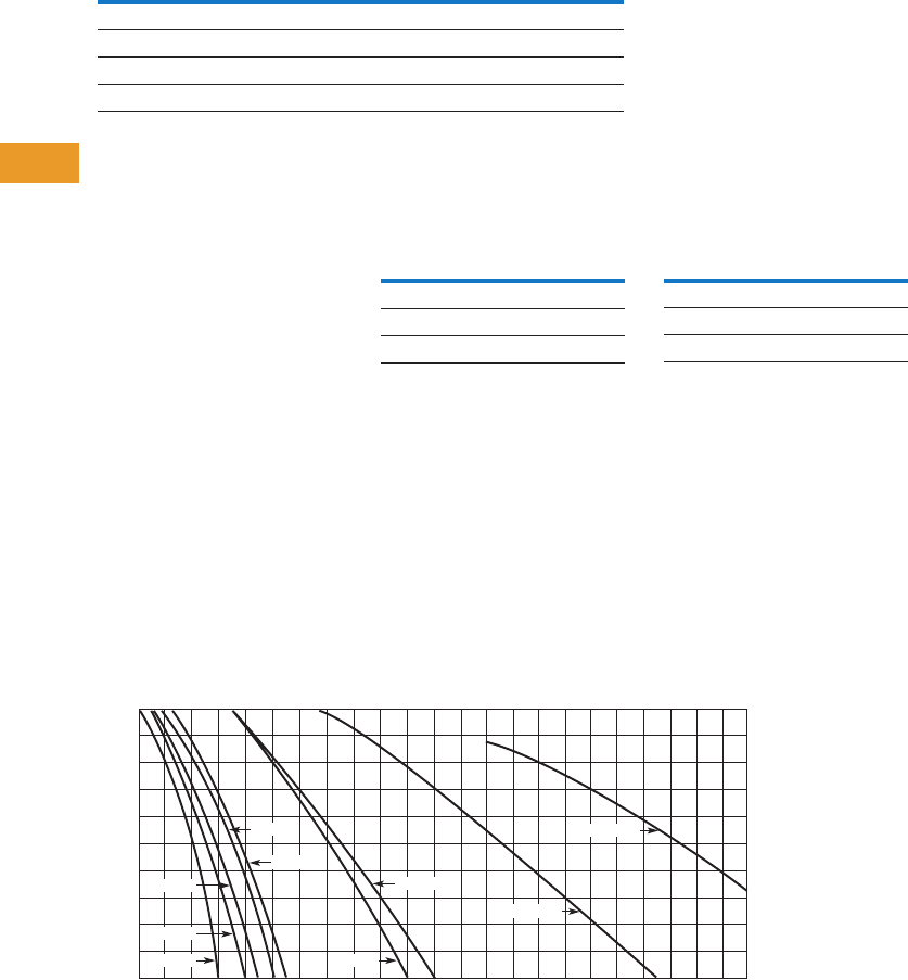
T42-114 Logic Control Products CA08100001K—June 2012 www.eatoncanada.ca
42
42
42
42
42
42
42
42
42
42
42
42
42
42
42
42
42
42
42
42
42
42
42
42
42
42
42
42
42
42
42.2
Terminal Blocks, Fuse Blocks and Fuse Holders
NEMA
Technical Data and Specifications
TB Series Terminal Blocks, Modular
●Chemical resistance to:
●Acetone
●Ammonia gas
●Benzene
●Gasoline
●Mineral oil
●Sodium bisulfate
●Sodium chloride
●Sodium nitrate
●Water up to 50˚C
Flashover Voltages Recommended Terminal
Tightening Torque
To find a current rating, place
a straight edge horizontally at
the value of anticipated
maximum internal panel
ambient (scale on the left),
and read the current rating for
the device on the bottom
scale. Example: at 60˚C,
TBAT3 is rated 54 amperes.
Ampere rating is based
on maximum allowable
temperature—ambient
temperature plus
temperature rise due
to current.
Ratings based on 90˚C total
temperature of a three-pole
block with each pole carrying
current and wired with
largest size conductors.
Temperature Rating
Description Specification
Continuous temperature 212˚F (100˚C)
Tensile strength 10,000–12,000 psi
Impact resistance 2.0 ft-lb/in (arc)
Arc resistance 140 seconds
Vac rms, 60 Hz
Catalogue
Number
Opposite
Polarity To Ground
TBAT1 9100 6600
TBAT2 9600 7300
TBAT3 8600 7300
Wire Size Torque
Up to 8 AWG 20 lb-in
Up to 4 AWG 35 lb-in
Up to 2/0 AWG 50 lb-in
30
20
Ambient Temp. in C°
Temp. Rise in C°
40 60 80 100 120 140 160 180
Current in Amps
200 220 240
40
50
60
70
80
60
50
40
30
20
10
TBAM4 TBAB70
TBAL90
TBAL100
TBAT2
TBAT3
TBAT1
TBAP
TBAL30
Tab42book.fm Page 114 Thursday, July 5, 2012 8:03 PM
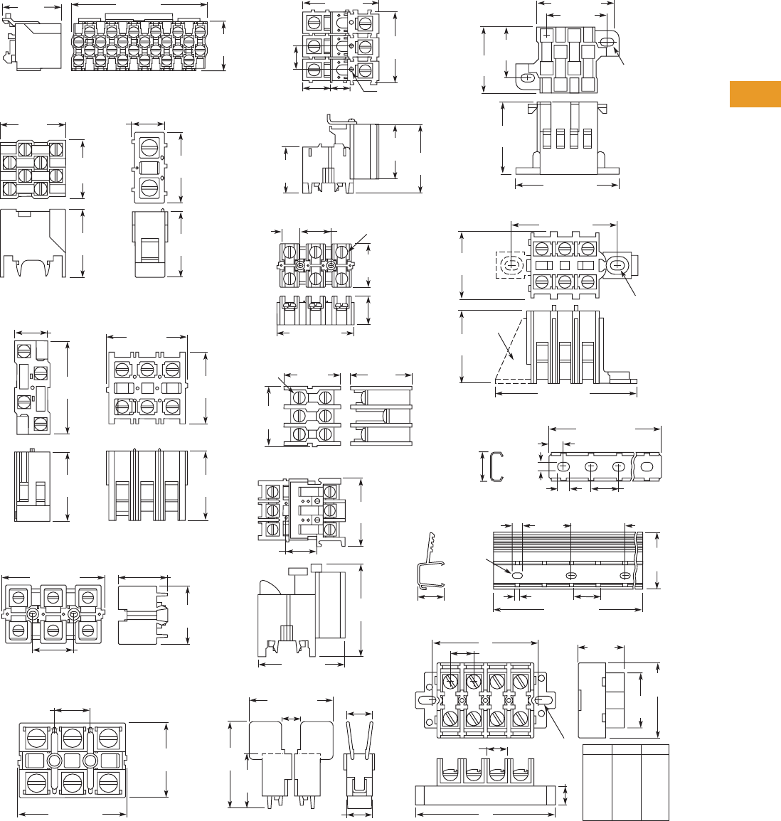
Logic Control Products CA08100001K—June 2012 www.eatoncanada.ca T42-115
42
42
42
42
42
42
42
42
42
42
42
42
42
42
42
42
42
42
42
42
42
42
42
42
42
42
42
42
42
42
42.2
Terminal Blocks, Fuse Blocks and Fuse Holders
NEMA
Dimensions
Approximate Dimensions in Inches (mm)
TB Series Terminal Blocks, Modular
0.88
(22.4)
1.09
(27.7)
TBDSM12
TBAP70 & TBAPL70
2.4 (61)
1.88
(47.8)
0.63
(16)
1.48
(37.6) 1.86
(47.2)
1.25
(31.8)
2 (50.8)
1
(25.4)
TBDV4 TBDT1
TBAT3 & TBDT3
1.25
(31.8)
1.23
(31.2)
1.71
(43.4)
1.3
(33)
0.59
(15)
TBAT2
TBA100
TBDT70
1.69
(42.9)
1.3
(33)
0.63 (16) 1.25
(31.8)
1.34
(34)
1.75
(44.5)
0.63
(16)
3.13 (79.5) 1.53 (38.9)
1.25 (31.8)
TBAL30
1.25
(31.8)
1.25
(31.8)
#6-32
Screw 1.33
(33.8)
1.23
(31.2)
1.3
(33)
TBAP
0.59
(15)
1.25
(31.8)
1.86
(47.2)
1.77 (45)
TBU4, TBU6, TBU8 & TBU12
0.31 (7.9)
0.25 (6.4) 0.63 (16)
0.66
(16.8) 0.19
(4.8)
12.5 – 37.5
(317.5 – 952.5)
TMR12 & TMR37
2
(50.8)
1.5
(38.1)
0.5
(12.7)
1.25
(31.8)
0.63 (16)
#10 Screw
Clearance
B
0.63
(16)
1.23
(31.2)
1.25
(31.8)
1 (25.4)
1.38 (35.1)
1.78 (45.2)
TBBT4
0.17 – 0.28
(4.3 – 7.1)
Clearance for
#8 Screw
0.44 (11.2)
A
1.88 (47.8)
TBAD & TBDTF
2
(50.8)
1.25
(31.8)
0.63 (16)
0.63 (16)
0.47 (11.9)
1.94 (49.3)
3 Holes
0.09 (2.3) Dia.
0.33 (8.4) Deep
0.67
(17) 0.59
(15)
1.75
(44.5)
1/4-28
Screw
TBAL90
1.53
(38.9)
0.63
(16) 1.25
(31.8)
3.13 (79.5)
TBABT3
1.25
(31.8)
1.19
(30.2)
2.47 (62.7)
1.88 (47.8)
0.17 – 0.27
(4.3 – 6.9)
Clearance for
#8 Screw
Footlock
Cat. #TAD
#10 Screw
Clearance 1.31
(33.3)
72 (1828.8)
0.13 (3.3) 0.63 (16)
0.56
(14.2) TBATR72
0.25 (6.4) 1.25 (31.8)
TBU4
TBU6
TBU8
TBU12
3.75
(95.3)
5
(127)
6.25
(158.8)
8.75
(222.3)
2.87
(72.9)
AB
4.12
(104.6)
5.37
(136.4)
7.87
(199.9)
Tab42book.fm Page 115 Thursday, July 5, 2012 8:03 PM
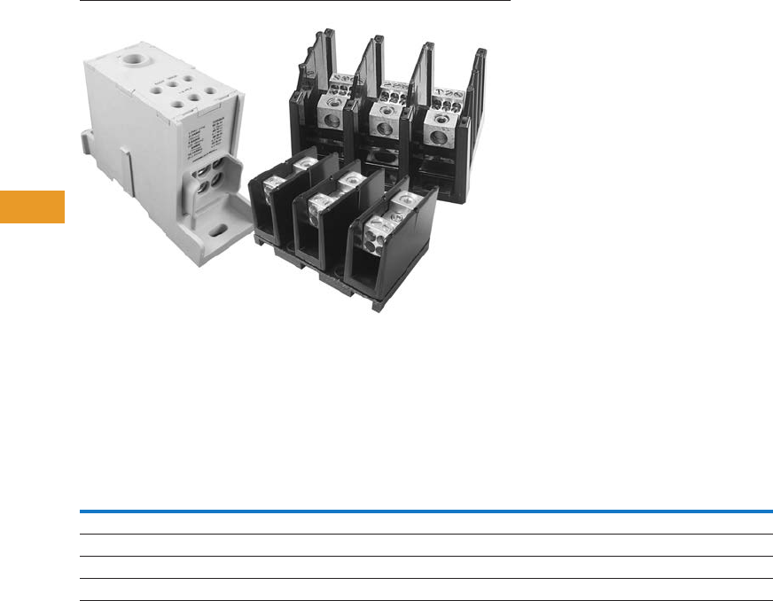
T42-116 Logic Control Products CA08100001K—June 2012 www.eatoncanada.ca
42
42
42
42
42
42
42
42
42
42
42
42
42
42
42
42
42
42
42
42
42
42
42
42
42
42
42
42
42
42
42.3
Terminal Blocks, Fuse Blocks and Fuse Holders
Power Distribution
Power Distribution Products Contents
Description Page
Power Distribution
CHDB Series—Power Distribution Blocks . . . . . . . T42-117
CH160 Series—Power Terminal Blocks . . . . . . . . . T42-123
Power Terminal Block Accessories . . . . . . . . . . . . T42-126
Power Distribution Overview
Product Selection Guide
Notes
Refer to Page T42-118 to determine short circuit current ratings with fuses and Pages T42-119 and T42-120 to determine short circuit current ratings
in conjunction with specific Eaton circuit breakers.
Single-pole units, when installed with proper spacings, may meet requirements for UL 508A feeder circuits.
Series
Current
Range UL Certification
High Short
Circuit Current
Rating
UL 508A Approved for Industrial Control Panels
HVAC UL 1995Branch Circuits Feeder Circuits
CH162 115–175A UL 1059 Recognized No Yes No Yes
CH163 175–420A UL 1059 Recognized No Yes No Yes
CH165 620–840A UL 1059 Recognized No Yes No Yes
CHDB 175–570A UL 1953 Listed Yes Yes Yes Yes
Tab42book.fm Page 116 Thursday, July 5, 2012 8:03 PM

Logic Control Products CA08100001K—June 2012 www.eatoncanada.ca T42-117
42
42
42
42
42
42
42
42
42
42
42
42
42
42
42
42
42
42
42
42
42
42
42
42
42
42
42
42
42
42
42.3
Terminal Blocks, Fuse Blocks and Fuse Holders
Power Distribution
CHDB Series—Power Distribution Blocks, Enclosed and Open Contents
Description Page
CHDB Series—Power Distribution Blocks
Product Selection . . . . . . . . . . . . . . . . . . . . . . . . . . T42-118
Technical Data and Specifications . . . . . . . . . . . . . T42-118
Dimensions . . . . . . . . . . . . . . . . . . . . . . . . . . . . . . T42-121
CH160 Series—Power Terminal Blocks . . . . . . . . . . . T42-123
Power Terminal Block Accessories . . . . . . . . . . . . . . . T42-126
CHDB Series—Power Distribution Blocks
Product Description
Eaton’s CHDB Series of
Power Distribution Blocks
was designed for high short
circuit current rating (SCCR)
applications up to 200,000
amperes. They are assembled
with the minimum spacing to
meet UL 1953 requirements
for feeder circuits in UL 508A
industrial control panels,
and provide significant
wiring flexibility.
Available in three-pole
open style and single-pole
enclosed style with a variety
of terminal arrangements
and current-carrying capability
up to 570 amperes.
Features and Benefits
Enclosed Style
●IP20 finger-safe enclosure
●600 Vac or Vdc (UL 1953),
690 Vac or Vdc
●DIN rail or panel mount
●Captive termination
screws prevent lost
screws
●Single-pole, gang
mountable for multi-pole
applications
●Tin plated Al connections
suitable for Cu conductors
●Flammability, UL 94V-0
Open Style
●600 Vac or Vdc (UL 1953)
●Panel mount
●Three-pole open design for
easy wiring
●Tin-plated Al connections
suitable for Cu conductors
●Flammability, UL 94V-0
●Available covers for
additional protection
(does not meet IP20)
Standards and Certifications
●UL Listed 1953, Guide
QPQS, File E256146
●CSA Certified,
Class 6228-01, File 15364
(enclosed style)
●CE Component
IEC 60947-7-1
(enclosed style)
●IEC 60529, IP20 (finger-
safe) under specific wiring
conditions (enclosed style)
Tab42book.fm Page 117 Thursday, July 5, 2012 8:03 PM
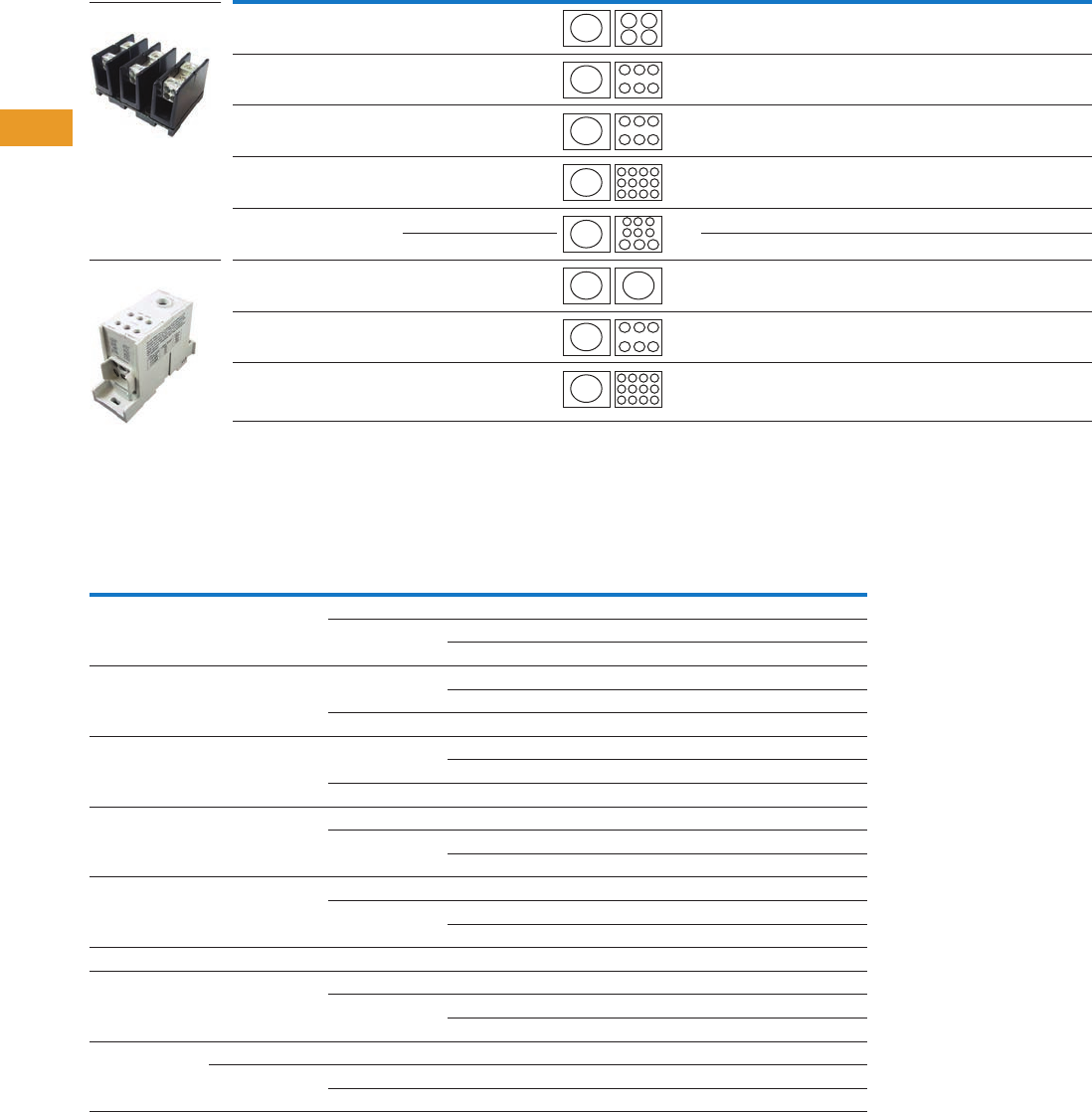
T42-118 Logic Control Products CA08100001K—June 2012 www.eatoncanada.ca
42
42
42
42
42
42
42
42
42
42
42
42
42
42
42
42
42
42
42
42
42
42
42
42
42
42
42
42
42
42
42.3
Terminal Blocks, Fuse Blocks and Fuse Holders
Power Distribution
Product Selection
CHDB Series—Power Distribution Blocks
Technical Data and Specifications
Power Terminal Block Short-Circuit Current Ratings (SCCR) with Fuses
Note
Finger-safe.
Line Connection Load Connection Configuration Amperes Style Poles
Catalogue
Number
2/0–#8 AWG (4) #4–#14 AWG 175 Open 3 CHDB2203
2/0–#8 AWG (6) #4–#14 AWG 175 Open 3 CHDB3213
300 kcmil–#4 AWG (6) #4–#12 AWG 310 Open 3 CHDB3233
300 kcmil–#4 AWG (12) #4–#14 AWG 310 Open 3 CHDB3703
300 kcmil–#4 AWG (6) #2–#12 AWG 310 Open 3 CHDB3713
(3) 1/0–#12 AWG 310 Open 3 CHDB3713
2/0–#8 AWG 2/0–#8 AWG 175 Enclosed 1CHDB204F
500 kcmil–#6 AWG (6) #2–#14 AWG 380 Enclosed 1CHDB330F
300 kcmil–#4 AWG (12) #4–#14 AWG 570 Enclosed 1CHDB377F
Catalogue
Number
Terminal Copper Conductors
Maximum Fuse Class and Amperes
J T RK-1 RK-5
SCCR (kA)Line Load LPJ JJS/JJN LPS-RK/LPN-RK FRS-R/FRN-R
CHDB2203 2/0–#8 AWG #4–#12 AWG 200 200 200 60 200
#4–#14 AWG 175 175 100 60 100
200 200 100 60 50
CHDB3213 2/0–#8 AWG #4–#12 AWG 400 400 200 100 200
400 400 400 100 100
#4–#14 AWG 175 175 100 60 100
CHDB3233 300 kcmil–#4 AWG #4–#8 AWG 400 400 200 100 200
400 400 400 100 100
#4–#12 AWG 175 175 100 60 100
CHDB3703 300 kcmil–#4 AWG #4–#8 AWG 400 400 200 100 200
#4–#14 AWG 400 400 400 100 100
175 175 100 60 100
CHDB3713 300 kcmil–#4 AWG 1/0–#6 AWG 400 400 200 100 200
#4–#12 AWG 400 400 400 100 100
175 175 100 60 100
CHDB204F 2/0–#8 AWG 2/0–#8 AWG 200 200 100 60 200
CHDB330F 500 kcmil–#6 AWG #2–#6 AWG 400 400 200 100 200
#2–#14 AWG 200 200 100 30 50
175 175 100 30 100
CHDB377F 300 kcmil #4–#8 AWG 600 600 400 200 200
300 kcmil–#4 AWG #4 AWG 600 600 400 200 50
#4–#14 AWG 200 200 100 30 50
CHDB2203 (Open)
CHDB204F (Enclosed)
Tab42book.fm Page 118 Thursday, July 5, 2012 8:03 PM
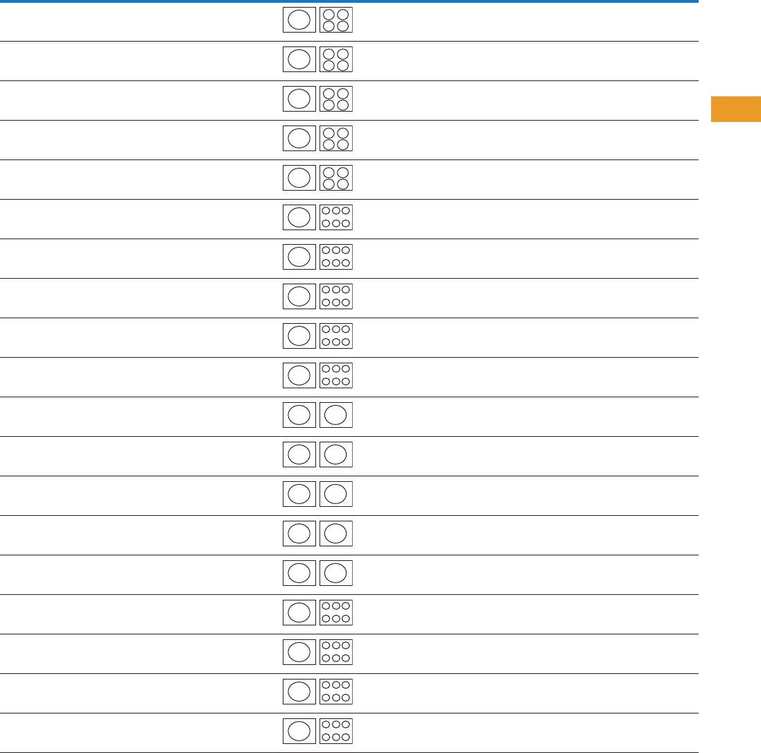
Logic Control Products CA08100001K—June 2012 www.eatoncanada.ca T42-119
42
42
42
42
42
42
42
42
42
42
42
42
42
42
42
42
42
42
42
42
42
42
42
42
42
42
42
42
42
42
42.3
Terminal Blocks, Fuse Blocks and Fuse Holders
Power Distribution
Power Terminal Block Short-Circuit Ratings (SCCR) for UL 508A Applications with Circuit Breakers
Note
This breaker frame is marked current limiting and suitable for use as current limiting per UL 508A SB.4.3.2.
Catalogue
Number Description
Enclosure Size in
Inches (mm)
Current
Rating
Opening per Pole Line
Conductors
Cu
Load
Conductors
Cu
SCCR @ 480V
(Load Side)
Eaton
Breaker
Available Breaker
Current RatingsLine Load
CHDB2203 Feeder Listed
Open PDB
16.00 x 16.00 x 6.75
(406.4 x 406.4 x 171.5)
175 2/0–#8 #4–#10
#12
#14
18 kA
18 kA
14 kA
EGB125 15, 20, 25, 30, 35, 40,
45, 50, 60, 70, 80, 90,
100, 125
CHDB2203 Feeder Listed
Open PDB
16.00 x 16.00 x 6.75
(406.4 x 406.4 x 171.5)
175 2/0–#8 #4–#10
#12
#14
25 kA
22 kA
14 kA
EGE125 15, 20, 25, 30, 35, 40,
45, 50, 60, 70, 80, 90,
100, 125
CHDB2203 Feeder Listed
Open PDB
16.00 x 16.00 x 6.75
(406.4 x 406.4 x 171.5)
175 2/0–#8 #4–#10
#12
#14
50 kA
22 kA
14 kA
EGS125 15, 20, 25, 30, 35, 40,
45, 50, 60, 70, 80, 90,
100, 125
CHDB2203 Feeder Listed
Open PDB
16.00 x 16.00 x 6.75
(406.4 x 406.4 x 171.5)
175 2/0–#8 #4–#10
#12
#14
65 kA
22 kA
14 kA
EGH125 15, 20, 25, 30, 35, 40,
45, 50, 60, 70, 80, 90,
100, 125
CHDB2203 Feeder Listed
Open PDB
16.00 x 16.00 x 6.75
(406.4 x 406.4 x 171.5)
175 2/0–#8 #4–#10
#12
#14
65 kA
22 kA
14 kA
EGC125 15, 20, 25, 30, 35, 40,
45, 50, 60, 70, 80, 90,
100, 125
CHDB3213 Feeder Listed
Open PDB
24.00 x 20.00 x 6.75
(609.6 x 508.0 x 171.5)
175 2/0–#8 #4–#10
#12
#14
18 kA
18 kA
18 kA
EGB125 15, 20, 25, 30, 35, 40,
45, 50, 60, 70, 80, 90,
100, 125
CHDB3213 Feeder Listed
Open PDB
24.00 x 20.00 x 6.75
(609.6 x 508.0 x 171.5)
175 2/0–#8 #4–#10
#12
#14
25 kA
22 kA
18 kA
EGE125 15, 20, 25, 30, 35, 40,
45, 50, 60, 70, 80, 90,
100, 125
CHDB3213 Feeder Listed
Open PDB
24.00 x 20.00 x 6.75
(609.6 x 508.0 x 171.5)
175 2/0–#8 #4–#10
#12
#14
50 kA
22 kA
18 kA
EGS125 15, 20, 25, 30, 35, 40,
45, 50, 60, 70, 80, 90,
100, 125
CHDB3213 Feeder Listed
Open PDB
24.00 x 20.00 x 6.75
(609.6 x 508.0 x 171.5)
175 2/0–#8 #4–#10
#12
#14
65 kA
22 kA
18 kA
EGH125 15, 20, 25, 30, 35, 40,
45, 50, 60, 70, 80, 90,
100, 125
CHDB3213 Feeder Listed
Open PDB
24.00 x 20.00 x 6.75
(609.6 x 508.0 x 171.5)
175 2/0–#8 #4–#10
#12
#14
65 kA
22 kA
18 kA
EGC125 15, 20, 25, 30, 35, 40,
45, 50, 60, 70, 80, 90,
100, 125
CHDB204F Feeder Listed
Enclosed PDB
16.00 x 16.00 x 6.75
(406.4 x 406.4 x 171.5)
175 2/0–#8 2/0–#8 18 kA EGB125 15, 20, 25, 30, 35, 40,
45, 50, 60, 70, 80, 90,
100, 125
CHDB204F Feeder Listed
Enclosed PDB
16.00 x 16.00 x 6.75
(406.4 x 406.4 x 171.5)
175 2/0–#8 2/0–#8 25 kA EGE125 15, 20, 25, 30, 35, 40,
45, 50, 60, 70, 80, 90,
100, 125
CHDB204F Feeder Listed
Enclosed PDB
16.00 x 16.00 x 6.75
(406.4 x 406.4 x 171.5)
175 2/0–#8 2/0–#8 35 kA EGS125 15, 20, 25, 30, 35, 40,
45, 50, 60, 70, 80, 90,
100, 125
CHDB204F Feeder Listed
Enclosed PDB
16.00 x 16.00 x 6.75
(406.4 x 406.4 x 171.5)
175 2/0–#8 2/0–#8 65 kA EGH125 15, 20, 25, 30, 35, 40,
45, 50, 60, 70, 80, 90,
100, 125
CHDB204F Feeder Listed
Enclosed PDB
16.00 x 16.00 x 6.75
(406.4 x 406.4 x 171.5)
175 2/0–#8 2/0–#8 65 kA EGC125 15, 20, 25, 30, 35, 40,
45, 50, 60, 70, 80, 90,
100, 125
CHDB3233 Feeder Listed
Open PDB
24.00 x 20.00 x 6.75
(609.6 x 508.0 x 171.5)
310 350 kmil–#4 #4–#6
#8
#10
25 kA
25 kA
14 kA
JGE250 70, 90, 100, 125, 150,
175, 200, 225, 250
CHDB3233 Feeder Listed
Open PDB
24.00 x 20.00 x 6.75
(609.6 x 508.0 x 171.5)
310 350 kmil–#4 #4–#6
#8
#10
35 kA
35 kA
14 kA
JGS250 70, 90, 100, 125, 150,
175, 200, 225, 250
CHDB3233 Feeder Listed
Open PDB
24.00 x 20.00 x 6.75
(609.6 x 508.0 x 171.5)
310 350 kmil–#4 #4–#6
#8
#10
65 kA
42 kA
14 kA
JGH250 70, 90, 100, 125, 150,
175, 200, 225, 250
CHDB3233 Feeder Listed
Open PDB
24.00 x 20.00 x 6.75
(609.6 x 508.0 x 171.5)
310 350 kmil–#4 #4–#6
#8
#10
65 kA
42 kA
25 kA
JGC250 70, 90, 100, 125, 150,
175, 200, 225, 250
Tab42book.fm Page 119 Thursday, July 5, 2012 8:03 PM
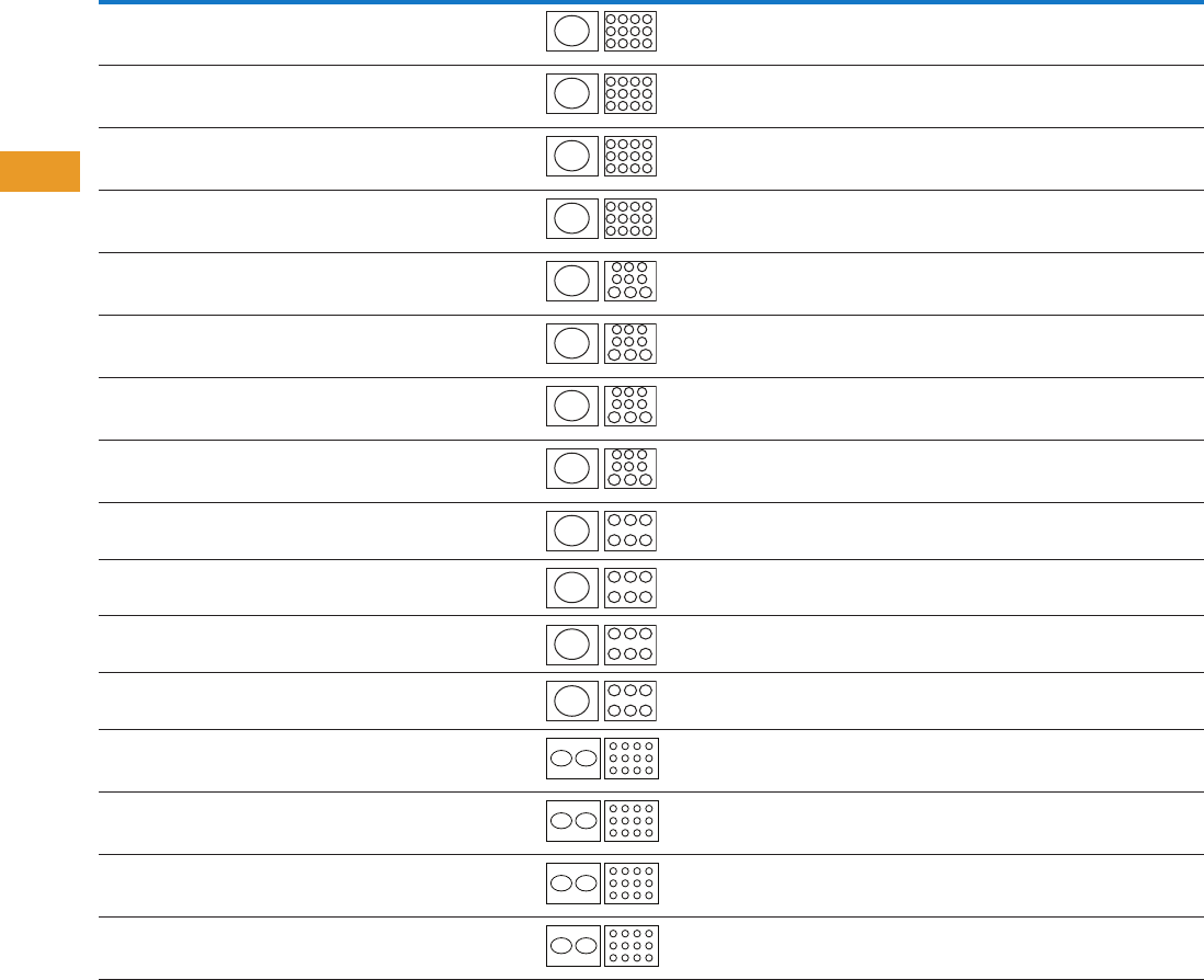
T42-120 Logic Control Products CA08100001K—June 2012 www.eatoncanada.ca
42
42
42
42
42
42
42
42
42
42
42
42
42
42
42
42
42
42
42
42
42
42
42
42
42
42
42
42
42
42
42.3
Terminal Blocks, Fuse Blocks and Fuse Holders
Power Distribution
Power Terminal Block Short-Circuit Ratings (SCCR) for UL 508A Applications with Circuit Breakers, continued
Note
This breaker frame is marked current limiting and suitable for use as current limiting per UL 508A SB.4.3.2.
Catalogue
Number Description
Enclosure Size in
Inches (mm)
Current
Rating
Opening per Pole Line
Conductors
Cu
Load
Conductors
Cu
SCCR at 480V
(Load Side)
Eaton
Breaker
Available Breaker
Current RatingsLine Load
CHDB3703 Feeder Listed
Open PDB
24.00 x 20.00 x 6.75
(609.6 x 508.0 x 171.5)
310 350 kmil–#4 #4–#6
#8
#10
25 kA
25 kA
14 kA
JGE250 70, 90, 100, 125, 150,
175, 200, 225, 250
CHDB3703 Feeder Listed
Open PDB
24.00 x 20.00 x 6.75
(609.6 x 508.0 x 171.5)
310 350 kmil–#4 #4–#6
#8
#10
35 kA
35 kA
14 kA
JGS250 70, 90, 100, 125, 150,
175, 200, 225, 250
CHDB3703 Feeder Listed
Open PDB
24.00 x 20.00 x 6.75
(609.6 x 508.0 x 171.5)
310 350 kmil–#4 #4–#6
#8
#10
65 kA
42 kA
14 kA
JGH250 70, 90, 100, 125, 150,
175, 200, 225, 250
CHDB3703 Feeder Listed
Open PDB
24.00 x 20.00 x 6.75
(609.6 x 508.0 x 171.5)
310 350 kmil–#4 #4–#6
#8
#10
65 kA
42 kA
25 kA
JGC250 70, 90, 100, 125, 150,
175, 200, 225, 250
CHDB3713 Feeder Listed
Open PDB
24.00 x 20.00 x 6.75
(609.6 x 508.0 x 171.5)
310 350 kmil–#4 #4–#6
#8
#10
25 kA
25 kA
14 kA
JGE250 70, 90, 100, 125, 150,
175, 200, 225, 250
CHDB3713 Feeder Listed
Open PDB
24.00 x 20.00 x 6.75
(609.6 x 508.0 x 171.5)
310 350 kmil–#4 #4–#6
#8
#10
35 kA
35 kA
14 kA
JGS250 70, 90, 100, 125, 150,
175, 200, 225, 250
CHDB3713 Feeder Listed
Open PDB
24.00 x 20.00 x 6.75
(609.6 x 508.0 x 171.5)
310 350 kmil–#4 #4–#6
#8
#10
50 kA
42 kA
14 kA
JGH250 70, 90, 100, 125, 150,
175, 200, 225, 250
CHDB3713 Feeder Listed
Open PDB
24.00 x 20.00 x 6.75
(609.6 x 508.0 x 171.5)
310 350 kmil–#4 #4–#6
#8
#10
65 kA
50 kA
25 kA
JGC250 70, 90, 100, 125, 150,
175, 200, 225, 250
CHDB330F Feeder Listed
Enclosed PDB
24.00 x 20.00 x 6.75
(609.6 x 508.0 x 171.5)
380 500 kmil–#3 #2–#8 14 kA LGE400 250, 300, 350, 400
CHDB330F Feeder Listed
Enclosed PDB
24.00 x 20.00 x 6.75
(609.6 x 508.0 x 171.5)
380 500 kmil–#3 #2–#8 14 kA LGS400 250, 300, 350, 400
CHDB330F Feeder Listed
Enclosed PDB
24.00 x 20.00 x 6.75
(609.6 x 508.0 x 171.5)
380 500 kmil–#3 #2–#8 14 kA LGH400 250, 300, 350, 400
CHDB330F Feeder Listed
Enclosed PDB
24.00 x 20.00 x 6.75
(609.6 x 508.0 x 171.5)
380 500 kmil–#3 #2–#8 25 kA LGC400 250, 300, 350, 400
CHDB377F Feeder Listed
Enclosed PDB
24.00 x 20.00 x 6.75
(609.6 x 508.0 x 171.5)
570 (2) 300 kmil–#2 #4
#6
#8
30 kA
18 kA
14 kA
LGE600 250, 300, 350, 400,
500, 600
CHDB377F Feeder Listed
Enclosed PDB
24.00 x 20.00 x 6.75
(609.6 x 508.0 x 171.5)
570 (2) 300 kmil–#2 #4
#6
#8
30 kA
18 kA
14 kA
LGS600 250, 300, 350, 400,
500, 600
CHDB377F Feeder Listed
Enclosed PDB
24.00 x 20.00 x 6.75
(609.6 x 508.0 x 171.5)
570 (2) 300 kmil–#2 #4
#6
#8
30 kA
18 kA
14 kA
LGH600 250, 300, 350, 400,
500, 600
CHDB377F Feeder Listed
Enclosed PDB
24.00 x 20.00 x 6.75
(609.6 x 508.0 x 171.5)
570 (2) 300 kmil–#2 #4
#6
#8
42 kA
35 kA
14 kA
LGC600 250, 300, 350, 400,
500, 600
Tab42book.fm Page 120 Thursday, July 5, 2012 8:03 PM
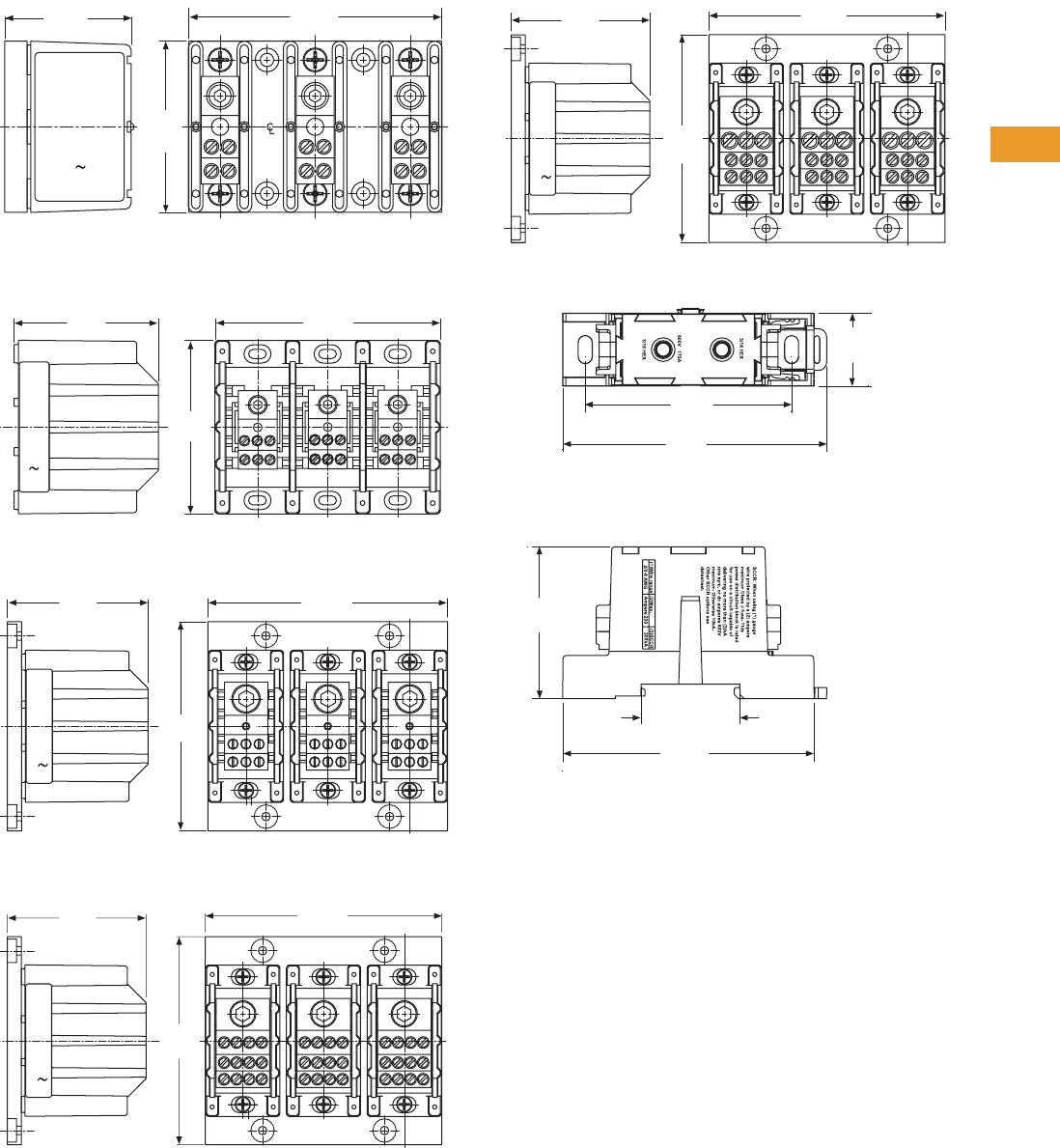
Logic Control Products CA08100001K—June 2012 www.eatoncanada.ca T42-121
42
42
42
42
42
42
42
42
42
42
42
42
42
42
42
42
42
42
42
42
42
42
42
42
42
42
42
42
42
42
42.3
Terminal Blocks, Fuse Blocks and Fuse Holders
Power Distribution
Dimensions
Approximate Dimensions in Inches (mm)
CHDB2203
CHDB3213
CHDB3233
CHDB3703
CHDB3713
CHDB204F
2.13
(54.1)
4.25
(108.0)
2.88
(73.2)
2221
1211 12
22
11
21 21
11
22
12
3.32
(84.3)
5.19
(131.8)
4.00
(101.6)
3.70
(94.0)
6.30
(160.0)
5.50
(139.7)
3.70
(94.0)
6.30
(160.0)
5.50
(139.7)
3.70
(94.0)
6.30
(160.0)
5.50
(139.7)
1.03
(26.2)
3.73
(94.7)
2.15
(54.6)
1.40
(35.6)
3.55
(90.2)
Line
Side
Load
Side
2.92
(74.2)
Tab42book.fm Page 121 Thursday, July 5, 2012 8:03 PM
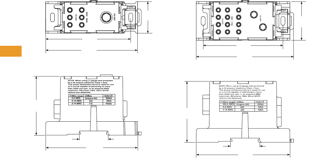
T42-122 Logic Control Products CA08100001K—June 2012 www.eatoncanada.ca
42
42
42
42
42
42
42
42
42
42
42
42
42
42
42
42
42
42
42
42
42
42
42
42
42
42
42
42
42
42
42.3
Terminal Blocks, Fuse Blocks and Fuse Holders
Power Distribution
Approximate Dimensions in Inches (mm)
CHDB330F CHDB377F
1.54
(39.1)
Line
Side
Load
Side
4.66
(118.4)
3.82
(97.0)
2.87
(72.9)
1.40 (35.6)
4.49
(114.0)
Line
Side
Load
Side 1.86
(47.2)
4.66
(118.4)
2.93
(74.4)
1.40 (35.6)
4.49
(114.0)
3.82
(97.0)
Tab42book.fm Page 122 Thursday, July 5, 2012 8:03 PM
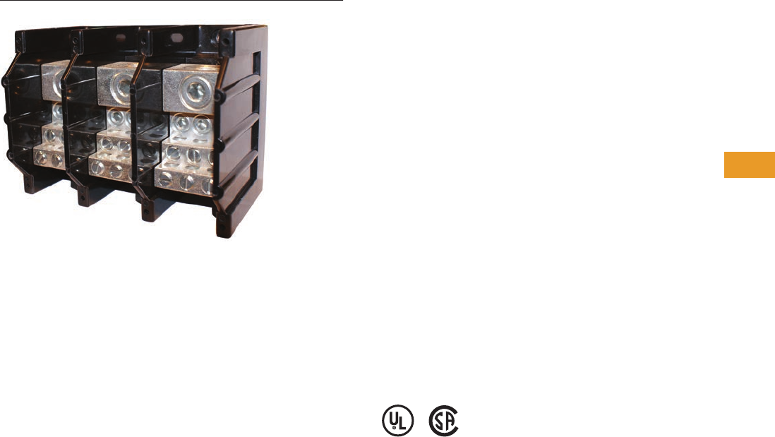
Logic Control Products CA08100001K—June 2012 www.eatoncanada.ca T42-123
42
42
42
42
42
42
42
42
42
42
42
42
42
42
42
42
42
42
42
42
42
42
42
42
42
42
42
42
42
42
42.3
Terminal Blocks, Fuse Blocks and Fuse Holders
Power Distribution
CH160 Series—Power Terminal Blocks Contents
Description Page
CHDB Series—Power Distribution Blocks . . . . . . . . . . T42-117
CH160 Series—Power Terminal Blocks
Product Selection . . . . . . . . . . . . . . . . . . . . . . . . . . T42-124
Technical Data and Specifications . . . . . . . . . . . . . T42-125
Dimensions . . . . . . . . . . . . . . . . . . . . . . . . . . . . . . T42-125
Power Terminal Block Accessories . . . . . . . . . . . . . . . T42-126
CH160 Series—Power Terminal Blocks
Product Description
The CH160 Series of Power
Terminal Blocks are UL 1059
recognized power terminal
blocks for branch circuit
applications. All short circuit
current ratings (SCCR) are
10 kA per UL 508A Table
SB4.1. The blocks are
available in a wide variety
of wiring configurations,
providing excellent flexibility.
Features and Benefits
●Ratings: To 840A, 600V
●Materials
●Molded material; black,
UL rated 94V-0
thermoplastic
●Operating temperature:
302˚F (150˚C)
●Optional cover:
See Page T42-126
Standards and Certifications
●UL Recognized
●CSA Certified
Tab42book.fm Page 123 Thursday, July 5, 2012 8:03 PM

T42-124 Logic Control Products CA08100001K—June 2012 www.eatoncanada.ca
42
42
42
42
42
42
42
42
42
42
42
42
42
42
42
42
42
42
42
42
42
42
42
42
42
42
42
42
42
42
42.3
Terminal Blocks, Fuse Blocks and Fuse Holders
Power Distribution
Product Selection
When Ordering, Specify
●Catalogue number
●Number of poles (up to three-pole available)
CH160 Power Terminal Blocks—CH162 Series
CH160 Power Terminal Blocks—CH163 Series
CH160 Power Terminal Blocks—CH165 Series
Note
Incomplete catalogue number—add code suffix -1, -2, -3 for number of poles.
Example: For a 150A 1/0-#14 Cu to 1/0-#14 Cu three-pole PDB, order CH16201-3.
Line Connection Load Connection
Connector Material
and Ampacity
Catalogue
Number
#2–#14 Cu/#8 Al #2–#14 Cu/#8 Al Al 115A CH16200_
1/0–#14 Cu 1/0–#14 Cu Cu 150A CH16201_
2/0–#8 Cu/Al 2/0–#8 Cu/Al Al 175A CH16204_
2/0–#14 Cu/#8 Al (4) #4–#14 Cu/#8 Al Al 175A CH16220_
Line Connection Load Connection
Connector Material
and Ampacity
Catalogue
Number
250 kcmil-#6 Cu 250 kcmil-#6 Cu Cu 255A CH16301_
350 kcmil-#6 Cu/Al 350 kcmil-#6 Cu/Al Al 310A CH16303_
500 kcmil-#6 Cu/Al 500 kcmil-#6 Cu/Al Al 380A CH16306_
2/0–#14 Cu/Al (6) #4–#14 Cu/#8 Al Al 175A CH16321_
350 kcmil-#6 Cu/Al (6) #4–#14 Cu/#8 Al Al 310A CH16323_
(2) 2/0–#14 Cu/#8 Al (6) #4–#14 Cu/#8 Al Al 350A CH16325_
500 kcmil-#6 Cu/Al (6) #2–#14 Cu/#8 Al Al 380A CH16330_
350 kcmil-#6 Cu/Al (3) #2–#14 Cu/#8 Al Al 310A CH16332_
(2) 1/0–#14 Cu/#8 Al Al 310A CH16332_
350 kcmil-#6 Cu/Al (12) #4–#14 Cu/#8 Al Al 310A CH16370_
350 kcmil-#6 Cu/Al (6) #2–#14 Cu/#8 Al Al 310A CH16371_
(3) 1/0–#14 Cu/#8 Al Al 310A CH16371_
350 kcmil-#6 Cu/Al (21) #10–#14 Cu/#10 Al Al 310A CH16372_
350 kcmil-#6 Cu/Al (3) 1/0–#14 Cu/#8 Al Al 310A CH16373_
(14) #10–#14 Cu/#8 Al Al 310A CH16373_
600 kcmil-#2 Cu/Al (12) #4–#14 Cu/#8 Al Al 420A CH16375_
600 kcmil-#2 Cu/Al (6) #2–#14 Cu/#8 Al Al 420A CH16376_
(3) 1/0–#14 Cu/#8 Al Al 420A CH16376_
Line Connection Load Connection
Connector Material
and Ampacity
Catalogue
Number
(2) 350 kcmil-4 Cu/Al (2) 350 kcmil-4 Cu/Al Al 620A CH16500_
(2) 500 kcmil-#6 Cu/Al (2) 500 kcmil-#6 Cu/Al Al 760A CH16504_
(2) 600 kcmil-#2 Cu/Al (4) 3/0–#8 Cu/Al Al 840A CH16528_
(4) #4–#14 Cu/#8 Al Al 840A CH16528_
(2) 500 kcmil-#6 Cu/Al (12) #4–#14 Cu/#8 Al Al 760A CH16530_
Tab42book.fm Page 124 Thursday, July 5, 2012 8:03 PM
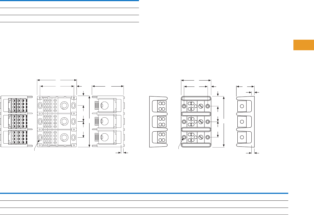
Logic Control Products CA08100001K—June 2012 www.eatoncanada.ca T42-125
42
42
42
42
42
42
42
42
42
42
42
42
42
42
42
42
42
42
42
42
42
42
42
42
42
42
42
42
42
42
42.3
Terminal Blocks, Fuse Blocks and Fuse Holders
Power Distribution
Technical Data and Specifications
CH160 Power Terminal Blocks
Note: For optional cover, see Power Terminal Block
Accessories, Page T42-126.
Dimensions
Approximate Dimensions in Inches (mm)
Series CH163
(Single-, Two- and Three-Pole Available)
Series CH162 and CH165
(Single-, Two- and Three-Pole Available)
CH160 Power Terminal Block Dimensions
Description Specification
Ratings To 840A, 600V
Materials Molded material; black, UL rated 94V-0 thermoplastic
Operating temperature 302˚F (150˚C)
F
B
Mtg. Holes 0.21 x 0.41 (5.3 x 10.4)
C'Bore 0.42 x 0.62 x 0.12 Deep
(10.7 x 15.7 x 3.0 Deep)
D
G
J
A
E
E
C
F
B
0.20 (5.1) Dia. Hole with
0.40 (10.2) C’Bore
DG
J
H
A
E
E
C
Series A B
CCC
DE4F GHJSingle-Pole Two-Pole Three-Pole
CH162 2.87 (72.9) 2.25 (57.2) 1.06 (26.9) 1.87 (47.5) 2.68 (68.1) 1.75 (44.5) 0.81 (20.6) 0.53 (13.5) 0.31 (7.9) 0.84 (21.3) 0.31 (7.9)
CH163 4.00 (101.6) 3.37 (85.6) 1.96 (49.8) 3.58 (90.9) 5.20 (132.1) 3.32 (84.3) 1.62 (41.1) 0.97 (24.6) 0.31 (7.9) 0.87 (22.1) 0.35 (8.9)
CH165 5.50 (139.7) 4.75 (120.7) 3.12 (79.2) 5.81 (147.6) 8.50 (215.9) 3.12 (79.2) 2.68 (68.1) 1.56 (39.6) 0.37 (9.4) 1.37 (34.8) 0.62 (15.7)
Tab42book.fm Page 125 Thursday, July 5, 2012 8:03 PM
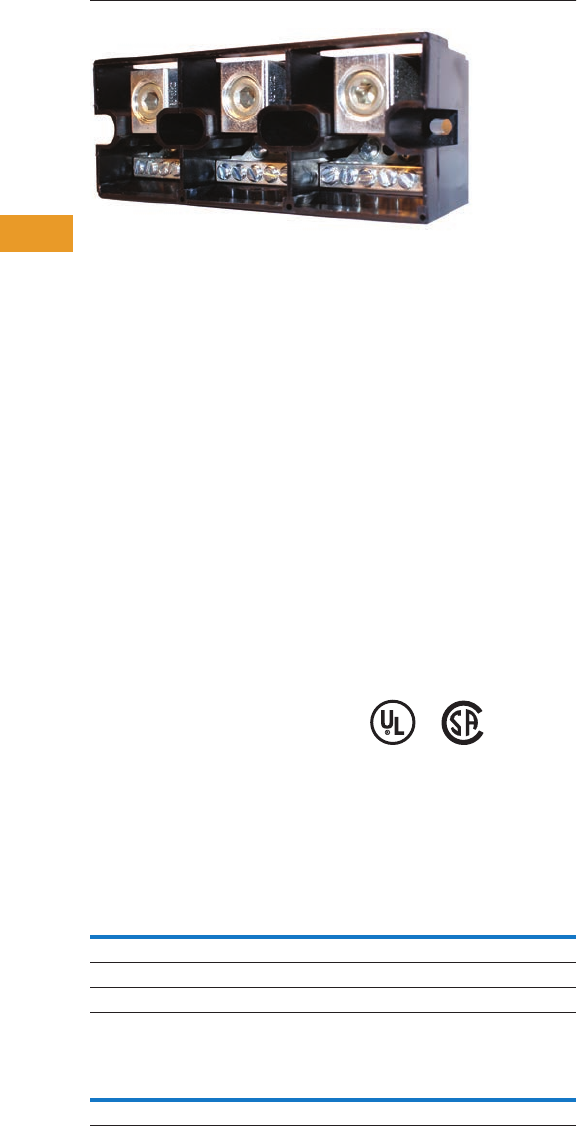
T42-126 Logic Control Products CA08100001K—June 2012 www.eatoncanada.ca
42
42
42
42
42
42
42
42
42
42
42
42
42
42
42
42
42
42
42
42
42
42
42
42
42
42
42
42
42
42
42.3
Terminal Blocks, Fuse Blocks and Fuse Holders
Power Distribution
Power Terminal Block Accessories Contents
Description Page
CHDB Series—Power Distribution Blocks . . . . . . . . . T42-117
CH160 Series—Power Terminal Blocks . . . . . . . . . . . T42-123
Power Terminal Block Accessories
Technical Data and Specifications . . . . . . . . . . . . . T42-127
Dimensions . . . . . . . . . . . . . . . . . . . . . . . . . . . . . . T42-127
Power Terminal Block Accessories
Product Description
Protective Cover
●Guards against accidental
contact
●Clear with write-on surface
for field termination
identification
●Available in single-, two-
and three-pole
Standards and Certifications
TB Series Power Blocks
●Contact Eaton for the
latest UL 508A short circuit
ratings on terminal blocks
●UL Recognized:
File No. E62622
●CSA Certified:
File No. LR15364
Product Selection
When Ordering, Specify
●Catalogue number
CH163 Series Cover
TB Series Power Blocks
Note
Standard pack, five pieces.
Description
Catalogue
Number
Single-pole cover CHCPDB-1
Two-pole cover CHCPDB-2
Three-pole cover CHCPDB-3
Line
Connection
Load
Connection
Catalogue
Number
#300 kcmil-#6 Cu/Al (6) #6–#14 Cu/#8Al TBAN63
Tab42book.fm Page 126 Thursday, July 5, 2012 8:03 PM
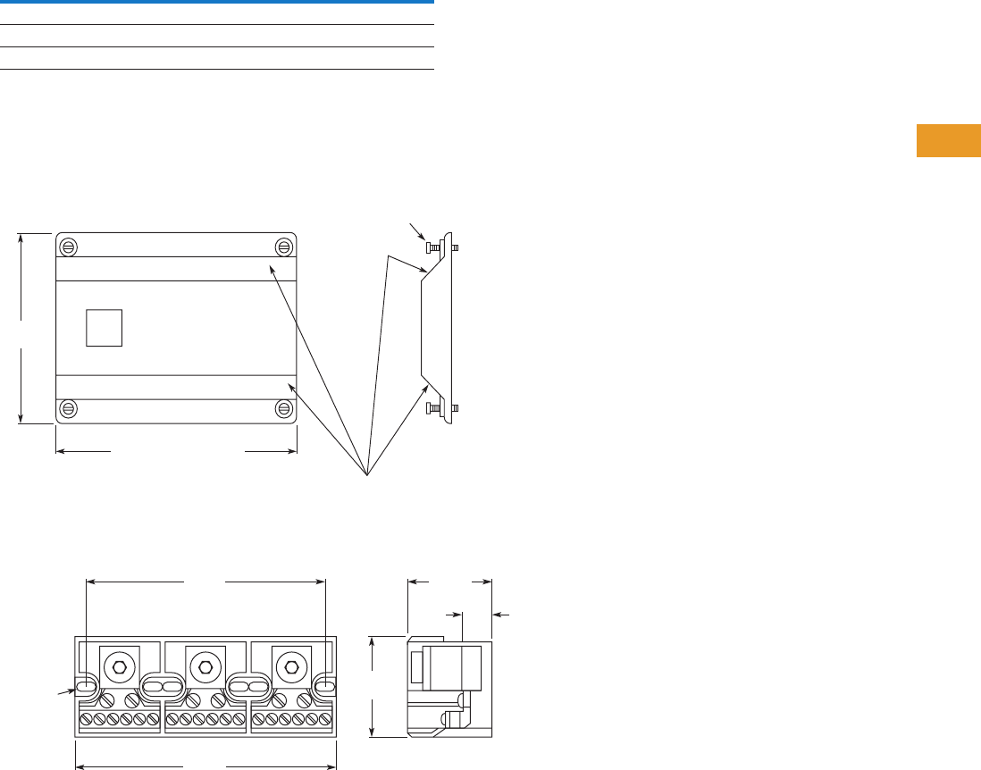
Logic Control Products CA08100001K—June 2012 www.eatoncanada.ca T42-127
42
42
42
42
42
42
42
42
42
42
42
42
42
42
42
42
42
42
42
42
42
42
42
42
42
42
42
42
42
42
42.3
Terminal Blocks, Fuse Blocks and Fuse Holders
Power Distribution
Technical Data and Specifications
TB Series Power Blocks
Dimensions
Approximate Dimensions in Inches (mm)
CH163 Series Cover
TB Series Power Blocks
Description Specification
Ratings 285A, 600V; UL/CSA
Materials Molded material; black, UL rated 94V-2 thermoplastic
Operating temperature 257˚F (125˚C)
CHCPDB-1 = 2.1 (53.3)
CHCPDB-2 = 3.72 (94.5)
CHCPDB-3 = 5.34 (135.6)
Textured
Surfaces
Supplied with
(4) #4 Thread-Cutting Screws
Assembled as Shown
4.14
(105.2)
5.37
(136.4)
0.2 x 0.37
(5.1 x 9.4)
Mtg. Slot
4.93
(125.2) 1.68
(42.7)
2.12
(53.8)
0.5
(12.7)
Tab42book.fm Page 127 Thursday, July 5, 2012 8:03 PM
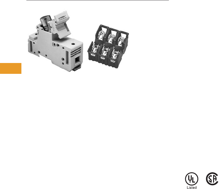
T42-128 Logic Control Products CA08100001K—June 2012 www.eatoncanada.ca
42
42
42
42
42
42
42
42
42
42
42
42
42
42
42
42
42
42
42
42
42
42
42
42
42
42
42
42
42
42
42.4
Terminal Blocks, Fuse Blocks and Fuse Holders
Fuse Blocks and Fuse Holders
Fuse Blocks and Fuse Holders Contents
Description Page
Fuse Blocks and Fuse Holders
C383 Series Disconnect Fuse Holders . . . . . . . . . T42-129
C350 Series Fuse Blocks and
W Series Fuse Holders. . . . . . . . . . . . . . . . . . . . . T42-131
Fuse Blocks and Fuse Holders Overview
Product Description
Available in compact finger
safe (C383) and an open
(C350) design. Eaton’s fuse
blocks and holders provide a
simple DIN mounting device
for protection in control
circuits.
Application Description
Fuse holders and blocks
available for Class CC,
midget, H, M and R.
Standards and Certifications
●UL listed
●CSA certified
(may not apply to all styles)
Tab42book.fm Page 128 Thursday, July 5, 2012 8:03 PM
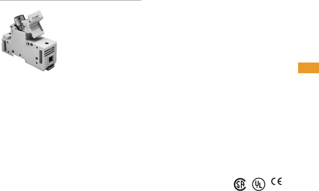
Logic Control Products CA08100001K—June 2012 www.eatoncanada.ca T42-129
42
42
42
42
42
42
42
42
42
42
42
42
42
42
42
42
42
42
42
42
42
42
42
42
42
42
42
42
42
42
42.4
Terminal Blocks, Fuse Blocks and Fuse Holders
Fuse Blocks and Fuse Holders
C383 Series Fuse Holders Contents
Description Page
C383 Series Disconnect Fuse Holders
Product Selection . . . . . . . . . . . . . . . . . . . . . . . . . . T42-130
Accessories . . . . . . . . . . . . . . . . . . . . . . . . . . . . . . T42-130
Technical Data and Specifications . . . . . . . . . . . . . T42-130
Dimensions . . . . . . . . . . . . . . . . . . . . . . . . . . . . . . T42-130
C350 Series Fuse Blocks and
W Series Fuse Holders . . . . . . . . . . . . . . . . . . . . . . . T42-131
C383 Series Disconnect Fuse Holders
Product Description
Eaton’s C383 Series
disconnect fuse holders
offer 600V fused circuit
protection and subsequently
“no load” switching.
These compact disconnects
are designed as components
in switchboards, panels and
control consoles where
positive and safe circuit
protection is required and
where space is at a premium.
The C383 fuse holders
mount directly on standard
TS35 DIN rails.
Features
●“Finger-Safe” design—
Recessed termination
screws and a fuse
extraction door afford you
IP20 grade protection and
qualify as “finger-safe” per
IEC standards
●Easy to adjust position on
rail—Simply unlatch the
DIN rail adapter, slide the
holder to desired position
and relock
●Quick change of fuse—
A permanently attached
pivoting fuse door
simplifies and speeds fuse
extraction. No tools or
accessories needed
●Class CC model is UL
listed and CSA certified for
branch circuit protection.
Midget models are UL
Recognized and CSA
certified for supplementary
and high-speed protection
●Runs cool—The vented
design provides adequate
air flow around the holders
at all times
●Self-extinguishing
UL 94-VO rated polyester
material
Standards and Certifications
Rated voltage:
●CSA/UL: 600 Vac/Vdc, 30A
●IEC (midget only):
690 Vac, 32A
Tab42book.fm Page 129 Thursday, July 5, 2012 8:03 PM
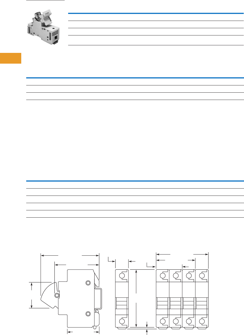
T42-130 Logic Control Products CA08100001K—June 2012 www.eatoncanada.ca
42
42
42
42
42
42
42
42
42
42
42
42
42
42
42
42
42
42
42
42
42
42
42
42
42
42
42
42
42
42
42.4
Terminal Blocks, Fuse Blocks and Fuse Holders
Fuse Blocks and Fuse Holders
Product Selection
Disconnect Fuse Holders
Accessories
Disconnect Fuse Holders
Accessory Details
C383MPCL
Multi-pole connection links
can be used to connect fuse
holders together for multi-
pole applications. Use two
per connection.
C383MPHP
Handle pins can be used to
connect handles in multi-pole
applications.
Technical Data and Specifications
Disconnect Fuse Holders
Dimensions
Approximate Dimensions in Inches (mm)
CH163 Series Cover
Notes
For additional technical information, consult the Eaton web site or Customer Support Centre.
UL recognizes both solid and stranded wire. Ferrules are not required. CSA requires ferrules on stranded wire to achieve approval.
Description Standard Pack Catalogue Number
For Class CC Fuse
Single-pole fuse holder 12 C383FHCC
For Midget Fuse (1-1/2 in x 13/32 in)
Single-pole fuse holder 12 C383FHMD
Description Standard Pack Catalogue Number
Midget or Class CC Fuse Holder
Multi-pole connection links 100 C383MPCL
Multi-pole handle pins 100 C383MPHP
C383FH_
Description Specification
Housing Polyester UL 94-VO rated
Colour White
Wire size 8–18 AWG
Torque 22 lb-in (2.5 Nm)
Fuse size 0.41 x 1.5 in
3.07
(78.0)
0.13
(3.2)
1.77
(45.0)
1.40
(35.6)
0.70 (17.8)
2.10 (53.4)
2.40 (61.0)
1.69 (43.0)
2.80 (71.2)
3.13 (79.5)
Tab42book.fm Page 130 Thursday, July 5, 2012 8:03 PM

Logic Control Products CA08100001K—June 2012 www.eatoncanada.ca T42-131
42
42
42
42
42
42
42
42
42
42
42
42
42
42
42
42
42
42
42
42
42
42
42
42
42
42
42
42
42
42
42.4
Terminal Blocks, Fuse Blocks and Fuse Holders
Fuse Blocks and Fuse Holders
C350 Series Fuse Blocks and W Series Fuse Holders Contents
Description Page
C383 Series Disconnect Fuse Holders . . . . . . . . . . . . T42-129
C350 Series Fuse Blocks and W Series Fuse
Holders
Product Selection . . . . . . . . . . . . . . . . . . . . . . . . . . T42-132
Accessories . . . . . . . . . . . . . . . . . . . . . . . . . . . . . . T42-133
Technical Data and Specifications . . . . . . . . . . . . . T42-133
Dimensions . . . . . . . . . . . . . . . . . . . . . . . . . . . . . . T42-133
C350 Series Fuse Blocks and W Series Fuse Holders
Product Description
Fuse Blocks
These space-saving Type
C350 Fuse Blocks are UL
approved for motor loads and
are rated 600V, 30A.
Fuse Holders
●Class H, M and R
Features
Fuse Blocks
●Mount to 35 mm flat
and 32 mm asymmetrical
DIN rails
●600V, 30A rated captive
pressure plate terminals
with copper alloy fuse clips
●Interlocking fuse blocks
permit single, double or
three-pole application—
reduce inventory
●Class CC fuses have an
interrupting rating of
200,000A
●Rejection feature prevents
insertion of fuses with
lower interrupting or
voltage ratings
Fuse Holders
●Break-resistant: molded of
heat-stabilized nylon
●Fuse clips: spring-
reinforced for cool
operation
●Fuse clip terminations:
one-piece construction
●Universal mounting
dimensions, for easy
assembly and retrofit
●Breathing action collar:
maintenance-free
●Pressure wire connectors:
vibration resistant
Standards and Certifications
Contact Eaton for the latest
UL 508A short circuit ratings
on terminal blocks.
Fuse Blocks
●UL listed
●CSA certified
Fuse Holders
●UL tested for OEM
subfeed applications
Fuse Blocks and Adapters
Cat. No. C350BD3C61
Three-Pole with Adapter
(Mounted on DIN Rail)
Cat. No. C350B1C61
One-Pole Fuse Blocks
Cat. No. C350KD DIN Rail Adapter
Tab42book.fm Page 131 Thursday, July 5, 2012 8:03 PM
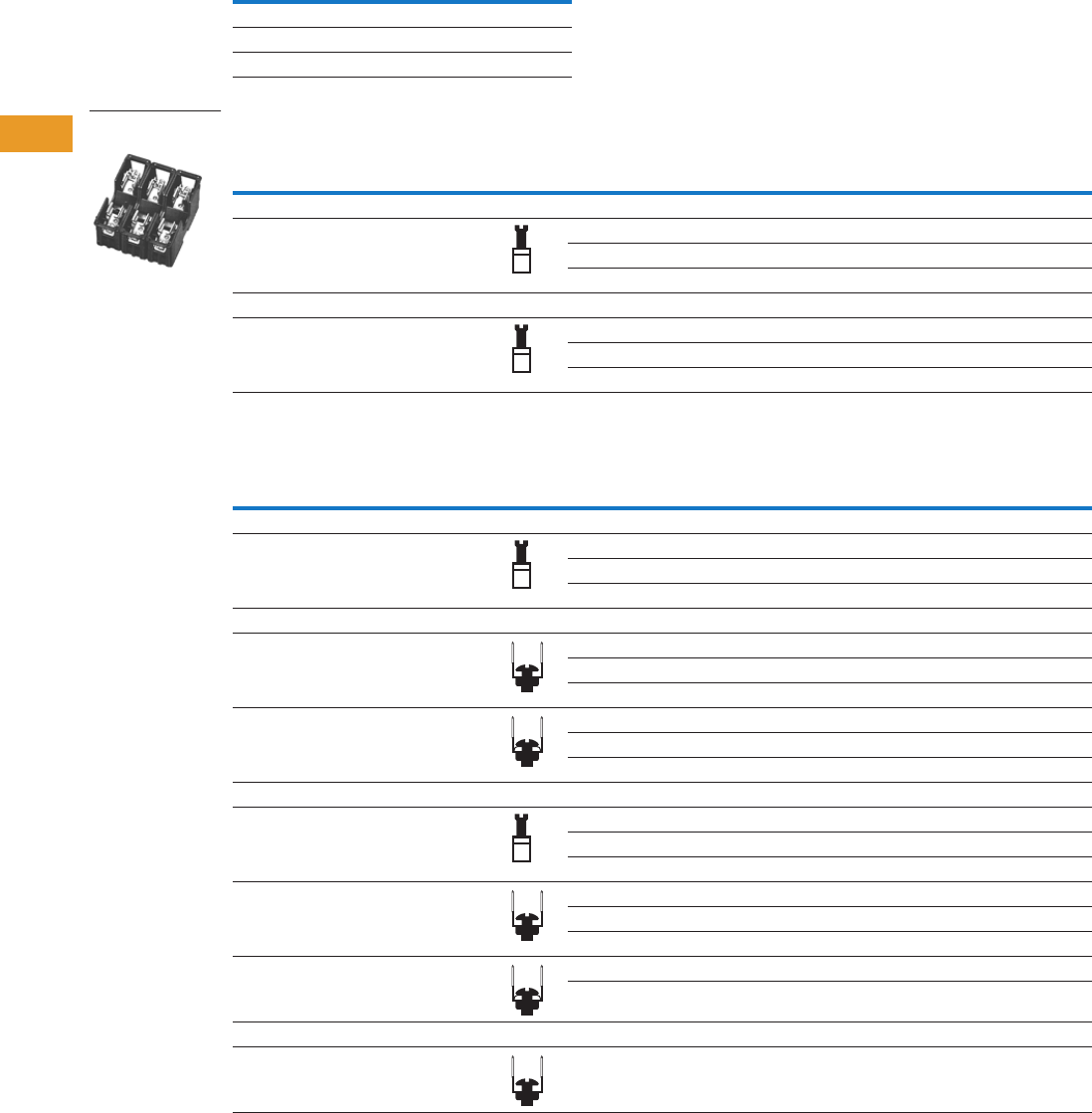
T42-132 Logic Control Products CA08100001K—June 2012 www.eatoncanada.ca
42
42
42
42
42
42
42
42
42
42
42
42
42
42
42
42
42
42
42
42
42
42
42
42
42
42
42
42
42
42
42.4
Terminal Blocks, Fuse Blocks and Fuse Holders
Fuse Blocks and Fuse Holders
Product Selection
Class CC Fuse Blocks
Fuse Holders—250V
Fuse Holders—600V
Note
Three-pole device is supplied with DIN rail adapter.
Type
Catalogue
Number
Three-pole C350BD3C61
Single-pole C350B1C61
DIN adapter C350KD
Wire Termination
Number
of Poles
Carton
Qty.
30A
Carton
Qty.
60A
Catalogue
Number
Catalogue
Number
Class H Fuse Holders
Single collar (box lug)—
sized to ampere rating
110W231HA 10 W261HA
25W232HA 5W262HA
35W233HA 5W263HA
Class R Fuse Holders
Single collar (box lug)—
sized to ampere rating
110WR231HA ——
2————
35WR233HA 1WR263HA
Wire Termination
Number
of Poles
Carton
Qty.
30A
Carton
Qty.
60A
Catalogue
Number
Catalogue
Number
Class H Fuse Holders
Single collar (box lug)—
sized to ampere rating
110W631HA 1W661HA
25W632HA 1W662HA
31W633HA 2W663HA
Class M Fuse Holders
Combination of double quick-connect,
20A max., and binding head screw,
#10 max., Cu/Al
110WM631F ——
28WM632F ——
36WM633F ——
Combination of double quick-connect,
20A max., and pressure plate screw,
#10 max., Cu only
110WM631G ——
28WM632G ——
36WM633G ——
Class R Fuse Holders
Single collar (box lug)—
sized to ampere rating
110WR631HA ——
25WR632HA ——
35WR633HA 5WR663HA
Combination of double quick-connect,
20A max., and binding head screw,
#10 max., Cu/Al
1————
21WMR632F ——
36WMR633F ——
Combination of double quick-connect,
20A max., and pressure plate screw,
#10 max., Cu only
110WMR631G ——
36WMR633G ——
Class R Fuse Holder, Type WRR Control Transformer Fuse Blocks
Combination of double quick-connect,
20A max., and pressure plate screw,
#14–#10 Cu only
36WRR633G ——
Class R, Three-Pole
Fuse Holder
Tab42book.fm Page 132 Thursday, July 5, 2012 8:03 PM
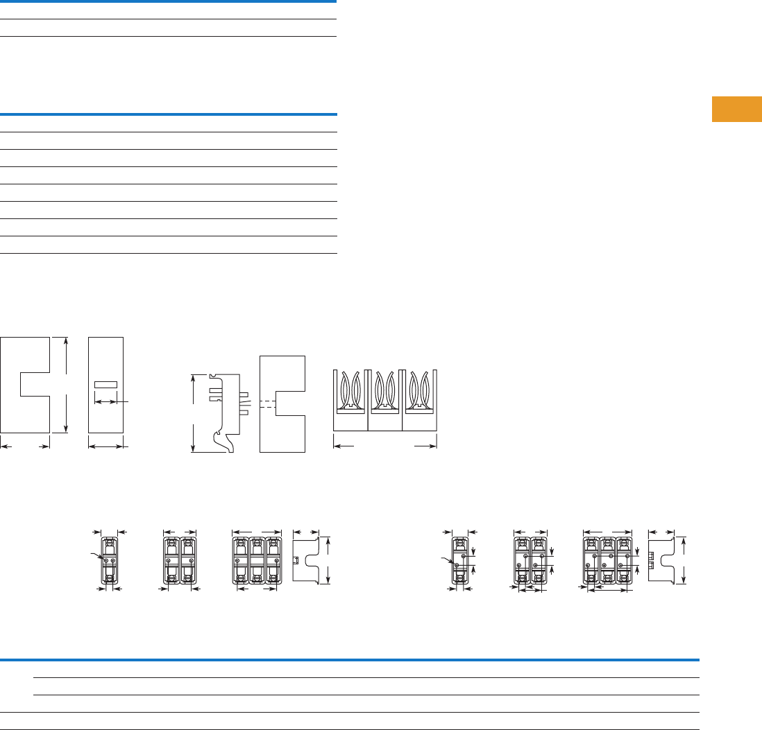
Logic Control Products CA08100001K—June 2012 www.eatoncanada.ca T42-133
42
42
42
42
42
42
42
42
42
42
42
42
42
42
42
42
42
42
42
42
42
42
42
42
42
42
42
42
42
42
42.4
Terminal Blocks, Fuse Blocks and Fuse Holders
Fuse Blocks and Fuse Holders
Accessories
Fuse Holder Accessories
Technical Data and Specifications
Fuse Blocks
Dimensions
Approximate Dimensions in Inches (mm)
Fuse Blocks
Fuse Holders
Description Catalogue Number
Fuse puller TBP
Lighted fuse puller (120 Vac) TBLP
Description Specification
Voltage rating 600V
Ampere rating Pressure plate terminals rated for 30A
Dielectric strength 1200V maximum
Ambient temperature 221˚F (105˚C) maximum
Clip/terminals Tin-plated copper alloy
Screw and captive pressure plate Zinc-plated steel
Base Thermoplastic UL 94VO flammability rating
DIN rail adapter Thermoplastic UL 94VO flammability rating
Class
Volts/
Amperes
Width A
Height
B
Depth
C
Mounting Holes Number of Mounting Holes
Single-
Pole
Two-
Pole
Three-
Pole D
Two-Pole
D1
Three-Pole
D1 E
Diameter
F
Single-
Pole
Two-
Pole
Three-
Pole
H, R 250V, 30A 1.00 (25.4) 2.00 (50.8) 3.00 (76.2) 3.13 (79.5) 1.56 (39.6) 0.38 (9.7) 1.25 (31.8) 2.50 (63.5) — 0.22 (5.6) 2 2 2
250V, 60A 1.44 (36.6) 2.88 (73.2) 4.31 (109.5) 4.75 (120.7) 2.06 (52.3) 0.50 (12.7) 1.81 (46.0) 3.13 (79.5) 1.25 (31.8) 0.22 (5.6) 2 4 4
600V, 30/60A 1.69 (42.9) 3.38 (85.9) 5.06 (128.5) 6.94 (176.3) 2.63 (66.8) 0.63 (16.0) 2.19 (55.6) 3.75 (95.3) 3.13 (79.5) 0.28 (7.1) 2 4 4
M, R 600V, 30A 0.84 (21.3) 1.63 (41.4) 2.41 (61.2) 3.00 (76.2) 1.28 (32.5) 0.38 (9.7) 0.75 (19.1) 1.50 (38.1) — 0.17 (4.3) 2 2 2
2.24
(56.9)
3.00
(76.2)
2.35 (59.7)
Three-Pole Width
Three-Pole WidthCatalog No. C350 Fuse Block Catalog No. C350 Fuse Block
with DIN Rail Adapter
1.25
(31.8) 0.78
(19.8)
0.60
(15.2)
CA
Single-
Pole AA
F
Dia. B
DD1D1
Two-
Pole Three-
Pole
Class H & R
250V, 30A
Class M & R
600V, 30A
CA
E
Single-
Pole AA
F
Dia. B
DD1
D
Two-
Pole Three-
Pole
D1
D
E E
Class H & R
250V, 60A
600V, 30/60A
Tab42book.fm Page 133 Thursday, July 5, 2012 8:03 PM

T42-134 Logic Control Products CA08100001K—June 2012 www.eatoncanada.ca
42
42
42
42
42
42
42
42
42
42
42
42
42
42
42
42
42
42
42
42
42
42
42
42
42
42
42
42
42
42
42.4
Terminal Blocks, Fuse Blocks and Fuse Holders
Fuse Blocks and Fuse Holders
This page left intentionally blank
Tab42book.fm Page 134 Thursday, July 5, 2012 8:03 PM
Logic Control Products
CA08100001K—June 2012 www.eatoncanada.ca
I-1
Appendix 1—Alphabetical Catalogue Number Index
The
bold
prefix indicates volume number followed by page number
Symbols
(2) XBAPPZ2 . . . . . . . . . . . . . . . . . .
T42-
66
(2) XBAPPZ4 . . . . . . . . . . . . . . . . . .
T42-
66
(4) XBAPPZ2 . . . . . . . . . . . . . . . . . .
T42-
66
Numerics
0TJS3. . . . . . . . . . . . . . . . . . . . . . . . .
T37-
204
0TJS3STAMP . . . . . . . . . . . . . . . . . .
T37-
204
10250ED1043 . . . . . . . . . . . . . . . . . .
T37-
177
10250ED1080 . . . . . . . . . . . . . . . . . .
T37-
190
10250ED1080-2 . . . . . . . . . . . . . . . .
T37-
183
10250ED1117-2KR. . . . . . . . . . . . . .
T37-
193
10250ED1117-2LR. . . . . . . . . . . . . .
T37-
193
10250ED1117-3KR. . . . . . . . . . . . . .
T37-
193
10250ED1117-3LR. . . . . . . . . . . . . .
T37-
193
10250ED1117-4KR. . . . . . . . . . . . . .
T37-
193
10250ED1117-4LR. . . . . . . . . . . . . .
T37-
193
10250ED1117-KR. . . . . . . . . . . . . . .
T37-
193
10250ED1117-LR. . . . . . . . . . . . . . .
T37-
193
10250ED1164 . . . . . . . . . . . . . . . . . .
T37-
174
10250ED1164-3 . . . . . . . . . . . . . . . .
T37-
174
10250ED1164-4 . . . . . . . . . . . . . . . .
T37-
174
10250ED1164-5 . . . . . . . . . . . . . . . .
T37-
174
10250ED1241 . . . . . . . . . . . . . . . . . .
T37-
212
10250ED1375 . . . . . . . . . . . . . . . . . .
T37-
185
10250ED1376 . . . . . . . . . . . . . . . . . .
T37-
185
10250ED1377 . . . . . . . . . . . . . . . . . .
T37-
185
10250ED1378 . . . . . . . . . . . . . . . . . .
T37-
185
10250ED664 . . . . . . . . . . . . . . . . . . .
T37-
19
10250ED824 . . . . . . . . . . . . . . . . . . .
T37-
198,
T37-
311
10250ED825-3 . . . . . . . . . . . . . . . . .
T37-
198
10250ED825-4 . . . . . . . . . . . . . . . . .
T37-
198
10250ED825-5 . . . . . . . . . . . . . . . . .
T37-
198
10250ED853 . . . . . . . . . . . . . . . . . . .
T37-
18
10250ED853-2 . . . . . . . . . . . . . . . . .
T37-
18
10250ED952 . . . . . . . . . . . . . . . . . . .
T37-
176
10250ED986 . . . . . . . . . . . . . . . . . . .
T37-
273
10250ED986-4 . . . . . . . . . . . . . . . . .
T37-
214,
T37-
225
10250H1881 . . . . . . . . . . . . . . . . . . .
T37-
20
10250H1884 . . . . . . . . . . . . . . . . . . .
T37-
20
10250H1885 . . . . . . . . . . . . . . . . . . .
T37-
20
10250H1890 . . . . . . . . . . . . . . . . . . .
T37-
20
10250H1913 . . . . . . . . . . . . . . . . . . .
T37-
20
10250H2538 . . . . . . . . . . . . . . . . . . .
T37-
19,
T37-
27
10250H2544 . . . . . . . . . . . . . . . . . . .
T37-
19
10250H2738 . . . . . . . . . . . . . . . . . . .
T37-
19
10250H2740 . . . . . . . . . . . . . . . . . . .
T37-
19
10250H2741 . . . . . . . . . . . . . . . . . . .
T37-
19
10250H2742 . . . . . . . . . . . . . . . . . . .
T37-
19
10250H2747 . . . . . . . . . . . . . . . . . . .
T37-
19
10250H289 . . . . . . . . . . . . . . . . . . . .
T37-
18
10250H364 . . . . . . . . . . . . . . . . . . . .
T37-
19
10250H4239 . . . . . . . . . . . . . . . . . . .
T37-
20
10250H4240 . . . . . . . . . . . . . . . . . . .
T37-
20
10250H4241 . . . . . . . . . . . . . . . . . . .
T37-
20
10250H4526 . . . . . . . . . . . . . . . . . . .
T37-
20
10250H4527 . . . . . . . . . . . . . . . . . . .
T37-
20
10250H5100 . . . . . . . . . . . . . . . . . . .
T37-
18
10250H5101 . . . . . . . . . . . . . . . . . . .
T37-
18
10250H5104 . . . . . . . . . . . . . . . . . . .
T37-
18
10250H5200 . . . . . . . . . . . . . . . . . . .
T37-
18
10250H5201 . . . . . . . . . . . . . . . . . . .
T37-
18
10250H5202 . . . . . . . . . . . . . . . . . . .
T37-
18
10250H5203 . . . . . . . . . . . . . . . . . . .
T37-
18
10250H5204 . . . . . . . . . . . . . . . . . . .
T37-
18
10250H5205 . . . . . . . . . . . . . . . . . . .
T37-
18
10250H5207 . . . . . . . . . . . . . . . . . . .
T37-
18
10250H5208 . . . . . . . . . . . . . . . . . . .
T37-
18
10250H5300 . . . . . . . . . . . . . . . . . . .
T37-
18
10250H5301 . . . . . . . . . . . . . . . . . . .
T37-
18
10250H5302 . . . . . . . . . . . . . . . . . . .
T37-
18
10250H5303 . . . . . . . . . . . . . . . . . . .
T37-
18
10250H5304 . . . . . . . . . . . . . . . . . . .
T37-
18
10250H5310 . . . . . . . . . . . . . . . . . . .
T37-
18
10250H658 . . . . . . . . . . . . . . . . . . . .
T37-
19
10250H89 . . . . . . . . . . . . . . . . . . . . .
T37-
18
10250T . . . . . . . . . . . . . . . . . . . . . . .
T37-
320
10250T1 . . . . . . . . . . . . . . . . . . . . . .
T37-
17,
T37-
204,
T37-
222
10250T10 . . . . . . . . . . . . . . . . . . . . .
T37-
190,
T37-
302
10250T101 . . . . . . . . . . . . . . . . . . . .
T37-
174,
T37-
290
10250T101-2. . . . . . . . . . . . . . . . . . .
T37-
173
10250T101-3. . . . . . . . . . . . . . . . . . .
T37-
173
10250T101-51. . . . . . . . . . . . . . . . . .
T37-
173
10250T102 . . . . . . . . . . . . . . . . . . . .
T37-
174,
T37-
290
10250T102-2. . . . . . . . . . . . . . . . . . .
T37-
173
10250T102-3. . . . . . . . . . . . . . . . . . .
T37-
173
10250T102-51. . . . . . . . . . . . . . . . . .
T37-
173
10250T103 . . . . . . . . . . . . . . . . . . . .
T37-
174,
T37-
290
10250T103-2. . . . . . . . . . . . . . . . . . .
T37-
173
10250T103-3. . . . . . . . . . . . . . . . . . .
T37-
173
10250T103-51. . . . . . . . . . . . . . . . . .
T37-
173
10250T104 . . . . . . . . . . . . . . . . . . . .
T37-
174,
T37-
290
10250T104-2. . . . . . . . . . . . . . . . . . .
T37-
173
10250T104-3. . . . . . . . . . . . . . . . . . .
T37-
173
10250T104-51. . . . . . . . . . . . . . . . . .
T37-
173
10250T105 . . . . . . . . . . . . . . . . . . . .
T37-
174,
T37-
290
10250T106 . . . . . . . . . . . . . . . . . . . .
T37-
174,
T37-
290
10250T1063C47-1X. . . . . . . . . . . . .
T37-
187
10250T1063LRD06-1X . . . . . . . . . .
T37-
187
10250T1079C47-1X. . . . . . . . . . . . .
T37-
187
10250T108 . . . . . . . . . . . . . . . . . . . .
T37-
174,
T37-
290
10250T1080C47-1X. . . . . . . . . . . . .
T37-
187
10250T1089C47-1X. . . . . . . . . . . . .
T37-
187
10250T1089LRD06-1X . . . . . . . . . .
T37-
187
10250T109 . . . . . . . . . . . . . . . . . . . .
T37-
174,
T37-
290
10250T1097LRD24-1X . . . . . . . . . .
T37-
187
10250T1097LRD2A-1X. . . . . . . . . .
T37-
187
10250T10B60-1X. . . . . . . . . . . . . . .
T37-
184
10250T10B62-1X. . . . . . . . . . . . . . .
T37-
184
10250T111 . . . . . . . . . . . . . . . . . . . .
T37-
174,
T37-
290
10250T111-2. . . . . . . . . . . . . . . . . . .
T37-
173
10250T111-3. . . . . . . . . . . . . . . . . . .
T37-
173
10250T111-51. . . . . . . . . . . . . . . . . .
T37-
173
10250T112 . . . . . . . . . . . . . . . . . . . .
T37-
174,
T37-
290
10250T112-2. . . . . . . . . . . . . . . . . . .
T37-
173
10250T112-3. . . . . . . . . . . . . . . . . . .
T37-
173
10250T113 . . . . . . . . . . . . . . . . . . . .
T37-
174,
T37-
290
10250T113-2. . . . . . . . . . . . . . . . . . .
T37-
173
10250T113-3. . . . . . . . . . . . . . . . . . .
T37-
173
10250T113-51. . . . . . . . . . . . . . . . . .
T37-
173
10250T116 . . . . . . . . . . . . . . . . . . . .
T37-
174,
T37-
290
10250T118 . . . . . . . . . . . . . . . . . . . .
T37-
174,
T37-
290
10250T119 . . . . . . . . . . . . . . . . . . . .
T37-
174,
T37-
290
10250T120 . . . . . . . . . . . . . . . . . . . .
T37-
174,
T37-
290
10250T120-2. . . . . . . . . . . . . . . . . . .
T37-
173
10250T120-3. . . . . . . . . . . . . . . . . . .
T37-
173
10250T120-51. . . . . . . . . . . . . . . . . .
T37-
173
10250T121 . . . . . . . . . . . . . . . . . . . .
T37-
174,
T37-
291
10250T121-2. . . . . . . . . . . . . . . . . . .
T37-
173
10250T121-3. . . . . . . . . . . . . . . . . . .
T37-
173
10250T121-51. . . . . . . . . . . . . . . . . .
T37-
173
10250T122 . . . . . . . . . . . . . . . . . . . .
T37-
174,
T37-
291
LogicControl2012IOM2.fm Page 1 Thursday, June 7, 2012 8:23 PM
I-2 Logic Control Products
CA08100001K—June 2012 www.eatoncanada.ca
Appendix 1—Alphabetical Catalogue Number Index
The
bold prefix indicates volume number followed by page number
10250T122-2 . . . . . . . . . . . . . . . . . . T37-173
10250T122-3 . . . . . . . . . . . . . . . . . . T37-173
10250T122-53 . . . . . . . . . . . . . . . . . T37-173
10250T123 . . . . . . . . . . . . . . . . . . . . T37-174, T37-291
10250T123-2 . . . . . . . . . . . . . . . . . . T37-173
10250T123-3 . . . . . . . . . . . . . . . . . . T37-173
10250T123-51 . . . . . . . . . . . . . . . . . T37-173
10250T124 . . . . . . . . . . . . . . . . . . . . T37-174, T37-291
10250T124-2 . . . . . . . . . . . . . . . . . . T37-173
10250T124-3 . . . . . . . . . . . . . . . . . . T37-173
10250T124-51 . . . . . . . . . . . . . . . . . T37-173
10250T129 . . . . . . . . . . . . . . . . . . . . T37-174, T37-291
10250T1311 . . . . . . . . . . . . . . . . . . . T37-198, T37-311
10250T1322 . . . . . . . . . . . . . . . . . . . T37-198, T37-311
10250T1323 . . . . . . . . . . . . . . . . . . . T37-198, T37-311
10250T1332 . . . . . . . . . . . . . . . . . . . T37-198, T37-311
10250T1333 . . . . . . . . . . . . . . . . . . . T37-198, T37-311
10250T1342 . . . . . . . . . . . . . . . . . . . T37-198, T37-311
10250T1343 . . . . . . . . . . . . . . . . . . . T37-198, T37-311
10250T1352 . . . . . . . . . . . . . . . . . . . T37-198, T37-311
10250T1353 . . . . . . . . . . . . . . . . . . . T37-198, T37-311
10250T1367 . . . . . . . . . . . . . . . . . . . T37-198, T37-311
10250T1371 . . . . . . . . . . . . . . . . . . . T37-198, T37-311
10250T1511_ . . . . . . . . . . . . . . . . . . T37-197, T37-311
10250T1522_ . . . . . . . . . . . . . . . . . . T37-197, T37-311
10250T1523_ . . . . . . . . . . . . . . . . . . T37-197, T37-311
10250T1532_ . . . . . . . . . . . . . . . . . . T37-197, T37-311
10250T1533_ . . . . . . . . . . . . . . . . . . T37-197, T37-311
10250T1542_ . . . . . . . . . . . . . . . . . . T37-197, T37-311
10250T1543_ . . . . . . . . . . . . . . . . . . T37-197, T37-311
10250T1571_ . . . . . . . . . . . . . . . . . . T37-197, T37-311
10250T1581_ . . . . . . . . . . . . . . . . . . T37-197, T37-311
10250T1611_ . . . . . . . . . . . . . . . . . . T37-197, T37-311
10250T1622_ . . . . . . . . . . . . . . . . . . T37-197, T37-311
10250T1623_ . . . . . . . . . . . . . . . . . . T37-197, T37-311
10250T1632_ . . . . . . . . . . . . . . . . . . T37-197, T37-311
10250T1633_ . . . . . . . . . . . . . . . . . . T37-197, T37-311
10250T1642_ . . . . . . . . . . . . . . . . . . T37-197, T37-311
10250T1643_ . . . . . . . . . . . . . . . . . . T37-197, T37-311
10250T1652_ . . . . . . . . . . . . . . . . . . T37-197, T37-311
10250T1653_ . . . . . . . . . . . . . . . . . . T37-197, T37-311
10250T1662_ . . . . . . . . . . . . . . . . . . T37-197, T37-311
10250T1663_ . . . . . . . . . . . . . . . . . . T37-197, T37-311
10250T1677_ . . . . . . . . . . . . . . . . . . T37-197, T37-311
10250T1687_ . . . . . . . . . . . . . . . . . . T37-197, T37-311
10250T171 . . . . . . . . . . . . . . . . . . . . T37-174, T37-291
10250T171-2 . . . . . . . . . . . . . . . . . . T37-173
10250T171-3 . . . . . . . . . . . . . . . . . . T37-173
10250T171-51 . . . . . . . . . . . . . . . . . T37-173
10250T172 . . . . . . . . . . . . . . . . . . . . T37-174, T37-291
10250T17213 . . . . . . . . . . . . . . . . . . T37-174, T37-291
10250T17213-2 . . . . . . . . . . . . . . . . T37-173
10250T17213-3 . . . . . . . . . . . . . . . . T37-173
10250T17213-53 . . . . . . . . . . . . . . . T37-173
10250T172-2 . . . . . . . . . . . . . . . . . . T37-173
10250T172-3 . . . . . . . . . . . . . . . . . . T37-173
10250T172-53 . . . . . . . . . . . . . . . . . T37-173
10250T173 . . . . . . . . . . . . . . . . . . . . T37-174, T37-291
10250T173-2 . . . . . . . . . . . . . . . . . . T37-173
10250T173-3 . . . . . . . . . . . . . . . . . . T37-173
10250T173-51 . . . . . . . . . . . . . . . . . T37-173
10250T174 . . . . . . . . . . . . . . . . . . . . T37-174, T37-291
10250T174-2 . . . . . . . . . . . . . . . . . . T37-173
10250T174-3 . . . . . . . . . . . . . . . . . . T37-173
10250T174-51 . . . . . . . . . . . . . . . . . T37-173
10250T181H. . . . . . . . . . . . . . . . . . . T37-295
10250T181HAP. . . . . . . . . . . . . . . . . T37-294
10250T181HGP. . . . . . . . . . . . . . . . . T37-294
10250T181HL . . . . . . . . . . . . . . . . . . T37-295
10250T181HLAP06. . . . . . . . . . . . . . T37-294
10250T181HLGP06. . . . . . . . . . . . . . T37-294
10250T181HLRP06. . . . . . . . . . . . . . T37-294
10250T181HRP. . . . . . . . . . . . . . . . . T37-294
10250T181L. . . . . . . . . . . . . . . . . . . . T37-180
10250T181LAP06 . . . . . . . . . . . . . . . T37-179
10250T181LGP06 . . . . . . . . . . . . . . . T37-179
10250T181LLP06 . . . . . . . . . . . . . . . T37-179
10250T181LRP06 . . . . . . . . . . . . . . . T37-179
10250T181LWP06. . . . . . . . . . . . . . . T37-179
10250T181LYP06 . . . . . . . . . . . . . . . T37-179
10250T181N . . . . . . . . . . . . . . . . . . . T37-180
10250T182H . . . . . . . . . . . . . . . . . . . T37-295
10250T182HL . . . . . . . . . . . . . . . . . . T37-295
10250T182L. . . . . . . . . . . . . . . . . . . . T37-180
10250T182N . . . . . . . . . . . . . . . . . . . T37-180
10250T183H . . . . . . . . . . . . . . . . . . . T37-295
10250T183HL . . . . . . . . . . . . . . . . . . T37-295
10250T183L. . . . . . . . . . . . . . . . . . . . T37-180
10250T183N . . . . . . . . . . . . . . . . . . . T37-180
10250T184H . . . . . . . . . . . . . . . . . . . T37-295
10250T184HL . . . . . . . . . . . . . . . . . . T37-295
10250T184L. . . . . . . . . . . . . . . . . . . . T37-180
10250T184N . . . . . . . . . . . . . . . . . . . T37-180
10250T185H . . . . . . . . . . . . . . . . . . . T37-295
10250T185HL . . . . . . . . . . . . . . . . . . T37-295
10250T185L. . . . . . . . . . . . . . . . . . . . T37-180
10250T185N . . . . . . . . . . . . . . . . . . . T37-180
10250T189N . . . . . . . . . . . . . . . . . . . T37-180
10250T197HL . . . . . . . . . . . . . . . . . . T37-295
10250T197HLAP24. . . . . . . . . . . . . . T37-294
10250T197HLAP2A . . . . . . . . . . . . . T37-294
10250T197HLGP24. . . . . . . . . . . . . . T37-294
10250T197HLGP2A . . . . . . . . . . . . . T37-294
10250T197HLRP24. . . . . . . . . . . . . . T37-294
10250T197HLRP2A . . . . . . . . . . . . . T37-294
10250T197L. . . . . . . . . . . . . . . . . . . . T37-180
10250T197LAP24 . . . . . . . . . . . . . . . T37-179
10250T197LAP2A. . . . . . . . . . . . . . . T37-179
10250T197LGP24 . . . . . . . . . . . . . . . T37-179
10250T197LGP2A. . . . . . . . . . . . . . . T37-179
10250T197LLP24 . . . . . . . . . . . . . . . T37-179
10250T197LLP2A. . . . . . . . . . . . . . . T37-179
10250T197LRP24 . . . . . . . . . . . . . . . T37-179
10250T197LRP2A. . . . . . . . . . . . . . . T37-179
10250T197LWP24. . . . . . . . . . . . . . . T37-179
10250T197LWP2A . . . . . . . . . . . . . . T37-179
10250T197LYP24 . . . . . . . . . . . . . . . T37-179
10250T197LYP2A. . . . . . . . . . . . . . . T37-179
10250T198H . . . . . . . . . . . . . . . . . . . T37-295
10250T198HL . . . . . . . . . . . . . . . . . . T37-295
10250T198L. . . . . . . . . . . . . . . . . . . . T37-180
10250T198N . . . . . . . . . . . . . . . . . . . T37-180
10250T1E. . . . . . . . . . . . . . . . . . . . . . T37-222, T37-272
10250T1EC . . . . . . . . . . . . . . . . . . . . T37-224
10250T1EP . . . . . . . . . . . . . . . . . . . . T37-223, T37-273
10250T1H . . . . . . . . . . . . . . . . . . . . . T37-316
10250T1P. . . . . . . . . . . . . . . . . . . . . . T37-223, T37-273
10250T2. . . . . . . . . . . . . . . . . . . . . . . T37-17, T37-204, T37-222, T37-
272
10250T201H . . . . . . . . . . . . . . . . . . . T37-295, T37-320
10250T201HAP. . . . . . . . . . . . . . . . . T37-294
10250T201HGP. . . . . . . . . . . . . . . . . T37-294
LogicControl2012IOM2.fm Page 2 Thursday, June 7, 2012 8:23 PM
Logic Control Products CA08100001K—June 2012 www.eatoncanada.ca I-3
Appendix 1—Alphabetical Catalogue Number Index
The bold prefix indicates volume number followed by page number
10250T201HRP. . . . . . . . . . . . . . . . . T37-294
10250T201N . . . . . . . . . . . . . . . . . . . T37-180
10250T201NC19N . . . . . . . . . . . . . . T37-179
10250T201NC1N . . . . . . . . . . . . . . . T37-179
10250T201NC2N . . . . . . . . . . . . . . . T37-179
10250T201NC3N . . . . . . . . . . . . . . . T37-179
10250T201NC4N . . . . . . . . . . . . . . . T37-179
10250T201NC5N . . . . . . . . . . . . . . . T37-179
10250T201NC6N . . . . . . . . . . . . . . . T37-179
10250T202H . . . . . . . . . . . . . . . . . . . T37-295, T37-320
10250T202N . . . . . . . . . . . . . . . . . . . T37-180
10250T203H . . . . . . . . . . . . . . . . . . . T37-295
10250T203N . . . . . . . . . . . . . . . . . . . T37-180
10250T204H . . . . . . . . . . . . . . . . . . . T37-295
10250T204N . . . . . . . . . . . . . . . . . . . T37-180
10250T206H . . . . . . . . . . . . . . . . . . . T37-295
10250T206HAP. . . . . . . . . . . . . . . . . T37-294
10250T206HGP. . . . . . . . . . . . . . . . . T37-294
10250T206HRP. . . . . . . . . . . . . . . . . T37-294
10250T206N . . . . . . . . . . . . . . . . . . . T37-180
10250T206NC19N . . . . . . . . . . . . . . T37-179
10250T206NC1N . . . . . . . . . . . . . . . T37-179
10250T206NC2N . . . . . . . . . . . . . . . T37-179
10250T206NC3N . . . . . . . . . . . . . . . T37-179
10250T206NC4N . . . . . . . . . . . . . . . T37-179
10250T206NC5N . . . . . . . . . . . . . . . T37-179
10250T206NC6N . . . . . . . . . . . . . . . T37-179
10250T207H . . . . . . . . . . . . . . . . . . . T37-295
10250T207N . . . . . . . . . . . . . . . . . . . T37-180
10250T208H . . . . . . . . . . . . . . . . . . . T37-295
10250T208N . . . . . . . . . . . . . . . . . . . T37-180
10250T20KB. . . . . . . . . . . . . . . . . . . T37-193
10250T20LB . . . . . . . . . . . . . . . . . . . T37-193
10250T21KB. . . . . . . . . . . . . . . . . . . T37-193
10250T21KB-POP . . . . . . . . . . . . . . T37-172
10250T21LB . . . . . . . . . . . . . . . . . . . T37-193
10250T221L . . . . . . . . . . . . . . . . . . . T37-180
10250T221LAP06. . . . . . . . . . . . . . . T37-179
10250T221LGP06. . . . . . . . . . . . . . . T37-179
10250T221LLP06 . . . . . . . . . . . . . . . T37-179
10250T221LRP06. . . . . . . . . . . . . . . T37-179
10250T221LWP06 . . . . . . . . . . . . . . T37-179
10250T221LYP06. . . . . . . . . . . . . . . T37-179
10250T221N . . . . . . . . . . . . . . . . . . . T37-180
10250T222L . . . . . . . . . . . . . . . . . . . T37-180
10250T222N . . . . . . . . . . . . . . . . . . . T37-180
10250T223L . . . . . . . . . . . . . . . . . . . T37-180
10250T223N . . . . . . . . . . . . . . . . . . . T37-180
10250T224L . . . . . . . . . . . . . . . . . . . T37-180
10250T224N . . . . . . . . . . . . . . . . . . . T37-180
10250T225L . . . . . . . . . . . . . . . . . . . T37-180
10250T225N . . . . . . . . . . . . . . . . . . . T37-180
10250T226H . . . . . . . . . . . . . . . . . . . T37-295
10250T226N . . . . . . . . . . . . . . . . . . . T37-180
10250T227H . . . . . . . . . . . . . . . . . . . T37-295
10250T227N . . . . . . . . . . . . . . . . . . . T37-180
10250T22KB. . . . . . . . . . . . . . . . . . . T37-193
10250T22KB-POP . . . . . . . . . . . . . . T37-172
10250T22LB . . . . . . . . . . . . . . . . . . . T37-193
10250T231N . . . . . . . . . . . . . . . . . . . T37-180
10250T231NC21. . . . . . . . . . . . . . . . T37-179
10250T231NC22. . . . . . . . . . . . . . . . T37-179
10250T231NC23. . . . . . . . . . . . . . . . T37-179
10250T231NC24. . . . . . . . . . . . . . . . T37-179
10250T231NC25. . . . . . . . . . . . . . . . T37-179
10250T231NC26. . . . . . . . . . . . . . . . T37-179
10250T231NC43. . . . . . . . . . . . . . . . T37-179
10250T232N. . . . . . . . . . . . . . . . . . . T37-180
10250T233N. . . . . . . . . . . . . . . . . . . T37-180
10250T235N. . . . . . . . . . . . . . . . . . . T37-180
10250T235NC21. . . . . . . . . . . . . . . . T37-179
10250T235NC22. . . . . . . . . . . . . . . . T37-179
10250T235NC23. . . . . . . . . . . . . . . . T37-179
10250T235NC24. . . . . . . . . . . . . . . . T37-179
10250T235NC25. . . . . . . . . . . . . . . . T37-179
10250T235NC26. . . . . . . . . . . . . . . . T37-179
10250T235NC43. . . . . . . . . . . . . . . . T37-179
10250T238N. . . . . . . . . . . . . . . . . . . T37-180
10250T239N. . . . . . . . . . . . . . . . . . . T37-180
10250T23B . . . . . . . . . . . . . . . . . . . . T37-173
10250T23G. . . . . . . . . . . . . . . . . . . . T37-173
10250T23R . . . . . . . . . . . . . . . . . . . . T37-173
10250T23Y. . . . . . . . . . . . . . . . . . . . T37-173
10250T240N. . . . . . . . . . . . . . . . . . . T37-180
10250T241_ . . . . . . . . . . . . . . . . . . . T37-206
10250T24111-1. . . . . . . . . . . . . . . . . T37-205
10250T24111-2. . . . . . . . . . . . . . . . . T37-205
10250T2411-2. . . . . . . . . . . . . . . . . . T37-205
10250T2415-2. . . . . . . . . . . . . . . . . . T37-205
10250T242_ . . . . . . . . . . . . . . . . . . . T37-206
10250T243_ . . . . . . . . . . . . . . . . . . . T37-206
10250T251_ . . . . . . . . . . . . . . . . . . . T37-206
10250T252_ . . . . . . . . . . . . . . . . . . . T37-206
10250T253_ . . . . . . . . . . . . . . . . . . . T37-206
10250T25B . . . . . . . . . . . . . . . . . . . . T37-173
10250T25G. . . . . . . . . . . . . . . . . . . . T37-173
10250T25R . . . . . . . . . . . . . . . . . . . . T37-173
10250T25Y. . . . . . . . . . . . . . . . . . . . T37-173
10250T261_ . . . . . . . . . . . . . . . . . . . T37-206
10250T262_ . . . . . . . . . . . . . . . . . . . T37-206
10250T263_ . . . . . . . . . . . . . . . . . . . T37-206
10250T26B . . . . . . . . . . . . . . . . . . . . T37-173
10250T26G. . . . . . . . . . . . . . . . . . . . T37-173
10250T26R . . . . . . . . . . . . . . . . . . . . T37-173
10250T26Y. . . . . . . . . . . . . . . . . . . . T37-173
10250T271_ . . . . . . . . . . . . . . . . . . . T37-206
10250T272_ . . . . . . . . . . . . . . . . . . . T37-206
10250T273_ . . . . . . . . . . . . . . . . . . . T37-206
10250T27B . . . . . . . . . . . . . . . . . . . . T37-173
10250T27G. . . . . . . . . . . . . . . . . . . . T37-173
10250T27R . . . . . . . . . . . . . . . . . . . . T37-173
10250T27Y. . . . . . . . . . . . . . . . . . . . T37-173
10250T29 . . . . . . . . . . . . . . . . . . . . . T37-173
10250T297L . . . . . . . . . . . . . . . . . . . T37-180
10250T297LAP24. . . . . . . . . . . . . . . T37-179
10250T297LAP2A . . . . . . . . . . . . . . T37-179
10250T297LGP24. . . . . . . . . . . . . . . T37-179
10250T297LGP2A . . . . . . . . . . . . . . T37-179
10250T297LLP24. . . . . . . . . . . . . . . T37-179
10250T297LLP2A . . . . . . . . . . . . . . T37-179
10250T297LRP24. . . . . . . . . . . . . . . T37-179
10250T297LRP2A . . . . . . . . . . . . . . T37-179
10250T297LWP24 . . . . . . . . . . . . . . T37-179
10250T297LWP2A. . . . . . . . . . . . . . T37-179
10250T297LYP24. . . . . . . . . . . . . . . T37-179
10250T297LYP2A . . . . . . . . . . . . . . T37-179
10250T2E . . . . . . . . . . . . . . . . . . . . . T37-222, T37-272
10250T2EC. . . . . . . . . . . . . . . . . . . . T37-224
10250T2EP . . . . . . . . . . . . . . . . . . . . T37-223, T37-273
10250T2P . . . . . . . . . . . . . . . . . . . . . T37-223, T37-273
10250T3 . . . . . . . . . . . . . . . . . . . . . . T37-17, T37-202, T37-222, T37-
272
LogicControl2012IOM2.fm Page 3 Thursday, June 7, 2012 8:23 PM
I-4 Logic Control Products CA08100001K—June 2012 www.eatoncanada.ca
Appendix 1—Alphabetical Catalogue Number Index
The bold prefix indicates volume number followed by page number
10250T3011 . . . . . . . . . . . . . . . . . . . T37-198
10250T3022 . . . . . . . . . . . . . . . . . . . T37-198, T37-311
10250T3023 . . . . . . . . . . . . . . . . . . . T37-198, T37-311
10250T3032 . . . . . . . . . . . . . . . . . . . T37-198, T37-311
10250T3033 . . . . . . . . . . . . . . . . . . . T37-198, T37-311
10250T304 . . . . . . . . . . . . . . . . . . . . T37-198
10250T3042 . . . . . . . . . . . . . . . . . . . T37-311
10250T3043 . . . . . . . . . . . . . . . . . . . T37-198, T37-311
10250T3052 . . . . . . . . . . . . . . . . . . . T37-198, T37-311
10250T3053 . . . . . . . . . . . . . . . . . . . T37-198, T37-311
10250T3067 . . . . . . . . . . . . . . . . . . . T37-198, T37-311
10250T3071 . . . . . . . . . . . . . . . . . . . T37-198, T37-311
10250T30B. . . . . . . . . . . . . . . . . . . . T37-173
10250T30B-POP . . . . . . . . . . . . . . . T37-172
10250T30G. . . . . . . . . . . . . . . . . . . . T37-173
10250T30R. . . . . . . . . . . . . . . . . . . . T37-173
10250T30Y. . . . . . . . . . . . . . . . . . . . T37-173
10250T31B. . . . . . . . . . . . . . . . . . . . T37-173
10250T31G. . . . . . . . . . . . . . . . . . . . T37-173
10250T31R. . . . . . . . . . . . . . . . . . . . T37-173
10250T31R-POP . . . . . . . . . . . . . . . T37-172
10250T31Y. . . . . . . . . . . . . . . . . . . . T37-173
10250T3213 . . . . . . . . . . . . . . . . . . . T37-206
10250T3214 . . . . . . . . . . . . . . . . . . . T37-206
10250T32B. . . . . . . . . . . . . . . . . . . . T37-173
10250T32G. . . . . . . . . . . . . . . . . . . . T37-173
10250T32R. . . . . . . . . . . . . . . . . . . . T37-172, T37-173
10250T32Y. . . . . . . . . . . . . . . . . . . . T37-173
10250T33 . . . . . . . . . . . . . . . . . . . . . T37-172, T37-173
10250T330 . . . . . . . . . . . . . . . . . . . . T37-188, T37-235
10250T331 . . . . . . . . . . . . . . . . . . . . T37-188
10250T332 . . . . . . . . . . . . . . . . . . . . T37-188
10250T333 . . . . . . . . . . . . . . . . . . . . T37-188
10250T334 . . . . . . . . . . . . . . . . . . . . T37-188
10250T335 . . . . . . . . . . . . . . . . . . . . T37-188
10250T338 . . . . . . . . . . . . . . . . . . . . T37-188
10250T33B. . . . . . . . . . . . . . . . . . . . T37-173
10250T33G. . . . . . . . . . . . . . . . . . . . T37-173
10250T33R. . . . . . . . . . . . . . . . . . . . T37-173
10250T33Y. . . . . . . . . . . . . . . . . . . . T37-173
10250T34A. . . . . . . . . . . . . . . . . . . . T37-179
10250T34B. . . . . . . . . . . . . . . . . . . . T37-179
10250T34C. . . . . . . . . . . . . . . . . . . . T37-179
10250T34G. . . . . . . . . . . . . . . . . . . . T37-179
10250T34R. . . . . . . . . . . . . . . . . . . . T37-179
10250T34W . . . . . . . . . . . . . . . . . . . T37-179
10250T34Y. . . . . . . . . . . . . . . . . . . . T37-179
10250T3516 . . . . . . . . . . . . . . . . . . . T37-21
10250T3517 . . . . . . . . . . . . . . . . . . . T37-21
10250T3518 . . . . . . . . . . . . . . . . . . . T37-21
10250T3519 . . . . . . . . . . . . . . . . . . . T37-21
10250T3520 . . . . . . . . . . . . . . . . . . . T37-21
10250T3523 . . . . . . . . . . . . . . . . . . . T37-21
10250T3524 . . . . . . . . . . . . . . . . . . . T37-21
10250T3525 . . . . . . . . . . . . . . . . . . . T37-21
10250T3526 . . . . . . . . . . . . . . . . . . . T37-21
10250T3528 . . . . . . . . . . . . . . . . . . . T37-21
10250T3532 . . . . . . . . . . . . . . . . . . . T37-21
10250T3536 . . . . . . . . . . . . . . . . . . . T37-21
10250T3537 . . . . . . . . . . . . . . . . . . . T37-21
10250T3538 . . . . . . . . . . . . . . . . . . . T37-21
10250T3539 . . . . . . . . . . . . . . . . . . . T37-21
10250T3540 . . . . . . . . . . . . . . . . . . . T37-21
10250T3541 . . . . . . . . . . . . . . . . . . . T37-21
10250T3542 . . . . . . . . . . . . . . . . . . . T37-21
10250T3543 . . . . . . . . . . . . . . . . . . . T37-21
10250T3544. . . . . . . . . . . . . . . . . . . . T37-21
10250T3545. . . . . . . . . . . . . . . . . . . . T37-21
10250T3573. . . . . . . . . . . . . . . . . . . . T37-21
10250T3574. . . . . . . . . . . . . . . . . . . . T37-21
10250T3575. . . . . . . . . . . . . . . . . . . . T37-21
10250T3576. . . . . . . . . . . . . . . . . . . . T37-21
10250T3577. . . . . . . . . . . . . . . . . . . . T37-21
10250T3580. . . . . . . . . . . . . . . . . . . . T37-21
10250T3581. . . . . . . . . . . . . . . . . . . . T37-21
10250T3582. . . . . . . . . . . . . . . . . . . . T37-21
10250T3583. . . . . . . . . . . . . . . . . . . . T37-21
10250T3585. . . . . . . . . . . . . . . . . . . . T37-21
10250T3589. . . . . . . . . . . . . . . . . . . . T37-21
10250T3593. . . . . . . . . . . . . . . . . . . . T37-21
10250T3594. . . . . . . . . . . . . . . . . . . . T37-21
10250T3595. . . . . . . . . . . . . . . . . . . . T37-21
10250T3596. . . . . . . . . . . . . . . . . . . . T37-21
10250T3598. . . . . . . . . . . . . . . . . . . . T37-21
10250T3599. . . . . . . . . . . . . . . . . . . . T37-21
10250T3600. . . . . . . . . . . . . . . . . . . . T37-21
10250T3601. . . . . . . . . . . . . . . . . . . . T37-21
10250T3602. . . . . . . . . . . . . . . . . . . . T37-21
10250T3614. . . . . . . . . . . . . . . . . . . . T37-21
10250T3615. . . . . . . . . . . . . . . . . . . . T37-21
10250T3672. . . . . . . . . . . . . . . . . . . . T37-21
10250T3673. . . . . . . . . . . . . . . . . . . . T37-21
10250T397HL . . . . . . . . . . . . . . . . . . T37-295
10250T397L. . . . . . . . . . . . . . . . . . . . T37-180
10250T397LAD24-1 . . . . . . . . . . . . . T37-178
10250T397LAD24-51 . . . . . . . . . . . . T37-178
10250T397LAD24-53 . . . . . . . . . . . . T37-178
10250T397LAD2A-1. . . . . . . . . . . . . T37-178
10250T397LAD2A-51. . . . . . . . . . . . T37-178
10250T397LAD2A-53. . . . . . . . . . . . T37-178
10250T397LGD24-1 . . . . . . . . . . . . . T37-178
10250T397LGD24-51 . . . . . . . . . . . . T37-178
10250T397LGD24-53 . . . . . . . . . . . . T37-178
10250T397LGD2A-1. . . . . . . . . . . . . T37-178
10250T397LGD2A-51. . . . . . . . . . . . T37-178
10250T397LGD2A-53. . . . . . . . . . . . T37-178
10250T397LLD24-1 . . . . . . . . . . . . . T37-178
10250T397LLD24-51 . . . . . . . . . . . . T37-178
10250T397LLD24-53 . . . . . . . . . . . . T37-178
10250T397LLD2A-1. . . . . . . . . . . . . T37-178
10250T397LLD2A-51. . . . . . . . . . . . T37-178
10250T397LLD2A-53. . . . . . . . . . . . T37-178
10250T397LRD24-1 . . . . . . . . . . . . . T37-178
10250T397LRD24-51 . . . . . . . . . . . . T37-178
10250T397LRD24-53 . . . . . . . . . . . . T37-178
10250T397LRD2A-1. . . . . . . . . . . . . T37-178
10250T397LRD2A-51. . . . . . . . . . . . T37-178
10250T397LRD2A-53. . . . . . . . . . . . T37-178
10250T397LWD24-1. . . . . . . . . . . . . T37-178
10250T397LWD24-51. . . . . . . . . . . . T37-178
10250T397LWD24-53. . . . . . . . . . . . T37-178
10250T397LWD2A-1 . . . . . . . . . . . . T37-178
10250T397LWD2A-51 . . . . . . . . . . . T37-178
10250T397LWD2A-53 . . . . . . . . . . . T37-178
10250T397LYD24-1 . . . . . . . . . . . . . T37-178
10250T397LYD24-51 . . . . . . . . . . . . T37-178
10250T397LYD24-53 . . . . . . . . . . . . T37-178
10250T397LYD2A-2. . . . . . . . . . . . . T37-178
10250T397LYD2A-51. . . . . . . . . . . . T37-178
10250T397LYD2A-53. . . . . . . . . . . . T37-178
10250T3C . . . . . . . . . . . . . . . . . . . . . T37-224
10250T3E. . . . . . . . . . . . . . . . . . . . . . T37-222, T37-272
LogicControl2012IOM2.fm Page 4 Thursday, June 7, 2012 8:23 PM
Logic Control Products CA08100001K—June 2012 www.eatoncanada.ca I-5
Appendix 1—Alphabetical Catalogue Number Index
The bold prefix indicates volume number followed by page number
10250T3EC . . . . . . . . . . . . . . . . . . . . T37-224
10250T3EP . . . . . . . . . . . . . . . . . . . . T37-223, T37-273
10250T3P . . . . . . . . . . . . . . . . . . . . . T37-223, T37-273
10250T4. . . . . . . . . . . . . . . . . . . . . . . T37-190, T37-204, T37-302
10250T40. . . . . . . . . . . . . . . . . . . . . . T37-222
10250T4011. . . . . . . . . . . . . . . . . . . . T37-199
10250T4022. . . . . . . . . . . . . . . . . . . . T37-199
10250T4023. . . . . . . . . . . . . . . . . . . . T37-199
10250T4032. . . . . . . . . . . . . . . . . . . . T37-199
10250T4033. . . . . . . . . . . . . . . . . . . . T37-199
10250T4042. . . . . . . . . . . . . . . . . . . . T37-199
10250T4043. . . . . . . . . . . . . . . . . . . . T37-199
10250T4052. . . . . . . . . . . . . . . . . . . . T37-199
10250T4053. . . . . . . . . . . . . . . . . . . . T37-199
10250T4067. . . . . . . . . . . . . . . . . . . . T37-199
10250T4081. . . . . . . . . . . . . . . . . . . . T37-199
10250T40C . . . . . . . . . . . . . . . . . . . . T37-224
10250T40E . . . . . . . . . . . . . . . . . . . . T37-222, T37-272
10250T40EC . . . . . . . . . . . . . . . . . . . T37-224
10250T41. . . . . . . . . . . . . . . . . . . . . . T37-222, T37-272
10250T411. . . . . . . . . . . . . . . . . . . . . T37-180
10250T411C21 . . . . . . . . . . . . . . . . . T37-172
10250T411H . . . . . . . . . . . . . . . . . . . T37-295
10250T411HL. . . . . . . . . . . . . . . . . . T37-295
10250T411L . . . . . . . . . . . . . . . . . . . T37-180
10250T411LAD06-1. . . . . . . . . . . . . T37-178
10250T411LAD06-51. . . . . . . . . . . . T37-178
10250T411LAD06-53. . . . . . . . . . . . T37-178
10250T411LGD06-1. . . . . . . . . . . . . T37-178
10250T411LGD06-51. . . . . . . . . . . . T37-178
10250T411LGD06-53. . . . . . . . . . . . T37-178
10250T411LLD06-1 . . . . . . . . . . . . . T37-178
10250T411LLD06-51 . . . . . . . . . . . . T37-178
10250T411LLD06-53 . . . . . . . . . . . . T37-178
10250T411LRD06-1. . . . . . . . . . . . . T37-178
10250T411LRD06-51. . . . . . . . . . . . T37-178
10250T411LRD06-53. . . . . . . . . . . . T37-178
10250T411LWD06-1 . . . . . . . . . . . . T37-178
10250T411LWD06-51 . . . . . . . . . . . T37-178
10250T411LWD06-53 . . . . . . . . . . . T37-178
10250T411LYD06-51. . . . . . . . . . . . T37-178
10250T412H . . . . . . . . . . . . . . . . . . . T37-295
10250T412HL. . . . . . . . . . . . . . . . . . T37-295
10250T412L . . . . . . . . . . . . . . . . . . . T37-180
10250T413. . . . . . . . . . . . . . . . . . . . . T37-180
10250T413H . . . . . . . . . . . . . . . . . . . T37-295
10250T413HL. . . . . . . . . . . . . . . . . . T37-295
10250T413L . . . . . . . . . . . . . . . . . . . T37-180
10250T414. . . . . . . . . . . . . . . . . . . . . T37-180
10250T414H . . . . . . . . . . . . . . . . . . . T37-295
10250T414HL. . . . . . . . . . . . . . . . . . T37-295
10250T414L . . . . . . . . . . . . . . . . . . . T37-180
10250T415. . . . . . . . . . . . . . . . . . . . . T37-180
10250T415H . . . . . . . . . . . . . . . . . . . T37-295
10250T415HL. . . . . . . . . . . . . . . . . . T37-295
10250T415L . . . . . . . . . . . . . . . . . . . T37-180
10250T416. . . . . . . . . . . . . . . . . . . . . T37-180
10250T416H . . . . . . . . . . . . . . . . . . . T37-295
10250T416HL. . . . . . . . . . . . . . . . . . T37-295
10250T416L . . . . . . . . . . . . . . . . . . . T37-180
10250T419. . . . . . . . . . . . . . . . . . . . . T37-180
10250T419H . . . . . . . . . . . . . . . . . . . T37-295
10250T419HL. . . . . . . . . . . . . . . . . . T37-295
10250T419L . . . . . . . . . . . . . . . . . . . T37-180
10250T41C . . . . . . . . . . . . . . . . . . . . T37-224
10250T41E . . . . . . . . . . . . . . . . . . . . T37-222, T37-272
10250T41EC. . . . . . . . . . . . . . . . . . . T37-224
10250T42 . . . . . . . . . . . . . . . . . . . . . T37-222, T37-272
10250T422 . . . . . . . . . . . . . . . . . . . . T37-180
10250T42C . . . . . . . . . . . . . . . . . . . . T37-224
10250T42E . . . . . . . . . . . . . . . . . . . . T37-222, T37-272
10250T42EC. . . . . . . . . . . . . . . . . . . T37-224
10250T430 . . . . . . . . . . . . . . . . . . . . T37-177
10250T431 . . . . . . . . . . . . . . . . . . . . T37-177
10250T432 . . . . . . . . . . . . . . . . . . . . T37-177
10250T433 . . . . . . . . . . . . . . . . . . . . T37-177
10250T434 . . . . . . . . . . . . . . . . . . . . T37-177
10250T435 . . . . . . . . . . . . . . . . . . . . T37-177
10250T436 . . . . . . . . . . . . . . . . . . . . T37-177
10250T437 . . . . . . . . . . . . . . . . . . . . T37-177
10250T438 . . . . . . . . . . . . . . . . . . . . T37-177
10250T44 . . . . . . . . . . . . . . . . . . . . . T37-202, T37-222, T37-272
10250T45 . . . . . . . . . . . . . . . . . . . . . T37-202, T37-222, T37-272
10250T451_ . . . . . . . . . . . . . . . . . . . T37-203
10250T452 . . . . . . . . . . . . . . . . . . . . T37-202
10250T4521 . . . . . . . . . . . . . . . . . . . T37-202
10250T4522 . . . . . . . . . . . . . . . . . . . T37-202
10250T452-3X . . . . . . . . . . . . . . . . . T37-201
10250T4525 . . . . . . . . . . . . . . . . . . . T37-202
10250T45C . . . . . . . . . . . . . . . . . . . . T37-224
10250T45E . . . . . . . . . . . . . . . . . . . . T37-222, T37-272
10250T45EC. . . . . . . . . . . . . . . . . . . T37-224
10250T45EP . . . . . . . . . . . . . . . . . . . T37-223, T37-273
10250T45P . . . . . . . . . . . . . . . . . . . . T37-223, T37-273
10250T461_ . . . . . . . . . . . . . . . . . . . T37-203
10250T463C47-3X. . . . . . . . . . . . . . T37-187
10250T463LRD06-3X . . . . . . . . . . . T37-187
10250T46KB. . . . . . . . . . . . . . . . . . . T37-193
10250T46LB. . . . . . . . . . . . . . . . . . . T37-193
10250T47 . . . . . . . . . . . . . . . . . . . . . T37-180, T37-222, T37-272
10250T471C21-1 . . . . . . . . . . . . . . . T37-178
10250T471C21-51 . . . . . . . . . . . . . . T37-178
10250T471C21-53 . . . . . . . . . . . . . . T37-178
10250T471C22-1 . . . . . . . . . . . . . . . T37-178
10250T471C22-51 . . . . . . . . . . . . . . T37-178
10250T471C22-53 . . . . . . . . . . . . . . T37-178
10250T471C23-1 . . . . . . . . . . . . . . . T37-178
10250T471C23-51 . . . . . . . . . . . . . . T37-178
10250T471C23-53 . . . . . . . . . . . . . . T37-178
10250T471C24-1 . . . . . . . . . . . . . . . T37-178
10250T471C24-51 . . . . . . . . . . . . . . T37-178
10250T471C24-53 . . . . . . . . . . . . . . T37-178
10250T471C25-1 . . . . . . . . . . . . . . . T37-178
10250T471C25-51 . . . . . . . . . . . . . . T37-178
10250T471C25-53 . . . . . . . . . . . . . . T37-178
10250T471C26-1 . . . . . . . . . . . . . . . T37-178
10250T471C26-51 . . . . . . . . . . . . . . T37-178
10250T471C26-53 . . . . . . . . . . . . . . T37-178
10250T471C43-1 . . . . . . . . . . . . . . . T37-178
10250T471C43-51 . . . . . . . . . . . . . . T37-178
10250T471C43-53 . . . . . . . . . . . . . . T37-178
10250T471H. . . . . . . . . . . . . . . . . . . T37-295, T37-320
10250T472 . . . . . . . . . . . . . . . . . . . . T37-180
10250T472H. . . . . . . . . . . . . . . . . . . T37-295, T37-320
10250T473 . . . . . . . . . . . . . . . . . . . . T37-180
10250T473H. . . . . . . . . . . . . . . . . . . T37-295
10250T474 . . . . . . . . . . . . . . . . . . . . T37-180
10250T474H. . . . . . . . . . . . . . . . . . . T37-295
10250T476 . . . . . . . . . . . . . . . . . . . . T37-180
10250T476C21-1 . . . . . . . . . . . . . . . T37-178
10250T476C21-51 . . . . . . . . . . . . . . T37-178
10250T476C21-53 . . . . . . . . . . . . . . T37-178
LogicControl2012IOM2.fm Page 5 Thursday, June 7, 2012 8:23 PM
I-6 Logic Control Products CA08100001K—June 2012 www.eatoncanada.ca
Appendix 1—Alphabetical Catalogue Number Index
The bold prefix indicates volume number followed by page number
10250T476C22-1 . . . . . . . . . . . . . . . T37-178
10250T476C22-51 . . . . . . . . . . . . . . T37-178
10250T476C22-53 . . . . . . . . . . . . . . T37-178
10250T476C23-1 . . . . . . . . . . . . . . . T37-178
10250T476C23-51 . . . . . . . . . . . . . . T37-178
10250T476C23-53 . . . . . . . . . . . . . . T37-178
10250T476C24-1 . . . . . . . . . . . . . . . T37-178
10250T476C24-51 . . . . . . . . . . . . . . T37-178
10250T476C24-53 . . . . . . . . . . . . . . T37-178
10250T476C25-1 . . . . . . . . . . . . . . . T37-178
10250T476C25-51 . . . . . . . . . . . . . . T37-178
10250T476C25-53 . . . . . . . . . . . . . . T37-178
10250T476C26-1 . . . . . . . . . . . . . . . T37-178
10250T476C26-51 . . . . . . . . . . . . . . T37-178
10250T476C26-53 . . . . . . . . . . . . . . T37-178
10250T476C43-1 . . . . . . . . . . . . . . . T37-178
10250T476C43-51 . . . . . . . . . . . . . . T37-178
10250T476C43-53 . . . . . . . . . . . . . . T37-178
10250T476H. . . . . . . . . . . . . . . . . . . T37-295
10250T477 . . . . . . . . . . . . . . . . . . . . T37-180
10250T477H. . . . . . . . . . . . . . . . . . . T37-295
10250T478 . . . . . . . . . . . . . . . . . . . . T37-180
10250T478H. . . . . . . . . . . . . . . . . . . T37-295
10250T479C47-3X. . . . . . . . . . . . . . T37-187
10250T47C. . . . . . . . . . . . . . . . . . . . T37-224
10250T47E. . . . . . . . . . . . . . . . . . . . T37-222, T37-272
10250T47EC . . . . . . . . . . . . . . . . . . T37-224
10250T47EP. . . . . . . . . . . . . . . . . . . T37-223, T37-273
10250T47P. . . . . . . . . . . . . . . . . . . . T37-223, T37-273
10250T480C47-3X. . . . . . . . . . . . . . T37-187
10250T489C47-3X. . . . . . . . . . . . . . T37-187
10250T489LRD06-3X. . . . . . . . . . . T37-187
10250T497LRD24-3X. . . . . . . . . . . T37-187
10250T497LRD2A-3X . . . . . . . . . . T37-187
10250T4B60-3X. . . . . . . . . . . . . . . . T37-184
10250T5 . . . . . . . . . . . . . . . . . . . . . . T37-190, T37-302
10250T501 . . . . . . . . . . . . . . . . . . . . T37-174, T37-290
10250T502 . . . . . . . . . . . . . . . . . . . . T37-174, T37-290
10250T503 . . . . . . . . . . . . . . . . . . . . T37-174, T37-290
10250T504 . . . . . . . . . . . . . . . . . . . . T37-174, T37-290
10250T505 . . . . . . . . . . . . . . . . . . . . T37-174, T37-290
10250T506 . . . . . . . . . . . . . . . . . . . . T37-174, T37-290
10250T508 . . . . . . . . . . . . . . . . . . . . T37-174, T37-290
10250T509 . . . . . . . . . . . . . . . . . . . . T37-174, T37-290
10250T51 . . . . . . . . . . . . . . . . . . . . . T37-17, T37-202, T37-222, T37-
272
10250T511 . . . . . . . . . . . . . . . . . . . . T37-174, T37-290
10250T512 . . . . . . . . . . . . . . . . . . . . T37-174, T37-290
10250T513 . . . . . . . . . . . . . . . . . . . . T37-174, T37-290
10250T514 . . . . . . . . . . . . . . . . . . . . T37-174, T37-290
10250T515 . . . . . . . . . . . . . . . . . . . . T37-174, T37-290
10250T516 . . . . . . . . . . . . . . . . . . . . T37-174, T37-290
10250T518 . . . . . . . . . . . . . . . . . . . . T37-174, T37-290
10250T519 . . . . . . . . . . . . . . . . . . . . T37-174, T37-290
10250T51C. . . . . . . . . . . . . . . . . . . . T37-224
10250T51E. . . . . . . . . . . . . . . . . . . . T37-222, T37-272
10250T51EC . . . . . . . . . . . . . . . . . . T37-224
10250T51EP. . . . . . . . . . . . . . . . . . . T37-223, T37-273
10250T51P. . . . . . . . . . . . . . . . . . . . T37-223, T37-273
10250T53 . . . . . . . . . . . . . . . . . . . . . T37-17, T37-222, T37-272
10250T53C. . . . . . . . . . . . . . . . . . . . T37-224
10250T53E. . . . . . . . . . . . . . . . . . . . T37-222, T37-272
10250T53EC . . . . . . . . . . . . . . . . . . T37-224
10250T53EP. . . . . . . . . . . . . . . . . . . T37-223, T37-273
10250T53P. . . . . . . . . . . . . . . . . . . . T37-223, T37-273
10250T55 . . . . . . . . . . . . . . . . . . . . . T37-222, T37-272
10250T55C . . . . . . . . . . . . . . . . . . . . T37-224
10250T55E. . . . . . . . . . . . . . . . . . . . . T37-222, T37-272
10250T55EC . . . . . . . . . . . . . . . . . . . T37-224
10250T55EP . . . . . . . . . . . . . . . . . . . T37-223, T37-273
10250T55P. . . . . . . . . . . . . . . . . . . . . T37-223, T37-273
10250T563C47-1X . . . . . . . . . . . . . . T37-185
10250T563C47-71X . . . . . . . . . . . . . T37-182
10250T563C53-71X . . . . . . . . . . . . . T37-182
10250T563LED06-71X. . . . . . . . . . . T37-182
10250T563LRD06-1X. . . . . . . . . . . . T37-185
10250T57. . . . . . . . . . . . . . . . . . . . . . T37-222, T37-272
10250T579C47-1X . . . . . . . . . . . . . . T37-185
10250T579C47-71X . . . . . . . . . . . . . T37-182
10250T579C53-71X . . . . . . . . . . . . . T37-182
10250T57C . . . . . . . . . . . . . . . . . . . . T37-224
10250T57E. . . . . . . . . . . . . . . . . . . . . T37-222, T37-272
10250T57EC . . . . . . . . . . . . . . . . . . . T37-224
10250T57EP . . . . . . . . . . . . . . . . . . . T37-223, T37-273
10250T57P. . . . . . . . . . . . . . . . . . . . . T37-223, T37-273
10250T580C47-1X . . . . . . . . . . . . . . T37-185
10250T580C47-71X . . . . . . . . . . . . . T37-182
10250T580C53-71X . . . . . . . . . . . . . T37-182
10250T589C47-1X . . . . . . . . . . . . . . T37-185
10250T589C47-71X . . . . . . . . . . . . . T37-182
10250T589C53-71X . . . . . . . . . . . . . T37-182
10250T589LED06-71X. . . . . . . . . . . T37-182
10250T589LRD06-1X. . . . . . . . . . . . T37-185
10250T589LRD06-71X. . . . . . . . . . . T37-182
10250T59. . . . . . . . . . . . . . . . . . . . . . T37-222, T37-272
10250T5961. . . . . . . . . . . . . . . . . . . . T37-200
10250T5961H . . . . . . . . . . . . . . . . . . T37-314
10250T5971. . . . . . . . . . . . . . . . . . . . T37-200
10250T5971H . . . . . . . . . . . . . . . . . . T37-314
10250T597LED24-71X. . . . . . . . . . . T37-182
10250T597LED2A-71X . . . . . . . . . . T37-182
10250T597LRD24-1X. . . . . . . . . . . . T37-185
10250T597LRD24-71X. . . . . . . . . . . T37-182
10250T597LRD2A-1X . . . . . . . . . . . T37-185
10250T597LRD2A-71X . . . . . . . . . . T37-182
10250T5981. . . . . . . . . . . . . . . . . . . . T37-200
10250T5981H . . . . . . . . . . . . . . . . . . T37-314
10250T5991. . . . . . . . . . . . . . . . . . . . T37-200
10250T5991H . . . . . . . . . . . . . . . . . . T37-314
10250T59C . . . . . . . . . . . . . . . . . . . . T37-224
10250T59E. . . . . . . . . . . . . . . . . . . . . T37-222, T37-272
10250T59EC . . . . . . . . . . . . . . . . . . . T37-224
10250T5B62 . . . . . . . . . . . . . . . . . . . T37-172
10250T5B62-1X . . . . . . . . . . . . . . . . T37-183
10250T5B62-71X . . . . . . . . . . . . . . . T37-182
10250T5B62-S101. . . . . . . . . . . . . . . T37-17
10250T5B62-S103. . . . . . . . . . . . . . . T37-17
10250T5B62-S104. . . . . . . . . . . . . . . T37-17
10250T5B62-S105. . . . . . . . . . . . . . . T37-17
10250T5B62-S106. . . . . . . . . . . . . . . T37-17
10250T5B62-S107. . . . . . . . . . . . . . . T37-17
10250T5B62-S108. . . . . . . . . . . . . . . T37-17
10250T5B62-S109. . . . . . . . . . . . . . . T37-17
10250T5B62-S110. . . . . . . . . . . . . . . T37-17
10250T5B62-S111. . . . . . . . . . . . . . . T37-17
10250T5B62-S121. . . . . . . . . . . . . . . T37-17
10250T5B62-S131. . . . . . . . . . . . . . . T37-17
10250T5B63-1X . . . . . . . . . . . . . . . . T37-183
10250T5B63-71X . . . . . . . . . . . . . . . T37-182
10250T5J62-71X. . . . . . . . . . . . . . . . T37-182
10250T5J63-1X. . . . . . . . . . . . . . . . . T37-183
10250T5J63-71X. . . . . . . . . . . . . . . . T37-182
LogicControl2012IOM2.fm Page 6 Thursday, June 7, 2012 8:23 PM
Logic Control Products CA08100001K—June 2012 www.eatoncanada.ca I-7
Appendix 1—Alphabetical Catalogue Number Index
The bold prefix indicates volume number followed by page number
10250T60. . . . . . . . . . . . . . . . . . . . . . T37-222, T37-272
10250T6001. . . . . . . . . . . . . . . . . . . . T37-200
10250T6001H . . . . . . . . . . . . . . . . . . T37-314
10250T6011. . . . . . . . . . . . . . . . . . . . T37-200
10250T6011H . . . . . . . . . . . . . . . . . . T37-314
10250T602_. . . . . . . . . . . . . . . . . . . . T37-200
10250T602_H . . . . . . . . . . . . . . . . . . T37-314
10250T603_. . . . . . . . . . . . . . . . . . . . T37-200
10250T603_H . . . . . . . . . . . . . . . . . . T37-314
10250T604_. . . . . . . . . . . . . . . . . . . . T37-200
10250T604_H . . . . . . . . . . . . . . . . . . T37-314
10250T605_. . . . . . . . . . . . . . . . . . . . T37-200
10250T605_H . . . . . . . . . . . . . . . . . . T37-314
10250T606_. . . . . . . . . . . . . . . . . . . . T37-200
10250T607_. . . . . . . . . . . . . . . . . . . . T37-200
10250T607_H . . . . . . . . . . . . . . . . . . T37-314
10250T6087. . . . . . . . . . . . . . . . . . . . T37-200
10250T6087H . . . . . . . . . . . . . . . . . . T37-314
10250T6097. . . . . . . . . . . . . . . . . . . . T37-200
10250T6097H . . . . . . . . . . . . . . . . . . T37-314
10250T60C . . . . . . . . . . . . . . . . . . . . T37-224
10250T60E . . . . . . . . . . . . . . . . . . . . T37-222, T37-272
10250T60EC . . . . . . . . . . . . . . . . . . . T37-224
10250T6107. . . . . . . . . . . . . . . . . . . . T37-200
10250T6107H . . . . . . . . . . . . . . . . . . T37-314
10250T6117. . . . . . . . . . . . . . . . . . . . T37-200
10250T6117H . . . . . . . . . . . . . . . . . . T37-314
10250T612_. . . . . . . . . . . . . . . . . . . . T37-200
10250T6127. . . . . . . . . . . . . . . . . . . . T37-200
10250T6127H . . . . . . . . . . . . . . . . . . T37-314
10250T613_. . . . . . . . . . . . . . . . . . . . T37-200
10250T6137. . . . . . . . . . . . . . . . . . . . T37-200
10250T6137H . . . . . . . . . . . . . . . . . . T37-314
10250T614_. . . . . . . . . . . . . . . . . . . . T37-200
10250T614_H . . . . . . . . . . . . . . . . . . T37-314
10250T615_. . . . . . . . . . . . . . . . . . . . T37-200
10250T615_H . . . . . . . . . . . . . . . . . . T37-314
10250T616_. . . . . . . . . . . . . . . . . . . . T37-200
10250T616_H . . . . . . . . . . . . . . . . . . T37-314
10250T617_. . . . . . . . . . . . . . . . . . . . T37-200
10250T617_H . . . . . . . . . . . . . . . . . . T37-314
10250T618. . . . . . . . . . . . . . . . . . . . . T37-314
10250T618_. . . . . . . . . . . . . . . . . . . . T37-200
10250T619_. . . . . . . . . . . . . . . . . . . . T37-200
10250T619_H . . . . . . . . . . . . . . . . . . T37-314
10250T620_. . . . . . . . . . . . . . . . . . . . T37-200
10250T620_H . . . . . . . . . . . . . . . . . . T37-314
10250T6201. . . . . . . . . . . . . . . . . . . . T37-200
10250T6201H . . . . . . . . . . . . . . . . . . T37-314
10250T621_. . . . . . . . . . . . . . . . . . . . T37-200
10250T621_H . . . . . . . . . . . . . . . . . . T37-314
10250T6211. . . . . . . . . . . . . . . . . . . . T37-200
10250T6211H . . . . . . . . . . . . . . . . . . T37-314
10250T622_. . . . . . . . . . . . . . . . . . . . T37-200
10250T622_H . . . . . . . . . . . . . . . . . . T37-314
10250T6221. . . . . . . . . . . . . . . . . . . . T37-200
10250T6221H . . . . . . . . . . . . . . . . . . T37-314
10250T623_. . . . . . . . . . . . . . . . . . . . T37-200
10250T623_H . . . . . . . . . . . . . . . . . . T37-314
10250T6231. . . . . . . . . . . . . . . . . . . . T37-200
10250T6231H . . . . . . . . . . . . . . . . . . T37-314
10250T624_. . . . . . . . . . . . . . . . . . . . T37-200
10250T624_H . . . . . . . . . . . . . . . . . . T37-314
10250T625_. . . . . . . . . . . . . . . . . . . . T37-200
10250T625_H . . . . . . . . . . . . . . . . . . T37-314
10250T626_. . . . . . . . . . . . . . . . . . . . T37-200
10250T626_H. . . . . . . . . . . . . . . . . . T37-314
10250T627_ . . . . . . . . . . . . . . . . . . . T37-200
10250T627_H. . . . . . . . . . . . . . . . . . T37-314
10250T628_ . . . . . . . . . . . . . . . . . . . T37-200
10250T628_H. . . . . . . . . . . . . . . . . . T37-314
10250T629_ . . . . . . . . . . . . . . . . . . . T37-200
10250T629_H. . . . . . . . . . . . . . . . . . T37-314
10250T63 . . . . . . . . . . . . . . . . . . . . . T37-191, T37-255
10250T630 . . . . . . . . . . . . . . . . . . . . T37-200
10250T630_ . . . . . . . . . . . . . . . . . . . T37-200
10250T630_H. . . . . . . . . . . . . . . . . . T37-314
10250T631_ . . . . . . . . . . . . . . . . . . . T37-200
10250T631_H. . . . . . . . . . . . . . . . . . T37-314
10250T632_ . . . . . . . . . . . . . . . . . . . T37-200
10250T6327 . . . . . . . . . . . . . . . . . . . T37-200
10250T6327H. . . . . . . . . . . . . . . . . . T37-314
10250T633_ . . . . . . . . . . . . . . . . . . . T37-200
10250T6337 . . . . . . . . . . . . . . . . . . . T37-200
10250T6337H. . . . . . . . . . . . . . . . . . T37-314
10250T6347 . . . . . . . . . . . . . . . . . . . T37-200
10250T6347H. . . . . . . . . . . . . . . . . . T37-314
10250T6357 . . . . . . . . . . . . . . . . . . . T37-200
10250T6357H. . . . . . . . . . . . . . . . . . T37-314
10250T6361 . . . . . . . . . . . . . . . . . . . T37-200
10250T6361H. . . . . . . . . . . . . . . . . . T37-314
10250T6371 . . . . . . . . . . . . . . . . . . . T37-200
10250T6371H. . . . . . . . . . . . . . . . . . T37-314
10250T638_ . . . . . . . . . . . . . . . . . . . T37-200
10250T638_H. . . . . . . . . . . . . . . . . . T37-314
10250T639_ . . . . . . . . . . . . . . . . . . . T37-200
10250T639_H. . . . . . . . . . . . . . . . . . T37-314
10250T63H. . . . . . . . . . . . . . . . . . . . T37-303
10250T63L . . . . . . . . . . . . . . . . . . . . T37-191, T37-255
10250T64 . . . . . . . . . . . . . . . . . . . . . T37-191, T37-255
10250T640_ . . . . . . . . . . . . . . . . . . . T37-200
10250T640_H. . . . . . . . . . . . . . . . . . T37-314
10250T641_ . . . . . . . . . . . . . . . . . . . T37-200
10250T641_H. . . . . . . . . . . . . . . . . . T37-314
10250T642_ . . . . . . . . . . . . . . . . . . . T37-200
10250T6427 . . . . . . . . . . . . . . . . . . . T37-200
10250T6427H. . . . . . . . . . . . . . . . . . T37-314
10250T643_ . . . . . . . . . . . . . . . . . . . T37-200
10250T6437 . . . . . . . . . . . . . . . . . . . T37-200
10250T6437H. . . . . . . . . . . . . . . . . . T37-314
10250T64H. . . . . . . . . . . . . . . . . . . . T37-303
10250T64HL. . . . . . . . . . . . . . . . . . . T37-303
10250T64L . . . . . . . . . . . . . . . . . . . . T37-191, T37-255
10250T65 . . . . . . . . . . . . . . . . . . . . . T37-191, T37-255
10250T6511 . . . . . . . . . . . . . . . . . . . T37-200
10250T6511H. . . . . . . . . . . . . . . . . . T37-314
10250T652_ . . . . . . . . . . . . . . . . . . . T37-200
10250T652_H. . . . . . . . . . . . . . . . . . T37-314
10250T653_ . . . . . . . . . . . . . . . . . . . T37-200
10250T653_H. . . . . . . . . . . . . . . . . . T37-314
10250T654_ . . . . . . . . . . . . . . . . . . . T37-200
10250T6547 . . . . . . . . . . . . . . . . . . . T37-200
10250T6547H. . . . . . . . . . . . . . . . . . T37-314
10250T655_ . . . . . . . . . . . . . . . . . . . T37-200
10250T656_ . . . . . . . . . . . . . . . . . . . T37-200
10250T656_H. . . . . . . . . . . . . . . . . . T37-314
10250T657_ . . . . . . . . . . . . . . . . . . . T37-200
10250T658_ . . . . . . . . . . . . . . . . . . . T37-200
10250T659_ . . . . . . . . . . . . . . . . . . . T37-200
10250T65H. . . . . . . . . . . . . . . . . . . . T37-303
10250T65HL. . . . . . . . . . . . . . . . . . . T37-303
10250T65L . . . . . . . . . . . . . . . . . . . . T37-255
LogicControl2012IOM2.fm Page 7 Thursday, June 7, 2012 8:23 PM
I-8 Logic Control Products CA08100001K—June 2012 www.eatoncanada.ca
Appendix 1—Alphabetical Catalogue Number Index
The bold prefix indicates volume number followed by page number
10250T66 . . . . . . . . . . . . . . . . . . . . . T37-191, T37-255
10250T660_ . . . . . . . . . . . . . . . . . . . T37-200
10250T661_ . . . . . . . . . . . . . . . . . . . T37-200
10250T662_ . . . . . . . . . . . . . . . . . . . T37-200
10250T662_H. . . . . . . . . . . . . . . . . . T37-314
10250T663_ . . . . . . . . . . . . . . . . . . . T37-200
10250T664_ . . . . . . . . . . . . . . . . . . . T37-200
10250T665_ . . . . . . . . . . . . . . . . . . . T37-200
10250T66H. . . . . . . . . . . . . . . . . . . . T37-303
10250T66HL . . . . . . . . . . . . . . . . . . T37-303
10250T66L. . . . . . . . . . . . . . . . . . . . T37-191, T37-255
10250T67 . . . . . . . . . . . . . . . . . . . . . T37-191, T37-255
10250T672_ . . . . . . . . . . . . . . . . . . . T37-200
10250T673_ . . . . . . . . . . . . . . . . . . . T37-200
10250T67H. . . . . . . . . . . . . . . . . . . . T37-303
10250T67HL . . . . . . . . . . . . . . . . . . T37-303
10250T67L. . . . . . . . . . . . . . . . . . . . T37-191, T37-255
10250T68 . . . . . . . . . . . . . . . . . . . . . T37-191, T37-255
10250T682_ . . . . . . . . . . . . . . . . . . . T37-200
10250T683_ . . . . . . . . . . . . . . . . . . . T37-200
10250T68H. . . . . . . . . . . . . . . . . . . . T37-303
10250T68HL . . . . . . . . . . . . . . . . . . T37-303
10250T68L. . . . . . . . . . . . . . . . . . . . T37-191, T37-255
10250T69 . . . . . . . . . . . . . . . . . . . . . T37-191, T37-255
10250T69H. . . . . . . . . . . . . . . . . . . . T37-303
10250T70 . . . . . . . . . . . . . . . . . . . . . T37-191, T37-255
10250T7003 . . . . . . . . . . . . . . . . . . . T37-22
10250T7003P. . . . . . . . . . . . . . . . . . T37-22
10250T7003S. . . . . . . . . . . . . . . . . . T37-22
10250T7005 . . . . . . . . . . . . . . . . . . . T37-22
10250T7005P. . . . . . . . . . . . . . . . . . T37-22
10250T7005S. . . . . . . . . . . . . . . . . . T37-22
10250T7007 . . . . . . . . . . . . . . . . . . . T37-22
10250T7007P. . . . . . . . . . . . . . . . . . T37-22
10250T7007S. . . . . . . . . . . . . . . . . . T37-22
10250T7009 . . . . . . . . . . . . . . . . . . . T37-22
10250T7009P. . . . . . . . . . . . . . . . . . T37-22
10250T7009S. . . . . . . . . . . . . . . . . . T37-22
10250T7011 . . . . . . . . . . . . . . . . . . . T37-22
10250T7011P. . . . . . . . . . . . . . . . . . T37-22
10250T7011S. . . . . . . . . . . . . . . . . . T37-22
10250T7013 . . . . . . . . . . . . . . . . . . . T37-22
10250T7013P. . . . . . . . . . . . . . . . . . T37-22
10250T7013S. . . . . . . . . . . . . . . . . . T37-22
10250T7019 . . . . . . . . . . . . . . . . . . . T37-22
10250T7019P. . . . . . . . . . . . . . . . . . T37-22
10250T7019S. . . . . . . . . . . . . . . . . . T37-22
10250T7023 . . . . . . . . . . . . . . . . . . . T37-22
10250T7023P. . . . . . . . . . . . . . . . . . T37-22
10250T7023S. . . . . . . . . . . . . . . . . . T37-22
10250T7025 . . . . . . . . . . . . . . . . . . . T37-22
10250T7025P. . . . . . . . . . . . . . . . . . T37-22
10250T7025S. . . . . . . . . . . . . . . . . . T37-22
10250T7033 . . . . . . . . . . . . . . . . . . . T37-22
10250T7033P. . . . . . . . . . . . . . . . . . T37-22
10250T7033S. . . . . . . . . . . . . . . . . . T37-22
10250T7035 . . . . . . . . . . . . . . . . . . . T37-22
10250T7035P. . . . . . . . . . . . . . . . . . T37-22
10250T7035S. . . . . . . . . . . . . . . . . . T37-22
10250T706B. . . . . . . . . . . . . . . . . . . T37-286
10250T706BB . . . . . . . . . . . . . . . . . T37-288
10250T706BG . . . . . . . . . . . . . . . . . T37-288
10250T706G. . . . . . . . . . . . . . . . . . . T37-286
10250T706GB . . . . . . . . . . . . . . . . . T37-288
10250T706GG . . . . . . . . . . . . . . . . . T37-288
10250T706R. . . . . . . . . . . . . . . . . . . T37-286
10250T706RB . . . . . . . . . . . . . . . . . . T37-288
10250T706RG . . . . . . . . . . . . . . . . . . T37-288
10250T707B . . . . . . . . . . . . . . . . . . . T37-286
10250T707BB . . . . . . . . . . . . . . . . . . T37-288
10250T707BG . . . . . . . . . . . . . . . . . . T37-288
10250T707G . . . . . . . . . . . . . . . . . . . T37-286
10250T707GB . . . . . . . . . . . . . . . . . . T37-288
10250T707GG. . . . . . . . . . . . . . . . . . T37-288
10250T707R . . . . . . . . . . . . . . . . . . . T37-286
10250T707RB . . . . . . . . . . . . . . . . . . T37-288
10250T707RG . . . . . . . . . . . . . . . . . . T37-288
10250T708B . . . . . . . . . . . . . . . . . . . T37-286
10250T708BB . . . . . . . . . . . . . . . . . . T37-288
10250T708G . . . . . . . . . . . . . . . . . . . T37-286
10250T708GB . . . . . . . . . . . . . . . . . . T37-288
10250T708R . . . . . . . . . . . . . . . . . . . T37-286
10250T708RB . . . . . . . . . . . . . . . . . . T37-288
10250T709B . . . . . . . . . . . . . . . . . . . T37-286
10250T709BB . . . . . . . . . . . . . . . . . . T37-288
10250T709G . . . . . . . . . . . . . . . . . . . T37-286
10250T709GB . . . . . . . . . . . . . . . . . . T37-288
10250T709R . . . . . . . . . . . . . . . . . . . T37-286
10250T709RB . . . . . . . . . . . . . . . . . . T37-288
10250T70H . . . . . . . . . . . . . . . . . . . . T37-303
10250T71. . . . . . . . . . . . . . . . . . . . . . T37-222, T37-272
10250T710B . . . . . . . . . . . . . . . . . . . T37-287
10250T710G . . . . . . . . . . . . . . . . . . . T37-287
10250T710R . . . . . . . . . . . . . . . . . . . T37-287
10250T711B . . . . . . . . . . . . . . . . . . . T37-287
10250T711G . . . . . . . . . . . . . . . . . . . T37-287
10250T711R . . . . . . . . . . . . . . . . . . . T37-287
10250T712B . . . . . . . . . . . . . . . . . . . T37-287
10250T712G . . . . . . . . . . . . . . . . . . . T37-287
10250T712R . . . . . . . . . . . . . . . . . . . T37-287
10250T713B . . . . . . . . . . . . . . . . . . . T37-287
10250T713G . . . . . . . . . . . . . . . . . . . T37-287
10250T713R . . . . . . . . . . . . . . . . . . . T37-287
10250T714R . . . . . . . . . . . . . . . . . . . T37-297
10250T715R . . . . . . . . . . . . . . . . . . . T37-297
10250T716R . . . . . . . . . . . . . . . . . . . T37-297
10250T717R . . . . . . . . . . . . . . . . . . . T37-297
10250T718R . . . . . . . . . . . . . . . . . . . T37-298
10250T71C . . . . . . . . . . . . . . . . . . . . T37-224
10250T71E. . . . . . . . . . . . . . . . . . . . . T37-222, T37-272
10250T71EC . . . . . . . . . . . . . . . . . . . T37-224
10250T71EP . . . . . . . . . . . . . . . . . . . T37-223, T37-273
10250T71P. . . . . . . . . . . . . . . . . . . . . T37-223, T37-273
10250T72. . . . . . . . . . . . . . . . . . . . . . T37-205
10250T721R . . . . . . . . . . . . . . . . . . . T37-298
10250T722BK . . . . . . . . . . . . . . . . . . T37-306
10250T723BK . . . . . . . . . . . . . . . . . . T37-306
10250T724BK . . . . . . . . . . . . . . . . . . T37-306
10250T725BK . . . . . . . . . . . . . . . . . . T37-306
10250T726BK . . . . . . . . . . . . . . . . . . T37-306
10250T727BK . . . . . . . . . . . . . . . . . . T37-306
10250T728BK . . . . . . . . . . . . . . . . . . T37-306
10250T729BK . . . . . . . . . . . . . . . . . . T37-306
10250T73. . . . . . . . . . . . . . . . . . . . . . T37-205
10250T730BK . . . . . . . . . . . . . . . . . . T37-306
10250T731BK . . . . . . . . . . . . . . . . . . T37-306
10250T732BK . . . . . . . . . . . . . . . . . . T37-306
10250T733BK . . . . . . . . . . . . . . . . . . T37-306
10250T743BK . . . . . . . . . . . . . . . . . . T37-307
10250T74NA. . . . . . . . . . . . . . . . . . . T37-179
10250T74NC . . . . . . . . . . . . . . . . . . . T37-179
10250T74NG. . . . . . . . . . . . . . . . . . . T37-179
LogicControl2012IOM2.fm Page 8 Thursday, June 7, 2012 8:23 PM
Logic Control Products CA08100001K—June 2012 www.eatoncanada.ca I-9
Appendix 1—Alphabetical Catalogue Number Index
The bold prefix indicates volume number followed by page number
10250T74NR. . . . . . . . . . . . . . . . . . . T37-179
10250T74NW . . . . . . . . . . . . . . . . . . T37-179
10250T74NY. . . . . . . . . . . . . . . . . . . T37-179
10250T75A . . . . . . . . . . . . . . . . . . . . T37-178
10250T75A 1. . . . . . . . . . . . . . . . . . . T37-178
10250T75B . . . . . . . . . . . . . . . . . . . . T37-178
10250T75B 1. . . . . . . . . . . . . . . . . . . T37-178
10250T75C . . . . . . . . . . . . . . . . . . . . T37-178
10250T75C 1. . . . . . . . . . . . . . . . . . . T37-178
10250T75G . . . . . . . . . . . . . . . . . . . . T37-178
10250T75G 1. . . . . . . . . . . . . . . . . . . T37-178
10250T75R . . . . . . . . . . . . . . . . . . . . T37-178
10250T75W. . . . . . . . . . . . . . . . . . . . T37-178
10250T75W 1 . . . . . . . . . . . . . . . . . . T37-178
10250T75Y . . . . . . . . . . . . . . . . . . . . T37-178
10250T75Y 1. . . . . . . . . . . . . . . . . . . T37-178
10250T76A . . . . . . . . . . . . . . . . . . . . T37-178
10250T76A 1. . . . . . . . . . . . . . . . . . . T37-178
10250T76B . . . . . . . . . . . . . . . . . . . . T37-178
10250T76B 1. . . . . . . . . . . . . . . . . . . T37-178
10250T76C . . . . . . . . . . . . . . . . . . . . T37-178
10250T76C 1. . . . . . . . . . . . . . . . . . . T37-178
10250T76G . . . . . . . . . . . . . . . . . . . . T37-178
10250T76G 1. . . . . . . . . . . . . . . . . . . T37-178
10250T76R . . . . . . . . . . . . . . . . . . . . T37-178
10250T76R 1. . . . . . . . . . . . . . . . . . . T37-178
10250T76W. . . . . . . . . . . . . . . . . . . . T37-178
10250T76W 1 . . . . . . . . . . . . . . . . . . T37-178
10250T76Y . . . . . . . . . . . . . . . . . . . . T37-178
10250T76Y 1. . . . . . . . . . . . . . . . . . . T37-178
10250T77A . . . . . . . . . . . . . . . . . . . . T37-178
10250T77A 1. . . . . . . . . . . . . . . . . . . T37-178
10250T77B . . . . . . . . . . . . . . . . . . . . T37-178
10250T77B 1. . . . . . . . . . . . . . . . . . . T37-178
10250T77C . . . . . . . . . . . . . . . . . . . . T37-178
10250T77C 1. . . . . . . . . . . . . . . . . . . T37-178
10250T77G . . . . . . . . . . . . . . . . . . . . T37-178
10250T77G 1. . . . . . . . . . . . . . . . . . . T37-178
10250T77R . . . . . . . . . . . . . . . . . . . . T37-178
10250T77R 1. . . . . . . . . . . . . . . . . . . T37-178
10250T77W. . . . . . . . . . . . . . . . . . . . T37-178
10250T77W 1 . . . . . . . . . . . . . . . . . . T37-178
10250T77Y . . . . . . . . . . . . . . . . . . . . T37-178
10250T77Y 1. . . . . . . . . . . . . . . . . . . T37-178
10250T79. . . . . . . . . . . . . . . . . . . . . . T37-191, T37-255
10250T79H . . . . . . . . . . . . . . . . . . . . T37-303
10250T80. . . . . . . . . . . . . . . . . . . . . . T37-191, T37-255
10250T802AD. . . . . . . . . . . . . . . . . . T37-292
10250T802AD06. . . . . . . . . . . . . . . . T37-292
10250T802AG. . . . . . . . . . . . . . . . . . T37-293
10250T802AG06. . . . . . . . . . . . . . . . T37-293
10250T802GD. . . . . . . . . . . . . . . . . . T37-292
10250T802GD06. . . . . . . . . . . . . . . . T37-292
10250T802GG. . . . . . . . . . . . . . . . . . T37-293
10250T802GG06. . . . . . . . . . . . . . . . T37-293
10250T802RD. . . . . . . . . . . . . . . . . . T37-292
10250T802RD06. . . . . . . . . . . . . . . . T37-292
10250T802RG. . . . . . . . . . . . . . . . . . T37-293
10250T802RG06. . . . . . . . . . . . . . . . T37-293
10250T80H . . . . . . . . . . . . . . . . . . . . T37-303, T37-320
10250T81. . . . . . . . . . . . . . . . . . . . . . T37-191, T37-255
10250T818AD. . . . . . . . . . . . . . . . . . T37-292
10250T818AG. . . . . . . . . . . . . . . . . . T37-293
10250T818GD. . . . . . . . . . . . . . . . . . T37-292
10250T818GG. . . . . . . . . . . . . . . . . . T37-293
10250T818RD. . . . . . . . . . . . . . . . . . T37-292
10250T818RG. . . . . . . . . . . . . . . . . . T37-293
10250T81H. . . . . . . . . . . . . . . . . . . . T37-303, T37-320
10250T82 . . . . . . . . . . . . . . . . . . . . . T37-191, T37-255
10250T824AD . . . . . . . . . . . . . . . . . T37-292
10250T824AG . . . . . . . . . . . . . . . . . T37-293
10250T824GD . . . . . . . . . . . . . . . . . T37-292
10250T824GG . . . . . . . . . . . . . . . . . T37-293
10250T824RD. . . . . . . . . . . . . . . . . . T37-292
10250T824RG. . . . . . . . . . . . . . . . . . T37-293
10250T828AD24 . . . . . . . . . . . . . . . T37-292
10250T828AD2A . . . . . . . . . . . . . . . T37-292
10250T828AG24 . . . . . . . . . . . . . . . T37-293
10250T828AG2A . . . . . . . . . . . . . . . T37-293
10250T828GD24 . . . . . . . . . . . . . . . T37-292
10250T828GD2A . . . . . . . . . . . . . . . T37-292
10250T828GG24 . . . . . . . . . . . . . . . T37-293
10250T828GG2A . . . . . . . . . . . . . . . T37-293
10250T828RD24. . . . . . . . . . . . . . . . T37-292
10250T828RD2A . . . . . . . . . . . . . . . T37-292
10250T828RG24. . . . . . . . . . . . . . . . T37-293
10250T828RG2A . . . . . . . . . . . . . . . T37-293
10250T82H. . . . . . . . . . . . . . . . . . . . T37-303
10250T82HL. . . . . . . . . . . . . . . . . . . T37-303
10250T82L . . . . . . . . . . . . . . . . . . . . T37-191, T37-255
10250T83 . . . . . . . . . . . . . . . . . . . . . T37-191, T37-255
10250T83H. . . . . . . . . . . . . . . . . . . . T37-303
10250T843RD. . . . . . . . . . . . . . . . . . T37-299
10250T843RD06. . . . . . . . . . . . . . . . T37-299
10250T844RD. . . . . . . . . . . . . . . . . . T37-299
10250T844RD06. . . . . . . . . . . . . . . . T37-299
10250T849RD. . . . . . . . . . . . . . . . . . T37-299
10250T851RD. . . . . . . . . . . . . . . . . . T37-299
10250T853RD24. . . . . . . . . . . . . . . . T37-299
10250T853RD2A . . . . . . . . . . . . . . . T37-299
10250T854RD. . . . . . . . . . . . . . . . . . T37-300
10250T854RD06. . . . . . . . . . . . . . . . T37-300
10250T855RD. . . . . . . . . . . . . . . . . . T37-300
10250T855RD06. . . . . . . . . . . . . . . . T37-300
10250T860RD. . . . . . . . . . . . . . . . . . T37-300
10250T862RD. . . . . . . . . . . . . . . . . . T37-300
10250T864RD24. . . . . . . . . . . . . . . . T37-300
10250T864RD2A . . . . . . . . . . . . . . . T37-300
10250T865RD. . . . . . . . . . . . . . . . . . T37-300
10250T865RD06. . . . . . . . . . . . . . . . T37-300
10250T866RD. . . . . . . . . . . . . . . . . . T37-300
10250T866RD06. . . . . . . . . . . . . . . . T37-300
10250T871RD. . . . . . . . . . . . . . . . . . T37-300
10250T873RD. . . . . . . . . . . . . . . . . . T37-300
10250T875RD24. . . . . . . . . . . . . . . . T37-300
10250T875RD2A . . . . . . . . . . . . . . . T37-300
10250T876RD. . . . . . . . . . . . . . . . . . T37-301
10250T876RD06. . . . . . . . . . . . . . . . T37-301
10250T877RD. . . . . . . . . . . . . . . . . . T37-301
10250T877RD06. . . . . . . . . . . . . . . . T37-301
10250T882RD. . . . . . . . . . . . . . . . . . T37-301
10250T884RD. . . . . . . . . . . . . . . . . . T37-301
10250T886RD24. . . . . . . . . . . . . . . . T37-301
10250T886RD2A . . . . . . . . . . . . . . . T37-301
10250T887RD. . . . . . . . . . . . . . . . . . T37-301
10250T887RD06. . . . . . . . . . . . . . . . T37-301
10250T888RD. . . . . . . . . . . . . . . . . . T37-301
10250T888RD06. . . . . . . . . . . . . . . . T37-301
10250T89 . . . . . . . . . . . . . . . . . . . . . T37-191, T37-255
10250T893RD. . . . . . . . . . . . . . . . . . T37-301
10250T895RD. . . . . . . . . . . . . . . . . . T37-301
10250T897RD24. . . . . . . . . . . . . . . . T37-301
LogicControl2012IOM2.fm Page 9 Thursday, June 7, 2012 8:23 PM
I-10 Logic Control Products CA08100001K—June 2012 www.eatoncanada.ca
Appendix 1—Alphabetical Catalogue Number Index
The bold prefix indicates volume number followed by page number
10250T897RD2A. . . . . . . . . . . . . . . T37-301
10250T89H. . . . . . . . . . . . . . . . . . . . T37-303
10250T89HL . . . . . . . . . . . . . . . . . . T37-303
10250T89L. . . . . . . . . . . . . . . . . . . . T37-191, T37-255
10250T9 . . . . . . . . . . . . . . . . . . . . . . T37-190
10250T963C47-3X. . . . . . . . . . . . . . T37-187
10250T963LRD06-3X. . . . . . . . . . . T37-187
10250T979C47-3X. . . . . . . . . . . . . . T37-187
10250T97HL . . . . . . . . . . . . . . . . . . T37-303
10250T97L. . . . . . . . . . . . . . . . . . . . T37-191, T37-255
10250T980C47-3X. . . . . . . . . . . . . . T37-187
10250T989C47-3X. . . . . . . . . . . . . . T37-187
10250T989LRD06-3X. . . . . . . . . . . T37-187
10250T997LRD24-3X. . . . . . . . . . . T37-187
10250T997LRD2A-3X . . . . . . . . . . T37-187
10250T9B60-3X. . . . . . . . . . . . . . . . T37-184
10250T9B62-3X. . . . . . . . . . . . . . . . T37-184
10250T9B63-3X. . . . . . . . . . . . . . . . T37-184
10250TA1. . . . . . . . . . . . . . . . . . . . . T37-214
10250TA10. . . . . . . . . . . . . . . . . . . . T37-212, T37-265
10250TA101. . . . . . . . . . . . . . . . . . . T37-212, T37-266
10250TA102. . . . . . . . . . . . . . . . . . . T37-215
10250TA11. . . . . . . . . . . . . . . . . . . . T37-211
10250TA12. . . . . . . . . . . . . . . . . . . . T37-212
10250TA13. . . . . . . . . . . . . . . . . . . . T37-214
10250TA14. . . . . . . . . . . . . . . . . . . . T37-214
10250TA15. . . . . . . . . . . . . . . . . . . . T37-212
10250TA16. . . . . . . . . . . . . . . . . . . . T37-176
10250TA17. . . . . . . . . . . . . . . . . . . . T37-214
10250TA18. . . . . . . . . . . . . . . . . . . . T37-214
10250TA19. . . . . . . . . . . . . . . . . . . . T37-214
10250TA2. . . . . . . . . . . . . . . . . . . . . T37-211
10250TA20. . . . . . . . . . . . . . . . . . . . T37-214
10250TA22. . . . . . . . . . . . . . . . . . . . T37-213
10250TA23. . . . . . . . . . . . . . . . . . . . T37-213
10250TA25. . . . . . . . . . . . . . . . . . . . T37-212
10250TA25 2 . . . . . . . . . . . . . . . . . . T37-265
10250TA26. . . . . . . . . . . . . . . . . . . . T37-211
10250TA3. . . . . . . . . . . . . . . . . . . . . T37-212, T37-265
10250TA30. . . . . . . . . . . . . . . . . . . . T37-213
10250TA31. . . . . . . . . . . . . . . . . . . . T37-213
10250TA36. . . . . . . . . . . . . . . . . . . . T37-211
10250TA38. . . . . . . . . . . . . . . . . . . . T37-211
10250TA39. . . . . . . . . . . . . . . . . . . . T37-214
10250TA4. . . . . . . . . . . . . . . . . . . . . T37-212
10250TA4 1 . . . . . . . . . . . . . . . . . . . T37-265
10250TA41. . . . . . . . . . . . . . . . . . . . T37-176
10250TA42. . . . . . . . . . . . . . . . . . . . T37-176
10250TA43. . . . . . . . . . . . . . . . . . . . T37-176
10250TA45. . . . . . . . . . . . . . . . . . . . T37-176
10250TA46. . . . . . . . . . . . . . . . . . . . T37-212, T37-265
10250TA47. . . . . . . . . . . . . . . . . . . . T37-212, T37-265
10250TA48. . . . . . . . . . . . . . . . . . . . T37-212, T37-265
10250TA49. . . . . . . . . . . . . . . . . . . . T37-212, T37-265
10250TA5. . . . . . . . . . . . . . . . . . . . . T37-214
10250TA51. . . . . . . . . . . . . . . . . . . . T37-176
10250TA52. . . . . . . . . . . . . . . . . . . . T37-176
10250TA53. . . . . . . . . . . . . . . . . . . . T37-176
10250TA54. . . . . . . . . . . . . . . . . . . . T37-176
10250TA55. . . . . . . . . . . . . . . . . . . . T37-176
10250TA56. . . . . . . . . . . . . . . . . . . . T37-212
10250TA56Y . . . . . . . . . . . . . . . . . . T37-212
10250TA6. . . . . . . . . . . . . . . . . . . . . T37-212
10250TA62. . . . . . . . . . . . . . . . . . . . T37-213
10250TA63. . . . . . . . . . . . . . . . . . . . T37-211
10250TA64. . . . . . . . . . . . . . . . . . . . T37-211
10250TA66 . . . . . . . . . . . . . . . . . . . . T37-175
10250TA67 . . . . . . . . . . . . . . . . . . . . T37-175
10250TA68 . . . . . . . . . . . . . . . . . . . . T37-175
10250TA69 . . . . . . . . . . . . . . . . . . . . T37-175
10250TA69 1. . . . . . . . . . . . . . . . . . . T37-175
10250TA7 . . . . . . . . . . . . . . . . . . . . . T37-203, T37-215
10250TA70 . . . . . . . . . . . . . . . . . . . . T37-213, T37-266
10250TA70-2. . . . . . . . . . . . . . . . . . . T37-213, T37-266
10250TA71 . . . . . . . . . . . . . . . . . . . . T37-213, T37-266
10250TA71-2. . . . . . . . . . . . . . . . . . . T37-213
10250TA72 . . . . . . . . . . . . . . . . . . . . T37-175
10250TA73 . . . . . . . . . . . . . . . . . . . . T37-175
10250TA74 . . . . . . . . . . . . . . . . . . . . T37-215
10250TA75 . . . . . . . . . . . . . . . . . . . . T37-175
10250TA76 . . . . . . . . . . . . . . . . . . . . T37-175
10250TA77 . . . . . . . . . . . . . . . . . . . . T37-175
10250TA79 . . . . . . . . . . . . . . . . . . . . T37-213, T37-226, T37-274
10250TA8 . . . . . . . . . . . . . . . . . . . . . T37-213
10250TA85 . . . . . . . . . . . . . . . . . . . . T37-265
10250TA95 . . . . . . . . . . . . . . . . . . . . T37-215
10250TA96 . . . . . . . . . . . . . . . . . . . . T37-215
10250TB60 . . . . . . . . . . . . . . . . . . . . T37-183, T37-184, T37-192, T37-
298, T37-304
10250TB61 . . . . . . . . . . . . . . . . . . . . T37-183, T37-184, T37-192, T37-
298, T37-304
10250TB62 . . . . . . . . . . . . . . . . . . . . T37-183, T37-184, T37-298, T37-
304
10250TB63 . . . . . . . . . . . . . . . . . . . . T37-183, T37-184, T37-192, T37-
298, T37-304
10250TB64 . . . . . . . . . . . . . . . . . . . . T37-183, T37-184, T37-192, T37-
298, T37-304
10250TBG . . . . . . . . . . . . . . . . . . . . . T37-21
10250TC10N . . . . . . . . . . . . . . . . . . . T37-181, T37-294, T37-296
10250TC11N . . . . . . . . . . . . . . . . . . . T37-181, T37-294, T37-296
10250TC12N . . . . . . . . . . . . . . . . . . . T37-181, T37-294, T37-296
10250TC13N . . . . . . . . . . . . . . . . . . . T37-181
10250TC14N . . . . . . . . . . . . . . . . . . . T37-181
10250TC15N . . . . . . . . . . . . . . . . . . . T37-181
10250TC16N . . . . . . . . . . . . . . . . . . . T37-181
10250TC17N . . . . . . . . . . . . . . . . . . . T37-181
10250TC18N . . . . . . . . . . . . . . . . . . . T37-181
10250TC19N . . . . . . . . . . . . . . . . . . . T37-181, T37-294, T37-296
10250TC1N . . . . . . . . . . . . . . . . . . . . T37-181, T37-294, T37-296
10250TC21 . . . . . . . . . . . . . . . . . . . . T37-181, T37-292, T37-293, T37-
296
10250TC22 . . . . . . . . . . . . . . . . . . . . T37-181, T37-292, T37-293, T37-
296
10250TC23 . . . . . . . . . . . . . . . . . . . . T37-181, T37-292, T37-293, T37-
296
10250TC24 . . . . . . . . . . . . . . . . . . . . T37-181, T37-292, T37-293, T37-
296
10250TC25 . . . . . . . . . . . . . . . . . . . . T37-181, T37-292, T37-293, T37-
296
10250TC26 . . . . . . . . . . . . . . . . . . . . T37-181, T37-292, T37-293, T37-
296
10250TC2N . . . . . . . . . . . . . . . . . . . . T37-181, T37-294, T37-296
10250TC3N . . . . . . . . . . . . . . . . . . . . T37-181, T37-294, T37-296
10250TC43 . . . . . . . . . . . . . . . . . . . . T37-181, T37-292, T37-293, T37-
296
10250TC47 . . . . . . . . . . . . . . . . . . . . T37-186, T37-192, T37-299, T37-
304
10250TC48 . . . . . . . . . . . . . . . . . . . . T37-186, T37-192, T37-299, T37-
304
10250TC49 . . . . . . . . . . . . . . . . . . . . T37-186, T37-192, T37-299, T37-
304
10250TC4N . . . . . . . . . . . . . . . . . . . . T37-181, T37-294, T37-296
LogicControl2012IOM2.fm Page 10 Thursday, June 7, 2012 8:23 PM
Logic Control Products CA08100001K—June 2012 www.eatoncanada.ca I-11
Appendix 1—Alphabetical Catalogue Number Index
The bold prefix indicates volume number followed by page number
10250TC50 . . . . . . . . . . . . . . . . . . . . T37-186, T37-192, T37-299, T37-
304
10250TC51 . . . . . . . . . . . . . . . . . . . . T37-186, T37-192, T37-299, T37-
304
10250TC52 . . . . . . . . . . . . . . . . . . . . T37-186, T37-192, T37-299, T37-
304
10250TC53 . . . . . . . . . . . . . . . . . . . . T37-186, T37-192, T37-299, T37-
304
10250TC57 . . . . . . . . . . . . . . . . . . . . T37-186, T37-192, T37-299, T37-
304
10250TC58 . . . . . . . . . . . . . . . . . . . . T37-186, T37-192, T37-299, T37-
304
10250TC59 . . . . . . . . . . . . . . . . . . . . T37-186, T37-192, T37-299, T37-
304
10250TC5N. . . . . . . . . . . . . . . . . . . . T37-181, T37-294, T37-296
10250TC60 . . . . . . . . . . . . . . . . . . . . T37-186, T37-192, T37-299, T37-
304
10250TC61 . . . . . . . . . . . . . . . . . . . . T37-186, T37-192, T37-299, T37-
304
10250TC62 . . . . . . . . . . . . . . . . . . . . T37-186, T37-192, T37-299, T37-
304
10250TC63 . . . . . . . . . . . . . . . . . . . . T37-186, T37-192, T37-299, T37-
304
10250TC64 . . . . . . . . . . . . . . . . . . . . T37-186, T37-192, T37-299, T37-
304
10250TC65 . . . . . . . . . . . . . . . . . . . . T37-186, T37-192, T37-299, T37-
304
10250TC66 . . . . . . . . . . . . . . . . . . . . T37-186, T37-192, T37-299, T37-
304
10250TC67 . . . . . . . . . . . . . . . . . . . . T37-186, T37-192, T37-299, T37-
304
10250TC69 . . . . . . . . . . . . . . . . . . . . T37-192
10250TC6N. . . . . . . . . . . . . . . . . . . . T37-181, T37-294, T37-296
10250TC77 . . . . . . . . . . . . . . . . . . . . T37-186, T37-192
10250TC7N. . . . . . . . . . . . . . . . . . . . T37-181, T37-294, T37-296
10250TC8N. . . . . . . . . . . . . . . . . . . . T37-181, T37-294, T37-296
10250TC9N. . . . . . . . . . . . . . . . . . . . T37-181, T37-294, T37-296
10250TCA. . . . . . . . . . . . . . . . . . . . . T37-199
10250TCB. . . . . . . . . . . . . . . . . . . . . T37-199
10250TCG. . . . . . . . . . . . . . . . . . . . . T37-199
10250TCL . . . . . . . . . . . . . . . . . . . . . T37-199
10250TCO. . . . . . . . . . . . . . . . . . . . . T37-199
10250TCR. . . . . . . . . . . . . . . . . . . . . T37-199
10250TCW . . . . . . . . . . . . . . . . . . . . T37-199
10250TCY. . . . . . . . . . . . . . . . . . . . . T37-199
10250TD2 . . . . . . . . . . . . . . . . . . . . . T37-316
10250TD21H. . . . . . . . . . . . . . . . . . . T37-316
10250TD21H1H . . . . . . . . . . . . . . . . T37-316
10250TD3 . . . . . . . . . . . . . . . . . . . . . T37-316
10250TD31H. . . . . . . . . . . . . . . . . . . T37-316
10250TD31H1H . . . . . . . . . . . . . . . . T37-316
10250TEA. . . . . . . . . . . . . . . . . . . . . T37-201, T37-264, T37-314, T37-
315
10250TEC . . . . . . . . . . . . . . . . . . . . . T37-201, T37-264, T37-314, T37-
315
10250TEG. . . . . . . . . . . . . . . . . . . . . T37-201, T37-264, T37-314, T37-
315
10250TEL . . . . . . . . . . . . . . . . . . . . . T37-201, T37-264, T37-314, T37-
315
10250TEM. . . . . . . . . . . . . . . . . . . . . T37-201, T37-264, T37-314, T37-
315
10250TEP76 . . . . . . . . . . . . . . . . . . . T37-216, T37-267
10250TEP77 . . . . . . . . . . . . . . . . . . . T37-216, T37-267
10250TER . . . . . . . . . . . . . . . . . . . . . T37-201, T37-264, T37-314, T37-
315
10250TEW . . . . . . . . . . . . . . . . . . . . T37-201, T37-264, T37-314, T37-
315
10250TF1 . . . . . . . . . . . . . . . . . . . . . T37-220
10250TF11 . . . . . . . . . . . . . . . . . . . . T37-220
10250TF12 . . . . . . . . . . . . . . . . . . . . T37-220
10250TF13 . . . . . . . . . . . . . . . . . . . . T37-220
10250TF14 . . . . . . . . . . . . . . . . . . . . T37-220
10250TF2 . . . . . . . . . . . . . . . . . . . . . T37-220
10250TF3 . . . . . . . . . . . . . . . . . . . . . T37-220
10250TF4 . . . . . . . . . . . . . . . . . . . . . T37-220
10250TFA. . . . . . . . . . . . . . . . . . . . . T37-201, T37-264, T37-314, T37-
315
10250TFC. . . . . . . . . . . . . . . . . . . . . T37-201, T37-264, T37-314, T37-
315
10250TFG. . . . . . . . . . . . . . . . . . . . . T37-201, T37-264, T37-314, T37-
315
10250TFL . . . . . . . . . . . . . . . . . . . . . T37-201, T37-264, T37-314, T37-
315
10250TFL1 . . . . . . . . . . . . . . . . . . . . T37-214, T37-266
10250TFL2 . . . . . . . . . . . . . . . . . . . . T37-214, T37-266
10250TFM . . . . . . . . . . . . . . . . . . . . T37-201, T37-264, T37-314, T37-
315
10250TFR. . . . . . . . . . . . . . . . . . . . . T37-201, T37-264, T37-314, T37-
315
10250TFW . . . . . . . . . . . . . . . . . . . . T37-201, T37-264, T37-314, T37-
315
10250TGL. . . . . . . . . . . . . . . . . . . . . T37-21
10250TGR. . . . . . . . . . . . . . . . . . . . . T37-21
10250TGS. . . . . . . . . . . . . . . . . . . . . T37-21
10250TJ36. . . . . . . . . . . . . . . . . . . . . T37-218
10250TJ37. . . . . . . . . . . . . . . . . . . . . T37-218
10250TJ60. . . . . . . . . . . . . . . . . . . . . T37-184, T37-192, T37-298, T37-
304
10250TJ61. . . . . . . . . . . . . . . . . . . . . T37-184, T37-192, T37-298, T37-
304
10250TJ62. . . . . . . . . . . . . . . . . . . . . T37-298, T37-304
10250TJ63. . . . . . . . . . . . . . . . . . . . . T37-184, T37-192, T37-298, T37-
304
10250TJ64. . . . . . . . . . . . . . . . . . . . . T37-184, T37-192, T37-298, T37-
304
10250TJ89. . . . . . . . . . . . . . . . . . . . . T37-218
10250TJS1 . . . . . . . . . . . . . . . . . . . . T37-204
10250TJS1STAMP. . . . . . . . . . . . . . T37-204
10250TJS2 . . . . . . . . . . . . . . . . . . . . T37-204
10250TJS2STAMP. . . . . . . . . . . . . . T37-204
10250TK5. . . . . . . . . . . . . . . . . . . . . T37-213
10250TKA . . . . . . . . . . . . . . . . . . . . T37-199
10250TKB. . . . . . . . . . . . . . . . . . . . . T37-199
10250TKD . . . . . . . . . . . . . . . . . . . . T37-199
10250TKG . . . . . . . . . . . . . . . . . . . . T37-199
10250TKG1 . . . . . . . . . . . . . . . . . . . T37-213
10250TKG2 . . . . . . . . . . . . . . . . . . . T37-213
10250TKG3 . . . . . . . . . . . . . . . . . . . T37-213
10250TKL. . . . . . . . . . . . . . . . . . . . . T37-199
10250TKR. . . . . . . . . . . . . . . . . . . . . T37-199
10250TKW . . . . . . . . . . . . . . . . . . . . T37-199
10250TKY . . . . . . . . . . . . . . . . . . . . T37-199
10250TL36 . . . . . . . . . . . . . . . . . . . . T37-218
10250TL37 . . . . . . . . . . . . . . . . . . . . T37-218
10250TLA. . . . . . . . . . . . . . . . . . . . . T37-199
10250TLB. . . . . . . . . . . . . . . . . . . . . T37-199
10250TLG. . . . . . . . . . . . . . . . . . . . . T37-199
10250TLL. . . . . . . . . . . . . . . . . . . . . T37-199
10250TLO. . . . . . . . . . . . . . . . . . . . . T37-199
10250TLP76 . . . . . . . . . . . . . . . . . . . T37-216, T37-267
10250TLP77 . . . . . . . . . . . . . . . . . . . T37-216, T37-267
10250TLR. . . . . . . . . . . . . . . . . . . . . T37-199
LogicControl2012IOM2.fm Page 11 Thursday, June 7, 2012 8:23 PM
I-12 Logic Control Products CA08100001K—June 2012 www.eatoncanada.ca
Appendix 1—Alphabetical Catalogue Number Index
The bold prefix indicates volume number followed by page number
10250TLW. . . . . . . . . . . . . . . . . . . . T37-199
10250TLY . . . . . . . . . . . . . . . . . . . . T37-199
10250TM11 . . . . . . . . . . . . . . . . . . . T37-216
10250TM12 . . . . . . . . . . . . . . . . . . . T37-216
10250TM13 . . . . . . . . . . . . . . . . . . . T37-216
10250TM14 . . . . . . . . . . . . . . . . . . . T37-216
10250TM15 . . . . . . . . . . . . . . . . . . . T37-216
10250TM16 . . . . . . . . . . . . . . . . . . . T37-216
10250TM17 . . . . . . . . . . . . . . . . . . . T37-216
10250TM18 . . . . . . . . . . . . . . . . . . . T37-216
10250TM19 . . . . . . . . . . . . . . . . . . . T37-216
10250TM20 . . . . . . . . . . . . . . . . . . . T37-216
10250TM21 . . . . . . . . . . . . . . . . . . . T37-216
10250TM22 . . . . . . . . . . . . . . . . . . . T37-216
10250TM23 . . . . . . . . . . . . . . . . . . . T37-216
10250TM24 . . . . . . . . . . . . . . . . . . . T37-216
10250TM25 . . . . . . . . . . . . . . . . . . . T37-216
10250TM26 . . . . . . . . . . . . . . . . . . . T37-216
10250TM27 . . . . . . . . . . . . . . . . . . . T37-216
10250TM28 . . . . . . . . . . . . . . . . . . . T37-216
10250TM29 . . . . . . . . . . . . . . . . . . . T37-216
10250TM30 . . . . . . . . . . . . . . . . . . . T37-216
10250TM31 . . . . . . . . . . . . . . . . . . . T37-216
10250TM32 . . . . . . . . . . . . . . . . . . . T37-216
10250TM33 . . . . . . . . . . . . . . . . . . . T37-216
10250TM34 . . . . . . . . . . . . . . . . . . . T37-216
10250TM35 . . . . . . . . . . . . . . . . . . . T37-216
10250TM36 . . . . . . . . . . . . . . . . . . . T37-218
10250TM37 . . . . . . . . . . . . . . . . . . . T37-218
10250TM38 . . . . . . . . . . . . . . . . . . . T37-217
10250TM39 . . . . . . . . . . . . . . . . . . . T37-217
10250TM40 . . . . . . . . . . . . . . . . . . . T37-217
10250TM41 . . . . . . . . . . . . . . . . . . . T37-217
10250TM42 . . . . . . . . . . . . . . . . . . . T37-217
10250TM43 . . . . . . . . . . . . . . . . . . . T37-217
10250TM44 . . . . . . . . . . . . . . . . . . . T37-217
10250TM45 . . . . . . . . . . . . . . . . . . . T37-217
10250TM46 . . . . . . . . . . . . . . . . . . . T37-217
10250TM47 . . . . . . . . . . . . . . . . . . . T37-217
10250TM48 . . . . . . . . . . . . . . . . . . . T37-217
10250TM49 . . . . . . . . . . . . . . . . . . . T37-217
10250TM50 . . . . . . . . . . . . . . . . . . . T37-217
10250TM51 . . . . . . . . . . . . . . . . . . . T37-217
10250TM53 . . . . . . . . . . . . . . . . . . . T37-217
10250TM54 . . . . . . . . . . . . . . . . . . . T37-217
10250TM67 . . . . . . . . . . . . . . . . . . . T37-217
10250TM68 . . . . . . . . . . . . . . . . . . . T37-217
10250TM69 . . . . . . . . . . . . . . . . . . . T37-217
10250TM70 . . . . . . . . . . . . . . . . . . . T37-217
10250TM71 . . . . . . . . . . . . . . . . . . . T37-217
10250TM72 . . . . . . . . . . . . . . . . . . . T37-218
10250TM80 . . . . . . . . . . . . . . . . . . . T37-216
10250TM81 . . . . . . . . . . . . . . . . . . . T37-216
10250TM82 . . . . . . . . . . . . . . . . . . . T37-216
10250TM83 . . . . . . . . . . . . . . . . . . . T37-216
10250TM84 . . . . . . . . . . . . . . . . . . . T37-216
10250TM85 . . . . . . . . . . . . . . . . . . . T37-216
10250TM86 . . . . . . . . . . . . . . . . . . . T37-216
10250TM87 . . . . . . . . . . . . . . . . . . . T37-216
10250TM88 . . . . . . . . . . . . . . . . . . . T37-216
10250TM89 . . . . . . . . . . . . . . . . . . . T37-218
10250TM90 . . . . . . . . . . . . . . . . . . . T37-216
10250TM91 . . . . . . . . . . . . . . . . . . . T37-216
10250TM92 . . . . . . . . . . . . . . . . . . . T37-216
10250TM93 . . . . . . . . . . . . . . . . . . . T37-216
10250TM94 . . . . . . . . . . . . . . . . . . . T37-216
10250TM95 . . . . . . . . . . . . . . . . . . . . T37-216
10250TMS36. . . . . . . . . . . . . . . . . . . T37-218
10250TMS37. . . . . . . . . . . . . . . . . . . T37-218
10250TMT8. . . . . . . . . . . . . . . . . . . . T37-214, T37-266
10250TN1 . . . . . . . . . . . . . . . . . . . . . T37-219
10250TN11 . . . . . . . . . . . . . . . . . . . . T37-219, T37-318
10250TN12 . . . . . . . . . . . . . . . . . . . . T37-219, T37-318
10250TN13 . . . . . . . . . . . . . . . . . . . . T37-219, T37-318
10250TN14 . . . . . . . . . . . . . . . . . . . . T37-219, T37-318
10250TN2 . . . . . . . . . . . . . . . . . . . . . T37-219
10250TN3 . . . . . . . . . . . . . . . . . . . . . T37-219
10250TN33 . . . . . . . . . . . . . . . . . . . . T37-219, T37-269, T37-318
10250TN34 . . . . . . . . . . . . . . . . . . . . T37-219, T37-269, T37-318
10250TN35 . . . . . . . . . . . . . . . . . . . . T37-219, T37-269, T37-318
10250TN36 . . . . . . . . . . . . . . . . . . . . T37-219, T37-269, T37-318
10250TNP99 . . . . . . . . . . . . . . . . . . . T37-218
10250TP36. . . . . . . . . . . . . . . . . . . . . T37-218
10250TP37. . . . . . . . . . . . . . . . . . . . . T37-218
10250TPP11. . . . . . . . . . . . . . . . . . . . T37-217
10250TPP12. . . . . . . . . . . . . . . . . . . . T37-217
10250TPP17. . . . . . . . . . . . . . . . . . . . T37-218
10250TPP18. . . . . . . . . . . . . . . . . . . . T37-218
10250TPP2. . . . . . . . . . . . . . . . . . . . . T37-217
10250TPP20. . . . . . . . . . . . . . . . . . . . T37-218
10250TPP21. . . . . . . . . . . . . . . . . . . . T37-218
10250TPP3. . . . . . . . . . . . . . . . . . . . . T37-217
10250TPP5. . . . . . . . . . . . . . . . . . . . . T37-217
10250TPP6. . . . . . . . . . . . . . . . . . . . . T37-217
10250TPP8. . . . . . . . . . . . . . . . . . . . . T37-217
10250TPP9. . . . . . . . . . . . . . . . . . . . . T37-217
10250TR11 . . . . . . . . . . . . . . . . . . . . T37-217
10250TR12 . . . . . . . . . . . . . . . . . . . . T37-217
10250TR17 . . . . . . . . . . . . . . . . . . . . T37-218
10250TR18 . . . . . . . . . . . . . . . . . . . . T37-218
10250TR2 . . . . . . . . . . . . . . . . . . . . . T37-217
10250TR20 . . . . . . . . . . . . . . . . . . . . T37-218
10250TR21 . . . . . . . . . . . . . . . . . . . . T37-218
10250TR3 . . . . . . . . . . . . . . . . . . . . . T37-217
10250TR30 . . . . . . . . . . . . . . . . . . . . T37-226, T37-274
10250TR5 . . . . . . . . . . . . . . . . . . . . . T37-217
10250TR6 . . . . . . . . . . . . . . . . . . . . . T37-217
10250TR8 . . . . . . . . . . . . . . . . . . . . . T37-217
10250TR9 . . . . . . . . . . . . . . . . . . . . . T37-217
10250TRP76 . . . . . . . . . . . . . . . . . . . T37-217
10250TRP78 . . . . . . . . . . . . . . . . . . . T37-217
10250TRP79 . . . . . . . . . . . . . . . . . . . T37-217
10250TS1. . . . . . . . . . . . . . . . . . . . . . T37-220, T37-270
10250TS10. . . . . . . . . . . . . . . . . . . . . T37-220, T37-270
10250TS11. . . . . . . . . . . . . . . . . . . . . T37-220, T37-270
10250TS12. . . . . . . . . . . . . . . . . . . . . T37-220, T37-270
10250TS13. . . . . . . . . . . . . . . . . . . . . T37-216
10250TS14. . . . . . . . . . . . . . . . . . . . . T37-220, T37-270
10250TS15. . . . . . . . . . . . . . . . . . . . . T37-216
10250TS16. . . . . . . . . . . . . . . . . . . . . T37-216
10250TS17. . . . . . . . . . . . . . . . . . . . . T37-216
10250TS18. . . . . . . . . . . . . . . . . . . . . T37-216
10250TS19. . . . . . . . . . . . . . . . . . . . . T37-216
10250TS2. . . . . . . . . . . . . . . . . . . . . . T37-220, T37-270
10250TS20. . . . . . . . . . . . . . . . . . . . . T37-216
10250TS21. . . . . . . . . . . . . . . . . . . . . T37-216
10250TS22. . . . . . . . . . . . . . . . . . . . . T37-216
10250TS23. . . . . . . . . . . . . . . . . . . . . T37-216
10250TS24. . . . . . . . . . . . . . . . . . . . . T37-216
10250TS25. . . . . . . . . . . . . . . . . . . . . T37-216
10250TS26. . . . . . . . . . . . . . . . . . . . . T37-216
10250TS27. . . . . . . . . . . . . . . . . . . . . T37-216
LogicControl2012IOM2.fm Page 12 Thursday, June 7, 2012 8:23 PM
Logic Control Products CA08100001K—June 2012 www.eatoncanada.ca I-13
Appendix 1—Alphabetical Catalogue Number Index
The bold prefix indicates volume number followed by page number
10250TS28 . . . . . . . . . . . . . . . . . . . . T37-216
10250TS29 . . . . . . . . . . . . . . . . . . . . T37-216
10250TS3 . . . . . . . . . . . . . . . . . . . . . T37-220, T37-270
10250TS30 . . . . . . . . . . . . . . . . . . . . T37-216
10250TS31 . . . . . . . . . . . . . . . . . . . . T37-216
10250TS32 . . . . . . . . . . . . . . . . . . . . T37-216
10250TS33 . . . . . . . . . . . . . . . . . . . . T37-216
10250TS34 . . . . . . . . . . . . . . . . . . . . T37-216
10250TS35 . . . . . . . . . . . . . . . . . . . . T37-216
10250TS36 . . . . . . . . . . . . . . . . . . . . T37-218
10250TS37 . . . . . . . . . . . . . . . . . . . . T37-218
10250TS38 . . . . . . . . . . . . . . . . . . . . T37-217
10250TS39 . . . . . . . . . . . . . . . . . . . . T37-217
10250TS4 . . . . . . . . . . . . . . . . . . . . . T37-220, T37-270
10250TS40 . . . . . . . . . . . . . . . . . . . . T37-217
10250TS41 . . . . . . . . . . . . . . . . . . . . T37-217
10250TS42 . . . . . . . . . . . . . . . . . . . . T37-217
10250TS43 . . . . . . . . . . . . . . . . . . . . T37-217
10250TS44 . . . . . . . . . . . . . . . . . . . . T37-217
10250TS45 . . . . . . . . . . . . . . . . . . . . T37-217
10250TS46 . . . . . . . . . . . . . . . . . . . . T37-217
10250TS47 . . . . . . . . . . . . . . . . . . . . T37-217
10250TS48 . . . . . . . . . . . . . . . . . . . . T37-217
10250TS49 . . . . . . . . . . . . . . . . . . . . T37-217
10250TS50 . . . . . . . . . . . . . . . . . . . . T37-217
10250TS51 . . . . . . . . . . . . . . . . . . . . T37-217
10250TS53 . . . . . . . . . . . . . . . . . . . . T37-217
10250TS54 . . . . . . . . . . . . . . . . . . . . T37-217
10250TS67 . . . . . . . . . . . . . . . . . . . . T37-217
10250TS68 . . . . . . . . . . . . . . . . . . . . T37-217
10250TS69 . . . . . . . . . . . . . . . . . . . . T37-217
10250TS70 . . . . . . . . . . . . . . . . . . . . T37-217
10250TS71 . . . . . . . . . . . . . . . . . . . . T37-217
10250TS72 . . . . . . . . . . . . . . . . . . . . T37-218
10250TS73 . . . . . . . . . . . . . . . . . . . . T37-216
10250TS74 . . . . . . . . . . . . . . . . . . . . T37-216
10250TS75 . . . . . . . . . . . . . . . . . . . . T37-216
10250TS76 . . . . . . . . . . . . . . . . . . . . T37-218
10250TS80 . . . . . . . . . . . . . . . . . . . . T37-216
10250TS81 . . . . . . . . . . . . . . . . . . . . T37-216
10250TS82 . . . . . . . . . . . . . . . . . . . . T37-216
10250TS83 . . . . . . . . . . . . . . . . . . . . T37-216
10250TS84 . . . . . . . . . . . . . . . . . . . . T37-216
10250TS85 . . . . . . . . . . . . . . . . . . . . T37-216
10250TS86 . . . . . . . . . . . . . . . . . . . . T37-216
10250TS87 . . . . . . . . . . . . . . . . . . . . T37-216
10250TS88 . . . . . . . . . . . . . . . . . . . . T37-216
10250TS90 . . . . . . . . . . . . . . . . . . . . T37-216
10250TS91 . . . . . . . . . . . . . . . . . . . . T37-216
10250TS92 . . . . . . . . . . . . . . . . . . . . T37-216
10250TS93 . . . . . . . . . . . . . . . . . . . . T37-216
10250TS94 . . . . . . . . . . . . . . . . . . . . T37-216
10250TS95 . . . . . . . . . . . . . . . . . . . . T37-216
10250TSA . . . . . . . . . . . . . . . . . . . . . T37-199
10250TSB . . . . . . . . . . . . . . . . . . . . . T37-199
10250TSG . . . . . . . . . . . . . . . . . . . . . T37-199
10250TSL . . . . . . . . . . . . . . . . . . . . . T37-199
10250TSO . . . . . . . . . . . . . . . . . . . . . T37-199
10250TSP76 . . . . . . . . . . . . . . . . . . . T37-216, T37-267
10250TSP77 . . . . . . . . . . . . . . . . . . . T37-216, T37-267
10250TSR . . . . . . . . . . . . . . . . . . . . . T37-199
10250TSW. . . . . . . . . . . . . . . . . . . . . T37-199
10250TSY . . . . . . . . . . . . . . . . . . . . . T37-199
11. . . . . . . . . . . . . . . . . . . . . . . . . . . . T37-226, T37-274
11-1632 . . . . . . . . . . . . . . . . . . . . . . . T37-226
11-2012 . . . . . . . . . . . . . . . . . . . . . . . T37-27
11-2014. . . . . . . . . . . . . . . . . . . . . . . T37-226
11-2090. . . . . . . . . . . . . . . . . . . . . . . T37-26
11-2168. . . . . . . . . . . . . . . . . . . . . . . T37-26
11-4553. . . . . . . . . . . . . . . . . . . . . . . T37-226
11-4654. . . . . . . . . . . . . . . . . . . . . . . T37-27
11-544. . . . . . . . . . . . . . . . . . . . . . . . T37-226
11-5719. . . . . . . . . . . . . . . . . . . . . . . T37-27
11-953. . . . . . . . . . . . . . . . . . . . . . . . T37-27
11LYD06 . . . . . . . . . . . . . . . . . . . . . T37-178
12278. . . . . . . . . . . . . . . . . . . . . . . . . T37-226
15. . . . . . . . . . . . . . . . . . . . . . . . . . . . T37-274
15-1530. . . . . . . . . . . . . . . . . . . . . . . T37-226
15-1547. . . . . . . . . . . . . . . . . . . . . . . T37-226
15-1885. . . . . . . . . . . . . . . . . . . . . . . T37-164
15-1938. . . . . . . . . . . . . . . . . . . . . . . T37-226
16. . . . . . . . . . . . . . . . . . . . . . . . . . . . T37-274
16-1548. . . . . . . . . . . . . . . . . . . . . . . T37-226, T37-274
16-1960. . . . . . . . . . . . . . . . . . . . . . . T37-26
16-2038. . . . . . . . . . . . . . . . . . . . . . . T37-226
16-2092. . . . . . . . . . . . . . . . . . . . . . . T37-164
16-3400. . . . . . . . . . . . . . . . . . . . . . . T37-226
17-16560. . . . . . . . . . . . . . . . . . . . . . T37-27
17-16561. . . . . . . . . . . . . . . . . . . . . . T37-27
17-19522. . . . . . . . . . . . . . . . . . . . . . T37-27
17-19523. . . . . . . . . . . . . . . . . . . . . . T37-27
17-19524. . . . . . . . . . . . . . . . . . . . . . T37-27
2. . . . . . . . . . . . . . . . . . . . . . . . . . . . . T37-226
24-5045. . . . . . . . . . . . . . . . . . . . . . . T37-226
24-6565. . . . . . . . . . . . . . . . . . . . . . . T37-226
24-6565-2 . . . . . . . . . . . . . . . . . . . . . T37-226
250T4B62 . . . . . . . . . . . . . . . . . . . . . T37-184
250T5B62 . . . . . . . . . . . . . . . . . . . . . T37-172
250TA79. . . . . . . . . . . . . . . . . . . . . . T37-226
250TJ62. . . . . . . . . . . . . . . . . . . . . . . T37-184
25-1851. . . . . . . . . . . . . . . . . . . . . . . T37-226, T37-274
25-1851-2 . . . . . . . . . . . . . . . . . . . . . T37-226, T37-274
28. . . . . . . . . . . . . . . . . . . . . . . . . . . . T37-273
28-1008. . . . . . . . . . . . . . . . . . . . . . . T37-164
28-1010. . . . . . . . . . . . . . . . . . . . . . . T37-164
28-1022. . . . . . . . . . . . . . . . . . . . . . . T37-164
28-1025. . . . . . . . . . . . . . . . . . . . . . . T37-164
28-1026. . . . . . . . . . . . . . . . . . . . . . . T37-164
28-1027. . . . . . . . . . . . . . . . . . . . . . . T37-164
28-1028. . . . . . . . . . . . . . . . . . . . . . . T37-164
28-1029. . . . . . . . . . . . . . . . . . . . . . . T37-164
28-1598. . . . . . . . . . . . . . . . . . . . . . . T37-164
28-2202. . . . . . . . . . . . . . . . . . . . . . . T37-225
28-3044. . . . . . . . . . . . . . . . . . . . . . . T37-225
28-3754. . . . . . . . . . . . . . . . . . . . . . . T37-225
28-3755. . . . . . . . . . . . . . . . . . . . . . . T37-225
28-494. . . . . . . . . . . . . . . . . . . . . . . . T37-27, T37-225
28-5184. . . . . . . . . . . . . . . . . . . . . . . T37-225
28-5185. . . . . . . . . . . . . . . . . . . . . . . T37-225
28-887. . . . . . . . . . . . . . . . . . . . . . . . T37-27
28-887-2 . . . . . . . . . . . . . . . . . . . . . . T37-27
28-887-3 . . . . . . . . . . . . . . . . . . . . . . T37-27
28-902. . . . . . . . . . . . . . . . . . . . . . . . T37-27
28-949. . . . . . . . . . . . . . . . . . . . . . . . T37-164
29-3749-2 . . . . . . . . . . . . . . . . . . . . . T37-226, T37-274
30-4460. . . . . . . . . . . . . . . . . . . . . . . T37-226, T37-274
32-253-2 . . . . . . . . . . . . . . . . . . . . . . T37-27
32-254. . . . . . . . . . . . . . . . . . . . . . . . T37-27
32-803. . . . . . . . . . . . . . . . . . . . . . . . T37-226, T37-274
35-1523. . . . . . . . . . . . . . . . . . . . . . . T37-164
35-1523-11 . . . . . . . . . . . . . . . . . . . . T37-164
35-1523-12 . . . . . . . . . . . . . . . . . . . . T37-164
LogicControl2012IOM2.fm Page 13 Thursday, June 7, 2012 8:23 PM
I-14 Logic Control Products CA08100001K—June 2012 www.eatoncanada.ca
Appendix 1—Alphabetical Catalogue Number Index
The bold prefix indicates volume number followed by page number
35-1523-13. . . . . . . . . . . . . . . . . . . . T37-164
35-1523-14. . . . . . . . . . . . . . . . . . . . T37-164
35-1523-15. . . . . . . . . . . . . . . . . . . . T37-164
35-1523-16. . . . . . . . . . . . . . . . . . . . T37-164
35-1523-17. . . . . . . . . . . . . . . . . . . . T37-164
35-1523-18. . . . . . . . . . . . . . . . . . . . T37-164
35-1523-19. . . . . . . . . . . . . . . . . . . . T37-164
35-1523-2. . . . . . . . . . . . . . . . . . . . . T37-164
35-1523-20. . . . . . . . . . . . . . . . . . . . T37-164
35-1523-21. . . . . . . . . . . . . . . . . . . . T37-164
35-1523-3. . . . . . . . . . . . . . . . . . . . . T37-164
35-1523-4. . . . . . . . . . . . . . . . . . . . . T37-164
35-1523-5. . . . . . . . . . . . . . . . . . . . . T37-164
35-1523-6. . . . . . . . . . . . . . . . . . . . . T37-164
35-1523-7. . . . . . . . . . . . . . . . . . . . . T37-164
35-1523-8. . . . . . . . . . . . . . . . . . . . . T37-164
35-1523-9. . . . . . . . . . . . . . . . . . . . . T37-164
41 . . . . . . . . . . . . . . . . . . . . . . . . . . . T37-226, T37-274
41-782-2. . . . . . . . . . . . . . . . . . . . . . T37-226
41-782-3. . . . . . . . . . . . . . . . . . . . . . T37-226
42-2663-2A . . . . . . . . . . . . . . . . . . . T37-164
42-2663-3A . . . . . . . . . . . . . . . . . . . T37-164
42-2663-4A . . . . . . . . . . . . . . . . . . . T37-164
42-2663-5A . . . . . . . . . . . . . . . . . . . T37-164
42-2663-6A . . . . . . . . . . . . . . . . . . . T37-164
42-2663A . . . . . . . . . . . . . . . . . . . . . T37-164
42-2664-2A . . . . . . . . . . . . . . . . . . . T37-164
42-2664-3A . . . . . . . . . . . . . . . . . . . T37-164
42-2664-4A . . . . . . . . . . . . . . . . . . . T37-164
42-2664-5A . . . . . . . . . . . . . . . . . . . T37-164
42-2664-6A . . . . . . . . . . . . . . . . . . . T37-164
42-2664A . . . . . . . . . . . . . . . . . . . . . T37-164
42-2671-2A . . . . . . . . . . . . . . . . . . . T37-164
42-2671-3A . . . . . . . . . . . . . . . . . . . T37-164
42-2671-4A . . . . . . . . . . . . . . . . . . . T37-164
42-2671-5A . . . . . . . . . . . . . . . . . . . T37-164
42-2671A . . . . . . . . . . . . . . . . . . . . . T37-164
42-2672-2A . . . . . . . . . . . . . . . . . . . T37-164
42-2672-3A . . . . . . . . . . . . . . . . . . . T37-164
42-2672-4A . . . . . . . . . . . . . . . . . . . T37-164
42-2672-5A . . . . . . . . . . . . . . . . . . . T37-164
42-2672-6A . . . . . . . . . . . . . . . . . . . T37-164
42-2672A . . . . . . . . . . . . . . . . . . . . . T37-164
49-3464. . . . . . . . . . . . . . . . . . . . . . . T37-26
49-3524. . . . . . . . . . . . . . . . . . . . . . . T37-26
49-3524-2. . . . . . . . . . . . . . . . . . . . . T37-26
49-3524-3. . . . . . . . . . . . . . . . . . . . . T37-26
49-3524-4. . . . . . . . . . . . . . . . . . . . . T37-26
4977D40G04 . . . . . . . . . . . . . . . . . . T40-148
50H5110. . . . . . . . . . . . . . . . . . . . . . T37-23
50T1 . . . . . . . . . . . . . . . . . . . . . . . . . T37-272
50T1C. . . . . . . . . . . . . . . . . . . . . . . . T37-224
50T2C. . . . . . . . . . . . . . . . . . . . . . . . T37-224
50T3011 . . . . . . . . . . . . . . . . . . . . . . T37-311
50T40 . . . . . . . . . . . . . . . . . . . . . . . . T37-272
50T63HL . . . . . . . . . . . . . . . . . . . . . T37-303
50T65L. . . . . . . . . . . . . . . . . . . . . . . T37-191
50T9 . . . . . . . . . . . . . . . . . . . . . . . . . T37-302
50TFL2. . . . . . . . . . . . . . . . . . . . . . . T37-266
50TJ62 . . . . . . . . . . . . . . . . . . . . . . . T37-192
50TJS4 . . . . . . . . . . . . . . . . . . . . . . . T37-204
50TJS4STAMP . . . . . . . . . . . . . . . . T37-204
50TK3. . . . . . . . . . . . . . . . . . . . . . . . T37-213
52-1116. . . . . . . . . . . . . . . . . . . . . . . T37-164
53 . . . . . . . . . . . . . . . . . . . . . . . . . . . T37-274
53-1169. . . . . . . . . . . . . . . . . . . . . . . T37-26
53-1169-10. . . . . . . . . . . . . . . . . . . . . T37-26
53-1169-11. . . . . . . . . . . . . . . . . . . . . T37-26
53-1169-12. . . . . . . . . . . . . . . . . . . . . T37-26
53-1169-13. . . . . . . . . . . . . . . . . . . . . T37-26
53-1169-15. . . . . . . . . . . . . . . . . . . . . T37-26
53-1169-16. . . . . . . . . . . . . . . . . . . . . T37-26
53-1169-17. . . . . . . . . . . . . . . . . . . . . T37-26
53-1169-18. . . . . . . . . . . . . . . . . . . . . T37-26
53-1169-3. . . . . . . . . . . . . . . . . . . . . . T37-26
53-1169-6. . . . . . . . . . . . . . . . . . . . . . T37-26
53-1169-66. . . . . . . . . . . . . . . . . . . . . T37-26
53-1169-7. . . . . . . . . . . . . . . . . . . . . . T37-26
53-1169-8. . . . . . . . . . . . . . . . . . . . . . T37-26
53-1169-9. . . . . . . . . . . . . . . . . . . . . . T37-26
53-1170-4. . . . . . . . . . . . . . . . . . . . . . T37-26
53-1170-5. . . . . . . . . . . . . . . . . . . . . . T37-26
53-1170-6. . . . . . . . . . . . . . . . . . . . . . T37-26
53-1170-7. . . . . . . . . . . . . . . . . . . . . . T37-26
53-1170-9. . . . . . . . . . . . . . . . . . . . . . T37-26
53-1201-2. . . . . . . . . . . . . . . . . . . . . . T37-26
53-1202 . . . . . . . . . . . . . . . . . . . . . . . T37-26
53-1202-2. . . . . . . . . . . . . . . . . . . . . . T37-26
53-1202-5. . . . . . . . . . . . . . . . . . . . . . T37-26
53-1314 . . . . . . . . . . . . . . . . . . . . . . . T37-226
53-1317 . . . . . . . . . . . . . . . . . . . . . . . T37-226, T37-274
53-1317-10. . . . . . . . . . . . . . . . . . . . . T37-226
53-1317-11. . . . . . . . . . . . . . . . . . . . . T37-226
53-1317-12. . . . . . . . . . . . . . . . . . . . . T37-226
53-1317-2. . . . . . . . . . . . . . . . . . . . . . T37-226
53-1317-22. . . . . . . . . . . . . . . . . . . . . T37-226
53-1317-3. . . . . . . . . . . . . . . . . . . . . . T37-226, T37-274
53-1317-4. . . . . . . . . . . . . . . . . . . . . . T37-226
53-1317-9. . . . . . . . . . . . . . . . . . . . . . T37-226
53-1349-18. . . . . . . . . . . . . . . . . . . . . T37-226
53-3157 . . . . . . . . . . . . . . . . . . . . . . . T37-226
53-3159 . . . . . . . . . . . . . . . . . . . . . . . T37-226
54-12279 . . . . . . . . . . . . . . . . . . . . . . T37-226
54-7173 . . . . . . . . . . . . . . . . . . . . . . . T37-226
54-7278 . . . . . . . . . . . . . . . . . . . . . . . T37-226
56-1066-18. . . . . . . . . . . . . . . . . . . . . T37-226, T37-274
56-9337 . . . . . . . . . . . . . . . . . . . . . . . T37-213
57-2567 . . . . . . . . . . . . . . . . . . . . . . . T37-164
57-2568-2A . . . . . . . . . . . . . . . . . . . . T37-164
57-2568A. . . . . . . . . . . . . . . . . . . . . . T37-164
57-2579-3A . . . . . . . . . . . . . . . . . . . . T37-164
69-2571 . . . . . . . . . . . . . . . . . . . . . . . T37-26
73-1337 . . . . . . . . . . . . . . . . . . . . . . . T37-27
79 . . . . . . . . . . . . . . . . . . . . . . . . . . . . T37-26
79-6649 . . . . . . . . . . . . . . . . . . . . . . . T37-26
79-6650 . . . . . . . . . . . . . . . . . . . . . . . T37-26
79-6650-2. . . . . . . . . . . . . . . . . . . . . . T37-27
80-5502 . . . . . . . . . . . . . . . . . . . . . . . T37-274
80-5502KIT . . . . . . . . . . . . . . . . . . . . T37-226
81MC. . . . . . . . . . . . . . . . . . . . . . . . . T42-109
86-2586 . . . . . . . . . . . . . . . . . . . . . . . T37-27
86-2588 . . . . . . . . . . . . . . . . . . . . . . . T37-26
86-2588-2. . . . . . . . . . . . . . . . . . . . . . T37-26
86-2588-3. . . . . . . . . . . . . . . . . . . . . . T37-26
86-2588-4. . . . . . . . . . . . . . . . . . . . . . T37-26
86-2593 . . . . . . . . . . . . . . . . . . . . . . . T37-26
86-2594 . . . . . . . . . . . . . . . . . . . . . . . T37-27
86-353 . . . . . . . . . . . . . . . . . . . . . . . . T37-27
86-353-3. . . . . . . . . . . . . . . . . . . . . . . T37-27
86-353-8. . . . . . . . . . . . . . . . . . . . . . . T37-27
86-356 . . . . . . . . . . . . . . . . . . . . . . . . T37-27
911-330F1 . . . . . . . . . . . . . . . . . . . . . T37-27
LogicControl2012IOM2.fm Page 14 Thursday, June 7, 2012 8:23 PM
Logic Control Products CA08100001K—June 2012 www.eatoncanada.ca I-15
Appendix 1—Alphabetical Catalogue Number Index
The bold prefix indicates volume number followed by page number
9575H2449 . . . . . . . . . . . . . . . . . . . . T40-117
9575H3 . . . . . . . . . . . . . . . . . . . . . . . T40-117
9575H3_010 . . . . . . . . . . . . . . . . . . . T40-117
9575H3_100 . . . . . . . . . . . . . . . . . . . T40-117
9575H3_110 . . . . . . . . . . . . . . . . . . . T40-117
A
AFBR105N . . . . . . . . . . . . . . . . . . . . T42-30
AFBS25. . . . . . . . . . . . . . . . . . . . . . . T42-7, T42-11, T42-34, T42-52
AR . . . . . . . . . . . . . . . . . . . . . . . . . . . T40-150, T40-155
AR10100A. . . . . . . . . . . . . . . . . . . . . T40-152
AR420A. . . . . . . . . . . . . . . . . . . . . . . T40-152
AR440A. . . . . . . . . . . . . . . . . . . . . . . T40-152
AR4A. . . . . . . . . . . . . . . . . . . . . . . . . T40-152
AR640A. . . . . . . . . . . . . . . . . . . . . . . T40-152
AR660A. . . . . . . . . . . . . . . . . . . . . . . T40-152
AR6A. . . . . . . . . . . . . . . . . . . . . . . . . T40-152
AR860A. . . . . . . . . . . . . . . . . . . . . . . T40-152
AR880A. . . . . . . . . . . . . . . . . . . . . . . T40-152
ARA20. . . . . . . . . . . . . . . . . . . . . . . . T40-153
ARA40. . . . . . . . . . . . . . . . . . . . . . . . T40-153
ARCR . . . . . . . . . . . . . . . . . . . . . . . . T40-152
ARD. . . . . . . . . . . . . . . . . . . . . . . . . . T40-150, T40-155
ARD10100S . . . . . . . . . . . . . . . . . . . T40-152
ARD420S . . . . . . . . . . . . . . . . . . . . . T40-152
ARD440S . . . . . . . . . . . . . . . . . . . . . T40-152
ARD4S . . . . . . . . . . . . . . . . . . . . . . . T40-152
ARD660S . . . . . . . . . . . . . . . . . . . . . T40-152
ARD6S . . . . . . . . . . . . . . . . . . . . . . . T40-152
ARD860S . . . . . . . . . . . . . . . . . . . . . T40-152
ARD880S . . . . . . . . . . . . . . . . . . . . . T40-152
ARDA20 . . . . . . . . . . . . . . . . . . . . . . T40-153
ARDA40 . . . . . . . . . . . . . . . . . . . . . . T40-153
ARDC . . . . . . . . . . . . . . . . . . . . . . . . T40-152
ARDCR. . . . . . . . . . . . . . . . . . . . . . . T40-152
ARDOC. . . . . . . . . . . . . . . . . . . . . . . T40-152
ARDOCR . . . . . . . . . . . . . . . . . . . . . T40-152
ARMLA. . . . . . . . . . . . . . . . . . . . . . . T40-153
ARMLG. . . . . . . . . . . . . . . . . . . . . . . T40-153
ARMLI . . . . . . . . . . . . . . . . . . . . . . . T40-153
ARMLL. . . . . . . . . . . . . . . . . . . . . . . T40-153
ARMLM . . . . . . . . . . . . . . . . . . . . . . T40-153
ARMLS. . . . . . . . . . . . . . . . . . . . . . . T40-153
ARMLT. . . . . . . . . . . . . . . . . . . . . . . T40-153
ARMLW . . . . . . . . . . . . . . . . . . . . . . T40-153
AROCR. . . . . . . . . . . . . . . . . . . . . . . T40-152
ARSS. . . . . . . . . . . . . . . . . . . . . . . . . T40-153
B
BF, AR, ARD . . . . . . . . . . . . . . . . . . T40-150, T40-155
BF02F . . . . . . . . . . . . . . . . . . . . . . . . T40-146
BF03F . . . . . . . . . . . . . . . . . . . . . . . . T40-146
BF04F . . . . . . . . . . . . . . . . . . . . . . . . T40-146
BF06F . . . . . . . . . . . . . . . . . . . . . . . . T40-146
BF08F . . . . . . . . . . . . . . . . . . . . . . . . T40-147
BF100F . . . . . . . . . . . . . . . . . . . . . . . T40-147
BF11F . . . . . . . . . . . . . . . . . . . . . . . . T40-146
BF120F . . . . . . . . . . . . . . . . . . . . . . . T40-147
BF12F . . . . . . . . . . . . . . . . . . . . . . . . T40-146
BF13F . . . . . . . . . . . . . . . . . . . . . . . . T40-146
BF20F . . . . . . . . . . . . . . . . . . . . . . . . T40-146
BF21F . . . . . . . . . . . . . . . . . . . . . . . . T40-146
BF22F . . . . . . . . . . . . . . . . . . . . . . . . T40-146
BF24F . . . . . . . . . . . . . . . . . . . . . . . . T40-146
BF28F . . . . . . . . . . . . . . . . . . . . . . . . T40-147
BF30F . . . . . . . . . . . . . . . . . . . . . . . . T40-146
BF31F . . . . . . . . . . . . . . . . . . . . . . . . T40-146
BF33F . . . . . . . . . . . . . . . . . . . . . . . . T40-146
BF40F . . . . . . . . . . . . . . . . . . . . . . . . T40-146
BF42F . . . . . . . . . . . . . . . . . . . . . . . . T40-146
BF44F . . . . . . . . . . . . . . . . . . . . . . . . T40-147
BF46F . . . . . . . . . . . . . . . . . . . . . . . . T40-147
BF48F . . . . . . . . . . . . . . . . . . . . . . . . T40-147
BF51F . . . . . . . . . . . . . . . . . . . . . . . . T40-146
BF53F . . . . . . . . . . . . . . . . . . . . . . . . T40-147
BF55F . . . . . . . . . . . . . . . . . . . . . . . . T40-147
BF57F . . . . . . . . . . . . . . . . . . . . . . . . T40-147
BF60F . . . . . . . . . . . . . . . . . . . . . . . . T40-146
BF62F . . . . . . . . . . . . . . . . . . . . . . . . T40-147
BF64F . . . . . . . . . . . . . . . . . . . . . . . . T40-147
BF66F . . . . . . . . . . . . . . . . . . . . . . . . T40-147
BF71F . . . . . . . . . . . . . . . . . . . . . . . . T40-147
BF73F . . . . . . . . . . . . . . . . . . . . . . . . T40-147
BF75F . . . . . . . . . . . . . . . . . . . . . . . . T40-147
BF80F . . . . . . . . . . . . . . . . . . . . . . . . T40-147
BF82F . . . . . . . . . . . . . . . . . . . . . . . . T40-147
BF84F . . . . . . . . . . . . . . . . . . . . . . . . T40-147
BFD. . . . . . . . . . . . . . . . . . . . . . . . . . T40-150, T40-155
BFD02S . . . . . . . . . . . . . . . . . . . . . . T40-146
BFD03S . . . . . . . . . . . . . . . . . . . . . . T40-146
BFD04S . . . . . . . . . . . . . . . . . . . . . . T40-146
BFD06S . . . . . . . . . . . . . . . . . . . . . . T40-146
BFD08S . . . . . . . . . . . . . . . . . . . . . . T40-147
BFD100S . . . . . . . . . . . . . . . . . . . . . T40-147
BFD11S . . . . . . . . . . . . . . . . . . . . . . T40-146
BFD120S . . . . . . . . . . . . . . . . . . . . . T40-147
BFD12S . . . . . . . . . . . . . . . . . . . . . . T40-146
BFD13S . . . . . . . . . . . . . . . . . . . . . . T40-146
BFD20S . . . . . . . . . . . . . . . . . . . . . . T40-146
BFD21S . . . . . . . . . . . . . . . . . . . . . . T40-146
BFD22S . . . . . . . . . . . . . . . . . . . . . . T40-146
BFD24S . . . . . . . . . . . . . . . . . . . . . . T40-146
BFD28S . . . . . . . . . . . . . . . . . . . . . . T40-147
BFD30S . . . . . . . . . . . . . . . . . . . . . . T40-146
BFD31S . . . . . . . . . . . . . . . . . . . . . . T40-146
BFD33S . . . . . . . . . . . . . . . . . . . . . . T40-146
BFD40S . . . . . . . . . . . . . . . . . . . . . . T40-146
BFD42S . . . . . . . . . . . . . . . . . . . . . . T40-146
BFD44S . . . . . . . . . . . . . . . . . . . . . . T40-147
BFD46S . . . . . . . . . . . . . . . . . . . . . . T40-147
BFD48S . . . . . . . . . . . . . . . . . . . . . . T40-147
BFD51S . . . . . . . . . . . . . . . . . . . . . . T40-146
BFD53S . . . . . . . . . . . . . . . . . . . . . . T40-147
BFD55S . . . . . . . . . . . . . . . . . . . . . . T40-147
BFD57S . . . . . . . . . . . . . . . . . . . . . . T40-147
BFD60S . . . . . . . . . . . . . . . . . . . . . . T40-146
BFD62S . . . . . . . . . . . . . . . . . . . . . . T40-147
BFD64S . . . . . . . . . . . . . . . . . . . . . . T40-147
BFD66S . . . . . . . . . . . . . . . . . . . . . . T40-147
BFD71S . . . . . . . . . . . . . . . . . . . . . . T40-147
BFD73S . . . . . . . . . . . . . . . . . . . . . . T40-147
BFD75S . . . . . . . . . . . . . . . . . . . . . . T40-147
BFD80S . . . . . . . . . . . . . . . . . . . . . . T40-147
BFD82S . . . . . . . . . . . . . . . . . . . . . . T40-147
BFD84S . . . . . . . . . . . . . . . . . . . . . . T40-147
BFMLF . . . . . . . . . . . . . . . . . . . . . . . T40-148
BFMLG. . . . . . . . . . . . . . . . . . . . . . . T40-148
BFMLI . . . . . . . . . . . . . . . . . . . . . . . T40-148
BFMLJ . . . . . . . . . . . . . . . . . . . . . . . T40-148
BFMLL. . . . . . . . . . . . . . . . . . . . . . . T40-148
BFMLM . . . . . . . . . . . . . . . . . . . . . . T40-148
BFMLS . . . . . . . . . . . . . . . . . . . . . . . T40-148
BFMLT. . . . . . . . . . . . . . . . . . . . . . . T40-148
LogicControl2012IOM2.fm Page 15 Thursday, June 7, 2012 8:23 PM
I-16 Logic Control Products CA08100001K—June 2012 www.eatoncanada.ca
Appendix 1—Alphabetical Catalogue Number Index
The bold prefix indicates volume number followed by page number
C
C22. . . . . . . . . . . . . . . . . . . . . . . . . . T37-128, T37-143
C22-D-G-K10. . . . . . . . . . . . . . . . . . T37-126
C22-D-G-K11. . . . . . . . . . . . . . . . . . T37-126
C22-D-G-K20. . . . . . . . . . . . . . . . . . T37-126
C22-D-G-X1-K10 . . . . . . . . . . . . . . T37-126
C22-D-G-X1-K11 . . . . . . . . . . . . . . T37-126
C22-D-G-X1-K20 . . . . . . . . . . . . . . T37-126
C22-DH-G-K10 . . . . . . . . . . . . . . . . T37-128
C22-DH-G-K11 . . . . . . . . . . . . . . . . T37-128
C22-DH-G-K20 . . . . . . . . . . . . . . . . T37-128
C22-DH-G-X1-K10 . . . . . . . . . . . . . T37-128
C22-DH-G-X1-K11 . . . . . . . . . . . . . T37-128
C22-DH-G-X1-K20 . . . . . . . . . . . . . T37-128
C22-DH-R-K01 . . . . . . . . . . . . . . . . T37-128
C22-DH-R-K02 . . . . . . . . . . . . . . . . T37-128
C22-DH-R-K11 . . . . . . . . . . . . . . . . T37-128
C22-DH-R-X0-K01 . . . . . . . . . . . . . T37-128
C22-DH-R-X0-K02 . . . . . . . . . . . . . T37-128
C22-DH-R-X0-K11 . . . . . . . . . . . . . T37-128
C22-DH-S-K01 . . . . . . . . . . . . . . . . T37-128
C22-DH-S-K02 . . . . . . . . . . . . . . . . T37-128
C22-DH-S-K11 . . . . . . . . . . . . . . . . T37-128
C22-DH-S-X0-K01 . . . . . . . . . . . . . T37-128
C22-DH-S-X0-K02 . . . . . . . . . . . . . T37-128
C22-DH-S-X0-K11 . . . . . . . . . . . . . T37-128
C22-DH-W-K10. . . . . . . . . . . . . . . . T37-128
C22-DH-W-K11. . . . . . . . . . . . . . . . T37-128
C22-DH-W-K20. . . . . . . . . . . . . . . . T37-128
C22-DH-W-X1-K10. . . . . . . . . . . . . T37-128
C22-DH-W-X1-K11. . . . . . . . . . . . . T37-128
C22-DH-W-X1-K20. . . . . . . . . . . . . T37-128
C22-DL-B-K10-120. . . . . . . . . . . . . T37-130
C22-DL-B-K10-230. . . . . . . . . . . . . T37-130
C22-DL-B-K10-24. . . . . . . . . . . . . . T37-130
C22-DL-G-K10-120. . . . . . . . . . . . . T37-130
C22-DL-G-K10-230. . . . . . . . . . . . . T37-130
C22-DL-G-K10-24. . . . . . . . . . . . . . T37-130
C22-DL-G-X1-K10-120. . . . . . . . . . T37-130
C22-DL-G-X1-K10-230. . . . . . . . . . T37-130
C22-DL-G-X1-K10-24. . . . . . . . . . . T37-130
C22-DLH-B-K10-120 . . . . . . . . . . . T37-132
C22-DLH-B-K10-230 . . . . . . . . . . . T37-132
C22-DLH-B-K10-24 . . . . . . . . . . . . T37-132
C22-DLH-G-K10-120 . . . . . . . . . . . T37-132
C22-DLH-G-K10-230 . . . . . . . . . . . T37-132
C22-DLH-G-K10-24 . . . . . . . . . . . . T37-132
C22-DLH-G-X1-K10-120 . . . . . . . . T37-132
C22-DLH-G-X1-K10-230 . . . . . . . . T37-132
C22-DLH-G-X1-K10-24 . . . . . . . . . T37-132
C22-DLH-R-K01-120 . . . . . . . . . . . T37-132
C22-DLH-R-K01-230 . . . . . . . . . . . T37-132
C22-DLH-R-K01-24 . . . . . . . . . . . . T37-132
C22-DLH-R-X0-K01-120 . . . . . . . . T37-132
C22-DLH-R-X0-K01-230 . . . . . . . . T37-132
C22-DLH-R-X0-K01-24 . . . . . . . . . T37-132
C22-DLH-W-K10-120. . . . . . . . . . . T37-132
C22-DLH-W-K10-230. . . . . . . . . . . T37-132
C22-DLH-W-K10-24. . . . . . . . . . . . T37-132
C22-DLH-W-X1-K10-120. . . . . . . . T37-132
C22-DLH-W-X1-K10-230. . . . . . . . T37-132
C22-DLH-W-X1-K10-24. . . . . . . . . T37-132
C22-DL-R-K01-120. . . . . . . . . . . . . T37-130
C22-DL-R-K01-230. . . . . . . . . . . . . T37-130
C22-DL-R-K01-24. . . . . . . . . . . . . . T37-130
C22-DL-R-X0-K01-120. . . . . . . . . . T37-130
C22-DL-R-X0-K01-230 . . . . . . . . . . T37-130
C22-DL-R-X0-K01-24 . . . . . . . . . . . T37-130
C22-DL-W-K10-120 . . . . . . . . . . . . . T37-130
C22-DL-W-K10-230 . . . . . . . . . . . . . T37-130
C22-DL-W-K10-24 . . . . . . . . . . . . . . T37-130
C22-DL-W-X1-K10-120. . . . . . . . . . T37-130
C22-DL-W-X1-K10-230. . . . . . . . . . T37-130
C22-DL-W-X1-K10-24. . . . . . . . . . . T37-130
C22-DL-XB-K10-120 . . . . . . . . . . . . T37-130
C22-DL-XB-K10-230 . . . . . . . . . . . . T37-130
C22-DL-XB-K10-24 . . . . . . . . . . . . . T37-130
C22-DL-XG-K10-120 . . . . . . . . . . . . T37-130
C22-DL-XG-K10-230 . . . . . . . . . . . . T37-130
C22-DL-XG-K10-24 . . . . . . . . . . . . . T37-130
C22-DL-XR-K01-120 . . . . . . . . . . . . T37-130
C22-DL-XR-K01-230 . . . . . . . . . . . . T37-130
C22-DL-XR-K01-24 . . . . . . . . . . . . . T37-130
C22-DL-XW-K10-120. . . . . . . . . . . . T37-130
C22-DL-XW-K10-230. . . . . . . . . . . . T37-130
C22-DL-XW-K10-24. . . . . . . . . . . . . T37-130
C22-DR-G-K10 . . . . . . . . . . . . . . . . . T37-127
C22-DR-G-K11 . . . . . . . . . . . . . . . . . T37-127
C22-DR-G-K20 . . . . . . . . . . . . . . . . . T37-127
C22-DR-G-X1-K10. . . . . . . . . . . . . . T37-127
C22-DR-G-X1-K11. . . . . . . . . . . . . . T37-127
C22-DR-G-X1-K20. . . . . . . . . . . . . . T37-127
C22-DRH-G-K10. . . . . . . . . . . . . . . . T37-129
C22-DRH-G-K11. . . . . . . . . . . . . . . . T37-129
C22-DRH-G-K20. . . . . . . . . . . . . . . . T37-129
C22-DRH-G-X1-K10 . . . . . . . . . . . . T37-129
C22-DRH-G-X1-K11 . . . . . . . . . . . . T37-129
C22-DRH-G-X1-K20 . . . . . . . . . . . . T37-129
C22-DRH-R-K01. . . . . . . . . . . . . . . . T37-129
C22-DRH-R-K02. . . . . . . . . . . . . . . . T37-129
C22-DRH-R-K11. . . . . . . . . . . . . . . . T37-129
C22-DRH-R-X0-K01. . . . . . . . . . . . . T37-129
C22-DRH-R-X0-K02. . . . . . . . . . . . . T37-129
C22-DRH-R-X0-K11. . . . . . . . . . . . . T37-129
C22-DRH-S-K01. . . . . . . . . . . . . . . . T37-129
C22-DRH-S-K02. . . . . . . . . . . . . . . . T37-129
C22-DRH-S-K11. . . . . . . . . . . . . . . . T37-129
C22-DRH-S-X0-K01. . . . . . . . . . . . . T37-129
C22-DRH-S-X0-K02. . . . . . . . . . . . . T37-129
C22-DRH-S-X0-K11. . . . . . . . . . . . . T37-129
C22-DRH-W-K10 . . . . . . . . . . . . . . . T37-129
C22-DRH-W-K11 . . . . . . . . . . . . . . . T37-129
C22-DRH-W-K20 . . . . . . . . . . . . . . . T37-129
C22-DRH-W-X1-K10 . . . . . . . . . . . . T37-129
C22-DRH-W-X1-K11 . . . . . . . . . . . . T37-129
C22-DRH-W-X1-K20 . . . . . . . . . . . . T37-129
C22-D-R-K01 . . . . . . . . . . . . . . . . . . T37-126
C22-D-R-K02 . . . . . . . . . . . . . . . . . . T37-126
C22-D-R-K11 . . . . . . . . . . . . . . . . . . T37-126
C22-DRL-B-K10-120 . . . . . . . . . . . . T37-131
C22-DRL-B-K10-230 . . . . . . . . . . . . T37-131
C22-DRL-B-K10-24 . . . . . . . . . . . . . T37-131
C22-DRL-G-K10-120 . . . . . . . . . . . . T37-131
C22-DRL-G-K10-230 . . . . . . . . . . . . T37-131
C22-DRL-G-K10-24 . . . . . . . . . . . . . T37-131
C22-DRLH-B-K10-120. . . . . . . . . . . T37-133
C22-DRLH-B-K10-230. . . . . . . . . . . T37-133
C22-DRLH-B-K10-24. . . . . . . . . . . . T37-133
C22-DRLH-G-K10-120. . . . . . . . . . . T37-133
C22-DRLH-G-K10-230. . . . . . . . . . . T37-133
C22-DRLH-G-K10-24. . . . . . . . . . . . T37-133
C22-DRLH-G-X1-K10-120. . . . . . . . T37-133
LogicControl2012IOM2.fm Page 16 Thursday, June 7, 2012 8:23 PM
Logic Control Products CA08100001K—June 2012 www.eatoncanada.ca I-17
Appendix 1—Alphabetical Catalogue Number Index
The bold prefix indicates volume number followed by page number
C22-DRLH-G-X1-K10-230 . . . . . . . T37-133
C22-DRLH-G-X1-K10-24 . . . . . . . . T37-133
C22-DRLH-R-K01-120. . . . . . . . . . . T37-133
C22-DRLH-R-K01-230. . . . . . . . . . . T37-133
C22-DRLH-R-K01-24. . . . . . . . . . . . T37-133
C22-DRLH-R-X0-K01-120 . . . . . . . T37-133
C22-DRLH-R-X0-K01-230 . . . . . . . T37-133
C22-DRLH-R-X0-K01-24 . . . . . . . . T37-133
C22-DRLH-W-K10-120 . . . . . . . . . . T37-133
C22-DRLH-W-K10-230 . . . . . . . . . . T37-133
C22-DRLH-W-K10-24 . . . . . . . . . . . T37-133
C22-DRLH-W-X1-K10-120. . . . . . . T37-133
C22-DRLH-W-X1-K10-230. . . . . . . T37-133
C22-DRLH-W-X1-K10-24. . . . . . . . T37-133
C22-DRL-R-K01-120 . . . . . . . . . . . . T37-131
C22-DRL-R-K01-230 . . . . . . . . . . . . T37-131
C22-DRL-R-K01-24 . . . . . . . . . . . . . T37-131
C22-DRL-W-K10-120 . . . . . . . . . . . T37-131
C22-DRL-W-K10-230 . . . . . . . . . . . T37-131
C22-DRL-W-K10-24 . . . . . . . . . . . . T37-131
C22-DRL-XB-K10-120. . . . . . . . . . . T37-131
C22-DRL-XB-K10-230. . . . . . . . . . . T37-131
C22-DRL-XB-K10-24. . . . . . . . . . . . T37-131
C22-DRL-XG-K10-120 . . . . . . . . . . T37-131
C22-DRL-XG-K10-230 . . . . . . . . . . T37-131
C22-DRL-XG-K10-24 . . . . . . . . . . . T37-131
C22-DRL-XR-K01-120. . . . . . . . . . . T37-131
C22-DRL-XR-K01-230. . . . . . . . . . . T37-131
C22-DRL-XR-K01-24. . . . . . . . . . . . T37-131
C22-DRL-XW-K10-120 . . . . . . . . . . T37-131
C22-DRL-XW-K10-230 . . . . . . . . . . T37-131
C22-DRL-XW-K10-24 . . . . . . . . . . . T37-131
C22-DR-R-K01. . . . . . . . . . . . . . . . . T37-127
C22-DR-R-K02. . . . . . . . . . . . . . . . . T37-127
C22-DR-R-K11. . . . . . . . . . . . . . . . . T37-127
C22-DR-R-X0-K01. . . . . . . . . . . . . . T37-127
C22-DR-R-X0-K02. . . . . . . . . . . . . . T37-127
C22-DR-R-X0-K11. . . . . . . . . . . . . . T37-127
C22-DR-S-K01 . . . . . . . . . . . . . . . . . T37-127
C22-DR-S-K02 . . . . . . . . . . . . . . . . . T37-127
C22-DR-S-K11 . . . . . . . . . . . . . . . . . T37-127
C22-DR-S-X0-K01 . . . . . . . . . . . . . . T37-127
C22-DR-S-X0-K02 . . . . . . . . . . . . . . T37-127
C22-DR-S-X0-K11 . . . . . . . . . . . . . . T37-127
C22-DR-W-K10 . . . . . . . . . . . . . . . . T37-127
C22-DR-W-K11 . . . . . . . . . . . . . . . . T37-127
C22-DR-W-K20 . . . . . . . . . . . . . . . . T37-127
C22-DR-W-X1-K10 . . . . . . . . . . . . . T37-127
C22-DR-W-X1-K11 . . . . . . . . . . . . . T37-127
C22-DR-W-X1-K20 . . . . . . . . . . . . . T37-127
C22-D-R-X0-K01 . . . . . . . . . . . . . . . T37-126
C22-D-R-X0-K02 . . . . . . . . . . . . . . . T37-126
C22-D-R-X0-K11 . . . . . . . . . . . . . . . T37-126
C22-DR-X-K01. . . . . . . . . . . . . . . . . T37-127
C22-DR-X-K02. . . . . . . . . . . . . . . . . T37-127
C22-DR-X-K10. . . . . . . . . . . . . . . . . T37-127
C22-DR-X-K11. . . . . . . . . . . . . . . . . T37-127
C22-DR-X-K20. . . . . . . . . . . . . . . . . T37-127
C22-D-S-K01 . . . . . . . . . . . . . . . . . . T37-126
C22-D-S-K02 . . . . . . . . . . . . . . . . . . T37-126
C22-D-S-K11 . . . . . . . . . . . . . . . . . . T37-126
C22-D-S-X0-K01 . . . . . . . . . . . . . . . T37-126
C22-D-S-X0-K02 . . . . . . . . . . . . . . . T37-126
C22-D-S-X0-K11 . . . . . . . . . . . . . . . T37-126
C22-D-W-K10. . . . . . . . . . . . . . . . . . T37-126
C22-D-W-K11. . . . . . . . . . . . . . . . . . T37-126
C22-D-W-K20 . . . . . . . . . . . . . . . . . T37-126
C22-D-W-X1-K10 . . . . . . . . . . . . . . T37-126
C22-D-W-X1-K11 . . . . . . . . . . . . . . T37-126
C22-D-W-X1-K20 . . . . . . . . . . . . . . T37-126
C22-D-X-K01. . . . . . . . . . . . . . . . . . T37-126
C22-D-X-K02. . . . . . . . . . . . . . . . . . T37-126
C22-D-X-K10. . . . . . . . . . . . . . . . . . T37-126
C22-D-X-K11. . . . . . . . . . . . . . . . . . T37-126
C22-D-X-K20. . . . . . . . . . . . . . . . . . T37-126
C22-L-B-120. . . . . . . . . . . . . . . . . . . T37-135
C22-L-B-230. . . . . . . . . . . . . . . . . . . T37-135
C22-L-B-24. . . . . . . . . . . . . . . . . . . . T37-135
C22-L-G-120. . . . . . . . . . . . . . . . . . . T37-135
C22-L-G-230. . . . . . . . . . . . . . . . . . . T37-135
C22-L-G-24. . . . . . . . . . . . . . . . . . . . T37-135
C22-L-R-120. . . . . . . . . . . . . . . . . . . T37-135
C22-L-R-230. . . . . . . . . . . . . . . . . . . T37-135
C22-L-R-24. . . . . . . . . . . . . . . . . . . . T37-135
C22-L-W-120 . . . . . . . . . . . . . . . . . . T37-135
C22-L-W-230 . . . . . . . . . . . . . . . . . . T37-135
C22-L-W-24 . . . . . . . . . . . . . . . . . . . T37-135
C22-L-XB-120 . . . . . . . . . . . . . . . . . T37-135
C22-L-XB-230 . . . . . . . . . . . . . . . . . T37-135
C22-L-XB-24 . . . . . . . . . . . . . . . . . . T37-135
C22-L-XG-120 . . . . . . . . . . . . . . . . . T37-135
C22-L-XG-230 . . . . . . . . . . . . . . . . . T37-135
C22-L-XG-24 . . . . . . . . . . . . . . . . . . T37-135
C22-L-XR-120 . . . . . . . . . . . . . . . . . T37-135
C22-L-XR-230 . . . . . . . . . . . . . . . . . T37-135
C22-L-XR-24 . . . . . . . . . . . . . . . . . . T37-135
C22-L-XW-120. . . . . . . . . . . . . . . . . T37-135
C22-L-XW-230. . . . . . . . . . . . . . . . . T37-135
C22-L-XW-24. . . . . . . . . . . . . . . . . . T37-135
C22-L-Y-120. . . . . . . . . . . . . . . . . . . T37-135
C22-L-Y-230. . . . . . . . . . . . . . . . . . . T37-135
C22-L-Y-24. . . . . . . . . . . . . . . . . . . . T37-135
C22-PVS45P-MS1-K02 . . . . . . . . . . T37-137
C22-PVS45P-MS1-K11 . . . . . . . . . . T37-137
C22-PVS45P-MS2-K02 . . . . . . . . . . T37-137
C22-PVS45P-MS2-K11 . . . . . . . . . . T37-137
C22-PVS45P-MS3-K02 . . . . . . . . . . T37-137
C22-PVS45P-MS3-K11 . . . . . . . . . . T37-137
C22-PVS45P-MS4-K02 . . . . . . . . . . T37-137
C22-PVS45P-MS4-K11 . . . . . . . . . . T37-137
C22-PVS45P-MS5-K02 . . . . . . . . . . T37-137
C22-PVS45P-MS5-K11 . . . . . . . . . . T37-137
C22-PVS45P-MS6-K02 . . . . . . . . . . T37-137
C22-PVS45P-MS6-K11 . . . . . . . . . . T37-137
C22-PVS45P-MS7-K02 . . . . . . . . . . T37-137
C22-PVS45P-MS7-K11 . . . . . . . . . . T37-137
C22-PVS45P-MS8-K02 . . . . . . . . . . T37-137
C22-PVS45P-MS8-K11 . . . . . . . . . . T37-137
C22-PVS45P-RS-K02 . . . . . . . . . . . T37-137
C22-PVS45P-RS-K11 . . . . . . . . . . . T37-137
C22-PVS60P-MS1-K02 . . . . . . . . . . T37-138
C22-PVS60P-MS1-K11 . . . . . . . . . . T37-138
C22-PVS60P-MS2-K02 . . . . . . . . . . T37-138
C22-PVS60P-MS2-K11 . . . . . . . . . . T37-138
C22-PVS60P-MS3-K02 . . . . . . . . . . T37-138
C22-PVS60P-MS3-K11 . . . . . . . . . . T37-138
C22-PVS60P-MS4-K02 . . . . . . . . . . T37-138
C22-PVS60P-MS4-K11 . . . . . . . . . . T37-138
C22-PVS60P-MS5-K02 . . . . . . . . . . T37-138
C22-PVS60P-MS5-K11 . . . . . . . . . . T37-138
C22-PVS60P-MS6-K02 . . . . . . . . . . T37-138
C22-PVS60P-MS6-K11 . . . . . . . . . . T37-138
LogicControl2012IOM2.fm Page 17 Thursday, June 7, 2012 8:23 PM
I-18 Logic Control Products CA08100001K—June 2012 www.eatoncanada.ca
Appendix 1—Alphabetical Catalogue Number Index
The bold prefix indicates volume number followed by page number
C22-PVS60P-MS7-K02. . . . . . . . . . T37-138
C22-PVS60P-MS7-K11. . . . . . . . . . T37-138
C22-PVS60P-MS8-K02. . . . . . . . . . T37-138
C22-PVS60P-MS8-K11. . . . . . . . . . T37-138
C22-PVS60P-RS-K02 . . . . . . . . . . . T37-138
C22-PVS60P-RS-K11 . . . . . . . . . . . T37-138
C22-PVT45P-K02 . . . . . . . . . . . . . . T37-137
C22-PVT45P-K11 . . . . . . . . . . . . . . T37-137
C22-PVT60P-K02 . . . . . . . . . . . . . . T37-137
C22-PVT60P-K11 . . . . . . . . . . . . . . T37-137
C22S. . . . . . . . . . . . . . . . . . . . . . . . . T37-127, T37-143
C22S-D-G-K10 . . . . . . . . . . . . . . . . T37-126
C22S-D-G-K11 . . . . . . . . . . . . . . . . T37-126
C22S-D-G-K20 . . . . . . . . . . . . . . . . T37-126
C22S-D-G-X1-K10 . . . . . . . . . . . . . T37-126
C22S-D-G-X1-K11 . . . . . . . . . . . . . T37-126
C22S-D-G-X1-K20 . . . . . . . . . . . . . T37-126
C22S-DH-G-K10 . . . . . . . . . . . . . . . T37-128
C22S-DH-G-K11 . . . . . . . . . . . . . . . T37-128
C22S-DH-G-K20 . . . . . . . . . . . . . . . T37-128
C22S-DH-G-X1-K10. . . . . . . . . . . . T37-128
C22S-DH-G-X1-K11. . . . . . . . . . . . T37-128
C22S-DH-G-X1-K20. . . . . . . . . . . . T37-128
C22S-DH-R-K01 . . . . . . . . . . . . . . . T37-128
C22S-DH-R-K02 . . . . . . . . . . . . . . . T37-128
C22S-DH-R-K11 . . . . . . . . . . . . . . . T37-128
C22S-DH-R-X0-K01 . . . . . . . . . . . . T37-128
C22S-DH-R-X0-K02 . . . . . . . . . . . . T37-128
C22S-DH-R-X0-K11 . . . . . . . . . . . . T37-128
C22S-DH-S-K01 . . . . . . . . . . . . . . . T37-128
C22S-DH-S-K02 . . . . . . . . . . . . . . . T37-128
C22S-DH-S-K11 . . . . . . . . . . . . . . . T37-128
C22S-DH-S-X0-K01 . . . . . . . . . . . . T37-128
C22S-DH-S-X0-K02 . . . . . . . . . . . . T37-128
C22S-DH-S-X0-K11 . . . . . . . . . . . . T37-128
C22S-DH-W-K10. . . . . . . . . . . . . . . T37-128
C22S-DH-W-K11. . . . . . . . . . . . . . . T37-128
C22S-DH-W-K20. . . . . . . . . . . . . . . T37-128
C22S-DH-W-X1-K10 . . . . . . . . . . . T37-128
C22S-DH-W-X1-K11 . . . . . . . . . . . T37-128
C22S-DH-W-X1-K20 . . . . . . . . . . . T37-128
C22S-DL-B-K10-120. . . . . . . . . . . . T37-130
C22S-DL-B-K10-230. . . . . . . . . . . . T37-130
C22S-DL-B-K10-24. . . . . . . . . . . . . T37-130
C22S-DL-G-K10-120. . . . . . . . . . . . T37-130
C22S-DL-G-K10-230. . . . . . . . . . . . T37-130
C22S-DL-G-K10-24. . . . . . . . . . . . . T37-130
C22S-DL-G-X1-K10-120 . . . . . . . . T37-130
C22S-DL-G-X1-K10-230 . . . . . . . . T37-130
C22S-DL-G-X1-K10-24 . . . . . . . . . T37-130
C22S-DLH-B-K10-120 . . . . . . . . . . T37-132
C22S-DLH-B-K10-230 . . . . . . . . . . T37-132
C22S-DLH-B-K10-24 . . . . . . . . . . . T37-132
C22S-DLH-G-K10-120 . . . . . . . . . . T37-132
C22S-DLH-G-K10-230 . . . . . . . . . . T37-132
C22S-DLH-G-K10-24 . . . . . . . . . . . T37-132
C22S-DLH-G-X1-K10-12 . . . . . . . . T37-132
C22S-DLH-G-X1-K10-23 . . . . . . . . T37-132
C22S-DLH-G-X1-K10-24 . . . . . . . . T37-132
C22S-DLH-R-K01-120 . . . . . . . . . . T37-132
C22S-DLH-R-K01-230 . . . . . . . . . . T37-132
C22S-DLH-R-K01-24 . . . . . . . . . . . T37-132
C22S-DLH-R-X0-K01-12 . . . . . . . . T37-132
C22S-DLH-R-X0-K01-23 . . . . . . . . T37-132
C22S-DLH-R-X0-K01-24 . . . . . . . . T37-132
C22S-DLH-W-K10-120. . . . . . . . . . T37-132
C22S-DLH-W-K10-230 . . . . . . . . . . T37-132
C22S-DLH-W-K10-24 . . . . . . . . . . . T37-132
C22S-DLH-W-X1-K10-12 . . . . . . . . T37-132
C22S-DLH-W-X1-K10-23 . . . . . . . . T37-132
C22S-DLH-W-X1-K10-24 . . . . . . . . T37-132
C22S-DL-R-K01-120 . . . . . . . . . . . . T37-130
C22S-DL-R-K01-230 . . . . . . . . . . . . T37-130
C22S-DL-R-K01-24 . . . . . . . . . . . . . T37-130
C22S-DL-R-X0-K01-120 . . . . . . . . . T37-130
C22S-DL-R-X0-K01-230 . . . . . . . . . T37-130
C22S-DL-R-X0-K01-24 . . . . . . . . . . T37-130
C22S-DL-W-K10-120. . . . . . . . . . . . T37-130
C22S-DL-W-K10-230. . . . . . . . . . . . T37-130
C22S-DL-W-K10-24. . . . . . . . . . . . . T37-130
C22S-DL-W-X1-K10-120. . . . . . . . . T37-130
C22S-DL-W-X1-K10-230. . . . . . . . . T37-130
C22S-DL-W-X1-K10-24. . . . . . . . . . T37-130
C22S-DL-XB-K10-120 . . . . . . . . . . . T37-130
C22S-DL-XB-K10-230 . . . . . . . . . . . T37-130
C22S-DL-XB-K10-24 . . . . . . . . . . . . T37-130
C22S-DL-XG-K10-120. . . . . . . . . . . T37-130
C22S-DL-XG-K10-230. . . . . . . . . . . T37-130
C22S-DL-XG-K10-24. . . . . . . . . . . . T37-130
C22S-DL-XR-K01-120 . . . . . . . . . . . T37-130
C22S-DL-XR-K01-230 . . . . . . . . . . . T37-130
C22S-DL-XR-K01-24 . . . . . . . . . . . . T37-130
C22S-DL-XW-K10-120 . . . . . . . . . . T37-130
C22S-DL-XW-K10-230 . . . . . . . . . . T37-130
C22S-DL-XW-K10-24 . . . . . . . . . . . T37-130
C22S-DR-G-K10. . . . . . . . . . . . . . . . T37-127
C22S-DR-G-K11. . . . . . . . . . . . . . . . T37-127
C22S-DR-G-K20. . . . . . . . . . . . . . . . T37-127
C22S-DR-G-X1-K10. . . . . . . . . . . . . T37-127
C22S-DR-G-X1-K11. . . . . . . . . . . . . T37-127
C22S-DR-G-X1-K20. . . . . . . . . . . . . T37-127
C22S-DRH-G-K10 . . . . . . . . . . . . . . T37-129
C22S-DRH-G-K11 . . . . . . . . . . . . . . T37-129
C22S-DRH-G-K20 . . . . . . . . . . . . . . T37-129
C22S-DRH-G-X1-K10 . . . . . . . . . . . T37-129
C22S-DRH-G-X1-K11 . . . . . . . . . . . T37-129
C22S-DRH-G-X1-K20 . . . . . . . . . . . T37-129
C22S-DRH-R-K01. . . . . . . . . . . . . . . T37-129
C22S-DRH-R-K02. . . . . . . . . . . . . . . T37-129
C22S-DRH-R-K11. . . . . . . . . . . . . . . T37-129
C22S-DRH-R-X0-K01 . . . . . . . . . . . T37-129
C22S-DRH-R-X0-K02 . . . . . . . . . . . T37-129
C22S-DRH-R-X0-K11 . . . . . . . . . . . T37-129
C22S-DRH-S-K01. . . . . . . . . . . . . . . T37-129
C22S-DRH-S-K02. . . . . . . . . . . . . . . T37-129
C22S-DRH-S-K11. . . . . . . . . . . . . . . T37-129
C22S-DRH-S-X0-K01. . . . . . . . . . . . T37-129
C22S-DRH-S-X0-K02. . . . . . . . . . . . T37-129
C22S-DRH-S-X0-K11. . . . . . . . . . . . T37-129
C22S-DRH-W-K10 . . . . . . . . . . . . . . T37-129
C22S-DRH-W-K11 . . . . . . . . . . . . . . T37-129
C22S-DRH-W-K20 . . . . . . . . . . . . . . T37-129
C22S-DRH-W-X1-K10. . . . . . . . . . . T37-129
C22S-DRH-W-X1-K11. . . . . . . . . . . T37-129
C22S-DRH-W-X1-K20. . . . . . . . . . . T37-129
C22S-D-R-K01 . . . . . . . . . . . . . . . . . T37-126
C22S-D-R-K02 . . . . . . . . . . . . . . . . . T37-126
C22S-D-R-K11 . . . . . . . . . . . . . . . . . T37-126
C22S-DRL-B-K10-120 . . . . . . . . . . . T37-131
C22S-DRL-B-K10-230 . . . . . . . . . . . T37-131
C22S-DRL-B-K10-24 . . . . . . . . . . . . T37-131
C22S-DRL-G-K10-120 . . . . . . . . . . . T37-131
LogicControl2012IOM2.fm Page 18 Thursday, June 7, 2012 8:23 PM
Logic Control Products CA08100001K—June 2012 www.eatoncanada.ca I-19
Appendix 1—Alphabetical Catalogue Number Index
The bold prefix indicates volume number followed by page number
C22S-DRL-G-K10-230. . . . . . . . . . . T37-131
C22S-DRL-G-K10-24. . . . . . . . . . . . T37-131
C22S-DRLH-B-K10-120 . . . . . . . . . T37-133
C22S-DRLH-B-K10-230 . . . . . . . . . T37-133
C22S-DRLH-B-K10-24 . . . . . . . . . . T37-133
C22S-DRLH-G-K10-120 . . . . . . . . . T37-133
C22S-DRLH-G-K10-230 . . . . . . . . . T37-133
C22S-DRLH-G-K10-24 . . . . . . . . . . T37-133
C22S-DRLH-G-X1-K10-120 . . . . . . T37-133
C22S-DRLH-G-X1-K10-230 . . . . . . T37-133
C22S-DRLH-G-X1-K10-24 . . . . . . . T37-133
C22S-DRLH-R-K01-120 . . . . . . . . . T37-133
C22S-DRLH-R-K01-230 . . . . . . . . . T37-133
C22S-DRLH-R-K01-24 . . . . . . . . . . T37-133
C22S-DRLH-R-X0-K01-120 . . . . . . T37-133
C22S-DRLH-R-X0-K01-230 . . . . . . T37-133
C22S-DRLH-R-X0-K01-24 . . . . . . . T37-133
C22S-DRLH-W-K10-120. . . . . . . . . T37-133
C22S-DRLH-W-K10-230. . . . . . . . . T37-133
C22S-DRLH-W-K10-24. . . . . . . . . . T37-133
C22S-DRLH-W-X1-K10-120. . . . . . T37-133
C22S-DRLH-W-X1-K10-230. . . . . . T37-133
C22S-DRLH-W-X1-K10-24. . . . . . . T37-133
C22S-DRL-R-K01-120. . . . . . . . . . . T37-131
C22S-DRL-R-K01-230. . . . . . . . . . . T37-131
C22S-DRL-R-K01-24. . . . . . . . . . . . T37-131
C22S-DRL-W-K10-120 . . . . . . . . . . T37-131
C22S-DRL-W-K10-230 . . . . . . . . . . T37-131
C22S-DRL-W-K10-24 . . . . . . . . . . . T37-131
C22S-DRL-XB-K10-120 . . . . . . . . . T37-131
C22S-DRL-XB-K10-230 . . . . . . . . . T37-131
C22S-DRL-XB-K10-24 . . . . . . . . . . T37-131
C22S-DRL-XG-K10-120 . . . . . . . . . T37-131
C22S-DRL-XG-K10-230 . . . . . . . . . T37-131
C22S-DRL-XG-K10-24 . . . . . . . . . . T37-131
C22S-DRL-XR-K01-120 . . . . . . . . . T37-131
C22S-DRL-XR-K01-230 . . . . . . . . . T37-131
C22S-DRL-XR-K01-24 . . . . . . . . . . T37-131
C22S-DRL-XW-K10-120. . . . . . . . . T37-131
C22S-DRL-XW-K10-230. . . . . . . . . T37-131
C22S-DRL-XW-K10-24. . . . . . . . . . T37-131
C22S-DR-R-K01. . . . . . . . . . . . . . . . T37-127
C22S-DR-R-K02. . . . . . . . . . . . . . . . T37-127
C22S-DR-R-K11. . . . . . . . . . . . . . . . T37-127
C22S-DR-R-X0-K01. . . . . . . . . . . . . T37-127
C22S-DR-R-X0-K02. . . . . . . . . . . . . T37-127
C22S-DR-R-X0-K11. . . . . . . . . . . . . T37-127
C22S-DR-S-K01 . . . . . . . . . . . . . . . . T37-127
C22S-DR-S-K02 . . . . . . . . . . . . . . . . T37-127
C22S-DR-S-K11 . . . . . . . . . . . . . . . . T37-127
C22S-DR-S-X0-K01. . . . . . . . . . . . . T37-127
C22S-DR-S-X0-K02. . . . . . . . . . . . . T37-127
C22S-DR-S-X0-K11. . . . . . . . . . . . . T37-127
C22S-DR-W-K10 . . . . . . . . . . . . . . . T37-127
C22S-DR-W-K11 . . . . . . . . . . . . . . . T37-127
C22S-DR-W-K20 . . . . . . . . . . . . . . . T37-127
C22S-DR-W-X1-K10 . . . . . . . . . . . . T37-127
C22S-DR-W-X1-K11 . . . . . . . . . . . . T37-127
C22S-DR-W-X1-K20 . . . . . . . . . . . . T37-127
C22S-D-R-X0-K01 . . . . . . . . . . . . . . T37-126
C22S-D-R-X0-K02 . . . . . . . . . . . . . . T37-126
C22S-D-R-X0-K11 . . . . . . . . . . . . . . T37-126
C22S-DR-X-K01. . . . . . . . . . . . . . . . T37-127
C22S-DR-X-K02. . . . . . . . . . . . . . . . T37-127
C22S-DR-X-K10. . . . . . . . . . . . . . . . T37-127
C22S-DR-X-K11. . . . . . . . . . . . . . . . T37-127
C22S-DR-X-K20 . . . . . . . . . . . . . . . T37-127
C22S-D-S-K01 . . . . . . . . . . . . . . . . . T37-126
C22S-D-S-K02 . . . . . . . . . . . . . . . . . T37-126
C22S-D-S-K11 . . . . . . . . . . . . . . . . . T37-126
C22S-D-S-X0-K01 . . . . . . . . . . . . . . T37-126
C22S-D-S-X0-K02 . . . . . . . . . . . . . . T37-126
C22S-D-S-X0-K11 . . . . . . . . . . . . . . T37-126
C22S-D-W-K10 . . . . . . . . . . . . . . . . T37-126
C22S-D-W-K11 . . . . . . . . . . . . . . . . T37-126
C22S-D-W-K20 . . . . . . . . . . . . . . . . T37-126
C22S-D-W-X1-K10 . . . . . . . . . . . . . T37-126
C22S-D-W-X1-K11 . . . . . . . . . . . . . T37-126
C22S-D-W-X1-K20 . . . . . . . . . . . . . T37-126
C22S-D-X-K01. . . . . . . . . . . . . . . . . T37-126
C22S-D-X-K02. . . . . . . . . . . . . . . . . T37-126
C22S-D-X-K10. . . . . . . . . . . . . . . . . T37-126
C22S-D-X-K11. . . . . . . . . . . . . . . . . T37-126
C22S-D-X-K20. . . . . . . . . . . . . . . . . T37-126
C22S-WK3-K02 . . . . . . . . . . . . . . . . T37-140
C22S-WK3-K11 . . . . . . . . . . . . . . . . T37-140
C22S-WK3-K20 . . . . . . . . . . . . . . . . T37-140
C22S-WK-K01 . . . . . . . . . . . . . . . . . T37-140
C22S-WK-K02 . . . . . . . . . . . . . . . . . T37-140
C22S-WK-K10 . . . . . . . . . . . . . . . . . T37-140
C22S-WK-K11 . . . . . . . . . . . . . . . . . T37-140
C22S-WK-K20 . . . . . . . . . . . . . . . . . T37-140
C22S-WKV-K01. . . . . . . . . . . . . . . . T37-140
C22S-WKV-K02. . . . . . . . . . . . . . . . T37-140
C22S-WKV-K10. . . . . . . . . . . . . . . . T37-140
C22S-WKV-K11. . . . . . . . . . . . . . . . T37-140
C22S-WKV-K20. . . . . . . . . . . . . . . . T37-140
C22S-WRK3-K02. . . . . . . . . . . . . . . T37-140
C22S-WRK3-K11. . . . . . . . . . . . . . . T37-140
C22S-WRK3-K20. . . . . . . . . . . . . . . T37-140
C22S-WRK-K01. . . . . . . . . . . . . . . . T37-140
C22S-WRK-K02. . . . . . . . . . . . . . . . T37-140
C22S-WRK-K10. . . . . . . . . . . . . . . . T37-140
C22S-WRK-K11. . . . . . . . . . . . . . . . T37-140
C22S-WRK-K20. . . . . . . . . . . . . . . . T37-140
C22S-WRKV-K01 . . . . . . . . . . . . . . T37-140
C22S-WRKV-K02 . . . . . . . . . . . . . . T37-140
C22S-WRKV-K10 . . . . . . . . . . . . . . T37-140
C22S-WRKV-K11 . . . . . . . . . . . . . . T37-140
C22S-WRKV-K20 . . . . . . . . . . . . . . T37-140
C22S-WRS3-MS1-K02 . . . . . . . . . . T37-143
C22S-WRS3-MS1-K11 . . . . . . . . . . T37-143
C22S-WRS3-MS1-K20 . . . . . . . . . . T37-143
C22S-WRS-MS1-A1-K01 . . . . . . . . T37-143
C22S-WRS-MS1-A1-K02 . . . . . . . . T37-143
C22S-WRS-MS1-A1-K10 . . . . . . . . T37-143
C22S-WRS-MS1-A1-K11 . . . . . . . . T37-143
C22S-WRS-MS1-A1-K20 . . . . . . . . T37-143
C22S-WRS-MS1-K01 . . . . . . . . . . . T37-142
C22S-WRS-MS1-K02 . . . . . . . . . . . T37-142
C22S-WRS-MS1-K10 . . . . . . . . . . . T37-142
C22S-WRS-MS1-K11 . . . . . . . . . . . T37-142
C22S-WRS-MS1-K20 . . . . . . . . . . . T37-142
C22S-WRS-MS2-K01 . . . . . . . . . . . T37-142
C22S-WRS-MS2-K02 . . . . . . . . . . . T37-142
C22S-WRS-MS2-K10 . . . . . . . . . . . T37-142
C22S-WRS-MS2-K11 . . . . . . . . . . . T37-142
C22S-WRS-MS2-K20 . . . . . . . . . . . T37-142
C22S-WRS-MS3-K01 . . . . . . . . . . . T37-142
C22S-WRS-MS3-K02 . . . . . . . . . . . T37-142
C22S-WRS-MS3-K10 . . . . . . . . . . . T37-142
C22S-WRS-MS3-K11 . . . . . . . . . . . T37-142
LogicControl2012IOM2.fm Page 19 Thursday, June 7, 2012 8:23 PM
I-20 Logic Control Products CA08100001K—June 2012 www.eatoncanada.ca
Appendix 1—Alphabetical Catalogue Number Index
The bold prefix indicates volume number followed by page number
C22S-WRS-MS3-K20 . . . . . . . . . . . T37-142
C22S-WRS-MS4-K01 . . . . . . . . . . . T37-143
C22S-WRS-MS4-K02 . . . . . . . . . . . T37-143
C22S-WRS-MS4-K10 . . . . . . . . . . . T37-143
C22S-WRS-MS4-K11 . . . . . . . . . . . T37-143
C22S-WRS-MS4-K20 . . . . . . . . . . . T37-143
C22S-WRS-MS5-K01 . . . . . . . . . . . T37-143
C22S-WRS-MS5-K02 . . . . . . . . . . . T37-143
C22S-WRS-MS5-K10 . . . . . . . . . . . T37-143
C22S-WRS-MS5-K11 . . . . . . . . . . . T37-143
C22S-WRS-MS5-K20 . . . . . . . . . . . T37-143
C22S-WRS-MS6-K01 . . . . . . . . . . . T37-143
C22S-WRS-MS6-K02 . . . . . . . . . . . T37-143
C22S-WRS-MS6-K10 . . . . . . . . . . . T37-143
C22S-WRS-MS6-K11 . . . . . . . . . . . T37-143
C22S-WRS-MS6-K20 . . . . . . . . . . . T37-143
C22S-WRS-MS7-K01 . . . . . . . . . . . T37-143
C22S-WRS-MS7-K02 . . . . . . . . . . . T37-143
C22S-WRS-MS7-K10 . . . . . . . . . . . T37-143
C22S-WRS-MS7-K11 . . . . . . . . . . . T37-143
C22S-WRS-MS7-K20 . . . . . . . . . . . T37-143
C22S-WS3-MS1-K02 . . . . . . . . . . . T37-143
C22S-WS3-MS1-K11 . . . . . . . . . . . T37-143
C22S-WS3-MS1-K20 . . . . . . . . . . . T37-143
C22S-WS-MS1-K01 . . . . . . . . . . . . T37-141
C22S-WS-MS1-K02 . . . . . . . . . . . . T37-141
C22S-WS-MS1-K10 . . . . . . . . . . . . T37-141
C22S-WS-MS1-K11 . . . . . . . . . . . . T37-141
C22S-WS-MS1-K20 . . . . . . . . . . . . T37-141
C22S-WS-MS2-K01 . . . . . . . . . . . . T37-141
C22S-WS-MS2-K02 . . . . . . . . . . . . T37-141
C22S-WS-MS2-K10 . . . . . . . . . . . . T37-141
C22S-WS-MS2-K11 . . . . . . . . . . . . T37-141
C22S-WS-MS2-K20 . . . . . . . . . . . . T37-141
C22S-WS-MS3-K01 . . . . . . . . . . . . T37-141
C22S-WS-MS3-K02 . . . . . . . . . . . . T37-141
C22S-WS-MS3-K10 . . . . . . . . . . . . T37-141
C22S-WS-MS3-K11 . . . . . . . . . . . . T37-141
C22S-WS-MS3-K20 . . . . . . . . . . . . T37-141
C22S-WS-MS4-K01 . . . . . . . . . . . . T37-141
C22S-WS-MS4-K02 . . . . . . . . . . . . T37-141
C22S-WS-MS4-K10 . . . . . . . . . . . . T37-141
C22S-WS-MS4-K11 . . . . . . . . . . . . T37-141
C22S-WS-MS4-K20 . . . . . . . . . . . . T37-141
C22S-WS-MS5-K01 . . . . . . . . . . . . T37-141
C22S-WS-MS5-K02 . . . . . . . . . . . . T37-141
C22S-WS-MS5-K10 . . . . . . . . . . . . T37-141
C22S-WS-MS5-K11 . . . . . . . . . . . . T37-141
C22S-WS-MS5-K20 . . . . . . . . . . . . T37-141
C22S-WS-MS6-K01 . . . . . . . . . . . . T37-142
C22S-WS-MS6-K02 . . . . . . . . . . . . T37-142
C22S-WS-MS6-K10 . . . . . . . . . . . . T37-142
C22S-WS-MS6-K11 . . . . . . . . . . . . T37-142
C22S-WS-MS6-K20 . . . . . . . . . . . . T37-142
C22S-WS-MS7-K01 . . . . . . . . . . . . T37-142
C22S-WS-MS7-K02 . . . . . . . . . . . . T37-142
C22S-WS-MS7-K10 . . . . . . . . . . . . T37-142
C22S-WS-MS7-K11 . . . . . . . . . . . . T37-142
C22S-WS-MS7-K20 . . . . . . . . . . . . T37-142
C22S-WS-MS8-K01 . . . . . . . . . . . . T37-142
C22S-WS-MS8-K02 . . . . . . . . . . . . T37-142
C22S-WS-MS8-K10 . . . . . . . . . . . . T37-142
C22S-WS-MS8-K11 . . . . . . . . . . . . T37-142
C22S-WS-MS8-K20 . . . . . . . . . . . . T37-142
C22-WK3-K02. . . . . . . . . . . . . . . . . T37-140
C22-WK3-K11. . . . . . . . . . . . . . . . . T37-140
C22-WK3-K20. . . . . . . . . . . . . . . . . . T37-140
C22-WK-K01. . . . . . . . . . . . . . . . . . . T37-140
C22-WK-K02. . . . . . . . . . . . . . . . . . . T37-140
C22-WK-K10. . . . . . . . . . . . . . . . . . . T37-140
C22-WK-K11. . . . . . . . . . . . . . . . . . . T37-140
C22-WK-K20. . . . . . . . . . . . . . . . . . . T37-140
C22-WKV-K01 . . . . . . . . . . . . . . . . . T37-140
C22-WKV-K02 . . . . . . . . . . . . . . . . . T37-140
C22-WKV-K10 . . . . . . . . . . . . . . . . . T37-140
C22-WKV-K11 . . . . . . . . . . . . . . . . . T37-140
C22-WKV-K20 . . . . . . . . . . . . . . . . . T37-140
C22-WRK3-K02 . . . . . . . . . . . . . . . . T37-140
C22-WRK3-K11 . . . . . . . . . . . . . . . . T37-140
C22-WRK3-K20 . . . . . . . . . . . . . . . . T37-140
C22-WRK-K01 . . . . . . . . . . . . . . . . . T37-140
C22-WRK-K02 . . . . . . . . . . . . . . . . . T37-140
C22-WRK-K10 . . . . . . . . . . . . . . . . . T37-140
C22-WRK-K11 . . . . . . . . . . . . . . . . . T37-140
C22-WRK-K20 . . . . . . . . . . . . . . . . . T37-140
C22-WRKV-K01. . . . . . . . . . . . . . . . T37-140
C22-WRKV-K02. . . . . . . . . . . . . . . . T37-140
C22-WRKV-K10. . . . . . . . . . . . . . . . T37-140
C22-WRKV-K11. . . . . . . . . . . . . . . . T37-140
C22-WRKV-K20. . . . . . . . . . . . . . . . T37-140
C22-WRS3-MS1-K02 . . . . . . . . . . . T37-143
C22-WRS3-MS1-K11 . . . . . . . . . . . . T37-143
C22-WRS3-MS1-K20 . . . . . . . . . . . . T37-143
C22-WRS-MS1-A1-K01. . . . . . . . . . T37-143
C22-WRS-MS1-A1-K02. . . . . . . . . . T37-143
C22-WRS-MS1-A1-K10. . . . . . . . . . T37-143
C22-WRS-MS1-A1-K11. . . . . . . . . . T37-143
C22-WRS-MS1-A1-K20. . . . . . . . . . T37-143
C22-WRS-MS1-K01 . . . . . . . . . . . . . T37-142
C22-WRS-MS1-K02 . . . . . . . . . . . . . T37-142
C22-WRS-MS1-K10 . . . . . . . . . . . . . T37-142
C22-WRS-MS1-K11 . . . . . . . . . . . . . T37-142
C22-WRS-MS1-K20 . . . . . . . . . . . . . T37-142
C22-WRS-MS2-K01 . . . . . . . . . . . . . T37-142
C22-WRS-MS2-K02 . . . . . . . . . . . . . T37-142
C22-WRS-MS2-K10 . . . . . . . . . . . . . T37-142
C22-WRS-MS2-K11 . . . . . . . . . . . . . T37-142
C22-WRS-MS2-K20 . . . . . . . . . . . . . T37-142
C22-WRS-MS3-K01 . . . . . . . . . . . . . T37-142
C22-WRS-MS3-K02 . . . . . . . . . . . . . T37-142
C22-WRS-MS3-K10 . . . . . . . . . . . . . T37-142
C22-WRS-MS3-K11 . . . . . . . . . . . . . T37-142
C22-WRS-MS3-K20 . . . . . . . . . . . . . T37-142
C22-WRS-MS4-K01 . . . . . . . . . . . . . T37-143
C22-WRS-MS4-K02 . . . . . . . . . . . . . T37-143
C22-WRS-MS4-K10 . . . . . . . . . . . . . T37-143
C22-WRS-MS4-K11 . . . . . . . . . . . . . T37-143
C22-WRS-MS4-K20 . . . . . . . . . . . . . T37-143
C22-WRS-MS5-K01 . . . . . . . . . . . . . T37-143
C22-WRS-MS5-K02 . . . . . . . . . . . . . T37-143
C22-WRS-MS5-K10 . . . . . . . . . . . . . T37-143
C22-WRS-MS5-K11 . . . . . . . . . . . . . T37-143
C22-WRS-MS5-K20 . . . . . . . . . . . . . T37-143
C22-WRS-MS6-K01 . . . . . . . . . . . . . T37-143
C22-WRS-MS6-K02 . . . . . . . . . . . . . T37-143
C22-WRS-MS6-K10 . . . . . . . . . . . . . T37-143
C22-WRS-MS6-K11 . . . . . . . . . . . . . T37-143
C22-WRS-MS6-K20 . . . . . . . . . . . . . T37-143
C22-WRS-MS7-K01 . . . . . . . . . . . . . T37-143
C22-WRS-MS7-K02 . . . . . . . . . . . . . T37-143
C22-WRS-MS7-K10 . . . . . . . . . . . . . T37-143
C22-WRS-MS7-K11 . . . . . . . . . . . . . T37-143
LogicControl2012IOM2.fm Page 20 Thursday, June 7, 2012 8:23 PM
Logic Control Products CA08100001K—June 2012 www.eatoncanada.ca I-21
Appendix 1—Alphabetical Catalogue Number Index
The bold prefix indicates volume number followed by page number
C22-WRS-MS7-K20. . . . . . . . . . . . . T37-143
C22-WS3-MS1-K02 . . . . . . . . . . . . . T37-143
C22-WS3-MS1-K11 . . . . . . . . . . . . . T37-143
C22-WS3-MS1-K20 . . . . . . . . . . . . . T37-143
C22-WS-MS1-K01 . . . . . . . . . . . . . . T37-141
C22-WS-MS1-K02 . . . . . . . . . . . . . . T37-141
C22-WS-MS1-K10 . . . . . . . . . . . . . . T37-141
C22-WS-MS1-K11 . . . . . . . . . . . . . . T37-141
C22-WS-MS1-K20 . . . . . . . . . . . . . . T37-141
C22-WS-MS2-K01 . . . . . . . . . . . . . . T37-141
C22-WS-MS2-K02 . . . . . . . . . . . . . . T37-141
C22-WS-MS2-K10 . . . . . . . . . . . . . . T37-141
C22-WS-MS2-K11 . . . . . . . . . . . . . . T37-141
C22-WS-MS2-K20 . . . . . . . . . . . . . . T37-141
C22-WS-MS3-K01 . . . . . . . . . . . . . . T37-141
C22-WS-MS3-K02 . . . . . . . . . . . . . . T37-141
C22-WS-MS3-K10 . . . . . . . . . . . . . . T37-141
C22-WS-MS3-K11 . . . . . . . . . . . . . . T37-141
C22-WS-MS3-K20 . . . . . . . . . . . . . . T37-141
C22-WS-MS4-K01 . . . . . . . . . . . . . . T37-141
C22-WS-MS4-K02 . . . . . . . . . . . . . . T37-141
C22-WS-MS4-K10 . . . . . . . . . . . . . . T37-141
C22-WS-MS4-K11 . . . . . . . . . . . . . . T37-141
C22-WS-MS4-K20 . . . . . . . . . . . . . . T37-141
C22-WS-MS5-K01 . . . . . . . . . . . . . . T37-141
C22-WS-MS5-K02 . . . . . . . . . . . . . . T37-141
C22-WS-MS5-K10 . . . . . . . . . . . . . . T37-141
C22-WS-MS5-K11 . . . . . . . . . . . . . . T37-141
C22-WS-MS5-K20 . . . . . . . . . . . . . . T37-141
C22-WS-MS6-K01 . . . . . . . . . . . . . . T37-142
C22-WS-MS6-K02 . . . . . . . . . . . . . . T37-142
C22-WS-MS6-K10 . . . . . . . . . . . . . . T37-142
C22-WS-MS6-K11 . . . . . . . . . . . . . . T37-142
C22-WS-MS6-K20 . . . . . . . . . . . . . . T37-142
C22-WS-MS7-K01 . . . . . . . . . . . . . . T37-142
C22-WS-MS7-K02 . . . . . . . . . . . . . . T37-142
C22-WS-MS7-K10 . . . . . . . . . . . . . . T37-142
C22-WS-MS7-K11 . . . . . . . . . . . . . . T37-142
C22-WS-MS7-K20 . . . . . . . . . . . . . . T37-142
C22-WS-MS8-K01 . . . . . . . . . . . . . . T37-142
C22-WS-MS8-K02 . . . . . . . . . . . . . . T37-142
C22-WS-MS8-K10 . . . . . . . . . . . . . . T37-142
C22-WS-MS8-K11 . . . . . . . . . . . . . . T37-142
C22-WS-MS8-K20 . . . . . . . . . . . . . . T37-142
C320DSTCVR. . . . . . . . . . . . . . . . . . T40-142
C320KGS3 . . . . . . . . . . . . . . . . . . . . T40-141
C320KGS4 . . . . . . . . . . . . . . . . . . . . T40-141
C320KGS5 . . . . . . . . . . . . . . . . . . . . T40-141
C320KGS7 . . . . . . . . . . . . . . . . . . . . T40-141
C320KGT13 . . . . . . . . . . . . . . . . . . . T40-141
C320KGT14 . . . . . . . . . . . . . . . . . . . T40-141
C320KGT15 . . . . . . . . . . . . . . . . . . . T40-141
C320KGT16 . . . . . . . . . . . . . . . . . . . T40-141
C320KGT17 . . . . . . . . . . . . . . . . . . . T40-141
C320KGT3 . . . . . . . . . . . . . . . . . . . . T40-141
C320KGT4 . . . . . . . . . . . . . . . . . . . . T40-141
C320KGT5 . . . . . . . . . . . . . . . . . . . . T40-141
C320KGT7 . . . . . . . . . . . . . . . . . . . . T40-141
C320LS1 . . . . . . . . . . . . . . . . . . . . . . T40-142
C320TDN1_ . . . . . . . . . . . . . . . . . . . T40-142
C320TDN30_ . . . . . . . . . . . . . . . . . . T40-142
C320TDN300_ . . . . . . . . . . . . . . . . . T40-142
C320TDN3000_ . . . . . . . . . . . . . . . . T40-142
C320TP1 . . . . . . . . . . . . . . . . . . . . . . T40-142
C320TP2 . . . . . . . . . . . . . . . . . . . . . . T40-142
C320TS1 . . . . . . . . . . . . . . . . . . . . . . T40-142
C320TS2. . . . . . . . . . . . . . . . . . . . . . T40-142
C320TS3. . . . . . . . . . . . . . . . . . . . . . T40-142
C321MP1 . . . . . . . . . . . . . . . . . . . . . T40-142
C350B1C61 . . . . . . . . . . . . . . . . . . . T42-132
C350BD3C61 . . . . . . . . . . . . . . . . . . T42-132
C350KD . . . . . . . . . . . . . . . . . . . . . . T42-132
C381CC . . . . . . . . . . . . . . . . . . . . . . T42-109
C381EF. . . . . . . . . . . . . . . . . . . . . . . T42-108
C381ES. . . . . . . . . . . . . . . . . . . . . . . T42-108, T42-109
C381FB. . . . . . . . . . . . . . . . . . . . . . . T42-108
C381GR . . . . . . . . . . . . . . . . . . . . . . T42-109
C381MC . . . . . . . . . . . . . . . . . . . . . . T42-109
C381MP . . . . . . . . . . . . . . . . . . . . . . T42-109
C381MS . . . . . . . . . . . . . . . . . . . . . . T42-109
C381PE. . . . . . . . . . . . . . . . . . . . . . . T42-108
C381PM . . . . . . . . . . . . . . . . . . . . . . T42-109
C381PP . . . . . . . . . . . . . . . . . . . . . . . T42-109
C381PS . . . . . . . . . . . . . . . . . . . . . . . T42-109
C381PT. . . . . . . . . . . . . . . . . . . . . . . T42-108
C381SB. . . . . . . . . . . . . . . . . . . . . . . T42-108
C381SF . . . . . . . . . . . . . . . . . . . . . . . T42-109
C381SP . . . . . . . . . . . . . . . . . . . . . . . T42-109
C381SR. . . . . . . . . . . . . . . . . . . . . . . T42-109
C381ST. . . . . . . . . . . . . . . . . . . . . . . T42-108
C381TF. . . . . . . . . . . . . . . . . . . . . . . T42-109
C381TJ . . . . . . . . . . . . . . . . . . . . . . . T42-109
C381TP. . . . . . . . . . . . . . . . . . . . . . . T42-108
C381TS. . . . . . . . . . . . . . . . . . . . . . . T42-108
C381VC . . . . . . . . . . . . . . . . . . . . . . T42-109
C383FHCC . . . . . . . . . . . . . . . . . . . . T42-130
C383FHMD . . . . . . . . . . . . . . . . . . . T42-130
C383MPCL. . . . . . . . . . . . . . . . . . . . T42-130
C383MPHP. . . . . . . . . . . . . . . . . . . . T42-130
CH162. . . . . . . . . . . . . . . . . . . . . . . . T42-116
CH16200_. . . . . . . . . . . . . . . . . . . . . T42-124
CH16201_. . . . . . . . . . . . . . . . . . . . . T42-124
CH16204_. . . . . . . . . . . . . . . . . . . . . T42-124
CH16220_. . . . . . . . . . . . . . . . . . . . . T42-124
CH163. . . . . . . . . . . . . . . . . . . . . . . . T42-116
CH16301_. . . . . . . . . . . . . . . . . . . . . T42-124
CH16303_. . . . . . . . . . . . . . . . . . . . . T42-124
CH16306_. . . . . . . . . . . . . . . . . . . . . T42-124
CH16321_. . . . . . . . . . . . . . . . . . . . . T42-124
CH16323_. . . . . . . . . . . . . . . . . . . . . T42-124
CH16325_. . . . . . . . . . . . . . . . . . . . . T42-124
CH16330_. . . . . . . . . . . . . . . . . . . . . T42-124
CH16332_. . . . . . . . . . . . . . . . . . . . . T42-124
CH16370_. . . . . . . . . . . . . . . . . . . . . T42-124
CH16371_. . . . . . . . . . . . . . . . . . . . . T42-124
CH16372_. . . . . . . . . . . . . . . . . . . . . T42-124
CH16373_. . . . . . . . . . . . . . . . . . . . . T42-124
CH16375_. . . . . . . . . . . . . . . . . . . . . T42-124
CH16376_. . . . . . . . . . . . . . . . . . . . . T42-124
CH165. . . . . . . . . . . . . . . . . . . . . . . . T42-116
CH16500_. . . . . . . . . . . . . . . . . . . . . T42-124
CH16504_. . . . . . . . . . . . . . . . . . . . . T42-124
CH16528_. . . . . . . . . . . . . . . . . . . . . T42-124
CH16530_. . . . . . . . . . . . . . . . . . . . . T42-124
CHCPDB-1. . . . . . . . . . . . . . . . . . . . T42-126
CHCPDB-2. . . . . . . . . . . . . . . . . . . . T42-126
CHCPDB-3. . . . . . . . . . . . . . . . . . . . T42-126
CHDB . . . . . . . . . . . . . . . . . . . . . . . . T42-116
CHDB204F. . . . . . . . . . . . . . . . . . . . T42-118, T42-119
CHDB2203 . . . . . . . . . . . . . . . . . . . . T42-118, T42-119
CHDB3213 . . . . . . . . . . . . . . . . . . . . T42-118, T42-119
CHDB3233 . . . . . . . . . . . . . . . . . . . . T42-118, T42-119
LogicControl2012IOM2.fm Page 21 Thursday, June 7, 2012 8:23 PM
I-22 Logic Control Products CA08100001K—June 2012 www.eatoncanada.ca
Appendix 1—Alphabetical Catalogue Number Index
The bold prefix indicates volume number followed by page number
CHDB330F. . . . . . . . . . . . . . . . . . . . T42-118, T42-120
CHDB3703. . . . . . . . . . . . . . . . . . . . T42-118, T42-120
CHDB3713. . . . . . . . . . . . . . . . . . . . T42-118, T42-120
CHDB377F. . . . . . . . . . . . . . . . . . . . T42-118, T42-120
D
D0. . . . . . . . . . . . . . . . . . . . . . . . . . . T37-115
D1. . . . . . . . . . . . . . . . . . . . . . . . . . . T37-115
D10. . . . . . . . . . . . . . . . . . . . . . . . . . T37-115
D100. . . . . . . . . . . . . . . . . . . . . . . . . T37-115
D11. . . . . . . . . . . . . . . . . . . . . . . . . . T37-115
D12. . . . . . . . . . . . . . . . . . . . . . . . . . T37-115
D13. . . . . . . . . . . . . . . . . . . . . . . . . . T37-115
D14. . . . . . . . . . . . . . . . . . . . . . . . . . T37-115
D15. . . . . . . . . . . . . . . . . . . . . . . . . . T37-115
D15CR04_B. . . . . . . . . . . . . . . . . . . T40-141
D15CR06_B. . . . . . . . . . . . . . . . . . . T40-141
D15CR13_B. . . . . . . . . . . . . . . . . . . T40-141
D15CR15_B. . . . . . . . . . . . . . . . . . . T40-141
D15CR22_B. . . . . . . . . . . . . . . . . . . T40-141
D15CR24_B. . . . . . . . . . . . . . . . . . . T40-141
D15CR26_B. . . . . . . . . . . . . . . . . . . T40-141
D15CR31_B. . . . . . . . . . . . . . . . . . . T40-141
D15CR33_B. . . . . . . . . . . . . . . . . . . T40-141
D15CR35_B. . . . . . . . . . . . . . . . . . . T40-141
D15CR40 . . . . . . . . . . . . . . . . . . . . . T40-141
D15CR42_B. . . . . . . . . . . . . . . . . . . T40-141
D15CR44_B. . . . . . . . . . . . . . . . . . . T40-141
D15CR51_B. . . . . . . . . . . . . . . . . . . T40-141
D15CR53_B. . . . . . . . . . . . . . . . . . . T40-141
D15CR60_B. . . . . . . . . . . . . . . . . . . T40-141
D15CR62_B. . . . . . . . . . . . . . . . . . . T40-141
D15CR71_B. . . . . . . . . . . . . . . . . . . T40-141
D15CR80_B. . . . . . . . . . . . . . . . . . . T40-141
D16. . . . . . . . . . . . . . . . . . . . . . . . . . T37-115
D17. . . . . . . . . . . . . . . . . . . . . . . . . . T37-115
D18. . . . . . . . . . . . . . . . . . . . . . . . . . T37-115
D19. . . . . . . . . . . . . . . . . . . . . . . . . . T37-115
D1PAA. . . . . . . . . . . . . . . . . . . . . . . T40-48
D1PF. . . . . . . . . . . . . . . . . . . . . . . . . T40-49
D1PF1AA. . . . . . . . . . . . . . . . . . . . . T40-47
D1PF1AA1. . . . . . . . . . . . . . . . . . . . T40-47
D1PF1AB. . . . . . . . . . . . . . . . . . . . . T40-47
D1PF1AP . . . . . . . . . . . . . . . . . . . . . T40-47
D1PF1AP1 . . . . . . . . . . . . . . . . . . . . T40-47
D1PF1AR. . . . . . . . . . . . . . . . . . . . . T40-47
D1PF1AR1. . . . . . . . . . . . . . . . . . . . T40-47
D1PF1AT. . . . . . . . . . . . . . . . . . . . . T40-47
D1PF1AT1. . . . . . . . . . . . . . . . . . . . T40-47
D1PF1AW . . . . . . . . . . . . . . . . . . . . T40-47
D1PF1AW1 . . . . . . . . . . . . . . . . . . . T40-47
D1PR . . . . . . . . . . . . . . . . . . . . . . . . T40-49
D1PR/D1PF . . . . . . . . . . . . . . . . . . . T40-43
D1PR11A. . . . . . . . . . . . . . . . . . . . . T40-47
D1PR11A1. . . . . . . . . . . . . . . . . . . . T40-47
D1PR11B . . . . . . . . . . . . . . . . . . . . . T40-47
D1PR11P . . . . . . . . . . . . . . . . . . . . . T40-47
D1PR11P1 . . . . . . . . . . . . . . . . . . . . T40-47
D1PR11R . . . . . . . . . . . . . . . . . . . . . T40-47
D1PR11R1 . . . . . . . . . . . . . . . . . . . . T40-47
D1PR11T . . . . . . . . . . . . . . . . . . . . . T40-47
D1PR11T1 . . . . . . . . . . . . . . . . . . . . T40-47
D1PR11W . . . . . . . . . . . . . . . . . . . . T40-47
D1PR11W1 . . . . . . . . . . . . . . . . . . . T40-47
D1PR1A. . . . . . . . . . . . . . . . . . . . . . T40-47
D1PR1A1. . . . . . . . . . . . . . . . . . . . . T40-47
D1PR1B . . . . . . . . . . . . . . . . . . . . . . T40-47
D1PR1P . . . . . . . . . . . . . . . . . . . . . . . T40-47
D1PR1P1 . . . . . . . . . . . . . . . . . . . . . . T40-47
D1PR1R. . . . . . . . . . . . . . . . . . . . . . . T40-47
D1PR1R1. . . . . . . . . . . . . . . . . . . . . . T40-47
D1PR1T. . . . . . . . . . . . . . . . . . . . . . . T40-47
D1PR1T1. . . . . . . . . . . . . . . . . . . . . . T40-47
D1PR1W . . . . . . . . . . . . . . . . . . . . . . T40-47
D1PR1W1 . . . . . . . . . . . . . . . . . . . . . T40-47
D2. . . . . . . . . . . . . . . . . . . . . . . . . . . . T37-115
D20. . . . . . . . . . . . . . . . . . . . . . . . . . . T37-115
D21. . . . . . . . . . . . . . . . . . . . . . . . . . . T37-115
D22. . . . . . . . . . . . . . . . . . . . . . . . . . . T37-115
D23. . . . . . . . . . . . . . . . . . . . . . . . . . . T37-115
D24. . . . . . . . . . . . . . . . . . . . . . . . . . . T37-115
D25. . . . . . . . . . . . . . . . . . . . . . . . . . . T37-115
D26MAP120 . . . . . . . . . . . . . . . . . . . T40-159
D26MAP240 . . . . . . . . . . . . . . . . . . . T40-159
D26MAS1 . . . . . . . . . . . . . . . . . . . . . T40-159
D26MAS2 . . . . . . . . . . . . . . . . . . . . . T40-159
D26MB . . . . . . . . . . . . . . . . . . . . . . . T40-158
D26MC12 . . . . . . . . . . . . . . . . . . . . . T40-159, T40-160, T40-164
D26MC16 . . . . . . . . . . . . . . . . . . . . . T40-159, T40-160, T40-164
D26MC4 . . . . . . . . . . . . . . . . . . . . . . T40-159, T40-160, T40-164
D26MC8 . . . . . . . . . . . . . . . . . . . . . . T40-159, T40-160, T40-164
D26MD10 . . . . . . . . . . . . . . . . . . . . . T40-158
D26MD20 . . . . . . . . . . . . . . . . . . . . . T40-158
D26MD40 . . . . . . . . . . . . . . . . . . . . . T40-158
D26MF. . . . . . . . . . . . . . . . . . . . . . . . T40-158
D26MPF. . . . . . . . . . . . . . . . . . . . . . . T40-158
D26MPF02. . . . . . . . . . . . . . . . . . . . . T40-158
D26MPF03. . . . . . . . . . . . . . . . . . . . . T40-158
D26MPL . . . . . . . . . . . . . . . . . . . . . . T40-158
D26MPR . . . . . . . . . . . . . . . . . . . . . . T40-158
D26MPR02 . . . . . . . . . . . . . . . . . . . . T40-158
D26MPR03 . . . . . . . . . . . . . . . . . . . . T40-158
D26MPS. . . . . . . . . . . . . . . . . . . . . . . T40-158
D26MR005 . . . . . . . . . . . . . . . . . . . . T40-158
D26MR006 . . . . . . . . . . . . . . . . . . . . T40-158
D26MR02 . . . . . . . . . . . . . . . . . . . . . T40-157
D26MR022 . . . . . . . . . . . . . . . . . . . . T40-157
D26MR03 . . . . . . . . . . . . . . . . . . . . . T40-157
D26MR032 . . . . . . . . . . . . . . . . . . . . T40-157
D26MR04 . . . . . . . . . . . . . . . . . . . . . T40-157
D26MR042 . . . . . . . . . . . . . . . . . . . . T40-157
D26MR06 . . . . . . . . . . . . . . . . . . . . . T40-157
D26MR062 . . . . . . . . . . . . . . . . . . . . T40-157
D26MR08 . . . . . . . . . . . . . . . . . . . . . T40-157
D26MR082 . . . . . . . . . . . . . . . . . . . . T40-157
D26MR11 . . . . . . . . . . . . . . . . . . . . . T40-157
D26MR112 . . . . . . . . . . . . . . . . . . . . T40-157
D26MR12 . . . . . . . . . . . . . . . . . . . . . T40-157
D26MR122 . . . . . . . . . . . . . . . . . . . . T40-157
D26MR13 . . . . . . . . . . . . . . . . . . . . . T40-157
D26MR132 . . . . . . . . . . . . . . . . . . . . T40-157
D26MR15 . . . . . . . . . . . . . . . . . . . . . T40-157
D26MR152 . . . . . . . . . . . . . . . . . . . . T40-157
D26MR17 . . . . . . . . . . . . . . . . . . . . . T40-157
D26MR172 . . . . . . . . . . . . . . . . . . . . T40-157
D26MR20 . . . . . . . . . . . . . . . . . . . . . T40-157
D26MR202 . . . . . . . . . . . . . . . . . . . . T40-157
D26MR21 . . . . . . . . . . . . . . . . . . . . . T40-157
D26MR212 . . . . . . . . . . . . . . . . . . . . T40-157
D26MR22 . . . . . . . . . . . . . . . . . . . . . T40-157
D26MR222 . . . . . . . . . . . . . . . . . . . . T40-157
D26MR24 . . . . . . . . . . . . . . . . . . . . . T40-157
D26MR242 . . . . . . . . . . . . . . . . . . . . T40-157
LogicControl2012IOM2.fm Page 22 Thursday, June 7, 2012 8:23 PM
Logic Control Products CA08100001K—June 2012 www.eatoncanada.ca I-23
Appendix 1—Alphabetical Catalogue Number Index
The bold prefix indicates volume number followed by page number
D26MR26 . . . . . . . . . . . . . . . . . . . . . T40-157
D26MR262 . . . . . . . . . . . . . . . . . . . . T40-157
D26MR30 . . . . . . . . . . . . . . . . . . . . . T40-157
D26MR302 . . . . . . . . . . . . . . . . . . . . T40-157
D26MR31 . . . . . . . . . . . . . . . . . . . . . T40-157
D26MR312 . . . . . . . . . . . . . . . . . . . . T40-157
D26MR33 . . . . . . . . . . . . . . . . . . . . . T40-157
D26MR332 . . . . . . . . . . . . . . . . . . . . T40-157
D26MR35 . . . . . . . . . . . . . . . . . . . . . T40-157
D26MR352 . . . . . . . . . . . . . . . . . . . . T40-157
D26MR40 . . . . . . . . . . . . . . . . . . . . . T40-157
D26MR402 . . . . . . . . . . . . . . . . . . . . T40-157
D26MR42 . . . . . . . . . . . . . . . . . . . . . T40-157
D26MR422 . . . . . . . . . . . . . . . . . . . . T40-157
D26MR44 . . . . . . . . . . . . . . . . . . . . . T40-157
D26MR442 . . . . . . . . . . . . . . . . . . . . T40-157
D26MR51 . . . . . . . . . . . . . . . . . . . . . T40-157
D26MR512 . . . . . . . . . . . . . . . . . . . . T40-157
D26MR53 . . . . . . . . . . . . . . . . . . . . . T40-157
D26MR532 . . . . . . . . . . . . . . . . . . . . T40-157
D26MR60 . . . . . . . . . . . . . . . . . . . . . T40-157
D26MR602 . . . . . . . . . . . . . . . . . . . . T40-157
D26MR62 . . . . . . . . . . . . . . . . . . . . . T40-157
D26MR622 . . . . . . . . . . . . . . . . . . . . T40-157
D26MR71 . . . . . . . . . . . . . . . . . . . . . T40-157
D26MR712 . . . . . . . . . . . . . . . . . . . . T40-157
D26MR80 . . . . . . . . . . . . . . . . . . . . . T40-157
D26MR802 . . . . . . . . . . . . . . . . . . . . T40-157
D26MRD005. . . . . . . . . . . . . . . . . . . T40-163
D26MRD006. . . . . . . . . . . . . . . . . . . T40-163
D26MRD02. . . . . . . . . . . . . . . . . . . . T40-162
D26MRD022. . . . . . . . . . . . . . . . . . . T40-162
D26MRD03. . . . . . . . . . . . . . . . . . . . T40-162
D26MRD032. . . . . . . . . . . . . . . . . . . T40-162
D26MRD04. . . . . . . . . . . . . . . . . . . . T40-162
D26MRD042. . . . . . . . . . . . . . . . . . . T40-162
D26MRD06. . . . . . . . . . . . . . . . . . . . T40-162
D26MRD062. . . . . . . . . . . . . . . . . . . T40-162
D26MRD07. . . . . . . . . . . . . . . . . . . . T40-162
D26MRD11. . . . . . . . . . . . . . . . . . . . T40-162
D26MRD112. . . . . . . . . . . . . . . . . . . T40-162
D26MRD12. . . . . . . . . . . . . . . . . . . . T40-162
D26MRD122. . . . . . . . . . . . . . . . . . . T40-162
D26MRD13. . . . . . . . . . . . . . . . . . . . T40-162
D26MRD132. . . . . . . . . . . . . . . . . . . T40-162
D26MRD15. . . . . . . . . . . . . . . . . . . . T40-162
D26MRD152. . . . . . . . . . . . . . . . . . . T40-162
D26MRD16. . . . . . . . . . . . . . . . . . . . T40-162
D26MRD20. . . . . . . . . . . . . . . . . . . . T40-162
D26MRD202. . . . . . . . . . . . . . . . . . . T40-162
D26MRD21. . . . . . . . . . . . . . . . . . . . T40-162
D26MRD212. . . . . . . . . . . . . . . . . . . T40-162
D26MRD22. . . . . . . . . . . . . . . . . . . . T40-162
D26MRD222. . . . . . . . . . . . . . . . . . . T40-162
D26MRD24. . . . . . . . . . . . . . . . . . . . T40-162
D26MRD242. . . . . . . . . . . . . . . . . . . T40-162
D26MRD25. . . . . . . . . . . . . . . . . . . . T40-162
D26MRD30. . . . . . . . . . . . . . . . . . . . T40-162
D26MRD302. . . . . . . . . . . . . . . . . . . T40-162
D26MRD31. . . . . . . . . . . . . . . . . . . . T40-162
D26MRD312. . . . . . . . . . . . . . . . . . . T40-162
D26MRD33. . . . . . . . . . . . . . . . . . . . T40-162
D26MRD332. . . . . . . . . . . . . . . . . . . T40-162
D26MRD34. . . . . . . . . . . . . . . . . . . . T40-162
D26MRD40. . . . . . . . . . . . . . . . . . . . T40-162
D26MRD402. . . . . . . . . . . . . . . . . . . T40-162
D26MRD42 . . . . . . . . . . . . . . . . . . . T40-162
D26MRD422 . . . . . . . . . . . . . . . . . . T40-162
D26MRD43 . . . . . . . . . . . . . . . . . . . T40-162
D26MRD51 . . . . . . . . . . . . . . . . . . . T40-162
D26MRD512 . . . . . . . . . . . . . . . . . . T40-162
D26MRD52 . . . . . . . . . . . . . . . . . . . T40-162
D26MRD60 . . . . . . . . . . . . . . . . . . . T40-162
D26MRD602 . . . . . . . . . . . . . . . . . . T40-162
D26MRD61 . . . . . . . . . . . . . . . . . . . T40-162
D26MRD70 . . . . . . . . . . . . . . . . . . . T40-162
D26MTA. . . . . . . . . . . . . . . . . . . . . . T40-159
D26MTD. . . . . . . . . . . . . . . . . . . . . . T40-159
D26MTE. . . . . . . . . . . . . . . . . . . . . . T40-159
D28 . . . . . . . . . . . . . . . . . . . . . . . . . . T37-115
D29 . . . . . . . . . . . . . . . . . . . . . . . . . . T37-115
D2PA4 . . . . . . . . . . . . . . . . . . . . . . . T40-54
D2PA6 . . . . . . . . . . . . . . . . . . . . . . . T40-54
D2PA7 . . . . . . . . . . . . . . . . . . . . . . . T40-54
D2PAL . . . . . . . . . . . . . . . . . . . . . . . T40-54
D2PAP . . . . . . . . . . . . . . . . . . . . . . . T40-54
D2PF. . . . . . . . . . . . . . . . . . . . . . . . . T40-55
D2PF2AA . . . . . . . . . . . . . . . . . . . . . T40-53
D2PF2AA1 . . . . . . . . . . . . . . . . . . . . T40-53
D2PF2AB . . . . . . . . . . . . . . . . . . . . . T40-53
D2PF2AP . . . . . . . . . . . . . . . . . . . . . T40-53
D2PF2AP1 . . . . . . . . . . . . . . . . . . . . T40-53
D2PF2AR . . . . . . . . . . . . . . . . . . . . . T40-53
D2PF2AR1 . . . . . . . . . . . . . . . . . . . . T40-53
D2PF2AT . . . . . . . . . . . . . . . . . . . . . T40-53
D2PF2AT1 . . . . . . . . . . . . . . . . . . . . T40-53
D2PF2AW1 . . . . . . . . . . . . . . . . . . . T40-53
D2PF4AA . . . . . . . . . . . . . . . . . . . . . T40-53
D2PF4AA1 . . . . . . . . . . . . . . . . . . . . T40-53
D2PF4AB . . . . . . . . . . . . . . . . . . . . . T40-53
D2PF4AR . . . . . . . . . . . . . . . . . . . . . T40-53
D2PF4AR1 . . . . . . . . . . . . . . . . . . . . T40-53
D2PF4AT . . . . . . . . . . . . . . . . . . . . . T40-53
D2PF4AT1 . . . . . . . . . . . . . . . . . . . . T40-53
D2PF4AW1 . . . . . . . . . . . . . . . . . . . T40-53
D2PJ1 . . . . . . . . . . . . . . . . . . . . . . . . T40-54, T40-114
D2PR/D2PF . . . . . . . . . . . . . . . . . . . T40-43
D2PR2/D2PR4 . . . . . . . . . . . . . . . . . T40-55
D2PR2A . . . . . . . . . . . . . . . . . . . . . . T40-53
D2PR2A1 . . . . . . . . . . . . . . . . . . . . . T40-53
D2PR2B . . . . . . . . . . . . . . . . . . . . . . T40-53
D2PR2P1 . . . . . . . . . . . . . . . . . . . . . T40-53
D2PR2R1 . . . . . . . . . . . . . . . . . . . . . T40-53
D2PR2T . . . . . . . . . . . . . . . . . . . . . . T40-53
D2PR2T1 . . . . . . . . . . . . . . . . . . . . . T40-53
D2PR2W1. . . . . . . . . . . . . . . . . . . . . T40-53
D2PR4A . . . . . . . . . . . . . . . . . . . . . . T40-53
D2PR4A1 . . . . . . . . . . . . . . . . . . . . . T40-53
D2PR4B . . . . . . . . . . . . . . . . . . . . . . T40-53
D2PR4P . . . . . . . . . . . . . . . . . . . . . . T40-53
D2PR4P1 . . . . . . . . . . . . . . . . . . . . . T40-53
D2PR4R . . . . . . . . . . . . . . . . . . . . . . T40-53
D2PR4R1 . . . . . . . . . . . . . . . . . . . . . T40-53
D2PR4T . . . . . . . . . . . . . . . . . . . . . . T40-53
D2PR4T1 . . . . . . . . . . . . . . . . . . . . . T40-53
D2PR5. . . . . . . . . . . . . . . . . . . . . . . . T40-55
D2PR5A . . . . . . . . . . . . . . . . . . . . . . T40-53
D2PR5T . . . . . . . . . . . . . . . . . . . . . . T40-53
D2PR5T1 . . . . . . . . . . . . . . . . . . . . . T40-53
D3 . . . . . . . . . . . . . . . . . . . . . . . . . . . T37-115
D30 . . . . . . . . . . . . . . . . . . . . . . . . . . T37-115
D31 . . . . . . . . . . . . . . . . . . . . . . . . . . T37-115
LogicControl2012IOM2.fm Page 23 Thursday, June 7, 2012 8:23 PM
I-24 Logic Control Products CA08100001K—June 2012 www.eatoncanada.ca
Appendix 1—Alphabetical Catalogue Number Index
The bold prefix indicates volume number followed by page number
D32. . . . . . . . . . . . . . . . . . . . . . . . . . T37-115
D33. . . . . . . . . . . . . . . . . . . . . . . . . . T37-115
D34. . . . . . . . . . . . . . . . . . . . . . . . . . T37-115
D35. . . . . . . . . . . . . . . . . . . . . . . . . . T37-115
D36. . . . . . . . . . . . . . . . . . . . . . . . . . T37-115
D37. . . . . . . . . . . . . . . . . . . . . . . . . . T37-115
D38. . . . . . . . . . . . . . . . . . . . . . . . . . T37-115
D39. . . . . . . . . . . . . . . . . . . . . . . . . . T37-115
D3PA . . . . . . . . . . . . . . . . . . . . . . . . T40-182
D3PA2 . . . . . . . . . . . . . . . . . . . . . . . T40-64, T40-175, T40-178, T40-
188
D3PA3 . . . . . . . . . . . . . . . . . . . . . . . T40-64, T40-175, T40-188
D3PA3-A2 . . . . . . . . . . . . . . . . . . . . T40-178
D3PA6 . . . . . . . . . . . . . . . . . . . . . . . T40-64
D3PA7 . . . . . . . . . . . . . . . . . . . . . . . T40-64
D3PAL11 . . . . . . . . . . . . . . . . . . . . . T40-64
D3PAL8 . . . . . . . . . . . . . . . . . . . . . . T40-64
D3PF. . . . . . . . . . . . . . . . . . . . . . . . . T40-65
D3PF2AA. . . . . . . . . . . . . . . . . . . . . T40-63
D3PF2AB. . . . . . . . . . . . . . . . . . . . . T40-63
D3PF2AR1. . . . . . . . . . . . . . . . . . . . T40-63
D3PF2AT1. . . . . . . . . . . . . . . . . . . . T40-63
D3PF2AW1 . . . . . . . . . . . . . . . . . . . T40-63
D3PF3AA. . . . . . . . . . . . . . . . . . . . . T40-63
D3PF3AB. . . . . . . . . . . . . . . . . . . . . T40-63
D3PF3AP1 . . . . . . . . . . . . . . . . . . . . T40-63
D3PF3AT. . . . . . . . . . . . . . . . . . . . . T40-63
D3PF3AT1. . . . . . . . . . . . . . . . . . . . T40-63
D3PF3AW1 . . . . . . . . . . . . . . . . . . . T40-63
D3PJ1. . . . . . . . . . . . . . . . . . . . . . . . T40-64, T40-79, T40-114
D3PR . . . . . . . . . . . . . . . . . . . . . . . . T40-65
D3PR/D3PF . . . . . . . . . . . . . . . . . . . T40-43
D3PR21A. . . . . . . . . . . . . . . . . . . . . T40-63
D3PR21T . . . . . . . . . . . . . . . . . . . . . T40-63
D3PR21T1 . . . . . . . . . . . . . . . . . . . . T40-63
D3PR2A. . . . . . . . . . . . . . . . . . . . . . T40-63
D3PR2A1. . . . . . . . . . . . . . . . . . . . . T40-63
D3PR2B . . . . . . . . . . . . . . . . . . . . . . T40-63
D3PR2P . . . . . . . . . . . . . . . . . . . . . . T40-63
D3PR2P1 . . . . . . . . . . . . . . . . . . . . . T40-63
D3PR2R . . . . . . . . . . . . . . . . . . . . . . T40-63
D3PR2R1 . . . . . . . . . . . . . . . . . . . . . T40-63
D3PR2T . . . . . . . . . . . . . . . . . . . . . . T40-63
D3PR2T1 . . . . . . . . . . . . . . . . . . . . . T40-63
D3PR2W . . . . . . . . . . . . . . . . . . . . . T40-63
D3PR2W1 . . . . . . . . . . . . . . . . . . . . T40-63
D3PR31B . . . . . . . . . . . . . . . . . . . . . T40-63
D3PR31T . . . . . . . . . . . . . . . . . . . . . T40-63
D3PR31T1 . . . . . . . . . . . . . . . . . . . . T40-63
D3PR3A. . . . . . . . . . . . . . . . . . . . . . T40-63
D3PR3A1. . . . . . . . . . . . . . . . . . . . . T40-63
D3PR3B . . . . . . . . . . . . . . . . . . . . . . T40-63
D3PR3R . . . . . . . . . . . . . . . . . . . . . . T40-63
D3PR3R1 . . . . . . . . . . . . . . . . . . . . . T40-63
D3PR3T . . . . . . . . . . . . . . . . . . . . . . T40-63
D3PR3T1 . . . . . . . . . . . . . . . . . . . . . T40-63
D3PR3W1 . . . . . . . . . . . . . . . . . . . . T40-63
D3PR5 . . . . . . . . . . . . . . . . . . . . . . . T40-65
D3PR5A. . . . . . . . . . . . . . . . . . . . . . T40-63
D3PR5A1. . . . . . . . . . . . . . . . . . . . . T40-63
D3PR5B . . . . . . . . . . . . . . . . . . . . . . T40-63
D3PR5R1 . . . . . . . . . . . . . . . . . . . . . T40-63
D3PR5T . . . . . . . . . . . . . . . . . . . . . . T40-63
D3PR5T1 . . . . . . . . . . . . . . . . . . . . . T40-63
D3PR5W1 . . . . . . . . . . . . . . . . . . . . T40-63
D4. . . . . . . . . . . . . . . . . . . . . . . . . . . T37-115, T40-44
D40. . . . . . . . . . . . . . . . . . . . . . . . . . . T37-115
D41. . . . . . . . . . . . . . . . . . . . . . . . . . . T37-115
D42. . . . . . . . . . . . . . . . . . . . . . . . . . . T37-115
D43. . . . . . . . . . . . . . . . . . . . . . . . . . . T37-115
D44. . . . . . . . . . . . . . . . . . . . . . . . . . . T37-115
D4PA1 . . . . . . . . . . . . . . . . . . . . . . . . T40-72
D4PA2 . . . . . . . . . . . . . . . . . . . . . . . . T40-72
D4PR1 . . . . . . . . . . . . . . . . . . . . . . . . T40-73
D4PR11A. . . . . . . . . . . . . . . . . . . . . . T40-72
D4PR11A1. . . . . . . . . . . . . . . . . . . . . T40-72
D4PR11B. . . . . . . . . . . . . . . . . . . . . . T40-72
D4PR11P . . . . . . . . . . . . . . . . . . . . . . T40-72
D4PR11P1 . . . . . . . . . . . . . . . . . . . . . T40-72
D4PR11R. . . . . . . . . . . . . . . . . . . . . . T40-72
D4PR11R1. . . . . . . . . . . . . . . . . . . . . T40-72
D4PR11T. . . . . . . . . . . . . . . . . . . . . . T40-72
D4PR11T1. . . . . . . . . . . . . . . . . . . . . T40-72
D4PR11W1 . . . . . . . . . . . . . . . . . . . . T40-72
D4PR1A. . . . . . . . . . . . . . . . . . . . . . . T40-72
D4PR1A1. . . . . . . . . . . . . . . . . . . . . . T40-72
D4PR1P . . . . . . . . . . . . . . . . . . . . . . . T40-72
D4PR1P1 . . . . . . . . . . . . . . . . . . . . . . T40-72
D4PR1R. . . . . . . . . . . . . . . . . . . . . . . T40-72
D4PR1R1. . . . . . . . . . . . . . . . . . . . . . T40-72
D4PR1R1-A2. . . . . . . . . . . . . . . . . . . T40-72
D4PR1T. . . . . . . . . . . . . . . . . . . . . . . T40-72
D4PR1T1. . . . . . . . . . . . . . . . . . . . . . T40-72
D4PR1W1 . . . . . . . . . . . . . . . . . . . . . T40-72
D4PR2 . . . . . . . . . . . . . . . . . . . . . . . . T40-73
D4PR21A. . . . . . . . . . . . . . . . . . . . . . T40-72
D4PR21A1. . . . . . . . . . . . . . . . . . . . . T40-72
D4PR21B. . . . . . . . . . . . . . . . . . . . . . T40-72
D4PR21P . . . . . . . . . . . . . . . . . . . . . . T40-72
D4PR21P1 . . . . . . . . . . . . . . . . . . . . . T40-72
D4PR21R. . . . . . . . . . . . . . . . . . . . . . T40-72
D4PR21R1. . . . . . . . . . . . . . . . . . . . . T40-72
D4PR21T. . . . . . . . . . . . . . . . . . . . . . T40-72
D4PR21T1. . . . . . . . . . . . . . . . . . . . . T40-72
D4PR21W1 . . . . . . . . . . . . . . . . . . . . T40-72
D4PR2A. . . . . . . . . . . . . . . . . . . . . . . T40-72
D4PR2A1. . . . . . . . . . . . . . . . . . . . . . T40-72
D4PR2B. . . . . . . . . . . . . . . . . . . . . . . T40-72
D4PR2P . . . . . . . . . . . . . . . . . . . . . . . T40-72
D4PR2P1 . . . . . . . . . . . . . . . . . . . . . . T40-72
D4PR2R. . . . . . . . . . . . . . . . . . . . . . . T40-72
D4PR2R1. . . . . . . . . . . . . . . . . . . . . . T40-72
D4PR2T. . . . . . . . . . . . . . . . . . . . . . . T40-72
D4PR2T1. . . . . . . . . . . . . . . . . . . . . . T40-72
D4PR2W1 . . . . . . . . . . . . . . . . . . . . . T40-72
D5. . . . . . . . . . . . . . . . . . . . . . . . . . . . T37-115
D5PA2 . . . . . . . . . . . . . . . . . . . . . . . . T40-79, T40-175
D5PA3L. . . . . . . . . . . . . . . . . . . . . . . T40-79
D5PA3S. . . . . . . . . . . . . . . . . . . . . . . T40-79
D5PAL. . . . . . . . . . . . . . . . . . . . . . . . T40-79
D5PF . . . . . . . . . . . . . . . . . . . . . . . . . T40-80
D5PF2AA . . . . . . . . . . . . . . . . . . . . . T40-77
D5PF2AA1 . . . . . . . . . . . . . . . . . . . . T40-77
D5PF2AB. . . . . . . . . . . . . . . . . . . . . . T40-77
D5PF2AR1. . . . . . . . . . . . . . . . . . . . . T40-77
D5PF2AT. . . . . . . . . . . . . . . . . . . . . . T40-77
D5PF2AT1. . . . . . . . . . . . . . . . . . . . . T40-77
D5PF2AW1 . . . . . . . . . . . . . . . . . . . . T40-77
D5PF3AA . . . . . . . . . . . . . . . . . . . . . T40-77
D5PF3AA1 . . . . . . . . . . . . . . . . . . . . T40-77
D5PF3AB. . . . . . . . . . . . . . . . . . . . . . T40-77
D5PF3AR1. . . . . . . . . . . . . . . . . . . . . T40-77
LogicControl2012IOM2.fm Page 24 Thursday, June 7, 2012 8:23 PM
Logic Control Products CA08100001K—June 2012 www.eatoncanada.ca I-25
Appendix 1—Alphabetical Catalogue Number Index
The bold prefix indicates volume number followed by page number
D5PF3AT . . . . . . . . . . . . . . . . . . . . . T40-77
D5PF3AT1 . . . . . . . . . . . . . . . . . . . . T40-77
D5PR. . . . . . . . . . . . . . . . . . . . . . . . . T40-80
D5PR/D5PF. . . . . . . . . . . . . . . . . . . . T40-44
D5PR21A1 . . . . . . . . . . . . . . . . . . . . T40-77
D5PR21P. . . . . . . . . . . . . . . . . . . . . . T40-77
D5PR21P1. . . . . . . . . . . . . . . . . . . . . T40-77
D5PR21R. . . . . . . . . . . . . . . . . . . . . . T40-77
D5PR21R1. . . . . . . . . . . . . . . . . . . . . T40-77
D5PR21T1. . . . . . . . . . . . . . . . . . . . . T40-77
D5PR21W . . . . . . . . . . . . . . . . . . . . . T40-77
D5PR21W1 . . . . . . . . . . . . . . . . . . . . T40-77
D5PR24B. . . . . . . . . . . . . . . . . . . . . . T40-77
D5PR24P. . . . . . . . . . . . . . . . . . . . . . T40-77
D5PR24P1. . . . . . . . . . . . . . . . . . . . . T40-77
D5PR24R. . . . . . . . . . . . . . . . . . . . . . T40-77
D5PR24R1. . . . . . . . . . . . . . . . . . . . . T40-77
D5PR24T. . . . . . . . . . . . . . . . . . . . . . T40-77
D5PR24T1. . . . . . . . . . . . . . . . . . . . . T40-77
D5PR24W . . . . . . . . . . . . . . . . . . . . . T40-77
D5PR2A . . . . . . . . . . . . . . . . . . . . . . T40-78
D5PR2A1 . . . . . . . . . . . . . . . . . . . . . T40-78
D5PR2B. . . . . . . . . . . . . . . . . . . . . . . T40-78
D5PR2G1 . . . . . . . . . . . . . . . . . . . . . T40-78
D5PR2P. . . . . . . . . . . . . . . . . . . . . . . T40-78
D5PR2P1. . . . . . . . . . . . . . . . . . . . . . T40-78
D5PR2R. . . . . . . . . . . . . . . . . . . . . . . T40-78
D5PR2R1. . . . . . . . . . . . . . . . . . . . . . T40-78
D5PR2T. . . . . . . . . . . . . . . . . . . . . . . T40-78
D5PR2T1. . . . . . . . . . . . . . . . . . . . . . T40-78
D5PR2W . . . . . . . . . . . . . . . . . . . . . . T40-78
D5PR2W1 . . . . . . . . . . . . . . . . . . . . . T40-78
D5PR31A . . . . . . . . . . . . . . . . . . . . . T40-77
D5PR31A1 . . . . . . . . . . . . . . . . . . . . T40-77
D5PR31P1. . . . . . . . . . . . . . . . . . . . . T40-77
D5PR31R. . . . . . . . . . . . . . . . . . . . . . T40-77
D5PR31R1. . . . . . . . . . . . . . . . . . . . . T40-77
D5PR31T1. . . . . . . . . . . . . . . . . . . . . T40-77
D5PR31W1 . . . . . . . . . . . . . . . . . . . . T40-77
D5PR3A . . . . . . . . . . . . . . . . . . . . . . T40-78
D5PR3A1 . . . . . . . . . . . . . . . . . . . . . T40-78
D5PR3B. . . . . . . . . . . . . . . . . . . . . . . T40-78
D5PR3G1 . . . . . . . . . . . . . . . . . . . . . T40-78
D5PR3P. . . . . . . . . . . . . . . . . . . . . . . T40-78
D5PR3P1. . . . . . . . . . . . . . . . . . . . . . T40-78
D5PR3R. . . . . . . . . . . . . . . . . . . . . . . T40-78
D5PR3R1. . . . . . . . . . . . . . . . . . . . . . T40-78
D5PR3T. . . . . . . . . . . . . . . . . . . . . . . T40-78
D5PR3T1. . . . . . . . . . . . . . . . . . . . . . T40-78
D5PR3W . . . . . . . . . . . . . . . . . . . . . . T40-78
D5PR3W1 . . . . . . . . . . . . . . . . . . . . . T40-78
D6 . . . . . . . . . . . . . . . . . . . . . . . . . . . T37-115
D65CHDS . . . . . . . . . . . . . . . . . . . . . T40-178, T40-182, T40-188
D7 . . . . . . . . . . . . . . . . . . . . . . . . . . . T37-115
D72 . . . . . . . . . . . . . . . . . . . . . . . . . . T37-115
D73 . . . . . . . . . . . . . . . . . . . . . . . . . . T37-115
D74 . . . . . . . . . . . . . . . . . . . . . . . . . . T37-115
D75 . . . . . . . . . . . . . . . . . . . . . . . . . . T37-115
D7PA9. . . . . . . . . . . . . . . . . . . . . . . . T40-89
D7PAA . . . . . . . . . . . . . . . . . . . . . . . T40-89
D7PAB . . . . . . . . . . . . . . . . . . . . . . . T40-89
D7PAD . . . . . . . . . . . . . . . . . . . . . . . T40-89
D7PF (3PDT) . . . . . . . . . . . . . . . . . . T40-91
D7PF (4PDT) . . . . . . . . . . . . . . . . . . T40-91
D7PF (DPDT) . . . . . . . . . . . . . . . . . . T40-91
D7PF (SPDT) . . . . . . . . . . . . . . . . . . T40-91
D7PF1AA . . . . . . . . . . . . . . . . . . . . . T40-87
D7PF1AP . . . . . . . . . . . . . . . . . . . . . T40-87
D7PF1AP1 . . . . . . . . . . . . . . . . . . . . T40-87
D7PF1AR . . . . . . . . . . . . . . . . . . . . . T40-87
D7PF1AT1 . . . . . . . . . . . . . . . . . . . . T40-87
D7PF1AW . . . . . . . . . . . . . . . . . . . . T40-87
D7PF1AW1 . . . . . . . . . . . . . . . . . . . T40-87
D7PF2AA . . . . . . . . . . . . . . . . . . . . . T40-87
D7PF2AA1 . . . . . . . . . . . . . . . . . . . . T40-87
D7PF2AB . . . . . . . . . . . . . . . . . . . . . T40-87
D7PF2AP . . . . . . . . . . . . . . . . . . . . . T40-87
D7PF2AP1 . . . . . . . . . . . . . . . . . . . . T40-87
D7PF2AR . . . . . . . . . . . . . . . . . . . . . T40-87
D7PF2AR1 . . . . . . . . . . . . . . . . . . . . T40-87
D7PF2AT . . . . . . . . . . . . . . . . . . . . . T40-87
D7PF2AT1 . . . . . . . . . . . . . . . . . . . . T40-87
D7PF2AW . . . . . . . . . . . . . . . . . . . . T40-87
D7PF2AW1 . . . . . . . . . . . . . . . . . . . T40-87
D7PF3AA . . . . . . . . . . . . . . . . . . . . . T40-87
D7PF3AP . . . . . . . . . . . . . . . . . . . . . T40-87
D7PF3AP1 . . . . . . . . . . . . . . . . . . . . T40-87
D7PF3AR . . . . . . . . . . . . . . . . . . . . . T40-87
D7PF3AT . . . . . . . . . . . . . . . . . . . . . T40-87
D7PF3AT1 . . . . . . . . . . . . . . . . . . . . T40-87
D7PF3AW . . . . . . . . . . . . . . . . . . . . T40-87
D7PF3AW1 . . . . . . . . . . . . . . . . . . . T40-87
D7PF4AA . . . . . . . . . . . . . . . . . . . . . T40-87
D7PF4AA1 . . . . . . . . . . . . . . . . . . . . T40-87
D7PF4AB . . . . . . . . . . . . . . . . . . . . . T40-87
D7PF4AP . . . . . . . . . . . . . . . . . . . . . T40-87
D7PF4AP1 . . . . . . . . . . . . . . . . . . . . T40-87
D7PF4AR . . . . . . . . . . . . . . . . . . . . . T40-87
D7PF4AR1 . . . . . . . . . . . . . . . . . . . . T40-87
D7PF4AT . . . . . . . . . . . . . . . . . . . . . T40-87
D7PF4AT1 . . . . . . . . . . . . . . . . . . . . T40-87
D7PF4AW . . . . . . . . . . . . . . . . . . . . T40-87
D7PF4AW1 . . . . . . . . . . . . . . . . . . . T40-87
D7PR (3PDT) . . . . . . . . . . . . . . . . . . T40-90
D7PR (4PDT) . . . . . . . . . . . . . . . . . . T40-90
D7PR (DPDT). . . . . . . . . . . . . . . . . . T40-90
D7PR (SPDT). . . . . . . . . . . . . . . . . . T40-90
D7PR/D7PF . . . . . . . . . . . . . . . . . . . T40-44
D7PR11A . . . . . . . . . . . . . . . . . . . . . T40-88
D7PR11A1 . . . . . . . . . . . . . . . . . . . . T40-88
D7PR11P . . . . . . . . . . . . . . . . . . . . . T40-88
D7PR11R . . . . . . . . . . . . . . . . . . . . . T40-88
D7PR11R1 . . . . . . . . . . . . . . . . . . . . T40-88
D7PR11T . . . . . . . . . . . . . . . . . . . . . T40-88
D7PR11T1 . . . . . . . . . . . . . . . . . . . . T40-88
D7PR11W1. . . . . . . . . . . . . . . . . . . . T40-88
D7PR1A . . . . . . . . . . . . . . . . . . . . . . T40-88
D7PR1A1 . . . . . . . . . . . . . . . . . . . . . T40-88
D7PR1B . . . . . . . . . . . . . . . . . . . . . . T40-88
D7PR1P . . . . . . . . . . . . . . . . . . . . . . T40-88
D7PR1R1 . . . . . . . . . . . . . . . . . . . . . T40-88
D7PR1T . . . . . . . . . . . . . . . . . . . . . . T40-88
D7PR1T1 . . . . . . . . . . . . . . . . . . . . . T40-88
D7PR1W1. . . . . . . . . . . . . . . . . . . . . T40-88
D7PR2A . . . . . . . . . . . . . . . . . . . . . . T40-88
D7PR2A1 . . . . . . . . . . . . . . . . . . . . . T40-88
D7PR2B . . . . . . . . . . . . . . . . . . . . . . T40-88
D7PR2P . . . . . . . . . . . . . . . . . . . . . . T40-88
D7PR2P1 . . . . . . . . . . . . . . . . . . . . . T40-88
D7PR2R . . . . . . . . . . . . . . . . . . . . . . T40-88
D7PR2R1 . . . . . . . . . . . . . . . . . . . . . T40-88
D7PR2T . . . . . . . . . . . . . . . . . . . . . . T40-88
LogicControl2012IOM2.fm Page 25 Thursday, June 7, 2012 8:23 PM
I-26 Logic Control Products CA08100001K—June 2012 www.eatoncanada.ca
Appendix 1—Alphabetical Catalogue Number Index
The bold prefix indicates volume number followed by page number
D7PR2T1 . . . . . . . . . . . . . . . . . . . . . T40-88
D7PR31A. . . . . . . . . . . . . . . . . . . . . T40-88
D7PR31B . . . . . . . . . . . . . . . . . . . . . T40-88
D7PR31T . . . . . . . . . . . . . . . . . . . . . T40-88
D7PR31T1 . . . . . . . . . . . . . . . . . . . . T40-88
D7PR31W1 . . . . . . . . . . . . . . . . . . . T40-88
D7PR3A. . . . . . . . . . . . . . . . . . . . . . T40-88
D7PR3B . . . . . . . . . . . . . . . . . . . . . . T40-88
D7PR3P . . . . . . . . . . . . . . . . . . . . . . T40-88
D7PR3R . . . . . . . . . . . . . . . . . . . . . . T40-88
D7PR3R1 . . . . . . . . . . . . . . . . . . . . . T40-88
D7PR3T . . . . . . . . . . . . . . . . . . . . . . T40-88
D7PR3T1 . . . . . . . . . . . . . . . . . . . . . T40-88
D7PR3W1 . . . . . . . . . . . . . . . . . . . . T40-88
D7PR41A. . . . . . . . . . . . . . . . . . . . . T40-88
D7PR41R1 . . . . . . . . . . . . . . . . . . . . T40-88
D7PR41T1 . . . . . . . . . . . . . . . . . . . . T40-88
D7PR4A. . . . . . . . . . . . . . . . . . . . . . T40-88
D7PR4A1. . . . . . . . . . . . . . . . . . . . . T40-88
D7PR4B . . . . . . . . . . . . . . . . . . . . . . T40-88
D7PR4P . . . . . . . . . . . . . . . . . . . . . . T40-88
D7PR4T . . . . . . . . . . . . . . . . . . . . . . T40-88
D7PR4T1 . . . . . . . . . . . . . . . . . . . . . T40-88
D7PR4W1 . . . . . . . . . . . . . . . . . . . . T40-88
D8. . . . . . . . . . . . . . . . . . . . . . . . . . . T37-115, T40-45
D851LA . . . . . . . . . . . . . . . . . . . . . . T40-188
D851LB . . . . . . . . . . . . . . . . . . . . . . T40-188
D851LR . . . . . . . . . . . . . . . . . . . . . . T40-188
D851LT . . . . . . . . . . . . . . . . . . . . . . T40-188
D851NA. . . . . . . . . . . . . . . . . . . . . . T40-188
D851NB . . . . . . . . . . . . . . . . . . . . . . T40-188
D851NR . . . . . . . . . . . . . . . . . . . . . . T40-188
D851NT . . . . . . . . . . . . . . . . . . . . . . T40-188
D852LA . . . . . . . . . . . . . . . . . . . . . . T40-188
D852LB . . . . . . . . . . . . . . . . . . . . . . T40-188
D852LR . . . . . . . . . . . . . . . . . . . . . . T40-188
D852LT . . . . . . . . . . . . . . . . . . . . . . T40-188
D852NA. . . . . . . . . . . . . . . . . . . . . . T40-188
D852NB . . . . . . . . . . . . . . . . . . . . . . T40-188
D852NR . . . . . . . . . . . . . . . . . . . . . . T40-188
D852NT . . . . . . . . . . . . . . . . . . . . . . T40-188
D852XLA. . . . . . . . . . . . . . . . . . . . . T40-188
D852XLB. . . . . . . . . . . . . . . . . . . . . T40-188
D852XLT. . . . . . . . . . . . . . . . . . . . . T40-188
D852XNA . . . . . . . . . . . . . . . . . . . . T40-188
D852XNB. . . . . . . . . . . . . . . . . . . . . T40-188
D852XNR. . . . . . . . . . . . . . . . . . . . . T40-188
D852XNT. . . . . . . . . . . . . . . . . . . . . T40-188
D8PA1 . . . . . . . . . . . . . . . . . . . . . . . T40-101
D8PA2 . . . . . . . . . . . . . . . . . . . . . . . T40-101
D8PA5 . . . . . . . . . . . . . . . . . . . . . . . T40-101
D8PR6TET. . . . . . . . . . . . . . . . . . . . T40-101
D8PR6TET1. . . . . . . . . . . . . . . . . . . T40-101
D8PR6TFA. . . . . . . . . . . . . . . . . . . . T40-101
D8PR6TFT1. . . . . . . . . . . . . . . . . . . T40-101
D8PR7TEA . . . . . . . . . . . . . . . . . . . T40-101
D8PR7TFA. . . . . . . . . . . . . . . . . . . . T40-101
D8PR7TFT1. . . . . . . . . . . . . . . . . . . T40-101
D9. . . . . . . . . . . . . . . . . . . . . . . . . . . T37-115, T40-45
D93210ACZ1. . . . . . . . . . . . . . . . . . T40-122, T40-123
D93210ACZ2. . . . . . . . . . . . . . . . . . T40-122, T40-123
D93210ATZ2. . . . . . . . . . . . . . . . . . T40-122, T40-123
D93225ACZ1. . . . . . . . . . . . . . . . . . T40-122, T40-123
D93225ACZ2. . . . . . . . . . . . . . . . . . T40-122, T40-123
D93225ATZ2. . . . . . . . . . . . . . . . . . T40-122, T40-123
D93240ACZ1. . . . . . . . . . . . . . . . . . T40-122, T40-124
D93240ACZ2. . . . . . . . . . . . . . . . . . . T40-122, T40-124
D93240ATZ2. . . . . . . . . . . . . . . . . . . T40-122, T40-124
D93250ACZ1. . . . . . . . . . . . . . . . . . . T40-122, T40-124
D93250ACZ2. . . . . . . . . . . . . . . . . . . T40-122, T40-124
D93275ACZ1. . . . . . . . . . . . . . . . . . . T40-122, T40-125
D93275ACZ2. . . . . . . . . . . . . . . . . . . T40-122, T40-125
D93312AMD2. . . . . . . . . . . . . . . . . . T40-122, T40-125
D93325AMD2. . . . . . . . . . . . . . . . . . T40-122, T40-125
D93340AMD2. . . . . . . . . . . . . . . . . . T40-122, T40-125
D96115ACZ3. . . . . . . . . . . . . . . . . . . T40-129, T40-130
D96208ACZ3. . . . . . . . . . . . . . . . . . . T40-129, T40-130
D96210ACR1 . . . . . . . . . . . . . . . . . . T40-129, T40-130
D96210ACR2 . . . . . . . . . . . . . . . . . . T40-129, T40-130
D96210ACZ1. . . . . . . . . . . . . . . . . . . T40-129, T40-130
D96210ACZ2. . . . . . . . . . . . . . . . . . . T40-129, T40-130
D96210BCR2. . . . . . . . . . . . . . . . . . . T40-129, T40-130
D96410ACR1 . . . . . . . . . . . . . . . . . . T40-129
D96410ACR2 . . . . . . . . . . . . . . . . . . T40-129
D96410ACZ1. . . . . . . . . . . . . . . . . . . T40-129
D96410ACZ2. . . . . . . . . . . . . . . . . . . T40-129
D96610ACR1 . . . . . . . . . . . . . . . . . . T40-129
D96610ACZ1. . . . . . . . . . . . . . . . . . . T40-129
D96610ACZ2. . . . . . . . . . . . . . . . . . . T40-129
D99. . . . . . . . . . . . . . . . . . . . . . . . . . . T37-115
D99210ACZ1. . . . . . . . . . . . . . . . . . . T40-134, T40-135
D99210ACZ2. . . . . . . . . . . . . . . . . . . T40-134, T40-135
D99225ACZ1. . . . . . . . . . . . . . . . . . . T40-134, T40-135
D99225ACZ2. . . . . . . . . . . . . . . . . . . T40-134, T40-135
D99240ACZ1. . . . . . . . . . . . . . . . . . . T40-134, T40-135
D99240ACZ2. . . . . . . . . . . . . . . . . . . T40-134, T40-135
D99610ACZ1. . . . . . . . . . . . . . . . . . . T40-134, T40-136
D99610ACZ2. . . . . . . . . . . . . . . . . . . T40-134, T40-136
D99625ACZ1. . . . . . . . . . . . . . . . . . . T40-134, T40-136
D99625ACZ2. . . . . . . . . . . . . . . . . . . T40-134, T40-136
D99640ACZ1. . . . . . . . . . . . . . . . . . . T40-134, T40-136
D99640ACZ2. . . . . . . . . . . . . . . . . . . T40-134, T40-136
D9PR10BA . . . . . . . . . . . . . . . . . . . . T40-107
D9PR10BT. . . . . . . . . . . . . . . . . . . . . T40-107
D9PR10BT1. . . . . . . . . . . . . . . . . . . . T40-107
D9PR8BA . . . . . . . . . . . . . . . . . . . . . T40-107
D9PR8BB . . . . . . . . . . . . . . . . . . . . . T40-107
D9PR8BT. . . . . . . . . . . . . . . . . . . . . . T40-107
D9PR8BT1. . . . . . . . . . . . . . . . . . . . . T40-107
D9PR9BA . . . . . . . . . . . . . . . . . . . . . T40-107
E
E10E118AL. . . . . . . . . . . . . . . . . . . . T37-9
E10E118AM . . . . . . . . . . . . . . . . . . . T37-9
E10E118AP . . . . . . . . . . . . . . . . . . . . T37-9
E10E118AS . . . . . . . . . . . . . . . . . . . . T37-9
E10E118BL . . . . . . . . . . . . . . . . . . . . T37-9
E10E118BP . . . . . . . . . . . . . . . . . . . . T37-9
E10E118BS . . . . . . . . . . . . . . . . . . . . T37-9
E10E118DL. . . . . . . . . . . . . . . . . . . . T37-9
E10E118DM . . . . . . . . . . . . . . . . . . . T37-9
E10E118DS . . . . . . . . . . . . . . . . . . . . T37-9
E10E118EL . . . . . . . . . . . . . . . . . . . . T37-9
E10E118EM. . . . . . . . . . . . . . . . . . . . T37-9
E10E118EP . . . . . . . . . . . . . . . . . . . . T37-9
E10E118ES . . . . . . . . . . . . . . . . . . . . T37-9
E10E118GL. . . . . . . . . . . . . . . . . . . . T37-9
E10E118GP . . . . . . . . . . . . . . . . . . . . T37-9
E10E118xx. . . . . . . . . . . . . . . . . . . . . T37-8
E10E120AL. . . . . . . . . . . . . . . . . . . . T37-4
E10E120AP . . . . . . . . . . . . . . . . . . . . T37-4
E10E120AS . . . . . . . . . . . . . . . . . . . . T37-4
E10E120DS . . . . . . . . . . . . . . . . . . . . T37-4
LogicControl2012IOM2.fm Page 26 Thursday, June 7, 2012 8:23 PM
Logic Control Products CA08100001K—June 2012 www.eatoncanada.ca I-27
Appendix 1—Alphabetical Catalogue Number Index
The bold prefix indicates volume number followed by page number
E10E120ES . . . . . . . . . . . . . . . . . . . . T37-4
E10E215SS . . . . . . . . . . . . . . . . . . . . T37-5
E10E218AL. . . . . . . . . . . . . . . . . . . . T37-9
E10E218AM . . . . . . . . . . . . . . . . . . . T37-9
E10E218AP. . . . . . . . . . . . . . . . . . . . T37-9
E10E218BL. . . . . . . . . . . . . . . . . . . . T37-9
E10E218BP. . . . . . . . . . . . . . . . . . . . T37-9
E10E218BS. . . . . . . . . . . . . . . . . . . . T37-9
E10E218DL. . . . . . . . . . . . . . . . . . . . T37-9
E10E218DM . . . . . . . . . . . . . . . . . . . T37-9
E10E218DP. . . . . . . . . . . . . . . . . . . . T37-9
E10E218DS. . . . . . . . . . . . . . . . . . . . T37-9
E10E218EL. . . . . . . . . . . . . . . . . . . . T37-9
E10E218EM . . . . . . . . . . . . . . . . . . . T37-9
E10E218EP . . . . . . . . . . . . . . . . . . . . T37-9
E10E218GL. . . . . . . . . . . . . . . . . . . . T37-9
E10E218GP. . . . . . . . . . . . . . . . . . . . T37-9
E10E218xx . . . . . . . . . . . . . . . . . . . . T37-8
E10E220AL. . . . . . . . . . . . . . . . . . . . T37-4
E10E220AP. . . . . . . . . . . . . . . . . . . . T37-4
E10E220AS. . . . . . . . . . . . . . . . . . . . T37-4
E10E220DP. . . . . . . . . . . . . . . . . . . . T37-4
E10E220ES . . . . . . . . . . . . . . . . . . . . T37-4
E10E315AP. . . . . . . . . . . . . . . . . . . . T37-4
E10E315AS. . . . . . . . . . . . . . . . . . . . T37-4
E10E315DL. . . . . . . . . . . . . . . . . . . . T37-4
E10E315DP. . . . . . . . . . . . . . . . . . . . T37-4
E10E315DS. . . . . . . . . . . . . . . . . . . . T37-4
E10E315EL. . . . . . . . . . . . . . . . . . . . T37-4
E10E315EP . . . . . . . . . . . . . . . . . . . . T37-4
E10E315ES . . . . . . . . . . . . . . . . . . . . T37-4
E10E315SS . . . . . . . . . . . . . . . . . . . . T37-5
E10E415AL. . . . . . . . . . . . . . . . . . . . T37-4
E10E415AS. . . . . . . . . . . . . . . . . . . . T37-4
E10E415DL. . . . . . . . . . . . . . . . . . . . T37-4
E10E415DS. . . . . . . . . . . . . . . . . . . . T37-4
E10E415EL. . . . . . . . . . . . . . . . . . . . T37-4
E10E415ES . . . . . . . . . . . . . . . . . . . . T37-4
E10E415SS . . . . . . . . . . . . . . . . . . . . T37-5
E10P106JS. . . . . . . . . . . . . . . . . . . . . T37-5
E10P106RP . . . . . . . . . . . . . . . . . . . . T37-5
E10P106RS . . . . . . . . . . . . . . . . . . . . T37-5
E10P115JS. . . . . . . . . . . . . . . . . . . . . T37-5
E10P115RP . . . . . . . . . . . . . . . . . . . . T37-5
E10P115RS . . . . . . . . . . . . . . . . . . . . T37-5
E10T106AL. . . . . . . . . . . . . . . . . . . . T37-4
E10T106AP. . . . . . . . . . . . . . . . . . . . T37-4
E10T106AS. . . . . . . . . . . . . . . . . . . . T37-4
E10T106DP. . . . . . . . . . . . . . . . . . . . T37-4
E10T106DS. . . . . . . . . . . . . . . . . . . . T37-4
E10T106ES . . . . . . . . . . . . . . . . . . . . T37-4
E10T115AL. . . . . . . . . . . . . . . . . . . . T37-4
E10T115AP. . . . . . . . . . . . . . . . . . . . T37-4
E10T115AS. . . . . . . . . . . . . . . . . . . . T37-4
E10T115BP. . . . . . . . . . . . . . . . . . . . T37-4
E10T115BS. . . . . . . . . . . . . . . . . . . . T37-4
E10T115DL. . . . . . . . . . . . . . . . . . . . T37-4
E10T115DP. . . . . . . . . . . . . . . . . . . . T37-4
E10T115DS. . . . . . . . . . . . . . . . . . . . T37-4
E10T115EL. . . . . . . . . . . . . . . . . . . . T37-4
E10T115EP . . . . . . . . . . . . . . . . . . . . T37-4
E10T115ES . . . . . . . . . . . . . . . . . . . . T37-4
E10T115FP . . . . . . . . . . . . . . . . . . . . T37-4
E10T115FS . . . . . . . . . . . . . . . . . . . . T37-4
E10T115GP. . . . . . . . . . . . . . . . . . . . T37-4
E10T115GS. . . . . . . . . . . . . . . . . . . . T37-4
E10T115HP. . . . . . . . . . . . . . . . . . . . T37-4
E10T115HS. . . . . . . . . . . . . . . . . . . . T37-4
E10T206AP. . . . . . . . . . . . . . . . . . . . T37-4
E10T206AS. . . . . . . . . . . . . . . . . . . . T37-4
E10T206DP. . . . . . . . . . . . . . . . . . . . T37-4
E10T206ES. . . . . . . . . . . . . . . . . . . . T37-4
E10T215AL . . . . . . . . . . . . . . . . . . . T37-4
E10T215AP. . . . . . . . . . . . . . . . . . . . T37-4
E10T215AS. . . . . . . . . . . . . . . . . . . . T37-4
E10T215BS. . . . . . . . . . . . . . . . . . . . T37-4
E10T215DL . . . . . . . . . . . . . . . . . . . T37-4
E10T215DP. . . . . . . . . . . . . . . . . . . . T37-4
E10T215DS. . . . . . . . . . . . . . . . . . . . T37-4
E10T215EL. . . . . . . . . . . . . . . . . . . . T37-4
E10T215EP. . . . . . . . . . . . . . . . . . . . T37-4
E10T215GP. . . . . . . . . . . . . . . . . . . . T37-4
E10T215GS. . . . . . . . . . . . . . . . . . . . T37-4
E10T215HP. . . . . . . . . . . . . . . . . . . . T37-4
E10T215HS. . . . . . . . . . . . . . . . . . . . T37-4
E10TA101. . . . . . . . . . . . . . . . . . . . . T37-5
E10TA102. . . . . . . . . . . . . . . . . . . . . T37-5
E10TA103. . . . . . . . . . . . . . . . . . . . . T37-5
E10TA104. . . . . . . . . . . . . . . . . . . . . T37-5, T37-9
E10TA105. . . . . . . . . . . . . . . . . . . . . T37-5
E10TA201. . . . . . . . . . . . . . . . . . . . . T37-5
E10TA202. . . . . . . . . . . . . . . . . . . . . T37-5
E10TA301. . . . . . . . . . . . . . . . . . . . . T37-5
E10TA302. . . . . . . . . . . . . . . . . . . . . T37-5
E22BA3. . . . . . . . . . . . . . . . . . . . . . . T38-10
E22CW . . . . . . . . . . . . . . . . . . . . . . . T37-160, T37-215, T37-266
E22LED006BAF. . . . . . . . . . . . . . . . T37-225
E22LED006BDF. . . . . . . . . . . . . . . . T37-225
E22LED006BN. . . . . . . . . . . . . . . . . T37-257, T37-305
E22LED006GAF . . . . . . . . . . . . . . . T37-225
E22LED006GDF . . . . . . . . . . . . . . . T37-225
E22LED006GN. . . . . . . . . . . . . . . . . T37-257, T37-305
E22LED006OAF . . . . . . . . . . . . . . . T37-225
E22LED006ODF . . . . . . . . . . . . . . . T37-225
E22LED006ON. . . . . . . . . . . . . . . . . T37-257, T37-305
E22LED006RAF. . . . . . . . . . . . . . . . T37-225
E22LED006RDF. . . . . . . . . . . . . . . . T37-225
E22LED006RN. . . . . . . . . . . . . . . . . T37-257, T37-305
E22LED006WAF . . . . . . . . . . . . . . . T37-225
E22LED006WDF . . . . . . . . . . . . . . . T37-225
E22LED006WN . . . . . . . . . . . . . . . . T37-257, T37-305
E22LED006YAF . . . . . . . . . . . . . . . T37-225
E22LED006YDF . . . . . . . . . . . . . . . T37-225
E22LED006YN. . . . . . . . . . . . . . . . . T37-257, T37-305
E22LED012BN. . . . . . . . . . . . . . . . . T37-257, T37-305
E22LED012GN. . . . . . . . . . . . . . . . . T37-257, T37-305
E22LED012ON. . . . . . . . . . . . . . . . . T37-257, T37-305
E22LED012RN. . . . . . . . . . . . . . . . . T37-257, T37-305
E22LED012WN . . . . . . . . . . . . . . . . T37-257, T37-305
E22LED012YN. . . . . . . . . . . . . . . . . T37-257, T37-305
E22LED024BAF. . . . . . . . . . . . . . . . T37-225
E22LED024BDF. . . . . . . . . . . . . . . . T37-225
E22LED024BN. . . . . . . . . . . . . . . . . T37-225, T37-257, T37-305
E22LED024GAF . . . . . . . . . . . . . . . T37-225
E22LED024GDF . . . . . . . . . . . . . . . T37-225
E22LED024GN. . . . . . . . . . . . . . . . . T37-225, T37-257, T37-305
E22LED024OAF . . . . . . . . . . . . . . . T37-225
E22LED024ODF . . . . . . . . . . . . . . . T37-225
E22LED024ON. . . . . . . . . . . . . . . . . T37-225, T37-257, T37-305
E22LED024RDF. . . . . . . . . . . . . . . . T37-225
E22LED024RN. . . . . . . . . . . . . . . . . T37-225, T37-257, T37-305
E22LED024WAF . . . . . . . . . . . . . . . T37-225
LogicControl2012IOM2.fm Page 27 Thursday, June 7, 2012 8:23 PM
I-28 Logic Control Products CA08100001K—June 2012 www.eatoncanada.ca
Appendix 1—Alphabetical Catalogue Number Index
The bold prefix indicates volume number followed by page number
E22LED024WDF. . . . . . . . . . . . . . . T37-225
E22LED024WN. . . . . . . . . . . . . . . . T37-225, T37-257, T37-305
E22LED024YAF . . . . . . . . . . . . . . . T37-225
E22LED024YDF . . . . . . . . . . . . . . . T37-225
E22LED024YN . . . . . . . . . . . . . . . . T37-225, T37-257, T37-305
E22LED048BAF . . . . . . . . . . . . . . . T37-225
E22LED048BDF . . . . . . . . . . . . . . . T37-225
E22LED048BN . . . . . . . . . . . . . . . . T37-225, T37-257, T37-305
E22LED048GAF . . . . . . . . . . . . . . . T37-225
E22LED048GDF . . . . . . . . . . . . . . . T37-225
E22LED048GN . . . . . . . . . . . . . . . . T37-225, T37-257, T37-305
E22LED048OAF . . . . . . . . . . . . . . . T37-225
E22LED048ODF . . . . . . . . . . . . . . . T37-225
E22LED048ON . . . . . . . . . . . . . . . . T37-225, T37-257, T37-305
E22LED048RAF . . . . . . . . . . . . . . . T37-225
E22LED048RDF . . . . . . . . . . . . . . . T37-225
E22LED048RN . . . . . . . . . . . . . . . . T37-225, T37-257, T37-305
E22LED048WAF. . . . . . . . . . . . . . . T37-225
E22LED048WDF. . . . . . . . . . . . . . . T37-225
E22LED048WN. . . . . . . . . . . . . . . . T37-225, T37-257, T37-305
E22LED048YAF . . . . . . . . . . . . . . . T37-225
E22LED048YDF . . . . . . . . . . . . . . . T37-225
E22LED048YN . . . . . . . . . . . . . . . . T37-225, T37-257, T37-305
E22LED060BAF . . . . . . . . . . . . . . . T37-225
E22LED060BDF . . . . . . . . . . . . . . . T37-225
E22LED060BN . . . . . . . . . . . . . . . . T37-225, T37-257, T37-305
E22LED060GAF . . . . . . . . . . . . . . . T37-225
E22LED060GDF . . . . . . . . . . . . . . . T37-225
E22LED060GN . . . . . . . . . . . . . . . . T37-225, T37-257, T37-305
E22LED060OAF . . . . . . . . . . . . . . . T37-225
E22LED060ODF . . . . . . . . . . . . . . . T37-225
E22LED060ON . . . . . . . . . . . . . . . . T37-225, T37-257, T37-305
E22LED060RAF . . . . . . . . . . . . . . . T37-225
E22LED060RDF . . . . . . . . . . . . . . . T37-225
E22LED060RN . . . . . . . . . . . . . . . . T37-225, T37-257, T37-305
E22LED060WAF. . . . . . . . . . . . . . . T37-225
E22LED060WDF. . . . . . . . . . . . . . . T37-225
E22LED060WN. . . . . . . . . . . . . . . . T37-225, T37-257, T37-305
E22LED060YAF . . . . . . . . . . . . . . . T37-225
E22LED060YDF . . . . . . . . . . . . . . . T37-225
E22LED060YN . . . . . . . . . . . . . . . . T37-225, T37-257, T37-305
E22LED120BA . . . . . . . . . . . . . . . . T37-257, T37-305
E22LED120BAF . . . . . . . . . . . . . . . T37-225
E22LED120BD . . . . . . . . . . . . . . . . T37-257, T37-305
E22LED120BDF . . . . . . . . . . . . . . . T37-225
E22LED120BN . . . . . . . . . . . . . . . . T37-225
E22LED120GA . . . . . . . . . . . . . . . . T37-257, T37-305
E22LED120GAF . . . . . . . . . . . . . . . T37-225
E22LED120GD . . . . . . . . . . . . . . . . T37-257, T37-305
E22LED120GDF . . . . . . . . . . . . . . . T37-225
E22LED120GN . . . . . . . . . . . . . . . . T37-225
E22LED120OA . . . . . . . . . . . . . . . . T37-257, T37-305
E22LED120OAF . . . . . . . . . . . . . . . T37-225
E22LED120OD . . . . . . . . . . . . . . . . T37-257, T37-305
E22LED120ODF . . . . . . . . . . . . . . . T37-225
E22LED120ON . . . . . . . . . . . . . . . . T37-225
E22LED120RA . . . . . . . . . . . . . . . . T37-257, T37-305
E22LED120RAF . . . . . . . . . . . . . . . T37-225
E22LED120RD . . . . . . . . . . . . . . . . T37-257, T37-305
E22LED120RDF . . . . . . . . . . . . . . . T37-225
E22LED120RN . . . . . . . . . . . . . . . . T37-225
E22LED120WA. . . . . . . . . . . . . . . . T37-257, T37-305
E22LED120WAF. . . . . . . . . . . . . . . T37-225
E22LED120WD. . . . . . . . . . . . . . . . T37-257, T37-305
E22LED120WDF. . . . . . . . . . . . . . . T37-225
E22LED120WN. . . . . . . . . . . . . . . . T37-225
E22LED120YA . . . . . . . . . . . . . . . . . T37-257, T37-305
E22LED120YAF. . . . . . . . . . . . . . . . T37-225
E22LED120YD . . . . . . . . . . . . . . . . . T37-257, T37-305
E22LED120YDF. . . . . . . . . . . . . . . . T37-225
E22LED120YN . . . . . . . . . . . . . . . . . T37-225
E22LED612BN . . . . . . . . . . . . . . . . . T37-225
E22LED612GN . . . . . . . . . . . . . . . . . T37-225
E22LED612ON . . . . . . . . . . . . . . . . . T37-225
E22LED612RN . . . . . . . . . . . . . . . . . T37-225
E22LED612WN. . . . . . . . . . . . . . . . . T37-225
E22LED612YN . . . . . . . . . . . . . . . . . T37-225
E26B . . . . . . . . . . . . . . . . . . . . . . . . . T38-6
E26B0 . . . . . . . . . . . . . . . . . . . . . . . . T38-6
E26B0V1 . . . . . . . . . . . . . . . . . . . . . . T38-6
E26B0V2 . . . . . . . . . . . . . . . . . . . . . . T38-6
E26B0V3 . . . . . . . . . . . . . . . . . . . . . . T38-6
E26B0V4 . . . . . . . . . . . . . . . . . . . . . . T38-6
E26B0V5 . . . . . . . . . . . . . . . . . . . . . . T38-6
E26B2 . . . . . . . . . . . . . . . . . . . . . . . . T38-6
E26B2V1 . . . . . . . . . . . . . . . . . . . . . . T38-6
E26B2V2 . . . . . . . . . . . . . . . . . . . . . . T38-6
E26B2V3 . . . . . . . . . . . . . . . . . . . . . . T38-6
E26B2V4 . . . . . . . . . . . . . . . . . . . . . . T38-6
E26B2V5 . . . . . . . . . . . . . . . . . . . . . . T38-6
E26B3 . . . . . . . . . . . . . . . . . . . . . . . . T38-6
E26B3V1 . . . . . . . . . . . . . . . . . . . . . . T38-6
E26B3V2 . . . . . . . . . . . . . . . . . . . . . . T38-6
E26B3V3 . . . . . . . . . . . . . . . . . . . . . . T38-6
E26B3V4 . . . . . . . . . . . . . . . . . . . . . . T38-6
E26B3V5 . . . . . . . . . . . . . . . . . . . . . . T38-6
E26B4 . . . . . . . . . . . . . . . . . . . . . . . . T38-6
E26B4V1 . . . . . . . . . . . . . . . . . . . . . . T38-6
E26B4V2 . . . . . . . . . . . . . . . . . . . . . . T38-6
E26B4V3 . . . . . . . . . . . . . . . . . . . . . . T38-6
E26B4V4 . . . . . . . . . . . . . . . . . . . . . . T38-6
E26B4V5 . . . . . . . . . . . . . . . . . . . . . . T38-6
E26B6 . . . . . . . . . . . . . . . . . . . . . . . . T38-6
E26B6V1 . . . . . . . . . . . . . . . . . . . . . . T38-6
E26B6V2 . . . . . . . . . . . . . . . . . . . . . . T38-6
E26B6V3 . . . . . . . . . . . . . . . . . . . . . . T38-6
E26B6V4 . . . . . . . . . . . . . . . . . . . . . . T38-6
E26B6V5 . . . . . . . . . . . . . . . . . . . . . . T38-6
E26B9 . . . . . . . . . . . . . . . . . . . . . . . . T38-6
E26B9V1 . . . . . . . . . . . . . . . . . . . . . . T38-6
E26B9V2 . . . . . . . . . . . . . . . . . . . . . . T38-6
E26B9V3 . . . . . . . . . . . . . . . . . . . . . . T38-6
E26B9V4 . . . . . . . . . . . . . . . . . . . . . . T38-6
E26B9V5 . . . . . . . . . . . . . . . . . . . . . . T38-6
E26BA . . . . . . . . . . . . . . . . . . . . . . . . T38-6
E26BA1V1. . . . . . . . . . . . . . . . . . . . . T38-6
E26BA1V2. . . . . . . . . . . . . . . . . . . . . T38-6
E26BA1V3. . . . . . . . . . . . . . . . . . . . . T38-6
E26BA1V4. . . . . . . . . . . . . . . . . . . . . T38-6
E26BAV1. . . . . . . . . . . . . . . . . . . . . . T38-6
E26BAV2. . . . . . . . . . . . . . . . . . . . . . T38-6
E26BAV3. . . . . . . . . . . . . . . . . . . . . . T38-6
E26BAV4. . . . . . . . . . . . . . . . . . . . . . T38-6
E26BAV5. . . . . . . . . . . . . . . . . . . . . . T38-6
E26BB . . . . . . . . . . . . . . . . . . . . . . . . T38-6
E26BB1V1. . . . . . . . . . . . . . . . . . . . . T38-6
E26BB1V2. . . . . . . . . . . . . . . . . . . . . T38-6
E26BB1V3. . . . . . . . . . . . . . . . . . . . . T38-6
E26BB1V4. . . . . . . . . . . . . . . . . . . . . T38-6
E26BBV1. . . . . . . . . . . . . . . . . . . . . . T38-6
E26BBV2. . . . . . . . . . . . . . . . . . . . . . T38-6
E26BBV3. . . . . . . . . . . . . . . . . . . . . . T38-6
LogicControl2012IOM2.fm Page 28 Thursday, June 7, 2012 8:23 PM
Logic Control Products CA08100001K—June 2012 www.eatoncanada.ca I-29
Appendix 1—Alphabetical Catalogue Number Index
The bold prefix indicates volume number followed by page number
E26BBV4 . . . . . . . . . . . . . . . . . . . . . T38-6
E26BBV5 . . . . . . . . . . . . . . . . . . . . . T38-6
E26BEV1. . . . . . . . . . . . . . . . . . . . . . T38-6
E26BEV2. . . . . . . . . . . . . . . . . . . . . . T38-6
E26BEV3. . . . . . . . . . . . . . . . . . . . . . T38-6
E26BEV4. . . . . . . . . . . . . . . . . . . . . . T38-6
E26BEV5. . . . . . . . . . . . . . . . . . . . . . T38-6
E26BFV1. . . . . . . . . . . . . . . . . . . . . . T38-8
E26BFV2. . . . . . . . . . . . . . . . . . . . . . T38-8
E26BFV3. . . . . . . . . . . . . . . . . . . . . . T38-8
E26BFV4. . . . . . . . . . . . . . . . . . . . . . T38-8
E26BFV5. . . . . . . . . . . . . . . . . . . . . . T38-8
E26BG. . . . . . . . . . . . . . . . . . . . . . . . T38-6
E26BG1V1 . . . . . . . . . . . . . . . . . . . . T38-6
E26BG1V2 . . . . . . . . . . . . . . . . . . . . T38-6
E26BG1V3 . . . . . . . . . . . . . . . . . . . . T38-6
E26BG1V4 . . . . . . . . . . . . . . . . . . . . T38-6
E26BGV1 . . . . . . . . . . . . . . . . . . . . . T38-6
E26BGV2 . . . . . . . . . . . . . . . . . . . . . T38-6
E26BGV3 . . . . . . . . . . . . . . . . . . . . . T38-6
E26BGV4 . . . . . . . . . . . . . . . . . . . . . T38-6
E26BGV5 . . . . . . . . . . . . . . . . . . . . . T38-6
E26BHM . . . . . . . . . . . . . . . . . . . . . . T38-9
E26BHU . . . . . . . . . . . . . . . . . . . . . . T38-9
E26BJM. . . . . . . . . . . . . . . . . . . . . . . T38-9
E26BJU . . . . . . . . . . . . . . . . . . . . . . . T38-9
E26BKM . . . . . . . . . . . . . . . . . . . . . . T38-9
E26BKU . . . . . . . . . . . . . . . . . . . . . . T38-9
E26BKV1 . . . . . . . . . . . . . . . . . . . . . T38-6
E26BKV2 . . . . . . . . . . . . . . . . . . . . . T38-6
E26BKV3 . . . . . . . . . . . . . . . . . . . . . T38-6
E26BKV4 . . . . . . . . . . . . . . . . . . . . . T38-6
E26BKV5 . . . . . . . . . . . . . . . . . . . . . T38-6
E26BL . . . . . . . . . . . . . . . . . . . . . . . . T38-8
E26BMM. . . . . . . . . . . . . . . . . . . . . . T38-9
E26BMU . . . . . . . . . . . . . . . . . . . . . . T38-9
E26BMV1 . . . . . . . . . . . . . . . . . . . . . T38-6
E26BMV2 . . . . . . . . . . . . . . . . . . . . . T38-6
E26BMV3 . . . . . . . . . . . . . . . . . . . . . T38-6
E26BMV4 . . . . . . . . . . . . . . . . . . . . . T38-6
E26BMV5 . . . . . . . . . . . . . . . . . . . . . T38-6
E26BNV1 . . . . . . . . . . . . . . . . . . . . . T38-9
E26BNV2 . . . . . . . . . . . . . . . . . . . . . T38-9
E26BNV3 . . . . . . . . . . . . . . . . . . . . . T38-9
E26BNV4 . . . . . . . . . . . . . . . . . . . . . T38-9
E26BNV5 . . . . . . . . . . . . . . . . . . . . . T38-9
E26BPV1. . . . . . . . . . . . . . . . . . . . . . T38-9
E26BPV2. . . . . . . . . . . . . . . . . . . . . . T38-9
E26BPV3. . . . . . . . . . . . . . . . . . . . . . T38-9
E26BPV4. . . . . . . . . . . . . . . . . . . . . . T38-9
E26BPV5. . . . . . . . . . . . . . . . . . . . . . T38-9
E26BQV1 . . . . . . . . . . . . . . . . . . . . . T38-9
E26BQV2 . . . . . . . . . . . . . . . . . . . . . T38-9
E26BQV3 . . . . . . . . . . . . . . . . . . . . . T38-9
E26BQV4 . . . . . . . . . . . . . . . . . . . . . T38-9
E26BQV5 . . . . . . . . . . . . . . . . . . . . . T38-9
E26BR. . . . . . . . . . . . . . . . . . . . . . . . T38-6
E26BR1V1 . . . . . . . . . . . . . . . . . . . . T38-6
E26BR1V2 . . . . . . . . . . . . . . . . . . . . T38-6
E26BR1V3 . . . . . . . . . . . . . . . . . . . . T38-6
E26BR1V4 . . . . . . . . . . . . . . . . . . . . T38-6
E26BRU . . . . . . . . . . . . . . . . . . . . . . T38-9
E26BRV1 . . . . . . . . . . . . . . . . . . . . . T38-6
E26BRV2 . . . . . . . . . . . . . . . . . . . . . T38-6
E26BRV3 . . . . . . . . . . . . . . . . . . . . . T38-6
E26BRV4 . . . . . . . . . . . . . . . . . . . . . T38-6
E26BRV5 . . . . . . . . . . . . . . . . . . . . . T38-6
E26BUV1 . . . . . . . . . . . . . . . . . . . . . T38-6
E26BUV2 . . . . . . . . . . . . . . . . . . . . . T38-6
E26BUV3 . . . . . . . . . . . . . . . . . . . . . T38-6
E26BUV4 . . . . . . . . . . . . . . . . . . . . . T38-6
E26BUV5 . . . . . . . . . . . . . . . . . . . . . T38-6
E26BVV1 . . . . . . . . . . . . . . . . . . . . . T38-6
E26BVV2 . . . . . . . . . . . . . . . . . . . . . T38-6
E26BVV3 . . . . . . . . . . . . . . . . . . . . . T38-6
E26BVV4 . . . . . . . . . . . . . . . . . . . . . T38-6
E26BVV5 . . . . . . . . . . . . . . . . . . . . . T38-6
E26BW . . . . . . . . . . . . . . . . . . . . . . . T38-6
E26BW1V1. . . . . . . . . . . . . . . . . . . . T38-6
E26BW1V2. . . . . . . . . . . . . . . . . . . . T38-6
E26BW1V3. . . . . . . . . . . . . . . . . . . . T38-6
E26BW1V4. . . . . . . . . . . . . . . . . . . . T38-6
E26BWV1. . . . . . . . . . . . . . . . . . . . . T38-6
E26BWV2. . . . . . . . . . . . . . . . . . . . . T38-6
E26BWV3. . . . . . . . . . . . . . . . . . . . . T38-6
E26BWV4. . . . . . . . . . . . . . . . . . . . . T38-6
E26BWV5. . . . . . . . . . . . . . . . . . . . . T38-6
E26BX0V1 . . . . . . . . . . . . . . . . . . . . T38-6
E26BX0V2 . . . . . . . . . . . . . . . . . . . . T38-6
E26BX0V3 . . . . . . . . . . . . . . . . . . . . T38-6
E26BX0V4 . . . . . . . . . . . . . . . . . . . . T38-6
E26BX0V5 . . . . . . . . . . . . . . . . . . . . T38-6
E26BX2V1 . . . . . . . . . . . . . . . . . . . . T38-6
E26BX2V2 . . . . . . . . . . . . . . . . . . . . T38-6
E26BX2V3 . . . . . . . . . . . . . . . . . . . . T38-6
E26BX2V4 . . . . . . . . . . . . . . . . . . . . T38-6
E26BX2V5 . . . . . . . . . . . . . . . . . . . . T38-6
E26BX3V1 . . . . . . . . . . . . . . . . . . . . T38-6
E26BX3V2 . . . . . . . . . . . . . . . . . . . . T38-6
E26BX3V3 . . . . . . . . . . . . . . . . . . . . T38-6
E26BX3V4 . . . . . . . . . . . . . . . . . . . . T38-6
E26BX3V5 . . . . . . . . . . . . . . . . . . . . T38-6
E26BX4V1 . . . . . . . . . . . . . . . . . . . . T38-6
E26BX4V2 . . . . . . . . . . . . . . . . . . . . T38-6
E26BX4V3 . . . . . . . . . . . . . . . . . . . . T38-6
E26BX4V4 . . . . . . . . . . . . . . . . . . . . T38-6
E26BX4V5 . . . . . . . . . . . . . . . . . . . . T38-6
E26BX6V1 . . . . . . . . . . . . . . . . . . . . T38-6
E26BX6V2 . . . . . . . . . . . . . . . . . . . . T38-6
E26BX6V3 . . . . . . . . . . . . . . . . . . . . T38-6
E26BX6V4 . . . . . . . . . . . . . . . . . . . . T38-6
E26BX6V5 . . . . . . . . . . . . . . . . . . . . T38-6
E26BX9V1 . . . . . . . . . . . . . . . . . . . . T38-6
E26BX9V2 . . . . . . . . . . . . . . . . . . . . T38-6
E26BX9V3 . . . . . . . . . . . . . . . . . . . . T38-6
E26BX9V4 . . . . . . . . . . . . . . . . . . . . T38-6
E26BX9V5 . . . . . . . . . . . . . . . . . . . . T38-6
E26BY. . . . . . . . . . . . . . . . . . . . . . . . T38-6
E26BY1V1 . . . . . . . . . . . . . . . . . . . . T38-6
E26BY1V2 . . . . . . . . . . . . . . . . . . . . T38-6
E26BY1V3 . . . . . . . . . . . . . . . . . . . . T38-6
E26BY1V4 . . . . . . . . . . . . . . . . . . . . T38-6
E26BYV1 . . . . . . . . . . . . . . . . . . . . . T38-6
E26BYV2 . . . . . . . . . . . . . . . . . . . . . T38-6
E26BYV3 . . . . . . . . . . . . . . . . . . . . . T38-6
E26BYV4 . . . . . . . . . . . . . . . . . . . . . T38-6
E26BYV5 . . . . . . . . . . . . . . . . . . . . . T38-6
E26BZV1 . . . . . . . . . . . . . . . . . . . . . T38-6
E26BZV2 . . . . . . . . . . . . . . . . . . . . . T38-6
E26BZV3 . . . . . . . . . . . . . . . . . . . . . T38-6
E26BZV4 . . . . . . . . . . . . . . . . . . . . . T38-6
E26BZV5 . . . . . . . . . . . . . . . . . . . . . T38-6
LogicControl2012IOM2.fm Page 29 Thursday, June 7, 2012 8:23 PM
I-30 Logic Control Products CA08100001K—June 2012 www.eatoncanada.ca
Appendix 1—Alphabetical Catalogue Number Index
The bold prefix indicates volume number followed by page number
E26S10. . . . . . . . . . . . . . . . . . . . . . . T38-10
E26S101. . . . . . . . . . . . . . . . . . . . . . T38-7
E26S102. . . . . . . . . . . . . . . . . . . . . . T38-7
E26S104. . . . . . . . . . . . . . . . . . . . . . T38-8
E26S106. . . . . . . . . . . . . . . . . . . . . . T38-10
E26S107 3 . . . . . . . . . . . . . . . . . . . . T38-10
E26S108. . . . . . . . . . . . . . . . . . . . . . T38-8
E26S109. . . . . . . . . . . . . . . . . . . . . . T38-8
E26S11. . . . . . . . . . . . . . . . . . . . . . . T38-10
E26S110. . . . . . . . . . . . . . . . . . . . . . T38-7
E26S111. . . . . . . . . . . . . . . . . . . . . . T38-7
E26S112. . . . . . . . . . . . . . . . . . . . . . T38-7
E26S114. . . . . . . . . . . . . . . . . . . . . . T38-7
E26S115. . . . . . . . . . . . . . . . . . . . . . T38-7
E26S116. . . . . . . . . . . . . . . . . . . . . . T38-7
E26S117. . . . . . . . . . . . . . . . . . . . . . T38-7
E26S118. . . . . . . . . . . . . . . . . . . . . . T38-7
E26S119. . . . . . . . . . . . . . . . . . . . . . T38-7
E26S12. . . . . . . . . . . . . . . . . . . . . . . T38-10
E26S121. . . . . . . . . . . . . . . . . . . . . . T38-7
E26S122. . . . . . . . . . . . . . . . . . . . . . T38-7
E26S123. . . . . . . . . . . . . . . . . . . . . . T38-7
E26S124. . . . . . . . . . . . . . . . . . . . . . T38-7
E26S125. . . . . . . . . . . . . . . . . . . . . . T38-7
E26S126. . . . . . . . . . . . . . . . . . . . . . T38-7
E26S128. . . . . . . . . . . . . . . . . . . . . . T38-7
E26S129. . . . . . . . . . . . . . . . . . . . . . T38-7
E26S130. . . . . . . . . . . . . . . . . . . . . . T38-7
E26S138. . . . . . . . . . . . . . . . . . . . . . T38-7
E26S139. . . . . . . . . . . . . . . . . . . . . . T38-7
E26S140. . . . . . . . . . . . . . . . . . . . . . T38-7
E26S142. . . . . . . . . . . . . . . . . . . . . . T38-7
E26S143. . . . . . . . . . . . . . . . . . . . . . T38-7
E26S15. . . . . . . . . . . . . . . . . . . . . . . T38-7
E26S16. . . . . . . . . . . . . . . . . . . . . . . T38-7
E26S17. . . . . . . . . . . . . . . . . . . . . . . T38-7
E26S18. . . . . . . . . . . . . . . . . . . . . . . T38-7
E26S19. . . . . . . . . . . . . . . . . . . . . . . T38-7
E26S20. . . . . . . . . . . . . . . . . . . . . . . T38-7
E26S21. . . . . . . . . . . . . . . . . . . . . . . T38-7
E26S22. . . . . . . . . . . . . . . . . . . . . . . T38-7
E26S23. . . . . . . . . . . . . . . . . . . . . . . T38-7
E26S24. . . . . . . . . . . . . . . . . . . . . . . T38-7
E26S25. . . . . . . . . . . . . . . . . . . . . . . T38-7
E26S26. . . . . . . . . . . . . . . . . . . . . . . T38-7
E26S27. . . . . . . . . . . . . . . . . . . . . . . T38-7
E26S28. . . . . . . . . . . . . . . . . . . . . . . T38-7
E26S29. . . . . . . . . . . . . . . . . . . . . . . T38-7
E26S30. . . . . . . . . . . . . . . . . . . . . . . T38-7
E26S31. . . . . . . . . . . . . . . . . . . . . . . T38-10
E26S32. . . . . . . . . . . . . . . . . . . . . . . T38-10
E26S33. . . . . . . . . . . . . . . . . . . . . . . T38-10
E26S34. . . . . . . . . . . . . . . . . . . . . . . T38-10
E26S35. . . . . . . . . . . . . . . . . . . . . . . T38-10
E26S36. . . . . . . . . . . . . . . . . . . . . . . T38-10
E26S37. . . . . . . . . . . . . . . . . . . . . . . T38-10
E26S38. . . . . . . . . . . . . . . . . . . . . . . T38-10
E26S39. . . . . . . . . . . . . . . . . . . . . . . T38-10
E26S40. . . . . . . . . . . . . . . . . . . . . . . T38-10
E26S41. . . . . . . . . . . . . . . . . . . . . . . T38-10
E26S42. . . . . . . . . . . . . . . . . . . . . . . T38-10
E26S43. . . . . . . . . . . . . . . . . . . . . . . T38-10
E26S44. . . . . . . . . . . . . . . . . . . . . . . T38-7
E26S45. . . . . . . . . . . . . . . . . . . . . . . T38-7
E26S46. . . . . . . . . . . . . . . . . . . . . . . T38-7
E26S47. . . . . . . . . . . . . . . . . . . . . . . T38-7
E26S48. . . . . . . . . . . . . . . . . . . . . . . . T38-7
E26S49. . . . . . . . . . . . . . . . . . . . . . . . T38-7
E26S50. . . . . . . . . . . . . . . . . . . . . . . . T38-7
E26S51. . . . . . . . . . . . . . . . . . . . . . . . T38-7
E26S52. . . . . . . . . . . . . . . . . . . . . . . . T38-7
E26S53. . . . . . . . . . . . . . . . . . . . . . . . T38-7
E26S54. . . . . . . . . . . . . . . . . . . . . . . . T38-7
E26S55. . . . . . . . . . . . . . . . . . . . . . . . T38-7
E26S56. . . . . . . . . . . . . . . . . . . . . . . . T38-7
E26S57. . . . . . . . . . . . . . . . . . . . . . . . T38-7
E26S58. . . . . . . . . . . . . . . . . . . . . . . . T38-7
E26S59. . . . . . . . . . . . . . . . . . . . . . . . T38-7
E26S60. . . . . . . . . . . . . . . . . . . . . . . . T38-7
E26S61. . . . . . . . . . . . . . . . . . . . . . . . T38-7
E26S62. . . . . . . . . . . . . . . . . . . . . . . . T38-7
E26S63. . . . . . . . . . . . . . . . . . . . . . . . T38-7
E26S64. . . . . . . . . . . . . . . . . . . . . . . . T38-7
E26S65. . . . . . . . . . . . . . . . . . . . . . . . T38-7
E26S66. . . . . . . . . . . . . . . . . . . . . . . . T38-7
E26S67. . . . . . . . . . . . . . . . . . . . . . . . T38-7
E26S68. . . . . . . . . . . . . . . . . . . . . . . . T38-10
E26S71. . . . . . . . . . . . . . . . . . . . . . . . T38-7
E26S72. . . . . . . . . . . . . . . . . . . . . . . . T38-7
E26S73. . . . . . . . . . . . . . . . . . . . . . . . T38-7
E26S74. . . . . . . . . . . . . . . . . . . . . . . . T38-7
E26S75. . . . . . . . . . . . . . . . . . . . . . . . T38-7
E26S76. . . . . . . . . . . . . . . . . . . . . . . . T38-7
E26S77. . . . . . . . . . . . . . . . . . . . . . . . T38-7
E26S78. . . . . . . . . . . . . . . . . . . . . . . . T38-7
E26S79. . . . . . . . . . . . . . . . . . . . . . . . T38-7
E26S8. . . . . . . . . . . . . . . . . . . . . . . . . T38-10
E26S80. . . . . . . . . . . . . . . . . . . . . . . . T38-7
E26S81. . . . . . . . . . . . . . . . . . . . . . . . T38-7
E26S82. . . . . . . . . . . . . . . . . . . . . . . . T38-7
E26S83. . . . . . . . . . . . . . . . . . . . . . . . T38-7
E26S84. . . . . . . . . . . . . . . . . . . . . . . . T38-7
E26S85. . . . . . . . . . . . . . . . . . . . . . . . T38-7
E26S86. . . . . . . . . . . . . . . . . . . . . . . . T38-7
E26S87. . . . . . . . . . . . . . . . . . . . . . . . T38-7
E26S88. . . . . . . . . . . . . . . . . . . . . . . . T38-7
E26S9. . . . . . . . . . . . . . . . . . . . . . . . . T38-10
E26XWWL2W-V2 . . . . . . . . . . . . . . T38-5
E26XWWL2W-V4 . . . . . . . . . . . . . . T38-5
E26XWWL32W-V2 . . . . . . . . . . . . . T38-5
E26XWWL32W-V4 . . . . . . . . . . . . . T38-5
E26XWWL392W-V2 . . . . . . . . . . . . T38-5
E26XWWL392W-V4 . . . . . . . . . . . . T38-5
E26XWWL3W-V2 . . . . . . . . . . . . . . T38-5
E26XWWL3W-V4 . . . . . . . . . . . . . . T38-5
E26XWWL9W-V2 . . . . . . . . . . . . . . T38-5
E26XWWL9W-V4 . . . . . . . . . . . . . . T38-5
E26XWWLA1W-V2. . . . . . . . . . . . . T38-5
E26XWWLA1W-V4. . . . . . . . . . . . . T38-5
E26XWWLG1A1R1W-V2 . . . . . . . . T38-5
E26XWWLG1A1R1W-V4 . . . . . . . . T38-5
E26XWWLG1R1W-V2. . . . . . . . . . . T38-5
E26XWWLG1R1W-V4. . . . . . . . . . . T38-5
E26XWWLG1W-V2. . . . . . . . . . . . . T38-5
E26XWWLG1W-V4. . . . . . . . . . . . . T38-5
E26XWWLR1W-V2 . . . . . . . . . . . . . T38-5
E26XWWLR1W-V4 . . . . . . . . . . . . . T38-5
E29KLT. . . . . . . . . . . . . . . . . . . . . . . T37-215
E30AA. . . . . . . . . . . . . . . . . . . . . . . . T37-151, T37-159
E30AB . . . . . . . . . . . . . . . . . . . . . . . . T37-151
E30AC . . . . . . . . . . . . . . . . . . . . . . . . T37-151
E30AD. . . . . . . . . . . . . . . . . . . . . . . . T37-151
LogicControl2012IOM2.fm Page 30 Thursday, June 7, 2012 8:23 PM
Logic Control Products CA08100001K—June 2012 www.eatoncanada.ca I-31
Appendix 1—Alphabetical Catalogue Number Index
The bold prefix indicates volume number followed by page number
E30AF . . . . . . . . . . . . . . . . . . . . . . . . T37-151
E30AG. . . . . . . . . . . . . . . . . . . . . . . . T37-151
E30AH. . . . . . . . . . . . . . . . . . . . . . . . T37-151
E30AK. . . . . . . . . . . . . . . . . . . . . . . . T37-151
E30AK 6 . . . . . . . . . . . . . . . . . . . . . . T37-151
E30AL. . . . . . . . . . . . . . . . . . . . . . . . T37-152
E30AM . . . . . . . . . . . . . . . . . . . . . . . T37-152, T37-159
E30AN. . . . . . . . . . . . . . . . . . . . . . . . T37-152
E30AP . . . . . . . . . . . . . . . . . . . . . . . . T37-151
E30AP 23 . . . . . . . . . . . . . . . . . . . . . T37-151
E30BA. . . . . . . . . . . . . . . . . . . . . . . . T37-152, T37-159
E30BJ . . . . . . . . . . . . . . . . . . . . . . . . T37-152
E30BM . . . . . . . . . . . . . . . . . . . . . . . T37-152
E30CA. . . . . . . . . . . . . . . . . . . . . . . . T37-152
E30CJ . . . . . . . . . . . . . . . . . . . . . . . . T37-152
E30CM . . . . . . . . . . . . . . . . . . . . . . . T37-152, T37-159
E30DA. . . . . . . . . . . . . . . . . . . . . . . . T37-153, T37-159
E30DF . . . . . . . . . . . . . . . . . . . . . . . . T37-153
E30DG. . . . . . . . . . . . . . . . . . . . . . . . T37-153
E30DM . . . . . . . . . . . . . . . . . . . . . . . T37-153, T37-159
E30DX13. . . . . . . . . . . . . . . . . . . . . . T37-153
E30DX3. . . . . . . . . . . . . . . . . . . . . . . T37-153
E30EA. . . . . . . . . . . . . . . . . . . . . . . . T37-153, T37-159
E30EF . . . . . . . . . . . . . . . . . . . . . . . . T37-153
E30EG. . . . . . . . . . . . . . . . . . . . . . . . T37-153
E30EM. . . . . . . . . . . . . . . . . . . . . . . . T37-153
E30EX13. . . . . . . . . . . . . . . . . . . . . . T37-153
E30EX3. . . . . . . . . . . . . . . . . . . . . . . T37-153
E30GM . . . . . . . . . . . . . . . . . . . . . . . T37-159
E30JA . . . . . . . . . . . . . . . . . . . . . . . . T37-153, T37-159
E30JF. . . . . . . . . . . . . . . . . . . . . . . . . T37-153
E30JM . . . . . . . . . . . . . . . . . . . . . . . . T37-159
E30JX3 . . . . . . . . . . . . . . . . . . . . . . . T37-153
E30KA100. . . . . . . . . . . . . . . . . . . . . T37-154
E30KA150. . . . . . . . . . . . . . . . . . . . . T37-154
E30KA180. . . . . . . . . . . . . . . . . . . . . T37-154
E30KA200. . . . . . . . . . . . . . . . . . . . . T37-154
E30KA204. . . . . . . . . . . . . . . . . . . . . T37-154
E30KA218. . . . . . . . . . . . . . . . . . . . . T37-154
E30KA231. . . . . . . . . . . . . . . . . . . . . T37-154
E30KA250. . . . . . . . . . . . . . . . . . . . . T37-154
E30KA268. . . . . . . . . . . . . . . . . . . . . T37-154
E30KA281. . . . . . . . . . . . . . . . . . . . . T37-154
E30KA300. . . . . . . . . . . . . . . . . . . . . T37-154
E30KA330. . . . . . . . . . . . . . . . . . . . . T37-154
E30KA350. . . . . . . . . . . . . . . . . . . . . T37-154
E30KA380. . . . . . . . . . . . . . . . . . . . . T37-154
E30KA400. . . . . . . . . . . . . . . . . . . . . T37-154
E30KA450. . . . . . . . . . . . . . . . . . . . . T37-154
E30KA500. . . . . . . . . . . . . . . . . . . . . T37-154
E30KA550. . . . . . . . . . . . . . . . . . . . . T37-154
E30KA600. . . . . . . . . . . . . . . . . . . . . T37-154
E30KA650. . . . . . . . . . . . . . . . . . . . . T37-154
E30KA700. . . . . . . . . . . . . . . . . . . . . T37-154
E30KA750. . . . . . . . . . . . . . . . . . . . . T37-154
E30KA800. . . . . . . . . . . . . . . . . . . . . T37-154
E30KA900. . . . . . . . . . . . . . . . . . . . . T37-154
E30KA950. . . . . . . . . . . . . . . . . . . . . T37-154
E30KB100. . . . . . . . . . . . . . . . . . . . . T37-154
E30KB101. . . . . . . . . . . . . . . . . . . . . T37-154
E30KB102. . . . . . . . . . . . . . . . . . . . . T37-154
E30KB103. . . . . . . . . . . . . . . . . . . . . T37-154
E30KB105. . . . . . . . . . . . . . . . . . . . . T37-154
E30KB107. . . . . . . . . . . . . . . . . . . . . T37-154
E30KB109. . . . . . . . . . . . . . . . . . . . . T37-154
E30KB110. . . . . . . . . . . . . . . . . . . . . T37-154
E30KB111. . . . . . . . . . . . . . . . . . . . . T37-154
E30KB112. . . . . . . . . . . . . . . . . . . . . T37-154
E30KB113. . . . . . . . . . . . . . . . . . . . . T37-154
E30KB114. . . . . . . . . . . . . . . . . . . . . T37-154
E30KB115. . . . . . . . . . . . . . . . . . . . . T37-154
E30KB116. . . . . . . . . . . . . . . . . . . . . T37-154
E30KB117. . . . . . . . . . . . . . . . . . . . . T37-154
E30KB119. . . . . . . . . . . . . . . . . . . . . T37-154
E30KB120. . . . . . . . . . . . . . . . . . . . . T37-154
E30KB121. . . . . . . . . . . . . . . . . . . . . T37-154
E30KB122. . . . . . . . . . . . . . . . . . . . . T37-154
E30KB124. . . . . . . . . . . . . . . . . . . . . T37-154
E30KB125. . . . . . . . . . . . . . . . . . . . . T37-154
E30KB126. . . . . . . . . . . . . . . . . . . . . T37-154
E30KB128. . . . . . . . . . . . . . . . . . . . . T37-154
E30KB130. . . . . . . . . . . . . . . . . . . . . T37-154
E30KB132. . . . . . . . . . . . . . . . . . . . . T37-154
E30KB134. . . . . . . . . . . . . . . . . . . . . T37-154
E30KB150. . . . . . . . . . . . . . . . . . . . . T37-154
E30KB151. . . . . . . . . . . . . . . . . . . . . T37-154
E30KB152. . . . . . . . . . . . . . . . . . . . . T37-154
E30KB153. . . . . . . . . . . . . . . . . . . . . T37-154
E30KB155. . . . . . . . . . . . . . . . . . . . . T37-154
E30KB157. . . . . . . . . . . . . . . . . . . . . T37-154
E30KB159. . . . . . . . . . . . . . . . . . . . . T37-154
E30KB160. . . . . . . . . . . . . . . . . . . . . T37-154
E30KB161. . . . . . . . . . . . . . . . . . . . . T37-154
E30KB162. . . . . . . . . . . . . . . . . . . . . T37-154
E30KB163. . . . . . . . . . . . . . . . . . . . . T37-154
E30KB164. . . . . . . . . . . . . . . . . . . . . T37-154
E30KB165. . . . . . . . . . . . . . . . . . . . . T37-154
E30KB166. . . . . . . . . . . . . . . . . . . . . T37-154
E30KB167. . . . . . . . . . . . . . . . . . . . . T37-154
E30KB169. . . . . . . . . . . . . . . . . . . . . T37-154
E30KB170. . . . . . . . . . . . . . . . . . . . . T37-154
E30KB171. . . . . . . . . . . . . . . . . . . . . T37-154
E30KB172. . . . . . . . . . . . . . . . . . . . . T37-154
E30KB174. . . . . . . . . . . . . . . . . . . . . T37-154
E30KB175. . . . . . . . . . . . . . . . . . . . . T37-154
E30KB176. . . . . . . . . . . . . . . . . . . . . T37-154
E30KB178. . . . . . . . . . . . . . . . . . . . . T37-154
E30KB180. . . . . . . . . . . . . . . . . . . . . T37-154
E30KB182. . . . . . . . . . . . . . . . . . . . . T37-154
E30KB184. . . . . . . . . . . . . . . . . . . . . T37-154
E30KB200. . . . . . . . . . . . . . . . . . . . . T37-154
E30KB204. . . . . . . . . . . . . . . . . . . . . T37-154
E30KB218. . . . . . . . . . . . . . . . . . . . . T37-154
E30KB231. . . . . . . . . . . . . . . . . . . . . T37-154
E30KB250. . . . . . . . . . . . . . . . . . . . . T37-154
E30KB268. . . . . . . . . . . . . . . . . . . . . T37-154
E30KB281. . . . . . . . . . . . . . . . . . . . . T37-154
E30KB300. . . . . . . . . . . . . . . . . . . . . T37-154
E30KB330. . . . . . . . . . . . . . . . . . . . . T37-154
E30KB350. . . . . . . . . . . . . . . . . . . . . T37-154
E30KB380. . . . . . . . . . . . . . . . . . . . . T37-154
E30KB400. . . . . . . . . . . . . . . . . . . . . T37-154
E30KB450. . . . . . . . . . . . . . . . . . . . . T37-154
E30KB500. . . . . . . . . . . . . . . . . . . . . T37-154
E30KB501. . . . . . . . . . . . . . . . . . . . . T37-154
E30KB508. . . . . . . . . . . . . . . . . . . . . T37-154
E30KB550. . . . . . . . . . . . . . . . . . . . . T37-154
E30KB600. . . . . . . . . . . . . . . . . . . . . T37-154
E30KB650. . . . . . . . . . . . . . . . . . . . . T37-154
E30KB700. . . . . . . . . . . . . . . . . . . . . T37-154
E30KB750. . . . . . . . . . . . . . . . . . . . . T37-154
E30KB800. . . . . . . . . . . . . . . . . . . . . T37-154
LogicControl2012IOM2.fm Page 31 Thursday, June 7, 2012 8:23 PM
I-32 Logic Control Products CA08100001K—June 2012 www.eatoncanada.ca
Appendix 1—Alphabetical Catalogue Number Index
The bold prefix indicates volume number followed by page number
E30KB850 . . . . . . . . . . . . . . . . . . . . T37-154
E30KB900 . . . . . . . . . . . . . . . . . . . . T37-154
E30KB950 . . . . . . . . . . . . . . . . . . . . T37-154
E30KC100 . . . . . . . . . . . . . . . . . . . . T37-155
E30KC101 . . . . . . . . . . . . . . . . . . . . T37-155
E30KC102 . . . . . . . . . . . . . . . . . . . . T37-155
E30KC103 . . . . . . . . . . . . . . . . . . . . T37-155
E30KC105 . . . . . . . . . . . . . . . . . . . . T37-155
E30KC107 . . . . . . . . . . . . . . . . . . . . T37-155
E30KC108 . . . . . . . . . . . . . . . . . . . . T37-155
E30KC109 . . . . . . . . . . . . . . . . . . . . T37-155
E30KC110 . . . . . . . . . . . . . . . . . . . . T37-155
E30KC111 . . . . . . . . . . . . . . . . . . . . T37-155
E30KC112 . . . . . . . . . . . . . . . . . . . . T37-155
E30KC113 . . . . . . . . . . . . . . . . . . . . T37-155
E30KC114 . . . . . . . . . . . . . . . . . . . . T37-155
E30KC115 . . . . . . . . . . . . . . . . . . . . T37-155
E30KC116 . . . . . . . . . . . . . . . . . . . . T37-155
E30KC117 . . . . . . . . . . . . . . . . . . . . T37-155
E30KC119 . . . . . . . . . . . . . . . . . . . . T37-155
E30KC120 . . . . . . . . . . . . . . . . . . . . T37-155
E30KC121 . . . . . . . . . . . . . . . . . . . . T37-155
E30KC122 . . . . . . . . . . . . . . . . . . . . T37-155
E30KC124 . . . . . . . . . . . . . . . . . . . . T37-155
E30KC125 . . . . . . . . . . . . . . . . . . . . T37-155
E30KC126 . . . . . . . . . . . . . . . . . . . . T37-155
E30KC128 . . . . . . . . . . . . . . . . . . . . T37-155
E30KC130 . . . . . . . . . . . . . . . . . . . . T37-155
E30KC132 . . . . . . . . . . . . . . . . . . . . T37-155
E30KC134 . . . . . . . . . . . . . . . . . . . . T37-155
E30KC150 . . . . . . . . . . . . . . . . . . . . T37-155
E30KC151 . . . . . . . . . . . . . . . . . . . . T37-155
E30KC152 . . . . . . . . . . . . . . . . . . . . T37-155
E30KC153 . . . . . . . . . . . . . . . . . . . . T37-155
E30KC155 . . . . . . . . . . . . . . . . . . . . T37-155
E30KC157 . . . . . . . . . . . . . . . . . . . . T37-155
E30KC158 . . . . . . . . . . . . . . . . . . . . T37-155
E30KC159 . . . . . . . . . . . . . . . . . . . . T37-155
E30KC160 . . . . . . . . . . . . . . . . . . . . T37-155
E30KC161 . . . . . . . . . . . . . . . . . . . . T37-155
E30KC162 . . . . . . . . . . . . . . . . . . . . T37-155
E30KC163 . . . . . . . . . . . . . . . . . . . . T37-155
E30KC164 . . . . . . . . . . . . . . . . . . . . T37-155
E30KC165 . . . . . . . . . . . . . . . . . . . . T37-155
E30KC166 . . . . . . . . . . . . . . . . . . . . T37-155
E30KC167 . . . . . . . . . . . . . . . . . . . . T37-155
E30KC169 . . . . . . . . . . . . . . . . . . . . T37-155
E30KC170 . . . . . . . . . . . . . . . . . . . . T37-155
E30KC171 . . . . . . . . . . . . . . . . . . . . T37-155
E30KC172 . . . . . . . . . . . . . . . . . . . . T37-155
E30KC174 . . . . . . . . . . . . . . . . . . . . T37-155
E30KC175 . . . . . . . . . . . . . . . . . . . . T37-155
E30KC176 . . . . . . . . . . . . . . . . . . . . T37-155
E30KC178 . . . . . . . . . . . . . . . . . . . . T37-155
E30KC180 . . . . . . . . . . . . . . . . . . . . T37-155
E30KC182 . . . . . . . . . . . . . . . . . . . . T37-155
E30KC184 . . . . . . . . . . . . . . . . . . . . T37-155
E30KC200 . . . . . . . . . . . . . . . . . . . . T37-155
E30KC218 . . . . . . . . . . . . . . . . . . . . T37-155
E30KC231 . . . . . . . . . . . . . . . . . . . . T37-155
E30KC250 . . . . . . . . . . . . . . . . . . . . T37-155
E30KC281 . . . . . . . . . . . . . . . . . . . . T37-155
E30KC300 . . . . . . . . . . . . . . . . . . . . T37-155
E30KC330 . . . . . . . . . . . . . . . . . . . . T37-155
E30KC350 . . . . . . . . . . . . . . . . . . . . T37-155
E30KC380 . . . . . . . . . . . . . . . . . . . . T37-155
E30KC400 . . . . . . . . . . . . . . . . . . . . . T37-155
E30KC450 . . . . . . . . . . . . . . . . . . . . . T37-155
E30KC500 . . . . . . . . . . . . . . . . . . . . . T37-155
E30KC550 . . . . . . . . . . . . . . . . . . . . . T37-155
E30KC600 . . . . . . . . . . . . . . . . . . . . . T37-155
E30KC650 . . . . . . . . . . . . . . . . . . . . . T37-155
E30KC700 . . . . . . . . . . . . . . . . . . . . . T37-155
E30KC750 . . . . . . . . . . . . . . . . . . . . . T37-155
E30KC800 . . . . . . . . . . . . . . . . . . . . . T37-155
E30KC850 . . . . . . . . . . . . . . . . . . . . . T37-155
E30KC900 . . . . . . . . . . . . . . . . . . . . . T37-155
E30KC950 . . . . . . . . . . . . . . . . . . . . . T37-155
E30KE100 . . . . . . . . . . . . . . . . . . . . . T37-156
E30KE102 . . . . . . . . . . . . . . . . . . . . . T37-156
E30KE103 . . . . . . . . . . . . . . . . . . . . . T37-156
E30KE105 . . . . . . . . . . . . . . . . . . . . . T37-156
E30KE107 . . . . . . . . . . . . . . . . . . . . . T37-156
E30KE109 . . . . . . . . . . . . . . . . . . . . . T37-156
E30KE110 . . . . . . . . . . . . . . . . . . . . . T37-156
E30KE111 . . . . . . . . . . . . . . . . . . . . . T37-156
E30KE112 . . . . . . . . . . . . . . . . . . . . . T37-156
E30KE113 . . . . . . . . . . . . . . . . . . . . . T37-156
E30KE114 . . . . . . . . . . . . . . . . . . . . . T37-156
E30KE115 . . . . . . . . . . . . . . . . . . . . . T37-156
E30KE116 . . . . . . . . . . . . . . . . . . . . . T37-156
E30KE119 . . . . . . . . . . . . . . . . . . . . . T37-156
E30KE120 . . . . . . . . . . . . . . . . . . . . . T37-156
E30KE121 . . . . . . . . . . . . . . . . . . . . . T37-156
E30KE122 . . . . . . . . . . . . . . . . . . . . . T37-156
E30KE124 . . . . . . . . . . . . . . . . . . . . . T37-156
E30KE125 . . . . . . . . . . . . . . . . . . . . . T37-156
E30KE126 . . . . . . . . . . . . . . . . . . . . . T37-156
E30KE128 . . . . . . . . . . . . . . . . . . . . . T37-156
E30KE130 . . . . . . . . . . . . . . . . . . . . . T37-156
E30KE132 . . . . . . . . . . . . . . . . . . . . . T37-156
E30KE134 . . . . . . . . . . . . . . . . . . . . . T37-156
E30KE200 . . . . . . . . . . . . . . . . . . . . . T37-156
E30KE218 . . . . . . . . . . . . . . . . . . . . . T37-156
E30KE231 . . . . . . . . . . . . . . . . . . . . . T37-156
E30KE300 . . . . . . . . . . . . . . . . . . . . . T37-156
E30KE330 . . . . . . . . . . . . . . . . . . . . . T37-156
E30KE400 . . . . . . . . . . . . . . . . . . . . . T37-156
E30KE500 . . . . . . . . . . . . . . . . . . . . . T37-156
E30KE600 . . . . . . . . . . . . . . . . . . . . . T37-156
E30KE700 . . . . . . . . . . . . . . . . . . . . . T37-156
E30KE800 . . . . . . . . . . . . . . . . . . . . . T37-156
E30KE900 . . . . . . . . . . . . . . . . . . . . . T37-156
E30KF10 . . . . . . . . . . . . . . . . . . . . . . T37-156
E30KF11 . . . . . . . . . . . . . . . . . . . . . . T37-156
E30KF12 . . . . . . . . . . . . . . . . . . . . . . T37-156
E30KF13 . . . . . . . . . . . . . . . . . . . . . . T37-156
E30KF20 . . . . . . . . . . . . . . . . . . . . . . T37-156
E30KF21 . . . . . . . . . . . . . . . . . . . . . . T37-156
E30KF22 . . . . . . . . . . . . . . . . . . . . . . T37-156
E30KF23 . . . . . . . . . . . . . . . . . . . . . . T37-156
E30KF30 . . . . . . . . . . . . . . . . . . . . . . T37-156
E30KF40 . . . . . . . . . . . . . . . . . . . . . . T37-156
E30KF50 . . . . . . . . . . . . . . . . . . . . . . T37-156
E30KF60 . . . . . . . . . . . . . . . . . . . . . . T37-156
E30KG10. . . . . . . . . . . . . . . . . . . . . . T37-157
E30KG11. . . . . . . . . . . . . . . . . . . . . . T37-157
E30KG12. . . . . . . . . . . . . . . . . . . . . . T37-157
E30KG13. . . . . . . . . . . . . . . . . . . . . . T37-157
E30KG20. . . . . . . . . . . . . . . . . . . . . . T37-157
E30KG21. . . . . . . . . . . . . . . . . . . . . . T37-157
E30KG22. . . . . . . . . . . . . . . . . . . . . . T37-157
LogicControl2012IOM2.fm Page 32 Thursday, June 7, 2012 8:23 PM
Logic Control Products CA08100001K—June 2012 www.eatoncanada.ca I-33
Appendix 1—Alphabetical Catalogue Number Index
The bold prefix indicates volume number followed by page number
E30KG23. . . . . . . . . . . . . . . . . . . . . . T37-157
E30KG24. . . . . . . . . . . . . . . . . . . . . . T37-157
E30KG30. . . . . . . . . . . . . . . . . . . . . . T37-157
E30KG40. . . . . . . . . . . . . . . . . . . . . . T37-157
E30KG50. . . . . . . . . . . . . . . . . . . . . . T37-157
E30KG60. . . . . . . . . . . . . . . . . . . . . . T37-157
E30KJ10 . . . . . . . . . . . . . . . . . . . . . . T37-157
E30KJ11 . . . . . . . . . . . . . . . . . . . . . . T37-157
E30KJ12 . . . . . . . . . . . . . . . . . . . . . . T37-157
E30KJ13 . . . . . . . . . . . . . . . . . . . . . . T37-157
E30KJ14 . . . . . . . . . . . . . . . . . . . . . . T37-157
E30KJ20 . . . . . . . . . . . . . . . . . . . . . . T37-157
E30KJ21 . . . . . . . . . . . . . . . . . . . . . . T37-157
E30KJ22 . . . . . . . . . . . . . . . . . . . . . . T37-157
E30KJ23 . . . . . . . . . . . . . . . . . . . . . . T37-157
E30KJ24 . . . . . . . . . . . . . . . . . . . . . . T37-157
E30KJ30 . . . . . . . . . . . . . . . . . . . . . . T37-157
E30KJ40 . . . . . . . . . . . . . . . . . . . . . . T37-157
E30KJ50 . . . . . . . . . . . . . . . . . . . . . . T37-157
E30KJ60 . . . . . . . . . . . . . . . . . . . . . . T37-157
E30KK10. . . . . . . . . . . . . . . . . . . . . . T37-158
E30KK11. . . . . . . . . . . . . . . . . . . . . . T37-158
E30KK12. . . . . . . . . . . . . . . . . . . . . . T37-157
E30KK13. . . . . . . . . . . . . . . . . . . . . . T37-157
E30KK14. . . . . . . . . . . . . . . . . . . . . . T37-158
E30KK15. . . . . . . . . . . . . . . . . . . . . . T37-158
E30KK16. . . . . . . . . . . . . . . . . . . . . . T37-158
E30KK17. . . . . . . . . . . . . . . . . . . . . . T37-158
E30KK20. . . . . . . . . . . . . . . . . . . . . . T37-158
E30KK21. . . . . . . . . . . . . . . . . . . . . . T37-158
E30KK22. . . . . . . . . . . . . . . . . . . . . . T37-157
E30KK23. . . . . . . . . . . . . . . . . . . . . . T37-157
E30KK24. . . . . . . . . . . . . . . . . . . . . . T37-158
E30KK25. . . . . . . . . . . . . . . . . . . . . . T37-158
E30KK26. . . . . . . . . . . . . . . . . . . . . . T37-158
E30KK27. . . . . . . . . . . . . . . . . . . . . . T37-158
E30KK30. . . . . . . . . . . . . . . . . . . . . . T37-158
E30KK31. . . . . . . . . . . . . . . . . . . . . . T37-158
E30KK32. . . . . . . . . . . . . . . . . . . . . . T37-158
E30KK34. . . . . . . . . . . . . . . . . . . . . . T37-158
E30KK35. . . . . . . . . . . . . . . . . . . . . . T37-158
E30KK36. . . . . . . . . . . . . . . . . . . . . . T37-158
E30KK40. . . . . . . . . . . . . . . . . . . . . . T37-158
E30KK41. . . . . . . . . . . . . . . . . . . . . . T37-158
E30KK42. . . . . . . . . . . . . . . . . . . . . . T37-158
E30KK43. . . . . . . . . . . . . . . . . . . . . . T37-158
E30KK45. . . . . . . . . . . . . . . . . . . . . . T37-158
E30KK46. . . . . . . . . . . . . . . . . . . . . . T37-158
E30KK50. . . . . . . . . . . . . . . . . . . . . . T37-158
E30KK51. . . . . . . . . . . . . . . . . . . . . . T37-158
E30KK52. . . . . . . . . . . . . . . . . . . . . . T37-158
E30KK53. . . . . . . . . . . . . . . . . . . . . . T37-158
E30KK54. . . . . . . . . . . . . . . . . . . . . . T37-158
E30KK56. . . . . . . . . . . . . . . . . . . . . . T37-158
E30KK60. . . . . . . . . . . . . . . . . . . . . . T37-158
E30KK61. . . . . . . . . . . . . . . . . . . . . . T37-158
E30KK62. . . . . . . . . . . . . . . . . . . . . . T37-158
E30KK63. . . . . . . . . . . . . . . . . . . . . . T37-158
E30KK64. . . . . . . . . . . . . . . . . . . . . . T37-158
E30KK65. . . . . . . . . . . . . . . . . . . . . . T37-158
E30KLA1 . . . . . . . . . . . . . . . . . . . . . T37-159
E30KLA2 . . . . . . . . . . . . . . . . . . . . . T37-159
E30KLA3 . . . . . . . . . . . . . . . . . . . . . T37-159
E30KLA4 . . . . . . . . . . . . . . . . . . . . . T37-159
E30KLA5 . . . . . . . . . . . . . . . . . . . . . T37-159
E30KLA6 . . . . . . . . . . . . . . . . . . . . . T37-159
E30KLA7 . . . . . . . . . . . . . . . . . . . . . T37-159
E30KLA8 . . . . . . . . . . . . . . . . . . . . . T37-159
E30KLA9 5. . . . . . . . . . . . . . . . . . . . T37-159
E30KLAE1 . . . . . . . . . . . . . . . . . . . . T37-159
E30KLAE2 . . . . . . . . . . . . . . . . . . . . T37-159
E30KLAE3 . . . . . . . . . . . . . . . . . . . . T37-159
E30KLAE4 . . . . . . . . . . . . . . . . . . . . T37-159
E30KLAE5 . . . . . . . . . . . . . . . . . . . . T37-159
E30KLB1 . . . . . . . . . . . . . . . . . . . . . T37-159
E30KLB2 . . . . . . . . . . . . . . . . . . . . . T37-159
E30KLB3 . . . . . . . . . . . . . . . . . . . . . T37-159
E30KLB4 . . . . . . . . . . . . . . . . . . . . . T37-159
E30KLB5 . . . . . . . . . . . . . . . . . . . . . T37-159
E30KLB6 . . . . . . . . . . . . . . . . . . . . . T37-159
E30KLB7 . . . . . . . . . . . . . . . . . . . . . T37-159
E30KLB8 . . . . . . . . . . . . . . . . . . . . . T37-159
E30KLB9 . . . . . . . . . . . . . . . . . . . . . T37-159
E30KM1 . . . . . . . . . . . . . . . . . . . . . . T37-163
E30KM4 . . . . . . . . . . . . . . . . . . . . . . T37-163
E30KR1. . . . . . . . . . . . . . . . . . . . . . . T37-160
E30KR10. . . . . . . . . . . . . . . . . . . . . . T37-160
E30KR2. . . . . . . . . . . . . . . . . . . . . . . T37-160
E30KR3. . . . . . . . . . . . . . . . . . . . . . . T37-160
E30KR30. . . . . . . . . . . . . . . . . . . . . . T37-160
E30KR31. . . . . . . . . . . . . . . . . . . . . . T37-160
E30KR32. . . . . . . . . . . . . . . . . . . . . . T37-160
E30KR4. . . . . . . . . . . . . . . . . . . . . . . T37-160
E30KR5. . . . . . . . . . . . . . . . . . . . . . . T37-160
E30KR6. . . . . . . . . . . . . . . . . . . . . . . T37-160
E30KR8. . . . . . . . . . . . . . . . . . . . . . . T37-160
E30KR9. . . . . . . . . . . . . . . . . . . . . . . T37-160
E30KT1. . . . . . . . . . . . . . . . . . . . . . . T37-160
E30KT2. . . . . . . . . . . . . . . . . . . . . . . T37-160
E30KT3. . . . . . . . . . . . . . . . . . . . . . . T37-160
E30KT4. . . . . . . . . . . . . . . . . . . . . . . T37-160
E30KT5. . . . . . . . . . . . . . . . . . . . . . . T37-160
E30KT6. . . . . . . . . . . . . . . . . . . . . . . T37-160
E30KT7. . . . . . . . . . . . . . . . . . . . . . . T37-160
E30KV1 . . . . . . . . . . . . . . . . . . . . . . T37-160, T37-215
E30KV2 . . . . . . . . . . . . . . . . . . . . . . T37-160
E34 . . . . . . . . . . . . . . . . . . . . . . . . . . T37-320
E34A1. . . . . . . . . . . . . . . . . . . . . . . . T37-263, T37-313
E34A2. . . . . . . . . . . . . . . . . . . . . . . . T37-263, T37-313
E34A3. . . . . . . . . . . . . . . . . . . . . . . . T37-263, T37-313
E34A4. . . . . . . . . . . . . . . . . . . . . . . . T37-263, T37-313
E34A5. . . . . . . . . . . . . . . . . . . . . . . . T37-263, T37-313
E34A6. . . . . . . . . . . . . . . . . . . . . . . . T37-263, T37-313
E34A7. . . . . . . . . . . . . . . . . . . . . . . . T37-263, T37-313
E34A8. . . . . . . . . . . . . . . . . . . . . . . . T37-263, T37-313
E34C1 . . . . . . . . . . . . . . . . . . . . . . . . T37-250, T37-256, T37-298, T37-
304
E34C2 . . . . . . . . . . . . . . . . . . . . . . . . T37-250, T37-256, T37-298, T37-
304
E34C2N8. . . . . . . . . . . . . . . . . . . . . . T37-250, T37-256, T37-298, T37-
304
E34C3 . . . . . . . . . . . . . . . . . . . . . . . . T37-250, T37-256, T37-298, T37-
304
E34C6 . . . . . . . . . . . . . . . . . . . . . . . . T37-250, T37-256, T37-298, T37-
304
E34CB06. . . . . . . . . . . . . . . . . . . . . . T37-248
E34CB06H . . . . . . . . . . . . . . . . . . . . T37-295
E34CB12. . . . . . . . . . . . . . . . . . . . . . T37-248
E34CB12H . . . . . . . . . . . . . . . . . . . . T37-295
E34CB24. . . . . . . . . . . . . . . . . . . . . . T37-248
E34CB24H . . . . . . . . . . . . . . . . . . . . T37-295
E34CB32. . . . . . . . . . . . . . . . . . . . . . T37-248
LogicControl2012IOM2.fm Page 33 Thursday, June 7, 2012 8:23 PM
I-34 Logic Control Products CA08100001K—June 2012 www.eatoncanada.ca
Appendix 1—Alphabetical Catalogue Number Index
The bold prefix indicates volume number followed by page number
E34CB32H. . . . . . . . . . . . . . . . . . . . T37-295
E34CB48 . . . . . . . . . . . . . . . . . . . . . T37-248
E34CB48H. . . . . . . . . . . . . . . . . . . . T37-295
E34CB497HL. . . . . . . . . . . . . . . . . . T37-295
E34CB497L . . . . . . . . . . . . . . . . . . . T37-248
E34EB1 . . . . . . . . . . . . . . . . . . . . . . T37-246, T37-247, T37-290
E34EB1-1X . . . . . . . . . . . . . . . . . . . T37-246
E34EB1-51X . . . . . . . . . . . . . . . . . . T37-246
E34EB2 . . . . . . . . . . . . . . . . . . . . . . T37-247, T37-290
E34EB2-1X . . . . . . . . . . . . . . . . . . . T37-246
E34EB2-51X . . . . . . . . . . . . . . . . . . T37-246
E34EB2-53X . . . . . . . . . . . . . . . . . . T37-246
E34EB3 . . . . . . . . . . . . . . . . . . . . . . T37-247, T37-290
E34EB3-1X . . . . . . . . . . . . . . . . . . . T37-246
E34EB3-51X . . . . . . . . . . . . . . . . . . T37-246
E34EB3-53X . . . . . . . . . . . . . . . . . . T37-246
E34EB4 . . . . . . . . . . . . . . . . . . . . . . T37-247, T37-290
E34EB5 . . . . . . . . . . . . . . . . . . . . . . T37-247, T37-290
E34EB6 . . . . . . . . . . . . . . . . . . . . . . T37-247, T37-290
E34EB7 . . . . . . . . . . . . . . . . . . . . . . T37-247, T37-290
E34EB8 . . . . . . . . . . . . . . . . . . . . . . T37-247, T37-290
E34EHB1 . . . . . . . . . . . . . . . . . . . . . T37-247, T37-290
E34EHB2 . . . . . . . . . . . . . . . . . . . . . T37-247, T37-290
E34EHB3 . . . . . . . . . . . . . . . . . . . . . T37-247, T37-290
E34EHB4 . . . . . . . . . . . . . . . . . . . . . T37-247, T37-290
E34EHB5 . . . . . . . . . . . . . . . . . . . . . T37-247, T37-290
E34EHB6 . . . . . . . . . . . . . . . . . . . . . T37-247, T37-290
E34EHB7 . . . . . . . . . . . . . . . . . . . . . T37-247, T37-290
E34EHB8 . . . . . . . . . . . . . . . . . . . . . T37-247, T37-290
E34EVB1 . . . . . . . . . . . . . . . . . . . . . T37-247, T37-290
E34EVB2 . . . . . . . . . . . . . . . . . . . . . T37-247, T37-290
E34EVB3 . . . . . . . . . . . . . . . . . . . . . T37-247, T37-290
E34EVB4 . . . . . . . . . . . . . . . . . . . . . T37-247, T37-290
E34EVB5 . . . . . . . . . . . . . . . . . . . . . T37-247, T37-290
E34EVB6 . . . . . . . . . . . . . . . . . . . . . T37-247, T37-290
E34EVB7 . . . . . . . . . . . . . . . . . . . . . T37-247, T37-290
E34EVB8 . . . . . . . . . . . . . . . . . . . . . T37-247, T37-290
E34EX7003 . . . . . . . . . . . . . . . . . . . T37-23
E34EX7003P . . . . . . . . . . . . . . . . . . T37-23
E34EX7003S . . . . . . . . . . . . . . . . . . T37-23
E34EX7005 . . . . . . . . . . . . . . . . . . . T37-23
E34EX7005P . . . . . . . . . . . . . . . . . . T37-23
E34EX7005S . . . . . . . . . . . . . . . . . . T37-23
E34EX7007 . . . . . . . . . . . . . . . . . . . T37-23
E34EX7007P . . . . . . . . . . . . . . . . . . T37-23
E34EX7007S . . . . . . . . . . . . . . . . . . T37-23
E34EX7009 . . . . . . . . . . . . . . . . . . . T37-23
E34EX7009P . . . . . . . . . . . . . . . . . . T37-23
E34EX7009S . . . . . . . . . . . . . . . . . . T37-23
E34EX7011 . . . . . . . . . . . . . . . . . . . T37-23
E34EX7011P . . . . . . . . . . . . . . . . . . T37-23
E34EX7011S . . . . . . . . . . . . . . . . . . T37-23
E34EX7013 . . . . . . . . . . . . . . . . . . . T37-23
E34EX7013P . . . . . . . . . . . . . . . . . . T37-23
E34EX7013S . . . . . . . . . . . . . . . . . . T37-23
E34EX7019 . . . . . . . . . . . . . . . . . . . T37-23
E34EX7019P . . . . . . . . . . . . . . . . . . T37-23
E34EX7019S . . . . . . . . . . . . . . . . . . T37-23
E34EX7023 . . . . . . . . . . . . . . . . . . . T37-23
E34EX7023P . . . . . . . . . . . . . . . . . . T37-23
E34EX7023S . . . . . . . . . . . . . . . . . . T37-23
E34EX7025 . . . . . . . . . . . . . . . . . . . T37-23
E34EX7025P . . . . . . . . . . . . . . . . . . T37-23
E34EX7025S . . . . . . . . . . . . . . . . . . T37-23
E34EX706B . . . . . . . . . . . . . . . . . . . T37-286
E34EX706BB. . . . . . . . . . . . . . . . . . T37-289
E34EX706BG . . . . . . . . . . . . . . . . . . T37-289
E34EX706G. . . . . . . . . . . . . . . . . . . . T37-286
E34EX706GB . . . . . . . . . . . . . . . . . . T37-289
E34EX706GG . . . . . . . . . . . . . . . . . . T37-289
E34EX706R. . . . . . . . . . . . . . . . . . . . T37-286
E34EX706RB . . . . . . . . . . . . . . . . . . T37-289
E34EX706RG . . . . . . . . . . . . . . . . . . T37-289
E34EX707B. . . . . . . . . . . . . . . . . . . . T37-286
E34EX707BB . . . . . . . . . . . . . . . . . . T37-289
E34EX707BG . . . . . . . . . . . . . . . . . . T37-289
E34EX707G. . . . . . . . . . . . . . . . . . . . T37-286
E34EX707GB . . . . . . . . . . . . . . . . . . T37-289
E34EX707GG . . . . . . . . . . . . . . . . . . T37-289
E34EX707R. . . . . . . . . . . . . . . . . . . . T37-286
E34EX707RB . . . . . . . . . . . . . . . . . . T37-289
E34EX707RG . . . . . . . . . . . . . . . . . . T37-289
E34EX708B. . . . . . . . . . . . . . . . . . . . T37-286
E34EX708BB . . . . . . . . . . . . . . . . . . T37-289
E34EX708G. . . . . . . . . . . . . . . . . . . . T37-286
E34EX708GB . . . . . . . . . . . . . . . . . . T37-289
E34EX708R. . . . . . . . . . . . . . . . . . . . T37-286
E34EX708RB . . . . . . . . . . . . . . . . . . T37-289
E34EX709B. . . . . . . . . . . . . . . . . . . . T37-286
E34EX709BB . . . . . . . . . . . . . . . . . . T37-289
E34EX709G. . . . . . . . . . . . . . . . . . . . T37-286
E34EX709GB . . . . . . . . . . . . . . . . . . T37-289
E34EX709R. . . . . . . . . . . . . . . . . . . . T37-286
E34EX709RB . . . . . . . . . . . . . . . . . . T37-289
E34EX710B. . . . . . . . . . . . . . . . . . . . T37-287
E34EX710G. . . . . . . . . . . . . . . . . . . . T37-287
E34EX710R. . . . . . . . . . . . . . . . . . . . T37-287
E34EX711B. . . . . . . . . . . . . . . . . . . . T37-287
E34EX711G. . . . . . . . . . . . . . . . . . . . T37-287
E34EX711R. . . . . . . . . . . . . . . . . . . . T37-287
E34EX712B. . . . . . . . . . . . . . . . . . . . T37-287
E34EX712G. . . . . . . . . . . . . . . . . . . . T37-287
E34EX712R. . . . . . . . . . . . . . . . . . . . T37-287
E34EX713B. . . . . . . . . . . . . . . . . . . . T37-287
E34EX713G. . . . . . . . . . . . . . . . . . . . T37-287
E34EX713R. . . . . . . . . . . . . . . . . . . . T37-287
E34EX714R. . . . . . . . . . . . . . . . . . . . T37-297
E34EX715R. . . . . . . . . . . . . . . . . . . . T37-297
E34EX716R. . . . . . . . . . . . . . . . . . . . T37-297
E34EX717R. . . . . . . . . . . . . . . . . . . . T37-297
E34EX718R. . . . . . . . . . . . . . . . . . . . T37-298
E34EX722BK . . . . . . . . . . . . . . . . . . T37-306
E34EX723BK . . . . . . . . . . . . . . . . . . T37-306
E34EX724BK . . . . . . . . . . . . . . . . . . T37-306
E34EX725BK . . . . . . . . . . . . . . . . . . T37-306
E34EX726BK . . . . . . . . . . . . . . . . . . T37-306
E34EX727BK . . . . . . . . . . . . . . . . . . T37-306
E34EX728BK . . . . . . . . . . . . . . . . . . T37-306
E34EX729BK . . . . . . . . . . . . . . . . . . T37-306
E34EX730BK . . . . . . . . . . . . . . . . . . T37-306
E34EX731BK . . . . . . . . . . . . . . . . . . T37-306
E34EX732BK . . . . . . . . . . . . . . . . . . T37-306
E34EX733BK . . . . . . . . . . . . . . . . . . T37-306
E34EX743BK . . . . . . . . . . . . . . . . . . T37-307
E34EX802AD . . . . . . . . . . . . . . . . . . T37-292
E34EX802AD06 . . . . . . . . . . . . . . . . T37-292
E34EX802AG . . . . . . . . . . . . . . . . . . T37-293
E34EX802AG06 . . . . . . . . . . . . . . . . T37-293
E34EX802GD . . . . . . . . . . . . . . . . . . T37-292
E34EX802GD06 . . . . . . . . . . . . . . . . T37-292
E34EX802GG . . . . . . . . . . . . . . . . . . T37-293
E34EX802GG06 . . . . . . . . . . . . . . . . T37-293
LogicControl2012IOM2.fm Page 34 Thursday, June 7, 2012 8:23 PM
Logic Control Products CA08100001K—June 2012 www.eatoncanada.ca I-35
Appendix 1—Alphabetical Catalogue Number Index
The bold prefix indicates volume number followed by page number
E34EX802RD . . . . . . . . . . . . . . . . . . T37-292
E34EX802RD06 . . . . . . . . . . . . . . . . T37-292
E34EX802RG . . . . . . . . . . . . . . . . . . T37-293
E34EX802RG06 . . . . . . . . . . . . . . . . T37-293
E34EX818AD . . . . . . . . . . . . . . . . . . T37-292
E34EX818AG . . . . . . . . . . . . . . . . . . T37-293
E34EX818GD . . . . . . . . . . . . . . . . . . T37-292
E34EX818GG . . . . . . . . . . . . . . . . . . T37-293
E34EX818RD . . . . . . . . . . . . . . . . . . T37-292
E34EX818RG . . . . . . . . . . . . . . . . . . T37-293
E34EX824AD . . . . . . . . . . . . . . . . . . T37-292
E34EX824AG . . . . . . . . . . . . . . . . . . T37-293
E34EX824GD . . . . . . . . . . . . . . . . . . T37-292
E34EX824GG . . . . . . . . . . . . . . . . . . T37-293
E34EX824RD . . . . . . . . . . . . . . . . . . T37-292
E34EX824RG . . . . . . . . . . . . . . . . . . T37-293
E34EX828AD24 . . . . . . . . . . . . . . . . T37-292
E34EX828AD2A. . . . . . . . . . . . . . . . T37-292
E34EX828AG24 . . . . . . . . . . . . . . . . T37-293
E34EX828AG2A. . . . . . . . . . . . . . . . T37-293
E34EX828GD24 . . . . . . . . . . . . . . . . T37-292
E34EX828GD2A. . . . . . . . . . . . . . . . T37-292
E34EX828GG24 . . . . . . . . . . . . . . . . T37-293
E34EX828GG2A. . . . . . . . . . . . . . . . T37-293
E34EX828RD24 . . . . . . . . . . . . . . . . T37-292
E34EX828RD2A. . . . . . . . . . . . . . . . T37-292
E34EX828RG24 . . . . . . . . . . . . . . . . T37-293
E34EX828RG2A. . . . . . . . . . . . . . . . T37-293
E34EX843RD . . . . . . . . . . . . . . . . . . T37-299
E34EX843RD06 . . . . . . . . . . . . . . . . T37-299
E34EX844RD . . . . . . . . . . . . . . . . . . T37-299
E34EX844RD06 . . . . . . . . . . . . . . . . T37-299
E34EX849RD . . . . . . . . . . . . . . . . . . T37-299
E34EX851RD . . . . . . . . . . . . . . . . . . T37-299
E34EX853RD24 . . . . . . . . . . . . . . . . T37-299
E34EX853RD2A. . . . . . . . . . . . . . . . T37-299
E34EX854RD . . . . . . . . . . . . . . . . . . T37-300
E34EX854RD06 . . . . . . . . . . . . . . . . T37-300
E34EX855RD . . . . . . . . . . . . . . . . . . T37-300
E34EX855RD06 . . . . . . . . . . . . . . . . T37-300
E34EX860RD . . . . . . . . . . . . . . . . . . T37-300
E34EX862RD . . . . . . . . . . . . . . . . . . T37-300
E34EX864RD24 . . . . . . . . . . . . . . . . T37-300
E34EX864RD2A. . . . . . . . . . . . . . . . T37-300
E34EX865RD . . . . . . . . . . . . . . . . . . T37-300
E34EX865RD06 . . . . . . . . . . . . . . . . T37-300
E34EX866RD . . . . . . . . . . . . . . . . . . T37-300
E34EX866RD06 . . . . . . . . . . . . . . . . T37-300
E34EX871RD . . . . . . . . . . . . . . . . . . T37-300
E34EX873RD . . . . . . . . . . . . . . . . . . T37-300
E34EX875RD24 . . . . . . . . . . . . . . . . T37-300
E34EX875RD2A. . . . . . . . . . . . . . . . T37-300
E34EX876RD . . . . . . . . . . . . . . . . . . T37-301
E34EX876RD06 . . . . . . . . . . . . . . . . T37-301
E34EX877RD . . . . . . . . . . . . . . . . . . T37-301
E34EX877RD06 . . . . . . . . . . . . . . . . T37-301
E34EX882RD . . . . . . . . . . . . . . . . . . T37-301
E34EX884RD . . . . . . . . . . . . . . . . . . T37-301
E34EX886RD24 . . . . . . . . . . . . . . . . T37-301
E34EX886RD2A. . . . . . . . . . . . . . . . T37-301
E34EX887RD . . . . . . . . . . . . . . . . . . T37-301
E34EX887RD06 . . . . . . . . . . . . . . . . T37-301
E34EX888RD . . . . . . . . . . . . . . . . . . T37-301
E34EX888RD06 . . . . . . . . . . . . . . . . T37-301
E34EX893RD . . . . . . . . . . . . . . . . . . T37-301
E34EX895RD . . . . . . . . . . . . . . . . . . T37-301
E34EX897RD24. . . . . . . . . . . . . . . . T37-301
E34EX897RD2A . . . . . . . . . . . . . . . T37-301
E34F1 . . . . . . . . . . . . . . . . . . . . . . . . T37-270
E34F11 . . . . . . . . . . . . . . . . . . . . . . . T37-270
E34F12 . . . . . . . . . . . . . . . . . . . . . . . T37-270
E34F13 . . . . . . . . . . . . . . . . . . . . . . . T37-270
E34F14 . . . . . . . . . . . . . . . . . . . . . . . T37-270
E34F2 . . . . . . . . . . . . . . . . . . . . . . . . T37-270
E34F3 . . . . . . . . . . . . . . . . . . . . . . . . T37-270
E34F4 . . . . . . . . . . . . . . . . . . . . . . . . T37-270
E34FB06. . . . . . . . . . . . . . . . . . . . . . T37-248
E34FB06H . . . . . . . . . . . . . . . . . . . . T37-295
E34FB12. . . . . . . . . . . . . . . . . . . . . . T37-248
E34FB12H . . . . . . . . . . . . . . . . . . . . T37-295
E34FB197HL . . . . . . . . . . . . . . . . . . T37-295
E34FB197HLAP24. . . . . . . . . . . . . . T37-294
E34FB197HLAP2A . . . . . . . . . . . . . T37-294
E34FB197HLGP24. . . . . . . . . . . . . . T37-294
E34FB197HLGP2A . . . . . . . . . . . . . T37-294
E34FB197HLRP24. . . . . . . . . . . . . . T37-294
E34FB197HLRP2A . . . . . . . . . . . . . T37-294
E34FB197L. . . . . . . . . . . . . . . . . . . . T37-248
E34FB197LAP24 . . . . . . . . . . . . . . . T37-246
E34FB197LAP2A. . . . . . . . . . . . . . . T37-246
E34FB197LGP24 . . . . . . . . . . . . . . . T37-246
E34FB197LGP2A. . . . . . . . . . . . . . . T37-246
E34FB197LRP24 . . . . . . . . . . . . . . . T37-246
E34FB197LRP2A. . . . . . . . . . . . . . . T37-246
E34FB24. . . . . . . . . . . . . . . . . . . . . . T37-248
E34FB24H . . . . . . . . . . . . . . . . . . . . T37-295
E34FB24H2X . . . . . . . . . . . . . . . . . . T37-246
E34FB24H3X . . . . . . . . . . . . . . . . . . T37-246
E34FB24H9X . . . . . . . . . . . . . . . . . . T37-246
E34FB24HAP. . . . . . . . . . . . . . . . . . T37-294
E34FB24HGP. . . . . . . . . . . . . . . . . . T37-294
E34FB24HRP . . . . . . . . . . . . . . . . . . T37-294
E34FB32. . . . . . . . . . . . . . . . . . . . . . T37-248
E34FB32H . . . . . . . . . . . . . . . . . . . . T37-295
E34FB48. . . . . . . . . . . . . . . . . . . . . . T37-248
E34FB48H . . . . . . . . . . . . . . . . . . . . T37-295
E34FPB06. . . . . . . . . . . . . . . . . . . . . T37-248
E34FPB12. . . . . . . . . . . . . . . . . . . . . T37-248
E34FPB24. . . . . . . . . . . . . . . . . . . . . T37-248
E34FPB297L . . . . . . . . . . . . . . . . . . T37-248
E34FPB32. . . . . . . . . . . . . . . . . . . . . T37-248
E34FPB48. . . . . . . . . . . . . . . . . . . . . T37-248
E34G0. . . . . . . . . . . . . . . . . . . . . . . . T37-249, T37-294, T37-296
E34G2. . . . . . . . . . . . . . . . . . . . . . . . T37-249, T37-294, T37-296
E34G3. . . . . . . . . . . . . . . . . . . . . . . . T37-249, T37-294, T37-296
E34G4. . . . . . . . . . . . . . . . . . . . . . . . T37-249, T37-294, T37-296
E34G5. . . . . . . . . . . . . . . . . . . . . . . . T37-249, T37-294, T37-296
E34G6. . . . . . . . . . . . . . . . . . . . . . . . T37-249, T37-294, T37-296
E34G9. . . . . . . . . . . . . . . . . . . . . . . . T37-249, T37-294, T37-296
E34GDB . . . . . . . . . . . . . . . . . . . . . . T37-254, T37-302
E34GDB63LRD06-1X . . . . . . . . . . . T37-251
E34GDB63M2-1X . . . . . . . . . . . . . . T37-251
E34GDB79M2-1X . . . . . . . . . . . . . . T37-251
E34GDB80M2-1X . . . . . . . . . . . . . . T37-251
E34GDB89LRD06-1X . . . . . . . . . . . T37-251
E34GDB89M2-1X . . . . . . . . . . . . . . T37-251
E34GDB97LRD24-1X . . . . . . . . . . . T37-251
E34GDB97LRD2A-1X. . . . . . . . . . . T37-251
E34GDBC2-1X. . . . . . . . . . . . . . . . . T37-250
E34GDBC2N8-1X . . . . . . . . . . . . . . T37-250
E34GDBJ2N8-1X. . . . . . . . . . . . . . . T37-250
E34GEB . . . . . . . . . . . . . . . . . . . . . . T37-254, T37-302
LogicControl2012IOM2.fm Page 35 Thursday, June 7, 2012 8:23 PM
I-36 Logic Control Products CA08100001K—June 2012 www.eatoncanada.ca
Appendix 1—Alphabetical Catalogue Number Index
The bold prefix indicates volume number followed by page number
E34GEB63LRD06-3X. . . . . . . . . . . T37-252
E34GEB63M2-3X . . . . . . . . . . . . . . T37-252
E34GEB79M2-3X . . . . . . . . . . . . . . T37-252
E34GEB80M2-3X . . . . . . . . . . . . . . T37-252
E34GEB89LRD06-3X. . . . . . . . . . . T37-252
E34GEB89M2-3X . . . . . . . . . . . . . . T37-252
E34GEB97LRD24-3X. . . . . . . . . . . T37-252
E34GEB97LRD2A-3X . . . . . . . . . . T37-252
E34GEBC1-3X. . . . . . . . . . . . . . . . . T37-250
E34GEBC2-3X. . . . . . . . . . . . . . . . . T37-250
E34GFB . . . . . . . . . . . . . . . . . . . . . . T37-254, T37-302
E34GFB63LRD06-3X . . . . . . . . . . . T37-253
E34GFB63M2-3X . . . . . . . . . . . . . . T37-253
E34GFB79M2-3X . . . . . . . . . . . . . . T37-253
E34GFB80M2-3X . . . . . . . . . . . . . . T37-253
E34GFB89LRD06-3X . . . . . . . . . . . T37-253
E34GFB89M2-3X . . . . . . . . . . . . . . T37-253
E34GFB97LRD24-3X . . . . . . . . . . . T37-253
E34GFB97LRD2A-3X. . . . . . . . . . . T37-253
E34GFBC1-3X. . . . . . . . . . . . . . . . . T37-250
E34GFBC2-3X. . . . . . . . . . . . . . . . . T37-250
E34GFBC2N8-3X . . . . . . . . . . . . . . T37-250
E34GHB. . . . . . . . . . . . . . . . . . . . . . T37-254, T37-302
E34GHB63LRD06-1X. . . . . . . . . . . T37-252
E34GHB63M2-1X. . . . . . . . . . . . . . T37-252
E34GHB79M2-1X. . . . . . . . . . . . . . T37-252
E34GHB80M2-1X. . . . . . . . . . . . . . T37-252
E34GHB89LRD06-1X. . . . . . . . . . . T37-252
E34GHB89M2-1X. . . . . . . . . . . . . . T37-252
E34GHB97LRD24-1X. . . . . . . . . . . T37-252
E34GHB97LRD2A-1X . . . . . . . . . . T37-252
E34GHBC1-1X . . . . . . . . . . . . . . . . T37-250
E34GHBC2-1X . . . . . . . . . . . . . . . . T37-250
E34H0. . . . . . . . . . . . . . . . . . . . . . . . T37-249, T37-294, T37-296
E34H2. . . . . . . . . . . . . . . . . . . . . . . . T37-249, T37-294, T37-296
E34H3. . . . . . . . . . . . . . . . . . . . . . . . T37-249, T37-294, T37-296
E34H4. . . . . . . . . . . . . . . . . . . . . . . . T37-249, T37-294, T37-296
E34H5. . . . . . . . . . . . . . . . . . . . . . . . T37-249, T37-294, T37-296
E34H6. . . . . . . . . . . . . . . . . . . . . . . . T37-249, T37-294, T37-296
E34H9. . . . . . . . . . . . . . . . . . . . . . . . T37-249, T37-294, T37-296
E34HB120HAP . . . . . . . . . . . . . . . . T37-294
E34HB120HGP . . . . . . . . . . . . . . . . T37-294
E34HB120HRP . . . . . . . . . . . . . . . . T37-294
E34J2 . . . . . . . . . . . . . . . . . . . . . . . . T37-250, T37-256, T37-298, T37-
304
E34J2N8. . . . . . . . . . . . . . . . . . . . . . T37-250, T37-256, T37-298, T37-
304
E34JB1. . . . . . . . . . . . . . . . . . . . . . . T37-246, T37-291
E34JB1-1X. . . . . . . . . . . . . . . . . . . . T37-246
E34JB1-51X. . . . . . . . . . . . . . . . . . . T37-246
E34JB2. . . . . . . . . . . . . . . . . . . . . . . T37-247, T37-291
E34JB2-1X. . . . . . . . . . . . . . . . . . . . T37-246
E34JB2-51X. . . . . . . . . . . . . . . . . . . T37-246
E34JB2-53X. . . . . . . . . . . . . . . . . . . T37-246
E34JB2N8 . . . . . . . . . . . . . . . . . . . . T37-247, T37-291
E34JB2N8-1X . . . . . . . . . . . . . . . . . T37-246
E34JB2N8-51X . . . . . . . . . . . . . . . . T37-246
E34JB2N8-53X . . . . . . . . . . . . . . . . T37-246
E34JB3. . . . . . . . . . . . . . . . . . . . . . . T37-247, T37-291
E34JB3-1X. . . . . . . . . . . . . . . . . . . . T37-246
E34JB3-51X. . . . . . . . . . . . . . . . . . . T37-246
E34JB3-53X. . . . . . . . . . . . . . . . . . . T37-246
E34JB4. . . . . . . . . . . . . . . . . . . . . . . T37-247, T37-291
E34K1. . . . . . . . . . . . . . . . . . . . . . . . T37-263, T37-313
E34K2. . . . . . . . . . . . . . . . . . . . . . . . T37-263, T37-313
E34K3. . . . . . . . . . . . . . . . . . . . . . . . T37-263, T37-313
E34K4 . . . . . . . . . . . . . . . . . . . . . . . . T37-263, T37-313
E34K5 . . . . . . . . . . . . . . . . . . . . . . . . T37-263, T37-313
E34K6 . . . . . . . . . . . . . . . . . . . . . . . . T37-263, T37-313
E34K7 . . . . . . . . . . . . . . . . . . . . . . . . T37-263, T37-313
E34K8 . . . . . . . . . . . . . . . . . . . . . . . . T37-263, T37-313
E34KEB_. . . . . . . . . . . . . . . . . . . . . . T37-262, T37-312
E34KEHB_ . . . . . . . . . . . . . . . . . . . . T37-262, T37-312
E34KFB. . . . . . . . . . . . . . . . . . . . . . . T37-262, T37-312
E34KFHB_ . . . . . . . . . . . . . . . . . . . . T37-262, T37-312
E34KGB_. . . . . . . . . . . . . . . . . . . . . . T37-262, T37-312
E34KGHB_ . . . . . . . . . . . . . . . . . . . . T37-262, T37-312
E34KHB_. . . . . . . . . . . . . . . . . . . . . . T37-262, T37-312
E34KHHB_ . . . . . . . . . . . . . . . . . . . . T37-262, T37-312
E34KJB_ . . . . . . . . . . . . . . . . . . . . . . T37-262, T37-312
E34KJHB_. . . . . . . . . . . . . . . . . . . . . T37-262, T37-312
E34KKB_. . . . . . . . . . . . . . . . . . . . . . T37-262, T37-312
E34KKHB_ . . . . . . . . . . . . . . . . . . . . T37-262, T37-312
E34KLB_. . . . . . . . . . . . . . . . . . . . . . T37-262, T37-312
E34KLHB_ . . . . . . . . . . . . . . . . . . . . T37-262, T37-312
E34KMB_ . . . . . . . . . . . . . . . . . . . . . T37-262, T37-312
E34KMHB_. . . . . . . . . . . . . . . . . . . . T37-262, T37-312
E34KNB_. . . . . . . . . . . . . . . . . . . . . . T37-262, T37-312
E34KNHB_ . . . . . . . . . . . . . . . . . . . . T37-262, T37-312
E34KPB_. . . . . . . . . . . . . . . . . . . . . . T37-262, T37-312
E34KPHB_ . . . . . . . . . . . . . . . . . . . . T37-262, T37-312
E34KTB_. . . . . . . . . . . . . . . . . . . . . . T37-262, T37-312
E34KTHB_ . . . . . . . . . . . . . . . . . . . . T37-262, T37-312
E34L1. . . . . . . . . . . . . . . . . . . . . . . . . T37-263, T37-313
E34L2. . . . . . . . . . . . . . . . . . . . . . . . . T37-263, T37-313
E34L3. . . . . . . . . . . . . . . . . . . . . . . . . T37-263, T37-313
E34L4. . . . . . . . . . . . . . . . . . . . . . . . . T37-263, T37-313
E34L5. . . . . . . . . . . . . . . . . . . . . . . . . T37-263, T37-313
E34L6. . . . . . . . . . . . . . . . . . . . . . . . . T37-263, T37-313
E34L7. . . . . . . . . . . . . . . . . . . . . . . . . T37-263, T37-313
E34L8. . . . . . . . . . . . . . . . . . . . . . . . . T37-263, T37-313
E34LB1 . . . . . . . . . . . . . . . . . . . . . . . T37-246, T37-291
E34LB1-1X . . . . . . . . . . . . . . . . . . . . T37-246
E34LB1-51X . . . . . . . . . . . . . . . . . . . T37-246
E34LB2 . . . . . . . . . . . . . . . . . . . . . . . T37-247, T37-291
E34LB2-1X . . . . . . . . . . . . . . . . . . . . T37-246
E34LB2-51X . . . . . . . . . . . . . . . . . . . T37-246
E34LB2-53X . . . . . . . . . . . . . . . . . . . T37-246
E34LB3 . . . . . . . . . . . . . . . . . . . . . . . T37-247, T37-291
E34LB3-1X . . . . . . . . . . . . . . . . . . . . T37-246
E34LB3-51X . . . . . . . . . . . . . . . . . . . T37-246
E34LB3-53X . . . . . . . . . . . . . . . . . . . T37-246
E34LB4 . . . . . . . . . . . . . . . . . . . . . . . T37-247, T37-291
E34LB6 . . . . . . . . . . . . . . . . . . . . . . . T37-247, T37-291
E34LP13 . . . . . . . . . . . . . . . . . . . . . . T37-267
E34LP15 . . . . . . . . . . . . . . . . . . . . . . T37-267
E34LP16 . . . . . . . . . . . . . . . . . . . . . . T37-267
E34LP17 . . . . . . . . . . . . . . . . . . . . . . T37-267
E34LP18 . . . . . . . . . . . . . . . . . . . . . . T37-267
E34LP19 . . . . . . . . . . . . . . . . . . . . . . T37-267
E34LP20 . . . . . . . . . . . . . . . . . . . . . . T37-267
E34LP21 . . . . . . . . . . . . . . . . . . . . . . T37-267
E34LP22 . . . . . . . . . . . . . . . . . . . . . . T37-267
E34LP23 . . . . . . . . . . . . . . . . . . . . . . T37-267
E34LP24 . . . . . . . . . . . . . . . . . . . . . . T37-267
E34LP25 . . . . . . . . . . . . . . . . . . . . . . T37-267
E34LP26 . . . . . . . . . . . . . . . . . . . . . . T37-267
E34LP27 . . . . . . . . . . . . . . . . . . . . . . T37-267
E34LP28 . . . . . . . . . . . . . . . . . . . . . . T37-267
E34LP29 . . . . . . . . . . . . . . . . . . . . . . T37-267
E34LP30 . . . . . . . . . . . . . . . . . . . . . . T37-267
E34LP31 . . . . . . . . . . . . . . . . . . . . . . T37-267
LogicControl2012IOM2.fm Page 36 Thursday, June 7, 2012 8:23 PM
Logic Control Products CA08100001K—June 2012 www.eatoncanada.ca I-37
Appendix 1—Alphabetical Catalogue Number Index
The bold prefix indicates volume number followed by page number
E34LP32 . . . . . . . . . . . . . . . . . . . . . . T37-267
E34LP33 . . . . . . . . . . . . . . . . . . . . . . T37-267
E34LP34 . . . . . . . . . . . . . . . . . . . . . . T37-267
E34LP35 . . . . . . . . . . . . . . . . . . . . . . T37-267
E34LP38 . . . . . . . . . . . . . . . . . . . . . . T37-268
E34LP39 . . . . . . . . . . . . . . . . . . . . . . T37-268
E34LP40 . . . . . . . . . . . . . . . . . . . . . . T37-268
E34LP41 . . . . . . . . . . . . . . . . . . . . . . T37-268
E34LP42 . . . . . . . . . . . . . . . . . . . . . . T37-268
E34LP43 . . . . . . . . . . . . . . . . . . . . . . T37-268
E34LP44 . . . . . . . . . . . . . . . . . . . . . . T37-268
E34LP45 . . . . . . . . . . . . . . . . . . . . . . T37-268
E34LP46 . . . . . . . . . . . . . . . . . . . . . . T37-268
E34LP47 . . . . . . . . . . . . . . . . . . . . . . T37-268
E34LP48 . . . . . . . . . . . . . . . . . . . . . . T37-268
E34LP49 . . . . . . . . . . . . . . . . . . . . . . T37-268
E34LP50 . . . . . . . . . . . . . . . . . . . . . . T37-268
E34LP51 . . . . . . . . . . . . . . . . . . . . . . T37-268
E34LP53 . . . . . . . . . . . . . . . . . . . . . . T37-268
E34LP54 . . . . . . . . . . . . . . . . . . . . . . T37-268
E34LP67 . . . . . . . . . . . . . . . . . . . . . . T37-268
E34LP68 . . . . . . . . . . . . . . . . . . . . . . T37-268
E34LP69 . . . . . . . . . . . . . . . . . . . . . . T37-268
E34LP70 . . . . . . . . . . . . . . . . . . . . . . T37-268
E34LP71 . . . . . . . . . . . . . . . . . . . . . . T37-268
E34LP73 . . . . . . . . . . . . . . . . . . . . . . T37-267
E34LP74 . . . . . . . . . . . . . . . . . . . . . . T37-267
E34LP75 . . . . . . . . . . . . . . . . . . . . . . T37-267
E34LP80 . . . . . . . . . . . . . . . . . . . . . . T37-267
E34LP81 . . . . . . . . . . . . . . . . . . . . . . T37-267
E34LP82 . . . . . . . . . . . . . . . . . . . . . . T37-267
E34LP83 . . . . . . . . . . . . . . . . . . . . . . T37-267
E34LP84 . . . . . . . . . . . . . . . . . . . . . . T37-267
E34LP85 . . . . . . . . . . . . . . . . . . . . . . T37-267
E34LP86 . . . . . . . . . . . . . . . . . . . . . . T37-267
E34LP87 . . . . . . . . . . . . . . . . . . . . . . T37-267
E34LP88 . . . . . . . . . . . . . . . . . . . . . . T37-267
E34LP90 . . . . . . . . . . . . . . . . . . . . . . T37-267
E34LP91 . . . . . . . . . . . . . . . . . . . . . . T37-267
E34LP92 . . . . . . . . . . . . . . . . . . . . . . T37-267
E34LP93 . . . . . . . . . . . . . . . . . . . . . . T37-267
E34LP94 . . . . . . . . . . . . . . . . . . . . . . T37-267
E34LP95 . . . . . . . . . . . . . . . . . . . . . . T37-267
E34LP99 . . . . . . . . . . . . . . . . . . . . . . T37-188, T37-253
E34M0. . . . . . . . . . . . . . . . . . . . . . . . T37-251, T37-256, T37-299, T37-
304
E34M2. . . . . . . . . . . . . . . . . . . . . . . . T37-251, T37-256, T37-299, T37-
304
E34M2N8 . . . . . . . . . . . . . . . . . . . . . T37-251, T37-256, T37-299, T37-
304
E34M3. . . . . . . . . . . . . . . . . . . . . . . . T37-251, T37-256, T37-299, T37-
304
E34M5. . . . . . . . . . . . . . . . . . . . . . . . T37-251, T37-256, T37-299, T37-
304
E34M6. . . . . . . . . . . . . . . . . . . . . . . . T37-251, T37-256, T37-299, T37-
304
E34M9. . . . . . . . . . . . . . . . . . . . . . . . T37-251, T37-256, T37-299, T37-
304
E34N1 . . . . . . . . . . . . . . . . . . . . . . . . T37-269
E34N11 . . . . . . . . . . . . . . . . . . . . . . . T37-269, T37-318
E34N12 . . . . . . . . . . . . . . . . . . . . . . . T37-269, T37-318
E34N13 . . . . . . . . . . . . . . . . . . . . . . . T37-269, T37-318
E34N14 . . . . . . . . . . . . . . . . . . . . . . . T37-269, T37-318
E34N2 . . . . . . . . . . . . . . . . . . . . . . . . T37-269
E34N3 . . . . . . . . . . . . . . . . . . . . . . . . T37-269
E34N51 . . . . . . . . . . . . . . . . . . . . . . . T37-219, T37-269, T37-318
E34N52. . . . . . . . . . . . . . . . . . . . . . . T37-219, T37-269, T37-318
E34N53. . . . . . . . . . . . . . . . . . . . . . . T37-219, T37-269, T37-318
E34N54. . . . . . . . . . . . . . . . . . . . . . . T37-219, T37-269, T37-318
E34NB120. . . . . . . . . . . . . . . . . . . . . T37-248
E34NB120H . . . . . . . . . . . . . . . . . . . T37-295
E34NB240. . . . . . . . . . . . . . . . . . . . . T37-248
E34NB240H . . . . . . . . . . . . . . . . . . . T37-295
E34P0 . . . . . . . . . . . . . . . . . . . . . . . . T37-249
E34P2 . . . . . . . . . . . . . . . . . . . . . . . . T37-249
E34P3 . . . . . . . . . . . . . . . . . . . . . . . . T37-249
E34P4 . . . . . . . . . . . . . . . . . . . . . . . . T37-249
E34P5 . . . . . . . . . . . . . . . . . . . . . . . . T37-249
E34P6 . . . . . . . . . . . . . . . . . . . . . . . . T37-249
E34P9 . . . . . . . . . . . . . . . . . . . . . . . . T37-249
E34PB1. . . . . . . . . . . . . . . . . . . . . . . T37-246, T37-247, T37-290
E34PB1-1X. . . . . . . . . . . . . . . . . . . . T37-246
E34PB1-51X. . . . . . . . . . . . . . . . . . . T37-246
E34PB2. . . . . . . . . . . . . . . . . . . . . . . T37-247, T37-290
E34PB2-1X. . . . . . . . . . . . . . . . . . . . T37-246
E34PB2-51X. . . . . . . . . . . . . . . . . . . T37-246
E34PB2-53X. . . . . . . . . . . . . . . . . . . T37-246
E34PB3. . . . . . . . . . . . . . . . . . . . . . . T37-247, T37-290
E34PB3-1X. . . . . . . . . . . . . . . . . . . . T37-246
E34PB3-51X. . . . . . . . . . . . . . . . . . . T37-246
E34PB3-53X. . . . . . . . . . . . . . . . . . . T37-246
E34PB4. . . . . . . . . . . . . . . . . . . . . . . T37-247, T37-290
E34PB5. . . . . . . . . . . . . . . . . . . . . . . T37-247, T37-290
E34PB6. . . . . . . . . . . . . . . . . . . . . . . T37-247, T37-290
E34PB7. . . . . . . . . . . . . . . . . . . . . . . T37-247, T37-290
E34PB8. . . . . . . . . . . . . . . . . . . . . . . T37-247, T37-290
E34PDB1A0 . . . . . . . . . . . . . . . . . . . T37-253
E34PDB1F1 . . . . . . . . . . . . . . . . . . . T37-253
E34PDB1F10 . . . . . . . . . . . . . . . . . . T37-253
E34PDB1F2 . . . . . . . . . . . . . . . . . . . T37-253
E34PDB1F25 . . . . . . . . . . . . . . . . . . T37-253
E34PDB1F5 . . . . . . . . . . . . . . . . . . . T37-253
E34PDB1F50 . . . . . . . . . . . . . . . . . . T37-253
E34PP11 . . . . . . . . . . . . . . . . . . . . . . T37-268
E34PP8 . . . . . . . . . . . . . . . . . . . . . . . T37-268
E34R11 . . . . . . . . . . . . . . . . . . . . . . . T37-268
E34R5 . . . . . . . . . . . . . . . . . . . . . . . . T37-268
E34R8 . . . . . . . . . . . . . . . . . . . . . . . . T37-268
E34RB120. . . . . . . . . . . . . . . . . . . . . T37-248
E34RB120H . . . . . . . . . . . . . . . . . . . T37-295, T37-320
E34RB120H2X. . . . . . . . . . . . . . . . . T37-246
E34RB120H3X. . . . . . . . . . . . . . . . . T37-246
E34RB120H9X. . . . . . . . . . . . . . . . . T37-246
E34RB120HAP. . . . . . . . . . . . . . . . . T37-294
E34RB120HGP. . . . . . . . . . . . . . . . . T37-294
E34RB120HRP. . . . . . . . . . . . . . . . . T37-294
E34RB240. . . . . . . . . . . . . . . . . . . . . T37-248
E34RB240H . . . . . . . . . . . . . . . . . . . T37-295, T37-320
E34RPB120 . . . . . . . . . . . . . . . . . . . T37-248
E34RPB240 . . . . . . . . . . . . . . . . . . . T37-248
E34SB120. . . . . . . . . . . . . . . . . . . . . T37-248
E34SB120H . . . . . . . . . . . . . . . . . . . T37-295, T37-320
E34SB240. . . . . . . . . . . . . . . . . . . . . T37-248
E34SB240H . . . . . . . . . . . . . . . . . . . T37-295, T37-320
E34SFB. . . . . . . . . . . . . . . . . . . . . . . T37-264, T37-315
E34SGB_ . . . . . . . . . . . . . . . . . . . . . T37-264
E34SGB_H . . . . . . . . . . . . . . . . . . . . T37-315
E34SHB_ . . . . . . . . . . . . . . . . . . . . . T37-264
E34SHB_H . . . . . . . . . . . . . . . . . . . . T37-315
E34SJB_ . . . . . . . . . . . . . . . . . . . . . . T37-264
E34SJB_H. . . . . . . . . . . . . . . . . . . . . T37-315
E34SKB_ . . . . . . . . . . . . . . . . . . . . . T37-264
LogicControl2012IOM2.fm Page 37 Thursday, June 7, 2012 8:23 PM
I-38 Logic Control Products CA08100001K—June 2012 www.eatoncanada.ca
Appendix 1—Alphabetical Catalogue Number Index
The bold prefix indicates volume number followed by page number
E34SKB_H. . . . . . . . . . . . . . . . . . . . T37-315
E34SLB_ . . . . . . . . . . . . . . . . . . . . . T37-264
E34SLB_H. . . . . . . . . . . . . . . . . . . . T37-315
E34SMB_. . . . . . . . . . . . . . . . . . . . . T37-264
E34SMB_H . . . . . . . . . . . . . . . . . . . T37-315
E34SNB_ . . . . . . . . . . . . . . . . . . . . . T37-264
E34SNB_H. . . . . . . . . . . . . . . . . . . . T37-315
E34SP13. . . . . . . . . . . . . . . . . . . . . . T37-267
E34SP15. . . . . . . . . . . . . . . . . . . . . . T37-267
E34SP16. . . . . . . . . . . . . . . . . . . . . . T37-267
E34SP17. . . . . . . . . . . . . . . . . . . . . . T37-267
E34SP18. . . . . . . . . . . . . . . . . . . . . . T37-267
E34SP19. . . . . . . . . . . . . . . . . . . . . . T37-267
E34SP20. . . . . . . . . . . . . . . . . . . . . . T37-267
E34SP21. . . . . . . . . . . . . . . . . . . . . . T37-267
E34SP22. . . . . . . . . . . . . . . . . . . . . . T37-267
E34SP23. . . . . . . . . . . . . . . . . . . . . . T37-267
E34SP24. . . . . . . . . . . . . . . . . . . . . . T37-267
E34SP25. . . . . . . . . . . . . . . . . . . . . . T37-267
E34SP26. . . . . . . . . . . . . . . . . . . . . . T37-267
E34SP27. . . . . . . . . . . . . . . . . . . . . . T37-267
E34SP28. . . . . . . . . . . . . . . . . . . . . . T37-267
E34SP29. . . . . . . . . . . . . . . . . . . . . . T37-267
E34SP30. . . . . . . . . . . . . . . . . . . . . . T37-267
E34SP31. . . . . . . . . . . . . . . . . . . . . . T37-267
E34SP32. . . . . . . . . . . . . . . . . . . . . . T37-267
E34SP33. . . . . . . . . . . . . . . . . . . . . . T37-267
E34SP34. . . . . . . . . . . . . . . . . . . . . . T37-267
E34SP35. . . . . . . . . . . . . . . . . . . . . . T37-267
E34SP38. . . . . . . . . . . . . . . . . . . . . . T37-268
E34SP39. . . . . . . . . . . . . . . . . . . . . . T37-268
E34SP40. . . . . . . . . . . . . . . . . . . . . . T37-268
E34SP41. . . . . . . . . . . . . . . . . . . . . . T37-268
E34SP42. . . . . . . . . . . . . . . . . . . . . . T37-268
E34SP43. . . . . . . . . . . . . . . . . . . . . . T37-268
E34SP44. . . . . . . . . . . . . . . . . . . . . . T37-268
E34SP45. . . . . . . . . . . . . . . . . . . . . . T37-268
E34SP46. . . . . . . . . . . . . . . . . . . . . . T37-268
E34SP47. . . . . . . . . . . . . . . . . . . . . . T37-268
E34SP48. . . . . . . . . . . . . . . . . . . . . . T37-268
E34SP49. . . . . . . . . . . . . . . . . . . . . . T37-268
E34SP50. . . . . . . . . . . . . . . . . . . . . . T37-268
E34SP51. . . . . . . . . . . . . . . . . . . . . . T37-268
E34SP53. . . . . . . . . . . . . . . . . . . . . . T37-268
E34SP54. . . . . . . . . . . . . . . . . . . . . . T37-268
E34SP67. . . . . . . . . . . . . . . . . . . . . . T37-268
E34SP68. . . . . . . . . . . . . . . . . . . . . . T37-268
E34SP69. . . . . . . . . . . . . . . . . . . . . . T37-268
E34SP70. . . . . . . . . . . . . . . . . . . . . . T37-268
E34SP71. . . . . . . . . . . . . . . . . . . . . . T37-268
E34SP73. . . . . . . . . . . . . . . . . . . . . . T37-267
E34SP74. . . . . . . . . . . . . . . . . . . . . . T37-267
E34SP75. . . . . . . . . . . . . . . . . . . . . . T37-267
E34SP80. . . . . . . . . . . . . . . . . . . . . . T37-267
E34SP81. . . . . . . . . . . . . . . . . . . . . . T37-267
E34SP82. . . . . . . . . . . . . . . . . . . . . . T37-267
E34SP83. . . . . . . . . . . . . . . . . . . . . . T37-267
E34SP84. . . . . . . . . . . . . . . . . . . . . . T37-267
E34SP85. . . . . . . . . . . . . . . . . . . . . . T37-267
E34SP86. . . . . . . . . . . . . . . . . . . . . . T37-267
E34SP87. . . . . . . . . . . . . . . . . . . . . . T37-267
E34SP88. . . . . . . . . . . . . . . . . . . . . . T37-267
E34SP90. . . . . . . . . . . . . . . . . . . . . . T37-267
E34SP91. . . . . . . . . . . . . . . . . . . . . . T37-267
E34SP92. . . . . . . . . . . . . . . . . . . . . . T37-267
E34SP93. . . . . . . . . . . . . . . . . . . . . . T37-267
E34SP94. . . . . . . . . . . . . . . . . . . . . . . T37-267
E34SP95. . . . . . . . . . . . . . . . . . . . . . . T37-267
E34SPB_ . . . . . . . . . . . . . . . . . . . . . . T37-264
E34SPB_H. . . . . . . . . . . . . . . . . . . . . T37-315
E34SRB_ . . . . . . . . . . . . . . . . . . . . . . T37-264
E34SRB_H. . . . . . . . . . . . . . . . . . . . . T37-315
E34TA11 . . . . . . . . . . . . . . . . . . . . . . T37-265
E34TA12 . . . . . . . . . . . . . . . . . . . . . . T37-265
E34TA15 . . . . . . . . . . . . . . . . . . . . . . T37-265
E34TA2 . . . . . . . . . . . . . . . . . . . . . . . T37-265
E34TA30 . . . . . . . . . . . . . . . . . . . . . . T37-265
E34TA31 . . . . . . . . . . . . . . . . . . . . . . T37-265
E34TA6 . . . . . . . . . . . . . . . . . . . . . . . T37-265
E34TB120 . . . . . . . . . . . . . . . . . . . . . T37-248
E34TB120H. . . . . . . . . . . . . . . . . . . . T37-295
E34TB120H2X . . . . . . . . . . . . . . . . . T37-246
E34TB120H3X . . . . . . . . . . . . . . . . . T37-246
E34TB120H9X . . . . . . . . . . . . . . . . . T37-246
E34TB120HL. . . . . . . . . . . . . . . . . . . T37-295
E34TB120HLAP06 . . . . . . . . . . . . . . T37-294
E34TB120HLGP06 . . . . . . . . . . . . . . T37-294
E34TB120HLRP06 . . . . . . . . . . . . . . T37-294
E34TB120L . . . . . . . . . . . . . . . . . . . . T37-248
E34TB240 . . . . . . . . . . . . . . . . . . . . . T37-248
E34TB240H. . . . . . . . . . . . . . . . . . . . T37-295
E34TB240HL. . . . . . . . . . . . . . . . . . . T37-295
E34TB240L . . . . . . . . . . . . . . . . . . . . T37-248
E34TB277 . . . . . . . . . . . . . . . . . . . . . T37-248
E34TB277H. . . . . . . . . . . . . . . . . . . . T37-295
E34TB277HL. . . . . . . . . . . . . . . . . . . T37-295
E34TB277L . . . . . . . . . . . . . . . . . . . . T37-248
E34TB380 . . . . . . . . . . . . . . . . . . . . . T37-248
E34TB380H. . . . . . . . . . . . . . . . . . . . T37-295
E34TB380HL. . . . . . . . . . . . . . . . . . . T37-295
E34TB380L . . . . . . . . . . . . . . . . . . . . T37-248
E34TB480 . . . . . . . . . . . . . . . . . . . . . T37-248
E34TB480H. . . . . . . . . . . . . . . . . . . . T37-295
E34TB480HL. . . . . . . . . . . . . . . . . . . T37-295
E34TB480L . . . . . . . . . . . . . . . . . . . . T37-248
E34TB600 . . . . . . . . . . . . . . . . . . . . . T37-248
E34TB600H. . . . . . . . . . . . . . . . . . . . T37-295
E34TB600HL. . . . . . . . . . . . . . . . . . . T37-295
E34TB600L . . . . . . . . . . . . . . . . . . . . T37-248
E34TK3 . . . . . . . . . . . . . . . . . . . . . . . T37-266
E34TPB120 . . . . . . . . . . . . . . . . . . . . T37-248
E34TPB120L. . . . . . . . . . . . . . . . . . . T37-248
E34TPB240 . . . . . . . . . . . . . . . . . . . . T37-248
E34TPB240L. . . . . . . . . . . . . . . . . . . T37-248
E34TPB380 . . . . . . . . . . . . . . . . . . . . T37-248
E34TPB380L. . . . . . . . . . . . . . . . . . . T37-248
E34TPB480 . . . . . . . . . . . . . . . . . . . . T37-248
E34TPB480L. . . . . . . . . . . . . . . . . . . T37-248
E34TPB600 . . . . . . . . . . . . . . . . . . . . T37-248
E34TPB600L. . . . . . . . . . . . . . . . . . . T37-248
E34V0 . . . . . . . . . . . . . . . . . . . . . . . . T37-249, T37-292, T37-293, T37-
296
E34V2 . . . . . . . . . . . . . . . . . . . . . . . . T37-249, T37-292, T37-293, T37-
296
E34V3 . . . . . . . . . . . . . . . . . . . . . . . . T37-249, T37-292, T37-293, T37-
296
E34V4 . . . . . . . . . . . . . . . . . . . . . . . . T37-249, T37-292, T37-293, T37-
296
E34V5 . . . . . . . . . . . . . . . . . . . . . . . . T37-249, T37-292, T37-293, T37-
296
E34V6 . . . . . . . . . . . . . . . . . . . . . . . . T37-249, T37-292, T37-293, T37-
296
LogicControl2012IOM2.fm Page 38 Thursday, June 7, 2012 8:23 PM
Logic Control Products CA08100001K—June 2012 www.eatoncanada.ca I-39
Appendix 1—Alphabetical Catalogue Number Index
The bold prefix indicates volume number followed by page number
E34V9 . . . . . . . . . . . . . . . . . . . . . . . . T37-249, T37-292, T37-293, T37-
296
E34VEBK1 . . . . . . . . . . . . . . . . . . . . T37-262, T37-312
E34VFB. . . . . . . . . . . . . . . . . . . . . . . T37-264, T37-315
E34VFB120ER . . . . . . . . . . . . . . . . . T37-258
E34VFB120FR . . . . . . . . . . . . . . . . . T37-258
E34VFBK1 . . . . . . . . . . . . . . . . . . . . T37-258, T37-262, T37-312
E34VFBL1 . . . . . . . . . . . . . . . . . . . . T37-258
E34VGB_ . . . . . . . . . . . . . . . . . . . . . T37-264
E34VGB_H. . . . . . . . . . . . . . . . . . . . T37-315
E34VGBK1. . . . . . . . . . . . . . . . . . . . T37-262, T37-312
E34VHB_ . . . . . . . . . . . . . . . . . . . . . T37-264
E34VHB_H. . . . . . . . . . . . . . . . . . . . T37-315
E34VHB120TER-23X . . . . . . . . . . . T37-258
E34VHB120TER-2X . . . . . . . . . . . . T37-258
E34VHB120TFR-23X. . . . . . . . . . . . T37-258
E34VHB120TFR-2X. . . . . . . . . . . . . T37-258
E34VHBK1. . . . . . . . . . . . . . . . . . . . T37-262, T37-312
E34VHBK1-23X. . . . . . . . . . . . . . . . T37-258
E34VHBK1-2X. . . . . . . . . . . . . . . . . T37-258
E34VHBL1 . . . . . . . . . . . . . . . . . . . . T37-258
E34VHBL1-23X . . . . . . . . . . . . . . . . T37-258
E34VHBL1-2X . . . . . . . . . . . . . . . . . T37-258
E34VJB_ . . . . . . . . . . . . . . . . . . . . . . T37-264
E34VJB_H. . . . . . . . . . . . . . . . . . . . . T37-315
E34VJBK1. . . . . . . . . . . . . . . . . . . . . T37-262, T37-312
E34VKB_ . . . . . . . . . . . . . . . . . . . . . T37-264
E34VKB_H. . . . . . . . . . . . . . . . . . . . T37-315
E34VKBK1. . . . . . . . . . . . . . . . . . . . T37-262, T37-312
E34VLB_. . . . . . . . . . . . . . . . . . . . . . T37-264
E34VLB_H . . . . . . . . . . . . . . . . . . . . T37-315
E34VLBK1 . . . . . . . . . . . . . . . . . . . . T37-262, T37-312
E34VMB_ . . . . . . . . . . . . . . . . . . . . . T37-264
E34VMB_H. . . . . . . . . . . . . . . . . . . . T37-315
E34VMBK1. . . . . . . . . . . . . . . . . . . . T37-262, T37-312
E34VNB_ . . . . . . . . . . . . . . . . . . . . . T37-264
E34VNB_H. . . . . . . . . . . . . . . . . . . . T37-315
E34VNBK1. . . . . . . . . . . . . . . . . . . . T37-262, T37-312
E34VPB_. . . . . . . . . . . . . . . . . . . . . . T37-264
E34VPB_H . . . . . . . . . . . . . . . . . . . . T37-315
E34VPBK1 . . . . . . . . . . . . . . . . . . . . T37-262, T37-312
E34VRB_ . . . . . . . . . . . . . . . . . . . . . T37-264
E34VRB_H . . . . . . . . . . . . . . . . . . . . T37-315
E34VRB120TER-23X. . . . . . . . . . . . T37-258
E34VRB120TFR-23X. . . . . . . . . . . . T37-258
E34VTBK1 . . . . . . . . . . . . . . . . . . . . T37-262, T37-312
E34VTBK1-23X . . . . . . . . . . . . . . . . T37-258
E34VTBL1-23X . . . . . . . . . . . . . . . . T37-258
E34XB024. . . . . . . . . . . . . . . . . . . . . T37-248
E34XB024H . . . . . . . . . . . . . . . . . . . T37-295
E34XB024HL . . . . . . . . . . . . . . . . . . T37-295
E34XB024L. . . . . . . . . . . . . . . . . . . . T37-248
E34XB120. . . . . . . . . . . . . . . . . . . . . T37-248
E34XB120H . . . . . . . . . . . . . . . . . . . T37-295
E34XB120HL . . . . . . . . . . . . . . . . . . T37-295
E34XB120L. . . . . . . . . . . . . . . . . . . . T37-248
E34XB240. . . . . . . . . . . . . . . . . . . . . T37-248
E34XB240H . . . . . . . . . . . . . . . . . . . T37-295
E34XB240HL . . . . . . . . . . . . . . . . . . T37-295
E34XB240L. . . . . . . . . . . . . . . . . . . . T37-248
E34XB277. . . . . . . . . . . . . . . . . . . . . T37-248
E34XB277H . . . . . . . . . . . . . . . . . . . T37-295
E34XB277HL . . . . . . . . . . . . . . . . . . T37-295
E34XB277L. . . . . . . . . . . . . . . . . . . . T37-248
E34XB380. . . . . . . . . . . . . . . . . . . . . T37-248
E34XB380H . . . . . . . . . . . . . . . . . . . T37-295
E34XB380HL. . . . . . . . . . . . . . . . . . T37-295
E34XB380L . . . . . . . . . . . . . . . . . . . T37-248
E34XB480. . . . . . . . . . . . . . . . . . . . . T37-248
E34XB480H . . . . . . . . . . . . . . . . . . . T37-295
E34XB480HL. . . . . . . . . . . . . . . . . . T37-295
E34XB480L . . . . . . . . . . . . . . . . . . . T37-248
E34XB600. . . . . . . . . . . . . . . . . . . . . T37-248
E34XB600H . . . . . . . . . . . . . . . . . . . T37-295
E34XB600HL. . . . . . . . . . . . . . . . . . T37-295
E34XB600L . . . . . . . . . . . . . . . . . . . T37-248
E5-248 3 . . . . . . . . . . . . . . . . . . . . . . T40-165
E5-248-C1420. . . . . . . . . . . . . . . . . . T40-186
EASY200 . . . . . . . . . . . . . . . . . . . . . T40-38
EASY200-EASY . . . . . . . . . . . . . . . T40-25, T40-26
EASY200-POW . . . . . . . . . . . . . . . . T40-36
EASY202-RE . . . . . . . . . . . . . . . . . . T40-25, T40-26
EASY204-DP . . . . . . . . . . . . . . . . . . T40-33
EASY205-ASI . . . . . . . . . . . . . . . . . T40-33
EASY209-SE . . . . . . . . . . . . . . . . . . T40-33
EASY221-CO. . . . . . . . . . . . . . . . . . T40-33
EASY222-DN. . . . . . . . . . . . . . . . . . T40-33
EASY256-HCI . . . . . . . . . . . . . . . . . T40-37
EASY400-POW . . . . . . . . . . . . . . . . T40-36, T40-38
EASY412-DC-SIM-NA . . . . . . . . . . T40-37
EASY512-AB . . . . . . . . . . . . . . . . T40-22
EASY512-AB-RC . . . . . . . . . . . . . . T40-21
EASY512-AB-RCX . . . . . . . . . . . . . T40-21
EASY512-AC . . . . . . . . . . . . . . . . T40-22
EASY512-AC-R. . . . . . . . . . . . . . . . T40-21
EASY512-AC-RC . . . . . . . . . . . . . . T40-21
EASY512-AC-RCX . . . . . . . . . . . . . T40-21
EASY512-DA . . . . . . . . . . . . . . . . T40-22
EASY512-DA-RC . . . . . . . . . . . . . . T40-21
EASY512-DA-RCX . . . . . . . . . . . . . T40-21
EASY512-DC-R. . . . . . . . . . . . . . . . T40-21
EASY512-DC-R . . . . . . . . . . . . . . T40-22
EASY512-DC-RC . . . . . . . . . . . . . . T40-21
EASY512-DC-RCX . . . . . . . . . . . . . T40-21
EASY512-DC-TC. . . . . . . . . . . . . . . T40-21
EASY512-DC-TC. . . . . . . . . . . . . . . T40-22
EASY512-DC-TCX . . . . . . . . . . . . . T40-21
EASY618-AC-RE. . . . . . . . . . . . . . . T40-25, T40-26
EASY618-DC-RE. . . . . . . . . . . . . . . T40-25, T40-26
EASY620-DC-TE. . . . . . . . . . . . . . . T40-25, T40-26
EASY719-AB . . . . . . . . . . . . . . . . T40-22
EASY719-AB-RC . . . . . . . . . . . . . . T40-21
EASY719-AB-RCX . . . . . . . . . . . . . T40-21
EASY719-AC . . . . . . . . . . . . . . . . T40-22
EASY719-AC-RC . . . . . . . . . . . . . . T40-21
EASY719-AC-RCX . . . . . . . . . . . . . T40-21
EASY719-DA . . . . . . . . . . . . . . . . T40-22
EASY719-DA-RC . . . . . . . . . . . . . . T40-21
EASY719-DA-RCX . . . . . . . . . . . . . T40-21
EASY719-DC-RC . . . . . . . . . . . . . . T40-21
EASY719-DC-RC . . . . . . . . . . . . T40-22
EASY719-DC-RCX . . . . . . . . . . . . . T40-21
EASY721-DC-TC. . . . . . . . . . . . . . . T40-21
EASY721-DC-TC. . . . . . . . . . . . . . . T40-22
EASY721-DC-TCX . . . . . . . . . . . . . T40-21
EASY800-PC-CAB . . . . . . . . . . . . . T40-37
EASY819-AC . . . . . . . . . . . . . . . . T40-22
EASY819-AC-RC . . . . . . . . . . . . . . T40-21
EASY819-AC-RCX . . . . . . . . . . . . . T40-21
EASY819-DC-RC . . . . . . . . . . . . . . T40-21
EASY819-DC-RC . . . . . . . . . . . . T40-22
EASY819-DC-RCX . . . . . . . . . . . . . T40-21
LogicControl2012IOM2.fm Page 39 Thursday, June 7, 2012 8:23 PM
I-40 Logic Control Products CA08100001K—June 2012 www.eatoncanada.ca
Appendix 1—Alphabetical Catalogue Number Index
The bold prefix indicates volume number followed by page number
EASY820-DC-RC . . . . . . . . . . . . . . T40-21
EASY820-DC-RC . . . . . . . . . . . . T40-22
EASY820-DC-RCX. . . . . . . . . . . . . T40-21
EASY821-DC-TC . . . . . . . . . . . . . . T40-21
EASY821-DC-TC . . . . . . . . . . . . T40-22
EASY821-DC-TCX. . . . . . . . . . . . . T40-21
EASY822-DC-TC . . . . . . . . . . . . . . T40-21
EASY822-DC-TC.. . . . . . . . . . . . . . T40-22
EASY822-DC-TCX. . . . . . . . . . . . . T40-21
EASY-LINK-DS . . . . . . . . . . . . . . . T40-37
EASY-M-256K . . . . . . . . . . . . . . . . T40-37
EASY-M-32K . . . . . . . . . . . . . . . . . T40-37
EASY-NT-150 . . . . . . . . . . . . . . . . . T40-37
EASY-NT-30 . . . . . . . . . . . . . . . . . . T40-37
EASY-NT-80 . . . . . . . . . . . . . . . . . . T40-37
EASY-NT-CAB. . . . . . . . . . . . . . . . T40-37
EASY-NT-R. . . . . . . . . . . . . . . . . . . T40-37
EASY-NT-RJ45. . . . . . . . . . . . . . . . T40-37
EASY-PC-CAB . . . . . . . . . . . . . . . . T40-37
EASYSOFT . . . . . . . . . . . . . . . . . . . T40-37
EASYSTARTKIT1 . . . . . . . . . . . . . T40-37
ESR5-NE-51_. . . . . . . . . . . . . . . . . . T40-196, T40-197
ESR5-NE-51-24VAC-DC . . . . . . . . T40-193
ESR5-NO-21_ . . . . . . . . . . . . . . . . . T40-194, T40-195
ESR5-NO-21-24VAC-DC . . . . . . . . T40-193
ESR5-NO-31-230VAC . . . . . . . . . . T40-193, T40-196, T40-197
ESR5-NO-31-24V- 230VAC-DC . . T40-196, T40-197
ESR5-NO-31-24VAC-DC . . . . . . . . T40-193, T40-194, T40-195
ESR5-NO-31-AC-DC . . . . . . . . . . . T40-193
ESR5-NO-41_ . . . . . . . . . . . . . . . . . T40-194, T40-195
ESR5-NO-41-24VAC-DC . . . . . . . . T40-193
ESR5-NV3_ . . . . . . . . . . . . . . . . . . . T40-196, T40-197
ESR5-NV3-30 . . . . . . . . . . . . . . . . . T40-193
ESR5-NZ-21_. . . . . . . . . . . . . . . . . . T40-194, T40-195
ESR5-NZ-21-24VAC-DC . . . . . . . . T40-193
ESR5-VE3_ . . . . . . . . . . . . . . . . . . . T40-196, T40-197
ESR5-VE3-42. . . . . . . . . . . . . . . . . . T40-193
F
F0 . . . . . . . . . . . . . . . . . . . . . . . . . . . T37-116
F1 . . . . . . . . . . . . . . . . . . . . . . . . . . . T37-116
F10 . . . . . . . . . . . . . . . . . . . . . . . . . . T37-116
F11 . . . . . . . . . . . . . . . . . . . . . . . . . . T37-116
F12 . . . . . . . . . . . . . . . . . . . . . . . . . . T37-116
F14 . . . . . . . . . . . . . . . . . . . . . . . . . . T37-116
F15 . . . . . . . . . . . . . . . . . . . . . . . . . . T37-116
F16 . . . . . . . . . . . . . . . . . . . . . . . . . . T37-116
F17 . . . . . . . . . . . . . . . . . . . . . . . . . . T37-116
F18 . . . . . . . . . . . . . . . . . . . . . . . . . . T37-116
F19 . . . . . . . . . . . . . . . . . . . . . . . . . . T37-116
F2 . . . . . . . . . . . . . . . . . . . . . . . . . . . T37-116
F20 . . . . . . . . . . . . . . . . . . . . . . . . . . T37-116
F3 . . . . . . . . . . . . . . . . . . . . . . . . . . . T37-116
F4 . . . . . . . . . . . . . . . . . . . . . . . . . . . T37-116
F5 . . . . . . . . . . . . . . . . . . . . . . . . . . . T37-116
F6 . . . . . . . . . . . . . . . . . . . . . . . . . . . T37-116
F67 . . . . . . . . . . . . . . . . . . . . . . . . . . T37-116
F68 . . . . . . . . . . . . . . . . . . . . . . . . . . T37-116
F7 . . . . . . . . . . . . . . . . . . . . . . . . . . . T37-116
F8 . . . . . . . . . . . . . . . . . . . . . . . . . . . T37-116
F9 . . . . . . . . . . . . . . . . . . . . . . . . . . . T37-116
F99 . . . . . . . . . . . . . . . . . . . . . . . . . . T37-116
FAK . . . . . . . . . . . . . . . . . . . . . . . . . T37-94, T37-95
FAK-R . . . . . . . . . . . . . . . . . . . . . . . T37-95
FAK-R-KC11-I . . . . . . . . . . . . . . . . T37-94
FAK-R-V-KC01-IY. . . . . . . . . . . . . T37-94
FAK-R-V-KC02-IY. . . . . . . . . . . . . T37-94
FAK-R-V-KC11-IY. . . . . . . . . . . . . . T37-94
FAK-R-V-KC12-IY. . . . . . . . . . . . . . T37-94
FAK-R-V-Y. . . . . . . . . . . . . . . . . . . . T37-95
FAK-Y. . . . . . . . . . . . . . . . . . . . . . . . T37-95
FAK-Y-KC11-I . . . . . . . . . . . . . . . . . T37-94
FBS26 . . . . . . . . . . . . . . . . . . . . . . . . T42-76
G
GB0 . . . . . . . . . . . . . . . . . . . . . . . . . . T37-115
GB1 . . . . . . . . . . . . . . . . . . . . . . . . . . T37-115
GB10 . . . . . . . . . . . . . . . . . . . . . . . . . T37-115
GB11 . . . . . . . . . . . . . . . . . . . . . . . . . T37-115
GB12 . . . . . . . . . . . . . . . . . . . . . . . . . T37-115
GB14 . . . . . . . . . . . . . . . . . . . . . . . . . T37-115
GB15 . . . . . . . . . . . . . . . . . . . . . . . . . T37-115
GB16 . . . . . . . . . . . . . . . . . . . . . . . . . T37-115
GB17 . . . . . . . . . . . . . . . . . . . . . . . . . T37-115
GB18 . . . . . . . . . . . . . . . . . . . . . . . . . T37-115
GB19 . . . . . . . . . . . . . . . . . . . . . . . . . T37-115
GB2 . . . . . . . . . . . . . . . . . . . . . . . . . . T37-115
GB20 . . . . . . . . . . . . . . . . . . . . . . . . . T37-115
GB21 . . . . . . . . . . . . . . . . . . . . . . . . . T37-115
GB22 . . . . . . . . . . . . . . . . . . . . . . . . . T37-115
GB23 . . . . . . . . . . . . . . . . . . . . . . . . . T37-115
GB24 . . . . . . . . . . . . . . . . . . . . . . . . . T37-115
GB25 . . . . . . . . . . . . . . . . . . . . . . . . . T37-115
GB26 . . . . . . . . . . . . . . . . . . . . . . . . . T37-115
GB27 . . . . . . . . . . . . . . . . . . . . . . . . . T37-115
GB3 . . . . . . . . . . . . . . . . . . . . . . . . . . T37-115
GB32 . . . . . . . . . . . . . . . . . . . . . . . . . T37-115
GB4 . . . . . . . . . . . . . . . . . . . . . . . . . . T37-115
GB5 . . . . . . . . . . . . . . . . . . . . . . . . . . T37-115
GB6 . . . . . . . . . . . . . . . . . . . . . . . . . . T37-115
GB62 . . . . . . . . . . . . . . . . . . . . . . . . . T37-115
GB63 . . . . . . . . . . . . . . . . . . . . . . . . . T37-115
GB64 . . . . . . . . . . . . . . . . . . . . . . . . . T37-115
GB65 . . . . . . . . . . . . . . . . . . . . . . . . . T37-115
GB66 . . . . . . . . . . . . . . . . . . . . . . . . . T37-115
GB7 . . . . . . . . . . . . . . . . . . . . . . . . . . T37-115
GB8 . . . . . . . . . . . . . . . . . . . . . . . . . . T37-115
GB9 . . . . . . . . . . . . . . . . . . . . . . . . . . T37-115
GB99 . . . . . . . . . . . . . . . . . . . . . . . . . T37-115
J
J2N8. . . . . . . . . . . . . . . . . . . . . . . . . . T37-304
M
M22 . . . . . . . . . . . . . . . . . . . . . . . . . . T37-36, T37-37, T37-38, T37-39,
T37-40, T37-41, T37-42, T37-43,
T37-44, T37-46, T37-47, T37-48,
T37-49, T37-50, T37-51, T37-52,
T37-53, T37-54, T37-55, T37-56,
T37-57, T37-58, T37-59, T37-60,
T37-63, T37-64, T37-65, T37-66,
T37-68, T37-69, T37-70, T37-71,
T37-72, T37-73, T37-74, T37-76,
T37-79, T37-80, T37-81, T37-82,
T37-85, T37-86, T37-88, T37-89,
T37-90, T37-91, T37-92, T37-93,
T37-95, T37-96, T37-97, T37-98,
T37-103
M22(S)-_(IEC/EN 60947). . . . . . . . . T37-112
M22(S)-W(L)(K). . . . . . . . . . . . . . . . T37-103
M22(S)-W(L)(K)3. . . . . . . . . . . . . . . T37-103
M22(S)-WR(L)(K). . . . . . . . . . . . . . . T37-103
M22(S)-WR(L)(K)3. . . . . . . . . . . . . . T37-103
M22(S)-WR(L)(K)3-1. . . . . . . . . . . . T37-103
LogicControl2012IOM2.fm Page 40 Thursday, June 7, 2012 8:23 PM
Logic Control Products CA08100001K—June 2012 www.eatoncanada.ca I-41
Appendix 1—Alphabetical Catalogue Number Index
The bold prefix indicates volume number followed by page number
M22(S)-WR(L)(K)3-2. . . . . . . . . . . . T37-103
M22(S)-WRS. . . . . . . . . . . . . . . . . . . T37-103
M22(S)-WRS3. . . . . . . . . . . . . . . . . . T37-103
M22(S)-WRS3-A1 . . . . . . . . . . . . . . T37-103
M22(S)-WRS3-A2 . . . . . . . . . . . . . . T37-103
M22(S)-WRS3-A3 . . . . . . . . . . . . . . T37-103
M22(S)-WRS3-A4 . . . . . . . . . . . . . . T37-103
M22(S)-WRS3-A5 . . . . . . . . . . . . . . T37-103
M22(S)-WRS3-A6 . . . . . . . . . . . . . . T37-103
M22(S)-WRS3-A7 . . . . . . . . . . . . . . T37-103
M22(S)-WRS-A1 . . . . . . . . . . . . . . . T37-103
M22(S)-WS. . . . . . . . . . . . . . . . . . . . T37-103
M22(S)-WS3. . . . . . . . . . . . . . . . . . . T37-103
M22-A4. . . . . . . . . . . . . . . . . . . . . . . T37-97
M22-ADC . . . . . . . . . . . . . . . . . . . . . T37-102
M22-ADC4 . . . . . . . . . . . . . . . . . . . . T37-102
M22-AMC. . . . . . . . . . . . . . . . . . . . . T37-91
M22-AMC-XAMP . . . . . . . . . . . . . . T37-91
M22-ASI-C . . . . . . . . . . . . . . . . . . . . T37-93
M22-ASI-CS . . . . . . . . . . . . . . . . . . . T37-93
M22-ASI-S . . . . . . . . . . . . . . . . . . . . T37-93
M22-B . . . . . . . . . . . . . . . . . . . . . . . . T37-101
M22-C1-M10H . . . . . . . . . . . . . . . . . T37-16
M22-C1-M11H . . . . . . . . . . . . . . . . . T37-16
M22-C1-M1H . . . . . . . . . . . . . . . . . . T37-16
M22-C1-M2H . . . . . . . . . . . . . . . . . . T37-16
M22-C1-M3H . . . . . . . . . . . . . . . . . . T37-16
M22-C1-M4H . . . . . . . . . . . . . . . . . . T37-16
M22-C1-M5H . . . . . . . . . . . . . . . . . . T37-16
M22-C1-M6H . . . . . . . . . . . . . . . . . . T37-16
M22-C1-M7H . . . . . . . . . . . . . . . . . . T37-16
M22-C1-M8H . . . . . . . . . . . . . . . . . . T37-16
M22-C1-M9H . . . . . . . . . . . . . . . . . . T37-16
M22-C2-M1H . . . . . . . . . . . . . . . . . . T37-16
M22-C2-M3V . . . . . . . . . . . . . . . . . . T37-16
M22-C3-M1H . . . . . . . . . . . . . . . . . . T37-16
M22-C3-M2V . . . . . . . . . . . . . . . . . . T37-16
M22-C3-M3H . . . . . . . . . . . . . . . . . . T37-16
M22-C3-M4V . . . . . . . . . . . . . . . . . . T37-16
M22-C3-M5V . . . . . . . . . . . . . . . . . . T37-16
M22-C3-M6V . . . . . . . . . . . . . . . . . . T37-16
M22-CK_. . . . . . . . . . . . . . . . . . . . . . T37-112
M22-CK01. . . . . . . . . . . . . . . . . . . . . T37-38, T37-82, T37-86, T37-90,
T37-97
M22-CK01D . . . . . . . . . . . . . . . . . . . T37-38, T37-82, T37-86, T37-88,
T37-90, T37-97
M22-CK02. . . . . . . . . . . . . . . . . . . . . T37-38, T37-82, T37-86, T37-88,
T37-90, T37-97
M22-CK11. . . . . . . . . . . . . . . . . . . . . T37-38, T37-50, T37-58, T37-82,
T37-86, T37-88, T37-90, T37-97
M22-CK20. . . . . . . . . . . . . . . . . . . . . T37-38, T37-82, T37-86, T37-88,
T37-90, T37-97
M22-CKC01 . . . . . . . . . . . . . . . . . . . T37-95, T37-97
M22-CKC10 . . . . . . . . . . . . . . . . . . . T37-97
M22-CLED_ . . . . . . . . . . . . . . . . . . . T37-112
M22-CLEDC230-B. . . . . . . . . . . . . . T37-98
M22-CLEDC230-G. . . . . . . . . . . . . . T37-98
M22-CLEDC230-R. . . . . . . . . . . . . . T37-98
M22-CLEDC230-W . . . . . . . . . . . . . T37-98
M22-CLED-W. . . . . . . . . . . . . . . . . . T37-98
M22-D(R)P_ . . . . . . . . . . . . . . . . . . . T37-112
M22-D_ + M22-T-D . . . . . . . . . . . . . T37-112
M22-D4. . . . . . . . . . . . . . . . . . . . . . . T37-112
M22-D4-S-ETCH . . . . . . . . . . . . . . . T37-88
M22-D4-S-ETCH 3. . . . . . . . . . . . . . T37-88
M22-D4-S-X7 . . . . . . . . . . . . . . . . . . T37-88
M22-DDL_ . . . . . . . . . . . . . . . . . . . . T37-112
M22-DDL_ + M22-T-DD. . . . . . . . . T37-112
M22-DDLF-GR-ETCH. . . . . . . . . . . T37-85
M22-DDLF-GR-X1-X0 . . . . . . . . . . T37-85
M22-DDLF-WS . . . . . . . . . . . . . . . . T37-85
M22-DDLF-WS-ETCH . . . . . . . . . . T37-85
M22-DDLF-WS-X1-X0 . . . . . . . . . . T37-85
M22-DDL-GR. . . . . . . . . . . . . . . . . . T37-84
M22-DDL-GR-ETCH. . . . . . . . . . . . T37-84
M22-DDL-GR-GB1-GB0. . . . . . . . . T37-84
M22-DDL-GR-X1-X0 . . . . . . . . . . . T37-84
M22-DDLM-GR-ETCH. . . . . . . . . . T37-85
M22-DDLM-GR-X1-X0. . . . . . . . . . T37-85
M22-DDLM-WS. . . . . . . . . . . . . . . . T37-85
M22-DDLM-WS-ETCH. . . . . . . . . . T37-85
M22-DDLM-WS-X1-X0 . . . . . . . . . T37-85
M22-DDL-S . . . . . . . . . . . . . . . . . . . T37-84
M22-DDL-S-ETCH . . . . . . . . . . . . . T37-84
M22-DDL-S-X4-X5 . . . . . . . . . . . . . T37-84
M22-DDL-S-X7-X7 . . . . . . . . . . . . . T37-84
M22-DDL-WS . . . . . . . . . . . . . . . . . T37-84
M22-DDL-WS-ETCH . . . . . . . . . . . T37-84
M22-DDL-WS-GB1-GB0 . . . . . . . . T37-84
M22-DDL-WS-X1-X0 . . . . . . . . . . . T37-84
M22-DGH-W . . . . . . . . . . . . . . . . . . T37-41
M22-DG-X . . . . . . . . . . . . . . . . . . . . T37-38
M22-DG-X-SRG. . . . . . . . . . . . . . . . T37-37
M22-DG-X-SWRGYB. . . . . . . . . . . T37-37
M22-DI4-S . . . . . . . . . . . . . . . . . . . . T37-88
M22-DI4-S-ETCH . . . . . . . . . . . . . . T37-88
M22-DI4-S-X7 . . . . . . . . . . . . . . . . . T37-88
M22-DL-R-K01-R . . . . . . . . . . . . . . T37-46
M22-DP-R-K01 . . . . . . . . . . . . . . . . T37-79
M22-DP-R-K12 . . . . . . . . . . . . . . . . T37-79
M22-DR-B . . . . . . . . . . . . . . . . . . . . T37-39
M22-DRL-X . . . . . . . . . . . . . . . . . . . T37-54
M22-DRP-G-X . . . . . . . . . . . . . . . . . T37-82
M22-DRP-R-X . . . . . . . . . . . . . . . . . T37-82
M22-DRP-Y-X . . . . . . . . . . . . . . . . . T37-82
M22-DR-X . . . . . . . . . . . . . . . . . . . . T37-44
M22-D-S-K10. . . . . . . . . . . . . . . . . . T37-36
M22-D-SRG . . . . . . . . . . . . . . . . . . . T37-37
M22-D-X. . . . . . . . . . . . . . . . . . . . . . T37-38
M22-D-X-SWRGYB . . . . . . . . . . . . T37-37
M22-DZ-B-GB14 . . . . . . . . . . . . . . . T37-92
M22-DZ-B-X6 . . . . . . . . . . . . . . . . . T37-92
M22-DZ-R . . . . . . . . . . . . . . . . . . . . T37-92
M22-DZ-R-GB0 . . . . . . . . . . . . . . . . T37-92
M22-DZ-R-X0 . . . . . . . . . . . . . . . . . T37-92
M22-DZ-X . . . . . . . . . . . . . . . . . . . . T37-92
M22-E(Y) . . . . . . . . . . . . . . . . . . . . . T37-110
M22-E1. . . . . . . . . . . . . . . . . . . . . . . T37-101
M22-E2. . . . . . . . . . . . . . . . . . . . . . . T37-101, T37-110
M22-E3. . . . . . . . . . . . . . . . . . . . . . . T37-101, T37-110
M22-E4. . . . . . . . . . . . . . . . . . . . . . . T37-101, T37-110
M22-E5. . . . . . . . . . . . . . . . . . . . . . . T37-101, T37-110
M22-E6. . . . . . . . . . . . . . . . . . . . . . . T37-101, T37-110
M22-ES-MS1 . . . . . . . . . . . . . . . . . . T37-58, T37-76
M22-ES-MS6 . . . . . . . . . . . . . . . . . . T37-76
M22-EY1 . . . . . . . . . . . . . . . . . . . . . T37-101
M22G . . . . . . . . . . . . . . . . . . . . . . . . T37-59, T37-60
M22-GR . . . . . . . . . . . . . . . . . . . . . . T37-102
M22G-XGPV . . . . . . . . . . . . . . . . . . T37-101
M22-H1. . . . . . . . . . . . . . . . . . . . . . . T37-101, T37-111
M22-H2. . . . . . . . . . . . . . . . . . . . . . . T37-101, T37-111
M22-H3. . . . . . . . . . . . . . . . . . . . . . . T37-101, T37-111
LogicControl2012IOM2.fm Page 41 Thursday, June 7, 2012 8:23 PM
I-42 Logic Control Products CA08100001K—June 2012 www.eatoncanada.ca
Appendix 1—Alphabetical Catalogue Number Index
The bold prefix indicates volume number followed by page number
M22-H4 . . . . . . . . . . . . . . . . . . . . . . T37-101, T37-111
M22-H5 . . . . . . . . . . . . . . . . . . . . . . T37-101, T37-111
M22-H6 . . . . . . . . . . . . . . . . . . . . . . T37-101
M22-HE6 . . . . . . . . . . . . . . . . . . . . . T37-111
M22-I(Y)1 . . . . . . . . . . . . . . . . . . . . T37-110
M22-I1-PG. . . . . . . . . . . . . . . . . . . . T37-101
M22-I2 . . . . . . . . . . . . . . . . . . . . . . . T37-110
M22-I2-PG. . . . . . . . . . . . . . . . . . . . T37-101
M22-I3 . . . . . . . . . . . . . . . . . . . . . . . T37-110
M22-I3-PG. . . . . . . . . . . . . . . . . . . . T37-101
M22-I4 . . . . . . . . . . . . . . . . . . . . . . . T37-110
M22-I4-PG. . . . . . . . . . . . . . . . . . . . T37-101
M22-I6 . . . . . . . . . . . . . . . . . . . . . . . T37-110
M22-I6-PG. . . . . . . . . . . . . . . . . . . . T37-101
M22-IVS. . . . . . . . . . . . . . . . . . . . . . T37-102
M22-IY1-PG . . . . . . . . . . . . . . . . . . T37-101
M22-K01 . . . . . . . . . . . . . . . . . . . . . T37-38, T37-82, T37-86, T37-88,
T37-90, T37-97
M22-K01-B100 . . . . . . . . . . . . . . . . T37-97
M22-K01-B25 . . . . . . . . . . . . . . . . . T37-97
M22-K01D. . . . . . . . . . . . . . . . . . . . T37-38, T37-82, T37-86, T37-88,
T37-90, T37-97
M22-K01SMC10˚˚˚˚ . . . . . . . . . . . . . T37-97
M22-K02SMC10 . . . . . . . . . . . . . . . T37-97
M22-K10 . . . . . . . . . . . . . . . . . . . . . T37-38, T37-40, T37-42, T37-44,
T37-48, T37-50, T37-52, T37-54,
T37-58, T37-60, T37-66, T37-70,
T37-76, T37-82, T37-97
M22-K10-B100 . . . . . . . . . . . . . . . . T37-97
M22-K10-B25 . . . . . . . . . . . . . . . . . T37-97
M22-K10P . . . . . . . . . . . . . . . . . . . . T37-38, T37-58, T37-82, T37-86,
T37-88, T37-90, T37-97
M22-KC01 . . . . . . . . . . . . . . . . . . . . T37-95, T37-97
M22-KC01-B100 . . . . . . . . . . . . . . . T37-97
M22-KC01-B25 . . . . . . . . . . . . . . . . T37-97
M22-KC01SMC10. . . . . . . . . . . . . . T37-97
M22-KC02SMC10. . . . . . . . . . . . . . T37-97
M22-KC10 . . . . . . . . . . . . . . . . . . . . T37-97
M22-KC10-B100 . . . . . . . . . . . . . . . T37-97
M22-KC10-B25 . . . . . . . . . . . . . . . . T37-97
M22-KT1 . . . . . . . . . . . . . . . . . . . . . T37-102
M22-LED230-B. . . . . . . . . . . . . . . . T37-98
M22-LED230-G. . . . . . . . . . . . . . . . T37-98
M22-LED230H-B . . . . . . . . . . . . . . T37-98
M22-LED230H-G . . . . . . . . . . . . . . T37-98
M22-LED230H-R . . . . . . . . . . . . . . T37-98
M22-LED230H-W. . . . . . . . . . . . . . T37-98
M22-LED230-R. . . . . . . . . . . . . . . . T37-98
M22-LED230-W . . . . . . . . . . . . . . . T37-86, T37-98
M22-LED-B. . . . . . . . . . . . . . . . . . . T37-98
M22-LEDC230-B. . . . . . . . . . . . . . . T37-98
M22-LEDC230-G . . . . . . . . . . . . . . T37-98
M22-LEDC230H-B . . . . . . . . . . . . . T37-98
M22-LEDC230H-G . . . . . . . . . . . . . T37-98
M22-LEDC230H-R . . . . . . . . . . . . . T37-98
M22-LEDC230H-W. . . . . . . . . . . . . T37-98
M22-LEDC230-R. . . . . . . . . . . . . . . T37-98
M22-LEDC230-W . . . . . . . . . . . . . . T37-98
M22-LEDC-B. . . . . . . . . . . . . . . . . . T37-98
M22-LEDC-G . . . . . . . . . . . . . . . . . T37-98
M22-LEDC-R. . . . . . . . . . . . . . . . . . T37-98
M22-LEDC-W . . . . . . . . . . . . . . . . . T37-98
M22-LED-G. . . . . . . . . . . . . . . . . . . T37-98
M22-LED-R. . . . . . . . . . . . . . . . . . . T37-98
M22-LED-W . . . . . . . . . . . . . . . . . . T37-48, T37-50, T37-52, T37-54,
T37-60, T37-70, T37-98
M22-L-X . . . . . . . . . . . . . . . . . . . . . . T37-56
M22-MS. . . . . . . . . . . . . . . . . . . . . . . T37-102
M22-PL-PV . . . . . . . . . . . . . . . . . . . . T37-101
M22-PV(L) + M22-PL-PV . . . . . . . . T37-112
M22-PV(L)(S_) + M22-D_ . . . . . . . . T37-112
M22-PV_ . . . . . . . . . . . . . . . . . . . . . . T37-112
M22-PV-K01. . . . . . . . . . . . . . . . . . . T37-57
M22-PVS. . . . . . . . . . . . . . . . . . . . . . T37-58
M22-R100K. . . . . . . . . . . . . . . . . . . . T37-91
M22-R100K-RH . . . . . . . . . . . . . . . . T37-91
M22-R10K. . . . . . . . . . . . . . . . . . . . . T37-91
M22-R10K-RH . . . . . . . . . . . . . . . . . T37-91
M22-R1K-RH . . . . . . . . . . . . . . . . . . T37-91
M22-R470K. . . . . . . . . . . . . . . . . . . . T37-91
M22-R470K-RH . . . . . . . . . . . . . . . . T37-91
M22-R47K. . . . . . . . . . . . . . . . . . . . . T37-91
M22-R47K-RH . . . . . . . . . . . . . . . . . T37-91
M22-R4K7. . . . . . . . . . . . . . . . . . . . . T37-91
M22-R4K7-RH . . . . . . . . . . . . . . . . . T37-91
M22S . . . . . . . . . . . . . . . . . . . . . . . . . T37-36, T37-37, T37-39, T37-40,
T37-41, T37-42, T37-43, T37-44,
T37-46, T37-47, T37-48, T37-49,
T37-50, T37-51, T37-52, T37-53,
T37-54, T37-58, T37-60, T37-63,
T37-64, T37-65, T37-68, T37-69,
T37-71, T37-72, T37-74, T37-75,
T37-79, T37-80, T37-81, T37-82,
T37-84, T37-88, T37-89, T37-91
M22S-B . . . . . . . . . . . . . . . . . . . . . . . T37-101
M22S-D4-S . . . . . . . . . . . . . . . . . . . . T37-88
M22S-D4-S-ETCH . . . . . . . . . . . . . . T37-88
M22S-D4-S-X7 . . . . . . . . . . . . . . . . . T37-88
M22S-DDLF-GR. . . . . . . . . . . . . . . . T37-85
M22S-DDLF-GR-ETCH. . . . . . . . . . T37-85
M22S-DDLF-GR-X1-X0. . . . . . . . . . T37-85
M22S-DDLF-WS. . . . . . . . . . . . . . . . T37-85
M22S-DDLF-WS-ETCH. . . . . . . . . . T37-85
M22S-DDLF-WS-X1-X0 . . . . . . . . . T37-85
M22S-DDL-GR-ETCH . . . . . . . . . . . T37-84
M22S-DDL-GR-GB1-GB0 . . . . . . . . T37-84
M22S-DDL-GR-X1-X0. . . . . . . . . . . T37-84
M22S-DDLM-GR . . . . . . . . . . . . . . . T37-85
M22S-DDLM-GR-ETCH . . . . . . . . . T37-85
M22S-DDLM-GR-X1-X0. . . . . . . . . T37-85
M22S-DDLM-WS. . . . . . . . . . . . . . . T37-85
M22S-DDLM-WS-ETCH . . . . . . . . . T37-85
M22S-DDLM-WS-X1-X0. . . . . . . . . T37-85
M22S-DDL-S. . . . . . . . . . . . . . . . . . . T37-84
M22S-DDL-S-ETCH. . . . . . . . . . . . . T37-84
M22S-DDL-S-X4-X5 . . . . . . . . . . . . T37-84
M22S-DDL-S-X7-X7 . . . . . . . . . . . . T37-84
M22S-DDL-WS. . . . . . . . . . . . . . . . . T37-84
M22S-DDL-WS-ETCH. . . . . . . . . . . T37-84
M22S-DDL-WS-GB1-GB0. . . . . . . . T37-84
M22S-DDL-WS-X1-X0 . . . . . . . . . . T37-84
M22S-DH-Y . . . . . . . . . . . . . . . . . . . T37-41
M22S-DI4-S. . . . . . . . . . . . . . . . . . . . T37-88
M22S-DI4-S-ETCH. . . . . . . . . . . . . . T37-88
M22S-DI4-S-X7 . . . . . . . . . . . . . . . . T37-88
M22S-DRP-G-X . . . . . . . . . . . . . . . . T37-82
M22S-DRP-R-X . . . . . . . . . . . . . . . . T37-82
M22S-DRP-Y-X . . . . . . . . . . . . . . . . T37-82
M22S-DR-X. . . . . . . . . . . . . . . . . . . . T37-44
M22S-D-S-K10 . . . . . . . . . . . . . . . . . T37-36
M22S-D-X. . . . . . . . . . . . . . . . . . . . . T37-38
M22S-D-X-SRG . . . . . . . . . . . . . . . . T37-37
LogicControl2012IOM2.fm Page 42 Thursday, June 7, 2012 8:23 PM
Logic Control Products CA08100001K—June 2012 www.eatoncanada.ca I-43
Appendix 1—Alphabetical Catalogue Number Index
The bold prefix indicates volume number followed by page number
M22S-D-X-SWRGYB . . . . . . . . . . . T37-37
M22S-R100K . . . . . . . . . . . . . . . . . . T37-91
M22S-R100K-RH . . . . . . . . . . . . . . . T37-91
M22S-R10K . . . . . . . . . . . . . . . . . . . T37-91
M22S-R10K-RH . . . . . . . . . . . . . . . . T37-91
M22S-R1K-RH . . . . . . . . . . . . . . . . . T37-91
M22S-R30. . . . . . . . . . . . . . . . . . . . . T37-102
M22S-R470K . . . . . . . . . . . . . . . . . . T37-91
M22S-R470K-RH . . . . . . . . . . . . . . . T37-91
M22S-R47K . . . . . . . . . . . . . . . . . . . T37-91
M22S-R47K-RH . . . . . . . . . . . . . . . . T37-91
M22S-R4K7 . . . . . . . . . . . . . . . . . . . T37-91
M22S-R4K7-RH . . . . . . . . . . . . . . . . T37-91
M22S-ST-D11. . . . . . . . . . . . . . . . . . T37-100
M22S-ST-D12. . . . . . . . . . . . . . . . . . T37-100
M22S-STDD-X. . . . . . . . . . . . . . . . . T37-99
M22S-ST-GB0 . . . . . . . . . . . . . . . . . T37-100
M22S-ST-GB1 . . . . . . . . . . . . . . . . . T37-100
M22S-ST-GB10 . . . . . . . . . . . . . . . . T37-100
M22S-ST-GB11 . . . . . . . . . . . . . . . . T37-100
M22S-ST-GB12 . . . . . . . . . . . . . . . . T37-100
M22S-ST-GB5 . . . . . . . . . . . . . . . . . T37-100
M22S-ST-GB6 . . . . . . . . . . . . . . . . . T37-100
M22S-ST-GB7 . . . . . . . . . . . . . . . . . T37-100
M22S-ST-GB8 . . . . . . . . . . . . . . . . . T37-100
M22S-ST-X. . . . . . . . . . . . . . . . . . . . T37-99
M22S-ST-X52. . . . . . . . . . . . . . . . . . T37-100
M22S-ST-X53. . . . . . . . . . . . . . . . . . T37-100
M22S-ST-X88. . . . . . . . . . . . . . . . . . T37-100
M22S-ST-X89. . . . . . . . . . . . . . . . . . T37-100
M22S-ST-X93. . . . . . . . . . . . . . . . . . T37-100
M22-ST_ . . . . . . . . . . . . . . . . . . . . . . T37-112
M22-STDD_ . . . . . . . . . . . . . . . . . . . T37-112
M22S-WJ2H-2P . . . . . . . . . . . . . . . . T37-89
M22S-WJ2V . . . . . . . . . . . . . . . . . . . T37-89
M22S-WJ2V-2P . . . . . . . . . . . . . . . . T37-89
M22S-WJ4. . . . . . . . . . . . . . . . . . . . . T37-89
M22S-WJ4-2P. . . . . . . . . . . . . . . . . . T37-89
M22S-WK. . . . . . . . . . . . . . . . . . . . . T37-64
M22S-WR3-ETCH . . . . . . . . . . . . . . T37-65
M22S-WR-ETCH . . . . . . . . . . . . . . . T37-65
M22S-WRJ2H. . . . . . . . . . . . . . . . . . T37-89
M22S-WRJ2V. . . . . . . . . . . . . . . . . . T37-89
M22S-WRJ4 . . . . . . . . . . . . . . . . . . . T37-89
M22S-WRS3-A7. . . . . . . . . . . . . . . . T37-75
M22S-WRS3-MS4 . . . . . . . . . . . . . . T37-74
M22-TA. . . . . . . . . . . . . . . . . . . . . . . T37-102
M22-TC. . . . . . . . . . . . . . . . . . . . . . . T37-102
M22-TCV . . . . . . . . . . . . . . . . . . . . . T37-102
M22-T-D . . . . . . . . . . . . . . . . . . . . . . T37-102
M22-T-DD. . . . . . . . . . . . . . . . . . . . . T37-102
M22-T-R-R . . . . . . . . . . . . . . . . . . . . T37-51
M22-UPE. . . . . . . . . . . . . . . . . . . . . . T37-101
M22-W . . . . . . . . . . . . . . . . . . . . . . . T37-65
M22-W J4. . . . . . . . . . . . . . . . . . . . T37-112
M22-WJ2H-2P . . . . . . . . . . . . . . . . . T37-89
M22-WJ2V . . . . . . . . . . . . . . . . . . . . T37-89
M22-WJ2V-2P . . . . . . . . . . . . . . . . . T37-89
M22-WJ4. . . . . . . . . . . . . . . . . . . . . . T37-89
M22-WJ4-2P. . . . . . . . . . . . . . . . . . . T37-89
M22-WLK3-W . . . . . . . . . . . . . . . . . T37-69
M22-WLK-W . . . . . . . . . . . . . . . . . . T37-68
M22-WR 4 . . . . . . . . . . . . . . . . . . . T37-112
M22-WR3-ETCH . . . . . . . . . . . . . . . T37-65
M22-WR-ETCH . . . . . . . . . . . . . . . . T37-65
M22-WRJ2H. . . . . . . . . . . . . . . . . . . T37-89
M22-WRJ2V. . . . . . . . . . . . . . . . . . . T37-89
M22-WRJ4 . . . . . . . . . . . . . . . . . . . . T37-89
M22-WRK . . . . . . . . . . . . . . . . . . . . T37-64
M22-WRK-K10 . . . . . . . . . . . . . . . . T37-63
M22-WRS3-A4. . . . . . . . . . . . . . . . . T37-74
M22-WRS3-MS3-A5 . . . . . . . . . . . . T37-74
M22-WS . . . . . . . . . . . . . . . . . . . . . . T37-71
M22-XAK. . . . . . . . . . . . . . . . . . . . . T37-100
M22-XAK_. . . . . . . . . . . . . . . . . . . . T37-112
M22-XAK1. . . . . . . . . . . . . . . . . . . . T37-100
M22-XAK5. . . . . . . . . . . . . . . . . . . . T37-100
M22-XAK-ETCH. . . . . . . . . . . . . . . T37-100
M22-XAK-ETCH 1 . . . . . . . . . . . . . T37-100
M22-XAMP . . . . . . . . . . . . . . . . . . . T37-91
M22-XBK. . . . . . . . . . . . . . . . . . . . . T37-100
M22-XBK_. . . . . . . . . . . . . . . . . . . . T37-112
M22-XBK1. . . . . . . . . . . . . . . . . . . . T37-100
M22-XBK5. . . . . . . . . . . . . . . . . . . . T37-100
M22-XBK-ETCH . . . . . . . . . . . . . . . T37-100
M22-XBK-ETCH 1 . . . . . . . . . . . . . T37-100
M22-XCK. . . . . . . . . . . . . . . . . . . . . T37-100
M22-XCK1. . . . . . . . . . . . . . . . . . . . T37-100
M22-XCK2. . . . . . . . . . . . . . . . . . . . T37-100
M22-XCK3. . . . . . . . . . . . . . . . . . . . T37-100
M22-XCK-ETCH . . . . . . . . . . . . . . . T37-100
M22-XCK-ETCH 1 . . . . . . . . . . . . . T37-100
M22-XC-R . . . . . . . . . . . . . . . . . . . . T37-101
M22-XC-Y . . . . . . . . . . . . . . . . . . . . T37-101
M22-XD-B . . . . . . . . . . . . . . . . . . . . T37-38, T37-40, T37-92, T37-96
M22-XD-B-ETCH . . . . . . . . . . . . . . T37-38, T37-40, T37-96
M22-XD-B-GB14. . . . . . . . . . . . . . . T37-92, T37-96
M22-XD-B-X6 . . . . . . . . . . . . . . . . . T37-92, T37-96
M22-XD-G . . . . . . . . . . . . . . . . . . . . T37-38, T37-40, T37-96
M22-XD-G-ETCH . . . . . . . . . . . . . . T37-38, T37-40, T37-96
M22-XD-G-GB1. . . . . . . . . . . . . . . . T37-96
M22-XD-G-GB6. . . . . . . . . . . . . . . . T37-96
M22-XD-G-X1 . . . . . . . . . . . . . . . . . T37-96
M22-XD-G-X2 . . . . . . . . . . . . . . . . . T37-96
M22-XDH-B. . . . . . . . . . . . . . . . . . . T37-42, T37-44, T37-96
M22-XDH-B-ETCH. . . . . . . . . . . . . T37-42, T37-44, T37-96
M22-XDH-B-GB14 . . . . . . . . . . . . . T37-96
M22-XDH-B-X6. . . . . . . . . . . . . . . . T37-96
M22-XDH-G. . . . . . . . . . . . . . . . . . . T37-42, T37-44, T37-96
M22-XDH-G-ETCH. . . . . . . . . . . . . T37-42, T37-44, T37-96
M22-XDH-G-GB1 . . . . . . . . . . . . . . T37-96
M22-XDH-G-GB6 . . . . . . . . . . . . . . T37-96
M22-XDH-G-X1. . . . . . . . . . . . . . . . T37-96
M22-XDH-G-X2. . . . . . . . . . . . . . . . T37-96
M22-XDH-R. . . . . . . . . . . . . . . . . . . T37-42, T37-44, T37-96
M22-XDH-R-ETCH. . . . . . . . . . . . . T37-42, T37-44, T37-96
M22-XDH-R-GB0 . . . . . . . . . . . . . . T37-96
M22-XDH-R-GB5 . . . . . . . . . . . . . . T37-96
M22-XDH-R-X0. . . . . . . . . . . . . . . . T37-96
M22-XDH-S . . . . . . . . . . . . . . . . . . . T37-42, T37-44, T37-96
M22-XDH-S-ETCH . . . . . . . . . . . . . T37-42, T37-44, T37-96
M22-XDH-S-GB0. . . . . . . . . . . . . . . T37-96
M22-XDH-S-GB1. . . . . . . . . . . . . . . T37-96
M22-XDH-S-GB15. . . . . . . . . . . . . . T37-44, T37-96
M22-XDH-S-GB16. . . . . . . . . . . . . . T37-96
M22-XDH-S-GB17. . . . . . . . . . . . . . T37-96
M22-XDH-S-GB18. . . . . . . . . . . . . . T37-96
M22-XDH-S-GB2. . . . . . . . . . . . . . . T37-96
M22-XDH-S-GB3. . . . . . . . . . . . . . . T37-96
M22-XDH-S-GB4. . . . . . . . . . . . . . . T37-96
M22-XDH-S-GB5. . . . . . . . . . . . . . . T37-96
M22-XDH-S-GB6. . . . . . . . . . . . . . . T37-44, T37-96
LogicControl2012IOM2.fm Page 43 Thursday, June 7, 2012 8:23 PM
I-44 Logic Control Products CA08100001K—June 2012 www.eatoncanada.ca
Appendix 1—Alphabetical Catalogue Number Index
The bold prefix indicates volume number followed by page number
M22-XDH-S-GB9 . . . . . . . . . . . . . . T37-44, T37-96
M22-XDH-SRG. . . . . . . . . . . . . . . . T37-96
M22-XDH-SWRGYB . . . . . . . . . . . T37-96
M22-XDH-S-X0. . . . . . . . . . . . . . . . T37-96
M22-XDH-S-X1. . . . . . . . . . . . . . . . T37-96
M22-XDH-S-X10. . . . . . . . . . . . . . . T37-96
M22-XDH-S-X11. . . . . . . . . . . . . . . T37-96
M22-XDH-S-X12. . . . . . . . . . . . . . . T37-96
M22-XDH-S-X13. . . . . . . . . . . . . . . T37-96
M22-XDH-S-X14. . . . . . . . . . . . . . . T37-96
M22-XDH-S-X15. . . . . . . . . . . . . . . T37-96
M22-XDH-S-X16. . . . . . . . . . . . . . . T37-96
M22-XDH-S-X17. . . . . . . . . . . . . . . T37-96
M22-XDH-S-X2. . . . . . . . . . . . . . . . T37-96
M22-XDH-S-X4. . . . . . . . . . . . . . . . T37-96
M22-XDH-S-X5. . . . . . . . . . . . . . . . T37-96
M22-XDH-S-X7. . . . . . . . . . . . . . . . T37-96
M22-XDH-S-X8. . . . . . . . . . . . . . . . T37-96
M22-XDH-S-X9. . . . . . . . . . . . . . . . T37-96
M22-XDH-W. . . . . . . . . . . . . . . . . . T37-42, T37-44, T37-96
M22-XDH-W-ETCH . . . . . . . . . . . . T37-42, T37-44, T37-96
M22-XDH-W-GB1 . . . . . . . . . . . . . T37-96
M22-XDH-W-X1. . . . . . . . . . . . . . . T37-96
M22-XDH-Y . . . . . . . . . . . . . . . . . . T37-42, T37-44, T37-96
M22-XDH-Y-ETCH . . . . . . . . . . . . T37-42, T37-44, T37-96
M22-XDL-B. . . . . . . . . . . . . . . . . . . T37-48, T37-50, T37-97
M22-XDL-B-ETCH. . . . . . . . . . . . . T37-48, T37-50, T37-97
M22-XDL-B-GB14 . . . . . . . . . . . . . T37-97
M22-XDL-B-X6. . . . . . . . . . . . . . . . T37-97
M22-XDL-G. . . . . . . . . . . . . . . . . . . T37-48, T37-50, T37-97
M22-XDL-G-ETCH. . . . . . . . . . . . . T37-50, T37-97
M22-XDL-G-GB1 . . . . . . . . . . . . . . T37-97
M22-XDL-G-GB6 . . . . . . . . . . . . . . T37-50, T37-97
M22-XDL-G-X1 . . . . . . . . . . . . . . . T37-97
M22-XDLH-B . . . . . . . . . . . . . . . . . T37-52, T37-54, T37-97
M22-XDLH-B-ETCH . . . . . . . . . . . T37-52, T37-54, T37-97
M22-XDLH-B-GB14. . . . . . . . . . . . T37-97
M22-XDLH-B-X6 . . . . . . . . . . . . . . T37-97
M22-XDLH-G . . . . . . . . . . . . . . . . . T37-52, T37-54, T37-97
M22-XDLH-G-ETCH . . . . . . . . . . . T37-52, T37-54, T37-97
M22-XDLH-G-GB1. . . . . . . . . . . . . T37-97
M22-XDLH-G-GB6. . . . . . . . . . . . . T37-97
M22-XDLH-G-X1 . . . . . . . . . . . . . . T37-97
M22-XDLH-R . . . . . . . . . . . . . . . . . T37-52, T37-54, T37-97
M22-XDLH-R-ETCH . . . . . . . . . . . T37-52, T37-54, T37-97
M22-XDLH-R-GB0. . . . . . . . . . . . . T37-97
M22-XDLH-R-GB5. . . . . . . . . . . . . T37-97
M22-XDLH-R-X0 . . . . . . . . . . . . . . T37-97
M22-XDLH-W. . . . . . . . . . . . . . . . . T37-52, T37-54, T37-97
M22-XDLH-W-ETCH. . . . . . . . . . . T37-52, T37-54, T37-97
M22-XDLH-Y . . . . . . . . . . . . . . . . . T37-52, T37-54, T37-97
M22-XDLH-Y-ETCH . . . . . . . . . . . T37-52, T37-54, T37-97
M22-XDL-R. . . . . . . . . . . . . . . . . . . T37-48, T37-50, T37-97
M22-XDL-R-ETCH. . . . . . . . . . . . . T37-48, T37-50, T37-97
M22-XDL-R-GB0 . . . . . . . . . . . . . . T37-97
M22-XDL-R-GB5 . . . . . . . . . . . . . . T37-97
M22-XDL-R-X0. . . . . . . . . . . . . . . . T37-97
M22-XDL-W . . . . . . . . . . . . . . . . . . T37-48, T37-50, T37-97
M22-XDL-W-ETCH . . . . . . . . . . . . T37-48, T37-50, T37-97
M22-XDL-Y. . . . . . . . . . . . . . . . . . . T37-48, T37-50, T37-97
M22-XDL-Y-ETCH. . . . . . . . . . . . . T37-48, T37-50, T37-97
M22-XDP-G. . . . . . . . . . . . . . . . . . . T37-80, T37-82, T37-96
M22-XDP-G-ETCH. . . . . . . . . . . . . T37-80, T37-82, T37-96
M22-XDP-G-GB1 . . . . . . . . . . . . . . T37-96
M22-XDP-G-GB6 . . . . . . . . . . . . . . T37-82, T37-96
M22-XDP-G-X0. . . . . . . . . . . . . . . . T37-82, T37-96
M22-XDP-G-X1 . . . . . . . . . . . . . . . . T37-80, T37-82, T37-96
M22-XDP-R. . . . . . . . . . . . . . . . . . . . T37-80, T37-82, T37-96
M22-XDP-R-ETCH. . . . . . . . . . . . . . T37-80, T37-82, T37-96
M22-XDP-R-GB0 . . . . . . . . . . . . . . . T37-96
M22-XDP-R-GB5 . . . . . . . . . . . . . . . T37-96
M22-XDP-R-X0 . . . . . . . . . . . . . . . . T37-96
M22-XDP-S. . . . . . . . . . . . . . . . . . . . T37-80, T37-82, T37-96
M22-XDP-S-ETCH. . . . . . . . . . . . . . T37-80, T37-82, T37-96
M22-XDP-S-GB0 . . . . . . . . . . . . . . . T37-96
M22-XDP-S-GB1 . . . . . . . . . . . . . . . T37-96
M22-XDP-S-GB15 . . . . . . . . . . . . . . T37-96
M22-XDP-S-GB16 . . . . . . . . . . . . . . T37-96
M22-XDP-S-GB3 . . . . . . . . . . . . . . . T37-96
M22-XDP-S-GB4 . . . . . . . . . . . . . . . T37-96
M22-XDP-S-GB5 . . . . . . . . . . . . . . . T37-96
M22-XDP-S-GB6 . . . . . . . . . . . . . . . T37-96
M22-XDP-S-X0. . . . . . . . . . . . . . . . . T37-96
M22-XDP-S-X1. . . . . . . . . . . . . . . . . T37-96
M22-XDP-S-X4. . . . . . . . . . . . . . . . . T37-96
M22-XDP-S-X5. . . . . . . . . . . . . . . . . T37-96
M22-XDP-S-X7. . . . . . . . . . . . . . . . . T37-96
M22-XDP-W . . . . . . . . . . . . . . . . . . . T37-80, T37-82, T37-96
M22-XDP-W 3. . . . . . . . . . . . . . . . . . T37-82
M22-XDP-W-ETCH . . . . . . . . . . . . . T37-80, T37-82, T37-96
M22-XDP-W-ETCH 4. . . . . . . . . . . . T37-82
M22-XDP-Y . . . . . . . . . . . . . . . . . . . T37-80, T37-82, T37-96
M22-XDP-Y 3 . . . . . . . . . . . . . . . . . . T37-82
M22-XDP-Y-ETCH. . . . . . . . . . . . . . T37-80, T37-82, T37-96
M22-XD-R. . . . . . . . . . . . . . . . . . . . . T37-38, T37-40, T37-92, T37-96
M22-XD-R-ETCH. . . . . . . . . . . . . . . T37-38, T37-40, T37-96
M22-XD-R-GB0 . . . . . . . . . . . . . . . . T37-92, T37-96
M22-XD-R-GB5 . . . . . . . . . . . . . . . . T37-96
M22-XD-R-X0. . . . . . . . . . . . . . . . . . T37-92, T37-96
M22-XD-S. . . . . . . . . . . . . . . . . . . . . T37-38, T37-40
M22-XD-S-ETCH . . . . . . . . . . . . . . . T37-38, T37-40, T37-96
M22-XD-S-GB0 . . . . . . . . . . . . . . . . T37-96
M22-XD-S-GB1 . . . . . . . . . . . . . . . . T37-96
M22-XD-S-GB15 . . . . . . . . . . . . . . . T37-96
M22-XD-S-GB16 . . . . . . . . . . . . . . . T37-96
M22-XD-S-GB17 . . . . . . . . . . . . . . . T37-96
M22-XD-S-GB18 . . . . . . . . . . . . . . . T37-96
M22-XD-S-GB2 . . . . . . . . . . . . . . . . T37-96
M22-XD-S-GB3 . . . . . . . . . . . . . . . . T37-96
M22-XD-S-GB4 . . . . . . . . . . . . . . . . T37-96
M22-XD-S-GB5 . . . . . . . . . . . . . . . . T37-96
M22-XD-S-GB6 . . . . . . . . . . . . . . . . T37-96
M22-XD-S-GB9 . . . . . . . . . . . . . . . . T37-96
M22-XD-SRG . . . . . . . . . . . . . . . . . . T37-96
M22-XD-SWRGYB . . . . . . . . . . . . . T37-96
M22-XD-S-X0. . . . . . . . . . . . . . . . . . T37-96
M22-XD-S-X1. . . . . . . . . . . . . . . . . . T37-96
M22-XD-S-X10. . . . . . . . . . . . . . . . . T37-96
M22-XD-S-X11. . . . . . . . . . . . . . . . . T37-96
M22-XD-S-X12. . . . . . . . . . . . . . . . . T37-96
M22-XD-S-X13. . . . . . . . . . . . . . . . . T37-96
M22-XD-S-X14. . . . . . . . . . . . . . . . . T37-96
M22-XD-S-X15. . . . . . . . . . . . . . . . . T37-96
M22-XD-S-X16. . . . . . . . . . . . . . . . . T37-96
M22-XD-S-X17. . . . . . . . . . . . . . . . . T37-96
M22-XD-S-X2. . . . . . . . . . . . . . . . . . T37-96
M22-XD-S-X4. . . . . . . . . . . . . . . . . . T37-96
M22-XD-S-X5. . . . . . . . . . . . . . . . . . T37-96
M22-XD-S-X7. . . . . . . . . . . . . . . . . . T37-96
M22-XD-S-X8. . . . . . . . . . . . . . . . . . T37-96
M22-XD-S-X9. . . . . . . . . . . . . . . . . . T37-96
M22-XD-W . . . . . . . . . . . . . . . . . . . . T37-38, T37-40, T37-96
LogicControl2012IOM2.fm Page 44 Thursday, June 7, 2012 8:23 PM
Logic Control Products CA08100001K—June 2012 www.eatoncanada.ca I-45
Appendix 1—Alphabetical Catalogue Number Index
The bold prefix indicates volume number followed by page number
M22-XD-W-ETCH . . . . . . . . . . . . . . T37-38, T37-40, T37-96
M22-XD-W-GB1 . . . . . . . . . . . . . . . T37-96
M22-XD-W-X1. . . . . . . . . . . . . . . . . T37-96
M22-XD-Y . . . . . . . . . . . . . . . . . . . . T37-38, T37-40, T37-96
M22-XD-Y-ETCH . . . . . . . . . . . . . . T37-38, T37-40, T37-96
M22-XE5. . . . . . . . . . . . . . . . . . . . . . T37-101
M22-XGPV. . . . . . . . . . . . . . . . . . . . T37-59, T37-60, T37-101
M22-XGWK . . . . . . . . . . . . . . . . . . . T37-101
M22-XI . . . . . . . . . . . . . . . . . . . . . . . T37-101
M22-XKDP. . . . . . . . . . . . . . . . . . . . T37-102
M22-XL-A. . . . . . . . . . . . . . . . . . . . . T37-56
M22-XL-A-ETCH. . . . . . . . . . . . . . . T37-56
M22-XL-B. . . . . . . . . . . . . . . . . . . . . T37-56
M22-XL-B-ETCH. . . . . . . . . . . . . . . T37-56
M22-XLED220 . . . . . . . . . . . . . . . . . T37-98
M22-XLED230-T . . . . . . . . . . . . . . . T37-98
M22-XLED60 . . . . . . . . . . . . . . . . . . T37-98
M22-XLED-T . . . . . . . . . . . . . . . . . . T37-98
M22-XL-G. . . . . . . . . . . . . . . . . . . . . T37-56
M22-XL-G-ETCH. . . . . . . . . . . . . . . T37-56
M22-XLH-A . . . . . . . . . . . . . . . . . . . T37-56
M22—XLH—B. . . . . . . . . . . . . . . . . . . T37-56
M22—XLH-G. . . . . . . . . . . . . . . . . . . T37-56
M22—XLH—R. . . . . . . . . . . . . . . . . . . T37-56
M22-XLH-W. . . . . . . . . . . . . . . . . . . T37-56
M22—XLH-Y. . . . . . . . . . . . . . . . . . . T37-56
M22-XL-R. . . . . . . . . . . . . . . . . . . . . T37-56
M22-XL-R-ETCH. . . . . . . . . . . . . . . T37-56
M22-XL-W . . . . . . . . . . . . . . . . . . . . T37-56
M22-XL-W-ETCH . . . . . . . . . . . . . . T37-56
M22-XL-Y. . . . . . . . . . . . . . . . . . . . . T37-56
M22-XL-Y-ETCH. . . . . . . . . . . . . . . T37-56
M22-XPV60-Y-120. . . . . . . . . . . . . . T37-101
M22-XPV60-Y-230. . . . . . . . . . . . . . T37-101
M22-XPV60-Y-24. . . . . . . . . . . . . . . T37-101
M22-XST. . . . . . . . . . . . . . . . . . . . . . T37-99
M22-XST-D11 . . . . . . . . . . . . . . . . . T37-99
M22-XST-D12 . . . . . . . . . . . . . . . . . T37-99
M22-XST-ETCH. . . . . . . . . . . . . . . . T37-99
M22-XST-ETCH 1 . . . . . . . . . . . . . . T37-99
M22-XST-GB0 . . . . . . . . . . . . . . . . . T37-99
M22-XST-GB1 . . . . . . . . . . . . . . . . . T37-99
M22-XST-GB10 . . . . . . . . . . . . . . . . T37-99
M22-XST-GB11 . . . . . . . . . . . . . . . . T37-99
M22-XST-GB12 . . . . . . . . . . . . . . . . T37-99
M22-XST-GB5 . . . . . . . . . . . . . . . . . T37-99
M22-XST-GB6 . . . . . . . . . . . . . . . . . T37-99
M22-XST-GB7 . . . . . . . . . . . . . . . . . T37-99
M22-XST-GB8 . . . . . . . . . . . . . . . . . T37-99
M22-XST-X52 . . . . . . . . . . . . . . . . . T37-99
M22-XST-X53 . . . . . . . . . . . . . . . . . T37-99
M22-XST-X88 . . . . . . . . . . . . . . . . . T37-99
M22-XST-X89 . . . . . . . . . . . . . . . . . T37-99
M22-XST-X93 . . . . . . . . . . . . . . . . . T37-99
M22-XW . . . . . . . . . . . . . . . . . . . . . . T37-66, T37-70, T37-76, T37-101
M22-XWS. . . . . . . . . . . . . . . . . . . . . T37-101
M22-XYK . . . . . . . . . . . . . . . . . . . . . T37-100
M22-XYK_ . . . . . . . . . . . . . . . . . . . . T37-112
M22-XYK1 . . . . . . . . . . . . . . . . . . . . T37-100
M22-XYK5 . . . . . . . . . . . . . . . . . . . . T37-100
M22-XYK-ETCH . . . . . . . . . . . . . . . T37-100
M22-XYK-ETCH 1. . . . . . . . . . . . . . T37-100
M22-XZK . . . . . . . . . . . . . . . . . . . . . T37-100
M22-XZK_ . . . . . . . . . . . . . . . . . . . . T37-112
M22-XZK-ETCH . . . . . . . . . . . . . . . T37-100
M22-XZK-ETCH 1. . . . . . . . . . . . . . T37-100
M22-XZK-GB99. . . . . . . . . . . . . . . . T37-100
MC382MA1-20 . . . . . . . . . . . . . . . . T42-113
MFD . . . . . . . . . . . . . . . . . . . . . . . . . T40-29
MFD-80 . . . . . . . . . . . . . . . . . . . . . . T40-29
MFD-80 . . . . . . . . . . . . . . . . . . . . T40-30
MFD-800-CAB. . . . . . . . . . . . . . . . . T40-37
MFD-800-CAB5. . . . . . . . . . . . . . . . T40-37
MFD-80-B . . . . . . . . . . . . . . . . . . . . T40-29
MFD-AC-CP4-500 . . . . . . . . . . . . . . T40-29
MFD-AC-CP4-800 . . . . . . . . . . . . . . T40-29
MFD-AC-CP8 . . . . . . . . . . . . . . . . T40-30
MFD-AC-CP8-ME . . . . . . . . . . . . . . T40-29
MFD-AC-CP8-NT . . . . . . . . . . . . . . T40-29
MFD-AC-R16. . . . . . . . . . . . . . . . . . T40-30
MFD-CP4 . . . . . . . . . . . . . . . . . . . . . T40-29
MFD-CP4/CP8 . . . . . . . . . . . . . . . . . T40-30
MFD-CP4- . . . . . . . . . . . . . . . . . . T40-30
MFD-CP4-500 . . . . . . . . . . . . . . . . . T40-29
MFD-CP4-500-CAB5. . . . . . . . . . . . T40-37
MFD-CP4-800 . . . . . . . . . . . . . . . . . T40-29
MFD-CP4-800-CAB5. . . . . . . . . . . . T40-37
MFD-CP8 . . . . . . . . . . . . . . . . . . . T40-30
MFD-CP8-ME . . . . . . . . . . . . . . . . . T40-29
MFD-CP8-NT. . . . . . . . . . . . . . . . . . T40-29
MFD-R16 . . . . . . . . . . . . . . . . . . . . . T40-30
MFD-RA17. . . . . . . . . . . . . . . . . . . . T40-29, T40-30
MFD-T16 . . . . . . . . . . . . . . . . . . . . . T40-30
MFD-TA17. . . . . . . . . . . . . . . . . . . . T40-29, T40-30
MFD-TS144 . . . . . . . . . . . . . . . . . . . T40-37
MFD-XM-80. . . . . . . . . . . . . . . . . . . T40-37
MFD-XS-80 . . . . . . . . . . . . . . . . . . . T40-37
MOD-AD250 . . . . . . . . . . . . . . . . . . T40-64, T40-79, T40-89, T40-111
MOD-ALG24 . . . . . . . . . . . . . . . . . . T40-64, T40-79, T40-89, T40-111
MOD-ALG240 . . . . . . . . . . . . . . . . . T40-64, T40-79, T40-89, T40-111
MOD-AMV120. . . . . . . . . . . . . . . . . T40-64, T40-89, T40-111
MOD-AMV24. . . . . . . . . . . . . . . . . . T40-64, T40-79, T40-89, T40-111
MOD-AMV240. . . . . . . . . . . . . . . . . T40-64, T40-79, T40-89, T40-111
MOD-BD250 . . . . . . . . . . . . . . . . . . T40-48, T40-54, T40-89, T40-111
MOD-BLG24 . . . . . . . . . . . . . . . . . . T40-48, T40-54, T40-89, T40-111
MOD-BLG240 . . . . . . . . . . . . . . . . . T40-48, T40-54, T40-89, T40-111
MOD-BMV120. . . . . . . . . . . . . . . . . T40-48, T40-54, T40-89, T40-111
MOD-BMV24. . . . . . . . . . . . . . . . . . T40-48, T40-54, T40-89, T40-111
MOD-BMV240. . . . . . . . . . . . . . . . . T40-48, T40-54, T40-89, T40-111
MOD-RC24 . . . . . . . . . . . . . . . . . . . T40-64, T40-79, T40-89, T40-111
MOD-RC240 . . . . . . . . . . . . . . . . . . T40-64, T40-79, T40-89, T40-111
MS5. . . . . . . . . . . . . . . . . . . . . . . . . . T37-72
O
OD. . . . . . . . . . . . . . . . . . . . . . . . . . . T40-48
P
PFC-D11. . . . . . . . . . . . . . . . . . . . . . T40-48, T40-115
PFC-D2D72 . . . . . . . . . . . . . . . . . . . T40-54, T40-89, T40-115
PFC-D73. . . . . . . . . . . . . . . . . . . . . . T40-89, T40-115
PFC-D74. . . . . . . . . . . . . . . . . . . . . . T40-89, T40-115
PFP-M. . . . . . . . . . . . . . . . . . . . . . . . T40-101
PFP-P . . . . . . . . . . . . . . . . . . . . . . . . T40-48, T40-54, T40-64, T40-79,
T40-89
PMC-1781. . . . . . . . . . . . . . . . . . . . . T40-48, T40-112
PMC-1783. . . . . . . . . . . . . . . . . . . . . T40-89, T40-113
PMC-1784. . . . . . . . . . . . . . . . . . . . . T40-89, T40-113
PQC-1332 . . . . . . . . . . . . . . . . . . . . . T40-64, T40-112
PQC-1342 . . . . . . . . . . . . . . . . . . . . . T40-54, T40-89, T40-112
PQC-1349 . . . . . . . . . . . . . . . . . . . . . T40-89, T40-113
PQC-1351 . . . . . . . . . . . . . . . . . . . . . T40-64, T40-79, T40-112
PQC-1782 . . . . . . . . . . . . . . . . . . . . . T40-54, T40-112
PQC-1783 . . . . . . . . . . . . . . . . . . . . . T40-89, T40-112
LogicControl2012IOM2.fm Page 45 Thursday, June 7, 2012 8:23 PM
I-46 Logic Control Products CA08100001K—June 2012 www.eatoncanada.ca
Appendix 1—Alphabetical Catalogue Number Index
The bold prefix indicates volume number followed by page number
PQC-1784. . . . . . . . . . . . . . . . . . . . . T40-89, T40-112
PWC-D24. . . . . . . . . . . . . . . . . . . . . T40-54, T40-113
PWF-D2P. . . . . . . . . . . . . . . . . . . . . T40-114
PWF-D3D5. . . . . . . . . . . . . . . . . . . . T40-64, T40-79, T40-114
PYC . . . . . . . . . . . . . . . . . . . . . . . . . T40-89
PYC-A1 . . . . . . . . . . . . . . . . . . . . . . T40-54, T40-112
PYC-B2 . . . . . . . . . . . . . . . . . . . . . . T40-89, T40-112
R
RC. . . . . . . . . . . . . . . . . . . . . . . . . . . T40-152
RMQ-Titan min.. . . . . . . . . . . . . . . . T37-112
ROC . . . . . . . . . . . . . . . . . . . . . . . . . T40-152
S
S0 . . . . . . . . . . . . . . . . . . . . . . . . . . . T37-116
S1 . . . . . . . . . . . . . . . . . . . . . . . . . . . T37-116
S10 . . . . . . . . . . . . . . . . . . . . . . . . . . T37-116
S11 . . . . . . . . . . . . . . . . . . . . . . . . . . T37-116
S12 . . . . . . . . . . . . . . . . . . . . . . . . . . T37-116
S14 . . . . . . . . . . . . . . . . . . . . . . . . . . T37-116
S15 . . . . . . . . . . . . . . . . . . . . . . . . . . T37-116
S16 . . . . . . . . . . . . . . . . . . . . . . . . . . T37-116
S17 . . . . . . . . . . . . . . . . . . . . . . . . . . T37-116
S18 . . . . . . . . . . . . . . . . . . . . . . . . . . T37-116
S19 . . . . . . . . . . . . . . . . . . . . . . . . . . T37-116
S2 . . . . . . . . . . . . . . . . . . . . . . . . . . . T37-116
S20 . . . . . . . . . . . . . . . . . . . . . . . . . . T37-116
S21 . . . . . . . . . . . . . . . . . . . . . . . . . . T37-116
S22 . . . . . . . . . . . . . . . . . . . . . . . . . . T37-116
S23 . . . . . . . . . . . . . . . . . . . . . . . . . . T37-116
S3 . . . . . . . . . . . . . . . . . . . . . . . . . . . T37-116
S4 . . . . . . . . . . . . . . . . . . . . . . . . . . . T37-116
S46 . . . . . . . . . . . . . . . . . . . . . . . . . . T37-116
S5 . . . . . . . . . . . . . . . . . . . . . . . . . . . T37-116
S6 . . . . . . . . . . . . . . . . . . . . . . . . . . . T37-116
S7 . . . . . . . . . . . . . . . . . . . . . . . . . . . T37-116
S8 . . . . . . . . . . . . . . . . . . . . . . . . . . . T37-116
S9 . . . . . . . . . . . . . . . . . . . . . . . . . . . T37-116
S99 . . . . . . . . . . . . . . . . . . . . . . . . . . T37-116
SKF-FF4. . . . . . . . . . . . . . . . . . . . . . T40-37
SKF-FF6. . . . . . . . . . . . . . . . . . . . . . T40-37
SKF-HA . . . . . . . . . . . . . . . . . . . . . . T40-37
T
TAD . . . . . . . . . . . . . . . . . . . . . . . . . T42-113
TAS . . . . . . . . . . . . . . . . . . . . . . . . . T42-113
TBA100 . . . . . . . . . . . . . . . . . . . . . . T42-112
TBABT3. . . . . . . . . . . . . . . . . . . . . . T42-112
TBAD. . . . . . . . . . . . . . . . . . . . . . . . T42-112
TBAL30 . . . . . . . . . . . . . . . . . . . . . . T42-112
TBAL90 . . . . . . . . . . . . . . . . . . . . . . T42-112
TBAN63. . . . . . . . . . . . . . . . . . . . . . T42-126
TBAP70 . . . . . . . . . . . . . . . . . . . . . . T42-112
TBAPL70. . . . . . . . . . . . . . . . . . . . . T42-112
TBAT1 . . . . . . . . . . . . . . . . . . . . . . . T42-114
TBAT2 . . . . . . . . . . . . . . . . . . . . . . . T42-112, T42-114
TBAT3 . . . . . . . . . . . . . . . . . . . . . . . T42-114
TBAT3-20 . . . . . . . . . . . . . . . . . . . . T42-112
TBATR72. . . . . . . . . . . . . . . . . . . . . T42-113
TBBT4 . . . . . . . . . . . . . . . . . . . . . . . T42-112
TBDSM12 . . . . . . . . . . . . . . . . . . . . T42-112
TBDT1 . . . . . . . . . . . . . . . . . . . . . . . T42-112
TBDT3-20 . . . . . . . . . . . . . . . . . . . . T42-112
TBDT70 . . . . . . . . . . . . . . . . . . . . . . T42-112
TBDTF. . . . . . . . . . . . . . . . . . . . . . . T42-112
TBDV4. . . . . . . . . . . . . . . . . . . . . . . T42-112
TBLP . . . . . . . . . . . . . . . . . . . . . . . . T42-113, T42-133
TBP . . . . . . . . . . . . . . . . . . . . . . . . . . T42-113, T42-133
TBU12 . . . . . . . . . . . . . . . . . . . . . . . . T42-112
TBU4 . . . . . . . . . . . . . . . . . . . . . . . . . T42-112
TBU6 . . . . . . . . . . . . . . . . . . . . . . . . . T42-112
TBU8 . . . . . . . . . . . . . . . . . . . . . . . . . T42-112
TJ1 . . . . . . . . . . . . . . . . . . . . . . . . . . . T42-113
TJ2 . . . . . . . . . . . . . . . . . . . . . . . . . . . T42-113
TJ3 . . . . . . . . . . . . . . . . . . . . . . . . . . . T42-113
TJ4 . . . . . . . . . . . . . . . . . . . . . . . . . . . T42-113
TJ5 . . . . . . . . . . . . . . . . . . . . . . . . . . . T42-113
TJ6 . . . . . . . . . . . . . . . . . . . . . . . . . . . T42-113
TJ62 . . . . . . . . . . . . . . . . . . . . . . . . . . T37-304
TJ7 . . . . . . . . . . . . . . . . . . . . . . . . . . . T42-113
TMR12. . . . . . . . . . . . . . . . . . . . . . . . T42-113
TMR37. . . . . . . . . . . . . . . . . . . . . . . . T42-113
TMR5. . . . . . . . . . . . . . . . . . . . . . . . . T40-165
TMR5C05120 . . . . . . . . . . . . . . . . . . T40-178
TMR5C0524 . . . . . . . . . . . . . . . . . . . T40-178
TMR5C08120 . . . . . . . . . . . . . . . . . . T40-178
TMR5C0824 . . . . . . . . . . . . . . . . . . . T40-178
TMR5F05120. . . . . . . . . . . . . . . . . . . T40-178
TMR5F0524. . . . . . . . . . . . . . . . . . . . T40-178
TMR5F08120. . . . . . . . . . . . . . . . . . . T40-178
TMR5F0824. . . . . . . . . . . . . . . . . . . . T40-178
TMR5N05120 . . . . . . . . . . . . . . . . . . T40-178
TMR5N0524 . . . . . . . . . . . . . . . . . . . T40-178
TMR5N08120 . . . . . . . . . . . . . . . . . . T40-178
TMR5R05120 . . . . . . . . . . . . . . . . . . T40-178
TMR5R0524 . . . . . . . . . . . . . . . . . . . T40-178
TMR5R08120 . . . . . . . . . . . . . . . . . . T40-178
TMR5R0824 . . . . . . . . . . . . . . . . . . . T40-178
TMR5T05120 . . . . . . . . . . . . . . . . . . T40-178
TMR5T0524 . . . . . . . . . . . . . . . . . . . T40-178
TMR5T08120 . . . . . . . . . . . . . . . . . . T40-178
TMR5T0824 . . . . . . . . . . . . . . . . . . . T40-178
TMR5Y05120 . . . . . . . . . . . . . . . . . . T40-178
TMR5Y0524 . . . . . . . . . . . . . . . . . . . T40-178
TMR5Y08120 . . . . . . . . . . . . . . . . . . T40-178
TMR5Y0824 . . . . . . . . . . . . . . . . . . . T40-178
TMR6. . . . . . . . . . . . . . . . . . . . . . . . . T40-165
TMR6X00120 . . . . . . . . . . . . . . . . . . T40-182
TMR6X0024 . . . . . . . . . . . . . . . . . . . T40-182
TMR6X00240 . . . . . . . . . . . . . . . . . . T40-182
TMRP. . . . . . . . . . . . . . . . . . . . . . . . . T40-165
TMRP5100. . . . . . . . . . . . . . . . . . . . . T40-184
TMRP5101. . . . . . . . . . . . . . . . . . . . . T40-184
TMRP5102. . . . . . . . . . . . . . . . . . . . . T40-184
TMS. . . . . . . . . . . . . . . . . . . . . . . . . . T42-113
TMS6. . . . . . . . . . . . . . . . . . . . . . . . . T42-113
TMSU . . . . . . . . . . . . . . . . . . . . . . . . T42-113
TR . . . . . . . . . . . . . . . . . . . . . . . . . . . T40-165
TRFB240AC . . . . . . . . . . . . . . . . . . . T40-175
TRFB24AD . . . . . . . . . . . . . . . . . . . . T40-175
TRFP240AC . . . . . . . . . . . . . . . . . . . T40-175
TRFP24AD . . . . . . . . . . . . . . . . . . . . T40-175
TRL04 . . . . . . . . . . . . . . . . . . . . . . . . T40-171, T40-172
TRL07 . . . . . . . . . . . . . . . . . . . . . . . . T40-171, T40-172
TRL27 . . . . . . . . . . . . . . . . . . . . . . . . T40-171, T40-172
TRNB240AC. . . . . . . . . . . . . . . . . . . T40-175
TRNB24AD. . . . . . . . . . . . . . . . . . . . T40-175
TRNP240AC . . . . . . . . . . . . . . . . . . . T40-175
TRNP24AD . . . . . . . . . . . . . . . . . . . . T40-175
TRW27. . . . . . . . . . . . . . . . . . . . . . . . T40-171, T40-172
U
U1S24 . . . . . . . . . . . . . . . . . . . . . . . . T40-13
Universal TR . . . . . . . . . . . . . . . . . . . T40-165
LogicControl2012IOM2.fm Page 46 Thursday, June 7, 2012 8:23 PM
Logic Control Products CA08100001K—June 2012 www.eatoncanada.ca I-47
Appendix 1—Alphabetical Catalogue Number Index
The bold prefix indicates volume number followed by page number
V
V-M20. . . . . . . . . . . . . . . . . . . . . . . . T37-101
W
W231HA . . . . . . . . . . . . . . . . . . . . . . T42-132
W232HA . . . . . . . . . . . . . . . . . . . . . . T42-132
W233HA . . . . . . . . . . . . . . . . . . . . . . T42-132
W261HA . . . . . . . . . . . . . . . . . . . . . . T42-132
W262HA . . . . . . . . . . . . . . . . . . . . . . T42-132
W263HA . . . . . . . . . . . . . . . . . . . . . . T42-132
W631HA . . . . . . . . . . . . . . . . . . . . . . T42-132
W632HA . . . . . . . . . . . . . . . . . . . . . . T42-132
W633HA . . . . . . . . . . . . . . . . . . . . . . T42-132
W661HA . . . . . . . . . . . . . . . . . . . . . . T42-132
W662HA . . . . . . . . . . . . . . . . . . . . . . T42-132
W663HA . . . . . . . . . . . . . . . . . . . . . . T42-132
WM631F . . . . . . . . . . . . . . . . . . . . . . T42-132
WM631G. . . . . . . . . . . . . . . . . . . . . . T42-132
WM632F . . . . . . . . . . . . . . . . . . . . . . T42-132
WM632G. . . . . . . . . . . . . . . . . . . . . . T42-132
WM633F . . . . . . . . . . . . . . . . . . . . . . T42-132
WM633G. . . . . . . . . . . . . . . . . . . . . . T42-132
WMR631G . . . . . . . . . . . . . . . . . . . . T42-132
WMR632F. . . . . . . . . . . . . . . . . . . . . T42-132
WMR633F. . . . . . . . . . . . . . . . . . . . . T42-132
WMR633G . . . . . . . . . . . . . . . . . . . . T42-132
WR231HA. . . . . . . . . . . . . . . . . . . . . T42-132
WR233HA. . . . . . . . . . . . . . . . . . . . . T42-132
WR631HA. . . . . . . . . . . . . . . . . . . . . T42-132
WR632HA. . . . . . . . . . . . . . . . . . . . . T42-132
WRR633G. . . . . . . . . . . . . . . . . . . . . T42-132
X
X1 . . . . . . . . . . . . . . . . . . . . . . . . . . . T37-116
X10 . . . . . . . . . . . . . . . . . . . . . . . . . . T37-116
X100 . . . . . . . . . . . . . . . . . . . . . . . . . T37-118
X101 . . . . . . . . . . . . . . . . . . . . . . . . . T37-118
X102 . . . . . . . . . . . . . . . . . . . . . . . . . T37-118
X103 . . . . . . . . . . . . . . . . . . . . . . . . . T37-118
X104 . . . . . . . . . . . . . . . . . . . . . . . . . T37-118
X105 . . . . . . . . . . . . . . . . . . . . . . . . . T37-118
X106 . . . . . . . . . . . . . . . . . . . . . . . . . T37-118
X107 . . . . . . . . . . . . . . . . . . . . . . . . . T37-118
X108 . . . . . . . . . . . . . . . . . . . . . . . . . T37-118
X109 . . . . . . . . . . . . . . . . . . . . . . . . . T37-118
X11 . . . . . . . . . . . . . . . . . . . . . . . . . . T37-116
X112 . . . . . . . . . . . . . . . . . . . . . . . . . T37-118
X115 . . . . . . . . . . . . . . . . . . . . . . . . . T37-118
X116 . . . . . . . . . . . . . . . . . . . . . . . . . T37-118
X117 . . . . . . . . . . . . . . . . . . . . . . . . . T37-118
X118 . . . . . . . . . . . . . . . . . . . . . . . . . T37-118
X119 . . . . . . . . . . . . . . . . . . . . . . . . . T37-118
X12 . . . . . . . . . . . . . . . . . . . . . . . . . . T37-116
X120 . . . . . . . . . . . . . . . . . . . . . . . . . T37-118
X125 . . . . . . . . . . . . . . . . . . . . . . . . . T37-118
X126 . . . . . . . . . . . . . . . . . . . . . . . . . T37-118
X127 . . . . . . . . . . . . . . . . . . . . . . . . . T37-118
X13 . . . . . . . . . . . . . . . . . . . . . . . . . . T37-116
X130 . . . . . . . . . . . . . . . . . . . . . . . . . T37-118
X131 . . . . . . . . . . . . . . . . . . . . . . . . . T37-118
X132 . . . . . . . . . . . . . . . . . . . . . . . . . T37-118
X133 . . . . . . . . . . . . . . . . . . . . . . . . . T37-118
X134 . . . . . . . . . . . . . . . . . . . . . . . . . T37-118
X137 . . . . . . . . . . . . . . . . . . . . . . . . . T37-118
X138 . . . . . . . . . . . . . . . . . . . . . . . . . T37-118
X14 . . . . . . . . . . . . . . . . . . . . . . . . . . T37-116
X140 . . . . . . . . . . . . . . . . . . . . . . . . . T37-118
X141 . . . . . . . . . . . . . . . . . . . . . . . . . T37-118
X142 . . . . . . . . . . . . . . . . . . . . . . . . . T37-118
X143 . . . . . . . . . . . . . . . . . . . . . . . . . T37-118
X144 . . . . . . . . . . . . . . . . . . . . . . . . . T37-118
X145 . . . . . . . . . . . . . . . . . . . . . . . . . T37-118
X146 . . . . . . . . . . . . . . . . . . . . . . . . . T37-119
X147 . . . . . . . . . . . . . . . . . . . . . . . . . T37-119
X148 . . . . . . . . . . . . . . . . . . . . . . . . . T37-119
X149 . . . . . . . . . . . . . . . . . . . . . . . . . T37-119
X15 . . . . . . . . . . . . . . . . . . . . . . . . . . T37-116
X150 . . . . . . . . . . . . . . . . . . . . . . . . . T37-119
X151 . . . . . . . . . . . . . . . . . . . . . . . . . T37-119
X152 . . . . . . . . . . . . . . . . . . . . . . . . . T37-119
X153 . . . . . . . . . . . . . . . . . . . . . . . . . T37-119
X154 . . . . . . . . . . . . . . . . . . . . . . . . . T37-119
X155 . . . . . . . . . . . . . . . . . . . . . . . . . T37-119
X156 . . . . . . . . . . . . . . . . . . . . . . . . . T37-119
X157 . . . . . . . . . . . . . . . . . . . . . . . . . T37-119
X158 . . . . . . . . . . . . . . . . . . . . . . . . . T37-119
X159 . . . . . . . . . . . . . . . . . . . . . . . . . T37-119
X16 . . . . . . . . . . . . . . . . . . . . . . . . . . T37-116
X160 . . . . . . . . . . . . . . . . . . . . . . . . . T37-119
X161 . . . . . . . . . . . . . . . . . . . . . . . . . T37-119
X162 . . . . . . . . . . . . . . . . . . . . . . . . . T37-119
X163 . . . . . . . . . . . . . . . . . . . . . . . . . T37-119
X164 . . . . . . . . . . . . . . . . . . . . . . . . . T37-119
X165 . . . . . . . . . . . . . . . . . . . . . . . . . T37-119
X166 . . . . . . . . . . . . . . . . . . . . . . . . . T37-119
X167 . . . . . . . . . . . . . . . . . . . . . . . . . T37-119
X168 . . . . . . . . . . . . . . . . . . . . . . . . . T37-119
X169 . . . . . . . . . . . . . . . . . . . . . . . . . T37-119
X17 . . . . . . . . . . . . . . . . . . . . . . . . . . T37-116
X170 . . . . . . . . . . . . . . . . . . . . . . . . . T37-119
X171 . . . . . . . . . . . . . . . . . . . . . . . . . T37-119
X172 . . . . . . . . . . . . . . . . . . . . . . . . . T37-119
X173 . . . . . . . . . . . . . . . . . . . . . . . . . T37-119
X174 . . . . . . . . . . . . . . . . . . . . . . . . . T37-119
X175 . . . . . . . . . . . . . . . . . . . . . . . . . T37-119
X176 . . . . . . . . . . . . . . . . . . . . . . . . . T37-119
X177 . . . . . . . . . . . . . . . . . . . . . . . . . T37-119
X178 . . . . . . . . . . . . . . . . . . . . . . . . . T37-119
X179 . . . . . . . . . . . . . . . . . . . . . . . . . T37-119
X18 . . . . . . . . . . . . . . . . . . . . . . . . . . T37-116
X180 . . . . . . . . . . . . . . . . . . . . . . . . . T37-119
X181 . . . . . . . . . . . . . . . . . . . . . . . . . T37-119
X182 . . . . . . . . . . . . . . . . . . . . . . . . T37-119
X183 . . . . . . . . . . . . . . . . . . . . . . . . . T37-119
X184 . . . . . . . . . . . . . . . . . . . . . . . . . T37-119
X185 . . . . . . . . . . . . . . . . . . . . . . . . . T37-119
X186 . . . . . . . . . . . . . . . . . . . . . . . . . T37-119
X187 . . . . . . . . . . . . . . . . . . . . . . . . . T37-119
X189 . . . . . . . . . . . . . . . . . . . . . . . . . T37-119
X19 . . . . . . . . . . . . . . . . . . . . . . . . . . T37-116
X190 . . . . . . . . . . . . . . . . . . . . . . . . . T37-119
X191 . . . . . . . . . . . . . . . . . . . . . . . . . T37-119
X192 . . . . . . . . . . . . . . . . . . . . . . . . . T37-119
X193 . . . . . . . . . . . . . . . . . . . . . . . . . T37-119
X196 . . . . . . . . . . . . . . . . . . . . . . . . . T37-119
X199 . . . . . . . . . . . . . . . . . . . . . . . . . T37-119
X2 . . . . . . . . . . . . . . . . . . . . . . . . . . . T37-116
X20 . . . . . . . . . . . . . . . . . . . . . . . . . . T37-116
X201 . . . . . . . . . . . . . . . . . . . . . . . . . T37-119
X202 . . . . . . . . . . . . . . . . . . . . . . . . . T37-120
X203 . . . . . . . . . . . . . . . . . . . . . . . . . T37-120
X204 . . . . . . . . . . . . . . . . . . . . . . . . . T37-120
X205 . . . . . . . . . . . . . . . . . . . . . . . . . T37-120
LogicControl2012IOM2.fm Page 47 Thursday, June 7, 2012 8:23 PM
I-48 Logic Control Products CA08100001K—June 2012 www.eatoncanada.ca
Appendix 1—Alphabetical Catalogue Number Index
The bold prefix indicates volume number followed by page number
X206. . . . . . . . . . . . . . . . . . . . . . . . . T37-120
X207. . . . . . . . . . . . . . . . . . . . . . . . . T37-120
X208. . . . . . . . . . . . . . . . . . . . . . . . . T37-120
X209. . . . . . . . . . . . . . . . . . . . . . . . . T37-120
X21. . . . . . . . . . . . . . . . . . . . . . . . . . T37-116
X211. . . . . . . . . . . . . . . . . . . . . . . . . T37-120
X212. . . . . . . . . . . . . . . . . . . . . . . . . T37-120
X214. . . . . . . . . . . . . . . . . . . . . . . . . T37-120
X216. . . . . . . . . . . . . . . . . . . . . . . . . T37-120
X218. . . . . . . . . . . . . . . . . . . . . . . . . T37-120
X22. . . . . . . . . . . . . . . . . . . . . . . . . . T37-116
X220. . . . . . . . . . . . . . . . . . . . . . . . . T37-120
X222. . . . . . . . . . . . . . . . . . . . . . . . . T37-120
X223. . . . . . . . . . . . . . . . . . . . . . . . . T37-120
X225. . . . . . . . . . . . . . . . . . . . . . . . . T37-120
X23. . . . . . . . . . . . . . . . . . . . . . . . . . T37-116
X230. . . . . . . . . . . . . . . . . . . . . . . . . T37-120
X231. . . . . . . . . . . . . . . . . . . . . . . . . T37-120
X232. . . . . . . . . . . . . . . . . . . . . . . . . T37-120
X233. . . . . . . . . . . . . . . . . . . . . . . . . T37-120
X234. . . . . . . . . . . . . . . . . . . . . . . . . T37-120
X235. . . . . . . . . . . . . . . . . . . . . . . . . T37-120
X236. . . . . . . . . . . . . . . . . . . . . . . . . T37-120
X237. . . . . . . . . . . . . . . . . . . . . . . . . T37-120
X238. . . . . . . . . . . . . . . . . . . . . . . . . T37-120
X239. . . . . . . . . . . . . . . . . . . . . . . . . T37-120
X24. . . . . . . . . . . . . . . . . . . . . . . . . . T37-116
X240. . . . . . . . . . . . . . . . . . . . . . . . . T37-120
X241. . . . . . . . . . . . . . . . . . . . . . . . . T37-120
X242. . . . . . . . . . . . . . . . . . . . . . . . . T37-120
X243. . . . . . . . . . . . . . . . . . . . . . . . . T37-120
X244. . . . . . . . . . . . . . . . . . . . . . . . . T37-120
X245. . . . . . . . . . . . . . . . . . . . . . . . . T37-120
X247. . . . . . . . . . . . . . . . . . . . . . . . . T37-120
X248. . . . . . . . . . . . . . . . . . . . . . . . . T37-120
X249. . . . . . . . . . . . . . . . . . . . . . . . . T37-120
X25. . . . . . . . . . . . . . . . . . . . . . . . . . T37-116
X250. . . . . . . . . . . . . . . . . . . . . . . . . T37-120
X251. . . . . . . . . . . . . . . . . . . . . . . . . T37-120
X252. . . . . . . . . . . . . . . . . . . . . . . . . T37-120
X253. . . . . . . . . . . . . . . . . . . . . . . . . T37-120
X254. . . . . . . . . . . . . . . . . . . . . . . . . T37-120
X255. . . . . . . . . . . . . . . . . . . . . . . . . T37-120
X256. . . . . . . . . . . . . . . . . . . . . . . . . T37-120
X257. . . . . . . . . . . . . . . . . . . . . . . . . T37-120
X258. . . . . . . . . . . . . . . . . . . . . . . . . T37-121
X26. . . . . . . . . . . . . . . . . . . . . . . . . . T37-117
X27. . . . . . . . . . . . . . . . . . . . . . . . . . T37-117
X28. . . . . . . . . . . . . . . . . . . . . . . . . . T37-117
X280. . . . . . . . . . . . . . . . . . . . . . . . . T37-121
X29. . . . . . . . . . . . . . . . . . . . . . . . . . T37-117
X3. . . . . . . . . . . . . . . . . . . . . . . . . . . T37-116
X30. . . . . . . . . . . . . . . . . . . . . . . . . . T37-117
X31. . . . . . . . . . . . . . . . . . . . . . . . . . T37-117
X32. . . . . . . . . . . . . . . . . . . . . . . . . . T37-117
X33. . . . . . . . . . . . . . . . . . . . . . . . . . T37-117
X34. . . . . . . . . . . . . . . . . . . . . . . . . . T37-117
X35. . . . . . . . . . . . . . . . . . . . . . . . . . T37-117
X36. . . . . . . . . . . . . . . . . . . . . . . . . . T37-117
X37. . . . . . . . . . . . . . . . . . . . . . . . . . T37-117
X38. . . . . . . . . . . . . . . . . . . . . . . . . . T37-117
X39. . . . . . . . . . . . . . . . . . . . . . . . . . T37-117
X4. . . . . . . . . . . . . . . . . . . . . . . . . . . T37-116
X40. . . . . . . . . . . . . . . . . . . . . . . . . . T37-117
X41. . . . . . . . . . . . . . . . . . . . . . . . . . T37-117
X42. . . . . . . . . . . . . . . . . . . . . . . . . . T37-117
X43. . . . . . . . . . . . . . . . . . . . . . . . . . . T37-117
X44. . . . . . . . . . . . . . . . . . . . . . . . . . . T37-117
X45. . . . . . . . . . . . . . . . . . . . . . . . . . . T37-117
X46. . . . . . . . . . . . . . . . . . . . . . . . . . . T37-117
X47. . . . . . . . . . . . . . . . . . . . . . . . . . . T37-117
X48. . . . . . . . . . . . . . . . . . . . . . . . . . . T37-117
X49. . . . . . . . . . . . . . . . . . . . . . . . . . . T37-117
X5. . . . . . . . . . . . . . . . . . . . . . . . . . . . T37-116
X50. . . . . . . . . . . . . . . . . . . . . . . . . . . T37-117
X51. . . . . . . . . . . . . . . . . . . . . . . . . . . T37-117
X52. . . . . . . . . . . . . . . . . . . . . . . . . . . T37-117
X53. . . . . . . . . . . . . . . . . . . . . . . . . . . T37-117
X55. . . . . . . . . . . . . . . . . . . . . . . . . . . T37-117
X56. . . . . . . . . . . . . . . . . . . . . . . . . . . T37-117
X57. . . . . . . . . . . . . . . . . . . . . . . . . . . T37-117
X58. . . . . . . . . . . . . . . . . . . . . . . . . . . T37-117
X59. . . . . . . . . . . . . . . . . . . . . . . . . . . T37-117
X6. . . . . . . . . . . . . . . . . . . . . . . . . . . . T37-116
X60. . . . . . . . . . . . . . . . . . . . . . . . . . . T37-117
X61. . . . . . . . . . . . . . . . . . . . . . . . . . . T37-117
X62. . . . . . . . . . . . . . . . . . . . . . . . . . . T37-117
X63. . . . . . . . . . . . . . . . . . . . . . . . . . . T37-117
X64. . . . . . . . . . . . . . . . . . . . . . . . . . . T37-117
X65. . . . . . . . . . . . . . . . . . . . . . . . . . . T37-117
X66. . . . . . . . . . . . . . . . . . . . . . . . . . . T37-117
X67. . . . . . . . . . . . . . . . . . . . . . . . . . . T37-117
X68. . . . . . . . . . . . . . . . . . . . . . . . . . . T37-117
X69. . . . . . . . . . . . . . . . . . . . . . . . . . . T37-117
X7. . . . . . . . . . . . . . . . . . . . . . . . . . . . T37-116
X70. . . . . . . . . . . . . . . . . . . . . . . . . . . T37-117
X71. . . . . . . . . . . . . . . . . . . . . . . . . . . T37-117
X72. . . . . . . . . . . . . . . . . . . . . . . . . . . T37-117
X73. . . . . . . . . . . . . . . . . . . . . . . . . . . T37-117
X74. . . . . . . . . . . . . . . . . . . . . . . . . . . T37-117
X75. . . . . . . . . . . . . . . . . . . . . . . . . . . T37-117
X76. . . . . . . . . . . . . . . . . . . . . . . . . . . T37-117
X77. . . . . . . . . . . . . . . . . . . . . . . . . . . T37-117
X78. . . . . . . . . . . . . . . . . . . . . . . . . . . T37-117
X79. . . . . . . . . . . . . . . . . . . . . . . . . . . T37-117
X8. . . . . . . . . . . . . . . . . . . . . . . . . . . . T37-116
X80. . . . . . . . . . . . . . . . . . . . . . . . . . . T37-117
X81. . . . . . . . . . . . . . . . . . . . . . . . . . . T37-117
X82. . . . . . . . . . . . . . . . . . . . . . . . . . . T37-118
X83. . . . . . . . . . . . . . . . . . . . . . . . . . . T37-118
X88. . . . . . . . . . . . . . . . . . . . . . . . . . . T37-118
X89. . . . . . . . . . . . . . . . . . . . . . . . . . . T37-118
X9. . . . . . . . . . . . . . . . . . . . . . . . . . . . T37-116
X90. . . . . . . . . . . . . . . . . . . . . . . . . . . T37-118
X91. . . . . . . . . . . . . . . . . . . . . . . . . . . T37-118
X92. . . . . . . . . . . . . . . . . . . . . . . . . . . T37-118
X93. . . . . . . . . . . . . . . . . . . . . . . . . . . T37-118
X94. . . . . . . . . . . . . . . . . . . . . . . . . . . T37-118
X95. . . . . . . . . . . . . . . . . . . . . . . . . . . T37-118
XB3UKA25. . . . . . . . . . . . . . . . . . . . T42-18, T42-19, T42-20
XB3UKA25L24. . . . . . . . . . . . . . . . . T42-18
XB3UKA25PE. . . . . . . . . . . . . . . . . . T42-19, T42-20
XB3UKA25PEL24 . . . . . . . . . . . . . . T42-19
XB3UKF25 . . . . . . . . . . . . . . . . . . . . T42-18, T42-19, T42-20
XB3UKF25PE. . . . . . . . . . . . . . . . . . T42-19, T42-20
XBACMPK15 . . . . . . . . . . . . . . . . . . T42-57
XBACMPKK15. . . . . . . . . . . . . . . . . T42-57
XBACMU254 . . . . . . . . . . . . . . . . . . T42-30
XBACMU254B. . . . . . . . . . . . . . . . . T42-30
XBACPT10 . . . . . . . . . . . . . . . . . . . . T42-34, T42-38
XBACPT16 . . . . . . . . . . . . . . . . . . . . T42-34, T42-38
XBACPT25 . . . . . . . . . . . . . . . . . . . . T42-34, T42-38, T42-52, T42-60
LogicControl2012IOM2.fm Page 48 Thursday, June 7, 2012 8:23 PM
Logic Control Products CA08100001K—June 2012 www.eatoncanada.ca I-49
Appendix 1—Alphabetical Catalogue Number Index
The bold prefix indicates volume number followed by page number
XBACPT25D12 . . . . . . . . . . . . . . . . T42-40, T42-43, T42-52, T42-60
XBACPT25D22 . . . . . . . . . . . . . . . . T42-40, T42-43, T42-52
XBACPT25D22MT . . . . . . . . . . . . . T42-52
XBACPT25K . . . . . . . . . . . . . . . . . . T42-47
XBACPT4. . . . . . . . . . . . . . . . . . . . . T42-34, T42-38
XBACPT4D12 . . . . . . . . . . . . . . . . . T42-40, T42-43
XBACPT4D22 . . . . . . . . . . . . . . . . . T42-40, T42-43
XBACPT6. . . . . . . . . . . . . . . . . . . . . T42-34, T42-38
XBACPTT25. . . . . . . . . . . . . . . . . . . T42-45
XBACPTT4. . . . . . . . . . . . . . . . . . . . T42-45
XBACPU25D12 . . . . . . . . . . . . . . . . T42-55
XBACQT15. . . . . . . . . . . . . . . . . . . . T42-69
XBACQT15D12 . . . . . . . . . . . . . . . . T42-71, T42-78
XBACQT15D22 . . . . . . . . . . . . . . . . T42-71
XBACQT25. . . . . . . . . . . . . . . . . . . . T42-69
XBACQT25D12 . . . . . . . . . . . . . . . . T42-71, T42-76, T42-78
XBACQTT15 . . . . . . . . . . . . . . . . . . T42-74
XBACQU15 . . . . . . . . . . . . . . . . . . . T42-80
XBACQU15D12. . . . . . . . . . . . . . . . T42-80
XBACQU25 . . . . . . . . . . . . . . . . . . . T42-80
XBACQU25D12. . . . . . . . . . . . . . . . T42-80
XBACTK4. . . . . . . . . . . . . . . . . . . . . T42-26
XBACUKK35. . . . . . . . . . . . . . . . . . T42-26
XBACUT10. . . . . . . . . . . . . . . . . . . . T42-7, T42-11
XBACUT16. . . . . . . . . . . . . . . . . . . . T42-7, T42-11
XBACUT4D12 . . . . . . . . . . . . . . . . . T42-13, T42-15
XBACUT4D22 . . . . . . . . . . . . . . . . . T42-13, T42-15
XBACUTT4 . . . . . . . . . . . . . . . . . . . T42-17
XBADGUKK35 . . . . . . . . . . . . . . . . T42-26
XBADPUKK35. . . . . . . . . . . . . . . . . T42-26
XBAEB10DIKB . . . . . . . . . . . . . . . . T42-19
XBAEB10DIKR . . . . . . . . . . . . . . . . T42-19
XBAEB231 . . . . . . . . . . . . . . . . . . . . T42-28
XBAEB80DIKB . . . . . . . . . . . . . . . . T42-19
XBAEB80DIKR . . . . . . . . . . . . . . . . T42-19
XBAES15C. . . . . . . . . . . . . . . . . . . . T42-91
XBAES15N. . . . . . . . . . . . . . . . . . . . T42-91
XBAES35AL. . . . . . . . . . . . . . . . . . . T42-91
XBAES35C. . . . . . . . . . . . . . . . . . . . T42-91
XBAES35N. . . . . . . . . . . . . . . . . . . . T42-91
XBAES35T . . . . . . . . . . . . . . . . . . . . T42-91
XBAF1 . . . . . . . . . . . . . . . . . . . . . . . T42-94, T42-95
XBAF10 . . . . . . . . . . . . . . . . . . . . . . T42-94, T42-95
XBAF11 . . . . . . . . . . . . . . . . . . . . . . T42-94, T42-95
XBAF12 . . . . . . . . . . . . . . . . . . . . . . T42-94, T42-95
XBAF13 . . . . . . . . . . . . . . . . . . . . . . T42-94, T42-95
XBAF14 . . . . . . . . . . . . . . . . . . . . . . T42-94, T42-95
XBAF15 . . . . . . . . . . . . . . . . . . . . . . T42-94, T42-95
XBAF16 . . . . . . . . . . . . . . . . . . . . . . T42-94, T42-95
XBAF17 . . . . . . . . . . . . . . . . . . . . . . T42-94
XBAF18 . . . . . . . . . . . . . . . . . . . . . . T42-94
XBAF19 . . . . . . . . . . . . . . . . . . . . . . T42-94, T42-95
XBAF20 . . . . . . . . . . . . . . . . . . . . . . T42-94, T42-95
XBAF21 . . . . . . . . . . . . . . . . . . . . . . T42-94, T42-95
XBAF23 . . . . . . . . . . . . . . . . . . . . . . T42-94, T42-95
XBAF24 . . . . . . . . . . . . . . . . . . . . . . T42-94, T42-95
XBAF25 . . . . . . . . . . . . . . . . . . . . . . T42-94, T42-95
XBAF26 . . . . . . . . . . . . . . . . . . . . . . T42-94
XBAF27 . . . . . . . . . . . . . . . . . . . . . . T42-94, T42-95
XBAF28 . . . . . . . . . . . . . . . . . . . . . . T42-94, T42-95
XBAF29 . . . . . . . . . . . . . . . . . . . . . . T42-94, T42-95
XBAF3 . . . . . . . . . . . . . . . . . . . . . . . T42-94, T42-95
XBAF4 . . . . . . . . . . . . . . . . . . . . . . . T42-94, T42-95
XBAF6 . . . . . . . . . . . . . . . . . . . . . . . T42-94, T42-95
XBAF9 . . . . . . . . . . . . . . . . . . . . . . . T42-94, T42-95
XBAFBI1012 . . . . . . . . . . . . . . . . . . T42-23
XBAFBI106 . . . . . . . . . . . . . . . . . . . T42-26
XBAFBI212 . . . . . . . . . . . . . . . . . . . T42-23
XBAFBI220 . . . . . . . . . . . . . . . . . . . T42-28
XBAFBR25N . . . . . . . . . . . . . . . . . . T42-57
XBAFBS105. . . . . . . . . . . . . . . . . . . T42-7, T42-11, T42-13, T42-15,
T42-34, T42-40, T42-45, T42-47,
T42-52, T42-55, T42-60, T42-63,
T42-69, T42-71, T42-74, T42-78,
T42-80
XBAFBS106. . . . . . . . . . . . . . . . . . . T42-7, T42-11, T42-13, T42-15,
T42-17, T42-23, T42-26, T42-34,
T42-40, T42-45, T42-49, T42-52,
T42-69, T42-71, T42-76, T42-78,
T42-80
XBAFBS108. . . . . . . . . . . . . . . . . . . T42-23
XBAFBS210. . . . . . . . . . . . . . . . . . . T42-7, T42-11, T42-34, T42-38
XBAFBS212. . . . . . . . . . . . . . . . . . . T42-7, T42-11, T42-34, T42-38
XBAFBS216. . . . . . . . . . . . . . . . . . . T42-7, T42-34, T42-38
XBAFBS25. . . . . . . . . . . . . . . . . . . . T42-13, T42-15, T42-40, T42-45,
T42-47, T42-52, T42-55, T42-60,
T42-63, T42-69, T42-71, T42-74,
T42-78, T42-80
XBAFBS26. . . . . . . . . . . . . . . . . . . . T42-7, T42-11, T42-13, T42-15,
T42-17, T42-23, T42-26, T42-34,
T42-40, T42-45, T42-49, T42-52,
T42-69, T42-71, T42-78, T42-80
XBAFBS28. . . . . . . . . . . . . . . . . . . . T42-7, T42-11, T42-23, T42-34,
T42-49
XBAFBS35. . . . . . . . . . . . . . . . . . . . T42-7, T42-11, T42-13, T42-15,
T42-34, T42-40, T42-45, T42-47,
T42-52, T42-55, T42-60, T42-63,
T42-69, T42-71, T42-74, T42-78,
T42-80
XBAFBS36. . . . . . . . . . . . . . . . . . . . T42-7, T42-11, T42-13, T42-15,
T42-17, T42-23, T42-26, T42-34,
T42-40, T42-45, T42-49, T42-52,
T42-69, T42-71, T42-76, T42-78,
T42-80
XBAFBS38. . . . . . . . . . . . . . . . . . . . T42-23
XBAFBS505. . . . . . . . . . . . . . . . . . . T42-7, T42-11, T42-13, T42-15,
T42-34, T42-40, T42-45, T42-47,
T42-52, T42-55, T42-60, T42-69,
T42-71, T42-74, T42-80
XBAFBS506. . . . . . . . . . . . . . . . . . . T42-7, T42-11, T42-13, T42-15,
T42-17, T42-23, T42-26, T42-34,
T42-40, T42-45, T42-52, T42-69,
T42-71, T42-80
XBAFBS55. . . . . . . . . . . . . . . . . . . . T42-7, T42-13, T42-15, T42-34,
T42-40, T42-45, T42-47, T42-52,
T42-55, T42-60, T42-63, T42-69,
T42-71, T42-74, T42-78, T42-80
XBAFBS56. . . . . . . . . . . . . . . . . . . . T42-7, T42-11, T42-13, T42-15,
T42-17, T42-23, T42-26, T42-34,
T42-40, T42-45, T42-49, T42-52,
T42-69, T42-71, T42-76, T42-78,
T42-80
XBAFBS58. . . . . . . . . . . . . . . . . . . . T42-23
XBAFT1 . . . . . . . . . . . . . . . . . . . . . . T42-94, T42-96
XBAFT11 . . . . . . . . . . . . . . . . . . . . . T42-94, T42-96
XBAFT13 . . . . . . . . . . . . . . . . . . . . . T42-94, T42-96
XBAFT15 . . . . . . . . . . . . . . . . . . . . . T42-94, T42-96
XBAFT18 . . . . . . . . . . . . . . . . . . . . . T42-94, T42-96
XBAFT3 . . . . . . . . . . . . . . . . . . . . . . T42-94, T42-96
XBAFT4 . . . . . . . . . . . . . . . . . . . . . . T42-94, T42-96
XBAFT6 . . . . . . . . . . . . . . . . . . . . . . T42-94, T42-96
XBAFT9 . . . . . . . . . . . . . . . . . . . . . . T42-94, T42-96
LogicControl2012IOM2.fm Page 49 Thursday, June 7, 2012 8:23 PM
I-50 Logic Control Products CA08100001K—June 2012 www.eatoncanada.ca
Appendix 1—Alphabetical Catalogue Number Index
The bold prefix indicates volume number followed by page number
XBANBGS. . . . . . . . . . . . . . . . . . . . T42-93
XBANBGSH . . . . . . . . . . . . . . . . . . T42-93
XBANS15P . . . . . . . . . . . . . . . . . . . T42-92
XBANS3515P . . . . . . . . . . . . . . . . . T42-92
XBANS3515U . . . . . . . . . . . . . . . . . T42-92
XBANS3575P . . . . . . . . . . . . . . . . . T40-142, T42-92
XBANS3575PL . . . . . . . . . . . . . . . . T42-92
XBANS3575U . . . . . . . . . . . . . . . . . T42-92
XBANS35PL . . . . . . . . . . . . . . . . . . T42-92
XBAPLT2006K1 . . . . . . . . . . . . . . . T42-104
XBAPPDZ2 . . . . . . . . . . . . . . . . . . . T42-63, T42-65, T42-66
XBAPPDZ4 . . . . . . . . . . . . . . . . . . . T42-63, T42-65, T42-66
XBAPPR . . . . . . . . . . . . . . . . . . . . . T42-63, T42-66
XBAPPR2 . . . . . . . . . . . . . . . . . . . . T42-63, T42-66
XBAPPRZ . . . . . . . . . . . . . . . . . . . . T42-63, T42-66
XBAPPZ2. . . . . . . . . . . . . . . . . . . . . T42-63, T42-66
XBAPPZ4. . . . . . . . . . . . . . . . . . . . . T42-66
XBAPSC25_ . . . . . . . . . . . . . . . . . . T42-65
XBAPSC2510 . . . . . . . . . . . . . . . . . T42-64, T42-65
XBAPSC2511 . . . . . . . . . . . . . . . . . T42-64, T42-65
XBAPSC2512 . . . . . . . . . . . . . . . . . T42-64, T42-65
XBAPSC252 . . . . . . . . . . . . . . . . . . T42-64, T42-65
XBAPSC253 . . . . . . . . . . . . . . . . . . T42-64, T42-65
XBAPSC254 . . . . . . . . . . . . . . . . . . T42-64, T42-65
XBAPSC255 . . . . . . . . . . . . . . . . . . T42-64, T42-65
XBAPSC256 . . . . . . . . . . . . . . . . . . T42-64, T42-65
XBAPSC257 . . . . . . . . . . . . . . . . . . T42-64, T42-65
XBAPSC258 . . . . . . . . . . . . . . . . . . T42-64, T42-65
XBAPSC259 . . . . . . . . . . . . . . . . . . T42-64, T42-65
XBAPSP25_. . . . . . . . . . . . . . . . . . . T42-63, T42-65
XBAPSP251. . . . . . . . . . . . . . . . . . . T42-62
XBAPSP2510. . . . . . . . . . . . . . . . . . T42-62
XBAPSP2511. . . . . . . . . . . . . . . . . . T42-62
XBAPSP2512. . . . . . . . . . . . . . . . . . T42-62
XBAPSP252. . . . . . . . . . . . . . . . . . . T42-62
XBAPSP253. . . . . . . . . . . . . . . . . . . T42-62
XBAPSP254. . . . . . . . . . . . . . . . . . . T42-62
XBAPSP255. . . . . . . . . . . . . . . . . . . T42-62
XBAPSP256. . . . . . . . . . . . . . . . . . . T42-62
XBAPSP257. . . . . . . . . . . . . . . . . . . T42-62
XBAPSP258. . . . . . . . . . . . . . . . . . . T42-62
XBAPSP259. . . . . . . . . . . . . . . . . . . T42-62
XBAPSPDB25_. . . . . . . . . . . . . . . . T42-63
XBAPSPDB251. . . . . . . . . . . . . . . . T42-63
XBAPSPDB2510. . . . . . . . . . . . . . . T42-63
XBAPSPDB2511. . . . . . . . . . . . . . . T42-63
XBAPSPDB2512. . . . . . . . . . . . . . . T42-63
XBAPSPDB252. . . . . . . . . . . . . . . . T42-63
XBAPSPDB253. . . . . . . . . . . . . . . . T42-63
XBAPSPDB254. . . . . . . . . . . . . . . . T42-63
XBAPSPDB255. . . . . . . . . . . . . . . . T42-63
XBAPSPDB256. . . . . . . . . . . . . . . . T42-63
XBAPSPDB257. . . . . . . . . . . . . . . . T42-63
XBAPSPDB258. . . . . . . . . . . . . . . . T42-63
XBAPSPDB259. . . . . . . . . . . . . . . . T42-63
XBARBST10 . . . . . . . . . . . . . . . . . . T42-35
XBARBST16 . . . . . . . . . . . . . . . . . . T42-35
XBARBST6 . . . . . . . . . . . . . . . . . . . T42-35
XBARBUT10. . . . . . . . . . . . . . . . . . T42-8
XBARBUT10ST . . . . . . . . . . . . . . . T42-8
XBARBUT16. . . . . . . . . . . . . . . . . . T42-8
XBARBUT16ST . . . . . . . . . . . . . . . T42-8
XBASPT25. . . . . . . . . . . . . . . . . . . . T42-40, T42-43, T42-60
XBASPT4. . . . . . . . . . . . . . . . . . . . . T42-40, T42-43
XBASQT15 . . . . . . . . . . . . . . . . . . . T42-71, T42-78, T42-80
XBASQT25 . . . . . . . . . . . . . . . . . . . T42-71, T42-78, T42-80
XBASUT4 . . . . . . . . . . . . . . . . . . . . . T42-13, T42-15
XBAT. . . . . . . . . . . . . . . . . . . . . . . . . T42-84
XBATCP1 . . . . . . . . . . . . . . . . . . . . . T42-83
XBATCP10 . . . . . . . . . . . . . . . . . . . . T42-83
XBATCP2 . . . . . . . . . . . . . . . . . . . . . T42-83
XBATCP3 . . . . . . . . . . . . . . . . . . . . . T42-83
XBATCP4 . . . . . . . . . . . . . . . . . . . . . T42-83
XBATCP6 . . . . . . . . . . . . . . . . . . . . . T42-83
XBATCP8 . . . . . . . . . . . . . . . . . . . . . T42-83
XBATCPH. . . . . . . . . . . . . . . . . . . . . T42-83
XBATCPQ. . . . . . . . . . . . . . . . . . . . . T42-83
XBATCPT. . . . . . . . . . . . . . . . . . . . . T42-83
XBATMPKK15. . . . . . . . . . . . . . . . . T42-30, T42-57
XBATMU254 . . . . . . . . . . . . . . . . . . T42-30
XBATPT4 . . . . . . . . . . . . . . . . . . . . . T42-34, T42-49, T42-52, T42-60
XBATPT6 . . . . . . . . . . . . . . . . . . . . . T42-34
XBATPTD12. . . . . . . . . . . . . . . . . . . T42-40, T42-52, T42-60
XBATPTD22. . . . . . . . . . . . . . . . . . . T42-40, T42-52
XBATPTT4 . . . . . . . . . . . . . . . . . . . . T42-45
XBATQT25. . . . . . . . . . . . . . . . . . . . T42-69, T42-80
XBATQTD12 . . . . . . . . . . . . . . . . . . T42-49, T42-71, T42-76, T42-78,
T42-80
XBATQTD22 . . . . . . . . . . . . . . . . . . T42-71
XBATQTT15. . . . . . . . . . . . . . . . . . . T42-74
XBATSDPPS5. . . . . . . . . . . . . . . . . . T42-105
XBATSDPPS6. . . . . . . . . . . . . . . . . . T42-26, T42-105
XBATSDPPS8. . . . . . . . . . . . . . . . . . T42-105
XBATSMPS-_. . . . . . . . . . . . . . . . . . T42-7, T42-11, T42-13, T42-15,
T42-17, T42-26, T42-34, T42-40,
T42-52, T42-55, T42-60, T42-65,
T42-69, T42-71, T42-74, T42-76,
T42-78, T42-80, T42-88
XBATSMPSIHBK. . . . . . . . . . . . . . . T42-105
XBATSMPSIHBU. . . . . . . . . . . . . . . T42-105
XBATSMPSIHRD. . . . . . . . . . . . . . . T42-105
XBATSMPSIHWH . . . . . . . . . . . . . . T42-105
XBATSMPSMT . . . . . . . . . . . . . . . . T42-105
XBATSPAI4 . . . . . . . . . . . . . . . . . . . T42-7, T42-11, T42-13, T42-15,
T42-17, T42-26, T42-34, T42-40,
T42-45, T42-47, T42-52, T42-55,
T42-60, T42-69, T42-71, T42-74,
T42-76, T42-78, T42-80, T42-88,
T42-105
XBATSPS . . . . . . . . . . . . . . . . . . . . . T42-7
XBATSPS5 . . . . . . . . . . . . . . . . . . . . T42-7, T42-11, T42-13, T42-15,
T42-34, T42-40, T42-45, T42-47,
T42-52, T42-55, T42-60, T42-69,
T42-71, T42-74, T42-76, T42-78,
T42-80, T42-105
XBATSPS6 . . . . . . . . . . . . . . . . . . . . T42-11, T42-13, T42-15, T42-17,
T42-34, T42-40, T42-45, T42-52,
T42-69, T42-71, T42-80, T42-105
XBATSPS8 . . . . . . . . . . . . . . . . . . . . T42-7, T42-11, T42-34, T42-88,
T42-105
XBATSPSIHBK . . . . . . . . . . . . . . . . T42-105
XBATSPSIHBU . . . . . . . . . . . . . . . . T42-105
XBATSPSIHRD . . . . . . . . . . . . . . . . T42-105
XBATSPSIHWH. . . . . . . . . . . . . . . . T42-105
XBATSPSMT . . . . . . . . . . . . . . . . . . T42-105
XBATTK4. . . . . . . . . . . . . . . . . . . . . T42-26
XBATUT10. . . . . . . . . . . . . . . . . . . . T42-7, T42-11
XBATUTD12 . . . . . . . . . . . . . . . . . . T42-13, T42-15
XBATUTD22 . . . . . . . . . . . . . . . . . . T42-13, T42-15
XBATUTT4. . . . . . . . . . . . . . . . . . . . T42-17
XBDPUTT4. . . . . . . . . . . . . . . . . . . . T42-17
XBGBS2512 . . . . . . . . . . . . . . . . . . . T42-102
LogicControl2012IOM2.fm Page 50 Thursday, June 7, 2012 8:23 PM
Logic Control Products CA08100001K—June 2012 www.eatoncanada.ca I-51
Appendix 1—Alphabetical Catalogue Number Index
The bold prefix indicates volume number followed by page number
XBMBSTIFT. . . . . . . . . . . . . . . . . . . T42-102
XBMDPEN25R. . . . . . . . . . . . . . . . . T42-104
XBMDPEN35R. . . . . . . . . . . . . . . . . T42-104
XBMGLMA . . . . . . . . . . . . . . . . . . . T42-102
XBMINK. . . . . . . . . . . . . . . . . . . . . . T42-102, T42-104
XBMKL25X12WH. . . . . . . . . . . . . . T42-101
XBMKLM2. . . . . . . . . . . . . . . . . . . . T42-102
XBMLMAL447. . . . . . . . . . . . . . . . . T42-101
XBMP1MCSF46. . . . . . . . . . . . . . . . T42-104
XBMP1MCU. . . . . . . . . . . . . . . . . . . T42-104
XBMP1MPZB. . . . . . . . . . . . . . . . . . T42-104
XBMP1MPZBF. . . . . . . . . . . . . . . . . T42-104
XBMP1MRC. . . . . . . . . . . . . . . . . . . T42-104
XBMP1MZB. . . . . . . . . . . . . . . . . . . T42-104
XBMP1MZBF. . . . . . . . . . . . . . . . . . T42-104
XBMP1PENDEPOT. . . . . . . . . . . . . T42-104
XBMP1PREPLATES . . . . . . . . . . . . T42-104
XBMPEN25 . . . . . . . . . . . . . . . . . . . T42-104
XBMPEN35 . . . . . . . . . . . . . . . . . . . T42-104
XBMPK15. . . . . . . . . . . . . . . . . . . . . T42-56, T42-57
XBMPK15BU. . . . . . . . . . . . . . . . . . T42-56
XBMPK15PE . . . . . . . . . . . . . . . . . . T42-56, T42-57
XBMPKK15 . . . . . . . . . . . . . . . . . . . T42-56, T42-57
XBMPZB5. . . . . . . . . . . . . . . . . . . . . T42-101
XBMPZB5BU. . . . . . . . . . . . . . . . . . T42-101
XBMPZB5GN. . . . . . . . . . . . . . . . . . T42-101
XBMPZB5RD. . . . . . . . . . . . . . . . . . T42-101
XBMPZB5YE. . . . . . . . . . . . . . . . . . T42-101
XBMPZB6. . . . . . . . . . . . . . . . . . . . . T42-101
XBMPZB6BU. . . . . . . . . . . . . . . . . . T42-101
XBMPZB6GN. . . . . . . . . . . . . . . . . . T42-101
XBMPZB6RD. . . . . . . . . . . . . . . . . . T42-101
XBMPZB6YE. . . . . . . . . . . . . . . . . . T42-101
XBMPZBF5 . . . . . . . . . . . . . . . . . . . T42-101
XBMPZBF5OG. . . . . . . . . . . . . . . . . T42-101
XBMPZBF6 . . . . . . . . . . . . . . . . . . . T42-101
XBMPZBF6OG. . . . . . . . . . . . . . . . . T42-101
XBMPZBF8 . . . . . . . . . . . . . . . . . . . T42-101
XBMRMEKFC2 . . . . . . . . . . . . . . . . T42-104
XBMRSET . . . . . . . . . . . . . . . . . . . . T42-104
XBMUBE . . . . . . . . . . . . . . . . . . . . . T42-102
XBMUBED. . . . . . . . . . . . . . . . . . . . T42-102
XBMUBEL4017 . . . . . . . . . . . . . . . . T42-102
XBMUK25 . . . . . . . . . . . . . . . . . . . . T42-29, T42-30
XBMUK25BU. . . . . . . . . . . . . . . . . . T42-29
XBMUK25PE . . . . . . . . . . . . . . . . . . T42-29, T42-30
XBMUK4 . . . . . . . . . . . . . . . . . . . . . T42-29, T42-30
XBMUK4BU. . . . . . . . . . . . . . . . . . . T42-29
XBMUK4PE . . . . . . . . . . . . . . . . . . . T42-29, T42-30
XBMXPEN . . . . . . . . . . . . . . . . . . . . T42-102
XBMZB10. . . . . . . . . . . . . . . . . . . . . T42-7, T42-11, T42-26, T42-28,
T42-34, T42-38, T42-101
XBMZB10V/1. . . . . . . . . . . . . . . . . . T42-99
XBMZB10V/11. . . . . . . . . . . . . . . . . T42-99
XBMZB10V/21. . . . . . . . . . . . . . . . . T42-99
XBMZB12. . . . . . . . . . . . . . . . . . . . . T42-7, T42-11, T42-34, T42-38,
T42-101
XBMZB12V/1. . . . . . . . . . . . . . . . . . T42-99
XBMZB12V/11. . . . . . . . . . . . . . . . . T42-99
XBMZB12V/21. . . . . . . . . . . . . . . . . T42-99
XBMZB15. . . . . . . . . . . . . . . . . . . . . T42-7, T42-11, T42-34, T42-38,
T42-101
XBMZB15V/1. . . . . . . . . . . . . . . . . . T42-99
XBMZB15V/11. . . . . . . . . . . . . . . . . T42-99
XBMZB15V/21. . . . . . . . . . . . . . . . . T42-99
XBMZB5. . . . . . . . . . . . . . . . . . . . . . T42-7, T42-11, T42-13, T42-15,
T42-23, T42-30, T42-34, T42-38,
T42-40, T42-43, T42-49, T42-52,
T42-55, T42-60, T42-69, T42-71,
T42-76, T42-78, T42-80, T42-101
XBMZB5V/1 . . . . . . . . . . . . . . . . . . T42-98
XBMZB5V/11 . . . . . . . . . . . . . . . . . T42-98
XBMZB5V/21 . . . . . . . . . . . . . . . . . T42-98
XBMZB5V/31 . . . . . . . . . . . . . . . . . T42-98
XBMZB5V/41 . . . . . . . . . . . . . . . . . T42-98
XBMZB5V/51 . . . . . . . . . . . . . . . . . T42-98
XBMZB5V/61 . . . . . . . . . . . . . . . . . T42-98
XBMZB5V/71 . . . . . . . . . . . . . . . . . T42-98
XBMZB5V/81 . . . . . . . . . . . . . . . . . T42-98
XBMZB5V/91 . . . . . . . . . . . . . . . . . T42-98
XBMZB6 . . . . . . . . . . . . . . . . . . . . . T42-7, T42-11, T42-13, T42-15,
T42-17, T42-19, T42-23, T42-26,
T42-30, T42-34, T42-38, T42-40,
T42-43, T42-49, T42-52, T42-69,
T42-71, T42-76, T42-78, T42-80,
T42-101
XBMZB6V/1 . . . . . . . . . . . . . . . . . . T42-98
XBMZB6V/11 . . . . . . . . . . . . . . . . . T42-98
XBMZB6V/21 . . . . . . . . . . . . . . . . . T42-98
XBMZB6V/31 . . . . . . . . . . . . . . . . . T42-98
XBMZB6V/41 . . . . . . . . . . . . . . . . . T42-98
XBMZB6V/51 . . . . . . . . . . . . . . . . . T42-98, T42-99
XBMZB6V/61 . . . . . . . . . . . . . . . . . T42-98
XBMZB6V/71 . . . . . . . . . . . . . . . . . T42-98
XBMZB6V/81 . . . . . . . . . . . . . . . . . T42-98
XBMZB6V/91 . . . . . . . . . . . . . . . . . T42-98
XBMZB8 . . . . . . . . . . . . . . . . . . . . . T42-7, T42-11, T42-23, T42-34,
T42-38, T42-86, T42-88, T42-101
XBMZB8V/1 . . . . . . . . . . . . . . . . . . T42-99
XBMZB8V/11 . . . . . . . . . . . . . . . . . T42-99
XBMZB8V/21 . . . . . . . . . . . . . . . . . T42-99
XBMZB8V/31 . . . . . . . . . . . . . . . . . T42-99
XBMZB8V/41 . . . . . . . . . . . . . . . . . T42-99
XBMZB8V/61 . . . . . . . . . . . . . . . . . T42-99
XBMZB8V/71 . . . . . . . . . . . . . . . . . T42-99
XBMZB8V/81 . . . . . . . . . . . . . . . . . T42-99
XBMZB8V/91 . . . . . . . . . . . . . . . . . T42-99
XBMZBF10 . . . . . . . . . . . . . . . . . . . T42-38, T42-101
XBMZBF10V/1 . . . . . . . . . . . . . . . . T42-99
XBMZBF10V/11 . . . . . . . . . . . . . . . T42-99
XBMZBF10V/21 . . . . . . . . . . . . . . . T42-99
XBMZBF12 . . . . . . . . . . . . . . . . . . . T42-34, T42-38, T42-101
XBMZBF12V/1 . . . . . . . . . . . . . . . . T42-99
XBMZBF12V/11 . . . . . . . . . . . . . . . T42-99
XBMZBF12V/21 . . . . . . . . . . . . . . . T42-99
XBMZBF15 . . . . . . . . . . . . . . . . . . . T42-34, T42-38, T42-101
XBMZBF15V/1 . . . . . . . . . . . . . . . . T42-99
XBMZBF15V/11 . . . . . . . . . . . . . . . T42-99
XBMZBF15V/21 . . . . . . . . . . . . . . . T42-99
XBMZBF5 . . . . . . . . . . . . . . . . . . . . T42-34, T42-38, T42-40, T42-43,
T42-45, T42-47, T42-52, T42-55,
T42-57, T42-60, T42-63, T42-65,
T42-69, T42-71, T42-74, T42-78,
T42-80, T42-84, T42-101
XBMZBF5V/1 . . . . . . . . . . . . . . . . . T42-98
XBMZBF5V/11 . . . . . . . . . . . . . . . . T42-98
XBMZBF5V/21 . . . . . . . . . . . . . . . . T42-98
XBMZBF5V/31 . . . . . . . . . . . . . . . . T42-98
XBMZBF5V/41 . . . . . . . . . . . . . . . . T42-98
XBMZBF5V/51 . . . . . . . . . . . . . . . . T42-98
XBMZBF5V/61 . . . . . . . . . . . . . . . . T42-98
XBMZBF5V/71 . . . . . . . . . . . . . . . . T42-98
LogicControl2012IOM2.fm Page 51 Thursday, June 7, 2012 8:23 PM
I-52 Logic Control Products CA08100001K—June 2012 www.eatoncanada.ca
Appendix 1—Alphabetical Catalogue Number Index
The bold prefix indicates volume number followed by page number
XBMZBF5V/81 . . . . . . . . . . . . . . . . T42-98
XBMZBF5V/91 . . . . . . . . . . . . . . . . T42-98
XBMZBF6 . . . . . . . . . . . . . . . . . . . . T42-34, T42-38, T42-40, T42-43,
T42-45, T42-49, T42-52, T42-69,
T42-71, T42-76, T42-78, T42-80,
T42-101
XBMZBF6V/1 . . . . . . . . . . . . . . . . . T42-98
XBMZBF6V/11 . . . . . . . . . . . . . . . . T42-98
XBMZBF6V/21 . . . . . . . . . . . . . . . . T42-98
XBMZBF6V/31 . . . . . . . . . . . . . . . . T42-98
XBMZBF6V/41 . . . . . . . . . . . . . . . . T42-98
XBMZBF6V/51 . . . . . . . . . . . . . . . . T42-98
XBMZBF6V/61 . . . . . . . . . . . . . . . . T42-98
XBMZBF6V/71 . . . . . . . . . . . . . . . . T42-98
XBMZBF6V/81 . . . . . . . . . . . . . . . . T42-98
XBMZBF6V/91 . . . . . . . . . . . . . . . . T42-98
XBMZBF8 . . . . . . . . . . . . . . . . . . . . T42-38, T42-49, T42-88, T42-101
XBMZBF8V/1 . . . . . . . . . . . . . . . . . T42-99
XBMZBF8V/11 . . . . . . . . . . . . . . . . T42-99
XBMZBF8V/21 . . . . . . . . . . . . . . . . T42-99
XBMZBF8V/31 . . . . . . . . . . . . . . . . T42-99
XBMZBF8V/41 . . . . . . . . . . . . . . . . T42-99
XBMZBF8V/51 . . . . . . . . . . . . . . . . T42-99
XBMZBF8V/61 . . . . . . . . . . . . . . . . T42-99
XBMZBF8V/71 . . . . . . . . . . . . . . . . T42-99
XBMZBF8V/81 . . . . . . . . . . . . . . . . T42-99
XBMZBF8V/91 . . . . . . . . . . . . . . . . T42-99
XBMZF10 . . . . . . . . . . . . . . . . . . . . T42-34
XBMZF8 . . . . . . . . . . . . . . . . . . . . . T42-34
XBPCO. . . . . . . . . . . . . . . . . . . . . . . T42-25, T42-51, T42-77
XBPFU. . . . . . . . . . . . . . . . . . . . . . . T42-25, T42-51, T42-77
XBPFUL24. . . . . . . . . . . . . . . . . . . . T42-51, T42-77
XBPFUL250. . . . . . . . . . . . . . . . . . . T42-25, T42-51, T42-77
XBPT10 . . . . . . . . . . . . . . . . . . . . . . T42-33, T42-34, T42-36
XBPT10BU . . . . . . . . . . . . . . . . . . . T42-33
XBPT10PE. . . . . . . . . . . . . . . . . . . . T42-37, T42-38
XBPT16 . . . . . . . . . . . . . . . . . . . . . . T42-33, T42-34, T42-36
XBPT16BU . . . . . . . . . . . . . . . . . . . T42-33
XBPT16PE. . . . . . . . . . . . . . . . . . . . T42-37, T42-38
XBPT25 . . . . . . . . . . . . . . . . . . . . . . T42-33, T42-34, T42-36
XBPT25BK . . . . . . . . . . . . . . . . . . . T42-33
XBPT25BU . . . . . . . . . . . . . . . . . . . T42-33
XBPT25D12. . . . . . . . . . . . . . . . . . . T42-39, T42-40, T42-41
XBPT25D12BU. . . . . . . . . . . . . . . . T42-39
XBPT25D12MT. . . . . . . . . . . . . . . . T42-51, T42-52, T42-53
XBPT25D12PE . . . . . . . . . . . . . . . . T42-42, T42-43
XBPT25D22. . . . . . . . . . . . . . . . . . . T42-40, T42-41
XBPT25D22BU. . . . . . . . . . . . . . . . T42-40
XBPT25D22MT. . . . . . . . . . . . . . . . T42-51, T42-52, T42-53
XBPT25D22PE . . . . . . . . . . . . . . . . T42-42, T42-43
XBPT25D22U . . . . . . . . . . . . . . . . . T42-40
XBPT25MT . . . . . . . . . . . . . . . . . . . T42-51, T42-52, T42-53
XBPT25P . . . . . . . . . . . . . . . . . . . . . T42-59, T42-60, T42-61
XBPT25PD12. . . . . . . . . . . . . . . . . . T42-59, T42-60, T42-61
XBPT25PE. . . . . . . . . . . . . . . . . . . . T42-37, T42-38
XBPT25RD . . . . . . . . . . . . . . . . . . . T42-33
XBPT25WH. . . . . . . . . . . . . . . . . . . T42-33
XBPT35 . . . . . . . . . . . . . . . . . . . . . . T42-33, T42-34, T42-36
XBPT35BU . . . . . . . . . . . . . . . . . . . T42-33
XBPT35PE. . . . . . . . . . . . . . . . . . . . T42-37, T42-38
XBPT4 . . . . . . . . . . . . . . . . . . . . . . . T42-33, T42-34, T42-36
XBPT4BU . . . . . . . . . . . . . . . . . . . . T42-33
XBPT4D12. . . . . . . . . . . . . . . . . . . . T42-39, T42-40, T42-41
XBPT4D12BU. . . . . . . . . . . . . . . . . T42-39
XBPT4D12PE . . . . . . . . . . . . . . . . . T42-42, T42-43
XBPT4D22. . . . . . . . . . . . . . . . . . . . T42-40, T42-41
XBPT4D22BU. . . . . . . . . . . . . . . . . . T42-40
XBPT4D22PE . . . . . . . . . . . . . . . . . . T42-42, T42-43
XBPT4D22U . . . . . . . . . . . . . . . . . . . T42-40
XBPT4FBE . . . . . . . . . . . . . . . . . . . . T42-48, T42-49, T42-50
XBPT4FBEL24 . . . . . . . . . . . . . . . . . T42-48
XBPT4FBEL250 . . . . . . . . . . . . . . . . T42-48
XBPT4FBEL60 . . . . . . . . . . . . . . . . . T42-48
XBPT4FBN . . . . . . . . . . . . . . . . . . . . T42-49, T42-50
XBPT4FBNL24. . . . . . . . . . . . . . . . . T42-49
XBPT4FBNL250. . . . . . . . . . . . . . . . T42-49
XBPT4FSI . . . . . . . . . . . . . . . . . . . . . T42-84, T42-88, T42-89
XBPT4FSIL_. . . . . . . . . . . . . . . . . . . T42-88, T42-89
XBPT4FSIL12. . . . . . . . . . . . . . . . . . T42-84, T42-88, T42-89
XBPT4FSIL24. . . . . . . . . . . . . . . . . . T42-84, T42-88, T42-89
XBPT4MT. . . . . . . . . . . . . . . . . . . . . T42-51, T42-52, T42-53
XBPT4PE. . . . . . . . . . . . . . . . . . . . . . T42-37, T42-38
XBPT4TG . . . . . . . . . . . . . . . . . . . . . T42-51, T42-52, T42-53
XBPT6. . . . . . . . . . . . . . . . . . . . . . . . T42-33, T42-34, T42-36
XBPT6BU . . . . . . . . . . . . . . . . . . . . . T42-33
XBPT6PE. . . . . . . . . . . . . . . . . . . . . . T42-37, T42-38
XBPTK25 . . . . . . . . . . . . . . . . . . . . . T42-46, T42-47
XBPTK25PV. . . . . . . . . . . . . . . . . . . T42-46, T42-47
XBPTT25. . . . . . . . . . . . . . . . . . . . . . T42-44, T42-45
XBPTT25BU. . . . . . . . . . . . . . . . . . . T42-44
XBPTT25PE . . . . . . . . . . . . . . . . . . . T42-44, T42-45
XBPTT25PV . . . . . . . . . . . . . . . . . . . T42-44
XBPTT4. . . . . . . . . . . . . . . . . . . . . . . T42-44, T42-45
XBPTT4BU. . . . . . . . . . . . . . . . . . . . T42-44
XBPTT4PE . . . . . . . . . . . . . . . . . . . . T42-44, T42-45
XBPTT4PV . . . . . . . . . . . . . . . . . . . . T42-44
XBPU25D12 . . . . . . . . . . . . . . . . . . . T42-54, T42-55
XBPU25D12PE. . . . . . . . . . . . . . . . . T42-54, T42-55
XBQT15. . . . . . . . . . . . . . . . . . . . . . . T42-68, T42-69
XBQT15BU. . . . . . . . . . . . . . . . . . . . T42-68
XBQT15D12 . . . . . . . . . . . . . . . . . . . T42-70, T42-71, T42-72
XBQT15D12BU . . . . . . . . . . . . . . . . T42-70
XBQT15D12PE. . . . . . . . . . . . . . . . . T42-71, T42-72
XBQT15D22 . . . . . . . . . . . . . . . . . . . T42-70, T42-71, T42-72
XBQT15D22BU . . . . . . . . . . . . . . . . T42-70
XBQT15D22PE. . . . . . . . . . . . . . . . . T42-70, T42-71, T42-72
XBQT15MT. . . . . . . . . . . . . . . . . . . . T42-77, T42-78
XBQT15PE . . . . . . . . . . . . . . . . . . . . T42-68, T42-69
XBQT15TG. . . . . . . . . . . . . . . . . . . . T42-77, T42-78
XBQT25. . . . . . . . . . . . . . . . . . . . . . . T42-68, T42-69
XBQT25BU. . . . . . . . . . . . . . . . . . . . T42-68
XBQT25D12 . . . . . . . . . . . . . . . . . . . T42-70, T42-71, T42-72
XBQT25D12BU . . . . . . . . . . . . . . . . T42-70
XBQT25D12PE. . . . . . . . . . . . . . . . . T42-71, T42-72
XBQT25FBE. . . . . . . . . . . . . . . . . . . T42-75, T42-76
XBQT25FBEL24. . . . . . . . . . . . . . . . T42-75
XBQT25FBEL250. . . . . . . . . . . . . . . T42-75
XBQT25FBEL60. . . . . . . . . . . . . . . . T42-75
XBQT25PE . . . . . . . . . . . . . . . . . . . . T42-68, T42-69
XBQT25TG. . . . . . . . . . . . . . . . . . . . T42-77, T42-78
XBQTT1 . . . . . . . . . . . . . . . . . . . . . . T42-73
XBQTT15 . . . . . . . . . . . . . . . . . . . . . T42-74
XBQTT15BU. . . . . . . . . . . . . . . . . . . T42-73
XBQTT15PE . . . . . . . . . . . . . . . . . . . T42-73, T42-74
XBQU15 . . . . . . . . . . . . . . . . . . . . . . T42-79, T42-80, T42-81
XBQU15D12. . . . . . . . . . . . . . . . . . . T42-79, T42-80, T42-81
XBQU15PE . . . . . . . . . . . . . . . . . . . . T42-79, T42-80, T42-81
XBQU25 . . . . . . . . . . . . . . . . . . . . . . T42-79, T42-80, T42-81
XBQU25D12. . . . . . . . . . . . . . . . . . . T42-79, T42-80, T42-81
XBQU25PE . . . . . . . . . . . . . . . . . . . . T42-79, T42-80, T42-81
XBTCRMP66 . . . . . . . . . . . . . . . . . . T42-97
XBTCUTSTP. . . . . . . . . . . . . . . . . . . T42-97
LogicControl2012IOM2.fm Page 52 Thursday, June 7, 2012 8:23 PM
Logic Control Products CA08100001K—June 2012 www.eatoncanada.ca I-53
Appendix 1—Alphabetical Catalogue Number Index
The bold prefix indicates volume number followed by page number
XBTDVR35. . . . . . . . . . . . . . . . . . . . T42-97
XBTDVR40. . . . . . . . . . . . . . . . . . . . T42-97
XBTK . . . . . . . . . . . . . . . . . . . . . . . . T42-26
XBTKE25 (Type E) . . . . . . . . . . . . . T42-25
XBTKJ25 (Type J) . . . . . . . . . . . . . . T42-25
XBTKK25 (Type K) . . . . . . . . . . . . . T42-25
XBTKR25 (Type R) . . . . . . . . . . . . . T42-25
XBTKT25 . . . . . . . . . . . . . . . . . . . . . T42-26
XBTKT25 (Type T) . . . . . . . . . . . . . T42-25
XBUK10FBCE . . . . . . . . . . . . . . . . . T42-22, T42-23
XBUK10FBCEL24. . . . . . . . . . . . . . T42-22
XBUK10FBCEL250. . . . . . . . . . . . . T42-22
XBUK10FBCN. . . . . . . . . . . . . . . . . T42-22
XBUK10FBCNL24. . . . . . . . . . . . . . T42-22
XBUK10FBCNL250. . . . . . . . . . . . . T42-22
XBUK150 . . . . . . . . . . . . . . . . . . . . . T42-27, T42-28
XBUK50 . . . . . . . . . . . . . . . . . . . . . . T42-27, T42-28
XBUK50BU . . . . . . . . . . . . . . . . . . . T42-27
XBUK6FSI . . . . . . . . . . . . . . . . . . . . T42-84, T42-86, T42-87
XBUK6FSIL_ . . . . . . . . . . . . . . . . . . T42-86, T42-87
XBUK6FSIL12 . . . . . . . . . . . . . . . . . T42-84, T42-86, T42-87
XBUK6FSIL24 . . . . . . . . . . . . . . . . . T42-84, T42-86, T42-87
XBUK95PE. . . . . . . . . . . . . . . . . . . . T42-27, T42-28
XBUKK4DI0. . . . . . . . . . . . . . . . . . . T42-26
XBUKK4DIO . . . . . . . . . . . . . . . . . . T42-25
XBUT10 . . . . . . . . . . . . . . . . . . . . . . T42-6, T42-9
XBUT10BU. . . . . . . . . . . . . . . . . . . . T42-6
XBUT10OR. . . . . . . . . . . . . . . . . . . . T42-6
XBUT10PE . . . . . . . . . . . . . . . . . . . . T42-10, T42-11
XBUT10RD. . . . . . . . . . . . . . . . . . . . T42-6
XBUT10YE. . . . . . . . . . . . . . . . . . . . T42-6
XBUT16 . . . . . . . . . . . . . . . . . . . . . . T42-6, T42-9
XBUT16BU. . . . . . . . . . . . . . . . . . . . T42-6
XBUT16PE . . . . . . . . . . . . . . . . . . . . T42-10, T42-11
XBUT25 . . . . . . . . . . . . . . . . . . . . . . T42-6, T42-9
XBUT25BU. . . . . . . . . . . . . . . . . . . . T42-6
XBUT25D12. . . . . . . . . . . . . . . . . . . T42-12, T42-13
XBUT25D12BU . . . . . . . . . . . . . . . . T42-12
XBUT25D12PE. . . . . . . . . . . . . . . . . T42-14, T42-15
XBUT25D22. . . . . . . . . . . . . . . . . . . T42-12, T42-13
XBUT25D22BU . . . . . . . . . . . . . . . . T42-12
XBUT25D22PE. . . . . . . . . . . . . . . . . T42-14, T42-15
XBUT25PE . . . . . . . . . . . . . . . . . . . . T42-10, T42-11
XBUT35 . . . . . . . . . . . . . . . . . . . . . . T42-6, T42-9
XBUT35BU. . . . . . . . . . . . . . . . . . . . T42-6
XBUT35PE . . . . . . . . . . . . . . . . . . . . T42-10, T42-11
XBUT4 . . . . . . . . . . . . . . . . . . . . . . . T42-6, T42-9
XBUT4BK. . . . . . . . . . . . . . . . . . . . . T42-6
XBUT4BU. . . . . . . . . . . . . . . . . . . . . T42-6
XBUT4D12. . . . . . . . . . . . . . . . . . . . T42-12, T42-13
XBUT4D12BU . . . . . . . . . . . . . . . . . T42-12
XBUT4D12PE. . . . . . . . . . . . . . . . . . T42-14, T42-15
XBUT4D22. . . . . . . . . . . . . . . . . . . . T42-12, T42-13
XBUT4D22BU . . . . . . . . . . . . . . . . . T42-12
XBUT4D22PE. . . . . . . . . . . . . . . . . . T42-14, T42-15
XBUT4FBE. . . . . . . . . . . . . . . . . . . . T42-21, T42-22, T42-23
XBUT4FBEL24 . . . . . . . . . . . . . . . . T42-21
XBUT4FBEL250 . . . . . . . . . . . . . . . T42-21
XBUT4FBEL60 . . . . . . . . . . . . . . . . T42-21
XBUT4FBN . . . . . . . . . . . . . . . . . . . T42-23
XBUT4GN . . . . . . . . . . . . . . . . . . . . T42-6
XBUT4MT . . . . . . . . . . . . . . . . . . . . T42-25, T42-26
XBUT4MTP . . . . . . . . . . . . . . . . . . . T42-25
XBUT4OR. . . . . . . . . . . . . . . . . . . . . T42-6
XBUT4PE . . . . . . . . . . . . . . . . . . . . . T42-10, T42-11
XBUT4RD. . . . . . . . . . . . . . . . . . . . . T42-6
XBUT4TG . . . . . . . . . . . . . . . . . . . . T42-25, T42-26
XBUT4TGP . . . . . . . . . . . . . . . . . . . T42-25
XBUT4WH. . . . . . . . . . . . . . . . . . . . T42-6
XBUT4YE . . . . . . . . . . . . . . . . . . . . T42-6
XBUT6 . . . . . . . . . . . . . . . . . . . . . . . T42-6, T42-9
XBUT6BU . . . . . . . . . . . . . . . . . . . . T42-6
XBUT6FBN . . . . . . . . . . . . . . . . . . . T42-22, T42-23
XBUT6FBNL24 . . . . . . . . . . . . . . . . T42-22
XBUT6FBNL250 . . . . . . . . . . . . . . . T42-22
XBUT6FBNL60 . . . . . . . . . . . . . . . . T42-22
XBUT6PE. . . . . . . . . . . . . . . . . . . . . T42-10, T42-11
XBUTT4. . . . . . . . . . . . . . . . . . . . . . T42-16, T42-17
XBUTT4BU . . . . . . . . . . . . . . . . . . . T42-16
XBUTT4PE. . . . . . . . . . . . . . . . . . . . T42-16, T42-17
XBUTT4PV . . . . . . . . . . . . . . . . . . . T42-16
XBUTT4RD . . . . . . . . . . . . . . . . . . . T42-16
XRAATPBK. . . . . . . . . . . . . . . . . . . T40-18
XRAFBST2BU. . . . . . . . . . . . . . . . . T40-18
XRAFBST2GY. . . . . . . . . . . . . . . . . T40-18
XRAFBST2RD. . . . . . . . . . . . . . . . . T40-18
XRAFBST500BU. . . . . . . . . . . . . . . T40-18
XRAFBST500GY. . . . . . . . . . . . . . . T40-18
XRAFBST500RD. . . . . . . . . . . . . . . T40-18
XRAPLCESK. . . . . . . . . . . . . . . . . . T40-18
XRP1D12 . . . . . . . . . . . . . . . . . . . . . T40-5, T40-8
XRP1D120U. . . . . . . . . . . . . . . . . . . T40-5, T40-8
XRP1D230U. . . . . . . . . . . . . . . . . . . T40-5
XRP1D24 . . . . . . . . . . . . . . . . . . . . . T40-5, T40-8
XRP1D24U. . . . . . . . . . . . . . . . . . . . T40-5, T40-8
XRR1D12 . . . . . . . . . . . . . . . . . . . . . T40-5, T40-6, T40-8
XRR1D120U . . . . . . . . . . . . . . . . . . T40-5, T40-6, T40-8
XRR1D120UG . . . . . . . . . . . . . . . . . T40-5, T40-7
XRR1D230U . . . . . . . . . . . . . . . . . . T40-5
XRR1D24 . . . . . . . . . . . . . . . . . . . . . T40-5, T40-6, T40-8
XRR1D24G . . . . . . . . . . . . . . . . . . . T40-5, T40-7
XRR1H12 . . . . . . . . . . . . . . . . . . . . . T40-16
XRR1H120U . . . . . . . . . . . . . . . . . . T40-16
XRR1H24 . . . . . . . . . . . . . . . . . . . . . T40-16
XRR1H24U . . . . . . . . . . . . . . . . . . . T40-16
XRR1S120U. . . . . . . . . . . . . . . . . . . T40-13
XRR1S24 . . . . . . . . . . . . . . . . . . . . . T40-13
XRR2D12 . . . . . . . . . . . . . . . . . . . . . T40-5, T40-9
XRR2D120U . . . . . . . . . . . . . . . . . . T40-5, T40-9
XRR2D230U . . . . . . . . . . . . . . . . . . T40-5
XRR2D24 . . . . . . . . . . . . . . . . . . . . . T40-5, T40-9
XRU1D12. . . . . . . . . . . . . . . . . . . . . T40-5, T40-6
XRU1D120U . . . . . . . . . . . . . . . . . . T40-5, T40-6
XRU1D120UG . . . . . . . . . . . . . . . . . T40-5, T40-7
XRU1D230U . . . . . . . . . . . . . . . . . . T40-5
XRU1D24. . . . . . . . . . . . . . . . . . . . . T40-5, T40-6
XRU1D24U . . . . . . . . . . . . . . . . . . . T40-5, T40-6
XRU1D24UG . . . . . . . . . . . . . . . . . . T40-5, T40-7
XRU1H12. . . . . . . . . . . . . . . . . . . . . T40-16
XRU1H120U . . . . . . . . . . . . . . . . . . T40-16
XRU1H24. . . . . . . . . . . . . . . . . . . . . T40-16
XRU1H24U . . . . . . . . . . . . . . . . . . . T40-16
XRU1S120U. . . . . . . . . . . . . . . . . . . T40-13
XRU1S24 . . . . . . . . . . . . . . . . . . . . . T40-13
XRU2D12. . . . . . . . . . . . . . . . . . . . . T40-5, T40-9
XRU2D120U . . . . . . . . . . . . . . . . . . T40-5, T40-9
XRU2D230U . . . . . . . . . . . . . . . . . . T40-5
XRU2D24. . . . . . . . . . . . . . . . . . . . . T40-5, T40-9
XRU2D24U . . . . . . . . . . . . . . . . . . . T40-5, T40-9
Z
ZB4-101-GF1 . . . . . . . . . . . . . . . . . . T40-37
ZB4-102-KS1 . . . . . . . . . . . . . . . . . . T40-37
LogicControl2012IOM2.fm Page 53 Thursday, June 7, 2012 8:23 PM
I-54 Logic Control Products CA08100001K—June 2012 www.eatoncanada.ca
Appendix 1—Alphabetical Catalogue Number Index
The bold prefix indicates volume number followed by page number
This page left intentionally blank
LogicControl2012IOM2.fm Page 54 Thursday, June 7, 2012 8:23 PM
Logic Control Products
CA08100001K—June 2012 www.eatoncanada.ca
I-55
Appendix 2—Alphabetical Parent Number Index
The
bold
prefix indicates volume number followed by page number
Numerics
10250ED
. . . . . . . . . . . . .
T37
-18
,
T37
-19
,
T37
-174
,
T37
-176
,
T37
-
177
,
T37
-183
,
T37
-185
,
T37
-190
,
T37
-
193
,
T37
-198
,
T37
-212
,
T37
-214
,
T37
-
225
,
T37
-273
,
T37
-311
10250ED1164-2
. . . . . . . .
T37
-174
10250H
. . . . . . . . . . . . . . .
T37
-18
—
T37
-20
,
T37
-23
,
T37
-27
10250T
. . . . . . . . . . . . . . .
T37
-255
10250T1
. . . . . . . . . . . . . .
T37
-17
,
T37
-173
,
T37
-174
,
T37
-179
,
T37
-180
,
T37
-184
,
T37
-187
,
T37
-190
,
T37
-197
,
T37
-198
,
T37
-204
,
T37
-222
—
T37
-224
,
T37
-272
,
T37
-273
,
T37
-290
,
T37
-291
,
T37
-294
,
T37
-295
,
T37
-302
,
T37
-311
,
T37
-316
10250T112-53
. . . . . . . . .
T37
-173
10250T2
. . . . . . . . . . . . . .
T37
-17
,
T37
-172
,
T37
-173
,
T37
-179
,
T37
-180
,
T37
-193
,
T37
-204
—
T37
-206
,
T37
-222
—
T37
-224
,
T37
-272
,
T37
-273
,
T37
-294
,
T37
-295
10250T3
. . . . . . . . . . . . . .
T37
-17
,
T37
-21
,
T37
-172
,
T37
-173
,
T37
-
178
—
T37
-180
,
T37
-188
,
T37
-198
,
T37
-
202
,
T37
-206
,
T37
-222
—
T37-224, T37-
272, T37-273, T37-295, T37-311
10250T4 . . . . . . . . . . . . . . T37-172, T37-177, T37-178, T37-180,
T37-184, T37-187, T37-190, T37-193,
T37-199, T37-201— T37-204, T37-222—
T37-224, T37-272, T37-273, T37-295,
T37-302
10250T411LAD06-1 . . . . T37-178
10250T411LAD06-51 . . . T37-178
10250T411LAD06-53 . . . T37-178
10250T411LGD06-1 . . . . T37-178
10250T411LGD06-51 . . . T37-178
10250T411LGD06-53 . . . T37-178
10250T411LLD06-1 . . . . T37-178
10250T411LLD06-51 . . . T37-178
10250T411LLD06-53 . . . T37-178
10250T411LRD06-1 . . . . T37-178
10250T411LRD06-51 . . . T37-178
10250T411LWD06-1 . . . . T37-178
10250T411LWD06-51 . . . T37-178
10250T411LWD06-53 . . . T37-178
10250T411LYD06-1 . . . . T37-178
10250T411LYD06-51 . . . T37-178
10250T411LYD06-53 . . . T37-178
10250T476C21-1-POP . . T37-172
10250T5 . . . . . . . . . . . . . . T37-17, T37-172, T37-174, T37-182,
T37-183, T37-185, T37-190, T37-200,
T37-202, T37-222— T37-224, T37-272,
T37-273, T37-290, T37-302, T37-314
10250T6 . . . . . . . . . . . . . . T37-191, T37-200, T37-222, T37-224,
T37-272, T37-303, T37-314
10250T7 . . . . . . . . . . . . . . T37-22, T37-178, T37-179, T37-191,
T37-205, T37-222— T37-224, T37-272,
T37-273, T37-286— T37-288, T37-297,
T37-298, T37-303, T37-306, T37-307
10250T8 . . . . . . . . . . . . . . T37-191, T37-292, T37-293, T37-299—
T37-301, T37-303
10250T9 . . . . . . . . . . . . . . T37-184, T37-187, T37-190, T37-191,
T37-302, T37-303
10250TA . . . . . . . . . . . . . T37-175, T37-176, T37-203, T37-211—
T37-215, T37-226, T37-265, T37-266,
T37-274
10250TB . . . . . . . . . . . . . T37-21, T37-183, T37-184, T37-192,
T37-298, T37-304
10250TC . . . . . . . . . . . . . T37-181, T37-186, T37-192, T37-199,
T37-292— T37-294, T37-296, T37-299,
T37-304
10250TD . . . . . . . . . . . . . . T37-316
10250TE . . . . . . . . . . . . . . T37-201, T37-216, T37-264, T37-267,
T37-314, T37-315
10250TF . . . . . . . . . . . . . . T37-201, T37-214, T37-220, T37-264,
T37-266, T37-314, T37-315
10250TG . . . . . . . . . . . . . . T37-21
10250TJ . . . . . . . . . . . . . . . T37-183, T37-184, T37-192, T37-204,
T37-218, T37-298, T37-304
10250TJ60 . . . . . . . . . . . . . T37-183
10250TJ61 . . . . . . . . . . . . . T37-183
10250TJ62 . . . . . . . . . . . . . T37-192
10250TJ63 . . . . . . . . . . . . . T37-183, T37-304
10250TJ64 . . . . . . . . . . . . . T37-183
10250TK . . . . . . . . . . . . . . T37-199, T37-213
10250TL . . . . . . . . . . . . . . T37-199, T37-216, T37-218, T37-267
10250TM . . . . . . . . . . . . . . T37-214, T37-216— T37-218, T37-266
10250TN . . . . . . . . . . . . . . T37-218, T37-219, T37-269, T37-318
10250TP . . . . . . . . . . . . . . T37-217, T37-218
10250TR . . . . . . . . . . . . . . T37-217, T37-218, T37-226, T37-274
10250TS . . . . . . . . . . . . . . T37-199, T37-216— T37-218, T37-220,
T37-267, T37-270
11 . . . . . . . . . . . . . . . . . . . . T37-274
11-11 . . . . . . . . . . . . . . . . . T37-226, T37-274
11-16 . . . . . . . . . . . . . . . . . T37-226, T37-274
11-20 . . . . . . . . . . . . . . . . . T37-26, T37-27, T37-226, T37-274
11-21 . . . . . . . . . . . . . . . . . T37-26
11-45 . . . . . . . . . . . . . . . . . T37-226, T37-274
11-46 . . . . . . . . . . . . . . . . . T37-27
11-54 . . . . . . . . . . . . . . . . . T37-226, T37-274
11-57 . . . . . . . . . . . . . . . . . T37-27
11-95 . . . . . . . . . . . . . . . . . T37-27
15-15 . . . . . . . . . . . . . . . . . T37-226, T37-274
15-18 . . . . . . . . . . . . . . . . . T37-164
15-19 . . . . . . . . . . . . . . . . . T37-226, T37-274
16-15 . . . . . . . . . . . . . . . . . T37-226, T37-274
16-19 . . . . . . . . . . . . . . . . . T37-26
16-20 . . . . . . . . . . . . . . . . . T37-164, T37-226, T37-274
16-34 . . . . . . . . . . . . . . . . . T37-226
17-16 . . . . . . . . . . . . . . . . . T37-27
17-19 . . . . . . . . . . . . . . . . . T37-27
24-50 . . . . . . . . . . . . . . . . . T37-226
24-65 . . . . . . . . . . . . . . . . . T37-226
25-18 . . . . . . . . . . . . . . . . . T37-226, T37-274
28-10 . . . . . . . . . . . . . . . . . T37-164
28-15 . . . . . . . . . . . . . . . . . T37-164
28-22 . . . . . . . . . . . . . . . . . T37-225, T37-273
28-30 . . . . . . . . . . . . . . . . . T37-225, T37-273
28-37 . . . . . . . . . . . . . . . . . T37-225, T37-273
28-49 . . . . . . . . . . . . . . . . . T37-27, T37-225, T37-273
28-51 . . . . . . . . . . . . . . . . . T37-225, T37-273
28-88 . . . . . . . . . . . . . . . . . T37-27
28-90 . . . . . . . . . . . . . . . . . T37-27
28-949 . . . . . . . . . . . . . . . . T37-164
29-37 . . . . . . . . . . . . . . . . . T37-226, T37-274
30-44 . . . . . . . . . . . . . . . . . T37-226, T37-274
32-25 . . . . . . . . . . . . . . . . . T37-27
32-80 . . . . . . . . . . . . . . . . . T37-226, T37-274
35-15 . . . . . . . . . . . . . . . . . T37-164
41-78 . . . . . . . . . . . . . . . . . T37-226, T37-274
42-26 . . . . . . . . . . . . . . . . . T37-164
49-34 . . . . . . . . . . . . . . . . . T37-26
49-35 . . . . . . . . . . . . . . . . . T37-26
4977 . . . . . . . . . . . . . . . . . . T40-148
50TPP20 . . . . . . . . . . . . . . T37-218
LogicControl2012IX.fm Page 55 Thursday, June 7, 2012 12:19 AM
I-56 Logic Control Products CA08100001K—June 2012 www.eatoncanada.ca
Appendix 2—Alphabetical Parent Number Index
The bold prefix indicates volume number followed by page number
50TPP21 . . . . . . . . . . . . . . T37-218
52-11 . . . . . . . . . . . . . . . . . T37-164
52-91 . . . . . . . . . . . . . . . . . T37-226
53-11 . . . . . . . . . . . . . . . . . T37-26
53-12 . . . . . . . . . . . . . . . . . T37-26
53-13 . . . . . . . . . . . . . . . . . T37-226, T37-274
53-31 . . . . . . . . . . . . . . . . . T37-226
54-12 . . . . . . . . . . . . . . . . . T37-226
54-71 . . . . . . . . . . . . . . . . . T37-226
54-72 . . . . . . . . . . . . . . . . . T37-226
56-10 . . . . . . . . . . . . . . . . . T37-226, T37-274
56-93 . . . . . . . . . . . . . . . . . T37-213
57-25 . . . . . . . . . . . . . . . . . T37-164
69-25 . . . . . . . . . . . . . . . . . T37-26
73-13 . . . . . . . . . . . . . . . . . T37-27
79-66 . . . . . . . . . . . . . . . . . T37-26, T37-27
80-55 . . . . . . . . . . . . . . . . . T37-226, T37-274
86-25 . . . . . . . . . . . . . . . . . T37-26, T37-27
86-35 . . . . . . . . . . . . . . . . . T37-27
911-3 . . . . . . . . . . . . . . . . . T37-27
9575 . . . . . . . . . . . . . . . . . . T40-117
A
AR . . . . . . . . . . . . . . . . . . . T40-152
ARA . . . . . . . . . . . . . . . . . T40-153
ARC . . . . . . . . . . . . . . . . . T40-152
ARD . . . . . . . . . . . . . . . . . T40-152, T40-153
ARM . . . . . . . . . . . . . . . . . T40-153
ARO . . . . . . . . . . . . . . . . . T40-152
ARS . . . . . . . . . . . . . . . . . . T40-153
B
BF . . . . . . . . . . . . . . . . . . . T40-146, T40-147
BFD . . . . . . . . . . . . . . . . . . T40-146, T40-147
BFM . . . . . . . . . . . . . . . . . T40-148
C
C320 . . . . . . . . . . . . . . . . . T40-141, T40-142
C321 . . . . . . . . . . . . . . . . . T40-142
C350 . . . . . . . . . . . . . . . . . T42-132
C381 . . . . . . . . . . . . . . . . . T42-108, T42-109
C383 . . . . . . . . . . . . . . . . . T42-130
CH16 . . . . . . . . . . . . . . . . . T42-124
CHCP . . . . . . . . . . . . . . . . T42-126
CHD . . . . . . . . . . . . . . . . . T42-118
D
D15C . . . . . . . . . . . . . . . . . T40-141
D1PA . . . . . . . . . . . . . . . . T40-48
D1PF . . . . . . . . . . . . . . . . . T40-47
D1PR . . . . . . . . . . . . . . . . . T40-47
D26 . . . . . . . . . . . . . . . . . . T40-162, T40-163
D26M . . . . . . . . . . . . . . . . T40-157— T40-159
D26MC16 . . . . . . . . . . . . . T40-160
D2PA . . . . . . . . . . . . . . . . T40-54
D2PF . . . . . . . . . . . . . . . . . T40-53
D2PJ . . . . . . . . . . . . . . . . . T40-54, T40-114
D2PR . . . . . . . . . . . . . . . . . T40-53
D3PA . . . . . . . . . . . . . . . . T40-64, T40-175, T40-178, T40-182,
T40-188
D3PF . . . . . . . . . . . . . . . . . T40-63
D3PJ . . . . . . . . . . . . . . . . . T40-64, T40-79, T40-114
D3PR . . . . . . . . . . . . . . . . . T40-63
D4PA . . . . . . . . . . . . . . . . T40-72
D4PR . . . . . . . . . . . . . . . . . T40-72
D5PA . . . . . . . . . . . . . . . . T40-79, T40-175
D5PF . . . . . . . . . . . . . . . . . T40-77
D5PR . . . . . . . . . . . . . . . . . T40-77, T40-78
D65C . . . . . . . . . . . . . . . . T40-178, T40-182, T40-188
D7PA . . . . . . . . . . . . . . . . T40-89
D7PF . . . . . . . . . . . . . . . . . T40-87
D7PR . . . . . . . . . . . . . . . . T40-88
D851 . . . . . . . . . . . . . . . . . T40-188
D852 . . . . . . . . . . . . . . . . . T40-188
D8PA . . . . . . . . . . . . . . . . T40-101
D8PR . . . . . . . . . . . . . . . . T40-101
D93 . . . . . . . . . . . . . . . . . . T40-122
D96 . . . . . . . . . . . . . . . . . . T40-129
D99 . . . . . . . . . . . . . . . . . . T40-134
D9PR . . . . . . . . . . . . . . . . T40-107
E
E10E . . . . . . . . . . . . . . . . . T37-4, T37-5, T37-9
E10P . . . . . . . . . . . . . . . . . T37-5
E10T . . . . . . . . . . . . . . . . . T37-4, T37-5, T37-9
E22B . . . . . . . . . . . . . . . . . T38-10
E22C . . . . . . . . . . . . . . . . . T37-160, T37-215, T37-266
E22L . . . . . . . . . . . . . . . . . T37-257, T37-305
E22LE22LED612RN . . . . T37-225
E26B . . . . . . . . . . . . . . . . . T38-6, T38-8, T38-9
E26S . . . . . . . . . . . . . . . . . T38-7, T38-8, T38-10
E26X . . . . . . . . . . . . . . . . . T38-5
E29K . . . . . . . . . . . . . . . . . T37-215
E30A . . . . . . . . . . . . . . . . . T37-151, T37-152
E30B . . . . . . . . . . . . . . . . . T37-152
E30C . . . . . . . . . . . . . . . . . T37-152
E30D . . . . . . . . . . . . . . . . . T37-153
E30E . . . . . . . . . . . . . . . . . T37-153
E30J . . . . . . . . . . . . . . . . . T37-153
E30K . . . . . . . . . . . . . . . . . T37-154— T37-160, T37-163, T37-215
E34A . . . . . . . . . . . . . . . . . T37-263, T37-313
E34C . . . . . . . . . . . . . . . . . T37-248, T37-250, T37-256, T37-295,
T37-298, T37-304
E34E . . . . . . . . . . . . . . . . . T37-246, T37-247, T37-290
E34EX . . . . . . . . . . . . . . . T37-23, T37-286, T37-287, T37-289,
T37-292, T37-293, T37-297— T37-301,
T37-306, T37-307
E34F . . . . . . . . . . . . . . . . . T37-246, T37-248, T37-270, T37-294,
T37-295
E34G . . . . . . . . . . . . . . . . . T37-249— T37-254, T37-294, T37-296,
T37-302
E34H . . . . . . . . . . . . . . . . . T37-249, T37-294, T37-296
E34J . . . . . . . . . . . . . . . . . T37-246, T37-247, T37-250, T37-256,
T37-291, T37-298, T37-304
E34J2N8 . . . . . . . . . . . . . . T37-304
E34JB1 . . . . . . . . . . . . . . . T37-247
E34K . . . . . . . . . . . . . . . . . T37-262, T37-263, T37-312, T37-313
E34L . . . . . . . . . . . . . . . . . T37-188, T37-246, T37-247, T37-253,
T37-263, T37-267, T37-268, T37-291,
T37-313
E34LB1 . . . . . . . . . . . . . . T37-247
E34M . . . . . . . . . . . . . . . . T37-251, T37-256, T37-299, T37-304
E34N . . . . . . . . . . . . . . . . . T37-219, T37-248, T37-269, T37-295,
T37-318
E34P . . . . . . . . . . . . . . . . . T37-246, T37-247, T37-249, T37-253,
T37-268, T37-290
E34R . . . . . . . . . . . . . . . . . T37-246, T37-248, T37-268, T37-294,
T37-295
E34S . . . . . . . . . . . . . . . . . T37-248, T37-264, T37-267, T37-268,
T37-295, T37-315
E34SP24 . . . . . . . . . . . . . . T37-267
E34T . . . . . . . . . . . . . . . . . T37-246, T37-248, T37-265, T37-266,
T37-294, T37-295
E34V . . . . . . . . . . . . . . . . . T37-249, T37-258, T37-262, T37-264,
T37-292, T37-293, T37-296, T37-312,
LogicControl2012IX.fm Page 56 Thursday, June 7, 2012 12:19 AM
Logic Control Products CA08100001K—June 2012 www.eatoncanada.ca I-57
Appendix 2—Alphabetical Parent Number Index
The bold prefix indicates volume number followed by page number
T37-315
E34X . . . . . . . . . . . . . . . . T37-248, T37-295
E5-248-C . . . . . . . . . . . . . T40-186
EASY . . . . . . . . . . . . . . . . T40-21, T40-25, T40-33, T40-36, T40-37
EASY512-AB-RCX . . . . . T40-21
EASY512-AC-RC . . . . . . T40-21
EASY512-AC-RCX . . . . . T40-21
EASY512-DA-RC . . . . . . T40-21
EASY512-DA-RCX . . . . T40-21
EASY512-DC-RC . . . . . . T40-21
EASY512-DC-RCX . . . . . T40-21
EASY512-DC-TC . . . . . . T40-21
EASY512-DC-TCX . . . . . T40-21
EASY-LINK . . . . . . . . . . T40-37
EASYSOFT . . . . . . . . . . . T40-37
EASYSTART . . . . . . . . . T40-37
F
FAK . . . . . . . . . . . . . . . . . T37-94, T37-95
M
M22 . . . . . . . . . . . . . . . . . T37-82
M22(S) . . . . . . . . . . . . . . . T37-103
M22-A . . . . . . . . . . . . . . . T37-91, T37-93, T37-102
M22-B . . . . . . . . . . . . . . . T37-101
M22-C . . . . . . . . . . . . . . . T37-16, T37-38, T37-40, T37-42, T37-44,
T37-48, T37-50, T37-52, T37-54, T37-
58, T37-60, T37-66, T37-70, T37-76,
T37-88, T37-90, T37-95, T37-97, T37-98
M22-D . . . . . . . . . . . . . . . T37-36— T37-44, T37-46— T37-54, T37-
79, T37-84, T37-88, T37-92
M22-E . . . . . . . . . . . . . . . T37-58, T37-76, T37-101
M22-G . . . . . . . . . . . . . . . T37-102
M22G-X . . . . . . . . . . . . . . T37-59, T37-60, T37-101
M22-H . . . . . . . . . . . . . . . T37-101
M22-I . . . . . . . . . . . . . . . . T37-101, T37-102
M22-K . . . . . . . . . . . . . . . T37-38, T37-40, T37-42, T37-44, T37-48,
T37-50, T37-52, T37-54, T37-58, T37-
60, T37-66, T37-70, T37-76, T37-88,
T37-90, T37-95, T37-102
M22-K10 . . . . . . . . . . . . . T37-97
M22-L . . . . . . . . . . . . . . . T37-48, T37-50, T37-52, T37-54— T37-
56, T37-60, T37-70, T37-98
M22-M . . . . . . . . . . . . . . . T37-102
M22-P . . . . . . . . . . . . . . . T37-57— T37-60, T37-101
M22-R . . . . . . . . . . . . . . . T37-91, T37-92
M22S-B . . . . . . . . . . . . . . T37-101
M22S-D . . . . . . . . . . . . . . T37-36— T37-44, T37-46— T37-54, T37-
79, T37-85, T37-88
M22S-DDLF-GR-ETCH 2 T37-85
M22S-DDLF-WS . . . . . . . T37-85
M22S-DDLF-WS-ETCH 2 T37-85
M22S-DDLF-WS-X1-X0 T37-85
M22S-P . . . . . . . . . . . . . . T37-58, T37-60
M22S-R . . . . . . . . . . . . . . T37-91, T37-102
M22S-S . . . . . . . . . . . . . . T37-99, T37-100
M22S-T . . . . . . . . . . . . . . T37-51
M22S-W . . . . . . . . . . . . . . T37-63— T37-65, T37-68, T37-69, T37-71,
T37-72, T37-74, T37-75, T37-89
M22-T . . . . . . . . . . . . . . . T37-51, T37-102
M22-U . . . . . . . . . . . . . . . T37-92, T37-101
M22-W . . . . . . . . . . . . . . . T37-63— T37-65, T37-68, T37-69, T37-
71— T37-74, T37-89
M22-X . . . . . . . . . . . . . . . T37-38, T37-40, T37-42, T37-44, T37-48,
T37-50, T37-52, T37-54, T37-56, T37-
59, T37-60, T37-66, T37-70, T37-76,
T37-91, T37-92, T37-96— T37-102
MC . . . . . . . . . . . . . . . . . . . T42-113
MFD . . . . . . . . . . . . . . . . . T40-29, T40-37
MOD . . . . . . . . . . . . . . . . . T40-48, T40-54, T40-64, T40-79, T40-89,
T40-111
P
PFC . . . . . . . . . . . . . . . . . . T40-48, T40-54, T40-89, T40-115
PFP . . . . . . . . . . . . . . . . . . T40-48, T40-54, T40-64, T40-79, T40-89,
T40-101
PMC . . . . . . . . . . . . . . . . . . T40-48, T40-112, T40-113
PQC . . . . . . . . . . . . . . . . . . T40-54, T40-64, T40-79, T40-89, T40-
112, T40-113
PWC . . . . . . . . . . . . . . . . . T40-54, T40-113
PWF . . . . . . . . . . . . . . . . . . T40-64, T40-79, T40-114
PYC . . . . . . . . . . . . . . . . . . T40-54, T40-112
S
SKF . . . . . . . . . . . . . . . . . . T40-37
T
TA . . . . . . . . . . . . . . . . . . . T42-113
TB . . . . . . . . . . . . . . . . . . . T42-112, T42-113, T42-126, T42-133
TJ . . . . . . . . . . . . . . . . . . . . T42-113
TM . . . . . . . . . . . . . . . . . . . T42-113
TMR5 . . . . . . . . . . . . . . . . T40-178
TMR6 . . . . . . . . . . . . . . . . T40-182
TMRP . . . . . . . . . . . . . . . . T40-184
TRF . . . . . . . . . . . . . . . . . . T40-175
TRL . . . . . . . . . . . . . . . . . . T40-171
TRN . . . . . . . . . . . . . . . . . . T40-175
TRW . . . . . . . . . . . . . . . . . T40-171
V
V-M20 . . . . . . . . . . . . . . . . T37-101
W
W23 . . . . . . . . . . . . . . . . . . T42-132
W26 . . . . . . . . . . . . . . . . . . T42-132
W63 . . . . . . . . . . . . . . . . . . T42-132
W66 . . . . . . . . . . . . . . . . . . T42-132
WM63 . . . . . . . . . . . . . . . . T42-132
WMR . . . . . . . . . . . . . . . . . T42-132
WR23 . . . . . . . . . . . . . . . . . T42-132
WR26 . . . . . . . . . . . . . . . . . T42-132
WR63 . . . . . . . . . . . . . . . . . T42-132
WR66 . . . . . . . . . . . . . . . . . T42-132
WRR . . . . . . . . . . . . . . . . . T42-132
X
XB3U . . . . . . . . . . . . . . . . . T42-18, T42-19
XBAC . . . . . . . . . . . . . . . . T42-7, T42-11, T42-13, T42-15, T42-17,
T42-26, T42-30, T42-34, T42-38, T42-
40, T42-43, T42-45, T42-47, T42-52,
T42-55, T42-57, T42-60, T42-69, T42-
71, T42-74, T42-76, T42-78, T42-80
XBAD . . . . . . . . . . . . . . . . T42-26
XBAE . . . . . . . . . . . . . . . . T42-19, T42-28, T42-91
XBAF . . . . . . . . . . . . . . . . T42-7, T42-11, T42-13, T42-15, T42-17,
T42-23, T42-26, T42-28, T42-30, T42-
34, T42-38, T42-40, T42-45, T42-47,
T42-49, T42-52, T42-55, T42-57, T42-
60, T42-63, T42-69, T42-71, T42-74,
T42-76, T42-78, T42-80, T42-94
XBAN . . . . . . . . . . . . . . . . T40-142, T42-92, T42-93
XBAP . . . . . . . . . . . . . . . . T42-62— T42-66, T42-104
XBAR . . . . . . . . . . . . . . . . T42-8, T42-35
XBAS . . . . . . . . . . . . . . . . T42-13, T42-15, T42-40, T42-43, T42-60,
T42-71, T42-78, T42-80
XBAT . . . . . . . . . . . . . . . . T42-7, T42-11, T42-13, T42-15, T42-17,
LogicControl2012IX.fm Page 57 Thursday, June 7, 2012 12:19 AM
I-58 Logic Control Products CA08100001K—June 2012 www.eatoncanada.ca
Appendix 2—Alphabetical Parent Number Index
The bold prefix indicates volume number followed by page number
T42-26, T42-30, T42-34, T42-40, T42-
45, T42-47, T42-49, T42-52, T42-55,
T42-57, T42-60, T42-65, T42-69, T42-
71, T42-74, T42-76, T42-78, T42-80,
T42-83, T42-88, T42-105
XBDP . . . . . . . . . . . . . . . . T42-17
XBGB . . . . . . . . . . . . . . . . T42-102
XBMB . . . . . . . . . . . . . . . . T42-102
XBMD . . . . . . . . . . . . . . . T42-104
XBMG . . . . . . . . . . . . . . . T42-102
XBMI . . . . . . . . . . . . . . . . T42-102, T42-104
XBMK . . . . . . . . . . . . . . . T42-101, T42-102
XBML . . . . . . . . . . . . . . . . T42-101
XBMP . . . . . . . . . . . . . . . . T42-56, T42-101, T42-104
XBMR . . . . . . . . . . . . . . . . T42-104
XBMU . . . . . . . . . . . . . . . T42-29, T42-102
XBMX . . . . . . . . . . . . . . . T42-102
XBMZ . . . . . . . . . . . . . . . . T42-7, T42-11, T42-13, T42-15, T42-17,
T42-19, T42-23, T42-26, T42-28, T42-
30, T42-34, T42-38, T42-40, T42-43,
T42-45, T42-47, T42-49, T42-52, T42-
55, T42-57, T42-60, T42-63, T42-65,
T42-69, T42-71, T42-74, T42-76, T42-
78, T42-80, T42-84, T42-86, T42-88,
T42-98, T42-99, T42-101
XBPC . . . . . . . . . . . . . . . . T42-25, T42-51, T42-77
XBPF . . . . . . . . . . . . . . . . T42-25, T42-51, T42-77
XBPT . . . . . . . . . . . . . . . . T42-33, T42-37, T42-39, T42-40, T42-42,
T42-44, T42-46, T42-48, T42-49, T42-
51, T42-59, T42-84, T42-88
XBPU . . . . . . . . . . . . . . . . T42-54
XBQT . . . . . . . . . . . . . . . . T42-68, T42-70, T42-71, T42-73, T42-75,
T42-77
XBQU . . . . . . . . . . . . . . . . T42-79
XBTC . . . . . . . . . . . . . . . . T42-97
XBTD . . . . . . . . . . . . . . . . T42-97
XBTK . . . . . . . . . . . . . . . . T42-25
XBUK . . . . . . . . . . . . . . . . T42-22, T42-25, T42-27, T42-84, T42-86
XBUT . . . . . . . . . . . . . . . . T42-6, T42-10, T42-12, T42-14, T42-16,
T42-21, T42-22, T42-25
XRA . . . . . . . . . . . . . . . . . T40-18
XRP . . . . . . . . . . . . . . . . . T40-5
XRR . . . . . . . . . . . . . . . . . T40-5, T40-13, T40-16
XRU . . . . . . . . . . . . . . . . . T40-5, T40-13, T40-16
Z
ZB4 . . . . . . . . . . . . . . . . . . T40-37
LogicControl2012IX.fm Page 58 Thursday, June 7, 2012 12:19 AM
Logic Control Products
CA08100001K—June 2012 www.eatoncanada.ca
I-63
Appendix 3—Alphabetical Product Index
The
bold
prefix indicates volume number followed by page number
A
Accessories
M22 and Commercial Control Stations
. . . . . . . . . . . . . . .
T37-
96
–
T37
-
102
Power Distribution Blocks
. . . . . . . . . . . . . . . . . . . . . . . .
T42
-126
Pushbutton Control Stations
. . . . . . . . . . . . . . . . . . . . . . .
T37
-96
–
T37
-
102
M22 and Commercial
. . . . . . . . . . . . . . . . . . . . . . . . . .
T37
-23
Pushbuttons
10250T 30.5 mm Heavy-Duty Watertight/Oiltight
. . . . . .
T37
-211
–
T37
-215
E30 30.5 mm Square Multifunction Watertight/Oiltight
. .
T37
-160
E34 30.5 mm Corrosion Resistant Watertight/Oiltight
. . .
T37
-265
Toggle Switches
E10
. . . . . . . . . . . . . . . . . . . . . . . . . . . . . . . . . . . . . . .
T37
-5
XB
Series Terminal Blocks
. . . . . . . . . . . . . . . . . . . . . . .
T42
-90
–
T42
-
105
DIN Rails
. . . . . . . . . . . . . . . . . . . . . . . . . . . . . . . . . .
T42
-92
End Stops
. . . . . . . . . . . . . . . . . . . . . . . . . . . . . . . . . .
T42
-91
Ferrules
. . . . . . . . . . . . . . . . . . . . . . . . . . . . . . . . . . . .
T42
-94
Hand Tools
. . . . . . . . . . . . . . . . . . . . . . . . . . . . . . . . .
T42
-97
Marking Accessories
. . . . . . . . . . . . . . . . . . . . . . . . . .
T42
-98
–
T42
-
104
Mounting Brackets
. . . . . . . . . . . . . . . . . . . . . . . . . . . .
T42
-93
Plates, Covers and Bridges
. . . . . . . . . . . . . . . . . . . . . .
T42
-105
Software, EMARK
. . . . . . . . . . . . . . . . . . . . . . . . . . . .
T42
-104
Testing Accessories
. . . . . . . . . . . . . . . . . . . . . . . . . . .
T42
-105
Acoustic Devices
Buzzers
. . . . . . . . . . . . . . . . . . . . . . . . . . . . . . . . . . . . .
T37
-91
Complete Devices
. . . . . . . . . . . . . . . . . . . . . . . . . . . . . .
T37
-91
ASi Adapter Modules
. . . . . . . . . . . . . . . . . . . . . . . . . . . . .
T37
-93
B
Bulkhead Interfaces
. . . . . . . . . . . . . . . . . . . . . . . . . . . . . .
T37
-92
C
Commercial Control Stations
10250H Series Heavy-Duty
. . . . . . . . . . . . . . . . . . . . . . .
T37
-20
,
T37
-
21
Class I Division 2 10250T Series Heavy-Duty
. . . . . . . . . .
T37
-22
Class I Division 2 E34 Series Corrosion Resistant
. . . . . . .
T37
-23
Custom Assembled
. . . . . . . . . . . . . . . . . . . . . . . . . . . . .
T37
-24
General Purpose
. . . . . . . . . . . . . . . . . . . . . . . . . . . . . . .
T37
-18
Key Specifications
. . . . . . . . . . . . . . . . . . . . . . . . . . . . .
T37
-17
Special Purpose
. . . . . . . . . . . . . . . . . . . . . . . . . . . . . . .
T37
-19
Control Relays and Timers
. . . . . . . . . . . . . . . . . . . . . . . . .
T40
-1
Alternating Relays
. . . . . . . . . . . . . . . . . . . . . . . . . . . . .
T40
-187
Catalogue Number Selection
. . . . . . . . . . . . . . . . . . . . . .
T40
-3
EASY Intelligent Relays
. . . . . . . . . . . . . . . . . . . . . . . . .
T40
-19
EAZY Intelligent Relays
. . . . . . . . . . . . . . . . . . . . . . . . .
T40
-41
General Purpose Plug-In Relays
. . . . . . . . . . . . . . . . . . . .
T40
-42
–
T40
-
115
Machine Tool Relays
. . . . . . . . . . . . . . . . . . . . . . . . . . . .
T40
-139
–
T40
-164
Product Overview
. . . . . . . . . . . . . . . . . . . . . . . . . . . . . .
T40
-2
Solid-State Relays
. . . . . . . . . . . . . . . . . . . . . . . . . . . . . .
T40
-120
–
T40
-138
Timing Relays
. . . . . . . . . . . . . . . . . . . . . . . . . . . . . . . .
T40
-165
–
T40
-186
XR
Series Terminal Block Relays
. . . . . . . . . . . . . . . . . . .
T40
-4
–
T40
-
18
Control Station Components, M22
Acoustic Devices
. . . . . . . . . . . . . . . . . . . . . . . . . . . . . .
T37
-91
ASi Adapter Modules
. . . . . . . . . . . . . . . . . . . . . . . . . . .
T37
-93
Bulkhead Interfaces
. . . . . . . . . . . . . . . . . . . . . . . . . . . . .
T37
-92
Double Pushbuttons
. . . . . . . . . . . . . . . . . . . . . . . . . . . .
T37
-84
Emergency Stops, Illuminated
. . . . . . . . . . . . . . . . . . . . .
T37
-60
Emergency Stops, Non-Illuminated
. . . . . . . . . . . . . . . . .
T37
-58
Four-Way Pushbuttons
. . . . . . . . . . . . . . . . . . . . . . . . . .
T37
-88
Indicating Lights, Flush
. . . . . . . . . . . . . . . . . . . . . . . . .
T37
-56
Joysticks
. . . . . . . . . . . . . . . . . . . . . . . . . . . . . . . . . . . .
T37
-89
Mushroom Head Pushbuttons, Non-Illuminated
. . . . . . . .
T37
-80
,
T37
-
82
Palm Switches
. . . . . . . . . . . . . . . . . . . . . . . . . . . . . . . .
T37
-94
Potentiometers
. . . . . . . . . . . . . . . . . . . . . . . . . . . . . . . .
T37
-91
Pushbuttons
Illuminated
. . . . . . . . . . . . . . . . . . . . . . . . . . . . . . . . .
T37
-48
,
T37
-
50
,
T37
-52
,
T37
-54
Non-Illuminated
. . . . . . . . . . . . . . . . . . . . . . . . . . . . .
T37
-38
,
T37
-
40
,
T37
-42
,
T37
-44
Selector Switches, Illuminated
. . . . . . . . . . . . . . . . . . . .
T37
-68
,
T37
-
69
Selector Switches, Key-Operated
. . . . . . . . . . . . . . . . . .
T37
-71
–
T37
-
76
Selector Switches, Non-Illuminated
. . . . . . . . . . . . . . . . .
T37
-64
–
T37
-
66
Symbols Library
. . . . . . . . . . . . . . . . . . . . . . . . . . . . . .
T37
-114
Through-the-Door Operators
. . . . . . . . . . . . . . . . . . . . . .
T37
-92
Control Stations Assembled
. . . . . . . . . . . . . . . . . . . . . .
T37
-14
–
T37
-
116
D
Double Pushbutton Components
. . . . . . . . . . . . . . . . . . . .
T37
-84
Double Pushbuttons
Catalog Number Selection
. . . . . . . . . . . . . . . . . . . . . . .
T37
-83
Extended and Flush, Center Light
. . . . . . . . . . . . . . . . . .
T37
-85
E
E10
Hesitation Switches, Heavy-Duty
. . . . . . . . . . . . . . . . . .
T37
-5
Pushbuttons, Non-Illuminated
. . . . . . . . . . . . . . . . . . . . .
T37
-5
Toggle Switches, General Purpose Toggles
. . . . . . . . . . .
T37
-4
E10E
Econoswitch
. . . . . . . . . . . . . . . . . . . . . . . . . . . . . . . . .
T37
-9
Molded-In Screw Terminal
. . . . . . . . . . . . . . . . . . . . . . .
T37
-9
Switch Guard
. . . . . . . . . . . . . . . . . . . . . . . . . . . . . . . .
T37
-9
EASY Intelligent Relays
EASY/MFD Accessories
. . . . . . . . . . . . . . . . . . . . . . . .
T40
-36
EASY/MFD Communication Modules
. . . . . . . . . . . . . .
T40
-33
EASY/MFD Expansion Modules
. . . . . . . . . . . . . . . . . .
T40
-25
EASY/MFD Power Supplies
. . . . . . . . . . . . . . . . . . . . . .
T40
-36
EASY/MFD Software
. . . . . . . . . . . . . . . . . . . . . . . . . .
T40
-36
EASY500/700/800
. . . . . . . . . . . . . . . . . . . . . . . . . . . . .
T40-20
MFD . . . . . . . . . . . . . . . . . . . . . . . . . . . . . . . . . . . . . . T40-28
Emergency Stop Components
Illuminated . . . . . . . . . . . . . . . . . . . . . . . . . . . . . . . . . . T37-60
Non-Illuminated . . . . . . . . . . . . . . . . . . . . . . . . . . . . . . T37-58
Emergency Stops
Catalogue Number Selection. . . . . . . . . . . . . . . . . . . . . . T37-57
Illuminated . . . . . . . . . . . . . . . . . . . . . . . . . . . . . . . . . . T37-59, T37-
60
Non-Illuminated . . . . . . . . . . . . . . . . . . . . . . . . . . . . . . T37-57, T37-
58
F
Four-Way Pushbutton Components . . . . . . . . . . . . . . . . . . T37-88
Four-Way Pushbuttons
Catalogue Number Selection. . . . . . . . . . . . . . . . . . . . . . T37-87
Fuse Blocks and Fuse Holders. . . . . . . . . . . . . . . . . . . . . . T42-128–
T42-134
C350 Series Fuse Blocks . . . . . . . . . . . . . . . . . . . . . . . . T42-131
C383 Series Fuse Holders. . . . . . . . . . . . . . . . . . . . . . . . T42-129
LogicControl2012IOM.fm Page 63 Friday, June 8, 2012 12:24 AM
I-64 Logic Control Products CA08100001K—June 2012 www.eatoncanada.ca
Appendix 3—Alphabetical Product Index
The bold prefix indicates volume number followed by page number
W Series Fuse Holders. . . . . . . . . . . . . . . . . . . . . . . . . . . T42-131
G
General Purpose Plug-In Relays
Accessories . . . . . . . . . . . . . . . . . . . . . . . . . . . . . . . . . . T40-110–
T40-115
D1PR/D1PF Series. . . . . . . . . . . . . . . . . . . . . . . . . . . . T40-48
D2PR/D2PF Series. . . . . . . . . . . . . . . . . . . . . . . . . . . . T40-54
D3PR/D3PF Series. . . . . . . . . . . . . . . . . . . . . . . . . . . . T40-64
D5PR/D5PF Series. . . . . . . . . . . . . . . . . . . . . . . . . . . . T40-79
D7PR/D7PF Series. . . . . . . . . . . . . . . . . . . . . . . . . . . . T40-89
D1PR/D1PF Series . . . . . . . . . . . . . . . . . . . . . . . . . . . . . T40-46
D2PR/D2PF Series . . . . . . . . . . . . . . . . . . . . . . . . . . . . . T40-51
D3PR/D3PF Series . . . . . . . . . . . . . . . . . . . . . . . . . . . . . T40-61
D4 Series . . . . . . . . . . . . . . . . . . . . . . . . . . . . . . . . . . . . T40-71
D5PR/D5PF Series . . . . . . . . . . . . . . . . . . . . . . . . . . . . . T40-75
D7PR/D7PF Series . . . . . . . . . . . . . . . . . . . . . . . . . . . . . T40-85
D8 Series . . . . . . . . . . . . . . . . . . . . . . . . . . . . . . . . . . . . T40-100
D9 Series . . . . . . . . . . . . . . . . . . . . . . . . . . . . . . . . . . . . T40-106
General Purpose Relays
9575H Series 3000 . . . . . . . . . . . . . . . . . . . . . . . . . . . . . T40-116
Accessories
Type AA . . . . . . . . . . . . . . . . . . . . . . . . . . . . . . . . . . . T40-117
Type AA . . . . . . . . . . . . . . . . . . . . . . . . . . . . . . . . . . . . T40-116
Type AA, AC and DC . . . . . . . . . . . . . . . . . . . . . . . . . . . T40-116
I
IEC XB Series Terminal Blocks
IDC (Insulation Displacement Connection) . . . . . . . . . . . . T42-67–T42-
81
Miniature Circuit Breakers. . . . . . . . . . . . . . . . . . . . . . . . T42-82–T42-
89
Pluggable Spring Cage . . . . . . . . . . . . . . . . . . . . . . . . . . T42-58–T42-
66
Product Overview . . . . . . . . . . . . . . . . . . . . . . . . . . . . . . T42-2
Screw Connection. . . . . . . . . . . . . . . . . . . . . . . . . . . . . . T42-4–T42-
30
Spring Cage . . . . . . . . . . . . . . . . . . . . . . . . . . . . . . . . . . T42-31–T42-
57
Indicating Lights . . . . . . . . . . . . . . . . . . . . . . . . . . . . . . . . T37-1
10250T/E34 30.5 mm Class I Division 2 Hazardous Locations T37-283–T37-
321
E34 30.5 mm Class I Division 2 . . . . . . . . . . . . . . . . . . . . T37-294
M22, Flush. . . . . . . . . . . . . . . . . . . . . . . . . . . . . . . . . . . T37-55
Catalogue Number Selection . . . . . . . . . . . . . . . . . . . . . T37-55
Components. . . . . . . . . . . . . . . . . . . . . . . . . . . . . . . . . T37-56
Ratings. . . . . . . . . . . . . . . . . . . . . . . . . . . . . . . . . . . . . . T37-322
Symbols Library . . . . . . . . . . . . . . . . . . . . . . . . . . . . . . . T37-114
J
Joystick Components . . . . . . . . . . . . . . . . . . . . . . . . . . . . . T37-89
Joysticks
10250T 30.5 mm Heavy-Duty . . . . . . . . . . . . . . . . . . . . . T37-202
M22. . . . . . . . . . . . . . . . . . . . . . . . . . . . . . . . . . . . . . . . T37-89, T37-
90
K
Key-Operated Selector Switch Components. . . . . . . . . . . . . T37-71–T37-
76
Key-Operated Selector Switches . . . . . . . . . . . . . . . . . . . . . T37-71–T37-
76
Catalog Number Selection . . . . . . . . . . . . . . . . . . . . . . . . T37-71
M
M22 Assembled Control Stations . . . . . . . . . . . . . . . . . . . . T37-16
Machine Tool Relays
Accessories
AR/ARD Series . . . . . . . . . . . . . . . . . . . . . . . . . . . . . . T40-153
D15 Series . . . . . . . . . . . . . . . . . . . . . . . . . . . . . . . . . T40-142
AR/ARD Series. . . . . . . . . . . . . . . . . . . . . . . . . . . . . . . T40-151
BF/BFD Series . . . . . . . . . . . . . . . . . . . . . . . . . . . . . . . T40-145
D15 Series . . . . . . . . . . . . . . . . . . . . . . . . . . . . . . . . . . T40-140
D26 Series Type M, 600 Vac . . . . . . . . . . . . . . . . . . . . T40-156
D26 Series Type M, DC . . . . . . . . . . . . . . . . . . . . . . . . T40-161
Options
AR/ARD Series . . . . . . . . . . . . . . . . . . . . . . . . . . . . . T40-153
BF/BFD Series . . . . . . . . . . . . . . . . . . . . . . . . . . . . . . T40-148
Mushroom Head Pushbutton Components
Non-Illuminated
Maintained. . . . . . . . . . . . . . . . . . . . . . . . . . . . . . . . . T37-82
Momentary. . . . . . . . . . . . . . . . . . . . . . . . . . . . . . . . . T37-80
Mushroom Head Pushbuttons
Catalogue Number Selection. . . . . . . . . . . . . . . . . . . . . . T37-78
Non-Illuminated
Maintained. . . . . . . . . . . . . . . . . . . . . . . . . . . . . . . . . T37-81, T37-
82
Momentary. . . . . . . . . . . . . . . . . . . . . . . . . . . . . . . . . T37-79, T37-
80
N
NEMA
Terminal Blocks . . . . . . . . . . . . . . . . . . . . . . . . . . . . . . T42-106–
T42-115
O
Operator Components
E30, Square Multifunction . . . . . . . . . . . . . . . . . . . . . . . T37-154
Operators
10250T 30.5 mm Heavy-Duty Watertight/Oiltight . . . . . . T37-167–
T37-233
10250T/E34 30.5 mm Class I Division 2 Hazardous LocationsT37-283–
T37-321
E30 30.5 mm Square Multifunction Watertight/Oiltight. . . T37-149–
T37-166
E30, Square Multifunction . . . . . . . . . . . . . . . . . . . . . . . T37-151
E30, Square Multifunction and Indicating Lights . . . . . . . T37-152
E30, Square Multifunction Components. . . . . . . . . . . . . . T37-159
E34 30.5 mm Corrosion Resistant Watertight/Oiltight. . . . T37-240–
T37-279
Symbols Library . . . . . . . . . . . . . . . . . . . . . . . . . . . . . . T37-114
Options
10250T/E34 30.5 mm Class I Division 2 Hazardous LocationsT37-316
Pushbuttons
10250T 30.5 mm Heavy-Duty Watertight/Oiltight . . . . . T37-216
E30 30.5 mm Square Multifunction Watertight/Oiltight . T37-161–
T37-163
E34 30.5 mm Corrosion Resistant Watertight/Oiltight . . T37-267
Toggle Switches
E10E . . . . . . . . . . . . . . . . . . . . . . . . . . . . . . . . . . . . . T37-8
P
Palm Switches
Catalogue Number Selection. . . . . . . . . . . . . . . . . . . . . . T37-94
Complete Devices . . . . . . . . . . . . . . . . . . . . . . . . . . . . . T37-94
Components . . . . . . . . . . . . . . . . . . . . . . . . . . . . . . . . . T37-95
Potentiometers
Complete Devices . . . . . . . . . . . . . . . . . . . . . . . . . . . . . T37-91
Components . . . . . . . . . . . . . . . . . . . . . . . . . . . . . . . . . T37-91
Power Distribution Blocks. . . . . . . . . . . . . . . . . . . . . . . . . T42-116–
T42-127
CH160 Series . . . . . . . . . . . . . . . . . . . . . . . . . . . . . . . . T42-123
CHDB Series. . . . . . . . . . . . . . . . . . . . . . . . . . . . . . . . . T42-117
Terminal Block Accessories . . . . . . . . . . . . . . . . . . . . . . T42-126
Pushbutton Components, M22
Illuminated
LogicControl2012IOM.fm Page 64 Friday, June 8, 2012 12:24 AM
Logic Control Products CA08100001K—June 2012 www.eatoncanada.ca I-65
Appendix 3—Alphabetical Product Index
The bold prefix indicates volume number followed by page number
Extended, Maintained. . . . . . . . . . . . . . . . . . . . . . . . . . T37-54
Extended, Momentary. . . . . . . . . . . . . . . . . . . . . . . . . . T37-52
Flush, Maintained. . . . . . . . . . . . . . . . . . . . . . . . . . . . . T37-50
Flush, Momentary . . . . . . . . . . . . . . . . . . . . . . . . . . . . T37-48
Non-Illuminated
Extended, Maintained. . . . . . . . . . . . . . . . . . . . . . . . . . T37-44
Extended, Momentary. . . . . . . . . . . . . . . . . . . . . . . . . . T37-42
Flush, Maintained. . . . . . . . . . . . . . . . . . . . . . . . . . . . . T37-40
Flush, Momentary . . . . . . . . . . . . . . . . . . . . . . . . . . . . T37-38
Pushbutton Control Stations
Coding Adapter Guide. . . . . . . . . . . . . . . . . . . . . . . . . . . T37-103
Commercial . . . . . . . . . . . . . . . . . . . . . . . . . . . . . . . . . . T37-17
10250H Series Heavy-Duty. . . . . . . . . . . . . . . . . . . . . . T37-20
10250T Series Heavy-Duty. . . . . . . . . . . . . . . . . . . . . . T37-21
Class I Division 2 10250T Series Heavy-Duty . . . . . . . . T37-22
Class I Division 2 E34 Series Corrosion Resistant. . . . . . T37-23
General Purpose. . . . . . . . . . . . . . . . . . . . . . . . . . . . . . T37-18
Special Purpose . . . . . . . . . . . . . . . . . . . . . . . . . . . . . . T37-19
Custom Assembled . . . . . . . . . . . . . . . . . . . . . . . . . . . . . T37-24
Pushbutton Control Stations Assembled . . . . . . . . . . . . . . T37-14–T37-
116
Pushbuttons. . . . . . . . . . . . . . . . . . . . . . . . . . . . . . . . . . . . T37-1
10250T
Catalog Number Selection. . . . . . . . . . . . . . . . . . . . . . . T37-171
Catalogue Number Selection. . . . . . . . . . . . . . . . . . . . . T37-170
Point-of-Purchase Packaging. . . . . . . . . . . . . . . . . . . . . T37-172
10250T 30.5 mm Heavy-Duty
Emergency Stops . . . . . . . . . . . . . . . . . . . . . . . . . . . . . T37-182–
T37-187
Indicating Light Units. . . . . . . . . . . . . . . . . . . . . . . . . . T37-179,
T37-180
Joystick Units . . . . . . . . . . . . . . . . . . . . . . . . . . . . . . . T37-201–
T37-203
Key Operators . . . . . . . . . . . . . . . . . . . . . . . . . . . . . . . T37-197
Operators and Pushbutton Units. . . . . . . . . . . . . . . . . . . T37-176
Potentiometers. . . . . . . . . . . . . . . . . . . . . . . . . . . . . . . T37-188
Push-Pull Operators . . . . . . . . . . . . . . . . . . . . . . . . . . . T37-189
Roto-Push . . . . . . . . . . . . . . . . . . . . . . . . . . . . . . . . . . T37-205–
T37-210
Selector Switches. . . . . . . . . . . . . . . . . . . . . . . . . . . . . T37-193
10250T 30.5 mm Heavy-Duty Watertight/Oiltight . . . . . . . T37-167–
T37-233
10250T/E34 30.5 mm Class I Division 2 Hazardous LocationsT37-283–
T37-321
E30 30.5 mm Square Multifunction Watertight/Oiltight . . . T37-149–
T37-166
E34 30.5 mm Corrosion Resistant Watertight/Oiltight . . . . T37-240–
T37-279
Illuminated
E34. . . . . . . . . . . . . . . . . . . . . . . . . . . . . . . . . . . . . . . T37-248
E34 30.5 mm Class I Division 2. . . . . . . . . . . . . . . . . . . T37-292
Key Operators, E34. . . . . . . . . . . . . . . . . . . . . . . . . . . . . T37-262
M22
Double . . . . . . . . . . . . . . . . . . . . . . . . . . . . . . . . . . . . T37-83
Emergency Stops . . . . . . . . . . . . . . . . . . . . . . . . . . . . . T37-57
Four-Way . . . . . . . . . . . . . . . . . . . . . . . . . . . . . . . . . . T37-87
Illuminated
Catalogue Number Selection. . . . . . . . . . . . . . . . . . . T37-45
Extended, Maintained. . . . . . . . . . . . . . . . . . . . . . . . T37-53, T37-
54
Extended, Momentary . . . . . . . . . . . . . . . . . . . . . . . T37-51, T37-
52
Flush, Maintained . . . . . . . . . . . . . . . . . . . . . . . . . . T37-49, T37-
50
Flush, Momentary . . . . . . . . . . . . . . . . . . . . . . . . . . T37-46–T37-
48
Key-Operated Selector Switches. . . . . . . . . . . . . . . . . . T37-71
Mushroom Head. . . . . . . . . . . . . . . . . . . . . . . . . . . . . T37-77
Non-Illuminated
Catalogue Number Selection . . . . . . . . . . . . . . . . . . T37-36
Extended, Maintained . . . . . . . . . . . . . . . . . . . . . . . T37-43, T37-
44
Extended, Momentary. . . . . . . . . . . . . . . . . . . . . . . T37-41, T37-
42
Flush, Maintained. . . . . . . . . . . . . . . . . . . . . . . . . . T37-39, T37-
40
Flush, Momentary. . . . . . . . . . . . . . . . . . . . . . . . . . T37-36–T37-
38
Selector Switches . . . . . . . . . . . . . . . . . . . . . . . . . . . . T37-61
Momentary Units
E34 30.5 mm Class I Division 2. . . . . . . . . . . . . . . . . . T37-286
Non-Illuminated
E34 . . . . . . . . . . . . . . . . . . . . . . . . . . . . . . . . . . . . . . T37-246
E34 30.5 mm Class I Division 2. . . . . . . . . . . . . . . . . . T37-290
Push-Pull Units
E34 . . . . . . . . . . . . . . . . . . . . . . . . . . . . . . . . . . . . . . T37-250
E34 30.5 mm Class I Division 2. . . . . . . . . . . . . . . . . . T37-297
Ratings. . . . . . . . . . . . . . . . . . . . . . . . . . . . . . . . . . . . . T37-322
Selector Switches
E34 . . . . . . . . . . . . . . . . . . . . . . . . . . . . . . . . . . . . . . T37-258
E34 30.5 mm Class I Division 2. . . . . . . . . . . . . . . . . . T37-306
Symbols Library . . . . . . . . . . . . . . . . . . . . . . . . . . . . . . T37-114
Pushbuttons and Indicating Lights . . . . . . . . . . . . . . . . . . . T37-1
R
Renewal Parts
M22 and Commercial Control Stations . . . . . . . . . . . . . . T37-26
Replacement Parts
Pushbuttons
10250T 30.5 mm Heavy-Duty Watertight/Oiltight . . . . . T37-225
E30 30.5 mm Square Multifunction Watertight/Oiltight . T37-164
E34 30.5 mm Corrosion Resistant Watertight/Oiltight . . T37-273
Stacklights, E26 Series. . . . . . . . . . . . . . . . . . . . . . . . . . T38-10
S
Selector Switch Components
Illuminated . . . . . . . . . . . . . . . . . . . . . . . . . . . . . . . . . . T37-68, T37-
69
Non-Illuminated . . . . . . . . . . . . . . . . . . . . . . . . . . . . . . T37-64–T37-
66
Selector Switches
10250T 30.5 mm Heavy-Duty Watertight/Oiltight . . . . . . T37-167–
T37-233
10250T/E34 30.5 mm Class I Division 2 Hazardous LocationsT37-283–
T37-321
E34 30.5 mm Corrosion Resistant Watertight/Oiltight. . . . T37-240–
T37-279
M22
Catalog Number Selection
Illuminated. . . . . . . . . . . . . . . . . . . . . . . . . . . . . . . T37-67
Catalogue Number Selection
Non-Illuminated. . . . . . . . . . . . . . . . . . . . . . . . . . . T37-62
Illuminated. . . . . . . . . . . . . . . . . . . . . . . . . . . . . . . . . T37-68
Non-Illuminated . . . . . . . . . . . . . . . . . . . . . . . . . . . . . T37-63–T37-
66
Solid-State Relays
Accessories
D93 Series . . . . . . . . . . . . . . . . . . . . . . . . . . . . . . . . . T40-122
D93 Series . . . . . . . . . . . . . . . . . . . . . . . . . . . . . . . . . . T40-121
D93, D96 and D99 Series
Catalog Number Selection . . . . . . . . . . . . . . . . . . . . . . T40-120
Overview . . . . . . . . . . . . . . . . . . . . . . . . . . . . . . . . . . T40-120
D96 Series . . . . . . . . . . . . . . . . . . . . . . . . . . . . . . . . . . T40-128
LogicControl2012IOM.fm Page 65 Friday, June 8, 2012 12:24 AM
I-66 Logic Control Products CA08100001K—June 2012 www.eatoncanada.ca
Appendix 3—Alphabetical Product Index
The bold prefix indicates volume number followed by page number
D99 Series . . . . . . . . . . . . . . . . . . . . . . . . . . . . . . . . . . . T40-133
Stacklights . . . . . . . . . . . . . . . . . . . . . . . . . . . . . . . . . . . . T38-1
E26 Series . . . . . . . . . . . . . . . . . . . . . . . . . . . . . . . . . . . T38-2
Assembled Units . . . . . . . . . . . . . . . . . . . . . . . . . . . . . T38-5
Components. . . . . . . . . . . . . . . . . . . . . . . . . . . . . . . . . T38-8
LEDs Cylindrical or Cluster . . . . . . . . . . . . . . . . . . . . T38-7
Light and Xenon Strobe Modules. . . . . . . . . . . . . . . . . . T38-6
T
Terminal Blocks
IDC (Insulation Displacement Connection) . . . . . . . . . . . . T42-67–T42-
81
Miniature Circuit Breakers. . . . . . . . . . . . . . . . . . . . . . . . T42-82–T42-
89
NEMA. . . . . . . . . . . . . . . . . . . . . . . . . . . . . . . . . . . . . . T42-106–
T42-115
C381 Series . . . . . . . . . . . . . . . . . . . . . . . . . . . . . . . . . T42-107
TB Series. . . . . . . . . . . . . . . . . . . . . . . . . . . . . . . . . . . T42-111
Pluggable Spring Cage . . . . . . . . . . . . . . . . . . . . . . . . . . T42-58–T42-
66
Screw Connection. . . . . . . . . . . . . . . . . . . . . . . . . . . . . . T42-4–T42-
30
Spring Cage . . . . . . . . . . . . . . . . . . . . . . . . . . . . . . . . . . T42-31–T42-
57
Terminal Blocks, Fuse Blocks and Fuse Holders. . . . . . . . . . T42-1
Through-the-Door Operators
Complete Devices. . . . . . . . . . . . . . . . . . . . . . . . . . . . . . T37-92
Components . . . . . . . . . . . . . . . . . . . . . . . . . . . . . . . . . T37-92
Timing Relays
Accessories
TMR5 Series . . . . . . . . . . . . . . . . . . . . . . . . . . . . . . . T40-178
TMR6 Series . . . . . . . . . . . . . . . . . . . . . . . . . . . . . . . T40-182
TR Series . . . . . . . . . . . . . . . . . . . . . . . . . . . . . . . . . . T40-175
E5-248 Battery-Powered LCD Time Control . . . . . . . . . T40-186
Product Selection Guide. . . . . . . . . . . . . . . . . . . . . . . . . T40-165
TMR5 Series. . . . . . . . . . . . . . . . . . . . . . . . . . . . . . . . . T40-177
TMR6 Series. . . . . . . . . . . . . . . . . . . . . . . . . . . . . . . . . T40-181
TMRP Series. . . . . . . . . . . . . . . . . . . . . . . . . . . . . . . . . T40-183
TR Series . . . . . . . . . . . . . . . . . . . . . . . . . . . . . . . . . . . T40-174
Universal TR Series. . . . . . . . . . . . . . . . . . . . . . . . . . . . T40-170
Toggle Switches
E10 . . . . . . . . . . . . . . . . . . . . . . . . . . . . . . . . . . . . . . . T37-2–T37-7
Accessories . . . . . . . . . . . . . . . . . . . . . . . . . . . . . . . . T37-5
E10E Environmentally Sealed. . . . . . . . . . . . . . . . . . . . . T37-8–T37-
11
Options . . . . . . . . . . . . . . . . . . . . . . . . . . . . . . . . . . . T37-8
X
XR Series Terminal Block Relays
Accessories. . . . . . . . . . . . . . . . . . . . . . . . . . . . . . . . . . T40-18
High Current. . . . . . . . . . . . . . . . . . . . . . . . . . . . . . . . . T40-15
OptoCoupler . . . . . . . . . . . . . . . . . . . . . . . . . . . . . . . . . T40-12
Standard . . . . . . . . . . . . . . . . . . . . . . . . . . . . . . . . . . . . T40-4
LogicControl2012IOM.fm Page 66 Friday, June 8, 2012 12:24 AM

Logic Control Products
CA081000001K—June 2012 www.eatoncanada.ca
I-63
Appendix 4
Appendix
Table A-1. E30 - Boutons Type A, B, C, D, E et Lentilles Type F, G, J
Table A-2. E30 - Lentilles Type K
Couleur Texte
Boutons Type A Boutons Type B Boutons Type C Boutons
Type D
Boutons
Type E Lentille
Type F
Lentille
Type G
Lentille
Type J
Bouton
Long
Bouton
Court
Bouton
Long
Bouton
Court
Bouton
Long
Bouton
Court
Bouton
Long
Bouton
Court
NO. DE.
CAT.
NO. DE.
CAT.
NO. DE.
CAT.
NO. DE.
CAT.
NO. DE.
CAT.
NO. DE.
CAT.
NO. DE.
CAT.
NO. DE.
CAT.
NO. DE.
CAT.
NO. DE.
CAT.
NO. DE.
CAT.
Noir
Noir
Noir
Noir
AUTO
FERMER
EN BAS
RAPIDE
AVANT
E30
---
---
---
---
---
E30
---
---
---
---
---
E30
KB101F
KB102F
KB103F
KB105F
KB107F
E30
KB151F
KB152F
KB153F
KB155F
KB157F
E30
KC101F
KC102F
KC103F
KC105F
KC107F
E30
KC151F
KC152F
KC153F
KC155F
KC157F
E30
KD101F
KD102F
KD103F
KD105F
KD107F
E30
---
KE102F
KE103F
KE105F
KE107F
E30
---
---
---
---
---
E30
---
---
---
---
---
E30
---
---
---
---
---
Noir
Noir
Noir
Noir
Noir
HAUT
ENTREE
REGLAGE
A COUPS
A COUPS AVANT
---
---
---
---
---
---
---
---
---
---
KB109F
KB110F
KB111F
KB112F
KB113F
KB159F
KB160F
KB161F
KB162F
KB163F
KC109F
KC110F
KC111F
KC112F
KC113F
KC159F
KC160F
KC161F
KC162F
KC163F
KD109F
KD110F
KD111F
KD112F
KD113F
KE109F
KE110F
KE111F
KE112F
KE113F
---
---
---
---
---
---
---
---
---
---
---
---
---
---
---
Noir
Noir
Noir
Noir
Noir
A COUPS ARRIERE
BASSE
BAISSER
MANUEL
EN CIRCUIT
---
---
---
---
---
---
---
---
---
---
KB114F
KB115F
KB116F
KB117F
KB119F
KB164F
KB165F
KB166F
KB167F
KB169F
KC114F
KC115F
KC116F
KC117F
KC119F
KC164F
KC165F
KC166F
KC167F
KC169F
KD114F
KD115F
KD116F
KD117F
KD119F
KE114F
KE115F
KE116F
---
KE119F
---
---
---
---
---
---
---
---
---
---
---
---
---
---
---
Noir
Noir
Noir
Noir
Noir
OUVERT
SORTIE
LEVER
REENCL
ARRIERE
---
---
---
---
---
---
---
---
---
---
KB120F
KB121F
KB122F
KB124F
KB125F
KB170F
KB171F
KB172F
KB174F
KB175F
KC120F
KC121F
KC122F
KC124F
KC125F
KC170F
KC171F
KC172F
KC174F
KC175F
KD120F
KD121F
KD122F
KD124F
KD125F
KE120F
KE121F
KE122F
KE124F
KE125F
---
---
---
---
---
---
---
---
---
---
---
---
---
---
---
Noir
Noir
Noir
Noir
Noir
MARCHE
LENT
DEPART
ESSAI
EN HAUT
---
---
---
---
---
---
---
KA180F
---
---
KB126F
KB128F
KB130F
KB132F
KB134F
KB176F
KB178F
KB180F
KB182F
KB184F
KC126F
KC128F
KC130F
KC132F
KC134F
KC176F
KC178F
KC180F
KC182F
KC184F
KD126F
KD128F
KD130F
KD132F
KD134F
KE126F
KE128F
KE130F
KE132F
KE134F
---
---
---
---
---
---
---
---
---
---
---
---
---
---
---
Rouge
Rouge
Rouge
Vert
BLANC
ARRET D’URGENCE
HORS CIRCUIT
ARRET
DEPART
AUTO
KA204F
KA218F
KA231F
---
---
---
KA268F
KA281F
---
---
KB204F
KB218F
KB231F
KB330F
KB501F
---
KB268F
KB281F
KB380F
---
---
KC218F
KC231F
KC330F
---
---
---
KC281F
KC380F
---
---
---
KD231F
KD330F
---
---
KE218F
KE231F
KE330F
---
---
---
---
---
---
---
---
---
---
---
---
---
---
---
---
Rouge
Rouge
Rouge
Rouge
MOTEUR EN MARCHE
EN CIRCUIT
SOUS TENSION
MOTEUR ARRETE
---
---
---
---
---
---
---
---
---
---
---
---
---
---
---
---
---
---
---
---
---
---
---
---
---
---
---
---
---
---
---
---
KF11F
KF12F
KF13F
---
KG11F
KG12F
KG13F
---
KJ11F
KJ12F
KJ13F
KJ14F
Vert
Vert
Vert
Vert
Vert
MOTEUR ARRETE
MOTEUR EN MARCHE
HORS CIRCUIT
PRET
EN CIRCUIT
---
---
---
---
---
---
---
---
---
---
---
---
---
---
---
---
---
---
---
---
---
---
---
---
---
---
---
---
---
---
---
---
---
---
---
---
---
---
---
---
KF21F
KF23F
KF22F
---
---
KG21F
KG22F
---
KG23F
---
KJ21F
KJ23F
KJ22F
---
KJ24F
Couleur Texte Numero de Catalogue
Lentille
Gauche
Lentille
Droite
Lentille
Gauche
Lentille
Droite
Rouge
Rouge
Vert
Vert
Rouge
Vert
Vert
Rouge
EN CIRC.
EN CIRC.
HORS CIRC.
HORS CIRC.
EN CIRC.
HORS CIRC.
HORS CIRC.
EN CIRC.
E30KK12F
E30KK13F
E30KK22F
E30KK23F
Bareme d’escompte LC1 (Discount schedule LC1.)
Vende a paire seulement . (Sold in pairs only.)
APPENDIX 2012 Page 63 Monday, June 4, 2012 6:08 AM

I-64 Logic Control Products
CA081000001K—June 2012 www.eatoncanada.ca
Appendix 4
Table A-3. 10250T - Boutons Etanches A L’Huile
Texte No. de
Cat.
Texte No. de
Cat.
Texte No. de
Cat.
Texte No. de
Cat.
A COUPS
A COUPS ARRIERE
A COUPS AVANT
A COUPS-MARCHE
10250T
MF19
MF21
MF20
MF41
DECLENCHE
DEPART
DEPART-A COUPS
DEPART-ARRET
10250T
MF84
MF33
MF46
MF47
HAUT
HAUT-BAS
HORS CIRC-EN CIRC
HORS CIRCUIT
10250T
MF16
MF40
MF42
MF24
OUVERT
OUVERT-FERME
OUVR-HORS CIRC-
FERM
PLUS LENT
10250T
MF26
MF43
MF53
MF88
ARRET
ARRET D’URGENCE
ARRIERE
AUTO-HORS CIRC-MAN
AVANT
MF34
MF13
MF30
MF49
MF15
EN-ARRET-SUR
EN BAS
EN CIRCUIT
EN HAUT
EN HAUT-EN BAS
MF71
MF12
MF25
MF35
MF48
LENT
LEVER
MAN-HORS CIRC-AUTO
MANUEL-AUTO
MARCHE
MF32
MF28
MF68
MF67
MF31
PLUS VITE
PRET
RAPIDE
REENCLENCHEMENT
REGLAGE
MF87
MF86
MF14
MF29
MF18
AVANT-ARRIERE
AVANT-HORS CIRC-ARR
AVANT-SUR-ARR
BAISSER
BASSE
MF38
MF50
MF69
MF23
MF22
EN HAUT-HORS CIRC-EN BAS
ENTREE
ESSAI
FERMER
MF54
MF17
MF83
MF11
MARCHE-A-COUPS
MARCHE-SUR-A-COUPS
MOTEUR ARRETE
MOTEUR EN MARCHE
MF44
MF70
MF82
MF81
SORTIE
SOUS TENSION
SUR
SUR-MARCHE
MF27
MF80
MF85
MF45
Table A-4. E34 - Boutons Etanches A L’Huile
Texte No.
de Cat.
Texte No.
de Cat.
Texte No.
de Cat.
Texte No.
de Cat.
A COUPS
A COUPS ARRIERE
A COUPS AVANT
A COUPS-MARCHE
E34
SPF19
SPF21
SPF20
SPF41
DECLENCHE
DEPART
DEPART-A COUPS
DEPART-ARRET
E34
SPF84
SPF33
SPF46
SPF47
HAUT
HAUT-BAS
HORS CIRC-EN CIRC
HORS CIRCUIT
E34
SPF16
SPF40
SPF42
SPF24
OUVERT
OUVERT-FERME
OUVR-HORS CIRC-FERM
PLUS LENT
E34
SPF26
SPF43
SPF53
SPF88
ARRET
ARRET D’URGENCE
ARRIERE
AUTO-HORS CIRC-MAN
AVANT
SPF34
SPF13
SPF30
SPF49
SPF15
EN-ARRET-SUR
EN BAS
EN CIRCUIT
EN HAUT
EN HAUT-EN BAS
SPF71
SPF74
SPF25
SPF35
SPF48
LENT
LEVER
MAN-HORS CIRC-AUTO
MANUEL-AUTO
MARCHE
SPF32
SPF28
SPF68
SPF67
SPF31
PLUS VITE
PRET
RAPIDE
REENCLENCHEMENT
REGLAGE
SPF87
SPF86
SPF75
SPF29
SPF18
AVANT-ARRIERE
AVANT-HORS CIRC ARR
AVANT-SUR-ARR
BAISSER
BASSE
SPF38
SPF50
SPF69
SPF23
SPF22
EN HAUT-HORS CIRC -EN BAS
ENTREE
ESSAI
FERMER
SPF54
SPF17
SPF83
SPF73
MARCHE-A-COUPS
MARCHE-SUR-A-COUPS
MOTEUR ARRETE
MOTEUR EN MARCHE
SPF44
SPF70
SPF82
SPF81
SORTIE
SOUS TENSION
SUR
SUR-MARCHE
SPF27
SPF80
SPF85
SPF45
Toutes les etiquettes sont Noires sauf indication contraire. (All legend plates are black unless otherwise indicated).
Etiquette rouge. (Red legend plate.)
APPENDIX 2012 Page 64 Monday, June 4, 2012 6:08 AM

Logic Control Products
CA081000001K—June 2012 www.eatoncanada.ca
I-65
Appendix 4
Table A-8. Type BF Relay Replacement Coils
Voltage Frequency Coil Part Number
12V 60 Hz
178C603G06
24V 60 Hz
178C603G15
48V 60 Hz
178C603G05
110V 60 Hz
178C603G54
208V 60 Hz
178C603G17
120/110V 60/50 Hz
178C603G01
240/220V 60/50 Hz
178C603G02
277V 60 Hz
178C603G26
440V 60 Hz
178C603G07
Table A-7. Type ARD and BFD Relay Replacement Coils
Voltage Coil Part Number
ARD RELAYS BFD RELAYS
6V DC
- 6717C75G12
12V DC
1253C48G03 6717C75G06
24V DC
1253C48G04 6717C75G07
38V DC
- 6717C75G13
48V DC
1253C48G05 6717C75G04
72V DC
1253C48G12 6717C75G03
95V DC
1253C48G06 6717C75G09
120V DC
1253C48G01 6717C75G02
125/130V DC
- 6717C75G22
130V DC
1253C48G10 -
240V DC
1253C48G02 6717C75G01
Table A-6. Type AR Relay Replacement Coils
Voltage Frequency Coil Part Number
12V 60 Hz
176C663G06
24V 60 Hz
176C663G07
48V 60 Hz
176C663G08
120/110V 60/50 Hz
176C663G01
208V 60 Hz
176C663G02
240V 60 Hz
176C663G03
277V 60 Hz
176C663G11
480/440V 60/50 Hz
176C663G04
600/550V 60/50 Hz
176C663G05
Note:
No contact replacement kits are available for BF relays. AR
relay replacement cartridges are available. See page T40-152.
Table A-5. Type M D26 Relay Replacement Coils
AC DC
Coil Voltage
and Frequency
Magnet Coil Latch Coil
Part No.
Coil Voltage
and Frequency
Magnet Coil Latch Coil
Part No.
Coil
Voltage
Magnet Coil Latch Coil
Part No.
Coil
Suffix
Part
Number
Coil
Suffix
Part
Number
Coil
Suffix
Part
Number
6V 60 Hz P
9-1989-5 9-1886-4
120/110V 60/50 Hz A
9-1989-1 9-1886-1
12V R1
9-2404-5 9-1886-21
12V 60 Hz R
9-1989-6 9-1886-5
240/220V 60/50 Hz B
9-1989-2 9-1886-2
24V T1
9-2404-4 9-1886-20
24V 60 Hz T
9-1989-7 9-1886-6
277V 60 Hz H
9-1989-10 9-1886-9
48V W1
9-2404-3 9-1886-19
32V 60 Hz V
9-1989-8 9-1886-7
480/440V 60/50 Hz C
9-1989-3 9-1886-3
120V A1
9-2404-1 9-1886-17
208V 60 Hz E
9-1989-9 9-1886-8
600/550V 60/50 Hz D
9-1989-4 9-1886-10
240V B1
9-2404-2 9-1886-18
380V 60 Hz L
9-1989-15 9-1886-22
APPENDIX 2012 Page 65 Monday, June 4, 2012 6:08 AM
I-66 Logic Control Products
CA081000001K—June 2012 www.eatoncanada.ca
Appendix 4
This page left intentionally blank
APPENDIX 2012 Page 66 Monday, June 4, 2012 6:08 AM

There’s a certain energy at Eaton. It’s the power of
uniting some of the world’s most respected names to
build a brand you can trust to meet your every power
management need. The energy created supports our
commitment to powering business worldwide.
From power distribution to power quality and control,
Eaton allows you to proactively manage your complete
power system by providing electrical solutions that
make your applications more reliable, effi cient and
safe. Visit Eaton.ca.
All of the above are trademarks of Eaton Corporation or its affiliates. Eaton has
a license to use the Westinghouse name in Asia Pacific. ©2010 Eaton Corporation.
The power of fusion.
1874 1886 1911 19901893 19831962 19991976190819061899 19631934
Brand inception dates:
Product
Name
Meeting demands
from packaging
to processing
Electrical solutions
that streamline
control
In order to improve
competitive strength and
reduce costs, today’s machine
builders require state-of-
the-art automation systems.
Eaton can help you achieve
this through industry-leading
solutions that increase
throughput, improve uptime
and improve quality
that lower your total cost
of development.
We recognize the challenges
faced by this industry. There
is a demand for intelligence,
operator guidance, presence
sensing, advanced protection
and diagnostic functions of
machines, and the reduction
in overall machine size.
No matter what your needs
entail, Eaton will provide
component solutions to help
you run a more energy-
efficient business.
For more information, visit
us at Eaton.ca
CA08100001K LCP 2012 Canada.indd 2 5/15/12 9:34:24 PM

Product Guide 2012
Product Guide 2012 Logic Control Products
Logic Control Products
© 2012 Eaton Corporation
All Rights Reserved
Printed in Canada
Pub No. CA08100001K
June 2012
Eaton Corporation
1111 Superior Ave.
Cleveland, OH 44114
United States
877-ETN-CARE (877-386-2273)
Eaton.com
Canadian Operations
5050 Mainway
Burlington, ON L7L 5Z1
Canada
1-800-268-3578
EatonCanada.ca
Eaton is a registered trademark
of Eaton Corporation.
All trademarks are property of their
respective owners.
Eaton Corporation is a diversified power management company
with more than 100 years of experience providing energy-
efficient solutions that help our customers effectively manage
electrical, hydraulic and mechanical power. With 2011 sales of
$16.0 billion, Eaton is a global technology leader in electrical
components, systems and services for power quality, distribution
and control; hydraulics components, systems and services for
industrial and mobile equipment; aerospace fuel, hydraulics
and pneumatic systems for commercial and military use; and
truck and automotive drivetrain and powertrain systems for
performance, fuel economy and safety. Eaton has approximately
72,000 employees and sells products to customers in more than
150 countries. For more information, visit www.eaton.com.
CA08100001K LCP 2012 Canada.indd 1 5/15/12 9:33:33 PM
