DIA6ED2061001EN US 438553 Catalog
2014-05-16
: Pdf 438553-Catalog 438553-Catalog 785901 Batch3 unilog
Open the PDF directly: View PDF ![]() .
.
Page Count: 218 [warning: Documents this large are best viewed by clicking the View PDF Link!]
Automation & Control
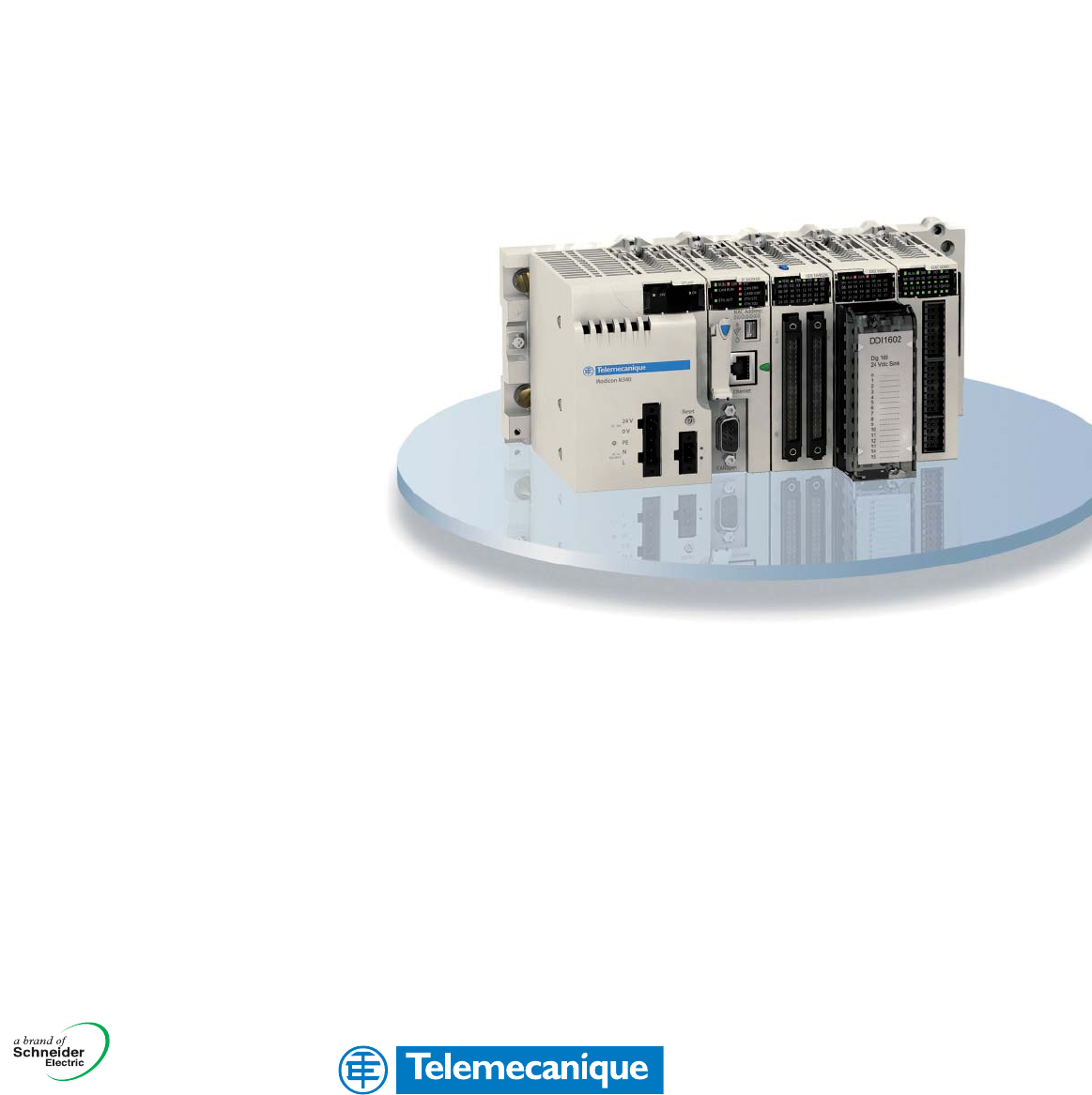
Modicon® M340™ PLC
Automation Platform
Unity™ Software
07
Catalog
June

This international site (www.us.telemecanique.
com) allows you to access all the Telemecanique
products in just 2 clicks via comprehensive range
data-sheets, with direct links to:
■ Complete library: technical documents, catalogs,
certifi cates, FAQs, brochures...
■ Selection guides from the e-catalog.
■ Product discovery sites and their Flash
animations.
You will also fi nd illustrated overviews, news to
which you can subscribe, a discussion forum, the
list of country contacts...
To live automation solutions every day!
Flexibility
■ Interchangeable
modular functions,
to better meet the
requirements for
extensions
■ Software and
accessories common to
multiple product families
Compactness
■ High functionality in a
minimum of space
■ Freedom in
implementation
Ingenuity
■ Auto-adapts to its
environment, “plug &
play”
■ Application functions,
control, communication
and diagnostics
embedded in the
products
■ User-friendly
operation either directly
on the product or
remotely
Openness
■ Compliance with fi eld
bus, connection, and
software standards
■ Enabling
decentralized or remote
surveillance via the web
with Transparent Ready
®
products
Simplicity
■ Cost effective
“optimum” offers that
make selection easy for
most typical applications
■ Products that are easy
to understand for users,
electricians and
automation specialists
■ User-friendly intuitive
programming

1
Contents Modicon® M340™ PLC
Automation Platform
1
Modicon M340 hardware and Unity™ software, a
naturally productive pair . . . . . . . . . . . . . . . . . . . . . . 2
Chapter 1
Modicon M340 processors, racks & power supplies
bProcessor modules . . . . . . . . . . . . . . . . . . . . . . . . . . . . . . . . . . . . . . . . . . . . . . 1/4
bPower supply modules . . . . . . . . . . . . . . . . . . . . . . . . . . . . . . . . . . . . . . . . . 1/10
bSingle rack configuration . . . . . . . . . . . . . . . . . . . . . . . . . . . . . . . . . . . . . . . . . 1/14
Chapter 2
Input/output modules
bDiscrete I/O modules. . . . . . . . . . . . . . . . . . . . . . . . . . . . . . . . . . . . . . . . . . . . . 2/6
bAnalog I/O modules and programmable process control . . . . . . . . . . . . . . . 2/24
bIP 67 and IP 20 distributed I/O modules . . . . . . . . . . . . . . . . . . . . . . . . . . . . . 2/34
bCounter modules and Motion Function Blocks
. . . . . . . . . . . . . . . . . . . . . . . . . 2/36
Chapter 3
Communication
bEthernet TCP/IP network - Transparent Ready® Services . . . . . . . . . . . . . . . . 3/4
bCANopen machine and installation bus. . . . . . . . . . . . . . . . . . . . . . . . . . . . . 3/38
bModbus® communication system and character mode serial link . . . . . . . . . . 3/42
Chapter 4
Unity™ software
bUnity™ software . . . . . . . . . . . . . . . . . . . . . . . . . . . . . . . . . . . . . . . . . . . . . . . . . 4/4
Chapter 5
Connection interfaces
bAdvantys™ Telefast® ABE7 pre-wired I/O system . . . . . . . . . . . . . . . . . . . . . . . 5/8
bPhaseo Universal range of regulated switch mode power supplies . . . . . . . . 5/22
bHMI Operator dialog terminals . . . . . . . . . . . . . . . . . . . . . . . . . . . . . . . . . . . . 5/34
Chapter 6
Services
bTechnical information
vStandards, certifications and environment conditions . . . . . . . . . . . . . . . . . . 6/2
vAutomation product certifications. . . . . . . . . . . . . . . . . . . . . . . . . . . . . . . . . . 6/6
vPower consumption table . . . . . . . . . . . . . . . . . . . . . . . . . . . . . . . . . . . . . . . 6/8
bIndex
vProduct reference index. . . . . . . . . . . . . . . . . . . . . . . . . . . . . . . . . . . . . . . . . 6/9
Advantys™, Altivar®, Atrium™, Concept™, ConneXium™, FactoryCast™, Fipio®, Fip-
way®, Lexium®, Magelis®, Modbus®, Modbus Plus™, Modicon®, M340™, Modsoft®,
Momentum™, Monitor Pro™ OsiTrack™, Phaseo®, PL7™, PowerSuite™, Premium™,
Preventa™, ProWORX™, Quantum™, Tego®, Telefast®, Telemecanique®, TeSys®,
Transparent Ready®, Twido®, TwidoSuite™, Unity™, Unity Pro™, and Vijeo™, are
trademarks or registered trademarks of Schneider Electric.
Other trademarks used herein are the property of their respective owners.
2
Simply Smart! (*)
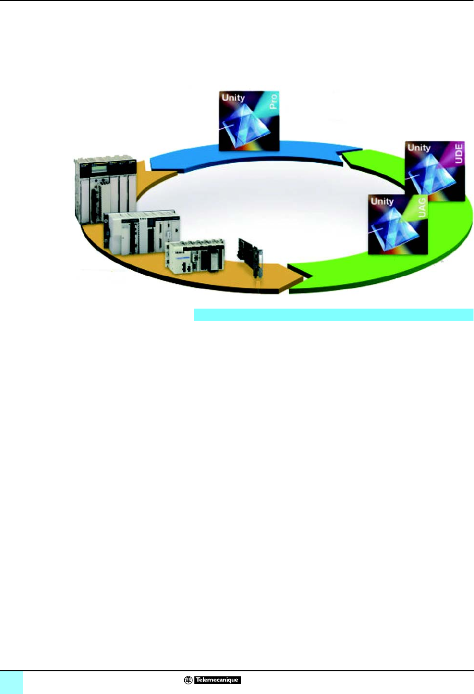
Modicon® hardware platforms and
Unity™ software 0
A naturally productive pair
The family of Modicon PLC platforms associated with Unity software offers you
ingenuity, flexibility and openness to ever-increasing productivity.
Modicon® M340™ PLC concentrates power and innovation, offering the optimum
response to the needs of machine manufacturers. It is also the ideal companion for
Modicon®Premium™ PLC and Modicon® Quantum™ PLC to satisfy the need for
automation of industrial processes and infrastructures.
Modicon® M340™ PLC, the ideal solution for machine
specialists
Robust, powerful and compact, the new Modicon M340 PLC is the ideal solution for
machine manufacturers in applications such as secondary packaging, materials
handling, textiles, printing, food processing, woodworking machines, ceramics, etc.
The integration of Altivar® and Lexium® adjustable speed drives, Magelis® display
units and Preventa™ safety modules has been enhanced to simplify the setup and
use of Telemecanique® solutions.
Modicon M340 PLC is also the ideal companion for Modicon Premium PLC and
Modicon Quantum PLC to meet the demand for automation of industrial processes
and infrastructures, at the heart of Transparent Ready® architectures.
Modicon® Premium™ PLC, the optimum solution for the
manufacturing industry and infrastructures
Modicon Premium PLC stands out as the specialist in complex machines and
manufacturing processes. Its level of performance when processing Boolean,
numeric instructions and instructions on tables make it the market preference.
Thanks to its ability to integrate distributed architectures, Modicon Premium PLC
provides ideal solutions for infrastructure projects, particularly in the water and
transport sectors.
In addition, Modicon® Atrium™ PLC, the version of Modicon Premium PLC in PCI
format, offers a “PC Based” alternative.
Modicon® Quantum™ PLC, the specialist in critical systems in
the process industries and infrastructures
Capable of sophisticated distributed architectures, with an extensive catalog of
modules complemented by several technological partnerships in the context of the
Collaborative Automation program ♦, Modicon Quantum PLC offers a perfect
response to the needs of continuous or semi-continuous industrial processes, and
control of large infrastructure sites.
Capitalizing on more than 25 years' experience in the field of redundancy,
Modicon Quantum PLC is the ideal solution for applications requiring very high levels
of availability. The offer is therefore suitable for critical applications such as
petrochemicals, metallurgy, cement, energy, tunnels and airports.
Programming software
Automation platforms
Modicon® automation platforms
( * ) Smarter and more intelligent, yet even easier to use.
♦ A globally run program, to develop and offer solutions to our
customers

3
Simply Smart! Modicon® hardware platforms and
Unity™ software 0
An organizer environment for Modicon® platforms
Unity Pro™ software is the common programming, debugging and run-time software
for Modicon M340, Premium and Quantum PLCs, and Atrium™ slot PLCs.
Meeting the requirements of an IEC 61131-3 program, Unity Pro software is based
on the acknowledged standards of PL7™ and Concept™ software. It opens the doors
of a complete set of new functions for increased productivity:
bState-of-the-art functionality
bOptimum standardization enabling re-use of developments
bNumerous tools for testing the program and improving system operation
bNew integrated diagnostic services
Migration of existing applications is provided for. This maximizes your software
investment, reduces training costs, and offers unrivaled potential for development
and compatibility.
The Unity software catalog includes specialist software for even better productivity:
bOpenness to developments in C language or in VBA (Visual Basic for Applications)
bDesign and generation of batch/process applications with PLC/HMI integration
Naturally communicative
Based on Ethernet TCP/IP and Web technologies, the Modicon Transparent Ready
automation platforms offer solutions to optimizing performances in electrical
distribution, automation and control.
Modicon controllers offers you the best of Ethernet: Web servers, sending e-mail,
direct database access, device synchronization, and I/O distribution.
The new world of automation
bRather than opting for proprietary systems, Telemecanique has adopted market
standards such as IEC languages, Ethernet TCP/IP, Modbus IDA, XML, OPC, and
IT standards.
bPartnerships with recognized leading hardware and software specialists have
been developed within the scope of the Collaborative Automation Partner Program,
in an effort to share technology more effectively.
bOffers you the ability to design the best solution without compromising on ease of
integration.
Unity™ software
Transparent Ready® Services
Collaborative Automation
4
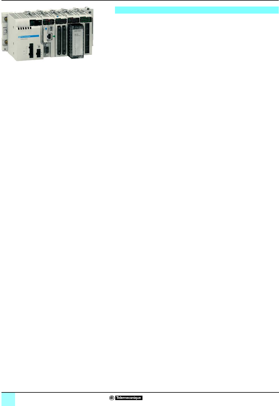
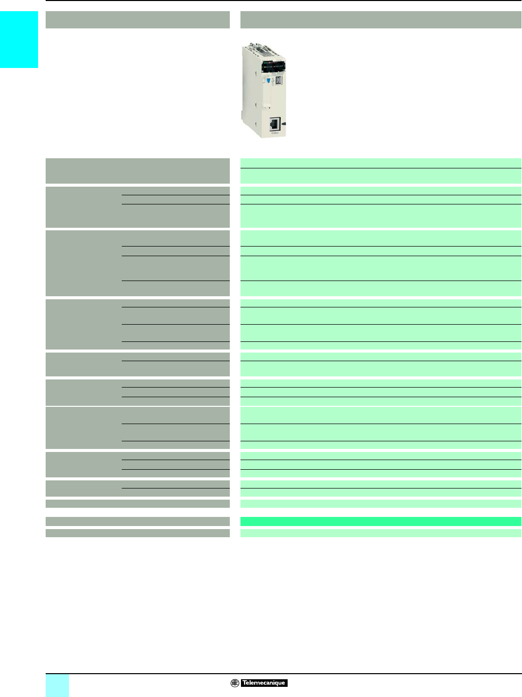
Introduction Modicon®M340™ Automation
Platform 0
Hardware base
Equipped with enhanced memory and functionality, this midrange PLC will give your
applications new capabilities. Designed to operate in total synergy with other
Telemecanique® devices, the Modicon M340 PLC represents pure concentrated
power.
Performance
b7 K instructions/ms
b4 Mb of program memory
b256 Kb of data
Compact design
b3 communication ports integrated in the processor
bH x W x D = 100 x 32 x 93 mm.
bHigh-density discrete I/O modules with 64 channels in a 32 mm wide format.
Communication ports are integrated
bCANopen machine and installation bus
bEthernet TCP/IP network - Transparent Ready® services
bModbus® serial link or character mode
bRemote access via STN, GSM/GPRS, Radio or ADSL
Expert
bCounter modules with ready-to-use functions
bFunction block library dedicated to motion control. MFB (Motion Function Blocks)
to the PLCopen standard
bAdvanced library of process control blocks oriented towards control of machinery
Innovative
bUSB port as standard
bEmbedded Web server
bRecipe file management via FTP protocol
b“Plug and Load” SD memory card
bNo batteries
Ruggedness
bRack architecture enabling hot swapping of modules during operation (Hot-Swap)
bExceeds the standards in terms of shock, vibration, temperature, altitude and
withstand to electrical interference.
As standard, Modicon® M340™ PLC has exclusive services normally reserved for
PLCs in a higher category.
New Modicon® M340™ platform
Modicon M340 platform
5
Introduction (continued) Modicon® M340™ Automation
Platform 0
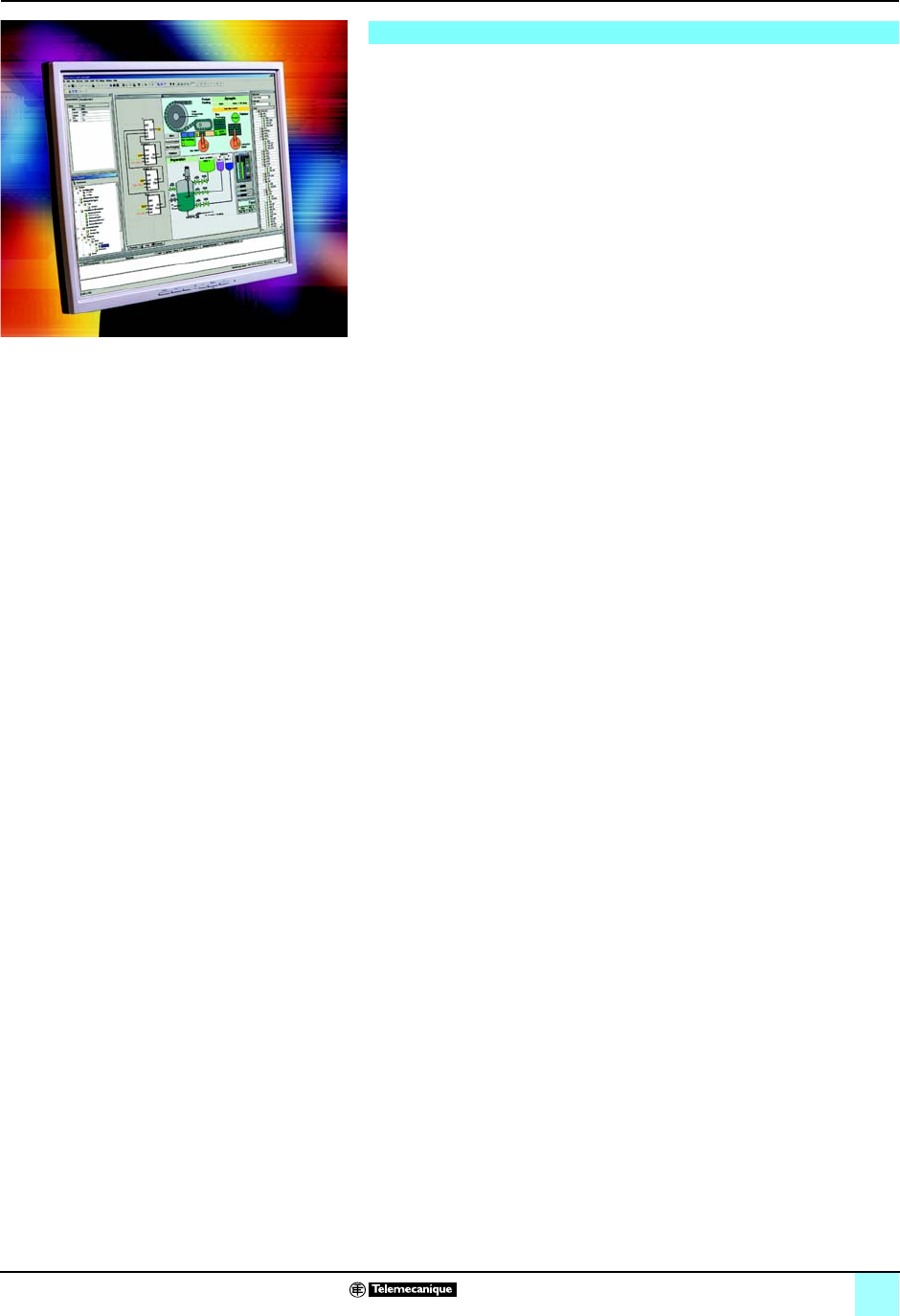
Unity Pro™ software
All-in-one, easy-to-use software
Unity Pro software fully exploits the advantages of the graphic and contextual
interfaces of Windows® XP and Windows® 2000 :
bDirect access to tools and information
b100% graphics-based configuration
bCustomizable toolbar and icons
bAdvanced drag & drop and zoom functions
bIntegrated diagnostic window
All the advantages of standardization
Unity Pro software provides a complete set of functions and tools for applying the
application structure to the structure of the process or machine. The program is
divided into hierarchically-organized function modules containing:
bProgram sections
bAnimation tables
bOperator screens
bHyperlinks
Basic functions that are used repeatedly can be encapsulated in user function blocks
(DFBs) in an IEC 61131-3 language.
Time savings from re-use of modules
Once they have been tested and qualified, your standardized application code
reduce development and installation times on site, thereby optimizing quality and
reducing lead times:
bFunction modules that can be reused in the application or between projects by
XML import/export.
bFunction blocks instantiated by dragging and dropping them from the library.
bInstances can be updated automatically to reflect modifications made in the library
(if this option is selected by the user)
Maximum quality assured
The integrated PLC simulator faithfully reproduces the behavior of the target program
on a PC. All the debugging tools can be used during simulation, to enhance quality
before installation:
bStep-by-step program execution
bBreakpoint and watchpoint
bReal-time animations for displaying the state of the variables and the logic during
operation
Reduced downtime
Unity Pro software features a DFB library for application diagnostics. Integrated into
the program, these DFBs can be used (depending on their function) to monitor
permanent conditions relating to security and the development of a process over
time. A display window provides a clear display of all system and application faults
in chronological order (date-stamped at source). From this window, you can simply
click to access the editor for the program in which the error occurred (search for
missing conditions at source).
Online modifications can be grouped consistently in local mode on a PC and
transferred directly to the PLC in a single operation in order to take effect in the same
scan cycle. A complete range of functions provide the basis for precision control of
your operations, to minimize downtime:
bLog of operator actions on Unity Pro software in a protected file
bUser profile and password protection
bIntegrated graphic runtime screens
Unity™ software productivity

01/0
1

1/1
1
Contents 1 - Processors, power supplies and
racks
1
Modicon® M340™ processors
bProcessor modules
vPresentation, description . . . . . . . . . . . . . . . . . . . . . . . . . . . . . . . . . . . . . . . . 1/4
vMemory structure . . . . . . . . . . . . . . . . . . . . . . . . . . . . . . . . . . . . . . . . . . . . . . 1/6
vCharacteristics . . . . . . . . . . . . . . . . . . . . . . . . . . . . . . . . . . . . . . . . . . . . . . . . 1/8
vReferences . . . . . . . . . . . . . . . . . . . . . . . . . . . . . . . . . . . . . . . . . . . . . . . . . . 1/9
bPower supply modules
vPresentation, description . . . . . . . . . . . . . . . . . . . . . . . . . . . . . . . . . . . . . . . 1/10
vFunctions . . . . . . . . . . . . . . . . . . . . . . . . . . . . . . . . . . . . . . . . . . . . . . . . . . . 1/11
vCharacteristics . . . . . . . . . . . . . . . . . . . . . . . . . . . . . . . . . . . . . . . . . . . . . . . 1/12
vReferences . . . . . . . . . . . . . . . . . . . . . . . . . . . . . . . . . . . . . . . . . . . . . . . . . 1/13
bSingle-rack configuration
vPresentation, description . . . . . . . . . . . . . . . . . . . . . . . . . . . . . . . . . . . . . . . 1/14
vFunctions . . . . . . . . . . . . . . . . . . . . . . . . . . . . . . . . . . . . . . . . . . . . . . . . . . . 1/14
vReferences . . . . . . . . . . . . . . . . . . . . . . . . . . . . . . . . . . . . . . . . . . . . . . . . . 1/15
vDimensions, mounting . . . . . . . . . . . . . . . . . . . . . . . . . . . . . . . . . . . . . . . . . 1/15
1/2
1
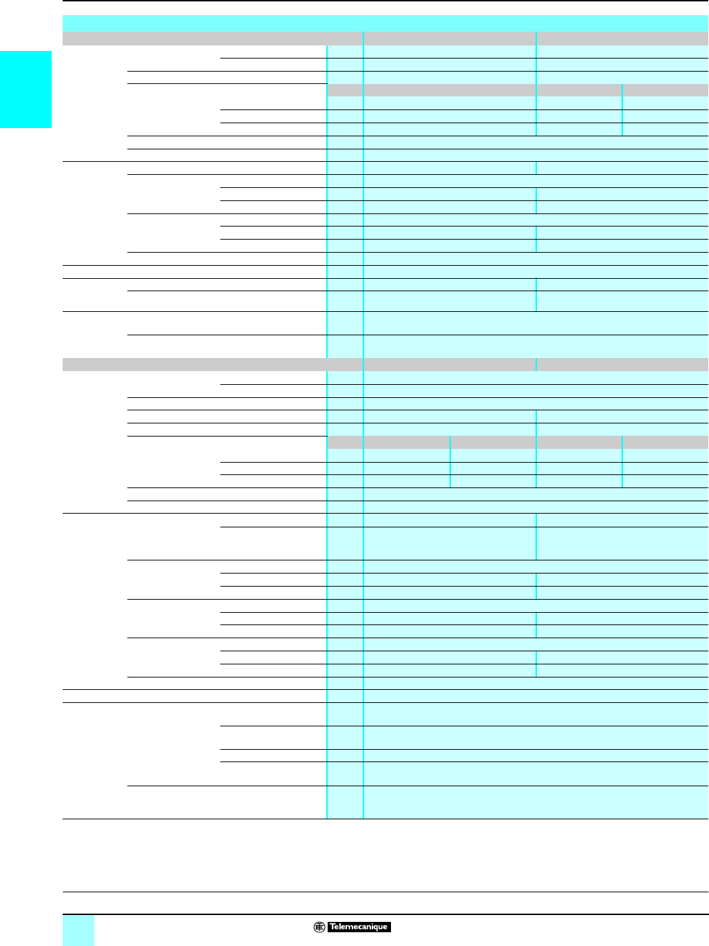
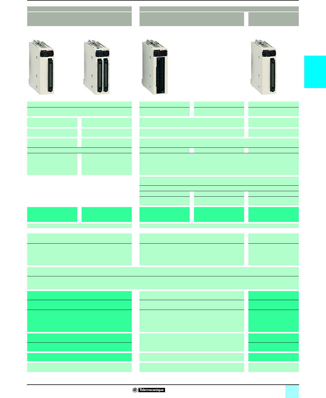
Selection guide Modicon® M340™ Automation
Platform 0
Modicon® M340™ processors
Modicon M340 platform for Unity Pro™ software offer BMX 34 10 Standard processor
Racks Number of racks 1 (4, 6, 8 or 12 slots)
Max. number of slots
(excluding power supply module)
12
Inputs/Outputs In-rack discrete I/O (1) 512 channels (modules with 8, 16, 32 or 64 channels)
In-rack analog I/O (1) 128/66 channels (2) (modules with 2, 4, 6 or 8 channels)
Distributed I/O Limited depending on the type of medium: Over Ethernet TCP/IP network via network module
(63 devices with I/O Scanning function), over Modbus® serial link (32 devices)
In-rack
application-specific
channels
Max. number of channels (counter
and serial link)
20
Counter (1) 2-channel (60 kHz) or 8-channel (10 kHz) modules
Motion control –
Process control, programmable
loops
Process control EFB library
Integrated
communication ports
Ethernet TCP/IP network –
CANopen Master machine and
installation bus
–
Serial link 1 in RTU/ASCII Modbus® communication master/slave mode or in character mode
(non-isolated RS232/RS485, 0.3...19.2 Kbps)
USB port 1 programming port (PC terminal)
Communication
modules
Max. number of networks (1) 1 (BMX NOE 0110/0110 network module)
Ethernet TCP/IP network 1 x 10BASE-T/100BASE-TX (Modbus TCP/IP, BOOTP/DHCP, FDR, Global Data,
I/O Scanning, web server (standard, class B30 or configurable, class C30)
Internal memory
capacity
Internal user RAM 2,048 Kb
Program, constants and symbols 1,792 Kb
Located/unlocated data 128 Kb
Memory card capacity
(on processor)
Backup of program, constants and
symbols
8 Mb as standard
Hosting and display of user web
pages
– (3)
File storage –
Application structure Master task 1
Fast task 1
Event tasks 32
No. of instructions
executed per ms
100% Boolean 5.4 K instructions/ms
65% Boolean + 35% fixed arithmetic 4.2 K instructions/ms
Rack power supply 24 V c isolated, 24…48 V c isolated or 100…240 V a depending on power supply module
Modicon M340 processor BMX P34 1000
Page 1/9
(1) The maximum values for the number of discrete I/O, analog I/O and counter channels and the number of networks are not cumulative (they are limited by the
number of slots in the single-rack configuration, i.e. 11 maximum).
(2) The first value is applied to a multi-rack configuration (not available). The second value corresponds to the physical limit with a single-rack configuration.
(3) User web pages with FactoryCast™ web server module BMX NOE 0110 (16 Mb available).

1/3
1
0
BMX 34 20 Performance processors
1 (4, 6, 8 or 12 slots)
12
1,024/704 channels (2) (modules with 8, 16, 32 or 64 channels)
256/66 channels (2) (modules with 2, 4, 6 or 8 channels)
Limited depending on the type of medium: on CANopen bus (63 devices), on Ethernet TCP/IP network via network module (63 devices with I/O Scanning function),
on a Modbus® serial link (32 devices)
36
2-channel (60 kHz) or 8-channel (10 kHz) modules
MFB (Motion Function Blocks) library (control of
drives or servo drives on the CANopen bus)
–MFB (Motion Function Blocks) library (control of
drives or servo drives on the CANopen bus)
Process control EFB library
–1 x 10BASE-T/100BASE-TX (Modbus TCP/IP, BOOTP/DHCP, FDR, class B10 standard web server)
1 (63 slaves, 50…1,000 Kbps, class M20) –1 (63 slaves, 50…1,000 Kbps, class M20)
1 in RTU/ASCII Modbus master/slave mode or in character mode (non-isolated RS232/RS485,
0.3...19.2 Kbps)
–
1 programming port (PC terminal)
1 (BMX NOE 0100/0110 network module)
1 x 10BASE-T/100BASE-TX [Modbus TCP/IP, BOOTP/DHCP, FDR, Global Data, I/O Scanning, web server (standard, class B30 or configurable, class C30)]
4,096 Kb
3,584 Kb
256 Kb
8 Mb as standard
– (3)
16 Mb (with optional card BMX RMS 008MPF)
1
1
64
8.1 K instructions/ms
6.4 K instructions/ms
24 V c isolated, 24…48 V c isolated or 100…240 V a power supply module
BMX P34 2010 BMX P34 2020 BMX P34 2030
1/9

1/4
1
Presentation Modicon® M340™ Automation
Platform 0
Processor modules
Standard and Performance processors from the Modicon M340 automation platform
manage an entire PLC single-rack station on which a maximum of 11 slots can be
equipped with:
v Discrete I/O modules
v Analog I/O modules
v Application-specific modules (counter, Ethernet TCP/IP communication)
The four processors offered have different memory capacities, processing speeds,
number of I/O and number and type of communication ports.
In addition, depending on the model, they offer a maximum (non-cumulative) of:
v 512 to 1024 discrete I/O
v 128 to 256 analog I/O
v 20 to 36 counter channels
v 0 to 2 Ethernet TCP/IP networks (with or without integrated port and network
module)
Depending on the model, Modicon M340 processors include:
v A 10BASE-T/100BASE-TX Ethernet TCP/IP port
v A CANopen machine and installation bus
v A Modbus® serial link
v A USB type TER port (for a programming terminal)
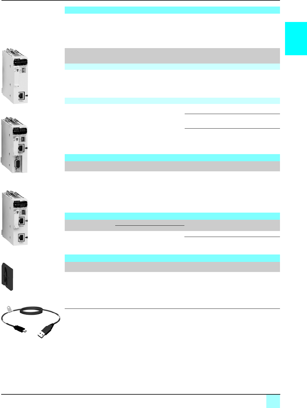
Each processor is supplied with a memory card used for:
v Backing up the application (program, symbols and constants)
v Activating a standard web server for Transparent Ready® service — B10 class
integrated Ethernet port (depending on the model)
This memory card can be replaced by another type of memory card, to be ordered
separately, that supports:
v Backing up the application and activating the standard web server (same as other
card)
v A 16 Mb storage area for additional data organized in a file system (directories
and sub-directories)
To set up processors from the Modicon M340 automation platform, you need either:
bUnity Pro™ Small programming software
bUnity Pro™ Medium, Large or Extra Large programming software identical to that
used to set up Modicon® Premium™ and Modicon® Quantum™ automation platforms
bWith possibly, depending on requirements:
v Unity™ EFB toolkit software for developing EF and EFB libraries in C language
v Unity™ SFC View software for viewing and diagnostics of applications written in
Sequential Function Chart language (SFC) or Grafcet
The function block software libraries provide Modicon M340 processors with the
processing capability required to meet the needs of specialist applications in the
following areas:
bProcess control via programmable control loops (EF and EFB libraries)
bMotion control with multiple independent axis functions (MFB Motion Function
Blocks) library. The axes are controlled by Altivar® 31/71 adjustable speed drives or
Lexium® 05/15 servo drives connected over the CANopen machine and installation
bus.
Presentation
I/O and application-specific
modules
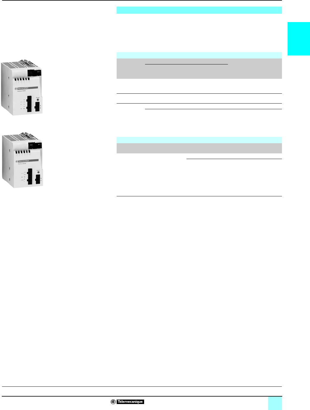
BMX P34 processor
c or a power supply
Modicon M340 automation platform
Programming Modicon® M340™ applications
1/5
1
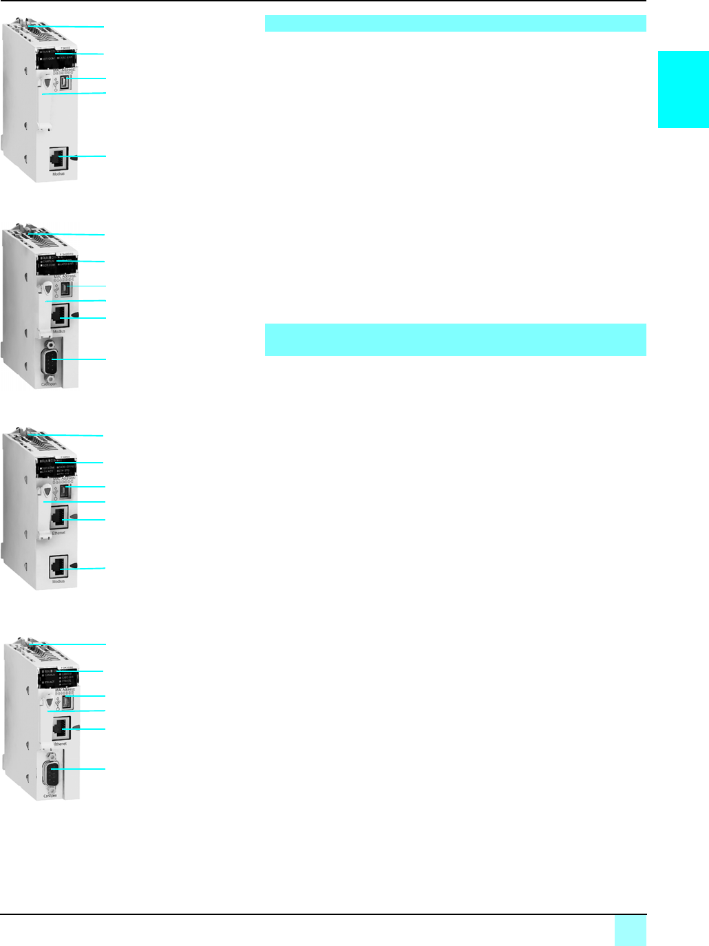
Description Modicon® M340™ Automation
Platform 0
Processor modules
BMX P34 1000/2010 Standard and Performance single-format processors have the
following on the front panel:
1Securing screw for locking the module in its slot (marked 0) in the rack
2A display block comprising 5 or 7 LEDs, depending on the model:
v RUN LED (green): Processor running (program executing)
v ERR LED (red): Processor or system fault
v I/O LED (red): I/O module fault
v SER COM LED (yellow): Activity on the Modbus® serial link
v CARD ERR LED (red): Memory card missing or faulty
With, in addition, for model BMX P34 2010:
v CAN RUN LED (green): Integrated machine/installation bus operational
v CAN ERR LED (red): Integrated machine/installation bus fault
3A mini B USB connector for a programming terminal (or Magelis® XBT GT
operator interface)
4A slot equipped with Flash memory card for backing up the application (an LED,
located above this slot, indicates recognition of or access to the memory card)
5An RJ45 connector for the Modbus® serial link or character mode link (RS
232C/RS-485, 2-wire, non-isolated)
With, in addition, for model BMX P34 2010:
6A 9-pin SUB-D connector for the CANopen master machine and installation bus
BMX P34 2020/2030 Performance single-format processors have the following on
the front panel:
1Securing screw for locking the module in its slot (marked 0) in the rack
2A display block comprising 8 or 10 LEDs, depending on the model:
v RUN LED (green): Processor running (program executing)
v ERR LED (red): Processor or system fault
v I/O LED (red): I/O module fault
v SER COM LED (yellow): Activity on the Modbus® serial link
v CARD ERR LED (red): Memory card missing or faulty
v ETH ACT LED (green): Activity on the Ethernet TCP/IP network
v ETH STS LED (green): Ethernet TCP/IP network status
v ETH 100 LED (red): Data rate on the Ethernet TCP/IP network (10 or 100 Mbps)
With, in addition, for model BMX P34 2030:
v CAN RUN LED (green): Integrated machine/installation bus operational
v CAN ERR LED (red): Integrated machine/installation bus fault
3A mini B USB connector for a programming terminal (or Magelis® XBT GT
operator interface)
4A slot equipped with Flash memory card for backing up the application (an LED,
located above this slot, indicates recognition of or access to the memory card)
5An RJ45 connector for connection to the Ethernet TCP/IP
10BASE-T/100BASE-TX network
Also included, depending on the model:
6BMX P 34 2020 processor: An RJ45 connector for the Modbus® serial link or
character mode link (RS 232C/RS 485, 2-wire, non-isolated)
7BMX P 34 2030 processor: A 9-pin SUB-D connector for the CANopen master
machine and installation bus
On the back panel there are two rotary switches for assigning the IP address. There
are three ways to define this assignment:
v Address set by the position of the two rotary switches
v Address set by the application parameters
v Address set by the Ethernet TCP/IP BOOTP server
Description of BMX P34 1000/2010 processors
BMX P34 2010
BMX P34 1000
BMX P34 2030
6
2
3
5
1
4
5
2
3
1
4
6
2
3
5
1
4
BMX P34 2020
6
2
3
5
1
4
Description of BMX P34 2020/2030 processors with integrated
Ethernet TCP/IP port

1/6
1
Memory structure Modicon® M340™ Automation
Platform 0
Processor modules
Application internal RAM
The application memory is divided into memory areas, physically distributed in the
Modicon M340 PLCs internal RAM:
1Application data area, which may be one of two possible types:
v Located data, corresponding to the data defined by an address (for example%
MW237) with which a symbol can be associated (for example, Counter_reject).
v Unlocated data, corresponding to data defined only by a symbol. The use of
unlocated data eliminates the restrictions of managing the memory location since the
addresses are assigned automatically and also allows data to be structured and
re-used.
This data area is backed up automatically when the PLC is turned off by duplicating
its contents in a 256 Kbyte non-volatile internal memory integrated in the processor.
It is also possible to back up this memory at any time with a user program.
2Program, symbols and comments area: At program level this area contains the
executable binary code and IEC source code.
3Constants area: This area supports the constant located data (%KWi).
4Area for online program modification (see page 1/7)
The user can choose to transfer the source data to the executable program in the
PLC. The fact of having the program source in the PLC means that, when an empty
programming terminal is connected to the PLC, all the elements needed to debug or
upgrade this application can be restored to the terminal. Comments and animation
tables can be excluded from the data embedded in the PLC.
Memory card
Modicon M340 processors are supplied with an SD (Secure Digital) type Flash
memory card. This memory card is intended for backing up the program, symbols
and comments area 2 and the constants area 3.
Duplication (for areas 22 and 33) and retrieval (on return of power) operations are
managed automatically by the system and are therefore transparent to the user.
This card (formatted by Schneider Electric® and supplied with each processor) is
referenced as a replacement part BMX RMS 008MP.
(1) For the size of the different memory areas, see characteristics, page 1/8.
Memory structure
BMX P34 1000/20p0 processor with memory card supplied as standard
1
1
2
3
4
22
33
Located data
Unlocated data
Program, symbols and
comments
Constants
Area for online program
modification
Program, symbols
and comments
Constants
User
internal
RAM
Application
internal
RAM
BMX RMS 008MP
memory card
(supplied as standard)
Application internal RAM (1)
System data

1/7
1
Memory structure (continued) Modicon® M340™ Automation
Platform 0
Processor modules
In place of the BMX RMS 008MP memory card (supplied as standard with each
processor), BMX P34 2010/2020/2030 processors can take the BMX RMS 008MPF
memory card. With the three above-mentioned processors, this card also offers (in
addition to the features of the BMX RMS 008MP card supplied as standard
described on page 1/6):
5A file storage area (for additional data, such as production data and manufacturing
sequences): This area is limited to 16 Mb. These files can be managed from the
application program or by any FTP client connected to the Ethernet TCP/IP port
integrated in the processor.
For BMX P34 2020/2030 processors with integrated Ethernet TCP/IP port, the
BMX RMS 008MPF memory card also offers standard Transparent Ready® web
service - class B10).
The Unity Pro™ programming software assists the application designer with
managing the structure and memory space occupation of the Modicon M340
automation platform.
If necessary, it is possible to prohibit access to the application (in terms of reading or
modifying the program) by only loading the executable code to the PLC.
Additionally, a memory protection bit, set in configuration mode, is also available to
prevent any program modification (via the programming terminal or downloads).
As with Modicon® Premium™ and Quantum™ platforms (with Unity Pro™ software),
the online program modification function is available on the Modicon M340
automation platform with the option of adding or modifying the program code and
data in different places in the application in a single modification session (thus
ensuring modification is homogenous and consistent with the controlled process).
The application internal RAM memory area 4 authorizes these program modification
or addition sessions while observing the recommendation to structure the application
program in several reasonably sized sections.
Memory structure (continued)
BMX P34 20p0 processor with BMX RMS 008MPF memory card
22
33
5
1
1
2
3
4File storage
Located data
Unlocated data
Program, symbols and
comments
Constants
Area for online program
modification
Program, symbols
and comments
Constants
User
internal
RAM
Application
internal
RAM
BMX RMS 008MP
memory card
(supplied as standard)
Application internal RAM (1)
System data
Protecting the application
Modifying the program in online mode

1/8
1
Characteristics Modicon® M340™ Automation
Platform 0
Processor modules
Modicon M340 Micro-PLCs have been designed to conform with the main national and international standards relating to electronic devices for
industrial control systems (see pages 6/2 to 6/7) “Standards, certifications and environmental conditions”.
Characteristics and performance
Processor Standard Performance
BMX P34 1000 BMX P34 2010 BMX P34 2020 BMX P34 2030
Maximum
configuration
No. of racks 4, 6, 8 or 12 slots 1
Max. number of slots for processor and
modules (excluding power supply
module)
12
Functions Max. no. (1) Discrete I/O 512 1,024; 704 in single-rack configuration (64 I/O x 11)
Analog I/O 128; 66 in single-rack
configuration
(4I/2Q x 11)
256; 66 in single-rack configuration (4I/2Q x 11)
Control channels Programmable loops (via CONT-CTL process control EFB library)
Counter channels 20 36
Motion control –Independent axes on
CANopen bus (via
MFB library)
–Independent axes on
CANopen bus (via
MFB library)
Integrated
connections
Ethernet TCP/IP –1 RJ45 port, 10/100 Mbps, with Transparent
Ready® web server - class B10 standard
CANopen master bus –1 (9-pin SUB-D) –1 (9-pin SUB-D)
Serial link 1 RJ45 port, Modbus® communication master/slave RTU/ASCII or
character mode (non-isolated RS 232C/RS 485), 0.3...19.2 Kbps
–
USB port 1 port, 12 Mbps
Communication
module
Ethernet TCP/IP 1 RJ45 port, 10/100 Mbps, with:
- Transparent Ready® web server - class B30 standard with BMX NOE 0100 module
- Transparent Ready® web server - class C30 configurable with BMX NOE 0110 module
Internal user
RAM
Total capacity Kb 2,048 4,096
Program, constants and symbols Kb 1,792 3,584
Data Kb 128 256
Memory card Supplied as standard
(reference BMX RMS 008MP)
Backup of program, constants, symbol and data
–Activation of standard web server, class B10
To be ordered separately
(reference BMX RMS 008MPF)
–Backup of program, constants, symbol and data
–File storage, 16 Mb
–Activation of standard web server, class B10
Maximum size
of object areas
Located internal
bits
Maximum bits 16,250% Mi 32,464% Mi
Default bits 256% Mi 512% Mi
Located internal
data
Maximum Bytes 32,464% MWi internal words, 32,760% KWi constant words
Default Bytes 512% MWi internal
words,
128% KWi constant
words
1,024% MWi internal words, 256% KWi constant words
Max. unlocated internal data Kb 128 (2) 256 (2)
Application
structure
Master task 1 cyclic or periodic
Fast task 1 periodic
Auxiliary tasks –
Event tasks 32 (including 2 with
priority)
64 (including 2 with priority)
Execution time
for one
instruction
Boolean μs0.18 0.12
On words or fixed
point arithmetic
Single-length words μs0.38 0.25
Double-length words μs0.26 0.17
On floating points μs1.74 1.16
No. of
K instructions
executed per
ms
100% Boolean K inst/
ms
5.4 8.1
65% Boolean and 35% fixed arithmetic K inst/
ms
4.2 6.4
System
overhead
Master task ms 1.05 0.70
Fast task ms 0.20 0.13
Power
consumption
With 24 V c voltage mA 72 90 95 135
(1) Only affects in-rack modules. The remote I/O on the CANopen bus are not included in these maximum numbers.
(2) The size of the located data (internal bits and data) and the size of the configuration data should be deducted from this value.
1/9
1
References Modicon® M340™ Automation
Platform 0
Processor modules
(1) For I/O capacity in single-rack configuration, see characteristics, page 1/8.
BMX P34 Modicon® M340™ processors
Modicon M340 processor modules are supplied with the BMX RMS 008MP Flash memory card. This card performs the
following actions transparently:
- Backing up the application (program, symbols and constants) supported in the processor internal RAM that is not backed up
- Activation of the Transparent Ready® web server - class B10 standard (with BMX P34 2020/2030 Performance processors)
This card can be replaced by another card featuring a file storage option.
I/O capacity (1) Memory
capacity
Max. no. of network
modules
Integrated
communication ports
Reference
(3)
Weight
kg
Standard BMX P340 10
512 discrete I/O
128 analog I/O
20 application-specific
channels
2,048 Kb
integrated
1 Ethernet TCP/IP
network
Modbus® serial link BMXP341000 0.200
Performance BMX P340 20
1,024 discrete I/O
256 analog I/O
36 application-specific
channels
4,096 Kb
integrated
1 Ethernet TCP/IP
network
Modbus® serial link
CANopen bus
BMXP342010 0.210
Modbus® serial link
Ethernet TCP/IP
network
BMXP342020 0.205
Ethernet TCP/IP
network
CANopen bus
BMXP342030 0.215
Memory card
Description Use Processor
compatibility
Reference Weight
kg
Memory card 16 Mb As replacement for the memory card
supplied as standard with each
processor, used for:
- Backup of program, constants,
symbol and data
- File storage, 16 Mb
- Activation of class B10 web server
BMX P34 20p0BMXRMS008MPF 0.002
Separate parts
Description Use Length Reference Weight
kg
From To
Terminal port/USB
cord sets
Mini B USB port
on the Modicon
M340 processor
PC terminal type A
USB port
1.8 m BMXXCAUSBH018 0.065
4.5 m BMXXCAUSBH045 0.110
Replacement parts
Description Use Processor
compatibility
Reference Weight
kg
Memory card 8 Mb Supplied as standard with each
processor, used for:
- Backup of program, constants,
symbol and data
- Activation of class B10 web server
BMX P34 1000 / 20p0BMXRMS008MP 0.002
BMX P34 1000
BMX P34 2010/2030
BMX P34 2020
BMX RMS 008MP / MPF
BMX XCA USB H0pp
1/10
1
Presentation,
description
Modicon®M340™ Automation
Platform 0
Power supply modules
BMX CPS ppp0 power supply modules provide the power supply for each
BMX XBP pp00 rack and the modules installed on it.
There are two types of power supply module:
bPower supply modules for AC supplies
bPower supply modules for DC supplies
The power supply module is selected according to:
v The electrical line supply: 24 V c, 48 V c or 100...240 V a
v The required power (see the power consumption table on page
6/8
)
(1)
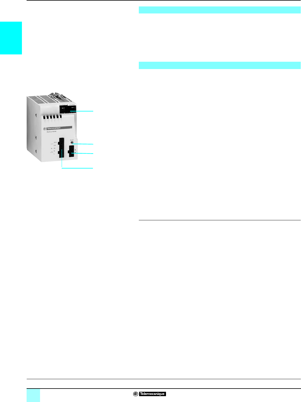
BMX CPS ppp0 power supply modules have the following on the front panel :
1 A display block comprising:
v OK LED (green), lit if rack voltages are present and correct
v 24 V LED (green), lit when the sensor voltage is present (for BMX CPS 2000/3500
AC power supply modules only)
2A pencil-point RESET push button for a cold restart of the application
3A 2-pin connector that can receive a removable terminal block (screw
or
spring-type)
for connecting the alarm relay
4A 5-pin connector that can receive a removable terminal block (screw
or
spring-type)
for connecting the following:
v c or a line supply
v Protective earth ground
v Dedicated 24 V c power supply for the input sensors (for BMX CPS 2000/3500
AC power supply modules only)
To be ordered separately:
Pack of two removable terminal blocks, depending on the model:
v Screw clamp BMX XTS CPS10
v Spring-type BMX XTS CPS20
(1) This power consumption calculation for the rack can also be performed by the Unity Pro™
programming software.
Presentation
Description
Functions:
page 1/11
Characteristics:
page 1/12
References:
page 1/13
1
3
4
2

1/11
1
Functions Modicon®M340™ Automation
Platform 0
Power supply modules
The alarm relay located in each power supply module has a voltage-free contact
accessible from the front of the 2-pin connector.
The operating principle is as follows:
In normal operation, with the PLC in RUN, the alarm relay is activated and its contact
is closed (state 1).
The relay de-energizes and its associated contact opens (state 0) whenever the
application stops, even partially, due to any of the following:
bOccurrence of a blocking fault
bIncorrect rack output voltages
bLoss of supply voltage
The power supply module in each rack has a RESET button on the front panel;
when activated, this triggers an initialization sequence for the processor and the rack
modules it supplies.
Pressing this push button triggers a sequence of service signals, which is the same
as that for:
bA power break when the push button is pressed
bA power-up when the push button is released
These operations represent a cold start (forcing the I/O modules to state 0 and
initializing the processor).
The BMX CPS 2000/3500 AC power supply modules have an integrated 24 V c
voltage supply for powering the input sensors. Connection to this sensor power supply
is via the 5-pin connector on the front panel.
The power available on this 24 V cvoltage depends on the power supply model (0.45
or 0.9 A) (see characteristics on page 1/12).
Functions
Alarm relay
RESET push button
Sensor power supply
Presentation:
page 1/10
Description:
page 1/10
Characteristics:
page 1/12
References:
page 1/13
1/12
1
Characteristics Modicon®M340™ Automation
Platform 0
Power supply modules
(1) These values should be considered when starting several devices simultaneously and when
sizing protection devices.
(2) 3.3 V
c
voltage for the I/O module logic power supply
(3) 24 V
c
voltage for the I/O module power supply and the processor
(4) 24 V
c
sensor output for the sensor power supply
(5) Protected by a fuse that cannot be accessed
Characteristics
c power supply module BMX CPS 2010 BMX CPS 3020
Primary Voltage Nominal V24 c isolated 24...48 c isolated
Limit (including ripple) V18...31.2 c18...62..4 c
Current Input nominal I rms A1 at 24 V c1.65 at 24 V c; 0.83 at 48 V c
Initial power-up
at 25 °C
(1)
V24 c24 c48 c
I inrush A30 30 60
I2t on activation A2s≤ 0.6 ≤ 1≤ 3
It on activation As ≤ 0.15 ≤ 0.2 ≤ 0.3
Micro-break duration Line (accepted) ms ≤ 1
Integrated protection With internal fuse (not accessible)
Secondary Useful power Max. W17 32
3.3 V c voltage
(2)
Nominal voltage V3.3
Nominal current A2.5 4.5
Typical power W8.25 14.85
24 V c output
(3)
Nominal voltage V24 c
Nominal current A0.7 1.3
Typical power W16.8 31.2
Integrated protection on the voltages (4) Yes, against overloads, short-circuits and overvoltages
Max. dissipated power W8.5
Max. length of
power supply
cable
Copper wires with 1.5 mm2 cross-section m20 10
Copper wires with 2.5 mm2 cross-section m30 15
Insulation Dielectric strength Primary/secondary
and primary/ground
V rms 1,500 - 50 Hz for 1 min at an altitude of 0...4,000 m
Insulation resistance Primary/secondary
and primary/ground
MΩ ≥ 10
a power supply module BMX CPS 2000 BMX CPS 3500
Primary
Voltages Nominal V100...240 a
Limit (including ripple) V85...264 a
Frequencies Nominal/limit Hz 50-60/47-63
Power Apparent VA 70 120
Current Input nominal I rms A rms 0.61 at 115 V a; 0.31 at 240 V a1.04 at 115 V a; 0.52 at 240 V a
Initial power-up
at 25 °C
(1)
V120 a240 a120 a240 a
I inrush A≤ 30 ≤ 60 ≤ 30 ≤ 60
I2t on activation A2s≤ 0.5 ≤ 2≤ 1≤ 3
It on activation As 0.03 0.06 ≤ 0.05 ≤ 0.07
Micro-break duration Line (accepted) ms ≤ 10
Integrated protection With internal fuse (not accessible)
Secondary Useful power Max. overall W20 36
Max. on 3.3 V c and
24 V c rack output
voltages
W16.5 31.2
3.3 V c voltage
(2)
Nominal voltage V3.3
Nominal current A2.5 4.5
Power (typical) W8.25 14.85
24 V rack c voltage
(3)
Nominal voltage V24 c
Nominal current A0.7 1.3
Typical power W16.8 31.2
24 V c sensor voltage
(4)
Nominal voltage V24 c
Nominal current A0.45 0.9
Typical power W10.8 21.6
Integrated protection on the voltages (5) Yes, against overloads, short-circuits and overvoltages
Maximum dissipated power W8.5
Insulation Dielectric strength Primary/secondary
(24 V/3.3 V)
V rms 1500
Primary/secondary
(sensor 24 V)
V rms 2300
Primary/ground V rms 1500
24 V sensor
output/ground
V rms 500
Insulation resistance Primary/secondary and
primary/ground
MΩ ≥ 100
Presentation:
page 1/10
Description:
page 1/10
Functions:
page 1/11
References:
page 1/13
1/13
1
References Modicon®M340™ Automation
Platform 0
Power supply modules
Each BMX XBP pp00 rack must be equipped with a power supply module. These
modules are inserted into the first two slots of each rack (marked CPS).
The power required to supply each rack depends on the type and number of modules
installed in the rack. It is therefore necessary to draw up a power consumption table
rack by rack to determine the BMX CPS ppp0 power supply module most suitable
for each rack (see page 6/8).
(1) The sum of the absorbed power on each voltage (3.3 V
c
and 24 V
c
) should not exceed
the total power of the module. See the power consumption table on page
6/8
(2) 3.3 V
c
and 24 V rack
c
voltages for powering Modicon M340 PLC modules
(3) 24 V
c
sensor voltage for powering the input sensors (voltage available via the 2-pin
removable connector on the front panel)
References
Power supply modules
Line supply Available power (1) Reference Weight
kg
3.3 V c (2) 24 V
rack c (2)
24 V
sensor c
(3)
Total
24 V c
isolated
8.3 W 16.5 W – 16.5 W BMXCPS2010 0.290
24...48 V c
isolated
15 W 31.2 W – 31.2 W BMXCPS3020 0.340
100...240 V a8.3 W 16.5 W 10.8 W 20 W BMXCPS2000 0.300
15 W 31.2 W 21.6 W 36 W BMXCPS3500 0.360
Separate parts
Description Composition Type Reference Weight
kg
Pack of 2
removable
connectors
One 5-pin terminal
block and one 2-pin
terminal block
Cage clamp BMXXTSCPS10 0.020
Spring-type BMXXTSCPS20 0.015
BMX CPS 2010 / 3020
BMX CPS 2000 / 3500
Presentation:
page 1/10
Description:
page 1/10
Functions:
page 1/11
Characteristics:
page 1/12
1/14
1
Presentation,
description,
function
Modicon® M340™ Automation
Platform 0
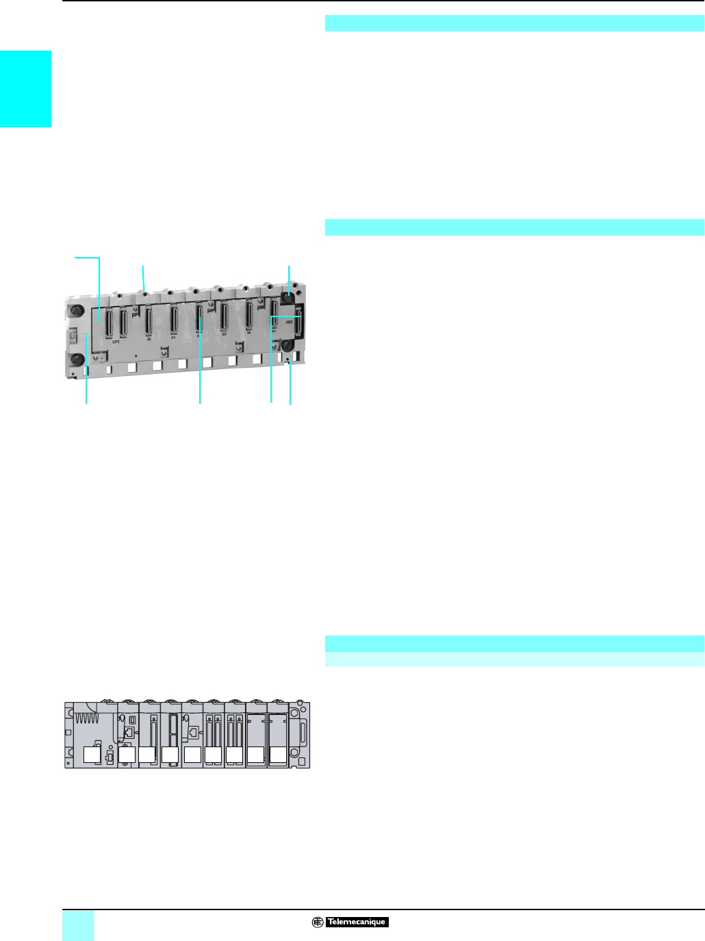
Single-rack configuration
BMX XBP pp00 racks are the basic element of the Modicon M340 automation
platform in a single-rack configuration.
These racks perform the following functions:
bMechanical function: They are used to install all the modules in a PLC station
(power
supply, processor, discrete I/O, analog and application-specific I/O). These
racks can be mounted on a panel, plate or DIN rail:
v Inside enclosures
v On machine frames, etc.
bElectrical function: The racks incorporate a Bus X. They are used to:
v Distribute the power supplies required for each module in the same rack
v Distribute data and service signals for the entire PLC station
v Hot swap modules during operation
BMX XBP pp00 racks are available in 4, 6, 8 or 12-slot versions, and comprise:
1A metal frame that performs the following functions:
v Holds the Bus X electronic card and protects it against EMI and ESD type
interference
v Holds the modules
v Gives the rack mechanical rigidity
2A ground terminal for grounding the rack
3Holes for mounting the rack on a frame. These holes are big enough for M6
screws.
4Connecting points for the shielding connection bar
5Tapped holes to receive each module locking screw
6A connector for an expansion module. This connector (marked XBE) is not used for
this version.
740-pin female ½ DIN connectors forming the connection between the rack and
each module. When the rack is delivered, these connectors are protected by
covers that should be removed before inserting the modules.
Slots for anchoring the module pins
To be ordered separately:
BMX XSP pp00 cable shielding connection kit, used to protect against electrostatic
discharge when connecting the shielding of cord sets for connecting:
v Analog modules
v A Magelis® XBT operator interface to the processor (via BMX XCA USBH0pp
shielded USB cable)
This kit comprises:
8A metal bar that receives the clamping rings
9Two sub-bases to be mounted on the rack
10 A set of spring clamping rings for attaching cables with their shielding to the metal bar.
Packs of 10 STB XSP 30p0 clamping rings can be ordered in addition if required.
Each rack must contain a power supply module and a processor module.
Inserting different modules into the rack:
v The power supply module always occupies the CPS slot.
v The processor module must always be installed in slot 00.
v Its I/O modules and application-specific modules are installed in slot 01 to slot ...
- 03 with a 4-slot rack
- 05 with a 6-slot rack
- 07 with an 8-slot rack
- 11 with a 12-slot rack
Presentation
Description
Function
Addressing modules in a single-rack configuration
274
15 3
Rack 6 slots BMX XBP 0600
6
CPS 01 02 03 04 05 06 0700
Example of installation with 8-slot rack
1/15
1
References,
dimensions,
mounting
Modicon® M340™ Automation
Platform 0
Single-rack configuration
Racks
Description Type of module
to be inserted
No. of slots
(1)
Reference Weight
kg
Racks BMX CPS power supply,
BMX P34 processor, I/O
modules and
application-specific
modules (counter,
communication)
4
BMXXBP0400
1.470
6
BMXXB0600
1.750
8
BMXXBP0800
2.310
12
BMXXBP1200
–
Accessories
Description For use with Unit reference Weight
kg
Shielding connection
kits comprising:
-a metal bar
- two sub-bases
- one set of spring
clamping rings
BMX XBP 0400 rack
BMXXSP0400
0.280
BMX XBP 0600 rack
BMXXSP0600
0.310
BMX XBP 0800 rack
BMXXSP0800
0.340
BMX XBP 1200 rack
BMXXSP1200
0.400
Spring clamping rings
(pack of 5)
Cables with 1.5…6 mm2 cross-section STBXSP3010 0.050
Cables with 5…11 mm2 cross-section STBXSP3020 0.070
Protective covers
(pack of 5)
Unoccupied slots on BMX XBP pp00
rack
BMXXEM010 0.005
(1) Number of slots receiving the processor module, I/O modules and application-specific
modules (excluding power supply module).
BMX XBP 0400
BMX XBP 1200
BMX XBP 0800
BMX XSP
pp
00 STB XSP 30p0
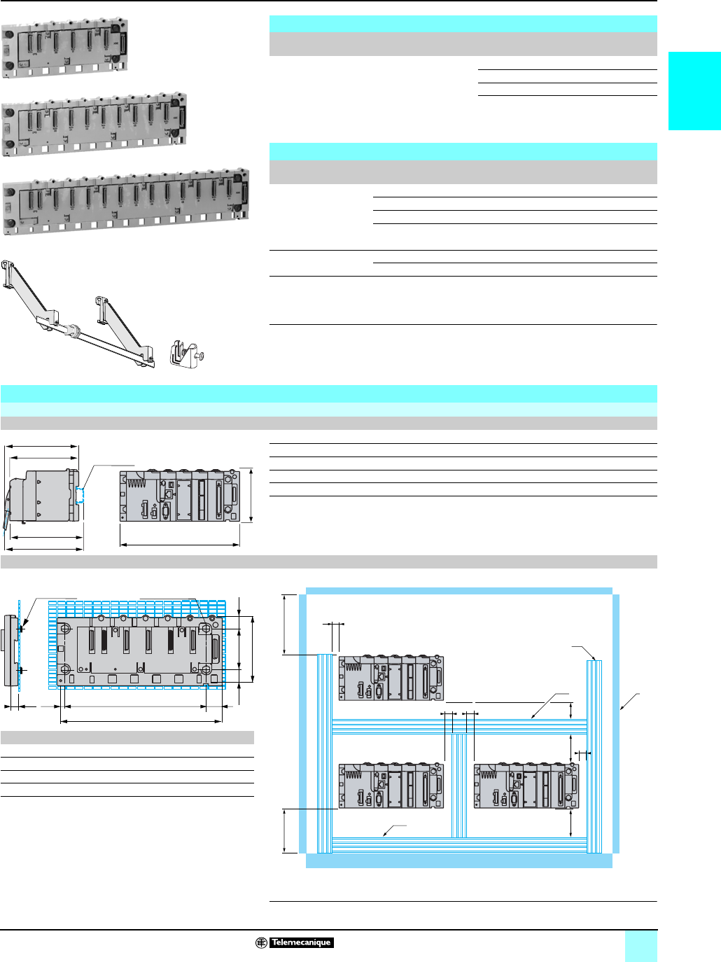
Dimensions, mounting
BMX XBP
Common side view Front view: BMX XBP example
a
BMX XBP 0400 242.4
BMX XBP 0600 307.6
BMX XBP 0800 372.8
BMX XBP 1200 503.2
(1) With removable terminal block (cage, screw or spring).
(2) With FCN connector.
Mounting the racks
On AM1 PA and AM3 PA pre-slotted plate Installation rules
a b
BMX XBP 0400 207.8 242.2
BMX XBP 0600 273 307.6
BMX XBP 0800 338.2 372.8
BMX XBP 1200 468.6 503.2
(1) On AM1 ED rail: 35 mm wide, 15 mm deep Only possible
with BMX XBP 0400/0600/0800 rack.
(2) For panel-mounting: The diameter of the mounting holes must
be sufficient to accept M4, M5, M6 screws ( 4.32 to 6.35).
a ≥ 3 mm
(1) Equipment or enclosure.
(2) Cable ducting or clip.
150
(2)
140
(1)
150
(1)
160
(2)
a
100
Rail (1)
a
b
11,2
60 1624
100
23,4
19
AF1-EA6 4 holes (2)
(2)
u 60 u 80
(2)
aa
u 80 u 60
u 60
(1)
(2)
a
a

02/0
2

2/1
2
Contents 2 - Input/output modules
1
Discrete I/O modules
bDiscrete I/O modules
vPresentation, description . . . . . . . . . . . . . . . . . . . . . . . . . . . . . . . . . . . . . . . . 2/6
vFunctions . . . . . . . . . . . . . . . . . . . . . . . . . . . . . . . . . . . . . . . . . . . . . . . . . . . . 2/8
vCharacteristics . . . . . . . . . . . . . . . . . . . . . . . . . . . . . . . . . . . . . . . . . . . . . . . 2/10
vReferences . . . . . . . . . . . . . . . . . . . . . . . . . . . . . . . . . . . . . . . . . . . . . . . . . 2/16
vConnections. . . . . . . . . . . . . . . . . . . . . . . . . . . . . . . . . . . . . . . . . . . . . . . . . 2/18
Analog I/O modules and process control
bAnalog I/O modules
vPresentation, description . . . . . . . . . . . . . . . . . . . . . . . . . . . . . . . . . . . . . . . 2/24
vConnections. . . . . . . . . . . . . . . . . . . . . . . . . . . . . . . . . . . . . . . . . . . . . . . . . 2/25
vFunctions . . . . . . . . . . . . . . . . . . . . . . . . . . . . . . . . . . . . . . . . . . . . . . . . . . . 2/26
vCharacteristics . . . . . . . . . . . . . . . . . . . . . . . . . . . . . . . . . . . . . . . . . . . . . . . 2/28
vReferences . . . . . . . . . . . . . . . . . . . . . . . . . . . . . . . . . . . . . . . . . . . . . . . . . 2/31
bProgrammable process control . . . . . . . . . . . . . . . . . . . . . . . . . . . . . . . . . . . . 2/32
Distributed I/O modules
Counter modules and Motion Function Blocks
bCounter modules
vPresentation, description . . . . . . . . . . . . . . . . . . . . . . . . . . . . . . . . . . . . . . . 2/36
vFunctions . . . . . . . . . . . . . . . . . . . . . . . . . . . . . . . . . . . . . . . . . . . . . . . . . . . 2/37
vCharacteristics . . . . . . . . . . . . . . . . . . . . . . . . . . . . . . . . . . . . . . . . . . . . . . . 2/40
vReferences . . . . . . . . . . . . . . . . . . . . . . . . . . . . . . . . . . . . . . . . . . . . . . . . . 2/41
vConnections. . . . . . . . . . . . . . . . . . . . . . . . . . . . . . . . . . . . . . . . . . . . . . . . . 2/42
bMFB, Motion Function Blocks . . . . . . . . . . . . . . . . . . . . . . . . . . . . . . . . . . . . . 2/44

2/2
2
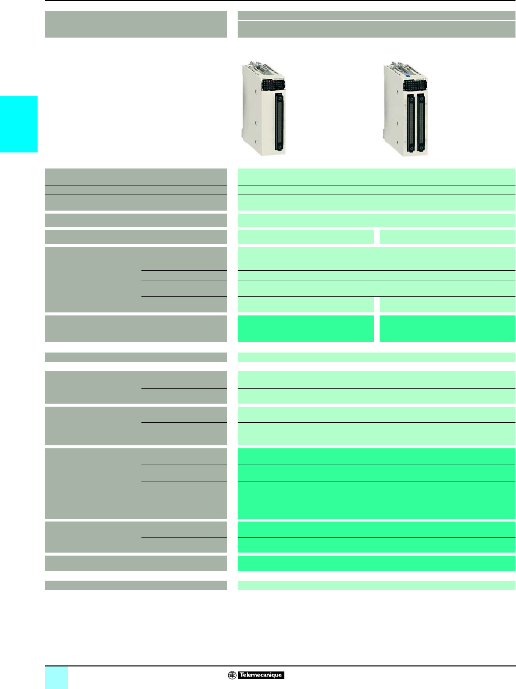
Selection guide Modicon®M340™ Automation
Platform 0
Discrete I/O modules
Input modules and mixed I/O modules
Applications 16-channel input modules
Connection via cage clamp, screw clamp or spring-type removable terminals
Type c c or a a
Voltage 24 V 48 V 24 V 48 V 100…120V
Modularity
(Number of channels)
16 isolated channels
Connection Via BMX FTB 2000/2010/2020 20-pin cage clamp, screw clamp or spring-type removable
terminals
Isolated inputs IEC 1131-2 conformity Type 3 Type 1 Type 1 (a)Type 3
Logic Positive Pos. or neg. –
Sensor compatibility in
accordance with standard
IEC 947-5-2
2-wire c, 3-wire c PNP any type 2-wire c/a,
3-wire c PNP
or NPN any
type
2-wire a
Isolated outputs Fallback
IEC 1131-2 conformity
Protection
Logic
Module BMX
DDI 1602
BMX
DDI 1603 r
BMX
DAI 1602 r
BMX
DAI 1603 r
BMX
DAI 1604
Page 1/16
Compatibility with
installation help system
Tego® Dial –
TeSys® Quickfit –
Compatibility with
Advantys™Telefast® ABE7
pre-wired I/O system
Connection sub-bases –
Input and output adapter
sub-bases
–
Passive connection sub-base Optimum “Economy” –
Optimum “Miniature” –
Universal –
Relay adapter sub-base Fixed relays –
Plug-in relays –
Preformed cord sets with 40-pin connector –
Pages –
r Available 4th quarter 2007
2/3
2
0
32/64-channel high-density input modules 16/32-channel mixed I/O modules
Connection via 40-pin connectors with preformed cord
sets
Connection via cage clamp, screw clamp or spring-type
removable terminals
Connection via 40-pin
connectors with
preformed cord sets
c c c and a (outputs only) c
24 V 24 V I/O 24 V inputs, relay outputs 24 V I/O
32 isolated channels 64 isolated channels 8 isolated inputs and 8 isolated outputs 16 isolated inputs and
16 isolated outputs
Via one 40-pin connector Via two 40-pin connectors Via BMX FTB 2000/2010/2020 20-pin cage clamp, screw
clamp or spring-type removable terminals
Via one 40-pin connector
Type 3 Non-IEC Type 3
Positive Positive –Positive
2-wire c,3-wire cPNP
any type
–
Configurable output fallback, continuous monitoring of output control and resetting of outputs
in case of internal fault
Yes
Protected Not protected Protected
Positive –Positive
BMX DDI 3202K BMX DDI 6402K BMX DDM 16022 BMX DDM 16025 BMX DDM 3202K
1/16 1/17
APE 1B24M Dialbase interface with 8I/8Q –APE 1B24M Dialbase
interface
LU9 G02 splitter boxes (8 motor starters) and
BMX FCC pp1/pp3 preformed cord sets
–LU9 G02 splitter boxes
(8 motor starters) and
BMX FCC pp1/pp3
preformed cord sets
Depending on model, 8- or 16-channel passive sub-bases, with or without LED, with common or 2 terminals per channel
Depending on model, 16-channel active sub-bases with solid state or electromechanical, fixed or removable relays, 5...48 V c, 24 V c, 24 V...240 V a or
voltage-free, with common or 2 terminals per channel, screw or spring-type connection
ABE7H20Ep00 – ABE7H20Ep00
ABE7H16Cpp –ABE7H16Cpp
ABE7H08Rpp/7H08S21,
ABE7H16R1p/7H16R50,
ABE7H16R2p/7H16S21,
ABE7H16R3p/7H16R23,
ABE7H16S43,
–ABE7H08Rpp/7H08S21,
ABE7H16R1p/7H16R50,
ABE7H16R2p/7H16S21,
ABE7H16R3p/7H16R23,
ABE7H16S43/7H16F43
ABE7S16E2pp –ABE7S16E2pp
ABE7S16Sppp/7R16S
ABE7P16F31pp –ABE7P16F31pp
ABE7R16Tppp/7P16Tppp
BMX FCC pp1/FCC pp3 –BMXFCC pp3
5/10 to 5/16, 2/17 –5/10 to 5/16, 2/17
2/4
2
Selection guide (continued) Modicon®M340™ Automation
Platform 0
Discrete I/O modules
Output modules
Applications 32/64-channel high-density output modules
Connection via 40-pin connectors with preformed cord sets
Type c solid state
Voltage 24 V
Current 0.1 A per channel
Modularity
(Number of channels)
32 protected channels 64 protected channels
Connection Via one 40-pin connector Via two 40-pin connectors
Isolated outputs Fallback Configurable output fallback, continuous monitoring of output control and resetting of outputs in
case of internal fault
IEC 1131-2 conformity Yes
Protection Current limiter with electronic tripping
Logic Positive –
Discrete output module BMX DDO 3202K BMX DDO 6402K
Page 2/16
Compatibility with
installation help system
Tego® Dial –
TeSys® Quickfit –
Compatibility with
Advantys™Telefast® ABE7
pre-wired I/O system
Connection sub-bases –
Input adapter sub-bases –
Passive sub-base Optimum “Economy” ABE7H20Ep00
Optimum “Miniature” ABE7H16Cpp
Universal ABE7H08Rpp/7H08S21,
ABE7H16R1p/7H16R50,
ABE7H16R2p/7H16S21,
ABE7H16R3p
ABE7H16F43
Relay adapter sub-base Fixed relays ABE7S16Sppp / 7R16S
Removable relays ABE7R16Tppp/7P16Tppp
Preformed cord sets with 40-pin connector BMXFCCpp1/FCC pp3
Pages 5/10 to 5/16, 2/17

2/5
2
0
16-channel output modules 8/16-channel output modules
Connection via cage clamp, screw clamp or spring-type removable terminals
c solid state a triac c/a relay
24 V c100…240 V 24 V c, 24...240 V a
0.5 A per channel 0.6 A per channel 3 A (Ith) per channel 2 A (Ith) per channel
16 protected channels 16 non-protected channels 8 non-protected channels 16 non-protected channels
Via BMX FTB 2000/2010/2020 20-pin cage clamp, screw clamp or spring-type removable terminals
Configurable output fallback, continuous monitoring of output
control and resetting of outputs in case of internal fault
Configurable output fallback
Yes Yes
Current limiter with electronic tripping –
Positive Negative –
BMX DDO 1602 BMX DDO 1612 r BMX DAO 1605 rBMX DRA 0805 BMX DRA 1605
2/16
–
–
–
–
–
–
–
–
–
–
–
r Available 4th quarter 2007
2/6
2
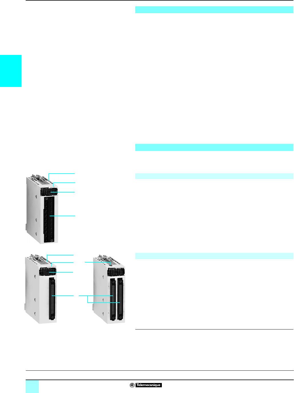
Presentation,
description
Modicon®M340™ Automation
Platform 0
Discrete I/O modules
Discrete I/O modules in the Modicon M340 PLC offer are standard modules
occupying a single slot, equipped with either of the following:
v A connector for a screw or spring-type 20-pin removable terminal block
v One or two 40-pin connector(s)
A wide range of discrete inputs and outputs can be used to meet whatever
requirements arise in terms of:
v functions: AC or DC I/O, positive or negative logic
v modularity: 8, 16, 32 or 64 channels per module
The inputs receive signals from the sensors and perform the following functions:
v acquisition
v adaptation
v electrical isolation
v filtering
v protection against interference signals
The outputs memorize commands issued by the processor to enable control of the
actuators via the decoupling and amplification circuits.
BMX DpI/DpO/DRA discrete I/O modules are standard format (1 slot). Their case
ensures IP 20 protection of the electronics, and they are locked into position by a
captive screw.
1Rigid body providing support and protection for the electronic card
2Module reference marking (a label is also visible on the right-hand side of the
module)
3Channel status display block
4Connector accepting the 20-pin removable terminal block for connecting sensors
or preactuators
To be ordered separately:
A BMX FTB 20p0 20-pin removable terminal block or a preformed cord set with a
20-pin removable terminal block at one end and wires at the other (see page 2/7.
1Rigid body providing support and protection for the electronic card
2Module reference marking (a label is also visible on the right-hand side of the
module)
3Channel status display block
4One or two 40-pin connectors (32 or 64 channels) (1) for connecting sensors or
preactuators
5With the 64-channel module, a push button which, with successive presses,
displays the state of channels 0...31 or 32...63 on the block 3 (see page 2/9)
To be ordered separately, depending on the type of module:
One or two preformed cord set(s) with a 40-pin connector (see page 2/7).
(1) Fujistu FCN 40-pin connector
Presentation
Description
I/O modules connected via 20-pin removable terminal block
I/O modules connected via 40-pin connector
1
8
4
2
Module and 20-pin removable terminal block
1
8
4
2
32- and 64-channel modules with for connection via
40-pin connector(s)
5
Characteristics:
pages 2/11 to 2/15
References:
pages 2/16 to 2/17
Connections:
pages 2/18 to 2/21
2/7
2
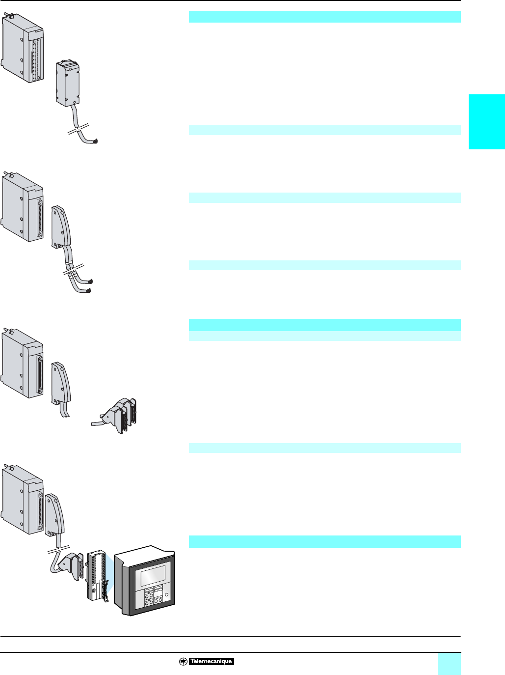
There are three types of 20-pin removable terminal blocks:
v Screw clamp terminal block
v Cage clamp terminal block
v Spring-type terminal block
Each removable terminal block can accept:
v Bare wires
v Wires equipped with DZ5-CE cable ends
One version of the removable terminal block is equipped with BMX FTWpp1 cord
sets with color-coded wires (3, 5 or 10 m long).
The capacity of each terminal is:
v Minimum: One 0.34 mm2 wire (22 AWG)
v Maximum: One 1.5 mm2 wire (14 AWG)
BMX FTB 2000 cage clamp connectors are equipped with captive screws
maximum tightening torque 0.5 N.m (4.4 lb-in).
The capacity of each terminal is:
v Minimum: One or two 0.34 mm2 wires (22 AWG)
v Maximum: Two 1.5 mm2 wires (14 AWG)
BMX FTB 2010 screw clamp connectors are equipped with captive screws
maximum tightening torque 0.5 N.m (4.4 lb-in).
The capacity of each terminal in the BMX FTB 2020 spring-type terminal blocks is:
v Minimum: Two 0.34 mm2 wires (22 AWG)
v Maximum: Two 1.5 mm2 wires (14 AWG)
Preformed cord sets can be used for easy direct wire-to-wire connection between the
I/O of modules with connectors 1, and the sensors, preactuators or intermediate
terminals.
These preformed cord sets comprise:
v At one end, a 40-pin connector 2, with either of the following:
- One sheath
3
,
containing 20 wires sized 0.34 mm
2
(22 AWG) (BMX FCW pp1)
- Two sheaths
4
, each containing 20 wires sized 0.34 mm
2
(22 AWG)
(BMX FCW pp3)
v At the other end
5
, color-coded wires conforming to standard DIN 47100 (see page
2/21)
Two types of cord sets can be used for connecting the I/O modules with 40-pin
connectors 1, using the Advantys™ Telefast® ABE7 pre-wired I/O system of rapid
wiring connections, and 2, adaptation interfaces (see page 5/8).
These preformed cord sets comprise:
v At one end, a 40-pin connector 3, with either of the following:
- One sheath
4
, containing 20 wires (BMX FCC pp1)
- Two sheaths
5
, each containing 20 wires (BMX FCC pp3)
v At the other end, one or two HE 10 connectors
6
BMX DDI 3202K/6402K input modules and BMX DDO 3202K/6402K output
modules
1
are designed for use in conjunction with Tego® Dial and TeSys® Quickfit
installation help systems.
The modules are easily connected using a connection cable.
Connecting modules with removable terminal blocks
Cage clamp terminal blocks
Screw clamp terminal blocks
Spring-type terminal blocks
Connecting modules with 40-pin connectors
Preformed cord sets with 40-pin connector at one end and wires at the other
B
BA
A
Example of connection to the Tego Dial installation help
system
Preformed cord set with removable terminal block at one end
and wires at the other
Preformed cord set with 40-pin connector at one end and
2 wires at the others
Preformed cord set with 40-pin connector and HE 10 connector
for Advantys Telefast ABE7 pre-wired I/O system Preformed cord sets with 40-pin connector and HE 10 connector(s)
Connection to Tego® Dial and TeSys® Quickfit systems
Characteristics:
pages 2/11 to 2/15
References:
pages 2/16 to 2/17
Connections:
pages 2/18to 2/21
Presentation (continued) Modicon®M340™ Automation
Platform 0
Discrete I/O modules

2/8
2
Functions Modicon®M340™ Automation
Platform 0
Discrete I/O modules
Due to their integrated devices, I/O modules (including application-specific modules)
can be removed and connected while powered up.
Note : When the PLC is powered up and running, the I/O modules can be removed without any
material risk by performing the following sequence before removing the module:
- Disconnect the power voltage on the outputs
- Disconnect the sensor and preactuator power supply
- Remove the terminal block or connector
Discrete I/O modules have different parameters for each channel. The channels are
grouped into blocks of 4, 8 or 16 consecutive channels depending on the type of
module. Each group of channels can be assigned to a specific application task
(master or fast).
The 24 and 48 V c inputs are constant-current type. This characteristic makes it
possible to:
v Ensure minimum current in active state in compliance with the IEC standard
v Limit the current consumption when the input voltage increases, to avoid unwanted
temperature rise in the module
v Reduce the current consumption on the sensor power supply provided by the PLC
power supply or by a process power supply
All protected solid state outputs have a protective device which, when an output is
active, can detect the occurrence of:
v An overload or short-circuit: This type of fault deactivates the output (tripping) and
indicates a fault on the display located on the module front panel (the faulty channel
LED flashes, and the I/O module fault LED lights up).
v Reverse polarity: This type of fault short-circuits the power supply without
damaging the module. For this protection to work in optimum conditions, it is
essential to place a fast-blow fuse on the power supply upstream of the preactuators.
v Inductive overvoltage: Each output is protected individually against inductive
overvoltages and has a fast zener diode demagnetization circuit for electromagnets,
which can reduce the output response time for some fast machines.
If a fault has caused an output to trip, the output can be reactivated using this
parameter if no other terminal fault is present.
Reactivation is defined for each group of 8 channels. It has no effect on an inactive
channel or one that is not faulty.
The reactivation command can be:
v Programmed: Reactivation is carried out by a command from the PLC application
or via the debug screen. To avoid repeated reactivations too close together, the
module automatically allows a time delay of 10 s between two reactivations.
v Automatic: Reactivation takes place automatically every 10 s until the fault
disappears.
An input can be configured to control the RUN/STOP mode for the PLC.
This takes effect on a rising edge. A STOP command from an input has priority over
a RUN command from a programming terminal or via the network.
Functions
Hot swapping
I/O module assignment
Protection of DC inputs
Protection of DC outputs
Reactivation of DC outputs
RUN/STOP command
Characteristics:
pages 2/11 to 2/15
References:
pages 2/16 to 2/17
Connections:
pages 2/18 to 2/21
2/9
2
Functions (continued) Modicon®M340™ Automation
Platform 0
Discrete I/O modules
This parameter defines the fallback mode used by the DC solid state outputs when
the PLC stops, following a:
v Processor fault
v Rack fault
v Fault on the cable connecting the racks
The outputs must be set to a state that is not harmful to the application. This state,
known as the fallback position, is defined for each module when the DC solid state
outputs are configured. This configuration offers a choice between:
v Fallback: The channels are set to 0 or 1 according to the fallback value defined for
the group of 8 corresponding channels.
v Maintain: The outputs maintain their state from before the stop.
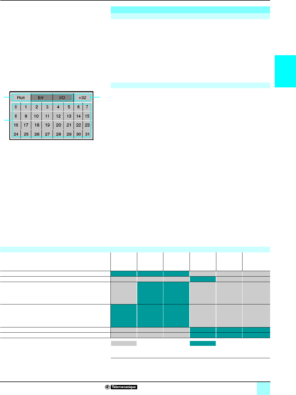
Each discrete I/O module is equipped with a display block on the front panel
centralizing all the information necessary for module control, diagnostics and
maintenance. The display block comprises:
1A set of 8, 16 or 32 green LEDs, depending on the module. Each LED is
associated with one channel:
- On: channel in state 1; Off: channel in state 0
- Flashing: channel faulty, overloaded or short-circuit
2Three LEDs indicating the module status:
- RUN (green): On: Normal operation
- ERR (red): On: Internal module fault; Flashing: Exchange fault between the
module and the processor
- I/O (red): On: External fault (sensor/preactuator voltage, overload, short-circuit,
etc.); Flashing: Terminal block fault
3A +32 LED (green) indicating, in the case of 64-channel modules, whether the set
of 32 LEDs 1 displays the state of channels 0...31 (off) or the state of channels
32...63 (on). This +32 LED is activated or deactivated by a push button located on
top of the module.
Diagnostics via Unity Pro™ software
Using the integrated diagnostics in Unity Pro™ software, the local diagnostics
indicators on the modules front panel are complemented by system diagnostics
based on predefined screens at the global hardware configuration level, the module
level and the channel level (see pages 4/21 and 4/22).
Remote diagnostics using a web browser on a “Thin Client” PC
In addition, the diagnostics described above can be performed remotely using a
simple web browser thanks to the standard web server integrated in the Modicon
M340 platform (processor with integrated Ethernet port or Ethernet module), using
the ready-to-use Rack Viewer function (see page 3/4).
(1) 24 V
a
sensors can be used as negative logic (source) 24 V
c
inputs compatible with 3-wire
c
sensor NPN type, but in this case, are not IEC-compliant.
Functions (continued)
Output fallback
1
23
I/O module diagnostics
Compatibility with 2-wire and 3-wire sensors
Input type 24 V c
Non-IEC
positive log.
(sink)
48 V c
type 1
positive log.
(sink)
24 V c
type 3
positive log.
(sink)
24 V a
type 1
48 V a
type 3
100...120 V a
type 3
Any 3-wire c sensor, PNP type
Any 3-wire c sensor, NPN type (1)
Telemecanique® 2-wire c sensor
or other brand with the following characteristics:
- Residual voltage in closed state ≤ 7V
- Minimum switched current ≤ 2.5 mA
- Residual current in open state ≤ 1.5 mA
Telemecanique® 2-wire c sensor
or other brand with the following characteristics:
- Residual voltage in closed state ≤ 4V
- Minimum switched current ≤ 1mA
- Residual current in open state ≤ 0.5 mA
2-wire c/a sensor (1)
2-wire a sensor
Not compatible Compatible

2/10
2
Characteristics Modicon®M340™ Automation
Platform 0
Discrete I/O modules
(1) This characteristic allows several inputs to be wired in parallel on the same module or on
different modules for input redundancy.
Common characteristics
Environment
Conformity to standards NFC 63 850, IEC 664, IEC 1131 2, UL 508, UL7 46C, CSA 22 2 no. 142
Temperature derating The characteristics at 60 °C are assured for 60% of inputs and 60% of outputs at state 1
Characteristics of DC input modules
Module BMX DDI 1602 BMX DDI 1603 BMX DDI 3202K BMX DDI 6402K BMX DAI 1602
Number of inputs 16 32 64 16
Connection Spring or screw-type 20-pin
removable terminal block
One 40-pin
connector
Two 40-pin
connectors
Spring
or screw-type
20-pin removable
terminal block
Nominal input values Voltage V24 c48 c24 c
Current mA 3.5 2.5 2.5 1 3
Logic Positive (sink) Negative (source)
Input limit
values
At state 1 Voltage V≥ 11 ≥ 34 ≥ 11 ≥ 15 ≥ 14
Current mA > 2
(for U ≥11 V)
> 2
(for U ≥ 34 V)
> 2
(for U ≥ 11 V)
> 1
(for U ≥ 15 V)
> 2
At state 0 Voltage V<5< 10 < 5
Current mA ≤ 1.5 ≤ 0.5 ≤ 1.5 ≤ 0.5
Sensor power supply
(including ripple)
V19…30 (possible
up to 34 V, limited
to 1 hour in every
24 hours)
38...60 19…30 (possible up to 34 V, limited to 1 hour in every
24 hours)
Input impedance at nominal voltage KΩ6.8 19.2 9.6 24 6.4
Response time (filtering) Typical ms 410
Maximum ms 720
Reverse polarity Protected No –
IEC 1131-2 conformity Type 3 Type 1 Type 3 Non-IEC
Compatibility with 2-wire/3-wire sensors IEC 947-5-2 –
Paralleling of inputs (1) Yes No
Protection of inputs Use one 0.5 A fast-blow fuse per group of channels
Insulation resistance MΩ>10 at 500 V c
Dielectric strength Primary/Secondary Vrms 1,500 - 50/60 Hz for 1 minute (up to 4,000 m)
Between groups of
channels
V–500 c–
Type of input Current sink Resistive
Sensor voltage control
threshold
OK V> 18 c > 36 c> 18 c
Fault V< 14 c< 24 c< 14 c
Reliability MTBF in hours At Tambient = 30 °C 798,237 696,320 362,681 1,504,958
Consumption Typical mA See power consumption table page 6/8
Maximum dissipated power W2.5 3.6 3.9 4.3 3
Temperature derating None
References:
pages 2/16 to 2/17
Connections:
pages 2/18 to 2/21
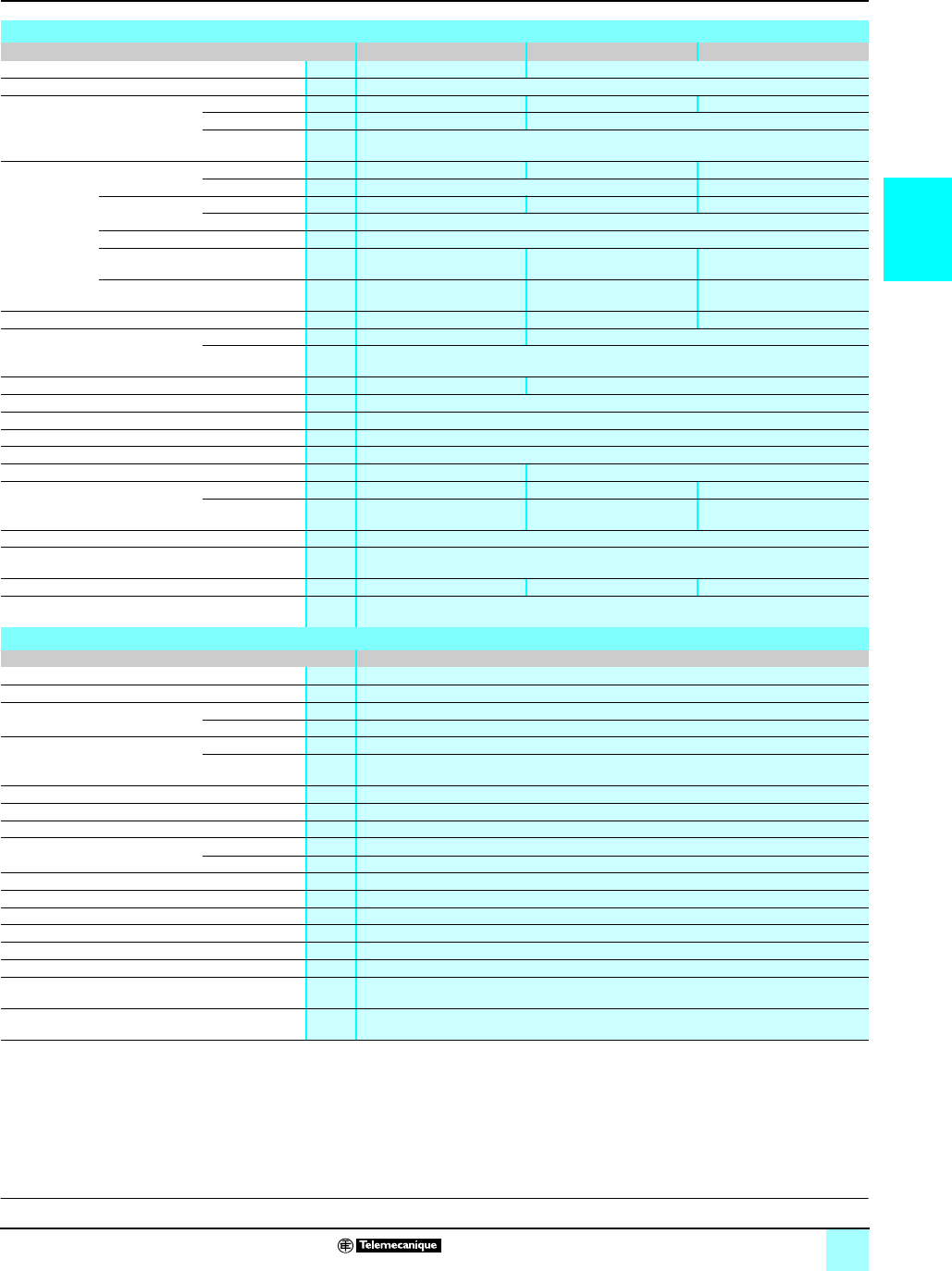
2/11
2
Characteristics (continued) Modicon®M340™ Automation
Platform 0
Discrete I/O modules
Characteristics of AC input modules
Module BMX DAI 1602 BMX DAI 1603 BMX DAI 1604
Number of inputs 16
Connection Spring or screw-type 20-pin removable terminal block
Nominal input values Voltage V24 a48 a100...120 a
Current mA 3 5
Frequency Hz 50/60
Input limit
values
At state 1 Voltage V≥ 15 ≥ 34 ≥ 74
Current mA ≥ 2 ≥ 2.5
At state 0 Voltage V≤ 5 y 10 y 20
Current mA ≤ 1
Frequency Hz 47...63
Sensor power supply
(including ripple)
V20...26 40...52 85…132
Current peak
on activation
At nominal voltage mA 595 240
Input impedance at nominal voltage and F = 55 Hz KΩ6 9 13
Response time (filtering) Activation ms 15 10
Deactivation ms 20
IEC 1131-2 conformity Type 1 Type 3
Compatibility with 2-wire/3-wire sensors IEC 947-5-2
Protection of inputs Use one 0.5 A fast-blow fuse per group of channels
Insulation resistance MΩ>10 at 500 V c
Dielectric strength Vrms 1,500 - 50/60 Hz for 1 minute (up to 4,000 m)
Type of input Resistive Capacitive
Sensor voltage control threshold OK V> 18 > 36 > 82
Fault V< 14 < 24 < 40
Reliability MTBF in hours At Tambient =30 °C 1,504,958
Consumption Typical mA See power consumption table page 6/8
Maximum dissipated power W3 4 3.8
Temperature derating None
Characteristics of triac output module
Module BMX DAO 1605
Number of inputs W16
Connection Spring or screw-type 20-pin removable terminal block
Operating voltages Nominal V100...240 a
Limit V85...288 a
Currents Maximum A0.6 per channel, 2.4 per common, 4.8 for all 4 commons
Minimum 25 mA at 100 V a, 25 mA at 240 V a
Maximum inrush current A≤ 20/cycle
Leakage current At state 0 mA ≤ 1.5 for 120 V a, 60 Hz, ≤ 3 for 240 V a, 60 Hz
Residual voltage At state 1 V≤ 1.5
Response time
Nominal resistive load
Activation ms ≤ 1 +/- 0.5 Hz
Deactivation ms ≤ 1 +/- 0.5 Hz
Type of command Passage through zero
Built-in protection Varistor
Protection fuses None (use an external fast-blow fuse)
Dielectric strength Vrms 2,830 a/3 cycles (2,000 m altitude)
Insulation resistance MΩ>10 at 500 V c
Reliability –
Consumption Typical mA See power consumption table page 6/8
Maximum dissipated power –
References:
pages 2/16 to 2/17
Connections:
pages 2/18 to 2/21
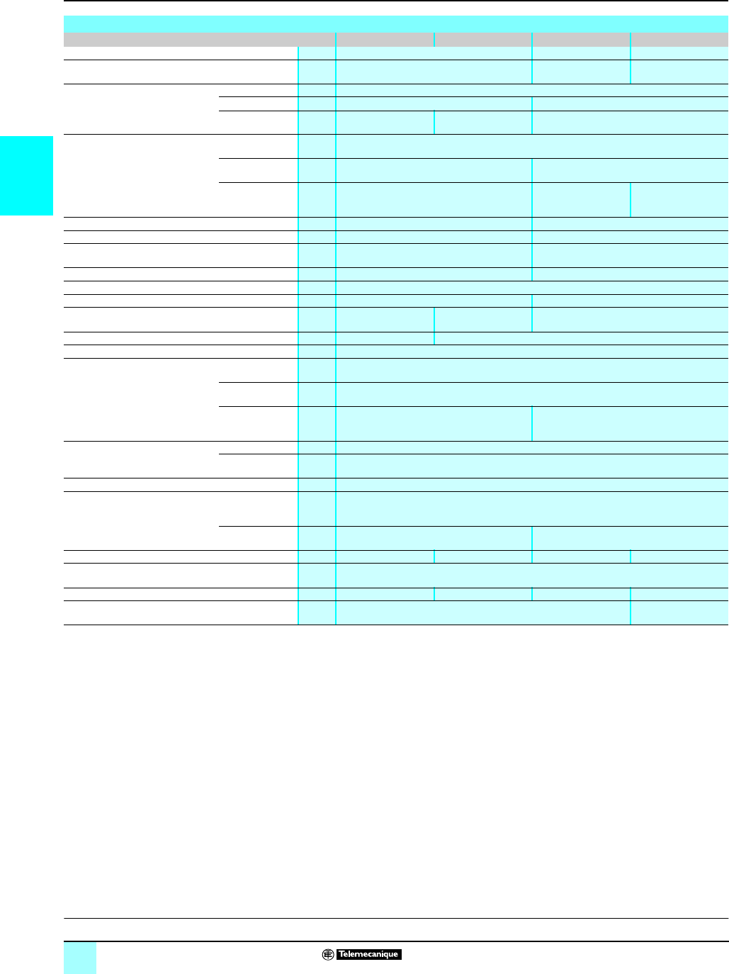
2/12
2
Characteristics (continued) Modicon®M340™ Automation
Platform 0
Discrete I/O modules
(1) All outputs are equipped with a fast demagnetization circuit for the electromagnets. Discharge
time for the electromagnets < L/R.
(2) Excluding load current.
Characteristics of DC solid state output modules
Module BMX DDO 1602 BMX DDO 1612 BMX DDO 3202K BMX DDO 6402K
Number of inputs 16 32 64
Connection Spring or screw-type 20-pin removable
terminal block
One 40-pin connector Two 40-pin
connectors
Output nominal values Voltage V24 c
Current A0.5 0.1
Logic Positive (source) Negative (sink) Positive (source)
Output limit values Voltage
(including ripple)
V19…30 (possible up to 34 V, limited to 1 hour in every 24 hours)
Current per
channel
A0.625 0.125
Current per
module
A10 3.2 6.4 if θ ≤ 40 °C
5.1 if θ ≤ 50 °C
3.8 if θ ≤ 60 °C
Tungsten filament lamp power W6 maximum 1.2 maximum
Leakage current At state 0 mA < 0.5 0.1 (for U = 30 V)
Residual voltage At state 1 V< 1.2 < 1.5 (for I = 0.1 A)
Minimum load impedance Ω48 220
Response time (1) ms 1.2
Maximum overload time ms –15
Compatibility with IEC 1131-2 DC inputs Yes (type 3, not IEC) Yes (not IEC) Yes (type 3, not IEC)
Paralleling of outputs Yes (2 max.) Yes (3 max.)
Switching frequency on inductive load Hz 0.5/LI2
Built-in protection Against
overvoltages
Yes, by Transil® diode
Against reverse
polarity
Yes, by reverse-mounted diode. Use a 2 A fuse on the + 24 V of the preactuators.
Against
short-circuit and
overloads
Yes, with current limiter and electronic circuit
breaker 1.5 In < Id < 2 In
Yes, with current limiter and electronic circuit
breaker 0.125 A < Id < 0.185 A
Preactuator voltage control
threshold
At state 0 V> 18
Fault V< 14
Insulation resistance MΩ> 10 at 500 V c
Dielectric strength Output/ground or
output/internal
logic
Vrms 1,500 a - 50/60 Hz for 1 minute
Between groups of
channels
V–500 c
Reliability MTBF in hours At Tambient = 30 °C 409,413 –360,412 173,792
Consumption Typical mA See power consumption table page 6/8
Maximum dissipated power W42.26 3.6 6.85
Temperature derating None See “Current per
module” above
References:
pages 2/16 to 2/17
Connections:
pages 2/18 to 2/21
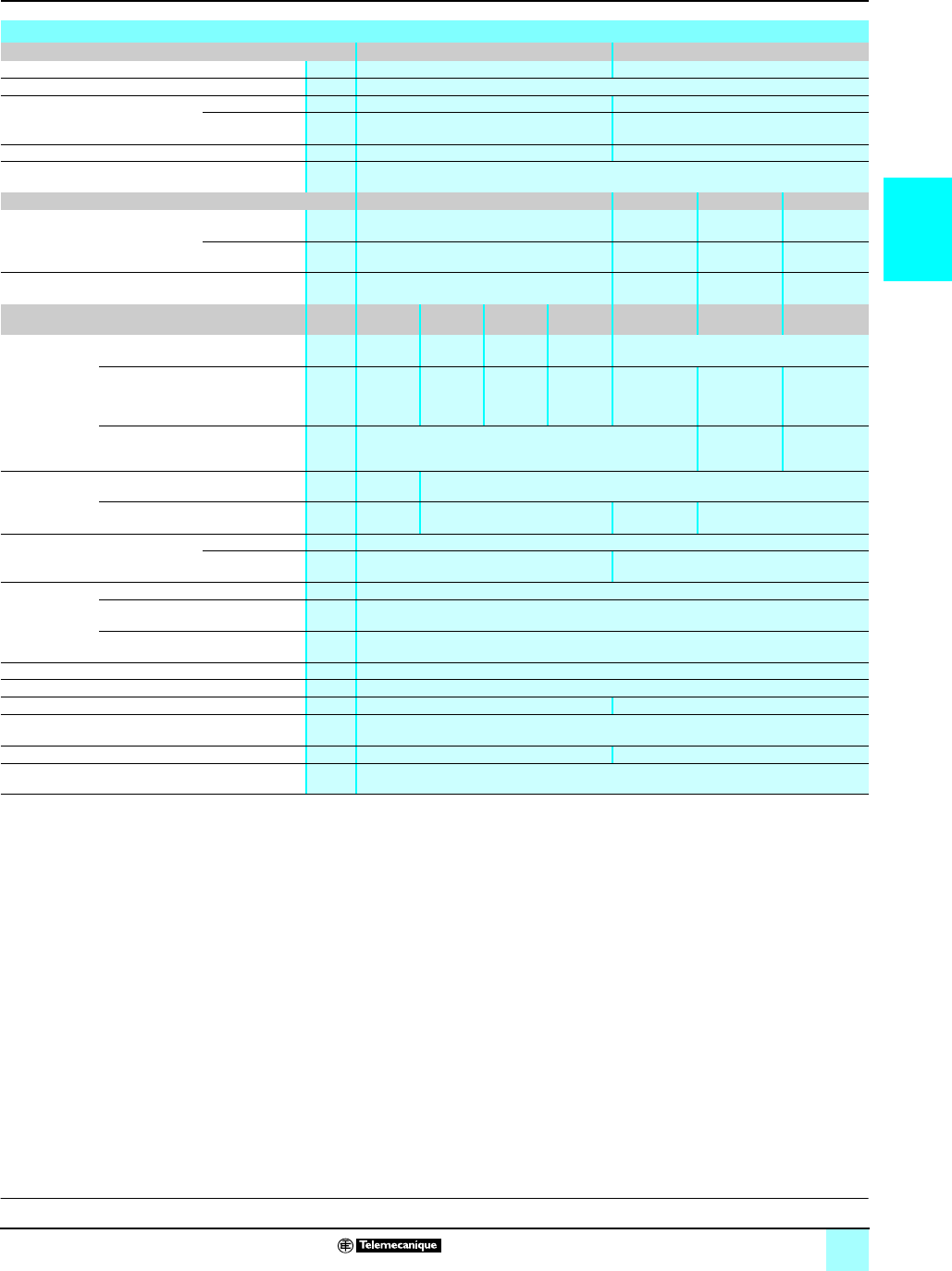
2/13
2
Characteristics (continued) Modicon®M340™ Automation
Platform 0
Discrete I/O modules
(1) For 1 x 10⁵ operating cycles
(2) For 3 x 10⁵ operating cycles
(3) For 0.7 x 10⁶ operating cycles
(4) For 1 x 10⁶ operating cycles
(5) For 0.5 x 10⁶ operating cycles
(6) For 5 x 10⁶ operating cycles
(7) For 2 x 10⁶ operating cycles
(8) For 10 x 106 operating cycles
(9) For 1.5 x 10⁶ operating cycles
(10)For 0.15 x 10⁶ operating cycles
(11)For 3 x 10⁶ operating cycles
(12)For 0.1 x 10⁶ operating cycles
(13)For 0.3 x 10⁶ operating cycles
(14)Where L/R = 60 ms for BMX DRA 0805 module, L/R = 7 ms for BMX DRA 1605 module
Characteristics of relay output modules
Module BMX DRA 0805 BMX DRA 1605
Number of inputs 816
Connection Spring or screw-type 20-pin removable terminal block
Limit operating voltages DC V10...34 c24...125 c (resistive load)
AC V10...264 a200...264 a (Cos ϕ = 1)
Thermal current A3 2
Switching load Minimum mA 1 at 5 V c
Electrical life –24 V 200 V 240 V
AC load Power
cos ϕ=0.7
VA – – 300 (1),
80 (2)
240 (1),
72 (2)
Power
cos ϕ=0.35
VA – – 200 (1),
60 (2)
120 (1),
36 (2)
DC load Power W–24 (1),
7.2 (2)
– –
Voltage 24 V 48 V 110...
120 V
200...
240 V
24 V 200 V 240 V
AC load R
esistive l
oads
AC-12
Power VA 50 (3) 50 (4),
110 (5)
110 (4),
220 (5)
220 (4) –
Inductive loads
AC-15
(cos ϕ=0.3)
Power VA 24 (5) 10 (6),
24 (7)
10 (8),
50 (9),
110 (10)
10 (8),
50 (11),
110 (4),
220 (12)
–200 (1),
60 (2)
120 (1),
36 (2)
Inductive loads
AC-14
(cos ϕ=0.7)
Power VA –300 (1),
80 (2)
240 (1),
72 (2)
DC load R
esistive l
oads
DC-12
Power W24 (4),
40 (13)
–
Inductive loads
DC-13 (14)
Power W10 (7),
24 (4)
–24 (1),
7.2 (2)
–
Response time Activation ms < 10
Deactivation ms < 8 < 12
Built-in
protection
Against overloads and short-circuits None. Use a fast-blow fuse per channel or group of channels
Against AC inductive overvoltages None. Use an RC circuit or ZNO surge limiter appropriate to the voltage in parallel on each
output
Against DC inductive overvoltages None. Use a discharge diode on each output
Insulation resistance MΩ> 10 at 500 V c
Dielectric strength Vrms 2,000 - 50/60 Hz for 1 minute
Reliability MTBF in hours At Tambient =30 °C 1,573,341 2,463,296
Consumption Typical mA See power consumption table page 6/8
Dissipated power W2.7 max. 3
Temperature derating None
References:
pages 2/16 to 2/17
Connections:
pages 2/18 to 2/21

2/14
2
Characteristics (continued) Modicon®M340™ Automation
Platform 0
Discrete I/O modules
(1) For 1 x 10⁵ operating cycles
(2) For 3 x 10⁵ operating cycles
(3) Excluding load current
Characteristics of mixed I/O relay module
Module BMX DDM 16025
24 V c inputs 24 V cor 24...240 V arelay outputs
Number of inputs/outputs 8 8
Connection Spring or screw-type 20-pin removable terminal block
Nominal values Inputs Voltage V24 c (positive logic) –
Current mA 3.5 –
Outputs DC voltage V–24 c
Direct current A–2 (resistive load)
AC voltage V–220 a, Cos ϕ = 1
Alternating current A– 2
Input limit
values
At state 1 Voltage V≥ 11 –
Current mA ≥ 2 (for U ≥ 11) –
At state 0 Voltage V5 –
Current mA ≤ 1.5 –
Sensor power supply
(including ripple)
V19…30 (possible up to 30 V, limited to 1 hour
in every 24 hours)
–
Relay output voltage 24 V 200 V 240 V
AC load Inductive loads
AC-14 (cos ϕ=
0.7)
Power VA – – 300 (1),
80 (2)
240 (1),
72 (2)
Inductive loads
AC-15 (cos ϕ=
0.35)
Power VA – – 200 (1),
60 (2)
120 (1),
36 (2)
DC load Inductive loads
DC-13
Power W–24 (1),
7.2 (2)
– –
Maximum switching frequency –3,600 cycles/hour
Input impedance at nominal voltage KΩ6.8 –
Input response time Typical ms 4 –
Maximum ms 7 –
Reverse polarity on inputs Protected –
IEC 1131-2 conformity Yes, type 3 –
Compatibility with 2-wire/3-wire sensors IEC 947-5-2 –
Paralleling of inputs No –
Input type Current sink –
Output response time Activation ms –≤ 12
Deactivation ms –≤ 10
Switching load Minimum –5V c/1 mA
Maximum V–264 a/125 c
Mechanical durability No. of switching
operations
–≥ 20 million
Fuse protection Use one 0.5 A fast-blow fuse per group of
channels
No (use one fast-blow fuse per channel or
group of channels)
Sensor voltage control thresholds OK V> 18 –
Fault V< 14 –
Insulation resistance MΩ> 10 at 500 V c
Dielectric
strength
Primary/secondary Vrms 1,500 - 50/60 Hz for 1 minute –
Between groups of I/O V500 c–
Max. voltage Vrms –2,830 a/cycle
Reliability MTBF in hours At Tambient = 30 °C 912,167
Consumption Typical mA See power consumption table page 6/8
Dissipated power W3.1 maximum
Temperature derating None
References:
pages 2/16 to 2/17
Connections:
pages 2/18 to 2/21
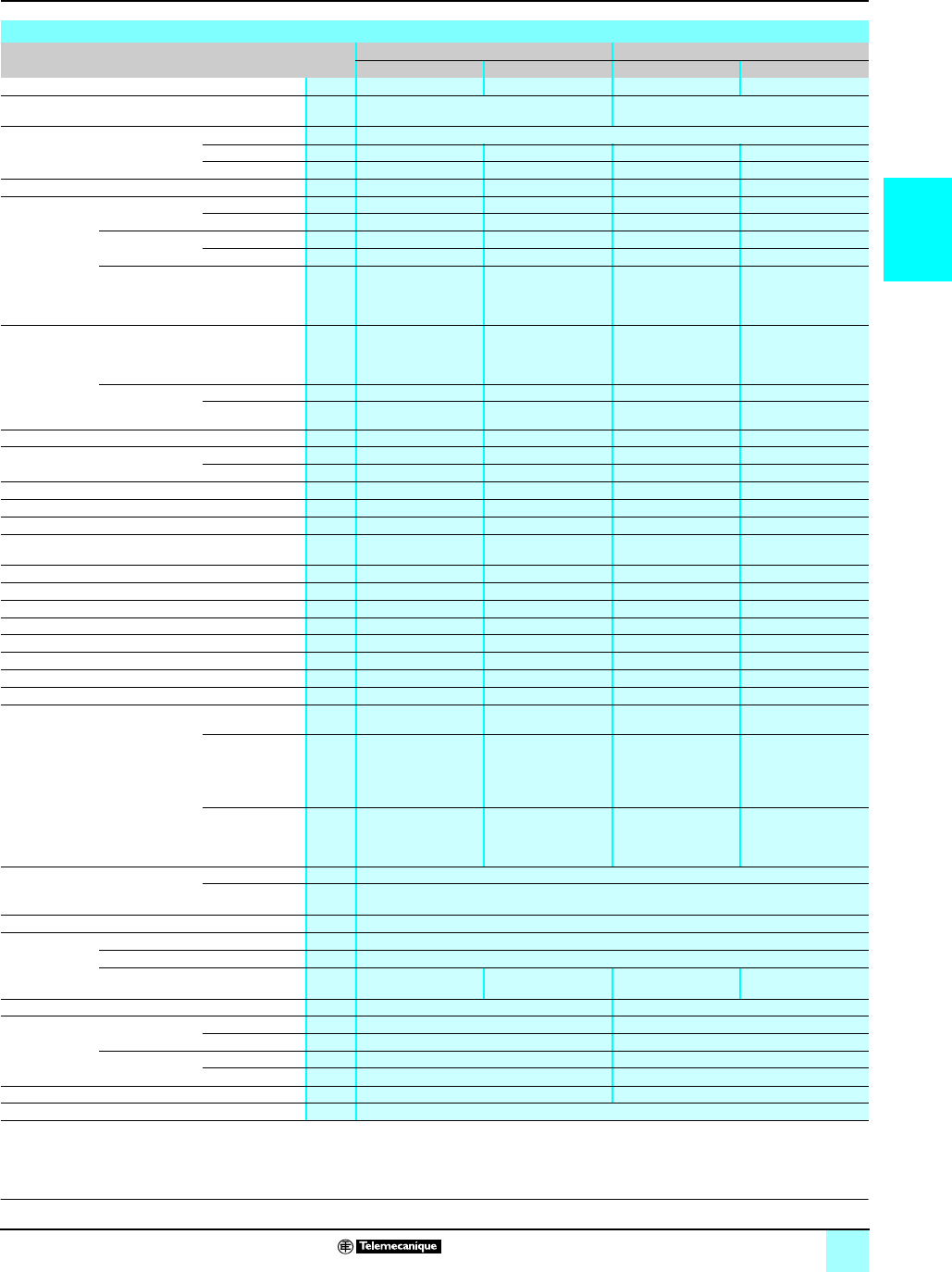
2/15
2
Characteristics (continued) Modicon®M340™ Automation
Platform 0
Discrete I/O modules
(1) All outputs are equipped with a fast demagnetization circuit for the electromagnets. Discharge
time for the electromagnets < L/R.
(2) Excluding load current.
Characteristics of 24 V c mixed I/O modules
Module BMX DDM 16022 BMX DDM 3202K
Inputs Solid state outputs Inputs Solid state outputs
Number of inputs/outputs 8 8 16 16
Connection Spring or screw-type 20-pin removable
terminal block
One 40-pin connector
Nominal values Voltage V24 c
Current mA 3.5 500 2.5 100
Logic Positive (sink) Positive (source) Positive (sink) Positive (source)
Tungsten filament lamp power W–6 maximum –1.2 maximum
Input limit
values
At state 1 Voltage V≥ 11 –≥ 11 –
Current mA > 3 (for U ≥ 11 V)–≥ 2 (for U ≥ 11) –
At state 0 Voltage V5 – 5 –
Current mA ≤ 1.5 –≤ 1.5 –
Sensor power
supply (including
ripple)
Possible up to
30 V, limited to
1 hour in every 24
hours
V19…30 –19…30 –
Output limit
values
Voltage (including
ripple)
Possible up to
30 V, limited to
1 hour in every 24
hours
V–19…30 –19…30
Currents Per channel mA –625 –125
Per module A–5–3.2
Input impedance at nominal voltage KΩ6.8 –9.6 –
Input response time Typical ms 4 – 4 –
Maximum ms 7 – 7 –
Reverse polarity on inputs Protected –Protected –
IEC 1131-2 conformity Yes, type 3 –Yes, type 3 –
Compatibility with 2-wire/3-wire sensors IEC 947-5-2 –IEC 947-5-2 –
Input type Current sink –Current sink –
Leakage current At state 0 mA –< 0.5 –0.1
Residual voltage At state 1 V–< 1.2 –< 1.5 (for I=0.1 A)
Minimum load impedance Ω–48 –220
Output response time (1) ms –1.2 –1.2
Max. overload time before fault state ms –15 –15
Compatibility with IEC 1131-2 DC inputs –Yes (type 3, not IEC) –Yes (type 3, not IEC)
Paralleling of outputs –Yes (2 maximum) –Yes (3 maximum)
Switching frequency on inductive load Hz –0.5/LI2 –0.5/LI2
Built-in protection Against
overvoltages
–Yes, by Transil® diode –Yes, by Transil® diode
Against inversions –Yes, by
reverse-mounted
diode. Use a 2 A fuse
on the preactuator
+24V
–Yes, by
reverse-mounted
diode. Use a 2 A fuse
on the preactuator
+24V
Against
short-circuits and
overloads
Use one 0.5 A
fast-blow fuse per
group of channels
Yes, by current limiter
and electronic
circuit breaker 1.5 ln<
Id < 2 ln
Use one 0.5 A
fast-blow fuse per
group of channels
Yes, by current limiter
and electronic
circuit breaker 0.125 A
< Id < 0.185 A
Sensor and preactuator voltage
control thresholds
OK V> 18
Fault < 14
Insulation resistance MΩ> 10 at 500 V c
Dielectric
strength
Primary/secondary Vrms 1,500 - 50/60 Hz for 1 minute
Between groups of inputs and outputs V500 c
Outputs/ground or outputs/internal
logic
–1,500 - 50/60 Hz for 1
minute
–1,500 - 50/60 Hz for 1
minute
Reliability MTBF in hours At Tambient =30 °C 447,581 432,904
Consumption 3.3 V cTypical mA 79 125
Maximum mA 111 166
24 V c
preactuators (2)
Typical mA 59 69
Maximum mA 67 104
Maximum dissipated power W3.7 4
Temperature derating None
References:
pages 2/16 to 2/17
Connections:
pages 2/18 to 2/21
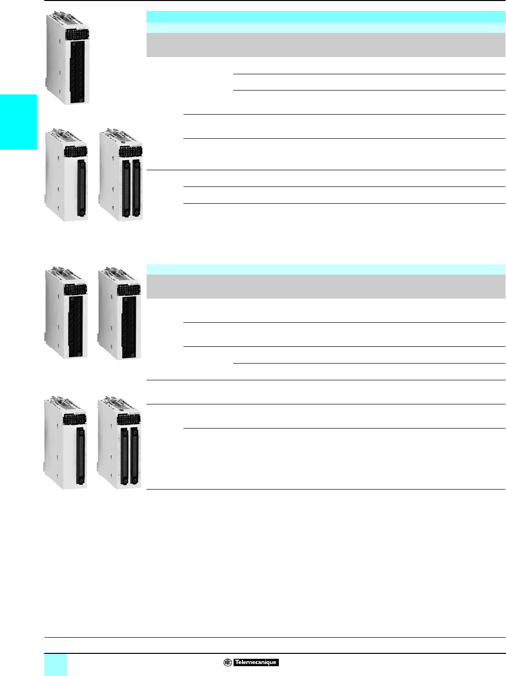
2/16
2
References Modicon®M340™ Automation
Platform 0
Discrete I/O modules
(1) By connector, module supplied with cover(s)
r Available 4th quarter 2007
References
Discrete input modules
Type of
current
Input voltage Connection by
(1)
IEC 1131-2
conformity
Modularity
(no. of channels)
Reference Weight
kg
c24 V (positive
logic)
Screw or spring-type 20-pin
removable terminal block
Type 3 16 isolated inputs BMXDDI1602 0.115
One 40-pin connector Type 3 32 isolated inputs BMXDDI3202K 0.112
Two 40-pin connectors Non-IEC 64 isolated inputs BMXDDI6402K 0.145
24 V (negative
logic)
Screw or spring-type 20-pin
removable terminal block
Non-IEC 16 isolated inputs BMXDAI1602 r 0.115
48 V (positive
logic)
Screw or spring-type 20-pin
removable terminal block
Type 1 16 isolated inputs BMXDDI1603 r 0.115
a24 V Screw or spring-type 20-pin
removable terminal block
Type 1 16 isolated inputs BMXDAI1602 r 0.115
48 V Screw or spring-type 20-pin
removable terminal block
Type 3 16 isolated inputs BMXDAI1603 r 0.115
100...120 V Screw or spring-type 20-pin
removable terminal block
Type 3 16 isolated inputs BMXDAI1604 0.115
Discrete output modules
Type of
current
Output voltage Connection by
(1)
IEC 1131-2
conformity
Modularity
(no. of channels)
Reference Weight
kg
c
solid state
24 V/0.5 A
(positive logic)
Screw or spring-type 20-pin
removable terminal block
Yes 16 protected
outputs
BMXDDO1602 0.120
24 V/0.5 A
(negative logic)
Screw or spring-type 20-pin
removable terminal block
Non-IEC 16 protected
outputs
BMXDDO1612 r 0.120
24 V/0.1 A
(positive logic)
One 40-pin connector Yes 32 protected
outputs
BMXDDO3202K 0.110
Two 40-pin connectors Yes 64 protected
outputs
BMXDDO6402K 0.150
a triac 100...240 Screw or spring-type 20-pin
removable terminal block
– 16 outputs BMXDAO1605 r0.140
c or a
relay
12...24 V c/3 A,
24...240 Va/3 A
Screw or spring-type 20-pin
removable terminal block
Yes 8 non-protected
outputs
BMXDRA0805 0.145
24 V c/2 A,
240 V a/2 A
Screw or spring-type 20-pin
removable terminal block
Yes 16 non-protected
outputs
BMXDRA1605 0.150
BMX DpI 160p
BMX DDI 3202K BMX DDI 6402K
BMX
DDO 16p2
BMX
DDO 3202K
BMX
DDO 6402K
BMX DRA
0805/1605
Characteristics:
pages 2/11 to 2/15
Connections:
pages 2/6o 2/9

2/17
2
References (continued) Modicon®M340™ Automation
Platform 0
Discrete I/O modules
References (continued)
Discrete mixed I/O modules
Number
of I/O
Connection
via (1)
No. and type of inputs No. and type of
outputs
IEC 1131 2
conformity
Reference Weight
kg
16 Screw
or spring-type
20-pin
removable
terminal block
8 (positive logic) 8, solid state
24 V c / 0,5 A
Inputs, type 3 BMXDDM16022 0.115
8, relay 24 V cor
24...240 V aInputs, type 3 BMXDDM16025 0.135
32 One 40-pin
connector
16 (positive logic) 16, solid state
24 V c / 0,1 A
Inputs, type 3 BMXDDM3202K 0.110
Removable connection blocks
Description Use Reference Weight
kg
20-pin
removable
terminal
blocks
Cage clamp For module with 20-pin removable terminal block BMXFTB2000 0.093
Screw clamp For module with 20-pin removable terminal block BMXFTB2010 0.075
Spring-type For module with 20-pin removable terminal block BMXFTB2020 0.060
Preformed cord sets for I/O modules with removable terminal block
Description Composition Length Reference Weight
kg
Preformed cordsets with
one end with wires
One 20-pin terminal block
One end with color-coded wires
3m BMXFTW301 0.850
5m BMXFTW501 1.400
10 m BMXFTW1001 2.780
Preformed cordsets for I/O modules with 40-pin connectors
Description No. of
sheaths
Composition Cross-
section
Length Reference Weight
kg
Preformed cord sets with
one end with wires
1 x 20
wires (16
channels)
One 40-pin connector
One end with
color-coded wires
0.324 mm23 m BMXFCW301 0.820
5 m BMXFCW501 1.370
10 m BMXFCW1001 2.770
2 x 20
wires (32
channels)
One 40-pin connector
Two ends with
color-coded wires
0.324 mm23 m BMXFCW303 0.900
5 m BMXFCW503 1.490
10 m BMXFCW1003 2.960
Preformed cord sets for
Telefast® Advantys™ ABE7
sub-bases
1 x 20
wires (16
channels)
One 40-pin connector
One HE 10 connector
0.324 mm20.5 m BMXFCC051 0.140
1 m BMXFCC101 0.195
2 m BMXFCC201 0.560
3 m BMXFCC301 0.840
5 m BMXFCC501 1.390
10 m BMXFCC1001 2.780
2 x 20
wires (32
channels)
One 40-pin connector
Two HE 10 connectors
0.324 mm20.5 m BMXFCC053 0.210
1 m BMXFCC103 0.350
2 m BMXFCC203 0.630
3 m BMXFCC303 0.940
5 m BMXFCC503 1.530
10 m BMXFCC1003 3.000
BMX
DDM 160p2
BMX
DDM 3202K
BMX FTB 20p0
BMX FTW p01
BMX FCW p01
BMX FCC p01
BMX FCW p03
Characteristics:
pages 2/11 to 2/15
Connections:
pages 2/6 to 2/9
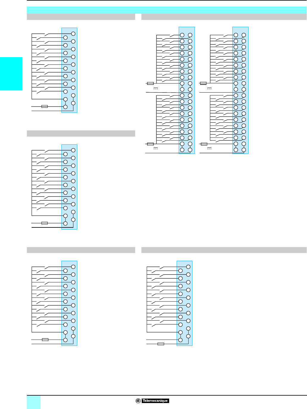
2/18
2
Connections Modicon®M340™ Automation
Platform 0
Discrete I/O modules
Input modules
BMX DDI 1602 BMX DDI 3202K/6402K
BMX DDI 3202K: Connector A (inputs I0...I32)
BMX DDI 6402K: Connector A (inputs I0...I32) and connector B (inputs I33...I63)
For correspondence of the 40-pin connector pins with the wire colors of BMX FCW p01/p03
prewired cord sets, in accordance with DIN 47100, see table on page 2/21
BMX DDI 1603
BMX DAI 1602/1603/1604 BMX DAI 1602, use in 24 V c, negative logic
P-N voltage:
24 V a: BMX DAI 1602
48 V a: BMX DAI 1603
100/120 V a: BMX DAI 1604
Fu: 0.5 A fast-blow fuse
18
20
6
8
12
14
10
16
2
1
4
5
7
11
13
9
15
3
19
17
+
–
+
+
6
8
12
14
10
2
1
4
5
7
11
13
9
15
3
0
–
–
Sensors
Chnl
24 V c
Fu
B
1010
88
66
44
24 V
9 9
7 7
1 1
5 5
3 3
A
1818
1616
1414
2020
19 19
17 17
15 15
13 13
+
+
+
+
-
-
-
-
22
24 V
1212
11 11
+
-
+
-
38
40
44
46
42
34
33
36
37
39
43
45
41
47
35
32
54
56
60
62
58
50
49
52
53
55
59
61
57
63
51
48
B
1010
88
66
44
24 V
9 9
7 7
1 1
5 5
3 3
A
1818
1616
1414
2020
19 19
17 17
15 15
13 13
+
+
+
+
-
-
-
-
22
24 V
1212
11 11
+
-
+
-
6
8
12
14
10
2
1
4
5
7
11
13
9
15
3
0
22
24
28
30
26
18
17
20
21
23
27
29
25
31
19
16
BA
SensorsChnl Sensors
Chnl
Fu Fu
Fu Fu
18
20
6
8
12
14
10
16
2
1
4
5
7
11
13
9
15
3
19
17
+
–
+
+
6
8
12
14
10
2
1
4
5
7
11
13
9
15
3
0
–
–
Sensors
Chnl
48 V c
Fu
18
20
6
8
12
14
10
16
2
1
4
5
7
11
13
9
15
3
19
17
N
P
6
8
12
14
10
2
1
4
5
7
11
13
9
15
3
0
Sensors
Chnl
Fu
18
20
6
8
12
14
10
16
2
1
4
5
7
11
13
9
15
3
19
17
+
–
+
+
6
8
12
14
10
2
1
4
5
7
11
13
9
15
3
0
–
–
Sensors
Chnl
24 V c
Fu
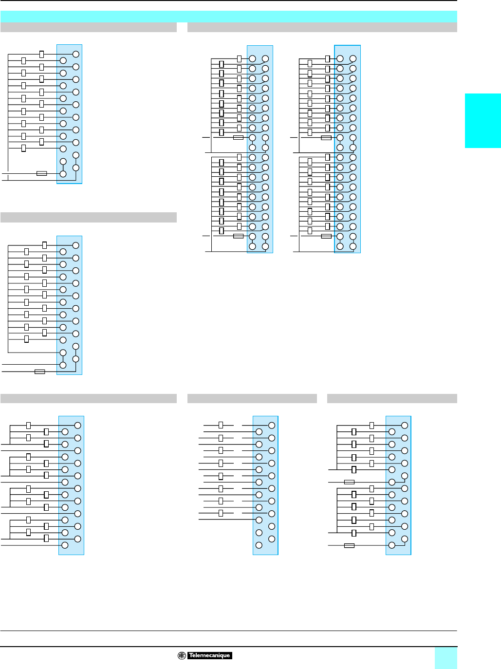
2/19
2
Connections (continued) Modicon®M340™ Automation
Platform 0
Discrete I/O modules
Output modules
BMX DDO 1602 BMX DDO 3202K/6402K
BMX DDO 3202K: Connector A (outputs Q0...Q32)
BMX DDO 6402K: Connector A (outputs Q0...Q32) and connector B (outputs Q33...Q63)
Nota : For correspondence of the 40-pin connector pins with the wire colors of
BMX FCW
p
01/
p
03 prewired cord sets, in accordance with DIN 47100, see table on page 2/21.
BMX DDO 1612
BMX DAO 1605 BMX DRA 0805 BMX DRA 1605
+
-
+
+
6
8
12
14
10
2
1
4
5
7
11
13
9
15
3
0
c 24 V
-
-
18
20
6
8
12
14
10
16
2
1
4
5
7
11
13
9
15
3
19
17
Chnl Preactuators B
1 1
A
1818
1616
1414
2020
19 19
17 17
15 15
13 13
+
+
+
+
-
-
-
-
22
c 24 V
1212
11 11
+
-
38
40
44
46
42
34
33
36
37
39
43
45
41
47
35
32
54
56
60
62
58
50
48
52
53
55
59
61
57
63
51
48
B A
+
+
+
+
-
-
-
-
6
8
12
14
10
2
1
4
5
7
11
13
9
15
3
0
22
24
28
30
26
18
17
20
21
23
27
29
25
31
19
16
BA
c 24 V
+
-
1010
88
66
44
9 9
7 7
5 5
3 3
c 24 V
+
-
c 24 V
+
-
1010
88
66
44
9 9
7 7
1 1
5 5
3 3
1818
1616
1414
2020
19 19
17 17
15 15
13 13
22
1212
11 11
PreactuatorsChnl PreactuatorsChnl
+
-
+
+
6
8
12
14
10
2
1
4
5
7
11
13
9
15
3
0
c 24 V
-
-
18
20
6
8
12
14
10
16
2
1
4
5
7
11
13
9
15
3
19
17
Chnl Preactuators
18
20
6
8
12
14
10
16
2
1
4
5
7
11
13
9
15
3
19
17
6
8
12
14
10
2
1
4
5
7
11
13
9
15
3
0
a 120/240 V
a 120/240 V
a 120/240 V
a 120/240 V
Chnl Preactuators
18
20
6
8
12
14
10
16
2
1
4
5
7
11
13
9
15
3
19
17
a
a
a
a
a
a
a
a
6
2
1
5
7
3
0
4
Preactuators
Channel
12…24 V c/24 V…240 V a
6
8
12
14
10
2
1
4
5
7
11
13
9
15
3
0
a 12/24 V
a 12/24 V
18
20
6
8
12
14
10
16
2
1
4
5
7
11
13
9
15
3
19
17
Preactuators
Channel
Description:
pages 2/6 and 2/7
Characteristics:
pages 2/10 to 2/15
References:
pages 2/16 and 2/17
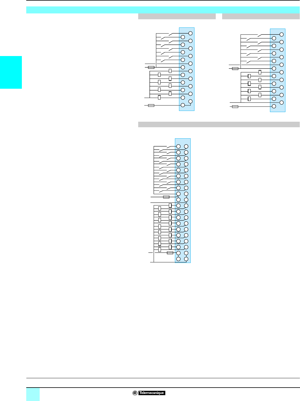
2/20
2
Connections (continued) Modicon®M340™ Automation
Platform 0
Discrete I/O modules
Fu: 0.5 A fast-blow fuse
Mixed I/O modules
BMX DDM 16025 BMX DDM 16022
BMX DDM 3202K
6
2
1
4
5
7
3
0
c 24 V/a 24…240 V
18
20
6
8
12
14
10
16
2
1
4
5
7
11
13
9
15
3
19
17
+
-
6
2
1
4
5
7
3
0
c 24 V
Sensors
Chnl
Preactuators
Fu
6
2
1
4
5
7
3
0
c 24 V
18
20
6
8
12
14
10
16
2
1
4
5
7
11
13
9
15
3
19
17
+
c 24 V
6
2
1
4
5
7
3
0
-
+
-
SensorsChnl
Preactuators
Fu
B
1 1
A
+
+
+
+
-
-
-
-
22
A
c 24 V
+
-
1010
88
66
44
9 9
7 7
5 5
3 3
6
8
12
14
10
2
1
4
5
7
11
13
9
15
3
0
1818
1616
1414
2020
19 19
17 17
15 15
13 13
1212
11 11
c 24 V
+
-
6
8
12
14
10
2
1
4
5
7
11
13
9
15
3
0
Sensors
Chnl
Preactuators
Fu
Description:
pages 2/6 and 2/7
Characterist1ics:
pages 2/10 to 2/15
References:
pages 2/16 and 2/17
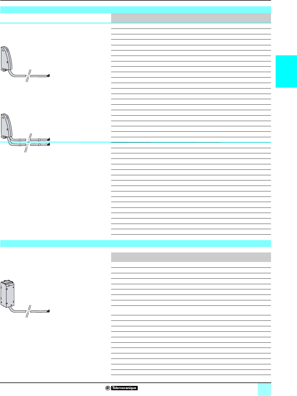
2/21
2
Connections (continued) Modicon®M340™ Automation
Platform 0
Discrete I/O modules
Cord set color codes in accordance with DIN 47100
Connection cables with 40-pin connector and end(s) with wires BMX FCW p01/p03
A
A
B
B
Cord set with one sheathed end with wires BMX FCW p01
Cord set with two sheathed ends with wires BMX FCW p03
20 wires
20 wires
20 wires
Connector
pin no.
Color at sheath
end
32/64-channel
inputs
32/64-channel
outputs
32-channel
I/O
B20 White Input 0/32 Output 0/32 Input 0
A20 Brown Input 1/33 Output 1/33 Input 1
B19 Green Input 2/34 Output 2/34 Input 2
A19 Yellow Input 3/35 Output 3/35 Input 3
B18 Gray Input 4/36 Output 4/36 Input 4
A18 Pink Input 5/37 Output 5/37 Input 5
B17 Blue Input 6/38 Output 6/38 Input 6
A17 Red Input 7/39 Output 7/39 Input 7
B16 Black Input 8/40 Output 8/40 Input 8
A16 Purple Input 9/41 Output 9/41 Input 9
B15 Gray/pink Input 10/42 Output 10/42 Input 10
A15 Red/blue Input 11/43 Output 11/43 Input 11
B14 White/green Input 12/44 Output 12/44 Input 12
A14 Brown/green Input 13/45 Output 13/45 Input 13
B13 White/yellow Input 14/46 Output 14/46 Input 14
A13 Yellow/brown Input 15/47 Output 15/47 Input 15
B12 White/gray + 24 V + 24 V + 24 V
A12 Gray/brown - 24 V - 24 V - 24 V
B11 White/pink + 24 V + 24 V + 24 V
A11 Pink/brown - 24 V - 24 V - 24 V
B10 White Input 16/48 Output 16/48 Output 0
A10 Brown Input 17/49 Output 17/49 Output 1
B9 Green Input 18/50 Output 18/50 Output 2
A9 Yellow Input 19/51 Output 19/51 Output 3
B8 Gray Input 20/52 Output 20/52 Output 4
A8 Pink Input 21/53 Output 21/53 Output 5
B7 Blue Input 22/54 Output 22/54 Output 6
A7 Red Input 23/55 Output 23/55 Output 7
B6 Black Input 24/56 Output 24/56 Output 8
A6 Purple Input 25/57 Output 25/57 Output 9
B5 Gray/pink Input 26/58 Output 26/58 Output 10
A5 Red/blue Input 27/59 Output 27/59 Output 11
B4 White/green Input 28/60 Output 28/60 Output 12
A4 Brown/green Input 29/61 Output 29/61 Output 13
B3 White/yellow Input 30/62 Output 30/62 Output 14
A3 Yellow/brown Input 31/63 Output 31/63 Output 15
B2 White/gray + 24 V + 24 V + 24 V
A2 Gray/brown -24V -24V -24V
B1 White/pink + 24 V + 24 V + 24 V
A1 Pink/brown -24V -24V -24V
Connection cables with 20-pin terminal block at one end and wires at the other BMX FTW p01
Correspondence of 20-pin removable terminal block pins with the wire colors (at sheath end)
Cord set with 1 sheathed end with wires BMX FTW p01
20 wires
Terminal
block pin no.
Color at sheath
end
16-channel
inputs
8- or 16-channel
outputs
16-channel
I/O
1 White Input 0 See page 2/19 Input 0
2 Brown Input 1 See page 2/19 Input 1
3 Green Input 2 See page 2/19 Input 2
4 Yellow Input 3 See page 2/19 Input 3
5 Gray Input 4 See page 2/19 Input 4
6 Pink Input 5 See page 2/19 Input 5
7 Blue Input 6 See page 2/19 Input 6
8 Red Input 7 See page 2/19 Input 7
9 Black Input 8 See page 2/19 Sensor + common
power supply
10 Purple Input 9 See page 2/19 Sensor pwr supply
11 Gray/pink Input 10 See page 2/19 Output 0
12 Red/blue Input 11 See page 2/19 Output 1
13 White/green Input 12 See page 2/19 Output 2
14 Brown/green Input 13 See page 2/19 Output 3
15 White/yellow Input 14 See page 2/19 Output 4
16 Yellow/brown Input 15 See page 2/19 Output 5
17 White/gray Power supply See page 2/19 Output 6
18 Gray/brown + common pwr sup. See page 2/19 Output 7
19 White/pink Power supply See page 2/19 Preactuator pwr sup.
20 Pink/brown Power supply See page 2/19 Preactuator pwr sup.
Correspondence of connector pins with the wire colors at the
sheath end
Correspondence of terminal block pins with the wire colors at the
sheath end
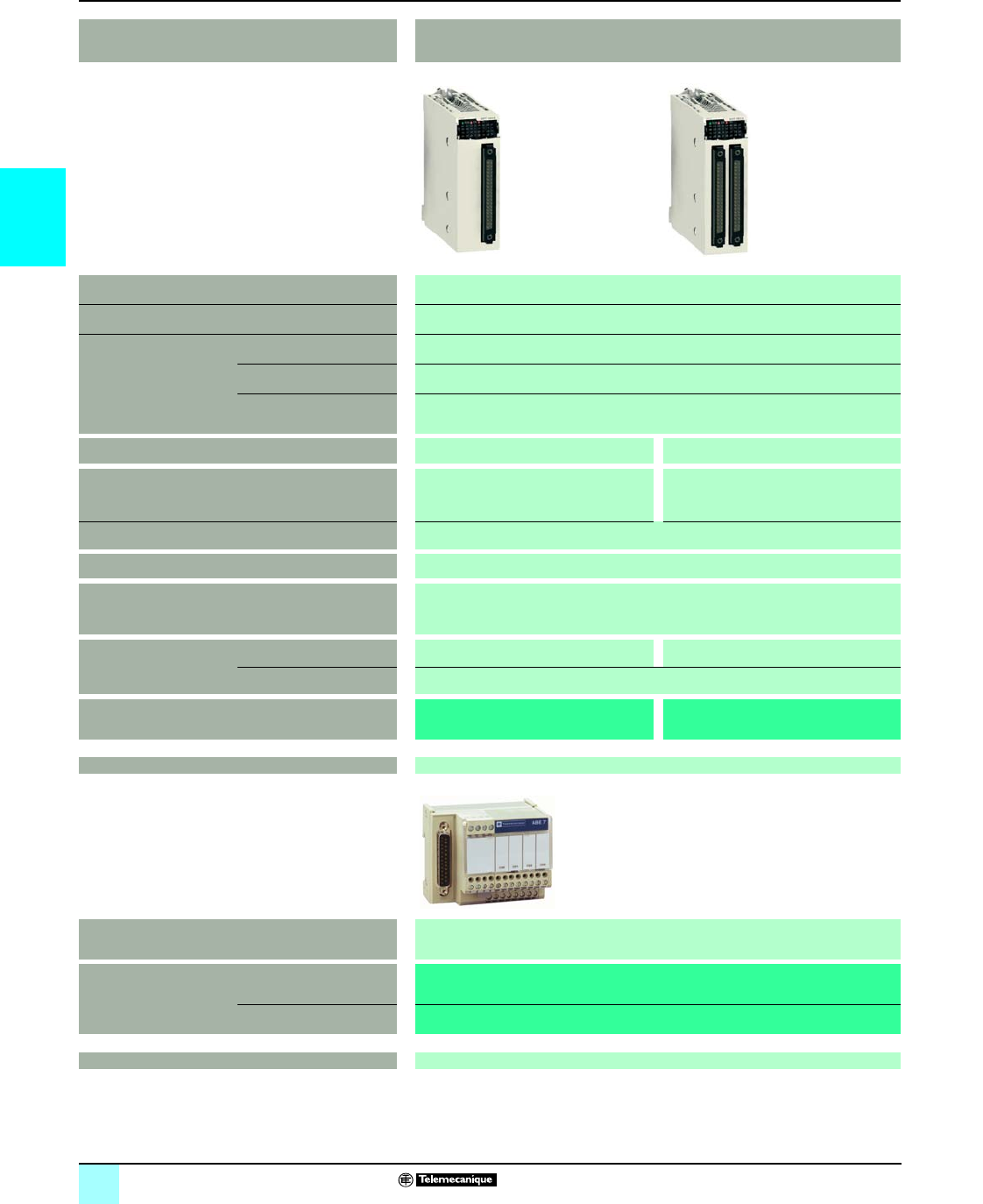
2/22
2
Selection guide Modicon®M340™ Automation
Platform 0
Analog I/O modules
r Available 4th quarter 2007
Applications Analog inputs
Type of I/O Isolated low-
level
voltage inputs, resistors
, thermocouples and temperature prob
es
Type Multi-range
Range Voltage ± 40 mV, ± 80 mV, ± 160 mV, ± 320 mV, ± 640 mV and ± 1.28 V
Current
–
Thermocouple,
Temperature probe,
Resistor
Thermocouples type B, E, J,
K, L, N, R, S, T, U
Temperature probes type Pt 100, Pt 1000, Ni 100, Ni 1000 and Cu 10, 2-,3- or 4-wire
Resistors 2-, 3- or 4-wire, 400 Ω or 4,000 Ω
Modularity 4 channels 8 channels
Acquisition period 400 ms for all 4 channels 400 ms for all 8 channels
Conversion time –
Resolution 16 bits
Isolation Between channels: 750 V c
Between channels and bus: 2,000 V c
Between channels and ground: 750 V c
Connection Directly to the module Via 40-pin connector Via two 40-pin connectors
Via preformed cord sets BMX FCW p01S cord sets with one end with color-coded wires (3 or 5 m long)
Module BMX ART 0414 BMX ART 0814 r
Page 2/32
Compatibility with Advantys™Telefast®ABE7 pre-wired
I/O system
Sub-base with 4 channels for direct connection of 4 thermocouples plus connection and
provision of cold-junction compensation
Type of module Connection sub-base ABE7CPA412
Preformed cord sets
(1.5, 3 or 5 m long)
BMX FCApp2
Pages 5/16 and 2/32
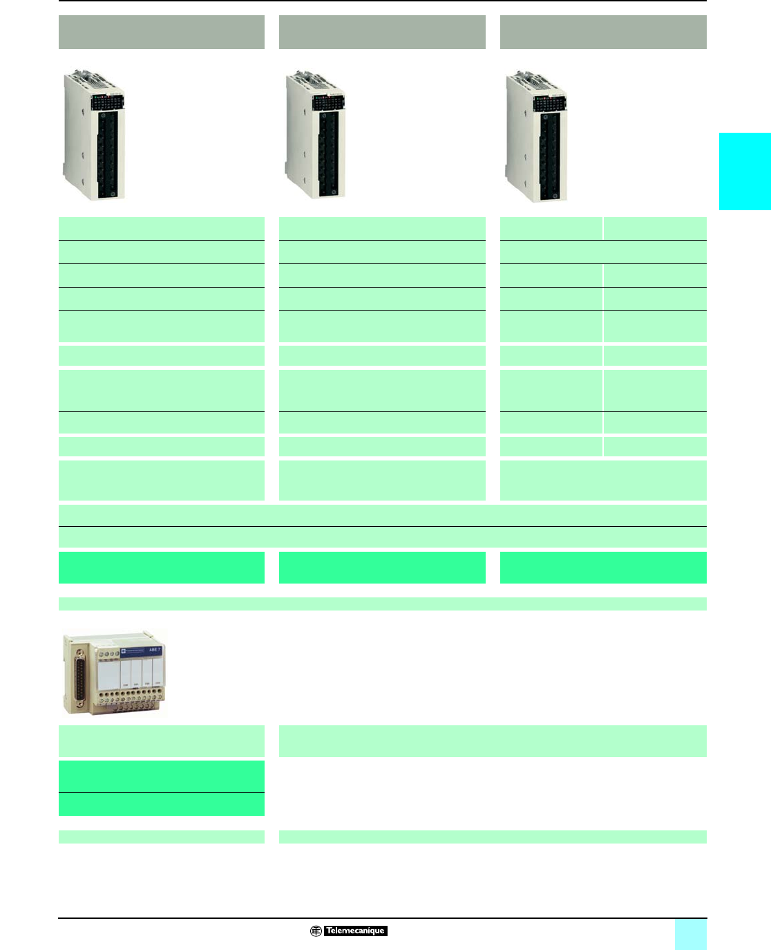
2/23
2
0
Analog inputs Analog outputs Mixed analog I/O
Isolated high-level inputs Isolated high-level outputs Non-isolated high-level
inputs
Non-isolated high-level
outputs
Voltage/current Voltage/current Voltage/current
± 10 V, 0...10 V, 0...5 V, 1...5 V, ± 5 V ±10V ± 10 V, 0...10 V, 0...5 V,
1...5 V
±10V
0...20 mA, 4...20 mA, ± 20 mA 0...20 mA, 4...20 mA 0...20 mA, 4...20 mA 0...20 mA, 4...20 mA
– – – –
4 channels 2 channels 4 channels 2 channels
Fast: 1 + (1 x no. of declared channels) ms
By default, 5 ms for all 4 channels
–Fast: 1 + (1 x no. of
declared channels) ms
By default, 5 ms for all 4
channels
–
–y1 ms –y2 ms
16 bits 16 bits 12 bits in 10 V range
10 bits in 20 mA range
12 bits
Between channels: 300 V c
Between channels and bus: 2,000 V c
Between channels and ground: 2,000 V c
Between channels: 1,400 V c
Between channels and bus: 2,000 V c
Between channels and ground: 2,000 V c
Between group of input channels and group of
output channels: 1,400 V c
Between channels and bus: 2,000 V c
Between channels and ground: 2,000 V c
Via 20-pin removable terminals (screw or spring-type)
BMX FTW p01S cord sets with one end with color-coded wires (3 or 5 m long)
BMX AMI 0410 BMX AMO 0210 BMX AMM 0600 r
2/32
4-channel sub-base for direct connection of
4 inputs, delivers and distributes 4 protected
isolated power supplies
–
ABE7CPA410
BMX FCApp0
5/16 and 2/32 –
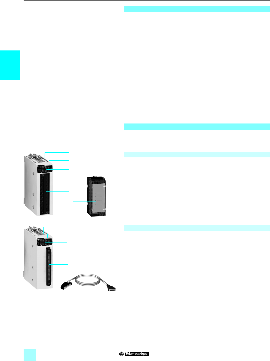
2/24
2
Presentation,
description
Modicon®M340™ Automation
Platform 0
Analog I/O modules
The analog I/O module offer consists of:
bThree isolated analog input modules:
v 4 analog high-speed channels (16 bits), voltage or current, BMX AMI 0410
v 4 and 8 analog channels (15 bits + sign) for thermocouples, Pt, Ni or Cu
temperature probes, BMX ART 0414/0814
bOne analog output module with 2 voltage/current channels, BMX AMO 0210
bOne mixed module (12 bits) with 4 analog input channels and 2 analog output
channels, non-isolated, voltage or current, BMX AMM 0600
Analog I/O modules are equipped with a connector for a 20-pin removable terminal
block, except for BMX ART 0414/0814 analog input modules with
thermocouples/temperature probes, which are equipped with a 40-pin connector.
All analog modules occupy a single slot in the BMX XBP ppp racks. These modules
can be installed in any slot in the rack, except the first two (PS and 00) reserved for
the power supply module in the BMX CPS pp0 rack, and the BMX P34 pp0
processor module respectively.
The power supply for the analog functions is supplied by the backplane bus (3.3 V
and 24 V). Analog I/O modules are hot-swappable (see page 2/8).
In a Modicon M340 single-rack configuration, the maximum number of analog
channels is limited by the number of slots available in the rack (11 slots maximum).
BMX AMp/ART analog I/O modules are standard format (1 slot). Their case ensures
IP 20 protection of the electronics, and they are locked into position by a captive
screw.
BMX AMp analog I/O modules have the following on the front panel:
1A rigid body providing support and protection for the electronic card
2A module reference marking (a label is also visible on the right-hand side of the
module).
3A module and channel status display block
4A connector taking the 20-pin removable terminal block, for connecting sensors or
preactuators on screw or spring-type terminals
To be ordered separately:
5A BMX FTB 20p0 20-pin removable terminal block, or preformed cord sets with
20-pin terminal block at one end and wires at the other (BMX FTW p01S or,
with 25-pin SUB-D connector, BMX FCA pp0) for direct connection to Advantys™
Telefast® ABE7 sub-bases (see page 2/30).
BMX ART 0p14 analog input modules have the following on the front panel:
1A rigid body providing support and protection for the electronic card
2A module reference marking (a label is also visible on the right-hand side of the
module)
3A module and channel status display block
4A 40-pin connector for connecting the sensors
To be ordered separately:
5Preformed cord sets with a 40-pin connector at one end and wires at the other
(BMX FCW p01S or, with 25-pin SUB-D connector, BMX FCA pp2) for direct
connection to Advantys™ Telefast® ABE7 sub-bases (see page 2/31).
To be ordered separately regardless of the type of module:
bA shielding connection kit to protect against electrostatic discharge, consisting of
a metal bar and two sub-bases for mounting on the rack supporting the analog
modules
bA set of STB XSP 3020 clamping rings for the shielding braids of analog signal
cables.
Presentation
Description
I/O modules connected via 20-pin removable terminal block
I/O modules connected via 40-pin connector
1
3
4
2
5
1
3
4
2
5
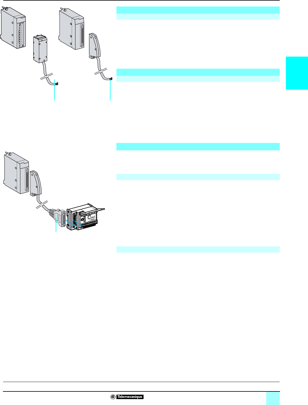
2/25
2
Connections Modicon®M340™ Automation
Platform 0
Analog I/O modules
These 20-pin removable terminal blocks are the same as those used for discrete
I/O modules (screw clamp, cage clamp or spring-type). See page 2/7.
One version of the removable terminal block is equipped with a 3 or 5 m long cord
set with color-coded wires (BMX FTWppS). These preformed cord sets, with
reinforced shielding have, at the other end
1
, color-coded wires conforming to
standard DIN 47100.
Two types of cord set are available:
bPreformed cord sets with reinforced shielding (BMX FCW p01S) have, at the other
end
2
, color-coded wires conforming to standard DIN 47100. They are available in 3
or 5 m lengths, and provide easy direct wire-to-wire connection of the analog sensors
via terminal blocks.
bPreformed cord sets with reinforced shielding (BMX FCA p02) which have at the
other end
3
, a 25-pin SUB-D connector. They are available in 1.5, 3 or 5 m lengths,
and provide direct connection to the Advantys™ Telefast® ABE7CPA412 sub-base
(see below).
Using the Advantys Telefast ABE7 pre-wired I/O system makes it easier to install the
modules since the inputs (or outputs) can be accessed using screw terminals. Two
special sub-bases are available:
The Advantys Telefast ABE7CPA410 sub-base is mainly used in conjunction with
the BMX AMI 0410 voltage/current analog 4-input module. It is used to:
bConnect the four sensors directly
bRemotely locate the input terminals in voltage mode
bPower the 4...20 mA conditioners one channel at a time with 24 V
voltage-protection, and circuit-limiting to 25 mA, while maintaining isolation between
channels
bProtect the current impedance matching resistors integrated in the sub-base
against overvoltages
Connection is via the BMX FCA pp0 cord set (1.5, 3 or 5 m long).
The Advantys Telefast ABE7CPA412 sub-base is specially designed as a wiring
interface for the BMX ART 0414 and BMX ART 0814 thermocouple modules. It is
used to:
bConnect the four thermocouple probes
bProvide external cold-junction compensation with a temperature probe integrated
in the sub-base
bEnsure continuity of the shielding
The BMX ART 0814 module requires two Advantys Telefast ABE7CPA412
sub-bases. The connection with each sub-base is made via a BMX FCA pp2 cord
set (1.5, 3 or 5 m long).
Connecting modules with removable terminal blocks
BMX AMI 0410/AMO 0210/AMM 0600 modules with 20-pin terminal block
BMX FCW p01S cord set
(with 40-pin connector at
one end and wires at the
other)
BMX ART 0414
4-channel module
ABE7CPA412
sub-base
BMX FCA pp2
cord sets
1
3
BMX FTW p01S cord set
(with 20-pin removable
terminal block at one end
and wires at the other)
2
Connecting modules with 40-pin connectors
BMX ART 0p14 modules with 40-pin connectors
Use with Advantys™ Telefast® ABE7 sub-bases
Advantys™ Telefast® ABE7CPA410 sub-base
Advantys™ Telefast® ABE7CPA412 sub-base
Functions:
pages 2/26 and 2/27
Characteristics:
pages 2/28 to 2/30
References:
page 42/31

2/26
2
Functions Modicon®M340™ Automation
Platform 0
Analog I/O modules
The BMX AMI 0410 module is a high-level analog input module with 4 isolated inputs
(16 bits).
Used with sensors or transmitters, it performs monitoring, measurement and process
control functions for continuous processes.
For each input, the BMX AMI 0410 module offers the following ranges:
v Voltage ± 10 V, ± 5 V, 0…10 V, 0…5 V and 1…5 V
v Current 0...20 mA, 4…20 mA and ± 20 mA, depending on the choice made during
configuration
The module operates with voltage inputs. It includes four reading resistors connected
to the terminal block to form the current inputs.
The BMX AMI 0410 module includes the following functions:
bAdaptation and multiplexing:
v Physical connection to the process
v Protection of the module against overvoltages
v Protection of the current reading resistors
v Adaptation of input signals by analog filtering
v
Scanning of input channels by solid state multiplexing, by optical commutator
switches
bAdaptation to input signals: Gain selection, drift compensation
bConversion: 24-bit analog/digital converter
bConversion of input measurements to a unit that is suitable for the user:
v Taking account of the alignment coefficients to be applied to measurements, as
well as the module auto calibration coefficients
v Measurement filtering, depending on the configuration parameters
v Measurement scaling, depending on the configuration parameters
bInterface and communication with the application:
v Receipt of the configuration parameters for the module and its channels
v Transmission of measured values to the application, as well as module status
bModule power supply
bModule monitoring and indication of any faults to the application:
v Conversion circuit test
v Channel range overshoot test and watchdog test.
BMX ART 0414/0814 modules are multi range input modules with 4 or 8 low-level
isolated inputs (15 bits + sign) respectively.
Depending on the choice made during configuration, the modules offer, for each of
the inputs, the following range:
bTemperature probe: Pt100, Pt1000, Cu10, Ni100 or Ni1000, with open-circuit
detection
bThermocouple: B, E, J, K, L, N, R, S, T or U, with broken wire detection
bResistor: 0...400 or 0...4000 Ω, 2-, 3- or 4-wire
bVoltage: ± 40 mV, ± 80 mV, ± 160 mV, ± 320 mV, ± 640 mV, ± 1.28 V.
BMX ART 0414/0814 modules offer the following functions
bAdaptation and current source per channel:
v Accepting an overload of ± 7.5 V
v Auto calibration of the analog module offset as close as possible to the input
terminal
v Selection of the cold-junction compensation sensor included in the Advantys™
Te l e f a s t ® ABE7CPA412 sub-base or externally by the Pt 100 probe
bAdaptation to input signals: Based on a low offset amplifier internal to the A/D
converter
bConversion: 16-bit converter
bConversion of input measurements to a unit that is suitable for the user:
v Taking account of the alignment coefficients to be applied to measurements, as
well as the module auto calibration coefficients
v Measurement filtering, depending on the configuration parameters
v Measurement scaling, depending on the configuration parameters
bInterface and communication with the application:
v Receipt of the configuration parameters for the module and its channels
v Transmission of measured values to the application, as well as module status
bModule monitoring and indication of any faults to the application:
v Conversion circuit test
v Channel range overshoot test and watchdog test.
BMX AMI 0410 analog input modules
Functions
BMX ART 0414/0814 analog input modules
Functions

2/27
2
Functions (continued) Modicon®M340™ Automation
Platform 0
Analog I/O modules
The BMX AMO 0210 module has 2 high-level isolated outputs (15 bits + sign). For
each of them it offers the ranges:
v Voltage: ± 10 V
v Current: 0...20 mA and 4...20 mA
The range is selected during configuration.
The BMX AMO 210 module includes the following functions:
bPhysical connection to the processor
bProtection of the module against overvoltages
bAdaptation of the output signals:
v Voltage or current adaptation by software configuration
v Protection of the outputs against short-circuits and overloads
bConversion to 15 bits + sign with redefinition of data
bConversion of application values into data that can be used by the digital/analog
converter:
v Use of factory calibration parameters
bInterface and communication with the application:
v Managing exchanges with the processor
v Geographical addressing
v Receipt of the configuration parameters for the module and its channels
v Transmission of module status to the application
bModule monitoring and indication of any faults to the application:
v Output power supply test
v Channel range overshoot test
v Output fault presence test
v Watchdog test.
The BMX AMM 0600 mixed module is a module with 4 inputs 14/12 bits and
2 outputs 12 bits non-isolated between one another. For each of them it offers the
ranges:
v Voltage: ± 10 V, 0...10 V, 0...5 V and 1...5 V
v Current: 0...20 mA and 4...20 mA.
The BMX AMM 0600 module has the following functions:
bProtection of the module against overvoltages
bAdaptation to the different actuators: voltage or current output
bConversion of digital signals (10 bits or 12 bits depending on the range) to analog
signals
bConversion of application data into data that can be used by the digital/analog
converter
bModule monitoring and fault indication to the application: Converter test, range
overshoot test, watchdog test.
BMX AMO 0210 analog output module
Functions
BMX AMM 0600 mixed analog I/O module
Functions
Description:
page 2/26
Characteristics:
pages 2/28 to 2/30
References:
page 2/31

2/28
2
Characteristics Modicon®M340™ Automation
Platform 0
Analog I/O modules
(1) %FS: Error as a% of full scale
(2) Including the conversion resistor error
Characteristics of BMX AMI 0410 analog input modules
Input module BMX AMI 0410
Input type Isolated high-level inputs
Number of channels 4
Nature of inputs Voltage ± 10 V, 0…10 V, 0…5 V, 1…5 V, ± 5 V
Current 0...20 mA, 4…20 mA, ± 20 mA (via protected internal 250 Ω resistors)
Analog/digital conversion 24 bits
Voltage/current range ± 10 V ± 5 V 0…5 V 0…10 V 1…5 V 0…20
mA
4…20
mA
± 20
mA
Maximum conversion value ± 11.4 V ± 30 mA
Resolution 0.35 mV 0.92 μA
Input impedance Typical MΩ10 (regardless of the input level)
Permitted overload on
the inputs
Voltage range V±30c
Current range mA ± 90 of short-circuit to + 24 V c
Voltage/current internal conversion resistor Ω–250
Precision of internal conversion resistor –0.1% - 15 ppm/°C
Filtering 1st order digital filtering
Read cycle time Fast ms 1 + 1 x no. of channels used (periodic reading of no. of declared channels)
Default ms 5 for 4 channels (periodic reading of all channels)
Measurement errors
(1)
At 25 °C %FS 0.075% 0.15% (2)
Maximum at 0…60 °C %FS 0.1% 0.3% (2)
Temperature drift 15 ppm/°C 30 ppm/°C
Recalibration Internal
Common mode between channels dB 120
Digital value format ± 10,000 by default, ± 32,000 in user scale
Isolation Between channels V±300c
Between channels and bus V2,000 c
Between channels and ground V2,000 c
Consumption Typical mA See power consumption table page 6/8
Characteristics of BMX ART 0414/0814 analog input modules
Input module BMX ART 0414 BMX ART 0814
Input type Isolated inputs, low-level voltage, resistors, temperature probes, thermocouples
Number of channels 4 8
Nature of inputs ± 40 mV; ± 80 mV; ± 160 mV; ± 320 mV; ± 640 mV; ±1.28 V
Analog/digital conversion Σ Δ 16 bits
Resolution mV 15 + sign
Filtering 1st order digital filtering
Read cycle time ms 400 with temperature probes (1...4)
200 with thermocouples (1...4)
400 with temperature probes (1...8)
200 with thermocouples (1...8)
Permitted overload on the inputs V±7.5c
50/60 Hz rejection Differential mode Typical dB 60
Common mode Typical dB 120
Cold junction
compensation
External compensation by Pt100 probe vUsing the dedicated Advantys™ Telefa st® ABE7CPA412 sub-base including the
probe
vUsing a 2-wire temperature probe wired on channel 0 and/or 4
vUsing a 3-wire temperature probe wired on channel 3 and/or 7
Recalibration Internal
Isolation Between channels V750 c
Between channels and bus V 2,000 c
Between channels and ground V750 c
Consumption Typical mA See power consumption table page 6/8
Description:
page 2/24
Functions:
pages 2/26 and 2/27
References:
page 2/31
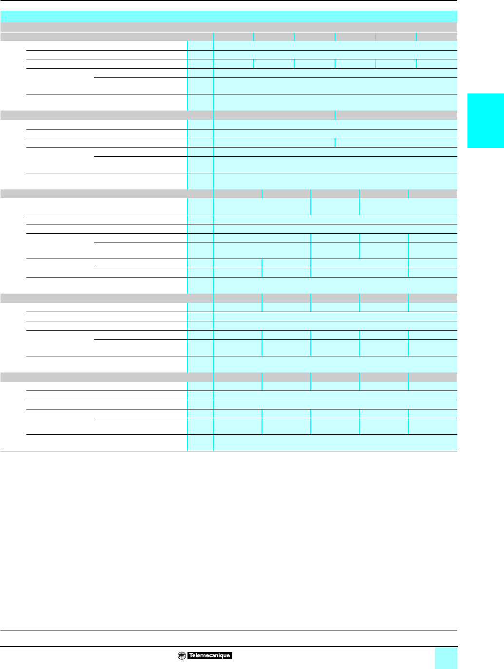
2/29
2
Characteristics (continued) Modicon®M340™ Automation
Platform 0
Analog I/O modules
(1) %FS: Error as a % of full scale. ± 1 °C with Pt100 temperature probe range, - 100...+ 200 °C
(2) Excluding error caused by the wiring
Characteristics of BMX ART 0414/0814 analog input modules
Input ranges for BMX ART 0414/0814 modules
Voltage range ± 40 mV ± 80 mV ± 160 mV ± 320 mV ± 640 mV ± 1.28 V
Typical input impedance MΩ10
Maximum conversion value ± 102.5%
Maximum resolution mV 40/214 80/214 160/214 320/214 640/214 1280/214
Measurement errors
(1)
At 25 °C %FS 0.05
Maximum at 0…60 °C %FS 0.15
Temperature drift ppm/°
C
30
Resistor range 400 Ω4,000 Ω
Type 2-, 3- or 4-wire
Maximum conversion value ± 100%
Maximum resolution mV 400/214 4,000/214
Measurement errors
(1)
At 25 °C %FS 0.12
Maximum at 0…60 °C %FS 0.2
Temperature drift ppm/°
C
25
Temperature probe ranges Pt100 Pt1000 Cu10 Ni100 Ni1000
Measurement range °C According to IEC: -200...+850
According to US/JIS: -100...+450
-100...+260 -60...+180
Resolution °C 0.1
Detection type Open circuit (detection on each channel)
Measurement errors
(1)
At 25 °C (2) °C ± 2.1 ± 4 ± 2.1 0.7
Maximum at 0…60 °C °C ± 2 ± 4 ± 3.0 1.3
Max. wiring
resistance
4-wire Ω50 500 50 500
2/3-wire Ω20 200 20 200
Temperature drift 30 ppm/°C
Thermocouple ranges B E J K L
Measurement range °C +130...+1820 -270...+1000 -200...+760 -270...+1370 -200...+900
Resolution °C 0.1
Detection type Open circuit (detection on each channel)
Measurement errors
(1)
At 25 °C °C ± 3.5 ± 3.7 ± 2.8 ± 3.7 ± 3.0
Maximum at 0…60 °C °C ± 5 ± 5 ± 4.5 ± 5 ± 4.5
Temperature drift ppm/°
C
25
Thermocouple ranges (continued) N R S T U
Measurement range °C +270...+1300 -50...+1769 -50...+1769 -270...+400 -200...+600
Resolution °C 0.1
Detection type Open circuit (detection on each channel)
Measurement errors
(1)
At 25 °C °C ± 3.7 ± 3.2 ± 3.2 ± 3.7 ± 2.7
Maximum at 0…60 °C °C ± 5 ± 4.5 ± 4.5 ± 5 ± 4.5
Temperature drift ppm/°
C
25
Description:
page 2/24
Functions:
pages 2/26 and 2/27
References:
page 2/31
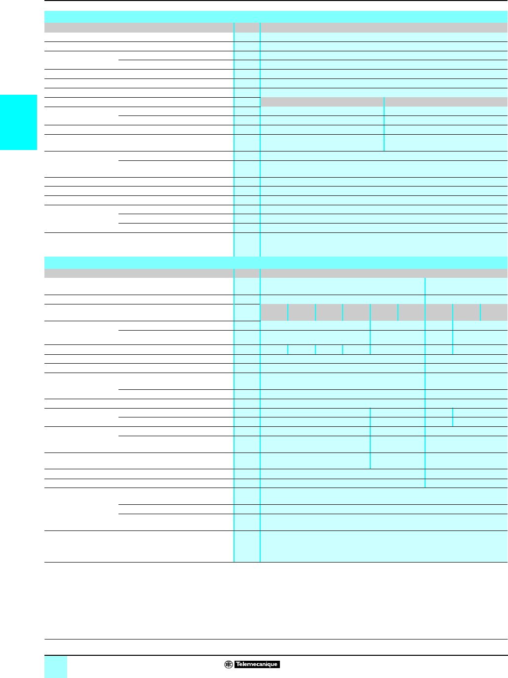
2/30
2
Characteristics (continued) Modicon®M340™ Automation
Platform 0
Analog I/O modules
(1) %FS: Error as a % of full scale
(2) Default: Output at 0 (V or mA). Configurable: Hold last value or set at predefined value for
each channel.
Characteristics of the BMX AMO 0210 analog output module
Module BMX AMO 0210
Output type Isolated high-level outputs
Number of channels 2
Ranges Voltage ± 10 V
Current 0...20 mA and 4...20 mA
Resolution bits 15 + sign
Conversion time ms y1
Output power supply Internal power supply via rack
Output ranges Voltage Current
Adjustment range
Nominal V± 10 V 0...20 mA, 4...20 mA
Maximum V± 11.25 V 24 mA
Load impedance Ω ≥ 1,000 y 600
Detection type Short-circuit Open circuit
Measurement errors
(1)
At 25 °C %FS 0.10
Maximum at 0…60 °C %FS 0.25
Temperature drift 40 ppm/°C
Recalibration None, factory-calibrated
Fallback mode (2) Default or configurable
Isolation Between channels V rms 1,400 V c
Between channels and bus V rms 2,000 V c
Between channels and ground V rms 2,000 V c
Consumption Typical mA See power consumption table page 6/8
Characteristics of BMX AMM 0600 mixed analog I/O module
Module BMX AMM 0600
Channel type Non-isolated high-level inputs Non-isolated high-level
outputs
Number of channels 4 2
Ranges ± 10 V 0…5 V 0…10 V 1…5 V 0…20
mA
4…20
mA
± 10 V 0…20
mA
4…20
mA
Maximum conversion
value
Voltage V± 11.25 –± 11.25 –
Current mA –0...30 –0...24 mA
Resolution bits 14 12 13 12 12 12 11
Filtering 1st order digital filtering by firmware
Precision of internal conversion resistor 250 Ω, 0.2% - 25 ppm/°C –
Read cycle time Fast ms 1 + 1 x no. of channels used
(periodic reading of no. of declared channels)
–
Default ms 5 for 4 channels –
Conversion time ms –y 2
Permitted overload on
the input channels
Voltage V± 30 –± 11.25 –
Current mA –± 30 –0...24
Measurement errors
(1)
At 25 °C %FS 0.25 0.35 0.25
Maximum at 0…60 °C %FS 0.35 0.50 0.60
Temperature drift 30 ppm/°C 50 ppm/°C 100 ppm/°C
Recalibration Internal None, factory-calibrated
Fallback mode (2) –Default or configurable
Isolation Between group of input channels and
group of output channels
V1,400 c
Between channels and bus V2,000 c
Between channels and ground V2,000 c
Consumption Typical mA See power consumption table page 6/8
Description:
page 2/24
Functions:
pages 2/26 and 2/28
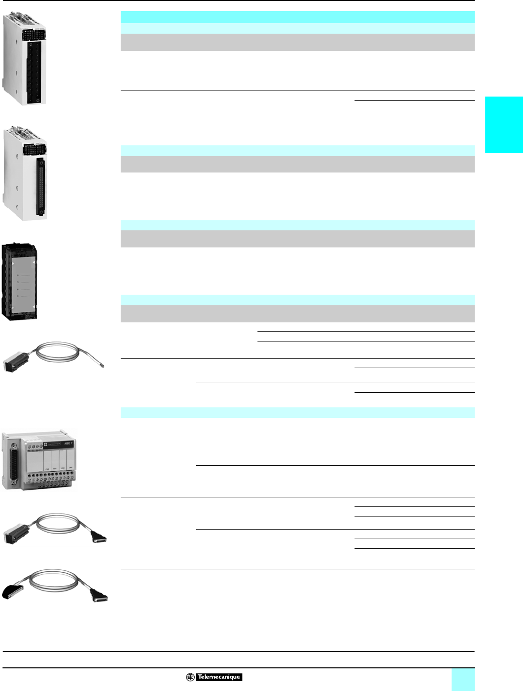
2/31
2
References Modicon®M340™ Automation
Platform 0
Analog I/O modules
(1) The shielding on the cord sets carrying the analog signals must always be connected to the
BMX XSPpp00 shielding connection kit mounted under the rack holding the analog modules
(see page 1/15).
(2) The BMX ART 0814 8-channel module requires two ABE7CPA412 sub-bases and two
BMX FCApp2 cord sets.
r Available 4th quarter 2007
References
Analog input modules
Input type Input signal range Resolution Connection No. of
channels
Reference Weight
kg
Isolated high-level
inputs
± 10 V, 0...10 V,
0...5 V, 1...5 V, ± 5 V
0...20 mA,
4...20 mA, ± 20 mA
16 bits Via cage clamp,
screw clamp or
spring-type
removable terminal
block
4 fast
channels
BMXAMI0410 –
Isolated low-level
inputs
Temperature probe,
thermocouple
± 40 mV, ± 80 mV,
± 160 mV, ± 320 mV,
± 640 mV, ± 1.28 V
0...400 Ω,
0...4000 Ω
15 bits
+sign
40-pin connector 4 channels BMXART0414 –
8 channels BMXART0814 r–
Analog output module
Output type Output signal
range
Resolution Connection No. of
channels
Reference Weight
kg
Isolated high-level
outputs
± 10 V,
0...20 mA, 4...20 mA
16 bits Via cage clamp,
screw clamp or
spring-type
removable terminal
block
2 channels BMXAMO0210 –
Mixed analog I/O module
Channel type Signal range Resolution Connection No. of
channels
Reference Weight
kg
Mixed I/O, non-isolated ± 10 V, 0...10 V,
0...5 V, 1...5 V,
0...20 mA, 4...20 mA
14 bits or
12 bits
depending
on the range
Via cage clamp,
screw clamp or
cage spring-type
removable terminal
block
I: 4
channels
Q: 2
channels
BMXAMM0600 r–
Connection accessories for analog modules (1)
Description For use with
modules
Type, composition Length Reference Weight
kg
20-pin removable
terminal blocks
BMX AMI 0410
BMX AMO 0210
BMX AMM 0600
Cage clamp – BMXFTB2000 –
Screw clamp – BMXFTB2010 –
Spring-type – BMXFTB2020 –
Preformed cord sets BMX AMI 0410
BMX AMO 0210
BMX AMM 0600
One 20-pin removable terminal
block
One end with color-coded wires
3m BMXFTW301S –
5m BMXFTW501S –
BMX ART 0414
BMX ART 0814 (2)
One 40-pin connector
One end with color-coded wires
3m BMXFCW301S –
5m BMXFCW501S –
Advantys™ Telefast® ABE7 pre-wired I/O system
Advantys Telefast
ABE7 sub-bases
BMX AMI 0410 Distribution of isolated power
supplies
Delivers 4 protected isolated
power supplies for 4...20 mA
inputs
Direct connection of 4 inputs
–ABE7CPA410 0.180
BMX ART 0414
BMX ART 0814
Connection and provision of cold
junction compensation for
thermocouples
Direct connection of 4 inputs
–ABE7CPA412 0.180
Preformed cord sets for
ABE7CPAppp
sub-bases
BMX AMI 0410 One 20-pin removable terminal
block and one 25-pin SUB-D
connector for ABE7CPA410
sub-base
1.5 m BMXFCA150 –
3m BMXFCA300 –
5m BMXFCA500 –
BMX ART 0414
BMX ART 0814
One 40-pin connector and
one 25-pin SUB-D connector for
ABE7CPA412 sub-base
1.5 m BMXFCA152 –
3m BMXFCA302 –
5m BMXFCA502 –
BMX AMp 0pp0
BMX ART 0414 BMX ART 0814
BMX FTB 20p0
BMX FTW p01S
BMX FCA pp0
BMX FCA p02
ABE7CPA41p
Description:
page 2/24
Functions:
pages 2/26 and 2/27
Characteristics:
pages 2/28 to 2/30
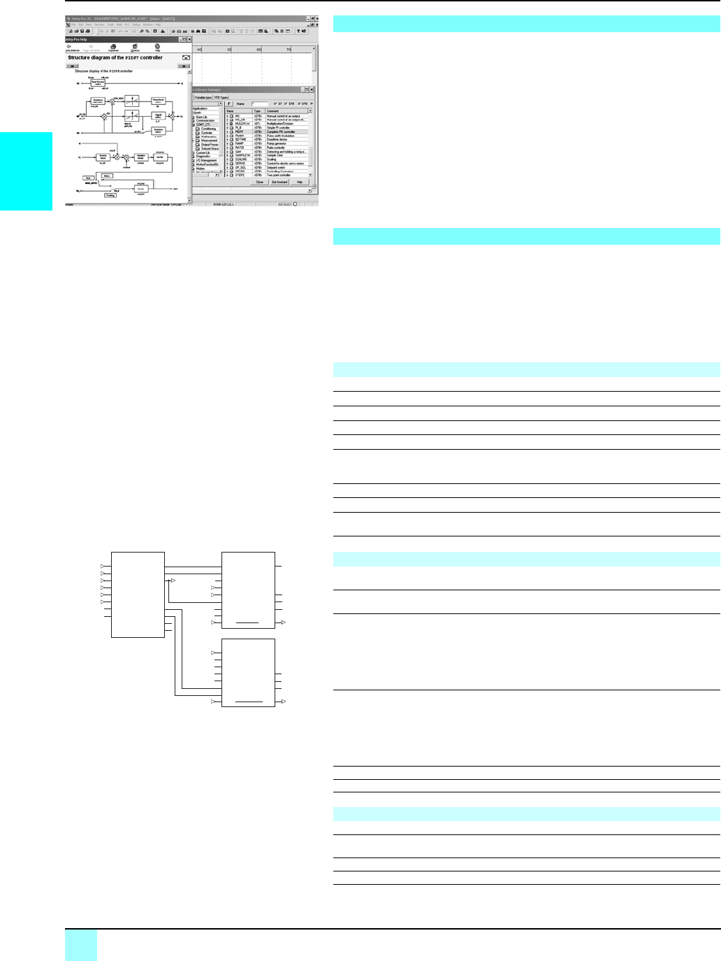
2/32
2
Presentation,
Functions
Automation platform 0
Modicon® M340™ processors
Programmable process control
Unity Pro™ software contains CONT_CTL, a library of 36 function blocks used to
create control loops for machine control.
Modicon M340 processors meet the requirements for closed loop control functions
in machines are adequately met by Modicon M340 thanks to the wealth of functions
in the library and the flexibility with which function blocks can be linked together
through programming. This solution therefore eliminates the need for external
controllers, and simplifies the overall control architecture of the machine, as well as
its design, roll-out and operation.
The function blocks, EF or EFB, can be used in all Unity Pro™ languages, i.e., LD,
ST, IL and FBD. FBD is particularly suitable for accessing control processing
operations in Unity Pro™ software through its assistant for entering and viewing
parameters and function block variables.
The library consists of five function families:
bInput data conditioning
bControllers
bMath functions
bMeasurement processing
bOutput value processing
Process control in machines
CONT_CTL library functions
Input data conditioning
DTIME Pure delay
INTEGRATOR Integrator with limiting
LAG_FILTER First order time lag device
LDLG PD device with smoothing
LEAD Differentiator with smoothing
MFLOW Mass flow calculation based on the measurement of differential
pressure or flow speed with pressure and temperature
compensation
QDTIME Deadtime device
SCALING Scaling
TOTALIZER Integrator (typically of flow) until a limit (typically a volume) is
reached, with automatic reset
VEL_LIM Velocity limiter, with manipulated variable limiting
Controllers
PI_B Simple PI controller: PI algorithm with a mixed structure
(series/parallel)
PIDFF Complete PID controller: PID algorithm with a parallel or mixed
structure (series/parallel)
AUTOTUNE Automatic tuner setting for the PIDFF (complete PID) controller or
the PI_B (simple PI) controller
vIdentification using Ziegler Nichols type method
vModeling based on 1st order process
vBuilding of control parameters with criterion for prioritizing either
the reaction time to disturbance (dynamic) or the stability of the
process
IMC Model corrector. The model is a first order model with delay. This
corrector is useful:
vWhen there are serious delays compared with the main time
constant of the process; this scenario cannot be satisfactorily
resolved by standard PID process control
vFor regulating a non-linear process
IMC can handle any stable and aperiodic process of any order.
SAMPLETM Control of controller startup and sampling
STEP2 Two-point controller
STEP3 Three-point controller for temperature regulation
Math functions
COMP_DB Comparison of two values, with dead zone and hysteresis
K_SQRT Square root, with weighting and threshold, useful for linearization
of flow measurements
MULDIV_W Weighted multiplication/division of 3 numerical values
SUM_W Weighted summation of 3 numerical values
CONT_CTL, programmable process control integrated in
Unity Pro
AUTOTUNE
PV
SP
RCPY
START
PREV
PARA
TR_I
TR_S
PV_O
SP_O
PARA_C
TRI
TRS
INFO
STATUS
TT18_PV
TT18_SP
TC18_OUT
TC18_START
TC18_PREV
TC_PARA
TC18_PARA
TC18_OUT
1
TC2_OUT
TC2_OUT
TC18_OUT
PV
SP
PARA
TR_I
TR_S
PIDFF
FF
RCPY
MAN_AUTO
OUT OUT
OUTD
MA_O
INFO
STATUT
TC2_OUT
MS
TC18_OUT
IN
PARA
TR_I
TR_S
FORC
MA_FORC
MAN_AUTO
OUT OUT
OUTD
MA_O
STATUT
Example: PID controller with MS manual control
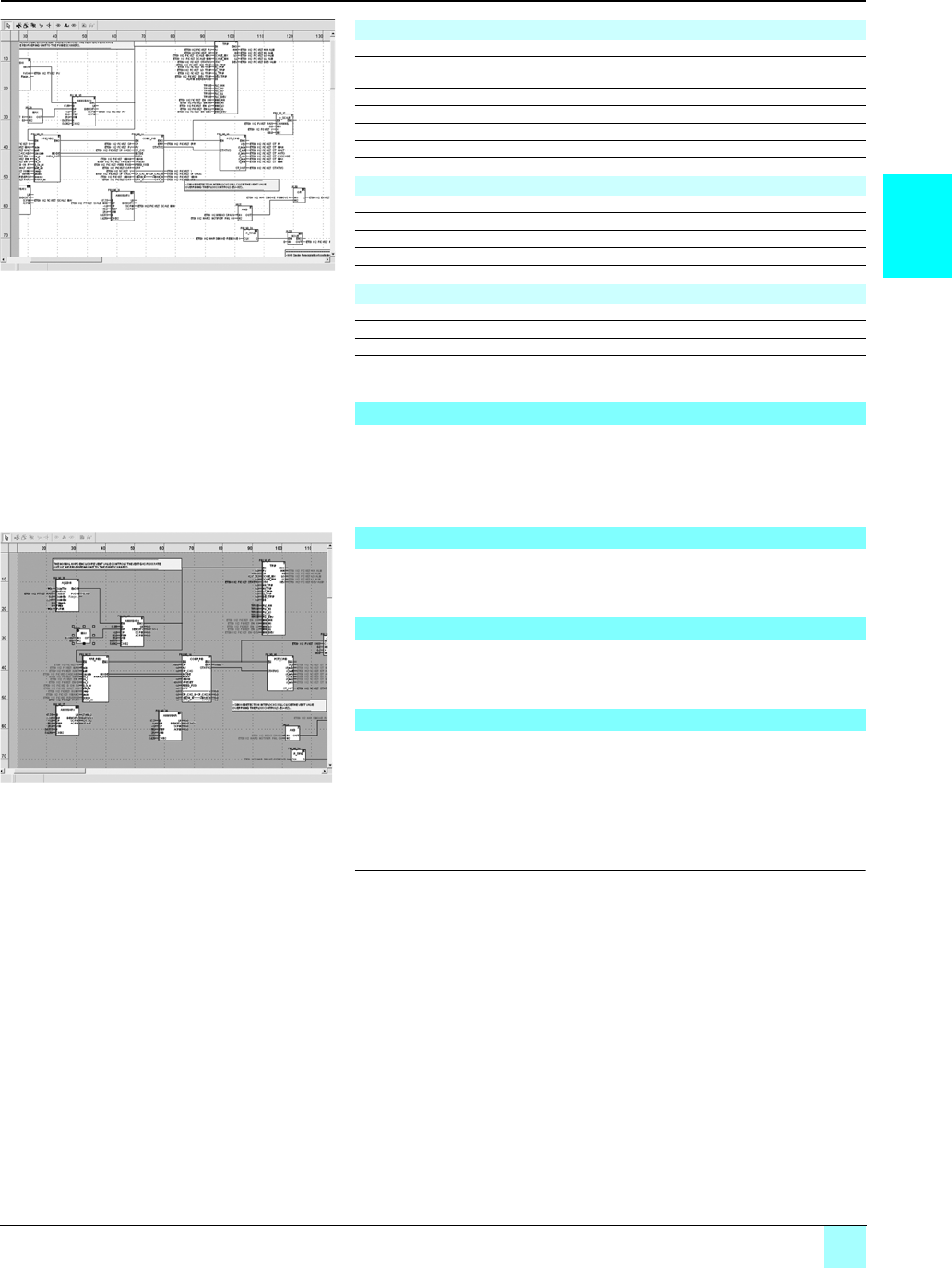
2/33
2
Functions (continued)
Setup
Automation platform 0
Modicon® M340™ processors
Programmable process control
Based on the sequencing of function blocks, the FBD language integrated into
Unity Pro™ programming language is particularly suitable for building control loops.
Designers can use FBD to easily associate blocks from the CONT_CTL library with
their own DFB blocks written in Unity Pro™ software ST, IL, or LD language, or in C
language.
All Unity Pro™ standard debugging services (see page 4/21) are available. In
particular, the Modicon M340 processor simulator can be used to check correct
execution of processing offline.
The CONT_CTL control function block library is available in all versions of Unity Pro™
software. It is compatible with all processors in the Modicon® M340™, Premium™,
Quantum™, and Atrium™ PLC ranges.
The technical documentation provides many examples of how to set up
programmable process control function blocks in FBD, LD, IL and ST languages.
The techniques for adjusting process control loops are described in the document
“Process control, Unity™ V3.0” available on the www.telemecanique.com website.
(1) XXX depending on the type of variable: DINT, INT, UINT, UDINT, REAL
Measurement processing
AVGMV Moving average with fixed number of samples (50 max.)
AVGMV_K Moving average with constant correction factor, 10,000 samples
max.
DEAD_ZONE Dead zone
LOOKUP_TABLE1 Linearization of characteristic curves using first-order interpolation
SAH Detection of a rising edge
HYST_XXX Detection of high threshold with hysteresis (1)
INDLIM_XXX Detection of high and low thresholds with hysteresis (1)
Output value processing
MS Manual control of an output
MS_DB Manual control of an output with dead zone
PWM1 Control via pulse width modulation
SERVO Control for servo motors
SPLRG Control of two Split Range actuators
Setpoint management
RAMP Ramp generator, with separate ascending and descending ramps
RATIO Ratio controller
SP_SEL Selection of setpoint value: local (operator) or remote (processing)
Setting up process control function blocks
Debugging, operation
Compatibility
Resources
Programming in Unity Pro in offline mode
Programming in online mode
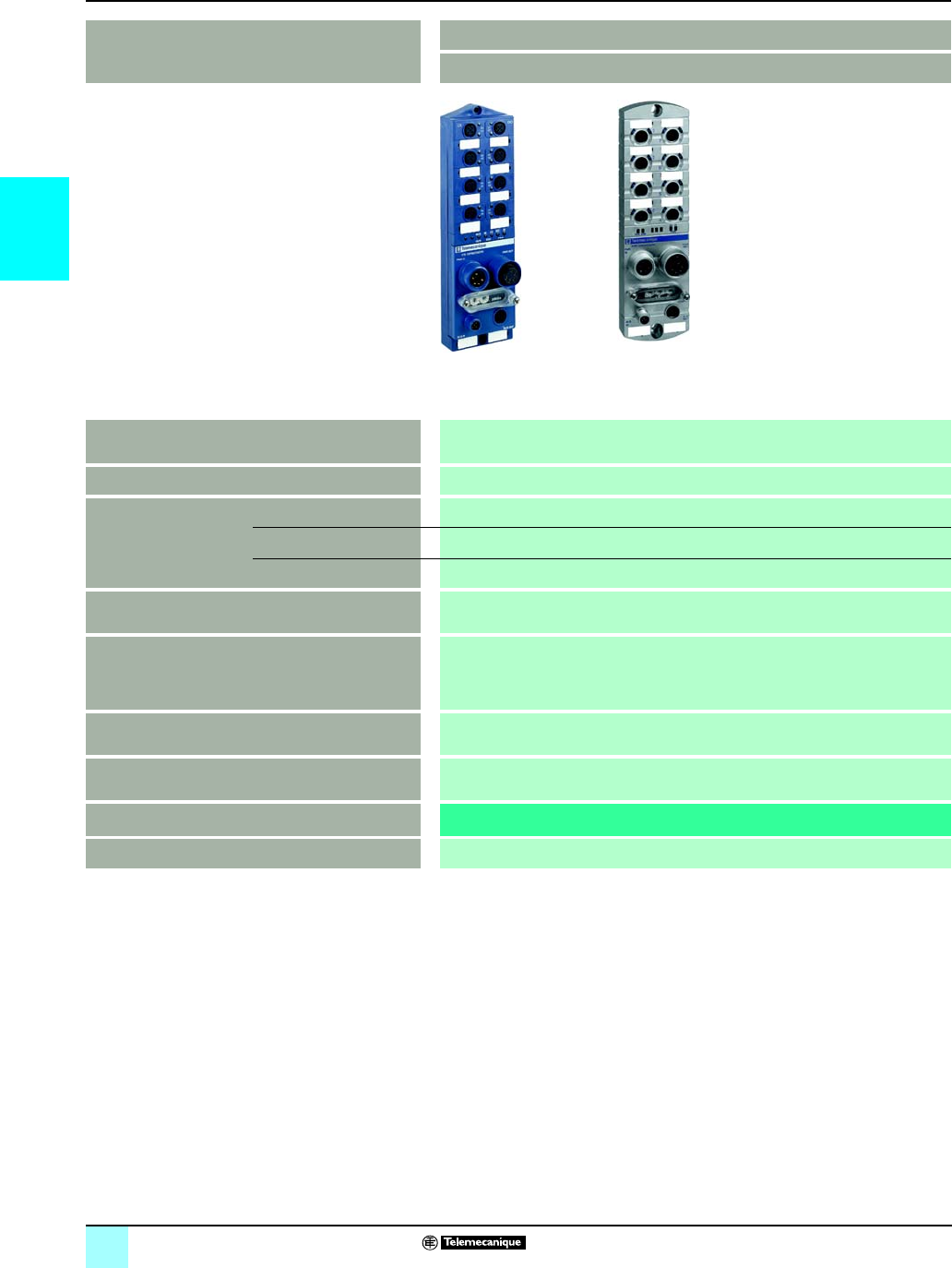
2/34
2
Selection guide Modicon®M340™ Automation
Platform 0
Distributed I/O system
Splitter box and module type Monobloc I/O splitter boxes
Advantys™ FTB distributed I/O system
Type of communication with Modicon M340 platform CANopen
Max. number per connection points 1 monobloc splitter
Discrete inputs/outputs Number of channels Splitter of 16 I, 8 I + 8 O, 12 I + 4 O, 16 I/O or 8 I + 8 I/O
Input voltage 24 V c
Output voltage 24 V c
analog inputs/outputs –
Counting –
Type of input/output connectors M12 connectors
Housing type Plastic and metal
Module type FTB 1
Pages Consult our catalog “IP 67 splitter boxes”
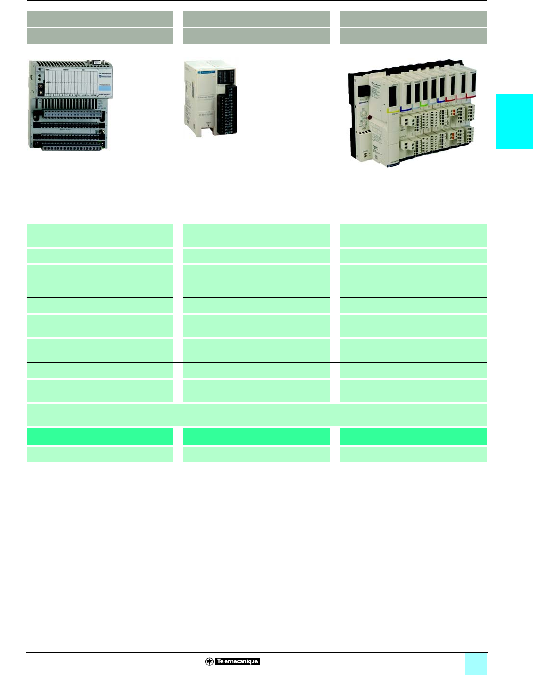
2/35
2
0
Monobloc IP 20 distributed I/O Optimum IP 20 distributed I/O Modular IP 20 distributed I/O
Modicon® Momentum™ PLC Advantys™ OTB distributed I/O system Advantys™ STB distributed I/O system
Ethernet TCP/IP Ethernet TCP/IP
CANopen
Modbus® communication (RS 485)
Ethernet TCP/IP
CANopen
1 base with 1 communicator 1 interface module 1 “NIM” interface module + 32 I/O modules
Base of 16 I, 32 I, 8 O, 16 O, 32 O, 10 I/8 O,
16 I/8 O, 16 I/12 O and 16 I/16 O
12 I/8 O Module of 2 I, 4 I, 6 I, 16 I, 2 O, 4 O, 6 O or 16 O
24 V c, 120 V a, and 230 V a24 V c24 V c, 115 V a, and 230 V a
24 V c, 120 V a, 230 V a, and relay 24 V c, and relay 24 V c, 115/230 V a, and relay
Bases 8 I, 16 I or 4 O voltage/current
Base 4 I thermocouple or RTD
– Modules 2 I and 2 O voltage/current
Module 2 I thermocouple or RTD
Base 2 channels 10 kHz/200 kHz Integrated in interface module:
- 2 channels 5 kHz/20 kHz
- 2 PWM function channels
Module 1 channel 40 kHz
Base 6 I/3 O 120 V a with 1 Modbus port –Parallel interface module for TeSys® Quickfit and
TeSys® U motor-starters
Screw or spring terminal blocks Removable screw terminal blocks Screw or spring connectors
Plastic
170 ADp OTB 1pODM9LP STB Dpp/App
Consult our catalog: Modicon Momentum
automation platform
Consult our catalog: Advantys OTB distributed I/O Consult our catalog: Advantys STB distributed I/O
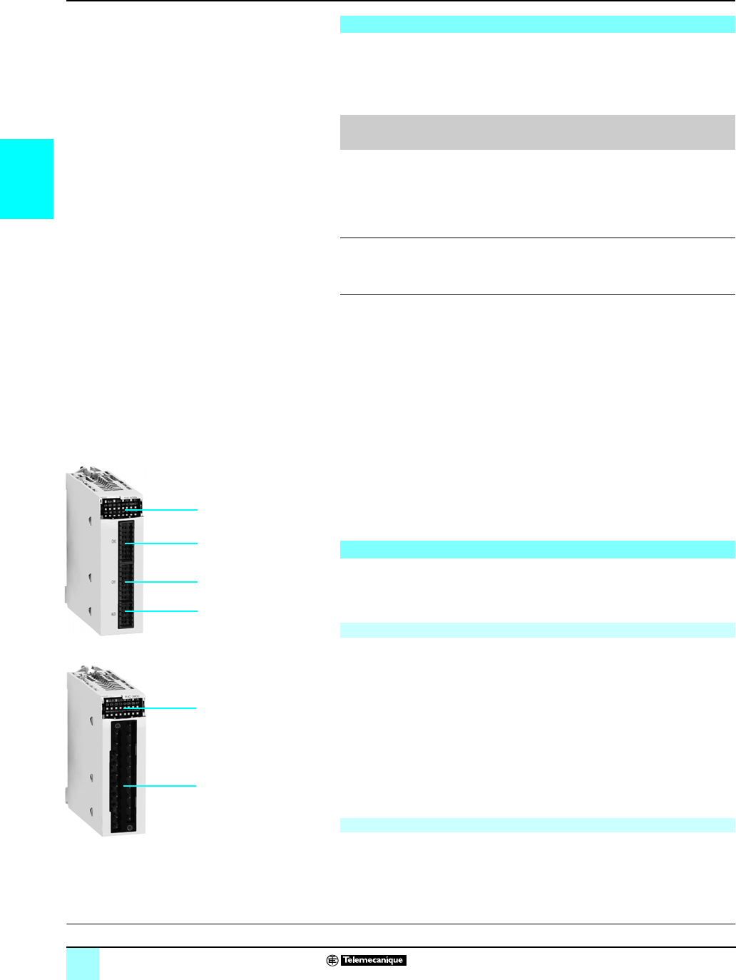
2/36
2
Presentation Modicon®M340™ Automation
Platform 0
BMX EHC 0200/0800 counter modules
BMX EHC 0200 and BMX EHC 0800 counter modules for the Modicon M340
automation platform are used to count the pulses generated by a sensor or to
process the signals from an incremental encoder.
The two modules differ in the number of counter channels, maximum input
frequencies, functions and auxiliary input and output interfaces:
The sensors used on each channel can be:
b2-wire 24 V proximity sensors
b3-wire 24 V proximity sensors
b10/30 V output signal incremental encoders with push-pull outputs
BMX EHC 0200 / 0800 counter modules can be used to meet the demands of
applications such as:
bAlarm generation on empty unwinder status using the ratio
bSorting small parts using the period meter
bSingle electronic cam using the dynamic setting thresholds
bSpeed control using the period meter
These standard format modules can be installed in any available slot of a
Modicon M340 PLC; they can be removed while powered up.
In a Modicon M340 PLC configuration, the number of BMX EHC 0200 / 0800 counter
modules should be added to the number of application-specific modules:
communication, motion control and weighing.
The function parameters are set using Unity Pro™ software.
BMX EHC 0200 / 0800 analog I/O modules are standard format. They occupy a
single slot in BMX XBP pp00 racks.
They come in a plastic case which ensures IP 20 protection of the electronics, and
locks into position with a screw.
The BMX EHC 0200 counter module has the following on the front panel:
1Module and channel status LED array
216-pin connector for wiring the sensors of counter 0
316-pin connector for wiring the sensors of counter 1
410-pin connector for wiring:
vthe auxiliary outputs
vthe sensor power supplies
To be ordered separately:
bA BMX XTS HSC 20 kit containing:
vTwo 16-pin connectors
vOne 10-pin connector
bA BMX XSP 010 electromagnetic compatibility kit.
The BMX EHC 0800 counter module has the following on the front panel:
1Module and channel status LED array
220-pin connector compatible with discrete I/O
To be ordered separately: a BMX XSP 010 electromagnetic compatibility kit.
Presentation
Counter module No. of
channels
Maximum
frequency
Integrated
functions
No. of
physical
inputs
No. of
physical
outputs
BMXEHC0200 2 60 kHz Upcounting
Downcounting
Period meter
Frequency
meter
Frequency
generator
Axis control
62
BMXEHC0800 8 10 kHz Upcounting
Downcounting
Measurement
Interface
2–
Description
BMX EHC 0200 module, 2 channels, 60 kHz
BMX EHC 0800 module, 8 channels, 10 kHz
BMX EHC 0200
2
1
3
4
BMX EHC 0800
2
1
Characteristics:
page 2/40
Connections:
page 2/42
References:
page 2/41
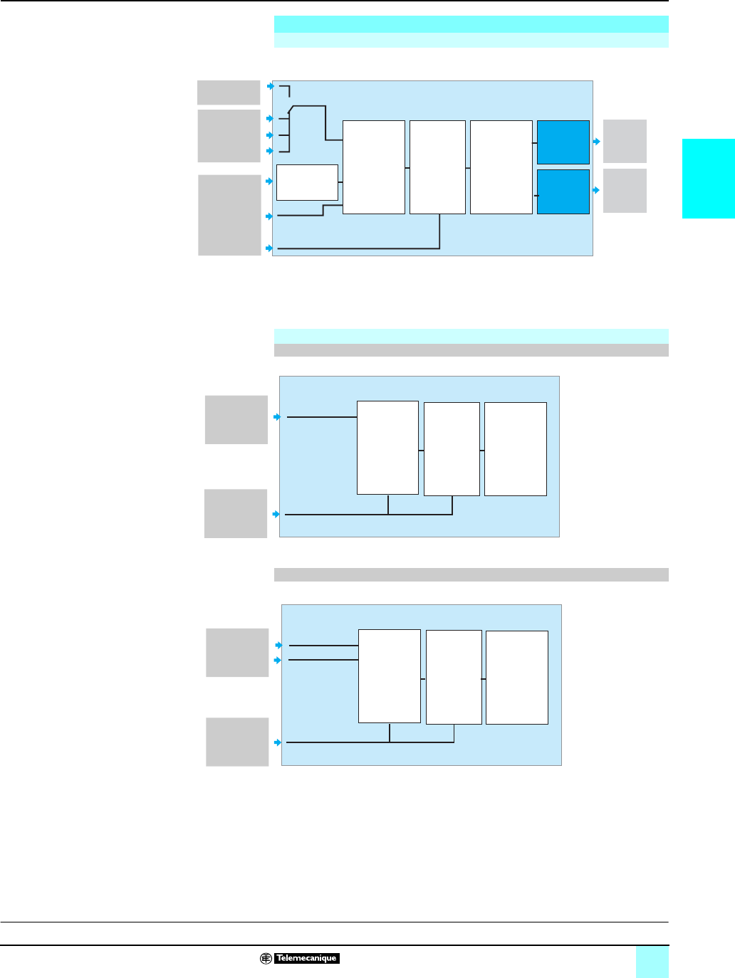
2/37
2
Functions Modicon®M340™ Automation
Platform 0
BMX EHC 0200/0800 counter modules
(1) Optional inputs
(2) Reference: 5 operating modes for SYNC "IN_SYNC" and Reference "IN_REF" inputs.
Functions of inputs: 15 possible types of behavior.
Operation
Block diagram of a BMX EHC 0200 module counter channel
Incremental
encoder A/B
SYNC input
Reference
(2)
Reference(1)
Enable (1)
Learn (1)
32-bit
up/down
counting
8
configurable
modes
2 capture
registers
Comparator
with 2
thresholds
Function on
output 0
(3)
Output
0
Output
1
Function on
output 1
(3)
Input A
Input B
Block diagram of a BMX EHC 0800 module counter channel
Used in 16-bit (8 channels)
Auxiliary
16-bit
up/down
counting
5
configurable
modes
1 capture
register
Comparator
with 1
threshold
or
Input A
Used in 32-bit (4 channels)
Incremental
encoder A/B 32-bit
up/down
counting
1
mode
1 capture
register
Comparator
with 1
threshold
Auxiliary B
Characteristics:
page 2/40
Connections:
page 2/42
References:
page 2/41

2/38
2
Functions (continued) Modicon®M340™ Automation
Platform 0
BMX EHC 0200/0800 counter modules
(1) If the measurement value exceeds 2,147,483,647 units then the application must convert the
measurement naturally to a signed integer (DINT) or an unsigned integer (UINT).
(2) The counter value is a signed integer (DINT) which must not be converted to an unsigned
integer (UINT).
Functional characteristics of the BMX EHC 0200 module
Configurable functions Frequency meter This function measures a frequency, speed, data rate or an event stream.
As standard, this function measures the frequency received on the IN A input.
This frequency is always expressed in Hz (number of pulses per second), with a precision of
1Hz.
The maximum frequency on the IN A input is 60 kHz.
The maximum cyclic ratio at 60 kHz is 60%.
Count events This function is used to determine the number of events received intermittently.
In this mode, the counter calculates the number of pulses applied to the IN_A input, at time
intervals defined by the user.
As an option, it is possible to use the IN_SYNC input during a period of time, provided that the
enable bit has indeed been configured.
The module counts the pulses applied to the IN_A input each time the pulse for this input lasts
longer than 5 µs (without anti-bounce filter).
IN_A input pulses that have appeared for less than 100 ms after a change of state of the
IN_SYNC input are lost.
Measure time periods This function is used to:
bdetermine how long an event lasts
bdetermine the time that separates 2 events
bmeasure the execution time of a process
Measures the elapsed time during an event or between two events (IN_A input) according to a
selectable time base of 10 µs, 100 µs or 1 ms.
The IN_SYNC input can be used to enable or stop a measurement.
The module can carry out a maximum of 1 measurement every 5 ms.
The smallest measurable pulse is 100 µs, even if the unit defined by the user is 10 µs.
The maximum measurable duration is 4,294,967,295 units (1) (unit to be defined).
Ratio count The ratio count mode only uses the IN_A and IN_B inputs. This count mode consists of
2 modes:
bRatio 1: used to divide 2 frequencies and useful in applications such as flowmeters and
mixers, for example.
bRatio 2: used to subtract 2 frequencies and useful in the same applications but requiring
more precise regulation (more similar frequencies).
Ratio 1 mode presents the results in thousandths in order to have better accuracy (a display of
2000 corresponds to a value of 2) and ratio 2 mode presents the results in Hz.
The maximum frequency that the module can measure on the IN_A and IN_B inputs is 60 kHz.
The maximum measurable value is 4,294,967,295 units (1).
Downcounting This function is used to list a group of operations. In this mode, activation of the synchronization
function starts the counter which, starting with a preset value, decreases on each pulse applied
to the IN_A input, until it reaches the value 0. This downcounting is made possible when the
enable function has been activated. The counting register is thus updated at intervals of 1 ms.
One basic use of this mode is to use an output to signal the end of a group of operations (when
the counter reaches 0).
The smallest pulse applied to the IN_SYNC input is 100 µs.
The frequency applied to the IN_SYNC input is at maximum 1 pulse every 5 ms.
The maximum value of the preset value is 4,294,967,295 (1).
The maximum count value is 4,294,967,295 units (1).
Loop (modulo) counting This function is used in packaging and labeling applications where actions are repeated in
series of moving objects.
In the counting direction, the counter increases until it reaches the preset modulo value. On the
next pulse, the counter is reset to 0 and counting restarts.
In the downcounting direction, the counter decreases until it reaches the value 0. On the next
pulse, the counter is reset to the preset modulo value. Downcounting can then restart.
The maximum frequency applied to the IN_A and IN_B inputs is 60 kHz.
The smallest pulse applied to the IN_SYNC input is 100 µs.
The frequency applied to the IN_SYNC input is at maximum 1 pulse every 5 ms.
The frequency of the modulo event is at maximum 1 every 5 ms.
The maximum modulo and counter value is 4,294,967,295 (1).
32-bit counter counting This function is used mainly in the axis following:
The maximum frequency applied simultaneously to the IN_A and IN_B inputs is 60 kHz.
The smallest pulse applied to the IN_SYNC input is 100 µs.
The frequency of the referencing event is at maximum 1 every 5 ms.
The counter value is between - 2,147,483,647 and + 2,147,483,647 (2).
Width modulation In this operating mode, the module uses an internal clock generator to supply a periodic signal
on the module output Q0. Only the Q0 output is affected by this mode, the Q1 output being
independent of this mode.
Control of the Q0 output must be at 1 to enable modulation on the Q0 output.
The maximum output frequency value is 4 kHz.
The frequency applied to the IN_SYNC input is at maximum 1 pulse every 5 ms.
Since the Q0 output is source type, a load resistor is needed for the Q0 output signal to change
to 0 at the correct frequency.
The cyclic ratio adjustment range varies according to the frequency of the Q0 output.
Characteristics:
page 2/40
Connections:
page 2/42
References:
page 2/41

2/39
2
Functions (continued) Modicon®M340™ Automation
Platform 0
BMX EHC 0200/0800 counter modules
Functional characteristics of the BMX EHC 0800 module
Configurable functions Frequency meter This function measures a frequency, speed, rate or data stream control.
As standard, this function measures the frequency received on the IN A input.
This frequency is always expressed in Hz (number of pulses per second), with a precision of
1Hz.
The maximum frequency on the IN A input is 60 kHz.
The maximum cyclic ratio at 60 kHz is 60%.
Count events This function is used to determine the number of events received intermittently.
In this mode, the counter calculates the number of pulses applied to the IN_A input, at time
intervals defined by the user.
As an option, it is possible to use the IN_AUX input during a period of time, provided that the
enable bit has indeed been configured.
The module counts the pulses applied to the IN_A input each time the pulse for this input lasts
longer than 50 µs (without anti-bounce filter).
Pulses with less than 100 ms synchronization are lost.
Downcounting This function is used to list a group of operations.
In this mode, when counting is enabled (software validation via the valid_sync command), a
rising or falling edge on the IN_AUX input causes a value, defined by the user, to be loaded in
the counter. The counter decreases on each pulse applied to the IN_A input, until it reaches the
value 0. Downcounting is made possible when the force_enable command is high (software
positioning).
The smallest pulse applied to the IN_AUX input is 100 µs.
The frequency applied to the IN_AUX input is at maximum 1 pulse every 25 ms.
Loop (modulo) counting This function is used in packaging and labeling applications where actions are repeated on
series of moving objects.
The counter increases on each pulse applied to the IN_A input, until it
reaches the preset modulo value. On the next pulse in the upcounting direction, the counter is
reset to 0 and upcounting restarts.
The maximum frequency applied to the IN_A input is 10 kHz.
The smallest pulse applied to the IN_AUX input varies according to the selected filter level.
The frequency applied to the IN_AUX input is at maximum 1 pulse every 25 ms.
The frequency of the modulo event is at maximum 1 every 25 ms.
The minimum acceptable modulo value varies according to the frequency of the IN_A input. For
example, for a frequency of 10 kHz applied to the IN_A input, the modulo must be higher than
250.
Up/down counter This function is used for an accumulation, upcounting or downcounting operation on a single
input.
Each pulse applied to the IN_A input produces:
bupcounting of pulses if the IN_AUX input is high
bdowncounting of pulses if the IN_AUX input is low
The counter values vary between the limits -65,536 and +65,535.
The maximum frequency applied to the IN_A input is 10 kHz.
Pulses applied to the IN_A input, after a change of direction, are only upcounted or
downcounted after a period corresponding to the delay for taking account of the state of the
IN_AUX input due to the programmable filter level on this input.
32-bit counter counting 32-bit counter counting mode is available for channels 0, 2, 4, and 6 (channels 1, 3, 5 and 7 are
now inactive). It behaves in the same way as the up/down counting mode using up to 3 physical
inputs. It enables simultaneous upcounting and downcounting.
The counter values vary between the limits -2,147,483,648 and +2,147,483,647 (31-bit word
and 1 sign bit).
The eight 16-bit registers can be configured as four 32-bit registers.
The maximum frequency applied to the IN_A and IN_B inputs is 10 kHz.
The smallest pulse applied to the IN_AUX input is defined according to the filtering applied to
this input.
The frequency of loading the preset value is at maximum 1 every 25 ms.
Characteristics:
page 2/40
Connections:
page 2/42
References:
page 2/41

2/40
2
Characteristics Modicon®M340™ Automation
Platform 0
BMX EHC 0200/0800 counter modules
.
General characteristics
Type of module BMX EHC 0200 BMX EHC 0800
Modularity 2 channels 8 channels
Number of physical inputs per module 6 2
Number of physical outputs per module 2 –
Application Upcounting, downcounting,
measurement, frequency meter,
frequency generator, axis following
Upcounting, downcounting,
measurement, interfacing
Frequency on counter inputs kHz max. 60 max. 10
Module cycle time ms 1 5
Number of
inputs/outputs per
counter channel
Inputs Number 6
2 in single mode
3 in special dual-phase mode
Type V24 c, Type 3
Outputs Number
2 –
Type V
24
c
–
Encoder 10...30 V incremental encoder model with push-pull outputs
Power supply Sensor voltage V19.2...30 c
Actuator current A
0.5 max. per output
2 per module
–
Distribution of power to the sensors Yes.
Short-circuit and overload protection, 300
mA typical
–
Hot swapping Yes, in certain conditions: the module can be removed and reinserted in its slot while
the rack is powered up, but the counter may need to be re-enabled when it is
reinserted in its base.
Insulation voltage from the ground to the bus V1500 for 1 min
Consumption Typical mA See power consumption table page 6/8
Input characteristics
Module type BMX EHC 0200 BMX EHC 0800
Input type High-speed inputs (IN_A, IN_B,
IN_SYNC) and auxiliary inputs (IN_EN,
IN_REF, IN_CAP)
High-speed inputs (IN_A, IN_B, IN_AUX)
Number of inputs per channel 6, 24 V c2, 24 V c
Inputs Voltage V30 c
At state 1 Voltage V11...30 c
Current mA 6 (24 V c)
At state 0 Voltage V< 5 c
Current mA < 1.5
Current at 11 V cmA > 2
Characteristics of outputs
Output type BMX EHC 0200 BMX EHC 0800
Number of outputs per channel 2, 24 V c, 0.5 A –
Voltages V19.2...30 c–
Maximum load current Each point A0.5 –
Per module A1 –
Maximum leakage current at state 0 mA 0.1 –
Maximum voltage drop at state 1 V<3 –
Maximum short-circuit output current Each point A1.5 –
Maximum load capacity μs< 200 –
Short-circuit and overload Protection for each channel –
Polarity on each output channel Default Normal logic on both channels –
User configuration Reverse logic on one or more channels –
Inductive load The inductive load is calculated by
application of the formula:
L = 0.5/I2 × F
where:
vL: load inductance in Henrys
vI: load current in A
vF: switching frequency in Hz
–
Characteristics:
page 2/40
Connections:
page 2/42
References:
page 2/41

2/41
2
References Modicon®M340™ Automation
Platform 0
BMX EHC 0200/0800 counter modules
(1) The shielding on the cord sets carrying the analog signals must always be connected to the
BMX XSPpp00 shielding connection kit mounted under the rack that holds the analog
modules (see page 2/15).
.
References
BMX EHC 0200/0800 counter modules
Description No. of
channels
Characteristics Reference
(1)
Weight
kg
Counter modules
for 2 and 3-wire 24 V c
sensors and
10/30 V cincremental
encoders with push-pull
outputs
2 Counting at 60 kHz BMXEHC0200 0.112
8 Counting at 10 kHz BMXEHC0800 0.113
Connection accessories (1)
Description Composition
Use
Unit reference Weight
kg
Connector kit Two 16-pin connectors and
one 10-pin connectors for
BMX EHC 0200 module
BMXXTSHSC20 0.021
20-pin removable terminals
blocks
For BMH EHC 0800 module
Cage clamp BMXFTB2000 0.093
Screw clamp BMXFTB2010 0.075
Spring-type BMXFTB2020 0.060
Electromagnetic
compatibility kits
For BMX EHC 0200/0800
modules
Comprising: a metal bar, two
sub-bases and one set of spring
clamping rings
See page 2/15 –
BMX EHC 0200
BMX EHC 0800
BMX FTB 20p0
Characteristics:
page 2/40
Connections:
page 2/42
References:
page 2/41
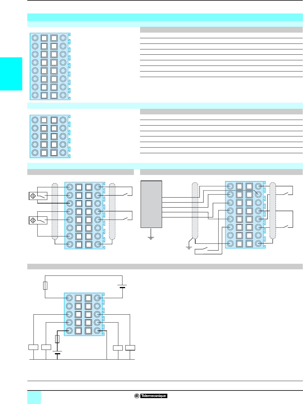
2/42
2
Connections Modicon®M340™ Automation
Platform 0
BMX EHC 0200/0800 counter modules
Connections
Pinout for the BMX EHC 0200 module 16-pin connector
Pin number Symbol Description
1, 2, 7, 8 24V_SEN 24 V coutput for the sensor power supply
5, 6, 13, 14 GND_SEN 0 V coutput for the sensor power supply
15, 16 FE Functional earth ground
3IN_A Input A
4IN_SYNC Synchronization input
9IN_B Input B
10 IN_EN Enable input
11 IN_REF Referencing input
12 IN_CAP Capture input
Pinout for the BMX EHC 0200 module 10-pin connector
Pin number Symbol Description
124V_IN 24 V cinput for the input power supply
2GND_IN 0 V cinput for the input power supply
5Q0-1 Q1 output of counter channel 0
6Q0-0 Q0 output of counter channel 0
7Q1-1 Q1 output of counter channel 1
8Q1-0 Q0 output of counter channel 1
924V_OUT 24 V cinput for the output power supply
10 GND_OUT 0 V cinput for the output power supply
Examples of connection to the BMX EHC 0200 module
Sensor connections Connection of an incremental encoder
Connection of power supplies and actuators (1)
(1) A fast-blow fuse should be used to protect the module electronics in the event of reversed polarity of the power supplies on the inputs and outputs.
12
34
56
78
910
11 12
13 14
15 16
1
3
5
7
9
2
4
6
8
10
+
–
+
–
12
34
56
78
910
11 12
13 14
15 16
Incremental
encoder
10/30 V
Z
A
B
GND
Reference
Enable
Capture
12
34
56
78
910
11 12
13 14
15 16
Fuse (1)
Fuse (1)
24 V c
inputs
24 V c
outputs
12
34
56
78
910
21
43
Q1, channel 0
Q1, channel 1 Q0, channel 1
Q0, channel 0
O V
Characteristics:
page 2/40
Connections:
page 2/42
References:
page 2/41
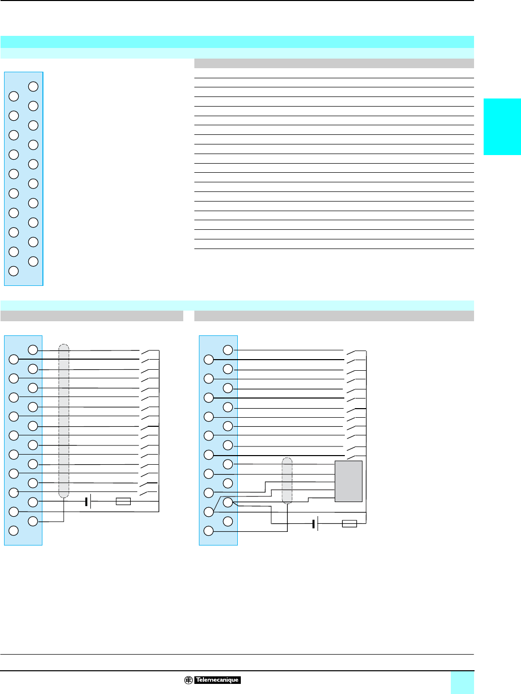
2/43
2
Connections (continued) Modicon®M340™ Automation
Platform 0
BMX EHC 0200/0800 counter modules
Connections (continued)
Pinout for the connector for the BMX EHC 0800 module 20-pin terminal block
Pin number Description
1IN_AUX input of channel 0
2IN_A input of channel 0
3IN_AUX input of channel 1
4IN_A input of channel 1 or IN_B input of channel 0
5IN_AUX input of channel 2
6IN_A input of channel 2
7IN_AUX input of channel 3
8IN_A input of channel 3 or IN_B input of channel 2
9IN_AUX input of channel 4
10 IN_A input of channel 4
11 IN_AUX input of channel 5
12 IN_A input of channel 5 or IN_B input of channel 4
13 IN_AUX input of channel 6
14 IN_A input of channel 6
15 IN_AUX input of channel 7
16 IN_A input of channel 7 or IN_B input of channel 0
17 Feedback - 24 V power supply for sensors
18 VDC + Power supply for sensors
19 Functional earth ground, for shielding connection
20 Functional earth ground, for shielding connection
Examples of connection to the BMX EHC 0800 module
Connection of sensors (1) (2) (3) Connection of an incremental encoder (1) (2) (3) (4)
(1) It is advisable to adapt the programmable filtering to the frequency applied to the inputs since using programmable filtering avoids the need to use a shielded
cable.
(2) In the case of an encoder or a high-speed sensor without programmable filtering, it is advisable to use a shielded cable connected to pins 15 and 16 of the
connector.
(3) In the case of a very disturbed environment without programmable filtering, it is advisable to use the BMX XSP 010 electromagnetic protection kit to connect the
shielding. In this case it is also advisable to use a 24 c power supply dedicated to the inputs as well as a shielded cable for connecting the power supply to the
module.
(4) A fast-blow fuse should be used to protect the module electronics in the event of reversed polarity of the power supplies.
18
20
6
8
12
14
10
16
2
1
4
5
7
11
13
9
15
3
19
17
18
20
6
8
12
14
10
16
2
1
4
5
7
11
13
9
15
3
19
17 0 V 24 V
18
20
6
8
12
14
10
16
2
1
4
5
7
11
13
9
15
3
19
17
Z
A
B
10/30 V
Ret
0 V 24 V
Characteristics:
page 2/40
Connections:
page 2/42
References:
page 2/41
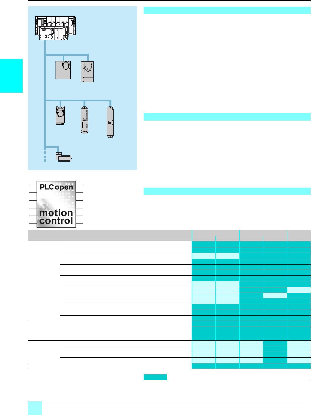
2/44
2
Presentation,
Functions
Automation platform 0
Modicon® M340™ PLC
MFB motion control
MFB (Motion Function Blocks) is a library of function blocks integrated into the
Unity Pro™ software, and is used to set up motion control in the architectures of
drives and servo drives on machine buses and CANopen installations:
v Altivar® 31 adjustable speed drive: For asynchronous motors from 0.18 to 15 kW
v Altivar® 71 adjustable speed drive: For asynchronous motors from 0.37 to 500 kW
v Lexium® 05 servo drive: For servo motors from 0.4 to 6 kW
v Lexium® 15LP/MP/HP servo drive: For BSH & BDH servo motors from 0.9 to 42.5 kW
v Lexium® 17D: For BPH, BPL and SER servo motors from 1.5 to 70 A rms (1)
v IclA® IFA/IFE/IFS: For integrated motor drives from 0.05 to 0.25 kW
In compliance with PLCopen specifications, the MFB library allows easy and flexible
motion programming with Unity Pro™software, as well as axis diagnosis. In
maintenance operations, drives can be replaced quickly and efficiently thanks to
drive parameter download blocks.
Setting up drives on the CANopen network is facilitated through Motion Tree
Manager organization in the Unity Pro™ browser, making it easy for users to access
the application drives.
The features of the MFB library are particularly suitable for machines with
independent axes. For these modular/special machines, MFB function blocks are the
perfect solution for controlling single axes. The following are typical applications for
this type of architecture:
v Automatic storage/removal
v Handling
v Palletizers/depalletizers
v Conveyors
v Packaging, simple label application
v Grouping/ungrouping
v Adjustment axes in flexible machines, etc.
The table below lists the function blocks of the MFB library and the drives compatible
with them. The prefix indicates the block family:
v MC: Function block defined by the Motion Function Blocks PLCopen standard
v TE: Function block specific to Telemecanique® products
v Lxm: Function block specific to Lexium® servo drives
(1) Lexium 17D drive supported by MFB with Modicon Premium platform only
Presentation
Applications
Functions
MFB: Motion control distributed over CANopen
ATV 31
Lexium 05
Lexium 15 Lexium 17D
(1)
IclA
ATV 71
CANopen
Modicon M340
Premium
Type Function Function block Altivar Lexium IclA
ATV 31 ATV 71 05 15/17D (1) IFA/IFE/IFS
Management
and motion
Read an internal parameter MC_ReadParameter
Write an internal parameter MC_WriteParameter
Read the current position MC_ReadActualPosition
Read the instantaneous speed MC_ReadActualVelocity
Acknowledge error messages MC_Reset
Stop all active movement MC_Stop
Axis coming to standstill MC_Power
Movement to absolute position MC_MoveAbsolute
Relative movement MC_MoveRelative
Additional movement MC_MoveAdditive
Homing MC_Home
Movement at given speed MC_MoveVelocity
Read diagnostic data MC_ReadAxisError
Read servo drive status MC_ReadStatus
Save and
restore
parameters
(FDR)
Read all parameters and store in PLC memory TE_UploadDriveParam
Write all parameters from the PLC memory TE_DownloadDriveParam
Advanced
Lexium
functions
Set the reduction ratio Lxm_GearPos
Read a motion task Lxm_UploadMTask
Write a motion task Lxm_DownloadMTask
Start a motion task Lxm_StartMTask
System Communication with the servo drive TE_CAN_Handler
Compatible
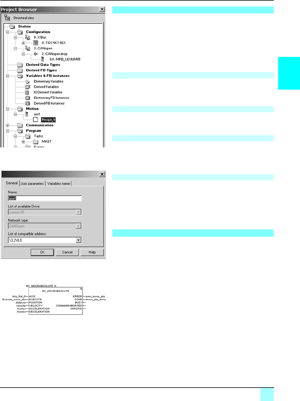
2/45
2
Setup Automation platform 0
Modicon® M340™ PLC
MFB motion control
Motion Tree Manager is associated with the Unity Pro™' MFB library, and integrated
in its browser. It provides specific assistance for:
bAxis object management
bAxis variable definition
bDrive parameter management
Motion Tree Manager automatically creates links between the CANopen bus
configuration and the MFB function block data using a limited amount of
configuration data.
In this tab, the designer is prompted to define:
bThe name of the axis that will identify it in the browser for the entire application
bThe address of the drive on the CANopen bus
The drop down lists in this tab are used to determine the exact type of drive: family,
version.
This last tab is used to identify data structures:
bAxis_Reference, used by all the instances of function blocks for the axis in
question
bCAN_Handler, used to manage communication with the drive via the CANopen
network
The “recipes” attached to the axis are the data structures containing all the
adjustment parameters of a given drive. This data is used when:
bChanging the drive with restoration of the context during “Faulty Device
Replacement” maintenance
bChanging the manufacturing program of the machine, and calling up an
appropriate set of parameters, such as servo control gains, limitations etc. adapted
to the weight and size of the moving parts.
Communication between the PLC and drive is automatically set up by the system as
soon as a TE_CAN_Handler instance is declared in the Unity Pro task with which the
axis is associated.
Movements are then programmed by sequencing function blocks from the library in
the Unity Pro editor as selected by the user (LD, ST, FBD).
The two function blocks, MC_ReadStatus, and in some cases MC_ReadAxisError,
are useful for determining the overall status of the axis, and the code of active
warnings or errors.
The function blocks TE_UploadDriveParam and TE_DownloadDriveParam allow the
application to save all the parameters of a drive (recipe) and to then quickly reload
them into another drive if the first one fails.
Motion Tree Manager
General axis parameters
Axis parameters
Variable names
Recipe definition
Programming, diagnostics and maintenance
Motion Tree Manager integrated in the Unity Pro browser
General parameters: Axis name and address
MFB: Programming a movement in absolute mode

03/0
3

3/1
3
Contents 3 - Communication
1
Ethernet TCP/IP networks with
Transparent Ready® Services
bEmbedded Web services. . . . . . . . . . . . . . . . . . . . . . . . . . . . . . . . . . . . . . . . . . 3/4
bEthernet TCP/IP communication services . . . . . . . . . . . . . . . . . . . . . . . . . . . . . 3/8
bPerformances . . . . . . . . . . . . . . . . . . . . . . . . . . . . . . . . . . . . . . . . . . . . . . . . . 3/16
bEthernet integrated port / module selection. . . . . . . . . . . . . . . . . . . . . . . . . . . 3/21
bEthernet processor/module product data sheet. . . . . . . . . . . . . . . . . . . . . . . . 3/22
bConneXium™ cabling system. . . . . . . . . . . . . . . . . . . . . . . . . . . . . . . . . . . . . . 3/24
CANopen machines and installations bus
bPresentation . . . . . . . . . . . . . . . . . . . . . . . . . . . . . . . . . . . . . . . . . . . . . . . . . . 3/37
bDescription. . . . . . . . . . . . . . . . . . . . . . . . . . . . . . . . . . . . . . . . . . . . . . . . . . . . 3/38
bCharacteristics. . . . . . . . . . . . . . . . . . . . . . . . . . . . . . . . . . . . . . . . . . . . . . . . . 3/38
bReferences . . . . . . . . . . . . . . . . . . . . . . . . . . . . . . . . . . . . . . . . . . . . . . . . . . . 3/39
bCabling system . . . . . . . . . . . . . . . . . . . . . . . . . . . . . . . . . . . . . . . . . . . . . . . . 3/40
Serial links
bModbus® interface and character mode serial link . . . . . . . . . . . . . . . . . . . . . 3/42
bCabling system . . . . . . . . . . . . . . . . . . . . . . . . . . . . . . . . . . . . . . . . . . . . . . . . 3/44
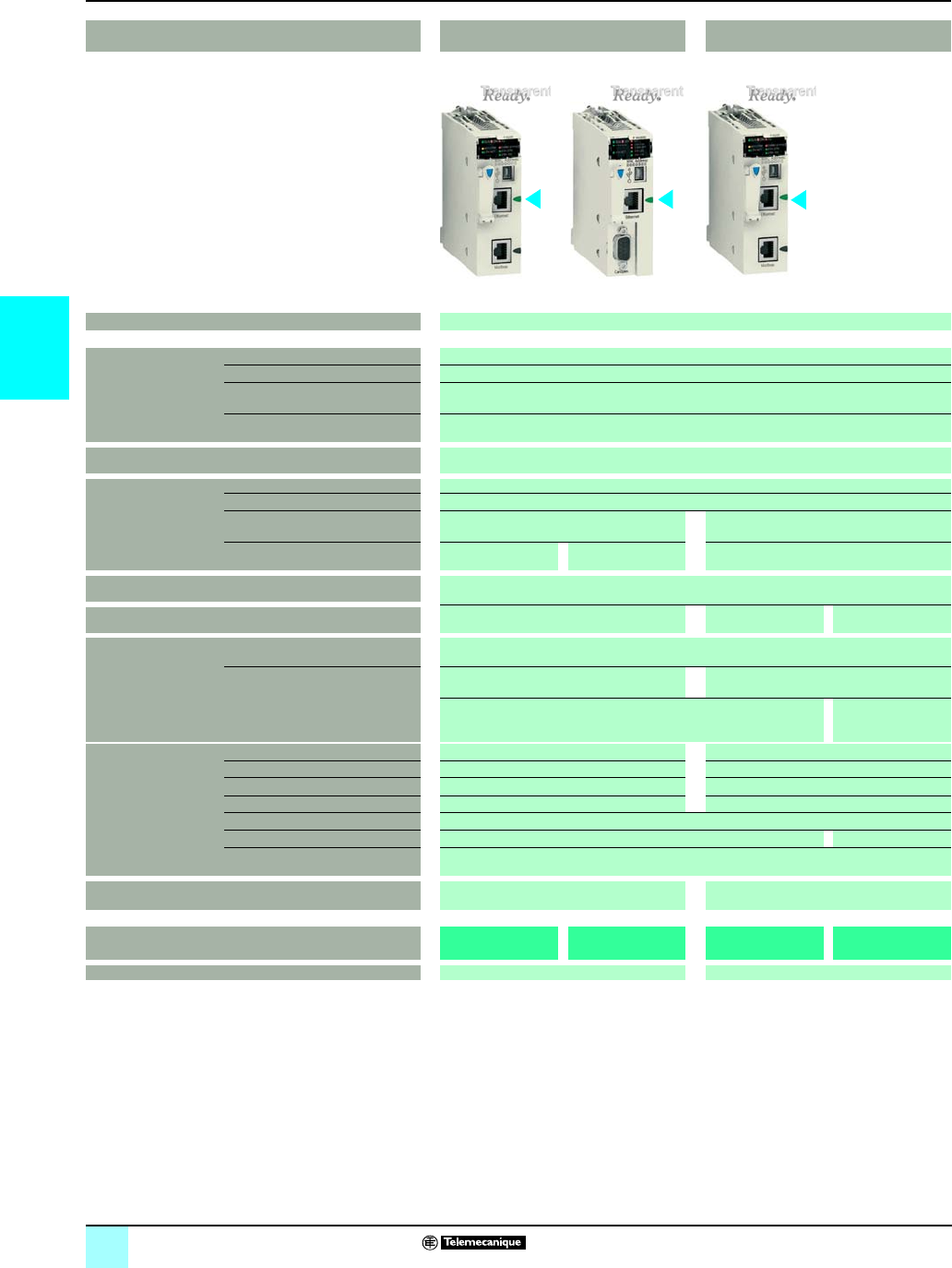
3/2
3
Selection guide Modicon® M340™ Automation
Platform 0
Communication, integrated ports and modules
Applications Processors with integrated Ethernet
TCP/IP port
Ethernet TCP/IP module
Type Ethernet TCP/IP
Structure Physical interface 10BASE-T/100BASE-TX
Connector type
Access method CSMA-CD
Data rate 10/100 Mbps
Medium Double twisted pair copper cable, category CAT 5E
Optical fiber via ConneXium™ wiring system
Configuration Maximum number of devices –
Maximum length 100 m (copper cable), 4,000 m (multi-mode optical fiber), 32,500 m (single-mode optical fiber)
Number of links of the same type per
station
1 (integrated port) 1 with BMX P34 1000/2010 processor
2 with BMX P34 2020/2030 processor
Other integrated port Serial link CANopen bus –
Standard services Modbus® TCP/IP messaging
Conformity class Transparent Ready® server — class B10 Transparent Ready®
server — class B30
Transparent Ready®
server — class C30
Embedded web server
services
Standard services “Rack viewer” PLC diagnostics
“Data editor” access to PLC data and variables
Configurable services –“Alarm viewer”
“Graphic Data Editor”
–Hosting and display
of user web pages
(16 Mb)
Transparent Ready®
communication
services
I/O Scanning service No Yes
FDR service Yes (client) Yes (server)
SNMP network management service No Yes
Global Data service No Yes
SMTP E-mail notification service No
SOAP/XML Web services No Server
Passband management Yes
Compatibility with processor –Standard and Performance processors
Processor or module BMX P34 2020 BMX P34 2030 BMX NOE 0100
BMX NOE 0110
r
Page 3/22 3/23
r Available 4th quarter 2007. Before this date, please order the BMX NOE 0100 Ethernet module with BMX RWS C016M memory card, same services except
Data editor service with pocket PC or PDA terminal and SOAP/XML Web services.
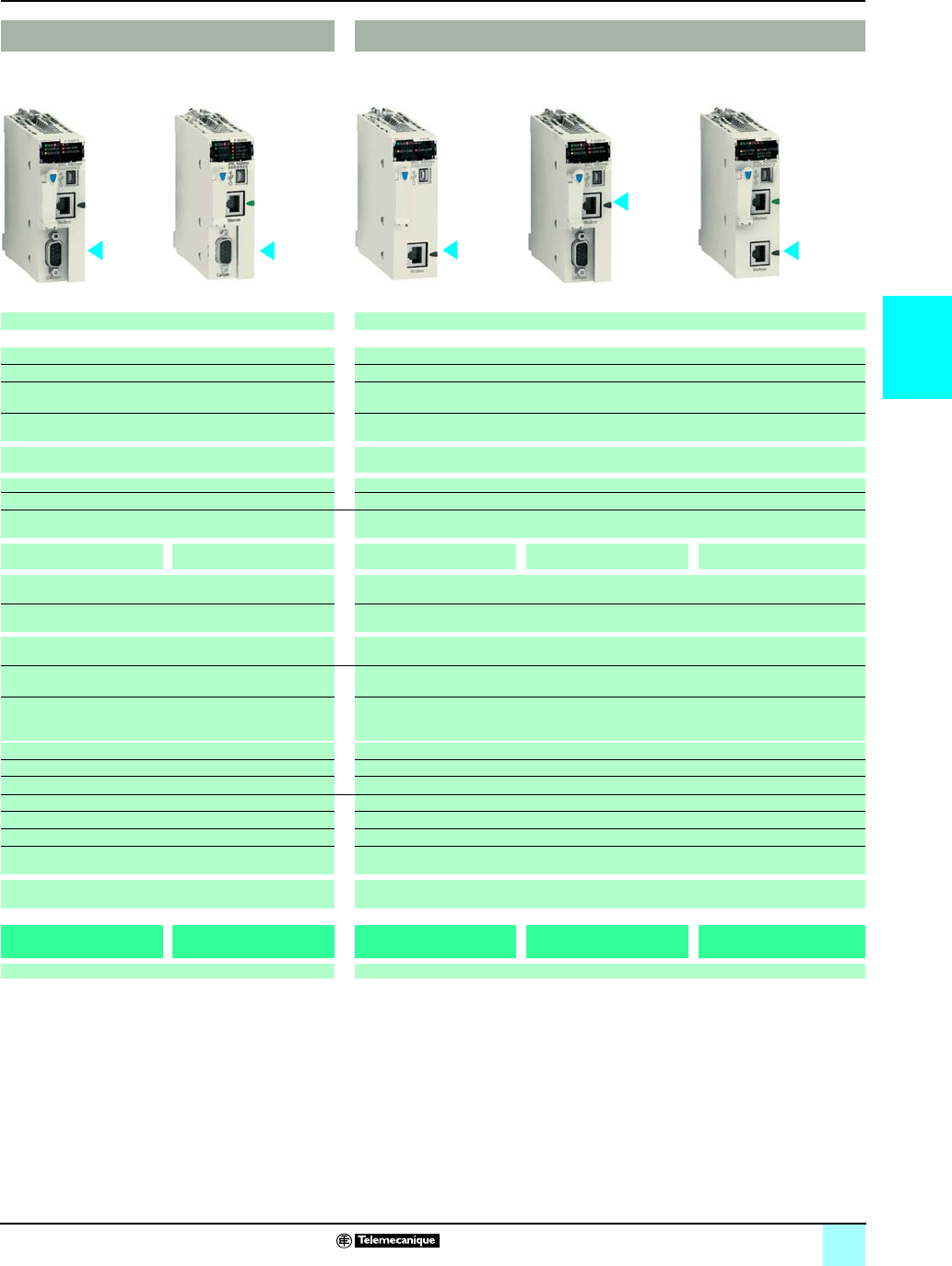
3/3
3
0
Processors with integrated machine and installation bus Processors with integrated serial link
CANopen Modbus® interface and Character mode
ISO 11898 (9-pin SUB-D connector) Non-isolated, 4-wire RS 232/2-wire RS 485
9-pin SUB-D RJ45
CSMA/CA (multiple access) Master/slave with Modbus link,
Half duplex (RS 485)/Full duplex (RS 232) in character mode
20 Kbps...1 Mbps depending on distance 0.3...19.2 Kbps
Double shielded twisted pair copper cable Double shielded twisted pair copper cable
63 32 per segment, 247 max.
20 m (1 Mbps)...2,500 m (20 kbps) 15 m (non-isolated), 1,000 m with insulating case
1 1
Serial link Ethernet TCP/IP –CANopen Ethernet TCP/IP
- PDO implicit exchange (application data)
- SDO explicit exchange (service data)
Read/write bits and words, diagnostics with Modbus link
Send and receive character string in character mode
Class M20 –
– –
– –
– –
– –
– –
– –
– –
– –
– –
– –
– –
BMX P34 2010 BMX P34 2030 BMX P34 1000 BMX P34 2010 BMX P34 2020
3/39 3/46
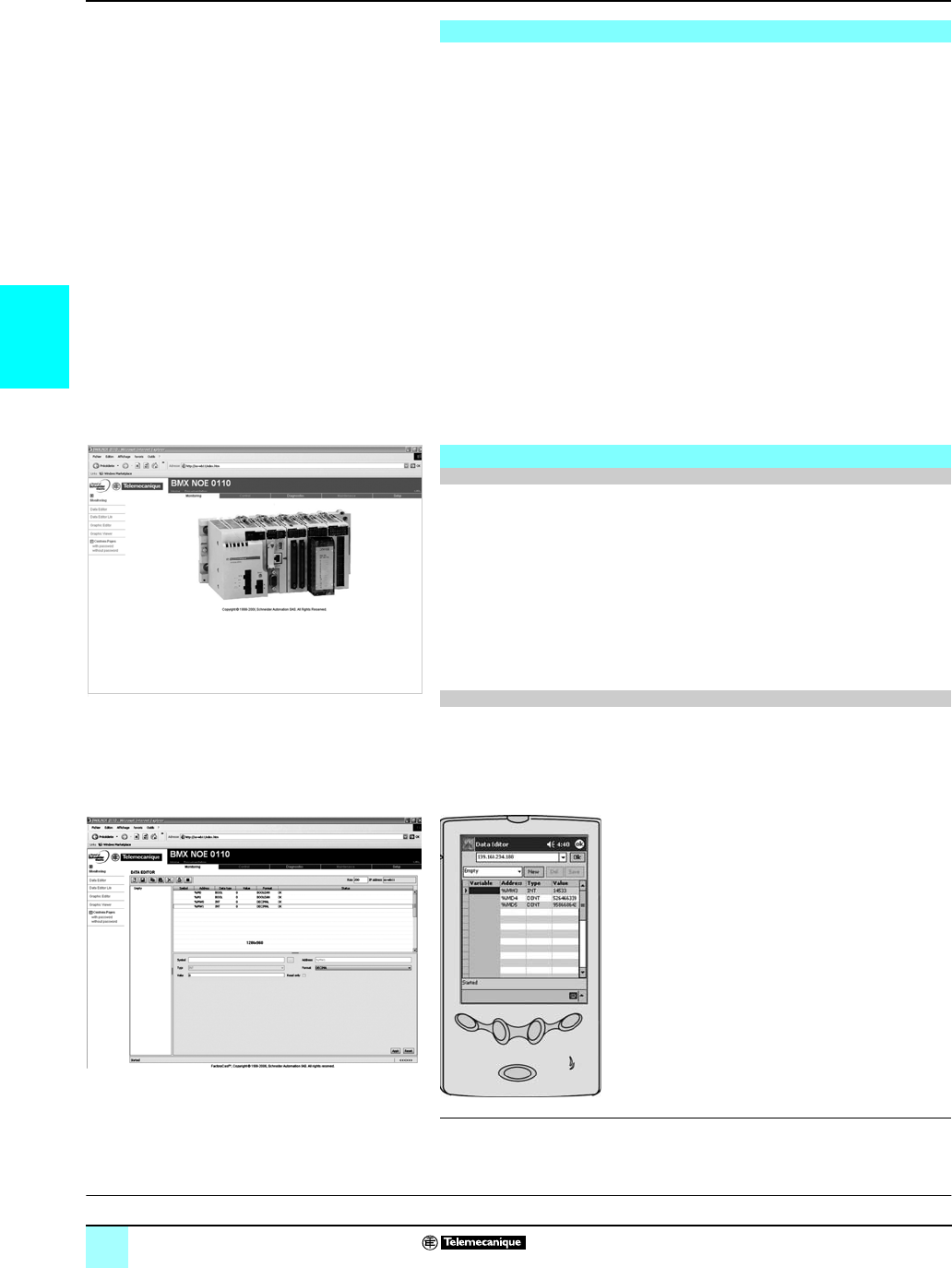
3/4
3
Presentation,
functions
Modicon®M340™ Automation
Platform 0
Ethernet TCP/IP network,
Transparent Ready® services
In conformity with Schneider Electric Ethernet products (processors and Ethernet
modules on Modicon automation platforms, distributed I/O modules, adjustable
speed drivesadjustable speed drives and gateways), standard Web functions are
integrated in BMX P34 2020/2030 processors and the BMX NOE 0100/110 Ethernet
network modules on the Modicon M340 platform.
From a simple Internet browser, the standard Web server authorizes the following
“ready-to-use” functions:
bRemote diagnostics and maintenance of products
bDisplay and adjustment of products (read/write variables, status)
With the BMX NOE 0110 (1) Ethernet network module, the Web server also offers
the following functions:
bManagement of PLC alarms (system and application) with partial or total
acknowledgement (ready-to-use Alarm Viewer function pages).
bHosting and display of Web pages created by the user.
The embedded Web server is a real-time data server. All the data can be presented
in the form of standard Web pages in HTML format and can therefore be accessed
using any Web browser that supports the embedded Java code. The standard
functions provided by the Web server are supplied ready-to-use and thus do not
require any programming of either the PLC or the client PC device supporting a Web
browser.
The Rack Viewer function can be used for PLC system and I/O diagnostics. It
displays the following in real-time:
bLED status on the front panel of the PLC
bThe PLC type and version
bThe hardware configuration of the PLC including the status of the system bits and
words
bDetailed diagnostics (2) of each of the:
v I/O module channels or application-specific channels in the configuration
v equipment connected on the CANopen bus.
The Data Editor function can be used to create tables of animated variables for
real-time read/write access to PLC data in the form of lists.
Various animation tables containing specific application variables to be monitored or
modified can be created by the user and saved in the standard Web server module.
In addition when using FactoryCast™ Web server of
the BMX NOE 0110 (1) module:
b The variables can be entered and displayed by their
symbol (3) (S_Pump 234)
b The write access option can be enabled/disabled for
each variable using the FactoryCast™ software. The
write access is protected by a dedicated password
b Dedicated data monitoring tool can be use on
pocket PC or PDA terminal (2).
(1) Module available 4th quarter 2007. Before this date, please order the BMX NOE 0100 module
with BMX RWS C016M memory card.
(2) Function available 4th quarter 2007.
(3) Access to symbols available 4thquarter 2007. Hence provides access to unlocated data.
Overview of the Web services
Standard Web server on the Modicon®M340™ platform
Rack Viewer PLC diagnostics function
Data Editor read/write function for PLC data and variables
Modicon M340 hardware configuration
Data editor variables table
References:
pages 3/22 and 3/23
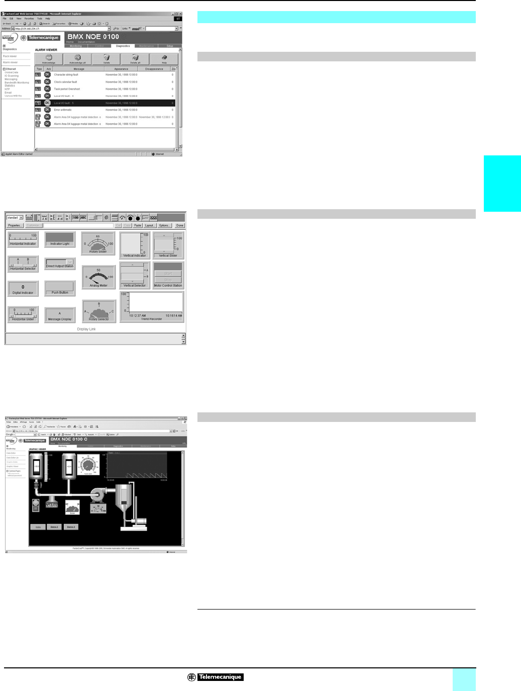
3/5
3
Functions (continued) Modicon®M340™ Automation
Platform 0
Ethernet TCP/IP network, Transparent Ready®
services, and FactoryCast™ Web server
With the BMX NOE 0110 (1) Ethernet network module, the Web server offers the
functions below, in addition to the standard Web services.
Alarm Viewer (2) is a ready-to-use, password-protected function. This function can
be used to process alarms (display, acknowledgment and deletion) managed at the
PLC level by the system or using diagnostic function blocks known as DFBs
(system-specific diagnostic function blocks and application-specific diagnostic
function blocks created by the user).
These alarms are stored in the diagnostic buffer managed by the Modicon M340
platform (special memory space for storing all the diagnostics events).
.
The diagnostics viewer is a Web page comprising a list of messages, which displays
the following information for each alarm:
v Dates and times of the occurrence removal of a fault
v Alarm message
v Alarm status
v Type of associated diagnostic function block (DFB).
This function is used to create the graphic views animated by the PLC variables that
can be accessed via their address or their symbol (3) (access to located data). The
ready-to-use graphic editor is available online, connected to the BMX NOE 0110
module (1).
These views are created from a library of predefined graphic objects by simple
copy/paste operations. The objects are configured to suit the user's requirements
(color, PLC variables, name, etc).
List of proposed graphic objects:
bAnalog and digital indicators
bHorizontal and vertical bar charts
bBoxes for displaying messages and entering values
bPush button boxes
bFunctions for recording trends
bVats, valves, motors, etc
Customized graphic objects can be added to this list. They can be reused in user
Web pages that have been created using standard software for editing HTML pages.
The views thus created are saved in the BMX NOE 0110 module and displayed
using any Web browser.
The BMX NOE 0110 Ethernet network module has a 16 Mbyte non-volatile memory
(accessible as a hard disk). This allows hosting of Web pages and any user-defined
Word or Acrobat Reader document (for example, maintenance manuals, or wiring
diagrams).
The Web pages can be created using any standard tool for creation and editing in
HTML format. These pages can be enhanced by inserting animated graphic objects
linked to PLC variables. These animated objects are created using the Graphic Data
Editor. They are then downloaded to the BMX NOE 0110 module via configuration
software of FactoryCast Web server.
The Web pages created can be used, for example, to:
bDisplay and modify all PLC variables in real time
bCreate hyperlinks to other external Web servers (documentation, suppliers, etc)
This function is particularly suitable for creating graphic interfaces used for the
following purposes:
bReal-time display and supervision
bProduction monitoring
bDiagnostics and help with maintenance
bOperator guides
(1) Module available 4th quarter 2007. Before this date, please order the BMX NOE 0100 module
with BMX RWS C016M memory card.
(2) Function available 4th quarter 2007.
(3) Access to symbols available 4thquarter 2007.
BMX NOE 0110 module FactoryCast™ Web server
Alarm Viewer function (2)
Graphic Data Editor function
User Web page hosting and display function
Alarm display from the diagnostic buffer
Library of predefined graphic objects
Real-time supervision graphic interface

3/6
3
Functions (continued) Modicon®M340™ Automation
Platform 0
Ethernet TCP/IP network, Transparent Ready®
services, FactoryCast™, & SOAP/XML Web server
The FactoryCast Web server configuration software is supplied on CD-ROM with th
BMX NOE 0110 FactoryCast module.
This software is used for configuration and administration of the Web server
embedded in these modules. It is compatible with Windows® 2000 and Windows® XP
operating systems. It provides the following functions:
bSetting the parameters of the FactoryCast functions
vDefinition of access security, and passwords
vImporting of PLC symbol databases
vDefinition of access to write-enabled variables
bManagement of the Web site:
vManagement of default Web site pages
vManagement of user Web site pages (2)
vGraphic object editor for animating Web pages
vDownloading of Web pages between the PC and the module
vDebugging of Web pages in online mode or in simulation mode (including
animations and Java beans)
bSimulation mode
The application and the Web site (including the Java animations) can be set up in
online mode or in simulation mode. Simulation mode is used to test the operation of
the Web application without a FactoryCast module (with no physical connection to a
PLC) thereby simplifying debugging.
A graphics editor integrated in the configuration software can be used for easy
customization of graphic objects (bar charts, gauges, LEDs, curves, cursors,
operator input fields, alphanumeric display fields, buttons, etc).
bCreation of user Web pages (1)
User Web pages are created graphically using an external HTML editor (FrontPage®
or similar, not supplied).
User Web pages created in the FactoryCast environment are actual animated
supervision screens and can be used to monitor your process. Based on Web
technologies (HTML and Java) they provide real-time access to PLC variables using
the FactoryCast graphic object library (Java beans).
The BMX NOE 0110 FactoryCast module (3) incorporates a standard SOAP/XML
data server that provides direct interoperability between automation devices and
computer management applications (MES, ERP, SAP, pNet application, etc).
Communication between platforms or applications is now a necessity in a market
where e-manufacturing and e-business are an essential fact of life for companies.
Web service technology currently represents the most successful strategy for
ensuring interoperability of heterogeneous software applications via an Intranet or
the Internet, independently of any platform, operating system and programming
language.
The standardization of Web services has come about as a result of joint development
between Microsoft and IBM, among others, validated at the W3C (World Wide Web
Consortium) as an open standard.
It now provides all the tools, specifications and environments needed for each
platform.
Web services are based on standards such as:
bXML (eXtensible Markup Language): the universal standard for data exchange
bSOAP (Single Object Access Protocol) carried via the HTTP (Hypertext Transfer
Protocol) channel.
bWSDL (Web Services Description Language) in XML format.
SOAP is currently considered to be the reference protocol, including in industry. It
has since been adopted by technology leaders such as Microsoft (pNET, SQL
Server, Office, etc), IBM (Java, Web Sphere), Lotus, ORACLE, Sub, and SAP.
(1) FactoryCast includes a plug-in for FrontPage® 2000. This plug-in makes it easier to set up
animations for real-time access to the PLC variables in HTML pages created by the user. They
are created in the HTML editor by simply inserting customized graphic objects.
(2) Web services available 4th quarter 2007.
(3) Module available 4th quarter 2007.
FactoryCast™ Web server configuration software
SOAP/XML Web services (2)
SOAP/XML Web Services embedded in the PLC
References:
pages 3/22 and 3/23
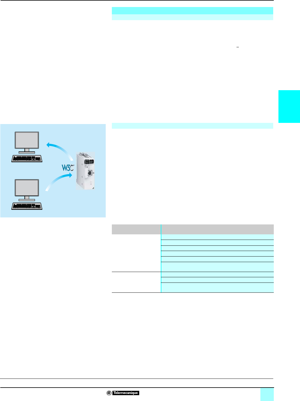
3/7
3
This new Transparent Ready® service offers the previously unused (or uncommon)
possibility of making an IT/e-business application interact directly with the control
system levels using the same standards.
With the implementation of Modbus XMLDa (Modbus XML Data access) Web
services in FactoryCast™ Web servers, the IT engineer can easily create an
application which will access the desired information directly in the PLC and in real
time.
Data exchanges are made in XML standard format in response to a request using
SOAP protocol.
The implementation of Web services in control system equipment makes it easy to
achieve vertical integration of the control level and the creation of even more
collaborative architectures which can be used to link production systems to the
corporate management systems. It simplifies access to information; reduces the
costs of training, development, and deployments; and increases productivity.
This implementation enables a SOAP client application (management level
computer application, such as MES, ERP) to communicate directly with a
FactoryCast Web server module embedded in the PLC.
Exchanges are initiated by the SOAP client application (the server responds to these
requests).
bStep 1: Creating the client application and learning the Web services. The
development environment (for example, Visual Studio pNET) searches in the
FactoryCast server for the list of available services and their WSDL standard
interfaces provided by the module.
bStep 2: Developing the client application. The developer integrates the Web
service functions using the code retrieved at the learning stage.
bStep 3: Executing the client application. The client application communicates in
real time with the FactoryCast Web server module using the SOAP protocol.
Requests implemented in the BMX NOE 0110 FactoryCast Web server module
provides data access to either physical or symbolic variables. They are defined in the
table below.
SOAP/XML Web services (suite)
Embedded SOAP/XML Web Services: Modbus® XMLDa Web services
1, 2
3
SOAP
request
Visual Studio pNET
pNET Java
BMX NOE 0110
FactoryCast Web
server module
SOAP server
Development tool
WSDL
Implementation of the Modbus® XMLDa Web services: server interface
Modbus® XMLDa functions implemented in each FactoryCast
Web server module
Access to data via
physical address
ReadDeviceIdentification
ReadMultipleRegisters
WriteMultipleRegisters
ReadCoils
WriteMultipleCoils
ReadDiscreteInputs
Access to data via symbol Read, operation to read item list value
Write, operation to write item list value
Browse, operation to browse item list
References:
pages 3/22 and 3/23
Functions (continued) Modicon®M340™ Automation
Platform 0
Ethernet TCP/IP network, Transparent Ready®
service, and SOAP/XML Web services

3/8
3
Presentation Modicon® M340™ Automation
Platform 0
Ethernet TCP/IP network, and communication
services, and Transparent Ready® services
BMX P34 2020 /2030 processors, via their integrated Ethernet port (class 10) and
the BMX NOE 0100/0110 network module (class 30) provide transparent
communication on a single Ethernet TCP/IP network.
In addition to universal Ethernet services (HTTP, BOOTP/DHCP, FTP, etc) and with
the Modicon M340 automation platform, the Transparent Ready device
communication services designed for use in automation applications include:
bModbus® TCP/IP messaging for class 10 or 30 devices
bI/O Scanning service for class 30 devices
bFDR (Faulty Device Replacement) for class 10 or 30 devices
bSNMP (Simple Network Management Protocol) network management for class 10
or 30 devices
bGlobal Data, for class 30 devices
bBandwidth management for class 10 or 30 devices
The following pages present the various options available through all of these
services to provide the optimum choice of solutions when defining a system
integrating Transparent Ready devices.
Presentation
Services
Applications
Transportation
Link
Physical
Network
management Global Data FDR automatic reconfiguration Web server Messaging I/O Scanning
SNMP RTPS DHCP TFTP FTP HTTP Modbus
UDP TCP
IP
Ethernet 802.3 and Ethernet II
MIB Transparent Ready
Presentation:
pages 3/4 and 3/5
Performance:
pages 3/16 to 3/21
Selection:
pages 3/2 and 3/3
References:
pages 3/22 and 3/23
Connections:
pages 3/24 to 3/37

3/9
3
Functions Modicon® M340™ Automation
Platform 0
Ethernet TCP/IP network, and communication
services, and Transparent Ready® services
HTTP (Hypertext Transfer Protocol) is used to transmit Web pages between a server
and a browser. HTTP has been used on the Web since 1990.
Web servers embedded in Transparent Ready automation products provide easy
access to products located anywhere in the world from a standard Internet browser
such as Internet Explorer.
BOOTP/DHCP is used to supply devices with IP parameters automatically. This
avoids having to manage each device address individually by transferring this
management to a dedicated IP address server.
The DHCP protocol (Dynamic Host Configuration Protocol) is used to assign
configuration parameters to devices automatically. DHCP is an extension of BOOTP.
The DHCP protocol consists of 2 components:
bOne to supply the IP network address.
bOne to supply the specific IP parameters to the device from a DHCP server.
Telemecanique® devices can be:
bBOOTP clients used to retrieve the IP address automatically from a server.
bBOOTP servers allowing the device to distribute IP addresses to the network
stations.
Telemecanique® products use BOOTP/DHCP standard protocols to offer the FDR
(Faulty Device Replacement) service.
File Transfer Protocol (FTP) provides the basic elements for file sharing. FTP is used
by several systems to exchange files between devices.
Trivial File Transfer Protocol (TFTP) is a network transfer protocol used to connect
to a device and download code to it.
For example, it can be used to transfer a boot code to a workstation without a disk
drive or to connect and download updates of network device firmware.
Note : Transparent Ready devices implement FTP and TFTP to transfer certain information to or
from products, particularly for downloads of firmware or user-defined Web pages.
Functions
Ethernet universal services
HTTP “Hypertext Transfer Protocol” (RFC1945)
BOOTP/DHCP (RFC1531)
FTP “File Transfer Protocol” (RFCs 959, 2228, and 2640)
TFTP “Trivial File Transfer Protocol” (updated firmware)
Presentation:
pages 3/4 and 3/5
Performance:
pages 3/16 to 3/21
Selection:
pages 3/2 and 3/3
References:
pages 3/22 and 3/23
Connections:
pages 3/24 to 3/37

3/10
3
Functions (continued) Modicon® M340™ Automation
Platform 0
Ethernet TCP/IP network, and communication
services, and Transparent Ready® services
The Internet community has developed the SNMP standard to manage the various
network components via a single system. The network management system can
exchange data with SNMP agent devices. This function allows the manager to
display the status of the network and products, modify their configuration, and feed
back alarms in the event of a fault.
Note : Transparent Ready products are compatible with SNMP and can be integrated naturally
into a network administered via SNMP.
COM/DCOM (Distributed Component Object Model) or OLE (Object Linking and
Embedding) technology consists of Windows® objects which enable transparent
communication between Windows® applications.
Nota : These technologies are used in the OFS (OLE for Process Control Factory Server) data
server software.
Functions (continued)
Ethernet universal services (continued)
SNMP “Simple Network Management Protocol” (RFCs 1155, 1156 and 1157)
COM/DCOM “Distributed Component Object Model”
Presentation:
pages 3/4 and 3/5
Performance:
pages 3/16 to 3/21
Selection:
pages 3/2 and 3/3
References:
pages 3/22 and 3/23
Connections:
pages 3/24 to 3/37

3/11
3
Functions (continued) Modicon® M340™ Automation
Platform 0
Ethernet TCP/IP network, and communication
services, and Transparent Ready® services
Modbus, the industry communication standard since 1979, has been brought
together with Ethernet TCP/IP, the medium for the Internet revolution, to form
Modbus TCP/IP, a totally open protocol on Ethernet. The development of a
connection to Modbus TCP/IP does not require any proprietary component nor the
purchase of a license.
This protocol can easily be combined with any product supporting a standard TCP/IP
communication stack. The specifications are available free of charge from the
following Web site: www.modbus-ida.org.
The Modbus application layer is simple and familiar, with its 9 million installed
connections. Thousands of manufacturers are already using this protocol. Many
have already developed a Modbus TCP/IP connection and numerous products are
currently available.
The simplicity of Modbus TCP/IP enables any field device, such as an I/O module, to
communicate on Ethernet without the need for a powerful microprocessor or lots of
internal memory.
Modbus TCP/IP offers excellent performance thanks to the simplicity of its protocol
and the fast speed of the 100 Mbps Ethernet. This allows a Modbus TCP/IP network
to be used in real-time applications such as I/O scanning.
The application protocol is identical on serial link Modbus, Modbus TCP/IP or
Modbus Plus™ networks. Messages can be routed from one network to the other
without converting protocol.
Since the Modbus network is implemented on top of the TCP/IP layer, users can also
benefit from IP routing that enables devices located anywhere in the world to
communicate regardless of the distance between them.
Schneider Electric® offers a complete range of gateways for connecting a Modbus
TCP/IP network to existing Modbus Plus™ networks, a Modbus serial link or
AS-Interface bus. Please consult your local sales office.
The IANA organization (Internet Assigned Numbers Authority) has allocated the
fixed port TCP 502 (“Well known” port) to the Modbus protocol. Thus Modbus
protocol has become an Internet standard.
A study by the ARC Advisory Group, the market leader in analysis of the automation
and software sectors, has shown that Modbus TCP/IP is the world-leading Ethernet
industrial protocol in terms of units sold in 2004.
Modbus and Modbus TCP/IP are recognized by the IEC 61158 international standard
as a fieldbus. They also comply with the “Chinese National Standard” managed by
ITEI.
CiA DSP 309-2 provides standardized organization of CANopen data to be carried
on a Modbus TCP/IP Ethernet network. The specification reserves the Modbus 43/13
function code for this purpose. This function code is reserved exclusively for
CANopen.
Maximum size of data:
bRead: 125 words or registers
bWrite: 100 words or registers
Functions (continued)
Modbus® standard communication protocol
Modbus TCP/IP, simple and open
Modbus TCP/IP, high-performance
Modbus TCP/IP, a standard
Interfacing CANopen with Modbus TCP/IP
Characteristics of Modbus TCP/IP
Modbus TCP/IP function codes dec hex
Bit access Read n input bits 02 02
Read n output bits 01 01
Read exception status 07 07
Write 1 output bit 05 05
Write n output bits 15 0F
Read 1 input word 04 04
Read n input words 03 03
Write 1 output word 06 06
Write n output words 16 10
Read device ID 43/14 2B/0E
Examples of Modbus TCP/IP function codes for accessing data
a
nd diagnostics.
Presentation:
pages 3/4 and 3/5
Performance:
pages 3/16 to 3/21
Selection:
pages3/2 and 3/3
References:
pages 3/22 and 3/23
Connections:
pages 3/24 to 3/37
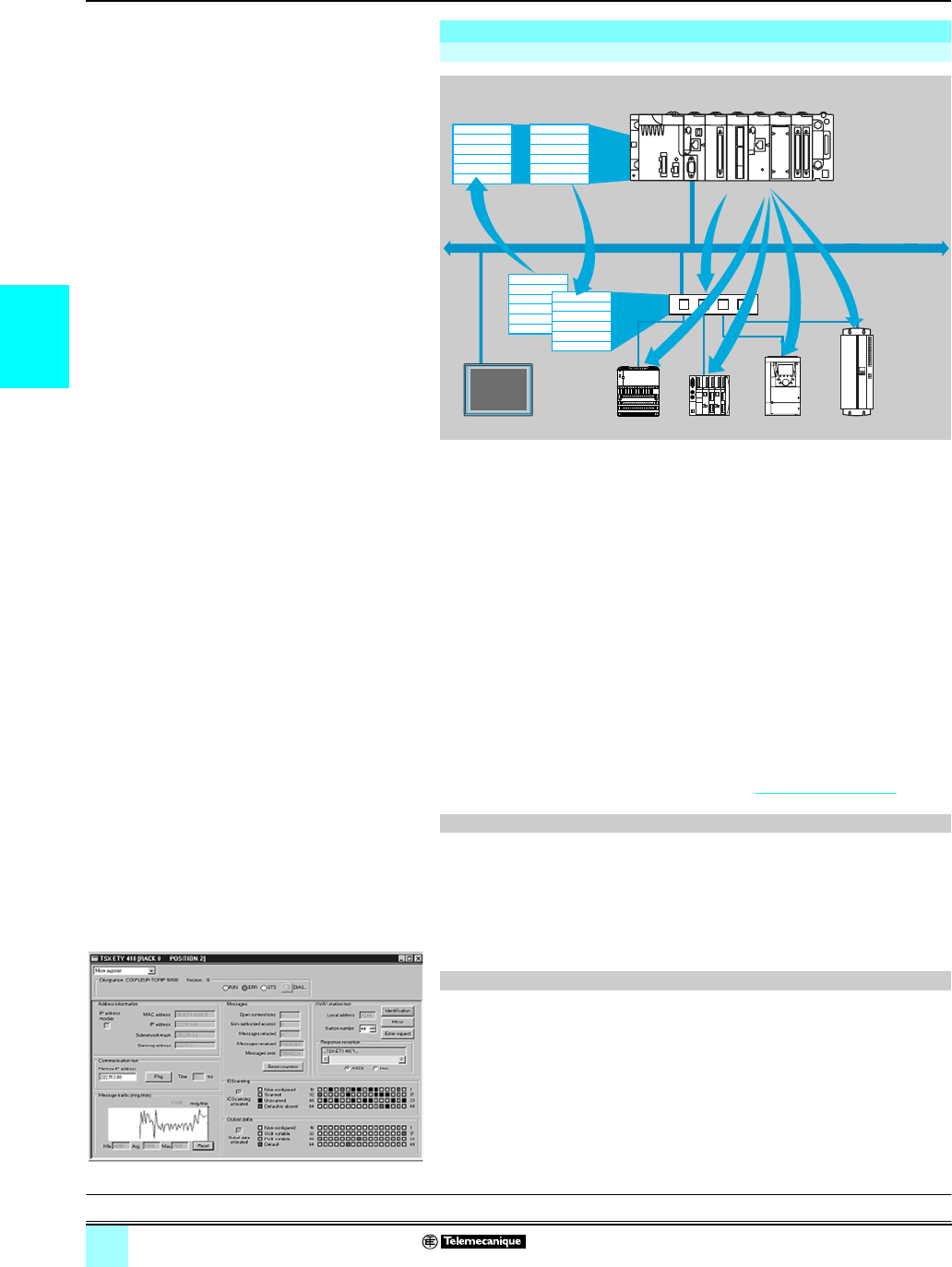
3/12
3
Functions (continued) Modicon® M340™ Automation
Platform 0
Ethernet TCP/IP network, and communication
services, and Transparent Ready® services
The I/O Scanning Service is used to manage the exchange of remote I/O states on
the Ethernet network after simple configuration, without the need for any special
programming.
I/O scanning is performed transparently by means of read/write requests according
to the Modbus® client/server protocol on the TCP/IP profile. This scanning principle
via a standard protocol is used to communicate with any device supporting a Modbus
server on TCP/IP.
This service allows you to define:
bA %MW word zone reserved for reading inputs.
bA %MW word zone reserved for writing outputs.
bRefresh periods independent of the PLC scan.
During operation, the module:
bManages TCP/IP connections for each remote device.
bScans devices and copies the I/O to the configured %MW word zone.
bFeeds back status words used to check that the service is working correctly from
the PLC application.
bApplies pre-configured fallback values if a communication problem occurs
An offering is available of hardware and software products used to implement the I/O
Scanning protocol on any type of device that can be connected to the Ethernet
network (please consult the Modbus-IDA Web site: www.modbus-ida.org).
bEach Modicon M340 station can exchange a maximum of:
v 100 write words
v 125 read words
bMaximum size in the Modicon M340 PLC that manages the service (64 stations max.):
v with BMX NOE 0100/0110 network module, 2 %MW Kwords as inputs and 2 %MW Kwords as
outputs
v with BMX P34 2020/2030 processor, 512 %MW words as inputs and 512 %MW words as
outputs
There are 3 ways to perform diagnostics on the I/O Scanning service:
bVia the application program from a specific PLC data zone.
bFrom the setup software debug screen.
bFrom the PLC system diagnostic function displayed using an internet browser on
a PC station.
bFrom the ConneXium™ diagnostic software TCSEAZ01PSFE10.
bFrom the standard SNMP manager software.
Functions (continued)
I/O Scanning service
Characteristics
Diagnostics of the I/O Scanning service
INPUT
OUTPUT
+
–
INPUT
OUTPUT
+
–
A
B
A
B
Word table
Read Write
Ethernet TCP/IP
Input words
Output words
of devices
Modicon M340
Presentation:
pages 3/4 and 3/5
Performance:
pages 3/16 to 3/21
Selection:
pages 3/2 and 3/3
References:
pages 3/22 and 3/23
Connections:
pages 3/24 to 3/37

3/13
3
Functions (continued) Modicon® M340™ Automation
Platform 0
Ethernet TCP/IP network, and communication
services, and Transparent Ready® services
The faulty device replacement service uses standard address management
technologies (BOOTP, DHCP) and the TFTP (Trivial File Transfer Protocol) file
management service to simplify maintenance of Ethernet products.
Using FDR, you can replace a faulty device with a new one that will then be detected,
configured, and automatically rebooted by the system.
The main steps in replacement are:
1A device using the FDR service malfunctions.
2Another similar device is taken from maintenance storage, preconfigured with the Device
name for the faulty device, and installed on the network. Depending on the devices,
addressing can be performed using rotary buttons (for example, Advantys™ STB distributed
I/O system, a or Advantys™ OTB distributed I/O system) or can be given via the keypad
integrated in the device (for example Altivar® adjustable speed drives).
3The FDR server detects the new device, allocates it an IP address, and transfers the
configuration parameters to it.
4The substituted device checks that all these parameters are ompatible with its own
characteristics and switches to operational mode.
The FDR server can be:
v A Modicon M340 Ethernet module, BMX NOE 0100/0110
v A Modicon® Premium™ Ethernet module, TSX ETY 4103/5103
v A Modicon® Quantum™ PLC Ethernet module, 140 NOE 771 01/771 11
v A Modicon Premium processor with integrated Ethernet port, TSX P57 ppppM
v A Modicon Quantum processor with integrated Ethernet port, 140 CPU 651 50/60
Functions (continued)
FDR (Faulty Device Replacement) service
a
“NIM” network module
for Advantys STB I/O
Presentation:
pages 3/4 and 3/5
Performance:
pages 3/16 to 3/21
Selection:
pages 3/2 and 3/3
References:
pages 3/22 and 3/23
Connections:
pages 3/24 to 3/37
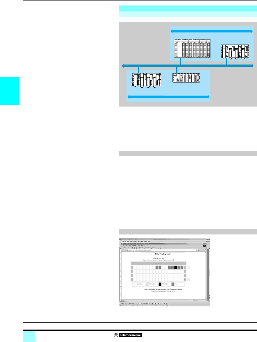
3/14
3
Functions (continued) Modicon® M340™ Automation
Platform 0
Ethernet TCP/IP network, and communication
services, and Transparent Ready® services
The Global Data service exchanges data in real time between stations belonging to
the same distribution group. It is used to synchronize remote applications, or even to
share a common database between a number of distributed applications.
Exchanges are based on a producer/consumer type standard protocol, avoiding
optimum performances with a minimum load on the network. This RTPS (Real Time
Publisher Subscriber) protocol is promoted by Modbus-IDA (Interface for Distributed
Automation), and is already a standard adopted by several manufacturers.
A maximum of 64 stations can participate in Global Data within a single distribution
group.
Each station can:
bPublish 1 variable of 1024 bytes. The publication period can be configured from
1 to n processor master task (Mast) periods.
bSubscribe between 1 and 64 variables. The validity of each variable is controlled
by status bits (Health Status bits) linked to a refresh time-out configurable between
50 ms and 1 s. Access to an element of the variable is not possible. The total size of
subscribed variables amounts to 4 contiguous Kbytes.
To further optimize the performance of the Ethernet network, Global Data can be
configured with the “multicast filtering” option which, combined with switches in the
ConneXium™ range (see pages 3/26 to 3/33), distribute data only to Ethernet ports
where there is a station subscribed to the Global Data service. If these switches are
not used, Global Data is sent in “multicast” mode to all switch ports.
The diagnostic screens
show the status of Global
Data using a color code:
b Configured/not
configured/faulty
b Published/subscribed
Functions (continued)
Global Data service
Characteristics
Global Data service diagnostics
Distribution
group 1 Data exchange 4 Kb max.
Data exchange 4 Kb max. Distribution
group 2
IP multicast 239.255.255.251
IP multicast 239.255.255.250
Ethernet TCP/IP
Modicon M340
Modicon Premium
Modicon Premium
Modicon Quantum
Presentation:
pages 3/4 and 3/5
Performance:
pages 3/16 to 3/21
Selection:
pages 3/2 and 3/3
References:
pages 3/22 and 3/23
Connections:
pages 3/24 to 3/37
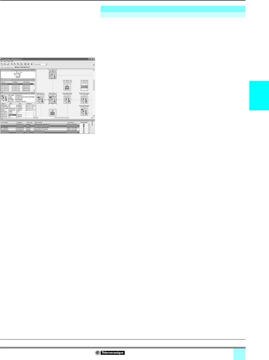
3/15
3
Functions (continued) Modicon® M340™ Automation
Platform 0
Ethernet TCP/IP network, and communication
services, and Transparent Ready® services
From a network management station, SNMP (Simple Network Management
Protocol) monitors and checks all components of the Ethernet architecture, ensuring
quick diagnostics in the event of a problem.
It is used to:
bInterrogate network components such as computer stations, routers, switches,
bridges, or terminal devices to display their status.
bObtain statistics about the network on which devices are connected.
This network management software adheres to the conventional client/server model.
However, to avoid confusion with other communication protocols that use this
terminology, we talk instead about:
bConneXview network diagnostics software, TCS EAZ 01P SFE10. For more
information, please consult our “Machines & Installations with industrial
communications” catalog.
bNetwork manager for the client application that operates on the computer station.
bSNMP agent for the network device server application
Transparent Ready devices can be managed by any SNMP network manager,
including the HP Openview and IBM® Netview®.
The SNMP managers standard protocol is used for access to configuration and
management objects that are contained in the device MIB (Management Information
Base). These MIBs must comply with certain standards to be accessed by any
commercially available manager, but depending on the complexity of products,
manufacturers can add certain objects to private databases.
The Transparent Ready private MIB presents management objects specific to the
Telemecanique® offering. These objects simplify the installation, setup and
maintenance of Transparent Ready devices in an open environment using standard
network management tools.
Transparent Ready devices support 2 levels of SNMP network management:
bThe Standard MIB II interface: An initial level of network management is accessible
via this interface. It enables the manager to identify the devices making up the
architecture and retrieve general information on the configuration and operation of
Ethernet TCP/IP interfaces.
bThe Transparent Ready MIB interface: the management of Transparent Ready
devices is improved via this interface. The MIB data set enables the network
management system to supervise all the Transparent Ready services.
The Transparent Ready MIB can be downloaded from the FTP server of any
Transparent Ready Ethernet module in a PLC.
Functions (continued)
SNMP network management service
Automatic recognition of IP devices via the ConneXview
diagnostic software for Ethernet industrial networks
Presentation:
pages 3/4 and 3/5
Performance:
pages 3/16 to 3/21
Selection:
pages 3/2 and 3/3
References:
pages 3/22 and 3/23
Connections:
pages 3/24 to 3/37

3/16
3
Performance Modicon®M340™ Automation
Platform 0
Ethernet TCP/IP network, and
Transparent Ready® Services — Performance
When choosing an architecture, be sure to consider the required performance as
early as possible. To do this, developers must:
1Know exactly what they need:
v quantity and type of devices to be connected to one another
v volume and type of exchanges
v expected response times
v environment
2Compare their needs with the characteristics of the available offering, being aware
that the actual performance level between any 2 points in an architecture depends
on the weakest link in the chain, which may:
v depend on the hardware
v but also depend on the applications (size, architecture, operating system, machine
power rating, etc) which are often only vaguely defined at this stage of the project.
3Work out from this which is the most suitable architecture.
The purpose of the next few pages is to provide the main information and instructions
needed to answer the second point. Given that the performance of an Ethernet
architecture is linked to several parameters, these pages do not supply all the
information needed to calculate the network performance. Their purpose is to focus
on the following main aspects:
bInstructions for calculating the network load to assist in designing an Ethernet
network that meets the demands of the applications.
bApplication response time to be obtained depending on the configuration used.
See page 3/17 to 3/19.
bProcessing capacities of Modicon®M340™, Modicon®Premium™ and
Modicon® Quantum™ platforms used to select the processor and define the
number of Ethernet connections required on the PLC, depending on the application.
See pages 3/20 and 3/21.®™
When calculating the load on an Ethernet network, the designer must consider all the
communication services of all the peripheral devices connected to the network.
Because of the outstanding performance of the Ethernet network, the load is often
less than the limits of the Ethernet network and does not greatly affect the application
response time. This phenomenon is explained by the high speed of the Ethernet
network: the network transaction time is 10% less than the application response time.
To ensure a low network load and avoid large theoretical calculations, the designer
should separate the collision domain so as to limit the network load, using only the
switched network (tree, star, or daisy-chain topology).
Selecting the communication architecture
Calculating the network load
Introduction
Presentation:
pages 3/4 and 3/5
Functions:
pages 3/9 to 3/15
Selection:
pages 3/2 and 3/3
References:
pages 3/22 and 3/23
Connections:
pages 3/24 to 3/37
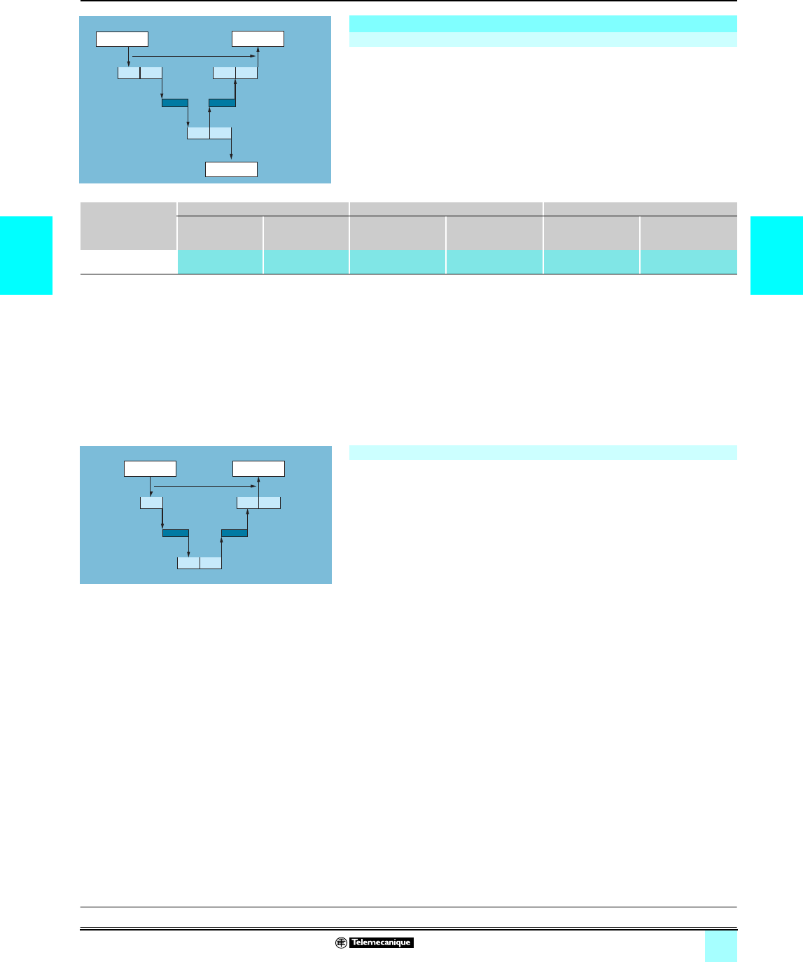
3/17
3 3
Performance (continued) Modicon®M340™ Automation
Platform 0
Ethernet TCP/IP network, and
Transparent Ready® Services — Performance
Exchanges between the PLC processor and the Ethernet module are
synchronous
with the PLC scan time, just like the I/O exchanges.
On occurrence of an event (for
example an input set to state 1), the message is sent on the start of the next cycle.
E
xecution of the PLC program (Modicon
®
M340
™
, Modicon
®
Premium
™
or
Modicon
®
Quantum
™
PLC) are on average
around 1.5 cycle times after occurrence of
the event.
The network access time (NAT) appearing in the table below in ms, is the sum of the
module transit time and the waiting time before the message can be sent on the
network. ®™
The transaction time TT integrates the delay between the sending of a message from
a client station 1, its reception by the server station 2, the processing of the request,
the sending the response, and its being accounted for by the station 1 (updating an
output for example).
As shown in the above block diagram:
The transaction time TT integrates the delay between publication of a Global Data
service by station 1, its reception, and processing by the remote station, 2 and its
being resent to the initial station 1:
For an exchanged variable:
Application response time
Modbus® messaging (or Uni-TE) service response time
Station 1
Event
CT1
NAT NAT
CT2 CT2 Station 2
Report
TT
CT1 CT1 CT1
Action
Processing Modbus
TCP/IP message
requests
Modicon M340 Modicon Premium Modicon Quantum
BMX NOE 0100
BMX NOE 0110
BMX P34 2020
BMX P34 2030
TSX ETY 210
TSX ETY 110WS
TSX ETY 4103/5103
TSX WMY 100
TSX P57 10...57 50
140 NOE 771 01/111
140 CPU 113/311 pp
140 CPU 434/534 1p
140 CPU 65 150/160
140 CPU 67 160
Network access time
NAT
< 10 ms < 10 ms < 25 ms < 10 ms < 10 ms < 10 ms
bThe transaction time TT should be between:
2 x CT1 + 2 x NAT < TT < 4 x CT1 + CT2 + 2 x NAT
bThe average duration TTav is equivalent to:
TT
av = 3 x CT1 + 0.5 x CT2 + 2 x NAT
Global Data service response time
bIf CT < 5 ms,
transaction time: TT = 5 to 6 x CT
bIf CT u 10 ms,
transaction time: TT = 3 x CT
Station 1
Synchro
pulse
CT CT CT
NAT NAT
CT CT Station 2
Synchro
feedback
TT
Transaction time
Publication
PublicationSubscription
Presentation:
pages 3/4 and 3/5
Performances:
pages 3/16 to 3/21
Selection:
pages 3/2 and 3/3
References:
pages 3/22 and 3/23
Connections:
pages 3/24 to 3/37

3/18
3
Performance (continued) Modicon®M340™ Automation
Platform 0
Ethernet TCP/IP network, and
Transparent Ready® Services — Performance
The response time RT includes the time between accounting for a remote input and
updating the state of a remote output. It includes the processing time in the PLC.
This response time RT consists of the following parameters:
v TMod In and TMod Out: Response time of the read/written device, excluding the
electrical transit time at the input/output (TMod depends on the device, usually
between 1 and 8 ms)
v TIOS In and TIOS Out: Time between 2 read/write operations on the same device
(0.3 ms xnumber of scanned devices), at least equivalent to the configured scan time
As TIOS is executed in parallel with the PLC scan, it can be hidden with respect to the
response time RT).
v Cycle T: PLC scan time.
v TNet : propagation time on the network (depending on the application, usually
TNet = 0.05 ms at 10 Mbit/s and 0.005 ms at 100 Mbit/s).
The response time RT can be estimated with the following 3 formulas:
bRTmin, minimum response time with TIOS hidden and 1 PLC scan:
bRTtyp., typical response time with 0.5 TIOS hidden:
bRTmax, maximum response time with TIOS not hidden:
Application response time (continued)
I/O Scanning service response time
Device 1
Device 2
Manager
Hub
Input
Output
CT
RT
Ethernet TCP/IP
Response time (RT)
Input
Output
TMod I
TMod Q
TIOS I
TNet
N x cycle T TIOS Q
TNet
RTmin =
(TMod In + 0) x TIOS In + (Tnet + N) x cycle T + (0 x TIOS Out) + Tnet + TMod Out
RTtyp. =
(
(TMod In + 0,5) x TIOS In + (Tnet + N) x Cycle T + ( 0,5 x TIOS Out) + Tnet + TMod Ou
t
RTmax = TMod In + TIOS In + (Tnet + N) x Cycle T + TIOS Out + Tnet + TMod Ou
t
Presentation:
pages 3/4 and 3/5
Performances:
pages 3/16 to 3/21
Selection:
pages 3/2 and 3/3
References:
pages 3/22 and 3/23
Connections:
pages 3/24 to 3/37

3/19
3 3
Performance (continued) Modicon®M340™ Automation
Platform 0
Ethernet TCP/IP network, and
Transparent Ready® Services — Performance
Below are the TMod In and TMod Out response times:
Below are the TIOS In/TIOS Out times measured between 2 scan cycles (Ethernet
network with switches)
Below is the number of processor cycles N:
®™
Application response time (continued)
I/O Scanning service response time (continued)
Type of distributed I/O Response time Min. Typical Max.
Momentum 170 ENT 110 02 TMod In 1 ms 1 ms 1 ms
TMod Out 5 ms 5 ms 5 ms
Momentum 170 ENT 110 01 TMod In 4 ms 6 ms 8 ms
TMod Out 4 ms 6 ms 8 ms
Advantys STB STB NIP 2212 TMod In 2 ms 3 ms 4 ms
TMod Out 2 ms 3 ms 4 ms
Number of processor cycles N Min. Typical Max.
Number of processor cycles N Min. Typical Max.
Modicon® M340™ platform with modules:
BMX NOE 0100 and BMX NOE 0110
22.5 3
Modicon® Premium™ platform with modules:
TSX ETY 4103 and TSX ETY 5103
Modicon® Quantum™ platform with modules:
140 NOE 771 01 and 140 NOE 771 11
Modicon® M340™ processors:
BMX P34 2020 and BMX P34 2030
Modicon® Premium™ processors:
TSX P57 26/3634M, TSX P57 26/2823M and
TSX P57 36/4823AM
Modicon® Premium™ processors:
TSX P57 4634M and 5634M
112
Modicon® Quantum™ processors:
140 CPU 651 50 and 140 CPU 651 60
0
5
10
15
20
25
1 5 10 20 30 40 50 60
No. of scanned devices
Time (ms)
Presentation:
pages 3/4 and 3/5
Performances:
pages 3/16 to 3/21
Selection:
pages 3/2 and 3/3
References:
pages 3/22 and 3/23
Connections:
pages 3/24 to 3/37
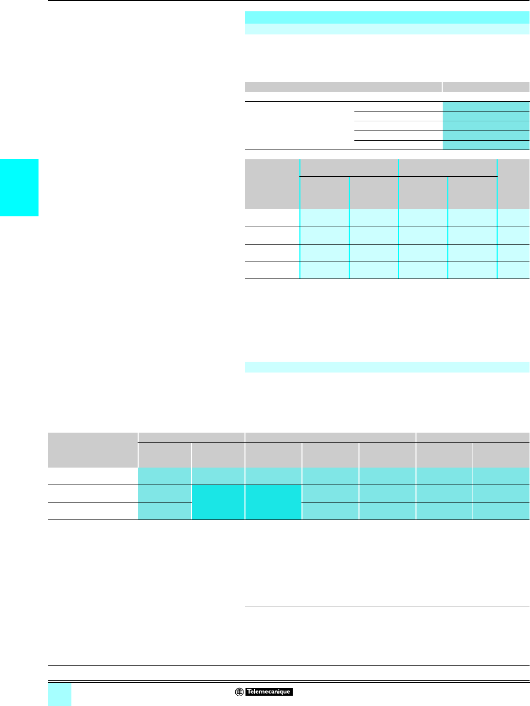
3/20
3
Performance (continued) Modicon®M340™ Automation
Platform 0
Ethernet TCP/IP network, and
Transparent Ready® Services — Performance
Use the table below to compare, for each station, the total number of messages
received on the Modbus® messaging service (or Uni-TE), if used (value R1, R2 or
Ri), with the station processor capacity.
Processing Modbus requests for each PLC scan
Example:
Quantum 140 CPU 434 12p processor with 4 Ethernet 140 NOE 771 p1 modules:
- 20 messages/cycle for all types of communication requests, and
- 32 messages/cycle for the read/write 4x registers
Compare, for each station, the total number of messages received Σ[values Ri, Rj]
and the total number of messages sent Σ [values Ei, Ej] (for example, for station N)
with the Ethernet transaction processing capacity indicated below.
Use the elements below for the Ethernet connection per PLC, rather than the number
of transactions required by the application.
(1) A temporary overload — due, for example, to an adjustment terminal or the temporary
connection of an Internet browser — on which a few PLC scans are permitted.
(2) Only with Unity Pro™ software.
(3) Only with Concept™/ProWORX™ software.
(4) Module not featuring I/O Scanning and Global Data services (TSX WMY 100 and
140 NWM 100 00).
Processing capacities of Modicon® platforms
Processing capacity
Modicon M340, Modicon® Premium™/Atrium™ PLC platforms Messages received
Communication using EFs or EFBs (PL7™ or Unity Pro™ software)
Total messages received by the
PLC from all the communication
modules (1)
TSX 57 10 4 messages/cycle
BMX P34 20/TSX 57 20 8 messages/cycle
TSX 57 30 12 messages/cycle
TSX 57 40 16 messages/cycle
TSX 57 50 (2) 16/20 messages/cycle
Modicon
Quantum
platform
Limitations of the integrated
port
Limitations of the
communication modules
Ethernet
modules
per PLC
All types of
communi-
cation
request
Additional
read/write 4x
registers
All types of
communi-
cation
requests
Additional
read/write 4x
registers
140 CPU 113 (3) ––1message/
cycle
4 messages/
cycle
max. 2
140 CPU 311 ––1message/
cycle
4 messages/
cycle
max. 2
140 CPU 434/534 ––4 messages/
cycle
8 messages/
cycle
max. 6
140 CPU 651 16 messages/
cycle
16 messages/
cycle
4 messages/
cycle
8 messages/
cycle
max. 6
messages/cycle: number of messages received per cycle from the PLC master task
(typical cycle of 50 to 100 ms)
Ethernet transaction processing capacity
Ethernet transaction
processing capacity
Modicon M340 BMX Modicon Premium TSX Modicon Quantum140
NOE 0100
NOE 0110
P34 2020
P34 2030
ETY 210
ETY 110WS
ETY 4103/5103
WMY 100 (4)
P57 10/20/30/40
P57 50 NOE 771 01/11
NWM 100 00 (4)
CPU 65 150/160
CPU 67 160
Modbus® messaging 450
transactions/s
200
transactions/s
60 transactions/s 450
transactions/s
500
transactions/s
350
transactions/s
350
transactions/s
I/O Scanning service 2,000
transactions/s
Service not
available
Service not
available
2,000
transactions/s
2,000
transactions/s
2,000
transactions/s
2,000
transactions/s
Publication of Global Data 800
transactions/s
800
transactions/s
800
transactions/s
800
transactions/s
800
transactions/s
Presentation:
pages 3/4 and 3/5
Performances:
pages 3/16 to 3/21
Selection:
pages 3/2 and 3/3
References:
pages 3/22 and 3/23
Connections:
pages 3/24 to 3/37
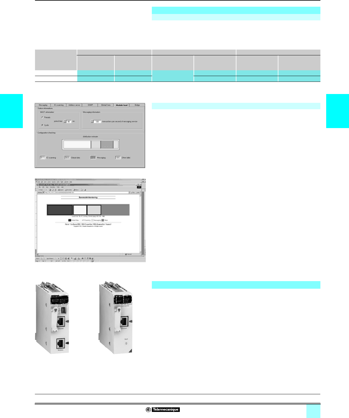
3/21
3 3
Performance (continued) Modicon®M340™ Automation
Platform 0
Ethernet TCP/IP network, and
Transparent Ready® Services — Performance
The maximum number of simultaneous TCP/IP connections depends on the platform
as well as the type of connection to the Ethernet network:
bThe 10/100BASE-TX port in network modules.
bThe 10/100BASE-TX port integrated in processors.
(1) With 64 simultaneous TCP/IP connections maximum (clients and servers).
The passband management service indicates the load level of the Ethernet network
module. This allows the user to monitor any drift and anticipate any problems.
The Ethernet module load is indicated in 3 ways:
bExpected load in the Unity Pro™/PL7™ configuration screen.
bActual load in the Unity Pro/PL7 diagnostics/debug screen, as well as in the
diagnostics pages via the Web. It is displayed in the form of a bar chart animated in
real time.
bIn the SNMP interface for access by the SNMP network manager.
The passband is indicated as a percentage for each of the following services:
bModbus® messaging (and Uni-TE)
bI/O Scanning
bGlobal Data
bOther
The M340 PLC has 2 types of connection to the Ethernet network:
bThe 10/100BASE-TX port integrated in BMX P34 2020/2030 Performance
processors, which also process the application, exchanges with other modules
supported by the rack and other communication ports (CANopen bus or Modbus
serial link).
bThe 10/100BASE-TX port in the BMX NOE 0100 and BMX NOE 0110 modules on
which, unlike the Performance processor, all the resources are allocated to Ethernet
TCP/IP communication.
These fundamentally different hardware characteristics result in equally different
capacities in terms of service, and performance:
bThe integrated port is a low-cost way of satisfying applications that have minimal
demands in terms of communication (less than 500 useful messages/s) in
environments little affected by interference.
bWhere there are a large number of exchanges, or network capacity approaches its
limitation, use of a dedicated module is unavoidable.
Processing capacities of Modicon® platforms (continued)
Maximum number of simultaneous TCP/IP connections
Number of
simultaneous TCP/IP
connections
Modicon M340 Modicon Premium Modicon Quantum
BMX NOE 0100
BMX NOE 0110
BMX P34 2020
BMX P34 2030
TSX ETY 210
TSX ETY 110WS
TSX ETY 4103/5103
TSX WMY 100
TSX P57 10...57 50
140 NOE 771 01/11
140 CPU 113/311 pp
140 CPU 434/534 14B
140 CPU 65 150
140 CPU 65 160
Client 16 16 32 16 (1) 16 (1) 16 (1)
Server 16 16 64 (1) 64 (1) 64 (1)
Managing the passband of Ethernet TCP/IP modules
Ethernet solutions with the Modicon® M340™ platform
Ethernet port integrated in
the BMX P34 2020/2030
Ethernet module
BMX NOE 0100/0110
or
Presentation:
pages 3/4 and 3/5
Performances:
pages 3/16 to 3/21
Selection:
pages 3/2 and 3/3
References:
pages 3/22 and 3/23
Connections:
pages 3/24 to 3/37
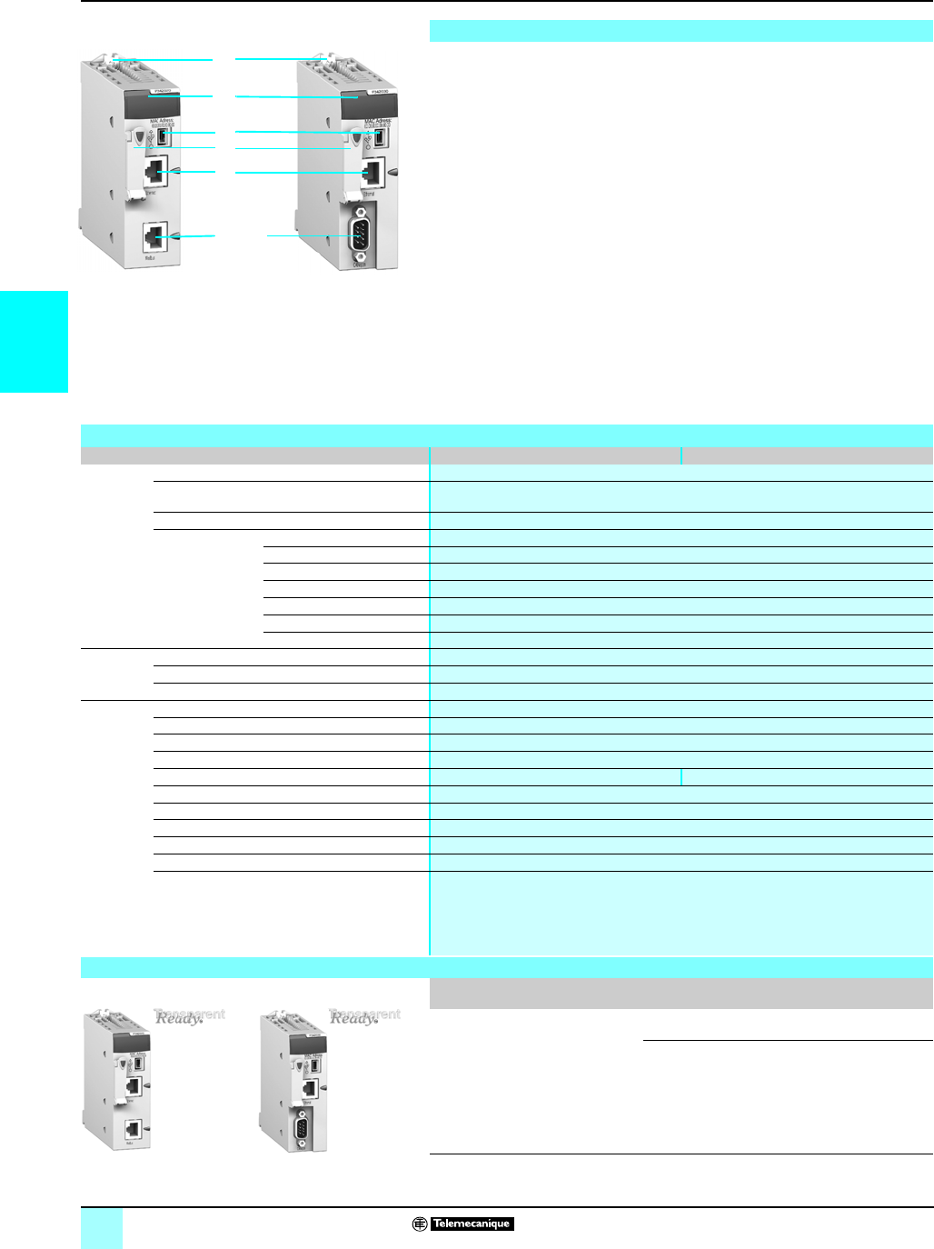
3/22
3
Product data sheet Modicon® M340™ Automation
Platform 0
Processors with integrated Ethernet port
BMX P34 2020 and BMX P34 2030 Modicon M340 processors with integrated
Ethernet port have the following on the front panel:
1Securing screw for locking the module in its slot (marked 0) in the rack
2A display unit including at minimum 3 LEDs relating to the Ethernet port:
v ETH ACT LED (green): Activity on the Ethernet TCP/IP network
v ETH STS LED (green): Ethernet TCP/IP network status
v ETH 100 LED (red): Data rate on the Ethernet TCP/IP network (10 or 100 Mbit/s)
3A mini B USB connector for a programming terminal (or Magelis® XBT GT
operator interface)
4A slot equipped with its Flash memory card for saving the application and
activating the standard Transparent Ready® Web server, class B10.
5An RJ45 connector for connection to the 10BASE-T/100BASE-TX Ethernet
TCP/IP network
Also included, depending on the model:
6BMX P34 2020 processor: An RJ45 connector for the Modbus® serial link or
character mode link (RS 232C/RS 485, 2-wire, non-isolated)
7BMX P34 2030 processor: A 9-pin SUB-D connector for the master CANopen
machine and installation bus
On the back panel: 2 rotary switches for assigning the IP address in one of 3 modes:
v address set by the position of the two rotary switches
v address set by the application parameters
v address set by the Ethernet TCP/IP BOOTP server
Description
6
2
3
5
1
4
7
Characteristics
Module type Unity Pro™ software BMX P34 2020 BMX P34 2030
Transparent
Ready
services
Class B10
Standard Web server Rack Viewer access to the product description and status and to the PLC diagnostics
Data Editor access to the configuration functions and PLC variables
Standard Ethernet TCP/IP communication service Modbus TCP messaging (read/write data words)
Ethernet TCP/IP
advanced
communication
services
I/O Scanning –
Global Data –
FDR Client Automatic assignment of IP address and network parameters
SMTP E-mail notification –
SNMP network administrator Yes
SOAP/XML Web services No
Bandwidth management Yes
Structure Physical interface 10BASE-T/100BASE-TX (RJ45)
Data rate 10/100 Mbit/s with automatic recognition
Medium Twisted pair
Modicon
M340
processor
No. of discrete I/O 1024
No. of analog I/O 256
No. of application-specific channels 36
Max. no. of Ethernet TCP/IP connections 2 (integrated port and BMX NOE 0100/0110 network module)
Other integrated communication ports Modbus serial link or character mode CANopen bus
Operating temperature 0…+ 60 °C
Relative humidity 10...95% non-condensing during operation
Degree of protection IP 20
Power supply Via the power supply of the rack supporting the processor
Conformity to standards IEC/EN 61131-2, UL 508, CSA 22.2 n°142, CSA 22.2 n°213 Class 1 Division 2, e
LED indicators Activity on the Ethernet TCP/IP network (ETH ACT, green)
Status of the Ethernet TCP/IP network (ETH STS, green)
Data rate on the 10 or 100 Mbit/s Ethernet TCP/IP network, (ETH 100, red)
4 LEDs specific to processor operation (RUN, ERR, I/O, CARD ERR)
1 or 2 LEDs specific to the other communication ports (SER COM or CAN RUN and CAN ERR)
(1)
References
Description I/O capacity
Memory capacity
Other integrated
communication ports
Reference Weight
kg
Processors with
integrated
Ethernet link
Transparent
Ready Web
server, class B10
1024 discrete I/O
256 analog I/O
36 app-sp. channels
4096 Kb integrated
Modbus serial link or
character mode
BMXP342020 0.205
CANopen bus BMXP342030 0.215
(1) SER COM for serial link or CAN RUN and CAN ERR for CANopen bus.
BMX P34 2020 BMX P34 2030
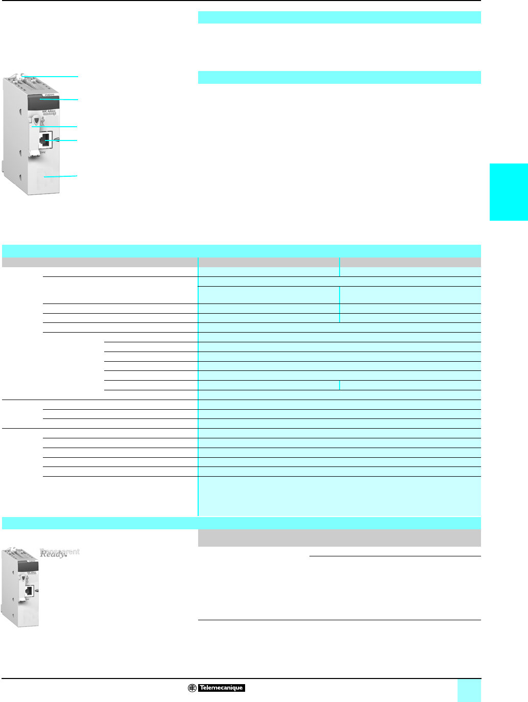
3/23
3
Product data sheet
(continued)
Modicon® M340™ Automation
Platform 0
Ethernet network module
The BMX NOE 0100 and BMX NOE 0100 modules are a standard module
occupying a single slot in the rack of the Modicon M340 platform equipped with a
Standard processor or associated Performance processor (maximum of 1 module
per configuration)
The BMX NOE 01p0 module has the following on the front panel:
1Securing screw for locking the module in its slot in the rack
2A display unit consisting of 6 LEDs, including 3 relating to the Ethernet port:
v ETH ACT LED (green): Activity on the Ethernet TCP/IP network
v ETH STS LED (green): Ethernet TCP/IP network status
v ETH 100 LED (red): Data rate on the Ethernet TCP/IP network (10 or 100 Mbit/s)
3A slot equipped with its Flash memory card for application saving and activating
the standard Web server, Transparent Ready® Web server, class B30 or C30
depending on model
4An RJ45 connector for connection to the 10BASE-T/100BASE-TX Ethernet
TCP/IP network
5A pencil-point RESET button for a cold restart of the module
On the back panel: 2 rotary switches for assigning the IP address in one of 3 modes:
v address set by the position of the two rotary switches
v address set by the application parameters
v address set by the Ethernet TCP/IP network BOOTP server
Presentation
Description
5
2
4
1
3
Characteristics
Module type Unity Pro™ software BMX NOE 0100 BMX NOE 0110
Transparent
Ready
services
Class B30 C30
Standard Web server Rack Viewer access to the product description and status and to the PLC diagnostics
Data Editor access to PLC variable via
PC terminal
Data Editor access to PLC variable via
PC terminal, pocket PC or PDA terminal
Configurable Web server Yes Yes
User Web pages (available size) –Yes (16 Mb)
Standard Ethernet TCP/IP communication service Modbus® TCP messaging (read/write data words)
Ethernet TCP/IP
advanced
communication
services
I/O Scanning Yes
Global Data Yes
FDR server Automatic assignment of IP address and network parameters
SMTP E-mail notification –
SNMP network administrator Yes
SOAP/XML Web services –Server
Bandwidth management Yes
Structure Physical interface 10BASE-T/100BASE-TX (RJ45)
Data rate 10/100 Mbit/s with automatic recognition
Medium Twisted pair
Network
module
Operating temperature 0…+ 60 °C
Relative humidity 10...95% non-condensing during operation
Degree of protection IP 20
Power supply Via the power supply of the rack supporting the processor
Conformity to standards IEC/EN 61131-2, UL 508, CSA 22.2 n°142, CSA 22.2 n°213 Class 1 Division 2, e
LED indicators Activity on the Ethernet TCP/IP network (ETH ACT, green)
State of the Ethernet TCP/IP network (ETH STS, green)
Data rate on the 10 or 100 Mbit/s Ethernet TCP/IP network, (ETH 100, red)
3 LEDs specific to module operation (RUN, ERR, CARD ERR)
References
Description Data rate Transparent Ready
class
Reference Weight
kg
Ethernet TCP/IP
network module
10/100 Mbit/s B30 BMXNOE0100 0.200
C30 BMXNOE0110 r0.200
r Available 4th quarter 2007
Before this date, please order the BMX NOE 0100 Ethernet module with BMX RWS C016M
memory card, same services except Data editor service with pocket PC or PDA terminal and
SOAP/XML Web services.
BMX NOE 0100/0110
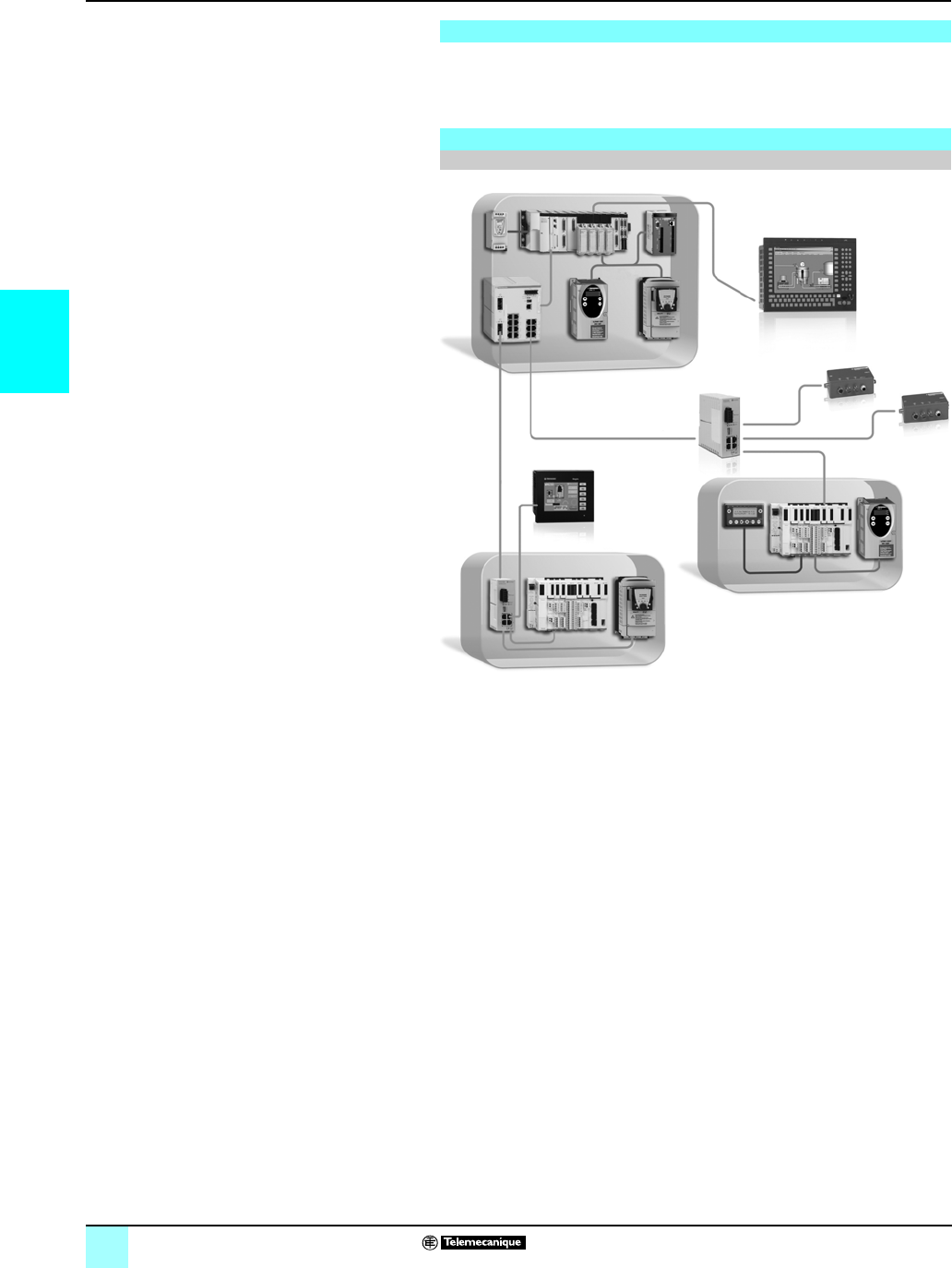
3/24
3
Wiring system Ethernet
in Machines and Installations 0
Infrastructure
The Ethernet cable provides all cable options to wire IP20 and IP67 devices using
copper as well as fiber optics.
For key:
1, 3: Straight cables,
2, 4: Crossed cord cables,
8: Cables with IP 67 connector,
see pages 3/26 and 3/27.
Presentation
Examples
Combined IP20 and IP67 wiring, copper
1, 3
2, 4
2, 4
8
8
1, 3
1, 3
1, 3
1, 3 1, 3
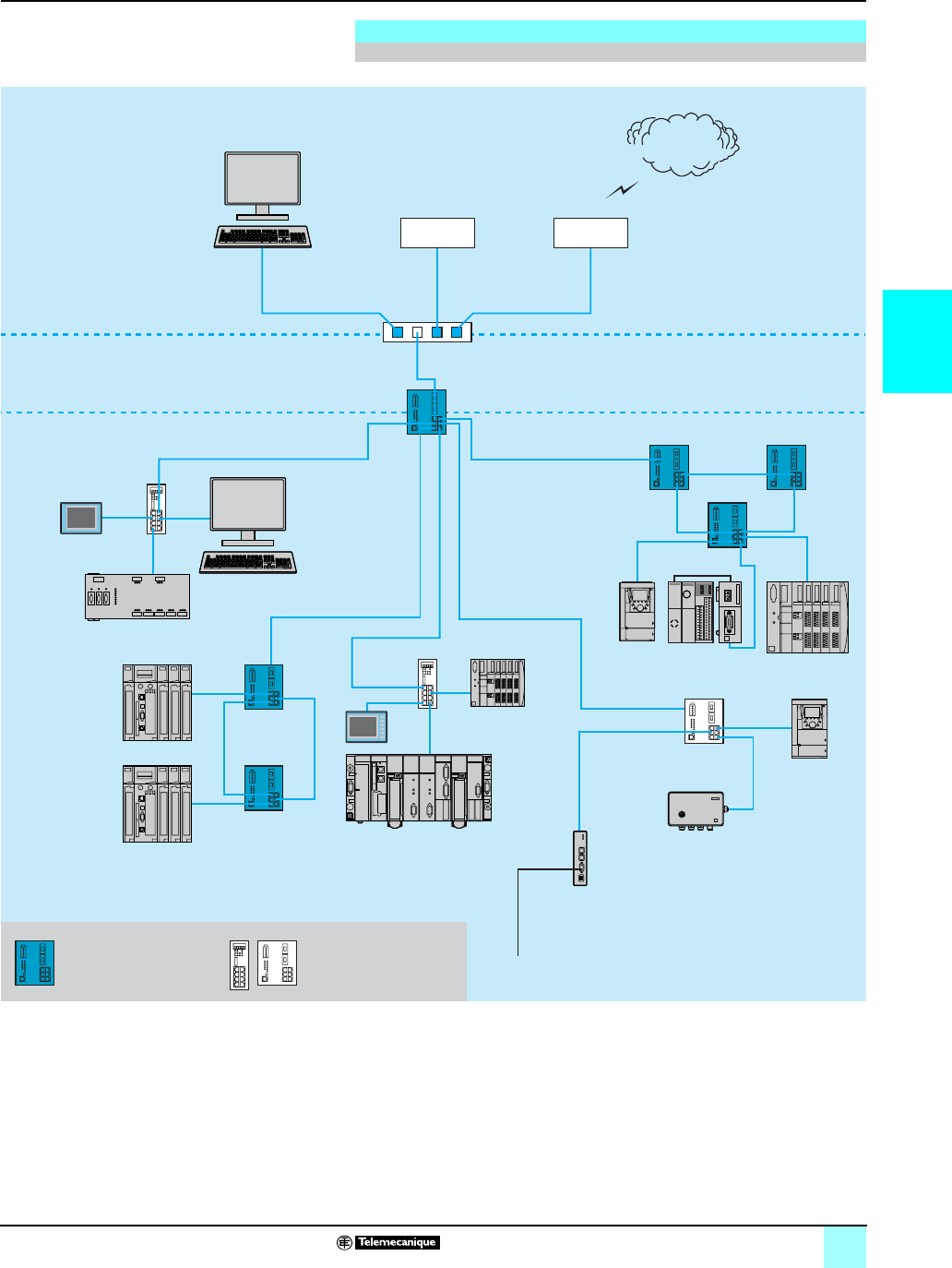
3/25
3
Wiring system Ethernet
in Machines and Installations 0
Infrastructure
For key:
1, 3: Straight cables,
2, 4: Crossed cord cables,
5, 6, 7: Fiber optic cables,
8: Cables with IP 67 connector,
see pages 3/26 and 3/27
Examples (continued)
Combined Copper and Fiber wiring
Firewall
Server
1, 3 1, 3
1, 3 1, 31, 31, 3
1, 3
1, 3
1, 3
1, 3
1, 3
1, 3
1, 3
2, 4 2, 4
2, 4
2, 42, 4
2, 4
2, 4
2, 4
8
5, 6, 7
Preventa safety PLC
Internet
MES Client
Router
Quantum
Quantum
Premium
Twido Advantys STB
Altivar 71
Altivar 71
Magelis
Magelis
Ositrack
FactoryCast
gateway
Modbus
Managed switch
Hub or
unmanaged
switch
Fiber link
Copper link
Copper link

3/26
3
Wiring system (continued) Ethernet
in Machines and Installations 0
Ethernet TCP/IP, Transparent Ready® Services
Cabling system: ConneXium™ connection components
ConneXium shielded connection cables are available in two versions to meet the various current
standards and approvals:
bEIA/TIA 568 standard shielded twisted pair cables
These cables conform to:
vEIA/TIA-568 standard, category CAT 5E,
vIEC 11801/EN 50173 standard, class D.
Their fire resistance conforms to:
vNFC 32070# C2 classification
vIEC 322/1 standards
vLow Smoke Zero Halogen (LSZH).
bUL and CSA 22.1 approved shielded twisted pair cables
These cables conform to:
vUL and CSA 22.1 standards
Their fire resistance conforms to NFPA 70.
These glass fiber optics are for making connections:
bTo a terminal device (DTE)
bBetween hubs, transceivers and switches
Shielded copper connection cables
490 NT
p
000
pp
EIA/TIA 568 standard shielded twisted pair cables
Description Preformed at both ends Rep. Length
m (ft.)
Reference Weight
kg
Straight cables 2 RJ45 connectors
For connection to terminal
devices (DTE)
12 (6.6) 490NTW00002 –
5 (16.4) 490NTW00005 –
12 (39.4) 490NTW00012 –
40 (131.2) 490NTW00040 –
80 (262.5) 490NTW00080
–
Crossed cord
cables
2 RJ45 connectors
For connections between
hubs, switches and
transceivers
25 (16.4) 490NTC00005 –
15 (49.2) 490NTC00015 –
40 (131.2) 490NTC00040 –
80 (262.5) 490NTC00080 –
UL and CSA 22.1 approved shielded twisted pair cables
Description Preformed at both ends Rep Length Reference Weight
kg
Straight cables 2 RJ45 connectors
For connection to terminal
devices (DTE)
32 (6.6) 490NTW00002U –
5 (16.4) 490NTW00005U –
12 (39.4) 490NTW00012U –
40 (131.2) 490NTW00040U –
80 (262.5) 490NTW00080U –
Crossed cord
cables
2 RJ45 connectors
For connections between
hubs, switches and
transceivers
45 (16.4) 490NTC00005U –
15 (49.2) 490NTC00015U –
40 (131.2) 490NTC00040U –
80 (262.5) 490NTC00080U –
Glass fiber optic cables
Description Preformed at both ends Rep. Length Reference Weight
kg
Glass fiber optic
cables
1 SC connector
1 MT-RJ connector
55 (16.4) 490NOC00005 –
1 ST connector (BFOC)
1 MT-RJ connector
65 (16.4) 490NOT00005 –
2 MT-RJ connectors 73 (9.8) 490NOR00003 –
5 (16.4) 490NOR00005 –
15 (49.2) 490NOR00015 –
490 NOC 000 05
MT-RJ
SC
490 NOR 000 05
MT-RJ
MT-RJ
490 NOT 000 05
MT-RJ
ST

3/27
3
Wiring system (continued) Ethernet
in Machines and Installations 0
Ethernet TCP/IP, Transparent Ready® Services
Cabling system: ConneXium™ connection components
(1) Dimensions W x H X D = 20 x 18 x 50 mm.
Separate parts for TCS ESM switches
TCS EAA F1LF
p
00
Description Optical fiber Type Reference Weight
kg
Fiber optic
modules for
Gigabit ports with
LC connector
(1)
Multimode 50/125µm
or 62.5/125µm
1000BASE-SX TCSEAAF1LFU00 0.040
Single mode 9/125µm 1000BASE-LH TCSEAAF1LFH00 0.040
Multimode 50/125µm
or 62.5/125µm
Single mode
62.5/125µm
1000BASE-LX TCSEAAF1LFS00 0.040
Configuration
backup key
Via the USB port on the front of the
switch, used to:
- save and retrieve the switch
configuration
- update the internal software
TCSEAM0100 –
Connection components for IP 67 switch
Description Preformed at both
ends
Rep. Length
m (ft.)
Reference Weight
kg
Copper cables 1 IP 67 4-pin M12
connector
and 1 RJ45 connector
81 (3.3) TCSEC1M3M1S2 –
1.5 (4.9) TCSECL1M3M1X5S2 –
3 (9,8) TCSECL1M3M3S2 –
5 (16.4) TCSECL1M3M5S2 –
10 (32.8) TCSECL1M3M10S2 –
25 (82) TCSECL1M3M25S2 –
40 (131.2) TCSECL1M3M40S2
–
2 IP 67 4-pin M12
connectors
–1 (3.3) TCSECL1M1M1S2 –
1.5 (4.9) TCSECL1M1M1X5S2 –
3 (9,8) TCSECL1M1M3S2 –
5 (16.4) TCSECL1M1M5S2 –
10 (32.8) TCSECL1M1M10S2 –
25 (82) TCSECL1M1M25S2 –
40 (131.2) TCSECL1M1M40S2 –
M12/RJ45
adapter
IP 67 female 4-pin M12
connector and female
RJ45 connector
–– TCSEAAF11F13F00 –
Power cables Female M12 straight
connector
–2(6.6) XZCP1164L2 –
5(16.4) XZCP1164L5 –
Female M12 elbowed
connector
–2.5(8.2) XZCP1264L2 –
5(16.4) XZCP1264L5 –
Power
connectors
Female M12 straight
connector
–– XZCC12FDM50B –
Female M12 elbowed
connector
–– XZCC12FCM50B –
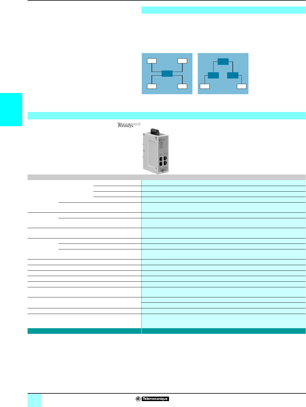
3/28
3
Ethernet
in Machines and Installations 0
Ethernet TCP/IP, Transparent Ready® Services
Cabling system: ConneXium™ hub
Hubs (concentrators) are used for transmitting signals between several media
(ports). Hubs are plug and play devices that require no configuration.
The use of hubs makes it possible to create the following topologies:
bStar topology using hubs
bTree topology using hubs
Consult our catalog “Ethernet TCP/IP and Web technologies, Transparent Ready”.
Presentation
DTE DTE
DTE DTE DTE DTE
Star topology Tree topology
Hub
Hub
HubHub
Characteristics and reference
Hubs
Interfaces Copper cable ports Number and type 4 x 10BASE-T ports
Shielded connectors RJ45
Medium Shielded twisted pair, category CAT 5E
Total length of pair 100 m
Fiber optic ports Number and type –
Topology Number of cascaded hubs max. 4
Number of hubs in a ring –
Redundancy P1 and P2 redundant power supplies
Power supply Voltage 24 V c (18…32), safety extra low voltage (SELV)
Power consumption 80 mA (130 max. at 24 V c)
Removable connector 5-pin
Operating temperature 0…+ 60 °C
Relative humidity 10…95% non-condensing
Degree of protection IP 30
Dimensions W x H x D 40 x 125 x 80 mm
Mounting On symmetrical DIN rail, 35 mm wide
Weight 0.530 kg
Conformity to standards cUL 60950, UL 508 and CSA 142, UL 1604 and CSA 213 Class 1 Division 2, e, GL
FM 3810, FM 3611 Class 1 Division 2
LED indicators Power supply, activity, link
Alarm relay Power supply fault, Ethernet network fault or communication port fault (1 A max. voltage-free
contact at 24 V c)
Reference 499 NEH 104 10
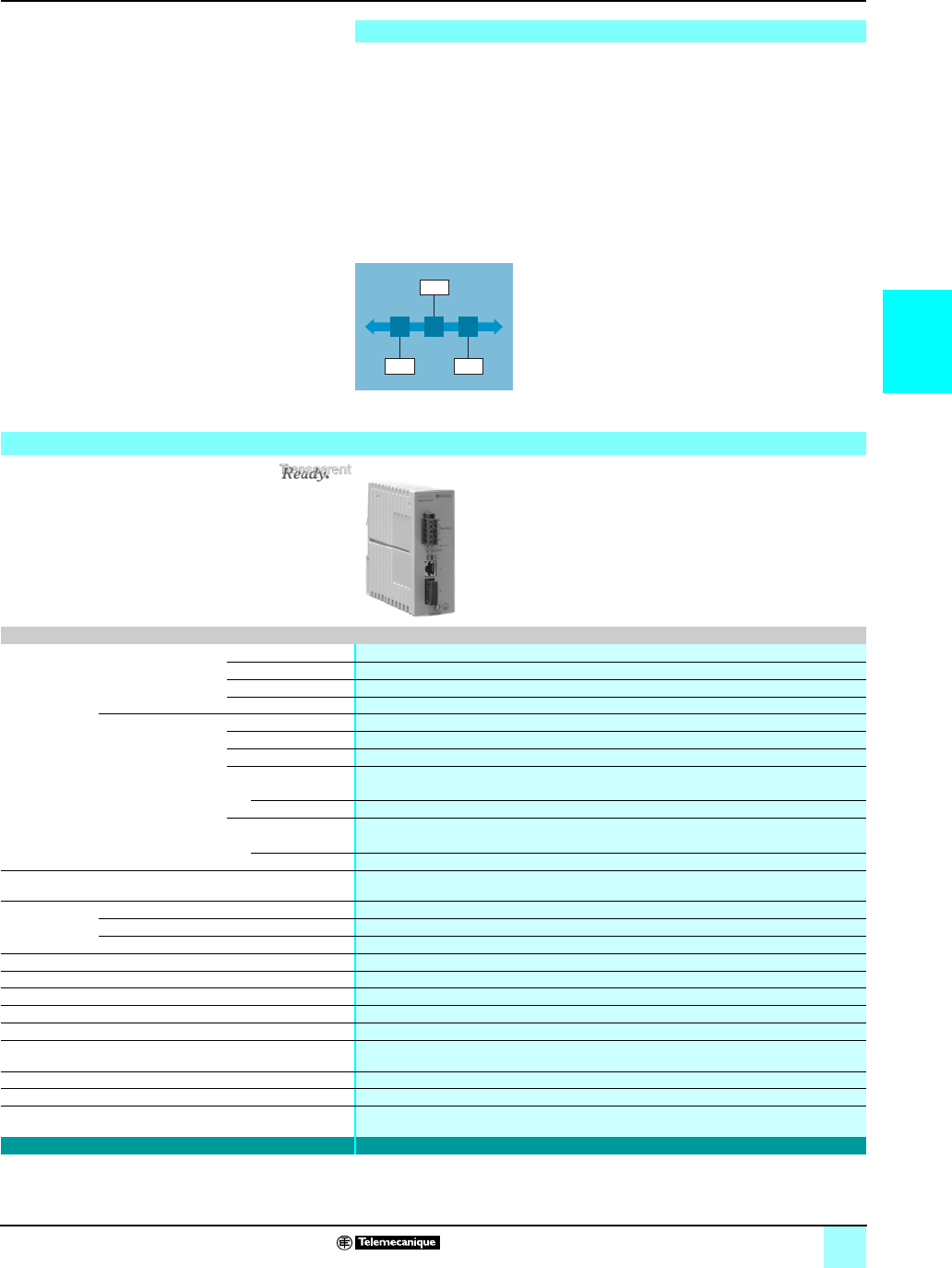
3/29
3
Product data sheet Ethernet
in Machines and Installations 0
Ethernet TCP/IP, Transparent Ready® Services
Cabling system: ConneXium™ transceivers
The use of ConneXium transceivers makes it possible to perform the following:
bCreation of linear fiber optic bus topologies, for products with twisted-pair cable
Ethernet connection.
bInterfacing products with twisted-pair cable Ethernet connection with a fiber optic
cable.
Transceivers are plug and play devices that requires no configuration. Consult our
catalog “Ethernet TCP/IP and Web technologies, Transparent Ready”.
ConneXium transceivers provide fiber optic connections for transmission in areas
subject to interference (high levels of electromagnetic interference) and for long
distance communications.
(1) Length depends on the attenuation analysis and attenuation of the optical fiber (typical
value: 2000 m).
Presentation
DTE
DTEDTE
Linear topology on optical fiber
Characteristics and reference
Transceivers
Interfaces Copper cable ports Number and type 1 x 100BASE-TX port
Shielded connectors RJ45
Medium Shielded twisted pair, category CAT 5E
Total length of pair 100 m
Fiber optic ports Number and type 1 x 100BASE-FX port
Connectors SC
Medium Multimode optical fiber
Length of optical fiber
50/125 µm fiber 3000 m (1)
62.2/125 µm fiber 3000 m (1)
Attenuation analysis
50/125 µm fiber 8dB
62.2/125 µm fiber 11 dB
Redundancy P1 and P2 redundant power supplies
Power supply Voltage 24 V c (18…32), safety extra low voltage (SELV)
Power consumption 160 mA (190 max. at 24 V c)
Removable connector 5-pin
Operating temperature 0…+ 60 °C
Relative humidity 10…95% non-condensing
Degree of protection IP 20
Dimensions W x H x D 47 x 135 x 111 mm
Mounting On symmetrical DIN rail, 35 mm wide
Weight 0.230 kg
Conformity to standards cUL 60950, UL 508 and CSA 142, UL 1604 and CSA 213 Class 1 Division 2, e, GL
LED indicators P1 and P2 power supplies, Ethernet link/port status
Alarm relay Power supply fault, Ethernet network fault or communication port fault (1 A max. voltage-free
contact at 24 V c)
Reference 499 NTR 101 00
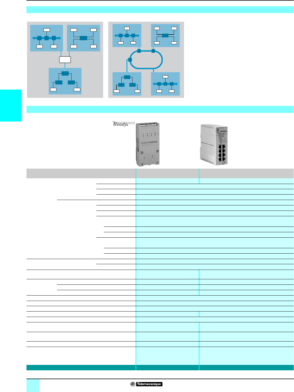
3/30
3
Product data sheet Ethernet
in Machines and Installations 0
Ethernet TCP/IP, Transparent Ready® Services
Cabling system: ConneXium™ unmanaged switches
Presentation
Switches are used to increase the limits of
architectures based on hubs or transceivers, by
separating collision domains.
Higher layer communication is provided between the
ports, and collisions at link layer are not propagated
(filtering). They therefore improve performance by
better allocation of the pass band due to the reduction
of collisions and the network load.
Certain ConneXium switch models also enable
redundant architectures to be created on twisted pair
copper ring or fiber optic.
Switches are plug and play devices that requires no
configuration. They can also be managed remotely via
the SNMP or HTTP protocols for monitoring and
diagnostics purposes.
Characteristics and references: twisted pair
Switches Optimized, copper twisted
pair, unmanaged
Copper twisted pair, unmanaged
Interfaces Copper
cable ports
Number and type 5 x 10BASE-T/100BASE-TX ports 8 10BASE-T/100BASE-TX ports
Shielded connectors RJ45
Medium Shielded twisted pair, category CAT 5E
Total length of pair
100 m
Fiber optic ports Number and type –
Connectors –
Medium –
Length of optical fiber
50/125 µm fiber –
62.2/125 µm fiber
9/125 µm fiber –
Attenuation analysis
50/125 µm fiber –
62.2/125 µm fiber
9/125 µm fiber –
Topology Number of switches Cascaded Unlimited
Redundant in a ring –
Redundancy –P1 and P2 redundant power supplies
Power supply Voltage 24 V c (19.2…30) 24 V c (18…32) safety extra low voltage (SELV)
Power consumption mA max. 120 125 (290 max.)
Removable connector 3-pin 5-pin
Operating temperature 0…+ 60 °C
Relative humidity 10…95% non-condensing
Degree of protection IP 20
Dimensions W x H x D
75.2 x 143 x 43 mm
47 x 135 x 111 mm
Mounting On symmetrical DIN rail, 35 mm wide
Weight 0.190 kg 0.230 kg
Conformity to standards
UL 508, CSA 1010, EN 61131-2
cUL 60950, UL 508 and CSA 142, UL 1604 and CSA 213
Class 1 Division 2, e, GL
LED indicators Power supply, link status, data rate P1 and P2 power supplies, Ethernet link/port status
Alarm relay –Power supply fault, Ethernet network fault or
communication port fault (1 A max. voltage-free contact
at 24 V c)
Reference 499 NES 251 00 499 NES 181 00
DTE
DTEDTE
DTE DTE
DTE DTE
DTE DTE
DTE
DTEDTE
DTE DTE
DTE
DTEDTE
DTE DTE
DTE DTE
100 Mbps optical
ring
Collision domain
1
Collision
domain 2
Collision
domain 3
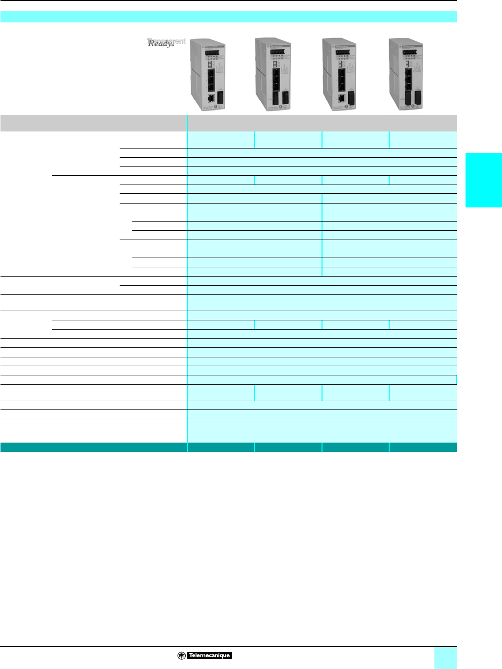
3/31
3
Product data sheet
(continued)
Ethernet
in Machines and Installations 0
Ethernet TCP/IP, Transparent Ready® Services
Cabling system: ConneXium™ unmanaged switches
Characteristics and references: 5 ports, twisted pair and fiber optic
Switches Copper twisted pair and fiber optic, unmanaged
Interfaces Copper
cable ports
Number and type 4 x 10BASE-T/
100BASE-TX ports
3 x 10BASE-T/
100BASE-TX ports
4 x 10BASE-T/
100BASE-TX ports
3 x 10BASE-T/
100BASE-TX ports
Shielded connectors RJ45
Medium Shielded twisted pair, category CAT 5E
Total length of pair
100 m
Fiber optic ports Number and type 1 x 100BASE-FX port 2 x 100BASE-FX ports 1 x 100BASE-FX port 2 x 100BASE-FX ports
Connectors SC
Medium Multimode optical fiber Single mode optical fiber
Length of optical fiber
50/125 µm fiber 5,000 m (1) –
62.2/125 µm fiber 4,000 m (1) –
9/125 µm fiber –32,500 m (2)
Attenuation analysis
50/125 µm fiber 8 dB –
62.2/125 µm fiber 11 dB –
9/125 µm fiber –16 dB
Topology Number of switches Cascaded Unlimited
Redundant in a ring –
Redundancy P1 and P2 redundant power supplies
Power supply Voltage 24 V c (18…32), safety extra low voltage (SELV)
Power consumption mA max. 200 240 200 240
Removable connector 5-pin
Operating temperature -40...+70 °C
Relative humidity 10…95% non-condensing
Degree of protection IP 20
Dimensions W x H x D 47 x 135 x 111 mm
Mounting On symmetrical DIN rail, 35 mm wide
Weight 0.330 kg 0.335 kg 0.330 kg 0.335 kg
Conformity to standards cUL 60950, cUL 508 and CSA 142, UL 1604 and CSA 213 Class 1 Division 2, e, GL
LED indicators P1 and P2 power supplies, Ethernet link status, transmission activity
Alarm relay Activity, power supply fault, Ethernet network fault or communication port fault (1 A max.
voltage-free contact at 24 V c)
Reference 499 NMS 251 01 499 NMS 251 02 499 NSS 251 01 499 NSS 251 02
(1) Length depends on the attenuation analysis and attenuation of the fiber optic (typical
value: 2,000 m).
(2) Length depends on the attenuation analysis and attenuation of the fiber optic (typical
value: 15,000 m).
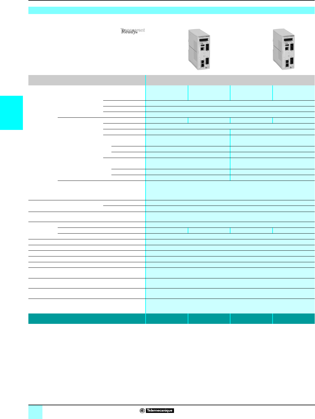
3/32
3
Product data sheet Ethernet
in Machines and Installations 0
Ethernet TCP/IP, Transparent Ready® Services
Cabling system: ConneXium™ managed switches
(1) Length depends on the attenuation analysis and attenuation of the fiber optic (typical
value: 2,000 m).
(2) Length depends on the attenuation analysis and attenuation of the fiber optic (typical
value: 15,000 m).
Characteristics and references: 4 ports, twisted pair and fiber optic
Switches Copper twisted pair and fiber optic, managed
Interfaces Copper cable ports Number and type 3 x 10/100BASE-TX
ports
2 x 10/100BASE-TX
ports
3 x 10/100BASE-TX
ports
2 x 10/100BASE-TX
ports
Shielded connectors RJ45
Medium Shielded twisted pair, category CAT 5E
Total length of pair
100 m
Fiber optic ports Number and type 1 x 100BASE-FX port 2 x 100BASE-FX ports 1 x 100BASE-FX port 2 x 100BASE-FX ports
Connectors Duplex SC
Medium Multimode optical fiber Single mode optical fiber
Length of optical fiber
50/125 µm fiber 5,000 m (1) –
62.2/125 µm fiber 4,000 m (1) –
9/125 µm fiber – 32,500 m (2)
Attenuation analysis
50/125 µm fiber 8 dB –
62.2/125 µm fiber 11 dB –
9/125 µm fiber –16 db
Ethernet services FDR, SMTP V3, SNTP client, multicast filtering for optimization of the Global Data protocol,
configuration via Web access
VLAN, IGMP Snooping, RSTP (Rapid Scanning Tree Protocol), priority port, data stream
control, secure port
Topology Number of switches Cascaded Unlimited
Redundant in a ring max. 50
Redundancy Redundant power supplies, redundant single ring, ring coupling
Power supply Voltage Operation 9.6...60 V c/18…30 V a, safety extra low voltage (SELV)
Power consumption 6.5 W 7.3 W 6.5 W 7.3 W
Removable connector 6-pin
Operating temperature 0…+ 60 °C
Relative humidity 10…90% non-condensing
Degree of protection IP 20
Dimensions W x H x D 47 x 131 x 111 mm
Mounting On symmetrical DIN rail, 35 mm wide
Weight 0.400 kg
Conformity to standards IEC 61131-2, IEC 61850-3, UL 508, UL 1604 Class 1 Division 2, CSA C22.2 14 (cUL),
CSA C22.2 213 Class 1 Division 2 (cUL), e, GL
LED indicators Power supply status, alarm relay status, active redundancy, redundancy management, copper
port status and copper port activity
Alarm relay Power supply fault, Ethernet network fault, communication port fault, redundancy fault (1 A max.
voltage-free contact at 24 V c)
Reference TCS ESM
043F1CU0
TCS ESM
043F2CU0
TCS ESM
043F1CS0
TCS ESM
043F2CS0
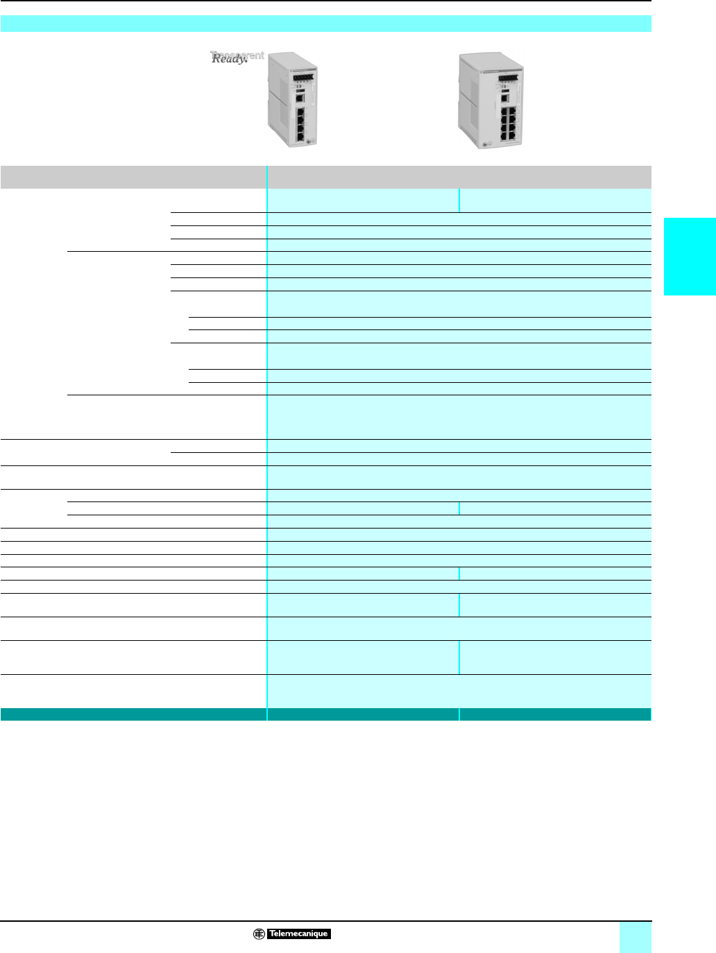
3/33
3
Product data sheet
(continued)
Ethernet
in Machines and Installations 0
Ethernet TCP/IP, Transparent Ready® Services
Cabling system: ConneXium™ managed switches
Characteristics and references: 4 and 8 ports, twisted pair
Switches Copper twisted pair, managed
Interfaces Copper cable ports Number and type 4 x 10/100BASE-TX ports 8 x 10/100BASE-TX ports
Shielded connectors RJ45
Medium Shielded twisted pair, category CAT 5E
Total length of pair
100 m
Fiber optic ports Number and type –
Connectors –
Medium
Length of optical fiber
50/125 µm fiber –
62.2/125 µm fiber –
9/125 µm fiber –
Attenuation analysis
50/125 µm fiber –
62.2/125 µm fiber –
9/125 µm fiber –
Ethernet services FDR, SMTP V3, SNTP client, multicast filtering for optimization of the Global Data protocol,
configuration via Web access
VLAN, IGMP Snooping, RSTP (Rapid Scanning Tree Protocol), priority port, data stream
control, secure port
Topology Number of switches Cascaded Unlimited
Redundant in a ring max. 50
Redundancy Redundant power supplies, redundant single ring, ring coupling
Power supply Voltage Operation 9.6...60 V c/18…30 V a, safety extra low voltage (SELV)
Power consumption 5.3 W 5.3 W
Removable connector 6-pin
Operating temperature 0…+ 60 °C
Relative humidity 10…90% non-condensing
Degree of protection IP 20
Dimensions W x H x D 47 x 131 x 111 mm 74 x 131 x 111 mm
Mounting On symmetrical DIN rail, 35 mm wide
Weight 0.400 kg
0.410 kg
Conformity to standards IEC 61131-2, IEC 61850-3, UL 508, UL 1604 Class 1 Division 2, CSA C22.2 14 (cUL),
CSA C22.2 213 Class 1 Division 2 (cUL), e, GL
LED indicators Power supply status, alarm relay status, active
redundancy, redundancy management,
copper port status and copper port activity
Power supply status, alarm relay status, active
redundancy, redundancy management,
fiber port status and fiber port activity
Alarm relay Power supply fault, Ethernet network fault or communication port fault (1 A max. voltage-free
contact at 24 V c)
Reference TCS ESM 043F23F0 TCS ESM 083F23F0
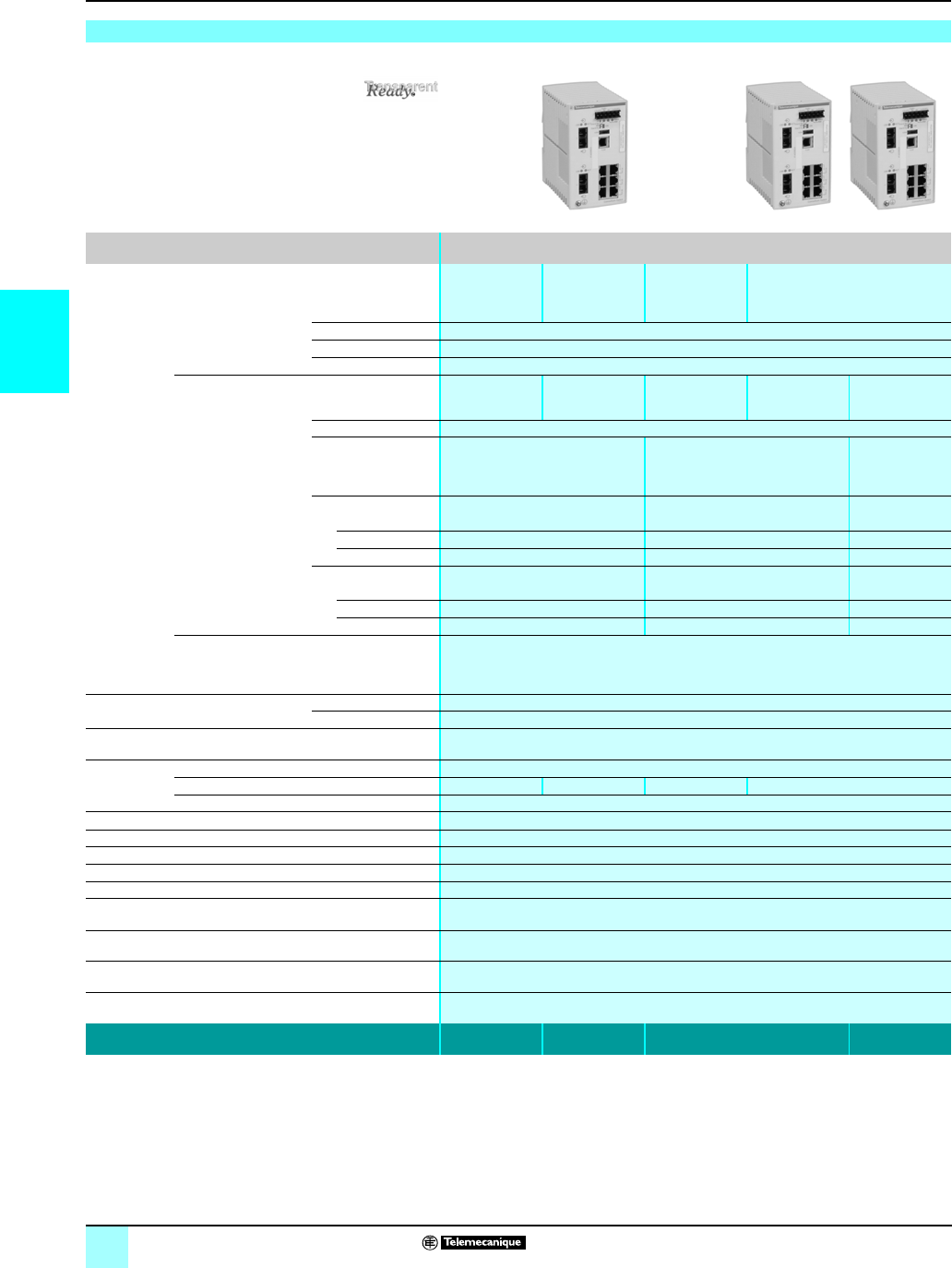
3/34
3
Product data sheet
(continued)
Ethernet
in Machines and Installations 0
Ethernet TCP/IP, Transparent Ready® Services
Cabling system: ConneXium™ managed switches
(1) Length depends on the attenuation analysis and attenuation of the fiber optic (typical
value: 2,000 m).
(2) Length depends on the attenuation analysis and attenuation of the fiber optic (typical
value: 15,000 m).
Characteristics and references: 8 ports, twisted pair and fiber optic
Switches Copper twisted pair and fiber optic, managed
Interfaces Copper cable ports Number and type 7 x
10/100BASE-TX
ports
6 x
10/100BASE-TX
ports
7 x
10/100BASE-TX
ports
6 x 10/100BASE-T ports
Shielded connectors RJ45
Medium Shielded twisted pair, category CAT 5E
Total length of pair
100 m
Fiber optic ports Number and type 1 x 100BASE-FX
port
2 x 100BASE-FX
ports
1 x 100BASE-FX
port
2x 100BASE-FX
ports
1 + 1 x
100BASE-FX
port
Connectors Duplex SC
Medium Multimode optical fiber Single mode optical fiber Single mode
optical fiber and
multimode optical
fiber
Length of optical fiber
50/125 µm fiber 5,000 m (1) – 5,000 m (1)
62.2/125 µm fiber 4,000 m (1) – 4,000 m (1)
9/125 µm fiber –32,500 m (2) 32,500 m (2)
Attenuation analysis
50/125 µm fiber 8dB –8dB
62.2/125 µm fiber 11 dB –11 dB
9/125 µm fiber –16 dB 16 dB
Ethernet services FDR, SMTP V3, SNTP client, multicast filtering for optimization of the Global Data protocol,
configuration via Web access
VLAN, IGMP Snooping, RSTP (Rapid Scanning Tree Protocol), priority port, data stream
control, secure port
Topology Number of switches Cascaded Unlimited
Redundant in a ring max. 50
Redundancy Redundant power supplies, redundant single ring, ring coupling
Power supply Voltage Operation 9.6...60 V c/18…30 V a, safety extra low voltage (SELV)
Power consumption 6.5 W 7.3 W 6.5 W 7.3 W
Removable connector 6-pin
Operating temperature 0…+ 60 °C
Relative humidity 10… 90% non-condensing
Degree of protection IP 20
Dimensions W x H x D 74 x 131 x 111 mm
Mounting On symmetrical DIN rail, 35 mm wide
Weight 0.410 kg
Conformity to standards IEC 61131-2, IEC 61850-3, UL 508, UL 1604 Class 1 Division 2, CSA C22.2 14 (cUL),
CSA C22.2 213 Class 1 Division 2 (cUL), e, GL
LED indicators Power supply status, alarm relay status, active redundancy, redundancy management,
fiber port status and fiber port activity
Alarm relay Power supply fault, Ethernet network fault or communication port fault (1 A max. voltage-free
contact at 24 V c)
Reference TCSESM
083F1CU0
TCSESM
083F2CU0
TCSESM
083F1CS0
TCSESM
083F2CS0
TCSESM
083F2CX0
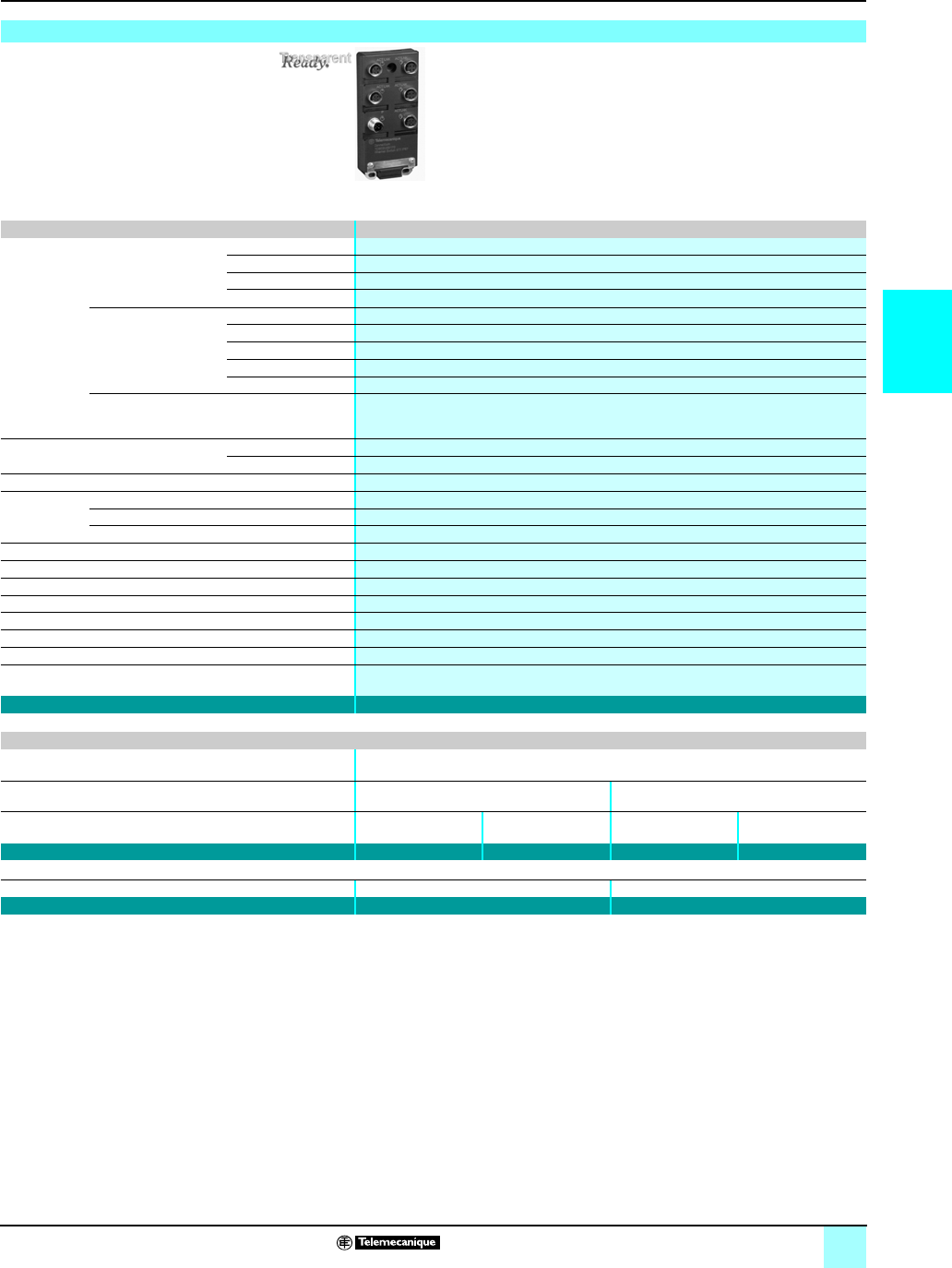
3/35
3
Product data sheet Ethernet
in Machines and Installations 0
Ethernet TCP/IP, Transparent Ready® Services
Cabling system: ConneXium™ IP 67 switch
Characteristics and references: IP 67 unmanaged switch
IP 67 switch Twisted pair, unmanaged
Interfaces Copper cable ports Number and type 5 x 10BASE-T/100BASE-TX ports
Shielded connectors M12 (type D)
Medium Shielded twisted pair, category CAT 5E
Total length of pair
100 m
Fiber optic ports Number and type –
Connectors –
Medium –
Length of optical fiber
–
Attenuation analysis –
Ethernet services Storage and re-routing of received data, auto MDI/MDX (automatic switching depending on
whether cables are straight or crossed), automatic negotiation of 10/100 Mbps and duplex mode
(on all ports), automatic change of polarity
Topology Number of switches Cascaded Unlimited
Redundant in a ring –
Redundancy –
Power supply Voltage 24 V c (18…32 V c), safety extra low voltage (SELV)
Power consumption 100 mA
Connector 5-pin M12 (type A, male)
Operating temperature 0…+ 60 °C
Relative humidity –
Degree of protection IP 67
Dimensions W x H x D 60 x 126 x 31 mm
Weight 0.210 kg
Conformity to standards cUL 508 and CSA 22.2 14
LED indicators Power supply, line status, line activity
Alarm relay –
Reference TCS ESU 051 F0
IP 67 cord sets
Ethernet cord sets Preformed at each end, see page 3/27
Power supply cables Preformed at each end with M12 female
straight connectors
Preformed at each end with female M12
angled connectors
Length 2 m 5 m 2.5 m 5 m
Reference XZC P1164L2 XZC P1164L5 XZC P1264L2 XZC P1264L5
Spare power connectors Female M12 straight connector Female M12 angled connector
Reference XZC C12 FDM 50B XZC C12 FCM 50B
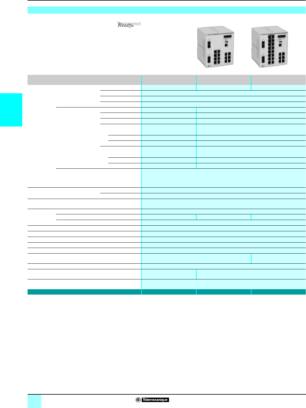
3/36
3
Product data sheet
(continued)
Ethernet
in Machines and Installations 0
Ethernet TCP/IP, Transparent Ready® Services
Cabling system: ConneXium™ managed switches
(1) Length depends on the attenuation analysis and attenuation of the fiber optic (typical
value: 2,000 m).
Characteristics and references: 16 and 24 ports, twisted pair, fiber optic
Switches Copper twisted pair and
fiber optic, managed
Copper twisted pair,
managed
Copper twisted pair and
fiber optic, managed
Interfaces Copper cable ports Number and type 16 x 10/100BASE-TX ports 14 x 10/100BASE-TX ports 22 x 10/100BASE-TX ports
Shielded connectors RJ45
Medium Shielded twisted pair, category CAT 5E
Total length of pair
100 m
Fiber optic ports Number and type –2 x 100BASE-FX ports
Connectors –Duplex SC
Medium –Multimode optical fiber
Length of optical fiber
50/125 µm fiber –5,000 m (1)
62.2/125 µm fiber –4,000 m (1)
9/125 µm fiber – –
Attenuation analysis
50/125 µm fiber –8dB
62.2/125 µm fiber –11 dB
9/125 µm fiber – –
Ethernet services FDR, SMTP V3, SNTP client, multicast filtering for optimization of the Global Data protocol,
configuration via Web access
VLAN, IGMP Snooping, RSTP (Rapid Scanning Tree Protocol), priority port, data stream
control, secure port
Topology Number of switches Cascaded Unlimited
Redundant in a ring max. 50
Redundancy Redundant power supplies, redundant single ring, ring coupling
Power supply Voltage Operation 9.6...60 V c/18…30 V a, safety extra low voltage (SELV)
Power consumption 9.4 W 11.8 W 15.5 W
Removable connector 6-pin
Operating temperature 0…+ 60 °C
Relative humidity 10… 90% non-condensing
Degree of protection IP 20
Dimensions W x H x D 111 x 131 x 111 mm
Mounting On symmetrical DIN rail, 35 mm wide
Weight 0.600 kg 0.650 kg
Conformity to standards cUL 60950, UL 508 and CSA 142, UL 1604 and CSA 213 Class 1 Division 2, e, GL
LED indicators Redundant power supplies,
single ring
Redundant power supplies, single ring, double ring
Alarm relay Power supply fault, Ethernet network fault or communication port fault (1 A max. voltage-free
contact at 24 V c)
Reference TCSESM 163F2CU0 TCSESM 163F23F0 TCSESM 243F2CU0
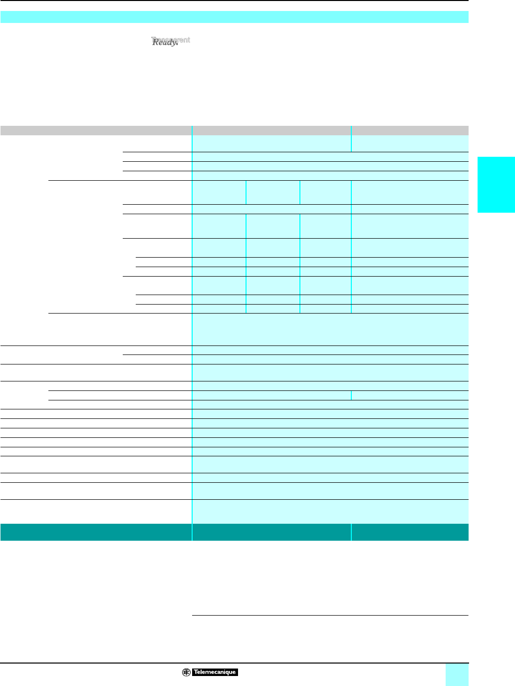
3/37
3
Product data sheet
(continued)
Ethernet
in Machines and Installations 0
Ethernet TCP/IP, Transparent Ready® Services
Cabling system: ConneXium™ managed switches
(1) With TCS EAA F1LFU00 fiber optic module to be ordered separately, see page 3/27.
(2) With TCS EAA F1LFH00 fiber optic module to be ordered separately, see page 3/27.
(3) With TCS EAA F1LFS00 fiber optic module to be ordered separately, see page 3/27.
Characteristics and references: 8 ports and 2 Gigabit ports, twisted pair, fiber optic
Switches Copper twisted pair and fiber optic, managed Copper twisted pair, managed
Interfaces Copper cable ports Number and type 8 x 10/100BASE-TX ports 8 x 10/100BASE-TX ports and
2 x 10/100/1000BASE-TX ports (Gigabit)
Shielded connectors RJ45
Medium Shielded twisted pair, category CAT 5E
Total length of pair
100 m
Gigabit ports
fiber optic
(with SFP fiber module to
be mounted on SFP
connector)
Number and type 2 x
1000BASE-SX
ports (1)
2 x
1000BASE-LH
ports (2)
2 x
1000BASE-LX
ports (3)
–
Connectors LC –
Medium Multimode
optical fiber
Single mode
optical fiber
Single mode
and multimode
optical fiber
–
Length of optical fiber
50/125 µm fiber 550 m – 550 m –
62.2/125 µm fiber 275 m – 550 m –
9/125 µm fiber – 8 -72,000 m 20,000 m –
Attenuation analysis
50/125 µm fiber 7.5 dB –11 dB –
62.2/125 µm fiber 7.5 dB –11 dB –
9/125 µm fiber –6 - 22 dB 11 dB –
Ethernet services FDR, SMTP V3, SNTP client, multicast filtering for optimization of the Global Data protocol,
configuration via Web access
VLAN, IGMP Snooping, RSTP (Rapid Scanning Tree Protocol), priority port, data stream
control, secure port
Topology Number of switches Cascaded Unlimited
Redundant in a ring max. 50
Redundancy Redundant power supplies, redundant single ring, ring coupling
Power supply Voltage Operation 9.6...60 V c/18…30 V a, safety extra low voltage (SELV)
Power consumption 8.9 W + 1 W per SFP fiber module 8.3 W
Removable connector 6-pin
Operating temperature 0…+ 60 °C
Relative humidity 10… 90% non-condensing
Degree of protection IP 20
Dimensions W x H x D 111 x 131 x 111 mm
Mounting On symmetrical DIN rail, 35 mm wide
Weight 0.410 kg
Conformity to standards cUL 60950, UL 508 and CSA 142, UL 1604 and CSA 213 Class 1 Division 2, e, GL
LED indicators Power supply status, alarm relay status, active redundancy, redundancy management,
fiber port status and fiber port activity
Alarm relay Power supply fault, Ethernet network fault or communication port fault (1 A max. voltage-free
contact at 24 V c)
Reference TCS ESM 103F2LG0 TCS ESM 103F23G0
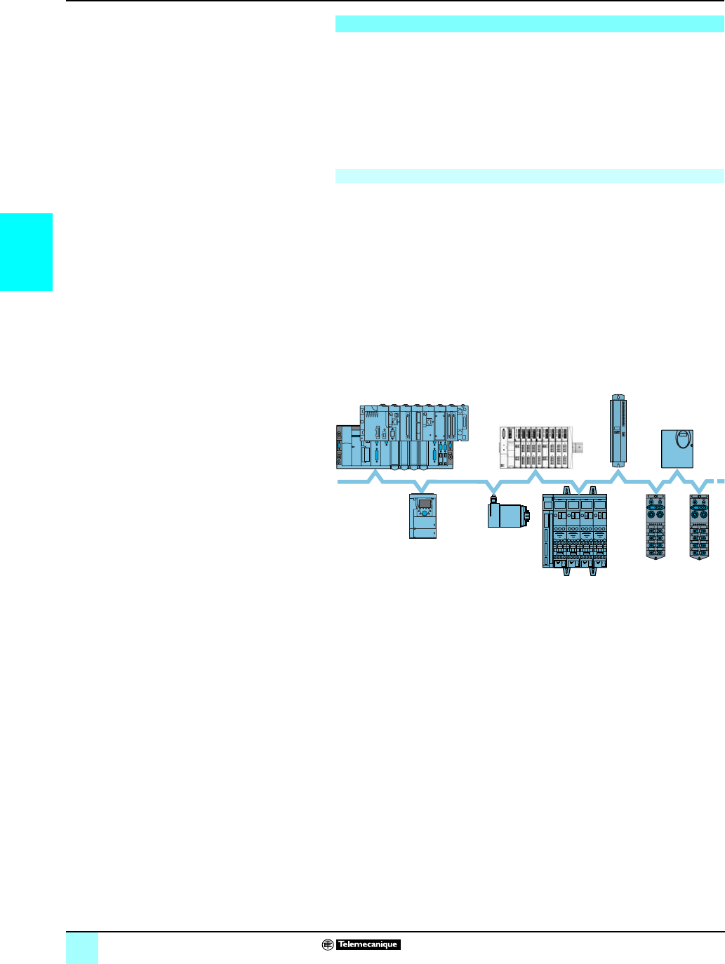
3/38
3
Presentation Modicon®M340™ Automation
Platform 0
CANopen machine and installation bus
Schneider Electric has selected CANopen for its machines and installations because
of its wealth of functions and its resulting benefits in the automation world. This
decision was based on the general acceptance of CANopen, and the fact that
CANopen products are increasingly used in control system architectures.
CANopen is an open network supported by more than 400 companies worldwide,
and promoted by CAN in Automation (CiA). CANopen conforms to standards
EN 50325-4 and ISO 15745-2.
Schneider Electric is heavily involved in working groups, which are important for
machine and installation architectures, systems, and products.
CAN in Automation and Modbus-IDA have worked together to create a standard that
ensures total transparency between CANopen and Modbus TCP/IP. The result of
this collaboration has been the CiA DSP309-2 specification, defining communication
standards between a Modbus TCP/IP network and a CANopen bus.
The specification defines mapping services enabling CANopen devices to
communicate with a Modbus TCP/IP network through a gateway. The data in a
CANopen device can be accessed in both read and write mode.
This specification is the first standard available for developing an open standard
communication between Modbus TCP/IP and CANopen. It is driving Schneider
Electric network solutions toward better integration, diagnostics and configuration of
distributed applications. It allows machines and installations to be connected to an
Ethernet network continuously, while combining the advantages of each network in
its specific area.
The CANopen bus is a multi-master bus ensuring reliable, deterministic access to
real-time data in control system devices. The CSMA/CA protocol is based on
broadcast exchanges, sent cyclically or on an event, to ensure optimum use of the
passband. A message handling channel can also be used to define slave
parameters.
The bus uses a double twisted pair on which, with the Modicon M340 platform,
63 devices maximum are connected by daisy-chaining or by tap junctions. The
variable data rate between 20 Kbit/s and 1 Mbit/s depends on the length of the bus
(between 20 m and 2,500 m).
Each end of the bus must be fitted with a line terminator.
The CANopen bus is a set of profiles on CAN systems, possessing the following
characteristics:
bOpen bus system
bData exchanges in real time without overloading the protocol
bModular design allowing modification of size
bInterconnection and interchangeability of devices
bStandardized configuration of networks
bAccess to all device parameters
bSynchronization and circulation of data from cyclic and/or event-controlled
processes (short system response time)
Presentation
CANopen brings transparency to Ethernet
FTB 1CN FTB 1CN
TeSys Quickfit with
TeSys D
Osicoder
ATV 71
1 to 127
slaves
Premium
Modicon M340
CANopen bus
Advantys STB
Lexium 15
Lexium 05,
ATV 31
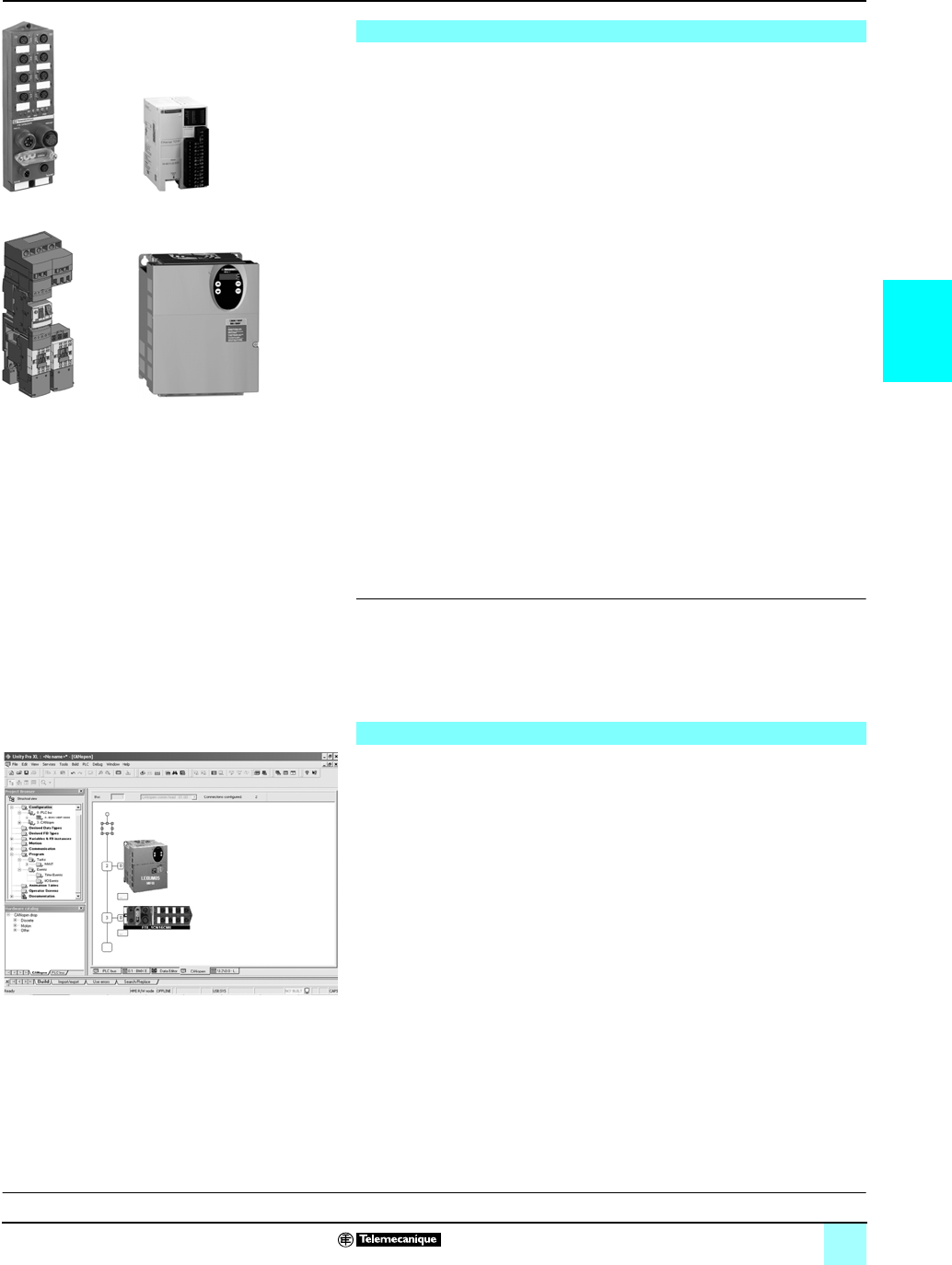
3/39
3
Connectable devices Modicon®M340™ Automation
Platform 0
CANopen machine and installation bus
The Modicon M340 automation platform, via its BMX P34 2010/2030 processors with
integrated CANopen link, performs the role of master on the machine bus.
The following Telemecanique® devices can be connected to the CANopen bus:
v Ø 58 mm Osicoder multi-turn absolute encoders:
- XCC 3510P/3515C S84CB, version u 1.0
v TeSy s®U starter-controllers:
- with LUL C08 communication module, version u 1.2
v TeSy s®D motor-starters, using the TeSys® Quickfit installation help system:
- with APP 1CCO0/O2 communication module, version u 1.0
v Advantys™ OTB IP 20 Optimum distributed I/O system (I/O extension modules not
permitted):
- with OTB 1C0 DM9LP interface module, version u 2.0
v Advantys™ STB IP 20 modular distributed I/O system:
- with NIM module STB NCO 1010, version u 1.0 or STB NCO 2212, version u 2.02
v Advantys™ FTB IP 67 monobloc I/O splitter boxes:
- FTB 1CNppppp, version u 1.7
v Preventa™ configurable safety controllers:
- XPS MC16ZC/32ZC, version u 1.10
v Altivar®31 adjustable speed drives for asynchronous motors 0.18…15 kW:
- AT V 31 H ppppp, version u 1.1 (1)
v Altivar® 71/61 adjustable speed drives for asynchronous motors 0.75…630 kW:
- ATV 61H /71H ppppp, version u 1.1 (1)
v Lexium® 05 servo drives (0.4...6 kW) for BSH servo motors:
- LXM 05ApDpppp, version u 1.120 (2)
v Lexium® 15 servo drives (0.9...42.5 kW) for BDH or BSH servo motors:
- LXM 15Lp, version u 1.45 (3)
- LXM 15MD/15HC, version u 6.64 (4)
v IcLA® intelligent compact motor-drives from Berger Lahr® (a company of
Schneider Electric®):
- IFA 6p, version u 1.105 (5)
- IFE 71, version u 1.104 (5)
- IFS 6p/9p, version u 1.107 (5)
(1) Requires the PowerSuite™ software workshop VW3A8104, version
u
2.00.
(2) Requires the PowerSuite™ software workshop for Lexium 05 servo drive VW3 A8 104,
version 2.2.0 patch V2.2.0B.
(3) Requires the Unilink® software, version
u
1.5.
(4) Requires the Unilink® software, version
u
4.0.
(5) Requires the IclA® Easy software, version
u
1.104.
Configuration of the CANopen bus on the Modicon M340 platform is fully integrated
in the Unity Pro software. From the Unity Pro graphic editor, simply select the
devices available in the catalog and assign them their CANopen slave address.
Exchanges between the CANopen bus and the Modicon M340 processor can be
assigned by configuration to the fast or master task.
Predefined profiles or functions are used to create the user interface automatically
using process variables (PDO), in such a way that any subsequent modification to
the mapping of these variables will have no impact on their topological addressing.
Depending on the devices, dedicated configuration screens are used to assign the
initial parameters.
The dedicated screens are available for CANopen specialists who wish to optimize
the performance of the CANopen bus or re-assign the Process Data Objects (PDO)
differently.
Acyclical access to the Service Data Object (SDO) corresponding to any CANopen
object of a particular device is possible from the application using the standard
communication functions READ_VAR and WRITE_VAR, or even from the Unity Pro
diagnostic screens.
These screens can be used to display the bus status graphically, as well as to access
the diagnostics sent by a faulty device with a single click of the mouse.
Connectable devices
Setup via Unity Pro™ Software
Advantys FTB
Altivar 31
TeSys Quickfit
Example of devices that can be connected on CANopen
Advantys OTB
Example of Unity Pro configuration screen for Lexium® 05 servo
drive and Advantys FTB IP 67 I/O splitter box
Presentation:
page 3/38
Characteristics:
page 3/40
References:
page 3/41
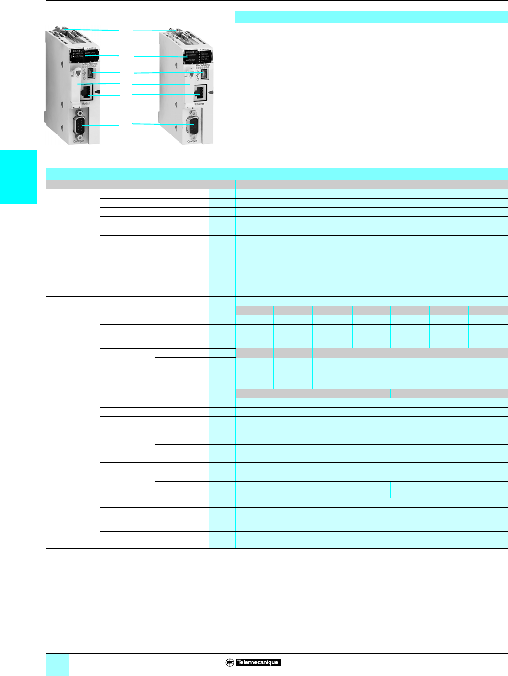
3/40
3
Description,
characteristics
Modicon®M340™ Automation
Platform 0
CANopen machine and installation bus
Both of the Performance processors on the Modicon M340 platform, BMX P34 2010
and BMX P34 2030, have an integrated CANopen communication port. They have
the following on the front panel:
1Securing screw for locking the module in its slot (marked 0) in the rack
2A display block comprising at least:
v CAN RUN LED (green): Integrated machine/installation bus operational
v CAN ERR LED (red): Integrated machine/installation bus faulty
3A mini B USB connector for a programming terminal
4A slot equipped with Flash memory card for backing up the application
5An RJ45 connector for serial link (with BMX P34 2010 model) or Ethernet TCP/IP
port (with BMX P34 2030 model)
6A 9-pin SUB-D connector for the CANopen Master machine and installation bus
(1) For more information, please refer to the “Machines & Installations with industrial
communications” catalog.
(2) Deduct 15 m per repeater from the length of the bus.
(3) For other restrictions, please refer to the CANopen hardware setup manual available on our
website (www.telemecanique.com).
(4) With the use of TSX CAN C
p
50/100/300 CANopen cables and TSX CAN C
p
DD03/1/3/5
preformed cord sets.
Description
2
3
5
1
4
6
BMX P34 2010 BMX P34 2030
Characteristics (1)
Type of bus CANopen
CANopen
services
Conformity class M20
Standard DS 301 V 04.02, 303-2
Device profile DS 405
Special –
Structure Physical interface 9-pin male SUB-D
Topology Devices connected by daisy-chaining and/or tap junctions
Access method CSMA/CA, carrier sense consumer/producer principle, collision detection and arbitration of
message priorities
Application layer Messages carrying objects: process data (PDO), service data (SDO), network management
(NMT), special functions (SYNC, EMCY, TIME)
Transmission Data rate 20 Kbit/s…1 Mbit/s depending on bus length
Medium Double shielded twisted pair
CANopen
physical
configuration
(1)
No. of slave devices 63 maximum
Data rate 1 Mbit/s 800 Kbit/s 500 Kbit/s 250 Kbit/s 125 Kbit/s 50 Kbit/s 20 Kbit/s
Maximum length of bus (2) m20 40 100 250 500 1000 2500
Maximum length of tap-offs on one
tap junction (3)
m0.6 610 10 10 120 300
Limitation per
segment
No. of devices 64 32 16
Maximum length
of segment (4)
m160 185 205
Modicon M340
processor
BMX P34 2010 BMX P34 2030
No. of racks 1 (4, 6, 8 or 12 slots)
Maximum no. of slots 12 for processor and modules (excluding power supply module)
Maximum no. in
rack
Discrete I/O 1,024; 704 in single-rack configuration (64 I/O x 11)
Analog I/O 256; 66 in single-rack configuration (4I/2Q x 11)
Process control Programmable loops (via CONT-CTL process control EFB library)
Counting 36 channels
Motion Independent axes on CANopen bus (via MFB library)
Integrated
connections
Ethernet TCP/IP –1 RJ45 port, 10/100 Mbit/s
CANopen bus 1 master (9-pin SUB-D)
Serial link 1 RJ45 port, Modbus® master/slave or character
mode
–
USB port 1 port, 12 Mbit/s
Communication
module
Ethernet TCP/IP 1 RJ45 port, 10/100 Mbit/s with Transparent Ready:
- class B30 standard Web server with BMX NOE 0100 module
- class C30 configurable Web server with BMX NOE 0110 module
Internal RAM capacity Kb 4,096 including 3,584 for the program, constants and symbols and 256 for data
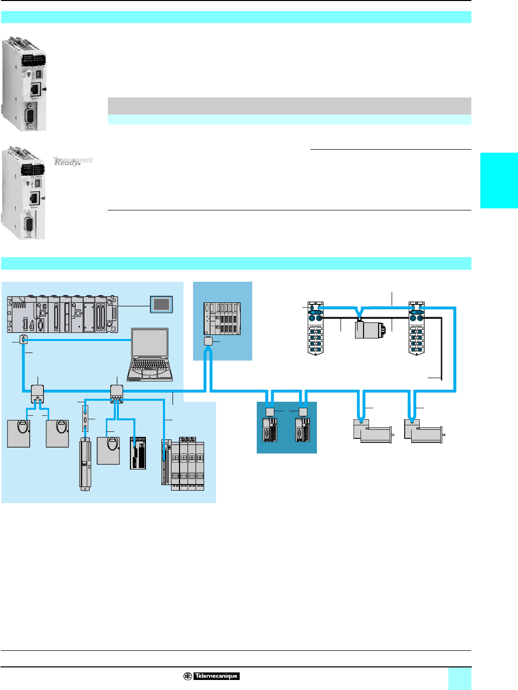
3/41
3
References Modicon®M340™ Automation
Platform 0
CANopen machine and installation bus
Modicon M340 processor modules are supplied with the BMX RMS 008MP Flash
memory card. This card performs the following actions transparently:
v Backing up the application (program, symbols and constants) supported in the
processor internal RAM that is not backed up
v Activation of the Transparent Ready® standard web server, class B10 (with
BMX P34 2030 processor)
This card can be replaced by another card featuring a file storage option
(see page 1/9).
(1) For I/O capacity in single-rack configuration, see characteristics, page 1/8
Note : For numbers and references 1, 2, ..., 17, see pages 3/42 and 3/43.
Different types of cable are available making it possible to create any type of
application, including for harsh environments (for a definition of standard and harsh
environments, see page 3/42).
Several connectors are available to meet any requirement: straight or 90° angled
connectors, or angled connectors with the option of connecting a PC or diagnostic
pocket PC.
Power can be supplied to the equipment by means of cables, cord sets and tap
junctions: one 24 AWG pair for the CAN signals, one 22 AWG pair for the power
supply and the ground.
In addition to the offering for IP 20 wiring, there is also an offering for IP 67 wiring.
Modicon® M340™ Performance processors with integrated CANopen bus link
BMX P34 2010
BMX P34 2030
I/O capacity (1) Memory
capacity
Max. no. of network
modules
Integrated
communication ports
Reference
(3)
Weight
kg
Performance BMX P340 20, 1 rack
1,024 discrete I/O
256 analog I/O
36 app-sp. channels
4,096 Kb
integrated
1 Ethernet TCP/IP
network
CANopen bus
Modbus® serial link
BMXP342010 –
CANopen bus
Ethernet TCP/IP
network
BMXP342030 –
CANopen bus wiring system
Presentation:
page 3/38
Description:
page 3/40
Characteristics:
page 3/40
9
10
2
575
4
17
1616
13
2
1
6b
14
6a
6a
12
5
ATV 31 ATV 71
Lexium 15
Preventa
safety
controller
TeSys Quickfit
Advantys OTB
Advantys STB
Modicon M340 with
BMX P34 2010/2030 processor
Magelis
XBT GT
PC or monitoring
tool
Advantys FTB
24 V c
IcLA
Advantys FTB
Osicoder
Lexium 05
3/42
3
References Modicon® M340™ Automation
Platform 0
CANopen machine and installation bus
Wiring system
Standard tap junctions and connectors
Designation Description No.
(1)
Length Reference Weight
kg
IP 20 CANopen tap
junction
4 SUB-D ports. Screw terminal block for
connection of trunk cables
Line termination
1–TSXCANTDM4 0.196
IP 20 connectors
CANopen female 9-pin
SUB-D.
Switch for line
termination
90° angled 2–TSXCANKCDF90T 0.046
Straight (2) ––TSXCANKCDF180T 0.049
90° angled with 9-pin SUB-D for connecting a PC
or diagnostic tool
4–TSXCANKCDF90TP 0.051
IP 67 M12 connectors Male ––FTXCN12M5 0.050
Female ––FTXCN12F5 0.050
IP 20 CANopen tap
junctions for Altivar
and Lexium 05 drives
2 RJ45 ports 9–VW3CANTAP2 –
IP 20 standard cables and preformed cord sets
Designation Description No.
(1)
Length Unit
reference
Weight
kg
CANopen cables
(24 AWG)
Standard, e marking: low smoke. Halogen-free.
Flame-retardant (IEC 60332-1)
550 m TSXCANCA50 4.930
100 m TSXCANCA100 8.800
300 m TSXCANCA300 24.560
Standard, UL certification, e marking:
flame-retardant (IEC 60332-2)
550 m TSXCANCB50 3.580
100 m TSXCANCB100 7.840
300 m TSXCANCB300 21.870
For harsh environments (3) or mobile installation,
e marking: low smoke. Halogen-free.
Flame-retardant (IEC 60332-1). Resistance to
oils
550 m TSXCANCD50 3.510
100 m TSXCANCD100 7.770
300 m TSXCANCD300 21.700
CANopen preformed
cord sets
One 9-pin female
SUB-D connector at
each end
(24 AWG )
Standard, e marking: low smoke. Halogen-free.
Flame-retardant (IEC 60332-1)
6a 0.3 m TSXCANCADD03 0.091
1 m TSXCANCADD1 0.143
3 m TSXCANCADD3 0.295
5 m TSXCANCADD5 0.440
Standard, UL certification, e marking:
flame-retardant (IEC 60332-2)
6a 0.3 m TSXCANCBDD03 0.086
1 m TSXCANCBDD1 0.131
3 m TSXCANCBDD3 0.268
5 m TSXCANCBDD5 0.400
CANopen preformed
cord sets
One 9-pin SUB-D
connector,
One RJ45 connector
(24 AWG )
Standard, e marking: low smoke. Halogen-free.
Flame-retardant (IEC 60332-1)
6b 0.5 m TCSCCE4F3M05 –
1 m TCSCCE4F3M1 –
Standard, UL certification, e marking:
flame-retardant (IEC 60332-2)
6b 0.5 m TCSCCU4F3M05 –
1 m TCSCCU4F3M1 –
CANopen preformed
cord sets
Two 9-pin SUB-D connectors, one male and
one female
–0.5 m TLACDCBA005 –
1.5 m TLACDCBA015 –
3 m TLACDCBA030 –
5 m TLACDCBA050 –
IP 67 standard preformed cord sets
Designation Description No.
(1)
Length Unit
reference
Weight
kg
CANopen preformed
cord sets
Preformed cord sets of two 5-pin M12 A-coded
angled connectors (one male connector and one
female connector)
12 0.3 m FTXCN3203 0.40
0.6 m FTXCN3206 0.70
1 m FTXCN3210 0.100
2 m FTXCN3220 0.160
3 m FTXCN3230 0.220
5 m FTXCN3250 0.430
Preformed cord sets with one 5-pin female M12
A-coded connector at one end and wires at the
other end
73 m FTXCN3130 –
5 m FTXCN3150 –
(1) For numbers, see page 3/41
(2) For connection to the Controller Inside programmable card, the VW3 CAN KCDF 180T connector can also be used.
(3) Standard environment:
-- Without any particular environmental constraints
-- Operating temperature between +5 °C and +60 °C
-- Fixed installation
Harsh environment:
-- Resistance to hydrocarbons, industrial oils, detergents, solder splashes
-- Relative humidity up to 100%
-- Saline atmosphere
-- Significant temperature variations
-- Operating temperature between -10 °C and +70 °C
-- Mobile installation
TSX CAN KCD F90T
TSX CAN KCD F180T
TSX CAN KCD F90TP
TSX CAN TDM4
VW3 CAN TAP2

3/43
3
References (continued) Modicon® M340™ Automation
Platform 0
CANopen machine and installation bus
Wiring system
(1) For numbers, see page 3/41.
(2) For ATV 71HpppM3, ATV 71HD11M3X, HD15M3X, ATV 71H075N4... HD18N4 drives, this
connector can be replaced by the TSXCANKCDF180T connector.
IP 20 connection accessories
Designation Description No.
(1)
Length Unit
reference
Weight
kg
CANopen connector
for Altivar 71 drive (2)
9-pin female SUB-D. Switch for line termination.
Cables exit at 180°
––VW3CANKCDF180T –
Adapter for Altivar 71
drive
CANopen adapter SUB-D to RJ45 ––VW3CANA71 –
Preformed CANopen
cord sets for Altivar
and Lexium 05 drives
One RJ45 connector at each end 10 0.3 m VW3CANCARR03 –
1 m VW3CANCARR1 –
CANopen bus
adapter for Lexium 15
servo drive
Hardware interface for a link conforming to the
CANopen standard + one connector for a PC
terminal
14 –AM02CA001V000 0.110
Y-connector CANopen/Modbus ––TCSCTN011M11F –
IP 67 connection accessories
For Advantys™ FTB monobloc I/O splitter boxes
Designation Composition No.
(1)
Length
m
Reference Weight
kg
IP 67 line terminator Equipped with one M12 connector
(for end of bus)
13 –FTXCNTL12 0.010
24 V c power supply
connection cables
Equipped with two 5-pin 7/8 connectors 16 0.6 FTXDP2206 0.150
1 FTXDP2210 0.190
2 FTXDP2220 0.310
5 FTXDP2250 0.750
Equipped with one 5-pin 7/8 connector at one end
and wires at the other end
17 1.5 FTXDP2115 0.240
3 FTXDP2130 0.430
5 FTXDP2150 0.700
T-junction box
for power supply
Equipped with two 5-pin 7/8 connectors ––FTXCNCT1 0,100
Separate parts
Designation Composition Sold in Reference Weigh
t
kg
Connectors 7/8 type, 5-pin Male – FTXC78M5 0.050
Female – FTXC78F5 0.050
Straight, M12 type, 5 screw terminals Male – XZCC12MDM50B 0.020
Female – XZCC12FDM50B 0.020
Angled, M12 type, 5 screw terminals Male – XZCC12MCM50B 0.020
Female – XZCC12FCM50B 0.020
Sealing plugs For M8 connector (sold in packs of 10) – FTXCM08B 0.100
For M12 connector
(sold in packs of 10)
–FTXCM12B 0.100
For 7/8 connector – FTXC78B 0.020
Y-connector Connection of two M8 connectors to M12 connector on
splitter box
–FTXCY1208 0.020
Connection of two M12 connectors to M12 connector on
splitter box
–FTXCY1212 0.030
Diagnostics adapter Equipped with two M12 connectors – FTXDG12 0.020
Marker labels For plastic splitter boxes Packs of 10 FTXBLA10 0.010
For metal splitter boxes Packs of 10 FTXMLA10 0.010
FTX DP21pp
FTX CY1208
VW3 CAN A71
AM0 2CA 001V000
XZ CC12pDM50B
XZ CC12pCM50B
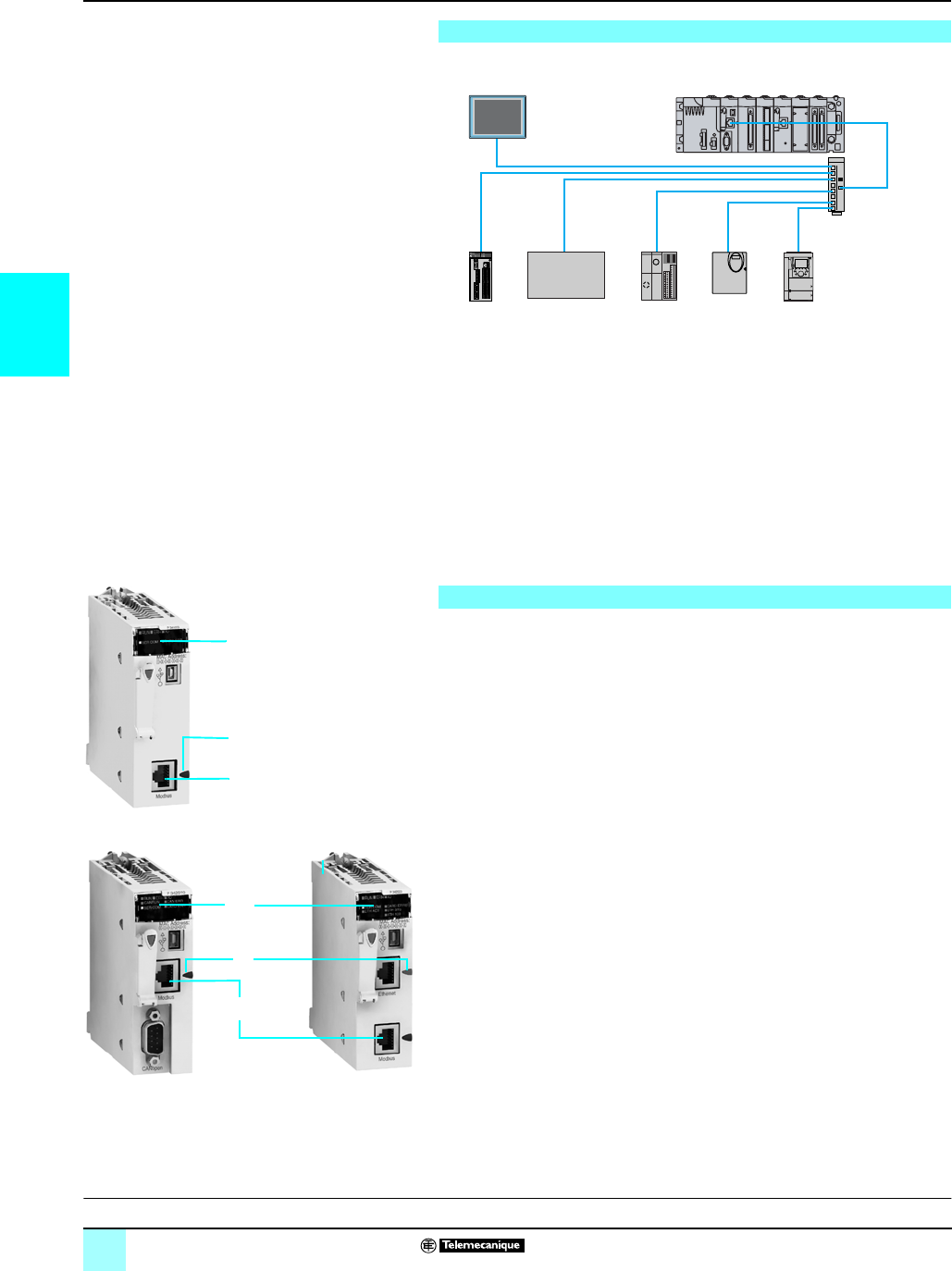
3/44
3
Presentation,
description
Modicon®M340™ Automation
Platform 0
Modbus® serial link and character mode
The Modbus bus is used for master/slave architectures (it is necessary, however,
to check that the Modbus services used by the application are implemented on the
devices concerned).
The bus comprises one master station and several slave stations. Only the master
station can initiate the exchange (direct communication between slave stations is not
possible). Two exchange mechanisms are possible:
bQuestion/answer, where the requests from the master are addressed to a given
slave. The master then waits for the response from the slave.
bBroadcasting, where the master broadcasts a message to all the slave stations on
the bus. These stations execute the order without transmitting a response.
The BMX P34 1000 / 2010 / 2020 processors in the Modicon M340 automation
platform range integrate a serial link that can operate under Modbus master/slave
RTU/ASCII protocol or under character mode protocol.
For this serial port, these processors have the following on the front panel :
1A display block comprising among other LEDs:
v SER COM LED (yellow): Activity on the Modbus serial link (lit) or failure on an
equipment present on the link (flashing).
2An RJ45 connector for the Modbus serial link or character mode link
(RS 232C/RS 485, non-isolated) and its black indicator 3.
Note : For complete processors descriptions, see page 1/5
Presentation
Description
Twido Lexium 05 Altivar 71
Modbus
3rd party product
Preventa
XPS MC
Modbus serial link
Modicon M340 Magelis XBT
2
1
1
2
BMX P34 1000
BMX P34 2010 BMX P34 2000
3
3
Characteristics:
page 3/45
References:
page 3/45
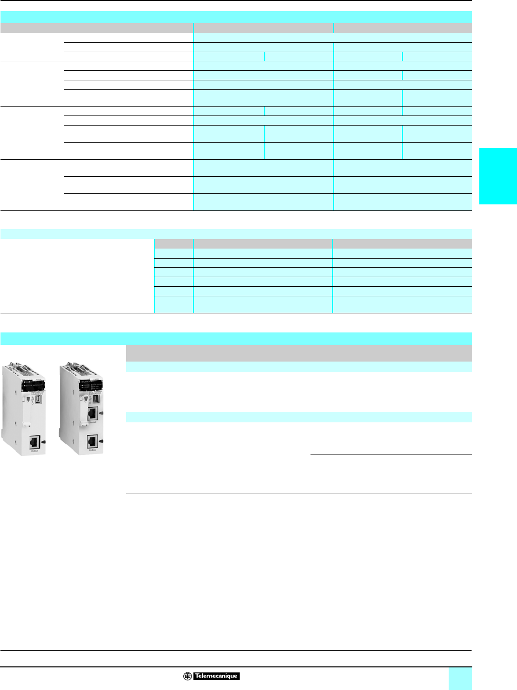
3/45
3
Characteristics,
references
Modicon®M340™ Automation
Platform 0
Modbus® serial link and character mode
(1) For an isolated link, you must use the TWD XCA ISO terminal port cable connector.
Serial link cabling system, see pages 3/46 and 3/47.
Characteristics
Protocol Modbus Character mode
Structure Type Non-isolated serial link (1)
Method of access Master/slave type –
Physical Interface RS 232, 2 wires RS 485, 2 wires RS 232, 4 wires RS 485, 2 wires
Transmission Mode Asynchronous in baseband Asynchronous in baseband
Frame RTU/ASCII, Half duplex Full duplex Half duplex
Data rate 0.3...19.2 Kbit/s (default 19.2 Kbit/s) 0.3...19.2 Kbit/s (default 19.2 Kbit/s)
Medium Shielded twisted pair Simple or double
shielded twisted pair
Shielded twisted pair
Configuration Number of devices 2 (point-to-point) 32 max. per segment 2 (point-to-point) 32 max. per segment
Maximum number of link addresses 248 248
Maximum length of bus 15 m 10 m non-isolated link
1000 m isolated link
15 m 10 m non-isolated link
1000 m isolated link
Maximum length of tap links –15 m non-isolated link
40 m isolated link
–15 m non-isolated link
40 m isolated link
Services Requests 252 data bytes per RTU request
504 data bytes per ASCII request
1 K data bytes per request
Security, control parameters One CRC on each frame (RTU)
One LRC on each frame (ASCII)
One LRC on each frame (ASCII)
Monitoring Diagnostic counters, event counters –
Modbus® system functions
Modbus functions available on serial ports
integrated to Modicon M340 processors
Code Modbus slave (server) Modbus master (client)
01 Read n output bits Read output bits
02 Read n input bits Read input bits
03 Read n output words Read words
04 Read n input words Read input words
15 Write n output bits Write n output bits
16 Write n output words Write n output words
References
I/O capacity (1) Memory capacity Integrated
communication ports
Reference
(3)
Weight
kg
Standard processor with integrated serial link BMX P340 10
512 discrete I/O
128 E/S analog I/O
20 application-
specific channels
2,048 Kb integrated Modbus serial link BMXP341000 0.200
Performance processors with integrated serial link BMX P340 20
1024 discrete I/O
256 E/S analog I/O
36 application-
specific channels
4,096 Kb integrated Modbus serial link
CANopen bus
BMXP342010 0.210
Modbus serial link
Ethernet TCP/IP
network
BMXP342020 0.205
BMX P34 1000 BMX P34 2020
Description:
pages 3/45
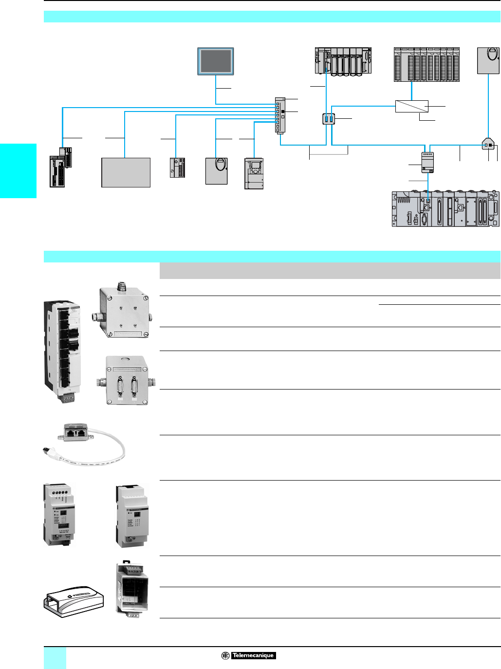
3/46
3
Connections Modicon®M340™ Automation
Platform 0
Modbus® serial link and character mode
Cabling system
(1) Polarized termination requires connection to Twido® controller master.
(2) 24 V
c
power supply, external, or through the serial port integrated in Modicon M340
processors.
Cabling system
1
7
8
7
4
3
9
5
212
10
12
RS 232C
RS 485
11
6
7
9
c 24 V
Modbus serial link
3rd party
Modbus
product
Twido Lexium 05 ATV 71
Modicon Premium Modicon Quantum ATV 31
Modbus RS 232C
Modicon M340
Magelis XBT
Advantys OTB
Preventa XPS MC
Extension and adaptation elements for RS 485 serial link
Designation Description Reference Length Unit
reference
Weight
kg
Modbus splitter box - 10 x RJ45 connectors
- 1 x screw terminal block
1–LU9GC3 0.500
T-junction boxes - 2 x RJ45 connectors
- 1 x integrated cable with RJ45
connector
Dedicated for Altivar and Lexium drives
20.3 m VW3A8306TF03 0.190
1 m VW3A8306TF10 0.210
Passive T-junction box - Tap-off point, extension of trunk cable
- Line termination adapter
––TSXSCA50 0.520
Passive 2-channel
subscriber socket, 2 x
15-pin female SUB-D
connectors and 2 x
screw terminals
- 2-channel tap-off point and extension
of trunk cable
- Address coding
- Line termination adapter
3–TSXSCA62 0.570
T-junction box
Screw terminals for main
cable.
1 x RJ45 connector for
derivation
- Insulation of the RS 485 serial line
- Line termination adaptation
(R = 120 Ω, C = 1 nF)
- Line pre-polarized (2 x R = 620 Ω) (1)
24 Vc power (2)
Mounting on 735 mm
4–TWDXCAISO 0.100
T-junction box
3 x RJ45 connectors
- Line termination adaptation
(R = 120 Ω, C = 1 nF)
- Line pre-polarized (2 x R = 620 Ω) (1)
Mounting on 735 mm
––TWDXCAT3RJ 0.080
Modbus / Bluetooth®
adapter
-1 x Bluetooth
® adapter (10 m range,
class 2) with 1 x RJ45 connector,
- 1 x 0.1 m long cord set for
PowerSuite™ software with 2 x RJ45
connectors,
- 1 x 0.1 m long cord set for
TwidoSuite™ software with 1 x RJ45
connector and 1 x mini-DIN connector,
- 1 x RJ45/SUB-D male 9-pin adapter
for ATV speed drives
––VW3 A8114 0.155
RS 232C/RS 485 line
adapter without modem
signals
24 Vc/20 mA power supply,
19.2 kbit/s
Mounting on 735 mm
5–XGSZ24 0.100
Line terminator For RJ45 connector
(R = 120 Ω, C = 1 nF)
12 Sold in lots
of 2
VW3A8306RC 0.200
LU9 GC3
TSX SCA 50
TSX SCA 62
XGS Z24
TWD XCA ISO TWD XCA T3RJ
VW3A8306TFpp
VW3A8114

3/47
3
References Modicon®M340™ Automation
Platform 0
Modbus® serial link and character mode
Cables and connecting cord sets for RS 485 serial link
Designation Description Reference Length Unit
reference
Weight
kg
RS 485 double
shielded twisted pair
trunk cables
Modbus serial link, supplied without
connector
6100 m TSXCSA100 5.680
200 m TSXCSA200 10.920
500 m TSXCSA500 30.000
Modbus RS 485 cables 2 x RJ45 connectors 70.3 m VW3A8306R03 0.030
1 m VW3A8306R10 0.050
3 m VW3A8306R30 0.150
1 x RJ45 connector and
1 x 15-pin SUB-D connector
–3 m VW3A8306 0.150
1 x mini-DIN connector for Twido®
controller and 1 x RJ45 connector
40.3 m TWDXCARJ003 0.040
1 m TWDXCARJ010 0.090
3 m TWDXCARJ030 0.16
1 x RJ45 connector and
1 end with wires
53 m VW3A8306D30 0.150
1 x miniature connector and
1 x 15-pin SUB-D connector
93 m TSXSCPCM4530 0.180
Cord sets for
Magelis XBT
display and terminal
1 x RJ45 connector and
1 x 25-pin SUB-D connector for:
- XBT N200/N400/NU400
- XBT R410/411
- XBT GT2...GT7 (COM1 port) (1)
11 2.5 m XBTZ938 0.210
2 x RJ45 connectors for :
-XBTGT1 (COM1 port)
- XBT GT2...GT7 (COM2 port)
11 3 m VW3A8306R30 0.150
Connecting cord sets for RS 232 serial link
Designation Description Reference Length Unit
reference
Weight
kg
Cord set for Data
Terminal Equipment
(DTE: printer…)
Serial link for Data Terminal Equipment
(DTE) (2)
1 x RJ45 connector and
1 x 9-pin SUB-D female connector
–3 m TCSMCN3M4F3C2 0.150
Cord set for Data
Communication
Equipment
(DCE: modem,
converter…)
Serial link for point-to-point equipment
(DCE)
1 x RJ45 connector and
1 x 9-pin SUB-D male connector
–3 m TCSMCN3M4M3S2 0.150
(1) Must be associated with an XBT ZG909 adapter.
(2) If the DTE is equipped with a 25-pin SUB-D connector, additionally order the
25-pin female / 9-pin male SUB-D TSX CTC 07 adapter.

04/0
4

4/1
4
Contents 4 - Unity™ software
1
Unity™ software
bUnity Pro™ programming software
vPresentation, setup . . . . . . . . . . . . . . . . . . . . . . . . . . . . . . . . . . . . . . . . . . . . 4/4
vSoftware structure . . . . . . . . . . . . . . . . . . . . . . . . . . . . . . . . . . . . . . . . . . . . . 4/9
v5 IEC languages . . . . . . . . . . . . . . . . . . . . . . . . . . . . . . . . . . . . . . . . . . . . . 4/12
vFunctions . . . . . . . . . . . . . . . . . . . . . . . . . . . . . . . . . . . . . . . . . . . . . . . . . . . 4/18
vReferences . . . . . . . . . . . . . . . . . . . . . . . . . . . . . . . . . . . . . . . . . . . . . . . . . 4/29
bUnity EFB Toolkit software . . . . . . . . . . . . . . . . . . . . . . . . . . . . . . . . . . . . . . . 4/32
bUnity SFC View software. . . . . . . . . . . . . . . . . . . . . . . . . . . . . . . . . . . . . . . . . 4/34
bUnity Loader software . . . . . . . . . . . . . . . . . . . . . . . . . . . . . . . . . . . . . . . . . . . 4/36
bUnity Application Generator. . . . . . . . . . . . . . . . . . . . . . . . . . . . . . . . . . . . . . . 4/40

4/2
4
Selection guide Modicon® M340™ Automation
Platform 0
Unity™ software
Unity Pro™ programming software for:
- Modicon M340 M
-Premium
™ PLC P, Atrium™ PLC A
- Quantum™ PLC Q
IEC 61131-3
languages
Instruction List (IL) MM - A - P M - A - P - Q M - A - P - Q
Ladder (LD) MM - A - P M - A - P - Q M - A - P - Q
Structured Text (ST) MM - A - P M - A - P - Q M - A - P - Q
Function Block Diagram (FBD) MM - A - P M - A - P - Q M - A - P - Q
Sequential Function Chart (SFC)/Grafcet MM - A - P M - A - P - Q M - A - P - Q
Programming
services
Multitask programming (Master, fast and
event-triggered)
MM - A - P M - A - P - Q M - A - P - Q
Multitask programming (Master, fast,
auxiliary and event-triggered)
P (TSX P57 5p)
Q (140 CPU 651/671)
Functional view and function modules MM - A - P M - A - P - Q M - A - P - Q
DFB editor and DFB instances MM - A - P M - A - P - Q M - A - P - Q
DDT compound data editor MM - A - P M - A - P - Q M - A - P - Q
Data structure instances and tables MM - A - P M - A - P - Q M - A - P - Q
EF function block libraries & EFB function
blocks
MM - A - P M - A - P - Q M - A - P - Q
User-definable control loops A (TSX PCI 2p) -
P (TSX P57 2p)
A (TSX PCI 20p) -
P (TSX P57 2p/3p/4p)
P
(TSX P57 2p/3p/4p/5p)
Programmable control loops (FB library) MM - A - P M - A - P - Q M - A - P - Q
Motion Function Blocks MM - A - P M - A - P M - A - P
Hot Standby PLC redundancy system P (TSX H57 24M) P (TSX H57 24/44M) P (TSX H57 24/44M) -
Q (140 CPU 67 160)
System diagnostics MM - A - P M - A - P - Q M - A - P - Q
Application diagnostics MM - A - P M - A - P - Q M - A - P - Q
Diagnostics with location of error source MM - A - P M - A - P - Q M - A - P - Q
Debugging and
display
services
PLC simulator MM - A - P M - A - P - Q M - A - P - Q
Hypertext link animations in graphic
languages
MM - A - P M - A - P - Q M - A - P - Q
Step by step execution, breakpoint MM - A - P M - A - P - Q M - A - P - Q
Watchpoint MM - A - P M - A - P - Q M - A - P - Q
Operator screens MM - A - P M - A - P - Q M - A - P - Q
Diagnostic viewer MM - A - P M - A - P - Q M - A - P - Q
Other services Creation of hyperlinks MM - A - P M - A - P - Q M - A - P - Q
XML import/export MM - A - P M - A - P - Q M - A - P - Q
Application converters (Concept™, and PL7™
software)
M - A - P M - A - P - Q M - A - P - Q
Utilities for updating PLC operating systems MM - A - P M - A - P - Q M - A - P - Q
Communication drivers for
Windows®2000/XP
MM - A - P M - A - P - Q M - A - P - Q
Unity Pro™ Servers - openness - M - A - P - Q
UDE support
OFS exchanges
Dynamic exchange with 3rd party tools, OFS M - A - P - Q
Static exchange thru XML/XVM export files MM - A - P M - A - P - Q
Compatible
Modicon
platforms
Modicon M340 PLCs MBMX P34 1000
BMX P34 20p0
BMX P34 1000
BMX P34 20p0
BMX P34 1000
BMX P34 20p0
BMX P34 1000
BMX P34 20p0
Atrium™ slot-PLCs A–TSX PCI 204M TSX PCI 204M
TSX PCI 354M
TSX PCI 204M
TSX PCI 354M
Premium™ CPUs P–
TSX P57 C
p
0244/0244M
TSX P57 104/1634/154M
TSX P57 204/2634/254M
TSX H57 24M
TSX P57 C
p
0244/0244M
TSX P57 104/1634/154M
TSX P57 204/2634/254M
TSX P57 304/3634/354M
TSX P57 4634/454M
TSX H57 24/44M
TSX P57 C
p
0244/0244M
TSX P57 104/1634/154M
TSX P57 204/2634/254M
TSX P57 304/3634/354M
TSX P57 4634/454M
TSX P57 5634/554M
TSX H57 24/44M
Quantum™ CPUs Q––140 CPU 311 10
140 CPU 434 12U
140 CPU 311 10
140 CPU 434 12U
140 CPU 651 50/60
140 CPU 671 60
Software name Unity Pro Small Unity Pro Medium Unity Pro Large Unity Pro Extra Large
Unity Pro™ software type UNY SPU SFp CD30 UNY SPU MFp CD30 UNY SPU LFp CD30 UNY SPU EFp CD30
Pages 4/27

4/3
4
0
EF/EFB function
development software in C
language
Software for firmware and
application loading
Software for designing and
generating batch/process
applications
SFC View application
diagnostic and monitoring
software
Pack for developing specific
solutions
Enhancement of EF and EFB
function block libraries:
vCreation of families
vDevelopment of functions in
C language
vAccess to all data and
variable types
vDebugging functions (step
by step, breakpoint)
vUse of functions created in
all languages
Supplied with:
vMicrosoft® Visual C++
vGNU source code and
compiler
Simple and easy to use
software to upgrade a
Modicon M340 PLC when the
user doesn’t need to
display/modify the program.
Upload/download:
vCPU and Ethernet module
firmware
vPLC project, including:
-Program
- Located and unlocated data
- User files and user web
pages
UAG specialist software for
designing and generating
batch/process applications in a
“Collaborative Automation”
environment. It provides the
unique project database:
vprocess and control (PLCs)
vMagelis® HMI user interface
vSCADA supervision
(Monitor Pro V7.2)
Based around re-usable
objects (PID, valves, etc) and
complying with standard ISA
S88, UAG generates the PLC
code and the elements
required for the HMI system.
Complies with the GAMP
standard (Good Automation
Manufacturing Practice)
ActiveX® control component
for monitoring and diagnostics
of chart status (SFC or Grafcet)
in sequential applications:
vOverview of charts and
detailed views
vCan be integrated in
human/machine interface
(HMI) applications
vAccess to PLC data via OFS
(OPC Factory Server)
Includes EFB function block
library for Unity Pro™ software
(for Premium™, Atrium™ and
Quantum™ CPUs)
Specialist software for
developing made-to-order
solutions (for example
interfaces with an electrical
CAD system, automatic
application generator, etc):
vAccess to Unity Pro™ object
servers
vReserved for IT
development engineers using
Visual Basic or C++
Compatible with:
vUnity Pro™ Small, Medium,
Large and Extra Large
programming software
vAll Modicon M340 PLCs
vAll Atrium™ slot-PLCs
vAll Premium™ Unity™ CPUs
vAll Quantum™ Unity™ CPUs
Compatible with:
vUnity Pro™ Small, Medium,
Large and Extra Large
programming software
vAll Modicon M340 PLCs
Compatible with:
vUnity Pro™Extra Large
programming software
vTSX P57 4634/454M and
TSX P57 5634/554M
Premium™ Unity™ CPUs
vAll Quantum™ Unity™ CPUs
Compatible with:
vUnity Pro™ Extra Large
programming software
vAll Modicon M340 PLCs
vAll Atrium™ slot-PLCs
vAll Premium™ Unity™ CPUs
vAll Quantum™ Unity™ CPUs
Compatible with:
vUnity Pro™ Extra Large
programming software
vAll Modicon M340 PLCs
vAll Atrium™ slot-PLCs
vAll Premium™ Unity™ CPUs
vAll Quantum™ Unity™ CPUs
Unity EFB Toolkit Unity Loader Unity Application Generator Unity SFC View Unity Developer’s Edition
UNY SPU ZFU CD30E UNY SMU ZU CD30 UNY SEW LFp CD23 UNY SDU MFp CD20 UNY UDE VFU CD21E
4/32 4/38 4/40 4/34 4/28
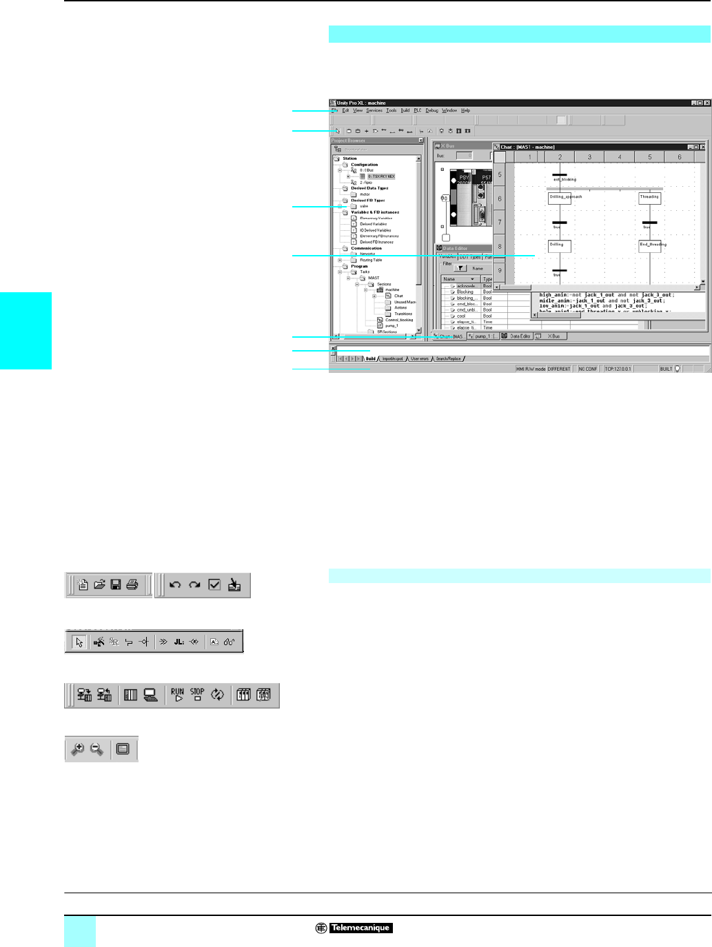
4/4
4
Presentation Modicon® Automation Platform 0
Unity Pro™ software
Unity Pro’s main screen provides access to all available tools in a user-friendly
format that has been redesigned on the basis of feedback received from users of
Concept™ and PL7™ application design software.
This main screen consists of a general view made up of a number of windows and
toolbars, which can be arranged as required on the screen:
1Menu bar from which all functions can be accessed
2Toolbar consisting of icons from which the most frequently used functions can be
accessed
3Application browser, which can be used to browse the application based on a
conventional and/or a functional view
4Editor windows area, which can be used to view a number of editors at the same
time (configuration editor, Structured Text/Ladder etc. language editors, data
editor)
5Tabs for direct access to editor windows
6Information window with tabs (User Errors, Import/Export, Search/Replace, etc.)
7Status bar
All functions can be accessed via drop-down menus from the menu bar. The toolbar,
which consists of icons, provides more rapid access to the most frequently used
functions. This toolbar, which is displayed by default, can be customized, and is
divided into three groups:
bMain toolbars, which are visible at all times
bContextual toolbar, which is displayed when the corresponding editor is selected
bToolbar with zoom functions (in and out), full-screen view for editor window
The three groups are classified according to the category of functions available:
bFile management (New Project, Open, Save, Print)
bEdit (Undo, Redo, Confirm, Go To)
bApplication services (Analyze Project, Build Project, Browse, Find, Access Library)
bAutomation platform operating mode (Upload/Download Project, Online/Offline,
Run/Stop, Animate, PLC/Simulation Mode)
bDebug mode (Set/Remove Breakpoint, etc.)
bWindow display (Cascade, Horizontal, Vertical)
bOnline help (non-contextual or contextual)
User interface
1
2
3
4
5
6
7
Accessing functions
File/Edit toolbar
FBD language editor contextual toolbar
PLC toolbar for debug mode
Toolbar with zoom (in and out)
Setup:
pages 4/5 and 4/8
Structure:
pages 4/9to 4/11
IEC language:
pages 4/12 to 4/17
Functions:
pages 4/18 to 4/28
References:
pages 4/29 and 4/31
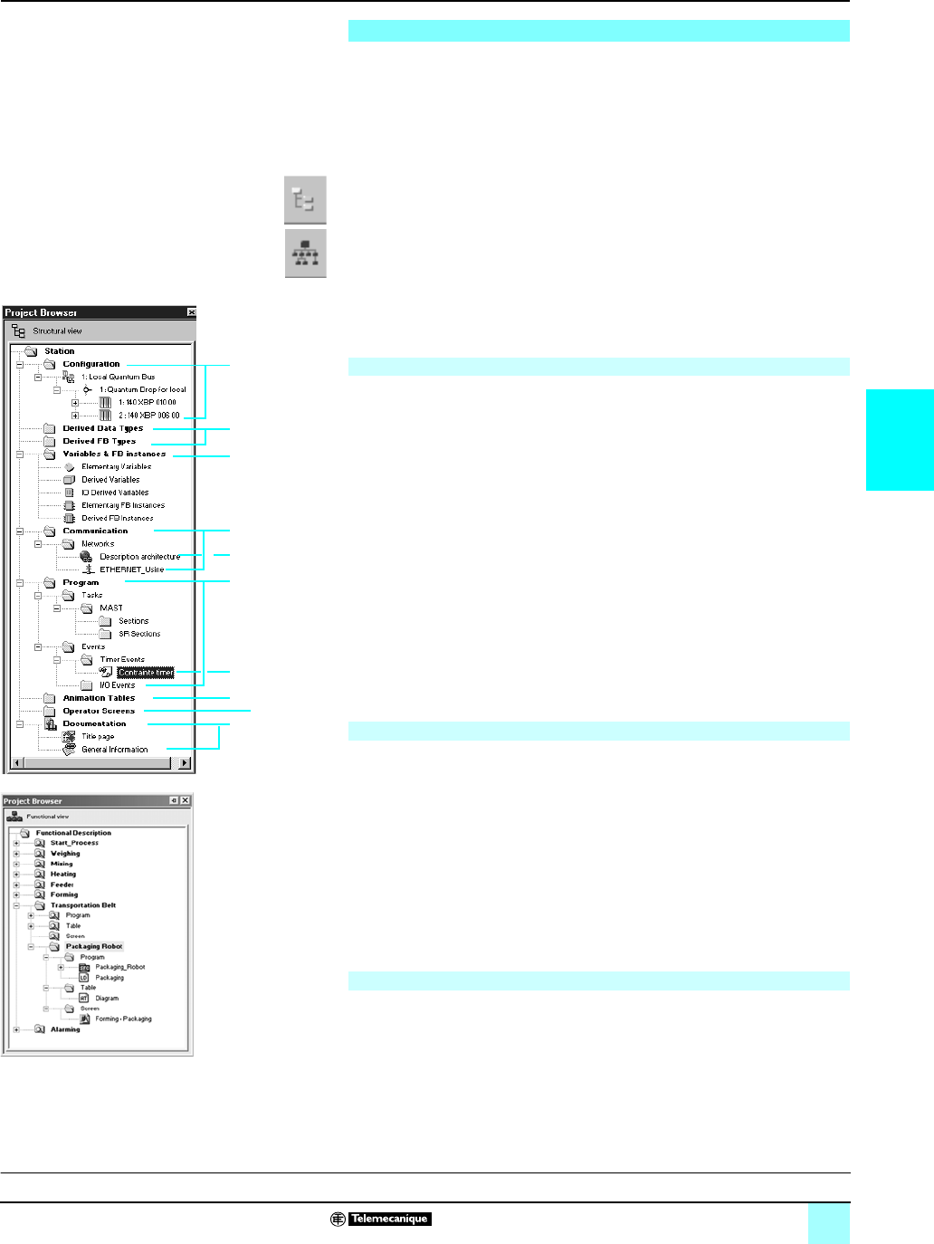
4/5
4
Setup Modicon® Automation Platform 0
Unity Pro™ software
The project browser can be used:
bTo display the contents of a Modicon® M340™, Atrium™, Premium™ or Quantum™
PLC project
bTo move between the different components of the application (configuration,
program, variables, communication, DFB user function blocks, DDT derived function
blocks) created by the user
The project can be displayed using two types of view:
bThe structural view, which provides an overall view of the various components of
the application. This representation provides a view of the order in which the program
sections are processed in the PLC.
bThe functional view, which provides a view of the project based on specific
function modules. This representation provides a breakdown according to consistent
functions in relation to the process to be controlled.
These two types of view, which are available at any time, can be displayed separately
or at the same time (horizontal or vertical windows) by clicking the icons in the
toolbar.
This conventional view allows you to access all the different components of the
application (configuration, programming, function blocks, debugging, etc.) via the
application browser.
The browser gives an overall view of the program and offers fast access to all
application components.
1Configuration editor
2DFB (user function block) and DDT (Derived Data Type) editors
3Communication networks editor
4Program editor
5Variables editor
6Animation tables editor
7Operator screens editor
8Documentation editor
From any level in the tree structure, you can:
9Create a hyperlink to a comment or description
10Create a directory for storing hyperlinks used to access a set of user folders
From this level, it is also possible to zoom in and only view the detailed levels for a
component on this level.
Unity Pro software applications support the creation of an application structure for
Modicon® M340™, Atrium™, Premium™ and Quantum™ platforms based on function
modules comprising:
bSections (program code)
bAnimation tables
bRuntime screens
The designer can define a multi-level tree structure for the application, independently
of the multitask structure of the PLC.
Program sections written in Ladder (LD), Structured Text (ST), Instruction List (IL),
Function Block Diagram (FBD) or Sequential Function Chart (SFC) language can be
associated with each level, along with animation tables and runtime screens.
All or part of the tree structure can be exported as function modules. In this case, all
program sections on the various module levels are exported.
Utilities make it easy to reuse these modules in new applications by means of data
and module name reassignment services.
Project browser
Structural view
Functional view
Exporting/Importing function modules
3
4
9
7
8
Structural view
6
1
2
5
10
Functional view
Presentation:
page 4/4
Structure:
pages 4/9 to 4/11
IEC language:
pages 4/12 to 4/17
Functions:
pages 4/18 to 4/28
References:
pages 4/29 and 4/31
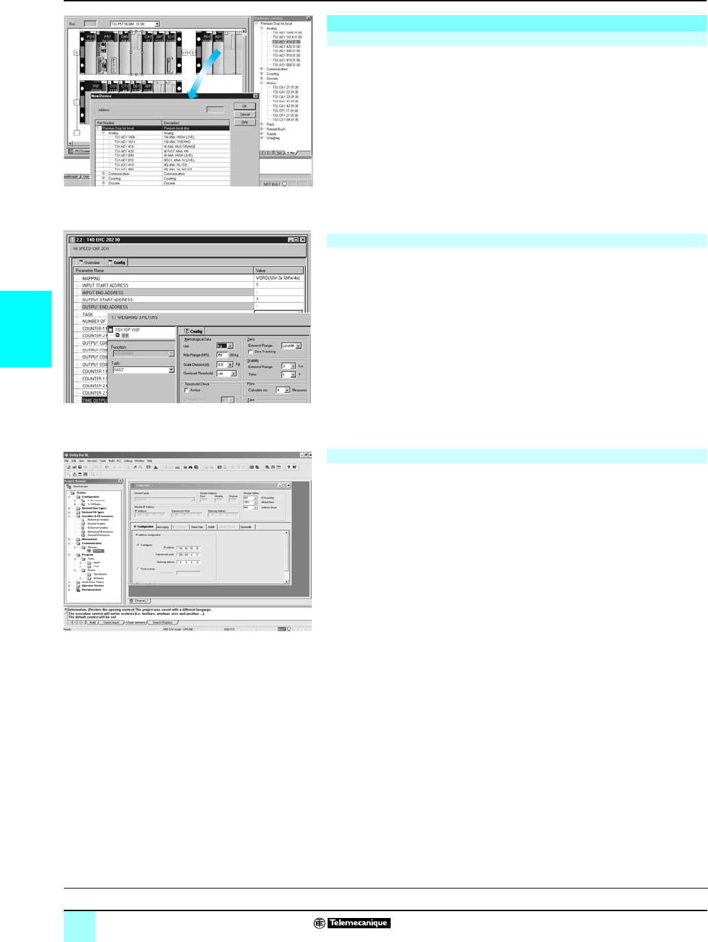
4/6
4
Setup (continued) Modicon® Automation Platform 0
Unity Pro™ software
The first step when creating an automation project based on a Modicon® M340™,
Atrium™, Premium™ or Quantum™ platform is to select the processor for which a rack
and power supply are defined by default.
The configuration editor supports the intuitive and graphics-based modification and
extension of this configuration with the following elements:
bRacks, power supply
bPCMCIA memory or communication cards (Atrium/Premium) on the processor
bDiscrete I/O, analog I/O or application-specific modules
bEtc
From the configuration screen for Modicon M340, Atrium, Premium or Quantum
racks, the parameters screen displayed for the module concerned can be used to
define the operating characteristics and parameters for the selected application, e.g.:
bFilter values for discrete I/O
bVoltage or current range for analog I/O
bThreshold counter values
bTrajectory of axes for position control
bWeigher calibration for weighing
bTransmission speed for communication
bPresymbolization for variables associated with modules
bEtc
The “Communication” folder in the structural view can be used to define the list of
networks connected to the PLC station. Then, the parameters for all elements
required for networks to function correctly can be set by:
bCreating a logical network to which comments can be associated
bConfiguring a logical network defining the various associated network services.
Once the network module has been created in the configuration, it must then be
associated with one of the logical networks.
Ethernet TCP/IP, Modbus Plus™ and Fipway® network modules are all configured in
this way.
Configuration editor
Hardware configuration
Configuration and parameter settings for I/O and application-specific modules
Configuration and parameter settings for communication networks
Hardware configuration
I/O modules parameter setting
Communication folder with 2 networks declared
Presentation:
page 4/4
Structure:
pages 4/9 to 4/11
IEC language:
pages 4/12 to 4/17
Functions:
pages 4/18to 4/28
References:
pages 4/29 and 4/31
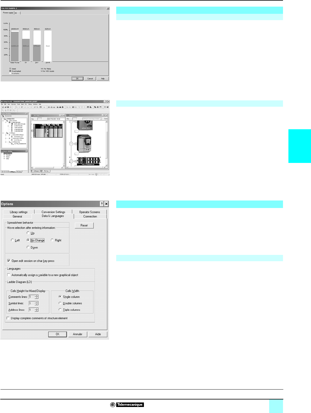
4/7
4
Setup (continued) Modicon® Automation Platform 0
Unity Pro™ software
The following information can be accessed at any time during configuration:
bThe power consumption statistics for the power supply in each of the racks in the
PLC configuration, for all the different voltages provided by each of these power
supplies
bThe number of inputs/outputs configured (with a Modicon M340, Atrium™ or
Premium™ platform)
In the same way as for in-rack modules, the configuration of devices on CANopen
though a Modicon M340 is fully integrated in the configuration editor.
Unity Pro can be used to configure both the working environment (workstation
options) and the content of the project itself.
It is also possible to configure the toolbars and to run third-party applications from
Unity Pro.
In addition, users can choose the working language from the list of languages
selected when the software was installed.
The workstation options cover all the characteristics specific to a given workstation.
They are applied when Unity Pro is used to develop any project on that station.
The following elements can be configured:
v How the data in the project being developed is edited and presented (for example,
whether or not coils are positioned in the last column of the editor, or the position of
the cursor after confirmation of the data entered)
v The application conversion strategy from PL7™, and Concept™ software , IEC and
LL984 language
v The function library path
v The opening mode for Unity Pro: either programming or run mode
Configuration editor (continued)
Configuration check
Configuration of devices on CANopen
Workstation and project configuration
Workstation options
Power supply requirements analysis
Graphical configuration of devices on CANopen bus
“Data & Languages” tab in the workstation options
Presentation:
page 4/4
Structure:
pages 4/9 to 4/11
IEC language:
pages 4/12 to 4/17
Functions:
pages 4/18 to 4/28
References:
pages 4/29 and 4/31
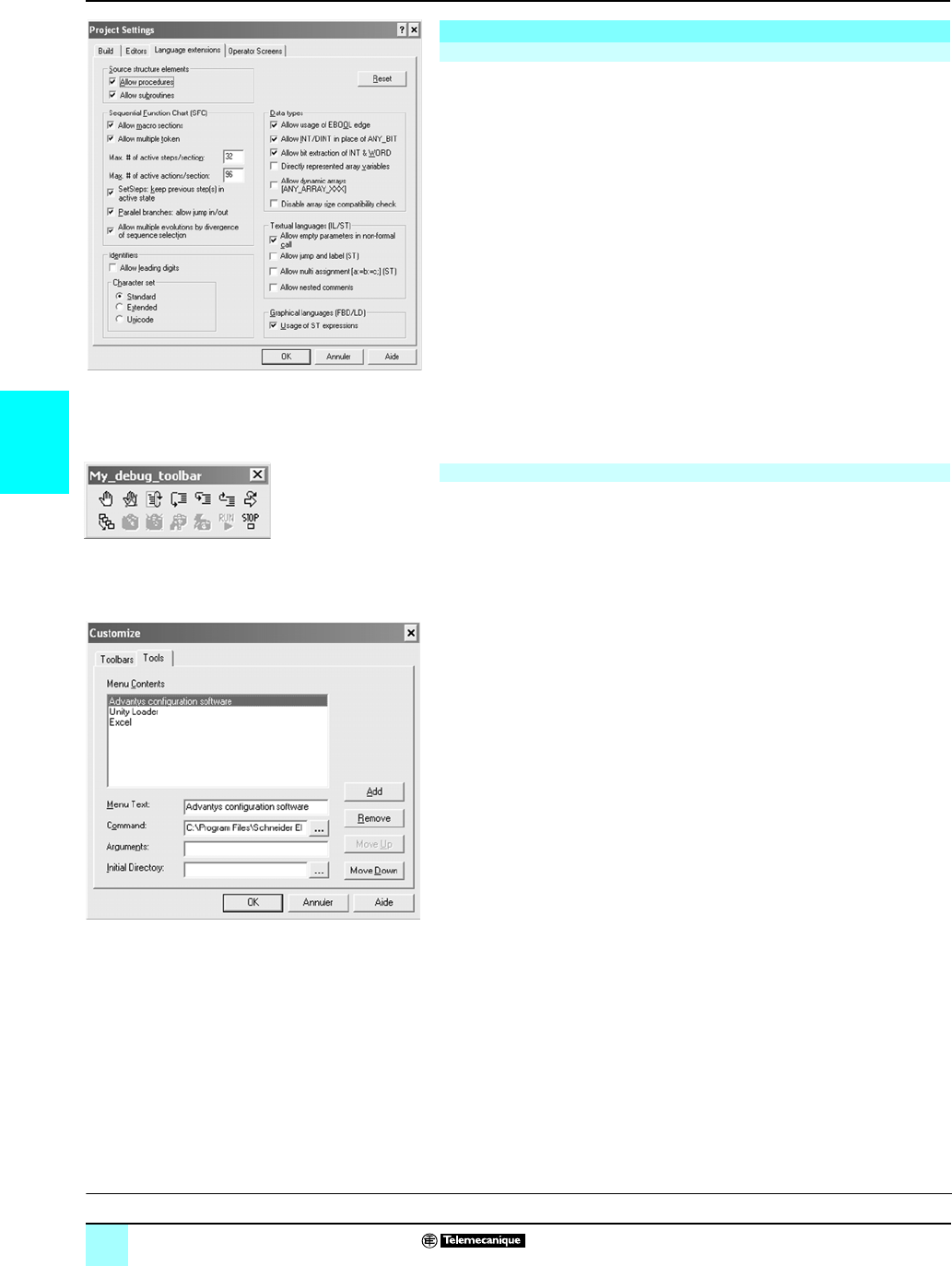
4/8
4
Setup (continued) Modicon® Automation Platform 0
Unity Pro™ software
Unlike the workstation options, the project options cover characteristics that have a
direct impact on the programming and operating capabilities offered by the program
in the PLC. They are saved in the application, and, consequently, are attached to the
project. They can be modified during the course of the project.
Project option configuration covers the following elements:
v Building the project with all or part of the data it contains so that it can be retrieved
on a new terminal
v Use of diagnostic functions, and language for messages
v Warnings generated during project analysis: overlapping of addresses, unused
variables etc.
v Language extension: If none of the boxes are checked, the program is strictly
compliant with standard IEC 61131-3. Extensions are possible in all five of
Unity Pro's languages.
v Access management to runtime screens in online mode
Users can create their own toolbars by reusing the default icons provided in the
toolbars.
It is also possible to enhance Unity Pro's main menu bar by adding direct links to
other software tools.
A utility in the Unity Pro program group can be used to change the working language.
This is then applied the next time the program is launched. Six languages are
available: English, French, German, Italian, Spanish and Chinese.
Workstation and project configuration (continued)
Project options
Other possible options
“Build” tab in the workstation options
User-created toolbar
containing all the debugging tools
Menu for adding and deleting tool access from Unity Pro
Presentation:
page 4/4
Structure:
pages 4/9 to 4/11
IEC language:
pages 4/12 to 4/17
Functions:
pages 4/18 to 4/28
References:
pages 4/29 and 4/31
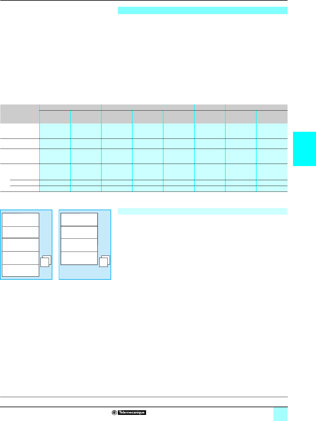
4/9
4
Software structure Modicon® Automation Platform 0
Unity Pro™ software
The Modicon M340, Atrium™, Premium™ and Quantum™ platforms set up by Unity
Pro software support two types of application structure:
bSingle-task: This is the more simple default structure, in which only the master
task is executed.
bMultitask: This structure, which is more suitable for high-performance real-time
events, consists of a master task, a fast task, periodic tasks, and high-priority
event-triggered tasks.
The master, fast and periodic tasks are made up of sections and subroutines. The
sections and subroutines can be programmed in any of the following languages:
Structured Text (ST), Instruction List (IL), Ladder (LD) or Function Block Diagram
(FBD). The event-triggered tasks use the same languages. Sequential Function
Chart (SFC) or Grafcet language is reserved for master task sections.
The table below lists the possible program tasks for Modicon M340, Atrium, Premium
and Quantum PLCs respectively.
The tasks of a Unity Pro program for Modicon M340, Atrium, Premium™ or
Quantum™ platforms are composed of several parts known as sections and
subroutines. Each of these sections can be programmed in the most appropriate
language for the process to be executed.
Such division into sections enables a structured program to be created and program
modules to be generated or added with ease.
Subroutines can be called from any section of the task to which they belong or from
other subroutines in the same task.
Compatibility of languages compliant with IEC standard 61131-3: Unity Pro
software can be configured (Tools/Project Settings/Language Extensions menu) to
ensure that applications generated are compliant with IEC standard 61131-3.
Furthermore, as long as you use only the standard instruction libraries, you will be
able to reuse programs created in this way on any Modicon M340, Atrium, Premium,
or Quantum platform.
Software structure
Platform Modicon M340 Premium Atrium Quantum
BMX P34 1000 BMX P34 20p0TSX P 57 Cp 244M
TSX P 57 0244M
TSX P 57 1p4M
TSX P 57 2p(3)4M
TSX P 57 3p(3)4M
TSX P 57 4p(3)4M
TSX P 57 554M
TSX P 57 5634M
TSX PCI 57 204 M
TSX PCI 57 454 M
140 CPU 31110
140 CPU 434 12U
140 CPU 651 p0
140 CPU 671 60
Cyclic or periodic
master task
Yes Yes Yes Yes Yes Yes Yes Yes
Periodic fast task Yes Yes Yes Yes Yes Yes Yes Yes
Periodic auxiliary
tasks
––––4––4
Event-triggered
tasks
From modules 32 64 32 64 128 64 64 128
From timers 32 64 ––32 –16 32
Total 32 64 32 64 128 64 64 128
Structure, modular and portable programming
Airlock (LD)
Oven_1 (SFC)
Tunnel_1 (SFC)
Extractor (FBD)
Cleaning (ST)
Airlock_Alarm (LD)
Mon_Sec (LD)
Oven_Alarm (ST)
Cleaning_Alarm (ST)
SR0 SR0
Master task Fast task
Presentation:
page 4/4
Setup:
pages 4/5 to 4/8
IEC language:
pages 4/12 to 4/17
Functions:
pages 4/18 to 4/28
References:
pages 4/29 and 4/31
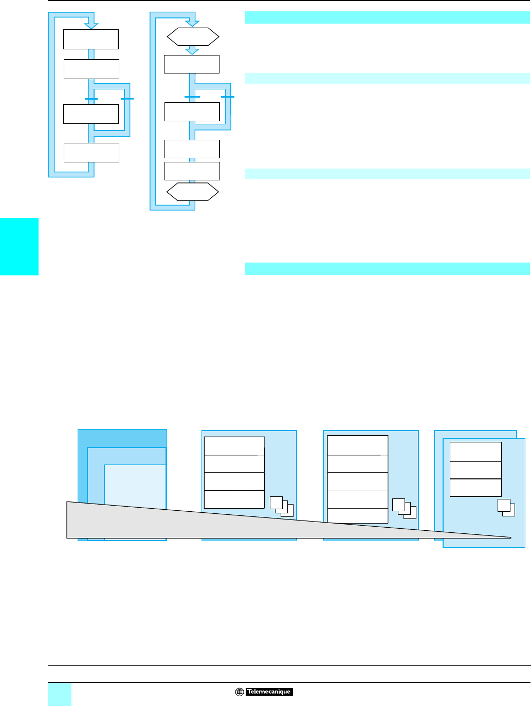
4/10
4
Memory structure (continued) Modicon® Automation Platform 0
Unity Pro™ software
Two types of cyclic execution are supported:
bNormal cyclic execution. This is the default option.
bPeriodic execution. This type of execution, as well as the period, are selected by
the user during programming when the task parameters are set (master task).
At the end of each scan, the PLC system launches a new scan. The execution time
of each scan is monitored by a software watchdog whose value is defined by the user
(max. 1500 ms).
In the event of overrun, a fault occurs causing:
bThe scan to stop immediately (STOP)
bA fault state to be displayed on the front panel of the processor
bThe alarm relay for the main rack power supply to be set to 0
A new scan is executed at the end of each period. The execution time of the scan
must be less than the time of the period defined (max. 255 ms). In the event of
overrun, the latter is stored in a system bit (%S19), which can be reset to 0 by the
user (via the program or terminal).
A software watchdog, which can be configured by the user (max. 1500 ms), monitors
the scan time. In the event of overrun, an execution fault is indicated (see normal
execution). The scan execution times (the last scan, the longest scan and the
shortest scan) are stored in system words %SW 30/31/32.
Modicon® M340™, Atrium™, Premium™ and Quantum™ platforms support a multitask
structure comprising:
b1 master task (divided into several sections programmed in ST, IL, LD, FBD, and
SFC languages)
b1 fast task (divided into sections)
b0 to 4 auxiliary tasks (divided into sections) (1)
b1 or more event-triggered tasks (only one section per task)
These tasks are independent and are executed in parallel, with the PLC processor
managing their execution priority. When an event occurs, or at the start of the fast
task scan:
bIf any lower-priority tasks are currently being executed, they are suspended.
bThe event-triggered task or fast task is executed.
bThe interrupted task resumes once execution of the priority task has been
completed.
This structure optimizes the way in which processing power is employed and can be
used to structure the application and simplify design and debugging, as each task
can be written and debugged independently of the others.
(1) Tasks reserved for top-of-the-range Premium TSX P57 5
p
4M and Quantum
140 CPU 651
p
0/67160 processors.
Single-task memory structure
Normal execution (cyclic)
Periodic execution
Multitask software structure
Cyclic execution
Internal processing
Input acquisition
(%I)
Updating of outputs
(%O)
Program processing
RUN STOP
Periodic execution
Program
processing
Updating of outputs
(%O)
Internal processing
End of period
Input acquisition
(%I)
Start of
period
STOPRUN
Event-triggered tasks Fast task Master task Auxiliary tasks (1)
Timer_1
EVT1
EVT0
Outside limits
Airlock_Alarm (IL)
Mon_Dry (LD)
Oven_Alarm (ST)
Cleaning_Alarm (ST)
Airlock (LD)
Oven_1 (SFC)
Tunnel_1 (SFC)
Extractor (FBD)
Drying (LD)
SR0SR0
Fast Mast
Aux1
Aux0
Process value
(FBD)
Oven Diag (ST)
Temp. (FBD)
SR0
Priority +…-
Presentation:
page 4/4
Software structure:
pages 4/9 to 4/11
IEC language:
pages 4/12 to 4/17
Functions:
pages 4/18 to 4/28
References:
pages 4/29 and 4/31
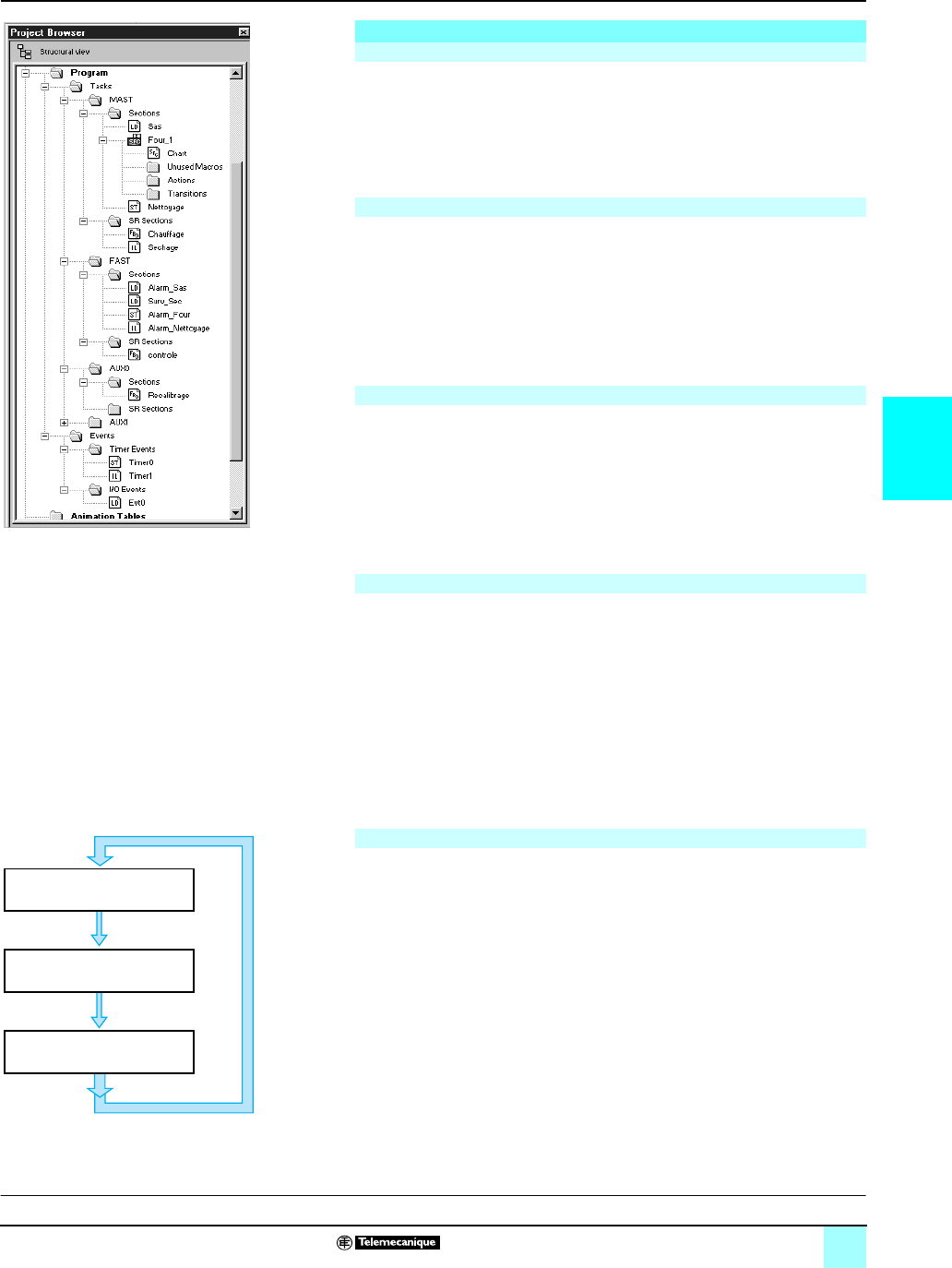
4/11
4
Memory structure (continued) Modicon® Automation Platform 0
Unity Pro™ software
This task, which can be periodic or cyclic, executes the main program. It is activated
systematically.
Each of its component sections and subroutines can be programmed in Ladder (LD),
Function Block Diagram (FBD), Structured Text (ST) or Instruction List (IL) language.
Several sections of the master task can be programmed in Sequential Function Chart
(SFC) or Grafcet language.
This task, which has a higher priority than the master task, is periodic to allow time
for tasks with lower priorities to be executed. It should be used when fast periodic
changes in discrete inputs need to be monitored and acknowledged.
The execution of the master task (lower priority) is suspended while the fast task is
being executed. Processing operations in this task must be as short as possible, to
avoid adversely affecting master task processing operations.
Each of the component sections and subroutines of the fast task can be programmed
in Instruction List, Structured Text, Ladder or Function Block Diagram language (ST,
IL, LD or FBD).
These tasks, which are available on top-of-the-range Premium™ TSX P57 5p4M and
Quantum™ 140 CPU 651 p0/67160 processors, are designed for use with slower
types of processing operation such as measurement, process control, HMI,
application diagnostics, etc.
Periodic type auxiliary tasks have the lowest level of priority and are executed once
the higher-priority periodic tasks (master and fast) have completed their scan.
Each of the component sections and subroutines of the fast task can be programmed
in Instruction List, Structured Text, Ladder or Function Block Diagram language (ST,
IL, LD or FBD).
Unlike the tasks described above, these tasks are not linked to one period. The
execution of these tasks is triggered asynchronously by:
An event from certain application-specific modules (e.g.: overrun of a counter
threshold, change of state of a discrete input)
An event from the event timers
These tasks are processed before all other tasks and are thus suitable for processing
requiring very short reaction times in comparison to the arrival of the event.
Modicon®M340™, Atrium™, Premium™ or Quantum™ platforms have 3 levels of
priority (these are, in descending order, module event EVT0, module events EVTi
and timer events Timeri).
These tasks, each comprised of a single section, can be programmed in Instruction
List, Structured Text, Ladder or Function Block Diagram language (ST, IL, LD or
FBD).
Each of the master, fast or event-triggered tasks reads (at the start of the scan) and
writes (at the end of the scan) the inputs assigned to it. By default, they are assigned
to the master task.
For the Quantum™ platform, the remote inputs/outputs (RIO) are only assigned to the
master task (these assignments can be made per station or for each of the
component sections of the task), while the distributed inputs/outputs (DIO) are all
assigned to the master task (without assignment to its component sections).
For event-triggered tasks, it is possible to assign input/output channels (1) other than
those relating to the event. Exchanges are then performed implicitly at the start of
processing for inputs and at the end of processing for outputs.
(1) These channel assignments are made per I/O module for Quantum PLC and per channel for
Atrium/Premium PLC inputs/outputs.
Multitask memory structure (continued)
Master task
Fast task
Auxiliary tasks
Event-triggered tasks
Assignment of I/O channels to tasks
Application browser
Input acquisition
Program processing
Updating of outputs
Program execution
Presentation:
page 4/4
Setup:
pages 4/5 and 4/6
IEC language:
pages 4/10 to 4/15
Functions:
pages 4/16 to 4/26
References:
pages 4/26 and 4/27

4/12
4
IEC language Modicon® Automation Platform 0
Unity Pro™ software
The five graphical or textual languages available in Unity Pro are used for
programming Modicon® M340™, Atrium™, Premium™ and Quantum™ automation
platforms.
The 3 graphical languages are:
bLadder (LD)
bFunction Block Diagram (FBD)
bSequential Function Chart (SFC) or Grafcet
The 2 textual languages are:
bStructured Text (ST)
bInstruction List (IL)
For these 5 languages, you can use the standard set of instructions compliant with
IEC standard 61131-3 to create applications, which can be transferred from one
platform to another. Unity Pro software also provides extensions to this standard set
of instructions. When they are specific to Modicon M340, Atrium/Premium and
Quantum™ PLCs, these extensions support the development of more complex
applications in order to maximize the potential of the specific features of each of
these platforms.
The editors for each of the 5 languages provide a number of common tools used for
writing, reading and analyzing programs in a user-friendly manner:
bThe text editors for Instruction List (IL) and Structured Text (ST) support:
v Text entry in insert or overwrite mode
v The use of dialog boxes for the assisted entry of variables, functions, function
blocks or assignment instructions
v Checks on data entry to detect syntax or semantics errors. The user is informed of
the result of this check by red wavy underlining or by a change in the color of the text
concerned.
v Access to a set of colors, which can be used to facilitate reading by distinguishing
text (black) from operators (red), language key words (blue), and program comments
(green)
bThe graphics editors for Ladder (LD) language, Function Block Diagram (FBD)
language and Sequential Function Chart (SFC) language feature:
v A set of graphic elements for direct access to the various graphic symbols in the
language via the mouse or keyboard
v A pop-up menu, which can be accessed by right-clicking with the mouse
bUnlimited number and length of comments. These comments can be positioned as
text objects in any cell (graphical languages) or at any point in expressions (textual
languages).
bAssisted data entry functions for:
v Accessing DFB function libraries, the variables editor or the text object for entering
comments
v Initializing a variable reference
v Initializing the animation table on selected variables
v Displaying and modifying the properties of the selected variable
v Creating variables in real time without having to use the data editor
bCut, Copy, Paste, Delete, Move ...
bSetting bookmarks on lines of text or in the margin so that you can:
v Easily locate lines in important program sections
v Browse in an editor by bookmark, label, or the line and column number
The five IEC languages
Functionality common to all five language editors
Presentation:
page 4/4
Setup:
pages 4/5 to 4/8
Structure:
pages 4/9 to 4/11
Functions:
pages 4/18 to 4/28
References:
pages 4/29 and 4/31
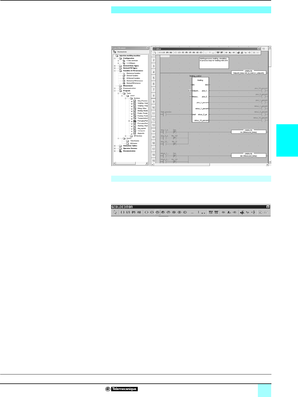
4/13
4
IEC languages (continued) Modicon® Automation Platform 0
Unity Pro™ software
Each section or subroutine using Ladder language consists of a series of rungs,
which are executed sequentially by the PLC. Each rung consists of graphic objects
(placed in cells arranged in columns and lines) corresponding to contacts, links, coils,
operation blocks, EF/EFB/DFB function blocks, jumps, SR calls, etc.
Each Ladder language section may contain:
bBetween 11 and 64 columns (number set by the user)
bUp to 2000 lines (for all rungs in the section)
Graphics palette in the Ladder language editor
Mixed Display mode supports the unrestricted display of comments, addresses and
symbols for the variables used for rungs.
Ladder (LD) language
Program structure (section or subroutine)
Presentation:
page 4/4
Setup:
pages 4/5 to 4/8
Structure:
pages 4/9 to 4/11
Functions:
pages /18 to 4/28
References:
pages 4/29 and 4/31
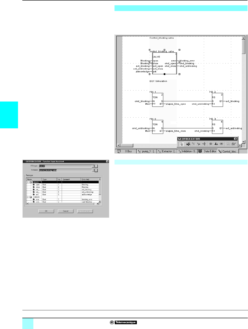
4/14
4
IEC languages (continued) Modicon® Automation Platform 0
Unity Pro™ software
Function Block Diagram language is a graphical language based on function blocks
associated with variables or parameters, which are linked together. This language is
particularly suitable for process control applications.
The graphical language FBD supports three types of function blocks:
bElementary blocks (EFs)
bElementary Function Blocks (EFBs), sorted into different libraries depending on
their type of use
bDerived Function Blocks (DFBs), which have a structure identical to that of EFBs
but are created by the user with the ST, IL, LD or FBD programming languages
Within the same section, subroutines can be called using a specific block. Program
jumps to a block instance can also be programmed.
A section programmed in FBD language contains the equivalent of a default grid with
30 columns and 23 rows. This can be extended to a wider page.
Function Block Diagram (FBD) language
Program structure (section or subroutine)
Function Block Assistant
Presentation:
page 4/4
Setup:
pages 4/5 to 4/8
Structure:
pages 4/9 to 4/11
Functions:
pages 4/18 to 4/28
References:
pages 4/29 and 4/31
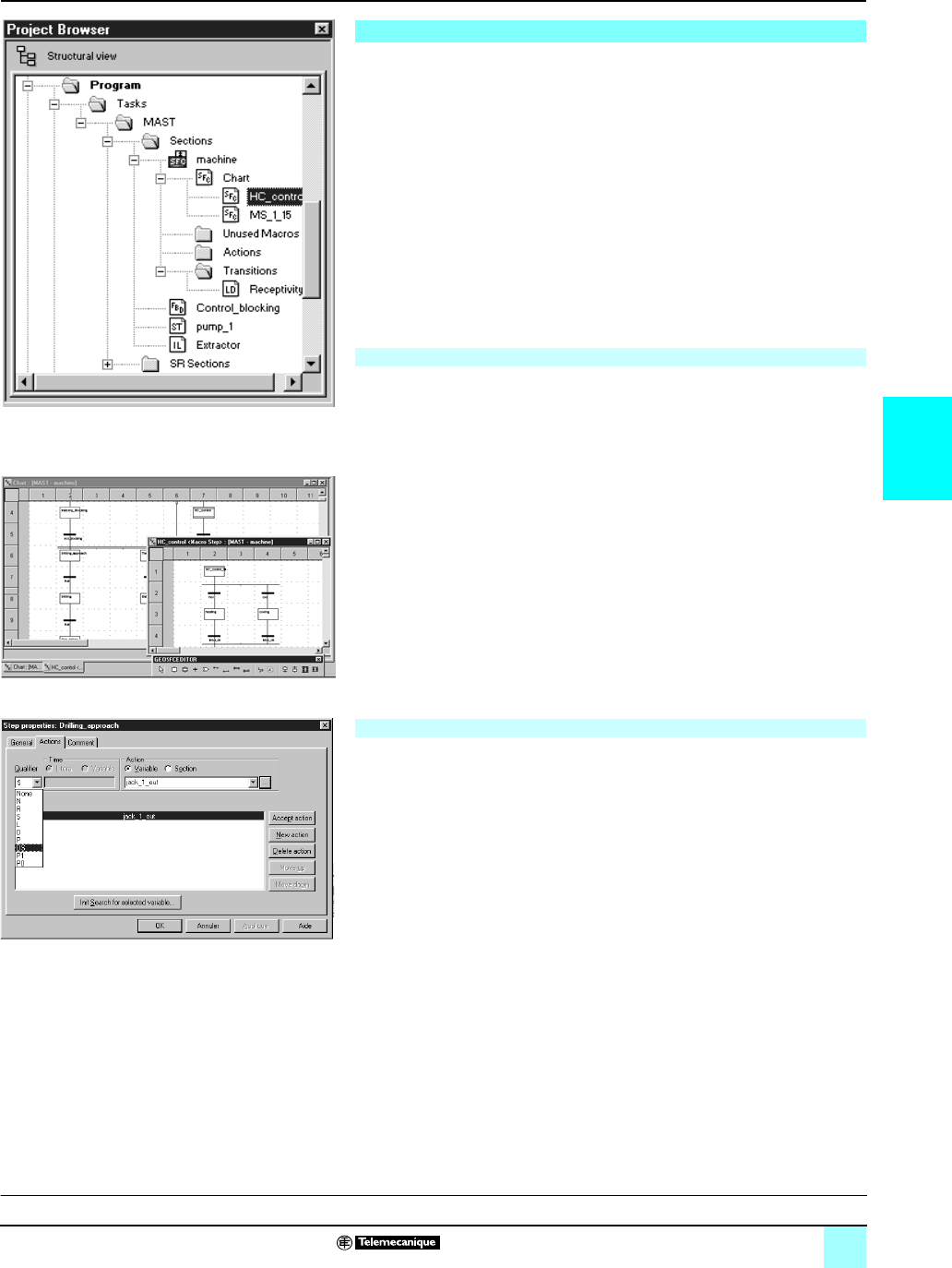
4/15
4
IEC languages (continued) Modicon® Automation Platform 0
Unity Pro™ software
Sequential Function Chart (and Grafcet) language can be used to describe the
sequential part of an automation system in simple graphical format using steps and
transitions.
SFC language does not process charts in the same way as Grafcet language:
bSFC only authorizes one token in one chart.
bGrafcet language authorizes several tokens in one chart.
Unity Pro software has one editor for these two languages with the option of defining
behavior in the application settings (Tools/Project Settings/Language Extensions
menu).
SFC language is only used in sections belonging to the master task. Each SFC
section consists of a main chart sub-section CHART and sub-sections for each of the
macro-steps. The component parts of the charts are:
bMacro-steps, which are the sole representation of a set of steps and transitions
(used to set up a hierarchical chart structure)
bSteps
bTransitions and directed links between steps and transitions
Associated with steps and transitions respectively, the actions and transition
conditions can be:
bIntegrated into the CHART or macro-step charts, in which case the actions or
transition conditions are defined by a single variable
bProcessed in specific sections, in which case dedicated processing (to be
programmed in Ladder, Function Block Diagram, Structured Text or Instruction List
language) is necessary
In order to check that machine scans have been completed successfully, activity
times (minimum, maximum) can be associated with each step. These times are set
by the user.
For each SFC section, the graphics editor provides a maximum of:
bOne grid containing 32 columns and 200 rows, or 6400 cells. Steps, transitions or
jumps all need one cell respectively.
b1024 steps (macro-steps and steps in macro-steps)
b20 actions assigned to the same step
b100 steps activated at the same time
b100 actions activated at the same time
To help you to create basic charts, graphic screens can be used to create “n” steps
in series and “m” steps in parallel in a single operation.
Dialog boxes can be used to assign associated properties to steps (activity time,
actions), transitions (variable linked to transition condition), etc.
Sequential Function Chart (SFC) and Grafcet language
Program structure (master task section)
Program structure (section in master task)
SFC structure in the browser
SFC chart
Step properties
Presentation:
page 4/4
Setup:
pages 4/5 to 4/8
Structure:
pages 4/9 to 4/11
Functions:
pages 4/18 to 4/28
References:
pages 4/29 and 4/31
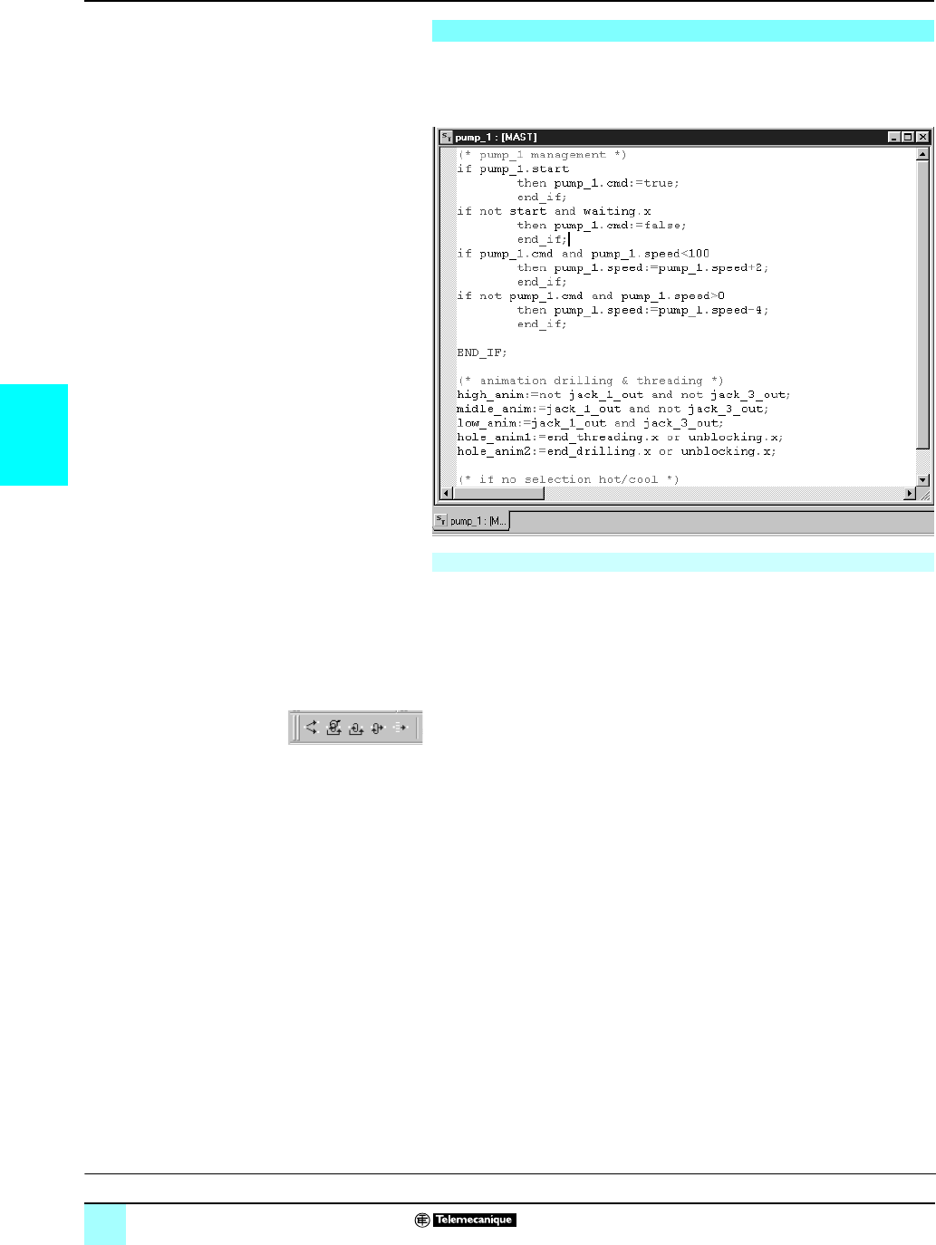
4/16
4
IEC languages (continued) Modicon® Automation Platform 0
Unity Pro™ software
Structured Text language is a sophisticated algorithmic type language, which is
particularly suitable for programming complex arithmetic functions, table operations,
message handling, etc.
Structured Text language, which can be used to directly transcribe an analysis based
on an organization chart, is structured into expressions composed of a series of
instructions organized in lines.
There is no limit to the number of characters an instruction line may contain. The only
limit is the program memory available for the Modicon M340, Premium™ and
Quantum™ platforms, except on TSX P57 10…40 processors, where the limit is 64
Kb.
Four preformatted expression structures can be called up directly from the toolbar:
bConditional action : IF…THEN…ELSIF…THEN…ELSE…END-IF;
bIterative conditional action: WHILE…DO…END_WHILE;
REPEAT…UNTIL…END_REPEAT;
bRepetitive action: FOR…TO…BY…DO…END_FOR;
bSelective action: CASE…OF…ELSE…END_CASE;
The operands used in the expressions are bit variables, word variables or variables
linked to function blocks.
To make the expressions easier to read, different colors are used to identify objects,
language key words and program comments.
Structured Text (ST) language
Program structure (section or subroutine)
Presentation:
page 4/4
Setup:
pages 4/5 to 4/8
Structure:
pages 4/9 to 4/11
Functions:
pages 4/18 to 4/28
References:
pages 4/29 and 4/31
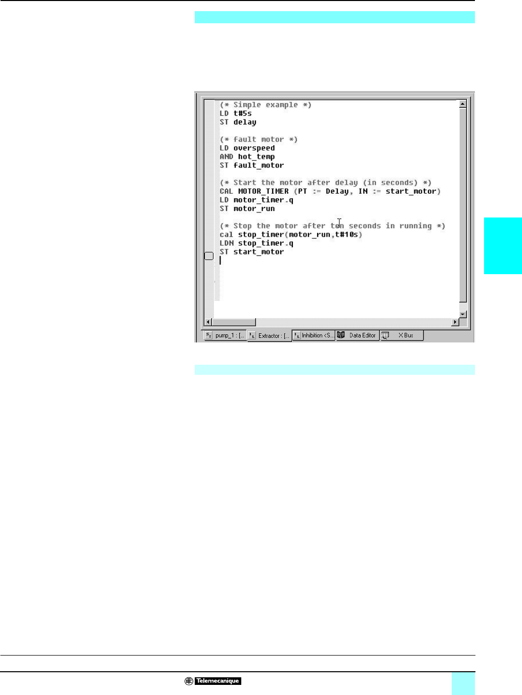
4/17
4
IEC languages (continued) Modicon® Automation Platform 0
Unity Pro™ software
Instruction List language is a language representing the equivalent of a Ladder
diagram in text form. It can be used to write Boolean and arithmetic equations using
all the functions available in the Unity Pro language (calling of functions and function
blocks, assignment of variables, creation of program jumps, branching to
subroutines within a program section, etc.).
A program in Instruction List language comprises a sequence of instructions
classified into the following different families:
bBit instructions, e.g. read input: LD overspeed
bFunction block instructions, e.g. call timer: CAL MOTOR_TIMER
bNumerical instructions using single, double and floating point integers, e.g.: LD
Result ADD Surplus ST Archive
bWord table or character string instructions, e.g. make assignment: LD Result:10:=
Setpoint:10
bProgram instructions, e.g. SR call: CALL SR10
The operands used in the expressions are bit variables, word variables or variables
linked to function blocks.
Instruction List (IL) language
Program structure (section or subroutine)
Presentation:
page 4/4
Setup:
pages 4/5 to 4/8
Structure:
pages 4/9 to 4/11
Functions:
pages 4/18 to 4/28
References:
pages 4/29 and 4/31
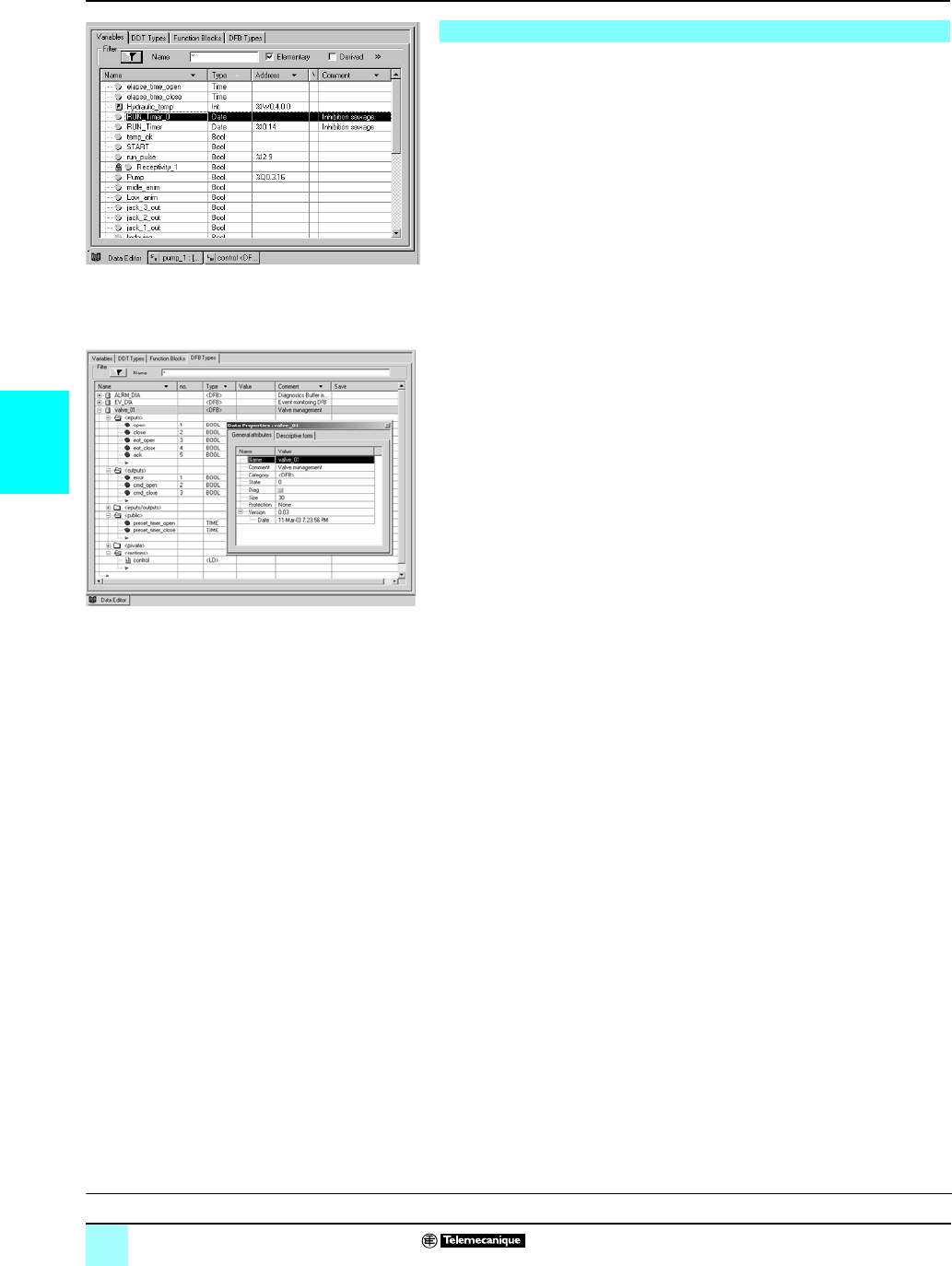
4/18
4
Functions Modicon® Automation Platform 0
Unity Pro™ software
The data editor, which can be accessed from the structural view of the project,
provides a single tool for performing the following editing tasks:
bDeclaration of data including variables and function blocks (declaration of their
type, instants and attributes)
bUse and archiving of function block data types in different libraries
bHierarchical view of data structures
bSearching, sorting and filtering of data
bCreation of a hyperlink to access a description from any variable comment
The data is displayed under four tabs:
b“Variables” tab for the creation and management of the following data instances:
bits, words, double words, inputs/outputs, tables, and structures
b“DDT Types” tab for the creation of derived data types (tables and structures)
b“Function Blocks” tabs for the declaration of EFB and DFB function blocks
b“DFB Types” for the creation of DFB user function block data types
Each data instance has several attributes, of which:
bThe name and type of the variable are mandatory
bThe comment, physical address in the memory or initial values are optional
The data editor columns can be configured (number of columns, order). All the
attributes associated with a variable can be displayed in a properties window.
This editor can be accessed at any time during programming by selecting variables
for data modification or creation.
Data editor
Data editor
V
ariable attributes
Presentation:
page 4/4
Setup:
pages 4/5 to 4/8
Structure:
pages 4/9 to 4/11
IEC language:
pages 4/12 to 4/17
References:
pages 4/29 and 4/31
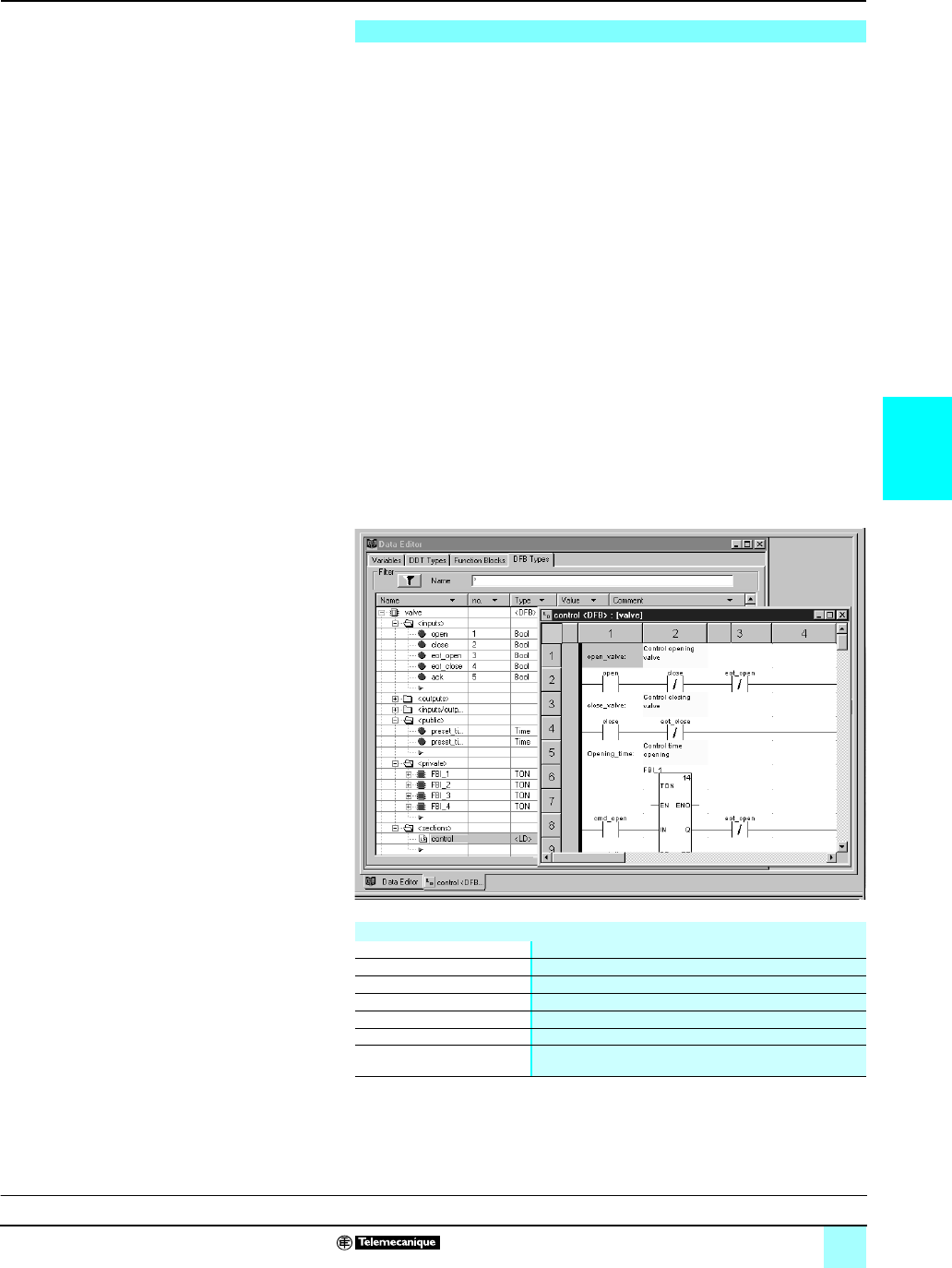
4/19
4
Functions (continued) Modicon® Automation Platform 0
Unity Pro™ software
Users can create their own function blocks for specific application requirements on
Modicon® M340™, Atrium™, Premium™ and Quantum™ platforms using Unity Pro
software.
Once created and saved in the library, these user function blocks can be reused as
easily as EFBs (Elementary Function Blocks).
DFB user function blocks can structure an application, such as when a program
sequence is repeated several times in the application or for correcting a standard
programming routine. They can be read-only protected or read/write-protected. They
can be exported to all other Unity Pro applications.
Using a DFB function block in one or more applications:
bSimplifies program design and entry
bImproves program readability and comprehension
bFacilitates program debugging (all variables handled by the DFB block function are
identified in the data editor)
bEnables the use of private variables specific to the DFBs, which are independent
of the application
A DFB is set up in several phases:
bThe DFB is designed by assigning a name, a set of parameters (inputs, outputs,
and public and private internal variables), and a comment via the data editor.
bThe code is created in one or more sections of the program, with the following
languages selected according to requirements: Structured Text, Instruction List,
Ladder or Function Block Diagram (ST, IL, LD or FBD).
bThe DFB may be stored in a library with an associated version number.
bA DFB instance is created in the data editor or when the function is called in the
program editor.
bThis instance is used in the program in the same way as an EFB (Elementary
Function Block). (The instance can be created from within the program.)
DFB user function blocks
Main characteristics
Inputs 32 max. (1)
Outputs 32 max. (2)
Inputs/outputs 32 max. (1) (2)
Public internal variables Unlimited (3), can be accessed via the application program
Private internal variables Unlimited (3), cannot be accessed via the application program
Comment 1024 characters max.
Program sections Unlimited, each section can be programmed independently in
one of the 4 languages (IL, ST, LD, and FBD).
(1) The maximum cumulative total of inputs and inputs/outputs is 32.
(2) The maximum cumulative total of outputs and inputs/outputs is 32.
(3) For Premium processors, see page 1/9: characteristics of memories, maximal sizes of objects
zones, internal unlocated data, DFB & EFB function blocks.
Presentation:
page 4/4
Setup:
pages 4/5 to 4/8
Structure:
pages 4/9 to 4/11
IEC language:
pages /12 to 4/17
References:
pages 4/29 and 4/31
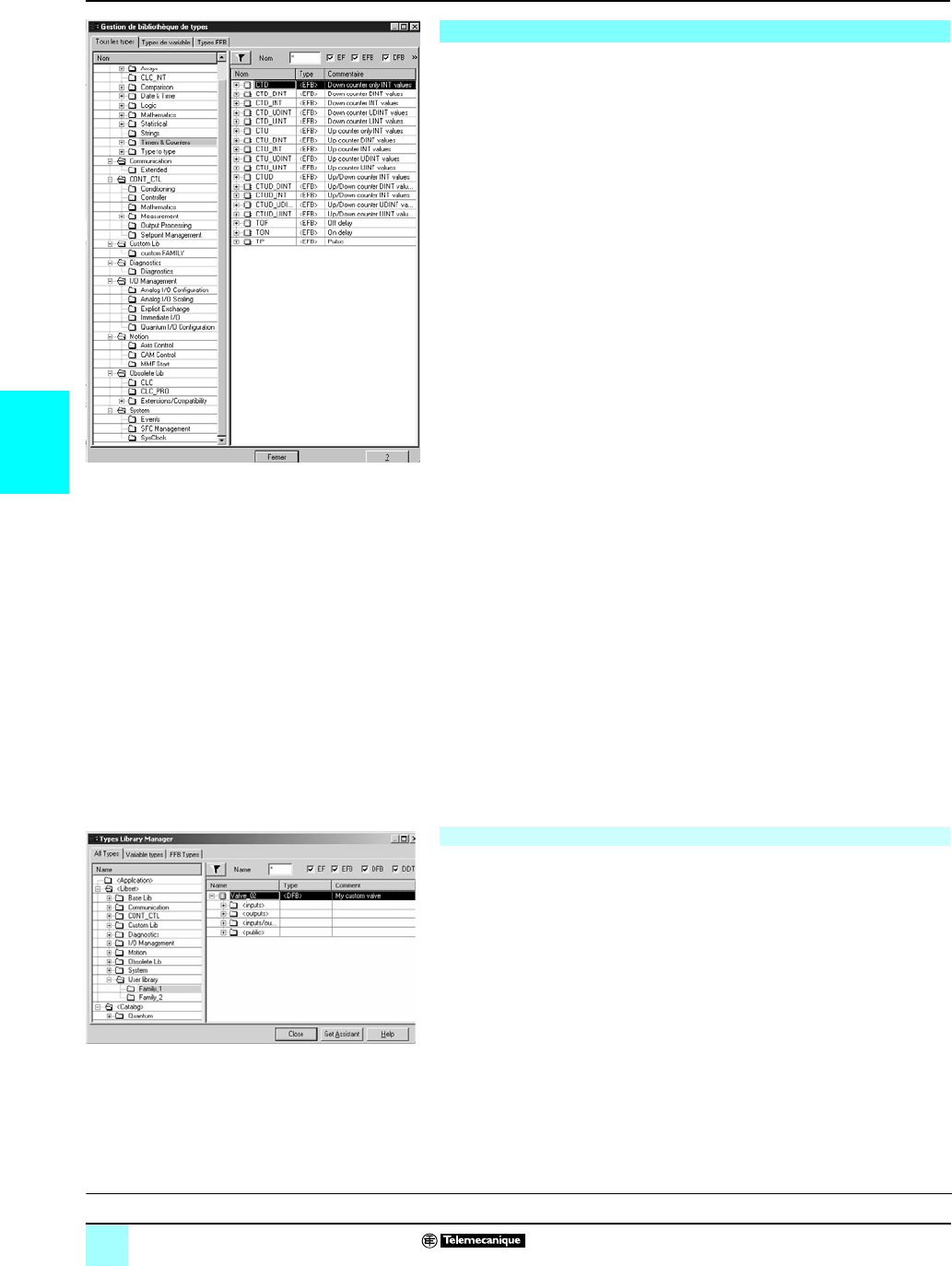
4/20
4
Functions (continued) Modicon® Automation Platform 0
Unity Pro™ software
The function and function block libraries manager contains all the elements provided
with Unity Pro software. The functions and function blocks are organized into
libraries, which themselves consist of families. Depending on the type of PLC
selected and the model of processor, the users will have a sub-set of these libraries
available to write their applications. However, the “Base Lib” library contains a set of
functions and function blocks, the majority of which are compatible with all platforms.
In particular, it contains the blocks compliant with IEC 61131-3.
The “Base Lib” library is structured into families:
bTimers and counters
bInternal process control
bArray management
bComparison
bDate and time management
bLogic processing
bMathematical processing
bStatistical processing
bCharacter string processing
bType-to-type data conversion
The “Base Lib” library, which covers standard automation functions, is supplemented
by other, more application-specific libraries, and some platform-specific functions:
bCommunication library, providing an easy means of integrating communication
programs from PLCs with those used by HMIs from the PLC application program.
Like other function blocks, these EFBs can be used in all languages to exchange data
between PLCs or to deliver data to be displayed on an HMI.
bProcess control library. The CONT_CTL library can be used to set up
process-specific control loops. In particular, it offers controller, derivative and integral
control functions. CONT_CTL comes with other families, providing additional
algorithms, e.g.: EFBs for calculating mean values, selecting a maximum value,
detecting edges or assigning a hysteresis to process variables.
bDiagnostics library, which can be used to monitor actuators. Also, it contains
EFBs for active diagnostics, reactive diagnostics, interlocking diagnostics,
permanent process condition diagnostics, dynamic diagnostics, monitoring of signal
groups, etc.
bI/O management library, providing services to handle information exchanged with
hardware modules (formatting data, scaling…)
bMotion Function Blocks library containing a set of predefined functions and data
structures to manage motion on drives and servo drives connected on CANopen.
bMotion library for motion control and fast counting
b“System” library, which provides EFBs for the execution of system functions
(such as evaluation of scan time, availability of several different system clocks, SFC
section monitoring, and display of system state) as well as management of files
inside the Modicon M340 memory cartridge.
bObsolete library containing all function blocks used by legacy programming
software that are needed to perform application conversions
Users may create libraries and families for storing their own DFB function blocks and
DDT data structures. This enhancement allows users to take advantage of
programming standards adapted to their needs, along with version management.
This means that it is possible to:
bCheck the version of the elements used in an application program against those
stored in the library
bPerform an upgrade, if necessary
Function block libraries
Management of user standards
Type library manager
User-defined library manager
Presentation:
page 4/4
Setup:
pages 4/5 to 4/8
Structure:
pages 4/9 to 4/11
IEC language:
pages 4/12 to 4/17
References:
pages 4/29 and 4/31
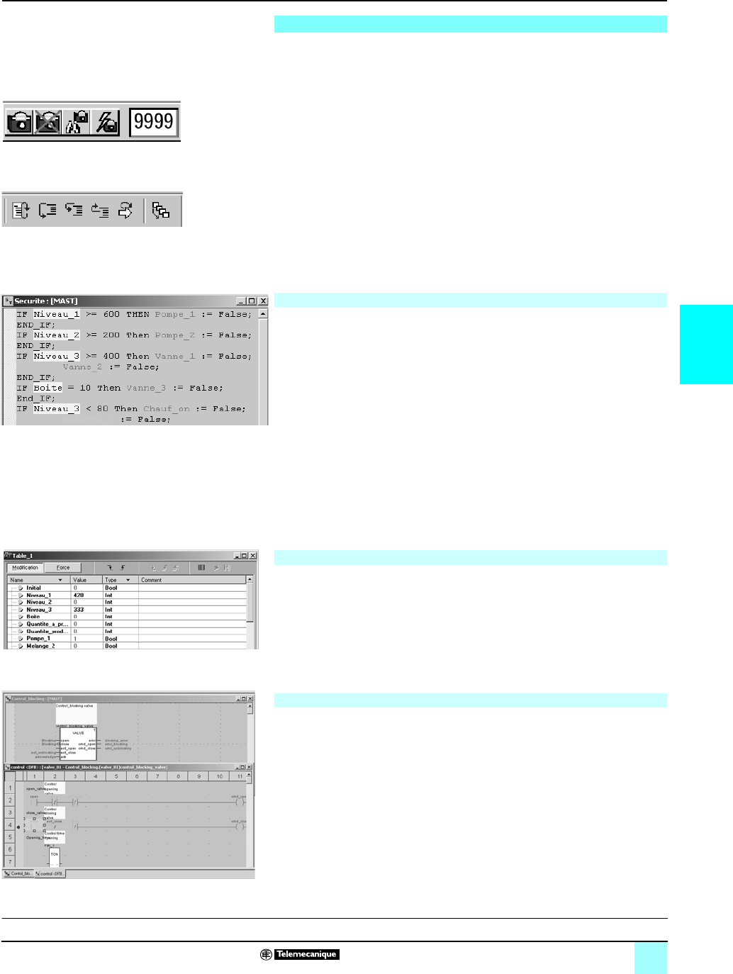
4/21
4
Functions (continued) Modicon® Automation Platform 0
Unity Pro™ software
Unity Pro software offers a complete set of tools for debugging Modicon® M340™,
Atrium™, Premium™ or Quantum™ applications. A tool palette provides direct access
to the main functions:
bDynamic program animation
bSetting of watchdogs or breakpoints (not authorized in event-triggered tasks)
bStep-by-step program execution. A function in this mode enables
section-by-section execution. Instruction-by-instruction execution can be launched
from the previous breakpoint. Three execution commands are therefore possible
when the element to be processed is a subroutine (SR) or DFB user block:
v Detailed step-by-step or “Step Into”. This command is used to move to the first
element of the SR or DFB.
v Overall step-by-step or “Step Over”. This command is used to process the entire
SR or DFB.
v Outgoing step-by-step or “Step Out”. This command is used to move to the next
instruction after the SR or DFB element.
bIndependent execution of the master (MAST), fast (FAST), auxiliary (AUX), and
event-triggered (EVTi) tasks.
Dynamic animation is managed section by section. A button in the toolbar is used to
activate or deactivate animation for each section.
When the PLC is in RUN, this mode can be used to view, simultaneously:
bThe animation of a program section, regardless of the language used
bThe variables window containing the application objects created automatically
from the section viewed
Several windows can be displayed and animated simultaneously. The “Tool tip”
function, which uses help balloons, can be used to view a variable and its content
simultaneously when the object is selected with the mouse (or other pointing device).
The user can add inspect windows to display variables inside the program.
Two types of animation are supported:
bStandard: The variables of the active section are refreshed at the end of the master
task (MAST).
bSynchronized: The watchpoint can be used to synchronize the display of animated
variables with a program element, to determine their value at this precise point in the
program.
Tables containing the variables of the application to be monitored or modified can be
created by data entry or initialized automatically from the selected program section.
In addition to data animation it is possible to:
bModify bit variables or force them to 0 or 1
bChange the display format
bCopy or move variables
bSearch by cross-reference
bDisplay the list of forced bits
These tables can be stored in the application.
The parameters and public variables of these blocks are displayed and animated in
real time using animation tables, with the possibility of modifying and forcing the
required objects.
In the same way as with other program elements, the watchpoint, breakpoint,
step-by-step execution, and program code diagnostics functions can be used to
analyze the behavior of DFBs. Setting a breakpoint in a DFB user function block
instance stops the execution of the task containing this block.
Debugging tools
Animation of program elements
Animation table
Debugging of DFB user function blocks
Insertion/removal of watchpoint
Execution: step-by-step command
Animation of ST program
Animation table
A
nimation of a DFB program
Presentation:
page 4/4
Setup:
pages 4/5 to 4/8
Structure:
pages 4/9 to 4/11
IEC language:
pages 4/12 to 4/17
References:
pages 4/29 and 4/31
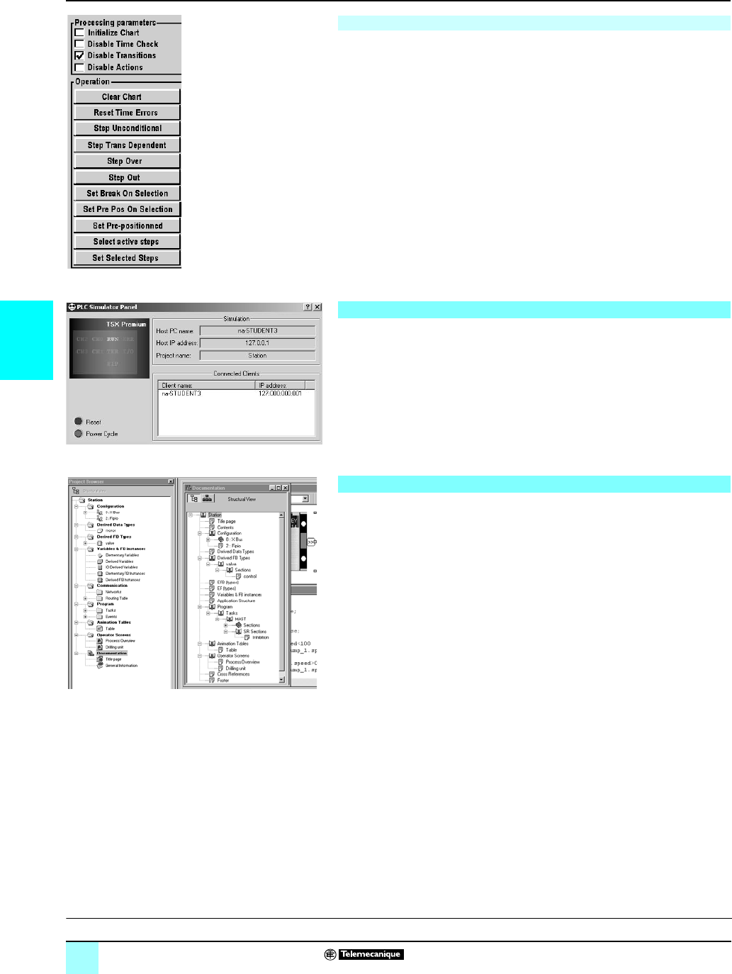
4/22
4
Functions (continued) Modicon® Automation Platform 0
Unity Pro™ software
The various debugging tools are also available in SFC language. However, unlike
other sections (IL, ST, LD or FBD) an SFC section executed step by step does not
stop execution of the task but instead freezes the SFC chart. Several breakpoints
can be declared simultaneously within a single SFC section.
Numerous commands are available in this debugging mode via the control panel:
bDeactivate active step(s)
bActivate initial step(s)
bDisable step execution times
bFreeze chart regardless of transition conditions
bStop processing steps
bMove to the next step taking account of the transition conditions
bEnable transition and move to next step(s) (detailed step-by-step command, “Step
Into”)
bEnable transition in order to execute the end of the macro-step (outgoing
step-by-step command, “Step Out”)
bChart the steps for which markers have been set.
The simulator integrated in Unity Pro can be used to test the application program for
Modicon® M340™, Atrium™, Premium™ or Quantum™ PLCs from the PC terminal
without having to connect to the PLC processor. The functions provided by the
debugging tools are available for debugging the master, fast and auxiliary tasks.
As the simulator does not manage the PLC I/O, animation tables can be used to
simulate the state of inputs by forcing them to 0 or 1.
The simulator can be connected to third-party applications via an OPC server with
OFS (OPC Factory Server) software.
The documentation editor is built around the Documentation Browser, which shows
the file structure in tree form.
It allows all or part of the application file to be printed in A4 or U.S. letter format on
any graphics printer accessible under Windows® that uses True Type technology.
The documentation editor supports the creation of user-specific documentation files
using the following headings:
bTitle page
bContents
bGeneral information
bTitle block
bConfiguration
bEF, EFB and DFB type function blocks
bUser variables
bCommunication
bProject structure
bProgram
bAnimation tables and cross-references
bRuntime screens
The documentation editor can generate the documentation file based on two different
structures:
bStructural view: All the objects in the project are associated with their
corresponding headings.
bFunctional view: The objects in the project are associated with the function
modules to which they belong.
The documentation file can be created and saved as the project progresses, from
one Unity Pro session to another.
Debugging in Sequential Function Chart (SFC) language
PLC simulator
Documentation editor
SFC control panel
Simulator control panel
Access to documentation editor
Presentation:
page 4/4
Setup:
pages 4/5 to 4/8
Structure:
pages 4/9 to 4/11
IEC language:
pages 4/12 to 4/17
References:
pages 4/29 and 4/31
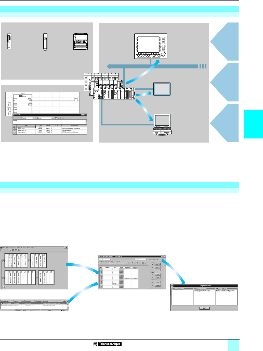
4/23
4
Functions (continued) Modicon® Automation Platform 0
Unity Pro™ software
Integrated diagnostics
The system diagnostics for the Modicon M340, Atrium, Premium, and Quantum
platforms supports the monitoring of system bits/words, and I/O modules, and the
activity times (minimum/maximum) of SFC steps. After the user chooses the relevant
option in the application configuration, any event will result in time-stamped messages
logged inside the diagnostic buffer in the PLC. These events are displayed on a
diagnostics viewer (1) automatically without the need of any additional programming.
With the assistance of Unity Pro's integrated diagnostics, this function can be used to
perform 1
st
level diagnostics of the elements in the configuration, up to and including
each I/O module channel.
(1) Diagnostics viewers are tools used to display and acknowledge error messages relating to
diagnostics. They are supplied as standard with Unity Pro, Vijeo Designer and Monitor Pro
software, with Magelis terminals, and with the PLC web server which is accessible through a
thin client Magelis iPC terminal.
Presentation
Diagnostics integrated into Modicon® M340™, Atrium™, Premium™ and Quantum™ automation platforms
The diagnostics offer for Modicon M340, Atrium, Premium, and Quantum platforms
is based on three components:
bSystem diagnostics
bDFB and EFB diagnostic function blocks (for system and application diagnostics)
bError message display system or viewers supplied as standard with Magelis®
XBT GT and iPC® terminals, Vijeo™ Designer/Monitor Pro™ supervisory software
and Unity Pro setup software.
Functions
System diagnostics
Processor for
system bits and
words
In-rack I/O
modules
Remote I/O
modules
on Fipio® bus
or CANopen
Higher-level
M.E.S.
Cell level
Machine level
Unity Pro
Diagnostics viewersSystem diagnostics
Application diagnostics
Ethernet TCP/IP
Vijeo Designer
Monitor Pro
Thin client Magelis iPC
Magelis XBT GT
Quantum,
Premium,
Modicon M340
PC
Configuration level Module level
Channel levelViewer window (example with Unity Pro software)
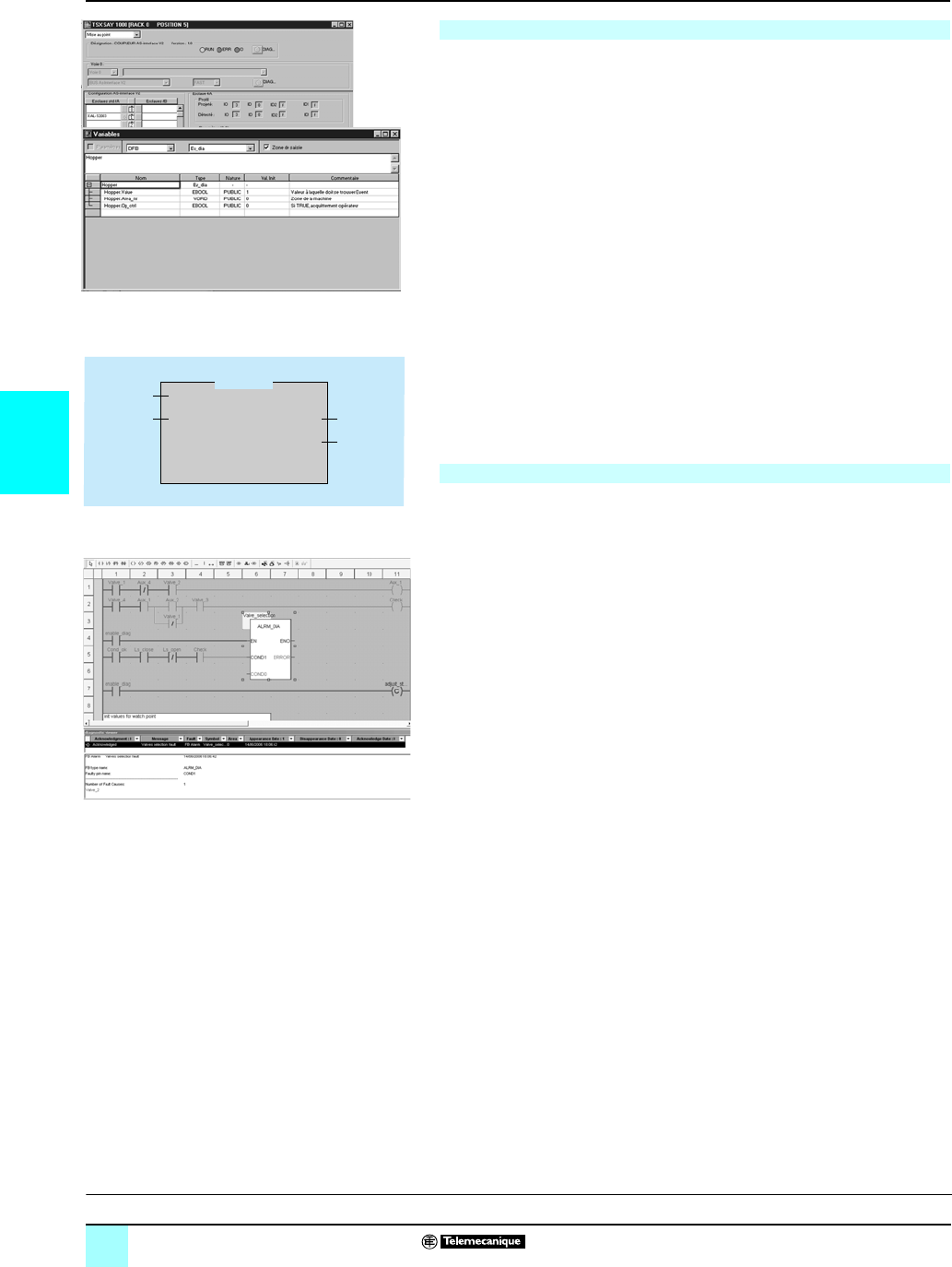
4/24
4
Functions (continued) Modicon® Automation Platform 0
Unity Pro™ software
Integrated diagnostics
Unity Pro software also has a library of function blocks for monitoring, called diagnostic
DFBs and EFBs. The library of diagnostic function blocks contains:
bManufacturer blocks for system diagnostics
v IO_DIA input/output fault, which is used to monitor the state of inputs/outputs.
v ASI_DIA, which monitors whether an error has occurred on the AS-Interface bus
(module or bus fault, no slave, slave not configured or faulty).
bManufacturer blocks for application diagnostics, for example:
v EV_DIA, which monitors whether an event (bit status) has the correct value at a
given time (no notion of timing).
v MV_DIA, D_GRP, D_REA, which monitor whether an event (the change in the status
of a bit) occurs within the specified time conditions.
v ALRM_DIA, which monitors the combination of the status of 2 bits.
v NEPO_DIA and TEPO_DIA, which can be used to check, control and perform
diagnostics for elements in the working part of the system made up of the
combination of 2 actuators and 2 sensors.
bOpen diagnostics blocks
These enable users to create their own diagnostic function blocks to meet the
specific requirements of their applications and therefore to supplement the
manufacturer DFBs and EFBs described above. They can be created from 2 model
blocks, which must be written in Ladder (LD), Structured Text (ST), Function Block
Diagram (FBD) or Instruction List (IL) language.
When a fault occurs, Unity Pro analyzes the program sections concerned and opens
a second window displaying the causes and probable sources of the fault.
The user or process operator is guided though the fault-finding process, enabling
machine downtimes to be reduced.
The configuration module or instruction which is the source of the fault can also be
accessed via the diagnostics viewer integrated into Unity Pro, directly from the alarm
in the viewer output window (see page 4/22).
Application diagnostics
Diagnostics with fault cause analysis
ED
COND ERROR
STATUS
AREA_NR
OP_CTRL
Usrst_dia
Outputs
Inputs
Fault cause analysis
Presentation:
page 4/4
Setup:
pages 4/5 to 4/8
Structure:
pages 4/9 to 4/11
IEC language:
pages 4/12 to 4/17
References:
pages 4/29 and 4/31
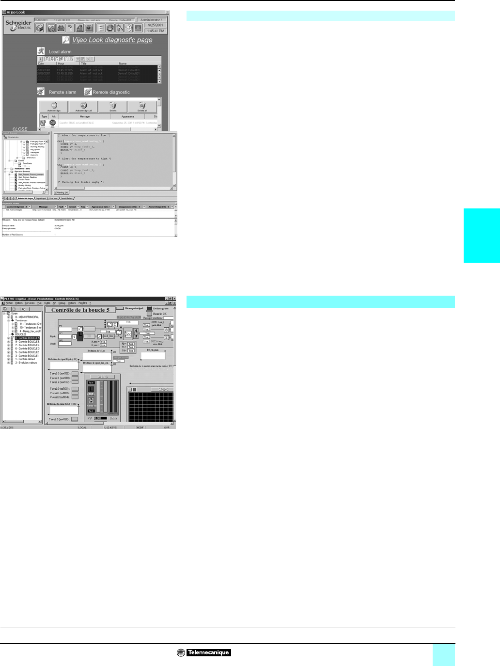
4/25
4
Functions (continued) Modicon® Automation Platform 0
Unity Pro™ software
Integrated diagnostics
Diagnostic viewers in Modicon® M340™, Atrium™, Premium™, and Quantum™
platforms automatically display diagnostic events for management of faults and
alarms.
The viewer function is supplied as standard with:
bVijeo™ Look and Monitor Pro™ V7 supervisory software
bUnity Pro programming software
bMagelis® XBT GT and Magelis® iPC HMI terminals
The viewer integrated in Unity Pro can also access the instruction or module which
is the source of the fault. See “Diagnostics with fault cause analysis”, page 4/21.
Modicon M340, Atrium, Premium and Quantum platforms have multiviewer capability
(can be used with a maximum of 15 viewers). A PC-compatible station with the
viewer function can be multi-PLC (can be used with a maximum of 15 Modicon M340,
Atrium, Premium, and/or Quantum platforms).
The viewer structure supports:
bA single point for fault management in each application
bTime-stamping of the occurrence of faults at the source
bStorage of intermittent faults in memory
bViewer functioning that is independent of the viewer used. The frame is identical
for all viewers.
bAutomatic archiving of all error messages
Output window
The diagnostics viewer takes the form of an output window divided into 2 sections:
bA message list indicating, for each alarm: state, DFB type, geographical zone,
dates and times of occurrence/correction associated message and status
bAn area for additional information about the selected message: type, comment,
date of occurrence, specific data, variables in error state, etc.
The operator screen tool is integrated into Unity Pro. The operator screens are
designed to facilitate the operation of automated processes during debugging,
startup and maintenance. The operator screens provide a set of information
(explanatory texts, display of dynamic values, push buttons, and synoptics), enabling
users to act quickly and easily to modify and dynamically monitor PLC variables.
The operator screens editor provides all the HMI elements needed for the animated
design and viewing of processes. It enables these screens to be designed using
specific tools:
bScreen: Create runtime screens, which can be classified according to family.
bMessage: Create messages to be displayed.
bObjects: Create a graphic objects library using:
v Geometrical elements (line, rectangle, ellipse, images, such as controller front
panels.)
v Control elements (buttons, data entry fields, screen browsing controls, etc.)
v Animation elements (colors, flashing elements, bar graphs, etc.)
When the station on which Unity Pro has been installed is connected to the PLC, the
user can obtain a dynamic display of the screens according to the state of the
process. Screen sequencing is possible, depending on the priority attributed, either
via the keyboard or a PLC request.
When online, the Unity Pro application program can be accessed directly from the
operator screens by clicking the selected object in a synoptic screen view. It is also
possible to activate the animation table or cross-reference functions by selecting one
or more variables on the screen. To make the display easier to read, the synoptic
views can be displayed in full-screen view.
Since it is possible to build or modify an operator screen while the PLC is running,
this service increases the productivity during the commissioning and maintenance
phases.
Diagnostics viewers
Operator screens
Viewer
Presentation:
page 4/4
Setup:
pages 4/5 to 4/8
Structure:
pages 4/9 to 4/11
IEC language:
pages 4/12 to 4/17
References:
pages 4/29 and 4/31
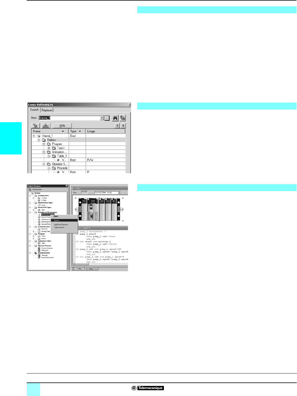
4/26
4
Functions (continued) Modicon® Automation Platform 0
Unity Pro™ software
Unity Pro enables changes to be made to the program when the PLC connected to
the programming terminal is in RUN. These modifications are made by performing
the following operations:
bWhen necessary, transferring the application from the PLC to the PC terminal
running Unity Pro.
bPreparing the program changes. These program modifications can be of any type
and in any language (IL, ST, LD, FBD, and SFC), for example adding/deleting SFC
steps or actions. Furthermore, modifications can be made to the code of a DFB user
function block (although its interface cannot be modified).
bUpdating the program in the PLC (in RUN) to reflect these program changes.
This function allows program code and data in different parts of the application to be
added or modified in a single modification session (thus making modification unified
and consistent with regard to the controlled process). This increased flexibility comes
at a cost in terms of the program memory volume required.
The Unity Pro Cross-References function, which is available in standalone mode
(offline) and when connected to the PLC (online), allows users to view all the
elements of a PLC application by searching for variables of any type. This view
indicates where the declared variable is used as well as the mode in which it is used
(write, read, etc.).
This function also provides access to the Search/Replace function for variable
names.
The variables search can be initialized from any editor (language, data, runtime
screen, animation table, etc.).
The import/export function available in Unity Pro supports the following operations
from the structural and functional project views:
bVia the import function, to reuse all or part of a project created previously in the
current project
bVia the export function, to copy all or part of the current project to a file for
subsequent reuse
The files generated on export are generally in XML format (1). However, variables
can also be exported or imported in the following formats:
b.xvm format compatible with OFS data server software
bSource format, in a .scy file compatible with PL7™ design software
bText format with separator (TAB), in a .txt file for compatibility with any other system
On import, data can be assigned to new instances of the following elements via an
assistant:
bDFB function blocks
bDDT data structures
bSimple data
Furthermore, when importing a function module, the data associated with animation
tables and operator screens is also reassigned.
The XML import function also supports the transfer of a Modicon® M340™, Atrium™,
Premium™ or Quantum™ PLC configuration prepared in the SIS Pro costing and
configuration tool for use in the creation of a project in Unity Pro.
This import function means that the user does not have to repeat the PLC
configuration process when this has already been completed in the SIS Pro tool.
(1) XML language: Open text-based language providing structural and semantic information.
Modifying the program with the PLC in RUN
Cross-References functions
Import/export function
Presentation:
page 4/4
Setup:
pages 4/5 to 4/8
Structure:
pages 4/9 to 4/11
IEC language:
pages 4/12 to 4/17
References:
pages 4/29 and 4/31

4/27
4
Functions (continued) Modicon® Automation Platform 0
Unity Pro™ software
Unity Pro's integrated conversion tools can be used to convert PLC applications
created with Concept™ and PL7™ programming and setup software in Unity Pro
applications.
The conversion can be performed from a Concept V2.5 application (possible in V2.11
or later but only once it has been updated to version V2.5). In order to perform the
conversion, the application must be exported to an ASCII file in Concept.
The export file is converted into Unity Pro source files automatically. This
source file is then analyzed by Unity Pro. At the end of the procedure, a conversion
report is generated and an output window displays any conversion errors from which
the part of the program to be modified can be accessed directly.
The Concept application converter converts the application into Unity Pro but does
not guarantee that it will operate correctly in real time. It is therefore essential to test
or debug any converted application.
The conversion can be performed from a PL7 application V4 or later (Premium PLC
or Atrium slot PLC). In order to perform the conversion, the source file (complete
application) or source file (user function block) must be exported in PL7.
The conversion procedure is similar to that of the Concept conversion described
above.
Note : Conversion of PLC applications created with Concept, Modsoft®, and ProWORX™
software, in LL984 is possible. Please consult your local sales office.
OS-Loader software is designed for updating operating systems on Atrium, Premium
and Quantum platforms and is supplied with Unity Pro software.
It can be used to upgrade the processor and modules from PL7 or Concept software
for compatibility with Unity Pro:
bPremium™ TSX P57 2p3M/2623M and TSX P57 3p3M/3623M processors
bQuantum™ 140 CPU 434 12A and 140 CPU 534 14A processors (requires PV 04
or later)
bEthernet TSX ETY p102 and 140 NOE 771 p1 communication modules
These operating system updates are performed as follows for the various types of
processor:
bUni-Telway RS 485 terminal link for Premium™ processors
bModbus® or Modbus Plus™ terminal link for Quantum processors
bEthernet TCP/IP network for integrated Ethernet port on Premium processors and
Ethernet Premium and Quantum processors (1)
Note: For Modicon M340 this service is supplied by Unity Loader (see page 4/38)
(1) Updating the OS on a Quantum 140 CPU 671 60 processor is performed through an Ethernet
network on its MT-RJ type optical fiber connector (and through a transceiver or a ConneXium
switch for electrical/optical interfacing)
Application converters
Concept™/Unity Pro™ software converter (Quantum™ PLC)
PL7™/Unity Pro™ software converter (Premium™ and Atrium™ slot PLC)
Operating system update utilities
Presentation:
page 4/4
Setup:
pages 4/5 to 4/8
Structure:
pages 4/9 to 4/11
IEC language:
pages 4/12 to 4/17
References:
pages 4/29 and 4/31
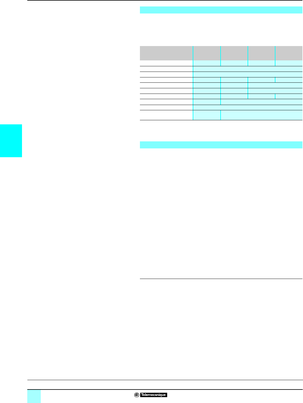
4/28
4
Functions (continued) Modicon® Automation Platform 0
Unity Pro™ software
The drivers used most frequently on the Atrium™, Premium™ and Quantum™
platforms are installed at the same time as the Unity Pro software.
Unity Pro also includes the following communication drivers, which can be installed
as required (1):
Advanced openness, which is reserved for experienced IT engineers, supports the
development of interfaces between Unity and expert tools as well as specific
user-defined functions.
This type of development requires expert IT knowledge in the following areas:
bC++ or Visual Basic languages
bClient/server architectures
bXML and COM/DCOM technologies
bIssues relating to data synchronization
As a supplement to the Unity Pro Extra Large software (3), the UDE (Unity
Developer's Edition) development tool UNY UDE VFU CD21E can be used to set up
made-to-order solutions. In addition to a development kit, it includes the Unity
servers and documentation.
Unity Developer’s Edition is compatible with:
bUnity Pro™ PLC configuration Extra Large.
bAll Modicon®M340™ processors.
bAll Atrium™ slot-PLCs.
bAll Premium ™ Unity™ processors.
bAll Quantum™ Unity™ processors.
(1) Also available as separate part TLX CD DRV 20M
(2) Windows® 98 only
(3) Only Unity Pro Extra Large implements dynamic databases management for OFS data
servers and 3rd party software.
Communication drivers
Driver type Windows ® XP
Windows®
2000
Windows®NT Windows®98
Millennium
Windows®95
Uni-Telway COM port V1.9 IE20 V1.9 IE17 V1.7 IE18 V7.8 IE18
Uni-Telway TSX SCP 114 V1.2 IE05
Modbus® COM port V1.6 IE29
Fip ISA TSX FPC10 card V1.4 IE06 V1.3 IE08 V1.4 IE06 V2.4 IE08
Fip TSX FPC20 PCMCIA card V1.2 IE03 V1.1 IE08 V1.2 IE04
Ethway V1.4 IE05 V1.1 IE03 V2.6 IE06 (2)
ISAway PCX 57, ISA card V1.2 IE04 V1.5 IE06 V1.2 IE04 V1.2 IE09
PCIway Atrium, PCI card V1.1 IE09 –
XIP X-Way on TCP/IP V1.10 IE22
USB for USB terminal port V1.2 IE17 –
Unity Developer’s Edition, advanced openness
Presentation:
page 4/4
Setup:
pages 4/5 to 4/8
Structure:
pages 4/9 to 4/11
IEC language:
pages 4/12 to 4/17
References:
pages 43/29 and 4/31

4/29
4
References Modicon® Automation Platform 0
Unity Pro™ software
The software is available in 4 versions:
b Unity Pro Small for programming and setting up Unity automation platforms:
v Modicon® M340™ PLC — BMX P34 1000 and BMX P34 20p0
b Unity Pro Medium for programming and setting up Unity automation platforms:
v Modicon M340 PLC — BMX P34 1000 and BMX P34 20p0
v Atrium™ PLC — TSX PCI 57 20
v Premium™ PLC — TSX 57 0p, 57 10 and 57 20 ®™
b Unity Pro Large for programming and setting up automation platforms:
v Modicon M340 PLC — BMX P34 1000 and BMX P34 20p0
v Atrium PLC — TSX PCI 57 20 and 57 30
v Premium PLC — TSX 57 0p, 57 10, 57 20, 57 30 and 57 40
v Quantum™ PLC — with 140 CPU 311 10, 434 12U and 534 14U processors
b Unity Pro Extra Large for programming and setting up all Unity automation
platforms:
v Modicon M340 PLC — BMX P34 1000, and BMX P34 20p0
v Atrium PLC — TSX PCI 57 20 and 57 30
v Premium PLC — TSX 57 0p, 57 10, 57 20, 57 30, 57 40 and 57 50
v Quantum PLC — with 140 CPU 311 10, 434 12U, 534 14U, 651 50, 651 60 and
Hot Standby 140 CPU 671 60 processors
Users who have already purchased these installed base software programs and
have a current subscription may purchase Unity Pro version V3.0 software at
reduced prices. These upgrades are only possible for licenses of the same type (from
Concept XL group license to Unity Pro Extra Large group license).
Unity Pro multilingual software is compatible with Windows® 2000 Professional and
Windows® XP operating systems.
It comprises:
bDocumentation in electronic format in 6 languages (English, Spanish, French,
German, Italian and Chinese)
bConverters for converting applications created with Concept and PL7 Pro
programming software
b PLC simulator
Cables for connecting the processor to the programming PC must be ordered
separately.
References
Unity Pro™ Small, Medium, Large and Extra Large software packages
Upgrade kits for Concept™, PL7 Pro™ and ProWORX™ software
OS Windows® composition and compatibility
Presentation:
page 4/4
Setup:
pages 4/5 to 4/8
Structure:
pages 4/9 to 4/11
IEC language:
pages 4/12 to 4/17
Functions:
pages 4/18 and 4/28

4/30
4
References (continued) Modicon® Automation Platform 0
Unity Pro™ software
References (continued)
Unity Pro Small version 3.0 software packages
For PLCs Description Type of license Reference Weight
kg
BMX P34 1000
BMX P34 20p0
Unity Pro Small software
packages
Single-station UNYSPUSFUCD30 –
Group (3 stations) UNYSPUSFGCD30 –
Team (10 stations) UNYSPUSFTCD30 –
Software upgrades from:
- Concept S
-PL7Micro
-ProWORX
™ software
NxT/32 Lite
Single-station UNYSPUSZUCD30 –
Group (3 stations) UNYSPUSZGCD30 –
Team (10 stations) UNYSPUSZTCD30 –
Unity Pro Medium version 3.0 software packages
For PLCs Description Type of license Reference Weight
kg
BMX P34 1000
BMX P34 20p0
TSX 57 0p…57 20
TSX PCI 57 20
Unity Pro Medium software
packages
Single-station UNYSPUMFUCD30 –
Group (3 stations) UNYSPUMFGCD30 –
Team (10 stations) UNYSPUMFTCD30 –
Software upgrades from:
- Concept S, M
- PL7 Micro, Junior
- ProWORX™ softwart
NxT/32 Lite
Single-station UNYSPUMZUCD30 –
Group (3 stations) UNYSPUMZGCD30 –
Team (10 stations) UNYSPUMZTCD30 –
Unity Pro Large version 3.0 software packages
For PLCs Description Type of license Reference Weight
kg
BMX P34 1000
BMX P34 20p0
TSX 57 0p…57 40
TSX PCI 57 20/30
140 CPU 311 10
140 CPU 434 12U
140 CPU 534 14U
Unity Pro Large software
packages
Single-station UNYSPULFUCD30 –
Group (3 stations) UNYSPULFGCD30 –
Team (10 stations) UNYSPULFTCD30 –
Site (> 10 stations) UNYSPULFFCD30 –
Software upgrades from:
- Concept S, M
- PL7 Micro, Junior, Pro
- ProWORX™ software
NxT/32 Lite
Single-station UNYSPULZUCD30 –
Group (3 stations) UNYSPULZGCD30 –
Team (10 stations) UNYSPULZTCD30 –
Site (> 10 stations) UNYSPULZFCD30 –
Unity Pro Extra Large version 3.0 software packages
For PLCs Description Type of license Reference Weight
kg
BMX P34 1000
BMX P34 20p0
TSX 57 0p…57 50
TSX PCI 57 20/30
140 CPU 311 10
140 CPU 434 12U
140 CPU 534 14U
140 CPU 651 50/60
140 CPU 671 60
Unity Pro Extra Large software
packages
Single-station UNYSPUEFUCD30 –
Group (3 stations) UNYSPUEFGCD30 –
Team (10 stations) UNYSPUEFTCD30 –
Site (> 10 stations) UNYSPUEFFCD30 –
Software upgrades from:
- Concept S, M, XL
- PL7 Micro, Junior, Pro
- ProWORX™ software
NxT Lite, Full
- ProWORX™ software
32 Lite, Full
Single-station UNYSPUEZUCD30 –
Group (3 stations) UNYSPUEZGCD30 –
Team (10 stations) UNYSPUEZTCD30 –
Site (> 10 stations) UNYSPUEZFCD30 –
Unity Developer’s Edition
For PLCs Description Type of licence Reference Weight
kg
BMX P34 1000
BMX P34 20p0
TSX 57 0p…57 50
TSX PCI 57 20/30
140 CPU 311 10
140 CPU 434 12U
140 CPU 534 14U
140 CPU 651 50/60
140 CPU 671 60
UDE Unity Developer’s Edition
Requires Unity Pro Extra Large
Single-station UNYUDEVFUCD21E –
Presentation:
page 4/4
Setup:
pages 4/5 and 4/6
Software structure:
pages 4/7 to 4/9
IEC language:
pages 4/10 to 4/15
Functions:
pages 4/16 to 4/26

4/31
4
References (continued) Modicon® Automation Platform 0
Unity Pro™ software
(1) With TSX CUSB 485 converter, use the TSX CRJMD 25 cord set (equipped with 1 x mini-DIN
and 1 x RJ45 connectors.
References (continued)
Documentation for Unity Pro version 3.0
For PLCs Description Type of license Reference Weight
kg
Hardware and software
manuals (on DVD)
Platform setup for:
- Modicon M340
- Atrium/Premium
- Quantum
- Momentum
Electromagnetic compatibility
of networks and fieldbuses
Software setup for:
- Unity Pro
- EF/EFB/DFB function blocks
library
Multilingual: English, Spanish,
French, German, Italian and
Chinese
UNYUSE909CDM –
Separate parts
Description Use from processor To PC port Length Reference Weight
kg
PC terminal connection
cables
USB Mini B port
Modicon M340
BMX P34 1000/20p0
USB port 1.8 m BMXXCAUSBH018 0.065
4.5 m BMXXCAUSBH045 0.110
Mini-DIN port for
Premium TSX 57 1p/2p/3p/4p
Atrium TSX PCI 57
RS 232D (15-pin
SUB-D connector)
2.5 m TSXPCX1031 0.170
USB port
(USB/RS 485
converter)
0,4 m TSXCUSB485
(1)
0,144
USB port
(Mini-DIN/RJ45
cordset)
2.5 m TSXCRJMD25 0.150
Modbus port
15-pin SUB-D Quantum
140 CPU 311 10
140 CPU 434 12A
140 CPU 534 14A
RS 232D (15-pin
SUB-D connector)
3.7 m 990NAA26320 0.300
15 m 990NAA26350 0.180
USB port Premium TSX 57 5p
Quantum 140 CPU 6p1
USB port 3.3 m UNYXCAUSB033 –
RJ45 connector for Modbus
port Quantum 140 CPU 6p1
RJ45 connector 1 m 110XCA28201 –
3 m 110XCA28202 –
6 m 110XCA28203 –
TSX PCX 1031
TSX CUSB 485
BMXXCAUSBH0pp
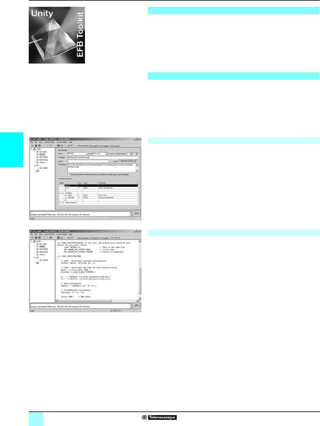
4/32
4
Presentation,
setup
Modicon® M340™ Automation
Platform 0
Unity™ EFB Toolkit software
Unity EFB Toolkit is the software for developing EF functions and EFB function
blocks in C language and is optional software for Unity Pro. It can be used to develop
new functions (whose internal code is written in C language) to extend and complete
the set of functions proposed as standard in Unity Pro. This software comes with
Microsoft® Visual C++ @.Net which can be used to debug the functions used on the
Unity Pro PLC simulator. Unity EFB Toolkit also includes a service for creating and
managing families of functions, with a view to their integration in the Unity Pro
function libraries.
C language development software is a tool for managing the whole function while it
is being performed. It provides:
bA user-friendly creation interface, integrated in Unity Pro, with automatic file
organization
bPowerful tools for testing and debugging
bManagement of compatibilities and software versions of created functions
bGeneration of files for subsequent installation of functions on other development
stations
The software can be used to define different function families. Functions, known as
EFs/EFBs are stored in families, making it possible to create an organized library of
functions written in C language.
Once created, these families can be distributed and integrated in the Unity Pro
libraries.
They are:
bArranged in families/functions
bUsed in all languages with the same flexibility as standard functions (data entry
wizard)
bManaged by the Unity Pro library tool (version management)
The various tabs in the EFB Toolkit software editor allow the user to create the
function by:
bDeclaring the interface; all data types are possible (elementary, structures, tables)
bSupporting public and private variables
Writing the source code file in C language
A function written in C language can access numerous internal PLC services such
as the real-time clock, PLC variables, system words, and math functions. In
particular, it is possible to perform numerical processing in floating point format.
Presentation
Setup
Managing function families
Editing functions
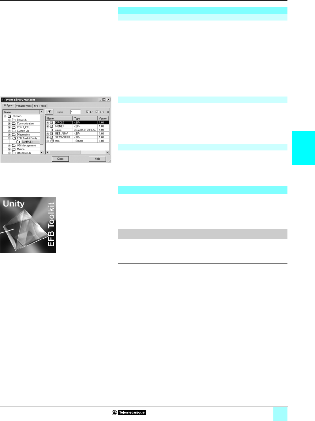
4/33
4
Setup (continued),
reference
Modicon® M340™ Automation
Platform 0
Unity™ EFB Toolkit software
The function created can be tested after insertion in an application and loading into
the Unity Pro PLC simulator.
The Microsoft® Visual C++ tool is used to debug the function.
It is used to:
bInsert breakpoints
bPerform step by step execution
bDisplay the code with the breakpoints visible
bDisplay manipulated data
Note: To generate the code for a Modicon M340 platform, a specific GNU compiler is used. It is
supplied with the Unity EFB Toolkit.
Once the function has been debugged, it can be generated and distributed, and the
updating tool supplied with Unity Pro can be used to enhance the libraries on a user
station.
Version management means that at any time the user knows the level of functions
installed on a station and can update the application with the latest existing versions.
Unity EFB Toolkit is compatible with Unity Pro Small, Medium, Large, and
Extra Large.
Developing EF functions and EFB functions is possible for the Modicon® M340™,
Premium™, Atrium™, and Quantum™ platforms.
The companion software for Unity Pro, Unity EFB Toolkit can be used to create EF
elementary blocks and EFB elementary function blocks. These are developed in
Visual C++ language and are integrated in Unity Pro function block libraries.
The Unity EFB Toolkit software and its documentation are supplied in electronic form
on CD-ROM in English.
Setup (continued)
Debugging functions
Enhancing the function library
Compatibility
References
Description Type of
license
Language Reference Weight
kg
Unity EFB Toolkit, kit for
developing EF and EFB
blocks
Single
(1 station)
English
(software and
electronic
documentation)
UNYSPUZFUCD30E –
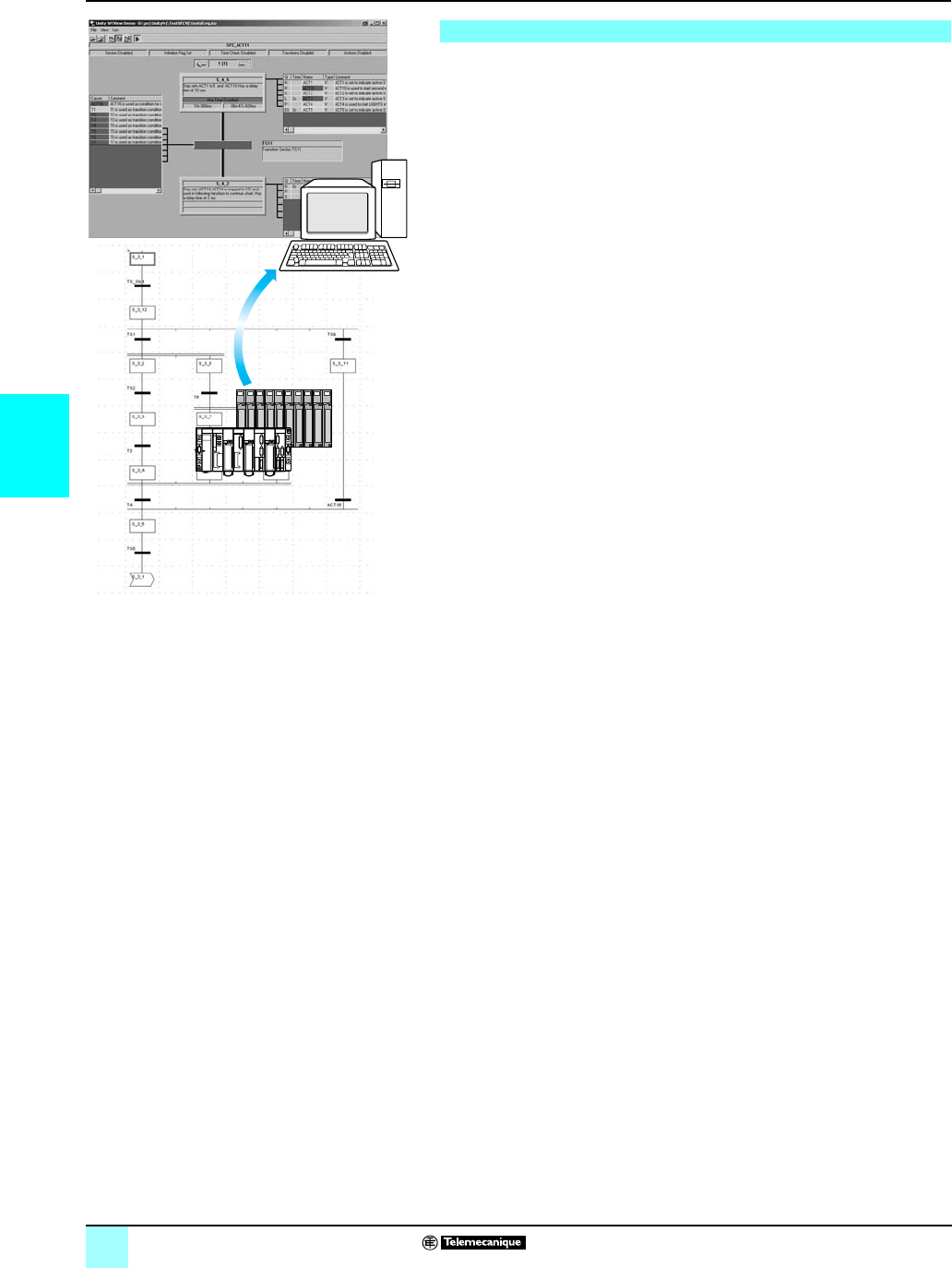
4/34
4
Presentation Modicon® M340™ Automation
Platform 0
Unity™ SFC View software
Unity SFC View is integrated in human/machine interface (HMI) applications for
monitoring Unity Pro sequential applications written in sequential function chart
language (SFC or Grafcet) executed by a PLC.
Set up in the same way as an ActiveX® control component, Unity SFC View is used
to display status information relating to SFC charts executed by a Modicon®M340™,
Premium™ or Quantum™ PLC. Installed on an HMI station, Unity SFC View monitors
and controls the status of SFC charts in real time, supplying detailed diagnostic data.
Unity SFC View reads the necessary data from the Unity project database in offline
mode. The PLC data is accessed online via the OFS (OPC Factory Server).
Without needing to recreate SFC charts in the HMI environment, Unity SFC View
reads the structure of the SFC charts directly from the Unity project database.
Modifications made to the SFC application are detected and updated at any time.
In online mode, Unity SFC View accesses the PLC diagnostic data, thus enabling
awareness and tracking of the occurrence of the first fault and subsequent faults.
System downtime is much reduced since Unity SFC View enables maintenance staff
to locate the source of the problem much more quickly.
Unity SFC View is designed for end users and system designers who wish to
integrate this control into their HMI system. Unity SFC View is compatible with most
HMI platforms handling ActiveX® Control components, such as Vijeo™ Look control
software or Monitor Pro™ supervisory software, or in a programming environment
such as Visual Basic.
Presentation
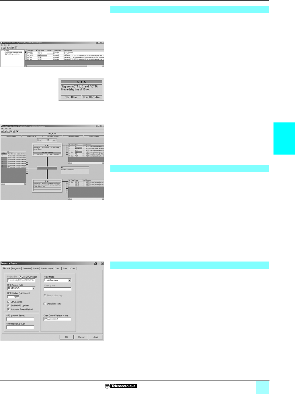
4/35
4
Presentation (continued) Modicon® M340™ Automation
Platform 0
Unity™ SFC View software
Unity SFC View offers 3 views:
bAn overview for managing selection of SFC charts
bTwo detailed views presenting the status and diagnostic data of the selected SFC
chart
The overview provides a general view of all the SFC charts in a Unity project. It
contains real-time data such as current step, simultaneous steps, chart error with
indication of the SFC chart status. The overview makes it easy to browse through
SFC charts and switch quickly to the detailed view of the desired SFC chart in the
Unity Pro application.
The simple detailed view shows the elementary data on the active step (or selected
step) of the SFC chart in real time. The data displayed may include the name,
comment, chart and step status, as well as the activity times (min, max, actual). You
can also enable the chart navigation option.
Because of the compact size of the simple detailed view, it is possible to place
several instances of it on a single HMI screen relating to a certain part of the process.
From this simple detailed mode, you can navigate between HMI screens with SFC
View controls and display the detailed view of SFC charts.
The detailed view illustrates the details of an SFC chart in real time. The display
indicates the current step, the transition awaiting activation and the next step. The
actions associated with the steps are displayed along with sequence selections or
parallel branches. The detailed diagnostic data includes analysis of the causes of the
fault at transition level. Depending on the diagnostic mode, the error grid contains the
causes of errors or all the variables assigned to the transition logic. The current state
of the various variables and selected errors are identified by different colors.
Transition logic diagnostics is a key function of Unity SFC View. It minimizes system
downtimes in the event of a fault.
Two different diagnostic modes are available:
bUnity SFC View reads the data in the Unity PLC diagnostic buffer. It provides
information about faulty or missing events that are preventing the transition from
being enabled. This mode does not require any configuration or additional
programming in the PLC program.
bUnity SFC View monitors the internal logic of the transition conditions
back-to-front. This mode provides diagnostic data concerning all the inputs
connected to the transition (not limited to faulty inputs). In this mode, for Premium™,
Atrium™ and- Quantum™ platforms, Unity SFC View uses specific EFB function
blocks linked to the transition conditions. The library for these blocks is supplied with
the Unity SFC View software.
Unity SFC View offers a programming interface which can be used to integrate the
ActiveX® Control component in an HMI application and customize its functions and
its operator interface.
The ActiveX® Control component in Unity SFC View can be customized. It accepts
properties, methods and events (all the properties have a default value).
The properties pages simplify configuration. Unity SFC View accepts scripts with
functions such as browsing through charts, and status control of charts, and also
events such as error notification or chart selection. This data can be used to launch
programs or operator screens.
The 3 Unity SFC View views
Overview
Simple detailed view
Detailed view
Diagnostic mode
SFC View properties page
Customization
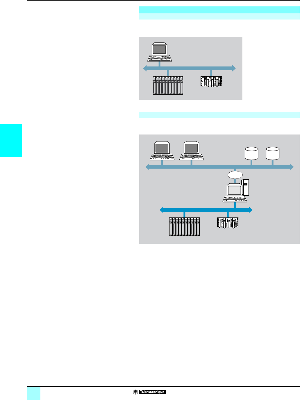
4/36
4
Presentation (continued) Modicon® M340™ Automation
Platform 0
Unity™ SFC View software
Unity SFC View is used in a configuration where the OFS and Unity Pro software
reside on the same PC platform as the HMI application.
In a distributed configuration, the OFS and Unity Pro software can be installed on
different servers.
Possible architectures
Basic architecture
Operator station with HMI
application and Unity Pro,
OFS and SFC View
programs and projects
Modicon M340, Premium, Atrium or
Quantum with Unity SFC program
Distributed architecture
Operator station with HMI
application and SFC View
projects
Ethernet TCP/IP
Unity projects
OFS server
P Server (Unity)
PLC network
COM or
DCOM
Modicon M340, Premium, Atrium or
Quantum with Unity SFC program

4/37
4
Presentation (continued) Modicon® M340™ Automation
Platform 0
Unity™ SFC View software
When integrated in an HMI application, Unity SFC View can be used to monitor and
control charts in applications developed in Sequential Function Chart (SFC)
language running on Premium™/Quantum™ Unity PLCs.
The HMI station, compatible with Windows® 2000 or Windows®XP Professional
operating systems, must support ActiveX® Control components.
Unity SFC View V2.0 requires:
bUnity Pro V3.p XL, to be ordered separately
bOFS V3.3 data server software, to be ordered separately
Unity SFC View multilingual software, supplied on a CD-ROM, includes:
bThe SFC View ActiveX® Control component
bThe EFB function block library for Unity Pro V3.p
bAn example of how to integrate SFC View in Unity Pro projects
bThe electronic documentation (English, French and German)
The Unity SFC View integration example illustrates the main possibilities offered by
Unity SFC View. This is an executable program which does not need HMI software
in order to run. It helps the user understand how to configure and use the Unity SFC
View ActiveX® Control component.
References
Description Type of license Reference Weight
kg
Unity SFC View software
packages
(version V2.0)
Single (1 station) UNYSDUMFUCD20 –
Team (10 stations) UNYSDUMFTCD20 –
Site (100 stations) UNYSDUMFFCD20 –
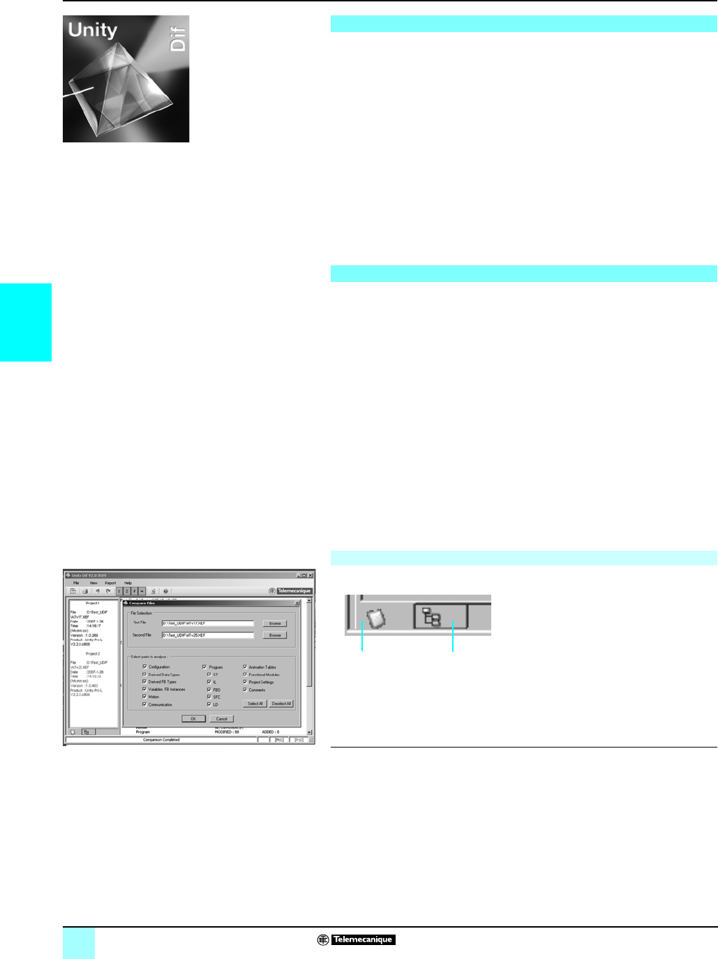
4/38
4
Presentation,
setup
Modicon® M340™ Automation
Platform 0
Unity™ Dif application comparison software
Unity Dif application comparison software for Modicon M340/Premium/Atrium/
Quantum platforms is an optional program which complements the Unity Pro
Extra Large programming software. It is used to compare two Unity applications
generated by Unity Pro and automatically provide an exhaustive list of all the
differences between them.
The Unity Dif program increases productivity in the main life phases of a control
system based on a M340/Premium/Atrium/Quantum platforms:
bApplication development and debugging.
bStarting up installations and processes.
bOperation and maintenance of installations and processes.
Unity Dif software is an efficient tool for handling Unity applications for:
bControl system design offices.
bOperation and maintenance managers.
bInstallers and systems integrators.
v
The Unity Dif software can be used in one of two modes:
bInteractive mode, when the comparison is launched by an operator command
(double-click on the Unity Dif software icon).
bAutomatic mode, when it is launched by a previously established call command.
These comparison commands locate all the differences between two applications in
terms of:
bThe hardware configuration (Modicon M340/Premium/Atrium/Quantum)
bThe network configuration (Ethernet TCP/IP network, CANopen bus and RIO
remote I/O)
bThe entire of variables and function block instances
bThe application structure and its content (regardless of the language(s) used)
bThe function modules.
bThe code for the DFB user function blocks and DDT coumpound data.
bThe project options.
The result of the comparison between the two applications can be:
bDisplayed.
bPrinted.
bSaved in .txt format in a differences list.
The end of the comparison operation is signalled by the appearance of the
application browser with its two tabs.
1 Identification tab for accessing the
characteristics of the two applications being
compared. The differences are marked by the
sign #.
2 Browser tab for accessing the application
multilevel tree structure.
(1) RIO remote I/O for Modicon Quantum platform.
Presentation
Software setup
Comparison
21
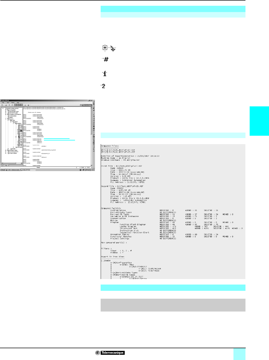
4/39
4
Setup (continued),
reference
Modicon® M340™ Automation
Platform 0
Unity™ Dif application comparison software
The representation of the application multilevel tree structure, which can be
accessed via the browser tab after launching a comparison, is annotated by
4 symbols in which the information associated with application 1 appear in blue and
those associated with application 2 appear in red:
In the example opposite, a difference on the rung causing changeover to manual
mode is detected:
1This line displayed in blue belongs to application 1 [Prj1]
2This line displayed in red belongs to application 2 [Prj2]
The source code extracts of both applications can be used to locate the differences
precisely.
The “Report” command allows to generate the report file (.txt):
This software extension used to compare two PL7 applications generated by Unity Pro software
version uV2.1
Setup (continued)
Display of results
This branch, found in this level of the tree structure, contains at least
one difference
This block contains at least one difference
This section is only present in application 1
This section is only present in application 2
1
2
Differentiation report
Reference
Function Target
extension PLC
target
Type of device Reference Weight
kg
Unity Dif application
comparison software
extension
CD-Rom containing
software and electronic
documentation (English-
French)
Unity Pro
Extra Large
Modicon M340/
Premium/Atrium
Quantum
Single
(1 station)
UNYSDUDFUCD20 –
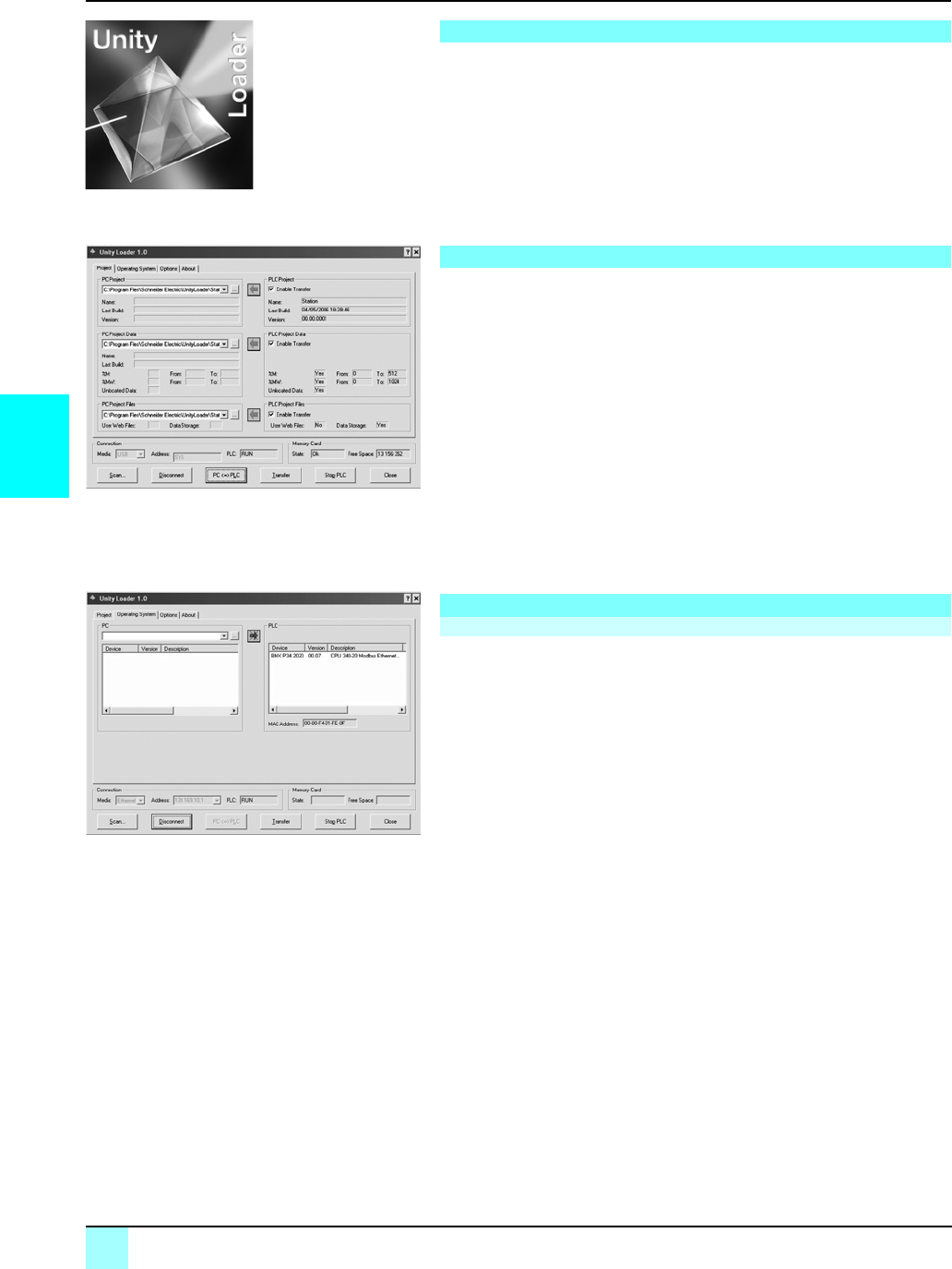
4/40
4
Presentation,
functions
Automation platform 0
Modicon® M340™ PLC
Unity™ Loader software
Unity Loader is companion software to Unity Pro and is used to perform maintenance
operations on automation applications. Its easy setup and the small size of its
executable make it an essential tool for updating Modicon M340 PLC projects when
it is not necessary to read or modify the program. It is also essential software for
updating the embedded software on the M340 PLC. It performs the following two
main functions:
bTransfer of automation project components from the PC to the PLC or from the
PLC to the PC, such as the program, data, files and user Web pages stored in the
memory cartridge
bTransfer of embedded software from the PC to the processor or Ethernet
communication modules
The software is designed to be used by people with limited automation expertise. The
interface consists of four tabs, and buttons within each of the tabs to perform different
operations.
bThe first tab, Project, is used for project transfers: program, data and user files. The
three exchange operations between the PC and the processor can be sequenced
together in a single command.
bThe second tab, Operating System, is used to update the embedded software in
the PLC. The screen displays the detailed content of the PLC firmware versions, and
when a file is selected on the PC, the characteristics of that file are displayed.
bThe third tab, Options, is used to configure the working environment, including the
location of files on the PLC, and selection of one of six languages (English, Spanish,
French, German, Italian, and Chinese) for the interface and online help.
The last tab can be used to display information about the software.
Note: Regardless of which tab is selected, the connection status with the PLC is displayed, along
with commands for connecting/disconnecting and changing the PLC operating mode.
The software can be used to transfer the components of a project in either direction:
bProgram: binary and source, if the application has been built using the source
format
bData file: located and unlocated data
bData on the processor memory cartridge: user files (if the cartridge allows this)
Unity Pro can be used to transfer the application from either the application file .stu,
or the archive file .sta. The program file and data formats, along with the functions
performed by Unity Loader, are identical to those built and used by Unity Pro.
When the cartridge-based user files are transferred from the PLC to the PC, a private
file specific to Unity Loader is created. The operation is then possible in the other
direction. Unity Pro cannot be used to perform this type of transfer.
In order to simplify project management, Unity Loader defaults to store the three files
read in the PLC in the same directory with an identical file name (the project name
by default), but with a different file extension. The default choice suggested can be
modified by the user.
Once connected to the PLC, Unity Loader displays the characteristics of the data
read in the PLC. Similarly, when the files are selected on the PC, the corresponding
characteristics are also displayed. All the data necessary to decide on the action
required is displayed on a single screen. The three components of the project are
selected by default, provided that they are valid for the chosen direction of transfer.
Transfer of one or two of the components can be disabled. All of the transfers are
performed in a single command.
Presentation
Software graphic interface
Modicon® M340™ PLC project transfer
Exchanges between the PC and the PLC processor
Unity Loader: Project tab
Unity Loader: Operating System tab
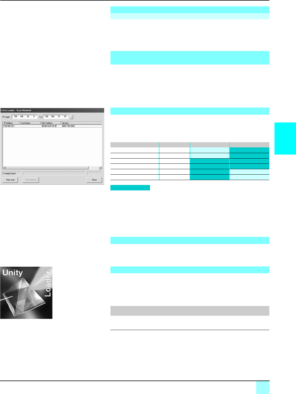
4/41
4
Functions (continued),
reference
Automation platform 0
Modicon® M340™ PLC
Unity™ Loader software
The BMX NOE 0100/BMX NOE 0110 communication modules contain a memory
cartridge that can store user web pages, depending on the model used. When Unity
Loader is connected to the communication module, web pages can be transferred
from the module to the PC or vice versa. The operating mode is identical to that
available for exchanges with the processor.
Firmware can be updated by following the same principle as that used for transferring
projects.
Once connected to the PLC, Unity Loader displays the characteristics of the firmware
read in the PLC. Similarly, when a file corresponding to a valid file for the firmware is
selected on the PC, the corresponding characteristics are also displayed. All the data
necessary to decide on whether the update should be performed is displayed on a
single screen.
Unity Loader uses two communication vectors, USB and Ethernet. USB is always
available for exchanges with the PLC processor. Ethernet is essential for exchanges
with the Ethernet modules and can also be used for exchanges with processors
which have an integrated Ethernet port.
When Unity Loader is connected to an Ethernet network, it is possible to define a
range of addresses to be scanned and thus display all the devices recognized on the
network. By selecting the Modicon M340 PLC, the transfer operations can then be
performed.
All connection and transfer operations, along with any errors, are recorded in a trace
file stored in the PC.
Unity Loader is compatible with Modicon M340 PLCs.
Its use is totally independent from Unity Pro. Program files and PLC data are
compatible between Unity Pro and Unity Loader.
Unity Loader is available in two formats. It is automatically provided with all versions
of Unity Pro Small, Medium, Large and Extra Large. It can also be ordered
separately.
The product includes a graphic interface and documentation in six languages
(English, Spanish, French, German, Italian, and Chinese).
Modicon® M340™ PLC project transfer (continued)
File transfer to the Modicon M340 PLC Ethernet communication module
Updating embedded software in the Modicon®M340™ processor
and Ethernet communication modules
Communication between the PC and the PLC
PLC Type Ethernet port USB port
BMX P34 1000 CPU
BMX P34 2010 CPU
BMX P34 2020 CPU
BMX P34 2030 CPU
BMX NOE 0100 Ethernet module
BMX NOE 0110 Ethernet module
Supported
Compatibility
Reference
Description Type Reference Weight
kg
Unity Loader Single license UNYSMUZUCD30 –
Unity Loader: Network scanning
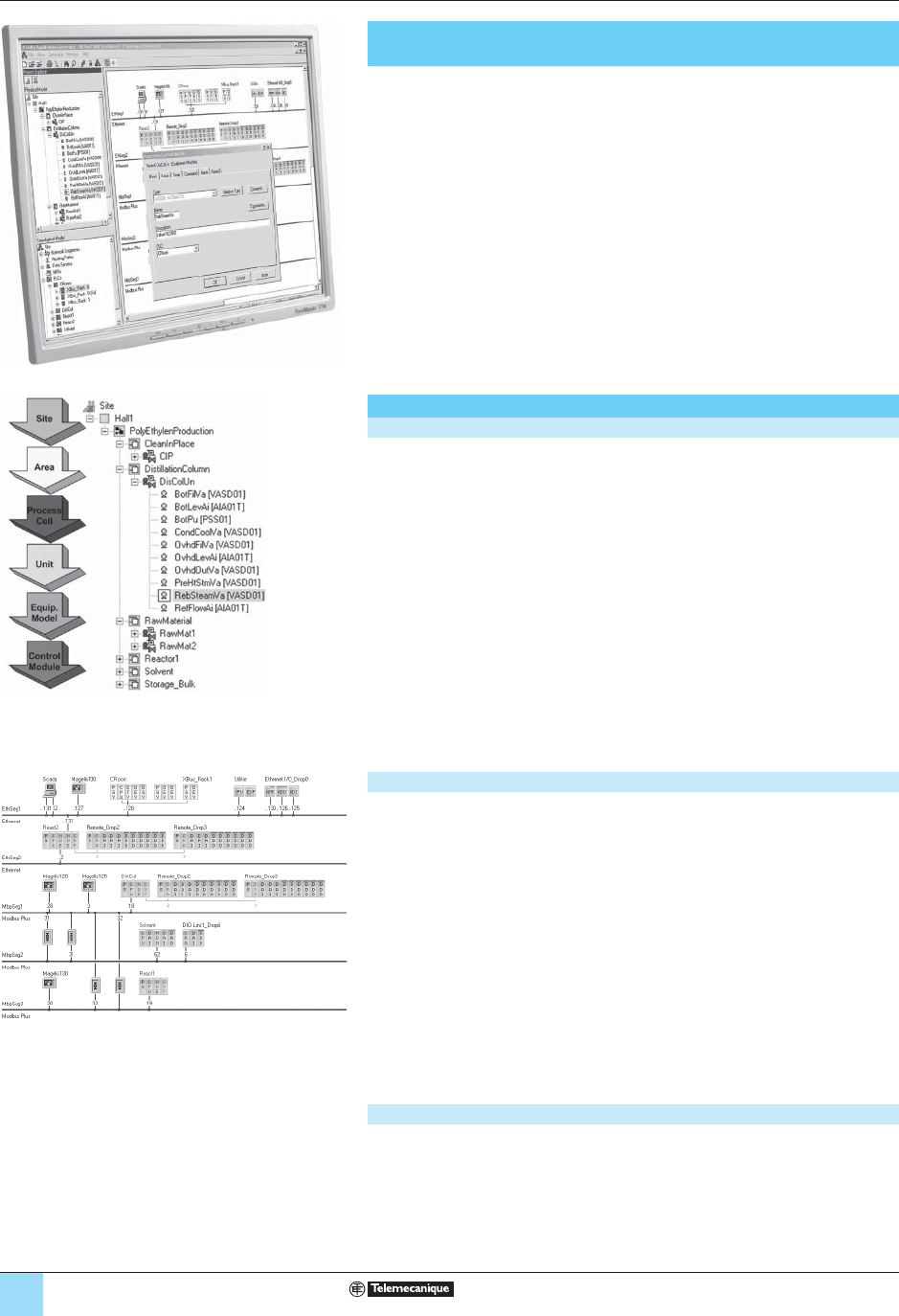
4/40
Modicon® Premium™/Quantum™
automation platform 0
Unity™ Application Generator
Unity Application Generator for designing and generating
process applications
Unity Application Generator (UAG) is a specialized software productivity tool for
modeling and generating process applications in a collaborative environment.
For process type applications, UAG provides a single database containing all the
project information (process model, control confi guration and SCADA integration).
Using an approach based on reusable control devices (PID, motor, valve,etc.), UAG
which complies with the standard ISA S88 and generates the PLC code (Unity Pro &
Concept), plus all the elements required by the HMI monitoring system (Magelis) or
SCADA (Monitor Pro V7.2 (1) or third-party supervision system).
Single entry and central information management ensure data consistency and the
integration of the control (PLC) and monitoring (HMI/SCADA) systems.
Process models
Physical model (process view)
Process components and logical structureation of the process are based on the ISA
S88 standard.
Adopting the ISA S88 standard provides the following benefi ts:
■ Considerable process fl exibility.
■ Signifi cant reduction in development and delivery timescales.
■ A standardized, uniform solution.
■ Reuse of sub-elements.
UAG offers the 6 structural levels from the ISA S88 standard (site, area, process cell,
unit, equipment module and control module):
These levels can be found again within the applications structure (supervision and
PLC) generated by UAG. Process parameters for control devices, such as motors,
control loops and valves, are set at control module level.
Topological model (automation view)
In a Collaborative Control environment, UAG can be applied to the entire process’
control, monitoring and supervision topology. The topological view includes all
devices with I/O points, as well as the communication channels between these
devices.
UAG supports:
■ Architectures comprising automation platforms.
□ Modicon Quantum, Premium and Atrium with Unity Pro.
□ Modicon Quantum and Momentum with Concept.
■ SCADA systems (Monitor Pro, iFix or generic), Magelis panels.
■ Ethernet TCP/IP and Modbus Plus communication networks.
■ Third-party devices.
The process for confi guration of networks, PLC applications with their I/O and other
devices of the topological model , takes place directly in UAG.
Complet model (project view)
The physical and topological models are independent and can be created in
parallel by independent process and automation experts.
The models are integrated via simple drag & drop operations between the two views..
This integration simply involves assigning PLC I/O points to control devices
(valves, motors, etc.).
Presentation
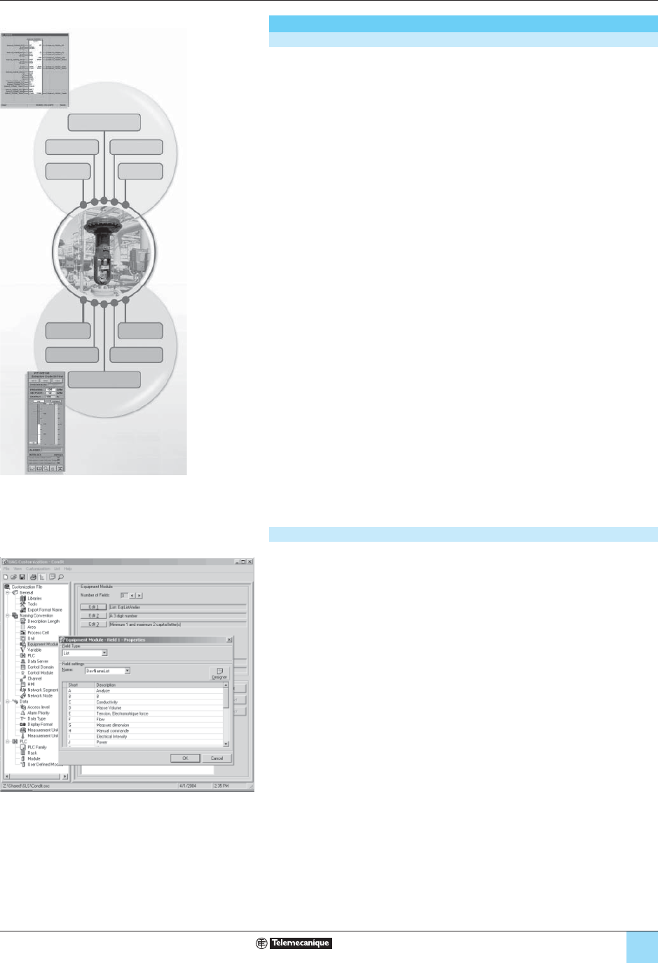
4/41
Modicon® Premium™/Quantum™
automation platform 0
Unity™ Application Generator
Integrating your expertise in UAG
Smart Control Devices (SCoDs)
UAG software is an object-oriented tool based on these Smart Control Devices.
These elements describe a part of the process, including all the aspects of the
process control system:
■ Links to the PLC logic.
■ Links to the graphic representation in the supervisory system.
■ Description of I/O interfaces.
■ Description of interfaces intended for HMI/SCADA supervisory.
■ Information related for handling alarms and events.
■Documentation.
In UAG these multi-faceted elements are called SCoDs (Smart Control Devices).
They are created using UAG’s specifi c SCoD editor.
A SCoD is defi ned for each control devices, and is created with the help of the SCoD
editor by:
■ Using the DFB or EFB interface of the PLC logic (Unity Pro/Concept) by importing
FBD Language.
■ Assigning a supervisory graphic reference (Monitor Pro (1) or others).
■ Defi ning the Smart control Device parameters and their behavior in the process
control system:
□ control device parameters and attributes from the process side (operating modes,
threshold limits, alarm texts, etc.).
□ I/O parameters and attributes for PLC logic,
□ parameters and attributes for HMI/SCADA supervisory.
■ Defi ning confi guration screens for the UAG user interface.
■ Defi ning default or initial parameters.
This means that you can integrate your process expertise and know-how in your
own SCoD libraries and reuse them again and again in all your UAG applications.
Customization
UAG can be used to defi ne your own standards and apply them. It provides a uniform
solution based on your standards, and prepares for validation operations.
During the design phase, the risk of error is kept to a minimum, thereby reducing
debugging and maintenance costs too.
UAG can be used to customize:
■ The selection of SCoD libraries.
■ The symbols nomenclature used in UAG.
■ The selection of PLC platforms and modules.
■ The defi nition of access levels, display formats, units of measurement, etc. used
for HMI/SCADA supervisory.
■ The user documentation.
■ Security.
This means that you can integrate your process expertise and standards in all
your UAG applications.
Documentation
PLC Logic Maintenance
DiagnosticLocking
Documentation
Security I/O interfaces
Alarms/
events
Graphic
representation
PLC
IHM
C
ontrol Loop
Documentation
PLC Logic Maintenance
DiagnosticLocking
Documentation
Security I/O interfaces
Alarms/
events
Graphic
representation
PLC
IHM
C
ontrol Loop
Presentation (continued)

4/42
Modicon® Premium™/Quantum™
automation platform 0
Unity™ Application Generator
Integrating your expertise in UAG (continued)
Modeling process applications
Once you have created the customization based on your standards and chosen your
SCoD libraries, UAG offers you a simple, user-friendly, application-specifi c method
of working.
The process is defi ned using the physical model (process view), exploiting the
expertise provided at customization and SCoD library creation stages. This means
that the process behavior and the process confi guration screens match exactly your
requirements.
The process control is defi ned using the topological model (automation view), again,
in accordance with your customization.
■ Process design using UAG is made easy through functional analyses. It allows
the user to reliably track the exact project status. In order to be able to detect any
error or oversight as soon as possible, UAG analyzes the project and fl ags any bugs
at the various levels of the project, for instance:
■ At physical model level:
□ SCoD instance attributes that are missing or over limit,
□ invalid or missing interlock parameters.
■ At topological model level:
□ Communication channels between devices that are not defi ned,
□ invalid or missing communication parameters.
■ At project level:
□ SCoD data is being transmitted from another PLC, but communication with this
device has not been confi gured,
□ the SCoD data is not assigned to any PLC I/O variable,
□ behavior on response time for I/O variables that is not defi ned.
This means that your process expertise and know-how is made available to be
used in UAG, ensuring consistent process application modeling.
Generating process applications
UAG provides at a single point all the process information intended for the project’s
multiple applications (PLCs, HMI/SCADA), along with the communication
parameters.
When applications are generated this information is used to create the confi guration
and part of the control logic in using IEC 61131-3 FBD functional language. The
following items are generated:
■ At PLC level:
□ Hardware confi guration,
□ localized and non-localized data with its initial value and symbol,
□ initialization,
□ inter-PLC communication and distributed I/O (I/O Scanning on Ethernet or Peer
Coop on Modbus Plus),
□ DFB/EFB block data (information from SCoDs),
□ interlocks.
■ At HMI/SCADA level:
□ Data for graphic animations,
□ localized data with its corresponding symbol (display, alarm, archiving
information.),
□ user access rights.
■ At communication level:
□ Communication driver confi guration (Monitor Pro (1) and iFIX),
□ confi guration data for third-party devices (via an XML interface).
The generation process in UAG is incremental, which makes it possible to
supplement the various applications with their dedicated tools outside UAG without
any risk. Incremental generation in UAG only impacts changed elements within the
applications, which ensures that any additions made using the dedicated tools are
stored permanently. This means that your process expertise and know-how is
quickly operational in your process without any errors or oversights.
Presentation (continued)
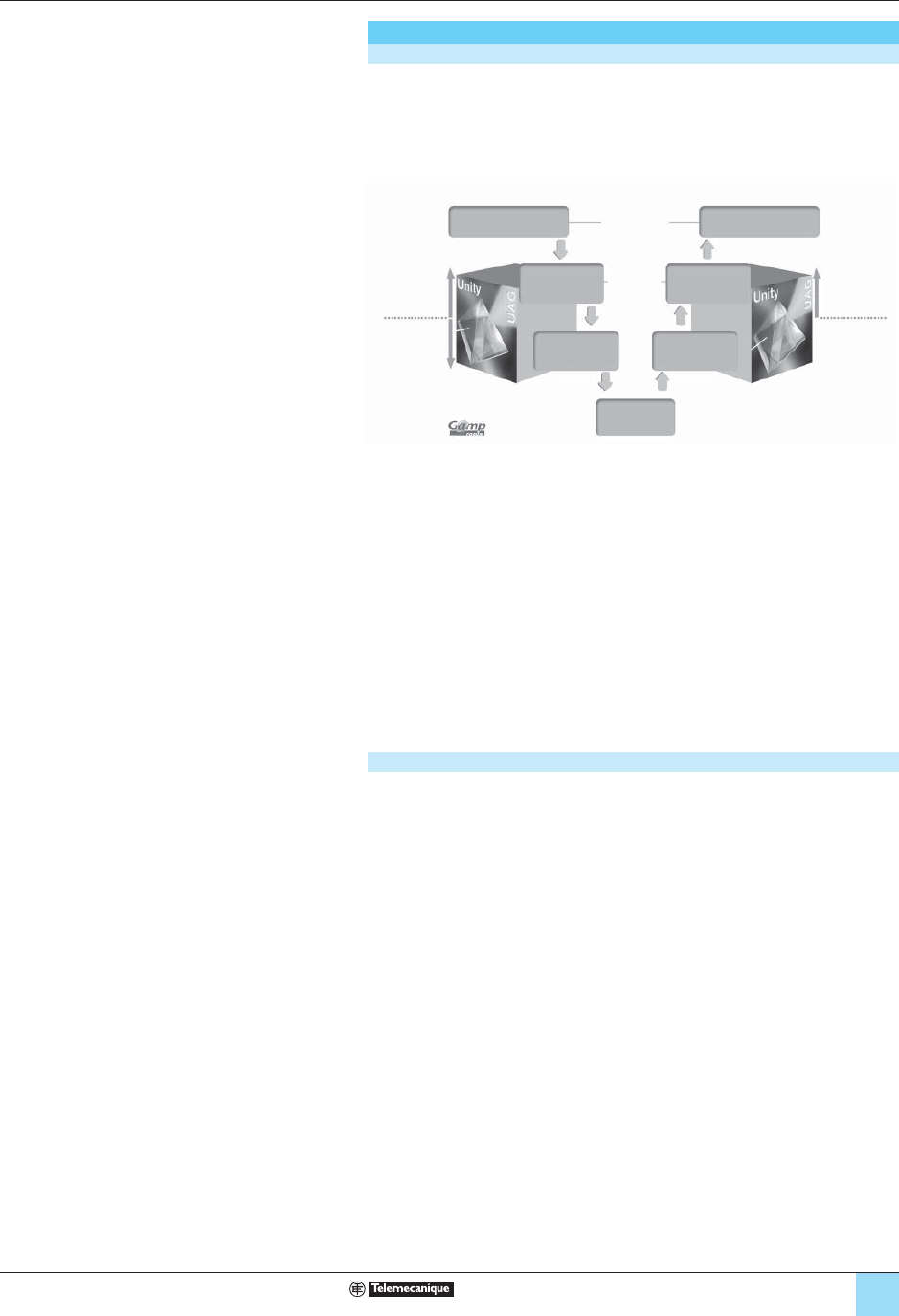
4/43
Modicon® Premium™/Quantum™
automation platform 0
Unity™ Application Generator
Validation
Validation
UAG is a specialized functional tool for process experts and has been developed to
comply with the following process standards:
■ ISA S88.
■ GAMP (Good Automation Manufacturing Practice).
UAG uses ISA S88 standard terminology for batch control and adopts the GAMP
methodology for creating an automated system.
The inclusion of these two standards provides major support in the task of approving
and validating processes. Validation according to FDA 21CFR Part 11 regulations is
simplifi ed by UAG, as it provides:
■ All process information at a single point, based on functional analysis.
■ Automatic generation of process applications by UAG.
■ Archiving in compliance with FDA regulations.
■ A log of all interactions by UAG.
■ Electronic documentation.
UAG tracks and documents every modifi cation made. The version control system, in
compliance with regulation FDA 21 CFR Part 11, ensures simple, straightforward
validation.
Active collaboration
Compatible with third-party tools
UAG arranges existing information according to your operating objectives and
constraints. Open import/export interfaces are available at every level, facilitating the
connection of third-party tools at any time. This means that you can share your
expertise by reusing, for example, data from your CAD tools.
Total user accessibility
With its multi-user environment and common language, UAG facilitates sharing
among process and PLC developers, as well as maintenance engineers and
operating staff.
UAG ensures optimum productivity throughout your application’s entire life
cycle.
Associated
System
build
Validation procedures
Associated
Associated
Process
applications,
Documentation
Validation
Qualifi cation
(IQ, OQ)
Modeling
software
PLC/IHM
application
software
User feedback report
(UFR)
Performance
qualifi cation (PQ)
Functional
specifi cations
Operational
qualifi cation
(OQ)
Detailed system
requirements
Installation
qualifi cation
Good Automation
Manufacturing Practice
Associated
System
build
Validation procedures
Associated
Associated
Process
applications,
Documentation
Validation
Qualifi cation
(IQ, OQ)
Modeling
software
PLC/IHM
application
software
User feedback report
(UFR)
Performance
qualifi cation (PQ)
Functional
specifi cations
Operational
qualifi cation
(OQ)
Detailed system
requirements
Installation
qualifi cation
Good Automation
Manufacturing Practice
Presentation (continued)
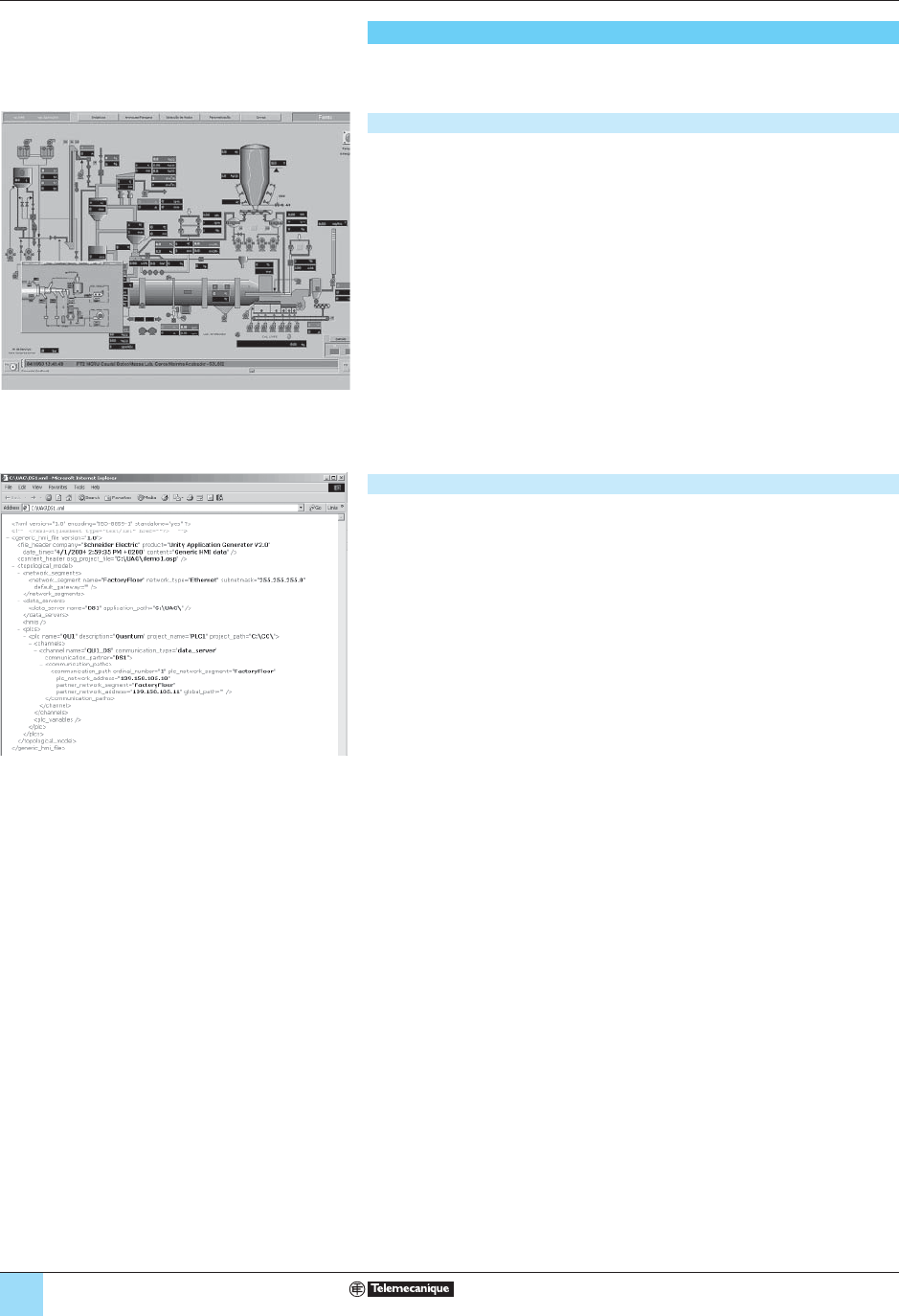
4/44
Modicon® Premium™/Quantum™
automation platform 0
Unity™ Application Generator
Interfacing with SCADA applications
UAG can openly interface with many of the SCADA systems currently available on
the market.
Direct integration
Direct integration by UAG automatically generates the Monitor Pro V7.2 supervisory
application elements, which are:
■ Variables with symbol and attributes.
■ Alarm server confi guration.
■ Trend server confi guration (real time and historical).
■ Mimics (graphic objects) of the devices.
■ Confi guration of the Modbus TCP/IP communication driver.
In addition, for each modifi cation by UAG, the Monitor Pro V7.2 application is
automatically updated without any confl icts or risk of disruption of added or changed
elements.
UAG therefore ensures data consistency between the automation control and the
supervory level.
This type of direct integration is also available with the iFix supervisory and control
system (GE Fanuc).
Open integration
Open integration is based on all the UAG application information made available via
XML fi le format. This XML fi le is generated by UAG and can be imported into many
third-party SCADA systems, once it has been customized using the XLS style sheets
specifi c to the third-party system.
Regardless of whether direct or open integration is involved, UAG provides
you with total consistency within your control, monitoring and supervision
system throughout the application’s entire life.
Presentation (continued)

4/45
Modicon® Premium™/Quantum™
automation platform 0
Unity™ Application Generator
References
This specialized software program UAG (Unity Application Generator) is multilingual
(available in English, French and German) and is compatible with the Windows 2000
Professional and Windows XP operating systems.
UAG can be used to model and generate process applications in a collaborative
environment. It generates the PLC code (Unity Pro & Concept) and the elements
required by the HMI monitoring system (Magelis), SCADA (Monitor Pro V7.2 or
third-party supervision systems).
There are two types of software license available for UAG: Medium (M) and Large
(L). They are determined by the functional level of the HMI integration:
■ The Medium version generates HMI information using customizable XML fi les
(XSL style sheets).
■ The Large version also provides customizable XML fi les, direct integration for
Monitor Pro and iFix supervision systems featuring the generation of SCADA
applications with variables and attributes, mimics (graphic objects), alarm tables and
communication driver confi guration.
Documentation is supplied in electronic format.
UAG software suites
Description Type
Code generated License type Reference Weight
kg
UAG software suites
(Unity Application
Generator)
Medium Single
(1 machine)
UAGSEWMFUCD21 –
Site UAGSEWMFFCD21 –
Large Single
(1 machine)
UAGSEWLFUCD21
–
Site UAGSEWLFFCD21 –
Coming soon!
References

05/0
5

5/1
5
Contents 5 - Connection interfaces
1
Advantys™ Telefast® ABE7 pre-wired I/O system
bPresentation, combinations . . . . . . . . . . . . . . . . . . . . . . . . . . . . . . . . . . . . . . . . 5/8
bReferences
vPassive connection sub-base for discrete inputs/outputs . . . . . . . . . . . . . . 5/10
vAdaptation sub-bases with soldered relays and removable terminal blocks 5/12
vAdaptation sub-bases for or with plug-in relays . . . . . . . . . . . . . . . . . . . . . . 5/13
vPlug-in relays . . . . . . . . . . . . . . . . . . . . . . . . . . . . . . . . . . . . . . . . . . . . . . . . 5/15
vConnection sub-bases for counter and analog channels. . . . . . . . . . . . . . . 5/16
vAccessories for connection sub-bases . . . . . . . . . . . . . . . . . . . . . . . . . . . . 5/17
bDimensions . . . . . . . . . . . . . . . . . . . . . . . . . . . . . . . . . . . . . . . . . . . . . . . . . . . 5/18
Phaseo® power supplies
bPhaseo Universal range of regulated switch mode power supplies . . . . . . . . 5/20
Human/machine Interfaces
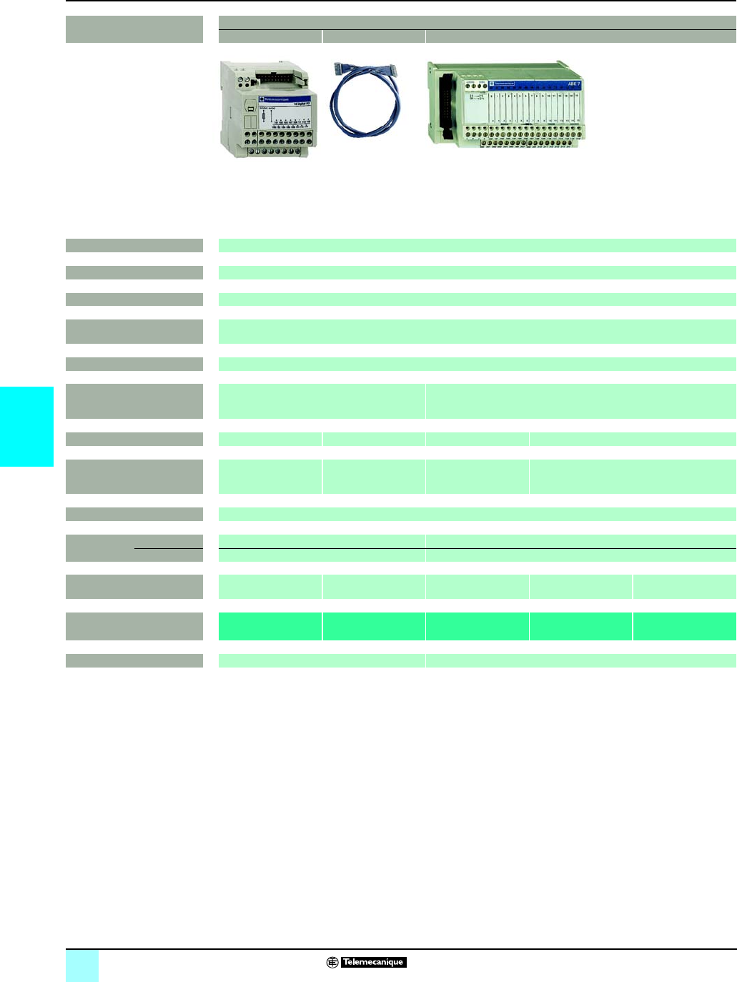
5/2
5
Selection guide
0
Connection interfaces 0
Advantys™Telefast®ABE7 pre-wired system
Discrete input and/or output sub-bases
Applications Discrete inputs or outputs
Optimum “Low cost” Optimum “Miniature” Universal
Relay amplification –
Equipped with relay –
Control voltage 24V c
Output voltage 24V c
Output current per channel 0.5 A
Modularity 16 8 -12 -16
No. of terminals per channel 11 to 3 1 2
Type of connection terminals Signal Signal, common
(configurable 24 V c or
0V)
Signal Signal, common (configurable 24 V c or 0 V)
Connectors 20-pin HE10 connector
Terminal
block
Removable No No
Terminal type Screw Screw or spring
Additional or optional*
function
Low cost version
fitted with cable
Miniature sub-bases Compact size *Type 2 input *
(1)
Isolator *
Device type ABE7H20Eppp
ABE7H32Eppp
ABE7H16Cpp ABE7HppR1p
ABE7HppR50
ABE7HppR2pABE7HppS21
Pages 5/10 5/11
(1) For TSX Micro and Premium PLCs
817437
817438
817436
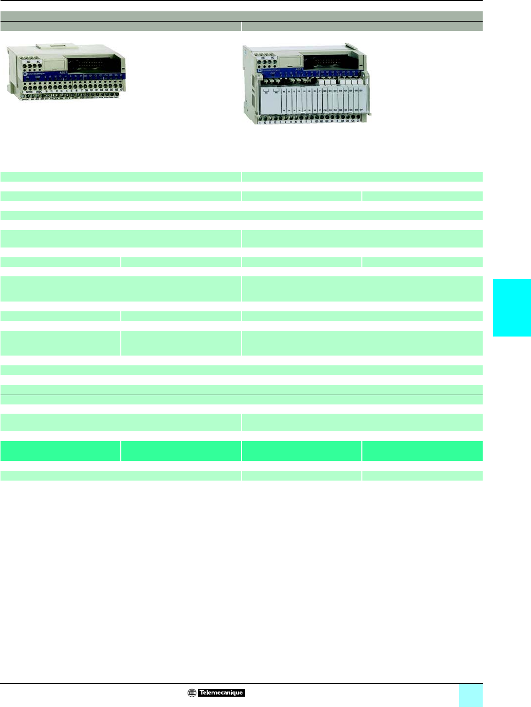
5/3
5
0
0
Discrete inputs and outputs
Optimum “Miniature” Optimum
–Plug-in electromechanical or solid state
–No Yes
24V c
24V c 24V c (solid state)
5... 24V c 230 V a (electromechanical)
0.5 A 0.5 A 5 A (E.M.), 2 A (solid state) 5 A (th)
16 16
8 passive inputs
8 relay outputs
1 2 1
Signal,
2 common connections between
the inputs and the outputs.
Signal, common,
2 common connections between
the inputs and the outputs.
1 N/O contact and common, 4 output channels
2 input connection points
20-pin HE10 connectors
No
Screw
Miniature sub-base
Synergy with Tego® Power and Micro PLC
Miniature sub-base - Common per 4 channels
Synergy with Tego® Power and Micro PLC
ABE7H16CM11 ABE7H16CM21 ABE7P16M111 ABE7R16M111
5/10 5/14 5/13
817432
521500
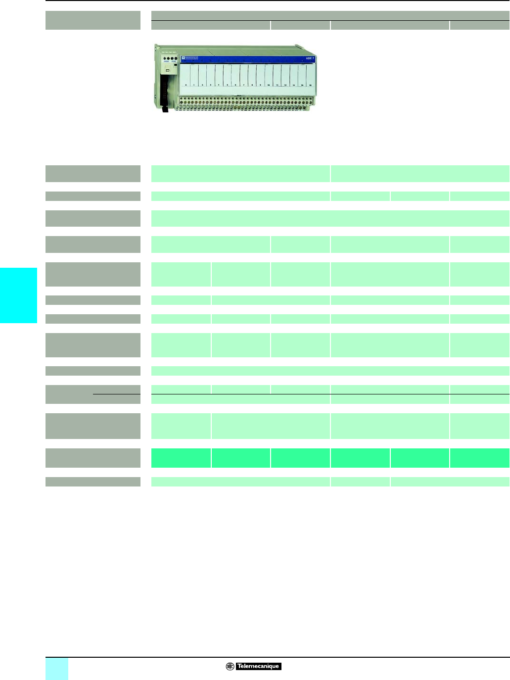
5/4
5
Selection guide (continued)
0
Connection interfaces 0
Advantys™Telefast®ABE7 pre-wired system
Discrete input and output sub-bases
Applications Discrete output
“Optimum” “Universal” “Optimum” “Universal”
Relay amplification Electromechanical, fixed Electromechanical or solid state
Equipped with relay Yes Yes No No
Control voltage 24 V c
Output voltage 5 V c ... 30 V
230 V a
5 V c ... 150 V
230 V a
24 V c (solid state)
5 V c ... 24 V, a 230 V (E.M.)
5 V c ... 150 V
230 V a
Output current per channel 2 A (th) 3 A (th) 5 A (th) 2 A (solid state),
6 A (electromechanical)
Depends on
relay mounted
0.5 to 10 A
Modularity 88 - 16 16 8 or 16
No. of terminals per channel 2 1 2 1 2 to 3
Type of connection terminals 1 N/O contact
and common
Voltage-free
1 N/O contact 1 N/O contact
and common
1 N/O contact Signal,
Polarities
Connectors 20-pin HE 10 connector
Terminal
block
Removable Yes Yes Yes No No
Terminal type Screw or spring Screw Screw or spring
Additional or optional*
function
Miniature sub-base
Latching relay
voltage-free
or common per 8 channels
Miniature sub-bases
Common per 4 channels
Isolator and fuse
Device type ABE7R08S216pABE7RppS1pp ABE7RppS2pp ABE7R16T111 ABE7P16T111 ABE7P16T2ppp
ABE7P08T3ppp
Pages 5/12 5/13 5/14
817440

5/5
5
0
0
Discrete outputs Discrete inputs
“Universal” “Universal”
Electromechanical, plug-in Solid state, fixed – – Solid state, fixed Solid state, plug-in
Yes Yes – – Yes No
24 V c From 24 V c
to 230 V a
From 5 V TTL
to 230 V a
5 V c ... 150 V
230 V a
24 V c
5A (th) 8 A (th) from 0.5 to 2 A 125 mA 0.5 A 125 mA 12 mA
16
2 to 3 2 to 6 2 3 2
1 C/O contact or
1 N/O contact
and common
1 C/O contact
or 2 C/O contacts
and common
Signal and 0 V Signal 24 V c
and 0 V
Signal can be
isolated,
Protected common
Signal Signal and
common
20-pin HE 10 connector
No Yes No No Yes No
Screw Screw or spring Screw Screw or spring
Voltage-free or common: Fault signal Isolator and fuse
(indicator)
3-wire proximity
sensor
Isolator and fuse
(indicator)
–
8 channels 4 channels
ABE7R16T2pp ABE7R16T3pp ABE7SppS2BpABE7H16F43 ABE7H16R3pABE7H16S43 ABE7S16E2pp ABE7P16F31p
5/13 5/12 5/11 5/12 5/15
817439
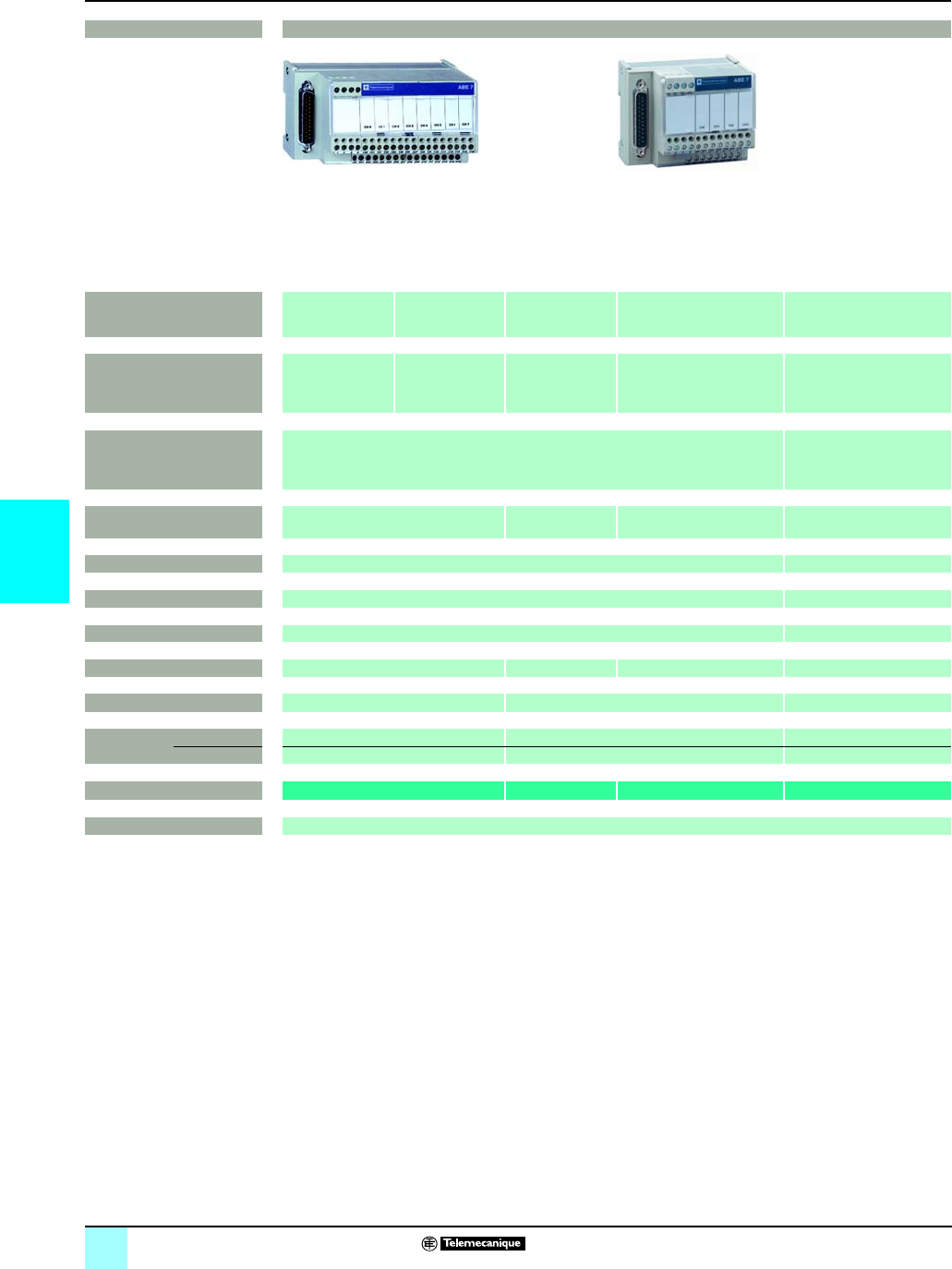
5/6
5
Selection guide (continued)
0
Connection interfaces 0
Advantys™Telefast®ABE7 pre-wired system
Analog and application-specific sub-bases
Applications Analog signals and special functions
Compatibility TSX Micro™ PLC Premium™ PLC Standard Modicon® M340™ PLC
BMX ART 0414 / 0814
BMX AMI 0410
Type of signal Counter inputs
and analog I/O
Counter inputs
Axis control
Position control
Analog inputs
Current
Voltage
Pt 100
Analog outputs
Current
Voltage
Analog inputs
Functions Passive connection, point-to-point with shield continuity Direct connection
Cold-junction compensation
or distributed 4 protected
isolated power supplies
Modularity 1 counter channel or 8 analog inputs + 2
analog outputs
8 channels 4 channels 4 channels
Control voltage 24 V c –
Output voltage 24 V c –
Output current per channel 25 mA –
No. of terminals per channel 22 or 4 2 or 4 2 or 4
Connector type 15-pin SUB-D + 9-pin SUB-D 25-pin SUB-D 25-pin SUB-D
Terminal
block
Removable No No No
Terminal type Screw Screw Screw
Device type ABE7CPA01 ABE7CPA02 ABE7CPA21 ABE7CPA412/410
Pages 5/16
817431
5/7
5
0
0
Analog signals and special functions
Standard Premium
TSX AEY810
Premium
TSX CAYp1
TSX CTY2C
Premium
TSX AEY1614
Premium
TSX PAY2p2
Analog inputs
Current
Voltage
Pt 100
Isolated analog inputs Inputs
Counter
Inputs for thermocouples Inputs/outputs
Distribution of sensor
power supplies per limiter
(25 mA)
Distribution of isolated sensor
power supplies per converter
Acquisition of value
from an absolute encoder
Connection of 16
thermocouples with
cold junction compensation
Safety module (BG)
8 channels 8 channels 1 channel 16 channels 12 Emergency stops
24 V c
24 V c
25 mA –
2 or 4 –2 or 4 1
25-pin SUB-D 25-pin SUB-D 15-pin SUB-D 25-pin SUB-D 50-pin SUB-D
No No No No No
Screw Screw or spring Screw Screw Screw
ABE7CPA03 ABE7CPA31pABE7CPA11 ABE7CPA12 ABE7CPA13
5/16
817435
817434
817435
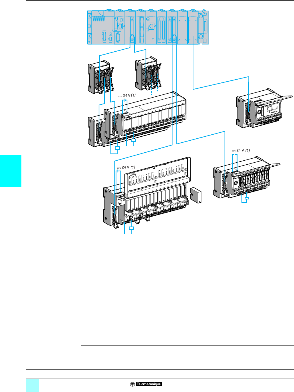
5/8
5
Presentation Connection interfaces 0
Advantys™Telefast®ABE7 pre-wired system
Interface with Modicon® M340™ I/O modules
1Discrete BMX DDI pp02K input modules, BMX DDO pp02K output modules and BMX DDM 3202K mixed I/O
modules equipped with one or two 40-pin connectors. The module modularity (pp) is 32 or 64 channels.
2Cord set equipped with connectors (one 40-pin connector with one or two 20-pin HE 10s). 2 models are
available: cord sets with one or two 20-wire sheaths (22 AWG) equipped with an HE 10 moulded connector,
BMX FCC pp1/pp3.
These cord sets are available in 0.5, 1, 2, 3, 5 or 10 m lengths.
316-channel Optimum or Universal Advantys Telefast ABE7 passive connection sub-bases or adapter
sub-bases.
4Cord set equipped with connectors (including one 25-pin SUB-D type on the sub-base end). 2 models are
available, depending on the type of connections on the analog module side:
v 20-pin screw terminal block, BMX FCApp0 cord set for ABE7CPA410 sub-bases
v 40-pin connector, BMX FCApp2 cord set for ABE7CPA412 analog input module
These cord sets are available in 1.5, 3 or 5 m lengths.
5Sub-bases for analog input modules:
v ABE7CPA410 for connection on a screw terminal block of 4 current/voltage inputs of the BMX AMI 0410 analog
module, with supply of 4 isolated protected power supplies for the current loop inputs.
v ABE7CPA412 for connection on a screw terminal block of 4 thermocouple inputs for the BMX ART 0414/0814
analog module, with supply of cold-junction compensation for these inputs.
6ABE7ACC02 sub-base for splitting 16 into 2 x 8 channels, allows connection to an 8-channel sub-base.
78-channel Optimum or Universal Advantys Telefast ABE7 passive connection sub-bases or adapter sub-bases.
Q8Q9Q10Q11Q12Q13Q14Q15
+24Vdc0Vdc
Fus I = 1A max
LC
Q0Q1Q2Q3
ABE7P16T214
16 Relays Outputs
Q4Q5Q6Q7
200
201
202
203
204
205
206
207
100
101
102
103
104
105
106
107
1
2
5
6
3
4
7
8
208
209
210
211
212
213
214
215
108
109
110
111
112
113
114
115
1
22
6
3
3
4
7
22
5
(1) Connection of the 24 V
c
power supply is only possible using Advantys Telefast ABE7 sub-bases. Equipotentiality of the 0 V
c
supplies is required.
References:
pages 5/10 to 5/16
Dimensions:
pages 5/18 and 15/19
5/9
5
Combinations Connection interfaces 0
Advantys™Telefast®ABE7 pre-wired system
Interface with Modicon® M340™ I/O modules
(1) Via the ABE7ACC02 splitter sub-base used to separate 16 channels into 2 x 8 channels
I/O modules on the Modicon M340 platform
Discrete 24 V c Analog
Inputs Outputs Inputs/
Outputs
Inputs Outputs
2 x 16 I 4 x 16 I 2 x 16 Q 4 x 16 Q 1 x 16 I
1 x 16 Q
4 I 4 I 2 x 4 I 2 Q
With Modicon M340 modules BMX DDI
3202K
DDI
6402K
DDO
3202K
DDO
6402K
DDM
3202K
AMI
0410
ART
0414
ART
0814
AMO
0210
Preformed cord sets (at both ends) BMX FCCpp1/FCCpp3FCCpp3FCApp0FCApp2FCApp0
Passive connection sub-bases
Optimum
16 channels
ABE7H20Epp0 low-cost
ABE7H16Cpp miniature
Universal
8 channels
ABE7H08Rpp (1) (1) (1) (1) (1)
ABE7H08S21 (1) (1) (1) (1) (1)
Universal
16 channels
ABE7H16R1pp
ABE7H16R50p
ABE7H16R2pp
ABE7H16S21p
ABE7H16R3p
ABE7H16R23
ABE7H16S43
ABE7H16F43
Input adapter sub-bases with solid state relays
Universal
16 channels
ABE7S16E2ppp
Welded solid state relays, removable terminal blocks
ABE7P16F31p
Removable solid state relays
Output adapter sub-bases with welded relays, removable terminal blocks
Optimum &
Universal
8 channels
ABE7S08S2Bpp
Solid state relays
(1) (1) (1)
ABE7R08S111p/7R08S21pp
Electromechanical relays
(1) (1) (1)
Optimum &
Universal
16 channels
ABE7S16SpBpp
Solid state relays
ABE7R16S111p/7R16S21pp
Electromechanical relays
Output adapter sub-bases with removable relays
Universal
8 channels
ABE7P08T330p
Solid state relays
(1) (1) (1)
Optimum &
Universal
16 channels
ABE7R16Tppp/7R16M111
Electromechanical relays
ABE7P16Tppp/7P16M111
Solid state and/or electromechanical relays
Sub-bases for analog I/O
4 channels ABE7CPA410
ABE7CPA412
ABE7CPA21
Preformed cord sets
References:
pages 5/10 to 5/16
Dimensions:
pages 5/18 and 5/19

5/10
5
References Connection interfaces 0
Advantys™ Telefast® ABE7 pre-wired system
Passive connection sub-bases
(1) 8 I + 8 O: these products have 2 common connections which enable inputs and outputs to be
connected to the same sub-base at the same time.
Passive connection sub-base for discrete inputs/outputs
Optimum Low Cost sub-bases
Function No.
of chan-
nels
No. of terminals For PLCs Length of
PLC
connection
cable
Type of
connection
Reference Weight
per
channel
on row
number
mkg
Input or output 16 1 2 Modicon M340
Modicon TSX Micro
Modicon Premium
1ScrewABE7H20E100 0.330
2ScrewABE7H20E200 0.410
3ScrewABE7H20E300 0.480
Siemens S7 1.5 Screw ABE7H32E150 0.360
3ScrewABE7H32E300 0.460
Optimum Miniature sub-bases
Function No. of
chan-
nels
No. of terminals LED
per channel
Polarity
distribution
Type of
connection
Reference Weight
kg
per
channel
on row
number
Input or output 16 1 1 No No Screw ABE7H16C10 0.160
Yes No Screw ABE7H16C11 0.160
2 2 Yes 0 or 24 V Screw ABE7H16C21 0.205
3 3 Yes 0 or 24 V Screw ABE7H16C31 0.260
Input and output
(1)
16 1 1 Yes No Screw ABE7H16CM11 0.160
2 2 Yes 0 or 24 V Screw ABE7H16CM21 0.200
81
8
ABE7H20E
ppp
ABE7H16C21
81
ABE7H16CM21
81
Presentation, compatibility:
pages 5/8 to 5/9
Dimensions:
pages 5/18 to 5/19

5/11
5
References (continued) Connection interfaces 0
Advantys™ Telefast® ABE7 pre-wired system
Passive connection sub-bases
(1) For Modicon Premium.
(2) With LED to indicate blown fuse.
Passive connection sub-base for discrete signals (continued)
Universal sub-bases
Function No. of
chan-
nels
No. of terminals LED per
channel
Polarity
distribution
Isolator (I)
Fuse (F)
per
channel
Type of
connection
Reference Weight
kg
per
channel
on row
number
Input or output 81 1NoNo – ScrewABE7H08R10 0.187
Yes No – Screw ABE7H08R11 0.187
2 2 Yes 0 or 24 V – Screw ABE7H08R21 0.218
IScrewABE7H08S21 0.245
12 1 1 No No – Screw ABE7H12R10 0.274
Yes No – Screw ABE7H12R11 0.274
2NoNo – ScrewABE7H12R50 0.196
2 2 No 0 or 24 V – Screw ABE7H12R20 0.300
Yes 0 or 24 V – Screw ABE7H12R21 0.300
IScrewABE7H12S21 0.375
16 1 1 No No – Screw ABE7H16R10 0.274
Yes No – Screw ABE7H16R11 0.274
Spring ABE7H16R11E 0.274
2NoNo – ScrewABE7H16R50 0.196
Spring ABE7H16R50E 0.196
2 2 No 0 or 24 V – Screw ABE7H16R20 0.300
Yes 0 or 24 V – Screw ABE7H16R21 0.300
Spring ABE7H16R21E 0.300
IScrewABE7H16S21 0.375
Spring ABE7H16S21E 0.375
3 3 No 0 or 24 V – Screw ABE7H16R30 0.346
Yes 0 or 24 V – Screw ABE7H16R31 0.346
Type 2 input (1) 16 2 2 Yes 0 or 24 V – Screw ABE7H16R23 0.320
Input 16 2 1 Yes 24 V I, F (2) Screw ABE7H16S43 0.640
Output 16 2 1 Yes 0 V I, F (2) Screw ABE7H16F43 0.640
81
ABE7H16R50
ABE7H16R31
81
Presentation, compatibility:
pages 5/8 to 5/9
Dimensions:
pages 5/18 to 5/19

5/12
5
References (continued) Connection interfaces 0
Advantys™ Telefast® ABE7 pre-wired system
Discrete input/output adaptation sub-bases
with soldered relays and removable terminal blocks
(1) A fault on a sub-base output Qn will set PLC output Qn to special mode, which will be
detected by the PLC.
(2) Can only be used with modules with protected outputs.
Adaptation sub-bases with soldered relays, removable terminal blocks
Input Universal sub-bases with solid state relays
No. of
channels
No. of
terminals
per channel
Isolation PLC/
Operative part
Voltage Type of
connection
Reference Weight
kg
16 2 Yes 24 V c Screw ABE7S16E2B1 0.370
Spring ABE7S16E2B1E 0.370
48 V c Screw ABE7S16E2E1 0.370
Spring ABE7S16E2E1E 0.370
48 V a Screw ABE7S16E2E0 0.386
Spring ABE7S16E2E0E 0.386
110 V a Screw ABE7S16E2F0 0.397
Spring ABE7S16E2F0E 0.397
230 V a Screw ABE7S16E2M0 0.407
Spring ABE7S16E2M0E 0.407
Output Universal sub-bases with solid state relays
No. of
channels
Isolation
PLC/Oper-
ative part
Output
voltage
Output
current
Fault
detection
signal (1)
Type of
connection
Reference Weight
kg
8No 24 V c 0.5 A Yes (2) Screw ABE7S08S2B0 0.252
Spring ABE7S08S2B0E 0.252
2A Yes (2) Screw ABE7S08S2B1 0.448
Spring ABE7S08S2B1E 0.448
16 No 24 V c 0.5 A Yes (2) Screw ABE7S16S2B0 0.405
Spring ABE7S16S2B0E 0.405
Non Screw ABE7S16S1B2 0.400
Spring ABE7S16S1B2E 0.400
Output Optimum & Universal sub-bases with electromechanical relays
No. of
channels
Relay
width
Number
of contacts
Output
current
Polarity
distribution/
operative part
Type of
connection
Reference Weight
kg
85 mm 1 N/O 2 A Contact common
per group of 4
channels
Screw ABE7R08S111 0.252
Spring ABE7R08S111E 0.252
Latching 2 A Voltage-free Screw ABE7R08S216 0.448
Spring ABE7R08S216E 0.448
10 mm 1 N/O 5 A Voltage-free Screw ABE7R08S210 0.448
Spring ABE7R08S210E 0.448
16 5 mm 1 N/O 2 A Contact common
per group of
8 channels
Screw ABE7R16S111 0.405
Spring ABE7R16S111E 0.405
10 mm 1 N/O 5 A Voltage-free Screw ABE7R16S210 0.405
Spring ABE7R16S210E 0.405
Common per
group of
8 channels on
both poles
Screw ABE7R16S212 0.400
Spring ABE7R16S212E 0.400
ABE7R08S216
81
Presentation, compatibility:
pages 5/8 to 5/9
Dimensions:
pages 5/18 to 5/19
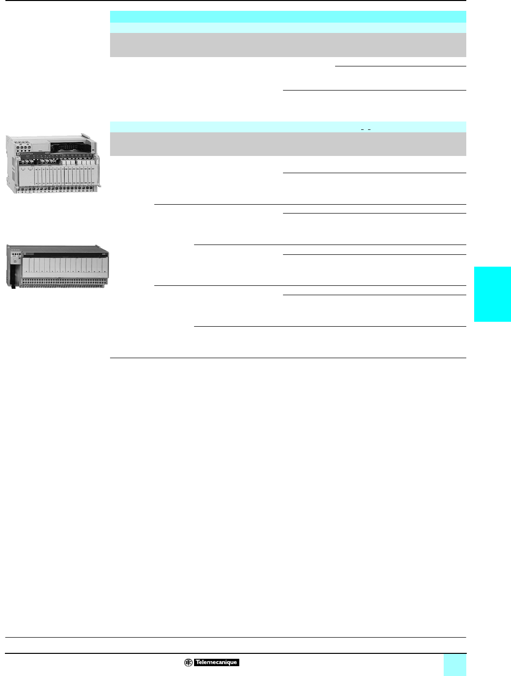
5/13
5
References (continued) Connection interfaces 0
Advantys™ Telefast® ABE7 pre-wired system
Discrete input/output adaptation sub-bases
for or with plug-in relays
(1) Not equipped with relays.
(2) Both technologies (electromechanical and solid state) may be combined on the same
sub-base.
(3) 2 connection methods are available, enabling inputs and outputs to be connected to the same
sub-base at the same time.
(4) Per group of 8 channels.
(5) Per group of 4 channels.
Adaptation sub-bases, for plug-in relays
Input Universal sub-bases for solid state relays (1)
No. of
channels
No. of
terminals
per channel
For
relay type
Isolation
PLC/Oper-
ative part
Input
connection
Type of
connection
Reference Weight
kg
16 2ABS7E
ABR7
ABS7S33E
Yes Voltage-free Screw ABE7P16F310 0.850
Spring ABE7P16F310E 0.850
Polarity
distribution
Screw ABE7P16F312 0.850
Output Optimum & Universal sub-bases with electromechanical relays (2)
No. of
channels
Relay
width
For
relay
type
No. and
type of
contacts
Polarity
distribution/operative part
Reference Weight
kg
16 5 mm ABR7S11 1 N/O Contact common per group of
4 channels
ABE7R16T111 0.600
Contact common per group of
4 output channels
+ 2 input common terminals
ABE7R16M111
(3)
0.600
10 mm ABR7S21 1 N/O Voltage-free ABE7R16T210 0.735
Common on both poles (4) ABE7R16T212 0.730
ABR7S23 1 C/O Voltage-free ABE7R16T230 0.775
Contact common (4) ABE7R16T231 0.730
12 mm ABR7S33 1 C/O Voltage-free ABE7R16T330 1.300
Common on both poles (5) ABE7R16T332 1.200
ABR7S37 2 C/O Voltage-free ABE7R16T370 1.300
81
ABE7R16M111
ABE7R16T210
52
Presentation, compatibility:
pages 5/8 to 5/9
Dimensions:
pages 5/18 to 5/19

5/14
5
References (continued) Connection interfaces 0
Advantys™ Telefast® ABE7 pre-wired system
Discrete output adaptation sub-bases
for plug-in relays
(1) Not equipped with relays.
(2) 2 connection methods are available, enabling inputs and outputs to be connected to the same
sub-base at the same time.
(3) With relay ABR7S21 for sub-base ABE7P16T210, with relay ABR7S23 for sub-base
ABE7P16T230p.
(4) Per group of 8 channels.
(5) Per group of 4 channels.
Adaptation sub-bases for plug-in relays (1)
Output Optimum & Universal sub-bases for solid state and/or electromechanical relays (2)
No. of
chan-
nels
Relay
width
For
relay type
Isolator
per
channel
Fuse per
channel
Polarity
distribution/operative part
Type of
connection
Reference Weight
kg
16 5 mm ABR7S11
ABS7SC1B
No No Contact common per group
of 4 channels
ABE7P16T111 0.550
Contact common per group
of 4 output channels and
2 common input terminals
ABE7P16M111 (2) 0.550
10 mm ABR7S2p
ABS7SA2p
ABS7SC2p
ABE7ACC20
No No Voltage-free Screw ABE7P16T210 (3) 0.615
ABE7P16T230 (3) 0.655
Spring ABE7P16T230E (3) 0.655
Yes Voltage-free Screw ABE7P16T214 0.675
No Common on both poles (4) Screw ABE7P16T212 0.615
Yes Common on both poles (4) Screw ABE7P16T215 0.670
812 mm ABR7S33
ABS7A3p
ABS7SC3pp
ABE7ACC21
No No Voltage-free Screw ABE7P08T330 0.450
Spring ABE7P08T330E 0.450
16 12 mm ABR7S33
ABS7A3p
ABS7SC3pp
ABE7ACC21
No No Voltage-free Screw ABE7P16T330 0.900
Spring ABE7P16T330E 0.900
Common on both poles (5) Screw ABE7P16T332 0.900
ABR7S33
ABS7A3M
ABS7SC3E
ABE7ACC21
No Yes Voltage-free Screw ABE7P16T334 0.900
Yes Yes Common on both poles (5) Screw ABE7P16T318 1.000
Spring ABE7P16T318E 1.000
ABE7P16T2
pp
52
Presentation, compatibility:
pages 5/8 to 5/9
Dimensions:
pages 5/18 to 5/19

5/15
5
References (continued) Connection interfaces 0
Advantys™ Telefast® ABE7 pre-wired system
Plug-in relays
(1) See characteristics table for specifications of relays in the sub-bases.
Plug-in solid state relays
Relay
width
Functions Input circuit Output circuit Unit reference
Sold in lots of 4
Weight
kg
Current Nominal
voltage
Current (1) Nominal
voltage
5mm Output c 24 V 2 A 24 V c ABS7SC1B 0.010
10 mm Output c 24 V 0.5 A 5…48 V c ABS7SC2E 0.016
24…240 V a ABS7SA2M 0.016
12 mm Input c 5V TTL – 24V c ABS7EC3AL 0.014
24 V
Type 2
–24V c ABS7EC3B2 0.014
48 V
Type 2
–24V c ABS7EC3E2 0.014
a 50 Hz 48 V – 24 V c ABS7EA3E5 0.014
a 60 Hz 110…130 V – 24 V c ABS7EA3F5 0.014
a 50 Hz 230…240 V – 24 V c ABS7EA3M5 0.014
Output c 24 V 2 A
Self-protected
24 V c ABS7SC3BA 0.016
1.5 A 5…48 V c ABS7SC3E 0.016
24…240 V a ABS7SA3MA 0.016
Plug-in electromechanical relays
Relay width Control
voltage
Output
current (1)
Number of
contacts
Sold in
lots of
Unit
reference
Weight
5mm 24 V c 5 A (Ith) 1 N/O 4ABR7S11 0.005
10 mm 24 V c 5 A (Ith) 1 N/O 4ABR7S21 0.008
1 C/O 4ABR7S23 0.008
12 mm 24 V c 10 A (Ith) 1 C/O 4ABR7S33 0.017
8 A (Ith) 2 C/O 4ABR7S37 0.017
48 V c 8 A (Ith) 1 C/O 4ABR7S33E 0.017
Accessory
Description Reference Weight
kg
Extractor for 5 mm miniature relays ABE7ACC12 0.010
ABS7SC1B
57
ABR7S2
p
81
ABR7S3
p
81
Presentation, compatibility:
pages 5/8 to 5/9
Dimensions:
pages 5/18 to 5/19
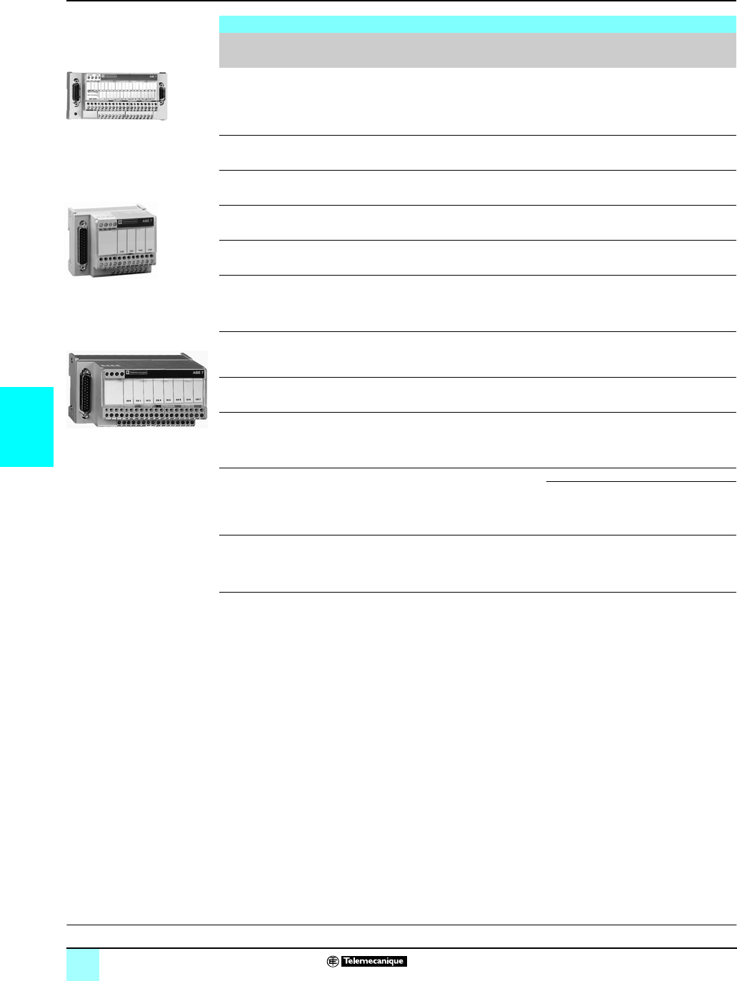
5/16
55
References Connection interfaces 0
Advantys™ Telefast® ABE7 pre-wired system
Connection sub-bases
for counter and analog channels
Connection sub-bases for counter and analog channels
Functions For Modicon
PLCs
Compatible
modules
Type of
connection
Telefast 2 side
Type of
connection
Reference Weight
kg
Counting
and analog
TSX Micro Integrated
analog
and counter
TSX 37 22
TSX CTZpA
15-pin SUB-D Screw ABE7CPA01
0.300
Counting, Axis control,
Position control
Premium TSX CTYpA
TSX CAYp1
15-pin SUB-D Screw ABE7CPA01
(
0.300
Parallel output absolute
encoder connection
Premium TSX CTYpA
TSX CAYp1
15-pin SUB-D Screw ABE7CPA11 0.330
Distribution of
4 thermocouples
Modicon M340 BMX ART 0414
BMX ART 0814
25-pin SUB-D Screw ABE7CPA412 0.180
Distribution of
16 thermocouples
Premium TSX AEY1614 25-pin SUB-D Screw ABE7CPA12 0.300
Passive distribution of
8 channels on screw
terminal block with
shielding continuity
Premium TSX ASY810
TSX AEY1600
TSX ApY800
25-pin SUB-D Screw ABE7CPA02 0.290
Distribution and supply of
4 analog channels
protected isolated
Modicon M340 BMX AMI 0410 25-pin SUB-D Screw ABE7CPA410 0.180
Distribution of 4 analog
output channels
Premium TSX ASY410
TSX AEY420
25-pin SUB-D Screw ABE7CPA21 0.180
Distribution and supply
of 8 analog channels with
limitation of each current
loop
Premium TSX AEY800
TSX AEY1600
25-pin SUB-D Screw ABE7CPA03 0.330
Distribution and supply
of 8 analog input channels
isolated
from each other with
25 mA/ channel limiter
Premium TSX AEY810 25-pin SUB-D Screw ABE7CPA31 0.410
Spring ABE7CPA31E 0.410
Safety Premium TSX PAY2p2 25-pin SUB-D Screw ABE7CPA13 0.290
816478
ABE7CPA01
ABE7CPA412/410/21
816477
ABE7CPA02
Presentation, compatibility:
pages 5/8 and 5/9
Dimensions:
pages 5/18 and 5/19
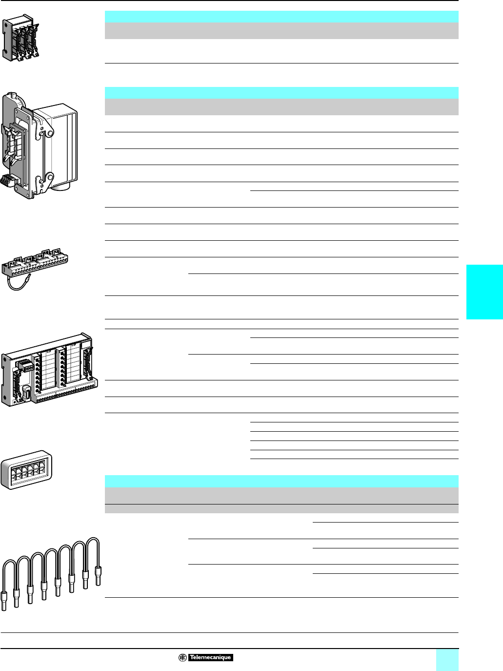
5/17
5
References (continued) Connection interfaces 0
Advantys™ Telefast® ABE7 pre-wired system
Accessories for connection sub-bases
Software
Description Operating system Reference Weight
kg
Software for marking
customer labels
Under Windows®
version 3.1 or 95
ABE7LOGV10 0.350
Pack of 25
pre-cut label sheets
(160 labels)
–ABE7LOGF25 0.200
Accessories
Description No. of channels Characteristics Sold in lots of Unit
reference
Weight
kg
Kit for mounting
on solid plate
––10 ABE7ACC01 0.008
Splitter sub-base – 16 as
2 x 8 channels
1ABE7ACC02 0.075
Redundant output
sub-base
– 16 as
2 x 16 channels
1ABE7ACC10 0.075
Redundant input
sub-base
– 16 as
2 x 16 channels
1ABE7ACC11 0.075
Plug-in continuity blocks – Width 10 mm 4ABE7ACC20 0.007
Width 12 mm 4ABE7ACC21 0.010
Locating device for
removable terminal block
––100 ABE7ACC30 0.100
Enclosure feedthrough
with industrial connector
32 40-pin 1ABE7ACC80 0.300
Plug-in 40-pin
male connector
32 For mounting on
ABE7ACC80
1ABE7ACC81 0.370
Enclosure feedthrough
with CNOMO M23
connector
(1 x 20-pin HE 10 connector,
PLC end)
16 19-pin 1ABE7ACC82 0.150
8 and 12 19-pin 1ABE7ACC83 0.150
Impedance adapter
for Type 2 compatibility
– Used with
ABE7ACC82 and
ABE7ACC83
1ABE7ACC85 0.012
IP 65 cable gland – For 3 cables 5ABE7ACC84 0.300
Additional snap-on
terminal blocks
(shunted terminals)
8 10 screw terminals 5ABE7BV10 0.030
10 spring terminals 5ABE7BV10E 0.030
16 20 screw terminals 5ABE7BV20 0.060
20 spring terminals 5ABE7BV20E 0.060
I/O simulator sub-base 16 Display, forcing
inhibition, continuity
1ABE7TES160 0.350
Self-adhesive
marker tag holder
– For 6 characters 50 AR1SB3 0.001
Quick-blow fuses
5 x 20, 250 V, UL
–0.125 A10 ABE7FU012 0.010
0.5 A 10 ABE7FU050 0.010
1 A 10 ABE7FU100 0.010
2 A 10 ABE7FU200 0.010
4 A 10 ABE7FU400 0.010
6.3 A 10 ABE7FU630 0.010
Jumper accessories
Description For common Color Distance between
cable ends
Reference Weight
cm kg
Jumper
Modularity 8 x 1 mm2
Coil White 12 ABFC08R12W 0.020
2ABFC08R02W 0.010
aRed 12 ABFC08R12R 0.020
2ABFC08R02R 0.010
cBlue 12 ABFC08R12B 0.020
2ABFC08R02B 0.010
816483
ABE7ACC02
816480
ABE7ACC80 + ABE7ACC81
816481
ABE7BV20
2
201
0
1
2
3
4
5
6
7
8
9
10
11
12
13
14
15
01
580700
ABE7TES160
816479
AR1SB3
816484
ABFC08R
ppp
Presentation, compatibility:
pages 5/8 and 5/9
Dimensions:
pages 5/18 and 5/19
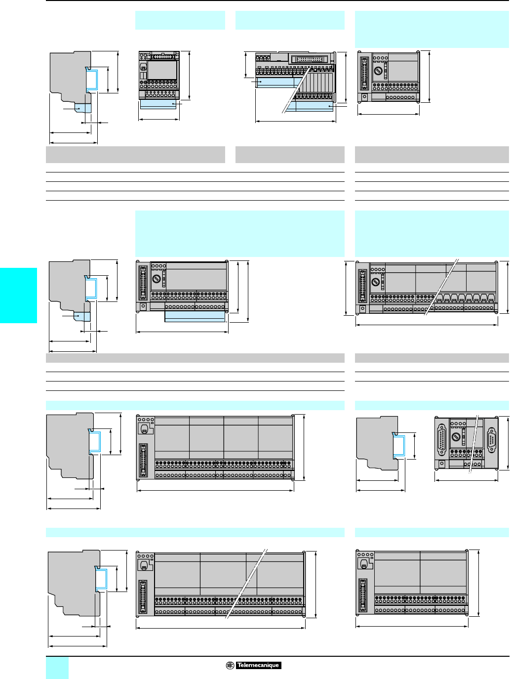
5/18
5
Dimensions Connection interfaces 0
Advantys™ Telefast® ABE7 pre-wired system
Common side view ABE7H20Eppp ABE7H16Cpp/ABE7H16CMpp,ABE7H16R50, ABE7H12R50,
ABE7H08R1p, ABE7H08R21,
ABE7R08S111/S111E,
ABE7H08S21, ABE7CPA21/40/412
ABE7H32Eppp ABE7p16M111/ABE7p16T111
ABE 7H20E/7H32Eppp ABE 7H16Cpp,
7H16CMpp 7p16M111,
7p16T111
ABE 7H16/12/08ppp
7CPA21/410/412
7R08S111p
b 67 a 106 110 b 70 77
b1 56 b 49 89 b1 58 58
c 59 b1 41.5 58 c 58 58
c60 54
1Additional shunt terminal block ABE7BV10/7BV20
Common side view ABE7H16R2p, ABE7H12R2p, ABE7H16R3p,ABE7R16S21p, ABE7H16p43
ABE7H16R1p, ABE7H12R1p, ABE7H12S21, ABE7S16S2B0/S2B02E,
ABE7H16S2p, ABE7R16S11p, ABE7R08S210, ABE7S16E2pp/S16E2ppE,
ABE7S08S2B0, ABE7CPA02, ABE7CPA03 ABE7S08S2B1/S08S2B1E
ABE7S16S1B2, ABE7R08S216 ABE7CPA31
ABE 7pppppp 7pR08S210p, 7S16S1B2p, 7R08S216 All sub-bases
b7077 b1
b1 58 58 c 58
c5858
1Additional shunt terminal block ABE7BV10/7BV20
ABE7R16T2pp, ABE7P16T2pp ABE7CPA01, ABE7CPA11/CPA12/CPA13
Note : details of the front view are the same as for the
ABE7CPA01.
ABE7R16T3pp, ABE7P16T3pp, ABE7P16F31pABE7P08T330
Common side view
c
c + 9
35
b1
15
1
55
b
1
b
b
a
1
1
b
84
c
c1
35
b1
15
1
b + 12
b
125
77
206
70
64
73
35
15
58
89
211
70
58
67
35
143
74
83
35
15
58
272
89
89
150
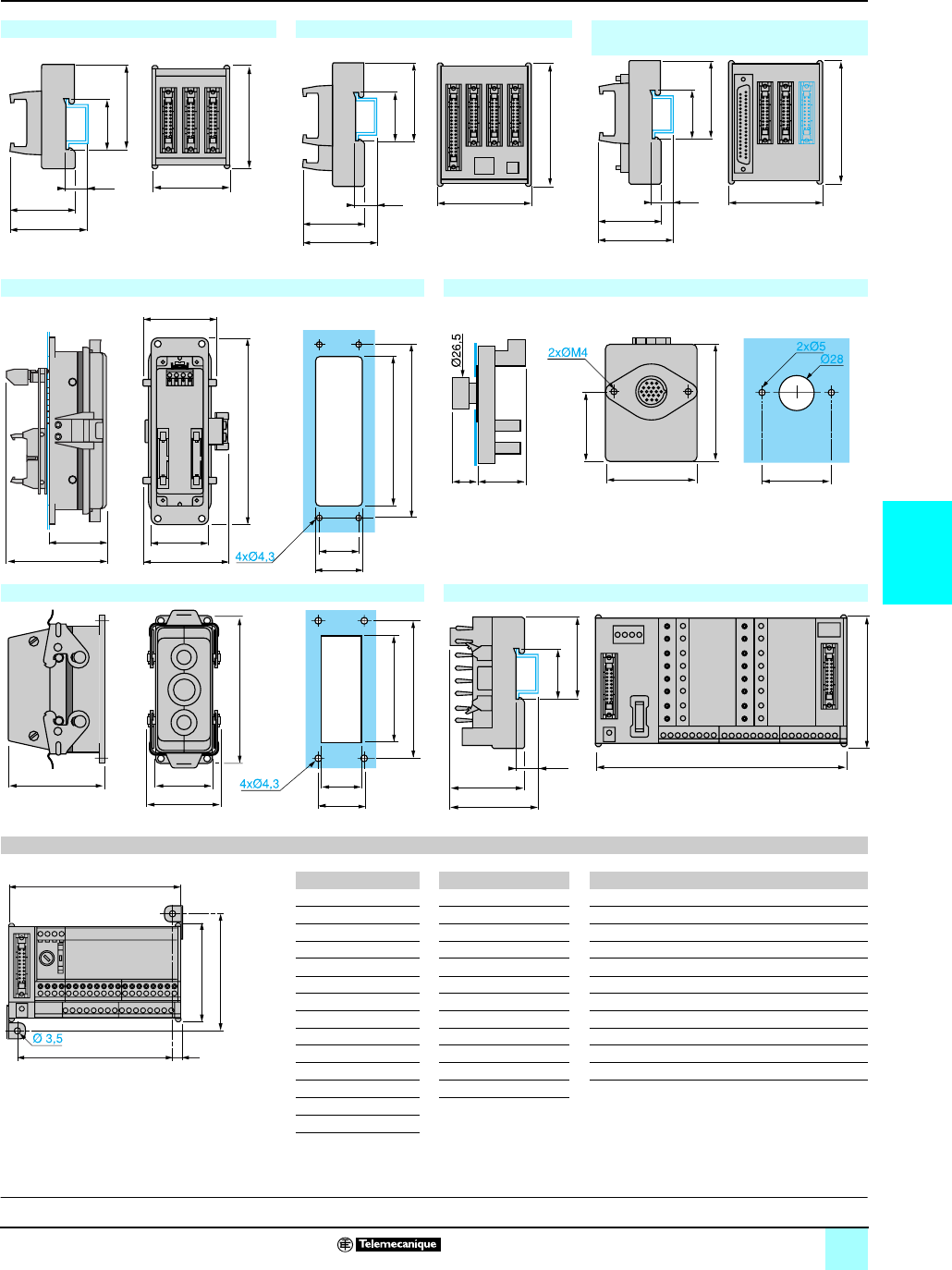
5/19
5
Dimensions (continued) Connection interfaces 0
Advantys™ Telefast® ABE7 pre-wired system
ABE7ACC02 ABE7ACC03 ABE7ACC04, ABE7ACC05
ABE7ACC10, ABE7ACC11
Note : Drawing representing ABE7ACC04 and
ABE7ACC05
ABE7ACC80 ABE7ACC82, ABE7ACC83
ABE7ACC84 ABE7TES160
Mounting hole dimensions for sub-bases using mounting kit ABE7ACC01
ABE7 G H ABE7 G H ABE7 G H
ACC02 38 82 H12R1p113 82 H16F43 194 82
ACC03 53 101 H12R2p113 82 H16S43 194 82
ACC04 53 101 H16R1p113 82 S16E2pp 194 82
ACC05 53 101 H16R2p113 82 S16S1B2 113 82
ACC10/11 53 101 H16R3p113 82 S16S2pp 194 82
H08Rpp 72 82 H12S21 113 82 R16T2pp 199 101
H08S21 72 82 H16S21 113 82 P16T2pp 199 101
H12R50 72 82 R08S210 113 82 R16T3pp 260 101
H16R50 72 82 R16S111 113 82 P08T330 150 101
R08S111 72 82 R16S21p194 82 P16T3pp 260 101
CPA01 131 82 S08S2B0 113 82 P16F3pp 260 101
CPA02 113 82 S08S2B1 194 82
CPA1p131 82
CPA03 113 82
48
57
50
70
35
15
ABC
58
88
89
B
ACD
48
57
35
15
58
66
89
B
A
CD
48
57
35
15
58
64,5
43
54
42
74
140
112
130
32
35
25 34
88
65 52
50
80
103
32
30
43
72
54
120
59
50
35
15
58
170
89
G = a-12 6
H = b+12
b
a
Presentation, compatibility:
pages 5/8 and 5/9
References:
pages 5/18 to 5/19
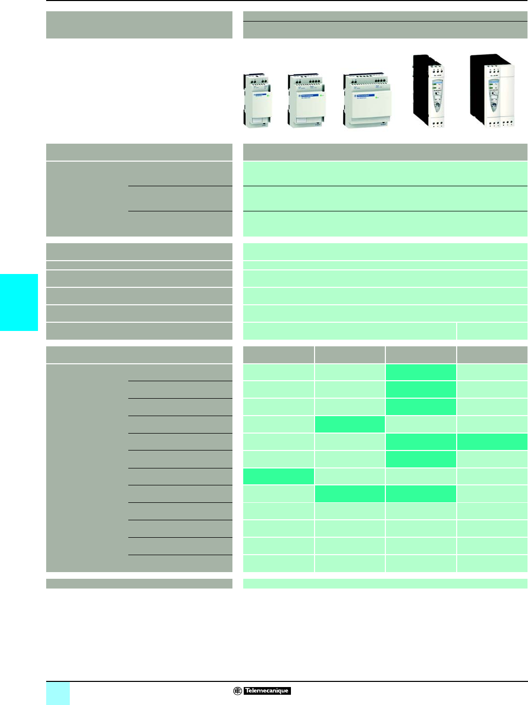
5/
5
Selection guide
0
Power supplies and transformers 0
Power supplies for DC control circuits
Phaseo® power supplies
Power supplies Regulated switch mode
Phaseo Modular range and Optimum range industrial power supplies
Input voltage 100...240 V a
120...250 V c (see pages 13 and 14)
Connection to
world-wide line supplies
United States
- 120 V (in phase-to-neutral)
- 240 V (in phase-to-phase)
Single-phase (N-L1) or 2-phase (L1-L2) connection
Europe
- 230 V (in phase-to-neutral)
- 400 V (in phase-to-phase)
Single-phase (N-L1) connection
United States
- 277 V (in phase-to-neutral)
- 480 V (in phase-to-phase)
–
IEC 61000-3-2 conformity Yes for ABL 7RP, not for ABL 8REM and not applicable for ABL 8MEM and ABL 7RM
Protection against undervoltage (U > 19 V) Yes
Protection against overloads and short-circuits Yes, voltage detection. Automatic restart on elimination on the fault
Diagnostic relay –
Compatibility with function modules –
Power reserve (Boost) 1,25 to 1,4 In during 1 minute, depending on model (with ABL 8MEM) No
Output voltage 5V c 12 V c 24 V c 48 V c
Output current 0.3 A ABL 8MEM24003
(Modular)
0.6 A ABL 8MEM24006
(Modular)
1.2 A ABL 8MEM24012
(Modular)
2A ABL 8MEM12020
(Modular)
2.5 A ABL 7RM24025
(Modular)
ABL 7RP4803
(Optimum)
3A ABL 8REM24030
(Optimum)
4 A ABL 8MEM05040
(Modular)
5A ABL 7RP1205
(Optimum)
ABL 8REM24050
(Optimum)
6A
10 A
20 A
40 A
Pages Consult our “Phaseo Power supplies and transformers” catalog
(1) Except ABL 8RPM24200. a 100...120 V and a 200...240 V.
(2)
c
/
c
converter module, requires to be associated with the Phaseo Universal range power supply.
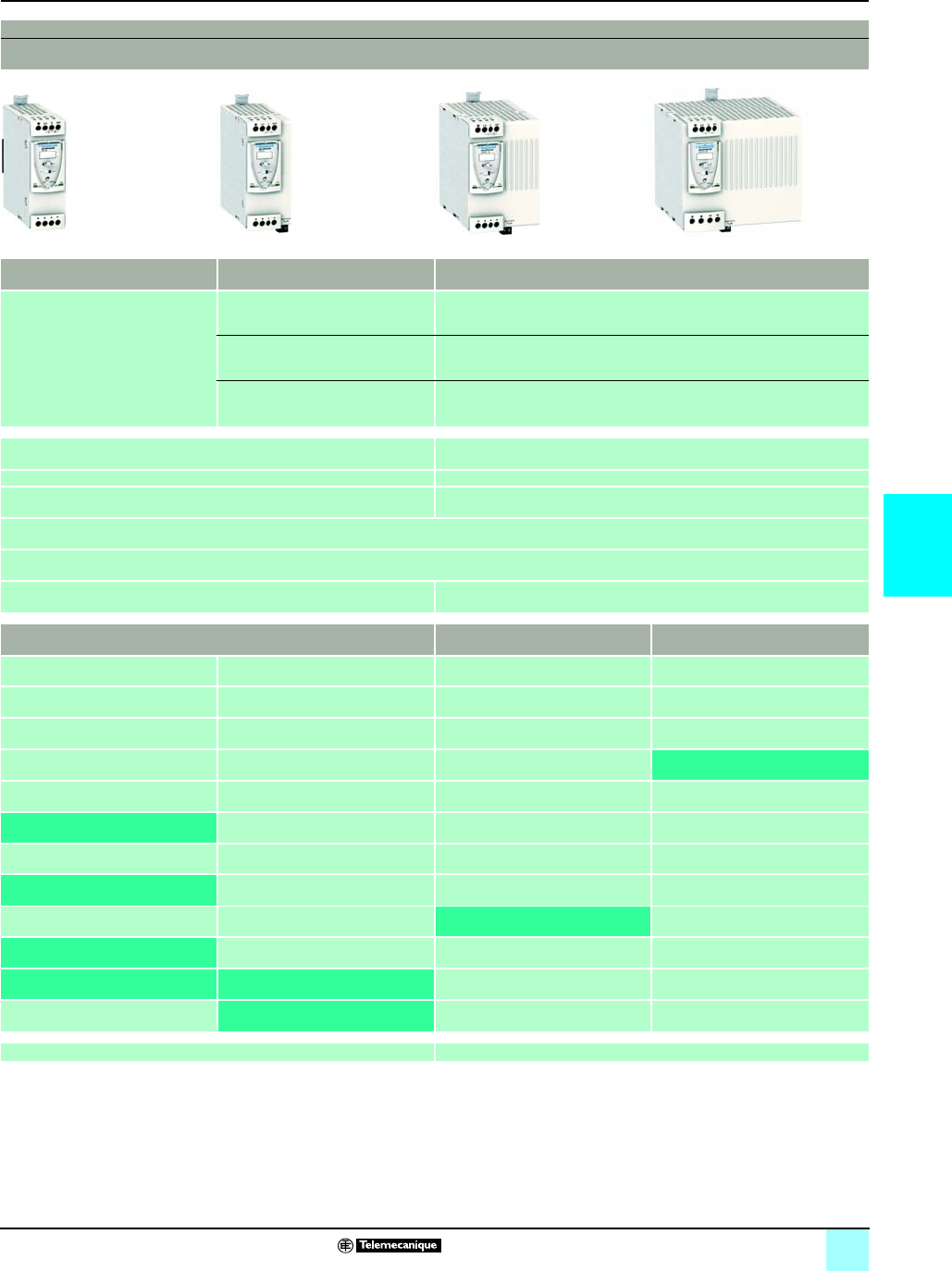
5/21
5
0
0
Regulated switch mode
Phaseo Universal range industrial power supplies
100...120 V a and 200...500 V a (1) 380...500 V a 24 V c
Single-phase (N-L1) or 2-phase (L1-L2)
connection
– –
3-phase (L1-L2-L3) connection –
3-phase (L1-L2-L3) connection –
Yes –
Yes –
Yes, current limitation or undervoltage detection Yes, current limitation
Yes, depending on model
Yes with buffer module, battery and battery check modules, redundancy module and discriminating downstream protection module
1,5 In during 4 secondes No
24 V c 5V c 7...12 V c
ABL 8DCC12020 (2)
ABL 8RPS24030
ABL 8RPS24050
ABL 8DCC05060 (2)
ABL 8RPS24100
ABL 8RPM24200 ABL 8WPS24200
ABL 8WPS24400
29 Consult our “Phaseo Power supplies and transformers” catalog

5/22
5
Presentation
0
Power supplies and transformers 0
Power supplies for DC control circuits
Regulated switch mode power supplies
Phaseo® power supplies, Universal range
The ABL 8RPS/RPM/WPS power supply offer is designed to provide the DC voltage
necessary for the control circuits of automation system equipment. Comprising six
products, this range meets the needs encountered in industrial and commercial
applications. These compact electronic switch mode power supplies provide a
quality of output current that is suitable for the loads supplied and compatible with the
Modicon M340, Premium and Quantum ranges. When used with additional
function modules, they ensure continuity of service in the event of network power
outages or application malfunctions. Clear guidelines are given on selecting the
function modules and upstream protection devices which are often used with them,
and thus a comprehensive solution is provided that can be used in total safety.
The Universal range of Phaseo power supplies must be connected in
phase-to-neutral or phase-to-phase for ABL 8RPS/RPM, and in 3-phase for
ABL 8WPS. They deliver a voltage that is precise to 3%, whatever the load and
whatever the type of line supply, within the ranges:
v 85 to 132 V a and 170 to 550 V a for ABL 8RPS
v 85 to 132 V a and 170 to 264 V a for ABL 8RPM
v 340 to 550 V a for ABL 8WPS
Their very wide input voltage range allows a considerable reduction of parts held in
stock and offers a distinct advantage in terms of machine design.
Conforming to IEC standards and UL and CSA certified, they are suitable for
universal use.
ABL 8RPS/RPM and ABL 8WPS power supplies are all equipped with a harmonic
filter, ensuring compliance with standard 61000-3-2 concerning harmonic pollution.
All the Universal range of Phaseo power supplies have protection devices to ensure
optimum performance of the automation system. Their operating mode can be
configured as required by the user:
bManual reset protection mode: Priority is given to the voltage so as to guarantee
the PLC logic states and nominal operation of the supplied actuators.
bAutomatic reset protection mode: Priority is given to the current to allow
troubleshooting for example, or to ensure continuity of service until the arrival of the
maintenance team.
The Universal range of Phaseo power supplies also has a power reserve, allowing
them to deliver a current of 1.5 In at regular intervals. This avoids the need to
oversize the power supply if the device has a high inrush current, while ensuring
optimum performance of the automation system.
The diagnostics for the Universal range of Phaseo power supplies are available on
the front of the device via LEDs (Uout and Iout) and via a volt-free relay contact
(whether or not the PLC states are guaranteed).
All products are equipped with an output voltage adjustment potentiometer in order
to be able to compensate for any line voltage drops in installations with long
connection cable runs.
These power supplies are designed for direct mounting on a 35 mm 5 rail.
Switch mode power supplies: Universal range
ABL 8RPS24050 Modicon M340 automation platform
a
c
Description:
page 23
Characteristics:
pages 24 to 28
References:
page 29
Dimensions:
page 30
Schemes:
page 31
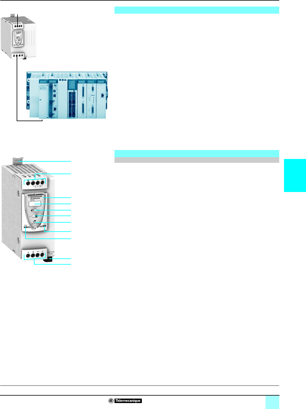
5/23
5
Presentation (continued),
description
0
Power supplies and transformers 0
Power supplies for DC control circuits
Regulated switch mode power supplies
Phaseo® powwer supplies, Universal range
There are four references available in the Universal range of Phaseo power supplies
for phase-to-neutral or phase-to-phase connection:
The Universal range of Phaseo power supplies also features two references for
3-phase connection:
A range of function modules also allows functions to be added to the Universal range
of Phaseo power supplies so as to ensure continuity of service:
v A Buffer module or Battery check modules combined with their batteries to ensure
continuity of service in the event of a network power outage
v A Redundancy module to meet the most demanding requirements for continuity of
service even if the power supply fails
v Downstream electronic Protection modules to ensure that the protection in the
application is discriminating
v Converter modules delivering nominal voltages of 5 and 12 V cfrom the 24 V c
output of the Universal range of Phaseo power supplies
The Universal range of Phaseo regulated switch mode power supplies,
ABL 8RPS24pp0/RPM24200/WPS24p00, comprise:
1Spring clip for 35 mm 5 rail
24mm
2 enclosed screw terminals for connection of the AC voltage (single-phase,
phase-to-phase or 3-phase connection)
3Protective glass flap
4Clip-on marker label
5Locking catch for the glass flap (sealable)
6Protection mode selector
7Output voltage adjustment potentiometer
8Output voltage status LED (green and red)
9Output current status LED (green, red and orange)
10Screw terminals for connection of the diagnostic relay contact, except
ABL 8RPS24030
114mm
2 (10 mm2 on ABL 8WPS24p00 and ABL 8RPM24200) enclosed screw
terminals for connection of the DC output voltage
Switch mode power supplies: Universal range (continued)
bABL 8RPS24030 72 W 3 A 24 V c
bABL 8RPS24050 120W 5A 24 V c
bABL 8RPS24100 240 W 10 A 24 V c
bABL 8RPM24200 480 W 20 A 24 V c
bABL 8WPS24200 480 W 20 A 24 V c
bABL 8WPS24400 960 W 20 A 24 V c
Description
Universal range of power supplies
ABL 8WPS24200
Premium automation platform
a
c
11
10
9
8
7
6
4
3
2
5
1
Characteristics:
pages 24 to 28
References:
page 29
Dimensions:
page 30
Schemes:
page 31
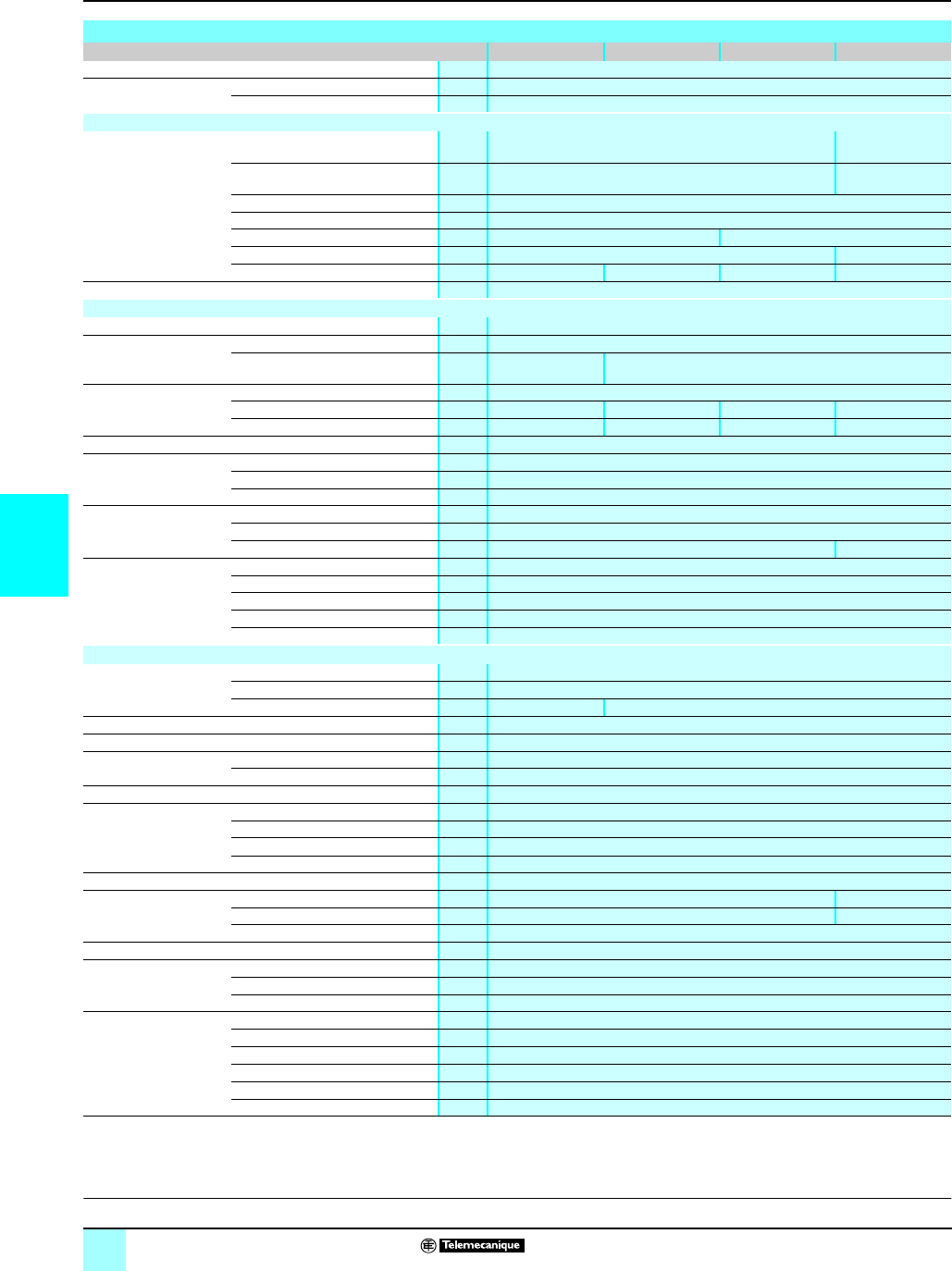
5/24
5
Characteristics
0
Power supplies and transformers 0
Power supplies for DC control circuits
Regulated switch mode power supplies
Phaseo® power supplies, Universal range
(1) No ground screw on ABL 8RPM 24200 power supply
Technical characteristics
Type of power supply ABL 8RPS24030 ABL 8RPS24050 ABL 8RPS24100 ABL 7RPM24200
Certifications CB scheme EN 60950-1, UL (pending), cCSAus
Conformity to standards Safety IEC/EN 60950-1, EN 61204, SELV
EMC EN 61000-6-1, EN 61000-6-2, EN 61000-6-3, EN 61000-6-4, EN 61204-3
Input circuit
Input values
phase-to-neutral (N-L1) or
phase-to-phase (L1-L2)
Nominal voltage V100…120 V a/200…500 V a100…120 V a/
200…240 V a
Limit voltage V85…132 V a/170…550 V a85…132 V a/
170…264 V a
Permissible frequencies Hz 47…63
Maximum inrush current A30 for 2 ms max.
Power factor 0.59 at 120 V a/0.51 at 240 V a 0.69 at 120 V a/0.68 at 240 V a
Efficiency at nominal load >87% >88%
Dissipated power at nominal load W7.8 15.5 31 57.6
Anti-harmonic filtering Yes, via integrated PFC (Power Factor Correction) passive filter
Output circuit
Compatibility with function modules Buffer, battery and battery check unit, redundancy, discriminating protection
Diagnostics LEDs on front panel Current (green, orange and red), voltage (green, red and off)
Relay –Relay closed UOut >21.6 V
contact 230 V a, 0.5 A max; 24 V c, 5 mA min
Nominal output values Nominal output voltage (UOut)V24 c
Current A3510 20
Power W72 120 240 480
Permissible temporary inrush current (boost) A1.5 In for 4 s maximum, see curves on page 5/27
Precision Nominal output voltage (UOut)VAdjustable 24…28.8
Line and load regulation 1 %...3 %
Residual ripple - noise mV < 200 (peak-peak)
Holding time for I max. UIn = 100 V ams u 20
UIn = 240 V ams u 40
UIn = 400 V ams u 120 –
Protection Against short-circuits Permanent, automatic or manual restart
Against overloads < 1.10 In (after "boost" function)
Against overvoltages V30…32 c
Against undervoltages VTripping if UOut < 21.6 (in manual mode)
Thermal Yes
Operating and environmental characteristics
Connections Input mm
2
2 x 0.5….4 screw terminals (22….12 AWG) + ground
Output mm
2
4 x 0.5….4 screw terminals (24….10 AWG) + ground (1)
Diagnostic relay mm
2
–2 x 2.5 removable screw terminal block
Mounting On 5 rail 35 x 7.5 mm and 35 x 15 mm
Operating position Vertical
Connections Series Possible, see page 5/28
Parallel Possible, see page5/28
Degree of protection IP 20 conforming to IEC 60529
Environment Operating temperature °C - 25…+ 60 (derating from 50°C, see page 5/26)
Storage temperature °C - 40…+ 70
Maximum relative humidity 90% during operation, 95% in storage
Vibration acc. to EN 61131-2 3...11.9 Hz amplitude 3.5 mm & 11.9 -150 Hz acceleration 2 g
Protection class According to VDE 0106 1 Class I
Dielectric strength
50 Hz for 1 min
Input/output V rms 4000 a3000 a
Input/ground V rms 3500 a2500 a
Output/ground V rms 500 a
Input fuse incorporated No
Emissions
according to EN 61000-6-3
Radiation EN 55022 Class B and GL levels
Conducted on the power line EN 55022 Class B and GL levels
Harmonic currents IEC/EN 61000-3-2
Immunity
according to EN 61000-6-2
and GL
Electrostatic discharge IEC/EN 61000-4-2 (6 kV contact/8 kV air)
Radiated electromagnetic fields IEC/EN 61000-4-3 level 3 (10 V/m)
Induced electromagnetic fields IEC/EN 61000-4-6 level 3 (10 V/m)
Rapid transients IEC/EN 61000-4-4 (4 kV)
Surges IEC/EN 61000-4-5 (2 kV)
Primary outages IEC/EN 61000-4-11 (voltage dips and interruptions)
Description:
page 23
References:
page 29
Dimensions:
page 30
Schemes:
page 31

5/25
5
Characteristics (continued)
0
Power supplies and transformers 0
Power supplies for DC control circuits
Regulated switch mode power supplies
Phaseo® power supplies, Universal range
Technical characteristics
Type of power supply ABL 8WPS24200 ABL 8WPS24400
Certifications CB scheme EN 60950-1, UL (pending), cCSAus
Conformity to standards Safety EN 60950-1, EN 61204, SELV
EMC EN 61000-6-1, EN 61000-6-2, EN 61000-6-3, EN 61000-6-4, EN 61204-3
Input circuit
LED indication –
Input values
3 phase (L1-L2-L3)
Nominal values V380-500 V a
Permissible values V320-550 V a
Permissible frequencies Hz 47…63
Maximum inrush current A25 for 2 ms max.
Power factor 0.65 0.85
Efficiency at nominal load > 92%
Dissipated power at nominal load W38.4 76.8
Anti-harmonic filtering Yes, via integrated PFC (Power Factor Correction) passive filter
Operating mode in the event of phase failure VOperation possible for a few minutes then protection trips
Output circuit
Compatibility with function modules Buffer, battery and battery check unit, redundancy, discriminating protection
Diagnostics LEDs on front panel Current (green, orange and red), voltage (green, red and off)
Relay Closed relay Uout > 21.6 V, contact 230 V a, 0.5 A max; 24 V c, 5 mA min
Nominal output values Output voltage (UOut)V24 c
Current A0...20 0...40
Power W480 960
Permissible temporary inrush current (boost) A1.5 In for 4 s maximum, see curves on page 5/27
Precision Output voltage (UOut)VAdjustable 24…28.8
Line and load regulation 1 %...3 %
Residual ripple - noise mV < 200 (peak-peak)
Holding time
for I max
UIn = 400 V ams u 18 u 14
Protection Against short-circuits Permanent, automatic or manual restart
Against overloads < 1.10 In (after "boost" function)
Against overvoltages V30…32 c
Against undervoltages VTripping if UOut < 21.6 (in manual mode)
Thermal Yes
Operating and environmental characteristics
Connections Input mm
2
3 x 0.5….4 screw terminals (22….12 AWG) + ground
Output mm
2
4 x 0.5….10 screw terminals (22….8 AWG)
Diagnostic relay mm
2
2 x 2.5 removable screw terminal block
Mounting On 5 rail 35 x 7.5 mm and 35 x 15 mm
Operating position Vertical
Connections Series Possible, see page 5/28
Parallel Possible, see page 5/28
Degree of protection IP 20 conforming to IEC 60529
Environment Operating temperature °C - 25…+ 60 (derating from 50°C, see page 5/26)
Storage temperature °C - 40…+ 70
Maximum relative humidity 90% during operation, 95% in storage
Vibration acc. to EN 61131-2 3...11.9 Hz amplitude 3.5 mm & 11.9 -150 Hz acceleration 2 g
Protection class according to VDE 0106 1 Class I
Dielectric strength
50 Hz for 1 min
Input/output V rms 4000 a
Input/ground V rms 3500 a
Output/ground V rms 500 a
Input fuse incorporated No
Emissions
according to EN 61000-6-3
Radiation EN 55022 Class B and GL levels
Conducted on the power line EN 55022 Class B and GL levels
Harmonic currents IEC/EN 61000-3-2
Immunity
according to EN 61000-6-2
and GL
Electrostatic discharge IEC/EN 61000-4-2 (6 kV contact/8 kV air)
Radiated electromagnetic fields IEC/EN 61000-4-3 level 3 (10 V/m)
Induced electromagnetic fields IEC/EN 61000-4-6 level 3 (10 V/m)
Rapid transients IEC/EN 61000-4-4 (4 kV)
Surges IEC/EN 61000-4-5 (1 kV)
Primary outages IEC/EN 61000-4-11 (voltage dips and interruptions)
Description:
page 23
References:
page 29
Dimensions:
page 30
Schemes:
page 31
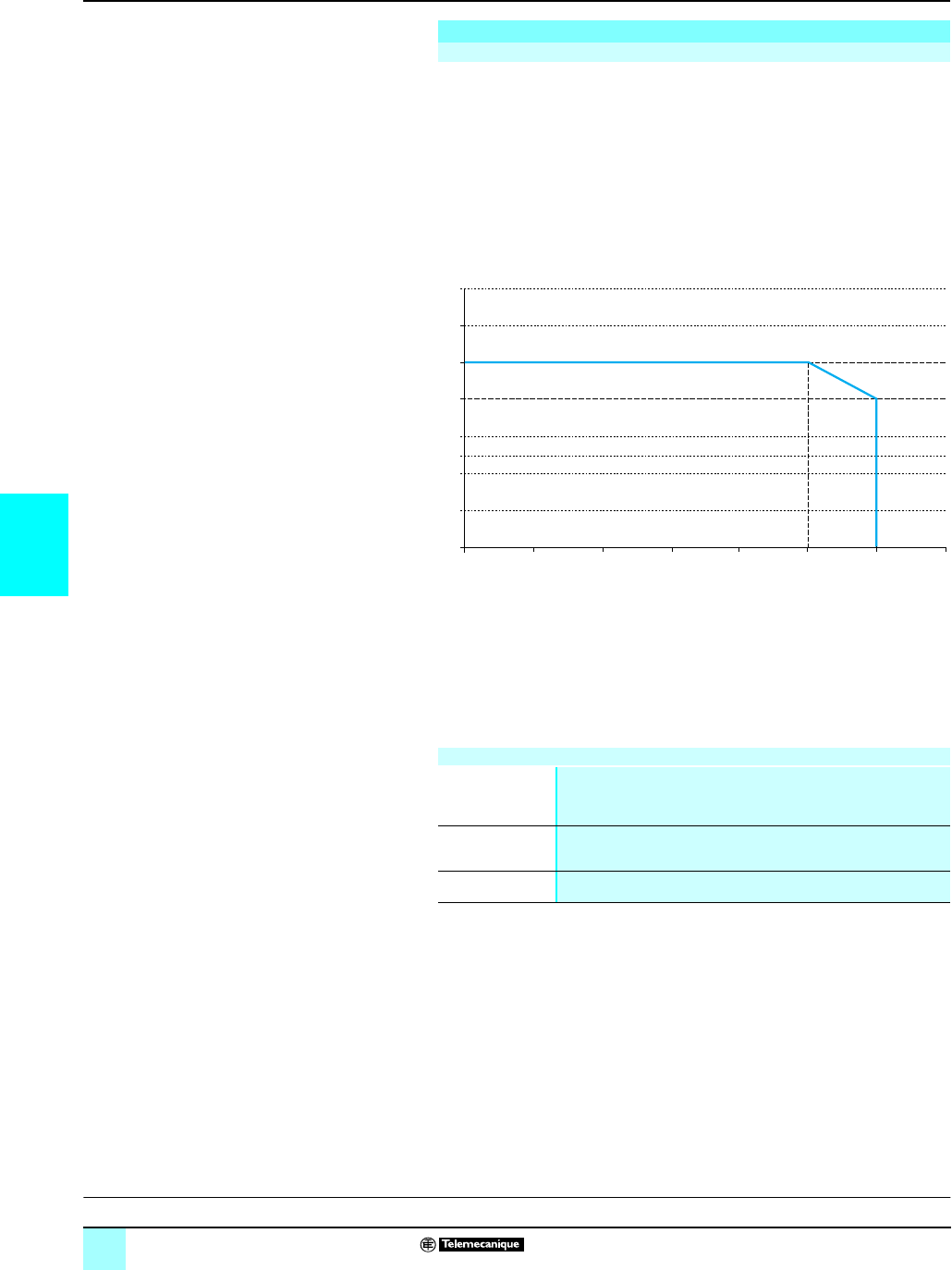
5/26
5
Output characteristics
0
Power supplies and transformers 0
Power supplies for DC control circuits
Regulated switch mode power supplies
Phaseo® power supplies, Universal range
The ambient temperature is a determining factor that limits the power an electronic
power supply can deliver continuously. If the temperature around the electronic
components is too high, their life will be significantly reduced.
The nominal ambient temperature for the Universal range of Phaseo power supplies
is 50°C. Above this temperature, derating is necessary up to a maximum
temperature of 60°C.
The graph below shows the power (in relation to the nominal power) that the power
supply can deliver continuously, depending on the ambient temperature.
ABL 8RPM, ABL 8RPS, ABL 8WPS mounted vertically
Derating should be considered in extreme operating conditions:
v Intensive operation (output current permanently close to the nominal current,
combined with a high ambient temperature)
v Output voltage set above 24V (to compensate for line voltage drops, for example)
v Parallel connection to increase the total power
In all cases, there must be adequate convection around the products to assist
cooling. There must be sufficient clearance around the Universal range of Phaseo
power supplies:
v 50 mm above and below
v 10 mm on the sides
Output characteristics
Derating
0
010 20 30 40 50 60 70
20
40
50
60
80
100
120
140
P/Pn (%)
Maximum operating temperature (°C)
General rules to be complied with
Intensive operation See derating on above graph.
Example for ABL 8RPS:
- Without derating, from 0°C to 50°C
- Derating of nominal current by 2%, per additional °C, up to 60°C
Rise in output
voltage
The nominal power is fixed.
Increasing the output voltage means that the current delivered must be
reduced.
Mounting To allow heat dissipation, the power supplies must not be in contact with
each other.
Description:
page 23
References:
page 29
Dimensions:
page 30
Schemes:
page 31
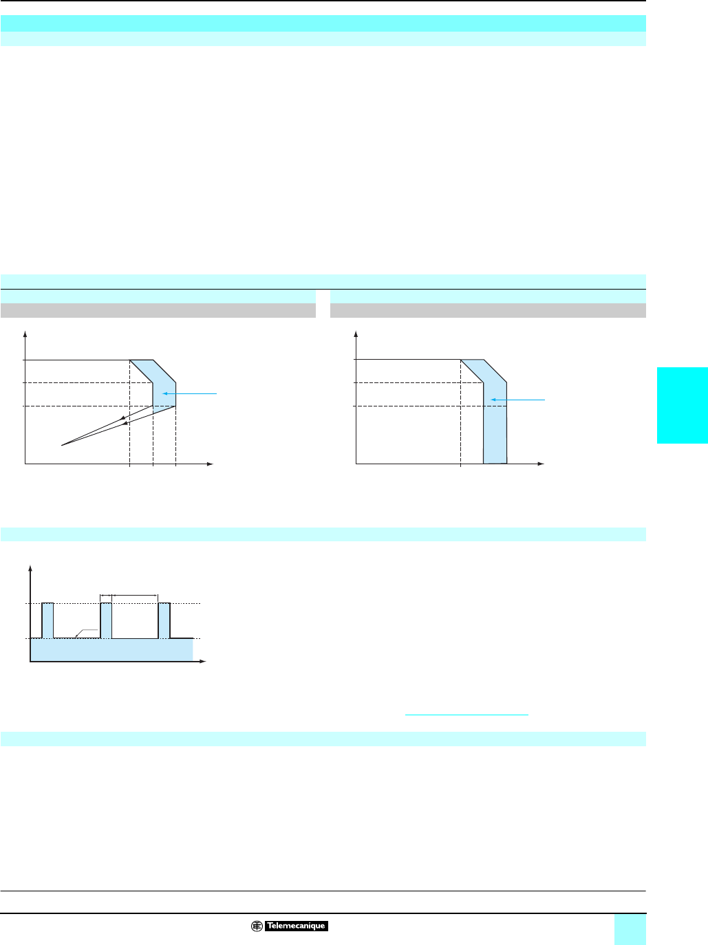
5/27
5
Output characteristics
(continued)
0
Power supplies and transformers 0
Power supplies for DC control circuits
Regulated switch mode power supplies
Phaseo® power supplies, Universal range
Behavior in the event of overloads:
bAutomatic reset protection mode (current limiting): If the output current
exceeds approximately 1.2 In, the output current is limited to this value. The value of
the output voltage can then be less than 21 V but the diagnostic relay opens, allowing
the anomaly to be fed back to the automation system and thus prevent feedback of
any undefined logic state. On elimination of the overload, the output voltage reverts
to its preset value.
bManual reset protection mode (undervoltage detection): If the output current
exceeds approximately 1.2 In, the power supply stops completely before the output
voltage drops below 21 V and no longer delivers any current. The fault is memorized
as long as voltage is present at the power supply primary. The power supply will
become operational again, if the fault has disappeared, after de-energizing the
primary for a few seconds.
Nota : In both these modes, any overload of less than 1.5 In and lasting less than 4 s will be
absorbed by the "boost" circuit and the voltage delivered will stay within the specified limits
(adjustment voltage +/- 3%).
The ABL 8RPS/RPM/WPS Universal range of Phaseo power supplies has a power
reserve, allowing them to supply the application with energy up to 1.5 times the
nominal current at the intervals illustrated by the graph opposite.
The "boost" amplitude and repeat accuracy depend on:
v The overload duration
v The overload intensity
v The period between each consumption peak
When the power supply can no longer cope (repeated overloads, overload duration
> 4 seconds, power rating > 150% of nominal power) the integrated protection trips.
This type of operation is described in detail in the user manual, which can be
downloaded from our website, www.telemecanique.com.
The ABL 8WPS24p00 Universal range of Phaseo power supplies is capable of
starting and delivering a nominal current and voltage for a few minutes in the event
of failure of one phase. Their protection (thermal) then trips and they are reset
automatically.
Output characteristics (continued)
Behavior in the event of overloads
Load limit
Manual reset protection mode Automatic reset protection mode
ABL 8RPM24200/ABL 8RPS24ppp/ABL 8WPS24ppp ABL 8RPM24200/ABL 8RPS24ppp/ABL 8WPS24ppp
U out
I out
28,8
24
21,6
In 1,5 In1,2 In
Boost 4 s
U out
I out
28,8
24
21,6
In 1,5 In1,2 In
Boost 4 s
"Boost" repeat accuracy
150 %
75 %
0 %
30 s
30 s4 s
t
Pout
Behavior in the event of phase failure on three-phase power supplies
Description:
page 23
References:
page 29
Dimensions:
page 30
Schemes:
page 31
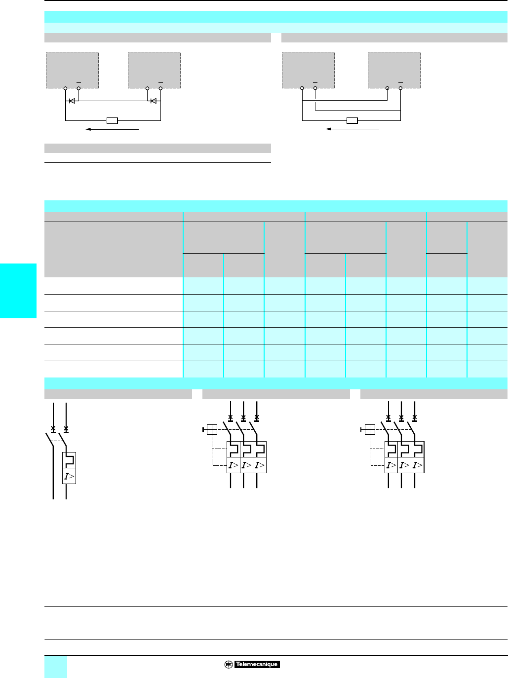
5/28
5
Output characteristics
(continued),
selection,
schemes
0
Power supplies and transformers 0
Power supplies for DC control circuits
Regulated switch mode power supplies
Phaseo® power supplies, Universal range
Output characteristics (continued)
Series or parallel connection
Series connection Parallel connection
Family Series Parallel
ABL 8RPS/8RPM/8WPS 2 products max. (1) 2 products max.
Nota : Series or parallel connection is only recommended for products with identical references.
For better availability, the power supplies can also be connected in parallel using the ABL8 RED24400 Redundancy module.
Selection of protection on the power supply primaries
Type of line supply 115 V a phase-to-neutral 230 V a phase-to-phase 400 V a phase-to-phase
Type of protection Thermal-magnetic
circuit-breaker
gG/gL
fuse
Thermal-magnetic
circuit-breaker
gG/gL
fuse
Thermal-
magnetic
circuit-
breaker
gG/gL
fuse
Telemecanique
GB2 (IEC)
(2)
Merlin Gerin
C60N (IEC)
C60N (UL)
Telemecanique
GB2 (IEC)
(2)
Merlin Gerin
C60N (IEC)
C60N (UL)
Telemecanique
GV2
(IEC/UL)
ABL 8RPS24030 GB2 CD07 MG24443 2A
(8 x 32)
GB2 CD07 MG24443 2A
(8 x 32)
GV2 RT06 2A
(14 x 51)
ABL 8RPS24050 GB2 CD08 MG24444 4A
(8 x 32)
GB2 CD07 MG24443 2A
(8 x 32)
GV2 RT06 2A
(14 x 51)
ABL 8RPS24100 GB2 CD12 MG24447 6A
(8 x 32)
GB2 CD08 MG24444 4A
(8 x 32)
GV2 RT07 4A
(14 x 51)
ABL 8RPM24200 GB2 CD16 MG24449 10 A
(8 x 32)
GB2 CD12 MG24447 6A
(8 x 32)
– –
ABL 8WPS24200 – –––––GV2 ME07 2A
(14 x 51)
ABL 8WPS24400 – –––––GV2 ME08 4A
(14 x 51)
Schemes
GB2 CDpp GV2 RTpp GV2 MEpp
(1) Two Shottky diodes Imin = power supply In and Vmin = 50 V
(2) UL certification pending
+
+
ABL 8RP
ABL 8WP
(1) (1)
ABL 8RP
ABL 8WP
2 x 24 V c/I out
+
+
ABL 8RP
ABL 8WP
ABL 8RP
ABL 8WP
24 V c/2 x I out
2/T1
4/T2 (14)
1/L1
3/L2 (13)
2/T1
4/T2
6/T3
1/L1
3/L2
5/L3
2/T1
4/T2
6/T3
1/L1
3/L2
5/L3
Description:
page 23
References:
page 29
Dimensions:
page 30
Schemes:
page 31
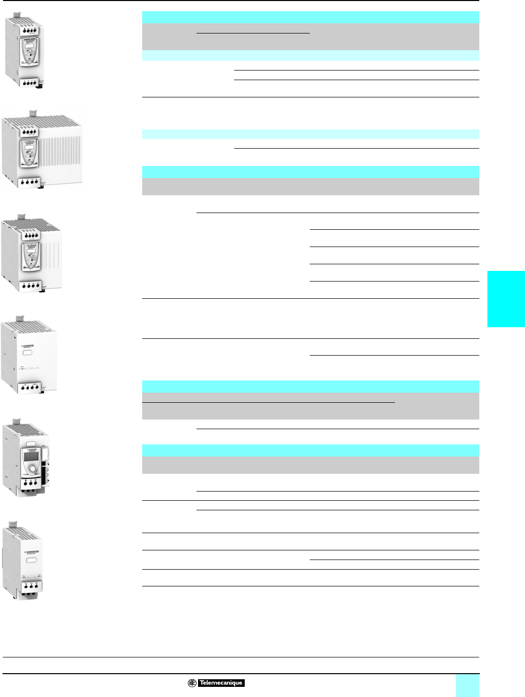
5/29
5
References
0
Power supplies and transformers 0
Power supplies for DC control circuits
Regulated switch mode power supplies
Phaseo® power supplies, Universal range
Regulated switch mode power supplies: Phaseo Universal range
Input
voltage
Secondary Reset Conforming
to standard
EN 61000-3-2
Reference Weight
kg
Output
voltage
Nominal
power
Nominal
current
Single-phase (N-L1) or phase-to-phase (L1-L2) connection
100…120 V -
200...500 V a
-15%,+10%
50/60 Hz
24...28.8 V
c72 W 3 A Auto/man Yes ABL 8RPS24030 0.300
120 W 5 A Auto/man Yes ABL 8RPS24050 0.700
240 W 10 A Auto/man Yes ABL 8RPS24100 1.000
100…120 V/200..
.240 V a
-15%,+10%
50/60 Hz
24...28.8 V
c480 W 20 A Auto/man Yes ABL 8RPM24200 1.600
3-phase connection (L1-L2-L3)
380…500 V a
±10%
50/60 Hz
24...28.8 V
c480 W 20 A Auto/man Yes ABL 8WPS24200 1.600
960 W 40 A Auto/man Yes ABL 8WPS24400 2.700
Function modules for continuity of service
Function Use Designation Reference Weight
kg
Continuity after
a power outage
Holding time 100 ms at 40 A and 2 s at
1A
Buffer module ABL 8BUF24400 1.200
Holding time 9 min at 40 A...2 hrs at
1 A (depending on use with a battery
check module-battery unit and load)
(1)
Battery check module
20 A output current
ABL 8BBU24200
r0.500
Battery check module
40 A output current
ABL 8BBU24200
r0.700
3.2 Ah battery module (2) ABL 8BPK24A03
r3.500
7 Ah battery module (2) ABL 8BPK24A03
r6.500
12 Ah battery module (2) ABL 8BPK24A12
r12.000
Continuity after
a malfunction
Paralleling and redundancy of the
power supply to ensure uninterrupted
operation of the application excluding
AC line failures and application
overloads
Redundancy module ABL 8RED24400 0.700
Discriminating
downstream
protection
Electronic protection (1...10 A
overload or short-circuit) with 4 output
terminals from a Universal range
Phaseo power supply
Protection module with
single-pole breaking (3)
ABL 8PRE24100
r0.270
Protection module with
2-pole breaking (4) (3)
ABL 8PRP24100
r0.270
c/c converters (for use with Universal range of Phaseo power supplies)
Primary (5) Secondary Reference Weight
kg
Input voltage Universal range power supply
module output current
Output
voltage
Nominal
current
24 V c
- 9%, + 24%
2.2 A 5...6.5 V c6 A ABL 8DCC05060 0.300
1.7 A 7...15 V c2A ABL 8DCC12020 0.300
Separate and replacement parts
Designation Description Composition Unit reference Weight
kg
Fuse
assemblies
For ABL 8PRp24100 discriminating
Protection modules
4 x 3 A, 4 x 7.5 A and 4 x
15 A
ABL 8FUS01 –
For ABL 8BKP24App Battery 4 x 20 A and 6 x 30 A ABL 8FUS02 –
Clip-on marker
labels
All products except ABL 8PRpppppp Order in multiples of 100 LAD 90 0.030
ABL 8PRpppppp Order in multiples of 22 ASI20MACC5 –
DIN rail
mounting kit
For ABL 8BPK2403 Battery Module Single unit ABL 1A02 –
Cables Connection cable between ABL8 BBU
and PC for updating the software
RS232 3 m SR2CBL01 0.150
USB 3 m SR2USB01 0.150
EEPROM
memory
Backup and duplication of ABL8 BBU
parameters
Single unit SR2MEM02 0.010
(1) For table of compatibility of battery check module-battery unit with holding time depending on the load, consult
our “Phaseo Power supplies and transformers” catalogue.
(2) Supplied with 20 or 30 A fuse depending on the model.
(3) Supplied with four 15 A fuses.
(4) Local reset via pushbutton or automatic reset on elimination of the fault and diagnostic relay.
(5) Voltage from a 24 V
c
Universal range Phaseo power supply.
r Available 2nd quarter 2007.
ABL 8RPS24050
ABL 8RPM24200
ABL 8WPS24200
ABL 8BUF24400
ABL 8BBU24200
ABL 8RED24400
Description:
page 23
Characteristics:
pages 24 to 28
Dimensions:
page 30
Schemes:
page 31
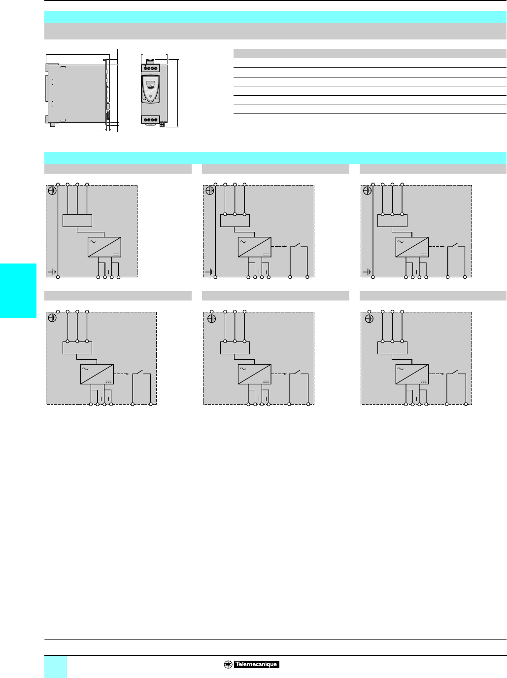
5/30
5
Dimensions,
internal schemes
0
Power supplies and transformers 0
Power supplies for DC control circuits
Regulated switch mode power supplies
Phaseo® power supplies, Universal range
Dimensions
ABL 8RPS24ppp/ABL 8RPM24200/ABL 8WPS24ppp
Common side view
ABL 8 a b
RPS24030 120 44
RPS24050 120 56
RPS24100 140 85
RPM24200 140 145
WPS24200 155 95
WPS24400 155 165
12
ab
+IN OUT
+
125
6
6
143
L1 N/L2 L3
11 14
Description:
page 23
Characteristics:
pages 24 to 28
References:
page 29
Schemes:
page 31
Internal schemes
ABL 8RPS24030 ABL 8RPS24050 ABL 8RPS24100
ABL 8RPM24200 ABL 8WPS24200 ABL 8WPS24400
+
HV
C
+
LV
PFC
+HV
C
+
LV
PFC
11
14
+HV
C
+
LV
PFC
11
14
+HV
C
+
LV
PFC
11
14
+L3
L2
+
L1
PFC
11
14
+L3
L2
+
L1
PFC
11
14

5/31
5
Connections
0
Power supplies and transformers 0
Power supplies for DC control circuits
Regulated switch mode power supplies
Phaseo® power supplies, Universal range
Line supply connection schemes
Single-phase (L-N) 100 to 120 V Phase-to-phase (L1-L2) 200 to 500 V 3-phase (L1-L2-L3) 3 x 380 to 500 V
Single-phase (L-N) 200 to 500 V
L
N
LV C HV
100
120
200
500
Ph 1
Ph 2
LV C HV
100
120
200
500
L 1
L 2
L 3
L1 L2 L3
3x380 - 500 VAC
L
N
LV C HV
100
120
200
500
Description:
page 23
Characteristics:
pages 24 to 28
References:
page 29
Dimensions:
page 30

5/32
5
Selection guide
0
Human/Machine Interfaces 0
Operator dialogue terminals
Magelis® display units and terminals
Applications Display of text messages Display of text messages and/or semi-
graphics
Type of unit Compact display units
Display Type Back-lit green LCD,
height 5.5 mm
or
Back-lit green, orange or red LCD,
height 4.34…17.36 mm
Back-lit monochrome matrix LCD
(240 x 64 pixels),
height 5.3 or 10.6 mm
Capacity 2 lines of 20 characters or
1 to 4 lines of 5 to 20 characters
4 to 8 lines of 20 to 40 characters
Data entry Via keypad with
8 keys (4 with changeable legends)
Display only
or
via keypad with 4 function keys + 1 service key
or
5 service keys
Memory capacity Application 512 Kb Flash 384 Kb Flash EPROM
Extension via type II PCMCIA –
Functions Maximum number of pages 128/200 application pages
256 alarm pages
600 application pages
256 alarm pages
256 print-out form pages (1)
Variables per page 40…50 50
Representation of variables Alphanumeric Alphanumeric, bargraph, gauge
Recipes –
Curves –
Alarm logs Depending on model
Real-time clock Access to the PLC real-time clock
Alarm relay –No
Communication Serial link RS 232 C/RS 485 RS 232C or RS 422/485
Downloadable protocols Uni-TE, Modbus Uni-TE, Modbus, AEG and for PLC brands:
Allen-Bradley, GE Fanuc, Omron, Siemens
Printer link RS 232C serial link (1)
Development software XBT L1001 and XBT L1003 (under Windows 98, 2000 and XP)
Operating systems Magelis
Type of terminal XBT N XBT HM
Pages Consult our “Human/Machine Interfaces” catalogue
(1) Depending on model.

5/33
5
0
0
Display of text messages
Control and parametering of data
Display of text messages and/or semi-graphics
Control and parametering of data
Compacts terminals
Back-lit green, orange and red LCD, height 4.34…17.36 mm Back-lit monochrome matrix LCD (240 x 64 pixels),
height 5.3 or 10.6 mm
1 to 4 lines of 5 to 20 characters 4 to 8 lines of 20 to 40 characters
Via keypad with
12 keys for function or numeric input (according to the context)
+ 8 service keys
Via keypad with
12 function keys
10 service keys
12 numeric keys
4 soft function keys
512 Kb Flash 512 Kb Flash EPROM
–
128/200 application pages
256 alarm pages
800 application pages
256 alarm pages
256 print-out form pages (1)
40…50 50
Alphanumeric Alphanumeric, bargraph, gauge
–
–
Depending on model
Access to the PLC real-time clock
No
RS 232C/RS 485 RS 232C or RS 422/485
Uni-TE, Modbus Uni-TE, Modbus, AEG and for PLC brands: Allen-Bradley, GE Fanuc, Omron,
Siemens
RS 232C serial link (1)
XBT L1001 and XBT L1003 (under Windows 98, 2000 and XP)
Magelis
XBT R XBT PM
Consult our “Human/Machine Interfaces” catalogue
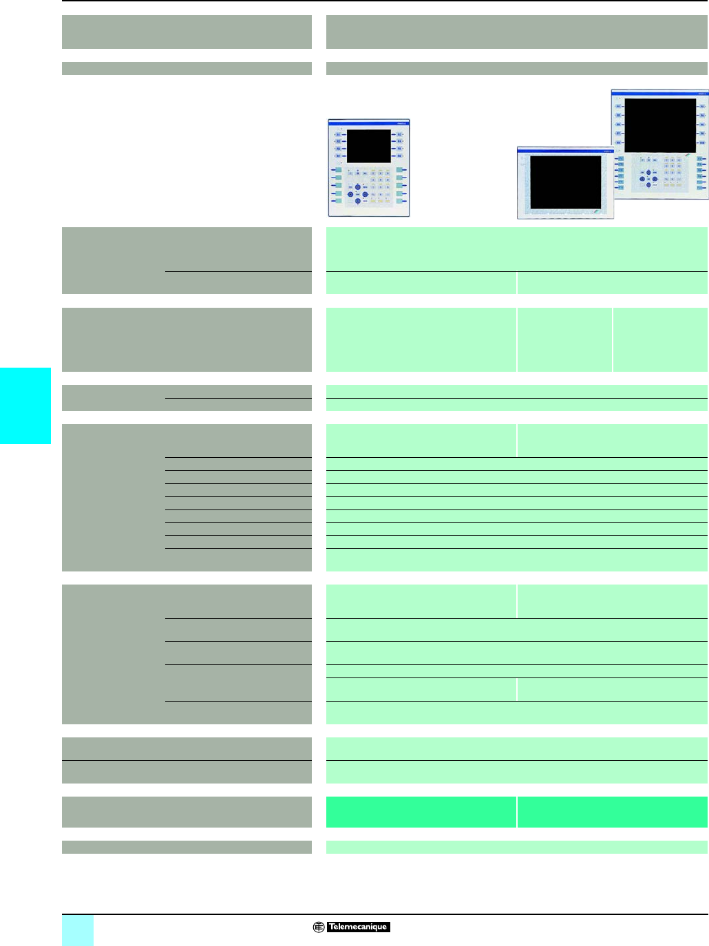
5/34
5
Selection guide
0
Human/Machine Interfaces 0
Operator dialogue terminals
Magelis® graphic terminals
Applications Display of text messages and graphic objects
Control and parametering of data
Type of unit Graphic terminals
Display Type Colour LCD TFT with touch-sensitive screen (320 x 240 pixels) with optimum viewing angle (1)
Capacity 5,7” (color) 10,4” (color)
Data entry Via keypad with:
- 10 static function keys
- 8 soft function keys
- 12 service keys
- 12 alphanumeric keys
Via touch-sensitive
screen
Via keypad with:
- 12 static function keys
- 10 soft function keys
-12 service keys
- 12 alphanumeric keys
Memory capacity Application 16 Mb Flash EPROM (via PCMCIA type II card)
Extension –
Functions Maximum number of pages 50 to 720 application, alarm, help and print-out
form pages depending on the memory card
used (512 alarms maximum)
30 to 480 application, alarm, help and print-out
form pages depending on the memory card
used (512 alarms maximum)
Variables per page 64
Representation of variables Alphanumeric, bitmap, bargraph, gauge, potentiometer, selector
Recipes 125 records maximum with 5000 values maximum
Curves 16
Alarm logs Yes
Real-time clock Access to the PLC real-time clock
Discrete inputs/outputs 1 alarm relay
Multimedia inputs/outputs –
Communication Downloadable protocols Uni-TE, Modbus, KS and for PLC brands:
GE Fanuc, Omron, Allen-Bradley and Siemens
Uni-TE, Modbus, KS, Modbus TCP/IP, Uni-TE
TCP/IP (1) and for PLC brands: GE Fanuc,
Omron, Allen-Bradley and Siemens
Asynchronous serial link RS 232C or RS 422/485
USB Ports –
Bus and networks Modbus Plus, Fipio/Fipway avec carte additive PCMCIA type III (1),
–Ethernet TCP/IP (10BASE-T/100BASE-TX) (1)
Printer link RS 232C serial link (1)
Development software XBT L1003 (under Windows 98, Windows 2000 and Windows XP)
Operating systems Magelis
Type of terminal XBT F01 XBT F02/F03
Pages Consult our “Human/Machine Interfaces” catalogue
(1) Depending on model.
(2) Uni-TE version V2 for Twido/TSX Micro/Premium PLCs.

5/35
5
0
0
Display of text messages and graphic objects
Control and parametering of data
New Technology touch-sensitive graphic terminals
Back-lit monochrome
(amber or red mode)
LCD STN
(320 x 240 pixels)
Back-lit monochrome or
colour LCD STN or
back-lit colour LCD TFT
(320 x 240 pixels)
Back-lit colour LCD STN
or color LCD TFT
(640 x 480 pixels)
Back-lit colour LCD STN
or color LCD TFT
(640 x 480 pixels)
Back-lit colour LCD TFT
(800 x 600 pixels)
Back-lit colour LCD TFT
(1024 x 768 pixels)
3,8” (monochrome) 5,7” (monochrome or
colour)
7,5” (colour) 10,4” (colour) 12,1” (colour) 15” (colour)
Via touch-sensitive
screen
6 dynamic function keys
Via touch-sensitive screen
8 Mb Flash EPROM 16 Mb Flash EPROM 32 Mo Flash EPROM
–By Compact Flash card 128, 256, 512 Mb or 1 Gb (except XBT GT2110 model)
Limited by the internal
Flash memory capacity
Limited by the internal Flash memory capacity or Compact Flash card memory capacity
Unrestricted (8000 variables max.)
Alphanumeric, bitmap, bargraph, gauge, tank, curves, polygons, button, light
32 groups of 64 recipes of 1024 ingredients max.
Yes, with log
Yes
Built-in
–1 input (reset) et 3 outputs (alarm, buzzer, run)
–1 audio input (microphone), 1 composite vidéo input (numerical or analog camera), 1 audio input
(loudspeaker) (1)
Uni-TE (2), Modbus, Modbus TCP/IP (1) and for PLC brands: Mitsubishi, Omron, Allen-Bradley and Siemens
RS 232C/485 (COM1) RS 232C/RS 422/485 (COM1) and RS 485 (COM2)
–1 (application download) 2 (application download and peripherals)
–
Ethernet TCP/IP
(10BASE-T) (1)
Ethernet TCP/IP (10BASE-T/100BASE-TX) (1)
–RS 232C serial link (COM1), USB port for parallel printer
Vijeo Designer VJD ppD TGS V44M (under Windows 2000 and Windows XP)
Magelis
(CPU 100 MHz RISC)
Magelis
(CPU 133 MHz RISC)
Magelis (CPU 266 MHz RISC)
XBT GT11 XBT GT21/22/23 XBT GT42/43 XBT GT52/53 XBT GT63 XBT GT73
Consult our “Human/Machine Interfaces” catalogue
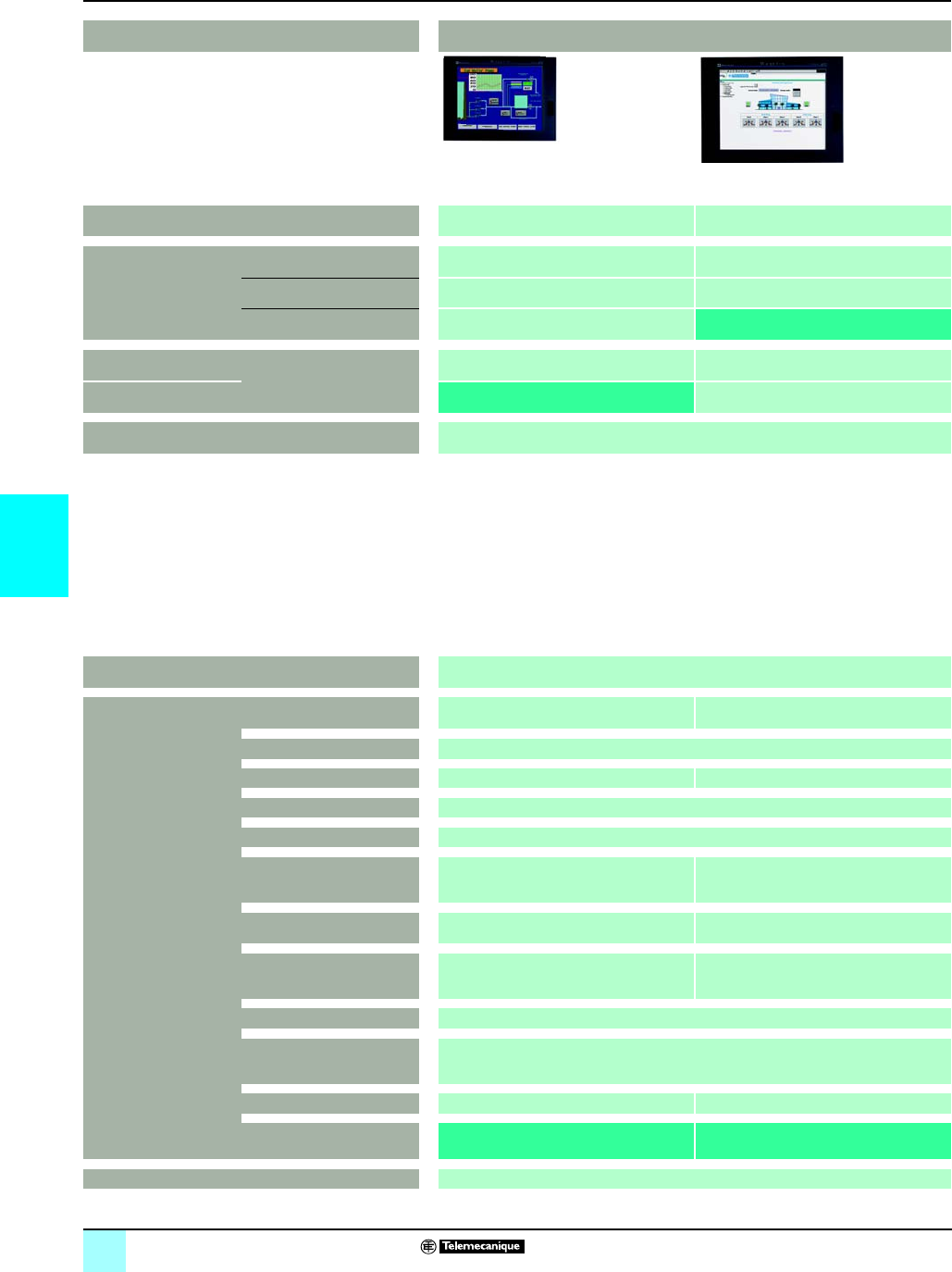
5/36
5
Selection guide Human/Machine Interfaces 0
Magelis® iPC industrial PCs
Applications “All in One” compact products
Model
15” screen
XGA (1024 x 768)
Data entry via keyboard
Data entry via keyboard and
touch screen
Data entry via touch screen p
12” screen
XGA (1024 x 768)
Data entry via touch screen
12” screen
SVGA (800 x 600)
p
Pages 43632/7
Model Smart iPC
Control box Processor Intel Celeron M 600 MHz VIA 667 MHz
Storage 1 GB Compact Flash
RAM 256 MB expandable up to 1024 MB 256 MB expandable up to 512 MB
CD-ROM drive –
Floppy disk drive –
Slots available for expansion 1 x PCMCIA slot
1 x type III/type I
1 x PCMCIA slot
1 x type III or 2 x type I
Ethernet TCP/IP Network 2 x 10BASE-T/100BASE-TX (RJ45) 1 x 10BASE-T/100BASE-TX (RJ45)
I/O ports 4 x USB + 1 x USB on front panel,
1 x RS232
2 x USB, 1 x COM1, 1 x COM2,
1 x parallel
1 x PS2 keyboard, 1 x PS2 pointing device
Operating system Windows Embedded XPe SP2
Pre-installed application or
software package
Web edition or
HMI edition - Vijeo Designer Run-Time
Power supply a 100...240 V c 24 V
Type of PC or Control box MPC ST2 1NAJ 10pMPC ST5 2NDJ 10p
Pages Consult our “Human/Machine Interfaces” catalogue
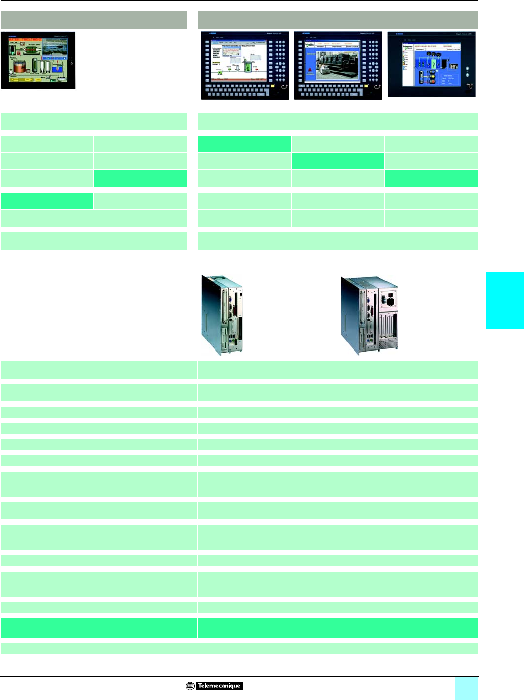
5/37
5
0
“All in One” compact products Modular products
(Control box to be connected to a front panel or used as a stand-alone device) (1)
Front panel
MPC NA5 0NNN 20N
MPC NB5 0NNN 20N
pMPC NT5 0NNN 20N
p
43634/6 43631/7
Compact iPC Control box 102 Control box 402
Intel Celeron M 1.3 GHz VIA 667 MHz or
Pentium 4 M 1.7 GHz
Intel Celeron M 1.3 GHz or
Intel Pentium M 1.6 GHz
Hard disk u 40 GB Hard disk u 20 GB Hard disk u 40 GB, removable
512 MB expandable up to 1024 MB
256 or 512 MB depend. on model 512 MB expandable up to 2 GB
–Yes Yes, removable. Combined DVD-R/CD-RW drive available as an option.
–Yes Yes
1 x PCI bus slot
1 x PCMCIA slot
1 x type III/type I
1 x PCI bus slot
1 x PCMCIA slot
1 x type III or 2 x type II
1 x PCI bus slot and
2 x type 1/2 (or 1 x type III) PCMCIA slots
4 x PCI bus slots and
2 x type 1/2 (or 1 x type III) PCMCIA slots
2 x 10BASE-T/100 BASE-TX
(RJ45)
1 x 10BASE-T/100 BASE-TX
(RJ45)
1 x 10BASE-T/100BASE-TX (RJ45)
4 x USB + 1 x USB on front
panel
1 x RS232
2 x USB, 1 COM1,
1 x COM2, 1 x parallel
2 x PS2
2 x USB, 1 x COM1, 1 x COM4 and 1 x parallel, 1 x VGA external video port,
1 x PS/2 port (2)
Windows 2000 or Windows XP Pro Windows XP Pro or Windows 2000 operating system pre-installed
Vijeo Designer Run-Time Package A: Vijeo Look Run-Time Package A: Vijeo Look Run-Time or
Package B: Vijeo Look Build-Time
a 100...240 V a 115…230 V or c 24 V depending on the model
MPC KT2 2NAp 00pMPC KT5 pNAp 00pMPC EN0 pNpp 00N MPC DN0 pNpp 00N
Consult our “Human/Machine Interfaces” catalogue
(1) To use a Control box without a front panel screen, you will require the mounting panel MPC NP0 0NNN 00NN.
(2) Port not operational when the Control box is fitted with the front panel screen.

5/38
5
Selection guide
0
Human/Machine Interfaces 0
HMI software and Web servers
Applications Traditional architecture, HMI executed on dedicated terminal or PC platform
Configuration software for user interface applications
Target products Type Magelis XBT N/R
Magelis XBT H/P/E/HM/PM
Magelis XBT F/FC
(1)
Magelis XBT G (1)
Magelis XBT GT
Operating system on terminals Proprietary Magelis operating system
Functions Reading/writing of PLC variables Yes
Display of variables Yes
Data processing –Yes, with Java programming
Sharing of variables between HMI
applications
–
Saving of variables to external
database
–
Development of
graphics
applications
Native library of graphic objects Yes
Container Active X –
Java Beans –Yes
Curves and alarms Yes, with XBT F/FC terminal + alarms via
diagnostic buffer (2)
Yes, with log
Scripts –Java
Online modification of applications –
Communication between PLCs and HMI application Via I/O drivers
Uploading of applications Yes –
Simulation of HMI applications Yes
Redundancy –
Recipe management Yes –
Report printing Form, historical data and alarm pages On the fly alarms, historical data
Access security Linked to user profiles
Software compatible with OS Windows 98, 2000 or Windows XP Windows 2000 or Windows XP
Type of software XBT L1000 Vijeo Designer
Pages Consult our “Human/Machine Interfaces” catalogue
(1) Magelis XBT terminals behave transparently on restoration of power.

5/39
5
0
0
Web architecture, embedded HMI in PLC
SCADA supervisory software Ethernet TCP/IP modules with embedded Web server
Magelis Compact iPC industrial PCs
Magelis Modular iPC industrial PCs
PC micro-computers
Servers
TSX Micro TSX ETZ
Premium TSX ETY
Quantum 140 NOE 771
FactoryCast Gateway TSX ETG 10p0
Premium TSX WMY 100
Quantum 140 NWM 100 00
Microsoft Windows
Yes –Yes
Yes
Client/server architecture
–
Yes –Yes + E-mail transmission triggered by event
Yes –
–Yes
Alarms via diagnostic buffer (2)
C compiler integrated –
Yes –Yes
Via OFS data server Via internal bus on Premium/Quantum platforms
Yes
–Yes
Yes –
Yes –
All information in the real-time database –
Windows XP, Servers Windows 98/2000/NT, Windows XP Windows 2000 or Windows XP
Vijeo Citect FactoryCast FactoryCast HMI
Consult our “Human/Machine Interfaces” catalogue
(2) Specific memory area with Modicon Premium (with PL7 or Unity Pro software) and Quantum (with Unity Pro software) PLC platforms.

06/0
6

6/1
6
Contents 6 - Services
1
Technical information
bStandards, certifications, and environmental conditions . . . . . . . . . . . . . . . . . . 6/2
bAutomation product certifications and community regulations . . . . . . . . . . . . . 6/6
bPower consumption table . . . . . . . . . . . . . . . . . . . . . . . . . . . . . . . . . . . . . . . . . 6/8
Index
bProduct reference index . . . . . . . . . . . . . . . . . . . . . . . . . . . . . . . . . . . . . . . . . . 6/9

6/2
6
Modicon® M340™ Automation
Platform 0
Standards, certifications and environmental
conditions
Modicon M340 PLCs have been developed to conform to the principal national and
international standards concerning electronic equipment for industrial automation
systems.
bRequirements specific to programmable controllers: functional characteristics,
immunity, resistance, safety, etc.: IEC/EN 61131-2, CSA 22.2 N° 142, UL 508.
bMerchant navy requirements of the main international bodies (with ABS, BV, DNV,
GL, LR, RINA, RMRS): IACS (International Association of Classification Societies)
bCompliance with European Directives:
v Low Voltage: 73/23/EEC amendment 93/68/EEC,
v Electromagnetic Compatibility: 89/336/EEC amendments 92/31/EEC and
93/68/EEC.
bElectrical qualities and self-extinguishing capacity of insulating materials:
UL 746C, UL 94.
bHazardous areas classification: CSA 22.2 No. 213, Class I, Division 2, Groups A,
B, C and D.
Modicon M340 PLCs meet the requirements of “TC” treatment (
Treatment for all
Climates
).
For installations in industrial production workshops or environments corresponding
to “TH” treatment (treatment for hot and humid environments), Modicon M340 PLCs
must be embedded in envelopes with a minimum IP 54 protection, in compliance with
IEC/EN 60664 and NF C 20 040.
Modicon M340 PLCs themselves offer
protection to IP 20 level
and
protection
against pins
(enclosed equipment) (1).
They can therefore be installed without an
envelope in reserved-access areas which do not exceed pollution level 2 (control
room with no dust-producing machine or activity). The pollution level 2 does not take
account of more severe environmental conditions: air pollution by dust, smoke,
corrosive or radioactive particles, vapors or salts, attack by fungi, insects, ...
(1) In the case where a position is not occupied by a module, a BMX XEM 010 protection cover
must be installed.
Standards and certifications
Characteristics
Service conditions and recommendations relating to environment
Temperature Operation °C 0...+ 60
Storage °C - 40...+ 85
Relative humidity Operation %93…95 without condensation according to IEC/EN 60060-2-30 Db
Storage %93…95 without condensation according to IEC/EN 60060-2-30 Db
Altitude m0…4000,
temperature derating above 3000 m: 1 °C / 400 m, equals + 55 °C at 4000 m
Supply voltage BMX CPS 2010 BMX CPS 3020 BMX CPS 2000 BMX CPS 3500
a: according to
IEC/EN 61131-2
Nominal voltage V24 c 24...48 c 100...240 a 100...240 a
Limit voltages 18...31.2 c 18...62.4 c 85...264 a 85...264 a
c: according to IACS E10
battery without charge
Nominal frequencies Hz ––50/60 50/60
Limit frequencies Hz ––47/63 47/63
Protective treatment of Modicon® M340™ PLCs
Standards and
certifications

6/3
6
Modicon® M340™ Automation
Platform 0
Standards, certifications and environmental
conditions
Environment tests
Immunity to LF interference (e) (1)
Name of test Standards Levels
Voltage and frequency variation IEC/EN 61000-4-11
IACS E10 / IEC 60092-504
0.9 Un/0.95 Fn for 30 minutes; 1.10 Un/1.05 Fn for 30 minutes;
0.8 Un/0.9 Fn for 1,5/5 seconds; 1.2 Un/1.1 Fn for 1,5/5 seconds
Direct voltage variation IEC/EN 61131-2
IEC/EN 61000-4-11
IEC 60092-504
IACS E10 (battery without
charge)
0.85 Un...1.2 Un for 30 minutes with 5% ripple (peak values)
Harmonic 3 IEC/EN 61131-2 10% Un; 0° for 5 min...180° for 5 min
Inter harmonic IACS E10 / IEC 60092-504 H2...H200 - 10% (H15), - 10%...1% (H15...H100) and 1% (H100...H200)
Short momentary interrupt IEC/EN 61131-2
IEC/EN 61000-4-11/-6-2
10 ms with a supply; 1 ms with c supply
Voltage shut-down/start-up IEC/EN 61131-2 Un-0-Un; Un for 60 s; 3 cycles separated by 10 s
Un-0-Un; Un for 5 s; 3 cycles separated by 1 to 5 s
Un-0.9-Udl; Un for 60 s; 3 cycles separated by 1 to 5 s
Where:
Un: nominal voltage
Fn: nominal frequency
Udl: detection level when powered
Immunity to HF interference. (e) (1)
Name of test Standards Levels
Damped oscillatory wave IEC/EN 61000-4-12
IEC/EN 61131-2 Zone C
a / cmain supply, a auxiliary supply, discrete a I/O (unshielded): 2.5 kV in common mode,
1 kV in differential mode
c auxiliary supply, discrete a I/O (unshielded) and analog I/O: 1 kV in common mode,
0.5 kV in differential mode
All shielded cable: 0.5 kV in common mode
Electrical fast transient bursts IEC/EN 61000-4-4
IEC 61131-2 / IACS E10
a / cmain and auxiliary supplies, discrete a I/O (unshielded): 2 kV in wire mode, 2 kV in
common mode
Discrete c I/O (unshielded), analog I/O and all shielded cable: 1 kV in common mode
Surge IEC/EN 61000-4-5
IEC/EN 61131-2 Zone B
IACS E10
a / cmain and auxiliary supplies, discrete a I/O (unshielded): 2 kV in common mode, 1 kV
in differential mode
Discrete a I/O (unshielded) and analog I/O: 0.5 kV in common mode, 0.5 kV in differential
mode
All shielded cable: 1 kV in common mode
Electrostatic discharges IEC/EN 61000-4-2
IEC/EN 61131-2 Zone B
IACS E10
6 kV contact, 8 kV air
Radiated electromagnetic field IEC/EN 61000-4-3 15 V/m : 80 MHz...2 GHz
Sinusoidal modulation amplitude 80% / 1 kHz + internal clock frequency
Conducted interference induced
by radiated field
IEC/EN 61000-4-6
IEC/EN 61131-2
IACS E10
10 V : 0,15 MHz...80 MHz
Sinusoidal modulation amplitude 80% / 1 kHz + spot frequency
Electromagnetic emissions (e) (1) (2)
Name of test Standards Levels
Interference voltage EN 55011, Class A
IEC/EN 61131-2
IEC/EN 61000-6-4
FCC part 15
150 kHz...500 kHz: quasi-peak 79 dB (µV); average 66 dB (µV)
500 kHz...30 MHz: quasi-peak 73 dB (µV); average 60 dB (µV)
IACS E10 Values according general power distribution zone
Interference field EN 55011, Class A
IEC/EN 61131-2
IEC/EN 61000-6-4
FCC part 15
30 MHz...230 MHz: quasi-peak 40 dB (measurement at 10 m), quasi-peak 50 dB
(measurement at 3 m)
230 MHz...2 GHz: quasi-peak 47 dB (measurement at 10 m), quasi-peak 57 dB (measurement
at 3 m)
IACS E10 Values depending on general power distribution zone
(1) Devices must be installed and wired in compliance with the instructions provided in the
manual “Grounding and Electromagnetic Compatibility of PLC Systems”, pdf format on
CD-Rom support included in Unity Pro software packages or on DVD UNY USE 909 CD M
reference (see page 4/31).
(2) These tests are performed without a cabinet, with devices fixed on a metal grid and wired
as per the recommendations in the manual “Grounding and Electromagnetic Compatibility of
PLC Systems”.
(e): tests required by European directives
e
. and based on IEC / EN 61131-2 standards.
Environment tests

6/4
6
Environment tests (continued) Modicon® M340™ Automation
Platform 0
Standards, certifications and environmental
conditions
.
Environment tests (continued)
Immunity to climatic variations
Name of test Standards Levels
Dry heat IEC/EN 60068-2-2 Bd
IACS E10
60 °C for 16 hours
Cold IEC/EN 60068-2-1 Ab & Ad
IACS E10
0 °C for 16 hours with start at 0 °C
Continuous humid heat IEC/EN 60068-2-78 Ca 60 °C with 93% relative humidity for 96 hours
Cyclical humid heat IEC/EN 60068-2-30 Db 55 °C; 25 °C with 93...95% relative humidity with 2 cycles of 12 hours/12 hours
Cyclical temperature variations IEC/EN 60068-2-14 Na & Nb
IEC/EN 61131-2
0...60 °C with 5 cycles of 3 hours/3 hours
Withstand to climatic variations
Name of test Standards Levels
Dry heat (power off) IEC/EN 60068-2-2 Bb & Bd 85 °C for 96 hours
Cold (power off) IEC/EN 60068-2-1 Ab & Ad
IEC/EN 60068-2-48
- 40 °C for 96 hours
Humid heat (power off) IEC/EN 60068-2-30 dB 25...60 °C with 93...95% relative humidity with 2 cycles of 12 hours/12 hours
Heat shocks (power off) IEC/EN 60068-2-14 Na & Nb - 40...85 °C with 2 cycles of 3 hours/3 hours

6/5
6
Environment tests (continued) Modicon® M340™ Automation
Platform 0
Standards, certifications and environmental
conditions
(1) Devices must be installed, wired and maintained in compliance with the instructions provided
in the users manual.
(2) In case of using fast actuators (response time y 15ms) driven by relay outputs: 15 g - 11 ms;
3 shocks/direction/axis\
(3) In case of using fast actuators (response time y 15ms) driven by relay outputs: 15 g - 6 ms;
100 bumps/direction/axis.
(e): tests required by European directives (
e
), and based on IEC / EN 61131-2 standards.
Environment tests (continued)
Immunity to mechanical constraints (1) (power on)
Name of test Standards Levels
Sinusoidal vibrations IEC/EN 60068-2-6 Fc
IACS E10
3 Hz...100 Hz/1 mm amplitude / 0.7 g, transition frequency 13.2 Hz
Endurance to resonance frequency 90 min/axis
Application coefficient < 10
Sinusoidal vibrations
(Class 3M7)
IEC/EN 60068-2-6 Fc
IEC/EN 61131-2
Specific profile
5...150 Hz with 10 mm amplitude / 3 g, transition frequency 9 Hz
Endurance: 10 cycles of 1 octave/min
Shocks IEC/EN 60068-2-27 Ea 30 g - 11 ms; 3 shocks/direction/axis
(2)
Bumps IEC/EN 60068-2-29 Eb 25 g - 6 ms; 100 bumps/direction/axis
(3)
Plugging / unplugging IEC/EN 61131-2 For modules and connectors
50 operations for permanent connections
500 operations for non-permanent connections
Withstand to mechanical constraints (power off)
Name of test Standards Levels
Flat free-fall IEC/EN 60068-2-32 Ed
method 1
IEC/EN 61131-2
10 cm / 2 falls
Controlled position free-fall
(for handheld product)
IEC/EN 60068-2-31 Ec
IEC/EN 61131-2
30 ° or 10 cm / 2 falls
Random free-fall
(equipment in packaging)
IEC/EN 60068-2-32
method 1
IEC/EN 61131-2
1 m / 5 falls
Vibrations, transports
(Class 2M3)
IEC/EN 60721-4-2
IEC/EN 60068-2-64 Fh
Stationary vibrations, random: 5 m2/s3 from 10…100 Hz, 7 dB/octave from 100…200 Hz,
1m
2/s3 de 200…2000 Hz, 30 min duration
Equipment and personnel reference information (1) (e)
Name of test Standards Levels
Dielectric strength UL 508/CSA 22-2 No.142 /
FM
IEC/EN 61131-2
2 Un + 1000 V / 1 min
Insulation resistance UL 508/CSA 22-2 No.142 /
FM
IEC/EN 61131-2
Un y 50 V: 10 MΩ
50 V y Un y 250 V: 10 MΩ
Continuity of earth ground UL 508/CSA 22-2 No.142 /
FM
IEC/EN 61131-2
30 A for 2 min, R < 0,1 Ω
Leakage current IEC/EN 61131-2 I < 3.5 mA after disconnecting
Protection offered by enclosures IEC/EN 61131-2 IP 20 and protection
Withstand to impacts UL 508/CSA 22-2 No.142 /
FM
IEC/EN 61131-2
500 g sphere: fall from 1.3 m
Stored energy injury risk IEC/EN 61131-2 After 10 s, max. 37 % Un
Overload UL 508/CSA 22-2 No.142 /
FM
IEC/EN 61131-2
50 cycles 1 s / 9 s to Un and 1.5 In
Endurance UL 508/CSA 22-2 No.142 /
FM
IEC/EN 61131-2
12 cycles 100 ms / 100ms, 988 cycles 1 s / 1 s and 5000 cycles 1 s / 9 s to Un and In
Temperature rise IEC/EN 61131-2/UL 508
CSA 22-2 No.142/UL 1604
CSA 22-2 No.213 / FM
Ambient temperature 60 °C
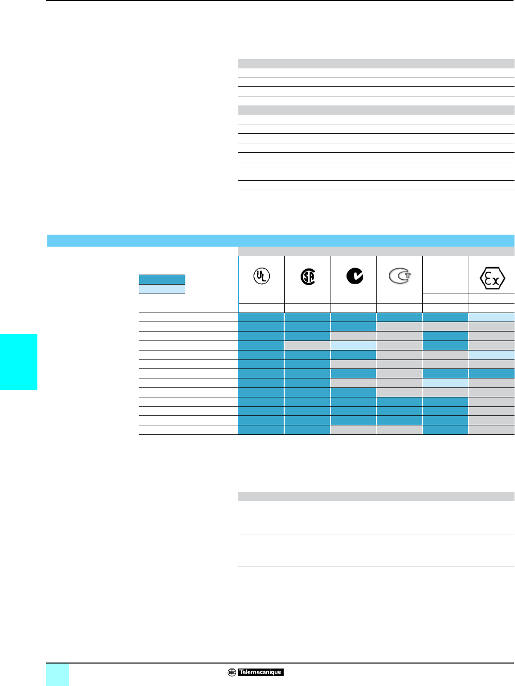
6/6
6
Technical information 0
Automation products certifications
In some countries, certifi cation of certain electrical components is enforced by law.
A standard conformity certifi cate is then issued by the offi cial organization. Each
certifi ed product must carry approval symbols when enforced. Use aboard
merchant navy vessels generally requires prior approval (= certifi cation) of an
electrical device by certain marine classifi cation authorities.
Key Certifi yrtnuoCydob noitac
CSA Canadian Standards Association Canada
C-Tick Australian Communication Authority Australia
GOST Gost Standard Scientifi c Research Institute C.I.S., Russia
UL ASUseirotarobaL sretirwrednU
Key Classifi yrtnuoCytirohtua noitac
IACS International Association of Classifi cation Societies International
ABS ASUgnippihS fo uaer
uB naciremA
BV ecnarFsatireV uaeruB
DNV yawroNsatireV eksroN teD
GL ynamreGdyolL rehcsinamreG
LR modgniK detinUret
sigeR s’dyolL
RINA ylatIelavaN onailatI ortsigeR
RMRS Russian Maritime Register of Shipping C.I.S.
The table below shows the situation as at 01.10.2006 for certifi cations obtained
or pending from organizations for base PLCs. An overview of certifi cates for
Telemecanique products is available on our Internet website:
www.telemecanique.com
Product certifi cations
Approvals
C-Tick
Hazardous
locations
Class I, Div 2 (1)
Certifi ed
Pending
certifi cation XETATSOGACAASCLU
USA Canada Australia CIS, Russia USA, Canada Europe
Advantys STB FM
Advantys Telefast ABE 7
ConneXium (2)
Magelis iPC (3) UL
Magelis XBT GT Cat 3 G-D
Magelis XBT F/FC/HM/PM
Magelis XBT N/R CSA/UL Cat 3 G-D
Modicon M340 CSA
Modicon Momentum
Modicon Premium (2) CSA
Modicon Quantum (2) FM (2)
Modicon TSX Micro
Twido (3) (2) UL (2)
(1) Hazardous locations: UL 1604, CSA 22.2 no. 213 or FM 3611, certifi ed products are
acceptable for use in hazardous locations of Class I, division 2, groups A, B, C and D or
unclassifi ed only.
(2) Depending on product, consult our website: www.telemecanique.com
(3) cULus North American certifi cation (Canada and USA).
Local certifi cations
BG Germany TSX DPZ 10D2A safety module (TSX Micro).
TSX PAY 262/282 safety modules (Premium).
SIMTARS Australia Modicon TSX Micro automation platform
Modicon Premium automation platform (PL7)
AS-Interface Europe TWD NOI 10M3 master module (Twido).
TSX SAZ 10 master module (TSX Micro).
TSX SAY 1000 master modules (Premium).
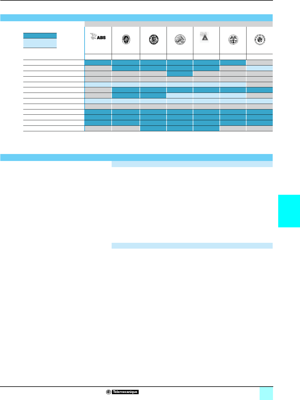
6/7
6
Technical information 0
Automation products certifications
Community regulations
Marine classifi cation
Marine classifi cation authorities
Certifi ed
Pending
certifi cation
ABS BV DNV GL LR RINA RMRS
USA France Norway Germany UK Italy C.I.S.
Advantys STB (1)
Advantys Telefast ABE 7
ConneXium (2)
Magelis iPC
Magelis XBT GT
Magelis XBT F/FC/HM/PM
Magelis XBT N/R
Modicon M340 (3)
Modicon Momentum
Modicon Premium (4) (2) (2) (2) (2) (2) (2) (2)
Modicon Quantum )2()2(
Modicon TSX Micro
Twido (2) (2) (2)
(1) Also meets US Navy requirements, ABS-NRV part 4.
(2) Depending on product, consult our website: www.telemecanique.com.
(3) Request for Marine certifi cations forecast 1st quarter of 2007.
(4) Modicon Premium, also KRS (Korean register of Shipping) certifi ed.
Community regulations
European directives
The opening of European markets implies a harmonization of regulations in the
various European Union member states.
European Directives are documents used to remove obstacles to the free movement
of goods, and their application is compulsory in all states of the European Union.
Member states must transcribe each Directive into their national legislation
and, at the same time, withdraw any confl icting regulations.
The Directives, particularly those of a technical nature, only set objectives,
called “general requirements”.
Manufacturers must take all necessary measures to ensure that their products
conform to the requirements of each Directive relating to their equipment.
As a general rule, manufacturers affi rms that their products conform to the
necessary requirements of the Directive(s) by applying the e label to their product.
The e marking is applied to Telemecanique products where relevant.
The signifi cance of e marking
The e marking on a product means that the manufacturer certifi es that its product
conforms to the relevant European Directives; it is necessary so that a product
which is subject to any Directive(s) can be marketed and freely moved within the
European Union.
The e marking is intended solely for the national authorities responsible for
market regulation.
For electrical equipment, conformity of the product to standards indicates that it is
suitable for use. Only the guarantee of a recognized manufacturer provides an
assurance of high quality.
One or more Directives, as appropriate, may apply to our products, in particular:
The Low Voltage Directive 72/23/EEC amended by Directive 93/68/EEC: The e
marking under the terms of this Directive is compulsory as of January 1, 1997.
The Electromagnetic Compatibility Directive 89/336/EEC, amended by Directives
92/31/EEC and 93/68/EEC: The e marking on the products covered by this Directive
has been compulsory since January 1, 1996.
Directive e ATEX 94/9/EC.
■
■
■
■
■
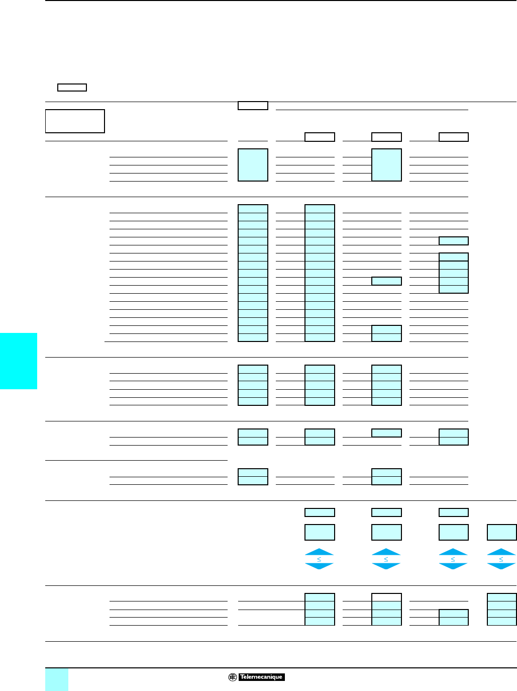
6/8
6
Choice of BMX CPS ppp0
power supply modules
Modicon®M340™ Automation
Platform 0
Power consumption table
The power required to supply each BMX XBP pp00 rack depends on the type and number of modules installed. It is therefore necessary to
create a power consumption table for each rack to define the most suitable BMX CPS ppp0 power supply module for each rack.
The table below can be used to calculate the consumption on the 2 or 3 different voltages (depending on model) to be supplied by the
BMX CPS ppp0 power supply module: 3,3 V c , 24 V c rack, 24 V c sensors.
Procedure:
bEnsure that the power supply module corresponds to the power supplies available for the two or three voltages.
bEnsure that the total power absorbed on these three voltages does not exceed the overall power of the power supply module.
b Values to be entered according to the type of Modicon M340 configuration.
Module reference Format Number Consumption in mA (1)
Rack n° S : standard
D : double
Voltage
3,3 V c
Voltage
24 V rack
Voltage
24 V c sensors
Module Total Module Total Module Total
Processors BMXP341000 S72
BMXP342010 S190
BMXP342020 S95
BMXP342030 S135
Discrete I/O
BMXDAI1602
S90
BMXDAI1603
S90
BMXDAI1604
S90
BMXDAO1605
S100
BMXDDI1602
S90 60
BMXDDI1603
S90
BMXDDI3202K
S140 110
BMXDDI6402K
S200 110
BMXDDM16022
S100 30
BMXDDM16025
S100 50 30
BMXDDM3202K
S150 55
BMXDDO1602
S100
BMXDDO1612
S100
BMXDDO3202K
S150
BMXDDO6402K
S240
BMXDRA0805
S100 55
BMXDRA1605
S100 95
Analog I/O
BMXAMI0410
S150 45
BMXAMM0600
S150 130
BMXAMO0210
S150 110
BMXART0414
S150 40
BMXART0814
S150 100
Counting
BMXEHC0200
S200 40 80
BMXEHC0800
S200 80
Communication
BMXNOE0100
S90
BMXNOE0110
S90
Consumption per voltage Total current (mA)
x 3,3 V x 24 V x 24 V
Consumption
voltage (mW)
+ + =
Power available (mW) Power overall (mW)
Choice of
power supply
BMXCPS2010
D24 V c isolated 8250 16 800 17 000
BMXCPS3020
D24...48 V c isolated 14850 31 200 32 000
BMXCPS2000
D 100...240 V a8250 16 800 10 800 20 000
BMXCPS3500
D14850 31 200 21 600 36 000
(1) Typical value given for 100% of inputs or outputs at state 1.

6/9
6

6/10
6
Product reference index
0
490NOC00005 . . . . . . . . . . . . 26
490NOR00003 . . . . . . . . . . . . 26
490NOR00005 . . . . . . . . . . . . 26
490NOR00015 . . . . . . . . . . . 26
490NOT00005 . . . . . . . . . . . . 26
490NTC00005 . . . . . . . . . . . . 26
490NTC00005U . . . . . . . . . . . 26
490NTC00015 . . . . . . . . . . . . 26
490NTC00015U . . . . . . . . . . . 26
490NTC00040 . . . . . . . . . . . . 26
490NTC00040U . . . . . . . . . . . 26
490NTC00080 . . . . . . . . . . . . 26
490NTC00080U . . . . . . . . . . . 26
490NTW00002 . . . . . . . . . . . . 26
490NTW00002U . . . . . . . . . . . 26
490NTW00005 . . . . . . . . . . . . 26
490NTW00005U . . . . . . . . . . 26
490NTW00012 . . . . . . . . . . . . 26
490NTW00012U . . . . . . . . . . . 26
490NTW00040 . . . . . . . . . . . . 26
490NTW00040U . . . . . . . . . . . 26
490NTW00080 . . . . . . . . . . . . 26
490NTW00080U . . . . . . . . . . . 26
AM02CA001V000 . . . . . . . . . . 43
BMXNOE0100 . . . . . . . . . . . . 23
BMXNOE0110 . . . . . . . . . . . . 23
BMXP341000 . . . . . . . . . . . . 45
BMXP342010 . . . . . . . . . . . . . 41
BMXP342010 . . . . . . . . . . . . . 45
BMXP342020 . . . . . . . . . . . . . 22
BMXP342020 . . . . . . . . . . . . . 45
BMXP342030 . . . . . . . . . . . . . 22
BMXP342030 . . . . . . . . . . . . . 41
FTXBLA10 . . . . . . . . . . . . . . . 43
FTXC78B . . . . . . . . . . . . . . . . 43
FTXC78F5 . . . . . . . . . . . . . . . 43
FTXC78M5 . . . . . . . . . . . . . . . 43
FTXCM08B . . . . . . . . . . . . . . . 43
FTXCM12B . . . . . . . . . . . . . . . 43
FTXCN12F5 . . . . . . . . . . . . . . 42
FTXCN12M5 . . . . . . . . . . . . . . 42
FTXCN3130 . . . . . . . . . . . . . . 42
FTXCN3150 . . . . . . . . . . . . . . 42
FTXCN3203 . . . . . . . . . . . . . . 42
FTXCN3206 . . . . . . . . . . . . . . 42
FTXCN3210 . . . . . . . . . . . . . . 42
FTXCN3220 . . . . . . . . . . . . . . 42
FTXCN3230 . . . . . . . . . . . . . . 42
FTXCN3250 . . . . . . . . . . . . . . 42
FTXCNCT1 . . . . . . . . . . . . . . . 43
FTXCNTL12 . . . . . . . . . . . . . . 43
FTXCY1208 . . . . . . . . . . . . . . 43
FTXCY1212 . . . . . . . . . . . . . . 43
FTXDG12 . . . . . . . . . . . . . . . . 43
FTXDP2115 . . . . . . . . . . . . . . 43
FTXDP2130 . . . . . . . . . . . . . . 43
FTXDP2150 . . . . . . . . . . . . . . 43
FTXDP2206 . . . . . . . . . . . . . . 43
FTXDP2210 . . . . . . . . . . . . . . 43
FTXDP2220 . . . . . . . . . . . . . . 43
FTXDP2250 . . . . . . . . . . . . . . 43
FTXMLA10 . . . . . . . . . . . . . . . 43
LU9GC3 . . . . . . . . . . . . . . . . . 46
TCSCCE4F3M05 . . . . . . . . . . 42
TCSCCE4F3M1 . . . . . . . . . . . 42
TCSCCU4F3M05 . . . . . . . . . . 42
TCSCCU4F3M1 . . . . . . . . . . . 42
TCSCTN011M11F . . . . . . . . . 43
TCSEAAF11F13F00 . . . . . . . . 27
TCSEAAF1LFH00 . . . . . . . . . 27
TCSEAAF1LFS00 . . . . . . . . . 27
TCSEAAF1LFU00 . . . . . . . . . 27
TCSEAM0100 . . . . . . . . . . . . . 27
TCSEC1M3M1S2 . . . . . . . . . . 27
TCSECL1M1M10S2 . . . . . . . . 27
TCSECL1M1M1S2 . . . . . . . . . 27
TCSECL1M1M1X5S2 . . . . . . . 27
TCSECL1M1M25S2 . . . . . . . . 27
TCSECL1M1M3S2 . . . . . . . . . 27
TCSECL1M1M40S2 . . . . . . . . 27
TCSECL1M1M5S2 . . . . . . . . . 27
TCSECL1M3M10S2 . . . . . . . . 27
TCSECL1M3M1X5S2 . . . . . . . 27
TCSECL1M3M25S2 . . . . . . . . 27
TCSECL1M3M3S2 . . . . . . . . . 27
TCSECL1M3M40S2 . . . . . . . . 27
TCSECL1M3M5S2 . . . . . . . . . 27
TCSMCN3M4F3C2 . . . . . . . . 47
TCSMCN3M4M3S2 . . . . . . . . 47
TLACDCBA005 . . . . . . . . . . . 42
TLACDCBA015 . . . . . . . . . . . 42
TLACDCBA030 . . . . . . . . . . . 42
TLACDCBA050 . . . . . . . . . . . 42
TSXCANCA100 . . . . . . . . . . . 42
TSXCANCA300 . . . . . . . . . . . 42
TSXCANCA50 . . . . . . . . . . . . 42
TSXCANCADD03 . . . . . . . . . . 42
TSXCANCADD1 . . . . . . . . . . . 42
TSXCANCADD3 . . . . . . . . . . . 42
TSXCANCADD5 . . . . . . . . . . .42
TSXCANCB100 . . . . . . . . . . . .42
TSXCANCB300 . . . . . . . . . . . .42
TSXCANCB50 . . . . . . . . . . . . .42
TSXCANCBDD03 . . . . . . . . . .42
TSXCANCBDD1 . . . . . . . . . . .42
TSXCANCBDD3 . . . . . . . . . . .42
TSXCANCBDD5 . . . . . . . . . . .42
TSXCANCD100 . . . . . . . . . . . .42
TSXCANCD300 . . . . . . . . . . . .42
TSXCANCD50 . . . . . . . . . . . . .42
TSXCANKCDF180T . . . . . . . .42
TSXCANKCDF90T . . . . . . . . .42
TSXCANKCDF90TP . . . . . . . .42
TSXCANTDM4 . . . . . . . . . . . .42
TSXCSA100 . . . . . . . . . . . . . .47
TSXCSA200 . . . . . . . . . . . . . .47
TSXCSA500 . . . . . . . . . . . . . .47
TSXSCA50 . . . . . . . . . . . . . . .46
TSXSCA62 . . . . . . . . . . . . . . .46
TSXSCPCM4530 . . . . . . . . . .47
TWDXCAISO . . . . . . . . . . . . . .46
TWDXCARJ003 . . . . . . . . . . .47
TWDXCARJ010 . . . . . . . . . . .47
TWDXCARJ030 . . . . . . . . . . .47
TWDXCAT3RJ . . . . . . . . . . . .46
VW3 A8114 . . . . . . . . . . . . . . .46
VW3A8306 . . . . . . . . . . . . . . .47
VW3A8306D30 . . . . . . . . . . . .47
VW3A8306R03 . . . . . . . . . . . .47
VW3A8306R10 . . . . . . . . . . . .47
VW3A8306R30 . . . . . . . . . . . .47
VW3A8306R30 . . . . . . . . . . . .47
VW3A8306RC . . . . . . . . . . . . .46
VW3A8306TF03 . . . . . . . . . . .46
VW3A8306TF10 . . . . . . . . . . .46
VW3CANA71 . . . . . . . . . . . . . . .3
VW3CANCARR03 . . . . . . . . . .43
VW3CANCARR1 . . . . . . . . . . .43
VW3CANKCDF180T . . . . . . . .43
VW3CANTAP2 . . . . . . . . . . . .42
XBTZ938 . . . . . . . . . . . . . . . . .47
XGSZ24 . . . . . . . . . . . . . . . . . .46
XZCC12FCM50B . . . . . . . . . .27
XZCC12FCM50B . . . . . . . . . .43
XZCC12FDM50B . . . . . . . . . .27
XZCC12FDM50B . . . . . . . . . .43
XZCC12MCM50B . . . . . . . . . .43
XZCC12MDM50B . . . . . . . . . .43
XZCP1164L2 . . . . . . . . . . . . . .27
XZCP1164L5 . . . . . . . . . . . . . .27
XZCP1264L2 . . . . . . . . . . . . . .27
XZCP1264L5 . . . . . . . . . . . . . .27
CHAPTER 4
110XCA28201 . . . . . . . . . . . . .31
110XCA28202 . . . . . . . . . . . . .31
110XCA28203 . . . . . . . . . . . . .31
990NAA26320 . . . . . . . . . . . . .31
990NAA26350 . . . . . . . . . . . . .31
BMXXCAUSBH018 . . . . . . . . .31
BMXXCAUSBH045 . . . . . . . . .31
TSXCRJMD25 . . . . . . . . . . . . .31
TSXCUSB485 . . . . . . . . . . . . .31
TSXPCX1031 . . . . . . . . . . . . .31
UNYSDUDFUCD20 . . . . . . . . .39
UNYSDUMFFCD20 . . . . . . . . .37
UNYSDUMFTCD20 . . . . . . . . .37
UNYSDUMFUCD20 . . . . . . . .37
UNYSMUZUCD30 . . . . . . . . . .39
UNYSPUEFFCD30 . . . . . . . . .30
UNYSPUEFGCD30 . . . . . . . . .30
UNYSPUEFTCD30 . . . . . . . . .30
UNYSPUEFUCD30 . . . . . . . . .30
UNYSPUEZFCD30 . . . . . . . . .30
UNYSPUEZGCD30 . . . . . . . . .30
UNYSPUEZTCD30 . . . . . . . . .30
UNYSPUEZUCD30 . . . . . . . . .30
UNYSPULFFCD30 . . . . . . . . .30
UNYSPULFGCD30 . . . . . . . . .30
UNYSPULFTCD30 . . . . . . . . .30
UNYSPULFUCD30 . . . . . . . . .30
UNYSPULZFCD30 . . . . . . . . .30
UNYSPULZGCD30 . . . . . . . . .30
UNYSPULZTCD30 . . . . . . . . .30
UNYSPULZUCD30 . . . . . . . . .30
UNYSPUMFGCD30 . . . . . . . .30
UNYSPUMFTCD30 . . . . . . . . .30
UNYSPUMFUCD30 . . . . . . . .30
UNYSPUMZGCD30 . . . . . . . .30
UNYSPUMZTCD30 . . . . . . . . .30
UNYSPUMZUCD30 . . . . . . . .30
UNYSPUSFGCD30 . . . . . . . . .30
UNYSPUSFTCD30 . . . . . . . . .30
UNYSPUSFUCD30 . . . . . . . . .30
UNYSPUSZGCD30 . . . . . . . . .30
UNYSPUSZTCD30 . . . . . . . . .30
UNYSPUSZUCD30 . . . . . . . . .30
UNYSPUZFUCD30E . . . . . . . .33
UNYUDEVFUCD21E . . . . . . . 30
UNYUSE909CDM . . . . . . . . . 31
UNYXCAUSB033 . . . . . . . . . . 31
CHAPTER 5
ABE7ACC01 . . . . . . . . . . . . . 17
ABE7ACC02 . . . . . . . . . . . . . 17
ABE7ACC10 . . . . . . . . . . . . . 17
ABE7ACC11 . . . . . . . . . . . . . 17
ABE7ACC12 . . . . . . . . . . . . . 15
ABE7ACC20 . . . . . . . . . . . . . 17
ABE7ACC21 . . . . . . . . . . . . . 17
ABE7ACC30 . . . . . . . . . . . . . 17
ABE7ACC80 . . . . . . . . . . . . . 17
ABE7ACC81 . . . . . . . . . . . . . 17
ABE7ACC82 . . . . . . . . . . . . . 17
ABE7ACC83 . . . . . . . . . . . . . 17
ABE7ACC84 . . . . . . . . . . . . . 17
ABE7ACC85 . . . . . . . . . . . . . 17
ABE7BV10 . . . . . . . . . . . . . . . 17
ABE7BV10E . . . . . . . . . . . . . . 17
ABE7BV20 . . . . . . . . . . . . . . 17
ABE7BV20E . . . . . . . . . . . . . . 17
ABE7CPA01 . . . . . . . . . . . . . . 16
ABE7CPA01 . . . . . . . . . . . . . . 16
ABE7CPA02 . . . . . . . . . . . . . . 16
ABE7CPA03 . . . . . . . . . . . . . . 16
ABE7CPA11 . . . . . . . . . . . . . . 16
ABE7CPA12 . . . . . . . . . . . . . . 16
ABE7CPA13 . . . . . . . . . . . . . . 16
ABE7CPA21 . . . . . . . . . . . . . . 16
ABE7CPA31 . . . . . . . . . . . . . . 16
ABE7CPA31E . . . . . . . . . . . . 16
ABE7CPA410 . . . . . . . . . . . . . 16
ABE7CPA412 . . . . . . . . . . . . . 16
ABE7FU012 . . . . . . . . . . . . . . 17
ABE7FU050 . . . . . . . . . . . . . . 17
ABE7FU100 . . . . . . . . . . . . . . 17
ABE7FU200 . . . . . . . . . . . . . . 17
ABE7FU400 . . . . . . . . . . . . . . 17
ABE7FU630 . . . . . . . . . . . . . . 17
ABE7H08R10 . . . . . . . . . . . . . 11
ABE7H08R11 . . . . . . . . . . . . . 11
ABE7H08R21 . . . . . . . . . . . . . 11
ABE7H08S21 . . . . . . . . . . . . . 11
ABE7H12R10 . . . . . . . . . . . . . 11
ABE7H12R11 . . . . . . . . . . . . . 11
ABE7H12R20 . . . . . . . . . . . . . 11
ABE7H12R21 . . . . . . . . . . . . . 11
ABE7H12R50 . . . . . . . . . . . . . 11
ABE7H12S21 . . . . . . . . . . . . . 11
ABE7H16C10 . . . . . . . . . . . . . 10
ABE7H16C11 . . . . . . . . . . . . . 10
ABE7H16C21 . . . . . . . . . . . . 10
ABE7H16C31 . . . . . . . . . . . . . 10
ABE7H16CM11 . . . . . . . . . . . 10
ABE7H16CM21 . . . . . . . . . . . 10
ABE7H16F43 . . . . . . . . . . . . . 11
ABE7H16R10 . . . . . . . . . . . . . 11
ABE7H16R11 . . . . . . . . . . . . . 11
ABE7H16R11E . . . . . . . . . . . 11
ABE7H16R20 . . . . . . . . . . . . . 11
ABE7H16R21 . . . . . . . . . . . . . 11
ABE7H16R21E . . . . . . . . . . . 11
ABE7H16R23 . . . . . . . . . . . . . 11
ABE7H16R30 . . . . . . . . . . . . . 11
ABE7H16R31 . . . . . . . . . . . . 11
ABE7H16R50 . . . . . . . . . . . . 11
ABE7H16R50E . . . . . . . . . . . 11
ABE7H16S21 . . . . . . . . . . . . . 11
ABE7H16S21E . . . . . . . . . . . . 11
ABE7H16S43 . . . . . . . . . . . . . 11
ABE7H20E100 . . . . . . . . . . . 10
ABE7H20E200 . . . . . . . . . . . . 10
ABE7H20E300 . . . . . . . . . . . . 10
ABE7H32E150 . . . . . . . . . . . . 10
ABE7H32E300 . . . . . . . . . . . . 10
ABE7LOGF25 . . . . . . . . . . . . 17
ABE7LOGV10 . . . . . . . . . . . . 17
ABE7P08T330 . . . . . . . . . . . . 14
ABE7P08T330E . . . . . . . . . . . 14
ABE7P16F310 . . . . . . . . . . . . 13
ABE7P16F310E . . . . . . . . . . . 13
ABE7P16F312 . . . . . . . . . . . . 13
ABE7P16M111 (2) . . . . . . . . . 14
ABE7P16T111 . . . . . . . . . . . . 14
ABE7P16T210 (3) . . . . . . . . . 14
ABE7P16T212 . . . . . . . . . . . . 14
ABE7P16T214 . . . . . . . . . . . . 14
ABE7P16T215 . . . . . . . . . . . . 14
ABE7P16T230 (3) . . . . . . . . . 14
ABE7P16T230E (3) . . . . . . . . 14
ABE7P16T318 . . . . . . . . . . . . 14
ABE7P16T318E . . . . . . . . . . . 14
ABE7P16T330 . . . . . . . . . . . . 14
ABE7P16T330E . . . . . . . . . . . 14
ABE7P16T332 . . . . . . . . . . . . 14
ABE7P16T334 . . . . . . . . . . . . 14
ABE7R08S111 . . . . . . . . . . . . 12
ABE7R08S111E . . . . . . . . . . .12
ABE7R08S210 . . . . . . . . . . . . 12
ABE7R08S210E . . . . . . . . . . .12
ABE7R08S216 . . . . . . . . . . . . 12
ABE7R08S216E . . . . . . . . . . .12
ABE7R16M111 . . . . . . . . . . . . 13
ABE7R16S111 . . . . . . . . . . . . 12
ABE7R16S111E . . . . . . . . . . .12
ABE7R16S210 . . . . . . . . . . . . 12
ABE7R16S210E . . . . . . . . . . .12
ABE7R16S212 . . . . . . . . . . . . 12
ABE7R16S212E . . . . . . . . . . .12
ABE7R16T111 . . . . . . . . . . . . 13
ABE7R16T210 . . . . . . . . . . . . 13
ABE7R16T212 . . . . . . . . . . . . 13
ABE7R16T230 . . . . . . . . . . . . 13
ABE7R16T231 . . . . . . . . . . . . 13
ABE7R16T330 . . . . . . . . . . . . 13
ABE7R16T332 . . . . . . . . . . . . 13
ABE7R16T370 . . . . . . . . . . . . 13
ABE7S08S2B0 . . . . . . . . . . . . 12
ABE7S08S2B0E . . . . . . . . . . . 12
ABE7S08S2B1 . . . . . . . . . . . . 12
ABE7S08S2B1E . . . . . . . . . . . 12
ABE7S16E2B1 . . . . . . . . . . . . 12
ABE7S16E2B1E . . . . . . . . . . . 12
ABE7S16E2E0 . . . . . . . . . . . . 12
ABE7S16E2E0E . . . . . . . . . . . 12
ABE7S16E2E1 . . . . . . . . . . . . 12
ABE7S16E2E1E . . . . . . . . . . . 12
ABE7S16E2F0 . . . . . . . . . . . . 12
ABE7S16E2F0E . . . . . . . . . . . 12
ABE7S16E2M0 . . . . . . . . . . . . 12
ABE7S16E2M0E . . . . . . . . . . . 12
ABE7S16S1B2 . . . . . . . . . . . . 12
ABE7S16S1B2E . . . . . . . . . . . 12
ABE7S16S2B0 . . . . . . . . . . . . 12
ABE7S16S2B0E . . . . . . . . . . . 12
ABE7TES160 . . . . . . . . . . . . .17
ABFC08R02B . . . . . . . . . . . . .17
ABFC08R02R . . . . . . . . . . . . .17
ABFC08R02W . . . . . . . . . . . . 17
ABFC08R12B . . . . . . . . . . . . .17
ABFC08R12R . . . . . . . . . . . . .17
ABFC08R12W . . . . . . . . . . . . 17
ABR7S11 . . . . . . . . . . . . . . . . 15
ABR7S21 . . . . . . . . . . . . . . . .15
ABR7S23 . . . . . . . . . . . . . . . . 15
ABR7S33 . . . . . . . . . . . . . . . .15
ABR7S33E . . . . . . . . . . . . . . . 15
ABR7S37 . . . . . . . . . . . . . . . . 15
ABS7EA3E5 . . . . . . . . . . . . . . 15
ABS7EA3F5 . . . . . . . . . . . . . . 15
ABS7EA3M5 . . . . . . . . . . . . . . 15
ABS7EC3AL . . . . . . . . . . . . . .15
ABS7EC3B2 . . . . . . . . . . . . . .15
ABS7EC3E2 . . . . . . . . . . . . . .15
ABS7SA2M . . . . . . . . . . . . . . .15
ABS7SA3MA . . . . . . . . . . . . . .15
ABS7SC1B . . . . . . . . . . . . . . 15
ABS7SC2E . . . . . . . . . . . . . . .15
ABS7SC3BA . . . . . . . . . . . . . . 15
ABS7SC3E . . . . . . . . . . . . . . .15
AR1SB3 . . . . . . . . . . . . . . . . .17
CHAPTER 6
BMXAMI0410 . . . . . . . . . . . . . .8
BMXAMM0600 . . . . . . . . . . . . .8
BMXAMO0210 . . . . . . . . . . . . . 8
BMXART0414 . . . . . . . . . . . . . .8
BMXART0814 . . . . . . . . . . . . . .8
BMXCPS2000 . . . . . . . . . . . . . .8
BMXCPS2010 . . . . . . . . . . . . . .8
BMXCPS3020 . . . . . . . . . . . . . .8
BMXCPS3500 . . . . . . . . . . . . . .8
BMXDAI1602 . . . . . . . . . . . . . . 8
BMXDAI1603 . . . . . . . . . . . . . . 8
BMXDAI1604 . . . . . . . . . . . . . . 8
BMXDAO1605 . . . . . . . . . . . . . 8
BMXDDI1602 . . . . . . . . . . . . . . 8
BMXDDI1603 . . . . . . . . . . . . . . 8
BMXDDI3202K . . . . . . . . . . . . . 8
BMXDDI6402K . . . . . . . . . . . . . 8
BMXDDM16022 . . . . . . . . . . . .8
BMXDDM16025 . . . . . . . . . . . .8
BMXDDM3202K . . . . . . . . . . . .8
BMXDDO1602 . . . . . . . . . . . . . 8
BMXDDO1612 . . . . . . . . . . . . . 8
BMXDDO3202K . . . . . . . . . . . . 8
BMXDDO6402K . . . . . . . . . . . . 8
BMXDRA0805 . . . . . . . . . . . . . . 8
BMXDRA1605 . . . . . . . . . . . . . . 8
BMXEHC0200 . . . . . . . . . . . . . . 8
BMXEHC0800 . . . . . . . . . . . . . . 8
BMXNOE0100 . . . . . . . . . . . . .8
BMXNOE0110 . . . . . . . . . . . . .8
BMXP341000 . . . . . . . . . . . . . .8
BMXP342010 . . . . . . . . . . . . . .8
BMXP342020 . . . . . . . . . . . . . .8
CHAPTER 1
BMXCPS2000. . . . . . . . . . . . . 13
BMXCPS2010 . . . . . . . . . . . . 13
BMXCPS3020 . . . . . . . . . . . . 13
BMXCPS3500 . . . . . . . . . . . . 13
BMXP341000 . . . . . . . . . . . . . 9
BMXP342010 . . . . . . . . . . . . . . 9
BMXP342020 . . . . . . . . . . . . . . 9
BMXP342030 . . . . . . . . . . . . . . 9
BMXRMS008MP . . . . . . . . . . . 9
BMXRMS008MPF . . . . . . . . . . 9
BMXXB0600 . . . . . . . . . . . . . 15
BMXXBP0400 . . . . . . . . . . . . 15
BMXXBP0800 . . . . . . . . . . . . 15
BMXXBP1200 . . . . . . . . . . . . 15
BMXXCAUSBH018 . . . . . . . . . 9
BMXXCAUSBH045 . . . . . . . . . 9
BMXXEM010 . . . . . . . . . . . . . 15
BMXXSP0400 . . . . . . . . . . . . 15
BMXXSP0600 . . . . . . . . . . . . 15
BMXXSP0800 . . . . . . . . . . . . 15
BMXXSP1200 . . . . . . . . . . . . 15
BMXXTSCPS10 . . . . . . . . . . . 13
BMXXTSCPS20 . . . . . . . . . . . 13
CHAPTER . . . . . . . . . . . . . . . . 1
STBXSP3010 . . . . . . . . . . . . . 15
STBXSP3020 . . . . . . . . . . . . . 15
CHAPTER 2
BMXDDI1602 . . . . . . . . . . . . . 16
BMXDDI3202K . . . . . . . . . . . 16
BMXDDI6402K . . . . . . . . . . . 16
BMXDAI1602 . . . . . . . . . . . . . 16
BMXDDI1603 . . . . . . . . . . . . 16
BMXDAI1602 . . . . . . . . . . . . . 16
BMXDAI1603 . . . . . . . . . . . . . 16
BMXDAI1604 . . . . . . . . . . . . . 16
BMXDDO1602 . . . . . . . . . . . . 16
BMXDDO1612 . . . . . . . . . . . 16
BMXDDO3202K . . . . . . . . . . . 16
BMXDDO6402K . . . . . . . . . . . 16
BMXDAO1605 . . . . . . . . . . . . 16
BMXDRA0805 . . . . . . . . . . . . 16
BMXDRA1605 . . . . . . . . . . . . 16
BMXDDM16022 . . . . . . . . . . . 17
BMXDDM16025 . . . . . . . . . . . 17
BMXDDM3202K . . . . . . . . . . 17
BMXFTB2000 . . . . . . . . . . . . 17
BMXFTB2010 . . . . . . . . . . . . 17
BMXFTB2020 . . . . . . . . . . . . 17
BMXFTW301 . . . . . . . . . . . . . 17
BMXFTW501 . . . . . . . . . . . . . 17
BMXFTW1001 . . . . . . . . . . . . 17
BMXFCW301 . . . . . . . . . . . . . 17
BMXFCW501 . . . . . . . . . . . . . 17
BMXFCW1001 . . . . . . . . . . . . 17
BMXFCW303 . . . . . . . . . . . . . 17
BMXFCW503 . . . . . . . . . . . . . 17
BMXFCW1003 . . . . . . . . . . . . 17
BMXFCC051 . . . . . . . . . . . . . 17
BMXFCC101 . . . . . . . . . . . . . 17
BMXFCC201 . . . . . . . . . . . . . 17
BMXFCC301 . . . . . . . . . . . . . 17
BMXFCC501 . . . . . . . . . . . . . 17
BMXFCC1001 . . . . . . . . . . . . 17
BMXFCC053 . . . . . . . . . . . . . 17
BMXFCC103 . . . . . . . . . . . . . 17
BMXFCC203 . . . . . . . . . . . . . 17
BMXFCC303 . . . . . . . . . . . . . 17
BMXFCC503 . . . . . . . . . . . . . 17
BMXFCC1003 . . . . . . . . . . . . 17
BMXAMI0410 . . . . . . . . . . . . . 31
BMXART0414 . . . . . . . . . . . . 31
BMXART0814 . . . . . . . . . . . . 31
BMXAMO0210 . . . . . . . . . . . . 31
BMXAMM0600 . . . . . . . . . . . . 31
BMXFTB2000 . . . . . . . . . . . . 31
BMXFTB2010 . . . . . . . . . . . . 31
BMXFTB2020 . . . . . . . . . . . . 31
BMXFTW301S . . . . . . . . . . . . 31
BMXFTW501S . . . . . . . . . . . . 31
BMXFCW301S . . . . . . . . . . . 31
BMXFCW501S . . . . . . . . . . . 31
ABE7CPA410 . . . . . . . . . . . . 31
ABE7CPA412 . . . . . . . . . . . . 31
BMXFCA150 . . . . . . . . . . . . . 31
BMXFCA300 . . . . . . . . . . . . . 31
BMXFCA500 . . . . . . . . . . . . . 31
BMXFCA152 . . . . . . . . . . . . . 31
BMXFCA302 . . . . . . . . . . . . . 31
BMXFCA502 . . . . . . . . . . . . . 31
BMXEHC0200 . . . . . . . . . . . . 41
BMXEHC0800 . . . . . . . . . . . . 41
BMXXTSHSC20 . . . . . . . . . . 41
BMXFTB2000 . . . . . . . . . . . . 41
BMXFTB2010 . . . . . . . . . . . . 41
BMXFTB2020 . . . . . . . . . . . . 41
CHAPTER 3

6/11
6
Product reference index
(continued)
0
BMXP342030 . . . . . . . . . . . . . .8

ART. 960128 06 / 2007
DIA6ED2061001EN-US
North American Operating Division
The effi ciency of Telemecanique®
branded solutions
Used in combination, Telemecanique products provide quality solutions,
meeting all your Automation and Control applications requirements.
A worldwide presence
Constantly available
■ More than 5 000 points of sale in 130 countries.
■ You can be sure to fi nd the range of products that are right for you and which
comply fully with the standards in the country where they are used.
Technical assistance wherever you are
■ Our technicians are at your disposal to assist in fi nding the optimum solution
for your particular needs.
■ Schneider Electric offers all necessary technical assistance, throughout the
world.
Simply Smart !
Schneider Electric
1415 South Roselle Road
Palatine, IL 60064
TEL: 847-397-2600
www.schneider-electric.com
www.us.telemecanique.com
Due to evolution of standards and equipment, the characteristics indicated in texts and images of this
document do not constitute a commitment on our part without confi rmation.
Design: Schneider Electric
Photos: Schneider Electric
Printed by: Delzer Lithograph
Platform for machine
manufacturers
Modicon® M340™ PLC
Unity
™
software
Platform for machines and
manufacturing processes
Modicon® Premium™
Unity™ and PL7™ software
Platform for continuous and semi-
continuous industrial processes
and infrastructure sites
Modicon® Quantum™
Unity™, Concept™ and
ProWORX™ 32 software
www.us.telemecanique.com
www.us.telemecanique.com
DIA6ED2061001EN-US © 2007 Schneider Electric. All Rights Reserved.
DIA6ED2061001EN-US
