RPI Handbuch Installation Directions
2016-10-06
: Pdf 44188-Installationsheet 1 44188-InstallationSheet_1 B5 unilog
Open the PDF directly: View PDF ![]() .
.
Page Count: 218 [warning: Documents this large are best viewed by clicking the View PDF Link!]

REMOTE PROCESS
INTERFACE
PROCESS AUTOMATION
MANUAL

With regard to the supply of products, the current issue of the following document is ap-
plicable: The General Terms of Delivery for Products and Services of the Electrical In-
dustry, published by the Central Association of the Electrical Industry (Zentralverband
Elektrotechnik und Elektroindustrie (ZVEI) e.V.) in its most recent version as well as the
supplementary clause: "Expanded reservation of proprietorship"
REMOTE PROCESS INTERFACE

3
RPI-System Manual
Table of contents
Subject to reasonable modifications due to technical advances. Copyright Pepperl+Fuchs, Printed in Germany
Pepperl+Fuchs Group • Tel.: Germany +49 621 776-0 • USA +1 330 4253555 • Singapore +65 67799091 • Internet http://www.pepperl-fuchs.com
Date of issue 06/03/03
INTRODUCTION, SYSTEM DESCRIPTION AND RPI SYSTEM COMPONENTS
1THE REMOTE PROCESS INTERFACE RPI IN BRIEF ............................................................13
1.1 Availability, Functional Integrity and Function Monitoring .................................................................14
1.2 Aim of the Handbook ...............................................................................................................................14
1.3 Notes on Using the Handbook ...............................................................................................................16
1.4 Prerequisites for RPI System Operation ...............................................................................................16
1.5 Responsibilities of the User ...................................................................................................................17
2SAFETY ...........................................................................................................................18
2.1 Safety Notes .............................................................................................................................................18
2.1.1 Explanation of the Symbols Used in This Document .................................................................................18
2.1.2 General Safety Regulations .......................................................................................................................18
2.2 Intended Use ............................................................................................................................................19
2.3 Installation in a Potentially Explosive Atmosphere ..............................................................................19
2.4 Installation Instructions for Use of the RPI System on Ships .............................................................20
2.5 Overvoltage and Lightning Protection ..................................................................................................21
2.6 Declaration of Conformity .......................................................................................................................21
2.7 Marking .....................................................................................................................................................22
3PRODUCT DESCRIPTION ...................................................................................................23
3.1 System Structure and Principle of Operation .......................................................................................23
3.1.1 Modularity of the RPI System ....................................................................................................................23
3.1.2 Integrated Signal Transfer and Mechanical Mounting: Power Rail ............................................................24
3.1.3 Communication Between the RPI Modules ...............................................................................................24
3.1.4 Gateways - Interface to an External Bus ...................................................................................................24
3.1.5 Voltage Supply via Power Feed Modules and Power Supply Units ...........................................................24
3.1.6 RPI Devices ...............................................................................................................................................24
3.1.7 HART Protocol Transmission ....................................................................................................................24
3.1.7.1 HART Programming Unit With Direct Connection ....................................................................................................... 25
3.1.7.2 Transmission via HART Multiplexer ............................................................................................................................. 26
3.1.7.3 HART Transmission via PROFIBUS ............................................................................................................................ 27
3.2 Performance Characteristics ..................................................................................................................28
3.2.1 Overview of the RPI System Characteristics .............................................................................................28
3.2.2 Flexibility by Virtue of Modularity ...............................................................................................................29
3.2.3 Internal and external communication .........................................................................................................29
3.2.4 Electrical Safety .........................................................................................................................................29
3.2.5 System Availability .....................................................................................................................................30
3.2.6 Configuration and Parameter Assignment .................................................................................................30
3.3 Summary of RPI Modules Currently Available ......................................................................................31
3.3.1 230 V AC POWER SUPPLY UNITS ................................................................................................................31
3.3.2 24 V DC POWER FEED MODULES ................................................................................................................31
3.3.3 ISOLATED SWITCH AMPLIFIERS ....................................................................................................................31
3.3.4 SOLENOID DRIVERS AND RELAY MODULES ..................................................................................................31
3.3.5 TRANSMITTER POWER SUPPLIES ..................................................................................................................31

RPI-System Manual
Table of contents
4
Subject to reasonable modifications due to technical advances. Copyright Pepperl+Fuchs, Printed in Germany
Pepperl+Fuchs Group • Tel.: Germany +49 621 776-0 • USA +1 330 4253555 • Singapore +65 67799091 • Internet http://www.pepperl-fuchs.com
Date of issue 06/03/03
3.3.6 Analogue Driver/Repeater ........................................................................................................................ 31
3.3.7 CURRENT FREQUENCY CONVERTERS, BATCH CONTROLLERS, FLOW METERS .............................................. 32
3.3.8 TEMPERATURE CONVERTERS ...................................................................................................................... 32
3.3.9 VOLTAGE CONVERTER ................................................................................................................................ 32
3.3.10 GATEWAYS ................................................................................................................................................. 32
3.3.11 HART Modules .......................................................................................................................................... 32
3.4 Commissioning Procedure for the RPI System ................................................................................... 33
3.4.1 Configuration ............................................................................................................................................. 33
3.4.2 Parameter Assignment ............................................................................................................................. 33
3.4.3 Integration into the Higher-Level Bus System ........................................................................................... 33
3.5 Control Cabinets: Assembly and Service ............................................................................................. 34
PLANNING, COMMISSIONING, CONFIGURATION AND PARAMETER ASSIGNMENT
4PLANNING OF THE RPI SYSTEM ....................................................................................... 35
4.1 Planning - Basics and Procedure .......................................................................................................... 35
4.1.1 MSR Technology ...................................................................................................................................... 36
4.1.2 Topology ................................................................................................................................................... 36
4.1.3 HART Communication .............................................................................................................................. 36
4.1.4 Fieldbus and Subordinate Service Level .................................................................................................. 36
4.1.5 Establishing the Measuring Ranges, Basic and Miscellaneous Functions ............................................... 36
4.1.5.1 Process Data ................................................................................................................................................................ 37
4.1.5.2 Device Parameters ....................................................................................................................................................... 37
4.1.5.3 Channel-Specific Parameters ...................................................................................................................................... 37
4.1.5.4 Device and Channel-Specific Diagnostic Information .................................................................................................. 37
4.1.5.5 Overview of Functions and Miscellaneous Functions for Each RPI Device ................................................................. 38
4.1.6 Selecting the RPI Devices ........................................................................................................................ 39
4.1.7 Establishing the Miscellaneous and Monitoring Functions for the Operation ........................................... 39
4.1.8 Layout and Addressing of the RPI Devices .............................................................................................. 40
4.1.9 Determining Where to Install the RPI System ........................................................................................... 40
4.2 Planning the Transmission of HART Protocols ................................................................................... 40
4.2.1 Direct Connection of a HART Programming Unit ...................................................................................... 41
4.2.2 Connection to the HART Multiplexer ......................................................................................................... 41
4.2.3 HART Transmission via KSD2-GW2-PRO Gateway ................................................................................42
4.2.3.1 Service Interface .......................................................................................................................................................... 42
4.2.3.2 PROFIBUS ................................................................................................................................................................... 42
4.3 General Information on Communication and Diagnostic Procedures via the Internal RPI Bus ..... 43
4.4 Calculating the RPI Cycle Time ............................................................................................................. 44
4.5 Planning the Internal and External Communication ............................................................................44
4.5.1 General Notes on Operating the Gateways .............................................................................................. 44
4.5.2 Redundancy Considerations ..................................................................................................................... 45
4.5.2.1 Redundancy Internal Bus ............................................................................................................................................. 45
4.5.2.2 Gateway Redundancy .................................................................................................................................................. 45
4.5.2.3 Redundancy External Bus ............................................................................................................................................ 46
4.5.3 Determining the Number of RPI Gateways Required ............................................................................... 46

5
RPI-System Manual
Table of contents
Subject to reasonable modifications due to technical advances. Copyright Pepperl+Fuchs, Printed in Germany
Pepperl+Fuchs Group • Tel.: Germany +49 621 776-0 • USA +1 330 4253555 • Singapore +65 67799091 • Internet http://www.pepperl-fuchs.com
Date of issue 06/03/03
4.6 Establishing the Service Functionality for the RPI System .................................................................46
4.6.1 Service Interface RS232 ............................................................................................................................46
4.6.2 Service Interface RS485 ............................................................................................................................46
4.6.3 PROFIBUS ................................................................................................................................................46
4.6.3.1 PROFIBUS DP ............................................................................................................................................................ 46
4.6.3.2 PROFIBUS DP V1 ....................................................................................................................................................... 46
4.7 Power Supply ...........................................................................................................................................46
4.7.1 Construction of the Power Feed Module ...................................................................................................47
4.7.2 Group Fusing on the Power Feed Module .................................................................................................47
4.7.3 Segmentation of the RPI System ...............................................................................................................48
4.7.4 Power Feed Modules for Redundant Power Supply ..................................................................................48
4.7.5 Setting up the Power Supply Balance for the RPI Devices Including the Gateways .................................48
4.7.6 Determining the Power Supply Segments .................................................................................................49
4.7.7 Establishing the Type and Number of the Power Supply Modules ............................................................49
4.7.8 Establishing the Type and Number of Power Supply Units, where Required ............................................50
4.8 Accessories ..............................................................................................................................................50
4.8.1 Power Rail .................................................................................................................................................50
4.8.1.1 Power Rail UPR-05 ...................................................................................................................................................... 50
4.8.1.2 Mounting the UPR-05 Power Rail ................................................................................................................................ 51
4.8.1.3 Accessories for Power Rail UPR-05 ............................................................................................................................ 51
4.8.1.4 POWER RAIL PR-05 ...................................................................................................................................................... 52
4.8.1.5 Mounting the POWER RAIL PR-05 ................................................................................................................................ 52
4.8.1.6 Accessories for POWER RAIL PR-05 ............................................................................................................................ 53
4.8.1.7 Combining the RPI System with Interface Modules from other Systems .................................................................... 53
4.8.2 KF Profile with Integrated Cable Ducts ......................................................................................................54
4.8.3 Human Machine Interface PACTwareTM Edition 2 ...................................................................................55
4.8.4 Interface adapter for RS 232 and RS 485 .................................................................................................58
4.8.5 Accessories for RPI Devices .....................................................................................................................58
4.9 Determining the Types and Numbers of Power Rails to be Used .......................................................60
4.10 Arrangement of the Power Rail Segments in a Control Cabinet .........................................................61
4.11 Installation ................................................................................................................................................62
4.11.1 General Information on Device Connection ...............................................................................................62
4.11.2 EMC, Screening and Earthing ...................................................................................................................62
4.11.3 Preparing the Wiring ..................................................................................................................................63
4.11.4 Installing the Devices .................................................................................................................................63
4.11.5 Connection to the Control System .............................................................................................................64
4.11.6 Connecting the Power Cables and Signal Cables .....................................................................................64
5CONFIGURING AND COMMISSIONING THE RPI SYSTEM ......................................................66
5.1 Offline Commissioning ...........................................................................................................................66
5.2 Power Supply ...........................................................................................................................................67
5.2.1 Construction of the Power Feed Module ...................................................................................................67
5.2.2 Setting the Mode of Operation of the Relay ...............................................................................................67
5.3 RPI Devices ..............................................................................................................................................69
5.3.1 Construction of the RPI Devices ................................................................................................................69
5.3.2 LEDs on the Front Panel of a Device ........................................................................................................69
5.4 Configuration ...........................................................................................................................................71

RPI-System Manual
Table of contents
6
Subject to reasonable modifications due to technical advances. Copyright Pepperl+Fuchs, Printed in Germany
Pepperl+Fuchs Group • Tel.: Germany +49 621 776-0 • USA +1 330 4253555 • Singapore +65 67799091 • Internet http://www.pepperl-fuchs.com
Date of issue 06/03/03
5.4.1 Construction of the Gateways and LEDs on the Front Panel ................................................................... 72
5.4.2 Operating the Gateways Type KSD2-GW-... ............................................................................................. 75
5.4.2.1 ALLOCATION OF THE DEVICE ADDRESSES ON THE INTERNAL BUS ................................................................................... 76
5.4.2.2 CHECKING THE DEVICE ADDRESSES ON THE INTERNAL BUS ........................................................................................... 76
5.4.2.3 SETTING THE GATEWAY ADDRESS ON TH E EXTERNAL BUS ............................................................................................. 76
5.4.2.4 SETTING THE ADDRESS OF THE RS 232/RS 485 SERVICE INTERFACE ............................................................................ 76
5.4.2.5 Transfer Rate of the Internal Bus ................................................................................................................................. 76
5.4.2.6 SETTING THE TRANSFER RATE OF THE RS232/RS 485 SERVICE INTERFACE .................................................................. 77
5.4.2.7 SETTING THE TRANSFER RATE OF THE EXTERN AL MODBUS ......................................................................................... 77
5.4.2.8 Setting the MODBUS Parameters ................................................................................................................................ 78
5.4.2.9 Teaching-in Existing Configurations of the RPI Devices .............................................................................................. 78
5.4.2.10 Error Messages in the LC-Displays of the Gateways ................................................................................................... 79
5.4.3 Operating the Gateways of Type KSD2-GW2-... ....................................................................................... 80
5.4.3.1 Normal Operation:’Run’ Menu ...................................................................................................................................... 80
5.4.3.2 HART Communication: ’HART' Menu .......................................................................................................................... 81
5.4.3.3 Fault ............................................................................................................................................................................. 82
5.4.3.4 Indication of Measured Values: ’Monitor’ Menu ........................................................................................................... 82
5.4.3.5 CHECKING THE DEVICE ADDRESSES ON THE INTERNAL BUS ........................................................................................... 83
5.4.3.6 Error Messages ............................................................................................................................................................ 84
5.4.3.7 Input of Configuration Data: ’Service’ Menu ................................................................................................................. 84
5.4.3.8 General Information on Input of Parameters and Values ............................................................................................. 85
5.4.3.9 Teaching-In the RPI Configuration: ’Teach-In’ Service Menu ...................................................................................... 86
5.4.3.10 Assignment of Device Addresses: ’AdrAssign’ Service Menu ..................................................................................... 86
5.4.3.11 Activation of the Redundancy: ’RedMode’ Service Menu ............................................................................................ 87
5.4.3.12 SETTING THE ADDRESS OF THE RS 232/RS 485 SERVICE INTERFACE: ’PARADR’ SER VICE MENU ................................... 87
5.4.3.13 SETTING THE TRANSFER RATE FOR THE RS 232/RS 485 SERVICE INTERFACE:’PARBAUD’ SERVIC E MENU ..................... 87
5.4.3.14 SETTING THE GATEWAY ADDRESS ON TH E EXTERNAL BUS: ’HSTADR’ SERVICE MEN U .................................................... 88
5.4.3.15 SETTING THE HART TRANSMISSION: ’HART’ SERVICE MENU ......................................................................................... 88
5.4.3.16 Resetting Internal Communication, ’ResIntCom’ Service Menu .................................................................................. 88
5.4.3.17 Switching Back from Redundant Operation:’SetActiveMode’ Service Menu ............................................................... 88
5.4.3.18 Information on Hardware and Software Versions: ’Info’ Service Menu ....................................................................... 88
5.5 Verification of Device Addresses .......................................................................................................... 89
5.5.1 Checking the Device Address on the RPI Internal Bus ............................................................................. 89
5.5.1.1 CHECKING BY MEA NS OF KSD2-GW-... GATEWAY ......................................................................................................... 89
5.5.1.2 Checking by Means of KSD2-GW2-... Gateway .......................................................................................................... 89
5.5.2 Assignment of the Device Address for the Internal Bus ............................................................................ 89
5.5.2.1 ADDRESS ASSIGNMENT BY MEA NS OF KSD2-GW-... GATEWAY ..................................................................................... 89
5.5.2.2 ADDRESS ASSIGNMENT BY MEA NS OF KSD2-GW2-... GATEWAY ................................................................................... 89
5.5.3 Assignment of the Neutral Device Address 0 for the Internal Bus ............................................................ 90
5.6 Configuration of RPI Devices with Automatic Address Assignment Using PACTwareTM ............. 91
5.6.1 Configuration via the Service Interface ..................................................................................................... 91
5.6.2 Acceptance of the Configuration and Parameter Assignment of an Existing RPI System ........................ 91
5.6.2.1 Gateway Type KSD2-GW-... ........................................................................................................................................ 91
5.6.2.2 Gateway Type KSD2-GW2-... ...................................................................................................................................... 91
5.6.3 Checking the Configuration and Parameter Assignment .......................................................................... 92
5.7 Online Commissioning ........................................................................................................................... 92
5.7.1 Fully Mounted RPI system ........................................................................................................................ 92
5.7.2 Successive Assembly of the RPI Devices ................................................................................................ 92
5.8 Configuration and Parameter Assignment via PROFIBUS DP V1 ...................................................... 92
5.9 Configuration and Parameter Assignment via PROFIBUS DP and GSD 0818p.gsd ........................ 92

7
RPI-System Manual
Table of contents
Subject to reasonable modifications due to technical advances. Copyright Pepperl+Fuchs, Printed in Germany
Pepperl+Fuchs Group • Tel.: Germany +49 621 776-0 • USA +1 330 4253555 • Singapore +65 67799091 • Internet http://www.pepperl-fuchs.com
Date of issue 06/03/03
6PARAMETER ASSIGNMENT ...............................................................................................93
6.1 Parameters of the RPI Modules ..............................................................................................................93
6.1.1 The PACTwareTM Parameterization Window ...........................................................................................93
6.1.1.1 ’Parameter’ Tab ........................................................................................................................................................... 93
6.1.1.2 ’Properties’ Tab ............................................................................................................................................................ 93
6.2 Editing a Project ......................................................................................................................................94
6.2.1 Opening a Project ......................................................................................................................................95
6.2.2 New Project ...............................................................................................................................................95
6.2.3 Adding Components ..................................................................................................................................95
6.2.4 Deleting Components ...............................................................................................................................96
6.3 Parameterizing Individual Components ................................................................................................97
6.3.1 Parameters of the COM Drivers ................................................................................................................97
6.3.1.1 RPI Serial Interface ...................................................................................................................................................... 97
6.3.1.2 HART Protocol Driver .................................................................................................................................................. 97
6.3.1.3 Device Type Managers for Non-RPI Devices .............................................................................................................. 98
6.3.2 Gateway Parameters .................................................................................................................................98
6.3.2.1 MODBUS RTU ............................................................................................................................................................. 98
6.3.2.2 MODBUS Plus ............................................................................................................................................................. 98
6.3.2.3 PROFIBUS DP and DP V1 .......................................................................................................................................... 99
6.3.2.4 ControlNet .................................................................................................................................................................... 99
6.3.3 Isolated Switch Amplifier ..........................................................................................................................100
6.3.4 Current Frequency Converter, Batch Controller ......................................................................................101
6.3.5 Solenoid Drivers ......................................................................................................................................102
6.3.6 Relay Modules .........................................................................................................................................103
6.3.7 Transmitter Power Supplies .....................................................................................................................103
6.3.8 Temperature Converter ...........................................................................................................................105
6.3.9 Converter for Voltage ...............................................................................................................................106
6.3.10 Analogue Driver/Repeater .......................................................................................................................107
6.4 Downloading Project Data into the Gateway ......................................................................................108
6.5 Commissioning the Gateways and the External Bus System ...........................................................108
7INTEGRATION INTO THE HIGHER-LEVEL BUS SYSTEM ......................................................109
7.1 General Notes on Operating the Gateways .........................................................................................109
7.1.1 Gateways of Type KSD2-GW-... ..............................................................................................................109
7.1.2 Gateways of Type KSD2-GW2-.. .............................................................................................................110
7.1.3 Data Formats ...........................................................................................................................................111
7.1.4 Status Information of Process Data .........................................................................................................112
7.1.5 Operation with a Redundant Gateway .....................................................................................................112
7.1.6 Exchanging a Gateway ............................................................................................................................113
7.1.7 Exchanging a Gateway - External Bus Redundant ..................................................................................113
7.2 Gateways for PROFIBUS DP .................................................................................................................114
7.2.1 Gateways KSD2-GW-PRO and KSD2-GW-PRO.485 .............................................................................114
7.2.2 Gateway KSD-GW2-PRO ........................................................................................................................115
7.2.3 General Notes on PROFIBUS DP ...........................................................................................................115
7.2.4 FEATURES OF THE PROFIBUS GATEWAYS ...............................................................................................116
7.2.5 Device Connection ...................................................................................................................................116
7.2.5.1 Gateways of Type KSD2-GW-PRO and KSD2-GW-PRO.485 .................................................................................. 116

RPI-System Manual
Table of contents
8
Subject to reasonable modifications due to technical advances. Copyright Pepperl+Fuchs, Printed in Germany
Pepperl+Fuchs Group • Tel.: Germany +49 621 776-0 • USA +1 330 4253555 • Singapore +65 67799091 • Internet http://www.pepperl-fuchs.com
Date of issue 06/03/03
7.2.5.2 KSD2-GW2-PRO Gateway ........................................................................................................................................ 116
7.2.5.3 Wiring ......................................................................................................................................................................... 116
7.2.6 PROFIBUS TRANSMISSION RATE ............................................................................................................. 116
7.2.7 Screening and EMC ................................................................................................................................ 117
7.2.8 GSD Files ................................................................................................................................................ 117
7.2.9 Configuration of the Cyclic Communication ............................................................................................ 119
7.2.9.1 Representation of the Gateway in the DP Master System ......................................................................................... 119
7.2.9.1 Representation of the RPI modules in the Gateway .................................................................................................. 120
7.2.9.2 Data Structure on the PROFIBUS .............................................................................................................................. 121
7.2.9.3 Format of the Input and Output Data ......................................................................................................................... 122
7.2.9.4 Structure of the Status Information ............................................................................................................................ 125
7.2.10 Commissioning ....................................................................................................................................... 127
7.2.11 GATEWAY-SPECIFIC DIAGNOSTIC INFORMATION ......................................................................................... 128
7.3 KSD2-GW-MOD and KSD2-GW-MOD.485, Gateways for the Modbus RTU ..................................... 135
7.3.1 Device Connection .................................................................................................................................. 136
7.3.2 Commissioning ....................................................................................................................................... 137
7.3.3 Operation with a Redundant Gateway .................................................................................................... 137
7.3.4 Operation on the Modbus ....................................................................................................................... 138
7.3.5 Reading Binary Input Data without Status .............................................................................................. 139
7.3.6 Reading binary input data with status ..................................................................................................... 142
7.3.7 Writing/Reading Binary Output Data without Status ............................................................................... 143
7.3.8 Writing/Reading Binary Output Data with Status .................................................................................... 146
7.3.9 Reading Analogue Input Data without Status ......................................................................................... 147
7.3.10 Reading Analogue Input Data with Status .............................................................................................. 149
7.3.11 Writing/Reading Analogue Output Data without Status .......................................................................... 151
7.3.12 Writing/Reading Analogue Output Data with Status ............................................................................... 153
7.3.13 Special case: Holding Register ............................................................................................................... 155
7.3.14 Configuring an RPI System via the Host ................................................................................................. 159
7.3.15 Diagnosis ................................................................................................................................................ 160
7.3.16 Summary of Tables ................................................................................................................................. 162
7.4 Gateways for the MODBUS Plus ......................................................................................................... 164
7.4.1 Gateways KSD2-GW-MPL and KSD2-GW-MPL.485 ............................................................................. 164
7.4.2 Device Connection .................................................................................................................................. 164
7.4.3 Modbus Plus address ............................................................................................................................. 166
7.4.4 Commissioning ....................................................................................................................................... 166
7.4.5 Data Transfer on the Modbus Plus ......................................................................................................... 166
7.4.6 Structure of Control Register Areas ........................................................................................................ 167
7.5 Gateways for ControlNet ...................................................................................................................... 169
7.5.1 KSD2-GW-CN and KSD2-GW-CN.485 Gateways .................................................................................. 169
7.5.2 Device connection ................................................................................................................................... 169
7.5.3 ControlNet Address ................................................................................................................................. 171
7.5.4 Commissioning ....................................................................................................................................... 171
7.5.5 Operation on the ControlNet ................................................................................................................... 171
7.5.6 Data Transmission .................................................................................................................................. 171
7.5.7 Command/Response Transmission ........................................................................................................ 173

9
RPI-System Manual
Table of contents
Subject to reasonable modifications due to technical advances. Copyright Pepperl+Fuchs, Printed in Germany
Pepperl+Fuchs Group • Tel.: Germany +49 621 776-0 • USA +1 330 4253555 • Singapore +65 67799091 • Internet http://www.pepperl-fuchs.com
Date of issue 06/03/03
MONITORING, SIMULATING MEASURED VALUES AND ERROR HANDLING
8RPI IN OPERATION ........................................................................................................174
8.1 Displaying Measured Values ................................................................................................................174
8.2 Displaying Trends ..................................................................................................................................175
8.3 Simulation ..............................................................................................................................................176
8.3.1 Simulation of Input Signals ......................................................................................................................176
8.3.2 Simulation of Output Signals ...................................................................................................................176
8.4 Servicing and Diagnostic System ........................................................................................................178
8.4.1 Via LEDs, LCD and Pushbuttons on the Devices ...................................................................................178
8.4.2 Via PC and PACTwareTM or RPI Human Machine Interface ..................................................................178
8.4.3 Via a Permanently Installed PC Based Service Level .............................................................................178
8.4.4 From the Control System Engineering Console ......................................................................................178
8.5 Error Handling ........................................................................................................................................178
8.5.1 Error Detection within the RPI System ....................................................................................................178
8.5.1.1 Error Detection Using the LEDs on the Devices: ....................................................................................................... 178
8.5.1.2 Error Detection Using the LC Display on the Gateway .............................................................................................. 178
8.5.1.3 Error Detection Using the PACTwareTM Human Machine Interface ......................................................................... 179
8.5.2 Error detection from the control system engineering console ..................................................................179
8.5.3 Fault elimination within the RPI System ..................................................................................................179
8.5.3.1 Replacement in the case of failure of an individual device ........................................................................................ 179
8.5.3.2 Replacement in the event of the simultaneous failure of a number of devices .......................................................... 179
8.6 Error detection on the external bus system ........................................................................................180
8.7 Fault elimination on the external bus system .....................................................................................180
8.8 Replacement of Defective Gateways ...................................................................................................180
9DISMANTLING AND DISPOSAL .........................................................................................181
APPENDIX
10 QUICK INSTRUCTIONS ....................................................................................................182
10.1 Installation of the Software on your PC ...............................................................................................182
10.2 Voltage supply for the RPI system .......................................................................................................182
10.3 Configuration and Parameter Assignment of the RPI System ..........................................................182
10.3.1 Offline Configuration and Downloading to the Devices ...........................................................................182
10.3.2 Manual Address Assignment for the Devices and Subsequent Online Configuration and
Parameter Assignment Using PACTwareTM Edition 2 186
10.4 Error Messages ......................................................................................................................................189
10.5 To Replace a Device while the System is in Operation ......................................................................190
10.6 Replacing a Gateway .............................................................................................................................190
10.7 Setting Address '0' / Deleting Address on a Device ...........................................................................190
10.8 Deleting an Existing Gateway Configuration (from Version 1.4) ......................................................190
10.9 Redundant Power Supply .....................................................................................................................190

RPI-System Manual
Table of contents
10
Subject to reasonable modifications due to technical advances. Copyright Pepperl+Fuchs, Printed in Germany
Pepperl+Fuchs Group • Tel.: Germany +49 621 776-0 • USA +1 330 4253555 • Singapore +65 67799091 • Internet http://www.pepperl-fuchs.com
Date of issue 06/03/03
10.10 Redundant Internal Bus System .......................................................................................................... 190
10.11 Redundant External Bus System ........................................................................................................ 190
10.12 Construction of a Redundant External Bus System with Gateways ................................................ 191
11 RPI SYSTEM ERROR MESSAGES ................................................................................... 192
11.1 Error Messages on the Display of the KSD2-GW-.. Gateway ........................................................... 192
11.2 Error Messages on the Display of the KSD2-GW2-... Gateway ......................................................... 192
11.3 Error Messages on the Gateways via LED ......................................................................................... 193
11.4 Error Messages on the RPI Devices via LED ..................................................................................... 196
K-SK1 - THE MAN/MACHINE INTERFACE FOR THE CONFIGURATION,
PARAMETERISING, SIMULATING TESTING AND MONITORING THE RPI
12 K-SK1 ......................................................................................................................... 198
12.1 General ................................................................................................................................................... 198
12.1.1 Computer related font ............................................................................................................................. 198
12.1.2 Hardware requirements .......................................................................................................................... 198
12.1.3 Operating system .................................................................................................................................... 198
12.1.3.1 Installation process .................................................................................................................................................... 198
12.2 Using the Software ............................................................................................................................... 198
12.2.1 T he advantage of using software ........................................................................................................... 198
12.2.2 Setting up a complete system ................................................................................................................. 198
12.2.3 Monitoring and Diagnosis ....................................................................................................................... 198
12.2.4 Changing system information ................................................................................................................. 198
12.3 K-SK1 Operation manual ...................................................................................................................... 198
12.3.1 Starting the software ............................................................................................................................... 198
12.3.2 The main screen ..................................................................................................................................... 199
12.3.2.1 The project manager .................................................................................................................................................. 199
12.3.2.2 The menu bar ............................................................................................................................................................. 199
12.3.2.3 The short cut buttons ................................................................................................................................................. 200
12.3.2.4 The title bar ................................................................................................................................................................ 200
12.3.2.5 Selecting an item ........................................................................................................................................................ 200
12.3.2.6 The structure level buttons ......................................................................................................................................... 200
12.3.2.7 The “Show details” check box .................................................................................................................................... 200
12.3.3 Handling the project ................................................................................................................................ 201
12.3.3.1 Overview .................................................................................................................................................................... 201
12.3.3.2 Creating a new project ............................................................................................................................................... 201
12.3.3.3 Opening an existing project ........................................................................................................................................ 202
12.3.3.4 Saving a project ......................................................................................................................................................... 202
12.3.4 Editing a project ...................................................................................................................................... 202
12.3.4.1 The three parts of the edit window ............................................................................................................................. 202
12.3.4.2 Selecting the active part of the window ...................................................................................................................... 203
12.3.4.3 Getting help ................................................................................................................................................................ 203
12.3.4.4 Undoing changes ....................................................................................................................................................... 203
12.3.4.5 Adding a device .......................................................................................................................................................... 203
12.3.4.6 Configuring a device .................................................................................................................................................. 205

11
RPI-System Manual
Table of contents
Subject to reasonable modifications due to technical advances. Copyright Pepperl+Fuchs, Printed in Germany
Pepperl+Fuchs Group • Tel.: Germany +49 621 776-0 • USA +1 330 4253555 • Singapore +65 67799091 • Internet http://www.pepperl-fuchs.com
Date of issue 06/03/03
12.3.4.7 Removing a device .................................................................................................................................................... 206
12.3.4.8 Printing a project ........................................................................................................................................................ 206
12.3.4.9 Exiting the edit window .............................................................................................................................................. 206
12.3.5 Connecting your PC with the RPI hardware ............................................................................................207
12.3.5.1 Connection ................................................................................................................................................................. 207
12.3.5.2 Setting the serial port ................................................................................................................................................. 207
12.3.5.3 Starting the communication between K-SK1 and RPI ............................................................................................... 207
12.3.5.4 Closing down the communication between K-SK 1 and RPI ..................................................................................... 208
12.3.6 Editing Device Data .................................................................................................................................208
12.3.6.1 SELECTING THE DEVICE ............................................................................................................................................... 208
12.3.6.2 Changing data ........................................................................................................................................................... 208
12.3.6.3 Changing between the tab strips ............................................................................................................................... 209
12.3.6.4 Setting a password .................................................................................................................................................... 210
12.3.6.5 Saving data ................................................................................................................................................................ 210
12.3.7 Downloading a project into a gateway .....................................................................................................210
12.3.8 Printing a project ......................................................................................................................................210
12.3.9 Monitoring devices ...................................................................................................................................210
12.3.9.1 Ending the monitoring ................................................................................................................................................ 211
12.3.10 Diagnosis of devices ................................................................................................................................212
12.3.10.1 Ending the diagnostics ............................................................................................................................................... 212
12.3.10.2 Simulating devices ..................................................................................................................................................... 212
12.3.10.3 Process Value ............................................................................................................................................................ 213
12.3.10.4 Device specific diagnostic .......................................................................................................................................... 213
12.3.10.5 Channel specific diagnostic ....................................................................................................................................... 213
12.3.11 Other program options .............................................................................................................................214
12.3.11.1 Setting basic program options ................................................................................................................................... 214
12.3.11.2 Getting help ............................................................................................................................................................... 214
12.3.11.3 Finding out the version of your software .................................................................................................................... 215
12.3.12 Exiting the K-SK1 software ......................................................................................................................215
13 GLOSSARY ....................................................................................................................216

RPI-System Manual
Table of contents
12
Subject to reasonable modifications due to technical advances. Copyright Pepperl+Fuchs, Printed in Germany
Pepperl+Fuchs Group • Tel.: Germany +49 621 776-0 • USA +1 330 4253555 • Singapore +65 67799091 • Internet http://www.pepperl-fuchs.com
Date of issue 06/03/03
13
Remote Process Interface
The Remote Process Interface RPI in Brief
Subject to reasonable modifications due to technical advances. Copyright Pepperl+Fuchs, Printed in Germany
Pepperl+Fuchs Group • Tel.: Germany +49 621 776-0 • USA +1 330 4253555 • Singapore +65 67799091 • Internet http://www.pepperl-fuchs.com
Date of issue 05/27/03
INTRODUCTION, SYSTEM DESCRIPTION AND RPI SYSTEM COMPONENTS
1 The Remote Process Interface RPI in Brief
The Pepperl + Fuchs Remote Process Interface (RPI) is an interface system, which connects the signal cur-
rents of conventionally wired sensors, actuators and field devices on the plant side via a field bus with a
process control system (DCS) or with a programmable logic controller (PLC) on the control side. An RPI
system consists of modular interface modules, where the field devices are directly connected, as well as of
at least one gateway functioning as communication interface between the RPI internal bus and the standard
bus for plant control. PROFIBUS DP, PROFIBUS DP V1, Modbus RTU, Modbus Plus or ControlNet can be
used as standard bus. The advantage of this system lies in the fact that the expensive point-to-point wiring
between interface level and plant control is eliminated. The I/O level of the DCS or PLC is likewise elimina-
ted.
By means of RPI a plant can be grouped into logical functional units. Thus a clear structuring is possible.
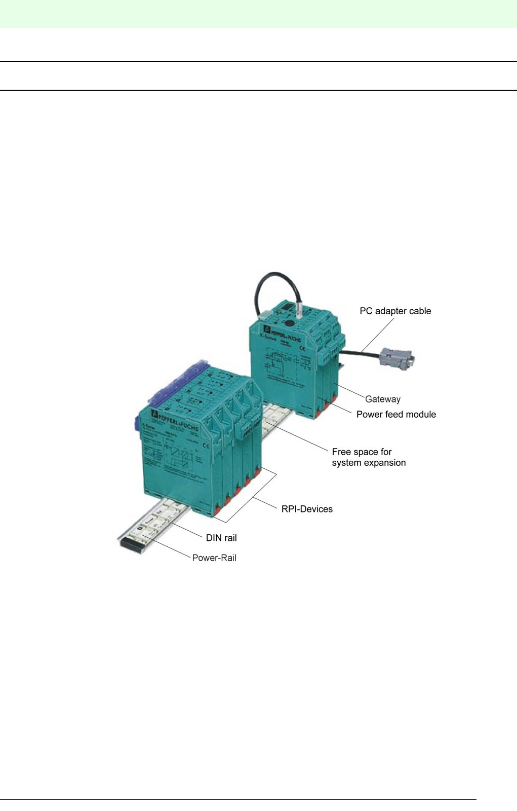
Figure 1.1:RPI system
In many production areas, relating to process automation, for example:
• chemical and petrochemical industry
• pharmaceutical and cosmetic industry
• paint production
• food industry and
• sewage treatment
but also in production areas relating to factory automation there are plants, in which a potentially explosive
atmosphere exists. In order to ensure protection and safety and guarantee proper functioning in safe as well
as in hazardous areas, RPI modules with intrinsically safe and non-intrinsically safe field circuits are availa-
ble.In the case of the “intrinsic safety” category of explosion protection these signal conditioners are desi-
gned as isolator modules, which limit the electrical energy of the signal circuits in such a way that, even
under specified fault conditions, the potentially explosive atmosphere cannot ignite.

Remote Process Interface
The Remote Process Interface RPI in Brief
14
S
ubject to reasonable modifications due to technical advances. Copyright Pepperl+Fuchs, Printed in Germany
Pepperl+Fuchs Group • Tel.: Germany +49 621 776-0 • USA +1 330 4253555 • Singapore +65 67799091 • Internet http://www.pepperl-fuchs.com
Date of issue 05/27/03
The RPI system can be installed in a control room with a safe environment or in the field within Zone 2 of
hazardous areas. Pepperl + Fuchs recommends the PACTwareΤΜ software package as human machine in-
terface for commissioning and operation of the RPI system. This software allows a simple configuration and
parameter assignment of the RPI system by means of a PC notebook directly on the system or via a statio-
nary engineering console in the control room.
A functional RPI system consists of:
1. Top hat DIN rail for mechanical installation, with Power Rail for voltage supply and internal bus con-
nection of all modules.
2. Power feed module for coupling and monitoring the voltage supply. In the case of 24 V DC power sup-
ply no power supply units are required.
3. Gateway for coupling the system to one of the external bus systems:
•PROFIBUS DP or PROFIBUS DP V1
•MODBUS RTU or MODBUS Plus
•ControlNet
4. RPI devices for both intrinsically safe and non-intrinsically safe field circuits are available for the follo-
wing applications:
•Analogue input 0/4 to 20 mA with or without transmitter power as well as with or without HART pro-
tocol transmission
•Analogue input for resistance thermometers, thermocouples, potentiometric recorders and mV-
transmitters
•Analogue output 0/4 to 20 mA with or without HART protocol transmission
•Binary input for mechanical contacts and proximity switches
•Binary output for solenoid valves
•Binary output for a potential-free relay contact
5. PC adapter for RS232 or RS485 as well as a suitable configuration software
Please refer to Chapter 2.2 "Intended Use" and Chapter 3.1 "System Structure and Prin-
ciple of Operation" for further details.
1.1 Availability, Functional Integrity and Function Monitoring
During the development of the Remote Process Interface we directed our special attention to electrical safe-
ty, system availability as well as functionality of the system:
• Redundant layout of the internal bus system.
• The use of two gateways per RPI bus line and two external bus branches, allows a completely redundant
layout of the system.
• Redundant layout of the power supply with two power feed modules.
• Lead breakage- and short circuit monitoring of the signal circuits by means of the RPI devices.
• Error and status indication via LEDs on the front panel of all devices.
• In addition to an external bus interface the gateway allows the connection of a PC or notebook via ser-
vice interface RS232 or RS485.A PC and an appropriate engineering tool constitute convenient tools for
configuration, parameter assignment, simulation, test, and diagnosis purposes.
• Configuration, parameter assignment, simulation, test and diagnosis can also be carried out by way of
the control system. Device and system failures are detected and signalled to the control system.
1.2 Aim of the Handbook
This handbook provides essential information and advice on how to plan, install and put the Remote Pro-
cess Interface RPI into operation. In addition, it provides all necessary information on status and fault indi-

15
Remote Process Interface
The Remote Process Interface RPI in Brief
Subject to reasonable modifications due to technical advances. Copyright Pepperl+Fuchs, Printed in Germany
Pepperl+Fuchs Group • Tel.: Germany +49 621 776-0 • USA +1 330 4253555 • Singapore +65 67799091 • Internet http://www.pepperl-fuchs.com
Date of issue 05/27/03
cations, on both device safety and monitoring functions as well as on fault diagnosis and fault elimination.
The RPI System Handbook provides essential information and advice on:
• Planning
• Installation
• Configuration
• Operation
• Safety
• Detection and elimination of faults
for the Pepperl+Fuchs Remote Process Interface (RPI).
This handbook applies in conjunction with the data sheets of the RPI modules that are used.
The handbook requires knowledge and experience in the field of planning, configuring and
design of bus systems as well as in the field of explosion protection. It cannot provide a basic
introduction into the various bus systems or the fundamental principles of system planning or
configuring. Users who require further information are recommended to refer to the relevant lite-
rature, the documentation of the bus and control system used or to the respective publications
from Pepperl+Fuchs (see e.g. Explosion Protection Handbook Part.-Nr. 21417).

Remote Process Interface
The Remote Process Interface RPI in Brief
16
S
ubject to reasonable modifications due to technical advances. Copyright Pepperl+Fuchs, Printed in Germany
Pepperl+Fuchs Group • Tel.: Germany +49 621 776-0 • USA +1 330 4253555 • Singapore +65 67799091 • Internet http://www.pepperl-fuchs.com
Date of issue 05/27/03
1.3 Notes on Using the Handbook
In order to enable you to familiarize yourself quickly with the RPI system and to have a rapid access to the
necessary pieces of information, this handbook provides a detailed table of contents.
The following overview provides a short outline of the topics dealt with in the individual chapters:
Operating Instructions in Brief
Summarizes all important steps of a commissioning procedure and should be used by experienced users
as a checklist for rapid commissioning, by means of the PACTwareΤΜ human machine interface.
Chapter 1: Introduction
explains the principle of operation of the RPI and provides an overview of the structure and aim of the hand-
book.
Chapter 2: Safety
explains the symbols used in the document, informs the user about potential dangers, the intended use of
the device and its use within Zone 2 of the hazardous area.
Chapter 3: Product Description
describes the structure and the individual components of the RPI system in detail.
Chapter 4: Planning of the RPI System
shows the planning procedure in chronological order. It provides the information required for a mechanical
and electronic assembly of the system and explains methods for determining the type and number of RPI
devices needed.
Chapter 5: Commissioning: Configuration
explains the addressing of both the gateway and the devices via the keys and the display of the gateway.
Chapter 6: Commissioning: Parameter assignment of the individual devices
describes the commissioning procedure of the RPI system via the PACTwareΤΜhuman machine interface.
Chapter 7: Commissioning: Integration into the higher level bus system
includes RPI specific information on integration into the standard bus systems PROFIBUS DP, PROFIBUS
DP V1, MODBUS RTU, MODBUS Plus and ControlNet. The various service and diagnostic functions allow
you to verify and correct faults with and without the higher level bus system.
Chapter 8: RPI in Operation
summarizes all service and diagnostic functions as well as fault signals. The simulation of measured values,
and the display of measured values and trends are explained.
Appendix A: Table of error codes
lists all error codes shown in the display of the gateway.
Appendix B: K-SK1
Installation and operating principle of the "K-SK1" human machine interface
Appendix C: Subject index
Appendix D: Glossary
1.4 Prerequisites for RPI System Operation
The Remote Process Interface employs the most modern signal processing and transmission technolo-
gies.The RPI assumes a central position in providing safety in hazardous areas in which control and instru-
mentation equipment is installed.
17
Remote Process Interface
The Remote Process Interface RPI in Brief
Subject to reasonable modifications due to technical advances. Copyright Pepperl+Fuchs, Printed in Germany
Pepperl+Fuchs Group • Tel.: Germany +49 621 776-0 • USA +1 330 4253555 • Singapore +65 67799091 • Internet http://www.pepperl-fuchs.com
Date of issue 05/27/03
When installing, commissioning, operating and maintaining RPI and MSR technology devices
and device components in hazardous areas, the applicable construction and installation regula-
tions (DIN EN 50020, DIN VDE 0165) must be observed.
Please consider all locally applicable regulations and directives when planning and configuring
plants and systems abroad. Especially in North America other regulations and directives apply,
than in the CENELEC member states.
As planner, installer and operator you are responsible for complying with all regulations and di-
rectives for potentially explosive environments.
1.5 Responsibilities of the User
Personnel undertaking commissioning should be familiar with the devices and both read and understand
the handbook, prior to installing and commissioning the Remote Process Interface.Various procedures and
instructions in this handbook require special precautions, in order to guarantee the safety of the persons
involved.
The devices may only be operated and maintained by persons who are authorized due to their
special training and qualifications and who have read and understood this handbook. In addition,
these persons need an appropriate instruction by the operating authority of the plant!
Apart from this handbook, the relevant guidelines for the installation in hazardous areas should
be observed.
The individual chapters of this handbook are aimed at persons with different qualifications,as listed below:.
Chapter Target Group, Qualifications
Chapter 1 Planners, personnel undertaking commission-
ing, process control engineers, service per-
sonnel
Chapter 2 Planners, personnel undertaking commission-
ing, process control engineers, service per-
sonnel
Chapter 3 Planners, personnel undertaking commission-
ing, process control engineers, service per-
sonnel
Chapter 4 Planners, personnel undertaking commission-
ing, process control engineers
Broad knowlege of RPI, installation in hazar-
dous areas, overvoltage protection and know-
ledge of the bus system
Chapter 5 Personnel undertaking commissioning, pro-
cess control engineers,
Broad knowlege of RPI, knowledge of the
human machine interface
Chapter 6 Personnel undertaking commissioning, pro-
cess control engineers
Broad knowlege of RPI, knowledge of the
human machine interface
Chapter 7.1 Process control engineers
Chapter 7.2 Process control engineers - PROFIBUS DP
and DP V1
Chapter 7.3 Process control engineers - MODBUS RTU
Chapter 7.4 Process control engineers - MODBUS Plus
Chapter 7.5 Process control engineers - ControlNet
Chapter 8 Operator, service personnel

Remote Process Interface
Safety
18
S
ubject to reasonable modifications due to technical advances. Copyright Pepperl+Fuchs, Printed in Germany
Pepperl+Fuchs Group • Tel.: Germany +49 621 776-0 • USA +1 330 4253555 • Singapore +65 67799091 • Internet http://www.pepperl-fuchs.com
Date of issue 05/27/03
2Safety
2.1 Safety Notes
2.1.1 Explanation of the Symbols Used in This Document
This symbol warns of danger. If the instruction given in this warning is not heeded the result could
be the serious injury of personnel and/or the severe damage or destruction of equipment.
This symbol warns of a possible fault. If the instruction given in this warning is not heeded, the
device and any plant or systems connected to it could develop a fault or even fail completely.
This symbol directs attention to important information.
2.1.2 General Safety Regulations
When used as related apparatus in accordance with EN 50020, the prototype test certificate
and the national installation regulations must be observed.
In addition, all applicable standards, directives and factory specifications as well as the relevant
publications of the fieldbus user organisations, as for example the PROFIBUS user organisa-
tion PNO, ContronNet International etc. should be observed.
Repairs to devices with intrinsically safe circuits should only be carried out by expertly qualified
personnel following the appropriate regulations.
We strongly recommend that repairs should be undertaken by the manufacturers. In the event
of inadequate repairs being carried out, Pepperl+Fuchs GmbH will not honour the guarantee.

19
Remote Process Interface
Safety
Subject to reasonable modifications due to technical advances. Copyright Pepperl+Fuchs, Printed in Germany
Pepperl+Fuchs Group • Tel.: Germany +49 621 776-0 • USA +1 330 4253555 • Singapore +65 67799091 • Internet http://www.pepperl-fuchs.com
Date of issue 05/27/03
2.2 Intended Use
The Remote Process Interface is a system, which represents an interface between the conventional sensor
and actor technology on one side and the process control system on the other side.
Measurement and control data is bidirectionally transmitted to the individual field devices via an internal bus
and is made available to a higher level SPS or DCS. Various gateways are available for the individual bus
systems. Connections to PROFIBUS DP, PROFIBUS DP V1, MODBUS RTU, MODBUS Plus and Control-
Net are possible.
Various power feed modules are available for the voltage supply. They have to be chosen according to their
ntended usage. The maximum power supply for each line must not exceed 4 A and 2 A in the case of red-
undant power feed modules.
The RPI system is installed in the safe area or in the hazardous area of zone 2, in accordance with the ap-
proval.
The maximum length of the RPI internal communication lines must not exceed 8 m and the cable length of
the power supply 10 m. Should these maximum lengths be exceeded, additional gateways and, possibly,
power supply units have to be used.
The protection of operating personnel and plant is not guaranteed if the equipment is used for
a purpose for which it was not intended.
The Remote Process Interface must only be operated by authorised specialist personnel in ac-
cordance with this equipment documentation (handbook, data sheet, certificate of conformity).
The handbook constitutes the operating instructions in accordance with the Equipment Safety
Law § 3 (3).
It applies in conjunction with the appropriate data sheets of the RPI modules.
2.3 Installation in a Potentially Explosive Atmosphere
The Pepperl+Fuchs Remote Process Interface can either be installed in a control room in the safe area or
in the field within zone 2 of the hazardous area. See chapter 2.6 "Declaration of Conformity". It is suitable
for intrinsically safe signals of zone 1 or 0 and for non-intrinsically safe signals.
Definition of Ex-zone 2:
An area in which, during normal operation, a potentially explosive gas atmosphere does not oc-
cur but seldom and only for a short-time.
According to the approval, the installation of the RPI system within zone 2 of the hazardous area, requires
the installation in a single housing of protection class IP54 or higher.
Installation of the RPI system with a voltage supply in zone 1 can be carried out in a pressurized housing.
For detailed information, please refer to Pepperl+Fuchs GmbH.
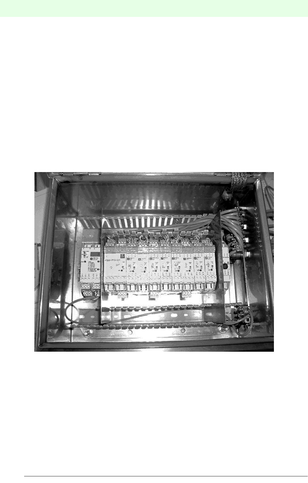
Remote Process Interface
Safety
20
S
ubject to reasonable modifications due to technical advances. Copyright Pepperl+Fuchs, Printed in Germany
Pepperl+Fuchs Group • Tel.: Germany +49 621 776-0 • USA +1 330 4253555 • Singapore +65 67799091 • Internet http://www.pepperl-fuchs.com
Date of issue 05/27/03
2.4 Installation Instructions for Use of the RPI System on Ships
The Pepperl+Fuchs RPI system must only be used in environments with ambient temperatures of -5 °C to
+60 °C. It is not suited for installation in cold locations.
The input voltage must be 24V +30% -25%.
Please note the following during installation:
• The RPI system must be installed in a metallic control cabinet.
• A copper or steel sheet has to be mounted between the gateway (or in the case of a redundant system
between the two gateways) and den RPI slaves.
• Another copper or steel sheet has to be mounted between the power feed module (or in the case of red-
undant supply between the two power feed modules) and the RPI slaves.
• The supply, communication, and I/O lines must be screened. The screen must be earthed and continued
even inside the control cabinet up to the terminals (see drawing).In addition, all lines must be damped
with a ferrite (e.g. Messrs. Würth Elektronik, type 742 700 5) between the earth of the screen and the
exit from the control cabinet.
• I/O lines must not be conducted past the gateway.
• The earth connection of the power feed module has to be connected as short as possible.
Figure 2.1:RPI system structure
21
Remote Process Interface
Safety
Subject to reasonable modifications due to technical advances. Copyright Pepperl+Fuchs, Printed in Germany
Pepperl+Fuchs Group • Tel.: Germany +49 621 776-0 • USA +1 330 4253555 • Singapore +65 67799091 • Internet http://www.pepperl-fuchs.com
Date of issue 05/27/03
Structure and configuration of the RPI system:
The system (see figure 2.1) consists of the following components:
2.5 Overvoltage and Lightning Protection
While planning the RPI system, the prevailing conditions in the field have to be tested in order to determine
whether an overvoltage or lightning protection is required. If it is required, it has to be carried out in accor-
dance with the relevant literature and regulations. Further information on overvoltage filters and lightning
protection barriers to be snapped onto the top hat rail can be obtained from the Pepperl + Fuchs "DIN Rail
Housing" catalogue.
2.6 Declaration of Conformity
Pepperl+Fuchs offers various devices and gateways for the modular Remote Process Interface (RPI). The
different types of devices and gateways can be found in Chapter ’Product description’ or in the Pep-
perl+Fuchs catalogue.
The TÜV 00 ATEX 1617X statement of conformity contains all device types of the RPI system without relay
output for installation in Ex-zone 2 hazardous areas:
Devic
e No.
Model number Description
1KSD2-GW-MOD.485
KSD2-GW-MOD
MODBUS Gateway
2 KFD2-EB.MAR.RPI Power Feed Module
3KSD2-BO-Ex2.2
KSD2-BO-Ex
Solenoid Driver
4KSD2-TI-Ex
KSD2-VI
KSD2-MVI
Converter
5KSD2-CI-S-Ex.H HART Transmitter Power Supply
6KSD2-BI-Ex4
KSD2-BI-Ex2
Isolated Switch Amplifier
7KSD2-FI-Ex Current Frequency Converter
8 KSD2-CO-S-Ex.H
KSD2-CO-Ex
KSD2-CO-S-Ex
HART Analogue Driver/Repeater
9KSD2-RO-Ex2 Relay Module
10 KSD2-CI-Ex2
KSD2-CI-S-Ex
Transmitter Power Supply
11 KSD2-PT2-Ex1 Potentiometer Input
KSD2-BI-4 KSD2-GW-PRO
KSD2-BI-Ex2 KSD2-GW-PRO.485
KSD2-BI-Ex4 KSD2-GW-MOD
KSD2-FI-Ex KSD2-GW-MOD.485
KSD2-BO-Ex KSD2-GW-MPL
KSD2-BO-Ex2.2 KSD2-GW-MPL.485
KSD2-CI-S-Ex KSD2-GW-CN
KSD2--CI-S-Ex.H KSD2-GW-CN.485
KSD2-CI-2 KSD2-GW2-PRO
KSD2-CI-Ex2
KSD2-TI-Ex
KSD2-CO-Ex
KSD2-CO-S-Ex
KSD2-CO-S-Ex.H
KSD2-HC
Remote Process Interface
Safety
22
S
ubject to reasonable modifications due to technical advances. Copyright Pepperl+Fuchs, Printed in Germany
Pepperl+Fuchs Group • Tel.: Germany +49 621 776-0 • USA +1 330 4253555 • Singapore +65 67799091 • Internet http://www.pepperl-fuchs.com
Date of issue 05/27/03
The TÜV 00 ATEX 1618X statement of conformity refers to all device types of the RPI system with relay
output as well as power feed modules for installation in Ex-zone 2 hazardous areas:
All products are developed and produced in accordance with the relevant European standards and directi-
ves.
The manufacturer of the product, Pepperl+Fuchs GmbH in 68307 Mannheim Germany, has a certified qua-
lity assurance system in accordance with ISO 9001.
2.7 Marking
The most important information from the data sheet can be found on the left housing side of the devices,
as listed below:
Manufacturer Pepperl+Fuchs GmbH
Device type with part number
Marking in accordance with EC-Type Examination Certificate *)
Device connection: Terminal assignment with the most important nominal values of the inputs and
outputs
*) not available for every device
KFD2-EB2 KSD2-EB.RPI
KFD2-EB2.B KSD2-EB-R2A.RPI
KFD2-EB.D1A.B KSD2-RO-Ex2
KFD2-EB.D2A.B
KFD2-EB.R2A.B
The current TÜV 00ATEX 1617X and TÜV 00 ATEX 1618X declarations of conformity can be
obtained from Pepperl+Fuchs GmbH or downloaded as pdf-file from our website www.pepperl-
fuchs.com.
ISO
9001
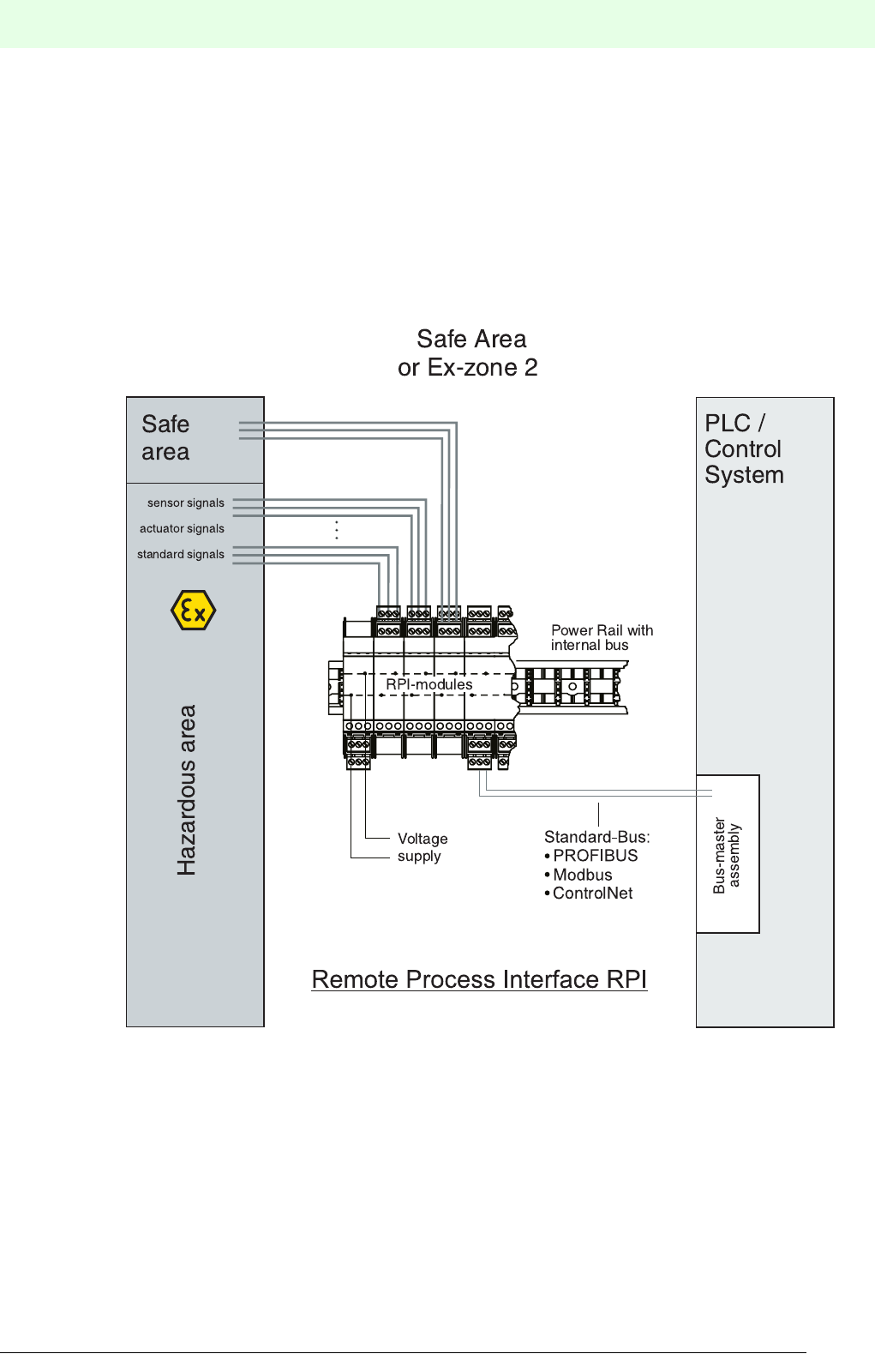
23
Remote Process Interface
Product Description
Subject to reasonable modifications due to technical advances. Copyright Pepperl+Fuchs, Printed in Germany
Pepperl+Fuchs Group • Tel.: Germany +49 621 776-0 • USA +1 330 4253555 • Singapore +65 67799091 • Internet http://www.pepperl-fuchs.com
Date of issue 05/27/03
3 Product Description
3.1 System Structure and Principle of Operation
The Remote Process Interface (RPI) is an interface system for conditioning conventional control signals and
signals from and to sensors, actuators and field devices on one side, and a bus system on the other side.
The connection via a bus to the process control system or a programmable logic controller is carried out by
means of gateways.
The RPI system is suitable for processing I/O-signals from a safe area or from a zone 1 or 0 hazardous area.
The signals are galvanically isolated using RPI.
Figure 3.1:Structure of the Remote Process Interface (RPI)
3.1.1 Modularity of the RPI System
A decided advantage of the RPI system is the high flexibility due to its modular structure. The DIN rail with
Power Rail represents the basis of the RPI. The devices, gateways and power feed modules or power sup-
ply units are mounted on the DIN rail. Voltage supply and communication are established via the Power
Rail. The DIN rail and the Power Rail can be mounted according to the prevailing conditions and cut to any
required length. RPI devices with up to four signal channels are available for characteristic MSR technical
tasks. See chapter 3.3 "Summary of RPI Modules Currently Available".

Remote Process Interface
Product Description
24
S
ubject to reasonable modifications due to technical advances. Copyright Pepperl+Fuchs, Printed in Germany
Pepperl+Fuchs Group • Tel.: Germany +49 621 776-0 • USA +1 330 4253555 • Singapore +65 67799091 • Internet http://www.pepperl-fuchs.com
Date of issue 05/27/03
3.1.2 Integrated Signal Transfer and Mechanical Mounting: Power Rail
The Power Rail is available:
• as insert for the DIN rail according to DIN EN 50022 or
• as insert for the 35 x 15 mm top hat rail
Five conductors are integrated into the Power Rail. They have the following functions:
• 24 V DC voltage supply of the components snapped onto the rail (conductor 1 + and 2-)
• Transfer of the RPI internal communication bus (conductor 3 and 5)
• Transfer of the HART communication (conductor 4). In this case, K-system modules with centralized
fault indications must not be installed, since they are likewise transferred via conductor 4.
3.1.3 Communication Between the RPI Modules
RPI uses an internal bus with a fixed transfer rate of 250 kbit/s. RPI allows up to 125 devices as bus stations.
The gateway calculates the current cycle time according to the stored configuration. The time need is cal-
culated in such a way that low-priority signals (acyclic services) can be transferred. The RPI internal bus
system has a redundant design and switches to redundant transmission in the event of failure.
3.1.4 Gateways - Interface to an External Bus
By means of an RPI internal bus, all connected RPI devices communicate with the gateway, which ex-
changes the process data with the plant control, via a standard bus.The plant can be both a process control
system (DCS) and a programmable logic controller (PLC). By using a second gateway, the bus connection
to the higher-level bus system can also be made redundant.Gateways are available for the following stan-
dard busses:
• PROFIBUS DP
• PROFIBUS DP V1
• MODBUS RTU
• MODBUS Plus
• ControlNet
3.1.5 Voltage Supply via Power Feed Modules and Power Supply Units
Special power feed modules are mounted on the Power Rail for voltage supply. The number of power feed
modules required depends on the current demand of the RPI modules, the spacial arrangement, and the
need for a redundant design. In case 24 V DC are not available, suitable power supply units can be used.
They are designed to supply the Power Rail directly and can be mounted on the rail. If the power supply
units are mounted separately, voltage supply takes place via the power feed modules.
3.1.6 RPI Devices
The devices of the RPI system translate the signals of the connected field devices into the protocol of the
RPI internal bus and vice versa.
In the case of devices with an intrinsically safe field circuit the signal line is safely galvanically isolated bet-
ween the hazardous and the safe area in the RPI device. The signals for the hazardous area are intrinsically
safe in accordance with ignition protection class ia or ib.
In addition, a signal preprocessing can be set by means of a parameter assignment of the RPI devices.
3.1.7 HART Protocol Transmission
The HART protocol is used to program HART compatible field devices. These field devices are able to carry
out calculations, self-diagnoses and error reports. Suitable RPI modules are available for the transmission
of the HART protocol.
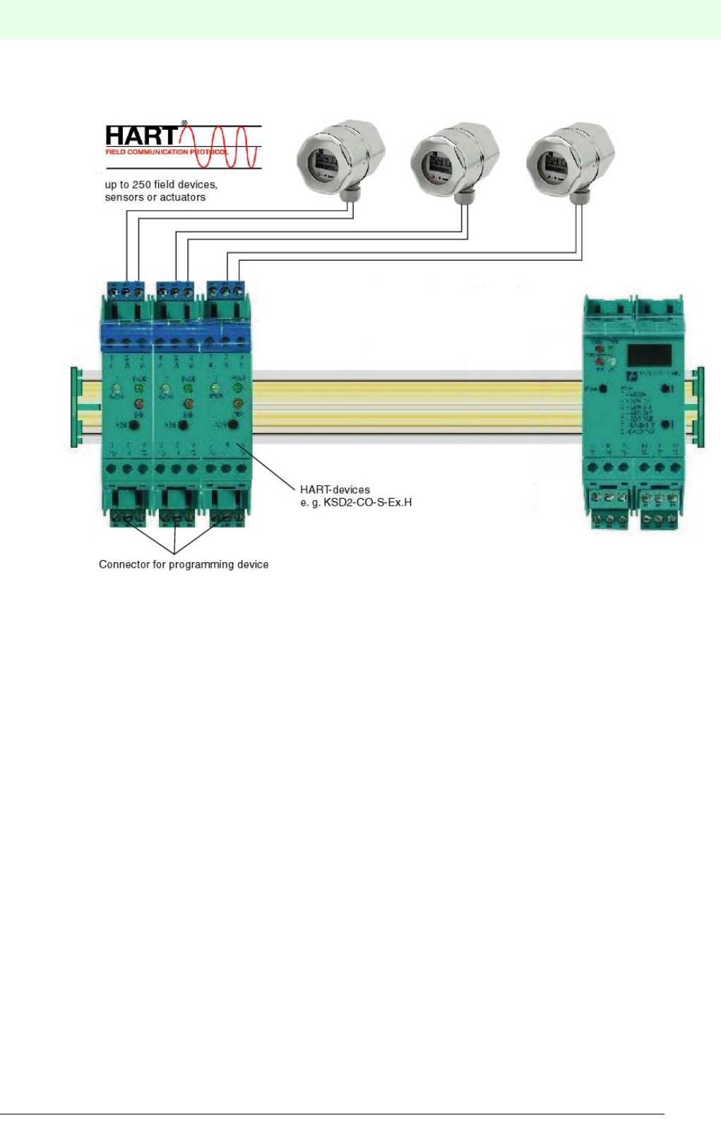
25
Remote Process Interface
Product Description
Subject to reasonable modifications due to technical advances. Copyright Pepperl+Fuchs, Printed in Germany
Pepperl+Fuchs Group • Tel.: Germany +49 621 776-0 • USA +1 330 4253555 • Singapore +65 67799091 • Internet http://www.pepperl-fuchs.com
Date of issue 05/27/03
3.1.7.1 HART Programming Unit With Direct Connection
Figure 3.2:Connection of the HART programming unit to the terminals of the RPI device
The RPI devices are equipped, as standard, with the appropriate terminals for the connection of the pro-
gramming unit. The connection can be established on the safe side.
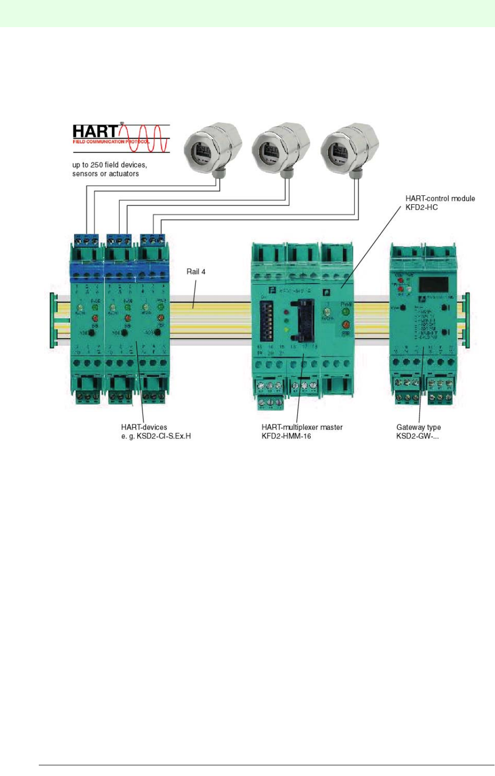
Remote Process Interface
Product Description
26
S
ubject to reasonable modifications due to technical advances. Copyright Pepperl+Fuchs, Printed in Germany
Pepperl+Fuchs Group • Tel.: Germany +49 621 776-0 • USA +1 330 4253555 • Singapore +65 67799091 • Internet http://www.pepperl-fuchs.com
Date of issue 05/27/03
3.1.7.2 Transmission via HART Multiplexer
The HART protocol is transferred by the KFD2-HMM-16 HART multiplexer master to the KSD2-HC HART
control module and further on to the RPI module via rail 4 of the Power Rail.
Figure 3.3:HART multiplexer master and HART control module
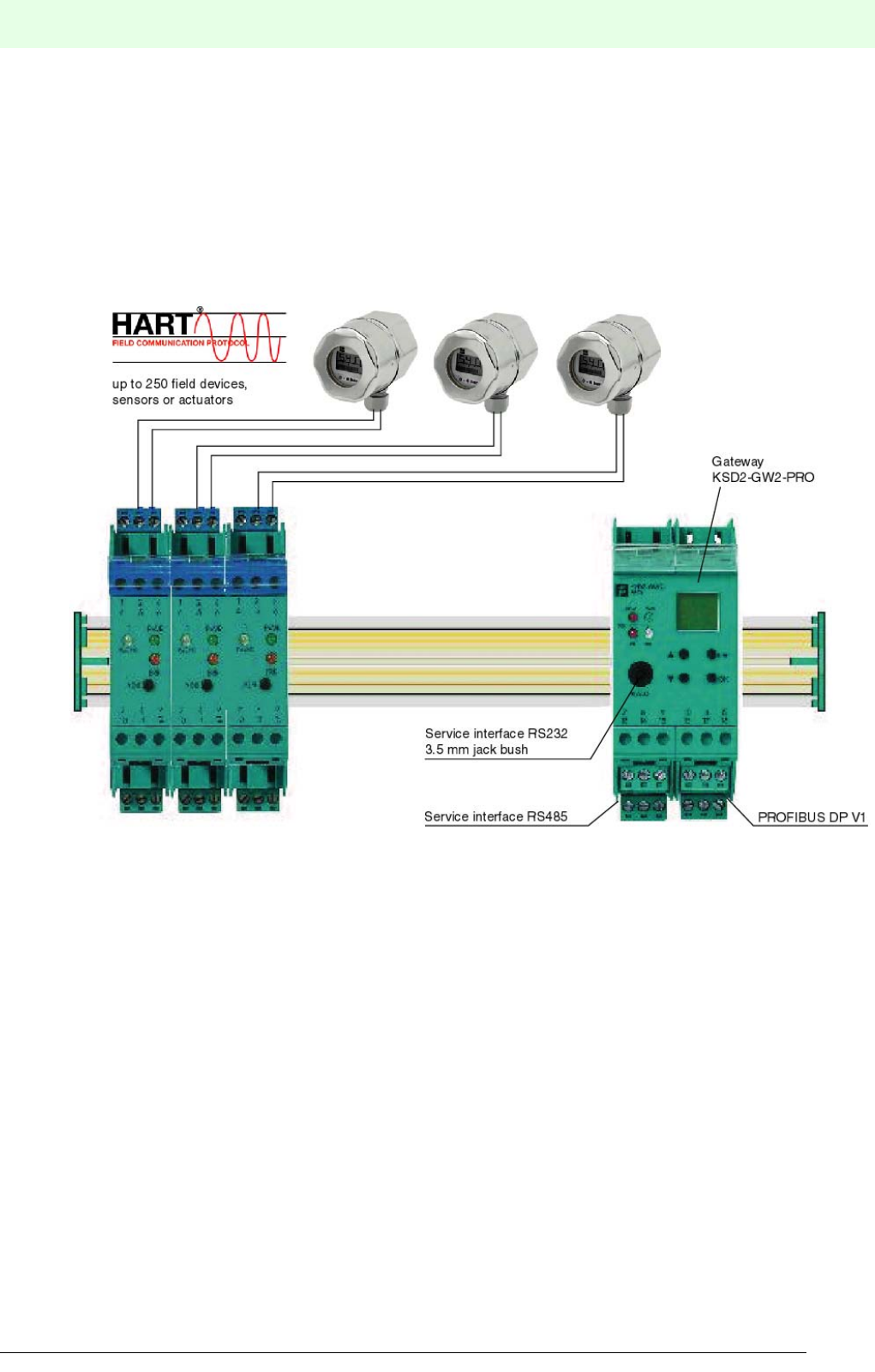
27
Remote Process Interface
Product Description
Subject to reasonable modifications due to technical advances. Copyright Pepperl+Fuchs, Printed in Germany
Pepperl+Fuchs Group • Tel.: Germany +49 621 776-0 • USA +1 330 4253555 • Singapore +65 67799091 • Internet http://www.pepperl-fuchs.com
Date of issue 05/27/03
3.1.7.3 HART Transmission via PROFIBUS
The PROFIBUS DP V1 gateway KSD2-GW2-PRO has an integrated HART multiplexer system that offers
full functionality. The transmission of the HART protocol is carried out through
- PROFIBUS DP V1 or
- the RS485 service interface
to the control system or a connected engineering console. Within the RPI system the HART protocol is
transferred via rail 4 of the Power Rail to the RPI devices.
Figure 3.4:PROFIBUS DP V1 gateway KSD2-GW2-PRO

Remote Process Interface
Product Description
28
S
ubject to reasonable modifications due to technical advances. Copyright Pepperl+Fuchs, Printed in Germany
Pepperl+Fuchs Group • Tel.: Germany +49 621 776-0 • USA +1 330 4253555 • Singapore +65 67799091 • Internet http://www.pepperl-fuchs.com
Date of issue 05/27/03
3.2 Performance Characteristics
3.2.1 Overview of the RPI System Characteristics
Power feed modules • 2 A or 4 A output current
• 24 V DC power supply
• Supply of the RPI modules on the Power Rail
• Group fusing via a fine-wire fuse
• Alarm relay output for defective fuse
Power supply units • 4 A output current at 24 V DC output voltage
• 90 to 253 V AC input voltage
• Supply for the modules on the Power Rail
• Group fusing provided by miniature fusing
Gateways • Master function for the RPI internal bus
• Couples internal bus to external standard bus system
• External bus systems: - PROFIBUS DP
- PROFIBUS DP V1 with HART transmission
- MODBUS RTU
- MODBUS Plus
-ControlNet
• Slave functionality on external bus
• Storage of the configuration and parameters of all RPI modules in an internal
EEPROM
• Configuration of the overall RPI system both via integrated RS232 or
RS485 service interface and external bus
• Diagnosis and error messages via LEDs and communication via external
bus, and the service interface
• Redundant external bus with second gateway
RPI devices • 1...4 channel interface modules for the transfer of digital and analogue I/O
data between the safe and the hazardous areas
• Non-Ex modules are also available
• Special modules for direct connection of transmitters, temperature sen-
sors, valves, contacts and inductive proximity switches
• Bi-directional transmission for HART signals
• Integrated lead breakage and short circuit monitoring
• Integration of instrumentation functions such as alarm and error limit
values, calibration, linearisation, etc.
• Diagnosis and error messages via LEDs and communication via the inter-
nal bus to the gateway and via the external bus, to the DCS or PLC or via
the service interface to the PC.

29
Remote Process Interface
Product Description
Subject to reasonable modifications due to technical advances. Copyright Pepperl+Fuchs, Printed in Germany
Pepperl+Fuchs Group • Tel.: Germany +49 621 776-0 • USA +1 330 4253555 • Singapore +65 67799091 • Internet http://www.pepperl-fuchs.com
Date of issue 05/27/03
3.2.2 Flexibility by Virtue of Modularity
3.2.3 Internal and external communication
3.2.4 Electrical Safety
Device combinations • RPI modules having various functions can be arbitrarily attached to the
Power Rail assembly
• All modules can easily be snapped-on the Power Rail
• Marshalling of the signal current circuits is not necessary
• Combinations with devices of the Pepperl+Fuchs K-system are possible
Number of RPI bus sta-
tions
• Up to 125 RPI devices on one RPI line
• 1 active RPI gateway per RPI line
• 1 redundant passive gateway per RPI line (option)
• Larger assemblies can be achieved by coupling a number of RPI bus lines
together on the external bus.
Transfer rate, internal • 250 kbit/s
Transfer rate, external • Dependent on the bus system used, See chapter 7 "Integration into the
Higher-Level Bus System"
Transfer rate of the RS
232/RS 485 interface
• Adjustable: 1.2 kbit/s, 2.4 kbit/s, 4.8 kbit/s, 9.6 kbit/s, 19.2 kbit/s,
28.8 kbit/s, 33.6 kbit/s, 38.4 kbit/s; 57.6 kbit/s
Cycle time • From the gateway, via the external bus to the control system, depending on
the bus system used and its baud rate, see Chapter 4 ’Planning’
• From the device, via the internal bus to the gateway, or the reverse:
1 Device 25 ms
125 Devices with up to 4 binary inputs 60 ms
125 Devices with up to 2 binary outputs 90 ms
125 Devices with 1 analogue input 75 ms
125 Devices with 1 analogue output 110 ms
Please refer to Chapter 4.4 "Calculating the RPI Cycle Time" for the pre-
cise calculation of the cycle time.
Wiring • The significantly reduced amount of wiring by comparison with conventional
systems, results in a corresponding reduction in the probability of wiring
faults
Fusing • Group fusing via a fuse in the power feed module
• Tripping of the fuse is indicated by an LED and can be communicated to the
control system via a relay output
EMC • All RPI devices satisfy the requirements of DIN EN 50 081 - 2,
DIN EN 50082-2, NAMUR NE 21
Ex-Protection • All devices identified by 'Ex' in the type code have circuits which are appro-
ved for use in the hazardous area and are designed as “intrinsically safe”
equipment.

Remote Process Interface
Product Description
30
S
ubject to reasonable modifications due to technical advances. Copyright Pepperl+Fuchs, Printed in Germany
Pepperl+Fuchs Group • Tel.: Germany +49 621 776-0 • USA +1 330 4253555 • Singapore +65 67799091 • Internet http://www.pepperl-fuchs.com
Date of issue 05/27/03
3.2.5 System Availability
3.2.6 Configuration and Parameter Assignment
Internal RPI bus • Standard redundant design of the internal bus
• The bus signals are transferred between the two bus lines of the Power Rail
as voltage difference signals
• If this transfer route fails due to lead breakage or short circuit between the
two bus lines, or due to a defective coupler, the system switches automati-
cally to common-mode operation, in which the negative potential of the sup-
ply voltage provides a reference.
External standard bus • Redundant design due to the use of a second gateway. The configuration
data and parameters of the RPI system are also stored in non-volatile
memory in the redundant gateway.
Fault finding • Error messages via LEDs on the front panel of all devices
• Extensive possibilities for diagnosis via the configuration interface on the
gateway, with PACTwareΤΜ Edition 2 and Device Type Manager (DTM) for
the RPI system.
• Transfer of all error and status messages to the control system via the
external standard bus system.
Thus, it is possible to reduce the time required for locating faults and equip-
ment defects to a minimum.
Replacement of defec-
tive devices
• A defective RPI module is simply replaced with one of similar type
• Due to the removable terminal blocks, there is no need to unfix any cable
glands
• When replacing a device, the device address and the device parameters
are automatically transferred by the gateway to the new module
• When replacing a gateway, the complete parameter and configuration data
set is transferred automatically to the new gateway via the service interface
Device addresses • The address of the RPI system on the external bus is set on the gateway.
• The addresses of the devices and gateways on the RPI internal bus can be
set
- via keys and the LCD-display of the gateway
- via PC and configuration software or
- via the external bus
Device parameters and
RPI configuration data
•Using the PC and PACTwareΤΜ human machine interface or by the control
system via the external bus. The DTM can be integrated into every configu-
ration tool that supports the FDT (Field Device Tool) technology.

31
Remote Process Interface
Product Description
Subject to reasonable modifications due to technical advances. Copyright Pepperl+Fuchs, Printed in Germany
Pepperl+Fuchs Group • Tel.: Germany +49 621 776-0 • USA +1 330 4253555 • Singapore +65 67799091 • Internet http://www.pepperl-fuchs.com
Date of issue 05/27/03
3.3 Summary of RPI Modules Currently Available
Currently devices are available within the RPI system for all instrumentation, control and monitoring appli-
cations. However, the RPI system will be continuously extended in order to satisfy customer requirements.
The RPI system can be combined with Pepperl+Fuchs K-system devices, thus covering a large number of
special applications.Further information can be obtained directly from Pepperl+Fuchs.
3.3.1 230 V AC Power Supply Units
• KFA6-STR.1.24.4 4 A Power Supply Unit
3.3.2 24 V DC Power Feed Modules
• KFD2-EB.RPI 4 A Power Feed Module with bus pick-off
• KFD2-EB.R2A.RPI 2 A Power Feed Module with bus pick-off for redundant voltage supply from two
power supplies
3.3.3 Isolated Switch Amplifiers
• KSD2-BI-Ex2 2 channel Isolated Switch Amplifier with Ex approval
• KSD2-BI-Ex4 4 channel Isolated Switch Amplifier with Ex approval
• KSD2-BI-4 4 channel Isolated Switch Amplifier for the connection of passive contacts
• KSD2-BI-4.2 4 channel Isolated Switch Amplifier for the connection of proximity switches and
mechanical contacts
3.3.4 Solenoid Drivers and Relay Modules
• KSD2-BO-Ex 1 channel Solenoid Driver with Ex approval
• KSD2-BO-Ex2.2 2 channel Solenoid Driver with Ex approval
• KSD2-RO-Ex2 2 channel Relay Module with Ex approval
• KSD2-RO-2 2 channel Relay Module
3.3.5 Transmitter Power Supplies
• KSD2-CI-S-Ex 1 channel SMART-Transmitter Power Supply with Ex approval
• KSD2-CI-S 1 channel SMART-Transmitter Power Supply
• KSD2-CI-2 2 channel Transmitter Power Supply
• KSD2-CI-Ex2 2 channel Transmitter Power Supply with Ex approval
• KSD2-CI-S-Ex.H 1 channel HART-Transmitter Power Supply with Ex approval, SMART via
terminals, HART via Power Rail and terminals
• KSD2-CI-S-H 1 channel HART-Transmitter Power Supply, SMART via terminals, HART
via Power Rail and terminals
3.3.6 Analogue Driver/Repeater
• KSD2-CO-Ex 1 channel Analogue Driver/Repeater with Ex approval
• KSD2-CO 1 channel Analogue Driver/Repeater
• KSD2-CO-S-Ex 1 channel SMART Analogue Driver/Repeater with Ex approval
• KSD2-CO-S 1 channel SMART Analogue Driver/Repeater
• KSD2-CO-S-Ex.H 1 channel HART Analogue Driver/Repeater with Ex approval,
SMART via terminals, HART via Power Rail or terminals
• KSD2-CO-S-H 1 channel HART Analogue Driver/Repeater, SMART via terminals,
HART via Power Rail or terminals

Remote Process Interface
Product Description
32
S
ubject to reasonable modifications due to technical advances. Copyright Pepperl+Fuchs, Printed in Germany
Pepperl+Fuchs Group • Tel.: Germany +49 621 776-0 • USA +1 330 4253555 • Singapore +65 67799091 • Internet http://www.pepperl-fuchs.com
Date of issue 05/27/03
3.3.7 Current Frequency Converters, Batch Controllers, Flow Meters
• KSD2-FI-Ex 1 channel Current Frequency Converter with Ex approval for the connection of
proximity switches and digital sensing elements, e.g.: optical or mechanical
• KSD2-FI 1 channel Current Frequency Converter for the connection of proximity switches
and digital sensing elements, e.g.: optical or mechanical
3.3.8 Temperature Converters
• KSD2-TI-Ex 1 channel Universal Temperature Converter with Ex approval
• KSD2-TI 1 channel Universal Temperature Converter
3.3.9 Voltage Converter
• KSD2-VI 1 channel Voltage Converter with a voltage range of 0/2 ... 10 V.
3.3.10 Gateways
• KSD2-GW-PRO PROFIBUS DP-Gateway with RS 232 service interface
• KSD2-GW-PRO.485 PROFIBUS DP-Gateway with RS 485 service interface
• KSD2-GW2-PRO PROFIBUS DP V1-Gateway with RS 232 and RS 485 service interface
and full transmission for HART Protocol
KSD2-GW-MOD MODBUS-Gateway RTU with RS 232 service interface
• KSD2-GW-MOD.485 MODBUS-Gateway RTU with RS 485 service interface
• KSD2-GW-CN ControlNet-Gateway with RS 232 service interface
• KSD2-GW-CN.485 ControlNet-Gateway with RS 485 service interface
• KSD2-GW-MPL MODBUS PLUS-Gateway with RS 232 service interface
• KSD2-GW-MPL.485 MODBUS PLUS-Gateway with RS 485 service interface
3.3.11 HART Modules
• KFD2-HMM-16 HART-Multiplexer Master
• KSD2-HC HARTControl Module

33
Remote Process Interface
Product Description
Subject to reasonable modifications due to technical advances. Copyright Pepperl+Fuchs, Printed in Germany
Pepperl+Fuchs Group • Tel.: Germany +49 621 776-0 • USA +1 330 4253555 • Singapore +65 67799091 • Internet http://www.pepperl-fuchs.com
Date of issue 05/27/03
3.4 Commissioning Procedure for the RPI System
Commissioning of the RPI system is carried out in three steps:
1. Configuration
2. Parameter assignment
3. Integration into the higher level-bus system.
The RPI system can be configured via the RS 232 or RS 485 service interface of the RPI gateway and each
channel of each RPI device can be parameterized individually.
For simple and rapid commissioning Pepperl+Fuchs offers thePACTwareΤΜ software package. PACTwareΤΜ
(Process Automation Configuration Tool) is an open source software with open FDT-interface (Field Device
Tool), which facilitates the multi-vendor and uniform configuration of modern field devices. Detailed infor-
mation on PACTwareΤΜ is given in Chapter 4.8.3 "PACTwareΤΜ".
3.4.1 Configuration
•Address assignment of the RPI gateway on the higher-level bus
•Address assignment of the RPI modules on the in-system bus
•Definition of the communication with the higher-level bus
•Definition of the communication via the RPI service interface
•Adjustment of the redundancy mode
Usually, the configuration is carried out via the operator level of the gateway.
3.4.2 Parameter Assignment
•Simulation of the structure of the RPI system in the commissioning software
•Adjustment of the individual RPI modules to the requirements of sensors, actuators and field devices
3.4.3 Integration into the Higher-Level Bus System
•is described, depending on the bus system used, in the respective chapters of this handbook.
Figure 3.5:PACTwareΤΜ - the human machine interface for the Remote Process Interface
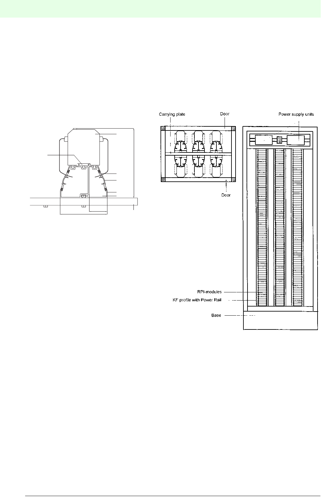
Remote Process Interface
Product Description
34
S
ubject to reasonable modifications due to technical advances. Copyright Pepperl+Fuchs, Printed in Germany
Pepperl+Fuchs Group • Tel.: Germany +49 621 776-0 • USA +1 330 4253555 • Singapore +65 67799091 • Internet http://www.pepperl-fuchs.com
Date of issue 05/27/03
3.5 Control Cabinets: Assembly and Service
Pepperl+Fuchs offers fully assembled and tested control cabinet systems. They are equipped with RPI de-
vices according to customer requirements and based on measurement, and automatic control engineering.
Local Pepperl+Fuchs sales offices will be pleased to advise on alternative installations and the most suitab-
le control cabinet layout for a given application.
The following diagram shows a possible arrangement of an RPI system in a control cabinet.
Figure 3.6:Possible arrangement of an RPI system in a control cabinet
Hazardous area Safe area
130
50
1
5
4
3
2
220
7
9
1. KS module
2. Wiring comb for direct wiring
to the KS modules
3. Comb cap
4. KF profile
5. Space for connection cable:
field cable für Ex and
non-Ex signals
6. Spacer bolts for mounting
in control cabinets
7. Mounting plate
8. Terminal
9. Power Rail
Detailed view
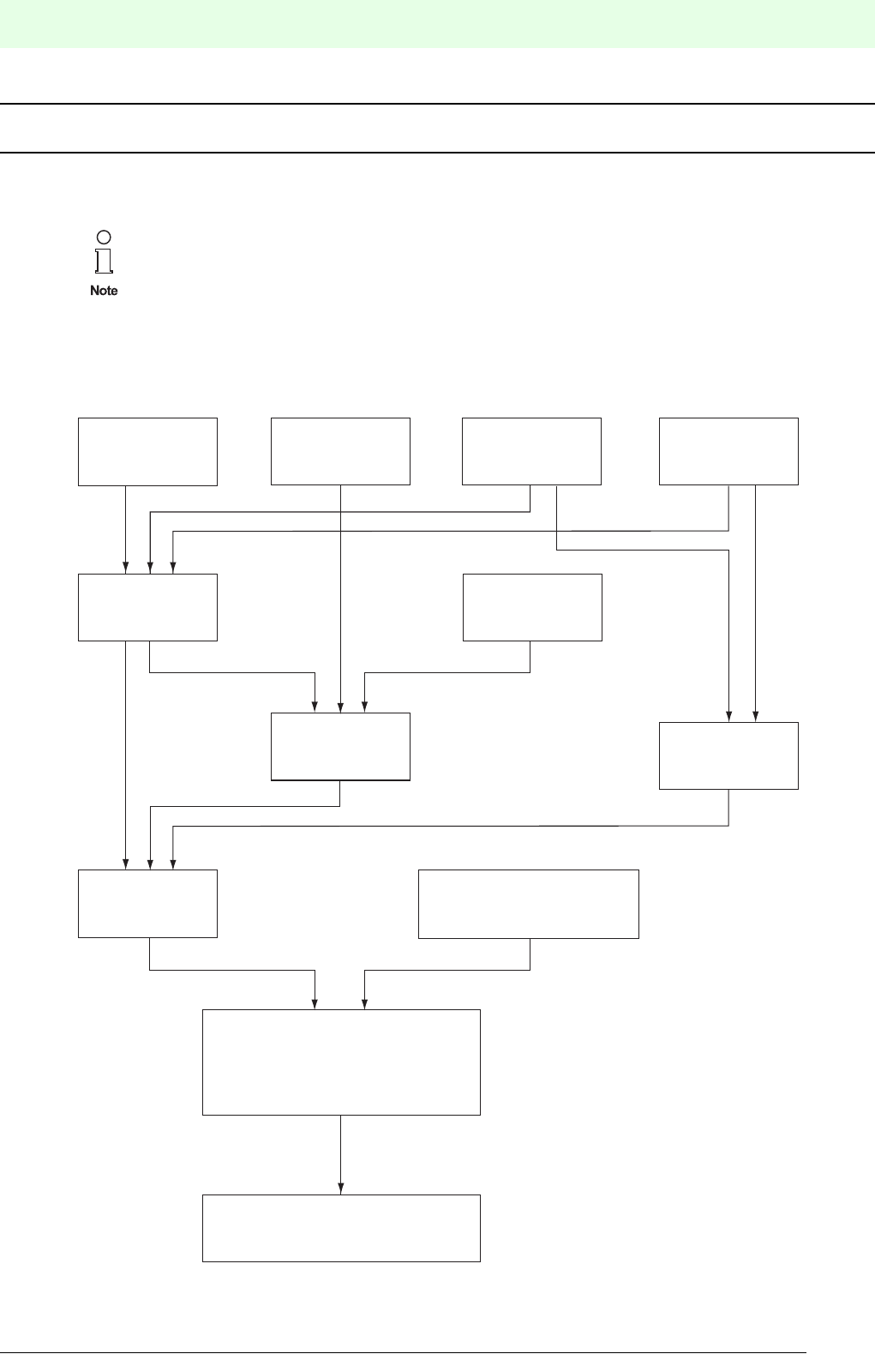
35
Remote Process Interface
Planning of the RPI System
Subject to reasonable modifications due to technical advances. Copyright Pepperl+Fuchs, Printed in Germany
Pepperl+Fuchs Group • Tel.: Germany +49 621 776-0 • USA +1 330 4253555 • Singapore +65 67799091 • Internet http://www.pepperl-fuchs.com
Date of issue 05/27/03
PLANNING, COMMISSIONING, CONFIGURATION AND PARAMETER ASSIGNMENT
4 Planning of the RPI System
4.1 Planning - Basics and Procedure
Figure 4.1 shows how to proceed when planning an RPI system. The individual steps are explained in the
following chapters, whose numbers are given in the diagram below.
Figure 4.1:Planning procedure
Pepperl+Fuchs offers planning and mounting of complete control cabinet systems for the
assembly of RPI systems.
Local Pepperl+Fuchs sales offices will be pleased to advise on alternative installations and the
most suitable control cabinet layout for a given application.
Process technology
application: determination
of number and type of the
loops (see chapter 4.1.1)
number and type
of the devices
(see chapter
4.1.5, 4.1.6)
Determination of
the total power
(see chapter 4.7.5)
Gateway
redundancy
(see chapter 4.5.2)
Topology
(see chapter 4.1.2)
HART or SMART
communication
(see chapter
4.1.3)
Number of
gateways
(see chapter 4.5.3)
Space requirement/
Number of switch cabinets
(see chapter 4.9, 4.10)
Number of power feed modules or
power supply units
(see chapter 4.7.7)
Number of Power Rail segments
(see chapter 4.9)
Fieldbus system
(see chapter
4.1.4)
Type of gateway
Type of voltage supply
:
power feed modules or
power supply units
(see chapter
4.7)

Remote Process Interface
Planning of the RPI System
36
S
ubject to reasonable modifications due to technical advances. Copyright Pepperl+Fuchs, Printed in Germany
Pepperl+Fuchs Group • Tel.: Germany +49 621 776-0 • USA +1 330 4253555 • Singapore +65 67799091 • Internet http://www.pepperl-fuchs.com
Date of issue 05/27/03
4.1.1 MSR Technology
First of all, you should determine the type and number of measuring points, field devices, actuators and con-
trol circuits required for the application. They are intended to communicate with the higher-level process
control system
or with the PLC via the RPI system. The individual sensors and actuators are connected to the RPI devices
using conventional wiring. The kind of information on system side devices, required for a parameter assi-
gnment of the RPI system, depends on the RPI devices to be used and is explained in Chapter 4.1.5 "Esta-
blishing the Measuring Ranges, Basic and Miscellaneous Functions".
4.1.2 Topology
The structure of the plant and the spacial conditions determine the subsequent layout
of the RPI system. You should determine, whether to accommodate the system in a control room or split it
up
and arrange it at different sites or in the field. Splitting it into several systems enables larger applications to
be divided into logical functional units and reduces the amount of wiring, as the individual systems can be
positioned closer to each field device.
4.1.3 HART Communication
The application of HART compatible field devices has to be taken into account when selecting the RPI de-
vices and the gateway. Suitable RPI devices have to be used for the transmission of the HART protocol.
Detailed information on various ways to transfer the protocol is provided in Chapter 4.2 "Planning the
Transmission of HART Protocols".
4.1.4 Fieldbus and Subordinate Service Level
The fieldbus used is a decisive factor in selecting the gateways to be employed. The RPI system can be
integrated into the following fieldbusses:
• PROFIBUS DP
• PROFIBUS DP V1
• MODBUS RTU
• MODBUS Plus
• ControlNet
When selecting a gateway, it is necessary to determine the structure of a service level simultaneously. The
KSD2-GW-... gateways have an RS 232 or an RS 485 service interface. The RS 485 interface allows up
to 31 gateways to be networked with a PC. It is possible to wire a point-to-point connection between a ga-
teway and a PC via the RS 232 interface, or to connect a notebook directly to a gateway by means of a 3.5
mm jack .
The KSD2-GW2-PRO gateway has both types of interfaces.
It is also possible to carry out a configuration and parameter assignment via PROFIBUS DP or PROFIBUS
DP V1. Further information can be found in Chapter 7.2.2 "Gateway KSD-GW2-PRO" and Chapter 7.2.8
"GSD Files".
4.1.5 Establishing the Measuring Ranges, Basic and Miscellaneous Functions
Now that the sensors and actuators are known, the details are defined for each sensor, field device and
actuator. The general data structure of the RPI devices can be entered or read out by means of a configu-
ration tool, e.g.
PACTwareΤΜ Edition 2, or by way of the control system via the gateway.
Safety-related signals
You should begin the planning process by clarifying which signals are safety-related and which
national specifications are applicable.

37
Remote Process Interface
Planning of the RPI System
Subject to reasonable modifications due to technical advances. Copyright Pepperl+Fuchs, Printed in Germany
Pepperl+Fuchs Group • Tel.: Germany +49 621 776-0 • USA +1 330 4253555 • Singapore +65 67799091 • Internet http://www.pepperl-fuchs.com
Date of issue 05/27/03
The data structure of each RPI device occupies the following areas:
• Process data (input/output data)
• Device parameters
• Channel-specific parameters
• Device diagnostic information
• Channel-specific diagnostic information
• Device command data area
The applicable data areas and specific requirements of individual device types are explained below:
4.1.5.1 Process Data
The process data contains the binary or analogue input or output data of all the channels on the devices,
e.g. the value measured by a temperature converter.This data depends on the RPI device type.
4.1.5.2 Device Parameters
The device parameters contain individual and detailed data for the relevant device:
• Device type, device ID,
• Serial number, software/hardware revision number, part number
• Number of channels, type and structure of the input/output data,
• HART support
4.1.5.3 Channel-Specific Parameters
The channel-specific parameters contain data which is specific to a measuring point. This data can be indi-
vidually set when programming the RPI devices using the human machine interface or via the higher-level
control system:
• Measuring point description (TAG No.)
•Comment
• Sensor type, connection system
•Comment
• Measuring range
• Damping
• Lead short circuit/lead breakage monitoring (not on all devices)
• Low/high signal warning, low/high signal alarm for analogue inputs
• Input/output status in the error case
• Calibration of the measuring range
• Linearization of measured value, cold junction compensation on thermocouples
• Physical unit of the analogue input parameters
• Hysteresis for falling short of/exceeding the limit value
• Lower and upper value of the measuring range (0% measured value or 100% measured value)
• Inversion of the input signals
• Cold junction compensation internal/external
• User-specific linearization
• The input value can be overwritten in a defined way for simulation purposes
4.1.5.4 Device and Channel-Specific Diagnostic Information
The diagnostic information contains detailed data on device and channel status:
• Internal device error messages, status of the bus communication, configuration errors
• Separate messages for lead breakage and short circuiting
• Overrange and underrange alarm, alarm for exeeding/falling short of limit value
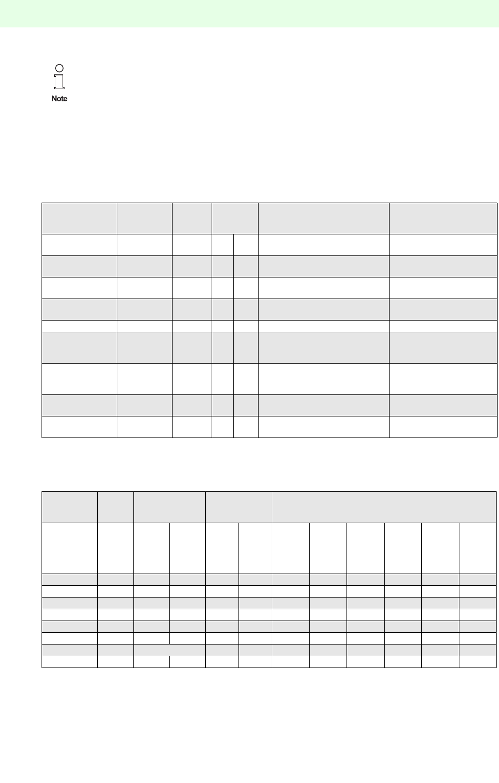
Remote Process Interface
Planning of the RPI System
38
S
ubject to reasonable modifications due to technical advances. Copyright Pepperl+Fuchs, Printed in Germany
Pepperl+Fuchs Group • Tel.: Germany +49 621 776-0 • USA +1 330 4253555 • Singapore +65 67799091 • Internet http://www.pepperl-fuchs.com
Date of issue 05/27/03
4.1.5.5 Overview of Functions and Miscellaneous Functions for Each RPI Device
The information provided in the tables below is required for the selection and parameter assignment of RPI-
devices. See also Chapter 6.1 "Parameters of the RPI Modules"
Table 4.1: RPI devices and functions
Table 4.2: Miscellaneous functions of the RPI devices
Detailed information on the data structure of the individual modules is given in Chapter 6
"Parameter Assignment".
Device designa-
tion
Function
Type code No. of
chan-
nels
available
in
Sensor
settings
Output
settings
Ex non-
Ex
Isolated switch
amplifier
KSD2-BI-... 2 or 4 yes yes Invert signal , filter time
Frequency conver-
ter
KSD2-FI-... 1 yes yes Unit, operating mode Measuring range: unit con-
stant, offset
Solenoid
driver
KSD2-BO-... 1 or 2 yes no invert signal
Relay module KSD2-RO-... 2 yes yes invert signal
Transmitter
power supply
KSD2-CI-... 1 or 2 yes yes Unit, current range, connection
method: 2 or 3-wire transmitters,
2-wire current source
Measuring range: start, end
HART transmission
Temperature
converter
KSD2-TI-... 1 yes yes Sensor type, connection method ,
unit, linearization, reference junction
internal/external
Measuring range: start, end
invert signal
Voltage
converter
KSD2-VI 1no yes Unit,
voltage range
Measuring range: start, end
Analogue Driver/
Repeaters
KSD2-CO-...
Type code Measu-
ring
station
Lead
monitoring
Limit-value
monitoring
Output status when fault occurs
TAG
No.
max.
charac-
ter
Brea-
kage
Short-
circuit
Warnin
g limits
Alarm
limits
Upsca-
led
Down-
scaled
Main-
tain last
value
As
input
Mini-
mum
Maxi-
mum
KSD2-BI-... 32 yes yes x x x
KSD2-FI-... 32 yes yes yes yes x x
KSD2-BO-... 32 yes yes x x x
KSD2-RO-... 32 x x x
KSD2-CI-... 32 yes yes yes yes x x x x
KSD2-TI-... 32 yes yes yes yes x x x x
KSD2-VI 32 yes yes yes x x x x
KSD2-CO-... 32 yes yes x x x x

39
Remote Process Interface
Planning of the RPI System
Subject to reasonable modifications due to technical advances. Copyright Pepperl+Fuchs, Printed in Germany
Pepperl+Fuchs Group • Tel.: Germany +49 621 776-0 • USA +1 330 4253555 • Singapore +65 67799091 • Internet http://www.pepperl-fuchs.com
Date of issue 05/27/03
4.1.6 Selecting the RPI Devices
Now that you have determined the functions and miscellaneous functions as described above, you can sel-
ect the individual RPI devices according to the following procedure:
1. Device type: Which sensor, actuator or field device must the RPI-device support?
2. Is the sensor, actuator or field device located in a hazardous area?
3. Is a HART or a SMART protocol transferred? (see Chapter 4.2 "Planning the Transmission of
HART Protocols")
4. Which requirements of the control system must the RPI modules meet?
(see Chapter 7.2.8 "GSD Files")
5. Is it possible to use multi-channel devices?
The PACTwareΤΜ software enables the devices to be parameterized channel by channel and thus to
connect a number of field devices of the same type with different parameter assignments to an RPI
device. For information on the type of multi-channel devices available, please refer to Chapter 4.1.7
"Establishing the Miscellaneous and Monitoring Functions for the Operation"
6. List of all RPI modules required with the full type code and, if available, with the corresponding measu-
ring point description.
The planning can be developed, as usual, by measuring station numbers, since these can be transferred to
the RPI and used in further working steps.
After having defined the basic functions and device types mentioned above, you can already start planning,
configuring and programming the RPI system offline on your PC using the PACTwareΤΜ human machine in-
terface.
For the rare case that specific functions are not supported by the RPI, devices from other systems can be
linked by the RPI.The Pepperl+Fuchs team will be happy to provide appropriate solutions.
4.1.7 Establishing the Miscellaneous and Monitoring Functions for the Operation
In addition to the basic functions described in the chapter above, the RPI devices also support a series of
miscellaneous functions, which can be activated and set. The miscellaneous functions available are listed
in Table 4.2: on page 38.
It must be decided which of these messages are to be displayed or processed in the control system and
which are merely required to be seen on the RPI human machine interface..
Not all of the devices in the RPI system are certified for application in the
hazardous area.
When selecting appropriately certified devices for the hazardous area, attention must be paid to
the permitted connection values, the class of ignition protection and the category.
Detailed information on the setting of these parameters and the various register cards of the
devices is given in Chapter 6 "Parameter Assignment"’
Full technical data on the devices can be obtained from the data sheets in our catalogue or from
our website: www.pepperl-fuchs.com

Remote Process Interface
Planning of the RPI System
40
S
ubject to reasonable modifications due to technical advances. Copyright Pepperl+Fuchs, Printed in Germany
Pepperl+Fuchs Group • Tel.: Germany +49 621 776-0 • USA +1 330 4253555 • Singapore +65 67799091 • Internet http://www.pepperl-fuchs.com
Date of issue 05/27/03
4.1.8 Layout and Addressing of the RPI Devices
Having determined the individual types and numbers of RPI devices needed, and the type of gateway re-
quired, the possible layout of the RPI-system and the arrangement of the individual devices should be spe-
cified.
Especially when several RPI systems are used, we recommend dividing the RPI devices into logical functio-
nal units. When arranging the system, devices of the same type should be combined into groups. The si-
gnals will be marshalled on the software side.
In this working step the RPI-internal adresses should be determined and recorded in the plan. (see Chapter
5.4.2.1 "ALLOCATION OF THE DEVICE ADDRESSES ON THE INTERNAL BUS")
The device addresses are organised as follows:
Table 4.3: Organisation of the RPI device addresses
4.1.9 Determining Where to Install the RPI System
The RPI system can be installed either in the safe area of the control room or in the zone 2 hazardous area
of the plant.
The installation of the RPI system within Ex-zone 2 must be undertaken with due regard for the statement
of conformity (TÜV 00 ATEX 1617X or TÜV 00 ATEX 1618X). Only devices with an appropriate statement
of conformity can be installed in zone 2.Detailed information is given in Chapter 2.6 "Declaration of Con-
formity".
4.2 Planning the Transmission of HART Protocols
HART stands for ’High Addressable Remote Transducer’. It is a digital communication protocol for the trans-
fer of data to sensors, actuators and field devices. These devices can perform calculations, self-diagnoses
and error reports.
RPI offers three possibilities to communicate with HART compatible field devices.
Address Device
0Neutral address of an RPI device, (the setting on delivery)
1 Active RPI gateway
2Redundant RPI gateway
3 ... 127 RPI device
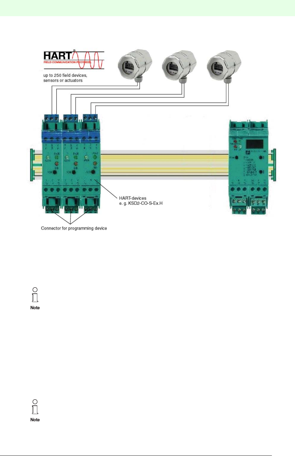
41
Remote Process Interface
Planning of the RPI System
Subject to reasonable modifications due to technical advances. Copyright Pepperl+Fuchs, Printed in Germany
Pepperl+Fuchs Group • Tel.: Germany +49 621 776-0 • USA +1 330 4253555 • Singapore +65 67799091 • Internet http://www.pepperl-fuchs.com
Date of issue 05/27/03
4.2.1 Direct Connection of a HART Programming Unit
Figure 4.2:Programming Unit
The field devices should be connected to appropriate HART compatible RPI devices. The programming unit
is connected to the non-Ex terminals of the RPI module. The protocol is transmitted via a hand-held device
or a PC which is connected to the terminals of the RPI device, thus enabling direct communication with the
field device.
4.2.2 Connection to the HART Multiplexer
HART mulitplexer and HART Control module
Signals of several HART compatible field devices can be collected and transmitted simultaneously via the
KFD2-HMM16 HART multiplexer.The HART signals of the field devices are transmitted to rail 4 of the Power
Rail by means of HART compatible RPI devices. This rail is read out by the KSD2-HC HART Control module
and the data is transferred to the HART multiplexer via a 14-core flat cable. The HART programming unit
or a PC with an appropriate HART software can be connected to the HART multiplexer. Further details can
be found in the product description of the KFD2-HMM-16 HART multiplexer master.
For transmitting the protocol, the
The HART and SMART compatible RPI devices KSD2-CI-S-Ex, KSD2-CI-S-Ex2.H,
KSD2-CO-S-Ex and KSD2-CO-S-Ex2.H are equipped as standard with KF-STP-BU / KF-STP-
GN
terminal blocks (Chapter 4.10.5 ’Accessories’) for the connection of the HART handheld device.
The power feed modules KFD2-EB.RPI or KFD2-EB.R2A.RPI must be used.
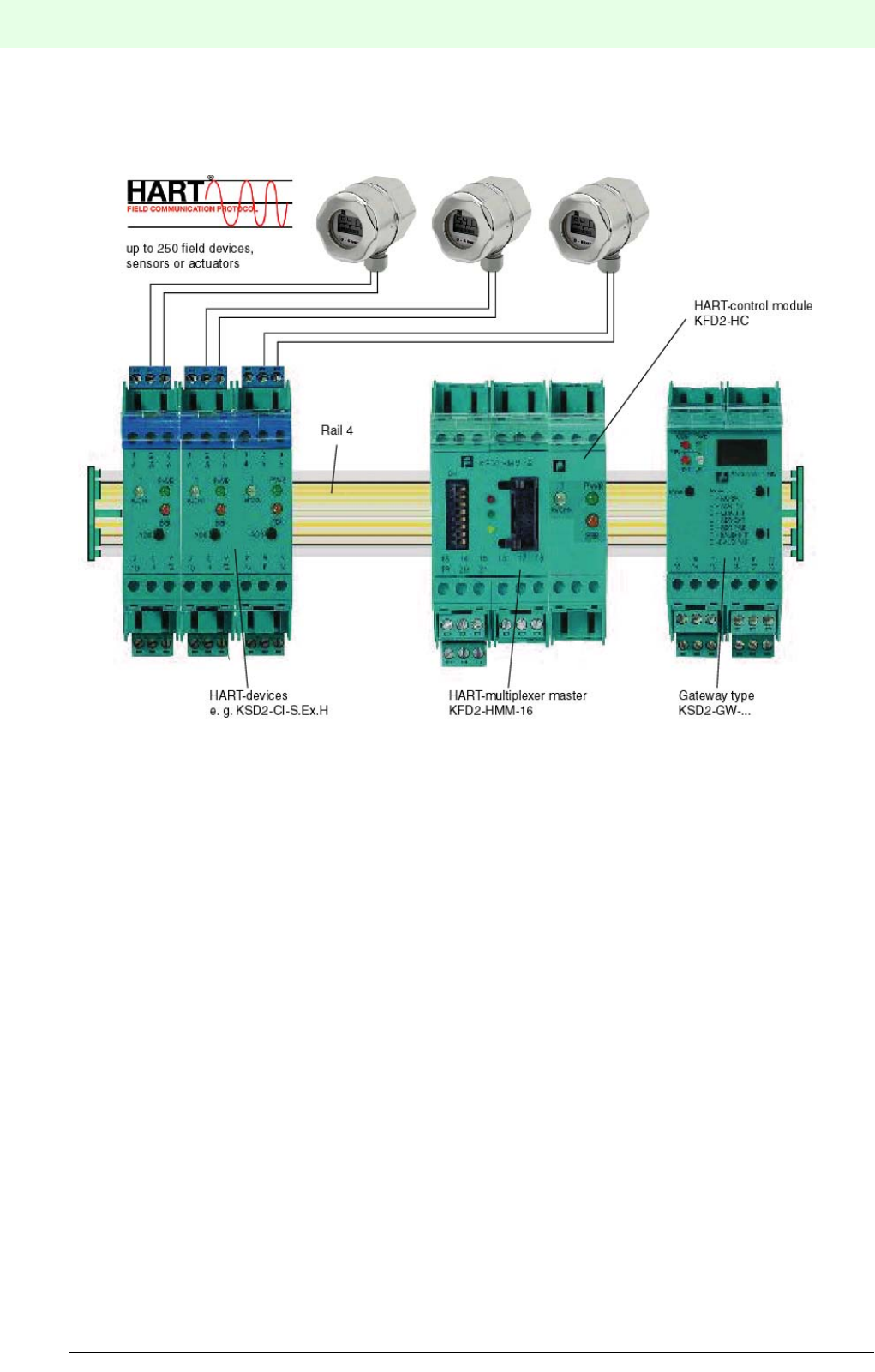
Remote Process Interface
Planning of the RPI System
42
S
ubject to reasonable modifications due to technical advances. Copyright Pepperl+Fuchs, Printed in Germany
Pepperl+Fuchs Group • Tel.: Germany +49 621 776-0 • USA +1 330 4253555 • Singapore +65 67799091 • Internet http://www.pepperl-fuchs.com
Date of issue 05/27/03
PACTwareΤΜ edition 2 software with integrated HART communication DTM, Cornerstone or AMS can be
used on a PC with an RS 485 interface.
Figure 4.3:HART multiplexer master and HART Control module
4.2.3 HART Transmission via KSD2-GW2-PRO Gateway
The PROFIBUS DP V1 Gateway KSD2-GW2-PRO has an integrated HART multiplexer system that offers
full functionality. The HART protocol is transmitted via:
- the service interface or
- the PROFIBUS DP V1
4.2.3.1 Service Interface
The PC is connected to the KSD2-GW2-PRO Gateway via the RS 232 or RS 585 service interface. The
protocol is transmitted to the gateway via the service interface and further on to the RPI devices via rail 4
of the Power Rail. HART compatible RPI modules modulate the data upon the 4 ... 20 mA signal.
4.2.3.2 PROFIBUS
PROFIBUS DP V1 supports both acyclic data exchange and logon of the service interface as class 2 PRO-
FIBUS master in conjunction with PACTwareΤΜ edition 2 or with any other FDT compatible human machine
interface. To enable the gateway and a PC to communicate via an external bus, it is necessary to integrate
the communication DTM. This DTM allows the transfer of the HART protocol to the class 2 master via
acyclic data exchange.
HART Control module
KSD2-HC
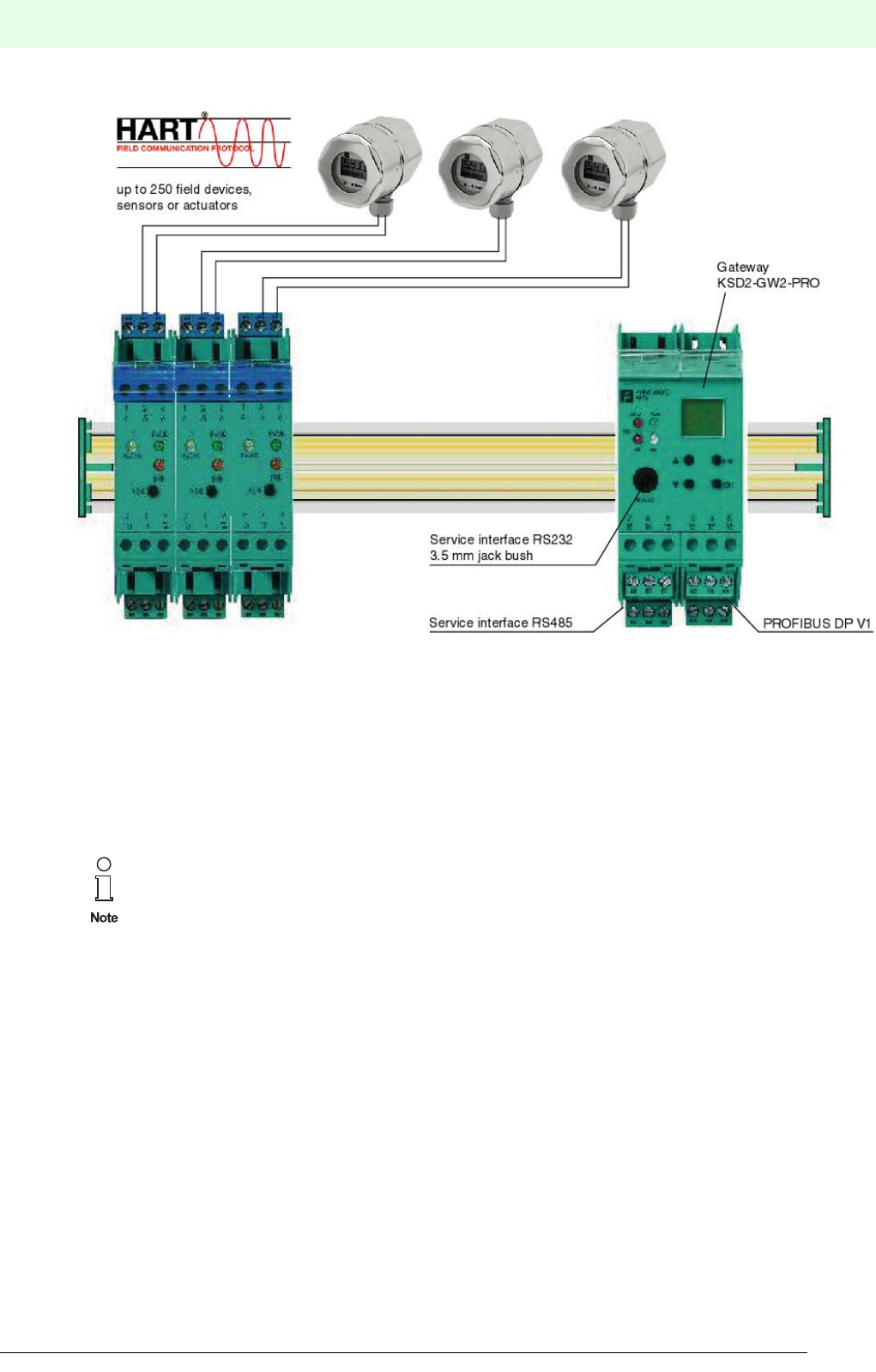
43
Remote Process Interface
Planning of the RPI System
Subject to reasonable modifications due to technical advances. Copyright Pepperl+Fuchs, Printed in Germany
Pepperl+Fuchs Group • Tel.: Germany +49 621 776-0 • USA +1 330 4253555 • Singapore +65 67799091 • Internet http://www.pepperl-fuchs.com
Date of issue 05/27/03
Figure 4.4:PROFIBUS Gateway KSD2-GW2-PRO
4.3 General Information on Communication and Diagnostic Procedures via the Internal RPI Bus
Communication via the internal bus is completely controlled through the RPI gateway. The gateway (ma-
ster) communicates cyclically with every RPI station (slave).
Extensive diagnostic information can be retrieved for each individual device via the external bus system to
the higher level host.For this purpose, we advise using the PACTwareΤΜ edition 2 human machine interface.
Further information can be found in Chapter 7 "Integration into the Higher-Level Bus
System".

Remote Process Interface
Planning of the RPI System
44
S
ubject to reasonable modifications due to technical advances. Copyright Pepperl+Fuchs, Printed in Germany
Pepperl+Fuchs Group • Tel.: Germany +49 621 776-0 • USA +1 330 4253555 • Singapore +65 67799091 • Internet http://www.pepperl-fuchs.com
Date of issue 05/27/03
4.4 Calculating the RPI Cycle Time
The internal RPI bus has a constant transfer rate of 250 kbit/s. The maximum number of RPI bus stations
is 125 devices or 500 channels. The gateway calculates the current cycle time depending on the stored
configuration and communicates to every slave when (cycle time) it must answer. The cycle time is calcu-
lated in such a way that low-priority signals (acyclic services) can be transferred.
The cycle time for an RPI system is calculated from the following formula
TUPDATE = [(53 nmodules + 38 nanalogue + 9nbinary + 53 noutput)tbit *1.2] + 25 ms
tbit4µs (250 kbit/s)
nmodulesNumber of devices
nanalogueNumber of analogue channels
nbinaryNumber of binary modules
noutputNumber of output modules (binary and analogue)
The cycle time is set to the lower integral multiple of 5 ms.
Exemplary calculation: an RPI system contains the following modules
10 KSD2-TI-Ex
20 KSD2-CI-S-Ex
10 KSD2-BO-Ex2
45 KSD2-BI-Ex4
Thus, the following parameters are obtained:
nmodulesNumber of modules85 modules
nanalogueNumber of analogue channels30 channels
nbinaryNumber of binary modules55 modules
noutputNumber of output modules (binary and analogue)10 modules
The cycle time is 55 ms.
4.5 Planning the Internal and External Communication
4.5.1 General Notes on Operating the Gateways
RPI gateways of type KSD2-GW-... and KSD2-GW2-... translate the protocols of the internal bus into the
protocols of the external bus to the control system and vice-versa. Up to 125 RPI devices with a maximum
of 500 channels can be connected to one gateway.
The construction and the operation of the gateways using the controls on the front of the devices is identical
for all types. Differences are referred to in the respective descriptions.
If the cycle time calculated for the RPI system is too long for your application, it can be also be
reduced by dividing the RPI devices between 2 or more gateways.
’The actual number of devices, which substantially depends on the transmitted data protocol,
should be determined taking account of the bus specific conditions. Detailed information is
given in Chapter 7 "Integration into the Higher-Level Bus System".
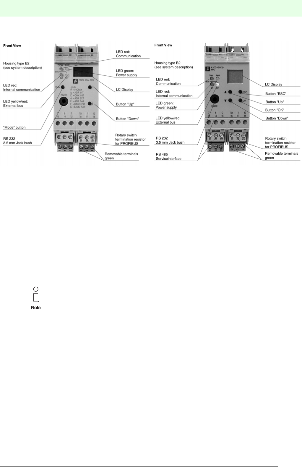
45
Remote Process Interface
Planning of the RPI System
Subject to reasonable modifications due to technical advances. Copyright Pepperl+Fuchs, Printed in Germany
Pepperl+Fuchs Group • Tel.: Germany +49 621 776-0 • USA +1 330 4253555 • Singapore +65 67799091 • Internet http://www.pepperl-fuchs.com
Date of issue 05/27/03
Construction of the devices
Figure 4.5:Front view of Gateway KSD2-GW-PRO and KSD2-GW2-PRO
More detailed information on the LEDs and the operation of the gateway can be obtained from Chapter 5
"Configuring and Commissioning the RPI System".
The RPI system can be integrated into the following bus systems:
• PROFIBUS DP: KSD2-GW-PRO Gateway
• PROFIBUS DP V1: KSD2-GW2-PRO Gateway
• MODBUS RTU: KSD2-GW-MOD Gateway
• MODBUS Plus: KSD2-GW-MPL Gateway
• ControlNet: KSD2-GW-CN Gateway
4.5.2 Redundancy Considerations
The planning of your application should also be considered from the point of view of availability.
4.5.2.1 Redundancy Internal Bus
The internal bus on the Power Rail is automatically redundant. A switch-over to redundant communication
is indicated by LED and LC displays on the gateway. It is also indicated in the diagnosis window of PACT-
wareΤΜ. The diagnosis is transferred to the control system via the external bus. The user is informed of the
switch-over on the internal redundant channel and has time to eliminate the fault whilst the communication
is continuing.
4.5.2.2 Gateway Redundancy
The external bus can also be made redundant by using a second gateway on the same Power Rail. If a
gateway fails, or if the external bus line is broken, the second redundant gateway automatically takes over
the communication.
Please note that the gateways are available with RS232 or RS485 service interfaces, alterna-
tively. See Chapter 4.6 "Establishing the Service Functionality for the RPI System" for
more information.
KSD2-GW2-PRO
KSD2-GW-PRO

Remote Process Interface
Planning of the RPI System
46
S
ubject to reasonable modifications due to technical advances. Copyright Pepperl+Fuchs, Printed in Germany
Pepperl+Fuchs Group • Tel.: Germany +49 621 776-0 • USA +1 330 4253555 • Singapore +65 67799091 • Internet http://www.pepperl-fuchs.com
Date of issue 05/27/03
4.5.2.3 Redundancy External Bus
Two completely isolated external bus systems should be provided if the control system will permit it, in order
to obtain even greater availability.For this purpose a second redundant gateway is used.
The bus cables for the two systems should be laid on different paths to the control system,thus avoiding the
danger of both cables suffering damage simultaneously.
4.5.3 Determining the Number of RPI Gateways Required
Obtain the number of gateways required by consideration of bus specific conditions; see Chapter 7 "Inte-
gration into the Higher-Level Bus System". One gateway can manage up to 125 RPI modules.
It should also be noted that twice the number of gateways are required if the gateway or the external bus
system is required to be redundant.
4.6 Establishing the Service Functionality for the RPI System
4.6.1 Service Interface RS232
If the PC is only used for commissioning or adjusting the RPI system, the RS232 service interface with a
jack is selected. Using the adapter, which is available as accessory, the RPI system can be configured and
parameterized. A PC can also be connected directly to the terminals of an individual gateway.
4.6.2 Service Interface RS485
Up to 31 gateways can be networked and connected to a PC via the RS485 service interface. This allows
a wired service level to be arranged, e.g.: for continuously monitoring the RPI systems.
4.6.3 PROFIBUS
4.6.3.1 PROFIBUS DP
The RPI system can be parameterized via PROFIBUS DP using the GSD-file ’PF0818p.GSD’. More infor-
mation is provided in Chapter 7.2.8 "GSD Files"
4.6.3.2 PROFIBUS DP V1
The application of PROFIBUS DP V1 will enable users to perform a parameter assignment (PACTproductΤΜ
or HART) directly via the bus system. The PC functions as class 2 master and transfers the data acyclically
to the gateway via the PROFIBUS. Further information can be found in Chapter 7.2.2 "Gateway KSD-
GW2-PRO".
4.7 Power Supply
All RPI modules are supplied with 24 V DC voltage via the Power Rail.
Power supply is provided via power feed modules which are mounted on the Power Rail too.
Suitable power supply units are available for the connection to 230 V AC. These supply the Power Rails
with power via power feed modules. Alternatively, they can be mounted directly on the Power Rail.
Gateway KSD2-GW2-PRO has both types of interfaces.
Note that no power feed module should be operated under zero-load conditions, since this can
lead to spurious tripping of the error signal (red LED ‘ERR’, relay output).
At least one RPI device or one RPI gateway should always be connected to each power feed
module.
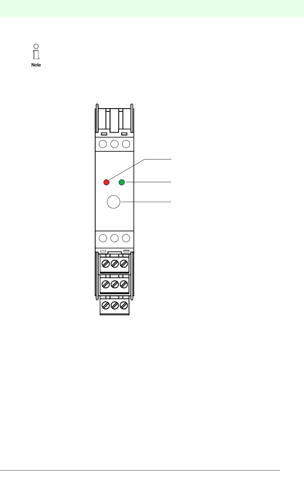
47
Remote Process Interface
Planning of the RPI System
Subject to reasonable modifications due to technical advances. Copyright Pepperl+Fuchs, Printed in Germany
Pepperl+Fuchs Group • Tel.: Germany +49 621 776-0 • USA +1 330 4253555 • Singapore +65 67799091 • Internet http://www.pepperl-fuchs.com
Date of issue 05/27/03
.
4.7.1 Construction of the Power Feed Module
Figure 4.6:Front view of power feed module KFD2-EB.RPI and KFD2-EB.R2A.RPI
Dual designed power feed terminals enable the external supply voltage to be daisy-chained.
The presence of the operating voltage is indicated by the green ‘PWR’ LED on the front panel of the device.
4.7.2 Group Fusing on the Power Feed Module
The fuses on the front panel of the power feed modules protect the contacts for the Power Rail from over-
load and serve to provide group fusing for the RPI devices of each Power Rail segment.
In addition, each RPI device is internally fused.
A fault of the fuse of the power feed module is optically indicated on the red LED on the front panel. In ad-
dition, external indicators can be triggered via an internal relay. The relay operates as normally open con-
tact, as standard; the direction of operation can be adjusted by means of a plug-in jumper.(see Chapter
5.2.2 "Setting the Mode of Operation of the Relay" )
Detailed information on power feed modules and power supply units can be obtained from the
data sheets on our website www.pepperl-fuchs.com or from our catalogue. A list of the indivi-
dual devices is provided in Chapter 3.3 "Summary of RPI Modules Currently Available".
1
4
2
5
3
6
7
10
13
8
11
14
9
12
15
4 AT
LED red
Fault signal
LED green
Power
Fine-wire fuse,
Type T
Remote Process Interface
Planning of the RPI System
48
S
ubject to reasonable modifications due to technical advances. Copyright Pepperl+Fuchs, Printed in Germany
Pepperl+Fuchs Group • Tel.: Germany +49 621 776-0 • USA +1 330 4253555 • Singapore +65 67799091 • Internet http://www.pepperl-fuchs.com
Date of issue 05/27/03
4.7.3 Segmentation of the RPI System
The RPI devices of a gateway can be mounted at different, isolated Power Rail segments.
The internal bus and HART protocol transmission can be daisy-chained by connecting the individual termi-
nals to the power feed modules KFD2-EB.RPI and KFD2-EB.R2A.RPI.
• Internal bus: Connection of terminals 12, 13 and 15
• HART protocol: Connection of terminals 14
4.7.4 Power Feed Modules for Redundant Power Supply
If required, the power supply can be given a redundant layout. As a rule, both the supply power systems or
power supply units must be decoupled via diodes.The KFD2-EB.R2A.RPI power feed module incorporates
decoupling diodes and can provide a supply of up to 2 A. The KFD2-EB.RPI power feed modules and the
KFA6-STR.1.24.4 power supply unit provide a voltage of 24 V DC and a maximum of 4 A. However, they
do not have a decoupling diode. When using external decoupling diodes, the KFD2-EB.RPI power feed mo-
dule can also be used for a redundant power supply.
4.7.5 Setting up the Power Supply Balance for the RPI Devices Including the Gateways
To size the power supply required, calculate the maximum current consumption of the RPI modules. The
data sheets contain data on the power consumption and the voltage supply range for each device. The ma-
ximum current consumption always occurs on the RPIs of minimum power supply, i.e. for a power supply
of 20 V. In this way, the maximum current consumption must be calculated for each RPI device used, inclu-
ding that of the gateway(s) and other devices.
Current = Power / 20 V
The power supply modules provide a maximum of 4 A or 2 A on the versions for redundant power supply.
The maximum current consumption of all RPI devices and gateways in a segment must not exceed the
available output currents of the power feed modules.
If the current consumption of all devices is higher than the output current of the power feed module used, a
number of Power Rail segments with one power supply module each, have to be installed. The RPI internal
bus can be daisy-chained from the segment with the gateway to all other segments.
Exemplary calculation: An RPI system consists of the following modules
1 KSD2-GW-PRO
10 KSD2-TI-Ex
20 KSD2-CI-S-Ex
10 KSD2-BO-Ex2
45 KSD2-BI-Ex4
We recommend to allow for a safety margin of 20 % in the power supply balance.
The nominal current for the conductors integrated in the Power Rail is 4 A.
This value must not be exceeded.

49
Remote Process Interface
Planning of the RPI System
Subject to reasonable modifications due to technical advances. Copyright Pepperl+Fuchs, Printed in Germany
Pepperl+Fuchs Group • Tel.: Germany +49 621 776-0 • USA +1 330 4253555 • Singapore +65 67799091 • Internet http://www.pepperl-fuchs.com
Date of issue 05/27/03
Detailed information on the power consumption and the current demand of the individual modules is provi-
ded in the data sheets. The data for the selected devices is summarized in the following table:
Table 4.4: Exemplary calculation: power consumption, current requirement
The RPI system has a power consumption of 116.80 W and a current demand of 5.84 A. Taking account of
a safety margin of 20 %, the power supply must be 7.0 A.
• Simple arrangement of the power supply:
two Power Rail segments with one 4 A power feed module each, 2 power feed modules in sum.
• Redundant design of the power supply:
four Power Rail segments with two 2 A power feed modules each, and an integrated decoupling diode,
8 in sum
• Redundant design with external decoupling diodes:
two Power Rail segments with two 4 A power feed modules each, 4 in sum
In this case, it should be ensured that the current consumption for each Power Rail segment, cannot ex-
ceed 4 A!
4.7.6 Determining the Power Supply Segments
As shown in the previous chapter, the power supply balance depending on the redundancy concept results
in different numbers of Power Rail segments per gateway.
The number of segments is only limited by the maximum permissible length of the internal bus line. The
latter is 8 m and can be obtained by adding the lengths of the segments and the lengths of the wiring bet-
ween the power feed modules. Therefore, in constructing the segments and the RPI modules, it should be
ensured that the separation of the power supply modules is as small as possible.
If a number of power supply segments are required on one mounting rail, then the Power Rail sections are
not connected with each other at the segment boundaries, but are separated from each other by a distance
of at least 1 mm.
One possibility of arranging the mounting rails and connecting the power supply segments is represented
in Figure 4.16: on page 61 of this system manual.
.
4.7.7 Establishing the Type and Number of the Power Supply Modules
When planning a redundant power supply the following should be considered:
• In the event of the failure of a power supply module, the complete segment must be supplied via the
intact power supply module. The power supply modules should be laid out accordingly.
• Furthermore, it must not be the case, that in the event of failure, a flow of power from the intact to the
defective power supply unit takes place. This flow of energy is prevented by decoupled diodes.
Type code Device designation Prefix Power I=P/20V Number of Sum P Sum I
[W] [mA] devices [W] [mA]
KSD2-GW-PRO PROFIBUS Gateway =2.80 140 12.80 140
KSD2-TI-Ex Temperature converter < 1.50 75 10 15.00 750
KSD2-CI-S-Ex.H Transmitter power supply <1.30 65 20 26.00 1300
KSD2-BO-Ex2.2 Solenoid driver = 2.80 140 10 28.00 1400
KSD2-BI-Ex4 Isolated switch amplifier =1.00 50 45 45.00 2250
Sum: 116.80 5840
In forming the segments without a redundant supply, it must be considered, that if the fuse ope-
rates, all interfaces of the segment in question fail if the system has no redundancy. It must be
ensured, that in this case, a dangerous situation does not arise in the system.

Remote Process Interface
Planning of the RPI System
50
S
ubject to reasonable modifications due to technical advances. Copyright Pepperl+Fuchs, Printed in Germany
Pepperl+Fuchs Group • Tel.: Germany +49 621 776-0 • USA +1 330 4253555 • Singapore +65 67799091 • Internet http://www.pepperl-fuchs.com
Date of issue 05/27/03
The decoupled diodes required must be either:
• in the power supply units that are used,
• sited externally in the power supply circuit,
• or in the KFD2-EB.R2A.RPI power supply module, two units of which are mounted on each Power Rail
segment.
The KFD2-EB2.RPI power feed module is used:
• when the supply has no redundancy
• when the supply has a redundancy and external decoupling diodes are used.
4.7.8 Establishing the Type and Number of Power Supply Units, where Required
The RPI operates with a voltage supply in the 20 to 30 V DC range and requires no additional power supply
units. If, however, it is required to operate with a voltage outside this range, the KFA6-STR.1.24.4 power
supply unit will have to be used. (input 90 to 265 V AC, output 24 V DC).
If a 24 V DC power supply is available in the control cabinet or within reach, power supply modules should
be used. In this case, you should proceed as follows:
• set up the power supply balance for your RPI system
• determine the number of power feed modules that are required, as shown in Chapter 4.7.5 .
If no 24 V DC supply is available, the KFA6-STR.1.24.4 power supply unit should be used.
4.8 Accessories
4.8.1 Power Rail
Power Rail is a DIN rail system, in which five conductors are integrated, providing for power supply and the
internal bus connection.
Power Rail is available in 2 different versions:
• UPR-05 with integrated mounting rail and variable device position
• PR-05 as component insert for standard top hat rails; device position predefined by grids.
4.8.1.1 Power Rail UPR-05
Delivery package (see Figure Figure 4.7:):
• Aluminium mounting rail, 15 mm deep, 2 m long
• Power Rail insert with 5 conductors, 2 m long, can simply be cut to length.
• Cover providing mechanical and electical protection of free plug-in stations.
• 2 End caps
The UPR-05 has no mounting grid. Thus, components of any width can be mounted on this rail. This is to
ensure that the rail may be cut to any length and that the devices of future generations can also be mounted.
The current for a Power Rail is a maximum of 4 A.
When using the KFA6-STR.1.24.4 power supply unit, a redundancy of the power supply is not
possible.
The nominal current for the conductors integrated in the Power Rail is 4 A.
This current must not be exceeded!
Only the UPR-05 Power Rail should be used for rewiring.
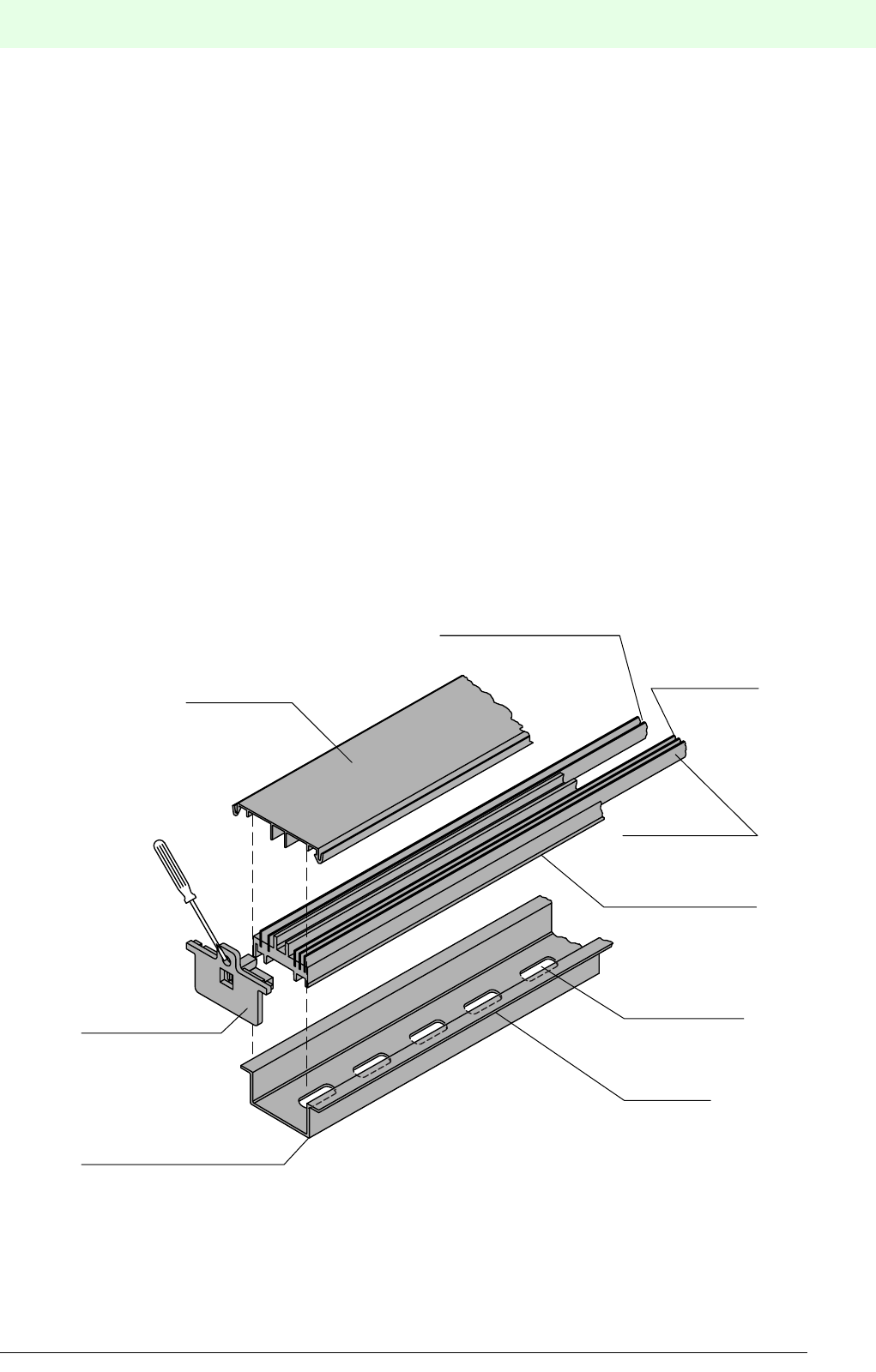
51
Remote Process Interface
Planning of the RPI System
Subject to reasonable modifications due to technical advances. Copyright Pepperl+Fuchs, Printed in Germany
Pepperl+Fuchs Group • Tel.: Germany +49 621 776-0 • USA +1 330 4253555 • Singapore +65 67799091 • Internet http://www.pepperl-fuchs.com
Date of issue 05/27/03
4.8.1.2 Mounting the UPR-05 Power Rail
You should proceed as follows:
• Cut the mounting rail including the Power Rail insert to arbitrary length using a hack saw.
• Remove the Power Rail insert by means of the end caps.
• Screw or rivet the mounting rail onto a mounting base.
M4 screws and DIN 125 washers or 4 mm rivets are required for this purpose.
• Snap the Power Rail insert into the mounting rail.
• Replace the end caps.
• In the case of vertical mounting of the mounting rail, TS 35 Type 12 end clamps should be screwed to
the rail at the required intervals, in order to provide mechanical protection of the RPI devices.
• Having mounted all RPI devices, the cover is cut according to the gaps between the modules. The cover
must be snapped in place in order to provide protection against accidental contact (IP 20).
4.8.1.3 Accessories for Power Rail UPR-05
The following accessories are available:
• UPR-E end caps (see Figure Figure 4.7:)
• TS35 type 12 end clamps(see Figure Figure 4.8:) providing mechanical protection of the RPI modules,
when they are installed on a vertically fixed mounting rail.At least one clamp per vertical mounting rail is
required for this purpose.
Figure 4.7:Assembly of the UPR-05 Power Rail
Cover
End cap UPR-E
Slot mounted Power Rail
2 leads for power supply
2 leads for
bus connection
universal Power Rail
Mount using M4
screws with
washers per
DIN 125
DIN Rail
35 mm x 15 mm
1 lead
HART signals

Remote Process Interface
Planning of the RPI System
52
S
ubject to reasonable modifications due to technical advances. Copyright Pepperl+Fuchs, Printed in Germany
Pepperl+Fuchs Group • Tel.: Germany +49 621 776-0 • USA +1 330 4253555 • Singapore +65 67799091 • Internet http://www.pepperl-fuchs.com
Date of issue 05/27/03
Figure 4.8:End clamp TS35 Type 12
4.8.1.4 Power Rail PR-05
Delivery package (see Figure Figure 4.9:):
• Insert component for standard top hat rails to DIN EN 50 022, length 500 mm
4.8.1.5 Mounting the Power Rail PR-05
You should proceed as follows:
• Shorten: the Power Rail can be shortened, as required, at intervals of 40 mm, at the points marked with
indents. It should be noted, that there must be an end contact on the shortened component, if shortened
Power Rail sections are to be fixed together.
• Extend: The Power Rails are a standard length of 500 mm, however, they can be extended by joining
them to another rail section, using a VE-PR connection fitting. The two ends of the PR-05 are different.
A right hand and a left hand end contact should be used for the respective ends to allow the VE-PR com-
ponents to be mounted.
• Snap the end caps on the free ends of the Power Rail sections.
• Insert the Power Rail sections into the top hat DIN rail. If a number of power supply circuits are to be
installed on one mounting rail (segmentation of the power supply), a separation of at least 1 mm should
exist between the individual segments, so that the end pieces of the Power Rail do not make contact
with the neighbouring segment.
• Join the individual Power Rail sections using a VE-PR connection fitting (see Figure Figure 4.9:). A right
hand and a left hand end contact should be used for the respective ends to allow the VE-PR components
to be mounted. RPI devices can also be mounted over the connecting components, so that no space is
lost.
• Having inserted the Power Rail into the top hat DIN rail, the devices of the RPI system are simply snap-
ped onto the rail.
27 10
40
26
34
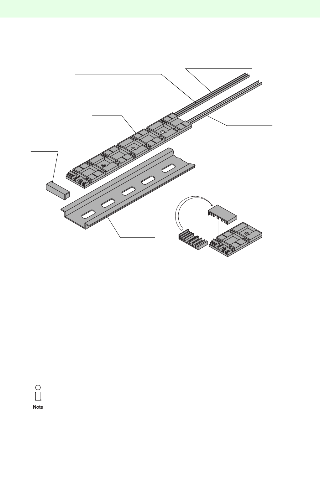
53
Remote Process Interface
Planning of the RPI System
Subject to reasonable modifications due to technical advances. Copyright Pepperl+Fuchs, Printed in Germany
Pepperl+Fuchs Group • Tel.: Germany +49 621 776-0 • USA +1 330 4253555 • Singapore +65 67799091 • Internet http://www.pepperl-fuchs.com
Date of issue 05/27/03
4.8.1.6 Accessories for Power Rail PR-05
Figure 4.9:Assembly of the PR-05 Power Rail
4.8.1.7 Combining the RPI System with Interface Modules from other Systems
If interface functions are required in your application, which are not available in the modular RPI system,
modules from other systems which can be rail-mounted can also be installed. Thus a unified mounting tech-
nique is achieved.
• Pepperl+Fuchs K-System: In the case of a mixed application of K-System modules and RPI modules,
the K-System modules are likewise supplied via the Power Rail. But they are, of course, not connected
to the RPI internal bus. A transmission of a combined fault indication of the K-System via the RPI power
feed modules is not possible.
• Other systems: The interface modules can be mounted mechanically onto the mounting rail. Power sup-
ply and signal transmission must be connected separately from the RPI system.
A simultaneous transmission of combined fault indications and the HART protocol via the
Power Rail is not possible!
End cap
Power rail
2 conductors for bus connection
2 conductors for
power supply
Connectors for coupling the
VE-PR power rail.
DIN rail
1 conductor
HART-signal transmission
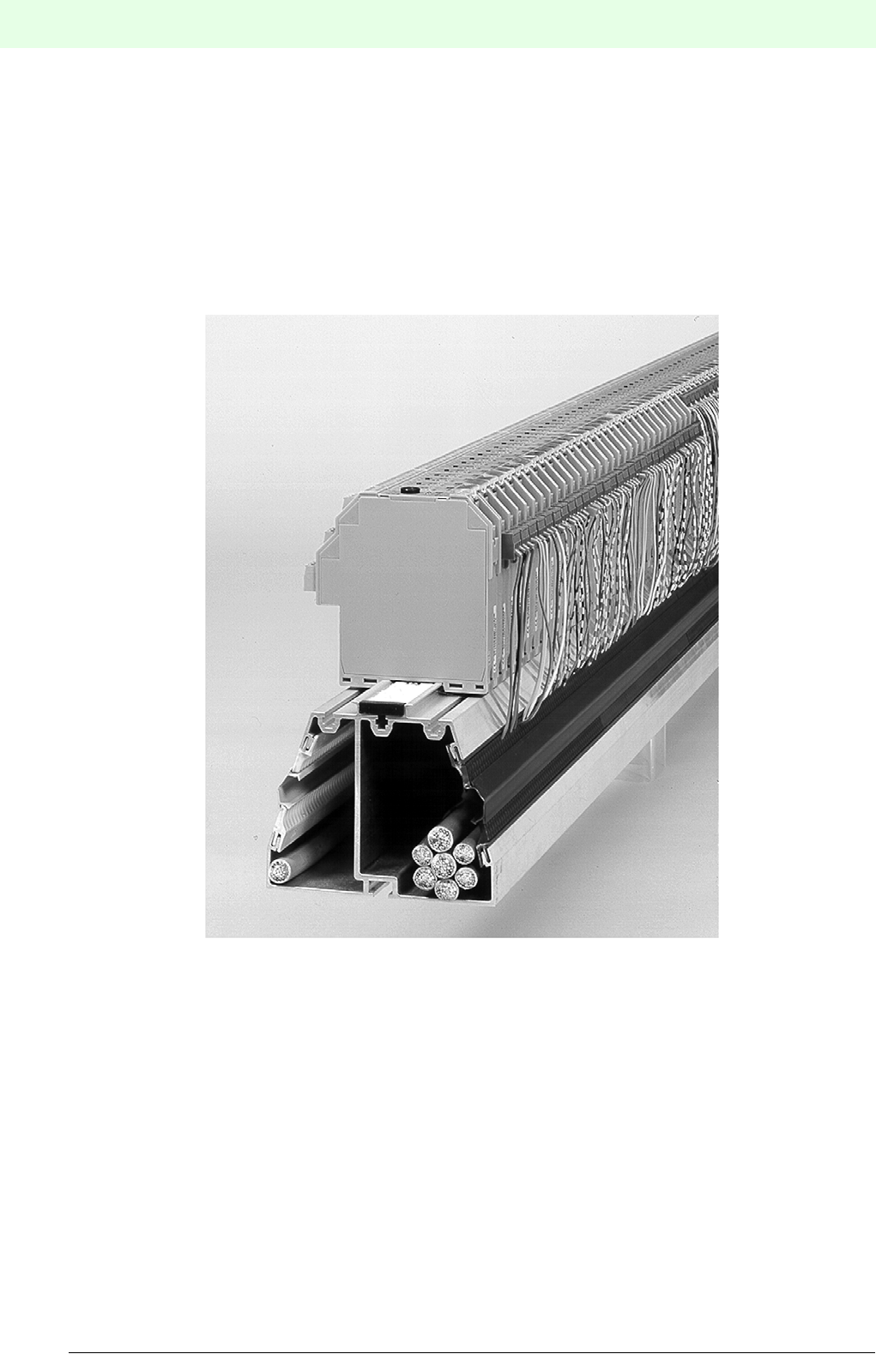
Remote Process Interface
Planning of the RPI System
54
S
ubject to reasonable modifications due to technical advances. Copyright Pepperl+Fuchs, Printed in Germany
Pepperl+Fuchs Group • Tel.: Germany +49 621 776-0 • USA +1 330 4253555 • Singapore +65 67799091 • Internet http://www.pepperl-fuchs.com
Date of issue 05/27/03
4.8.2 KF Profile with Integrated Cable Ducts
The KF Profile is an aluminium extruded section, which provides a space-saving installation of the RPI sy-
stem.
The profile contains three main components (see Figure Figure 4.10:):
• Large cable duct for routing the cables from the field side.
• Small cable duct for the cables of the power supply and of the external bus to the DCS or PLC.
• Integrated mounting rail for installing the RPI modules above the cable ducts. The PR-05 Power Rail is
inserted into this mounting rail.
Figure 4.10:KF Profile
The KF Profile is available including the PR-05 Power Rail. It will accept up to 90 RPI modules over a length
of 1.8 m, in a space-saving installation, with simple provision for wiring.
In addition, the KF Profile is available with a lateral shunting bridge.
The KF Profile has the following advantages:
• Very high packing density in the control cabinet installation, since the cable ducts are integrated in the
mounting profile.
• A saving in installation costs, since the cable ducts are integral and do not need to be mounted separa-
tely. In addition, Pepperl+Fuchs offers preconfigured cables (see "DIN Rail Housing" catalogue).
• Since on the Remote Process Interface the wiring to the control system is almost completely eliminated,
the separation between the non-Ex connections of two installation lines can be very small, thus further
increasing the compactness of the installation in the control cabinet.

55
Remote Process Interface
Planning of the RPI System
Subject to reasonable modifications due to technical advances. Copyright Pepperl+Fuchs, Printed in Germany
Pepperl+Fuchs Group • Tel.: Germany +49 621 776-0 • USA +1 330 4253555 • Singapore +65 67799091 • Internet http://www.pepperl-fuchs.com
Date of issue 05/27/03
4.8.3 Human Machine Interface PACTwareTM Edition 2
PACTwareΤΜ (Process Automation Configuration
Tool) configuration tool with FDT interface (Field De-
vice Tool) independent of the manufacturer and the
fieldbus.
• Based on FDT technology
• Device Type Managers (DTMs) available for all
Pepperl+Fuchs devices and systems
• Commissioning, configuration and parameter as-
signment independent of the process control sy-
stem
• Communication DTMs available for serial inter-
face and field bus systems
• Maintenance, diagnostics and
fault handling
• Suited for PCs running Windows 98, Windows NT,
Windows 2000 and Windows XP
• In accordance with VDI/VDE 2187
Hardware requirements PC with Pentium II 200_MHz processor; 64 MB RAM minimum
Operating system Windows 98, Windows NT 4.0 Service Pack 4 (or later), Windows 2000 and Win-
dows XP.
Languages German, English and French can be set
Licensing The packages point to point Interface Technology, point to bus Remote I/O, point to
bus HART and Level are available separately or together as download
(http://www.pepperl-fuchs.com/pa/accessories/pactware/main.html) in a BASIC ver-
sion without the functions Print and Save.
The BASIC version can also be obtained from Pepperl+Fuchs as CD-ROM.
A license number is required to enable the functions Print and Save . Licenses with
the functionality stated in the table (page 138) can be ordered from Pepperl+Fuchs.
Schematic representation of
the system configuration
Graphic representation of all communication and device DTMs in a tree structure.
Colour coding to identify affected units and the simulation mode during online ope-
ration. A number of windows can be open at the same time. It is therefore possible,
to view the set device parameters, monitor the measurement value, and display the
device diagnosis simultaneously.
System planning, project
processing
Generating a configuration by means of a graphical project processing menu.
Editing of available projects. Measuring point descriptions for each channel. Offline
configuration, storing project data on a hard-disk drive or a disk. Automatic compari-
son of the project planning to the available system during connection set-up on
device level and parameter level.
Figure 4.11:PACTwareΤΜ - the human machine in-
terface for be Remote Process Interface
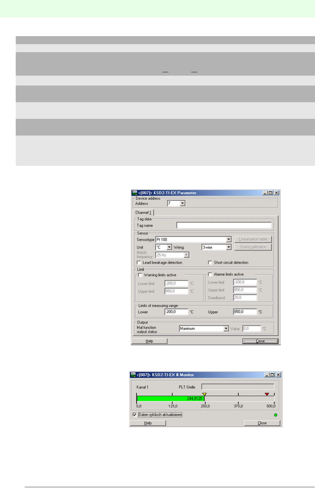
Remote Process Interface
Planning of the RPI System
56
S
ubject to reasonable modifications due to technical advances. Copyright Pepperl+Fuchs, Printed in Germany
Pepperl+Fuchs Group • Tel.: Germany +49 621 776-0 • USA +1 330 4253555 • Singapore +65 67799091 • Internet http://www.pepperl-fuchs.com
Date of issue 05/27/03
PACTware BASIC version
Type Functionality
PW2-BASIC all available DTMs for Pepperl+Fuchs K and E-Devices, HART multiplexers, Remote
I/O systems RPI and IS-RPI and Level Control devices.
Restricted functionality: no printing, no saving
Licenses
PW2-P.LEVEL Professional Level license for all available DTMs for Pepperl+Fuchs Level Control
devices
PW2-P.RIO100 Professional RIO100 license for the connection of 100 measuring circuits to Pep-
perl+Fuchs Remote I/O systems RPI and IS-RPI including HART multiplexers.
PW2-P.RIO500 Professional RIO500 license for the connection of 500 measuring circuits to Pep-
perl+Fuchs Remote I/O systems RPI and IS-RPI including HART multiplexer.
PW2-ENTERPRISE Enterprise license for all available DTMs for Pepperl+Fuchs K and E devices, HART
multiplexers, Remote I/O systems RPI and IS-RPI and Level Control devices.
Unlimited number of devices, measuring circuits and systems in a project can be ope-
rated.
Parameter assignment of
devices
Access to all device parameters via serial interface, via HART communication or by
means of acyclic field bus communication.
Measured value indication Online monitoring of random process variables
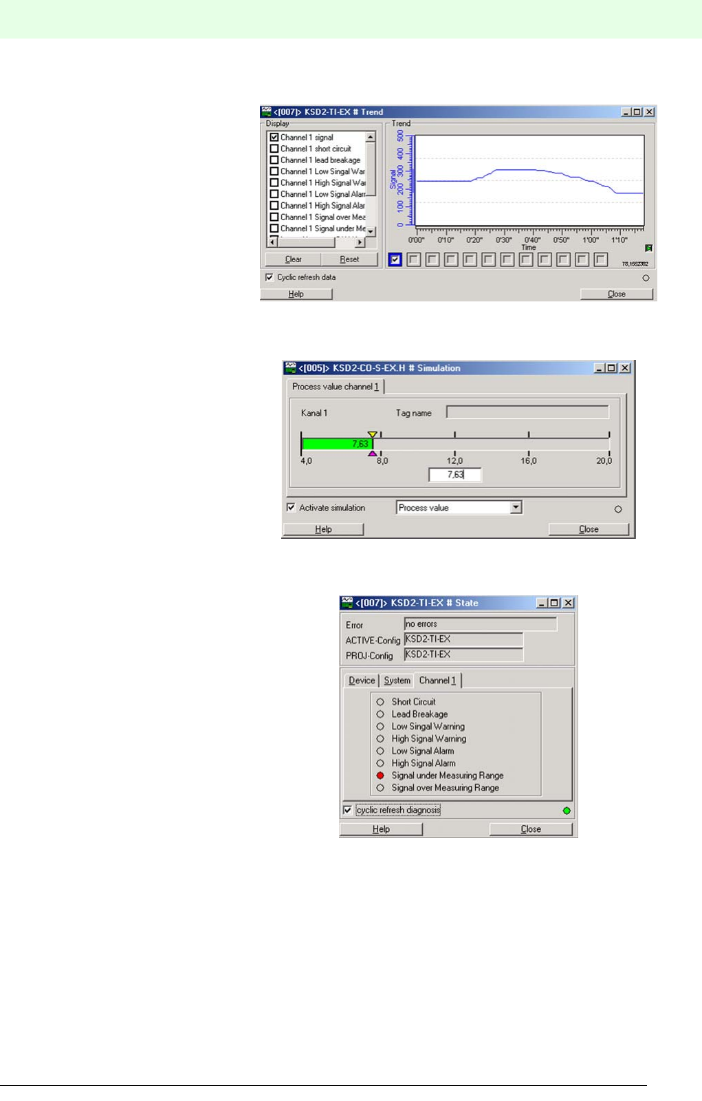
57
Remote Process Interface
Planning of the RPI System
Subject to reasonable modifications due to technical advances. Copyright Pepperl+Fuchs, Printed in Germany
Pepperl+Fuchs Group • Tel.: Germany +49 621 776-0 • USA +1 330 4253555 • Singapore +65 67799091 • Internet http://www.pepperl-fuchs.com
Date of issue 05/27/03
Trend display Trends of random process variables are displayed
Simulation Simulation of all measured variables and diagnostic data
Diagnosis All diagnostic information is accessible via PACTware™
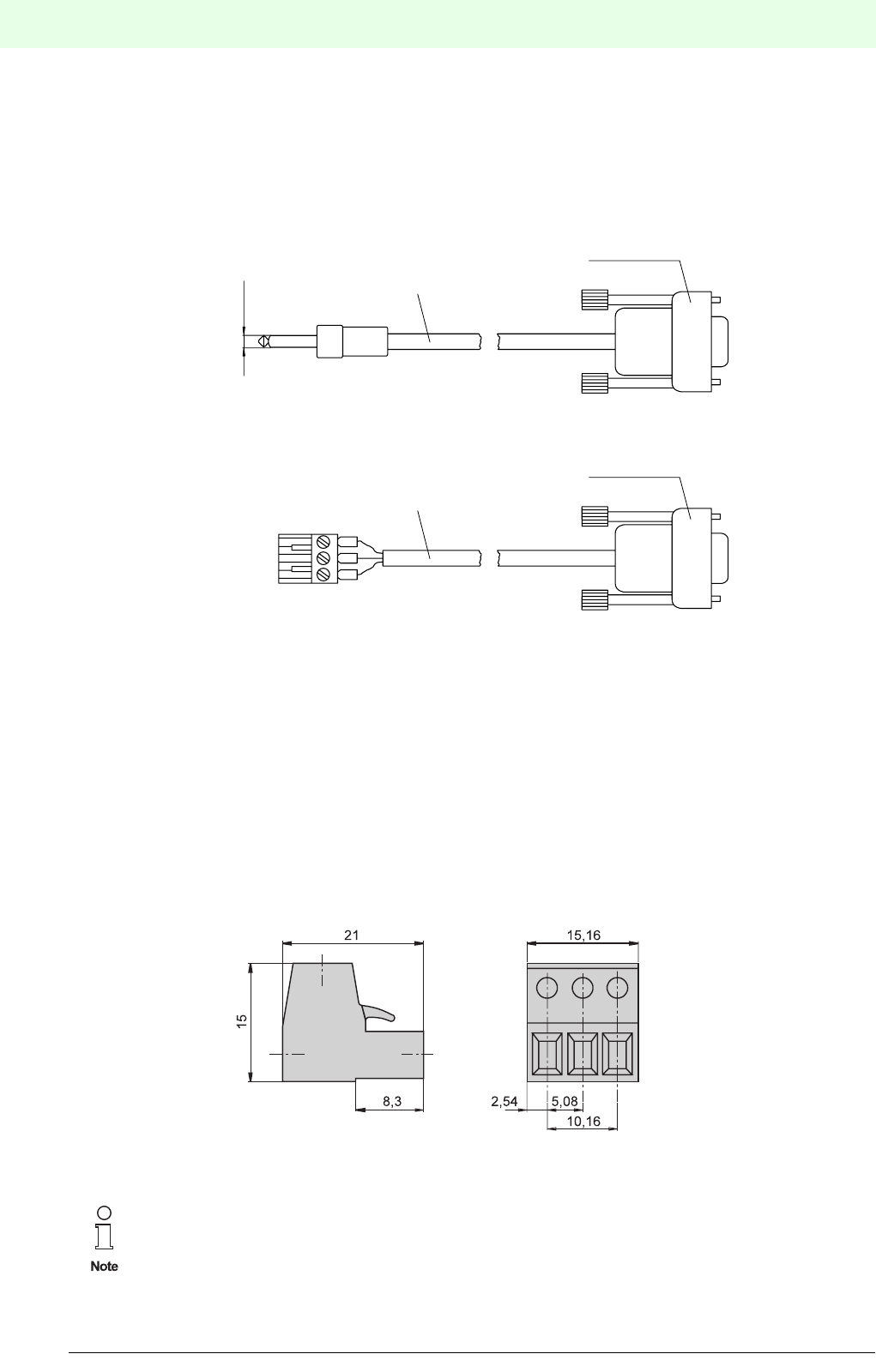
Remote Process Interface
Planning of the RPI System
58
S
ubject to reasonable modifications due to technical advances. Copyright Pepperl+Fuchs, Printed in Germany
Pepperl+Fuchs Group • Tel.: Germany +49 621 776-0 • USA +1 330 4253555 • Singapore +65 67799091 • Internet http://www.pepperl-fuchs.com
Date of issue 05/27/03
4.8.4 Interface adapter for RS 232 and RS 485
Connection of a PC or Notebook to the RPI service interface using the PACTwareΤΜ human machine inter-
face is achieved by means of the K-ADP2 or K-ADP4 interface adapters, available as optional accessories.
• K-ADP2 adapter: for gateways with an RS 232 service interface and a jack plug
• K-ADP4 adapter: for gateways with an RS 485 service interface and a terminal
Figure 4.12:K-ADP2 and K-ADP4 Interface adapters
4.8.5 Accessories for RPI Devices
Usually no special accessories are required for the RPI system devices. All devices are supplied with remo-
vable terminal blocks. However, the following components can be ordered separately:
Terminal block with test sockets for HART/SMART hand-held terminals
Removable terminal block with integrated test sockets for 2.3 mm standard test connectors of HART or
SMART hand-held terminals.
Order codes: KF-STP-BU (blue) Ex side
KF-STP-GN (green) non-Ex side
Figure 4.13:Terminal block KF-STP-BU / KF-STP-GN
The HART and SMART-compatible RPI devices KSD2-CI-S-Ex, KSD2-CI-S-Ex2.H,
KSD2-CO-S-Ex and KSD2-CO-S-Ex2.H are equipped as standard with
terminal block KF-STP-BU / KF-STP-GN .
Sub-D 9 pin
connector
Sub-D 9 pin
connector
Ø 3.55
2m
2m
K-ADP2
K-ADP4
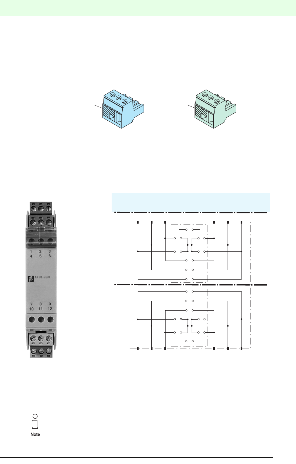
59
Remote Process Interface
Planning of the RPI System
Subject to reasonable modifications due to technical advances. Copyright Pepperl+Fuchs, Printed in Germany
Pepperl+Fuchs Group • Tel.: Germany +49 621 776-0 • USA +1 330 4253555 • Singapore +65 67799091 • Internet http://www.pepperl-fuchs.com
Date of issue 05/27/03
Terminal block with cold junction compensation
Removable terminal block with integrated temperature sensors for cold junction compensation for the con-
nection of thermocouples to the KSD2-TI-Ex universal temperature converter.
Order codes: K-CJC-BU: blueEx side
K-CJC-GN: greennon-Ex side
Figure 4.14:K-CJC Terminal block with cold junction compensation
Dummy housing
The KFDO-LGH dummy housing is a module used for laying cables.
An RPI system can be completely prewired without mounting the actual module. The clarity of the installa-
tion and compactness in the control cabinet are considerably enhanced by this device. Order code: KFD0-
LGH
Figure 4.15:KFD0-LGH Dummy module
Various wiring layouts are possible by using soldering jumpers and optional DIP switches. Intrinsically safe
circuits up to 40 V can be connected to terminals 1, 2 and 3 or 4, 5 and 6. Non-intrinsically safe circuits up
to 50 V can be connected to terminals 7, 8 and 9 or 10, 11 and 12.
Terminals 1 to 6 are to be considered connected.
Device connectors with sensors
Potted Pt100 RTD
in a 2-wire
configuation
Potted Pt100 RTD
in a 2-wire
configuation
for the connection of intrinsically safe circuits
for the connection of safe area circuits
123
S8
S7 S5
S6 S4
S3
S2
S1
S16
S15
S14
S11 S12
S10 S13
S9
789 121110
654
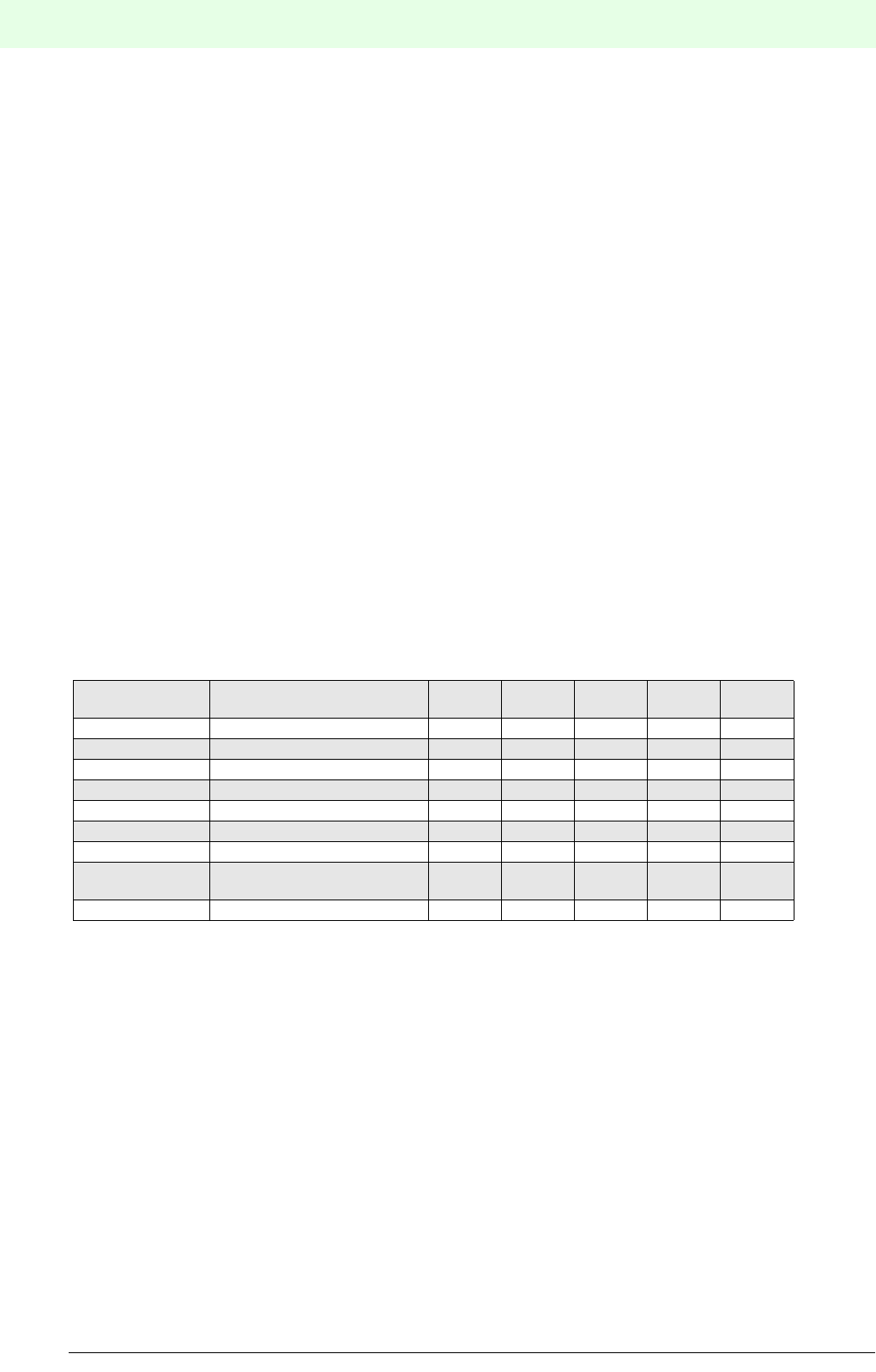
Remote Process Interface
Planning of the RPI System
60
S
ubject to reasonable modifications due to technical advances. Copyright Pepperl+Fuchs, Printed in Germany
Pepperl+Fuchs Group • Tel.: Germany +49 621 776-0 • USA +1 330 4253555 • Singapore +65 67799091 • Internet http://www.pepperl-fuchs.com
Date of issue 05/27/03
4.9 Determining the Types and Numbers of Power Rails to be Used
Having determined the types of Power Rails to be used
• PR-05, length of the rail 500 mm or
• UPR-05, length of the rail 2000 mm
the number of rails required can be calculated based on the number of RPI modules and power supply seg-
ments determined in the previous chapters.
It must be noted, that approx.1 mm or more separation is required between the Power Rails if two power
supply segments are to be built on a common mounting rail.
The following calculation determines the space required for the RPI system for both simple and redundant
design.
Exemplary calculation: The RPI-System contains the following modules
1 KSD2-GW-PRO (2 modules for gateway redundancy)
10 KSD2-TI-Ex
20 KSD2-CI-S-Ex
10 KSD2-BO-Ex2
45 KSD2-BI-Ex4
2 power feed modules for simple power supply
8 power feed modules for redundant power supply
Determining the number of Power Rails:
1. For a non-redundant system: overall length 1,780 mm
- Power Rail UPR-05 (length 2,000 mm): 1x
- KF Profile (length 1,800 mm): 1x
- Power Rail PR-05 (length 500 mm): 4x, 2 rails each, fitted with VE-PR connection element
- Assembly in typical control cabinet in 3 layers:
Power Rails as stated above, but with 3 power feed modules
2. For a redundant system: overall length 1,940 mm
- Power Rail UPR-05 (length 2,000 mm): 1x
- KF Profile (length 1,800 mm) 2x
- Power Rail PR-05 (length 500 mm): 4x
Type code Device designation Overall
length
Number
devices
Sum
simple
Number
devices
Sum
redundant
(mm) simple (mm) redundant (mm)
KSD2-GW-PRO PROFIBUS Gateway 40 140 280
KSD2-TI-Ex Temperature converter 20 10 200 10 200
KSD2-CI-S-Ex.H Transmitter power supply 20 20 400 20 400
KSD2-BO-Ex2.2 Solenoid driver 20 10 200 10 200
KSD2-BI-Ex4 Isolated switch amplifier 20 45 900 45 900
KFD2-EB.RPI 4 A Power feed module, simple 20 2 40 0 0
KFD2-EB.R2A.RPI 2 A Power feed module, redun-
dant
20 008160
Sum: 1,780 1,940
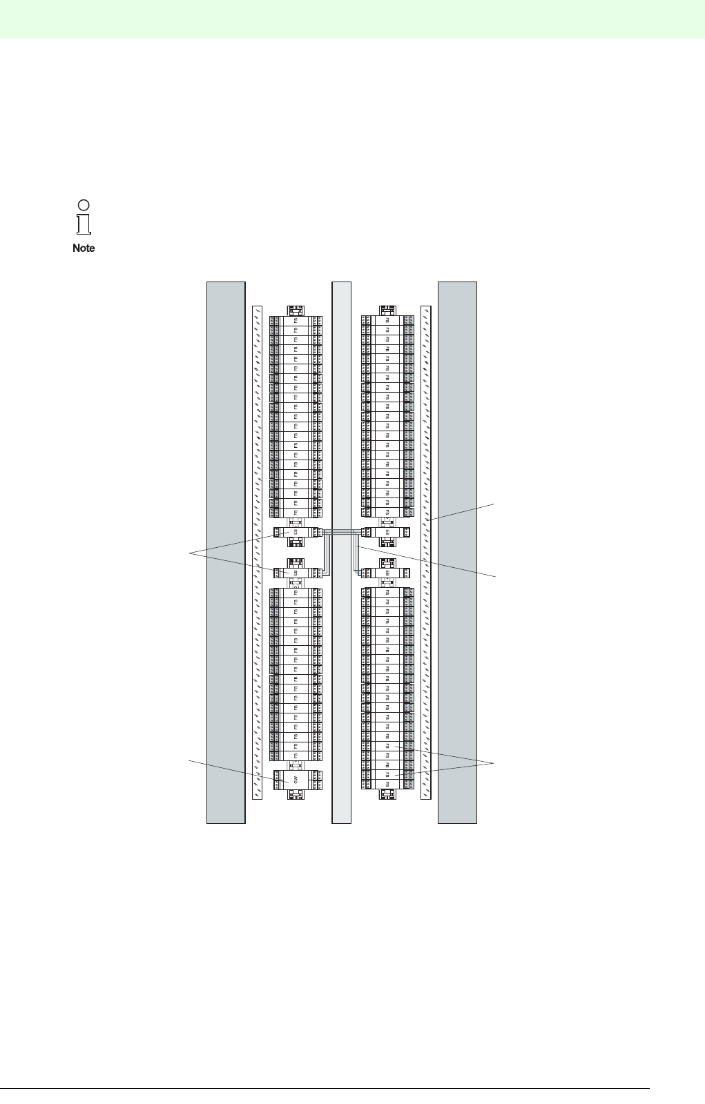
61
Remote Process Interface
Planning of the RPI System
Subject to reasonable modifications due to technical advances. Copyright Pepperl+Fuchs, Printed in Germany
Pepperl+Fuchs Group • Tel.: Germany +49 621 776-0 • USA +1 330 4253555 • Singapore +65 67799091 • Internet http://www.pepperl-fuchs.com
Date of issue 05/27/03
4.10 Arrangement of the Power Rail Segments in a Control Cabinet
The mounting rails with integrated Power Rails can be installed horizontally or vertically in the control cabi-
net. A power supply module is required for each rail segment. In the case of vertical mounting of the rails,
the length of the rail is in general greater than for a horizontal installation. So that usually, less power supply
modules are required.
Figure 4.16:Example of the arrangement of an RPI system
The internal bus connection shown in this figure is achieved by connecting terminals 12, 13 and 15 of the
power supply modules. Terminals 13 and 15 make a connection to the Power Rail internal transmission line.
Terminal 12 corresponds to the earth potential of the supply line. This is necessary, since then the internal
redundancy thereby ensures that the signal from the voltage difference of a transmission line (terminal 13
or 15) and the earth potential (terminal 12) can be won back.
When adopting a horizontal assembly, it can be useful when an assembly string is identical with a segment.
Every power supply module and hence every device on the related segment is protected by a fuse.
When the RPI is used, marshalling is not necessary, since this procedure is followed by addres-
sing the RPI internal bus.
Power feed module
Cable channel 80 x 80, blue
Cable channel 40 x 60, grey
Cable channel 80 x 80, blue
Labeling
Internal bus connection
Function module
Gateway

Remote Process Interface
Planning of the RPI System
62
S
ubject to reasonable modifications due to technical advances. Copyright Pepperl+Fuchs, Printed in Germany
Pepperl+Fuchs Group • Tel.: Germany +49 621 776-0 • USA +1 330 4253555 • Singapore +65 67799091 • Internet http://www.pepperl-fuchs.com
Date of issue 05/27/03
4.11 Installation
4.11.1 General Information on Device Connection
The connection of a module on the Ex side is made on the removable blue terminal block via self-opening
screw terminals - max. core cross section 1 x 2.5 mm² for rigid cable or 2 x 1.5 mm² for flexible cable with
plastic wire end ferrule.
The connection of a module on the non-Ex side is made on the removable green terminal block via self-
opening screw terminals - max. core cross-section 1 x 2.5 mm² for rigid cable or 2 x 1.5 mm² for flexible
cable with plastic wire end ferrule.
It should be noted that appropriate plug connectors are available on the market, which can be used to re-
place the screw terminals. These plug connectors are fitted by crimping onto the wiring.
4.11.2 EMC, Screening and Earthing
The screening of cables provides protection against electromagnetic interference. The screening of the bus
line must be undertaken with due regard for the recommendations of the organizations for PROFIBUS,
MODBUS and ControlNet.
When screening the signal cables between the RPI modules and the field devices, the screen of the cable
must be located at the earthing connections of the field devices.
If bus cables with a double screen are used, e.g. wire braiding and metallic foil, both screens
must be connected together at the cable ends with a low-resistance connection when preparing
the cable.
Power supply cables are a source of much interference radiation, e.g. the starting current of a
three-phase motor. For this reason, parallel cable routing of supply cables and data/signal ca-
bles should be avoided, especially within the same ducting.
Connection of the intrinsically safe and non-intrinsically safe circuits is undertaken with due
consideration of all locally applicable regulations, directives and standards governing the hazar-
dous area.
The installation and operation of devices with intrinsically safe circuits
must be undertaken with due regard for the certificates of conformity and the applicable regula-
tions relating to construction and installation (DIN EN 50020, DIN VDE 0165).
On connecting the supply voltage to the power supply module, all RPI devices mounted on the
Power Rail are immediately supplied with power.
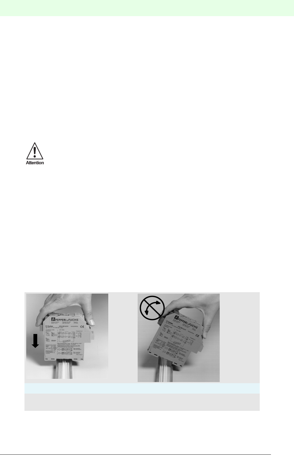
63
Remote Process Interface
Planning of the RPI System
Subject to reasonable modifications due to technical advances. Copyright Pepperl+Fuchs, Printed in Germany
Pepperl+Fuchs Group • Tel.: Germany +49 621 776-0 • USA +1 330 4253555 • Singapore +65 67799091 • Internet http://www.pepperl-fuchs.com
Date of issue 05/27/03
4.11.3 Preparing the Wiring
Please refer toChapter 4.11.1 "General Information on Device Connection"
Ex side:
On the Ex side the cables are laid from the field devices to the corresponding blue terminals of the RPI de-
vice. Marshalling of the field cables is not necessary; it is carried out by means of RPI internal addressing.
Non-Ex side:
• On the non-Ex side it is merely necessary to provide the bus cable between the gateways and the control
system.If there are a number of RPI systems, the bus line runs from gateway to gateway, i.e. only one
separate cable has to be laid to the control system. Only in the case of a redundant design with two ga-
teways per RPI system are two mutually isolated bus systems required to the control system.
• Providing the voltage supply cables for the power feed modules or power supply units.
• Possibly, another cable string for the service level must be laid. This is the fixied wiring between the ser-
vice interface of the gateways and the Engineering PC. It can be used for HART communication, for a
separate diagnosis of the RPI system, or for a software engineering tool.
• The HART protocol transmission via the HART multiplexer possibly requires an additional cable.
Due to the fact that only a few cables are needed in the non-Ex area, the space required in the control ca-
binet will be considerably reduced.
4.11.4 Installing the Devices
Snap the power supply modules, gateways and RPI devices onto the mounting rail/Power Rail assembly.
Arrange the devices to suit the field cables. The order of assembly on the Power Rail is not a significant
factor from the standpoint of the internal bus system.
When snapping the devices on the rail, they should not be tipped at an angle, but pressed on to the moun-
ting rail in a vertical attitude.
If the UPR-05 is being used, it must be remembered that the cover must be fitted to provide protection
against accidental contact.
Figure 4.17:Installing the RPI devices
When using 90 .... 240 V power supply units, the power cables and the signal or bus lines should
not be laid in the same cable duct.
Correct: Incorrect:
Device installed vertically from
above
Device inserted at an inclined
attitude
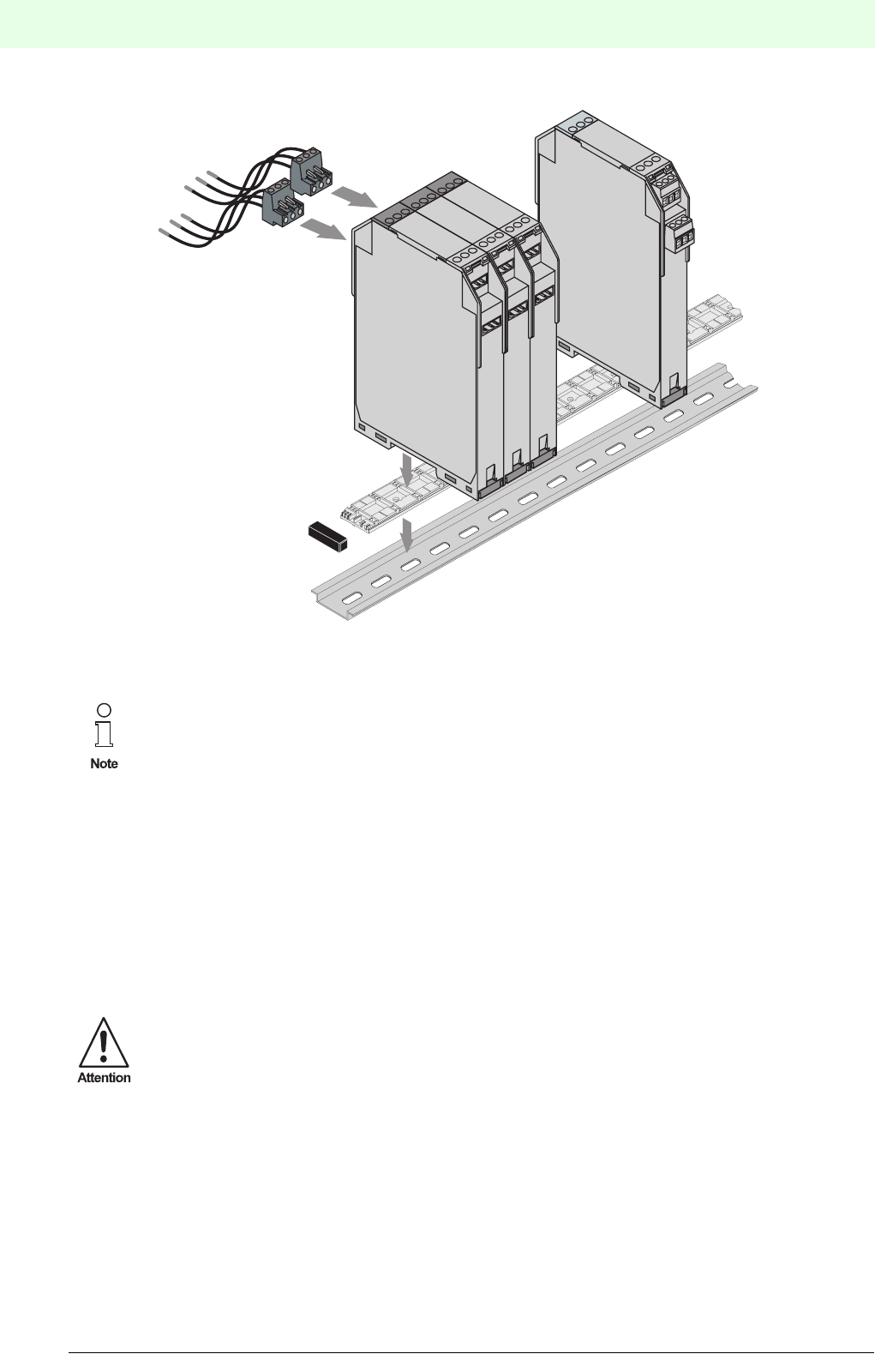
Remote Process Interface
Planning of the RPI System
64
S
ubject to reasonable modifications due to technical advances. Copyright Pepperl+Fuchs, Printed in Germany
Pepperl+Fuchs Group • Tel.: Germany +49 621 776-0 • USA +1 330 4253555 • Singapore +65 67799091 • Internet http://www.pepperl-fuchs.com
Date of issue 05/27/03
Figure 4.18:Installation of the RPI modules
.
4.11.5 Connection to the Control System
The connection of signal lines from the field devices is completely eliminated, since the RPI system converts
the field signals into standard bus signals. Only the bus line from the RPI Gateway has to be connected. No
input/output units are required on the control system or PLC.An appropriate bus-master assembly must be
provided in their place. The manufacturer will provide information on which bus system is appropriate and
available for a given control system.
4.11.6 Connecting the Power Cables and Signal Cables
The electrical connection of the cables of RPI system devices is made by means of self-opening screw ter-
minals in the removable terminal blocks, max. core cross section 1 x 2.5 mm2.
When installing the modules, please consider the specifications stated in the previous chapters,
regarding the power supply segments and the internal RPI bus stations.
Operation of the equipment under power and the connection to the power supply must only be
carried out by appropriately trained personnel.
Prior to connecting the RPI system, ascertain that the power supply voltage is 24 V DC in accor-
dance with the RPI module data sheet.
When installing and operating devices with intrinsically safe circuits, the certificates of confor-
mity and the relevant assembly and installation instructions (DIN EN 50020, DIN VDE 0165)
should be observed.

65
Remote Process Interface
Planning of the RPI System
Subject to reasonable modifications due to technical advances. Copyright Pepperl+Fuchs, Printed in Germany
Pepperl+Fuchs Group • Tel.: Germany +49 621 776-0 • USA +1 330 4253555 • Singapore +65 67799091 • Internet http://www.pepperl-fuchs.com
Date of issue 05/27/03
Connect the wiring as described in the connection diagram and the terminal allocation list for the individual
devices:
• The supply voltage is only connected to the power feed modules.
• The external bus system is connected to the gateway.
• An available service level is connected to the service interface of the gateway.
• In the case of HART communication, when using a HART multiplexer, the latter must be connected ac-
cordingly.
• Connection to the RPI internal bus and to the supply voltage is achieved automatically when the devices
are snapped onto the mounting rail/Power Rail assembly.
• The intrinsically safe signal circuits are connected to the blue terminals of the RPI devices in accordance
with the applicable regulations and directives.
The connection diagrams and terminal allocation lists for the devices are given in the data
sheets.
Special instructions for the connection of the external bus system, as for example, recommen-
ded bus cables, permissible cable lengths, fieldbus terminators, etc., are given in Chapter 7
"Integration into the Higher-Level Bus System".

Remote Process Interface
Configuring and Commissioning the RPI System
66
S
ubject to reasonable modifications due to technical advances. Copyright Pepperl+Fuchs, Printed in Germany
Pepperl+Fuchs Group • Tel.: Germany +49 621 776-0 • USA +1 330 4253555 • Singapore +65 67799091 • Internet http://www.pepperl-fuchs.com
Date of issue 05/27/03
5 Configuring and Commissioning the RPI System
5.1 Offline Commissioning
Offline commissioning enables you to document and largely prepare the RPI system for actual commission-
ing on your PC during the planning phase.
The RPI system can be configured and the topology can be designed accordingly using the PACTware hu-
man machine interface. Configuration and parameter assignment can be largely carried out without the RPI
system. This kind of commissioning assists you in planning the system and provides support for the docu-
mentation.
Having installed the RPI system, it is configured using the push-buttons and the LC-display of the gateway.
The project data generated offline is transferred to the gateway in the next step.
These are the steps to be followed during commissioning:
1. The RPI system should be installed according to the planning using the PACTware edition 2 human ma-
chine interface on the PC. The structure of the RPI system with the gateways, the individual I/O mo-
dules and the service interfaces has to be rebuilt accordingly and configured. Parameters for the
individual RPI modules are entered in register cards as shown in Chapter 6 "Parameter Assign-
ment".
2. If your RPI system is designed with gateway redundancy, the redundant gateway is inserted in the
structure of the RPI system, just below the active gateway. When parameterizing the gateways, please
make sure, that the active gateway for the RPI internal bus has address 1 and that the redundant ga-
teway has address 2. Similarly, the gateways receive different addresses for communication on the
higher-level fieldbus later on.
3. Installation and connection of the RPI system, as described in Chapter 4.11 "Installation" .
4. Switching on the power supply for the RPI system, as described in Chapter 5.2 "Power Supply".
5. The RPI modules are configured via the gateway, see Chapter 5.4 "Configuration".
Parameter Assignment
6. For the parameter assignment the PC is connected to the gateway on the service interface RS232 by
means of the K-ADP2 adapter or RS485 by means of the K-ADP4 adapter. After that, the project which
was generated offline is downloaded to the gateway (see Chapter 6.4 "Downloading Project Data
into the Gateway").
When installing a service level with fixed wiring, adapters are not necessary since the networked ga-
teways can be controlled directly from the PC via RS485.
Having transferred the configuration and parameter assignment data, the LEDs and the gateway display
indicate possible faults. A verification of the RPI system can be carried out using the diagnostic and simu-
lation functions provided by the PACTware man machine interface. The individual fault signals of the RPI mo-
dules and the fault signals of the gateway are described in Chapter 5, Chapter 6 and Appendix A.
Commissioning of the gateway on the higher-level fieldbus is described in Chapter 7.
During the configuration and parameter assignment of the RPI system, the red LEDs light up to
indicate possible faults. While proceeding with commissioning, the LEDs extinguish and at the
end of the commissioning procedure the only LED still illuminated is the ’bus external’ LED,
since an integration into the higher-level bus system has not yet been carried out.
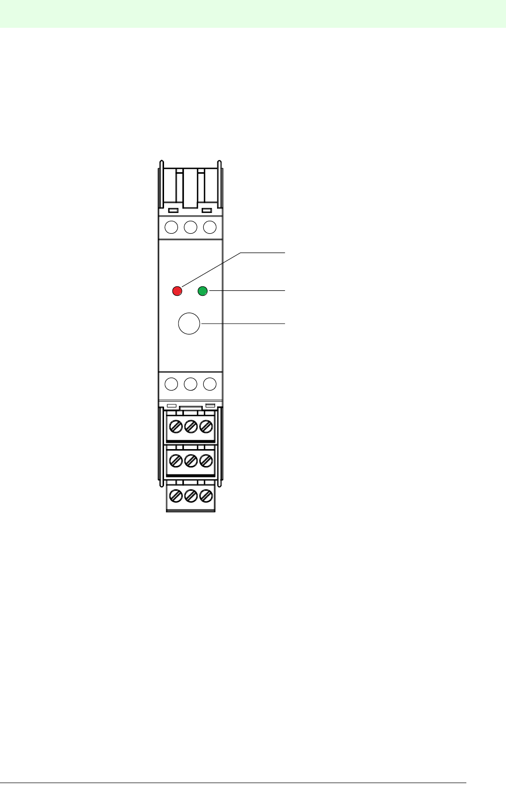
67
Remote Process Interface
Configuring and Commissioning the RPI System
Subject to reasonable modifications due to technical advances. Copyright Pepperl+Fuchs, Printed in Germany
Pepperl+Fuchs Group • Tel.: Germany +49 621 776-0 • USA +1 330 4253555 • Singapore +65 67799091 • Internet http://www.pepperl-fuchs.com
Date of issue 05/27/03
5.2 Power Supply
The power feed modules are connected to a 24 V DC power supply. This voltage supply is fed to the Power
Rail and hence to all the devices mounted on this rail. Fuses in the power feed modules provide the group
fusing.
5.2.1 Construction of the Power Feed Module
Figure 5.1:Front view of power feed module
The presence of rated operating voltage is indicated by a green ‘PWR’ LED on the front panel of the device.
The status of the fusing is signalled via a red ’fault’ LED.
5.2.2 Setting the Mode of Operation of the Relay
The response of the fuse is indicated via the energized relay in the setting on delivery. In order to adjust the
mode of operation of the relay, first remove the narrow front panel using a suitable screwdriver:Insert the
screwdriver into one of the two cutouts and remove the front plate by careful leverage. The cover of the left
section can then be gently lifted away from the catches.
1
4
2
5
3
6
7
10
13
8
11
14
9
12
15
4 AT
LED red
Fault signal
LED green
Power
Fine-wire fuse,
Type T
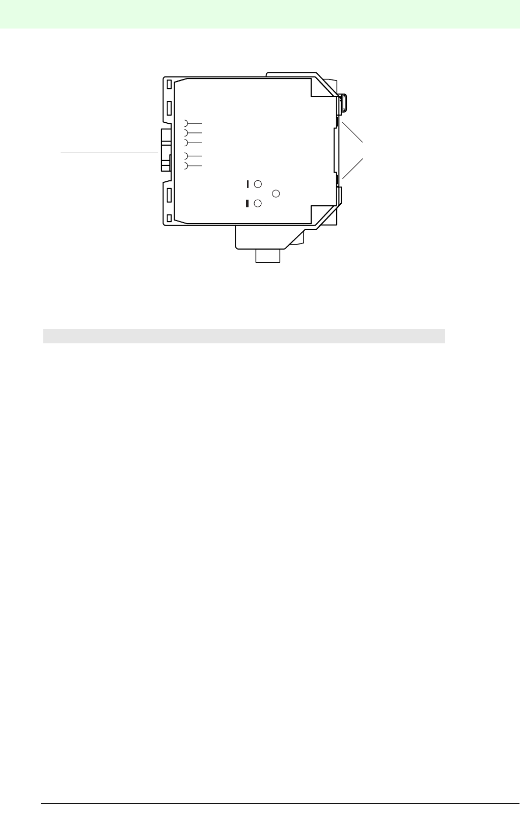
Remote Process Interface
Configuring and Commissioning the RPI System
68
S
ubject to reasonable modifications due to technical advances. Copyright Pepperl+Fuchs, Printed in Germany
Pepperl+Fuchs Group • Tel.: Germany +49 621 776-0 • USA +1 330 4253555 • Singapore +65 67799091 • Internet http://www.pepperl-fuchs.com
Date of issue 05/27/03
.
Figure 5.2:Setting the mode of operation of the relay
The mode of operation is set to ‘normally open' in the setting on delivery.
Jumper between Mode of operation of the relay
1 and I Normally open
1 and II Normally closed
Bridge
1
2 recesses
Power Rail
supply module
and bus
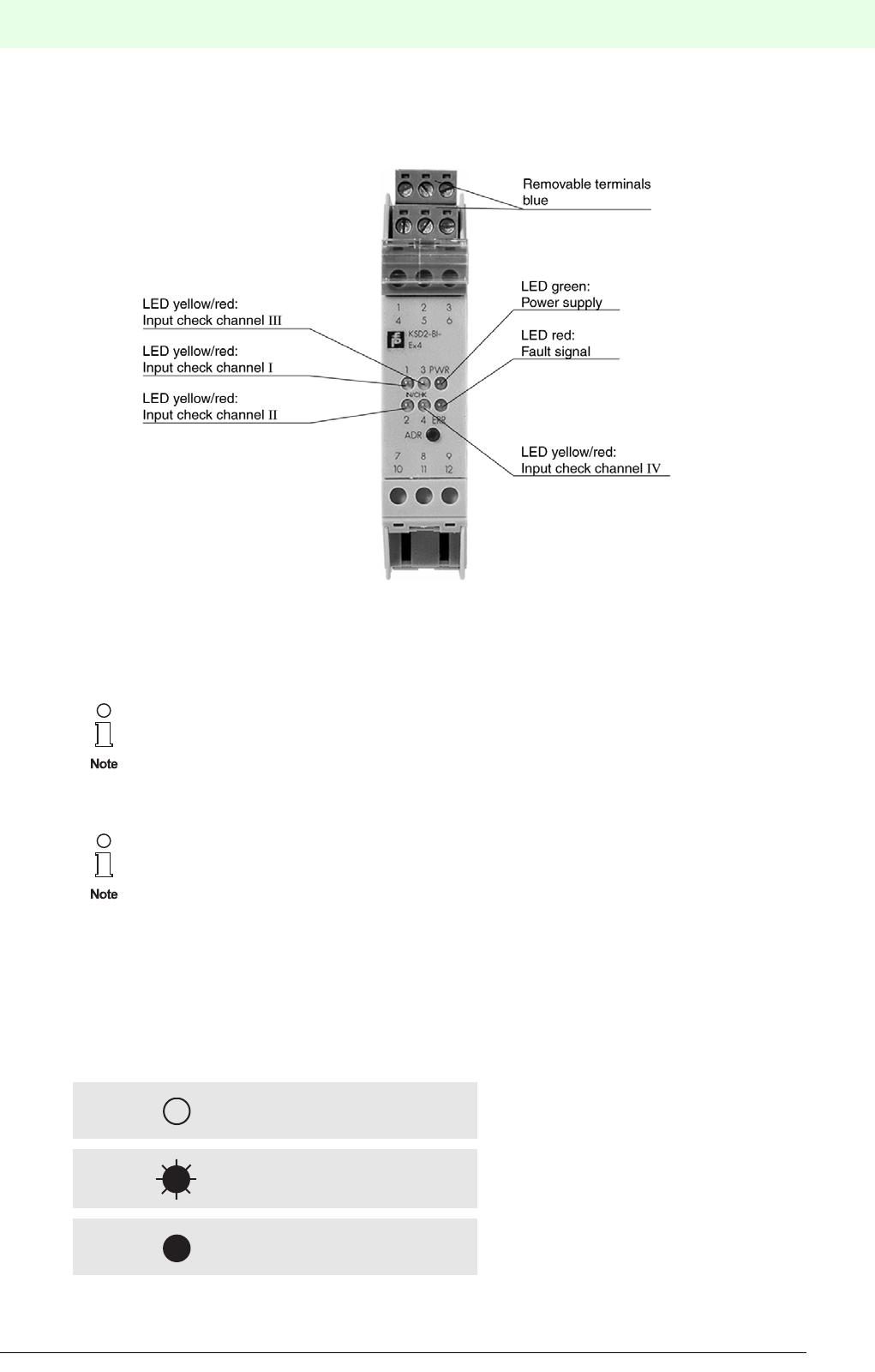
69
Remote Process Interface
Configuring and Commissioning the RPI System
Subject to reasonable modifications due to technical advances. Copyright Pepperl+Fuchs, Printed in Germany
Pepperl+Fuchs Group • Tel.: Germany +49 621 776-0 • USA +1 330 4253555 • Singapore +65 67799091 • Internet http://www.pepperl-fuchs.com
Date of issue 05/27/03
5.3 RPI Devices
5.3.1 Construction of the RPI Devices
Figure 5.3:Front view of RPI device
5.3.2 LEDs on the Front Panel of a Device
There are between three and six LEDs on the front panel of a device, which indicate the current status of
the device as well as hardware and communication errors.
The following symbols are used in the descriptions below::
The RPI system devices have 1, 2 or 4 input and output channels, depending on the model. The
construction, the operation of the devices by means of the ADR button (address), and the LEDs
are identical for all models.
An IN/CHK and OUT/CHK LED is available for each individual channel.
The flashing red LED’s on the RPI system should not be allowed to cause confusion. They do
not extinguish until commissioning is finished.
LED off
Flashing LED
LED constantly illuminated
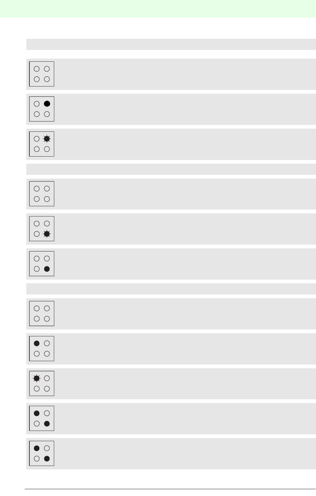
Remote Process Interface
Configuring and Commissioning the RPI System
70
S
ubject to reasonable modifications due to technical advances. Copyright Pepperl+Fuchs, Printed in Germany
Pepperl+Fuchs Group • Tel.: Germany +49 621 776-0 • USA +1 330 4253555 • Singapore +65 67799091 • Internet http://www.pepperl-fuchs.com
Date of issue 05/27/03
LED PWR (green)
No voltage supply
Voltage supply present
Setting and checking the device address
LED ERR (red)
No error
Bus error
Hardware error (specification via LED IN/CHK or OUT/CHK
LED (s) IN/CHK or OUT/CHK (1 ... 4)
Input/Output channel 1 not active
Yellow LED: Input/Output channel 1 active
Red LED: Lead breakage or short circuit in the field circuit, channel 1
Red LED 1 and ERR-LED: EEPROM error
Yellow LED 1 and ERR-LED: Communication error
PWR
ERR
PWR
ERR
ERR
ERR
1
1
1
ERR
1
ERR
1

71
Remote Process Interface
Configuring and Commissioning the RPI System
Subject to reasonable modifications due to technical advances. Copyright Pepperl+Fuchs, Printed in Germany
Pepperl+Fuchs Group • Tel.: Germany +49 621 776-0 • USA +1 330 4253555 • Singapore +65 67799091 • Internet http://www.pepperl-fuchs.com
Date of issue 05/27/03
5.4 Configuration
In Chapter 4 "Planning of the RPI System" of this handbook the layout of the RPI system was planned. The
RPI devices and gateways, the voltage supply as well as the addresses for the individual devices were de-
termined.
The basic configuration of the system is described in this chapter. The following table provides an overview
of the configuration steps and the respective menu items for configuration directly on the gateway.
Tabelle 5.4: Configuration procedure
(*) Teach-in of an existing configuration
If the RPI devices already have addresses on the internal bus, the structure can be uploaded to the gateway
by means of the 'Teach-in’ function. Existing parameters are likewise uploaded from the RPI devices. This
function helps you to commission RPI quickly or to teach-in hardware changes. However, you must ascer-
tain, that you keep track of these changes in your software human machine interface!
Alternatively, the values for the configuration of the RPI system can be set by means of a software human
machine interface or via PROFIBUS DP.
A detailed description of the configuration via the gateway can be obtained from
Chapter 5.4.2 "Operating the Gateways Type KSD2-GW-..."
or
Chapter 5.4.3 "Operating the Gateways of Type KSD2-GW2-..."
.
Configuration step Menu item for gateways
KSD2-GW-...
Menu item for gateways
SD2-GW2-...
Addressing the gateway on the internal bus
(address 1 = prior, 2 = redundant)
b RedMode
Set RPI internal address for the devices (addresses 3...127) b AdrAssign
Addressing the gateway on the external bus d
Addressing the service interface EParAdr
Setting the baud rate for the service interface G ParBaud
Only MODBUS: Setting the baud rate for the external bus Hn.a.
Only MODBUS: Setting the parameter values for the external bus I n.a.
Optional: Uploading the current RPI device configuration to the
gateway (*)
A, then press ’Mode’
button > 3 sec.
Teach-In
Note: Normal operation mode of the gateway A Run
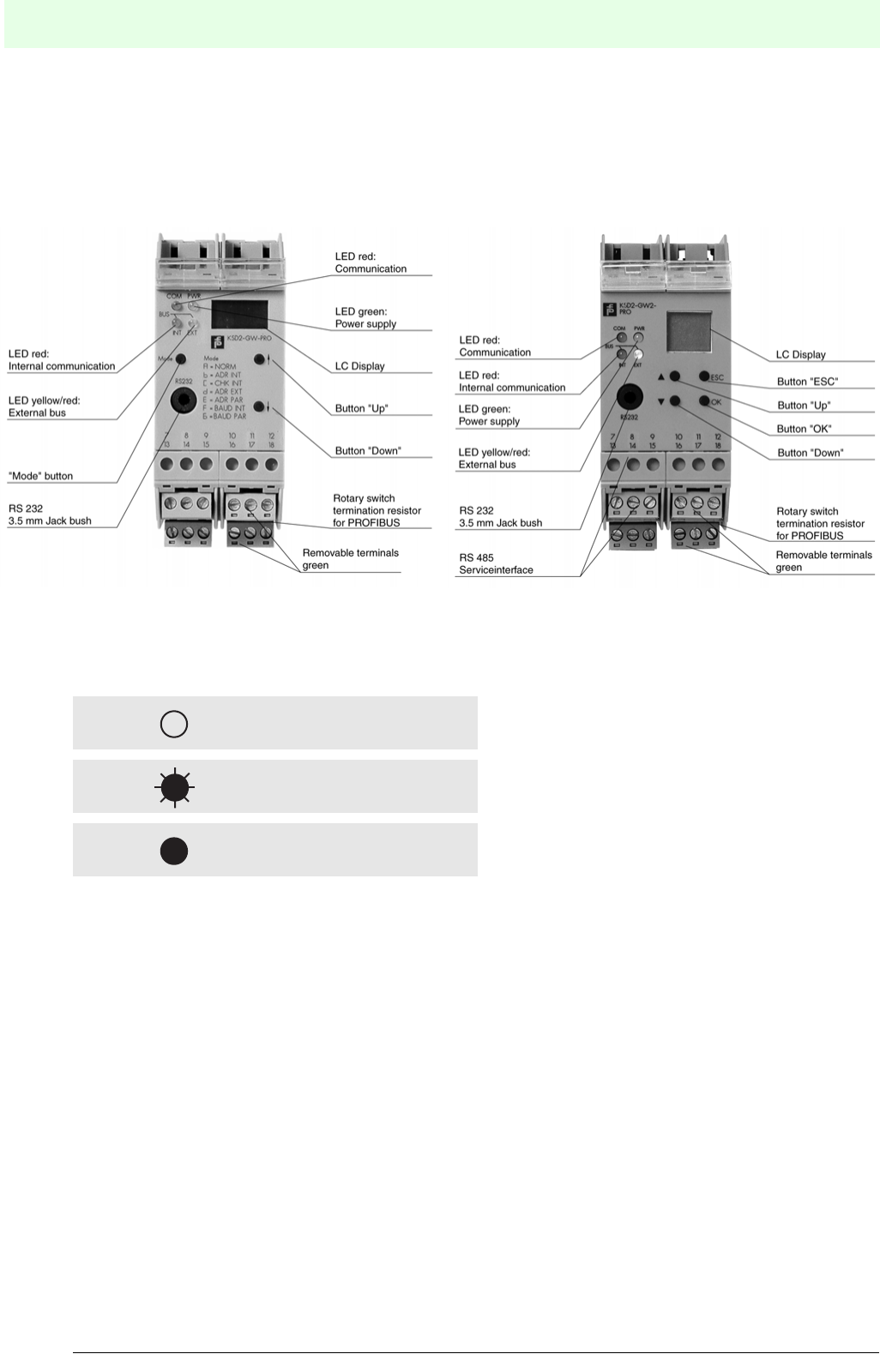
Remote Process Interface
Configuring and Commissioning the RPI System
72
S
ubject to reasonable modifications due to technical advances. Copyright Pepperl+Fuchs, Printed in Germany
Pepperl+Fuchs Group • Tel.: Germany +49 621 776-0 • USA +1 330 4253555 • Singapore +65 67799091 • Internet http://www.pepperl-fuchs.com
Date of issue 05/27/03
5.4.1 Construction of the Gateways and LEDs on the Front Panel
The four LEDs on the front panel indicate the current status of the device as well as hardware and commu-
nication errors. The four LEDs are identical for the gateways KSD2-GW-... and KSD2-GW2-... .
Figure 5.5:Front view of KSD2-GW-... and KSD2-GW2-... gateway
The following symbols are used in the descriptions below:
LED off
Flashing LED
LED constantly illuminated
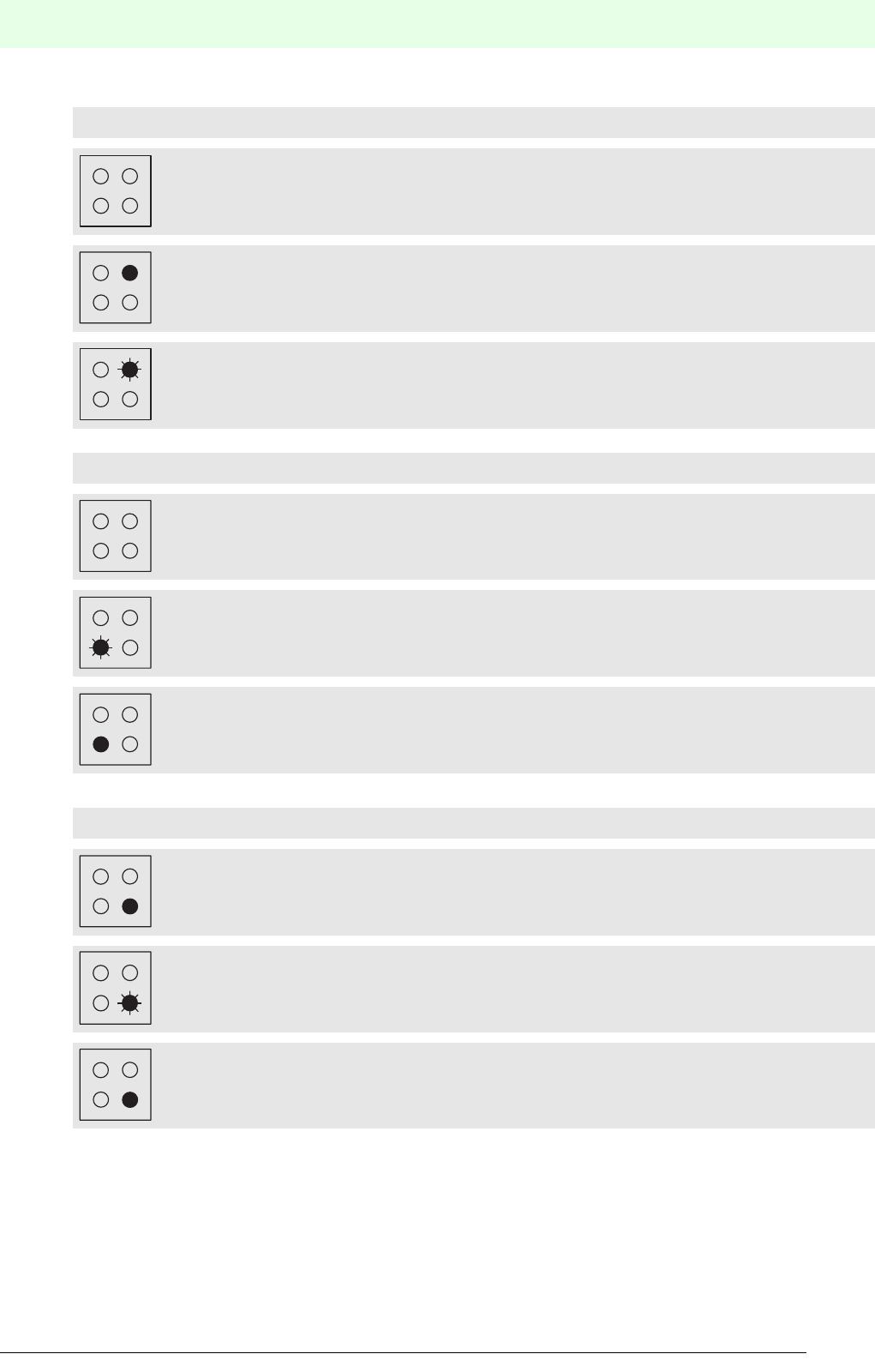
73
Remote Process Interface
Configuring and Commissioning the RPI System
Subject to reasonable modifications due to technical advances. Copyright Pepperl+Fuchs, Printed in Germany
Pepperl+Fuchs Group • Tel.: Germany +49 621 776-0 • USA +1 330 4253555 • Singapore +65 67799091 • Internet http://www.pepperl-fuchs.com
Date of issue 05/27/03
LED PWR (green)
No voltage supply
Voltage supply present
Display of the gateway address for the RPI internal bus
LED INT (red)
Internal bus in normal operation
Internal bus or device error
Internal interface error
LED EXT (yellow / red)
Yellow LED: External bus in normal operation
Red LED : No communication on external bus
Red LED : Internal interface error
PWR
PWR
PWR
INT
INT
INT
EXT
EXT
EXT

Remote Process Interface
Configuring and Commissioning the RPI System
74
S
ubject to reasonable modifications due to technical advances. Copyright Pepperl+Fuchs, Printed in Germany
Pepperl+Fuchs Group • Tel.: Germany +49 621 776-0 • USA +1 330 4253555 • Singapore +65 67799091 • Internet http://www.pepperl-fuchs.com
Date of issue 05/27/03
LED COM (red)
Normal condition: Internal CAN bus in differential mode
Internal CAN bus in common mode, redundancy failure
RAM/ROM/EEPROM error, or other internal error
RAM/ROM error, or other error (red EXT LED lights)
COM
COM
INT
COM
EXT
COM
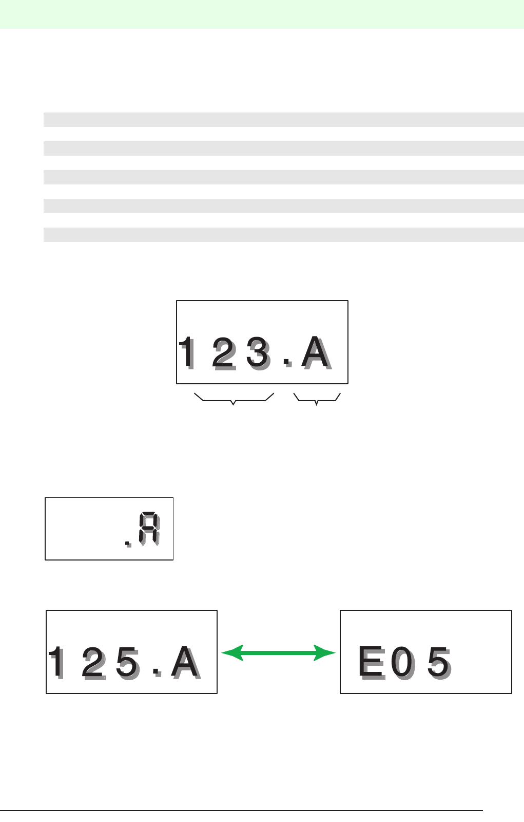
75
Remote Process Interface
Configuring and Commissioning the RPI System
Subject to reasonable modifications due to technical advances. Copyright Pepperl+Fuchs, Printed in Germany
Pepperl+Fuchs Group • Tel.: Germany +49 621 776-0 • USA +1 330 4253555 • Singapore +65 67799091 • Internet http://www.pepperl-fuchs.com
Date of issue 05/27/03
5.4.2 Operating the Gateways Type KSD2-GW-...
The operating modes and parameters can be set by means of the three pushbutton switches “Mode”, “Up
Ñ” and “Down Ò” and the 3 1/2 digit LC display. The last position on the display is a letter, that indicates the
current operating mode. The operating modes can be identified from the table provided on the front panel.
The first three digits displayed show the status, addresses or parameters,
depending on the set operating mode.
Normal operation
During normal operation the menu identifier “A” appears in the gateway LC display:
If a device error message is communicated via the internal bus, the display shows the address of the faulty
device and the error code, alternately:The table of error codes is given in Chapter 5.4.2.10 :
A = NORM Normal operation
b = ADR INT Assignment of device addresses, internal bus
C = CHK INT Checking device addresses, internal bus
d = ADR EXT Setting the gateway address, external bus
E = ADR PAR Set the gateway address, service interface
F = BAUD INT Set baud rate, internal bus
G = BAUD PAR Set baud rate, service interface
H = BAUD EXT Set baud rate, external bus (only MODBUS gateway)
I = PARAM EXT Set parameter values, external bus (only MODBUS gateway)
Addresses,
Parameter,
Status
Operating mode
Alternately

Remote Process Interface
Configuring and Commissioning the RPI System
76
S
ubject to reasonable modifications due to technical advances. Copyright Pepperl+Fuchs, Printed in Germany
Pepperl+Fuchs Group • Tel.: Germany +49 621 776-0 • USA +1 330 4253555 • Singapore +65 67799091 • Internet http://www.pepperl-fuchs.com
Date of issue 05/27/03
5.4.2.1 Allocation of the Device Addresses on the Internal Bus
In Section 4, addresses were allocated to the RPI devices while planning the system. (see Chapter 4.1.8
"Layout and Addressing of the RPI Devices"). Now these addresses must be set in the RPI devices.
The device addresses are organised as follows:
• On selecting the operating mode b = ADR INT (set internal address) using the "Mode" button on the ga-
teway, the lowest possible free device address is shown on the display.
• Select the desired device address using the "Up" and "Down" buttons. Occupied and prohibited addres-
ses are not displayed.
• If the ADR pushbutton on the front panel of the device that is to be addressed is depressed for longer
than 3 s,
• the displayed address is allocated to this device. This is indicated by the green LED PWR on the device
and the gateway flashing for a brief period.
5.4.2.2 Checking the Device Addresses on the Internal Bus
On selecting the operating mode C = CHK INT there are two principal ways of checking the address of a
device:
1. By ascertaining the device that has the address that is indicated on the gateway display.
The address on the gateway display can be set using the Ð andÏ buttons. Only addresses which are
actually available on the internal bus are displayed.
The green PWR LED flashes on the device whose address is shown on the gateway display.
2. By determining and displaying the address which is held by a particular device.
Briefly depress the ADR button (less than 3 s) on the device that is to be identified.
The gateway display shows the address of the device. On the device itself, the green PWR LED flas-
hes.
5.4.2.3 Setting the Gateway Address on the External Bus
On selecting operating mode d = ADR EXT, the currently set address appears in the display. The address
can be reset by means of the Ð and Ï pushbuttons. The set address is accepted on depressing the mode
button for longer than 3 s.
5.4.2.4 Setting the Address of the RS 232/RS 485 Service Interface
The RPI human machine interface supports the simultaneous connection of a PC to a number of gateways
as a subordinate service level.Up to 31 gateways can be managed and parameterised if the installed PC
and the gateways operate via RS 485 interfaces.
On selecting the operating mode E = ADR PAR, the currently set address is shown in the display (default:
0). The address (address range 0 ... 31) can be reset using the Ð and Ï buttons.The address is accepted
by depressing the mode button for longer than 3 s.
5.4.2.5 Transfer Rate of the Internal Bus
The operating mode F = BAUD INT shows the set baud rate of 250 kbit/s of the internal bus.
Address Device
0Neutral address of an RPI device (the setting on delivery)
1Active RPI gateway
2Redundant RPI gateway
3 ... 127 RPI device
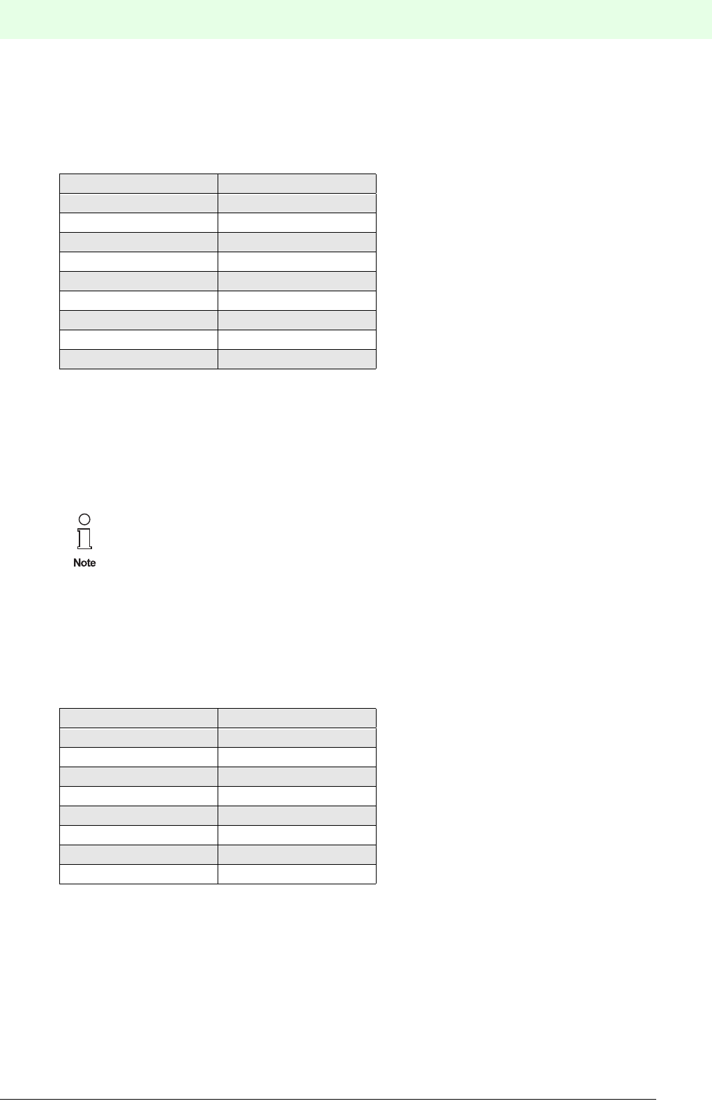
77
Remote Process Interface
Configuring and Commissioning the RPI System
Subject to reasonable modifications due to technical advances. Copyright Pepperl+Fuchs, Printed in Germany
Pepperl+Fuchs Group • Tel.: Germany +49 621 776-0 • USA +1 330 4253555 • Singapore +65 67799091 • Internet http://www.pepperl-fuchs.com
Date of issue 05/27/03
5.4.2.6 Setting the Transfer Rate of the RS232/RS 485 Service Interface
On selecting the operating mode G = BAUD PAR, the currently set transfer rate is shown in the display. The
transfer rate for the RS 232 / RS 485 service interface can be set by means of the Ð and Ï pushbuttons.The
set transfer rate is accepted by depressing the mode button for longer than 3 s.
The following transfer rates can be set:
The transfer parameters for the RS 232/RS 485 service interface are fixed and cannot be changed:
• 1 Start bit
• 8 Data bits
• 1 Stop bit
• Even parity
5.4.2.7 Setting the Transfer Rate of the External MODBUS
On selecting the operating mode H = BAUD EXT (only available on MODBUS gateway) the currently set
transfer rate is shown in the display. The MODBUS transfer rate can be set by means of the Ï and Ð but-
tons. The set transfer rate is accepted by depressing the mode button for longer than 3 s.
The following transfer rates can be set:
Tran sfer r a te Display indication
1.2 kbit/s 1
2.4 kbit/s 2
4.8 kbit/s 4
9.6 kbit/s 9
19.2 kbit/s 19
28.8 kbit/s 28
33.6 kbit/s 33
38.4 kbit/s 38
57.6 kbit/s 57
Compare the transfer parameters with the values of your PC, indicated in the menu item "sys-
tem control".
Transfer rate Display indication
1.2 kbit/s 01
2.4 kbit/s 02
4.8 kbit/s 04
9.6 kbit/s 09
19.2 kbit/s 19
28.8 kbit/s 28
38.4 kbit/s 38
57.6 kbit/s 57

Remote Process Interface
Configuring and Commissioning the RPI System
78
S
ubject to reasonable modifications due to technical advances. Copyright Pepperl+Fuchs, Printed in Germany
Pepperl+Fuchs Group • Tel.: Germany +49 621 776-0 • USA +1 330 4253555 • Singapore +65 67799091 • Internet http://www.pepperl-fuchs.com
Date of issue 05/27/03
5.4.2.8 Setting the MODBUS Parameters
On selecting the operating mode I = PARAM EXT (only available on MODBUS gateway) the current setting
is shown in the display. A different setting can be selected using the Ï and Ð pushbuttons and accepted
by depressing the mode pushbutton for longer than 3 s. The following settings are available:
5.4.2.9 Teaching-in Existing Configurations of the RPI Devices
The current configuration of all connected RPI devices is uploaded to the gateway using the ’Teach-in’
function. Likewise, existing parameter data of the devices is uploaded to the gateway.
This function is helpful in starting-up the RPI rapidly, or in teaching-in hardware changes rapidly.However,
you must ascertain that you keep track of these changes in your software human machine interface.
Depress the “mode” button for longer than 3 seconds. All new settings of the RPI devices are now stored
in the gateway.
Setting Display indication
No parity bit, 1 stop bit 00
Odd parity, 1 stop bit 01
Even parity, 1 stop bit 02
No parity bit, 2 stop bits 03
Bear in mind, that you can use the human machine interface to keep track of the set-up of your
project.
This can be accomplished by means of the ’Project upload’ function of the PACTwareΤΜ human
machine interface.
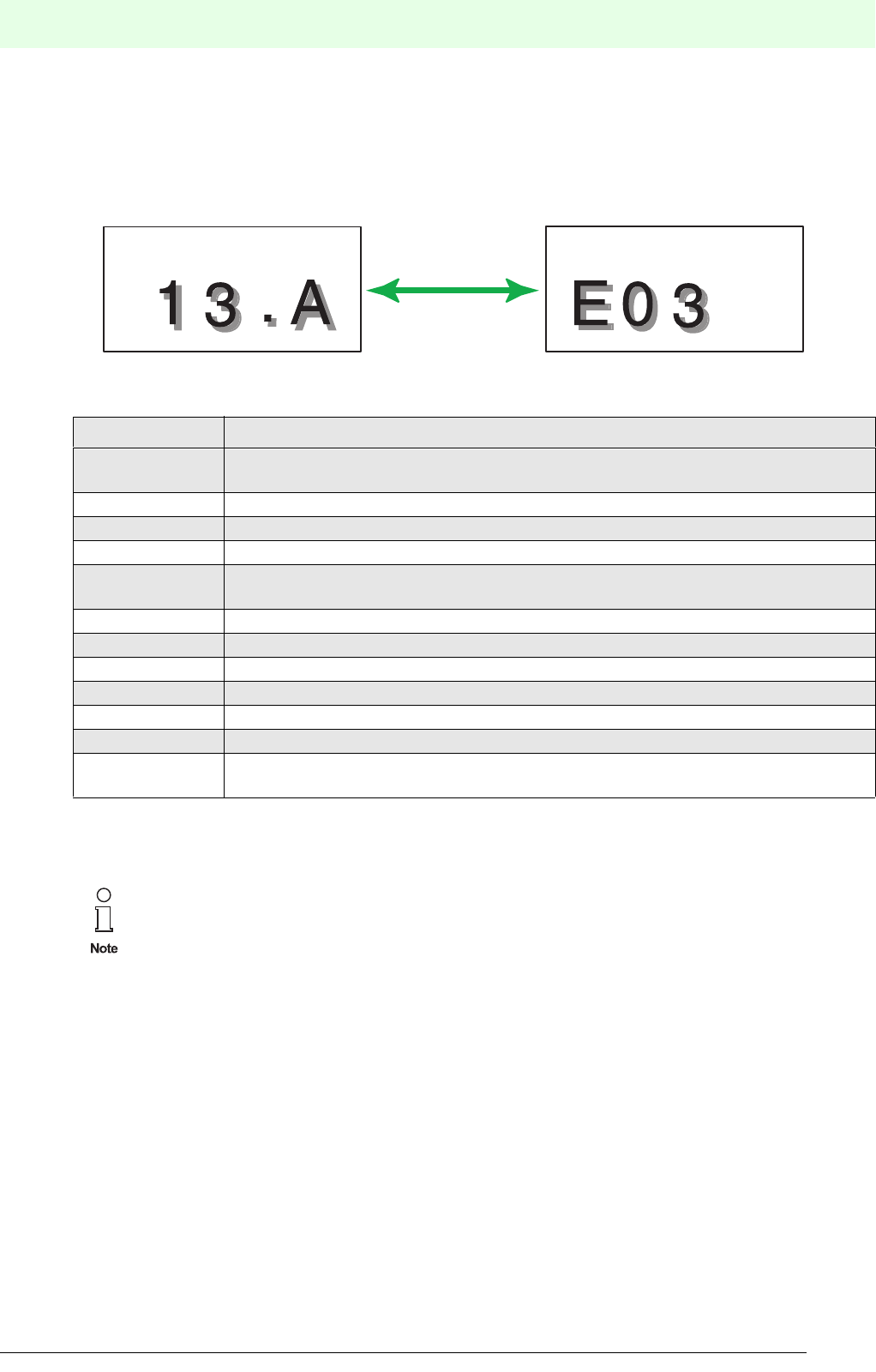
79
Remote Process Interface
Configuring and Commissioning the RPI System
Subject to reasonable modifications due to technical advances. Copyright Pepperl+Fuchs, Printed in Germany
Pepperl+Fuchs Group • Tel.: Germany +49 621 776-0 • USA +1 330 4253555 • Singapore +65 67799091 • Internet http://www.pepperl-fuchs.com
Date of issue 05/27/03
5.4.2.10 Error Messages in the LC-Displays of the Gateways
If a device error message is communicated via the internal bus, the LC-display shows the address of the
faulty device and the error code, alternately.
The addresses and error codes of other faulty devices can be shown in the display by means of the Ð and
Ï pushbuttons:
The error codes have the following meanings:
Tabelle 5.6: Error codes
Error code Significance
01 A device included in the gateway configuration does not exist as a station on the
internal bus
02 Device address indicates it is not included in the gateway configuration
03 Incorrect device type
04 Device error
05 Channel error, e.g. lead breakage or short circuit of the signal circuit of the faulty
device (for channel No. see device LED)
06 Device in initialisation phase
07 Addressing conflict
08 Device is being simulated
81 Redundant communication failure - internal communication
82 Redundant communication failure - external communication
83 Loss of redundancy - user initiated
84 Check sums of the parameter sets in the active and passive gateway are not the
same
It is recommended, that on the occurrence of an error message, the “Up” and “Down" buttons
are always pressed in order to be able to detect errors in other devices.
The RPI system can also be operated without an external bus connected. In this case the “EXT”
LED flashes.
It is possible to simulate individual RPI modules during normal operation. Bear in mind, that
simualted signals could interact with your process.
Further information on maintenance and diagnosis can be found in Chapter 8 "RPI in Opera-
tion"
Alternately
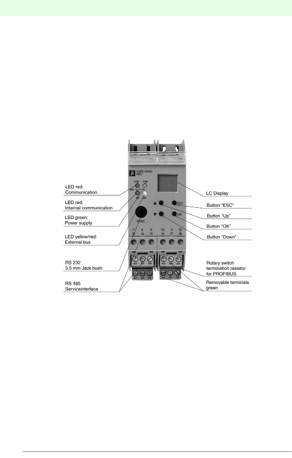
Remote Process Interface
Configuring and Commissioning the RPI System
80
S
ubject to reasonable modifications due to technical advances. Copyright Pepperl+Fuchs, Printed in Germany
Pepperl+Fuchs Group • Tel.: Germany +49 621 776-0 • USA +1 330 4253555 • Singapore +65 67799091 • Internet http://www.pepperl-fuchs.com
Date of issue 05/27/03
5.4.3 Operating the Gateways of Type KSD2-GW2-...
The gateways of type KSD2-GW2-... have four buttons “OK”, "Esc", “Up” and “Down”, four LEDs and an LC-
display. The function of the LED corresponds to the description in Chapter 5.3.2 onPage 69.
The LC-display shows the following information:
• Operating data of an RPI device as well as of the individual channels
• Error messages of the RPI devices
• Operating modes and parameters during the configuration of the RPI system
In normal operation "run" appears in the display.
On depressing the "OK" button, the data menu which displays the operating data appears.
Using the key combination "Esc" + "OK", the service menu appears. It enables you to carry out the settings
for the configuration data.
Figure 5.7:Front view of KSD2-GW2-PRO Gateway
5.4.3.1 Normal Operation:’Run’ Menu
During normal operation the information "run" appears in the gateway LC display.
The following diagram shows the menu logic of the gateway. The commands in the middle of the arrows
represent strokes on the corresponding keys of the gateway. In general, the following applies to the com-
mands:
• "OK" guides the user to the next operator level or confirms an input
• "Esc" guides the user back to the preceding operator level or aborts an input
• "Up" and "Down" pages the display elements or input values within each operator level
• "Esc" and "OK" depressed simultaneously guides the user from the normal mode to the service mode,
where inputs can be made.
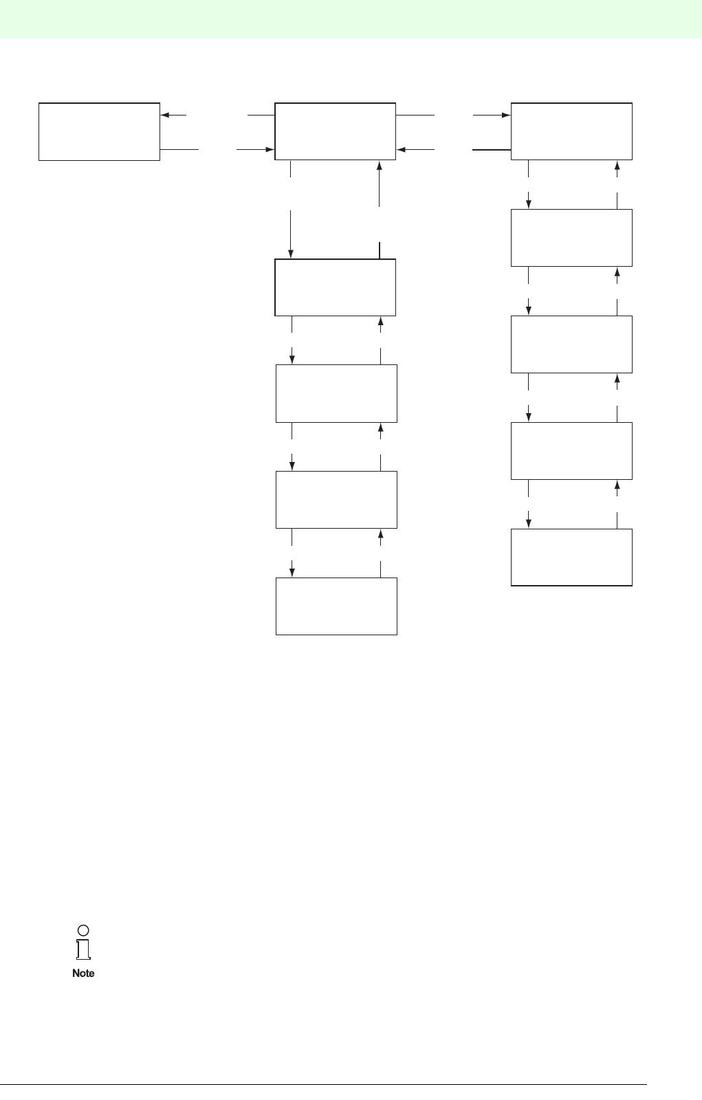
81
Remote Process Interface
Configuring and Commissioning the RPI System
Subject to reasonable modifications due to technical advances. Copyright Pepperl+Fuchs, Printed in Germany
Pepperl+Fuchs Group • Tel.: Germany +49 621 776-0 • USA +1 330 4253555 • Singapore +65 67799091 • Internet http://www.pepperl-fuchs.com
Date of issue 05/27/03
Figure 5.8:’Standard’ menu
5.4.3.2 HART Communication: ’HART' Menu
Depressing "OK" guides the user from the ’Run’ normal mode to the display mode. Here the user can toggle
between the display of the process data and the display of the HART communication status.
HART communication status:
• OpState HART communication active
• ScanState HART communication in scan mode
• NumOfInst Number of installed HART loops
In order to carry out HART communication, the HART support of the gateway must be activa-
ted. See Chapter 5.4.3.7 "Input of Configuration Data: ’Service’ Menu".
Service
see chapter 5.4.3.7
Monitor
see chapter 5.4.3.4
Run
A008
Err 5
A012
Err 2
Up Down
UpDown
Hart
see chapter 5.4.3.2
Opstate
Up Down
ScanState
Up Down
NumOflnst
EscOK
A054
Err 5
Up Down
other
error messages
Up Down
Esc+OK
Esc
OK
Esc
if an
error occurs
if no
error occurs
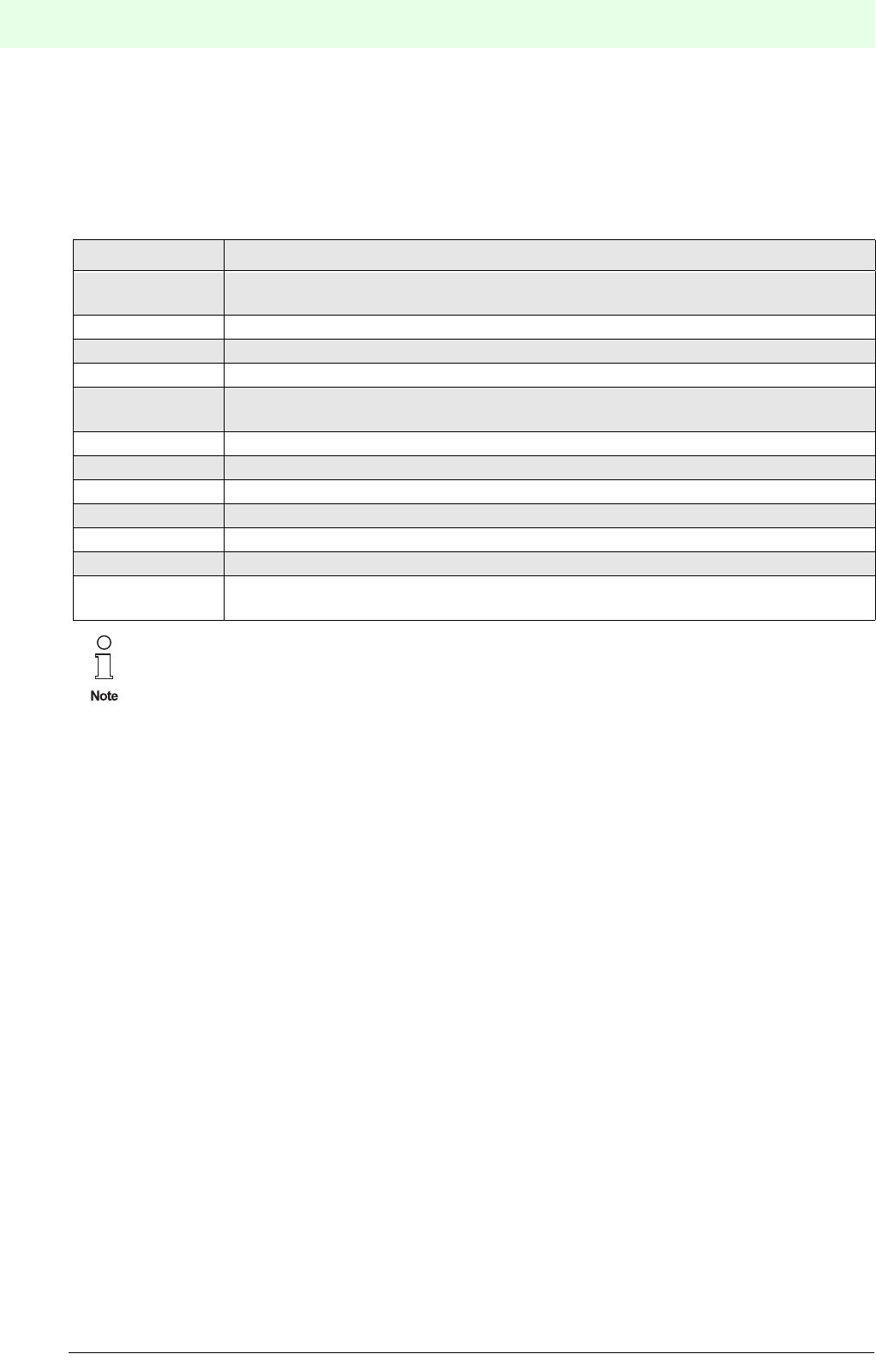
Remote Process Interface
Configuring and Commissioning the RPI System
82
S
ubject to reasonable modifications due to technical advances. Copyright Pepperl+Fuchs, Printed in Germany
Pepperl+Fuchs Group • Tel.: Germany +49 621 776-0 • USA +1 330 4253555 • Singapore +65 67799091 • Internet http://www.pepperl-fuchs.com
Date of issue 05/27/03
5.4.3.3 Fault
If device error messages are communicated via the internal bus, the display shows the device with the lo-
west address and its error code. The addresses and error codes of other faulty devices can be shown in the
display using the "Up" and "Down" buttons.
The error codes have the following meanings:
5.4.3.4 Indication of Measured Values: ’Monitor’ Menu
Device and channel-specific information can be retrieved from the ’Monitor’ menu. The current address of
the device, the device type (BI, BO, AI, AO, ...), and the channel number is shown in the LC-display. If an
error is communicated for this address, the error instead of the device type is indicated.
• Button "Up" or "Down": next device
• Button "OK": measured values of the set device; in the case of multi-channel devices, the "Up"/"Down"
buttons can be used to toggle between the channels.
The current measured value together with the channel number appears in the display as channel-related
information. Channel-specific errors are abbreviated and added to the channel number.
Error code Significance
01 A device included in the gateway configuration does not exist as a station on the
internal bus
02 Device address indicates it is not included in the gateway configuration.
03 Incorrect device type
04 Device error
05 Channel error, e.g. lead breakage or short circuit of the signal circuit of the faulty
device. for channel No. see device LED.
06 Device in initialisation phase
07 Addressing conflict
08 Device is being simulated
81 Redundant communication failure - internal communication
82 Redundant communication failure - external communication
83 Loss of redundancy - user initiated
84 Check sums of the parameter sets in the active and passive gateway are not the
same
It is recommended, that on the occurrence of an error message, the “Up” and “Down" buttons
are always pressed in order to be able to detect errors in other devices.
The RPI system can also be operated without an external bus connected. in this case the “EXT”
LED flashes.
It is possible to simulate individual RPI modules during normal operation. Bear in mind, that
simualted signals could interact with your process.
Further information on maintenance and diagnosis can be found in Chapter 8 "RPI in Opera-
tion"

83
Remote Process Interface
Configuring and Commissioning the RPI System
Subject to reasonable modifications due to technical advances. Copyright Pepperl+Fuchs, Printed in Germany
Pepperl+Fuchs Group • Tel.: Germany +49 621 776-0 • USA +1 330 4253555 • Singapore +65 67799091 • Internet http://www.pepperl-fuchs.com
Date of issue 05/27/03
Figure 5.9:’Monitor’ menu
For binary channels the states appear as 0 or 1 in the display.
If the transferred measured value of analogue channels is outside the number range of -999 to 9999, "OFL"
is indicated.
The PWR LED flashes on the RPI device, whose measured value is shown on the display.
5.4.3.5 Checking the Device Addresses on the Internal Bus
There are two principal ways of determining the address which is held by a particular RPI device:
1. By selecting the device in the ’Monitor’ menu of the gateway. On the RPI-device itself, the green PWR
LED flashes.
2. By briefly (less than 3 s) depressing the ADR button of the device. The gateway should be in the ’Run’
or in the ’Monitor’ menu. The gateway display shows the address of the device and the device type.
Now, the gateway is in the ’Monitor’ menu and should be reset to normal mode ’Run’ by means of the
"Esc" button. The green PWR LED flashes on the device.
MonitorRun
OK
Esc
0
Ch 1
1
Ch 2
OK
Esc
A021
Err 5
if an
error occurs
if no
error occurs without fault
fault
Device button
is actuated
A008
Al 1
Up Down
A012
Err 2
Up Down
A021
Err 5
Up Down
10.05
Ch 2
Up Down
5.05
Ch 3
A109
Bl 4
Up Down
Up Down
EscOK
14.45
Ch 1 (:Error)
Analogue presentation
Binary presentation
OK
Esc

Remote Process Interface
Configuring and Commissioning the RPI System
84
S
ubject to reasonable modifications due to technical advances. Copyright Pepperl+Fuchs, Printed in Germany
Pepperl+Fuchs Group • Tel.: Germany +49 621 776-0 • USA +1 330 4253555 • Singapore +65 67799091 • Internet http://www.pepperl-fuchs.com
Date of issue 05/27/03
5.4.3.6 Error Messages
The following error messages are indicated and abbreviated.
5.4.3.7 Input of Configuration Data: ’Service’ Menu
The data for the configuration of the gateway, HART transmission and the address allocation to the RPI
devices can be entered in the ’Service' menu. User prompting via LC-display is shown in the diagram below.
The service menu is entered by simultaneously depressing the "Esc" and "OK" buttons and reconfirming
with "OK".
Data structure Error Display Comment
-Err 01 Dev miss Device not available
- Err 02 Dev not conf Device not configured
-Err 03 Wrg Dev Wrong device
- Err 04 Dev Err Device causes error
-Err 05 Chn Err Channel causes error
- Err 06 Lin Err Error in linearization table
-Err 07 Addr Confl Two devices with same address
- Err 08 Sim Device in simulation mode
Divice Diag. E2PR_ERR MEM Memory error
APPL_ERR INT Internal interface
CAN_H_FAULT CAN_H CAN Bus connection: short-circuit
CAN_L_FAULT CAN_L CAN Bus connection: lead breakage
All other NOT DEF Not defined or supported
Func Diag. SHORT_CIRC SC -
LEAD-BREAK LB -
LO-ALM LO_WRN Low signal: warning
HI_ALM HI_WRN High signal: warning
LO_LO_ALM LO_ALM Low signal: alarm
HI_HI_ALM HI_ALM High signal: alarm
UNDER_RANGE UR -
OVER_RANGE OR -
All other NOT_DEF Not defined or supported
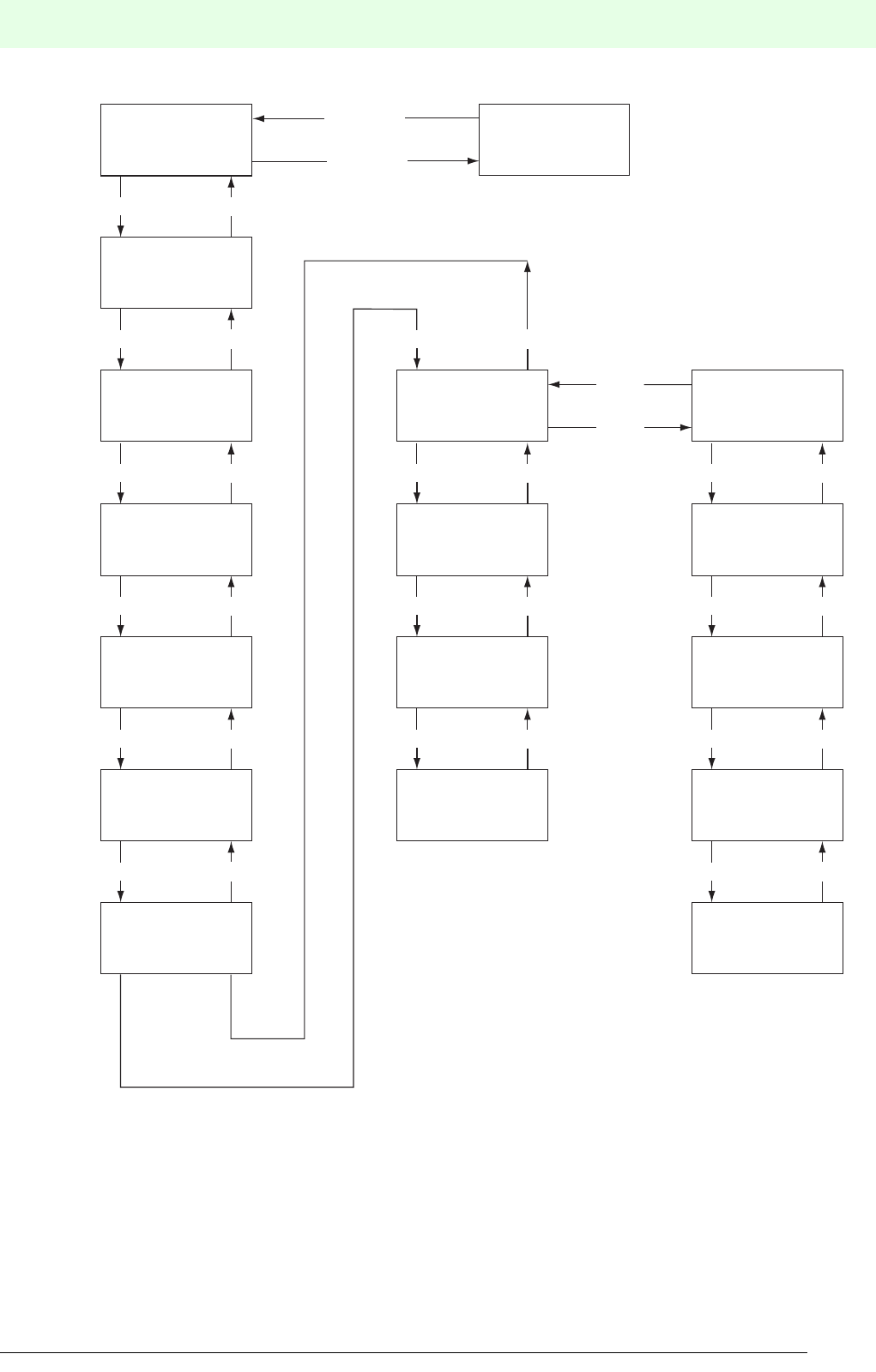
85
Remote Process Interface
Configuring and Commissioning the RPI System
Subject to reasonable modifications due to technical advances. Copyright Pepperl+Fuchs, Printed in Germany
Pepperl+Fuchs Group • Tel.: Germany +49 621 776-0 • USA +1 330 4253555 • Singapore +65 67799091 • Internet http://www.pepperl-fuchs.com
Date of issue 05/27/03
Figure 5.10:’Service’ menu
5.4.3.8 General Information on Input of Parameters and Values
The input mode is selected by depressing the "OK" button for every menu item of the "Service" menu. The
display flashes and can be changed using the "Up" and "Down" buttons within the predefined range of va-
lues. "Esc" guides the user back to the source value; "OK" confirms the indicated value which stops flashing.
"Esc" guides the user back to the service menu.
Monitor
Teach In
Run
Esc+OK
Esc
Adress
Assign
Red Mode
Par Adr
Par Baud
Hst Adr
Hart
ReselntCom
SetActiveMode
Info
Support
RebldSingleLp
RebAllLps
PerfMode
LongFrAddr
Down
Up Down
Up Down
Up Down
Up Down
Up Down
OK
Esc
Up Down
Up Down
Up Down
Up
Up Down
Up Down
Up Down Up Down
Up Down
Remote Process Interface
Configuring and Commissioning the RPI System
86
S
ubject to reasonable modifications due to technical advances. Copyright Pepperl+Fuchs, Printed in Germany
Pepperl+Fuchs Group • Tel.: Germany +49 621 776-0 • USA +1 330 4253555 • Singapore +65 67799091 • Internet http://www.pepperl-fuchs.com
Date of issue 05/27/03
The following diagram shows the input of parameters and values. This procedure applies to all variable pa-
rameters and values.
Figure 5.11:Changing parameters and values
5.4.3.9 Teaching-In the RPI Configuration: ’Teach-In’ Service Menu
The current configurations of all connected RPI devices are uploaded to the gateway by means of 'Teach-
In'. Existing parameter data of the devices is likewise uploaded.
This function helps you to start-up the RPI rapidly, or to teach-in hardware changes. However, you have to
ascertain that you keep track of these changes in your software human machine interface!.
5.4.3.10 Assignment of Device Addresses: ’AdrAssign’ Service Menu
The ’Address Assign’ menu is used to transfer the desired address for an RPI device on the gateway:
• Set the desired address using the "Up" and "Down" buttons. Only free addresses are indicated.
• The address is transferred to the RPI device by depressing the ADR pushbutton on the front panel of the
device that is to be addressed for longer than 3 s.
• The green LED on the gateway flashes for a brief period; the display of the gateway shows the next free
address.
Bear in mind, that you can use the human machine interface to keep track of the set-up of your
project.
In PACTware this is accomplished using the ’Project upload’ function.
PARAM
ADDRESS 19.2
BAUD 19.2
BAUD
Up Down
OK
Esc
OK
Esc
o.k., accept value
esc, reject value
19.6
BAUD
Up Down
1.2
BAUD
no flashing flashing
87
Remote Process Interface
Configuring and Commissioning the RPI System
Subject to reasonable modifications due to technical advances. Copyright Pepperl+Fuchs, Printed in Germany
Pepperl+Fuchs Group • Tel.: Germany +49 621 776-0 • USA +1 330 4253555 • Singapore +65 67799091 • Internet http://www.pepperl-fuchs.com
Date of issue 05/27/03
The device addresses are organised as follows::
5.4.3.11 Activation of the Redundancy: ’RedMode’ Service Menu
The redundancy function of the gateway is determined in this menu. The priority gateway obtains the setting
master "Mst." and hence also the internal address 1; the redundant gateway is set to "Red." and thus ob-
tains the internal address 2.
5.4.3.12 Setting the Address of the RS 232/RS 485 Service Interface: ’ParAdr’ Service Menu
PACTware human machine interface supports the simultaneous connection of a PC to a number of gate-
ways as a subordinate service level. Up to 31 gateways can be managed and wired with the RS 485 inter-
face of a PC.
Each individual gateway can be connected to a PC by means of an adapter cable via the RS232 interface
in the gateway. Parallel operation of the two interfaces is possible.
Establishing an address from 0 to 255 for the parameterization interface is possible by means of the ’Parm
Address’ menu.
5.4.3.13 Setting the Transfer Rate for the RS 232/RS 485 Service Interface:’ParBaud’ Service Menu
On selecting the ’ParBaud’ menu, the currently set transfer rate is shown in the display.The following trans-
fer rates can be set:
The transfer parameters for the RS232/RS485 service interface are fixed and cannot be changed:
• 1 Start bit
• 8 Data bits
• 1 Stop bit
• Even parity
Address Device
0Neutral address of an RPI device, (the setting on delivery)
1 Active RPI gateway - see Set Gateway Mode
2Redundant RPI gateway - see Set Gateway Mode
3 ... 127 RPI device
Transfer rate Display indication
1.2 kbit/s 1200 Baud
2.4 kbit/s 2400 Baud
4.8 kbit/s 4800 Baud
9.6 kbit/s 9600 Baud
19.2 kbit/s 19.2 kBaud
28.8 kbit/s 28.8 kBaud
33.6 kbit/s 33.6 kBaud
38.4 kbit/s 38.4 kBaud
57.6 kbit/s 57.6 kBaud
Compare the transfer parameters with the values of your PC listed in the menu item "System
Control".

Remote Process Interface
Configuring and Commissioning the RPI System
88
S
ubject to reasonable modifications due to technical advances. Copyright Pepperl+Fuchs, Printed in Germany
Pepperl+Fuchs Group • Tel.: Germany +49 621 776-0 • USA +1 330 4253555 • Singapore +65 67799091 • Internet http://www.pepperl-fuchs.com
Date of issue 05/27/03
5.4.3.14 Setting the Gateway Address on the External Bus: ’HstAdr’ Service Menu
On selecting the ’Host Address’ menu, the currently set gateway address on the higher-level fieldbus is
shown in the display. It can be changed in a range of 0 ... 126.
5.4.3.15 Setting the HART Transmission: ’HART’ Service Menu
In this menu the parameters for the HART protocol transmission are set by means of the HART Multiplexer
which is integrated in the gateway.
The following submenus can be selected using the "Up" and "Down" buttons:
• Support: Activates the HART support. Settings: On / Off
• RebldSingleLp: Individual HART loops can be built up. Settings: 0 to 255
• RebAllLps: All connected HART loops are rebuilt. This process can be extremely time-consuming, de-
pending on the application!
• PerfMode: This is where the operating mode for the HART support can be determined with regard to the
details of the HART standard:
nor: Normal mode, secondary master and Burst mode are permitted
FASt: Only Burst mode permitted
HI: Neither Burst mode nor secondary master are permitted
• LongFrAddr: The Long Frame Address can be uploaded here. Display: Byte 1.... byte 5
5.4.3.16 Resetting Internal Communication, ’ResIntCom’ Service Menu
This menu enables a synchronization procedure to be initiated on the internal bus, in order to allow the sy-
stem to change from redundant operation to normal operation. The procedure is initated using the key com-
bination which is also used to save parameters.
5.4.3.17 Switching Back from Redundant Operation:’SetActiveMode’ Service Menu
This command relates to the external gateway-redundancy. If the system is in redundant operation, and if
the priority gateway is available again, the latter is reactivated by means of this function. In this case, the
same functions as in the ’ResIntCom’ and ’TeachIn’ menus are performed.
5.4.3.18 Information on Hardware and Software Versions: ’Info’ Service Menu
The version of the gateway is indicated in this menu:
1. SWRem: Software version internal bus
2. SWHst: Software version PROFIBUS
3. HWVer: Gateway hardware version

89
Remote Process Interface
Configuring and Commissioning the RPI System
Subject to reasonable modifications due to technical advances. Copyright Pepperl+Fuchs, Printed in Germany
Pepperl+Fuchs Group • Tel.: Germany +49 621 776-0 • USA +1 330 4253555 • Singapore +65 67799091 • Internet http://www.pepperl-fuchs.com
Date of issue 05/27/03
5.5 Verification of Device Addresses
5.5.1 Checking the Device Address on the RPI Internal Bus
5.5.1.1 Checking by Means of KSD2-GW-... Gateway
On selecting the operating mode C = CHK INT, there are two principal ways of checking the address of a
device:
1. By ascertaining the device that has the address that is indicated on the gateway display:
Cycle through the addresses on the gateway display, using the Ð and Ï buttons. Only those addres-
ses are displayed which are actually present on the internal bus.
The green PWR LED flashes on the device whose address is shown on the gateway display.
2. By determining and displaying the address which is held by a particular device:
Briefly depress the ADR button (less than 3 s) on the device that is to be identified.
The gateway display shows the address of the device. On the device itself, the green PWR LED flas-
hes.
5.5.1.2 Checking by Means of KSD2-GW2-... Gateway
There are two principal ways of checking the address which is held by a particular RPI device:
1. By selecting the device in the ’Monitor’ menu of the gateway. On the RPI-device itself, the green PWR
LED flashes.
2. By briefly depressing the ADR button (less than 3 s) on the device. The gateway should be in the ’Run’
or in the ’Monitor’ menu. The gateway display shows the address of the device and the device type.
Now the gateway is in the ’Monitor’ menu and should be reset to the normal mode ’Run’ by means of
the "Esc" button.On the device itself, the green PWR LED flashes.
5.5.2 Assignment of the Device Address for the Internal Bus
The device addresses of the RPI internal bus are organised as follows::
5.5.2.1 Address Assignment by Means of KSD2-GW-... Gateway
• Select the operating mode b = ADR INT (set internal address) with the “Mode” button on the gateway.
The lowest possible free device address is shown on the display.
• The device address can be changed using the "Up" and "Down" buttons. Occupied and prohibited
addresses are not displayed.
• After that, depress the ADR pushbutton on the front panel of the device that is to be addressed for longer
than 3 s.
• The displayed address is allocated to the device. This is indicated by the green LED PWR flashing briefly
on the device and on the gateway.
5.5.2.2 Address Assignment by Means of KSD2-GW2-... Gateway
• Use the buttons of the gateway to select the ’Service’ menu, as described in Chapter 5.4.3 on Page 80 .
• Select the service menu ’Address Assign’
• The address can be changed using the "Up" and "Down" buttons. Only free addresses are displayed.
• The address is transferred to the RPI device by depressing the ADR pushbutton on the front panel of the
device that is to be addressed for longer than 3 s.
• The green LED on the gateway flashes for a brief period and the gateway display shows the next free
address.
Address Device
0Neutral address of an RPI device, (the setting on delivery)
1Active RPI gateway
2Redundant RPI gateway
3 ... 127 RPI device

Remote Process Interface
Configuring and Commissioning the RPI System
90
S
ubject to reasonable modifications due to technical advances. Copyright Pepperl+Fuchs, Printed in Germany
Pepperl+Fuchs Group • Tel.: Germany +49 621 776-0 • USA +1 330 4253555 • Singapore +65 67799091 • Internet http://www.pepperl-fuchs.com
Date of issue 05/27/03
5.5.3 Assignment of the Neutral Device Address 0 for the Internal Bus
The address of an operational device can be reset to the neutral address 0 (the setting on delivery), by snap-
ping the device without a gateway on to a Power Rail with power supply, and then depressing the "ADR"
button of the device for longer than 3 s.
The parameters of the device do not need to be deleted, since they are automatically overwrit-
ten by the gateway when the device is used as replacement device.

91
Remote Process Interface
Configuring and Commissioning the RPI System
Subject to reasonable modifications due to technical advances. Copyright Pepperl+Fuchs, Printed in Germany
Pepperl+Fuchs Group • Tel.: Germany +49 621 776-0 • USA +1 330 4253555 • Singapore +65 67799091 • Internet http://www.pepperl-fuchs.com
Date of issue 05/27/03
5.6 Configuration of RPI Devices with Automatic Address Assignment Using PACTwareΤΜ
The parameter assignment of the RPI devices can be prepared offline during the planning phase of the RPI
system; see Chapter 6.
The RPI devices can be allocated to both the planned parameters and the RPI internal addresses during
the mechanical layout of the system.
5.6.1 Configuration via the Service Interface
1. Project the RPI system using the human machine interface PACTwareΤΜ edition 2 on the PC, as des-
cribed in Chapter 4 "Planning of the RPI System".
2. Prepare the installation of the RPI system following the details given inChapter 4 "Planning of the
RPI System"’. Mount the power feed modules and gateways at the appropriate positions on the Power
Rails. Keep the RPI devices ready, but do not yet mount them on the Power Rail.
3. Switch on the power supply for the RPI system, see Chapter 5.2 "Power Supply"
4. Configure the gateways as described in Chapter 5.4.2 for the KSD2-GW-... type and in Chapter 5.4.3
for the KSD2-GW2-... type.
5. Connect your PC, with PACTwareΤΜ edition 2, and your configured RPI system on it, to the gateway.
Please use adapter K-ADP2 for RS232 or K-ADP4 for RS485, depending on the service interface.
After that, you should download the offline generated project to the gateway.
6. Snap the individual RPI devices onto the Power Rail one after the other, in ascending order of address
according to your project. In so doing, the device is allocated an RPI internal address and the related
parameter data is downloaded to the device.
Make sure:
- that you commence with the RPI device with the lowest RPI address.
- that the devices have RPI address 0 prior to commissioning.
5.6.2 Acceptance of the Configuration and Parameter Assignment of an Existing RPI System
In case your RPI system is already configured or in operation, the parameter data of the RPI devices can
be transferred to the gateway and further on to the PACTwareΤΜ human machine interface.
This is helpful for changing RPI devices, replacing a gateway or documenting the system using the PACT-
wareΤΜhuman machine interface.
5.6.2.1 Gateway Type KSD2-GW-...
Set operating mode ’A’ on the gateway and depress the “mode” button for longer than 3 seconds. All new
settings of the RPI devices are now stored in the gateway.
5.6.2.2 Gateway Type KSD2-GW2-...
Select the ’Service’ menu by simultaneously depressing the 'Esc' and 'OK' button on the gateway. The data
from the RPI devices are transferred to the gateway using the ’Teach-in’ service menu.
A detailed description of the software human machine interface PACTwareΤΜ edition 2 can be
obtained from the PACTwareΤΜ edition 2’, handbook . The handbook is available for download
on: http://www.pepperl-fuchs.com/pa/accessories/pactware/main.html
Be sure to keep track of the documentation of your project on the human machine interface.
This can be done by using the ’Project upload’ function of thePACTwareΤΜ human machine inter-
face.

Remote Process Interface
Configuring and Commissioning the RPI System
92
S
ubject to reasonable modifications due to technical advances. Copyright Pepperl+Fuchs, Printed in Germany
Pepperl+Fuchs Group • Tel.: Germany +49 621 776-0 • USA +1 330 4253555 • Singapore +65 67799091 • Internet http://www.pepperl-fuchs.com
Date of issue 05/27/03
5.6.3 Checking the Configuration and Parameter Assignment
After the configuration and parameterization data has been transmitted, possible errors are indicated on the
LEDs and on the display of the gateway. A verification of the RPI system can be carried out by means of
the diagnostic and simulation functions provided by PACTwareΤΜ. The individual error messages of the RPI
modules are described in Chapter "Monitoring, Simulating Measured Values and Error Handling" and
the error messages are desribed in Chapter 11 "RPI System Error Messages".
5.7 Online Commissioning
Online commissioning implies that the PC with the human machine interface PACTwareΤΜ edition 2 is directly
connected to the gateway and that the devices can be parameterized on site.
For this kind of commissioning a distinction must be made between two different situations.
5.7.1 Fully Mounted RPI system
For a fully mounted and configured RPI system the configuration can be uploaded on the PC as described
in Chapter 5.6.2. The parameter assignment is carried out according to Chapter 6 "Parameter Assign-
ment" and is downloaded to the RPI device in question.
5.7.2 Successive Assembly of the RPI Devices
The Power Rail, power supply, and gateways are mounted and the unconnected terminals of the RPI de-
vices and the sensor and actuator cables are screwed together. This situation may arise, when KFD0-LGH
dummy housings were originally installed which are later on replaced by RPI devices.
Commissioning takes place analogous with Chapter 5.6.1., however, no preplanned PACTwareΤΜ project is
downloaded to the gateway. After an RPI device has been snapped on, it is automatically assigned the next
free address by the gateway. The parameter assignment for this device can now be carried out. After that,
the next device can be snapped onto the Power Rail, if required.
5.8 Configuration and Parameter Assignment via PROFIBUS DP V1
This method of configuration and parameter assignment can only be carried out using the KSD2-GW2-PRO
Gateway for PROFIBUS DP V1 in conjunction with PACTwareΤΜ Edition 2 or with another FDT compatible
human machine interface. To enable the gateway to communicate with a PC as PROFIBUS master class
2 via the external bus, it is necessary to integrate a communication Device Type Manager (DTM).This DTM
enables PACTwareΤΜ to carry out the configuration and parameter assignment of the RPI system by means
of an acyclic data exchange via the master class 2.
1. Set the transfer rate and the gateway addresses depending on the bus system using the pushbuttons.
The information required for this procedure is given in Chapter 7.2 "Gateways for PROFIBUS DP" on
Page 114.
2. Insert the communication DTM into the offline project.
5.9 Configuration and Parameter Assignment via PROFIBUS DP and GSD 0818p.gsd
Alternatively, the devices can be parameterized device by device using the GSD file. This procedure is de-
scribed in Chapter 7.2 "Gateways for PROFIBUS DP" on Page 114 .

93
Remote Process Interface
Parameter Assignment
Subject to reasonable modifications due to technical advances. Copyright Pepperl+Fuchs, Printed in Germany
Pepperl+Fuchs Group • Tel.: Germany +49 621 776-0 • USA +1 330 4253555 • Singapore +65 67799091 • Internet http://www.pepperl-fuchs.com
Subject to reasonable modifications due to technical advances. Copyright Pepperl+Fuchs, Printed in Germany
Pepperl+Fuchs Group • Tel.: Germany +49 621 776-0 • USA +1 330 4253555 • Singapore +65 67799091 • Internet http://www.pepperl-fuchs.com
Date of issue 05/27/03
6 Parameter Assignment
6.1 Parameters of the RPI Modules
The individual RPI devices can be parameterized by means of both the human machine interface PACTwa-
reΤΜ edition 2 or a different configuration tool. In the case of PACTwareΤΜ Device Type Managers (DTM) are
available for each RPI device. As far as compatibility with other configuration tools is concerned, your local
Pepperl+Fuchs sales office will be pleased to advise you.
6.1.1 The PACTwareΤΜ Parameterization Window
In general, on the PA C T wareΤΜ human machine interface, the screen is divided into two windows. The left
window shows the project tree, while the right window shows the respective edit windows.
The DTM settings for each RPI device (see section 6.2) are carried out in a parameterization window.
6.1.1.1 ’Parameter’ Tab
You can access all settable parameter values of the selected RPI devices via the ’Parameter’ tab. Informa-
tion that cannot be changed is displayed in light grey.
The data of this tab can be:
1. saved into a file
2. saved to the device.
On clicking the ’Save to device’ button PACTwareΤΜ edition 2 after requesting sets up a connection to the
selected device and loads the data to this device.
This means that in a project, consisting of a COM driver and devices, the changed settings must be down-
loaded twice - for the COM driver and for the device separately.
6.1.1.2 ’Properties’ Tab
The individual DTMs offer information on themselves and on the devices to be edited using these DTMs.
The ’Properties' tab contains the ’Device Info’ and ’Description’ tabs.
’Device Info’
’Device Info’ provides unchangeable information on the selected device.The following information can be
obtained from the card:
• the data source
• the time when the module specific data was generated
• the time when the last change was made
• the device type
• and the description of the device
In this section the RPI-specific features of PACTwareΤΜ are discussed. A detailed description of
the human machine interface PACTwareΤΜ edition 2 can be obtained from the Handbook
PACTwareΤΜ edition 2. The handbook can be downloaded free of charge from http://www.pep-
perl-fuchs.com/pa/accessories/pactware/main.html.
Using Save to file or Save to device the data of the activated device or the COM driver is stored,
whereas the remaining data of the project is not stored.
In addition, the overall project should be stored on data carriers by using ’Save project’.
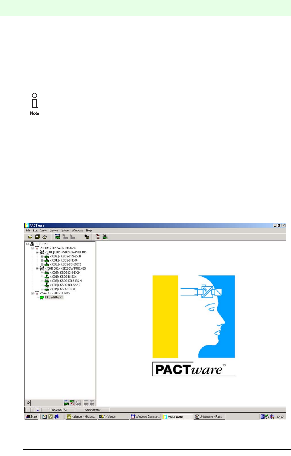
Remote Process Interface
Parameter Assignment
94
S
ubject to reasonable modifications due to technical advances. Copyright Pepperl+Fuchs, Printed in Germany
Pepperl+Fuchs Group • Tel.: Germany +49 621 776-0 • USA +1 330 4253555 • Singapore +65 67799091 • Internet http://www.pepperl-fuchs.com
Date of issue 05/27/03
Additional information is read out of the device as soon as a first connenction to the RPI system is set up:
• Serial number,
• Software version
• Hardware version
’Description’
Using ’Description’ you can store data which is specific to a measuring point , e.g.: tag data and tag name.
6.2 Editing a Project
A project in PACTwareΤΜ presents the structure of your RPI system. By means of the connection of your field
devices to the RPI interface modules, the allocation of the field devices to both the RPI gateways and the
corresponding address on the external bus is documented.
The same applies to the underlaying service network, provided that the RS 485 service interfaces of your
gateways have been wired.
The project is configured using the various Device Type Managers (DTM). DTMs for devices of other ma-
nufacturers can be used apart from the DTMs offered by Pepperl+Fuchs, as long as they conform to the
FDT (Field Device Tool) standard .
A typical project is structured as follows:
Figure 6.1:Projekt structure
This information is only stored in the project on the data carrier not in the individual RPI devices.

95
Remote Process Interface
Parameter Assignment
Subject to reasonable modifications due to technical advances. Copyright Pepperl+Fuchs, Printed in Germany
Pepperl+Fuchs Group • Tel.: Germany +49 621 776-0 • USA +1 330 4253555 • Singapore +65 67799091 • Internet http://www.pepperl-fuchs.com
Subject to reasonable modifications due to technical advances. Copyright Pepperl+Fuchs, Printed in Germany
Pepperl+Fuchs Group • Tel.: Germany +49 621 776-0 • USA +1 330 4253555 • Singapore +65 67799091 • Internet http://www.pepperl-fuchs.com
Date of issue 05/27/03
6.2.1 Opening a Project
An existing project is opened using the menu item <Open file> in the menu bar or the tool bar button in
the tool bar .
6.2.2 New Project
Open a new project using the menu item <New> in the menu bar and then store it under the name you have
chosen.
The project is structured as a tree based on the preset entry ’HOST IBM-PC’ in the following order of suc-
cession:
1. COM driver (RPI Serial interface)
2. First gateway
3. Added to the first gateway (optionally): second gateway for redundant communication with the control
system
4. RPI devices, added to the first gateway
5. Next gateway for additional RPI string, added to COM driver gateways and devices
6. Next COM driver, added to HOST IBM-PC, e.g.: for HART communication or connection of non-RPI
devices
6.2.3 Adding Components
There are three ways to edit a project in the project window:
1. Click onto the desired position in the project tree using the right mouse button and select the menu
item <Add device>.
2. Click onto the desired position in the project tree using the left mouse button and then onto <Add>
down on the left.
3. Select <Project> in the menu bar and then <Device catalogue> or press function key F3 after which
the device catalogue appears in the edit window. It contains all the installed Device Type Managers in
a Windows-Explorer representation. By highlighting the desired position in the project tree and then
double clicking onto a device, the latter is pasted into the project.
If you select options 1 or 2, a selection window offers you only those options, that can be pasted to the
selected position. Click onto the desired Device Type Manager in the selection window and confirm your
selection using the <OK> button or double click the desired Device Type Manager.
If you wish to use the device catalogue (point 3 given above), the screen separates into three parts.
The left part shows the project tree. The middle part shows the DTM components structured according to
their functions and installed on your PC using PACTwareΤΜ. The right part lists the entire device catalogue.
In general the following applies to projecting: Only those devices can be selected from the
device catalogue, whose model numbers correspond to the devices used in the RPI system.
PACTwareΤΜ does not permit the connection of Device Type Managers, unless they are useful on
the relevant position in the project tree.
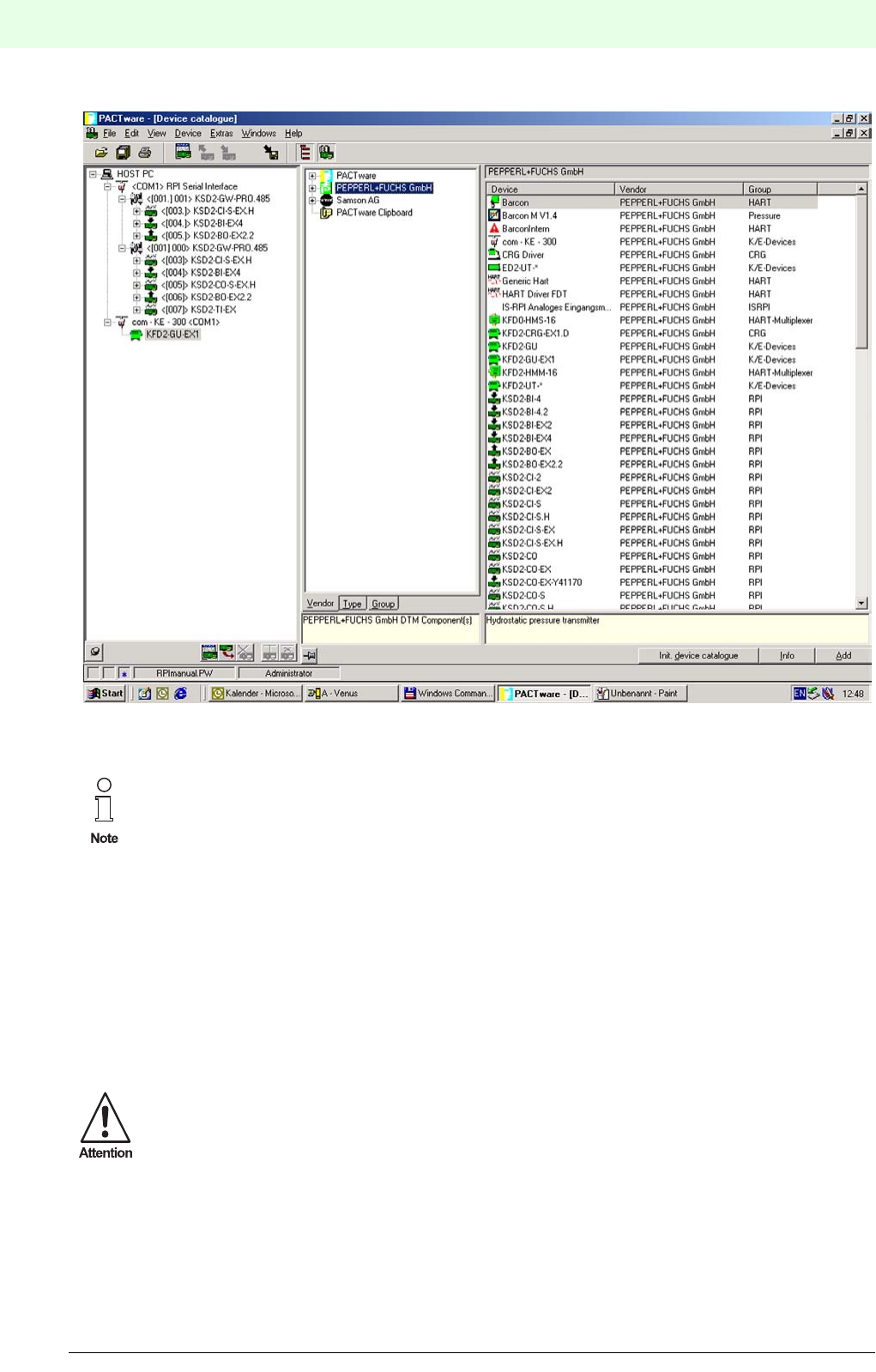
Remote Process Interface
Parameter Assignment
96
S
ubject to reasonable modifications due to technical advances. Copyright Pepperl+Fuchs, Printed in Germany
Pepperl+Fuchs Group • Tel.: Germany +49 621 776-0 • USA +1 330 4253555 • Singapore +65 67799091 • Internet http://www.pepperl-fuchs.com
Date of issue 05/27/03
Figure 6.2:Device catalogue
This means that, if you wish to project a COM driver, the HOST IBM PC must be activated. Similarly, if you
wish to project an RPI device, an RPI gateway should be activated.
If this is not the case, an error message appears.
PACTwareΤΜ adds a device and assigns this device an address for the RPI internal bus, simultaneously.
The first gateway is generally assigned Number 1, the second gateway Number 2, and the first RPI device
is assigned Number 3. A gateway can communicate with a maximum of 125 RPI devices (addresses [003]
to [127]).
6.2.4 Deleting Components
There are two ways to delete a device from the project tree:
1. Click onto the device that you wish to delete from the project tree using the right mouse button and
select<Delete Device>.
2. Click onto the device that you wish to delete from the project tree using the left mouse button and then
onto the <Delete> button down on the left.
Make sure to activate (i.e. highlight grey/blue) exactly that level in the left column which can be
used to project your component.
Before you delete a device from the project tree make sure that you selected the correct
device(s). There is no undo function available.
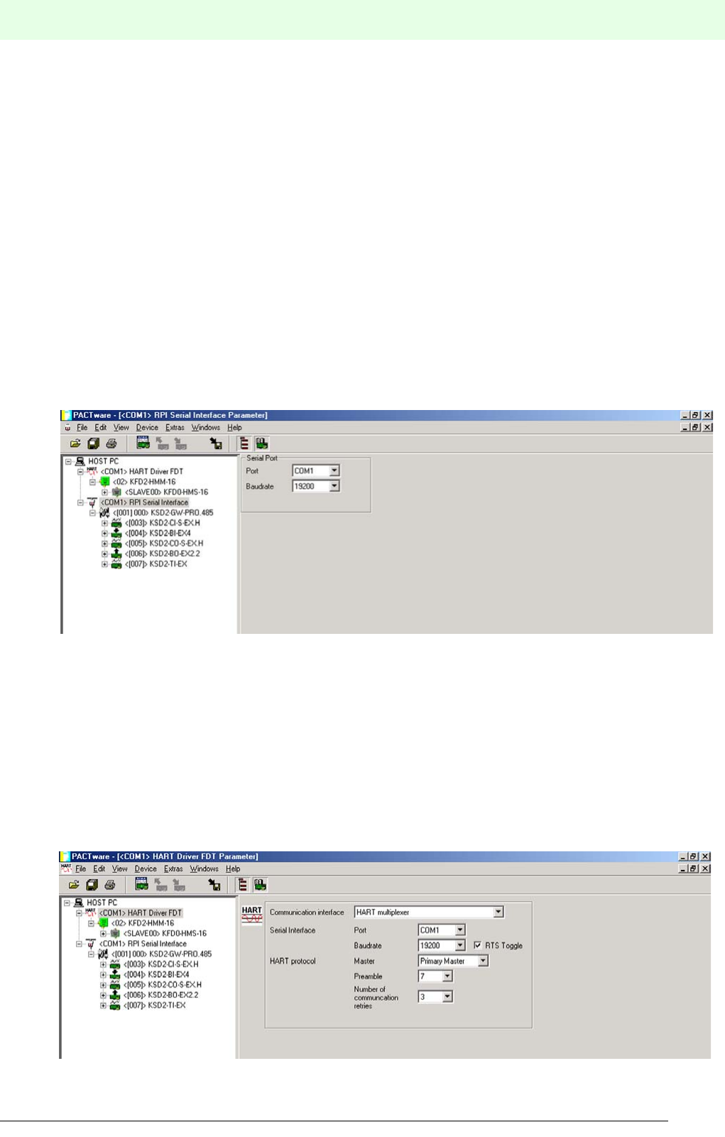
97
Remote Process Interface
Parameter Assignment
Subject to reasonable modifications due to technical advances. Copyright Pepperl+Fuchs, Printed in Germany
Pepperl+Fuchs Group • Tel.: Germany +49 621 776-0 • USA +1 330 4253555 • Singapore +65 67799091 • Internet http://www.pepperl-fuchs.com
Subject to reasonable modifications due to technical advances. Copyright Pepperl+Fuchs, Printed in Germany
Pepperl+Fuchs Group • Tel.: Germany +49 621 776-0 • USA +1 330 4253555 • Singapore +65 67799091 • Internet http://www.pepperl-fuchs.com
Date of issue 05/27/03
6.3 Parameterizing Individual Components
In order to edit an RPI device in PACTwareΤΜ:
1. click onto the component that you wish to edit in the project tree using the right mouse button and sel-
ect Offline Parameter, or
2. double click the component that you wish to edit in the project tree, or
3. click onto the component that you wish to edit in the project tree using the left mouse button and then
click the Edit button in the project window down on the right, or
4. click onto the component that you wish to edit in the project tree using the left mouse button and then
press function key F5.
Now the offline parameterization window opens, displaying the tabs 'Device Info', 'Description' and 'Para-
meter'.
6.3.1 Parameters of the COM Drivers
6.3.1.1 RPI Serial Interface
The <Parameter> tab is used to set the serial interface together with the port designation on your PC and
the baud rate.
Figure 6.3:Parameterize the serial interface
Serial interface
Port: Setting the designation of the serial port on the PC/notebook.
Baud rate: Must correspond to the set baud rate on the PC/notebook.
6.3.1.2 HART Protocol Driver
The <Parameter> tab is used to set the serial interface together with the port designation on your PC, the
baud rate as well as a number of HART parameters. Detailed information can be obtained from the HART
Multiplexer KFD2-HMM-16 Handbook .
Figure 6.4:Parameterizing the HART protocol driver
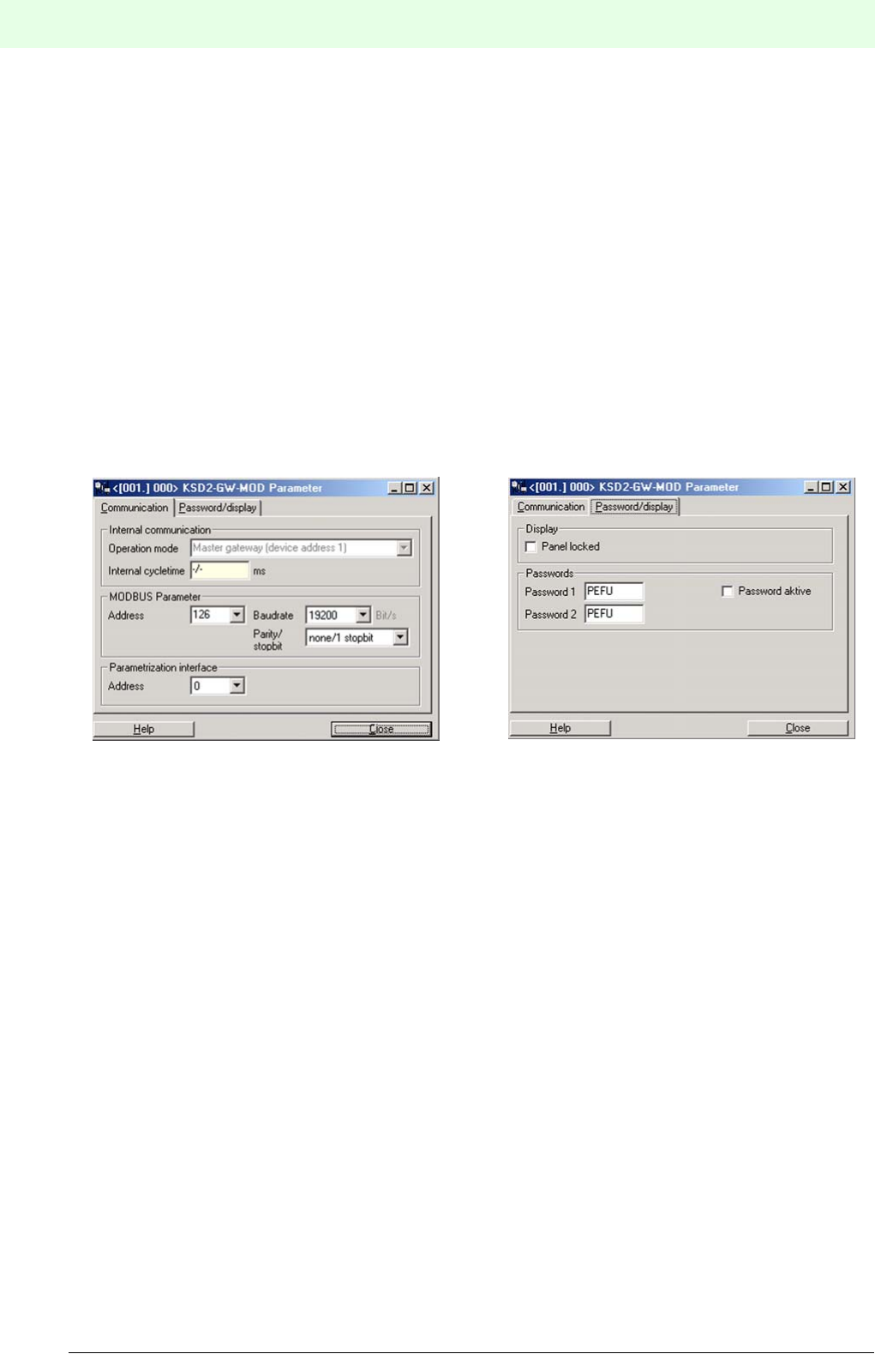
Remote Process Interface
Parameter Assignment
98
S
ubject to reasonable modifications due to technical advances. Copyright Pepperl+Fuchs, Printed in Germany
Pepperl+Fuchs Group • Tel.: Germany +49 621 776-0 • USA +1 330 4253555 • Singapore +65 67799091 • Internet http://www.pepperl-fuchs.com
Date of issue 05/27/03
6.3.1.3 Device Type Managers for Non-RPI Devices
DTM for field devices or interface modules, not relating to the RPI system, can likewise be embedded into
the project tree. To do this, one needs suitable communication drivers. These must conform to the FDT
standard. For more detailed information, please refer to the handbook of the relevant device.
6.3.2 Gateway Parameters
6.3.2.1 MODBUS RTU
The tab for the gateway parameters contains theCommunication and the Password/Panel tab. The fol-
lowing four parameters must be set for the communication of the gateway:
• Address on the MODBUS: 0 ... 127
• Baud rate: 1,200 ... 57,600 bit/s
• Parity/stop bit: no/1 stop bit - odd/1 stop bit - even/1 stop bit - no/2 stop bits
• Address of the parameterization interface: 0 ... 127, as set on the gateway
The section Internal Communication indicates the Operating Mode and the Internal Cycle
Time . However, they cannot be changed.
Figure 6.5:Parameterizing the Modbus RTU gateway
The Password/Panel tab enables you to lock the operating unit and to activate the passwords by
checking the respective boxes.
6.3.2.2 MODBUS Plus
The tab for the gateway parameters contains the tabs Communication and Password/Panel. Two pa-
rameters have to be set for the communication of the gateway:
• Address on the MODBUS: 0 ... 127
• Address of the parameterization interface: 0 ... 127, as set on the gateway
The sectionInternal Communication indicates the Operating Mode and the Internal Cycle
Time. However, they cannot be changed.
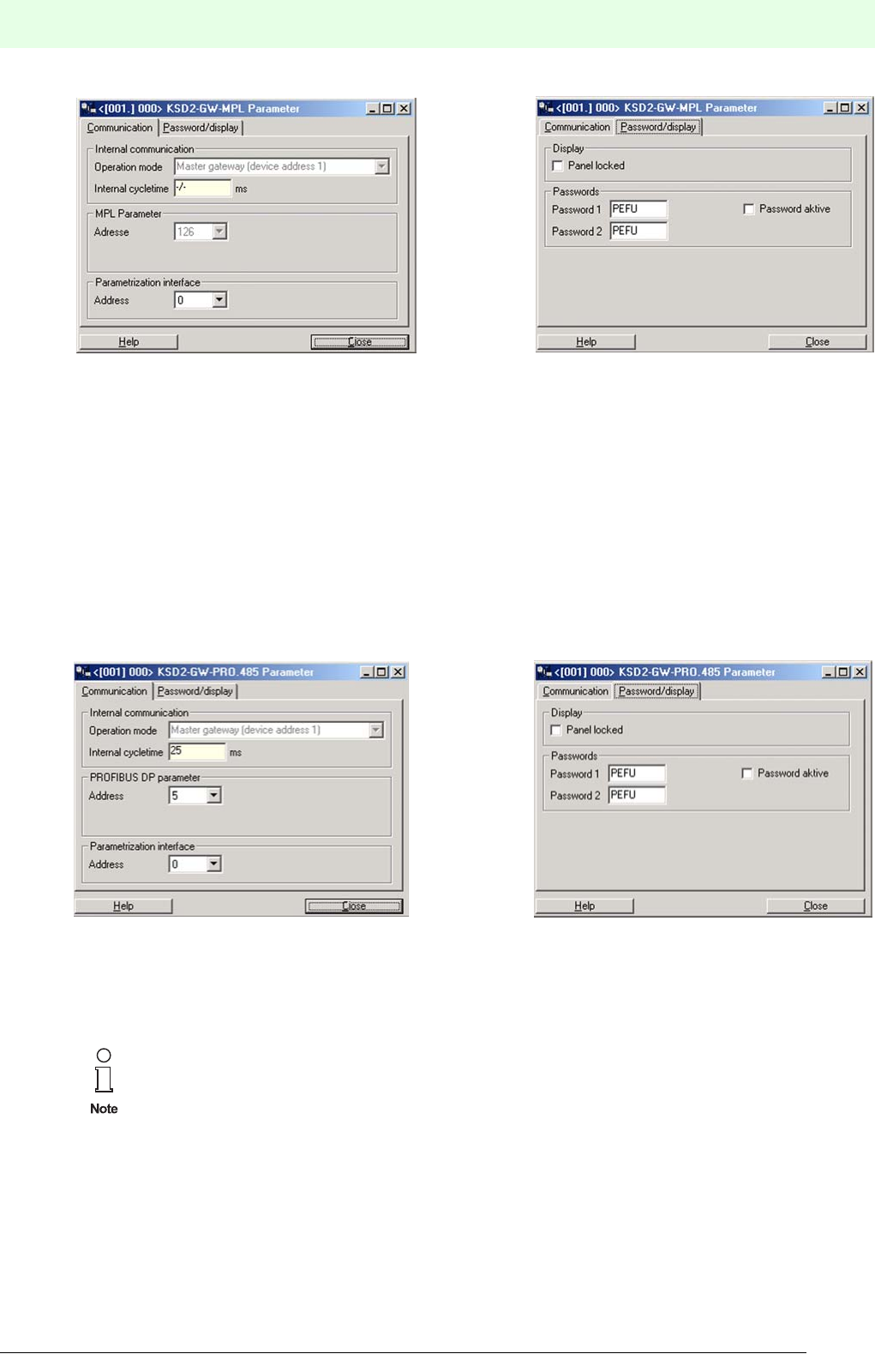
99
Remote Process Interface
Parameter Assignment
Subject to reasonable modifications due to technical advances. Copyright Pepperl+Fuchs, Printed in Germany
Pepperl+Fuchs Group • Tel.: Germany +49 621 776-0 • USA +1 330 4253555 • Singapore +65 67799091 • Internet http://www.pepperl-fuchs.com
Subject to reasonable modifications due to technical advances. Copyright Pepperl+Fuchs, Printed in Germany
Pepperl+Fuchs Group • Tel.: Germany +49 621 776-0 • USA +1 330 4253555 • Singapore +65 67799091 • Internet http://www.pepperl-fuchs.com
Date of issue 05/27/03
Figure 6.6:Parameterizing the Modbus Plus Gateway
The Password/Panel tab enables you to lock the operating unit and to activate the passwords by
checking the respective boxes.
6.3.2.3 PROFIBUS DP and DP V1
The tab for the gateway parameters contains the tabs Communication and Password/Panel. Two pa-
rameters have to be set for the communication of the gateway.
• Address on the PROFIBUS: 0 ... 127
• Address of the parameterization interface: 0 ... 127, as set on the gateway.
The section Internal Communication indicates theOperating Mode and the Internal Cycle
Time. However, they cannot be changed.
Figure 6.7:Parameterizing the PROFIBUS DP gateway
The Password/Panel tab enables you to lock the operating unit and to activate the passwords by
checking the respective boxes.
6.3.2.4 ControlNet
The tab for the gateway parameters contains the tabs Communication and Password/Panel. Two pa-
rameters have to be set for the communication of the gateway.
• Address on the ControlNet bus: 0 ... 127
• Address of the parameterization interface: 0 ... 127
The device address 127 is reserved for a specific PROFIBUS service and cannot be set on the
gateways.
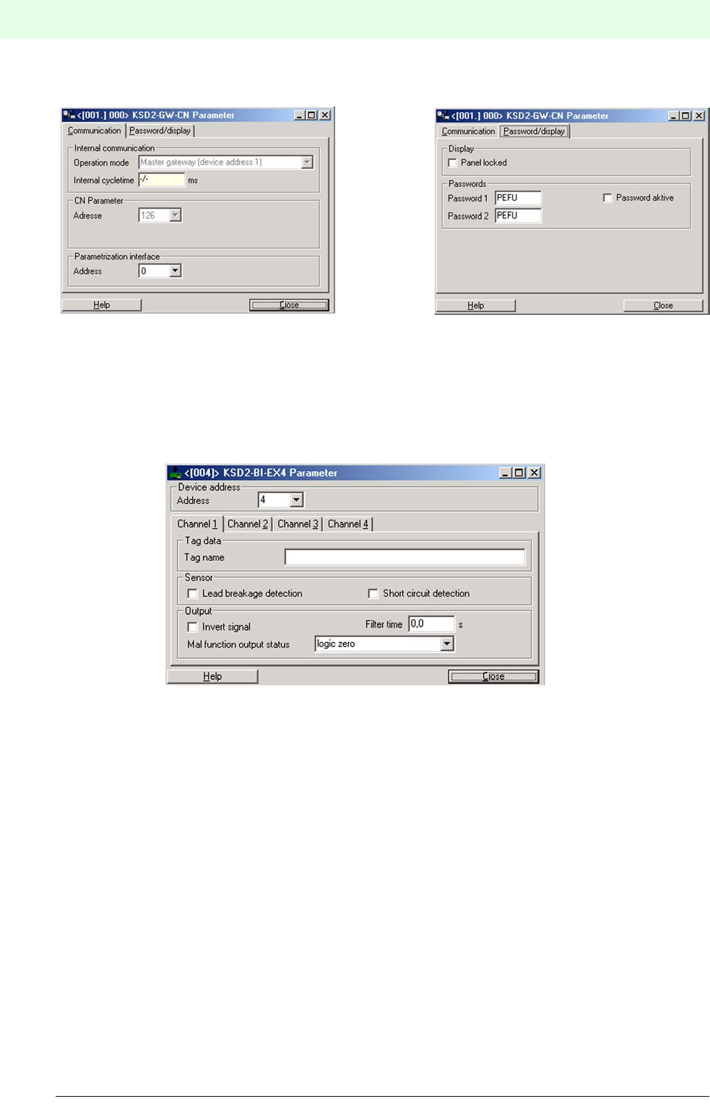
Remote Process Interface
Parameter Assignment
100
S
ubject to reasonable modifications due to technical advances. Copyright Pepperl+Fuchs, Printed in Germany
Pepperl+Fuchs Group • Tel.: Germany +49 621 776-0 • USA +1 330 4253555 • Singapore +65 67799091 • Internet http://www.pepperl-fuchs.com
Date of issue 05/27/03
The section Internal Communication indicates the Operating Mode and the Internal Cycle
Time. However, they cannot be changed.
Figure 6.8:Parameterizing the ControlNet gateway
The Password/Panel tab enables you to lock the operating unit and to activate the passwords by
checking the respective boxes.
6.3.3 Isolated Switch Amplifier
The Parameter tab contains both device specific and channel specific parameters.
Figure 6.9:Parameterizing KSD2-BI-...
Device Address: The entered address must be identical with the address set on
the relevant device.
Tag Data:
Tag Name: A description with a maximum of 32 characters can be entered
into the box in order to ensure rapid and secure allocation.
Sensor:
Lead breakage detection: The sensor lead is monitored for lead breakage.
Short circuit detection: The sensor lead is monitored for short circuits.
Output:
Invert Signal: The input signal is inverted and transferred to the bus.
Filter Time: Filter time signifies that input pulses shorter than the filter time
are suppressed.
Malfunction output status: By means of the settings Downscaled, Upscaled or Hold
Last Value the signal transferred to the control system in the
error case is determined according to the application.
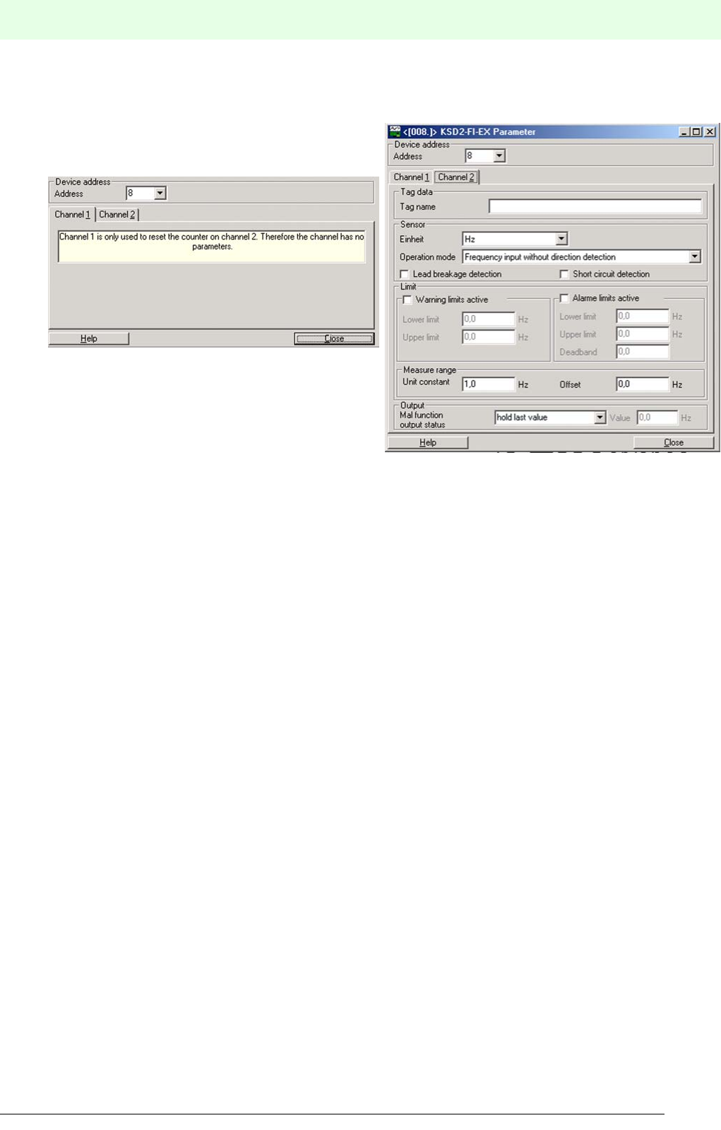
101
Remote Process Interface
Parameter Assignment
Subject to reasonable modifications due to technical advances. Copyright Pepperl+Fuchs, Printed in Germany
Pepperl+Fuchs Group • Tel.: Germany +49 621 776-0 • USA +1 330 4253555 • Singapore +65 67799091 • Internet http://www.pepperl-fuchs.com
Subject to reasonable modifications due to technical advances. Copyright Pepperl+Fuchs, Printed in Germany
Pepperl+Fuchs Group • Tel.: Germany +49 621 776-0 • USA +1 330 4253555 • Singapore +65 67799091 • Internet http://www.pepperl-fuchs.com
Date of issue 05/27/03
6.3.4 Current Frequency Converter, Batch Controller
The Parameter tab contains both device specific and channel specific parameters.
Figure 6.10:Parameterizing KSD2-FI-...
Device Address: The entered address must be identical with the address set on
the relevant device.
Tag Data:
Tag Name: It allows you to type in a descriptor (tag name) which may contain
up to 32 characters. This is helpful for larger projects to identify
the devices clearly.
Sensor:
Unit: In this box the input signal can be assigned a physical unit.
Operating Mode: Four different operating modes can be selected. Frequency
input with or without rotation direction monito-
ring, counter input with or without rotation direc-
tion monitoring.
Lead breakage detection: The sensor lead is monitored for lead breakage.
Short circuit detection: The sensor lead is monitored for short circuits.
Limit Values:
Warning limits active: If you check the left box by clicking into it, you activate the
warning limits. Now Lower Limit and Upper Limit turn
from grey to black. The limit values are entered into the boxes on
the right hand side.
Alarm limits active: If you check the left box by clicking into it, you activate the alarm
limits. Now Lower Limit, Upper Limit and Hysteresis
turn from grey to black. The limit values are entered into the bo-
xes on the right hand side.
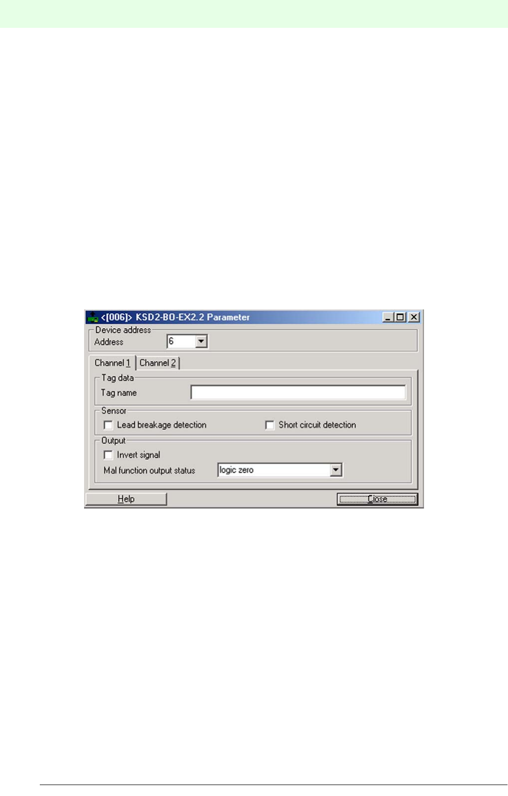
Remote Process Interface
Parameter Assignment
102
S
ubject to reasonable modifications due to technical advances. Copyright Pepperl+Fuchs, Printed in Germany
Pepperl+Fuchs Group • Tel.: Germany +49 621 776-0 • USA +1 330 4253555 • Singapore +65 67799091 • Internet http://www.pepperl-fuchs.com
Date of issue 05/27/03
Measuring Range:
Unit Constant: In the operating mode frequency input the unit constant allows a
conversion from Hz to another physical unit (e.g. rpm for rotatio-
nal speed, m³/h for flow etc.) This is necessary, when the higher
level system requires other units than Hz. The unit constant is de-
fined as follows:
Example: At an input frequency of 100 Hz, the output value is to
be 20. This results in a unit constant of 5. At a counter reading of
2500 the transferred value is to be 125. This leads to a unit con-
stant of 20.
Offset: Enter value for Offset.
Output:
Malfunction output status: By means of the settings As Input or Hold Last Value the
signal transferred to the control system in the error case is deter-
mined according to the application. For the setting As input a
value should be entered in the box on the right hand side.
6.3.5 Solenoid Drivers
The Parameter tab contains both device specific and channel specific parameters.
Figure 6.11:Parameterizing KSD2-BO-...
Device Address: The entered address must be identical with the address set on
the relevant device.
Tag Data:
Tag Name: It allows you to type in a descriptor (tag name) which may contain
up to 32 characters. This is helpful for larger projects to identify
the devices clearly.
Sensor:
Lead breakage detection: The sensor lead is monitored for lead breakage..
Short circuit detection: The sensor lead is monitored for short circuits.
Output:
Invert Signal: The input signal is inverted and transferred to the bus.
Malfunction Output Status: By means of the settings Downscaled, Upscaled or Hold
Last Value the signal transferred to the control system in the
error case is determined according to the application.
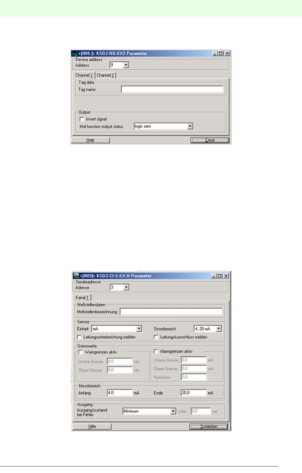
103
Remote Process Interface
Parameter Assignment
Subject to reasonable modifications due to technical advances. Copyright Pepperl+Fuchs, Printed in Germany
Pepperl+Fuchs Group • Tel.: Germany +49 621 776-0 • USA +1 330 4253555 • Singapore +65 67799091 • Internet http://www.pepperl-fuchs.com
Subject to reasonable modifications due to technical advances. Copyright Pepperl+Fuchs, Printed in Germany
Pepperl+Fuchs Group • Tel.: Germany +49 621 776-0 • USA +1 330 4253555 • Singapore +65 67799091 • Internet http://www.pepperl-fuchs.com
Date of issue 05/27/03
6.3.6 Relay Modules
The Parameter tab contains both device specific and channel specific parameters.
Figure 6.12:Parameterizing KSD2-RO-...
Device Address: The entered address must be identical with the address set on
the relevant device.
Tag Data:
Tag Name: It allows you to type in a descriptor (tag name) which may contain
up to 32 characters. This is helpful for larger projects to identify
the devices clearly.
Output:
Invert Signal: The input signal is inverted and transferred to the bus.
Malfunction Output Status: By means of the settings Downscaled, Upscaled or Hold
Last Value the signal transferred to the control system in the
error case is determined according to the application.
6.3.7 Transmitter Power Supplies
The Parameter tab contains both device specific and channel specific parameters..
Figure 6.13:Parameterizing KSD2-CI-...

Remote Process Interface
Parameter Assignment
104
S
ubject to reasonable modifications due to technical advances. Copyright Pepperl+Fuchs, Printed in Germany
Pepperl+Fuchs Group • Tel.: Germany +49 621 776-0 • USA +1 330 4253555 • Singapore +65 67799091 • Internet http://www.pepperl-fuchs.com
Date of issue 05/27/03
Device Address: The entered address must be identical with the address set on
the relevant device.
Tag Data:
Tag Name: It allows you to type in a descriptor (tag name) which may contain
up to 32 characters. This is helpful for larger projects to identify
the devices clearly.
Sensor:
Unit: In this box the input signal can be assigned a physical unit.
Current Range: The zero point of the input signal is defined by selecting the cur-
rent range.
Lead breakage detection: The sensor lead is monitored for lead breakage..
Short circuit detection: The sensor lead is monitored for short circuits.
Limit Values:
Warning limits active: If you check the left box by clicking into it, you activate the
warning limits. Now Lower Limit and Upper Limit turn from
grey to black. The limit values are entered into the boxes on the
right hand side..
Alarm Limits active: If you check the left box by clicking into it, you activate the alarm
limits. Now Lower Limit, Upper limit and Hysteresis
turn from grey to black. The limit values are entered into the bo-
xes on the right hand side.
Measurement Range
Start: The start value needs to be entered in order to be able to scale
the measured value.
End: The final value needs ot be entered in order to be able to scale
the measured value.
Example: The current range is 4 ... 20 mA and the measuring ran-
ge
is 1 ... 5 bar. The measured value is transferred via the external
bus with a factor of 100, i.e., for instance at 2.5 bar a value of 250
is transferred.
Output
Malfunction Output Status: By means of the settings As Input, Minimum, Maximum or
Hold Last Value the signal transferred to the control system
in the error case is determined according to the application. For
the setting As Input a value should be entered in the box on the
right hand side.
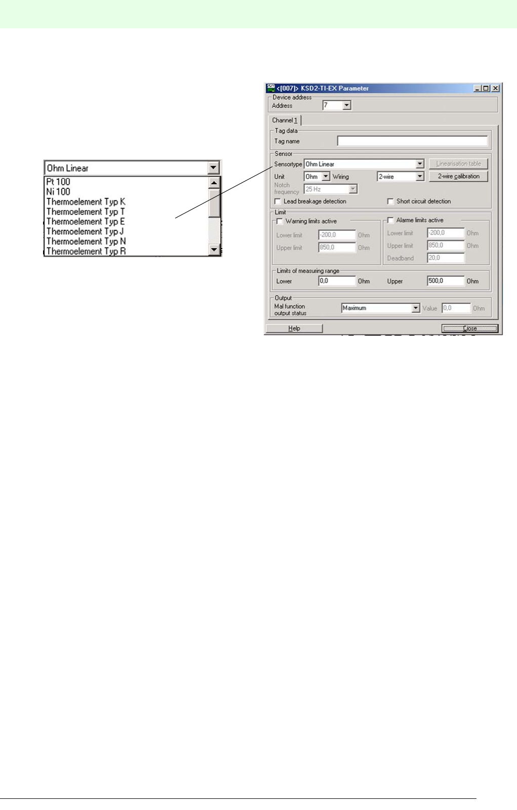
105
Remote Process Interface
Parameter Assignment
Subject to reasonable modifications due to technical advances. Copyright Pepperl+Fuchs, Printed in Germany
Pepperl+Fuchs Group • Tel.: Germany +49 621 776-0 • USA +1 330 4253555 • Singapore +65 67799091 • Internet http://www.pepperl-fuchs.com
Subject to reasonable modifications due to technical advances. Copyright Pepperl+Fuchs, Printed in Germany
Pepperl+Fuchs Group • Tel.: Germany +49 621 776-0 • USA +1 330 4253555 • Singapore +65 67799091 • Internet http://www.pepperl-fuchs.com
Date of issue 05/27/03
6.3.8 Temperature Converter
The Parameter tab contains both device specific and channel specific parameters.
Figure 6.14:Parameterizing KSD2-TI-...
Device Address: The entered address must be identical with the address set on
the relevant device.
Tag Data:
Tag Name: It allows you to type in a descriptor (tag name) which may contain
up to 32 characters. This is helpful for larger projects to identify
the devices clearly.
Sensor:
Sensor Type: In this menu you can select a sensor from a list of various sensor
types.
Connection Method: The connection method of the sensor to the RPI module should
be set using this list box.
Unit: In this box the input signal can be assigned a physical unit..
Linearization Table: Here you can enter values into a table (Ohm/Temperature)
Lead breakage detection: The sensor lead is monitored for lead breakage.
Short circuit detection: The sensor lead is monitored for short circuits.
Limit Values:
Warning limits active: If you check the left box by clicking into it, you activate the
warning limits. Now Lower Limit and Upper Limit turn from
grey to black. The limit values are entered into the boxes on the
right hand side..
Alarm limits active: If you check the left box by clicking into it, you activate the alarm
limits. Now Lower Limit, Upper Limit and Hysteresis
turn from grey to black. The limit values are entered into the bo-
xes on the right hand side.
Measuring Range:
Start: The start value needs to be entered in order to be able to scale
the measured value.
End: The end value needs to be entered in order to be able to scale
the measured value.
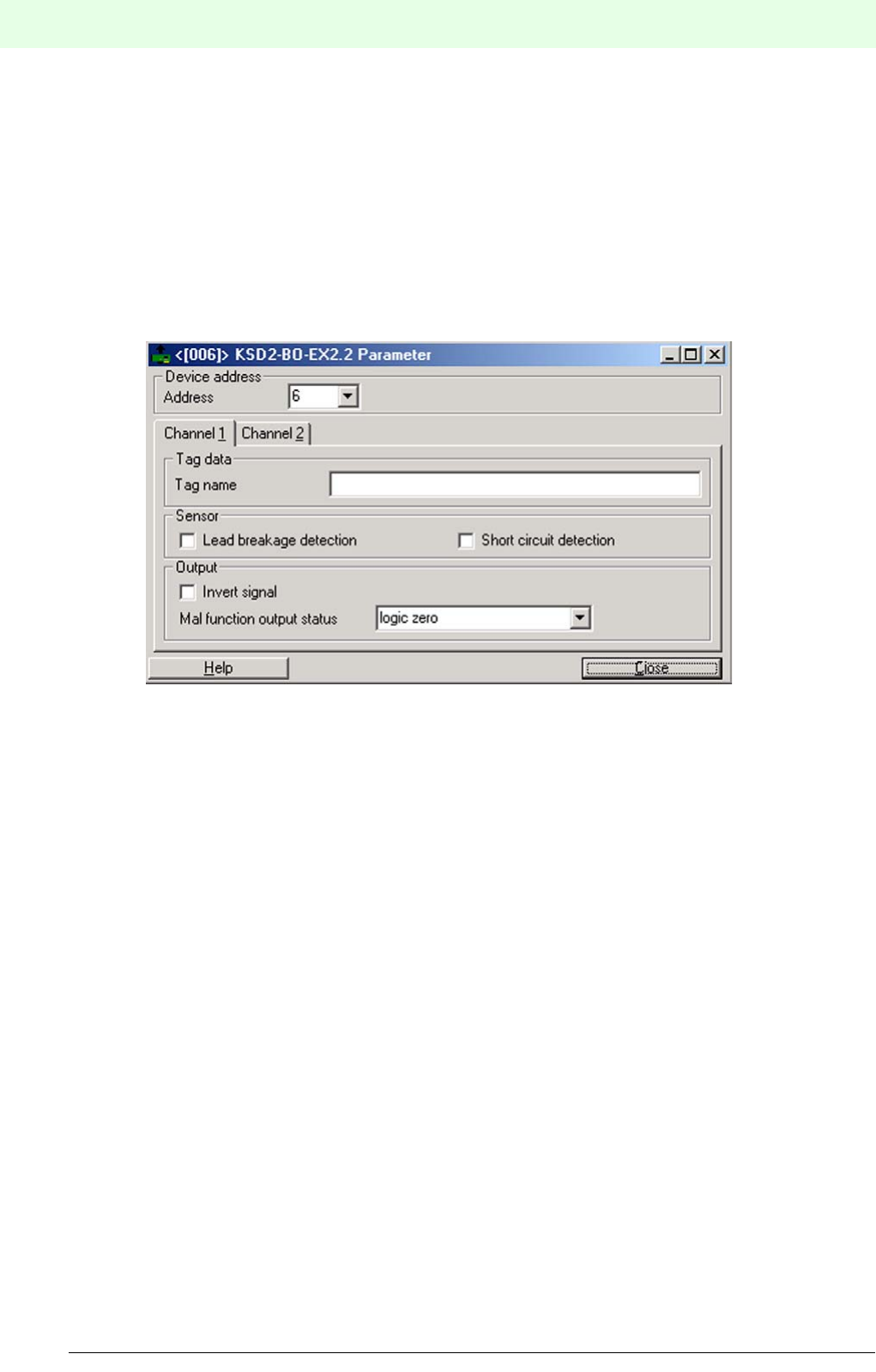
Remote Process Interface
Parameter Assignment
106
S
ubject to reasonable modifications due to technical advances. Copyright Pepperl+Fuchs, Printed in Germany
Pepperl+Fuchs Group • Tel.: Germany +49 621 776-0 • USA +1 330 4253555 • Singapore +65 67799091 • Internet http://www.pepperl-fuchs.com
Date of issue 05/27/03
Output:
Invert Signal: The input signal is inverted and transferred to the bus.
Malfunction Output Status: By means of the settings As Input, Minimum, Maximum or
Last Value the signal transferred to the control system in the
error case is determined according to the application. For the set-
ting As Input a value should be entered in the box on the right
hand side.
6.3.9 Converter for Voltage
The Parameter tab contains both device specific and channel specific parameters.
Figure 6.15:Parameterizing KSD2-VI
Device Address: The entered address must be identical with the address set on
the relevant device.
Tag Data:
Tag Name: It allows you to type in a descriptor (tag name) which may contain
up to 32 characters. This is helpful for larger projects to identify
the devices clearly.
Sensor:
Unit: In this box the input signal can be assigned a physical unit..
Voltage Range: The zero point of the input signal is defined by selecting the volta-
ge range.
Lead fault detection: The sensor lead is monitored for lead breakage.
Limit Values:
Warning limits active: If you check the left box by clicking into it, you activate the
warning limits. Now Lower Limit and Upper Limit turn from
grey to black. The limit values are entered into the boxes on the
right hand side..
Alarm limits active: If you check the left box by clicking into it, you activate the alarm
limits. Now Lower Limit, Upper Limit and Hysteresis
turn from grey to black. The limit values are entered into the bo-
xes on the right hand side.
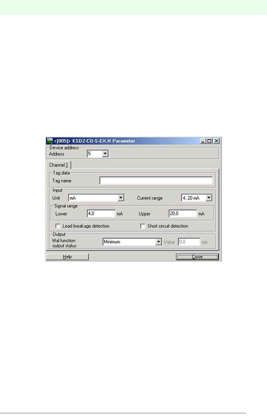
107
Remote Process Interface
Parameter Assignment
Subject to reasonable modifications due to technical advances. Copyright Pepperl+Fuchs, Printed in Germany
Pepperl+Fuchs Group • Tel.: Germany +49 621 776-0 • USA +1 330 4253555 • Singapore +65 67799091 • Internet http://www.pepperl-fuchs.com
Subject to reasonable modifications due to technical advances. Copyright Pepperl+Fuchs, Printed in Germany
Pepperl+Fuchs Group • Tel.: Germany +49 621 776-0 • USA +1 330 4253555 • Singapore +65 67799091 • Internet http://www.pepperl-fuchs.com
Date of issue 05/27/03
Measuring Range:
Start: The start value needs to be entered in order to be able to scale
the measured value.
End: The end value needs to be entered in order to be able to scale
the measured value.
Output:
Invert Signal: The input signal is inverted and transferred to the bus.
Malfunction Output Status: By means of the settings As Input, Minimum, Maximum or
Hold Last Value the signal transferred to the control system
in the error case is determined according to the application. For
the setting As Input a value should be entered in the box on the
right hand side.
6.3.10 Analogue Driver/Repeater
The Parameter tab contains both device specific and channel specific parameters..
Figure 6.16:Parameterizing KSD2-C0-...
Device Address: The entered address must be identical with the address set on
the relevant device.
Tag Data:
Tag Name: It allows you to type in a descriptor (tag name) which may contain
up to 32 characters. This is helpful for larger projects to identify
the devices clearly.
Input:
Unit: In this box the input signal can be assigned a physical unit.
Current Range: The zero point of the input signal is defined by selecting the cur-
rent range.
Lead breakage detection: The sensor lead is monitored for lead breakage.
Short circuit detection: The sensor lead is monitored for short circuits.

Remote Process Interface
Parameter Assignment
108
S
ubject to reasonable modifications due to technical advances. Copyright Pepperl+Fuchs, Printed in Germany
Pepperl+Fuchs Group • Tel.: Germany +49 621 776-0 • USA +1 330 4253555 • Singapore +65 67799091 • Internet http://www.pepperl-fuchs.com
Date of issue 05/27/03
Measuring Range
Start: The start value needs to be entered in order to be able to scale
the measured value.
End: The end value needs to be entered in order to be able to scale
the measured value.
Example:
The current range is 4 ... 20 mA and the measuring range is 1 ...
5 bar. The measured value is transferred via the external bus
with a factor of 100, i.e., for instance at 2.5 bar a value of 250 is
transferred.
Output
Malfunction Output Status: By means of the settings As Input, Maximum, Minimum or
Hold Last Value the signal transferred to the control system
in the error case is determined according to the application. For
the setting As Input a value should be entered in the box on the
right hand side.
6.4 Downloading Project Data into the Gateway
Having configured the RPI system and generated the project offline on the PC, the data is downloaded to
the gateway. The PC/notebook and the gateway are connected as follows:
1. The PC is connected to the RS232 service interface of the gateway via the RS232 serial interface and
the K-ADP2 adapter.
2. The PC is connected to the RS485 service interface of the gateway via a plug-in card with RS485 or
via a RS232/RS485 converter and a K-ADP4 adapter. The adapter is not required if there is a fixed
wiring between the RS485 service interface and the PC.
3. In the case of PROFIBUS DP V1 gateway KSD2-GW2-PRO it is possible to integrate the PC as class
2 master into the PROFIBUS and to transfer the data directly to the gateway via the bus.
The red LEDs of both RPI devices and gateways extinguish after the project data has been transferred to
the gateway, and as soon as the configuration is identical with the transferred parameter data and all field
devices are connected to the RPI system correctly.
The ’External bus - fault’ LED may continue to flash on the gateway, if the bus master is not yet active.
If a redundant gateway is used, the data must also be transferred to the second gateway, as stated above.
Usually, on downloading the parameterization data the commissioning of the RPI system ends, since the
integration into the higher-level bus system is carried out using process control technique. The information
required for this procedure is given in Chapter 7 "Integration into the Higher-Level Bus System".
Verification of the RPI system can also be carried out without a higher level bus system. Information on the
various options is provided in Chapter "Monitoring, Simulating Measured Values and Error Handling" .
6.5 Commissioning the Gateways and the External Bus System
The commissioning procedure strongly depends on the bus system used, e.g. PROFIBUS DP, MODBUS
RTU, MODBUS Plus or ControlNet, as well as on the control system used.
Important information on commissioning the external bus system and the control system will
also be found in the technical documentation of your control system and in Chapter 7 "Integra-
tion into the Higher-Level Bus System"
Prior to commissioning the bus addresses and if necessary the bus termination must be reset.
The gateway automatically adjusts to the transfer rate prescribed by the bus master.
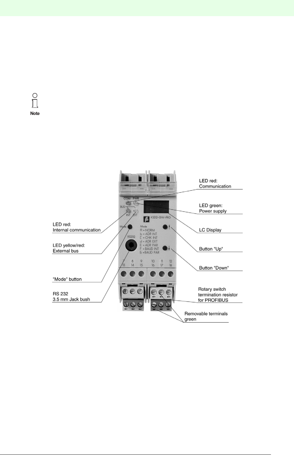
109
Remote Process Interface
Integration into the Higher-Level Bus System
Subject to reasonable modifications due to technical advances. Copyright Pepperl+Fuchs, Printed in Germany
Pepperl+Fuchs Group • Tel.: Germany +49 621 776-0 • USA +1 330 4253555 • Singapore +65 67799091 • Internet http://www.pepperl-fuchs.com
Date of issue 05/27/03
7 Integration into the Higher-Level Bus System
7.1 General Notes on Operating the Gateways
This chapter provides information on all functions and communications which are identical for all gateways.
7.1.1 Gateways of Type KSD2-GW-...
The construction and operation of the KSD2-GW-... gateways, using the controls on the front of the devices
is similar for all types. They only differ in that they contain either RS232 or RS485 service interfaces.
Gateways with RS485 service interfaces have no jack. Detailed information on the differences between ga-
teways for PROFIBUS, Modbus RTU, Modbus Plus and ControlNet is provided from Chapter 7.2 onwards.
Chapter 5 "Configuring and Commissioning the RPI System" provides an explanation of the RPI system
configuration via the gateway pushbuttons and of the menu structure.
Construction of the devices:
Figure 7.1:Front View of the KSD2-GW-... gateways
In the case of gateways with RS232 service interfaces, the terminal connection and the jack
must not be used simultaneously since simultaneous data transfer is not possible on the inter-
nal bus.
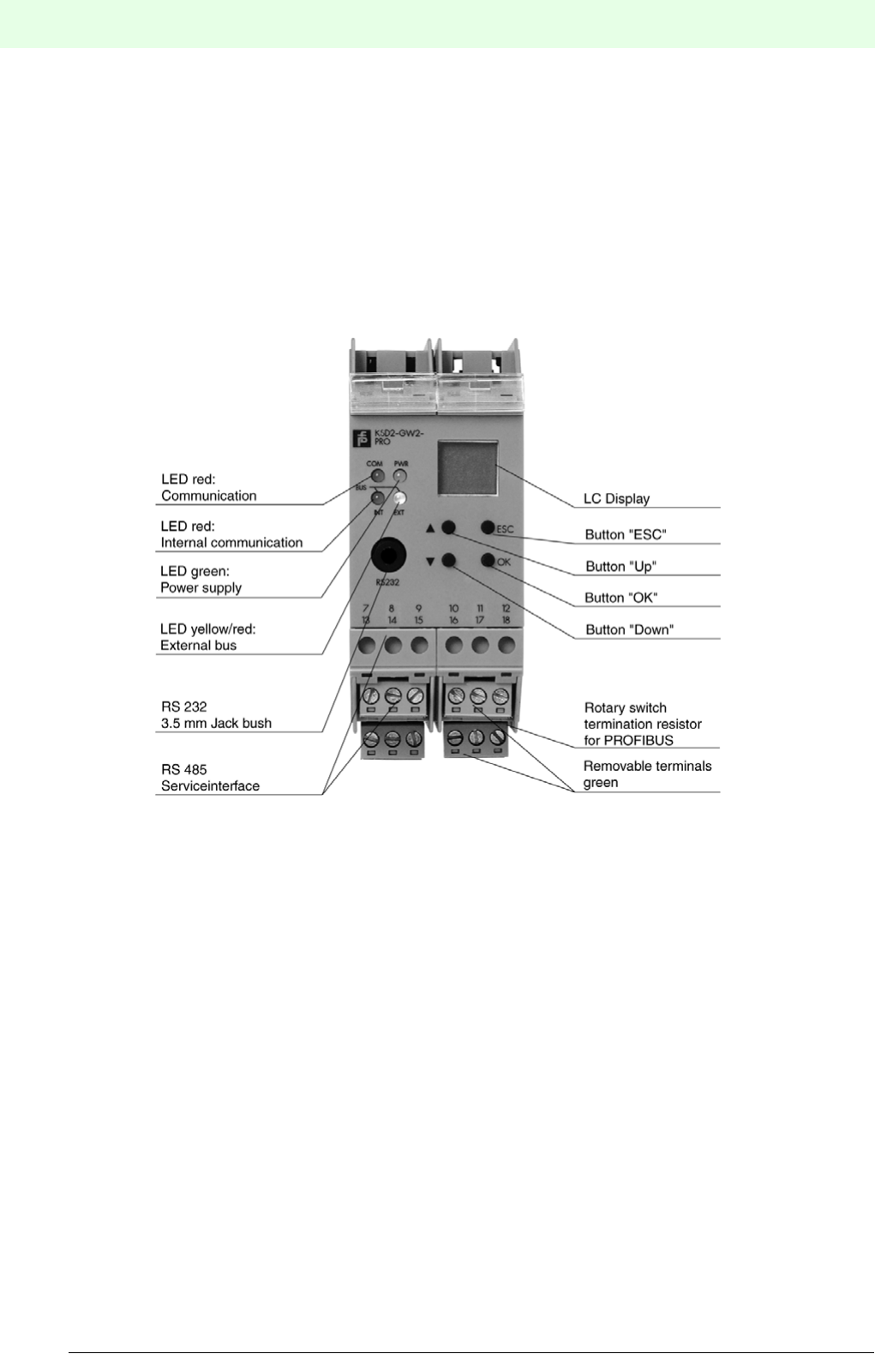
Remote Process Interface
Integration into the Higher-Level Bus System
110
S
ubject to reasonable modifications due to technical advances. Copyright Pepperl+Fuchs, Printed in Germany
Pepperl+Fuchs Group • Tel.: Germany +49 621 776-0 • USA +1 330 4253555 • Singapore +65 67799091 • Internet http://www.pepperl-fuchs.com
Date of issue 05/27/03
7.1.2 Gateways of Type KSD2-GW2-..
Gateways of type KSD2-GW2-... have both RS232 and RS485 service interfaces, a double-row LC-Display
and four buttons for menu prompting. The RS485 interface is connected via the terminals 7, 8 and 9 whe-
reas the RS232 interface is designed as a 3.5 mm jack plug located on the front of the device. Since both
interfaces are independent they can be used simultaneously. Detailed information is given in Chapter 7.2
"Gateways for PROFIBUS DP". Chapter 5 "Configuring and Commissioning the RPI System" provides an
explanation of the RPI system configuration by means of the gateway pushbuttons and of the menu struc-
ture.
Construction of the devices:
Figure 7.2:Front view of the KSD2-GW2-... gateways
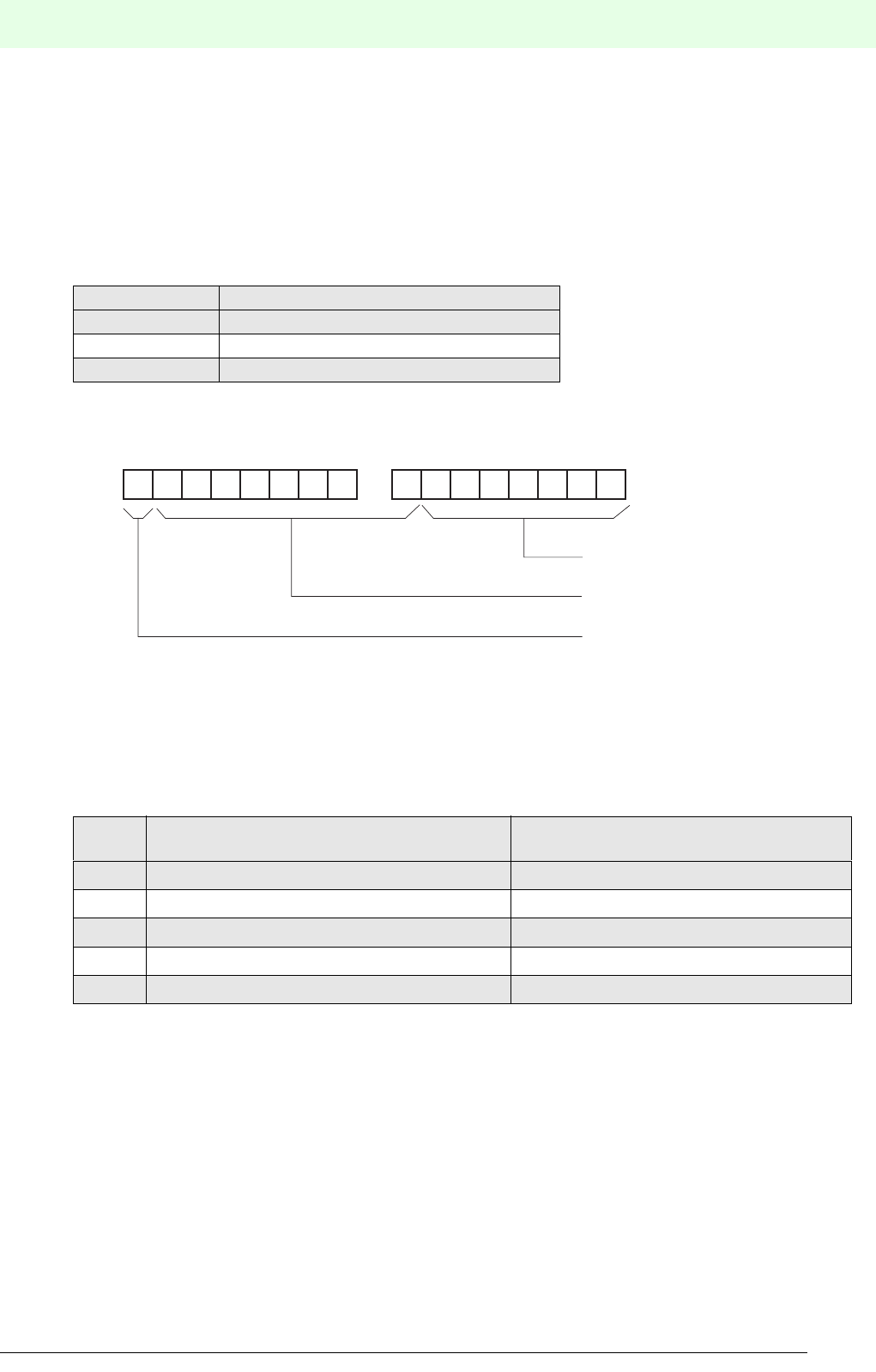
111
Remote Process Interface
Integration into the Higher-Level Bus System
Subject to reasonable modifications due to technical advances. Copyright Pepperl+Fuchs, Printed in Germany
Pepperl+Fuchs Group • Tel.: Germany +49 621 776-0 • USA +1 330 4253555 • Singapore +65 67799091 • Internet http://www.pepperl-fuchs.com
Date of issue 05/27/03
7.1.3 Data Formats
Analogue values of the different RPI modules or values for the configuration and parameterization of the
system can be transmitted either in signed integer (integer numbers) or in floating point format.
Floating-point arithmetic
In the case of both RPI-internal communication and communication to the host computer, the floating point
values are transmitted with single precision in accordance with "IEEE 754 short real number".The values
are stored at 4 bytes (=32 bit) and the memory block is classified as follows:
The sign bit 31 indicates whether the stored number be positive (s=0) or negative (s=1). The 8 exponent
bits constitute the exponent. However, a BIAS of 127 has to be subtracted from each exponent. In other
words, in the exponent a bit sequence of 111 1111 (corresponds to 127) stands for exponent 0. The 23 ma-
tissa bits represent the 23 fractional digits of a 24-digit binary number. The first digit before the dual point is
always 1. It is not stored.
The following table provides examples of "simple" floating point numbers.
Integer format
2 byte are required to transmit the measured values in the signed integer format. Likewise, 2 byte are re-
quired in order to represent numbers from -32.768 to +32.767 in the signed integer format. In order to achie-
ve a more accurate transfer of the data, temperature measurement values are transferred with a factor of
10 whereas current input and output values are transferred with a factor of 100. As a result, the transfer of
the numerical value of 1560 leads to a measured value of 156.0 °C for temperature measurements or
15.6 mA for mA-measurements.
Bit position Meaning
31 Sign bit
30-23 Exponent (with a BIAS of 127)
22-0 Mantissa
Numbe
rBinary notation (Sign, Exp., Mantissa) Meaning
1.0 0011 1111 1000 0000 0000 0000 0000 0000 +/127-127/1.00 => 20 * 1.00 = 1
5.0 0100 0000 1010 0000 0000 0000 0000 0000 +/129-127/1.25 => 22 * 1.25 = 5
-13.0 1100 0001 0101 0000 0000 0000 0000 0000 - /130-127/1.625 => 23 * 1.625 = -13
16.5 0100 0001 1000 0100 0000 0000 0000 0000 +/131-127/1.03125 =>24 * 1.03125 = 16.5
125.635 0100 0010 1111 1011 0100 0101 0000 0000 +/133-127/1.9630469 => 26 * M = 125.635
31 30 29 28 27 26 25 24
MSB 1. Byte LSB
Bit-No. 23 22 21 20 19 18 17 16
MSB 2. Byte LSB
Mantissa
Exponent
Sign bit

Remote Process Interface
Integration into the Higher-Level Bus System
112
S
ubject to reasonable modifications due to technical advances. Copyright Pepperl+Fuchs, Printed in Germany
Pepperl+Fuchs Group • Tel.: Germany +49 621 776-0 • USA +1 330 4253555 • Singapore +65 67799091 • Internet http://www.pepperl-fuchs.com
Date of issue 05/27/03
7.1.4 Status Information of Process Data
Profibus, Modbus RTU, Modbus Plus and ControlNet can also transfer the status of process values.
Depending on the status, the transferred value is either reprocessed or rejected. The space occupied by
the status information per channel of a device is 1 byte for the PROFIBUS protocol, 1 register for Modbus
RTU, 1 word for Modbus Plus, and 1 word for ControlNet 1.
During the transfer of analogue values, bit 0 of the low byte (Dat) is always set to 0. Binary signals are trans-
ferred via bit 0 of the low byte (Dat).
Bits GW1 and GW2 are reserved for limit value monitoring.
CD1 to CD3 code any errors which have occurred.
Q1 and Q2 provide information on the signal quality.
The messages shown in the table below are generated instantaneously.
7.1.5 Operation with a Redundant Gateway
Operation with redundant gateways increases the availability of the system. The gateway that is active in
normal operation must have the RPI address 1, whilst the redundant gateway must have the RPI address 2.
The prerequisite for the operation of a system with a redundant gateway, is that the configuration data for
each RPI device is stored in a file in the current project directory.
The following describes the installation procedure that is necessary in the case of a gateway newly deliver-
ed from the manufacturer..
If this not the case, connect the Modbus gateway alone to a 24 V DC supply and depress the mode button
in mode A (for KSD2-GW-... ) for longer than 3 s or depress the OK button in the 'Teach-in' service menu
(for KSD2-GW2-...). This causes the current configuration (here: no device) to be taught-in.
In the following it is assumed that the RPI devices are pre-configured and mounted on the Power Rail. If this
is not the case, then when the active gateway has been installed (step 1) the RPI devices must be addres-
sed. The information required for this procedure is given in Chapter 5 ’Configuration’ and in Chapter 6 ’Pa-
rameter Assignment’.
Meaning GW2 GW1 CD3 CD2 CD1 Q2 Q1 Dat
Good 0 0
Not certain 010
Bad 000100
Good, no error 0 00000
Measurement range exceeded/fallen
short
011010
Simulated measured value 101010
Reserved 110010
Configuration error 001100
RPI device error 010100
Field device error 100100
No communication (last good value) 101100
No limit value reached 0 0 0
Lower limit value fallen short 0 1 0
Upper limit value exceeded 1 0 0

113
Remote Process Interface
Integration into the Higher-Level Bus System
Subject to reasonable modifications due to technical advances. Copyright Pepperl+Fuchs, Printed in Germany
Pepperl+Fuchs Group • Tel.: Germany +49 621 776-0 • USA +1 330 4253555 • Singapore +65 67799091 • Internet http://www.pepperl-fuchs.com
Date of issue 05/27/03
The following sequence should then be carried out:
1. Mount a gateway on the Power Rail and set the RPI address of this gateway to 1 (active gateway).
2. Teach in the current configuration via mode A or via the 'Teach-in' menu.
3. Load the project into the gateway (download) using the PACTwareΤΜ software or transmit the configu-
ration and parameterization data by means of Profibus DP V1, as described in Chapter 6.4 "Downloa-
ding Project Data into the Gateway" .
4. Mount the 2nd gateway on the Power Rail and set the RPI address of this gateway to 2 (redundant
gateway).
5. Connect the PC to the redundant gateway and then repeat steps 2 and 3 for the redundant gateway.
If the project has been downloaded into the redundant gateway, the system is ready for redundant operati-
on.
When both gateways have been configured, the type and method of switching from the active to the redun-
dant gateway must be established. This is achieved by setting the modes for the master of the fieldbus. The
following modes can be set:
The active gateway (master) is set to 01 and the redundant gateway is set to 03 as standard. The advantage
of this setting is that, in the event of an error after which the defective gateway is replaced, the gateway
which is given the internal address 1 is always active.
7.1.6 Exchanging a Gateway
The addresses and parameters for the new gateway are set via PC and thePACTwareΤΜ edition 2 human
machine interface. Normal operation is resumed. A status information on the elimination of the fault is trans-
mitted via the external bus.
7.1.7 Exchanging a Gateway - External Bus Redundant
If the system is redundant, due to the use of 2 gateways and two external bus branches, one gateway is
defined as active (priority) and the other as redundant.
If one external bus branch or one gateway fails, then communication takes place via the second gateway
and the second bus branch. A status information on the interference is transmitted via the external bus
branch.
The addresses and parameters for a new gateway are set by means of a PC and the PACTwareΤΜ edition 2
human machine interface.
The active and the redundant gateway must receive different addresses for the PROFIBUS.
Value Description
00h Automatic switch-over to redundant gateway, in the event of the active gateway beco-
ming defective
01h Like 00, but also in the event of errors in the communication with the host
02h Switch-over to the redundant gateway by the host (see gateway diagnosis)
03h Switch-over of the passive gateway into the active mode
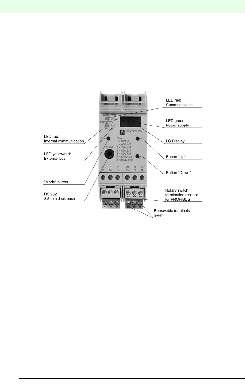
Remote Process Interface
114
S
ubject to reasonable modifications due to technical advances. Copyright Pepperl+Fuchs, Printed in Germany
Pepperl+Fuchs Group • Tel.: Germany +49 621 776-0 • USA +1 330 4253555 • Singapore +65 67799091 • Internet http://www.pepperl-fuchs.com
Date of issue 05/27/03
7.2 Gateways for PROFIBUS DP
7.2.1 Gateways KSD2-GW-PRO and KSD2-GW-PRO.485
Gateways of type KSD2-GW-PRO and KSD2-GW-PRO.485 support the cyclic PROFIBUS DP data protocol
in accordance with EN 50170/8-2. The KSD2-GW-PRO gateway has an RS232 service interface both in the
form of a jack on the front and on screw terminals. The KSD2-GW-PRO.485 gateway has an RS 485 service
interface, which is merely connected to the screw terminals. The controls consist of an LC-display with 3 1/
2 digits and the three buttons "Mode", "Up" and "Down".
Figure 7.3:KSD2-GW-PRO gateway
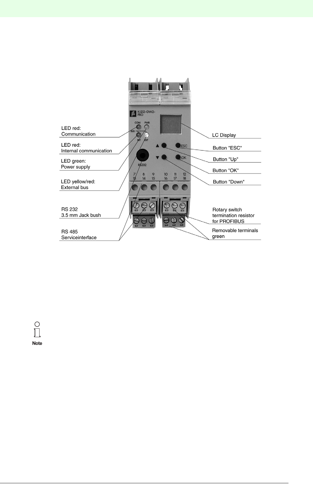
115
Remote Process Interface
Subject to reasonable modifications due to technical advances. Copyright Pepperl+Fuchs, Printed in Germany
Pepperl+Fuchs Group • Tel.: Germany +49 621 776-0 • USA +1 330 4253555 • Singapore +65 67799091 • Internet http://www.pepperl-fuchs.com
Date of issue 05/27/03
7.2.2 Gateway KSD-GW2-PRO
The KSD2-GW2-PRO gateway supports the cyclic and acyclic PROFIBUS DP V1 data protocol and has
both serial service interfaces RS232 and RS485. The controls consist of a two-lined alphanumeric LC-dis-
play with 4 digits and the four buttons "OK", "ESC", "Up" and "Down".
Figure 7.4:KSD2-GW2-PRO gateway
7.2.3 General Notes on PROFIBUS DP
PROFIBUS DP (distributed peripherals) is a standardised field bus that allows the rapid exchange of data
between central automation devices and distributed field devices such as sensors and actuators. Meanw-
hile, the cyclic data exchange to DIN 50170 has been supplemented by PROFIBUS DP V1, which is also
referred to as acyclic data data traffic.
Further information can be found in the PROFIBUS standard, EN 50170 (DIN 19245) and the
relevant literature.
The PROFIBUS user association, PROFIBUS Nutzerorganisation e.V. (PNO), Karlsruhe, pub-
lishes information brochures and a PROFIBUS product catalogue:
PROFIBUS Nutzerorganisation e.V.
Haid-und-Neu-Str. 7
D-76131 Karlsruhe
Tel.: 0721 9658-590
http:/www.profibus.com

Remote Process Interface
116
S
ubject to reasonable modifications due to technical advances. Copyright Pepperl+Fuchs, Printed in Germany
Pepperl+Fuchs Group • Tel.: Germany +49 621 776-0 • USA +1 330 4253555 • Singapore +65 67799091 • Internet http://www.pepperl-fuchs.com
Date of issue 05/27/03
7.2.4 Features of the PROFIBUS Gateways
The KSD2-GW-PRO, KSD2-GW-PRO.485 and KSD2-GW2-PRO RPI gateways connect the internal RPI
bus to the external PROFIBUS.The gateway thus assumes the master function for the internal bus. The ga-
teway has the function of a modular DP slave device on the external PROFIBUS. To increase system avai-
lability, the gateway and external bus can be implemented in a redundant configuration.
7.2.5 Device Connection
The electrical connection of the PROFIBUS-DP gateways by means of cables, merely involves establishing
the PROFIBUS connection.
7.2.5.1 Gateways of Type KSD2-GW-PRO and KSD2-GW-PRO.485
The RS 232 interface is only used to configure the RPI system. To do this, the PC (with the PACTware
human machine interface) is connected to the jack on the front of the gateway via the K-ADP2 adapter. If
the PC is to remain permanently connected to the RPI system as a parameterization and monitoring system,
it is recommended that connection is made via the RS485 service interface using the plug-in screw termi-
nals 7, 8 and 9.
7.2.5.2 KSD2-GW2-PRO Gateway
The KSD2-GW2-PRO gateway is provided with both service interfaces. The RS 232 service interface is
connected to the jack on the front while the RS 485 service interface is connected to the terminals.
7.2.5.3 Wiring
The connection to the 24 V DC power supply and to the internal bus are made via the Power Rail.
The cable connections are made via self-opening screw terminals; max. core cross-section 1 x 2.5 mm² for
rigid cable or 2 x 1,5 mm² for flexible cable with plastic wire end ferrule. The screw terminal blocks can be
pulled out of the device for easier connection.
Fit the gateway to the Power Rail and connect the PROFIBUS cable and, if necessary, the RS 232/RS 485
cable, as shown in the connection diagram and the terminal assignment list.
The current connection plan of the gateways is given in the “Modular Interface Housings”
catalogue.
7.2.6 PROFIBUS Transmission Rate
The PROFIBUS gateway synchronises itself
with the transmission rate of the PROFIBUS master
The following transmission rates are supported:
• 9.6 kbit/s
• 19.2 kbit/s
• 93.75 kbit/s
• 187.5 kbit/s
• 500 kbit/s
• 1.500 kbit/s
In the case of the KSD-GW-PRO.485 gateway, with RS 485 parameterization interface, only the
terminal connection is available.
The jack on the front of the KSD-GW-PRO gateway and the screw terminal connection for the
RS232 link cannot be used simultaneously.
Both service interfaces must not communicate with the gateway simultaneously.

117
Remote Process Interface
Subject to reasonable modifications due to technical advances. Copyright Pepperl+Fuchs, Printed in Germany
Pepperl+Fuchs Group • Tel.: Germany +49 621 776-0 • USA +1 330 4253555 • Singapore +65 67799091 • Internet http://www.pepperl-fuchs.com
Date of issue 05/27/03
Bus termination
With PROFIBUS, each bus segment must be terminated at both ends with terminating resistors.
Figure 7.5:Rotary switch S1 for bus termination
The PROFIBUS gateways incorporate a switchable internal bus termination.Using a screwdriver, the bus
termination can be activated on the rotary switch S1 on the right side of the housing (as viewed from the
front). This is used if the gateway is installed at the end of a line.
7.2.7 Screening and EMC
The screening of cables provides protection against electromagnetic interference and increases electroma-
gnetic compatibility.
The gateway are provided with two ground terminals (15, 16). These terminals have to be connected to
ground at the place of installation.
7.2.8 GSD Files
Pepperl+Fuchs provides 2 different GSD files for the configuration of an RPI/Profibus gateway:
• the PF0818.GSD file
• the PF0818P.GSD file
If the PF0818.GSD file is used
• a parameterization of the RPI devices by means of PACTware is obligatory
• up to 8 RPI devices can be allocated to 1 PROFIBUS DP data module (pack). This is obligatory, if there
are more than 64 RPI devices on a gateway.
• In case a gateway has to be replaced, the new gateway should be parameterized via the service inter-
face (no parameterization via PROFIBUS)
The transmission rate depends on the length and type of the cable used. Detailed information
can be obtained from the PROFIBUS specification EM 50170/2.
Information on the construction of a screen is given in the PROFIBUS directive ’PROFIBUS-DP/
FMS’ - available from PNO (order No. 2111).
If cables with a double screen are used, e.g. wire braiding and metallised foil, both screens
must be connected together at the cable ends with a low-resistance connection when making
up the cable.
Power supply cables are a source of much interference radiation, e.g. the switching current of a
three-phase motor. For this reason, the laying of supply cables and signal/data cables in paral-
lel runs should be avoided, especially within the same ducting.
Rotary switch 'S1' for
bus termination on the
right side of the device
Actuating by means
of a screw driver
Bus termination
active!
Bus termination
not active!
S1
1
0

Remote Process Interface
118
S
ubject to reasonable modifications due to technical advances. Copyright Pepperl+Fuchs, Printed in Germany
Pepperl+Fuchs Group • Tel.: Germany +49 621 776-0 • USA +1 330 4253555 • Singapore +65 67799091 • Internet http://www.pepperl-fuchs.com
Date of issue 05/27/03
If the PF0818P.GSD file is used
• parameter assignment of the RPI devices is carried out via PROFIBUS. However, not all the functions
of the RPI devices can be accessed. For example, scaling will no longer be possible for analogue inputs
or outputs!
• Likewise, packing modules will no longer be possible (exception: up to 4 temperature converters can
be packed).
Defined Modules and Data Types
Many different types of module are defined in the GSD files to allow all RPI devices to be clearly represented
as DP slave modules.
The modules defined are oriented to the function of the RPI modules and differ according to
Examples:
In addition to the modules shown above, other modules that perform special functions are defined.
These are:
Empty modules
•Type of data: input data (I)
output data (O)
•Data format: binary (D)
analogue, format: signed integer (A _INT)
analogue, format: FLOAT (floating point, A _FLOAT)
• Status information: with status information (_S, _STAT)
without status information
• Number of channels 1 ... 8
•Number of RPI modules: 1 ... 8 (nx) - Note: packing the modules
Type of module Explanation
4DI_STAT 1 RPI device with 4 channels,
binary input data,
with status information
1AO_FLOAT 1 RPI device with 1 channel,
analogue output data,
floating point data format
without status information
4x2DO_S KSD2-BO-Ex2 4 RPI devices, each with 2 channels
are packed, binary output data,
with status information,
RPI device type KSD2-BO-Ex2
Empty modules allow place holders to be included in the DP master configuration for modules
that are not yet installed.The use of these empty modules in the configuration avoids the need
to change addresses later, which can lead to problems, especially in the application program, if
the RPI system has to be upgraded or expanded.
The defined empty modules are given in the device master file (GSD file).
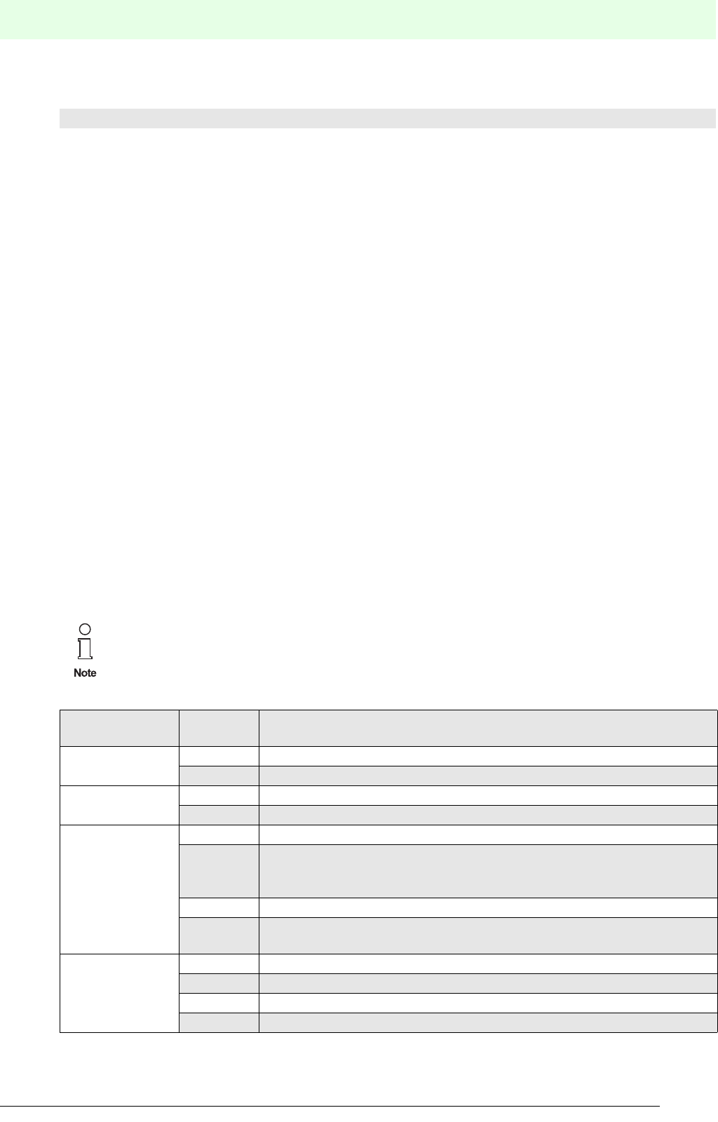
119
Remote Process Interface
Subject to reasonable modifications due to technical advances. Copyright Pepperl+Fuchs, Printed in Germany
Pepperl+Fuchs Group • Tel.: Germany +49 621 776-0 • USA +1 330 4253555 • Singapore +65 67799091 • Internet http://www.pepperl-fuchs.com
Date of issue 05/27/03
Example:
7.2.9 Configuration of the Cyclic Communication
Prior to configuration, the GSD file selected for the RPI system should be copied into the prescribed direc-
tory of the configuration tool.
Having started the program, the master for the PROFIBUS communication in a new project has to be sel-
ected and the hardware is to be configured. By inserting the CPU or the communication module, the pro-
perties of the PROFIBUS stations, such as PROFIBUS address, baudrate and the profile can be set.
7.2.9.1 Representation of the Gateway in the DP Master System
On opening the GSD file, the RPI structure tree is reproduced in the configuration tool in order to establish
the communication. This is done, by selecting the gateway from the GSD-file list and adding it to the master
system. By adding the gateway as a DP slave, the PROFIBUS address is automatically assigned. The latter
must correspond either to the external address in Mode 'd' or to the one in the ’Address Assign' service
menü on the gateway. The PROFIBUS address, can be changed and adapted to the gateway address.
When a second gateway is used (redundant gateway), the RPI structure tree of the priority gateway is co-
pied and pasted to the redundant one. The addresses of the two gateways must differ (this does not apply
to redundant gateways operated at high-availability control systems).
The settings for the four user parameters of the DP slave must be selected according to the details listed
below.
• Acyclic access via the cyclic data channel (module 0 access). This functionality is not specified in this
handbook.
• Signed Integer or FLOAT format for analogue values
• Operation with or without redundant gateway
• With or without status transmission
Module type Explanation
0x1AO_INT_S KSD2-CO-Ex 0 (empty module) RPI devices with 1 channel, analogue output data,
‘signed integer’ data format with status information,
RPI device type KSD2-CO-Ex
Please note that the settings that are made via the user parameters will apply to all RPI devices
of the gateway!
User parameter
byte Value Meaning
100h no module 0 access (standard setting)
01h module 0 access activated
200h signed integer format for analogue values
01h floating point format for analogue values
3
00h no redundant gateway available (standard setting)
01h automatic switch-over to redundant gateway, in the event of the active
gateway becoming defective (recommended for gateway with RPI inter-
nal address 2)
02h redundant gateway waiting for switch-over command
03h Switch-over of the passive gateway into the active mode (recommended
for gateway with RPI internal address 2)
4
x0h without status transmission
x1h with status transmission
0xh packing only possible using special IDs
1xh packing always possible
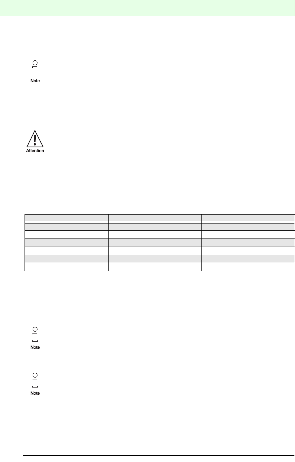
Remote Process Interface
120
S
ubject to reasonable modifications due to technical advances. Copyright Pepperl+Fuchs, Printed in Germany
Pepperl+Fuchs Group • Tel.: Germany +49 621 776-0 • USA +1 330 4253555 • Singapore +65 67799091 • Internet http://www.pepperl-fuchs.com
Date of issue 05/27/03
The setting of the data format for analogue values (user parameter byte 2) and the transmission of status
values via the data telegram both have an effect on the data volume to be transmitted and thus on the me-
mory space requirement and the cycle time.
More detailed information is given in section 7.2.9.3.
7.2.9.1 Representation of the RPI modules in the Gateway
The term "module" in the following description means the software module that communicates with PROFI-
BUS DP.
If you wish to deactivate status signals such as lead breakage for individual devices, you can do so by set-
ting the device data in the parameterization software accordingly.
The assignment of the RPI devices to the individual DP slave module addresses is carried out automatically
by the gateway, but can also be changed by a class 2 DP master device using the Set_Slave_Add
function.A new DP slave module is always installed in the plug-in station with the lowest free DP slave mo-
dule address. If no more than 64 RPI devices are connected to the gateway, each device is assigned its
own DP slave module address.
A terminal strip for marshalling signals must be provided for conventional MSR systems (see Chapter 6
’Commissioning’). This can be done on the software side, by assigning the RPI module a different RPI bus
address.
This assignment is no longer possible if there are more than 64 RPI devices on the gateway. In this case,
up to eight identical RPI devices are assigned to a DP slave module (by means of the PF0818-GSD GSD
file), and these are addressed by the DP master device using a common address.
The sum of all the identifiers in a configuration must not exceed 244 bytes. This is a PROFIBUS constraint.
Independent of whether data transfer is carried out with or without status, the PROFIBUS diag-
nosis can be evaluated at any time!
When selecting the RPI devices the following PROFIBUS-specific details should be considered:
Use the status transmission for all or none of the devices, depending on the parameterization
of the gateway.
Always use either INT or FLOAT as a data format for analogue values.
RPI Bus Address RPI Device DP Slave Module Address
10 KSD2-BI-Ex4 0
11 K SD 2-B O- Ex 2. 2 1
12 KSD2-TI-Ex 2
20 KSD2-CO-Ex 3
21 KSD2-BI-Ex2 4
40 KSD2-CI-S-Ex.H 5
To allow the gateway’s automatic DP slave module address assignment function to continue to
operate in this case, the devices included in a DP slave module must have
consecutive RPI addresses.
If the limit of 244 bytes for the sum of all identifiers in a configuration is approached, module
types that will support a number of RPI devices per module should be used as much as pos-
sible.
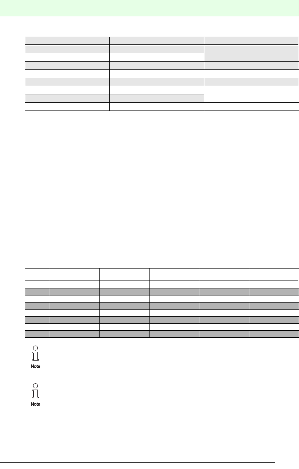
121
Remote Process Interface
Subject to reasonable modifications due to technical advances. Copyright Pepperl+Fuchs, Printed in Germany
Pepperl+Fuchs Group • Tel.: Germany +49 621 776-0 • USA +1 330 4253555 • Singapore +65 67799091 • Internet http://www.pepperl-fuchs.com
Date of issue 05/27/03
When configuring a PROFIBUS DP system, each module must be assigned a module type. The available
module types are defined in the device master data file.
7.2.9.2 Data Structure on the PROFIBUS
Each device inserted into the DP slave window is automatically assigned an address range. The assign-
ment of peripheral addresses to the RPI devices or to the individual DP slave modules is carried out auto-
matically via the PLC or the host computer. However, it is also possible to assign the addresses manually
to a specified input and/or output address range.
The data without status information from binary devices occupies one bit per channel. The switching state
of the lowest channel number is located in the lowest bit. The efficiency of a data transmission can be
increased either by packing a number of RPI modules into one DP slave module or by using multi-channel
RPI modules, since, otherwise, only one bit would be occupied whereas one byte is required for the trans-
mission.
The data transmission with status information occupies one byte per channel. The switching state of the
channel is located in the lowest bit and the remaining bits transfer the status, see Chapter 7.1. ’Status De-
scription’.
The data of the analogue devices is transmitted in decimal format (DEC). Temperature values are transmit-
ted in the signed integer format at a factor of 10, whereas current values are transmitted at a factor of 100.
Data transmission requires 2 byte in the signed integer format and 4 bytes in the FLOAT format. For a status
information an additional byte is required, which is placed in front of the data bytes, adding up to 3 or 5 bytes
per transmission.
RPI Bus Address RPI Device DP Slave Module Address
10 KSD2-BI-Ex4 0
11 KSD2-BI-Ex4
12 KSD2-TI-Ex 1
... ... ...
79 KSD2-BO-Ex4 41
80 KSD2-CO-Ex 42
81 KSD2-CO-Ex
90 KSD2-CI-S-Ex 43
RPI
Address
RPI Modules
Type
DP Module
Description
DP Module
Address
Input Address
Length
Output Address
Length
10 KSD2-BI-Ex4 4 DI 0 1 byte ---
11 KSD2-BO-Ex2 2 DO 1--- 1 byte
12 KSD2-TI-Ex 1 AI_INT 2 2 byte ---
20 KSD2-CO-Ex 1 AO_INT 3--- 2 byte
21 KSD2-BI-Ex2 2 DI 4 2 byte
32 KSD2-CO-Ex 1 AO_FLOAT_S 51 4 bytes
36 KSD2-CI-S-Ex 1 AI_FLOAT_S 6 5 bytes
40 KSD2-CI-S-Ex 1 AI_INT 72 byte
It is not possible to combine ’INT’ and ’FLOAT’ or ’with status’ and ’without status’ in a transmis-
sion. This is a PROFIBUS constraint.
Further restrictions are: a maximum of 64 DP slave modules per RPI system and a maximum of
244 bytes for the identifier of I/O data. This corresponds to the sum of all bytes in the ’input/out-
put address’ column.
The data of a maximum of 48 analogue modules with status and 'Floating Point’ format can be
transmitted using 244 bytes.
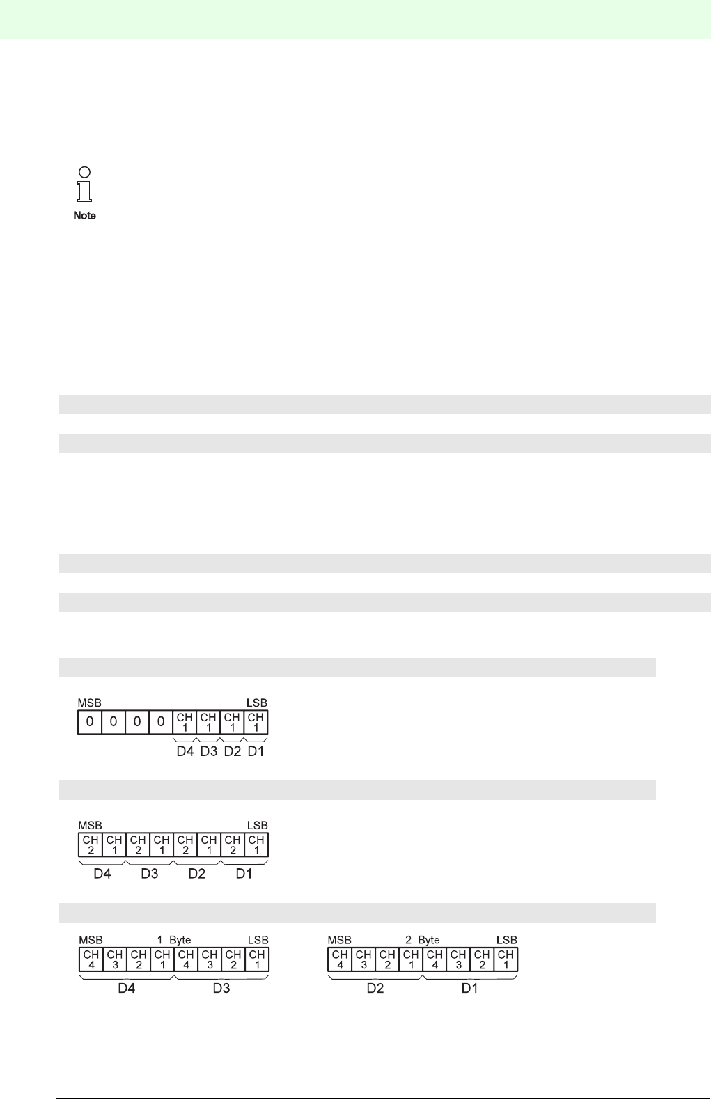
Remote Process Interface
122
S
ubject to reasonable modifications due to technical advances. Copyright Pepperl+Fuchs, Printed in Germany
Pepperl+Fuchs Group • Tel.: Germany +49 621 776-0 • USA +1 330 4253555 • Singapore +65 67799091 • Internet http://www.pepperl-fuchs.com
Date of issue 05/27/03
7.2.9.3 Format of the Input and Output Data
As described in the previous section, the module identifier specifies the data type and format and whether
status information is to be transmitted. The format of the input and output data for the individual module ty-
pes is described in this section.
Data types
The following data types are used to represent input and output data:
Data structure
The structure of the data bytes transmitted is given below.
The following abbreviations are used:
Binary input and output data without status
It should be noted that input and output data each have their own data area.This means that, for
output modules, where status information is to be transmitted in addition to the user data, the
status information is in the input data area and is not transmitted with the user data as is the
case with the input data.
On a number of RPI modules (1...8) per module, the data is arranged module by module in
ascending order according to the RPI bus address.
If a module has several channels, the data is arranged in ascending order by channel.
The arrangement of binary data within a byte is in ascending order from bit 0.
• boolean bit by bit data organisation
• signed integer 2 byte integer format with sign
• FLOAT 4 byte floating-point to IEEE 754 standard, short real number
CH =channel =channel number of an RPI device
D = device = number of the RPI device within a module
n = 1...8
1-channel modules: Module types:n x 1DI, n x 1DO
2-channel modules: Module types: n x 2DI, n x 2DO
4-channel modules: Module types: n x 4DI
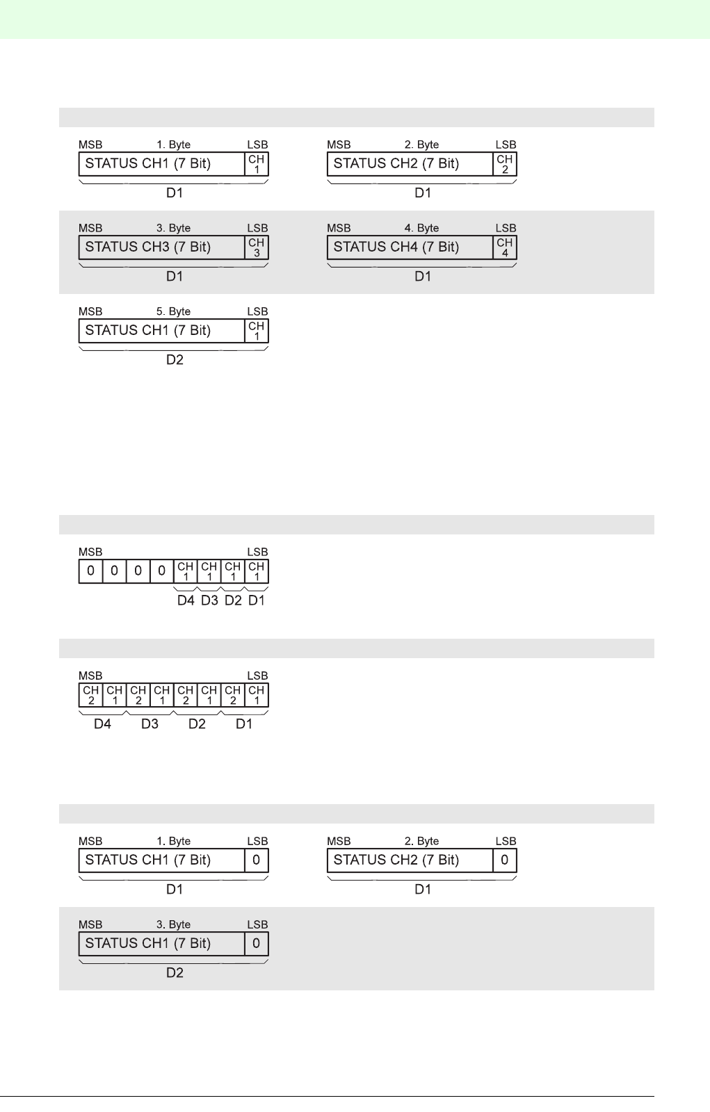
123
Remote Process Interface
Subject to reasonable modifications due to technical advances. Copyright Pepperl+Fuchs, Printed in Germany
Pepperl+Fuchs Group • Tel.: Germany +49 621 776-0 • USA +1 330 4253555 • Singapore +65 67799091 • Internet http://www.pepperl-fuchs.com
Date of issue 05/27/03
Binary input data with status
Binary output data with status
In the case of output data with status information, the DP master sends the output data to the DP slave and
receives the status data as input data in a reply telegram, i.e. the output data is in the output data area and
the status data is in the input data area of the module.
Output data area
Input data area
1...4-channel modules: Module types: n x 2DI_S, n x 4DI_S
etc.
1-channel modules: Module types: n x 1DO_S
2-channel modules: Module types: n x 2DO_S
1...2-channel modules: Module types: n x 1DO_S, n x 2DO_S
etc.
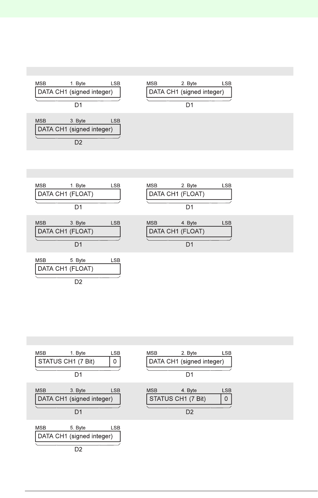
Remote Process Interface
124
S
ubject to reasonable modifications due to technical advances. Copyright Pepperl+Fuchs, Printed in Germany
Pepperl+Fuchs Group • Tel.: Germany +49 621 776-0 • USA +1 330 4253555 • Singapore +65 67799091 • Internet http://www.pepperl-fuchs.com
Date of issue 05/27/03
Analogue input and output data without status
Data type: signed integer
Data type: FLOAT
Analogue input data with status
Data type: signed integer
1-channel modules: Module types: n x 1AI_INT, n x 1AO_INT
etc.
1-channel modules: Module types: n x 1AI_FLOAT, n x 1AO_FLOAT
etc.
1-channel modules: Module types: n x 1AI_INT_S
etc.
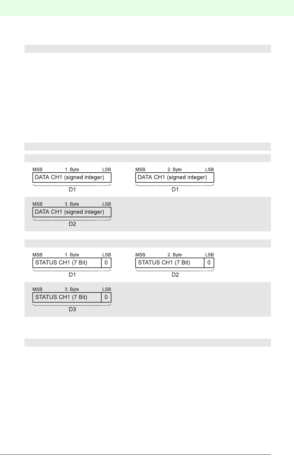
125
Remote Process Interface
Subject to reasonable modifications due to technical advances. Copyright Pepperl+Fuchs, Printed in Germany
Pepperl+Fuchs Group • Tel.: Germany +49 621 776-0 • USA +1 330 4253555 • Singapore +65 67799091 • Internet http://www.pepperl-fuchs.com
Date of issue 05/27/03
Data type: FLOAT
The position of status bytes and data bytes is the same as that of the signed integer data type, there being
4 bytes per channel for the date.
Analogue output data with status
In the case of output data with status information, the DP master sends the output data to the DP slave and
receives the status data as input data in the reply telegram, i.e. the output data is in the output data area of
the module and the status data is in the input area.
Data type: signed integer
Data type: FLOAT
The configuration of the status bytes and data bytes is the same as that of the signed integer data type,
there being 5 bytes of data per channel for the date.
7.2.9.4 Structure of the Status Information
By means of the user parameter byte 11 the RPI system can be set to allow status information for each
channel to be transmitted in the data telegram. Whether this option is selected or not, diagnostic information
is transmitted via the PROFIBUS DP diagnosis (see section 7.2.11)
1-channel modules: Module types: n x 1AI_FLOAT_S
1-channel modules: Module types: n x 1AO_INT_S
Output data area
etc.
Input data area
etc.
1-channel modules: Module types: n x 1AO_FLOAT_S

Remote Process Interface
126
S
ubject to reasonable modifications due to technical advances. Copyright Pepperl+Fuchs, Printed in Germany
Pepperl+Fuchs Group • Tel.: Germany +49 621 776-0 • USA +1 330 4253555 • Singapore +65 67799091 • Internet http://www.pepperl-fuchs.com
Date of issue 05/27/03
If the "transfer with status byte" option is selected, the status byte is structured as follows:
For binary inputs and outputs the "Dat" bit 0 represents the current status of the channel. For analogue in-
puts and outputs it is always set to 0.
Q1 and Q2 provide information on the signal quality. If an error occurs, this bit is always logical "1".
CD1 to CD3 code any errors which have occurred. In the event of a field device error, no distinction is made
between lead breakage, lead short-circuit or a defective field device.
Bits GW1 and GW2 are reserved for monitoring the limit values of analogue inputs and outputs. They are
insignificant for binary signals.
Meaning GW2 GW1 CD3 CD2 CD1 Q2 Q1 Dat
Good 0 0
Not certain 010
Bad 000100
Good, no error 0 00000
Measurement range exceeded/fallen
short
0 1 1 0 1 X
Simulated measured value 10101X
Reserved 1 1 0 0 1 X
Configuration error 00110X
RPI device error 0 1 0 1 0 X
Field device error 10010X
No communication (last good value) 1 0 1 1 0 X
No limit value reached 0 0 X
Lower limit violated 0 1 X
Upper limit violated 1 0 X

127
Remote Process Interface
Subject to reasonable modifications due to technical advances. Copyright Pepperl+Fuchs, Printed in Germany
Pepperl+Fuchs Group • Tel.: Germany +49 621 776-0 • USA +1 330 4253555 • Singapore +65 67799091 • Internet http://www.pepperl-fuchs.com
Date of issue 05/27/03
7.2.10 Commissioning
Before commissioning, an additional check should be made that all connections are correct..
Personnel undertaking commissioning should be familiar with communication between the PROFIBUS ma-
ster and the gateway.Commissioning requires knowledge of PROFIBUS-DP and how to configure and pa-
rameterize the master device.
Time response
The Remote Process Interface is deterministic. The RPI devices are interrogated cyclically.
The most important factors affecting the time response are::
• The higher-level host system, e.g. process control system, PLC or PC
• Type and number of PROFIBUS masters, e.g. specified transmission rate
• Type and number of PROFIBUS slaves, e.g. when using several gateways
• Communication between PROFIBUS master and host system
• Number of RPI devices and cycle time of RPI system, see Chapter 4 ’Planning - Basics and Procedure’
• The user program
The most important features of the gateway with respect to PROFIBUS DP are:
• Modular DP slave, i.e. the gateway represents the RPI devices on PROFIBUS according to the RPI in-
ternal hardware structure (< 64 RPI devices; for more than 64 RPI devices several identical devices will
be represented in one module).
• Full DP slave functionality with the functions: Data_Exchange, RD_Inp, RD_Outp, Slave_Diag,
Set_Prm, Chk_Cfg, Get_Cfg, Global_Control, Set_Slave_Add
• Self-synchronising transmission rates between 9.6 and 1500 kbit/s
• Switchable bus termination
• PROFIBUS device addresses 1 ... 125 are available.
Further information about commissioning is provided in Part ’System Description, Planning,
Installation, Commissioning and Servicing’. Important information about commissioning will also
be found in the technical documentation for the DP master system.
There is a whole range of project tools available that enable the PROFIBUS user to plan and
commission a network without in-depth knowledge of the basic communication processes.
PC programs and PROFIBUS PC plug-in cards are available to enable the communication rela-
tionships and their parameters to be specified and to allow bus telegrams to be displayed on the
screen in an understandable manner.
The system software provided with PLCs and process control systems that use PROFIBUS
communications processors often provides appropriate network configuration and management
facilities.
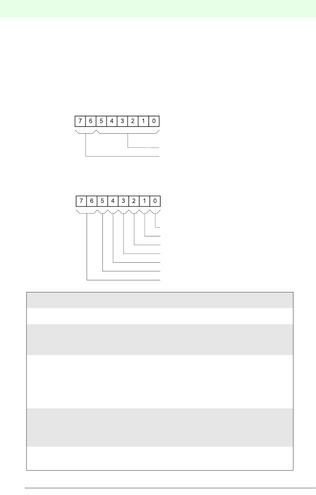
Remote Process Interface
128
S
ubject to reasonable modifications due to technical advances. Copyright Pepperl+Fuchs, Printed in Germany
Pepperl+Fuchs Group • Tel.: Germany +49 621 776-0 • USA +1 330 4253555 • Singapore +65 67799091 • Internet http://www.pepperl-fuchs.com
Date of issue 05/27/03
7.2.11 Gateway-Specific Diagnostic Information
During data transmission diagnostic data for a station, module and channel-based diagnosis can be trans-
mitted in addition to the status information. These diagnosis messages allow a rapid error localization.
The diagnostic information consists of a standard diagnostic information (byte 1 to byte 6) and an extended
DP slave specific diagnostic information.
The start of the gateway-specific diagnostic data is identified by a header byte.
Byte 7: Gateway Diagnostic Header
Byte 8: Gateway Status
E2PROM_ERR 1 = error in E2PROM
0 = no error
APPL_ERR 1 = internal interface error
0 = no error
WATCHDOG 1 = one or more RPI modules have gone into the safe condition follo-
wing
expiry of the watchdog timer
0 = no error
TIMEOUT_KOM 1 = one or more RPI modules with output channels were not addres-
sed
by the gateway within the agreed time-out period or, one or more
RPI modules with input channels have not sent their data to the
gateway within the agreed time-out period.
0 = no error
COM_MODE 1 = one or more RPI modules have changed over from difference
mode
to common mode operation for communication oth the RPI internal
CAN bus.
0 = no error
LOCAL_ACCESS 1 = local access has taken place on one or more RPI modules via a
separate interface, e.g. via a hand-held terminal.
(HART protocol transmitted)
MSB LSB
Bit-No.
Block length, header byte incl. in byte
Fixed on 00
MSB LSB
Bit-No.
E2PROM_ERR
APPL_ERR
WATCHDOG
TIMEOUT_KOM
COM_MODE
LOCAL_ACCESS
Reserved
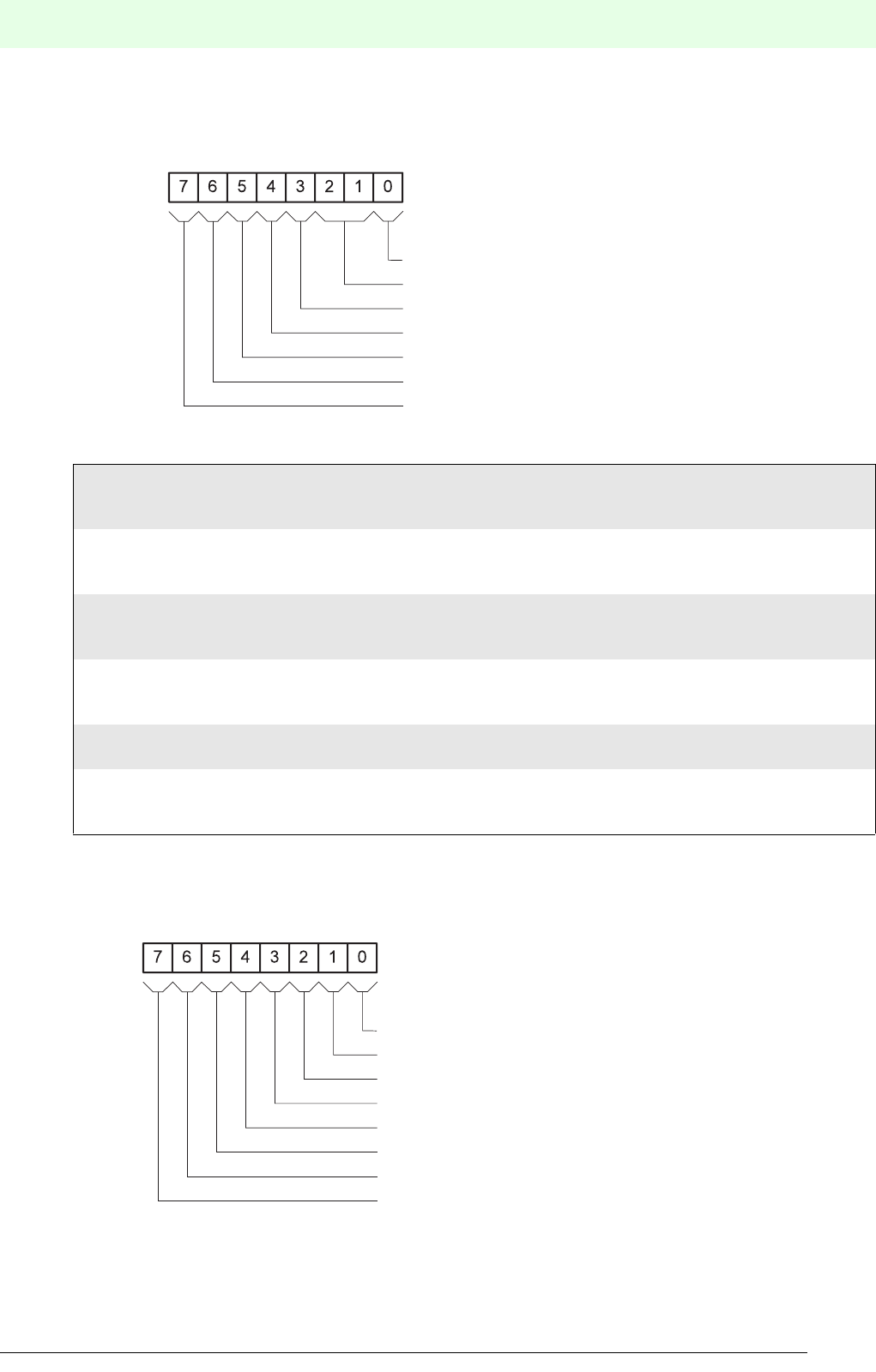
129
Remote Process Interface
Subject to reasonable modifications due to technical advances. Copyright Pepperl+Fuchs, Printed in Germany
Pepperl+Fuchs Group • Tel.: Germany +49 621 776-0 • USA +1 330 4253555 • Singapore +65 67799091 • Internet http://www.pepperl-fuchs.com
Date of issue 05/27/03
Byte 9: RPI System Status
Byte 10: DP Configuration Status
RPI configuration error 1 = the number of RPI modules on the internal bus does not
correspond with the gateway configuration.
0= no error
RPI module error, device specific 1 = device-specific error in one or more
RPI modules
0 = no error
RPI module error, channel specific 1 = channel-specific error in one or more
RPI modules
0 = no error
Redundant mode switch request 1 = in redundant mode with two gateways
the gateway expected a mode switch-over command.
0 = no request received
Redundant mode 1 = RPI in redundant mode
0 = RPI not in redundant mode
Parameter check error, 1 = error when comparing parameter sets of active and passive
gateways
0 = no error
MSB LSB
Bit-No.
RPI configuration error
Reserved
RPI module error, device specific
RPI module error, channel specific
Redundant mode switch request
Redundant mode
Parameter check fault, active/passive gateway
MSB LSB
Bit-No.
user data length error
acyclic channel error
RPI-DP configuration error
special ID, RPI module overflow
special ID, RPI-DP module overflow
special ID, DP module-ID different to RPI-module-ID
special ID, module data length error
special ID, module number error
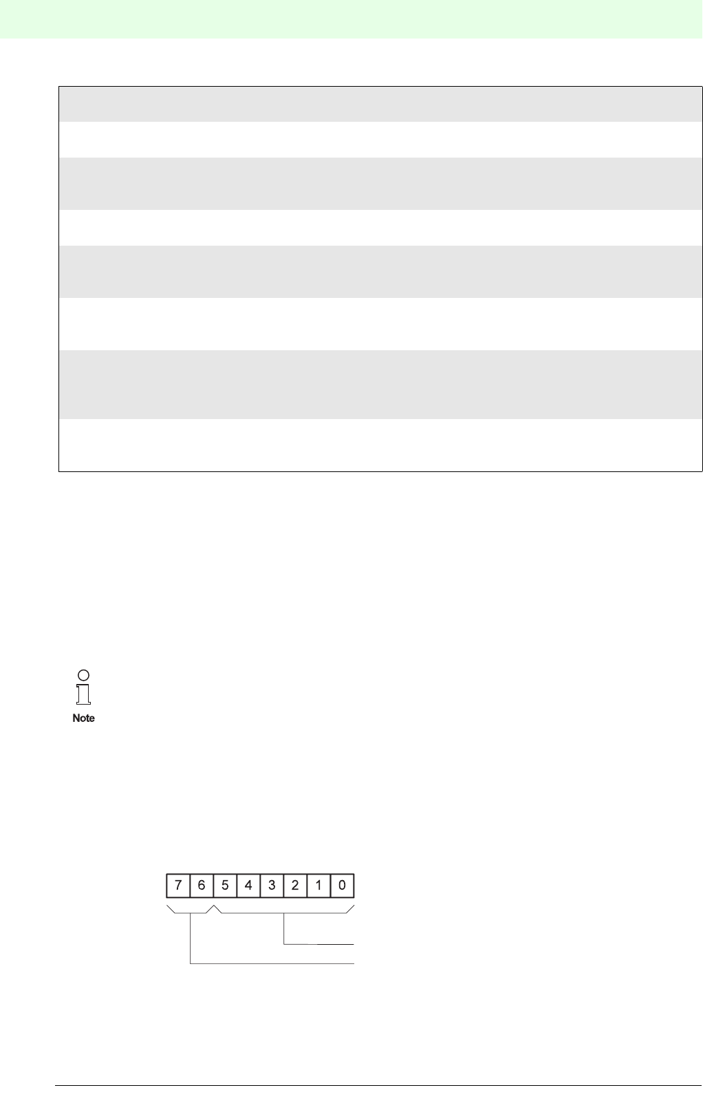
Remote Process Interface
130
S
ubject to reasonable modifications due to technical advances. Copyright Pepperl+Fuchs, Printed in Germany
Pepperl+Fuchs Group • Tel.: Germany +49 621 776-0 • USA +1 330 4253555 • Singapore +65 67799091 • Internet http://www.pepperl-fuchs.com
Date of issue 05/27/03
Byte 11: Status counter
The value of the status counter is stored in this byte. The status counter is an 8 bit counter that is incremen-
ted every time a change is made to the status information.
Byte 12: Param counter
The value of the parameter counter is stored in this byte. The parameter counter is an 8 bit counter that is
incremented every time a change is made to the parameter assignment, whether via the gateway or via an
RPI module.
Module-specific diagnostic information
The start of the module-specific diagnosis data is identified by a header byte..
Header byte.: Module diagnostics header
Module-specific diagnosis information with the block lengths specified in the header byte follow the header
byte. Each bit in these diagnosis bytes represents a DP module. If a bit is set, diagnostic information is
available for that module.
User data length error 1 = max. process data length of 244 bytes exceeded
0 = no error
Acyclic channel error 1 = acyclic transmission error, module 0 access
0 = no error
RPI-DP configuration error 1 = the RPI configuration does not correspond with the configuration of
the DP master
0 = no error
Special ID,
RPI module overflow
1 = more than 64 RPI devices have been configured
0 = no error
Special ID,
RPI-DP module overflow
1 = more RPI devices have been configured than there are DP modules
available
0 = no error
Special ID, DP module ID
different to RPI module ID
1 = the device ID in the identifier of a DP slave module does not
correspond with the device ID of the assigned RPI device.
0 = no error
Special ID, module data length
error
1 = the defined user data length of the RPI and DP configurations do
not
correspond
0 = no error
Special ID, module number error 1 = the number of RPI devices to be packed does not correspond with
the special identifier
0 = no error
When module 0 access is activated (see Chapter 7.2.2), additional information is inserted after
byte 12 ‘Param Counter’..
Module 0 access has no significance for normal operation.
More information about module 0 access is available on request.
MSB LSB
Bit-No.
Block length, header byte incl. in byte
Fixed on 01
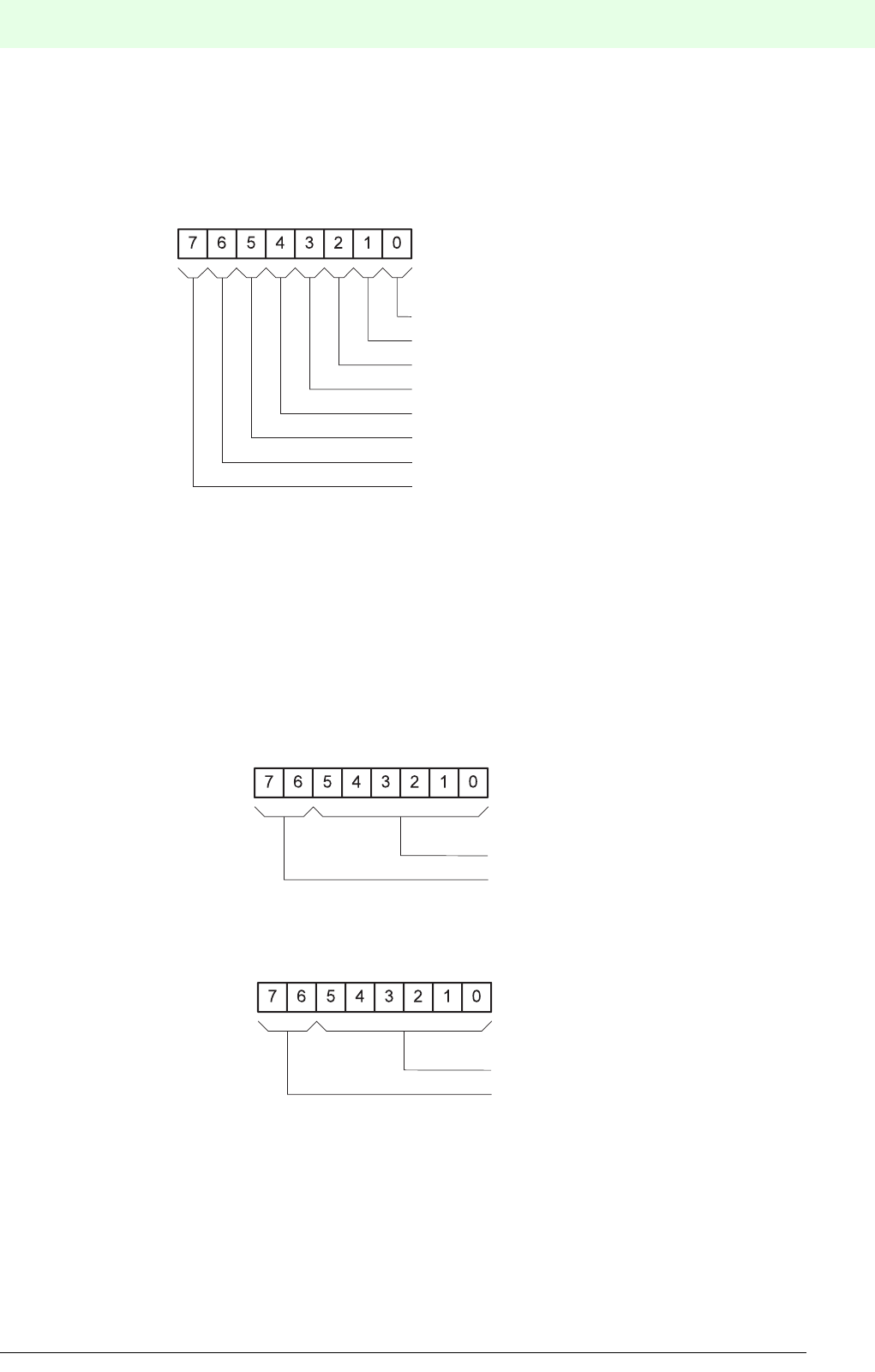
131
Remote Process Interface
Subject to reasonable modifications due to technical advances. Copyright Pepperl+Fuchs, Printed in Germany
Pepperl+Fuchs Group • Tel.: Germany +49 621 776-0 • USA +1 330 4253555 • Singapore +65 67799091 • Internet http://www.pepperl-fuchs.com
Date of issue 05/27/03
Structure of diagnostic byte
1st module diagnostic byte
The following 7 module diagnostic bytes contain the appropriate information for all further modules defined
in the configuration (max. 64)..
Channel-specific diagnostic information
The channel-specific diagnostic data follows the module-specific diagnostic data, in order, for all modules
that have been diagnosed. The length of each diagnostic entry is 3 bytes.
Byte 1: Module number
Byte 2: Channel number
MSB LSB
Bit-No.
1 = module with address 0 with a diagnosis
1 = module with address 1 with a diagnosis
1 = module with address 2 with a diagnosis
1 = module with address 3 with a diagnosis
1 = module with address 4 with a diagnosis
1 = module with address 5 with a diagnosis
1 = module with address 6 with a diagnosis
1 = module with address 7 with a diagnosis
MSB LSB
Bit-No.
Type number: 0 ... 63
Fixed on 10
MSB LSB
Bit-No.
Channel number: 0 ... 63
In-/output channel
00 Reserved
01 Input
10 Output
11 In-/Output

Remote Process Interface
132
S
ubject to reasonable modifications due to technical advances. Copyright Pepperl+Fuchs, Printed in Germany
Pepperl+Fuchs Group • Tel.: Germany +49 621 776-0 • USA +1 330 4253555 • Singapore +65 67799091 • Internet http://www.pepperl-fuchs.com
Date of issue 05/27/03
Byte 3: Type of diagnosis
MSB LSB
Bit-No.
Error type
Channel type
000 Reserved
001 1 Bit
010 2 Bit
011 4 Bit
100 1 Byte
101 2 Byte
110 4 Byte
111 Reserved

133
Remote Process Interface
Subject to reasonable modifications due to technical advances. Copyright Pepperl+Fuchs, Printed in Germany
Pepperl+Fuchs Group • Tel.: Germany +49 621 776-0 • USA +1 330 4253555 • Singapore +65 67799091 • Internet http://www.pepperl-fuchs.com
Date of issue 05/27/03
Type of error:
0dec 0hex reserved
1dec 1hex lead short-circuit
2dec 2hex under-voltage
3dec 3hex over-voltage
4dec 4hex overload
5dec 5hex over-temperature
6dec 6hex lead breakage
7dec 7hex upper limit violated
8dec 8hex lower limit violated
9dec 9hex error
10dec Ahex reserved
: : :
15dec Fhex reserved
16dec 10hex upper alarm limit violated
17dec 11hex lower alarm limit violated
18dec 12hex top of range violated
19dec 13hex bottom of range violated
20dec 14hex not used
: : :
31dec 1Fhex not used
The diagnosis diagram contains a maximum of 64 bytes, i.e. if more than 13 DP modules deve-
lop a fault, the gateway cuts off the information after 64 bytes.
Remote Process Interface
134
S
ubject to reasonable modifications due to technical advances. Copyright Pepperl+Fuchs, Printed in Germany
Pepperl+Fuchs Group • Tel.: Germany +49 621 776-0 • USA +1 330 4253555 • Singapore +65 67799091 • Internet http://www.pepperl-fuchs.com
Date of issue 05/27/03
Summary of the structure of the standard diagnosis for the RPI system
Structure of the PROFIBUS DP User Diagnosis for the RPI System
Prerequisite: No module 0 access
PROFIBUS DP
Diagnosis Byte
Meaning
Gateway Diagnosis
7 always 6hex; block length gateway diagnosis including header byte.
8gateway status
9 RPI system status
10 PROFIBUS DP configuration status
11 counter status
12 paramter counter
PROFIBUS DP Module Diagnosis
13 always 49 hex; block length module diagnosis (9 bytes) including header byte.
14 PROFIBUS DP module 0 to 7 (LSB = module 0; MSB = module 7)
15 PROFIBUS DP module 8 to 15 (LSB = module 8; MSB = module 15)
16 PROFIBUS DP module 16 to 23 (LSB = module 16; MSB = module 23)
17 PROFIBUS DP module 24 to 31 (LSB = module 24; MSB = module 31)
18 PROFIBUS DP module 32 to 39 (LSB = module 32; MSB = module 39)
19 PROFIBUS DP module 40 to 47 (LSB = module 40; MSB = module 47)
20 PROFIBUS DP module 48 to 55 (LSB = module 48; MSB = module 55)
21 PROFIBUS DP module 56 to 63 (LSB = module 56; MSB = module 63)
Channel Diagnosis
22 module number (bit 7 = 1, bit 6 = 0)
23 bit 0 to 5 channel number; bit 6, 7 input and/or output channel
24 type of channel; type of error
... ....
64 max. 13 faulty modules
It should be noted that an indication of the faulty PROFIBUS DP data module is not synony-
mous with the RPI internal address of the faulty RPI module. This applies especially to the case
where packed modules are used.
The channel diagnosis is only transmitted when a channel error occurs.
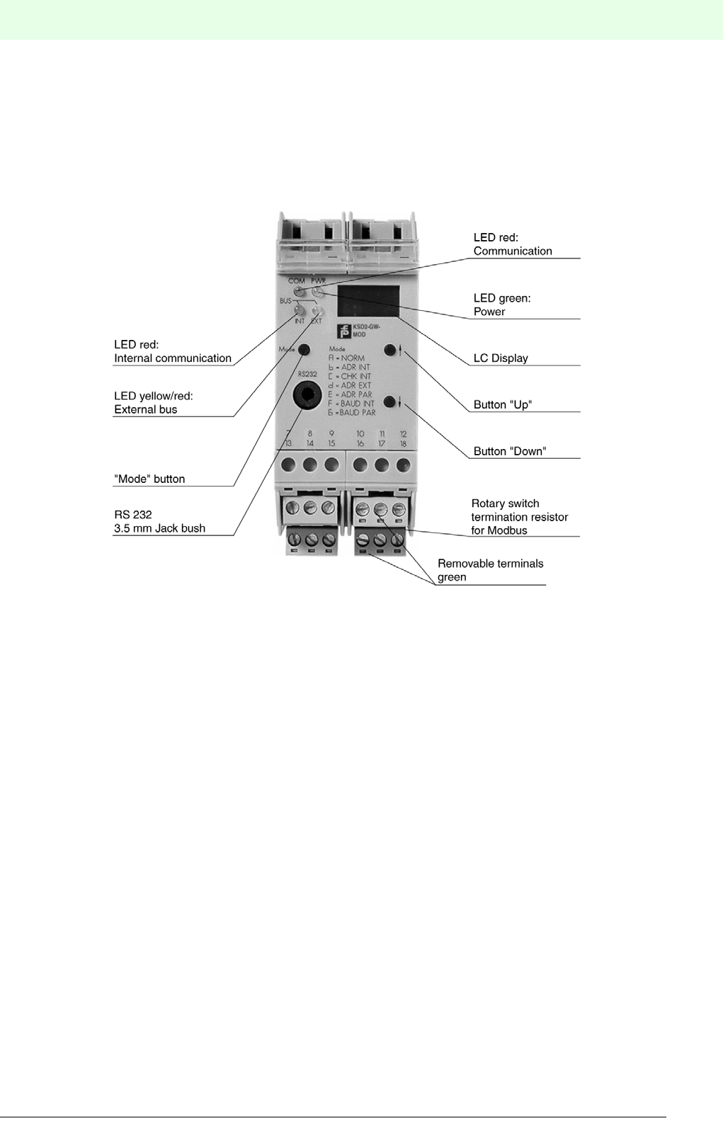
135
Remote Process Interface
Subject to reasonable modifications due to technical advances. Copyright Pepperl+Fuchs, Printed in Germany
Pepperl+Fuchs Group • Tel.: Germany +49 621 776-0 • USA +1 330 4253555 • Singapore +65 67799091 • Internet http://www.pepperl-fuchs.com
Date of issue 05/27/03
7.3 KSD2-GW-MOD and KSD2-GW-MOD.485, Gateways for the Modbus RTU
Gateways KSD2-GW-MOD and KSD2-GW-MOD.485 support the command and reply telegram, according
to MODICON Modbus protocol, Reference Guide, PI-MBUS-300 Rev.D. The gateway incorporates a serial
RS 232 or RS 485 parameterization interface, optionally. The operating level consists of an 3 1/2 digit LC-
display and of the three pushbuttons "Mode", "Up" and "Down".
Figure 7.2: KSD2-GW-MOD gateway
Features of KSD2-GW(2)-MOD / KSD-GW-MOD.485 gateways
The gateways connect the RPI internal CAN bus to the external Modbus RTU. The gateway thus assumes
the master function for the internal bus. The gateway has the function of a slave device on the external Mod-
bus. To increase system availability, the gateway and external bus can be implemented in a redundant con-
figuration.

Remote Process Interface
136
S
ubject to reasonable modifications due to technical advances. Copyright Pepperl+Fuchs, Printed in Germany
Pepperl+Fuchs Group • Tel.: Germany +49 621 776-0 • USA +1 330 4253555 • Singapore +65 67799091 • Internet http://www.pepperl-fuchs.com
Date of issue 05/27/03
7.3.1 Device Connection
The electrical connection of the KSD2-GW-MOD Modbus gateway by means of a cable, merely involves
establishing the Modbus connection. The Modbus interface is an RS 485, on which up to 32 stations can
be operated.
The service interface can be either an RS 232 (KSD2-GW-MOD) or an RS 485 interface (KSD2-GW-
MOD.485); it is used to configure and parameterize the RPI system with the RPI human machine interface.
To do this, the PC is connected to the gateway via the service interface.
If the RS 232 interface is used, connection to the PC can be made via the K-ADP2 adapter. A jack socket
is provided on the front of the gateway for this purpose.If the PC is to remain connected to the RPI system
as a parameterising and monitoring device, it is recommended that connection is made via the plug-in screw
terminals 7, 8 and 9, which are in parallel with the jack socket.
On the KSD2-GW-MOD.485 gateway, with the RS 485 interface, only the terminal connection is available.
The complete configuration of the RPI system can also be undertaken from the control system, via the Mod-
bus, providing that the control system supports this.
Connection to the 24 V DC supply and to the internal bus is achieved via the Power Rail.
The cable connections are made via self-opening screw terminals, max. core cross-section 1 x 2.5 mm² for
rigid cables or 2 x 1.5 mm² for flexible cables with plastic wire end ferrule. The screw terminal blocks on the
device can be removed for ease of connection.
Mount the gateway on the Power Rail and connect the Modbus cable and, if necessary, the RS232/RS485
cable.
The connection plan for the gateway can be obtained from the current issue of the "Interface DIN-Rail Hou-
sing" catalogue.
The maximum length of lead on a bus segment is effectively determined by the following parameters:
• Type of bus cable used
• Transmission rate
• External interference effects
• Number of bus stations
More detailed information on the determination of the maximum lead length can be obtained from EIA 485
or ISO 8482.
The jack socket on the front and the screw terminal connection for the RS 232 link cannot be
used simultaneously.
The number of stations on one RS485 interface (Modbus interface, such as the RS485 service
interface) is a maximum of 31, as standard.

137
Remote Process Interface
Subject to reasonable modifications due to technical advances. Copyright Pepperl+Fuchs, Printed in Germany
Pepperl+Fuchs Group • Tel.: Germany +49 621 776-0 • USA +1 330 4253555 • Singapore +65 67799091 • Internet http://www.pepperl-fuchs.com
Date of issue 05/27/03
Bus termination
Figure 7.3:Rotary switch S1 for bus termination
The Modbus gateways operate internally via a switchable bus termination. Using a screwdriver, the bus ter-
mination can be activated on the rotary switch S1 on the right side of the housing (as viewed from the front).
This is used if the gateway is installed at the end of a line.
7.3.2 Commissioning
Before commissioning, check once again that all the connections are correct.
Familiarise yourself with the method of communication between the Modbus master and the gateway.
Commissioning requires a knowledge of the Modbus and the parameter assignment of the Modbus gate-
way.
Time response
The Remote Process Interface is deterministic. The RPI devices are interrogated cyclically
The most important factors which determine the time response are:
• the higher level host system, e.g., PLC, PC or other control system
• the type and number of Modbus stations
• the set Modbus transmission rate
• the number of the RPI devices and the cycle time of the RPI system
• the user program
Further information on commissioning can be found in Section 5 of this handbook.
7.3.3 Operation with a Redundant Gateway
Operation with redundant gateways increases the availability of the system. The gateway that is active in
normal operation must have the RPI address 1, whilst the redundant gateway must have the RPI address 2.
The prerequisite for the operation of a system with a redundant gateway, is that the configuration data for
each RPI device is stored in a file in the current project directory.
The following describes the installation procedure that is necessary in the case of a gateway newly deliver-
ed from the manufacturer.
If this not the case, connect the Modbus gateway alone to a 24 V DC supply and depress the mode button
on Modbus A for longer than 3 s. This causes the current configuration (here: no device) to be taught-in.
In the following it is assumed that the RPI devices are pre-configured and mounted on the Power Rail. If this
is not the case, then when the active gateway has been installed (step 1) the RPI devices must be addres-
sed.The information required for this procedure is given in Section 5 of this handbook.
The following sequence should then be carried out:
1. Mount a gateway on the Power Rail and set the RPI address of this gateway to 1 (active gateway).
On the Modbus, each bus segment must be terminated by resistances at both ends of the line.
Rotary switch 'S1' for
bus termination on the
right side of the device
Actuating by means
of a screw driver
Bus termination
active!
Bus termination
not active!
S1
1
0
Remote Process Interface
138
S
ubject to reasonable modifications due to technical advances. Copyright Pepperl+Fuchs, Printed in Germany
Pepperl+Fuchs Group • Tel.: Germany +49 621 776-0 • USA +1 330 4253555 • Singapore +65 67799091 • Internet http://www.pepperl-fuchs.com
Date of issue 05/27/03
2. Teach the current configuration into Modbus A.
3. Load the project into the gateway (download) using the PACTwareTM software.
4. Mount the 2nd gateway on the Power Rail and set the RPI address of this gateway to 2 (redundant
gateway).
5. Connect the PC to the redundant gateway and then repeat steps 2 and 3 for the redundant gateway.
If the project has been downloaded into the redundant gateway, the system is ready for redundant operati-
on.
When both gateways have been configured, the type and method of switching from the active to the redun-
dant gateway must be established. This takes place in register table 3, register address 4360, where the
following modes can be set:
7.3.4 Operation on the Modbus
The Modbus is a register-orientated bus system.This means that the data is automatically stored in a me-
mory area, the so-called registers of the Modbus gateway.The user can access specific data by reading the-
se registers and set targeted outputs by writing to them. These registers are organised into four tables:
The Modbus offers two transfer modes for data exchange: the ASCII and the RTU mode..
Value Description
00h No redundancy
01h Automatic switch-over to redundant gateway, in the event of the active gateway beco-
ming defective
02h Switch-over to the redundant gateway by the host (see gateway diagnosis)
03h Switch-over of the passive gateway into the active mode
Table Contents
1Binary outputs
2 Binary inputs
3Analogue outputs, acyclic parameter channels
4 Analogue inputs, DEVICE_TYP and DEVICE_ID
The KSD2-GW-MOD and KSD2-GW-MOD.485 gateways only support the RTU mode.
139
Remote Process Interface
Subject to reasonable modifications due to technical advances. Copyright Pepperl+Fuchs, Printed in Germany
Pepperl+Fuchs Group • Tel.: Germany +49 621 776-0 • USA +1 330 4253555 • Singapore +65 67799091 • Internet http://www.pepperl-fuchs.com
Date of issue 05/27/03
The Modbus master informs the slave via the function code which table should be interrogated and whether
values are to be read or written.The following table shows which function codes are supported by the Mod-
bus gateway:
These function codes are part of the Modbus message.The Modbus message also gives the register
address of the first and the number of registers to be processed. The following relationship between the
transferred register address and the register to be processed should be noted:
The register address transferred in the message is always referenced from zero. The register address 0
must be transferred in order to be able to access the first register that can be interrogated (Register number
1).
Example:
In order to access register 26 in table 2 (status of the binary input RPI address 3, channel 1), the function
code 2 and the register address 25 must be transferred.
The equations used to calculate the register addresses and a description of how the data is represented in
the individual registers, are given in 7.3.6 to 7.3.13 .Section 7.3.16 provides a tabular summary of all the
equations.
Detailed information on the Modbus protocol can be obtained from the "Modicon modbus protocol, refe-
rence guide, PI-MBUS-300 Rev.D"
A register is 16 bits long. In this handbook the data is represented as follows:
7.3.5 Reading Binary Input Data without Status
The expression "binary input data" is intended to imply the switching states of switches and proximity sen-
sors.
The KSD2-GW-MOD and KSD2-GW-MOD.485 provides the user with this data, both channel-based and
device-based. In the case of the channel-based representation, each channel of a device is presented in an
individual register. This type of representation is to be preferred if only one channel is to be read. In the de-
vice-based type of representation, up to four RPI devices can be represented in one register.
This type of representation enables the data of many RPI devices to be transmitted with relatively small
Code Function Description
01 Read Coil Status Read binary outputs
02 Read Input Status Read binary inputs
03 Read Holding Register Read from write/read registers, e.g. analogue outputs,
acyclic parameter channels
04 Read Input Register Read from read registers, e.g. analogue inputs, device type,
device ID
05 Force Single Coil Write binary outputs
06 Preset Single Register Read from write/read registers, e.g. analogue outputs,
acyclic parameter channels
07 Read Exception Status Read the exception status of the gateway
08 Read Diagnostic Service functions for Modbus
15 Force Multiple Coils Block-wise writing of binary outputs
16 Preset Multiple Registers Block-wise writing of analogue outputs or acyclic parameter chan-
nels
In the following description, the register addresses to be transferred are given as a basis. If
your software register numbers are to be used in processing, the "given register address +
1" value must be used.
Register higher byte Register lower byte
MSB LSB MSB LSB
Bit 15Bit 14Bit 13Bit 12Bit 11Bit 10Bit 9Bit 8 Bit 7Bit 6Bit 5Bit 4Bit 3Bit 2Bit 1Bit 0

Remote Process Interface
140
S
ubject to reasonable modifications due to technical advances. Copyright Pepperl+Fuchs, Printed in Germany
Pepperl+Fuchs Group • Tel.: Germany +49 621 776-0 • USA +1 330 4253555 • Singapore +65 67799091 • Internet http://www.pepperl-fuchs.com
Date of issue 05/27/03
amounts of data.The prerequisite for this is that the RPI addresses of the devices are consecutive.Further
information on the relationship between RPI address and data range can be obtained from the relevant to-
pics within this section.
Register addresses for channel-based registers
Reading a channel
This data is deposited in register table 2, which can be called-up via the function code 02.
The register address depends on the RPI internal address of the device and on the channel. It can be de-
rived from the following equations:
RPI address = 3 ... 127; channel number = 1 ... 4
The information is represented as follows:
Reading a number of channels and/or status information
This data is deposited in register table 4, which can be called-up via the function code 04.
Analogue input data is usually read from the input registers (register table 04) of a Modbus station by PLCs
or process control systems. In exceptional cases, it may be that control of the access to the input register
is not supported. In these cases, the correct register address can be obtained from Chapter 7.3.13.
RPI devices with a maximum of 8 channels without status, 1 device per register
All data from 1-, 2-, 4- and 8 channel devices is filed in this area.
The register address is obtained from the following equation:
Address = RPI address + 1536
The data is represented as follows:
Channels not available are set to 0.
RPI devices with a maximum of 4 channels, 4 devices per register
All data from 1-, 2- and 4 channel devices are filed in this area.
The register address is obtained from the following equation:
Address = Int[(RPI address-3)/4] + 9216
Int (...) signifies a whole number of (...) rounded down.
max. Channel
No. Register address
88*RPI address + channel number - 1
4 4*(RPI address - 3) + channel number +
1035
0 0 0 0 0 0 0 0 0 0 0 0 0 0 0 Ch
0 0 0 0 0 0 0 0 Ch 8 Ch 7 Ch 6 Ch 5 Ch 4 Ch 3 Ch 2 Ch 1

141
Remote Process Interface
Subject to reasonable modifications due to technical advances. Copyright Pepperl+Fuchs, Printed in Germany
Pepperl+Fuchs Group • Tel.: Germany +49 621 776-0 • USA +1 330 4253555 • Singapore +65 67799091 • Internet http://www.pepperl-fuchs.com
Date of issue 05/27/03
The data is represented as follows:
If the term (RPI address -3)/4 is divisible without a remainder, then the data is that which is represented in
the low nibble of the lower byte (RPI address, Ch 1 ... Ch 4 or bit 0 to bit 3 of the register).If the division
results in a remainder, this remainder describes the nibble of the register in which the data is represen-
ted.The following relationship applies:
x = arbitrary digit before decimal point
Example 1: To find the address for an RPI device with RPI address 27:
The division (RPI address -3)/4 gives 6, without a remainder.
Hence the register address is 6 + 9216 = 9222.
The 4 channels are represented in the low nibble of the lower byte.
Example 2: To find the address for an RPI device with RPI address 37:
The division (RPI address -3)/4 gives 8.5, or 8 with a remainder of 2.
The address to be transferred is therefore given by 8 + 9216 = 9224.
The remainder shows that channels 1 to 4 of this device are represented in the low nibble of the higher byte
of this register.
Channels which are not available are set to 0.
RPI devices with a maximum of 8 channels, 2 devices per register
All data from 1-, 2-, 4- or 8 channel devices are filed in this area.
The register address is obtained from the following equation:
Address = Int[(RPI address -2)/2] + 9345
Int (...) denotes a whole number of (...) rounded down
The data is represented as follows:
It should be noted, that fundamentally, only even RPI addresses are represented in the lower byte of a re-
gister and odd RPI addresses in the higher byte.
Channels not available are set to 0.
RPI address+3 RPI address+2 RPI address+1 RPI address
Ch 4 Ch 3 Ch 2 Ch 1 Ch 4 Ch 3 Ch 2 Ch 1 Ch 4 Ch 3 Ch 2 Ch 1 Ch 4 Ch 3 Ch 2 Ch 1
Remainder Data
0Lower byte, low nibble or bit 0 to bit 3
1 or x.25 Lower byte, high nibble or bit 4 to bit 7
2 or x.50 Higher byte, low nibble or bit 8 to bit 11
3 or x.75 Higher byte, high nibble or bit 2 to bit 15
RPI address+1 RPI address
Ch 8 Ch 7 Ch 6 Ch 5 Ch 4 Ch 3 Ch 2 Ch 1 Ch 8 Ch 7 Ch 6 Ch 5 Ch 4 Ch 3 Ch 2 Ch 1
Remote Process Interface
142
S
ubject to reasonable modifications due to technical advances. Copyright Pepperl+Fuchs, Printed in Germany
Pepperl+Fuchs Group • Tel.: Germany +49 621 776-0 • USA +1 330 4253555 • Singapore +65 67799091 • Internet http://www.pepperl-fuchs.com
Date of issue 05/27/03
7.3.6 Reading binary input data with status
This data is deposited in register table 4, which can be called-up via the function code 04.
This data is exclusively represented as device-based. The switching state (bit 0) and 7 status bits (bit 1 to
7) are available in one data byte. The exact structure is shown in the following table:
Bits GW1 and GW2 are of no significance for binary inputs.
CD1 to CD3 code the error that has occurred.
Q1 and Q2 provide information on signal quality.
Three error messages are generated for the binary data, the significance of which is given in the following
table:
The first two lines indicate an error in the RPI device.The third line indicates a lead breakage or short circuit,
where this information is only generated if the option(s) lead breakage monitoring or short circuit monitoring
is/are activated on the device. Further details can be found in PACTwareTM or in Section 12 of this handbook.
RPI devices with a maximum of 4 channels with status, 2 registers per RPI device
The data from 1-, 2- or 4 channel devices is deposited in this area. 2 registers must be read in order to obtain
the complete information for all channels.
The register address is obtained from the following equation:
Address = 2*(RPI address-3) + 3587
The data is represented as follows:
Register address
Register address + 1
The data for channels which are not available is set to 0.
GW2 GW1 CD 3 CD 2 CD 1 Q2 Q1 Dat
Analogue input data is usually read from the input registers of a Modbus station by PLC's or
process control systems. In exceptional cases, it may be that control of access to the input
register is not supported.In this case the correct register addresses can be obtained from
Chapter 7.3.13.
Meaning GW2 GW1 CD3 CD2 CD1 Q2 Q1 Dat
Internal memory or interface error 0001010
No communication 0010110
Sensor error 0010010
High byte = Channel 2 Low byte = Channel 1
High byte = Channel 4 Low byte = Channel 3

143
Remote Process Interface
Subject to reasonable modifications due to technical advances. Copyright Pepperl+Fuchs, Printed in Germany
Pepperl+Fuchs Group • Tel.: Germany +49 621 776-0 • USA +1 330 4253555 • Singapore +65 67799091 • Internet http://www.pepperl-fuchs.com
Date of issue 05/27/03
RPI devices with a maximum of 8 channels with status, 4 registers per RPI device
The data from 1-, 2-, 4- or 8 channel devices are filed in this area. 4 registers must be read in order to obtain
the complete information for all channels.
The register address is obtained from the following equation
Address = 4*(RPI address -3) + 3084
The data is represented as follows:
Register address
Register address+1
Register address+2
Register address+3
The data for channels which are not available is set to 0.
7.3.7 Writing/Reading Binary Output Data without Status
Binary output data includes signals for valves, operating coils of relays and optical and acoustic alarms.
The KSD2-GW-MOD and KSD2-GW-MOD.485 provide this data, both channel-based and device-based. In
the channel-based form of representation, each channel of a device is represented in an individual register.
This type of representation is to be preferred if only 1 channel is to be read or written to. In the case of the
device-based form of representation, up to 4 RPI devices can be represented in one register. This form of
representation enables the data of many RPI devices to be transmitted with relatively small amounts of data.
Further information on the relationship between RPI address and data range can be obtained from the cor-
responding topics in this section.
High byte = Channel 2 Low byte = Channel 1
High byte = Channel 4 Low byte = Channel 3
High byte = Channel 6 Low byte = Channel 5
High byte = Channel 8 Low byte = Channel 7
The prerequisite for this is that the RPI addresses of the devices are consecutive.
Remote Process Interface
144
S
ubject to reasonable modifications due to technical advances. Copyright Pepperl+Fuchs, Printed in Germany
Pepperl+Fuchs Group • Tel.: Germany +49 621 776-0 • USA +1 330 4253555 • Singapore +65 67799091 • Internet http://www.pepperl-fuchs.com
Date of issue 05/27/03
Register addresses for channel-based registers
Writing/reading a channel
This data is deposited in register table 1. The current states can be read via function code 01 and written to
with function code 05.
The register address is dependent on the RPI internal address of the device and the channel. It can be de-
rived from the following equations:
The RPI address can be in the range 3 to 127.
The information is represented as follows::
Reading a number of channels and/or status information
This data is deposited in register table 3, which can be read via function code 03 and written to via function
code 06.
RPI devices with a maximum of 8 channels, 2 devices per register
All data from 1-, 2-, 4 and 8 channel devices is filed in this area.
The register address is obtained from the following equation:
Address = Int[(RPI address-2)/2] + 9345
Int (...) denotes a whole number of (...) rounded down.
The data is represented as follows:
It should be noted, that fundamentally, only even RPI addresses are represented in the lower byte of a re-
gister and odd RPI addresses in the higher byte.
Channels not available are set to 0.
RPI devices with a maximum of 4 channels, 4 devices per register, without status
All data from 1-, 2- and 4 channel devices is filed in this area.
Max. Channel
No. Register address
88*RPI address + channel number - 1
4 4(RPI address - 3) + channel number +
1035
0 0 0 0 0 0 0 0 0 0 0 0 0 0 0 Ch 1
Analogue input data is usually read from the input registers (Table 04) of a Modbus station
by PLC’s or process control systems. In exceptional cases, it may be that control of access
to the input register is not supported. In this case the correct register addresses can be
obtained from Chapter 7.3.13.
RPI address+1 RPI address
Ch 8 Ch 7 Ch 6 Ch 5 Ch 4 Ch 3 Ch 2 Ch 1 Ch 8 Ch 7 Ch 6 Ch 5 Ch 4 Ch 3 Ch 2 Ch 1

145
Remote Process Interface
Subject to reasonable modifications due to technical advances. Copyright Pepperl+Fuchs, Printed in Germany
Pepperl+Fuchs Group • Tel.: Germany +49 621 776-0 • USA +1 330 4253555 • Singapore +65 67799091 • Internet http://www.pepperl-fuchs.com
Date of issue 05/27/03
The address is obtained from the following equation:
Address = Int(RPI address/4) + 9216
Int (...) denotes division without a remainder.
The data is represented as follows:
If the term RPI address / 4 is divisible without a remainder, this implies that the data will be represented in
the low nibble of the lower byte (RPI address, Ch 1 ... Ch 4 or bit 0 to bit 3 of the register). If the division
results in a remainder, then this remainder describes the nibble of the register in which the data is repre-
sented. The following relationship applies:
x = arbitrary digit before decimal point
Example 1: To determine the register address for an RPI device with RPI address 36.
The division RPI address/4 gives 9. The register address to be transferred is 9 + 9216 = 9225. The rema-
inder from the division indicates that channels 1 to 4 of this device are represented in the low nibble of the
lower byte of this register.
Example 2: To determine the register address for an RPI device with RPI address 27
The division RPI address/4 gives 6.75 or 6 with a remainder of 3. Therefore the address to be transferred
is 9222. The remainder from the division indicates that channels 1 to 4 of this device are represented in the
high nibble of the higher byte of this register.
Channels which are not available are set to 0.
RPI address+3 RPI address+2 RPI address+1 RPI address
Ch 4 Ch 3 Ch 2 Ch 1 Ch 4 Ch 3 Ch 2 Ch 1 Ch 4 Ch 3 Ch 2 Ch 1 Ch 4 Ch 3 Ch 2 Ch 1
Remainder Data
0Lower byte, low nibble or bit 0 to 3
1 or x.25 Lower byte, high nibble or bit 4 to bit 7
2 or x.50 Higher byte, low nibble or bit 8 to bit 11
3 or x.75 Higher byte, high nibble or bit 12 to bit 15
Remote Process Interface
146
S
ubject to reasonable modifications due to technical advances. Copyright Pepperl+Fuchs, Printed in Germany
Pepperl+Fuchs Group • Tel.: Germany +49 621 776-0 • USA +1 330 4253555 • Singapore +65 67799091 • Internet http://www.pepperl-fuchs.com
Date of issue 05/27/03
7.3.8 Writing/Reading Binary Output Data with Status
This data is deposited in register table 3, which can be read via function code 03 and written to via function
code 06.
This data is represented exclusively device-based. The switching state (bit 0) and 7 status bits (bit 1 to 7)
are included in one data byte. The exact construction is as follows:
The bits GW1 and GW2 are of no significance for binary output signals.
CD1 to CD3 code the error that has occurred.
Q1 and Q2 provide information on signal quality.
Analogue input data is usually read from the input registers of a Modbus station by PLC’s or process control
systems. In exceptional cases, it may be that control of access to the input register is not supported.In this
case the corrrect register addresses can be obtained from Section 7.3.13.
Three error messages are generated for the binary data, the significance of which is given in the following
table:
The first two lines indicate an error in the RPI device. The third line indicates a lead breakage or short circuit,
where this information is only generated if the option(s) of lead breakage monitoring or short circuit monito-
ring are activated on the device. Further information can be obtained from Part B of this handbook.
RPI devices with a maximum of 4 channels with status, 2 registers per RPI device
The data from 1-, 2- or 4 channel devices are filed in this area. 2 registers must be read in order to obtain
the complete information for all channels.
The register address is obtained from the following equation:
Address = 2*(RPI address -3) + 3587
The data is represented as follows:
Register address
Register address+1
GW2 GW1 CD 3 CD 2 CD 1 Q2 Q1 Dat
Meaning GW2 GW1 CD3 CD2 CD1 Q2 Q1 Dat
Internal memory or interface error 0001010
No communication 0010110
Field device error 0010010
High byte = Channel 2 Low byte = Channel 1
High byte = Channel 4 Low byte = Channel 3
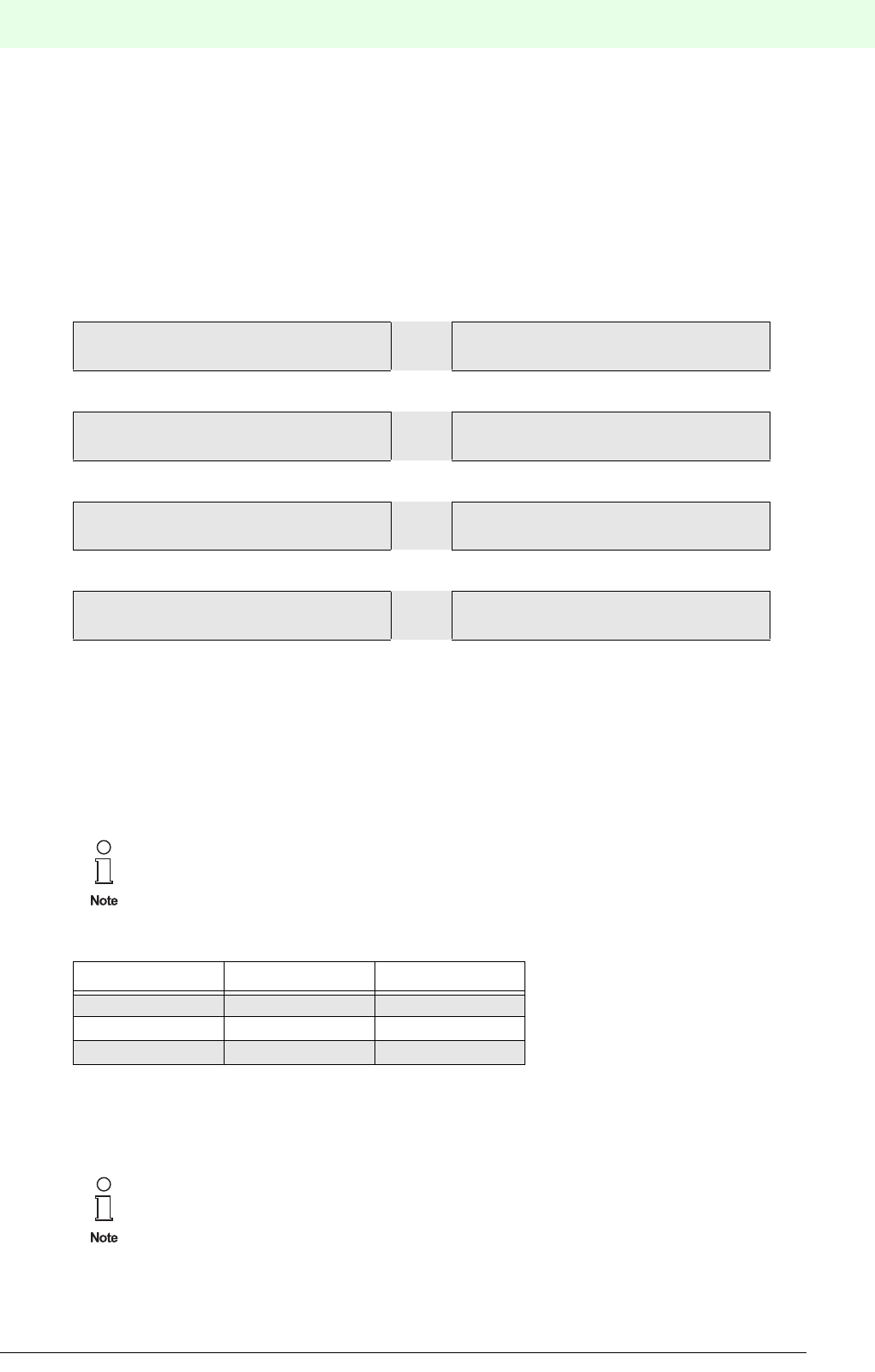
147
Remote Process Interface
Subject to reasonable modifications due to technical advances. Copyright Pepperl+Fuchs, Printed in Germany
Pepperl+Fuchs Group • Tel.: Germany +49 621 776-0 • USA +1 330 4253555 • Singapore +65 67799091 • Internet http://www.pepperl-fuchs.com
Date of issue 05/27/03
RPI devices with a maximum of 8 channels with status, 4 registers per RPI device
The data from 1-, 2-, 4- or 8 channel devices are filed in this area. 4 registers must be read in order to obtain
the complete information for all channels.
The address is obtained from the following equation:
Address = 4*(RPI address -3) + 3084
The data is represented as follows:
Register address
Register address+1
Register address+2
Register address+3
The data from channels which are not available is set to 0.
7.3.9 Reading Analogue Input Data without Status
All analogue values are represented in signed integer format (16 bit) and in floating point format in accor-
dance with "IEEE 754 short real number".
In signed integer format, the data is represented as follows::
The statement of the register contents is in decimal format. The values in the meaning column are given
units. These can be set by means of the PACTwareTM or K-SK1 configuration software. Further information
is provided in the description of the PACTwareTM software or in Section 12 of this handbook.
High byte = Channel 2 Low byte = Channel 1
High byte = Channel 4 Low byte = Channel 3
High byte = Channel 6 Low byte = Channel 5
High byte = Channel 8 Low byte = Channel 7
In the signed integer format, the number of places after the decimal point depends on the RPI
module. The KSD2-TI-Ex universal temperature converter operates with one, all others operate
with 2 places after the decimal point.
Device type Register content Meaning
KSD2-FI-Ex2 327d 327
KSD2-TI-Ex 327d 32.7
327d 3.27
Analogue input data is usually read from the input registers of a Modbus station by PLC's or
process control systems. In exceptional cases, it may be that control of access to the input
register is not supported. In this case, the correct register address can be obtained from Chap-
ter 7.3.13.
Remote Process Interface
148
S
ubject to reasonable modifications due to technical advances. Copyright Pepperl+Fuchs, Printed in Germany
Pepperl+Fuchs Group • Tel.: Germany +49 621 776-0 • USA +1 330 4253555 • Singapore +65 67799091 • Internet http://www.pepperl-fuchs.com
Date of issue 05/27/03
Reading analogue input data, 1 channel devices
This data is deposited in register table 4, which can be read via function code 04.
The register address is dependent on the RPI internal address of the device. It can be derived from the fol-
lowing equations:
In the signed integer format, only one register must be read.In the floating point format, two registers must
be read. The data is structured as follows:
Reading analogue input data, 2 channel devices
All measured values from 1 and 2 channel devices are represented in this area, as a funct ion of the current
RPI adress. The register addresses can be obtained from the following equations:
Two registers must be read in the signed integer format.The data is constructed as follows:
Four registers must be read in the floating point format. These are constructed as follows::
Channel 1
Channel 2
Data for unoccupied channels is set to 0.
Reading analogue input data, 3 channel devices
AlI measured values from 1-, 2- and 3 channel devices are given in this area as a function of the current
RPI address. The register addresses can be obtained from the following equations:
Data format Register address
Signed integer RPI address+4608
Floating point 2*(RPI address -3)+6150
Register address+1 Register address
Data byte 4 Data byte 3 Data byte 2 Data byte 1
Data format Register address
Signed integer 2*(RPI address-3)+5126
Floating point 4*(RPI address-3)+7052
Register address+1 Register address
Channel 2 Channel 1
Register address+1 Register address
Data byte 4 Data byte 3 Data byte 2 Data byte 1
Register address+3 Register address+2
Data byte 4 Data byte 3 Data byte 2 Data byte 1
Data format Register address
Signed integer 3*(RPI address-3)+12
Floating point 6*(RPI address-3)+8210

149
Remote Process Interface
Subject to reasonable modifications due to technical advances. Copyright Pepperl+Fuchs, Printed in Germany
Pepperl+Fuchs Group • Tel.: Germany +49 621 776-0 • USA +1 330 4253555 • Singapore +65 67799091 • Internet http://www.pepperl-fuchs.com
Date of issue 05/27/03
In the signed integer format, 3 registers have to be read. The data is constructed as follows:
6 registers have to be read in the floating point format. These are constructed as follows:
Channel 1
Channel 2
Channel 3
Data for unoccupied channels is set to 0.
7.3.10 Reading Analogue Input Data with Status
The status information occupies one register per channel, of which 7 bits are used for the analogue data.
The structure of the status register is as follows:
Bit 0 of the low byte (Dat) is always set to 0.
Bits GW1 and GW2 are reserved for limit value monitoring.
CD1 to CD3 code the error that has occurred.
Q1 and Q2 provide information on signal quality.
The messages shown in the table below are generated instantaneously.
Register address+2 Register address+1 Register address
Channel 3 Channel 2 Channel 1
Register address+1 Register address
Data byte 4 Data byte 3 Data byte 2 Data byte 1
Register address+3 Register address+2
Data byte 4 Data byte 3 Data byte 2 Data byte 1
Register address+5 Register address+4
Data byte 4 Data byte 3 Data byte 2 Data byte 1
0 0 0 0 0 0 0 0 GW2 GW1 CD3 CD2 CD1 Q2 Q1 Dat
Meaning GW2 GW1 CD3 CD2 CD1 Q2 Q1 Dat
Good 0 0
Not certain 010
Bad 000100
Good, no error 0 0 0 0 0 0
Measurement range exceeded/fallen
short
011010
Simulated measured value 1 0 1 0 1 0
Reserved 110010
Configuration error 0 0 1 1 0 0
RPI device error 010100
Field device error 1 0 0 1 0 0
No communication (last good value) 101100
No limit value reached 0 0 0
Lower limit violated 0 1 0
Upper limit violated 1 0 0

Remote Process Interface
150
S
ubject to reasonable modifications due to technical advances. Copyright Pepperl+Fuchs, Printed in Germany
Pepperl+Fuchs Group • Tel.: Germany +49 621 776-0 • USA +1 330 4253555 • Singapore +65 67799091 • Internet http://www.pepperl-fuchs.com
Date of issue 05/27/03
Reading analogue input data, 1 channel devices
All the measured values from single channelled devices are represented in this area as a function of the
current RPI address. The register addresses can be obtained from the following equations:
Two registers have to be read in the signed integer format. The data is constructed as follows:
In the floating point format, 3 registers have to be read. These are constructed as follows:
Reading analogue input data, 2 channel devices
All the measured values from 1 or 2 channelled devices are represented in this area as a function of the
current RPI address.The register addresses can be obtained from the following equations:
3 registers have to be read in the signed integer format. The data is constructed as follows:
5 registers have to be read in the floating point format. These are constructed as follows:
Data format Register address
Signed integer 2*(RPI address-3)+4742
Floating point 3*(RPI address-3)+6409
Register address+1 Register address
Status Channel 1
Register address+1 register address
Data byte 2 Data byte 1 Not used Status
Register address+2
Data byte 4 Data byte 3
Data format Register address
Signed integer 3*(RPI address-3)+5641
Floating point 5*(RPI address-3)+7567
Register address+1 Register address
Channel 1 Status Channel 2 Status Channel 1
Register address+2
Channel 2
Register address+1 Register address
Channel 1, Data word 1 Status Channel 2 Status Channel 1
Register address+3 Register address+2
Channel 2, Data word 1 Channel 1, Data word 2
Register address+4
Channel 2, Data word 2
151
Remote Process Interface
Subject to reasonable modifications due to technical advances. Copyright Pepperl+Fuchs, Printed in Germany
Pepperl+Fuchs Group • Tel.: Germany +49 621 776-0 • USA +1 330 4253555 • Singapore +65 67799091 • Internet http://www.pepperl-fuchs.com
Date of issue 05/27/03
Reading analogue input data, 3 channel devices
All the measured values from 1, 2 or 3 channelled devices are represented in this area as a function of the
current RPI address.. The register addresses can be obtained from the following equations:
If all the information from a device is to be read in signed integer format, 6 registers have to be read. Access
to one channel can be achieved by the addition of the term: 2*(Channel number-1). The data is constructed
as follows:
8 registers have to be read in the floating point format. These are constructed as follows:
7.3.11 Writing/Reading Analogue Output Data without Status
All analogue values are represented in signed integer format (16 bit) and in floating point format in accor-
dance with
"IEEE 754 short real number".
The content of the register is given in decimal format. The values in the Meaning column are in units. These
can be set using the PACTwareTM edition 2 software.
Data format Register address
Signed integer 6*(RPI address-3)+2072
Floating point 8*(RPI address-3)+536
Register address+1 Register address
Channel 1 Status Channel 1
Register address+3 Register address+2
Channel 2 Status Channel 2
Register address+5 Register address+4
Channel 3 Status Channel 3
Register address+1 Register address
Status Channel 2 Status Channel 1 Not used Status Channel 3
Register address+3 Register address+2
Channel 1, Data word 2 Channel 1, Data word 1
Register address+5 Register address+4
Channel 2, Data word 1 Channel 2, Data word 1
Register address+7 Register address+6
Channel 3, Data word 2 Channel 3, Data word 1
On the output modules, in signed integer format, the number of places after the decimal point
is 2.
Device type Register content Meaning
KSD2-CO-Ex 327d 3.27
Remote Process Interface
152
S
ubject to reasonable modifications due to technical advances. Copyright Pepperl+Fuchs, Printed in Germany
Pepperl+Fuchs Group • Tel.: Germany +49 621 776-0 • USA +1 330 4253555 • Singapore +65 67799091 • Internet http://www.pepperl-fuchs.com
Date of issue 05/27/03
Writing/reading analogue output data, 1 channel devices
This data is deposited in register table 3, which can be read via the function code 03 and written to via
function code 05 (Preset Single Register) and function code 16 (Preset Multiple Register).
The register address is dependent on the RPI internal address. It can be derived from the following equati-
ons:
In the signed integer format, only 1 register must be read and written to.
In the floating point format, 2 registers have to be read/written in order to access the data from an RPI de-
vice. The floating point format data is structured as follows:
Writing/reading analogue output data, 2 channel devices
All the measured values from 1 and 2 channelled devices are represented in this area as a function of the
current RPI address. The register addresses can be obtained from the following equations:
In the signed integer format, 2 registers have to be read/written in order to access the data from an RPI
device.The data is constructed as follows:
In the floating point format, 4 registers have to be read/written in order to access the data from an RPI de-
vice. The data is constructed as follows:
Channel 1
Channel 2
Data for unoccupied channels is set to 0.
If your control system does not support access to the input registers (Table 04), the register
addresses can be obtained from Chapter 7.3.13.
Data format Register address
Signed integer RPI address+4608
Floating point 2*(RPI address-3)+6150
Register address+1 Register address
Data byte 4 Data byte 3 Data byte 2 Data byte 1
Data format Register address
Signed integer 2*(RPI address-3)+5126
Floating point 4*(RPI address-3)+7052
Register address+1 Register address
Channel 2 Channel 1
Register address+1 Register address
Channel 2 Channel 1
Register address+3 Register address+2
Channel 2 Channel 1
153
Remote Process Interface
Subject to reasonable modifications due to technical advances. Copyright Pepperl+Fuchs, Printed in Germany
Pepperl+Fuchs Group • Tel.: Germany +49 621 776-0 • USA +1 330 4253555 • Singapore +65 67799091 • Internet http://www.pepperl-fuchs.com
Date of issue 05/27/03
Writing/reading analogue input data, 3 channel devices
All measured values from 1-, 2- and 3 channelled devices are represented in this area as a function of the
current RPI address. The register addresses can be obtained from the following equations:
In the signed integer format, 3 registers have to be read/written per device. The data is constructed as fol-
lows:
In the floating point format, 6 registers have to be read per device. The data is constructed as follows:
Channel 1
Channel 2
Channel 3
Data for unoccupied channels is set to 0.
7.3.12 Writing/Reading Analogue Output Data with Status
Reference should be made to Chapter 7.1. of this handbook for the structure of the status information.
Writing/reading analogue input data, 1 channel devices
All measured values from 1 channelled devices are represented in this area, as a function of the current RPI
address. The register addresses can be obtained from the following equations:
In the signed integer format, 2 registers have to be read. The data is constructed as follows::
Data format Register address
Signed integer 3*(RPI address-3)+12
Floating point 6*(RPI address-3)+8210
Register address+2 Register address+1 Register address
Channel 3 Channel 2 Channel 1
Register address+1 Register address
Data byte 4 Data byte 3 Data byte 2 Data byte 1
Register address+3 Register address+2
Data byte 4 Data byte 3 Data byte 2 Data byte 1
Register address+5 Register address+4
Data byte 4 Data byte 3 Data byte 2 Data byte 1
Data format Register address
Signed integer 2*(RPI address-3)+4742
Floating point 3*(RPI address-3)+6409
Register address+1 Register address
Status Channel 1
Remote Process Interface
154
S
ubject to reasonable modifications due to technical advances. Copyright Pepperl+Fuchs, Printed in Germany
Pepperl+Fuchs Group • Tel.: Germany +49 621 776-0 • USA +1 330 4253555 • Singapore +65 67799091 • Internet http://www.pepperl-fuchs.com
Date of issue 05/27/03
In the floating point format, 3 registers have to be read. These are constructed as follows:
Writing/reading analogue output data, 2 channel devices
All measured values from 1 or 2 channelled devices are represented in this area, as a function of the current
RPI address. The register addresses can be obtained from the following equations:
3 registers have to be read in the signed integer format. The data is constructed as follows:
5 registers have to be read in floating point format. These are constructed as follows:
Writing/reading analogue output data, 3 channel devices
All measured values from 1-, 2- and 3 channelled devices are represented in this area, as a function of the
current RPI address. The register addresses can be obtained from the following equations:
If all the information from a device is to be read in signed integer format, 6 registers have to be read. Access
to one channel can be achieved by adding the term: 2*(Channel number-1). The data is constructed as fol-
lows:
Register address+1 Register address
Data byte 2 Data byte 1 Not used Status
Register address+2
Data byte 4 Data byte 3
Data format Register address
Signed integer 3*(RPI address-3)+5641
Floating point 5*(RPI address-3)+7567
Register address+1 Register address
Channel 1 Status Channel 2 Status Channel 1
Register address+2
Channel 2
Register address+1 Register address
Channel 1, Data word 1 Status Channel 2 Status Channel 1
Register address+3 Register address+2
Channel 2, Data word 1 Channel 1, Data word 2
Register address+4
Channel 2, Data word 2
Data format Register address
Signed integer 6*(RPI address-3)+2072
Floating point 8*(RPI address-3)+536
155
Remote Process Interface
Subject to reasonable modifications due to technical advances. Copyright Pepperl+Fuchs, Printed in Germany
Pepperl+Fuchs Group • Tel.: Germany +49 621 776-0 • USA +1 330 4253555 • Singapore +65 67799091 • Internet http://www.pepperl-fuchs.com
Date of issue 05/27/03
In the floating point format, 8 registers have to be read. These are constructed as follows:
7.3.13 Special case: Holding Register
If the gateway is operated in this mode, some gateway diagnostic functions and configuration options are
not available.
Reading analogue input data
All analogue values are represented in signed integer format (16 bit) and in floating point format in accor-
dance with
"IEEE 754 short real number".
In the signed integer format, the data is represented as follows:
Register address+1 Register address
Channel 1 Status Channel 1
Register address+3 Register address+2
Channel 2 Status Channel 2
Register address+5 Register address+4
Channel 3 Status Channel 3
Register address+1 Register address
Status Channel 2 Status Channel 1 Not used Status Channel 3
Register address+3 Register address+2
Channel 1, Data word 2 Channel 1, Data word 1
Register address+5 Register address+4
Channel 2, Data word 1 Channel 2, Data word 1
Register address+7 Register address+6
Channel 3, Data word 2 Channel 3, Data word 1
This section deals with the special case in which the host (PLC or control system) does not sup-
port access to the input register (Table 04).. In this case, the analogue input data is imaged in
holding registers (Table 03).
In order to have access to the analogue input data, the register address 0 (Table Select) in
Table 03, must be set to the value FFhex. The standard setting is 0!
Device type Register content Meaning
KSD2-FI-Ex2 327d 327
KSD2-TI-Ex 327d 32.7
all others 327d 3.27
Remote Process Interface
156
S
ubject to reasonable modifications due to technical advances. Copyright Pepperl+Fuchs, Printed in Germany
Pepperl+Fuchs Group • Tel.: Germany +49 621 776-0 • USA +1 330 4253555 • Singapore +65 67799091 • Internet http://www.pepperl-fuchs.com
Date of issue 05/27/03
The statement of the register contents is in decimal format. The values in the meaning column are given
units. These can be set using the configuration software.
Reading analogue input data, 1 channel devices
This data is deposited in register table 3, which can be read via function code 03.
The register address is dependent on the RPI internal address It can be derived from the following equati-
ons:
Only 1 register has to be read in the signed integer format.
In the floating point format, 2 registers have to be read.The data is structured as follows:
Reading analogue input data, 2 channel devices
All measured values from 1 and 2 channelled devices are represented in this area as a function of the cur-
rent RPI address. The register addresses can be obtained from the following equations:
In signed integer format, 2 registers have to be read. The data is constructed as follows:
4 registers have to be read in the floating point format. These are constructed as follows:
Channel 1
Channel 2
Data for unoccupied channels is set to 0.
Reading status information
The status information is filed in separate registers. A register is always assigned to a particular RPI device,
that can have up to two channels. The register address can be obtained as follows:
Data format Register address
Signed integer RPI address+1248
Floating point 2*(RPI address-3)+1376
Register address+1 Register address
Data byte 4 Data byte 3 Data byte 2 Data byte 1
Data format Register address
Signed integer 2*(RPI address-3)+1626
Floating point 4*(RPI address-3)+1876
Register address+1 Register address
Channel 2 Channel 1
Register address+1 Register address
Data byte 4 Data byte 3 Data byte 2 Data byte 1
Register address+3 Register address+2
Data byte 4 Data byte 3 Data byte 2 Data byte 1

157
Remote Process Interface
Subject to reasonable modifications due to technical advances. Copyright Pepperl+Fuchs, Printed in Germany
Pepperl+Fuchs Group • Tel.: Germany +49 621 776-0 • USA +1 330 4253555 • Singapore +65 67799091 • Internet http://www.pepperl-fuchs.com
Date of issue 05/27/03
Register address = RPI address + 2373
The data is structured as follows:
The significance of the individual bits is given in Section 7.3.10
Writing/reading analogue output data
All analogue values are represented in signed integer format (16 bit) and in floating point format in accor-
dance with
"IEEE 754 short real number".
On the output modules, in signed integer format, the number of places after the decimal point is 2.
The statement of the register contents is in decimal format. The values in the meaning column are given
units. These can be set using the human machine interface.
Writing/reading analogue output data, 1 channel devices
This data is deposited in register table 3, which can be read via function code 03 and written to via function
code 05 (Preset Single Register) and function code 16 (Preset Multiple Register).
The register address is dependent on the RPI internal address It can be derived from the following equati-
ons:
In the signed integer format, only 1 register must be read and written to. In floating point format, 2 registers
have to be read/written to in order to access the data from an RPI device. The floating point format data is
structured as follows:
High byte Low byte
Status Channel 2 Status Channel 1
Device type Register content Meaning
KSD2-CO-Ex 327d 3.27
Data format Register address
Signed integer RPI address 2
Floating point 2*(RPI address-3)+126
Register address+1 Register address
Data byte 4 Data byte 3 Data byte 2 Data byte 1

Remote Process Interface
158
S
ubject to reasonable modifications due to technical advances. Copyright Pepperl+Fuchs, Printed in Germany
Pepperl+Fuchs Group • Tel.: Germany +49 621 776-0 • USA +1 330 4253555 • Singapore +65 67799091 • Internet http://www.pepperl-fuchs.com
Date of issue 05/27/03
Writing/reading analogue output data, 2 channel devices
All measured values from 1 and 2 channelled devices are represented in this area as a function of the cur-
rent RPI address. The register addresses can be obtained from the following equations:
2 registers have to be read/written to in signed integer format, in order to access the data from an RPI de-
vice.The data is constructed as follows:
In the floating point format, 4 registers have to be read/written to, in order to access the data of an RPI de-
vice.The data is constructed as follows:
Channel 1
Channel 2
Data for unoccupied channels is set to 0.
Reading status information
The status information is filed in separate registers. One RPI is always allocated to one register and can
have up to 2 channels. The register address can be obtained as follows:
Register address = RPI address + 1126
The data is structured as follows:
The meaning of the individual bits is given in Section 7.3.10
Data format Register address
Signed integer 2*(RPI address-3)+376
Floating point 4*(RPI address-3)+626
Register address+1 Register address
Channel 2 Channel 1
Register address+1 Register address
Data byte 4 Data byte 3 Data byte 2 Data byte 1
Register address+3 Register address+2
Data byte 4 Data byte 3 Data byte 2 Data byte 1
High byte Low byte
Status Channel 2 Status Channel 1

159
Remote Process Interface
Subject to reasonable modifications due to technical advances. Copyright Pepperl+Fuchs, Printed in Germany
Pepperl+Fuchs Group • Tel.: Germany +49 621 776-0 • USA +1 330 4253555 • Singapore +65 67799091 • Internet http://www.pepperl-fuchs.com
Date of issue 05/27/03
Reading binary inputs with status
This information is deposited in register table 3 for up to 4 channelled devices. The register address can be
obtained from the following equation:
Register address = 2*(RPI address-3)+2751
The data is constructed as follows:
The meaning of the individual bits is given in Section 7.3.6.
Writing/reading binary outputs with status
This information is deposited in register table 3 for up to 4 channelled devices. The register address can be
obtained from the following equation:
Register address = 2*(RPI address-3)+2501
The data is constructed as follows:
The meaning of the individual bits is given in Section 7.3.6. It should be noted that the status bits cannot be
written.
7.3.14 Configuring an RPI System via the Host
It is possible to configure an RPI system via the host (PLC or control system) and to read the current con-
figuration. In so doing, the following information must be transmitted to the gateway/ read:
•Device ID
• Device type
• Parameter values for each device (measuring range, with or without lead breakage/short circuit monitoring,
etc.)
The following table shows the relationship between RPI device, device ID and device type:
Register address+1 Register address
Data byte 4 Data byte 3 Data byte 2 Data byte 1
Register address+1 Register address
Data byte 4 Data byte 3 Data byte 2 Data byte 1
Device Device ID Device type
KSD2-GW-MOD 82h --
KSD2-TI-Ex 01h 0140h
KSD2-CI-Ex 02h 0140h
KSD2-BI-Ex2 03h 0111h
KSD2-BO-Ex 04h 0120h
KSD2-CI-S-Ex 05h 0540h
KSD2-CO-Ex 06h 0180h
KSD2-BI-Ex4 07h 0113h
KSD2-BO-Ex2 08h 0121h
KSD2-CI-2 0Ah 0120h
KSD2-CO-S-Ex 0Bh 0180h
KSD2-BI-4 0Dh 0113h
KSD2-RO-Ex2 0Eh 0121

Remote Process Interface
160
S
ubject to reasonable modifications due to technical advances. Copyright Pepperl+Fuchs, Printed in Germany
Pepperl+Fuchs Group • Tel.: Germany +49 621 776-0 • USA +1 330 4253555 • Singapore +65 67799091 • Internet http://www.pepperl-fuchs.com
Date of issue 05/27/03
The device-ID and the device type is stored as a function of the RPI address.
The register addresses are obtained as follows:
Device ID
Register address = RPI address + 4096
Device type
Register address = RPI address + 4224
The parameter values can be accessed or written to via an acyclic channel. These values are then ex-
changed via 2 mailboxes (host ? RPI or RPI ? host).
Further information on this functional procedure can be obtained directly from Pepperl+Fuchs.
7.3.15 Diagnosis
Channel-based diagnosis can be supported by read-out of the corresponding status information.
In addition to this information, register table 4 provides device-based data:
Register address = RPI address + 4225
Bit 0 E²PROM error
Bit 1 Internal interface error
Bit 2 Internal interface error
Bit 3 TIN Time Out
Bit 4 Common mode active
Bit 5 Local access (e.g., HART communication)
Bit 6 Reserved
Bit 7 Reserved
Bit 8 RPI system is in the run-up phase
Bit 9 Reserved
Bit 10 Reserved
Bit 11 Is set, if re-addressing has taken place within the last 5 seconds
Bit 12 Is set, if the current device address has been checked within the last second
Bit 13 Reserved
Bit 14 Reserved
Bit 15 Reserved

161
Remote Process Interface
Subject to reasonable modifications due to technical advances. Copyright Pepperl+Fuchs, Printed in Germany
Pepperl+Fuchs Group • Tel.: Germany +49 621 776-0 • USA +1 330 4253555 • Singapore +65 67799091 • Internet http://www.pepperl-fuchs.com
Date of issue 05/27/03
The gateway diagnostic information is deposited bitwise in register addresses 8 to 23 in Table 2 or wordwise
in register addresses 8, 528, 1538, 2064, 3080 and 4225. The individual bits have the following meaning:
Error codes are given in Appendix A, which are indicated in mode A on the gateway display.These error
codes can be read from register table 4
Register address = RPI address + 4355
If the status of the RPI system is changed, e.g., through a change in the configuration, device error or chan-
nel error, a counter is incremented. This 8 bit counter can be read from register table 4.
Register address = 4480
Table 2
Register adr.
Register addresses 8, 528,
1538, 2064, 3080 and 4225 Meaning
8Bit No. 0 E²PROM Fehler
9 Bit No. 1 Internal interface error
10 Bit No. 2 Watchdog
11 Bit No. 3 TIN Time Out
12 Bit No. 4 Communication mode (switch-over from differential to
common mode)
13 Bit No. 5 Local access (e.g., HART protocol)
14 Bit No. 6 Reserved
15 Bit No. 7 Reserved
16 Bit No. 8 RPI configuration error (1 or more devices too many)
17 Bit No. 9 RPI configuration error (1 or more devices missing)
18 Bit No. 10 RPI configuration error (1 or more incorrect device ID's)
19 Bit No. 11 RPI configuration error, device-specific
20 Bit No. 12 RPI configuration error, channel-specific
21 Bit No. 13 1 = switch-over of the redundant gateway to active
mode, if automatic switch-over has not been selected
22 Bit No. 14 Redundant mode 0 = passive; 1 = active
23 Bit No. 15 Reserved

Remote Process Interface
162
S
ubject to reasonable modifications due to technical advances. Copyright Pepperl+Fuchs, Printed in Germany
Pepperl+Fuchs Group • Tel.: Germany +49 621 776-0 • USA +1 330 4253555 • Singapore +65 67799091 • Internet http://www.pepperl-fuchs.com
Date of issue 05/27/03
7.3.16 Summary of Tables
Binary inputs without status
Binary inputs with status
Binary outputs without status
Binary outputs with status
Analogue inputs without status
Reg.Tab. Register address
Channel-based, max. 8 channels 28*RPI address + channel number -1
Channel-based, max. 4 channels 2 4*(RPI address - 3) + channel number + 1035
Device-based, max. 8 channels,
1 device per register
4RPI address + 1536
Device-based, max. 4 channels,
4 devices per register
4 Int[(RPI address-3)/4] + 9216
Device-based, max. 8 channels,
2 devices per register
4Int[(RPI address 2)/2] + 9345
Device-based, max. 4 channels,
2 registers per device
4
Device-based, max. 8 channels,
4 registers per device
4
Reg.Tab. Register address
Device-based, max. 4 channels,
2 registers per device
42*(RPI address-3) + 3587
Device-based, max. 8 channels,
4 registers per device
4 4*(RPI address-3) + 3084
Reg.Tab Register address
Channel-based, max. 8 channels 18*RPI address + channel number - 1
Channel-based, max. 4 channels 1 4(RPI address - 3) + channel number + 1035
Device-based, max. 8 channels,
2 devices per register
3Int[(RPI address 2)/2] + 9345
Device-based, max. 4 channels,
4 devices per register
3 Int(RPI address/4) + 9216
Reg.Tab Register address
Device-based, max. 4 channels,
2 registers per device
32*(RPI address-3) + 3587
Device-based, max. 8 channels,
4 registers per device
3 4*(RPI address-3) + 3084
Reg.Tab Signed integer format Floating point format
Analogue inputs, 1 channel device 4RPI address+4608 2*(RPI address-3)+6150
Analogue inputs, 2 channel device 4 2*(RPI address-3)+5126 4*(RPI address-3)+7052
Analogue inputs, 3 channel device 43*(RPI address-3)+12 6*(RPI address-3)+8210
163
Remote Process Interface
Subject to reasonable modifications due to technical advances. Copyright Pepperl+Fuchs, Printed in Germany
Pepperl+Fuchs Group • Tel.: Germany +49 621 776-0 • USA +1 330 4253555 • Singapore +65 67799091 • Internet http://www.pepperl-fuchs.com
Date of issue 05/27/03
Analogue inputs with status
Analogue outputs without status
Analogue outputs with status
Special case - holding register, binary input or output data
Special case - holding register, analogue input or output data and status information
Other available register addresses
Reg.Tab. Signed integer format Floating point format
Analogue inputs, 1 channel device 42*(RPI address-3)+4742 3*(RPI address-3)+6409
Analogue inputs, 2 channel device 4 3*(RPI address-3)+5641 5*(RPI address-3)+7567
Analogue inputs, 3 channel device 46*(RPI address-3)+2072 8*(RPI address-3)+536
Reg.Tab Signed integer format Floating point format
Analogue outputs, 1 channel device 3RPI address+4608 2*(RPI address-3)+6150
Analogue outputs, 2 channel device 3 2*(RPI address-3)+5126 4*(RPI address-3)+7052
Analogue outputs, 3 channel device 33*(RPI address-3)+12 6*(RPI address-3)+8210
Reg.Tab Signed integer format Floating point format
Analogue outputs, 1 channel device 32*(RPI address-3)+4742 3*(RPI address-3)+6409
Analogue outputs, 2 channel device 3 3*(RPI address-3)+5641 5*(RPI address-3)+7567
Analogue outputs, 3 channel device 36*(RPI address-3)+2072 8*(RPI address-3)+536
Binary inputs with status, max. 4 channels 2*(RPI address-3)+2751
Binary outputs with status, max. 4 channels 2*(RPI address-3)+2501
Signed integer Floating point
Analogue inputs, 1 channel device RPI address+1248 2*(RPI address-3)+1376
Analogue inputs, 2 channel device 2*(RPI address-3)+1626 4*(RPI address-3)+1876
Analogue outputs, 1 channel device RPI address 2 2*(RPI address-3)+126
Analogue outputs, 2 channel device 2*(RPI address-3)+376 4*(RPI address-3)+626
Status information RPI address + 1126
Reg.Tab. Register address
Device ID 3RPI address + 4096
Device type 3 RPI address + 4224
Device diagnosis 4RPI address + 4225
Gateway diagnosis, wordwise 4 8, 528, 1538, 2064, 3080 and 4225
Gateway diagnosis, bitwise 28 - 23
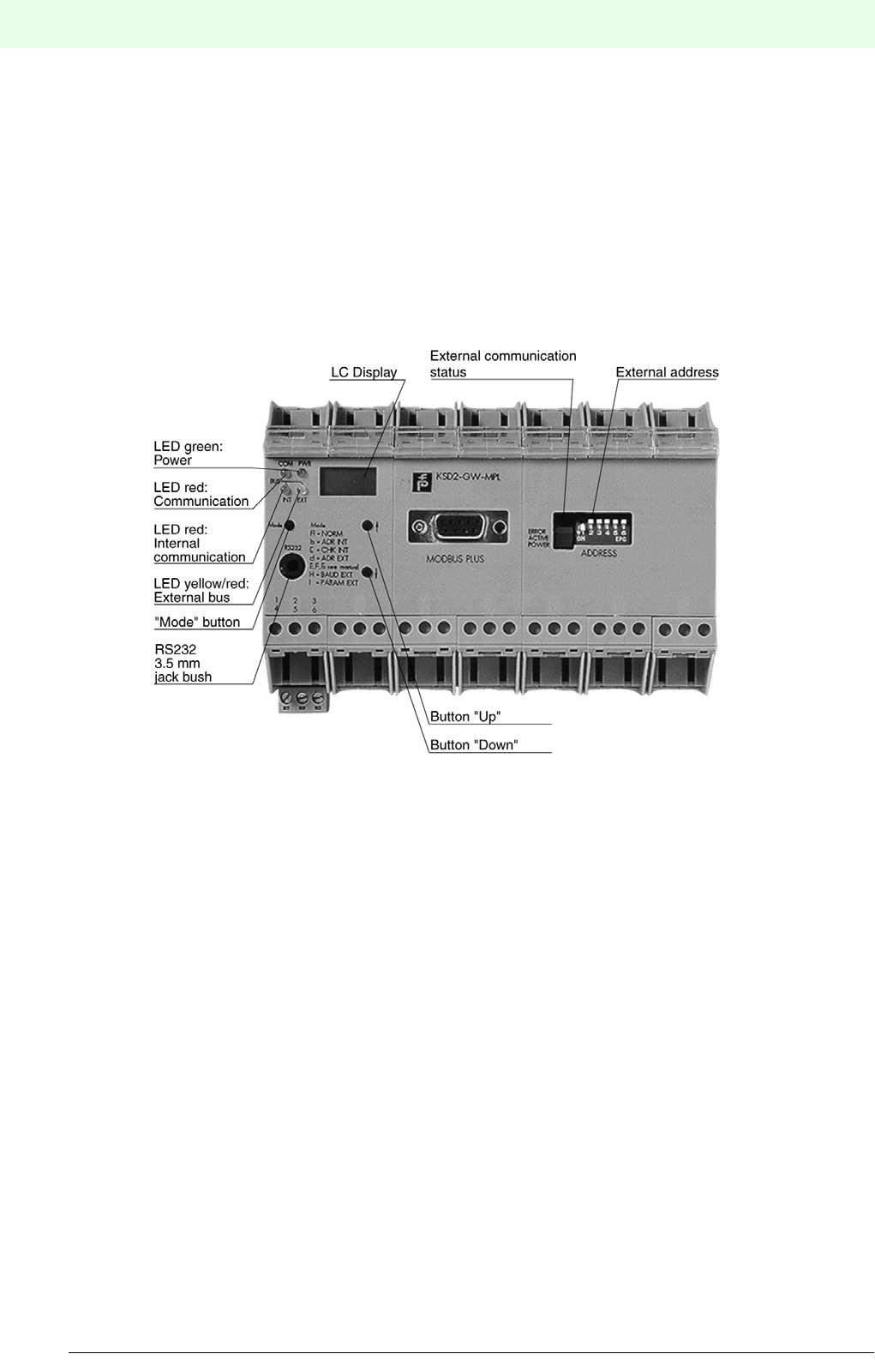
Remote Process Interface
164
S
ubject to reasonable modifications due to technical advances. Copyright Pepperl+Fuchs, Printed in Germany
Pepperl+Fuchs Group • Tel.: Germany +49 621 776-0 • USA +1 330 4253555 • Singapore +65 67799091 • Internet http://www.pepperl-fuchs.com
Date of issue 05/27/03
7.4 Gateways for the MODBUS Plus
7.4.1 Gateways KSD2-GW-MPL and KSD2-GW-MPL.485
The KSD2-GW-MPL and KSD2-GW-MPL.485 gateways supports the command and response telegram, in
accordance with MODICON Modbusprotokoll, Reference Guide, PI-MBUS-300 Rev.D. The KSD2-GW-
MPL gateway is provided with an RS232 service interface, whereas the KSD2-GW-MPL.485 gateway has
an RS 485-interface. The operating level consists of an LC-display with 3 1/2 digits and the three buttons
"Mode", "Up" and "Down".
Figure 7.4:KSD2-GW-MPL gateway
Features of KSD2-GW-MPL / KSD-GW-MPL.485 Gateways
The KSD2-GW-MPL and KSD-GW-MPL.485 gateway connects the RPI internal bus to the external MOD-
BUS Plus. The gateway thus assumes the master function for the internal bus. The gateway has the function
of a slave device on the external Modbus Plus. To increase system availability, the gateway and the external
bus can be implemented in a redundant configuration. The transmission rate of the Modbus Plus bus is 1
Mbps (Megabit per second).
7.4.2 Device Connection
The electrical connection of the KSD2-GW-MPL Modbus gateways by means of cables with 9-pin Sub-D
connectors, merely involves establishing the Modbus Plus connection.The Modbus interface is an RS 485
interface, on which up to 64 stations can be operated.
The parameterization interface can be either an RS232 (KSD2-GW-MPL) or an RS485 interface (KSD2-
GW-MPL.485); it is used to configure the RPI system with the PACTwareTM edition 2 or the K-SK1 human
machine interface. To do this, the PC is connected to the gateway via the service interface.
If an RS 232 interface is available, connection to the PC can be made via the K-ADP2 adapter. A jack socket
is provided on the front of the gateway for this purpose. If the PC is to remain connected to the RPI system
as a configuring and monitoring system, it is recommended that connection is made via the plug-in screw
terminals 7, 8 and 9 using the K-ADP4 adapter.
On the KSD2-GW-MOD.485 gateway, with the RS 485 program interface only the terminal connection is
available.
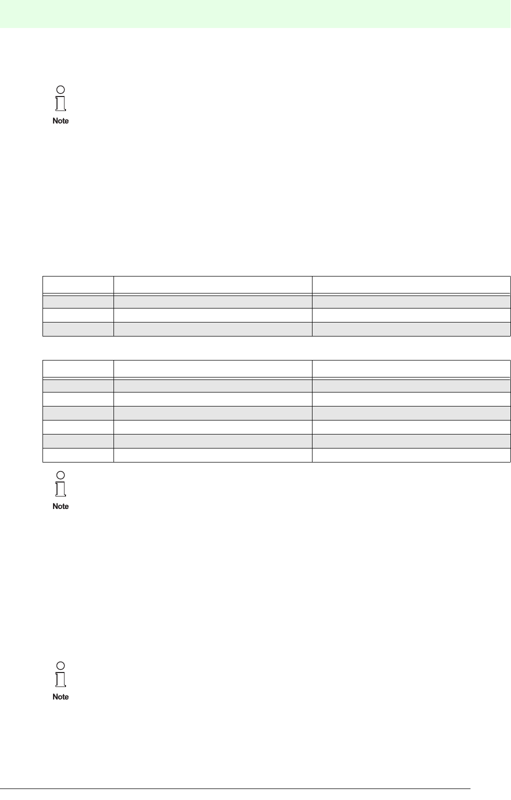
165
Remote Process Interface
Subject to reasonable modifications due to technical advances. Copyright Pepperl+Fuchs, Printed in Germany
Pepperl+Fuchs Group • Tel.: Germany +49 621 776-0 • USA +1 330 4253555 • Singapore +65 67799091 • Internet http://www.pepperl-fuchs.com
Date of issue 05/27/03
The complete configuration of the RPI system can also be undertaken from the control system, via the Mod-
bus, providing that the control system supports this.
Connection to the 24 V DC supply and to the internal CAN bus is achieved via the Power Rail.
The cable connections are made via self-opening screw terminals; max. core cross-section 1 x 2.5 mm² for
rigid cables or 2 x 1.5 mm² for flexible cables with plastic wire end ferrules. The screw terminal blocks on
the device can be removed for ease of connection.
Mount the gateway on the Power Rail and connect the Modbus cable and, if necessary, the RS232/RS485
cable as described in the connection plan and the terminal assignment list.
The connection plan for the RS232 or RS485 gateway can be obtained from the current issue of the "Inter-
face DIN-Rail Housing" catalogue.
Sub-D connector
Terminal assignment
The maximum length of lead on a bus segment is effectively determined by the following parameters:
• Type of bus cable used
• Transfer rate
• External interference effects
• Number of bus stations
More detailed information on the determination of the maximum lead length can be obtained from the EIA
485 or ISO 8482.
Bus termination
The jack socket on the front and the screw terminal connection for the RS 232 link cannot be
used simultaneously.
Terminal KSD2-GW-MOD KSD2-GW-MOD.485
1Screen, RS 485 Screen, RS 485
2 RxD/TxD-P, RS485 param. interface RxD/TxD-P, RS485 param. interface
3RxD/TxD-N, RS485 param. interface RxD/TxD-N, RS485 param. interface
Terminal KSD2-GW-MOD KSD2-GW-MOD.485
7RxD, RS232 param. interface RxD/TxD-P, RS485 param. interface
8 TxD, RS232 param. interface RxD/TxD-N, RS485 param. interface
9GND, RS232 GND, RS485
13 Screen, RS232 Screen, RS 485
14 Screen, RS232 Screen, RS485
15 Earth Earth
The number of stations on one RS485 interface (Modbus interface, such as the RS 485 pro-
gram interface) is a maximum of 32, as standard.
On the Modbus Plus, each bus segment must be terminated by resistances at both ends of the
line.
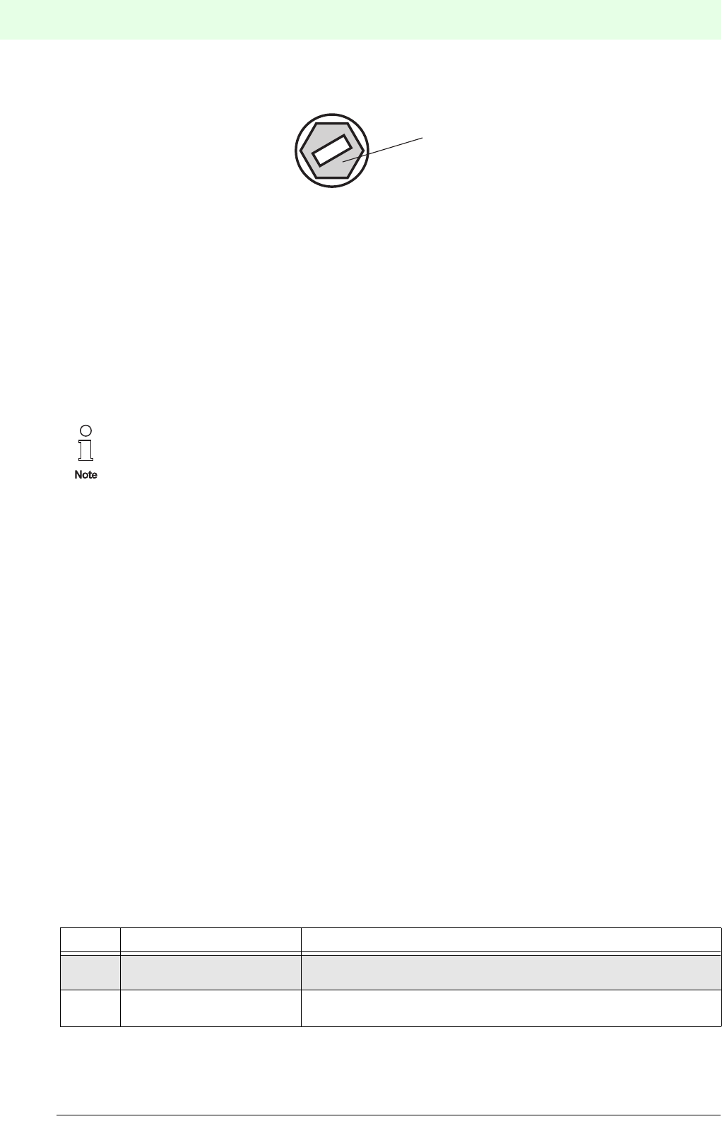
Remote Process Interface
166
S
ubject to reasonable modifications due to technical advances. Copyright Pepperl+Fuchs, Printed in Germany
Pepperl+Fuchs Group • Tel.: Germany +49 621 776-0 • USA +1 330 4253555 • Singapore +65 67799091 • Internet http://www.pepperl-fuchs.com
Date of issue 05/27/03
Figure 7.5:Rotary switch S1 for bus termination
The Modbus gateways operate internally via a switchable bus termination. Using a screwdriver, the bus ter-
mination can be activated on the rotary switch S1 on the right side of the housing (as viewed from the front).
This is used if the gateway is installed at the end of a line.
7.4.3 Modbus Plus address
The address is set by the 6 dip switches on the front of the gateway marked "NODE ADD." Possible Modbus
Plus addresses are 1 through 64. The coding of the DIP-switches is indicated on the housing side. A switch
in the down, or ON, position is a logic '0' and conversely a switch in the up, or OFF, position is a logic '1'.
7.4.4 Commissioning
Before commissioning, check once again that all the connections are correct.
Familiarise yourself with the method of communication between the Modbus Plus master and the gateway.
Commissioning requires a knowledge of the Modbus Plus and the parameter assignment of the Modbus
Plus gateway.
Time response
The Remote Process Interface is deterministic. The RPI devices are interrogated cyclically.
The most important factors which determine the time response are:
• the higher level host system, e.g. process control system, PLC or PC
• the type and number of Modbus Plus stations
• the number of the RPI devices and the cycle time of the RPI system
• the user program
7.4.5 Data Transfer on the Modbus Plus
Modbus Plus functions
The Modbus Plus is a register-orientated bus system. This means that the data is automatically stored in a
memory area, the so-called registers of the Modbus Plus gateways. Modbus Plus supports the Modbus
RTU functions, which are listed in the table below. The user can access specific data by reading the regi-
sters, and set targeted outputs or interrogate diagnoses by writing to these registers.
The number of stations on one RS485 interface (Modbus interface, such as the RS 485 service
interface) is a maximum of 31, as standard.
Code Function Description
03 Read Holding Registers Reading write/read registers, e.g. analogue outputs,
acyclic parameter channels
16 Preset Multiple Registers Block-wise writing of analogue outputs or acyclic parameter chan-
nels
Rotary switch 'S1' for
bus termination on the
right side of the device
Actuating by means
of a screw driver
Bus termination
active!
Bus termination
not active!
S1
1
0
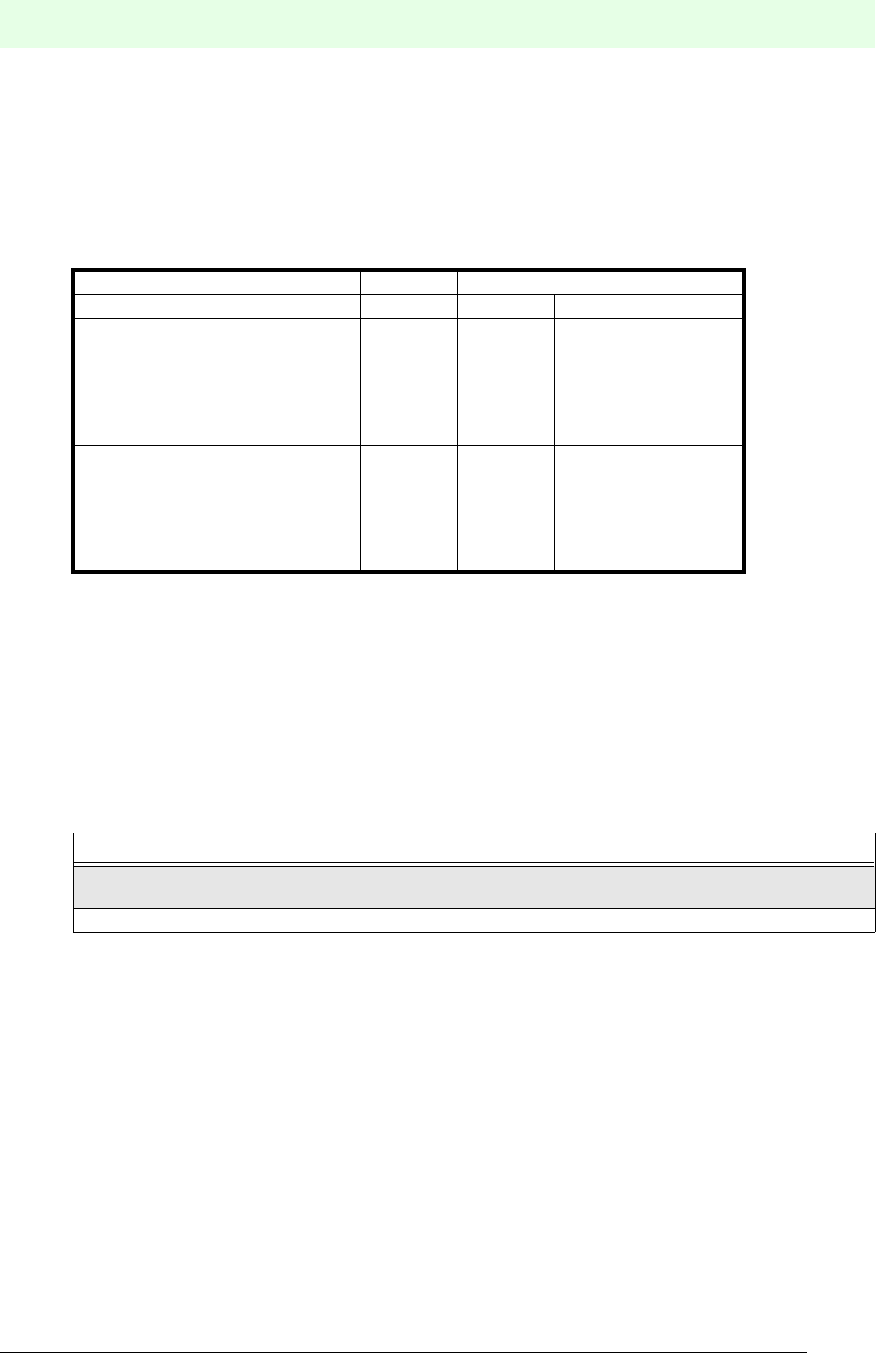
167
Remote Process Interface
Subject to reasonable modifications due to technical advances. Copyright Pepperl+Fuchs, Printed in Germany
Pepperl+Fuchs Group • Tel.: Germany +49 621 776-0 • USA +1 330 4253555 • Singapore +65 67799091 • Internet http://www.pepperl-fuchs.com
Date of issue 05/27/03
Data transfer
In the RPI gateway there are two 256-word registers which are accessible to the Modbus Plus master.The
Read Holding Register starts with register No. 1 and the Write Holding Register starts with register No.
1025. The data in the Write Holding Register is written by the host via the 'Preset Multiple Registers'
function, while the data in the Read Holding Register is read via the 'Read Holding Registers' function.Both
Read Holding Register and Write Holding Register are divided into two sections: a Control Register Area
(first 10 registers) and a Data Register Area (remaining 246 registers).
Figure 7.6:Read/Write Holding Register Configuration
Generally the Control Register Area is used for the Modbus Plus master device to send commands and read
responses to or from the RPI gateway.
7.4.6 Structure of Control Register Areas
Write Holding Register (registers 1025 - 1034)
Of the ten registers available only the first register (No. 1025) is used to transfer commands. The remaining
regisers are not used and contain ’0’.
Modbus Plus supports the eight HOST commands listed below. Further details can be found in the ’Modbus
Plus Gateway - User Manual’.
• HOST command 1: Exchange data
• HOST command 2: Set I/O data structure
• HOST command 3: Set redundancy mode
• HOST command 4: Read module diagnosis
• HOST command 5: Single channel function diagnostics
• HOST command 6: Read error code and channel alarms
• HOST command 7: Read gateway ID list
• HOST command 8: Read RPI system module types
Write Holding Register Read Holding Register
Register Area Register Area
1025
1026
...
1034
Control Register
Area
1
2
...
10
Control Register
Area
1035
1036
...
1280
Data Register
Area
11
12
...
256
Data Register
Area
Register Description of Write Holding Register
1025 HOST command register
- used for commands to be sent to the Modbus Plus gateway.
1026 ... 1034 - not used and should be cleared to '0'

Remote Process Interface
168
S
ubject to reasonable modifications due to technical advances. Copyright Pepperl+Fuchs, Printed in Germany
Pepperl+Fuchs Group • Tel.: Germany +49 621 776-0 • USA +1 330 4253555 • Singapore +65 67799091 • Internet http://www.pepperl-fuchs.com
Date of issue 05/27/03
Read Holding Register (registers 1 - 10)
Further information about the ’Functional Commands’ and the tools can be obtained from the ’Modbus Plus
Gateway - User Manual’.
Register Byte Description of Read Holding Register
1
High 0
Low Host Command - Ack Register:
echo of the Host Command register to verify if this is the response to the latest
host command.
2
High 0
Low Response Counter
- Modbus Plus data register update in the RPI Gateway. The RPI Modbus Plus
may response to a single Host Command periodically. The Response Counter is
incremented by one for each response. For each new Host Command, the coun-
ter counts starting from 1.
3
High 0
Low RPI Status Counter
- a counter for status change of the RPI. A change in the counter indicates either
an error status change in ERROR_CODE_LIST or a channel alarm status change
in CHANNEL_ALARM_ LIST.
4
High 0
Low RPI Parameter Counter
- a counter for gateway parameter change.
5High Low
RPI configuration error
Bit 0: RPI configuration error
Bit 1: reserved
Bit 2: reserved
Bit 3: RPI device error
Bit 4: RPI channel error
Bit 5: Redundant circuit
Bit 6: Redundant mode
Bit 7: Parameter check
Gateway diagnosis
Bit 0: E2PR_Err
Bit 1: APPL_Err
Bit 2: WATCHDOG
Bit 3: TIMEOUT_COM
Bit 4: not used
Bit 5: not used
Bit 6: not used
Bit 7: reserved
6...10 reserved
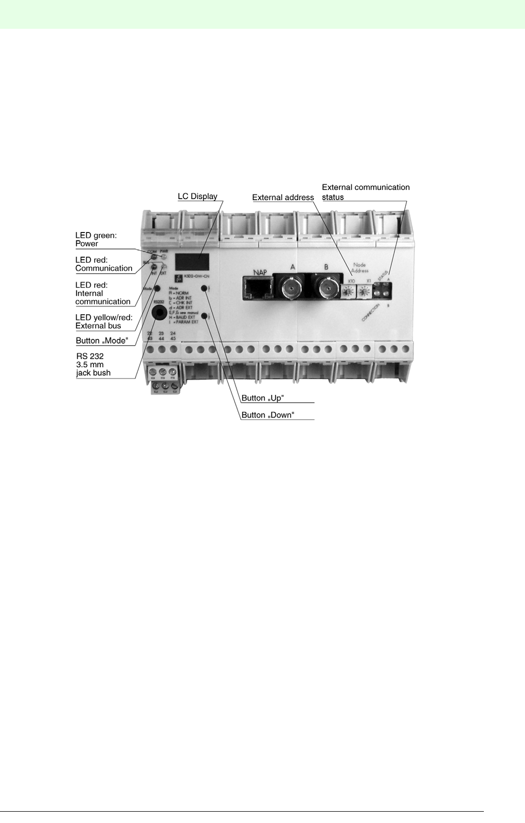
169
Remote Process Interface
Subject to reasonable modifications due to technical advances. Copyright Pepperl+Fuchs, Printed in Germany
Pepperl+Fuchs Group • Tel.: Germany +49 621 776-0 • USA +1 330 4253555 • Singapore +65 67799091 • Internet http://www.pepperl-fuchs.com
Date of issue 05/27/03
7.5 Gateways for ControlNet
7.5.1 KSD2-GW-CN and KSD2-GW-CN.485 Gateways
The KSD2-GW-CN and KSD2-GW-CN.485 gateways are designed in accordance with the international
ControlNet specification for ’Communication Adapters’ (profile No. 12). The KSD2-GW-CN gateway has an
RS 232 service interface while the gateway of the type KSD2-GW-CN.485 has an RS 485 interface. The
operating level consists of an LC-display with 3 1/2 digits and of the three pushbuttons "Mode", "Up" and
"Down".
Figure 7.7:KSD2-GW-CN gateway
Features of the KSD2-GW-CN / KSD-GW-CN.485 gateways
The KSD2-GW-CN and KSD2-GW-CN.485 gateways connect the RPI internal bus to the external Control-
Net bus. The gateway thus assumes the master function for the internal bus. The gateway has the function
of a ControlNet adapter (slave) on the external ControlNet. To increase system availability, the gateway and
external bus can be arranged redundantly.
The gateway is provided with two BNC plugs for the connection to the ControlNet. The cable to the ’Scanner
node’ (ControlNet host) may be arranged redundantly by using both connectors (’A’ and ’B’). The MacID
(ControlNet Node address) can be set by means of the two decimal rotary switches, before switching on the
power supply. The addess range is 1 through 99.
A configuration tool for system configuration or problem solving can be connected using the NAP interface
(Network Access Port).
7.5.2 Device connection
The electrical connection of the ControlNet gateway by means of a BNC plug and a RG-6 four-core scree-
ned cable, merely involves establishing the ControlNet connection.The ControlNet address is set by the two
rotary switches. Possible addresses are 1 through 99.
The RPI service interface can be either an RS 232 (KSD2-GW-CN) or an RS 485 interface (KSD2-GW-
MPL.485); it is used to configure the RPI system with the PACTwareTM edition 2 human machine interface.
To do this, the PC is connected to the gateway via the service interface.
If an RS 232 interface is available, connection to the PC can be made via the K-ADP2 adapter. A jack socket
is provided on the front of the gateway for this purpose. If the PC is to remain permanently connected to the
RPI system as a configuring and monitoring system, it is recommended that connection is made via the
Remote Process Interface
170
S
ubject to reasonable modifications due to technical advances. Copyright Pepperl+Fuchs, Printed in Germany
Pepperl+Fuchs Group • Tel.: Germany +49 621 776-0 • USA +1 330 4253555 • Singapore +65 67799091 • Internet http://www.pepperl-fuchs.com
Date of issue 05/27/03
plug-in screw terminals 7, 8 and 9, which are in parallel with the jack socket.
On the KSD2-GW-MOD.485 gateway, with the RS 485 service interface, only the terminal connection is
available.
Connection to the 24 V DC supply and to the RPI internal bus is achieved via the Power Rail.
The cable connections are made via self-opening screw terminals; max. core cross-section 1 x 2.5 mm² for
rigid cables or 2 x 1.5 mm² for flexible cables with plastic wire end ferrules. The screw terminal blocks on
the device can be removed for easier connection.
Mount the gateway on the Power Rail and connect the coaxial cable and, if necessary, the RS232/RS485
service interface cable.
The connection diagram for the gateway with RS232 or RS485 interface can be obtained from the current
issue of the "Interface DIN-Rail Housing" catalogue.
Connection type on the front
Terminal assignment
The maximum length of lead on a bus segment is effectively determined by the following parameters:
• Type of bus cable used
• Transmission rate
• External interference effects
• Number of bus stations
More detailed information on the determination of the maximum lead length can be obtained from the EIA
485 or ISO 8482.
The jack socket on the front and the screw terminal connection for the RS 232 link cannot be
used simultaneously.
Connection KSD2-GW-CN KSD2-GW-CN.485
ABNC plug for ControlNet BNC plug for ControlNet
B BNC plug for ControlNet BNC plug for ControlNet
NAP 8-pin RJ-45 connector for configuration tool 8-pin RJ-45 connector for configuration tool
Terminal KSD2-GW-CN KSD2-GW-CN.485
22 RxD, RS232 param. interface RxD/TxD-P, RS485 param. interface
23 TxD, RS232 param. interface RxD/TxD-N, RS485 param. interface
24 GND, RS232 GND, RS485
43 Screen, RS232 Screen, RS 485
44 Screen, RS232 Screen, RS485
45 Earth Earth
The number of stations on one RS485 interface (Modbus interface such as RS 485 parameteri-
zation interface) is a maximum of 31, as standard.

171
Remote Process Interface
Subject to reasonable modifications due to technical advances. Copyright Pepperl+Fuchs, Printed in Germany
Pepperl+Fuchs Group • Tel.: Germany +49 621 776-0 • USA +1 330 4253555 • Singapore +65 67799091 • Internet http://www.pepperl-fuchs.com
Date of issue 05/27/03
7.5.3 ControlNet Address
The address is set by the two rotary switches on the front of the gateway marked "Node Address".Possible
addresses are 1 through 99. Using switch X1 the number which has been set is multiplied by 1 and using
switch X10 it is multiplied by 10.
7.5.4 Commissioning
Before commissioning, check once again that the connections are correct.
Familiarise yourself with the method of communication between the ControlNet scanner (host) and the ga-
teway (ControlNet adapter). Commissioning requires a knowledge of the the ControlNet and the parame-
terisation of the gateway.
Time response
The Remote Process Interface is deterministic. The RPI devices are interrogated cyclically.
The most important factors which determine the time response are:
• the higher level host system, e.g. process control system, PLC or PC
• the type and number of ControlNet stations
• the number of the RPI devices and the cycle time of the RPI system
7.5.5 Operation on the ControlNet
The I/O data is transmitted via the ’ControlNet scheduled service’ (cyclic data exchange). The ’ControlNet
unscheduled service’ (acyclic data exchange) is used to transmit the commands for the I/O data structure,
the redundant mode or the diagnosis and the gateway responses.
7.5.6 Data Transmission
The RPI ControlNet gateway can transmit up to 450 data bytes, which consist of 225 input and 225 output
bytes. The data in the Input Area is transmitted from the RPI gateway to the host and the data in the Output
Area is transmitted to the gateway. Both Input and Output Area, each containing 225 bytes, are divided into
two sections: a Control Area (10 bytes) and a Data Area (215 bytes).
Figure 7.8:Output/Input Areas configuration
Output Area Input Area
Word 0
...
Word 9
Output Control
Area
Input Control
Area
Word 10
...
Word 224
Output Data
Area
Input Data
Area

Remote Process Interface
172
S
ubject to reasonable modifications due to technical advances. Copyright Pepperl+Fuchs, Printed in Germany
Pepperl+Fuchs Group • Tel.: Germany +49 621 776-0 • USA +1 330 4253555 • Singapore +65 67799091 • Internet http://www.pepperl-fuchs.com
Date of issue 05/27/03
Structure of the Output Control Area
Of the ten areas available only the word 0 is used for the command counter.
Structure of the Output Data Area
The data structure of the Output Area depends on the configuration of the RPI modules. It may contain up
to 215 words. The configuration of each RPI device, the data format and the transfer of the status byte can
be defined using ’Command Word 2’. Additional information can be obtained from the ’ControlNet Gateway
Users Manual’.
Structure of the Input Control Area
Word in Output
Control Area Description of the Write Holding Register
0High 0
Low Command Counter
Detects commands, which are transmitted by the host to the gateway via
the ’unscheduled service’.
1 ... 9 reserved
Register Byte Description of the Read Holding Register
0
High Low
Low Response Counter
Echo of the ’Command Counter’, if the response to a command for transmission
in the gateway is complete.
1
High Low
Low Input Update Counter
Counts updates of the input data in the input data field.
2
High Low
Low RPI Status Counter
- a counter for status change of the RPI. A change in the counter indicates either
an error status change in ERROR_CODE_LIST or a channel alarm status change
in CHANNEL_ALARM_ LIST
3
High Low
Low RPI Parameter Counter
- a counter for each gateway parameter change.
4High Low
RPI configuration error
Bit 0: RPI configuration error
Bit 1: reserved
Bit 2: reserved
Bit 3: RPI device error
Bit 4: RPI channel error
Bit 5: Redundant circuit
Bit 6: Redundant mode
Bit 7: Parameter check
Gateway diagnosis
Bit 0: E2PR_Err
Bit 1: APPL_Err
Bit 2: WATCHDOG
Bit 3: TIMEOUT_COM
Bit 4: not used
Bit 5: not used
Bit 6: not used
Bit 7: reserved
5...10 reserved
173
Remote Process Interface
Subject to reasonable modifications due to technical advances. Copyright Pepperl+Fuchs, Printed in Germany
Pepperl+Fuchs Group • Tel.: Germany +49 621 776-0 • USA +1 330 4253555 • Singapore +65 67799091 • Internet http://www.pepperl-fuchs.com
Date of issue 05/27/03
Input Data Area
The data structure of the input area depends on the configuration of the RPI modules. It may contain up to
215 words. Further information can be found in the ’ControlNet Gateway Users Manual’.
7.5.7 Command/Response Transmission
The command/response is transferred by means of the ’ControlNet unscheduled service’ (acyclic data ex-
change). The host transmits a command to the gateway and the gateway transmits the response back to
the host. The commands available (’Command word’) are given in the list below.Further information can be
obtained from the User Manual.
• Command Word 2: Set I/O data structure
• Command Word 3: Set redundancy mode
• Command Word 4: Read module diagnosis
• Command Word 5: Single channel function diagnostics
• Command Word 6: Read error code and RPI device alarms
• Command Word 7: Read gateway ID list
• Command Word 8: Read RPI system module types
• Command Word 9: Read error code and channel alarms
Format
Command and response are transmitted in the 16-bit integer format. The data length depends on the com-
mand and the response. It varies from ‘Command Word‘ to ‘Command Word´.
Command Format
Command Word
Data 0
Data 1
Up to data 126
Response Format
Response Word
Data 0
Data 1
Up to data 126
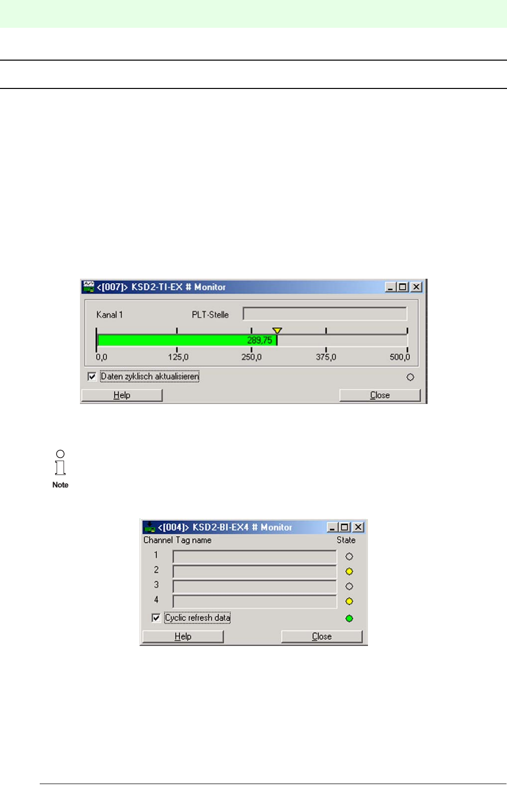
Remote Process Interface
RPI in Operation
174
S
ubject to reasonable modifications due to technical advances. Copyright Pepperl+Fuchs, Printed in Germany
Pepperl+Fuchs Group • Tel.: Germany +49 621 776-0 • USA +1 330 4253555 • Singapore +65 67799091 • Internet http://www.pepperl-fuchs.com
Date of issue 05/27/03
MONITORING, SIMULATING MEASURED VALUES AND ERROR HANDLING
8 RPI in Operation
By monitoring and simulating process data, as explained below, the RPI system and the connected control
system can be checked prior to commissioning. While the system is in operation, measured values can be
monitored over a lengthy period of time and trend analyses can be made. Just open the respective window
on the PACTwareΤΜ human machine interface by clicking onto the required device with the right mouse but-
ton.
8.1 Displaying Measured Values
The Measured Value window shows the current input values, in the binary or analogue format. Binary si-
gnals are displayed in the form of LEDs, while analogue input signals are displayed by means of a scaled
bar graph. The scaling of the display corresponds to the parameterization of the channel.
Figure 8.1:Window displaying analogue values
.
Figure 8.2:Window displaying binary inputs
To enable the data of selected devices to be read out and any changes to be indicated, it is
necessary to mark the check box Check connection to RPI device cyclic .
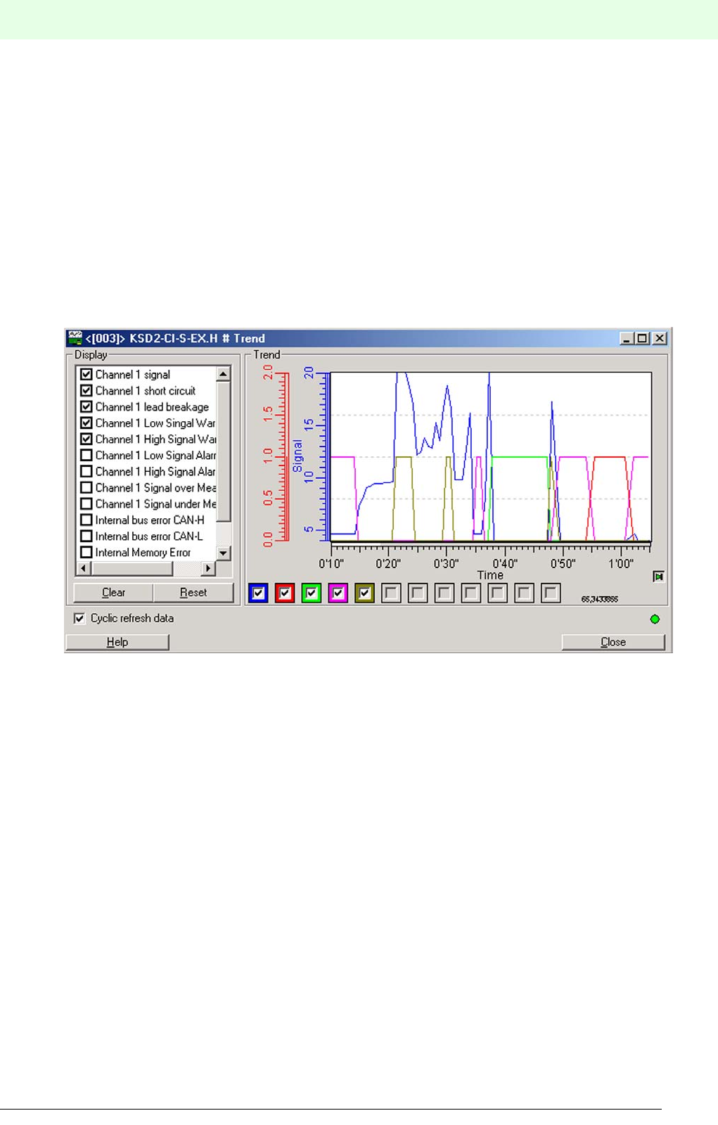
175
Remote Process Interface
RPI in Operation
Subject to reasonable modifications due to technical advances. Copyright Pepperl+Fuchs, Printed in Germany
Pepperl+Fuchs Group • Tel.: Germany +49 621 776-0 • USA +1 330 4253555 • Singapore +65 67799091 • Internet http://www.pepperl-fuchs.com
Date of issue 05/27/03
8.2 Displaying Trends
The Trend window contains a recorder which displays the monitored values in a graph. Analogue values
are displayed according to the scale (Y axis). The two states of binary information are displayed as 0%
value (equals 0), and as 50% value (equals 1).
The <Trend> tab contains the sections Display and Trend.
On opening the Trend menu a recorder appears in the Trend section which displays the measured values
continuously. The time axis and the axis for the measured value may be adapted to suit the requirements
by changing the scale range and the graduation (of the scale). Just move the cursor along the required sca-
le. Hold the right mouse button depressed to scale the axis to the right and upwards, and hold the left button
depressed to scale it to the left or downwards. The arrow button down on the right (in the same section)
enables you to shift between updating and locking the display.
Figure 8.3:Window showing the display and the trend graph
The Display section enables you to select the measured values, the messages and limit values, that are to
appear in the Trend section on the right. To do this, check the box on the left of the value that is to be dis-
played. Use the Delete button to remove selected values and the Reset button to undo changes. These
options are only available if the ’Cyclic update’ checkbox is not marked.
Individual values can be shielded during the recording phase by clicking onto the checkboxes under the re-
corder and thus removing the check marks. The colours of the boxes correspond to the colours of the re-
corder graph. The order of the colours from left to right corresponds to the measured values selected in the
Display section from the top downwards.
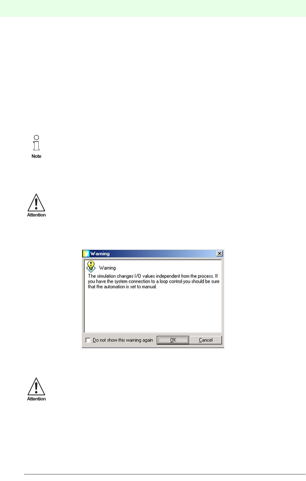
Remote Process Interface
RPI in Operation
176
S
ubject to reasonable modifications due to technical advances. Copyright Pepperl+Fuchs, Printed in Germany
Pepperl+Fuchs Group • Tel.: Germany +49 621 776-0 • USA +1 330 4253555 • Singapore +65 67799091 • Internet http://www.pepperl-fuchs.com
Date of issue 05/27/03
8.3 Simulation
8.3.1 Simulation of Input Signals
The control system can be checked by simulating the input values without connecting a process peripheral.
The actual measured values of the simulated circuit are overwritten by the simulation data if a process pe-
ripheral is connected. The data exchange with the other, non-simulated devices, is not interrupted by the
simulation.
8.3.2 Simulation of Output Signals
By simulating the output values, the actuators in the field, e.g., valves, pumps, motors, can be checked and
adjusted, without a control system connected.The signals of the simulated measuring circuits are input from
the human machine interface. Output signals from the control system are suppressed for the simulated
measuring circuits.The data exchange with the other, non-simulated devices, is not interrupted by the simu-
lation.
Figure 8.4:Warning prior to starting a simulation
Confirm the warning with OK to proceed.If you proceed you are asked to choose the features you want to
simulate.There are three simulation options available: Process Value, Device Specific Diagnostic, and
Channel Specific Diagnostic.
The simulation of a device can be carried out during operation.
During the simulation, the error code 08 (‘device being simulated’) is displayed on the gateway
LC Display and the red LED 'internal bus fault' flashes.
Up to 5 devices can be simulated simultaneously.
Simulation plays an active part in a process. A simulation of the input values may cause undesi-
rable reactions in the control system.
A simulation of the output values initiates the actuators, opens valves and controls pumps!
A check should be made, in any case, prior to starting the simulation, that no system endange-
ring or undesirable conditions are likely to arise!
If you are not authorized or do not wish to intervene in the process, select 'Cancel' to close the
window and exit the ’Simulation’ menu.
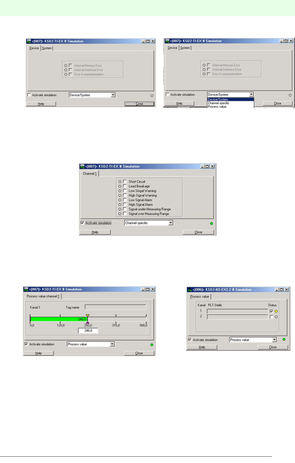
177
Remote Process Interface
RPI in Operation
Subject to reasonable modifications due to technical advances. Copyright Pepperl+Fuchs, Printed in Germany
Pepperl+Fuchs Group • Tel.: Germany +49 621 776-0 • USA +1 330 4253555 • Singapore +65 67799091 • Internet http://www.pepperl-fuchs.com
Date of issue 05/27/03
Figure 8.5:Simulation of device and system specific error messages
The options Device/System and Channel specific enable you to simulate the error messages.Mark
the check box of the signal whose status you want to change. A checked box means that the according error
signal is set.
Figure 8.6:Simulation of channel specific messages
If you choose Process Value you can simulate the state of the device inputs and outputs.For binary de-
vices you simply check the box beside the LED of the channel whose state you want to change. With ana-
logue devices you will find a text box under the bar graph to enter the desired value.
Figure 8.7:Simulation of process values

Remote Process Interface
RPI in Operation
178
S
ubject to reasonable modifications due to technical advances. Copyright Pepperl+Fuchs, Printed in Germany
Pepperl+Fuchs Group • Tel.: Germany +49 621 776-0 • USA +1 330 4253555 • Singapore +65 67799091 • Internet http://www.pepperl-fuchs.com
Date of issue 05/27/03
8.4 Servicing and Diagnostic System
The components of the RPI system do not require servicing within the given environmental conditions.Fault
conditions on the gateways and devices are indicated by the diagnostics of the RPI human machine inter-
face.
8.4.1 Via LEDs, LCD and Pushbuttons on the Devices
The failure of devices is indicated via the LEDs on the devices and the LC display on the gateway, see Ka-
pitel 5 "Configuring and Commissioning the RPI System".
8.4.2 Via PC and PACTwareΤΜ or RPI Human Machine Interface
If a PC is connected to the RS 232/RS 485 service interface of the gateway, extensive diagnosis can be
retrieved via the PACTwareΤΜ edition 2 human machine interface.In this event the faulty device is indicated
in red on the PC. If the device concerned is marked with the cursor, all the relevant data on the RPI modules
can be requested via the “Diagnosis” menu. The same messages are also available on the control system
via the external bus.
8.4.3 Via a Permanently Installed PC Based Service Level
If gateways are used with the RS 485 service interface, the gateway service interfaces with up to 31 RPI
segments can be networked with a common PC. Thus the RPI human machine interface provides the
function of a central engineering console for your RPI systems.
8.4.4 From the Control System Engineering Console
Depending on the type of implementation in the control system, the RPI can also be controlled from the con-
trol system engineering console. Access is obtained for reading and writing to the complete data contents
of all the connected gateways and RPI devices: Measured values, status values, configuration data and pa-
rameters.
8.5 Error Handling
When an error occurs, a message is always generated by the RPI system. If there is not an error on the
gateway, or if the system has a redundant gateway, then the unaffected circuits continue to operate, unin-
terrupted. So far as is possible, the faulty devices output replacement values to the control system and in
the field.
8.5.1 Error Detection within the RPI System
The RPI system offers a number of methods of error detection and device diagnosis.There are four main
procedures:
• Error detection using the LEDs on the devices
• Error detection using the LC display on the gateway
• Error detection and device diagnosis using the PACTwareΤΜ human machine interface
• Error detection and device diagnosis via the external bus
8.5.1.1 Error Detection Using the LEDs on the Devices:
The LEDs on the front panels of the gateways and the RPI devices provide information on:
• Voltage supply
• Lead breakage or short circuit of the field circuits
• Device errors
• Status of the internal communication via the bus
• Status of the external communication via the external bus system
8.5.1.2 Error Detection Using the LC Display on the Gateway
An error code is displayed on the LC display on the gateway, which can be used to diagnose the error. A
list of the error codes is given in Chapter in the appendix Kapitel 11 "RPI System Error Messages".
Detailed information on the possible status of the LEDs on the front panels of the devices is pro-
vided in the appendix section 11 "RPI System Error Messages":

179
Remote Process Interface
RPI in Operation
Subject to reasonable modifications due to technical advances. Copyright Pepperl+Fuchs, Printed in Germany
Pepperl+Fuchs Group • Tel.: Germany +49 621 776-0 • USA +1 330 4253555 • Singapore +65 67799091 • Internet http://www.pepperl-fuchs.com
Date of issue 05/27/03
8.5.1.3 Error Detection Using the PACTwareΤΜ Human Machine Interface
Detailed information on the status of the RPI system can be obtained from the PACTwareΤΜ human machine
interface. Errors are indicated by coloured identification of the devices involved in the main menu.. The error
can be precisely pinpointed using the diagnostic menu.
8.5.2 Error detection from the control system engineering console
Depending on the type of implementation in the control system, it is also possible to detect errors in the RPI
system from the control system engineering console. If all diagnostic functions are implemented, access to
the complete data for the connected gateways and RPI devices will be available as when detecting errors
using the RPI human machine interface: Measured values, status values, configuration data and parame-
ters.
8.5.3 Fault elimination within the RPI System
The fault diagnosis shows whether the error lies in the field circuit, in the internal or external bus system, in
the parameterization, or in the device itself. If the fault lies in the device, then it can be replaced by a new
one.
8.5.3.1 Replacement in the case of failure of an individual device
The device is replaced by another of similar type, which is set to the neutral address 0. Communication with
the gateway commences immediately. The gateway overwrites the address 0 with that of the replacement
module. The parameter set is transferred to the device following storage in the gateway. Normal operation
is resumed. A status message regarding the elimination of the fault is transmitted via the external bus.
8.5.3.2 Replacement in the event of the simultaneous failure of a number of devices
If the failed devices are all of different types, they are simply replaced as described under “Replacement in
the case of failure of a single device.”The replacement devices are identified by the gateway.The correct
addresses for the internal bus are assigned automatically. The parameters are loaded into the devices. The
system informs the control system that full serviceability has been regained, in that the existing error mes-
sages are withdrawn.
If more than one device of a type has failed, the defective devices are removed from the rail.The replace-
ment devices are set to the address “0” at the factory.They are snapped onto the rail one after the other, in
ascending order of address for the internal bus.The gateway automatically assigns the lowest address of
all the failed devices on the internal bus to each new device. Then the parameters are automatically loaded
into the new device. The next replacement device can then be snapped onto the rail.
Detailed information on error detection and diagnosis with the
PACTwareΤΜ edition 2 human machine interface are given in Part PACTwareΤΜ.
The failure of one or more devices has no effect on the function of the remaining serviceable
devices.
Devices intended for replacement purposes should be set to the neutral address 0. Otherwise,
on the replacement of an individual device, the automatic address assignment cannot take
place.
In the event that the new device has an address other than „0“, an error message is generated.
If the address of the new device is identical to that of another device, then its function is termi-
nated and a second error message ensues. In this case the correct address should be immedi-
ately allocated to the new device, as described in Chapter 7.
When using this method, no addresses, parameters or measurement ranges must be set when
servicing. Straightforward replacement of the devices is sufficient.

Remote Process Interface
RPI in Operation
180
S
ubject to reasonable modifications due to technical advances. Copyright Pepperl+Fuchs, Printed in Germany
Pepperl+Fuchs Group • Tel.: Germany +49 621 776-0 • USA +1 330 4253555 • Singapore +65 67799091 • Internet http://www.pepperl-fuchs.com
Date of issue 05/27/03
If more than one device of a type has failed and it is desired that the ascending sequence of addresses is
not maintained, then the device addresses and parameter sets are loaded into the devices individually in a
separate work area, using a gateway, via a PC and the PACTwareΤΜ human machine interface. These new
devices are then incorporated into the system by snapping them onto the rail.
8.6 Error detection on the external bus system
Depending on the bus system used, the scope of error detection and device diagnosis are also very exten-
sive. The way in which the error and diagnostic information are placed at the disposal of the user depends
very much, however, on the master device used.
Reference should be made to the documentation for the bus system in use, as provided by the manufactu-
rer.
.
8.7 Fault elimination on the external bus system
The possibilities of eliminating a bus error depend on the higher level system which is installed. In the case
of a redundant mode of operation, gateway No.2 automatically takes over the functions of gateway No.1, if
it has detected an error on the external bus.
The failure of bus 1 is detected by the bus master. In parallel with this, gateway No. 2 provides a message
via bus 2.
8.8 Replacement of Defective Gateways
Replacing a gateway:
The addresses and parameters for the new gateway should be downloaded via PC and PACTwareΤΜ. Nor-
mal operation is resumed. A status message regarding the elimination of the fault is transmitted via the ex-
ternal bus.
Replacing a gateway - external bus redundant:
If the system is redundant, due to the use of 2 gateways and two external bus branches, one gateway is
defined as active (priority) and the other as redundant.
If one external bus branch or one gateway fails, then communication takes place via the second gateway
and the second bus branch. A status message regarding the fault is transmitted via the bus branch that
remains operative.
The addresses and parameters for a new gateway are set by means of a PC and the PACTwareΤΜ human
machine interface.
The devices must be allocated addresses in ascending order, commencing with the lowest
address in the series.
Otherwise the automatic loading of the parameter sets does not function.
Detailed information for an evaluation of PROFIBUS-DP, PROFIBUS DP V1, MODBUS RTU,
MODBUS PLUS oder CONTROLNET can be found in Chapter 7 "Gateways".

181
Remote Process Interface
Dismantling and Disposal
Subject to reasonable modifications due to technical advances. Copyright Pepperl+Fuchs, Printed in Germany
Pepperl+Fuchs Group • Tel.: Germany +49 621 776-0 • USA +1 330 4253555 • Singapore +65 67799091 • Internet http://www.pepperl-fuchs.com
Date of issue 05/27/03
9 Dismantling and Disposal
Repackaging
Where devices and components are to be stored for reuse at a future date, they should be protected against
shock loads and humidity. The original packaging affords optimum protection.
Disposal
Electronic scrap is special refuse. Local regulations must be followed when disposing of elec-
tronic components.
The devices in the RPI system do not contain internal batteries which must be removed prior
to disposal.

Remote Process Interface
Quick instructions
182
S
ubject to reasonable modifications due to technical advances. Copyright Pepperl+Fuchs, Printed in Germany
Pepperl+Fuchs Group • Tel.: Germany +49 621 776-0 • USA +1 330 4253555 • Singapore +65 67799091 • Internet http://www.pepperl-fuchs.com
Date of issue 05/27/03
APPENDIX
10 Quick instructions
10.1 Installation of the Software on your PC
It is recommended that all Windows programs are closed prior to the installation.
Load the PACTwareTM CD into your CD drive. Start Setup.exe on the installation disc by going to the Start
menu and clicking on Run.Enter the following line into the next window.
Drive letter:\setup.exe (e.g. e:\setup.exe).
You can also select your disc drive by clicking Browse and then Setup.exe.
Click OK to confirm your entry. Now the setup program starts.
The human machine interface is provided with a context sensitive help menu to answer your questions.
10.2 Voltage supply for the RPI system
The supply voltage (20 to 30 V DC or 230V AC) is connected to the power feed modules that make a con-
nection to the Power Rail. The devices will be plugged onto the rail later, when they will have been configu-
red and the parameters will have been set.
Power will now be supplied automatically and the green ’PWR’ LED's on the devices will light.
10.3 Configuration and Parameter Assignment of the RPI System
The two alternative methods of configuring the RPI system are described in the following:
10.3.1 Offline Configuration and Downloading to the Devices
The project is set up offline, using the PACTwareTM and stored in the PC. On Download, the data in all con-
figuration files relating to the project, are stored in the individual devices.
1. Start PACTwareTM edition 2:
Start the PACTwareTM human machine interface on your PC. When working with PACTwareTM you can chan-
ge decisions you have made later on.
After the program start, the main window opens. The project window displays and installs the RPI sy-
stem and the various components and drivers.The edit window displays the various menus that are
required for the project such as device catalogue, register cards for the parameter assignment, menus
for diagnosis, measurement values and simulation or the communication monitor.
2. New project:
A new project can be configured immediately after the program start. By adding the COM driver, the
gateways, and the various devices the RPI system is installed in the project window.
There are three different ways to add the components
• Click onto HOST IBM-PC, COM Driver or Gateway with the right mouse button and select <Add
device>. A menu opens in the edit window which only offers options that can be projected at this
point.
• Click HOST IBM-PC, COM Driver or Gateway with the right mouse button and then click the <Pa-
ste> button down on the left. The menu described above opens.
• On the menu bar click Project and then Device catalogue or simply press the function key F3. The
device catalogue which contains all the installed device and communication drivers now appears
in the edit window.
All the installed components appear in the middle column. Click onto the plus sign to the left of the
components to be projected.
The COM driver, Gateway and Device subdirectories are then displayed.

183
Remote Process Interface
Quick instructions
Subject to reasonable modifications due to technical advances. Copyright Pepperl+Fuchs, Printed in Germany
Pepperl+Fuchs Group • Tel.: Germany +49 621 776-0 • USA +1 330 4253555 • Singapore +65 67799091 • Internet http://www.pepperl-fuchs.com
Date of issue 05/27/03
Now the individual components should be projected in order, as follows:
• COM driver ( RPI serial interface, HART protocol driver)
• Gateway or the devices for direct communication with the HART driver
• Second gateway for redundant communication with the control system or the first RPI device.
• RPI devices
3. Open project:
Select <File> <Open>. Now you can open project *.PW and start editing it.
4. Select COM driver:
Highlight <HOST IBM-PC>, select the COM driver, the RPI serial interface or the HART protocol driver
from the menu or from the device catalogue and paste it to the project window.
In order to project the COM driver you can
• click on the COM driver in the right window, and drag it, keeping the mouse button depressed, to
HOST IBM_PC in the left window (drag and drop) or
• double click the COM driver in the right window or
• click on the COM driver once and confirm the selection by clicking the Paste button down on the
right.
This means that, if you wish to project a COM driver, the HOST IBM PC must be activated, for K or E
devices the KE-GUT driver must be activated, and for an RPI device the RPI gateway should be acti-
vated.
If this is not the case, an error message will appear.
5. Select gateway:
Mark the COM driver, select the gateway in the menu or in the device catalogue and paste it to the
project window. The gateway automatically obtains the address [001] while the redundant gateway ob-
tains the address [002] as RPI internal bus addresses.
6. Select devices:
Open the menu or the device catalogue and mark the required device (its symbol is on a blue back-
ground) and accept it with <Paste> or <OK> (the device is then inserted under the position marked on
the left hand side) or just drag the marked device to the project window. On pasting a device to the
project window PACTwareTM automatically assigns the lowest address available to the RPI internal
CAN-Bus. The 3-digit number appears in square brackets to the left of the device. A maximum of 125
addresses, [003] to [127], can be assigned per gateway for the internal bus. We recommend that
addresses should be assigned consecutively for similar device functions. The sequence in which you
arrange the devices is arbitrary. The assignment to the hardware takes place during the addressing
procedure.
Note that the level in the left column where you can project the required component should be
activated, i.e. be on a grey or blue background.

Remote Process Interface
Quick instructions
184
S
ubject to reasonable modifications due to technical advances. Copyright Pepperl+Fuchs, Printed in Germany
Pepperl+Fuchs Group • Tel.: Germany +49 621 776-0 • USA +1 330 4253555 • Singapore +65 67799091 • Internet http://www.pepperl-fuchs.com
Date of issue 05/27/03
7. Configuring and parameterizing
In order to edit a PACTwareTM component
• click onto the component that you wish to edit in the project window with the right mouse button
and select Edit, or
• double click the component that you wish to edit in the project window, or
• click onto the component that you wish to edit in the project window with the left mouse button and
then click the Edit button down on the right in the project window, or
• click onto the component that you wish to edit in the project window with the left mouse button and
then depress the function key F5.
Now the display and interface of the Device Type Manager opens, providing the Device Info, Descrip-
tion and Parameter tabs for offline parameterization.
The Device Info tab provides unchangeable information on the selected component.
The Description tab can be used to store data which is specific to a measuring point (e.g. tag name
and measuring point description). This information is only stored in the project not in the devices.
The Parameter tab provides access to all settable parameter values of the selected components. In-
formation which is not changeable is displayed in light grey on this tab.
The data on this tab can be
• stored in a file
• stored in the device.
When you click the Save to device button, PACTwareTM edition 2 establishes a connection to the sel-
ected device and loads the data to this device.
This means that in a project consisting of a COM driver and devices the changed settings must be
downloaded twice - for the COM driver and for the device separately.
8. Parameterizing the COM port
In order to parameterize the COM port, the COM port on the PC/notebook and the baud rate of the
serial interface should be set in the tab.
9. Parameterizing gateways
In order to parameterize the gateways, the address of the gateways, the baud rate, and the parity/stop
bit should be entered. You enter the data into the white fields of the dialogue window tabs.
Two code words can be used to provide protected access.Each of these ensures full access to the
system. Always assign both code words. If one code word is left blank, it increases the risk of access
by unauthorised persons.
If you click on ’Panel locked’, you will not be able to make changes later with the gateway buttons.
Therefore this option should not be marked in the check box at this stage.
In order to be able to link the parameterization interfaces together, assign an address.
This address must be assigned, even in the case of simple point-to-point RS 232 connections.
In the diagram, it appears in pointed brackets ’<0>’. The selected address must correspond with that
set later on the gateway.
When this window is closed, the gateway data should be stored in a file (offline) or in the device (online)
as when parameterising the COM ports. Any names can be used for the files, but the file extension is
always ’.dat’.
10. Parameterizing RPI devices
Depending on the device type, different tabs are opened in order to be able to parameterize the de-
vices. Detailed information is given in appendix B about PACTwareTM.
The Save to file or Save to device function stores the data of the activated device or the COM
driver exclusively. The remaining project data is not stored.

185
Remote Process Interface
Quick instructions
Subject to reasonable modifications due to technical advances. Copyright Pepperl+Fuchs, Printed in Germany
Pepperl+Fuchs Group • Tel.: Germany +49 621 776-0 • USA +1 330 4253555 • Singapore +65 67799091 • Internet http://www.pepperl-fuchs.com
Date of issue 05/27/03
11. Store the project:
Save the data for your RPI system on your PC by selecting ’Project ? Save as’.
You can select any name for your project, but the file extension is always ’*.PW’.
12. The configuration of the RPI system is now complete.
You will next install the gateway and download the configuration into the hardware.
13. Installation of the gateway:
Snap the gateway onto the mounting rail containing the Power Rail. The green ’PWR’ LED indicates
that the power supply is present. The ’COM’ (Communication),’EXT’ (External) and ’INT’ (Internal) ga-
teway LEDs flash. The gateway version number appears briefly on the display, followed by ’SYN’ (Syn-
chronisation).
14. Cable connection:
Now connect the gateway parameterizing interface with your PC interface, using the cable supplied. If
you are using a gateway with an RS232 parameterising interface, connect your PC either to the jack
on the front, or to the plug-in screw terminals 7, 8 and 9 of the gateway.
The front jack and the screw terminals for the RS232 must not be used at the same time.
The gateway with the RS485 parameterization interface has only the plug-in screw terminal connec-
tion.
15. Gateway settings, address and baud rate of the parameterizing interface:
To set the address and baud rate of the interface, press the gateway 'Mode' button repeatedly, until
'E' appears in the right hand space on the gateway display.The number on the left is the address of
the parameterizing interface.If this does not agree with the entry in the pointed brackets ’<0>’ on the
human machine interface, select the correct address by operating the or pushbuttons on the
gateway. Now depress the ’Mode’button until the gateway display flashes. The address has now been
accepted by the gateway.
Now press the gateway ’Mode’ button until ’G’ appears in the right hand position on the gateway dis-
play.The number on the left is a code denoting the parameterizing interface baud rate. If this does not
agree with the data rate assigned to the COM port by the human machine interface, select the correct
setting by operating the or buttons on the gateway. Finally, depress the ’Mode’button until the
gateway display flashes. The baud rate has now been accepted by the gateway.
Baud rate code digits:
16. Download:
On the human machine interface of your PC, click on the gateway and store your configuration in the
gateway, using 'Project? Download’.
’1’ 1.2 kbit/s
’2’ 2.4 kbit/s
’4’ 4.8 kbit/s
’9’ 9.6 kbit/s
’19’ 19.2 kbit/s
’28’ 28.8 kbit/s

Remote Process Interface
Quick instructions
186
S
ubject to reasonable modifications due to technical advances. Copyright Pepperl+Fuchs, Printed in Germany
Pepperl+Fuchs Group • Tel.: Germany +49 621 776-0 • USA +1 330 4253555 • Singapore +65 67799091 • Internet http://www.pepperl-fuchs.com
Date of issue 05/27/03
17. Installing the devices::
Your devices are factory-set to the address ’0’ for the internal bus. The device that is to have the lowest
address should now be snapped onto the Power Rail, so that the following automatic sequence can
take place, followed one after the other by the remaining devices, in the sequence planned in the pro-
ject tree.The gateway automatically assigns the lowest planned address that has yet to be assigned,
to the device with the address ’0’.
It then automatically writes the set configuration into the device. The ’ERR’ and ’PWR’ LEDs on the
device concerned flash briefly, then ’ERR’ goes out. When the ’PWR’ LED lights continuously, confi-
guration of that device is complete and the next device can be snapped on.
18. Address ’0’:
If you wish to use devices which are neither set to the address ’0’ nor to the planned project address,
then you can assign the address ’0’ yourself, as described in the appendix.
19. Incorrect connections:
See Section 10.4 "Error Messages".
10.3.2 Manual Address Assignment for the Devices and Subsequent Online Configuration and
Parameter Assignment Using PACTwareTM Edition 2
The device addresses are set manually. Then the devices are configured and parameterized, during ope-
ration, using the RPI human machine interface.
This method is advantageous,
• if the system is to be set into operation first in the workshop outside the plant,
• if the device data changes frequently during commissioning,
• if the devices are already pre-configured.
1. Preparation::
You have set up the power supply for the RPI system. Snap the gateway onto the mounting rail with
the Power Rail.. The green ’PWR’ LED will light, indicating that the power supply is present. The ’COM’
(Communication),’EXT’ (External) and ’INT’ (Internal) LEDs of the gateway will flash. The gateway ver-
sion number will appear briefly on the display, followed by’SYN’ (Synchronisation).
2. Address assignment:
You now assign the device addresses manually.The sequence of devices and addresses is arbitrary.
Now press the ’Mode’ button of the gateway repeatedly, until ’b’ appears on the right hand position on
the gateway display. This is the symbol denoting the ’address assignment’ mode of operation. The
number on the left of the symbol represents a device address. Using the or buttons on the ga-
teway select the desired address, in the range 3 to 127 (the address ’0’ is reserved for new or repla-
cement devices, ’1’ is reserved for the gateway, ’2’ for the redundant gateway). The only addresses
displayed are those not already assigned within the system.An address is accepted by depressing the
’ADR’ button on the device for a longer period.The green ’PWR’ LED on the device flashes for a brief
period. Brief flashing of the red ’COM’ LED is irrelevant, as is the error message on the gateway dis-
play, which indicates that the device is addressed, but has not yet been accepted into the gateway con-
figuration.
Now mount the next device, select the appropriate address on the gateway, using the or but-
tons, etc. Repeat this procedure until all the devices have been installed and assigned addresses. It is
important, that the devices are mounted and addressed one after the other,
otherwise the gateway cannot build up the connection to each device.
As soon as a device is snapped on, the red ’COM’ LED on the gateway goes out, if not, depress the
’Mode’ button for 3 - 5 secs, in Mode ’F’. The green ’PWR’ LED on the device illuminates and the red
’ERR’ (Error) LED flashes.
3. Conflicting addresses and address ’0’:
It is possible to mount a device ’B’, that already has another address, provided that a different device
'A' is not in operation on the gateway with the same address. If it is, device 'A' has to be removed from
the mounting rail and device 'B' assigned the correct address, following the procedure given above.
Device ’A’ can then be returned to operation by simply snapping it onto the rail again.

187
Remote Process Interface
Quick instructions
Subject to reasonable modifications due to technical advances. Copyright Pepperl+Fuchs, Printed in Germany
Pepperl+Fuchs Group • Tel.: Germany +49 621 776-0 • USA +1 330 4253555 • Singapore +65 67799091 • Internet http://www.pepperl-fuchs.com
Date of issue 05/27/03
1. In order to avoid such conflicts, new devices are factory-set to the address ’0’. As described in Section
10.7 "Setting Address '0' / Deleting Address on a Device" you can also assign the address ’0’ yourself.
2. To check the addresses of devices:
You can check the addresses of devices.Press the ’Mode’ button repeatedly, until ’C’ (Check internal
address) appears in the right hand position on the gateway display. The number to the left of the sym-
bol represents a device address.Using the or buttons on the gateway, select the desired
address. Only those addresses are displayed which have actually been assigned within the system.
The green ’PWR’ LED flashes on the device to which the selected address belongs.
Conversely, you can determine the address of a particular device, in operating mode ’C’ of the gate-
way. Press the ’ADR’ button briefly on the device. The green ’PWR’ LED flashes on the device; the
address of the device appears on the gateway display.
3. To teach the bus structure into the gateway::
Press the gateway ’Mode’ button repeatedly, until ’A’ appears in the right hand position on the gateway
display (normal operation).In mode ’A’ press the ’Mode’ button once again and hold it depressed until
the LC display flashes. Brief flashing of the LEDs is irrelevant.
The gateway has now accepted the existing bus structure.
4. To set the address and the baud rate of the gateway parameterizing interface:
In order to be able to link the parameterization interfaces together, assign an address.
This address must be assigned, even in the case of simple point-to-point RS 232 connections.
Press the gateway ’Mode’ button repeatedly, until ’E’ appears in the right hand position on the gate-
way display. The number on the left is the address of the parameterizing interface. Select the desired
address using the or buttons on the gateway. The address is accepted in the gateway by de-
pressing the ’Mode’button for a longer period. Later on, this address must agree with the entry in the
pointed brackets ’<0>’ on the human machine interface.
Now press the gateway ’Mode’ button repeatedly, until ’G’ (baud rate setting) appears in the right
hand position on the gateway display. The adjacent number on the left is the code for the parameteri-
zing interface baud rate: Select the desired code using the or buttons on the gateway. The baud
rate is accepted in the gateway by depressing the ’Mode’ button, until the LC display flashes. Later
on, this baud rate must agree with the COM port setting of the RPI human machine interface.
Baud rate codes:
5. To set the gateway address for the external bus (Mode D):
Now press the gateway ’Mode’ button repeatedly, until ’d’ (external address setting) appears in the
right hand position on the gateway display. The adjacent number on the left is the code for the gateway
baudrate for the external bus: Select the desired value using the or buttons on the gateway.
The baud rate is accepted in the gateway by depressing the ’Mode’ button for a longer period.
6. The addressing and the settings on the devices are now complete:
You should now connect your PC and establish the device parameters, using the RPI human machine
interface.
7. Now connect the gateway parameterizing interface with your PC interface, using the cable supplied.
If you are using a gateway with an RS232 parameterizing interface, connect your PC either to the jack
on the front, or to the plug-in screw terminals 7, 8 and 9 of the gateway.
The front jack and the screw terminals for the RS 232 connection must not be used at the same time.
The gateway with the RS485 parameterization interface has only the plug-in screw terminal connec-
tion.
’1’ 1.2 kbit/s
’2’ 2.4 kbit/s
’4’ 4.8 kbit/s
’9’ 9.6 kbit/s
’19’ 19.2 kbit/s
’28’ 28.8 kbit/s

Remote Process Interface
Quick instructions
188
S
ubject to reasonable modifications due to technical advances. Copyright Pepperl+Fuchs, Printed in Germany
Pepperl+Fuchs Group • Tel.: Germany +49 621 776-0 • USA +1 330 4253555 • Singapore +65 67799091 • Internet http://www.pepperl-fuchs.com
Date of issue 05/27/03
8. Start PACTwareTM :
You start the PACTwareTM human machine interface on your PC. Your PC, its COM port interface, your
gateway and, depending on the circumstances, other devices, are symbolically represented in the left
window of the main menu. If this is not the case, then click on Button ’2’ in the window.
9. Parameterizing the COM Port
Parameterize the COM port by setting the COM port on the PC/notebook and the baud rate of the serial
interface in the dialogue window tab.
10. Parameterizing gateways
Parameterize the gateways by entering the gateway address, the baud rate, and the parity/stop bit.
You enter the data into the white fields of the dialogue window tabs.
Two code words can be used to provide protected access. Each of these ensures full access to the
system. Always assign both code words. If one code word is left blank, it increases the risk of access
by unauthorised persons.
If you click on ’Panel locked’, you will not be able to make changes later with the gateway buttons.
Therefore this item should not be selected at this stage.
In order to be able to link the parameterization interfaces together, assign an address.
This address must be assigned, even in the case of simple point-to-point RS 232 connections.
In the diagram, it appears in pointed brackets ’<0>’. The selected address must correspond with that
set later on the gateway.
When closing the window save the data of the gateways to a file (offline) or to a device (online) as in
the case of the COM port parameterization. Any names can be used for the files, but the file extension
is always ’.dat’.
11. To set the address of the parameterizing interface for the gateway:
The address for the parameterizing interface ’<0>’ is given in the pointed brackets in the left window
of the main menu, adjacent to the symbol for the gateway. This must agree with the setting on the ga-
teway in mode ’E’.
If this is not the case, select ’Device data ? RPI settings’ or ’Device data ? Edit device data’ (depending
on the version). Set the correct address for the parameterizing interface in the ’Communication’ tab.
12. To set up the gateway connection:
Click on the gateway symbol in the left window of the main menu and select ’Connection ? Establish
connection’. The symbols for the devices appear in bold text.
When you are asked whether you want to copy the set gateway configuration into the project, you must
respond with ’Yes’ in order that the configuration data from the devices and the gateway will be accep-
ted into your PC.
If you respond with ’No’ all the devices will be assigned the default values.
Do not accept the device data entries into the new project.
You can always change these values at any later point in time.
Depending on the version of your human machine interface the question appears if the device data
files should be accepted. You respond ’Yes for all’.
The connection has now been successfully established.
13. Faulty connection::
see Appendix, Error Messages.

189
Remote Process Interface
Quick instructions
Subject to reasonable modifications due to technical advances. Copyright Pepperl+Fuchs, Printed in Germany
Pepperl+Fuchs Group • Tel.: Germany +49 621 776-0 • USA +1 330 4253555 • Singapore +65 67799091 • Internet http://www.pepperl-fuchs.com
Date of issue 05/27/03
14. Parameterizing devices::
Now set up the data for the individual devices. In the left window of the main menu of the human ma-
chine interface, click on a device that is to be configured and select ’Device data ? Edit device data’.
A dialogue window opens, with tabs having white fields into which the data can be entered. Write the
data into the device with ’Device ? Save to device’. On closing the device data window, save the data
in a file. The file name can be freely selected, but the file name extension must always be ’*.dat’.
Depending on the device type used, different tabs are opened for parameterizing the devices. Detailed
information is given in appendix B about PACTwareTM.
15. Store the project:
Save the data for your RPI system on your PC using ’Project ?Project save as’.
The file name for your project can be freely selected, but the file extension is always ’PW’.
10.4 Error Messages
1. RPI human machine interface error messages::
The COM port you wish to use to establish a connection, is either not available, or is already being
used for another purpose:
Adapt the COM port settings for your project on the human machine interface to the COM port settings
on your PC.
It has not been possible to establish a connection with the device:
If a connection has not been established, you should check the cable connection with the gateway pa-
rameterizing interface; the COM ports, COM 1 to COM 4, selected for adaptation to your PC, using the
RPI human machine interface; the compatibility of the baud rate of the parameterizing interface on the
gateway in mode ’G’ with the setting of the COM port on the human machine interface and the agree-
ment between the address of the parameterizing interface on the gateway in mode ’Eand that on the
human machine interface ’<0>’.
2. Error messages on the gateway LC display:
Now press the ’Mode’ button on the priority gateway repeatedly, until ’A’ (normal operation) appears
in the right hand position on the gateway display.
If the left hand positions on the display are empty, the system is in normal operation.
If a fault occurs, the address of the faulty device appears on the left hand side, adjacent to the ’A’ sym-
bol. The display then cycles between ’E’ (Error) and an error code that indicates the type of fault that
has occurred.
Operate the or buttons a number of times, in order to establish whether any other devices have
a fault condition.
Error codes:
01 There is a device in the gateway configuration that is not available on the internal bus.
02 A device is present on the internal bus, that is not in the gateway configuration.
03 Incorrect type of device.
04 Device error.
05 Channel error, e.g. lead breakage or short-circuit. For the channel number, see the flashing
red ’IN/CHK’ or ’OUT/CHK’ LED on the indicated device.
06 The device is in the initialisation phase.
07 Address conflict.
08 The device is in the simulation mode.
81 Loss of redundancy - internal communication.
82 Loss of redundancy - external communication.
83 Loss of redundancy - user initiated.
84 The check sums of the parameter sets in the active and passive gateways are not the same.

Remote Process Interface
Quick instructions
190
S
ubject to reasonable modifications due to technical advances. Copyright Pepperl+Fuchs, Printed in Germany
Pepperl+Fuchs Group • Tel.: Germany +49 621 776-0 • USA +1 330 4253555 • Singapore +65 67799091 • Internet http://www.pepperl-fuchs.com
Date of issue 05/27/03
10.5 To Replace a Device while the System is in Operation
If a device is to be replaced, the system must first have been set into operation from the gateway. It is im-
portant, that the device data are stored in the gateway, i.e. using ’Save to device’ or ’Download’, otherwise
the new device will have nonsensical data written to it.
Devices of the same type can be exchanged while the system is in operation, providing they have the
address ’0’ (new device). The new device is then automatically assigned the address and related data of
the old device!
If more than one device of the same type are exchanged, then you must install the replacement device that
is to receive the lowest address first, since the gateway stores addresses in the devices in order of ascen-
ding addresses.
The address of previously used, serviceable devices, which are to be stored, should be set to ’0’ so that
later they can be incorporated into a new system without problem.
10.6 Replacing a Gateway
Replace the gateway and set the correct address (Mode ’E’) and baud rate (Mode ’G’) on the new gateway,
as described above for the parameterizing interface. Connect your PC to the parameterizing interface, using
the cable. Start the RPI human machine interface on your PC, load your project and store the data in the
new gateway, using’Download’.
Of course, you can also pre-configure the new gateway in this way, in the workshop, and use it later in the
system, without further processing.
10.7 Setting Address '0' / Deleting Address on a Device
When supplied, the devices have the address ’0’. This address can be automatically overwritten and repla-
ced with the planned project address by the gateway, thus considerably simplifying the commissioning and
replacement of the devices. You can give the address ’0’ to a device that has another address. Snap the
device onto a mounting rail containing a Power Rail and having a power supply, but without a gateway.
Press the ’ADR’ button on the device, until the green ’PWR’ LED flashes.
10.8 Deleting an Existing Gateway Configuration (from Version 1.4)
From gateway version 1.4, onwards, it is possible to delete an existing gateway configuration. Snap the ga-
teway onto a mounting rail containing a Power Rail and having a power supply, but without any other de-
vices mounted. The LC display shows ’SYN’. Now press the ’Mode’ button for longer than 3 s. The ’INT’
LED goes out. The set configuration and all other device data stored in the gateway, are deleted.
10.9 Redundant Power Supply
The 24 V DC power supply can be laid out as a redundant system.Both power supplies can be fed together
via a single power supply module, or via two separate power supply modules, on the Power Rail. Special
power supply modules are available, having decoupling diodes, which avoid interference between the two
power supply nets (see Interface DIN-Rail Housing catalogue).
10.10 Redundant Internal Bus System
The internal bus system always has a redundant layout. The failure of the bus system and switch-over to
operation via the redundant system is automatically signalled to the control system.
10.11 Redundant External Bus System
The external bus system can also be provided with a redundant layout by installing a second gateway. In
this case, the configuration data is replicated in the second gateway.

191
Remote Process Interface
Quick instructions
Subject to reasonable modifications due to technical advances. Copyright Pepperl+Fuchs, Printed in Germany
Pepperl+Fuchs Group • Tel.: Germany +49 621 776-0 • USA +1 330 4253555 • Singapore +65 67799091 • Internet http://www.pepperl-fuchs.com
Date of issue 05/27/03
10.12 Construction of a Redundant External Bus System with Gateways
1. Project with redundant gateway:
Build-up your project in the usual way, with a gateway, using the PACTwareTM human machine inter-
face. In the project window, highlight HOST-IBM PC (its symbol is on a blue background). Now high-
light your gateway in the list of devices and select ’Paste’.
In the project window, highlight the redundant gateway (its symbol is on a blue background). Highlight
your redundant gateway in the list of devices and select ’Paste’.
Go back to the project window and highlight the redundant gateway (its symbol is on a blue back-
ground). Now add all the required RPI devices until the project tree is complete.
On adding a device, PACTwareTM automatically assigns an address for the RPI internal CAN bus. This
appears on the left of the component as a symbol in pointed brackets or ’<1>’. The software assigns
different addresses to priority and non-priority devices and it always assigns the lowest free address,
<3> to <127>, to devices that are inserted.
2. Address assignment and prioritization:
When operating with redundant gateways, the gateway having the address ’1’ is the priority gateway;
that with the address ’2’ is the non-priority gateway. During fault-free operation, both gateways transfer
the data from the field to the control system, via the external bus.In order to avoid conflicts, data from
the control system is passed to the field exclusively via the priority gateway.It is only when this path is
interrupted, that data is passed to the field via the non-priority gateway.
Now press the ’Mode’ button on the non-priority gateway repeatedly, until ’b’ (address assignment)
appears in the right hand position on the gateway display. Using the or buttons set the address
’2’ on the left hand side of the display. Press the ’Mode’ button for longer than 3 s. The address is
accepted into the gateway.
Address ’1’ is automatically assigned to the priority gateway.
3. Editing RPI components
Mark the devices in the project window in order and open the tabs for editing these devices. When
parameterizing the two gateways it should be noted that the addresses for the higher-level control sy-
stem must differ. Similarly, if a serial RS485 interface is used for the parameterization, the two gate-
ways must be assigned two different addresses.
4. Address and baud rate setting on the gateway parameterizing interface::
As described above, using the pushbuttons, set the addresses (Mode ’E’) and the baud rates (Mode
’G’) for the parameterizing interfaces on both gateways. Take care that the addresses are different; if
the RS 485 parameterizing interfaces are linked together.
5. Commissioning:
Mount both gateways and set the RPI system into operation as usual, with the priority gateway. Con-
nect the system to your PC and save your configuration data in this gateway via ’Download’.
Now install the non-priority gateway, connect it to your PC and then save your configuration data in
this gateway via ’Download’.
If the ’E81’ error message now appears on the gateway displays, then the priority gateway has not yet
been detected. This error is eliminated by briefly interrupting the power supply.

Remote Process Interface
RPI System Error Messages
192
S
ubject to reasonable modifications due to technical advances. Copyright Pepperl+Fuchs, Printed in Germany
Pepperl+Fuchs Group • Tel.: Germany +49 621 776-0 • USA +1 330 4253555 • Singapore +65 67799091 • Internet http://www.pepperl-fuchs.com
Date of issue 05/27/03
11 RPI System Error Messages
11.1 Error Messages on the Display of the KSD2-GW-.. Gateway
11.2 Error Messages on the Display of the KSD2-GW2-... Gateway
Error Code Meaning
01 A device included in the gateway configuration does not exist as a station on the
internal bus
02 Device address indicates it is not included in the gateway configuration.
03 Incorrect device type
04 Device error
05 Channel error, e.g. lead breakage or short circuit of the signal circuit of the faulty
device (channel No. see device LED)
06 Device in initialisation phase
07 Addressing conflict
08 Device is being simulated
81 Redundant communication failure internal communication
82 Redundant communication failure external communication
83 Redundant communication failure user initiated
84 Check sums of the parameter sets in the active and passive gateway are not the
same
Data Structure Error Indication Comment
-Err 01 Dev miss Device not available
- Err 02 Dev not conf Device not configured
-Err 03 Wrg Dev Wrong device
- Err 04 Dev Err Device causes error
-Err 05 Chn Err Channel causes error
- Err 06 Lin Err Error in linearization table
-Err 07 Addr Confl Two devices with same address
- Err 08 Sim Device in simulation mode
Divice Diag. E2PR_ERR MEM Memory error
APPL_ERR INT Internal interface
CAN_H_FAULT CAN_H CAN Bus connection: short-circuit
CAN_L_FAULT CAN_L CAN Bus connection: lead breakage
All other NOT DEF Not defined or supported
Func Diag. SHORT_CIRC SC -
LEAD-BREAK LB -
LO-ALM LO_WRN Low signal: Warning
HI_ALM HI_WRN High signal: Warning
LO_LO_ALM LO_ALM Low signal: Alarm
HI_HI_ALM HI_ALM High signal: Alarm
UNDER_RANGE UR -
OVER_RANGE OR -
All other NOT_DEF Not defined or supported
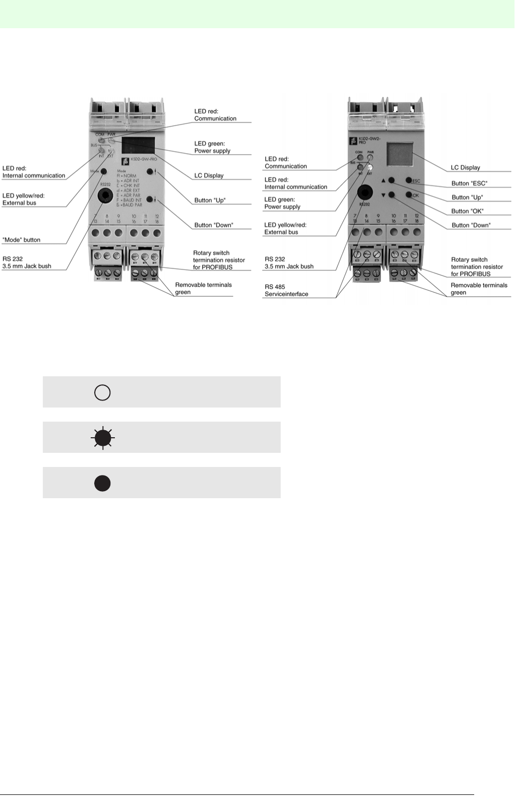
193
Remote Process Interface
RPI System Error Messages
Subject to reasonable modifications due to technical advances. Copyright Pepperl+Fuchs, Printed in Germany
Pepperl+Fuchs Group • Tel.: Germany +49 621 776-0 • USA +1 330 4253555 • Singapore +65 67799091 • Internet http://www.pepperl-fuchs.com
Date of issue 05/27/03
11.3 Error Messages on the Gateways via LED
Figure 11.1:Front View of the KSD2-GW-... and KSD2-GW2-... gateways
The following symbols are used:
LED off
Flashing LED
LED constantly illuminated
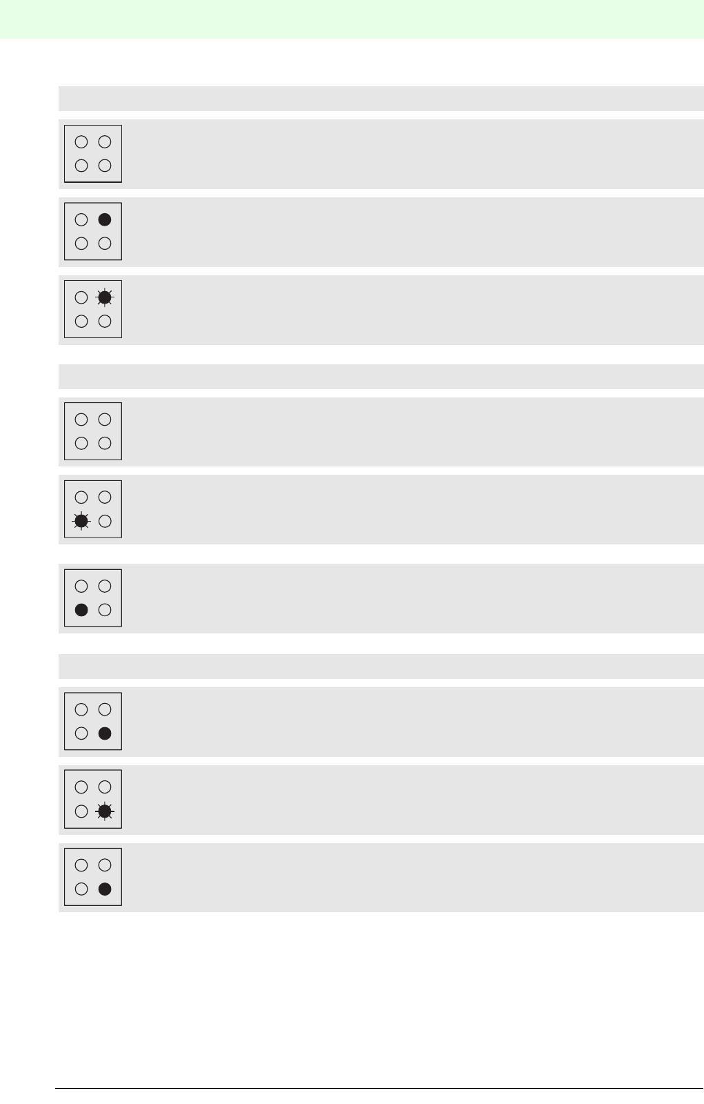
Remote Process Interface
RPI System Error Messages
194
S
ubject to reasonable modifications due to technical advances. Copyright Pepperl+Fuchs, Printed in Germany
Pepperl+Fuchs Group • Tel.: Germany +49 621 776-0 • USA +1 330 4253555 • Singapore +65 67799091 • Internet http://www.pepperl-fuchs.com
Date of issue 05/27/03
LED PWR (green)
No voltage supply
Voltage supply present
Indication of the gateway address for the RPI internal bus
LED INT (red)
Internal bus in normal operation
Internal bus or device error
Internal interface error
LED EXT (yellow / red)
Yellow LED: external bus in normal operation
Red LED: no communication on external bus
Red LED: internal interface error
PWR
PWR
PWR
INT
INT
INT
EXT
EXT
EXT

195
Remote Process Interface
RPI System Error Messages
Subject to reasonable modifications due to technical advances. Copyright Pepperl+Fuchs, Printed in Germany
Pepperl+Fuchs Group • Tel.: Germany +49 621 776-0 • USA +1 330 4253555 • Singapore +65 67799091 • Internet http://www.pepperl-fuchs.com
Date of issue 05/27/03
LED COM (red)
Normal condition: internal CAN bus in differential mode
Internal CAN bus in common mode, redundancy failure
RAM/ROM/EEPROM error, or other internal error
RAM/ROM error, or other error (red EXT LED lights)
COM
COM
INT
COM
EXT
COM
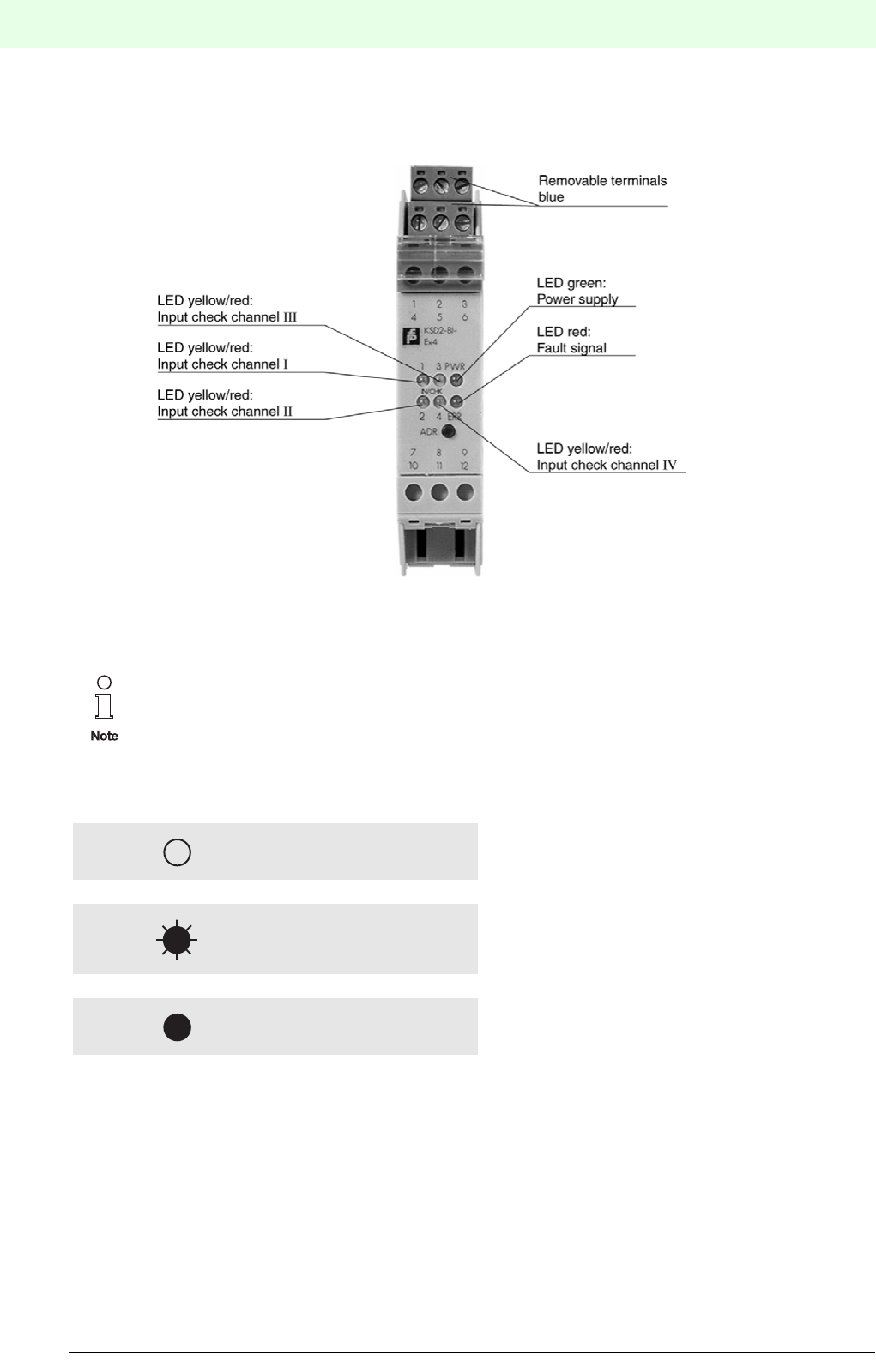
Remote Process Interface
RPI System Error Messages
196
S
ubject to reasonable modifications due to technical advances. Copyright Pepperl+Fuchs, Printed in Germany
Pepperl+Fuchs Group • Tel.: Germany +49 621 776-0 • USA +1 330 4253555 • Singapore +65 67799091 • Internet http://www.pepperl-fuchs.com
Date of issue 05/27/03
11.4 Error Messages on the RPI Devices via LED
Figure 11.2:Front view of RPI device
The following symbols are used:
The RPI system devices are provided with 1, 2 or 4 input and output channels depending on the
model. The construction, the operation of the devices with the ADR button (address) and the
LED display is identical for all types.
A IN/CHK or OUT/CHK control LED is available for each individual channel.
LED off
Flashing LED
LED constantly illuminated
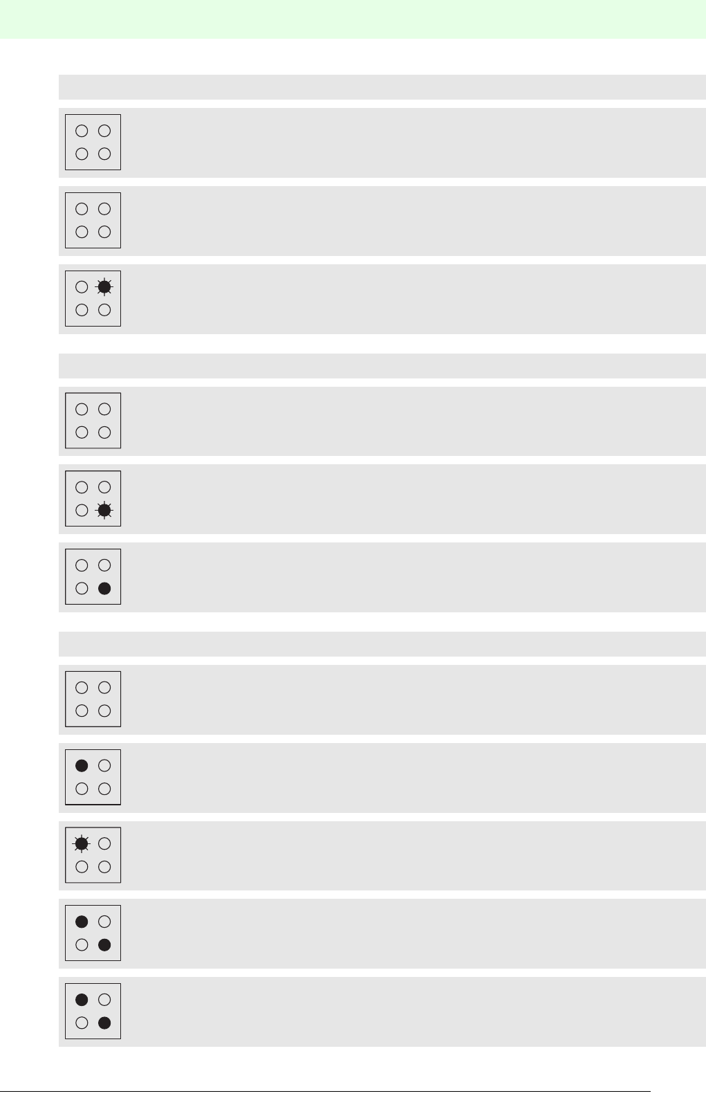
197
Remote Process Interface
RPI System Error Messages
Subject to reasonable modifications due to technical advances. Copyright Pepperl+Fuchs, Printed in Germany
Pepperl+Fuchs Group • Tel.: Germany +49 621 776-0 • USA +1 330 4253555 • Singapore +65 67799091 • Internet http://www.pepperl-fuchs.com
Date of issue 05/27/03
LED PWR (green)
No voltage supply
Voltage supply present
Setting and checking the device address
LED ERR (red)
No error
Bus error
Hardware error (specification via IN/CHK or OUT/CHK LEDs)
IN/CHK or OUT/CHK LED(s)(1 ... 4)
Input/output channel 1 not active
Yellow LED: input/output channel 1 active
Red LED: lead breakage or short-circuit of the field circuit, channel 1
LED 1 (red) and ERR-LED: EEPROM error
LED 1 (yellow) and ERR-LED: communication error
PWR
ERR
PWR
ERR
ERR
ERR
1
1
1
ERR
1
ERR
1

Remote Process Interface
K-SK1
198
S
ubject to reasonable modifications due to technical advances. Copyright Pepperl+Fuchs, Printed in Germany
Pepperl+Fuchs Group • Tel.: Germany +49 621 776-0 • USA +1 330 4253555 • Singapore +65 67799091 • Internet http://www.pepperl-fuchs.com
Date of issue 05/27/03
K-SK1 - THE MAN/MACHINE INTERFACE FOR THE CONFIGURATION,
PARAMETERISING, SIMULATING TESTING AND MONITORING THE RPI
12 K-SK1
12.1 General
12.1.1 Computer related font
Computer related items like keys, software buttons, menu items, etc. are written in courier font.
The presentation of menu items is menu ? menu item. If the menu item is depending on the active window
but unambiguous it is represented by menu ? (?).
The and symbols note that the described action relates to that input device.
12.1.2 Hardware requirements
To run K-SK 1 you need at least an IBM-compatible PC with 486-CPU, 8 MB RAM (16 MB RAM recommen-
ded), 5 MB free harddisk space, and a free serial port. Find out the COM-port-number of this free port since
you have to set up your software accordingly.
12.1.3 Operating system
K-SK1 runs under Windows 3.x, Windows 95 and Windows NT 4.0
12.1.3.1 Installation process
Insert disk #1 into a disk drive and start Setup.exe. An installshield guides you through the remaining instal-
lation process.
12.2 Using the Software
12.2.1 T he advantage of using software
K-SK1 let’s you configure a complete RPI system or upload an existing configuration. The advantage of the
software is that you can multiply this configuration as many times as you want. This is a valuable feature in
production processes
12.2.2 Setting up a complete system
The recommended way of setting up a complete RPI system is to plan the structure of the system with a
PC. The gateway and all devices are configured first in the PC, then the hardware in the control cabinet is
set up. After configurating the project in the software, you have to download the configuration into the gate-
way. When setting up the hardware you can do it in either one of those ways:
Download all device information at your desk, then insert the devices into your cabinet. Or insert your con-
figured gateway into the control cabinet and add the devices in the order of your project.
12.2.3 Monitoring and Diagnosis
K-SK1 allows you to monitor the state of the devices connected to your PC via the gateway. You can also
have a diagnosis of the connected devices or simulate their inputs and outputs, or their error messages re-
spectively.
12.2.4 Changing system information
You can edit the information stored in each device by software. K-SK1 also allows you to save this informa-
tion on your PC. This storage is of great use as a system backup for the case you have to exchange com-
ponents later.
12.3 K-SK1 Operation manual
This part guides you through the configuration process of a RPI system. It shows you how to use the project
manager and the tools provided.
12.3.1 Starting the software
Double click the K-SK-icon.
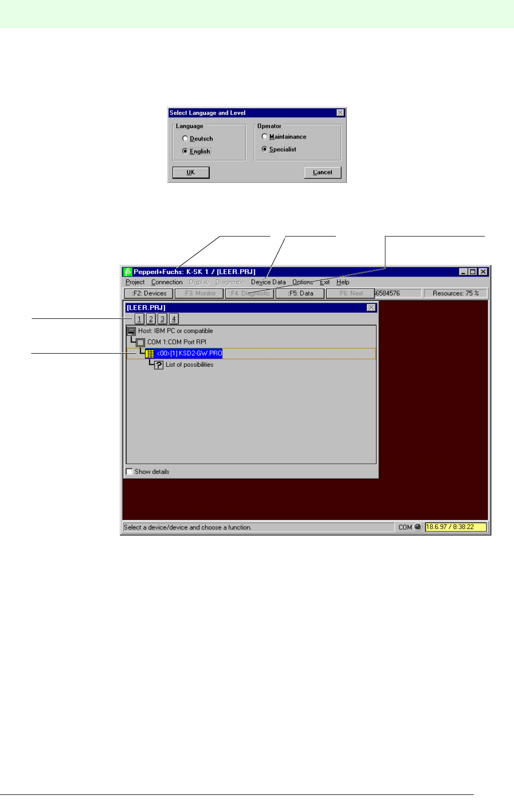
199
Remote Process Interface
K-SK1
Subject to reasonable modifications due to technical advances. Copyright Pepperl+Fuchs, Printed in Germany
Pepperl+Fuchs Group • Tel.: Germany +49 621 776-0 • USA +1 330 4253555 • Singapore +65 67799091 • Internet http://www.pepperl-fuchs.com
Date of issue 05/27/03
Select the language and operation mode in the dialog box comming up. Use specialist if you need to set up
a new project or edit an existing one otherwise select maintenance. If you select specialist mode you might
be asked for a password when you try to establish a connection to the gateway. If you do not possess the
password, exit the program and start in maintenance mode. Confirm your choice with OK.
12.3.2 The main screen
After fully loading the program, the screen displays this window:
The K-SK 1-software contains some Windows specific elements (close box, etc.). Please refer to the Win-
dows manual for help on their function and use.
12.3.2.1 The project manager
The window inside is called "project manager". It displays the current project tree and let's you select
devices for monitoring, diagnosis, or simulation. It provides a title bar, four structure level buttons, scroll bars
if necessary and a “show details” check box.
The icon of the selected item is displayed in yellow.
12.3.2.2 The menu bar
The menu bar gives you full control of the program. You can start any action you like to perform from the
menu bar by selecting the right menu items. The content of the menu bar and the availability of menu items
may change depending on the active window below.
Title bar Short cut buttons
Structure level
button
Project tree
Menue bar
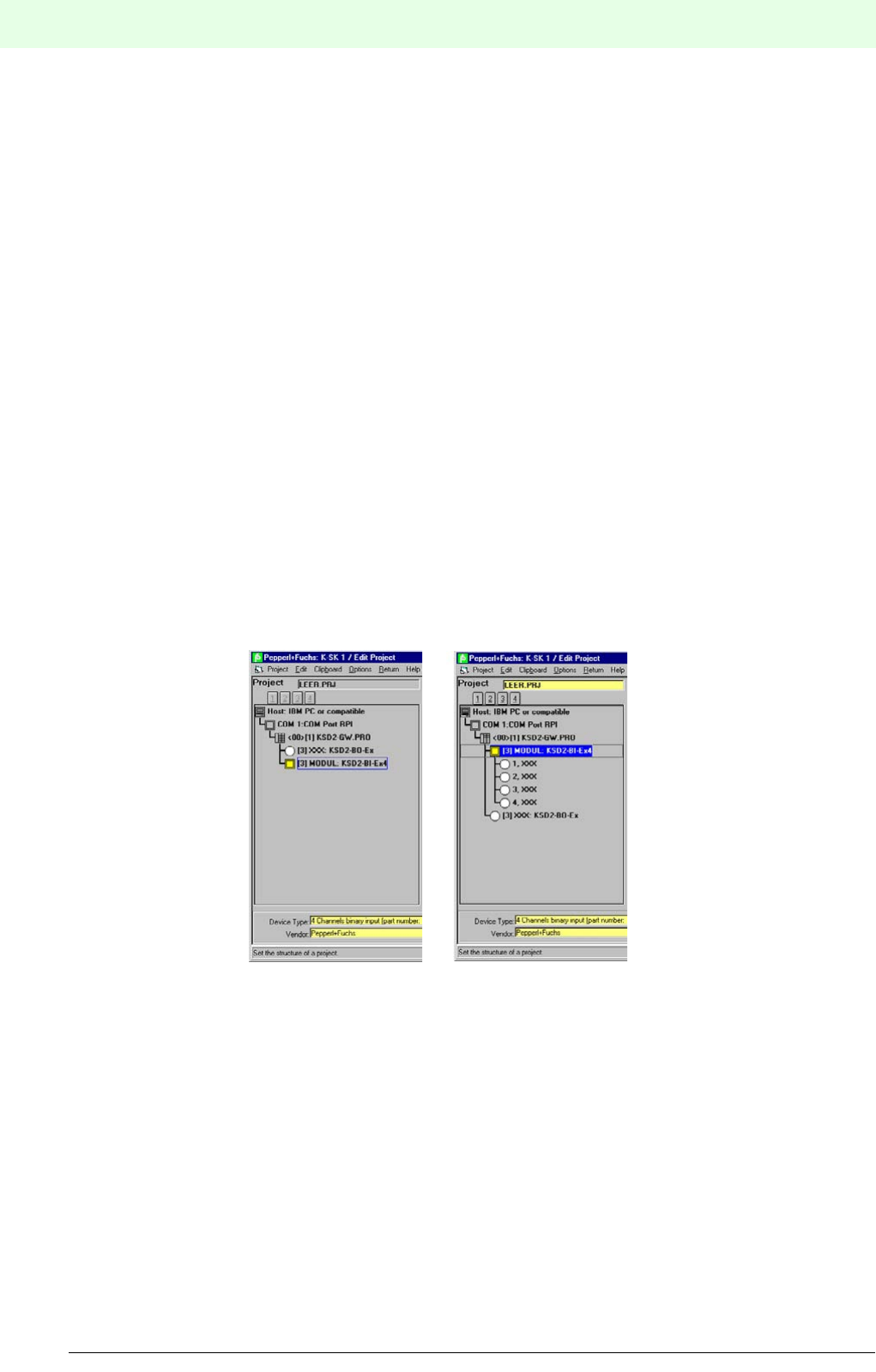
Remote Process Interface
K-SK1
200
S
ubject to reasonable modifications due to technical advances. Copyright Pepperl+Fuchs, Printed in Germany
Pepperl+Fuchs Group • Tel.: Germany +49 621 776-0 • USA +1 330 4253555 • Singapore +65 67799091 • Internet http://www.pepperl-fuchs.com
Date of issue 05/27/03
12.3.2.3 The short cut buttons
These buttons are short cuts to menu items. Some of the buttons may not always be available. You can use
them instead of the menu bar. Note that not all functions have a short cut.
12.3.2.4 The title bar
The title bar of this window states the name of the present project.
12.3.2.5 Selecting an item
Click onto the item with the left mouse button.
Use the cursor keys to move up or down to the item. The up and the left key move to the
item above, the down and the right key to the item below.
12.3.2.6 The structure level buttons
The four structure level buttons below the title bar control the level of the presented structure. Level 1 is the
serial port level, level 2 the gateway level, level 3 the RPI devices level, and level 4 the channel level. If you
need to see the full information of the device tree make sure that level 4 is selected. The use of those buttons
is simple:
Click onto the structure level button with the left mouse button. The whole tree is expanded
or shrunk to that level.
If you want to expand or shrink only parts of the tree you have to double click onto the item
with the branch to change. If nothing happens your selected item does not have a minor
structur.
Use the cursor keys to navigate in the tree. Up and left select the item above, down and
right select the item below. Use enter to expand or shrink a branch.
You can choose the details of information by selecting different structure levels. The picture above shows
a device tree in "level 3" and "level 4".
12.3.2.7 The “Show details” check box
If you check this box by clicking into it, the project manager window separates into two
parts. The lower part provides you with additional information about the selected item of the
top part. You deactivate this option by deselecting the check box.
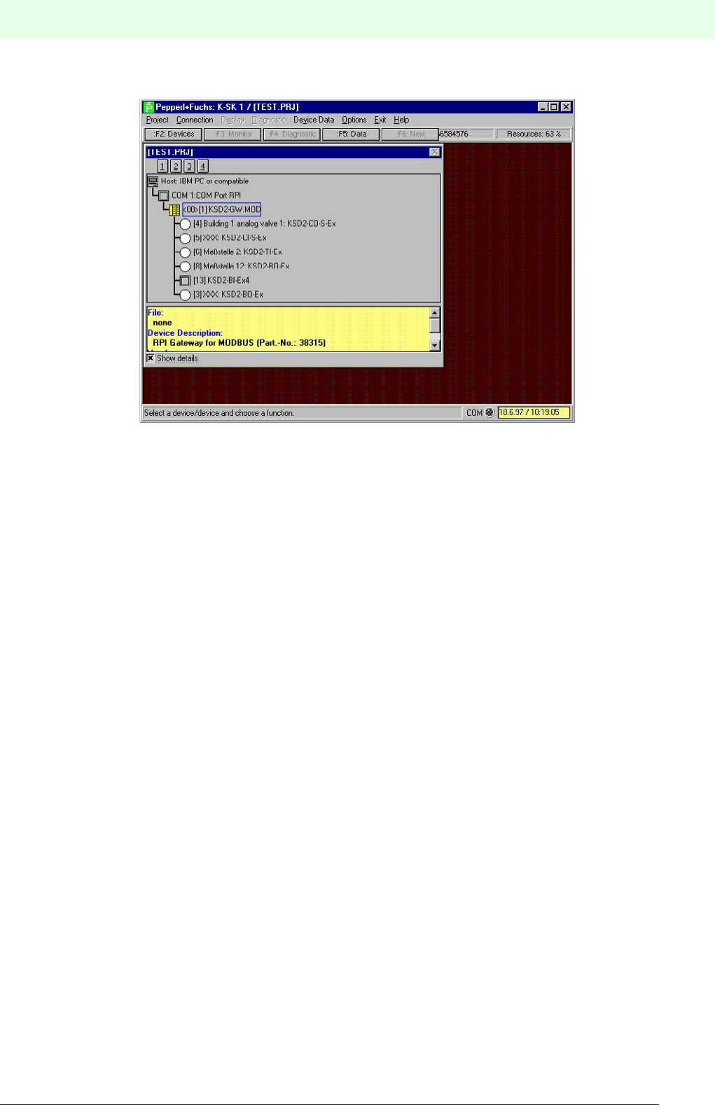
201
Remote Process Interface
K-SK1
Subject to reasonable modifications due to technical advances. Copyright Pepperl+Fuchs, Printed in Germany
Pepperl+Fuchs Group • Tel.: Germany +49 621 776-0 • USA +1 330 4253555 • Singapore +65 67799091 • Internet http://www.pepperl-fuchs.com
Date of issue 05/27/03
12.3.3 Handling the project
You need only a few functions to fully handle a project in K-SK 2. Besides opening and saving a project, the
most important function is to edit the current project displayed in the project manager. This section describes
only the basic set up. The normal operation of RPI including monitoring, diagnosis, and simulation is des-
cribed later.
12.3.3.1 Overview
This section is only an overview to give you an impression of the standard workflow. The following sections
will describe each of the steps more detailed.
To create a new project do the following:
1. Create a new project
2. Save the project under the name you want the project to be refered to.
3. Edit the project in edit mode
4. Save all the changes to that project
When finished you might want to configure your gateway accordingly. To do so:
1. Make sure that your gateway is powered and correctly connected to your PC.
2. Choose Project ? download.
By now you have a correct set up in your PC and your gateway. You can build your cabinet right now by
adding device by device to the cabinet. They will be configured according to that project laid down in the
gateway.
12.3.3.2 Creating a new project
Select Project ? New from the menu. The project manager is reset and the project name is set to
noname.prj. See “Editing a project” for more information about changing the project information.
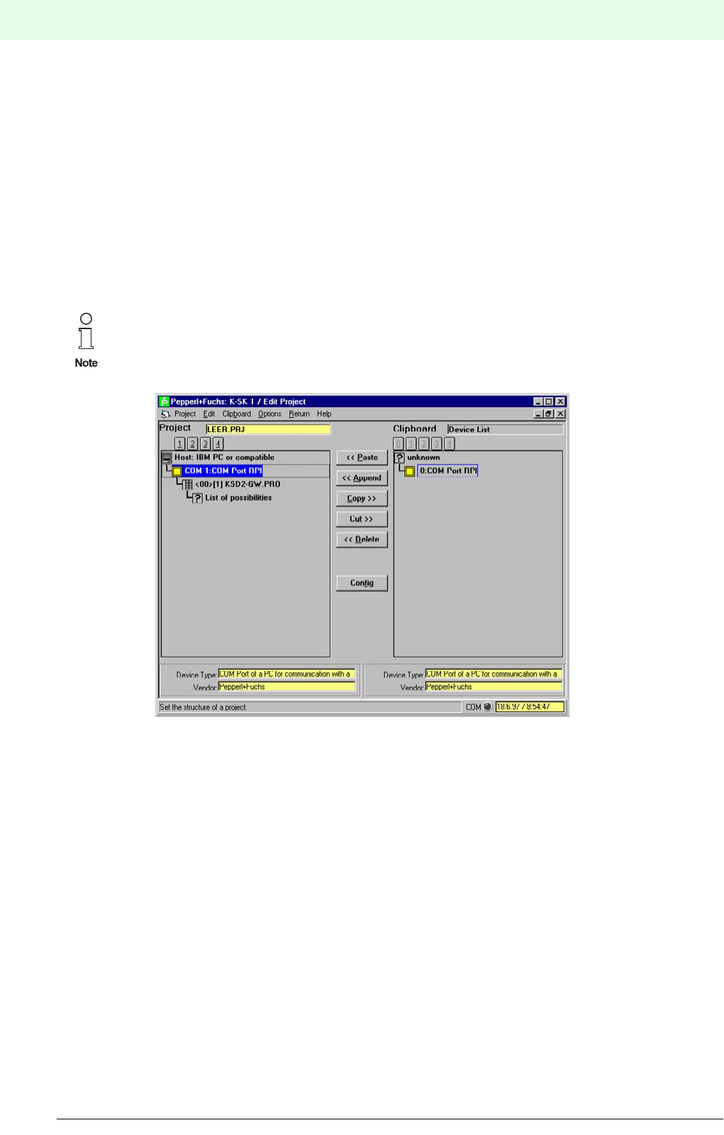
Remote Process Interface
K-SK1
202
S
ubject to reasonable modifications due to technical advances. Copyright Pepperl+Fuchs, Printed in Germany
Pepperl+Fuchs Group • Tel.: Germany +49 621 776-0 • USA +1 330 4253555 • Singapore +65 67799091 • Internet http://www.pepperl-fuchs.com
Date of issue 05/27/03
12.3.3.3 Opening an existing project
Select Project ? Open to load an existing project into the project manager. If you have another project
open that contains changes you want to keep use Project ? Save or Project ? Save as... first.
12.3.3.4 Saving a project
To save a project select Project ? Save or Project ? Save as. The latter let’s you change the name of
the project, if you do not want to overwrite an existing project with the changes made. A valid name contains
up to 8 characters and the extension ".prj". If you do not need to add the extension. In this case K-SK1 will
add the extension automatically. If you save a project for the first time it’s always “saving as ...”.
12.3.4 Editing a project
To edit a project select Project ? Edit from the menu and the edit window appears. You have full control
over the project tree in this window. You can add or delete devices or whole branches and it also lets you
configure the basic information like the slave address or tag name of each device.
12.3.4.1 The three parts of the edit window
PROJECT (LEFT)
This part of the window shows you the present project as is. You can select items that should be copied into
the clipboard or removed from the project and you can also configure the selected item.
The order of the devices in the tree does not have to be identical with the order in the cabinet.
The devices are addressed by their slave address, not by their physical order.
Therefore it is not important where they are located in the device tree. (However, the device
tree is sorted by slave address.)

203
Remote Process Interface
K-SK1
Subject to reasonable modifications due to technical advances. Copyright Pepperl+Fuchs, Printed in Germany
Pepperl+Fuchs Group • Tel.: Germany +49 621 776-0 • USA +1 330 4253555 • Singapore +65 67799091 • Internet http://www.pepperl-fuchs.com
Date of issue 05/27/03
CLIPBOARD (RIGHT)
The clipboard has three different views: The copy view, the project view and the device list view.
The copy view is suitable if you have to copy parts of your project. Instead of adding piece by piece to your
project you copy the part into the clipboard and add it to the project again as often as you want.
This method works for single items as well as for whole branches or trees.
The project view opens a former project and you can copy the whole project into your current one or any
part you like. If you want to change the content of this view select Clipboard ? Open Project.
The device list offers you a complete list of devices you may add to your project. The content is depending
on the selected item and gives you a choice of suitable devices.
BUTTONS (MIDDLE)
You can copy, cut, or delete selected items by clicking onto the buttons. If they are not available they are
shaded in gray. The direction indicated by “<<” and “>>” means that the window in this direction is affected.
12.3.4.2 Selecting the active part of the window
Click into the window part you want to activate.
Press tab to switch between the two window parts.
A blue ribbon marks the selected item in the active part of the window.
SELECTING ITEMS
The selected item is highlighted in yellow and blue. To select an other item
click onto the new item.
move the marker with the cursor keys. The cursor up and the cursor left move the marker
up, the cursor down and the cursor down move it downwards.
USING THE BUTTONS
To activate any button
click onto the button.
use the ¶ key + the underlined character.
12.3.4.3 Getting help
If you need additional help you can select Help ? Contents or search for help on...
12.3.4.4 Undoing changes
There is no undo function available. Please make all changes to your project carefully and use the save
function frequently. This helps you to avoid undesired additional work.
12.3.4.5 Adding a device
Select the place in the current project where you want to add the new device or branch by selecting a device
before or after that desired place. Then select the device you want to add in the clipboard view. Press paste
if you want to add it before the selected device or append if you want to add it behind the selected device
position. It is also possible to choose Edit ? Paste. After you added the device(s) you should configure it.
+
+
To select more than one icon at the same time press down the shift key or the control key.
With the shift key you select the whole range between the already selected and the new sel-
ected item. Using the control key let’s you choose item by item.
Strg
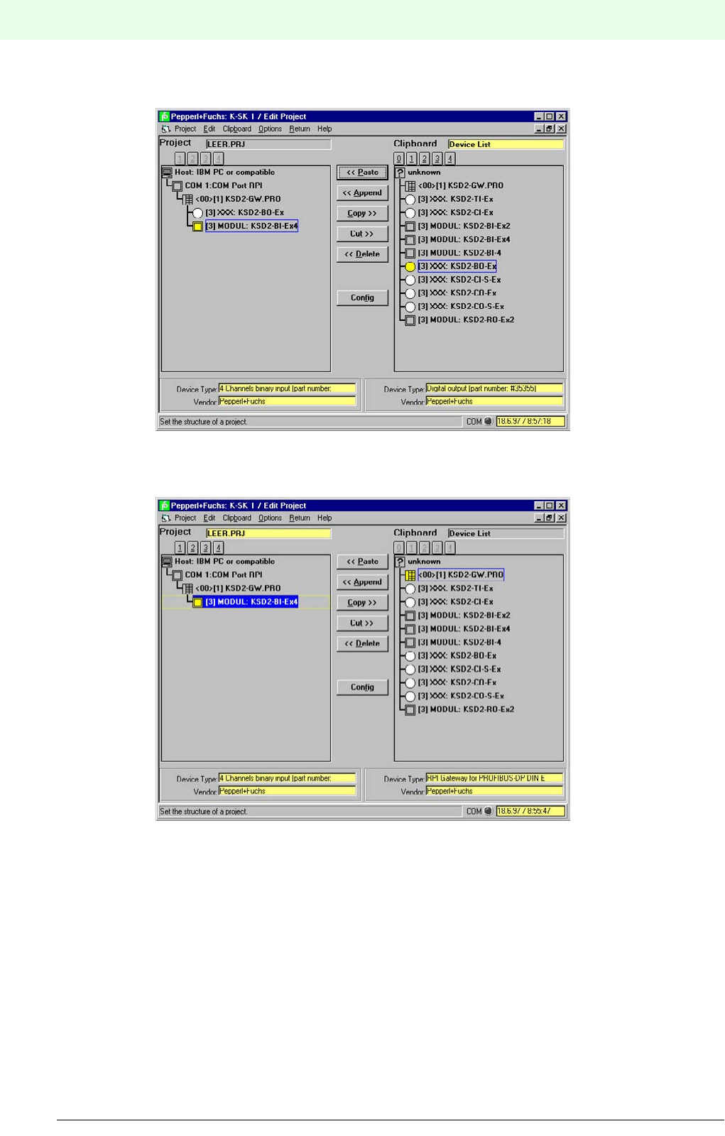
Remote Process Interface
K-SK1
204
S
ubject to reasonable modifications due to technical advances. Copyright Pepperl+Fuchs, Printed in Germany
Pepperl+Fuchs Group • Tel.: Germany +49 621 776-0 • USA +1 330 4253555 • Singapore +65 67799091 • Internet http://www.pepperl-fuchs.com
Date of issue 05/27/03
Starting point: The selected device is highlighted. Paste and Append are relative to the selected item.
Paste will add the new device in front of the selected item, append will add it behind.
A new device is pasted. The new device is right in front of the seleced one.
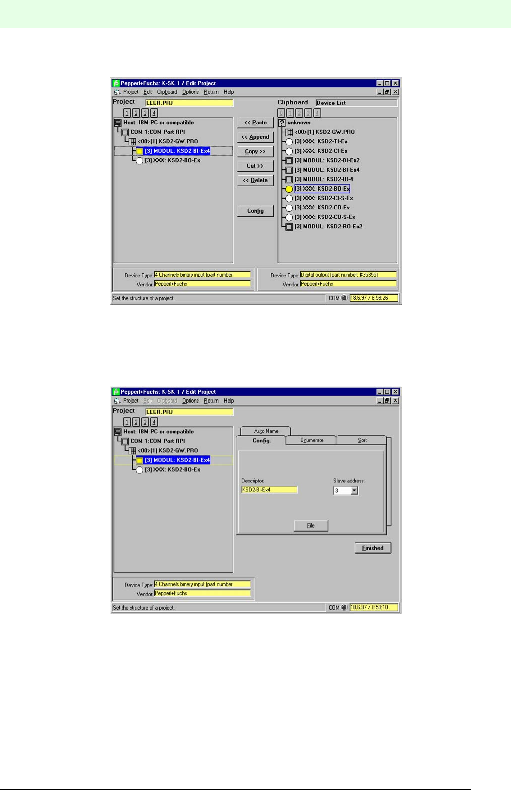
205
Remote Process Interface
K-SK1
Subject to reasonable modifications due to technical advances. Copyright Pepperl+Fuchs, Printed in Germany
Pepperl+Fuchs Group • Tel.: Germany +49 621 776-0 • USA +1 330 4253555 • Singapore +65 67799091 • Internet http://www.pepperl-fuchs.com
Date of issue 05/27/03
A new device is appended. The new device is right behind the selected one.
12.3.4.6 Configuring a device
Select a device of the project and press the button config. The clipboard view is closed and a configuration
window with tab strips opened.
The first tab strip is Config. It allows you to set the RPI-Address of the device or the channel number if you
have selected a channel. It also allows you to type in a descriptor (tag name) for the device or channel.
It may contain up to 28 characters. This is helpful for larger projects to identify the devices clearly.
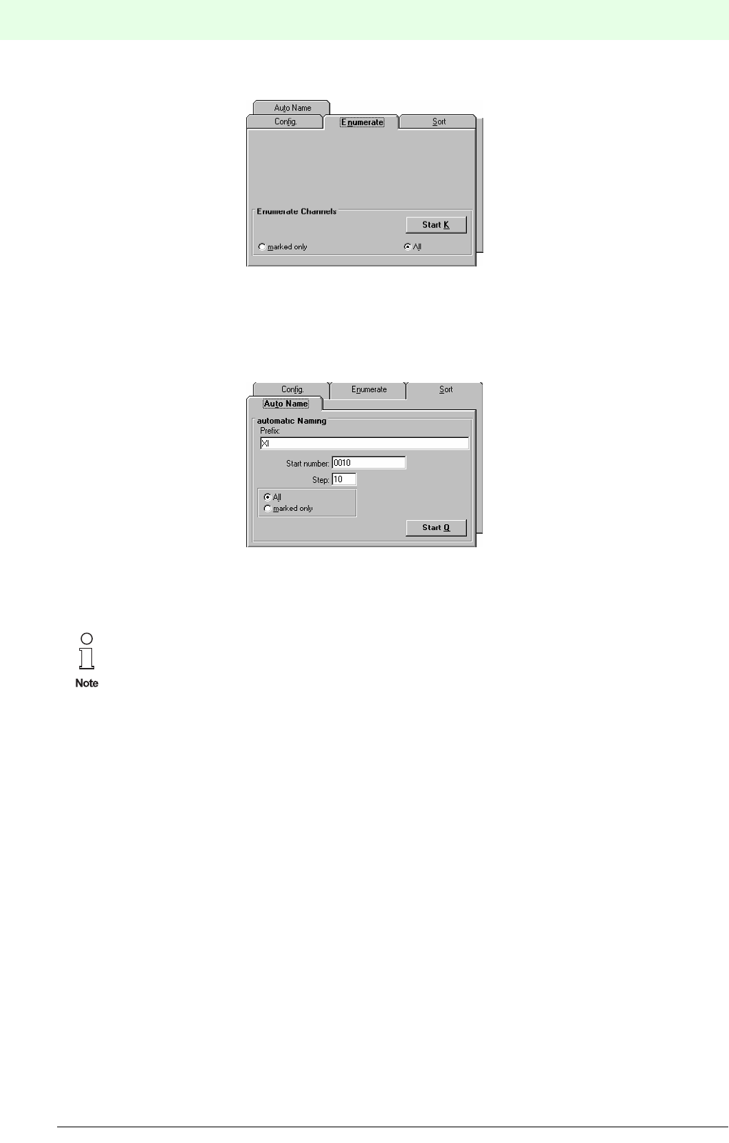
Remote Process Interface
K-SK1
206
S
ubject to reasonable modifications due to technical advances. Copyright Pepperl+Fuchs, Printed in Germany
Pepperl+Fuchs Group • Tel.: Germany +49 621 776-0 • USA +1 330 4253555 • Singapore +65 67799091 • Internet http://www.pepperl-fuchs.com
Date of issue 05/27/03
The Enumerate tab strip is useful in numbering channels.
You can automatically number the channels consecutively by pressing the button Start K. If you choose to
enumerate a range of modules, the channels of each module are numbered separately starting from 1.
The Sort tab strip is not implemented in this version.
The last tab strip is Auto Name which allows you to fill the TAG field of all devices with a string and an au-
tomatically added number.
Unlike enumerate the Auto Name function influences all devices. You cannot select a range!
The auto name function is started by pressing the Start Q button.
After you have finished the configuration press Finished.
12.3.4.7 Removing a device
Before you remove a device make sure that you selected the correct device(s). There is no undo function
available.
There are two ways the remove a device or branch out of the current project. You can either use delete or
cut. Delete removes the device definitely from the project, cut changes the clipboard view to copy and dis-
plays the cut part of the project.
12.3.4.8 Printing a project
Select Project | Print to print the current project. If you need to configure your printer choose Options ?
Printer configuration. The printout contains the full project tree plus some additional information.
12.3.4.9 Exiting the edit window
Select Return ? Close and Return to Main Menu. The edit window is closed and project manager activa-
ted again.
This is only a basic set of information stored in the devices. Use Device Data ? Edit
Device Data to edit the complete information of the device. Refer to section XX to find out
how to edit the full information stored in the devices.
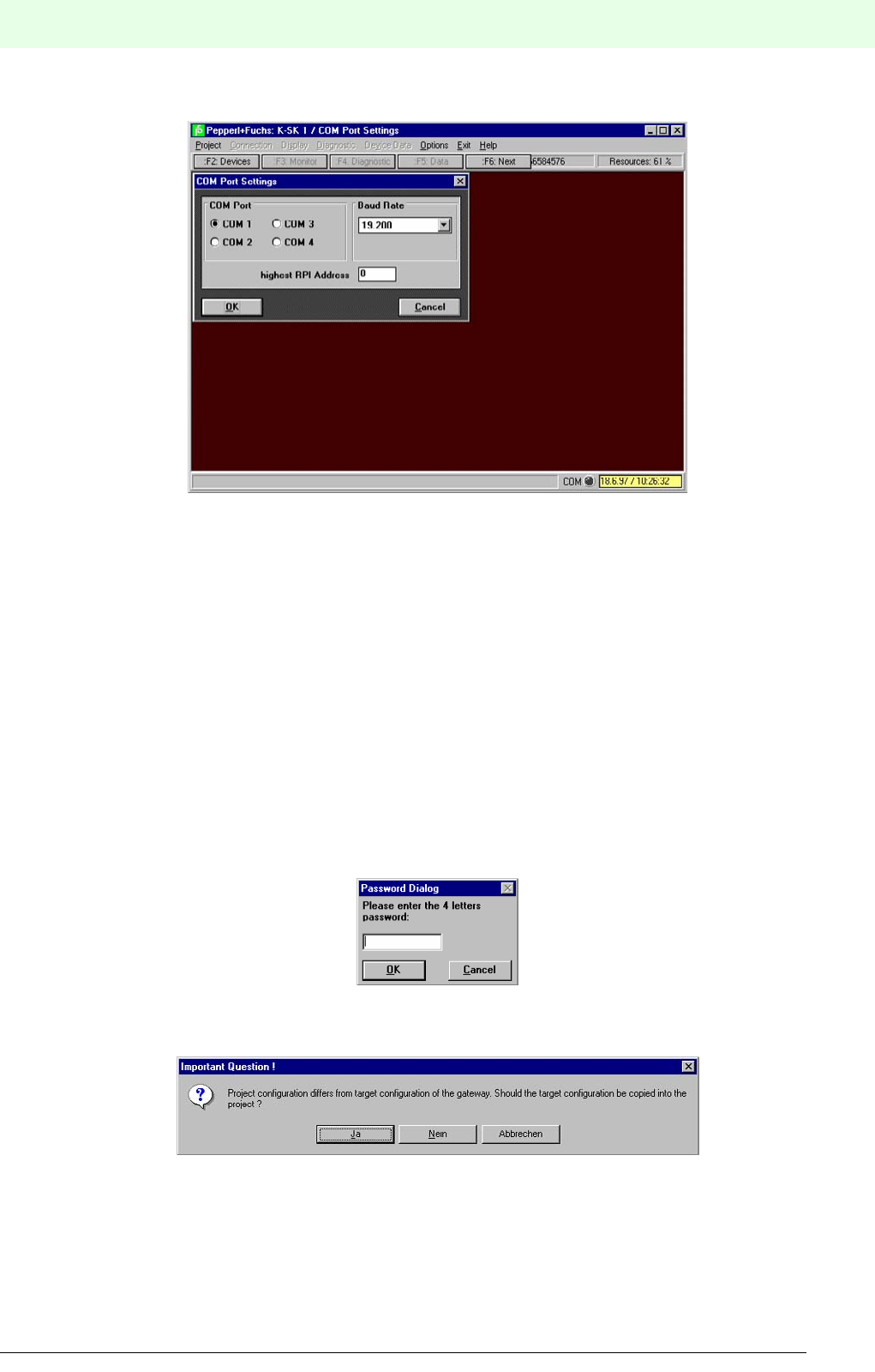
207
Remote Process Interface
K-SK1
Subject to reasonable modifications due to technical advances. Copyright Pepperl+Fuchs, Printed in Germany
Pepperl+Fuchs Group • Tel.: Germany +49 621 776-0 • USA +1 330 4253555 • Singapore +65 67799091 • Internet http://www.pepperl-fuchs.com
Date of issue 05/27/03
12.3.5 Connecting your PC with the RPI hardware
12.3.5.1 Connection
Use the K-ADP2 respectively the K-ADP4 interface adapter to connect your PC or laptop and the gateway.
12.3.5.2 Setting the serial port
Select the com-icon in the project and select Device Data ? COM Port Settings. Enter the serial port
you have connected to the hardware and adjust the baud rate accordingly. Confirm with OK.
12.3.5.3 Starting the communication between K-SK1 and RPI
Select the gateway in your project. This makes the menu Connection available.
Select Connection ? Establish Connection.
If you are working in service mode you might be asked to enter a password if the option is activated in the
gateway. Setting this option is described in section XX. Confirm your password with OK.
This password does not appear in maintenance mode. If you do not posses the password, exit the program
and start in maintenance mode again.
The next dialog box appears, if the project configuration in your PC differs from the hardware setup.
Select yes if you want to upload the hardware configuration into your present project, no otherwise.
If the project and the configuration of the gateway are the same or you chose to upload the configuration, a
dialog box appears stating that the connection is established.
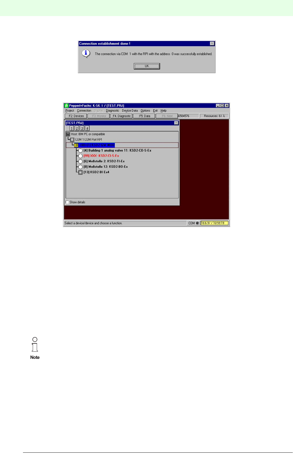
Remote Process Interface
K-SK1
208
S
ubject to reasonable modifications due to technical advances. Copyright Pepperl+Fuchs, Printed in Germany
Pepperl+Fuchs Group • Tel.: Germany +49 621 776-0 • USA +1 330 4253555 • Singapore +65 67799091 • Internet http://www.pepperl-fuchs.com
Date of issue 05/27/03
All devices appear in black bold letters in the program manager. If there is a difference between the confi-
guration in the gateway and software or a device is not working correctly, the affected device appears in red
letters.
12.3.5.4 Closing down the communication between K-SK 1 and RPI
Select the gateway in the project manager then Connection ? Go Off Line to shut down the commu-
nication. The communication is also shut down, if you select Project ? Edit during operation.
After the connection is shut down, the devices in the project manager are displayed in normal letters again.
12.3.6 Editing Device Data
There are two ways of editing device data: online and offline. In the first case you load and save the data
directly from and to the device (with a possibilty to save it to a file, too), in the second case you load and
save the data from and to a file on your computer. K-SK also allows you to load the data from a device and
save it to a file or vice versa.
The difference between both methods is the updating of the project. The project is automatically updated if
you save changes to the device. If you save information only to files you have to update the project by down-
loading the new information with Project ? download. In this case the project uses all data files (extension
.dat) related with that project to rewrite the device information.
12.3.6.1 SELECTING THE DEVICE
Click onto the device which contains the data you want to change. Select Device Data ?
Edit Device Data or click onto ï Data.
Select the device by moving the marker with the cursor keys. Press either ï or ¶+v then ¶+e.
12.3.6.2 Changing data
The available data is device-depended. Your edit window may look different for each device. Also the con-
tent of the tab strip may vary. You are only able to change white or gray text fields on the tab strip. To change
a field content click into the field. Then do your changes.
If you close the window containing device data, a dialog will prompt asking you whether you
want to save the information in a file or not. Confirm with yes if you want to save the information
into a file, no if not. If you close the window without saving to the devicve or a file, your informa-
tion is lost afterwards.
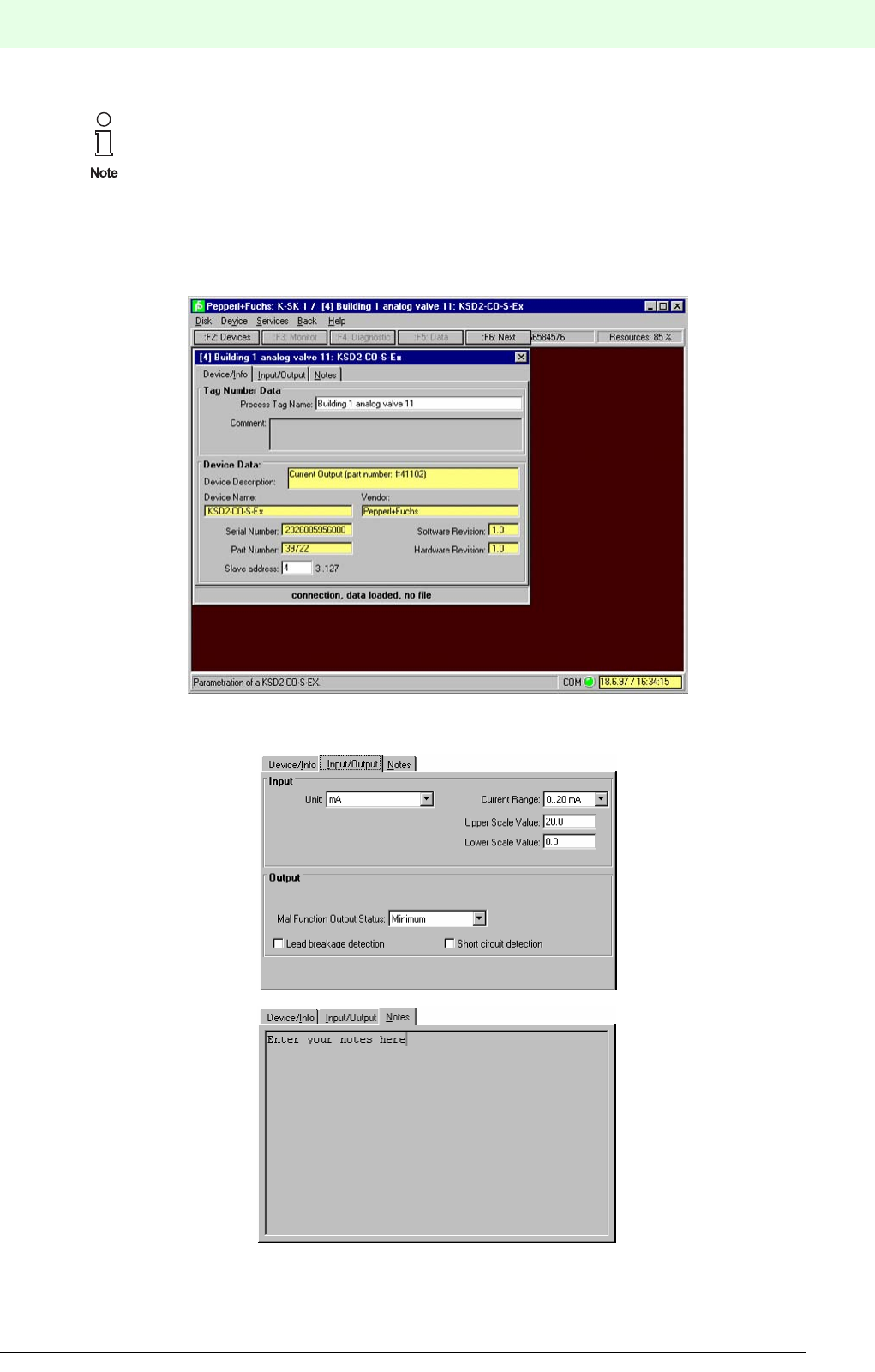
209
Remote Process Interface
K-SK1
Subject to reasonable modifications due to technical advances. Copyright Pepperl+Fuchs, Printed in Germany
Pepperl+Fuchs Group • Tel.: Germany +49 621 776-0 • USA +1 330 4253555 • Singapore +65 67799091 • Internet http://www.pepperl-fuchs.com
Date of issue 05/27/03
12.3.6.3 Changing between the tab strips
click on the tab strip you want to edit.
use ¶ + the underlined letter of the register tab strip you want to edit.
The display after selecting Device Data ? Edit. The content of the window may vary.
Two other example tab strips.
After you are finished, always safe the changes.

Remote Process Interface
K-SK1
210
S
ubject to reasonable modifications due to technical advances. Copyright Pepperl+Fuchs, Printed in Germany
Pepperl+Fuchs Group • Tel.: Germany +49 621 776-0 • USA +1 330 4253555 • Singapore +65 67799091 • Internet http://www.pepperl-fuchs.com
Date of issue 05/27/03
12.3.6.4 Setting a password
The tab strip contains a part "Password/Panel". You can set two different passwords here. Both will be
activated when you check the box "Password active" and save the information in the gateway.
You need to know only one password of the two passwords to get access to a protected gateway, since
both passwords are equal and have the same function.
12.3.6.5 Saving data
If you want to save the data to the device
select Device ? save to Device.
use ¶ + v, then ¶ + s.
To save the data into a .dat-file
select Disk ? save to Disk.
use ¶ + d, then ¶ + s.
Enter a file name with up to 8 characters plus the extension ".dat" and press OK. The project file contains
a list of all related data-files. If you do a download, the project manager uses the data-files to set the infor-
mation of the according devices.
12.3.7 Downloading a project into a gateway
Use Project ? Project Download to download the present project configuration into the selected gate-
way. If you use this option, the gateway accepts this configuration as target configuration. Any different
hardware set up results in error messages. To proceed with downloading, confirm the following dialog box
with yes. After positive confirmation a connection to the gateway is established and the information proces-
sed. The connection shuts down afterwards.
12.3.8 Printing a project
Select Project ? Print to print the present project. If you need to configure your printer or want to use a
different than the standard use Options ? Printer Configuration first.
12.3.9 Monitoring devices
You can monitor the output signals of all connected devices by selecting Display ? (?) but only if you
have a PC connected to the RPI hardware, an established communication connection, and selected a de-
vice. If the menu Display or the button ì Monitor is not available, check the communication and select the
device to be monitored.
If you are using passwords, avoid using "empty" password boxes. Make sure that both pass-
words are set.
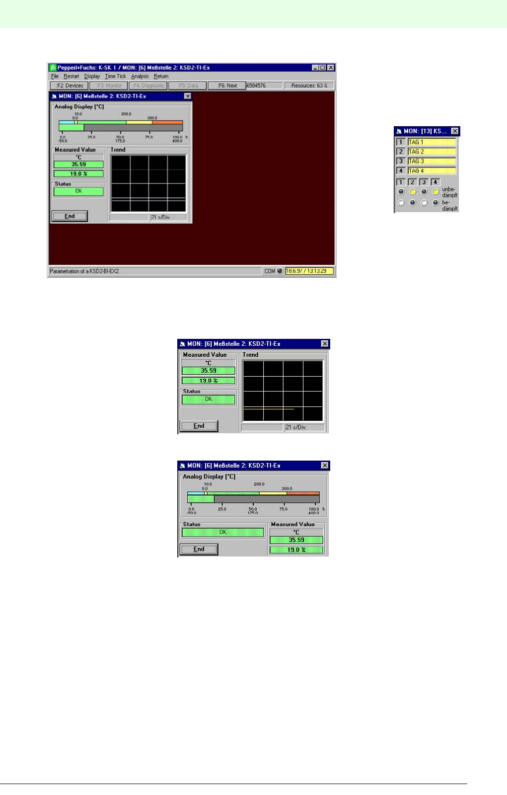
211
Remote Process Interface
K-SK1
Subject to reasonable modifications due to technical advances. Copyright Pepperl+Fuchs, Printed in Germany
Pepperl+Fuchs Group • Tel.: Germany +49 621 776-0 • USA +1 330 4253555 • Singapore +65 67799091 • Internet http://www.pepperl-fuchs.com
Date of issue 05/27/03
The big window shows a window for an analogue device the small window is an example of a binery device.
If you chose to monitor an analogue device you can set the type of display. To see only the trend graph
deselect display ? bar graph.
You may also hide the trend and see only the bar graph by deselecting display ? trend.
If you need further help on the content of the windows and the menu bar please use the online help.
12.3.9.1 Ending the monitoring
All windows can be closed by menu commands. Some windows may use the Back ? Close or Back ? Back
to Main Menu command, others Return ? Return to Main Menu. Also some of the windows may have
an end button which closes the window when clicked.
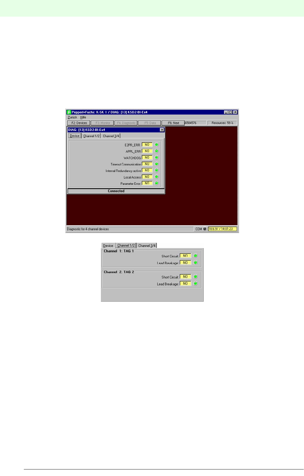
Remote Process Interface
K-SK1
212
S
ubject to reasonable modifications due to technical advances. Copyright Pepperl+Fuchs, Printed in Germany
Pepperl+Fuchs Group • Tel.: Germany +49 621 776-0 • USA +1 330 4253555 • Singapore +65 67799091 • Internet http://www.pepperl-fuchs.com
Date of issue 05/27/03
12.3.10 Diagnosis of devices
If an error occurs (e.g. lead breakage, limit value exceeded, etc.) the device will be shown in red in the pro-
ject. To get information about the error use Diagnostic ? all Diagnostics. Of course you can use
diagnostics also with fully working devices.
Using the diagnostics is only possible with the PC connected to the RPI hardware, an established commu-
nication connection and a selected device.
To start the diagnostics select a device in the project manager and do one of the either way: press î, select
Diagnostic ? all Diagnostics or click the î Diagnostic button.
The diagnostics window opens.
The content of the windows should be self-describing. If you need further information about the content use
the online help.
12.3.10.1Ending the diagnostics
All windows can be closed by menu commands or the close symbol in the top right corner. Some windows
may use the Back ? Close or Back to Main Menu command, others Return ? Return to Main Menu.
Also some of the windows may have an end button which closes the window when clicked.
12.3.10.2Simulating devices
Simulation plays an active part in a process. A simulation of the input values can pinpoint undesirable reac-
tions in the control system, PLC, or PC system. A simulation of the output values initiates the actuators,
opens valves and control pumps!
A check should be made, in any case, prior to starting the simulation, that no system endangering or un-
desirable conditions a likely to arise.
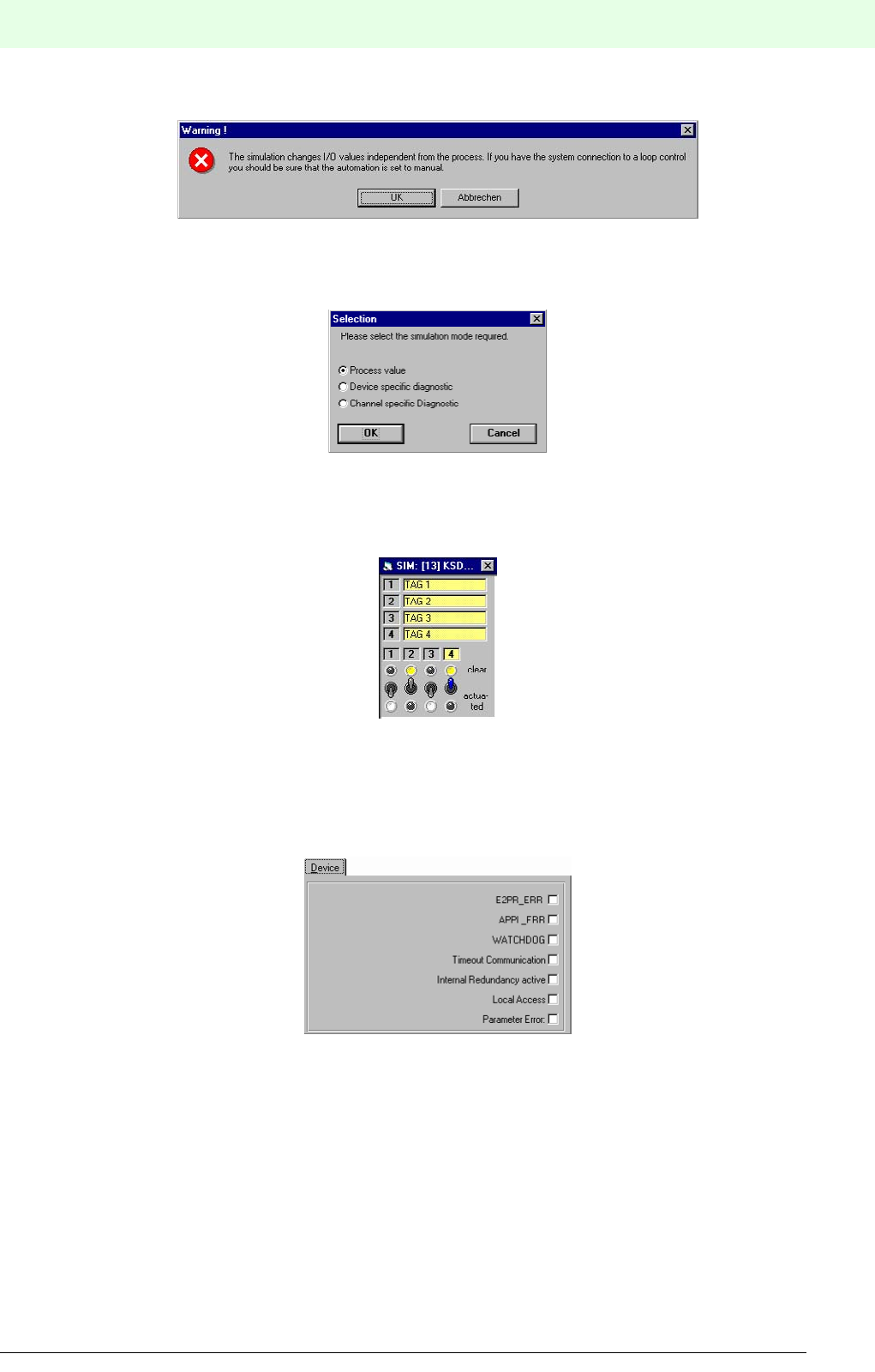
213
Remote Process Interface
K-SK1
Subject to reasonable modifications due to technical advances. Copyright Pepperl+Fuchs, Printed in Germany
Pepperl+Fuchs Group • Tel.: Germany +49 621 776-0 • USA +1 330 4253555 • Singapore +65 67799091 • Internet http://www.pepperl-fuchs.com
Date of issue 05/27/03
Confirm the warning with OK to proceed, to abort the action select Cancel. If you proceed you are asked to
choose the features you want to simulate. There are three options available: Process Value, Device Specific
Diagnostic, and Channel Specific Diagnostic.
12.3.10.3Process Value
If you choose Process Value you are allowed to change the state of the inputs and / or outputs. Select the
feature and confirm with OK.
You change the switching state of binary inputs / outputs by clicking onto the according switch or the led of
the state you want to set. With analogue devices you will find a drag bar to change the values. Just drag the
button to the desired value or write down the value into the according field.
12.3.10.4Device specific diagnostic
With this option you simulate the error signals of the devices.
The simulation is straight forward: a checked box means that the according error signal is set.
Reset the signal by clicking into the box again.
12.3.10.5Channel specific diagnostic
The function principle is the same as with the device specific diagnostic. Again a checked box means that
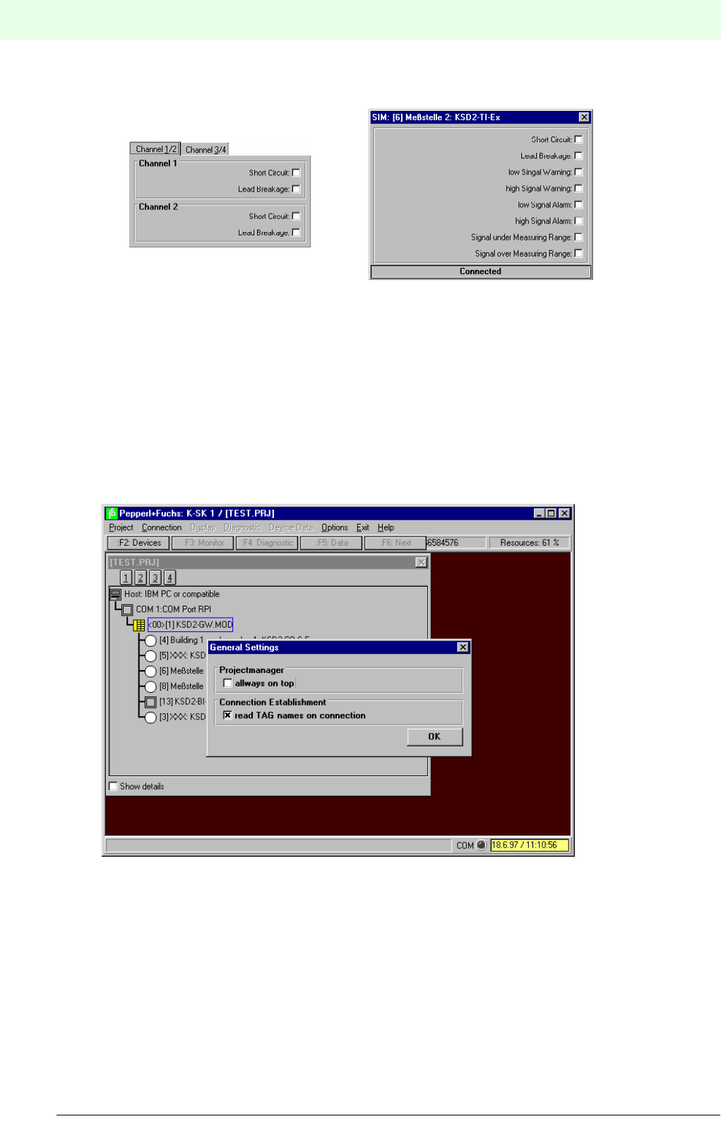
Remote Process Interface
K-SK1
214
S
ubject to reasonable modifications due to technical advances. Copyright Pepperl+Fuchs, Printed in Germany
Pepperl+Fuchs Group • Tel.: Germany +49 621 776-0 • USA +1 330 4253555 • Singapore +65 67799091 • Internet http://www.pepperl-fuchs.com
Date of issue 05/27/03
the according error signal is set, a non-checked box means that the signal is not set.
Two examples of channel specific diagnostic windows. The content is device dependend.
12.3.11 Other program options
12.3.11.1Setting basic program options
Select Options ? Setting to set basic program options.
If you have selected “Project manager always on top” the project manager window is always dis-
played. If you do not check this option, the project manager window is closed when you open a diagnosis
or a monitor window.
The option “connection establishment read tag names on connection” determines whether
additional information is transmitted between PC and gateway during the connection establishment or not.
12.3.11.2 Getting help
Use Help ? Contents or Help ? Search For Help on to get the build in online help.

215
Remote Process Interface
K-SK1
Subject to reasonable modifications due to technical advances. Copyright Pepperl+Fuchs, Printed in Germany
Pepperl+Fuchs Group • Tel.: Germany +49 621 776-0 • USA +1 330 4253555 • Singapore +65 67799091 • Internet http://www.pepperl-fuchs.com
Date of issue 05/27/03
12.3.11.3 Finding out the version of your software
Select Help ? About K-SK 1. A dialog appears, stating the version.
Confirm with OK to close the dialog box.
12.3.12 Exiting the K-SK1 software
Select Project ? Exit or Exit ? Exit Program to close the program.
You can also use the close box of Windows.
If you have made any changes to the project you want to keep, make sure to safe the information first. If
you confirm the dialog box with OK the program is quit and all unsaved data lost.

Remote Process Interface
Glossary
216
S
ubject to reasonable modifications due to technical advances. Copyright Pepperl+Fuchs, Printed in Germany
Pepperl+Fuchs Group • Tel.: Germany +49 621 776-0 • USA +1 330 4253555 • Singapore +65 67799091 • Internet http://www.pepperl-fuchs.com
Date of issue 05/27/03
13 Glossary
0x Hexadecimal representation
ADR Address
CAN bus RPI internal data bus
CH Channel
CHK Check
COM Communication
COM Communication Object Model
DCOM Distributed Communication Object Model
DDLM Direct Data Link Mapper
DC Direct Current
DP Distributed Peripherals
E/A Eingang/Ausgang = I/O Input/Output
EEPROM Electrical Erasable and Programmable ROM
EMC Electromagnetic Compatibility
ERR Error
Ex side Side of a device from which circuits lead to environments in which explosive atmosphe-
res can arise
EXT External
FDL Fieldbus Data Link
FMS Fieldbus Message Specification
GND Ground
DTM Device Type Manager
FDT Field Device Tools
h Hexadecimal representation
HART Highway Adressable Remote Transducer
I/O Input/Output
ID Identification
INT Internal
LCD Liquid Crystal Display
LED Light Emitting Diode
LSAP Link Service Access Point
LSB Least Significant Bit
MSB Most Significant Bit
MSR Mess-, Steuer- und Regeltechnik = Measuring and Control Technology

217
Remote Process Interface
Glossary
Subject to reasonable modifications due to technical advances. Copyright Pepperl+Fuchs, Printed in Germany
Pepperl+Fuchs Group • Tel.: Germany +49 621 776-0 • USA +1 330 4253555 • Singapore +65 67799091 • Internet http://www.pepperl-fuchs.com
Date of issue 05/27/03
PC Personal Computer
PHY Physical Layer
DCS Distributed Control System
PWR Power
RAM Random Access Memory
ROM Read Only Memory
RPI Remote Process Interface
SAP Service Access Point
SCADA Supervisory Control and Data Acquisition
SMART Self Monitoring Analysis and Reporting Technology
PLC Programmable Logic Controller
Tag Number Measuring point description
USV Unterbrechungsfreie Stromversorgung = UPS Uninterruptible Power Supply

Subject to modifications
Copyright PEPPERL+FUCHS • Printed in Germany
www.pepperl-fuchs.com
Worldwide Headquarters
Pepperl+Fuchs GmbH
68307 Mannheim · Germany
Tel. +49 621 776-0
E-mail: info@de.pepperl-fuchs.com
For the Pepperl+Fuchs representative
closest to you check www.pepperl-fuchs.com/pfcontact
PROCESS AUTOMATION –
PROTECTING YOUR PROCESS
043014 / TDOCT-0129B
03/2005
