Handbuch_33_apm 467484 Catalog
119285-Attachment 119285-Attachment 119285-Attachment 639889 Batch8 unilog cesco-content
271532-Catalog 271532-Catalog 271532-Catalog 639889 Batch6 unilog cesco-content
100331-Catalog 100331-Catalog 100331-Catalog 639889 Batch6 unilog cesco-content
2014-09-05
: Pdf 467484-Catalog 467484-Catalog 639889 Batch7 unilog
Open the PDF directly: View PDF ![]() .
.
Page Count: 648 [warning: Documents this large are best viewed by clicking the View PDF Link!]
- Catalogue 33
- Index
- Enclosures
- Competency in enclosure systems
- Small enclosures
- Compact enclosures
- Wall-mounted network enclosures
- Enclosure systems
- Baying systems TS 8
- Height: 1200 mm/1400 mm, depth: 500 mm
- Height: 1600 mm, depth: 500 mm
- Height: 1800 mm, depth: 400 mm
- Height: 1800 mm, depth: 500 mm
- Height: 1800 mm, depth: 600 mm
- Height: 2000 mm, depth: 400 mm
- Height: 2000 mm, depth: 500 mm
- Height: 2000 mm, depth: 600 mm
- Height: 2000 mm, depth: 800 mm
- Height: 2200 mm, depth: 600 mm
- Baying systems TS 8
- Baying systems TS 8
- Baying systems TS 8
- Network distribution enclosures
- Server enclosures
- Console systems/PC enclosure systems/Industrial Workstations
- Operating housings/support arm/stand systems
- Support arm systems
- Support arm system CP-S, steel – Overview of components
- Support arm system CP-L
- Support arm system CP-L
- Tilting adaptor 10° CP-L
- Tilting adaptor ±45° CP-L
- Connection console CP-L
- Enclosure attachment CP-L
- Enclosure attachment, locatable CP-L
- Housing coupling CP-L
- Angle coupling 90° CP-L
- Support section CP-L
- Angle piece 90° CP-L
- Articulated joint 90° CP-L
- Intermediate hinge CP-L
- Wall/base mounting, large CP-L
- Mounting component for signal pillar
- Top-mounted joint CP-L
- Wall-mounted hinge CP-L
- Wall/base mounting bracket, small, CP-L
- Accessories CP-L:
- Support arm system CP-L
- Support arm system CP-C
- Support arm system CP-C
- Enclosure attachment CP-C for support arm connection CP-L Ø 130 mm
- Housing coupling CP-C for support arm connection CP-L Ø 130 mm
- Angle coupling 90° CP-C, for support arm connection CP-L Ø 130 mm
- Support section CP-C
- Angle piece 90° CP-C
- Intermediate hinge CP-C
- Top-mounted joint CP-C
- Wall-mounted hinge CP-C
- Wall/base mounting bracket, small, CP-C
- Wall/base mounting bracket, large, CP-C
- Mounting component for signal pillar
- Accessories CP-C:
- Support arm system CP-C
- Support arm system CP-XL
- Support arm system CP-XL
- Connection adaptor CP-L to CP-XL
- Tilting adaptor 10° CP-XL
- Enclosure attachment, round CP-XL
- Enclosure attachment, rectangular CP-XL
- Housing coupling CP-XL
- Angle coupling 90° CP-XL
- Support section CP-XL
- Angle piece 90° CP-XL
- Intermediate hinge CP-XL
- Top-mounted joint CP-XL
- Wall-mounted hinge CP-XL
- Wall/base mounting bracket CP-XL
- Rotation range restrictor
- Support arm systems
- Accessories
- Connection adaptor CP-L Ø 130 mm to CP-L 120 x 65 mm
- Connection adaptor CP-L to CP-XL
- Adaptor
- Connection console CP-L
- Connection plate CP-L
- Enclosure attachment, tilting, base mounting
- Connection adaptor CP-C to CP-L
- Adjustment set for support section CP-XL
- Housing couplings CP-XL
- Support arm, height adjustable for support arm system CP-L
- Pivot CP-L
- Support arm bracket 90° CP-L
- Enclosure attachment, tilting, top mounting
- Angle adaptor 90°
- Accessories
- Support arm system CP-XL
- Stand systems
- Hygienic Design – Small and compact enclosures HD
- Stainless steel
- Switch housings
- Terminal boxes KL
- Bus enclosures BG
- Compact enclosures AE
- Compact enclosures AE, protection category IP 69K
- Premium Panel, protection category IP 69K
- Command panel housing with door
- Tilting adaptor 10°
- Enclosure attachment CP-S, stainless steel
- Housing coupling CP-S stainless steel
- Support section CP-S, stainless steel
- Angle piece 90° CP-S stainless steel
- Wall/base mount, rigid, CP-S stainless steel
- Wall/base mount, rotating, CP-S stainless steel
- Wall console CP-S stainless steel
- One-piece consoles AP
- PC enclosure systems
- Baying systems TS 8
- Ex enclosures/EMC enclosures
- Outdoor enclosures
- Power
- UPS – Power Modular Concept
- PMC 12, single-phase, output range 1 – 12 kVA n+1
- PMC 40 (type 1-4), 3-phase, output range scalable 10 – 40 kW
- PMC 40 (type 5), 3-phase, output range scalable 10 – 40 kW, redundant
- PMC 120, 3-phase, output range scalable 10 – 120 kW
- PMC 200, 3-phase, output range scalable 8 – 800 kW
- PMC 800, 3-phase, output range scalable 64 – 960 kW
- Accessories
- Power Distribution Rack
- Power System Module Plus
- Power System Module
- RiCell Flex fuel cell system
- UPS – Power Modular Concept
- Climate control
- Experts in climate control
- Cooling with ambient air
- Cooling units
- Thermoelectric coolers
- Wall-mounted cooling units
- TopTherm, horizontal format, useful cooling output 300 W
- TopTherm, useful cooling output 300 W
- TopTherm “Blue e”, useful cooling output 500 W
- TopTherm “Blue e”, useful cooling output 750 W
- TopTherm “Blue e”, useful cooling output 1000 W
- TopTherm “Blue e”, useful cooling output 1500 W
- TopTherm “Blue e”, useful cooling output 2000 W
- TopTherm “Blue e”, useful cooling output 2500 W
- TopTherm “Blue e”, useful cooling output 4000 W
- TopTherm “Blue e”, slimline, useful cooling output 1500 W
- TopTherm “Blue e”, design NEMA 4X, useful cooling output 500/1000/1500 W
- TopTherm “Blue e”, design NEMA 4X, useful cooling output 2000/2500 W
- TopTherm “Blue e”, Ex cooling units for zone 22 (dust); useful cooling output 500/1000/1500 W
- Roof-mounted cooling units
- TopTherm “Blue e”, useful cooling output 500 W
- TopTherm “Blue e”, useful cooling output 750 W
- TopTherm “Blue e”, useful cooling output 1000 W
- TopTherm “Blue e”, useful cooling output 1100/3000 W, especially for office and IT applications
- TopTherm “Blue e”, useful cooling output 1500 W
- TopTherm “Blue e”, useful cooling output 2000 W
- TopTherm “Blue e”, useful cooling output 3000 W/4000 W
- Modular climate control concept
- Liquid cooling
- Air/water heat exchangers
- Roof-mounted, useful cooling output 2500 W, water-carrying parts CuAl
- Roof-mounted, useful cooling output 4000 W, water-carrying parts CuAl
- Roof-mounted, useful cooling output 1875 W, water-carrying parts V4A (1.4571)
- Roof-mounted, useful cooling output 3000 W, water-carrying parts V4A (1.4571)
- Air/water heat exchangers
- Wall-mounted, useful cooling output 300/600/1250 W
- Wall-mounted, useful cooling output 500 W, water-carrying parts CuAl
- Wall-mounted, useful cooling output 1000 W, water-carrying parts CuAl
- Wall-mounted, useful cooling output 2000 W, water-carrying parts CuAl
- Wall-mounted, useful cooling output 3000 W, water-carrying parts CuAl
- Wall-mounted, useful cooling output 5000 W, water-carrying parts CuAl
- Wall-mounted, useful cooling output 7000 W
- Wall-mounted, useful cooling output 500 W, water-carrying parts V4A (1.4571)
- Wall-mounted, useful cooling output 750 W, water-carrying parts V4A (1.4571)
- Wall-mounted, useful cooling output 1750 W, water-carrying parts V4A (1.4571)
- Wall-mounted, useful cooling output 2500 W, water-carrying parts V4A (1.4571)
- Wall-mounted, useful cooling output 4000 W, water-carrying parts V4A (1.4571)
- Cold Plate
- Chillers for water
- TopTherm, cooling output 1/1.5 kW
- TopTherm, cooling output 3/4.5/6 kW
- TopTherm, for wall mounting, cooling output 1/2.5/4 kW
- TopTherm, cooling output 8 – 40 kW
- In floor-standing enclosure, cooling output 2.1 to 7.7 kW
- In floor-standing enclosure, cooling output 10 to 25 kW
- In floor-standing enclosure, cooling output 32 to 59 kW
- Air/water heat exchangers
- IT cooling
- CS Outdoor climate control
- Enclosure heaters
- Climate control accessories
- IT infrastructure
- IT competence
- Wall-mounted/floor-standing network enclosures
- Server enclosures
- Power
- Cooling
- Monitoring
- Security solutions
- Software & services
- System accessories
- System accessories for enclosures
- Base
- Flex-Block base/plinth system
- Baying clip
- Adaptor sleeve
- TS base/plinth
- Base/plinth components front and rear
- Base/plinth trim panels, side
- Base/plinth baying brackets
- Cable chamber
- Side panels
- Transport castors
- Base mounting plate
- Fastening bolts
- Levelling component
- Cover cap
- Base/plinth trim
- Connecting plinth trim
- Base/plinth trim
- Base/plinth, stationary
- Filter mat
- Spare filter mat
- Base/plinth components front and rear
- Base/plinth trim panels, side
- Base/plinth trim, modular
- Transport plinth
- Concrete base/plinth
- Base/plinth, complete
- Transport castors
- Cross member
- Cast feet
- Levelling feet
- Under-floor frame
- Stabiliser bracket
- Stabiliser
- Levelling feet
- Twin castors
- Transport castors
- Transport kit
- Base/plinth adaptor
- Width divider
- Base mounting bracket
- Reinforcement bracket
- Base frame, divided
- Clips
- Gland plate
- For enclosure depth 300 mm, complete module groups
- For enclosure depth 400 mm, complete module groups
- For enclosure depth 500 mm, complete module groups
- Trim panel
- Gland plate, multi-piece
- One-piece gland plate
- Filter mat
- Gland plate modules
- Spare filter mat
- Gland plate modules, vented
- Spare filter mat
- Base module for cable entry
- Module plates
- Pressure relief stopper
- Condensate discharge
- Gland plates
- Walls
- Baying system
- Enclosure suites
- Quick-fit baying clamp, one-piece
- Quick-fit baying clamp, three-piece
- Baying clamp, horizontal
- Baying clamp, vertical
- Baying connectors, external
- Angular baying brackets
- Baying brackets
- Angular baying bracket
- Combination angle
- Baying attachment, vertical
- Baying clamp, horizontal
- Baying cover, top
- Baying connector, external
- Compensating panel
- Baying kit
- TS 8 corner enclosures
- Enclosure suites
- Doors/locks
- Door variants
- Glazed door
- Handle adaptor
- Lock components
- Sheet steel door
- Sheet steel door, vented
- Glazed door, vented
- Sheet steel door, vertically divided
- Sheet steel glazed door, vertically divided
- All-glass door, vertically divided
- Lockable and adjacent door
- Protective bars
- Holder
- Variable modular climate control concept
- Trim frame
- Interior door
- Doors/locks
- Allocation of lock systems
- Lock systems
- Rittal comfort handle
- Lock inserts
- Folding lever handle
- Security handle
- Adjacent door latch
- Swivel handle
- Locking bar latch to CNOMO1)
- Spring washer
- Mini-comfort handle
- Ergoform-S lock system
- Plastic handles
- T handles
- Cam locks
- Lock inserts
- Lock cylinder inserts
- Semi-cylinder lock
- Lock cover
- Multiple lock
- Lock cover
- Security lock
- Enclosure keys
- Quick-release fastener
- Hinges
- Door, internal
- Support strips
- Spacers
- Perforated mounting strip
- Utility lectern
- Wiring plan lectern
- CD/disk box
- Plastic wiring plan pockets
- Wiring plan pockets with transparent pouch
- Wiring plan pockets of sheet steel
- Door stay
- Door stay for escape routes
- Ride-up roller
- Transport and mounting handle
- Document clip, magnetic
- Alternate frame, magnetic
- Door variants
- Roof/wall mounting
- Interior installation
- Mounting plates
- Mounting plate infill
- Mounting plate attachment
- Installation kit
- Mounting plate slide block
- Slide rails
- Mounting plate adjustment bracket
- Mounting plate attachment
- Cross-brace for mounting plates
- Transport handles for mounting plates
- Partial mounting plates
- Hinge attachment
- Partial mounting plates, locatable into rails
- Support rail, locatable
- Mounting plate, small
- Mounting plates
- Rail systems
- Assembly components
- Snap-on nut TS
- Adaptor bracket TS
- Mounting bracket TS
- Mounting bracket PS
- Angle bracket PS
- Support bracket TS
- Support bracket PS
- Bracket/spacer
- Quick-assembly block
- Angle piece
- Frame connector piece
- T-connector piece
- Corner connector
- Universal bracket
- Rail mounting bracket
- Mounting block
- U nuts
- Captive nuts/threaded blocks
- Spring nut M5
- Threaded inserts M6
- Multi-tooth screws
- Metal multi-tooth screws
- Self-tapping screws
- TS adaptor for wiring systems
- Kit
- Component shelves for frame attachment
- Component shelves for attachment to the 482.6 mm (19˝) section
- Component shelves for attachment to the 482.6 mm (19˝) punchings
- Installation kits for component shelves
- Accessories for component shelves
- System lights
- EMC
- Earthing
- Earth straps
- Earthing strap
- Assembly parts
- Contact washers
- Earthing plate
- Central earthing point
- Potential equalisation star
- Complete earthing kit
- Extension kit for complete earthing kit
- Complete earthing kit
- Earthing kit KE
- Earthing kit
- PE busbar
- Earth rail, horizontal
- Earthing kit, pre-assembled
- Earth rail, vertical
- Extension kit
- ESD connection point
- Mounting plates
- Voltage supply
- Cable management
- Cable entry
- Gland plates
- Cable glands
- Connector gland
- Edge protector
- Sealing frame
- Sealing module
- Connector gland, small
- Cable gland module
- Stepped collar
- Cable duct
- Aluminium rivet
- Cable clamp rails
- Cable clamps
- Cable clamping bracket
- Cable clamp rails
- Combination rails
- Cascade cable routing
- Cable conduit and cable conduit holder
- Cable attachment
- Cable ties
- Nylon loop
- Nylon loop cable holder
- Cable tie fastener
- Snap-in cable routing
- Cable clamp rails, depth-variable
- Cable clamp, variable
- Cable manager
- Shunting ring, plastic
- Cable shunting ring
- Anti-twist guard
- Shunting ring
- Fibre-optic shunting rings
- Cable clamp strap
- System supports for cable routes
- Cable route on the mounting frame
- Cable route, vertical
- Cable route
- Surplus cable holder
- Cable routing 482.6 mm (19˝)
- Cable routing bars
- Cable duct
- Distributor clip
- Drawer 482.6 mm (19˝)
- Cable management panel
- Cable management panel with cable routing bars
- Cable management panel, 2 U
- Cable routing channel
- Cable management duct, horizontal
- Cable tray, 2 U
- Fibre-optic cable management panel, 1 U
- Cable entry panel
- Cable routing across the 482.6 mm (19˝) mounting level
- 482.6 mm (19˝) installation system
- Swing frame
- Compact swing frames
- Pull-out frame, 482.6 mm (19˝)
- Divider kits
- Swing frame stay
- Slide rails
- Mounting angles
- Mounting angles, 482.6 mm (19˝)
- Mounting angles, metric
- Mounting frame, 482.6 mm (19˝)
- Explanation of the mounting dimensions in interior installations
- Adaptor sections, 482.6 mm (19˝)
- Adaptor pieces, 482.6 mm (19˝)
- Adaptor sections, 482.6 mm (19˝)
- Infill panels, 482.6 mm (19˝), horizontal
- Mounting angles, 482.6 mm (19˝)
- Depth stay for PS
- Mounting angles, 482.6 mm (19˝)
- Adhesive measurement strip, 482.6 mm (19˝)
- Mounting angles/Mounting kits for mounting angles
- Mounting kits for mounting angles
- Accessories for Data Rack
- Slide rails
- Adaptor kit, 3 U
- Adaptor, 3 U
- Adaptor, metric to 21˝/19˝
- Drawer, 2 U, 3 U
- Drawer for 482.6 mm (19˝)
- Installation kit
- Installation kit, depth-variable
- Blanking plate, 482.6 mm (19˝)
- Blanking plate, horizontally hinged
- Blanking plate, vertically hinged
- Hinge
- Ventilated front panels
- Air baffle plates
- Infill panel, hinged
- Brush strip, vertical
- Mounting panel 482.6 mm (19˝), 2 U
- Support
- Mounting kit
- Captive nuts M5/M6
- Multi-tooth screws
- Assembly screws
- Cage nut – front mounting, 482.6 mm (19˝)
- Spring nuts with screws
- 482.6 mm (19˝) installation
- Patch panels
- Top-hat rail module
- Data distributors
- For shielded RJ 45 modular jacks
- For 24 V interfaces
- To accommodate BNC jacks (version E)
- To accommodate E-2000, E-2000 duplex, SC or LC duplex fibre-optic couplings
- To accommodate SC duplex and LC quad fibre-optic couplings
- To accommodate ST fibre-optic couplings
- Panel 1 U, 482.6 mm (19˝)
- Blanking panel, 482.6 mm (19˝)
- Blanking panel, 482.6 mm (1 U)
- Identification strips
- Splicing boxes
- Splicing boxes/LSA connection system
- LSA connection system
- Base
- System accessories for monitoring
- Monitoring system CMC III – System representation
- CMC III Processing Unit Compact – System overview
- CMC III Processing Unit – System overview
- CMC III Processing Unit/Compact
- CMC III sensors/accessories
- CMC III accessories
- Power pack 230 V
- Power pack 48 V/ Connection cable 24 V
- Programming cable
- CAN-Bus connection cable
- Connection cable/extension
- Extension cable
- CMC III mounting unit, 1 U
- CMC III mounting unit
- Mounting unit, 1 U
- Display Unit II
- ISDN unit
- GSM unit quad-band
- Fan Control System FCS
- Fan 24 V DC for FCS
- Universal lock unit
- Door Control System
- Monitor/keyboard unit
- KVM switches
- Dynamic Rack Control
- System accessories for the human/machine interface
- Handles
- Handles, external mounting accessories
- External mounting accessories
- Front assembly
- Monitors
- Keyboards, supports and drawers
- Keyboard, pull-out
- Built-in keyboard 19˝/4 U
- Fold-out tray
- Support for mousepad, pull-out
- Support
- Utility bars, vertically hinged
- Keyboard rack, 482.6 mm (19˝)
- Mousepad
- Keyboard, 482.6 mm (19˝)
- TFT display, 15˝
- Drawer 482.6 mm (19˝)/2 U
- Drawer for keyboard and mouse
- Keyboard drawer 1 U
- Keyboard drawer 2 U
- Drawer 482.6 mm (19˝)
- Support for mousepad
- Support for mousepad, vertically hinged
- Holder for mouse
- Paper removal flap
- Interfaces
- Signal pillars
- List of model numbers
- Index
- Bestellnummernliste
- Sachwortverzeichnis
- System accessories for enclosures
- List of model numbers
- Index

2012 / 2013
Catalogue 33
RITTAL GmbH & Co. KG
Postfach 1662 䡠 D-35726 Herborn
Phone +49(0)2772 505-0 䡠 Fax +49(0)2772 505-2319
E-mail: info@rittal.de 䡠 www.rittal.com
䡲Enclosures
䡲Power Distribution
䡲Climate Control
䡲IT Infrastructure
䡲Software & Services
12.2011 / E913
Rittal. Power and Vision!
Catalogue 33
Edition 2012 /2013
ENCLOSURES POWER DISTRIBUTION CLIMATE CONTROL IT INFRASTRUCTURE SOFTWARE & SERVICES

Small enclosures............................................................ 27
Compact enclosures...................................................... 43
Wall-mounted network enclosures................................. 53
Enclosure systems......................................................... 69
Floor-standing network enclosures................................ 79
Server enclosures .......................................................... 91
Console systems/PC enclosure systems/IW.................. 97
Operating housings/support arm systems/stand systems
.113
Hygienic Design........................................................... 153
Stainless steel .............................................................. 159
Ex enclosures/EMC...................................................... 175
Outdoor enclosures ..................................................... 181
UPS – Power Modular Concept ................................... 190
Power Distribution Rack............................................... 200
Power System Module ................................................. 201
Fuel cell system ........................................................... 205
Cooling with ambient air .............................................. 211
Cooling units ................................................................ 231
Liquid cooling .............................................................. 251
IT cooling ..................................................................... 271
CS Outdoor climate control.......................................... 285
Climate control accessories......................................... 291
Wall-mounted/floor-standing network enclosures..... 53/79
Server enclosures .......................................................... 91
Power ........................................................................... 189
IT cooling ..................................................................... 271
Monitoring .................................................................... 577
Security solutions......................................................... 321
Software ....................................................................... 337
Service ......................................................................... 349
Quality management.................................................... 353
Enclosures ................................................................... 357
Monitoring .................................................................... 577
Human/machine interface............................................ 599
List of model numbers ................................................. 625
Index ............................................................................ 640
Enclosures from page 23
Power from page 189
Climate control from page 207
IT infrastructure from page 307
Software & services from page 333
System accessories from page 355

3
Dear Customer,
In 2011, Rittal can reflect on five very successful decades. For the past 50 years, we
have been redefining the future, in every project. Together with our customers, we have
developed an innovative, value-creating system with precise-fit solutions for almost every
information on “Rittal – The System.”. Discover the many different facets of our unique
range of solutions that is unrivalled anywhere else. Each day, “Rittal – The System.”,
with its coordinated modular system, facilitates innovative solutions with maximum cost
efficiency for companies of all sizes. Embark on a voyage of discovery. The future – your
success – starts right here.
Best wishes
Friedhelm Loh
Owner and CEO of the Friedhelm Loh Group
industry. The new Rittal Catalogue 33 2012/2013 contains more than 600 pages of detailed
4
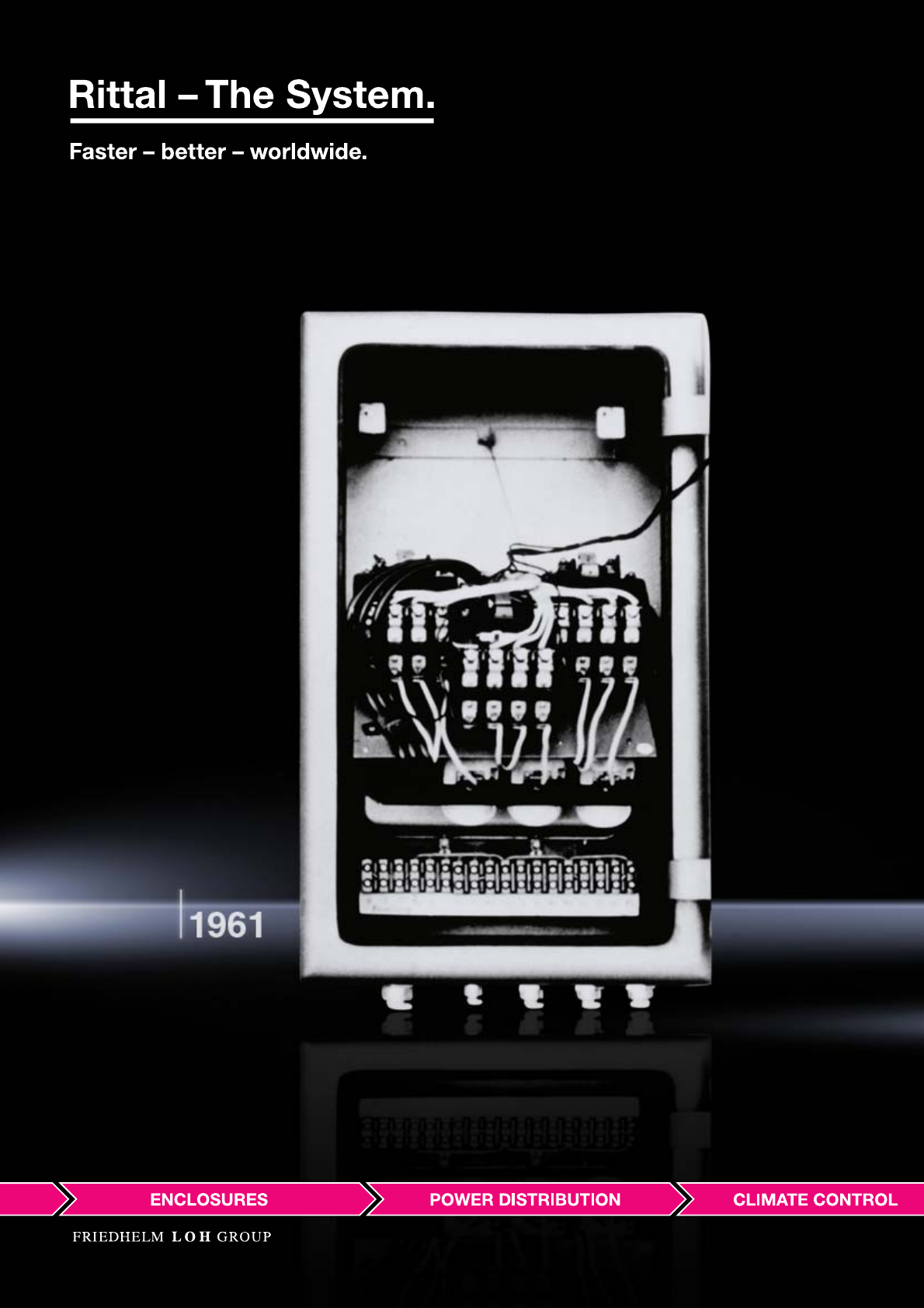
1961: Series production of the very first standard enclosure, AE, begins.

5
Setting standards.
For 50 years, and well into the future.
To have been setting standards for 50 years, you not only need a good idea, but also the strength
and ambition to implement it consistently. Rittal had the idea of producing standardised enclosures for
its customers. This idea became a reality in 1961 with the very first standard enclosure AE, laying the
foundations for long-term success.
Today, Rittal are world market leaders. We do not see this as a reason to rest on our laurels, but rather
as an incentive for future outstanding achievements: By permanently improving our products and
services and constant, innovative collaboration with our customers.
6
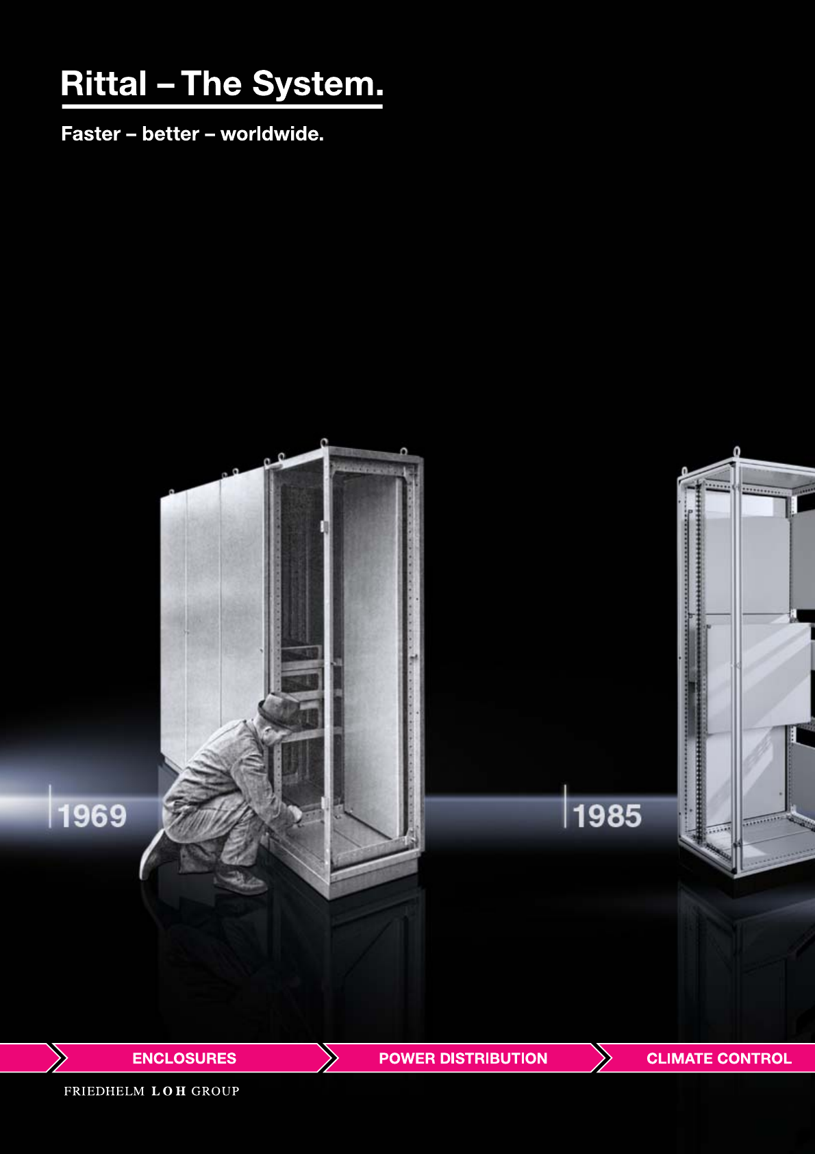
1969: Development of the modular series enclosure system RS.
1985: Presentation of the perfect enclosure system PS 4000. With more than 7.1 million units sold, it becomes a global standard.
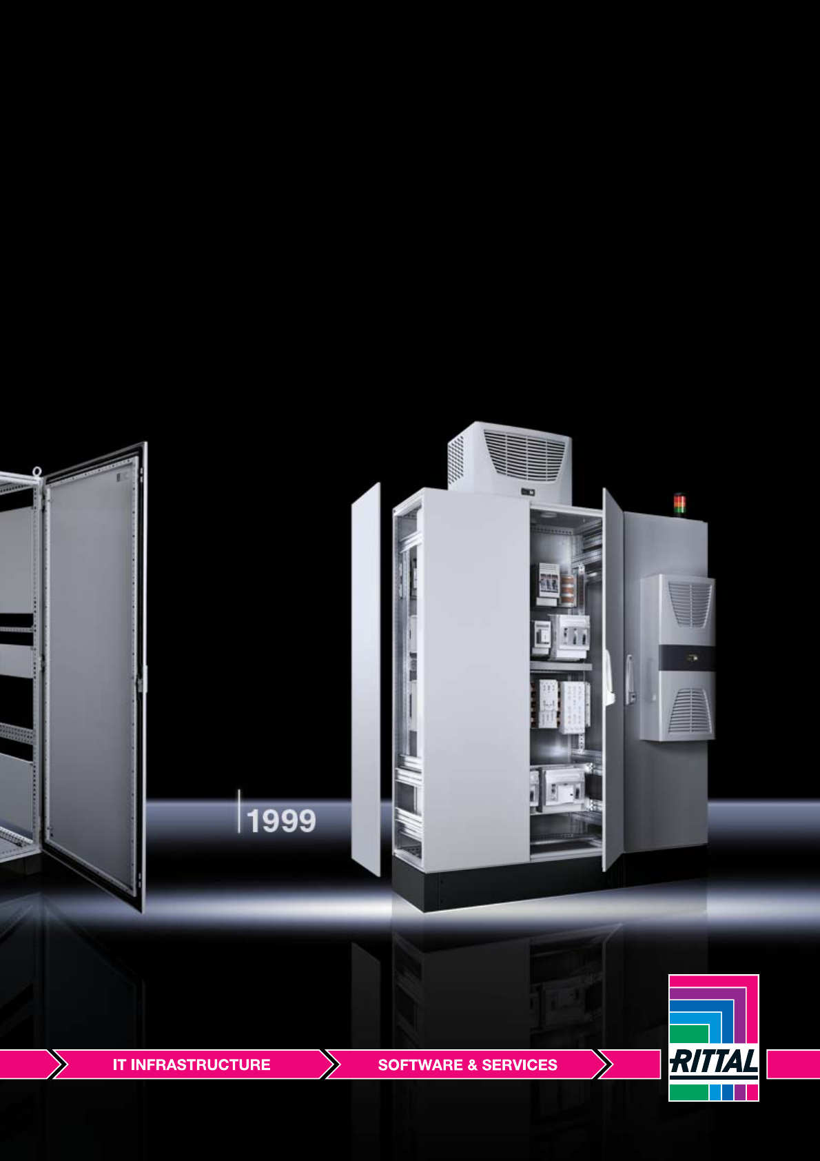
1999: Perfecting of the global standard PS 4000 and extending it to infinite possibilities with the Top enclosure system TS 8.
7
Perfect collaboration.
For 50 years, and well into the future.
We attach great value to direct contact with our customers, with qualified employees who listen
attentively and understand your concerns. This is what enabled us to develop ground-breaking
product series such as the modular series enclosure system RS at an early stage, in collaboration
with our customers. This cooperation is based on our many years of expertise and the unstinting
willingness of our employees to acquire forward-thinking knowledge and implement it in a profes-
sional fashion. Our customers are still the most important source of new products and services.
We continue this dialogue enthusiastically throughout every phase of the process, from the initial
idea, to development of a solution, through to the use of our products.
8
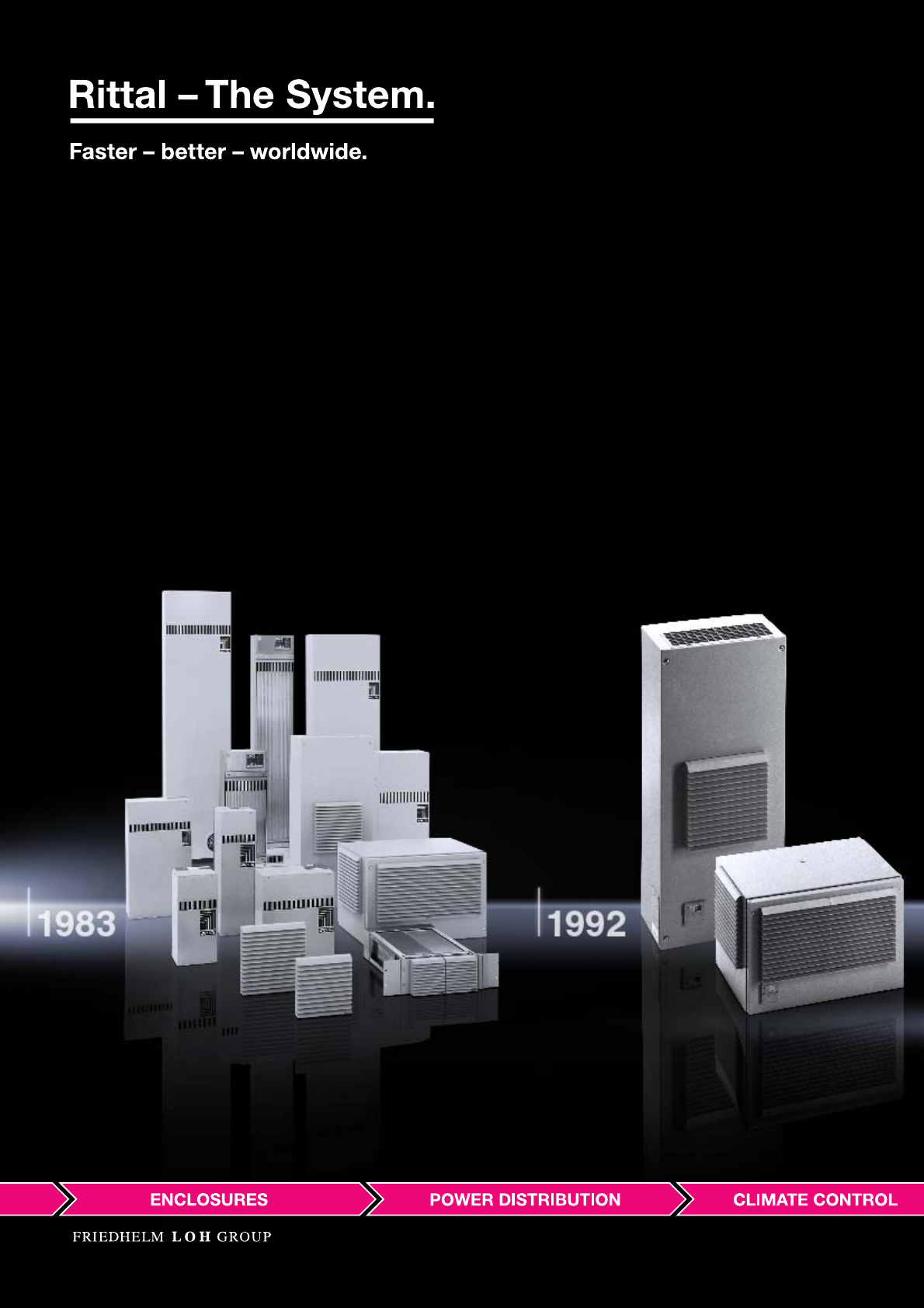
1983: Development and production of enclosure cooling units
1992: Ground-breaking ProOzone initiative to develop the first CFC-free cooling units.
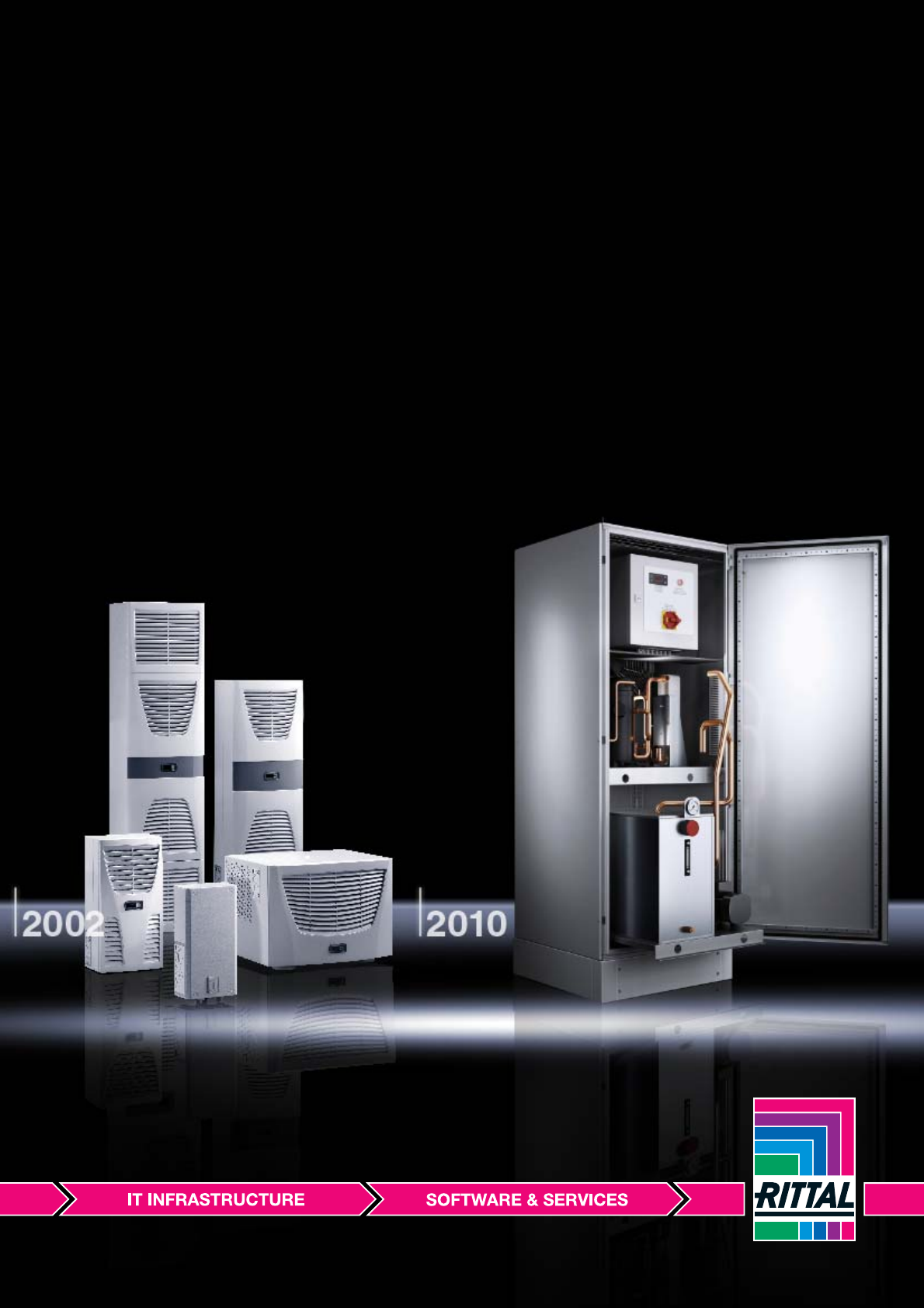
2002: Revolutionising enclosure climate control with cooling units in the TopTherm series with innovative air routing.
2010: Development of the TopTherm chiller as a new modular concept in machine and process cooling.
9
Always two steps ahead.
For 50 years, and well into the future.
Rittal always offers solutions that make its customers’ business more efficient. One good example of
this is the problem of heat generation in enclosures as a result of electronic components. Rittal has
identified this problem and solved it by developing a wide range of climate control technologies.
Highly efficient and versatile. With every innovation, we set new trends: With energy-saving cooling
units with nano-technology, fan-and-filter units with innovative diagonal technology, modular recooling
systems and modern software tools.
10
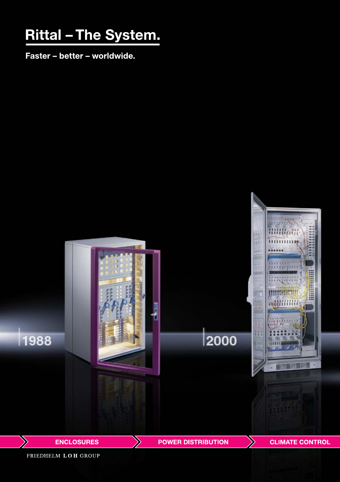
1988: Start of enclosure production for network technology.
2000: Rittal IT racks with an extensive range of accessories for modern IT infrastructures.
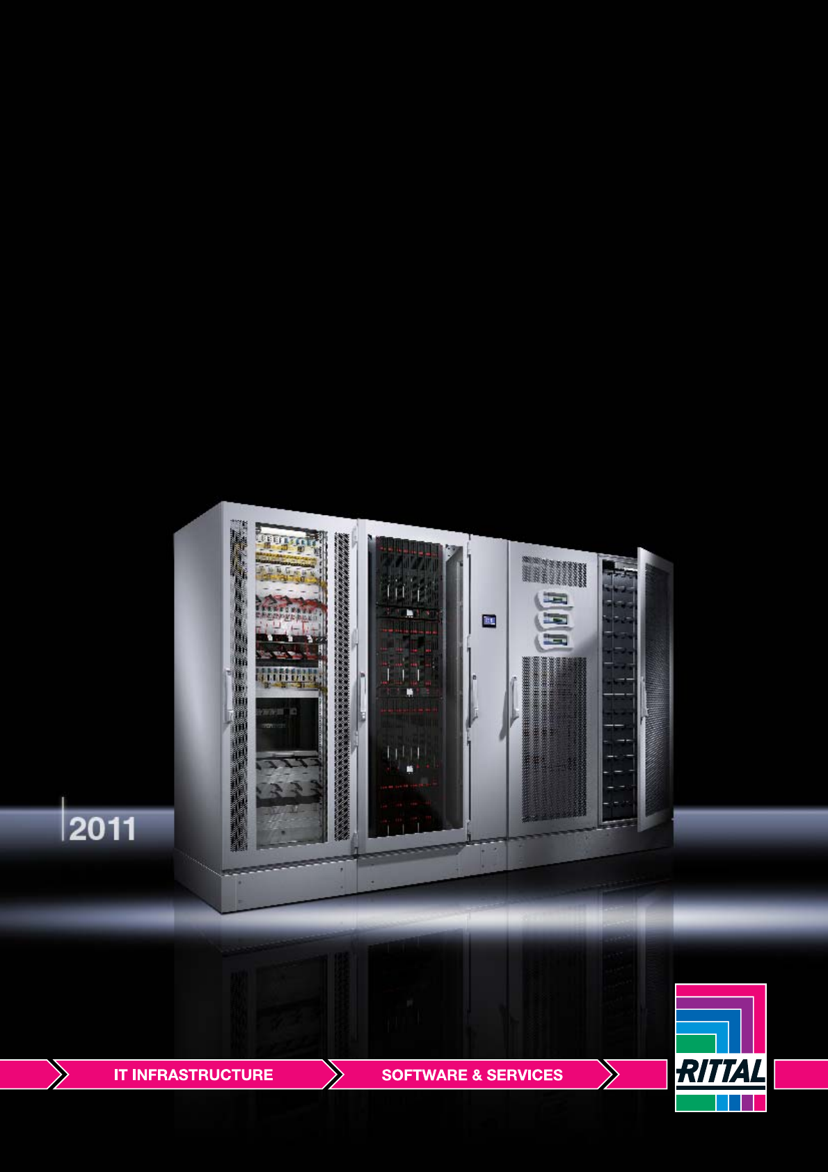
2011: Modular, scalable system solution for complete data centres.
11
We are always there for you.
For 50 years, and well into the future.
For years, we have seen increasing convergence between the IT and industrial markets.
Back in 1988, Rittal seized on this opportunity, and has since used its industrial expertise to tap
into global IT markets with the production of enclosures for modern network technologies. First,
our experience and competency from industry were transferred to the individual components for IT
use. From this, Rittal has continuously developed an unbeatable system solution with perfectly
coordinated products and processes. Today, not only can our customers rely on pioneering solutions
for super-efficient and reliable data centres, IT environments and infrastructures, but also on our
global presence and availability.

12
The future

13
The fact that we are not content to look to the past, but instead are always looking to the future,
has been pivotal to our success in recent decades. And the same goes for the next 50 years.
For Rittal, the future starts afresh with every project. Be it the development of new materials,
product improvements, process optimisations or investing in new production sites around the
globe, everything we do is to your benefit and your advantage.
begins today!
14

15
Faster.
For 50 years, and well into the future.
For Rittal, being faster is not an empty promise, but a claim that is practised throughout every area
of the company, and that is linked to direct customer benefits:
Fast development of innovations, with short paths and fast decision-making
Fast tapping of new markets and industries
Fast, problem-free use of all products worldwide, thanks to national and international approvals
Fast individual solutions through direct product development in collaboration with customers
Faster thanks to a perfect interplay between development, engineering, products and service
Faster thanks to flexible project implementation with system solutions from a single source

16
Axia Award, Diesel Medal, Top Employer, Prize for Innovation – these are just a few examples of what other people think of Rittal!

17
Better.
For 50 years, and well into the future.
Many companies promise to be better. Rittal really is better. This isn’t just an empty claim; it has been
confirmed by independent experts and selection jury members. They bear witness to our outstanding
innovations and corporate achievements with positive analyses and awards. Most important of all for
us, however, is the confirmation we get from our customers. For 50 years, they have been placing their
trust in us, and therefore play a large part in our current position as global market leaders.
The reasons for this are:
Better with powerful innovative strength and the associated safeguarding of competitive advantages
on the market
Better thanks to certified quality in management, production and environmental protection
Better thanks to rational production on state-of-the art, automated production lines
Better through targeted solutions that are designed to make our customers’ lives easier
Better thanks to the verifiable energy efficiency of our products with tangible cost savings
Better with outstanding education and training, and superbly trained staff

18

19
Worldwide.
For 50 years, and well into the future.
One major advantage that our customers really appreciate is our global presence.
For more than 50 years we have been on hand to offer advice, assistance and products.
Around the globe. We call this healthy customer relationships. It helps our customers to success-
fully tap into new markets. A dynamic status quo that we will be further expanding in future.
The cornerstones of our global availability:
Worldwide thanks to outstanding logistics with 63 subsidiaries, 40 agencies, 100 warehouses
with a total storage area of more than 160,000 m worldwide
Worldwide thanks to production sites on 3 continents, in 10 state-of-the-art plants with a total
production area of more than 210,000 m
Worldwide thanks to global service with 5 global support points, more than 250 service partners
and over 1,000 service engineers
Worldwide thanks to international expertise with country-specific know-how and cross-regional
approvals
20

21
Dynamic success.
For 50 years, and well into the future.
Rittal – a global success for more than 50 years – is part of the dynamic Friedhelm Loh Group,
which invests continuously in new technologies and markets. It specialises in the invention,
development and production of customised products and system solutions. At the heart of its
success is a lively and exemplary corporate culture which is wholly committed to ethical, social
and environmental values with commercial responsibility.
The Friedhelm Loh Group includes the following specialists:
Rittal
The world’s leading system suppliers of
enclosures, power distribution, climate control,
IT infrastructure and software & services
Eplan
Software for global engineering solutions
Mind8
Solution providers for products that are available
in a large number of versions and which require
intensive explanation
Stahlo
A modern steel service centre
LKH
Processors of plastics in the hot pressing and
injection moulding fields
Würz Energy
Combined heat and power (CHP) units
22
23
Enclosures
Small enclosures
Polycarbonate enclosures PK .....................................................................28
Aluminium enclosures GA ...........................................................................32
Terminal boxes KL.......................................................................................34
E-Box EB .....................................................................................................37
Bus enclosures BG......................................................................................39
Compact enclosures
Compact enclosures AE..............................................................................44
Compact system enclosures CM ................................................................48
Plastic enclosures KS..................................................................................50
Wall-mounted network enclosures
Wall-mounted enclosures............................................................................54
Enclosure systems
Baying systems TS 8 ...................................................................................70
Network distribution enclosures
Network enclosures TS 8.............................................................................80
Network enclosures TE 7000.......................................................................85
Distributor racks ..........................................................................................88
Server enclosures
Server enclosures TS 8 ...............................................................................92
Server enclosures TE 7000 .........................................................................95
Console systems/PC enclosure systems/IW
TopConsole system TP..............................................................................100
One-piece consoles TP .............................................................................106
Universal consoles TP ...............................................................................107
PC enclosure systems...............................................................................108
Enclosure for tower PC..............................................................................109
Industrial Workstations ..............................................................................110
Operating housings/support arm systems/
stand systems
Comfort Panel............................................................................................116
Optipanel...................................................................................................118
Operating housings...................................................................................120
Support arm systems ................................................................................128
Stand systems ...........................................................................................147
Hygienic Design
Small and compact enclosures HD...........................................................154
Stainless steel
Enclosures.................................................................................................160
Support arm system CP-S .........................................................................168
Enclosure systems ....................................................................................170
Ex enclosures/EMC
Ex enclosures ............................................................................................176
EMC enclosures ........................................................................................178
Outdoor enclosures
Outdoor enclosures...................................................................................182
24
25
As system providers, Rittal are the world’s leading suppliers
of innovative enclosure and case technology. Rittal meets very high
standards of security, ergonomics, energy and cost efficiency.
Your benefits
Planning and engineering
●Software tools for targeted planning and project management
●Component library RiCAD 3D for efficient engineering
Products
●Modular enclosure and case technology
●Extensive Rittal system solutions for a high level of investment reliability
and maximum flexibility
●Compatibility with all types of applications: Industrial, IT,
power distribution and climate control
●A comprehensive range of system accessories for individual installation
and fast assembly
Service
●Contiguous global delivery and service network
●Comprehensive quality management
●Our own accredited laboratories for tests, trials and protection category
verification
●Global spare parts service
●AE Laser Express – Individual enclosures to order
Competency
in enclosure systems
26

27
Small enclosures
Polycarbonate enclosures PK
Polycarbonate enclosures PK .....................................................................28
Polycarbonate enclosures PK, accessories................................................31
Cast aluminium enclosures GA
Cast aluminium enclosures GA ...................................................................32
Cast aluminium enclosures GA, accessories..............................................33
Terminal boxes KL
Terminal boxes KL.......................................................................................34
E-Box EB
E-Box EB .....................................................................................................37
Bus enclosures BG
Bus enclosures BG......................................................................................39
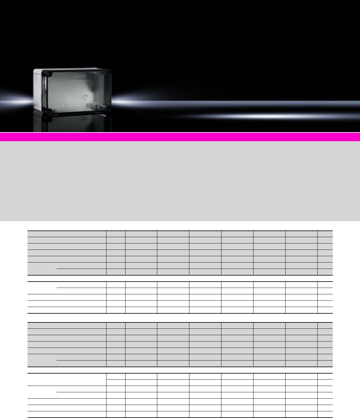
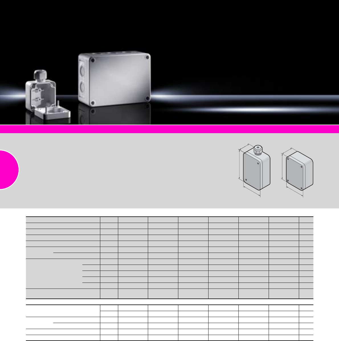
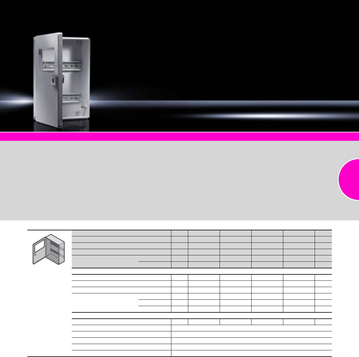
Polycarbonate enclosures PK
28 Rittal Catalogue 33/Enclosures
PK accessories Page 31 System accessories Page 355 Polyamide cable gland Page 519
Material:
−Housing of fibre-glass
reinforced polyamide
−Cover either transparent
(version .100) or grey (ver-
sion .000), made from fibre-
glass-reinforced polycar-
bonate
−Cover screws from polyamide
−Insulating bung from poly-
ethylene
−All-round foamed-in PU seal
Colour:
RAL 7035
Protection category:
IP 66 to IEC 60 529
Supply includes:
−Enclosure with cover
−Cover screws
−Insulating bungs for wall
mounting screws
Approvals:
−UL
−cUL
−Bureau Veritas
Detailed drawing:
Available on the Internet.
Width mm 65 94 94 94 110 110 Page
Height mm 65 65 94 94 110 110
Depth mm 57 57 57 81 66 90
Model No. PK 9500.000 9502.000 9504.000 9505.000 9506.000 9507.000
Packs of 12 86666
Cover Transparent – – – – – –
Grey
Accessories
Support rail
TS 35/7.5
Installation in the width 12 – – 9564.000 9564.000 9564.000 9564.000 31
Installation in the height 12 – – 9564.000 9564.000 9564.000 9564.000 31
Wall mounting brackets 40 9583.000 9583.000 9583.000 9583.000 9583.000 9583.000 31
Turn-lock fastener 100 9582.000 9582.000 9582.000 9582.000 9582.000 9582.000 31
Hinges 10 sets 9580.000 9580.000 9580.000 9580.000 9580.000 9580.000 31
Width mm 130 130 130 130 130 130 Page
Height mm 94 94 94 94 130 130
Depth mm 57 57 81 81 75 75
Model No. PK 9508.100 9508.000 9509.100 9509.000 9510.100 9510.000
Packs of 444444
Cover Transparent – – –
Grey – – –
Accessories
Mounting plate – – – – 9545.000 9545.000 31
Packs of – – – – 10 10
Support rail
TS 35/7.5
Installation in the width 12 9565.000 9565.000 9565.000 9565.000 9565.000 9565.000 31
Installation in the height 12 9564.000 9564.000 9564.000 9564.000 9565.000 9565.000 31
Wall mounting brackets 40 9583.000 9583.000 9583.000 9583.000 9583.000 9583.000 31
Turn-lock fastener 100 9582.000 9582.000 9582.000 9582.000 9582.000 9582.000 31
Hinges 10 sets 9580.000 9580.000 9580.000 9580.000 9580.000 9580.000 31
Polycarbonate enclosures PK
29Rittal Catalogue 33/Enclosures
Width mm 130 130 180 180 180 180 Page
Height mm 130 130 94 94 94 94
Depth mm 99 99 57 57 81 81
Model No. PK 9511.100 9511.000 9512.100 9512.000 9513.100 9513.000
Packs of 442222
Cover Transparent – – –
Grey – – –
Accessories
Mounting plate 9545.000 9545.000 – – – – 31
Packs of 10 10 – – – –
Support rail
TS 35/7.5
Installation in the width 12 9565.000 9565.000 9566.000 9566.000 9566.000 9566.000 31
Installation in the height 12 9565.000 9565.000 9564.000 9564.000 9564.000 9564.000 31
Wall mounting brackets 40 9583.000 9583.000 9583.000 9583.000 9583.000 9583.000 31
Turn-lock fastener 100 9582.000 9582.000 9582.000 9582.000 9582.000 9582.000 31
Hinges 10 sets 9580.000 9580.000 9580.000 9580.000 9580.000 9580.000 31
Width mm 180 180 180 180 180 180 Page
Height mm 110 110 110 110 110 110
Depth mm 90 90 111 111 165 165
Model No. PK 9514.100 9514.000 9515.100 9515.000 9516.100 9516.000
Packs of 222222
Cover Transparent – –
Grey – – – –
Accessories
Mounting plate 9547.000 9547.000 9547.000 9547.000 9547.000 9547.000 31
Packs of 10 10 10 10 10 10
Support rail
TS 35/7.5
Installation in the width 12 9566.000 9566.000 9566.000 9566.000 9566.000 9566.000 31
Installation in the height 12 9564.000 9564.000 9564.000 9564.000 9564.000 9564.000 31
Wall mounting brackets 40 9583.000 9583.000 9583.000 9583.000 9583.000 9583.000 31
Turn-lock fastener 100 9582.000 9582.000 9582.000 9582.000 9582.000 9582.000 31
Hinges 10 sets 9581.000 9581.000 9581.000 9581.000 9581.000 9581.000 31
Width mm 182 182 182 182 182 182 254 254 Page
Height mm 180 180 180 180 180 180 180 180
Depth mm 90 90 111 111 165 165 90 90
Model No. PK 9517.100 9517.000 9518.100 9518.000 9519.100 9519.000 9520.100 9520.000
Packs of 1 1 1 1 1 1 1 1
Cover Transparent – – – –
Grey – – – –
Accessories
Mounting plate 9548.000 9548.000 9548.000 9548.000 9548.000 9548.000 9549.000 9549.000 31
Packs of 10 10 10 10 10 10 8 8
Support rail
TS 35/7.5
Installation in the width 12 9566.000 9566.000 9566.000 9566.000 9566.000 9566.000 9567.000 9567.000 31
Installation in the height 12 9566.000 9566.000 9566.000 9566.000 9566.000 9566.000 9566.000 9566.000 31
Wall mounting brackets 40 9583.000 9583.000 9583.000 9583.000 9583.000 9583.000 9583.000 9583.000 31
Turn-lock fastener 100 9582.000 9582.000 9582.000 9582.000 9582.000 9582.000 9582.000 9582.000 31
Hinges 10 sets 9581.000 9581.000 9581.000 9581.000 9581.000 9581.000 9581.000 9581.000 31
Width mm 254 254 254 254 360 360 360 360 Page
Height mm 180 180 180 180 254 254 254 254
Depth mm 111 111 165 165 111 111 165 165
Model No. PK 9521.100 9521.000 9522.100 9522.000 9523.100 9523.000 9524.100 9524.000
Packs of 1 1 1 1 1 1 1 1
Cover Transparent – – – –
Grey – – – –
Accessories
Mounting plate 9549.000 9549.000 9549.000 9549.000 9550.000 9550.000 9550.000 9550.000 31
Packs of88884444
Support rail
TS 35/7.5
Installation in the width 12 9567.000 9567.000 9567.000 9567.000 9568.000 9568.000 9568.000 9568.000 31
Installation in the height 12 9566.000 9566.000 9566.000 9566.000 9567.000 9567.000 9567.000 9567.000 31
Wall mounting brackets 40 9583.000 9583.000 9583.000 9583.000 9583.000 9583.000 9583.000 9583.000 31
Turn-lock fastener 100 9582.000 9582.000 9582.000 9582.000 9582.000 9582.000 9582.000 9582.000 31
Hinges 10 sets 9581.000 9581.000 9581.000 9581.000 9581.000 9581.000 9581.000 9581.000 31
Polycarbonate enclosures PK
30 Rittal Catalogue 33/Enclosures
PK accessories Page 31 System acessories Page 355 Polyamide cable gland Page 519
Material:
−Housing and cover of fibre-
glass reinforced polyamide
−Cover screws from polyamide
−Insulating bung from poly-
ethylene
−All-round foamed-in PU seal
Colour:
RAL 7035
Protection category:
IP 66 to IEC 60 529
Supply includes:
−Enclosure with cover
−Cover screws
−Insulating bung for wall
mounting screws
(not with PK 9530.000
and PK 9531.000)
Approvals:
−UL
−cUL
−Bureau Veritas
Detailed drawing:
Available on the Internet.
H
B
T
H
B
T
Width (B) mm 65 130 180 254 50 50 Page
Height (H) mm 65 94 110 180 52 65
Depth (T) mm 57 57 90 111 35 35
Model No. PK 9500.050 9508.050 9514.050 9521.050 9530.000 9531.000
Packs of 12 4 2 1 10 10
Cover Transparent – – – – – –
Grey
No. of metric knockouts
M16/20 410 – – – –
M20 – – 16 24 – –
M20/25 – – 2– – –
M25/32 – – – 4 – –
M32/40 – – 2 4 – –
Cable gland for cable diameter
5 – 10 mm – – – –
Accessories
Mounting plate – – 9547.000 9549.000 – – 31
Packs of – – 10 8 – –
Support rail
TS 35/7.5
Installation in the width 12 – 9565.000 9566.000 9567.000 – – 31
Installation in the height 12 – 9564.000 9564.000 9566.000 – – 31
Wall mounting brackets 40 9583.000 9583.000 9583.000 9583.000 – – 31
Turn-lock fastener 100 9582.000 9582.000 9582.000 9582.000 – – 31
Hole patterns for metric knockout available on the Internet.
Accessories
Polycarbonate enclosures PK
31Rittal Catalogue 33/Enclosures
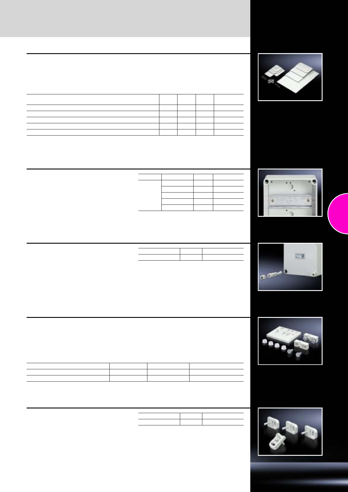
Mounting plate
For universal interior installation.
Material:
2.5 mm melamine phenol-coated laminated
paper.
Colour:
RAL 7035
Supply includes:
−Mounting plate
−Self-tapping assembly screws
For enclosure Width
mm Height
mm Packs of Model No. PK
PK 9510.000/.100, PK 9511.000/.100 110 110 10 9545.000
PK 9514.000/.100, PK 9514.050, PK 9515.000/.100, PK 9516.000/.100 150 90 10 9547.000
PK 9517.000/.100, PK 9518.000/.100, PK 9519.000/.100 150 150 10 9548.000
PK 9520.000/.100, PK 9521.000/.100, PK 9521.050, PK 9522.000/.100 220 150 8 9549.000
PK 9523.000/.100, PK 9524.000/.100 331 220 4 9550.000
Support rail
The support rail section provides good flexibility
for accommodating terminal blocks and installed
components.
Supply includes:
−Support rails
−Self-tapping assembly screws
Rail Rail length mm Packs of Model No. PK
TS 35/7.5
81 12 9564.000
106 12 9565.000
144 12 9566.000
216 12 9567.000
336 12 9568.000
Turn-lock fastener
A quick, convenient screw fastening aid is
obtained by clipping into the head of the lid
screw.
Material:
Polyamide
Colour:
Similar to RAL 7035
Supply includes:
1 pack = 100 pieces
Packs of Model No. PK
For all enclosures 100 9582.000
Hinges
For hinged attachment of covers.
The supplied drilling template ensures problem-
free assembly.
Colour:
Similar to RAL 7035
Supply includes:
1 set =
2 hinges,
4 assembly screws,
4 polyethylene sealing bungs,
1 drilling template.
For enclosure Material Packs of Model No. PK
PK 9500.000/.100 – PK 9513.000/.100 Polycarbonate 10 sets 9580.000
PK 9514.000/.100 – PK 9524.000/.100 Polystyrene 10 sets 9581.000
Wall mounting brackets
The enclosure can be screwed to the wall using
four wall mounting brackets. The bracket is
securely attached to the enclosure by means of
pins.
Material:
Polyamide, grey
Colour:
Similar to RAL 7035
Supply includes:
1 pack = 40 pieces
Packs of Model No. PK
For all enclosures 40 9583.000
Cast aluminium enclosures GA
32 Rittal Catalogue 33/Enclosures
GA accessories Page 33 System accessories Page 355
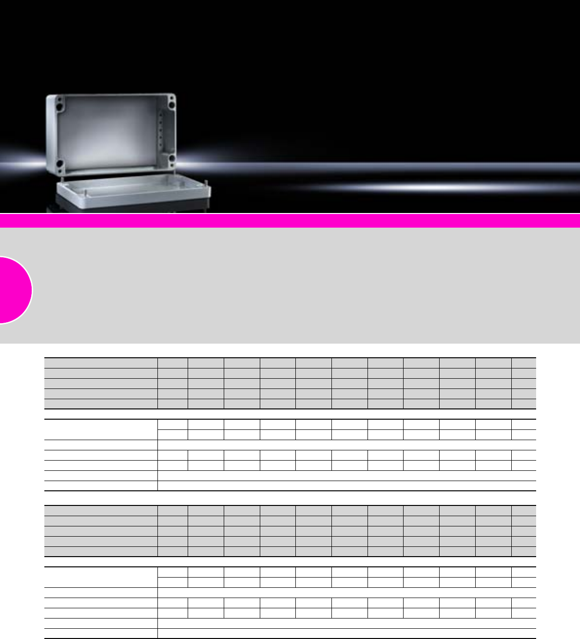
Material:
−Enclosure: Cast aluminium
−Cover: Cast aluminium,
all-round foamed-in PU seal
Surface finish:
Textured paint
Colour:
RAL 7001
Protection category:
IP 66 to IEC 60 529,
complies with NEMA 4.
Supply includes:
−Enclosure with cover
−Cover screws, captive
−Screws for attaching support
rails
−Screw for connection of the
PE conductor
Detailed drawing:
Available on the Internet.
Width mm 50 58 98 150 75 125 175 250 122 Page
Height mm 45 64 64 64 80 80 80 80 120
Depth mm 30 34 35 35 57 57 57 57 80
Model No. GA 9100.210 9101.210 9102.210 9103.210 9104.210 9105.210 9106.210 9107.210 9108.210
Packs of 653211111
Accessories
Mounting plate –––––9105.700 – – 9108.700 33
Packs of–––––10––2
Support rail TS 35, length 2 m see page 467
Wall mounting brackets 2––––––––9121.122 33
Hinge, exterior 2––––––––9123.000 33
Earth straps see page 501
Cable gland see page 519
Width mm 220 360 160 260 360 202 280 334 330 Page
Height mm 120 120 160 160 160 232 232 233 230
Depth mm 91 82 91 91 91 111 111 111 181
Model No. GA 9110.210 9111.210 9112.210 9113.210 9114.210 9116.210 9117.210 9118.210 9119.210
Packs of 111111111
Accessories
Mounting plate 9110.700 – 9112.700 9113.700 9114.700 9116.700 9117.700 9118.700 9118.700 33
Packs of2–2211111
Support rail TS 35, length 2 m see page 467
Wall mounting brackets 2 9121.122 9121.122 9121.160 9121.160 9121.160 9121.230 9121.230 9121.230 9121.230 33
Hinge, exterior 2 9123.000 9123.000 9123.000 9123.000 9123.000 9123.000 9123.000 9123.000 9123.000 33
Earth straps see page 501
Cable gland see page 519
Accessories
Cast aluminium enclosures GA
33Rittal Catalogue 33/Enclosures
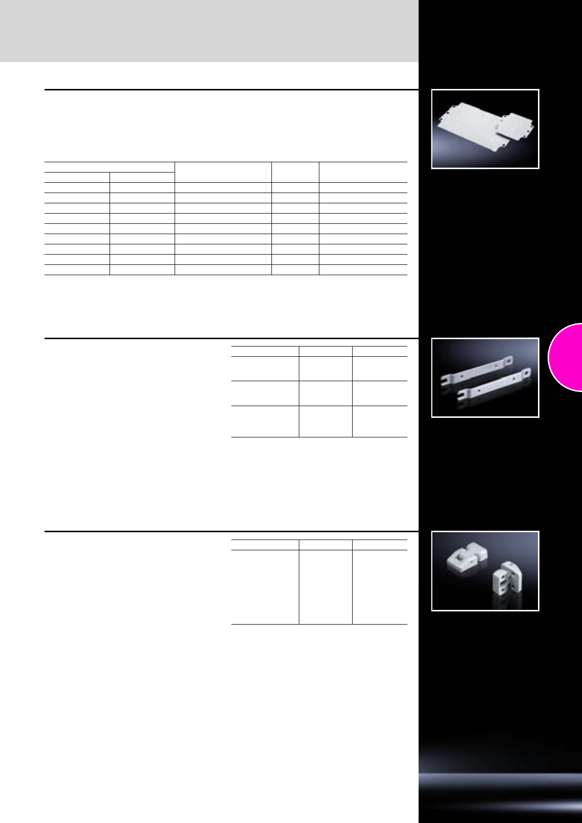
Mounting plate
For universal interior installation, with mounting
holes.
Material:
Sheet steel, zinc-plated
Exterior dimensions mm For GA enclosures Packs of Model No. GA
Width Height
114 69 9105.210 10 9105.700
109 107 9108.210 2 9108.700
207 107 9110.210 2 9110.700
144 142 9112.210 2 9112.700
245 142 9113.210 2 9113.700
346 142 9114.210 1 9114.700
183 214 9116.210 1 9116.700
264 214 9117.210 1 9117.700
314 214 9118.210/9119.210 1 9118.700
Wall mounting bracket
For external mounting on surfaces – no need to
dismantle the cover if pre-assembled.
Material:
Sheet steel, zinc-plated
For GA enclosures Packs of Model No. GA
9108.210/
9110.210/
9111.210 29121.122
9112.210/
9113.210/
9114.210 29121.160
9116.210/
9117.210/
9118.210/
9119.210
29121.230
Hinge, exterior
For fastening the cover to the enclosure base.
Material:
Die-cast aluminium
Colour:
RAL 7001
For GA enclosures Packs of Model No. GA
9108.210/
9110.210/
9111.210/
9112.210/
9113.210/
9114.210/
9116.210/
9117.210/
9118.210/
9119.210
2 + 8 screws 9123.000
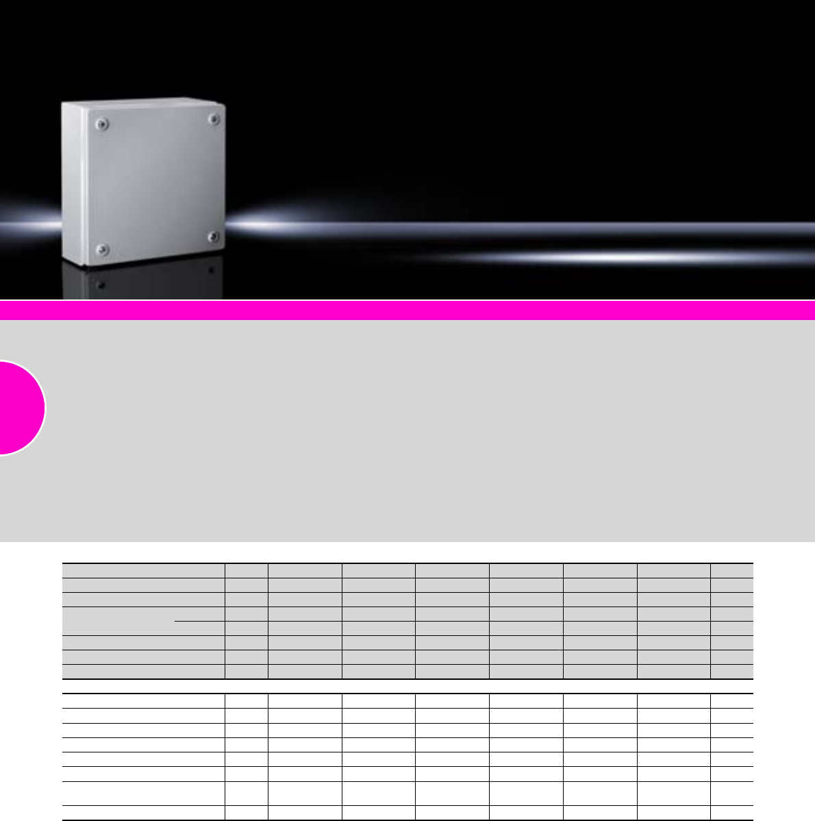
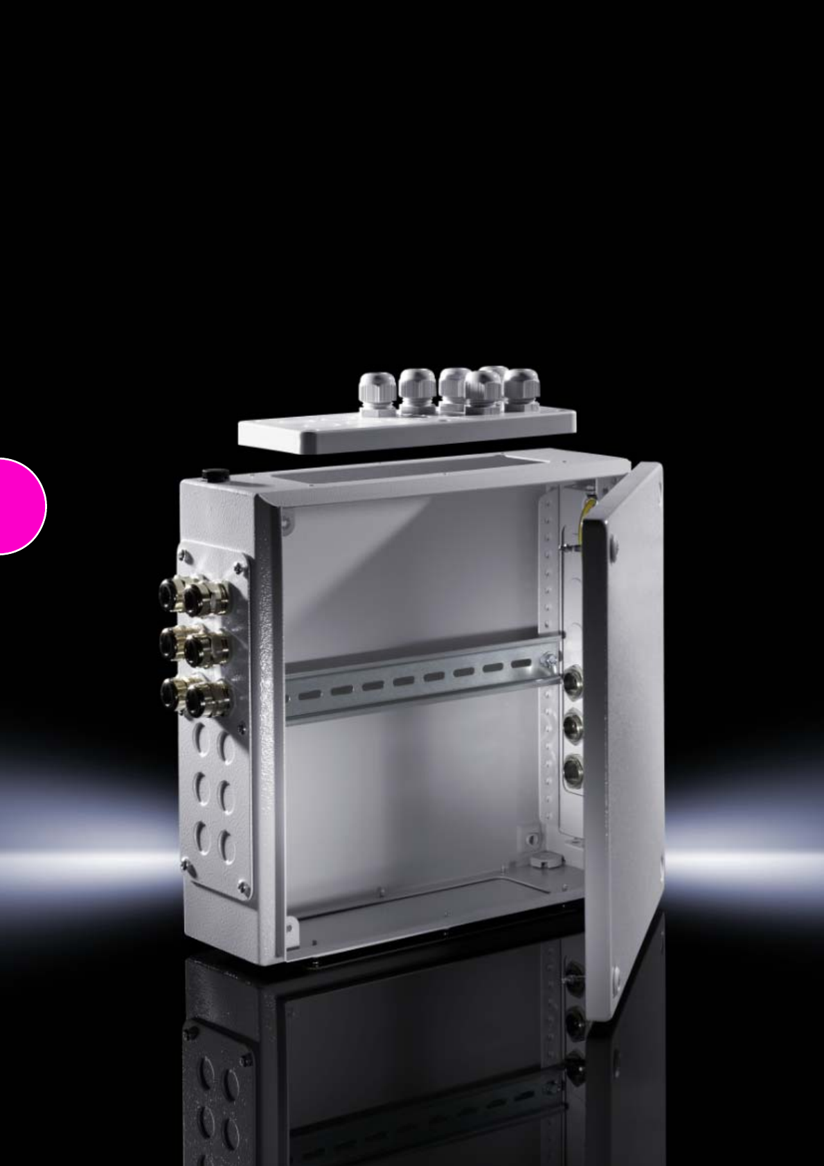
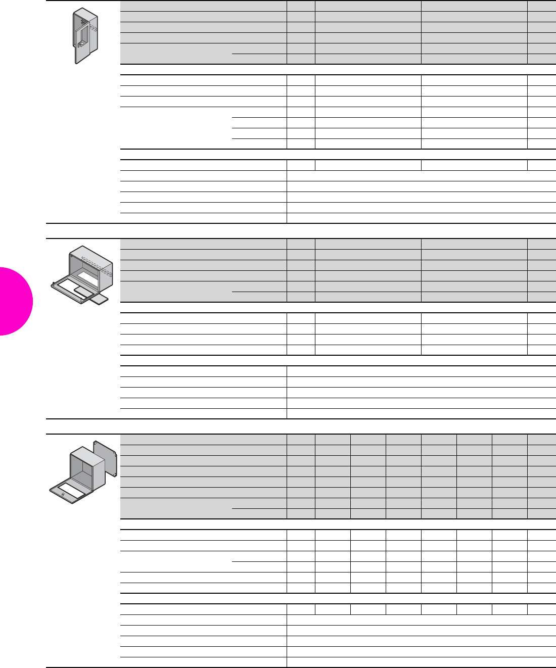
Terminal boxes KL
34 Rittal Catalogue 33/Enclosures
System accessories Page 355 KL stainless steel Page 161 KL for Ex areas Page 176
Material:
−Enclosure: Sheet steel
−Cover: Sheet steel, all-round
foamed-in PU seal
Surface finish:
Enclosure and cover: Dipcoat-
primed, powder-coated on the
outside, textured paint
Colour:
RAL 7035
Protection category:
−Without gland plate:
IP 66 to IEC 60 529,
complies with NEMA 4.
−With gland plate:
IP 55 to IEC 60 529,
complies with NEMA 12.
Supply includes:
−Enclosure with cover
−Quick-action screw including
plastic bushes
−For enclosures with gland
plate plus sheet steel gland
plates with seals and assem-
bly parts
Approvals
−UL
−CSA
−TÜV
−Germanischer Lloyd
−Russian Maritime Register of
Shipping
−Lloyds Register of Shipping
−Bureau Veritas
−VDE
Detailed drawing:
Available on the Internet.
Width mm Packs of 150 200 200 300 300 400 Page
Height mm 150 150 200 150 200 200
Depth mm 80 80 80 80 80 80
Material thickness mm Enclosure 1.25 1.25 1.25 1.25 1.25 1.25
Cover 1.25 1.25 1.25 1.25 1.25 1.25
Model No. KL 11514.510 1528.510 1516.510 1515.510 1517.510 1518.510
Weight (kg) 1.4 1.6 1.9 2.1 2.6 3.2
Gland plate – – – – – –
Accessories
Mounting plate 1 1560.700 1575.700 1562.700 1561.700 1563.700 1564.700 443
Support rail TS 35/7.5 10 2314.000 2315.000 2315.000 2316.000 2316.000 2317.000 467
Support rail TS 35/15 10 – – – – – – 467
Cover retainer 3 pairs 1591.000 1591.000 1591.000 1591.000 1591.000 1591.000 425
Cover hinge 6 1592.000 1592.000 1592.000 1592.000 1592.000 1592.000 425
Earthing kit 5 2570.100 2570.100 2570.100 2570.100 2570.100 2570.100 503
Wall mounting bracket
with 8 mm distance from wall 4 1590.000 1590.000 1590.000 1590.000 1590.000 1590.000 439
Spare quick-release fastener for KL 12 1593.000 1593.000 1593.000 1593.000 1593.000 1593.000 –
Terminal boxes KL
35Rittal Catalogue 33/Enclosures
Width mm Packs of 150 200 200 300 300 300 300 300 Page
Height mm 150 150 200 150 150 200 200 300
Depth mm 120 120 120 120 120 120 120 120
Material thickness
mm
Enclosure 1.25 1.25 1.25 1.25 1.25 1.25 1.25 1.38
Cover 1.25 1.25 1.25 1.25 1.25 1.25 1.25 1.25
Model No. KL 11500.510 1529.510 1502.510 1501.510 1530.510 1503.510 1531.510 1507.510
Gland plate – – – – – –
Weight (kg) 1.6 1.8 2.3 2.6 2.7 3.0 3.3 4.0
Accessories
Gland plate
(top + bottom)
Size – – – – 2 – 2 –
Qty. – – – – 1 + 1 – 1 + 1 –
Gland plate
(left + right)
Size – – – – – – – –
Qty. – – – – – – – –
Mounting plate 1 1560.700 1575.700 1562.700 1561.700 1561.700 1563.700 1563.700 1567.700 443
Support rail TS 35/7.5 10 2314.000 2315.000 2315.000 2316.000 2316.000 2316.000 2316.000 2316.000 467
Cover retainer 3 pairs 1591.000 1591.000 1591.000 1591.000 1591.000 1591.000 1591.000 1591.000 425
Cover hinge 6 1592.000 1592.000 1592.000 1592.000 1592.000 1592.000 1592.000 1592.000 425
Earthing kit 5 2570.100 2570.100 2570.100 2570.100 2570.100 2570.100 2570.100 2570.100 503
Wall mounting bracket
with 8 mm distance from wall 4 1590.000 1590.000 1590.000 1590.000 1590.000 1590.000 1590.000 1590.000 439
Spare quick-release fastener
for KL 12 1593.000 1593.000 1593.000 1593.000 1593.000 1593.000 1593.000 1593.000 –
Width mm Packs of 300 400 400 400 400 400 400 400 Page
Height mm 300 150 200 200 300 300 400 400
Depth mm 120 120 120 120 120 120 120 120
Material thickness
mm
Enclosure 1.38 1.25 1.25 1.25 1.38 1.38 1.38 1.38
Cover 1.25 1.25 1.25 1.25 1.25 1.25 1.25 1.25
Model No. KL 11535.510 1589.510 1504.510 1532.510 1508.510 1536.510 1511.510 1539.510
Gland plate – – – –
Weight (kg) 4.5 3.2 3.6 4.0 4.8 5.2 6.2 6.7
Accessories
Gland plate
(top + bottom)
Size 2– – 2– 2– 2
From
514
Qty. 1 + 1 – – 1 + 1 – 1 + 1 – 1 + 1
Gland plate
(left + right)
Size 2 – – – – 2 – 2 From
514
Qty. 1 + 1 – – – – 1 + 1 – 1 + 1
Mounting plate 1 1567.700 1576.700 1564.700 1564.700 1568.700 1568.700 1571.700 1571.700 443
Support rail TS 35/7.5 10 2316.000 2317.000 2317.000 2317.000 2317.000 2317.000 2317.000 2317.000 467
Cover retainer 3 pairs 1591.000 1591.000 1591.000 1591.000 1591.000 1591.000 1591.000 1591.000 425
Cover hinge 6 1592.000 1592.000 1592.000 1592.000 1592.000 1592.000 1592.000 1592.000 425
Earthing kit 5 2570.100 2570.100 2570.100 2570.100 2570.100 2570.100 2570.100 2570.100 503
Wall mounting bracket
with 8 mm distance from wall 4 1590.000 1590.000 1590.000 1590.000 1590.000 1590.000 1590.000 1590.000 439
Spare quick-release fastener
for KL 12 1593.000 1593.000 1593.000 1593.000 1593.000 1593.000 1593.000 1593.000 –
Rittal Australia
RITTAL Pty. Ltd.
130 – 140 Parraweena Road
Miranda NSW 2228
Phone: +61 (2) 9525 2766
Fax: +61 (2) 9525 2888
E-mail: info@rittal.com.au www.rittal.com.au
Terminal boxes KL
36 Rittal Catalogue 33/Enclosures
Width mm Packs of 500 500 500 500 Page
Height mm 200 200 300 300
Depth mm 120 120 120 120
Material thickness mm Enclosure 1.25 1.25 1.38 1.38
Cover 1.25 1.25 1.25 1.25
Model No. KL 11505.510 1533.510 1509.510 1537.510
Gland plate – –
Weight (kg) 4.4 4.9 5.8 5.2
Accessories
Gland plate
(top + bottom)
Size –2–2
From 514
Qty. – 2 + 2 – 2 + 2
Gland plate
(left + right)
Size –––2
From 514
Qty. –––1 + 1
Mounting plate 1 1565.700 1565.700 1569.700 1569.700 443
Support rail TS 35/15 10 2318.000 2318.000 2318.000 2318.000 467
Cover retainer 3 pairs 1591.000 1591.000 1591.000 1591.000 425
Cover hinge 6 1592.000 1592.000 1592.000 1592.000 425
Earthing kit 5 2570.100 2570.100 2570.100 2570.100 503
Wall mounting bracket
with 8 mm distance from wall 4 1590.000 1590.000 1590.000 1590.000 439
Spare quick-release fastener for KL 12 1593.000 1593.000 1593.000 1593.000 –
Rittal Portugal
RITTAL – Sistemas Eléctricos
e Eléctrónicos, Lda.
Z. I. de Rio Meão Rua 8, no 228
4520-475 – Rio Meão Sta Maria da Feira
Phone: +351 25678 0210
Fax: +351 25678 0219
E-mail: info@rittal.pt www.rittal.pt
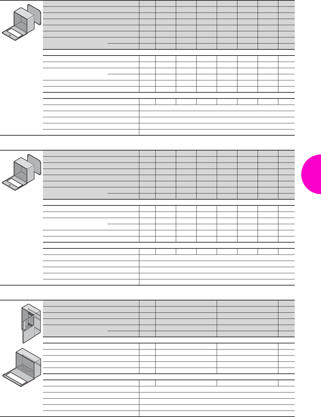
E-Box EB
37Rittal Catalogue 33/Enclosures
System accessories Page 355 E-Box EMC-shielded Page 178
Material:
−Enclosure: Sheet steel
−Door: Sheet steel, all-round
foamed-in PU seal
Surface finish:
−Enclosure and door: Dipcoat-
primed, powder-coated on the
outside, textured paint
−Mounting plate: Zinc-plated
Colour:
RAL 7035
Protection category:
IP 66 to IEC 60 529,
complies with NEMA 4.
Supply includes:
−Enclosure with hinged door
−180° hinge
−Cam lock with double-bit
insert
−Mounting plate
Approvals:
−UL
−CSA
−TÜV
−Germanischer Lloyd
−Russian Maritime Register of
Shipping
−Lloyds Register of Shipping
−Bureau Veritas
−VDE
Detailed drawings:
Available on the Internet.
G
F
H
B
T
Depth 120 mm
Width (B) mm Packs of 150 150 200 200 200 300 300 200 Page
Height (H) mm 150 300 200 300 400 300 400 500
Depth (T) mm 120 120 120 120 120 120 120 120
Mounting plate width (F) mm 125 125 175 175 175 275 275 175
Mounting plate height (G) mm 135 285 185 285 385 285 385 485
Material thickness
mm
Enclosure 1.25 1.25 1.25 1.25 1.25 1.38 1.38 1.25
Door 1.25 1.25 1.25 1.25 1.25 1.25 1.25 1.25
Model No. EB 1 1553.500 1548.500 1549.500 1554.500 1550.500 1555.500 1556.500 1557.500
Weight (kg) 2.0 3.0 2.8 3.6 5.0 5.0 6.4 6.2
Accessories
Wall mounting bracket
with 8 mm distance from wall 4 1590.000 1590.000 1590.000 1590.000 1590.000 1590.000 1590.000 1590.000 439
Pole clamp 1 set 2584.000 2584.000 2584.000 2584.000 2584.000 2584.000 2584.000 2584.000 441
Mounting clip 30 2309.000 2309.000 2309.000 2309.000 2309.000 2309.000 2309.000 2309.000 467
Support rail TS 35, length 2 m see page 467
Cable gland see page 519
Earth straps see page 501
Alternative lock systems see page 411
E-Box EB
38 Rittal Catalogue 33/Enclosures
Depth 155 mm
Width (B) mm Packs of 300 300 300 Page
Height (H) mm 400 600 800
Depth (T) mm 155 155 155
Mounting plate width (F) mm 275 275 275
Mounting plate height (G) mm 385 585 785
Material thickness
mm
Enclosure 1.38 1.38 1.38
Door 1.25 1.25 1.25
Model No. EB 1 1577.500 1578.500 1579.500
Weight (kg) 7.1 11.0 13.2
Accessories
Wall mounting bracket
with 8 mm distance from wall 4 1590.000 1590.000 1590.000 439
Pole clamp 1 set 2584.000 2584.000 2584.000 441
Mounting clip 30 2309.000 2309.000 2309.000 467
Support rail TS 35, length 2 m see page 467
Cable gland see page 519
Earth straps see page 501
Alternative lock systems see page 411
Rittal Brazil
RITTAL Sistemas Eletromecânicos Ltda.
Av. Cândido Portinari, 1174
VI Jaguara 05114-001 São Paulo-SP
Phone: +55 (11) 3622 2377
Fax: +55 (11) 3622 2399
E-mail: info@rittal.com.br www.rittal.com.br
Bus enclosures BG
39Rittal Catalogue 33/Enclosures
System accessories Page 355
Material:
−Enclosure: Sheet steel
−Door: Sheet steel with poly-
carbonate viewing window,
4 mm
Surface finish:
Enclosure and door:
Dipcoat-primed, powder-coated,
textured paint
Colour:
RAL 7035
Protection category:
IP 65 to IEC 60 529,
complies with NEMA 12.
Supply includes:
−Enclosure with door
−Viewing window in the door
−Product-specific supply
scope, see tables
Approvals:
−TÜV
−Lloyds Register of Shipping
−VDE
−UL
−cUL
Detailed drawings:
Available on the Internet.
Width mm Packs of 200 300 400 500 Page
Height mm 300 300 300 300
Depth mm 80 80 80 80
Model No. BG 1 1583.520 1584.520 1585.520 1586.520
Material thickness mm Enclosure 1.25 1.25 1.25 1.25
Door 1.25 1.25 1.25 1.25
Product-specific supply scope
Door hinge Left Left Left Left
Cam lock with double-bit insert 1 1 1 1
Support rail TS 35/7.5 2 2 2 2
Number of metric holes
M12 2 2 2 3
M20 5 9 13 24
M25 2 2 3 –
Accessories
Lock cover 1 2476.000 2476.000 2476.000 2476.000 423
Cable glands see page 519
Wall mounting bracket see page 439
Pole clamp see page 441
Earth straps see page 501
Alternative lock systems see page 411
Bus enclosures BG
40 Rittal Catalogue 33/Enclosures
Width mm Packs of 200 400 Page
Height mm 300 300
Depth mm 120 120
Model No. BG 1 1605.520 1606.520
Material thickness mm Enclosure 1.25 1.38
Door 1.25 1.25
Product-specific supply scope
Door hinge Right Right
Cam lock with double-bit insert 1 1
Support rail TS 35/7.5 1 1
Number of metric holes
M12 2 –
M20 – 2
M32 5 9
M50 – 1
Accessories
Lock cover 1 2476.000 2476.000 423
Cable glands see page 519
Wall mounting bracket see page 439
Pole clamp see page 441
Earth straps see page 501
Alternative lock systems see page 411
Width mm Packs of 400 600 Page
Height mm 200 200
Depth mm 125 125
Model No. BG 1 1558.510 1559.510
Material thickness mm Enclosure 1.25 1.25
Door 1.25 1.25
Product-specific supply scope
Door hinge Bottom Bottom
Quick-release fastener 2 3
Support rail TS 35/7.5 1 1
Gland plate in base 1 1
Accessories
Cable glands see page 519
Wall mounting bracket see page 439
Pole clamp see page 441
Earth straps see page 501
Alternative lock systems see page 411
Width mm Packs of 400 400 400 400 400 400 Page
Height mm 300 300 300 300 300 300
Depth mm 155 155 155 155 155 155
Mounting plate width 385 385 385 385 385 385
Mounting plate height 275 275 275 275 275 275
Model No. BG 1 1577.500 1577.5201) 1577.5301) 1577.5501) 1577.5601) 1577.4501)
Material thickness mm Enclosure 1.38 1.38 1.38 1.38 1.38 1.38
Door 1.25 1.25 1.25 1.25 1.25 1.25
Product-specific supply scope
Door hinge Bottom Bottom Bottom Bottom Bottom Bottom
Cam lock with double-bit insert 1 1 1 1 1 1
Viewing window Size mm – 340 x 115 340 x 190 340 x 115 340 x 190 340 x 155
Position2) mm – 92 42 92 42 92
Mounting plate 1 1 1 1 1 1
Gland plate in base – – – 1 1 –
Accessories
Lock cover 1 2476.000 2476.000 2476.000 2476.000 2476.000 2476.000 423
Cable glands see page 519
Wall mounting bracket see page 439
Pole clamp see page 441
Earth straps see page 501
Alternative lock systems see page 411
1) Extended delivery times.
2) Bottom edge of window to bottom edge of door
Bus enclosures BG
41Rittal Catalogue 33/Enclosures
Width mm Packs of 600 600 600 600 600 600 Page
Height mm 300 300 300 300 300 300
Depth mm 155 155 155 155 155 155
Mounting plate width 585 585 585 585 585 585
Mounting plate height 275 275 275 275 275 275
Model No. BG 1 1578.500 1578.5201) 1578.5301) 1578.5501) 1578.5601) 1578.4501)
Material thickness mm Enclosure 1.38 1.38 1.38 1.38 1.38 1.38
Door 1.25 1.25 1.25 1.25 1.25 1.25
Product-specific supply scope
Door hinge Bottom Bottom Bottom Bottom Bottom Bottom
Cam lock with double-bit insert 2 2 2 2 2 2
Viewing window Size mm – 540 x 115 540 x 190 540 x 115 540 x 190 540 x 155
Position2) mm – 92 42 92 42 92
Mounting plate 1 1 1 1 1 1
Gland plate in base – – – 1 1 –
Accessories
Lock cover 1 2476.000 2476.000 2476.000 2476.000 2476.000 2476.000 423
Cable glands see page 519
Wall mounting bracket see page 439
Pole clamp see page 441
Earth straps see page 501
Alternative lock systems see page 411
1) Extended delivery times. 2) Bottom edge of window to bottom edge of door
Width mm Packs of 800 800 800 800 800 800 Page
Height mm 300 300 300 300 300 300
Depth mm 155 155 155 155 155 155
Mounting plate width 785 785 785 785 785 785
Mounting plate height 275 275 275 275 275 275
Model No. BG 1 1579.500 1579.5201) 1579.5301) 1579.5501) 1579.5601) 1579.4501)
Material thickness mm Enclosure 1.38 1.38 1.38 1.38 1.38 1.38
Door 1.25 1.25 1.25 1.25 1.25 1.25
Product-specific supply scope
Door hinge Bottom Bottom Bottom Bottom Bottom Bottom
Cam lock with double-bit insert 2 2 2 2 2 2
Viewing window Size mm – 740 x 115 740 x 190 740 x 115 740 x 190 740 x 155
Position2) mm – 92 42 92 42 92
Mounting plate 1 1 1 1 1 1
Gland plate in base – – – 1 1 –
Accessories
Lock cover 1 2476.000 2476.000 2476.000 2476.000 2476.000 2476.000 423
Cable glands see page 519
Wall mounting bracket see page 439
Pole clamp see page 441
Earth straps see page 501
Alternative lock systems see page 411
1) Extended delivery times. 2) Bottom edge of window to bottom edge of door
Width mm Packs of 400 500 Page
Height mm 500 300
Depth mm 160 120
Model No. BG 1 1611.510 1609.510
Material thickness mm Enclosure 1.38 1.38
Door 1.5 1.25
Product-specific supply scope
Door hinge Right Bottom
Cam lock with double-bit insert 1 –
Quick-release fastener – 2
Support rail TS 35/7.5 3 1
Number of drilled holes for PG 13.5 or M20 33 48
Accessories
Lock cover 1 2476.000 – 423
Cable glands see page 519
Wall mounting bracket see page 439
Pole clamp see page 441
Earth straps see page 501
Alternative lock systems see page 411
42

43
Compact enclosures
Compact enclosures AE
Compact enclosures AE..............................................................................44
Compact system enclosures CM
Width: 600 – 800 mm, height: 800 – 1200 mm............................................48
Width: 1000 – 1200 mm, height: 1000 – 1400 mm......................................49
Plastic enclosures KS
Plastic enclosures KS..................................................................................50
Compact enclosures AE
44 Rittal Catalogue 33/Enclosures
System accessories Page 355 AE stainless steel Page 162 AE IP 69K Page 165 AE EMC-shielded Page 179 Hygienic Design Page 154
Material:
−Enclosure: Sheet steel
−Door: Sheet steel, all-round
foamed-in PU seal
Surface finish:
−Enclosure and door:
Dipcoat primed, powder-
coated on the outside,
textured paint
−Mounting plate: Zinc-plated
Colour:
RAL 7035
Protection category:
See tables.
Supply includes:
−Enclosure with hinged
door(s), of all-round solid
construction
−Gland plate(s) in enclosure
base
−For single-door enclosures,
door hinged on right,
may be swapped to left
(except with AE 1032.500
and AE 1035.500)
−With cam lock or 3-point lock
system
−Mounting plate
Approvals:
−UL
−CSA
−TÜV
−Germanischer Lloyd
−Russian Maritime
Register of Shipping
−Lloyds Register of Shipping
−Bureau Veritas
−VDE
Detailed drawings:
Available on the Internet.
B
T
H
F
G
Width (B) mm Packs of 200 200 300 300 380 380 380 Page
Height (H) mm 300 300 300 400 300 300 380
Depth (T) mm 120 155 210 210 155 210 210
Mounting plate width (F) mm 162 162 254 254 334 334 334
Mounting plate height (G) mm 275 275 275 375 275 275 355
Material thickness
mm
Enclosure 1.25 1.25 1.38 1.38 1.38 1.38 1.38
Door 1.5 1.5 1.5 1.5 1.5 1.5 1.5
Mounting plate thickness mm 2.0 2.0 2.0 2.0 2.0 2.0 2.0
Cam lock 1 1 1 1 1 1 1
Model No. AE 11032.500 1035.500 1033.500 1034.500 1030.500 1031.500 1380.500
Weight (kg) 4.0 4.5 7.0 8.8 7.4 7.5 9.8
Protection category IP 66 to IEC 60 529, complies with NEMA 4.
Accessories
Gland plate Size 11––333
From
514
Qty. 1111111
Rails for interior installation 4 – – 2373.210 2373.210 – 2373.210 2373.210 459
Wall mounting bracket
for external mounting 4 2508.100 2508.100 2508.100 2508.100 2508.100 2508.100 2508.100 439
Baying kit 1 set 1199.100 1199.100 1199.100 1199.100 1199.100 1199.100 1199.100 400
Door stay 5 – – 2519.000 2519.000 2519.000 2519.000 2519.000 429
180° hinges 2 2449.000 2449.000 2449.000 2449.000 2449.000 2449.000 2449.000 425
Rain canopies Sheet steel 1–––––2501.5002501.500 431
Stainless steel 1 – 2470.000 2361.000 2361.000 2471.000 2472.000 2472.000 431
Earth straps see page 501
LED system light see page 494
Wiring plan pocket, plastic see page 428
Cable gland see page 519
Alternative lock systems see page 411
Compact enclosures AE
45Rittal Catalogue 33/Enclosures
Width (B) mm Packs of 380 380 400 500 500 500 Page
Height (H) mm 600 600 500 500 500 700
Depth (T) mm 210 350 210 210 300 250
Mounting plate width (F) mm 334 334 354 449 449 449
Mounting plate height (G) mm 570 570 475 470 470 670
Material thickness
mm
Enclosure 1.38 1.5 1.38 1.38 1.5 1.5
Door 1.5 1.5 1.5 1.75 1.75 2.0
Mounting plate thickness mm 2.5 2.5 2.0 2.5 2.5 2.5
Cam lock 2222 2 2
Model No. AE 11038.500 1338.500 1045.500 1050.50 0 1350.500 1057.500
Weight (kg) 15.6 19.4 13.0 16.8 19.6 31.2
Protection category IP 66 to IEC 60 529, complies with NEMA 4.
Accessories
Gland plate Size 344444
From
514
Qty. 111111
Rails for interior installation 4 2373.210 2373.350 2373.210 2373.210 2373.300 2373.250 459
Wall mounting bracket
for external mounting 4 2508.100 2508.100 2508.100 2508.100 2508.100 2508.100 439
Baying kit 1 set 1199.100 1199.100 1199.100 1199.100 1199.100 1199.100 400
Door stay 5 2519.000 2519.000 2519.000 2519.000 2519.000 2519.000 429
180° hinge 2 2449.000 2449.000 2449.000 2449.000 2449.000 2449.000 425
Support strips 20 – – – 2325.000 2325.000 2325.000 426
Rain canopies Sheet steel 1 2501.500 – – – – – 431
Stainless steel 1 2472.000 – – 2362.000 – – 431
Earth straps see page 501
LED system light see page 494
Wiring plan pocket, plastic see page 428
Cable gland see page 519
Dust guard trim see page 432
Alternative lock systems see page 411
Width (B) mm Packs of 600 600 600 600 600 600 600 600 600 Page
Height (H) mm 380 380 600 600 600 760 760 800 1000
Depth (T) mm 210 350 210 250 350 210 350 250 250
Mounting plate width (F) mm 549 549 549 549 549 549 549 549 539
Mounting plate height (G) mm 355 355 570 570 570 730 730 770 955
Material thickness
mm
Enclosure 1.38 1.5 1.38 1.5 1.5 1.38 1.5 1.5 1.5
Door 1.5 1.5 1.75 1.75 1.75 2.0 2.0 2.0 2.0
Mounting plate thickness mm 2.5 2.5 2.5 2.5 2.5 3.0 3.0 3.0 3.0
Cam lock 1 1 2 2 2 2 2 2 2
Model No. AE 11039.500 1339.500 1060.500 1054.500 1360.500 1076.500 1376.500 1058.500 1090.50 0
Weight (kg) 15.4 20.0 22.8 24.8 28.4 32.1 36.0 33.6 50.5
Protection category IP 66 to IEC 60 529, complies with NEMA 4.
Accessories
Gland plate Size 555555555
From
514
Qty. 111111111
Rails for interior installation 4 2373.210 2373.350 2373.210 2373.250 2373.350 2373.210 2373.350 2373.250 2373.250 459
Wall mounting bracket
for external mounting 4 2508.100 2508.100 2508.100 2508.100 2508.100 2508.100 2508.100 2508.100 2508.100 439
Baying kit 1 set 1199.100 1199.100 1199.100 1199.100 1199.100 1199.100 1199.100 1199.100 – 400
Door stay 5 2519.000 2519.000 2519.000 2519.000 2519.000 2519.000 2519.000 2519.000 2519.000 429
180° hinge 2 2449.000 2449.000 2449.000 2449.000 2449.000 2449.000 2449.000 2449.000 2449.000 425
Support strips 20 2326.000 2326.000 2326.000 2326.000 2326.000 2326.000 2326.000 2326.000 2326.000 426
Rain canopies Sheet steel 1 2502.500 2511.500 2502.500 – 2511.500 2502.500 2511.500 – – 431
Stainless steel 1 2473.000 – 2473.000 – – 2473.000 – – – 431
Earth straps see page 501
LED system light see page 494
Wiring plan pocket, plastic see page 428
Cable gland see page 519
Dust guard trim see page 432
Alternative lock systems see page 411
Compact enclosures AE
46 Rittal Catalogue 33/Enclosures
Width (B) mm Packs of 600 760 760 800 800 800 Page
Height (H) mm 1200 760 760 600 1000 1200
Depth (T) mm 300 210 300 300 300 300
Mounting plate width (F) mm 540 704 704 749 739 740
Mounting plate height (G) mm 1155 730 730 570 955 1155
Material thickness
mm
Enclosure 1.5 1.5 1.5 1.5 1.5 1.5
Door 2.0 2.0 2.0 2.0 2.0 2.0
Mounting plate thickness mm 3.0 3.0 3.0 2.5 3.0 3.0
Cam lock – 2 2 2 2 –
3-point lock system – – – –
Model No. AE 11260.500 1077.500 1073.500 1055.500 118 0. 50 0 1280.500
Weight (kg) 55.0 40.0 44.5 33.9 57.0 70.0
Protection category IP 66 to IEC 60 529, complies with NEMA 4.
Accessories
Gland plate Size 555555
From
514
Qty. 111111
Rails for interior installation 4 2373.300 2373.210 2373.300 2373.300 2373.300 2373.300 459
Wall mounting bracket
for external mounting 4 2508.100 2508.100 2508.100 2508.100 2508.100 2508.100 439
Baying kit 1 set – 1199.100 1199.100 1199.100 – – 400
Door stay 5 2519.000 2519.000 2519.000 2519.000 2519.000 2519.000 429
180° hinge 2 2449.000 2449.000 2449.000 2449.000 2449.000 2449.000 425
Support strips 20 2326.000 2327.000 2327.000 2328.000 2328.000 2328.000 426
Rain canopies, stainless steel 1 – – 2474.000 2475.000 2475.000 2475.000 431
Base/plinths Height 100 mm 1 2816.200 – – – – 2818.200 369
Height 200 mm 1 2826.200 – – – – 2828.200 369
Eyebolts 4 2509.000 – – – – 2509.000 438
Earth straps see page 501
LED system light see page 494
Wiring plan pocket, plastic see page 428
Cable gland see page 519
Dust guard trim see page 432
Alternative lock systems see page 411
Width (B) mm Packs of 1000 1000 1000 1000 1000 Page
Height (H) mm 760 760 1000 1200 1400
Depth (T) mm 210 300 300 300 300
Mounting plate width (F) mm 944 944 939 940 940
Mounting plate height (G) mm 730 730 955 1155 1355
Material thickness
mm
Enclosure 1.5 1.5 1.5 1.5 1.5
Door 2.0 2.0 2.0 2.0 2.0
Mounting plate thickness mm 3.0 3.0 3.0 3.0 3.0
Cam lock 2 2 2 – –
3-point lock system – – –
Model No. AE 1110 0. 50 0 1130.500 1110. 50 0 1213.500 1114 .5 0 0
Door(s) 22222
Weight (kg) 52.0 56.0 71.0 85.0 97.0
Protection category IP 55 to IEC 60 529, complies with NEMA 12.
Accessories
Gland plate Size 44444
From
514
Qty. 22222
Rails for interior installation 4 2373.210 2373.300 2373.300 2373.300 2373.300 459
Wall mounting bracket
for external mounting 4 2508.100 2508.100 2508.100 2508.100 2508.100 439
Baying kit 1 set 1199.100 1199.100 – – – 400
Door stay 5 2519.000 2519.000 2519.000 2519.000 2519.000 429
180° hinge 2 2449.000 2449.000 2449.000 2449.000 2449.000 425
Support strips 20 2325.000 2325.000 2325.000 2325.000 2325.000 426
Rain canopies, stainless steel 1 – 2363.000 2363.000 2363.000 2363.000 431
Base/plinths Height 100 mm 1 – 2801.200 2801.200 2801.200 2801.200 369
Height 200 mm 1 – 2802.200 2802.200 2802.200 2802.200 369
Eyebolts 4 – – – 2509.000 2509.000 438
Earth straps see page 501
LED system light see page 494
Wiring plan pocket, plastic see page 428
Alternative lock systems see page 411
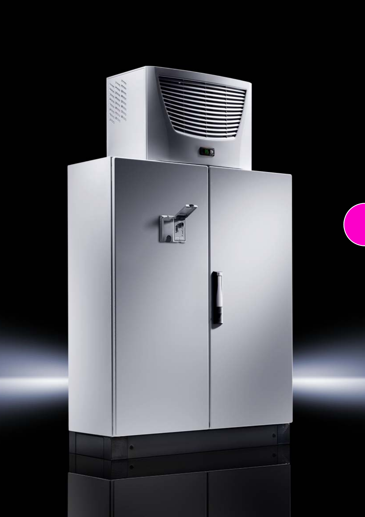
47
Compact system enclosures Rittal CM
48 Rittal Catalogue 33/Enclosures
System accessories Page 355 System lights Page 491 Cable duct Page 526 Climate control Page 207
Material:
−Enclosure: Sheet steel,
1.5 mm
−Door: Sheet steel, 2.0 mm,
all-round foamed-in PU seal
−Mounting plate: Sheet steel,
3.0 mm
Surface finish:
−Enclosure and door:
Dipcoat-primed, powder-
coated on the outside,
textured paint
−Mounting plate: Zinc-plated
Colour:
RAL 7035
Protection category:
IP 55 to IEC 60 529,
complies with NEMA 12 pro-
vided suitable gland plates are
selected.
Supply includes:
−Enclosure with hinged door(s)
−R/h door hinge with single-
door enclosures, may be
swapped to opposite side
−3-point lock
−Mounting plate
−Open base for individual
cable entry
Also required:
−Gland plates,
see page 378 – 380
−Or trim panel,
see page 381
Approvals:
−UL
−CSA
−TÜV
−Lloyds Register of Shipping
Detailed drawings:
Available on the Internet.
T
B
H
F
G
Width: 600 – 800 mm, height: 800 – 1200 mm
Width (B) mm Packs of 600 600 600 600 800 800 800 800 Page
Height (H) mm 800 1000 1200 1200 1000 1000 1200 1200
Depth (T) mm 400 400 300 400 300 400 300 400
Mounting plate width (F) mm 540 540 540 540 740 740 740 740
Mounting plate height (G) mm 755 955 1155 1155 955 955 1155 1155
Model No. CM 15110.500 5111.500 5112.500 5113.500 5114.500 5115.500 5116.500 5117.500
Door 11111111
Base/plinths
Components front and rear Height 100 mm 1 set 8601.600 8601.600 8601.600 8601.600 8601.800 8601.800 8601.800 8601.800 361
Height 200 mm 1 set 8602.600 8602.600 8602.600 8602.600 8602.800 8602.800 8602.800 8602.800 361
Trim panels, sides Height 100 mm 1 set 8601.040 8601.040 8601.030 8601.040 8601.030 8601.040 8601.030 8601.040 362
Height 200 mm 1 set 8602.040 8602.040 8602.030 8602.040 8602.030 8602.040 8602.030 8602.040 362
Accessories
Rail for interior installation for height 4 5001.051 5001.052 5001.053 5001.053 5001.052 5001.052 5001.053 5001.053 459
for width 4 5001.050 5001.050 5001.050 5001.050 5001.051 5001.051 5001.051 5001.051 459
Matching punched sections
with mounting flanges
in depth 4 8612.140 8612.140 8612.130 8612.140 8612.130 8612.140 8612.130 8612.140 459
in width 4 8612.060 8612.060 8612.060 8612.060 8612.080 8612.080 8612.080 8612.080 459
Base configuration rail 2 5001.370 5001.370 5001.371 5001.370 5001.371 5001.370 5001.371 5001.370 461
Mounting plate slide block 2 5001.070 5001.070 5001.070 5001.070 5001.070 5001.070 5001.070 5001.070 446
Support strips for door 20 4596.000 4596.000 4596.000 4596.000 4598.000 4598.000 4598.000 4598.000 426
TS punched section with mounting flange,
17 x 73 mm 4 8612.050 8612.050 8612.050 8612.050 ––––459
Cable clamp rails 1 5001.080 5001.080 5001.080 5001.080 5001.081 5001.081 5001.081 5001.081 527
Sheet steel wiring plan pocket, depth 35 mm 1 4116.500 4116.500 4116.500 4116.500 4118.500 4118.500 4118.500 4118.500 429
Rain canopy/vented roof 1 5001.310 5001.310 – 5001.310 – 5001.330 – 5001.330 431
Alternative lock systems see page 411
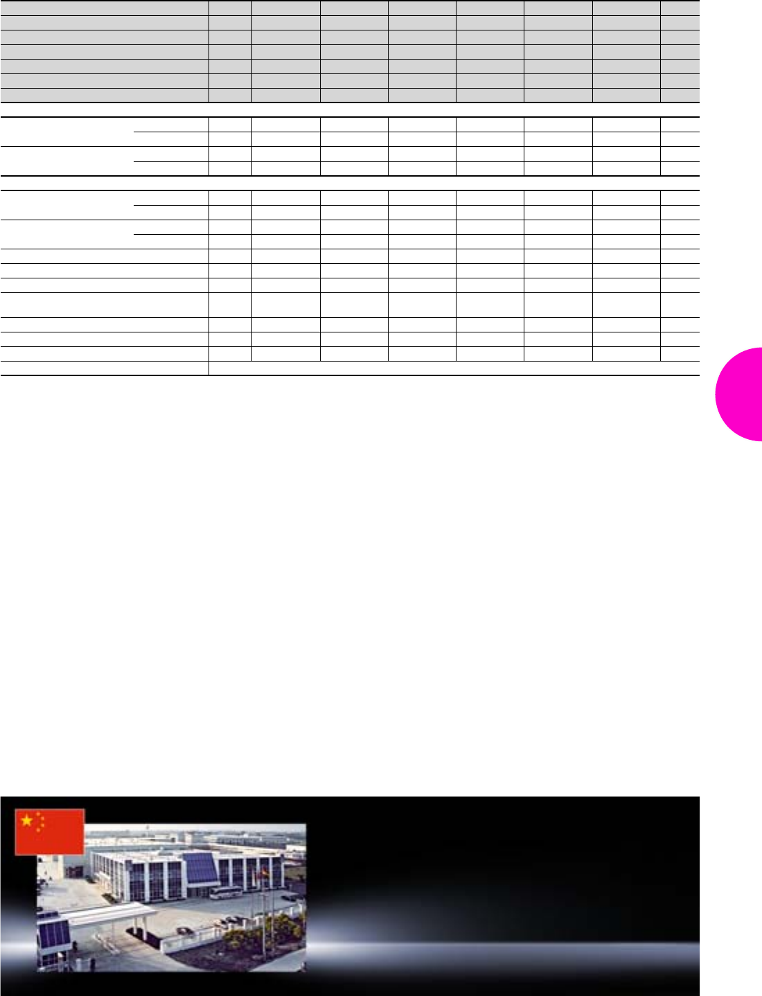
Compact system enclosures Rittal CM
49Rittal Catalogue 33/Enclosures
Width: 1000 – 1200 mm, height: 1000 – 1400 mm
Width (B) mm Packs of 1000 1000 1000 1000 1000 1200 Page
Height (H) mm 1000 1200 1200 1400 1400 1200
Depth (T) mm 300 300 400 300 400 400
Mounting plate width (F) mm 940 940 940 940 940 1140
Mounting plate height (G) mm 955 1155 1155 1355 1355 1155
Model No. CM 15118.500 5119.500 5120.500 5121.500 5122.500 5123.500
Doors 222222
Base/plinths
Components front and rear Height 100 mm 1 set 8601.000 8601.000 8601.000 8601.000 8601.000 8601.200 361
Height 200 mm 1 set 8602.000 8602.000 8602.000 8602.000 8602.000 8602.200 361
Trim panels, sides Height 100 mm 1 set 8601.030 8601.030 8601.040 8601.030 8601.040 8601.040 362
Height 200 mm 1 set 8602.030 8602.030 8602.040 8602.030 8602.040 8602.040 362
Accessories
Rail for interior installation for height 4 5001.052 5001.053 5001.053 5001.054 5001.054 5001.053 459
for width 4 5001.052 5001.052 5001.052 5001.052 5001.052 5001.053 459
Matching punched sections
with mounting flanges
in depth 4 8612.130 8612.130 8612.140 8612.130 8612.140 8612.140 459
in width 4 8612.000 8612.000 8612.000 8612.000 8612.000 8612.020 459
Base configuration rail 2 5001.371 5001.371 5001.370 5001.371 5001.370 5001.370 461
Mounting plate slide block 2 5001.070 5001.070 5001.070 5001.070 5001.070 5001.070 446
Support strips for door 20 4309.000 4309.000 4309.000 4309.000 4309.000 4596.000 426
TS punched section with mounting flange,
17 x 73 mm 4 8612.040 8612.040 8612.040 8612.040 8612.040 8612.050 459
Cable clamp rails 1 5001.082 5001.082 5001.082 5001.082 5001.082 5001.083 527
Sheet steel wiring plan pocket, depth 35 mm 1 4115.500 4115.500 4115.500 4115.500 4115.500 4116.500 429
Rain canopy/vented roof 1 – – 5001.350 – 5001.350 5001.360 431
Alternative lock systems see page 411
Rittal China
RITTAL Electro-Mechanical Technology
(Shanghai) Co. Ltd.
No. 1658 Minyi Road Songjiang District
Shanghai, 201612
Phone: +86 (0) 21 5115 7799
Fax: +86 (0) 21 5115 7788
E-mail: marketing@rittal.cn www.rittal.cn
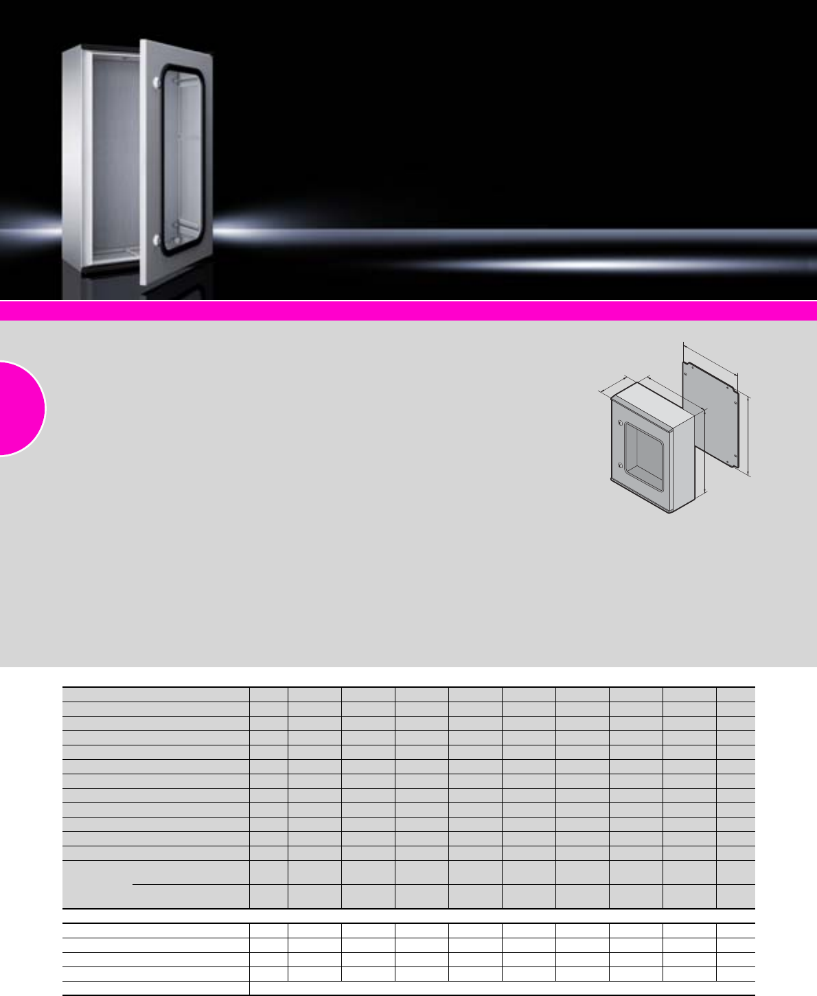
Plastic enclosures KS
50 Rittal Catalogue 33/Enclosures
System accessories Page 355 KS for potentially explosive areas Page 177
Material:
−Enclosure and door:
Fibreglass-reinforced
unsaturated polyester
−Mounting plate:
Sheet steel
−Foamed-in PU seal
For KS with viewing window:
−Glazed acrylic, 3.0 mm with
all-round rubber cable clamp
strip
Surface finish:
−Enclosure and door:
Dyed plastic with no
aftertreatment
−Mounting plate: Zinc-plated
Protection category:
See table
Colour:
Similar to RAL 7035
Supply includes:
−Enclosure with hinged door,
of all-round solid construc-
tion, 3 mm double-bit lock
−For single-door enclosures:
R/h door hinge, may be
swapped to opposite side by
rotating the enclosure
−For two-door enclosures:
Lockable door on right
−Mounting plate
−Twin seal on the top and
bottom edges of the door as
integral rain protection strip
−Press-fitted C sections at the
sides for infinitely variable
mounting plate depth adjust-
ment
−KS 1400.500 additionally with
removable centre bar in the
enclosure
Note:
Under the influence of long-term
UV radiation (sunlight) in con-
junction with wind and rain, the
surface finish may become
visually impaired. This does not
affect the protection of the
installed electrical components
in any way. If the enclosures
cannot be protected from UV
radiation, we recommend that
they should be painted with a
PUR paint.
Ambient temperature –30°C to
+75°C.
Approvals:
−TÜV
−Germanischer Lloyd
−Russian Maritime Register
of Shipping
−Lloyds Register of Shipping
−Bureau Veritas
−VDE
Detailed drawings:
Available on the Internet.
T
F
B
H
G
Width (B) mm Packs of 200 250 300 400 400 400 400 500 Page
Height (H) mm 300 350 400 400 400 600 600 500
Depth (T) mm 150 150 200 200 200 200 200 300
Mounting plate width (F) mm 145 195 245 345 345 345 345 417
Mounting plate height (G) mm 250 300 350 350 350 550 550 450
Mounting plate thickness mm 2.0 2.0 2.0 2.5 2.5 2.5 2.5 2.5
Model No. KS 11423.500 1432.500 1434.500 1444.500 1448.500 1446.500 1449.500 1453.500
Door(s) 1 1 1 1 1 1 1 1
Viewing window – – – – – –
Cam lock 1 1 2 2 2 2 2 2
3-point lock system – – – – – – – –
Weight (kg) 3.4 4.3 5.9 7.9 8.0 11.5 11.2 13.5
Protection
category
IP 66 to IEC 60 529,
complies with NEMA 4X. – –
IP 56 to IEC 60 529,
complies with NEMA 12. – – – – – –
Accessories
Mounting plate adjustment bracket 4 1481.000 1481.000 1481.000 1481.000 1481.000 1481.000 1481.000 1491.000 446
Threaded inserts M6 20 1482.000 1482.000 1482.000 1482.000 1482.000 1482.000 1482.000 1482.000 478
Pole clamp 1 set 2584.000 2584.000 2584.000 2584.000 2584.000 2584.000 2584.000 2584.000 441
Wall mounting bracket 4 1483.010 1483.010 1483.010 1483.010 1483.010 1483.010 1483.010 1483.010 440
Alternative lock systems see page 411
Plastic enclosures KS
51Rittal Catalogue 33/Enclosures
Width (B) mm Packs of 500 600 600 600 600 800 800 1000 Page
Height (H) mm 500 600 600 800 800 1000 1000 1000
Depth (T) mm 300 200 200 300 300 300 300 300
Mounting plate width (F) mm 417 545 545 517 517 717 717 917
Mounting plate height (G) mm 450 550 550 750 750 950 950 950
Mounting plate thickness mm 2.5 2.5 2.5 3.0 3.0 3.0 3.0 3.0
Model No. KS 11454.500 1466.500 1467.500 1468.500 1469.500 1480.500 1479.500 1400.500
Door(s) 1 1 1 1 1 1 1 2
Viewing window – – – –
Cam lock 2 2 2 – – – – –
3-point lock system – – –
Weight (kg) 13.4 15.9 15.6 26.5 26.0 41.7 39.9 51.6
Protection
category
IP 66 to IEC 60 529,
complies with NEMA 4X. – – – – –
IP 56 to IEC 60 529,
complies with NEMA 12. – – –
Accessories
Mounting plate adjustment bracket 4 1491.000 1481.000 1481.000 1491.000 1491.000 1491.000 1491.000 1491.000 446
Threaded inserts M6 20 1482.000 1482.000 1482.000 1482.000 1482.000 1482.000 1482.000 1482.000 478
Pole clamp 1 set 2584.000 2584.000 2584.000 2584.000 2584.000 2584.000 2584.000 2584.000 441
Wall mounting bracket 4 1483.010 1483.010 1483.010 1483.010 1483.010 1483.010 1483.010 1483.010 440
Alternative lock systems see page 411
Rittal Denmark
RITTAL A/S
Dybendalsvænget 4 DK-2630 Taastrup
Phone: +45 70 25 59 00 Fax: +45 70 25 59 01
E-mail: info@rittal.dk www.rittal.dk
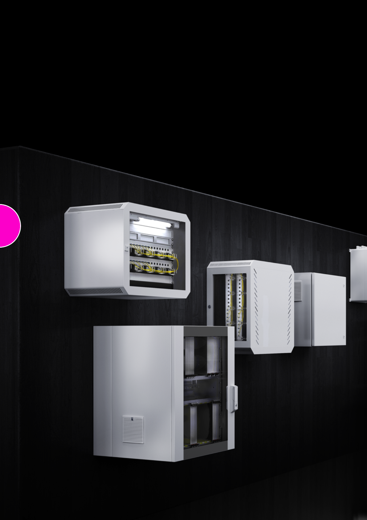
52
53
Wall-mounted network enclosures
Wall-mounted distributors
VerticalBox ..................................................................................................54
FlatBox with 482.6 mm (19˝) mounting angles............................................55
FlatBox with 482.6 mm (19˝) mounting frame .............................................56
QuickBox with glazed door .........................................................................57
QuickBox with glazed door/sheet steel door ..............................................58
QuickBox with vertical 482.6 mm (19˝) level ...............................................59
Wall-mounted enclosures EL, 3-part, depth 573/673 mm, pre-configured ...60
Wall-mounted enclosures EL, 3-part, depth 473 mm, with punched rails.....61
Wall-mounted enclosures EL, 3-part, depth 373 mm, with mounting plate
...62
Wall-mounted enclosures EL, 3-part, depth 473 mm, with mounting plate...63
Wall-mounted enclosures EL, 2-part, depth 369 mm, with swing frame
.......64
Wall-mounted enclosures AE with 482.6 mm (19˝) mounting angles ............65
Wall-mounted enclosures AE with 482.6 mm (19˝) pull-out frame
................66
Small fibre-optic distributors .......................................................................67
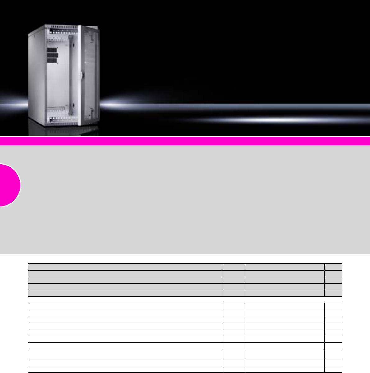
VerticalBox
54 Rittal Catalogue 33/Enclosures
System accessories Page 355
Compact 482.6 mm (19˝)
enclosure for small networks
●May be used as wall-
mounted, under-desk or
desktop enclosure
●482.6 mm (19˝) level, front
and rear
●Free access from three sides
for interior installation
●Freely selectable door hinging
●Passive ventilation with vent
slots
●Rear panel prepared to
accommodate a fan
●Horizontal 10 U may be used
by installing 482.6 mm (19˝)
mounting angles
Material:
−Sheet steel
−Viewing window: Single-pane
safety glass, 3 mm
Surface finish:
Powder-coated
Colour:
RAL 7035
Supply includes:
−Enclosure with glazed door
−Side panels (1 x fixed,
1 x slot-in) with vent slots
−Knockouts for cable entry
via roof or base
−Slot-in rear panel with knock-
outs for cable entry and fan
accommodation
−482.6 mm (19˝) mounting
level, 5 U, front and rear,
depth-variable, distance
between levels 434 – 489 mm
−Security lock 12321 on the
door, side and rear panel
−4 plastic feet, self-adhesive
Detailed drawing:
Available on the Internet.
U Packs of 5Page
Width mm 300
Height mm 540
Depth mm 600
Model No. DK 1 7501.000
Accessories
Mounting kit for VerticalBox, hinged mounting plate 350 x 484 mm 1 7501.100 567
482.6 mm (19˝) mounting angles, 12 U (10 U usable)1) 2 7502.203 554
Brush strip for cut-out openings 2 x 1 m 7072.200 518
Wall mounting bracket, 10 mm 4 2508.010 439
Wall mounting bracket, 40 mm 4 2503.010 439
Fan expansion kit, 230 V AC, 50/60 Hz, 108/125 m3/h, air throughput, unimpeded airflow 1 set 7980.100 222
Blanking panel, 482.6 mm (19˝), 1 U, RAL 7035 2 7151.035 571
Cable management panel, 482.6 mm (19˝), 1 U, RAL 7035,
with 5 cable shunting rings 40 x 50 mm 1 7257.200 539
482.6 mm (19˝) socket strip, 7-way, with rocker switch 1 7240.220 505
Cable entry panel, 482.6 mm (19˝), 1 U 1 7140.535 542
1) For mounting at the side of the VerticalBox. With these mounting angles, instead of 5 U vertically at the side, up to 10 U may be used horizontally
if only a minimal installation depth is required. Infinitely depth-variable positioning.
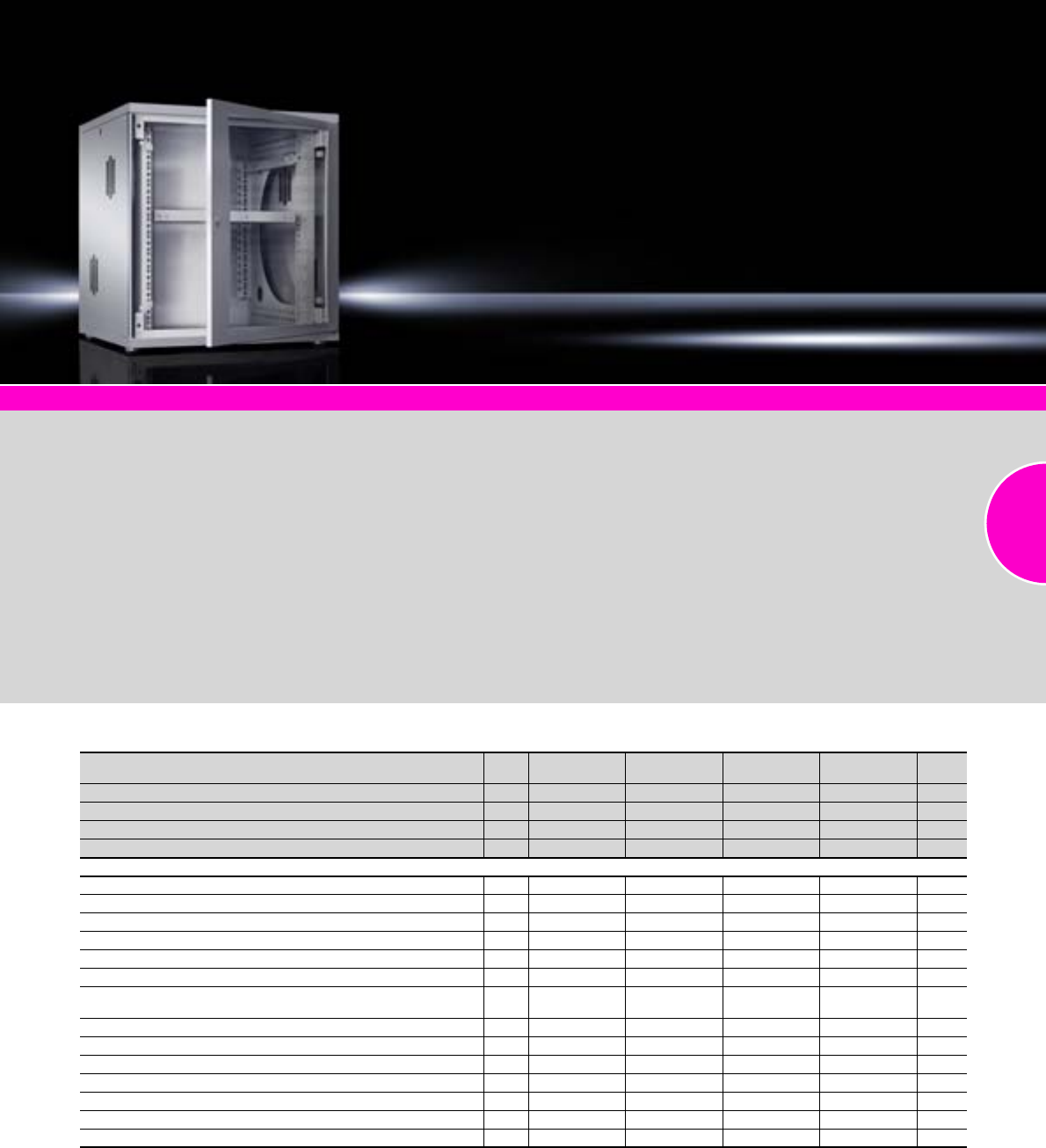
FlatBox
55Rittal Catalogue 33/Enclosures
System accessories Page 355
For use as a wall-mounted and
floor-standing enclosure.
Small package – big perform-
ance. Time-saving, flexible,
clever
●For flexible use as a wall-
mounted or floor-standing
enclosure
●Maximum width and depth
of 700 mm creates plenty of
space for use as a patch
distributor
●Toolless quick assembly
●System assembly on the open
482.6 mm (19˝) frame
Material:
−Sheet steel
−Viewing window: Single-pane
safety glass, 3 mm
Surface finish:
Powder-coated
Colour:
RAL 7035
Note:
−Max. installation depth:
D – 112 mm
−Max. distance between two
482.6 mm (19˝) levels:
D – 126 mm
Supply includes:
−Flat-packed enclosure
−1 wall section
−2 basic supports
−2 roof/base plates,
with cut-outs for cable entry,
with brush strips
−2 mounting angles, 482.6 mm
(19˝) (for 6 U and 9 U)
−1 mounting frame 482.6 mm
(19˝) (from 12 U)
−4 levelling feet (from 12 U)
−2 side panels, lockable
−1 glazed door, lockable,
security lock 3524 E,
door hinge point selectable
−Connection components for
toolless, fast assembly
−Earthing kit for system-
compatible earthing of all
enclosure parts
Detailed drawing:
Available on the Internet.
Photo shows a configuration
example with equipment not
included in the scope of supply.
With 482.6 mm (19˝) mounting angles
U Packs
of 6 6 9 9 Page
Width mm 600 600 600 600
Height mm 358 358 492 492
Depth mm 400 600 400 600
Model No. DK 17507.000 7507.100 7507.010 7507.110
Accessories
482.6 mm (19˝) mounting angles as second attachment level 2 7507.706 7507.706 7507.709 7507.709 554
Levelling feet 4 7507.740 7507.740 7507.740 7507.740 374
Cover plates for fan panels 6 7507.760 7507.760 7507.760 7507.760 222
Earth rail 1 7113.000 7113.000 7113.000 7113.000 504
C rail for cable clamping 1 7016.140 7016.140 7016.140 7016.140 532
T-head rail for cable clamping 1 7016.150 7016.150 7016.150 7016.150 532
Fan, 230 V AC, 50/60 Hz, 117/135 m3/h, air throughput,
unimpeded airflow 1 7980.100 7980.100 7980.100 7980.100 222
Fan, 48 V DC, 184 m3/h, air throughput, unimpeded airflow 1 7980.148 7980.148 7980.148 7980.148 222
Enclosure internal thermostat 1 3110.000 3110.000 3110.000 3110.000 294
Cable management panel, 1 U, 5 cable shunting rings 40 x 50 mm 1 7257.200 7257.200 7257.200 7257.200 539
Component shelf 2 U, static installation, depth 250 mm 1 7119.250 7119.250 7119.250 7119.250 487
Component shelf 2 U, static installation, depth 400 mm 1 – 7119.400 – 7119.400 487
Component shelf 1 U, complete set, pull-out, depth 500 mm 1 set – 7000.625 – 7000.625 486
Base/plinths 1 – 7507.750 – 7507.750 371
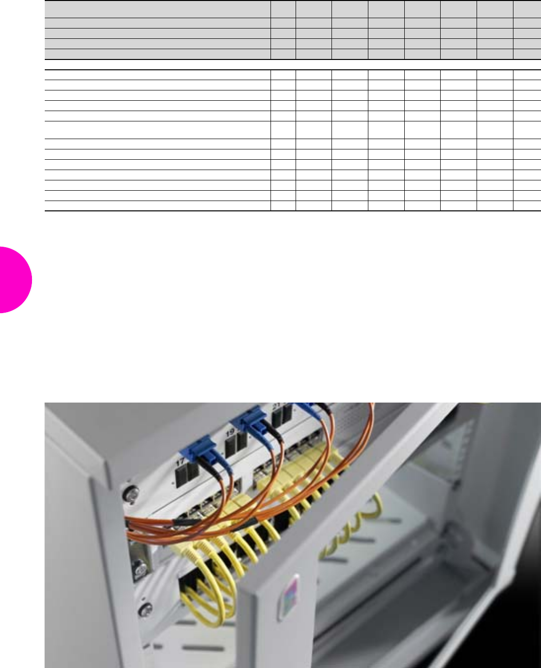
FlatBox
56 Rittal Catalogue 33/Enclosures
With 482.6 mm (19˝) mounting frame
U Packs
of 12 12 15 15 18 21 Page
Width mm 600 600 600 700 700 700
Height mm 625 625 758 758 892 1025
Depth mm 400 600 400 700 700 700
Model No. DK 17507.020 7507.120 7507.030 7507.200 7507.210 7507.220
Accessories
482.6 mm (19˝) mounting angles as second attachment level 2 7507.712 7507.712 7507.715 7507.715 7507.718 7507.721 554
Cover plates for fan panels 6 7507.760 7507.760 7507.760 7507.760 7507.760 7507.760 222
Earth rail 1 7113.000 7113.000 7113.000 7113.000 7113.000 7113.000 504
C rail for cable clamping 1 7016.140 7016.140 7016.140 7016.140 7016.140 7016.140 532
T-head rail for cable clamping 1 7016.150 7016.150 7016.150 7016.150 7016.150 7016.150 532
Fan, 230 V AC, 50/60 Hz, 117/135 m3/h, air throughput,
unimpeded airflow 1 7980.100 7980.100 7980.100 7980.100 7980.100 7980.100 222
Fan, 48 V DC, 184 m3/h, air throughput, unimpeded airflow 1 7980.148 7980.148 7980.148 7980.148 7980.148 7980.148 222
Enclosure internal thermostat 1 3110.000 3110.000 3110.000 3110.000 3110.000 3110.000 294
Cable management panel, 1 U, 5 cable shunting rings 40 x 50 mm 1 7257.200 7257.200 7257.200 7257.200 7257.200 7257.200 539
Component shelf 2 U, static installation, depth 250 mm 1 7119.250 7119.250 7119.250 7119.250 7119.250 7119.250 487
Component shelf 2 U, static installation, depth 400 mm 1 – 7119.400 – 7119.400 7119.400 7119.400 487
Component shelf 1 U, complete set, pull-out, depth 500 mm 1 set – 7000.625 – 7000.625 7000.625 7000.625 486
Base/plinths 1 – 7507.750 – 7507.755 7507.755 7507.755 371
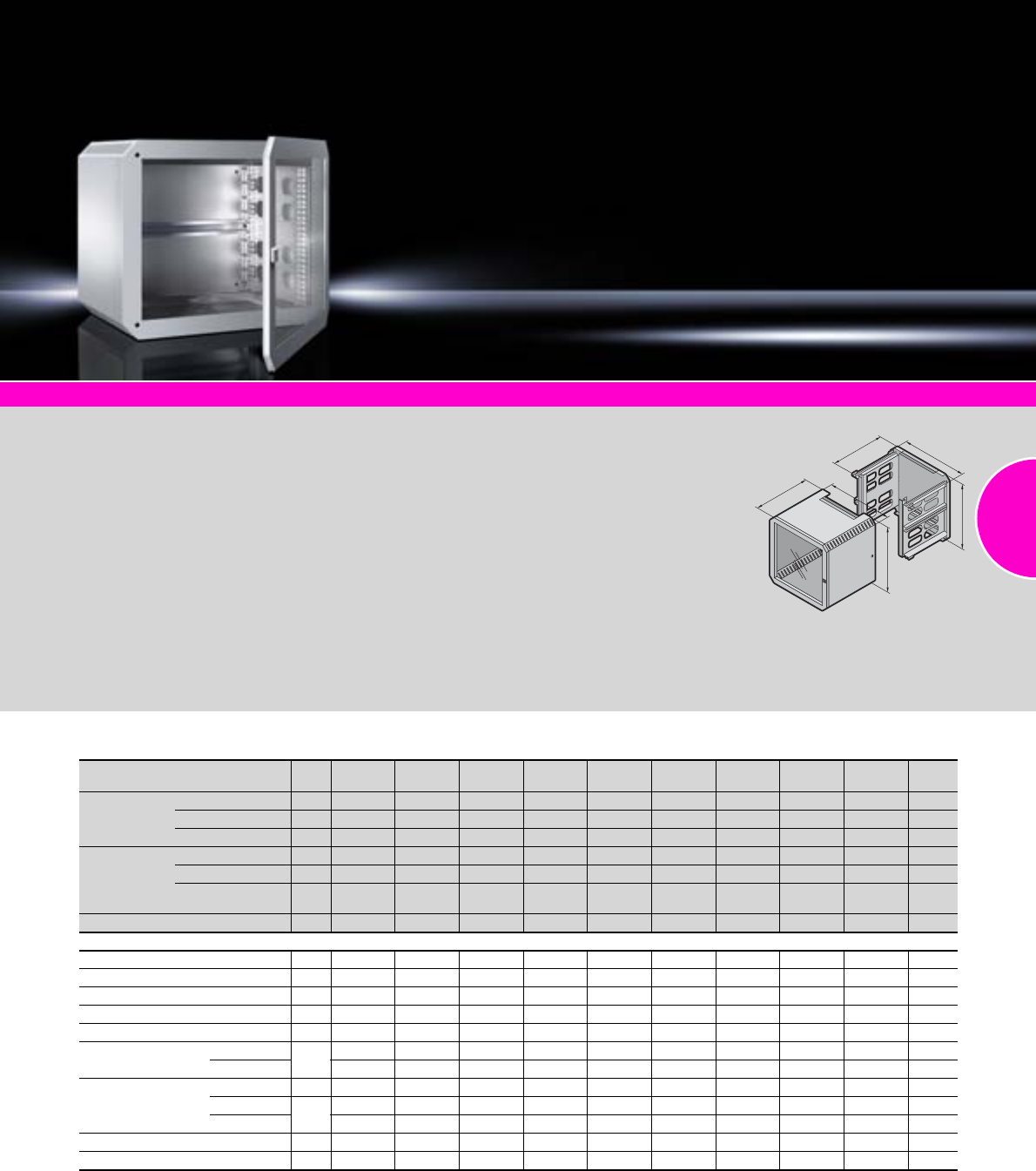
QuickBox
57Rittal Catalogue 33/Enclosures
System accessories Page 355
Wall-mounted enclosure with
removable cover for perfect
handling during installation
and maintenance.
Material:
−Wall mounting plate with
mounting brackets:
Sheet steel, 2.0 mm
−Enclosure cover:
Sheet steel, 1.0 mm
−Door: Sheet steel door or
glazed door with sheet steel
frame and single-pane safety
glass, 3 mm
Surface finish:
Enclosure: Powder-coated
Colour:
RAL 7035
Supply includes:
Wall section:
−Pre-configured mounting
bracket
−Brush strip for cable entry at
the bottom/top
−Cable clamp rail
−482.6 mm (19˝) mounting
angles, fully depth adjustable
Enclosure cover:
−Base and cover tray with vent
slots
−Brush strip for cable entry at
the top/bottom
−2 side security locks
−Sheet steel door or glazed
door with security lock 12321
−Version with Ergoform-S lock
system, may optionally be
retrofitted with semi-cylinder
Detailed drawings:
Available on the Internet.
Photo shows a configuration
example with equipment not
included in the scope of supply.
H2
T2
B2
H1
T1
B1
With glazed door
U Packs
of 6669912 12 12 12 Page
Enclosure
cover
Width (B1) mm 600 600 600 600 600 600 600 600 600
Height (H1) mm 362 362 362 495 495 628 628 628 628
Depth (T1) mm 300 400 600 400 600 400 500 600 600
Wall section
Width (B2) mm 595 595 595 595 595 595 595 595 595
Height (H2) mm 355 355 355 488 488 621 621 621 621
Max. installation
depth (T2) mm 247 347 547 347 547 347 447 547 547
Model No. DK 17502.013 7502.014 7502.016 7502.024 7502.026 7502.034 7502.035 7502.036 7502.4361)
Accessories
Mounting angles, 482.6 mm (19˝)2–––––7502.203 7502.203 7502.203 7502.203 554
Solid gland plate 2 7502.310 7502.310 7502.310 7502.310 7502.310 7502.310 7502.310 7502.310 7502.310 517
Wall mounting bracket, 10 mm 4 2508.010 2508.010 2508.010 2508.010 2508.010 2508.010 2508.010 2508.010 2508.010 439
Wall mounting bracket, 40 mm 4 2503.010 2503.010 2503.010 2503.010 2503.010 2503.010 2503.010 2503.010 2503.010 439
Combination rails for enclosure width 6 7502.304 7502.304 7502.304 7502.304 7502.304 7502.304 7502.304 7502.304 7502.304 528
Combination rails
for enclosure depth
300/400 mm 67502.302 7502.302 7502.302 7502.302 7502.302 7502.302 7502.302 7502.302 7502.302 528
500/600 mm 7502.304 7502.304 7502.304 7502.304 7502.304 7502.304 7502.304 7502.304 7502.304 528
Slide rails for the
enclosure depth
300 mm 10 4530.000 4530.000 4530.000 4530.000 4530.000 4530.000 4530.000 4530.000 4530.000 561
400 mm 24531.000 4531.000 4531.000 4531.000 4531.000 7492.3002) 7492.3002) 7492.3002) 7492.3002) 560/561
500/600 mm 4531.000 4531.000 4531.000 4531.000 4531.000 7492.4002) 7492.4002) 7492.4002) 7492.4002) 560/561
Earthing kit 1 7502.240 7502.240 7502.260 7502.240 7502.260 7502.240 7502.260 7502.260 7502.260 503
Quick-release fastener 2 7502.220 7502.220 7502.220 7502.220 7502.220 7502.220 7502.220 7502.220 7502.220 424
1) With Ergoform-S lock system for semi-cylinder, for combining with quick-release fastener QB 7502.220.
2) Additional mounting angles required at the rear.
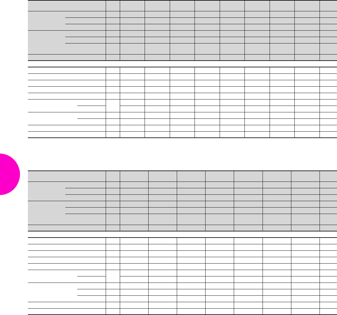
QuickBox
58 Rittal Catalogue 33/Enclosures
With glazed door
With sheet steel door
U Packs
of 15 15 15 15 18 18 21 21 Page
Enclosure cover
Width (B1) mm 600 600 600 600 600 600 600 600
Height (H1) mm 762 762 762 762 895 895 1028 1028
Depth (T1) mm 400 500 600 600 400 600 400 600
Wall section
Width (B2) mm 595 595 595 595 595 595 595 595
Height (H2) mm 755 755 755 755 888 888 1021 1021
Max. installation
depth (T2) mm 347 447 547 547 347 547 347 547
Model No. DK 17502.044 7502.045 7502.046 7502.4461) 7502.0543) 7502.056 7502.0643) 7502.066
Accessories
Mounting angles, 482.6 mm (19˝) 2 7502.204 7502.204 7502.204 7502.204 7502.205 7502.205 7502.206 7502.206 554
Solid gland plate 2 7502.310 7502.310 7502.310 7502.310 7502.310 7502.310 7502.310 7502.310 517
Wall mounting bracket, 10 mm 4 2508.010 2508.010 2508.010 2508.010 2508.010 2508.010 2508.010 2508.010 439
Wall mounting bracket, 40 mm 4 2503.010 2503.010 2503.010 2503.010 2503.010 2503.010 2503.010 2503.010 439
Combination rails for enclosure width 6 7502.304 7502.304 7502.304 7502.304 7502.304 7502.304 7502.304 7502.304 528
Combination rails
for enclosure depth
300/400 mm 67502.302 7502.302 7502.302 7502.302 7502.302 7502.302 7502.302 7502.302 528
500/600 mm 7502.304 7502.304 7502.304 7502.304 7502.304 7502.304 7502.304 7502.304 528
Slide rails
for the enclosure depth
400 mm 2 7492.3002) 7492.3002) 7492.3002) 7492.3002) 7492.3002) 7492.3002) 7492.3002) 7492.3002) 560
500/600 mm 2 7492.4002) 7492.4002) 7492.4002) 7492.4002) 7492.4002) 7492.4002) 7492.4002) 7492.4002) 560
Earthing kit 1 7502.240 7502.260 7502.260 7502.260 7502.240 7502.260 7502.240 7502.260 503
Quick-release fastener 2 7502.220 7502.220 7502.220 7502.220 7502.220 7502.220 7502.220 7502.220 424
1) With Ergoform-S lock system for semi-cylinder F, for combining with quick-release fastener QB 7502.220.
2) Additional mounting angles required at the rear.
3) Extended delivery times.
U Packs
of 69912 15 15 21 Page
Enclosure cover
Width (B1) mm 600 600 600 600 600 600 600
Height (H1) mm 362 495 495 628 762 762 1028
Depth (T1) mm 400 400 600 600 400 600 600
Wall section
Width (B2) mm 595 595 595 595 595 595 595
Height (H2) mm 355 488 488 621 755 755 1021
Max. installation
depth (T2) mm 347 347 547 547 347 547 547
Model No. DK 17502.114 7502.124 7502.126 7502.136 7502.1443) 7502.146 7502.1663)
Accessories
Mounting angles, 482.6 mm (19˝) 2 – – – 7502.203 7502.204 7502.204 7502.206 554
Solid gland plate 2 7502.310 7502.310 7502.310 7502.310 7502.310 7502.310 7502.310 517
Wall mounting bracket, 10 mm 4 2508.010 2508.010 2508.010 2508.010 2508.010 2508.010 2508.010 439
Wall mounting bracket, 40 mm 4 2503.010 2503.010 2503.010 2503.010 2503.010 2503.010 2503.010 439
Combination rails for enclosure width 6 7502.304 7502.304 7502.304 7502.304 7502.304 7502.304 7502.304 528
Combination rails
for enclosure depth
300/400 mm 67502.302 7502.302 7502.302 7502.302 7502.302 7502.302 7502.302 528
500/600 mm 7502.304 7502.304 7502.304 7502.304 7502.304 7502.304 7502.304 528
Slide rails
for the enclosure depth
300 mm 10 4530.000 4530.000 4530.000 4530.000 4530.000 4530.000 4530.000 561
400 mm 10 4531.000 4531.000 4531.000 7492.3002) 7492.3002) 7492.3002) 7492.3002) 560/561
500/600 mm 2 4531.000 4531.000 4531.000 7492.4002) 7492.4002) 7492.4002) 7492.4002) 560/561
Earthing kit 1 7502.240 7502.240 7502.260 7502.260 7502.240 7502.260 7502.260 503
Quick-release fastener 2 7502.220 7502.220 7502.220 7502.220 7502.220 7502.220 7502.220 424
2) Additional mounting angles required at the rear.
3) Extended delivery times.
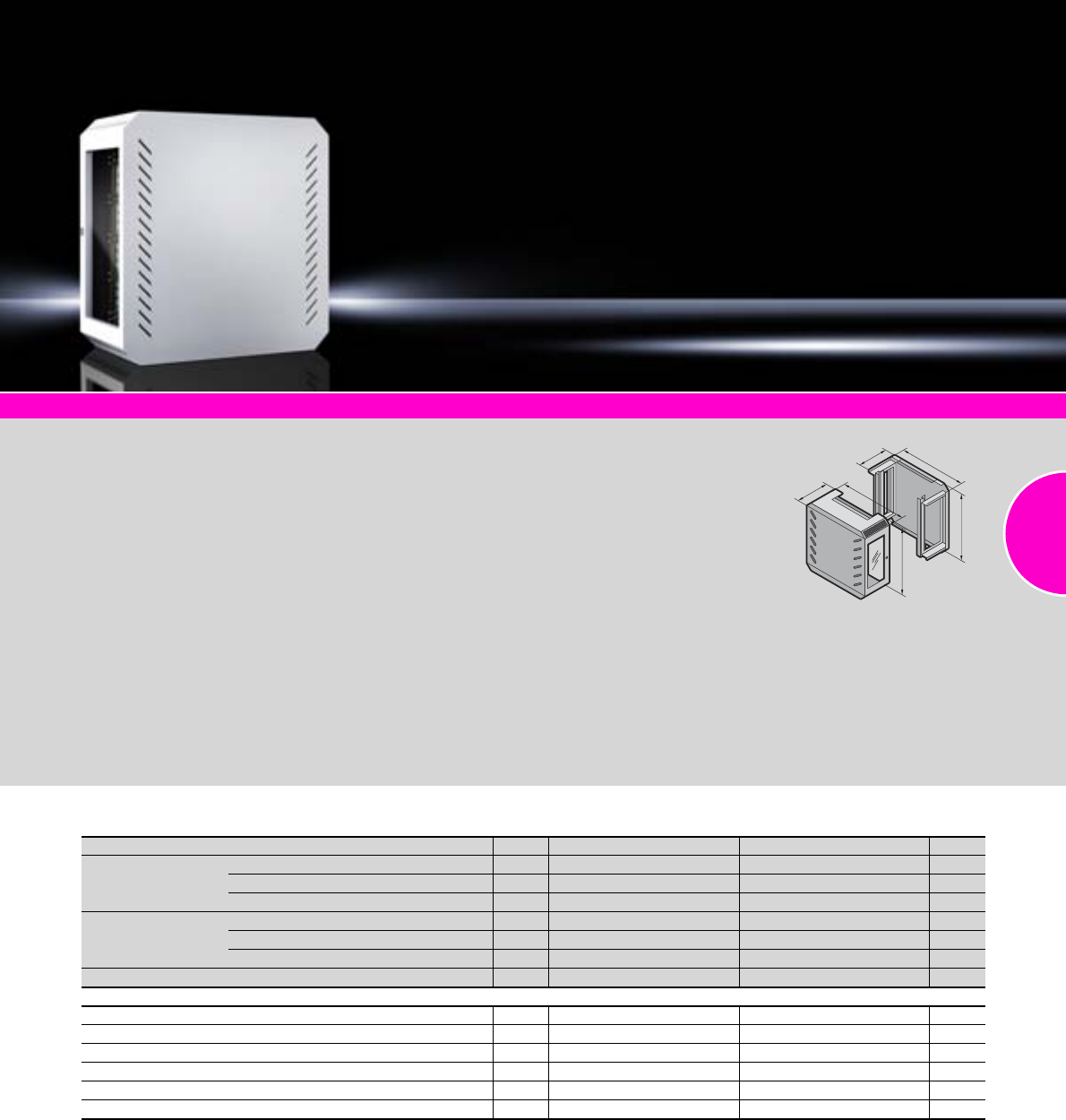
QuickBox
59Rittal Catalogue 33/Enclosures
System accessories Page 355
Wall-mounted enclosure
with optimum use of the
interior space
thanks to side installation of the
482.6 mm (19˝) components.
Status monitoring via side view-
ing window.
Material:
−Wall mounting plate with
mounting brackets:
Sheet steel, 2.0 mm
−Enclosure cover:
Sheet steel, 1.0 mm, with
single-pane safety glass at
the side, 3 mm
Surface finish:
Powder-coated
Colour:
RAL 7035
Supply includes:
Wall section:
−With pre-configured 482.6 mm
(19˝) mounting brackets for
accommodating equipment at
the side
−Brush strip for cable entry at
the bottom and top
Enclosure cover:
−Side vent slots to support
passive climate control
−The enclosure is secured via
two security locks positioned
at the sides.
Detailed drawings:
Available on the Internet.
Photo shows a configuration
example with equipment not
included in the scope of supply.
T2
B2
H2
H1
T1
B1
With vertical 482.6 mm (19˝) level
U Packs of 3 6 Page
Enclosure cover
Width (B1) mm 600 600
Height (H1) mm 631 631
Depth (T1) mm 210 360
Wall section
Width (B2) mm 595 595
Height (H2) mm 621 621
Depth (T2) mm 198 348
Model No. DK 17502.6301) 7502.6601)
Accessories
Gland plates, solid 2 7502.310 7502.310 517
Wall mounting bracket, 10 mm 4 2508.010 2508.010 439
Wall mounting bracket, 40 mm 4 2503.010 2503.010 439
Combination rails for vertical mounting on the QuickBox wall section 6 7502.304 7502.304 528
Combination rails for horizontal mounting on the QuickBox wall section 6 7502.304 7502.304 528
Mounting angles, 482.6 mm (19˝) for front mounting, 12 U 2 7502.203 7502.203 554
1) Extended delivery times.
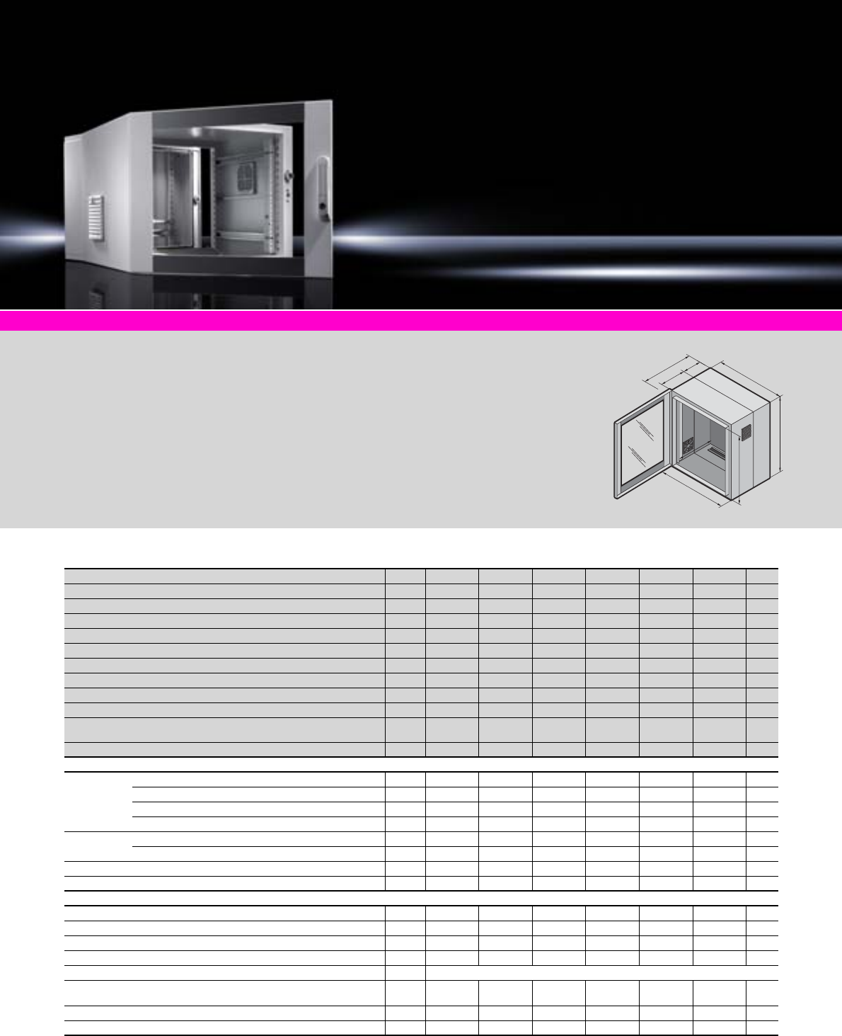
Wall-mounted enclosures EL, 3-part
60 Rittal Catalogue 33/Enclosures
Depth 573/673 mm, pre-configured
U Packs of 9 9 15 15 21 21 Page
Width (B1) mm 600 600 600 600 600 600
Height (H1) mm 478 478 746 746 1012 1012
Depth (T1) mm 573 673 573 673 573 673
Clearance width (B2) mm 502 502 502 502 502 502
Clearance height (H2) mm 415 415 683 683 949 949
Depth of wall section (T2) mm 135 135 135 135 135 135
Depth of hinged part (T3) mm 416 516 416 516 416 516
Maximum installation depth (T4) mm 520 620 520 620 520 620
Load capacity of hinged part (kg, static) 45 45 75 75 75 75
Protection category IP 54 to IEC 60 529
when using solid gland plates SZ 2235.135
Model No. DK 17709.735 7709.535 7715.735 7715.535 7721.735 7721.535
Product-specific supply scope
Wall section:
Gland plate, solid, top 1
Gland plate with brush insert, bottom 1
Vertical punched rails 2
Horizontal C rail 1
Hinged part: 482.6 mm (19˝) mounting angles, fully depth adjustable 2
Side outlet filters left and right 2
Earth rail with star earthing 1 set
Wall mounting bracket, 10 mm 4
Accessories
Gland plate for metric cable glands 1 7705.235 7705.235 7705.235 7705.235 7705.235 7705.235 517
Fan expansion kit, 230 V 1 7980.100 7980.100 7980.100 7980.100 7980.100 7980.100 222
Spare filter mats 5 3322.700 3322.700 3322.700 3322.700 3322.700 3322.700 301
Wall mounting bracket, 40 mm 4 2503.010 – 2503.010 – 2503.010 – 439
Lock inserts, type F see page 421
Component shelf 2 U, static installation or fully extendible,
300 mm deep 1 7148.035 7148.035 7148.035 7148.035 7148.035 7148.035 485
Component shelf 2 U, static installation, 250 mm deep 1 7119.250 7119.250 7119.250 7119.250 7119.250 7119.250 487
Cable management panel, 1 U, 5 cable shunting rings 40 x 50 mm 1 7257.200 7257.200 7257.200 7257.200 7257.200 7257.200 539
Included with the supply.
System accessories Page 355 Socket strips Page 505 Wall mounting bracket Page 439 Cable clamps Page 529
Wall-mounted enclosure
with optimum accessibility
thanks to hinged part.
Material:
−Wall and hinged part:
Sheet steel, 1.5 mm
−Viewing window: Single-pane
safety glass, 3 mm
Surface finish:
Powder-coated
Colour:
−Wall and hinged part:
RAL 7035
−Glazed door: RAL 7035/7015
(slate grey)
Supply includes:
−Wall section
−Hinged part with 25 mm pitch
pattern of holes in the front
and rear frame
−Designer glazed door
−Mini comfort handle
for 3 – 15 U
−Comfort handle and 2-point
lock for 18 – 21 U
−Including security lock 3524 E
−Product-specific supply
scope, see table
Detailed drawings:
Available on the Internet.
H1
H2
T1
B1
T4
T3 T2
B2
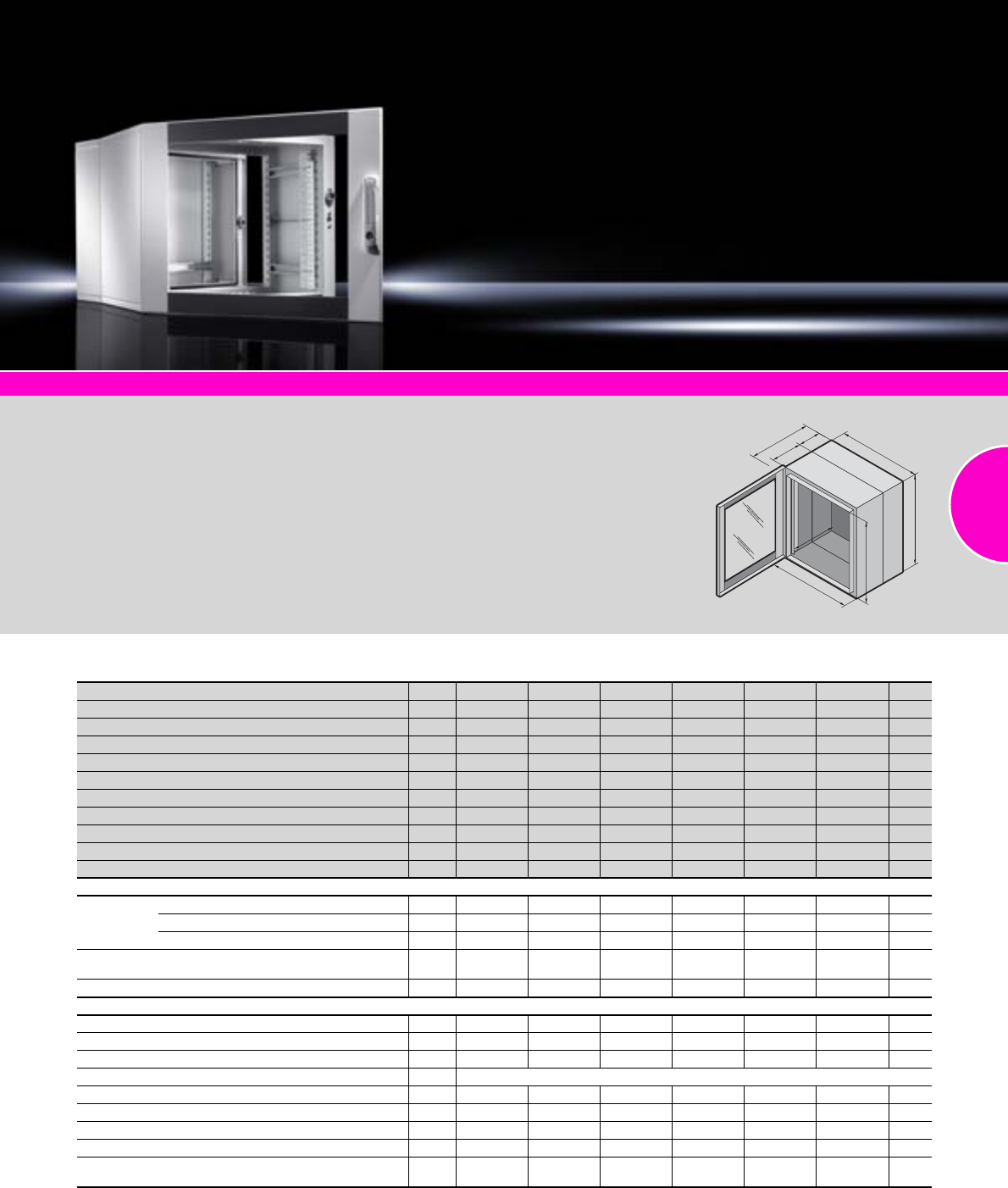
Wall-mounted enclosures EL, 3-part
61Rittal Catalogue 33/Enclosures
System accessories Page 355 Socket strips Page 505 Wall mounting bracket Page 439 Earthing Page 501 Cable clamps Page 529
Wall-mounted enclosure
with optimum accessibility
thanks to hinged part.
Material:
−Wall and hinged part:
Sheet steel, 1.5 mm
−Viewing window: Single-pane
safety glass, 3 mm
Surface finish:
Powder-coated
Colour:
−Wall and hinged part:
RAL 7035
−Glazed door: RAL 7035/7015
(slate grey)
Protection category:
IP 55 to IEC 60 529
Supply includes:
−Wall section
−Hinged part with 25 mm pitch
pattern of holes in the front
and rear frame
−Designer glazed door
−Mini comfort handle
for 3 – 15 U
−Comfort handle and 2-point
lock for 18 – 21 U
−Including security lock 3524 E
−Product-specific supply
scope, see table
Detailed drawings:
Available on the Internet.
H1
H2
T1
B1
T4
T3 T2
B2
Depth 473 mm, with punched rails
UPacks of 6 9 12 15 18 21 Page
Width (B1) mm 600 600 600 600 600 600
Height (H1) mm 345 478 612 746 878 1012
Depth (T1) mm 473 473 473 473 473 473
Clearance width (B2) mm 502 502 502 502 502 502
Clearance height (H2) mm 282 415 549 683 815 949
Depth of wall section (T2) mm 135 135 135 135 135 135
Depth of hinged part (T3) mm 316 316 316 316 316 316
Maximum installation depth (T4) mm 420 420 420 420 420 420
Load capacity of hinged part (kg, static) 30 45 60 75 75 75
Model No. DK 17706.135 7709.135 7712.135 7715.135 7718.135 7721.135
Product-specific supply scope
Wall section:
Gland plate, solid, top and bottom 2
Vertical punched rails 2
Horizontal C rail for cable clamping 1
Hinged part: 482.6 mm (19˝) mounting angles,
fully depth adjustable 2
Wall mounting bracket, 10 mm 4
Accessories
Gland plate with brush insert 1 7705.035 7705.035 7705.035 7705.035 7705.035 7705.035 518
Gland plate for metric cable glands 1 7705.235 7705.235 7705.235 7705.235 7705.235 7705.235 517
Wall mounting bracket, 40 mm 4 2503.010 2503.010 2503.010 2503.010 2503.010 2503.010 439
Lock inserts, type F see page 421
Earth rail, horizontal 1 7113.000 7113.000 7113.000 7113.000 7113.000 7113.000 504
Component shelf 2 U, static installation and fully extendible 1 7148.035 7148.035 7148.035 7148.035 7148.035 7148.035 485
Component shelf 2 U, static installation, 250 mm deep 1 7119.250 7119.250 7119.250 7119.250 7119.250 7119.250 487
Component shelf 1 U, static installation, 140 mm deep 1 7119.140 7119.140 7119.140 7119.140 7119.140 7119.140 486
Cable management panel, 1 U,
5 cable shunting rings 40 x 50 mm 1 7257.200 7257.200 7257.200 7257.200 7257.200 7257.200 539
Included with the supply.
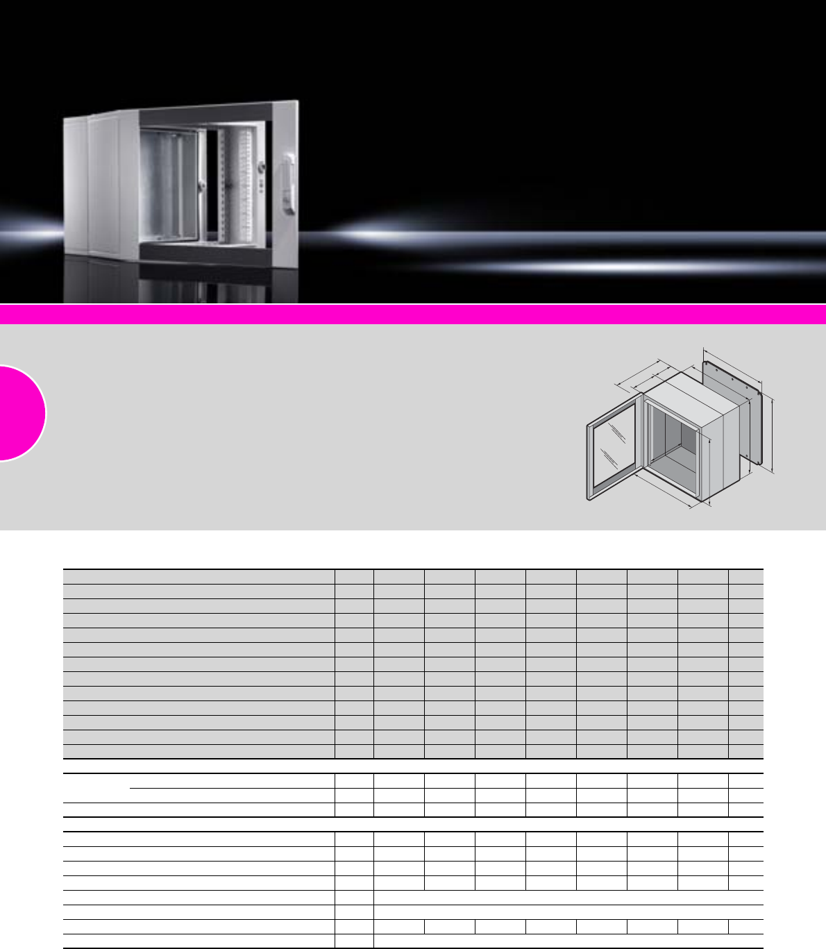
Wall-mounted enclosures EL, 3-part
62 Rittal Catalogue 33/Enclosures
Depth 373 mm, with mounting plate
U Packs of 3 6 9 12 15 18 21 Page
Width (B1) mm 600 600 600 600 600 600 600
Height (H1) mm 212 345 478 612 746 878 1012
Depth (T1) mm 373 373 373 373 373 373 373
Clearance width (B2) mm 502 502 502 502 502 502 502
Clearance height (H2) mm 149 282 415 549 683 815 949
Depth of wall section (T2) mm 135 135 135 135 135 135 135
Depth of hinged part (T3) mm 216 216 216 216 216 216 216
Maximum installation depth (T4) mm 320 320 320 320 320 320 320
Width of mounting plate (B3) mm 485 485 485 485 485 485 485
Height of mounting plate (H3) mm 165 299 432 565 699 832 965
Load capacity of hinged part (kg, static) 15 30 45 60 75 75 75
Model No. EL 12243.605 2246.605 2249.605 2252.605 2255.605 2258.605 2261.605
Product-specific supply scope
Wall section: Gland plate, solid, top and bottom 2
Mounting plate supplied loose 1
Hinged part: 482.6 mm (19˝) mounting angles 2
Accessories
Wall mounting bracket, 10 mm 4 2508.010 2508.010 2508.010 2508.010 2508.010 2508.010 2508.010 439
Wall mounting bracket, 40 mm 4 2503.010 2503.010 2503.010 2503.010 2503.010 2503.010 2503.010 439
Gland plate with brush insert 1 7705.035 7705.035 7705.035 7705.035 7705.035 7705.035 7705.035 518
Gland plate for metric cable glands 1 7705.235 7705.235 7705.235 7705.235 7705.235 7705.235 7705.235 517
Cable glands see page 519
Lock inserts, type F see page 421
C rails 4 2238.000 2238.000 2238.000 2238.000 2238.000 2238.000 2238.000 467
Blanking plates, 482.6 mm (19˝) 3 see page 564
Included with the supply.
System accessories Page 355 Socket strip Page 505 Wall mounting bracket Page 439 Cable clamps Page 529 Earthing Page 501
Wall-mounted enclosure
with optimum accessibility
thanks to hinged part.
Material:
−Wall and hinged part:
Sheet steel, 1.5 mm
−Viewing window: Single-pane
safety glass, 3 mm
Surface finish:
Powder-coated
Colour:
−Wall and hinged part:
RAL 7035
−Glazed door: RAL 7035/7015
(slate grey)
Protection category:
IP 55 to IEC 60 529
Supply includes:
−Wall section
−Hinged part with 25 mm pitch
pattern of holes in the front
and rear frame
−Designer glazed door
−Mini comfort handle
for 3 – 15 U
−Comfort handle and 2-point
lock for 18 – 21 U
−Including security lock 3524 E
−Product-specific supply
scope, see table
Detailed drawings:
Available on the Internet.
H1
H2
T1
B1
T4
T3 T2
B2
H3
B3
Wall-mounted enclosures EL, 3-part
63Rittal Catalogue 33/Enclosures
Depth 473 mm, with mounting plate
UPacks of 3 6 9 12 15 18 21 Page
Width (B1) mm 600 600 600 600 600 600 600
Height (H1) mm 212 345 478 612 746 878 1012
Depth (T1) mm 473 473 473 473 473 473 473
Clearance width (B2) mm 502 502 502 502 502 502 502
Clearance height (H2) mm 149 282 415 549 683 815 949
Depth of wall section (T2) mm 135 135 135 135 135 135 135
Depth of hinged part (T3) mm 316 316 316 316 316 316 316
Maximum installation depth (T4) mm 420 420 420 420 420 420 420
Width of mounting plate (B3) mm 485 485 485 485 485 485 485
Height of mounting plate (H3) mm 165 299 432 565 699 832 965
Load capacity of hinged part (kg, static) 15 30 45 60 75 75 75
Model No. EL 12253.605 2256.605 2259.605 2262.605 2265.605 2268.605 2271.605
Product-specific supply scope
Wall section: Gland plate, solid, top and bottom 2
Mounting plate supplied loose 1
Hinged part: 482.6 mm (19˝) mounting angles 2
Accessories
Wall mounting bracket, 10 mm 4 2508.010 2508.010 2508.010 2508.010 2508.010 2508.010 2508.010 439
Wall mounting bracket, 40 mm 4 2503.010 2503.010 2503.010 2503.010 2503.010 2503.010 2503.010 439
Gland plate with brush insert 1 7705.035 7705.035 7705.035 7705.035 7705.035 7705.035 7705.035 518
Gland plate for metric cable glands 1 7705.235 7705.235 7705.235 7705.235 7705.235 7705.235 7705.235 517
Cable glands see page 519
Lock inserts, type F see page 421
C rails 4 2239.000 2239.000 2239.000 2239.000 2239.000 2239.000 2239.000 467
Blanking plates, 482.6 mm (19˝) 3 see page 564
Included with the supply.
Rittal Great Britain
RITTAL Limited
Braithwell Way Hellaby Industrial Estate
Hellaby Rotherham S Yorks S66 8QY
Phone: +44 (0) 1709 704000
Fax: +44 (0) 1709 701217
E-mail: information@rittal.co.uk
www.rittal.co.uk
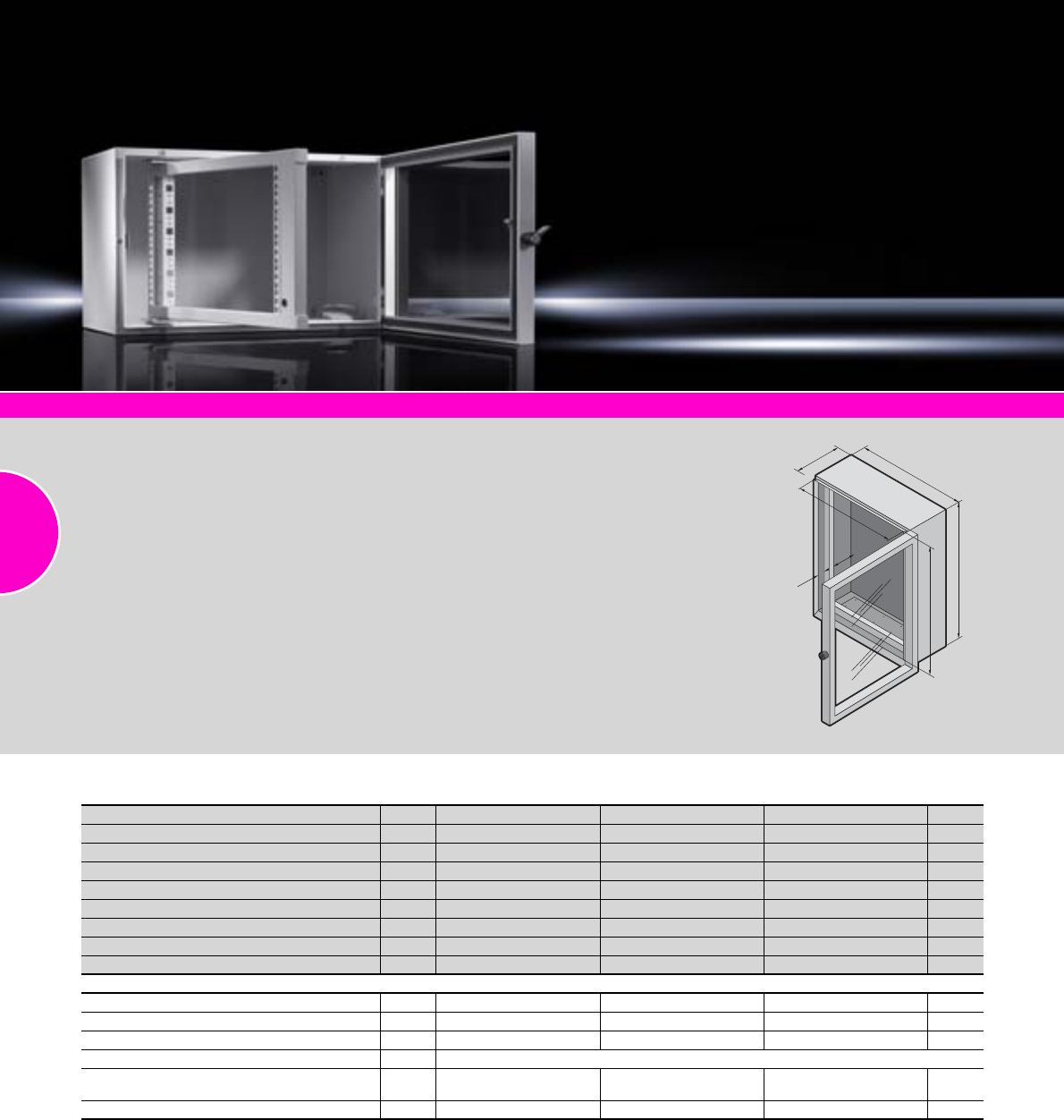
Wall-mounted enclosures EL, 2-part
64 Rittal Catalogue 33/Enclosures
System accessories Page 355 Cage nuts Page 567 Patch panel for copper technology Page 569 Socket strips Page 505
Wall-mounted enclosure
with optimum accessibility
thanks to swing frame.
Material:
−Enclosure: Sheet steel,
1.5 mm
−Swing frame: Sheet steel
−Front door: Extruded alumin-
ium section, acrylic glazing,
3 mm
Surface finish:
−Enclosure and swing frame:
Primed and powder-coated
−Front door: Anodised
Colour:
−Enclosure and swing frame:
RAL 7035
−Front door: Silver
Protection category:
IP 55 to IEC 60 529
Supply includes:
−Enclosure
−Front door
−Swing frame,
482.6 mm (19˝), fitted
−Assembly parts
Approvals:
−TÜV
−Russian Maritime Register
of Shipping
−Lloyds Register of Shipping
−VDE
−UL/cUL
−Bureau Veritas
−Germanischer Lloyd
Detailed drawings:
Available on the Internet.
H1
B1
T1
T2 T3
B2
H2
Depth 369 mm, with swing frame
UPacks of 6 11 14 Page
Width (B1) mm 600 600 600
Height (H1) mm 380 600 760
Depth (T1) mm 369 369 369
Clearance width (B2) mm 537 537 537
Clearance height (H2) mm 317 537 697
Distance from glazed door to swing frame (T2) mm 67 – 97 67 – 97 67 – 97
Maximum installation depth (T3) mm 270 270 270
Model No. EL 11919.500 1920.500 1926.500
Accessories
Wall mounting bracket, 10 mm 4 2508.010 2508.010 2508.010 439
Wall mounting bracket, 40 mm 4 2503.010 2503.010 2503.010 439
Gland plates for metric cable glands 5 2563.010 2563.010 2563.010 514
Blanking plates, 482.6 mm (19˝) 3 see page 564
Cable management panel, 482.6 mm (19˝), 1 U,
5 cable shunting rings 40 x 50 mm 1 7257.200 7257.200 7257.200 539
Cable entry panel, 482.6 mm (19˝), 1 U 1 7140.535 7140.535 7140.535 542
Standard swing frame with double-bit lock insert may be exchanged for 27 mm lock inserts, type A, see page 421.
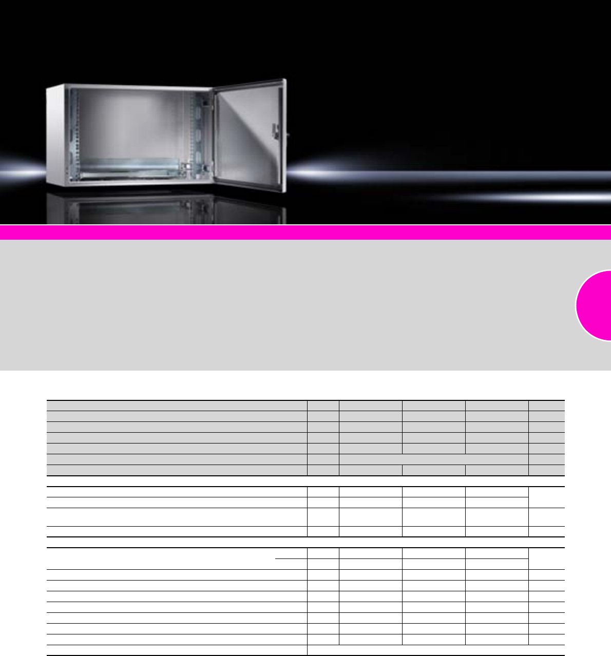
Wall-mounted enclosures AE
65Rittal Catalogue 33/Enclosures
System accessories Page 355 Socket strips Page 505 Captive nuts Page 567 Viewing panels Page 407
Wall-mounted enclosures
for small networks with a high
protection category.
Material:
Enclosure: Sheet steel
Surface finish:
−Enclosure: Powder-coated
−Mounting angles: Zinc-plated
Colour:
RAL 7035
Protection category:
See table.
Supply includes:
−Enclosure with hinged door
−Interchangeable door hinge
−Cam lock and double-bit
insert
−Gland plate with brush strip
for cable entry in the enclo-
sure base
−Product-specific supply
scope, see table
Approvals:
(except AE with pull-out frame)
−UL
−CSA
−Lloyds Register of Shipping
−Bureau Veritas
−TÜV
−VDE
−Germanischer Lloyd
Detailed drawing:
Available on the Internet.
With 482.6 mm (19˝) mounting angles
UPacks of 813 16 Page
Width mm 600 600 600
Height mm 380 600 760
Depth mm 350 350 350
Max. installation depth (T2) mm 310 310 310
Protection category with gland plate for cable gland IP 55 to IEC 60 529
Model No. DK 17641.000 7643.000 7645.000
Product-specific supply scope
Mounting angles, 482.6 mm (19˝), fully depth adjustable 2
C rail, for cable clamping on the rear panel 1
Metal bracket for optional accommodation of an earth rail
or 482.6 mm (19˝) socket strip 1
Cam locks 4 1 x 2 x 2 x
Accessories
Gland plates in various versions Size 5 5 5 514 – 518
Qty. 1 1 1
Wall mounting bracket, 10 mm 4 2508.010 2508.010 2508.010 439
Wall mounting bracket, 40 mm 4 2503.010 2503.010 2503.010 439
Wall mounting bracket for external mounting 4 2508.100 2508.100 2508.100 439
Viewing window, 34 mm profile depth 1 2730.000 2731.000 2732.000 408
Viewing window, 60 mm profile depth 1 2760.000 2761.000 2762.000 408
Component shelf 2 U, static installation, 250 mm deep 1 7119.250 7119.250 7119.250 487
Earth rail 1 7113.000 7113.000 7113.000 504
Alternative lock systems see page 411
Included with the supply.
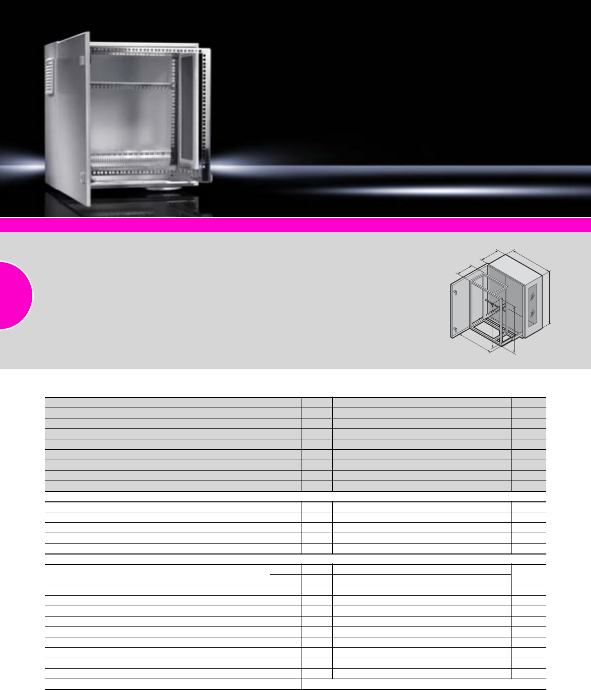
Wall-mounted enclosures AE
66 Rittal Catalogue 33/Enclosures
System accessories Page 355 Socket strips Page 505 Captive nuts Page 567 Viewing panels Page 407
Material:
−Enclosure: Sheet steel
−Viewing window: Single-pane
safety glass, 3 mm
Surface finish:
−Enclosure: Powder-coated
−Pull-out frame: Stainless steel
Colour:
RAL 7035
Protection category:
See table.
Supply includes:
−Enclosure with hinged door
−Cam lock and double-bit
insert
−Gland plate with brush strip
for cable entry in the enclo-
sure base
−Product-specific supply
scope, see table
Detailed drawing:
Available on the Internet.
350
210
600
600
520
450
525
With 482.6 mm (19˝) pull-out frame
Width mm Packs of 600 Page
Height mm 600
Depth mm 350
L/h door hinge
Cam locks 2
Side installation, vertical 4 U
Front installation, vertical and horizontal 10 U
Protection category with gland plate for cable gland IP 54 to IEC 60 529
Model No. DK 17644.000
Product-specific supply scope
Pull-out frame attached to telescopic slides 1
Outlet filter in enclosure base and on left-hand side 2
Viewing window on right-hand side 1
Cable clamp rail on rear wall 1
Additional cable clamp rail for mounting on the pull-out frame
Accessories
Choice of gland plates Size 5 514 – 518
Qty. 1
Wall mounting bracket, 10 mm 4 2508.010 439
Wall mounting bracket for external mounting 4 2508.100 439
Wall mounting bracket, 40 mm 4 2503.010 439
Shelf 1 7644.4001) 487
Component shelf, 1 U, 140 mm deep 1 7119.140 486
Earth rail, horizontal 1 7113.000 504
Fan expansion kit 230 V AC (only for use at the bottom) 1 set 7980.100 222
Fan expansion kit 48 V DC (only for use at the bottom) 1 set 7980.148 222
Spare filter mats 5 3322.700 301
Alternative lock systems see page 411
1) Extended delivery times.
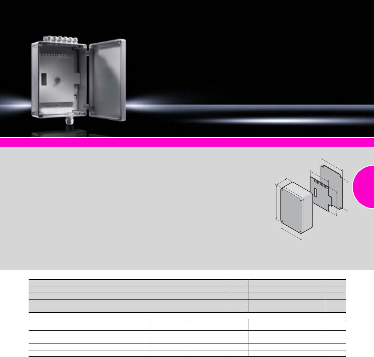
Small fibre-optic distributors
67Rittal Catalogue 33/Enclosures
System accessories Page 355
Layout of the small fibre-optic
distributor:
−Mounting plate with variable
accommodation for up to two
splicing cassettes (cassette
width variable from 92 to
120 mm) and integral anti-
twist guard
−Dividing plate with comb strip
for cable clamping, to cover
the splicing cassette, and
to accommodate 2 patch
panels and patch panels for
F-SMA, E-2000 ST couplings,
E-2000 duplex, SC couplings
and SC duplex couplings
−Cable entry via cable glands
in knockouts (12 x PG 7 and
1 x PG 16). Assembled con-
nectors fit through the knock-
outs (diameter of cut-outs:
12 x 12.5 mm and 2 x
22.5 mm). Additional sealing
inserts are required to reduce
the clamping range of the
cable glands
Material:
−Enclosure and cover:
Fibreglass-reinforced poly-
carbonate
−Cover screws: Polyamide
−Insulating bungs: Polyamide
−Foamed-in PU seal
Colour:
RAL 7035
Protection category:
IP 66 to IEC 60 529
Supply includes:
−Enclosure with knockouts
for cable glands
−Hinged cover with seal
−2 cover screws, prepared
for a lead seal
−Insulating bungs for wall
mounting
−Mounting plate
−Dividing plate
−12 cable glands PG 7
−1 cable gland PG 16
Detailed drawing:
Available on the Internet.
H
244
169.5
170
145
B
T
Width (B) mm Packs of 180 Page
Height (H) mm 254
Depth (T) mm 90
Number of fibres (when using patch panels) 1 – 24
Model No. DK 17451.000
Accessories
Locations per
patch panel Locations per
enclosure
Patch panel for ST couplings 12 24 2 7462.000
Patch panel for SC, E-2000, E-2000 duplex couplings 12/6 24/12 2 7463.100
Patch panel for SC duplex couplings 6 12 2 7463.200
Wall mounting brackets 40 9583.000 31
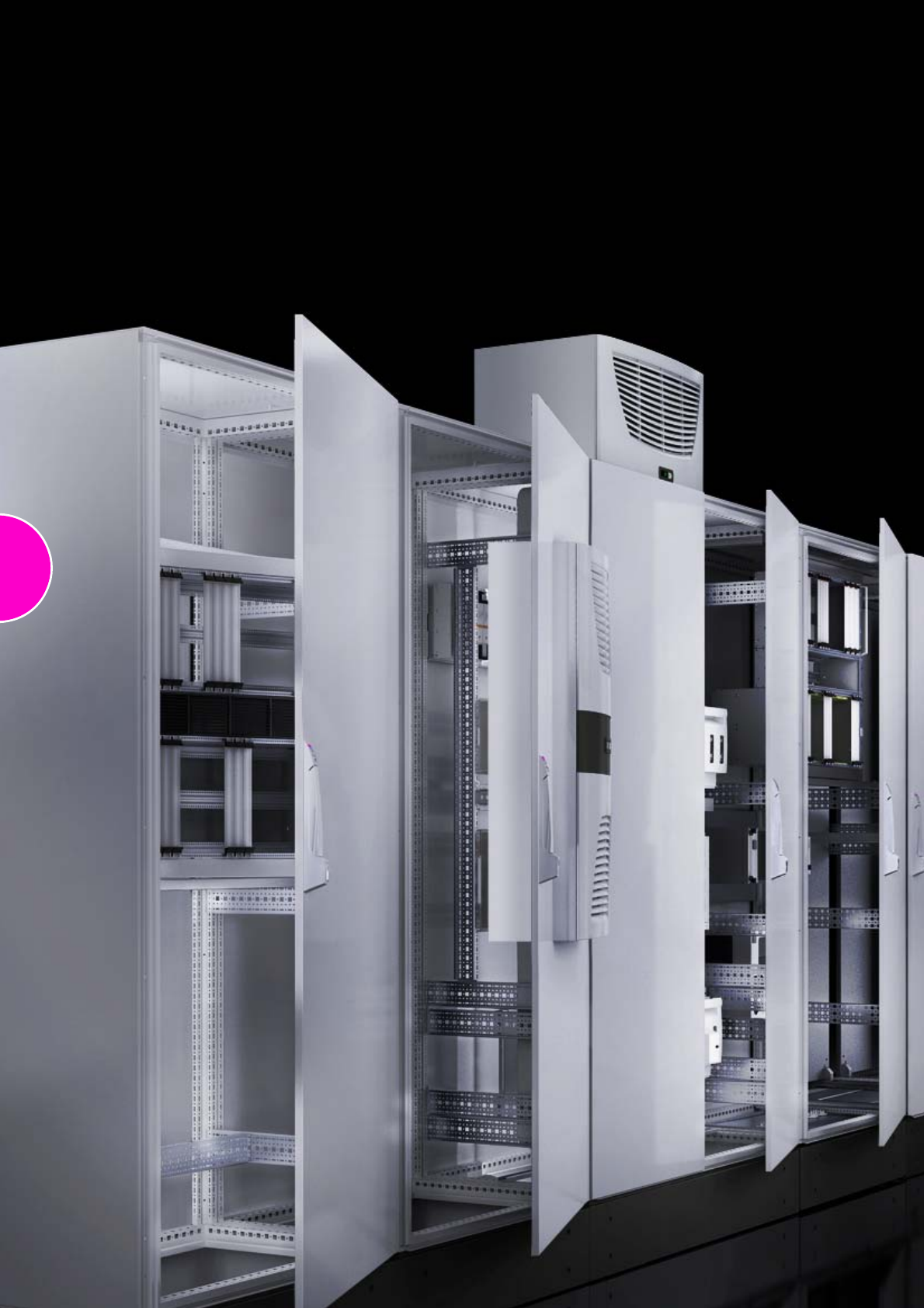
68
69
Enclosure systems
Baying systems TS 8
Height: 1200 mm/1400 mm, depth: 500 mm...............................................70
Height: 1600 mm, depth: 500 mm...............................................................71
Height: 1800 mm, depth: 400 mm...............................................................71
Height: 1800 mm, depth: 500 mm...............................................................72
Height: 1800 mm, depth: 600 mm...............................................................72
Height: 2000 mm, depth: 400 mm...............................................................73
Height: 2000 mm, depth: 500 mm...............................................................73
Height: 2000 mm, depth: 600 mm...............................................................74
Height: 2000 mm, depth: 800 mm...............................................................74
Height: 2200 mm, depth: 600 mm...............................................................75
IP 66/NEMA 4X and IP 66/NEMA 4 .............................................................76
For areas at risk from earthquakes..............................................................77
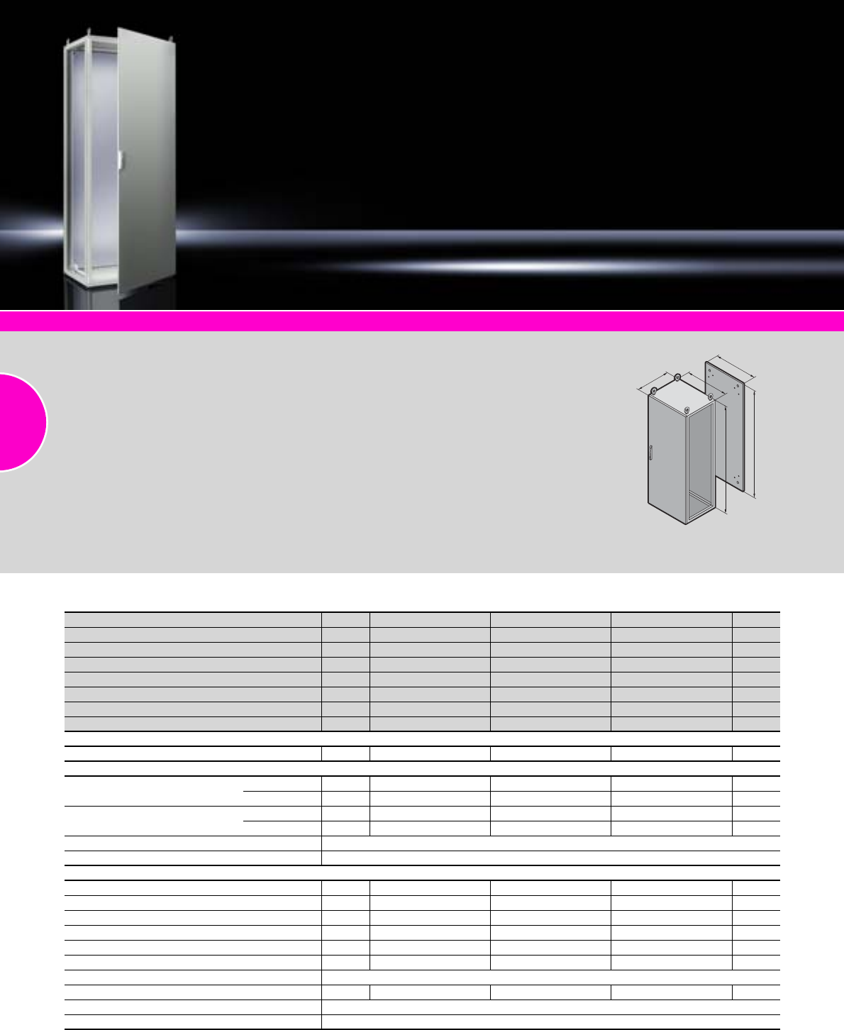
Baying systems TS 8
70 Rittal Catalogue 33/Enclosures
System accessories Page 355 TS 8 corner enclosures Page 401 TS 8 stainless steel Page 172
Material:
−Enclosure frame, roof, rear
panel and gland plates:
Sheet steel, 1.5 mm
−Door: Sheet steel, 2.0 mm
−Mounting plate: Sheet steel,
3.0 mm
Surface finish:
−Enclosure frame:
Dipcoat-primed
−Door, roof and rear panel:
Dipcoat-primed, powder-
coated on the outside,
textured paint
−Mounting plate and gland
plates: Zinc-plated
Colour:
RAL 7035
Protection category:
IP 55 to IEC 60 529,
complies with NEMA 12.
Supply includes:
−Enclosure frame with door(s),
3 mm double-bit lock insert
−Mounting plate
−Gland plates
−Rear panel
−Roof plate
−4 eyebolts
Approvals:
−UL
−CSA
−TÜV
−Russian Maritime Register
of Shipping
−TÜV Mark
−Lloyds Register of Shipping
−Bureau Veritas
−VDE
−Germanischer Lloyd
Detailed drawings:
Available on the Internet.
T
F
G
H
B
Height: 1200 mm/1400 mm, depth: 500 mm
Width (B) mm Packs of 600 800 1200 Page
Height (H) mm 1400 1400 1400
Depth (T) mm 500 500 500
Mounting plate width (F) mm 499 699 1099
Mounting plate height (G) mm 1296 1296 1296
Model No. TS 18645.500 8845.500 8245.500
Door(s) 1 1 2
Weight (kg) 86.0 107.5 163.5
Walls
Side panels 2 8145.235 8145.235 8145.235 385
Base/plinths
Components front and rear Height 100 mm 1 set 8601.600 8601.800 8601.200 361
Height 200 mm 1 set 8602.600 8602.800 8602.200 361
Trim panels, sides Height 100 mm 1 set 8601.050 8601.050 8601.050 362
Height 200 mm 1 set 8602.050 8602.050 8602.050 362
Flex-Block see page 358
Levelling component for base/plinth see page 364
Accessories
Cable clamp rails for cable clamps 2 4191.000 4192.000 4196.000 527
Cable clamp rails (C section) for cable clamps 6 4944.000 4945.000 4947.000 465
Section for cable entry, rear 1 set 8802.065 8802.085 8802.1251) 513
Support strips for door 20 4596.000 4598.000 4596.000 426
Wiring plan pocket, sheet steel 1 4116.X00 4118.X00 4116.X00 429
180° hinges 4 8800.190 8800.190 8800.190 425
System lights see page 491
Door stay for escape routes 1 4583.500 4583.500 4583.500 429
Earth straps see page 501
Alternative lock systems see page 412
1) Packs of 2 sets
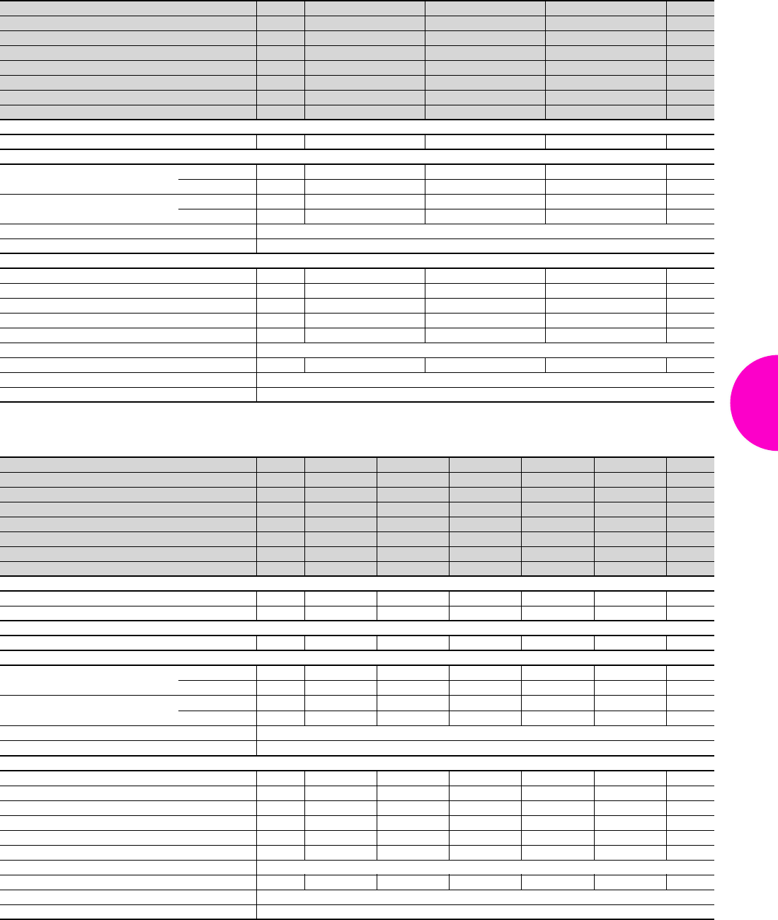
Baying systems TS 8
71Rittal Catalogue 33/Enclosures
Height: 1600 mm, depth: 500 mm
Height: 1800 mm, depth: 400 mm
Width (B) mm Packs of 600 800 1200 Page
Height (H) mm 1600 1600 1600
Depth (T) mm 500 500 500
Mounting plate width (F) mm 499 699 1099
Mounting plate height (G) mm 1496 1496 1496
Model No. TS 18665.500 8865.500 8265.500
Door(s) 1 1 2
Weight (kg) 100.0 103.0 159.3
Walls
Side panels 2 8165.235 8165.235 8165.235 385
Base/plinths
Components front and rear Height 100 mm 1 set 8601.600 8601.800 8601.200 361
Height 200 mm 1 set 8602.600 8602.800 8602.200 361
Trim panels, sides Height 100 mm 1 set 8601.050 8601.050 8601.050 362
Height 200 mm 1 set 8602.050 8602.050 8602.050 362
Flex-Block see page 358
Levelling component for base/plinth see page 364
Accessories
Cable clamp rails for cable clamps 2 4191.000 4192.000 4196.000 527
Cable clamp rails (C section) for cable clamps 6 4944.000 4945.000 4947.000 465
Section for cable entry, rear 1 set 8802.065 8802.085 8802.1251) 513
Support strips for door 20 4596.000 4598.000 4596.000 426
180° hinges 4 8800.190 8800.190 8800.190 425
System lights see page 491
Door stay for escape routes 1 4583.500 4583.500 4583.500 429
Earth straps see page 501
Alternative lock systems see page 412
1) Packs of 2 sets
Width (B) mm Packs of 600 800 1000 1000 1200 Page
Height (H) mm 1800 1800 1800 1800 1800
Depth (T) mm 400 400 400 400 400
Mounting plate width (F) mm 499 699 899 899 1099
Mounting plate height (G) mm 1696 1696 1696 1696 1696
Model No. TS 18684.500 8884.500 8084.500 8080.500 8284.500
Door(s) 11122
Weight (kg) 91.3 113.5 136.4 140.0 170.6
Walls
Side panels 2 8184.235 8184.235 8184.235 8184.235 8184.235 385
Divider panel 1 8609.840 8609.840 8609.840 8609.840 8609.840 389
Doors
Glazed door 1 8610.680 8610.880 – – – 402
Base/plinths
Components front and rear Height 100 mm 1 set 8601.600 8601.800 8601.000 8601.000 8601.200 361
Height 200 mm 1 set 8602.600 8602.800 8602.000 8602.000 8602.200 361
Trim panels, sides Height 100 mm 1 set 8601.040 8601.040 8601.040 8601.040 8601.040 362
Height 200 mm 1 set 8602.040 8602.040 8602.040 8602.040 8602.040 362
Flex-Block see page 358
Levelling component for base/plinth see page 364
Accessories
Cable clamp rails for cable clamps 2 4191.000 4192.000 4336.000 4336.000 4196.000 527
Cable clamp rails (C section) for cable clamps 6 4944.000 4945.000 4946.000 4946.000 4947.000 465
Section for cable entry, rear 1 set 8802.065 8802.085 8802.1051) 8802.1051) 8802.1251) 513
Support strips for door 20 4596.000 4598.000 4599.000 4309.000 4596.000 426
Wiring plan pocket, sheet steel 1 4116.X00 4118.X00 4124.000 4115.X00 4116.X00 429
180° hinges 4 8800.190 8800.190 8800.190 8800.190 8800.190 425
System lights see page 491
Door stay for escape routes 1 4583.500 4583.500 4583.500 4583.500 4583.500 429
Earth straps see page 501
Alternative lock systems see page 412
1) Packs of 2 sets
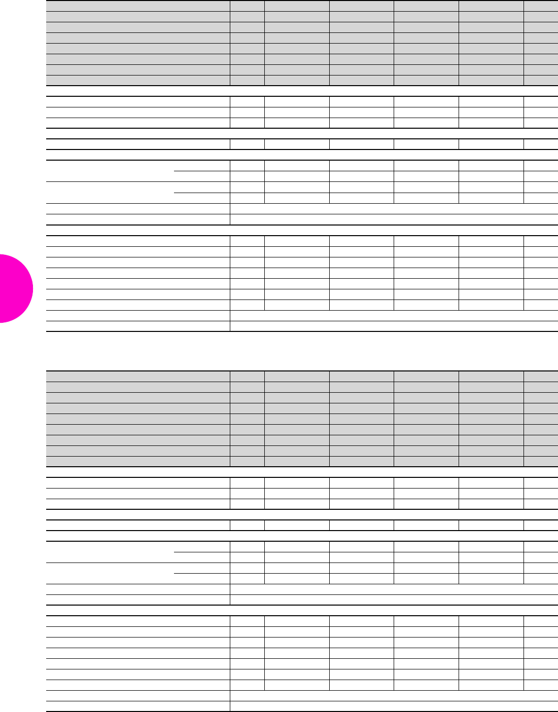
Baying systems TS 8
72 Rittal Catalogue 33/Enclosures
Height: 1800 mm, depth: 500 mm
Height: 1800 mm, depth: 600 mm
Width (B) mm Packs of 600 800 800 1200 Page
Height (H) mm 1800 1800 1800 1800
Depth (T) mm 500 500 500 500
Mounting plate width (F) mm 499 699 699 1099
Mounting plate height (G) mm 1696 1696 1696 1696
Model No. TS 18685.500 8885.500 8880.500 8285.500
Door(s) 1122
Weight (kg) 93.8 115.8 122.5 173.3
Walls
Side panels 2 8185.235 8185.235 8185.235 8185.235 385
Divider panel 1 8609.850 8609.850 8609.850 8609.850 389
Divider panel for module plates 1 8609.100 8609.100 8609.100 8609.100 390
Doors
Glazed door 1 8610.680 8610.880 – – 402
Base/plinths
Components front and rear Height 100 mm 1 set 8601.600 8601.800 8601.800 8601.200 361
Height 200 mm 1 set 8602.600 8602.800 8602.800 8602.200 361
Trim panels, sides Height 100 mm 1 set 8601.050 8601.050 8601.050 8601.050 362
Height 200 mm 1 set 8602.050 8602.050 8602.050 8602.050 362
Flex-Block see page 358
Levelling component for base/plinth see page 364
Accessories
Mounting plate 1 – – – – 451
Cable clamp rails for cable clamps 2 4191.000 4192.000 4192.000 4196.000 527
Cable clamp rails (C section) for cable clamps 6 4944.000 4945.000 4945.000 4947.000 465
Section for cable entry, rear 1 set 8802.065 8802.085 8802.085 8802.1251) 513
Support strips for door 20 4596.000 4598.000 4594.000 4596.000 426
180° hinges 4 8800.190 8800.190 8800.190 8800.190 425
Door stay for escape routes 1 4583.500 4583.500 4583.500 4583.500 429
Earth straps see page 501
Alternative lock systems see page 412
1) Packs of 2 sets
Width (B) mm Packs of 600 800 800 1200 Page
Height (H) mm 1800 1800 1800 1800
Depth (T) mm 600 600 600 600
Mounting plate width (F) mm 499 699 699 1099
Mounting plate height (G) mm 1696 1696 1696 1696
Model No. TS 18686.500 8886.500 8881.500 8286.500
Door(s) 1122
Weight (kg) 96.8 120.3 125.8 179.9
Support strips fitted in the enclosure depth
Walls
Side panels 2 8186.235 8186.235 8186.235 8186.235 385
Divider panel 1 8609.860 8609.860 8609.860 8609.860 389
Divider panel for module plates 1 8609.110 8609.110 8609.110 8609.110 390
Doors
Glazed door 1 8610.680 8610.880 – – 402
Base/plinths
Components front and rear Height 100 mm 1 set 8601.600 8601.800 8601.800 8601.200 361
Height 200 mm 1 set 8602.600 8602.800 8602.800 8602.200 361
Trim panels, sides Height 100 mm 1 set 8601.060 8601.060 8601.060 8601.060 362
Height 200 mm 1 set 8602.060 8602.060 8602.060 8602.060 362
Flex-Block see page 358
Levelling component for base/plinth see page 364
Accessories
Mounting plate 1 – – – – 451
Cable clamp rails for cable clamps 2 4191.000 4192.000 4192.000 4196.000 527
Cable clamp rails (C section) for cable clamps 6 4944.000 4945.000 4945.000 4947.000 465
Section for cable entry, rear 1 set 8802.065 8802.085 8802.085 8802.1251) 513
Support strips for door 20 4596.000 4598.000 4594.000 4596.000 426
180° hinges 4 8800.190 8800.190 8800.190 8800.190 425
Door stay for escape routes 1 4583.500 4583.500 4583.500 4583.500 429
Earth straps see page 501
Alternative lock systems see page 412
1) Packs of 2 sets
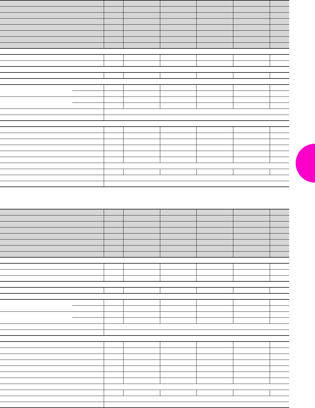
Baying systems TS 8
73Rittal Catalogue 33/Enclosures
Height: 2000 mm, depth: 400 mm
Height: 2000 mm, depth: 500 mm
Width (B) mm Packs of 600 800 1000 1200 Page
Height (H) mm 2000 2000 2000 2000
Depth (T) mm 400 400 400 400
Mounting plate width (F) mm 499 699 899 1099
Mounting plate height (G) mm 1896 1896 1896 1896
Model No. TS 18604.500 8804.500 8004.500 8204.500
Door(s) 1122
Weight (kg) 99.0 124.0 152.8 184.5
Walls
Side panels 2 8104.235 8104.235 8104.235 8104.235 385
Divider panel 1 8609.040 8609.040 8609.040 8609.040 389
Doors
Glazed door 1 8610.600 8610.800 – – 402
Base/plinths
Components front and rear Height 100 mm 1 set 8601.600 8601.800 8601.000 8601.200 361
Height 200 mm 1 set 8602.600 8602.800 8602.000 8602.200 361
Trim panels, sides Height 100 mm 1 set 8601.040 8601.040 8601.040 8601.040 362
Height 200 mm 1 set 8602.040 8602.040 8602.040 8602.040 362
Flex-Block see page 358
Levelling component for base/plinth see page 364
Accessories
Cable clamp rails for cable clamps 2 4191.000 4192.000 4336.000 4196.000 527
Cable clamp rails (C section) for cable clamps 6 4944.000 4945.000 4946.000 4947.000 465
Section for cable entry, rear 1 set 8802.065 8802.085 8802.1051) 8802.1251) 513
Support strips for door 20 4596.000 4598.000 4309.000 4596.000 426
Wiring plan pocket, sheet steel 1 4116.X00 4118.X00 4115.X00 4116.X00 429
180° hinges 4 8800.190 8800.190 8800.190 8800.190 425
System lights see page 491
Door stay for escape routes 1 4583.500 4583.500 4583.500 4583.500 429
Earth straps see page 501
Alternative lock systems see page 412
1) Packs of 2 sets
Width (B) mm Packs of 600 800 1000 1200 Page
Height (H) mm 2000 2000 2000 2000
Depth (T) mm 500 500 500 500
Mounting plate width (F) mm 499 699 899 1099
Mounting plate height (G) mm 1896 1896 1896 1896
Model No. TS 18605.500 8805.500 8005.500 8205.500
Door(s) 1122
Weight (kg) 101.3 126.3 157.1 190.6
Walls
Side panels 2 8105.235 8105.235 8105.235 8105.235 385
Divider panel 1 8609.050 8609.050 8609.050 8609.050 389
Divider panel for module plates 1 8609.120 8609.120 8609.120 8609.120 390
Doors
Glazed door 1 8610.600 8610.800 – – 402
Base/plinths
Components front and rear Height 100 mm 1 set 8601.600 8601.800 8601.000 8601.200 361
Height 200 mm 1 set 8602.600 8602.800 8602.000 8602.200 361
Trim panels, sides Height 100 mm 1 set 8601.050 8601.050 8601.050 8601.050 362
Height 200 mm 1 set 8602.050 8602.050 8602.050 8602.050 362
Flex-Block see page 358
Levelling component for base/plinth see page 364
Accessories
Mounting plate 1 – – – – 451
Cable clamp rails for cable clamps 2 4191.000 4192.000 4336.000 4196.000 527
Cable clamp rails (C section) for cable clamps 6 4944.000 4945.000 4946.000 4947.000 465
Section for cable entry, rear 1 set 8802.065 8802.085 8802.1051) 8802.1251) 513
Support strips for door 20 4596.000 4598.000 4309.000 4596.000 426
Wiring plan pocket, sheet steel 1 4116.X00 4118.X00 4115.X00 4116.X00 429
180° hinges 4 8800.190 8800.190 8800.190 8800.190 425
System lights see page 491
Door stay for escape routes 1 4583.500 4583.500 4583.500 4583.500 429
Earth straps see page 501
Alternative lock systems see page 412
1) Packs of 2 sets
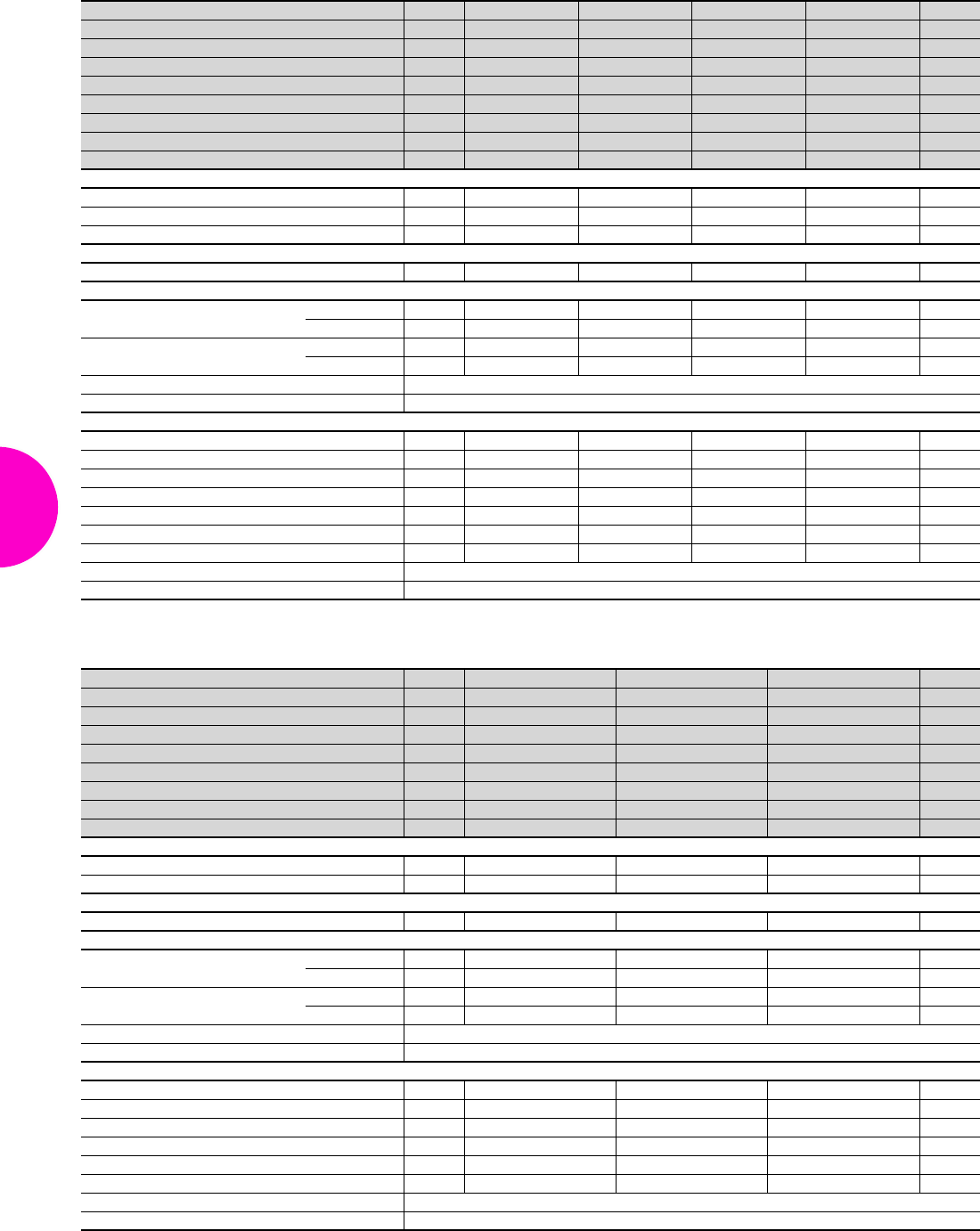
Baying systems TS 8
74 Rittal Catalogue 33/Enclosures
Height: 2000 mm, depth: 600 mm
Height: 2000 mm, depth: 800 mm
Width (B) mm Packs of 600 800 1000 1200 Page
Height (H) mm 2000 2000 2000 2000
Depth (T) mm 600 600 600 600
Mounting plate width (F) mm 499 699 899 1099
Mounting plate height (G) mm 1896 1896 1896 1896
Model No. TS 18606.500 8806.500 8006.500 8206.500
Door(s) 1122
Weight (kg) 104.0 130.5 161.2 194.6
Support strips fitted in the enclosure depth
Walls
Side panels 2 8106.235 8106.235 8106.235 8106.235 385
Divider panel 1 8609.060 8609.060 8609.060 8609.060 389
Divider panel for module plates 1 8609.130 8609.130 8609.130 8609.130 390
Doors
Glazed door 1 8610.600 8610.800 – – 402
Base/plinths
Components front and rear Height 100 mm 1 set 8601.600 8601.800 8601.000 8601.200 361
Height 200 mm 1 set 8602.600 8602.800 8602.000 8602.200 361
Trim panels, sides Height 100 mm 1 set 8601.060 8601.060 8601.060 8601.060 362
Height 200 mm 1 set 8602.060 8602.060 8602.060 8602.060 362
Flex-Block see page 358
Levelling component for base/plinth see page 364
Accessories
Mounting plate 1 – – – – 451
Cable clamp rails for cable clamps 2 4191.000 4192.000 4336.000 4196.000 527
Cable clamp rails (C section) for cable clamps 6 4944.000 4945.000 4946.000 4947.000 465
Section for cable entry, rear 1 set 8802.065 8802.085 8802.1051) 8802.1251) 513
Support strips for door 20 4596.000 4598.000 4309.000 4596.000 426
180° hinges 4 8800.190 8800.190 8800.190 8800.190 425
Door stay for escape routes 1 4583.500 4583.500 4583.500 4583.500 429
Earth straps see page 501
Alternative lock systems see page 412
1) Packs of 2 sets
Width (B) mm Packs of 600 800 1200 Page
Height (H) mm 2000 2000 2000
Depth (T) mm 800 800 800
Mounting plate width (F) mm 499 699 1099
Mounting plate height (G) mm 1896 1896 1896
Model No. TS 18608.500 8808.500 8208.500
Door(s) 1 1 2
Weight (kg) 111.3 137.0 203.0
Support strips fitted in the enclosure depth
Walls
Side panels 2 8108.235 8108.235 8108.235 385
Divider panel 1 8609.080 8609.080 8609.080 389
Doors
Glazed door 1 8610.600 8610.800 – 402
Base/plinths
Components front and rear Height 100 mm 1 set 8601.600 8601.800 8601.200 361
Height 200 mm 1 set 8602.600 8602.800 8602.200 361
Trim panels, sides Height 100 mm 1 set 8601.080 8601.080 8601.080 362
Height 200 mm 1 set 8602.080 8602.080 8602.080 362
Flex-Block see page 358
Levelling component for base/plinth see page 364
Accessories
Cable clamp rails for cable clamps 2 4191.000 4192.000 4196.000 527
Cable clamp rails (C section) for cable clamps 6 4944.000 4945.000 4947.000 465
Section for cable entry, rear 1 set 8802.065 8802.085 8802.1251) 513
Support strips for door 20 4596.000 4598.000 4596.000 426
180° hinges 4 8800.190 8800.190 8800.190 425
Door stay for escape routes 1 4583.500 4583.500 4583.500 429
Earth straps see page 501
Alternative lock systems see page 412
1) Packs of 2 sets
Baying systems TS 8
75Rittal Catalogue 33/Enclosures
Height: 2200 mm, depth: 600 mm
Width (B) mm Packs of 600 800 1200 Page
Height (H) mm 2200 2200 2200
Depth (T) mm 600 600 600
Mounting plate width (F) mm 499 699 1099
Mounting plate height (G) mm 2096 2096 2096
Model No. TS 18626.500 8826.500 8226.500
Door(s) 1 1 2
Weight (kg) 113.1 139.3 208.0
Support strips fitted in the enclosure depth
Walls
Side panels 2 8126.235 8126.235 8126.235 385
Divider panel 1 8609.260 8609.260 8609.260 389
Doors
Glazed door 1 8610.620 8610.820 – 402
Base/plinths
Components front and rear Height 100 mm 1 set 8601.600 8601.800 8601.200 361
Height 200 mm 1 set 8602.600 8602.800 8602.200 361
Trim panels, sides Height 100 mm 1 set 8601.060 8601.060 8601.060 362
Height 200 mm 1 set 8602.060 8602.060 8602.060 362
Flex-Block see page 358
Levelling component for base/plinth see page 364
Accessories
Cable clamp rails for cable clamps 2 4191.000 4192.000 4196.000 527
Cable clamp rails (C section) for cable clamps 6 4944.000 4945.000 4947.000 465
Section for cable entry, rear 1 set 8802.065 8802.085 8802.1251) 513
Support strips for door 20 4596.000 4598.000 4596.000 426
Wiring plan pocket, sheet steel 1 4116.X00 4118.X00 4116.X00 429
180° hinges 4 8800.190 8800.190 8800.190 425
System lights see page 491
Door stay for escape routes 1 4583.500 4583.500 4583.500 429
Earth straps see page 501
Alternative lock systems see page 412
1) Packs of 2 sets
Rittal France
RITTAL SAS
ZA des Grands Godets 880 rue Marcel Paul
94507 Champigny sur Marne Cedex
Phone: +33 (0) 1 49 83 60 00
Fax: +33 (0) 1 49 83 82 06
E-mail: info@rittal.fr www.rittal.fr
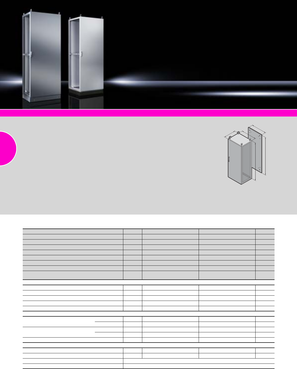
Baying systems TS 8
76 Rittal Catalogue 33/Enclosures
System accessories Page 355 Cable entry Page 511
Supply includes:
−Enclosure frame with door,
3 mm double-bit lock insert
−Roof plate
−Gland plate
−Rear panel
−Mounting plate
−4 eyebolts
Protection category:
See table.
NEMA 4X:
Material:
−Enclosure frame, roof, base,
rear panel: Stainless steel
1.4301 (AISI 304), 1.5 mm
−Door: Stainless steel 1.4301
(AISI 304), 2.0 mm
−Mounting plate: Sheet steel,
3.0 mm
Surface finish:
−Enclosure frame: Uncoated
−Door, roof, base, rear panel:
Exterior brushed,
grain size 400
−Mounting plate: Zinc-plated
NEMA 4:
Material:
−Enclosure frame, roof, base,
rear panel: Sheet steel,
spray-finished, 1.5 mm
−Door: Sheet steel,
spray-finished, 2.0 mm
−Mounting plate: Sheet steel,
3.0 mm
Surface finish:
−Enclosure frame, door, roof,
base, rear panel:
Dipcoat-primed and powder-
coated on the outside,
textured paint
−Mounting plate: Zinc-plated
Colour:
RAL 7035
T
F
G
H
B
IP 66/NEMA 4X and IP 66/NEMA 4
Packs of Stainless steel Sheet steel Page
Width (B) mm 800 800
Height (H) mm 2000 2000
Depth (T) mm 600 600
Mounting plate width (F) mm 699 699
Mounting plate height (G) mm 1896 1896
Model No. TS 18450.680 8806.580
Door(s) 1 1
Protection category IP 66 to IEC 60 529,
complies with NEMA 4X. IP 66 to IEC 60 529,
complies with NEMA 4.
Also required
Side panels IP 66/NEMA 4X, NEMA 4 2 8700.680 8106.580 –
Baying frame IP 66/NEMA 4X, NEMA 4 1 8700.010 8700.010 –
Quick-fit baying clamp, one-piece 6 8800.500 8800.500 395
Baying clamp, horizontal 4 8800.400 8800.400 395
Angular baying brackets 4 8800.430 8800.430 397
Base/plinths
Components front and rear Height 100 mm 1 set 8701.800 8601.800 367/361
Height 200 mm 1 set 8702.800 8602.800 367/361
Trim panels, sides Height 100 mm 1 set 8701.060 8601.060 367/362
Height 200 mm 1 set 8702.060 8602.060 367/362
Base/plinth trim, modular 4 2913.000 – 367
Accessories
Cable clamp rails 2 4192.000 4192.000 527
Wiring plan pocket, sheet steel 1 4118.000 4118.000 429
System light see page 491
Alternative lock systems see page 412
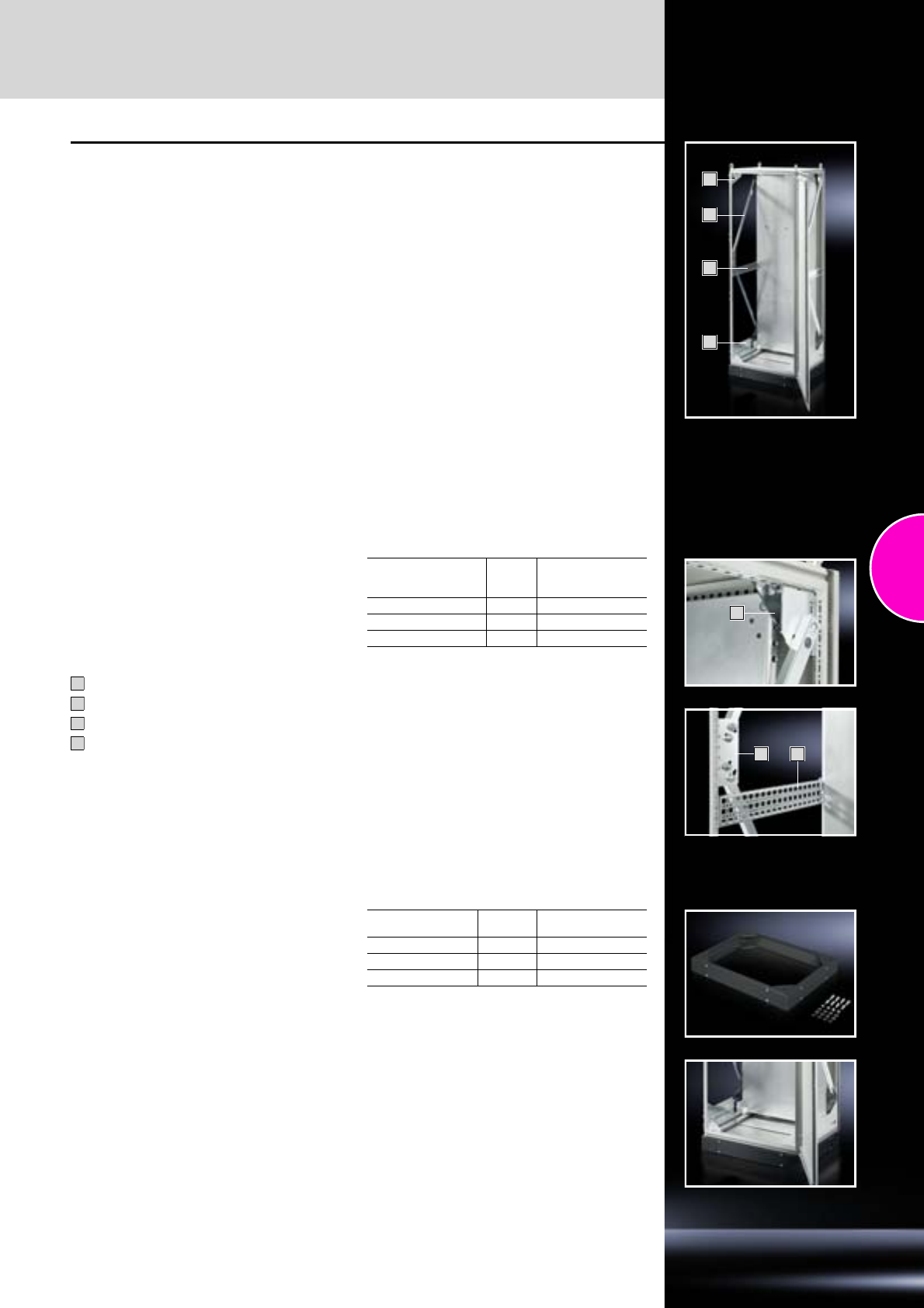
For areas at risk from earthquakes
Baying systems TS 8
77Rittal Catalogue 33/Enclosures
1
4
2
3
TS 8 for earthquake zone 1, 2 and 3 to Bellcore
TS 8806.500:
W x H x D 800 x 2000 x 600 mm
With base/plinth (base/plinth components front
and rear, see page 361 and base/plinth trim, side,
see page 362), 100 mm high with a weight load of
152 kg spread evenly over the mounting plate.
Note:
These versions have been tested and meet the
requirements to Telcordia GR 63-CORE. They
should be seen as a comparative variable to the
customer’s own plant, since the certification of
empty enclosures is not possible.
TS 8 for earthquake zone 4 to Bellcore
TS 8806.500:
W x H x D 800 x 2000 x 600 mm
Fitted with:
−Earthquake kit and
−Earthquake base/plinth, see page 77,
with weight load of 450 kg distributed evenly over
the mounting plate.
(Photo shows TS 8 for earthquake zone 4 to
Bellcore)
3
2
4
Earthquake kit
Material:
Sheet steel
Surface finish:
Zinc-plated
Supply includes:
2 side reinforcements, bottom
2 bracing struts each, sides
8 gusset plates
Mounting plate attachment and reinforcement
including assembly parts
1
2
3
4
For enclosures
W x H x D
mm Packs of Model No. TS
800 x 2000 x 600 1 8613.860
600 x 2000 x 600 1 8613.6601)
600 x 2000 x 400 1 8613.6401)
1) Extended delivery times.
Earthquake base/plinth
Height 100 mm
Material:
−Corner pieces: Sheet steel 5 mm
−Trim panels: Sheet steel 2 mm
Surface finish:
Powder-coated
Colour:
RAL 7022
Supply includes:
1 set =
−4 corner pieces
−2 depth stays
−1 trim panel each front and rear
fully assembled.
For enclosures
W x D mm Packs of Model No. TS
800 x 600 1 8601.860
600 x 600 1 8601.6601)
600 x 400 1 8601.6401)
1) Extended delivery times.
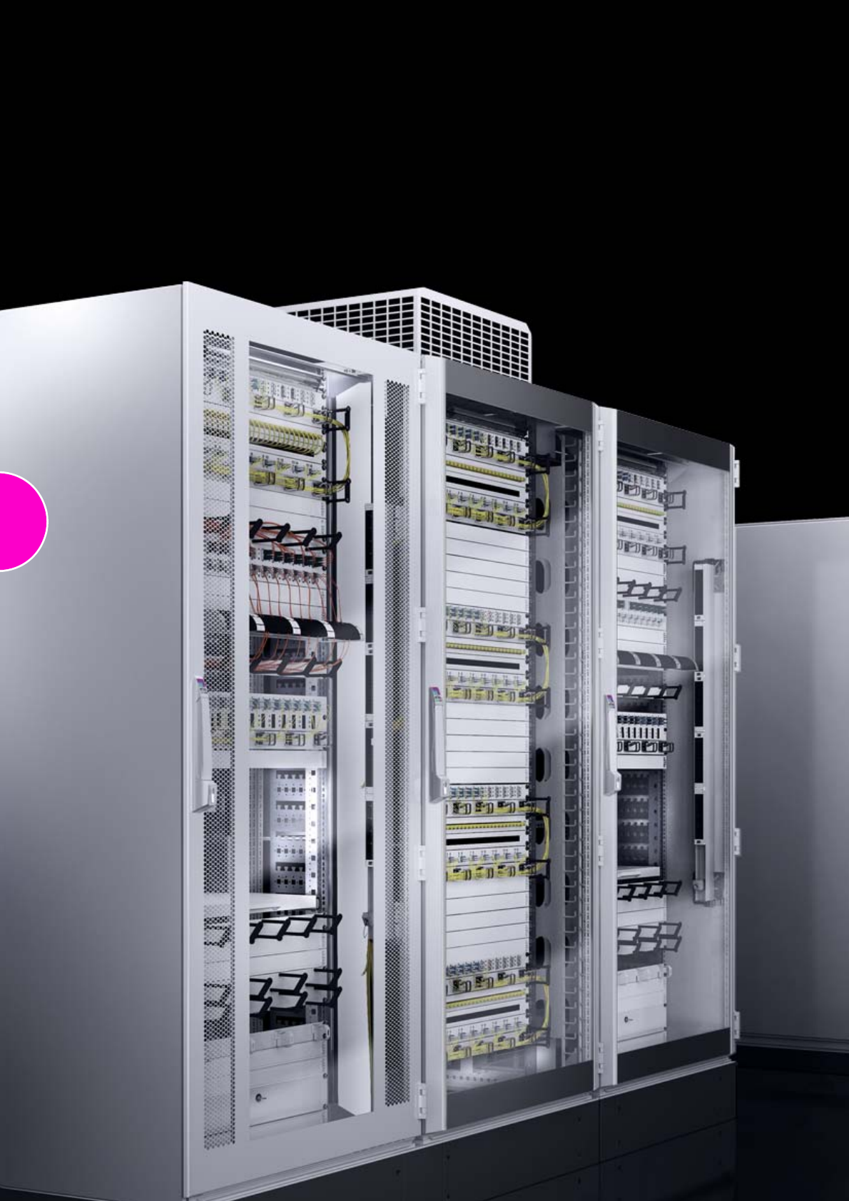
78
79
Network distribution enclosures
Network enclosures TS 8
Pre-configured, doors unvented .................................................................80
Pre-configured, doors unvented/vented .....................................................81
Pre-configured, doors/rear wall unvented...................................................82
Pre-configured, doors unvented, divided ...................................................82
Network enclosures TS 8.............................................................................83
Network enclosures TE 7000
Pre-configured.............................................................................................85
600 mm width ..............................................................................................86
800 mm width ..............................................................................................87
Distributor racks
TE 7000 open ..............................................................................................88
Data Rack....................................................................................................89
Network enclosures TS 8
80 Rittal Catalogue 33/Enclosures
System accessories Page 355 Power System Module Page 201 Monitoring Page 577 Climate control Page 207
Material:
−Enclosure: Sheet steel
−Glazed door: Single-pane
safety glass, 3 mm
Surface finish:
−Enclosure frame:
Dipcoat-primed
−Doors and roof:
Dipcoat-primed,
powder-coated
−Gland plates, punched
sections with mounting flanges
and mounting angles:
Zinc-plated
Colour:
RAL 7035
Supply includes:
Product-specific supply scope,
see table.
Detailed drawing:
Available on the Internet.
Photo shows a configuration
example with equipment not
included in the scope of supply.
T
B
H1H2
Pre-configured, doors unvented
U Packs of 24 24 38 42
Width (B) mm 600 800 800 800
Height (H1 + H2) mm 1200 + 100 1200 + 100 1800 + 100 2000 + 100
Depth (T) mm 600 800 800 800
Distance between levels, pre-configured mm –498 498 498
Glazed aluminium door at the front, 180°, with comfort handle for semi-cylinder
and security lock 3524 E 1
Sheet steel door at the rear, 130°, with handle and security lock 3524 E 1
482.6 mm (19˝) mounting level at the front and rear,
cranked mounting angles screw-fastened onto installation brackets
approx. 150 mm behind the front edge of the frame, depth-variable –
482.6 mm (19˝) mounting angle at the front,
cranked mounting angle screw-fastened to TS punched sections with
mounting flanges as support strips – – –
Gland plate mounted at front as infill panel 1 –
Gland plate, one-piece, vented, with cable entry 1 – – –
Roof plate for cable entry, two-piece 1
Including side panels 2 –
Model No. DK 1 7830.100 7830.110 7830.850 7830.200
Supply includes
Baying kit TS 8800.500 1 set – – –
Base/plinth vented, 100 mm high 1
Earthing of all enclosure panels pre-configured 1 set
Levelling feet (incl. base/plinth adaptor) 4
Spacers for raising the roof 4
Cable clamp rails for the inner frame level 4
Cable shunting rings, plastic 10
Captive nuts M6, conductive 50
Multi-tooth screws M6 50
Accessories
Side panel, lockable, see page 387 2 – – 7824.188 –
Included with the supply.
Network enclosures TS 8
81Rittal Catalogue 33/Enclosures
Pre-configured, doors unvented
Pre-configured, doors vented
U Packs of 42 42 42 42 47
Width (B) mm 800 800 800 800 800
Height (H1 + H2) mm 2000 + 100 2000 + 100 2000 + 100 2000 + 100 2200 + 100
Depth (T) mm 800 800 1000 1000 800
Distance between levels, pre-configured mm 498 498 498 498 498
Glazed aluminium door at the front, 180°,
with comfort handle for semi-cylinder and security lock 3524 E 1
Sheet steel door at the rear, 130°, with handle and security lock 3524 E 1
482.6 mm (19˝) mounting level at the front and rear,
cranked mounting angles screw-fastened onto installation brackets
approx. 150 mm behind the front edge of the frame, depth-variable
Gland plate mounted at front as infill panel 1
Roof plate for cable entry, two-piece 1
Including side panels 2 – – –
Model No. DK 1 7830.250 7830.202 7830.230 7830.240 7830.270
Supply includes
Baying kit TS 8800.500 1 set – –
Base/plinth vented, 100 mm high 1
Earthing of all enclosure panels pre-configured 1 set
Levelling feet (incl. base/plinth adaptor) 4
Spacers for raising the roof 4
Cable clamp rails for the inner frame level 4
Cable shunting rings, plastic 10
Captive nuts M6, conductive 50
Multi-tooth screws M6 50
Also included:
Compact light (8 W), mounting kit (magnetic), 482.6 mm (19˝) socket strip,
7-way (earthing-pin), door-operated switch, junction box incl. connection
accessories, 482.6 mm (19˝) component shelf (500 mm) incl. mounting
accessories
– – – –
Accessories
Side panel, lockable, see page 387 2 7824.208 – – 7824.200 7824.228
Included with the supply.
U Packs of 24 42 42 47
Width (B) mm 800 800 800 800
Height (H1 + H2) mm 1200 + 100 2000 + 100 2000 + 100 2200 + 100
Depth (T) mm 1000 1000 1000 1000
Distance between levels, pre-configured mm 740 740 740 740
Glazed sheet steel door at the front, 180°,
with comfort handle for semi-cylinder and security lock 3524 E 1
Vented sheet steel door at the rear, 180°,
with handle and security lock 3524 E 1
482.6 mm (19˝) mounting level at the front and rear, L-shaped mounting
angles screw-fastened onto 2 or 3 support strips, depth-variable
Gland plate, one-piece, vented, with cable entry 1
Roof plate for cable entry, two-piece 1
Including side panels 2 – –
Model No. DK 1 7830.130 7830.330 7830.335 7830.3801)
Supply includes
Baying kit TS 8800.500 1 set – –
Base/plinth vented, 100 mm high 1
Earthing of all enclosure panels pre-configured 1 set
Levelling feet (incl. base/plinth adaptor) 4
Spacers for raising the roof 4
Cable clamp rails for the inner frame level 4
Cable shunting rings, plastic 10
Captive nuts M6, conductive 50
Multi-tooth screws M6 50
Accessories
Side panel, lockable, see page 387 2 – – 7824.200 7824.220
Included with the supply. 1) Extended delivery times.
Network enclosures TS 8
82 Rittal Catalogue 33/Enclosures
Pre-configured, doors/rear wall unvented
Pre-configured, doors unvented, divided
U Packs of 42 40
Width (B) mm 800 800
Height (H1 + H2 + H3) mm 2000 + 100 + 25 2000 + 100 + 25
Depth (T) mm 800 800
Distance between levels, pre-configured mm 498 –
Glazed aluminium door at the front, 180°,
with comfort handle for semi-cylinder and security lock 3524 E 1
Sheet steel door at the rear, 130°, with handle and security lock 3524 E 1 –
Sheet steel rear panel 1 –
482.6 mm (19˝) mounting level at the front and rear,
L-shaped mounting angles screw-fastened onto support strips,
depth-variable –
Swing frame, large, with side trim panel for the installation of 482.6 mm (19˝)
mounting components whilst utilising the full enclosure height
(130°, 150 kg static load capacity) –
Gland plate, one-piece, vented, with cable entry 1 –
Gland plate mounted at front as infill panel 1 –
Roof plate with cut-out for fan insert and vent panel on spacers 1
Including side panels 2 – –
Model No. DK 1 7830.550 7830.670
Supply includes
Baying kit TS 8800.500 1 set
Base/plinth vented, 100 mm high 1
Earthing of all enclosure panels pre-configured 1 set
Levelling feet (incl. base/plinth adaptor) 4
Spacers for raising the roof 4
Cable clamp rails for the inner frame level 4
Cable shunting rings, plastic 10
Captive nuts M6, conductive 50
Multi-tooth screws M6 50
Accessories
Side panel, lockable, see page 387 2 7824.208 7824.208
Included with the supply.
U Packs of 42
Width (B) mm 800
Height (H1 + H2) mm 2000 + 100
Depth (T) mm 800
Distance between levels, pre-configured mm 498
Glazed sheet steel door at front, vertically divided, 180° 1
Sheet steel door at rear, vertically divided, 180° 1
482.6 mm (19˝) mounting level at the front and rear,
cranked mounting angles screw-fastened onto installation brackets
approx. 150 mm behind the front edge of the frame, depth-variable
Gland plate mounted at front as infill panel 1
Roof plate for cable entry, two-piece, with cut-out for fan insert
and vent panel on spacers 1
Including side panels 2 –
Model No. DK 1 7830.260
Supply includes
Baying kit TS 8800.500 1 set
Base/plinth vented, 100 mm high 1
Earthing of all enclosure panels pre-configured 1 set
Levelling feet (incl. base/plinth adaptor) 4
Spacers for raising the roof 4
Cable clamp rails for the inner frame level 4
Cable shunting rings, plastic 10
Captive nuts M6, conductive 50
Multi-tooth screws M6 50
Accessories
Side panel, lockable, see page 387 2 7824.208
Included with the supply.
Network enclosures TS 8
83Rittal Catalogue 33/Enclosures
System accessories Page 355 Power System Module Page 201 Monitoring Page 577 Climate control Page 207
Material:
−Sheet steel
−Glazed door: Single-pane
safety glass, 3 mm
Surface finish:
−Enclosure frame:
Dipcoat-primed
−Doors and roof: Dipcoat-
primed, powder-coated
−Base plates and punched
sections with mounting
flanges: Zinc-plated
Colour:
RAL 7035
Protection category:
IP 55 to IEC 60 529
in connection with side panels,
screw-fastened
Supply includes:
Product-specific supply scope,
see table.
Approvals:
−UL
−cUL
Detailed drawing:
Available on the Internet.
Photo shows a configuration
example with equipment not
included in the scope of supply.
U 15 15 20 20 24 24 24 24
Width mm 600 600 600 600 600 600 800 800
Height mm 800 800 1000 1000 1200 1200 1200 1200
Depth mm 600 600 600 600 600 600 600 600
Model No. DK 7820.100 7821.100 7820.200 7821.200 7820.300 7821.300 7820.3401) 7821.340
Supply includes
Glazed aluminium door at the front (180°),
with comfort handle for semi-cylinder and security lock 3524 E – – – –
Sheet steel door at the front (180°),
with comfort handle for semi-cylinder and security lock 3524 E – – – –
Sheet steel door at the rear (130°),
with handle and security lock 3524 E
Gland plate, multi-piece, solid
Roof plate, solid
Base/plinths see page 360
U 24 29 29 33 33 33 33
Width mm 800 600 600 600 600 600 600
Height mm 1200 1400 1400 1600 1600 1600 1600
Depth mm 800 800 800 600 600 800 800
Model No. DK 7820.350 7820.410 7821.410 7820.500 7821.500 7820.510 7821.510
Supply includes
Glazed aluminium door at the front (180°),
with comfort handle for semi-cylinder and security lock 3524 E – – –
Sheet steel door at the front (180°),
with comfort handle for semi-cylinder and security lock 3524 E – – – –
Sheet steel door at the rear (130°),
with handle and security lock 3524 E
Gland plate, multi-piece, solid
Roof plate, solid
Base/plinths see page 360
Included with the supply. 1) Extended delivery times.
Network enclosures TS 8
84 Rittal Catalogue 33/Enclosures
U 38 38 38 38 38 38
Width mm 600 600 600 600 800 800
Height mm 1800 1800 1800 1800 1800 1800
Depth mm 600 600 800 800 800 800
Model No. DK 7820.600 7821.600 7820.610 7821.610 7820.650 7821.650
Supply includes
Glazed aluminium door at the front (180°),
with comfort handle for semi-cylinder and security lock 3524 E – – –
Sheet steel door at the front (180°),
with comfort handle for semi-cylinder and security lock 3524 E – – –
Sheet steel door at the rear (130°),
with handle and security lock 3524 E
Gland plate, multi-piece, solid
Roof plate, solid
Base/plinths see page 360
U 42 42 42 42 42 42
Width mm 600 600 600 600 600 600
Height mm 2000 2000 2000 2000 2000 2000
Depth mm 600 600 800 800 1000 1000
Model No. DK 7820.700 7821.700 7820.710 7821.710 7820.730 7821.730
Supply includes
Glazed aluminium door at the front (180°),
with comfort handle for semi-cylinder and security lock 3524 E – – –
Sheet steel door at the front (180°),
with comfort handle for semi-cylinder and security lock 3524 E – – –
Sheet steel door at the rear (130°),
with handle and security lock 3524 E
Gland plate, multi-piece, solid
Roof plate, solid
Base/plinths see page 360
U 42 42 42 42 42 42
Width mm 800 800 800 800 800 800
Height mm 2000 2000 2000 2000 2000 2000
Depth mm 600 600 800 800 1000 1000
Model No. DK 7820.740 7821.740 7820.750 7821.750 7820.770 7821.770
Supply includes
Glazed aluminium door at the front (180°),
with comfort handle for semi-cylinder and security lock 3524 E – – –
Sheet steel door at the front (180°),
with comfort handle for semi-cylinder and security lock 3524 E – – –
Sheet steel door at the rear (130°),
with handle and security lock 3524 E
Gland plate, multi-piece, solid
Roof plate, solid
Base/plinths see page 360
U 47 47 47 47 47 47
Width mm 600 600 600 600 800 800
Height mm 2200 2200 2200 2200 2200 2200
Depth mm 600 600 800 800 800 800
Model No. DK 7820.800 7821.800 7820.810 7821.810 7820.850 7821.850
Supply includes
Glazed aluminium door at the front (180°),
with comfort handle for semi-cylinder and security lock 3524 E – – –
Sheet steel door at the front (180°),
with comfort handle for semi-cylinder and security lock 3524 E – – –
Sheet steel door at the rear (130°),
with handle and security lock 3524 E
Gland plate, multi-piece, solid
Roof plate, solid
Base/plinths see page 360
Included with the supply.
Network enclosures TE 7000
85Rittal Catalogue 33/Enclosures
System accessories Page 355 Power System Module Page 201 Monitoring Page 577 Climate control Page 207
Benefits:
●No frame structure
●Optimum accessibility
●Readily dismantled and
therefore easily installed
Material:
−Sheet steel
−Glazed door: Single-pane
safety glass, 4 mm
Surface finish:
−Mounting frame:
Dipcoat-primed
−Enclosure panels:
Powder-coated
Colour:
RAL 7035
Supply includes:
Product-specific supply scope,
see table.
Detailed drawing:
Available on the Internet.
Pre-configured
U Packs of 24 42 42 Page
Width mm 800 800 800
Height (enclosure + pase/plinth) mm 1200 + 100 2000 + 100 2000 + 100
Depth mm 800 800 800
Distance between levels, pre-configured mm 495 495 495
Model No. TE 1 7000.840 7000.850 7000.852
Supply includes
Self-supporting 482.6 mm (19˝) mounting frame, front and rear, depth-variable 2
Glazed door at the front, incl. 130° hinge, recessed handle and security lock 3524 E 1
Sheet steel door at the rear, including 130° hinge, security lock 3524 E 1
Side panels, lockable, including security lock 3524 E 2 7000.652 388
Base frame with maximum cut-out (for optional population with module plates) 1
Roof plate including brush strip for cable entry and concealed cut-out for optional fan 1
Levelling feet (including base/plinth adaptor) supplied loose 4
Spacers, 20 mm, supplied loose to raise the roof 4
Base/plinth 100 mm, vented 1
Tested frame earthing to IEC 60 950, fitted
C rails, for cable clamping in the enclosure depth via cable clamps, supplied loose 4
Cable shunting rings made of plastic, 105 x 70 mm, supplied loose 10
Captive nuts M6, conductive 50
Multi-tooth screw M6, with plastic washers 50
Accessories
Baying kit 1 set 7000.640 7000.640 400
Ergoform-S handle for semi-cylinder, to exchange for the existing lock 1 2435.000 2435.000 2435.000 419
Fan unit, with 2 fans and thermostat, pre-wired ready for connection 1 7000.670 7000.670 7000.670 224
Slide rail for TE, for attachment between the 482.6 mm (19˝) mounting frames,
length 424 mm 2 7963.410 7963.410 7963.410 560
482.6 mm (19˝) component shelf for static installation, for direct screw fastening
without an installation kit, 413 mm deep, load capacity 30 kg, static 1 7000.620 7000.620 7000.620 483
482.6 mm (19˝) component shelf, complete set, pull-out, 500 mm deep,
load capacity 50 kg static 1 set 7000.625 7000.625 7000.625 486
Socket strip, 8-way 1 7000.630 7000.630 7000.630 506
Transport castors (only without base/plinth) 4 7000.672 7000.672 7000.672 375
Included with the supply.
Network enclosures TE 7000
86 Rittal Catalogue 33/Enclosures
System accessories Page 355 Power System Module Page 201 Monitoring Page 577 Climate control Page 207
Benefits:
●No frame structure
●Optimum accessibility
●Readily dismantled and
therefore easily installed
Material:
−Sheet steel
−Glazed door: Single-pane
safety glass, 4 mm
Surface finish:
−Mounting frame:
Dipcoat-primed
−Enclosure panels:
Powder-coated
Colour:
RAL 7035
Supply includes:
Product-specific supply scope,
see table.
Detailed drawing:
Available on the Internet.
600 mm width
U Packs of 11 11 24 24 42 42 47 47 Page
Width mm 600 600 600 600 600 600 600 600
Height mm 600 600 1200 1200 2000 2000 2200 2200
Depth mm 600 800 600 800 600 800 600 800
Distance between levels, pre-configured mm 495 495 495 495 495 495 495 495
Model No. TE 17000.390 7000.410 7000.430 7000.440 7000.500 7000.510 7000.5601) 7000.5701)
Supply includes
Self-supporting 482.6 mm (19˝) mounting frame,
front and rear, depth-variable 2
Glazed door at the front, incl. 130° hinge, recessed
handle and security lock 3524 E 1
Sheet steel door at the rear, including 130° hinge,
security lock 3524 E 1
Side panels, lockable, including security lock 3524 E
2
Base frame with maximum cut-out
(for optional population with module plates) 1
Roof plate including brush strip for cable entry
and concealed cut-out for optional fan 1
Levelling feet, M10, supplied loose 4
Spacers, 20 mm, supplied loose to raise the roof 4
Accessories
Base/plinth components, front and rear, vented 1 set 7825.601 7825.601 7825.601 7825.601 7825.601 7825.601 7825.601 7825.601 361
Base/plinth trim panels, side 1 set 8601.065 8601.085 8601.065 8601.085 8601.065 8601.085 8601.065 8601.085 362
Baying kit 4 7000.640 7000.640 7000.640 7000.640 7000.640 7000.640 7000.640 7000.640 400
Fan unit, with 2 fans and thermostat,
pre-wired ready for connection 1 7000.670 7000.670 7000.670 7000.670 7000.670 7000.670 7000.670 7000.670 224
Earthing kit 1 set 7000.675 7000.675 7000.675 7000.675 7000.675 7000.675 7000.675 7000.675 503
Socket strip, 8-way 1 7000.630 7000.630 7000.630 7000.630 7000.630 7000.630 7000.630 7000.630 506
482.6 mm (19˝) component shelf, complete set,
pull-out, 500 mm deep, load capacity 50 kg static 1 set 7000.625 7000.625 7000.625 7000.625 7000.625 7000.625 7000.625 7000.625 486
Transport castors (only without base/plinth) 4 7000.672 7000.672 7000.672 7000.672 7000.672 7000.672 7000.672 7000.672 375
Included with the supply. 1) Extended delivery times.
Network enclosures TE 7000
87Rittal Catalogue 33/Enclosures
800 mm width
UPacks of 24 24 42 42 42 47 47 47 Page
Width mm 800 800 800 800 800 800 800 800
Height mm 1200 1200 2000 2000 2000 2200 2200 2200
Depth mm 600 800 600 800 800 600 800 800
Distance between levels, pre-configured mm 495 495 495 495 495 495 495 495
Model No. TE 1 7000.4501) 7000.460 7000.520 7000.530 7000.532 7000.5801) 7000.590 7000.5921)
Supply includes
Self-supporting 482.6 mm (19˝) mounting frame,
front and rear, depth-variable 2
Glazed door at the front, incl. 130° hinge, recessed
handle and security lock 3524 E 1
Sheet steel door at the rear, including 130° hinge,
security lock 3524 E 1
Side panels, lockable, including security lock 3524 E
2 –
Base frame with maximum cut-out
(for optional population with module plates) 1
Roof plate including brush strip for cable entry
and concealed cut-out for optional fan 1
Levelling feet (including base/plinth adaptor)
supplied loose 4
Spacers, 20 mm, supplied loose to raise the roof 4
Accessories
Base/plinth components, front and rear, vented 1 set 7825.801 7825.801 7825.801 7825.801 7825.801 7825.801 7825.801 7825.801 361
Base/plinth trim panels, side 1 set 8601.065 8601.085 8601.065 8601.085 8601.085 8601.065 8601.085 8601.085 362
Baying kit 4 7000.640 7000.640 7000.640 7000.640 7000.640 7000.640 400
Fan module, with 2 fans and thermostat,
pre-wired ready for connection 1 7000.670 7000.670 7000.670 7000.670 7000.670 7000.670 7000.670 7000.670 224
Earthing kit 1 set 7000.675 7000.675 7000.675 7000.675 7000.675 7000.675 7000.675 7000.675 503
Socket strip, 8-way 1 7000.630 7000.630 7000.630 7000.630 7000.630 7000.630 7000.630 7000.630 506
482.6 mm (19˝) component shelf, complete set,
pull-out, 500 mm deep, load capacity 50 kg static 1 set 7000.625 7000.625 7000.625 7000.625 7000.625 7000.625 7000.625 7000.625 486
Transport castors (only without base/plinth) 4 7000.672 7000.672 7000.672 7000.672 7000.672 7000.672 7000.672 7000.672 375
Included with the supply. 1) Extended delivery times.
Rittal Norway
RITTAL AS
Postboks 258 N-1401 Ski
Phone: +47 64 85 13 00 Fax: +47 64 85 13 01
Besøksadresse: Regnbueveien 10
N-1405 Langhus
E-mail: rittal@rittal.no www.rittal.no
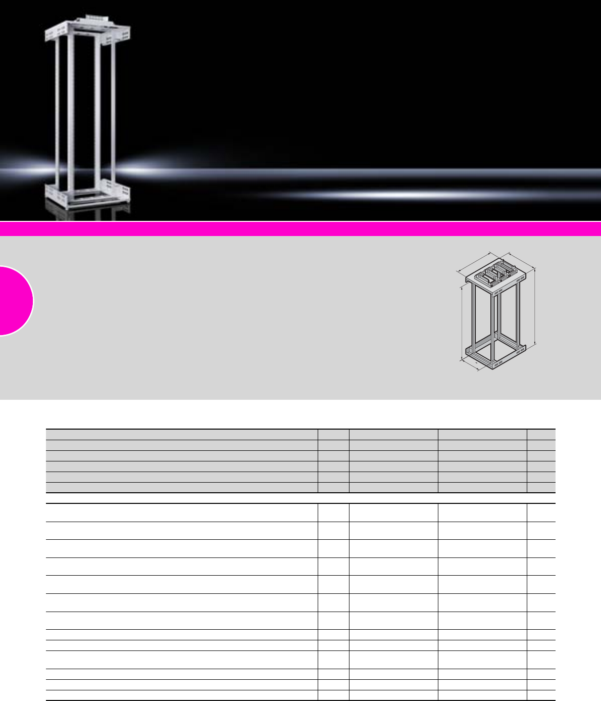
Distributor racks
88 Rittal Catalogue 33/Enclosures
482.6 mm (19˝) installation system Page 559 Monitoring Page 577 Power System Module Page 201
Benefits:
●Optimum accessibility from all
sides during assembly and
installation.
●Unrestricted airflow, due to
the open design.
●Standard cable trays in the
roof area for larger quantities
of cables.
●The distance between
attachment levels is infinitely
variable.
Material:
Sheet steel
Colour:
RAL 7035
Surface finish:
Powder-coated
Load capacity:
700 kg, static
Supply includes:
−Self-supporting mounting
frame, with 482.6 mm (19˝)
mounting level front and rear
−Open roof frame for cable
entry
−3 cable routing trays
−Open base frame with
2 punched sections with
mounting flanges for indivi-
dual configuration fitted in the
width
−Levelling feet
Detailed drawings:
Available on the Internet.
19
HE
T
H
B
TE 7000 open
U (HE) Packs of 42 42 Page
Width (B) mm 600 800
Height1) (H) mm 2000 2000
Depth (T) mm 1000 1000
Distance between levels (mm) as delivered 745 745
Model No. TE 1 7000.940 7000.944
Accessories
Cable management panel 482.6 mm (19˝), 1 U for horizontal cable routing,
with 5 steel rings, zinc-plated, passivated, size 105 x 43 mm 1 7257.035 7257.035 539
Cable management panel 482.6 mm (19˝), 2 U for horizontal cable routing,
with 5 steel rings, zinc-plated, passivated, size 125 x 85 mm 1 7257.100 7257.100 539
Shunting rings to accommodate large quantities of cables,
for mounting on the side of the mounting frame, dimension 330 x 90 mm 4 7220.600 7220.600 534
Cable management duct 482.6 mm (19˝), 2 U for horizontal cable routing,
with removable front panel 1 7158.100 7158.100 541
Component shelf 482.6 mm (19˝), 1/2 U static installation,
depth-variable in the range from 600 – 900 mm 1 7063.720 7063.720 485
Slide rail 482.6 mm (19˝), load capacity 100 kg,
for 740 mm distance between 482.6 mm (19˝) levels (internal) 2 7063.740 7063.740 560
Slide rail 482.6 mm (19˝), depth-variable within the range from 590 – 930 mm,
load capacity 80 kg, static 2 7063.883 7063.883 559
C rail, variable within the range 450 – 800 mm 1 7016.140 7016.140 532
T-head rail, variable within the range 450 – 800 mm 1 7016.150 7016.150 532
Cable route for vertical cable management, for mounting at the side rear
of the 482.6 mm (19˝) mounting frame, W = 100 mm, H = 1700 mm 1 set 7000.685 7000.685 536
Cable duct, 42 U 1 7827.320 7827.320 538
Cable manager, basic kit, for system-compatible cable deflection 8 7064.100 7064.100 533
Cable routing bars for 482.6 mm (19˝) system punchings 4 7111.224 7111.224 537
1) Plus 100 mm roof-mounting/cable-routing trays.
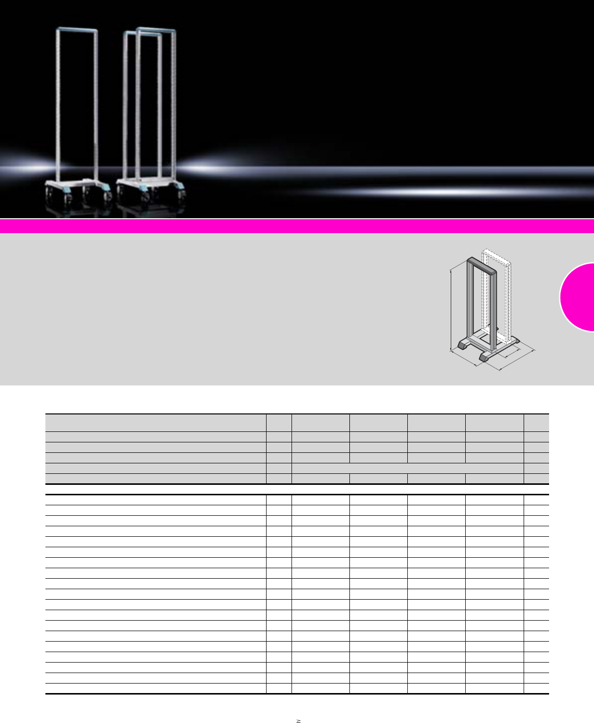
Distributor racks
89Rittal Catalogue 33/Enclosures
482.6 mm (19˝) installation system Page 558 Monitoring Page 577 Power System Module Page 201
Material:
−Profile frame, base/plinth:
Sheet steel
−Feet: Die-cast zinc
Colour:
−Profile frame, base/plinth:
RAL 7035
−Trim panel, feet: RAL 5018
Load capacity:
Max. 150 kg, static/level
Supply includes:
−Torsionally stiff profile frame
with 482.6 mm (19˝) punch-
ings
−Stable base/plinth with
integral feet, with the option
for base anchoring
−Assembly parts
Note:
Order second mounting level
separately.
Detailed drawings:
Available on the Internet.
Photo shows a configuration
example with equipment not
included in the scope of supply.
T1
H
B
T2
Data Rack
UPacks
of 31 36 40 45 Page
Width (B) mm 550 550 550 550
Height (H) mm 1499.5 1721.8 1899.5 2121.8
Depth (T1) mm 750 750 750 750
Distance from the second mounting level (T2) mm1) min. 150 – max. 350
Model No. DK 1 7391.000 7396.000 7400.000 7445.000
Accessories
Second mounting level1) 1 7296.000 7297.000 7298.000 7299.000 558
Baying connector 3 7494.000 7494.000 7494.000 7494.000 558
Levelling feet 4 7493.000 7493.000 7493.000 7493.000 373
Cable duct, 42 U 1 7827.320 7827.320 7827.320 7827.320 538
C rails, 482.6 mm (19˝) 6 7016.100 7016.100 7016.100 7016.100 542
Cable clamp rails, 482.6 mm (19˝) 6 7016.110 7016.110 7016.110 7016.110 542
Cable clamp strap D = 250 mm 6 7016.120 7016.120 7016.120 7016.120 542
Twin castors 4 7495.000 7495.000 7495.000 7495.000 374
Depth stays 2 7401.000 7401.000 7401.000 7401.000 558
Component shelf 2 U for one pair of mounting angles D = 250 mm 1 7119.250 7119.250 7119.250 7119.250 487
Component shelf 2 U for one pair of mounting angles D = 400 mm 1 7119.400 7119.400 7119.400 7119.400 487
Component shelf 2 U for one pair of mounting angles D = 300 mm3) 1 7148.035 7148.035 7148.035 7148.035 485
Drawer 2 U for one pair of mounting angles 1 7281.035 7281.035 7281.035 7281.035 614
Component shelf D = 300 mm2) 3) 1 7143.035 7143.035 7143.035 7143.035 482
Component shelf D = 400 mm2) 3) 1 7144.035 7144.035 7144.035 7144.035 482
Component shelf D = 500 mm2) 3) 1 7145.035 7145.035 7145.035 7145.035 482
Slide rails D max. < 190 mm 10 1962.200 1962.200 1962.200 1962.200 548
Slide rails D max. > 190 mm 10 1963.200 1963.200 1963.200 1963.200 548
Slide rails for two pairs of mounting angles1) 2) 4) 2 7402.000 7402.000 7402.000 7402.000 558
1) Second mounting level may be positioned on a 50 mm pitch pattern.
2) A second pair of mounting angles is required for assembly.
3) Stationary installation or full withdrawal, telescopic slides, see page 489.
4) 350 mm distance between levels (T2), can be combined with component shelf D = 500 mm.
90
91
Server enclosures
Server enclosures TS 8
Server enclosures TS 8 ...............................................................................92
Colocation ...................................................................................................93
For High Performance Cooling systems HPC .............................................94
Server enclosures TE 7000
Server enclosures TE 7000 .........................................................................95
Server enclosures TS 8
92 Rittal Catalogue 33/Enclosures
System accessories Page 355 Power System Module Page 201 Monitoring Page 577 Climate control Page 207
Material:
Sheet steel
Surface finish:
−Enclosure frame:
Dipcoat-primed
−Enclosure panels:
Dipcoat-primed,
powder-coated
−Mounting angles, mounting
frame and punched sections
with mounting flanges:
Zinc-plated
Colour:
RAL 7035
Supply includes:
Product-specific supply scope,
see table.
Detailed drawing:
Available on the Internet.
Photo shows a configuration
example with equipment not
included in the scope of supply.
UPacks of 24 42 42 47 42 42 Page
Width mm 600 600 600 600 800 800
Height mm 1200 2000 2000 2200 2000 2000
Depth mm 1000 1000 1200 1000 1000 1200
Distance between levels, pre-configured mm 740 740 740 740 740 740
482.6 mm (19˝) level, flat mounting angles on punched
sections with mounting flanges, front and rear, depth-variable 2 – –
482.6 mm (19˝) mounting frames, front and rear, depth-variable 2 – – – –
Model No. DK 1 7831.4332) 7831.438 7831.481 7831.442 7831.446 7831.485
Supply includes
Enclosure frame 1
Sheet steel doors, vented1), front and rear 2
Roof plate for cable entry, two-piece 1
Levelling feet 4
Open base, without base frame 1
Comfort handle for semi-cylinder with security lock 3524 E 2
Earthing of all enclosure panels pre-configured 1 set
Accessories
Side panels, lockable 2 7824.120 7824.200 – 7824.220 7824.200 – 387
Side panel, plug-type, divided 1 – – 7824.310 – – 7824.310 388
Base mounting bracket 4 8800.210 8800.210 8800.210 8800.210 8800.210 8800.210 376
Depth-variable slide rail, 1 U 2 7063.883 7063.883 7063.883 7063.883 7063.883 7063.883 559
Stabiliser, pull-out 1 7825.250 7825.250 7825.2602) 7825.250 7825.250 7825.2602) 372
Included with the supply. 1) Vented surface area > 78% perforated. 2) Extended delivery times.
Server enclosures TS 8
93Rittal Catalogue 33/Enclosures
System accessories Page 355 Power System Module Page 201 Monitoring Page 577 Climate control Page 207
Design features
−Robust frame structure
−Front and rear door fully
vented; vented surface area
> 78% perforated
−2-point locking
−Door hinge may be swapped
to opposite side without
machining
−Cable entry via the base/plinth
and roof (optional)
−Bayable at all levels
−Static load capacity of up to
1000 kg
Material:
Sheet steel
Surface finish:
−Enclosure frame:
Dipcoat-primed
−Enclosure panels:
Dipcoat-primed,
powder-coated
−Mounting angles, mounting
frame and punched sections
with mounting flanges:
Zinc-plated
Colour:
RAL 7035
Supply includes:
Product-specific supply scope,
see table.
Detailed drawing:
Available on the Internet.
Photo shows a configuration
example with equipment not
included in the scope of supply.
Colocation
Number of front and rear doors Packs of 2/2 4/4 Page
U2 x 21 4 x 10
Width mm 600 600
Height mm 2200 2200
Depth mm 1000 1000
Distance between levels, pre-configured mm 740 740
Model No. DK 17831.4531) 7831.4631)
Supply includes
Sheet steel doors, vented, front and rear with 180° hinges
Roof plate, solid 1
Levelling feet 4
482.6 mm (19˝) levels, flat mounting angles on punched sections with mounting flanges,
front and rear, depth-variable
Earthing of all enclosure panels pre-configured
Individual compartments, shielded/separate cable routing per compartment
Comfort handle for semi-cylinder with security lock 3524 E
Accessories
Side panels, lockable 2 7824.220 7824.220 387
Base mounting bracket 4 8800.210 8800.210 376
Depth-variable slide rail, 1 U 2 7063.883 7063.883 559
Semi-cylinder for individual lock 2 9785.042 9785.042 416
Quick-fit baying clamps 6 8800.500 8800.500 395
Stabiliser, pull-out 1 7825.250 7825.250 372
Included with the supply. 1) Extended delivery times.
Server enclosures TS 8
94 Rittal Catalogue 33/Enclosures
System accessories Page 355 Baying system Page 394 Monitoring Page 577
Load capacity:
Max. static load capacity of the
interior installation 1000 kg
Material:
−Sheet steel
−Glazed door: Single-pane
safety glass, 4 mm
Surface finish:
−Enclosure frame:
Dipcoat-primed
−Enclosure panels:
Additionally powder-coated
−Gland plates and 482.6 mm
(19˝) mounting frame:
Zinc-plated
Colour:
RAL 7035
Protection category:
IP 54 to IEC 60 529, in conjunc-
tion with solid roof plate (bayed
option) and additional screw-
fastened side panels with stand-
alone siting.
Supply includes:
Product-specific supply scope,
see table.
Photo shows a configuration
example with equipment not
included in the scope of supply.
For High Performance Cooling systems HPC
UPacks of 42 42 42 42 42 42 Page
Width mm 600 600 600 800 800 800
Height mm 2000 2000 2000 2000 2000 2000
Depth mm 1000 1200 1200 1000 1200 1200
Distance between levels, pre-configured mm 740 740 740 740 740 740
Including side panels – – – –
Model No. DK 1 7831.8101) 7831.8121) 7831.8131) 7831.8001) 7831.8021) 7831.8031)
Supply includes
Glazed aluminium door at the front (180°) 1
Sheet steel door at the rear (130°) 1
Comfort handle front and rear for semi-cylinder,
security lock 3524 E 2
Roof plate for cable entry, two-piece 1
Levelling feet 4
Base frame with multi-piece gland plate 1
482.6 mm (19˝) mounting frames, front and rear, depth-variable 2
Earthing of all enclosure panels pre-configured 1 set
Accessories
Side panel, screw-fastened, IP 55 2 8100.235 – 8100.235 – 385
Depth-variable slide rail, 1 U, length 590 – 930 mm,
80 kg, static 2 7063.883 7063.883 7063.883 7063.883 7063.883 7063.883 559
482.6 mm (19˝) heavy-duty component shelf, 700 mm deep,
100 kg static load capacity 1 7063.897 7063.897 7063.897 7063.897 7063.897 7063.897 484
Installation kit for heavy-duty component shelf, depth-variable 1 set 7063.890 7063.890 7063.890 7063.890 7063.890 7063.890 488
Flex-Block see page 358
Liquid Cooling Package see page 279
Included with the supply. 1) Extended delivery times.
Server enclosures TE 7000
95Rittal Catalogue 33/Enclosures
System accessories Page 355 Power System Module Page 201 Monitoring Page 577 Climate control Page 207
Benefits:
●No frame structure
●Optimum accessibility
●Readily dismantled and
therefore easily installed
Material:
Sheet steel
Surface finish:
−Mounting frame:
Dipcoat-primed
−Enclosure panels:
Powder-coated
Colour:
See table.
Supply includes:
Product-specific supply scope,
see table.
Detailed drawing:
Available on the Internet.
Photo shows a configuration
example with equipment not
included in the scope of supply.
UPacks of 24 42 42 42 42 Page
Width mm 600 600 600 800 800
Height mm 1200 2000 2000 2000 2000
Depth mm 1000 1000 1000 1000 1000
Distance between levels, pre-configured mm 745 745 745 745 745
Colour RAL 7035 RAL 7035 RAL 9005 RAL 7035 RAL 9005
Model No. TE 17000.875 7000.882 7000.885 7000.892 7000.895
Supply includes
Self-supporting 482.6 mm (19˝) mounting frame, front and rear,
depth-variable 2
Sheet steel door vented2), front with moulded handle, 130° hinge,
security lock 3524 E 1
Sheet steel door vented2), rear with moulded handle, 130° hinge,
security lock 3524 E 1
Levelling feet 4
Roof plate including brush strip for cable entry and optional fitting
with an active fan unit 1
Base frame with maximum cut-out for optional fitting
with module plates, solid, passively vented or for cable entry 1
Accessories
Side panels, lockable, including security lock 3524 E 2 7000.653 7000.663 7000.653 7000.663 388
Baying kit 1 set 7000.640 400
Ergoform-S handle for semi-cylinder, to exchange for the existing lock 1 2435.000 2435.000 2452.0001) 2435.000 2452.0001) 419
Fan unit, with 2 fans and thermostat, pre-wired ready for connection 1 7000.670 7000.670 – 7000.670 – 224
Transport castors, including assembly parts 4 7000.672 7000.672 7000.672 7000.672 7000.672 375
C rail, for cable clamping in the enclosure width via cable clamps,
on the 482.6 mm (19˝) mounting frame at the rear 4 7828.060 7828.060 7828.060 7828.060 7828.060 465
Slide rail, 482.6 mm (19˝) for 740 mm distance between levels 2 7063.740 7063.740 7063.740 7063.740 7063.740 560
Cable clamp rail, depth-variable 500 – 895 mm,
for cable attachment in the enclosure depth via cable ties 4 7858.162 7858.162 7858.162 7858.162 7858.162 532
Cable clamp rail, for cable attachment in the enclosure width
via cable ties, on the 482.6 mm (19˝) mounting frame at the rear 4 7828.062 7828.062 7828.062 7828.062 7828.062 532
Earthing kit for TE 1 set 7000.675 7000.675 7000.675 7000.675 7000.675 503
Socket strip for TE, 8-way for earthing-pin plugs 1 7000.630 7000.630 7000.630 7000.630 7000.630 506
Included with the supply. 1) Matt nickel-plated 2) Vented surface area > 67% perforated.
96
97
TopConsole system TP
Overview of mounting components.............................................................99
Combination options .................................................................................100
600 mm wide .............................................................................................101
800 mm wide .............................................................................................102
1200 mm wide ...........................................................................................103
1600 mm wide ...........................................................................................104
Accessories...............................................................................................105
One-piece consoles TP
One-piece consoles TP .............................................................................106
Universal consoles TP
Universal consoles TP ...............................................................................107
PC enclosure systems
PC enclosure systems TS 8.......................................................................108
Enclosure for tower PC..............................................................................109
Industrial Workstations
Combination options .................................................................................110
IW enclosures and worktops .....................................................................111
Console systems/
PC enclosure systems/
Industrial Workstations
98
1
1
1
2
2
3
3
4
4
4
4
1
5
7
8
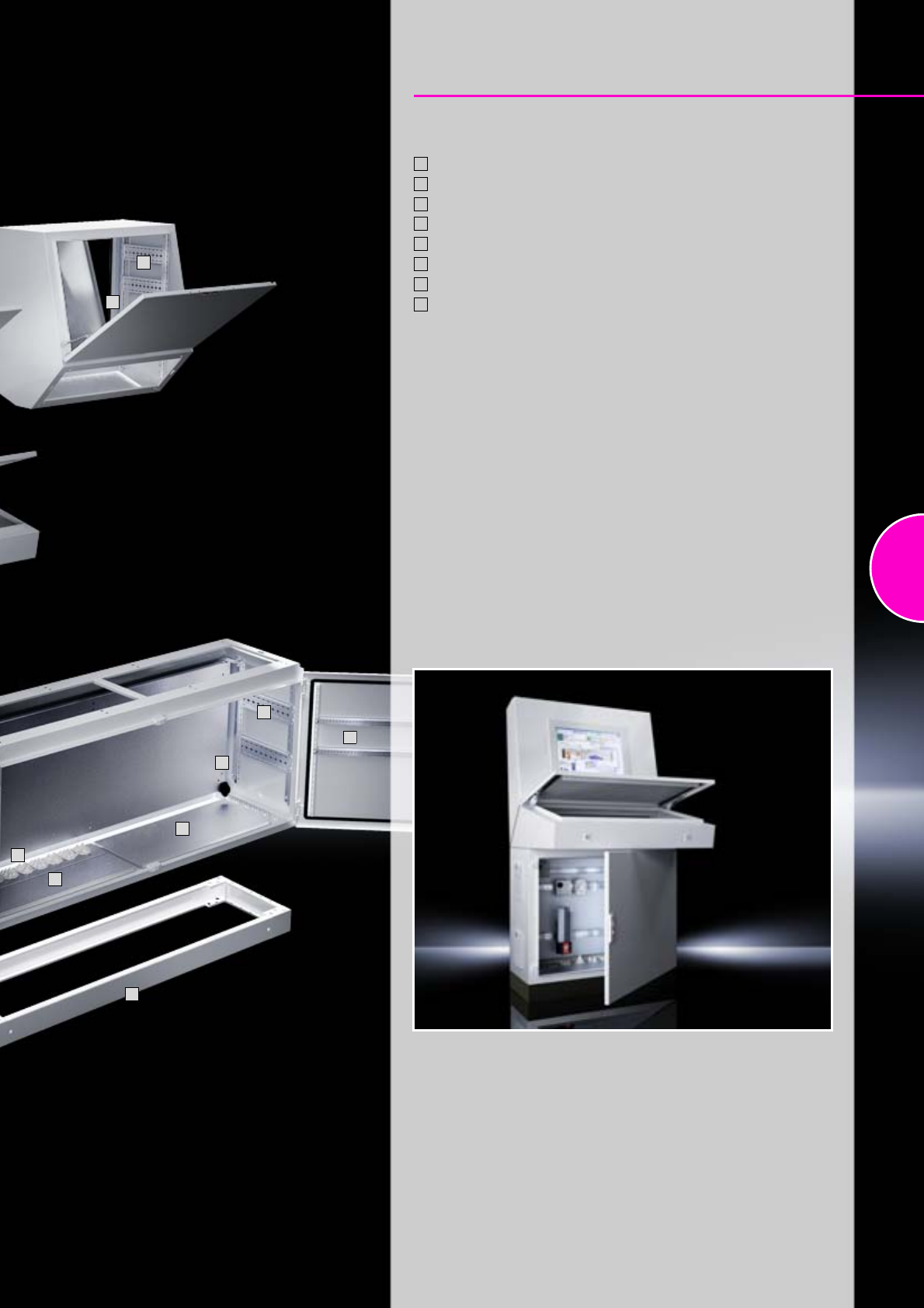
99
TopConsole system TP
Overview of mounting components
Punched section with mounting flange, 17 x 73 mm
Support strips
Partial mounting plates
Rail for interior installation
Gland plates
Cable entry grommets
Base/plinth
Assembly bolts for base/plinth
1
2
3
4
5
6
7
8
1
1
2
4
4
5
5
6
7
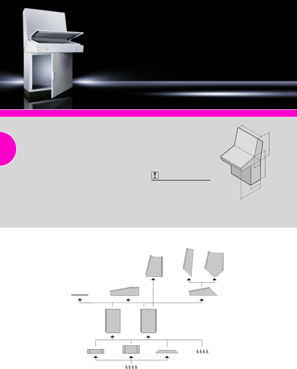
TopConsole system TP
100 Rittal Catalogue 33/Enclosures
System accessories Page 355 Monitors, keyboards From page 606 Climate control Page 207
Material:
−Enclosure:
Sheet steel 1.5 mm
−Door and console cover:
Sheet steel, 2.0 mm,
all-round foamed-in PU seal
−Mounting plate:
Sheet steel 2.5 mm
Surface finish:
−Dipcoat-primed, powder-
coated on the outside,
textured paint
−Mounting plate zinc-coated
on bottom part
Colour:
RAL 7035
Protection category:
IP 55 to IEC 60 529,
complies with NEMA 12
(provided suitable gland plates
are selected)
Supply includes:
Console
−Enclosure
−Cover hinged at bottom,
including cover retainer
−Open base for individual
cable entry
Console, deep
−Enclosure
−Front cover hinged at bottom,
including cover retainer
−Rear door, hinged at bottom
−Open base for individual
cable entry
Desk section
−Enclosure
−Cover hinged, 2 stays with
automatic locking and unlock-
ing
−Opening for running cables
into the enclosure base
Pedestal
−Enclosure open at top
−Door or double door with lock-
ing rod (with depth 400 mm at
the front, with depth 500 mm
at the front and rear)
−Depth-adjustable mounting
plate (with depth 500 mm)
−Open base for individual
cable entry
Also required:
Gland plates, see page 378.
Approvals:
−CE
−UL
−cUL
Detailed drawings:
Available on the Internet.
Photo shows a configuration
example with equipment not
included in the scope of supply.
T
H
B
T
HH
T
Consoles
Desk units
Base/plinth
Pedestals
1-part 2-part 3-part
Combination options

TopConsole system TP
101Rittal Catalogue 33/Enclosures
600 mm wide
Configuration 3-part 2-part 2-part 1-part
Depth of pedestal in mm 400 500 400 500 400 500 400 500
Consoles 700 mm high
Height (H) mm Packs
of 700 –––Page
Depth (T) mm 240 –––
Model No. TP 16720.500 –––
Consoles 540/730 mm high with enlarged installation depth
Height (H) mm Packs
of –730 – – 540 –Page
Depth (T) mm –520 – – 520 –
Model No. TP 1– 6720.200 –– 6720.100 –
Accessories
Partial mounting plate Width 200 mm 1 6730.310 – – 6730.3101) – 450
Width 500 mm 1 6730.330 – – 6730.3301) – 450
Rail for interior installation For width 4 5001.050 – – 5001.050 – 459
For height 4 5001.051 – – 5001.050 – 459
Desk units
Height (H) mm Packs
of 235 235 – – Page
Depth (T) mm 700 700 – –
Model No. TP 1 6714.500 6710.500 ––
Accessories
Rail for interior installation For width 4 5001.050 5001.050 – – 459
Strengthener 1 – 6730.400 – – 105
Trim panel for pedestal 1 – – – 5001.130 6370.100 105
Pedestals
Height (H) mm Packs
of 675 675 675 675 – 675 675 675 Page
Depth (T) mm 400 500 400 500 – 500 400 500
Model No. TP 16700.500 6704.500 6700.500 6704.500 – 6704.500 6700.500 6704.500
Accessories
Base/plinth components
front and rear
Height 100 mm 1 set 8601.600 8601.600 8601.600 8601.600 – 8601.600 8601.600 8601.600 361
Height 200 mm 1 set 8602.600 8602.600 8602.600 8602.600 – 8602.600 8602.600 8602.600 361
Base/plinth trim panels, side Height 100 mm 1 set 8601.040 8601.050 8601.040 8601.050 – 8601.050 8601.040 8601.050 362
Height 200 mm 1 set 8602.040 8602.050 8602.040 8602.050 – 8602.050 8602.040 8602.050 362
Cross member, adjustable 2 8601.450 8601.450 8601.450 8601.450 – 8601.450 8601.450 8601.450 370
Gland plates
1-part 1 5001.222 – 5001.222 – – – 5001.222 – 379
2-part
1 5001.214 5001.214 5001.214 5001.214 5001.214 5001.214 5001.214 379
++++– ++ +
1 5001.218 5001.222 5001.218 5001.222 5001.222 5001.218 5001.222 379
Individual For more gland plate variants, see page 381
Rail for interior installation For height 4 5001.050 5001.050 5001.050 5001.050 – 5001.050 5001.050 5001.050 459
Punched section with
mounting flange, 17 x 73 mm In the depth 4 8612.140 8612.150 8612.140 8612.150 – 8612.150 8612.140 8612.150 459
Punched rail 18 x 38 mm In the depth 4 8612.240 8612.250 8612.240 8612.250 – 8612.250 8612.240 8612.250 462
Support strips In the depth 20 4694.000 4695.000 4694.000 4695.000 – 4695.000 4694.000 4695.000 462
Punched section with
mounting flange, 17 x 73 mm For door 4 8612.050 8612.050 8612.050 8612.050 – 8612.050 8612.050 8612.050 459
Support strips For door 20 4596.000 4596.000 4596.000 4596.000 – 4596.000 4596.000 4596.000 462
Cable clamp rail 1 5001.080 5001.080 5001.080 5001.080 – 5001.080 5001.080 5001.080 527
Wiring plan pocket 1 4116.500 4116.500 4116.500 4116.500 – 4116.500 4116.500 4116.500 429
Alternative lock systems see page 413
1) Configuration examples and further details of the accessories required may be found on the Internet.
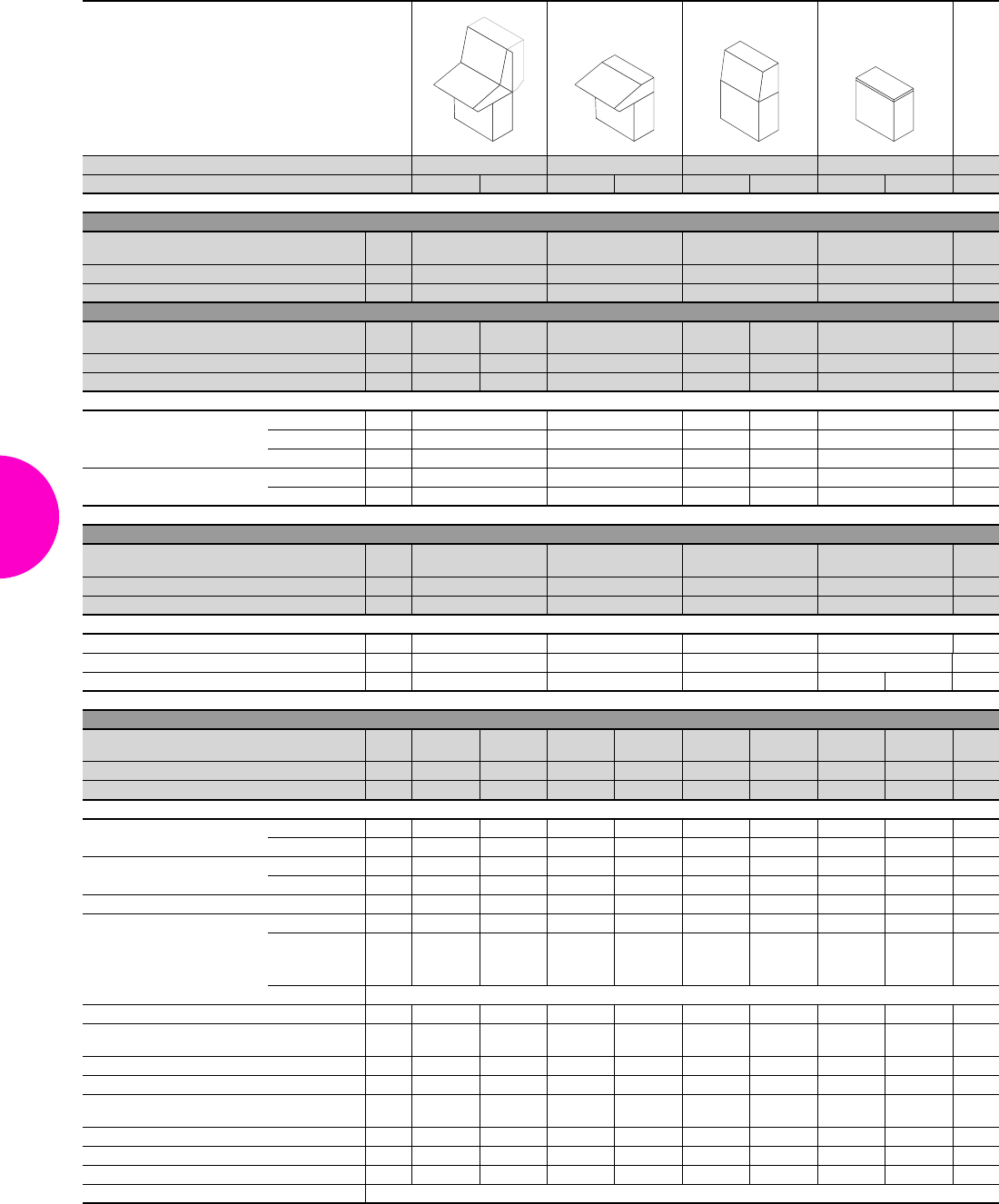
TopConsole system TP
102 Rittal Catalogue 33/Enclosures
800 mm wide
Configuration 3-part 2-part 2-part 1-part
Depth of pedestal in mm 400 500 400 500 400 500 400 500
Consoles 700 mm high
Height (H) mm Packs
of 700 –––Page
Depth (T) mm 240 –––
Model No. TP 16721.500 –––
Consoles 540/730 mm high with enlarged installation depth
Height (H) mm Packs
of –730 – – 540 –Page
Depth (T) mm –520 – – 520 –
Model No. TP 1– 6721.200 –– 6721.100 –
Accessories
Partial mounting plate
Width 200 mm 1 6730.310 – – 6730.3101) – 450
Width 500 mm 1 6730.330 – – 6730.3301) – 450
Width 700 mm 1 6730.340 – – 6730.3401) – 450
Rail for interior installation For width 4 5001.051 – – 5001.051 – 459
For height 4 5001.051 – – 5001.050 – 459
Desk units
Height (H) mm Packs
of 235 235 – – Page
Depth (T) mm 700 700 – –
Model No. TP 16715.500 6711.500 – –
Accessories
Rail for interior installation For width 4 5001.051 5001.051 – – 459
Strengthener 1 – 6730.410 – – 105
Trim panel for pedestal 1 – – – 5001.140 6730.110 105
Pedestals
Height (H) mm Packs
of 675 675 675 675 – 675 675 675 Page
Depth (T) mm 400 500 400 500 – 500 400 500
Model No. TP 1 6701.500 6705.500 6701.500 6705.500 – 6705.500 6701.500 6705.500
Accessories
Base/plinth components
front and rear
Height 100 mm 1 set 8601.800 8601.800 8601.800 8601.800 – 8601.800 8601.800 8601.800 361
Height 200 mm 1 set 8602.800 8602.800 8602.800 8602.800 – 8602.800 8602.800 8602.800 361
Base/plinth trim panels, side Height 100 mm 1 set 8601.040 8601.050 8601.040 8601.050 – 8601.050 8601.040 8601.050 362
Height 200 mm 1 set 8602.040 8602.050 8602.040 8602.050 – 8602.050 8602.040 8602.050 362
Cross member, adjustable 2 8601.450 8601.450 8601.450 8601.450 – 8601.450 8601.450 8601.450 370
Gland plates
1-part 1 5001.223 – 5001.223 – – – 5001.223 – 379
2-part
1 5001.215 5001.215 5001.215 5001.215 5001.215 5001.215 5001.215 379
++++– +++
1 5001.219 5001.223 5001.219 5001.223 5001.223 5001.219 5001.223 379
Individual For more gland plate variants, see page 381
Rail for interior installation For height 4 5001.050 5001.050 5001.050 5001.050 – 5001.050 5001.050 5001.050 459
Punched section with
mounting flange, 17 x 73 mm In the depth 4 8612.140 8612.150 8612.140 8612.150 – 8612.150 8612.140 8612.150 459
Punched rail 18 x 38 mm In the depth 4 8612.240 8612.250 8612.240 8612.250 – 8612.250 8612.240 8612.250 462
Support strips In the depth 20 4694.000 4695.000 4694.000 4695.000 – 4695.000 4694.000 4695.000 462
Punched section with
mounting flange, 17 x 73 mm For door 4 8612.050 8612.050 8612.050 8612.050 – 8612.050 8612.050 8612.050 459
Support strips For door 20 4598.000 4598.000 4598.000 4598.000 – 4598.000 4598.000 4598.000 462
Cable clamp rail 1 5001.081 5001.081 5001.081 5001.081 – 5001.081 5001.081 5001.081 527
Wiring plan pocket 1 4118.500 4118.500 4118.500 4118.500 – 4118.500 4118.500 4118.500 429
Alternative lock systems see page 413
1) Configuration examples and further details of the accessories required may be found on the Internet.
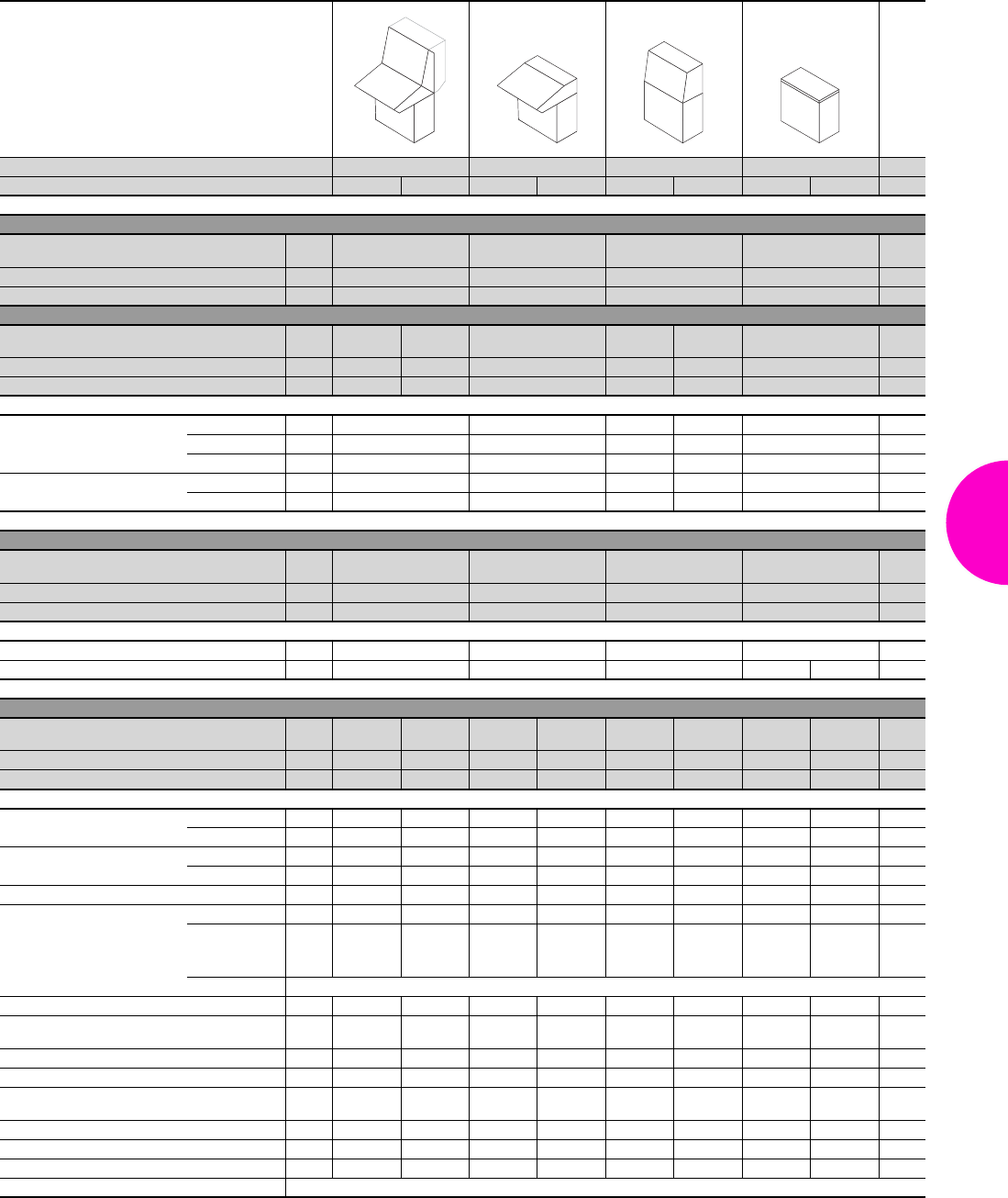
TopConsole system TP
103Rittal Catalogue 33/Enclosures
1200 mm wide
Configuration 3-part 2-part 2-part 1-part
Depth of pedestal in mm 400 500 400 500 400 500 400 500
Consoles 700 mm high
Height (H) mm Packs
of 700 –––Page
Depth (T) mm 240 –––
Model No. TP 1 6722.500 –––
Consoles 540/730 mm high with enlarged installation depth
Height (H) mm Packs
of –730 – – 540 –Page
Depth (T) mm –520 – – 520 –
Model No. TP 1 – 6722.2003) – – 6722.1003) –
Accessories
Partial mounting plate
Width 200 mm 1 6730.310 – – 6730.3101) – 450
Width 500 mm 1 6730.330 – – 6730.3301) – 450
Width 700 mm 1 6730.340 – – 6730.3401) – 450
Rail for interior installation For width 4 5001.053 – – 5001.053 – 459
For height 4 5001.051 – – 5001.050 – 459
Desk units
Height (H) mm Packs
of 235 235 – – Page
Depth (T) mm 700 700 – –
Model No. TP 1 6716.500 6712.500 – –
Accessories
Rail for interior installation For width 4 5001.053 5001.053 – – 459
Trim panel for pedestal 1 – – – 5001.160 6730.120 105
Pedestals
Height (H) mm Packs
of 675 675 675 675 – 675 675 675 Page
Depth (T) mm 400 500 400 500 – 500 400 500
Model No. TP 1 6702.500 6706.500 6702.500 6706.500 – 6706.500 6702.500 6706.500
Accessories
Base/plinth components
front and rear
Height 100 mm 1 set 8601.200 8601.200 8601.200 8601.200 – 8601.200 8601.200 8601.200 361
Height 200 mm 1 set 8602.200 8602.200 8602.200 8602.200 – 8602.200 8602.200 8602.200 361
Base/plinth trim panels, side Height 100 mm 1 set 8601.040 8601.050 8601.040 8601.050 – 8601.050 8601.040 8601.050 362
Height 200 mm 1 set 8602.040 8602.050 8602.040 8602.050 – 8602.050 8602.040 8602.050 362
Cross member, adjustable 2 8601.450 8601.450 8601.450 8601.450 – 8601.450 8601.450 8601.450 370
Gland plates2)
1-part 1 5001.225 – 5001.225 – – – 5001.225 – 379
2-part
1 5001.217 5001.217 5001.217 5001.217 5001.217 5001.217 5001.217 379
++++– +++
1 5001.221 5001.225 5001.221 5001.225 5001.225 5001.221 5001.225 379
Individual For more gland plate variants, see page 381
Rail for interior installation For height 4 5001.050 5001.050 5001.050 5001.050 – 5001.050 5001.050 5001.050 459
Punched section with
mounting flange, 17 x 73 mm In the depth 4 8612.140 8612.150 8612.140 8612.150 – 8612.150 8612.140 8612.150 459
Punched rail 18 x 38 mm In the depth 4 8612.240 8612.250 8612.240 8612.250 – 8612.250 8612.240 8612.250 462
Support strips In the depth 20 4694.000 4695.000 4694.000 4695.000 – 4695.000 4694.000 4695.000 462
Punched section with
mounting flange, 17 x 73 mm For door 4 8612.050 8612.050 8612.050 8612.050 – 8612.050 8612.050 8612.050 459
Support strips For door 20 4596.000 4596.000 4596.000 4596.000 – 4596.000 4596.000 4596.000 462
Cable clamp rail 1 5001.083 5001.083 5001.083 5001.083 – 5001.083 5001.083 5001.083 527
Wiring plan pocket 1 4116.500 4116.500 4116.500 4116.500 – 4116.500 4116.500 4116.500 429
Alternative lock systems see page 413
1) Configuration examples and further details of the accessories required may be found on the Internet.
2) With the two-door pedestal, the base opening is divided in two, and two sets of gland plates are required!
3) Extended delivery times.
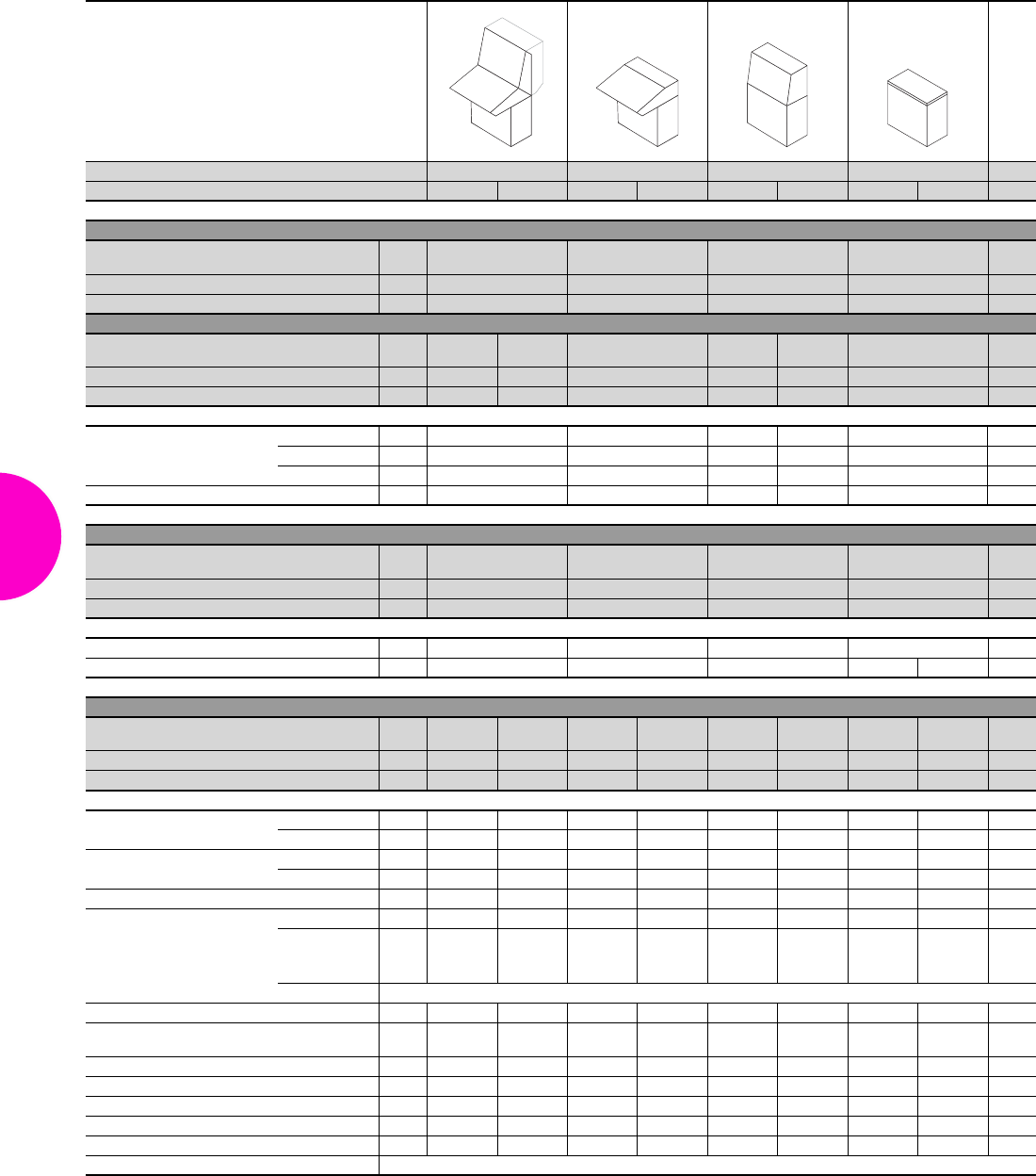
TopConsole system TP
104 Rittal Catalogue 33/Enclosures
1600 mm wide
Configuration 3-part 2-part 2-part 1-part
Depth of pedestal in mm 400 500 400 500 400 500 400 500
Consoles 700 mm high
Height (H) mm Packs
of 700 –––Page
Depth (T) mm 240 –––
Model No. TP 1 6723.500 –––
Consoles 540/730 mm high with enlarged installation depth
Height (H) mm Packs
of –730 – – 540 –Page
Depth (T) mm –520 – – 520 –
Model No. TP 1 – 6723.200 –– 6723.100 –
Accessories
Partial mounting plate
Width 200 mm 1 6730.310 – – 6730.3101) – 450
Width 500 mm 1 6730.330 – – 6730.3301) – 450
Width 700 mm 1 6730.340 – – 6730.3401) – 450
Rail for interior installation For height 4 5001.051 – – 5001.050 – 459
Desk units
Height (H) mm Packs
of 235 235 – – Page
Depth (T) mm 700 700 – –
Model No. TP 1 6717.500 6713.500 – –
Accessories
Rail for interior installation For width 4 5001.054 5001.054 – – 459
Trim panel for pedestal 1 – – – 6730.030 6730.130 105
Pedestals
Height (H) mm Packs
of 675 675 675 675 – 675 675 675 Page
Depth (T) mm 400 500 400 500 – 500 400 500
Model No. TP 1 6703.500 6707.500 6703.500 6707.500 – 6706.500 6703.500 6707.500
Accessories
Base/plinth components
front and rear
Height 100 mm 1 set 8601.920 8601.920 8601.920 8601.920 – 8601.920 8601.920 8601.920 361
Height 200 mm 1 set 8602.920 8602.920 8602.920 8602.920 – 8602.920 8602.920 8602.920 361
Base/plinth trim panels, side Height 100 mm 1 set 8601.040 8601.050 8601.040 8601.050 – 8601.050 8601.040 8601.050 362
Height 200 mm 1 set 8602.040 8602.050 8602.040 8602.050 – 8602.050 8602.040 8602.050 362
Cross member, adjustable 2 8601.450 8601.450 8601.450 8601.450 – 8601.450 8601.450 8601.450 370
Gland plates2)
1-part 1 5001.236 – 5001.236 – – – 5001.236 – 379
2-part
1 5001.234 5001.234 5001.234 5001.234 5001.234 5001.234 5001.234 379
++++– +++
1 5001.235 5001.236 5001.235 5001.236 5001.236 5001.235 5001.236 379
Individual For more gland plate variants, see page 381
Rail for interior installation For height 4 5001.050 5001.050 5001.050 5001.050 – 5001.050 5001.050 5001.050 459
Punched section with
mounting flange, 17 x 73 mm In the depth 4 8612.140 8612.150 8612.140 8612.150 – 8612.150 8612.140 8612.150 459
Punched rail 18 x 38 mm In the depth 4 8612.240 8612.250 8612.240 8612.250 – 8612.250 8612.240 8612.250 462
Support strips In the depth 20 4694.000 4695.000 4694.000 4695.000 – 4695.000 4694.000 4695.000 462
Support strips For door 20 4598.000 4598.000 4598.000 4598.000 – 4598.000 4598.000 4598.000 462
Cable clamp rail Width 800 mm 1 5001.081 5001.081 5001.081 5001.081 – 5001.081 5001.081 5001.081 527
Wiring plan pocket 1 4118.500 4118.500 4118.500 4118.500 – 4118.500 4118.500 4118.500 429
Alternative lock systems see page 413
1) Configuration examples and further details of the accessories required may be found on the Internet.
2) With the two-door pedestal, the base opening is divided in two, and two sets of gland plates are required!
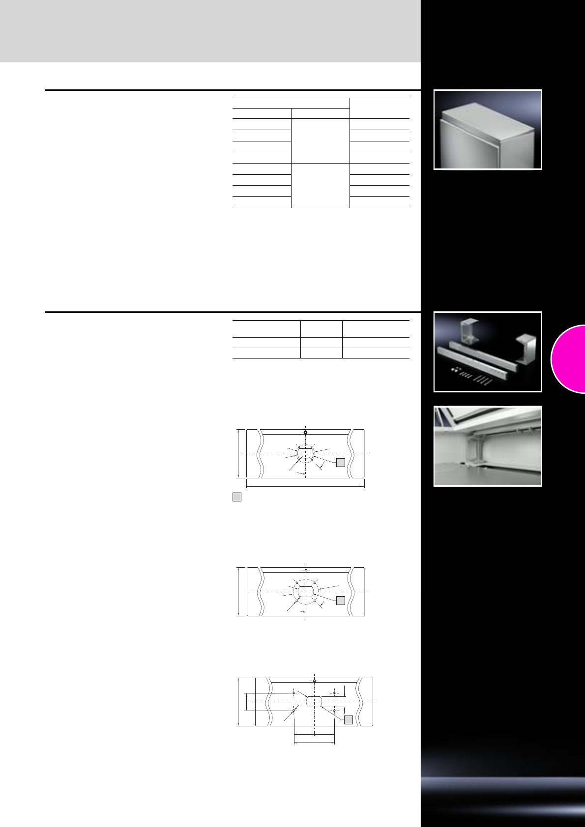
Accessories
TopConsole system TP
105Rittal Catalogue 33/Enclosures
Trim panel
for pedestal
For covering the complete top opening when
using the pedestal on its own.
Material:
Sheet steel
Surface finish:
Textured paint
Colour:
RAL 7035
Protection category:
IP 55 to IEC 60 529,
complies with NEMA 12.
Supply includes:
Assembly parts.
For pedestal Model No.
Width mm Depth mm
600
400
5001.130
800 5001.140
1200 5001.160
1600 6730.030
600
500
6730.100
800 6730.110
1200 6730.120
1600 6730.130
Strengthener
for desk unit, rear with hinged cover
●Suitable for mounting operating housings using
−CP-L enclosure attachment, Ø 130 mm,
CP 6525.510, see page 133
−CP-XL enclosure attachment, round
CP 6130.610, see page 141
−Housing couplings CP-XL for desk mounting,
CP 6528.410, see page 144
●Easily screw-fastened to the base of the desk
unit.
●Connection hole pattern for CP support arm
systems in the centre as standard; other posi-
tions can be accommodated by drilling extra
holes.
Mounting cut-out required in the cover of the desk
units, mounting cut-outs to match the various
support arm systems.
Material:
Sheet steel
Supply includes:
Assembly parts.
Mounting cut-outs
for the covers of the desk units
For width
mm Packs of Model No. TP
600 1 6730.400
800 1 6730.410
Ø 9
Ø 82
45°
592/792
215
1
for external mounting of CP 6525.510
Max. Ø 70 mm
1
for external mounting of CP 6130.610
Ø 9
Ø 112
45°
215
1
for external mounting of CP 6528.410
180
==
79
45
Ø 9
215
1
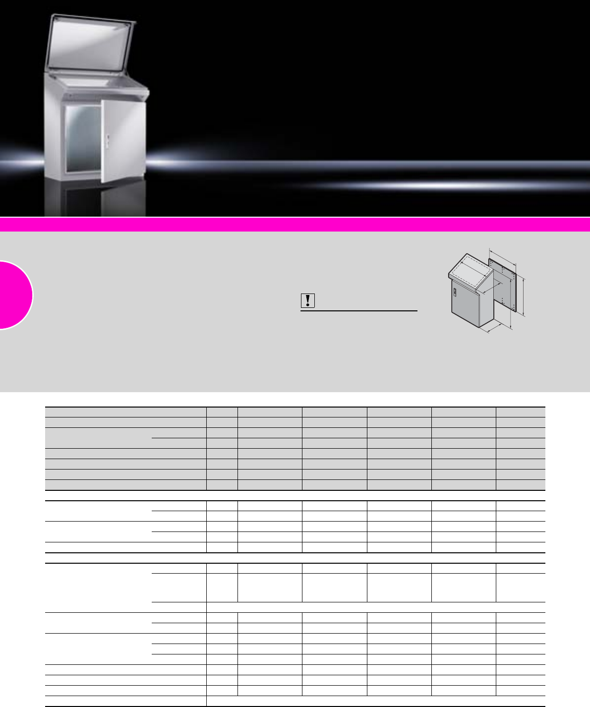
One-piece consoles TP
106 Rittal Catalogue 33/Enclosures
System accessories
Page 355
Monitors, keyboards
From page 606
Climate control
Page 207
One-piece consoles AP stainless steel
Page 170
Material:
−Enclosure: Sheet steel 1.5 mm
−Door and console cover:
Sheet steel, 2.0 mm, all-round
foamed-in PU seal
−Mounting plate: Sheet steel
3.0 mm
−Lock cover: Plastic,
self-extinguishing
Surface finish:
−Enclosure, cover and door:
Dipcoat-primed, powder-
coated on the outside,
textured paint
−Mounting plate: Zinc-plated
Colour:
RAL 7035
Protection category:
IP 55 to IEC 60 529,
complies with NEMA 12
(provided suitable gland plates
are selected).
Supply includes:
−Enclosure, solid back and
sides
−Door or double door at front,
with locking rod
−Mounting plate
−Cover hinged at rear, 2 stays
with automatic locking and
unlocking
−Open base for individual
cable entry
Also required:
Gland plates,
see page 378 – 380.
Detailed drawings:
Available on the Internet.
T
H
G
F
T
B
Width (B) mm Packs of 600 800 1000 1200 Page
Height (H) mm 960 960 960 960
Depth (T) mm Bottom 400 400 400 400
Top 520 520 520 520
Mounting plate width (F) mm 530 730 930 1130
Mounting plate height (G) mm 900 900 900 900
Model No. TP 1 6746.500 6748.500 6740.500 6742.500
Door(s) 1 1 2 2
Base/plinth
Components front and rear Height 100 mm 1 set 8601.600 8601.800 8601.000 8601.200 361
Height 200 mm 1 set 8602.600 8602.800 8602.000 8602.200 361
Trim panels, sides Height 100 mm 1 set 8601.040 8601.040 8601.040 8601.040 362
Height 200 mm 1 set 8602.040 8602.040 8602.040 8602.040 362
Cross member, adjustable 2 8601.450 8601.450 8601.450 8601.450 370
Accessories
Gland plates1)
1-part 1 5001.222 5001.223 5001.224 5001.225 379
2-part
1 5001.214 5001.215 5001.216 5001.217
379
+++++
1 5001.218 5001.219 5001.220 5001.221
Individual For more gland plate variants, see page 381
Rail for interior installation For enclosures 4 5001.051 5001.051 5001.051 5001.051 157
For cover 4 5001.050 5001.051 5001.052 5001.053 157
Punched section
with mounting flange,
17 x 73 mm
For enclosures 4 8612.140 8612.140 8612.140 8612.140 459
For cover 4 8612.040 8612.040 8612.040 8612.040 459
For door 4 8612.050 – 8612.040 8612.050 459
Punched rail 18 x 38 mm For enclosures 4 8612.240 8612.240 8612.240 8612.240 462
Cable clamp rail 1 5001.080 5001.081 5001.082 5001.083 527
Wiring plan pocket 1 4116.500 4118.500 4115.500 4116.500 429
Alternative lock systems see page 413
1) With the two-door variant, the base opening is divided in two, and two sets of gland plates are required!
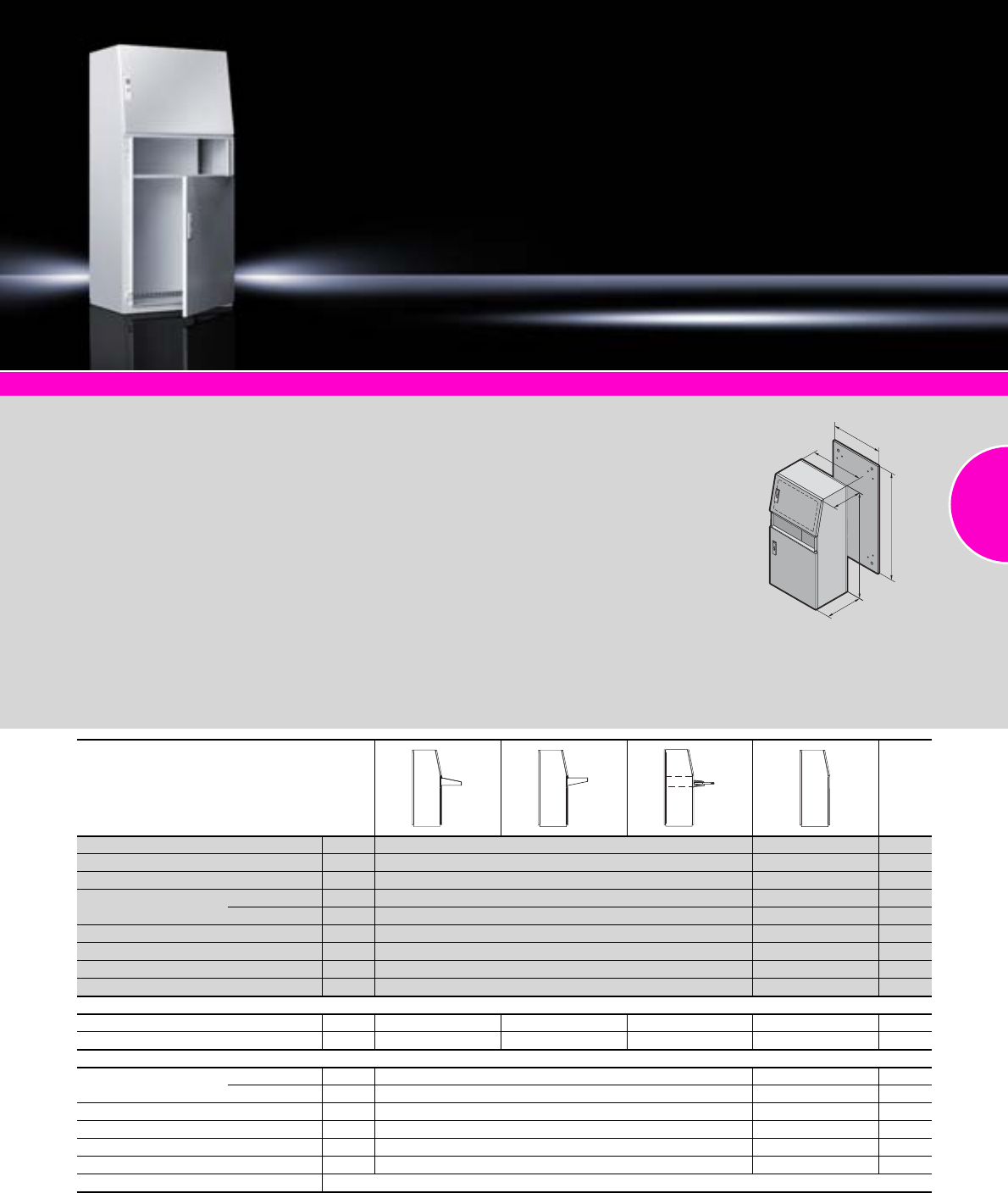
Universal consoles TP
107Rittal Catalogue 33/Enclosures
System accessories Page 355 Monitors, keyboards From page 606 Climate control Page 207
Material:
−Enclosure, gland plates:
Sheet steel 1.5 mm
−Doors: Sheet steel 2.0 mm
−Mounting plate: Sheet steel
3.0 mm
Surface finish:
−Enclosure and doors:
Dipcoat-primed, powder-
coated on the outside,
textured paint
−Mounting plate and gland
plates: Zinc-plated
Colour:
RAL 7035
Protection category:
−IP 55 to IEC 60 529,
complies with NEMA 12.
−With a short bottom door
(TP 2694.500), the drawer or
desk section (see below)
should be fitted in order to
preserve the protection
category.
Supply includes:
−Enclosure with doors
−Mounting plate
−Gland plates
Note:
Top door with studs left and right
for installing vertical perforated
mounting strips SZ 2310.038
and horizontal support strips
SZ 2325.000 to be mounted on
top (see page 426/427).
Approvals:
−UL
−CSA
−TÜV
−Germanischer Lloyd
−Russian Maritime Register
of Shipping
−Lloyds Register of Shipping
−VDE
Detailed drawing:
Available on the Internet.
Photo shows a configuration
example with equipment not
included in the scope of supply.
H
G
F
T
B
T
Packs of with short front door with tall front door Page
Width (B) mm 600 600
Height (H) mm 1300 1300
Depth (T) mm Bottom 500 500
Top 417.5 417.5
Mounting plate width (F) mm 499 499
Mounting plate height (G) mm 1196 1196
Model No. TP 12694.500 2695.500
Weight (kg) 77.0 80.0
Also required
Desk section 2696.500 2696.500 – – –
Drawer for keyboard – – 4757.5001) ––
Accessories
Base/plinth Height 100 mm 1 2807.200 2807.200 369
Height 200 mm 1 2808.200 2808.200 369
Cross member, adjustable 2 8601.450 8601.450 370
Perforated mounting strip 1 2310.038 2310.038 427
Support strips 1 2325.000 2325.000 426
Cable clamp rail 1 4191.000 4191.000 527
Alternative lock systems see page 413
1) Only suitable for installation without a mounting plate.

PC enclosure systems
108 Rittal Catalogue 33/Enclosures
System accessories
Page 355
Monitors, keyboards
From page 606
Climate control
Page 207
PC case system, stainless steel
Page 171
Material:
−Enclosure, door, mounting
compartment, supports:
Sheet steel
−Handles, decorative trim
panels: Plastic
−Door trim panels: Aluminium
Protection category:
IP 55 to IEC 60 529,
complies with NEMA 12.
Supply includes:
Enclosure, door, rear door and
enclosure-specific supply scope
(see table)
Approvals:
−UL
−CSA
−TÜV
−Germanischer Lloyd
−Russian Maritime Register
of Shipping
−Lloyds Register of Shipping
−VDE
Detailed drawings/
Technical information:
Available on the Internet.
Photo shows a configuration
example with equipment not
included in the scope of supply.
Enclosure-specific supply scope
Keyboard drawer Packs of – – – Page
Folding keyboard – – – – –
Desk section – – – – – –
Glazed door, top –
Mounting compartment, small – – – – – –
Mounting compartment, large – – – – – –
Component shelf –
Width mm 600 600 600 600 600 600 600
Height mm 1600 1600 1600 1600 1600 1600 1600
Depth mm 636 836 636 636 636 836 636
Model No. PC 18366.000 8368.000 8366.300 8366.400 8366.100 8368.100 8366.200
Max. keyboard dimensions mm
Width 480 480 480 480 475 475 540
Height 70 70 70 70 60 50 60 50 40
Depth 260 260 260 260 200 250 200 250 175
Weight (kg) 118 133 118 117 118 124 108
Accessories
Base/plinth, stationary 1 8800.920 on request 8800.920 8800.920 8800.920 on request 8800.920 366
Base/plinth components
front and rear
Height 100 mm 1 set 8601.600 8601.600 8601.600 8601.600 8601.600 8601.600 8601.600 361
Height 200 mm 1 set 8602.600 8602.600 8602.600 8602.600 8602.600 8602.600 8602.600 361
Base/plinth trim, front Height 200 mm 1 8360.920 8360.920 8360.920 8360.920 8360.920 8360.920 8360.920 366
Base/plinth trim, side Height 100 mm 1 set 8601.060 8601.080 8601.060 8601.060 8601.060 8601.080 8601.060 362
Height 200 mm 1 set 8602.060 8602.080 8602.060 8602.060 8602.060 8602.080 8602.060 362
Cross member, adjustable Height 70 mm 2 8601.680 8601.680 8601.680 8601.680 8601.680 8601.680 8601.680 370
Partial mounting plate Height 775 mm 1 8614.675 8614.675 8614.675 8614.675 8614.675 8614.675 8614.675 448
Component shelf, pull-out 1 6902.960 6902.980 6902.960 6902.960 6902.960 6902.980 6902.960 480
Drawer tray 1 6902.700 6902.700 6902.700 6902.700 6902.700 6902.700 6902.700 481
Paper removal flap 1 6903.200 6903.200 6903.200 6903.200 6903.200 6903.200 6903.200 615
Socket strips see page 505
Alternative lock systems see page 412
PC enclosure systems
109Rittal Catalogue 33/Enclosures
System accessories Page 355 Comfort Panel Page 116 Optipanel Page 118 TFT monitor Page 606
Compact enclosure, ready to
connect.
Standard commercially avail-
able tower PCs, up to W/H/D:
250 x 530 x 600 mm (max.
20 kg) may be attached securely
to the base screw fastened to
the door using the retaining
strap supplied loose. The rear
interfaces of the PC are readily
accessible with the door open.
Because the socket strip and
fan-and-filter unit are already
pre-installed, the enclosure is
ready for immediate use.
Roof prepared for mounting
●Worktop IW 6902.310
●Beneath surfaces
Base prepared for mounting
●Cast feet IW 6902.920
●On surfaces
Material:
−Enclosure: Sheet steel
−Door: Sheet steel
−Design strips: Aluminium
Surface finish:
−Enclosure: Powder-coated,
textured paint
−Door: Powder-coated
Colour:
−Enclosure: RAL 7035
−Door: RAL 7015
−Design strips: RAL 7035
Protection category:
IP 54 to IEC 60 529,
complies with NEMA 12
(in conjunction with connector
gland SZ 2400.300/.500
supplied loose)
Supply includes:
−Enclosure of all-round solid
construction
−R/h door hinge
−Door with base screw-
fastened on the inside
−Side cam lock
−Rear panel with two cut-outs
for use of the connector gland
SZ 2400.300/.500 supplied
loose
−Cable gland M20, brass,
nickel-plated
−Outlet filter fitted in left side
panel
−Fan-and-filter unit fitted in
the right side panel, door-
operated switch,
supply socket for 230 V
power supply, socket strip
with 3 sockets and
overvoltage protection
Also required:
Connection cable for infeed,
see page 495.
Photo shows a configuration
example with equipment not
included in the scope of supply.
Enclosure for tower PC
Width mm Packs of 760 Page
Height mm 760
Depth mm 300
Model No. IW 1 6900.300
Weight (kg) 55
Accessories
Cast feet 2 6902.920 371
Twin castors 1 set 7495.000 374
Worktop without handle 1 6902.310 148
Enclosure attachment, tilting, base mounting 1 6902.640 143
Optipanel for TFT monitor 17˝ 1 6380.040 118
TFT monitor 17˝ with safety glass screen 1 6450.020 606
Alternative lock systems see page 413
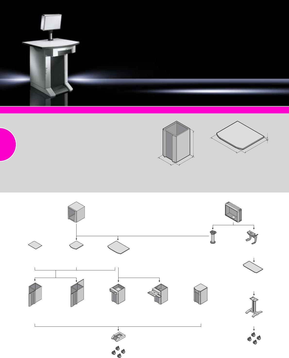
Industrial Workstations
110 Rittal Catalogue 33/Enclosures
System accessories Page 355 Comfort Panel Page 116 Optipanel Page 118 TFT monitor Page 606
Material:
−Enclosure, roof, drawer tray,
designer door, rear wall and
rear door: Sheet steel
−Worktop:
Chipboard: Plastic-laminated
on both sides (edging)
−Aluminium handle:
Powder-coated
Surface finish:
Enclosure: Dipcoat-primed,
powder-coated on the outside,
textured paint
Colour:
−Enclosure, worktop:
RAL 7035
−Worktop edge strip:
RAL 7015
−Worktop handle:
RAL 9006
Protection category:
See table.
Supply includes:
Available on the Internet.
Detailed drawing:
Available on the Internet. Photo shows a configuration
example with equipment not
included in the scope of supply.
H
T
B
H
T
B
Combination options
Monitor housing 21˝
Model No IW 6902.500 Optipanel
Custom-manufactured
for TFT monitors or other
display and input devices
Support arm
system
CP-L
Enclosure attachment
tilting
Model No. IW 6902.640
Roof
solid
Model No. IW 6902.400
Worktop
small, solid
Model No. IW 6902.300
Worktop
solid
Model No. IW 6902.100
Drawer section for
keyboard and mouse,
designer door, rear door
Height 900 mm
Model No. IW 6900.410
Worktop, keyboard
drawer, designer door,
rear door
Height 1000 mm
Model No. IW 6901.100
Designer door, rear door
Height 900 mm
Model No. IW 6900.100
Designer door, rear
panel screw-fastened
from the inside
Height 900 mm
Model No. IW 6900.000
Worktop
prepared for tilting
enclosure attachment
Model No IW 6902.310,
see page 148.
Pedestal
Model No. IW 6141.200
Drawer section, designer
door, rear door
Height 900 mm
Model No. IW 6900.400
Base/plinth, stationary
Model No. PC 8800.920
Twin castors
Model No. DK 7495.000
Twin castors
Model No. DK 7495.000
or CP 6148.000
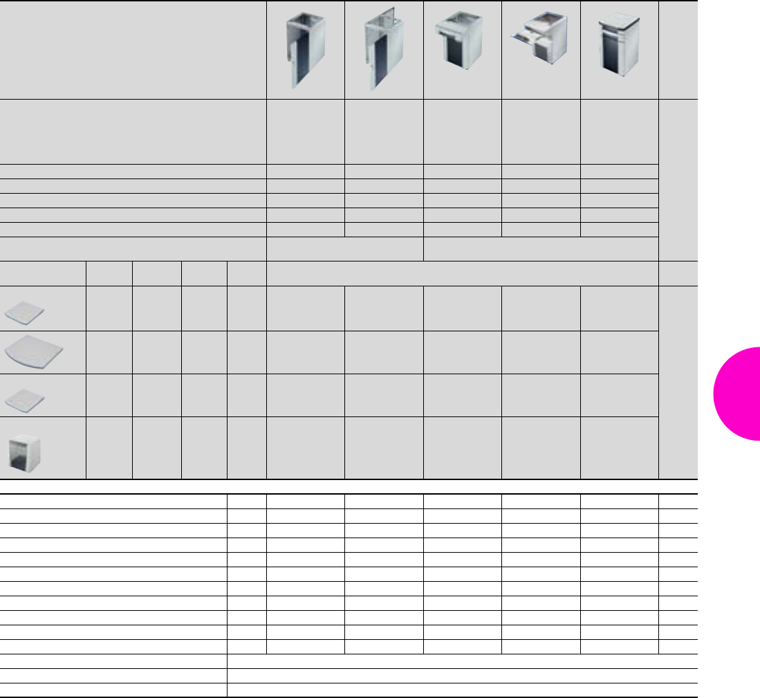
Industrial Workstations
111Rittal Catalogue 33/Enclosures
IW enclosures and worktops
Enclosure Page
Design
Designer door,
rear panel
screw-fastened
from the inside
Designer door,
rear door Drawer section,
designer door,
rear door
Drawer section
for keyboard
and mouse,
designer door,
rear door
Worktop,
keyboard drawer,
designer door,
rear door
Width (B) mm 600 600 600 600 600
Height (H) mm 900 900 900 900 1000
Depth (T) mm 600 600 600 (890) 600 (890) 645
Weight kg 54,9 59,9 73 73 91
Model No. IW 6900.000 6900.100 6900.400 6900.410 6901.100
Protection category IP 55 to IEC 60 529,
complies with NEMA 12 IP 54 to IEC 60 529,
complies with NEMA 12
Width (B)
mm Height (H)
mm Depth (T)
mm Weight
kg Model No. IW
Worktops
610 38 645 11.6 6902.300 6902.300 – –
1000 38 895 24 6902.100 6902.100 6902.100 6902.100 –
Roof
600 13 640 7.4 6902.400 6902.400 – – –
Monitor housing
600 600 600 42.5 6902.500 6902.500 6902.500 6902.500 –
Accessories Packs of
Base/plinth, stationary 1 8800.920 8800.920 8800.920 8800.920 8800.920 366
Cross member, adjustable 2 8601.680 8601.680 8601.680 8601.680 – 370
Twin castors 1 set 7495.000 7495.000 7495.000 7495.000 7495.000 374
Handle adaptor for comfort handle 1 8611.300 8611.300 – – – 402
Cable gland 1 6902.770 6902.770 6902.770 6902.770 6902.770 522
Mounting plate for enclosure width 600 mm 1 8614.675 8614.675 8614.675 8614.675 8614.680 448
Component shelf, static installation 1 8800.900 8800.900 8800.900 8800.900 8800.900 481
Component shelf, pull-out 1 6902.960 6902.960 6902.960 6902.960 6902.960 480
Drawer tray 1 6902.700 6902.700 6902.700 6902.700 6902.700 481
Adaptor section 482.6 mm (19˝) 1 8613.070 8613.070 8613.070 8613.070 – 551
Paper removal flap 1 6903.200 6903.200 6903.200 6903.200 6903.200 615
Enclosure attachment, tilting see page 143
Support arm systems see page 125
Operating housing see page 120
Included with the supply.
112

113
Comfort Panel
Benefits at a glance...................................................................................115
Comfort Panel............................................................................................116
Comfort Panel, configuration examples ....................................................117
Optipanel
Benefits at a glance...................................................................................115
Optipanel...................................................................................................118
Optipanel, configuration examples ...........................................................119
Operating housings
Compact Panel..........................................................................................120
Command panel housing with door ..........................................................121
Operating housing with handle strips .......................................................122
Operating housing with display panel front ..............................................123
Support arm systems
Support arm systems, overview ................................................................125
Support arm system CP-S, steel ...............................................................127
Support arm system CP-L .........................................................................131
Support arm system CP-C.........................................................................135
Support arm system CP-XL .......................................................................139
Support arm systems, accessories ...........................................................142
Stand systems
Pedestal, modular .....................................................................................147
Pedestal, complete....................................................................................148
Pillar, small ................................................................................................149
Pillar...........................................................................................................150
Accessories...............................................................................................151
Operating housings/support
arm systems/stand systems
114
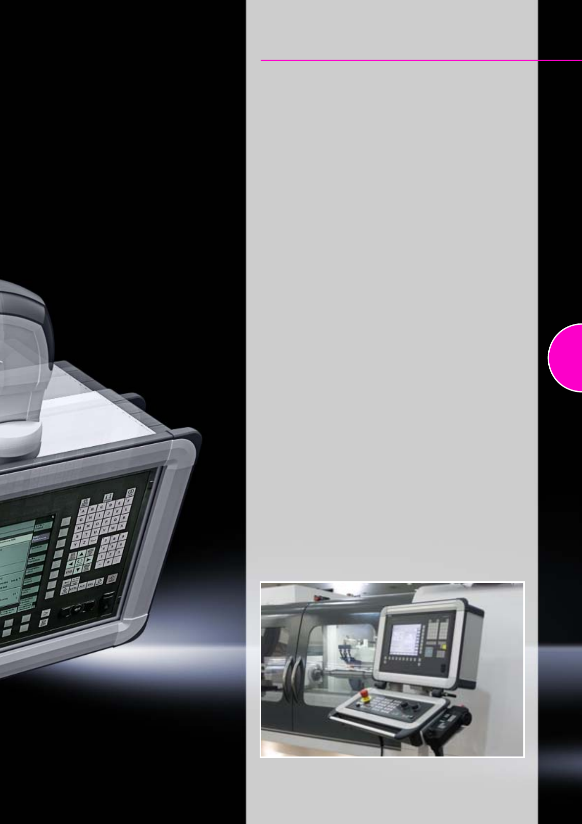
115
Comfort Panel/Optipanel
Benefits at a glance
●Aluminium enclosure, high thermal conductivity for optimum
passive heat dissipation
●Low weight coupled with high stability
●Protection category IP 65
●Compatible with all Rittal stand and support arm systems
The choice is yours
Standard range
●Standard variants offering outstanding value for money
and short delivery times
●Easy, fast and reliable selection
●For front panel installations, tailored to the most common
operating solutions
Comfort Panel, see page 116.
Optipanel, see page 118.
Configurable special solutions
●Individual sizes, also for the direct installation of panels
with no front plate
●Complete solution diversity for virtually all applications
●Maximum flexibility in design and function
The command panel configurator determines the most suitable
enclosure for your application based on user-specific parameters.
More detailed information can be found at: www.rittal.com
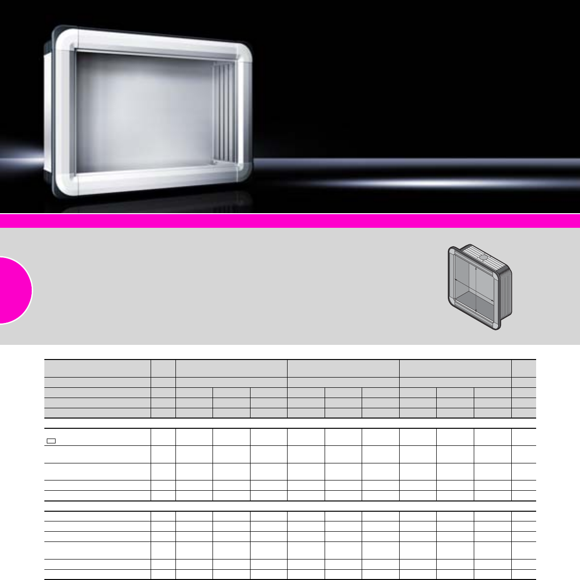
Comfort Panel
116 Rittal Catalogue 33/Enclosures
For front panel width (B) mm Packs
of 520 520 520 Page
For front panel height (H) mm 400 500 600
Installation depth mm 74 152 191 74 152 191 74 152 191
Model No. CP4) 1 6372.541 6372.542 6372.543 6372.551 6372.552 6372.553 6372.561 6372.562 6372.563
Weight (kg) 7.8 11.7 13.8 8.8 12.3 15.2 9.7 13.5 16.7
Design
Support arm connection CP-L,
120 x 65 mm1) – – – – – –
Support arm connection CP-L,
Ø 130 mm1) – – –
Hinged rear panel
with screw lock –– –– ––
Hinged rear panel with cam2) – –– –– –
Screw-fastened rear panel3) –– –– ––
Accessories
Front panel 1 6028.014 6028.014 6028.014 6028.015 6028.015 6028.015 6028.016 6028.016 6028.016 604
Handle set, horizontal 1 6375.000 6375.000 6375.000 6375.000 6375.000 6375.000 6375.000 6375.000 6375.000 600
Handle set, vertical 2 6375.040 6375.040 6375.040 6375.050 6375.050 6375.050 6375.060 6375.060 6375.060 600
Mounting bracket
for interior installation 4 6205.100 6205.100 6205.100 6205.100 6205.100 6205.100 6205.100 6205.100 6205.100 470
Spring nut M5 50 6108.000 6108.000 6108.000 6108.000 6108.000 6108.000 6108.000 6108.000 6108.000 478
Earthing plate 1 2570.500 2570.500 2570.500 2570.500 2570.500 2570.500 2570.500 2570.500 2570.500 502
1) Top or bottom, by rotating the enclosure.
2) With 3 mm double-bit lock insert, may be exchanged for 41 mm lock inserts, version C, see page 421, plastic handles and T handles, version C, see page 420.
3) Enclosure hinged at the front with side double-bit lock insert, may be exchanged for 41 mm lock inserts, version C, see page 421,
plastic handles and T handles, version C, see page 420.
4) Configuration examples, see page 117.
System accessories Page 355 Support arm systems Page 125 Stand systems Page 147 Industrial Workstations Page 110
Material:
−Enclosure:
Extruded aluminium section
−Corner pieces:
Die-cast zinc
−Corner protectors:
Plastic
Colour:
−Enclosure:
Natural-anodised
−Corner pieces:
RAL 7035
−Corner protectors:
Similar to RAL 7024
Protection category:
IP 65 to IEC 60 529
Supply includes:
Seals and assembly parts
for front panels.
Detailed drawings:
Available on the Internet.
B
H

Comfort Panel
117Rittal Catalogue 33/Enclosures
Configuration examples
Front panel height
mm Cut-out dimensions
400
W (B) = 484 mm
H = 364 mm
= 18 mm all-round for attaching the adaptor plate
500
W (B) = 484 mm
H = 464 mm
= 18 mm all-round for attaching the adaptor plate
600
W (B) = 484 mm
H = 564 mm
= 18 mm all-round for attaching the adaptor plate
Free space, available for individual installed equipment such as rows of switches etc.
HE = U
1
BH
7 HE
53.7
8 HE
1
1
B
H
153.7
7 HE
109.2
8 HE
65
9 HE
1
1
B
H
7 HE
253.7 209.2
8 HE
165
9 HE
7 HE
3.5 HE
98.7
8 HE
3.5 HE
54.2
9 HE
3.5 HE
1
Rittal Australia
RITTAL Pty. Ltd.
130 – 140 Parraweena Road
Miranda NSW 2228
Phone: +61 (2) 9525 2766
Fax: +61 (2) 9525 2888
E-mail: info@rittal.com.au www.rittal.com.au
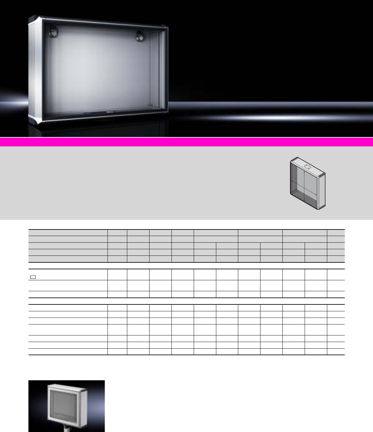
Optipanel
118 Rittal Catalogue 33/Enclosures
To fit desktop TFT up to 20.1˝
with rear connection
●VESA 75
●VESA 100
Model No. CP 6380.050
System accessories Page 355 Support arm systems Page 125 Stand systems Page 147 Industrial Workstations Page 110
Material:
−Enclosure:
Extruded aluminium section
−Corner pieces:
Die-cast zinc
−Corner protectors:
Plastic
Colour:
−Enclosure:
Natural-anodised
−Corner pieces:
RAL 7035
−Corner protectors:
Similar to RAL 7024
Protection category:
IP 65 to IEC 60 529
Supply includes:
Seals and assembly parts
for front panels.
Detailed drawings:
Available on the Internet.
H
B
For front panel width (B) mm Packs of 430 482.6 482.6 520 520 520 Page
For front panel height (H) mm 343 310.3 354.8 400 500 600
Installation depth mm 100 100 100 100 150 100 150 100 150
Model No. CP 1 6380.0201) 6380.000 6380.0401) 6380.4002) 6380.410 6380.5002) 6380.5102) 6380.6002) 6380.6102)
Weight (kg) 5.3 6.2 6.6 5.8 7.3 6.6 8.3 7.3 9.2
Design
Support arm connection CP-L,
120 x 65 mm3) – – –
Support arm connection CP-L,
Ø 130 mm3) – – – – – –
Hinged rear panel4)
Accessories
Front panel 1 – 6028.010 – 6028.014 6028.014 6028.015 6028.015 6028.016 6028.016 604
Handle set, horizontal 1 – 6385.010 6385.010 6385.000 6385.000 6385.000 6385.000 6385.000 6385.000 600
Handle set, vertical 2 – – – 6385.040 6385.040 6385.050 6385.050 6385.060 6385.060 600
Mounting bracket
for interior installation 4 6205.100 6205.100 6205.100 6205.100 6205.100 6205.100 6205.100 6205.100 6205.100 470
Mounting bracket 4 4597.000 4597.000 4597.000 4597.000 4597.000 4597.000 4597.000 4597.000 4597.000 470
Earthing plate 1 2570.500 2570.500 2570.500 2570.500 2570.500 2570.500 2570.500 2570.500 2570.500 502
Spring nut M5 50 6108.000 6108.000 6108.000 6108.000 6108.000 6108.000 6108.000 6108.000 6108.000 478
1) To fit TFT monitors, see page 606.
2) Configuration examples, see page 119.
3) Top or bottom, by rotating the enclosure.
4) With 3 mm double-bit lock insert, may be exchanged for 41 mm lock inserts, version C, see page 421, plastic handles and T handles, version C, see page 420.
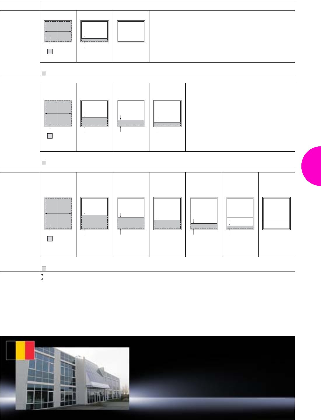
Optipanel
119Rittal Catalogue 33/Enclosures
Configuration examples
Front panel height
mm Cut-out dimensions
400
W (B) = 484 mm
H = 364 mm
= 18 mm all-round for attaching the adaptor plate
500
W (B) = 484 mm
H = 464 mm
= 18 mm all-round for attaching the adaptor plate
600
W (B) = 484 mm
H = 564 mm
= 18 mm all-round for attaching the adaptor plate
Free space, available for individual installed equipment such as rows of switches etc.
HE = U
1
BH
7 HE
53.7
8 HE
1
1
B
H
153.7
7 HE
109.2
8 HE
65
9 HE
1
1
B
H
7 HE
253.7 209.2
8 HE
165
9 HE
7 HE
3.5 HE
98.7
8 HE
3.5 HE
54.2
9 HE
3.5 HE
1
Rittal Belgium
RITTAL nv/sa
Industrieterrein E17/3206 Stokkelaar 8
B-9160 Lokeren
Phone: +32 (0) 9 353 9111
Fax: +32 (0) 9 355 6862
E-mail: info@rittal.be www.rittal.be
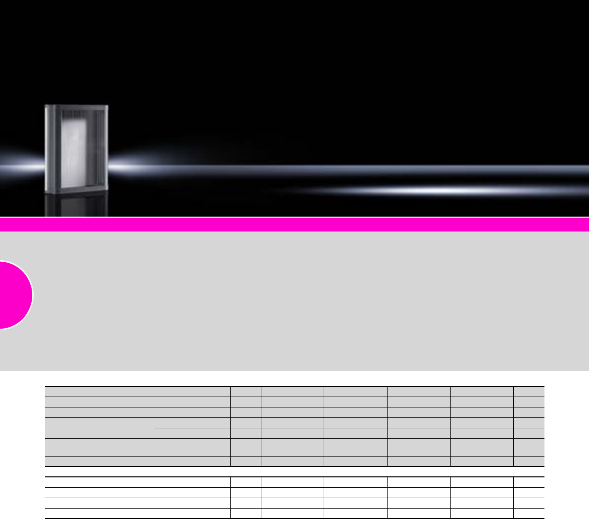
Compact Panel
120 Rittal Catalogue 33/Enclosures
System accessories Page 355 Support arm systems Page 125 Stand systems Page 147
For small operating units built
into front panels. The front panel
is inserted from the rear and
secured with screw clamps.
Special front panels with a
material thickness of between
2 and 6 mm are possible. Rear
panel optionally hinged on the
left or right.
Material:
−Roof tray, base tray,
rear panel: Aluminium
−Side parts:
Extruded aluminium section
−Screw cover: Plastic
Surface finish:
−Roof tray, base tray,
side parts: Powder-coated
−Rear panel: Natural-anodised
Colour:
RAL 7024
Protection category:
IP 65 to IEC 60 529
Supply includes:
−Roof tray
−Base tray
−Rear panel
−Side parts
−Screw cover
−Seal and screw clamp
Detailed drawings:
Available on the Internet.
Width mm Packs of 241 241 315 315 Page
Height mm 238 388 238 388
Depth mm 87 87 87 87
To fit Front panel width mm 178 178 252 252
Front panel height mm 200 350 200 350
Model No. CP
(with support arm connection CP-S) 16340.000 6340.100 6340.300 6340.400
Weight (kg) 2.8 3.8 3.4 4.5
Accessories
Front panel, 3.0 mm aluminium, natural-anodised 1 6028.500 6028.510 6028.530 6028.540 604
Wall mounting bracket, vertically hinged 1 set 6341.000 6341.000 6341.000 6341.000 442
Cover plate for support arm connection CP-S 1 6505.200 6505.200 6505.200 6505.200 604
Spring nut M5 50 6108.000 6108.000 6108.000 6108.000 478
To order different heights for front panel width:
– 178 mm use Model No.: CP 6342.109
– 252 mm use Model No.: CP 6342.209
and additionally specify the front panel height. Extended delivery times.
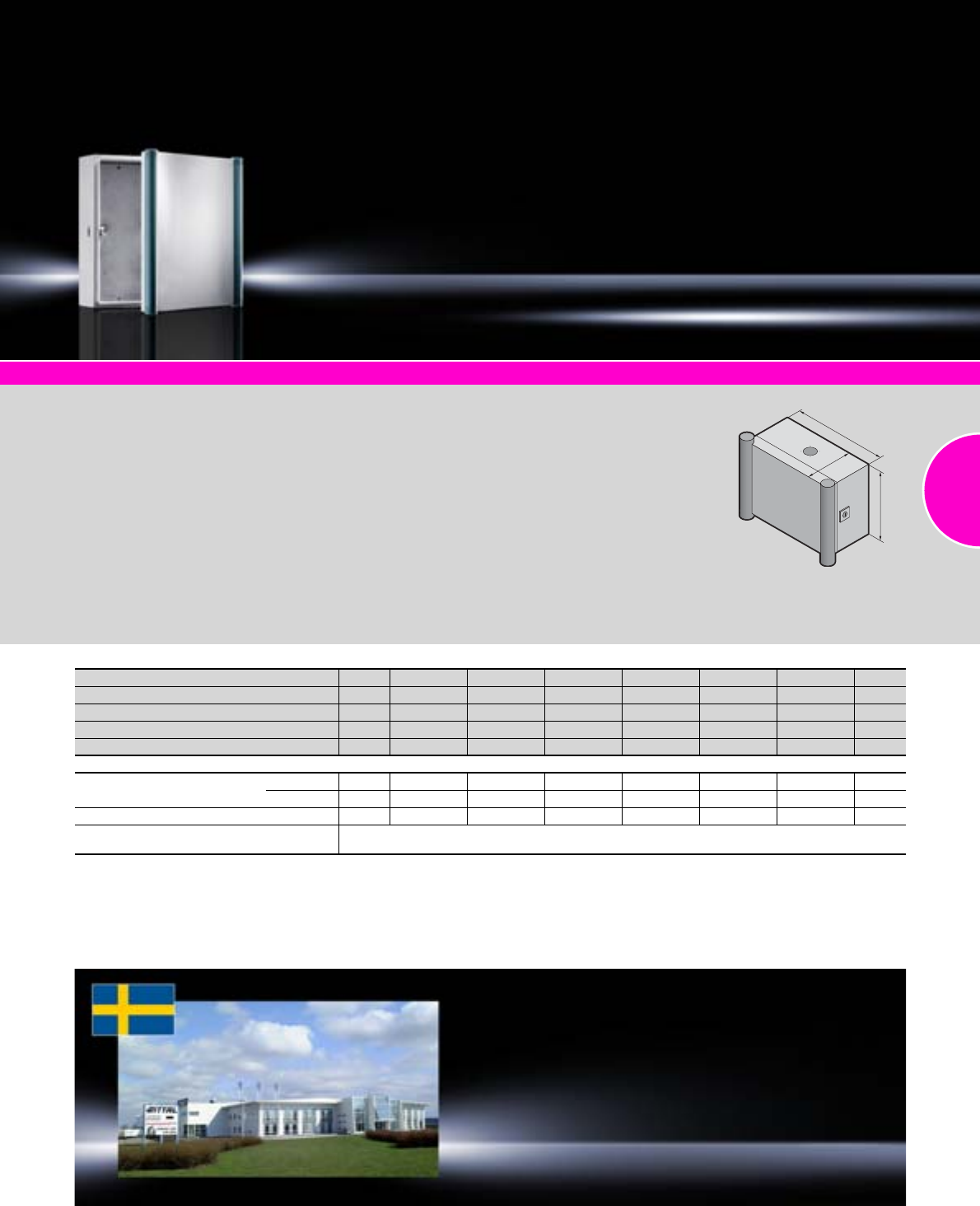
Command panel housing with door
121Rittal Catalogue 33/Enclosures
System accessories
Page 355
Support arm systems
Page 125
Stand systems
Page 147
Command panel housing with door, stainless steel
Page 167
Material:
−Enclosure and door:
Sheet steel
−Handle strips: Aluminium
−Cover caps: Plastic
Surface finish:
−Enclosure and door: Dipcoat-
primed, powder-coated on the
outside, textured paint
−Handle strips: Powder-coated
Colour:
−
Enclosure and door: RAL 7035
−Handle strips and cover caps:
RAL 5018
Protection category:
IP 55 to IEC 60 529
Supply includes:
−Enclosure with cut-out and
reinforcement for support arm
system CP-L, Ø 130 mm
−Cam lock with double-bit
insert
−Door with sealing frame
−Side handle strips and cover
caps
Note:
The support arm connection and
door hinge may be swapped
over by rotating the enclosure.
Approvals:
−UL
−cUL
Detailed drawings:
Available on the Internet.
T
H
B
Rittal Sweden
RITTAL Scandinavian ab
Rittalgatan 1 SE-262 73 Ängelholm
Phone: +46 (431) 44 26 00
Fax: +46 (431) 44 26 44
E-mail: info@rittal.se www.rittal.se
Width (B) mm Packs of 300 300 300 400 400 500 Page
Height (H) mm 200 300 400 300 400 500
Depth (T) mm 180 180 180 180 180 180
Model No. CP 16534.000 6535.000 6537.000 6536.000 6538.000 6544.000
Weight (kg) 5.5 7.1 8.4 8.4 10.6 14.5
Accessories
Matching mounting plate AE type 1032.500 1033.500 1034.500 1030.500 1380.500 1050.500 44
Model No.2) 0271.324 0271.926 0271.927 0274.131 0271.548 0271.333 –
Support rails1) Model No. 10 2316.000 2316.000 2316.000 2317.000 2317.000 2318.000 467
Alternative lock systems With 3 mm double-bit lock insert, may be exchanged for 41 mm lock inserts, version C, see page 421,
plastic handles and T handles, version C, see page 420.
1) Only with vertical attachment of punched rail 23 x 23 mm, see page 463.
2) Extended delivery times.
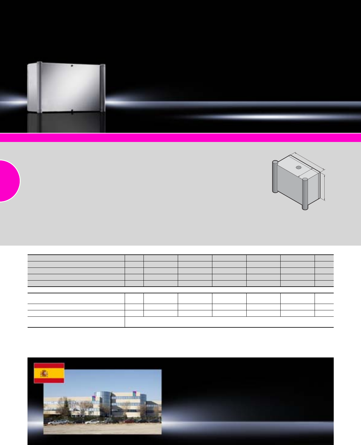
Operating housing with handle strips
122 Rittal Catalogue 33/Enclosures
System accessories
Page 355
Support arm systems
Page 125
Stand systems
Page 147
Command panel housing with door, stainless steel
Page 167
Material:
−Enclosure and door:
Sheet steel
−Handle strips: Aluminium
−Cover caps: Plastic
Surface finish:
−Enclosure and door: Dipcoat-
primed, powder-coated on the
outside, textured paint
−Handle strips: Powder-coated
Colour:
−Enclosure and doo
r: RA
L
7035
−Handle strips and cover caps:
RAL 7030
Protection category:
IP 55 to IEC 60 529
Supply includes:
−Enclosure with cut-out and
reinforcement for support arm
system CP-L, Ø 130 mm
−Mounting angles spot welded
at the sides
−Front with maximum cut-out,
covered with easily machina-
ble 3 mm aluminium front
panel
−Side handle strips with cover
caps
−Rear door with r/h hinge
−
Cam lock with double-bit insert
Note:
The support arm connection and
door hinge may be swapped
over by rotating the enclosure.
Approvals:
−UL
−cUL
Detailed drawings:
Available on the Internet.
T
H
B
Rittal Spain
RITTAL Disprel S.A.
Mas Baiona, 40
Polígono Industrial Can Roqueta
08202 Sabadell (Barcelona)
Phone: +34 937 001 300
Fax: +34 937 001 301
E-mail: info@rittal.es www.rittal.es
Width (B) mm Packs of 300 380 380 500 600 Page
Height (H) mm 200 300 380 500 380
Depth (T) mm 155 210 210 210 210
Model No. CP 16540.2001) 6531.200 6530.200 6532.200 6533.200
Weight (kg) 4.9 9.3 10.2 15.4 14.6
Accessories
Support strips for attaching to the mounting
angles of the side panel 20 – – 4594.000 4309.000 4594.000 426
Rail for interior installation 4 – 2373.210 2373.210 2373.210 2373.210 459
Mini comfort handle 1 – – 2537.0X0 2537.0X0 2537.0X0 418
Alternative lock systems With 3 mm double-bit lock insert, may be exchanged for 27 mm lock inserts, version A, see page 421,
lock cylinder, plastic handles and T handles, version B, see page 420.
1) Support arm connection and door hinge at the bottom.
Operating housing with display panel front
123Rittal Catalogue 33/Enclosures
System accessories
Page 355
Support arm systems
Page 125
Stand systems
Page 147
Command panel housing with door, stainless steel
Page 167
Material:
−Enclosure and door:
Sheet steel
−Frame and front panel:
Aluminium
Surface finish:
−Enclosure and door:
Dipcoat-primed, powder-
coated on the outside,
textured paint
−Frame and front panel:
Natural-anodised
Colour:
RAL 7035
Protection category:
IP 54 to IEC 60 529
Supply includes:
−Enclosure without gland plate
−Mounting angles spot welded
at the sides
−With maximum cut-out at the
front and fitted, easily
machinable 3 mm front panel
with aluminium frame, with r/h
hinge, screw-fastened from
the inside.
−Rear door with r/h hinge
−Cam lock with double-bit
insert
Approvals:
−UL
−cUL
Detailed drawings:
Available on the Internet.
Rittal South Korea
RITTAL Co., Ltd.
Seoul Head Office
3rd Floor Asaan Venture Tower B/D
315-6 Yangjae-Dong
Seocho-Gu Seoul 137-896 Korea
Phone: +82 (0)2-577-6525
Fax: +82 (0)2-577-6526
E-mail: rittal@rittal.co.kr www.rittal.co.kr
Width mm Packs of 380 380 500 600 Page
Height mm 380 600 500 600
Depth mm 249 249 249 249
Model No. CP 16442.500 6462.500 6552.500 6662.500
Weight (kg) 9.5 13.4 18.0 19.6
Cam lock 1 2 2 2
Accessories
Enclosure reinforcement
with support arm cut-out CP-L 1 6143.210 6143.210 6143.210 – 151
Enclosure reinforcement
with support arm cut-out CP-XL 1 – – – 6503.000 151
Rail for interior installation 4 2373.210 2373.210 2373.210 2373.210 459
Mini comfort handle 1 2537.0X0 2537.0X0 2537.0X0 2537.0X0 418
Alternative lock systems With 3 mm double-bit lock insert, may be exchanged for 27 mm lock inserts, version A, see page 421,
lock cylinder, plastic handles and T handles, version B, see page 420.
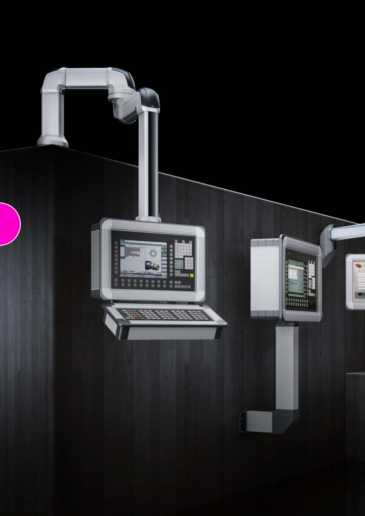
124
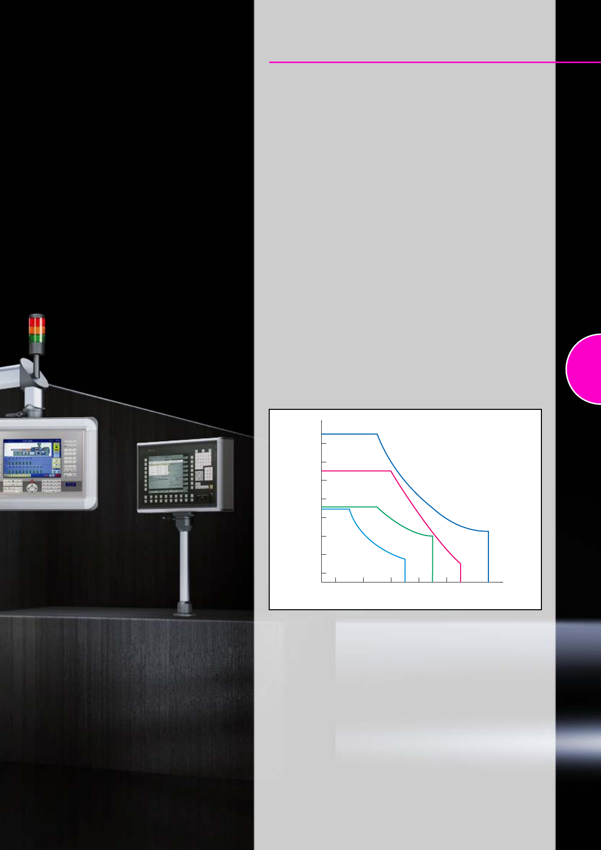
125
Support arm systems
Support arm system CP-S
Overview of components...........................................................................127
Support section CP-S ................................................................................128
Support arm system CP-S, components ...................................................129
Support arm system CP-L
Overview of components...........................................................................131
Support section CP-L ................................................................................132
Support arm system CP-L, components ...................................................133
Support arm system CP-C
Overview of components...........................................................................135
Support section CP-C................................................................................136
Support arm system CP-C, components...................................................137
Support arm system CP-XL
Overview of components...........................................................................139
Support section CP-XL ..............................................................................140
Support arm system CP-XL, components .................................................141
Support arm configurator
The support arm configurator determines the correct support arm system
according to user-specific parameters.
More detailed information can be found at: www.rittal.com
800
1000
1200
1400
1600
600
400
200
0
500
0 1000 1500 2000 2500 3000
CP-XL
CP-C
CP-L
CP-S
Permissible static load [N]
(enclosure and vertical support arm section)
Jib length (mm)
Load information
Comparison of support arm systems
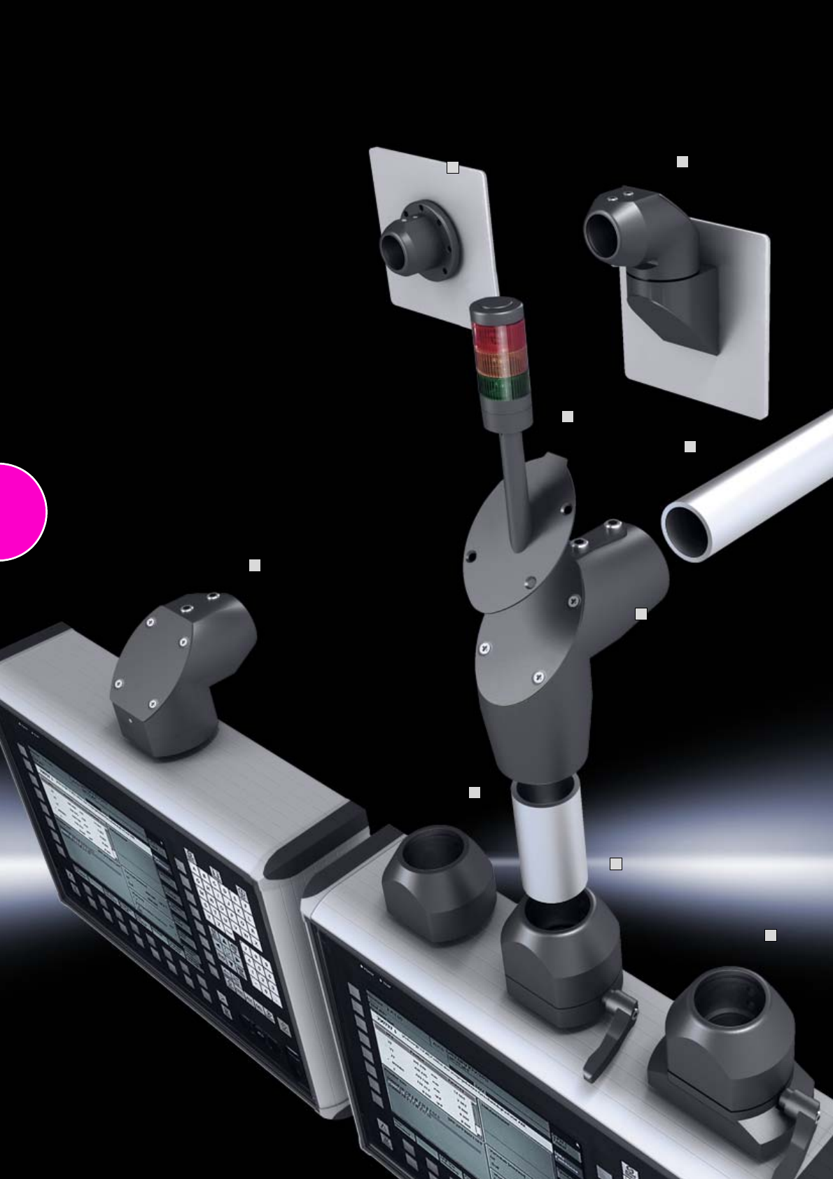
126
1
2
3
4
5
6
8
9
10
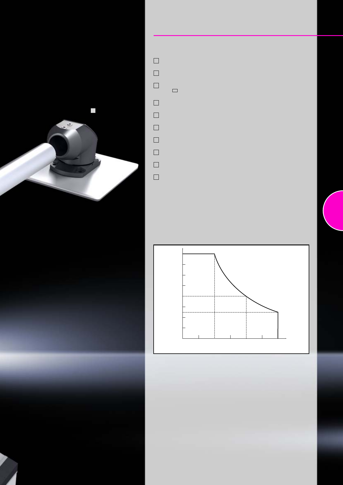
127
Support arm system CP-S, steel
Overview of components
Enclosure attachment CP-S
(CP 6501.070)
Housing coupling, round CP-S
(CP 6501.050)
Housing coupling, CP-S for support arm connection
CP-L 120 x 65 mm
(CP 6501.130)
Angle coupling 90° CP-S
(CP 6501.120)
Support section CP-S
(CP 6501.000, .020)
Angle piece 90° CP-S
(CP 6501.140)
Top-mounted joint CP-S
(CP 6501.160)
Wall-mounted hinge CP-S
(CP 6501.150)
Wall/base mounting bracket CP-S
(CP 6501.110)
Mounting components for signal pillar
(CP 2375.030)
1
2
3
4
5
6
7
8
9
10
400
600
800
200
0
0 500 1000 1500
Permissible static load [N]
(enclosure and vertical support arm section)
Jib length (mm)
Load information
When using CP-S in conjunction with CP-L
(in the horizontal development of the system),
the CP-L load diagram applies.
7
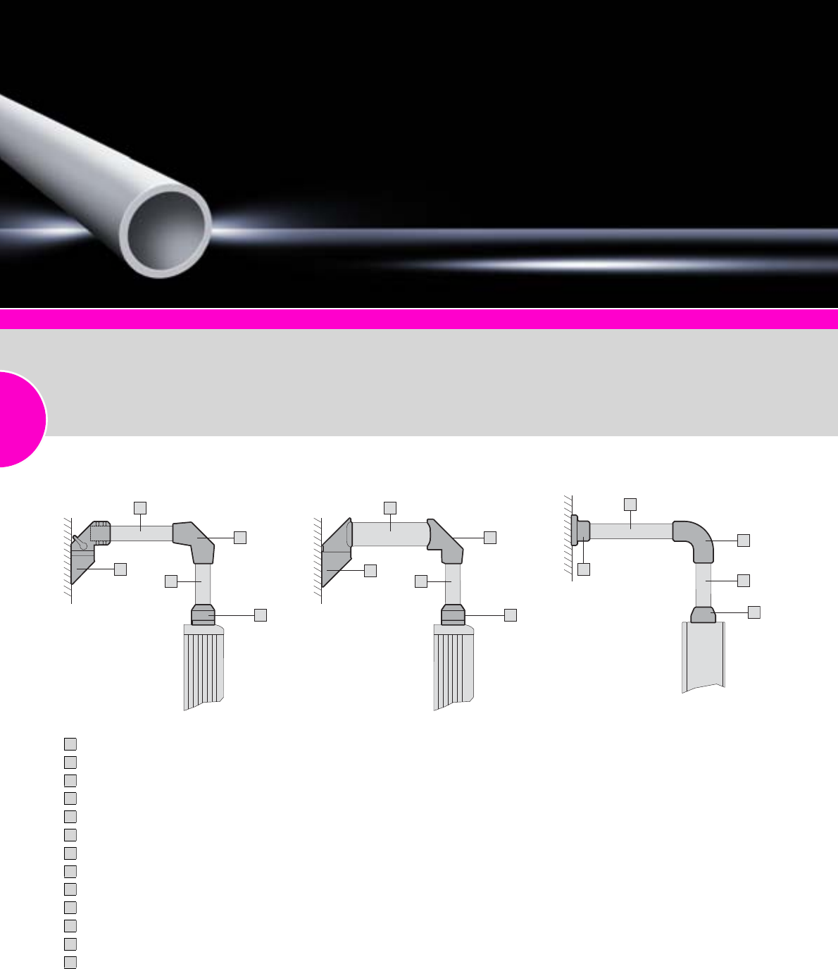
Support arm system CP-S, steel
128 Rittal Catalogue 33/Enclosures
4
1
3
2
5
8
1
6
7
5
9
10
12
11
13
Comfort Panel
Page 116
Optipanel
Page 118
Compact Panel
Page 120
Command panel housing with door
Page 121
Operating housings
Page 122
Support section CP-S
Attached to the connection com-
ponents via 2 clamping screws.
Size:
−External diameter: 48.3 mm
−Wall thickness: 4.0 mm
Material:
−Steel conduit, powder-coated
Colour:
RAL 7035
Supply includes:
Support section CP-S
Note:
Stainless steel, see page 168.
Detailed drawings:
Available on the Internet.
Integral adjustment facility Combination with support arm system
CP-L Also available in stainless steel version,
see page 168
Support section CP-S, 1000 mm (CP 6501.020)
Support section CP-S, 500 mm (CP 6501.000)
Wall-mounted hinge CP-S (CP 6501.150)
Angle piece 90° CP-S (CP 6501.140)
Housing coupling CP-S (CP 6501.050)
Wall-mounted hinge CP-L (CP 6521.010)
Support section CP-L, 500 mm (CP 6511.000)
Angle adaptor CP-L to CP-S 90° (CP 6501.090)
Wall/base mounting, rigid, CP-S, stainless steel (CP 6663.000)
Support section CP-S, stainless steel, 1000 mm (CP 6660.010)
Angle piece 90°, CP-S, stainless steel (CP 6664.300)
Support section CP-S, stainless steel, 500 mm (CP 6660.050)
Housing coupling CP-S, stainless steel (CP 6664.000)
1
2
3
4
5
6
7
8
9
10
11
12
13
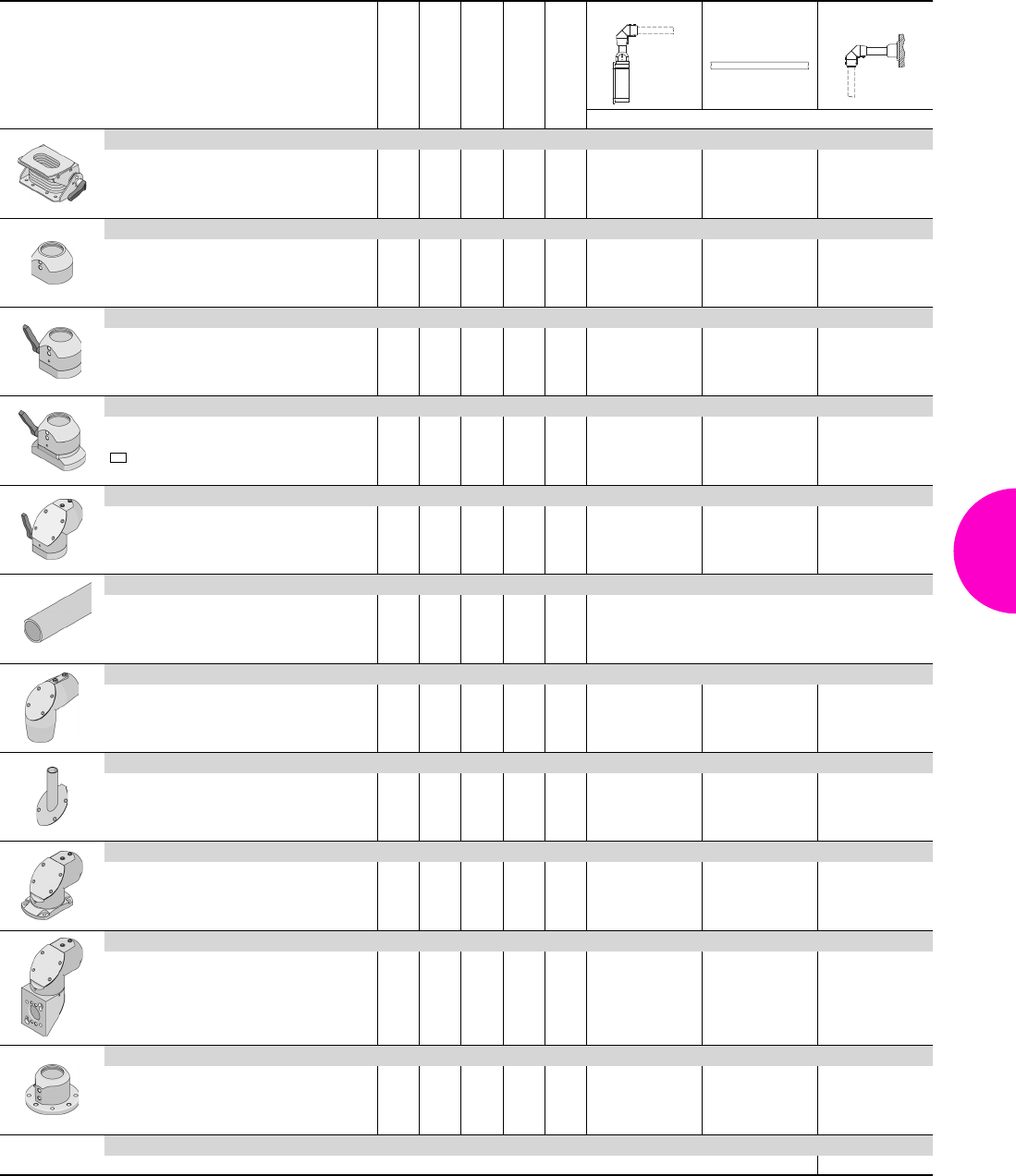
Support arm system CP-S, steel
129Rittal Catalogue 33/Enclosures
Rotating/tilting
Rigid
Length mm
Weight kg
Colour RAL
Enclosure section Desk section Wall section
Model No. CP
Enclosure attachment, tilting
see page 145 – – 0.8 7024 6902.670 – –
Enclosure attachment CP-S
– – 1.0 7024 6501.070 – –
Housing coupling, round CP-S
– – 1.1 7024 6501.050 – –
Housing coupling CP-S
for support arm connection CP-L
120 x 65 mm – – 1.5 7024 6501.130 – –
Angle coupling 90° CP-S
– – 1.6 7024 6501.120 – –
Support section CP-S
– –
500
1000 2.1
4.2 7035
7035 6501.000
6501.020
Angle piece 90° CP-S
– – 1.1 7024 6501.140 – 6501.140
Mounting component for signal pillar
see page 623 – – 0.3 7024 2375.030 – –
Top-mounted joint CP-S
– – 1.8 7024 – – 6501.160
Wall-mounted hinge CP-S
– – 2.2 7024 – – 6501.150
Wall/base mounting bracket CP-S
– – 0.7 7024 – – 6501.110
Accessories CP-S
Angle adaptor 90° CP-L to CP-S CP 6501.090 see page 146
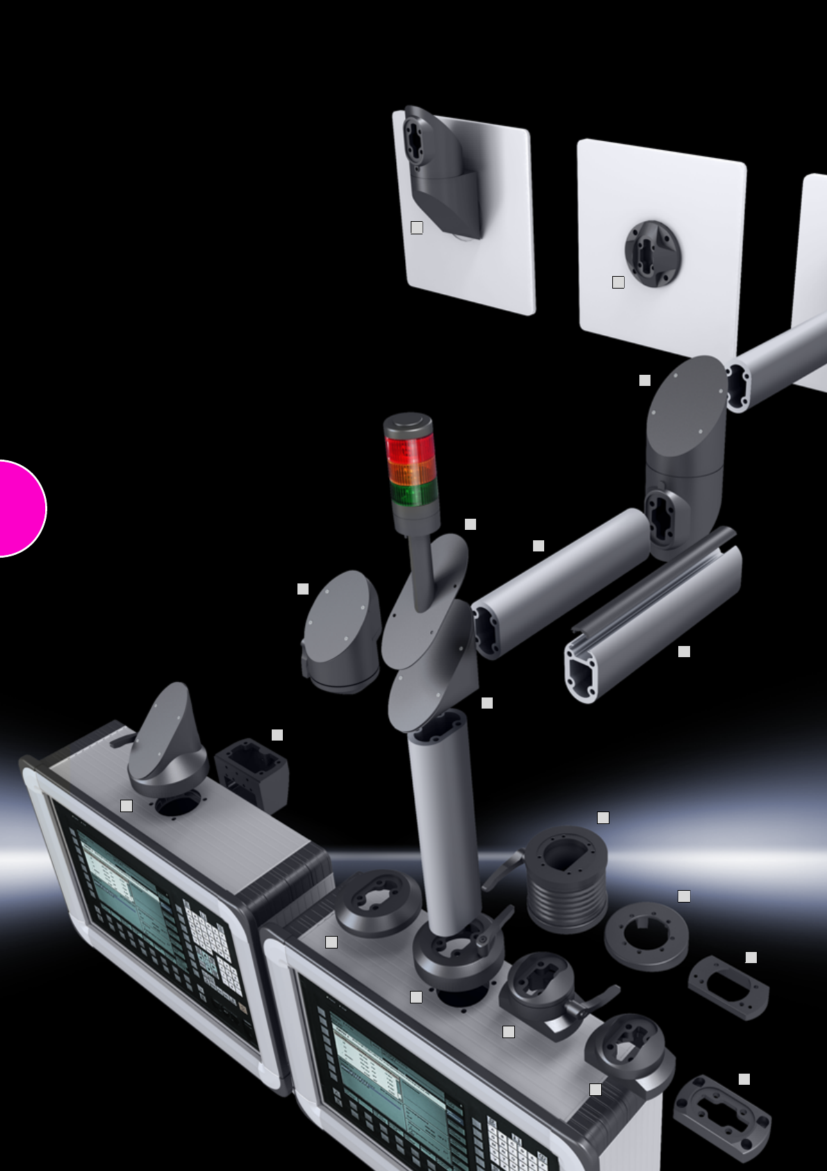
130
2
1
3
4
5
6
7
8
9
10
11
12
13
14
15
17
18
20
131
Support arm system CP-L
Overview of components
Tilting adaptor 10° CP-L, for support arm connection Ø 130 mm
(CP 6527.010)
Tilting adaptor 10° CP-L, for support arm connection
CP-L 120 x 65 mm (CP 6527.110)
Tilting adaptor ±45° CP-L, for support arm connection Ø 130 mm
(CP 6529.010)
Connection console CP-L (CP 6508.010)
Enclosure attachment CP-L, for support arm connection Ø 130 mm
(CP 6525.510)
Enclosure attachment CP-L, for support arm connection
CP-L 120 x 65 mm (CP 6525.610)
Enclosure attachment, locatable CP-L, for support arm connection
CP-L 120 x 65 mm (CP 6525.210)
Housing coupling CP-L, for support arm connection Ø 130 mm
(CP 6525.010)
Housing coupling CP-L, for support arm connection
CP-L 120 x 65 mm (CP 6525.110)
Angle coupling 90° CP-L, for support arm connection Ø 130 mm
(CP 6526.010)
Support section CP-L, closed
(CP 6509.000, CP 6511.000, CP 6513.000, CP 6515.000)
Support section CP-L, open (CP 6513.050)
Angle piece 90° CP-L (CP 6524.010)
Articulated joint 90° CP-L, may only be top-mounted/suspended
on the enclosure side (CP 6524.210)
Intermediate hinge CP-L (CP 6523.010)
Top-mounted joint CP-L (CP 6522.010)
Wall-mounted hinge CP-L (CP 6521.010)
Wall/base mounting bracket, small CP-L (CP 6520.510)
Wall/base mounting bracket, large CP-L (CP 6520.010)
Mounting components for signal pillar (CP 2375.000, .020)
1
2
3
4
5
6
7
8
9
10
11
12
13
14
15
16
17
18
19
20
800
600
400
200
0
500
0 1000 1500 2000
1
2
3
Permissible static load [N]
(enclosure and vertical support arm section)
Jib length (mm)
Load information
Permissible load depending on system configuration
System configuration without intermediate hinge
System configuration with one intermediate hinge
System configuration with one intermediate hinge
and one top-mounted/wall-mounted joint
Note:
−Intermediate hinge CP 6523.010 should only be used once per system!
−When using the open support section, the load information is 70% of the
closed support section.
1
2
3
19
16
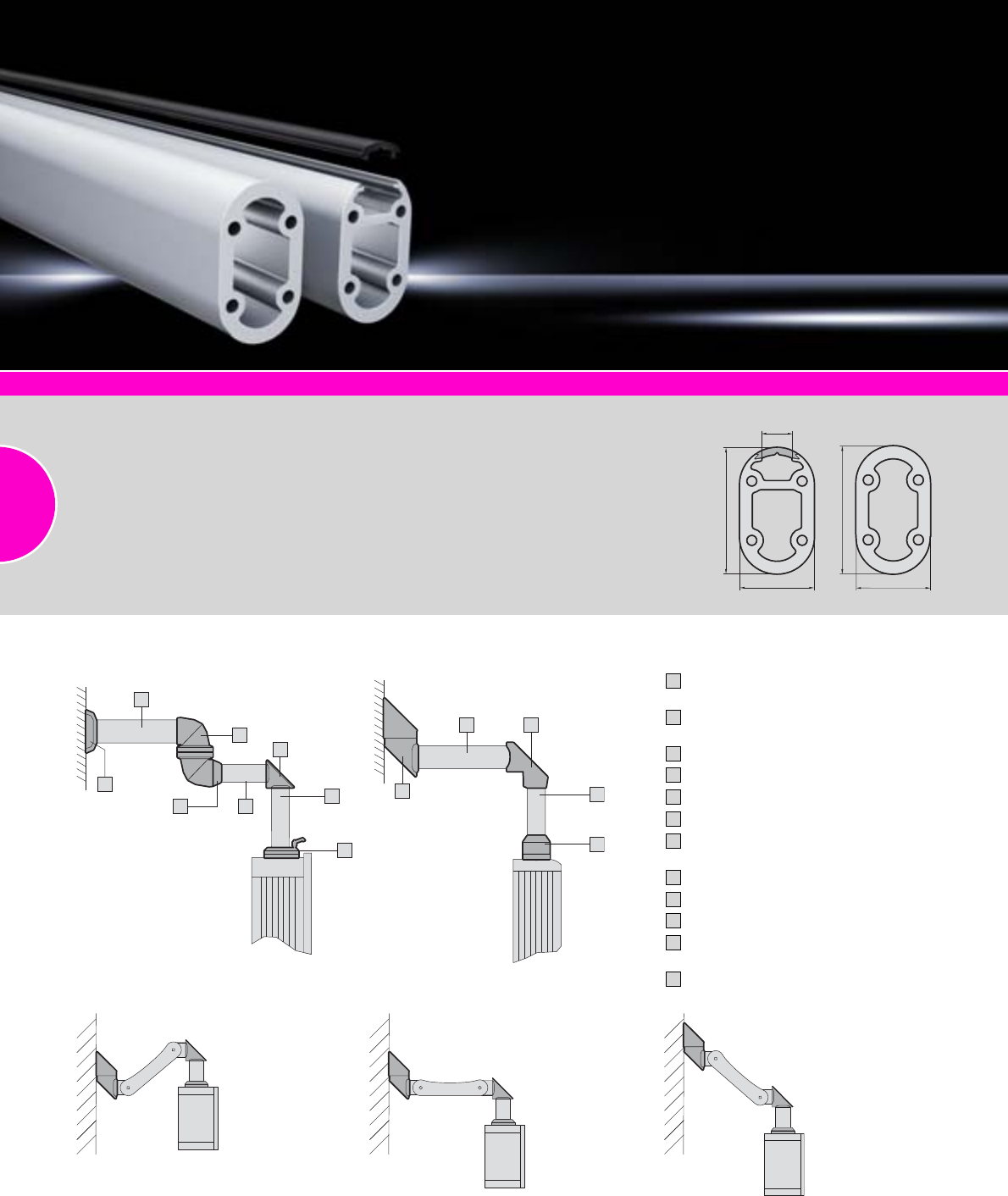
Support arm system CP-L
132 Rittal Catalogue 33/Enclosures
Comfort Panel
Page 116
Optipanel
P
age 118
Compact Panel
Page 120
Command panel housing with door
Page 121
Operating housings
Page 122
Support section CP-L
Attachment to the connection
components with 4 self-tapping
screws in the screw channel,
may be cut to any required
length, no thread-tapping
required.
Size:
−External dimensions:
50 x 85 mm
−Wall thickness: 8 mm
Material:
−Support section:
Extruded aluminium section
−Cover: Plastic
Colour:
Support section: RAL 7035
Supply includes:
Support section CP-L
Detailed drawings:
Available on the Internet.
50
85
21
50
85
●Adjustment range up to 800 mm
●Integral stay in three stages, except for CP 6510.210
●Problem-free cable entry with connectors such as DVI, VGA, except with CP 6510.210
●Support arm, height-adjustable, see page 144
Combination with support arm, height adjustable
Combination with support arm systems
CP-C to CP-L Combination with support arm systems
CP-C to CP-S
Wall/base mounting bracket CP-C,
large (CP 6072.000)
Support section CP-C, 500 mm
(CP 6074.100)
Intermediate hinge CP-C (CP 6071.800)
Adaptor CP-C to CP-L (CP 6071.600)
Support section CP-L (CP 6511.000)
Angle piece 90° CP-L (CP 6524.010)
Support section CP-L, 500 mm
(CP 6511.000)
Housing coupling CP-L (CP 6525.010)
Wall-mounted hinge
CP-L (CP 6521.010)
Angle adaptor 90° (CP 6501.090)
Support section CP-S, steel, 500 mm
(CP 6501.000)
Housing coupling CP-S (CP 6501.050)
1
2
3
4
5
6
7
8
9
10
11
12
1
2
3
45
6
7
8
9
510
11
12
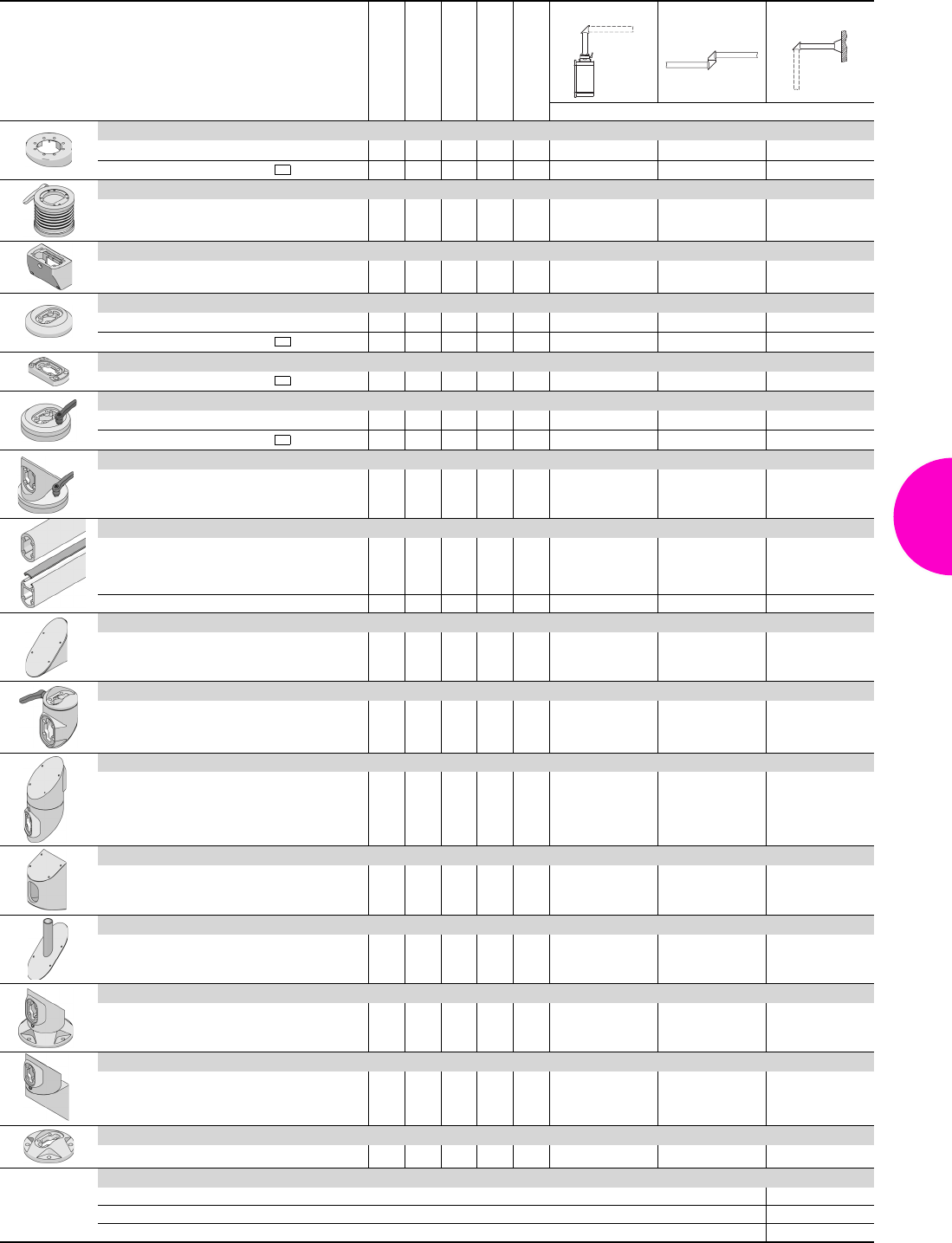
Support arm system CP-L
133Rittal Catalogue 33/Enclosures
Rotating/tilting
Rigid
Length mm
Weight kg
Colour RAL
Enclosure section Desk section Wall section
Model No. CP
Tilting adaptor 10° CP-L
for support arm connection
Ø 130 mm – – 0.6 7024 6527.010 – –
for support arm connection CP-L 120 x 65 mm
– – 0.4 7024 6527.110 – –
Tilting adaptor ±45° CP-L
for support arm connection
Ø 130 mm – – 1.3 7024 6529.010 – –
Connection console CP-L
for flat operating housings – – 0.7 7024 6508.010 – –
Enclosure attachment CP-L
for support arm connection Ø 130 mm – – 1.0 7024 6525.510 – –
for support arm connection CP-L 120 x 65 mm
– – 1.0 7024 6525.610 – –
Enclosure attachment, locatable CP-L
for support arm connection CP-L 120 x 65 mm
– – 0.4 7024 6525.210 – –
Housing coupling CP-L
for support arm connection
Ø 130 mm – – 1.7 7024 6525.010 – –
for support arm connection CP-L 120 x 65 mm
– – 1.4 7024 6525.110 – –
Angle coupling 90° CP-L
for support arm connection Ø 130 mm – – 1.9 7024 6526.010 – –
Support section CP-L
Closed
–
–
–
–
–
–
–
–
250
500
1000
2000
1.3
2.6
5.1
10.2
7035
7035
7035
7035
6509.000
6511.000
6513.000
6515.000
6509.000
6511.000
6513.000
6515.000
6509.000
6511.000
6513.000
6515.000
Open – – 1000 4.75 7035 6513.050 6513.050 6513.050
Angle piece 90° CP-L
– – 1.4 7024 6524.010 – 6524.010
Articulated joint 90° CP-L
– – 1.2 7024 6524.210 – –
Intermediate hinge CP-L
– – 3.2 7024 – 6523.010 –
Wall/base mounting, large CP-L
– – 1.9 7024 – – 6520.010
Mounting component for signal pillar
see page 623 –
–
–
– 0.4 9017
9017 2375.000
–
–
2375.020
–
2375.020
Top-mounted joint CP-L
– – 3.0 7024 – – 6522.010
Wall-mounted hinge CP-L
– – 3.2 7024 – – 6521.010
Wall/base mounting bracket, small, CP-L
– – 0.6 7024 – – 6520.510
Accessories CP-L:
Adaptation options see page 142
Support arm bracket CP 6519.000 see page 145
Connection plate CP 6528.210 see page 143
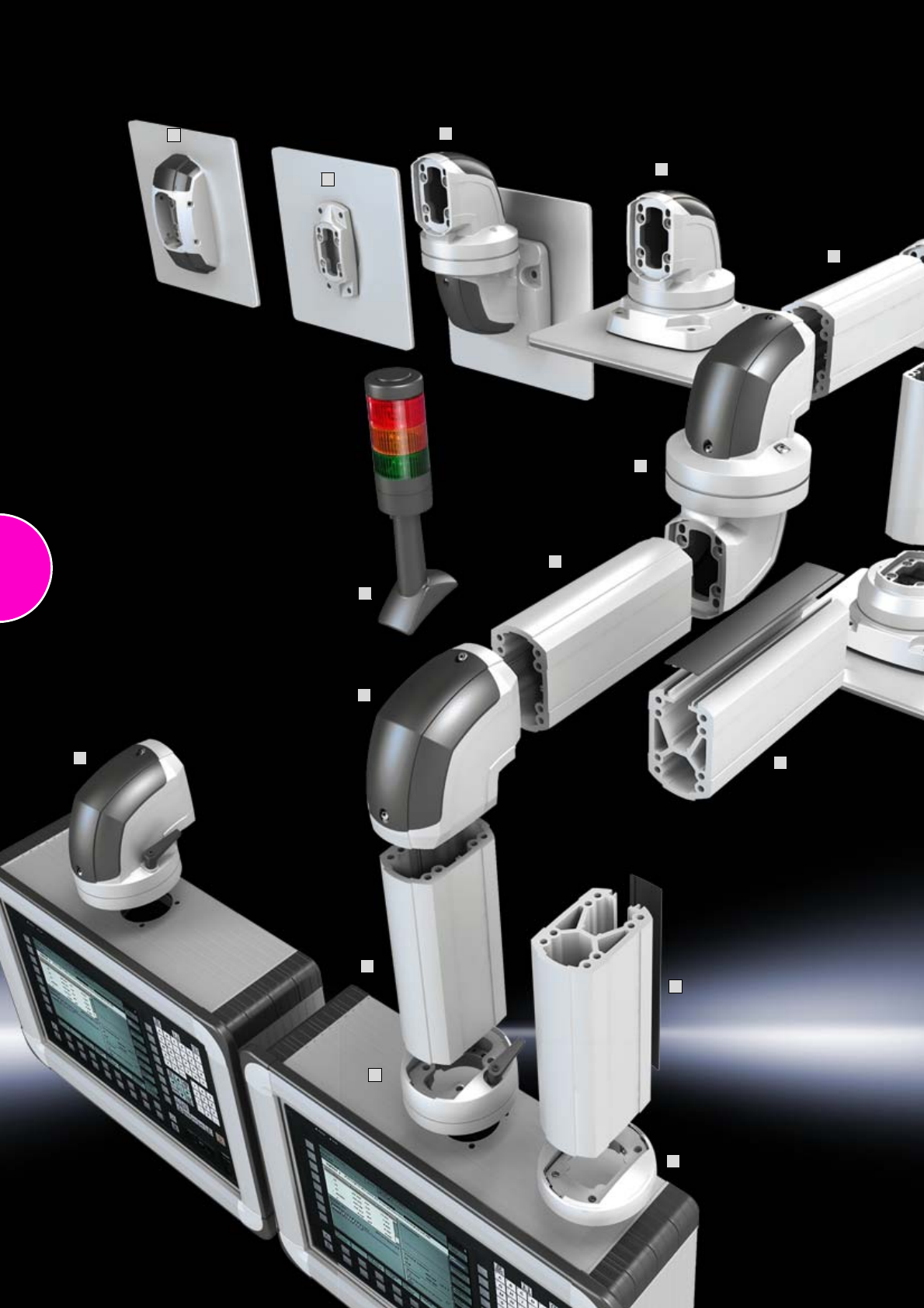
134
1
2
3
6
14
4
7
9
5
4
5
11
12
13
4
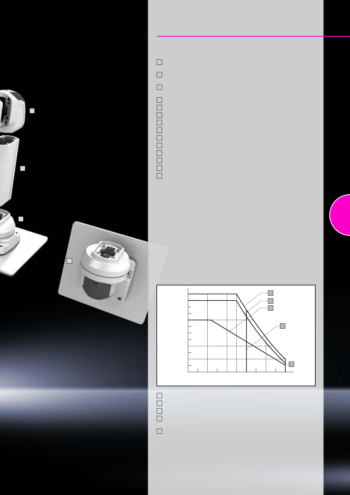
135
Support arm system CP-C
Overview of components
Enclosure attachment CP-C, for support arm connection
CP-L Ø 130 mm (CP 6070.200)
Enclosure attachment CP-C, for support arm connection
CP-L Ø 130 mm (CP 6070.000)
Angle coupling 90° CP-C, for support arm connection
CP-L Ø 130 mm (CP 6071.200)
Support section CP-C, closed (CP 6074.000, .100, .300, .500)
Support section CP-C, open (CP 6075.100, .300, .500)
Angle piece 90° CP-C (CP 6071.400)
Intermediate hinge CP-C (CP 6071.800)
Top-mounted joint CP-C, vertical outlet (CP 6072.800)
Top-mounted joint CP-C, horizontal outlet (CP 6072.600)
Wall-mounted joint CP-C, vertical outlet (CP 6072.400)
Wall-mounted joint CP-C, horizontal outlet (CP 6072.500)
Wall/base mounting bracket, small CP-C (CP 6072.200)
Wall/base mounting bracket, large CP-C (CP 6072.000)
Mounting components for signal pillar (CP 6073.000)
1
2
3
4
5
6
7
8
9
10
11
12
13
14
10
8
4
6
800
1000
1200
600
400
200
0
500
0 1000 1500 2000 2500
1
2
3
B
A
Permissible static load [N]
(enclosure and vertical support arm section)
Jib length (mm)
Load information
Permissible load depending on system configuration
Without intermediate hinge
With intermediate hinge CP 6071.800 and closed support section
With intermediate hinge CP 6071.800 and open support section
Maximum system length 2500 mm for systems with horizontal outlet
at the system start.
Maximum system length 1500 mm for systems with vertical outlet
at the system start.
Note:
−Wall/base mounting bracket, small CP 6072.200 must not be used in
conjunction with intermediate hinge CP 6071.800!
−Intermediate hinge CP 6071.800 should only be used once per system!
1
2
3
A
B
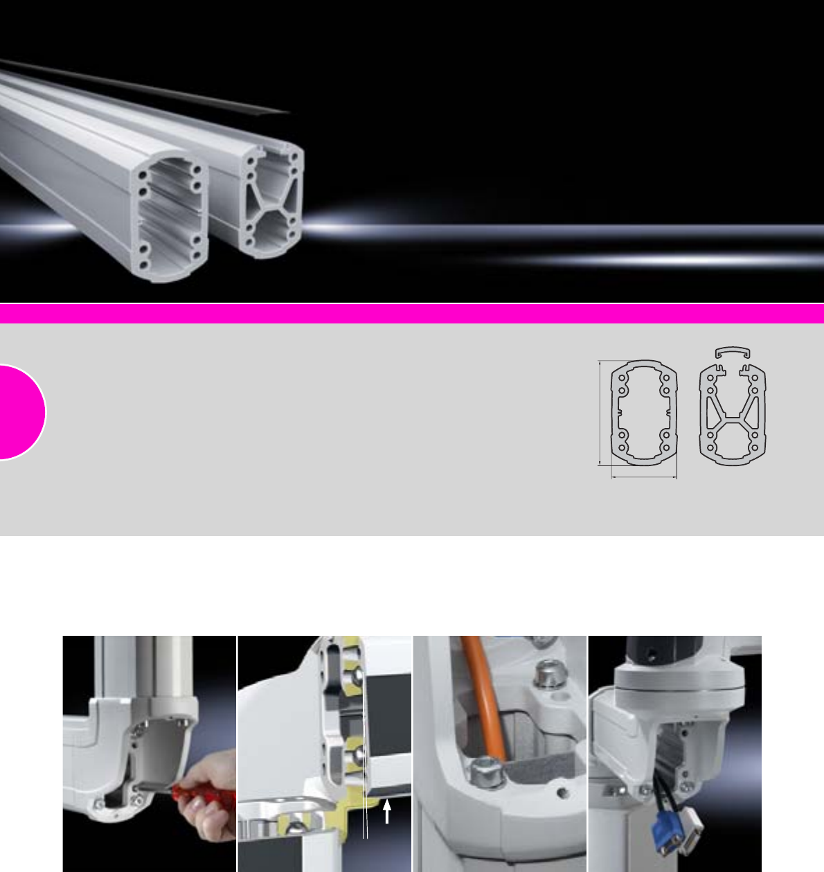
Support arm system CP-C
136 Rittal Catalogue 33/Enclosures
Comfort Panel
Page 116
Optipanel
Page 118
Compact Panel
Page 120
Command panel housing with door
Page 121
Operating housings
Page 122
Support section CP-C
Attachment to the connection
components with 4 self-tapping
screws in the screw channel. May
be cut to any required length, no
thread-tapping required.
Closed cable duct with a large
cross-section.
Open cable duct for easy servic-
ing access and for pre-assemb-
led cables with connectors; lock-
able via cover section. X-shaped
profile for higher load capacity,
large cable routing channels.
Upper channel adequate for
cables with large connectors
(e.g. DVI or VGA) and available/
usable throughout the entire
system.
Size:
−External dimensions:
75 x 120 mm
−Wall thickness: 6.5 mm
Material:
−Support section:
Extruded aluminium section
−Cover: Plastic
Colour:
−Support section: RAL 7035
−Cover: RAL 7024
Supply includes:
−Support section CP-C
−Clip-in lid (only for CP-C
open)
Detailed drawings:
Available on the Internet.
120
75
Function
●Easily adjusted without dismantling the system
●Fast, simple assembly of the system
●Rotation range may be limited without dismantling the system
Cable management
●Cross-section sufficient for large connectors
●Separation between data and power cables
●Removable cover for simple cable entry
●Flexible cable entry and routing options
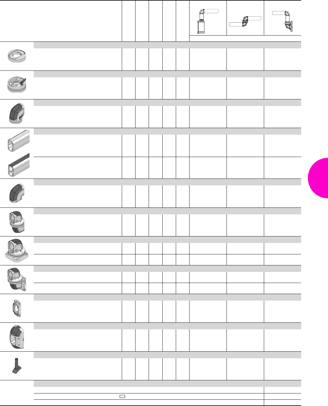
Support arm system CP-C
137Rittal Catalogue 33/Enclosures
Rotating/tilting
Rigid
Length mm
Weight kg
Colour RAL
Enclosure section Desk section Wall section
Model No. CP
Enclosure attachment CP-C for support arm connection CP-L Ø 130 mm
– – 0.7 7035 6070.200 – –
Housing coupling CP-C for support arm connection CP-L Ø 130 mm
– – 2.0 7035 6070.000 – –
Angle coupling 90° CP-C, for support arm connection CP-L Ø 130 mm
– – 2.1 7035/
7024 6071.200 – –
Support section CP-C
Closed
–
–
–
–
–
–
–
–
250
500
1000
2000
2.0
3.9
7.8
15.6
7035
6074.000
6074.100
6074.300
6074.500
6074.000
6074.100
6074.300
6074.500
6074.000
6074.100
6074.300
6074.500
Open –
–
–
–
–
–
500
1000
2000
4.6
9.2
18.4
7035/
7024
6075.100
6075.300
6075.500
6075.100
6075.300
6075.500
6075.100
6075.300
6075.500
Angle piece 90° CP-C
– – 1.1 7035/
7024 6071.400 – 6071.400
Intermediate hinge CP-C
– – 4.4 7035/
7024 – 6071.800 –
Top-mounted joint CP-C
Vertical outlet – – 3.8 7035 – – 6072.800
Horizontal outlet – – 4.3 7035/
7024 – – 6072.600
Wall-mounted hinge CP-C
Vertical outlet – – 5.5 7035/
7024 – – 6072.400
Horizontal outlet – – 6.1 7035/
7024 – – 6072.500
Wall/base mounting bracket, small, CP-C
– – 0.5 7035 – – 6072.200
Wall/base mounting bracket, large, CP-C
– – 2.5 7035/
7024 – – 6072.000
Mounting component for signal pillar
See page 623 – – 0.1 7024 6073.000 6073.000 6073.000
Accessories CP-C:
Adaptor CP-C to CP-L CP 6071.600 see page 143
Connection adaptor CP-L Ø 130 mm to CP-L 120 x 65 mm CP 6071.000 see page 142
Support arm, height adjustable see page 144

138
7
10
8
12
14
15
5
8
4
9
6
11
1
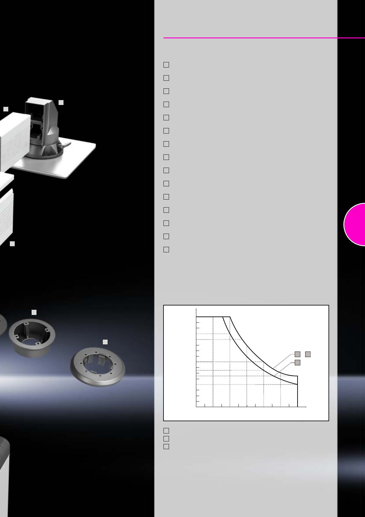
139
Support arm system CP-XL
Overview of components
Connection adaptor CP-L to CP-XL, 20 mm height
(CP 6528.010)
Connection adaptor CP-L to CP-XL, 55 mm height
(CP 6528.510)
Tilting adaptor 10° CP-XL
(CP 6023.010)
Enclosure attachment, round CP-XL
(CP 6130.610)
Enclosure attachment, square CP-XL
(CP 6130.510)
Housing coupling CP-XL
(CP 6130.010)
Angle coupling 90° CP-XL
(CP 6140.010)
Support section CP-XL, closed
(CP 6050.500, 6100.500, 6200.500)
Support section CP-XL, open
(CP 6050.000, 6100.000, 6200.000)
Angle piece 90° CP-XL, outlet at bottom
(CP 6140.010)
Angle piece 90° CP-XL, outlet at top
(CP 6180.010)
Intermediate hinge CP-XL
(CP 6120.010)
Top-mounted joint CP-XL
(CP 6170.010)
Wall-mounted hinge CP-XL
(CP 6110.010)
Wall/base mounting bracket CP-XL
(CP 6160.010)
1
2
3
4
5
6
7
8
9
10
11
12
13
14
15
8
3
2
13
9
Load information
Permissible load depending on system configuration
800
1000
1200
1400
1600
600
400
200
0
500
0 1000 1500 2000 2500 3000
1
3
+2
Permissible static load [N]
(enclosure and vertical support arm section)
Jib length (mm)
Open and solid support section without intermediate hinge
Solid support section with one intermediate hinge
Open support section with one intermediate hinge
Note:
Intermediate hinge CP 6120.010 should only be used once per system!
1
2
3
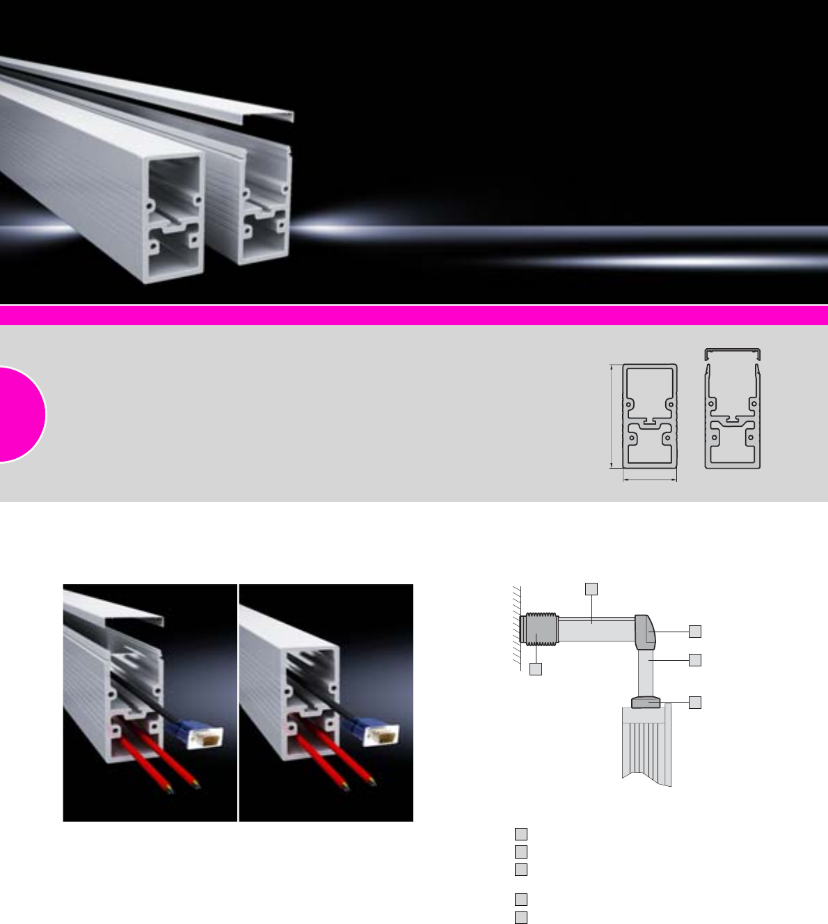
Support arm system CP-XL
140 Rittal Catalogue 33/Enclosures
2
1
3
4
5
Comfort Panel
Page 116
Optipanel
Page 118
Compact Panel
Page 120
Command panel housing with door
Page 121
Operating housings
Page 122
Support section CP-XL
Attachment to the connection
components with 4 self-tapping
screws in a screw channel, may
be cut to any required length.
Closed cable duct for higher
loads and torsion.
Open cable duct for easy servic-
ing access and for pre-assem-
bled cables with connectors;
lockable via clip-in cover.
Size:
External dimensions:
80 x 155 mm
Material:
Extruded aluminium section
Colour:
RAL 7035
Supply includes:
−Support section CP-XL
−Clip-in cover
(only for CP-XL open)
Detailed drawings:
Available on the Internet.
155
80
Wall-mounted hinge CP-XL (CP 6110.010)
Support section CP-XL (CP 6100.000)
Angle adaptor 90° CP-XL to CP-L
(CP 6528.110)
Support section CP-L (CP 6511.000)
Housing coupling CP-L for support arm
connection CP-L Ø 130 mm (CP 6525.010)
1
2
3
4
5
Combination with support arm systems
CP-XL to CP-L
Cable management
●Open support section for retrospective cable insertion
●Separation of control cables from power supply
with two separate ducts
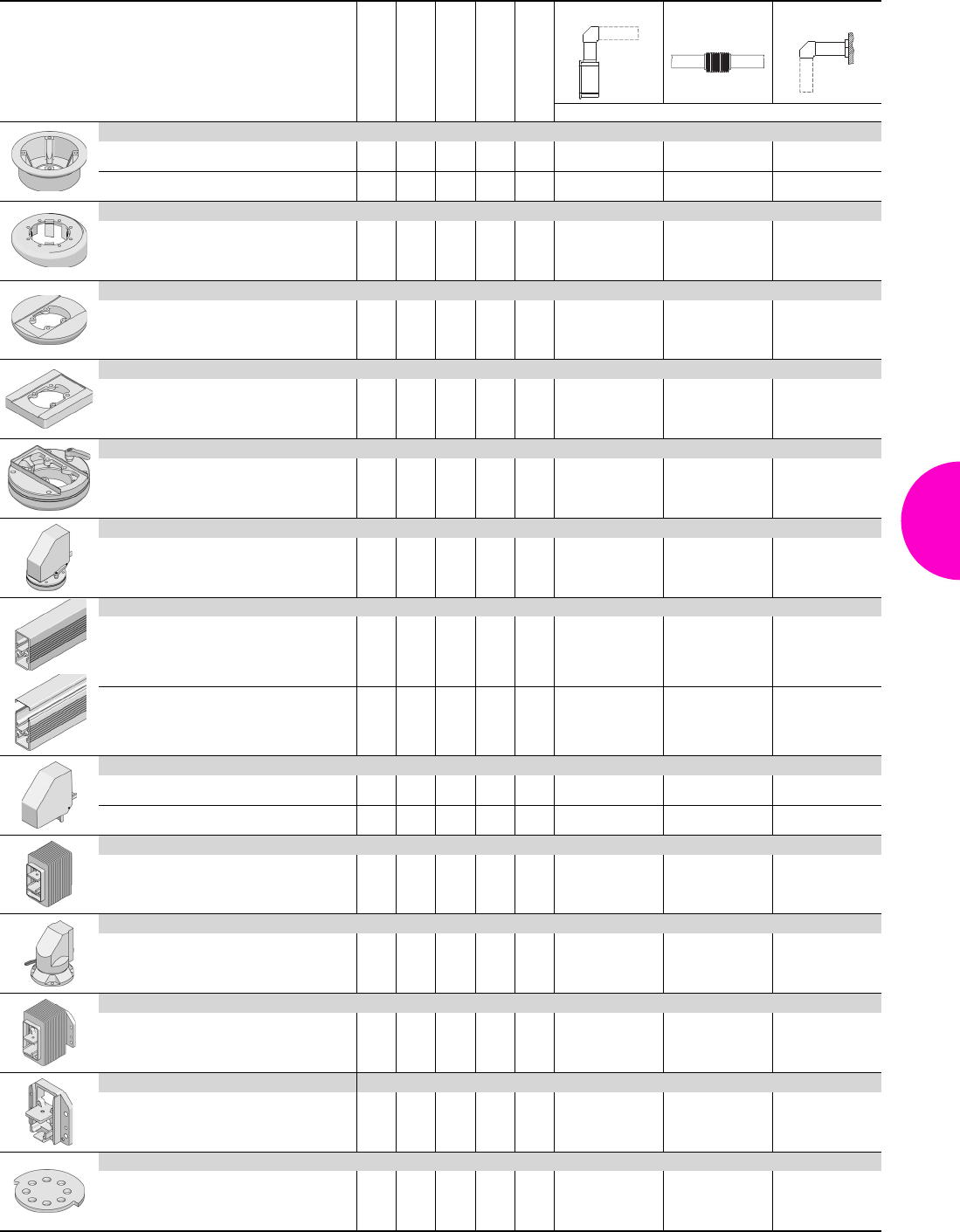
Support arm system CP-XL
141Rittal Catalogue 33/Enclosures
Rotating/tilting
Rigid
Length mm
Weight kg
Colour RAL
Enclosure section Desk section Wall section
Model No. CP
Connection adaptor CP-L to CP-XL
Height 20 mm – – 0.6 7024 6528.010 – –
Height 55 mm – – 0.7 7024 6528.510 – –
Tilting adaptor 10° CP-XL
– – 1.4 7024 6023.010 – –
Enclosure attachment, round CP-XL
– – 1.2 7024 6130.610 – –
Enclosure attachment, rectangular CP-XL
– – 1.2 7024 6130.510 – –
Housing coupling CP-XL
– – 3.6 7024 6130.010 – –
Angle coupling 90° CP-XL
– – 2.1 7024 6040.010 – –
Support section CP-XL
Closed –
–
–
–
–
–
500
1000
2000
5.5
11.0
22.0
7035
7035
7035
6050.500
6100.500
6200.500
6050.500
6100.500
6200.500
6050.500
6100.500
6200.500
Open –
–
–
–
–
–
500
1000
2000
4.9
9.8
19.6
7035
7035
7035
6050.000
6100.000
6200.000
6050.000
6100.000
6200.000
6050.000
6100.000
6200.000
Angle piece 90° CP-XL
Outlet at bottom – – – 2.4 7024 6140.010 – 6140.010
Outlet at top – – – 3.6 7024 6180.010 – 6180.010
Intermediate hinge CP-XL
– – 6.5 7024 – 6120.010 –
Top-mounted joint CP-XL
– – 11.9 7024 – – 6170.010
Wall-mounted hinge CP-XL
– – 8.5 7024 – – 6110.010
Wall/base mounting bracket CP-XL
– – 4.1 7024 – – 6160.010
Rotation range restrictor
for:
Intermediate hinge CP 6120.010
Wall-mounted hinge CP 6110.010 – – 0.6 – – 6110.100 6110.100
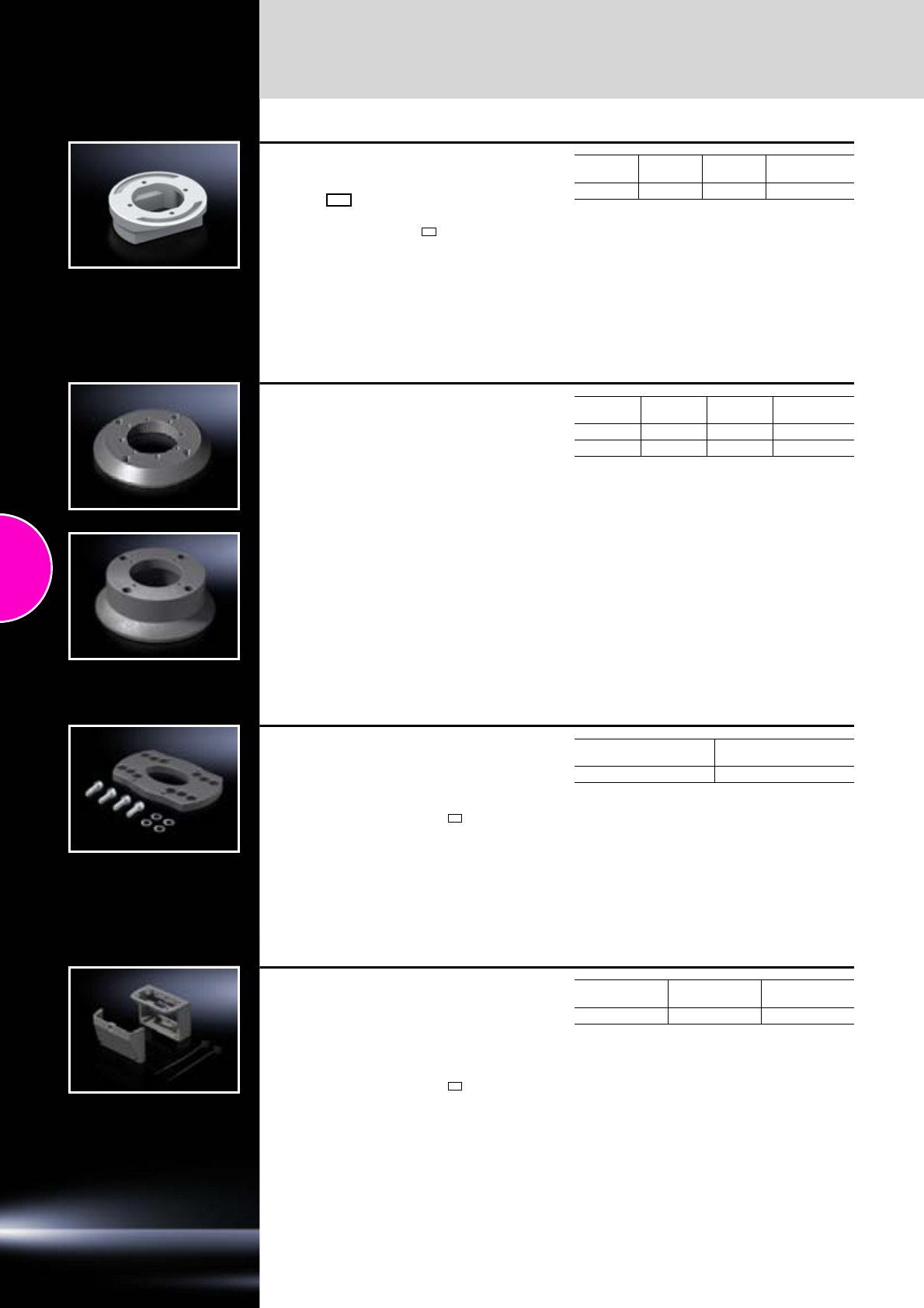
Support arm systems
Accessories
142 Rittal Catalogue 33/Enclosures
Connection adaptor
CP-L Ø 130 mm to
CP-L 120 x 65 mm
For external mounting of command panels with
support arm cut-out CP-L 120 x 65 mm.
Material:
Cast aluminium
Supply includes:
Seal and assembly parts.
Detailed drawings:
Available on the Internet.
Height
mm Colour
RAL Weight
kg Model No. CP
40 7035 0.5 6071.000
Connection adaptor CP-L
to CP-XL
For mounting between enclosures with support
arm connection CP-L and support arm system
CP-XL.
May also be used for the attachment of command
panels with cut-out for CP-L directly to machines
and systems without a support arm. The mount-
ing cut-out CP-XL should be provided there.
Assembly sequence:
●Mount the connection adaptor on the support-
ing structure
●Mount the enclosure and tighten the screws
Material:
Cast aluminium
Supply includes:
Seal and assembly parts.
Detailed drawings:
Available on the Internet.
Height
mm Colour
RAL Weight
kg Model No.
CP
201) 7024 0.6 6528.010
55 7024 0.7 6528.510
1) If the load permits, also suitable for mounting between
enclosure with support arm connection CP-XL and
support arm system CP-L Ø 130 mm.
Adaptor
for Siemens Pro-Panel
●For external mounting of Siemens Simatic
Pro-Panel on
−Support arm system CP-S
−Support arm system CP-L 120 x 65 mm
Material:
Aluminium
Supply includes:
Assembly parts.
Colour
RAL Model No. CP
7024 6528.450
Connection console CP-L
for Beckhoff Control-Panels
●Removable cover for easy cable entry with
a large opening (110 x 50 mm)
●For external mounting of Beckhoff
Control-Panels on
−Support arm system CP-S
−Support arm system CP-L 120 x 65 mm
Material:
Cast aluminium
Supply includes:
Seals and assembly parts for mounting on the
enclosure and 2 cable ties.
Detailed drawings:
Available on the Internet.
Colour
RAL Weight
kg Model No. CP
7024 0.7 6508.020
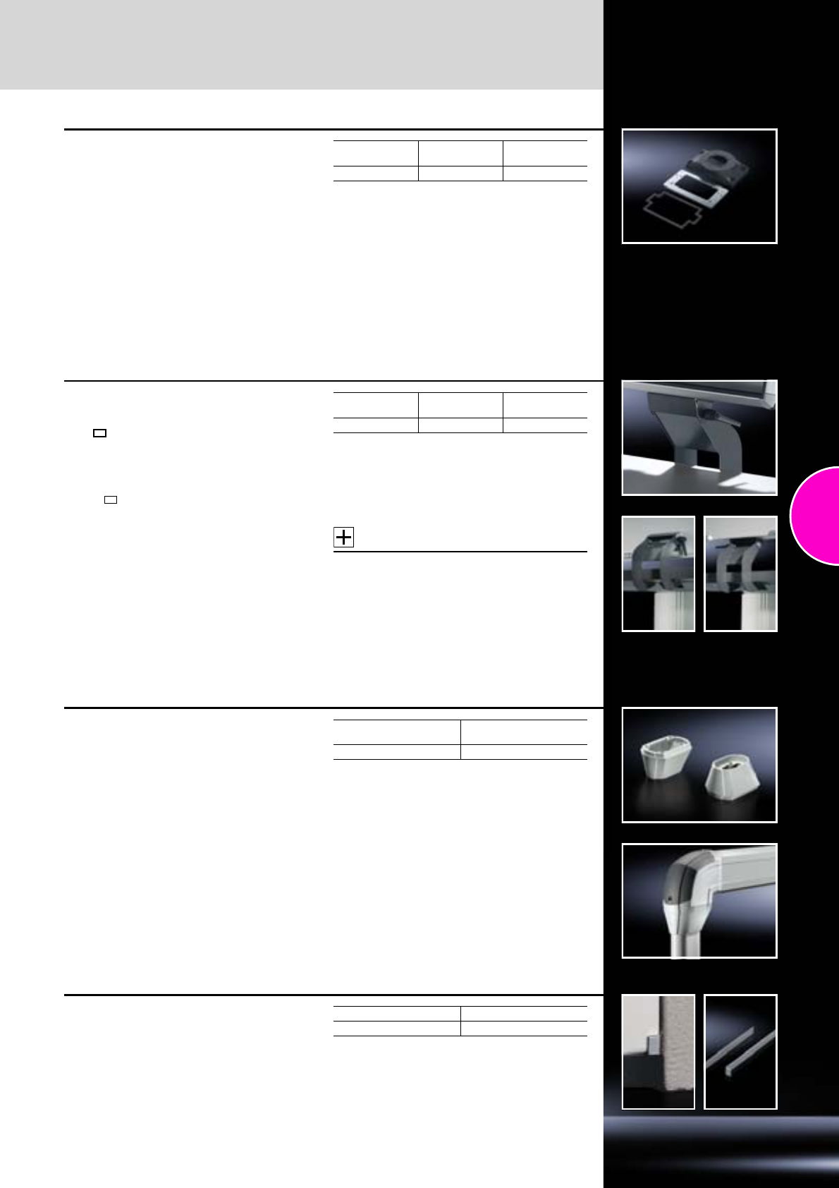
Accessories
Support arm systems
143Rittal Catalogue 33/Enclosures
Connection plate CP-L
With reinforcement plate
●For easy location of the command panel onto
the support arm or pedestal.
●More space for cable entry
●For mounting command panels
−Comfort Panel from a front panel width of
247 mm and installation depth of 152 mm
−Optipanel from a front panel width of 220 mm
and installation depth of 150 mm
−Sheet steel from 135 mm installation depth
Material:
−Connection plate: Cast aluminium
−Reinforcement plate: Sheet steel, 6 mm
Supply includes:
Seals and assembly parts.
Detailed drawings:
Available on the Internet.
Colour
RAL Weight
kg Model No.
CP
7024 0.7 6528.210
Enclosure attachment, tilting,
base mounting
CP-L 120 x 65 mm
For mounting beneath:
●IW worktop with pedestal
●Adequately large surfaces
Fits enclosures with mounting cut-out:
●CP-L 120 x 65 mm
(e.g. Optipanel, see page 118,
Comfort Panel, see page 116)
With mounting cut-out for connector grommet
for sealed cable entry.
Tilt angle:
+/–40°, lockable via clamping levers.
Material:
Sheet steel
Surface finish:
Spray-finished
Supply includes:
Assembly parts.
Note:
The enclosure attachment can be mounted either
on the support arm connection of the Optipanel
enclosure or on the underside or rear of any
enclosure.
Accessories:
−Connector gland, see page 522
−IW worktop, see page 111
−Pedestal, see page 147.
Detailed drawings:
Available on the Internet.
Colour
RAL Weight
kg Model No.
IW
7024 1.6 6902.640
Connection adaptor
CP-C to CP-L
Applications: For integration of the support arm,
height-adjustable CP-L (see page 132) to the
CP-C support arm system
●For mounting small, flat operating housings if
the load capacity of the support arm system
CP-C is needed for long jib lengths
Benefits:
●Integral adjustment facility
Material:
Cast aluminium
Supply includes:
−Seals
−Self-tapping screws for CP-L support section
attachment.
Detailed drawings:
Available on the Internet.
Weight
kg Model No. CP
0.6 6071.600
Adjustment set for support
section CP-XL
The adjustment set also supports retrospective
alignment of the CP support section.
Material:
Sheet steel 1.0 mm
Surface finish:
Zinc-plated
Packs of Model No. CP
10 6205.000
Support arm systems
Accessories
144 Rittal Catalogue 33/Enclosures
Housing couplings CP-XL
for desktop mounting
The stable, rotating connection with extra space
for cable routing.
For additional stability of the roof and base with
heavy installed equipment.
For mounting
●Command panels from 150 mm installation
depth on
●IW worktops
●Horizontal surfaces (floors or ceilings)
Attachment
●of command panels: With one-man assembly
via machined keyholes
●on surfaces: Via external screws with cover
Rotation range:
Max. 350°, lockable via clamping levers.
By using additional M6 cheese-head screws,
the rotation range may be limited to ±28°, ±73°,
±118°, ±163°.
Material:
−Housing coupling: Cast aluminium/die-cast zinc
−Reinforcement plate: Sheet steel, 6 mm
Surface finish:
−Housing coupling: Powder-coated, textured
−Reinforcement plate: Zinc-plated
Colour:
Housing coupling: RAL 7024
Supply includes:
−Reinforcement plate
−Seals
−Assembly parts
Note:
With the Comfort Panel and Optipanel enclo-
sures, the rectangular support arm cut-out can be
selected, ordered and prepared using the com-
mand panel configurators at www.rittal.com.
Detailed drawings:
Available on the Internet.
Design Optipanel Comfort
Panel Weight
kg Model No.
CP
W =
418 mm 4321) 4351) 4,2 6528.410
1) From front panel width mm without keyboard housing;
with keyboard housing on request.
Support arm, height adjustable
for support arm system CP-L
Offers enhanced ergonomics thanks to:
●Adjustment range
−for tall and short operators
−for seated and standing work
−adjustable to a maximum of 800 mm as
required via an adjusting screw at the front of
the support arm.
●Precise coordination of the compression spring
to the enclosure weight via an adjusting screw
at the rear of the support arm.
●Complete functional reliabilty – if the compres-
sion spring breaks, the arm will remain in posi-
tion.
●Clip-off plastic panels for access to integral
cable routing.
●Tilting angle of the mounted enclosure is identi-
cal in every height position.
For 6510.330 and 6510.340:
●More space for cable routing.
●Cables with connectors such as DVI,
VGA are also easily inserted.
●Integral locking in three stages.
●Superior load capacity.
Supply includes:
Assembly parts.
Note:
Maximum cross-section for cable entry:
6510.210 = 8 x 15 mm
6510.330/.340 = 16 x 40 mm
Detailed drawings:
Available on the Internet.
Overall
length
mm
Colour
RAL
Weight
range
kg1)
Model No.
CP
962 9006 10 – 20 6510.210
1090 9006 15 – 32 6510.330
1090 9006 20 – 40 6510.340
1) For populated enclosure and vertical support section.
Accessories
Support arm systems
145Rittal Catalogue 33/Enclosures
Pivot CP-L
with/without jib
●For direct, vertically hinged integration into
machines and systems
●Enclosure suspended or top-mounted
●With integral rotation range restrictor
●To fit enclosures with mounting cut-out
CP-L Ø 130 mm
Detailed drawings:
Available on the Internet.
Jib length
mm Colour
RAL Load
capacity N Model No.
CP
– 7024 700 6016.700
200 7024/7035 700 6016.600
Support arm bracket 90° CP-L
●For the configuration of compact systems
●To fit support arm system CP-L
●No thread-tapping required
Detailed drawings:
Available on the Internet.
Colour
RAL Weight
kg Model No.
CP
7035 3.4 6519.000
Enclosure attachment, tilting,
top mounting
For mounting on:
●IW worktop, prepared for enclosure attachment
CP-L, Ø 130 mm, see page 111
●Surfaces
●Enclosure attachment/coupling
CP-L 120 x 65 mm, see page 133
●Attachment/housing coupling CP-S (may also
be used as tilting adaptor +100°/–60° for CP-S),
see page 129
To fit enclosures up to 20 kg with support arm
connection:
●CP-S
●CP-L 120 x 65 mm
●CP-L Ø 130 mm
●VESA Standard 75.
With cable tube for protected cable entry.
Tilt angle:
+100°/–60°, adjustable in 7.2° increments via
clamping lever and may be limited to +100°/–15°
using the stop screw supplied loose.
Material:
Sheet steel
Surface finish:
Spray-finished
Supply includes:
−Assembly parts
−Plastic concertina section
Accessories:
IW worktops prepared for enclosure attachment,
see page 111.
Detailed drawings:
Available on the Internet.
Colour RAL Weight kg Model No. IW
7024 0.8 6902.670
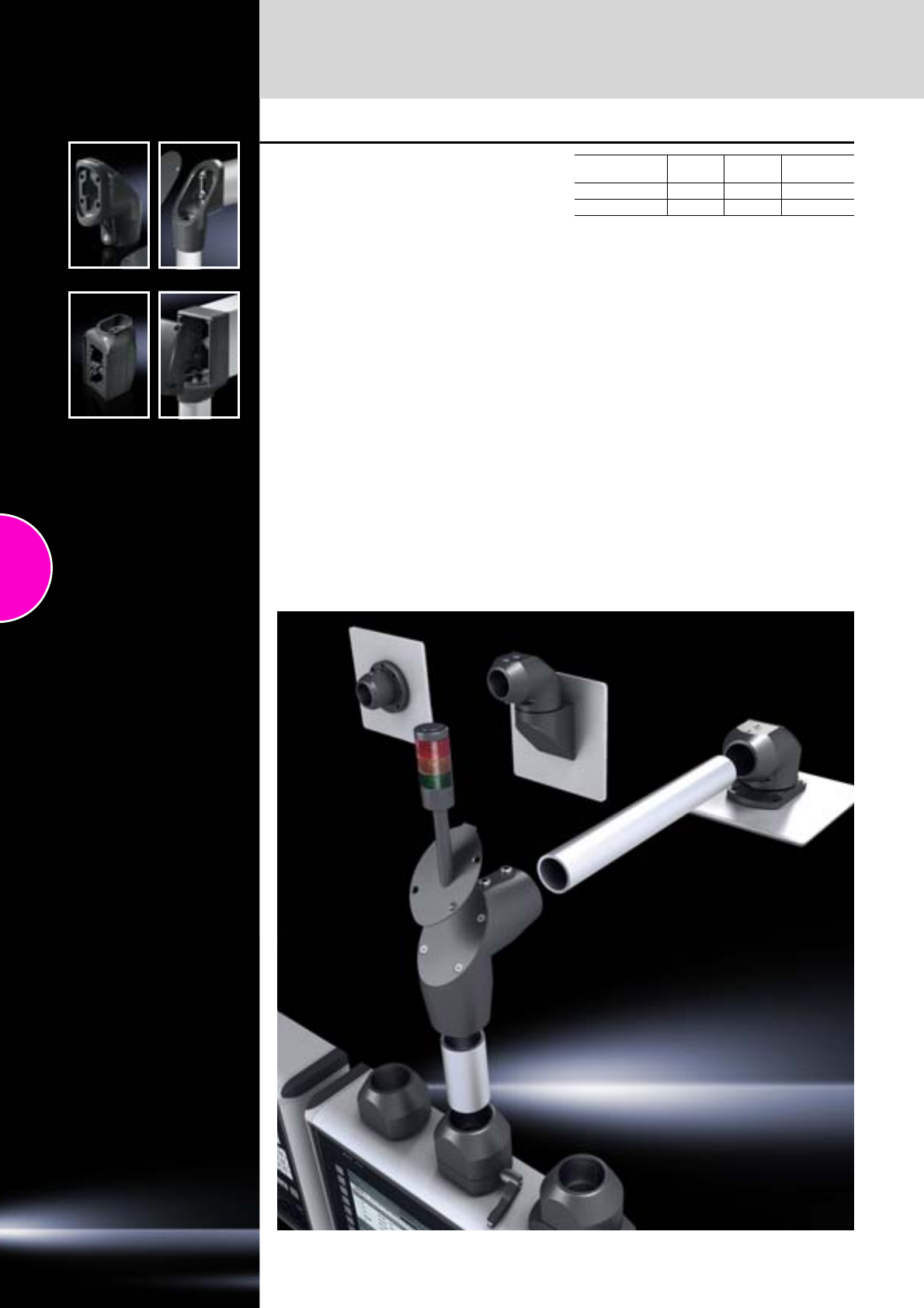
Support arm systems
Accessories
146 Rittal Catalogue 33/Enclosures
Angle adaptor 90°
Connection component between:
●small and larger support arm systems.
Outlet optionally at the top or bottom if this config-
uration is chosen for static or visual reasons. The
removable cover ensures easier cable entry.
Material:
Cast aluminium
Supply includes:
Seal for support section attachment.
Detailed drawings:
Available on the Internet.
Colour
RAL Weight
kg Model No.
CP
CP-L to CP-S 7024 1.0 6501.090
CP-XL to CP-L 7024 1.7 6528.110
Stand systems
147Rittal Catalogue 33/Enclosures
Comfort Panel
Page 116
Optipanel
Page 118
Compact Panel
Page 120
Command panel housing with door
Page 121
Operating housings
Page 122
Pedestal, modular, consisting of:
●Pedestal base plate
●Support section
●Enclosure connection
Colour:
RAL 7035 Detailed drawings:
Available on the Internet.
Photo shows a configuration
example with equipment not
included in the scope of supply.
Pedestal, modular
Weight load kg 15 18 35 50 Page
Pedestal base plate Model No. CP
Pedestal base plate 6146.100 6143.200 6137.535 6137.035
Dimensions W x H x D mm 400 x 10 x 400 400 x 108 x 400 490 x 100 x 600
Support section Model No. CP
Height-adjustable (adjustment range 732 – 1122 mm) 6146.200 – – –
Closed, length 1000 mm – 6513.000 6513.000 6100.500 133/141
Open, length 1000 mm – 6513.050 6513.050 6100.000 133/141
Enclosure connection Model No. CP
Enclosure reinforcement, rigid – 6143.210 – – 151
Enclosure attachment CP-S 6501.070 – – – 129
Housing coupling CP-S 6501.050 – – – 129
Enclosure attachment CP-L, Ø 130 mm – – 6525.510 – 133
Enclosure attachment CP-L, 120 x 65 mm – – 6525.610 – 133
Housing coupling CP-L, Ø 130 mm – – 6525.010 – 133
Housing coupling CP-L, 120 x 65 mm – – 6525.110 – 133
Enclosure attachment CP-XL, round – – – 6130.610 141
Enclosure attachment CP-XL, rectangular – – – 6130.510 141
Housing coupling CP-XL – – – 6130.010 141
Tilt adjustment 6146.300 – – –
Accessories
Twin castors 6148.000 – 6148.000 6148.000 374
Levelling feet – – 4612.000 4612.000 373
Base mount – – 1590.000 1590.000 439
Gas pressurised spring, load capacity 15 kg 6146.400 – – –
3
2
1
1
2
3
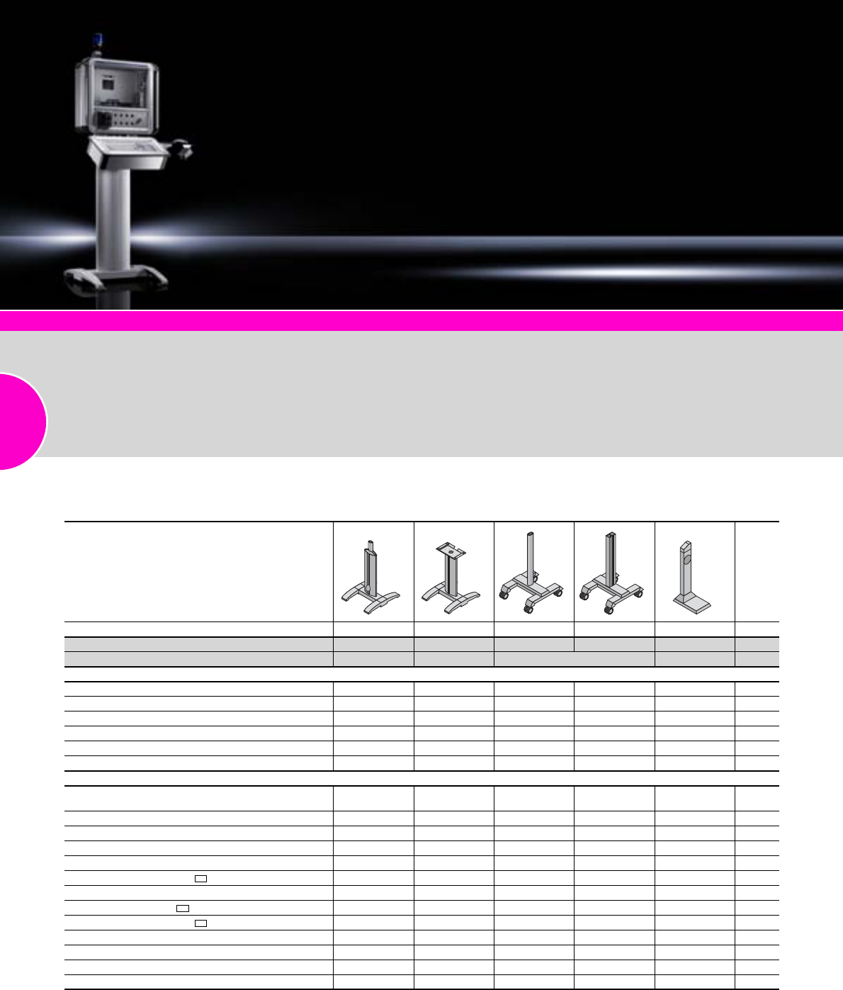
Stand systems
148 Rittal Catalogue 33/Enclosures
Comfort Panel
Page 116
Optipanel
Page 118
Compact Panel
Page 120
Command panel housing with door
Page 121
Operating housings
Page 122
The right system to suit any
application:
●Fixed or mobile variant
●Different designs
●Weight load from 15 – 50 kg
●Reliable protection of cable
management
Colour:
RAL 7035 Detailed drawings:
Available on the Internet.
Photo shows a configuration
example with equipment not
included in the scope of supply.
Pedestal, complete
Weight load kg 25 25 35 50 50 Page
Model No. CP 6141.100 6141.200 6136.500 6136.000 6135.000
Dimensions W x H x D mm 600 x 1093 x 660 600 x 946 x 660 600 x 1005 x 550 360 x 995 x 500
Supply includes
Cross member –
Base plate – – – –
Twin castors – – –
Support section –
Vertical aluminium moulding, may be opened – – –
Worktop attachment – – – –
Accessories
Twin castors 6148.000,
7495.000 6148.000,
7495.000 – – – 374
Levelling feet 4612.000 4612.000 – – – 373
Base mount 6147.000 6147.000 – – – 151
Trim panel for pedestal 6144.100 6144.100 – – – 151
Enclosure attachment CP-L, Ø 130 mm 6525.510 – 6525.510 – – 133
Enclosure attachment CP-L, 120 x 65 mm 6525.610 – 6525.610 – – 133
Housing coupling CP-L, Ø 130 mm 6525.010 – – – – 133
Housing coupling CP-L, 120 x 65 mm 6525.110 – – – – 133
Enclosure attachment CP-L, 120 x 65 mm, locatable 6525.210 – – – – 133
Enclosure attachment CP-XL, round – – – 6130.610 – 141
Enclosure attachment CP-XL, rectangular – – – 6130.510 – 141
Enclosure attachment, tilting – 6902.640 – – – 143
Worktop without handle1) – 6902.310 – – –
Included with the supply.
1) W x H x D 950 x 38 x 600 mm
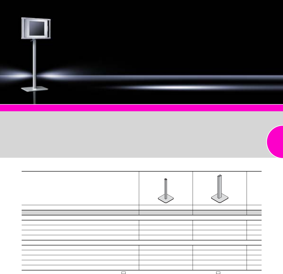
Stand systems
149Rittal Catalogue 33/Enclosures
Comfort Panel
Page 116
Optipanel
Page 118
Compact Panel
Page 120
Command panel housing with door
Page 121
Operating housings
Page 122
The welded alternatives to the
pedestal, complete
●Pedestal, open:
For retrospective cable entry
with pre-assembled connec-
tors
●Pillar, small:
For heavy installed equipment
Material:
Steel
Surface finish:
Spray-finished
Colour:
RAL 7035
Detailed drawings:
Available on the Internet.
Photo shows a configuration
example with equipment not
included in the scope of supply.
Pillar, small
Weight load kg 40 80 Page
Model No. CP 6215.000 6214.500
Design
Base plate cross-section W x H x D mm 400 x 10 x 400 500 x 12 x 500
Pedestal tube cross-section W x H mm 86 x 73 160 x 80
Pedestal tube wall thickness mm 3 3,2
Overall height mm 1093 1150
Accessories
Enclosure attachment CP-L, Ø 130 mm 6525.510 – 133
Housing coupling CP-L, Ø 130 mm 6525.0101) – 133
Enclosure attachment CP-XL, round – 6130.610 141
Enclosure attachment CP-XL, rectangular – 6130.510 141
Housing coupling CP-XL – 6130.010 141
1) When assembling enclosures with support arm connection CP-L, 120 x 65 mm, connection adaptor CP-L, Ø 130 mm to CP-L, 120 x 65 mm CP 6071.000
(see page 142) should additionally be used.
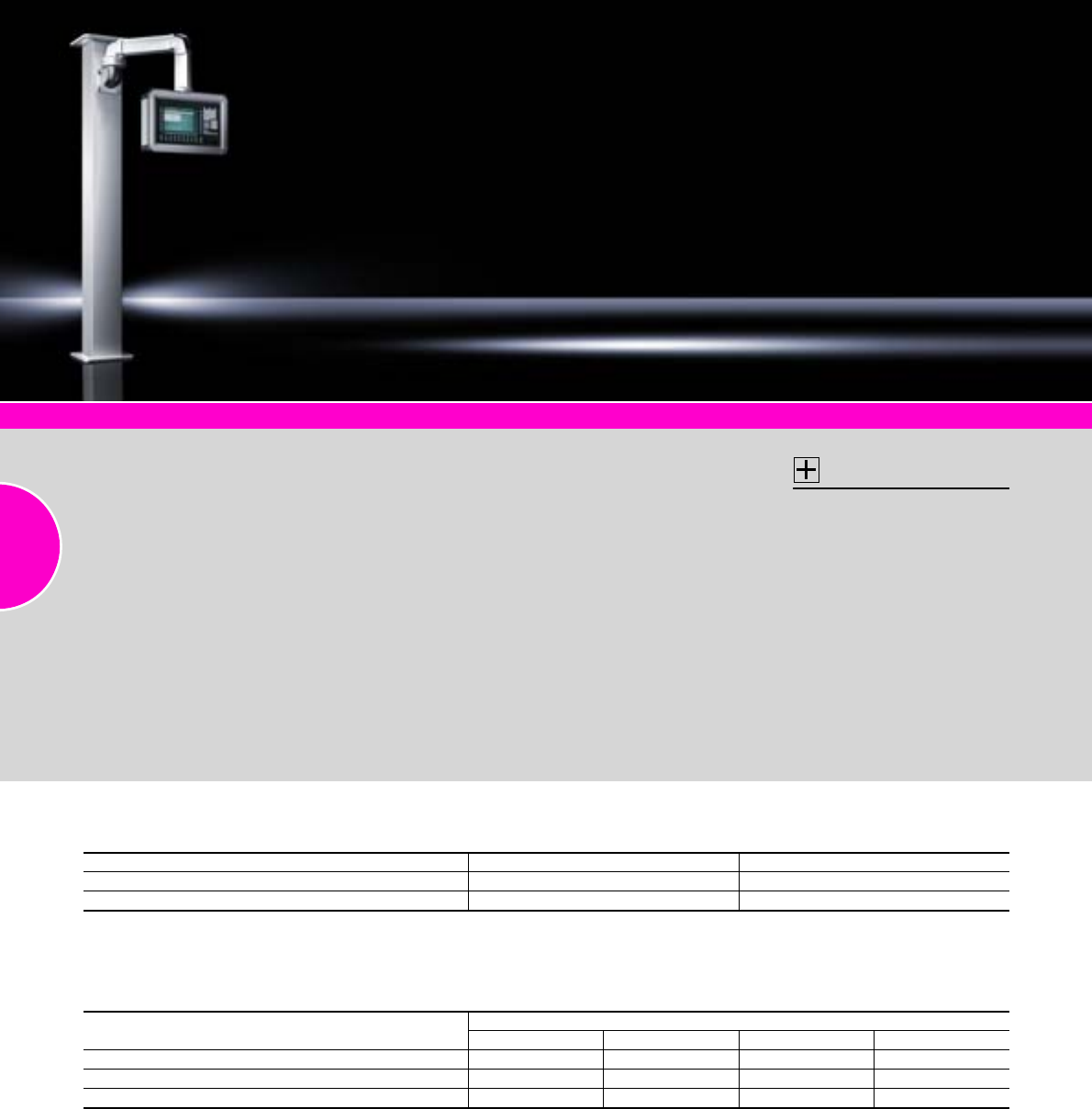
Stand systems
150 Rittal Catalogue 33/Enclosures
Support arm system CP-S
Page 127
Support arm system CP-L
Page 131
Support arm system CP-C
Page 135
Support arm system CP-XL
Page 139
The stable base point for the
support arm system. The attach-
ment of additional enclosures,
e.g. for security systems, is also
possible.
There is a choice of 2 cross-sec-
tions:
●140 x 140 mm
●200 x 200 mm
Design:
−Base plate, thickness:
15 mm, with 4 mounting holes
−Cut-out in the base plate in
accordance with the cross-
section for cable entry from
below
−Pedestal tube (wall thickness
5 mm) welded to the base
plate
−Connection facility for
support arm systems as
per the selection table.
Delivery time:
Available on request.
Material:
Steel
Surface finish:
Spray-finished
Colour:
RAL 7035
Supply includes:
Assembly parts for support arm
system according to selection.
Note:
Customer-specific designs,
such as:
−Other RAL colours
−Heights
−Consoles for additional
enclosures
available on request.
Accessories:
−Support arm system
CP-S, see 128
−CP-L, see page 132
−CP-C, see page 136
−CP-XL, see page 140
−Gland plates size 2,
see from page 514.
Detailed drawings:
Available on the Internet.
Photo shows a configuration
example with equipment not
included in the scope of supply.
Pillar
In addition to the Model Number, the following information is also needed:
1. Unless otherwise stated, the position for the cable entry cut-out is on the rear.
2. Position and Item No. of support arm component
Design For support arm system Model No. CP
Cross-section 140 x 140 mm, height 2000 mm1) CP-S, CP-L, CP-C 6214.000
Cross-section 200 x 200 mm, height 2000 mm1) CP-C, CP-XL 6220.000
1) Unless otherwise specified.
Support arm component Support arm system
CP-S CP-L CP-C CP-XL
Wall/base mounting bracket, large, side mounting 6501.110 6520.010 6072.000 6160.010
Wall-mounted hinge, horizontal outlet, side mounting 6501.150 6521.010 6072.500 6110.010
Top-mounted joint, mounting on top 6501.160 6522.010 6072.600, 6072.800 6170.010
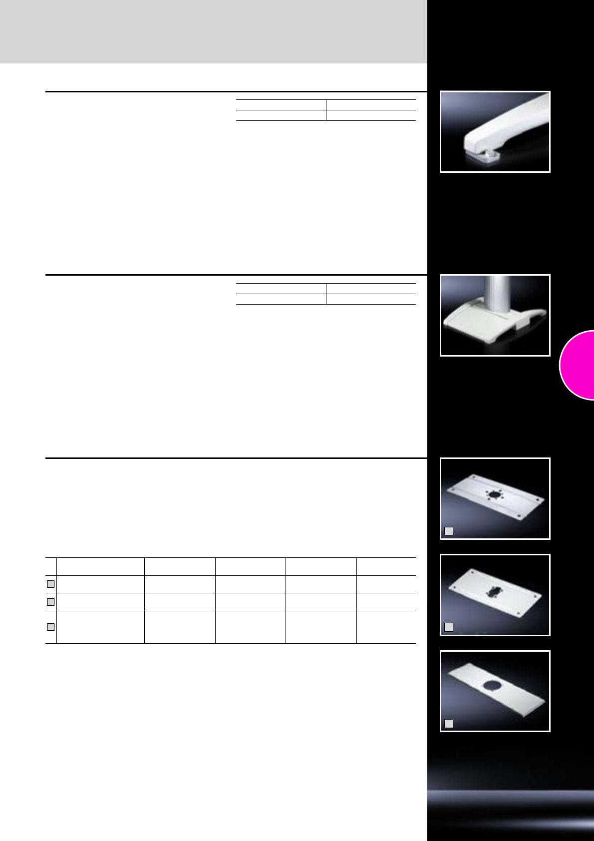
Accessories
Stand systems
151Rittal Catalogue 33/Enclosures
Base mount
Brackets for screw-fastening from below to the
cast feet with posidrive raised countersunk
screws M12. Optionally with projection at the front,
interior or sides, with Ø 11 mm hole for screw-
fastening to the base.
Material:
Steel
Surface finish:
Zinc-plated
Supply includes:
Posidrive raised countersunk screws M12.
Packs of Model No. CP
46147.000
Trim panel
Material:
Cast aluminium
Supply includes:
Assembly parts for screw-fastening between the
cast feet at the front or rear.
Colour RAL Model No. CP
7035 textured 6144.100
1
2
3
Enclosure reinforcement
For external or internal reinforcement of enclo-
sures of a corresponding size.
Smaller enclosures may also be mounted directly
without enclosure reinforcement.
Supply includes:
Assembly parts for the enclosure and support
section plus 2 seals.
Detailed drawings:
Available on the Internet.
B = Width
T = Depth
For enclosure Support arm
connection Material Weight kg Model No.
CP
B1 ≥ 300 mm,
T1 ≥ 150 mm CP-S Stainless steel
1.4301 0.9 6143.310
B1 ≥ 300 mm,
T1 ≥ 150 mm CP-L Sheet steel 0.9 6143.210
CP 6662.500
or
AE (B1 = 600 mm,
T1 ≥ 210 mm)
CP-XL Sheet steel 2.2 6503.000
1
2
3
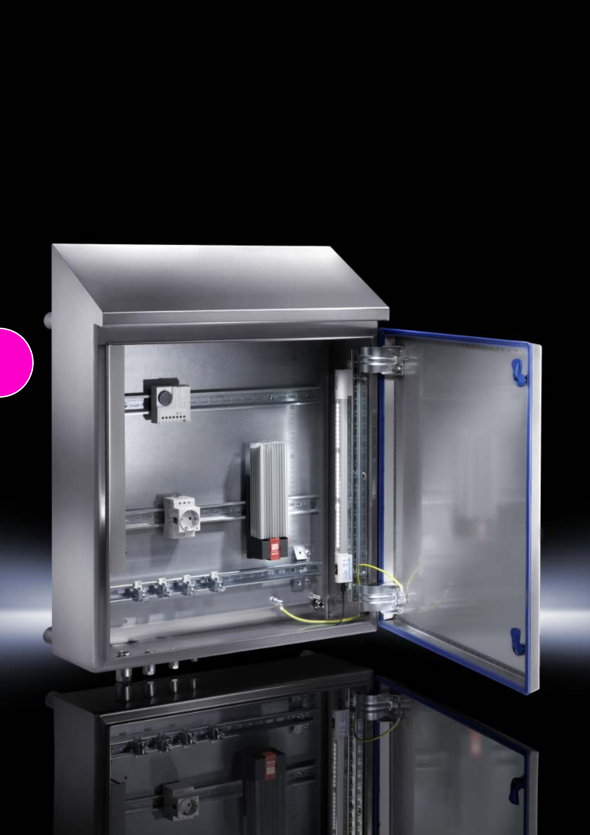
152

153
Hygienic Design
Small and compact enclosures HD
Terminal boxes HD....................................................................................154
Compact enclosures HD, single-door.......................................................155
Accessories...............................................................................................156
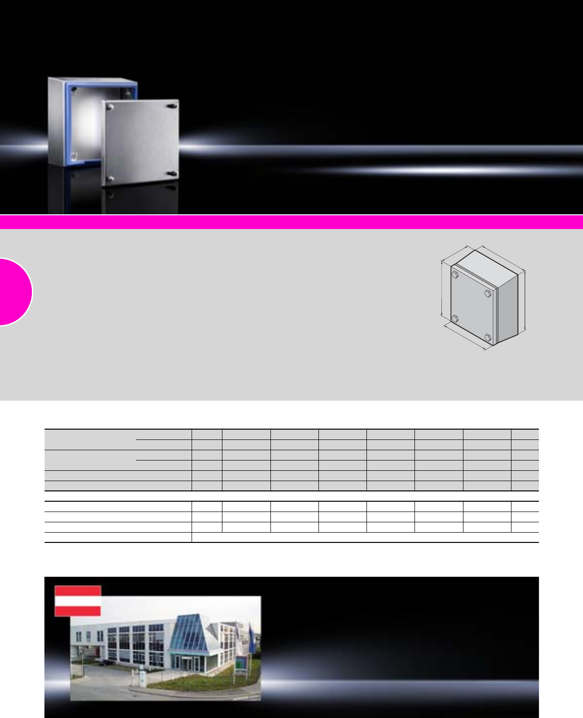
Hygienic Design
154 Rittal Catalogue 33/Enclosures
Terminal boxes HD
Width Front (B1) mm Packs of 150 150 200 300 400 400 Page
Rear (B2) mm 172 177 227 327 427 427
Height Front (H1) mm 150 150 200 200 200 300
Rear (H2) mm 172 177 227 227 227 327
Depth (T) mm 80 120 120 120 120 120
Model No. HD 11670.600 1671.600 1672.600 1674.600 1675.600 1676.600
Accessories
Wall spacer bracket HD 1 4000.100 4000.100 4000.100 4000.100 4000.100 4000.100 156
Mounting plate 1 1560.700 1560.700 1562.700 1563.700 1564.700 1568.700 443
Support rail TS 35/7.5 10 2314.000 2314.000 2315.000 2316.000 2317.000 2317.000 467
Cable gland HD see page 521
HD accessories Page 156 System accessories Page 355
Material:
−Enclosure and cover:
Stainless steel 1.4301
(AISI 304), 1.5 mm
−Mounting bracket:
Sheet steel, zinc-plated,
passivated, 2.0 mm
−Quick-release fasteners:
Stainless steel
−Seal: Silicone,
compliant with FDA Guideline
21 CFR 177.2600
Surface finish:
−Enclosure and cover:
Brushed, grain 400,
RA<0.8μm
−Seal: Blue, dyed (RAL 5010)
Protection category:
−IP 66 to IEC 60 529
−IP 69K to DIN 40 050-9
Compliant with NEMA 13
Compliant with NEMA 4X
Compliant with NEMA 3R
Supply includes:
−Enclosure of all-round solid
construction
−Cover
−Mounting bracket
(pre-assembled)
−Seal and quick-release locks
(supplied loose)
Detailed drawing:
Available on the Internet.
H2
H1
B1
T
B2
Rittal Austria
RITTAL Schaltschränke Gesellschaft m.b.H.
Laxenburger Straße 246a A-1239 Wien
Phone: +43 (0) 5 99 40-0
Fax: +43 (0) 5 99 40-99 0
E-mail: info@rittal.at www.rittal.at
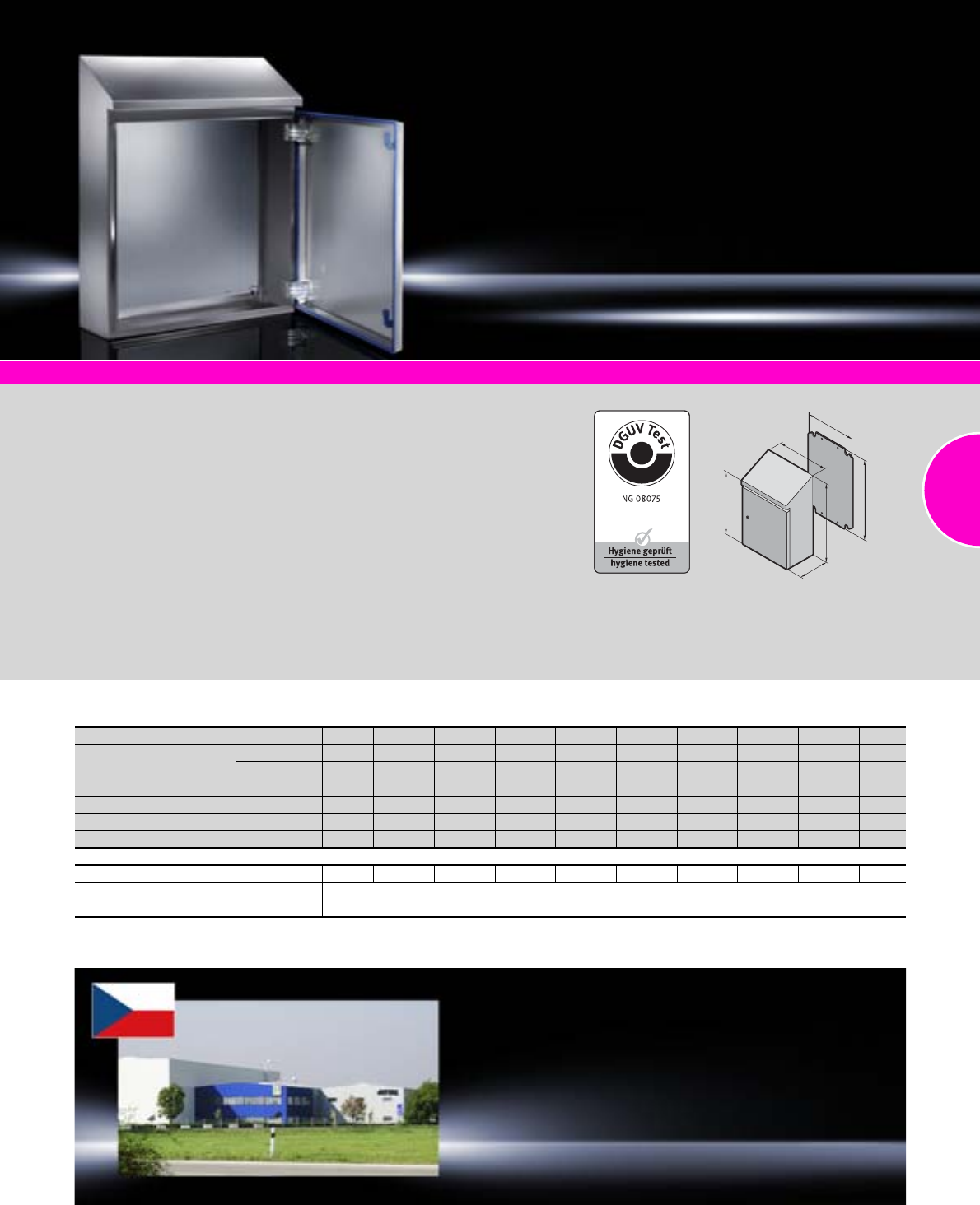
Hygienic Design
155Rittal Catalogue 33/Enclosures
Compact enclosures HD, single-door
Width (B) mm Packs of 220 390 390 510 610 610 810 810 Page
Height Front (H1) mm 350 430 650 550 430 650 1050 1250
Rear (H2) mm 437 549 769 669 601 769 1221 1421
Depth (T) mm 155 210 210 210 300 210 300 300
Mounting plate width (F) mm 162 334 334 449 549 549 739 740
Mounting plate height (G) mm 275 355 570 470 355 570 955 1155
Model No. HD 1 1302.600 1306.600 1308.600 1307.600 1320.600 1310.600 1316.600 1317.600
Accessories
Wall spacer bracket HD 1 4000.100 4000.100 4000.100 4000.100 4000.100 4000.100 4000.100 4000.100 156
Rails for interior installation see page 157
Cable gland HD see page 521
HD accessories Page 156 System accessories Page 355
Material:
−Enclosure and door:
Stainless steel 1.4301
(AISI 304)
−Mounting plate: Sheet steel
−Lock inserts HD:
Stainless steel 1.4404
(AISI 316L)
−Seal: Silicone, compliant
with FDA Guideline 21
CFR 177.2600
Surface finish:
−Enclosure and door:
Brushed, grain 400, ´
RA< 0.8 μm
−Mounting plate: Zinc-plated
−Seal: Blue, dyed (RAL 5010)
Protection category:
−IP 66 to IEC 60 529
−IP 69K to DIN 40 050-9
Compliant with NEMA 13
Compliant with NEMA 4X
Supply includes:
−Enclosure of all-round solid
construction
−Door with press-fitted seal
−Interchangeable door hinge
−Mounting plate
Detailed drawing:
Available on the Internet.
F
G
T
H2
B
H1
Rittal Czech Republic
RITTAL Czech, s.r.o.
Ke Zdibsku 182 250 66 Zdiby u Prahy
Phone: +420 234 099 000
Fax: +420 234 099 099
E-mail: info@rittal.cz www.rittal.cz
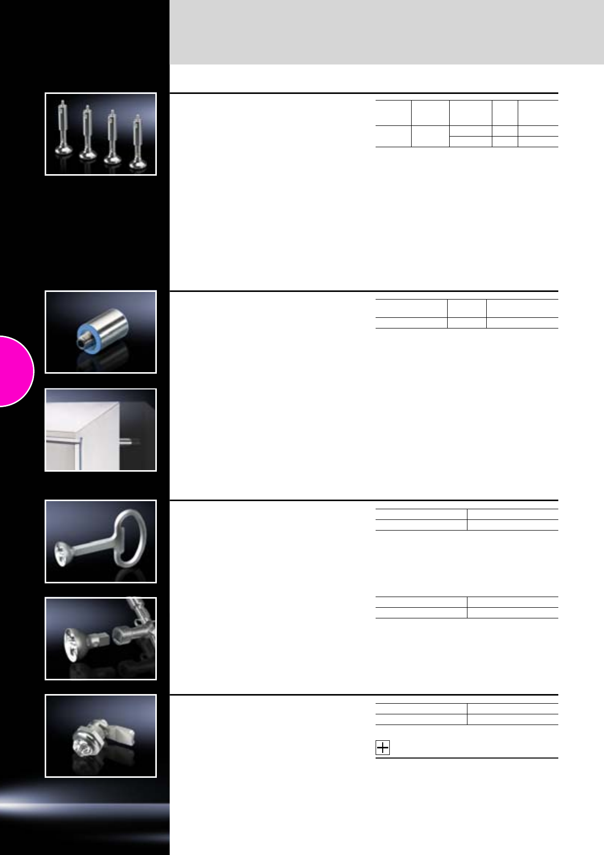
Hygienic Design
Accessories
156 Rittal Catalogue 33/Enclosures
Levelling feet HD
for TS 8
Benefits:
●Minimises cleaning time thanks to fully
covered, permanently sealed threads.
●Compensation of floor inclines up to an angle
of 10° thanks to flexible base plate.
●Baying can even be achieved on sloping floors,
thanks to a large levelling range of 55 mm.
Load capacity:
Max. 5000 N static per levelling foot.
Material:
Stainless steel 1.4301 (AISI 304)
Supply includes:
Assembly parts and seals.
Thread Levelling
range
mm
Base
mount Packs
of Model No.
HD
M12 120 – 175 without 4 4000.200
with 4 4000.210
Wall spacer bracket HD
Benefits:
●Creates space for cleaning behind the
enclosure.
●Shorter assembly times by eliminating the need
for an all-round seal.
●Greater hygiene safety by avoiding an uncon-
trollable dead space or gap between the enclo-
sure and wall.
Functional principle:
●Mounting on the wall optionally from the enclo-
sure interior via a through-hole (max. M8) or
from the rear via an integral M10 thread.
Material:
Stainless steel 1.4301 (AISI 304)
Supply includes:
Assembly parts and seals.
Wall distance
mm Packs of Model No. HD
50 1 4000.100
Enclosure key HD Packs of Model No. HD
1 2549.600
Bit HD
for universal key SZ 2549.500
See page 424.
Packs of Model No. HD
1 2549.510
Cam lock HD
Hygienic Design variant for easy, safe cleaning.
Applications:
●Compact enclosures AE stainless steel
(except AE 1017.XXX and AE 1019.XXX).
●May be integrated into customised applica-
tions, e.g. covers of machine panels.
Material:
Stainless steel 1.4404 (AISI 316L)
Accessories:
Enclosure key HD,
see page 156.
Packs of Model No. HD
1 2304.010
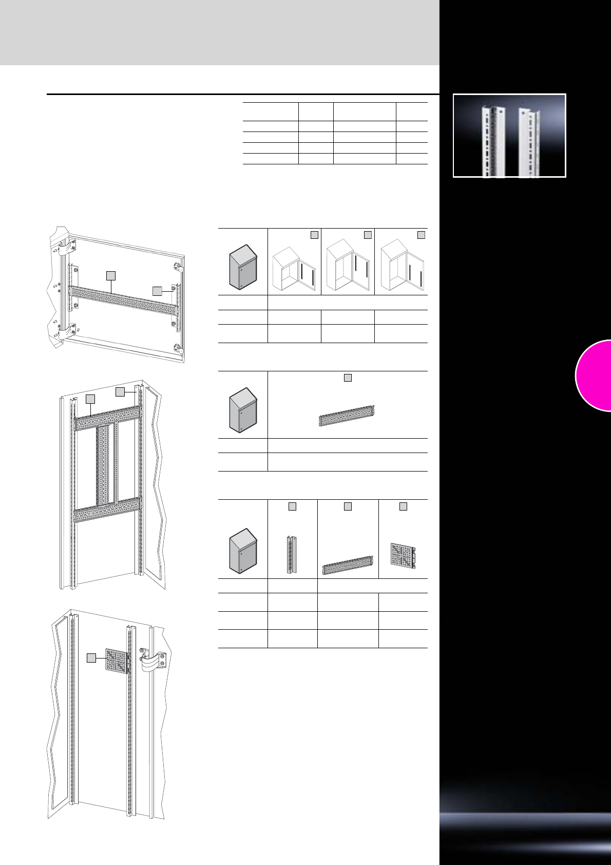
Accessories
Hygienic Design
157Rittal Catalogue 33/Enclosures
Rails for interior installation
for compact enclosures HD
For mounting on the existing threaded bolts.
With TS system punchings on three sides.
Material:
Sheet steel, zinc-plated
Supply includes:
Assembly parts.
Length
mm Packs of Model No. CM Page
510 4 5001.050 459
710 4 5001.051 459
910 4 5001.052 459
1110 4 5001.053 459
Interior installation, door
Rails for door installation
Interior installation, enclosure
Enclosure
Model No. HD Model No. CM
1316.600 5001.052 5001.050 5001.050
1317.600 5001.053 5001.051
5001.050 5001.051
5001.050
Enclosure
TS punched section without mounting flange,
17 x 73 mm
Model No. HD Model No. TS
1316.600
1317.600 8612.065
Enclosure
Rails for inte-
rior installation
TS punched
section without
mounting flange,
17 x 73 mm
Mounting
plates
Model No. HD Model No. CM Model No. TS
1308.600
1310.600 5001.050 – –
1316.600 5001.052 8612.130
(only on lock side) 8612.400
8612.410
1317.600 5001.053 8612.130
(only on lock side) 8612.400
8612.410
1
1
1
2
1
3
4
1
3
4
2
1
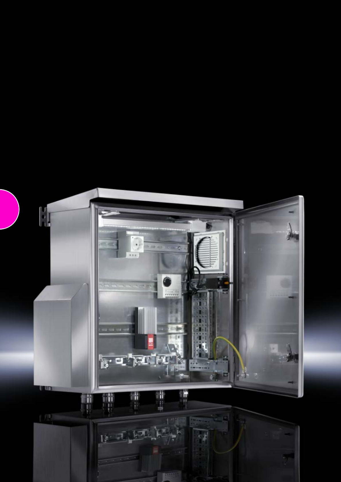
158

159
Stainless steel
Small enclosures
Switch housings ........................................................................................160
Terminal boxes KL.....................................................................................161
Bus enclosures BG....................................................................................161
Compact enclosures
Compact enclosures AE............................................................................162
Compact enclosures AE, protection category IP 69K...............................165
Operating housings
Premium Panel, protection category IP 69K .............................................166
Command panel housing with door ..........................................................167
Support arm system
Support section CP-S, stainless steel .......................................................168
Support arm system CP-S, stainless steel, components ..........................169
Enclosure systems
One-piece consoles AP.............................................................................170
PC enclosure systems...............................................................................171
Baying systems TS 8 .................................................................................172
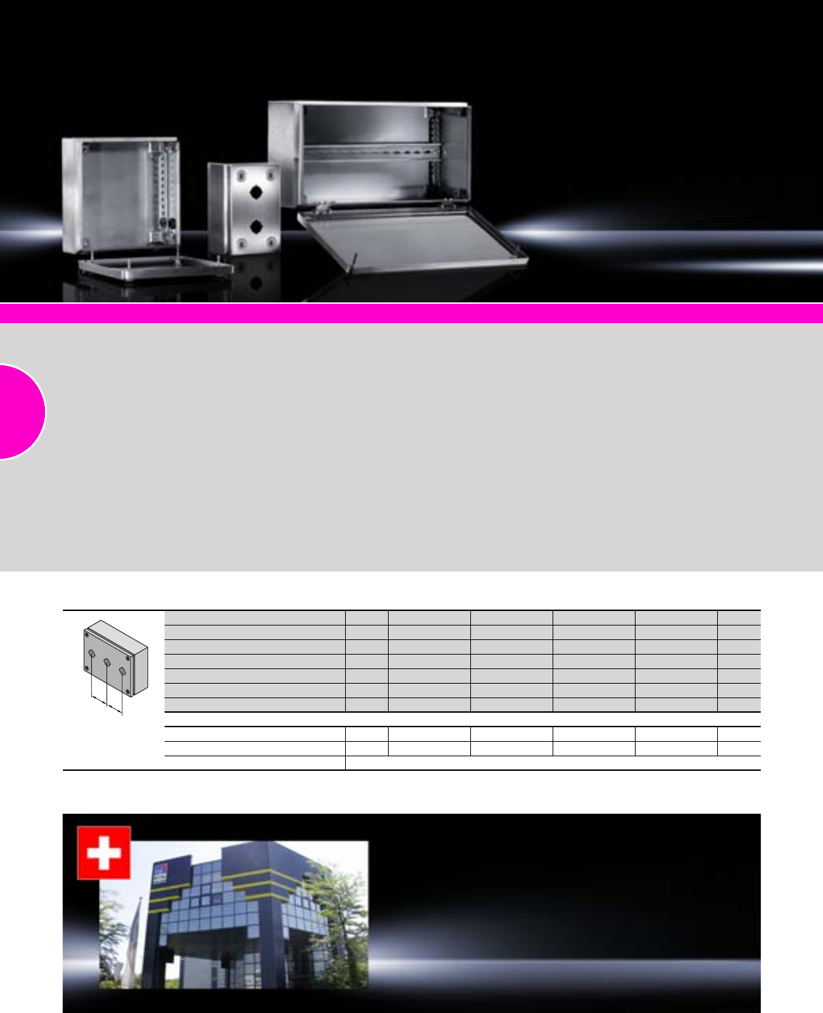
Stainless steel
160 Rittal Catalogue 33/Enclosures
Switch housings
Width mm Packs of 100 160 220 280 Page
Height mm 100 100 100 100
Depth mm 90 90 90 90
Model No. SM 12384.010 2384.020 2384.030 2384.040
Pitch pattern (R) mm –60 60 60
No. of switch cut-outs, Ø 22.5 mm 1 2 3 4
Number of quick-release fasteners 2 4 4 4
Accessories
Wall mounting bracket 4 1594.000 1594.000 1594.000 1594.000 439
Pressure relief stoppers 5 2459.500 2459.500 2459.500 2459.500 384
Cable gland HD see page 521
RR
System accessories Page 355
Material:
−Enclosure: Stainless steel
1.4301 (AISI 304), 1.25 mm
−Cover: Stainless steel 1.4301
(AISI 304), 1.25 mm, all-round
foamed-in PU seal
Surface finish:
−Enclosure and cover:
Brushed, grain 240 or
180 (for terminal boxes)
Protection category:
IP 66 to IEC 60 529,
complies with NEMA 4X.
Supply includes:
−Enclosure with cover
−Product-specific supply
scope, see tables
Approvals:
Terminal boxes KL
−UL
−CSA
−TÜV
−Germanischer Lloyd
−Russian Maritime Register
of Shipping
−Lloyds Register of Shipping
−Bureau Veritas
−VDE
Bus enclosures BG
−TÜV
−Lloyds Register of Shipping
−VDE
−UL
−cUL
Detailed drawings:
Available on the Internet.
Photo shows a configuration
example with equipment not
included in the scope of supply.
Rittal Switzerland
RITTAL AG
Ringstrasse 1 CH-5432 Neuenhof
Phone: +41 (0) 56 416 06 00
Fax: +41 (0) 56 416 06 66
E-mail: rittal@rittal.ch www.rittal.ch
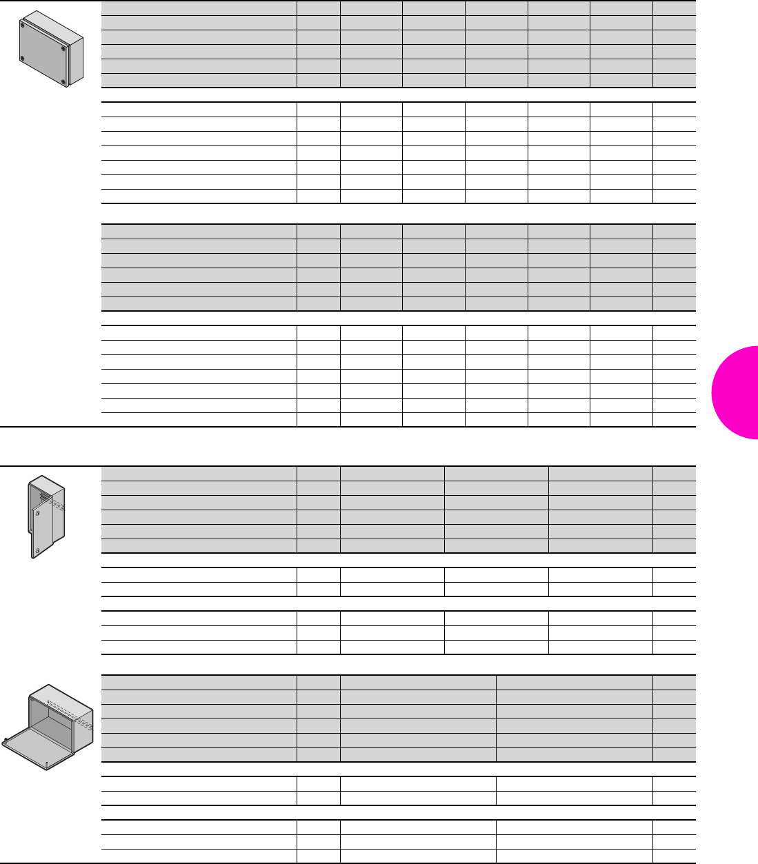
Stainless steel
161Rittal Catalogue 33/Enclosures
Terminal boxes KL
Bus enclosures BG
Width mm Packs of 150 150 300 200 200 Page
Height mm 150 150 150 200 200
Depth mm 80 120 80 80 120
Model No. KL 11521.010 1527.010 1522.010 1523.010 1528.010
Weight (kg) 1.3 1.6 1.8 1.8 2.2
Number of quick-release fasteners 44444
Accessories
Mounting plate 1 1560.700 1560.700 1561.700 1562.700 1562.700 443
Wall mounting bracket 4 1594.000 1594.000 1594.000 1594.000 1594.000 439
Wall angle 4 2583.010 2583.010 2583.010 2583.010 2583.010 440
Pole clamp 1 2584.000 2584.000 2584.000 2584.000 2584.000 441
Support rails TS 35/7.5 10 2314.000 2314.000 2316.000 2315.000 2315.000 467
Cover hinge, stainless steel 1.4404 2 1592.010 1592.010 1592.010 1592.010 1592.010 425
Pressure relief stoppers 5 2459.500 2459.500 2459.500 2459.500 2459.500 384
Width mm Packs of 300 300 400 300 400 Page
Height mm 200 200 200 300 300
Depth mm 80 120 120 120 120
Model No. KL 11524.010 1529.010 1525.010 1526.010 1530.010
Weight (kg) 2.4 2.9 3.6 3.9 4.6
Number of quick-release fasteners 44444
Accessories
Mounting plate 1 1563.700 1563.700 1564.700 1567.700 1568.700 443
Wall mounting bracket 4 1594.000 1594.000 1594.000 1594.000 1594.000 439
Wall angle 4 2583.010 2583.010 2583.010 2583.010 2583.010 440
Pole clamp 1 2584.000 2584.000 2584.000 2584.000 2584.000 441
Support rails TS 35/7.5 10 2316.000 2316.000 2317.000 2316.000 2316.000 467
Cover hinge, stainless steel 1.4404 2 1592.010 1592.010 1592.010 1592.010 1592.010 425
Pressure relief stoppers 5 2459.500 2459.500 2459.500 2459.500 2459.500 384
Width mm Packs of 200 300 400 Page
Height mm 300 300 300
Depth mm 80 80 80
Model No. BG 11583.0101) 1584.0101) 1585.0101)
Weight (kg) 2.8 3.7 4.5
Number of quick-release fasteners 222
Product-specific supply scope
Support rail TS 35/7.5 1 467
180° hinge, die-cast zinc, chrome-plated 2 425
Accessories
Wall mounting bracket 4 1594.000 1594.000 1594.000 439
Pole clamp 1 2584.000 2584.000 2584.000 441
Condensate discharge 6 2459.000 2459.000 2459.000 384
Width mm Packs of 400 600 Page
Height mm 200 200
Depth mm 123 123
Model No. BG 11558.0102) 1559.0102)
Weight (kg) 4.5 6.0
Number of quick-release fasteners 2 3
Product-specific supply scope
Support rail TS 35/7.5 1 467
180° hinge, die-cast zinc, chrome-plated 2 425
Accessories
Wall mounting bracket 4 1594.000 1594.000 439
Pole clamp 1 2584.000 2584.000 441
Condensate discharge 6 2459.000 2459.000 384
1) Support rail fixed on studs
2) Support rail adjustable on profile strip
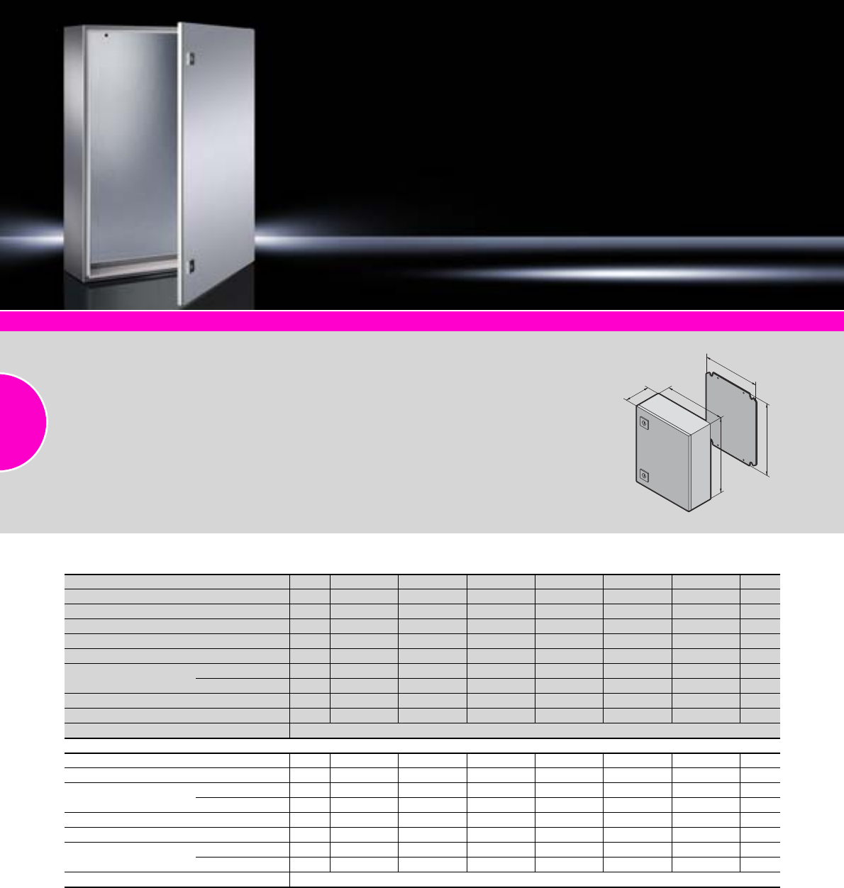
Stainless steel
162 Rittal Catalogue 33/Enclosures
System accessories Page 355 Compact enclosures AE, sheet steel Page 44 Hygienic Design Page 154
Material:
−Enclosure: Stainless steel
−Door: Stainless steel, all-round
foamed-in PU seal
−Mounting plate: Sheet steel
−Locks: Die-cast zinc
Surface finish:
−Enclosure and door:
Brushed, grain 240
−Mounting plate: Zinc-plated
−Locks: Nickel-plated
Protection category:
See tables.
Supply includes:
−Enclosure with door(s)
−Cam lock or 3-point lock
system (for AE 1017.X00 and
AE 1019.X00) with double-bit
insert
−Mounting plate
Approvals:
−UL
−CSA
−TÜV
−Germanischer Lloyd
−Russian Maritime
Register of Shipping
−Lloyds Register of Shipping
−Bureau Veritas
−VDE
Detailed drawing:
Available on the Internet.
B
T
H
F
G
Compact enclosures AE
Width (B) mm Packs of 200 200 200 300 380 380 Page
Height (H) mm 300 300 300 300 300 300
Depth (T) mm 120 155 155 210 155 210
Mounting plate width (F) mm 162 162 162 254 334 334
Mounting plate height (G) mm 275 275 275 275 275 275
Model No. AE 1001.600 1002.600 1002.500 1003.600 10 04.600 1011.600
Material 1.4301 (AISI 304) 1 –
1.4404 (AISI 316L) 1 – – – – –
Door 111111
Weight (kg) 3.6 4.1 4.1 6.9 7.4 8.4
Protection category IP 66 to IEC 60 529, complies with NEMA 4X
Accessories
Rails for interior installation 4 – – – 2373.210 – 2373.210 459
Rain canopy 1.4301 (AISI 304) 1 – 2470.000 2470.000 2361.000 2471.000 2472.000 431
Wall mounting bracket 1.4301 (AISI 304) 4 2433.000 2433.000 – 2433.000 2433.000 2433.000 439
1.4404 (AISI 316L) 4 – – 2433.500 – – – 439
Wall angle 1.4301 (AISI 304) 4 2583.010 2583.010 2583.010 2583.010 2583.010 2583.010 440
Pole clamp 1 2584.000 2584.000 2584.000 2584.000 2584.000 2584.000 441
Cam lock 1.4404
(AISI 316L)
Standard 1 2304.000 2304.000 2304.000 2304.000 2304.000 2304.000 421
Hygienic Design 1 2304.010 2304.010 2304.010 2304.010 2304.010 2304.010 156
Alternative lock systems see page 414
Stainless steel
163Rittal Catalogue 33/Enclosures
Compact enclosures AE
Width (B) mm Packs of 300 300 380 380 600 400 Page
Height (H) mm 380 380 380 380 380 500
Depth (T) mm 210 210 210 210 210 210
Mounting plate width (F) mm 275 275 334 334 549 354
Mounting plate height (G) mm 334 334 355 355 355 475
Model No. AE 11005.600 1005.50 0 1006.600 10 06.500 10 09.600 1015.60 0
Material 1.4301 (AISI 304) – –
1.4404 (AISI 316L) – – – –
Door 111111
Weight (kg) 8.4 8.4 9.8 9.8 14.6 12.9
Protection category IP 66 to IEC 60 529, complies with NEMA 4X
Accessories
Rails for interior installation 4 2373.210 2373.210 2373.210 2373.210 2373.210 2373.210 459
Rain canopy 1.4301 (AISI 304) 1 2361.000 2361.000 2472.000 2472.000 2473.000 – 431
Wall mounting bracket 1.4301 (AISI 304) 4 2433.000 – 2433.000 – 2433.000 2433.000 439
1.4404 (AISI 316L) 4 – 2433.500 – 2433.500 – – 439
Wall angle 1.4301 (AISI 304) 4 2583.010 2583.010 2583.010 2583.010 2583.010 2583.010 440
Pole clamp 1 2584.000 2584.000 2584.000 2584.000 2584.000 2584.000 441
Cam lock 1.4404
(AISI 316L)
Standard 1 2304.000 2304.000 2304.000 2304.000 2304.000 2304.000 421
Hygienic Design 1 2304.010 2304.010 2304.010 2304.010 2304.010 2304.010 156
Alternative lock systems see page 414
Width (B) mm Packs of 500 500 380 600 600 600 Page
Height (H) mm 500 500 600 600 600 760
Depth (T) mm 210 300 210 210 210 210
Mounting plate width (F) mm 449 449 334 549 549 549
Mounting plate height (G) mm 470 470 570 570 570 730
Model No. AE 110 07.600 1013.600 1008.60 0 1010.600 1010.50 0 1012.600
Material 1.4301 (AISI 304) –
1.4404 (AISI 316L) – – – – –
Door 111111
Weight (kg) 15.7 18.4 15.1 23.5 23.5 30.2
Protection category IP 66 to IEC 60 529, complies with NEMA 4X
Accessories
Rails for interior installation 4 2373.210 2373.300 2373.210 2373.210 2373.210 2373.210 459
Rain canopy 1.4301 (AISI 304) 1 2362.000 – 2472.000 2473.000 2473.000 2473.000 431
Wall mounting bracket 1.4301 (AISI 304) 4 2433.000 2433.000 2433.000 2473.000 – 2433.000 439
1.4404 (AISI 316L) 4 – – – – 2433.500 – 439
Wall angle 1.4301 (AISI 304) 4 2583.010 2583.010 2583.010 2583.010 2583.010 2583.010 440
Pole clamp 1 2584.000 2584.000 2584.000 2584.000 2584.000 2584.000 441
Cam lock 1.4404
(AISI 316L)
Standard 1 2304.000 2304.000 2304.000 2304.000 2304.000 2304.000 421
Hygienic Design 1 2304.010 2304.010 2304.010 2304.010 2304.010 2304.010 156
Alternative lock systems see page 414
Rittal Hungary
RITTAL Kereskedelmi Kft.
1044 Budapest, Ipari Park u. 1.
Phone: +36 (1) 399 8000
Fax: +36 (1) 399 8009
E-mail: rittal@rittal.hu www.rittal.hu
Stainless steel
164 Rittal Catalogue 33/Enclosures
Compact enclosures AE
Width (B) mm Packs of 760 800 800 1000 1000 1000 Page
Height (H) mm 760 1000 1200 1000 1200 1200
Depth (T) mm 300 300 300 300 300 300
Mounting plate width (F) mm 704 739 740 939 940 940
Mounting plate height (G) mm 730 955 1155 955 1155 1155
Model No. AE 11014.600 1016.600 1017.600 1018.600 1019.600 1019.500
Material 1.4301 (AISI 304) –
1.4404 (AISI 316L) – – – – –
3-point lock system – – –
Door(s) 111222
Weight (kg) 42.5 52.9 61.5 71.0 76.0 76.0
Protection category IP 66 to IEC 60 529, complies with NEMA 4X IP 55 to IEC 60 529, complies with NEMA 12
Accessories
Rails for interior installation 4 2373.300 2373.300 2373.300 2373.300 2373.300 2373.300 459
Rain canopy 1.4301 (AISI 304) 1 2474.000 2475.000 2475.000 2363.000 2363.000 2363.000 431
Wall mounting bracket 1.4301 (AISI 304) 4 2433.000 2433.000 2433.000 2433.000 2433.000 – 439
1.4404 (AISI 316L) 4 – ––––2433.500439
Wall angle 1.4301 (AISI 304) 4 2583.010 2583.010 2583.010 2583.010 2583.010 2583.010 440
Cam lock 1.4404
(AISI 316L)
Standard 1 2304.000 2304.000 – 2304.000 – – 421
Hygienic Design 1 2304.010 2304.010 – 2304.010 – – 156
Alternative lock systems see page 414
Rittal Japan
RITTAL K.K.
Sales HQ.
Shin-Yokohama AK Bldg 2F
3-23-3, Shin-Yokohama, Kohoku-ku
Kanagawa 222-0033
Phone: 0120-998-631 / +81 (45) 478-6801
Fax: 0120-998-632 / +81 (45) 478-6880
E-mail: contact@rittal.co.jp www.rittal.co.jp
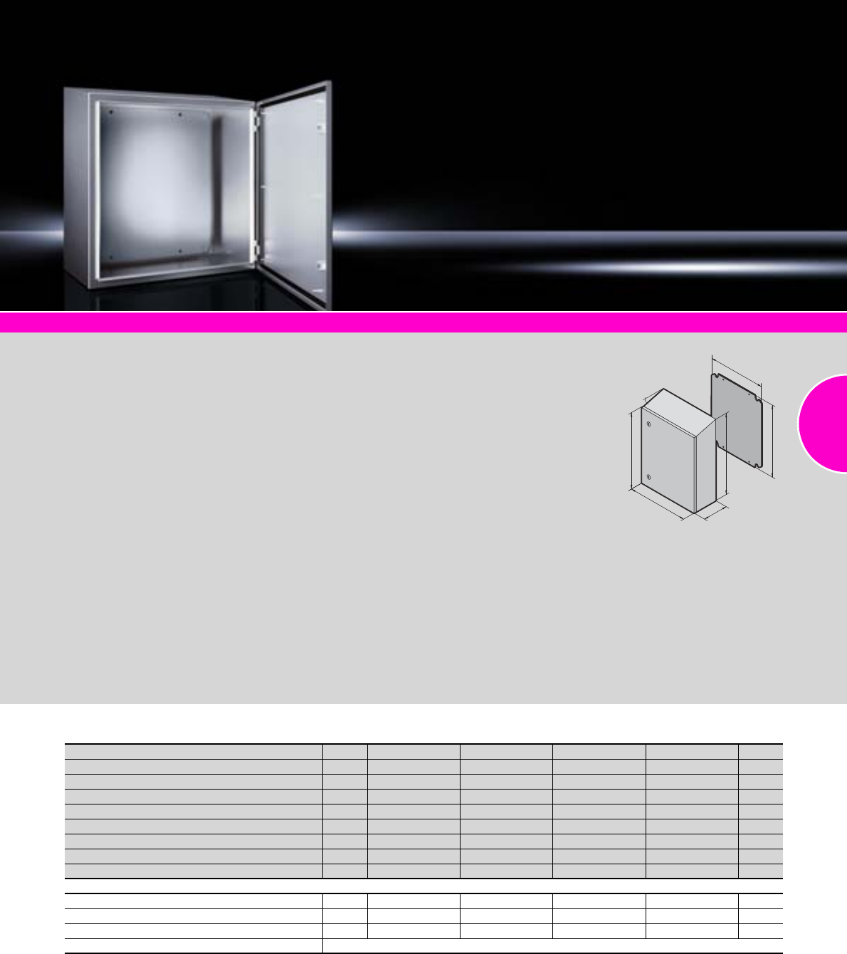
Stainless steel
165Rittal Catalogue 33/Enclosures
System accessories Page 355 AE sheet steel Page 44 AE EMC shielded Page 179 AE Ex-proof Page 176 Hygienic Design Page 154
Perfect protection in a tough
environment
The compact enclosure AE in
IP 69K is the ideal solution when
a high protection category com-
bined with corrosion resistance
is needed.
●Resistant to high-pressure
cleaning (protection cate-
gory IP 69K). The interior seal
is protected against direct
hosed water.
●Ideal for mounting on vehi-
cles: Lock, hinges and mount-
ing plate are all vibration
resistant.
●10° roof tilt prevents liquids
from accumulating on the roof.
●Foamed-in silicone seal.
The closed cell structure of
the foam means that water
absorption is negligible.
Temperature resistant from
–60°C to +180°C.
Material:
−Enclosure, hinge and lock:
Stainless steel 1.4301
(AISI 304)
−Door: Stainless steel 1.4301
(AISI 304), all-round foamed-
in PU seal
−Mounting plate: Sheet steel
Surface finish:
−Enclosure and door:
Brushed, grain 240
−Mounting plate: Zinc-plated
Protection category:
IP 69K to DIN 40 050-9,
complies with NEMA 4X.
Supply includes:
−Enclosure of all-round solid
construction
−Single-door
−Interchangeable door hinge
−Cam lock with double-bit
insert
−Mounting plate.
Detailed drawing:
Available on the Internet.
B
T
H2
F
G
10˚
H1
Compact enclosures AE, protection category IP 69K
Width (B) mm Packs of 230 400 400 650 Page
Height, front (H1) mm 330 400 650 650
Height, rear (H2) mm 352 439 689 689
Depth (T) mm 155 250 250 250
Mounting plate width (F) mm 162 334 334 549
Mounting plate height (G) mm 275 355 570 570
Mounting plate thickness mm 2 2 2.5 2.5
Model No. AE 11101.110 1101.12 0 1101.130 1101.140
Locks 1 1 2 2
Accessories
Interior door 1 1101.910 1101.920 1101.930 1101.940 406
Door stay 1 1101.800 1101.800 1101.800 1101.800 429
Wall mounting bracket, stainless steel 1.4301 (AISI 304) 4 2433.000 2433.000 2433.000 2433.000 439
Cable glands see page 519
Stainless steel
166 Rittal Catalogue 33/Enclosures
System accessories Page 355 TFT monitor Page 606 Support arm system CP-S, stainless steel Page 168 Hygienic Design Page 154
Optionally with or without
keyboard housing
●Resistant to high-pressure
cleaning (protection cate-
gory IP 69K). The seal lies
between two seals and is
optimally compressed by the
screw fastening.
●Suitable for clean room use
Screw fastening to comply
with high standards in the
food industry. With plastic
stoppers on the inside or hex
screws on the outside.
●Optimum EMC conditions
The labyrinth seal achieves
a particularly high level of RF
shielding of the enclosure.
●Accessibility
Internal rear panel bracket.
This solution is clearly supe-
rior to external hinges from
a hygiene point of view.
●Handling
Two duct connectors between
the enclosures.
Material:
Stainless steel 1.4301 (AISI 304)
Surface finish:
Brushed, grain 240
Protection category:
IP 69K to DIN 40 050-9
Clean room:
Air purity class 1 to
DIN EN ISO 14 644-1
Detailed drawings:
Available on the Internet.
Photo shows a configuration
example with equipment not
included in the scope of supply.
H
B
T
H1
Premium Panel, protection category IP 69K
Packs of Premium Panel
With keyboard housing Without keyboard housing
Model No. CP 16680.0001) 6681.000
Width (B) mm 530 530
Height mm Operating housing (H) 460 360
Keyboard housing (H1) 200 –
Depth mm Operating housing (T) 120 120
For installation panel
W x H
Operating housing 482.6 mm (19˝) x 354.8 mm (8 U) 482.6 mm (19˝) x 310 mm (7 U)
Keyboard housing 482.6 mm (19˝) x 177 mm (4 U) –
Installation depth
mm
Operating housing 115 115
Keyboard housing Front 58
Rear 63 –
Support arm connection Top Top, or bottom by rotating the enclosure
1) Extended delivery times.
Stainless steel
167Rittal Catalogue 33/Enclosures
System accessories Page 355 TFT monitor Page 606 Support arm system CP-S, stainless steel Page 168 Hygienic Design Page 154
Material:
−Enclosure and door:
Stainless steel 1.4301
(AISI 304)
−Handle strips:
Plastic approved for use
with foodstuffs
Surface finish:
Brushed, grain 240
Colour:
Handle strips:
Similar to RAL 5002
Protection category:
IP 66 to IEC 60 529
Supply includes:
−Enclosure of all-round solid
construction
−Cut-out and reinforcement for
support arm system
−Fastener with guide plate
−Door with sealing frame and
side handle strips
−The support arm connection
and door hinge may be
swapped over by rotating the
enclosure
Approvals:
−UL
−cUL
Detailed drawings:
Available on the Internet.
T
H
B
Rittal USA
RITTAL Corporation
1 Rittal Place Urbana, OH 43078, USA
Phone: +1 (937) 399-0500
Fax: +1 (937) 390-5599
Toll-free: 1-800-477-4000
E-mail: rittal@rittal-corp.com
www.rittal-corp.com
Command panel housing with door
Width (B) mm Packs of 300 400 400 600 Page
Height (H) mm 300 300 400 400
Depth (T) mm 150 150 150 150
Model No. CP 16535.010 6536.010 6538.010 6539.010
Weight (kg) 6.3 7.5 8.8 12.1
Accessories
Matching mounting plate from AE 1033.500 1030.500 1380.500 1039.500 44/45
ID no. 0271.926 0274.131 0271.548 0271.351
Support rails1) Model No. SZ 10 2316.000 2317.000 2317.000 2319.000 467
Alternative lock systems With 3 mm double-bit lock insert, may be exchanged for 41 mm lock inserts, version C, see page 421,
plastic handles and T handles, version C, see page 420.
1) Only with vertical attachment of punched rail 23 x 23 mm, see page 463.
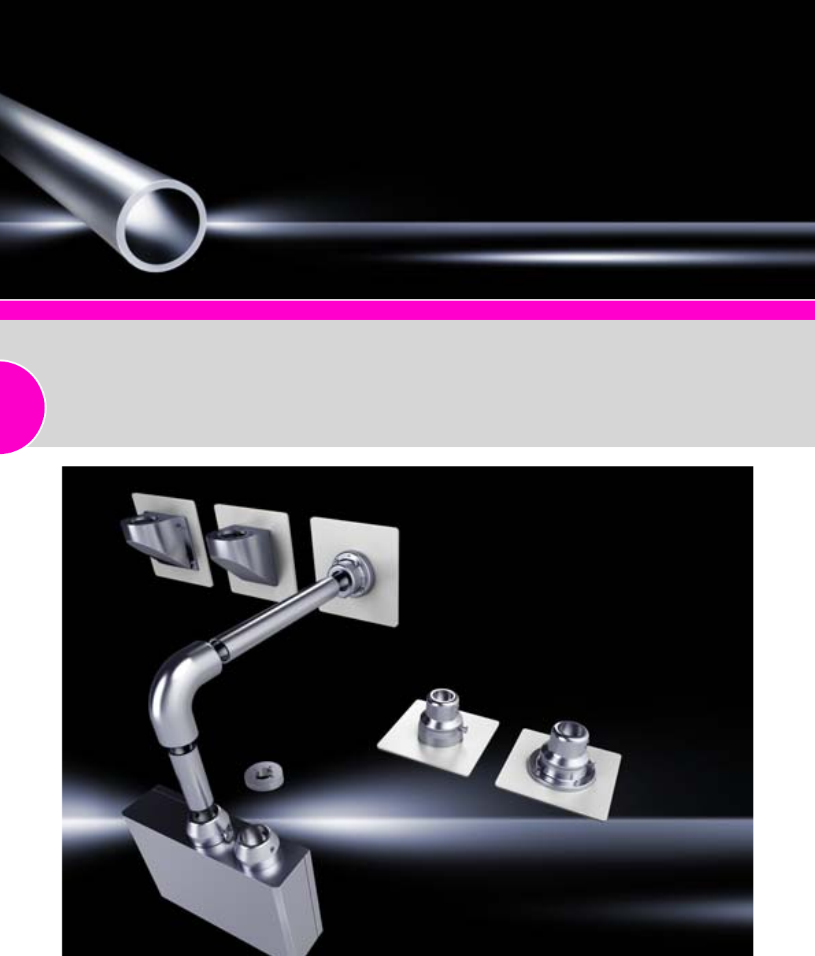
Stainless steel
168 Rittal Catalogue 33/Enclosures
Stainless steel enclosures Page 166 – 167 Support section CP-S, steel Page 128
Support section CP-S,
stainless steel
Attached to the connection com-
ponents via 2 clamping screws.
Size:
−External diameter: 48.3 mm
−Wall thickness: 3 mm
Material:
Stainless steel
Surface finish:
Brushed, grain 240 (support
section and wall console only)
Protection category:
IP 69K to DIN 40 050-9
(resistant to high-pressure
cleaning)
Supply includes:
Support section CP-S
Detailed drawings:
Available on the Internet.
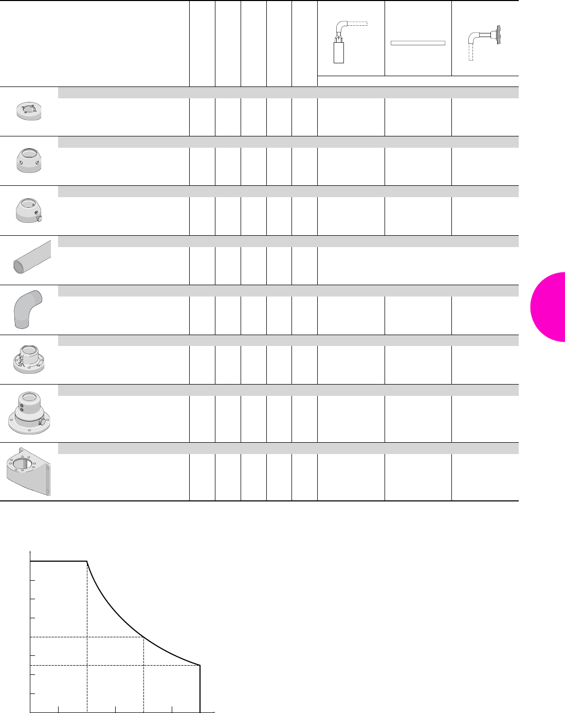
Stainless steel
169Rittal Catalogue 33/Enclosures
Rotating/tilting
Rigid
Length mm
Weight kg
Material
Enclosure section Desk section Wall section
Model No. CP
Tilting adaptor 10°
– – 0.7
1.4305
(AISI
303) 6664.100 – –
Enclosure attachment CP-S, stainless steel
– – 1.3 1.4305
(AISI
303) 6664.500 – –
Housing coupling CP-S stainless steel
– – 1.1 1.4305
(AISI
303) 6664.000 – –
Support section CP-S, stainless steel
– 500
1000 2.0
3.9
1.4301
(AISI
304)
6660.050
6660.010
Angle piece 90° CP-S stainless steel
– – 1.3
1.4305
(AISI
303) 6664.300 – 6664.300
Wall/base mount, rigid, CP-S stainless steel
– – 1.7 1.4305
(AISI
303) – – 6663.000
Wall/base mount, rotating, CP-S stainless steel
Rear, thread M8
Front, hole Ø 9 mm – –
3.9
4.5
1.4305
(AISI
303) – – 6663.500
6663.400
Wall console CP-S stainless steel
Rear, thread M8
Front, hole Ø 9 mm – –
1.5
1.8
1.4301
(AISI
304) – –
6665.000
6665.500
400
600
800
200
0
0 500 1000 1500
Permissible static load [N]
(enclosure and vertical support arm section)
Jib length (mm)
Load information
Permissible load depending on system configuration
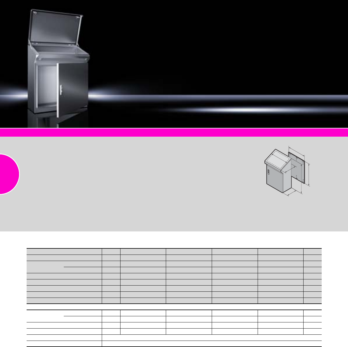
Stainless steel
170 Rittal Catalogue 33/Enclosures
System accessories Page 355 Monitors, keyboards Page 606/608 Climate control Page 207 One-piece consoles, sheet steel Page 106
Material:
−Enclosure: Stainless steel
1.4301 (AISI 304), 1.5 mm
−Door or double door and
console lid: Stainless steel
1.4301 (AISI 304), 2.0 mm
−Mounting plate:
Sheet steel, 3.0 mm
Surface finish:
−Enclosure, door, console lid
and gland plates:
Brushed, grain 120
−Mounting plate: Zinc-plated
Protection category:
IP 55 to IEC 60 529,
complies with NEMA 12.
Supply includes:
−Enclosure, solid rear and
sides
−Door or double door at front,
with locking rod
−Console lid with lid stay and
cam lock latched in the enclo-
sure
−Cam lock with double-bit
insert
−Gland plates, divided
−Mounting plate
Approvals:
−UL
−CSA
−TÜV
−Germanischer Lloyd
−Russian Maritime Register
of Shipping
−Lloyds Register of Shipping
−VDE
Detailed drawings:
Available on the Internet.
T
H
G
F
T
B
One-piece consoles AP
Width (B) mm Packs of 600 800 1000 1200 Page
Height (H) mm 960 960 960 960
Depth (T) mm Bottom 400 400 400 400
Top 480 480 480 480
Mounting plate width (F) mm 530 730 930 1130
Mounting plate height (G) mm 780 780 780 780
Model No. AP 1 2683.600 2684.600 2685.600 2686.600
Door(s) 1122
Weight (kg) 52.0 65.2 79.5 90.3
Accessories
Base/plinth Height 100 mm 1 2865.000 2869.000 2867.000 2870.000 370
Height 200 mm 1 2875.000 2878.000 2885.000 2886.000 370
Cable clamp rail 2 4191.000 4192.000 4336.000 4196.000 527
Support rail TS 35/15 6 4934.000 4935.000 4933.000 4937.000 467
Hose-proof hood see page 303
Alternative lock systems see page 414
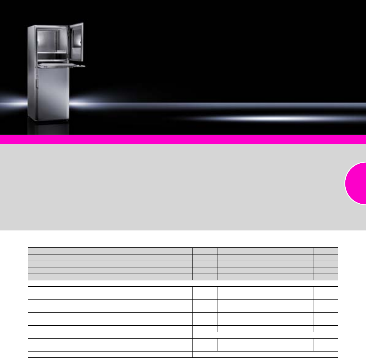
Stainless steel
171Rittal Catalogue 33/Enclosures
System accessories Page 355 PC enclosure systems, sheet steel Page 108
Material:
−Enclosure: Stainless steel
1.4301 (AISI 304), 1.8 mm
−Rear door: Stainless steel
1.4301 (AISI 304), 2.0 mm
−Gland plates: Stainless steel
1.4301 (AISI 304) 1.5 mm
−Monitor field:
Single-pane safety glass,
4 mm
Surface finish:
Brushed, grain 240
Protection category:
IP 55 to IEC 60 529,
complies with NEMA 12.
Supply includes:
−Enclosure, solid top and sides
−Rear door with locking rod
−Glazed door at the top,
latched from the inside
−Component shelf
−Lock insert, lock no. 3524 E
−Keyboard drawer with front,
swing-down for handrest and
mouse pad support
−Bottom door with locking rod
−Gland plate, divided
−Lock with double-bit insert
Approvals:
−UL
−CSA
−TÜV
−Germanischer Lloyd
−Russian Maritime Register
of Shipping
−Lloyds Register of Shipping
−VDE
Detailed drawings:
Available on the Internet.
PC enclosure systems
Width (B) mm Packs of 600
Height (H) mm 1600
Depth (T) mm 620
Model No. PC 14650.000
Weight (kg) 115
Accessories
Base/plinth, height 100 mm 1 2855.000 370
Levelling feet, 100 mm high 1 set 2859.000 374
Base/plinth trim, modular 4 2913.000 367
Adaptor pieces, 482.6 mm (19˝) 8 4547.000 552
TFT holder, vertically hinged 1 2383.040 607
Component shelf, pull-out 1 set 6902.960 480
Cable clamp rail 2 4191.000 527
Connector gland see page 523
LED system light 1 4140.840 494
Compact light 1 4140.210 493
Alternative lock systems see page 414
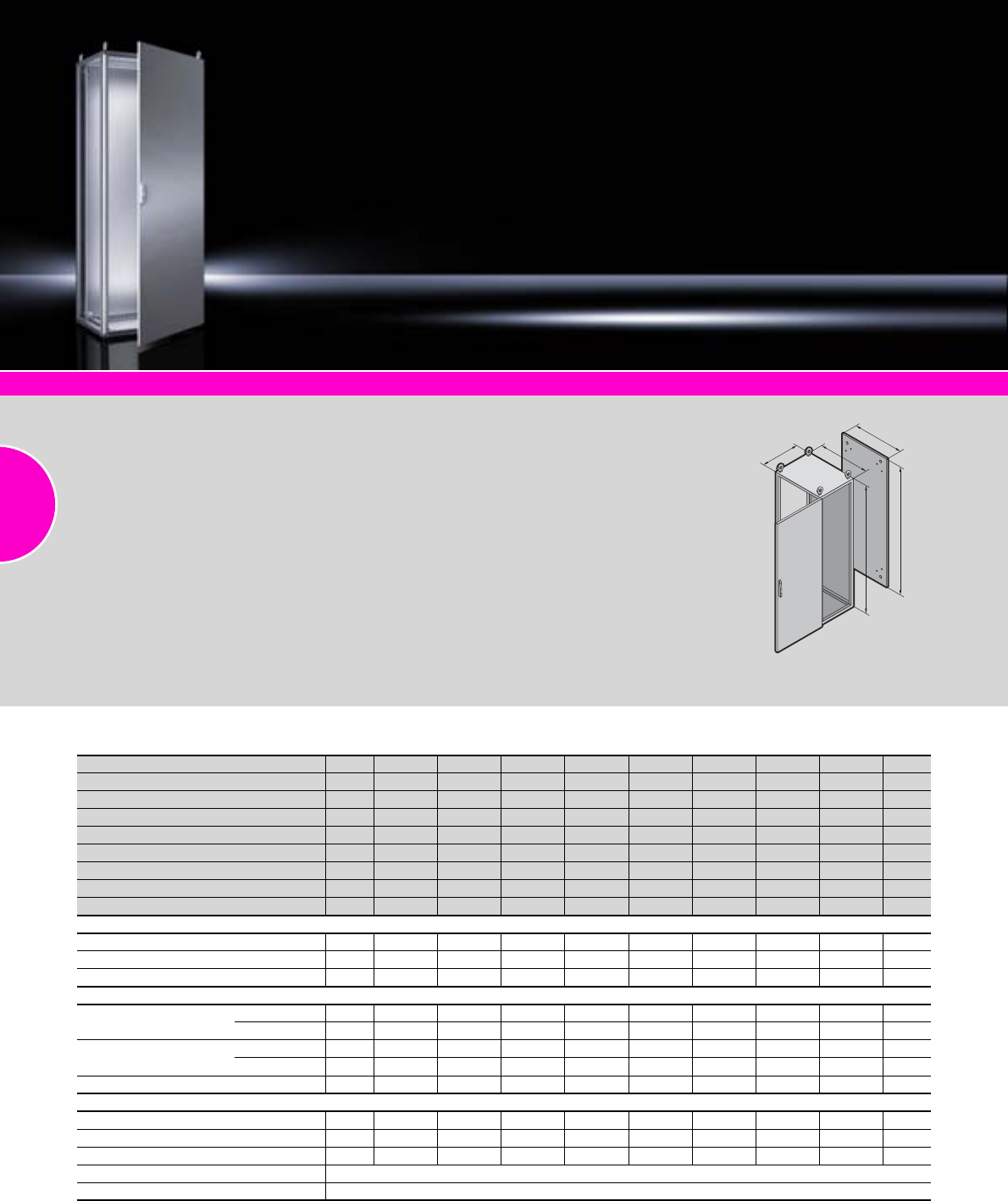
Stainless steel
172 Rittal Catalogue 33/Enclosures
System accessories Page 355 Baying systems TS 8, sheet steel Page 70
Material:
−Enclosure frame, roof,
rear panel and gland plates:
Stainless steel 1.4301
(AISI 304), 1.5 mm
−Door(s): Stainless steel 1.4301
(AISI 304), 2.0 mm
−Mounting plate:
Sheet steel, 3.0 mm
Surface finish:
−Enclosure frame and gland
plates: Uncoated
−Door(s), roof, rear panel:
Exterior brushed,
grain 400
−Mounting plate: Zinc-plated
Protection category:
IP 55 to IEC 60 529,
complies with NEMA 12.
Supply includes:
−Enclosure frame with door(s)
−Mounting plate
−Gland plates
−Rear panel
−Roof
−Locking rod with double-bit
insert
Note:
Due to the hardness of the mate-
rial, we recommend using metal
multi-tooth screw SZ 2486.300,
see page 478, for the interior
installation.
Approvals:
−UL
−CSA
−TÜV
−Russian Maritime Register
of Shipping
−TÜV Mark
−Lloyds Register of Shipping
−Bureau Veritas
−VDE
−Germanischer Lloyd
Detailed drawings:
Available on the Internet.
T
F
G
H
B
Baying systems TS 8
Width (B) mm Packs of 800 1200 600 800 1200 600 800 1200 Page
Height (H) mm 1800 1800 1800 1800 1800 2000 2000 2000
Depth (T) mm 400 400 500 500 500 600 600 600
Mounting plate width (F) mm 699 1099 499 699 1099 499 699 1099
Mounting plate height (G) mm 1696 1696 1696 1696 1696 1896 1896 1896
Model No. TS 18454.600 8456.600 8457.600 8455.600 8453.600 8452.600 8450.600 8451.600
Door(s) 12112112
Support strips – – – – – 2 2 2
Weight (kg) 112.9 170.4 92.5 116.3 174.9 104.4 129.7 194.7
Walls
Side panels 2 8700.840 8700.840 8700.850 8700.850 8700.850 8700.060 8700.060 8700.060 385
Divider panel 1 8609.840 8609.840 8609.850 8609.850 8609.850 8609.060 8609.060 8609.060 389
Divider panel for module plates 1 – – 8609.100 8609.100 8609.100 8609.130 8609.130 8609.130 390
Base/plinth
Components front and rear Height 100 mm 1 set 8701.800 8701.200 8701.600 8701.800 8701.200 8701.600 8701.800 8701.200 367
Height 200 mm 1 set 8702.800 8702.200 8702.600 8702.800 8702.200 8702.600 8702.800 8702.200 367
Trim panels, sides Height 100 mm 1 set 8701.040 8701.040 8701.050 8701.050 8701.050 8701.060 8701.060 8701.060 367
Height 200 mm 1 set 8702.040 8702.040 8702.050 8702.050 8702.050 8702.060 8702.060 8702.060 367
Base/plinth trim, modular 4 2907.000 2907.000 2908.000 2908.000 2908.000 2913.000 2913.000 2913.000 367
Accessories
Cable clamp rails 2 4192.000 4196.000 4191.000 4192.000 4196.000 4191.000 4192.000 4196.000 527
Cable entry plates 2 8700.800 8700.1201) 8700.600 8700.800 8700.1201) 8700.600 8700.800 8700.1201) 511
Wiring plan pocket, sheet steel 1 4118.000 4116.000 4116.000 4118.000 4116.000 4116.000 4118.000 4116.000 429
Alternative lock systems see page 414
System lights see page 491
1) Packs of 4
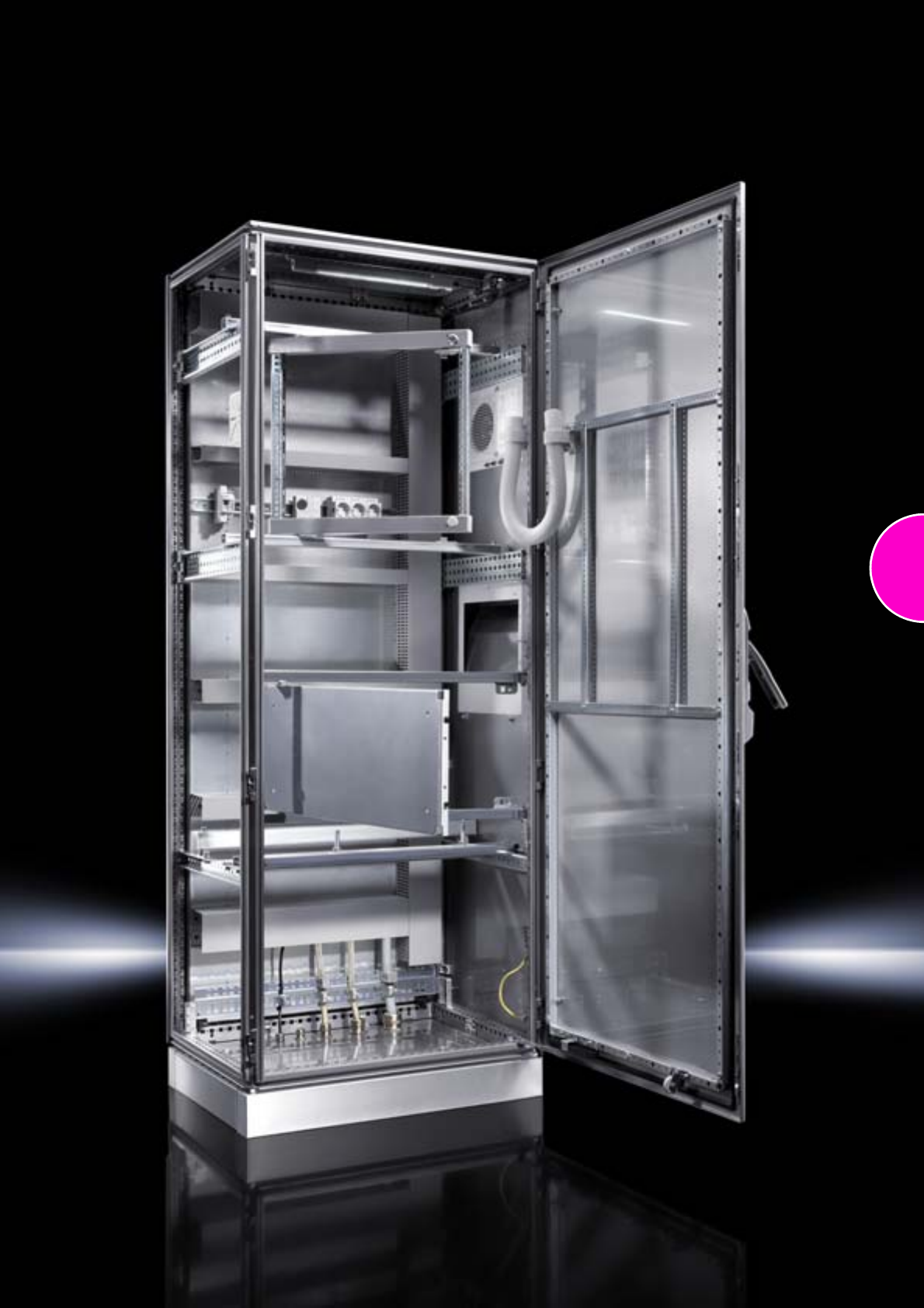
173
174
175
Ex enclosures/EMC enclosures
Ex enclosures
Stainless steel............................................................................................176
Plastic ........................................................................................................177
EMC enclosures
The Rittal EMC concept.............................................................................178
EMC E-Box EB...........................................................................................178
EMC compact enclosures AE ...................................................................179
Note:
All TS 8 enclosures prepared for pressurisation on request.
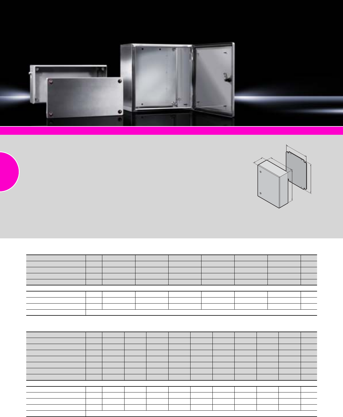
Ex enclosures
176 Rittal Catalogue 33/Enclosures
System accessories Page 355
Application range:
−Zone 1 and 2 or 21 and 22 to
94/9/EC
−Ambient temperature range:
–30°C to +80°C
−Protection type to IEC 60 079:
Equipment protection thanks
to increased safety, equipment
protection thanks to enclosure
Material:
−Enclosure: Stainless steel
1.4301 (AISI 304)
−Cover or door:
Stainless steel 1.4301
(AISI 304), all-round foamed-in
silicone seal
−Mounting plate: Sheet steel
Surface finish:
−Enclosure: Brushed, grain 240
−Mounting plate: Zinc-plated
Protection category:
IP 66 to IEC 60 529
Supply includes:
−Enclosure
−Cover or door
−Mounting plate (only for enclo-
sures with door)
Certificates:
Enclosure with cover:
−PTB 03 ATEX 1013U
−IEC Ex PTB 09.0033U
Enclosure with door:
−PTB 02 ATEX 1082U
−IEC Ex PTB 09.0035U
Approvals:
−ATEX
−IEC
Detailed drawing:
Available on the Internet.
B
H
F
G
T
Stainless steel, with hinged door
Width (B) mm Packs of 200 300 380 380 380 600 600 760 800 Page
Height (H) mm 300 380 300 380 600 600 760 760 1000
Depth (T) mm 155 210 155 210 210 210 210 300 300
Mounting plate width (F) mm 162 334 334 334 334 549 549 704 739
Mounting plate height (G) mm 275 275 275 355 570 570 730 730 955
Model No. KEL 19401.600 9409.600 9402.600 9403.600 9404.600 9405.600 9406.600 9407.600 9408.600
Cam lock with double-bit insert 111122222
Weight (kg) 3.8 7.7 7.4 9.7 13.3 15.6 22.3 30.5 36.3
Accessories
Wall mounting bracket1) 4 2433.000 2433.000 2433.000 2433.000 2433.000 2433.000 2433.000 2433.000 2433.000 439
Support rails TS 35/7.5 10 2315.000 2316.000 – – – 2319.000 2319.000 – – 467
Rails for interior installation 4 – 2373.210 – 2373.210 2373.210 2373.210 2373.210 2373.300 2373.300 459
Perforated mounting strip 20 – 2310.038 – 2310.038 – – – – – 427
Earth straps see page 501
1) Stainless steel 1.4301 (AISI 304)
Stainless steel, with screw-fastened cover
Width (B) mm Packs of 150 200 300 300 300 400 Page
Height (H) mm 150 200 150 200 300 200
Depth (T) mm 80 80 80 80 120 120
Model No. KEL 19301.000 9303.000 9302.000 9304.000 9306.000 9305.000
Weight (kg) 1.3 1.8 1.8 2.4 3.9 3.6
Accessories
Mounting plates 1560.700 1562.700 1561.700 1563.700 1567.700 1564.700 443
Wall mounting bracket1) 4 1594.000 1594.000 1594.000 1594.000 1594.000 1594.000 439
Support rails TS 35/7.5 10 2314.000 2315.000 2316.000 2316.000 2316.000 2317.000 467
Earth straps see page 501
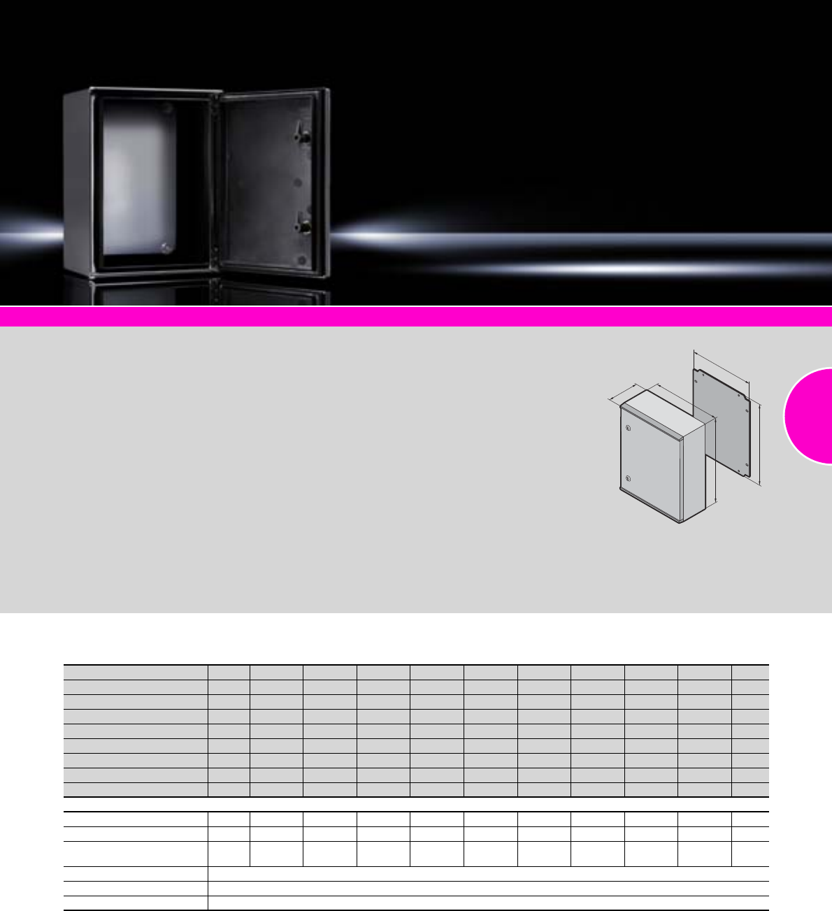
Ex enclosures
177Rittal Catalogue 33/Enclosures
System accessories Page 355
Application range:
−Zone 1 and 2 or 21 and 22 to
94/9/EC
−Ambient temperature range:
–30°C to +80°C
−Protection type to IEC 60 079:
Equipment protection thanks
t
o increased safety, equipment
protection thanks to enclosure
Material:
−Enclosure: Fibre-glass-rein-
forced unsaturated polyester,
surface resistance: < 109 Ω
−Door: Fibre-glass-reinforced
unsaturated polyester,
surface resistance: < 109 Ω,
all-round foamed-in silicone
seal
−Mounting plate: Sheet steel,
zinc-plated
Colour:
RAL 9011
Protection category:
IP 66 to IEC 60 529
Supply includes:
−Enclosure
−Door
−Mounting plate
Certificates:
−PTB 03 ATEX 1011U
−IEC Ex PTB 10.0011U
Approvals:
−ATEX
−IEC
Detailed drawing:
Available on the Internet.
F
B
T
H
G
Plastic
Width (B) mm Packs of 200 250 300 400 400 500 600 600 800 Page
Height (H) mm 300 350 400 400 600 500 600 800 1000
Depth (T) mm 150 150 200 200 200 300 200 300 300
Mounting plate width (F) mm 145 195 245 345 345 417 545 517 717
Mounting plate height (G) mm 250 300 350 350 550 450 550 750 950
Model No. KEL 19201.600 9202.600 9203.600 9204.600 9205.600 9207.600 9206.600 9208.600 9209.600
Cam lock with double-bit insert 1 1 2 2 2 2 2 – –
3-point locking rod – – – – – – –
Weight (kg) 3.7 4.6 6.0 6.5 11.5 12.9 15.9 24.3 39.0
Accessories
Wall mounting bracket 4 9266.000 9266.000 9266.000 9266.000 9266.000 9266.000 9266.000 9266.000 9266.000 440
Threaded inserts M6 20 1482.000 1482.000 1482.000 1482.000 1482.000 1482.000 1482.000 1482.000 1482.000 478
Mounting plate
adjustment bracket 4 1481.000 1481.000 1481.000 1481.000 1481.000 1491.000 1481.000 1491.000 1491.000 446
Support rails see page 466
Earth straps see page 501
Cable duct see page 525
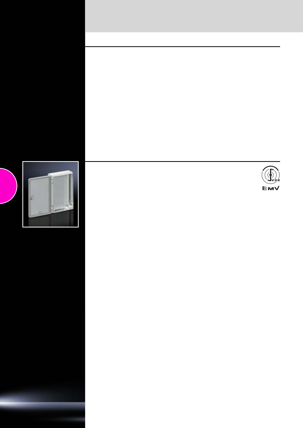
EMC enclosures
178 Rittal Catalogue 33/Enclosures
The Rittal EMC concept
Rittal offers excellent pre-requisites for EMC
enclosure configurations in the form of its stand-
ard sheet steel enclosures, EMC-shielded enclo-
sures, and a practical range of EMC accessories.
Depending on the individual application, anything
is possible, be it closely intermeshed potential
equalisation in a standard enclosure to prevent
conducted interference, or extra shielding to pro-
tect against high-frequency electromagnetic
fields.
For Rittal EMC enclosures with a high level of
shielding, excellent attenuation levels and attrac-
tive value-for-money products are achieved on the
basis of zinc-plated metal surfaces in conjunction
with low-resistance EMC shields.
Empty enclosures and mechanical accessory
components are not subject to the European EMC
Directive and the German EMC Act.
Thanks to the basic design in conjunction with the
metal-plated enclosure body, even standard
enclosures offer a good shielding effect against
electrical fields, which in many cases is sufficient.
The large enclosures in the TS 8 series offer a
good level of shielding across a broad frequency
range, even in the standard version.
For increased EMC requirements, Rittal offers the
TS 8 enclosure in a version certified by the VDE
with high RF attenuation. This shielding concept
is also transferred to other enclosure platforms.
Further information on the topic of EMC may be
found on our website at www.rittal.com.
EMC E-Box EB
Material:
Sheet steel with aluminium zinc coating
Surface finish:
−Powder-coated on the outside
−Interior surfaces conductive
Colour:
RAL 7035
Protection category:
−IP 55 to IEC 60 529
−The EMC version (“high RF attenuation”)
has been certified by the VDE.
Note:
All sizes available on request.
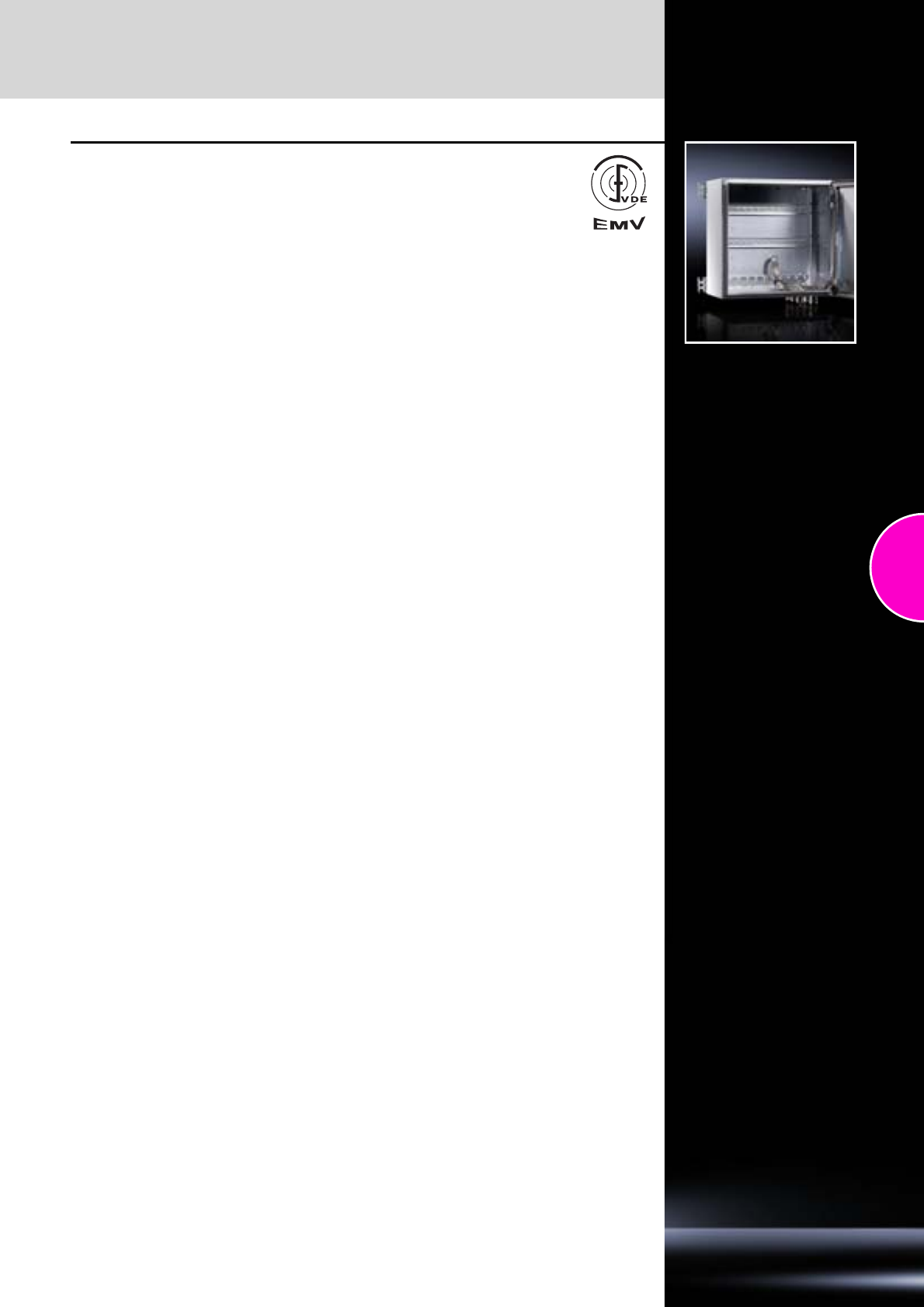
EMC enclosures
179Rittal Catalogue 33/Enclosures
EMC compact enclosures AE
Material:
Sheet steel with aluminium zinc coating
Surface finish:
−Powder-coated on the outside
−Interior surfaces conductive
Colour:
RAL 7035
Protection category:
−IP 55 to IEC 60 529
−The EMC version (“high RF attenuation”)
has been certified by the VDE.
Note:
All sizes available on request.
Approvals:
Available on the Internet.
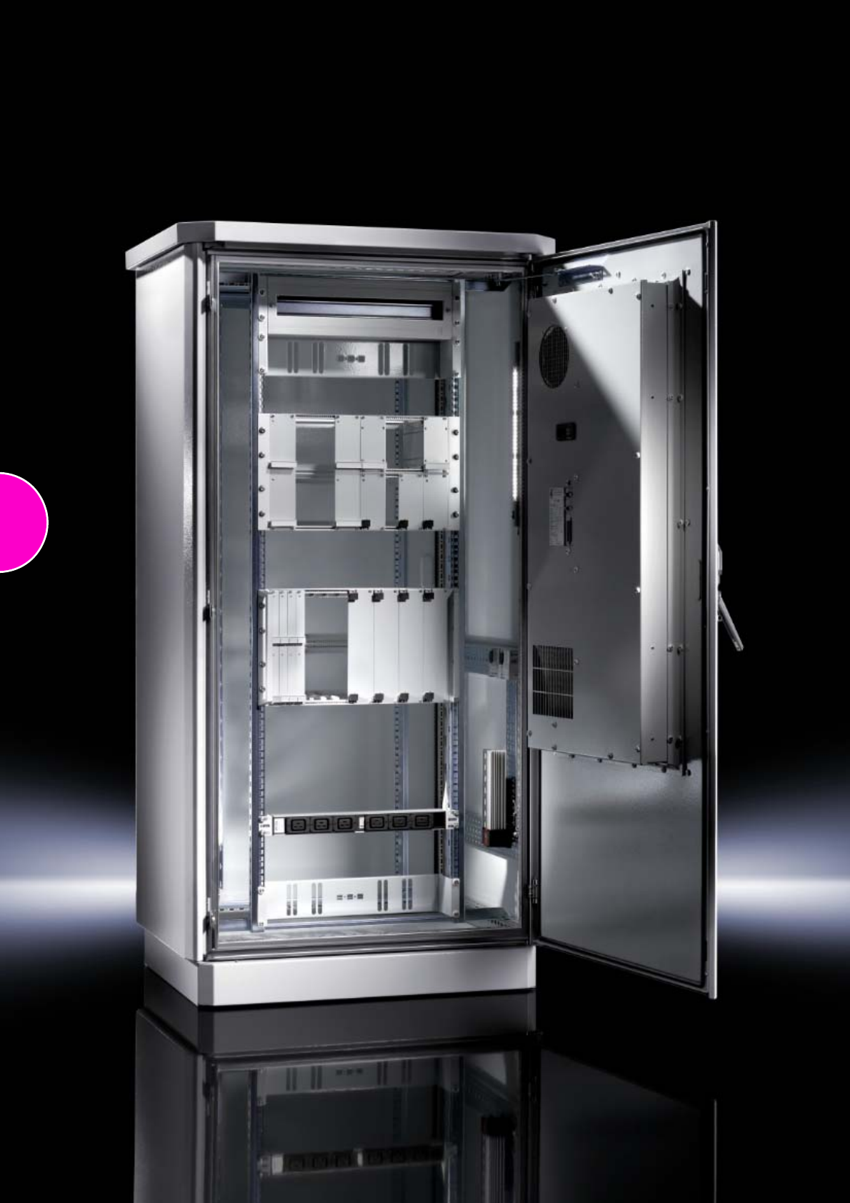
180

181
Outdoor enclosures
CS wall-mounted enclosures
Double-walled ...........................................................................................182
CS New Basic enclosures
Single-walled and one-door, width: 600 and 800 mm ..............................183
Single-walled and two-door, width: 1200 mm ...........................................184
CS Toptec
Double-walled, platform TS 8 ....................................................................185
CS modular enclosures
Double-walled, configuration variants, width: 600 mm .............................186
Double-walled, configuration variants, width: 800 and 1200 mm .............187
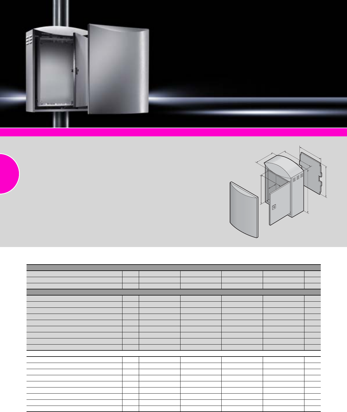
CS wall-mounted enclosures
182 Rittal Catalogue 33/Enclosures
Compact enclosures AE, stainless steel Page 162 Compact enclosures AE, stainless steel, protection category IP 69K Page 165
Outdoor enclosures for wall or
pole mounting.
Enclosure-within-an-enclosure
concept, outer enclosure with
cut-out at the bottom and inte-
grated louvres on the rear panel
and side panels for ventilation.
Material:
−Enclosure:
Aluminium AlMg3
−Mounting plate:
Sheet steel, zinc-plated
Surface finish:
−Powder-coated
−UV-resistant pure polyester
Colour:
RAL 7035
Protection category:
IP 55 to IEC 60 529
Supply includes:
Double-walled outdoor enclo-
sure, fully pre-configured:
−Inner enclosure with mount-
ing plate, gland plate and
security lock (CS 9791.045
with 2 security locks)
−Mounting bracket for thermo-
stat or hygrostat
−Outer enclosure with designer
cover and security lock 3524 E
−2 C rails on the rear panel
Detailed drawing:
Available on the Internet.
T1
H1
B1
B2
H2
T2
H3
B3
Double-walled
Outer enclosure
Width (B1) mm Packs of 370 420 530 630 Page
Height (H1) mm 522 560 700 780
Depth (T1) mm 210 210 265 380
Inner enclosure
Width (B2) mm 300 350 460 580
Height (H2) mm 400 440 565 580
Depth (T2) mm 170 170 220 333
Clearance width mm 280 330 440 560
Clearance height mm 380 420 545 560
Clearance depth mm 145 145 195 308
Mounting plate width (B3) mm 270 320 430 550
Mounting plate height (H3) mm 380 410 535 550
Model No. CS 19791.015 9791.025 9791.035 9791.045
Accessories
Wall mounting bracket 4 9765.120 9765.120 9765.120 9765.120 441
Pole clamp 1 set 2584.000 2584.000 2584.000 2584.000 441
Enclosure heaters 1 3105.330 3105.330 3105.330 3105.330 289
Enclosure internal thermostat 1 3110.000 3110.000 3110.000 3110.000 294
Hygrostat 1 3118.000 3118.000 3118.000 3118.000 294
Socket 2 2506.100 2506.100 2506.100 2506.100 508
LED system light 1 4140.810 4140.810 4140.820 4140.820 494
LED connection cable 1 4315.800 4315.800 4315.800 4315.800 495
Adaptor power pack 1 4315.860 4315.860 4315.860 4315.860 495

CS New Basic enclosures
183Rittal Catalogue 33/Enclosures
Climate control Page 285 Rail systems Page 464 Cable management Page 525
Outdoor enclosure with 100 mm
transport plinth and rain canopy
with projections on all sides.
Photo shows a configuration
example with equipment not
included in the scope of supply.
Material:
Aluminium AlMg3
Surface finish:
−Powder-coated
−UV-resistant pure polyester
Colour:
RAL 7035
Protection category:
IP 55 to IEC 60 529,
complies with NEMA 3R in con-
junction with the gland plates
offered in the accessories.
Supply includes:
Single-walled outdoor enclo-
sure, fully pre-configured:
−Basic enclosure with open
base
−25 mm system punchings in
the roof, base, front and in the
enclosure depth
−Front door(s) with door stay,
swing lever handle and
semi-cylinder, lock BJ20027
−Transport plinth with screw-
fastened trim panels front and
rear
−Enclosure with width 1200 mm
has two 600 mm wide mount-
ing panels
−Rain canopy
Detailed drawing:
Available on the Internet.
Note:
When configuring with partial
mounting panels or 482.6 mm
(19˝) partial installation,
punched rails are required in the
enclosure height, see page 463.
B1
T1
T3
B3
T2
B2
H2
H1H4 H3
H5
Single-walled and one-door, width: 600 and 800 mm
Width (B1) mm Packs of 600 600 600 800 800 800 Page
Height (H1) mm 800 1200 1200 800 1200 1200
Depth (T1) mm 400 400 500 400 400 500
Clearance width (B2) mm 512 512 512 712 712 712
Clearance height (H2) mm 712 1112 1112 712 1112 1112
Clearance depth (T2) mm 349 349 449 349 349 449
Rain canopy width (B3) mm 650 650 650 850 850 850
Rain canopy height (H3) mm 55 55 55 55 55 55
Rain canopy depth (T3) mm 450 450 550 450 450 550
Base/plinth height (H4) mm 100 100 100 100 100 100
Overall height (H5) mm 955 1355 1355 955 1355 1355
Model No. CS 19783.540 9783.550 9783.530 9783.510 9783.520 9783.610
Accessories
Concrete base/plinth 1 9765.182 9765.182 9765.082 9765.088 9765.088 9765.084 368
Gland plate, divided 1 set 9785.511 9785.511 9785.514 9785.512 9785.512 9785.513 384
Cable entry plates 2 8800.060 8800.060 8800.060 8800.080 8800.080 8800.080 511
Mounting plates 1 9765.090 9765.092 9765.092 9765.097 9765.095 9765.095 451
Mounting angles, 482.6 mm (19˝) 2 7685.000 7688.000 7688.000 7685.000 7688.000 7688.000 553
Installation kit for mounting angles 2 7696.000 7696.000 7696.000 7698.000 7698.000 7698.000 553
Enclosure heaters 1 3105.400 3105.400 3105.400 3105.400 3105.400 3105.400 289
Enclosure internal thermostat 1 3110.000 3110.000 3110.000 3110.000 3110.000 3110.000 294
Semi-cylinder, alternative closure 1 9785.040 9785.040 9785.040 9785.040 9785.040 9785.040 416

CS New Basic enclosures
184 Rittal Catalogue 33/Enclosures
Single-walled and two-door, width: 1200 mm
Width (B1) mm Packs of 1200 1200 Page
Height (H1) mm 1200 1200
Depth (T1) mm 400 500
Clearance width (B2) mm 512 512
Clearance height (H2) mm 1112 1112
Clearance depth (T2) mm 349 449
Rain canopy width (B3) mm 1250 1250
Rain canopy height (H3) mm 55 55
Rain canopy depth (T3) mm 450 550
Base/plinth height (H4) mm 100 100
Overall height (H5) mm 1355 1355
Model No. CS 19784.620 9784.520 9784.640 9784.540
Without centre bar, overlapping doors – –
With removable centre bar, 2 lockable doors – –
Accessories
Concrete base/plinth 1 9765.089 9765.086 368
Gland plate, divided 1 set 2 x 9785.511 2 x 9785.514 384
Cable entry plates 2 8800.060 8800.060 511
Mounting plate for one half of the enclosure 1 9765.092 9765.092 451
Mounting plate, full installation 1 9765.191 9765.191 451
Mounting angles, 482.6 mm (19˝) 2 7688.000 7688.000 553
Installation kit for mounting angles 2 7696.000 7696.000 553
Enclosure heaters 1 3105.400 3105.400 289
Enclosure internal thermostat 1 3110.000 3110.000 294
Semi-cylinder 1 9785.040 – 9785.040 – 416
2 – 9785.042 – 9785.042 416
Rittal Australia
RITTAL Pty. Ltd.
130 – 140 Parraweena Road
Miranda NSW 2228
Phone: +61 (2) 9525 2766
Fax: +61 (2) 9525 2888
E-mail: info@rittal.com.au www.rittal.com.au
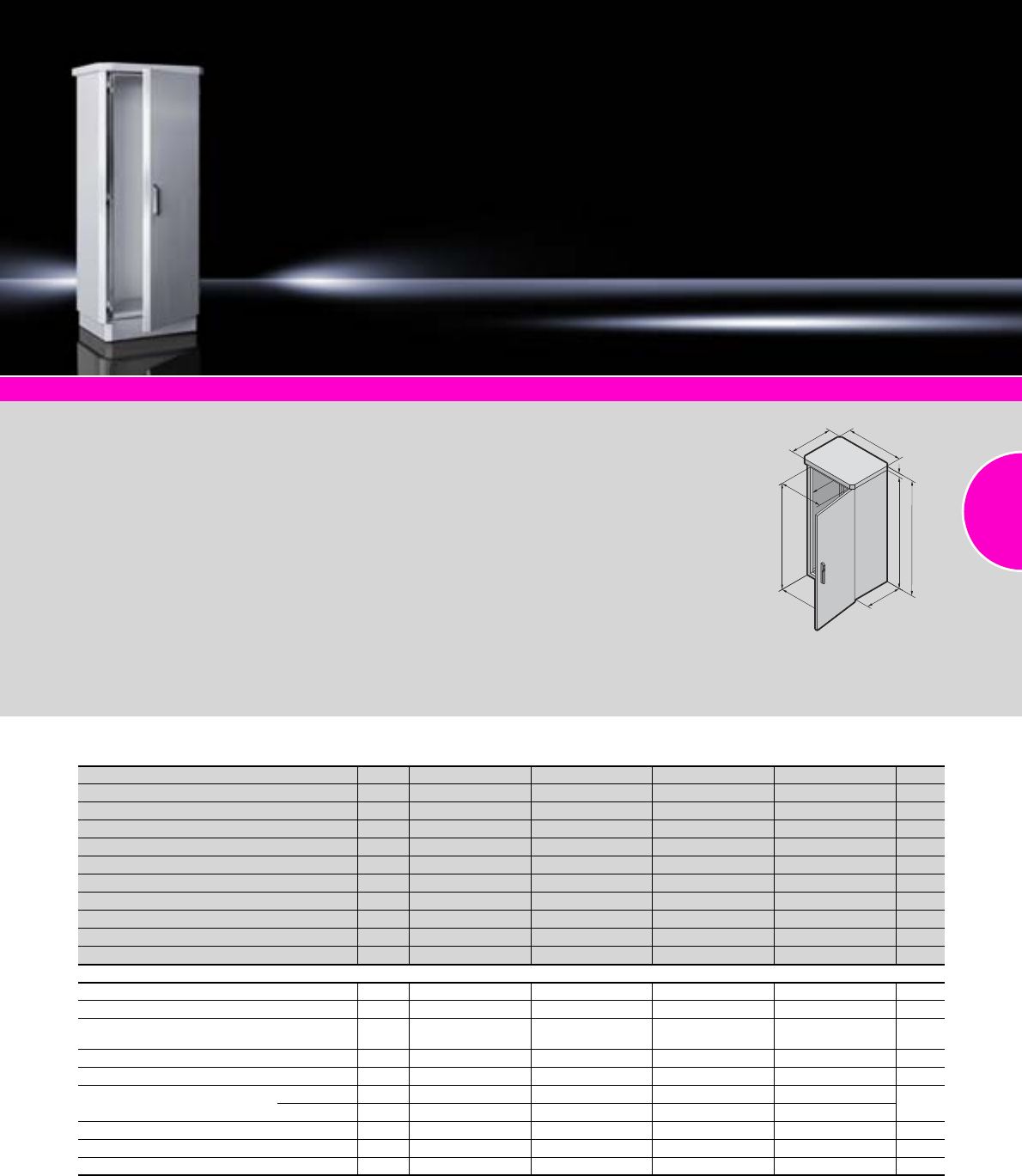
CS Toptec
185Rittal Catalogue 33/Enclosures
Climate control Page 285 Rail systems Page 456 Cable management Page 525
Outdoor enclosure with 100 mm
transport plinth and rain canopy
with projections on all sides.
Side panels, rear panel and door
fully double-walled on the out-
side, the entire TS 8 frame is
available for interior installation.
Material:
−Enclosure frame:
Stainless steel 1.4301
(AISI 304)
−Enclosure panels and
base/plinth trim:
Aluminium, AlMg3
Surface finish:
−Powder-coated
−UV-resistant pure polyester
Colour:
RAL 7035
Protection category:
IP 55 to IEC 60 529
Supply includes:
Double-walled outdoor enclo-
sure, fully pre-configured:
−TS 8 frame with 25 mm sys-
tem punchings in the roof and
base frame plus vertical sec-
tions with two mounting levels
−Front door with door stay,
swing lever handle and
semi-cylinder, lock BJ20027
−Side panels left and right
−Rear panel
−Rain canopy
−Base/plinth with screw-
fastened gland plates and
screw-fastened trim panels
front and rear
−All enclosure panels are
doubled and earthed (exter-
nal wall onto internal wall)
Detailed drawing:
Available on the Internet.
T3
B3
T1
B1
H4
H2
B2
T2
H1 H3
Double-walled, platform TS 8
Width (B1) mm Packs of 600 800 600 800 Page
Height (H1) mm 1200 1200 1600 1600
Depth (T1) mm 600 600 600 600
Clearance width (B2) mm 512 712 512 712
Clearance height (H2) mm 1112 1112 1512 1512
Clearance depth (T2) mm 512 512 512 512
Rain canopy width (B3) mm 694 894 694 894
Rain canopy height (H3) mm 45 45 45 45
Rain canopy depth (T3) mm 694 694 694 694
Overall height (H4) mm 1345 1345 1745 1745
Model No. CS 1 9774.105 9774.205 9774.305 9774.405
Accessories
Concrete base/plinth 1 9765.071 9765.072 9765.071 9765.072 368
Mounting angles, 482.6 mm (19˝) 2 7827.120 7827.120 7827.160 7827.160 549
TS punched section with mounting flange as
installation kit 4 8612.060 – 8612.060 – 459
Installation bracket TS 2 – 7827.480 – 7827.480 556
Mounting plate 1 9765.092 9765.095 – 9765.096 451
Gland plate Size4444
From
514
Qty.2222
Semi-cylinder 1 9785.040 9785.040 9785.040 9785.040 416
Cooling unit, 1000 W 1 – 9776.500 – 9776.500 286
Heat exchanger, 85 W/K 1 – 9776.102 – 9776.102 286
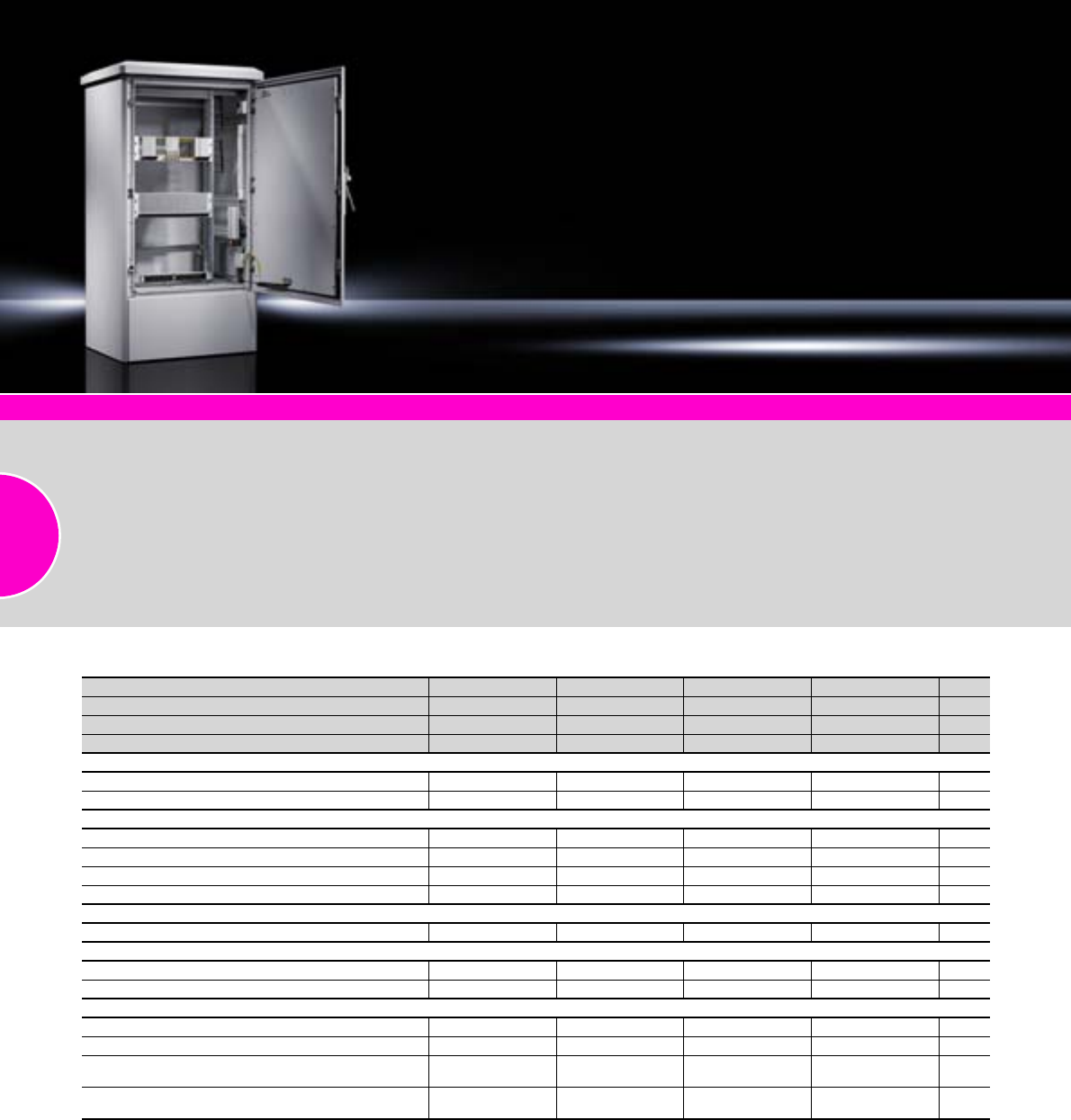
CS modular enclosures
186 Rittal Catalogue 33/Enclosures
System accessories Page 355
CS modular enclosures
Double-walled outdoor enclo-
sure with base/plinth and rain
canopy projecting on all sides.
Side panels doubled up to the
outside, door and rear panel to
the inside.
Photo shows a configuration
example with equipment not
included in the scope of supply.
Material:
−Enclosure, roof and
side panel:
Aluminium AlMg3
−Base/plinth, battery plinth:
Aluminium AlMg3
Surface finish:
−Powder-coated
−UV-resistant pure polyester
Colour:
RAL 7035
Protection category:
IP 55 to IEC 60 529,
complies with NEMA 3R.
Order example,
see page 187.
Other climate control devices,
from page 285.
Detailed drawings:
Available on the Internet.
Double-walled, configuration variants, width: 600 mm
Width mm 600 600 600 600 Page
Height mm 800 1000 1200 1600
Depth mm 600 500 600 600
Model No. CS 9751.015 9751.075 9751.025 9751.035
Base/plinth
Standard base/plinth 100 mm 9755.015 9755.065 9755.015 9755.015
Battery plinth 350 mm 9754.025 9754.015 9754.025 9754.025
Roof-mounted climate control
Cooling unit, 1000 W 9762.212 9762.212 9762.212 9762.212 287
Heat exchanger, 30 W/K 9764.040 9764.040 9764.040 9764.040 287
Mounting frame for cooling unit 9765.051 9765.051 9765.051 9765.051 287
Climate hood 9756.015 9756.065 9756.015 9756.015
Wall-mounted climate control
Cooling unit, 1000 W – – 9761.212 9761.212 287
Roof
Standard roof 9757.015 9757.065 9757.015 9757.015
Roof for wall-mounted climate control – – 9758.015 9758.015
Side panel
Side panel for 100 mm base/plinth 9753.015 9753.175 9753.035 9753.045
Side panel for 350 mm base/plinth 9753.055 9753.195 9753.075 9753.085
Side panel for 100 mm base/plinth
and roof-mounted climate control 9753.095 9753.185 9753.115 9753.125
Side panel for 350 mm base/plinth
and roof-mounted climate control 9753.135 9753.205 9753.155 9753.165
Delivery times available on request.
CS modular enclosures
187Rittal Catalogue 33/Enclosures
Double-walled, configuration variants, width: 800 and 1200 mm
Width mm 800 800 800 800 1200 1200 Page
Height mm 1000 1200 1200 1600 1200 1200
Depth mm 500 500 600 600 500 600
Model No. CS 9751.085 9751.045 9751.055 9751.065 9752.015 9752.025
Base/plinth
Standard base/plinth 100 mm 9755.025 9755.025 9755.035 9755.035 9755.045 9755.055
Battery plinth 350 mm 9754.035 9754.035 9754.045 9754.045 2 x
9754.015
2 x
9754.025
Roof-mounted climate control
Cooling unit, 1000 W 9762.212 9762.212 9762.212 9762.212 9762.212 9762.212 287
Heat exchanger, 30 W/K 9764.040 9764.040 9764.040 9764.040 9764.040 9764.040 287
Mounting frame for cooling unit 9765.051 9765.051 9765.051 9765.051 9765.051 9765.051 287
Climate hood 9756.025 9756.025 9756.035 9756.035 9756.045 9756.055
Wall-mounted climate control
Cooling unit, 1000 W – 9761.212 9761.212 9761.212 9761.212 9761.212 287
Roof
Standard roof 9757.025 9757.025 9757.035 9757.035 9757.045 9757.055
Roof for wall-mounted climate control – 9758.025 9758.035 9758.035 9758.045 9758.055
Side panel
Side panel for 100 mm base/plinth 9753.175 9753.025 9753.035 9753.045 9753.025 9753.035
Side panel for 350 mm base/plinth 9753.195 9753.065 9753.075 9753.085 9753.065 9753.075
Side panel for 100 mm base/plinth
and roof-mounted climate control 9753.185 9753.105 9753.115 9753.125 9753.105 9753.115
Side panel for 350 mm base/plinth
and roof-mounted climate control 9753.205 9753.145 9753.155 9753.165 9753.145 9753.155
Delivery times available on request.
Order example:
Enclosure 800 x 1200 x 500 mm of aluminium AlMg3 with standard base/plinth and roof-mounted cooling unit.
You will need:
Enclosure: Basic enclosure 800 x 1200 x 500 mm CS 9751.045
Base/plinth: Standard base/plinth 100 mm CS 9755.025
Roof-mounted climate control: Roof-mounted cooling unit CS 9762.212
Mounting frame CS 9765.051
Climate hood CS 9756.025
Roof: Standard roof CS 9757.025
Side panel: Side panel for 100 mm base/plinth and roof-mounted climate control CS 9753.105
Rittal Belgium
RITTAL nv/sa
Industrieterrein E17/3206 Stokkelaar 8
B-9160 Lokeren
Phone: +32 (0) 9 353 9111
Fax: +32 (0) 9 355 6862
E-mail: info@rittal.be www.rittal.be
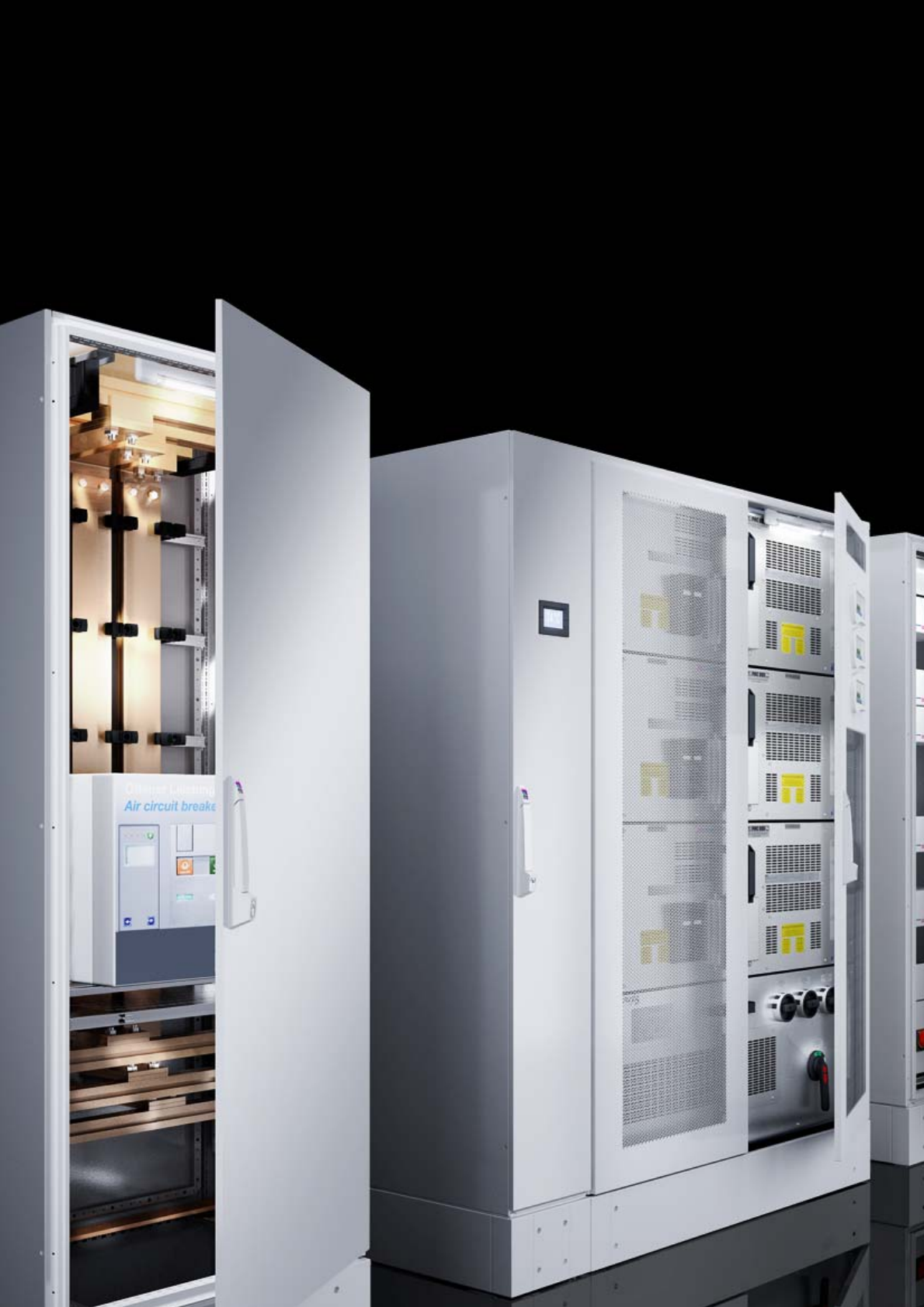
188

189
Power
UPS – Power Modular Concept
PMC 12/PMC 12 compact.........................................................................190
PMC 40 (type 1-4) .....................................................................................191
PMC 40 (type 5) ........................................................................................192
PMC 120....................................................................................................193
PMC 200....................................................................................................194
PMC 800....................................................................................................195
PMC accessories ......................................................................................196
Power Distribution Rack
Power Distribution Rack PDR ....................................................................200
Power Distribution Module PDM................................................................200
Power System Module
PSM Plus busbar .......................................................................................201
PSM Plus plug-in modules ........................................................................201
PSM busbars .............................................................................................202
PSM socket modules.................................................................................203
PSM accessories.......................................................................................204
Fuel cell system
RiCell Flex..................................................................................................205
Rittal UPS systems Power Modular Concept
Ensuring UPS protection of all processes whose availability is crucial is
more than just a question of kilowatts, autonomy and UPS redundancy.
The key here is to protect the critical load with a high UPS efficiency.
Output range
(scalable)
1 – 18
kVA PMC
12
10 – 40
kW PMC
40
10 – 120
kW PMC
120
8 – 800
kW PMC
200
64 – 960
kW PMC
800
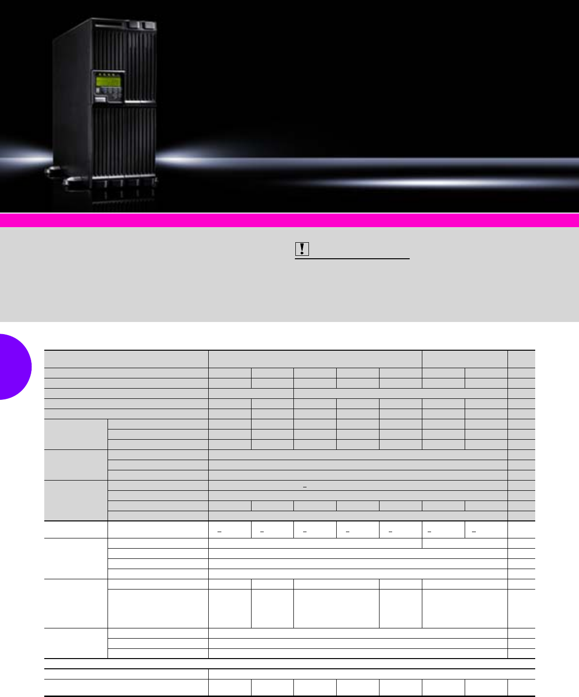
UPS – Power Modular Concept
190 Rittal Catalogue 33/Power distribution
PMC 12, single-phase, output range 1 – 12 kVA n+1
UPS for 482.6 mm (19˝) racks
or as floor-standing enclosures UPS with integral battery UPS control unit Page
Internal hot swap-compatible batteries – –
Model No. DK PMC 12 7857.482 7857.483 7857.430 7857.431 7857.432 7857.433 7857.434
Width x height mm 440 (19˝) x 176 (4 U) 440 (19˝) x 88 (2 U)
Depth mm 420 420 405 650 650 680 680
Weight kg 26 27 15,7 26 29 24 24
Power
VA 2000 3000 1000 2000 3000 4500 6000
Watts 1600 2400 800 1600 2400 3500 4800
Max. heat loss (W) 105 262 105 210 252 315 420
Input
Rated voltage 230 V (160 – 288 V)
Frequency 50/60 Hz ±5%
Power factor > 0.99 with linear load
Output
Voltage 230 V ±1% (200/208/220/230/240 V adjustable)
Frequency, synchronised ±1 Hz
Efficiency, AC mode 88% 90% 88% 88% 90% 90% 90%
Power factor 0.8
Battery
5 years EUROBAT Autonomy at 100% load 7 min. 5 min. 7 min. 7 min. 5 min. 12 min.1) 8 min.1)
Communication
Interface 1 x USB, 1 x RS232 1 x RS232
SNMP Optional network monitoring card DK 7857.420/relay card 7857.410
Operating systems supported Windows, Unix, Linux, Novell, Apple; RCCMD shutdown licence DK 7857.421
Emergency Power Off (EPO)
Connection
Input connection 230 V 10 A C14 16 A C20 10 A C14 16 A C20 Compact connector
Output connection 230 V 6 x 10 A,
C13, 2 units
switched
4 x 10 A,
C13,
2 units
switched,
1 x 16 A, C19
6 x 10 A, C13,
2 units switched
4 x 10 A,
C13,
2 units
switched,
1 x 16 A, C19
Compact connector
Standards and
certifications
Power IEC/EN 62 040-3
EMC EN 50 091-2/EN 62 040-2 class A, EN 61 000-4-2/-3/-4/-6-8/-11, EN 61 000-3-2/-3
Labelling CE, FCC
Accessories
Battery pack PMC 12 see page 196
Connection cable at output end, UPS, single-phase,
for PSM busbar 7856.027 7856.030 7856.027 7856.027 7856.030 – – 204
Included with the supply. 1) With an external battery pack
<
>
>
>
>
>
>
>
Shutdown software Page 347 Battery packs Page 196
Double conversion technology
to the highest classification
VFI-SS-111.
Supply includes:
−Single-phase UPS system
−Operating manual
−Software on CD-ROM
−RS232 cable
−For 1 – 3 kVA:
UPS, earthing-pin connection
cable, USB cable
Also required:
Country-specific connection
cables and slide rails are
required to operate the UPS
systems,
see page 585/559.
Technical information:
Available on the Internet.
Photo shows a configuration
example with equipment not
included in the scope of supply.
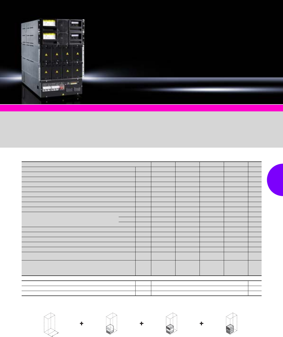
UPS – Power Modular Concept
191Rittal Catalogue 33/Power distribution
Shutdown software Page 347
Double conversion technology
to the highest classification
VFI-SS-111.
Supply includes:
−Basic module and UPS mod-
ule(s) fitted to specifications.
−Battery pack(s), separate
Service:
Commissioning by Rittal. Technical information:
Available on the Internet.
Photo shows a configuration
example with equipment not
included in the scope of supply.
PMC 40 modules, rack-independent
482.6 mm (19˝) rack, at least
800 mm deep. Basic module ... ... plus UPS module ... ... plus battery pack produces
a complete UPS system
min.
800
PMC 40 (type 1-4), 3-phase, output range scalable 10 – 40 kW
Type 1 Type 2 Type 3 Type 4 Page
Number of UPS modules Qty. 11 2 2
Number of battery packs Qty. 1 2 2 4
Maximum UPS output (with 10 kW/20 kW module) kW 10 10/20 20 20/40
UPS output with 1+1 redundancy (with 10 kW/20 kW module) kW – – 10 10/20
Approx. autonomies at 100% load (10 kW/20 kW modules) min. 6/– 15/5 6/– 16/5
Approx. autonomies at 50% load (10 kW/20 kW modules) min. 12/– 30/10 12/– 32/10
RS232 (D-Sub 9) and USB interface (configuration and shutdown) Qty. 1/1 1/1 1/1 1/1
Fault signal contacts (floating) Qty. 5 5 5 5
Clamping strip input/output (3L+N+PE) max. conductor cross-section mm2 10/16 10/16 10/16 10/16
Dimensions
Width mm 485 (19˝) 485 (19˝) 485 (19˝) 485 (19˝)
Height U11 15 18 26
Depth mm 735 735 735 735
Required distance between 482.6 mm (19˝) levels (min./max.) mm 690 – 800 690 – 800 690 – 800 690 – 800
Weight (approx. incl. batteries and UPS modules) kg 162 278 310 537
Model No. DK basic unit 7040.010 7040.020 7040.030 7040.040
Model No. DK PMC 40 10 kW module (order quantity acc. to type) Qty. 1 x 7040.110 1 x 7040.110 2 x 7040.110 2 x 7040.110
Model No. DK PMC 40 20 kW module (order quantity acc. to type) Qty. – 1 x 7040.120 – 2 x 7040.120
Model No. DK
PMC 40 battery pack each n x 4 x 10 batteries (12 V/7 Ah) prewired Packs of 7040.211 7040.212 7040.212 7040.214
Model No. DK
PMC 40 battery preparation (for export or air freight)
Drawers and battery cabling (excluding battery, quantity depending
on type)
Packs of 7040.201 7040.202 7040.202 7040.204
Accessories
SNMP monitoring card (budget) Packs of 7857.420 198
RCCMD licence, bundle of 5 licences Packs of 7857.423 347
RCCMD licence, bundle of 25 licences Packs of 7857.424 347
Note: Only UPS modules with an identical output may be combined.
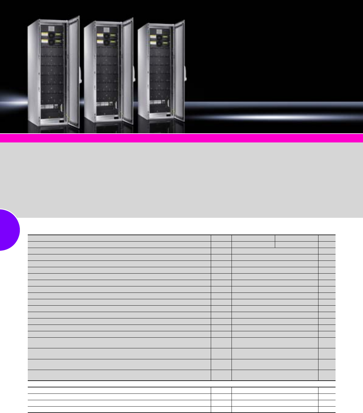
UPS – Power Modular Concept
192 Rittal Catalogue 33/Power distribution
Shutdown software Page 347
UPS rack with integral power
modules and batteries
●Thanks to the double conver-
sion technology (VFI-SS-111)
the output voltage is inde-
pendent from the input volt-
age and frequency
●Efficient IGBT power transis-
tor technology achieves a
high operating ratio of 95%
even in part-load operation
●“Safe swap” compatibility with
a redundant design, i.e. the
module may be exchanged
while operational
●Every UPS module includes
power electronics as well as
the control unit including dis-
play
●Installation, commissioning
and servicing to be carried
out by authorised experts only
Supply includes:
−UPS system in the TS 8 rack
−Vented front door and rear
panel
−Fitted with UPS power mod-
ules (depending on configura-
tion) and batteries
−The batteries must only be
installed at the point of
assembly and are delivered
separately
Note:
Only UPS modules with an iden-
tical output may be combined.
Technical information/
battery configurations:
Available on the Internet.
Photo shows a configuration
example with equipment not
included in the scope of supply.
PMC 40 (type 5), 3-phase, output range scalable 10 – 40 kW, redundant
Dimensions (UPS rack, without base/plinth) width x height x depth mm Packs of 600 x 2000 x 800 600 x 2000 x 1000 Page
Model No. UPS basic rack 7040.065 7040.060
Maximum no. of UPS modules 3
Maximum no. of batteries 240 (4 x 50, 6 x 40)
Maximum UPS output (with 10 kW/20 kW modules) 30/60 kW
UPS output with n+1 redundancy (with 10 kW/20 kW modules) 20/40 kW
RS232 (D-Sub 9) and USB interface (configuration and shutdown) 1/1
Fault signal contacts (floating) 5
Clamping strip input/output (3L+N+PE) max. conductor cross-section 35/50 mm2
Weight (approx. incl. batteries and 3 UPS modules) 740 kg
Protection category of UPS system IP 20
Operating temperature range (UPS with batteries, recommended) 20 – 25°C
Accessibility only required to front (for servicing, maintenance) 900 mm
Distance from wall at rear (due to fan cooling) 200 mm
Model No. PMC 40 10 kW module (order quantity acc. to output) 1 7040.110
Model No. PMC 40 20 kW module (order quantity acc. to output) 1 7040.120
Model No. PMC 40 battery pack 1 x 4 x 10 batteries, when using 10 kW modules
(12 V/7 Ah) prewired (service life 5 years under EUROBAT) Order volume n = 1-6 x 40 7040.311
Model No. PMC 40 battery pack 1 x 5 x 10 batteries, when using 20 kW modules
(12 V/7 Ah) prewired (service life 5 years under EUROBAT) Order volume n = 1-4 x 50 7040.315
Model No. PMC 40 battery preparation n x 4 x 10 (for export or air freight)
Drawers and battery cabling (n = 1-6 x, without batteries), cable set of 40 1 set 7040.301
Model No. PMC 40 battery preparation n x 5 x 10 (for export or air freight)
Drawers and battery cabling (n = 1-4 x, without batteries), cable set of 50 1 set 7040.305
Accessories
UPS monitoring/SNMP monitoring card 1 7857.420 198
Base/plinth components, front and rear, RAL 7035, 100 mm high 1 set 8601.605 361
Base/plinth trim panels, side, RAL 7035, 800 mm deep/100 mm high 1 set 8601.085 362
Base/plinth trim panels, side, RAL 7035, 1000 mm deep/100 mm high 1 set 8601.015 362
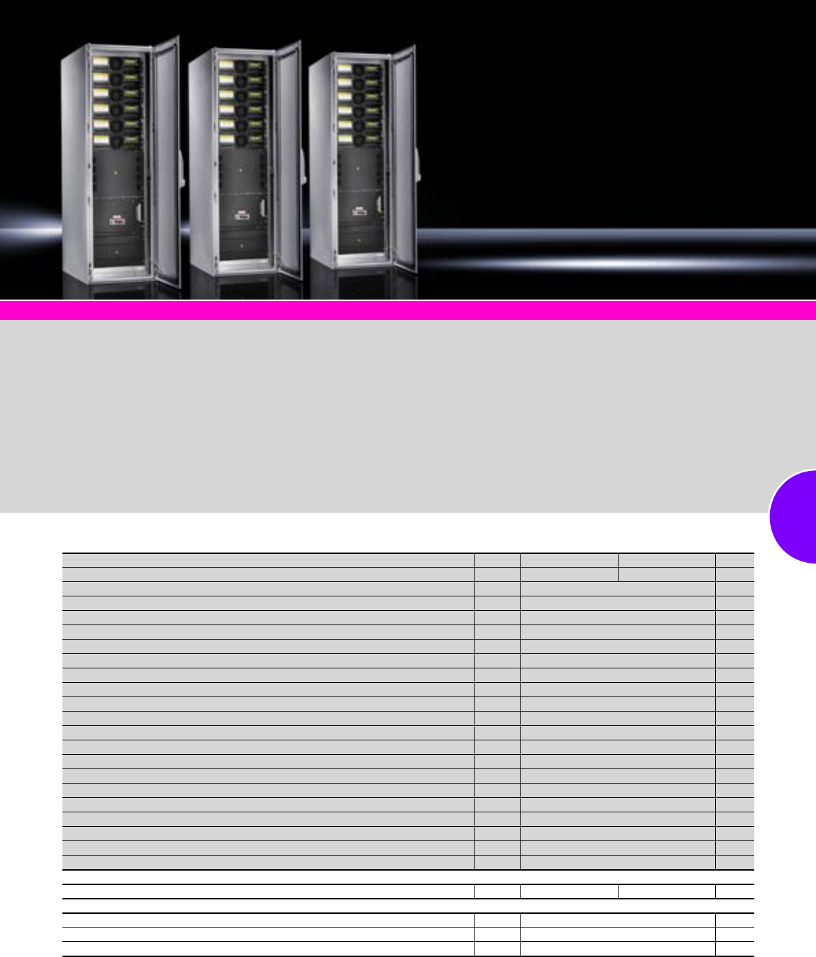
UPS – Power Modular Concept
193Rittal Catalogue 33/Power distribution
Shutdown software Page 347
Modular UPS system
(up to 120 kW)
●UPS power modules operate
according to the double con-
version principle (classifica-
tion to VFI-SS-111) and have a
transformerless design thanks
to the high intermediate cir-
cuit voltage
●Efficient IGBT power transis-
tor technology achieves a
high operating ratio of 95%
even in part-load operation
●“Safe swap” compatibility with
a redundant design, i.e. the
module may be exchanged
while operational
●Every UPS module includes
power electronics as well as
the control unit including dis-
play
●Installation, commissioning
and servicing to be carried
out by authorised experts only
Supply includes:
−UPS system in the TS 8 rack
−Vented front door and rear
panel
−Fitted with UPS power mod-
ules (depending on configura-
tion) and batteries
Note:
Only UPS modules with an iden-
tical output may be combined.
Technical information/
battery configurations:
Available on the Internet.
Photo shows a configuration
example with equipment not
included in the scope of supply.
PMC 120, 3-phase, output range scalable 10 – 120 kW
Dimensions (UPS rack, without base/plinth) width x height x depth mm Packs of 600 x 2000 x 800 600 x 2000 x 1000 Page
Model No. UPS basic rack 7040.075 7040.070
Maximum no. of UPS modules 6
Maximum UPS output (with 10 kW/20 kW modules) 60/120 kW
UPS output with n+1 redundancy (with 10 kW/20 kW modules) 50/100 kW
No. of batteries (12 V/28 Ah) per module/battery bank (per 10 kW/20 kW) 40/50
No. of battery banks per battery rack1), max. 3
No. of batteries (12 V/28 Ah) per battery rack1), max. 150
Operating ratio (from 50% load) 95%
Operating ratio in eco-mode (100% load) 98%
RS232 (D-Sub 9) and USB interface (configuration and shutdown) 1/1
Fault signal contacts (floating) 5
Input (3L+N+PE) conductor cross-section 70/95 mm2
Output (3L+N+PE) conductor cross-section 70/95 mm2
Battery connection (3 x M10, joint batteries) conductor cross-section 150 mm2
Weight (approx., UPS rack with 6 UPS modules) 285 kg
Protection category of UPS system IP 20
Operating temperature range (UPS with batteries, recommended) 20 – 25°C
Accessibility only required to front (for servicing, maintenance) 900 mm
Distance from wall at rear (due to fan cooling) 200 mm
Model No. PMC 40 10 kW module (order quantity acc. to output) 1 7040.110
Model No. PMC 40 20 kW module (order quantity acc. to output) 1 7040.120
Also required
Battery rack, width 800 mm (max. 150 batteries) 1 7040.3611) 7857.3641)
Accessories
Base/plinth components, front and rear, RAL 7035, 600 mm wide/100 mm high 1 set 8601.605 361
Base/plinth trim panels, side, RAL 7035, 800 mm deep/100 mm high 1 set 8601.085 362
Base/plinth trim panels, side, RAL 7035, 1000 mm deep/100 mm high 1 set 8601.015 362
1) Batteries not included with the supply of the battery rack, connection cable for battery racks DK 7040.371.
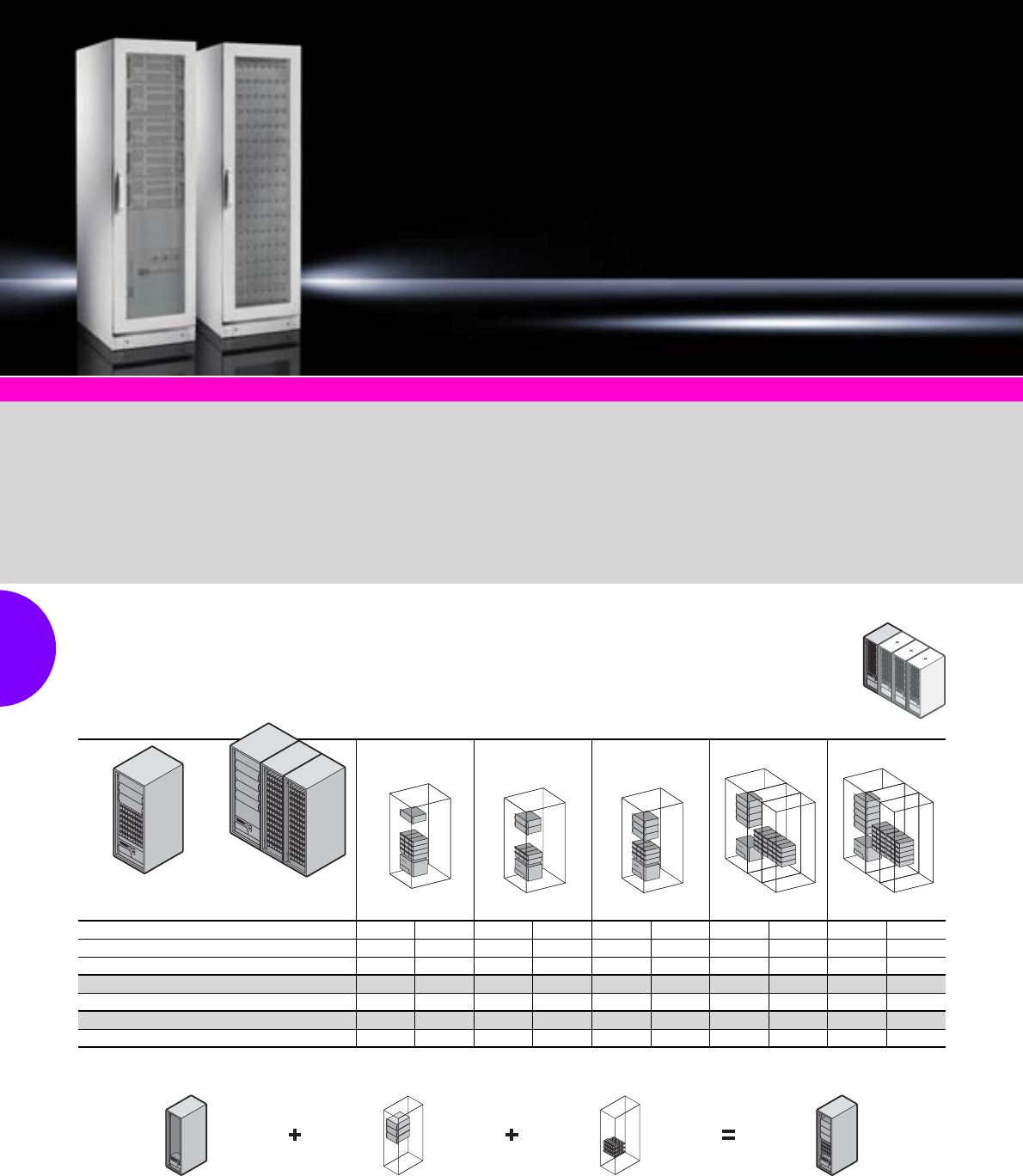
UPS – Power Modular Concept
194 Rittal Catalogue 33/Power distribution
Shutdown software Page 347
Rittal PMC 200 ensures opti-
mum availability for critical
appli-
cations by combining modularity
(flexible scalability and redun-
dancy, whereby up to 20 mod-
ules may be switched in paral-
lel) with decentralised parallel
architecture or DPA (redundant
protection without a “single point
of failure”). Transformerless,
genuine online, double-
conversion UPSs with static
bypass and classification code
VFI-SS-111.
This modular concept keeps the
purchasing and operating costs
of redundant solutions low. As
your performance requirements
grow, the UPS grows with you –
even in the most confined
spaces, and with the system
operational. The benefits to you:
Less capital tie-up, inexpensive
expansion, and minimal space
requirements.
Technical information:
Available on the Internet.
Photo shows a configuration
example with equipment not
included in the scope of supply.
PMC 200 modules
20
20
20
20
20
20
Minimum floor space is required by a rack with three modules (2+1 redundancy) and batteries with autonomy integrated into a single rack.
The Rittal PMC 200 allows the integration of up to 5 modules (4+1 redundancy) in one rack. For this configuration, an additional battery rack
is required. The autonomy may be flexibly adapted to suit your requirements.
UPS rack UPS module Battery packs PMC 200
Examples of 32 and 40 kW module configurations and autonomies
UPS racks:
W 800 x H 2000 x
D 1000 mm
Battery racks:
W 800 x H 2000 x
D 1000 mm
Redundancy without with without with without with without with without with
UPS rack/battery rack 1/– – 1/– 1/– 1/– 1/– 1/2 1/2 1/2 1/2
Number of UPS modules 1–22334455
PMC 32 module type, output in kW 32 –64 32 96 64 128 96 160 128
Battery autonomy1) 18 – 9 9 9 9 12 12 12 12
PMC 40 module type, output in kW 40 – – – – – 160 120 200 160
Battery autonomy1) 15–––––9999
1) Minutes/modules with cos ϕ 1.0/autonomy may be extended to order. Delivery times available on request.
40
40
40
40
40
40
PMC 200, 3-phase, output range scalable 8 – 800 kW
Up to 20 PMC modules may be gradually switched in parallel e.g. in order to supply 800 kW without redundancy or 760 kW
n+1 (with 40 kW modules) uninterrupted. May be upgraded with the system operational; no need to switch over to an
unprotected network.
Note:
This table contains only sample configurations. We would be pleased to configure your individual solution with you.
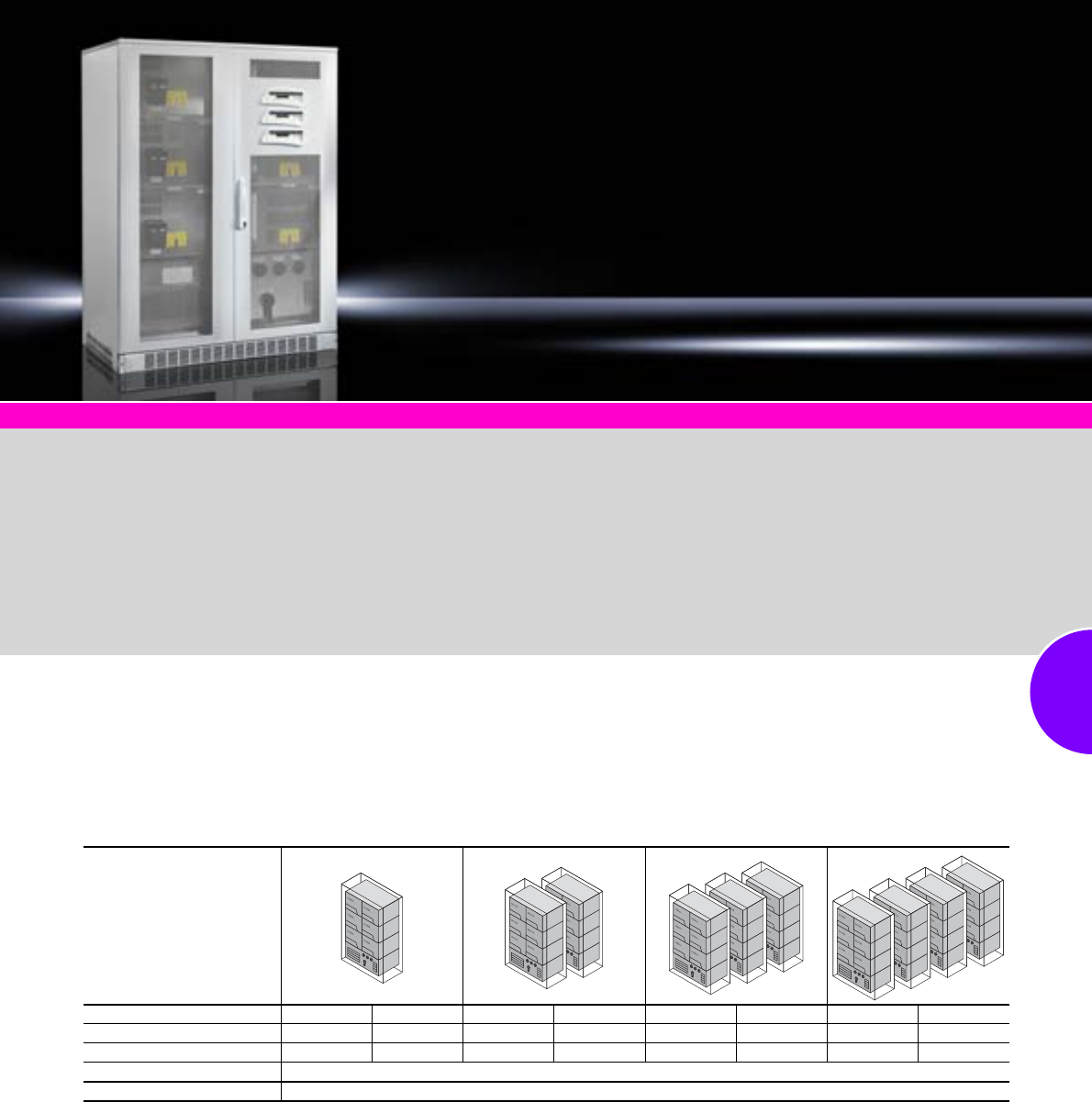
UPS – Power Modular Concept
195Rittal Catalogue 33/Power distribution
Shutdown software Page 347
Rittal PMC 800 is the solution for
data centres with a high power
consumption. The modular
architecture allows optimum,
tailored configuration of the UPS.
The PMC 800 may be extended
to accommodate up to 12 mod-
ules, facilitating a maximum out-
put of up to 960 kW or 880 kW
(n+1), redundant. If a UPS with a
higher output is required, this
can of course be achieved with
the PMC 800.
UPS PMC 800 at a glance:
●Topology: On-line, double
conversion, VFI-SS-111.
●Technology: Transformerless
●Architecture: Modular, may be
connected in parallel
●Maximum output in standard
configuration: 800 kW (higher
outputs available on request)
●Operating ratio at 25/50/75/
100% load
(cos phi = 0.8): 92/93.5/95/
95%
●Use of battery racks:
Technical information:
Available on the Internet.
Photo shows a configuration
example with equipment not
included in the scope of supply.
Examples of 64 and 80 kW module configurations
PMC 800
Redundancy (n+1) without with without with without with without with
Module with 64 kW 192 128 384 320 576 512 768 704
Module with 80 kW 240 160 480 400 720 640 960 880
Batteries Battery rack, e.g. 28 Ah batteries or battery racks, e.g. 70 Ah batteries
UPS racks W x H x D mm 1400 x 1900 x 870
PMC 800, 3-phase, output range scalable 64 – 960 kW
The separation into one power module and one control module is exemplary for UPS systems in this output class.
This ensures a high level of service-friendliness and allows precise planning of maintenance work.
Note:
This table contains only sample configurations. We would be pleased to configure your individual solution with you.

UPS – Power Modular Concept
Accessories
196 Rittal Catalogue 33/Power distribution
Battery packs
for PMC 12
To operate or increase the power of PMC 12 UPS
systems. With overload protection. Vertical siting
is also possible. Battery packs are “hot plug”-
compatible (replacement of batteries while opera-
tional). Batteries can be exchanged from the front,
without removing the battery pack from the
482.6 mm (19˝) level. Depending on the UPS
version, 2 – 3 battery packs may be connected
together to increase the autonomy. Cooling of the
UPS and the battery packs is absolutely essential.
Material:
Maintenance-free lead gel accumulators,
service life 5 years (to EUROBAT)
Supply includes:
−Fully preassembled and populated with
accumulators (12 V/7 Ah)
−0.5 m connection cable with connector
−Feet.
Note:
For mounting in the 482.6 mm (19˝) rack,
a slide rail DK 7063.883 is required.
Autonomy (min.) at 100% load:
XL version Standard version
UPS PMC 12 system 7857.482 7857.483 7857.430 7857.431 7857.432 7857.433 7857.434
Battery packs Model No. DK 7857.488 7857.488 7857.435 7857.437 7857.437 7857.442 7857.442
Width mm 465 465 465 465 465 465 465
Height mm 178 (4 U) 178 (4 U) 89 (2 U) 89 (2 U) 89 (2 U) 133.5 (3 U) 133.5 (3 U)
Depth mm 420 420 650 650 650 650 650
Weight kg 35 35 20 20 20 55 55
Number of batteries
per battery pack 12 12 6 6 6 20 20
UPS PMC 12 In supplied
state
Battery packs
11
(XL version) 22
(XL version) 3
7857.430, 1 kVA 7 min. 28 min. – 55 min. – –
7857.482/7857.431, 2 kVA 7 min. 17 min. 26 min. 29 min. 54 min. –
7857.483/7857.432, 3 kVA 5 min. 12 min. 24 min. 20 min. 46 min. –
7857.433, 4.5 kVA – 9 min. – 23 min. – 39 min.
7857.434, 6 kVA – 8 min. – 20 min. – 33 min.
1
2
Mechanical maintenance
bypass
for PMC 12
Facilitates uninterrupted removal/maintenance of
the UPS. Various designs are required depending
on the UPS output category.
Connection of the bypass for 1 – 3 kVA UPS
models is via a connector (plug & play), while the
4.5 and 6 kVA UPS variant must be installed by a
qualified electrician. It is important to ensure the
correct prefuse of the UPS bypass depending on
the UPS power used.
Dimensions:
W x H x D (mm):
−465 x 88 (2 U) x 80 (DK 7857.440)
−465 x 88 (2 U) x 350 (DK 7857.441)
Model No. DK
1 – 3 kVA
(incl. UPS fuse 16 A) 7857.440
4.5 – 6 kVA
(incl. UPS fuse 32 A) 7857.441
1
2
Relay card
for PMC 12
This card allows the UPS alarm messages (5 UPS
alarms) to be forwarded to external indicator
devices (e.g. building services management)
via floating contacts.
The card is plugged into the extension slot on the
rear of the PMC 12 UPS.
Note:
Cannot be used together with the SNMP card.
Packs of Model No. DK
1 7857.410
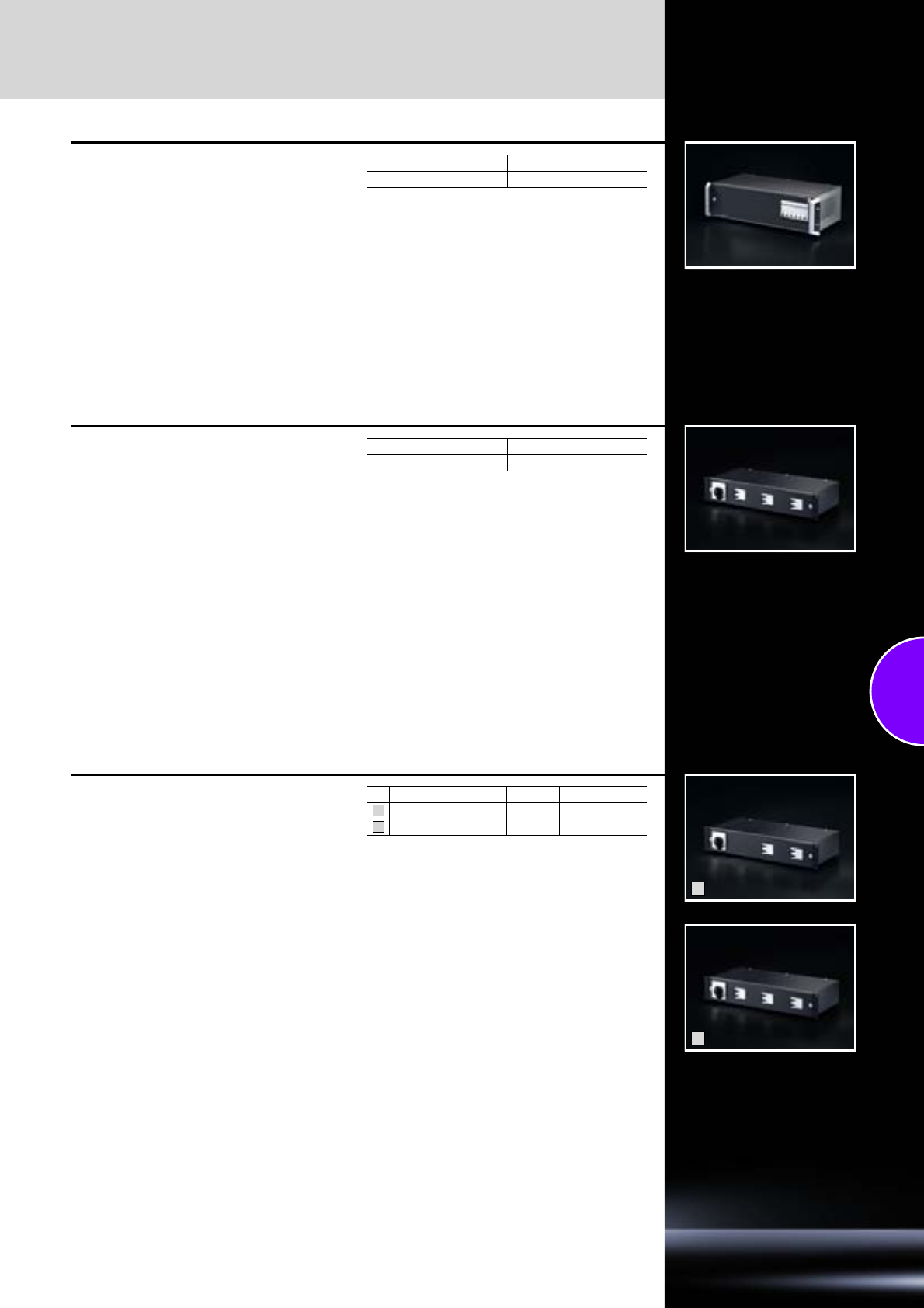
Accessories
UPS – Power Modular Concept
197Rittal Catalogue 33/Power distribution
Sub-distribution
for PMC 12
Outlets 4 x C19 and 2 x 32 A CEE-conforming,
single-phase, individually fused. Allows the direct
connection of up to 6 pieces of equipment.
Installation must be carried out by a qualified
electrician.
Dimensions:
W x H x D (mm): 482.6 (19˝) x 131 (3 U) x 300
Technical specifications:
Ambient conditions:
−Temperature: 5 – 40°C
−Humidity:
5 – 90% rel. humidity (non-condensing)
−Input (open ends with wire end ferrules):
3 x 6 mm² (2 m)
−Output:
4 x C19 jack, 2 x CEE 32 A coupling
−Fuses:
4 x 16 AC, 2 x 32 A type C
Packs of Model No. DK
1 7857.445
Plug & play sub-distribution
for PMC 12, 4.5 and 6 kVA
This sub-distribution facilitates simple installation
and commissioning of the PMC 12 UPS, 4.5 and
6 kVA. All that is needed is a single-phase 32 A
connection to DIN/EN 60 309.
Dimensions:
W x H x D (mm): 482.6 (19˝) x 88 (2 U) x 300
Technical specifications:
Ambient conditions:
Temperature: 5 – 40°C
−Humidity:
5 – 90% rel. humidity (non-condensing)
−UPS connection PMC 12:
Via connection cables with fitted Harting
connector (1.5 m)
−Input (connection cable):
3 x 4 mm² (3 m) with 32 CEE connector,
single-phase
−Output:
2 x C19 jack, 4 x C13 jack
−Fuses:
2 x 16 AC, 4 x 10 A type C
Packs of Model No. DK
1 7857.448
1
2
Parallel hot swap chassis
for PMC 12, 4.5 and 6 kVA
Facilitates parallel switching of 2 (or 3) PMC UPS
systems to increase the output or redundancy of
the UPS. A mechanical maintenance bypass is
also integrated.
Parallel connection is only possible with the 4.5
and 6 kVA PMC 12 version. The two UPS systems
to be connected in parallel must have identical
battery configurations (number/type of battery
packs). The autonomy of the system will not be
increased as a result of parallel connection.
Installation must be carried out by a qualified
electrician.
Dimensions:
W x H x D (mm): 482.6 (19˝) x 88 (2 U) x 300
Technical specifications:
Ambient conditions:
−Temperature: 5 – 40°C
−Humidity:
5 – 90% rel. humidity (non-condensing)
−UPS connection PMC 12:
Via connection cables with fitted Harting
connector (1 m)
−Input (connection cable):
3 x 10/16 mm² (2 m) with open cable end and
wire end ferrules
−Output (connection cable):
3 x 10/16 mm² (2 m) with open cable end and
wire end ferrules
−Fuses (UPS input):
2 x 2 x 32 A type C (for DK 7857.442)
3 x 2 x 32 A type C (for DK 7857.443)
Note:
Commissioning of a PMC 12 UPS connected in
parallel must only be carried out by a member of
the Rittal Service team because the UPS may be
destroyed if wrongly configured.
Additionally, we recommend the use of the
PMC 12 sub-distribution (DK 7857.445).
for UPS systems Packs of Model No. DK
2 1 7857.443
3 1 7857.444
1
2
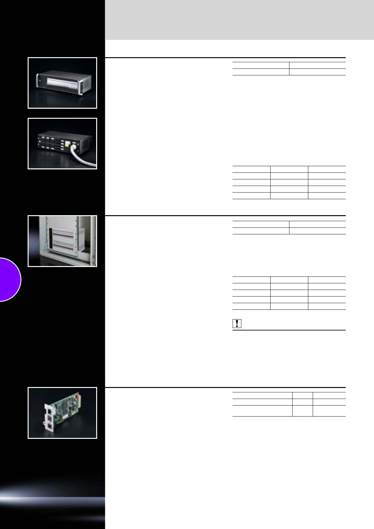
UPS – Power Modular Concept
Accessories
198 Rittal Catalogue 33/Power distribution
Sub-distribution
for PMC 40 UPS
Allows the direct, fused connection of single- and
3-phase equipment. In this way, up to 4 PSM bus-
bars may be connected directly to the PMC 40
UPS via the relevant connection cables.
Additionally, there are six single-phase outlets
(16 A) available via C19 jacks.
Connection to the PMC 40 UPS must be carried
out by a qualified electrician.
Dimensions:
W x H x D: 482.6 (19˝) x 131 mm (3 U) x 300 mm
Technical specifications:
Ambient conditions:
−Temperature: 5 – 40°C
−Humidity:
5 – 90% rel. humidity (non-condensing)
−Input (open ends with wire end ferrules):
5 x 16 mm² (2 m)
−Output:
4 x GST18 (3-phase), 6 x C19 (1-phase)
−Fuses:
18 x 16 AC
Note:
Observe the country-specific connection data.
Plug & play connection cable for server enclosures
:
Packs of Model No. DK
1 7040.500
Length Packs of Model No. DK
3 m 1 7857.130
5 m 1 7857.150
8 m 1 7857.180
9 m 1 7857.190
Sub-distribution, modular
for PMC 200
The distributor may be fitted directly in the UPS
PMC 200 rack. This allows the configuration of a
complete, compact system with a 0.6 m2 footprint
containing a rack-mounted modular UPS
PMC 200, batteries and distributor.
Application range:
UPS systems Rittal Power Modular Concept
PMC 200 up to 20 kW N+1.
Technical specifications:
●482.6 mm (19˝) , 6 U
●12 outlets, three-phase 400 V/50 Hz with 10 A
●On-load isolator for disconnecting
●Circuit-breaker 10 A per phase
Supply includes:
482.6 mm (19˝) modules, 6 U, instructions.
Note:
Observe the country-specific connection data.
Plug & play connection cable for server enclosures
:
Also required:
UPV PMC 200, 60 kW, see page 194.
Design Model No. DK
482.6 mm (19˝), 6 U 7857.372
Length Packs of Model No. DK
3 m 1 7857.130
5 m 1 7857.150
8 m 1 7857.180
9 m 1 7857.190
UPS monitoring card
(SNMP card)
This optional monitoring card facilitates monitor-
ing of the UPS via Web browsers. In this way,
various monitoring states of the UPS (e.g. input
voltage, output currents/power per phase,
battery charging status, autonomies etc.) may be
remotely monitored. However, the main applica-
tion is a controlled server shutdown via the net-
work interface. To this end, a UPS shutdown
client (RCCMD software) must be installed and
configured on every server.
Note:
Only one extension card may be installed per UPS
system.
Redundant monitoring solutions for UPS systems
available on request.
RCCMD software, see page 347.
Design Packs of Model No. DK
SNMP card, budget version 1 7857.420
SNMP card CS121
with swtiching contacts 1 7857.366
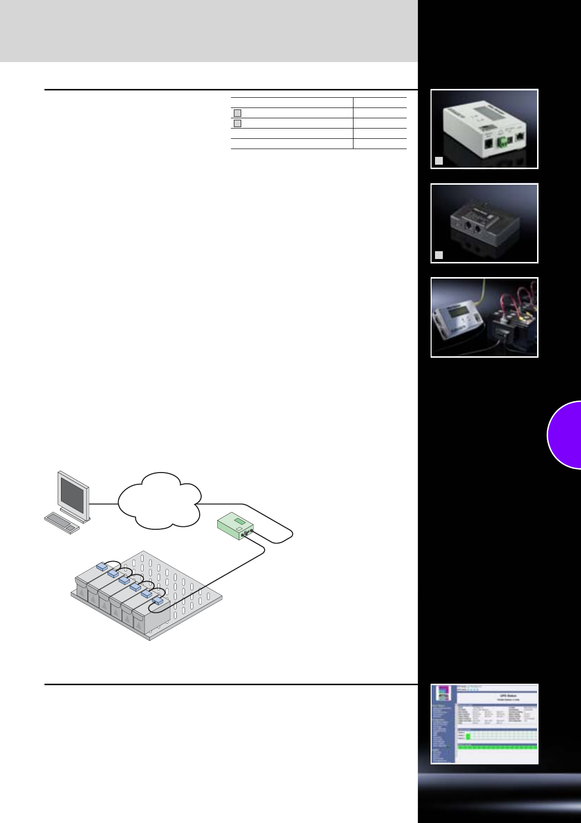
Accessories
UPS – Power Modular Concept
199Rittal Catalogue 33/Power distribution
1
2
Battery Manager RiBat
for PMC 200/800
Management system for the batteries in a UPS.
RiBat can extend the service life of a battery by
up to 30%.
Benefits:
●Optimised charging for each individual battery.
●Temperature monitoring per battery.
●Early identification of defective batteries.
●Supports preventive maintenance of batteries.
●Defective batteries can be restored rather than
replaced before reaching the end of their use-
ful life.
●RiBat Manager replaces the internal SNMP card
of the UPS.
The Rittal battery manager RiBat determines all
relevant data such as battery voltage, internal
resistance, discharge curve, temperature etc.
throughout the service life of the monitored batter-
ies. This data is evaluated and used to control the
charging process. RiBat facilitates optimum
charging of each individual battery.
The RiBat module regulates the charging process
for each connected battery. This avoids over-
charging of a battery which is connected to other
batteries. This technology can extend the service
life of a battery by up to 30%. The RiBat modules
are connected using preassembled cables and
connected to the RiBat Manager.
Up to 250 modules may be connected to one
RiBat Manager.
Technical specifications
RiBat Manager:
−Supply voltage: 9 – 30 V DC
−Serial interface: 3 x RS232
−LAN interface: 10/100 MBit full/half
−Supported protocols:
SNMP, RCCMD, SNMP, HTTP
−Alarm contact: 1 floating contact
−Display: LCD display
Temperature range: 5°C – 45°C,
−90% humidity, non-condensing
−Certifications: CEE, WEEE, RoHS
RiBat module:
−Battery voltage: 12 V DC
−Battery capacity: 7 – 300 Ah
−W x H x D: 800 x 55 x 27 mm
−Certifications: CEE, WEEE, RoHS
Designation Model No. DK
RiBat Manager 7857.800
RiBat module 7857.801
RiBat cable kit 120 batteries 7857.8021)
RiBat cable kit 150 batteries 7857.8032)
Extended delivery times.
1) In conjunction with a battery rack for 120 batteries
2) In conjunction with a battery rack for 150 batteries
1
2
TCP/IP
Battery Manager
Battery
Module
RCCMD software
Client software for controlled server shutdown
see page 347.
Power Distribution Rack
200 Rittal Catalogue 33/Power distribution
Power Distribution Rack PDR
●To accommodate a maximum
of 8 PDM
●Height 1.20 m for 4 PDMs and
2 m height for 8 PDMs
●PDM may be retrofitted whilst
operational
●A maximum of 32 racks may
be fitted to the sub-distributor
●Fully shock-hazard protected
●Main switch in various
options:
−Isolator switch
−On-load isolator
−Air circuit-breaker
−RC circuit-breaker
●Low-voltage distribution
up to 250 A
Material:
Sheet steel
Surface finish:
−Enclosure frame:
Dipcoat-primed
−Doors, roof and base/plinth:
Dipcoat-primed, powder-
coated
−Gland plates, punched sec-
tions with mounting flanges
and mounting angles:
Zinc-plated, clear-chromated
Colour:
RAL 7035
Supply includes:
−Enclosure frame with door
(without tubular door frame),
−Rear panel,
−Side panels and roof plate,
−Levelling feet incl. base/plinth
adaptor,
−Earthing of all enclosure
panels,
−Busbars shock-hazard-
protected
−Main switch integral.
Note:
Observe the standards of the
lo
cal power supply companies
.
Approvals:
VDE
Detailed drawings:
Available on the Internet.
Power Distribution Module
PDM
●Mechanically latchable in the
PDR
●Scalable
●RC circuit-breaker, optional
Supply includes:
−482.6 mm (19˝) module, 3 U
−Incl. master switch
−4 fused 3-phase outlets to the
rack
−3 x 230 V/16 A per outlet
−Connected load 400 V/3 AC,
max. 63 A
Photo shows a configuration
example with equipment not
included in the scope of supply.
Power Distribution Rack PDR
Power Distribution Module PDM
Packs of Page
Possible number of PDM modules 4 8
Dimensions mm W x H x D 800 x 1200 x 500 800 x 2000 x 500
Model No. DK 17857.3101) 7857.3001)
Accessories
Base/plinth components front and rear Height 100 mm 1 set 8601.800 8601.800 361
Height 200 mm 1 set 8602.800 8602.800 361
Base/plinth trim panels, side Height 100 mm 1 set 8601.050 8601.050 362
Height 200 mm 1 set 8602.050 8602.050 362
1) Extended delivery times.
Packs of
Design 4 outlets per 10 kW 4 outlets project-specific
Dimensions mm W x H 19˝ (482.6 mm) x 3 U
Model No. DK 17857.320 7857.350
Also required
Plug & play connection cable
for PSM busbar to the server enclosures
Length 3 m 1 7857.130
Length 5 m 1 7857.150
Length 8 m 1 7857.180
Length 9 m 1 7857.190
Connection cable 32 A CEE-conforming
connector, for operation without PDR 17857.321
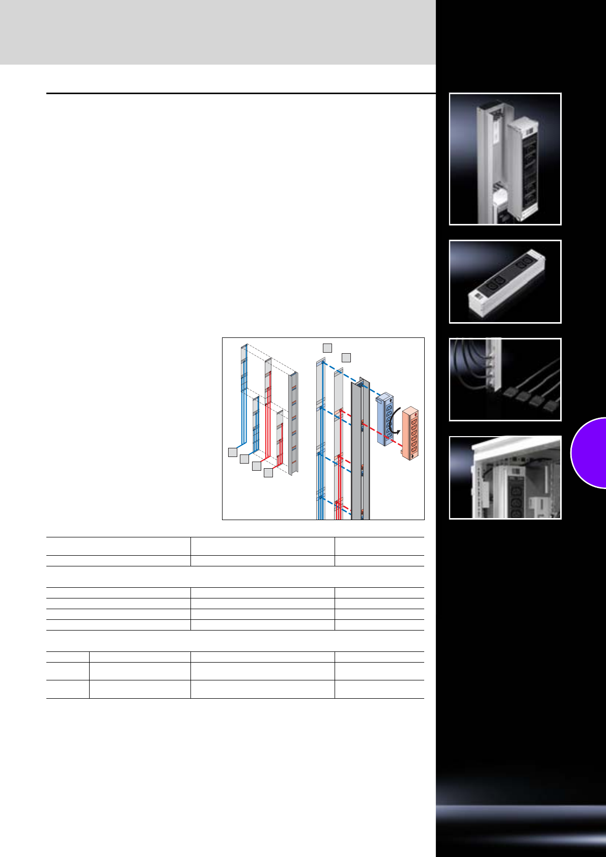
Power System Module Plus
201Rittal Catalogue 33/Power distribution
Power System Module
PSM Plus
Current carrying capacity up to 192 A per rack
Busbar with redundant design and 3-phase
infeed.
By integrating two further three-phase circuits the
PSM Plus now has four independent three-phase
infeeds. Each of the feeds can be supplied with
up to 3 x 16 A, producing a total of max. 192 A.
With four independent infeeds, it is possible to
assemble a redundant, high-MTBF power supply
system for IT racks.
The benefits at a glance:
●2 m busbar with four independent infeeds
(A, B, C, D each 400 V/3~, 50/60 Hz, 3 x 16 A).
●Shock-hazard-protected; may be retrofitted
whilst the system is operational.
●With four integral connection cables, each 3 m
long, 5 x 2.5 mm2 and Wieland GST connec-
tors.
●Directly suitable for connecting to Rittal PDM.
●Easily integrated into existing applications with
standard extension cables.
●6 slots per 2 m busbar
●Attachment with no loss of U in the rack.
Note:
−PSM Plus bar for modules with two infeeds.
This means that redundancy can now be
achieved at module level.
−Only fits PSM Plus socket modules.
PSM Plus busbar
For enclosure height
mm Number of modules Model No. DK
2000 6 7856.015
PSM Plus plug-in modules
Connector pattern Number of sockets
C13 6 (3 x per infeed) 7856.081
C19 4 (2 x per infeed) 7856.231
Earthing-pin 2 (1 x per infeed) 7856.101
PSM Plus connection cable
Length Type Connections
5 m 3-phase supply connection
cable Three-phase connector EN 60 309
on Wieland GST socket 7856.018
5 m Extension cable Wieland GST socket
on Wieland GST 18 connector 7856.017
A
B
A
B
C
D
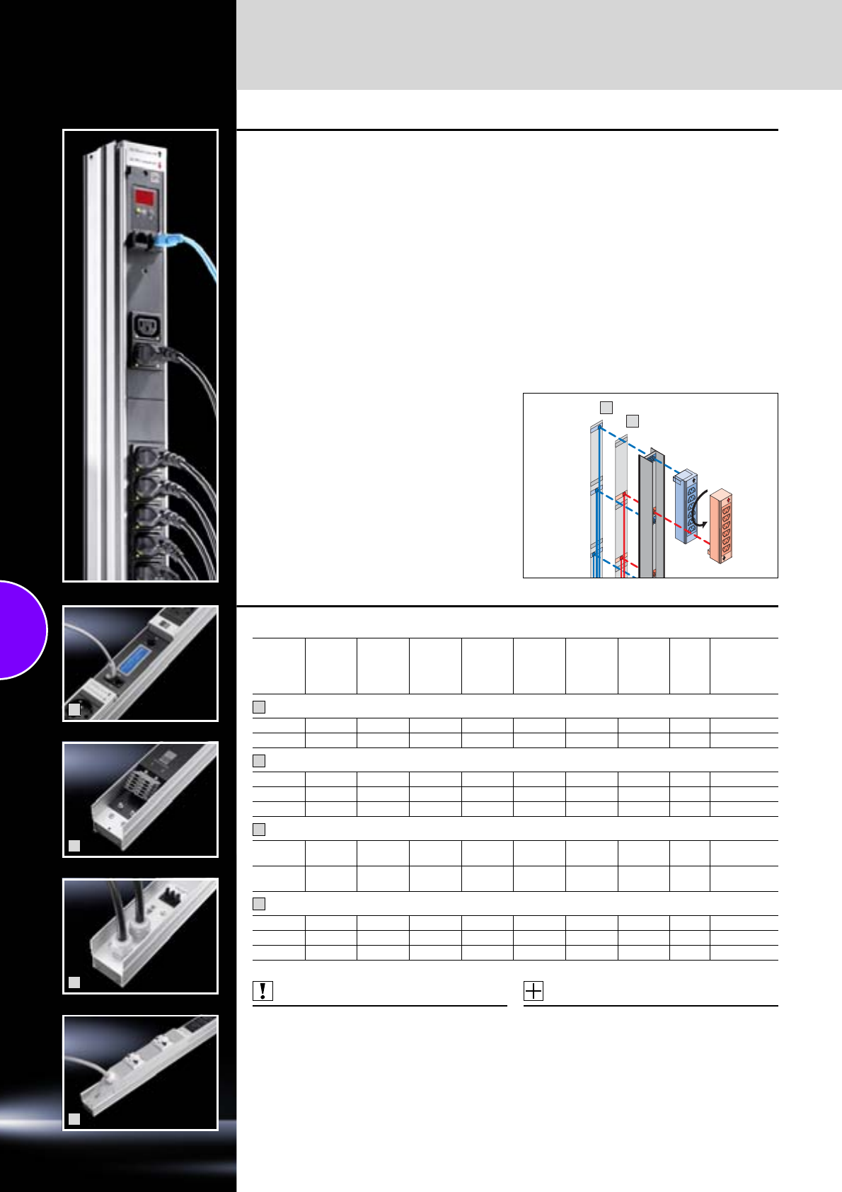
Power System Module
PSM busbars
202 Rittal Catalogue 33/Power distribution
PSM busbars + PSM socket
modules
PSM busbars
The modular system facilitates basic configura-
tion of the racks, thanks to a vertical support rail
with 1/3-phase infeed. The various socket mod-
ules to supply the active components may be
snap-fitted into the support rail. This can even be
done whilst the system is operational, because
the support section is shock-hazard protected.
PSM socket modules
The various modules, earthing pins, IEC 320 etc.
may be inserted into the support rail in any combi-
nation. This is easily achieved, even by non-elec-
tricians, thanks to the shock hazard protected
plug & play system.
Approvals:
Available on the Internet.
Technical specifications/benefits:
●Each plug-in module picks off a phase on the
support rail, either from infeed A or from the
redundant infeed B, depending on the direc-
tion of connection.
●1-/3-phase construction with a maximum cur-
rent of 2 x (3 x 16 A).
●3-phase redundant infeed supported.
●The redundant circuit is completely separate
from the 3 phases of the support rail.
●Modules may be retrofitted whilst operational.
●Modules may be equipped with integral over-
current protection, so that only the affected
module is deactivated in the event of an exces-
sively high current. The other modules remain
operational.
●Overvoltage protection may be integrated into
the supply line.
●Various modules also available with current
measurement and switchable outputs.
A
B
1
2
3
4
PSM busbars
Also required:
PSM socket modules,
see page 203.
Accessories:
−Mounting kit for PSM busbars,
see page 204.
−Connection cables,
see page 204.
−Cable lock,
see page 204.
−Overvoltage protection,
see page 204.
For
enclosure
height
mm
Phases
per
infeed
No. of
infeeds
Input
current
(A)
Maximum
no. of
module
slots
Connec-
tion,
connector
type
Circuit-
breaker
16 A
Earth-
leakage
circuit-
breaker
RCD
Packs
of Model No.
DK
With measurement of voltage, current and power (consumption), via CMC, remote-controllable
2000 3 2 16 6 Jack – – 1 7856.016
2000 1 1 32 6 CEE 2 – 1 7856.003
With 2 infeeds (jack), 3-phase redundancy
1200 3 2 16 4 Jack – – 1 7856.010
2000 3 2 16 7 Jack – – 1 7856.020
2200 3 2 16 8 Jack – – 1 7856.008
With 3 m connection cable (wire end ferrules)
2000 3 1 16 7 Wire end
ferrules – – 1 7856.005
2000 3 2 16 7 Wire end
ferrules – – 1 7856.006
With 3 m connection cable (connector type CEE/EN 60 309)
2000 1 1 32 6 CEE 2 – 1 7856.321
2000 3 1 32 6 CEE 6 – 1 7856.323
2000 1 1 32 6 CEE 2 1 7856.043
1
2
3
4
PSM socket modules
Power System Module
203Rittal Catalogue 33/Power distribution
1
2
3
4
5
PSM socket modules
Approvals:
Available on the Internet.
Module slots required
in PSM busbar Connector pattern Slots Thermal overcurrent
protection Packs of Model No.
Standard socket modules/non-switchable
1 C13 6 – 1 7856.080
1C136 1 7856.070
1C134/per output 1 7856.220
1 Earthing-pin 4 – 1 7856.100
1Earthing-pin4 1 7856.090
1 C19 4 – 1 7856.230
1 C13 red 6 – 1 7856.082
1 Earthing-pin, red 4 – 1 7856.240
2 C13 8 RCD 1 7856.095
International socket modules
1 France/Belgium 4 – 1 7856.120
1 France/Belgium 4 1 7856.110
1 Switzerland 5 – 1 7856.190
1 Switzerland 4 1 7856.180
1UK3– 1 7856.160
1UK3 1 7856.150
1 USA (120 V/208 V) 5 – 1 7856.140
1 USA (120 V/208 V) 5 1 7856.130
Socket modules with LED display/current measurement per module
1 C13 6 – 1 7859.120
1 C19 4 – 1 7859.130
Socket modules with switchable slot/aggregate current measurement per module
2C138 1 7856.201
2 Earthing-pin/C13 4/2 1 7856.203
2 C19/C13 4/2 1 7856.204
Socket modules with switchable slot/individual current measurement per slot
2 Earthing-pin/C13 4/2 1 7859.212
2C138 1 7859.222
2 C19/C13 4/2 1 7859.232
1
2
3
4
5
Power System Module
Accessories
204 Rittal Catalogue 33/Power distribution
Mounting kit
for PSM busbars
Without cable routing With cable routing
For Model No. DK
TS For static installation 7856.011
TE For static installation 7000.684
For Model No. DK
TS
For static installation 7856.022
Adjustable,
for freely accessible
482.6 mm (19˝) level 7856.023
Connection cable
for PSM-busbar
Connection cable, 3-phase
Length Packs of Model No. DK
CEE-conforming 5-pole/16 A 3 m 1 7856.025
Connection cable, single-phase
CEE-conforming 3-pole/16 A 3 m 1 7856.026
Connection cable, UPS, single-phase
C14/X-Com 10 A 3 m 1 7856.027
C20/X-Com 16 A 3 m 1 7856.030
Connection cable C19/C20
16 A 2 m 1 7200.217
Connection cable C13/C14
16 A 0.5 m 2 7856.014
Cable lock PSM
for all modules with EN 60 320 C13 connector
configurations
All terminal connection cables are therefore pro-
tected against unintentional disconnection of the
power supply. Two bars are needed for two
cables.
Accessories:
Optimum locking function is only achieved
with connection cable DK 7856.014,
see page 204.
Design Packs of Model No. DK
Bar 20 7856.013
Measurement module PSM
For power measurement of existing PSM or for
new installations.
Suitable for for PSM busbar:
DK 7856.010, DK 7856.020, DK 7856.008.
Note:
Detailed information, see PSM rail with
measurement, page 202.
Packs of Model No. DK
17856.019
Overvoltage protection PSM
Is connected upstream of the busbar.
●Fine fuse
●Connection:
−Socket Wago X-Com
−Connector Wago X-Com
Note:
One adaptor is required for each infeed.
Overvoltage protection Packs of Model No. DK
With adaptor connector 1 7856.170
RiCell Flex fuel cell system
205Rittal Catalogue 33/Power distribution
Application:
●Emergency power supplies,
e.g. for mobile telecommuni-
cation base stations
●Indoor and outdoor use
●Temporary power supplies
●UPS applications
●High-MTBF applications
●Balancing energy supplies
Material:
−Enclosure frame:
Stainless steel 1.4301
(AISI 304)
−Door, side panels, roof:
Aluminium AlMg3,
powder-coated
Colour:
RAL 7035
Supply includes:
−Ready-to-connect fuel cell
system including climate
control. Hydrogen supply
not included.
−3 fuel cell modules fitted for
7.5 kW
−Controller
Project planning:
−Higher level of cascading
−Different output voltages
−Housing for gas cylinders
−Primary power supply
Photo shows a configuration
example with equipment not
included in the scope of supply.
T
B
H1
H2
Width (B) mm 850
Height (H1) mm 2000
Depth (T) mm 850
Base/plinth height mm 100
Overall height (H2) mm 2100
Model No. FC 1782.135
Fuel cell module
Power consumption 2000 watts
Maximum power output 2500 watts1)
Output voltage –44.0 to –55.5 V DC
Noise generation < 60 dB (A) at distance of 1 m
Weight 28 kg
Hydrogen supply
Gas type Hydrogen, purity 99.9%, class 3.0
Consumption 10 slpm (standard litres per minute) per kW
Typical autonomy time Freely scalable with bottle batteries;
600 l (1 bundle), 200 bar hydrogen provides for more than 24 h autonomy at 6 kW full load
Input pressure 12.0 to 20.0 bar
Ambient conditions
Temperature range –33°C to +45°C
Relative humidity 5% to 95%, non-condensing
Height above mean sea level –60 m to 2000 m; thereafter 5% power reduction per 1000 m
Monitoring
Interfaces Ethernet TCP/IP
Software Web-based user interface with display for status messages, event log and parameters
Alarm outputs 4 floating contacts: “H2 low”; “Non-critical error”; “Serious error”; “FC in operation”
1) Begin of life (BOL).
206

207
Climate control
Cooling with ambient air
TopTherm fan-and-filter units ....................................................................212
Rack-mounted fans/tangential fans...........................................................217
Fan systems ..............................................................................................219
Air/air heat exchangers .............................................................................226
Cooling units
Thermoelectric cooler................................................................................232
Wall-mounted cooling units .......................................................................233
Roof-mounted cooling units ......................................................................244
Modular climate control concept...............................................................248
Liquid cooling
Air/water heat exchangers ........................................................................252
Cold Plate ..................................................................................................262
Chillers for water........................................................................................264
IT cooling
Chillers for IT cooling.................................................................................272
CRAC system ............................................................................................274
Aisle containment ......................................................................................278
Liquid Cooling Package ............................................................................279
CS Outdoor climate control
Air/air heat exchangers and cooling units for CS Toptec .........................286
Air/air heat exchangers and cooling units for CS modular enclosures.....287
Enclosure heaters
Enclosure heaters......................................................................................289
Climate control accessories
Air routing ..................................................................................................291
Control/regulation ......................................................................................293
Mounting accessories ...............................................................................296
Filter technology ........................................................................................299
General......................................................................................................302
Generation “Blue e”
Save energy permanently with Rittal cooling units.
Savings of up to 45% energy consumption with the same
cooling output (ideally 70% compared with a conventional
Rittal TopTherm Plus cooling unit in field trials).
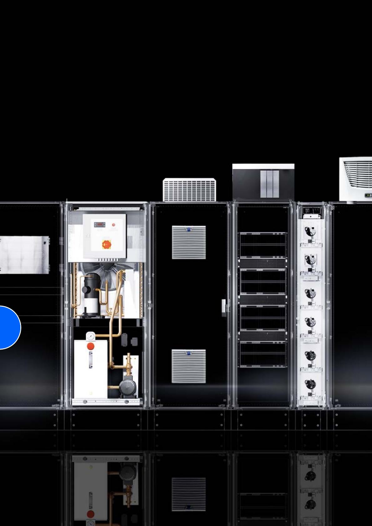
208
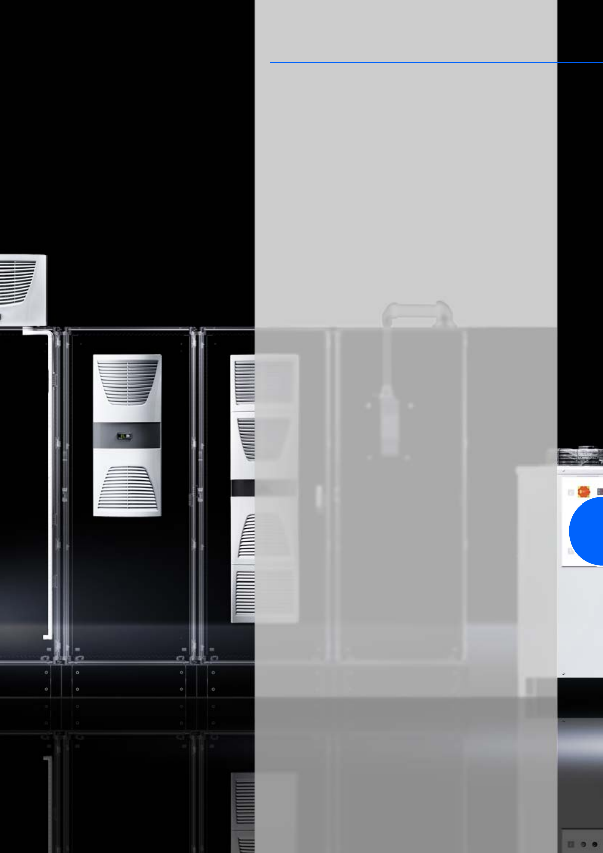
209
As system providers, Rittal are the world’s top suppliers of exceptionally
effective, energy-saving and environmentally-friendly climate control
solutions, precisely tailored to the customer’s individual requirements.
Your benefits
Planning and engineering
●RiTherm climate calculation software for requirement-based
dimensioning
●Rittal system consulting for optimised cost and energy efficiency
Products
●Energy-saving enclosure climate control for all ambient conditions in
the industrial sector
●Effective, application-oriented product solutions for machine and
process cooling
●Efficient, cost-saving IT climate control concepts, from individual server
enclosures through to high-MTBF data centres
Service
●Contiguous global delivery and service network
●Global spare parts service
●Our own accredited laboratories for testing and simulation of climate
conditions
Experts in climate control
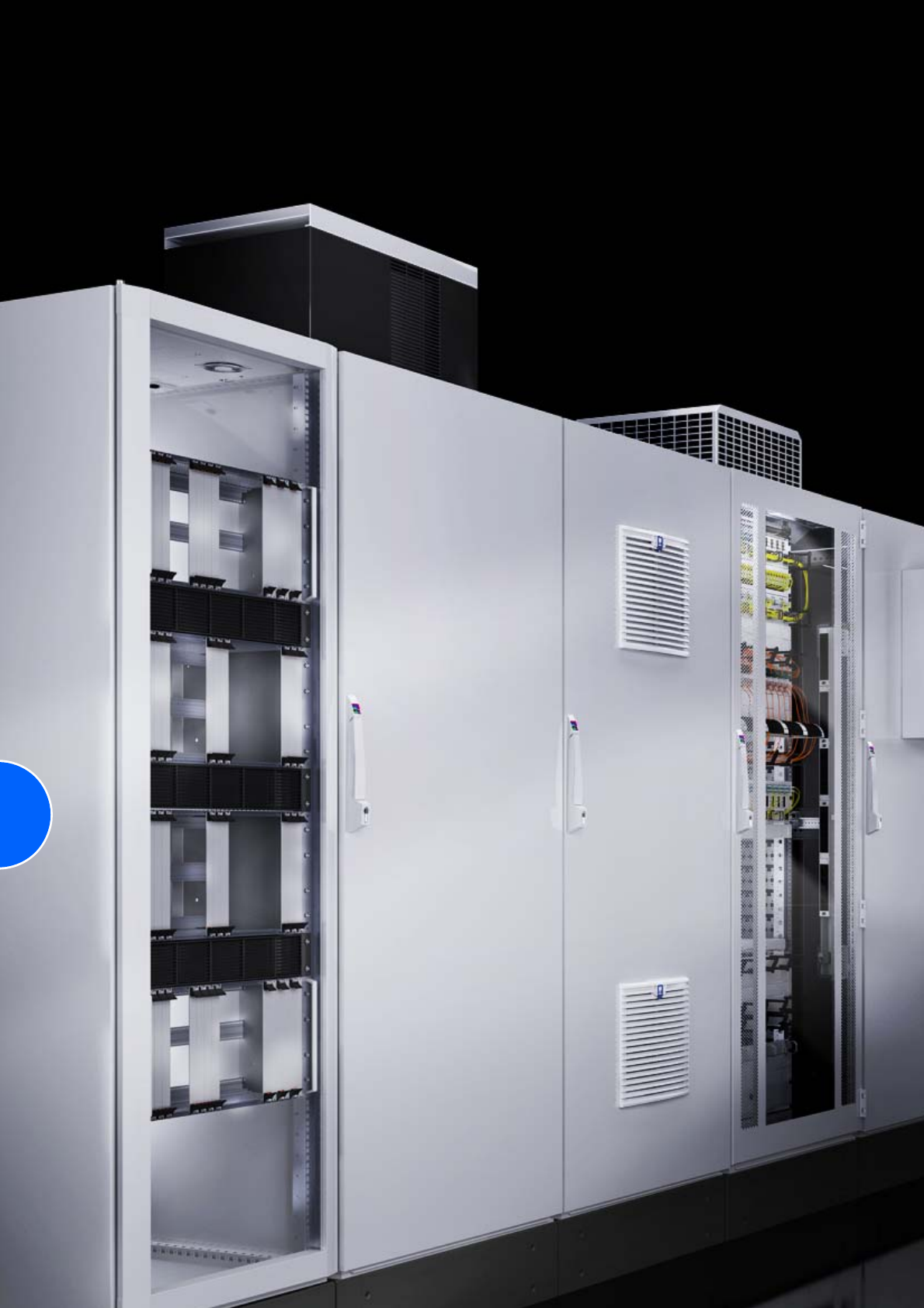
210

211
Cooling with ambient air
TopTherm fan-and-filter units
TopTherm fan-and-filter unit ..................................20 – 66 m3/h..............212
TopTherm fan-and-filter unit .............................. 105 – 120 m3/h..............213
TopTherm fan-and-filter unit .............................. 180 – 250 m3/h..............214
TopTherm fan-and-filter unit .............................. 550 – 770 m3/h..............215
TopTherm fan-and-filter unit ........................................900 m3/h..............216
Conversion table old/new..........................................................................216
Rack-mounted climate control
Rack-mounted fan .................................................320/480 m3/h..............217
Vario rack-mounted fan .........................................320/480 m3/h..............218
Tangential fan...............................................................320 m3/h..............218
Fan systems
RTT roof-mounted fan............................................400/800 m3/h..............219
Roof-mounted fan.........................................................360 m3/h..............220
Roof-mounted fan for the office sector.......................1500 m3/h..............220
Enclosure internal fan...................................................160 m3/h..............221
Fan mounting plate.......................................................180 m3/h..............221
Mini-fan...........................................................................21 m3/h..............222
Fan expansion kit ...............................................108 – 184 m3/h..............222
Fan roof, modular, two-piece ................................160/180 m3/h..............223
Fan unit, active .............................................................160 m3/h..............224
Fan mounting plate DC .............................................1050 m3/h..............224
Door-mounted fan ........................................................600 m3/h..............225
Fan expansion kit ......................................................................................225
Air/air heat exchangers
Wall-mounted .............................................................12/62 W/K..............226
Wall-mounted with controller ................................17.5 – 90 W/K..............227
Wall-mounted, railway-compatible version .............27 – 98 W/K ..............228
Roof-mounted..................................................................66 W/K..............229
TopTherm fan-and-filter units
212 Rittal Catalogue 33/Climate control
Climate control accessories Page 291 Software & services Page 333
Colour:
RAL 7035
Protection category:
See tables.
Supply includes:
−Unit ready for installation
−Filter mat
Note:
For energy-efficient operation
of the fan-and-filter units, we
recommend using the enclosure
internal thermostat SK 3110.000,
the speed control SK 3120.200
or the digital thermostat with
display SK 3114.200
(see accessories).
Approvals:
Available on the Internet.
Detailed drawing:
Available on the Internet.
Performance diagrams:
Available on the Internet.
H
T1 T2
B
Air throughput 20 – 66 m3/h
Model No. SK fan-and-filter unit 3237.100 3237.600 3237.110 3237.124 3238.100 3238.600 3238.110 3238.124 Page
EMC version – – – – – –
Rated operating voltage V, Hz 230, 50/60 115, 50/60 24 (DC) 230, 50/60 115, 50/60 24 (DC)
Dimensions mm W (B) x H 116.5 x 116.5 148.5 x 148.5
D (T1) 16 16
Max. installation depth mm D (T2) 43 58.5
Air throughput, unimpeded air flow 20/25 m3/h 20 m3/h 55/66 m3/h 55 m3/h
Air throughput with outlet filter
including standard filter mat 1 x SK 3237.200: 15/18 m3/h 1 x SK 3238.200: 43/50 m3/h
2 x SK 3238.200: 48/57 m3/h
Diagonal fan Self-starting shaded pole motor DC motor Self-starting shaded pole motor DC motor
Rated current 0.065 A/
0.052 A 0.12 A/
0.10 A 0.125 A 0.12 A/
0.11 A 0.24 A/
0.22 A 0.23 A
Power consumption 11 W/9 W 3 W 19 W/18 W 5.5 W
Pre-fuse 2 A
Noise level 38/43 dB (A) 38 dB (A) 46/49 dB (A) 46 dB (A)
Operating temperature range –15°C to +55°C
Storage temperature range –30°C to +70°C
Protection category
Standard IP 54 IP 54 IP 54 IP 54 IP 54 IP 54 IP 54 IP 54
With hose-proof hood IP 56 IP 56 IP 56 IP 56 IP 56 IP 56 IP 56 IP 56
Accessories Packs of
SK outlet filter 1 3237.200 – 3237.200 3237.200 3238.200 – 3238.200 3238.200 303
SK outlet filter – EMC 1 – 3237.060 – – – 3238.060 – – 303
Spare filter mats 5 3321.700 3237.066 3321.700 3321.700 3238.066 3238.066 3322.700 3322.700 301
Fine filter mats 5 – – – – 3238.055 3238.055 3238.055 3238.055 302
Hose-proof hood 1 3237.080 3237.080 3237.080 3237.080 3238.080 3238.080 3238.080 3238.080 303
Blanking cover 1 3237.020 3237.020 3237.020 3237.020 3238.020 3238.020 3238.020 3238.020 303
Enclosure internal thermostat 1 3110.000 3110.000 3110.000 3110.000 3110.000 3110.000 3110.000 3110.000 294
Digital temperature display/thermostat 1 3114.200 3114.200 3114.200 3114.200 3114.200 3114.200 3114.200 3114.200 293
Hygrostat 1 3118.000 3118.000 3118.000 3118.000 3118.000 3118.000 3118.000 3118.000 294
Speed control 1 3120.200 3120.200 3120.200 – 3120.200 3120.200 3120.200 – 295
Special voltages available on request. We reserve the right to make technical modifications.
TopTherm fan-and-filter units
213Rittal Catalogue 33/Climate control
Air throughput 105 – 120 m3/h
Model No. SK fan-and-filter unit 3239.100 3239.600 3239.110 3239.124 Page
EMC version – – –
Rated operating voltage V, Hz 230, 50/60 115, 50/60 24 (DC)
Dimensions mm W (B) x H 204 x 204
D (T1) 24
Max. installation depth mm D (T2) 90
Air throughput, unimpeded air flow 105/120 m3/h 105 m3/h
Air throughput with outlet filter
including standard filter mat
1 x SK 3239.200: 87/100 m3/h
2 x SK 3239.200: 93/108 m3/h
1 x SK 3240.200: 98/111 m3/h
Diagonal fan Self-starting shaded pole motor DC motor
Rated current 0.12 A/0.11 A 0.24 A/0.22 A 0.23 A
Power consumption 19 W/18 W 5.5 W
Pre-fuse 2 A
Noise level 46/49 dB (A) 46 dB (A)
Operating temperature range –15°C to +55°C
Storage temperature range –30°C to +70°C
Protection category
Standard IP 54 IP 54 IP 54 IP 54
With additional fine filter mat or hose-proof hood IP 55 IP 55 IP 55 IP 55
With hose-proof hood IP 56 IP 56 IP 56 IP 56
Accessories Packs of
SK outlet filter 1 3239.200 – 3239.200 3239.200 303
SK outlet filter – EMC 1 – 3239.060 – – 303
Spare filter mats 5 3171.100 3239.066 3171.100 3171.100 301
Fine filter mats 5 3181.100 3181.100 3181.100 3181.100 302
Hose-proof hood 1 3239.080 3239.080 3239.080 3239.080 303
Blanking cover 1 3239.020 3239.020 3239.020 3239.020 303
Enclosure internal thermostat 1 3110.000 3110.000 3110.000 3110.000 294
Digital temperature display/thermostat 1 3114.200 3114.200 3114.200 3114.200 293
Hygrostat 1 3118.000 3118.000 3118.000 3118.000 294
Speed control 1 3120.200 3120.200 3120.200 3120.200 295
Special voltages available on request. We reserve the right to make technical modifications.
Rittal Germany
RITTAL GmbH & Co. KG
Postfach 1662 D-35726 Herborn
Phone: +49(0)2772 505-0
Fax: +49(0)2772 505-2319
E-mail: info@rittal.de www.rittal.com
TopTherm fan-and-filter units
214 Rittal Catalogue 33/Climate control
Air throughput 180 – 250 m3/h
Model No. SK fan-and-filter unit 3240.100 3240.600 3240.110 3240.124 3241.100 3241.600 3241.110 3241.124 Page
EMC version – – – – – –
Rated operating voltage V, Hz 230, 50/60 115, 50/60 24 (DC) 230, 50/60 115, 50/60 24 (DC)
Dimensions mm W (B) x H 255 x 255
D (T1) 25
Max. installation depth mm D (T2) 107
Air throughput, unimpeded air flow 180/160 m3/h 180 m3/h 230/250 m3/h 230 m3/h
Air throughput with outlet filter
including standard filter mat
1 x SK 3240.200: 138/115 m3/h
2 x SK 3240.200: 165/140 m3/h
1 x SK 3243.200: 165/140 m3/h
1 x SK 3240.200: 183/195 m3/h
2 x SK 3240.200: 203/230 m3/h
1 x SK 3243.200: 203/230 m3/h
Diagonal fan Self-starting shaded pole motor DC motor Self-starting shaded pole motor DC motor
Rated current 0.21 A/
0.19 A 0.42 A/
0.38 A 0.43 A 0.26 A/
0.24 A 0.52 A/
0.48 A 0.78 A
Power consumption 35 W/34 W 11 W 40 W/42 W 19 W
Pre-fuse 2 A 4 A 2 A 4 A 2 A
Noise level 51/46 dB (A) 51 dB (A) 54/56 dB (A) 54 dB (A)
Operating temperature range –30°C to +55°C
Storage temperature range –30°C to +70°C
Protection category
Standard IP 54 IP 54 IP 54 IP 54 IP 54 IP 54 IP 54 IP 54
With additional fine filter mat or hose-proof hood IP 55 IP 55 IP 55 IP 55 IP 55 IP 55 IP 55 IP 55
With hose-proof hood IP 56 IP 56 IP 56 IP 56 IP 56 IP 56 IP 56 IP 56
Accessories Packs of
SK outlet filter 1 3240.200 – 3240.200 3240.200 3240.200 – 3240.200 3240.200 303
SK outlet filter – EMC 1 – 3240.060 – – – 3240.060 – – 303
Spare filter mats 5 3172.100 3240.066 3172.100 3172.100 3172.100 3240.066 3172.100 3172.100 301
Fine filter mats 5 3182.100 3182.100 3182.100 3182.100 3182.100 3182.100 3182.100 3182.100 302
Hose-proof hood 1 3240.080 3240.080 3240.080 3240.080 3240.080 3240.080 3240.080 3240.080 303
Blanking cover 1 3240.020 3240.020 3240.020 3240.020 3240.020 3240.020 3240.020 3240.020 303
Enclosure internal thermostat 1 3110.000 3110.000 3110.000 3110.000 3110.000 3110.000 3110.000 3110.000 294
Digital temperature display/thermo-
stat 1 3114.200 3114.200 3114.200 3114.200 3114.200 3114.200 3114.200 3114.200 293
Hygrostat 1 3118.000 3118.000 3118.000 3118.000 3118.000 3118.000 3118.000 3118.000 294
Speed control 1 3120.200 3120.200 3120.200 – 3120.200 3120.200 3120.200 – 295
Special voltages available on request. We reserve the right to make technical modifications.
Rittal Netherlands
RITTAL bv
Hengelder 56 Postbus 246
6900 AE Zevenaar
Phone: +31 (0) 316 59 16 60
Fax: +31 (0) 316 52 51 45
E-mail: sales@rittal.nl www.rittal.nl
TopTherm fan-and-filter units
215Rittal Catalogue 33/Climate control
Air throughput 550 – 770 m3/h
Model No. SK fan-and-filter unit 3243.100 3243.600 3243.110 3244.100 3244.600 3244.110 3244.140 Page
EMC version – – – – –
Rated operating voltage V, Hz 230, 50/60 115, 50/60 230, 50/60 115, 50/60 400/460, 3~,
50/60
Dimensions mm W (B) x H 323 x 323
D (T1) 25
Max. installation depth mm D (T2) 118.5 130.5
Air throughput, unimpeded air flow 550/600 m3/h 700/770 m3/h
Air throughput with outlet filter
including standard filter mat 1 x SK 3243.200: 440/490 m3/h
2 x SK 3243.200: 510/560 m3/h
1 x SK 3243.200: 544/610 m3/h
2 x SK 3243.200: 630/690 m3/h
Diagonal fan 1~ capacitor motor Rotary
current motor
Rated current 0.37 A/0.39 A 0.78 A/0.80 A 0.43 A/0.60 A 0.9 A/1.25 A 0.17 A/0.21 A
Power consumption 70 W/87 W 75 W/90 W 95 W/135 W 100 W/145 W 93 W/140 W
Pre-fuse 4 A 6 A 4 A 6 A Motor circuit-
breaker
Noise level 59/61 dB (A) 65/66 dB (A)
Operating temperature range –30°C to +55°C
Storage temperature range –30°C to +70°C
Protection category
Standard IP 54 IP 54 IP 54 IP 54 IP 54 IP 54 IP 54
With additional fine filter mat or hose-proof hood IP 55 IP 55 IP 55 IP 55 IP 55 IP 55 IP 55
With hose-proof hood IP 56 IP 56 IP 56 IP 56 IP 56 IP 56 IP 56
Accessories Packs of
SK outlet filter 1 3243.200 – 3243.200 3243.200 – 3243.200 3243.200 303
SK outlet filter – EMC 1 – 3243.060 – – 3243.060 – – 303
Spare filter mats 5 3173.100 3243.066 3173.100 3173.100 3243.066 3173.100 3173.100 301
Fine filter mats 5 3183.100 3183.100 3183.100 3183.100 3183.100 3183.100 3183.100 302
Hose-proof hood 1 3243.080 3243.080 3243.080 3243.080 3243.080 3243.080 3243.080 303
Blanking cover 1 3243.020 3243.020 3243.020 3243.020 3243.020 3243.020 3243.020 303
Enclosure internal thermostat 1 3110.000 3110.000 3110.000 3110.000 3110.000 3110.000 3110.000 294
Digital temperature display/
thermostat 1 3114.200 3114.200 3114.200 3114.200 3114.200 3114.200 3114.200 293
Hygrostat 1 3118.000 3118.000 3118.000 3118.000 3118.000 3118.000 3118.000 294
Speed control 1 3120.200 3120.200 3120.200 3120.200 3120.200 3120.200 3120.200 295
Special voltages available on request. We reserve the right to make technical modifications.
Rittal India
RITTAL India Pvt. Ltd.
Nos. 23 & 24, KIADB Industrial Area
Veerapura Doddaballapur-561 203
Bengaluru Dist
Phone: +91 80 2289 0700
Fax: +91 80 2762 3343
E-mail: info@rittal-india.com
www.rittal-india.com
TopTherm fan-and-filter units
216 Rittal Catalogue 33/Climate control
Air throughput 900 m3/h, with EC technology
Conversion table old/new
Model No. SK fan-and-filter unit 3245.5001) 3245.6001) 3245.5101) Page
EMC version – –
Rated operating voltage V, Hz 230, 50/60 115, 50/60
Dimensions mm W (B) x H 323 x 323
D (T1) 25
Max. installation depth mm D (T2) 130,5
Air throughput, unimpeded air flow 900 m3/h
Air throughput with outlet filter
including standard filter mat 1 x SK 3243.200: 680 m3/h
2 x SK 3243.200: 820 m3/h
1 x SK 3243.060: 680 m3/h
2 x SK 3243.060: 820 m3/h
1 x SK 3243.200: 680 m3/h
2 x SK 3243.200: 820 m3/h
Diagonal fan EC motor
Rated current 1.25 A 2.5 A
Power consumption 170 W
Pre-fuse 4 A 6 A
Noise level 72 dB (A)
Operating temperature range –30°C to +55°C
Storage temperature range –30°C to +70°C
Protection category
Standard IP 51 IP 51 IP 51
With additional fine filter mat IP 52 IP 52 IP 52
With hose-proof hood IP 56 IP 56 IP 56
Accessories Packs of
SK outlet filter 1 3243.200 – 3243.200 303
SK outlet filter – EMC 1 – 3243.060 – 303
Spare filter mats 5 3173.100 3243.066 3173.100 301
Fine filter mats 5 3183.100 3183.100 3183.100 302
Hose-proof hood 1 3245.080 3245.080 3245.080 303
Blanking cover 1 3243.020 3243.020 3243.020 303
Enclosure internal thermostat 1 3110.000 3110.000 3110.000 294
Digital temperature display/thermostat 1 3114.200 3114.200 3114.200 293
Hygrostat 1 3118.000 3118.000 3118.000 294
Speed control and monitoring
for EC fan-and-filter units 1 3235.4402) 3235.4402) 3235.4402) 294
1) 0 – 10 V input and tacho signal output
2) On request.
Special voltages available on request. We reserve the right to make technical modifications.
Output class 20/25 m3/h 55/66 m3/h 105/120 m3/h 180/160 m3/h 230/250 m3/h 550/600 m3/h 700/770 m3/h
Cut-out dimensions (old = new) 92 x 92 124 x 124 177 x 177 224 x 224 292 x 292
24 V new 3237.124 3238.124 3239.124 3240.124 3241.124 – –
old 3321.027 3322.027 3323.027 3324.027 3325.027 – –
230 V new 3237.100 3238.100 3239.100 3240.100 3241.100 3243.100 3244.100
old 3321.107 3322.107 3323.107 3324.107 3325.107 3326.107 3327.107
115 V new 3237.110 3238.110 3239.110 3240.110 3241.110 3243.110 3244.110
old 3321.117 3322.117 3323.117 3324.117 3325.117 3326.117 3327.117
400 V new ––––––3244.140
old – – – – – – 3327.147
EMC fan-and-filter unit, 230 V new 3237.600 3238.600 3239.600 3240.600 3241.600 3243.600 3244.600
old 3321.607 3322.607 3323.607 3324.607 3325.607 3326.607 3327.607
Outlet filter new 3237.200 3238.200 3239.200 3240.200 3243.200
old 3321.207 3322.207 3323.207 3325.207 3326.207
EMC outlet filter new 3237.060 3238.060 3239.060 3240.060 3243.060
old 3321.267 3322.267 3323.267 3325.267 3326.267
Hose-proof hood new 3237.080 3238.080 3239.080 3240.080 3243.080
old 3321.800 3322.800 3323.800 3324.800 3326.800
Blanking cover new 3237.020 3238.020 3239.020 3240.020 3243.020
old –––––––
Standard filter mat (IP 54) new 3321.700 3322.700 3171.100 3172.100 3173.100
old 3321.700 3322.700 3171.100 3172.100 3173.100 3327.700
Fine filter mat (IP 55) new –3238.055 3181.100 3182.100 3183.100
old – – 3181.100 3182.100 3183.100
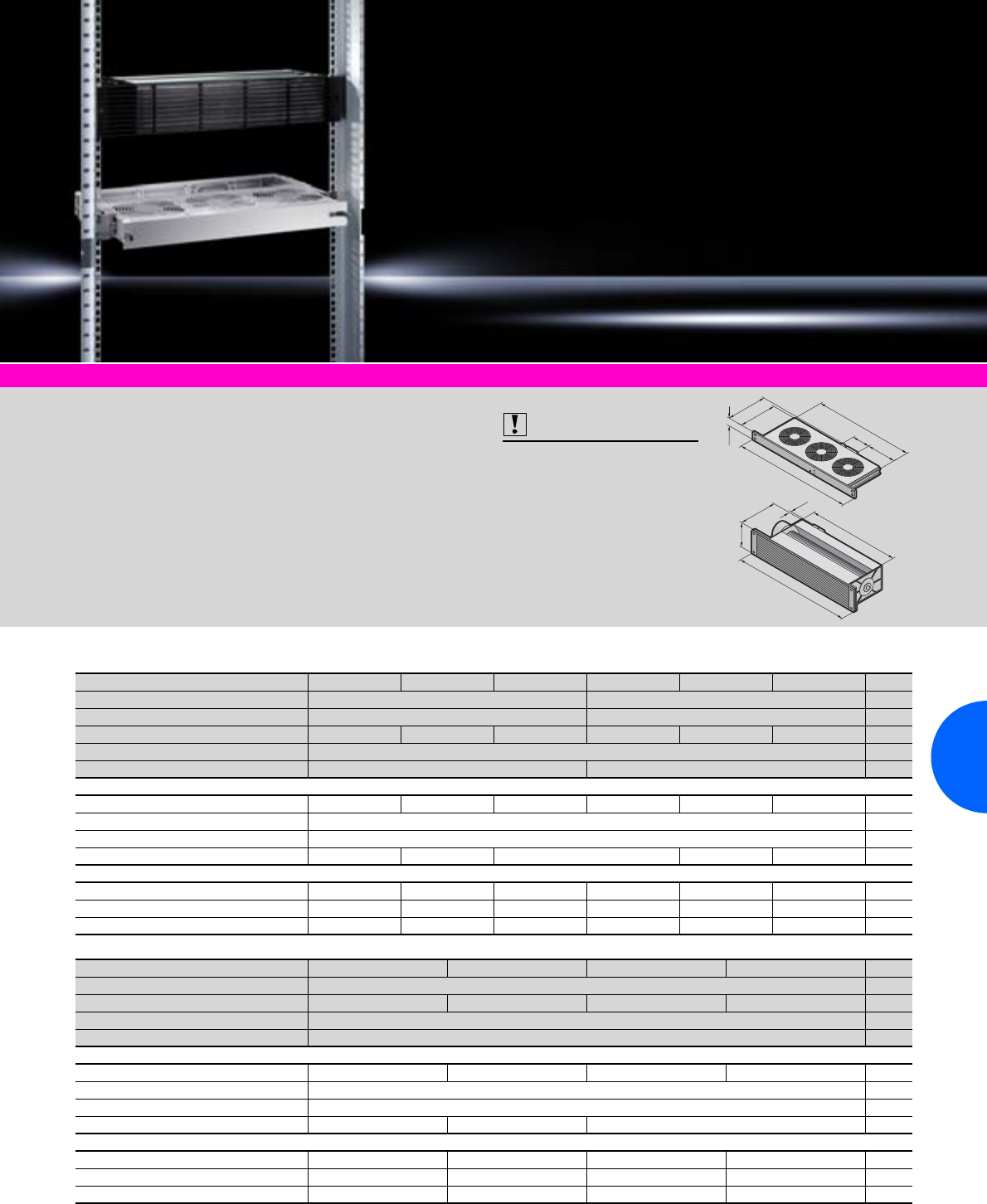
Rack-mounted fans/tangential fans for 482.6 mm (19˝)
217Rittal Catalogue 33/Climate control
Climate control accessories Page 291 Software & services Page 333
Supply includes:
−Fully wired unit ready for
connection
−Clamping strip and assembly
parts (for rack-mounted fan/
Vario rack-mounted fan)
−Filter mat
(for tangential fan)
Guide frame supply includes:
−Guide frame
−Connector and fitted connec-
tion cable (3 m)
−Mounting bracket for optional
attachment to the 482.6 mm
(19˝) system
−Assembly parts
Also required:
Order a guide frame according
to the application (only for
Vario rack-mounted fan)
Approvals:
Available on the Internet.
Detailed drawing:
Available on the Internet.
Performance diagrams:
Available on the Internet.
163
17
88
482.6 (19˝)
380
482.6 (19˝)
180
200
73
410
100
1 HE
HE = U
Rack-mounted fan, air throughput 320/480 m3/h
Model No. SK 3340.0241) 3340.1151) 3340.230 3341.0241) 3341.115 3341.230 Page
2 fans, distance between axes 85 mm –
3 fans, distance between axes 85 mm –
Rated operating voltage V, Hz 24 (DC) 115 (AC), 50/60 230 (AC), 50/60 24 (DC) 115 (AC), 50/60 230 (AC), 50/60
Dimensions mm W x H x D 482.6 (19˝) x 44 (1 U) x 200
Air throughput, unimpeded air flow 320 m3/h 480 m3/h
Rated current max. 0.49 A 0.46 A/0.46 A 0.24 A/0.22 A 0.74 A 0.69 A/0.69 A 0.36 A/0.33 A
Pre-fuse T 6.0 A
Operating temperature range –10°C to +55°C
Noise level 51 dB (A) 52 dB (A) 51 dB (A) 52 dB (A) 51 dB (A)
Accessories
Digital temperature display/thermostat 3114.200 3114.200 3114.200 3114.200 3114.200 3114.200 293
Enclosure internal thermostat 3110.000 3110.000 3110.000 3110.000 3110.000 3110.000 294
Speed control – 3120.200 3120.200 – 3120.200 3120.200 295
Model No. SK 3342.0241) 3342.1151) 3342.230 3342.5002)3) Page
3 fans, distance between axes 105 mm
Rated operating voltage V, Hz 24 (DC) 115 (AC), 50/60 230 (AC), 50/60 24 (DC) 115 – 230 (AC)
Dimensions mm W x H x D 482.6 (19˝) x 44 (1 U) x 200
Air throughput, unimpeded air flow 480 m3/h
Rated current max. 0.74 A 0.69 A/0.69 A 0.36 A/0.33 A 0.85 A
Pre-fuse T 6.0 A
Operating temperature range –10°C to +55°C
Noise level 51 dB (A) 52 dB (A) 51 dB (A)
Accessories
Digital temperature display/thermostat 3114.200 3114.200 3114.200 3114.200 293
Enclosure internal thermostat 3110.000 3110.000 3110.000 3110.000 294
Speed control – 3120.200 3120.200 – 295
1) Extended delivery times. 2) Rack-mounted fan for metric mounting angles available on request. 3) Version with monitoring.
Rack-mounted fans/tangential fans for 482.6 mm (19˝)
218 Rittal Catalogue 33/Climate control
Vario rack-mounted fan, air throughput 320/480 m3/h
Tangential fans, air throughput 320 m3/h
Model No. SK 3350.0241) 3350.1151) 3350.230 3351.0241) 3351.115 3351.230 Page
2 fans, distance between axes 85 mm –
3 fans, distance between axes 85 mm –
Rated operating voltage V, Hz 24 (DC) 115 (AC), 50/60 230 (AC), 50/60 24 (DC) 115 (AC), 50/60 230 (AC), 50/60
Dimensions mm W x H x D 482.6 (19˝) x 44 (1 U) x 200
Air throughput, unimpeded air flow 320 m3/h 480 m3/h
Rated current max. 0.49 A 0.46 A/0.46 A 0.24 A/0.22 A 0.74 A 0.69 A/0.69 A 0.36 A/0.33 A
Pre-fuse T 6.0 A
Operating temperature range –10°C to +55°C
Noise level 51 dB (A) 52 dB (A) 51 dB (A) 52 dB (A) 51 dB (A)
Accessories
Guide frame 3356.100 3355.100 3355.100 3356.100 3355.100 3355.100 –
Digital temperature display/thermostat 3114.200 3114.200 3114.200 3114.200 3114.200 3114.200 293
Enclosure internal thermostat 3110.000 3110.000 3110.000 3110.000 3110.000 3110.000 294
Speed control – 3120.200 3120.200 – 3120.200 3120.200 295
Model No. SK 3352.0241) 3352.1151) 3352.230 3352.5001)2) Page
3 fans, distance between axes 105 mm
Rated operating voltage V, Hz 24 (DC) 115 (AC), 50/60 230 (AC), 50/60 24 (DC), 115 – 230 (AC)
Dimensions mm W x H x D 482.6 (19˝) x 44 (1 U) x 200
Air throughput, unimpeded air flow 480 m3/h
Rated current max. 0.74 A 0.69 A/0.69 A 0.36 A/0.33 A 0.85 A
Pre-fuse T 6.0 A
Operating temperature range –10°C to +55°C
Noise level 51 dB (A) 52 dB (A) 51 dB (A)
Accessories
Guide frame 3356.100 3355.100 3355.100 3357.1001) –
Digital temperature display/thermostat 3114.200 3114.200 3114.200 3114.200 293
Enclosure internal thermostat 3110.000 3110.000 3110.000 3110.000 294
Speed control 3120.200 3120.200 3120.200 – 295
1) Extended delivery times.
2) Version with monitoring
Model No. SK 3145.000 3144.000 Page
Rated operating voltage V, Hz 115, 50/60 230, 50/60
Dimensions mm W x H x D 482.6 (19˝) x 88 (2 U) x 158
Air throughput, unimpeded air flow 320 m3/h
Rated current max. 0.32 A 0.16 A
Power 37 W
Noise level 52 dB (A)
Speed 2245 min–1
Operating temperature range –10°C to +55°C
Maximum static pressure difference 65 – 70 Pa
Accessories Packs
of
Digital temperature display/
thermostat 1 3114.200 3114.200 293
Enclosure internal thermostat 1 3110.000 3110.000 294
Filter mats 5 3177.000 3177.000 299
Front outlet grille 2 U 1 3176.000 3176.000 304
Roof vent 1 3148.007 3148.007 220
Speed control 1 3120.200 3120.200 295
Special voltages available on request. We reserve the right to make technical modifications.
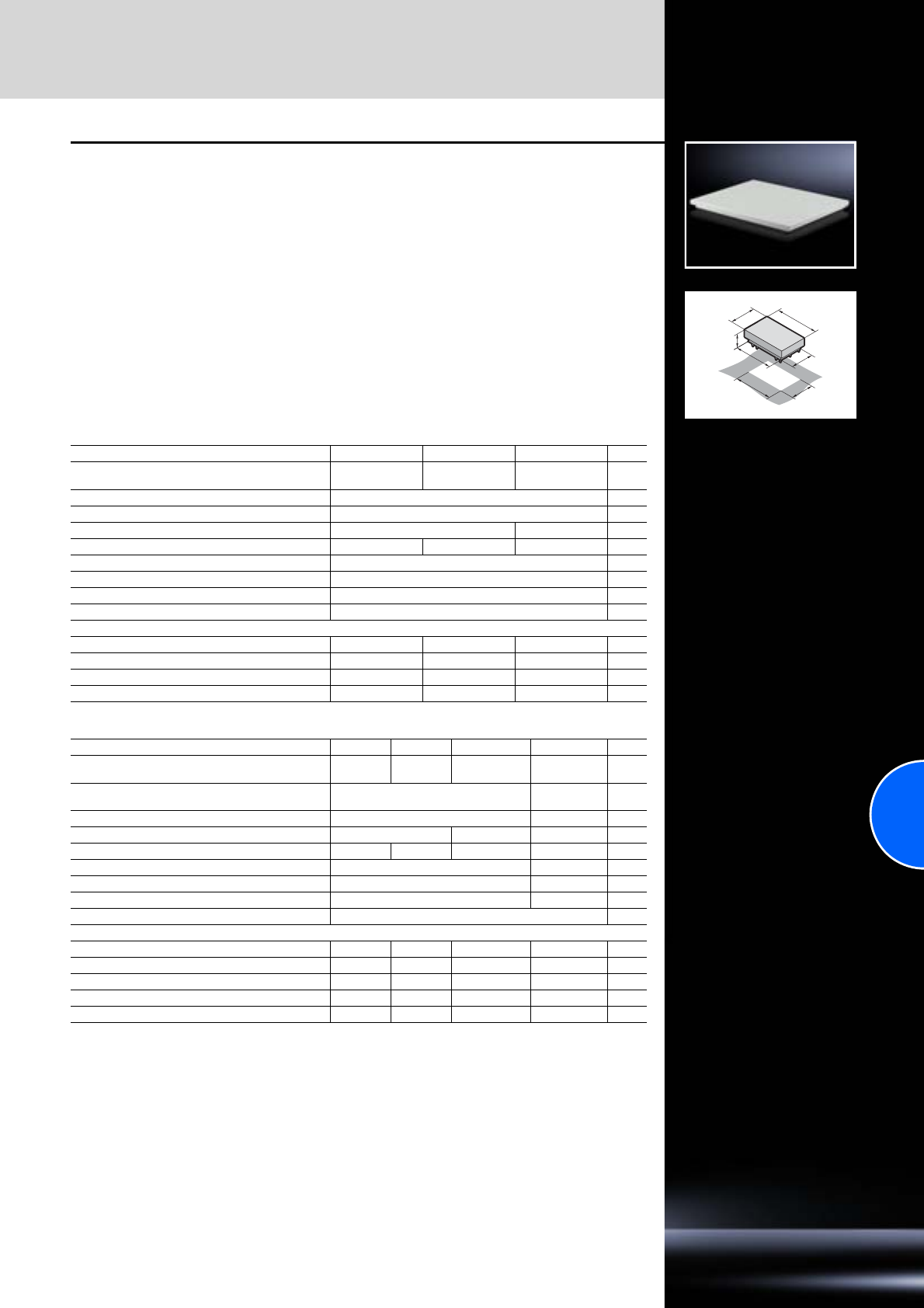
Fan systems
219Rittal Catalogue 33/Climate control
T
B
290
500
370
550
125
RTT roof-mounted fan and
vent attachment
for TS
The active roof-mounted fan and the passive vent
attachment (TS 8801.380) integrate perfectly into
the system-wide mounting concept of the Rittal
TopTherm platform. They fit precisely onto the
cut-outs of the small and medium performance
category of TopTherm roof-mounted cooling units.
Of course, they may also be mounted on any
sufficiently large roof surface.
TS roof plates with prepared mounting cut-outs
are additionally available.
Roof-mounted fan supply includes:
−Unit ready for connection with built-in radial fan
−Sealing and assembly parts
Vent attachment TS:
see page 296.
Protection category:
IP 43 to IEC 60 529
Detailed drawings:
Available on the Internet.
Air throughput 400 m3/h
Air throughput 800 m3/h
Model No. SK 3149.410 3149.420 3149.440 Page
Rated operating voltage V, Hz 115, 50/60 230, 50/60 400, 3~, 50/60
460, 3~, 60
Air throughput, unimpeded air flow 400 m3/h
Required mounting cut-out W (B) x D (T) mm 475 x 260
Power consumption of fan 120 W/170 W 95 W/140 W
Rated current of fan 1.1/1.6 A 0.5/0.88 A 0.35/0.35 A
Operating temperature range –10°C to +55°C
Noise level 68/69 dB (A)
Weight 10 kg
Colour RAL 7035
Accessories
Roof plate 800 x 600 mm for TS 8 with cut-out 8801.320 8801.320 8801.320 296
Roof plate 1200 x 600 mm for TS 8 with cut-out – – – 296
Digital temperature display/thermostat 3114.200 3114.200 – 293
Speed control 3120.200 3120.200 – 295
Model No. SK 3149.810 3149.820 3149.840 8801.380 Page
Rated operating voltage V, Hz 115, 50/60 230, 50/60 400, 3~, 50/60
460, 3~, 60 Vent
attachment
Air throughput, unimpeded air flow 800 m3/h Without
motor
Required mounting cut-out W (B) x D (T) mm 475 x 260 490 x 390
Power consumption of fan 170 W/225 W 180 W/310 W –
Rated current of fan 1.5/2.2 A 0.75/1.1 A 0.35/0.55 A –
Operating temperature range –10°C to +55°C –
Noise level 69/70 dB (A) –
Weight 11 kg 6 kg
Colour RAL 7035
Accessories
Roof plate 600 x 600 mm for TS 8 with cut-out 8801.300 8801.300 8801.300 8801.310 296
Roof plate 800 x 600 mm for TS 8 with cut-out 8801.320 8801.320 8801.320 8801.330 296
Roof plate 1200 x 600 mm for TS 8 with cut-out – – – 8801.350 296
Digital temperature display/thermostat 3114.200 3114.200 – – 293
Speed control 3120.200 3120.200 – – 295
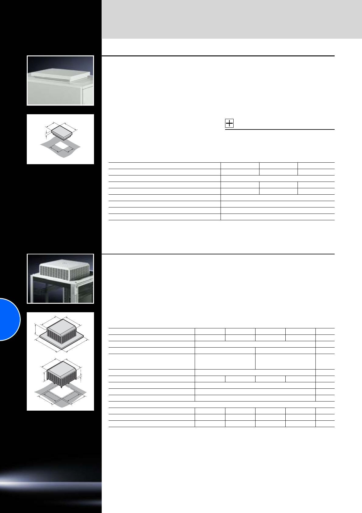
Fan systems
220 Rittal Catalogue 33/Climate control
50
265
345
340
420
Roof-mounted fan,
roof vent
●The roof-mounted fan is easily installed using
6 screws. The sealing tape supplied can be
used to seal it against the enclosure.
●The assembly screws are invisible from the
outside.
●The roof-mounted fan casing has a large air
outlet surface and labyrinth air ducting.
Protection category:
IP 43 to IEC 60 529. Via additional installation
of the filter holder with filter mat SK 3175.000,
a protection category of IP 44 is achieved with
roof vent SK 3148.007.
Supply includes:
−Unit ready for connection with built-in radial fan
−Sealing and assembly parts
−Connection cable (3 m)
−Drilling template
Accessories:
Filter holder, see page 304.
Detailed drawings:
Available on the Internet.
Model No. SK 3149.007 3169.007 3148.007
Rated operating voltage V, Hz 230, 50/60 115, 50/60 Without fan motor
Air throughput 360 m3/h
Rated current max. 0.2 A 0.55 A
Power consumption 42 W 65 W
Operating temperature range –10°C to +60°C
Noise level 53 dB (A)
Weight 7.8 kg
Colour RAL 7035, textured enamel
Special voltages available on request. We reserve the right to make technical modifications.
T
H
B
511
511
410
450
450
410
H
13.5
T
B
Roof-mounted fan
for TS in the office sector
This new roof ventilation concept offers a wealth
of performance, assembly and cost benefits asso-
ciated with the use of integrated ventilation sys-
tems. This roof-mounted fan may be ordered with
and without a roof plate. Another outstanding fea-
ture is the enormous volumetric flow in proportion
to exceptionally low noise levels, making it ideal
for use in sensitive office areas.
Technical specifications:
−Fitted onto a roof plate based on TS.
−Easy assembly; mounting cut-outs have been
provided.
−Radial fan.
Supply includes:
−Fully wired ready for connection
−Assembly parts.
Detailed drawings:
Available on the Internet.
Model No. SK 3164.610 3164.620 3164.115 3164.230 Page
Rated operating voltage V, Hz 115, 50/60 230, 50/60 115, 50/60 230, 50/60
Air throughput, unimpeded air flow 1500 m3/h1)
Design with roof plate without roof plate
Dimensions mm W (B)
H
D (T)
800
240
800
511
227
511
Power consumption 68 W/81 W
Rated current 0.6 A/0.7 A 0.3 A/0.35 A 0.6 A/0.7 A 0.3 A/0.35 A
Noise level 40 dB (A)
Operating temperature range +20°C to +55°C
Colour RAL 7035
Accessories
Temperature indicator in 1 U patch panel 7109.035 7109.035 7109.035 7109.035 293
Digital temperature display/thermostat 3114.200 3114.200 3114.200 3114.200 293
Enclosure internal thermostat 3110.000 3110.000 3110.000 3110.000 294
1) 800 m3/h at 40 Pa counterpressure using two integrated louvres, type DK 7825.801, in the enclosure base/plinth.
Special voltages available on request. We reserve the right to make technical modifications.
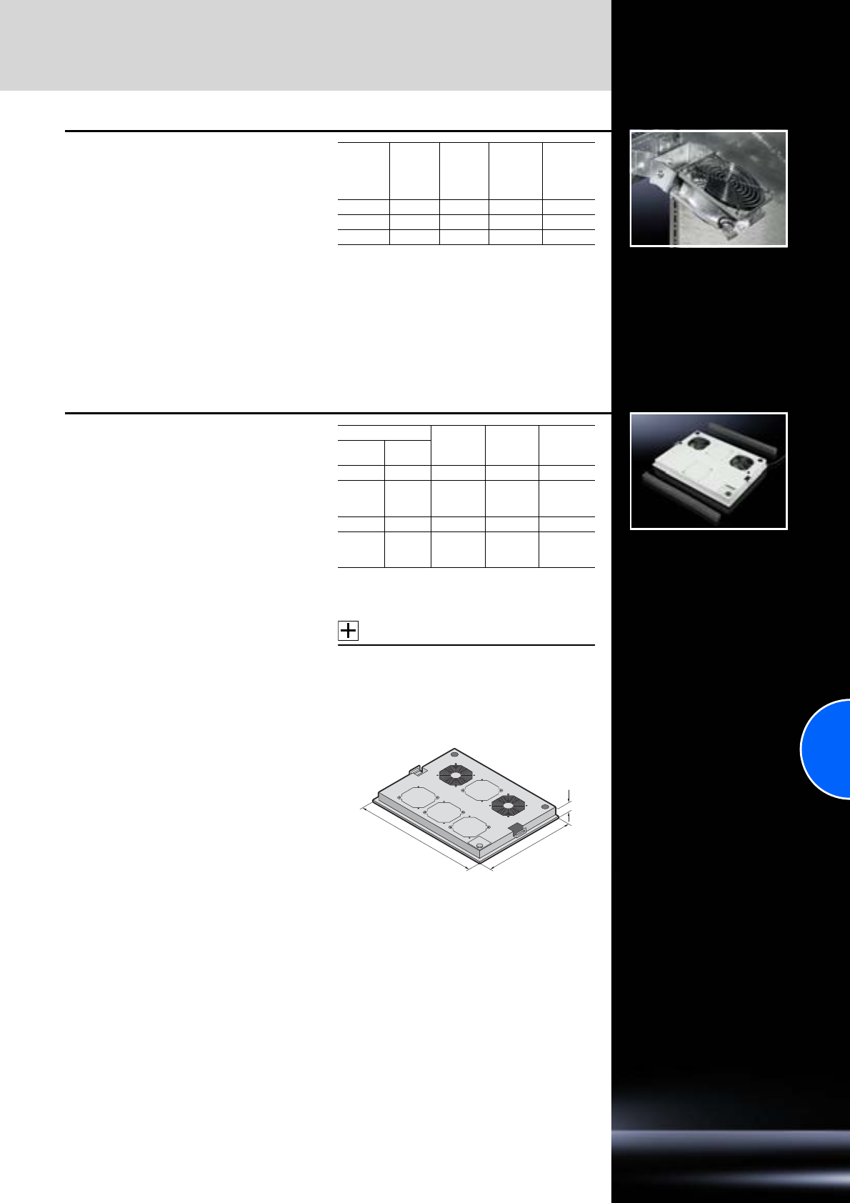
Fan systems
221Rittal Catalogue 33/Climate control
Enclosure internal fan
for TS
To prevent hot-spots and support the air routing
of active enclosure climate control components.
Adjustable in two axes. Attached to the TS 8
frame section. Several fans may be cascaded
using the quick-release clamping strip.
Supply includes:
−Complete unit with radial fan ready
for connection
−Snap-on pivot device
−Assembly parts
Detailed drawings:
Available on the Internet.
Air
through-
put (un-
impeded
air flow)
Power
consump-
tion
W
Rated
current
A
Rated
voltage
V, Hz
Model No.
SK
160 m3/h 19.0/18.0 0.12/0.11 230, 50/60 3108.100
160 m3/h 19.0/18.0 0.24/0.23 115, 50/60 3108.115
160 m3/h 3.5 0.15 24 V (DC) 3108.024
Fan mounting plate
for TS
The fan mounting plate may be retro-fitted in all
TS 8 network enclosures from above. The plate is
mounted at the front of the enclosure, whilst the
rear section is left free for cable entry. A rubber
cable clamp strip is supplied loose for optional
sealing at the rear.
The following combinations are also possible:
●Solid roof plate raised with 20 or 50 mm roof
spacers.
●Roof plate for cable entry raised with 20 or
50 mm roof spacers.
●Vented roof plate for cable entry.
In conjunction with the large swing frame,
usage is only possible from an enclosure depth
of 800 mm, in conjunction with a roof plate for
cable entry from 1000 mm.
Note:
−Not suitable for crane transportation
−Not suitable for
combination with 482.6 mm (19˝)
mounting frame
Technical specifications for one fan:
−Rated operating voltage: 230 V
−Power consumption: 15/14 W at 50/60 Hz
−Air throughput (unimpeded air flow):
160/180 m3/h, 50/60 Hz
−Operating temperature range: –10°C to +55°C
Technical specifications of thermostat:
−Rated operating voltage: 250 V
−Operating temperature range: +5°C to +55°C
Colour:
RAL 7035
Supply includes:
−2 fans
−2/4 cut-outs to extend to 4/6 fans
−Thermostat
−Foam rubber cable clamp strip
−Thermostat and fan fully wired to connection
cable (3.5 m).
The air throughput can be increased with the fan
expansion kit DK 7980.000.
Accessories:
−Fan extension kit,
see page 222.
−Self-adhesive foam cable clamp strip
SZ 2573.000 for sealing at the sides and
targeted air routing when bayed,
see page 513.
For enclosures Number
of fans
Max.
number
of fans
Model No.
DK
Width
mm Depth
mm
600 600 2 4 7966.035
600 800
1000
1200 267968.035
800 600 2 6 7986.035
800 800
1000
1200 267988.035
385/585
525/725
40
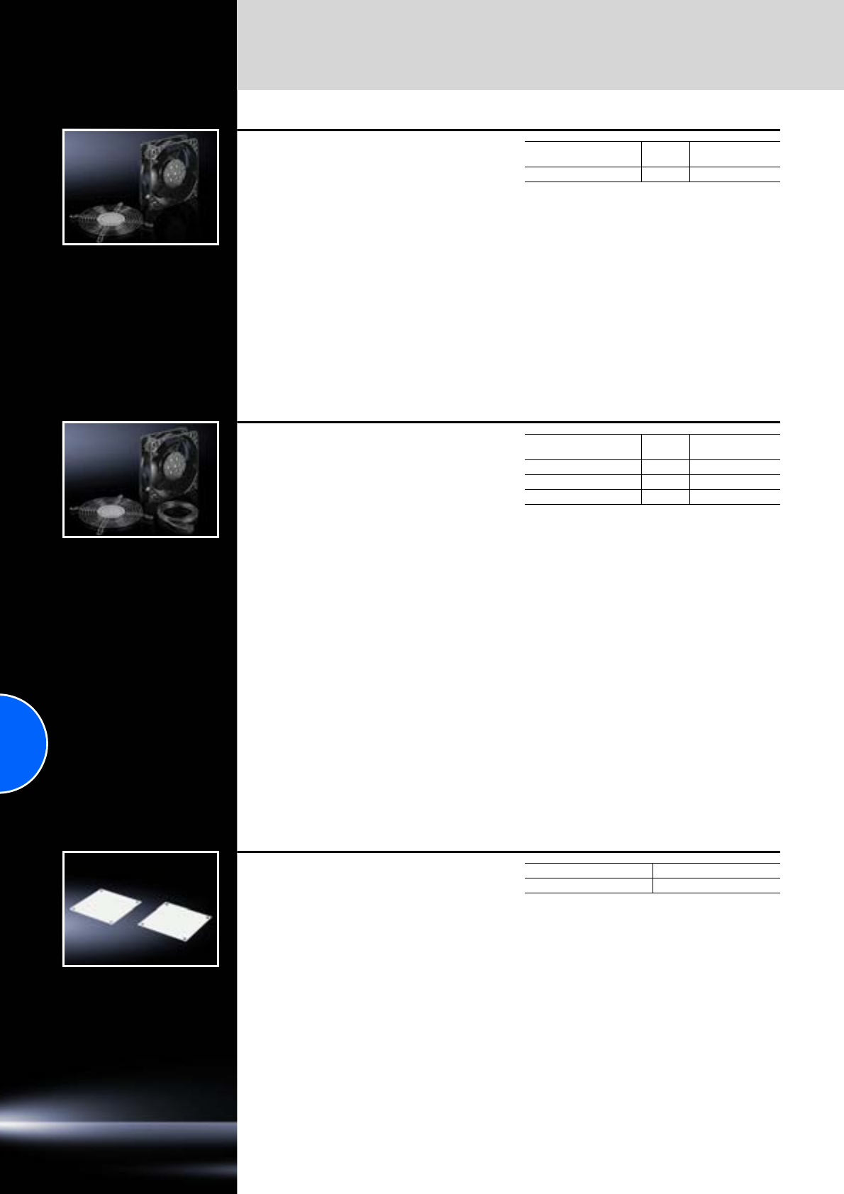
Fan systems
222 Rittal Catalogue 33/Climate control
Mini-fan
Compact DC fan for enclosure and component
cooling in enclosures.
Technical specifications:
−Rated operating voltage: 24 V (DC)
−Power consumption: 1 W
−Air throughput (unimpeded air flow): 21 m3/h
−Noise level (unimpeded air flow): 20 dB (A)
−Operating temperature range: –20°C to +70°C
Supply includes:
−Fans
−Assembly screws
−Contact hazard protection
Dimensions
W x H x D mm Packs of Model No. SK
60 x 60 x 25.4 1 3236.124
Fan expansion kit
For retro-fitting various fan units or to supplement
the fan mounting plate and modular fan roof.
Technical specifications DK 7980.000:
−Rated operating voltage: 230 V~
−Power consumption: 15/14 W at 50/60 Hz
−Air throughput (unimpeded air flow):
160/180 m3/h, 50/60 Hz
−Noise level (unimpeded air flow): 37 dB (A)
−Operating temperature range: –10°C to +55°C
Technical specifications DK 7980.100:
−Rated operating voltage: 230 V~
−Power consumption: 14/12 W at 50/60 Hz
−Air throughput (unimpeded air flow):
108/120 m3/h, 50/60 Hz
−Noise level (unimpeded air flow): 34 dB (A)
−Operating temperature range: –20°C to +70°C
Technical specifications DK 7980.148:
−Rated operating voltage: 48 V (DC)
−Power consumption: 7.7 W
−Air throughput (unimpeded air flow): 184 m3/h
−Noise level (unimpeded air flow): 43 dB (A)
−Operating temperature range: –20°C to +70°C
Supply includes:
−Fans
−Assembly parts
−Connection cable (0.61 m)
Dimensions
W x H x D mm Packs of Model No. DK
119 x 119 x 38 1 set 7980.000
119 x 119 x 25 1 set 7980.100
119 x 119 x 38 1 set 7980.148
Cover plates for fan panels
for FlatBox
To cover unused fan panels when using fans in
the FlatBox.
Material:
Sheet steel
Surface finish:
Powder-coated
Colour:
RAL 7035
Supply includes:
Assembly parts.
Packs of Model No. DK
67507.760
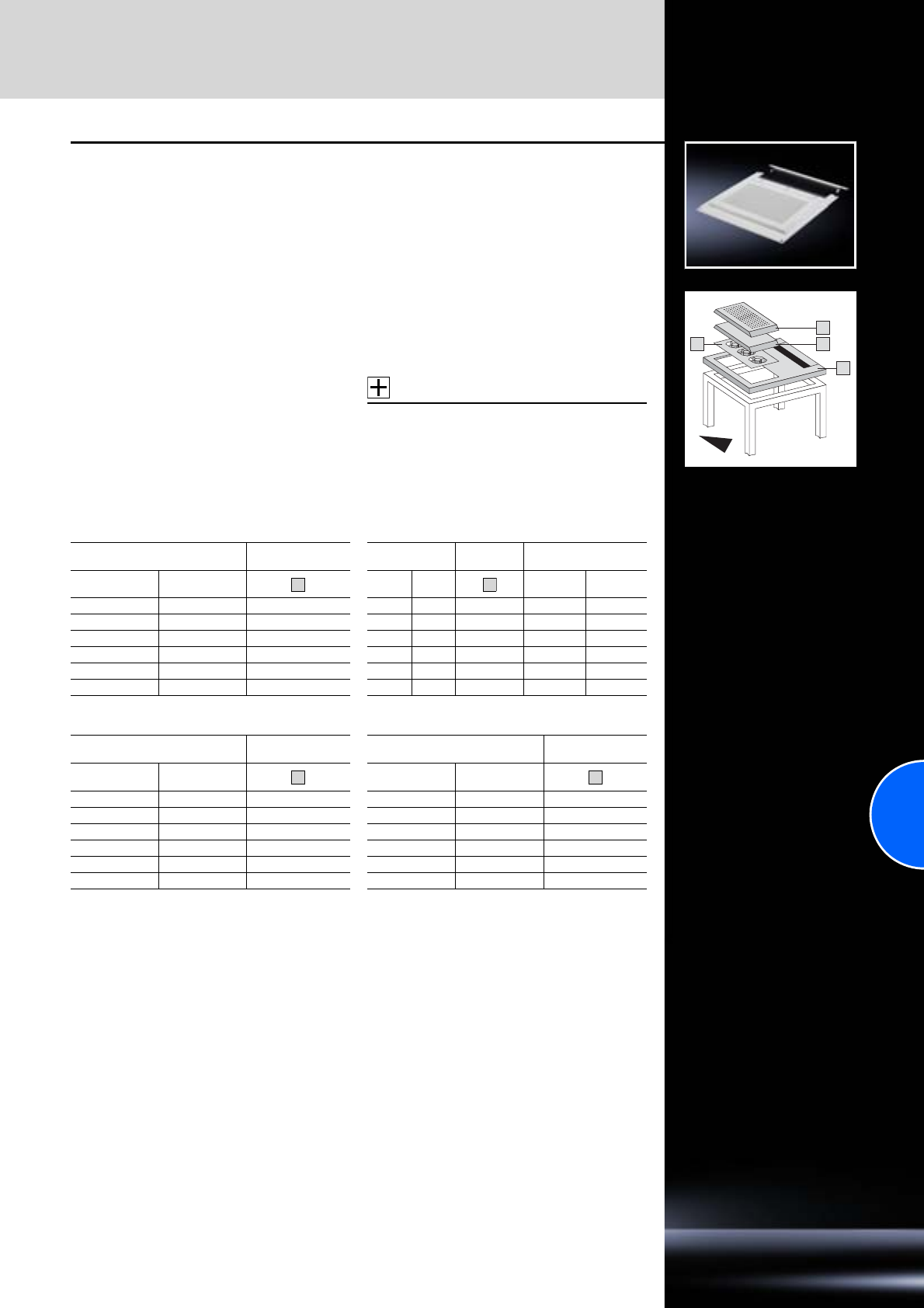
Fan systems
223Rittal Catalogue 33/Climate control
1
23
4
Fan roof, modular, two-piece
for TS
The modular roof plate consists of individual
components and can be configured for enclosure
ventilation in various ways.
The modules:
Roof plate, two-piece with cut-out
For fan mounting and cable entry at the rear via
a sliding angular bracket with rubber cable clamp
strip. Replaces the existing roof plate. The two-
piece design allows convenient retrofitting of
cables at any time.
Cover plate
To cover the cut-out, optionally solid or vented
options. The top-mounted cover plate may be
raised for extra air throughput using the supplied
spacers.
Fan insert
For active ventilation:
A fully pre-wired fan tray including 2.5 m connec-
tion cable, with two fan motors and additional
cut-outs. The air throughput may be increased
with a fan expansion kit.
Material:
Sheet steel
Surface finish:
Spray-finished
Colour:
RAL 7035
Technical specifications for one fan:
−Rated operating voltage: 230 V
−Power consumption: 15/14 W at 50/60 Hz
−Air throughput (unimpeded air flow):
160/180 m3/h at 50/60 Hz
−Temperature range: –10°C to +55°C
Detailed drawing:
Available on the Internet.
Accessories:
−Fan expansion kit DK 7980.000,
see page 222.
−Enclosure internal thermostat SK 3110.000,
see page 294.
−Speed control SK 3120.200,
see page 295.
Roof plate TS with cut-out Fan insert
For enclosures Model No.
DK For enclosures Model No.
DK Fan insert
Width
mm Depth
mm Width
mm Depth
mm Fans
pre-wired Maximum
no. of fans
600 600 7826.366 600 600 2102.320 22
600 800 7826.368 600 800 2102.490 26
600 1000 7826.360 600 1000 2102.490 26
800 600 7826.486 800 600 7885.000 23
800 800 7826.488 800 800 7886.000 28
800 1000 7826.480 800 1000 7886.000 28
Roof plate, solid Roof plate, vented
For enclosures Model No.
DK For enclosures Model No.
DK
Width
mm Depth
mm Width
mm Depth
mm
600 600 2102.1801) 600 600 2102.400
600 800 2102.1901) 600 800 2102.410
600 1000 2102.1901) 600 1000 2102.410
800 600 7885.100 800 600 7885.200
800 800 7886.100 800 800 7886.200
800 1000 7886.100 800 1000 7886.200
1) Extended delivery times.
1
2
3
4
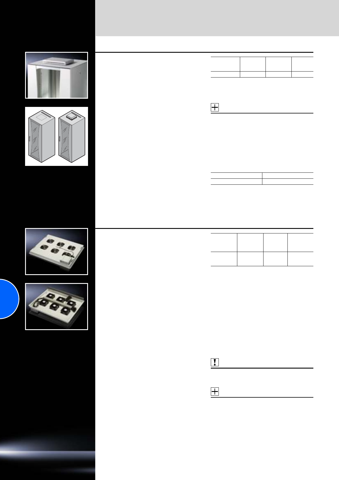
Fan systems
224 Rittal Catalogue 33/Climate control
Fan unit, active
for TE
For active ventilation of the TE 7000. The fan
unit is installed in the prepunched cut-out.
An additional fan may optionally be integrated.
Supply includes:
−Fan unit
−Assembly parts
−2 fans
−1 thermostat
−Open connection cable
Technical specifications for one fan:
Fan extension kit, DK 7980.000,
see page 222.
Technical specifications of thermostat:
−Rated operating voltage: 250 V
−Temperature range: +5°C to +55°C
Note:
Connection via distributor box or
country-specific connector.
Accessories:
Fan expansion kit,
see page 222.
For enclosures
W x D
mm
Number
of pre-wired
fans
Possible
number
of fans
Model No.
TE
All sizes 2 3 7000.670
Active kit
for TE
consisting of fan unit including thermostat,
complete, wired ready for connection, socket strip
(DK 7000.630) for up to 8 earthing pin plugs,
version D and connection cable (DK 7200.210).
Packs of Model No. DK
1 set 7000.680
Fan mounting plate DC
for TS
Exceptionally low-noise thanks to FCS
speed control, fully fitted
Suitable for TS 8 enclosures with a raised roof
(> 20 mm) or TS 8 roof plate, vented. The fan
mounting plate may be used as an alternative to
fan mounting plate 7988.035. It is installed from
above. Cable entry is prepared in the rear section
of the plate.
Not suitable for combination with 482.6 mm (19˝)
mounting frame.
Advantages of the DC fan mounting plate with
FCS technology:
●Exceptionally low-noise thanks to speed con-
trol.
●All fans are individually monitored for failure.
●High air throughput thanks to DC technology
(unimpeded air flow 6 x 175 m3/h = 1050 m3/h).
●EMC compatibility.
●Temperature monitoring and control.
●High level of safety (low safety voltage with
24 V DC power supply).
●Visual and acoustic alarm messages, plus relay
alarm output.
●Freely selectable installation location for the
FCS control unit (included with the supply of
the fan mounting plate, in 482.6 mm (19˝) with
7320.440).
●Suitable for international use, thanks to wide-
range power supply 100 – 240 V AC and socket
to IEC 320.
●Pre-configured.
●Network-compatible via CMC-TC (all relevant
data such as temperature etc. is displayed in
the web browser, or alarms are sent in the form
of an SNMP trap).
Technical specifications:
−Rated voltage of power supply:
100 – 240 V AC, 50/60 Hz
−Power pack rated current: max. 1.5 A
−Secondary range of power supply:
24 V DC, 3 A
−Temperature range: +5°C to +40°C
−Total air throughput (unimpeded air flow):
6 x 175 m3/h = 1050 m3/h
Technical specifications for one fan:
−Rated voltage: 24 V DC
−Rated current: max. 0.3 A
−Air throughput (unimpeded air flow): 175 m3/h
−Speed: 2650 rpm
−Noise level: up to 45 dB (A) at maximum speed
activation
Also required:
Connection cable 230/115 V.
Example D version, Model No. DK 7200.210,
see page 585.
Accessories:
1 U mounting unit, Model No. DK 7320.440,
see page 586.
Note:
For more information on the Fan Control System
(FCS) system, see page 587.
For
enclosures
width
mm
For
enclosures
depth
mm
Number of
DC fans Model No.
DK
800 800
900
1000 67858.488
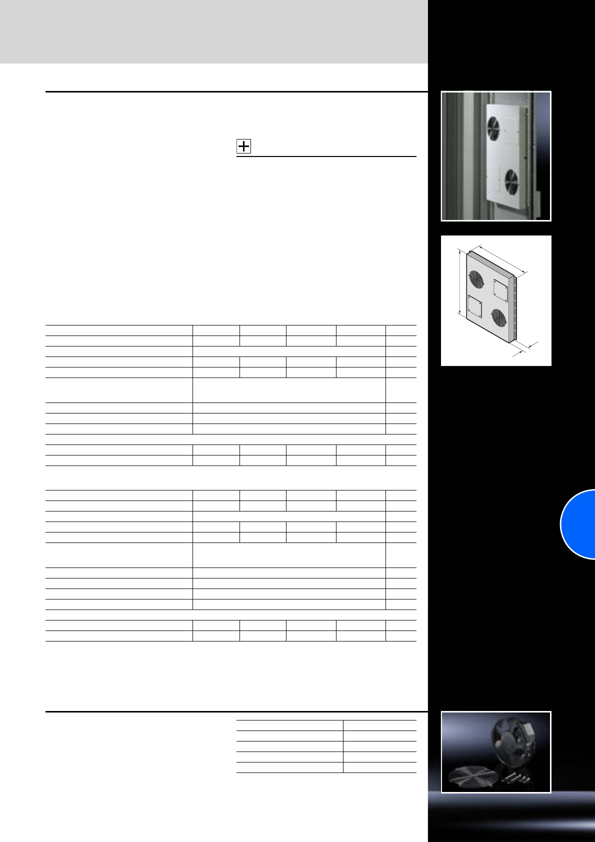
Fan systems
225Rittal Catalogue 33/Climate control
B
T
H
Door-mounted fan
for server enclosures TS, TE
Specifically for installing in perforated doors.
Given the growing packaging density in data
communications and network enclosures, active,
direct ventilation of the enclosure is essential.
The door-mounted fan, which is attached to the
rear or front door, supports horizontal air routing
via the servers and therefore facilitates faster heat
dissipation from active components.
Technical specifications:
−Standard assembly with two fans.
−Air throughput, unimpeded air flow 600 m3/h.
−By adding two fan expansion kits, the air
throughput is increased to 1200 m3/h.
−The direction of air flow is easily reversed by
rotating the fan.
−Several units may be positioned in a cascade
arrangement.
−Simple mounting on the tubular door frame.
Supply includes:
−Fully wired ready for connection
−Connection cable 2.5 m
−Assembly parts
Accessories:
Fan expansion kit,
see page 225.
Note:
−Only for mounting on the tubular door frame!
−Door configuration for installation in 2 and
4-door ISP racks available on request.
Detailed drawings:
Available on the Internet.
For doors with width 600 mm
For doors with width 800 mm
Model No. SK 3165.6241) 3165.6481) 3165.6151) 3165.6301) Page
Rated operating voltage V, Hz 24 (DC) 48 (DC) 115, 50/60 230, 50/60
Air throughput (unimpeded air flow) 600 m3/h
Power consumption for two fans 40 W 48 W 70 W/64 W 70 W/70 W
Rated current of fan 1.5 A 1.0 A 0.76 A/0.72 A 0.38 A/0.36 A
Dimensions mm W (B)
H
D (T)
493
606
64,5
Noise level 55 dB (A)
Temperature range +20°C to +55°C
Colour RAL 7035
Accessories
Digital temperature display/thermostat 3114.200 3114.200 3114.200 3114.200 293
Enclosure internal thermostat 3110.000 3110.000 3110.000 3110.000 294
Model No. SK 3165.8241) 3165.8481) 3165.8151) 3165.8301) Page
Rated operating voltage V, Hz 24 (DC) 48 (DC) 115, 50/60 230, 50/60
Air throughput (unimpeded air flow) 600 m3/h
Power consumption for two fans 40 W 48 W 70 W/64 W 70 W/70 W
Rated current of fan 1.5 A 1.0 A 0.76 A/0.72 A 0.38 A/0.36 A
Dimensions mm W (B)
H
D (T)
693
606
64,5
For doors with width (mm) 800
Noise level 55 dB (A)
Temperature range +20°C to +55°C
Colour RAL 7035
Accessories
Digital temperature display/thermostat 3114.200 3114.200 3114.200 3114.200 293
Enclosure internal thermostat 3110.000 3110.000 3110.000 3110.000 294
1) Delivery times on request.
Special voltages available on request. We reserve the right to make technical modifications.
Fan expansion kit
for door-mounted fan
To increase the air throughput of the door-
mounted fan.
To fit door-mounted fan Model No. SK
SK 3165.624, SK 3165.824 3165.024
SK 3165.648, SK 3165.848 3165.048
SK 3165.615, SK 3165.815 3165.115
SK 3165.630, SK 3165.830 3165.230
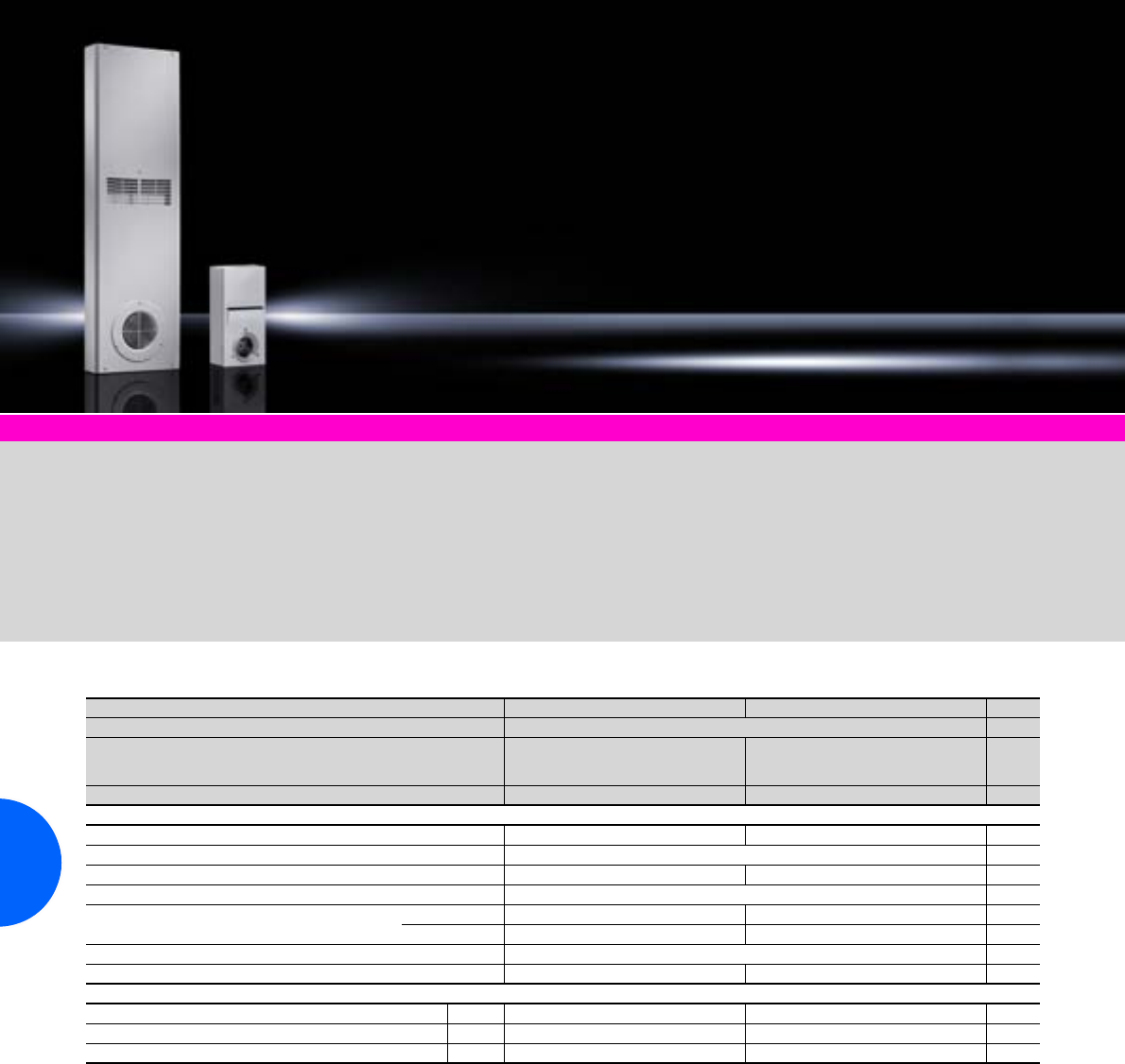
Air/air heat exchangers
226 Rittal Catalogue 33/Climate control
Climate control accessories Page 291 Software & services Page 333
Colour:
RAL 7035
Protection category:
Internal circuit IP 54
to IEC 60 529
Supply includes:
Complete unit ready for connec-
tion.
Note:
For precise temperature
control inside the enclosure,
we recommend the digital tem-
perature indicator/thermostat
SK 3114.200, the enclosure
internal thermostat SK 3110.000
or the speed control
SK 3120.200.
Approvals:
Available on the Internet.
Detailed drawing:
Available on the Internet.
Performance diagrams:
Available on the Internet.
Wall-mounted
Model No. SK 3125.800 3129.800 Page
Rated operating voltage V, Hz 230, 1~, 50/60
Dimensions mm W
H
D
200
400
146
400
1360
110
Specific thermal output 12 W/K 62 W/K
Max. rated current per fan 0.11 A/0.13 A 0.45 A/0.55 A
Pre-fuse T 2.0 A
Output per fan 25 W/30 W 100 W/130 W
Operating temperature range –5°C to +55°C
Air throughput of fans (unimpeded air flow) External circuit 265 m3/h / 315 m3/h 860 m3/h / 900 m3/h
Internal circuit 265 m3/h / 315 m3/h 860 m3/h / 900 m3/h
Type of connection Connection cable
Weight 8 kg 30 kg
Accessories Packs of
Enclosure internal thermostat 1 3110.000 3110.000 294
Digital temperature display/thermostat 1 3114.200 3114.200 293
Speed control 1 3120.200 3120.200 295
Special voltages available on request. We reserve the right to make technical modifications.
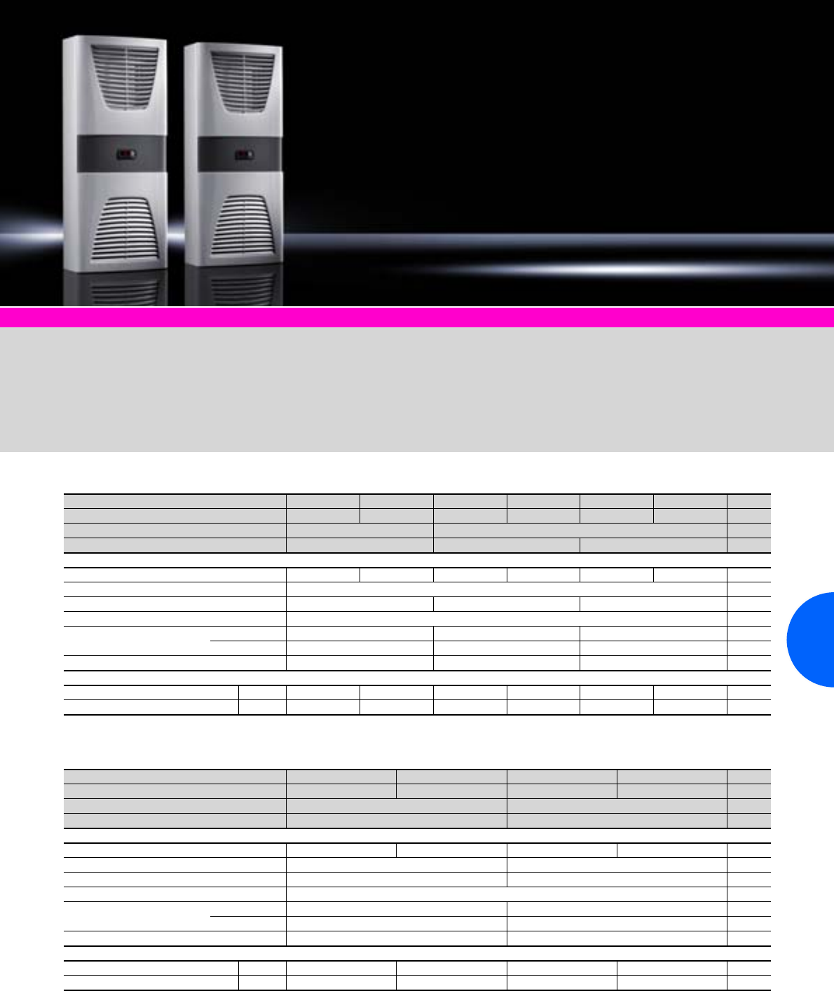
Air/air heat exchangers
227Rittal Catalogue 33/Climate control
Climate control accessories Page 291 Software & services Page 333
Colour:
RAL 7035
Protection category:
Internal circuit IP 54
to IEC 60 529
Supply includes:
−Complete unit ready for
connection
−Plug-in terminal strip
−With controller and digital
temperature display
−Floating fault signal contact
in case of overtemperature
Approvals:
Available on the Internet.
Detailed drawing:
Available on the Internet.
Performance diagrams:
Available on the Internet.
Wall-mounted with controller, 17.5 – 45 W/K
Wall-mounted with controller, 60 – 90 W/K
Model No. SK 3126.100 3126.115 3127.100 3127.115 3128.100 3128.115 Page
Rated operating voltage V, Hz 230, 1~, 50/60 115, 1~, 50/60 230, 1~, 50/60 115, 1~, 50/60 230, 1~, 50/60 115, 1~, 50/60
Dimensions mm W x H x D 280 x 550 x 150 400 x 950 x 205
Specific thermal output 17.5 W/K 30 W/K 45 W/K
Max. rated current per fan 0.11 A/0.13 A 0.23 A/0.25 A 0.28 A/0.34 A 0.55 A/0.7 A 0.3 A/0.4 A 0.6 A/0.8 A
Pre-fuse T 2.0 A
Output per fan 23 W/27 W 60 W/75 W 70 W/90 W
Operating temperature range –5°C to +55°C
Air throughput of fans
(unimpeded air flow)
External circuit 265 m3/h / 315 m3/h 480 m3/h / 525 m3/h 600 m3/h / 625 m3/h
Internal circuit 265 m3/h / 315 m3/h 480 m3/h / 525 m3/h 600 m3/h / 625 m3/h
Weight 10 kg 18 kg 19 kg
Accessories Packs of
Filter mats 3 3286.300 3286.300 3286.400 3286.400 3286.400 3286.400 299
Metal filters 1 3286.310 3286.310 3286.410 3286.410 3286.410 3286.410 300
Special voltages available on request. We reserve the right to make technical modifications.
Model No. SK 3129.100 3129.115 3130.100 3130.115 Page
Rated operating voltage V, Hz 230, 1~, 50/60 115, 1~, 50/60 230, 1~, 50/60 115, 1~, 50/60
Dimensions mm W x H x D 400 x 950 x 225 400 x 1580 x 215
Specific thermal output 60 W/K 90 W/K
Max. rated current per fan 0.38 A/0.4 A 0.65 A/0.8 A 0.67 A/0.88 A 1.3 A/1.8 A
Pre-fuse T 2.0 A 4.0 A
Output per fan 85 W/90 W 150 W/200 W
Operating temperature range –5°C to +55°C
Air throughput of fans
(unimpeded air flow)
External circuit 860 m3/h / 900 m3/h 850 m3/h / 945 m3/h
Internal circuit 860 m3/h / 900 m3/h 850 m3/h / 945 m3/h
Weight 21 kg 34 kg
Accessories Packs of
Filter mats 3 3286.400 3286.400 3286.400 3286.400 299
Metal filters 1 3286.410 3286.410 3286.410 3286.410 300
Special voltages available on request. We reserve the right to make technical modifications.
Air/air heat exchangers
228 Rittal Catalogue 33/Climate control
Wall-mounted, railway-compatible version
Model No. SK 3126.424 3128.424 3129.424 3130.424 3126.410 3128.410 3129.410 3130.410 Page
Rated operating voltage 24 V (DC) 24 V (DC) 24 V (DC) 24 V (DC) 110 V (DC) 110 V (DC) 110 V (DC) 110 V (DC)
Dimensions mm W
H
D
280
650
127
400
950
140
400
950
150
400
1580
150
280
650
127
400
950
140
400
950
150
400
1580
150
Specific thermal output 27 W/K 47 W/K 66 W/K 98 W/K 27 W/K 47 W/K 66 W/K 98 W/K
Max. rated current per fan 2.7 A 7.5 A 10.5 A 9.2 A 2.7 A 1.9 A 2.47 A 2.3 A
Output per fan 65 W 180 W 240 W 220 W 65 W 203 W 256 W 230 W
Air throughput of fans
(unimpeded air flow)
External circuit 360 m3/h 560 m3/h 1055 m3/h 1125 m3/h 360 m3/h 560 m3/h 1055 m3/h 1125 m3/h
Internal circuit 360 m3/h 560 m3/h 1055 m3/h 1125 m3/h 360 m3/h 560 m3/h 1055 m3/h 1125 m3/h
Operating temperature range –30°C to +60°C
Weight 10 kg 16 kg 18 kg 25 kg 12.5 kg 18.5 kg 205 kg 27.5 kg
Accessories Packs of
Adjustable frame 1 3286.260 3286.270 3286.270 3286.280 3286.260 3286.270 3286.270 3286.280 297
Metal filters 1 3286.230 3286.240 3286.240 3286.250 3286.230 3286.240 3286.240 3286.250 300
Extended delivery times. We reserve the right to make technical modifications.
Climate control accessories Page 291 Software & services Page 333
Rittal air/air heat exchangers in
a railway-compatible version are
used specifically in the mobile
railway engineering sector, e.g.
for local trains, locomotives and
high-speed trains.
Products are available both in
24 V DC and in 110 V DC.
Railway-compatible design of
the units means construction
to EN 50 155, halogen-free
connection cables, screw pro-
tection, shock and vibration test-
ing to EN 61 373, preparation for
EN 45 545, and spray-finishing
in RAL 7035 S to DB TL 918340,
among other things.
Benefits:
●External and internal fans
may be controlled separately
●Simple maintenance
Colour:
RAL 7035
Protection category:
Internal circuit IP 54 to
IEC 60 529
Supply includes:
Complete unit ready
for connection.
Detailed drawings:
Available on the Internet.
Rittal Israel
RITTAL Enclosure Systems Ltd.
13, Hatarshish St. Zone 29 P.O. Box 3597
Industrial Park, Caesarea 38900
Phone: +972 (0) 4 6275 505
Fax: +972 (0) 4 6275 535
E-mail: moshe@rittal.co.il
www.rittal.co.il
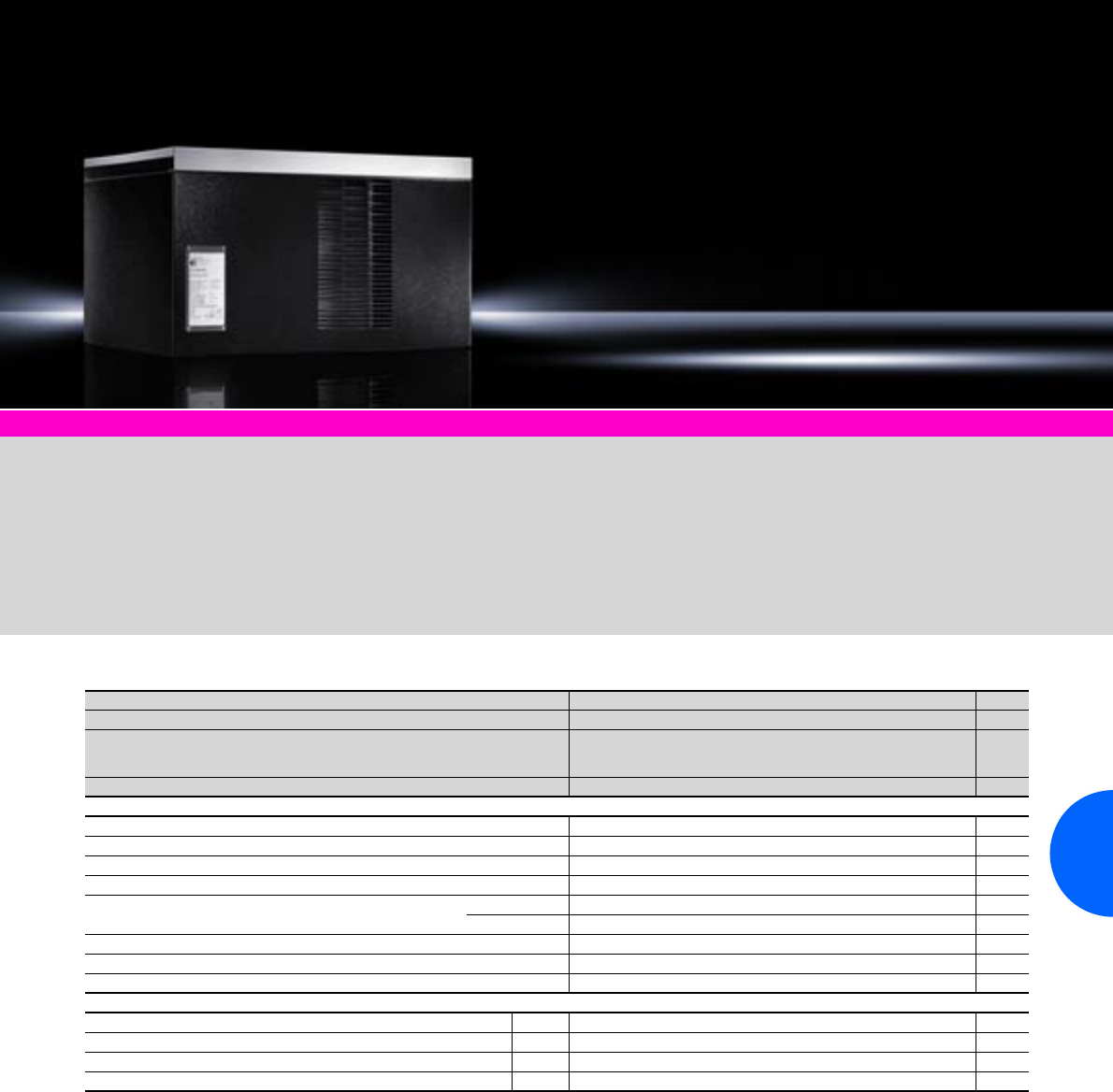
Air/air heat exchangers
229Rittal Catalogue 33/Climate control
Roof-mounted
Model No. SK 3248.000 Page
Rated operating voltage V, Hz 230, 1~, 50/60
Dimensions mm W
H
D
595
362
440
Specific thermal output 66 W/K
Fans 2 per heat exchanger
Max. rated current per fan 0.45 A/0.55 A
Pre-fuse T 4.0 A
Output per fan 75 W
Air throughput of fans (unimpeded air flow) External circuit 965 m3/h
Internal circuit 965 m3/h
Operating temperature range –5°C to +55°C
Type of connection Connection cable
Weight 168 kg
Accessories Packs of
Digital temperature display/thermostat 1 3114.200 293
Enclosure internal thermostat 1 3110.000 294
Hygrostat 1 3118.000 294
Speed control 1 3120.200 295
Special voltages available on request. We reserve the right to make technical modifications.
Climate control accessories Page 291 Software & services Page 333
Colour:
RAL 7035/9005
Protection category:
Internal circuit IP 54 to
IEC 60 529
Supply includes:
−Complete unit ready for
connection
−The fans are connected via
two 3-wire connection cables,
with wire end ferrules.
Note:
For precise temperature
control inside the enclosure,
we recommend the digital tem-
perature indicator/thermostat
SK 3114.200, the enclosure
internal thermostat SK 3110.000
or the speed control
SK 3120.200.
Detailed drawings:
Available on the Internet.
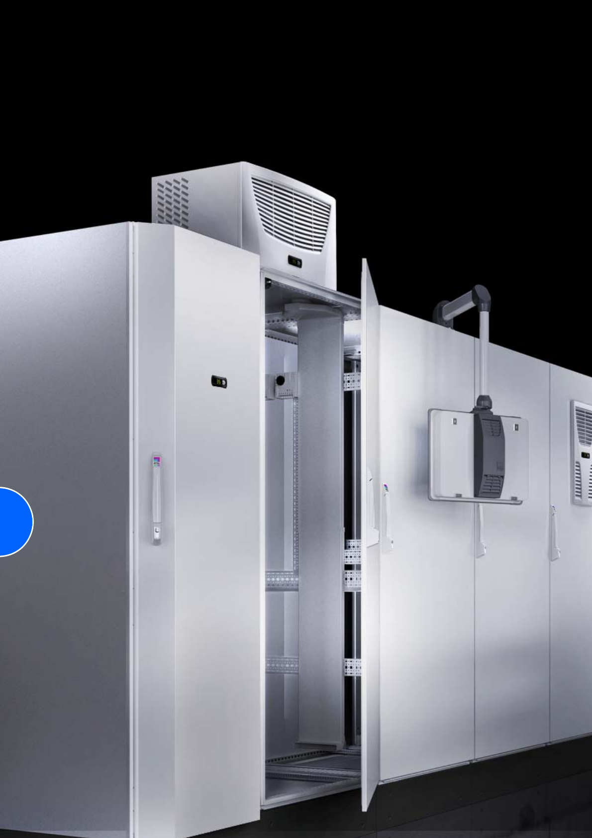
230
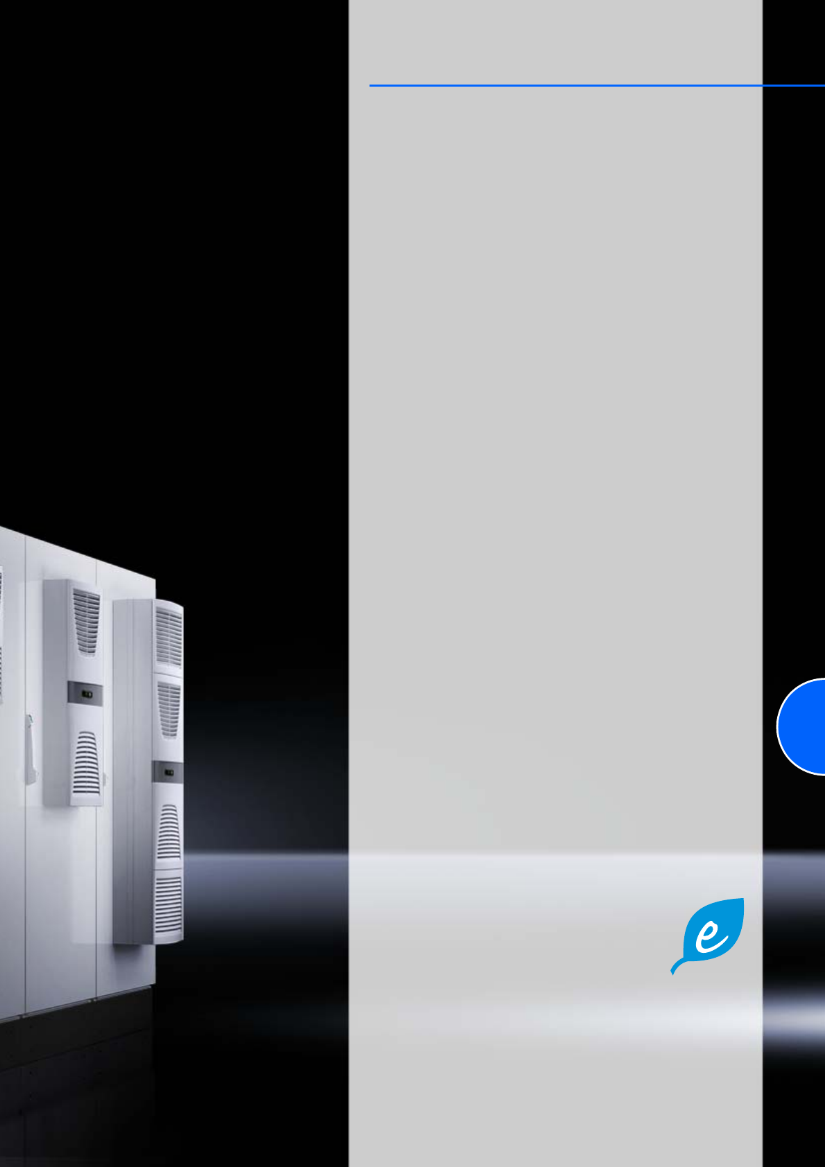
231
Cooling units
Thermoelectric coolers
Thermoelectric coolers.....................................................100 W..............232
Wall-mounted cooling units
TopTherm, horizontal format ............................................ 300 W..............233
TopTherm .........................................................................300 W..............234
TopTherm “Blue e” ...........................................................500 W..............235
TopTherm “Blue e” ...........................................................750 W..............236
TopTherm “Blue e” .........................................................1000 W..............237
TopTherm “Blue e” .........................................................1500 W..............238
TopTherm “Blue e” .........................................................2000 W..............239
TopTherm “Blue e” .........................................................2500 W..............240
TopTherm “Blue e” .........................................................4000 W..............240
TopTherm “Blue e”, slimline ...........................................1500 W..............241
TopTherm “Blue e”, design NEMA 4X............500/1000/1500 W..............242
TopTherm “Blue e”, design NEMA 4X...................2000/2500 W..............243
TopTherm “Blue e”, Ex cooling units
for zone 22 (dust) ...........................................500/1000/1500 W..............243
Roof-mounted cooling units
TopTherm “Blue e” ...........................................................500 W..............244
TopTherm “Blue e” ...........................................................750 W..............245
TopTherm “Blue e” .........................................................1000 W..............245
TopTherm “Blue e” ................................................1100/3000 W..............246
TopTherm “Blue e” .........................................................1500 W..............246
TopTherm “Blue e” .........................................................2000 W..............247
TopTherm “Blue e” ................................................3000/4000 W..............247
Modular climate control concept
Cooling modules “Blue e” .....................................1500/2500 W..............248
Section doors for installing cooling modules ............................................249
TopTherm cooling units –
generation “Blue e”
●Energy-saving range of cooling units in the
output range from 500 to 4000 W.
●Savings of up to 45% energy consumption with the same cooling output
(ideally 70% compared with a conventional Rittal TopTherm Plus cooling
unit in field trials).
●Further information can be found on the Internet at www.rittal.com under
“System climate control”.
Eco-Mode control
Intelligent, targeted use of energy thanks to the new eco-mode control from
Rittal.
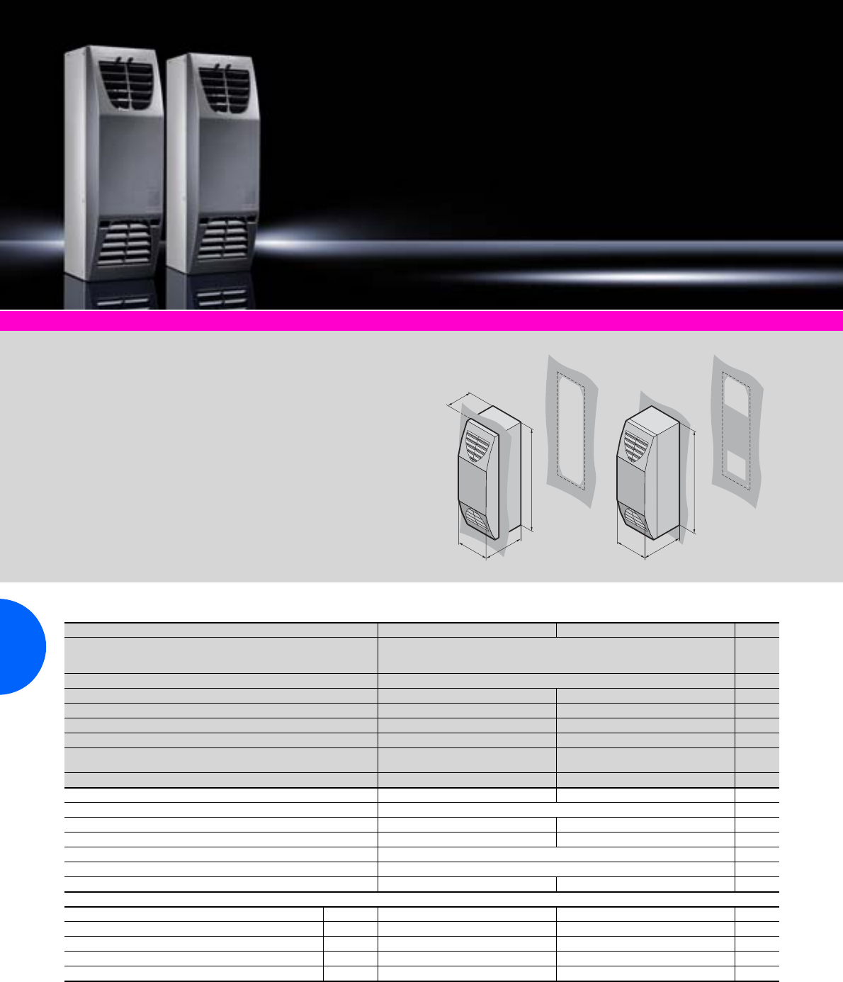
Thermoelectric coolers
232 Rittal Catalogue 33/Climate control
Climate control accessories Page 291 Therm software Page 341
Protection category:
−External circuit IP 34
to IEC 60 529
−Internal circuit IP 54
to IEC 60 529
Supply includes:
−Thermoelectric climate
control unit
−Fully wired
ready for connection
−Mounting accessories
−Parameterization software.
Detailed drawing:
Available on the Internet.
Performance diagrams:
Available on the Internet.
T1
B
H
T1
B
H
T2
Useful cooling output 100 W/thermal output 100 W
Model No. SK 3201.200 3201.300 Page
Dimensions mm W (B)
H
D (T1)
125
400
155
Installation depth mm D (T2) 100
Rated operating voltage V, Hz 100 – 230 V, 50/60 24 V DC
Start-up current 4.6 A 4.5 A
Rated current 0.7 A 4.5 A
Refrigeration factor/COP L 35 L 35 1.0 1.2
Useful cooling output
to DIN 3168 L 35 L 35 10 0 W 100 W
Thermal output 100 W 100 W
Power pack integrated –
Colour of cover/unit RAL 7024/anodised aluminium
Weight 3.0 kg 2.4 kg
Operating temperature range –30°C to +55°C –30°C to +60°C
Air throughput, unimpeded air flow 50 m3/h
Type of connection Plug-in spring connection terminal
Pre-fuse T 4 A 10 A
Accessories Packs of
Auto Range power pack 240 W 1 – 3201.040 302
Spare filter mat 1 3201.050 3201.050 301
Digital temperature display/thermostat 1 3114.200 3114.200 293
Master/slave adaptor 1 3201.070 3201.070 295
Condensate hose, 5 m length 1 3301.606 3301.606 303
We reserve the right to make technical modifications. Special voltages available on request.
QK
.
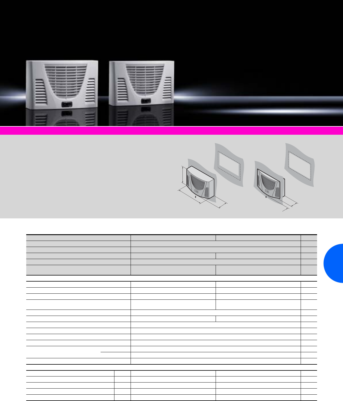
Wall-mounted cooling units
233Rittal Catalogue 33/Climate control
Climate control accessories Page 291 Software & services Page 333
Protection category:
−External circuit IP 34
to IEC 60 529
−Internal circuit IP 54
to IEC 60 529
Supply includes:
−Nano-coated condenser
−Wired ready for connection
(plug-in terminal strip)
−Drilling template
−Assembly parts
Approvals:
Available on the Internet.
Detailed drawing:
Available on the Internet.
Performance diagrams:
Available on the Internet.
340
525
153
98
55
TopTherm, horizontal format, useful cooling output 300 W
Model No. SK 3302.300 3302.310 Page
Material Sheet steel
Colour RAL 7035
Rated operating voltage V, Hz 230, 1~, 50/60 115, 1~, 60
Dimensions mm W x H x D 525 x 340 x 153
Useful cooling output
to DIN 3168
L 35 L 35
L 35 L 50
300 W/320 W
150 W/160 W
300 W
150 W
Rated current max. 1.6 A/1.7 A 4.0 A
Start-up current 4.3 A/5.3 A 12.0 A
Pre-fuse T 10.0 A 10.0 A
Power consumption Pel
to DIN 3168 L 35 L 35
L 35 L 50 285 W/300 W
320 W/340 W 290 W
340 W
Refrigeration factor ε = L 35 L 35 1.1
Refrigerant R134a, 100 g R134a, 95 g
Permissible operating pressure p. max. 25 bar
Operating temperature range +20°C to +55°C
Setting range +30°C to +55°C
Weight 13 kg
Air throughput of fans External circuit 345 m3/h
Internal circuit 310 m3/h
Temperature control Basic controller
Accessories Packs of
Digital temperature display/thermostat 1 3114.200 3114.200 293
Condensate hose 1 3301.608 3301.608 303
Filter mats 3 3286.110 3286.110 299
Metal filters 1 3286.120 3286.120 300
Door-operated switch 1 4127.010 4127.010 496
Special voltages available on request. We reserve the right to make technical modifications.
QK
.
QK/Pel
.
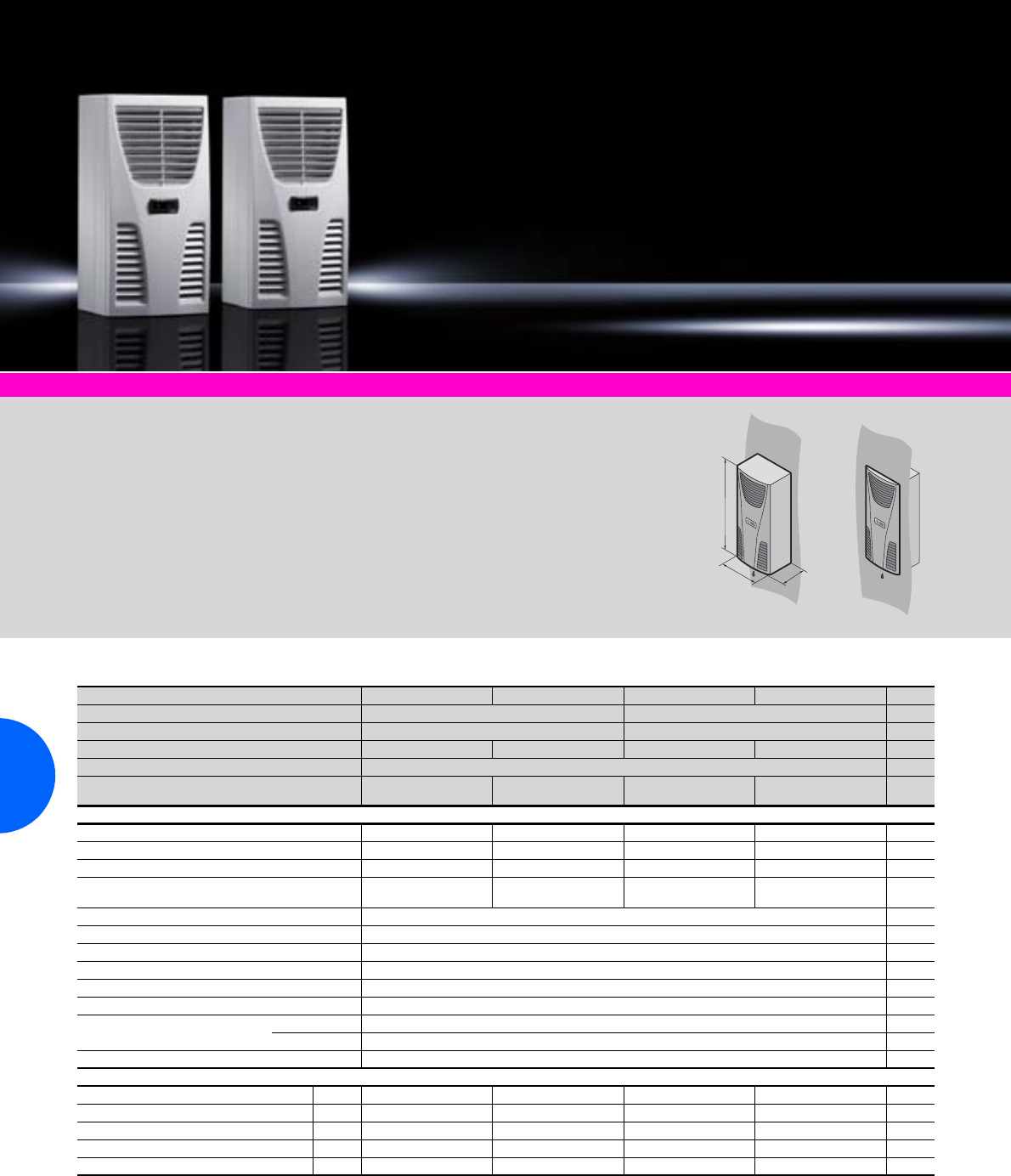
Wall-mounted cooling units
234 Rittal Catalogue 33/Climate control
TopTherm, useful cooling output 300 W
Model No. SK 3302.100 3302.110 3302.2001) 3302.2101) Page
Material Sheet steel Stainless steel
Colour RAL 7035 –
Rated operating voltage V, Hz 230, 1~, 50/60 115, 1~, 60 230, 1~, 50/60 115, 1~, 60
Dimensions mm
W (B) x H x D (T)
280 x 550 x 140
Useful cooling output
to DIN 3168
L 35 L 35
L 35 L 50
300 W/320 W
150 W/170 W
300 W
150 W
300 W/320 W
150 W/170 W
300 W
150 W
Rated current max. 1.6 A/1.7 A 3.3 A 1.6 A/1.7 A 3.3 A
Start-up current 3.0 A/3.4 A 8.0 A 3.0 A/3.4 A 8.0 A
Pre-fuse T 10.0 A 10.0 A 10.0 A 10.0 A
Power consumption Pel
to DIN 3168 L 35 L 35
L 35 L 50 245 W/255 W
255 W/275 W 290 W
340 W 245 W/255 W
255 W/275 W 290 W
340 W
Refrigeration factor ε = L 35 L 35 1.2
Refrigerant R134a, 100 g
Permissible operating pressure p. max. 25 bar
Operating temperature range +20°C to +55°C
Setting range +30°C to +55°C
Weight 13 kg
Air throughput of fans External circuit 310 m3/h
Internal circuit 345 m3/h
Temperature control Basic controller (factory setting +35°C)
Accessories Packs of
Filter mats 3 3286.300 3286.300 3286.300 3286.300 299
Metal filters 1 3286.310 3286.310 3286.310 3286.310 300
Door-operated switch 1 4127.010 4127.010 4127.010 4127.010 496
Digital temperature display/thermostat 1 3114.200 3114.200 3114.200 3114.200 293
Condensate hose 1 3301.608 3301.608 3301.608 3301.608 303
1) Extended delivery times.
Special voltages available on request. We reserve the right to make technical modifications.
QK
.
QK/Pel
.
Climate control accessories Page 291 Software & services Page 333
Protection category:
−External circuit IP 34
to IEC 60 529
−Internal circuit IP 54
to IEC 60 529
Supply includes:
−Nano-coated condenser
−Wired ready for connection
(plug-in terminal strip)
−Drilling template
−Assembly parts
Approvals:
Available on the Internet.
Detailed drawing:
Available on the Internet.
Performance diagrams:
Available on the Internet.
T
H
B
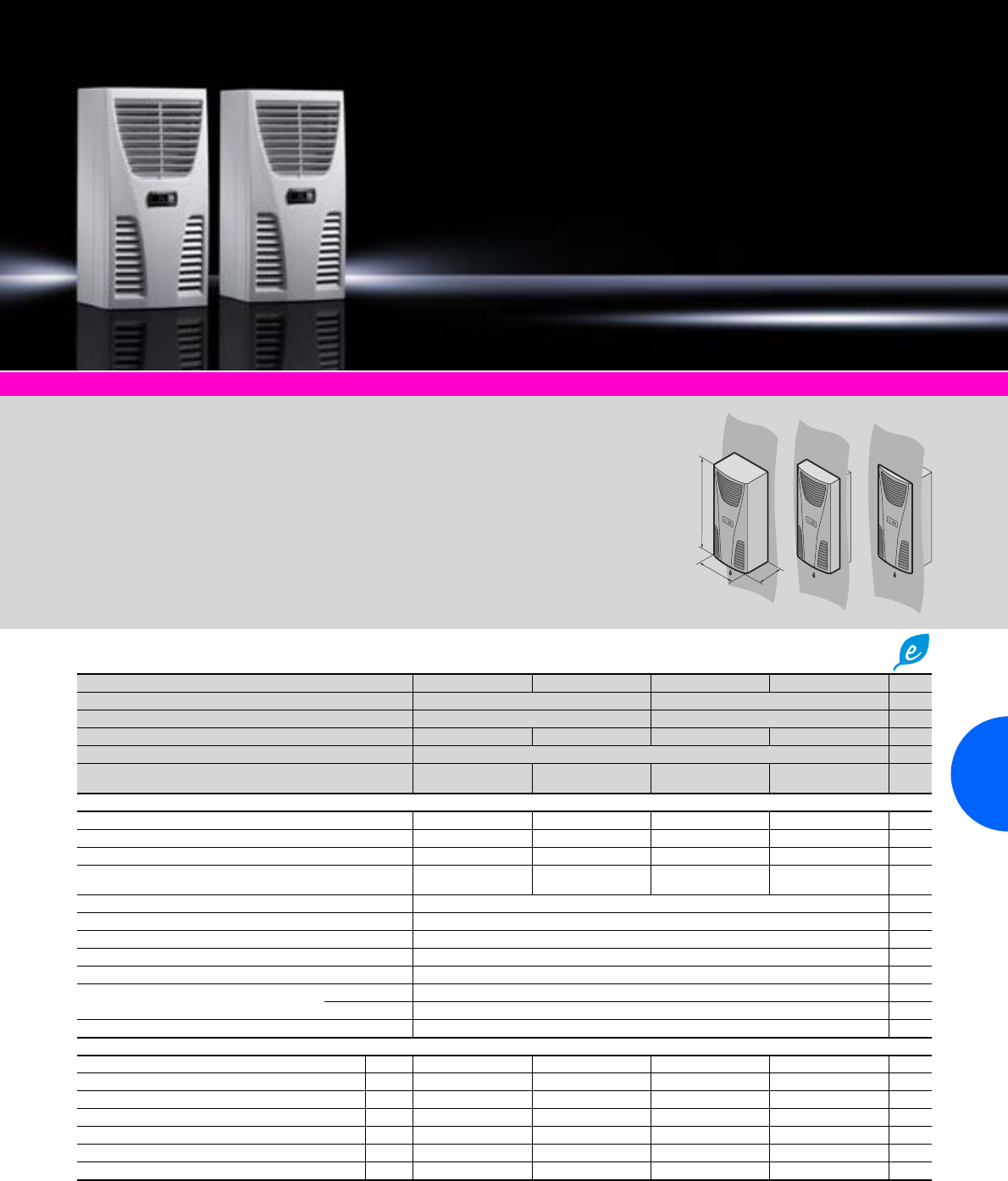
Wall-mounted cooling units
235Rittal Catalogue 33/Climate control
Climate control accessories Page 291 Software & services Page 333
Protection category:
−External circuit IP 34
to IEC 60 529
−Internal circuit IP 54
to IEC 60 529
Supply includes:
−Nano-coated condenser
−Wired ready for connection
(plug-in terminal strip)
−Drilling template
−Assembly parts
Approvals:
Available on the Internet.
Detailed drawing:
Available on the Internet.
Performance diagrams:
Available on the Internet.
T
H
B
TopTherm “Blue e”, useful cooling output 500 W
Model No. SK 3303.500 3303.510 3303.6001) 3303.6101) Page
Material Sheet steel Stainless steel
Colour RAL 7035 –
Rated operating voltage V, Hz 230, 1~, 50/60 115, 1~, 60 230, 1~, 50/60 115, 1~, 60
Dimensions mm W (B) x H x D (T) 280 x 550 x 210
Useful cooling output
to DIN 3168
L 35 L 35
L 35 L 50
500 W/610 W
280 W/350 W
500 W
280 W
500 W/610 W
280 W/350 W
500 W
280 W
Rated current max. 2.6 A/2.6 A 5.7 A 2.6 A/2.6 A 5.7 A
Start-up current 5.1 A/6.4 A 11.5 A 5.1 A/6.4 A 11.5 A
Pre-fuse T 10.0 A 10.0 A 10.0 A 10.0 A
Power consumption Pel
to DIN 3168 L 35 L 35
L 35 L 50 360 W/380 W
420 W/390 W 470 W
500 W 360 W/380 W
420 W/390 W 470 W
500 W
Refrigeration factor ε = L 35 L 35 1.4
Refrigerant R134a, 170 g
Permissible operating pressure p. max. 28 bar
Operating temperature and setting range +20°C to +55°C
Weight 17 kg
Air throughput of fans External circuit 345 m3/h
Internal circuit 310 m3/h
Temperature control e-Comfort controller (factory setting +35°C)
Accessories Packs of
Filter mats 3 3286.300 3286.300 3286.300 3286.300 299
Metal filters 1 3286.310 3286.310 3286.310 3286.310 300
Door-operated switch 1 4127.010 4127.010 4127.010 4127.010 496
SK BUS system 1 3124.100 3124.100 3124.100 3124.100 295
RiDiag II 1 3159.100 3159.100 3159.100 3159.100 347
Interface board 1 3124.200 3124.200 3124.200 3124.200 295
Condensate hose 1 3301.610 3301.610 3301.610 3301.610 303
1) Extended delivery times.
Special voltages available on request. We reserve the right to make technical modifications.
QK
.
QK/Pel
.
Wall-mounted cooling units
236 Rittal Catalogue 33/Climate control
TopTherm “Blue e”, useful cooling output 750 W
Model No. SK 3361.500 3361.510 3361.540 3361.6001) 3361.6101) 3361.6401) Page
Material Sheet steel Stainless steel
Colour RAL 7035 –
Rated operating voltage V, Hz 230, 1~,
50/603) 115, 1~,
603) 4002), 2~,
50/603) 230, 1~,
50/603) 115, 1~,
602) 4002), 2~,
50/603)
Dimensions mm W x H x D 280 x 550 x 206
Useful cooling output
to DIN 3168
L 35 L 35
L 35 L 50
750 W/790 W
570 W/570 W
750 W
500 W
750 W/790 W
570 W/570 W
750 W/790 W
570 W/570 W
750 W
500 W
750 W/790 W
570 W/570 W
Rated current max. 2.7 A/2.7 A 5.3 A 1.2 A/1.4 A 2.7 A/2.7 A 5.3 A 1.2 A/1.4 A
Start-up current 6.0 A/9.6 A 12.0 A 3.1 A/3.3 A 6.0 A/9.6 A 12.0 A 3.1 A/3.3 A
Pre-fuse T 10.0 A 10.0 A 6.3 A – 10.0 A4) 10.0 A 10.0 A 6.3 A – 10.0 A4)
Power consumption Pel
to DIN 3168 L 35 L 35
L 35 L 50 420 W/450 W
480 W/510 W 570 W
670 W 450 W/470 W
520 W/550 W 420 W/450 W
480 W/510 W 570 W
670 W 450 W/470 W
520 W/550 W
Refrigeration factor ε = L 35 L 35 1.8 1.3 1.7 1.8 1.3 1.7
Refrigerant R134a, 280 g R134a, 260 g R134a, 280 g R134a, 280 g R134a, 260 g R134a, 280 g
Permissible operating pressure p. max. 28 bar
Operating temperature and setting range +20°C to +55°C
Weight 22 kg
Air throughput of fans External circuit 480 m3/h
Internal circuit 600 m3/h
Temperature control e-Comfort controller (factory setting +35°C)
Accessories Packs of
Filter mats 3 3286.300 3286.300 3286.300 3286.300 3286.300 3286.300 299
Metal filters 1 3286.310 3286.310 3286.310 3286.310 3286.310 3286.310 300
Door-operated switch 1 4127.010 4127.010 4127.010 4127.010 4127.010 4127.010 496
SK BUS system 1 3124.100 3124.100 3124.100 3124.100 3124.100 3124.100 295
RiDiag II 1 3159.100 3159.100 3159.100 3159.100 3159.100 3159.100 347
Interface board 1 3124.200 3124.200 3124.200 3124.200 3124.200 3124.200 295
Condensate hose 1 3301.610 3301.610 3301.610 3301.610 3301.610 3301.610 303
1) Extended delivery times. 2) External toroidal core transformer Ø 126 x 65 mm deep for mounting in the enclosure.
3) Tu max. = 53°C/60 Hz. 4) Transformer protection switch.
Special voltages available on request. We reserve the right to make technical modifications.
QK
.
QK/Pel
.
Rittal Canada
RITTAL Systems Ltd.
6485 Ordan Drive Missisauga ON L5T 1X2
Canada
Phone: +1 (905) 795-0777
Fax: +1 (905) 795-9548
Toll-free: 1-800-399-0748
E-mail: marketing@rittal.ca www.rittal.ca
Wall-mounted cooling units
237Rittal Catalogue 33/Climate control
Climate control accessories Page 291 Software & services Page 333
Protection category:
−External circuit IP 34
to IEC 60 529
−Internal circuit IP 54
to IEC 60 529
Supply includes:
−Nano-coated condenser
−Integral electric condensate
evaporation
−Wired ready for connection
(plug-in terminal strip)
−Drilling template
−Assembly parts
Approvals:
Available on the Internet.
Detailed drawing:
Available on the Internet.
Performance diagrams:
Available on the Internet.
H
B
T
TopTherm “Blue e”, useful cooling output 1000 W
Model No. SK 3304.500 3304.510 3304.540 3304.6001) 3304.6101) 3304.6401) Page
Material Sheet steel Stainless steel
Colour RAL 7035 –
Rated operating voltage V, Hz 230, 1~, 50/60 115, 1~, 50/60 400, 3~, 50/
460, 3~, 60 230, 1~, 50/60 115, 1~, 50/60 400, 3~, 50/
460, 3~, 60
Dimensions mm
W (B) x H x D
(T)
400 x 950 x 260
Useful cooling output
to DIN 3168
L 35 L 35
L 35 L 50
1000 W/1450 W
1050 W/1100 W
1000 W/1450 W
980 W/1050 W
1000 W/1460 W
880 W/890 W
1000 W/1450 W
1050 W/1100 W
1000 W/1450 W
1050 W/1100 W
1000 W/1460 W
880 W/990 W
Rated current max. 3.9 A/4.3 A 8.0 A/8.8 A 2.2 A/2.1 A 3.9 A/4.3 A 8.0 A/8.8 A 2.2 A/2.1 A
Start-up current 12.0 A/14.0 A 26.0 A/28.0 A 11.5 A/12.7 A 12.0 A/14.0 A 26.0 A/28.0 A 11.5 A/12.7 A
Pre-fuse T 10.0 A 11.0 A – 16.0 A 6.3 A – 10.0 A2) 10.0 A 11.0 A – 16.0 A 6.3 A – 10.0 A2)
Power consumption Pel
to DIN 3168 L 35 L 35
L 35 L 50 640 W/720 W
750 W/850 W 670 W/750 W
780 W/880 W 670 W/820 W
760 W/930 W 640 W/720 W
750 W/850 W 670 W/750 W
780 W/880 W 670 W/820 W
760 W/930 W
Refrigeration factor ε = L 35 L 35 1.6 1.7 1.6 1.7
Refrigerant R134a, 325 g
Permissible operating pressure p. max. 25 bar
Operating temperature and setting range +20°C to +55°C
Weight 39 kg 44 kg 40 kg 39 kg 44 kg 40 kg
Air throughput of fans External circuit 900 m3/h
Internal circuit 600 m3/h
Temperature control e-Comfort controller (factory setting +35°C)
Accessories Packs of
Filter mats 3 3286.400 3286.400 3286.400 3286.400 3286.400 3286.400 299
Metal filters 1 3286.410 3286.410 3286.410 3286.410 3286.410 3286.410 300
Door-operated switch 1 4127.010 4127.010 4127.010 4127.010 4127.010 4127.010 496
SK BUS system 1 3124.100 3124.100 3124.100 3124.100 3124.100 3124.100 295
RiDiag II 1 3159.100 3159.100 3159.100 3159.100 3159.100 3159.100 347
Interface board 1 3124.200 3124.200 3124.200 3124.200 3124.200 3124.200 295
Condensate hose 1 3301.612 3301.612 3301.612 3301.612 3301.612 3301.612 303
1) Extended delivery times. 2) Motor circuit-breaker.
Special voltages and other output categories available on request. We reserve the right to make technical modifications.
QK
.
QK/Pel
.
Wall-mounted cooling units
238 Rittal Catalogue 33/Climate control
TopTherm “Blue e”, useful cooling output 1500 W
Model No. SK 3305.500 3305.5101) 3305.540 3305.6001) 3305.6101) 3305.6401) Page
Material Sheet steel Stainless steel
Colour RAL 7035 –
Rated operating voltage V, Hz 230, 1~, 50/60 115, 1~, 50/60 400, 3~, 50/
460, 3~, 60 230, 1~, 50/60 115, 1~, 50/60 400, 3~, 50/
460, 3~, 60
Dimensions mm W x H x D 400 x 950 x 260
Useful cooling output
to DIN 3168
L 35 L 35
L 35 L 50
1500 W/1510 W
1150 W/1200 W
1500 W/1660 W
1150 W/1270 W
1500 W/1510 W
1230 W/1250 W
1500 W/1510 W
1150 W/ 120 0 W
1500 W/1660 W
1150 W/1270 W
1500 W/1510 W
1230 W/1250 W
Rated current max. 5.5 A/5.8 A 11.5 A/12.5 A 2.5 A/2.8 A 5.5 A/5.8 A 11.5 A/12.5 A 2.5 A/2.8 A
Start-up current 12.0 A/14.0 A 26.0 A/28.0 A 12.2 A/11.3 A 12.0 A/14.0 A 26.0 A/28.0 A 12.2 A/11.3 A
Pre-fuse T 16.0 A/16.0 A 14.0 A –
20.0 A3) 6.3 A – 10.0 A2) 16.0 A/16.0 A 14.0 A –
20.0 A3) 6.3 A – 10.0 A2)
Power consumption Pel
to DIN 3168 L 35 L 35
L 35 L 50 870 W/890 W
1030 W/1150 W 1010 W/900 W
1180 W/1060 W 820 W/1000 W
980 W/1170 W 870 W/890 W
1030 W/1150 W 1010 W/900 W
1180 W/1060 W 820 W/1000 W
980 W/1170 W
Refrigeration factor ε = L 35 L 35 1.7 1.5 1.8 1.7 1.5 1.8
Refrigerant R134a, 600 g
Permissible operating pressure p. max. 25 bar
Operating temperature and setting range +20°C to +55°C
Weight 41 kg 46 kg 42 kg 41 kg 46 kg 42 kg
Air throughput of fans External circuit 900 m3/h
Internal circuit 800 m3/h
Temperature control e-Comfort controller (factory setting +35°C)
Accessories Packs of
Filter mats 3 3286.400 3286.400 3286.400 3286.400 3286.400 3286.400 299
Metal filters 1 3286.410 3286.410 3286.410 3286.410 3286.410 3286.410 300
Door-operated switch 1 4127.010 4127.010 4127.010 4127.010 4127.010 4127.010 496
SK BUS system 1 3124.100 3124.100 3124.100 3124.100 3124.100 3124.100 295
RiDiag II 1 3159.100 3159.100 3159.100 3159.100 3159.100 3159.100 347
Interface board 1 3124.200 3124.200 3124.200 3124.200 3124.200 3124.200 295
Condensate hose 1 3301.612 3301.612 3301.612 3301.612 3301.612 3301.612 303
1) Extended delivery times. 2) Motor circuit breaker. 3) Transformer protection switch.
Special voltages available on request. We reserve the right to make technical modifications.
QK
.
QK/Pel
.
Rittal Malaysia
RITTAL Systems Sdn Bhd
7, Jalan TPP 1/1A Taman Industri Puchong
Batu 12 Jalan Puchong 47100 Puchong
Solangor, Malaysia
Phone: +603-8060 6688
Fax: +603-8060 8866
E-mail: sales@rittal.com.my www.rittal.com.my
Wall-mounted cooling units
239Rittal Catalogue 33/Climate control
Climate control accessories Page 291 Software & services Page 333
Protection category:
−External circuit IP 34
to IEC 60 529
−Internal circuit IP 54
to IEC 60 529
Supply includes:
−Nano-coated condenser
−Integral electric condensate
evaporation
−Wired ready for connection
(plug-in terminal strip)
−Drilling template
−Assembly parts
Approvals:
Available on the Internet.
Detailed drawing:
Available on the Internet.
Performance diagrams:
Available on the Internet.
Cannot be installed
with SK 3332.XXX.
1
1
H
B
T
TopTherm “Blue e”, useful cooling output 2000 W
Model No. SK 3328.500 3328.510 3328.540 3328.6001) 3328.6101) 3328.6401) Page
Material Sheet steel Stainless steel
Colour RAL 7035 –
Rated operating voltage V, Hz 230, 1~, 50/60 115, 1~, 50/60 400, 3~, 50/
460, 3~, 60 230, 1~, 50/60 115, 1~, 50/60 400, 3~, 50/
460, 3~, 60
Dimensions mm W (B) x H x D (T) 400 x 1580 x 295
Useful cooling output
to DIN 3168
L 35 L 35
L 35 L 50
2000 W/2360 W
1620 W/1745 W
2000 W/2360 W
1620 W/1745 W
2000 W/2350 W
1450 W/1690 W
2000 W/2360 W
1620 W/1745 W
2000 W/2360 W
1620 W/1745 W
2000 W/2350 W
1450 W/1690 W
Rated current max. 6.1 A/6.6 A 13.4 A/14.8 A 2.8 A/3.3 A 6.1 A/6.6 A 13.4 A/14.8 A 2.8 A/3.3 A
Start-up current 20.0 A/22.0 A 40.0 A/38.0 A 6.8 A/7.8 A 20.0 A/22.0 A 40.0 A/38.0 A 6.8 A/7.8 A
Pre-fuse T 16.0 A 18.0 A – 25.0 A3) 6.3 A – 10.0 A2) 16.0 A 18.0 A – 25.0 A3) 6.3 A – 10.0 A2)
Power consumption Pel
to DIN 3168 L 35 L 35
L 35 L 50 935 W/1055 W
1080 W/1250 W 965 W/1085 W
1110 W/1280 W 920 W/1145 W
1145 W/1395 W 935 W/1055 W
1080 W/1250 W 965 W/1085 W
1110 W/1280 W 920 W/1145 W
1145 W/1395 W
Refrigeration factor
ε = L 35 L 35 2.1 2.1 2.2 2.1 2.1 2.2
Refrigerant R134a, 950 g
Permissible operating pressure p. max. 28 bar
Operating temperature and setting range +20°C to +55°C
Weight 66 kg 73 kg 67 kg 66 kg 73 kg 67 kg
Air throughput of fans External circuit 640 m3/h
Internal circuit 550 m3/h
Temperature control e-Comfort controller (factory setting +35°C)
Accessories Packs of
Filter mats 3 3286.400 3286.400 3286.400 3286.400 3286.400 3286.400 299
Metal filters 1 3286.410 3286.410 3286.410 3286.410 3286.410 3286.410 300
Door-operated switch 1 4127.010 4127.010 4127.010 4127.010 4127.010 4127.010 496
SK BUS system 1 3124.100 3124.100 3124.100 3124.100 3124.100 3124.100 295
RiDiag II 1 3159.100 3159.100 3159.100 3159.100 3159.100 3159.100 347
Interface board 1 3124.200 3124.200 3124.200 3124.200 3124.200 3124.200 295
Condensate hose 1 3301.612 3301.612 3301.612 3301.612 3301.612 3301.612 303
1) Extended delivery times. 2) Motor circuit breaker. 3) Transformer protection switch.
Special voltages available on request. We reserve the right to make technical modifications.
QK
.
QK/Pel
.
Wall-mounted cooling units
240 Rittal Catalogue 33/Climate control
TopTherm “Blue e”, useful cooling output 2500 W
Model No. SK 3329.500 3329.510 3329.540 3329.6001) 3329.6101) 3329.6401) Page
Material Sheet steel Stainless steel
Colour RAL 7035 –
Rated operating voltage V, Hz 230, 1~, 50/60 115, 1~, 50/60 400, 3~, 50/
460, 3~, 60 230, 1~, 50/60 115, 1~, 50/60 400, 3~, 50/
460, 3~, 60
Dimensions mm W (B) x H x D (T) 400 x 1580 x 295 400 x 1580 x 295
Useful cooling output
to DIN 3168
L 35 L 35
L 35 L 50
2500 W/2660 W
1840 W/1920 W
2500 W/2700 W
1900 W/1950 W
2500 W/2660 W
1840 W/1920 W
2500 W/2700 W
1900 W/1950 W
Rated current max. 8.2 A/9.3 A 17.0 A/20.0 A 3.7 A/3.8 A 8.2 A/9.3 A 17.0 A/20.0 A 3.7 A/3.8 A
Start-up current 20.0 A/24.0 A 44.0 A/42.0 A 6.8 A/7.6 A 20.0 A/24.0 A 44.0 A/42.0 A 6.8 A/7.6 A
Pre-fuse T 16.0 A 18.0 A – 25.0 A3) 6.3 A – 10.0 A2) 16.0 A 18.0 A – 25.0 A3) 6.3 A – 10.0 A2)
Power consumption Pel
to DIN 3168 L 35 L 35
L 35 L 50 1270 W/1410 W
1470 W/1700 W 1300 W/1440 W
1500 W/1730 W 1295 W/1495 W
1545 W/1845 W 1270 W/1410 W
1470 W/1700 W 1300 W/1440 W
1500 W/1730 W 1295 W/1495 W
1545 W/1845 W
Refrigeration factor
ε = L 35 L 35 2.0 1.9 1.9 2.0 1.9 1.9
Refrigerant R134a, 950 g
Permissible operating pressure p. max. 28 bar
Operating temperature and setting range
+20°C to +55°C
Weight 69 kg 76 kg 70 kg 69 kg 76 kg 70 kg
Air throughput of fans External circuit 710 m3/h
Internal circuit 640 m3/h
Temperature control e-Comfort controller (factory setting +35°C)
Accessories Packs of
Filter mats 3 3286.400 3286.400 3286.400 3286.400 3286.400 3286.400 299
Metal filters 1 3286.410 3286.410 3286.410 3286.410 3286.410 3286.410 300
Door-operated switch 1 4127.010 4127.010 4127.010 4127.010 4127.010 4127.010 496
SK BUS system 1 3124.100 3124.100 3124.100 3124.100 3124.100 3124.100 295
RiDiag II 1 3159.100 3159.100 3159.100 3159.100 3159.100 3159.100 347
Interface board 1 3124.200 3124.200 3124.200 3124.200 3124.200 3124.200 295
Condensate hose 1 3301.612 3301.612 3301.612 3301.612 3301.612 3301.612 303
1) Extended delivery times. 2) Motor circuit breaker. 3) Transformer protection switch.
Special voltages available on request. We reserve the right to make technical modifications.
QK
.
QK/Pel
.
TopTherm “Blue e”, useful cooling output 4000 W
Model No. SK 3332.540 3332.6401) Page
Material Sheet steel Stainless steel
Colour RAL 7035 –
Rated operating voltage V, Hz 400, 3~, 50/
460, 3~, 60
Dimensions mm W (B) x H x D (T) 500 x 1580 x 340
Useful cooling output
to DIN 3168
L 35 L 35
L 35 L 50
4000 W/4400 W
3070 W/3570 W
Rated current max. 4.2 A/4.2 A
Start-up current 9.2 A/11.0 A
Pre-fuse T 6.3 A – 10.0 A2)
Power consumption Pel
to DIN 3168 L 35 L 35
L 35 L 50 1720 W/2120 W
1990 W/2460 W
Refrigeration factor
ε = L 35 L 35 2.3
Refrigerant R134a, 3000 g
Permissible operating pressure p. max. 28 bar
Operating temperature and setting range
+20°C to +55°C
Weight 91 kg
Air throughput of fans External circuit 2000 m3/h
Internal circuit 1500 m3/h
Temperature control e-Comfort controller (factory setting +35°C)
Accessories Packs of
Filter mats 3 3286.400 3286.400 299
Metal filters 1 3286.410 3286.410 300
Door-operated switch 1 4127.010 4127.010 496
SK BUS system 1 3124.100 3124.100 295
RiDiag II 1 3159.100 3159.100 347
Interface board 1 3124.200 3124.200 295
Condensate hose 1 3301.612 3301.612 303
1) Extended delivery times. 2) Motor circuit breaker.
Special voltages available on request. We reserve the right to make technical modifications.
QK
.
QK/Pel
.
Wall-mounted cooling units
241Rittal Catalogue 33/Climate control
TopTherm “Blue e”, slimline, useful cooling output 1500 W
Model No. SK 3366.500 3366.510 3366.540 3366.6001) 3366.6101) 3366.6401) Page
Material Sheet steel Stainless steel
Colour RAL 7035 –
Rated operating voltage V, Hz 230, 1~, 50/60 115, 1~, 50/60 400, 3~, 50/
460, 3~, 60 230, 1~, 50/60 115, 1~, 50/60 400, 3~, 50/
460, 3~, 60
Dimensions mm W x H x D 435 x 1590 x 205
Useful cooling output
to DIN 3168
L 35 L 35
L 35 L 50
1500 W/1500 W
1050 W/1100 W
1500 W/1500 W
980 W/1080 W
1500 W/1500 W
1050 W/1100 W
1500 W/1500 W
980 W/1080 W
Rated current max. 6.7 A/6.9 A 13.6 A/13.8 A 2.7 A/2.9 A 6.7 A/6.9 A 13.6 A/13.8 A 2.7 A/2.9 A
Start-up current 22.0 A/24.0 A 43.0 A/47.0 A 8.0 A/8.8 A 22.0 A/24.0 A 43.0 A/47.0 A 8.0 A/8.8 A
Pre-fuse T 10.0 A 14.0 A –
20.0 A3) 6.3 A –
10.0 A2) 10.0 A 14.0 A –
20.0 A3) 6.3 A –
10.0 A2)
Power consumption Pel
to DIN 3168 L 35 L 35
L 35 L 50 940 W/1070 W
1115 W/1230 W 940 W/1070 W
1115 W/1230 W 970 W/1120 W
1140 W/1310 W 940 W/1070 W
1115 W/1230 W 940 W/1070 W
1115 W/1230 W 970 W/1120 W
1140 W/1310 W
Refrigeration factor
ε = L 35 L 35 1.6 1.5 1.6 1.5
Refrigerant R134a, 700 g
Permissible operating pressure p. max. 28 bar
Operating temperature and setting range +20°C to +55°C
Weight 45 kg 49 kg 46 kg 45 kg 49 kg 46 kg
Air throughput of fans
(unimpeded air flow)
External circuit 910 m3/h
Internal circuit 860 m3/h
Temperature control e-Comfort controller (factory setting +35°C)
Accessories Packs of
Filter mats 3 3286.400 3286.400 3286.400 3286.400 3286.400 3286.400 299
Metal filters 1 3286.410 3286.410 3286.410 3286.410 3286.410 3286.410 300
Trim frame 1 3377.000 3377.000 3377.000 3377.000 3377.000 3377.000 297
Door-operated switch 1 4127.010 4127.010 4127.010 4127.010 4127.010 4127.010 496
SK BUS system 1 3124.100 3124.100 3124.100 3124.100 3124.100 3124.100 295
RiDiag II 1 3159.100 3159.100 3159.100 3159.100 3159.100 3159.100 347
Interface board 1 3124.200 3124.200 3124.200 3124.200 3124.200 3124.200 295
Condensate hose 1 3301.612 3301.612 3301.612 3301.612 3301.612 3301.612 303
1) Extended delivery times. 2) Motor circuit breaker. 3) Transformer protection switch.
Special voltages available on request. We reserve the right to make technical modifications.
QK
.
QK/Pel
.
Climate control accessories Page 291 Software & services Page 333
Protection category:
−External circuit IP 34
to IEC 60 529
−Internal circuit IP 54
to IEC 60 529
Supply includes:
−Nano-coated condenser
−Integral electric condensate
evaporation
−Wired ready for connection
(plug-in terminal strip)
−Drilling template
−Assembly parts
Approvals:
Available on the Internet.
Detailed drawing:
Available on the Internet.
Performance diagrams:
Available on the Internet.
Wall-mounted cooling units
242 Rittal Catalogue 33/Climate control
TopTherm “Blue e”, design NEMA 4X, useful cooling output 500/1000/1500 W
Model No. SK 3303.5042) 3303.5142) 3304.504 3304.514 3304.544 3305.504 3305.514 3305.544 Page
Material Stainless steel
Rated operating voltage
V, Hz 230, 1~,
50/60 115, 1~,
60 230, 1~,
50/60 115, 1~,
50/60 400, 3~, 50/
460, 3~, 60 230, 1~,
50/60 115, 1~,
50/60 400, 3~, 50/
460, 3~, 60
Dimensions mm W x H x D 285 x 620 x 298 405 x 1020 x 358 405 x 1020 x 358
Useful cooling output
to DIN 3168
L 35 L 35
L 35 L 50
500 W/
610 W
280W/
350 W
500 W
280 W
1000 W/
1450 W
1050 W/
110 0 W
1000 W/
1450 W
980 W/
1050 W
1000 W/
1460 W
880 W/
990 W
1500 W/
1510 W
1150 W/
1200 W
1500 W/
1660 W
1150 W/
1270 W
1500 W/
1510 W
1230 W/
1250 W
Rated current max. 2.6 A/
2.6 A 5.7 A 3.9 A/
4.3 A 8.0 A –
8.8 A 2.2 A –
2.1 A 5.5 A –
5.8 A 11.5 A –
12.5 A 2.6 A –
2.8 A
Start-up current 5.1 A/
6.4 A 11.5 A 12.0 A/
14.0 A 26.0 A/
28.0 A 11.5 A/
12.7 A 12.0 A/
14.0 A 26.0 A/
28.0 A 12.2 A/
11.3 A
Pre-fuse T 10.0 A 10.0 A 10.0 A 11.0 A –
16.0 A 6.3 A –
10.0 A1) 16.0 A 14.0 A –
20.0 A3) 6.3 A –
10.0 A1)
Power consumption Pel
to DIN 3168
L 35 L 35
L 35 L 50
360 W/
380 W
420 W/
390 W
470 W
500 W
640 W/
720 W
750 W/
850 W
670 W/
750 W
780 W/
880 W
670 W/
820 W
760 W/
930 W
870 W/
890 W
1030 W/
1150 W
1010 W/
900 W
1180 W/
1060 W
820 W/
1000 W
980 W/
1170 W
Refrigeration factor
ε = L 35 L 35 1.4 1.6 1.6 1.7 1.7 1.5 1.8
Refrigerant R134a, 170 g R134a, 325 g R134a, 325 g R134a, 600 g
Permissible operating pressure p. max
. 28 bar 25 bar
Operating temperature
and setting range +20°C to +55°C
Protection category NEMA 4X
Weight 25 kg 49 kg 54 kg 50 kg 51 kg 56 kg 52 kg
Air throughput of fans External circuit 345 m3/h 900 m3/h 900 m3/h
Internal circuit 310 m3/h 600 m3/h 800 m3/h
Temperature control e-Comfort controller (factory setting +35°C)
Accessories Packs of
Door-operated switch 1 4127.010 4127.010 4127.010 4127.010 4127.010 4127.010 4127.010 4127.010 496
SK BUS system 1 3124.100 3124.100 – – – 3124.100 3124.100 3124.100 295
RiDiag II 1 3159.100 3159.100 3159.100 3159.100 3159.100 3159.100 3159.100 3159.100 347
Interface board 1 3124.200 3124.200 3124.200 3124.200 3124.200 3124.200 3124.200 3124.200 295
Condensate hose 1 3301.610 3301.610 3301.612 3301.612 3301.612 3301.612 3301.612 3301.612 303
1) Motor circuit breaker. 2) Without integral condensate evaporation. 3) Transformer protection switch.
Extended delivery times. Special voltages available on request. We reserve the right to make technical modifications.
QK
.
QK/Pel
.
Climate control accessories Page 291 Software & services Page 333
Protection category:
See tables. Supply includes:
−Nano-coated condenser
−Integral electric condensate
evaporation
−Wired ready for connection
(plug-in terminal strip)
−Drilling template
−Assembly parts Approvals:
Available on the Internet.
Detailed drawing:
Available on the Internet.
Performance diagrams:
Available on the Internet.
Wall-mounted cooling units
243Rittal Catalogue 33/Climate control
TopTherm “Blue e”, design NEMA 4X, useful cooling output 2000/2500 W
Model No. SK 3328.504 3328.514 3328.544 3329.504 3329.514 3329.544 Page
Material Stainless steel
Rated operating voltage
V, Hz 230, 1~, 50/60 115, 1~, 50/60 400, 3~, 50/
460, 3~, 60 230, 1~, 50/60 115, 1~, 50/60 400, 3~, 50/
460, 3~, 60
Dimensions mm W x H x D 405 x 1650 x 388
Useful cooling output
to DIN 3168
L 35 L 35
L 35 L 50
2000 W/2360 W
1620 W/1745 W
2000 W/2360 W
1620 W/1745 W
2000 W/2350 W
1450 W/1690 W
2500 W/2660 W
1840 W/1920 W
2500 W/2660 W
1840 W/1920 W
2500 W/2700 W
1900 W/1950 W
Rated current max. 6.1 A/6.6 A 13.4 A – 14.8 A 2.8 A/3.3 A 8.2 A/9.3 A 17.0 A/20.0 A 3.7 A/3.8 A
Start-up current 20.0 A/22.0 A 40.0 A/38.0 A 6.8 A/7.8 A 20.0 A/24.0 A 44.0 A/42.0 A 6.8 A/7.6 A
Pre-fuse T 16.0 A 18.0 A –
25.0 A2) 6.3 A –
10.0 A1) 16.0 A 18.0 A –
25.0 A2) 6.3 A –
10.0 A1)
Power consumption Pel
to DIN 3168 L 35 L 35
L 35 L 50 935 W/1055 W
1080 W/1250 W 965 W/1085 W
1110 W/1280 W 920 W/1145 W
1145 W/1395 W 1270 W/1410 W
1470 W/1700 W 1300 W/1440 W
1500 W/1730 W 1295 W/1495 W
1545 W/1845 W
Refrigeration factor
ε = L 35 L 35 2.1 2.1 2.2 2.0 1.9 1.9
Refrigerant R134a, 900 g
Permissible operating pressure p. max. 28 bar
Operating temperature and setting range +20°C to +50°C
Protection category NEMA 4X
Weight 80 kg 87 kg 80 kg 83 kg 90 kg 83 kg
Air throughput of fans External circuit 640 m3/h 710 m3/h
Internal circuit 550 m3/h 640 m3/h
Temperature control e-Comfort controller (factory setting +35°C)
Accessories Packs of
Door-operated switch 1 4127.010 4127.010 4127.010 4127.010 4127.010 4127.010 496
SK BUS system 1 3124.100 3124.100 3124.100 3124.100 3124.100 3124.100 295
RiDiag II 1 3159.100 3159.100 3159.100 3159.100 3159.100 3159.100 347
Interface board 1 3124.200 3124.200 3124.200 3124.200 3124.200 3124.200 295
Condensate hose 1 3301.612 3301.612 3301.612 3301.612 3301.612 3301.612 303
1) Motor circuit breaker. 2) Transformer protection switch.
Delivery times available on request. Special voltages available on request. We reserve the right to make technical modifications.
QK
.
QK/Pel
.
TopTherm “Blue e”, Ex cooling units for zone 22 (dust);
useful cooling output 500/1000/1500 W
Model No. SK 3303.530 3304.530 3304.560 3305.530 3305.560 Page
Material Sheet steel
Colour RAL 7035
Rated operating voltage V, Hz 230, 1~, 50/60 230, 50/60 400, 3~, 50/
460, 3~, 60 230, 50/60 400, 3~, 50/
460, 3~, 60
Dimensions mm W x H x D 280 x 550 x 210 400 x 950 x 260 400 x 950 x 260
Useful cooling output
to DIN 3168
L 35 L 35
L 35 L 50
500 W/610 W
280 W/350 W
1000 W/1450 W
1050 W/1100 W
1000 W/1460 W
880 W/990 W
1500 W/1510 W
1150 W/1200 W
1500 W/1510 W
1230 W/1250 W
Rated current max. 2.6 A/2.6 A 3.9 A/4.3 A 2.1 A/2.2 A 5.4 A/6.0 A 2.3 A/2.6 A
Start-up current 5.1 A/6.4 A 12.0 A/14.0 A 11.5 A/12.7 A 22.0 A/24.0 A 12.2 A/11.3 A
Pre-fuse T 10.0 A 10.0 A/10.0 A 6.3 A – 10.0 A1) 16.0 A/16.0 A 6.3 A – 10.0 A1)
Power consumption Pel
to DIN 3168 L 35 L 35
L 35 L 50 360 W/380 W
420 W/390 W 640 W/720 W
750 W/850 W 670 W/820 W
760 W/930 W 870 W/980 W
1030 W/1150 W 820 W/1000 W
980 W/1170 W
Refrigeration factor ε = L 35 L 35 1.4 1.4 1.7 1.7 1.8
Refrigerant R134a, 170 g R134a, 325 g R134a, 325 g R134a, 600 g
Permissible operating pressure p. max. 28 bar 25 bar
Operating temperature and setting range +20°C to +50°C
Protection category External circuit IP 54
Internal circuit IP 54
Weight 17 kg 39 kg 41 kg
Air throughput of fans External circuit 345 m3/h 900 m3/h
Internal circuit 310 m3/h 600 m3/h 800 m3/h
Temperature control e-Comfort controller (factory setting +35°C)
Accessories Packs of
Filter mats 3 3286.300 3286.400 3286.400 3286.400 3286.400 299
Door-operated switch 1 4127.010 4127.010 4127.010 4127.010 4127.010 496
Digital temperature display/thermostat 1 3114.200 3114.200 3114.200 3114.200 3114.200 293
Condensate hose 1 3301.612 3301.612 3301.612 3301.612 3301.612 303
1) Motor circuit breaker.
Without electric condensate evaporation.
Delivery times available on request. We reserve the right to make technical modifications.
QK
.
QK/Pel
.
Roof-mounted cooling units
244 Rittal Catalogue 33/Climate control
Climate control accessories Page 291 Software & services Page 333 RiDiag II Page 347
Technical specifications:
−Permissible operating
pressure p. max.: 25 bar
−Duty cycle: 100%
−Type of connection:
Plug-in terminal strip
Protection category:
−External circuit IP 34
to IEC 60 529
−Internal circuit IP 54
to IEC 60 529
Supply includes:
−Nano-coated condenser
−Integral electric condensate
evaporation
−Fully wired ready for
connection
−Drilling template
−Assembly parts
Accessories:
Roof plate for TS 8 with
mounting cut-out, see page 296.
New: TopTherm
roof-mounted cooling unit,
useful cooling output 1100/
3000 W, for office and IT appli-
cations with targeted air routing,
see page 246. Detailed drawing
and technical information can be
found on the Internet.
Approvals:
Available on the Internet.
Detailed drawing:
Available on the Internet.
Performance diagrams:
Available on the Internet.
TopTherm “Blue e”, useful cooling output 500 W
Model No. SK 3382.500 3382.6001) 3382.510 3382.6101) Page
Material Sheet steel Stainless steel Sheet steel Stainless steel
Colour RAL 7035 – RAL 7035 –
Rated operating voltage V, Hz 230, 1~, 50/60 115, 1~, 50/60
Dimensions mm W x H x D 597 x 417 x 380
Useful cooling output
to DIN 3168
L 35 L 35
L 35 L 50
500 W/586 W
273 W/429 W
Rated current max. 2.3 A/2.6 A 4.1 A/5.4 A
Start-up current 9.1 A/8.8 A 18.2 A/15.9 A
Pre-fuse T 10.0 A 6.3 A – 10.0 A2)
Power consumption Pel
to DIN 3168 L 35 L 35
L 35 L 50 302 W/347 W
342 W/402 W 312 W/357 W
352 W/422 W
Refrigeration factor ε = L 35 L 35 1.6
Refrigerant R134a, 300 g
Operating temperature and setting range +20°C to +55°C
Weight 30 kg 35 kg
Air throughput of fans (unimpeded air flow) External circuit 800 m3/h
Internal circuit 170 m3/h
Temperature control e-Comfort controller (factory setting +35°C)
Accessories Packs of
Filter mats 3 3286.500 3286.500 3286.500 3286.500 299
Metal filters 1 3286.510 3286.510 3286.510 3286.510 300
Quick-change frame 1 3286.700 3286.700 3286.700 3286.700 297
Door-operated switch 1 4127.010 4127.010 4127.010 4127.010 496
SK BUS system 1 3124.100 3124.100 3124.100 3124.100 295
Interface board 1 3124.200 3124.200 3124.200 3124.200 295
Air duct system 1 3286.870 3286.870 3286.870 3286.870 291
Stoppers 2 3286.780 3286.780 3286.780 3286.780 292
Condensate hose 1 3301.612 3301.612 3301.612 3301.612 303
1) Extended delivery times. 2) Transformer protection switch.
Special voltages available on request. We reserve the right to make technical modifications.
QK
.
QK/Pel
.

Roof-mounted cooling units
245Rittal Catalogue 33/Climate control
TopTherm “Blue e”, useful cooling output 750 W
Model No. SK 3359.500 3359.6001) 3359.510 3359.6101) 3359.540 3359.6401) Page
Material Sheet steel Stainless steel Sheet steel Stainless steel Sheet steel Stainless steel
Colour RAL 7035 – RAL 7035 – RAL 7035 –
Rated operating voltage V, Hz 230, 1~, 50/60 115, 1~, 50/60
400, 2~, 50/60
Dimensions mm W x H x D 597 x 417 x 380
Useful cooling output
to DIN 3168
L 35 L 35
L 35 L 50
750 W/625 W
304 W/368 W
Rated current max. 2.8 A/3.7 A 5.6 A/7.4 A 1.6 A/2.1 A
Start-up current 9.2 A/9.0 A 18.4 A/18.0 A 5.4 A/5.2 A
Pre-fuse T 10.0 A 11.0 A – 16.0 A2) 6.3 A – 10.0 A2)
Power consumption Pel
to DIN 3168 L 35 L 35
L 35 L 50 401 W/494 W
444 W/536 W 411 W/509 W
454 W/526 W
Refrigeration factor ε = L 35 L 35 1.8
Refrigerant R134a, 300 g
Operating temperature and setting range +20°C to +55°C
Weight 32 kg 37 kg
Air throughput of fans
(unimpeded air flow)
External circuit 800 m3/h
Internal circuit 585 m3/h
Temperature control e-Comfort controller (factory setting +35°C)
Accessories Packs of
Filter mats 3 3286.500 3286.500 3286.500 3286.500 3286.500 3286.500 299
Metal filters 1 3286.510 3286.510 3286.510 3286.510 3286.510 3286.510 300
Quick-change frame 1 3286.700 3286.700 3286.700 3286.700 3286.700 3286.700 297
Door-operated switch 1 4127.010 4127.010 4127.010 4127.010 4127.010 4127.010 496
SK BUS system 1 3124.100 3124.100 3124.100 3124.100 3124.100 3124.100 295
Interface board 1 3124.200 3124.200 3124.200 3124.200 3124.200 3124.200 295
Air duct system 1 3286.870 3286.870 3286.870 3286.870 3286.870 3286.870 291
Stoppers 2 3286.780 3286.780 3286.780 3286.780 3286.780 3286.780 292
Condensate hose 1 3301.612 3301.612 3301.612 3301.612 3301.612 3301.612 303
1) Extended delivery times. 2) Transformer protection switch.
Special voltages available on request. We reserve the right to make technical modifications.
QK
.
QK/Pel
.
TopTherm “Blue e”, useful cooling output 1000 W
Model No. SK 3383.500 3383.6001) 3383.510 3383.6101) 3383.5401) 3383.640 Page
Material Sheet steel Stainless steel Sheet steel Stainless steel Sheet steel Stainless steel
Colour RAL 7035 – RAL 7035 – RAL 7035 –
Rated operating voltage V, Hz 230, 1~, 50/603) 115, 1~, 50/603) 400, 2~, 50/603)
Dimensions mm W x H x D 597 x 417 x 475
Useful cooling output
to DIN 3168
L 35 L 35
L 35 L 50
1000 W/1088 W
709 W/807 W
Rated current max. 2.9 A/3.9 A 5.6 A/7.7 A 2.9 A/3.9 A
Start-up current 8.8 A/10.1 A 14.4 A/15.8 A 4.6 A/5.7 A
Pre-fuse T 10.0 A 11.0 A – 16.0 A2) 6.3 A – 10.0 A2)
Power consumption Pel
to DIN 3168 L 35 L 35
L 35 L 50 426 W/514 W
485 W/606 W 456 W/524 W
495 W/616 W
Refrigeration factor ε = L 35 L 35 2.3 2.2
Refrigerant R134a, 650 g
Operating temperature and setting range +20°C to +55°C
Weight 40 kg 46 kg
Air throughput of fans
(unimpeded air flow)
External circuit 1600 m3/h
Internal circuit 491 m3/h
Temperature control e-Comfort controller (factory setting +35°C)
Accessories Packs of
Filter mats 3 3286.500 3286.500 3286.500 3286.500 3286.500 3286.500 299
Metal filters 1 3286.510 3286.510 3286.510 3286.510 3286.510 3286.510 300
Quick-change frame 1 3286.800 3286.800 3286.800 3286.800 3286.800 3286.800 297
Door-operated switch 1 4127.010 4127.010 4127.010 4127.010 4127.010 4127.010 496
SK BUS system 1 3124.100 3124.100 3124.100 3124.100 3124.100 3124.100 295
Interface board 1 3124.200 3124.200 3124.200 3124.200 3124.200 3124.200 295
Air duct system 1 3286.870 3286.870 3286.870 3286.870 3286.870 3286.870 291
Stoppers 2 3286.880 3286.880 3286.880 3286.880 3286.880 3286.880 292
Condensate hose 1 3301.612 3301.612 3301.612 3301.612 3301.612 3301.612 303
1) Extended delivery times. 2) Transformer protection switch. 3) Tu max = 53°C/60 Hz.
Special voltages available on request. We reserve the right to make technical modifications.
QK
.
QK/Pel
.

Roof-mounted cooling units
246 Rittal Catalogue 33/Climate control
TopTherm “Blue e”
,
useful cooling output 1100/3000 W, especially for office and IT applications
Model No. SK 3273.500 3273.5151) 3301.800 Page
Application areas Office application IT application
Material Sheet steel
Colour RAL 7035
Rated operating voltage V, Hz 230, 1~, 50/60 115, 1~, 50/60 230, 1~, 50
Dimensions mm W x H x D 597 x 417 x 475 597 x 417 x 895
Useful cooling output
to DIN 3168
L 35 L 35
L 35 L 50
1100 W/1200 W
850 W/870 W
3000 W
3200 W
L 25 L 35
L 35 L 45
Rated current max. 5.2 A/5.4 A 11.0 A/11.5 A 10.4 A
Start-up current 15.5 A/16.5 A 32.0 A/35.0 A 36.0 A
Pre-fuse T 10.0 A 11.0 A – 16.0 A2) Air circuit-breaker 16.0 A
Power consumption Pel
to DIN 3168 L 35 L 35
L 35 L 50 760 W/780 W
830 W/970 W 790 W/810 W
860 W/1010 W 1820 W
2325 W L 25 L 35
L 35 L 45
Refrigeration factor ε = L 35 L 35 1.4 1.6
Refrigerant R134a, 700 g
Operating temperature and setting range +20°C to +50°C +20°C to +45°C
Weight 42 kg 47 kg 72 kg
Air throughput of fans
(unimpeded air flow)
External circuit 1760 m3/h 2000 m3/h
Internal circuit 440 m3/h 1450 m3/h
Temperature control e-Comfort controller (factory setting +35°C)
Accessories Packs of
Filter mats 3 3286.500 3286.500 3286.600 299
Metal filters 1 3286.510 3286.510 3286.610 300
Quick-change frame 1 3286.700 3286.700 3286.800 297
Door-operated switch 1 4127.010 4127.010 4127.010 496
SK BUS system 1 3124.100 3124.100 3124.100 295
Interface board 1 3124.200 3124.200 3124.200 295
Air duct system 1 3286.870 3286.870 3286.970 291
Stoppers 2 3286.880 3286.880 3286.980 292
Condensate hose 1 3301.612 3301.612 3301.612 303
1) Extended delivery times. 2) Transformer protection switch.
In order to avoid increased condensation, we recommend enclosures with a protection category of at least IP 54.
Special voltages available on request. We reserve the right to make technical modifications.
QK
.
QK/Pel
.
TopTh
erm “Blue e”
,
useful cooling output
1500 W
Model No. SK 3384.500 3384.6001) 3384.510 3384.6101) 3384.540 3384.6401) Page
Material Sheet steel
Stainless steel
Sheet steel
Stainless steel
Sheet steel Stainless steel
Colour RAL 7035 – RAL 7035 – RAL 7035 –
Rated operating voltage V, Hz 230, 1~, 50/603) 115, 1~, 50/603) 400, 2~, 50/603)
Dimensions mm W x H x D 597 x 417 x 475
Useful cooling output
to DIN 3168
L 35 L 35
L 35 L 50
1500 W/1637 W
1207 W/1308 W
Rated current max. 4.2 A/4.9 A 8.7 A/10.1 A 2.5 A/2.9 A
Start-up current 14.7 A/13.6 A 27.2 A/23.2 A 8.7 A/7.6 A
Pre-fuse T 10.0 A 14.0 A – 20.0 A2) 6.3 A – 10.0 A2)
Power consumption Pel
to DIN 3168 L 35 L 35
L 35 L 50 641 W/743 W
741 W/857 W 666 W/757 W
775 W/899 W
Refrigeration factor ε = L 35 L 35 2.4 2.3
Refrigerant R134a, 500 g
Operating temperature and setting range +20°C to +55°C
Weight 41 kg 47 kg
Air throughput of fans
(unimpeded air flow)
External circuit 1600 m3/h
Internal circuit 491 m3/h
Temperature control e-Comfort controller (factory setting +35°C)
Accessories Packs of
Filter mats 3 3286.500 3286.500 3286.500 3286.500 3286.500 3286.500 299
Metal filters 1 3286.510 3286.510 3286.510 3286.510 3286.510 3286.510 300
Quick-change frame 1 3286.800 3286.800 3286.800 3286.800 3286.800 3286.800 297
Door-operated switch 1 4127.010 4127.010 4127.010 4127.010 4127.010 4127.010 496
SK BUS system 1 3124.100 3124.100 3124.100 3124.100 3124.100 3124.100 295
Interface board 1 3124.200 3124.200 3124.200 3124.200 3124.200 3124.200 295
Air duct system 1 3286.870 3286.870 3286.870 3286.870 3286.870 3286.870 291
Stoppers 2 3286.880 3286.880 3286.880 3286.880 3286.880 3286.880 292
Condensate hose 1 3301.612 3301.612 3301.612 3301.612 3301.612 3301.612 303
1) Extended delivery times. 2) Transformer protection switch. 3) Tu max = 53°C/60 Hz.
Special voltages available on request. We reserve the right to make technical modifications.
QK
.
QK/Pel
.
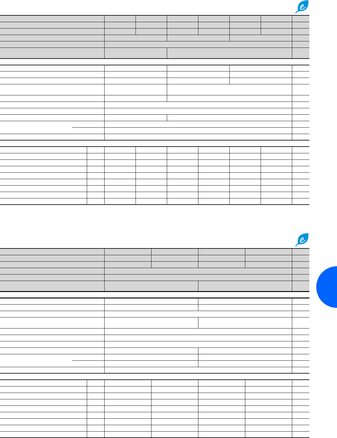
Roof-mounted cooling units
247Rittal Catalogue 33/Climate control
TopTherm “Blue e”, useful cooling output 2000 W
Model No. SK 3385.500 3385.6001) 3385.510 3385.6101) 3385.540 3385.6401) Page
Material Sheet steel Stainless steel Sheet steel Stainless steel Sheet steel Stainless steel
Colour RAL 7035 – RAL 7035 – RAL 7035 –
Rated operating voltage V, Hz 230, 1~, 50/603) 115, 1~, 50/603) 400, 2~, 50/603)
Dimensions mm W x H x D 597 x 417 x 475
Useful cooling output
to DIN 3168
L 35 L 35
L 35 L 50
2000 W/2030 W
1454 W/1547 W
2000 W/2140 W
1409 W/1511 W
Rated current max. 5.9 A/6.3 A 13.3 A/13.5 A 3.5 A/3.7 A
Start-up current 19.7 A/17.9 A 42.2 A/31.1 A 11.7 A/11.7 A
Pre-fuse T 10.0 A 14.0 A – 20.0 A2) 6.3 A – 10.0 A2)
Power consumption Pel
to DIN 3168 L 35 L 35
L 35 L 50 970 W/1155 W
1081 W/1511 W 1020 W/1235 W
1441 W/1310 W
Refrigeration factor ε = L 35 L 35 2.1 2.0
Refrigerant R134a, 900 g
Operating temperature and setting range +20°C to +55°C
Weight 42 kg 48 kg
Air throughput of fans
(unimpeded air flow)
External circuit 2100 m3/h
Internal circuit 657 m3/h
Temperature control e-Comfort controller (factory setting +35°C)
Accessories Packs of
Filter mats 3 3286.500 3286.500 3286.500 3286.500 3286.500 3286.500 299
Metal filters 1 3286.510 3286.510 3286.510 3286.510 3286.510 3286.510 300
Quick-change frame 1 3286.800 3286.800 3286.800 3286.800 3286.800 3286.800 297
Door-operated switch 1 4127.010 4127.010 4127.010 4127.010 4127.010 4127.010 496
SK BUS system 1 3124.100 3124.100 3124.100 3124.100 3124.100 3124.100 295
Interface board 1 3124.200 3124.200 3124.200 3124.200 3124.200 3124.200 295
Air duct system 1 3286.870 3286.870 3286.870 3286.870 3286.870 3286.870 291
Stoppers 2 3286.880 3286.880 3286.880 3286.880 3286.880 3286.880 292
Condensate hose 1 3301.612 3301.612 3301.612 3301.612 3301.612 3301.612 303
1) Extended delivery times. 2) Transformer protection switch. 3) Tu max = 53°C/60 Hz.
Special voltages available on request. We reserve the right to make technical modifications.
QK
.
QK/Pel
.
TopTherm “Blue e”, useful cooling output 3000 W/4000 W
Model No. SK 3386.540 3386.6401) 3387.540 3387.6401) Page
Material Sheet steel Stainless steel Sheet steel Stainless steel
Colour RAL 7035 – RAL 7035 –
Rated operating voltage V, Hz 400, 3~, 50/460, 3~, 60
Dimensions mm W x H x D 796 x 470 x 580
Useful cooling output
to DIN 3168
L 35 L 35
L 35 L 50
3000 W/3300 W
2200 W/2500 W
4000 W/4200 W
3250 W/3490 W
Rated current max. 3.4 A/3.4 A 3.9 A/3.9 A
Start-up current 8.0 A/9.0 A 17.0 A/19.0 A
Pre-fuse T Motor circuit breaker 6.3 A – 10.0 A
Power consumption Pel
to DIN 3168 L 35 L 35
L 35 L 50 1190 W/1500 W
1440 W/1780 W 1630 W/2070 W
1880 W/2350 W
Refrigeration factor ε = L 35 L 35 2.3
Refrigerant R134a, 1600 g
Operating temperature and setting range +20°C to +55°C
Weight 70 kg 77 kg
Air throughput of fans
(unimpeded air flow)
External circuit 3450 m3/h 3870 m3/h
Internal circuit 1280 m3/h 1420 m3/h
Temperature control e-Comfort controller (factory setting +35°C)
Accessories Packs of
Filter mats 3 3286.600 3286.600 3286.600 3286.600 299
Metal filters 1 3286.610 3286.610 3286.610 3286.610 300
Quick-change frame 1 3286.900 3286.900 3286.900 3286.900 297
Door-operated switch 1 4127.010 4127.010 4127.010 4127.010 496
SK BUS system 1 3124.100 3124.100 3124.100 3124.100 295
Interface board 1 3124.200 3124.200 3124.200 3124.200 295
Air duct system 1 3286.970 3286.970 3286.970 3286.970 291
Stoppers 2 3286.980 3286.980 3286.980 3286.980 292
Condensate hose 1 3301.612 3301.612 3301.612 3301.612 303
1) Extended delivery times.
Special voltages available on request. We reserve the right to make technical modifications.
QK
.
QK/Pel
.
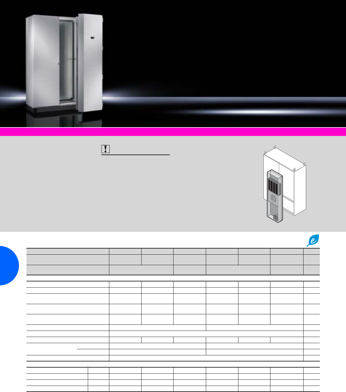
Modular climate control concept
248 Rittal Catalogue 33/Climate control
Climate control accessories Page 291 TS 8 enclosures Page 69 Software & services Page 333
Colour:
RAL 7035
Protection category:
−External circuit IP 34
to IEC 60 529
−Internal circuit IP 54
to IEC 60 529
Supply includes:
−Cooling module prepared for
installation in section door
−Nano-coated condenser
−Integral electric condensate
evaporation
Also required:
−Section door, fits TS 8
enclosures, 600, 800,
1200 mm widths and
1800, 2000 mm heights,
see page 249.
−Base/plinth,
100 or 200 mm high,
see page 361.
Approvals:
Available on the Internet.
Detailed drawing:
Available on the Internet.
Performance diagrams:
Available on the Internet.
Cooling modules “Blue e”, 1500/2500 W useful cooling output
Model No. SK with Comfort controller 3307.700 3307.710 3307.740 3310.700 3310.710 3310.740 Page
Rated operating voltage V, Hz 230, 1~, 50/60 115, 1~, 50/60 400, 3~, 50/
460, 3~, 60 230, 1~, 50/60 115, 1~, 50/60 400, 3~, 50/
460, 3~, 60
Useful cooling output
to DIN 3168
L 35 L 35
L 35 L 50
1500 W/1550 W
850 W/900 W
1500 W/1550 W
930 W/950 W
2500 W/2520 W
1620 W/1730 W
2500 W/2500 W
1760 W/1800 W
Rated current max. 6.0 A/6.1 A 11.2 A/11.8 A 2.5 A/2.7 A 7.6 A/9.4 A 17.3 A/19.0 A 3.5 A/3.7 A
Start-up current 22.0 A/24.0 A 36.0 A/39.0 A 8.5 A/9.2 A 22.0 A/24.0 A 36.0 A/39.0 A 13.0 A/14.0 A
Pre-fuse T 16.0 A/16.0 A 11.0 A –
16.0 A3) 6.3 A – 10.0 A1) 16.0 A/16.0 A 18.0 A –
25.0 A3) 6.3 A – 10.0 A1)
Power consumption Pel
to DIN 3168 L 35 L 35
L 35 L 50 850 W/1050 W
1000 W/1150 W 870 W/1080 W
1070 W/1180 W 790 W/1000 W
900 W/1100 W 1310 W/1520 W
1480 W/1850 W 1360 W/1570 W
1530 W/1900 W 1130 W/1480 W
1400 W/1750 W
Refrigeration factor
ε = L 35 L 35 1.8 1.7 1.9 1.9 1.8 2.2
Refrigerant R134a, 700 g R134a, 1175 g
Operating temperature and setting range +20°C to +55°C
Weight2) 68 kg 72 kg 68 kg 73 kg 78 kg 72 kg
Air throughput of fans
(unimpeded air flow)
External circuit 1100 m3/h 1100 m3/h
Internal circuit 600 m3/h 1100 m3/h
Temperature control Comfort controller (factory setting +35°C)
Accessories Packs of
Door-operated switch 1 4127.010 4127.010 4127.010 4127.010 4127.010 4127.010 496
SK BUS system 1 3124.100 3124.100 3124.100 3124.100 3124.100 3124.100 295
RiDiag II 1 3159.100 3159.100 3159.100 3159.100 3159.100 3159.100 347
Interface board 1 3124.200 3124.200 3124.200 3124.200 3124.200 3124.200 295
Special voltages available on request. We reserve the right to make technical modifications.
1) Motor circuit breaker
2) Includes section door weight
3) Transformer protection switch
QK
.
QK/Pel
.
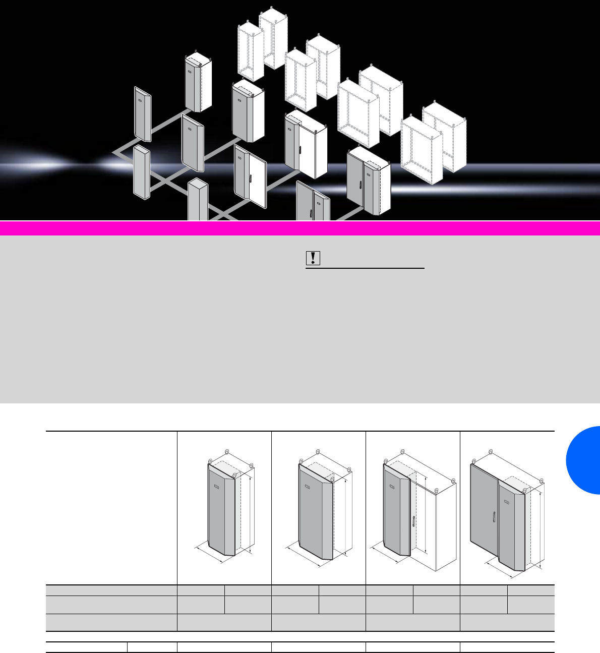
Modular climate control concept
249Rittal Catalogue 33/Climate control
Climate control accessories Page 291 TS 8 enclosures Page 69 Software & services Page 333
Colour:
RAL 7035
Supply includes:
−Section door without precon-
figured cooling module
−TS 8 hinges, door opening
angle approx. 110°
Note for 1200 mm wide
TS 8 enclosures:
−With the unit positioned on
the right, one pack consists
of a section door for installing
in the right-hand half of the
enclosure plus a special
lockable door for the left-hand
half.
−With the device positioned on
the “left”, one pack consists
of a section door for installing
in the left-hand half of the
enclosure. The existing lock-
able door on the right may be
used.
Also required:
−Cooling module,
see page 248.
−Base/plinth,
100 or 200 mm high,
see page 361.
Approvals:
Available on the Internet.
Detailed drawing:
Available on the Internet.
Performance diagrams:
Available on the Internet.
Section doors for installing cooling modules
Model No. SK 3300.040 3300.050 3300.060 3300.070 3300.080 3300.090 3300.110 3300.120
Dimensions
to fit TS enclosures Height mm 1800 2000 1800 2000 1800 2000 1800 2000
Dimensions
to fit TS enclosures Width (B) mm 600 800 1200
(unit positioned on the left) 1200
(unit positioned on the right)
Accessories Packs of
Metal filters 1 3284.210 3284.210 3284.210 3284.210
All SK 3307.700/.710/.740 or 3310.700/.710/.740 cooling module models, see page 248, can be integrated into one of the section doors mentioned above.
B
H
B
H
B
H
B
H
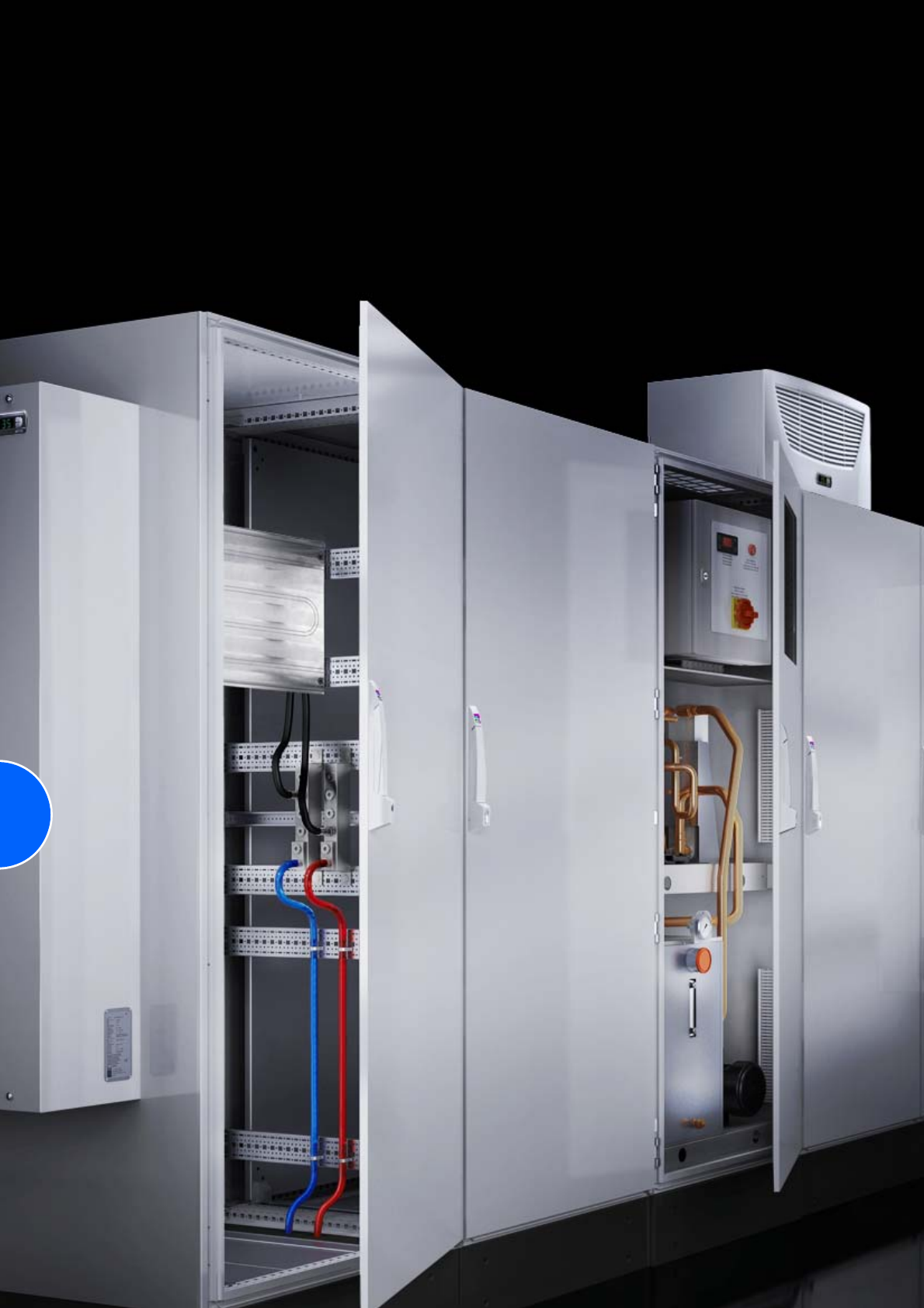
250
251
Liquid cooling
Air/water heat exchangers
Roof-mounted, water-carrying parts CuAl........................... 2500 W.........252
Roof-mounted, water-carrying parts CuAl........................... 4000 W.........253
Roof-mounted, water-carrying parts V4A (1.4571) ............. 1875 W.........253
Roof-mounted, water-carrying parts V4A (1.4571) ............. 3000 W.........254
Wall-mounted ........................................................ 300/600/1250 W.........255
Wall-mounted, water-carrying parts CuAl ............................. 500 W.........256
Wall-mounted, water-carrying parts CuAl ........................... 1000 W.........256
Wall-mounted, water-carrying parts CuAl ........................... 2000 W.........257
Wall-mounted, water-carrying parts CuAl ........................... 3000 W.........257
Wall-mounted, water-carrying parts CuAl ........................... 5000 W.........258
Wall-mounted ...................................................................... 7000 W.........258
Wall-mounted, water-carrying parts V4A (1.4571) ................ 500 W.........259
Wall-mounted, water-carrying parts V4A (1.4571) ................ 750 W.........259
Wall-mounted, water-carrying parts V4A (1.4571) .............. 1750 W.........260
Wall-mounted, water-carrying parts V4A (1.4571) .............. 2500 W.........260
Wall-mounted, water-carrying parts V4A (1.4571) .............. 4000 W.........261
Cold Plate
Cold Plate incl. T channel for frequency converters .. 2500/3000 W.........262
Accessories for Cold Plate ........................................................................263
Chillers for water
TopTherm .......................................................................... 1/1.5 kW.........264
TopTherm ....................................................................... 3/4.5/6 kW.........265
TopTherm, for wall mounting.......................................... 1/2.5/4 kW.........266
TopTherm ........................................................................ 8 – 40 kW.........267
In a floor-standing enclosure....................................... 2.1 – 7.7 kW.........268
In a floor-standing enclosure......................................... 10 – 25 kW.........269
In a floor-standing enclosure......................................... 32 – 59 kW.........269
Air/water heat exchangers
252 Rittal Catalogue 33/Climate control
Climate control accessories Page 291 Recooling systems Page 264 Software & Services Page 333
Colour:
RAL 7035
Supply includes:
−Fully wired ready for
connection, with connector
−Drilling template, sealing mat
and assembly parts
Also required:
Cooling water system
such as recooling systems,
from page 264.
Approvals:
Available on the Internet.
Detailed drawing:
Available on the Internet.
Performance diagrams:
Available on the Internet.
Roof-mounted, useful cooling output 2500 W, water-carrying parts CuAl
Model No. SK 3209.500 3209.100 Page
Thermostat
(factory setting +35°C)
e-Comfort controller –
Basic controller –
Useful cooling output L 35 W 10, 400 l/h 2500 W
Rated operating voltage V, Hz 230, 50/60
Dimensions mm W x H x D 597 x 417 x 475
Rated current max. 0.40 A/0.48 A
Pre-fuse T 4.0 A
Cooling medium Water (for specifications see Internet; user manual)
Water inlet temperature > +1°C to +30°C
Permissible operating pressure p. max. 1 to 10 bar
Operating temperature and setting range +1°C to +70°C
Protection category to IEC 60 529 IP 551)
Duty cycle 100%
Type of connection Plug-in terminal strip
Weight 23.5 kg
Air throughput of the fans (unimpeded air flow) 1030 m3/h
Accessories Packs of
Door-operated switch 1 4127.010 4127.010 496
SK BUS system 1 3124.100 – 295
Interface board 1 3124.200 – 295
Air duct system 1 3286.870 3286.870 291
Stoppers 1 3286.880 3286.880 292
Condensate hose 1 3301.612 3301.612 303
Flow regulator valve 1 see page 304
1) IP 65 available on request.
Special voltages available on request. We reserve the right to make technical modifications.

Air/water heat exchangers
253Rittal Catalogue 33/Climate control
Roof-mounted, useful cooling output 4000 W, water-carrying parts CuAl
Roof-mounted, useful cooling output 1875 W, water-carrying parts V4A (1.4571)
Model No. SK 3210.500 3210.100 3210.5401) 3210.1401) Page
Thermostat
(factory setting +35°C)
e-Comfort controller – –
Basic controller – –
Useful cooling output L 35 W 10, 400 l/h 4000 W
Rated operating voltage V, Hz 230, 50/60 400, 2~, 50/60
Dimensions mm W x H x D 597 x 417 x 475
Rated current max. 0.44 A/0.5 A 0.25 A/0.3 A
Pre-fuse T 4.0 A
Cooling medium Water (for specifications see Internet; user manual)
Water inlet temperature > +1°C to +30°C
Permissible operating pressure p. max. 1 to 10 bar
Operating temperature and setting range +1°C to +70°C
Protection category to IEC 60 529 IP 552)
Duty cycle 100%
Type of connection Plug-in terminal strip
Weight 25.5 kg 29.5 kg
Air throughput of the fans (unimpeded air flow) 925 m3/h
Accessories Packs of
Door-operated switch 1 4127.010 4127.010 4127.010 4127.010 496
SK BUS system 1 3124.100 – 3124.100 – 295
Interface board 1 3124.200 – 3124.200 – 295
Air duct system 1 3286.870 3286.870 3286.870 3286.870 291
Stoppers 1 3286.880 3286.880 3286.880 3286.880 292
Condensate hose 1 3301.612 3301.612 3301.612 3301.612 303
Flow regulator valve 1 see page 304
1) Extended delivery times.
2) IP 65 available on request.
Special voltages available on request. We reserve the right to make technical modifications.
Model No. SK 3209.5041) 3209.1041) Page
Thermostat
(factory setting +35°C)
e-Comfort controller –
Basic controller –
Useful cooling output L 35 W 10, 400 l/h 1875 W
Rated operating voltage V, Hz 230, 50/60
Dimensions mm W x H x D 597 x 417 x 475
Rated current max. 0.40 A/0.48 A
Pre-fuse T 4.0 A
Cooling medium Water (for specifications see Internet; user manual)
Water inlet temperature > +1°C to +30°C
Permissible operating pressure p. max. 1 to 10 bar
Operating temperature and setting range +1°C to +70°C
Protection category to IEC 60 529 IP 552)
Duty cycle 100%
Type of connection Plug-in terminal strip
Weight 23.5 kg
Air throughput of the fans (unimpeded air flow) 1030 m3/h
Accessories Packs of
Door-operated switch 1 4127.010 4127.010 496
SK BUS system 1 3124.100 – 295
Interface board 1 3124.200 – 295
Air duct system 1 3286.870 3286.870 291
Stoppers 1 3286.880 3286.880 292
Condensate hose 1 3301.612 3301.612 303
Flow regulator valve 1 see page 304
1) Extended delivery times.
2) IP 65 available on request.
Special voltages available on request. We reserve the right to make technical modifications.
Air/water heat exchangers
254 Rittal Catalogue 33/Climate control
Roof-mounted, useful cooling output 3000 W, water-carrying parts V4A (1.4571)
Model No. SK 3210.5041) 3210.1041) Page
Thermostat
(factory setting +35°C)
e-Comfort controller –
Basic controller –
Useful cooling output L 35 W 10, 400 l/h 3000 W
Rated operating voltage V, Hz 230, 50/60
Dimensions mm W x H x D 597 x 417 x 475
Rated current max. 0.44 A/0.5 A
Pre-fuse T 4.0 A
Cooling medium Water (for specifications see Internet; user manual)
Water inlet temperature > +1°C to +30°C
Permissible operating pressure p. max. 1 to 10 bar
Operating temperature and setting range +1°C to +70°C
Protection category to IEC 60 529 IP 552)
Duty cycle 100%
Type of connection Plug-in terminal strip
Weight 25.5 kg
Air throughput of the fans (unimpeded air flow) 925 m3/h
Accessories Packs of
Door-operated switch 1 4127.010 4127.010 496
SK BUS system 1 3124.100 – 295
Interface board 1 3124.200 – 295
Air duct system 1 3286.870 3286.870 291
Stoppers 1 3286.880 3286.880 292
Condensate hose 1 3301.612 3301.612 303
Flow regulator valve 1 see page 304
1) Extended delivery times.
2) IP 65 available on request.
Special voltages available on request. We reserve the right to make technical modifications.
Rittal Norway
RITTAL AS
Postboks 258 N-1401 Ski
Phone: +47 64 85 13 00 Fax: +47 64 85 13 01
Besøksadresse: Regnbueveien 10
N-1405 Langhus
E-mail: rittal@rittal.no www.rittal.no
Air/water heat exchangers
255Rittal Catalogue 33/Climate control
Climate control accessories Page 291 Recooling systems Page 264 Software & Services Page 333
Colour:
RAL 7035
Supply includes:
−Fully wired ready for
connection
−Drilling template
and assembly parts
Also required:
Cooling water system
such as recooling systems,
see from page 264.
Approvals:
Available on the Internet.
Detailed drawing:
Available on the Internet.
Performance diagrams:
Available on the Internet.
Wall-mounted, useful cooling output 300/600/1250 W
Model No. SK 3212.230 3212.1151) 3212.024 3214.100 3215.100 Page
Temperature control –Thermostat-controlled magnetic valve
Useful cooling output L 35 W 10, 200 l/h
L 35 W 10, 400 l/h 300 W 600 W
650 W
1250 W
1300 W
Rated operating voltage V, Hz 230, 50/60 115, 50/60 24 V (DC) 230, 50/60
Dimensions mm W x H x D 150 x 300 x 85 200 x 500 x 100 200 x 950 x 100
Rated current max. 0.11 A/0.13 A 0.23 A/0.24 A 1.20 A 0.17 A/0.18 A 0.38 A/0.4 A
Pre-fuse T 2.0 A 4.0 A
Cooling medium Water (for specifications see Internet; user manual)
Water inlet temperature > +1°C to +30°C
Permissible operating pressure p. max. 1 to 10 bar
Operating temperature and setting range +1°C to +70°C
Protection category to IEC 60 529 IP 552)
Duty cycle 100%
Type of connection Connection clamp Terminal strip
Weight 3 kg 7 kg 13 kg
Air throughput of the fans (unimpeded air flow) 280 m3/h 250 m3/h 120 m3/h 200 m3/h
Temperature monitoring – Internal thermostat, with change-over contact,
switching load 16 A, setting range +20°C to +60°C
(factory setting +35°C)
Accessories Packs of
Digital temperature display/thermostat 1 3114.200 3114.200 3114.200 3114.200 3114.200 293
Door-operated switch 1 4127.010 4127.010 4127.010 4127.010 4127.010 496
Condensate hose 1 3301.610 3301.610 3301.610 3301.612 3301.612 303
Flow regulator valve 1 see page 304
1) Extended delivery times.
2) IP 65 available on request.
Special voltages available on request. We reserve the right to make technical modifications.
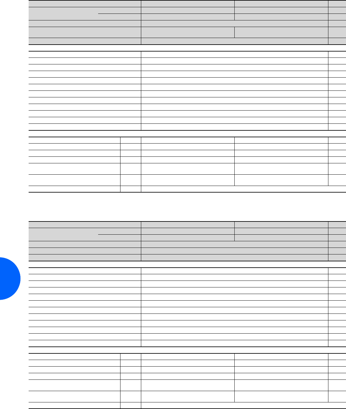
Air/water heat exchangers
256 Rittal Catalogue 33/Climate control
Wall-mounted, useful cooling output 500 W, water-carrying parts CuAl
Wall-mounted, useful cooling output 1000 W, water-carrying parts CuAl
Model No. SK 3363.500 3363.100 Page
Thermostat
(factory setting +35°C)
e-Comfort controller –
Basic controller –
Useful cooling output L 35 W 10, 400 l/h 500 W
Rated operating voltage V, Hz 230, 1~,
50/60 230, 1~,
50/60
Dimensions mm W x H x D 280 x 550 x 120
Rated current max. 0.17 A/0.18 A
Pre-fuse T 4.0 A
Cooling medium Water (for specifications see Internet; user manual)
Water inlet temperature +1°C to +30°C
Water connection Quick-release fastener system
Permissible operating pressure p. max. 1 to 10 bar
Operating temperature and setting range +1°C to +70°C
Protection category to IEC 60 529 IP 551)
Duty cycle 100%
Type of connection Plug-in terminal strip
Weight 12 kg
Air throughput of the fans (unimpeded air flow) 270/320 m3/h
Accessories Packs of
Door-operated switch 1 4127.010 4127.010 496
SK BUS system 1 3124.100 – 295
Interface board 1 3124.200 – 295
Condensate hose 1 3301.612 3301.612 303
Threaded adaptor for quick-release fastener
with G3/8˝ internal thread 2 3201.900 3201.900 304
Threaded adaptor for quick-release fastener
with G3/8˝ external thread 2 3201.910 3201.910 304
Flow regulator valve 1 see page 304
1) IP 65 available on request.
Special voltages available on request. We reserve the right to make technical modifications.
Model No. SK 3364.500 3364.100 Page
Thermostat
(factory setting +35°C)
e-Comfort controller –
Basic controller –
Useful cooling output L 35 W 10, 400 l/h 1000 W
Rated operating voltage V, Hz 230, 1~, 50/60
Dimensions mm W x H x D 280 x 550 x 120
Rated current max. 0.2 A/0.19 A
Pre-fuse T 4.0 A
Cooling medium Water (for specifications see Internet; user manual)
Water inlet temperature +1°C to +30°C
Water connection Quick-release fastener system
Permissible operating pressure p. max. 1 to 10 bar
Operating temperature and setting range +1°C to +70°C
Protection category to IEC 60 529 IP 551)
Duty cycle 100%
Type of connection Plug-in terminal strip
Weight 15 kg
Air throughput of the fans (unimpeded air flow) 270/320 m3/h
Accessories Packs of
Door-operated switch 1 4127.010 4127.010 496
SK BUS system 1 3124.100 – 295
Interface board 1 3124.200 – 295
Condensate hose 1 3301.612 3301.612 303
Threaded adaptor for quick-release fastener
with G3/8˝ internal thread 2 3201.900 3201.900 304
Threaded adaptor for quick-release fastener
with G3/8˝ external thread 2 3201.910 3201.910 304
Flow regulator valve 1 see page 304
1) IP 65 available on request.
Special voltages available on request. We reserve the right to make technical modifications.

Air/water heat exchangers
257Rittal Catalogue 33/Climate control
Wall-mounted, useful cooling output 2000 W, water-carrying parts CuAl
Wall-mounted, useful cooling output 3000 W, water-carrying parts CuAl
Model No. SK 3373.500 3373.100 Page
Thermostat
(factory setting +35°C)
e-Comfort controller –
Basic controller –
Useful cooling output L 35 W 10, 400 l/h 2000 W
Rated operating voltage V, Hz 230, 1~, 50/60
Dimensions mm W x H x D 400 x 950 x 140
Rated current max. 0.38 A/0.43 A
Pre-fuse T 4.0 A
Cooling medium Water (for specifications see Internet; user manual)
Water inlet temperature +1°C to +30°C
Water connection Quick-release fastener system
Permissible operating pressure p. max. 1 to 10 bar
Operating temperature and setting range +1°C to +70°C
Protection category to IEC 60 529 IP 551)
Duty cycle 100%
Type of connection Plug-in terminal strip
Weight 20 kg
Air throughput of the fans (unimpeded air flow) 600/625 m3/h
Accessories Packs of
Door-operated switch 1 4127.010 4127.010 496
SK BUS system 1 3124.100 – 295
Interface board 1 3124.200 – 295
Condensate hose 1 3301.612 3301.612 303
Threaded adaptor for quick-release fastener
with G3/8˝ internal thread 2 3201.900 3201.900 304
Threaded adaptor for quick-release fastener
with G3/8˝ external thread 2 3201.910 3201.910 304
Flow regulator valve 1 see page 304
1) IP 65 available on request.
Special voltages available on request. We reserve the right to make technical modifications.
Model No. SK 3374.500 3374.100 Page
Thermostat
(factory setting +35°C)
e-Comfort controller –
Basic controller –
Useful cooling output L 35 W 10, 400 l/h 3000 W
Rated operating voltage V, Hz 230, 1~, 50/60
Dimensions mm W x H x D 400 x 950 x 140
Rated current max. 0.57 A/0.78 A
Pre-fuse T 4.0 A
Cooling medium Water (for specifications see Internet; user manual)
Water inlet temperature +1°C to +30°C
Water connection Quick-release fastener system
Permissible operating pressure p. max. 1 to 10 bar
Operating temperature and setting range +1°C to +70°C
Protection category to IEC 60 529 IP 551)
Duty cycle 100%
Type of connection Plug-in terminal strip
Weight 20 kg
Air throughput of the fans (unimpeded air flow) 700/730 m3/h
Accessories Packs of
Door-operated switch 1 4127.010 4127.010 496
SK BUS system 1 3124.100 – 295
Interface board 1 3124.200 – 295
Condensate hose 1 3301.612 3301.612 303
Threaded adaptor for quick-release fastener
with G3/8˝ internal thread 2 3201.900 3201.900 304
Threaded adaptor for quick-release fastener
with G3/8˝ external thread 2 3201.910 3201.910 304
Flow regulator valve 1 see page 304
1) IP 65 available on request.
Special voltages available on request. We reserve the right to make technical modifications.
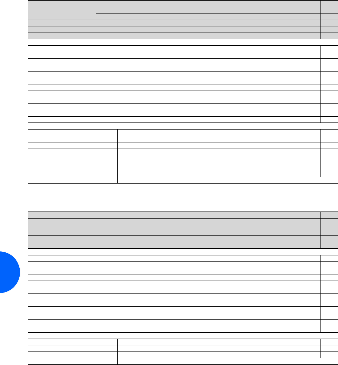
Air/water heat exchangers
258 Rittal Catalogue 33/Climate control
Wall-mounted, useful cooling output 5000 W, water-carrying parts CuAl
Wall-mounted, useful cooling output 7000 W
Model No. SK 3375.500 3375.100 Page
Thermostat
(factory setting +35°C)
e-Comfort controller –
Basic controller –
Useful cooling output L 35 W 10, 400 l/h 5000 W
Rated operating voltage V, Hz 230, 1~, 50/60
Dimensions mm W x H x D 450 x 1400 x 220
Rated current max. 1.0 A/1.35 A
Pre-fuse T 4.0 A
Cooling medium Water (for specifications see Internet; user manual)
Water inlet temperature +1°C to +30°C
Water connection Quick-release fastener system
Permissible operating pressure p. max. 1 to 10 bar
Operating temperature and setting range +1°C to +70°C
Protection category to IEC 60 529 IP 551)
Duty cycle 100%
Type of connection Plug-in terminal strip
Weight 56 kg
Air throughput of the fans (unimpeded air flow) 2365/2,750 m3/h
Accessories Packs of
Door-operated switch 1 4127.010 4127.010 496
SK BUS system 1 3124.100 – 295
Interface board 1 3124.200 – 295
Condensate hose 1 3301.612 3301.612 303
Threaded adaptor for quick-release fastener
with G3/8˝ internal thread 2 3201.900 3201.900 304
Threaded adaptor for quick-release fastener
with G3/8˝ external thread 2 3201.910 3201.910 304
Flow regulator valve 1 see page 304
1) IP 65 available on request.
Special voltages available on request. We reserve the right to make technical modifications.
Model No. SK 3216.4801) Page
Temperature control Thermostat-controlled magnetic valve
Useful cooling output L 35 W 10, 500 l/h
L 35 W 20, 500 l/h
7000 W
4500 W
Rated operating voltage V, Hz 400, 3~, 50/60 460, 3~, 60
Dimensions mm W x H x D 450 x 1800 x 300
Rated current max. 1.4 A/1.6 A 1.2 A
Pre-fuse T 4.0 A, 3-pole
Power consumption Pel 450 W/700 W 630 W
Cooling medium Water (for specifications see Internet; user manual)
Water inlet temperature +1°C to +30°C
Permissible operating pressure p. max. 1 to 10 bar
Operating temperature and setting range +1°C to +70°C
Protection category to IEC 60 529 IP 552)
Duty cycle 100%
Type of connection Terminal strip
Weight 79 kg
Air throughput of the fans (unimpeded air flow) 2400 m3/h
Accessories Packs of
Digital temperature display/thermostat 1 3114.200 293
Door-operated switch 1 4127.010 496
Condensate hose 1 3301.612 303
Flow regulator valve 1 see page 304
1) Extended delivery times.
2) IP 65 available on request.
Special voltages available on request. We reserve the right to make technical modifications.
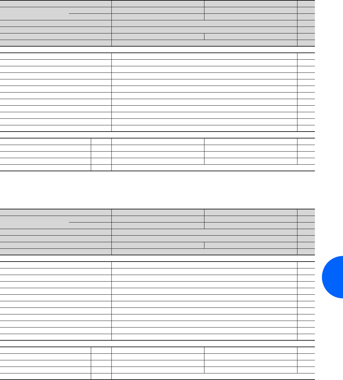
Air/water heat exchangers
259Rittal Catalogue 33/Climate control
Wall-mounted, useful cooling output 500 W, water-carrying parts V4A (1.4571)
Wall-mounted, useful cooling output 750 W, water-carrying parts V4A (1.4571)
Model No. SK 3363.5041) 3363.1041) Page
Thermostat
(factory setting +35°C)
e-Comfort controller –
Basic controller –
Useful cooling output L 35 W 10, 400 l/h 500 W
Rated operating voltage V, Hz 230, 1~, 50/60
External transformer – –
Dimensions mm W x H x D 280 x 550 x 120
Rated current max. 0.17 A/0.18 A
Pre-fuse T 4.0 A
Cooling medium Water (for specifications see Internet; user manual)
Water inlet temperature +1°C to +30°C
Permissible operating pressure p. max. 1 to 10 bar
Operating temperature and setting range +1°C to +70°C
Protection category to IEC 60 529 IP 552)
Duty cycle 100%
Type of connection Plug-in terminal strip
Water connection Quick-release fastener system3)
Weight 12 kg
Air throughput of the fans (unimpeded air flow) 270/320 m3/h
Accessories Packs of
Door-operated switch 1 4127.010 4127.010 496
SK BUS system 1 3124.100 – 295
Interface board 1 3124.200 – 295
Condensate hose 1 3301.612 3301.612 303
Flow regulator valve 1 see page 304
1) Extended delivery times.
2) IP 65 available on request.
3) Threaded adaptor for quick-release fastener available on request.
Special voltages available on request. We reserve the right to make technical modifications.
Model No. SK 3364.5041) 3364.1041) Page
Thermostat
(factory setting +35°C)
e-Comfort controller –
Basic controller –
Useful cooling output L 35 W 10, 400 l/h 750 W
Rated operating voltage V, Hz 230, 1~, 50/60
External transformer – –
Dimensions mm W x H x D 280 x 550 x 120
Rated current max. 0.2 A/0.19 A
Pre-fuse T 4.0 A
Cooling medium Water (for specifications see Internet; user manual)
Water inlet temperature +1°C to +30°C
Permissible operating pressure p. max. 1 to 10 bar
Operating temperature and setting range +1°C to +70°C
Protection category to IEC 60 529 IP 552)
Duty cycle 100%
Type of connection Plug-in terminal strip
Water connection Quick-release fastener system3)
Weight 15 kg
Air throughput of the fans (unimpeded air flow) 270/320 m3/h
Accessories Packs of
Door-operated switch 1 4127.010 4127.010 496
SK BUS system 1 3124.100 – 295
Interface board 1 3124.200 – 295
Condensate hose 1 3301.612 3301.612 303
Flow regulator valve 1 see page 304
1) Extended delivery times.
2) IP 65 available on request.
3) Threaded adaptor for quick-release fastener available on request.
Special voltages available on request. We reserve the right to make technical modifications.
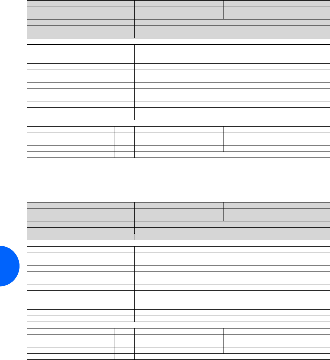
Air/water heat exchangers
260 Rittal Catalogue 33/Climate control
Wall-mounted, useful cooling output 1750 W, water-carrying parts V4A (1.4571)
Wall-mounted, useful cooling output 2500 W, water-carrying parts V4A (1.4571)
Model No. SK 3373.5041) 3373.1041) Page
Thermostat
(factory setting +35°C)
e-Comfort controller –
Basic controller –
Useful cooling output L 35 W 10, 400 l/h 1750 W
Rated operating voltage V, Hz 230, 1~, 50/60
Dimensions mm W x H x D 400 x 950 x 140
Rated current max. 0.38 A/0.43 A
Pre-fuse T 4.0 A
Cooling medium Water (for specifications see Internet; user manual)
Water inlet temperature +1°C to +30°C
Permissible operating pressure p. max. 1 to 10 bar
Operating temperature and setting range +1°C to +70°C
Protection category to IEC 60 529 IP 552)
Duty cycle 100%
Type of connection Plug-in terminal strip
Water connection Quick-release fastener system3)
Weight 20 kg
Air throughput of the fans (unimpeded air flow) 600/625 m3/h
Accessories Packs of
Door-operated switch 1 4127.010 4127.010 496
SK BUS system 1 3124.100 – 295
Interface board 1 3124.200 – 295
Condensate hose 1 3301.612 3301.612 303
Flow regulator valve 1 see page 304
1) Extended delivery times.
2) IP 65 available on request.
3) Threaded adaptor for quick-release fastener available on request.
Special voltages available on request. We reserve the right to make technical modifications.
Model No. SK 3374.5041) 3374.1041) Page
Thermostat
(factory setting +35°C)
e-Comfort controller –
Basic controller –
Useful cooling output L 35 W 10, 400 l/h 2500 W
Rated operating voltage V, Hz 230, 1~, 50/60
Dimensions mm W x H x D 400 x 950 x 140
Rated current max. 0.57 A/0.78 A
Pre-fuse T 4.0 A
Cooling medium Water (for specifications see Internet; user manual)
Water inlet temperature +1°C to +30°C
Permissible operating pressure p. max. 1 to 10 bar
Operating temperature and setting range +1°C to +70°C
Protection category to IEC 60 529 IP 552)
Duty cycle 100%
Type of connection Plug-in terminal strip
Water connection Quick-release fastener system3)
Weight 20 kg
Air throughput of the fans (unimpeded air flow) 700/730 m3/h
Accessories Packs of
Door-operated switch 1 4127.010 4127.010 496
SK BUS system 1 3124.100 – 295
Interface board 1 3124.200 – 295
Condensate hose 1 3301.612 3301.612 303
Flow regulator valve 1 see page 304
1) Extended delivery times.
2) IP 65 available on request.
3) Threaded adaptor for quick-release fastener available on request.
Special voltages available on request. We reserve the right to make technical modifications.
Air/water heat exchangers
261Rittal Catalogue 33/Climate control
Wall-mounted, useful cooling output 4000 W, water-carrying parts V4A (1.4571)
Model No. SK 3375.5041) 3375.1041) Page
Thermostat
(factory setting +35°C)
e-Comfort controller –
Basic controller –
Useful cooling output L 35 W 10, 400 l/h 4000 W
Rated operating voltage V, Hz 230, 1~, 50/60
Dimensions mm W x H x D 450 x 1400 x 220
Rated current max. 1.0 A/1.35 A
Pre-fuse T 4.0 A
Cooling medium Water (for specifications see Internet; user manual)
Water inlet temperature +1°C to +30°C
Permissible operating pressure p. max. 1 to 10 bar
Operating temperature and setting range +1°C to +70°C
Protection category to IEC 60 529 IP 552)
Duty cycle 100%
Type of connection Plug-in terminal strip
Water connection Quick-release fastener system3)
Weight 56 kg
Air throughput of the fans (unimpeded air flow) 2365/2750 m3/h
Accessories Packs of
Door-operated switch 1 4127.010 4127.010 496
SK BUS system 1 3124.100 – 295
Interface board 1 3124.200 – 295
Condensate hose 1 3301.612 3301.612 303
Flow regulator valve 1 see page 304
1) Extended delivery times.
2) IP 65 available on request.
3) Threaded adaptor for quick-release fastener available on request.
Special voltages available on request. We reserve the right to make technical modifications.
Rittal Sweden
RITTAL Scandinavian ab
Rittalgatan 1 SE-262 73 Ängelholm
Phone: +46 (431) 44 26 00
Fax: +46 (431) 44 26 44
E-mail: info@rittal.se www.rittal.se
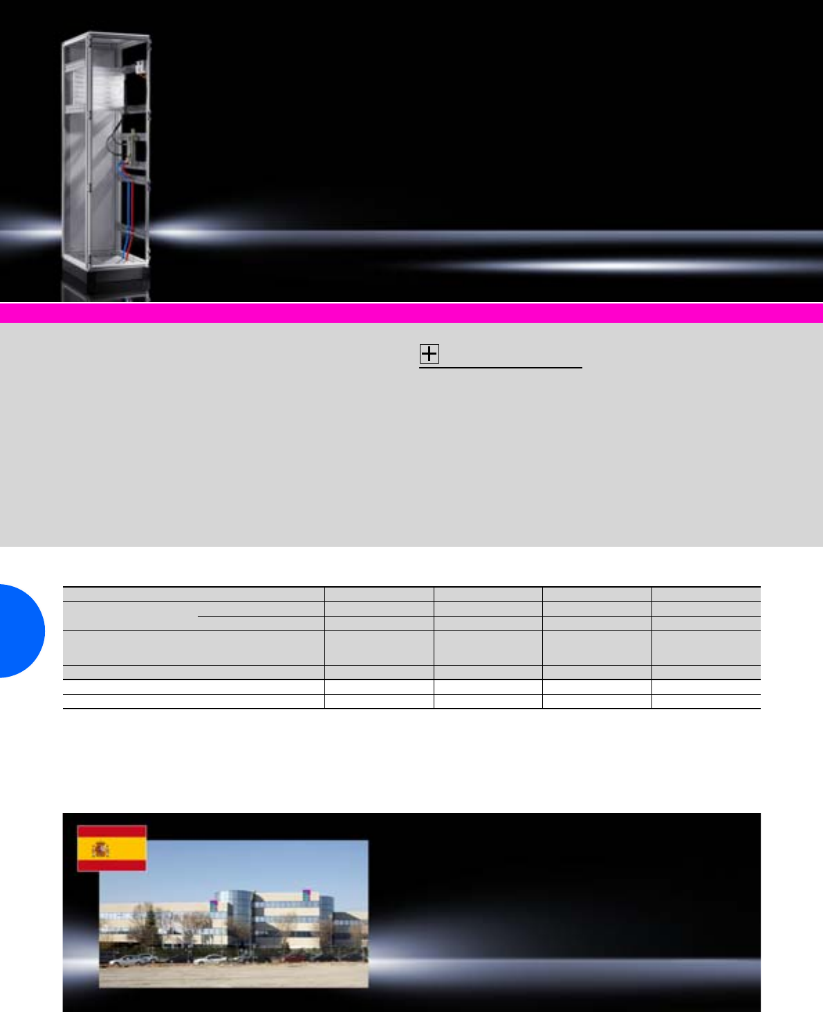
Cold Plate
262 Rittal Catalogue 33/Climate control
Recooling systems page 264 Accessories for climate control page 291
Liquid-cooled partial
mounting plate with drilling
surface and T channel
Whole surface can be used by
the customer for own tapped
holes (blind holes) to a maxi-
mum drilling depth of 12 mm.
Alternatively, drive units may be
secured to the T channel
depending on the version.
Design:
−Press-fitted copper or stain-
less steel tubes, dependent
on the application, in closed
recooling systems or existing
(open) water infrastructure.
−Cooling water connection:
G1/4˝, anti-twist
Supply includes:
Mounting accessories for
system integration into TS 8.
Accessories:
−Quick-action vent valve,
see page 263.
−Accessories for fluid distribu-
tor connection, see page 263.
−TS punched section with
mounting flange 17 x 73 mm
for the outer mounting level,
see page 459.
−Recooling systems for closed
cooling circuits,
see from page 264.
−System attachment
SK 8616.700, see page 263.
Further technical information
is available at www.rittal.com
Detailed drawing:
Available on the Internet.
Rittal Spain
RITTAL Disprel S.A.
Mas Baiona, 40
Polígono Industrial Can Roqueta
08202 Sabadell (Barcelona)
Phone: +34 937 001 300
Fax: +34 937 001 301
E-mail: info@rittal.es www.rittal.es
Cold Plate incl. T channel for frequency converters
Model No. SK 8616.602 8616.622 8616.802 8616.822
For installation in Enclosure width mm 600 600 800 800
Enclosure depth (side) mm 600 600 800 800
Dimensions mm W
H
D
499
399
20
499
399
20
699
399
20
699
399
20
Output1) 2500 W 2500 W 3000 W 3000 W
Material CU VA CU VA
Packs of 1 1 1 1
1) At 25°C medium inlet temperature, Cold Plate surface temperature ≈ 50°C, medium flowrate = 200 l/h, surface roughness: 1.2 μm.
Special sizes available on request.
Q
.
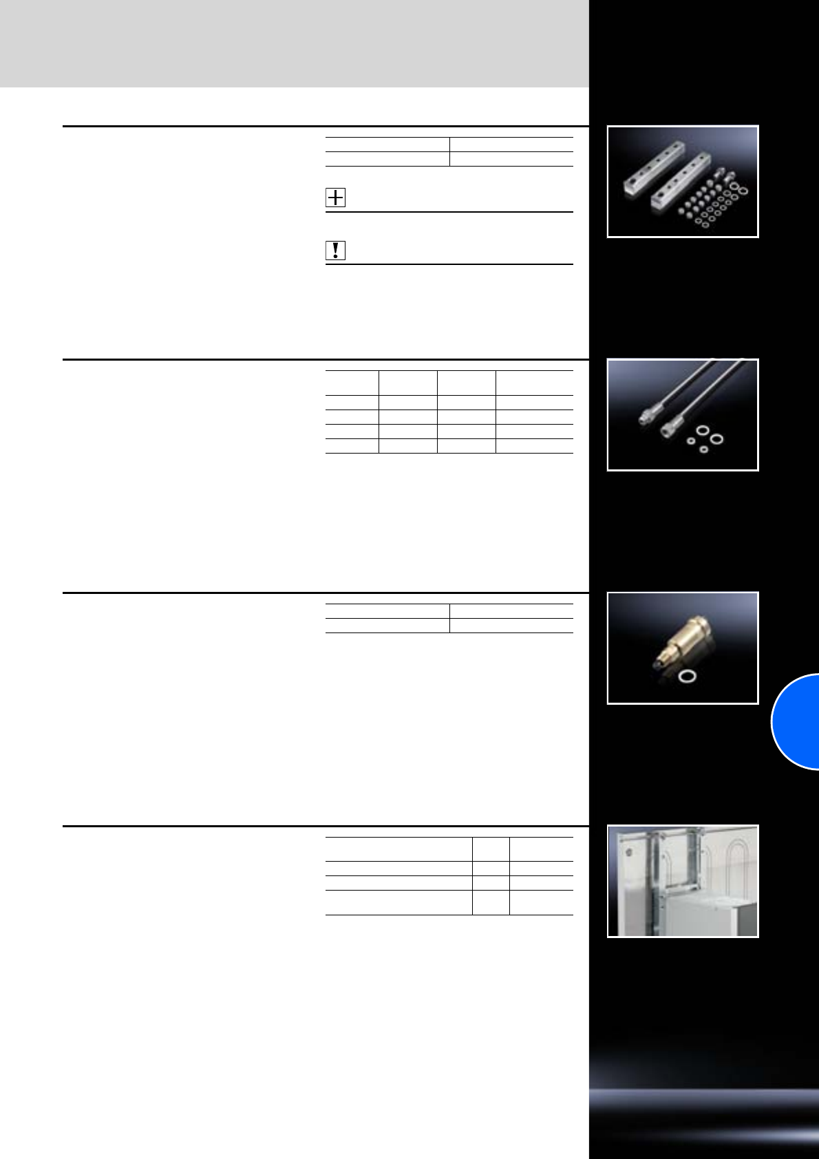
Accessories
Cold Plate
263Rittal Catalogue 33/Climate control
Fluid distribution manifold
For the connection of up to 4 Cold Plate units.
Supply includes:
−2 fluid distribution manifold blocks
(inlet and return)
−Screw plugs G1/4˝, G3/8˝
−Connector sleeves G1/2˝
−Seals
Accessories:
Flexible hose, see page 263.
Also required:
Quick-action vent valve, see page 263.
Packs of Model No. SK
1 set 8616.750
Flexible hose
For connection of the Cold Plate to a fluid distribu-
tion manifold or direct fluid connection.
Supply includes:
−2 flexible hoses G1/4˝
−Seals
Packs of Length
mm Material Model No. SK
1 set 500 CU 8616.772
1 set 1000 CU 8616.773
1 set 500 VA 8616.7601)
1 set 1000 VA 8616.7611)
1) Extended delivery times.
Quick-action vent valve
To vent the complete Cold Plate system.
Easily mounted on the fluid distribution manifold.
Supply includes:
−Quick-action vent valve G3/8˝
−Seal
Packs of Model No. SK
18616.762
System attachment
for frequency converters
For mounting frequency converters on the
Cold Plate.
Supply includes:
−Wire clamp system
−T-slot blocks
For the attachment
of frequency converters Packs
of Model No.
SK
with all-round clamping surface 1 8616.700
with side clamping surfaces 1 8616.710
with clamping surfaces top
and bottom 18616.720
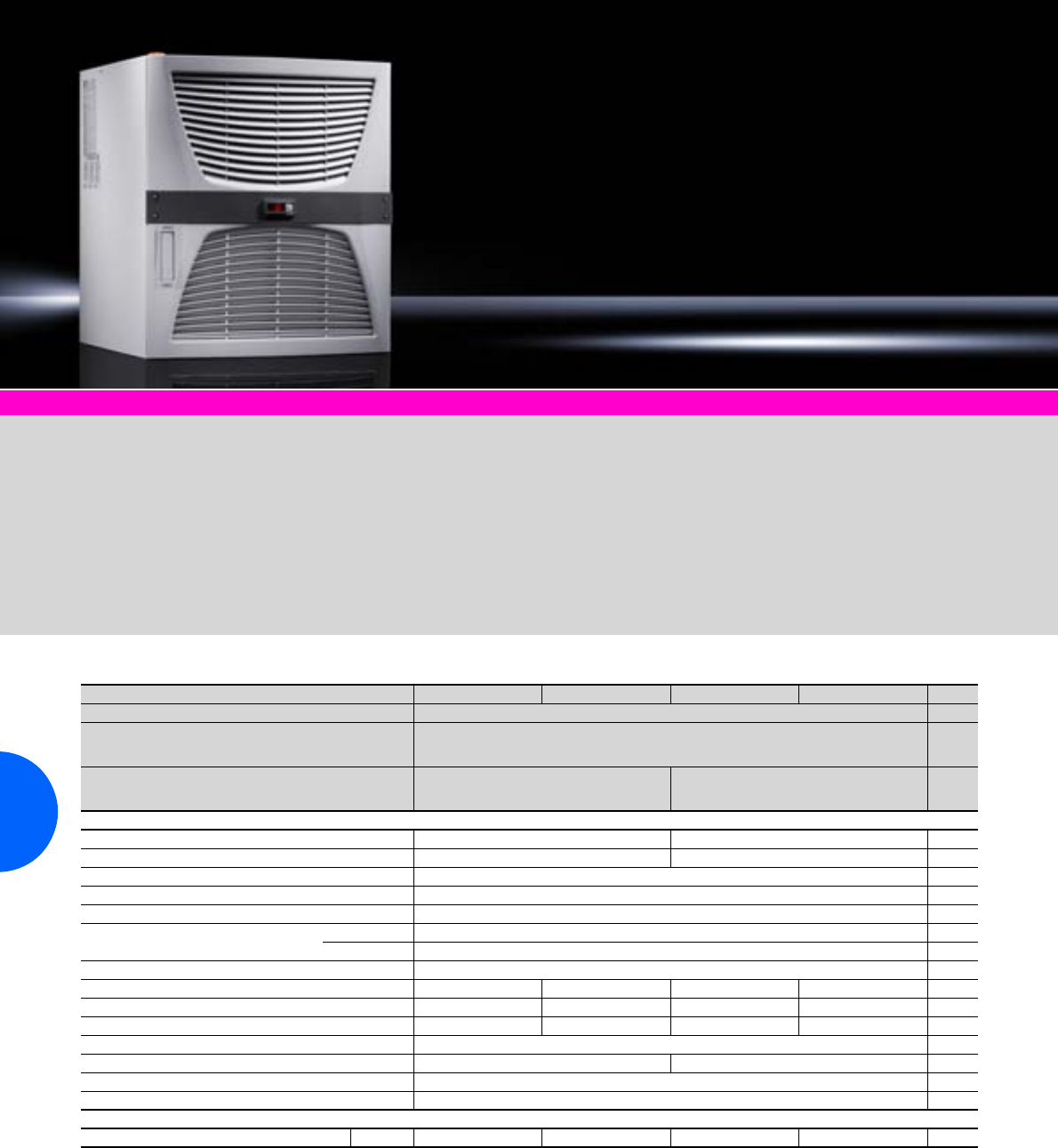
Chillers for water
264 Rittal Catalogue 33/Climate control
Air/water heat exchangers From page 252 Overflow valve Page 304 Cooling medium Page 305
Technical design:
−Compact, modular layout of
the refrigeration components
−With RiNano coating
−Pump to convey the medium
−Precise temperature control,
based on microprocessor
technology
−Collective fault signal with
floating contact
Colour:
RAL 7035
Protection category:
IP 44 (electrics)
Supply includes:
−Recooling system wired ready
for connection
−Multi-lingual documentation
−Functional diagram and
wiring plans
Approvals:
Available on the Internet.
Layout diagram:
Available on the Internet.
Characteristic curves of pump:
Available on the Internet.
Other options:
Available on the Internet.
TopTherm, cooling output 1/1.5 kW
Model No. SK 3318.600 3318.610 3319.600 3319.610 Page
Rated operating voltage V, Hz 230, 50/60
Dimensions mm W
H
D
600
400
430
Cooling output at
Tw = 10°C/Tu = 32°C
Tw = 18°C/Tu = 32°C
0.8 kW/0.9 kW
1.0 kW/1.1 kW
1.2 kW/1.3 kW
1.5 kW/1.7 kW
Power consumption 0.63 kW/0.78 kW 0.85 kW/1.05 kW
Rated current max. 4.2 A/4.1 A 5.4 A/5.3 A
Pre-fuse T 10 A
Refrigerant R134a
Number of cooling circuits 1
Temperature range Environment +15°C to +43°C
Liquid media +10°C to +30°C
Pump capacity See characteristic curve of pump
Design Pressure-sealed Open Pressure-sealed Open
Tank –
Made from PP plastic
–
Made from PP plastic
Tank capacity – 2.5 l – 2.5 l
Water connections 1/2˝ internal thread
Weight 48 kg 51 kg
Air throughput of fans 900 m3/h
Temperature control Microcontroller control (factory setting +20°C)
Accessories Packs of
Metal filters 1 3286.510 3286.510 3286.510 3286.510 300
Customised solutions and technical modifications available on request.
We reserve the right to make technical modifications.
Chillers for water
265Rittal Catalogue 33/Climate control
TopTherm, cooling output 3/4.5/6 kW
Model No. SK 3320.600 3334.600 3334.6602) Page
Rated operating voltage V, Hz 400, 3~, 50/60/460, 3~, 601)
Dimensions mm W
H
D
602
676
645
602
1050
645
Cooling output at
Tw = 10°C/Tu = 32°C
Tw = 18°C/Tu = 32°C
2.7 kW/3.0 kW
3.0 kW/3.4 kW
3.9 kW/4.7 kW
4.5 kW/5.4 kW
4.8 kW/5.2 kW/5.2 kW
6.0 kW/6.6 kW/6.6 kW
Power consumption 1.72 kW/1.95 kW 2.00 kW/2.51 kW 4.3 kW/5.1 kW/5.1 kW
Rated current max. 3.8 A/4.6 A/3.9 A 4.9 A/5.9 A/5.0 A 8 A/9.7 A/8 A
Pre-fuse T 10 A 16 A
Refrigerant R134a
Number of cooling circuits 1
Temperature range Environment +15°C to +43°C
Liquid media +10°C to +30°C
Pump capacity See characteristic curve of pump
Tank Made from PP plastic
Tank capacity 30 l
Water connections 1/2˝ internal thread 3/4˝ internal thread
Weight (empty) 88 kg 94 kg 125 kg
Air throughput of fans 1785 m3/h 2200/2500 m3/h
Temperature control Microcontroller control (factory setting +20°C)
Accessories
Metal filters 3286.520 3286.520 3286.510 300
Packs of 1 1 2
1) Supports multiple voltages without rewiring.
2) Integral fill level display.
Special voltages and technical modifications available on request.
We reserve the right to make technical modifications.
Rittal South Korea
RITTAL Co., Ltd.
Seoul Head Office
3rd Floor Asaan Venture Tower B/D
315-6 Yangjae-Dong
Seocho-Gu Seoul 137-896 Korea
Phone: +82 (0)2-577-6525
Fax: +82 (0)2-577-6526
E-mail: rittal@rittal.co.kr www.rittal.co.kr
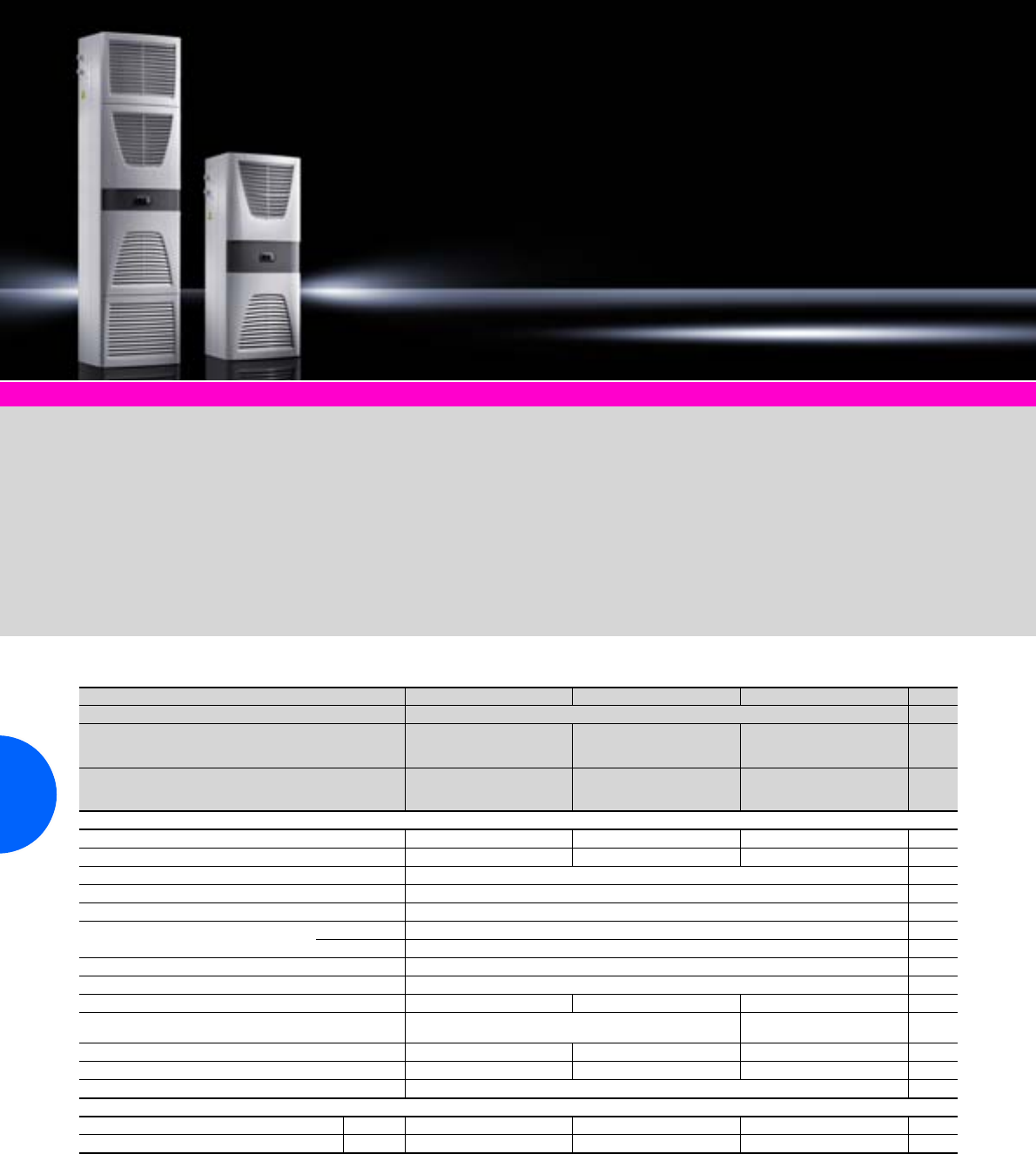
Chillers for water
266 Rittal Catalogue 33/Climate control
Air/water heat exchangers From page 252 Overflow valve Page 304 Cooling medium Page 305
Technical design:
−Compact, modular configura-
tion of the cooling compo-
nents with integral water tank
−With RiNano coating
−Pump to convey the medium
−Precise temperature control,
based on microprocessor
technology
−Open system with tank
−Collective fault signal with
floating contact
Colour:
RAL 7035
Protection category:
IP 44 (electrics)
Supply includes:
−Recooling system wired ready
for connection
−Multi-lingual documentation
−Functional diagram and
wiring plans
Approvals:
Available on the Internet.
Layout diagram:
Available on the Internet.
Characteristic curves of pump:
Available on the Internet.
Other options:
Available on the Internet.
TopTherm, for wall mounting, cooling output 1/2.5/4 kW
Model No. SK 3360.100 3360.250 3360.470 Page
Rated operating voltage V, Hz 400, 3~, 50/60/460, 3~, 601)
Dimensions mm W
H
D
400
950
310
400
1580
290
500
1580
390
Cooling output at
Tw = 10°C/Tu = 32°C
Tw = 18°C/Tu = 32°C
0.8 W/0.9 kW
1.0 kW/1.1 kW
2.1 kW/2.3 kW
2.5 kW/2.8 kW
3.3 kW/3.7 kW
4.0 kW/4.5 kW
Power consumption 0.7 kW/0.76 kW 1.55 kW/2.0 kW 1.85 kW/2.74 kW
Rated current max. 2.7 A/3.0 A 3.7 A/3.8 A 4.6 A/5.2 A
Pre-fuse T 10 A
Refrigerant R134a
Number of cooling circuits 1
Temperature range Environment +15°C to +43°C
Liquid media +10°C to +30°C
Pump capacity See characteristic curve of pump
Tank Plastic
Tank capacity 5 l 10 l 15 l
Water connections Quick-release coupling
(counterpart included in accessory bag) 3/4˝ internal thread
Weight 47 kg 78 kg 103 kg
Air throughput of fans 500 m3/h 710 m3/h 2000 m3/h
Temperature control Microcontroller control (factory setting +20°C)
Accessories Packs of
Filter mat 1 3286.400 3286.400 3286.400 299
Metal filters 1 3286.410 3286.410 3286.410 300
1) Supports multiple voltages without rewiring.
Special voltages and technical modifications available on request.
We reserve the right to make technical modifications.
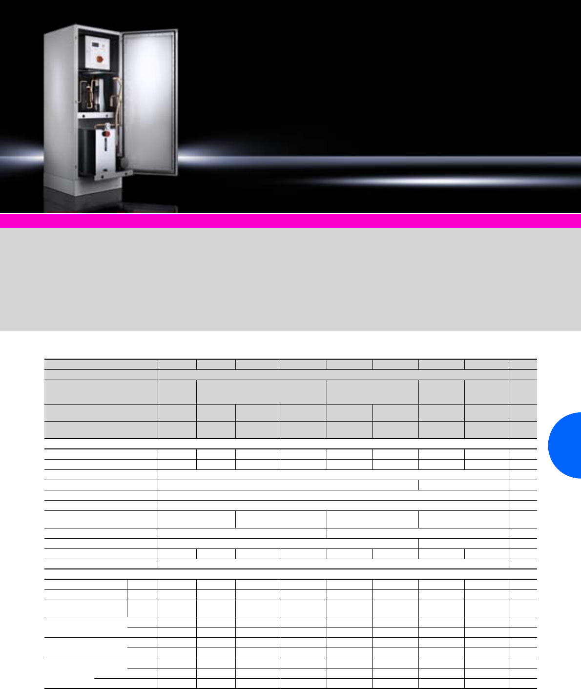
Chillers for water
267Rittal Catalogue 33/Climate control
Climate control accessories Page 291
Benefits:
●Modular design
●Small footprint
●Convenient servicing
●High reliability thanks to
standard water bypass
●One version for two
frequencies = international
compatibility
●Series product available from
stock
●Fast delivery, as pre-assem-
bled modules can simply be
combined into a recooling
system
Colour:
RAL 7035
Protection category:
IP 44
Supply includes:
Fully wired unit ready for
connection with side panels
and door.
Layout diagram:
Available on the Internet.
Characteristic curves of pump:
Available on the Internet.
Other options:
Available on the Internet.
TopTherm, cooling output 8 – 40 kW
Model No. SK 3335.590 3335.600 3335.610 3335.620 3335.630 3335.640 3335.650 3335.660 Page
Rated operating voltage V, Hz 400, 3~, 50 Hz/460, 3~, 60 Hz
Dimensions mm W
H
D
805
1600
805
805
2000
805
1205
2000
805
1605
2000
805
2405
2000
805
Cooling output1)
at Tw = 10°C/Tu = 32°C 6.5/7.6 kW 6.5/7.6 kW 10.3/11.3 kW 13.8/15.2 kW 16.6/18.7 kW 21.6/23.8 kW 27.6/30.4 kW 33.5/37.5 kW
Cooling output1)
at Tw = 18°C/Tu = 32°C 8/8.6 kW 8/8.6 kW 12/13.1 kW 16/17.6 kW 20/21.8 kW 25/27.6 kW 32/35.2 kW 40/44 kW
Power consumption max. kW 3.4/4.0 3.4/4.0 5.9/6.4 6.7/8.0 8.0/9.9 10.5/12.9 13.5/15.9 16.0/19.8
Rated current max. A 6.4/6.0 6.4/6.0 8.2/9.5 11.1/11.3 15.9/13.9 20.3/20.7 22.2/22.6 31.7/31.5
Refrigerant R410A
Number of cooling circuits 1 2
Temperature range – environment +10°C to +43°C
Temperature range – water +7°C to +25°C
Pump capacity at 2.5 bar (l/min.)
50/60 Hz 35/70 30/85 50/140 60/40 (at 60 Hz 3.7 bar)
Tank capacity l 80 170
Water connections 1˝ 11/4˝
Weight (empty) kg 245 250 270 325 425 425 580 940
Temperature control Microcontroller cotnrol (factory setting +18°C, differential value control also possible)
Accessories Packs of
Metal filters 1 3286.550 3286.550 3286.530 3286.530 3286.540 3286.540 3286.5302) 3286.5402) 300
Levelling feet 4 7493.100 7493.100 7493.100 7493.100 7493.100 7493.100 7493.100 7493.100 371
Levelling feet with
vibration dampening 4 7493.230 7493.230 7493.230 7493.230 7493.230 7493.230 7493.230 7493.230 373
Base/plinth components
front and rear
100 mm 8601.805 8601.805 8601.805 8601.805 8601.200 8601.200 8601.8052) 8601.2002) 361
200 mm 8602.805 8602.805 8602.805 8602.805 8602.200 8602.200 8602.8052) 8602.2002) 361
Base/plinth trim panels,
side
100 mm 8601.085 8601.085 8601.085 8601.085 8601.085 8601.085 8601.085 8601.085 362
200 mm 8602.085 8602.085 8602.085 8602.085 8602.085 8602.085 8602.085 8602.085 362
Cooling
medium
Canister 10 l 3301.960 3301.960 3301.960 3301.960 3301.960 3301.960 3301.960 3301.960 305
25 l 3301.965 3301.965 3301.965 3301.965 3301.965 3301.965 3301.965 3301.965 305
Barrel 200 l 3301.967 3301.967 3301.967 3301.967 3301.967 3301.967 3301.967 3301.967 305
1) Without pump heat losses. 2) 2 packs. We reserve the right to make technical modifications.
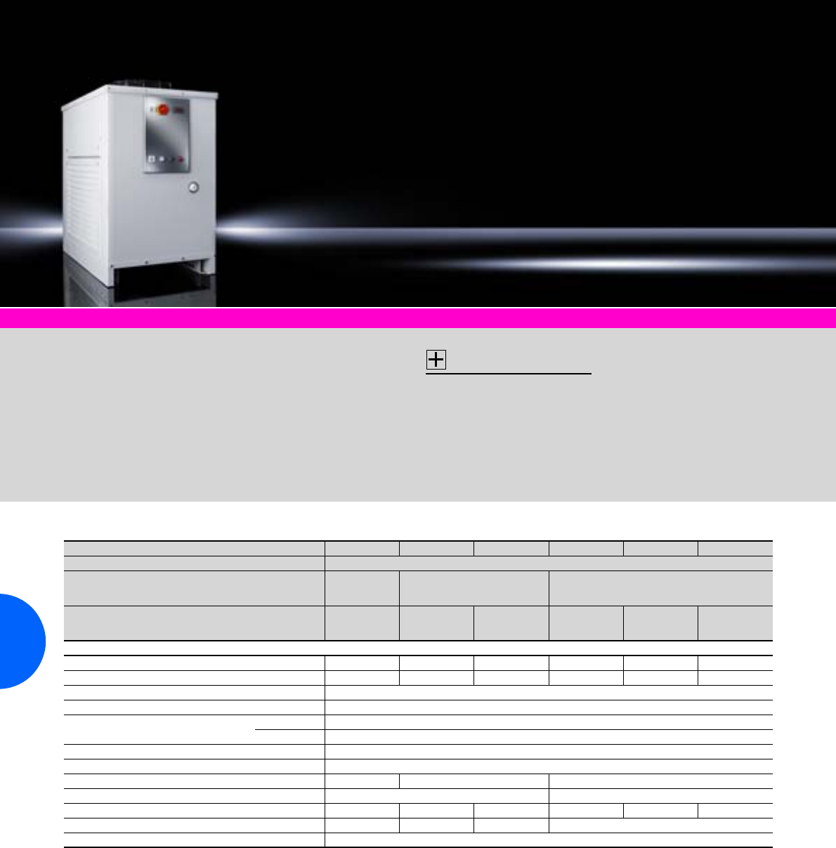
Chillers for water
268 Rittal Catalogue 33/Climate control
Air/water heat exchangers from page 252 Climate control accessories Page 291 Cooling medium Page 305
Technical design:
−Robust industrial standard
−Variable air routing is
possible via the l/h or r/h
side panel
−Floating contact for collective
fault signal
Colour:
RAL 7035
Protection category:
IP 44 (electrics)
Supply includes:
−Recooling system
wired ready for connection
−Multi-lingual documentation
−Functional diagram and
wiring plans
Accessories:
−Metal filter mats
−Castors
−Bypass valve
on request
Approvals:
Available on the Internet.
Layout diagram:
Available on the Internet.
Characteristic curves of pump:
Available on the Internet.
Other options:
Available on the Internet.
In floor-standing enclosure, cooling output 2.1 to 7.7 kW
Model No. SK 3336.100 3336.200 3336.300 3336.500 3336.600 3336.650
Rated operating voltage V, Hz 400, 3~, 50
Dimensions mm W
H
D
470
725
540
485
965
650
595
1180
800
Cooling output at
Tw = 10°C/Tu = 32°C
Tw = 18°C/Tu = 32°C
1.7 kW
2.1 kW
2.1 kW
2.6 kW
2.3 kW
3.4 kW
3.6 kW
5.0 kW
4.8 kW
6.2 kW
5.2 kW
7.7 kW
Power consumption 1.5 kW 1.7 kW 2.3 kW 2.9 kW 3.7 kW 3.9 kW
Rated current max. 3.4 A 3.0 A 4.2 A 5.5 A 6.2 A 7.3 A
Refrigerant R134a
Number of cooling circuits 1
Temperature range Environment +15°C to +43°C
Liquid media +10°C to +25°C
Pump capacity See characteristic curve of pump
Tank Made from stainless steel 1.4301 (AISI 304)
Tank capacity 17 l 33 l 57 l
Water connections 3/4˝ internal thread 1˝ internal thread
Weight 75 kg 97 kg 99 kg 141 kg 143 kg 147 kg
Air throughput of fans 700 m3/h 1250 m3/h 1785 m3/h 3140 m3/h
Temperature control Electronic control with digital display (factory setting +18°C)
Extended delivery times.
Special voltages, other frequencies, and technical modifications available on request.
We reserve the right to make technical modifications.

Chillers for water
269Rittal Catalogue 33/Climate control
In floor-standing enclosure, cooling output 10 to 25 kW
In floor-standing enclosure, cooling output 32 to 59 kW
Model No. SK 3336.700 3336.710 3336.720 3336.730 3336.740 3336.750
Rated operating voltage
V, Hz 400, 3~, 50/460, 3~, 60
Dimensions mm W
H
D
615
1178
1160
715
1178
1360
Cooling output at
Tw = 10°C/Tu = 32°C
Tw = 18°C/Tu = 32°C
8.3/10.4 kW
10.0/12.6 kW
11.9/15.5 kW
14.4/18.7 kW
13.5/16.6 kW
16.3/20.1 kW
15.0/18.1 kW
18.5/22.4 kW
17.0/20.7 kW
20.9/25.4 kW
20.6/26.4 kW
25.2/32.3 kW
Power consumption 3.8 kW 4.8 kW 5.3 kW 6.4 kW 7.1 kW 13.1 kW
Rated current max. 10.6 A 13.1 A 14.1 A 16.2 A 18.2 A 23.7 A
Refrigerant R407C
Number of cooling circuits 1
Temperature range Environment +15°C to +43°C1)
Liquid media +10°C to +25°C
Pump capacity See characteristic curve
Tank Made from stainless steel 1.4301 (AISI 304)
Tank capacity 60 l 100 l
Water connections 1˝ internal thread
Weight 215 kg 225 kg 235 kg 240 kg 250 kg 260 kg
Air throughput of fans 6280 m3/h 10880 m3/h
Temperature control Electronic control with digital display (factory setting +18°C)
1) SK 3336.720 and SK 3336.750 +15°C to +40°C at 60 Hz.
Delivery times available on request.
Special voltages and technical modifications available on request.
We reserve the right to make technical modifications.
Model No. SK 3339.100 3339.200 3339.250 3339.280
Rated operating voltage
V, Hz 400, 3~, 50/460, 3~, 60 400, 3~, 50
Dimensions mm W
H
D
815
1400
1560
1000
1800
2000
Cooling output at
Tw = 10°C/Tu = 32°C
Tw = 18°C/Tu = 32°C
26.2/31.4 kW
32.0/38.4 kW
29.6/35.5 kW
36.2/43.5 kW
40.0 kW
46.7 kW
52.0 kW
59.0 kW
Power consumption 18.3 kW 18.6 kW 20.6 kW 36.8 kW
Rated current max. 29.2 A 30.7 A 36.8 A 41.1 A
Refrigerant R407C
Number of cooling circuits 1
Temperature range Environment +15°C to +43°C +15°C to +40°C
Liquid media +15°C to +25°C
Pump capacity See characteristic curve
Tank Made from stainless steel 1.4301 (AISI 304)
Tank capacity 150 l 220 l
Water connections 11/4˝ internal thread 11/2˝ internal thread
Weight 260 kg 300 kg 680 kg 740 kg
Air throughput of fans 16000 m3/h 32000 m3/h
Temperature control Electronic control with digital display (factory setting +18°C)
Extended delivery times.
Special voltages and technical modifications available on request.
We reserve the right to make technical modifications.
270
271
IT cooling
Roof-mounted cooling units
TopTherm for office and IT applications ...............1100/3000 W..............246
Chillers for IT cooling
Chillers for IT cooling.............................................. 15 – 123 kW..............272
Chillers for IT cooling............................................ 155 – 481 kW..............273
CRAC system
CRAC system CW ............................................ 27.8 – 137.4 kW..............274
CRAC system DX ............................................... 19.2 – 56.2 kW..............276
Aisle containment
Aisle containment ......................................................................................278
Liquid Cooling Package
TopTherm LCP Rack CW and DX ........................... up to 60 kW..............279
TopTherm LCP Inline CW and DX ...........................up to 60 kW..............280
TopTherm LCP T3+ CW .......................................... up to 25 kW..............281
TopTherm LCP Passive CW ............................................. 20 kW..............282
Accessories...............................................................................................283
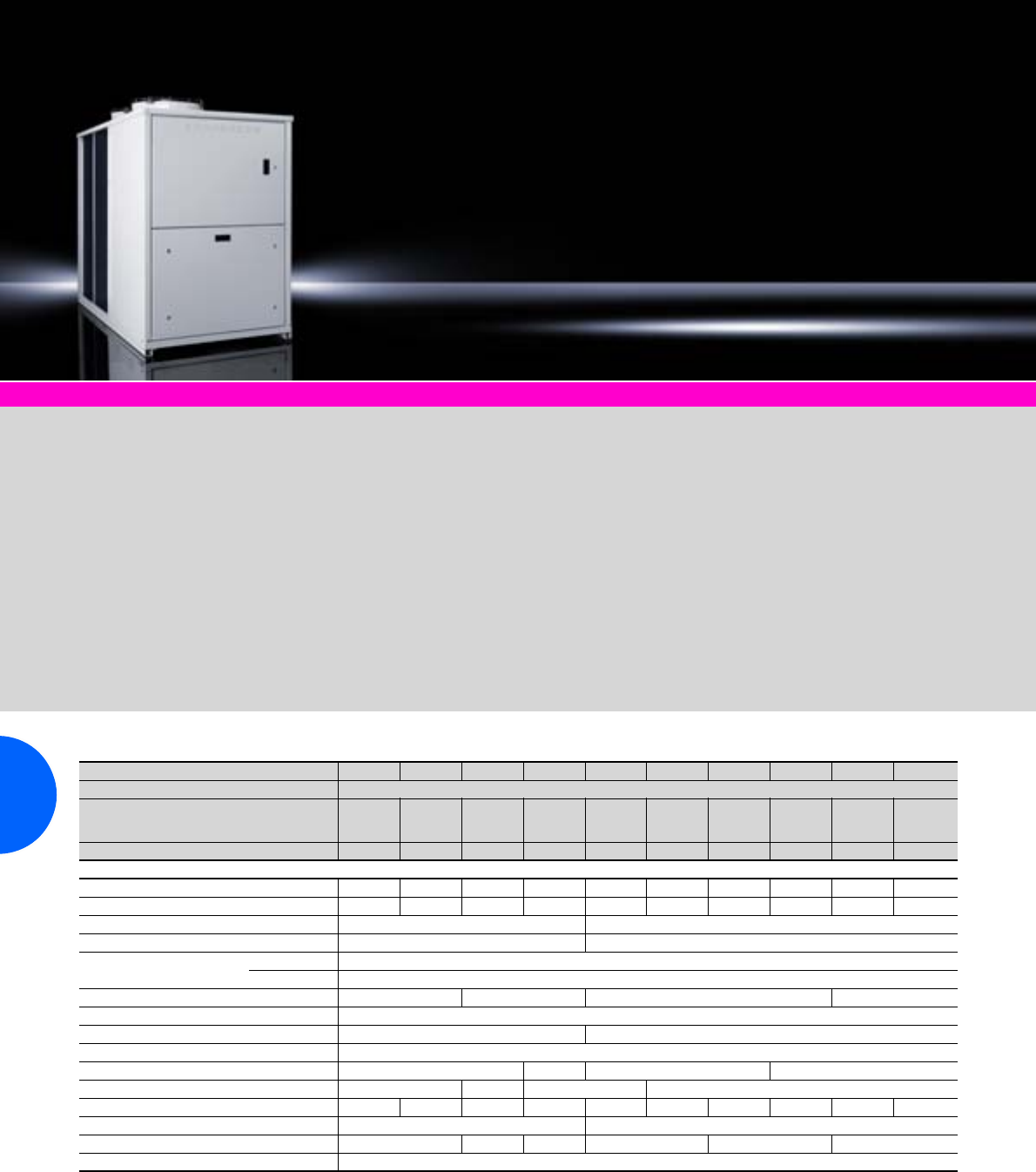
Chillers for IT cooling
272 Rittal Catalogue 33/Climate control
Climate control accessories Page 291
Application:
Especially for cooling IT applica-
tions, such as LCP or air/water
heat exchangers. Safety-rele-
vant features such as redundant
speed-controlled pumps, com-
pressors or buffer stores are the
distinguishing features of these
atmospherically sealed systems.
Technical design:
−Compact design with control
components in the front and
air intake via both side pan-
els, air outlet upwards.
−Pressure-sealed system
−Digital thermostat for tempera-
ture control with setpoint and
actual value display
−Monitoring interface with
Rittal CMC II supported.
−Flow monitor
Protection category:
IP 54
Supply includes:
−Chiller wired ready for con-
nection
−Multi-lingual documentation
−Functional diagram and
wiring plans
Options:
−Free cooling may be inte-
grated from 67 kW.
Please follow the instructions!
−Buffer store for separate siting
−Emergency cooling with
mains water infeed
−Integral bypass
−Special voltages
Note:
Technical deviations in terms
of cooling output, dimensions
or weight are possible for unit
types with free cooling.
Layout diagram:
Available on the Internet.
Cooling output 15 to 124 kW
Model No. SK 3232.700 3232.710 3232.720 3232.730 3232.740 3232.750 3232.760 3232.770 3232.780 3232.790
Rated operating voltage V, Hz 400, 3~, 50
Dimensions mm W
H
D
810
1542
1560
810
1542
1560
810
1542
1560
1000
1780
2000
1100
1606
2450
1100
1606
2950
1100
1606
2950
1100
1606
2950
1100
1875
2950
1100
1875
2950
Cooling output1) 15 kW 24 kW 36 kW 48 kW 67 kW 77 kW 88 kW 99 kW 117 kW 124 kW
Power consumption 6.9 kW 9.7 kW 14.6 kW 21 kW 21 kW 24 kW 26 kW 29 kW 36 kW 41 kW
Rated current max. 23.0 A 25.0 A 37.0 A 46.5 A 52.2 A 59.2 A 64.2 A 69.2 A 84.1 A 89.1 A
Refrigerant R407C R410A
Pmax. cooling circuit 28 bar 45 bar
Temperature range Environment –20°C to +43°C
Liquid media +5°C to +15°C
Pump capacity 60 l/min. 120 l/min. 240 l/min. 500 l/min.
Pump pressure 2.5 bar
Number of cooling circuits 1 2
Tank with 10 mm condensate insulation Steel
Tank capacity 48 l 100 l 300 l 500 l
Water connections 1˝ 1 1/4˝ 2 ˝ 2
1/2˝
Operating weight 375 kg 390 kg 480 kg 710 kg 831 kg 896 kg 906 kg 912 kg 1119 kg 1123 kg
Colour RAL 7035 RAL 9002
Air throughput of fans m3/h 10880 14000 18000 22000 27000 34100
Temperature control Electronic control with digital display (factory setting +15°C)
1) The performance data varies according to the option package chosen, and should be taken from the IT chiller configurator (see Internet).
Extended delivery times. We reserve the right to make technical modifications.
Chillers for IT cooling
273Rittal Catalogue 33/Climate control
Cooling output 155 to 481 kW
Model No. SK 3232.800 3232.810 3232.820 3232.890 3232.830 3232.840 3232.850 3232.860 3232.870 3232.880
Rated operating voltage V, Hz 400, 3~, 50
Dimensions mm W
H
D
1100
1875
2950
1100
1875
2950
1100
1875
3950
1500
1975
4350
2200
2450
3400
2200
2450
3400
2200
2450
3400
2200
2450
4250
2200
2450
4250
2200
2450
4250
Cooling output1) 155 kW 172 kW 196 kW 235 kW 262 kW 291 kW 326 kW 387 kW 430 kW 481 kW
Power consumption 47 kW 52 kW 60 kW 70 kW 80 kW 93 kW 106 kW 121 kW 141 kW 159 kW
Rated current max. 108 A 120 A 127 A 149 A 181 A 203 A 225 A 293 A 307 A 336 A
Refrigerant R410A
Pmax. cooling circuit 45 bar
Temperature range Environment –20°C to +43°C
Liquid media +5°C to +15°C
Pump capacity 500 l/min. 500 l/min. 810 l/min. 1200 l/min.
Pump pressure 2.5 bar
Number of cooling circuits 2
Tank with 10 mm condensate insulation Steel
Tank capacity 500 l 700 l 1000 l
Water connections 2 1/2˝ 3˝ 4˝
Operating weight 1308 kg 1321 kg 1489 kg 1933 kg 2546 kg 2693 kg 2843 kg 3148 kg 3354 kg 3576 kg
Colour RAL 9002
Air throughput of fans m3/h 32600 50000 49000 72800 71500 70200 106200 104100 102000
Temperature control Electronic control with digital display (factory setting +15°C)
1) The performance data varies according to the option package chosen, and should be taken from the IT chiller configurator (see Internet).
Extended delivery times. We reserve the right to make technical modifications.
Rittal Austria
RITTAL Schaltschränke Gesellschaft m.b.H.
Laxenburger Straße 246a A-1239 Wien
Phone: +43 (0) 5 99 40-0
Fax: +43 (0) 5 99 40-99 0
E-mail: info@rittal.at www.rittal.at
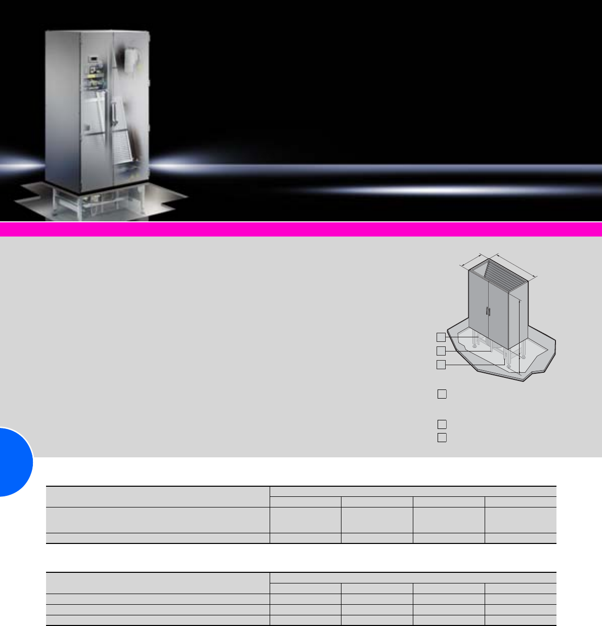
CRAC system CW
274 Rittal Catalogue 33/Climate control
Chillers for IT cooling Page 272 Liquid Cooling Package Page 279
Application and mode
of operation:
The CRAC system draws warm
waste air from the top of your
data centre, cools it using water
in a closed heat exchanger, and
blows the cooled, filtered sup-
ply air into the raised floor with
overpressure.
The heated cooling water is
cooled in an external recooling
system outside of the building.
Benefits:
●Broad output range, suitable
for use with a wide range of
cooling media.
●The unit supports optimum
integration of both hardware
and software.
●Optimum energy and space
efficiency thanks to intelligent
design features, such as the
slanted heat exchanger and
base-integrated fan.
●Frame based on the popular
TS 8 system.
Equipment:
−User-friendly, high-quality con-
troller with an extensive range
of functions and connectivity.
−Space-saving, readily acces-
sible, high-efficiency fan.
−Flow and energy-optimised
special heat exchanger with
a generous safety factor.
Colour:
RAL 7035
Water inlet,
condensate discharge,
humidifier inlet
Electrical connection
Water return
B
T
H2 H1
1
2
3
1
2
3
Base unit
Fan unit in base
Top piece Model No. SK
3301.620 3301.660 3301.830 3301.870
Dimensions mm W (B)
H1
D (T)
1100
1950
650
1100
1950
850
1800
1950
850
2600
1950
850
Connection voltage V/Ph/Hz 400/3/50 400/3/50 400/3/50 400/3/50
Supporting structure with fan Model No. SK
3300.310 3300.320 3300.330 3300.340
No. of fans Quantity 1 1 2 3
Height of supporting structure mm1) H2 500 550 550 550
Min. raised floor height mm 350 350 350 350
1) Other supporting structure heights available on request.
CRAC system CW
275Rittal Catalogue 33/Climate control
Base unit
Fan unit
Options
Model No. SK 3301.620 3301.660 3301.830 3301.870
Rated volumetric flow
Air volume m3/h 6000 11000 22000 33000
External compression Pa 20 20 20 20
Support area m20.72 0.94 1.53 2.21
Weight kg 340 385 585 843
Cooling – cold water 7°C/12°C and air inlet 24°C/50% relative humidity
Cooling output, total kW 27.8 45.7 90.2 137.4
Cooling output, sensitive kW 23.4 39.8 79.4 119.5
SHR1) 0.84 0.87 0.88 0.87
Volumetric flow of medium m3/h 4.78 7.85 15.49 23.6
Cooler pressure loss kPa 33.4 39 37.6 37.5
Valve pressure loss kPa 22.8 24.1 38.4 34.8
Connection Rp 1 Rp 1 1/4 Rp 1 1/2 Rp 2
Cooling – cold water 10°C/15°C and air inlet 26°C/45% relative humidity
Cooling output, total kW 22.9 39.1 77.4 117.2
Cooling output, sensitive kW 22.9 39.1 77.4 117.2
SHR1) 1111
Volumetric flow of medium m3/h 3.94 6.72 13.3 20.2
Cooler pressure loss kPa 23.4 29.1 28.2 27.8
Valve pressure loss kPa 15.5 17.6 28.3 25.5
Connection Rp 1 Rp 1 1/4 Rp 1 1/2 Rp 2
Filter in intake
Design Cassette filter
Filter class to DIN EN 779 G4 G4 G4 G4
Noise data
Sound power level, intake end dB (A) 69 74 77 79
Sound power level, discharging end dB (A) 79 82 85 87
Enclosure radiation dB (A) 55 60 63 65
Sound pressure level in empty space (2 m distance) dB (A) 57 62 65 67
1) SHR = Sensible Heat Ratio. We reserve the right to make technical modifications in line with progress.
Design EC motor, directly driven, free-running
Qty. Quantity 1 1 2 3
Power consumption, total kW 0.6 1.4 3.1 4.6
Max. current rating A 1.5 4.6 9.2 13.8
Steam humidification
Design Electrode steam humidifier
Max. steam output kg/h 8 8 15 15
Max. power consumption kW 6 6 11.3 11.3
Max. current rating A8.7 8.7 16.3 16.3
Water inlet connection Inches G 1/2 G 1/2 G 1/2 G 1/2
Water discharge connection mm 40 40 40 40
Electric heater
Design Bare-tube heater, permanently controlled
Max. thermal output kW 4.5 7.5 15 22.5
Max. current rating A6.5 10.8 21.7 32.5
Energy-saving extractor plenum
For top-mounting on CRAC systems 3300.290 3300.291 3300.292 3300.293
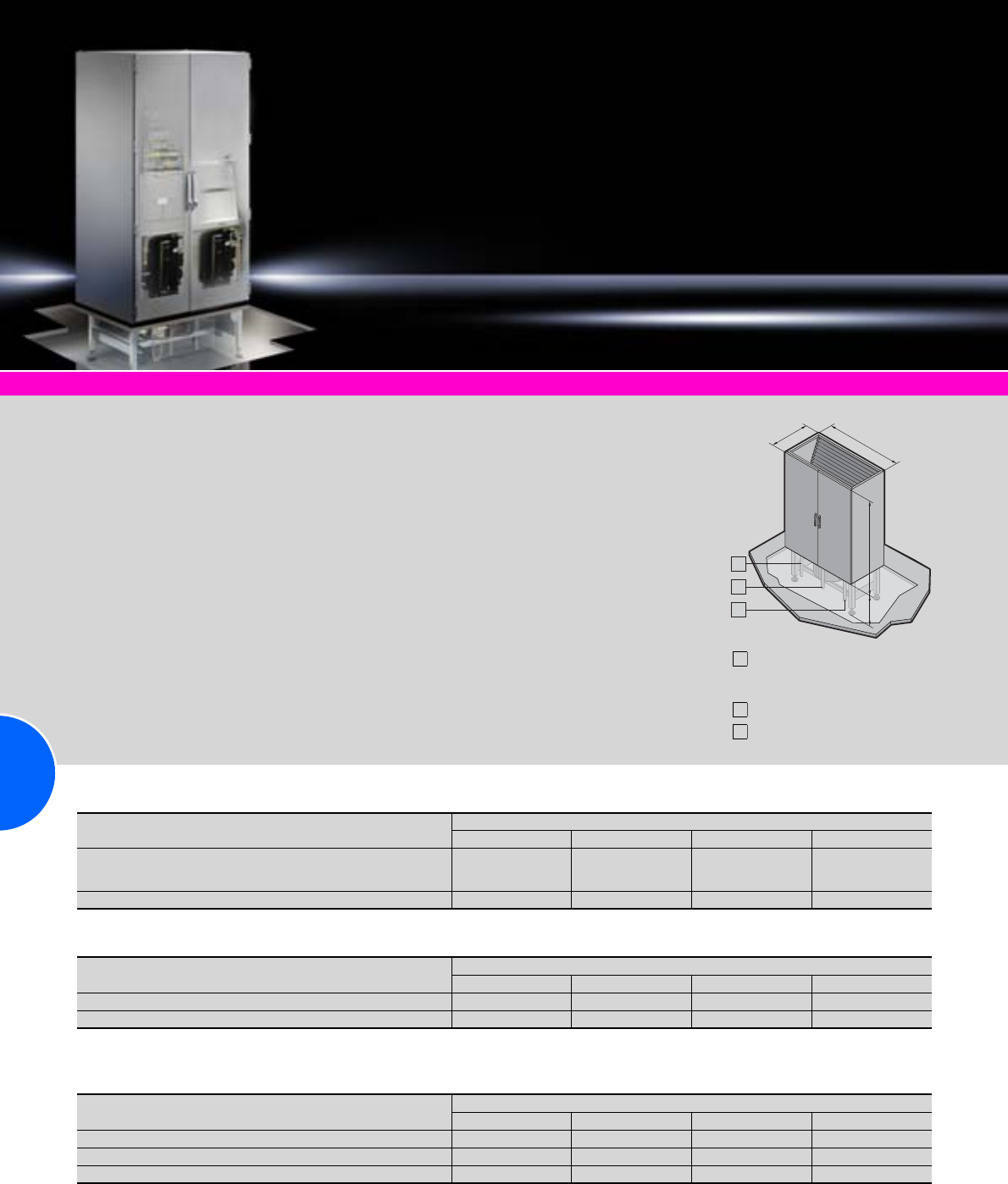
CRAC system DX
276 Rittal Catalogue 33/Climate control
Chillers for IT cooling Page 272 Liquid Cooling Package Page 279
Application and mode
of operation:
The air-cooled DX units with
direct evaporation discharge the
heat to the external air via an air-
cooled condenser installed out-
side of the building. The climate
control enclosure has one, two
or three compressors, depend-
ing on size, which are com-
bined into one cooling circuit.
For this reason, connection to
the air-cooled condenser is via
just one refrigerant line.
Benefits:
●Broad output range, suitable
for use with a wide range of
cooling media.
●The unit supports optimum
integration of both hardware
and software.
●Optimum energy and space
efficiency thanks to intelligent
design features, such as the
slanted heat exchanger and
base-integrated fan.
●Frame based on the popular
TS 8 system.
Equipment:
−User-friendly, high-quality con-
troller with an extensive range
of functions and connectivity.
−Space-saving, readily acces-
sible, high-efficiency fan.
−Flow and energy-optimised
special heat exchanger with
a generous safety factor.
Colour:
RAL 7035
Refrigerant pressure line,
condensate discharge,
humidifier inlet
Electrical connection
Refrigerant fluid line
B
T
H2 H1
1
2
3
1
2
3
Base unit
Fan unit in base
Condenser unit
Top piece Model No. SK
3300.510 3300.560 3300.710 3300.760
Dimensions mm W (B)
H1
D (T)
1100
1950
850
1100
1950
850
1400
1950
850
1800
1950
850
Connection voltage V/Ph/Hz 400/3/50 400/3/50 400/3/50 400/3/50
Supporting structure with fan Model No. SK
3300.360 3300.320 3300.370 3300.330
Height of supporting structure mm1) H2 500 550 550 550
Min. raised floor height mm 350 350 350 350
1) Other supporting structure heights available on request.
Model No. SK
3300.353 3300.354 3300.355 3300.356
No. of fans Quantity 1 2 2 2
Max. volumetric flow m3/h 8500 12400 18000 18400
Connection voltage V/Ph/Hz 230/1/50 230/1/50 230/1/50 230/1/50
CRAC system DX
277Rittal Catalogue 33/Climate control
Base unit
Fan unit
Condenser unit
Options
Model No. SK 3300.510 3300.560 3300.710 3300.760
Rated volumetric flow
Air volume m3/h 6000 8500 12500 16000
External compression Pa 20 20 20 20
Support area m20.94 0.94 1.19 1.53
Weight kg 455 505 585 871
Cooling – condensation temperature 45°C and air inlet 24°C/50% relative humidity
Design Scroll compressor
No. of compressors Quantity 1 2 3 3
Cooling output, total kW 19.2 31.4 46.4 56.2
Cooling output, sensitive kW 18.3 28.3 41.5 51.9
SHR1) 0.95 0.90 0.89 0.92
Power consumption, total kW 4.4 7.7 11.5 13.3
Max. operating temperature A13.1 25.6 38.4 39.3
Filter in intake
Design Cassette filter
Filter class to DIN EN 779 G4 G4 G4 G4
Noise data
Sound power level, intake end dB (A) 69 69 77 72
Sound power level, discharging end dB (A) 79 76 84 79
Enclosure radiation dB (A) 54 56 62 59
Sound pressure level in empty space (2 m distance) dB (A) 57 57 64 59
1) SHR = Sensible Heat Ratio. We reserve the right to make technical modifications in line with progress.
Design EC motor, directly driven, free-running
Qty. Quantity 1 1 1 2
Power consumption, total kW 0.5 0.8 1.8 1.6
Max. current rating A 1.8 4.6 4.6 9.2
Design Axial fan condenser
Condenser output kW 27 38 49 71
Max. power consumption kW 0.67 1.28 1.34 1.34
Max. current rating A3.3 66.0 6.6
Max. noise level in empty space (5 m distance) dB (A) 56 60 59 59
Dimensions mm Width (B1 + B2) 1415 1420 2130 2680
Weight kg 109 132 160 217
Steam humidification
Design Electrode steam humidifier
Max. steam output kg/h 8 8 8 15
Max. power consumption kW 6 6 6 11.3
Max. current rating A8.7 8.7 8.7 16.3
Water inlet connection Inches G 1/2 G 1/2 G 1/2 G 1/2
Water discharge connection mm 40 40 40 40
Electric heater
Design Bare-tube heater, permanently controlled
Max. thermal output kW 4.5 7.5 7.5 15
Max. current rating A6.5 10.8 10.8 21.7
Energy-saving extractor plenum
For top-mounting on CRAC systems 3300.294 3300.295 3300.296 3300.297
1120
B1B1
B1 B2
1105
563
B1B1
B1 B2
1615
Design
Vertically blowing Design
Horizontally blowing

Aisle containment
278 Rittal Catalogue 33/Climate control
TopTherm LCP Passive CW From page 282
Application and mode
of operation:
Aisle containment is a combina-
tion of door and roof compo-
nents which facilitate consistent
separation of the hot and cold
air in the data centre. Such
separation is pivotal to saving
energy and increasing the effi-
ciency of the available climate
control technology. Depending
on the application, aisle contain-
ment may be used with CRAC
systems or TopTherm LCP Inline
CW and DX as hot or cold aisle
containment.
Benefits:
●Increased energy efficiency
and performance capability of
climate control.
●Superior output density is
facilitated, thanks to guaran-
teed cold air supply.
●
Easily installed and retrofitted,
as it is fully compatible with
the TS 8 enclosure system.
●An inexpensive way to boost
the performance of your exist-
ing plant, lengthening the in-
vestment cycle until a replace-
ment needs to be purchased.
Equipment:
−Slimline door element with
viewing window, sliding door
−Stable roof elements in a com-
posite metal with a high level
of light permeability
−Where required, safety glass
may also be used
Note:
Other size variants and individu-
ally modified systems available
on request.
1200
2000
600/800
Element Roof element Door element
Position Start/end Centre –
Model No. SK 3300.270 3300.280 3300.170 3300.180 3300.160
Width of element
(identical to enclosure width) mm 600 800 600 800 –
Width of cold aisle mm 1200 1200 1200 1200 1200
Height of cold aisle mm ––––2000
Liquid Cooling Package
279Rittal Catalogue 33/Climate control
Accessories for climate control Page 291 Chillers for IT cooling Page 272 Server enclosures Page 92
Benefits:
●Maximum energy efficiency
thanks to EC fan technology
and IT-based control
●Minimal pressure loss at the
air end, which in turn mini-
mises the power consump-
tion of the fans
●Optimum adaptability thanks
to dynamic, continuous con-
trol of the cold water volume
flow
●By using high water inlet
temperatures, the proportion
of indirect free cooling is
increased, which in turn
reduces operating costs
●Thanks to six modular,
box-type plug-in fan units,
the cooling output can be
adapted to actual require-
ments
●The box-type plug-in fan units
are configurable as n+1
redundancy
●Standard 3-phase connection
for electrical redundancy
●With redundant temperature
sensor integrated at the air
end as standard
●The separation of cooling and
rack prevents water from pen-
etrating the server enclosure
●Up to 60 kW cooling output on
a footprint of just 0.36 m²
●The low weight means a mini-
mal load area
●Touchscreen display may be
retrofitted
Monitoring:
Monitoring of all system-relevant
parameters such as:
●Server air intake temperature
●Server waste air temperature
●Water inlet/return temperature
●Water flow
●Cooling output
●Fan speed
●Leakage
●Optional sensors
●Direct connection of the unit
via SNMP/Ethernet
●Integration into RiZone
Application and mode of
operation:
The LCP draws in the air at the
sides at the rear of the server
enclosures, cools it using high-
performance compact impel-
lers, and blows the cooled air
back into the front part of the
server enclosure at the sides.
Colour:
RAL 7035
Protection category:
IP 40 to IEC 60 529
TopTherm LCP rack CW and DX
Design CW CW CW DX Page
Cooling medium Water (for specifications see Internet) Refrigerant R410a
Model No. SK 3311.130 3311.230 3311.260 3311.110
Rated operating voltage V, Hz 230, 1~, 50/60
400, 3~, 50/60 230, 1~, 50/60
400, 3~, 50/60 230, 1~, 50/60
400, 3~, 50/60 230, 1~, 50/60
400, 3~, 50/60
Dimensions mm W x H x D 300 x 2000 x 1000 300 x 2000 x 1200 300 x 2000 x 1200 300 x 2000 x 1000
Usable U 42 42 42 42
Useful cooling output Up to 30 kW Up to 30 kW Up to 60 kW Up to 10 kW
Duty cycle 100%
Electrical connection Connection cable
Temperature control Linear fan control
Two-way control valve –
Fans may be exchanged with the system operational
EC fan
Also required Packs of
Condenser unit 1 – – – 3311.310 283
Accessories
Fan module 1 3311.010 3311.010 3311.010 3311.010 –
Touchscreen display, colour 1 3311.030 3311.030 3311.030 3311.030 283
Connection hose, top 1 3311.040 3311.040 3311.040 3311.040 283
Connection hose, bottom 1 3311.050 3311.050 3311.050 3311.050 283
Liquid Cooling Package
280 Rittal Catalogue 33/Climate control
Accessories for climate control Page 291 Chillers for IT cooling Page 272 Server enclosures Page 92 Aisle containment Page 278
Benefits:
●Maximum energy efficiency
thanks to EC fan technology
and IT-based control
●Minimal pressure loss at the
air end, which in turn mini-
mises the power consump-
tion of the fans
●Optimum adaptability thanks
to dynamic, continuous con-
trol of the cold water volume
flow
●By using high water inlet
temperatures, the proportion
of indirect free cooling is
increased, which in turn
reduces operating costs
●Thanks to six modular,
box-type plug-in fan units,
the cooling output can be
adapted to actual require-
ments
●The box-type plug-in fan units
are configurable as n+1
redundancy
●Standard 3-phase connection
for electrical redundancy
●With redundant temperature
sensor integrated at the air
end as standard
●The separation of cooling and
rack prevents water from pen-
etrating the server enclosure
●Up to 60 kW cooling output on
a footprint of just 0.36 m²
●The low weight means a mini-
mal load area
●Touchscreen display may be
retrofitted
Monitoring:
Monitoring of all system-relevant
parameters such as:
●Server air intake temperature
●Server waste air temperature
●Water inlet/return temperature
●Water flow
●Cooling output
●Fan speed
●Leakage
●Optional sensors
●Direct connection of the unit
via SNMP/Ethernet
●Integration into RiZone
Application and mode of
operation:
The LCP is designed for siting
within a bayed enclosure suite.
The hot air is drawn in from the
room or hot aisle at the rear of
the device and expelled at the
front into the cold aisle after
cooling.
The LCP achieves maximum
performance and efficiency in
conjunction with Rittal cold aisle
containment. With this product,
a raised floor is not necessary.
Colour:
RAL 7035
Protection category:
IP 40 to IEC 60 529
TopTherm LCP Inline CW and DX
Design CW CW DX Page
Cooling medium Water (for specifications see Internet) Refrigerant R410a
Model No. SK 3311.530 3311.560 3311.210
Rated operating voltage V, Hz 230, 1~, 50/60
400, 3~, 50/60 230, 1~, 50/60
400, 3~, 50/60 230, 1~, 50/60
400, 3~, 50/60
Dimensions mm W x H x D 300 x 2000 x 1200 300 x 2000 x 1200 300 x 2000 x 1200
Usable U 42 42 42
Useful cooling output Up to 30 kW Up to 60 kW Up to 10 kW
Duty cycle 100%
Electrical connection Connection cable
Temperature control Linear fan control
Two-way control valve –
Fans may be exchanged with the system operational
EC fan
Also required Packs of
Condenser unit 1 – – 3311.310 283
Accessories
Front cover 1 3311.060 3311.060 3311.060 283
Fan module 1 3311.020 3311.020 3311.020 –
Touchscreen display, colour 1 3311.030 3311.030 3311.030 283
Connection hose, top 1 3311.040 3311.040 3311.040 283
Connection hose, bottom 1 3311.050 3311.050 3311.050 283
Liquid Cooling Package
281Rittal Catalogue 33/Climate control
Accessories for climate control Page 291 Chillers for IT cooling Page 272 Server enclosures Page 92
Benefits:
●Error-tolerant, efficient cooling
of server racks with high ther-
mal loads
●Fully redundant – Two active
cooling circuits and two
switchable power circuits
ensure optimum fail-safeness
●The built-in controllers are
capable of adapting all device
parameters automatically to
preserve the required climate
conditions
●A separate decentralised
intelligence which automati-
cally recognises emergency
situations and responds
appropriately with the “auto
load balancing” and “auto
recovery” functions
●Interfaces which facilitate
user-friendly operation and
monitoring via the network or
BSM systems
Optional:
−Fully integrated fire detection
and extinguisher system
−Automatic server enclosure
door opening
−Various sensors
Application and mode
of operation:
The LCP draws in the air at the
sides at the rear of the server
enclosures, cools it using high-
performance compact impel-
lers, and blows the cooled air
back into the front part of the
server enclosures at the sides.
Colour:
RAL 7035
Protection category:
IP 40 to IEC 60 529
TopTherm LCP T3+ CW
Cooling medium Water (for specifications see Internet) Page
Model No. SK 3311.400
Rated operating voltage V, Hz 230, 1~, 50/60
400, 3~, 50/60
Dimensions mm W x H x D 300 x 2000 x 1200
Usable U 42
Useful cooling output, redundant Up to 25 kW
Duty cycle 100%
Electrical connection C19/C20
Temperature control Linear fan control
Two-way control valve
Fans may be exchanged with the system operational
EC fan
Auto-load balancing
Auto-recovery
Accessories
Fan module 1 3311.010 –
Touchscreen display, colour 1 3311.030 283
Connection hose, top 1 3311.040 283
Connection hose, bottom 1 3311.050 283
Liquid Cooling Package
282 Rittal Catalogue 33/Climate control
Accessories for climate control Page 291 Chillers for IT cooling Page 272 Server enclosures Page 92
Benefits:
●High cooling output of 20 kW
in a minimal space
●Easily exchanged for the
standard rear door of the
server enclosure
●Retrofitting is not a problem
●A door opening angle of 120°
allows rear access to the
server enclosure and makes
assembly and configuration
inside the enclosure easier
●The LCP does not require its
own fan, and therefore does
not need an integrated control
●Maximum energy efficiency,
as there is no electrical power
consumption whatsoever
Application and mode of
operation:
Air/water heat exchanger
mechanically integrated into a
rear door for server enclosures.
The 482.6 mm (19˝) equipment
built into the server enclosure
must have suitable airflow capa-
bilities in order to route the
heated waste air through the
heat exchanger rear door. The
waste air is cooled down to room
temperature. The heat energy
absorbed by the water is trans-
ported to the external cold water
supply, where it is cooled back
down to the required inlet tem-
perature.
Colour:
RAL 7035
Approvals:
Available on the Internet.
Rittal China
RITTAL Electro-Mechanical Technology
(Shanghai) Co. Ltd.
No. 1658 Minyi Road Songjiang District
Shanghai, 201612
Phone: +86 (0) 21 5115 7799
Fax: +86 (0) 21 5115 7788
E-mail: marketing@rittal.cn www.rittal.cn
TopTherm LCP Passive CW
Model No. SK 3311.600
Dimensions mm W x H x D 600 x 2000 x 170
Usable U 42
Useful cooling output Up to 20 kW
Accessories
Liquid Cooling Package
283Rittal Catalogue 33/Climate control
Touchscreen display, colour
for LCP rack, inline, T3+
The display offers the opportunity of directly
monitoring key LCP functions and implementing
settings.
Packs of Model No. SK
1 3311.030
Front cover
for LCP Inline CW and DX
The optional front cover ensures an even air
exhaust and reduces the air outlet speed,
thereby preventing draught effects.
Packs of Model No. SK
1 3311.060
Condenser unit
The condenser unit is needed to operate the
refrigerant-based LCPs, and comprises the
external condenser, fan and inverter-controlled
compressor.
Refrigerant:
R410a
For LCP Packs of Model No. SK
SK 3311.110,
SK 3311.210 1 3311.310
Vertical shielding
To block the airflow on the left and right of the
482.6 mm (19˝) level, for enclosure height
2000 mm.
Material:
−Cellular PU foam
−Flame-inhibiting to UL 94 (HF1)
−Length: 1900 mm
−Self-adhesive on one side
For sealing
between
For
enclosure width
mm
Packs
of Model No.
SK
Side panel and
482.6 mm (19˝)
level
600 1 3301.380
800 1 3301.390
LCP and
482.6 mm (19˝)
level
600 1 3301.370
800 1 3301.320
Connection hose,
bottom and top
Flexible connection hose, may be shortened,
including union nuts on both sides for connecting
the LCP to existing pipework.
For LCP Thread Water
connection
from
Packs
of Model No.
SK
SK 3311.130,
SK 3311.230,
SK 3311.260,
SK 3311.530,
SK 3311.560,
SK 3311.400,
SK 3311.110,
SK 3311.210
11/4˝
Bottom 2 3311.050
Top 2 3311.040
Add-on cover
For height compensation with 2200 mm high
racks in conjunction with the LCP (H = 2000 mm).
Material:
Sheet steel
Surface finish:
Spray-finished
Colour:
RAL 7035
For LCP Packs of Model No. SK
SK 3311.130, ....110 1 3301.221
SK 3311.230, ....260,
SK 3311.530, ....560,
SK 3311.400, ....210 1 3301.421
Extended delivery times.
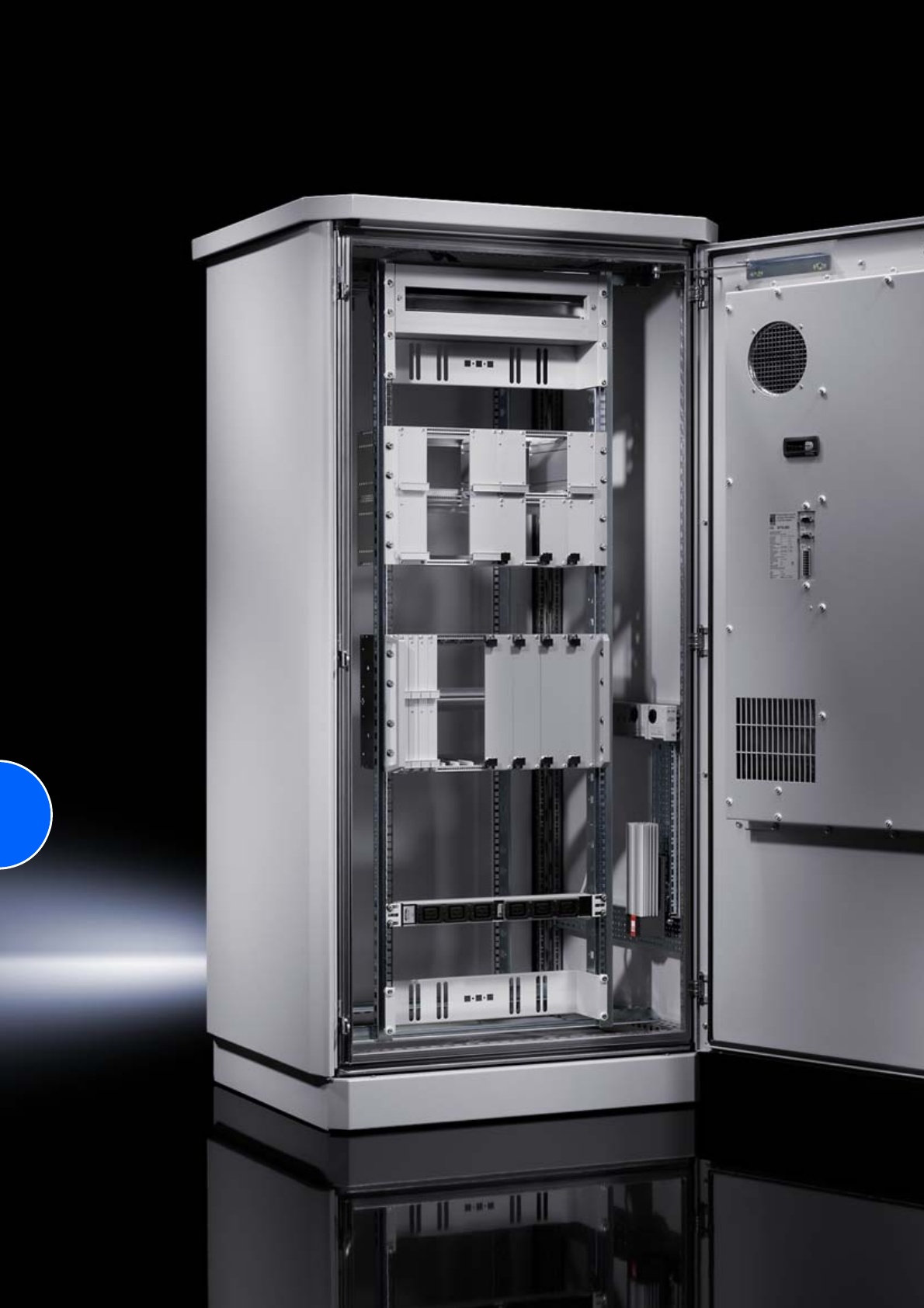
284

285
CS Outdoor climate control
Air/air heat exchangers
For CS Toptec ..........................................................85/105 W/K..............286
For CS modular enclosures.............................................30 W/K..............287
Cooling units
For CS Toptec .......................................................1000/1600 W ..............286
For CS modular enclosures.....................................900/1500 W..............287
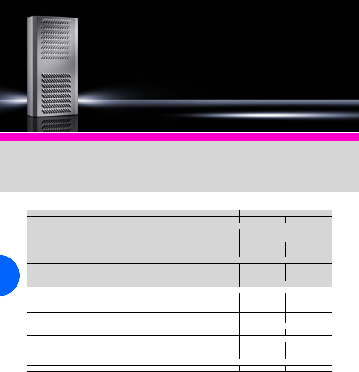
CS Outdoor climate control
286 Rittal Catalogue 33/Climate control
CS Toptec Page 185 Enclosure heaters Page 289
With sealing frame for universal
mounting on the CS Toptec in
3 positions: Internal, partial inter-
nal and external.
Material:
Enclosure: Aluminium
Surface finish:
Powder-coated, pure polyester Colour:
RAL 7035 Protection category:
IP 55 to IEC 60 529 (internal
circuit to external circuit)
Air/air heat exchangers and cooling units for CS Toptec
Air/air heat exchangers Cooling units
Model No. CS 9776.102 9776.152 9776.500 9776.550
Installation Universal
Rated operating voltage DC 48 V –
AC –230 V, 50/60 Hz
Enclosure dimensions mm
(including sealing frame and designer cover)
W
H
D
500 (550)
1000 (1050)
150 (175)
500 (550)
1000 (1050)
200 (225)
500 (550)
1000 (1050)
150 (175)
500 (550)
1000 (1050)
260 (285)
Minimum enclosure dimensions (mm) W x H 800 x 1200
Specific thermal output 85 W/K 105 W/K – –
Useful cooling output
to DIN 3168
L 35 L 35
L 35 L 50 – – 1000 W/1150 W
650 W/700 W
1600 W/1750 W
1200 W/1250 W
Heater – – 400 W
Rated current max. DC4.2 A4.5 A– –
AC – 5.0 A/5.0 A 6.0 A/6.8 A
Start-up current max. – 24.0 A/22.0 A 34.0 A/32.0 A
Power consumption Pel
to DIN 3168 L 35 L 35
L 35 L 50 – 640 W/760 W
780 W/920 W 960 W/1170 W
1125 W/1310 W
Coolant – R134a
Permissible operating pressure p. max. – 28 bar 28 bar
Temperature range –33°C to +65°C –33°C to +55°C
Air throughput of fans
– unimpeded air flow Internal/external
circuit fan 570 m3/h 1200 m3/h 600/625 m3/h
600/625 m3/h 880/950 m3/h
1000/1090 m3/h
Temperature control Comfort controller1) Comfort controller1) Comfort controller Comfort controller
Type of connection Plug-in terminal strip
Weight 22 kg 30 kg 35 kg 45 kg
Extended delivery times. Products are manufactured to order. The units are assembled and supplied connected to the Toptec enclosure.
1) Setpoint settings may be altered via software.
QK
.
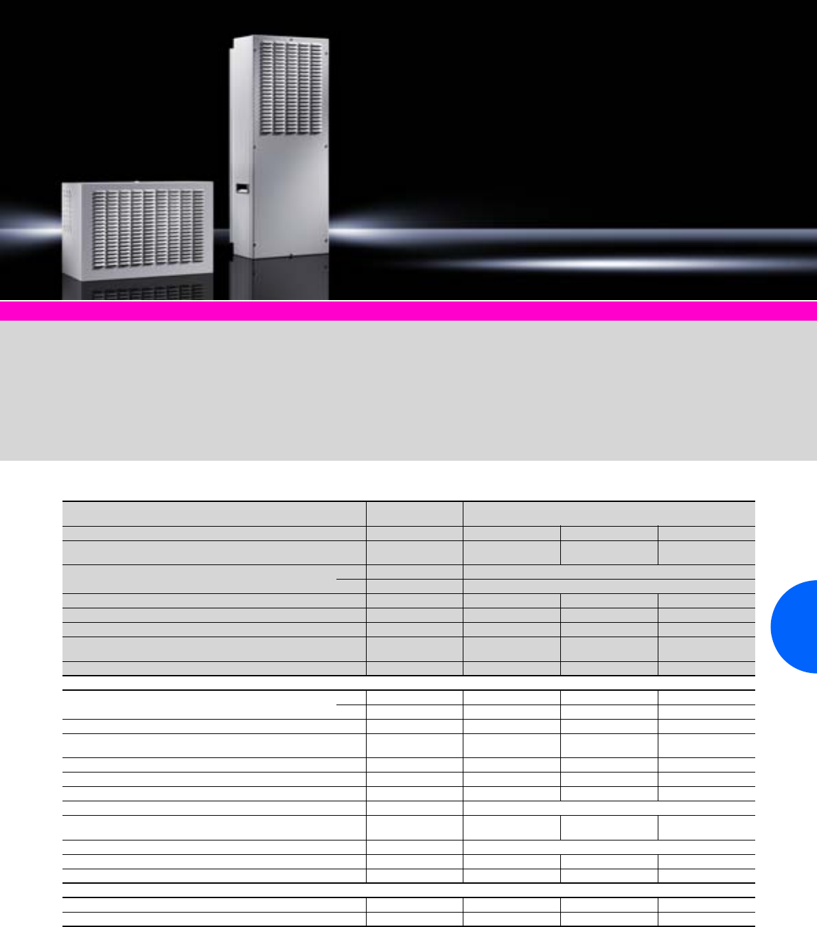
CS Outdoor climate control
287Rittal Catalogue 33/Climate control
CS modular enclosures Page 186 Enclosure heaters Page 289
For roof mounting
With Comfort controller as stand-
ard1) and 400 W heater or con-
trol via thermostat.
Heat exchanger CS 9764.040
without Comfort controller.
Mounting frame:
Required for CS 9762.212.
For wall mounting
With Comfort controller1) and
400 W heater as standard.
For partial installation
With Comfort controller1) and
800 W heater as standard.
Installation options:
●in the door or rear panel
●in the side panel
Surface finish:
Powder-coated, pure polyester
Colour:
RAL 7035
Protection category:
IP 55 to IEC 60 529 (internal
circuit to external circuit)
1) Units with Comfort controller.
The Comfort controller is
installed on the inside of the
cooling units, and is not acces-
sible from the outside.
Air/air heat exchangers and cooling units for CS modular enclosures
Air/air heat
exchangers Cooling units
Model No. CS 9764.040 9762.212 9761.212 9768.152
Installation Roof-mounted Roof-mounted Wall-mounted Partial internal
mounting
Rated operating voltage DC 48 V –
AC –230 V, 50/60 Hz
Unit dimensions (mm) W x H x D 470 x 158 x 380 535 x 390 x 400 515 x 1170 x 152 400 x 1050 x 310
Minimum enclosure dimensions (mm) W x D 600 x 500 W x D 600 x 500 W x H 600 x 1200 W/D x H 600 x 1200
Specific thermal output 30 W/K – – –
Useful cooling output
to DIN 3168
L 35 L 35
L 35 L 50 – 900 W/1020 W
720 W/780 W
900 W/1050 W
750 W/820 W
1500 W/1600 W
1250 W/1250 W
Heater – 400 W 400 W 800 W
Rated current max. DC 1.3 A – – –
AC – 3.1 A/4 A 3.2 A/4.2 A 5.8 A/6.7 A
Start-up current max. – 10.6 A 10.8 A 19.0 A
Power consumption Pel
to DIN 3168 L 35 L 35
L 35 L 50 –460 W/570 W
520 W/655 W 605 W/790 W
690 W/880 W 940 W/1145 W
1045 W/1270 W
Temperature control Without2) Comfort controller Comfort controller Comfort controller
Coolant R134a – 550 g 600 g 650 g
Permissible operating pressure p. max. – 27 bar 24 bar 28 bar
Temperature range –33°C to +65°C –33°C to +55°C
Air throughput of fans
– unimpeded air flow Internal/ external circuit fan 345 m3/h 570 m3/h
570 m3/h 880 m3/h
880 m3/h 850 m3/h
680 m3/h
Type of connection Plug panel Plug-in terminal strip
Weight 7 kg 29 kg 45 kg 40 kg
Material (enclosure) Aluminium/sheet steel /– /– –/ /–
Accessories
Mounting frame – 9765.051 – –
Enclosure internal thermostat 3110.000 – – –
Extended delivery times. The partially internally mounted CS 9768.152 may be inserted directly. Cooling units are manufactured to order.
The units are assembled and supplied connected to the modular enclosure. Adaptations to other enclosure platforms are available on request.
2) Customers may fit their own thermostat (SK 3110.000).
QK
.
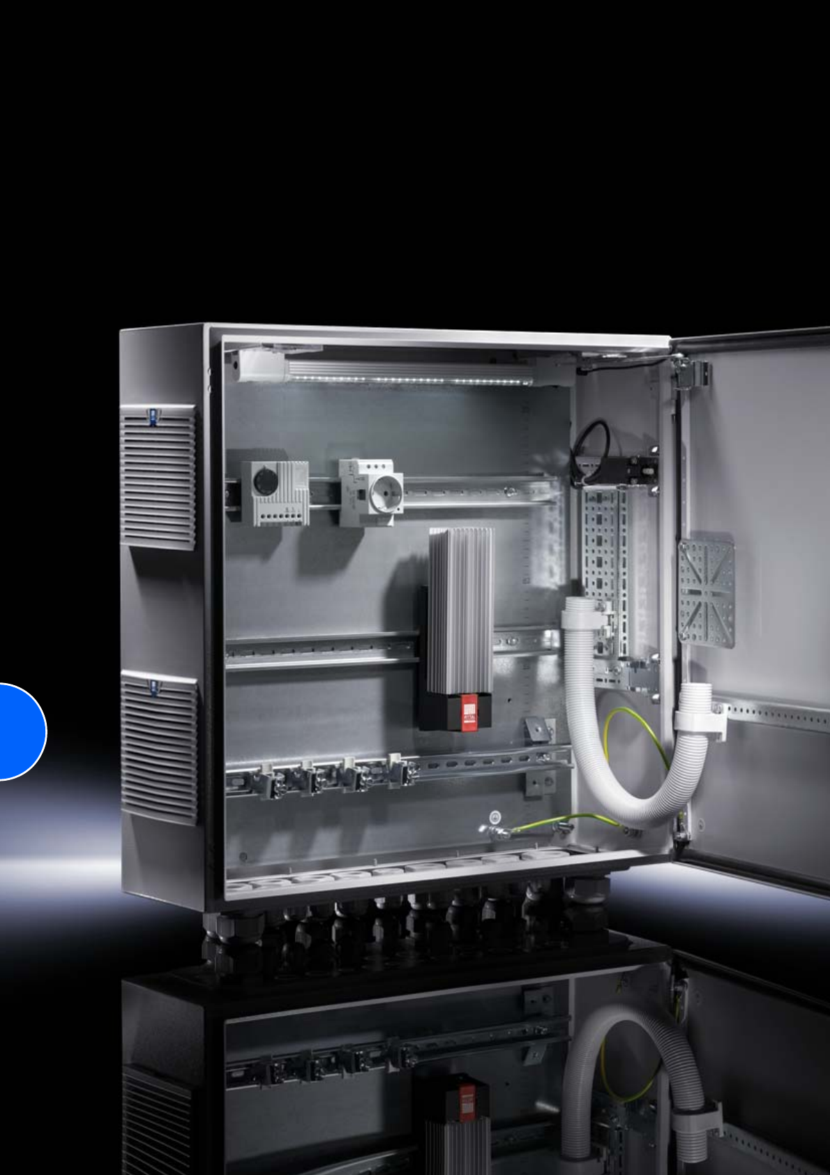
288
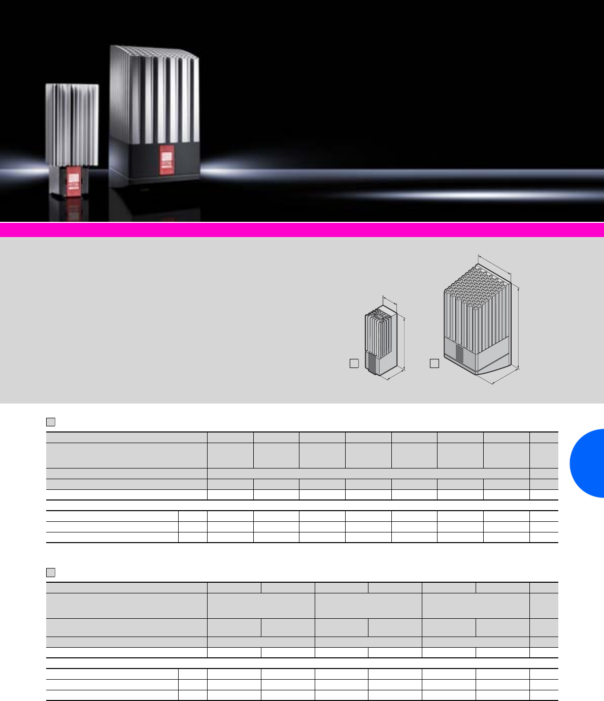
Enclosure heaters
289Rittal Catalogue 33/Climate control
Climate control accessories Page 291 Software & services Page 333
Supply includes:
−PTC heater
−Quick-connection terminal
−Assembly parts
Note:
−For precise temperature
control inside the enclosure,
we recommend the enclo-
sure internal thermostat
SK 3110.000 or the digital
thermostat SK 3114.200 with
display (see accessories).
−In order to prevent condensa-
tion on assemblies, hygrostat
SK 3118.000 (see accesso-
ries) is recommended to regu-
late heating.
−In larger enclosures, even
heat distribution is best
achieved by installing several
low-output heaters.
−The installation of heaters is
generally advisable, in order
to prevent condensation.
T
H
B
T
H
B
1
2
Without fan, continuous thermal output 10 – 150 W
With fan, continuous thermal output 250 – 800 W
Model No. SK 3105.310 3105.320 3105.330 3105.340 3105.350 3105.360 3105.370 Page
Dimensions mm W (B)
H
D (T)
45
120
46
45
120
46
64
155
56
64
155
56
64
230
56
90
165
75
90
180
75
Rated operating voltage V, Hz 110 – 240 V, 50/60 Hz
Continuous thermal output at Tu = 10°C 8 – 10 W 18 – 20 W 23 – 30 W 49 – 50 W 63 – 75 W 86 – 100 W 130 – 150 W
Pre-fuse T 2 A 2 A 4 A 4 A 4 A 4 A 4 A
Accessories Packs of
Enclosure internal thermostat 1 3110.000 3110.000 3110.000 3110.000 3110.000 3110.000 3110.000 294
Hygrostat 1 3118.000 3118.000 3118.000 3118.000 3118.000 3118.000 3118.000 294
Digital temperature display/thermostat 1 3114.200 3114.200 3114.200 3114.200 3114.200 3114.200 3114.200 293
Special voltages available on request. We reserve the right to make technical modifications.
Model No. SK 3105.410 3105.380 3105.420 3105.390 3105.430 3105.400 Page
Dimensions mm W (B)
H
D (T)
103
200
103
103
200
103
103
200
103
Rated operating voltage V, Hz 110 V,
50/60 Hz 230 V,
50/60 Hz 110 V,
50/60 Hz 230 V,
50/60 Hz 110 V,
50/60 Hz 230 V,
50/60 Hz
Continuous thermal output at Tu = 10°C 250 W1) 400 W1) 800 W1)
Pre-fuse T 4 A 4 A 6 A 6 A 10 A 6 A
Accessories Packs of
Enclosure internal thermostat 1 3110.000 3110.000 3110.000 3110.000 3110.000 3110.000 294
Hygrostat 1 3118.000 3118.000 3118.000 3118.000 3118.000 3118.000 294
Digital temperature display/thermostat 1 3114.200 3114.200 3114.200 3114.200 3114.200 3114.200 293
1) Thermal output with fan.
Special voltages available on request. We reserve the right to make technical modifications.
1
2
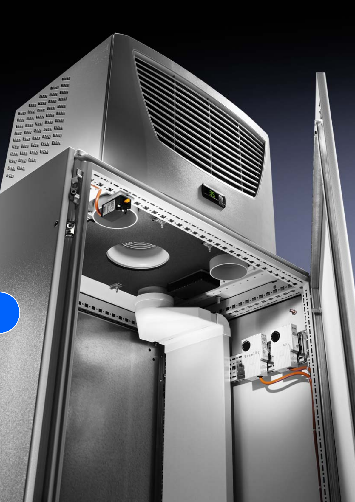
290
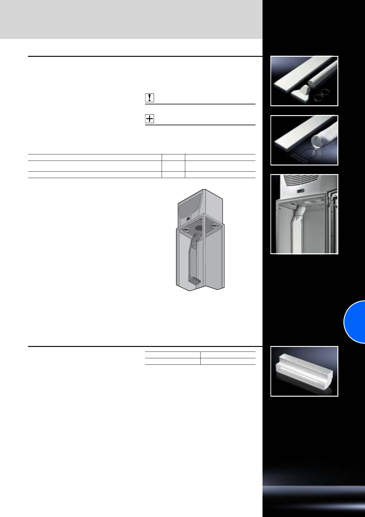
Air routing
Climate control accessories
291Rittal Catalogue 33/Climate control
Air duct system
for roof-mounted variants:
cooling units and air/water heat exchangers
It is possible to route the cold air directly to spe-
cific areas of the enclosure using the air duct
system. The risk of “short circuits” in the air cir-
culation due to self-ventilated installed devices is
therefore eliminated.
The dimensions of the shallow duct are
W x H x D 229 x 1500 x 29 mm, and can be
shortened to the required length.
Material:
Flame-resistant plastic to DIN 4102/B1
Supply includes:
Shallow duct, compensating hose.
Note:
Do not direct cold air straight at active compo-
nents. When using the ducting system, the per-
formance of the cooling unit may be reduced,
depending on the application in question.
Also required:
TS support strips, see page 462.
Accessories:
−Deflector 90°, see page 291.
−Stopper, see page 292.
For unit Packs of Model No. SK
SK 3209. . . ./SK 3210. . . ./SK 3273. . . ./SK 3359. . . ./SK 3382. . . ./
SK 3383. . . ./SK 3384. . . ./SK 3385. . . . 13286.870
SK 3386. . . ./SK 3387. . . . 1 3286.970
Deflector, 90°
for air duct system
For targeted air deflection at the end of the shal-
low channel.
Material:
Flame-resistant plastic to DIN 4102/B1
Packs of Model No. SK
13286.990
Climate control accessories
Air routing
292 Rittal Catalogue 33/Climate control
Shallow air duct system
for roof-mounted variants:
cooling units and air/water heat exchangers,
to fit TS 8 enclosures from a width of 800 mm
and a depth of 600 mm.
It is possible to route the cold air directly to spe-
cific areas of the enclosure using the air duct
system. The risk of “short circuits” in the air cir-
culation due to self-ventilated installed devices is
therefore eliminated.
The dimensions of the shallow duct are
W x H x D 229 x 1500 x 29 mm, and can be
shortened to the required length.
Material:
Flame-resistant plastic to DIN 4102/B1
Supply includes:
−Shallow duct
−Adaptor
−Compensating piece
−Deflector, 90°
Note:
Do not direct cold air straight at active compo-
nents. When using the ducting system, the per-
formance of the cooling unit may be reduced,
depending on the application in question.
Also required:
−Shallow duct extension SK 3286.860 to com-
pensate for the enclosure width and height.
−TS support strips, see page 462.
Accessories:
−Deflector 90°, see page 291.
−Stopper, see page 292.
For unit Packs of Model No. SK
SK 3209. . . ./SK 3210. . . ./SK 3273. . . ./SK 3383. . . ./SK 3384. . . ./
SK 3385. . . . 13286.850
Shallow duct extension
Extension kit for shallow air duct system
SK 3286.850 for width, depth or height length
extensions in TS 8 enclosures.
Material:
Flame-resistant plastic to DIN 4102/B1
Supply includes:
−Shallow duct 1500 mm
−Connecting piece
Packs of Model No. SK
13286.860
Stoppers
for roof-mounted cooling units
To cover unneeded cold air outlets in roof-
mounted cooling units.
Material:
Polyurethane foam
For units Max. no. of
stoppers per unit Packs of Model No. SK
SK 3359. . . ./SK 3382. . . . 1 2 3286.780
SK 3209. . . ./SK 3210. . . ./SK 3273. . . ./SK 3383. . . ./
SK 3384. . . ./SK 3385. . . . 223286.880
SK 3386. . . ./SK 3387. . . . 1 2 3286.980
Max. 1 x
Max. 2 x
SK 3359. . . . /SK 3382. . . .
SK 3386. . . . /SK 3387. . . . SK 3209. . . . /SK 3210. . . .
SK 3383. . . . /SK 3384. . . .
SK 3385. . . . /SK 3273. . . .
Air routing/control/regulation
Climate control accessories
293Rittal Catalogue 33/Climate control
Air diverter
For use with wall-mounted cooling units.
For targeted air routing of the cold air in a down-
ward direction.
Particularly well-suited for densely-packed electri-
cal components in the lower section of the enclo-
sure.
Material:
Sheet steel
For units Model No. SK
SK 3304. . . ./SK 3305. . . . 3213.310
SK 3328. . . ./SK 3329. . . . 3213.320
SK 3332. . . . 3213.3301)
651)
External
air circuit Internal
air circuit
1) 115 mm for SK 3213.330
Digital enclosure internal
temperature display and
thermostat
For installation in the enclosure door or wall.
Technical specifications:
−2 voltage ranges for 100 – 230 V, 50/60 Hz
and 24 – 60 V (DC)
−Depth: 100 mm
−Three-digit, 7-segment display
−Option of switching between °C/°F
−Temperature range: +5°C to +55°C
−Includes 1800 mm long NTC sensor
−Two relay outputs as change-over contact
and normally open contact (max. contact load
230 V, 6 A)
−Freely selectable switching difference
−The freely adjustable setpoint values can be set
using the membrane keyboard at the front
Setting range: +5°C to +55°C
−Display and switching accuracy +/– 2 K
−The minimum and maximum recorded tempera-
tures are stored until it is next reset
Packs of Model No. SK
1 3114.200
Special requirements can be accommodated on request.
Digital enclosure internal
temperature display and
thermostat
Integrated into a panel 1 U.
Including cable attachment for connection cable
and label holder.
Technical specifications:
−2 voltage ranges for 100 – 230 V, 50/60 Hz
and 24 – 60 V (DC)
−Depth: 100 mm
−Three-digit, 7-segment display
−Option of switching between °C/°F
−Temperature range: +5°C to +55°C
−Includes 1800 mm long NTC sensor
−Two relay outputs as change-over contact
and normally open contact (max. contact load
230 V, 6 A)
−Freely selectable switching difference
−The freely adjustable setpoint values can be set
using the membrane keyboard at the front
Setting range: +5°C to +55°C
−Display and switching accuracy +/– 2 K
−The minimum and maximum recorded tempera-
tures are stored until it is next reset
Colour:
RAL 7035
Packs of Model No. DK
1 7109.035
Special requirements can be accommodated on request.
Climate control accessories
Control/regulation
294 Rittal Catalogue 33/Climate control
Enclosure internal thermostat
Especially suitable for controlling fan-and-filter
units, heaters and heat exchangers, this thermo-
stat can also be used as a signal generator for
monitoring the enclosure internal temperature.
Technical specifications:
−Bi-metal controller as a temperature-sensitive
element with thermal feedback.
−Contact population: Single-pole change-over
contact as a quick-break contact.
−Permissible contact load:
Cat. 5 – 3 (heating)
AC 10 (4)1) A,
DC = max. 30 W
Cat. 5 – 4 (cooling)
AC 5 (4)1) A,
DC = max. 30 W
1) = inductive load at cos ϕ = 0.6
−Setting range: +5°C to +60°C
−Weight: approx. 105 g
−Dimensions: 71 x 71 x 33.5 mm
−Switching difference: approx. 1 K ± 0.8 K.
−Flexible mounting on a vertical or horizontal
35 mm support rail to EN 50 022, and snap
fastening in the TS/SE enclosure section or on
the mounting plate using the supplied adaptor.
Accessories:
Mounting plate TS with integral top-hat rail,
see page 470.
Rated operating voltage Model No. SK
230/115/60/48/24 V (AC) 3110.000
60/48/24 V (DC)
Hygrostat
The hygrostat switches on the heater and/or fan
when a preset relative humidity in the enclosure is
exceeded.
In this way, the relative humidity is raised above
the dew point, and condensation on assemblies
or electronic components is avoided.
Technical specifications:
−Contact population: Single-pole change-over
contact as a quick-break contact.
−Permissible contact load:
AC ~ 5 (0.2)1) A
DC = max. 20 W
1) = inductive load at cos ϕ = 0.6
−Setting range: 50 – 100 % relative humidity
−Weight: approx. 100 g
−Dimensions: 71 x 71 x 33.5 mm
−Switching difference: approx. 4%
−Flexible mounting on a vertical or horizontal
35 mm support rail to EN 50 022, and snap
fastening in the TS/SE enclosure section or on
the mounting plate using the supplied adaptor.
Accessories:
Mounting plate TS with integral top-hat rail,
see page 470.
Rated operating voltage Model No. SK
24 – 230 V (AC),
24 – 75 V (DC) 3118.000
Bottom-mounted adaptor
for enclosure internal thermostat SK 3110.000
and hygrostat SK 3118.000
Bottom-mounted adaptor with mounting option for
screwed cable glands, for targeted cable infeed
from appropriate equipment such as SK fan-and-
filter units and enclosure heaters. In conjunction
with screwed cable glands, it is also suitable for
use as strain relief.
Packs of Model No. SK
13110.200
Control unit for
EC fan-and-filter units
Temperature-dependent speed control for EC fan-
and-filter units to reduce noise and save energy.
The function of the fan can also be monitored.
●Activation and monitoring of up to 4 EC fan-
and-filter units (caution: EC fan-and-filter units
cannot be controlled with speed control
3120.200!)
●Rated operating voltage: 24 V (DC)
●Top-hat rail assembly
●Temperature setting range:
+5°C to +55°C/41°F to 131°F
●External temperature sensor to record the
ACTUAL temperature
●Status LED to display the operating status
●Alarm relay for reporting overtemperature, fan
defect, cable interruption and sensor failure
Supply includes:
NTC sensor, length 1.80 m.
For fan-and-filter units Model No. SK
SK 3245.XXX 3235.440
Control/regulation
Climate control accessories
295Rittal Catalogue 33/Climate control
Speed control
Temperature-dependent speed control for
TopTherm fan-and-filter units and air/air heat
exchangers for noise reduction and to save
energy in part-load operation.
Technical specifications:
−For mounting on a 35 mm support rail
DIN EN 50 022
−Dimensions (W x H x D):
105 x 90.5 x 60.2 mm
−Rated operating voltage: 100 – 230 V (AC)
−Setting range: +20°C to +55°C
−Phase cross-over with microcontroller
−Maximum fan output 300 W or 2 A
Supply includes:
−Speed control
−NTC sensor, length 1.80 m.
Note:
Only suitable for use with 1-phase AC motors and
equipment.
Accessories:
Mounting plate TS with integral top-hat rail,
see page 470.
Packs of Model No. SK
1 3120.200
Interface board
for equipment with e-Comfort controller
The interface board is an extension for equipment
with e-Comfort controller. In this way it is possi-
ble, e.g. to monitor a master/slave combination of
up to 10 cooling units in conjunction with a Rittal
CMC III. Control is achieved via standardised
interfaces: RS232 (DB9) or RS485, one PLC inter-
face (DB9). RS422 (RJ 45 jack) is the connection
to the Rittal CMC III. In this way, remote monitor-
ing via TCP-IP, graphical interfaces for operation,
evaluation and control, documentation, and con-
nection to additional sensors for access control
are possible. The extension board is built into a
1 U plastic housing.
A voltage supply of 24 V (DC) is required.
This may be supplied from the CMC III via a
wide-range power pack DK 7320.425 (100 to
240 V (AC), 50/60 Hz) or externally via a Kycon
connector.
Supply includes:
−Interface board integrated into a plastic box
W x H x D (mm): 136 x 44 (1 U) x 129
−Serial SUB-D cable, 1.5 m.
Note:
Networking and monitoring plan may be found
on the relevant product page on the Internet,
under “Download”.
Packs of Model No. SK
13124.200
35C
30C
25C
20C
20C
40C
35C
SK BUS system
The SK bus system facilitates communications
between several enclosure cooling units and air/
water heat exchangers .500/.510/.540/.600/.610/
.640. via a master/slave construction such as that
required e.g. in complex bayed enclosure sys-
tems for optimum operating conditions.
Technical specifications:
The master/slave construction facilitates common
activation and deactivation via door limit switches,
parallel activation and deactivation via a tempera-
ture setpoint, and common collective fault signals
and temperature logging, thereby eliminating the
need for intricate wiring.
Supply includes:
−3 m shielded interface cable
−Operating instructions on programming the
cooling units
Note:
−nB = nK – 1
−nB: Number of order units (SK bus system)
−nK: Number of cooling units to be linked
Networking and monitoring plan may be found
on the relevant product page on the Internet,
under “Download”.
Packs of Model No. SK
13124.100
Master/slave adaptor
for Thermoelectric Cooler
Parallel operation of up to 5 thermoelectric cool-
ers to increase cooling output or for redundant
use.
Also required:
Per slave 1 x RJ 45 network cable DK 7320.470
or DK 7320.472, see page 596.
For units Model No. SK
SK 3201.200, SK 3201.300 3201.070
Climate control accessories
Mounting accessories
296 Rittal Catalogue 33/Climate control
13
T1
B1
T2 T3
B2 =
=
Roof plates TS
For mounting:
●Roof-mounted units
●Air/water heat exchangers
●Roof-mounted fan
●Vent attachment TS
The cut-outs in the roof plate are arranged in such
a way that the roof-mounted cooling units are
positioned centrally on the enclosure.
Material:
Sheet steel
Colour:
RAL 7035
Supply includes:
Assembly parts.
For enclosures
W (B) x D (T) mm For mounting B1
mm B2
mm T1
mm T2
mm T3
mm Model No. TS
800 x 600 SK 3382. . . ./SK 3359. . . ./
SK 3149.4 . ./SK 3149.8. . 767.5 475 567.5 260 129.3 8801.320
600 x 600 SK 3209. . . ./SK 3383. . . ./
SK 3210. . . ./SK 3384. . . ./
SK 3273. . . ./SK 3385. . . ./
TS 8801.380
567.5 490 567.5 390 61.3 8801.3101)
800 x 600 767.5 490 567.5 390 61.3 8801.330
1200 x 600 1167.5 490 567.5 390 61.3 8801.350
800 x 600 SK 3386. . . ./SK 3387. . . . 767.5 692 567.5 392 57.8 8801.3402)
1) When mounting the cooling units, there may be a collision with the eyebolts of the enclosure; for this reason,
roof fastening screws are supplied loose with the roof plates.
2) Attachment is from the inside using metal brackets and retaining clamps.
37.5
464
564
Vent attachment TS
For passive ventilation with labyrinthine air flow
routing, to match the roofs for roof-mounted
cooling units.
Colour:
RAL 7035
Protection category:
IP 43
Supply includes:
Assembly parts.
For roof plates
with cut-out Model No. TS
490 x 390 mm 8801.380
Vent cover
The ideal addition for incorporating sealed racks
into an existing central climate control system.
The stepped connection is suitable for standard
pipe diameters 150 mm and 200 mm, thereby
ensuring effective cooling thanks to targeted air
exchange inside the rack.
Design:
Diameter of hose connection:
150 mm/200 mm
Maximum cut-out on roof plate:
380 mm x 230 mm
Material:
PET-G, transparent
Supply includes:
Assembly parts.
Rittal service:
Mounting on the enclosure on request.
Width
mm Height
mm Depth
mm Packs
of Model No. DK
450 144 300 1 7826.750
Extended delivery times.
Mounting accessories
Climate control accessories
297Rittal Catalogue 33/Climate control
Trim frame
for slimline cooling units
Slimline cooling units can be internally or exter-
nally mounted on an enclosure door or wall. The
trim frame presents a closed front for the cooling
unit.
Material:
Sheet steel
Colour:
RAL 7035
For cooling unit Model No. SK
SK 3366. . . . 3377.000
140
Quick-change frame
for roof-mounted cooling units
The quick-change frame is more than just an alter-
nate frame. Together with the seal, the lower part
of the frame is screw-fastened to the enclosure.
In this way, it is possible to install and remove the
connector-ready cooling unit with the upper part
of the quick-change frame previously mounted
on the cooling unit with quick-release fasteners.
During servicing work, this means shorter assem-
bly times and hence minimised downtime. What
is more, the quick-change frame offers effective
protection against the ingress of oil into the enclo-
sure in oily atmospheres, thanks to its integral
drainage trough.
Material:
Sheet steel
Colour:
RAL 7035
Supply includes:
−Quick-change frame
−Seal
−Quick-release fasteners
For roof-mounted cooling units Model No. SK
SK 3359. . . ./SK 3382. . . . 3286.700
SK 3209. . . ./SK 3210. . . ./
SK 3383. . . ./SK 3384. . . ./
SK 3385. . . . 3286.800
SK 3301.800/SK 3386. . . . /
SK 3387. . . . 3286.900
Adjustable frame
for air/air heat exchangers,
railway-compatible version
The adjustable frame allows variable partial instal-
lation of air/air heat exchangers on enclosures, to
facilitate optimum space utilisation.
Material:
Sheet steel
Colour:
RAL 7035
For heat exchangers Model No. SK
SK 3126.4. . 3286.260
SK 3128.4. ./SK 3129.4. . 3286.270
SK 3130.4. . 3286.280
Climate control accessories
Mounting accessories
298 Rittal Catalogue 33/Climate control
Adaptor frame
for wall-mounted cooling units
To compensate for the rear tilt of the TP consoles.
Material:
Sheet steel
Surface finish:
−Powder-coated
−Textured paint
Colour:
RAL 7035
Supply includes:
Assembly parts.
For cooling units 300 W Packs of Model No. TP
SK 3302.300/.310 1 6730.600
Extended delivery times.
245
167
481
77.5
20020077.5
20
329
84 84
201
277
Ø7
Mounting cut-out
1
Top edge of console
Adaptor frame
Cooling units SK 3302.3X0
1
2
3
2
3
B
H
T
Integrated louvres
For ventilation by convection; easily retro-fitted
using 4 screws.
Material:
Sheet steel
Colour:
RAL 7035 Detailed drawing:
Available on the Internet.
W (B) x H x D (T) mm Packs of Model No. SK
160 x 110 x 8 4 2541.235
210 x 100 x 8 4 2542.235
330 x 110 x 8 4 2543.235
Filter technology
Climate control accessories
299Rittal Catalogue 33/Climate control
Filter mats
for tangential fans
Made of chopped-fibre mat with a progressive
structure. Temperature-resistant to 100°C,
self-extinguishing category F1 to DIN 53 438.
Dust-laden air side: Open structure.
Clean air side: Closed structure.
Reliable filtering of virtually all types of dust from
a particle size of 10 μm.
Material:
Chemical fibre
For tangential fans/front outlet grilles 2 U W x H x D mm Packs of Model No. SK
SK 3144.000/SK 3145.000/SK 3176.000 425 x 85 x 8 5 3177.000
Filter mats
For
●Cooling units
●Air/air heat exchangers
Rittal cooling units are low-maintenance and are
supplied without filter mats. Filter mats may be
used for extreme conditions.
Material:
−Open-celled polyurethane foamed plastic
−Outstanding physical and mechanical proper-
ties
−Temperature-resistant from –40°C to +80°C
−Thickness: 10 mm
For cooling units W x H x D mm Packs of Model No. SK
SK 3302.300/SK 3302.310 190 x 95 x 10 3 3286.110
SK 3302. . . ./SK 3303. . . ./SK 3361. . . . 265 x 200 x 10 3 3286.300
SK 3304. . . ./SK 3305. . . ./SK 3328. . . ./SK 3329. . . ./
SK 3332. . . ./SK 3366. . . . 344 x 268 x 10 3 3286.400
SK 3273. . . ./SK 3382. . . ./SK 3383. . . ./SK 3384. . . ./
SK 3385. . . ./SK 3359. . . . 530 x 255 x 10 3 3286.500
SK 3386. . . ./SK 3387. . . . 720 x 300 x 10 3 3286.600
SK 3377. . . . 205 x 210 x 10 3 3253.010
For discontinued cooling units W x H x D mm Packs of Model No. SK
SK 3296. . . ./SK 3272.100/SK 3290. . . ./SK 3280.100/
SK 3299. . . ./SK 3261. . . . 539 x 332 x 10 3 3286.100
SK 3265.100/SK 3266.100 270 x 332 x 10 3 3267.100
SK 3256. . . . 395 x 300 x 10 3 3254.000
SK 3293. . . ./SK 3281.100/SK 3298. . . ./SK 3279.100/
SK 3260. . . ./SK 3269. . . ./SK 3262.100/SK 3393. . . ./
SK 3381.100/SK 3391. . . . 334 x 313 x 10 3 3294.100
SK 3255. . . ./SK 3395. . . . 350 x 245 x 10 3 3253.000
SK 3394. . . . 315 x 200 x 10 3 3285.000
SK 3292.134/SK 3278.134 325 x 250 x 10 3 3286.000
For air/air heat exchangers W x H x D mm Packs of Model No. SK
SK 3126.100/SK 3126.115 265 x 200 x 10 3 3286.300
SK 3127.100/SK 3127.115/SK 3128.100/SK 3128.115/
SK 3129.100/SK 3129.115/SK 3130.100/SK 3130.115 344 x 268 x 10 3 3286.400
Climate control accessories
Filter technology
300 Rittal Catalogue 33/Climate control
Metal filters
Particularly when cooling units are used in dusty
and damp environments, it is advisable to use
washable metal filters.
If air or steam condenses on the metal surfaces,
any particles that may be present will adhere to
the metal and are easily washed out with water
or grease-dissolving detergents.
Material:
−Aluminium
−Thickness: 10 mm
For cooling units W x H x D mm Packs of Model No. SK
SK 3302.300/SK 3302.310 190 x 95 x 10 1 3286.120
SK 3302.100/SK 3302.110/SK 3303. . . ./SK 3361. . . . 265 x 200 x 10 1 3286.310
SK 3304. . . ./SK 3305. . . ./SK 3328. . . ./SK 3329. . . ./
SK 3332. . . ./SK 3366. . . . 344 x 268 x 10 1 3286.410
SK 3273. . . ./SK 3382. . . ./SK 3383. . . ./SK 3384. . . ./
SK 3385. . . ./SK 3359. . . . 530 x 255 x 10 1 3286.510
SK 3386. . . ./SK 3387. . . . 720 x 300 x 10 1 3286.610
SK 3377. . . . 225 x 200 x 10 1 3253.220
For discontinued cooling units W x H x D mm Packs of Model No. SK
SK 3296. . . ./SK 3272.100/SK 3290. . . ./SK 3280.100 520 x 290 x 10 1 3286.210
SK 3299. . . ./SK 3261. . . . 520 x 315 x 10 1 3286.200
SK 3265.100/SK 3266.100 265 x 320 x 10 1 3267.200
SK 3256. . . . 315 x 365 x 10 1 3254.200
SK 3293. . . ./SK 3281.100/SK 3298. . . ./SK 3279.100/
SK 3260. . . ./SK 3269. . . ./SK 3262.100/SK 3393. . . ./
SK 3381.100/SK 3391. . . . 300 x 328 x 10 1 3294.200
SK 3255. . . ./SK 3395. . . . 348 x 210 x 10 1 3253.200
SK 3394. . . . 375 x 415 x 10 1 3285.200
For climate control door/section door W x H x D mm Packs of Model No. SK
SK 3300.040/SK 3300.050/SK 3300.060/SK 3300.070/
SK 3300.080/SK 3300.090/SK 3300.110/SK 3300.120 425 x 78 x 10 1 3284.210
For discontinued climate control doors W x H x D mm Packs of Model No. SK
SK 3306. . . ./SK 3307. . . ./SK 3309. . . ./SK 3310. . . . 424 x 100 x 10 1 3284.200
SK 3308. . . . 624 x 100 x 10 1 3288.200
For discontinued climate control side panel W x H x D mm Packs of Model No. SK
SK 3331. . . . 380 x 150 x 10 1 3289.200
For air/air heat exchangers W x H x D mm Packs of Model No. SK
SK 3126.100/SK 3126.115 265 x 200 x 10 1 3286.310
SK 3127.100/SK 3127.115/SK 3128.100/SK 3128.115/
SK 3129.100/SK 3129.115/SK 3130.100/SK 3130.115 344 x 268 x 10 1 3286.410
For air/air heat exchangers,
wall-mounted, railway-compatible version W x H x D mm Packs of Model No. SK
SK 3126.4XX 130 x 130 x 10 1 3286.230
SK 3128.4XX/SK 3129.4XX 208 x 208 x 10 1 3286.240
SK 3130.4XX 225 x 225 x 10 1 3286.250
For recooling systems W x H x D mm Packs of Model No. SK
SK 3318.600/SK 3318.610/SK 3319.600/SK 3319.610 530 x 255 x 10 1 3286.510
SK 3320.600/SK 3334.600 500 x 558 x 8 1 3286.520
SK 3360. . . . 344 x 268 x 10 1 3286.410
For chillers W x H x D mm Packs of Model No. SK
SK 3335.590/SK 3335.600 600 x 800 x 20 1 3286.550
SK 3335.610/SK 3335.620/SK 3335.650 600 x 1050 x 20 1 3286.530
SK 3335.630/SK 3335.640/SK 3335.660 1000 x 1035 x 20 1 3286.540
Filter technology
Climate control accessories
301Rittal Catalogue 33/Climate control
Lint screen
Especially for the use of cooling units and air/air
heat exchangers where there is a high proportion
of lint in the ambient air.
Material:
Stainless steel mesh
Also required:
Louvred grille for lint screen.
For units Packs
of Model No. SK
SK 3304. . . ./SK 3305. . . ./
SK 3328. . . ./SK 3329. . . ./
SK 3332. . . ./SK 3360. . . ./
SK 3126. . . ./SK 3127. . . ./
SK 3128. . . ./SK 3129. . . ./
SK 3130. . . .
1 3329.904
Extended delivery times.
Louvred grille for lint screen
Material:
ABS
For lint screen Packs
of Model No. SK
SK 3329.904 1 3329.903
Extended delivery times.
Spare filter mats
Made of chopped-fibre mat with a progressive
structure. Temperature-resistant to +100°C,
self-extinguishing category F1 to DIN 53 438.
Dust-laden air side: Open structure.
Clean air side: Closed structure.
Reliable filtering of virtually all types of dust from
a particle size of 10 μm.
For thermoelectric cooler Material Filter class
to DIN EN 779 Packs of Model No. SK
SK 3201.200/SK 3201.300 Chemical fibres G2 5 3201.050
For fan-and-filter units Material Filter class
to DIN EN 779 Packs of Model No. SK
SK 3237. . . .
Chemical fibres
G2 5 3321.700
SK 3238. . . . G2 5 3322.700
SK 3239. . . . G3 5 3171.100
SK 3240. . . ./SK 3241. . . . G3 5 3172.100
SK 3243. . . ./SK 3244. . . . G3 5 3173.100
For discontinued fan-and-filter units/
outlet filters Material Filter class
to DIN EN 779 Packs of Model No. SK
SK 3321. . . .
Chemical fibres
G2 5 3321.700
SK 3322. . . . G2 5 3322.700
SK 3323. . . . G3 5 3171.100
SK 3324. . . ./SK 3325. . . . G3 5 3172.100
SK 3326. . . . G3 5 3173.100
SK 3327. . . . G3 5 3327.700
For filter holders Material Filter class
to DIN EN 779 Packs of Model No. SK
SK 3175.000 Chemical fibres G2 3 3174.000
For EMC fan-and-filter units Material Filter class
to DIN EN 779 Packs of Model No. SK
SK 3237. . . .
Copper-nickel
coated
chemical fibres
G2 5 3237.0661)
SK 3238. . . . G2 5 3238.0661)
SK 3239. . . . G3 5 3239.0661)
SK 3240. . . ./SK 3241. . . . G3 5 3240.0661)
SK 3243. . . ./SK 3244. . . ./SK 3245. . . . G3 5 3243.0661)
1) To achieve the shielding/dampening properties of EMC fan-and-filter units.
Climate control accessories
Filter technology/general
302 Rittal Catalogue 33/Climate control
Fine filter mats
for fan-and-filter units
Made of chopped-fibre mat with a progressive
structure. Temperature-resistant to +100°C,
self-extinguishing category F1 to DIN 53 438.
Dust-laden air side: Open structure.
Clean air side: Closed structure.
Reliable filtering of virtually all types of dust from
a particle size of 10 μm.
Material:
Chemical fibre
For fan-and-filter units Filter class to
DIN EN 779 Packs of Model No. SK
SK 3238. . . . F5 5 3238.055
SK 3239. . . . F5 5 3181.100
SK 3240. . . ./SK 3241. . . . F5 5 3182.100
SK 3243. . . ./SK 3244. . . ./SK 3245. . . . F5 5 3183.100
For discontinued fan-and-filter units/outlet filters Filter class to
DIN EN 779 Packs of Model No. SK
SK 3323. . . . F5 5 3181.100
SK 3324. . . ./SK 3325. . . . F5 5 3182.100
SK 3326. . . ./SK 3327. . . . F5 5 3183.100
Auto Range power pack 240 W
for 24 V (DC) components
For power supply e.g. to DC fan-and-filter units
or the Thermoelectric Cooler SK 3201.300 with
primary 115/230 V (AC) voltage supply input.
Technical specifications:
−Approvals: CE, UL-listed
−Dimensions W x H x D: 83 x 125 x 116 mm
−Operating temperature range: –10°C to +71°C
−Snaps onto a 35 mm top-hat rail
Packs of Model No. SK
13201.040
Electric condensate evaporator
For external mounting on enclosures.
For use with all enclosure cooling units and
air/water heat exchangers.
Evaporation performance:
1) 2.4 l/d
2) 4.2 l/d
Colour:
RAL 7035
Supply includes:
Electric condensate evaporator, ready to connect.
Detailed drawings:
Available on the Internet.
For cooling units Rated
operating voltage Model No.
SK
SK 3302. . . ./
SK 3303. . . .
230 V, 50/60 Hz 3301.5601)
115 V, 50/60 Hz 3301.5801)
400 mm wide 230 V, 50/60 Hz 3301.5702)
115 V, 50/60 Hz 3301.5902)
1
2
3
Ø 73
239
66
Condensate collecting bottle
For mounting on the enclosure.
For use with all enclosure cooling units and
air/water heat exchangers.
Safety overflow at the side.
Capacity approximately 0.75 l.
Condensate discharge tube
Membrane grommet
Max. 70 mm
Supply includes:
−Condensate collecting bottle
−Bottle holder
−Assembly parts
1
2
3
Packs of Model No. SK
13301.600
General
Climate control accessories
303Rittal Catalogue 33/Climate control
Condensate hose
For removing and directing condensate.
For connecting to enclosure cooling units.
Material:
PVC, transparent
For units Hose length Material thickness
Ø Model No. SK
SK 3201. . . . 5 m 6 x 1 mm 3301.606
SK 3302. . . ./SK 320. . . . . 10 m 8 x 1.5 mm 3301.608
SK 3303. . . ./SK 3361. . . . 10 m 10 x 1.5 mm 3301.610
SK 3273. . . ./SK 3304. . . ./SK 3305. . . ./SK 3328. . . ./
SK 3329. . . ./SK 3332. . . ./SK 3359. . . ./SK 3366. . . ./
SK 3377. . . ./SK 3382. . . ./SK 3383. . . ./SK 3384. . . ./
SK 3385. . . ./SK 3386. . . ./SK 3387. . . .
10 m 12 x 2 mm 3301.612
Outlet filters
For ventilation by convection, an outlet filter can
be installed in the upper and lower sections of the
enclosure.
Material:
ABS,
material resistance to UL 94-5VA.
Colour:
RAL 7035
Supply includes:
−Outlet filter
−Filter mat
Accessories:
−Spare filter mats, see page 301.
−Fine filter mats, see page 302.
Dimensions
W x H x D in mm
Model No. SK
Standard EMC
116.5 x 116.5 x 16 3237.200 3237.060
148.5 x 148.5 x 24 3238.200 3238.060
204 x 204 x 24 3239.200 3239.060
255 x 255 x 25 3240.200 3240.060
323 x 323 x 25 3243.200 3243.060
Hose-proof hood
For fan-and-filter units/outlet filters. Easy cleaning
thanks to exterior silicon coating approved for use
with foodstuffs. When mounted over the fan-and-
filter unit and outlet filter, a protection category of
IP 56 to IEC 60 529 is achieved.
Material:
−Stainless steel
−Silicone
Protection category:
−In conjunction with the fan-and-filter units/
outlet filters, NEMA 3R + 12 is met.
−Protection category is met by type 1, 12, 3, 3R,
4, 4X.
−With SK 3237.080 and SK 3245.080, the protec-
tion category is only met by type 1, 12, 3R.
For fan-and-filter units Dimensions
mm Model No.
SK
SK 3237. . . . 150 x 230 x 40 3237.080
SK 3238. . . . 176 x 245 x 55 3238.080
SK 3239. . . . 233 x 330 x 55 3239.080
SK 3240. . . ./SK 3241. . . . 282 x 390 x 85 3240.080
SK 3243. . . ./SK 3244. . . . 350 x 480 x 110 3243.080
SK 3245. . . . 350 x 480 x 160 3245.080
Blanking cover
If existing mounting cut-outs for fan-and-filter
units/outlet filters need to be closed to achieve
a higher protection category, the filter mat of the
fan-and-filter unit/outlet filter can simply be
replaced with a blanking cover; welding or other
mechanical modification of the enclosure is not
necessary.
Material:
Plastic
Protection category:
IP 54
For fan-and-filter units/
outlet filters Packs of Model No.
SK
SK 3237. . . . 2 3237.020
SK 3238. . . . 2 3238.020
SK 3239. . . . 2 3239.020
SK 3240. . . ./SK 3241. . . . 2 3240.020
SK 3243. . . ./SK 3244. . . . 2 3243.020
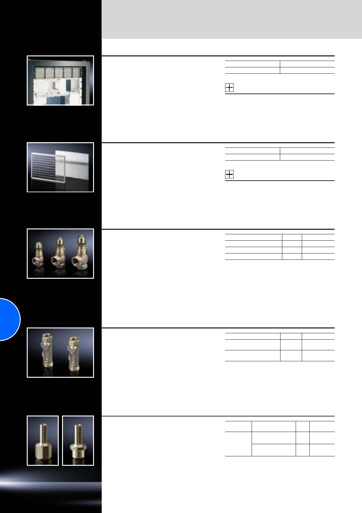
Climate control accessories
General
304 Rittal Catalogue 33/Climate control
Front outlet grille 2 U
for tangential fans
This front outlet grille is required if a 482.6 mm (19˝)
cross-flow blower (SK 3144.000/SK 3145.000) is
used in the lower section of the electronic enclo-
sure and the hot air is to be expelled to the out-
side from the upper section of the enclosure.
The design of the grille matches that of the intake
grille in the cross-flow blower.
These grilles can also be used as simple inflow
and outflow grilles with natural convection.
Accessories:
Filter mat, see page 299.
Packs of Model No. SK
1 3176.000
Filter holder
for roof ventilation
The use of a filter mat is required in order to
increase the protection category of the roof vent
(SK 3148.007).
Protection category IP 44 to IEC 60 529 is
achieved.
Material:
Sheet steel
Supply includes:
Filter holder including filter mat.
Accessories:
Spare filter mat, see page 301.
W x H x D mm Model No. SK
340 x 244 x 15 3175.000
Overflow valve
Pressostat for use in the water cycle between
the recooling system and the air/water heat
exchanger. It prevents an increase in pump pres-
sure in the recooling system against the closed
magnetic valve of the air/water heat exchanger
outside of the cooling cycle.
Setting range:
2 – 12 bar
Presetting:
3 bar
Material:
Brass
Design Packs of Model No. SK
1/2˝ bypass valve 1 3301.900
3/4˝ bypass valve 1 3301.910
1˝ bypass valve 1 3301.920
Flow regulator valve
For use with air/water heat exchangers, espe-
cially if more than one heat exchanger (n > 1) is
used in the water cooling circuit. The correctly set
valve then ensures the same quantity of cooling
medium for all equipment. The valve is used for
hydraulic balancing.
Setting range:
3 – 12 l/min
Material:
Brass
Design Packs of Model No. SK
3/4˝ x 1/2˝
for volumetric flow control 1 3301.930
3/4˝ x 3/4˝
for volumetric flow control 1 3301.940
Threaded adaptor for
quick-release fastener
For use with air/water heat exchangers with quick-
release fastener. This threaded adaptor enables
simple adaptation to fixed and flexible pipework.
Material:
Brass
For
units Design Packs
of Model No.
SK
SK 3363..../
SK 3364..../
SK 3373..../
SK 3374..../
SK 3375....
G3/8˝ internal thread 2 3201.900
G3/8˝ external thread 2 3201.910
Stainless steel V4A version available on request.
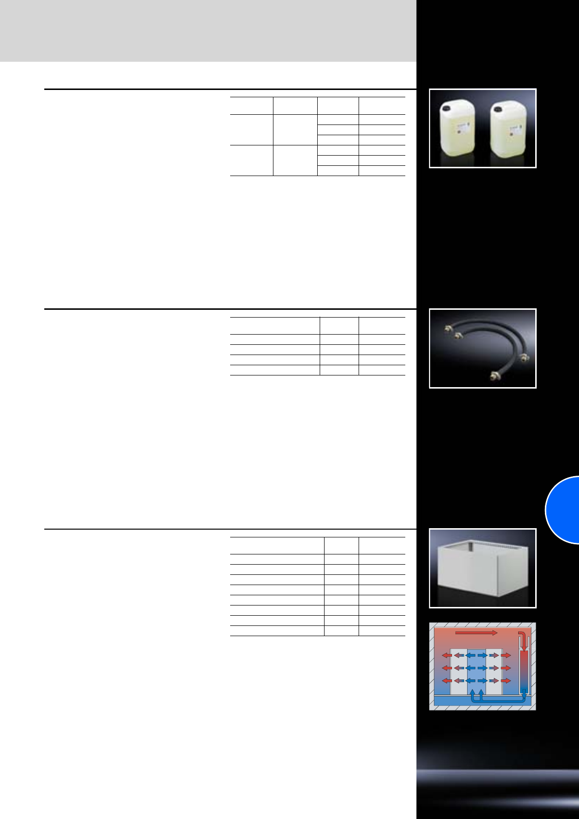
General
Climate control accessories
305Rittal Catalogue 33/Climate control
Cooling medium
for recooling systems
Ready mix
Apart from the recooling systems for oil and emul-
sion, all other recooling systems are only suitable
for the cooling of water or a water/glycol mixture.
As well as protecting against frost, this cooling
medium also serves to inhibit bacterial growth and
provide optimum corrosion protection.
Supply includes:
−10 l canister
−25 l canister
−200 l barrel
Cooling
medium Antifreeze/
water mixture Container Model No. SK
Outdoor 1 : 2
10 l 3301.950
25 l 3301.955
200 l 3301.9571)
Standard 1 : 4
10 l 3301.960
25 l 3301.965
200 l 3301.9671)
1) Extended delivery times.
Connection kit
for connecting the CRAC system CW to the cus-
tomer’s pipework when using water as a cooling
medium.
The connection kit is preassembled and is con-
nected to an outgoing pipe with stop valve (to be
provided by the customer) in both the inlet and
outlet.
Supply includes:
Inlet side in direction of flow
High-pressure hose for flexible connection to the
CRAC system CW.
Return side in direction of flow
High-pressure hose for flexible connection to the
CRAC system CW.
For CRAC system CW Nominal
width Model No. SK
SK 3301.620 to 3301.650 1˝ 3300.260
SK 3301.660 to 3301.690 11/4˝3300.261
SK 3301.830 to 3301.860 11/2˝3300.262
SK 3301.870 to 3301.990 2˝ 3300.263
Energy-saving extractor
plenum
for top-mounting on CRAC systems CW/DX.
The extractor plenum is used to raise the extrac-
tion height of the return air and return it to the
CRAC system CW/DX at the highest possible
temperature level. In this way, the energy effi-
ciency of the unit can be increased significantly.
The extractor plenum is comprised of an empty
enclosure tailored to the width and depth of the
CRAC system CW/DX. The equipment enclosure
and extractor plenum are screw-fastened together
using the assembly kit supplied loose.
Supply includes:
Empty enclosure including assembly kit.
Note:
Special heights to adapt to the available room
height are available on request.
For
CRAC system CW/DX Height
mm Model No. SK
SK 3301.620 to 3301.650 550 3300.290
SK 3301.660 to 3301.690 550 3300.291
SK 3301.830 to 3301.860 550 3300.292
SK 3301.870 to 3301.990 550 3300.293
SK 3300.510 to 3300.540 550 3300.294
SK 3300.560 to 3300.590 550 3300.295
SK 3300.710 to 3300.740 550 3300.296
SK 3300.760 to 3300.790 550 3300.297

306
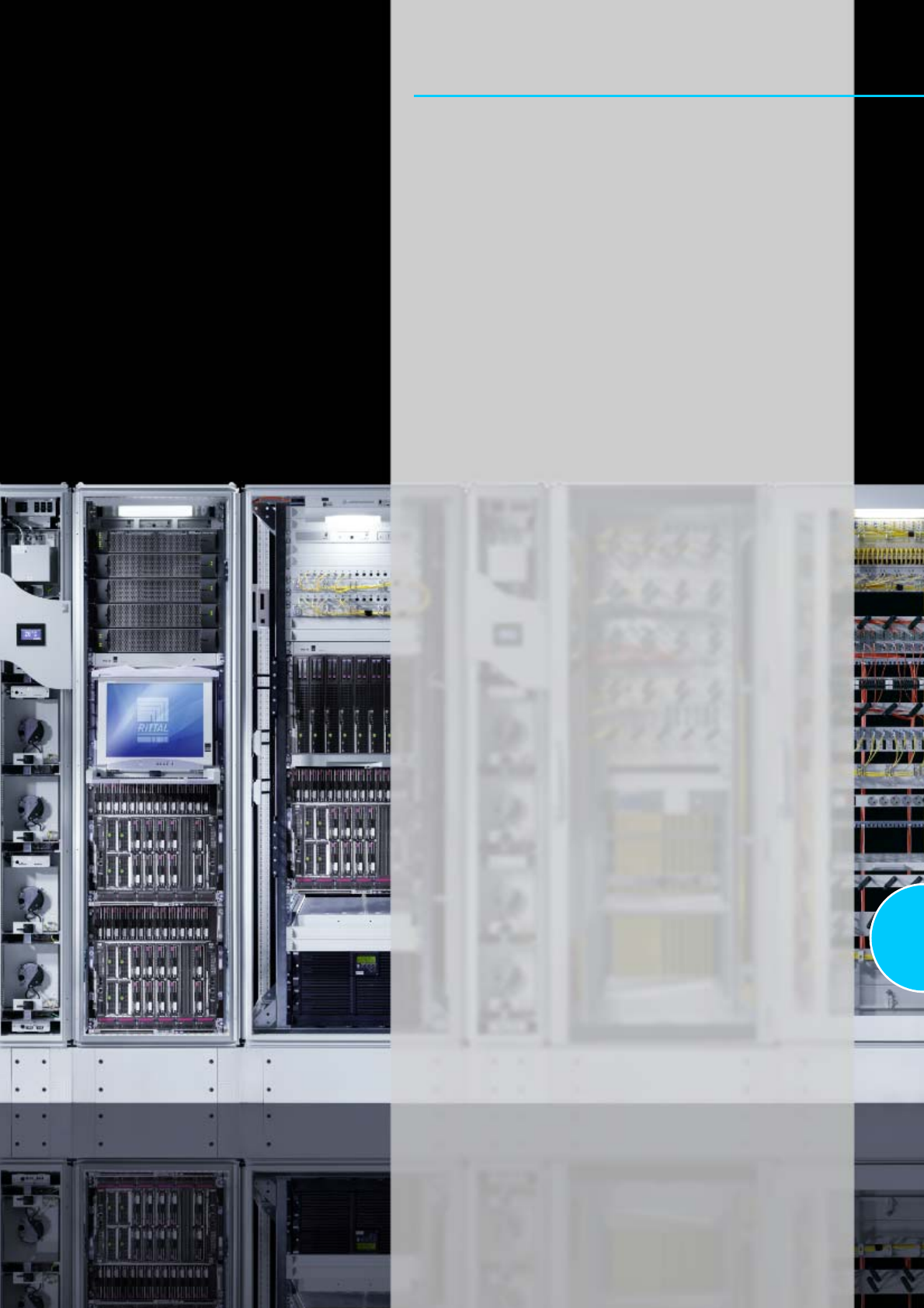
307
IT infrastructure
IT competence
System overview – Wall-mounted/floor-standing network enclosures ......311
System overview – Server enclosures.......................................................313
System overview – Power..........................................................................315
System overview – Cooling .......................................................................317
System overview – Monitoring...................................................................319
System overview – Security solutions........................................................321
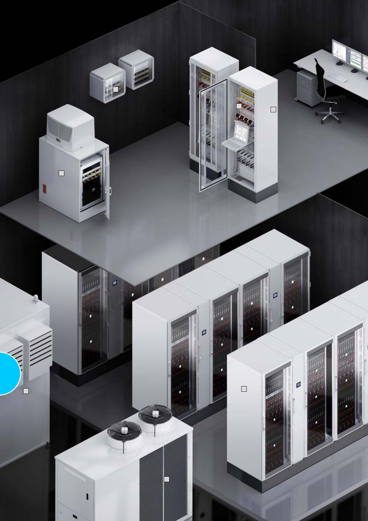
308
1
9
7
3
2
10
8
309
IT competence
Wall-mounted/floor-standing network enclosures
Wall-mounted enclosures............................................................................53
Network enclosures.....................................................................................79
Server enclosures
Server enclosures........................................................................................91
Power
UPS systems .............................................................................................189
Power Distribution Rack ............................................................................200
Power System Module Plus .......................................................................201
Power System Module...............................................................................202
RiCell Flex fuel cell system........................................................................205
Cooling
Chillers for IT cooling.................................................................................272
CRAC system ............................................................................................274
Aisle containment ......................................................................................278
Liquid Cooling Package ............................................................................279
Monitoring
Monitoring system CMC III ........................................................................578
Door control system ..................................................................................589
Monitor/keyboard unit................................................................................590
KVM switches ............................................................................................591
Dynamic Rack Control...............................................................................597
Security solutions
Compact data centre ................................................................................321
Data Centre Container...............................................................................327
Fire alarm and extinguisher system ..........................................................328
Security rooms...........................................................................................331
Software
RiZone .......................................................................................................345
Your benefits
●Standardised server racks and network enclosures
●Modular power distribution and back-up
●Scalable IT cooling concepts
●High-MTBF IT security rooms, including certificates
●Complete system accessories for IT environments and data centres
●Software-based IT and infrastructure management system
6
5
4
Sample applications
Wall-mounted enclosures, see page 53
Network enclosures, see page 79
Server enclosures, bayed in combination with LCP, see page 94/279
Power distribution
UPS systems, see page 189
Power Distribution Rack, see page 200
Chillers for IT cooling, see page 272
Monitoring system CMC III, see page 578
Compact data centre, see page 321
Data Center Container, see page 327
1
2
3
4
5
6
7
8
9
10
310
4
3
1
5
5
6
2
311
Wall-mounted network enclosures
VerticalBox ..................................................................................................54
FlatBox with 482.6 mm (19˝) mounting angles............................................55
FlatBox with 482.6 mm (19˝) mounting frame .............................................56
QuickBox with glazed door .........................................................................57
QuickBox with sheet steel door...................................................................58
QuickBox with vertical 482.6 mm (19˝) level ...............................................59
Wall-mounted enclosures EL, 3-part, depth 573/673 mm, pre-configured
....60
Wall-mounted enclosures EL, 3-part, depth 473 mm, with punched rails
......61
Wall-mounted enclosures EL, 3-part, depth 373 mm, with mounting plate
....62
Wall-mounted enclosures EL, 3-part, depth 473 mm, with mounting plate
....63
Wall-mounted enclosures EL, 2-part, depth 369 mm, with swing frame
........64
Wall-mounted enclosures AE with 482.6 mm (19˝) mounting angles
.............65
Wall-mounted enclosures AE with 482.6 mm (19˝) pull-out frame
.................66
Small fibre-optic distributors
.........................................................................67
Floor-standing network enclosures
Network enclosures TS 8
Pre-configured, doors unvented .................................................................80
Pre-configured, doors vented .....................................................................81
Pre-configured, doors/rear wall unvented...................................................82
Pre-configured, doors unvented, divided ...................................................82
Network enclosures TS 8.............................................................................83
Network enclosures TE 7000
Pre-configured.............................................................................................85
600 mm width ..............................................................................................86
800 mm width ..............................................................................................87
Distributor racks
TE 7000 open ..............................................................................................88
Data Rack....................................................................................................89
Your benefits
Network enclosures
●Network enclosures for stand-alone installation and data centres
●Complete system solutions for small to large networks
●Maximum configuration diversity and protection for installed equipment
●Investment protection and flexibility thanks to simple conversions and
use of the comprehensive modular system
Wall-mounted enclosures
●The right enclosure to suit all applications – up to protection category
IP 55
●Sizes available from 3 U to 21 U
●Wide choice of accessories with “Rittal – The System.”
●Fast assembly, conversion and simple installation based on the modular
principle
Wall-mounted/floor-standing
network enclosures
Sample applications
Wall-mounted enclosures EL, see page 60
FlatBox, see page 55
QuickBox wall-mounted enclosure with vertical 482.6 mm (19˝) level,
see page 59
QuickBox wall-mounted enclosure with glazed door, see page 57
TE 7000 network enclosure with base/plinth and installation accessories,
see page 85
TS 8 network enclosures, bayed with base/plinth, roof-mounted fan
and installation accessories, see page 80
1
2
3
4
5
6
6
6
312
1
2
2
1
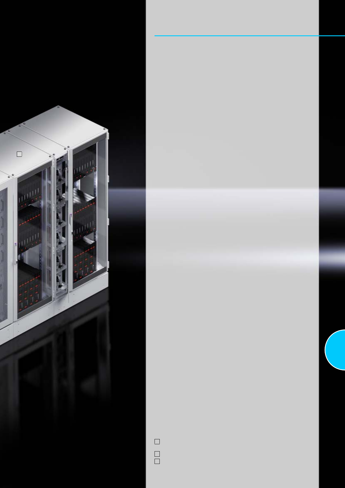
313
Server enclosures
Server enclosures
Server enclosures TS 8 ...............................................................................92
TS 8 server enclosures, colocation .............................................................93
TS 8 server enclosures for High Performance Cooling systems HPC ........94
Server enclosures TE 7000 .........................................................................95
Your benefits
●Broad spectrum of sizes
●Integrated system, from small server racks to bayed rack suites
in the data centre
●First-class finish for maximum protection
●High-quality lock systems for optimum access protection
●Comprehensive, system-compatible complete range for cooling,
power distribution/power backup and monitoring
Sample applications
TS 8 server enclosures in combination with aisle containment and LCP,
see page 278
TS 8 server enclosures, colocation, see page 93
TS 8 server enclosures in combination with LCP, see page 94
1
2
3
3
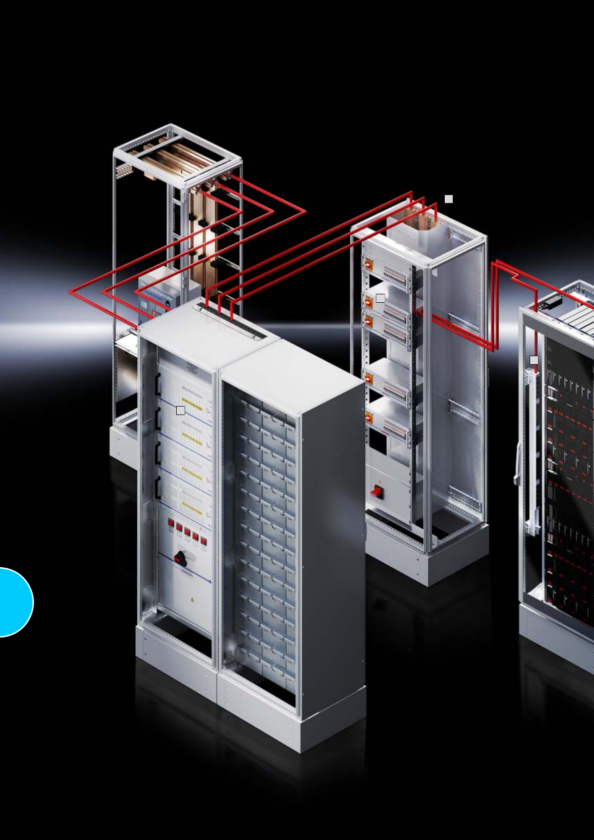
314
1
3
2
4
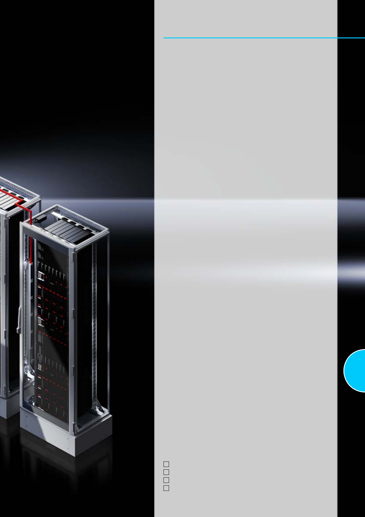
315
Power
UPS systems
UPS PMC 12..............................................................................................190
UPS PMC 40 (type 1-4) .............................................................................191
UPS PMC 40 (type 5) ................................................................................192
UPS PMC 120............................................................................................193
UPS PMC 200............................................................................................194
UPS PMC 800............................................................................................195
UPS PMC accessories ..............................................................................196
Power Distribution Rack
Power Distribution Rack ............................................................................200
Power Distribution Module ........................................................................200
Power System Module
PSM Plus busbar .......................................................................................201
PSM Plus plug-in modules ........................................................................201
PSM busbars .............................................................................................202
PSM socket modules.................................................................................203
PSM accessories.......................................................................................204
Fuel cell system
RiCell Flex fuel cell system........................................................................205
Your benefits
●Holistic, systematic energy management concepts
●Comprehensive, complete solutions for power distribution and back-up,
consistently modular, and flexibly extendible at any time
●Optimum energy and cost efficiency with maximum availability of the
entire system
●Reduced costs for installation, administration and manpower
●High level of investment certainty
●All from a single source!
Sample applications
Power Modular Concept PMC 200, see page 194
Power Distribution Rack PDR, see page 200
Power Distribution Module PDM, see page 200
Power System Module PSM, see page 201
1
2
3
4
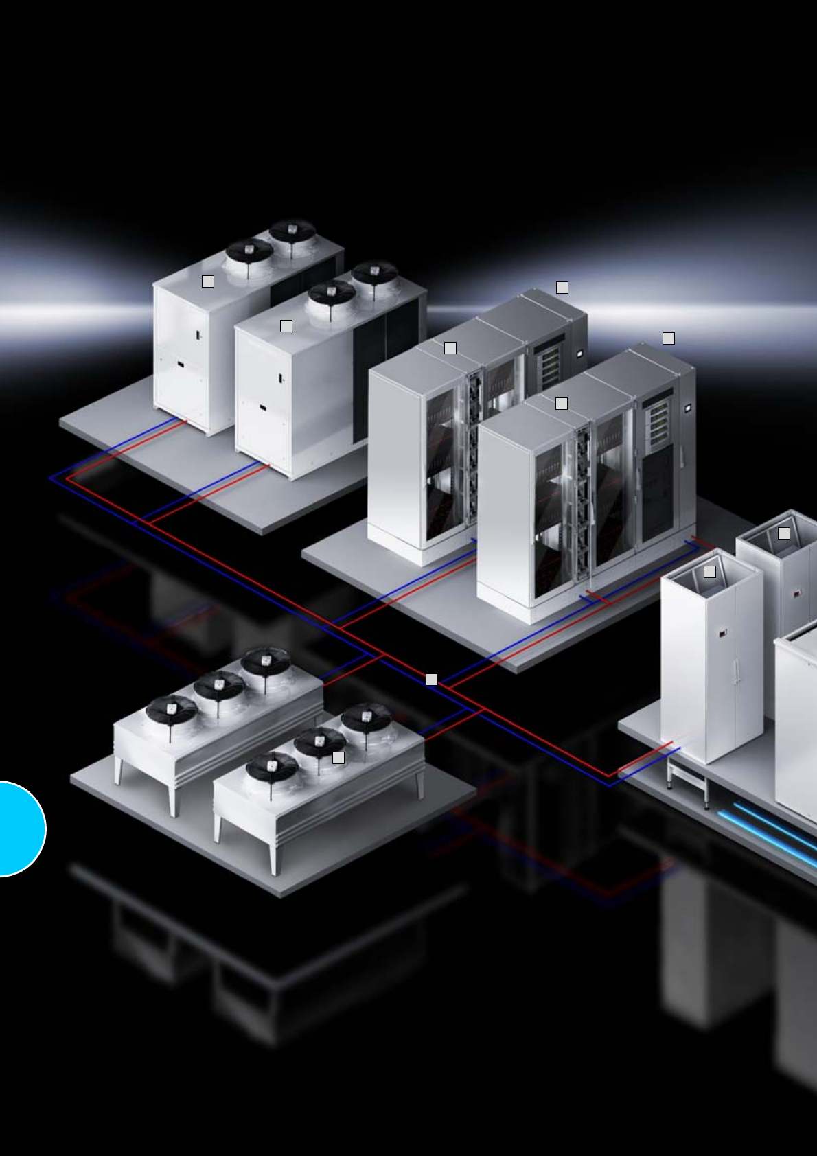
316
2
2
3
3
5
3
3
4
4
6
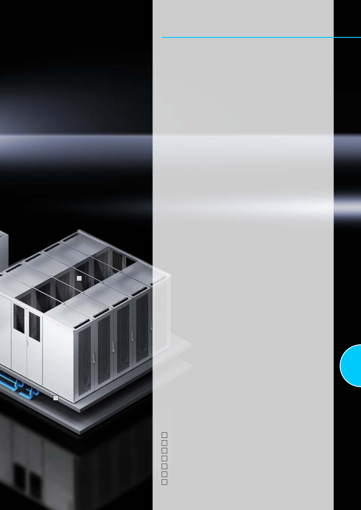
317
Cooling
Chillers for IT cooling
Chillers for IT cooling.............................................. 15 – 123 kW..............272
Chillers for IT cooling............................................ 155 – 481 kW..............273
CRAC system
CRAC system CW ............................................ 27.8 – 137.4 kW..............274
CRAC system DX ............................................... 19.2 – 56.2 kW..............276
Aisle containment
Aisle containment ......................................................................................278
Liquid Cooling Package
TopTherm LCP Rack CW and DX ........................... up to 60 kW..............279
TopTherm LCP Inline CW and DX ...........................up to 60 kW..............280
TopTherm LCP T3+ CW .......................................... up to 25 kW..............281
TopTherm LCP Passive CW ............................................. 20 kW..............282
Accessories...............................................................................................283
Your benefits
●State-of-the-art climate control technology, from cooling a single rack
through to entire data centres
●Individual climate control concepts for rack, suite and room cooling
●Enhanced security plus superior energy and cost efficiency
●Optimisation with aisle containment and cross-system control concepts
●Energy-efficient cooling with IT chillers
●Minimises operating costs with free cooling
●Environmentally friendly thanks to resource and CO2 savings
●Planning, assembly, commissioning and servicing –
all from a single supplier!
1
7
Sample applications
Rittal aisle containment, see page 278
CRAC systems, see page 274
Liquid Cooling Package LCP, see page 279
IT chiller, see page 272
Free cooling
Pipework
Raised floor for cold air supply
1
2
3
4
5
6
7
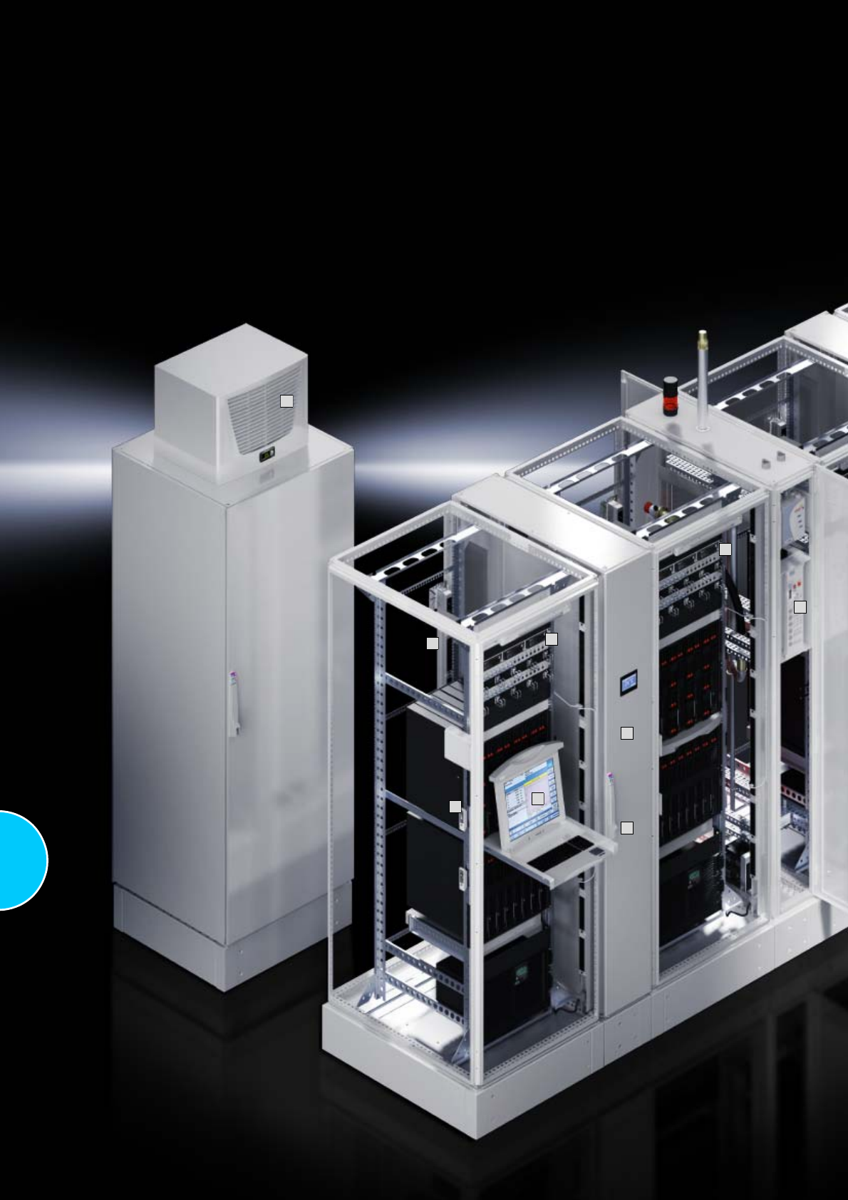
318
4
2
5
1
6
3
1
8
7
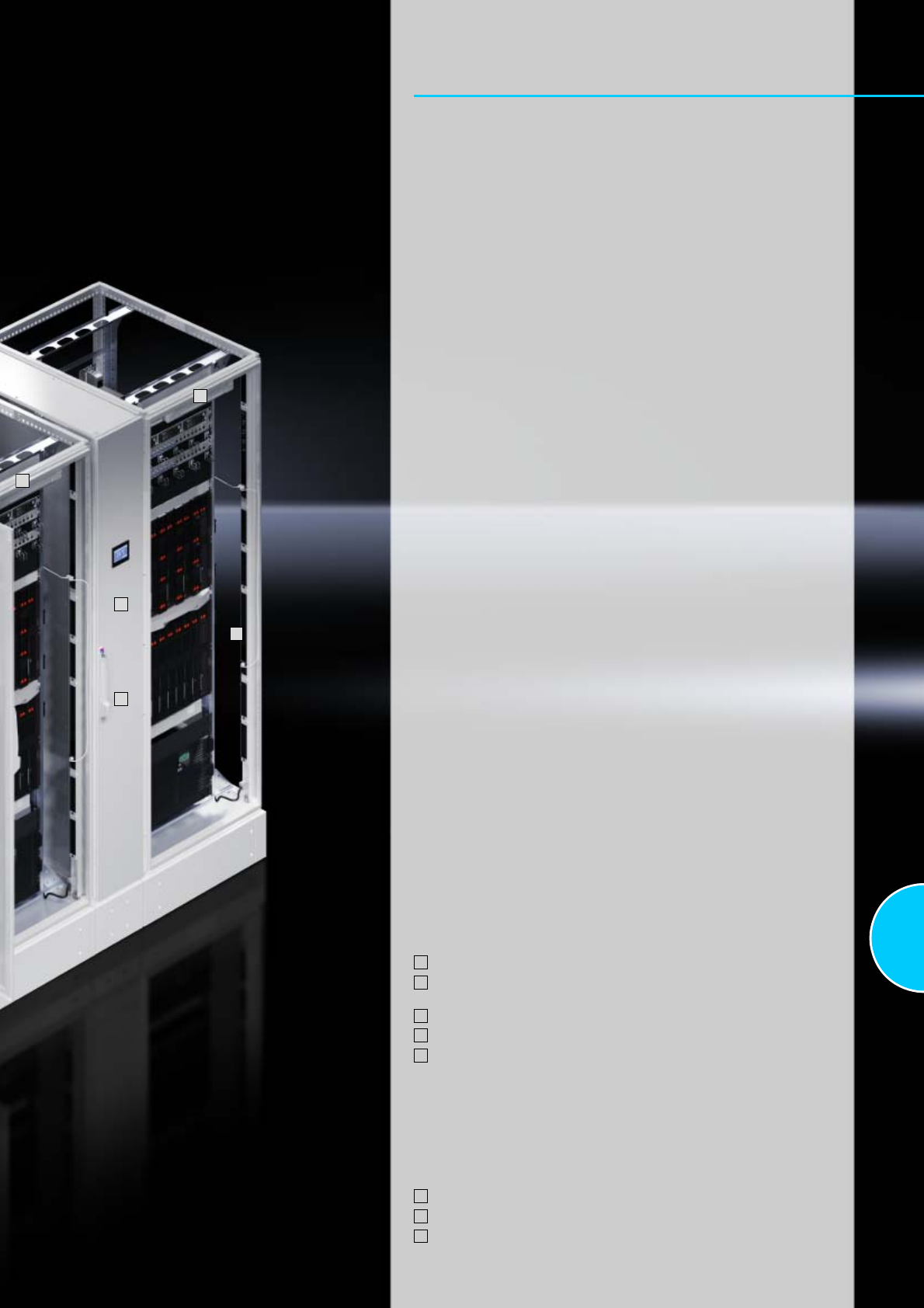
319
Monitoring
Monitoring system CMC III
CMC III system representation..................................................................578
CMC III system overview...........................................................................580
CMC III Processing Unit/Compact ............................................................582
CMC III sensors.........................................................................................583
CMC III accessories ..................................................................................584
Door Control System
Door Control System .................................................................................588
Monitor/keyboard unit
Monitor/keyboard unit................................................................................590
KVM switches
SSC view 8 USB, SSC view 32 Cat, SSC compact 32 Cat........................591
SSC premium 2/16, 4/32, 8/32 ..................................................................592
SSC Duo 16 ...............................................................................................593
Dynamic Rack Control
RFID mounting frame, tags, controller ......................................................597
Software
RiZone .......................................................................................................345
Your benefits
●Overview of your IT infrastructure
●Enhanced security
●Automated processes
●High cost efficiency
●Enormous energy savings
●Simple project management
●Fast installation
●Flexible, individual solutions with standard products from Rittal
●High standard of quality with coordinated standard products
1
1
2
3
Sample applications:
CMC III, see page 581
Power System Module PSM, Power Control Unit PCU
incl. current measurement see page 201
Liquid Cooling Package LCP, see page 279
Connection of up to 10 cooling units with Comfort control via one unit
Sensors/actuators, see page 583
– Temperature sensor
– Humidity sensor
– Access and vandalism sensors
– Motion detectors
– Airflow monitors
– Smoke detectors
– Voltage monitor
– Power supply
– Leaks
Monitor/keyboard unit, see page 590
Electric comfort handle TS 8, see page 415
Fire alarm and extinguisher system DET-AC XL, see page 329
1
2
3
4
5
6
7
8
7
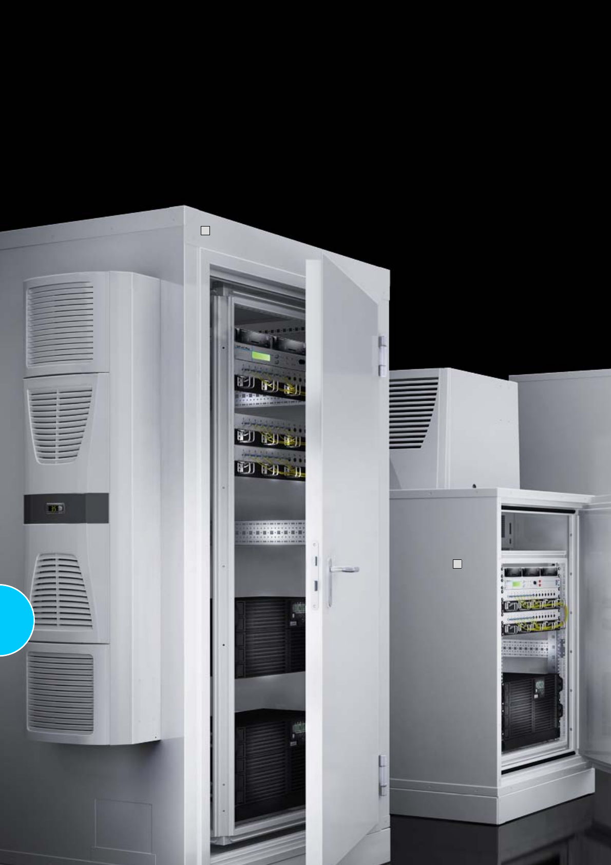
320
1
2
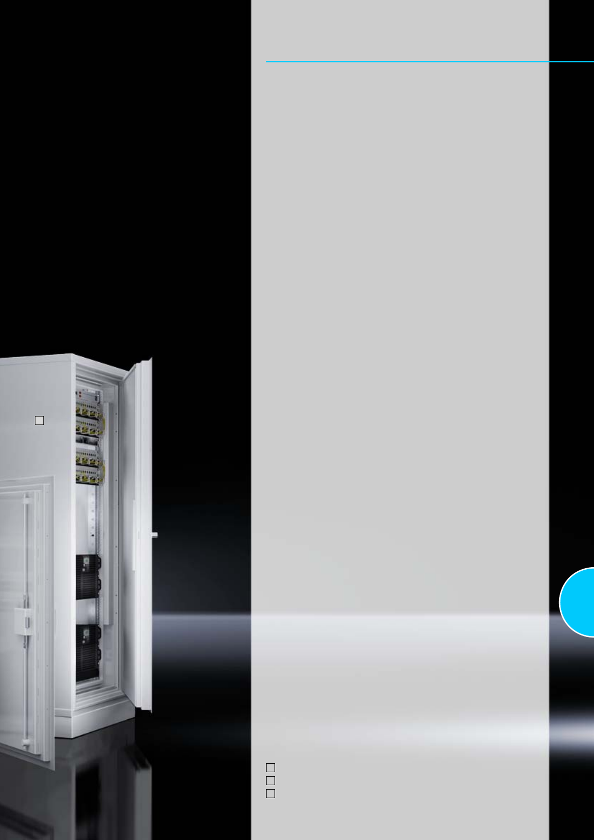
321
Security solutions
Compact data centre
Basic Safe .................................................................................................322
Modular Safe .............................................................................................323
Modular Safe Extend .................................................................................324
Climate control for Modular Safe/Modular Safe Extend ............................325
Data Centre Container DCC
Data Centre Container DCC......................................................................327
Fire alarm and extinguisher system
DET-AC Plus..............................................................................................328
DET-AC XL ................................................................................................329
Security rooms
Data centres ..............................................................................................331
3
Sample applications
Modular Safe with climate control, see page 323, 325
Basic Safe with CMC and extinguisher system, see page 322
Modular Safe Extend as compact data centre, see page 324
1
2
3
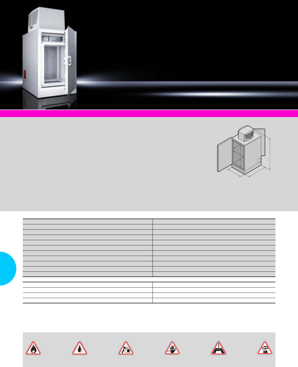
Basic Safe
322 Rittal Catalogue 33/IT infrastructure
System accessories Page 355
Applications:
●Micro data centre for small
businesses
●Protection for servers and
storage applications
●Protection for business-critical
data
●Storage of personal data,
e.g. doctors’ surgeries or tax
advisors
Benefits:
●Complete system with built-in
climate control
●High level of operational and
service-friendliness thanks to
the two-door system
●Compatibility with other infra-
structure elements
Protection standards:
−Fire protection F90 based on
DIN 4102
−Compliance with limit values
ΔT < 50 K, relative humidity
< 85% for 10 minutes
−Tested burglary protection
WK 2 EN 1627
−Protection against dust and
water jets IP 55 to IEC 60 529
The tests were performed as
system tests and confirmed by
way of test reports.
Material:
Pladur plate
Colour:
Enclosure: RAL 7035
Supply includes:
−Security enclosure with
operating and service doors
(three-point locking)
−Cable entry in both side
elements
−Climate control 2.4 kW
Detailed drawings:
Available on the Internet.
Photo shows a configuration
example with equipment not
included in the scope of supply.
T1
H1
T2
B2
H2
B1
Fire Extinguishing
water Vandalism Unauthorised
access Dust Theft/
burglary
Standard protection from:
U15
Cooling capacity kW 2.4
Width (B1) mm 806
Height (H1) mm 1699
Depth (T1) mm 1270
Clearance width (B2) mm 620
Clearance height (H2) mm 827
Clearance depth (T2) mm 1024
Weight excluding internal installation approx. kg 360
Model No. LS Basic Safe with built-in 482.6 mm (19˝) rack 7999.999
Model No. LS Basic Safe without built-in 482.6 mm (19˝) rack 7999.898
Accessories
482.6 mm (19˝) rack, 15 U, depth 1000 mm 7995.992
Early fire detection system EFD Plus see page 328
Fire alarm and extinguisher system DET-AC Plus see page 328
CMC monitoring system see page 577
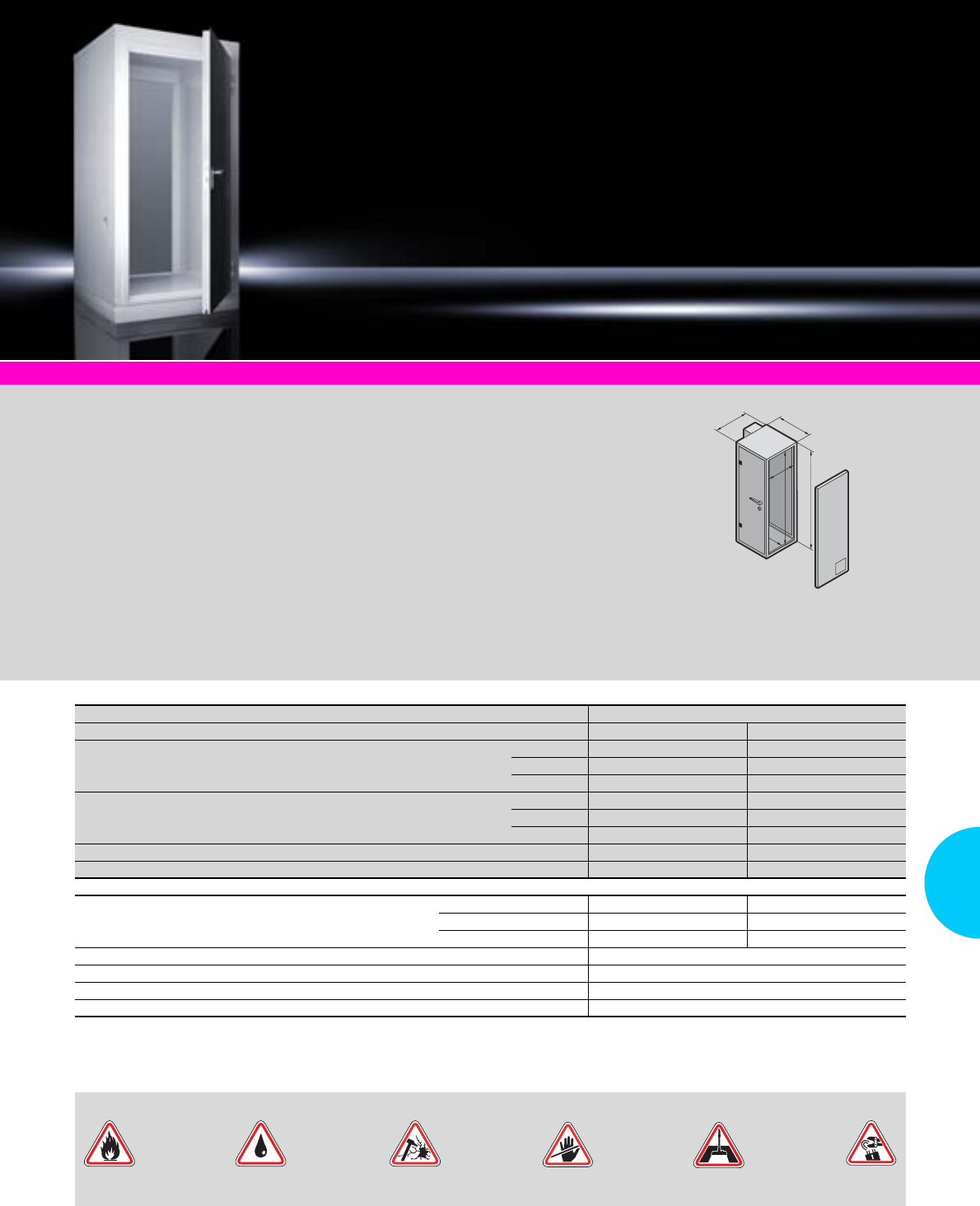
Modular Safe
323Rittal Catalogue 33/IT infrastructure
System accessories Page 355
Applications:
●Solid protection against
potential physical threats for
IT components
●Targeted configuration
components transform the
safe into a complete,
compact data centre.
Benefits:
●Modular assembly
●Prepared for the installation
of various IT climate control
solutions
●Low weight
●User-friendly, thanks to
operator and service door
Protection standards:
−Fire protection F90 based on
DIN 4102
−Burglary protection WK 2 to
EN 1627
−Protection against dust and
water jets IP 56 to IEC 60 529
−Protection from acrid gases to
DIN 18 095
Material:
Pladur plate
Colour:
Enclosure: RAL 7035
Supply includes:
−Security safe as a two-door
system
−Cable duct in both side
elements
−Both doors with semi-cylinder
and two locks
−Optional cable routing in
the top element, selectable
positioning
Detailed drawings:
Available on the Internet.
B1
T2
T1
H1
B2
H2
Fire Extinguishing
water Vandalism Unauthorised
access Dust Theft/
burglary
Standard protection from:
Two-door-system
U 33 47
External dimensions mm
Width (B1) 1500 1500
Height (H1) 1942 2321
Depth (T1) 1238 1238
Internal dimensions mm
Width (B2) 9791) 9791)
Height (H2) 1840 2219
Depth (T2) 1010 1010
Clearance height of door opening mm 1678 2057
Model No. LS 7999.892 7999.893
Accessories
482.6 mm (19˝) rack, based on TS 8, 482.6 mm (19˝) level front
and rear, 6 support strips for mounting on the 482.6 mm (19˝) level,
2 punched sections with mounting flanges
W 800 x H 1600 x D 1000 7831.429 –
W 800 x H 2000 x D 1000 – 7995.969
W 800 x H 2200 x D 1000 – 7999.970
Early fire detection system EFD Plus see page 328
Fire alarm and extinguisher system DET-AC Plus see page 328
CMC monitoring system see page 577
Climate control for Modular Safe see page 325/326
1) With built-in heat exchanger.
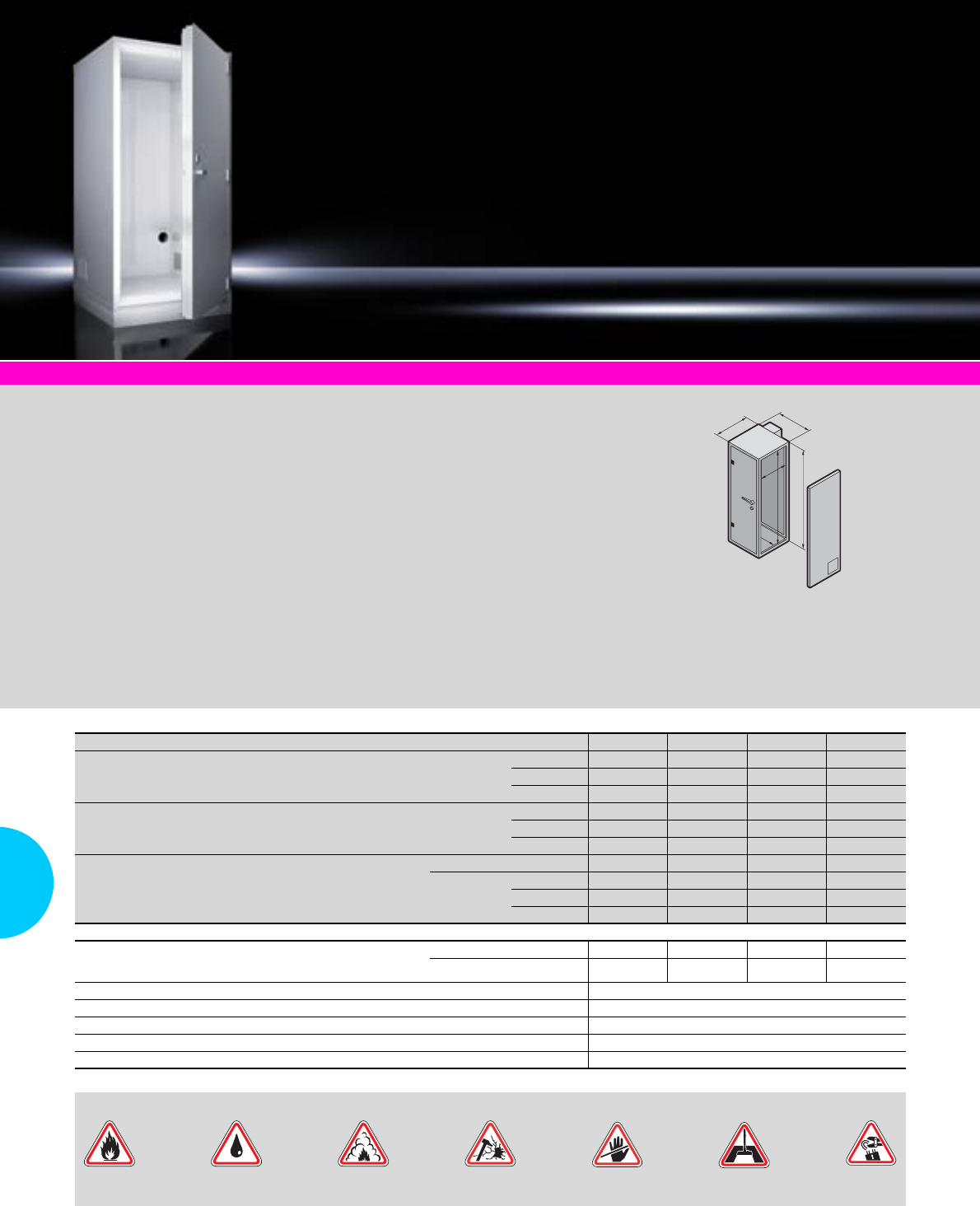
Modular Safe Extend
324 Rittal Catalogue 33/IT infrastructure
System accessories Page 355
Applications:
●A high level of protection
against potential physical
threats for IT
●Targeted configuration com-
ponents transform the safe
into a complete, compact
data centre.
Benefits:
●Modular assembly
●Expandability for graduated
investment in line with IT
growth
●Prepared for the installation
of various IT climate control
solutions
●Systems may be dismantled
and reassembled, for maxi-
mum investment security
Protection standards:
−Fire protection F90 based on
DIN 4102
−Compliance with limit values
ΔT < 50 K, relative humidity
< 85% for 30 minutes
−Burglary protection optionally
WK 2, 3 or 4 EN 1627
−Protection against dust and
water jets IP 56 to IEC 60 529
−Protection from acrid gases to
DIN 18 095
The tests were performed as
system tests and confirmed by
way of test reports.
Material:
Pladur plate
Colour:
Enclosure: RAL 7035
Supply includes:
−Security safe with operator
door and servicing door
−Cable entry in both side
elements
−Both doors with key lock
Optional:
−Electronic combination lock
−Electronic lock pre-equipped
for activation by an external
access control system
−Cable entry in the top and
base unit
−Twin-walled doors
−Choice of door hinges
Detailed drawings:
Available on the Internet.
T2
T1
B1
H1
B2
H2
U42 47 42 47
External dimensions mm
Width (B1) 1100 1100 1100 1100
Height (H1) 2210 2410 2210 2410
Depth (T1) 1200 1200 1400 1400
Internal dimensions mm
Width (B2) 920 920 920 920
Height (H2) 2030 2230 2030 2230
Depth (T2) 1000 1000 1200 1200
Model No. LS
Individual solution 7999.896 7999.897 7999.983 7999.987
Suite creation
Left 7999.977 7999.980 7999.984 7999.988
Centre 7999.978 7999.981 7999.985 7999.989
Right 7999.979 7999.982 7999.986 7999.990
Accessories
482.6 mm (19˝) rack, based on TS 8, 482.6 mm (19˝) level front
and rear, 6 support strips for mounting on the 482.6 mm (19˝) level,
2 punched sections with mounting flanges
W 800 x H 2000 x D 1000 7995.969 7995.969 7995.969 7995.969
W 800 x H 2200 x D 1000 7999.970 7999.970 7999.970 7999.970
Early fire detection system EFD Plus see page 328
Fire alarm and extinguisher system DET-AC Plus see page 328
CMC monitoring system see page 577
PSM busbar see page 202
Climate control for Modular Safe see page 325/326
Fire Extinguishing
water Vandalism Unauthorised
access Dust Theft/
burglary
Standard protection from:
Corrosive
gases
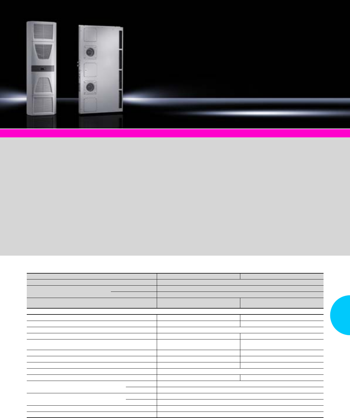
Climate control for Modular Safe/Modular Safe Extend
325Rittal Catalogue 33/IT infrastructure
System accessories Page 355 Modular Safe/Modular Safe Extend Page 323/324
●All climate control units are
designed as split units to
ensure hermetic separation
between the cooling circuits
inside and outside of the safe.
This prevents the ingress of
dust and corrosive gases.
●Air routing inside the safe is
horizontal. The hot air is
drawn in at the rear, and the
cooled air is expelled in front
of the 482.6 mm (19˝) level.
Compact climate control
Suitable for use in rooms with
climate control in the building or
adequate ventilation, and low or
no noise level requirements. The
climate control unit is available
in the output categories 2.5 kW
and 4 kW.
The evaporator coil is fastened
to the side panel on the inside of
the modular safe, and the exter-
nal device on the service door
(Modular Safe Extend) or side
panel (Modular Safe).
Outdoor climate control
When using the outdoor variant,
the internal circuit of the climate
control unit is secured to the
side panel on the inside of the
safe.
The external unit is positioned
outside of the building. The
internal and external units are
connected to one another via
coolant lines and control cables.
The hot air from the servers is
drawn in at the rear of the safe,
and the cooled air is expelled in
front of the 482.6 mm (19˝) level.
Benefits of the outdoor model:
The waste heat is routed directly
to the outside. As a result, room
ventilation or air-conditioning is
not necessary.
Outdoor climate control
with inverter technology
The external unit with inverter
technology allows targeted
speed control of the compres-
sor. The volume of refrigerant
is regulated via the electronic
expansion valve. Adaptation to
cooling requirements facilitates
energy savings of up to 40%.
The cold air is expelled in front
of the 482.6 mm (19˝) level by
the internal unit (evaporator
coil), while the hot air is drawn
in at the rear. Modified air baffle
plates achieve additional effi-
ciency gains and help to avoid
hot spots.
Compact climate control
Model No. SK 3126.230 3126.240
Rated operating voltage V, Hz 400/460, 3~, 50/60
Dimensions mm W x H x D external unit 500 x 1580 x 231
W x H x D internal unit 804 x 1544 x 100
Useful cooling output
to DIN 3168
L 35 L 35
L 35 L 50
2500 W/3090 W
2070 W/2300 W
4000 W/4010 W
3020 W/3250 W
Rated current max. 3.3 A/3.5 A 4.1 A/4.8 A
Start-up current 14.2 A/14.7 A 15.2 A/15.8 A
Pre-fuse T 6,3 – 10.0 A
Motor circuit-breaker
Power consumption Pel
to DIN 3168 L 35 L 35
L 35 L 50 1275 W/1615 W
1525 W/1920 W 1620 W/2125 W
1825 W/2835 W
Refrigeration factor ε = L 35 L 35 2.0 2.5
Refrigerant R134a,1500 g R134a, 2900 g
Permissible operating pressure p. max. 28 bar 25 bar
Temperature and setting range +20°C to +55°C
Noise level dB (A) < 70 < 72
Protection category to
IEC 60 529
Internal circuit IP 54
External circuit IP 24
Weight External unit 65 kg
Internal unit 70 kg
Colour RAL 7035
Temperature control Comfort controller (factory setting +25°C)
QK
.
QK/Pel
.
Climate control for Modular Safe/Modular Safe Extend
326 Rittal Catalogue 33/IT infrastructure
Outdoor climate control
Outdoor climate control with inverter technology
Model No. SK 7999.963 7999.965 7999.964 7999.966
Redundancy – –
Rated operating voltage V, Hz 230 V, 50 Hz, 1~ 400 V, 50 Hz, 3~ 230 V, 50 Hz, 1~ (2 x) 400 V, 50 Hz, 3~ (2 x)
Dimensions mm W x H x D 795 x 610 x 290 900 x 680 x 340 (2 x) 795 x 610 x 290 900 x 680 x 340 (2 x)
Useful cooling output
to DIN 3168 L 25 L 35 2400 W 5000 W 2400 W 5000 W
Rated current per unit, max. 3.8 A 4.1 A 3.8 A 4.1 A
Start-up current per unit 19.5 A 35 A 19.5 A 35 A
Pre-fuse T 16 A 3 x 16 A 16 A (2 x) 3 x 16 A (2 x)
Refrigerant R410 a
Temperature and setting range –15°C to +35°C
Weight External unit 38 kg 74 kg 2 x 38 kg 2 x 74 kg
Internal unit 59 kg 59 kg 63 kg 66 kg
Colour RAL 7035
Accessories
Refrigerant line incl. electric control cable for 2400 W,
length 20 m 7999.961 7999.961 7999.961 7999.961
Refrigerant line incl. electric control cable for 5000 W,
length 20 m 7999.962 7999.962 7999.962 7999.962
Model No. SK 7999.991 7999.992
Redundancy –
Rated operating voltage V, Hz 230 V, 50 Hz, 1~ 230 V, 50 Hz, 1~ (2 x)
Dimensions mm W x H x D 900 x 795 x 320 900 x 795 x 320 (2 x)
Useful cooling output
to DIN 3168
L 181)/L 35
L 18/L 43
7850 W
7030 W
Rated current max. 13.9 A
Start-up current 36 A
Pre-fuse T 25 A 25 A (2 x)
Refrigerant R410a
Temperature and setting range –15°C to +43°C
Noise level 48 – 49 dB (A)
Weight External unit 63 kg 63 (2 x) kg
Internal unit 70 kg 70 (2 x) kg
Colour RAL 7035
Also required
Heat exchanger (evaporator coil) 3126.270 3126.2702)
1) Server inlet temperature
2) 2 heat exchangers are required.
QK
.
QK
.
Rittal Czech Republic
RITTAL Czech, s.r.o.
Ke Zdibsku 182 250 66 Zdiby u Prahy
Phone: +420 234 099 000
Fax: +420 234 099 099
E-mail: info@rittal.cz www.rittal.cz
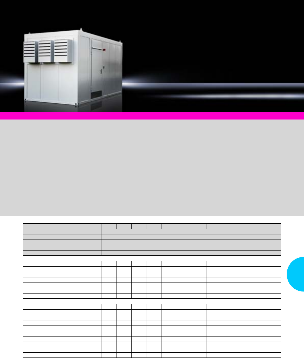
Data Centre Container DCC
327Rittal Catalogue 33/IT infrastructure
Version R7A R7B R7C R7D R14A R14B R14C R14D R20A R20B R20C R20D
Width mm 3000
Height mm 3250
Depth mm 6055
Useful area 15.2 m2
Model No. Project planning on request
Cooling capacity kW 7 7 7 7 14 14 14 14 20 20 20 20
Redundancy cooling 1+1 1+1 1+1 1+1 2+1 2+1 2+1 2+1 2+1 2+1 2+1 2+1
Available area mm (racks, UPS, DET-AC) 4500 4500 4500 4500 4000 4000 4000 4000 4000 4000 4000 4000
Heavy-duty raised floor
Plug-and-play power distribution
Hard ducts 2 x DN200
Security door WK 2
Optional fittings
UPS (uninterruptible power supply) ▫ ▫ ▫ ▫ ▫ ▫
DET-AC XL fire alarm/extinguisher system ▫ ▫ ▫ ▫ ▫ ▫
Max. no. of racks 42 U (600 mm wide) 7 6 7 6 7 6 6 5 7 6 6 5
Max. no. of racks 42 U (800 mm wide) 5 4 5 4 5 4 4 4 5 4 4 4
Higher racks (47 U) ▫ ▫ ▫ ▫ ▫ ▫ ▫ ▫ ▫ ▫ ▫ ▫
Rack power supply (PSM, PDM) ▫ ▫ ▫ ▫ ▫ ▫ ▫ ▫ ▫ ▫ ▫ ▫
Monitoring package (CMC) ▫ ▫ ▫ ▫ ▫ ▫ ▫ ▫ ▫ ▫ ▫ ▫
Security door WK 3 ▫ ▫ ▫ ▫ ▫ ▫ ▫ ▫ ▫ ▫ ▫ ▫
Additional hard ducts ▫ ▫ ▫ ▫ ▫ ▫ ▫ ▫ ▫ ▫ ▫ ▫
Metal sun shade ▫ ▫ ▫ ▫ ▫ ▫ ▫ ▫ ▫ ▫ ▫ ▫
Standard ▫ Option
Technical specifications:
Fire protection:
−Fire protection, internal
panels: F30, optionally F90
based on DIN 4102/EN 1363,
component-tested
Duct system:
−Type: Hard duct DN200
−Dimensions of packing space:
120 x 120 mm
Raised floor:
−Substructure type:
Control room
−Number of slotted plates
dependent on number of
racks
−Total raised height: 300 mm
Climate control –
Direct Free Cooling:
−Available with 7 and 10 kW
units. Up to 3 units can be
integrated.
−Targeted cooling via aisle
containment
Power distribution:
−Infeed: Wall-mounted
CEE connector, 125 A,
3-phase/N/PE, 400 V/50 Hz
−Enclosure dimensions
(W x H x D):
600 x 2000 x 400 mm
Note on standard and
customised solutions:
There is a standard range of
models available with 12 pre-
configured data centre types.
Ask for the Rittal Data Centre
Container project planning form.
Within just a few days, you will
receive an initial quote.
Customised solutions:
Bayed containers, higher cool-
ing outputs e.g. using LCP tech-
nology or more than seven racks
– we would be happy to design
your own individual data centre
container.
Optional:
−Up to seven 482.6 mm (19˝)
IT racks with power supply
−UPS, with up to 15 minutes
autonomy
−Fire alarm/gas extinguisher
system (Novec 1230)
−Access systems, access door
(keyboard, code card)
−Monitoring and management
(CMC, RiZone)
Detailed drawings:
Available on the Internet.
Photo shows a configuration
example with equipment not
included in the scope of supply.
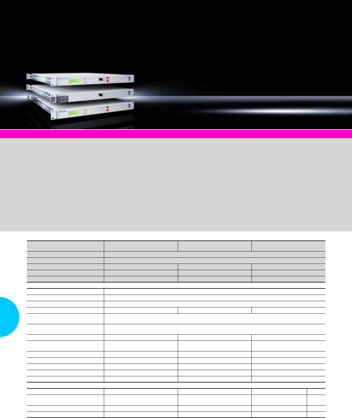
Fire alarm and extinguisher system DET-AC/EFD Plus
328 Rittal Catalogue 33/IT infrastructure
Fire alarm and extinguisher
system DET-AC Plus
Add-on unit
DET-AC Plus Slave
Early fire detection system
EFD Plus
Width mm 482,6 (19˝) rack mount
Height mm 44 (1 U)
Depth mm 640 570 500
Weight kg Approx. 15 Approx. 12 Approx. 8
Model No. DK 7338.120 7338.320 7338.220
Protection category IP 20
Ambient temperature (operation) +10°C to +35°C
Battery storage –10°C to +50°C
Operating voltage 100/240 V AC 50/60 Hz 24 V DC 100/240 V AC 50/60 Hz
Uninterruptible mains electricity
operation 2 x 12 V; 2.2 A/approx. 4 h
Connections 3 RJ 12 connectors for connecting to the CMC, alternatively 3 relay outputs,
max. contact load 24 V DC/0.5 A
Sensors 2 different scattered-light sensors – 2 different scattered-light sensors
Display LCD display with
plain text information – LCD display with
plain text information
No. of slave modules Max. 4 – Max. 5
No. of monitored enclosures Max. 5 – Max. 5
Extinguisher gas NOVEC 1230 NOVEC 1230 –
Fill volume of extinguisher gas 3.2 kg 3.2 kg –
Admissible max. protection volume 3 m³ 3 m³ –
Also required
Pipe kit 7338.130 7338.130 7338.130 Page
RJ 12 cable for alarm relaying to CMC,
packs of 2 7320.8141) 7320.8141) 7320.8141) 585
Access sensors 7320.530 7320.530 – 583
Depth-variable slide rails – – 7063.883 559
1) 2 packs are required.
System accessories Page 355 Server enclosures Page 91
EFD Plus
The EFD Plus system is a com-
pact early fire detection system
with active smoke extraction
system.
The integral fan system conti-
nuously extracts the air from the
enclosure, and passes it over
two smoke detectors. The first
smoke detector is extremely
sensitive and triggers a pre-
alarm. The second smoke
detector triggers the main alarm.
DET-AC Plus
The DET-AC Plus is a compact
fire alarm and active extin-
guisher system with smoke
extraction system, built into one
height unit. The detection sys-
tem is identical to that used in
the EFD Plus system. Fire extin-
guishing with the extinguisher
gas NOVEC 1230 is automati-
cally activated when a main
alarm is triggered. With the
extinguisher gas supply pro-
vided, a volume of up to 3 m3
can be extinguished.
DET-AC Plus Slave
In conjunction with the DET-AC
Plus slave system, up to five
bayed enclosures may be ex-
tinguished. In addition to the
DET-AC Plus unit, a DET-AC Plus
Save unit is used for each addi-
tional enclosure and contains
the extinguisher gas for one
enclosure. For detection pur-
poses, the pipework from the
DET-AC Plus system is laid in
all enclosures.
Benefits:
●Early fire detection
●Automatic extinguishing
●Innovative extinguisher gas
NOVEC 1230
−Eco-friendly
−Uncritical for IT components
●482.6 mm (19˝) rack mount
with just 1 U

Fire alarm and extinguisher system DET-AC XL
329Rittal Catalogue 33/IT infrastructure
Fire alarm and extinguisher system DET-AC XL S-08-40-10 S-16-40-10 S-24-40-10 S-08-40-12 S-16-40-12 S-24-40-12
Width mm 300 300
Height mm 2000 2000
Depth mm 1000 1200
Model No. DK 7338.160 7338.161 7338.162 7338.163 7338.164 7338.165
Accessories
Nozzle piping kit for extinguisher system 7338.166 7338.166 7338.166 7338.166 7338.166 7338.166
Piping kit for smoke extraction system 7338.167 7338.167 7338.167 7338.167 7338.167 7338.167
Nozzle piping kit for extinguisher system between enclosure suites 7338.168 7338.168 7338.168 7338.168 7338.168 7338.168
Piping kit for smoke extraction system between enclosure suites 7338.170 7338.170 7338.170 7338.170 7338.170 7338.170
Pressure relief valve for enclosures 7338.171 7338.171 7338.171 7338.171 7338.171 7338.171
System accessories Page 355 Server enclosures Page 91
Standardised solution for ex-
tinguishing individual bayed
enclosure suites with up to
24 enclosures or entire rooms.
All components of the system are
built into a 300 mm wide TS 8
enclosure, facilitating optimum
baying to a suite of server en-
closures. The integral early-
warning fire detection system
with active smoke extraction
detects fire from a very early
stage. The fire is extinguished
automatically.
NOVEC 1230 is used as the
extinguisher gas.
Benefits:
●Extinguisher system for room
volumes up to 84 m³
●Rack extinguisher system
for up to 24 racks
●Suitable for incorporation into
TS 8 server rack suites
●Simple project planning on
the basis of standard pack-
ages
●Innovative extinguisher gas
NOVEC 1230
−Eco-friendly
−Uncritical for IT components
Three solutions are available
in the standard version:
For extinguishing up to:
●8 racks
●16 racks
●24 racks
In addition, Rittal is able to
configure both room and rack
extinguisher systems to your
individual specifications.
Function principle:
The detection system of the
DET-AC XL draws room or rack
air in continuously and detects
even the tiniest smoke particles
during the initial phase of a fire,
the pyrolysis phase.
After a defined delay time, the
extinguisher gas bottle is
opened electrically and the gas
flows out into the room or racks
via the extinguisher nozzles.
Photo shows a configuration
example with equipment not
included in the scope of supply.
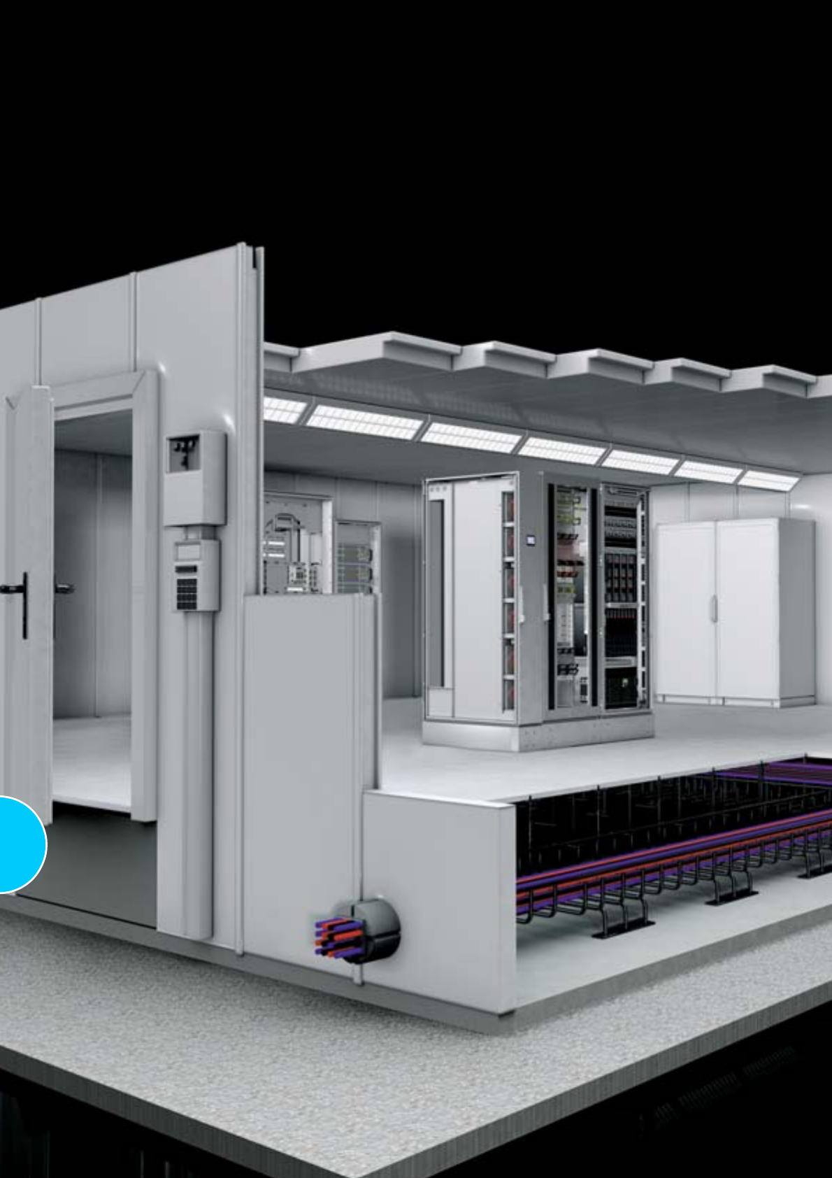
330
Security rooms
Rittal Catalogue 33/IT infrastructure 331
We plan and implement
data centres
Whether you are planning a new building, an
extension or an optimisation to your data centre,
we are at your side as a trustworthy partner and
leading provider with decades of experience.
●Basic protection or high-MBTF protection
for data centres
●Extendible
●Dismantling and reassembly =
investment protection
●Dust- and noise-reduced installation
●System-tested
●Multi-functional risk coverage
Criterion Standards Conven-
tional
design2)
Basic protection High-
MTBF
LER
Extend LER
Basic LSR
18.6 E
System testing Testing of the following standards as
complete system or structure1) –
Fire protection
Testing at temperatures
of up to 1000°C and
above
ECB·S certifications to EN 1047-2,
50 K temperature increase and 85%
rel. humidity up to 24 hours (reheating
period), 60 minutes flame impingement
time
– – –
50 K temperature rise and 85% rel. humidity over
30 minutes, without reheat period – –
F120 as system test, according to the limits of
EN 1363 (DIN 4102), for the cellular structure
and its built-in modules – – –
F90 as system test, according to the limits of
EN 1363 (DIN 4102), for the cellular structure
and its built-in modules –
F180 only as component testing to EN 1363
(DIN 4102), wall system only – – –
F120 only as component testing to EN 1363
(DIN 4102), wall system only
F90 only as component testing to EN 1363
(DIN 4102), wall system only
Explosion Detonation test as system testing of 200 kg TNT
from 40 m – – –
Water
Standing water, 72 hours, 40 cm,
maximum 20 drops – – –
Extinguisher water, IP x6 as system testing to
IEC 60 529, for the cellular structure and its
built-in modules –
Relative humidity, 85%, over 24 hours (reheat
period), 60 minutes flame impingement time,
to EN 1047-2 – – –
Relative humidity, 85%, over 30 minutes – –
Dust-tightness IP 5x as system testing to IEC 60 529, for the
cellular structure and its built-in modules –
Corrosive fire gases Acrid gas-tightness, based on EN 1634-3
(DIN 18 095) –
Unauthorised access
WK 3 as system test to EN 1627/1630,
for the cellular structure and its built-in modules,
such as doors –
WK 2 as system test to EN 1627/1630,
for the cellular structure and its built-in modules,
such as doors –
WK 4 only as component testing to
EN 1627/1630, door system only – – –
Falling debris
Shock test as system test,
3 shocks of 200 kg from 1.5 m after 45 minutes
flame impingement time – – –
Shock test as system test,
1 shock of 200 kg from 1.5 m after 30 minutes
flame impingement time –
EMC protection
Protection against high-frequency irradiation
and radiation, verified by tests on comparable
components by TU Aachen –
EMC optional package Extended high-frequency shielding in accord-
ance with BSI TL-03304 – – –
1) System-tested products are tested as a complete construction. This comprises the cellular structure and installation
modules such as doors, cable shields or ventilation units. By contrast, component testing only refers to
individual parts.
2) The conventional design refers to room structures of plasterboard, concrete and other standard construction
materials which do not offer sufficient protection for data centre applications.
Conventional designs are generally tested for use as fire walls.
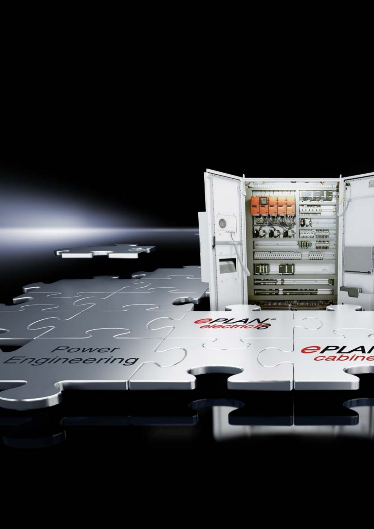
332
333
Software & services
Expertise............................................................................................335
Planning..............................................................................................337
Project management .................................................................341
Configuration...................................................................................343
Monitoring..........................................................................................345
Service ................................................................................................349
Quality management.................................................................353
Training courses, seminars and workshops
See our website www.rittal.com

334
Rittal added-value
Rittal Catalogue 33/Software & services 335
Rittal system consulting
Rittal offers you more than just efficient products.
Rittal can help you to save costs throughout the
entire value creation chain. It is a question of
uncovering and tapping into hidden potential.
A whole team of Rittal experts – who know exactly
what they are talking about – are waiting to give
you their support. Together with your own special-
ists, they investigate the full process chain, from
initial development and engineering, through to
the actual manufacturing. Always on the lookout
for optimisation potential.
Rittal offers you an ingenious and integrated con-
cept combining consulting, software, products,
services and support. A conclusive approach, but
nevertheless open to all your individual contribu-
tions. Benefit from our proven expertise and long-
standing experience. Put our promise to the test.
Rittal has both the consultants and the
requisite know-how.
1
3
212
11
10
9
8
7
6
5
4
Step 1:
Analysis of current situation
Rittal follows a systematic approach to solution-
finding.
The starting point is a customer-specific analysis
of the current situation at all levels:
●Products, tools and software used
●Defined processes and procedures
●Efficiency of the solution
Step 2:
Identify potential
The second step is to uncover the potential for
time and cost savings. An individual evaluation
scrutinises data consistency, technology effi-
ciency and the options for process optimisation.
In many cases, the first savings are already
apparent here.
Step 3:
Implement measures
With corresponding support from Rittal, the cus-
tomer can now translate the theoretical results into
concrete efficiency-boosting measures.
Rittal possesses all the necessary intelligent tools,
solutions and systems. Each component is per-
fectly integrated – without compromise, without
the need for improvisation.
Step 4:
Performance review
A systematic approach is the key to significantly
enhanced efficiency. To this end, Rittal offers a
complete package (products, planning and soft-
ware, service and support). After a defined
period, we join you to review the success of the
implemented measures.
336
Planning
337Rittal Catalogue 33/Software & services
RiCAD 3D
The download platform for seamless integra-
tion of Rittal CAD data into your plant designs
– 3D data for efficient planning
Regardless of which CAD system you use,
RiCAD 3D effectively supports the efficiency
and productivity of your plant design work.
It includes both 2D and 3D drawings for virtually
all Rittal products, together with an extensive
range of system accessories.
Benefits:
●Precisely detailed CAD product data
●Export in all standard CAD formats
●Simple integration into the most varied CAD
systems
●Considerable reduction of engineering and
design work
●Error-free, detailed Rittal data
●Generic original data in 3D and 2D format
●No conversion of neutral formats
CAD data in the following formats:
●DWG.3D
●ProE 2001
●ProE Wildfire
●SolidWorks 3D
●Neutral Step format
Fast online access to original data in many
other CAD formats with direct downloading
facility available at: www.rittal.com
AE Laser Express
Rittal provides a very special service: You will
receive an enclosure that has been assembled
as defined in your specifications, finished with
cut-outs and drilled holes and painted in the spe-
cial colour that you stipulated within just 7 days!
Benefits:
●Send us your drawing via our Internet portal.
You will receive your quote within the next
24 hours.
●Production will start as soon as we receive your
order.
●Within 7 days, customers in Germany will
receive their own compact enclosure, custom-
manufactured for their particular application.
www.rittal.com
Planning
338 Rittal Catalogue 33/Software & services
EPLAN platform
●EPLAN electric P8
●EPLAN pro panel
●EPLAN fluid
●EPLAN ppe
●EPLAN cabinet
●EPLAN data portal
●EPLAN engineering center
All applications on the same, consistent
platform technology
●Uniform project planning environment for
electrical, fluid, EI&C engineering and 3D
assembly design
●Consistent project data and component
management
●Modularisation for individual system
configuration
●Open system architecture for seamless
system integration
●Cross-platform basic functions
www.eplan.com
EPLAN electric P8
The new dimension in engineering.
●Professional project planning, documentation
and administration of electrical engineering
automation projects
●Optimisation of the engineering process
through standardisation, reuse and automated
circuit diagram generation
●Variant technology – unique, powerful,
convincing
●High-end electrical project planning –
process-oriented and automated
●Transfer and processing of data from
upstream processes
●Qualified master data ready to use
“out-of-the-box”
●Consistent support in circuit diagram
generation
EPLAN pro panel
●High-end 3D assembly layouts for electrical
and fluid design
●Description of the assembly layout with virtual
3D prototypes
●EPLAN eTouch technology for the simplest
handling
●Positioning aids for optimum dimensioning
and utilisation of the available space
●Planning confidence by taking manufacturer
data into account
●50% or more time savings with layout
●Early availability of precise production
documents
●Precise-fit components for greater assembly
efficiency
●Complete consistency with participating
engineering disciplines
●Improved communications thanks to
high-quality documentation
EPLAN fluid
From drawing to engineering.
●Clear project structures instead of a single
drawing
●The latest symbol data based on the current
standard ISO 1219
●Consistency in electro-hydraulic system
documentation
●Direct connection of parts lists and hydraulic
diagrams
●Automatic documentation of revisions
Planning
339Rittal Catalogue 33/Software & services
EPLAN ppe
For consistent engineering with process tech-
nology in mechanical and plant engineering
●Professional planning and project management
of EI&C technology in process-related
machinery and plant
●Generation of plant overviews, P&I diagrams,
administration of PIC points, and documen-
tation
●Smooth-running interdisciplinary cooperation
thanks to deep platform integration
●Optimum support for both preplanning and
detailed planning
EPLAN cabinet
Efficient enclosure production in the product
development process
●Transfer of equipment and wiring information
from the upstream electrical design
●3D configuration of mounting plates and enclo-
sures
●Automatic calculation of optimum wiring routes
and wire lengths
●Transfer of production data to NC machines
●Transfer of assembly data to wire assembly
machines
●High-quality product data thanks to links with
RiCAD 3D
EPLAN data portal
Web-based supply of high-quality equipment
data.
●Seamless integration into the EPLAN platform
●Fast project planning with no media inter-
ruptions
●Minimal effort required for master data
maintenance
●Enhanced quality, thanks to high-quality
templates
●Extensive additional information
●Multi-lingualism at no extra cost
●Uniform layout and complete documentation
EPLAN engineering center
Functional engineering for unimaginable
productivity benefits.
●Functional engineering is the crucial link
between sales, design and service
●Existing projects indicate potential savings of
up to 80%
●EPLAN EC guarantees rapid commissioning
on the basis of tested, standardised machine
functions
●Cross-disciplinary engineering minimises the
need for coordination and speeds up the time
to market
●EPLAN EC proves that: module-based engi-
neering cuts costs and permanently improves
quality
●The EPLAN EC automatisms prevent the usual
last minute changes from becoming a project
cost trap
●A central database ensures engineering
expertise and allows rapid induction during
peak project times
340
Project management
341Rittal Catalogue 33/Software & services
Therm 6.1 software
The Therm 6.1 software package takes care of the
complex calculation of climate control require-
ments. A user-friendly interface guides the opera-
tor to the most suitable, correctly dimensioned
climate control component.
All evaluations are closely based on the require-
ments of IEC/TR 60 890 AMD 1/02.95 and
DIN 3168 for enclosure cooling units.
Rittal Therm 6.1 is a calculation program
for enclosure climate control.
●Improved user guidance via tabs and simple
selection menus
●Express and expert versions
●Configurator for recooling systems
●Heat loss calculator for busbars
●Key calculation data is visible at all times
●Internet updates
●Fast and thorough determination of the required
climate control measures
●Determining the correct climate control meas-
ures leads to cost savings
●Easy calculation of the required actual cooling
output, as well as any upgrades or enhance-
ments to the switchgear
●Detailed documentation is supplied with the
calculation
Supply includes:
CD-ROM, with 19 languages
Packs of Model No. SK
1 3121.000
Note:
Your free 30-day trial version may be down-
loaded at www.rittal.com
Rittal Power Engineering
Planning software for RiLine60 busbar sys-
tems and Ri4Power low-voltage switchgear
with design certificate
The multi-lingual software package includes the
following functions:
●Project handling, from the initial enquiry through
to ordering
●Configuration of RiLine60 busbar systems in the
Top enclosure system TS 8. Compact enclo-
sures AE, CM, KS and free-standing enclosure
ES 5000.
●Configuration of low-voltage switchgear with
Ri4Power systems Form 1-4 and ISV
●Complete, automatic function for the genera-
tion of bills of materials and a calculation pro-
gram for quote preparation
●Input and evaluation of assembly times to cal-
culate man hours
●Access to the entire range of Rittal products
●Output of automatically generated plant docu-
mentation with rated current and heat loss
calculation
●Generation of special fields configured by
the customer with graphical processing in the
CAD view
●Import/export interfaces for product and
CAD data
●Export function for order lists and bills of mate-
rials in Excel format
●Interface to EPLAN Electric P8, for the export
of CAD data and bills of materials
●The extra benefit for engineering and planning
offices: Output of detailed tender texts based
on plants that have been project-planned in
Power Engineering in MS Word format.
●Output of project-specific assembly plans
together with field and plant definitions
●Integral configurator for the generation of
drawings and bills of materials to create con-
nector kits for connecting open air circuit-
breakers (ACB).
Supply includes:
CD-ROM
Languages: German/English/French/Dutch/Dan-
ish/Swedish/Czech/Italian/Spanish/Polish/Russian
Packs of Model No. SV
1 3020.500
342
Configuration
343Rittal Catalogue 33/Software & services
TS 8 configurator
A complete enclosure configured in just eight
clicks, including parts list and 3D model.
Benefits:
●Easy menu-assisted configuration of a bayed
TS 8 enclosure with base/plinth, side panels
and the handle system required
●
Mounting rails and punched sections with mounting
flanges can be pre-assembled for interior installation
●This will produce a 3D drawing that can be
incorporated directly into the system design or
integrated into EPLANCabinet
www.rittal.com
Command panel configurator
Optimised, coordinated solutions for the human/
machine interface based on Rittal Comfort Panel
and Optipanel.
Benefits:
●Select the enclosure that holds the panels to
be used (the integrated database contains a
variety of commercial panels from various
manufacturers)
●Easy navigation thanks to the list of related
questions
●Quick compilation of the features required
●Request a quote based on the selected data
●Request the 3D data for integration in the
system design
www.rittal.com
Support arm configurator
The system is able to precisely define the correct
support arm system using important user-specific
parameters such as the jib length, enclosure
weight or required cable cross-section.
Benefits:
●Individual assembly tailored to the user’s
specific requirements
●Integrated consistency checking
●Configured system parts list
www.rittal.com
CM configurator
Rittal CM compact system enclosures combine
the advantages of the AE compact system enclo-
sure with the configuration diversity of the TS 8
top enclosure system.
Benefits:
●Simple menu-assisted selection of a CM enclo-
sure together with a base/plinth and gland
plates that meet the requirements
●The relevant interior installation accessories can
also be selected to match the chosen enclosure
●The end result will enable you to request a
quote that reflects the actual configuration
selected
www.rittal.com
Subrack configurator
Generate a component-based order list for a
subrack in just a few clicks.
Benefits:
●Fast, reliable selection of individually coordi-
nated systems in the Ripac Easy and Ripac
Vario series
●Simple prompt masks reliably create techni-
cally feasible solutions with error-free order lists
●Intelligent plausibility checking of admissible
component combinations
●Request a quote based on the order list
generated
●Parts list for the configured subrack
www.rittal.com
IT configurator
Rittal offers the ideal system solution for every net-
working task, matched to the user’s individual
demands.
Benefits:
●A specific enclosure can be selected
●Accessories can be configured
●Plausibility checking
●The end result will enable you to request a
quote that reflects the actual configuration
selected
www.rittal.com
344
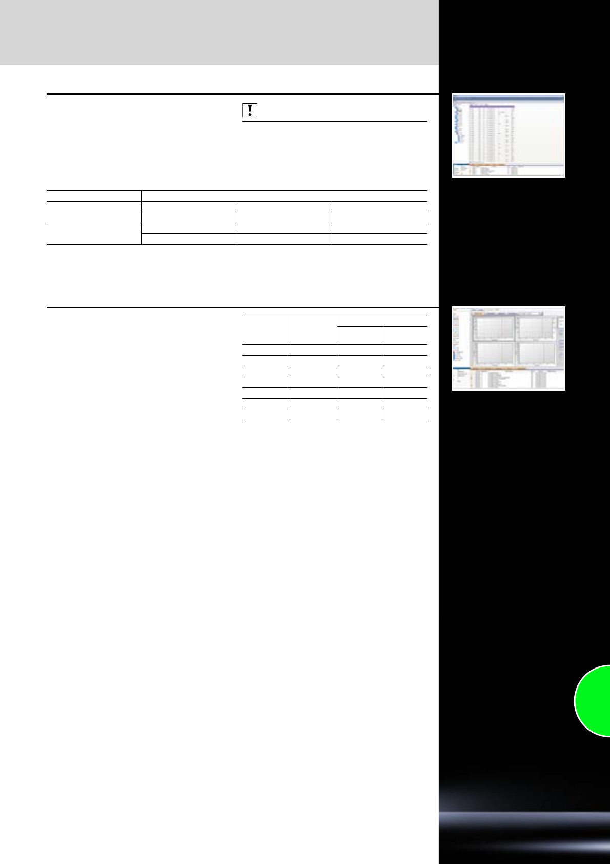
Monitoring
345Rittal Catalogue 33/Software & services
RiZone Appliance Standard
RiZone is supplied as an appliance or a software
appliance.
As an appliance, RiZone is supplied with global
support, installed on a powerful server. The soft-
ware appliance is available as a virtual server
which can easily be used on existing hardware in
the data centre.
Also required:
RiZone Appliance IP node licence according to
the number of IP nodes available
Standard version Model No. DK
Hardware appliance1) Server with Windows RiZone software RiZone graphics tool
7990.101 7990.201 7990.301
Software appliance1) Hard drive + Windows RiZone software RiZone graphics tool
7990.103 7990.203 7990.303
1) All Model Nos. on the same line belong together, and must always be ordered together.
RiZone Appliance
IP node licence
The flexible RiZone licence model allows opti-
mum adaptation to any project size, while at the
same time allowing the opportunity to grow with
the data centre.
The volume licences for the IP nodes are gradu-
ated from 10 to 1000 nodes and may be adapted
precisely to the size of the data centre. For each
active component or other SNMP-compatible
component to be covered, one node licence is
required.
For no. of
IP nodes1)
Console
licences
included
Model No. DK
RiZone
software RiZone
graphics tool
10 2 7990.205 7990.305
25 4 7990.206 7990.306
50 4 7990.207 7990.307
100 8 7990.208 7990.308
250 10 7990.209 7990.309
500 15 7990.210 7990.310
1000 20 7990.211 7990.311
1) All Model Nos. on the same line belong together,
and must always be ordered together.
Monitoring
346 Rittal Catalogue 33/Software & services
Client Access licence
Additional licence for operation of another RiZone
console.
Model No. DK
Client Access1)
RiZone
software RiZone
graphics tool
7990.213 7990.313
1) All Model Nos. on the same line belong together,
and must always be ordered together.
RiZone module SNMP support
for units from
other manufacturers
For the incorporation of SNMP-compatible units
from other manufacturers into RiZone. With MIB
browser.
Extension Model No. DK
RiZone SNMP support for units
from other manufacturers 7990.014
Microsoft Operations Manager
Management Pack
For integrating RiZone into the Microsoft Opera-
tions Manager.
Extension Model No. DK
Microsoft SCOM
Management Pack 7990.012
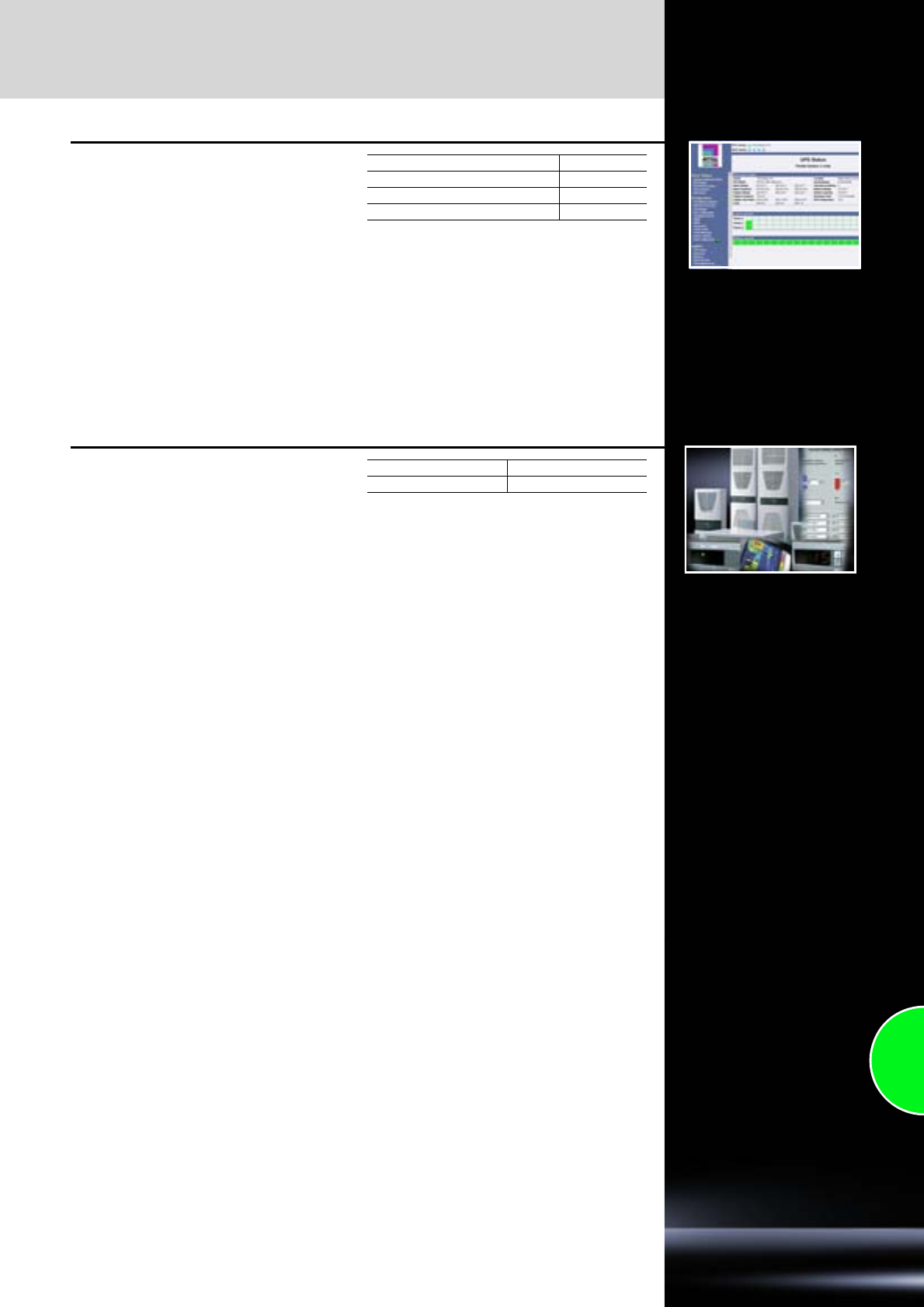
Monitoring
347Rittal Catalogue 33/Software & services
RCCMD software
Client software to control the server shutdown via
the PMC UPS. The software supports all common
operating systems and versions (e.g. Windows 7,
VISTA, XP, Server 2003/2008, UNIX/LINUX and
VMWARE Sphere/ESX Server, CITRIX XEN etc).
One licence is required for each server to be shut
down on an event-controlled basis. Note:
Software updates and a complete list of currently
supported operating systems may be found at
www.rittal.com.
Licences Model No. DK
Single licence 7857.421
Licence bundle (5 servers) 7857.423
Licence bundle (25 servers) 7857.424
RiDiag II
For the diagnosis, maintenance and long-term
data capture of TopTherm units with Comfort con-
troller. RiDiag logs equipment data and prepares
an error list. RiDiag also offers the option of dis-
playing and setting the device’s operating para-
meters. The logging of measurement data can be
tracked in real time in the form of a diagram.
Supply includes:
−CD-ROM
Languages: German/English/Italian/French/
Spanish/Portuguese
−Connection cable
Packs of Model No. SK
1 3159.100

348
Service – Global availability
349Rittal Catalogue 33/Software & services
Rittal Global Service: Always on hand, whenever you need us!
Perfect service for individual requirements, all from a single supplier. That's Rittal Global Service.
Wherever in the world you use our products, we are happy to ensure that every aspect of “Rittal – The
System.” is exactly as it should be. With this in mind, every minute and every kilometre counts when
it comes to service. We have set up five strategic service hubs to ensure proximity to our customers:
In Germany, the USA, Brazil, China and India. Every hub forms the central heart of our regional service
organisations and ensures rapid response times (on-site service engineers) and efficient service
handling.
Faster
●Short paths, fast communications:
Thanks to regional service support points
●A perfect interplay between sales,
project management and service
Better
●Individual service solutions from a single source
●A high standard of qualifications among Rittal
service technicians worldwide
●A uniform global service ticket system
Worldwide
●5 strategic service support points
●Service representation in more than
60 subsidiaries
●More than 250 service partners and over
1000 service technicians
Rittal Europe (Herborn)
Rittal North America (Urbana)
Rittal South America (São Paulo)
Rittal Asia-Pacific (Shanghai)
Rittal Middle East (Bangalore)
service@rittal.de
+49(0)2772 505 1855
service@rittal.us
+1 (800) 477 4000 Option 3
service@rittal.com.br
+55 11 36 22 23 77
service@rittal.cn
+86 800 820 0866
service@rittal-india.com
+91 80 22 890 78
Around the globe, we can be contacted 365 days a year
on the following numbers:
Service from a single partner
●24/7/365 service availability
●Highly qualified service specialists
●Service engineers on site within 8 hours
●Automated incident and emergency management
●Individual availability of spare parts
●Global service ticket system

350

Services
351Rittal Catalogue 33/Software & services
Individual service throughout the entire product lifecycle
Rittal’s added value begins with the perfect qual-
ity of our products, and extends throughout every
phase, from planning and commissioning, right
through to support and servicing once the system
is up and running.
The added extra for customers with the Rittal
system: Firstly, our comprehensive global service
network, which complements the high quality and
reliability of our products. And secondly, an ex-
tended guarantee above and beyond the statu-
tory warranty for defects, thereby ensuring maxi-
mum availability during operation.
We have developed a range of individual service
offerings for our customers, so that every poten-
tial requirement profile is covered.
In this way, we permanently ensure the systems’
productivity on behalf of our customers. Services
play a decisive role in our lifecycle management
approach. You decide for yourself which service
you need.
We are committed to perfection at every phase
PRE-SALES IMPLEMENTATION AFTER-SALES
●Advice/information
●Requirement analysis
(on site)
●Load tests
●Simulation and calculation
●Thermal imaging
●Laboratory testing in our
own accredited laboratories
●Project meeting
●Prototyping
●Planning/team-building
(sales, service, project
management, quality
assurance, customer)
●Installation/integration
●Assembly and system
connection
●Commissioning/parame-
terisation
●Final inspection and
handover
●Instruction (training)
●Site coordination/project
management
●Certification
●Service contracts
●Training
●Inspection, maintenance/
servicing, repair
●Management/sale of spare
parts
●Round-the-clock availability
●Thermal analyses
Flexible service contracts:
The right solution to suit every requirement.
Rittal Global Service is just as flexible and individual as your requirements.
An overview of the features of the various Rittal service packages:
Availability Response time Spare parts
availability Repair Warranty
extension
BASIC Business hours Next working day Standard 1 x per annum Optional
COMFORT Business hours Next day Standard 2 x per annum Optional
ADVANCED 24 hours
365 days a year Next day 24 hours 2 x per annum Yes
FULL 24 hours
365 days a year 8 hours Individual
concept Individual
(
at least 2 x/annum
)Yes
CUSTOMIZED Individual by arrangement
Warranty extension
Rittal products are always an excellent choice. Day after day, around the globe, they prove their high
quality and reliability in tough industrial production environments. With regular preventive maintenance,
you can help to further extend the product's service life and the cost-effectiveness of your plant.
Anyone purchasing an “Advanced” or “Full” contract will be rewarded with a 1 to 3-year warranty
extension, up to a maximum of 5 years. With “Basic”, “Comfort” and “Customized” contracts, warranty
extensions are optional.

352
Quality management
353Rittal Catalogue 33/Software & services
Quality management is a must. Quality philosophy is an attitude.
“Rittal – The System.” stands for consistent quality management and on-going refinements to
products, services and internal processes.
Rittal quality management ensures that regulations and standards are observed, and individual cus-
tomer requirements are met. In addition to this, we also define our exacting product quality demands
in supplementary Rittal standards. The consistent Rittal quality philosophy guarantees perpetually high
standards and ensures the global usability of all products with countless international approvals and
licences.
Alongside product quality, we also focus on process and service quality.
All internal processes are continuously refined by quality control groups, and reviewed during in-house
audits. Each year, our improvements and high standards are verified by countless successful external
system and customer audits.
Rittal offers support from day one
●Project planning of technical specifications
●Prototype assembly, testing and simulations
●Manufacturing and assembly
●Warehousing service and on-time delivery
●Your own personal point of contact throughout
the entire project
Accredited Rittal test laboratory in Germany
●Simulation of climatic conditions
●Dynamic and static load tests
●3D measurement
●Particle density testing
●Hosed water tests
●Salt spray tests
●Electrical safety and function tests
●Performance testing of all active products
●Various material tests
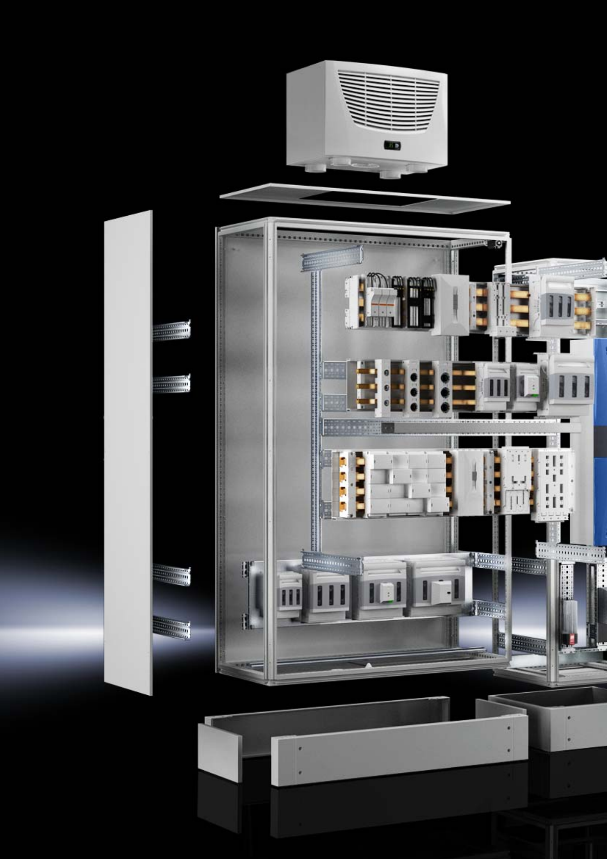
354
355
System accessories
Enclosures
Base ..........................................................................................................358
Walls ..........................................................................................................385
Baying system ...........................................................................................394
Doors/locks................................................................................................402
Roof/wall mounting ....................................................................................431
Interior installation .....................................................................................443
Voltage supply...........................................................................................505
Cable management...................................................................................511
482.6 mm (19˝) installation system............................................................543
Monitoring
CMC III Processing Unit/Compact ............................................................578
CMC III sensors.........................................................................................583
CMC III accessories ..................................................................................584
Door Control System .................................................................................588
Monitor/keyboard unit................................................................................590
KVM switches ............................................................................................591
Dynamic Rack Control...............................................................................597
Human/machine interface
Handles .....................................................................................................600
External mounting accessories .................................................................602
Front assembly ..........................................................................................604
Monitors.....................................................................................................606
Keyboards, supports and drawers............................................................608
Interfaces...................................................................................................616
Signal pillars ..............................................................................................618
356
357
System accessories for enclosures
Base
Flex-Block base/plinth ...............................................................................358
TS base/plinth............................................................................................360
Base/plinths...............................................................................................368
Base ..........................................................................................................373
Walls
Side panels................................................................................................385
Divider panels/partitions............................................................................389
Isolator door locking..................................................................................393
Baying system
Enclosure suites ........................................................................................394
TS 8 corner enclosures .............................................................................401
Doors/locks
Door variants .............................................................................................402
Viewing panels/operating panels ..............................................................407
Lock systems.............................................................................................411
Hinges .......................................................................................................425
Door, internal .............................................................................................426
Roof/wall mounting
Roof ...........................................................................................................431
Wall mounting bracket...............................................................................439
Interior installation
Mounting plates.........................................................................................443
Rail systems ..............................................................................................452
Assembly components..............................................................................471
Component shelves...................................................................................480
System lights .............................................................................................491
EMC...........................................................................................................498
Earthing .....................................................................................................501
Socket strips..............................................................................................505
Cable management
Cable entry ................................................................................................511
Gland plates ..............................................................................................514
Cable glands .............................................................................................519
Cable management...................................................................................525
482.6 mm (19˝) cable routing....................................................................537
482.6 mm (19˝) installation system
Swing frame...............................................................................................543
Mounting angles........................................................................................549
Mounting kits for mounting angles ............................................................555
Accessories for Data Rack........................................................................558
Slide rails ...................................................................................................559
482.6 mm (19˝) installation ........................................................................562
Patch panels..............................................................................................569
Splicing boxes...........................................................................................572
LSA connection system.............................................................................574
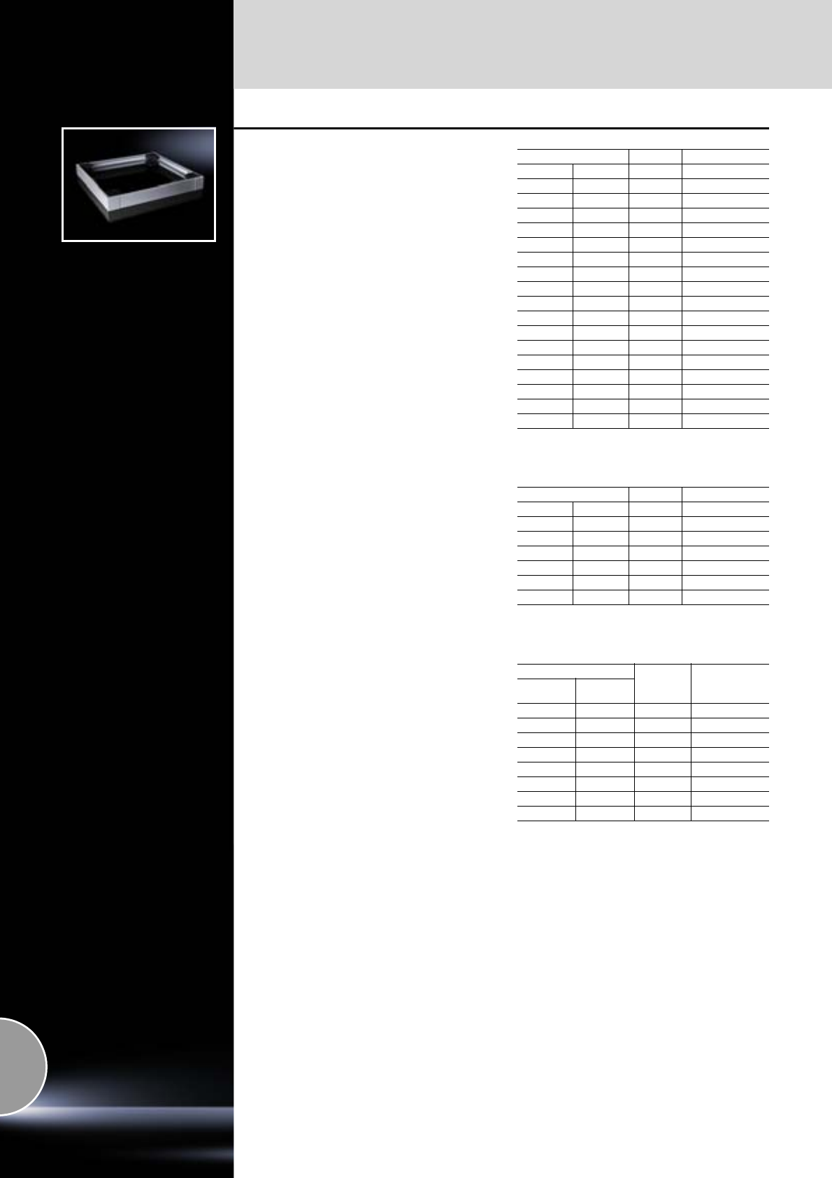
Base
Flex-Block base/plinth system
358 Rittal Catalogue 33/System accessories
Flex-Block
for TS
– For fast, toolless assembly
– Individual cable management
– Fully symmetrical base/plinth
– Base/plinth height: 100 mm
Solid, RAL 9005
Solid, RAL 7035
Vented in enclosure width, RAL 7035
For enclosure size mm Packs of Model No. SO
400 500 1 8001.450
400 600 1 8001.460
600 500 1 8001.650
600 600 1 8001.660
600 800 1 8001.680
800 400 1 8001.840
800 500 1 8001.850
800 800 1 8001.880
800 1000 1 8001.800
1000 400 1 8001.040
1000 500 1 8001.050
1000 600 1 8001.060
1200 400 1 8001.240
1200 500 1 8001.250
1200 600 1 8001.260
1200 800 1 8001.280
1600 400 1 8001.940
1800 500 1 8001.950
We reserve the right to make technical modifications.
Delivery times available on request.
For enclosure size mm Packs of Model No. SO
600 600 1 8001.665
600 800 1 8001.685
600 1000 1 8001.605
600 1200 1 8001.625
800 800 1 8001.885
800 1000 1 8001.805
800 1200 1 8001.825
We reserve the right to make technical modifications.
Delivery times available on request.
For enclosure size mm
Packs of Model No. SO
Width
mm Depth
mm
600 600 1 8001.661
600 800 1 8001.681
600 1000 1 8001.601
600 1200 1 8001.621
800 600 1 8001.861
800 800 1 8001.881
800 1000 1 8001.801
800 1200 1 8001.821
We reserve the right to make technical modifications.
Delivery times available on request.
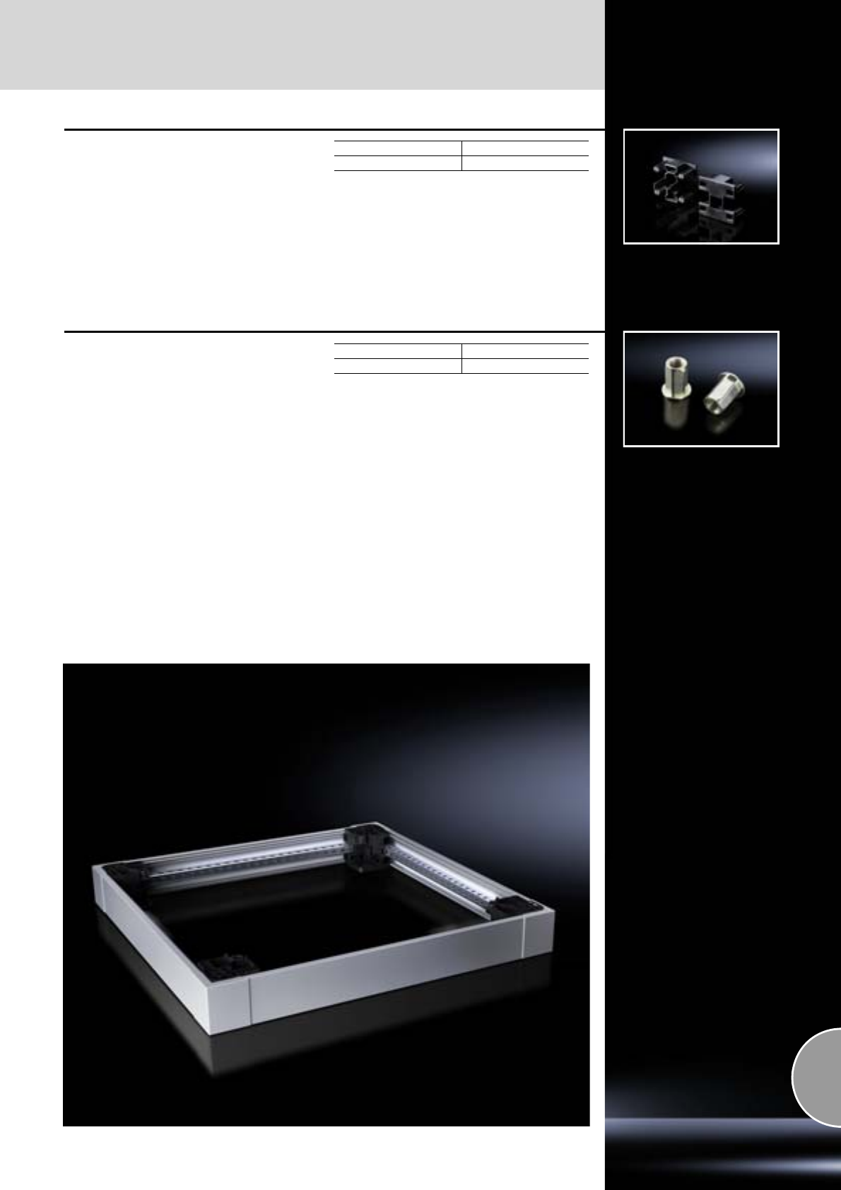
Flex-Block base/plinth system
Base
359Rittal Catalogue 33/System accessories
Baying clip
for baying the Flex-Block corner pieces
Simply insert the clip from behind into the
recesses provided (no need for tools).
Material:
Fibreglass-reinforced polyamide
Packs of Model No. SO
12 8000.100
We reserve the right to make technical modifications.
Delivery times available on request.
Adaptor sleeve
for levelling feet and twin castors
To hold levelling feet and twin castors on the
Flex-Block
Packs of Model No. SO
12 8000.500
We reserve the right to make technical modifications.
Delivery times available on request.
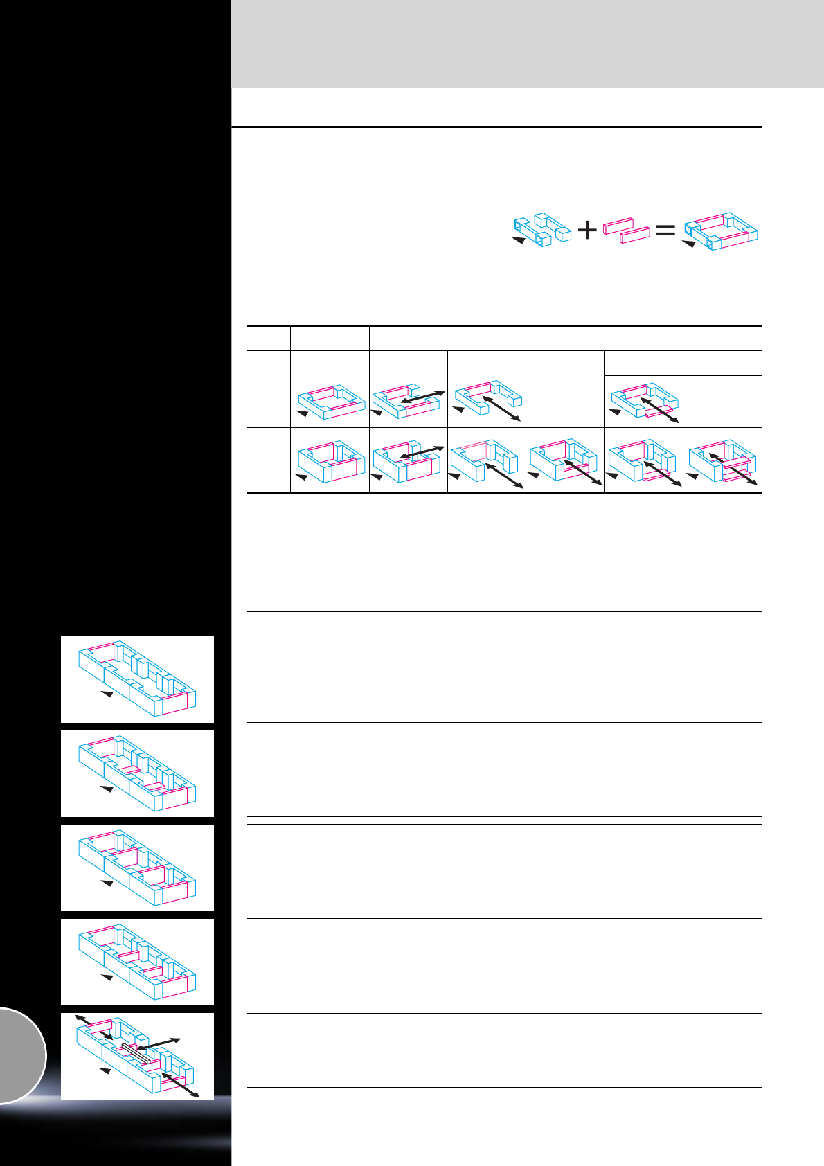
Base
TS base/plinth
360 Rittal Catalogue 33/System accessories
Modular base/plinth diversity
Regardless of the enclosure depth:
The base/plinth components at the front and rear,
pre-configured with corner pieces, are always the
same for the chosen width.
Only the side trim panels are selected according
to the enclosure depth and the required base/
plinth configuration. The modular concept pro-
duces exceptional advantages in terms of cost
and function.
Mounting on the enclosure is conveniently carried
out from the outside. The base/plinth interior offers
diverse opportunities for mounting levels for cable
management.
One Model No.
for the
base/plinth trim,
side.
A complete
base/plinth
TS.
One Model No.
for the
base/plinth compo-
nents front and rear.
Function and cost benefits
Fewer parts, more opportunities, lower purchas-
ing, storage and assembly costs – this is the for-
mula behind the new modular base/plinth system.
The following table shows three bayed base/
plinths in 200 mm height illustrating a wide range
of possible solutions and the potential savings
with trim panels compared with the previous
200 mm base/plinth system each with two trim
panels of 100 mm height at the sides.
New supply includes Functional benefits Savings potential compared
with twelve 100 mm trim panels
3 packs of base/plinth components
1 pack of base/plinth trim panels
200 mm high
Continuous cable chamber 2 trim panels 200 mm
3 packs of base/plinth components
1 pack of base/plinth trim panels
200 mm high
1 pack of base/plinth trim panels
100 mm high
1 pack of base/plinth baying brackets
TS 8601.100 (packs of 20)
4 are required for this solution.
Additional stabilisation for transporta-
tion purposes with base/plinth trim
rotated through 90°
2 trim panels 200 mm
2 trim panels 100 mm
3 packs of base/plinth components
2 packs of base/plinth trim panels
200 mm high
Shielding of the base/plinths in
relation to one another 4 trim panels 200 mm
3 packs of base/plinth components
1 pack of base/plinth trim panels
200 mm high
1 pack of base/plinth trim panels
100 mm high
Additional connection of the base/
plinths 2 trim panels 200 mm
2 trim panels 100 mm
Other options:
●
●
●
Cable entry at the side by mounting a 100 mm base/plinth trim panel (top or bottom).
Cable entry from the rear by dismantling one or more trim panels of the base/plinth components.
Cable clamp rail fitted on the 100 mm high trim panel.
Base/pl.
height Basic form Cable gland options
Stabilisation of bayed
base/plinth
100 mm
200 mm
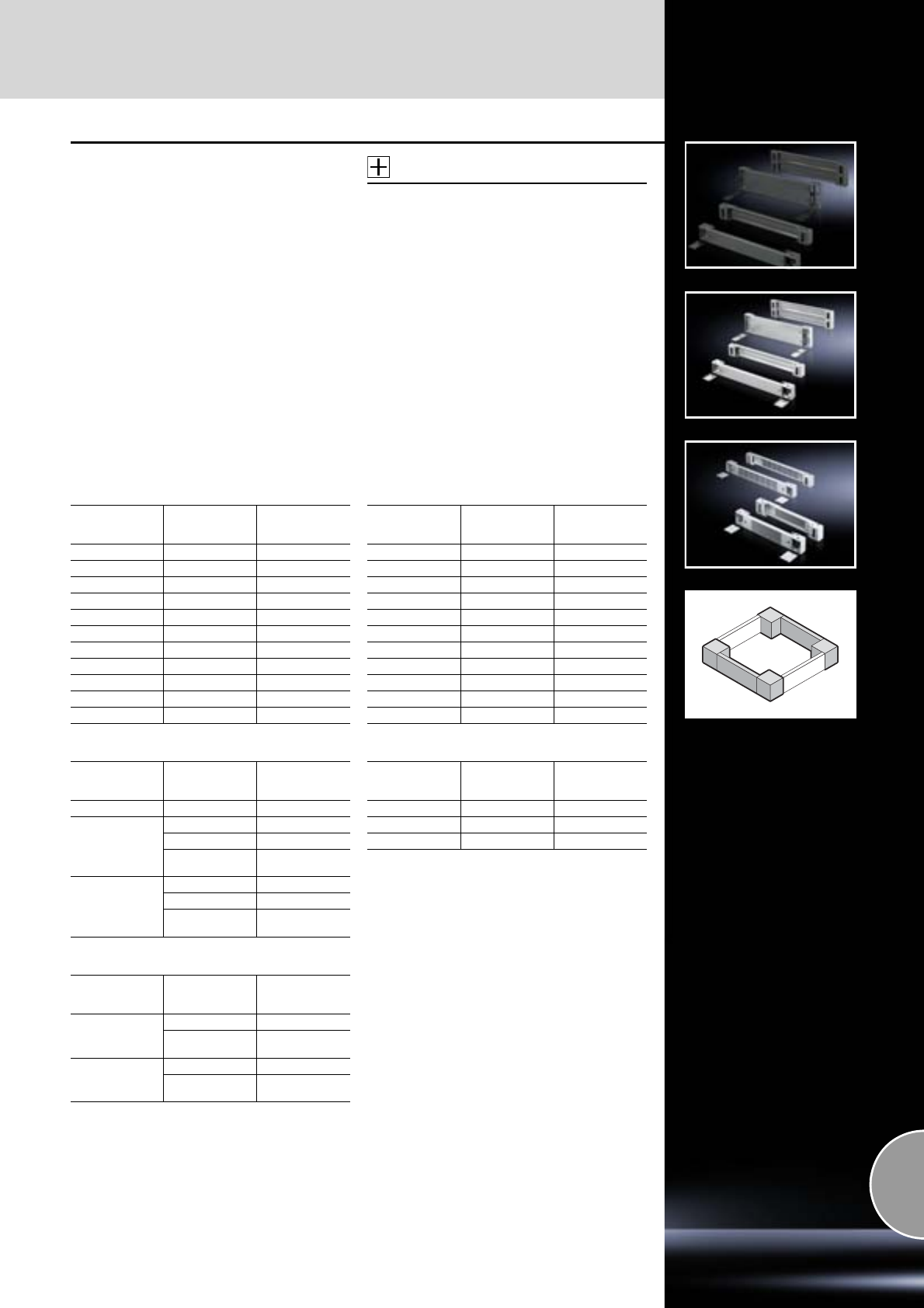
TS base/plinth
Base
361Rittal Catalogue 33/System accessories
Base/plinth components
front and rear
Sheet steel
for TS, CM, TP, PC, IW, TE
Base/plinth component consisting of one trim
panel and two pre-configured corner pieces.
In 200 mm high base/plinth components, one
trim panel is divided into two for cable entry.
Material:
−Base/plinth components: Sheet steel
−Cover caps: Plastic
Surface finish:
Spray-finished
Colour:
Cover caps: RAL 9005/7035
Supply includes:
1 set =
2 base/plinth components, 4 cover caps,
4 screws and captive nuts M12
for mounting on the enclosure.
Accessories:
−Base mounting plate SO 2817.000,
see page 364.
−Filter mat for vented versions,
see page 366.
Detailed drawings:
Available on the Internet.
100 mm high, colour: RAL 7022
100 mm high, colour: RAL 7035
100 mm high, colour: RAL 9005
200 mm high, colour: RAL 7022
200 mm high, colour: RAL 7035
For
enclosure width
mm Design Model No. TS
300 Solid 8601.915
400 Solid 8601.400
500 Solid 8601.500
600 Solid 8601.600
800 Solid 8601.800
850 Solid 8601.850
1000 Solid 8601.000
1100 Solid 8601.300
1200 Solid 8601.200
1600 Solid 8601.920
1800 Solid 8601.980
For
enclosure width
mm Design Model No. TS
300 Solid 8601.905
600
Solid 8601.605
Vented 7825.601
Vented with
designer cover 7825.603
800
Solid 8601.805
Vented 7825.801
Vented with
designer cover 7825.803
For
enclosure width
mm Design Model No. TS
600
Solid 8601.602
Vented with
designer cover 7825.605
800
Solid 8601.802
Vented with
designer cover 7825.805
For
enclosure width
mm Design Model No. TS
300 Solid 8602.915
400 Solid 8602.400
500 Solid 8602.500
600 Solid 8602.600
800 Solid 8602.800
850 Solid 8602.850
1000 Solid 8602.000
1100 Solid 8602.100
1200 Solid 8602.200
1600 Solid 8602.920
1800 Solid 8602.980
For
enclosure width
mm Design Model No. TS
300 Solid 8602.905
600 Solid 8602.605
800 Solid 8602.805
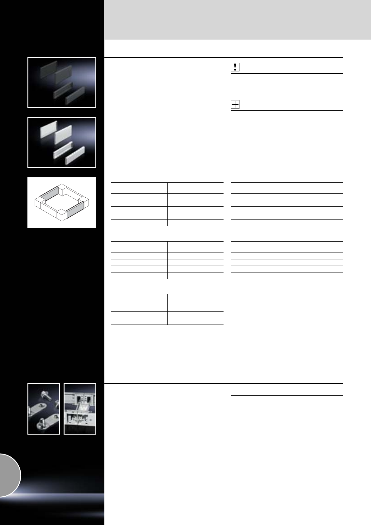
Base
TS base/plinth
362 Rittal Catalogue 33/System accessories
Base/plinth trim panels, side
Sheet steel
for TS, CM, TP, PC, IW, TE
For mounting between the base/plinth compo-
nents. At 200 mm height, two 100 mm base/plinth
trims may be used. Base/plinth trim (100 mm
high) may be installed rotated through 90° in
order to stabilise bayed base/plinth components.
Material:
Sheet steel
Surface finish:
Spray-finished
Supply includes:
1 set =
2 base/plinth trim panels, including parts for
attaching to the base/plinth components.
Also required:
Base/plinth baying brackets TS 8601.100,
see page 362,
when mounting base/plinth trim panels rotated
through 90°.
Accessories:
Fastening bolts for base/plinth,
see page 364.
Detailed drawings:
Available on the Internet.
100 mm high, colour: RAL 7022
100 mm high, colour: RAL 7035
100 mm high, colour: RAL 9005
200 mm high, colour: RAL 7022
200 mm high, colour: RAL 7035
For enclosure depth
mm Model No. TS
300 8601.030
400 8601.040
500 8601.050
600 8601.060
800 8601.080
For enclosure depth
mm Model No. TS
600 8601.065
800 8601.085
1000 8601.015
1200 8601.025
For enclosure depth
mm Model No. TS
800 8601.086
1000 8601.010
1200 8601.026
For enclosure depth
mm Model No. TS
300 8602.030
400 8602.040
500 8602.050
600 8602.060
800 8602.080
For enclosure depth
mm Model No. TS
600 8602.065
800 8602.085
1000 8602.015
1200 8602.025
Base/plinth baying brackets
for TS base/plinth
Essential if the trim panels are mounted rotated
through 90° for additional stabilisation during the
transportation of bayed enclosures.
Additionally required for each trim panel: 2 units.
Material:
Sheet steel
Surface finish:
Zinc-plated
Supply includes:
Screws M8 x 16 mm.
Packs of Model No. TS
20 8601.100
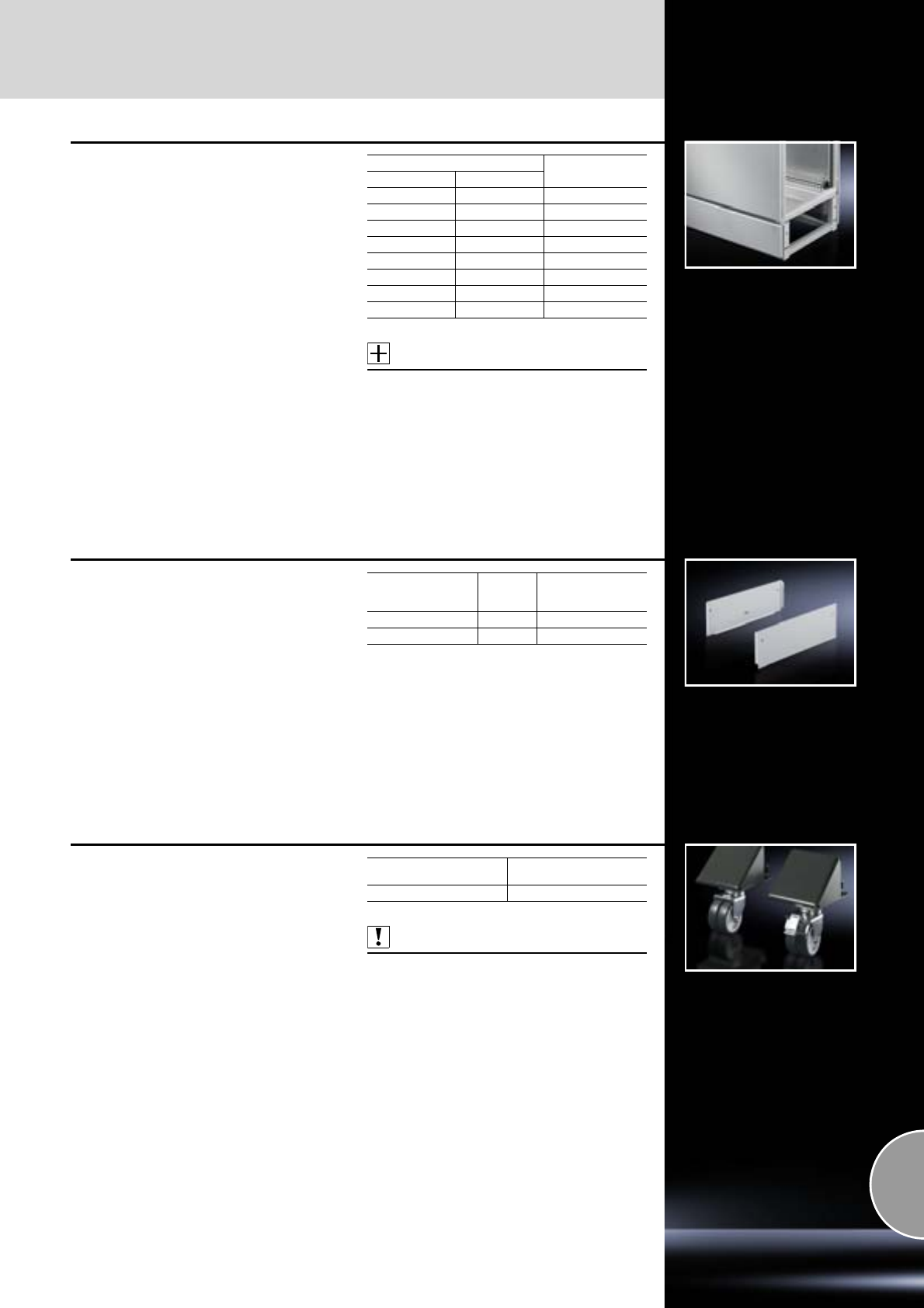
TS base/plinth
Base
363Rittal Catalogue 33/System accessories
Cable chamber
for TS
With integral system punchings for individual
system accessories. Height = 200 mm.
Material:
Sheet steel
Colour:
RAL 7035
Supply includes:
−Sheet steel trim panels front and rear
−Assembly parts for mounting on the enclosure.
Accessories:
Side panels for cable chamber,
see page 363.
Detailed drawings:
Available on the Internet.
For enclosures Model No. TS
Width mm Depth mm
400 500 8600.455
400 600 8600.465
600 500 8600.655
600 600 8600.665
800 500 8600.855
800 600 8600.865
1200 500 8600.255
1200 600 8600.265
Side panels
for cable chamber
Material:
Sheet steel
Colour:
RAL 7035
Supply includes:
Assembly parts.
For
enclosure depth
mm Packs of Model No. TS
500 2 8600.510
600 2 8600.520
Transport castors
for TS base/plinth
For locating onto the base/plinth corner piece
100 or 200 mm high.
Load capacity:
Maximum permissible load per twin castor:
Static: 100 kg
Supply includes:
1 set =
4 twin castors,
2 x with, 2 x without locks.
Colour:
RAL 7022
Also required:
Base/plinth trim panels, side,
see page 362.
Floor clearance
mm Model No. TS
100 8800.390
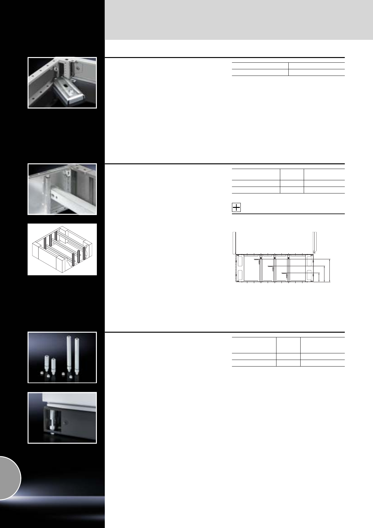
Base
TS base/plinth
364 Rittal Catalogue 33/System accessories
Base mounting plate
for
● TS base/plinth
● base/plinth, complete
For fastening the base/plinth to the floor without
moving the enclosure or the bayed enclosure
suite. For assembly screws up to 12 mm Ø.
Material:
Sheet steel
Surface finish:
Zinc-plated
Packs of Model No. SO
10 2817.000
Fastening bolts
for
● TS base/plinth
● Base/plinth, complete
● Base/plinth, stationary
For mounting on base/plinth trim panels, side.
The lockable assembly bolt allows the installation
of cable clamp rails. Tighten with hex spanner,
width across flats 19 mm.
Material:
Hexagon steel
Surface finish:
Zinc-plated
Accessories:
Cable clamp rail,
see page 527.
Base/plinth trim panel
mm high Packs of Model No. SZ
100 10 2819.000
200 10 2819.200
67
1171)
1671)
1) Only for height 200 mm
Levelling component
for TS base/plinth
For retrospective levelling of floor unevenness at
the installation site up to a maximum of 15 mm.
Installed through the corner piece of the base/
plinth component. Adjusted using a SW 19 hex
spanner.
Benefits:
●A door offset caused by uneven flooring can
be corrected.
●Installed on the assembled enclosure,
i.e. no need to plan levelling in advance.
Max. admissible static load:
2500 N per levelling component
(check the load capacity of the floor).
Supply includes:
Assembly parts.
For
base/plinth height
mm Packs of Model No. SZ
100 4 2891.000
200 4 2892.000
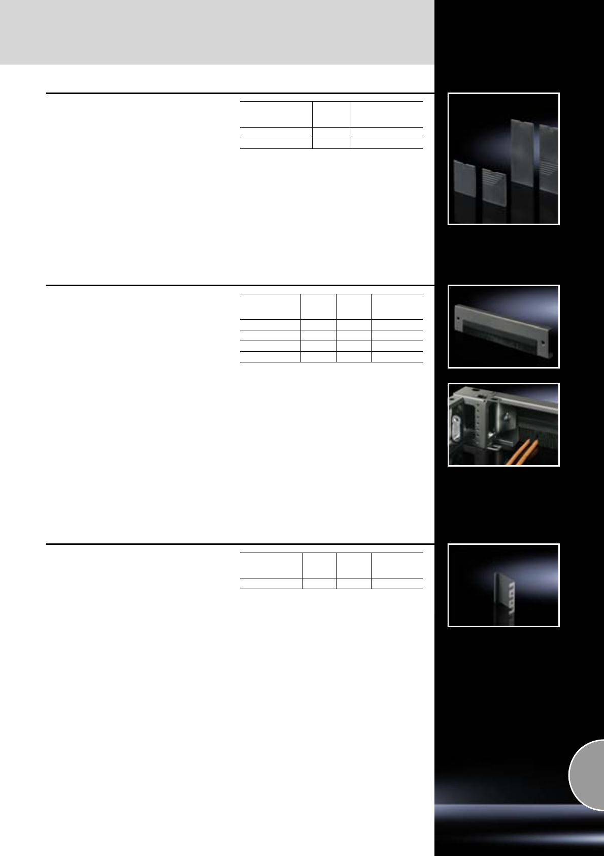
TS base/plinth
Base
365Rittal Catalogue 33/System accessories
Cover cap
for TS base/plinth components
As a replacement.
Material:
Plastic ABS
Colour:
RAL 9005
For
base/plinth height
mm Packs of Model No. TS
100 4 8601.130
200 4 8601.140
Base/plinth trim
with brush strip
for TS base/plinth
To supplement the modular base/plinth concept.
May also be exchanged retrospectively for the
front or rear trim panel of the base/plinth compo-
nents 100 mm high.
Open on one side for retrospective mounting if
cables have already been inserted.
Material:
Sheet steel
Surface finish:
Spray-finished
For
base/plinth width
mm
Height
mm Colour
RAL Model No. TS
600 100 7035 7825.607
800 100 7035 7825.807
600 100 9005 7825.608
800 100 9005 7825.808
Connecting plinth trim
for TS base/plinth
For covering gaps in bayed back-to-back or cor-
ner enclosure suites. Simply push in between the
trim panel and the corner piece before tightening
the screws.
Material:
Sheet steel
Note:
For a base/plinth height of 200 mm, 2 trim panels
must be fitted one above the other.
For
base/plinth height
mm
Colour
RAL Packs of Model No. TS
100 7022 2 8601.110
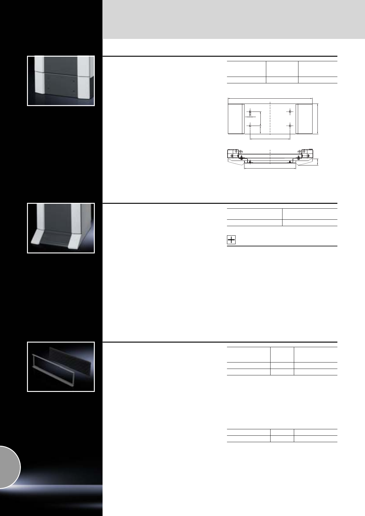
Base
TS base/plinth
366 Rittal Catalogue 33/System accessories
Base/plinth trim
for TS base/plinth
To continue the design of the
●lower front door of PC enclosures
●door of the IW enclosure.
The base/plinth trim is screw-fastened to the
corner pieces of the TS base/plinth components
from the outside.
Material:
Sheet steel, spray-finished
Designer trim panels: Extruded aluminium section
Colour:
RAL 7015
Designer trim panels: RAL 7035
For
base/plinth width
mm
Height
mm Model No. PC
600 200 8360.920
592
100
56
280
9
212
362
45.2
Base/plinth, stationary
for PC-TS, IW
Design-coordinated with the enclosures,
height 100 mm, with front projection.
Material:
Sheet steel, 2.0 mm
Colour:
RAL 7035
Design component, front: RAL 7015
Supply includes:
−1 design component, front
−1 base/plinth component, rear
−2 base/plinth trims, side
Accessories:
Attachment opportunities for:
−Twin castors DK 7495.000,
see page 374,
−Levelling feet PS 4612.000,
see page 373.
−Fastening bolt for cable clamp rails
SO 2819.000,
see page 364,
−Support bracket PS 4183.000,
see page 473.
For depth
mm Model No. PC
600 8800.920
Filter mat
for
● Base/plinth component, vented
● Base/plinth component, vented,
with designer trim panel
To cover the trim panel in the base/plinth compo-
nent.
The mounting frame slides into position behind
the filter mat in the base/plinth trim panel.
Filter class G3 to DIN EN 779.
Supply includes:
Mounting frame.
For
enclosure width
mm Packs of Model No. DK
600 1 7561.500
800 1 7581.500
Spare filter mat
Spare filter mat for base/plinth trim panels up to
800 mm wide.
Packs of Model No. DK
Spare filter mats 5 7582.500
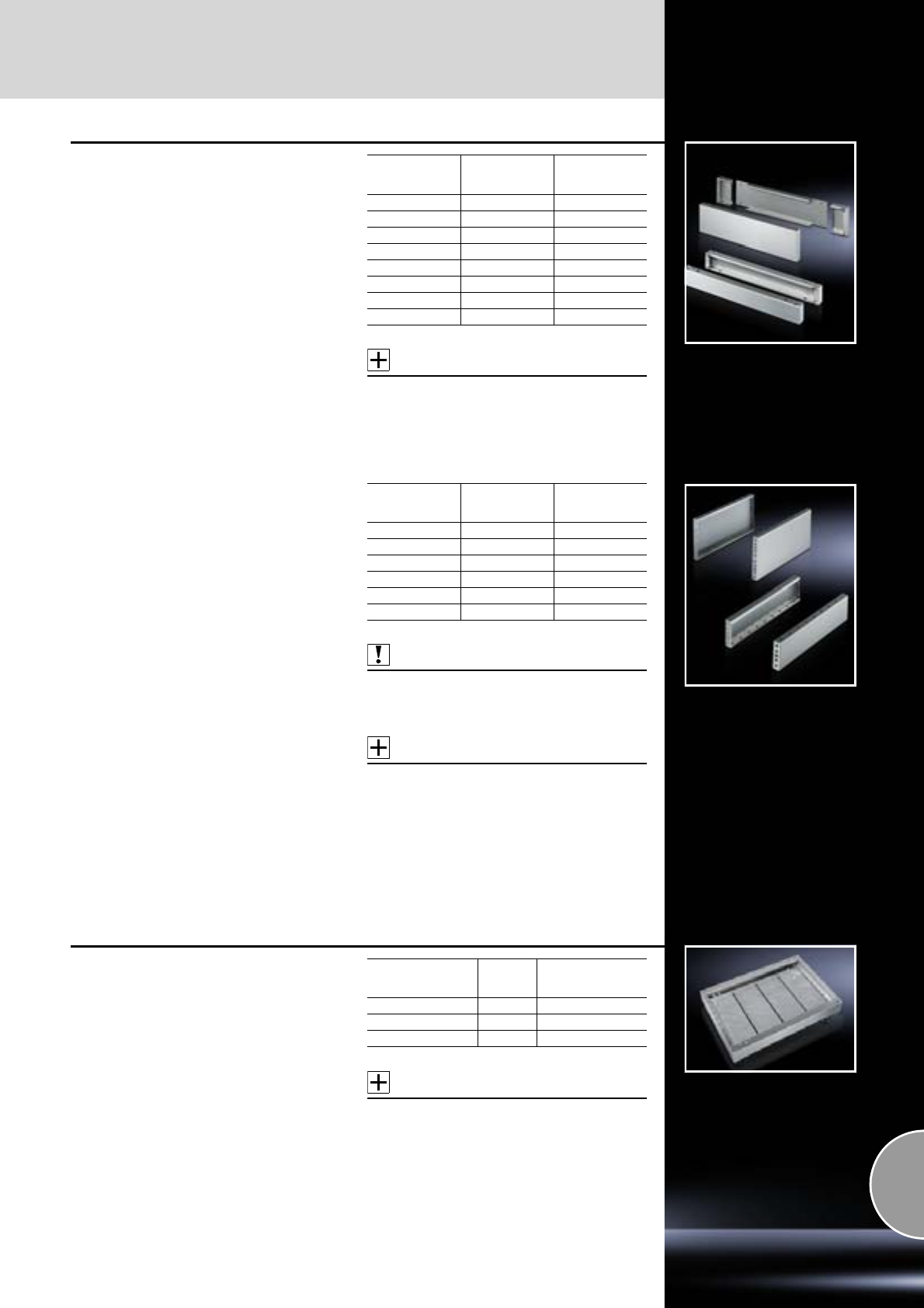
TS base/plinth
Base
367Rittal Catalogue 33/System accessories
Base/plinth components
front and rear
Stainless steel
for TS
Material:
Stainless steel 1.4301 (AISI 304)
Surface finish:
Brushed, grain 400
Supply includes:
Mounting accessories for mounting on the enclo-
sure.
100 mm high:
2 trim panels front/rear
200 mm high:
−2 corner pieces with removable trim panel
−1 trim panel front/rear
Accessories:
Base/plinth trim, modular (perforated plate),
see page 367.
For
enclosure width
mm
Height
mm Model No. TS
600 100 8701.600
800 100 8701.800
1000 100 8701.000
1200 100 8701.200
600 200 8702.600
800 200 8702.800
1000 200 8702.000
1200 200 8702.200
Base/plinth trim panels, side
Stainless steel
for TS
For mounting between the base/plinth compo-
nents. At 200 mm height, two 100 mm base/plinth
trims may be used.
Base/plinth trim (100 mm high) may be installed
rotated through 90° in order to stabilise bayed
base/plinth components.
Material:
Stainless steel 1.4301 (AISI 304)
Surface finish:
Brushed, grain 400
Supply includes:
2 base/plinth trim panels, including parts for
attaching to the base/plinth components.
Also required:
Base/plinth baying brackets TS 8601.100,
see page 362,
when mounting base/plinth trim panels rotated
through 90°.
Accessories:
−Fastening bolts for base/plinth,
see page 364.
−Levelling feet PS 4612.000,
see page 373.
Detailed drawings:
Available on the Internet.
For
enclosure depth
mm
Height
mm Model No. TS
400 100 8701.040
500 100 8701.050
600 100 8701.060
400 200 8702.040
500 200 8702.050
600 200 8702.060
Base/plinth trim, modular
for
● TS base/plinth
● base/plinth, complete, stainless steel
For cable routing in the stainless steel base/plinth,
e.g. if levelling feet SO 2890.000 or SO 2890.000,
see page 371, are used.
Width: 175 mm.
Material:
Stainless steel 1.4301 (AISI 304)
Supply includes:
4 base/plinth trim panels.
Note:
One base/plinth trim panel is needed per 200 mm
base/plinth width.
Accessories:
Cable tie SZ 2597.000,
see page 530.
For
enclosure depth
mm Packs of Model No. SO
400 4 2907.000
500 4 2908.000
600 4 2913.000
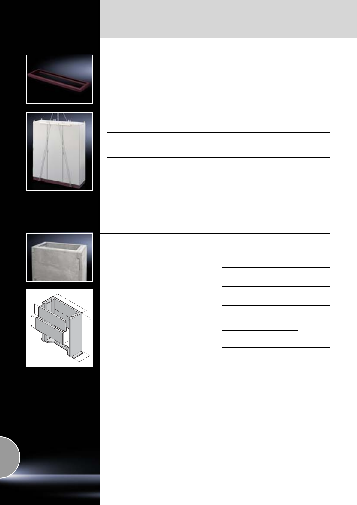
Base
Base/plinths
368 Rittal Catalogue 33/System accessories
Transport plinth
for TS
For the transportation of heavy, bayed enclosure
suites. Available in 200 mm increments from
2 to 5 m.
Transport plinths can have 2 tubes welded to
receive cross-bars for transportation.
Variable punchings to suit all enclosure widths of
600 mm and above.
Surface finish:
Primed in reddish-brown rust-inhibiting paint,
optionally spray-finished.
Supply includes:
With transport tubes.
Note:
Please state the required width and depth of the
enclosure suite when ordering.
For mounting on the TS base frame
Transport plinth depth = enclosure depth – 31 mm
Colour Packs of Model No. SO
Primed, reddish-brown rust-inhibiting paint 1 1228.010
Similar to RAL 7022 1 1228.110
Similar to RAL 7035 1 1228.310
Delivery times available on request.
T
300
270
1000
B
Concrete base/plinth
for CS Toptec, CS modular and
basic enclosures
The base/plinth is made from pre-cast concrete
sections which are easily fitted in situ. Front/rear
base/plinth plate screw-fastened from the inside
may be removed for servicing purposes.
Overall height: approx. 1000 mm,
Excavation depth: approx. 700 mm.
Material:
Light-weight concrete
Surface finish:
Untreated
Supply includes:
−1 base plate
−2 side parts
−2 divided base/plinth plates
−Assembly parts and fastening screws for
mounting the enclosure.
For CS modular and basic enclosures
Model No. CS
Width (B)
mm Depth (T)
mm
600 400 9765.182
600 500 9765.082
600 600 9765.083
800 400 9765.088
800 500 9765.084
800 600 9765.085
1200 400 9765.089
1200 500 9765.086
1200 600 9765.087
Delivery times available on request.
For CS Toptec
Model No. CS
Width (B)
mm Depth (T)
mm
600 600 9765.071
800 600 9765.072
Delivery times available on request.
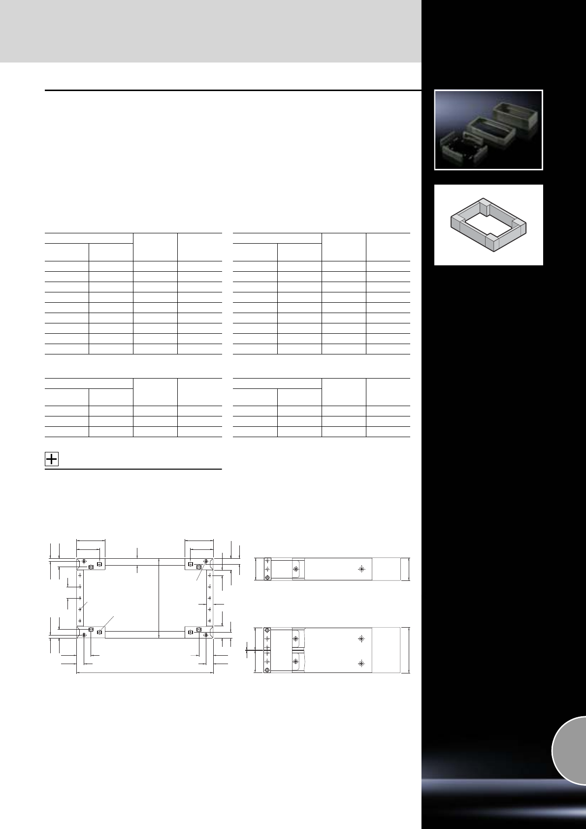
Base/plinths
Base
369Rittal Catalogue 33/System accessories
Base/plinth, complete
Sheet steel
for AE, TP, ES
Trim panels at the front and rear with fitted corner
pieces and side trim panels.
Material:
Sheet steel
Surface finish:
Spray-finished
Colour:
RAL 7022
Supply includes:
Mounting accessories for mounting on the enclo-
sure.
100 mm high:
−4 corner pieces
−2 trim panels front/rear
−2 trim panels, side
200 mm high:
−4 corner pieces
−1 trim panel front/rear x 200 mm
−2 trim panels front/rear x 100 mm
−4 trim panels, side
Base/plinth for ES, TP universal console, 100 mm high
Base/plinth for AE, 100 mm high
Accessories:
−Fastening bolt,
see page 364.
−Base mounting plate,
see page 364.
Base/plinth for ES, TP universal console, 200 mm high
Base/plinth for AE, 200 mm high
Detailed drawings:
Available on the Internet.
For enclosures/consoles Base/plinth
depth
mm
Model No.
SO
Width (B)
mm Depth (T)
mm
600 400 350 2804.200
600 500 450 2807.200
800 400 350 2823.200
800 500 450 2829.200
1000 400 350 2909.200
1200 400 350 2836.200
1200 500 450 2839.200
1600 400 350 2905.200
1800 500 450 2903.200
For enclosures Base/plinth
depth
mm
Model No.
SO
Width (B)
mm Depth (T)
mm
600 300 279 2816.200
800 300 279 2818.200
1000 300 279 2801.200
For enclosures/consoles Base/plinth
depth
mm
Model No.
SO
Width (B)
mm Depth (T)
mm
600 400 350 2805.200
600 500 450 2808.200
800 400 350 2824.200
800 500 450 2830.200
1000 400 350 2910.200
1200 400 350 2837.200
1200 500 450 2840.200
1600 400 350 2906.200
1800 500 450 2904.200
For enclosures Base/plinth
depth
mm
Model No.
SO
Width (B)
mm Depth (T)
mm
600 300 279 2826.200
800 300 279 2828.200
1000 300 279 2802.200
32.5 32.5
100
125
100
125
62.5 62.5
Ø 8.5
□ 14
30
18 x 14
37.5
12.5
T
22.5
52.5
25
52.5
25
37.5
12.5
30
50
B
98
100
2
98 98
200
Base/plinth, 100 mm high
Base/plinth, 200 mm high
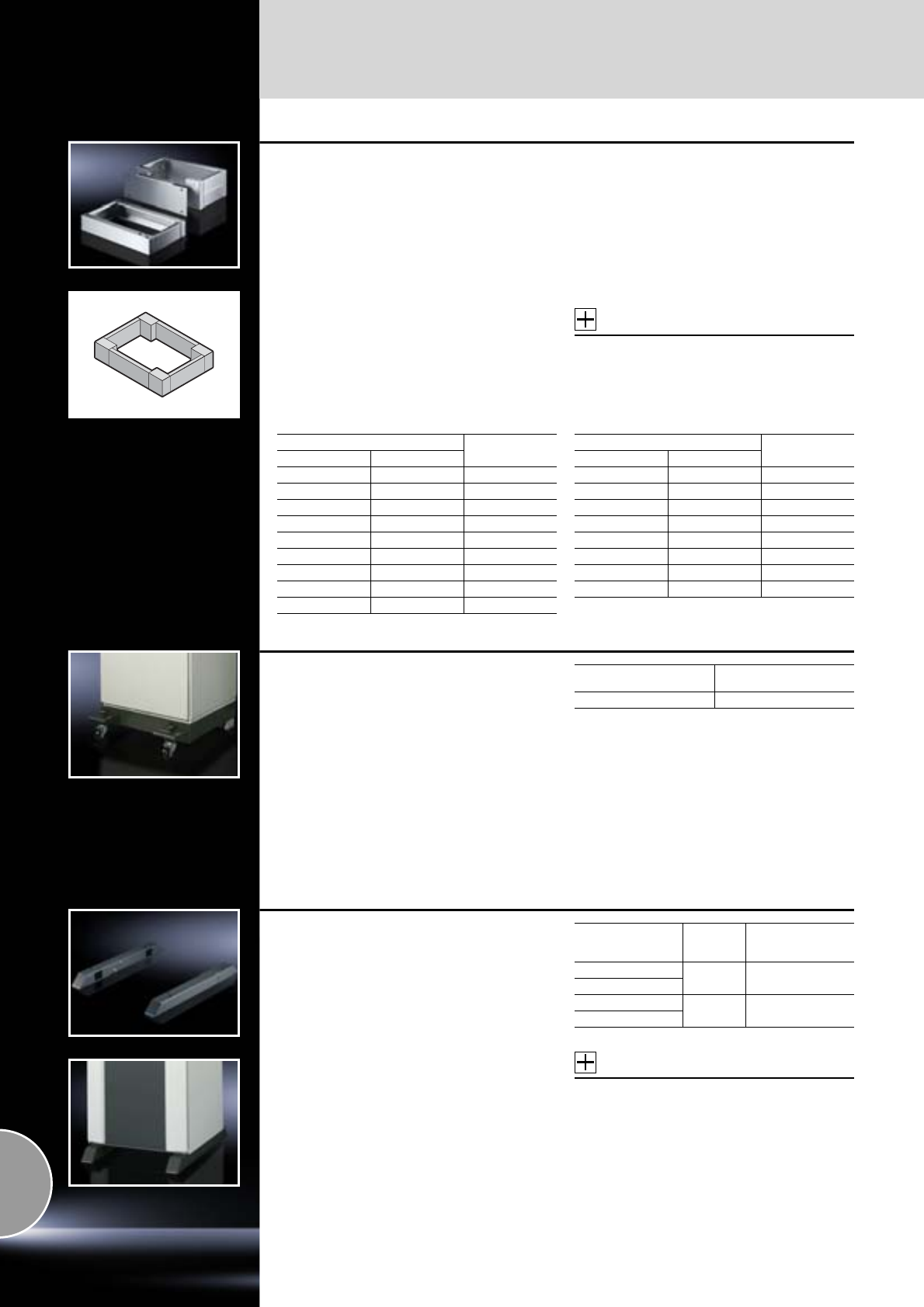
Base
Base/plinths
370 Rittal Catalogue 33/System accessories
Base/plinth, complete
Stainless steel
for ES, PC-ES stainless steel,
AP stainless steel
Material:
Stainless steel 1.4301 (AISI 304)
Surface finish:
Brushed
Supply includes:
Mounting accessories for mounting on the enclo-
sure.
100 mm high:
−2 trim panels front/rear
−2 trim panels, side
200 mm high:
−2 corner pieces with removable trim panel
−1 trim panel front/rear
−4 trim panels, side
Accessories:
−Levelling feet,
see page 371.
−Base/plinth trim, modular (perforated plate),
see page 367.
100 mm high 200 mm high
For enclosures Model No.
SO
Width mm Depth mm
600 400 2865.000
600 500 2868.000
600 600 2855.000
800 400 2869.000
800 500 2866.000
800 600 2856.000
1000 400 2867.000
1200 400 2870.000
1200 500 2860.000
For enclosures Model No.
SO
Width mm Depth mm
600 400 2875.000
600 500 2876.000
800 400 2878.000
800 500 2879.000
800 600 2880.000
1000 400 2885.000
1200 400 2886.000
1200 500 2887.000
Transport castors
for base/plinth, complete, sheet steel
For locating onto the base/plinth corner piece
100 or 200 mm high by raising or tilting.
Load capacity:
Maximum permissible static load:
100 kg per twin castor
Colour:
RAL 7022
Supply includes:
1 set =
4 twin castors,
2 x with, 2 x without locks.
Floor clearance
mm Model No. PS
60 4570.000
Cross member
for TS, CM, TP, PC, IW, ES
adjustable
●To increase stability
●Height 70 mm
●Adjustable from the enclosure depth
To increase stability, the cross member is posi-
tioned 138 mm above the base frame of the
enclosure at the front and rear. For deeper enclo-
sures, the rear part may be extended and screw-
fastened again. For screw-fastening to the floor
and enclosure with mounting hole at the sides,
front and rear. The castors and levelling feet may
be secured to the welded nuts M12.
Material:
Sheet steel
Surface finish:
Spray-finished
Colour:
RAL 7015
Accessories:
Attachment opportunities for
−Twin castors DK 7495.000,
see page 374,
−Levelling feet PS 4612.000,
see page 373.
Detailed drawings:
Available on the Internet.
For
enclosure depth
mm Packs of Model No.
TS
400 28601.450
500
600 28601.680
800
Base/plinths
Base
371Rittal Catalogue 33/System accessories
Cast feet
For secure siting of
●Enclosure for tower PC
or
●Other own assemblies
Depth 700 mm
Material:
Cast aluminium
Colour:
RAL 7035
Supply includes:
Assembly parts.
Accessories:
−Base mount CP 6147.000,
see page 151.
−Twin castors,
see page 374.
Packs of Model No. IW
26902.920
Levelling feet
For direct mounting underneath the base/plinth TS
and the base/plinth, complete.
For unhindered access e.g. when cleaning the
floor, and to compensate for floor irregularities.
Load capacity:
Maximum permissible static load:
400 kg per levelling foot
Adjustment range:
M12: 55 mm – 125 mm
M16: 45 mm – 120 mm
Material:
Stainless steel 1.4301 (AISI 304)
Possible
alternative:
Levelling feet Hygienic Design,
see page 156.
Thread Packs of Model No. SO
M12 4 2889.000
M16 4 2890.000
Base/plinth
for FlatBox
The base/plinth may be mounted on any FlatBox
with a base area of 600 x 600 or 700 x 700 mm.
For attachment purposes, the base/plinth may be
mounted on the pre-existing thread in the base
area of the FlatBox. There is a rear recess pro-
vided for cable entry.
Material:
Sheet steel
Surface finish:
Powder-coated
Colour:
RAL 7035
Supply includes:
4 levelling feet and
assembly parts.
For base area
Packs of Model No. DK
Width
mm Depth
mm
600 600 1 7507.750
700 700 1 7507.755
Base
Base/plinths
372 Rittal Catalogue 33/System accessories
Under-floor frame
for DK-TS
For siting the enclosure on a false floor when
heavy equipment is installed.
Material:
Sheet steel
Colour:
RAL 7035
Supply includes:
Mounting accessories for mounting on the enclo-
sure.
Width
mm Height
mm Depth
mm Model No. DK
600 400 1000 7855.340
800 400 1000 7855.342
Delivery times available on request.
Stabiliser bracket
for base/plinth TS
The stabiliser bracket may be retrospectively
screw-fastened to the outside of the base/plinth
corner pieces.
Load capacity:
Up to a maximum of 80 kg static load.
Material:
Sheet steel
Surface finish:
Spray-finished
Colour:
RAL 7035, warning markings RAL 2002
Supply includes:
Assembly parts.
Packs of Model No. DK
27825.150
Delivery times available on request.
Stabiliser
for TS 8 server enclosures
The pull-out stabiliser is quickly and easily retro-
fitted to the lower frame of the server racks and
only extended when necessary.
Load capacity:
Up to a maximum of 150 kg static load.
Material:
Sheet steel
Surface finish:
Zinc-plated
Supply includes:
Assembly parts.
Note:
−The stabiliser cannot be used together with
base plates, base frames or base/plinths.
−Combined use with the divided base frame
(DK 7825.342), see page 377, is supported.
Accessories:
−Levelling feet, see page 373
and/or
−Transport kit for DK-TS, see page 375.
Enclosure depth mm Model No. DK
1000 7825.250
1200 7825.2601)
1) Delivery times available on request.
150kg
Base
Base
373Rittal Catalogue 33/System accessories
Levelling feet
18 – 43 mm high
To compensate for height differences with floor
irregularities. Thread length 40 mm.
Assembly thread M12.
Max. admissible static load:
approx. 300 kg per levelling foot.
For:
●Baying system TS 8
●PC enclosure system
●Pedestal base plate
CP 6137.035 – CP 6137.535
●Pedestal CP 6141.XXX
●Industrial workstations
Also required:
For mounting on the TS base/plinth:
Base/plinth adaptor TS 8800.220,
see page 375.
Packs of Model No. PS
44612.000
58
4018
M12
Ø 47
SW 19
Levelling feet
18 – 63 mm high, with hex socket for baying
system TS 8
To compensate for floor irregularities.
Particularly in confined spaces, adjustments can
be made quickly and easily from the enclosure
interior.
Mounting thread: M12
Hex socket: 6 mm
Thread length: 60 mm
Max. admissible static load:
300 kg per levelling foot.
Also required:
For mounting on the TS base/plinth:
Base/plinth adaptor TS 8800.220,
see page 375.
Packs of Model No. DK
47493.100
M12
SW 19
60
78
18
Ø 48
Levelling feet
with vibration dampening
For vibration insulation of enclosures and to
compensate for floor irregularities.
The levelling foot is comprised of a disc of re-
inforced polyamide and an M12 screw, zinc-
plated, with ball joint pendulum plus anti-slip
and insulating plate for buffering.
The insulating plate is resistant to water, mineral
oils, petrol, alkaline and acid solutions, salts,
soap lye and detergents.
Also suitable for special applications such as
chemical and laboratory environments.
Thread length: 50 mm
Max. admissible static load:
300 kg per levelling foot.
Packs of Model No. DK
47493.230
30
45 50
95
M12
SW19
50
Levelling feet
for Data Rack
To compensate for height differences with floor
irregularities.
The levelling feet are attached into the die-cast
zinc feet of the base/plinth.
Supply includes:
4 levelling feet M12,
levelling range 40 mm.
Packs of Model No. DK
47493.000
Base
Base
374 Rittal Catalogue 33/System accessories
Levelling feet
for FlatBox, TE
M10 x 20 mm
For screw-fastening onto the enclosure base
when used as a floor-standing or desktop
enclosure.
Width across flats 17, mounting thread multi-
tooth 30.
Packs of Model No. DK
47507.740
Levelling feet
85 – 115 mm high
For mounting on TS, ES and PC enclosures, for
easier floor cleaning and to compensate for floor
irregularities ±15 mm.
Height 100 mm.
Max. admissible static load:
350 kg per levelling foot.
Material:
−Feet: Brass, nickel-plated
−Threaded bolts and mounting plates:
Stainless steel 1.4301 (AISI 304)
Supply includes:
Assembly parts to the enclosure.
Possible
alternative:
Levelling feet Hygienic Design,
see page 156.
Packs of Model No. SO
42859.000
1
2
3
Twin castors
Mounting thread M12 x 20.
For:
●Baying system TS 8
●PC enclosure system
●Pedestal base plate
CP 6137.035 – CP 6137.535
●Pedestal CP 6141.XXX
●TopConsole pedestals
●Industrial workstations
●Data Rack
Also required:
For mounting on the TS base/plinth:
Base/plinth adaptor for twin castors TS 8800.290,
see page 375.
Max. permissible
static load (per castor) 40 kg
Ground clearance 50 mm
Lock 4 without
Packs of 1 set
Colour Black
Model No. PS 4611.000
1
Max. permissible
static load (per castor) 75 kg
Ground clearance 85 mm
Lock 2 with, 2 without
Packs of 1 set
Colour Black with grey
running surface
Model No. CP 6148.000
2
Max. permissible
static load (per castor) 120 kg
Ground clearance 125 mm
Lock 2 with, 2 without
Packs of 1 set
Colour Black
Model No. DK 7495.000
3
Base
Base
375Rittal Catalogue 33/System accessories
Transport castors
for TE
The castors may be screw-fastened in the corner
areas within the base frame in place of the level-
ling feet.
Ground clearance: 58 mm,
Mounting thread M10 x 20.
Permissible static load:
300 kg per enclosure
Supply includes:
1 set = 4 baying clamps,
including assembly parts.
Packs of Model No. TE
1 set 7000.672
Transport kit
for DK-TS
Ground clearance: approx. 40 mm.
Permissible static load:
750 kg per enclosure
Supply includes:
1 set =
4 castors (2 steerable) including assembly parts.
Note:
Only for enclosures without gland plates or gland
plate frames.
For 800 mm wide enclosures with 482.6 mm (19˝)
mounting frame, special installation dimensions
must be observed (see drawing).
Packs of Model No. DK
1 set 7825.900
Min.
175
Base/plinth adaptor
for levelling feet
Connection component for fastening M12 level-
ling feet PS 4612.000 to the TS base/plinth.
Material:
Sheet steel
Surface finish:
Zinc-plated
Also required:
Levelling feet, PS 4612.000,
see page 373.
Packs of Model No. TS
48800.220
Base/plinth adaptor
for twin castors
Connection component for mounting twin castors
to the TS and TE base/plinth.
Material:
Sheet steel
Surface finish:
Zinc-plated
Also required:
Base/plinth trim panels, side,
see page 362,
wherever a twin castor is fitted.
Packs of Model No. TS
48800.290
Base
Base
376 Rittal Catalogue 33/System accessories
Width divider
Divides 1200 mm wide TS enclosures into two
halves.
Material:
Sheet steel
Surface finish:
Zinc-plated
Supply includes:
1 set =
1 bracket for right/left,
2 compensating plates for the top,
mounting accessories.
Also required:
Depending on the installation situation:
−TS punched rail 18 x 38 mm,
see page 462.
−PS punched section without mounting flange,
23 x 73 mm,
see page 464.
Packs of Model No. TS
1 set 8800.200
1. Mounting position:
Two mounting plates side by side.
Two mounting plates (from 600 mm wide
enclosures) in a 1200 mm wide enclosure permit
independent positioning and easy handling.
Also required:
In accordance with the enclosure depth:
−4 TS punched rails 18 x 38 mm, bottom,
see page 462.
−1 PS punched section without mounting flange
23 x 73 mm at the top, see page 464.
2. Mounting position:
System support rails, fitted on the left.
Whilst heavy installed equipment rests on the
system support rails, the remaining floor space
is free, e.g. for unhindered cable entry.
Also required:
−2 system support rails PS 4361.000,
see page 466.
−1 TS punched rail 18 x 38 mm in accordance
with the enclosure depth (included with the
supply of the standard enclosure).
3. Mounting position:
Cable clamp rail, installed on the left.
With 1200 mm wide enclosures, the width divider
allows cable entry and cable clamping to be
arranged differently on the left and right of the
enclosure.
Also required:
−1 cable clamp rail PS 4191.000,
see page 527.
−1 TS punched rail 18 x 38 mm in accordance
with the enclosure depth (included with the
supply of the standard enclosure).
Base mounting bracket
for TS, ES, TP universal console
For anchoring the enclosure at any position of the
base frame, particularly in cases where the exist-
ing holes in the frame or base tray cannot be used
due to the installed equipment or because the
substructure prevents them from being used.
Material:
Sheet steel
Surface finish:
Zinc-plated
Note:
Additional holes in the base are required for
mounting.
Packs of Model No. TS
48800.210
Base
Base
377Rittal Catalogue 33/System accessories
Reinforcement bracket
for TS, ES, TP universal console
For use as an additional stabiliser to the clamping
straps when populated enclosures are screw-fas-
tened via the base tray to the base/plinth or pallet
for transportation purposes.
Material:
Sheet steel
Surface finish:
Zinc-plated
Supply includes:
Assembly parts.
Packs of Model No. TS
48800.830
Base frame, divided
for TS 8 server enclosures
For retro-fitting gland plates or base modules.
Suitable for combining with the pull-out stabiliser.
Material:
Sheet steel
Surface finish:
Zinc-plated
Supply includes:
Packs of 1 set
Frame elements, assembly parts.
Accessories:
−Multi-piece gland plate,
see page 381.
−Stabiliser,
see page 372.
For enclosures
Model No. DK
Width
mm Depth
mm
600 1000 7825.342
Clips
for gland plates
As replacement and for additional gland plate
attachments in TS, CM, TP.
Material:
Sheet steel
Surface finish:
Zinc-plated
Packs of Model No. TS
50 8800.075
Base
Base
378 Rittal Catalogue 33/System accessories
Gland plate
for CM, TopConsole TP
and one-piece console TP
Select suitable gland plates depending on the
application. The following examples illustrate the
individual options for cable entry structuring.
Potential equalisation is provided via assembly
components and earthing points.
Material:
Sheet steel
Surface finish:
Zinc-plated
Protection category:
IP 55 to IEC 60 529, subject to correct mounting.
Supply includes:
1 piece, including assembly parts.
Note:
For greater stability and universal cable entry,
the base opening is divided in the width for 1000,
1200 and 1600 mm wide enclosures, and is suit-
able for various configurations.
For enclosure depth 300 mm, complete module groups
For enclosure/console depth
mm
One-piece base opening Two-piece base opening
For enclosure width Packs
of
Requires
packs
of
600 800 Packs
of
Requires
packs
of
1000 1200 1600
Cable entry
module groups Model No. Model No.
Cable clamp strip, centre
Gland plate,
depth 50 mm 1 2 5001.210 5001.211 1 4 50 01.212 5001.213 50 01.233
Section for cable entry,
centre 1 set 1 8802.060 8802.080 2 sets 1 8802.100 8802.120 8802.160
Cable clamp strip, rear
Gland plate,
depth 100 mm 1 1 5001.214 5001.215 1 2 50 01.216 5001.217 5001.234
Section for cable entry,
rear 1 set 1 8802.065 8802.085 2 sets 1 8802.105 8802.125 8802.165
Grommets, 1 x
Gland plate,
depth 50 mm 11 5001.210 5001.211 1 2 5001.212 5001.213 5001.233
Cable entry plates
for grommets 11 5001.226 5001.227 1 1 5001.228 5001.229 5001.237
Cable entry and connector grommets, see page 512.
For cable glands
One-piece
Gland plate,
depth 150 mm 11 5001.218 5001.219 12 5001.220 5001.221 5001.235
Two-piece
Gland plate,
depth 50 mm 11 5001.210 5001.211 12 5001.212 5001.213 5001.233
Gland plate,
depth 100 mm 11 5001.214 5001.215 12 5001.216 5001.217 5001.234
Cable glands, see page 519.
Base
Base
379Rittal Catalogue 33/System accessories
For enclosure depth 400 mm, complete module groups
For enclosure/console depth
mm
One-piece base opening Two-piece base opening
For enclosure width Packs
of
Requires
packs
of
600 800 Packs
of
Requires
packs
of
1000 1200 1600
Cable entry
module groups Model No. Model No.
Cable clamp strip, centre
Gland plate,
depth 50 mm 1 1 5001.210 5001.211 1 2 50 01.212 5001.213 5001.233
Gland plate,
depth 150 mm 1 1 5001.218 5001.219 1 2 5001.220 5001.221 5001.235
Section for cable entry,
centre 1 set 1 8802.060 8802.080 2 sets 1 8802.100 8802.120 8802.160
Cable clamp strip, rear
Gland plate,
depth 100 mm 1 2 5001.214 5001.215 1 4 5001.216 5001.217 5001.234
Section for cable entry,
rear 1 set 1 8802.065 8802.085 2 sets 1 8802.105 8802.125 8802.165
Cable clamp strip, centre and rear
Gland plate,
depth 50 mm 1 1 5001.210 5001.211 1 2 50 01.212 5001.213 5001.233
Gland plate,
depth 100 mm 1 1 5001.214 5001.215 1 2 5001.216 5001.217 5001.234
Section for cable entry,
centre 1 set 1 8802.060 8802.080 2 sets 1 8802.100 8802.120 8802.160
Section for cable entry,
rear 1 set 1 8802.065 8802.085 2 sets 1 8802.105 8802.125 8802.165
Grommets, 1 x
Gland plate,
depth 150 mm 11 5001.218 5001.219 12 5001.220 5001.221 5001.235
Cable entry plates
for grommets 11 5001.226 5001.227 12 5001.228 5001.229 5001.237
Cable entry and connector grommets, see page 512.
Grommets, 2 x
Gland plate,
depth 50 mm 11 50 01.210 5001.211 12 5001.212 5001.213 5001.233
Cable entry plates
for grommets 12 5001.226 5001.227 14 5001.228 5001.229 5001.237
Cable entry and connector grommets, see page 512.
EMC
EMC gland plate 1 set 1 8800.660 8800.680 1 set 2 8800.600 8800.620 –
Gland plate,
depth 100 mm 1 1 5001.214 5001.215 1 2 5001.216 5001.217 –
Cable entry and connector grommets, see page 512.
For cable glands
One-piece
Gland plate,
depth 250 mm 11 5001.222 5001.223 12 5001.224 5001.225 5001.236
Two-piece
Gland plate,
depth 150 mm 11 5001.218 5001.219 12 5001.220 5001.221 5001.235
Gland plate,
depth 100 mm 11 5001.214 5001.215 12 50 01.216 5001.217 5001.234
Cable glands, see page 519.
Base
Base
380 Rittal Catalogue 33/System accessories
For enclosure depth 500 mm, complete module groups
For enclosure/console depth
mm
One-piece base opening Two-piece base opening
For enclosure width Packs
of
Requires
packs
of
600 800 Packs
of
Requires
packs
of
1000 1200 1600
Cable entry
module groups Model No. Model No.
Cable clamp strip, centre
Gland plate,
depth 50 mm 1 1 5001.210 5001.211 1 2 50 01.212 5001.213 50 01.233
Gland plate,
depth 250 mm 1 1 5001.222 5001.223 1 2 5001.224 5001.225 5001.236
Section for cable entry,
centre 1 set 1 8802.060 8802.080 2 sets 1 8802.100 8802.120 8802.160
Cable clamp strip, rear
Gland plate,
depth 150 mm 1 2 5001.218 5001.219 1 4 5001.220 5001.221 5001.235
Section for cable entry,
rear 1 set 1 8802.065 8802.085 2 sets 1 8802.105 8802.125 8802.165
Cable clamp strip, centre and rear
Gland plate,
depth 50 mm 1 1 5001.210 5001.211 1 2 50 01.212 5001.213 50 01.233
Gland plate,
depth 100 mm 1 2 5001.214 5001.215 1 4 50 01.216 5001.217 5001.234
Section for cable entry,
centre 1 set 1 8802.060 8802.080 2 sets 1 8802.100 8802.120 8802.160
Section for cable entry,
rear 1 set 1 8802.065 8802.085 2 sets 1 8802.105 8802.125 8802.165
Grommets, 1 x
Gland plate,
depth 250 mm 11 5001.222 5001.223 12 5001.224 5001.225 5001.236
Cable entry plates
for grommets 11 5001.226 5001.227 12 5001.228 5001.229 5001.237
Cable entry and connector grommets, see page 512.
Grommets, 2 x
Gland plate,
depth 150 mm 11 5001.218 5001.219 12 5001.220 5001.221 5001.235
Cable entry plates
for grommets 12 5001.226 5001.227 14 5001.228 5001.229 5001.237
Cable entry and connector grommets, see page 512.
EMC
EMC gland plate 1 set 1 8800.660 8800.680 1 set 2 8800.600 8800.620 –
Gland plate,
depth 100 mm 1 2 5001.214 5001.215 1 4 50 01.216 50 01.217 –
Cable entry and connector grommets, see page 512.
For cable glands, two-piece
Gland plate,
depth 100 mm 11 5001.214 5001.215 12 5001.216 5001.217 5001.234
Gland plate,
depth 250 mm 11 5001.222 5001.223 12 5001.224 5001.225 5001.236
Cable glands, see page 519.
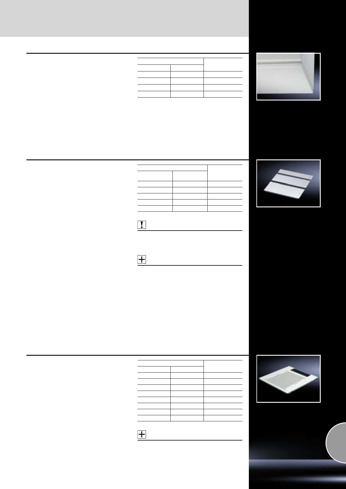
Base
Base
381Rittal Catalogue 33/System accessories
Trim panel
for CM
To conceal the entire base opening.
Material:
Sheet steel
Surface finish:
Textured paint
Colour:
RAL 7035
Protection category:
IP 55 to IEC 60 529
Supply includes:
Assembly parts.
For enclosure Model No. CM
Width mm Depth mm
600 400 5001.130
800 400 5001.140
1000 400 5001.150
1200 400 5001.160
Gland plate, multi-piece
for DK-TS
Any combination possible
Material:
Sheet steel
Surface finish:
Zinc-plated
Supply includes:
Packs of 1 set
Gland plates including sliding plate for cable
entry, including sealing tape and assembly parts.
Note:
For the size variant 800 x 800 mm, the gland plate
included with the supply of pre-configured net-
work enclosures should be additionally used.
Also required:
For integration of the gland plates, there must be
a base frame inside the enclosure.
Base frame, divided, for retro-fitting,
see page 377.
Accessories:
All gland plates with a depth of 237.5 mm may be
exchanged for gland plate modules on request.
−Gland plate modules,
see page 382.
−Gland plate modules,
vented with airflow regulator,
see page 382.
−Base module for cable entry,
see page 383.
−Section for cable entry,
see page 512, 513.
For enclosures
Model No. TS
Width
mm Depth
mm
600 1000 7825.364
600 1200 7825.365
800 800 7825.382
800 1000 7825.384
800 1200 7825.385
One-piece gland plate
vented, for TS
−With ventilation holes
−Cut-out for cable entry at the rear, covered with
brush strip.
Material:
Sheet steel
Surface finish:
Zinc-plated
Supply includes:
Assembly parts.
Accessories:
Filter mat for gland plate,
see page 382.
For enclosures Model No. DK
Width mm Depth mm
600 600 7825.660
600 800 7825.680
600 1000 7825.610
800 600 7825.860
800 800 7825.880
800 1000 7825.810
600 1200 7825.612
800 1200 7825.812
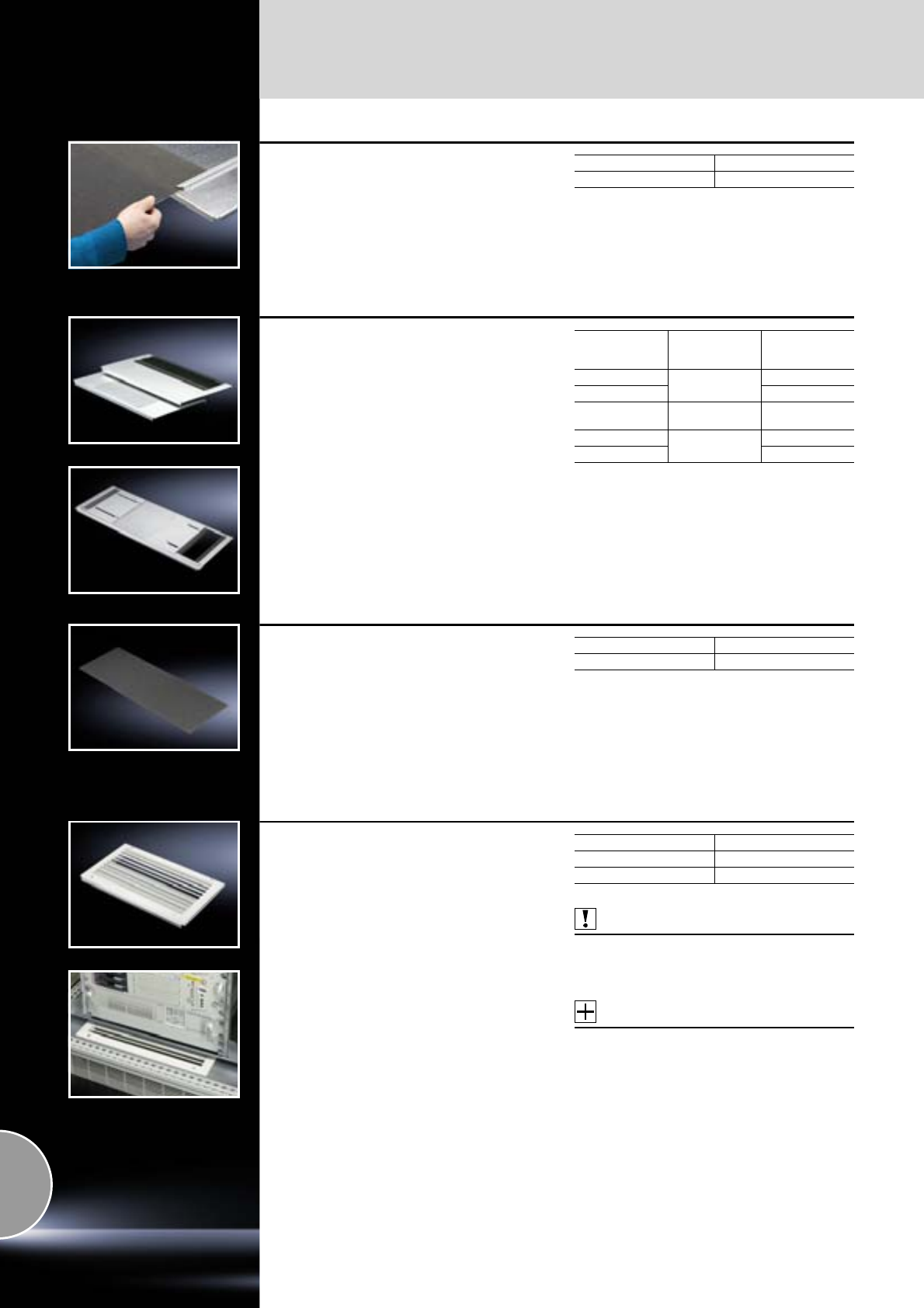
Base
Base
382 Rittal Catalogue 33/System accessories
Filter mat
for one-piece gland plate
The filter mat may be cut to size according to the
required cut-out.
Material:
PPI 35-5/polyamide
Packs of Model No. DK
17825.620
Gland plate modules
for DK-TS
For use in the base frame of the network enclo-
sure. Used in exchange for an existing gland
plate of the same depth or in conjunction with a
multi-piece gland plate for pre-configured TS 8
enclosures, see page 381.
Gland plate depth:
237.5 mm
Version for cable entry at the rear:
With brush strip.
Version for cable entry at the sides:
With rubber cable clamp strip.
Vented design:
With filter mat for concealing the holes and nylon
tape for securing from the inside or outside.
Material:
Sheet steel
Surface finish:
Zinc-plated
For
enclosure width
mm Design Model No. DK
600 For cable entry,
rear
7825.361
800 7825.381
800 For cable entry,
sides 7825.388
600 Vented 7825.360
800 7825.380
Spare filter mat
for gland plate modules, vented
To be used in exchange for the existing filter mat.
Material:
PPI 35-5/polyamide
Supply includes:
Assembly parts.
Packs of Model No. DK
27825.350
Gland plate modules, vented
with airflow regulator
for DK-TS
Allows controlled air routing from the twin base to
the installed components. Individually adjustable
membranes allow control of the air inlet opening
between 10% and 80% free space.
If the rear area of the enclosure is partitioned by
base/gland plates, the required volumetric airflow
may be individually regulated, and distribution of
the airflow inside the twin base adapted to suit the
requirements of each enclosure.
The gland plate module may be combined with all
gland plates as required. Gland plate module
including contacting assembly screws; the addi-
tional installation of PE conductors is not required.
Material:
Sheet steel
Supply includes:
Packs of 1
−Gland plate module, vented
−Filter mat
−Assembly parts
Also required:
For integration of the gland plates, there must be
a base frame inside the enclosure.
Base frame, divided, for retro-fitting,
see page 377.
Accessories:
Spare filter mat,
see page 383.
For enclosure width mm Model No. DK
600 7825.366
800 7825.386
Base
Base
383Rittal Catalogue 33/System accessories
Spare filter mat
for gland plate modules, vented,
with airflow regulator
To be used in exchange for the existing filter mat.
Material:
PPI 35-5/polyamide
Supply includes:
Assembly parts.
Packs of Model No. DK
17825.622
Base module
for cable entry
Super-airtight
for DK-TS
The two-part base module has a special cable
entry with alternate offset brush strips which
guarantee an excellent seal even with large cable
quantities.
Material:
−Module plate: Sheet steel
−Brush strip: Plastic, UL 94-V0
Surface finish:
Module plate: Zinc-plated
Supply includes:
Brush strip and assembly parts.
For enclosure width
mm Packs of Model No. DK
600 1 7825.367
800 1 7825.387
T
B
B1
T1
Module plates
for TE
The base area of the TE may be varied as
required using the module plates.
Material:
Sheet steel
Supply includes:
Assembly parts.
Design Width
mm Depth
mm Model No. TE
Solid
450 200 7526.760
450 550 7526.770
450 750 7526.780
650 550 7526.7851)
650 200 7526.800
650 750 7526.8201)
With brush strip 450 200 7526.850
650 200 7526.860
Vented 450 200 7526.829
650 200 7526.834
Compensating
panel
450 50 7526.750
450 150 7526.755
650 50 7526.790
650 150 7526.795
1) Extended delivery times.
Enclosure dimensions
mm
W (B) 600 600 600 800 800 800
D (T) 600 800 1000 600 800 1000
Base cut-out dimensions
mm
W (B1) 450 450 450 650 650 650
D (T1) 550 750 950 550 750 950
Base
Base
384 Rittal Catalogue 33/System accessories
Pressure relief stopper
Especially when enclosures are exposed to
changing climatic conditions (e.g. with outdoor
siting), condensation may form in sealed enclo-
sures due to pressure differences. The integral
sealing membrane largely prevents such pres-
sure differences and hence condensation; addi-
tionally, it also prevents the ingress of moisture
from the outside.
Installed in vertical surfaces to protect against
dirt.
Technical specifications:
−Air permeability up to 120 litres/hour with a
pressure difference of 70 mbar
−Connection thread M12 x 1.5
−For fitting in wall thicknesses up to 4 mm
Material:
Polyamide
Colour:
Similar to RAL 9005
Protection category:
−IP 66, 68 to EN 60 529
−IP 69K to DIN 40 050-9
Supply includes:
Lock nut
Packs of Model No. SZ
52459.500
Condensate discharge
For reliable discharge from the inside and protec-
tion against splashes from the outside (labyrinth
effect).
A hole diameter of 16 mm is required.
(With AE sheet steel, the holes are already pro-
vided in the base.)
Material:
Polyamide
Colour:
Similar to RAL 7035
Protection category:
IP 55 to IEC 60 529,
subject to correct mounting at the bottom.
Packs of Model No. SZ
62459.000
Gland plates
for CS New Basic enclosures
For sealing the base opening and for cable entry.
Material:
Sheet steel
Surface finish:
Powder-coated, zinc-plated
Colour:
RAL 7035
Supply includes:
Assembly parts.
For enclosure dimensions
Packs of Model No. CS
Width
mm Depth
mm
600 400 1 set 9785.511
600 500 1 set 9785.514
800 400 1 set 9785.512
800 500 1 set 9785.513
1200 400 1 set 2 x
9785.511
1200 500 1 set 2 x
9785.514
Side panels
Walls
385Rittal Catalogue 33/System accessories
1
Side panels, screw-fastened,
sheet steel
for TS
●Automatic potential equalisation and higher
EMC protection thanks to enclosure panel
fasteners with earthing insert
●Easy positioning with the location aid
●Earthing bolt with contact surface
Material:
Sheet steel 1.5 mm, textured
Surface finish:
Dipcoat-primed, powder-coated on the outside
Colour:
RAL 7035
Protection category:
IP 55 to IEC 60 529
Supply includes:
Assembly parts.
Note:
Enclosure panel holders may optionally be fitted
from the inside or outside of the enclosure.
Area available for population:
External dimension – 100 mm.
Automatic potential equalisation
Accessories:
−Earth straps,
see page 501.
−Enclosure panel fasteners, internal,
see page 386, for heavy installed equipment
and high dynamic pressures.
1
For enclosures Packs
of Model No. TS
Height mm Depth mm
800 600 2 8173.235
1000 600 2 8174.235
1200 500 2 8115.235
1200 600 2 8170.235
1200 800 2 8175.235
1200 1000 2 8176.235
1400 500 2 8145.235
1400 600 2 8146.235
1400 800 2 8148.235
1600 500 2 8165.235
1600 600 2 8166.235
1600 800 2 8168.235
1800 400 2 8184.235
1800 500 2 8185.235
1800 600 2 8186.235
1800 800 2 8188.235
1800 1000 2 8180.235
2000 400 2 8104.235
2000 500 2 8105.235
2000 600 2 8106.235
2000 800 2 8108.235
2000 1000 2 8100.235
2200 600 2 8126.235
2200 800 2 8128.235
Side panels, screw-fastened,
stainless steel
for TS
●Automatic potential equalisation and higher
EMC protection thanks to enclosure panel
fasteners
●Easy positioning with the location aid
●Earthing bolt with contact surface
Material:
Stainless steel 1.4301 (AISI 304), 1.5 mm
Surface finish:
Brushed, grain 400
Protection category:
IP 55 to IEC 60 529
Supply includes:
Assembly parts.
Accessories:
Enclosure panel fasteners, internal, see page 386,
for heavy installed equipment and high dynamic
pressures.
Detailed drawings:
Available on the Internet.
For enclosures Packs
of Model No. TS
Height
mm Depth
mm
1800 400 2 8700.840
1800 500 2 8700.850
2000 600 2 8700.060
Walls
Side panels
386 Rittal Catalogue 33/System accessories
Side panels, asymmetrical
for TS
The alternative to the standard side panel for
improved visual appearance in the event of back-
to-back, back-to-side or corner baying. The gap
(A) which occurs with standard side panels is
reduced to a standard dimension (B), see techni-
cal drawing. In the case of the TS 8 corner enclo-
sure, an asymmetrical side panel is included in
the supply.
The number of additional asymmetrical side pan-
els required depends on the chosen baying vari-
ant.
Material:
Sheet steel, 1.5 mm
Colour:
RAL 7035
Protection category:
IP 55 to IEC 60 529
Supply includes:
Assembly parts.
Accessories:
Enclosure panel fasteners, internal, see page 386,
for heavy installed equipment and high dynamic
pressures.
For enclosures Packs
of Model No. TS
Height mm Depth mm
1800 400 2 8184.500
1800 500 2 8185.500
1800 600 2 8186.500
2000 400 2 8104.500
2000 500 2 8105.500
2000 600 2 8106.500
2000 800 2 8108.500
2200 600 2 8126.500
Asymmetrical
side panel Side panel Corner baying Back-to-back baying
B
A
Rear panel Door Standard side panel Asymmetrical side panel
Enclosure panel fasteners,
internal
for TS
for additional fixing of the side or rear panel with
heavy installed equipment and high dynamic
pressures.
Packs of Model No. TS
10 8800.071
Side panels
Walls
387Rittal Catalogue 33/System accessories
Hinges
for
TS side panel, screw-fastened, sheet steel
TS side panel, asymmetrical
The 180° opening angle allows unhindered
access. May be installed optionally from the
inside or outside of the enclosure: Simply replace
3 enclosure panel fasteners with hinges. Despite
the hinge, the protection category of the enclo-
sure is retained.
Material:
Die-cast zinc
Supply includes:
Assembly screws.
Note:
−Side panel and door hinges may only be
installed on the same enclosure section when
using a 180° door hinge (see page 425).
−Please note: Red areas (side panels), hinged
and unhinged, must always be opposite one
another. Blue areas (doors/rear panels) must
always be opposite one another. Only one
surface on each vertical enclosure section
may be hinged.
Design Packs of Model No. TS
RAL 7035 6 8800.110
Side panel, lockable
for TS
●Simply locate from above
●Lock via security lock no. 3524 E
●Earthing bolt with contact lug.
Material:
Sheet steel, powder-coated
Protection category:
IP 20/NEMA 1 to IEC 60 529
Supply includes:
2 side panels each with 4 security locks
no. 3524 E.
Note:
Side panels 1200 mm deep as divided variants,
see page 388.
Accessories:
Internal latch DK 7824.510,
see page 388.
For enclosures Colour RAL Model No.
DK
Height mm Depth mm 7035 9005
800 600 – 7824.086
1000 600 – 7824.106
1200 600 – 7824.126
1200 800 – 7824.128
1200 1000 – 7824.120
1200 1000 – 7816.120
1400 600 –7824.1461)
1400 800 – 7824.148
1600 600 – 7824.166
1600 800 – 7824.168
1800 600 – 7824.186
1800 800 – 7824.188
1800 1000 –7824.1801)
2000 600 – 7824.206
2000 800 – 7824.208
2000 1000 – 7824.200
2000 1000 – 7816.2001)
2200 600 – 7824.226
2200 800 – 7824.228
2200 1000 – 7824.220
1) Extended delivery times.
Walls
Side panels
388 Rittal Catalogue 33/System accessories
Internal latch
for side panel, lockable
Additional security is achieved via the option of
latching the side panel from the inside.
The side panels on the frame section are screw-
fastened from the inside with latching brackets.
Supply includes:
Assembly parts.
For enclosure system Packs of Model No. DK
TS 4 7824.510
Side panel, plug-type, divided
for DK-TS
The horizontally divided side panel offers clear
advantages for storage, transportation and
assembly, thanks to the reduced weight and
smaller dimensions of its individual parts. The
lower side panel part is inserted into the base
frame and secured in the centre of the enclosure
via a punched section with mounting flange. After
attaching, the complete side panel is locked at
the top with 2 locks.
Material:
Sheet steel
Colour:
RAL 7035
Supply includes:
−Side panel with security lock 3524 E
−Punched sections with mounting flanges
−Earth conductor
−Assembly parts
For enclosures
Packs of Model No. DK
Height
mm Depth
mm
2000 1200 1 7824.310
2200 1200 1 7824.312
Side panels
for TE
●Simple assembly with insertion aid at the
bottom and lock at the top
●Earthing bolt with contact lug
Material:
Sheet steel
Surface finish:
Powder-coated
Protection category:
IP 20
Supply includes:
Security lock 3524 E.
For enclosures Packs of Colour RAL Model No. TE
Height mm Depth mm 7035 9005
2000 800 2 – 7000.652
2000 1000 2 – 7000.653
2000 1000 2 – 7000.663
Primer/paint
For touching up and repairing powder-coated and
wet-painted surfaces, air-drying.
Colour RAL Model No. SZ
Touch-up pen 12 ml 7032 2436.732
7035 2436.735
Tin 1000 ml 7035 2438.735
Spray can 150 ml
7022 2581.000
7032 2437.000
7035 2440.735
Divider panels/partitions
Walls
389Rittal Catalogue 33/System accessories
Cable management panel
for DK-TS
The universal routing aid for network enclosures
where large quantities of cables and lines are
managed. Can also be used as a partition with
cable management option.
By attaching to the inner level, cables may be
routed inside and out, also in conjunction with
a side panel.
Mounting options:
●Directly onto the inner mounting level of TS 8
enclosures
●On the outer mounting level on punched
sections with mounting flanges.
Material:
Sheet steel
Surface finish:
Powder-coated
Colour:
RAL 7035
Supply includes:
Assembly parts.
Accessories:
−Nylon loop fasteners,
see page 530.
−Cable route,
see page 536.
−Cable ties,
see page 530.
−Cable shunting rings,
see page 534.
−Cable manager,
see page 533.
For enclosures
Model No. DK
Width/depth
mm Height
mm
600 2000 7824.560
800 2000 7824.5801)
1) Extended delivery times.
Divider panel
for TS
For shielding individual enclosure cells. Thanks to
the symmetry of the frame system, the divider
panel can also be used at the rear. All-round,
double fold for stability and to hold the seal.
Notches in the corners and half-way up the sides
permit the use of angular baying brackets and
baying brackets, even with a divider panel fitted.
For mounting on the outer mounting level. This
leaves the inner level free for further population.
Material:
Sheet steel, 1.5 mm, zinc-plated
Protection category:
IP 54 to IEC 60 529, subject to the correct use of
module plates.
Supply includes:
Assembly parts.
Note:
The divider panel may also be fitted to the rear.
This allows, e.g. frequency converters for heat
dissipation to be installed in a divider panel with
the cooling units facing outwards and protected/
finished off with a cover (see page 392).
Accessories:
−Cover with door,
see page 392.
−Baying attachment, vertical (TS 8800.470)
for enclosures with fitted divider panel,
see page 398.
For enclosures Model No. TS
Height mm Depth mm
1800 400 8609.840
1800 500 8609.850
1800 600 8609.860
2000 400 8609.040
2000 500 8609.050
2000 600 8609.060
2000 800 8609.080
2200 600 8609.260
1702/1902/2102
302/402/502/702
289/389/489/689
247/347/447/647

Walls
Divider panels/partitions
390 Rittal Catalogue 33/System accessories
Partition
for DK-TS
For rack mounting, suspended between two TS 8
enclosures.
With three Ø 40 mm holes in all 4 corner areas for
the insertion of cable sections, conduits etc.
Drilled holes may be sealed with the enclosed
stepped collars. For cable entry, simply cut off at
a suitable level to match the required cross-sec-
tion.
Material:
−Partition: Sheet steel
−Stepped collar: Plastic to UL 94-HB
Surface finish:
Partition: Zinc-plated
Supply includes:
12 stepped collars Ø 40 mm.
Note:
Use baying connector TS 8800.490.
Not for use in conjunction with a baying seal.
Any existing seals must be removed prior to
installation.
Accessories:
Baying clamp TS 8800.490,
see page 396.
For enclosures Model No. DK
Height mm Depth mm
2000 1000 7831.723
2000 1200 7831.724
2200 1200 7831.726
The divider panel and
module plate system
More options:
The cut-outs of a divider panel are individually
equipped with module plates for 16-pole or 24-
pole connectors, with module plates for cable
entry and with solid module plates.
Faster assembly:
Usually only some of the total number of connec-
tor cut-outs are used. Thanks to the new divider
panel technique, the cut-outs do not need to be
covered individually. The solid module plate is
used instead.
The benefits: Less plates, less screws,
less assembly work.
402/502
318
144
188
1702/1902
8 x 188 (1504)/9 x 188 (1692)
99/105
Divider panel
for module panels TS
With cut-outs for the installation of module plates
for connectors or for cable entry, and also for
the entry of busbar systems and other installed
equipment. All-round, double fold for stability
and to hold the seal. Thanks to the symmetry of
the enclosure frame, divider panels may also be
fitted at the rear, dimensions permitting.
For mounting on the outer mounting level. This
leaves the inner level free for further population.
Material:
Sheet steel, 2 mm
Surface finish:
Zinc-plated
Supply includes:
Assembly parts and multi-tooth screws
M5 x 12 mm for mounting the module plates.
Note:
Notches in the corners and half-way up the sides
permit the use of angular baying brackets and
baying brackets, even with a divider panel fitted.
Accessories:
−Module plates,
see page 391.
−Cover with door,
see page 392.
−Baying attachment (TS 8800.470)
for enclosures with fitted divider panel,
see page 398.
For enclosures Number of cut-outs Model No. TS
Height mm Depth mm
1800 500 9 8609.100
1800 600 9 8609.110
2000 500 10 8609.120
2000 600 10 8609.130
Divider panels/partitions
Walls
391Rittal Catalogue 33/System accessories
Module plates
Material:
Sheet steel, 2 mm
Surface finish:
Zinc-plated
Supply includes:
Seal
Design Cut-outs Packs of Model No. TS
Solid – 1 8609.160
For 16-pole
connectors 418609.150
For 24-pole
connectors 418609.140
For cable entry 1 1 8609.170
For cable entry
grommets 418609.190
With cable sleeve 1 1 8609.390
Solid
For sealing unused cut-outs. Easily machined for
individual cut-outs.
Detailed drawings:
Available on the Internet.
for 16/24-pole connectors
With cut-outs to accommodate connectors. In
addition to mounting on divider panels, module
plates may also be attached to the 25 mm pitch
pattern of the enclosure and to the rails of the TS/
PS system.
Accessories:
−Adaptor, cover plate,
see page 392.
−Connector gland for connector cut-outs,
see page 522.
−Connector gland sealing frame and sealing
module, see page 523.
For cable entry
For the entry of pre-assembled cables. Sealed,
secure routing is achieved via adjustable angle
brackets with inserted foam cable clamp strip.
Attachment bracket, punched, for cable clamp-
ing.
Accessories:
Cable tie for fast assembly SZ 2597.000,
see page 530.
For cable entry grommets
For mounting on the divider panel for module
plates TS. Slide the grommets into the cut-outs,
slide the clamp plate with seal down over them,
and screw-fasten.
Also required:
−Cable entry grommets,
see page 512 or
−Connector grommets,
see page 512.
With cable sleeve
For 10 – 65 mm cable diameters. The flexible
grommet adapts to the cable's bending radius.
Walls
Divider panels/partitions
392 Rittal Catalogue 33/System accessories
Adaptors
for connector cut-outs
For using connectors with varying numbers of
poles.
Material:
Sheet steel
Surface finish:
Zinc-plated
Supply includes:
Seal for adaptor and mounting accessories.
For reduction Packs of Model No. SZ
From 24 to 16 poles 5 2479.000
From 24 to 10 poles 5 2480.000
From 24 to 6 poles 5 2481.000
From 16 to 10 poles 5 2401.000
From 16 to 6 poles 5 2402.000
Cover plate
for connector cut-outs
For unused cut-outs.
Material:
Sheet steel
Surface finish:
Zinc-plated
Supply includes:
Seal and assembly parts.
For Packs of Model No. SZ
24-pole cut-outs 20 2477.000
16-pole cut-outs 20 2478.000
Cover with door
for TS
●To protect and finish off connectors or other
installed equipment.
●Optional cable entry from above or below.
Material:
−Cover: Sheet steel, 1.5 mm
−Door: Sheet steel, 2.0 mm
Colour:
RAL 7035
Supply includes:
−Cover
−Door with locking rod and double-bit lock insert
−1 cover plate for top or bottom.
Accessories:
−Lock inserts, version F,
see page 421.
−Comfort handle,
see page 415.
−180° hinge,
see page 425.
For enclosures
Model No. TS
Height
mm Depth
mm
2000 500 8609.020
2000 600 8609.030
Noise protection kit
for TS
Noise insulating mats for equipping or retro-fitting
enclosures.
Thanks to their self-adhesive rear, the noise insu-
lating mats are easily attached to existing sur-
faces. Sound is absorbed, leading to significant
noise reduction. The kit is designed to reduce
noise from the roof, sides and rear of an enclo-
sure with dimensions WHD 800 x 2000 x 800 mm.
Other dimensions can be accommodated by
cutting to size individually.
Material:
Soft foam based on melamine resin, 20 mm
Colour:
Pale grey
Supply includes:
Spacer bolts for sound insulation of the roof plate.
Material category:
B1 to DIN 4102 Asorption level α: share of absorbed output,
1 = 100% (averaged).
Averaged noise reduction (comparison source,
50 Hz – 20 kHz): 1 m standard distance (averaged)
For enclosures
W x H x D mm Packs of Model No. DK
800 x 2000 x 800 1 set 7824.650
0.00
0.10
0.20
0.30
0.40
0.50
0.60
0.70
0.80
0.90
1.00
63 100 160 250 400 630 1000 1600 2500 4000 6300 10000
α
Hz
Absorption level
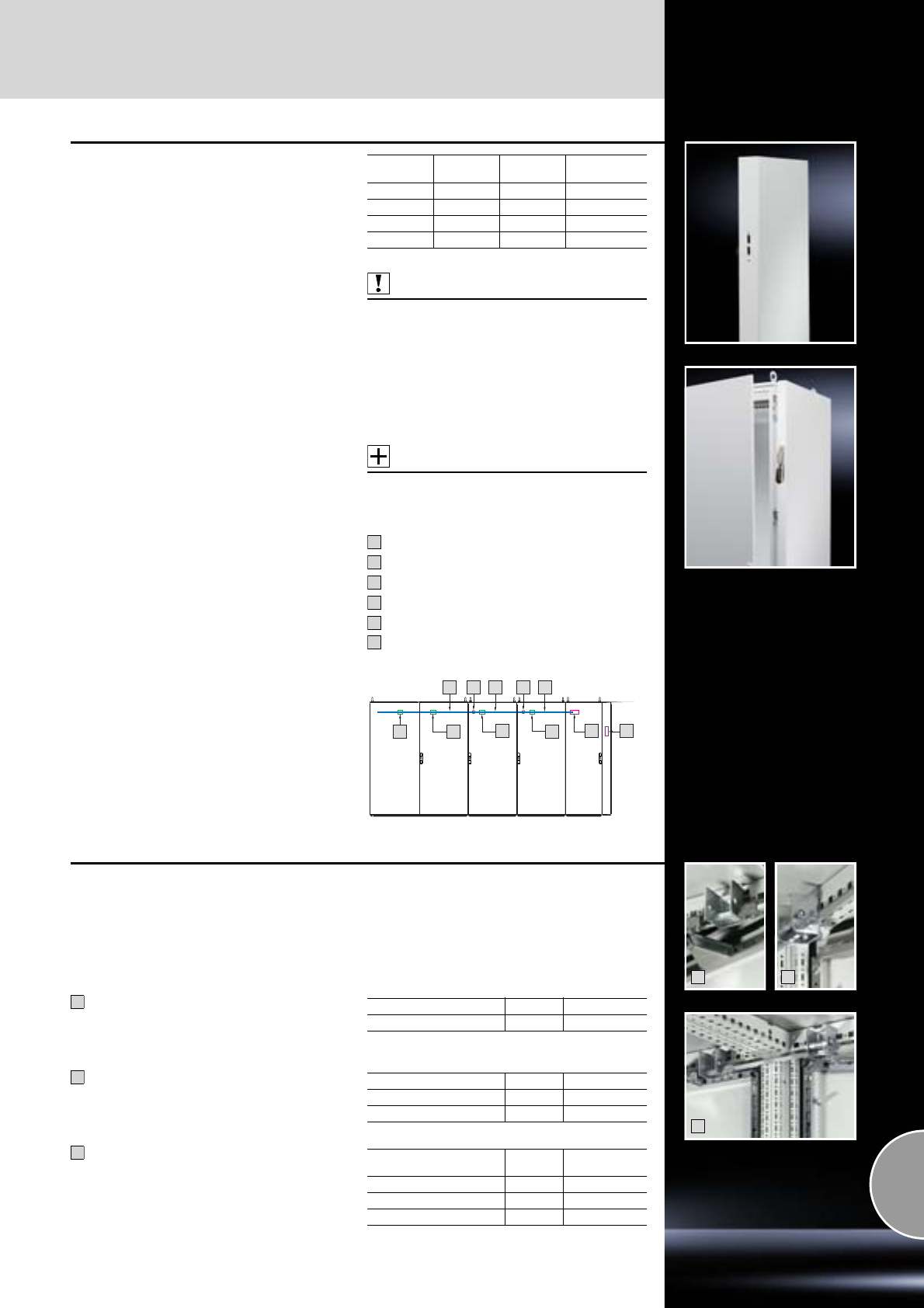
Isolator door locking
Walls
393Rittal Catalogue 33/System accessories
TS isolator door cover
(US version)
Including main door lock for safety locking of
enclosures and bayed enclosure suites in accord-
ance with US regulations, only in conjunction with
actuator lever for master switches:
●Allen Bradley 1494 F-M1/P1/S1
and 140 U-K-FCX04
●Square D 9422 A1
●ITE Siemens Max-Flex series/FHOH
(only available in the USA)
●General Electric TDA Type 1 and 2
●Moeller NZM-XSHGVR 12-NA
Benefits:
●In combination with
−Operating mechanism
−Adjacent door latch
−Interconnecting rods
meets the requirements of UL 508 A
●Compact design with a width of just 100 mm.
●May be mounted instead of a side panel.
With this cover, all standard single-door TS 8
enclosures may be configured as isolator door
enclosures. The complete installation surface of
the enclosure is retained.
●May be mounted optionally on the left or right of
the enclosure.
●In conjunction with the integrable TS 8 mount-
ing plate infill, (see page 443), the mounting
surface of the main enclosure can be enlarged
by around 14%.
Material:
Sheet steel
Surface finish:
Powder-coated
Colour:
RAL 7035
Protection category:
IP 55 to IEC 60 529, complies with NEMA 12.
Supply includes:
Main door lock, cover plate and assembly parts.
Also required:
−Operating mechanism, TS 4912.000, for enclo-
sure with isolator door cover and additionally
every fourth adjacent enclosure,
see page 393.
−Adjacent door latch, TS 4911.000, TS 4911.100,
for every adjacent enclosure,
see page 393.
−Interconnecting rods, for every adjacent
enclosure in the appropriate enclosure width,
see page 393.
Accessories:
Mounting plate infill,
see page 443.
Isolator door locking (US version)
Operating mechanism
Adjacent door locking (single-door)
Interconnecting rod
Connection component
Main door latch
Adjacent door locking (two-door)
Width
mm Height
mm Depth
mm Model No.
TS
100 1800 400 8900.840
100 1800 500 8900.850
100 2000 500 8900.050
100 2000 600 8900.060
1
2
3
4
5
6
34343
2
66 21 5
2
1
3
Door latch
for bayed enclosure suites
For extending the door locking of commercially
available master switches to bayed suites TS.
Adjacent door cannot be opened until the main
door has been opened.
Operating mechanism
(Fitted in the enclosure with master switch and
additionally in every fourth adjacent enclosure)
1
Packs of Model No. TS
Operating mechanism 1 4912.000
Adjacent door latch
(Installation in adjacent enclosure)
2
Adjacent door locking for Packs of Model No. TS
single-door enclosures 1 4911.000
two-door enclosures 1 4911.100
Interconnecting rods
To extend locking from the main enclosure to
the adjacent enclosures of a bayed suite.
An interconnecting rod corresponding to the
width of the enclosure is required for each
adjacent enclosure.
3
For enclosure width
mm Packs of Model No. TS
600 10 4916.000
800 10 4918.000
1200 10 4920.000
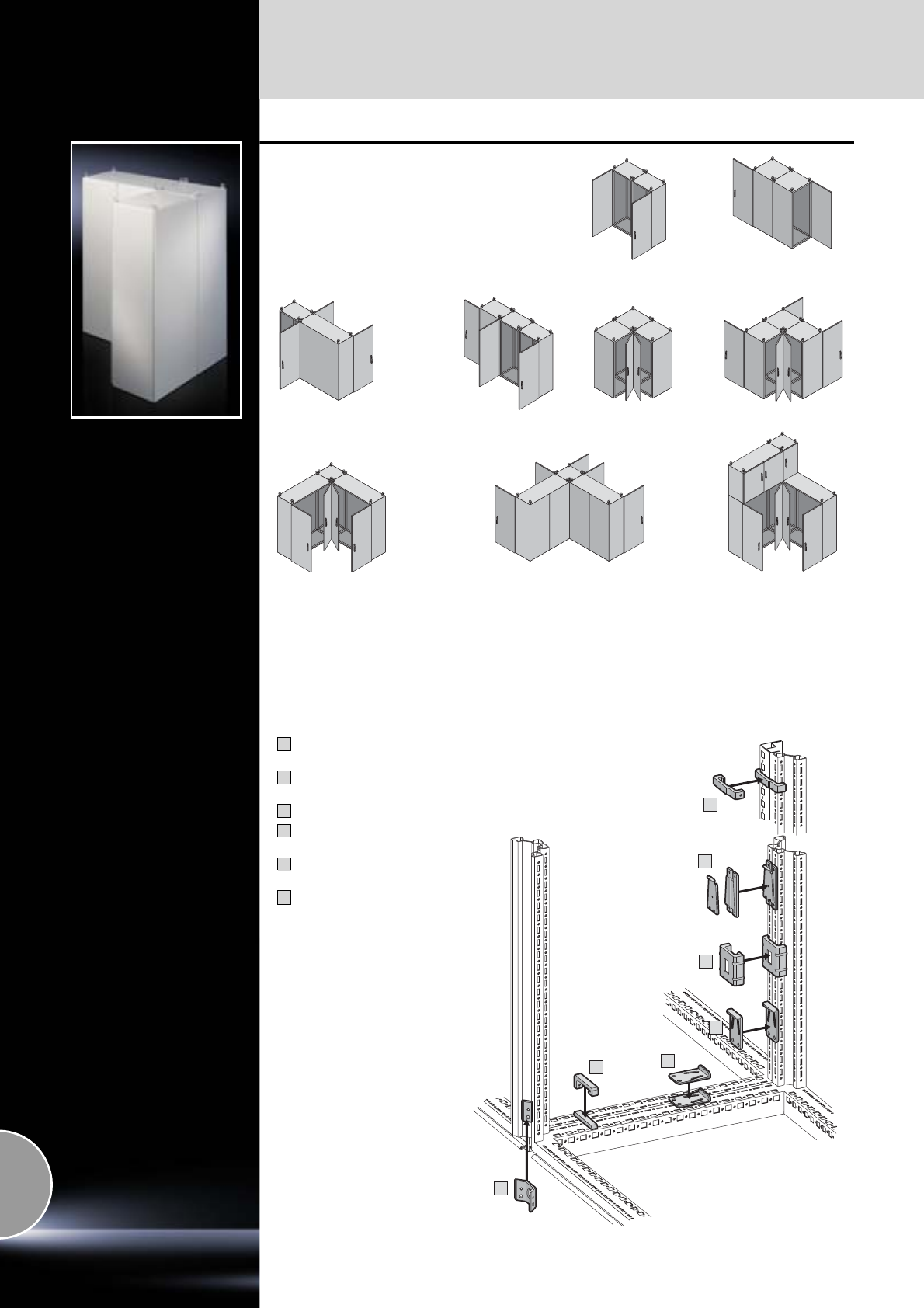
Baying system
Enclosure suites
394 Rittal Catalogue 33/System accessories
1
1
3
4
5
6
2
Bayable on all sides
Whether around corners, forwards, backwards,
to the left or right or even upwards if required,
the baying options are unlimited.
Quick-fit baying clamps,
one-piece
Quick-fit baying clamps,
three-piece
Baying clamp, horizontal
Baying clamp, vertical
for TS/TS
Baying clamp, vertical
for TS/PS
Baying connector, external
Notes on the transportation
of bayed enclosures,
see page 396.
1
2
3
4
5
6
For baying at the installation site
or for provisional siting in the workshop
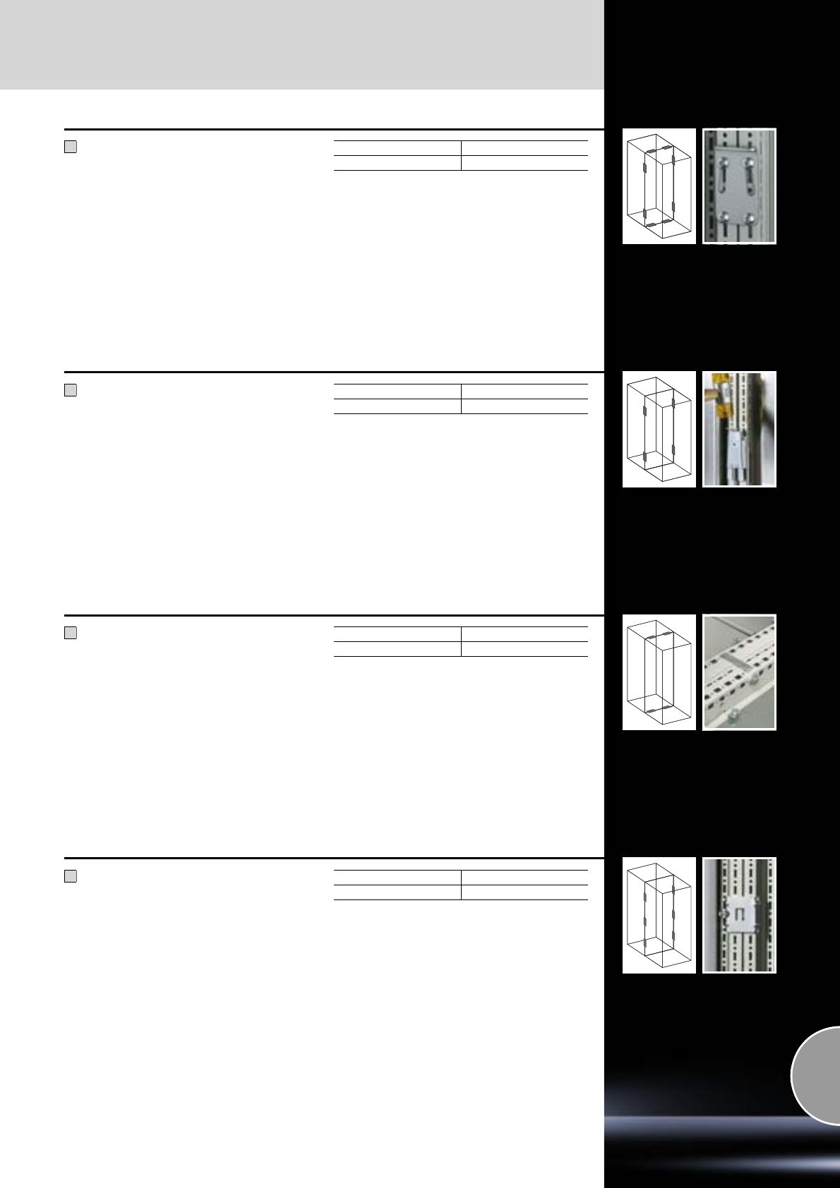
Enclosure suites
Baying system
395Rittal Catalogue 33/System accessories
Quick-fit baying clamp,
one-piece
for TS/TS
Simply attach the screws, insert the quick-fit
baying clamp, tap in with a hammer and lock.
Material:
Sheet steel
Surface finish:
Zinc-plated
Supply includes:
Assembly parts.
1
Packs of Model No. TS
68800.500
Quick-fit baying clamp,
three-piece
for TS/TS
Simply locate, connect with the lock plate,
and secure.
Material:
Sheet steel
Surface finish:
Zinc-plated
Supply includes:
Assembly parts.
2
Packs of Model No. TS
68800.590
Baying clamp, horizontal
for TS/TS, TS/PS
For mounting on the horizontal enclosure sections.
Material:
Cast steel
Surface finish:
Zinc-plated
Supply includes:
Assembly parts.
3
Packs of Model No. TS
48800.400
Baying clamp, vertical
for TS/TS
For mounting on the vertical enclosure sections.
Material:
Sheet steel
Surface finish:
Zinc-plated
Supply includes:
Assembly parts.
4
Packs of Model No. TS
68800.410
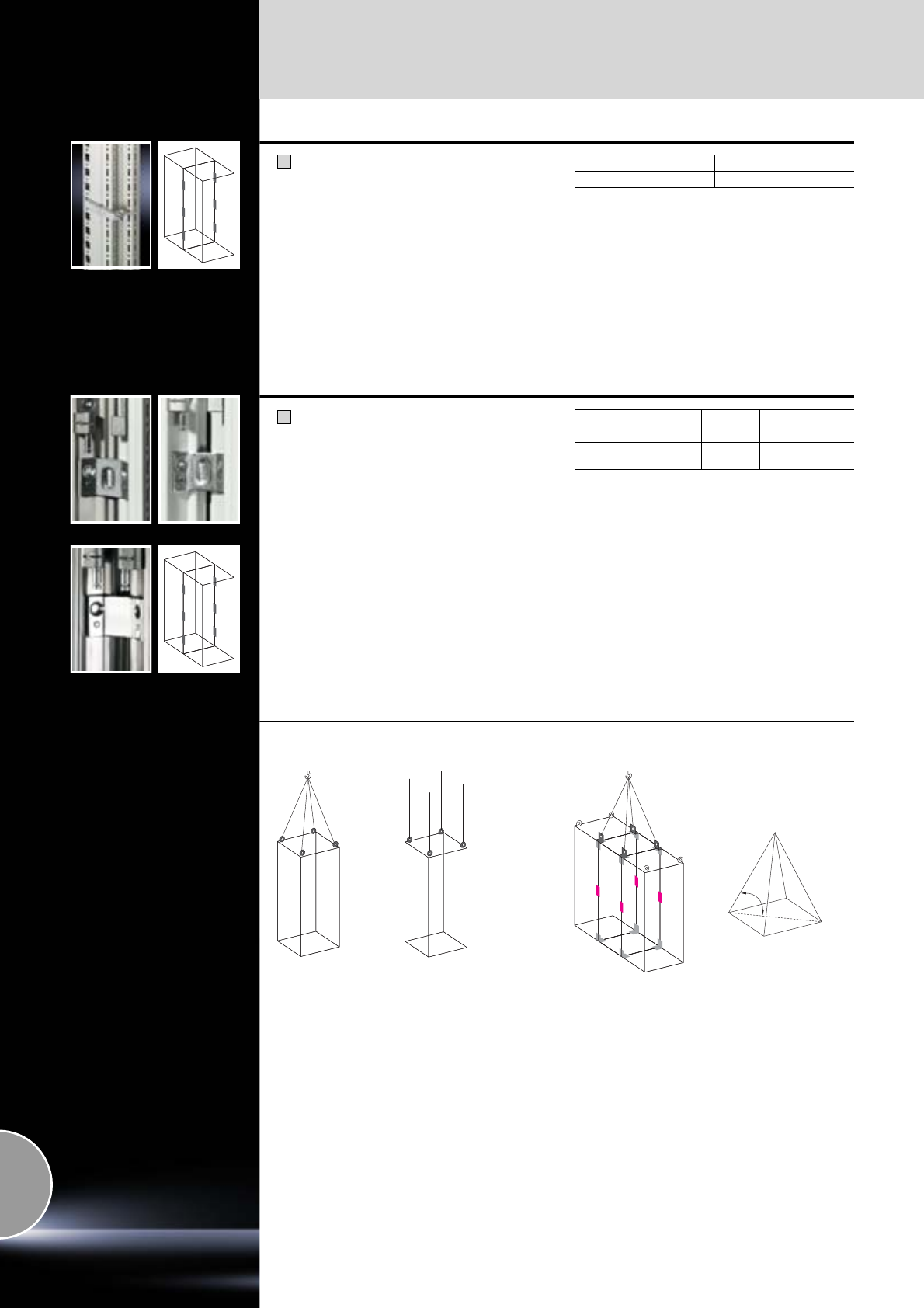
Baying system
Enclosure suites
396 Rittal Catalogue 33/System accessories
Baying clamp, vertical
for TS/PS
For mounting on the vertical enclosure sections.
Material:
Cast steel
Surface finish:
Zinc-plated
Supply includes:
Assembly parts.
5
Packs of Model No. TS
68800.420
Baying connectors, external
for TS/TS
For mounting on the vertical enclosure sections.
Simply position on the outside and screw-fasten
either from the inside or outside.
Supply includes:
Assembly parts.
6
Material/surface finish Packs of Model No. TS
Sheet steel, zinc-plated 6 8800.490
Stainless steel 1.4301
(AISI 304) 68700.000
Individual enclosures may be safely transported
using the eyebolts included with the supply.
For symmetrical loads, the following maximum
permissible loads apply:
for 45° cable pull angle 4,800 N,
for 60° cable pull angle 6,400 N,
for 90° cable pull angle 13,600 N.
Note:
The eyebolts must be aligned in the direction of
the cable pull.
For larger baying combinations, we recommend
the use of a transport base/plinth, see page 368.
For the enclosure combi-
nation with angular bay-
ing brackets, quick-fit
baying clamps and com-
bination angles shown
here, the load capacity
with a cable pull angle of
60° is as follows:
for the left-hand enclo-
sure 7,000 N,
for the central enclosure
14,000 N,
for the right-hand enclo-
sure 7,000 N.
The cable pull angle
between the roof
plate and the cable
has a significant influ-
ence on the total per-
missible load.
The cable pull angle
must not be less than
45°, and where possi-
ble, should be less
than 60°.
Note on the transport of bayed enclosures
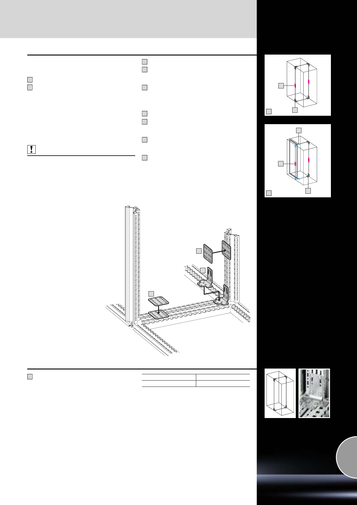
Enclosure suites
Baying system
397Rittal Catalogue 33/System accessories
7
8
1
B
7
1
A
7
8
8
When transporting bayed
enclosures
Baying bracket for TS/TS
Baying bracket for TS/TS
and TS/PS
Note:
−In addition, the outer baying connector
(see page 396), can be used.
−When transporting large, heavy enclosure com-
binations by crane, we additionally recommend
the use of combination angles TS 4540.000,
see page 398.
Also required:
For protection category IP 55:
One connector/clamp is required half-way up the
enclosure height, see page 395.
Baying clamp, see page 395/396.
Notes on the transportation of bayed enclosures,
see page 396.
2 quick-fit baying clamps
TS 8800.500
(see page 395).
4 baying brackets
TS 8800.430
(see page 397).
2 quick-fit baying clamps
TS 8800.500
(see page 395).
2 baying brackets
TS 8800.430
(see page 397).
4 baying brackets
TS 4582.500
(see page 398) if the angular baying brackets
cannot be fitted in the foremost installation
position due to installed equipment such as
large swing frames.
7
8
A
1
7
B
1
7
8
Angular baying brackets
for TS/TS
For a stable connection when transporting bayed
enclosure suites.
Screw-fastening either
●Horizontally and vertically with 8 screws
●Horizontally with 2 screws and M8 threaded
blocks, vertically with 4 screws
connection.
Material:
Sheet steel
Surface finish:
Zinc-plated
Supply includes:
Assembly parts.
7
Packs of Model No. TS
48800.430
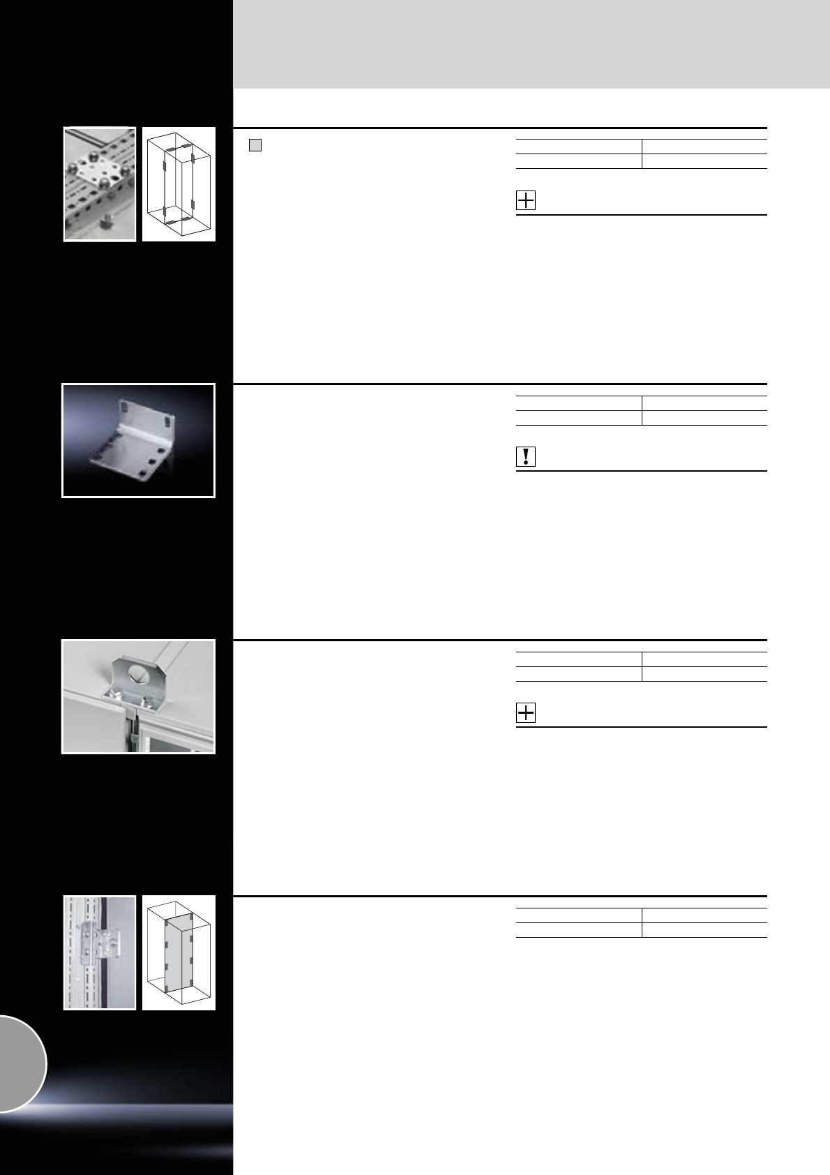
Baying system
Enclosure suites
398 Rittal Catalogue 33/System accessories
Baying brackets
for TS/TS and TS/PS
For additional stabilistation, or in cases where:
●Mounting plate brackets
●Swing frame
●Busbar support
prevent the installation of angular baying
brackets.
Material:
Sheet steel
Surface finish:
Zinc-plated
Supply includes:
Assembly parts.
Accessories:
For mounting on the vertical TS enclosure section:
Snap-on nut M8, TS 8800.808,
see page 471.
8
Packs of Model No. TS
44582.500
Angular baying bracket
The alternative to baying bracket TS 4582.500
and for individual interior installations.
Material:
Sheet steel
Surface finish:
Zinc-plated
Supply includes:
Screws M8 x 16 mm.
Also required:
For mounting on:
−Horizontal TS enclosure section,
captive nuts/threaded blocks M8,
see page 477,
−Vertical TS enclosure section,
snap-on nut M8, TS 8800.808,
see page 471.
Packs of Model No. PS
44582.000
Combination angle
For optimum distribution of tensile forces during
transportation of bayed enclosures by crane.
Material:
Sheet steel
Surface finish:
Zinc-plated
Supply includes:
Assembly parts.
Accessories:
Top baying cover,
see page 399.
Notes on the transportation of bayed enclosures,
see page 396.
Packs of Model No. TS
44540.000
Baying attachment, vertical
for TS/TS with divider panel
Only suitable for mounting in conjunction with the
angle brackets of the divider panel (included with
the supply).
Material:
Sheet steel
Surface finish:
Zinc-plated
Supply includes:
Assembly parts.
Note:
May also be used for side or rear wall attachment/
fastening of enclosures. In such cases, additional
holes must be drilled in the side or rear panel.
Packs of Model No. TS
88800.470
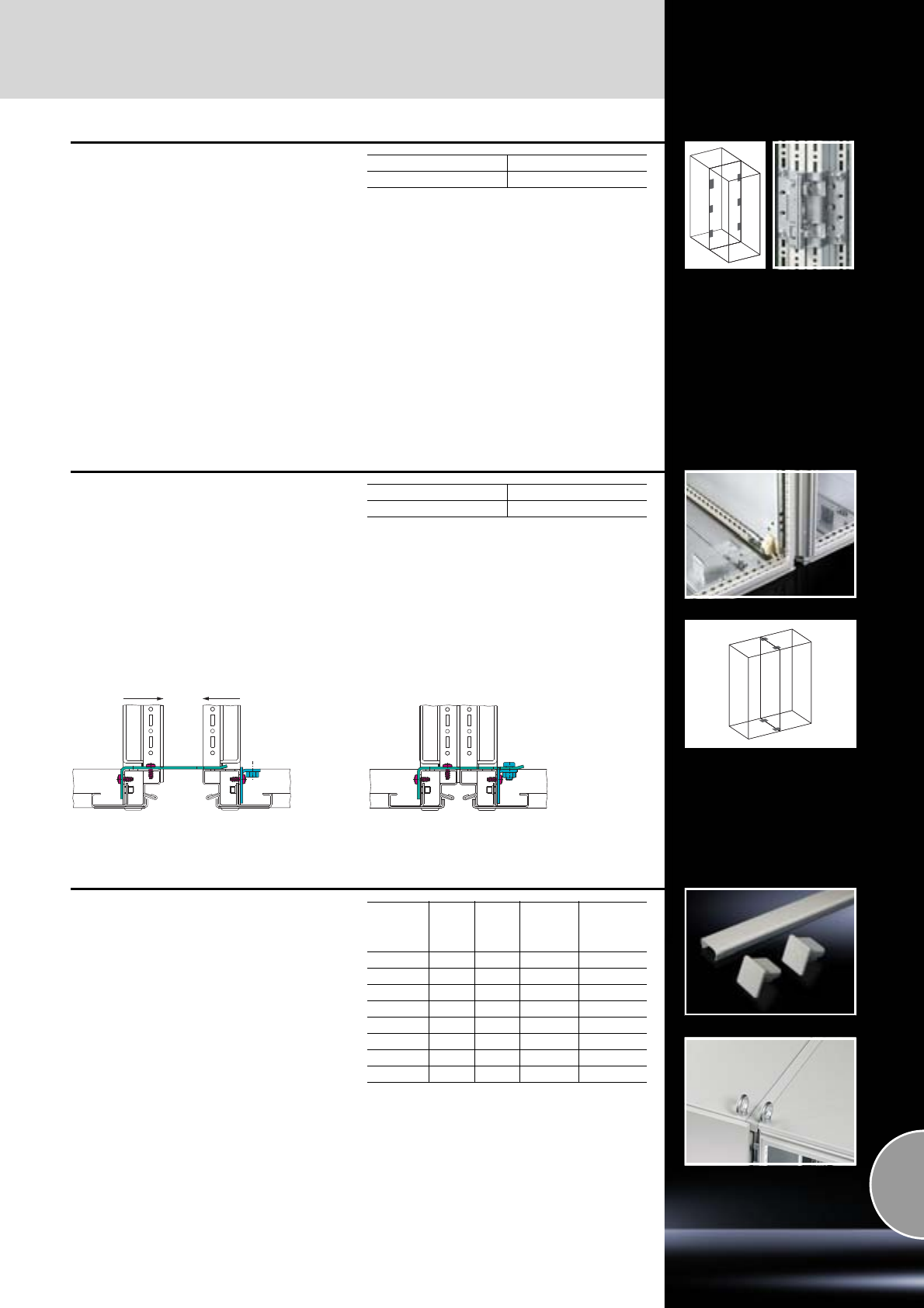
Enclosure suites
Baying system
399Rittal Catalogue 33/System accessories
Baying attachment, vertical
for TS/TS
For baying two populated enclosures on the verti-
cal enclosure section.
Simply locate into the vertical TS punchings,
secure and connect both brackets by using the
hex screws (supplied loose).
Using the fastening bolts, the enclosure is pulled
into a defined end position, with a height or side
offset of up to ± 2 mm.
Material:
Sheet steel, 3 mm
Surface finish:
Zinc-plated
Supply includes:
Assembly parts.
Packs of Model No. TS
68800.670
Baying clamp, horizontal
for back-to-back mounting
Two-piece, for in situ assembly of enclosures
with mounting plate in the rearmost installation
position.
Material:
Sheet steel
Surface finish:
Zinc-plated
Supply includes:
Assembly parts.
Packs of Model No. TS
48800.170
Baying cover, top
A cover with two end caps may additionally be
clipped over the seal between the two enclo-
sures. This prevents dirt and liquid from collect-
ing on the baying seal.
Material:
−Cover section: Sheet steel or stainless steel
−End caps: Plastic
Surface finish:
Spray-finished
Supply includes:
−Cover section
−2 end caps
Note:
May also be fitted in the width with enclosure
suites bayed back-to-back.
May also be used in conjunction with dust guard
trim, see page 432.
For
enclosure
depth
mm
Packs
of RAL
7035
Stainless
steel
1.4301
(AISI 304)
Model No.
TS
400 1 – 8800.840
500 1 – 8800.850
600 1 – 8800.860
800 1 – 8800.880
1000 1 – 8800.892
400 1 – 8700.140
500 1 – 8700.150
600 1 – 8700.160
Baying system
Enclosure suites
400 Rittal Catalogue 33/System accessories
Baying connector, external
for DK-TS/DK-TS with side panels
For retrospective baying of enclosures with screw-
fastened or lockable side panels.
Material:
Sheet steel
Colour:
RAL 7035
Supply includes:
Assembly parts.
Packs of Model No. DK
47824.540
Compensating panel
for TS
The panel is screw-fastened to the outside of the
enclosure frame and serves as an infill panel
when baying 2000 mm high enclosures of varying
depths.
No seal between the enclosures.
Material:
Sheet steel
Colour:
RAL 7035
Supply includes:
Assembly parts.
Depth difference
mm Model No. DK
100 7067.1001)
200 7067.200
1) Extended delivery times.
Baying kit
for TE/TE
For connecting individual enclosures into bayed
suites at the sides. The enclosures are connected
between the base and roof frame.
Material:
Sheet steel
Surface finish:
Zinc-plated
Supply includes:
Assembly parts.
Packs of Model No. TE
47000.640
Baying kit
for KL, AE
Special screws and nuts
●For fast, simple assembly without thread-tap-
ping.
●Compression of the seal is limited to a prede-
fined level, to ensure a long-lasting, permanent
seal between enclosures.
Seal, self-adhesive
●Comprised of bayable sealing elements and
corner pieces, for individual adaptation to vari-
ous enclosure sizes.
One pack is sufficient for a baying point up to
H x D = 800 x 350 mm.
Supply includes:
−Sealing elements
−Assembly parts
Packs of Model No. SZ
1 set 1199.10 0
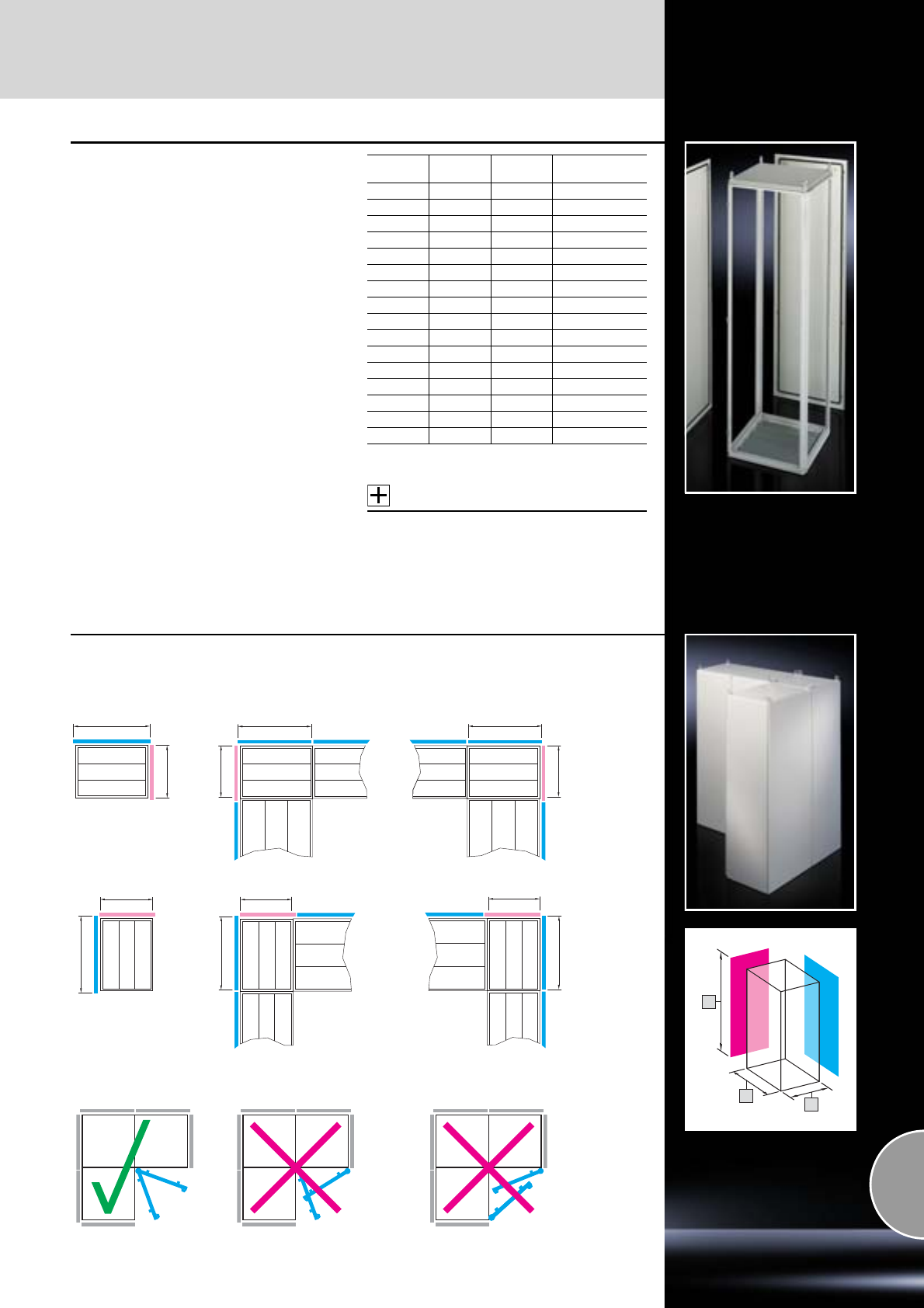
TS 8 corner enclosures
Baying system
401Rittal Catalogue 33/System accessories
TS 8 corner enclosures
The corner enclosure and the supplied compo-
nents will accommodate the various baying
options of the TS 8 frame on all outer surfaces.
Fitted with a rear panel and an asymmetrical side
panel (see page 386, mounted on the l/h side),
the corner enclosure also permits the option of
baying in both the width and depth.
The gland plates are aligned parallel to the rear
panel. In TS 8 enclosures with a square footprint,
the gland plates may also be rotated through 90°.
The baying system is identical to all other TS 8
enclosures.
Material:
Sheet steel, 1.5 mm
Surface finish:
−Enclosure frame, roof, rear panel, side panel:
Dipcoat-primed, powder-coated on the outside,
textured paint
−Gland plates: Zinc-plated
Colour:
RAL 7035
Supply includes:
−Enclosure frame
−Roof
−Rear wall (on the longest side)
−Side panel, asymmetrical
−Gland plates (divided in a longitudinal
direction)
Accessories:
−TS base/plinth,
see page 360.
−Connecting plinth trim,
see page 365.
Width
mm Height
mm Depth
mm Model No. TS
400 1800 400 8484.300
500 1800 400 8584.300
600 1800 400 8684.300
500 1800 500 8585.300
600 1800 500 8685.300
600 1800 600 8686.300
400 2000 400 8404.300
500 2000 400 8504.300
600 2000 400 8604.300
800 2000 400 8804.300
500 2000 500 8505.300
600 2000 500 8605.300
800 2000 500 8805.300
600 2000 600 8606.300
800 2000 600 8806.300
600 2200 600 8626.300
Extended delivery times.
H
B
T
Baying examples
TS 8 corner enclosures
T 500
B 600
B 600
T 500
B 600
T 500
B 600
T 500
B 600
T 500
B 600
T 500
Correct Incorrect
Note:
Incorrect
B = Width
T = Depth
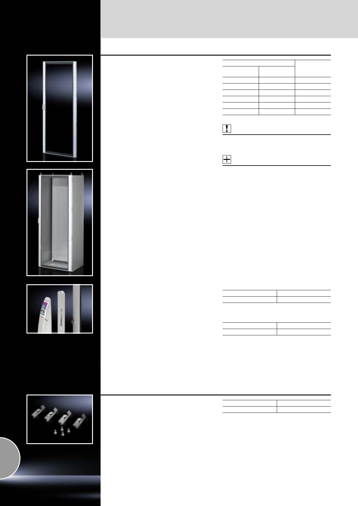
Doors/locks
Door variants
402 Rittal Catalogue 33/System accessories
Glazed door
for TS
Instead of a sheet steel door or rear panel.
Material:
−Front panel: Extruded aluminium section
−Corner pieces: Die-cast zinc
−Viewing window: Single-pane safety glass,
3mm
Surface finish:
Powder-coated
Colour:
−Frame and corner pieces: RAL 7035
−Viewing window (printed mask on the inside):
RAL 7015
Protection category:
IP 55 to IEC 60 529
Supply includes:
−Viewing door frame with safety glass
−Locking rod with double-bit insert
−180° hinges (4)
−Visible area: W – 140 mm, H – 160 mm
Also required:
When mounting instead of the rear panel:
Lock components for frame TS 8800.040,
see page 402.
Accessories:
−Lock inserts, version F,
see page 421.
−Comfort handle,
see page 415.
For enclosures
Model No. TS
Width
mm Height
mm
600 1800 8610.680
800 1800 8610.880
600 2000 8610.600
800 2000 8610.800
600 2200 8610.620
800 2200 8610.820
Handle adaptor
The handle adaptor compensates for the design
chamfer in the door profile to enable installation of
the comfort handle.
Material:
Plastic
Supply includes:
−1 adaptor plate
−1 extension for drive
−2 assembly screws
For glazed door TS
Colour Model No. TS
RAL 7035 8611.080
For designer door IW and PC-TS, bottom door
Colour Model No. PC
RAL 7035 8611.300
Lock components
for frame TS
For retrofitting a glazed door or sheet steel door
in place of a rear panel.
Material:
Die-cast zinc
Supply includes:
Assembly screws.
Packs of Model No. TS
48800.040
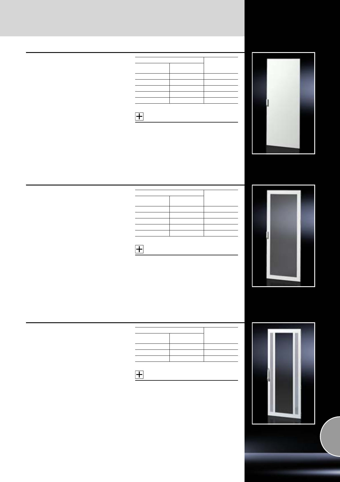
Door variants
Doors/locks
403Rittal Catalogue 33/System accessories
Sheet steel door
for DK-TS
To replace existing doors. With 180° hinges and
swivel handle with security lock no. 3524 E,
in exchange for comfort handle.
Material:
Sheet steel
Colour:
RAL 7035
Protection category:
IP 55 to IEC 60 529
Supply includes:
Assembly parts.
Accessories:
−Comfort handle,
see page 415.
−180° hinge for bayed TS enclosure suites
with comfort handle,
see page 425.
For enclosures
Model No. DK
Width
mm Height
mm
600 2000 7824.205
800 1200 7824.127
800 2000 7824.207
600 2200 7824.225
800 2200 7824.227
Sheet steel door, vented
for DK-TS
With 180° hinges and swivel handle with security
lock no. 3524 E, in exchange for comfort handle.
For optimum air throughput in network enclosures
with a high proportion of active components.
Slotted surface with air inlet opening > 78%.
Material:
Sheet steel
Colour:
RAL 7035
Supply includes:
Assembly parts.
Accessories:
−Comfort handle,
see page 415.
−180° hinge for bayed TS enclosure suites
with comfort handle,
see page 425.
For enclosures
Model No. DK
Width
mm Height
mm
600 1800 7824.183
600 2000 7824.203
800 2000 7824.204
600 2200 7824.223
800 2200 7824.224
Glazed door, vented
for DK-TS
With 180° hinges and comfort handle with secu-
rity lock no. 3524 E. For optimum air throughput in
network enclosures with a low proportion of active
components.
Material:
−Front panel: Sheet steel
−Viewing window: Single-pane safety glass,
3 mm
−Slotted surfaces (SWG-6.7 hexagon) at the
sides for air inlet
Surface finish:
Spray-finished
Colour:
RAL 7035
Supply includes:
Assembly parts.
Accessories:
180° hinge for bayed TS enclosure suites
with comfort handle,
see page 425.
For enclosures
Model No. DK
Width
mm Height
mm
600 2000 7824.201
800 2000 7824.202
800 2200 7824.222
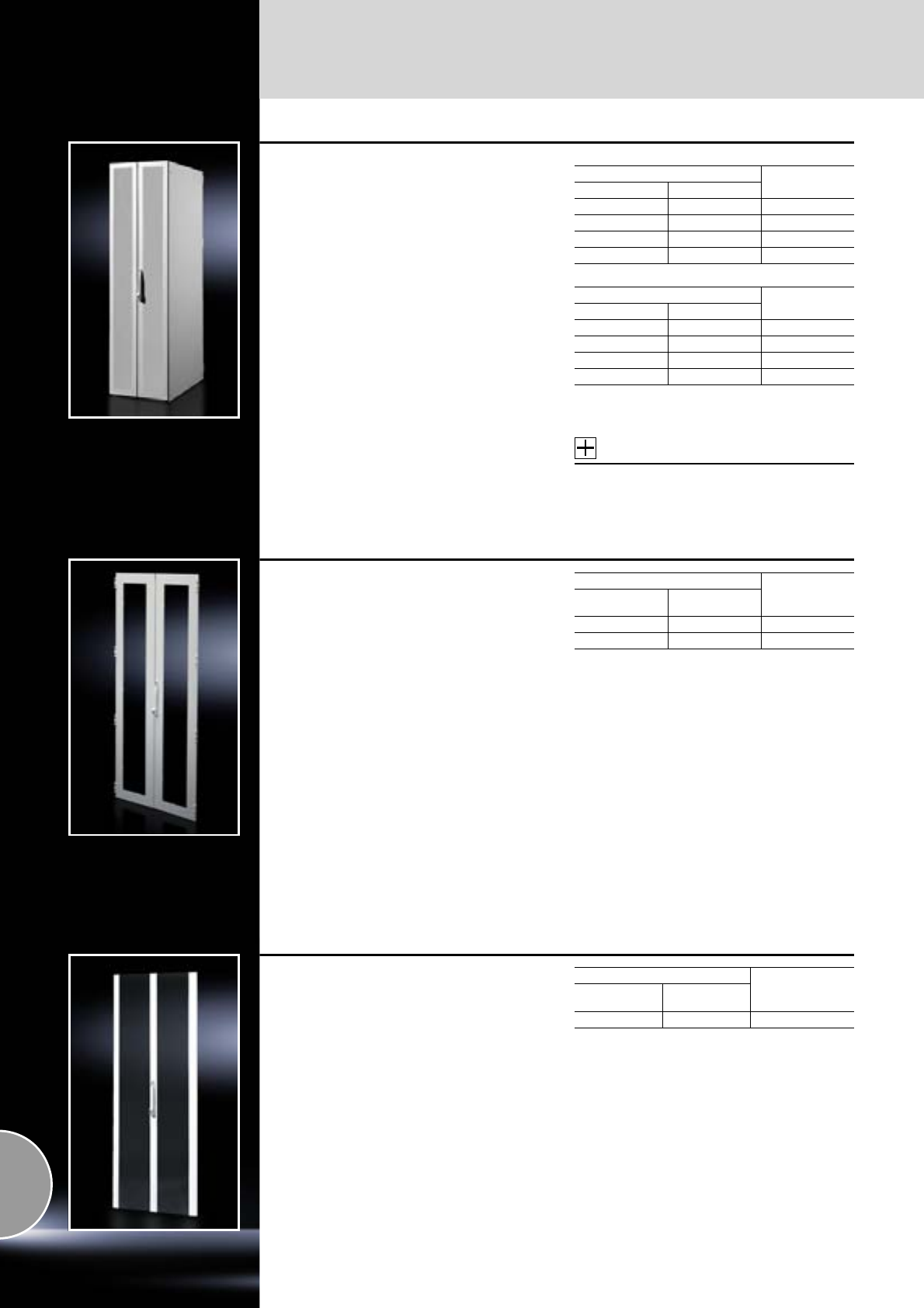
Doors/locks
Door variants
404 Rittal Catalogue 33/System accessories
Sheet steel door,
vertically divided
for DK-TS
With 130° hinges and locking rod, including com-
fort handle for semi-cylinder with security lock
no. 3524 E. Thanks to the minimal rotation radius
of the individual doors, the distance between indi-
vidual bayed enclosure suites may be reduced.
The extensive door perforations additionally sup-
port climate control of the installed equipment.
Slotted surface with air inlet opening > 78%.
Material:
Sheet steel
Protection category:
−IP 55 to IEC 60 529 (unvented)
−IP 20 to IEC 60 529 (vented)
Colour:
RAL 7035
Supply includes:
Assembly parts.
Accessories:
180° hinge TS 8800.190,
see page 425.
Vented
For enclosures Model No. DK
Width mm Height mm
600 2000 7824.360
600 2200 7824.362
800 2000 7824.380
800 2200 7824.382
Unvented1)
For enclosures Model No. DK
Width mm Height mm
600 2000 7816.360
600 2200 7816.362
800 2000 7816.380
800 2200 7816.382
1) Without tubular door frame.
Tubular door frame available on request.
Sheet steel glazed door,
vertically divided
for TS
With underlaid viewing panel, 4-point locking rod
and comfort handle for semi-cylinder with secu-
rity lock 3524 E.
The divided design allows room-optimised siting
of the enclosures coupled with the best possible
access, thanks to a reduced distance between
the individual bayed enclosure suites. Max. door
opening angle, thanks to pre-integrated 180°
hinges.
Material:
−Front panel: Sheet steel
−Viewing window: Single-pane safety glass,
3 mm
Surface finish:
Powder-coated
Colour:
RAL 7035
Protection category:
IP 55
Supply includes:
Assembly parts.
Note:
Height 2200 mm cannot be combined with
swing frame 45 U.
For enclosures
Model No. DK
Width
mm Height
mm
800 2000 7824.280
800 2200 7824.282
All-glass door,
vertically divided
for DK-TS
With 180° hinges and locking rod including com-
fort handle for semi-cylinder with security lock
no. 3524 E. Thanks to the minimal rotation radius
of the individual doors, the distance between indi-
vidual bayed enclosure suites may be reduced.
Material:
−Frame elements: Aluminium
−Viewing window: Single-pane safety glass,
5 mm
Colour:
−Frame elements: RAL 7035
−Viewing windows: Tinted
Supply includes:
Assembly parts.
Note:
Not to be used in conjunction with a swing frame.
For enclosures
Model No. DK
Width
mm Height
mm
800 2000 7824.490
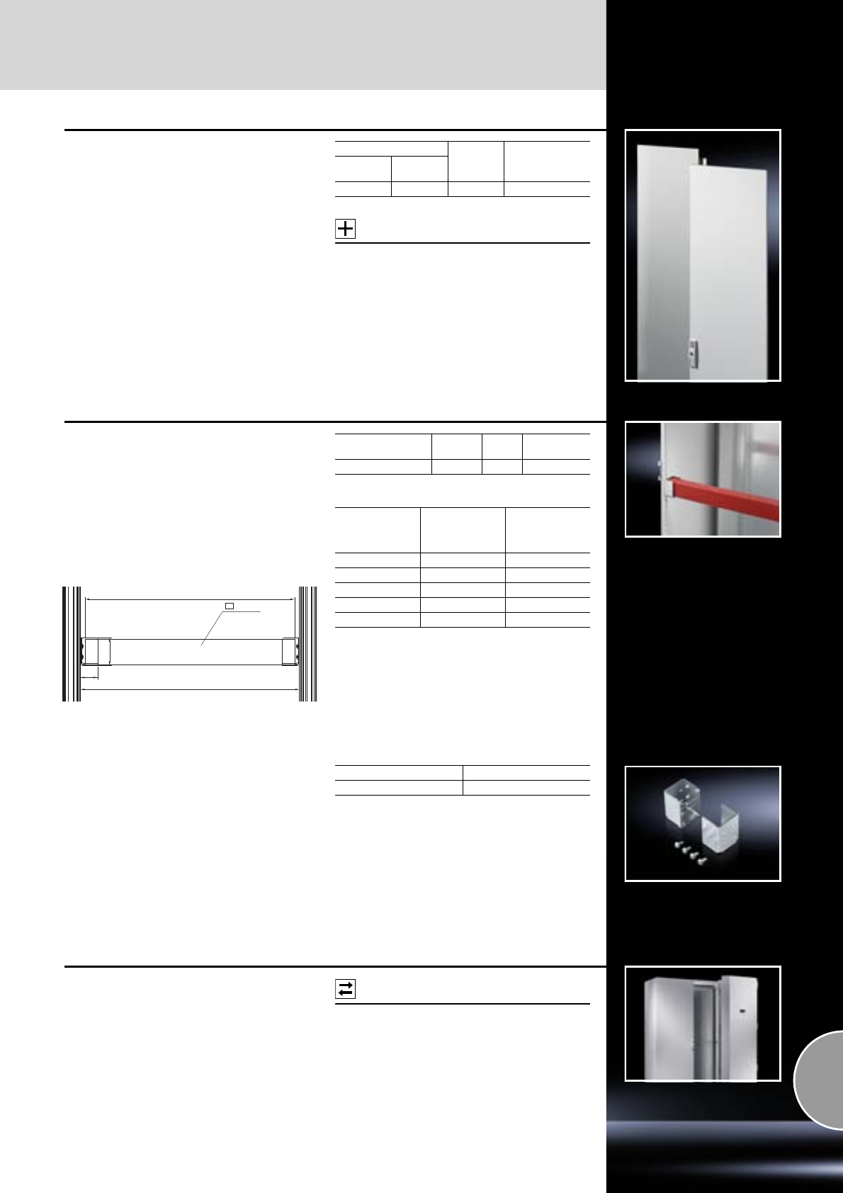
Door variants
Doors/locks
405Rittal Catalogue 33/System accessories
Lockable and adjacent door
for TS
For example, if two 400 mm doors instead of one
800 mm wide door are used to comply with
escape routes.
Material:
Sheet steel
Surface finish:
Dipcoat-primed,
powder-coated on the outside
Supply includes:
2 doors
including hinges and lock parts.
Accessories:
Lock system,
see page 415.
For enclosures Colour
RAL Model No. TS
Width
mm Height
mm
800 2000 7035 8801.450
Protective bars
for TS
As an alternative to a door, e.g. in sealed switch
rooms. Prevents people from falling into the open
enclosure frame. Easily removable for mainte-
nance purposes.
For 1200 mm enclosure width; may be shortened
or divided for other sizes.
Material:
Wood, spray-finished, RAL 3000
L
60 x 40
B3
40
65
For enclosure width
mm Length
mm Packs
of Model No. TS
1200 1090 1 8801.010
Enclosure
width
mm
Clearance
between the
enclosure frame
(B3) mm
Length
protective bar (L)
mm
400 312 2901)
600 512 4901)
800 712 6901)
1000 912 8901)
1200 1112 1090
1) The protective bar TS 8801.010 (1090 mm) will need
to be shortened.
Holder
for protective bars
For location into the vertical TS section.
The protective bar is simply inserted.
Material:
Sheet steel
Surface finish:
Zinc-plated
Supply includes:
Assembly screws.
Packs of Model No. TS
28801.000
Variable modular climate
control concept
Instead of an enclosure door in a 600 mm/
800 mm/1200 mm wide and 1800 mm/2000 mm
high TS enclosure, section doors with integral
cooling module may be retrofitted without major
assembly work.
Possible
alternative:
Modular climate control concept,
see page 248/249.
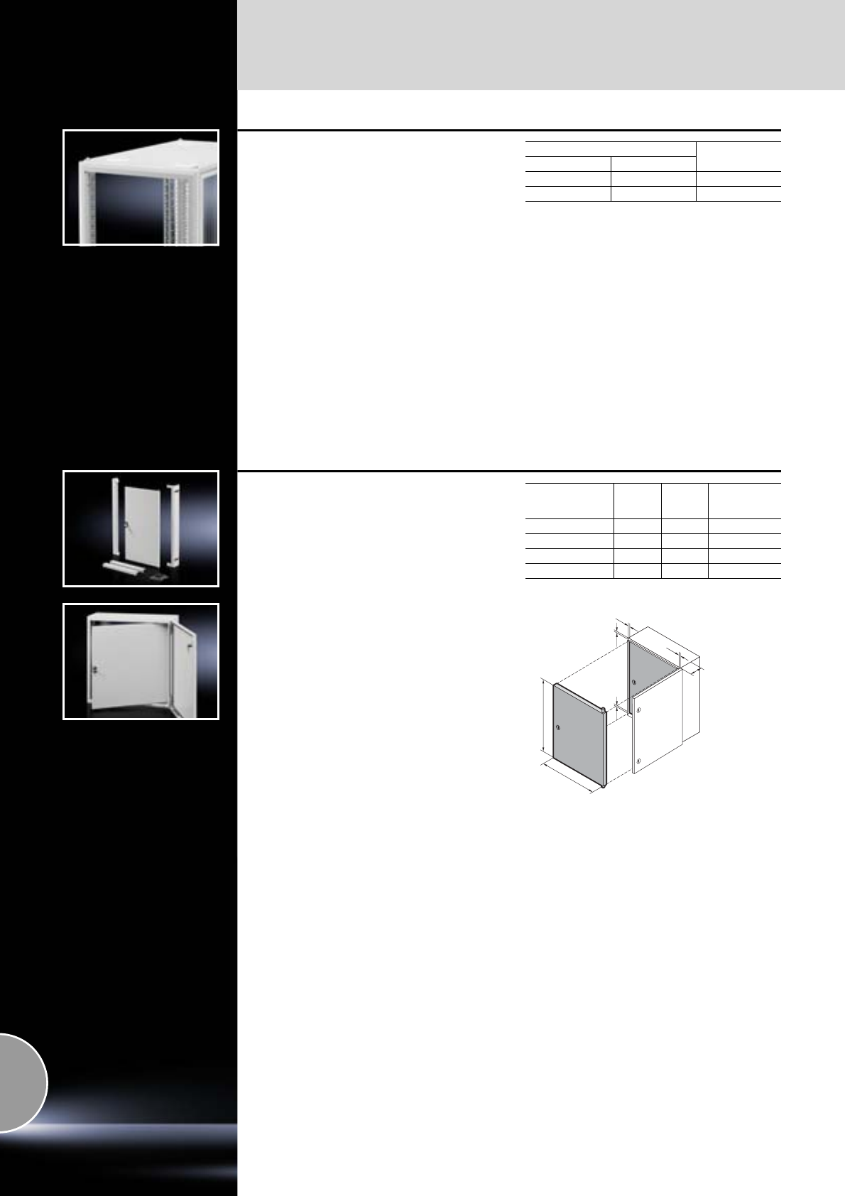
Doors/locks
Door variants
406 Rittal Catalogue 33/System accessories
Trim frame
for TS
To conceal the TS 8 front frame in enclosures
without a door. Can be combined with large
swing frames.
Possible application areas include, for example:
●Studio technology
●Electronic configuration
Material:
Sheet steel
Colour:
RAL 7035
Supply includes:
Assembly parts.
Note:
The trim frame conceals the system punchings
at the sides in the inner mounting level.
The TS punched sections with mounting flange
23 x 73 mm (see page 460) may be used for
installation.
For enclosures Model No. DK
Width mm Height mm
600 2000 7824.130
800 2000 7824.132
Interior door
with mounting frame
for compact enclosure AE IP 69K,
stainless steel
For the installation of control and display compo-
nents. Mounting frame, depth-adjustable for a
distance between the outer surface and the inside
of the outer door of 35 to 85 mm (80 mm with
AE 1101.110).
Material:
Sheet steel, 1.5 mm
Colour:
RAL 7035
Supply includes:
−Mounting frame
−Door with cam lock and screwdriver insert
−Assembly parts
For
AE enclosure
W
(B)
mm
H
mm Model No.
AE
1101.110 160 260 1101.910
1101.120 330 330 1101.920
1101.130 330 580 1101.930
1101.140 580 580 1101.940
23
H
B
30 30
23
70

Viewing panels/operating panels
Doors/locks
407Rittal Catalogue 33/System accessories
System window
To conceal display and operating instruments or
cut-outs, and to protect against dirt and liquids as
well as unauthorised access.
Consisting of the following 2 components:
1. Base frame:
●Easily screw-fastened to the door thanks to
modified dimensions (tubular door frame may
be used as a drilling template).
●Readily height-adjustable.
●Stabilises the door cut-out.
●Conceals the cut edge.
●The rain canopy
−prevents dirt from landing on the seal,
−protects the glass from being lifted out,
−prevents the ingress of dirt and moisture
when opening the window.
●Frame section height 30 mm or 60 mm
2. Viewing window:
●Made from single-pane safety glass:
−high level of resistance to solvents and
scratches,
−anti-static,
−reduced risk of injury if broken.
●Cam lock with double-bit insert, easily
exchanged for lock inserts, type A, and semi-
cylinders in the Ergoform-S lock system
(not with FT 2735.500 and .560)
●Hinge with 180° opening angle, easily inserted.
Material:
Extruded aluminium sections with die-cast zinc
corner pieces and single-pane safety glass.
Surface finish:
−Base frame:
Powder-coated in RAL 7035
−Hinge and lock section:
Natural-anodised
Protection category:
IP 54 to IEC 60 529
30 section
To fit
TS, ES
with width
mm
Window size,
exterior, mm Model No. FT
W (B) H
600 500
270 2735.500
370 2735.510
470 2735.520
570 2735.530
670 2735.540
800 700
270 2735.560
370 2735.570
470 2735.580
570 2735.590
670 2735.250
60 section
To fit
TS, ES
with width
mm
Window size,
exterior, mm Model No. FT
W (B) H
600 500
370 2736.510
470 2736.520
570 2736.530
670 2736.540
800 700 670 2736.500
Standard double-bit lock insert may be exchanged
for lock inserts 27 mm, type A, see page 421
and for lock system Ergoform-S (except H = 270 mm),
see page 419.
B
85 52B – 137
H
h– 2
h – 70
b – 70
47
33
63
Viewing area (W (B) – 137) offset by 16.5 mm
towards the hinge side.
View Y
for profile height 60
View X
for profile height 30
X
Y
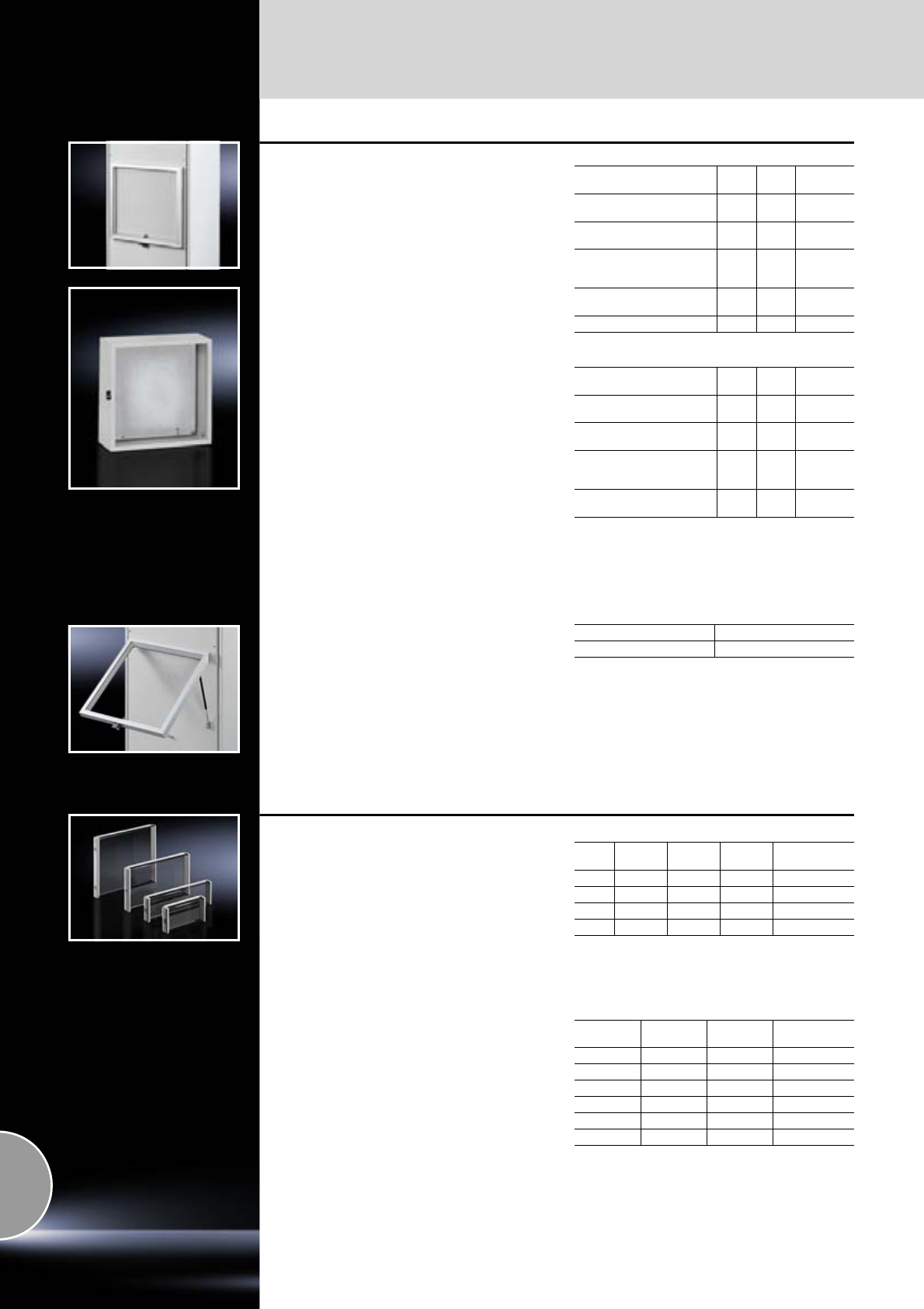
Doors/locks
Viewing panels/operating panels
408 Rittal Catalogue 33/System accessories
Viewing window
For mounting on
●AE instead of door
●Surfaces
Material:
−Front panel: Aluminium, natural-anodised.
−Glass panel: Acrylic
Protection category:
IP 54 to IEC 60 529
Supply includes:
Plastic handle with lock insert no. 3524 E.
Max. installation depth: (depth – 4 mm)
Visible area: (width – 60 mm) x (height – 60 mm)
Note:
Other sizes available on request.
Depth = 34 mm
For use
as door variant with Width
mm Height
mm Model No.
FT
AE 1050.500, AE 1350.500
AE 1007.600 497 497 2733.000
AE 1039.500, AE 1339.500
AE 1009.600, DK 7641.000 597 377 2730.000
AE 1010.500, AE 1054.500
AE 1060.500, AE 1360.500
DK 7643.000 597 597 2731.000
AE 1012.500, AE 1076.500
AE 1376.500, DK 7645.000 597 757 2732.000
for 3 U subrack 597 197 2734.000
Depth = 60 mm
For use
as door variant with Width
mm Height
mm Model No.
FT
AE 1050.500, AE 1350.500
AE 1007.600 497 497 2763.000
AE 1039.500, AE 1339.500,
AE 1009.600, DK 7641.000 597 377 2760.000
AE 1010.500, AE 1054.500
AE 1060.500, AE 1360.500
DK 7643.000 597 597 2761.000
AE 1012.500, AE 1076.500
AE 1376.500, DK 7645.000 597 757 2762.000
Horizontally hinged FT stay
A gas pressurised spring holds the viewing win-
dow securely open (top or side).
When the viewing window is closed, the gas pres-
surised spring disappears into the frame section.
Packs of Model No. FT
22772.000
Acrylic glazed cover
With security lock, lock no. 3524 E.
Material:
−Front panel:
Extruded aluminium sections with die-cast
corner pieces
−Glass panel: Smoked acrylic
Protection category:
IP 54 to IEC 60 529
Acrylic glazed covers, 482.6 mm (19˝)
Max. installation depth: 43 mm
Visible area: (width – 40 mm) x (height – 20.5 mm)
Metric acrylic glazed covers
Max. installation depth: 43 mm
Visible area: (width – 40 mm) x (height – 20.5 mm)
UWidth
mm Height
mm Depth
mm Model No. FT
3 320 158 47.5 2780.000
3 534 158 47.5 2781.000
6 534 291.5 47.5 2782.000
9 534 425 47.5 2796.000
Width
mm Height
mm Depth
mm Model No. FT
400 200 47.5 2784.000
400 400 47.5 2785.000
500 200 47.5 2786.000
500 400 47.5 2787.000
600 200 47.5 2788.000
600 400 47.5 2789.000

Viewing panels/operating panels
Doors/locks
409Rittal Catalogue 33/System accessories
Viewing window
Stainless steel
Fitted as standard with internal 130° hinges and
all-round seal.
The double-bit lock insert may be exchanged
for 27 mm lock inserts, type A, and Ergoform-S
handle SZ 2452.000.
Material:
Stainless steel 1.4301 (AISI 304)
Single-pane safety glass
Protection category:
IP 54 to IEC 60 529
Supply includes:
Assembly parts.
Accessories:
−Lock inserts, 27 mm, version A,
see page 421.
−Ergoform-S handle SZ 2452.000,
see page 419.
Width
mm Height
mm Depth
mm Model No. FT
522 600 38 2793.560
25
38
31
522
408
600
543
525
475
37.5
285
25.5
Monitor frame
For door width 600 and 800 mm
For covering a door cut-out, for all standard
monitors up to 482.6 mm (19˝).
Protection category:
IP 54 to IEC 60 529
Supply includes:
Security glass pane.
Dimensions Width
mm Height
mm Model No.
SZ
External dimensions 470 430
2305.000Viewing area 375 325
Cut-out required 415 375
Identification strips
For individual field identifiers on the door,
including transparent cover and assembly parts.
For labels:
Width: Enclosure width – 150 mm
Height: 29 mm
Thickness: 0.75 mm.
Colour:
RAL 7033
For enclosure width mm Model No. SZ
600 2403.000
800 2404.000
Doors/locks
Viewing panels/operating panels
410 Rittal Catalogue 33/System accessories
Operating panel
For mounting on:
●AE instead of door
●Surfaces
Frame construction with corner connectors on
the inside, 3 mm aluminium plate secured from
the inside and sealed against the frame
Material:
Aluminium, natural-anodised
Protection category:
IP 54 to IEC 60 529
Supply includes:
Aluminium frame, display panel, hinges, brackets.
Area available for population:
(width – 70 mm) x (height – 70 mm)
Dimensions of aluminium plate:
(width – 54 mm) x (height – 54 mm)
Accessories:
Cam lock FT 2749.000,
see page 410.
For use
as door variant
for AE
Width
mm Height
mm Depth
mm Model No.
FT
1001.600
1002.500
1002.600
1032.500
1035.500
197 297 34 2740.0001)
1004.600
1011.600
1030.500
1031.500
377 297 34 2741.000
1006.500
1006.600
1380.500 377 377 34 2742.000
1008.600
1038.500
1338.500 377 597 34 2743.000
1007.600
1013.600
1050.500
1350.500
497 497 34 2745.000
1009.600
1039.500
1339.500 597 377 34 2744.000
1010.500
1010.600
1060.500
1360.500
597 597 34 2746.000
1) With AE, only for use on the rear panel
Cam lock
May be retrofitted to the operating area or
enclosure panel of operating panels.
Standard double-bit lock insert may be
exchanged for type C lock inserts and type C
plastic handle.
Accessories:
−Lock inserts, type C,
see page 421.
−Plastic handle, type C,
see page 420.
Packs of Model No. FT
12749.000
Viewing window
for operating panel
For the protection of display and control compo-
nents. With a build height of max. 35 mm.
Material:
Frame: Aluminium, natural-anodised
Glazed panel: Smoked acrylic
Supply includes:
Lock insert no. 3524 E.
For operating panel Model No. FT
FT 2741.000 2791.000
FT 2742.000 2792.000
Allocation of lock systems
Doors/locks
411Rittal Catalogue 33/Enclosures
Compact enclosures, sheet steel
Enclosure series Lock inserts for handle systems
EB BG AE,
wall-mounted
enclosures AE CM KS EL
3-part Semi-cylinder Lock inserts
Condition –
With cam
With cam
With 3-point lock
–
With cam
With 3-point lock
3 – 15 U
18 – 21 U
Lock and
push-button inserts
DIN 18 252
Version A
Version F
Lock and
push-button inserts
from
page 37 39 44 46 48 50 51 60 60 416 416 421 421 416
Handle systems for enclosures
Comfort handle
For lock inserts 415 – – – – – – – – – – –
For padlock and
lock inserts 415 – – – – – – – – – – –
With security lock insert
E1 415 – – – – – – – – – – – – –
For semi-cylinder 415 – – – – – – – – – – –
Prepared for
ASSA lock system 415 – – – – – – – – – – – – –
Mini-comfort handle (from AE enclosure height 380 mm, from AE enclosure width 300 mm)
For lock inserts 418 – – – – – – – – – –
For semi-cylinder 418 – – – – – – – – – –
Ergoform-S handle
Standard 419 – – – – – – – – – –
Special with lock insert,
lock E1 419 – – – – – – – – – – – – –
Specially prepared for
ASSA lock system 419 – – – – – – – – – – – – –
Standard for KS
plastic enclosures 419 – – – – – – – – – –
Folding lever handle
For lock inserts 416 – – – – – – – – – –
For padlock and
lock inserts 416 – – – – – – – – – –
With security lock insert
E1 416 – – – – – – – – – – – – –
Semi-cylinder lock
For AE 422 – – – – – – – – – – – –
Plastic handles
Version B 420 – – – – – –
Version E 420 – – – – – – – –
T handles
Version B 420 – – – – – –
Lock inserts for enclosures
Lock inserts
Version A 421 – – – – –
Version E 421 – – – – – – –
Version F 421 – – – – – –
Lock cylinder inserts
Version B 422 – – – – – –
Doors/locks
Allocation of lock systems
412 Rittal Catalogue 33/Enclosures
Large enclosures, sheet steel
Enclosure series Lock inserts for handle systems
TS 8
PC enclosure TS 8
DK-TS
TE 7000
Semi-cylinder Lock inserts
Condition
Door
For keyboard drawer
or fold-out tray
Lock and
push-button inserts
DIN 18 252
Version A
Version F
Lock and
push-button inserts
from
page 70 108 108 80 85 416 416 421 421 416
Handle systems for enclosures
Comfort handle
For lock inserts 415 – – – – –
For padlock and lock inserts 415 – – – – –
For semi-cylinder 415 – – – – –
With security lock insert E1 415 – – – – – – –
Prepared for ASSA lock system 415 – – – – – – –
Security handle with code 417 1) – 1) – – – –
Ergoform-S handle
Standard 419 – – – – – –
Security handle with code 417 – – – – – – –
Special with lock insert, lock E1 419 – – – – – – – – –
Special, prepared for
ASSA lock system 419 – – – – – – – – –
Lock inserts for enclosures
Lock inserts
Version A 421 – – – –
Version F 421 – – –
1) Only suitable for use with rear door
Rittal Switzerland
RITTAL AG
Ringstrasse 1 CH-5432 Neuenhof
Phone: +41 (0) 56 416 06 00
Fax: +41 (0) 56 416 06 66
E-mail: rittal@rittal.ch www.rittal.ch
Allocation of lock systems
Doors/locks
413Rittal Catalogue 33/Enclosures
Console systems and industrial workstation, sheet steel
Enclosure series Lock inserts for handle systems
TopConsole TP One-piece console
TP
Universal consoler TP
IW
IW enclosure for tower PC
Semi-cylinder Lock inserts
Condition
Desk section
and console
Pedestal
Console cover
Console door
Lock and
push-button inserts
DIN 18 252
Version A
Version F
Lock and
push-button inserts
from
page 101 101 106 106 107 110 109 416 416 421 421 416
Handle systems for enclosures
Comfort handle
For lock inserts 415 – – – – – – – – –
For padlock and
lock inserts 415 – – – – – – – – –
For semi-cylinder 415 – – – – – – – – –
With security lock insert E1 415 – – – – – – – – – – –
Prepared for ASSA
lock system 415 – – – – – – – – – – –
Security handle
with code 417 – – – – – – – – –
Ergoform-S handle
Standard 419 – – – – – –
Special with lock insert,
lock E1 419 – – – – – – – – –
Special, prepared for
ASSA lock system 419 – – – – – – – – –
T handles
Version B 420 – – – – –
Lock inserts for enclosures
Lock inserts
Version A 421 – –
Version D 421 – – – – – –
Version F 421 – – – – – –
Lock cylinder inserts
Version B 422 – – – – – –
Rittal Hungary
RITTAL Kereskedelmi Kft.
1044 Budapest, Ipari Park u. 1.
Phone: +36 (1) 399 8000
Fax: +36 (1) 399 8009
E-mail: rittal@rittal.hu www.rittal.hu
Doors/locks
Allocation of lock systems
414 Rittal Catalogue 33/Enclosures
Enclosures and cases, stainless steel
Enclosure series Lock inserts for handle systems
AE One-piece console
AP
TS 8
PC
Semi-cylinder Lock inserts
Condition
With cam
With 3-point lock
Console cover
Console door
Lock and
push-button inserts
DIN 18 252
Version A
Version F
Lock and
push-button inserts
Page 162/163 164 170 170 172 171 416 416 421 421 416
Handle systems for enclosures
Comfort handle
For lock inserts 415 – – – – – – – –
For padlock and
lock inserts 415 – – – – – – – –
For semi-cylinder 415 – – – – – – – –
With security lock insert
E1 415 – – – – – – – – – –
Prepared for
ASSA lock system 415 – – – – – – – – – –
Ergoform-S handle
Standard 419 – – – – –
Special with lock insert,
lock E1 419 – – – – – – – –
Special, prepared for
ASSA lock system 419 – – – – – – – –
Plastic handles
Version C 420 1) – – – – – – – – –
T handles
Version C 420 1) – – – – – – – – –
Semi-cylinder lock
for AE 422 2) – – – – – – – – –
Lock inserts for enclosures
Lock inserts
Version A 421 – – – –
Version C 421 – – – –
Version F 421 – – – – –
Lock cylinder inserts
Version C 422 – – – –
1) Not with AE 1018.600.
2) Not with enclosures from stainless steel 1.4401 (AISI 316L) and use of cam lock SZ 2304.000.
Rittal Japan
RITTAL K.K.
Sales HQ.
Shin-Yokohama AK Bldg 2F
3-23-3, Shin-Yokohama, Kohoku-ku
Kanagawa 222-0033
Phone: 0120-998-631 / +81 (45) 478-6801
Fax: 0120-998-632 / +81 (45) 478-6880
E-mail: contact@rittal.co.jp www.rittal.co.jp
Lock systems
Doors/locks
415Rittal Catalogue 33/System accessories
Rittal comfort handle
for TS, DK-TS, PC, IW
As the handle does not take up any swing space,
due to its folding mechanism, the door surface
area may be maximised for installed equipment.
Material:
Die-cast zinc
Surface finish:
Powder-coated
Also required:
Handle adaptor for mounting on a
−Glazed door TS
−Bottom door PC-TS
−Designer door IW
see page 402.
For
lock inserts
For
padlock
and
lock
inserts
With
lock insert,
lock E11)
For
semi-cylinder2)
Prepared
for
ASSA
lock
system
Model No. TS
RAL 7032 8611.010 8611.030 8611.040 8611.060 8611.050
RAL 7035 8611.020 8611.290 8611.045 8611.070 8611.280
RAL 8019 8611.250 8611.260 – 8611.270 –
RAL 9005 8611.350 – – 8611.360 –
Matt nickel-plated 8611.330 – – 8611.340 –
Lock inserts, type F
7 mm square 8611.100 8611.100 – – –
8 mm square 8611.110 8611.110 – – –
7 mm triangular 8611.120 8611.120 – – –
8 mm triangular 8611.130 8611.130 – – –
Screwdriver 8611.140 8611.140 – – –
Daimler insert 8611.150 8611.150 – – –
3 mm double-bit 8611.160 8611.160 – – –
Fiat 8611.170 8611.170 – – –
6.5 mm triangular
(CNOMO) 8611.220 8611.220 – – –
Lock and push-button inserts
Security lock insert
no. 3524 E3) 8611.180 8611.180 – 2467.000 –
Push-button insert 8611.190 8611.190 – 2468.000 –
Push-button and
lock insert3) 8611.2004) 8611.2004) – 2469.0005) –
Semi-cylinder
to DIN 18 2526) – – – 9785.040 –
– – – 9785.0427) –
1) Only for use with VW, Audi, SEAT, SkodaAuto. Supplied without key.
Other VW locks available on request.
2) Comfort handle for lock cylinder KESO/KABA with Model No. TS 8611.240 available on request.
3) With 2 keys.
4) Lock no. 12321, no other lock is possible.
5) Lock no. 2123, no other lock is possible.
6) With 3 keys for each lock insert.
7) Packs of 2. Simultaneous locking within the same pack, no simultaneous locking for different packs.
Doors/locks
Lock systems
416 Rittal Catalogue 33/System accessories
Lock inserts
For installation in comfort handle, mini-comfort
handle, Ergoform-S standard, folding lever handle
Lock and push-button inserts Semi-cylinder
Installation in Comfort handle6),
mini-comfort handle6)
Comfort handle7),
mini-comfort handle7),
Ergoform-S standard,
folding lever handle CM
Comfort handle,
mini-comfort handle,
Ergoform-S standard,
folding lever handle for CM
Model No. TS Model No. SZ Model No. CS
Security lock insert
no. 3524 E1) 8611.180 2467.000 –
Push-button insert 8611.190 2468.000 –
Push-button and
lock insert1) 8611.2002) 2469.0003) –
to DIN 18 2524) – – 9785.040
– – 9785.0425)
1) With 2 keys. 2) Lock no. 12321, no other lock is possible.
3) Lock no. 2123, no other lock is possible. 4) With 3 keys for each lock insert.
5) Packs of 2. Simultaneous locking within the same pack, no simultaneous locking for different packs.
6) For lock inserts. 7) For semi-cylinder.
Folding lever handle
for CM
As the handle does not take up any swing space,
due to its folding mechanism, the door surface
area may be maximised for installed equipment.
Colour:
−Enclosure: Similar to RAL 9005
−Handle: Similar to RAL 9006
Size:
−Length: 242 mm (with inserted trim panel)
−Width: 50 mm
−Depth: 17.5 mm
For
lock inserts
For
padlock and
lock inserts
With
lock insert,
lock E11)
Model No. CM
5001.060 5001.062 5001.061
Lock inserts, type F
7 mm square 8611.100 8611.100 –
8 mm square 8611.110 8611.110 –
7 mm triangular 8611.120 8611.120 –
8 mm triangular 8611.130 8611.130 –
Screwdriver 8611.140 8611.140 –
Daimler insert 8611.150 8611.150 –
3 mm double-bit 8611.160 8611.160 –
Fiat 8611.170 8611.170 –
6.5 mm triangular (CNOMO) 8611.220 8611.220 –
Lock and push-button inserts
Security lock insert no. 3524 E2) 2467.000 2467.000 –
Push-button insert 2468.000 2468.000 –
Push-button and lock insert2) 2469.0003) 2469.0003) –
Semi-cylinder
to DIN 18 2524) 9785.040 9785.040 –
9785.0425) 9785.0425) –
1) Only for use with VW, Audi, SEAT, SkodaAuto. Supplied without key.
Other VW locks available on request.
2) With 2 keys.
3) Lock no. 2123; no other lock is possible.
4) With 3 keys for each lock insert.
5) Packs of 2. Simultaneous locking within the same pack, no simultaneous locking for different packs.
Lock systems
Doors/locks
417Rittal Catalogue 33/System accessories
Security handle
with code
Flexible access opportunities with
●individual 3-digit code without key
or
●with the master key function via an additional
semi-cylinder of 40 or 45 mm to DIN 18 252,
irrespective of the code.
Accessories:
−SZ lock and push-button inserts,
see page 416.
−Semi-cylinder,
see page 416.
Design with Model No. DK
Comfort handle for TS 7200.800
Ergoform-S handle for TE 7200.810
Adjacent door latch
for TS
For optimum operation of the adjacent door from
the outside if the handle on the inside is difficult
to access due to swing frames or 482.6 mm (19˝)
installed equipment. Retrospective conversion of
the adjacent door is easily achieved using the
supplied drilling template.
The handle on the inside is no longer required.
Colour:
RAL 7035
Supply includes:
Assembly parts.
Accessories:
Standard double-bit lock insert may be
exchanged for 27 mm lock inserts, version A,
see page 421.
Packs of Model No. TS
18611.370
Swivel handle
for sheet steel door DK-TS
With lock insert, lock no. 3524 E.
The use of semi-cylinders is not supported.
Length: 150 mm.
Note:
The swivel handle cannot be used in conjunction
with 180° hinges (TS 7824.520).
Position for door opening
Max. projection of the upper handle part
Design Model No. DK
RAL 7035 7829.300
69.7
64
120°
90°
1
2
1
2
Doors/locks
Lock systems
418 Rittal Catalogue 33/System accessories
Locking bar latch to CNOMO1)
To fit all locking bars in TS doors and glazed
doors with standard lock or comfort handle.
The latch prevents the locking bars from moving
when the door is open.
For mounting on the bolt of the bar guide.
1) CNOMO is a specification by the French auto-
mobile industry. For safety reasons, it must not be
possible to lock the handle whilst the door is
open.
Also required:
for CNOMO1)
Lock inserts, version F, 6.5 mm triangular insert
TS 8611.220,
see page 421.
Packs of Model No. TS
10 8611.210
Spring washer
Upon dismantling the TS locking rods, the spring
washers cannot be reused.
Material:
Spring steel
Surface finish:
Zinc-plated
Packs of Model No. TS
Spring washer 100 8800.070
Mini-comfort handle
for AE with cam, EL 3-part
Prepared for the installation of lock inserts and
for the installation of commercially available 40
or 45 mm semi-cylinders, and of lock and push-
button inserts.
Material:
Die-cast zinc
Colour:
RAL 7035
For lock inserts For semi-cylinder
Model No. DK
Fro enclosure system EL AE EL AE
7705.110 2537.010 7705.120 2537.000
Lock inserts, type F
7 mm square 8611.100 8611.100 – –
8 mm square 8611.110 8611.110 – –
7 mm triangular 8611.120 8611.120 – –
8 mm triangular 8611.130 8611.130 – –
Screwdriver 8611.140 8611.140 – –
Daimler insert 8611.150 8611.150 – –
3 mm double-bit 8611.160 8611.160 – –
Fiat 8611.170 8611.170 – –
6.5 mm triangular (CNOMO) 8611.220 8611.220 – –
Lock and push-button inserts
Security lock insert
no. 3524 E1) 8611.180 8611.180 2467.000 2467.000
Push-button insert 8611.190 8611.190 2468.000 2468.000
Push-button and
lock insert1) 8611.2002) 8611.2002) 2469.0003) 2469.0003)
Semi-cylinder
to DIN 18 2524) – – 9785.040 9785.040
– – 9785.0425) 9785.0425)
1) With 2 keys.
2) Lock no. 12321; no other lock is possible.
3) Lock no. 2123; no other lock is possible.
4) With 3 keys for each lock insert.
5) Packs of 2. Simultaneous locking within the same pack, no simultaneous locking for different packs.
Lock systems
Doors/locks
419Rittal Catalogue 33/System accessories
Ergoform-S lock system
The unlocked handle folds down forwards,
and the lock is opened by swivelling.
Material:
Die-cast zinc
Surface finish:
Powder-coated
Standard Standard
for KS
plastic enclosures
Special
with
lock insert E11)
Specially
prepared for
ASSA
lock system
Model No. SZ Model No. KS Model No. SZ
RAL 7032 with brown handle 2450.000 – – –
RAL 7035 with brown handle 2450.010 – 2456.500 –
Brown 2451.000 – – 2453.000
Matt nickel-plated 2452.000 – – –
RAL 7032 2454.000 – – –
RAL 7035 2435.000 1490.010 – –
RAL 7032 with brown handle and
bracket 2455.000 – – –
RAL 7035 with brown handle and
bracket 2455.010 – – –
Lock inserts, version A
7 mm square 2460.000 2460.000 – –
8 mm square 2461.000 2461.000 – –
7 mm triangular 2462.000 2462.000 – –
8 mm triangular 2463.000 2463.000 – –
Screwdriver 2464.000 2464.000 – –
Daimler insert 2465.000 2465.000 – –
3 mm double-bit 2466.000 2466.000 – –
Fiat 2307.000 2307.000 – –
6.5 mm triangular (CNOMO) 2460.650 2460.650 – –
Lock and push-button inserts
Security lock insert no. 3524 E2) 2467.000 2467.000 – –
Push-button insert 2468.000 2468.000 – –
Push-button and lock insert2) 2469.0003) 2469.0003) – –
Semi-cylinder
to DIN 18 2524) 9785.040 9785.040 – –
9785.0425) 9785.0425) – –
1) Only for use with VW, Audi, SEAT, SkodaAuto. Supplied without key.
Other lock systems available on request.
2) With 2 keys.
3) Lock no. 2123; no other lock is possible.
4) With 3 keys for each lock insert.
5) Packs of 2. Simultaneous locking within the same pack, no simultaneous locking for different packs.
Doors/locks
Lock systems
420 Rittal Catalogue 33/System accessories
Plastic handles
With or without lock cylinder insert.
Supply includes:
Assembly parts and seals.
Design B C E G
With
lock
cylinder
insert,
lock
no. 3524 E1)
Without
lock cylinder
insert
With
lock
cylinder
insert,
lock
no. 3524 E1)
Without
lock cylinder
insert
With
lock
cylinder
insert,
lock
no. 3524 E1)
Without
lock cylinder
insert
With
lock
cylinder
insert,
lock
no. 3524 E1)
Model No. SZ Model No. KS Model No. SZ
RAL 9011 2576.000 2533.000 2485.000 2485.100 – – 2599.000
RAL 7030 2439.000 – – – – – –
RAL 8019 – – – – 1484.000 1484.001 –
1) With 2 keys
T handles
With or without lock cylinder insert.
Supply includes:
Seal
Design B C
With
lock cylinder insert1) Without
lock cylinder insert With
lock cylinder insert1) Without
lock cylinder insert
Model No. SZ
2575.0002) 2572.000 2535.0002) 2536.000
1) With 2 keys
2) Lock no. 3524 E
Lock systems
Doors/locks
421Rittal Catalogue 33/System accessories
Cam locks
With
double-bit
insert
With
lock cylinder
insert3)
With
double-bit
insert
With
lock cylinder
insert3)
With
lock insert,
lock E11) With
double-bit insert
RAL 7035
Material:
Enclosure Die-cast zinc,
nickel-plated Fibreglass-reinforced polyamide
Made entirely
from
stainless
steel 1.4404
(AISI 316L)
Model No. SZ
2520.000 2530.000 2420.000 2430.000 2540.500 2304.000
Lock inserts
7 mm square 2523.000 – 2460.000 – – –
8 mm square 2526.000 – 2461.000 – – –
7 mm triangular 2527.000 – 2462.000 – – –
8 mm triangular 2528.000 – 2463.000 – – –
Screwdriver – – 2464.000 – – –
Daimler insert 2522.000 – 2465.000 – – –
3 mm double-bit 2483.000 – 2466.000 – – –
Fiat – – 2307.000 – – –
6.5 mm triangular
(CNOMO) – – 2460.650 – – –
Lock cylinder inserts
With lock
no. 3524 E2) – – 2571.000 – – –
1) Only for use with VW, Audi, SEAT, SkodaAuto. Supplied without key.
Other lock systems available on request.
2) With 2 keys
3) Lock no. 3524 E
Lock inserts
Design A C D E F
Material Die-cast zinc Die-cast zinc Die-cast zinc Plastic Die-cast zinc
Length 27 mm 41 mm 47 mm
Model No. SZ Model No. KS Model No. TS
7 mm square 2460.000 2523.000 – 1487.000 8611.100
8 mm square 2461.000 2526.000 – 1488.000 8611.110
7 mm triangular 2462.000 2527.000 – 1485.000 8611.120
8 mm triangular 2463.000 2528.000 – 1486.000 8611.130
Screwdriver 2464.000 – – 1489.000 8611.140
Daimler insert 2465.000 2522.000 – – 8611.150
3 mm double-bit 2466.000 2483.000 2484.000 1492.000 8611.160
Fiat 2307.000 – – – 8611.170
6.5 mm triangular
(CNOMO) 2460.650 – – – 8611.220
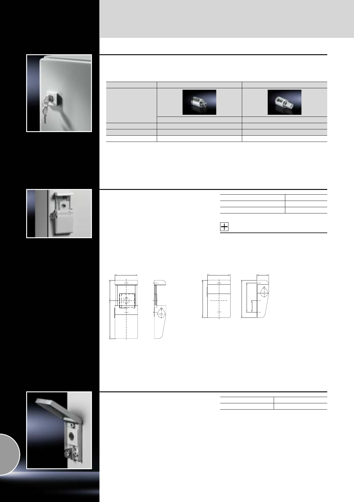
Doors/locks
Lock systems
422 Rittal Catalogue 33/System accessories
Lock cylinder inserts
Design B C
With lock no. 3524 E1) With lock no. 3524 E1)
Material Die-cast zinc Die-cast zinc
Model No. SZ Model No. SZ
2571.000 2525.000
1) With 2 keys
Semi-cylinder lock
for compact enclosures AE
For retro-fitting to single-door enclosures with
cam lock.
The cover plate is locked by semi-cylinders with
a total length of 40/45 mm (to DIN 18 252).
An additional cover protects the cylinder against
dirt. The protection category of the enclosure is
not impaired.
Supplied without semi-cylinder.
Material:
Die-cast zinc
Accessories:
Semi-cylinder,
see page 416.
Design Model No. SZ
RAL 7035 2534.100
Nickel-plated (matt) 2534.500
4991.5
55
90
55
28.5
27.5
70
90
Lock cover
For padlocks or multiple locks
For retrospective mounting on all compact enclo-
sures AE, of sheet steel and with cam lock.
Material:
Die-cast zinc
Surface finish:
Nickel-plated
Packs of Model No. SZ
12493.000
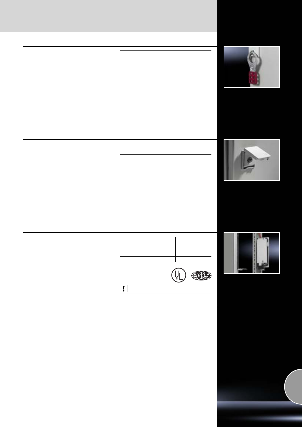
Lock systems
Doors/locks
423Rittal Catalogue 33/System accessories
Multiple lock
for 6 cam locks
The the ideal solution in cases where individual
access for several persons is required for
maintenance and repair purposes.
Material:
Sheet steel
Surface finish:
Zinc-plated
Packs of Model No. SZ
22493.500
Lock cover
prepared for lead seal
For all enclosure types with Rittal-specific locks,
such as AE and EB.
Material:
Polyamide
Colour:
RAL 7035
Packs of Model No. SZ
22476.000
Security lock
Fitted to doors, to protect against contact with live
electrical equipment whilst the master switch is
ON.
Function:
●Locks the door when the main switch is ON.
●Mains power (voltage) is only enabled whilst
the door is closed.
●Monitoring of the lock magnet via an additional
closing contact.
Supply includes:
−Lock
−Actuator
−Angle bracket
−Assembly parts
Also required:
For twin-door enclosures (for the overlapping
door, to indicate “enclosure door closed”),
Rittal door-operated switch SZ 4127.010,
see page 496.
Connection voltage
for lock magnet Model No. SZ
230 V AC 11 VA 2416.000
24 V DC 8 W 2418.000
120 V AC 8 VA 2419.000
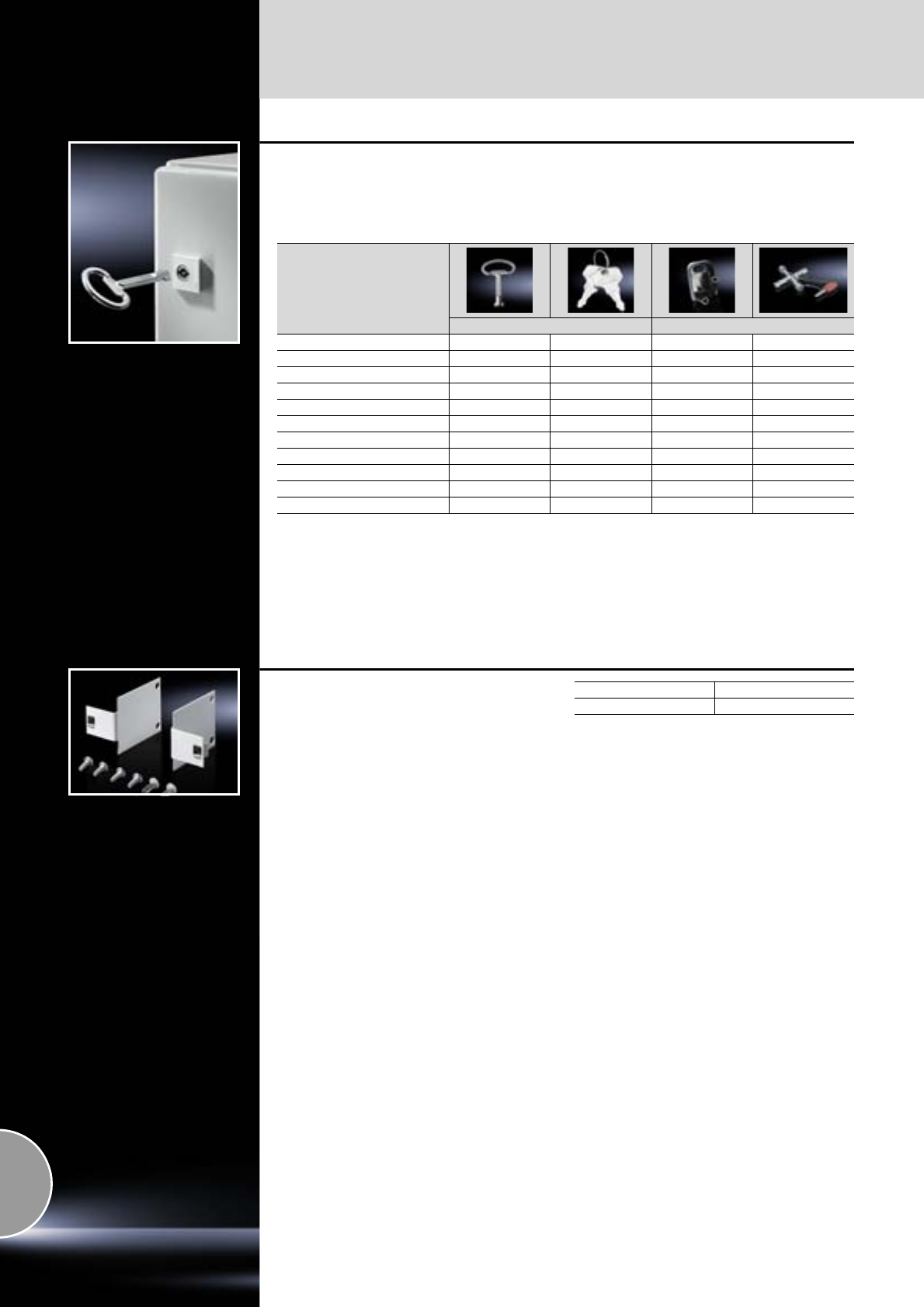
Doors/locks
Lock systems
424 Rittal Catalogue 33/System accessories
Enclosure keys
For lock inserts (one double-bit key is supplied
with every enclosure).
Model No. SZ/QB Model No. SZ
– – 2549.000 2549.5002)3)
Double-bit key no. 5 2531.000 –
Security key no. 3524 E – 2532.0001) – –
7 mm triangular 2545.000 – –
8 mm triangular 2546.000 –
7 mm square 2547.000 – –
8 mm square 2548.000 –
For HD locks 2549.600 – – –
Daimler key 2521.000 – – –
Fiat key 2308.000 – – –
Lock 12321 – 7526.0501) – –
1) Packs of 2
2) With bit adaptor and reversible bit for multi-tooth size 25 and Phillips-head (Ph 2)
3) Bit for HD lock insert (Model No. HD 2549.510), see page 156.
Quick-release fastener
for QuickBox
The quick-release fastener is ideal for use in
inaccessible areas. To facilitate locking, the
quick-release fastener is screw-fastened to the
mounting bracket at the front. This enables the
QuickBox to be locked even when the fasteners
of the sides are opened, allowing the enclosure
cover to be attached and removed easily.
Material:
Sheet steel
Surface finish:
Spray-finished
Colour:
RAL 7035
Supply includes:
2 mounting brackets, mounting material and
quick-release fasteners.
Packs of Model No. QB
27502.220
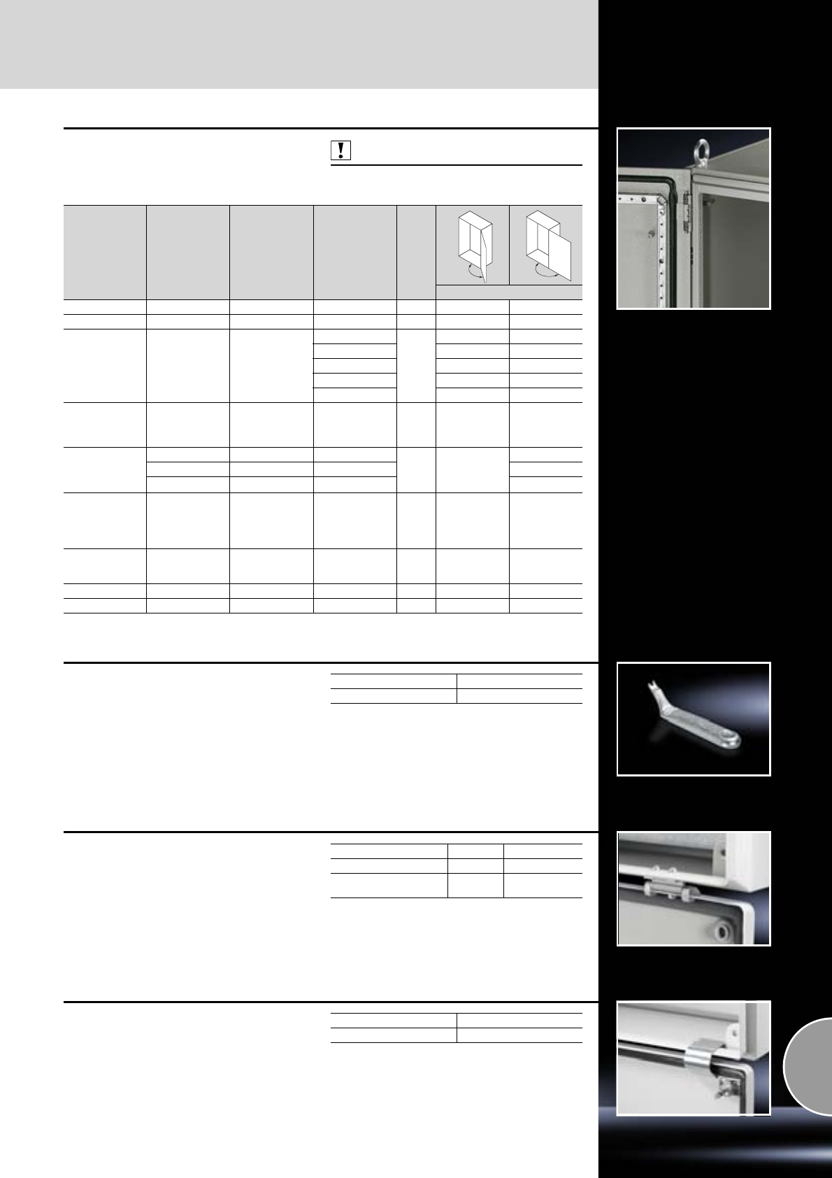
Hinges
Doors/locks
425Rittal Catalogue 33/System accessories
130°/180° hinges
Supply includes:
Assembly parts
Also required:
1) Lock components for frame TS 8800.040,
see page 402.
Enclosure type Door variant Material Colour Packs
of
Model No.
ES 5000 Sheet steel door Die-cast zinc – 6 4190.000 –
TS 8 Sheet steel door Die-cast zinc – 4 8800.0201) –
TS 8 Sheet steel door Die-cast zinc
RAL 7035
4
– 8800.190
RAL 7032 – 8800.030
RAL 8019 – 8800.230
RAL 9005 – 8800.950
Matt nickel-plated – 8701.180
TS 8
Doors with high
dynamic loads,
door installations
up to 900 N
Precision casting/
die-cast zinc RAL 7035 4 – 8800.710
TS 8 bayed
enclosure suites
with
comfort handle
Sheet steel door Die-cast zinc RAL 7035
4–
7824.520
Glazed door Die-cast zinc RAL 7035 7824.5252)
Sheet steel door Die-cast zinc RAL 9005 7824.522
ES 5000,
TP universal
console,
TP pedestals,
TE 7000
Standard door Aluminium Powder-coated
in RAL 8019 6 – 4189.000
ES 5000 Standard door Stainless steel
1.4301
(AISI 304) – 6 – 4156.000
AE Standard door Die-cast zinc – 2 – 2449.000
CM Standard door Die-cast zinc RAL 9011/9006 3 – 5001.000
2) Max. 140°
130°
180°
Hinge pin remover
For safe and easy removal of hinge pins.
For enclosure Model No. SM
AE/CM 2432.000
Cover hinge
for KL
The cover hinge is simply screwed to the enclo-
sure protection channel and to the edge fold.
Supply includes:
Assembly parts.
Material Packs of Model No. KL
Die-cast zinc 6 1592.000
Stainless steel 1.4404
(AISI 316L) 21592.010
Cover retainer
for KL
The cover retainer is easily fitted without drilling,
and allows the covers to be opened upwards,
even when the terminal box below is bayed.
Packs of Model No. KL
3 pairs 1591.000
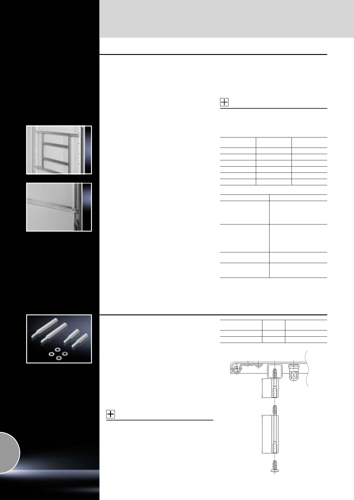
Doors/locks
Door, internal
426 Rittal Catalogue 33/System accessories
Support strips
For attachment of
●Cable ducts
●Cable conduit holders
●Contact hazard protection covers
●Equipment installed on the door
●Cable clamping and attachment
4.5 mm diameter hole on a 25 mm DIN pitch
pattern.
Material:
Sheet steel
Surface finish:
Zinc-plated
Supply includes:
Packs of 20 (screws included).
Accessories:
Screws and self-tapping screws M5,
see page 478.
For TS, CM, ES, TP For door width
mm Length
mm Model No. SZ
400 290 4594.000
500 390 4309.000
600 490 4596.000
800 690 4598.000
900 790 4579.000
1000 890 4599.000
For AE For enclosures AE Model No. SZ
1018.6002),
1050.5001),
1100.500,
1114.5001),
1213.5001),
1019.5002)
1057.500
1110.500
1130.500
1350.5001)
2325.000
1009.6002),
1012.5002),
1054.500,
1060.500,
1090.500,
1339.500,
1376.500
1039.500
1058.500
1076.500
1260.5001)
1360.500
2326.000
1014.5002),
1077.500 1073.500 2327.000
1016.5002),
1055.500,
1280.5001)
1017.5002)
1180.500 2328.000
1) For these AE models, the support strips should be cut
to length at the knockout.
2) Only in conjunction with perforated mounting strips
(see page 427).
Spacers
The universal assembly component for all cases
where a distance from the mounting level is
required. With self-tapping thread for diameter
4.5 mm. The following components may be
attached to the rear using 5.5 x 13 mm screws:
●Top-hat/cross rails
●Contact hazard protection covers
●Master switch trim panels
●Cable clamp rails,
etc.
Material:
Hexagonal steel (SW8)
Surface finish:
Zinc-plated
Accessories:
Screws 5.5 x 13 mm,
see page 478.
Length
mm Packs of Model No. TS
25 12 2311.225
50 12 2311.250
50 25
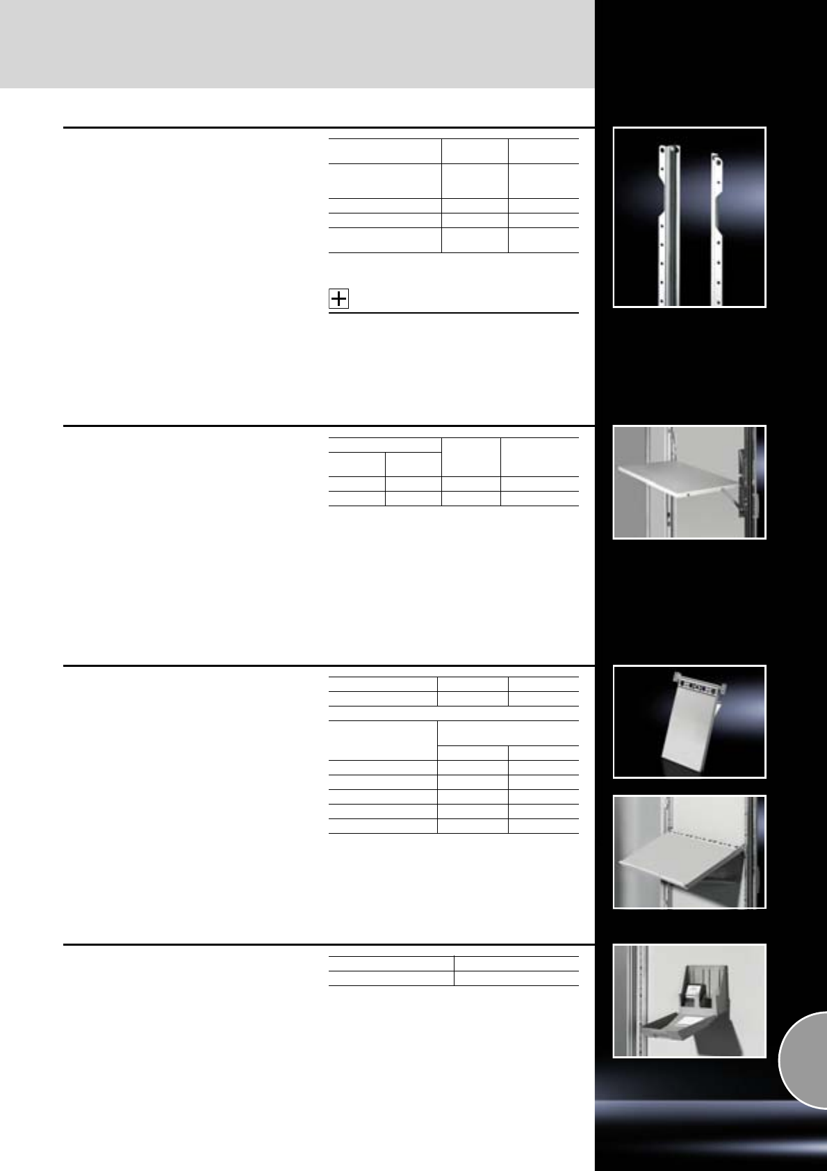
Door, internal
Doors/locks
427Rittal Catalogue 33/System accessories
Perforated mounting strip
for AE stainless steel, TP universal console1)
For vertical mounting on the threaded bolts of the
door, for attaching
●Support strips for AE, see page 426.
●Door stay SZ 2519.000, see page 429.
3.7 mm diameter hole on a 25 mm DIN pitch
pattern.
Material:
Sheet steel
Surface finish:
Zinc-plated
Supply includes:
Packs of 20 (nuts and serrated washers included).
Accessories:
Screws,
see page 478.
To match AE Length
mm Model No. SZ
1005.500, 1005.600,
1006.500, 1006.600,
1009.600 318 2310.0381)
1012.600, 1014.600 698 2310.076
1016.600, 1018.600 938 2310.100
1017.600, 1019.500,
1019.600 1138 2310.120
1) For door at top
Utility lectern
For programming units etc. Prepared for mount-
ing on the tubular door frame of TS, CM, ES, PC or
on any sufficiently large surface.
When required for servicing, it folds down quickly
with a maximum support area, and after use is
stowed between the tubular door frames in a
space-saving design.
Load capacity: max. 30 kg.
Material:
Sheet steel
Colour:
RAL 7035
Support area For door
width
mm Model No. TS
Width
mm Depth
mm
413 400 600 4638.600
613 400 800 4638.800
Wiring plan lectern
Holds wiring plans during fault finding and main-
tenance work.
The wiring plan lecterns can be bayed according
to the door width.
For mounting on the tubular door frame.
Material:
−Utility lectern: Polypropylene
−Mounting bracket: Die-cast zinc
Colour:
Similar to RAL 7035
Supply includes:
−Wiring plan lectern (width 210 mm)
−Assembly parts
For enclosures Packs of Model No. TS
TS, CM, ES, PC, TP 1 4120.000
For door width
mm
Required/possible number
of wiring plan lecterns
min. max.
400 1 1
500 1 1
600 2 2
800 2 3
1000 3 3
CD/disk box
For fixing to all flat, clean surfaces with double-
sided adhesive tape.
Capacity:
Max. 10 CDs/DVDs or 18 (3 1/2˝) disks.
Material:
Polyamide
Colour:
RAL 7033
Packs of Model No. SZ
12446.000
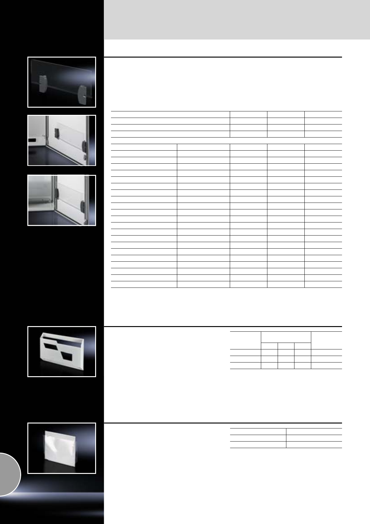
Doors/locks
Door, internal
428 Rittal Catalogue 33/System accessories
Plastic wiring plan pockets
for AE
For installation options, refer to table
●B = Screw-fastened to the perforated door strip
on both sides
●E = Screw-fastened on one side, other side
stuck with adhesive
or stuck entirely with adhesive
Supply includes:
−2 holders with double-sided adhesive tape
−Acrylic glazed pane
−Assembly parts
Note:
The acrylic glazed pane may be shortened to any
required size for shorter doors.
Model No. SZ 2514.500 2514.600 2514.800
Usable width mm 340 415 615
Usable depth mm 18 18 18
Height of acrylic glazed pane mm 167 167 167
Installation options:
For Model No. AE Width mm
1050.500 500 B – –
1054.500 600 E E –
1055.500 800 E E E
1057.500 500 B – –
1058.500 600 E E –
1060.500 600 E E –
1073.500 760 E E –
1076.500 600 E E –
1077.500 760 E E –
1090.500 600 E E –
1100.500 1000 B – –
1110.500 1000 B – –
1114.500 1000 B1) ––
1130.500 1000 B – –
1180.500 800 E E E
1213.500 1000 B1) ––
1260.500 600 E B –
1280.500 800 E E B
1350.500 500 B – –
1360.500 600 E E –
1376.500 600 E E –
1) Prepared for mounting on the l/h side door; for mounting on the r/h side door, the acrylic glazed pane can be
shortened.
Plastic wiring plan pockets
For affixing to the inside surfaces of doors.
Material:
Polystyrene with self-adhesive fastening strips.
Colour:
Similar to RAL 7035
For format
Clearance opening
mm Model No. SZ
BHD
A3 landscape 438 286 45 2513.000
A4 portrait 228 254 17 2514.000
A5 landscape 228 174 17 2515.000
Wiring plan pockets
with transparent pouch
With welded-on transparent pouch and self-adhe-
sive backing.
For format Model No. SZ
DIN A4 2510.000
DIN A3 2512.000
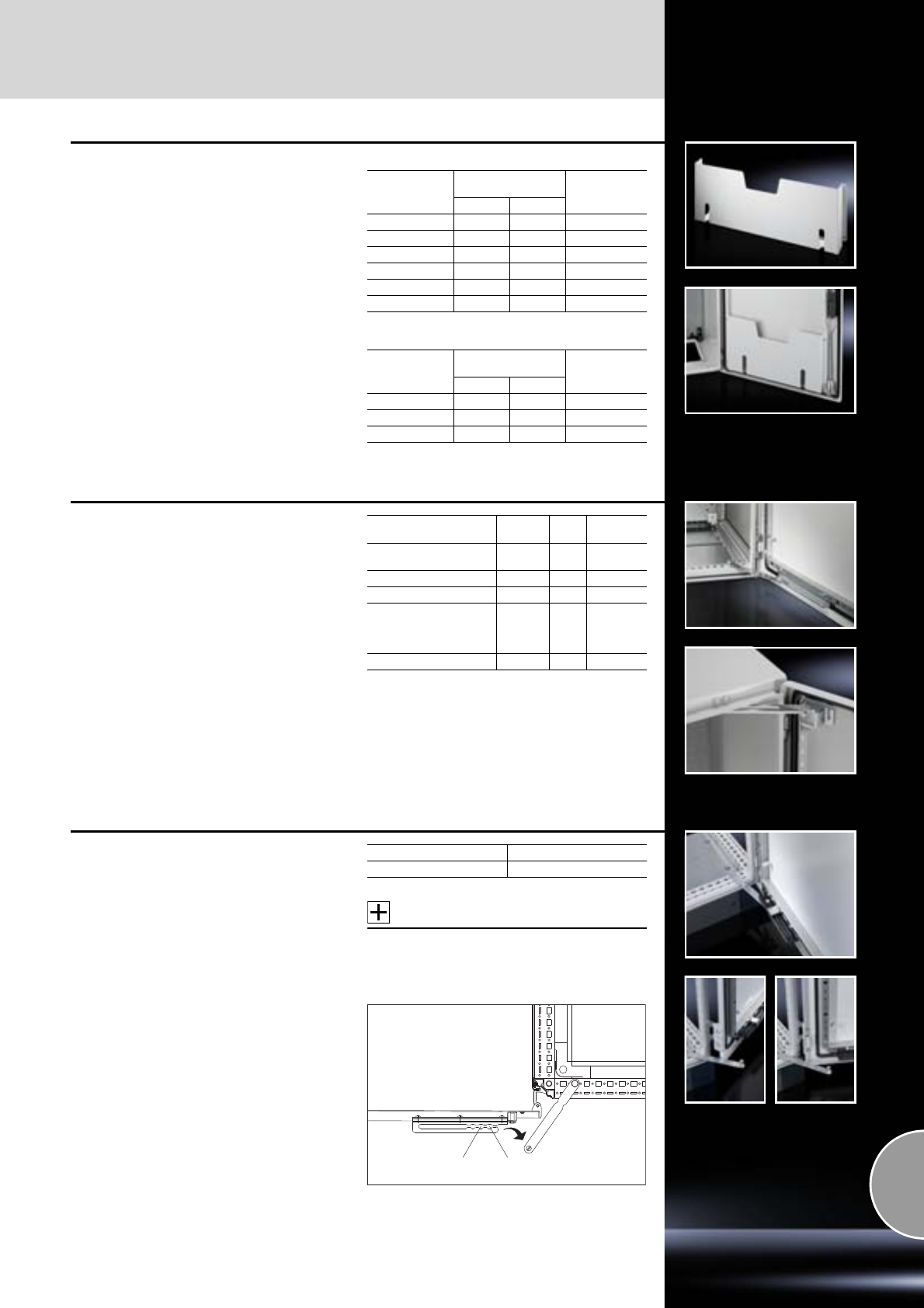
Door, internal
Doors/locks
429Rittal Catalogue 33/System accessories
Wiring plan pockets
of sheet steel
for TS, CM, ES, PC, TP pedestal
For fastening to tubular door frames at any height.
Colour:
RAL 7035
Supply includes:
Assembly screws.
D = 90 mm
D = 35 mm
To fit door width
mm
Clearance opening
mm Model No. TS
WH
400 255 210 4114.000
500 355 210 4115.000
600 455 210 4116.000
800 655 210 4118.000
900 755 210 4123.000
1000 855 210 4124.000
To fit door width
mm
Clearance opening
mm Model No. TS
WH
500 355 260 4115.500
600 455 260 4116.500
800 655 260 4118.500
Door stay
To secure the door in the open position. For
Assembly
Packs
of Model No.
TS, ES, PC,
TP universal console Bottom 5 4583.000
AP one-piece console Top 5 2518.000
CM, TP Top 2 2519.200
AE (except AE 1032.500
and AE 1035.500) and
all AE stainless steel
enclosures1)
Top 5 2519.000
AE IP 69K Top 1 1101.8 0 0
1) With AE stainless steel, only in conjunction with
perforated mounting strips, see page 427.
Door stay for escape routes
TS sheet steel/stainless steel doors
with tubular door frames
In case of an emergency, conventional door stays
can block the escape route. The stay is actuated
automatically in the event of pressure, releasing
the door in both directions. In conjunction with
180° hinges, this ensures that no escape routes
are blocked by locked doors in the event of an
emergency.
Supply includes:
Assembly parts.
Accessories:
180° hinge,
see page 425.
Packs of Model No. TS
1 4583.500
130°90°
180° hinge
Doors/locks
Door, internal
430 Rittal Catalogue 33/System accessories
Ride-up roller
for TS, ES, PC
Lifts the door with heavy installed equipment
(e.g. cooling unit) as a closing aid. For attaching
to the tubular door frame.
Packs of Model No. TS
10 4538.000
Transport and mounting handle
for doors TS, ES
For safe installation and removal of the door and
during relocation in the workshop. The matching
hinge pin removal tool for 130° hinges is pre-inte-
grated, and supplied loose for 180° hinges.
Packs of Model No. SM
12415.100
Document clip, magnetic
For simple attachment of installation documenta-
tion as a reminder or for flexible accommodation
of a wide range of documents, measurement
records, test reports etc. May be attached to any
magnet compatible surface via a permanent mag-
net.
Material:
−Plastic: Transparent
−Handle pieces: Black
Supply includes:
−2 mounting clamps
−Permanent magnet
Packs of Model No. DK
27950.200
Alternate frame, magnetic
For individual marking or labelling of the existing
network infrastructure.
The magnetic surface facilitates flexible mounting
on all magnet compatible surfaces. Adhesive
strips are supplied for non-magnetic compatible
surfaces.
The maximum size of the labels is 130 x 50 mm.
Material:
Plastic
Supply includes:
−Alternate frame, magnetic
−Labels
−Double-sided adhesive tape
Packs of Model No. DK
10 7950.150
Roof
Roof/wall mounting
431Rittal Catalogue 33/System accessories
Rain canopies
for AE, CM
Reliable protection for outdoor siting – with water
run-off to the rear. Easily retro-fitted.
Supply includes:
Assembly parts.
Accessories:
−Condensate discharge,
see page 384.
−Pressure relief stopper,
see page 384.
−Wall mounting brackets SZ 2503.010 and
SZ 2508.010 may be used,
see page 439.
Note:
For outdoor siting, we generally recommend a rain
canopy above the enclosure or the gap between
the door or screw-fastened rear panel and the
enclosure, in order to protect against water and
UV radiation.
The tests of IP protection categories for water pro-
tection (2nd code number to EN 60 529) cannot
be compared with an enclosure sited outdoors or
under similar conditions.
Upon request, rain canopies of sheet steel, stain-
less steel or aluminium can also be produced for
other enclosures.
for AE, sheet steel version
Material:
Sheet steel
Surface finish:
Powder-coated, textured paint
Colour:
RAL 7035
For
Model No. SZ
Enclosure width
mm Enclosure depth
mm
380 210 2501.500
600 210 2502.500
600 350 2511.500
for AE, stainless steel version
Material:
Stainless steel 1.4301 (AISI 304)
Surface finish:
Brushed, grain 240
Possible
alternative:
Compact enclosures Hygienic Design,
see page 153.
T1
T2 38 1.25
25
50
15.5
B1
23 23
For
Model No. SZ
Enclosure width
mm Enclosure depth
mm
200 155 2470.000
300 210 2361.000
380 155 2471.000
380 210 2472.000
500 210 2362.000
600 210 2473.000
760 300 2474.000
800 300 2475.000
1000 300 2363.000
B1 =
T1 =
T2 =
Enclosure width + 11 mm
Enclosure depth + 25 mm
Enclosure depth – 90 mm, from enclosure
width 600 mm: Enclosure depth – 115 mm
for CM, sheet steel version
Benefits:
●Mounting via the two holes in the top of the CM
●At the front, with integrated ventilation holes at
the top
Material:
Sheet steel
Surface finish:
Powder-coated, textured paint
Colour:
RAL 7035
6.5
6.5
6.5
12.5
13
32.5
25
Enclosure
depth
1
1
2
Enclosure
width
2
Width
mm Depth
mm Model No. CM
600 400 50 01.310
800 400 5001.330
1000 400 5001.350
1200 400 5001.360
Roof/wall mounting
Roof
432 Rittal Catalogue 33/System accessories
Dust guard trim
for AE, CM, EB, KL and BG
To protect against deposits on the upper edge of
the door and between the enclosure and the door/
lid. Cut the door protection strip to length accord-
ing to the enclosure width. Drill the enclosure and
mount the strip using the adhesive strips and
screws.
Material:
Plastic, UV-resistant
Colour:
Similar to RAL 7024
For
enclosure Length
mm A
mm Model No.
SZ
AE
1200
25
2426.500CM 20
KL, EB, BG 20.5
Ø 5
A
6
60
Dust guard trim
for TS, ES
To protect against dust deposits on the upper
edge of the door and between the door and upper
horizontal enclosure section. The dust guard trim
provides space for texts or company logos.
Colour:
RAL 7035
Supply includes:
Clear plastic strip for text labels (height 29.5 mm).
Note:
Also suitable for use in conjunction with top
baying cover, see page 399.
Length mm Model No. SZ
600 2424.100
800 2425.100
1000 2427.100
1200 2426.100
Roof
Roof/wall mounting
433Rittal Catalogue 33/System accessories
606
B - 3
150
B - 88
200
512
Top mounting module
for TS
As a cable chamber for cable infeed from above
or for power distribution with busbar systems
across bayed enclosures. The TS cover plate is
used as standard to finish off at the top. The
enclosure height is increased by 200 mm with the
top mounting module fitted.
The top baying cover cannot be fitted. Installation
accessories for top and bottom, see diagram and
explanations below.
Material:
Sheet steel, 1.5 mm
Surface finish:
Spray-finished, textured paint
Colour:
RAL 7035
Protection category:
IP 55 to IEC 60 529, compliant with NEMA 12
(in conjunction with side panel for top mounting
module, see page 433).
Supply includes:
−1 frame module
−2 trim panels (front and rear)
−8 retainers with automatic
potential equalisation
−4 tapped rods with eyebolts
For enclosures
Model No. TS
Width (B)
mm Depth
mm
600 600 8801.735
800 600 8801.745
1000 600 8801.755
1200 600 8801.765
Accessories:
Designation Page
TS punched rail 18 x 38 mm 462
PS punched rail 23 x 23 mm
with angle bracket 463
PS punched rail 23 x 23 mm
with support bracket 463
PS punched section without
mounting flange 23 x 73 mm,
with support bracket PS 464
PS punched section
with mounting flange 23 x 73 mm 464
Support rail 466
System support rails 466
C rail 30/15
with support bracket or spacer 465
Cable clamp rail 527
TS punched rail 25 x 38 mm 461
TS punched section without
mounting flanges, 45 x 88 mm 461
1
1 7 8 9
2 3 45
6
11
10
1
2
3
4
5
6
7
8
9
10
11
Side panel
for top mounting module
To finish off the side of a top mounting module or
bayed suite.
Material:
Sheet steel, 1.5 mm
Surface finish:
Spray-finished, textured paint
Colour:
RAL 7035
Supply includes:
−2 side panels
−8 retainers with automatic potential equalisation
Packs of Model No. TS
28801.775
Roof/wall mounting
Roof
434 Rittal Catalogue 33/System accessories
Roof plates
for SV-TS
For SV-TS 8 enclosures without roof plate and in
exchange for the standard roof plate for other TS
enclosures.
Material:
Sheet steel, 1.5 mm
Surface finish:
Textured paint
Colour:
RAL 7035
Supply includes:
Assembly parts.
IP 55, solid
IP 43 with ventilation hole
Build height: 93 mm
IP 2X with ventilation hole
Build height: 72 mm
With pressure relief valve
Build height: 25 mm
For enclosures
Packs of Model No. SV
Width
mm Depth
mm
300 600 1 9671.636
400 600 1 9671.646
600 600 1 9671.666
800 600 1 9671.686
300 800 1 9671.638
400 800 1 9671.648
600 800 1 9671.668
800 800 1 9671.688
For enclosures
Packs of Model No. SV
Width
mm Depth
mm
300 600 1 9671.736
400 600 1 9671.746
600 600 1 9671.766
800 600 1 9671.786
300 800 1 9671.738
400 800 1 9671.748
600 800 1 9671.768
800 800 1 9671.788
Extended delivery times.
For enclosures
Packs of Model No. SV
Width
mm Depth
mm
400 600 1 9671.8461)
600 600 1 9660.235
800 600 1 9660.245
1000 600 1 9660.255
1200 600 1 9660.265
400 800 1 9671.8481)
600 800 1 9659.5251)
800 800 1 9659.5351)
1000 800 1 9659.5451)
1200 800 1 9659.5551)
1) Extended delivery times.
For enclosures
Packs of Model No. SV
Width
mm Depth
mm
400 600 1 9671.446
600 600 1 9660.935
800 600 1 9660.945
1000 600 1 9660.955
1200 600 1 9660.965
400 800 1 9671.448
600 800 1 9671.468
800 800 1 9671.488
Extended delivery times.
For cable entry glands
Also required:
Cable entry gland,
see page 435.
For enclosures Required
number
of glands
Packs
of Model No. SV
Width
mm Depth
mm
600 400 2 1 9665.943
850 400 3 1 9665.953
1100 400 4 1 9665.963
300 600 2 1 9671.536
400 600 3 1 9671.546
600 600 4 1 9665.903
800 600 8 1 9671.586
850 600 6 1 9665.913
1100 600 8 1 9665.923
300 800 2 1 9671.5381)
400 800 4 1 9671.548
600 800 8 1 9671.5681)
800 800 8 1 9671.5881)
1) Extended delivery times.
Roof
Roof/wall mounting
435Rittal Catalogue 33/System accessories
1
2
3
4
5
Cable entry glands
●Including seal
●External dimensions 250 x 160 mm
●Protection category IP 55
Design Material Colour Packs of Model No. SV
14 x M25/32 Insulating
material RAL 7032 1 9665.750
2 x M25/32/40, 1 x M32/40/50, 2 x M40/50/63 Insulating
material RAL 7032 1 9665.760
With sealing membranes
32 x Ø 7 – 16 mm, 4 x Ø 10 – 20 mm, 3 x Ø 14 – 26 mm Insulating
material RAL 7032 1 9665.770
With entry glands up to 66 mm diameter Insulating
material RAL 7032 1 9665.780
Solid Sheet steel,
spray-finished RAL 7035 4 9665.785
1
2
3
4
5
R25
135
223
138
226
Ø 4.5
Cut-out dimensions for
SV 9665.750 to SV 9665.785
Roof/wall mounting
Roof
436 Rittal Catalogue 33/System accessories
Roof plate
for cable entry, two-piece
for DK-TS
In exchange for the standard roof. Equipped
with a sliding angular bracket in the rear section.
Rubber cable clamp strip on both sides for
attaching cable bundles and bunched cables.
Thanks to the symmetrical design of the TS 8
frame, side cable entry can also be achieved by
rotating the roof plate.
The two-piece design additionally allows easy
retro-fitting, by simply removing the front part of
the plate for retrospective cable entry.
For active ventilation, a fan mounting plate may be
fitted in the front section of the enclosure (not in
conjunction with 482.6 mm (19˝) mounting frames).
To this end, the roof plate must be raised by at
least 20 mm using spacers.
Material:
Sheet steel
Colour:
RAL 7035
Accessories:
−Fan mounting plate,
see page 221.
−Spacers,
see page 438.
Detailed drawing:
Available on the Internet.
For enclosures
Model No. DK
Width
mm Depth
mm
600 400 7826.6451)
600 600 7826.665
600 800 7826.685
600 1000 7826.605
600 1200 7826.625
800 400 7826.845
800 600 7826.865
800 800 7826.885
800 1000 7826.805
1200 400 7826.245
800 1200 7826.825
1) Extended delivery times.
Roof plate, multi-piece
for side cable entry in TS
The roof plate allows side cable entry on both
sides across the entire enclosure depth. Sliding
brackets at the sides allow variable adaptation of
the entry opening. Additional rubber cable clamp
strips secure the inserted cable bundles and
cable sections.
The multi-piece design allows convenient retro-
fitting, as the roof plate is removable even with the
cables already inserted.
Passive ventilation is supported by raising the roof
with spacers.
Material:
Sheet steel
Surface finish:
Spray-finished
Colour:
RAL 7035
Supply includes:
Assembly parts.
Accessories:
Spacers,
see page 438.
For enclosures
Model No. DK
Width
mm Depth
mm
800 1000 7526.807
800 1200 7526.8271)
1) Extended delivery times.
Roof
Roof/wall mounting
437Rittal Catalogue 33/System accessories
Roof plate
for cable entry on all sides
for DK-TS
The roof plate has sliding plates for cable entry
on all four sides, and therefore allows individual
selection of cable routing tailored to the specific
requirements. After cable entry, the sliding plate is
closed again as far as possible, and the rubber
cable clamp strips supplied loose then seal the
cable entry area.
Material:
Sheet steel
Colour:
RAL 7035
Supply includes:
Assembly parts.
Detailed drawing:
Available on the Internet.
For enclosures
Model No. DK
Width
mm Depth
mm
800 800 7826.588
Roof plate, vented
for DK-TS
In exchange for the standard roof.
Variant 1:
72 mm high roof plate, all-round vent slots, option-
ally with clamp strip for cable entry. The two-piece
design with cable entry allows easy retro-fitting,
by simply removing the front part of the plate. The
cables are held in position via a guide at the side.
Material:
Sheet steel
Colour:
RAL 7035
One-piece without cable entry
Two-piece with cable entry
For enclosures
Model No. DK
Width
mm Depth
mm
600 600 7826.766
600 800 7826.768
600 1000 7826.7601)
800 600 7826.786
800 800 7826.788
800 1000 7826.780
1) Extended delivery times.
For enclosures
Model No. DK
Width
mm Depth
mm
600 600 7826.669
600 800 7826.689
800 600 7826.869
800 800 7826.889
800 1000 7826.809
Variant 2:
Ventilation holes (Ø 5 mm) are incorporated all-
round into the 97 mm high roof plate. In conjunc-
tion with the vented glazed and sheet steel door,
the roof plate matches the door design to perfec-
tion.
Material:
Sheet steel
Colour:
RAL 7035
Accessories:
Fan mounting plate,
see page 221.
Detailed drawing:
Available on the Internet.
For enclosures
Model No. DK
Width
mm Depth
mm
800 600 7826.866
800 800 7826.886
800 1000 7826.8061)
1) Extended delivery times.
Roof/wall mounting
Roof
438 Rittal Catalogue 33/System accessories
Roof mounting screw
For screw-fastening the roof plate instead of
eyebolts. With the TS 8, the contact washers for
potential equalisation may be taken from the eye-
bolts included with the supply of the enclosures.
Material:
Steel
Surface finish:
Zinc-plated
Packs of Model No. PS
20 4198.000
Spacers
for roof plate TS
To raise the TS 8 roof for ventilation purposes,
in three different heights.
Not suitable for crane transportation!
Material:
Hexagonal sectional steel
Surface finish:
Zinc-plated
Supply includes:
Assembly parts.
Height mm Packs of Model No. SZ/DK
10 4 2422.000
20 4 2423.000
50 4 7967.000
Eyebolts
for TS, ES
For crane transportation of enclosures, where
not already included in the supply.
Thread: M12
Packs of Model No. PS
44568.000
Eyebolts
for CM
For crane transportation of enclosures, with
reinforcement plate to be inserted underneath.
Mounting via the two holes in the top of the CM.
Thread: M12
Supply includes:
−Eyebolts
−Reinforcement plates
Packs of Model No. CM
22509.500
Eyebolts
for AE
For crane transportation of enclosures, with
reinforcement plate to be inserted underneath.
Thread: M12
Supply includes:
−Eyebolts
−Reinforcement plates
Packs of Model No. SZ
42509.000
Wall mounting
Roof/wall mounting
439Rittal Catalogue 33/System accessories
Wall mounting bracket
For the attachment of KL, EB, BG and EL enclo-
sures as well as DK wall-mounted distributors.
Supply includes:
Assembly parts for mounting on the enclosure.
Note:
For hygiene reasons, and in view of the protec-
tion category, the stainless steel enclosures do
not have any drilled holes for the wall mounting
brackets.
Material Wall distance
mm Packs
of Model No.
SZ
Brass,
nickel-plated 841580.000
Sheet steel
zinc-plated,
passivated 841590.000
Stainless steel
1.4301 (AISI 304) 841594.000
20
20
20
10
10
8
25
Ø 8.2
Wall mounting bracket
for AE
For attaching to the enclosure from the outside.
Simply insert the expandable dowel into the
enclosure hole from the outside, and screw-
fasten the wall bracket from the outside.
Material:
Sheet steel
Surface finish:
Zinc-plated
Supply includes:
Wall bracket pre-fitted with seal and expandable
dowel.
Wall distance
mm Packs of Model No. SZ
15 4 2508.100
Wall mounting bracket
For the attachment of KL, EB, BG, AE, CM and
EL enclosures, TP consoles as well as DK wall-
mounted distributors and small fibre-optic distrib-
utors.
Supply includes:
Assembly parts for mounting on the enclosure.
Possible
alternative:
Wall spacer bracket Hygienic Design,
see page 156.
Material Wall distance
(A) mm Packs
of Model No.
SZ
Sheet steel
zinc-plated,
passivated
40 4 2503.010
10 4 2508.010
Stainless steel
1.4301 (AISI 304) 10 4 2433.000
Stainless steel
1.4404 (AISI 316L) 10 4 2433.500
20
20
29
15
15
Ø 10.2
54 A
Roof/wall mounting
Wall mounting
440 Rittal Catalogue 33/System accessories
Wall mounting bracket
for KS
For attachment to the wall, only possible from the
outside of the enclosure.
Material:
Fibreglass-reinforced polyamide1)
Supply includes:
Assembly parts for mounting on the
enclosure.
11.5
35
50 30
Ø 8.5
Colour Packs of Model No. KS/KE
Similar to RAL 7035 4 1483.010
Similar to RAL 9011 4 9266.0001)
1) With graphite additive for Ex applications.
Wall angle
For compact enclosures (additional holes required
in the enclosure).
Supply includes:
Assembly parts for mounting on the enclosure.
Material Colour Packs of Model No. SZ
Sheet steel RAL 7035 4 2505.510
Stainless steel
1.4301 (AISI 304) –42583.010
70
35
34
6.5
26
R4
20
13
90
2
Wall bracket
For wall mounting of TS and ES enclosures at the
roof, e.g. with heavy components on the door or
built-in swing frame.
Material:
Sheet steel
Surface finish:
Zinc-plated
Possible
alternative:
With TS 8 inside the enclosure
(without mounting plate),
baying bracket TS 8800.470,
see page 398.
Packs of Model No. PS
44595.000
Wall mounting
Roof/wall mounting
441Rittal Catalogue 33/System accessories
Wall mounting bracket
for CS wall-mounted enclosures
For mounting on a wall or panel.
Material:
Stainless steel 1.4301 (AISI 304)
Packs of Model No. CS
49765.120
Pole clamp
for KL, EB, BG, AE, KS and CS wall-mounted
enclosures
For reliable, convenient fastening to round or
square poles.
For pole diameter/size:
−Ø from 40 to 190 mm
−□ from 50 to 150 mm
Material:
−Mounting angles, clamping section:
Sheet steel
−Clamping strap:
Stainless steel 1.4301 (AISI 304)
Surface finish:
Mounting angles, clamping section: Zinc-plated
Supply includes:
−2 mounting angles, 600 mm long
−4 clamping sections
−2 clamping straps
−4 clamping brackets
−4 screws and captive nuts M8
for mounting on the enclosure.
Packs of Model No. SZ
1 set 2584.000
Enclosure connectors
Adjustable
Between Command Panels, terminal boxes,
compact enclosures and horizontal or vertical
surfaces.
Pre-mount the connector halves on both sides,
screw together and secure with a locking screw,
and/or adjust the angle of rotation.
Rotation range:
±105° adjustable in 7.5° stepped increments.
Material:
Die-cast zinc
Surface finish:
Powder-coated
Colour:
RAL 7035
Supply includes:
Assembly parts for both sides.
Note:
The locking screws may be exchanged for
standard, commercially available clamping
levers (M10 x 50 mm).
Packs of Model No. CP
1 set 6016.200
105°
105°
54 54
Roof/wall mounting
Wall mounting
442 Rittal Catalogue 33/System accessories
Frame connector, adjustable
for Comfort Panel
Between the command panel and keyboard
housing and horizontal or vertical surfaces.
Rotation range:
Adjustable in 8° stepped increments,
see drawing.
Material:
Die-cast zinc
Surface finish:
Powder-coated
Colour:
RAL 7024
Supply includes:
Assembly parts and clamping levers for both
sides.
Packs of Model No. CP
1 set 6005.500
120°
104°
32°
64
47.5
–14°/+178°
Wall mounting bracket
Vertically hinged
Between the Compact Panel and horizontal or
vertical surfaces.
Rotation range:
180° adjustable on a 7.2° pitch pattern.
Material:
−Wall mounting bracket:
Sheet steel
−Knurled screw:
Steel with plastic knurled handle
Supply includes:
Locking screw and assembly parts for mounting
on the Compact Panel.
Packs of Model No. CP
1 set 6341.000
Mounting plates
Interior installation
443Rittal Catalogue 33/System accessories
Mounting plates
for KL and KL-HD
For component installation outside of the enclo-
sure. Assembly screws included as accessories
with the enclosure.
Material:
Sheet steel, 2 mm
Surface finish:
Zinc-plated
Accessories:
Self-tapping screws SZ 2487.000,
see page 478.
Possible
alternative:
Support rails,
see page 467.
Detailed drawings:
Available on the Internet.
For size
mm For Model No. KL and KL-HD Model No. KL
150 x 150 1500.510, 1514.510, 1521.010, 1527.010, 1670.600, 1671.600 1560.700
200 x 150 1528.510, 1529.510 1575.700
300 x 150 1501.510, 1515.510, 1522.010, 1530.510 1561.700
400 x 150 1589.510 1576.700
200 x 200 1502.510, 1516.510, 1523.010, 1528.010, 1672.600 1562.700
300 x 200 1503.510, 1517.510, 1524.010, 1529.010, 1531.510, 1674.600 1563.700
400 x 200 1504.510, 1518.510, 1525.010, 1532.510, 1675.600 1564.700
500 x 200 1505.510, 1533.510 1565.700
300 x 300 1507.510, 1526.010, 1535.510 1567.700
400 x 300 1508.510, 1530.010, 1536.510, 1676.600 1568.700
500 x 300 1509.510, 1537.510 1569.700
400 x 400 1511.510, 1539.510 1571.700
Mounting plate infill
for TS
For a continuous mounting surface in bayed
suites where the mounting plate is set forward.
Material:
Sheet steel, 2 mm
Surface finish:
Zinc-plated
Supply includes:
Assembly parts.
For enclosure height
mm Model No. TS
1800 4590.700
2000 4591.700
2200 4592.700
Interior installation
Mounting plates
444 Rittal Catalogue 33/System accessories
Mounting plate attachment
For additional clamping and to reduce potential
vibration of the mounting plate. Select according
to mounting position, installation type and enclo-
sure.
Material:
Sheet steel
Surface finish:
Zinc-plated
Supply includes:
Assembly parts.
For TS
Installation options:
●Side, at half height in conjunction with
mounting plate infill
●In the penultimate position
●Set forward (supplied state)
Benefit:
No impairment to the mounting surface, but
mounting is only possible from the enclosure rear.
Accessories:
Mounting plate infill,
see page 443.
Packs of Model No. TS
10 8800.630
For TS
Installation options:
●Side
●Rear, flush with enclosure frame
Benefit:
No impairment to the mounting surface, but
mounting is only possible from the enclosure rear.
Packs of Model No. TS
10 8800.610
For TS
Installation options:
●Side
●Rear, flush with enclosure frame
●Set forward on a 25 mm pitch pattern
Benefit:
No impairment to the mounting surface.
May optionally used for attachment or screw
fastening.
Also required:
Punched section with mounting flange
17 x 73 mm for the inner mounting level,
see page 459 (with Fig. 3).
Packs of Model No. TS
10 8800.090
2
1
3
Mounting plate screw-fastened in the rear-
most installation position.
Mounting plate screw-fastened from the rear
in the rearmost installation position.
Mounting plate in a set forward position, either
attached or screw-fastened (not shown).
1
2
3
For TS
Installation options:
●Side
●Rear, flush with enclosure frame
Slide over the plate at the side and secure with
screws. Additionally, the mounting plate may be
drilled and screw-fastened at the rear C-edge.
Packs of Model No. TS
10 8800.050
Mounting plates
Interior installation
445Rittal Catalogue 33/System accessories
Mounting plate attachment
For additional clamping and to reduce potential
vibration of the mounting plate. Select according
to mounting position, installation type and enclo-
sure.
Material:
Sheet steel
Surface finish:
Zinc-plated
Supply includes:
Assembly parts.
For TS, ES
Installation options:
●All-round
●Set forward on a 25 mm pitch pattern
Slide in between the bar and plate from below or
above or from the side, and secure with screws.
Also required:
−Support strip (with TS for inner level),
see page 462 or
−Punched section with mounting flange
(with TS for inner level),
see page 459 or
−Punched rails and punched sections without
mounting flange,
see page 463/464.
Packs of Model No. TS
10 4593.000
For TS, ES
Installation options:
●On the top and bottom of the mounting plate
(with ES all-round)
●Rear, flush with enclosure frame
Screw in the clip behind the plate and secure with
screws.
Packs of Model No. TS
10 4576.000
Installation kit
for mounting plates TS, back-to-back
The minimal distance between the two mounting
plates ensures a maximum installation depth for
installed equipment on both sides.
Material:
Sheet steel
Surface finish:
Zinc-plated
Note:
Build height front and rear
with central installation =
(enclosure depth – 48 mm) : 2
For example:
TS 8806.521 = Depth 600 mm
Build depth = 2 x 276 mm
Packs of Model No. TS
1 set 8800.280
Interior installation
Mounting plates
446 Rittal Catalogue 33/System accessories
Mounting plate slide block
for CM
In this way, populated mounting plates slide easily
into the mounting position for installation and/or
clip-fastening.
Benefits:
●Installation without drilling
●Simply screw-fasten to the existing holes in
the mounting plate
●May be reused, unscrew to detach
Material:
Polyamide
Colour:
Similar to RAL 9011
Supply includes:
Assembly parts.
Packs of Model No. CM
25001.070
Slide rails
for mounting plate TS
Slides in from the side.
●Attachment of the mounting plate to the slide
rails via captive nuts and screws.
●Mounting of the slide rails directly on the enclo-
sure frame, depth-adjustable on a 25 mm pitch
pattern.
Technical specifications:
Possible mounting depth T6 – 25 mm,
refer to the Internet.
Material:
Sheet steel
Surface finish:
Zinc-plated
Supply includes:
Assembly parts.
For enclosure width
mm Packs of Model No. TS
600 2 8802.260
800 2 8802.280
1200 2 8802.220
Mounting plate adjustment
bracket
for KS
Infinitely adjustable.
Other equipment can also be installed in this way,
instead of the mounting plate.
Material:
Sheet steel
Surface finish:
Zinc-plated
Supply includes:
Assembly parts.
Enclosure width:
– 76 mm (KS 1481.000)
– 104 mm (KS 1491.000)
Enclosure height:
– 150 mm
B
H
For enclosures KS Packs of Model No. KS
1423.500, 1432.500,
1434.500, 1444.500,
1446.500, 1448.500,
1449.500, 1466.500,
1467.500
41481.000
1400.500, 1453.500,
1454.500, 1468.500,
1469.500, 1479.500,
1480.500
41491.000
M8 x 15
B
H
Mounting plates
Interior installation
447Rittal Catalogue 33/System accessories
Mounting plate attachment
for CM, TP one-piece console, TP pedestal
for high dynamic loads
For example, if a direct connection between the
mounting plate and the enclosure is required
(cranes etc.).
Tested as per DIN EN 60 721 severity 4M4, with
a weight of 150 kg evenly distributed over the
mounting plate.
Simply screw-fasten to the existing holes in the
mounting plate to pre-assemble for:
Wall mounting from the inside
Direct using a bracket and wall/support mounted
enclosure.
Wall mounting from the outside
Screws for wall mounting brackets (see page 439)
can easily be screwed into the plate nuts from the
outside.
Material:
Sheet steel
Surface finish:
Zinc-plated
Supply includes:
Assembly parts.
Packs of Model No. CM
1 set 5001.075
Cross-brace
for mounting plates
for TS, ES
Additional horizontal rigidity for vibration resist-
ance and/or stabilisation of wide mounting plates.
This brace may also be used as an attachment
aid for heavy components.
Material:
Sheet steel
Surface finish:
Zinc-plated
Supply includes:
−2 sections
−4 clamping sections
−4 grub screws M10 x 16 mm
For enclosure width
mm Model No. TS
1200 4333.120
1600 4333.160
1800 4333.180
Other widths available on request.
Transport handles
for mounting plates
for TS, ES
May be used at any given position in the side
C-fold
Benefits include:
●Can be used for people of different heights
●Optimised force transmission
●Easy handling
Packs of Model No. SZ
22415.500
Interior installation
Mounting plates
448 Rittal Catalogue 33/System accessories
Partial mounting plates
for TS, CS Toptec
For
●Universal interior installation, also in conjunc-
tion with punched sections with mounting
flanges and support strips. Defective assem-
blies are quickly and easily replaced
●Additional mounting levels.
Partial mounting plates are fastened directly onto
the vertical enclosure sections via the inner mount-
ing level using the assembly parts supplied loose.
In this mounting position (in both the width and
the depth) they form one level with TS punched
sections with mounting flanges 17 x 73 mm and
TS support strips for the inner mounting level.
Material:
Sheet steel, 2.5 mm
Surface finish:
Zinc-plated
Supply includes:
Assembly parts.
Accessories:
−TS punched section with mounting flange
17 x 73 mm for the outer mounting level,
see page 459.
−TS support strip, see page 462.
−Hinge attachment, see page 449.
−Self-tapping screws, SZ 2487.000,
see page 478.
When installing around corners due to collision
between the assembly components
At least 75 mm (adjustable on a 25 mm pitch
pattern).
Maximum space utilisation
1 mm (adjustable on a 25 mm pitch pattern).
Partial installation
Partial utilisation of the enclosure depth or
width is also possible. In this example, using a
PS punched section without mounting flange
23 x 73 mm, see page 464.
Set forward installation position
Quickly and easily achieved wtih four TS punched
sections with mounting flanges 17 x 73 mm for the
outer mounting level, see page 459.
Continuously flush
In bayed enclosures, the partial mounting plate is
in the rearmost position flush with the standard
mounting plate. This facilitates continuous com-
ponent mounting.
For installation in
Size
mm Packs
of Model No. TSEnclosure width mm Enclosure depth (side) mm
400 600 800 1000 1200 400 500 600 800
500 x 300 1 8614.640
500 x 400 1 8614.650
500 x 500 1 8614.660
500 x 700 1 8614.680
500 x 775 1 8614.6751)
700 x 300 1 8614.840
700 x 400 1 8614.850
700 x 700 1 8614.880
900 x 300 1 8614.040
900 x 400 1 8614.050
900 x 500 1 8614.060
1100 x 300 1 8614.240
1100 x 400 1 8614.250
1100 x 500 1 8614.260
1) Also suitable for installing in
– PC enclosures based on TS behind the lower front door
– IW enclosures, height 900 and 1000 mm
1
2
1
2
Mounting plates
Interior installation
449Rittal Catalogue 33/System accessories
Hinge attachment
for partial mounting plate TS
Material:
Steel
Surface finish:
Zinc-plated
Supply includes:
Assembly parts.
Also required:
Depending on the installation position
Installation kit for swing frame, small,
for enclosure width
600 mm, Model No. SR 2377.860,
800 mm, Model No. SR 2377.880,
see page 543.
PS punched section without mounting flange
23 x 73 mm according to the enclosure depth,
see page 464.
Support brackets TS 8800.330,
see page 473.
Side installation:
In conjunction with hinge, for side panel,
see page 387, for an enclosure depth of 600 or
800 mm, side installation is identical to installation
parallel to the front.
1
1
21
1
2
In the highest or lowest position
Set backAt the front
Examples
1
11
1
2
2
2
2
1
1
In a central position
Set backAt the front
Side installation
Packs of Model No. TS
1 set 8614.100
1
2
Partial mounting plates
for ES, CS Basic and modular enclosures
For additional mounting levels.
Material:
Sheet steel, 2.5 mm
Surface finish:
Zinc-plated
Supply includes:
Assembly parts.
Accessories:
−PS punched section without mounting flange,
23 x 73 mm,
see page 464.
−Self-tapping screws, SZ 2487.000,
see page 478.
For
enclosure width
mm
Width x height
mm Packs
of Model No.
PS
600 492 x 373 2 4131.700
600 492 x 573 2 4132.700
800 692 x 573 2 4137.700
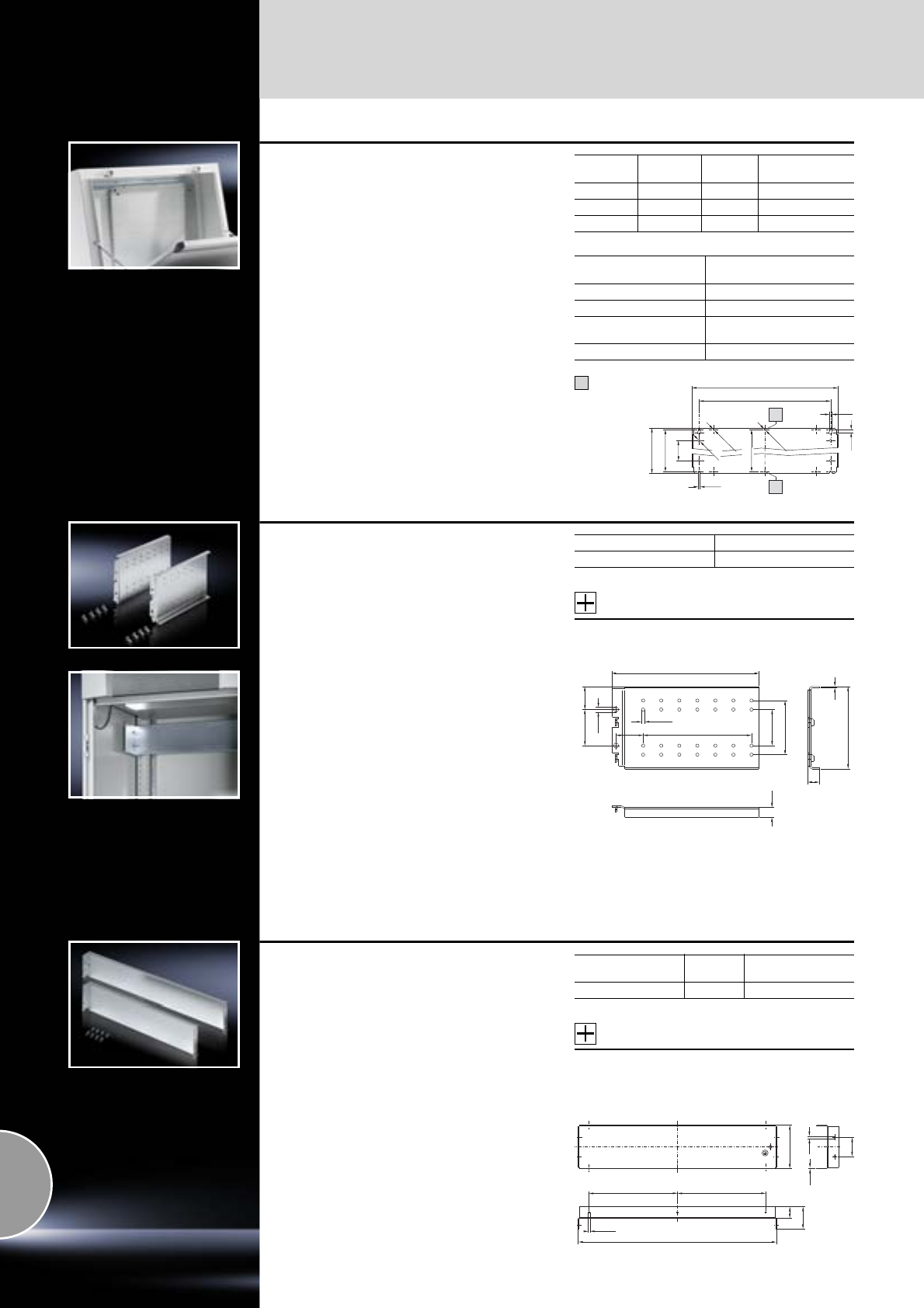
Interior installation
Mounting plates
450 Rittal Catalogue 33/System accessories
Partial mounting plates,
locatable into rails
for TP
For installation in:
●Console and desk unit on the interior installa-
tion system rails
●Punched sections with mounting flanges or
support strips fitted to the side of the pedestal
in the depth
●Other enclosures mounted on rails with 25 mm
pitch pattern punchings
For easy mounting on pre-fitted assembly screws.
Bayable by screw-fastening at the sides.
Material:
Sheet steel
Surface finish:
Zinc-plated
Supply includes:
Assembly parts.
Width
mm Height
mm Packs of Model No. TP
200 437 1 6730.310
500 437 1 6730.330
700 437 1 6730.340
For console/desk unit
Width mm Max. partial mounting plate
installation
600 1 x TP 6730.330
800 1 x TP 6730.340
1200 2 x TP 6730.310
1 x TP 6730.340
1600 3 x TP 6730.330
200/500/700
150/450/650
Ø 6.5
Ø 6.5
Ø 10
425
6.5
6.5
10
437
425
350
1
1
From width
500 mm
1
Support rail, locatable
for TS, CM, PC, TP
To fit:
●Internal mounting behind the mounting com-
partment, small, of the PC enclosure,
●Mounting on the vertical TS enclosure section,
●Mounting in CM and TP on the interior installa-
tion rail.
Integral 25 mm pitch pattern of holes to accom-
modate:
– Mounting plate, small
– PS punched section without mounting flange
via support brackets PS as a second mounting
level, if due to an installed:
– Mounting plate infill
– Cable duct, vertical
no punched sections or other assemblies can be
mounted in the depth.
Static load: max. 15 kg.
Material:
Sheet steel, 2.0 mm
Surface finish:
Zinc-plated
Supply includes:
Assembly parts.
Accessories:
PS punched section without mounting flange,
see page 464.
Packs of Model No. TS
1 set 8612.200
50 32
Ø 7
114
Ø 4.5
75
2
(6 x 25 = 150)
204
50
16
14
37.5
Mounting plate, small
For external mounting on:
●Support rail TS, locatable, depth-adjustable on
a 25 mm pitch pattern,
●Punched sections with mounting flanges,
attached to the outer mounting level.
Material:
Sheet steel, 1.5 mm
Surface finish:
Zinc-plated
Supply includes:
Assembly parts.
Accessories:
−TS punched section with mounting flange,
see page 459.
−Self-tapping screws, SZ 2487.000,
see page 478.
Enclosure width
mm Packs of Model No. TS
600 1 8612.600
Ø 6
Ø 4.5
1.5
114
30
58
50
250
250
557 (757)
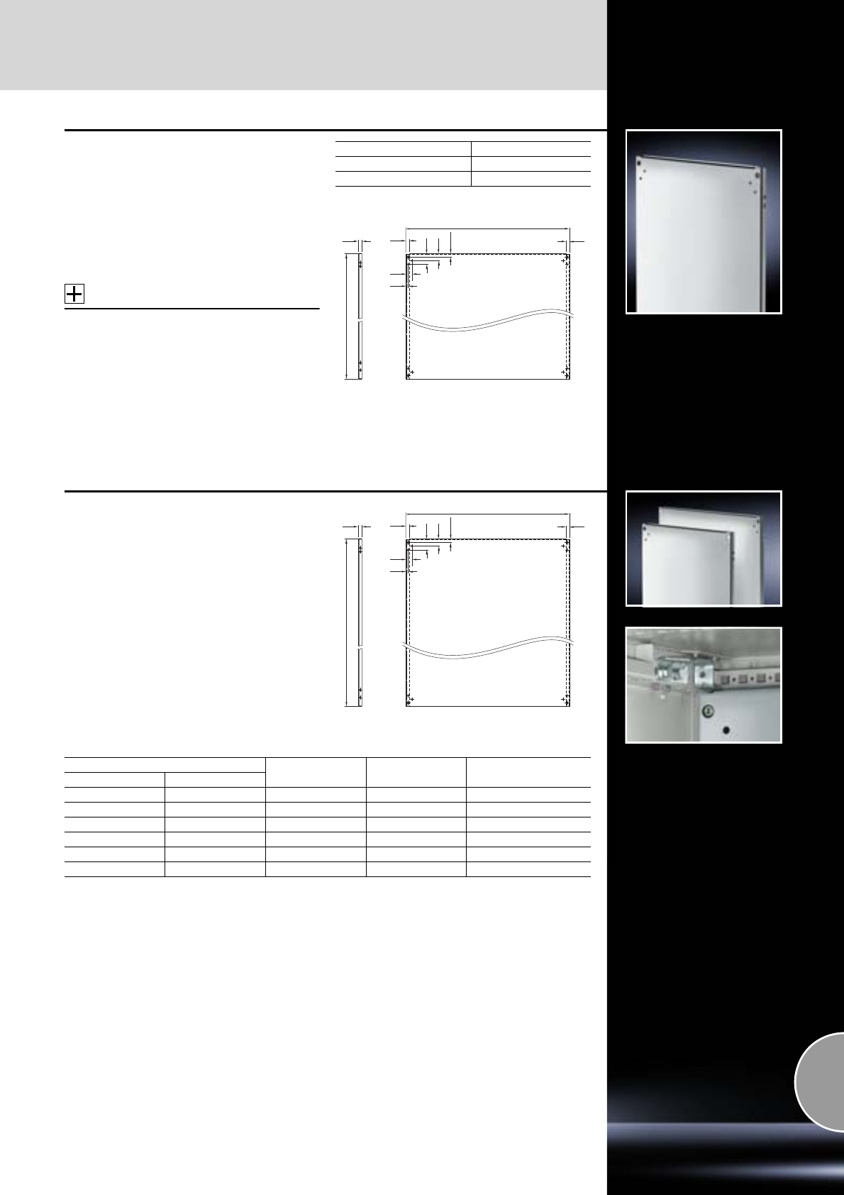
Mounting plates
Interior installation
451Rittal Catalogue 33/System accessories
Mounting plate
for TS, 400 mm wide
Depth-adjustable on a 25 mm pitch pattern.
Material:
Sheet steel, 3 mm
Surface finish:
Zinc-plated
Supply includes:
Assembly parts.
Accessories:
−TS 18 x 38 mm punched rail, used as mounting
plate slide rail, see page 462.
−TS width divider, for installation in wider enclo-
sures, see page 376.
For enclosure height mm Model No. TS
1800 8614.180
2000 8614.200
299
23
1696/1896
24.5
48
73
17
42
23 23
Mounting plates
for CS Toptec, Basic and modular enclosures
For the configuration of mounting levels.
The mounting plates are depth-adjustable on a
25 mm pitch pattern.
Material:
Aluminium, 3 mm
Supply includes:
Assembly parts.
Note:
For an enclosure width of 1200 mm,
partial installation with one or two 600 mm wide
mounting plates is possible.
F
23
G
24.5
48
73
17
42
23 23
For enclosure FGModel No. CS
Width mm Height mm
600 800 499 696 9765.090
600 1200 499 1096 9765.092
800 800 699 696 9765.097
800 1200 699 1096 9765.095
800 1600 699 1496 9765.096
1200 1200 1099 1096 9765.191
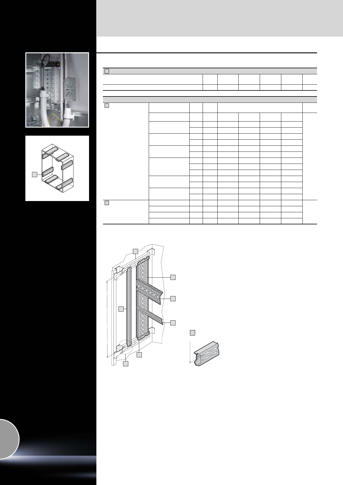
Interior installation
Rail systems
452 Rittal Catalogue 33/System accessories
1
AE installation examples with TS system rails
Rails for interior installation AE (preparing for installation)
For enclosure depth mm Packs
of 210 250 300 350 Page
Model No. SZ 4 2373.210 2373.250 2373.300 2373.350 459
Interior installation in the width and height
TS punched
section with
mounting flange,
17 x 73 mm
AE from enclosure
width/height mm A1)
mm Packs
of Model No. TS
380 225 4 8612.130 8612.130 8612.130 8612.130
459
500 325 4 8612.140 8612.140 8612.140 8612.140
375 4 8612.040 8612.040 8612.040 8612.040
600 425 4 8612.150 8612.150 8612.150 8612.150
475 4 8612.050 8612.050 8612.050 8612.050
760 525 4 8612.160 8612.160 8612.160 8612.160
575 4 8612.060 8612.060 8612.060 8612.060
1000
725 4 8612.180 8612.180 8612.180 –
775 4 8612.080 8612.080 8612.080 –
875 4 8612.090 8612.090 8612.090 –
1200 925 4 – – 8612.100 –
975 4 – – 8612.000 –
1400 1125 4 – – 8612.120 –
1175 4 – – 8612.020 –
TS support strips 400 325 20 4694.000 4694.000 4694.000 4694.000
462
500 425 20 4695.000 4695.000 4695.000 4695.000
600 525 20 4696.000 4696.000 4696.000 4696.000
800 725 20 4697.000 4697.000 4697.000 4697.000
1) A = Rail mounting distance
1
2
3
A
1
X
1
2
2
3
3
A
X
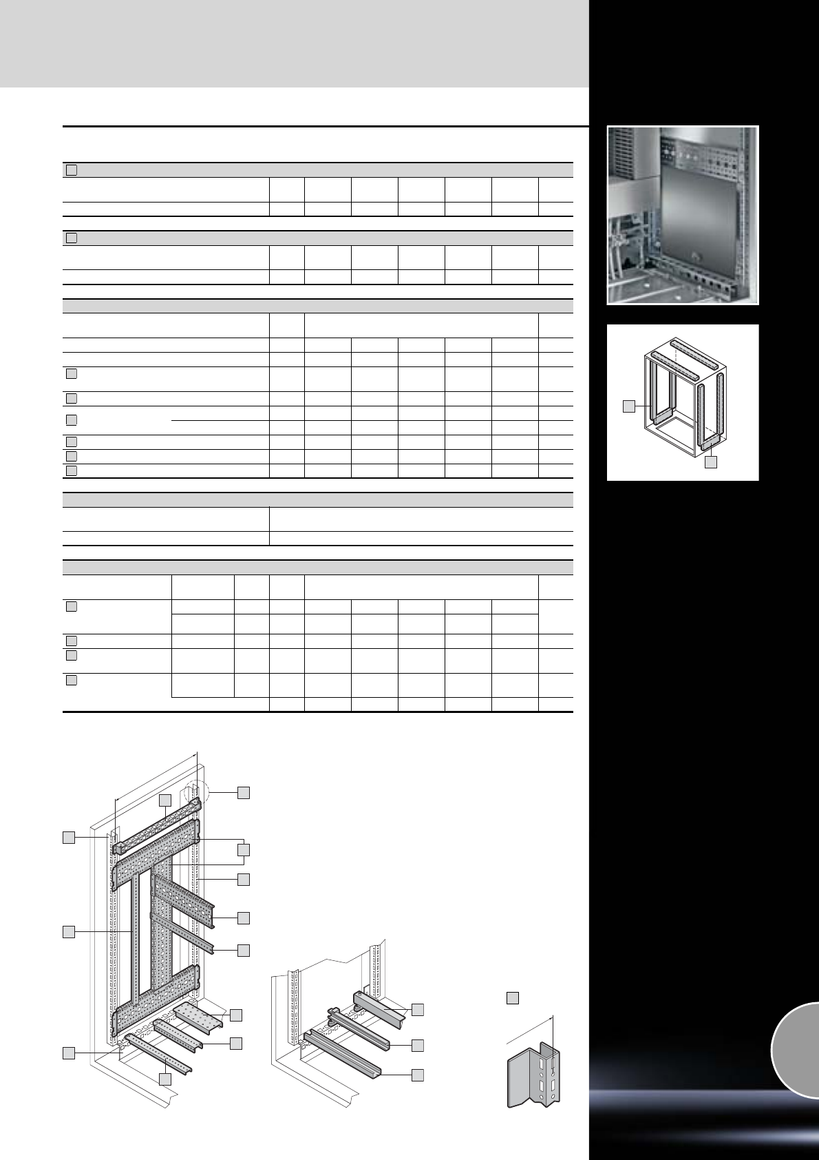
Rail systems
Interior installation
453Rittal Catalogue 33/System accessories
1
2
8
7
6
CM installation examples with TS system rails
Rails for interior installation (preparing for installation)
For enclosure width/height mm Packs
of 600 800 1000 1200 1400 Page
Model No. CM 4 5001.050 5001.051 5001.052 5001.053 5001.054 459
Base configuration rail (preparing for installation)
For enclosure depth Packs
of 300 400 – – –
Model No. CM 2 5001.371 5001.370 – – – 461
Installation in the width
Packs
of Model No. TS
For enclosure width mm 600 800 1000 1200 1400
A1) mm 575 775 975 1175 –
TS punched section with mounting flange,
17 x 73 mm 4 8612.060 8612.080 8612.000 8612.020 – 459
TS support strips 20 8800.130 4579.000 – – – 462
Support rail slotted 4 4396.000 4398.000 – – – 466
unslotted 4 4396.500 4398.500 – – – 466
System support rails 2 4361.000 4362.000 4347.000 4363.000 – 466
C rails 30/15 6 4944.000 4945.000 4946.000 4947.000 – 465
Cable clamp rail 2 4191.000 4192.000 4336.000 4196.000 – 527
Installation in the height (individual installation e.g. with)
TS punched section with mounting flange,
17 x 73 mm see page 459
TS support strips see page 462
Installation in the depth
For enclosure
depth mm
A1)
mm Packs
of Model No. TS/PS
TS punched section
with mounting
flange, 17 x 73 mm
300 225 4 8612.130 8612.130 8612.130 8612.130 8612.130
459
400 325 4 8612.140 8612.140 8612.140 8612.140 8612.140
TS support strips 400 325 20 4694.000 4694.000 4694.000 4694.000 4694.000 462
TS punched rail
18 x 38 mm 400 325 4 8612.240 8612.240 8612.240 8612.240 8612.240 462
PS punched rail,
23 x 23 mm 400 275 12 4169.000 4169.000 4169.000 4169.000 4169.000 463
With mounting bracket TS (2 per rail) 24 8800.370 8800.370 8800.370 8800.370 8800.370 472
1) A = Rail mounting distance
1
2
3
4
5
6
7
8
9
10
11
12
X
A
5
11
2
10
10
12
9
1
1
3
4
A
X
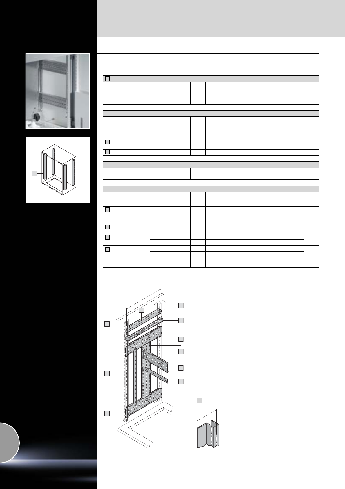
Interior installation
Rail systems
454 Rittal Catalogue 33/System accessories
1
TP pedestal
Installation examples with TS system rails
Rails for interior installation (preparing for installation)
For enclosure width mm Packs
of 600 800 1200 1600 Page
For enclosure height mm 675 675 675 675
Model No. CM 4 5001.050 5001.050 5001.050 5001.050 459
Installation in the width
Packs
of Model No. TS
For enclosure width mm 600 800 1200 1600
A1) mm 575 775 1175 1575
TS punched section with mounting flange,
17 x 73 mm 4 8612.060 8612.080 8612.020 – 459
TS support strips 20 8800.130 4579.000 – – 462
Installation in the height (individual installation e.g. with)
TS support strips see page 462
TS punched rail 18 x 38 mm see page 462
Installation in the depth
For
enclosure
depth mm
A1)
mm Packs
of Model No. TS
TS punched section
with mounting
flange, 17 x 73 mm
400 325 4 8612.140 8612.140 8612.140 8612.140 459
500 425 4 8612.150 8612.150 8612.150 8612.150
TS support strips 400 325 20 4694.000 4694.000 4694.000 4694.000 462
500 425 20 4695.000 4695.000 4695.000 4695.000
TS punched rail
18 x 38 mm
400 325 4 8612.240 8612.240 8612.240 8612.240 462
500 425 4 8612.250 8612.250 8612.250 8612.250
PS punched rail
23 x 23 mm
400 325 12 4169.000 4169.000 4169.000 4169.000 463
500 425 12 4170.000 4170.000 4170.000 4170.000
With mounting bracket TS (2 per rail) 24 8800.370 8800.370 8800.370 8800.370 472
1) A = Rail mounting distance
1
2
3
4
5
6
7
2
1
7
6
X
1
4
5
3
4
A
A
X
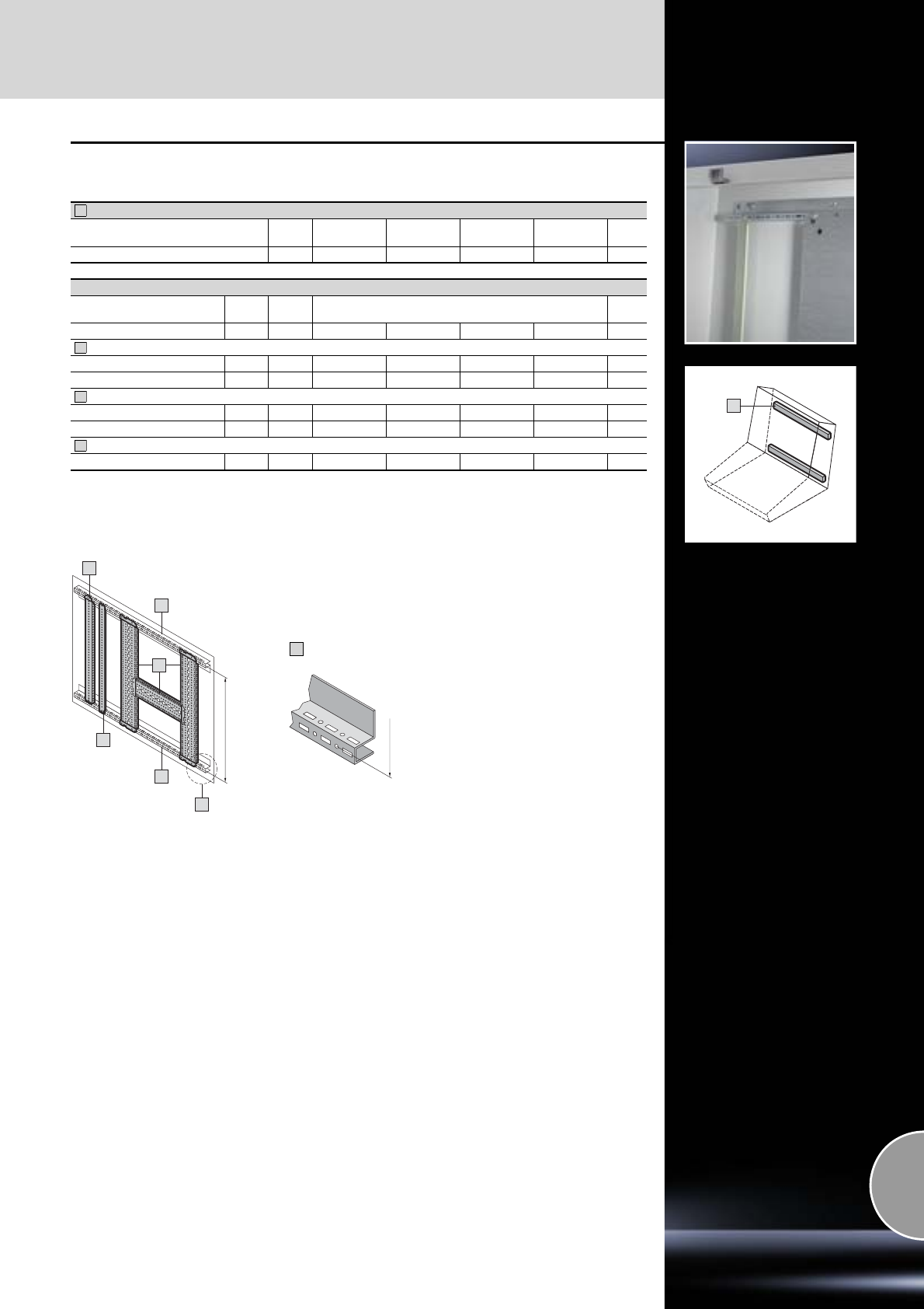
Rail systems
Interior installation
455Rittal Catalogue 33/System accessories
1
TP pedestal
Installation examples with TS system rails
Rails for interior installation (preparing for installation)
For enclosure width mm Packs
of 600 800 1200 1600 Page
Model No. CM 4 5001.050 5001.051 5001.053 – 459
Installation in the height
A1)
mm Packs
of Model No. TS
For enclosure width mm 600 800 1200 1600
TS punched section with mounting flange, 17 x 73 mm
For cover 375 4 8612.040 8612.040 8612.040 8612.040 459
For enclosure 425 4 8612.150 8612.150 8612.150 8612.150 459
TS support strips
For cover 375 4 4309.000 4309.000 4309.000 4309.000 462
For enclosure 425 4 4695.000 4695.000 4695.000 4695.000 462
TS punched rail 18 x 38 mm
For enclosure 425 4 8612.250 8612.250 8612.250 8612.250 462
1) A = Rail mounting distance
1
2
3
4
1
1
X
2
3
4
A
A
X
Console
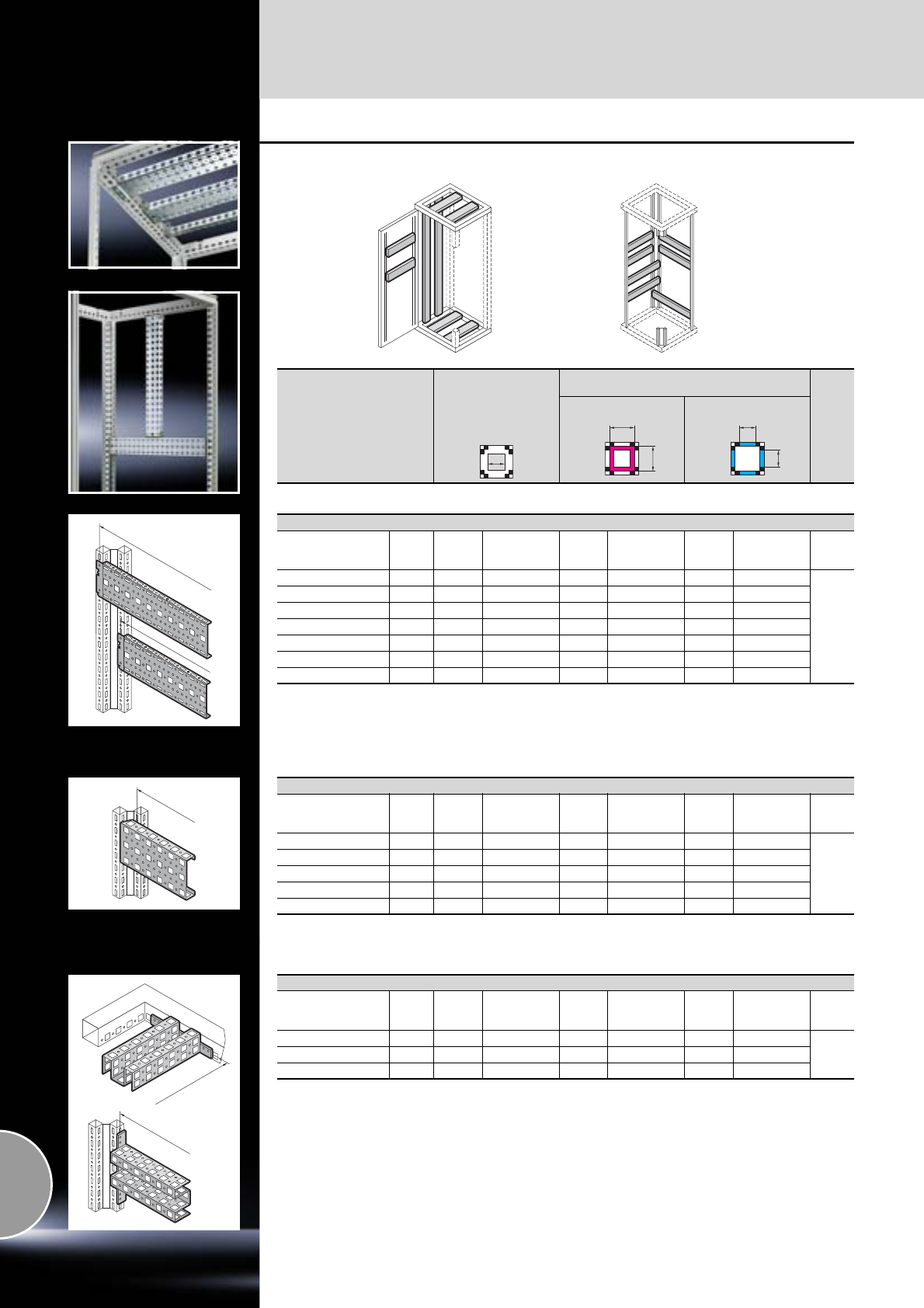
Interior installation
Rail systems
456 Rittal Catalogue 33/System accessories
TS installation examples with TS system rails
Installation in the roof
and base frame
in the width/depth
Installation between vertical sections
in the width/depth
Internal level External level
A
A
A
A
A
A
A
TS punched section with mounting flange, 17 x 73 mm
For
enclosure width/depth
mm
Packs
of A1)
mm Model No. TS A1)
mm Model No. TS A1)
mm Model No. TS Page
300 4 – – 275 8612.030 225 8612.130
459
400 4 – – 375 8612.040 325 8612.140
500 4 – – 475 8612.050 425 8612.150
600 4 – – 575 8612.060 525 8612.160
800 4 – – 775 8612.080 725 8612.180
1000 4 – – 975 8612.000 925 8612.100
1200 4 – – 1175 8612.020 1125 8612.120
1) A = Rail mounting distance
A
TS punched section with mounting flange, 23 x 73 mm
For
enclosure width/depth
mm
Packs
of A1)
mm Model No. TS A1)
mm Model No. TS A1)
mm Model No. TS Page
500 4 – – 425 8612.550 – –
460
600 4 – – 525 8612.560 – –
800 4 – – 725 8612.580 – –
1000 4 – – 925 8612.500 – –
1200 4 – – 1125 8612.520 – –
1) A = Rail mounting distance
A
A
TS punched section without mounting flanges, 45 x 88 mm
For
enclosure width/depth
mm
Packs
of A1)
mm Model No. TS A1)
mm Model No. TS A1)
mm Model No. TS Page
500 2 375 8612.650 – – 375 8612.650
461 600 2 475 8612.660 – – 475 8612.660
800 2 675 8612.680 – – 675 8612.680
1) A = Rail mounting distance
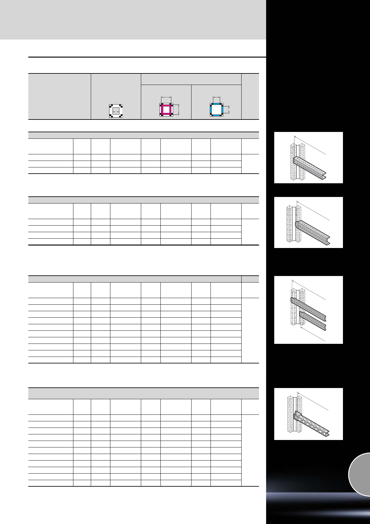
Rail systems
Interior installation
457Rittal Catalogue 33/System accessories
TS installation examples with TS system rails
Installation in the roof
and base frame
in the width/depth
Installation between vertical sections
in the width/depth
Internal level External level
A
A
A
A
A
A
TS punched rail 25 x 38 mm (with snap-on nut M8)
For
enclosure width/depth
mm
Packs
of A1)
mm Model No. TS A1)
mm Model No. TS A1)
mm Model No. TS Page
500 2 – – 435 8612.750 – –
461 600 2 – – 535 8612.760 – –
800 2 – – 735 8612.780 – –
1) A = Rail mounting distance
A
TS punched rail 18 x 38 mm
For
enclosure width/depth
mm
Packs
of A1)
mm Model No. TS A1)
mm Model No. TS A1)
mm Model No. TS Page
400 2 335 8612.240 – – 335 8612.240
462
500 2 435 8612.250 – – 435 8612.250
600 2 535 8612.260 – – 535 8612.260
800 2 735 8612.280 – – 735 8612.280
1) A = Rail mounting distance
Two TS punched rails 18 x 38 mm are included in the supply of enclosures with a mounting plate. After installing the
mounting plate, the TS punched rail may be inserted, as shown here.
A
A
TS support strips
For
enclosure width/depth
mm
Packs
of A1)
mm Model No. TS A1)
mm Model No. TS A1)
mm Model No. TS Page
400 20 – – – – 325 4694.000
462
500 20 – – – – 425 4695.000
600 20 – – – – 525 4696.000
800 20 – – – – 725 4697.000
400 20 – – 375 4309.000 – –
500 20 – 475 4596.000 – –
600 20 – 575 8800.130 – –
– 20 – 675 4598.000 – –
800 20 – 775 4579.000 – –
– 20 – 875 4599.000 – –
1) A = Rail mounting distance
Alternatively, the TS support strip for the inner mounting level may also be used for mounting on the door.
A
PS punched rails 23 x 23 mm
(for installation options, see support bracket TS/PS, angle bracket, mounting bracket)
For
enclosure width/depth
mm
Packs
of A1)
mm Model No. PS A1)
mm Model No. PS A1)
mm Model No. PS Page
400 12 275 4169.000 275 4169.000 – –
463
500 12 375 4170.000 375 4170.000 – –
600 12 475 4171.000 475 4171.000 – –
800 12 675 4172.000 675 4172.000 – –
1000 12 875 4173.000 875 4173.000 – –
1200 6 1075 4174.000 1075 4174.000 – –
1400 6 1275 4393.000 1275 4393.000 – –
1600 6 1475 4175.000 1475 4175.000 – –
1800 6 1675 4176.000 1675 4176.000 – –
2000 6 1875 4177.000 1875 4177.000 – –
2200 6 2075 4178.000 2075 4178.000 – –
1) A = Rail mounting distance
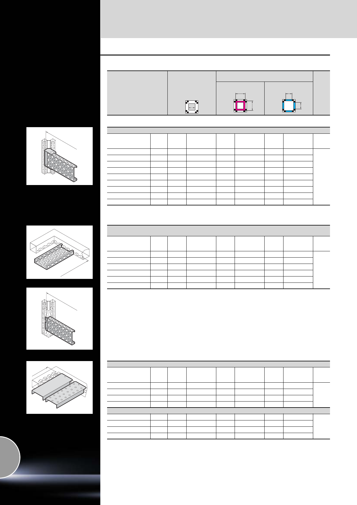
Interior installation
Rail systems
458 Rittal Catalogue 33/System accessories
TS installation examples with TS system rails
Installation in the roof
and base frame
in the width/depth
Installation between vertical sections
in the width/depth
Internal level External level
A
A
A
A
A
A
PS punched section without mounting flange 23 x 73 mm (installation option with support bracket TS)
For
enclosure width/depth
mm
Packs
of A1)
mm Model No. PS A1)
mm Model No. PS A1)
mm Model No. PS Page
400 4 275 4374.000 275 4374.000 – –
464
500 4 375 4375.000 375 4375.000 – –
600 4 475 4376.000 475 4376.000 – –
800 4 675 4377.000 675 4377.000 – –
1000 4 875 4382.000 875 4382.000 – –
1200 4 1075 4378.000 1075 4378.000 – –
1800 4 1675 4379.000 1675 4379.000 – –
2000 4 1875 4380.000 1875 4380.000 – –
2200 4 2075 4381.000 2075 4381.000 – –
1) A = Rail mounting distance
A
A
PS punched section with mounting flange 23 x 73 mm
(installation options with TS adaptor rail when mounting on the vertical TS enclosure section)
For
enclosure width/depth
mm
Packs
of A1)
mm Model No. PS A1)
mm Model No. PS A1)
mm Model No. PS Page
400 4 335 8800.640 – 8800.640 – –
464
500 4 435 8800.650 – 8800.650 – –
600 4 535 4364.000 – 4364.000 – –
800 4 735 4365.000 – 4365.000 – –
1000 4 935 4373.000 – 4373.000 – –
1200 4 1135 4367.000 – 4367.000 – –
1) A = Rail mounting distance
A
Support rails, slotted
For
enclosure width/depth
mm
Packs
of A1)
mm Model No. PS A1)
mm Model No. PS A1)
mm Model No. PS Page
400 4 335 4394.000 – – – –
466
500 2 435 4395.000 – – – –
600 2 535 4396.000 – – – –
800 2 735 4398.000 – – – –
Support rails, unslotted
400 4 335 – – – – –
466
500 2 435 – – – – –
600 2 535 4396.500 – – – –
800 2 735 4398.500 – – – –
1) A = Rail mounting distance
Alternatively, the support rail (slotted and unslotted) can also be fitted with snap-on nut M8, adaptor rail or
TS punched rail 25 x 38 mm on the vertical TS enclosure section.
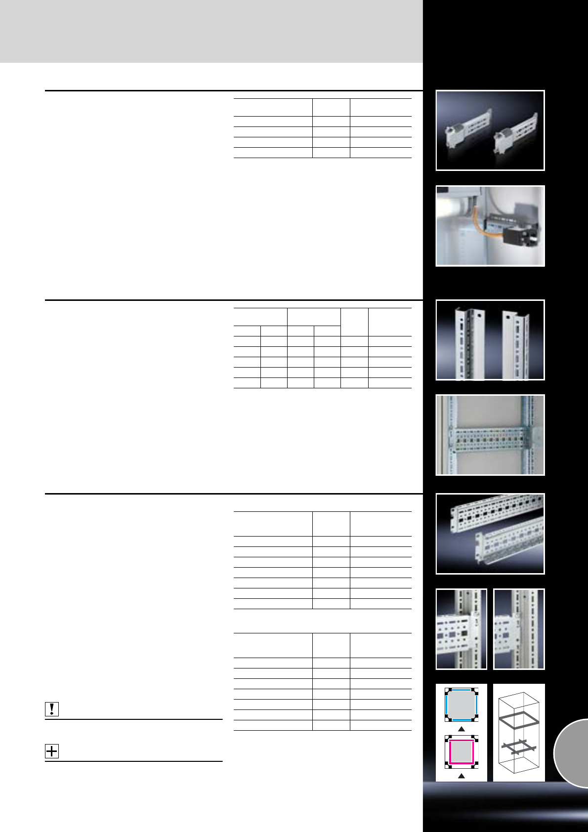
Rail systems
Interior installation
459Rittal Catalogue 33/System accessories
Rails for interior installation
for AE
For mounting in the enclosure, no machining
required. Suitable for all-round mounting on the
sides, base and roof areas.
Variable with 2 rows of system punchings,
creates additional mounting space e.g. for:
●TS punched section with mounting flange
●Enclosure lights
●Door-operated switch
●Door stay
●Cable conduit holder
Material:
Sheet steel
Surface finish:
Zinc-plated
Note:
Other mounting options:
−Mounting plates, locatable,
TS 8612.400, see page 469.
−Mounting plates, screw-fastening, large,
TS 8612.410, see page 469.
−Mounting plates, screw-fastening, small,
PS 4532.000, see page 470.
−Mounting brackets,
PS 4597.000, see page 470.
Configuration examples:
See page 452.
For enclosure depth
mm Packs of Model No. SZ
210 4 2373.210
250 4 2373.250
300 4 2373.300
350 4 2373.350
Rails for interior installation
for CM, TP
For mounting on the existing threaded bolts.
With TS system punchings on three sides.
Material:
Sheet steel
Surface finish:
Zinc-plated
Supply includes:
Assembly parts.
Configuration examples:
See page 453.
Width
mm Height
mm Packs
of Model No.
CM
CM TP1) CM TP2)
600 600 – 675 4 5001.050
800 800 800 – 4 5001.051
1000 – 1000 – 4 5001.052
1200 1200 1200 – 4 5001.053
– – 1400 – 4 5001.054
1) Only with TP console and desk unit
(cover or rear panel/base).
2) Only with TP pedestal.
TS punched section with
mounting flange, 17 x 73 mm
Variable, with 5 rows of holes for universal skele-
ton structures or partial assembly. Simply locate
into the TS punchings and secure.
Installation options:
●On the vertical TS enclosure section
−On the outer mounting level, all-round,
at the same height
−On the inner mounting level, all-round,
height-offset
●In CM and TP via rail for interior installation
−In the depth, for outer mounting level
−In the width, for inner mounting level
Material:
Sheet steel
Surface finish:
Zinc-plated
Supply includes:
Assembly screws.
Also required:
For installation in CM, TP:
Rail for interior installation, see page 459.
Accessories:
−Screws, see page 478.
−Cable tie for fast assembly SZ 2597.000,
see page 530.
For the outer mounting level
For the inner mounting level
Configuration examples:
See from page 453.
For
enclosure width/depth
mm Packs of Model No. TS
300 4 8612.130
400 4 8612.140
500 4 8612.150
600 4 8612.160
800 4 8612.180
1000 4 8612.100
1200 4 8612.120
For
enclosure width/depth
mm Packs of Model No. TS
300 4 8612.030
400 4 8612.040
500 4 8612.050
600 4 8612.060
800 4 8612.080
1000 4 8612.000
1200 4 8612.020
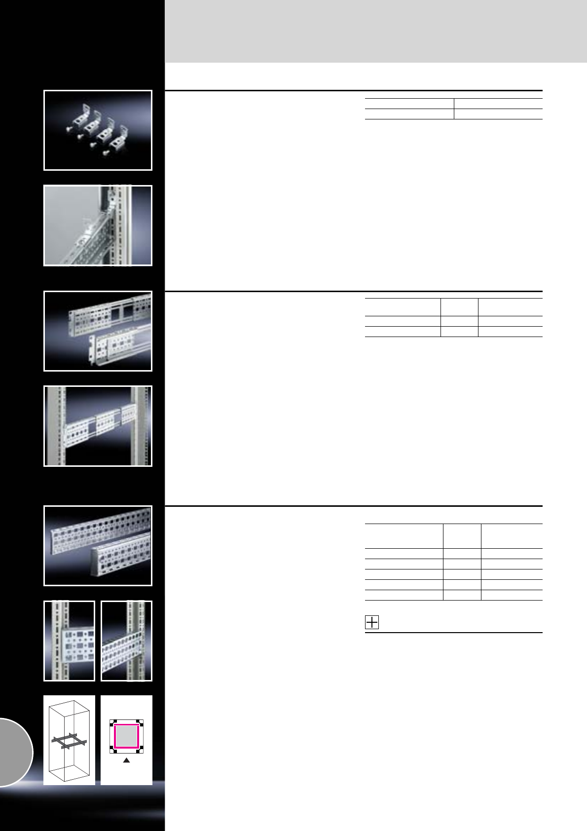
Interior installation
Rail systems
460 Rittal Catalogue 33/System accessories
Attachment TS
for TS punched section with mounting flange,
17 x 73 mm
Benefits:
●For attaching the TS punched section with
mounting flange where access to installed
equipment, such as mounting plates, is
blocked by the screw fastening.
●May also be screw-fastened onto the punched
section with mounting flange or enclosure frame
and used as a support for contact hazard pro-
tection covers or master switch trim panels.
Material:
Sheet steel
Surface finish:
Zinc-plated
Packs of Model No. TS
12 8612.010
TS punched section with
mounting flange, 17 x 73 mm
Depth-variable for mounting frames
for DK-TS, TE
For designing flexible interior installation, and/or
to accommodate additional built-in components.
The punched sections with mounting flanges may
be located in the enclosure depth between two
mounting frames. An additional screw fastening
secures the unit. The depth variability of the rails
facilitates flexible adaptation of their length to the
existing attachment distance between the two
482.6 mm (19˝) mounting frames. An additional
punched section centre piece may be slid flexibly
along the rail in the depth and secured to slots.
This facilitates flexible attachment at any point
between the mounting frames in the enclosure
depth.
Material:
Sheet steel
Surface finish:
Zinc-plated
Supply includes:
−2 variable punched sections with mounting
flanges
−One sliding centre part each
−Assembly parts
Length
mm Packs of Model No. HP
300 – 4701) 2) 2 7000.676
530 – 7001) 27000.678
1) Distance between 482.6 mm (19˝) levels =
length + 120 mm
2) L < 420 mm, without centre piece
TS punched section with
mounting flange, 23 x 73 mm
The alternative to the TS punched section with
mounting flange 17 x 73 mm, see page 459,
with punchings for captive nuts/threaded blocks
instead of the slotted holes top and bottom.
Simply locate and secure.
Installation options:
●On the vertical TS enclosure section
Material:
Sheet steel
Surface finish:
Zinc-plated
Supply includes:
Assembly screws.
For the inner mounting level
Accessories:
−Screws,
see page 478.
−Threaded blocks, captive nuts,
see page 477.
Configuration examples:
See page 456.
For
enclosure width/depth
mm Packs of Model No. TS
500 4 8612.550
600 4 8612.560
800 4 8612.580
1000 4 8612.500
1200 4 8612.520
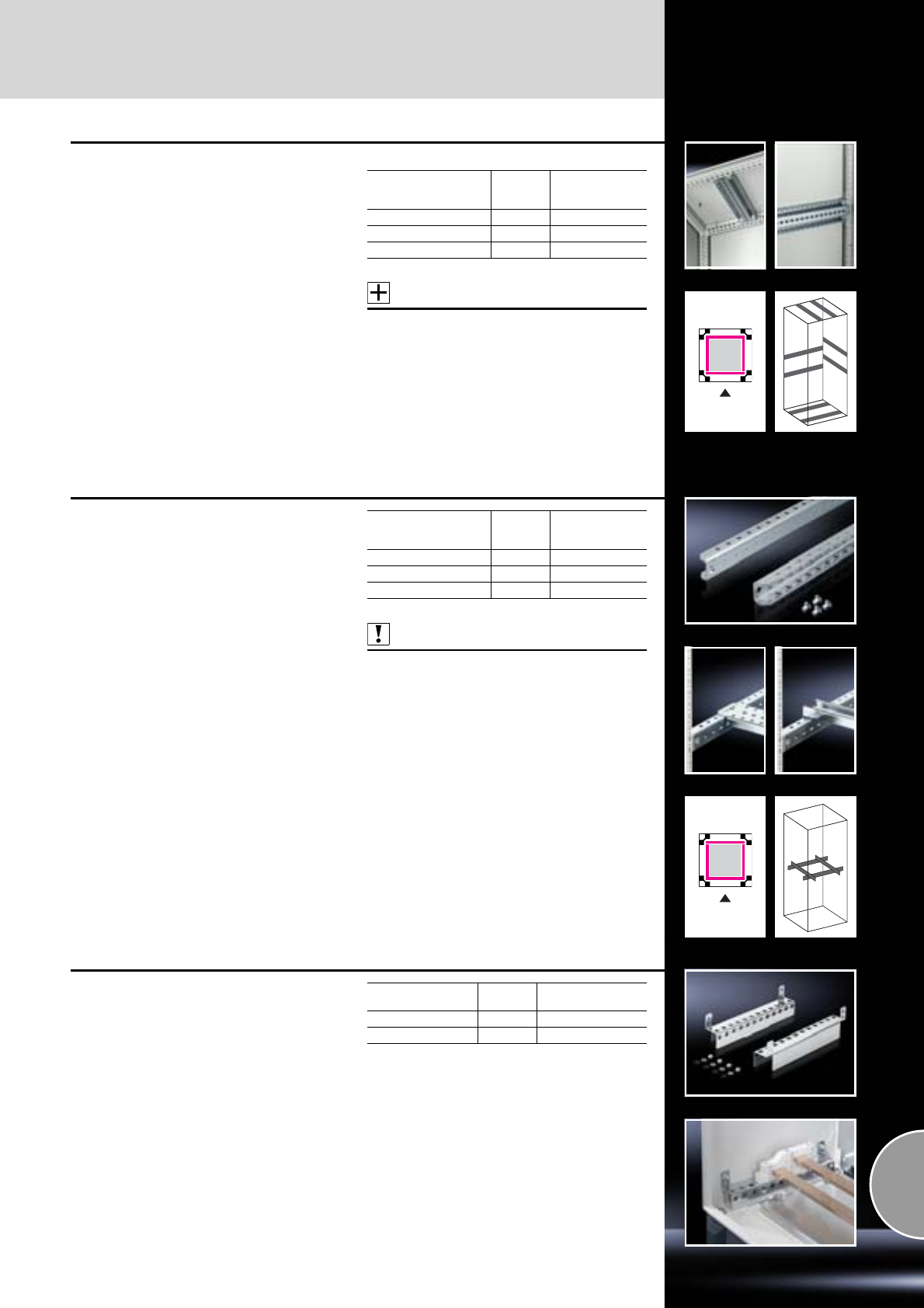
Rail systems
Interior installation
461Rittal Catalogue 33/System accessories
TS punched section without
mounting flanges, 45 x 88 mm
Heavy top-mounted equipment mounted directly
on the internal surfaces (e.g. roof) is supported.
Mounted on the side or rear, the enclosure can
then be screw-fastened securely to the machine.
The twin profile with 11 rows of holes offers
numerous additional opportunities for interior
installation.
Installation options:
●On the vertical and horizontal TS enclosure
section
Material:
Sheet steel
Surface finish:
Zinc-plated
Supply includes:
Assembly parts.
For the inner mounting level
Accessories:
−Screws,
see page 478.
−Threaded blocks, captive nuts,
see page 477.
Configuration examples:
See page 456.
For
enclosure width/depth
mm Packs of Model No. TS
500 2 8612.650
600 2 8612.660
800 2 8612.680
TS punched rail 25 x 38 mm
For heavy installations, with attachment holes.
Installation options:
●On the vertical TS enclosure section
With 9 mm round holes on a 25 mm pitch pattern
on all sides, for mounting:
●Support rails, see page 466
●System support rails, see page 466
●C rails 30/15, see page 465
●Cable clamp rails (right angle section),
see page 527
●Own assemblies.
Material:
Sheet steel, 3.0 mm
Surface finish:
Zinc-plated
Supply includes:
Assembly screws.
Also required:
Snap-on nut M8, TS 8800.808,
see page 471.
Note:
In conjunction with the snap-on nut, particularly
well-suited for dynamic connections.
Configuration examples:
See page 457.
For
enclosure width/depth
mm Packs of Model No. TS
500 2 8612.750
600 2 8612.760
800 2 8612.780
Base configuration rail
for CM
For mounting in the enclosure depth, on the
existing threaded bolts, no machining required.
TS system punchings on 2 sides.
Creates additional installation options.
Material:
Sheet steel
Surface finish:
Zinc-plated
Supply includes:
Assembly parts.
For enclosure depth
mm Packs of Model No. CM
400 2 5001.370
300 2 5001.371
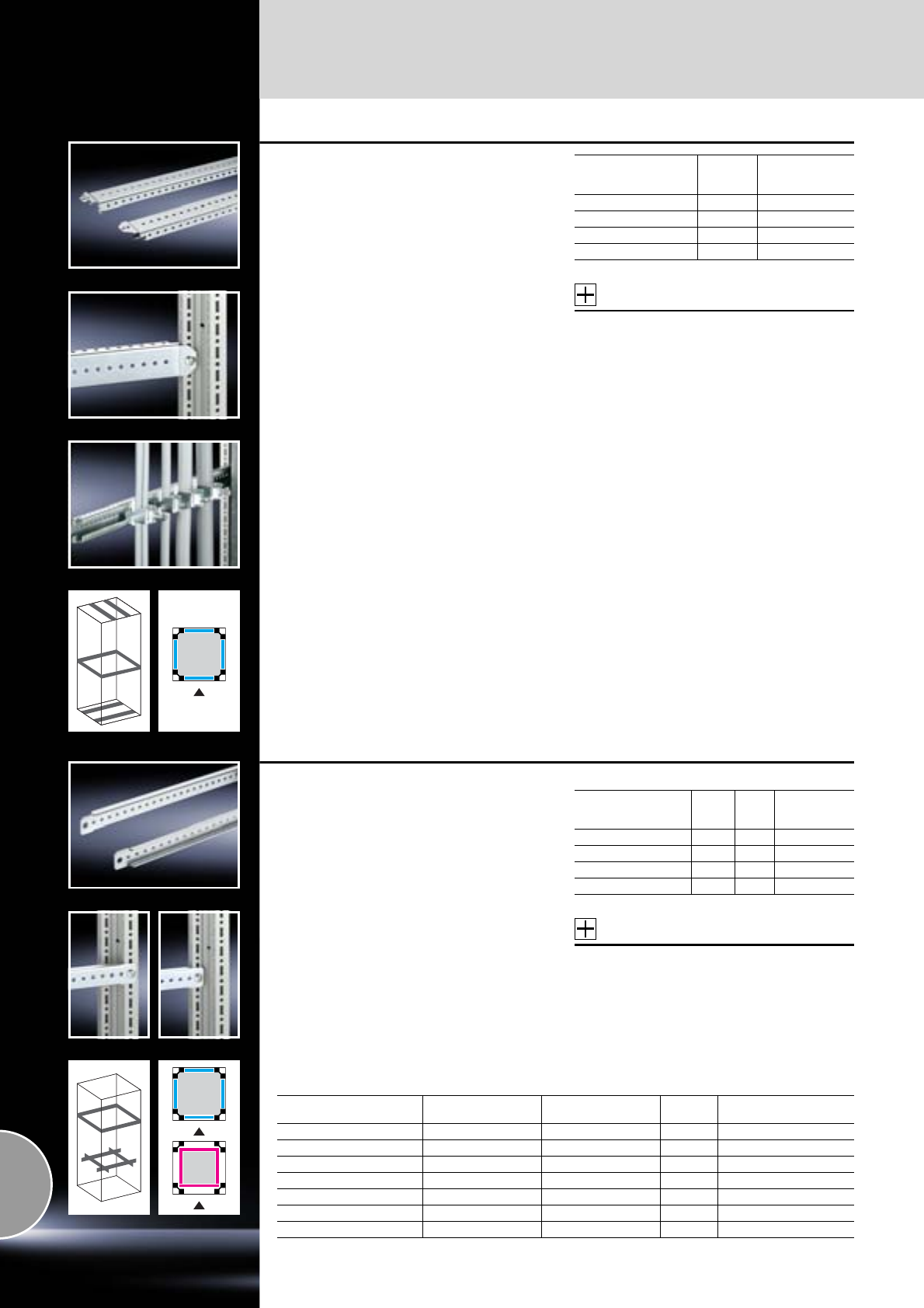
Interior installation
Rail systems
462 Rittal Catalogue 33/System accessories
TS punched rail 18 x 38 mm
Simply locate and secure with a screw.
The location system makes assembly and dis-
mantling easier. It only needs to be secured on
one side, but may be secured on both sides if
required.
Installation options:
●On the vertical TS enclosure section
−On the outer mounting level
●On the horizontal TS enclosure section
●On base configuration rail for CM
Material:
Sheet steel
Surface finish:
Zinc-plated
Supply includes:
Assembly screws.
Note:
In enclosures with a mounting plate, 2 punched
rails are already included with the supply.
Accessories:
−Screws,
see page 478.
−Cable tie for fast assembly SZ 2597.000,
see page 530.
−Cable clamps,
see page 529.
Configuration examples:
See from page 453.
For
enclosure width/depth
mm Packs of Model No. TS
400 4 8612.240
500 4 8612.250
600 4 8612.260
800 4 8612.280
TS support strips
Installation options:
●On the vertical and horizontal TS enclosure
section
−On the outer mounting level, all-round,
at the same height
−On the inner mounting level, all-round,
height-offset
●On the tubular door frame TS, ES
●On the perforated door strip CM, TP
●On the ES system punchings, in the enclosure
depth
Material:
Sheet steel
Surface finish:
Zinc-plated
Supply includes:
Assembly screws.
For the outer mounting level
Accessories:
−Screws,
see page 478.
−Cable tie for fast assembly SZ 2597.000,
see page 530.
Configuration examples:
See from page 452.
For
enclosure width/depth
mm
Length
mm Packs
of Model No. TS
400 340 20 4694.000
500 440 20 4695.000
600 540 20 4696.000
800 740 20 4697.000
For the inner mounting level and for mounting on doors
For enclosure width/depth
mm For door width
mm Length
mm Packs of Model No. TS
– 400 290 20 4594.000
400 500 390 20 4309.000
500 600 490 20 4596.000
600 – 590 20 8800.130
– 800 690 20 4598.000
800 900 790 20 4579.000
– 1000 890 20 4599.000
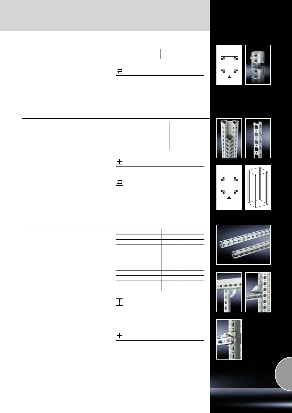
Rail systems
Interior installation
463Rittal Catalogue 33/System accessories
TS assembly block
Installation in the vertical TS enclosure sections
for mounting PS-compatible individual compo-
nents.
Material:
Die-cast zinc
Supply includes:
Assembly screws.
Possible
alternative:
Snap-on nut,
see page 471.
Packs of Model No. TS
48800.310
Adaptor rail
for PS compatibility
Installation in the vertical TS enclosure sections
(across the entire enclosure height or in sub-sec-
tions) to create compatibility with:
−PS punched rail, 23 x 23 mm
−PS punched section without mounting flange,
23 x 73 mm
−PS punched section with mounting flange
23 x 73 mm
Material:
Sheet steel
Surface finish:
Zinc-plated
Supply includes:
Assembly screws.
Accessories:
Screws,
see page 478.
Possible
alternative:
Snap-on nut,
see page 471.
For
enclosure height
mm Packs of Model No. TS
1800 4 8800.380
2000 4 8800.300
2200 4 8800.320
PS punched rails 23 x 23 mm
for TS, ES
Installation options:
●On the vertical enclosure section
−Directly via support brackets TS
−Via adaptor rail for PS compatibility in
conjunction with angle brackets, mounting
brackets or support brackets PS
●On the horizontal enclosure section
−Directly via angle brackets, mounting
brackets or support brackets PS
Material:
Sheet steel
Surface finish:
Zinc-plated
Also required:
−U nuts, see page 477.
−Mounting brackets TS/PS,
see page 472 or
−Angle brackets, support brackets TS/PS,
see page 473.
Accessories:
−Cable attachment, see page 530.
−Screws, see page 478.
−Cable tie for fast assembly SZ 2597.000,
see page 530.
Configuration examples:
See from page 453.
Length mm For WHD mm Packs of Model No. PS
295 400 12 4169.000
395 500 12 4170.000
495 600 12 4171.000
695 800 12 4172.000
895 1000 12 4173.000
1095 1200 6 4174.000
1295 1400 6 4393.000
1495 1600 6 4175.000
1695 1800 6 4176.000
1895 2000 6 4177.000
2095 2200 6 4178.000
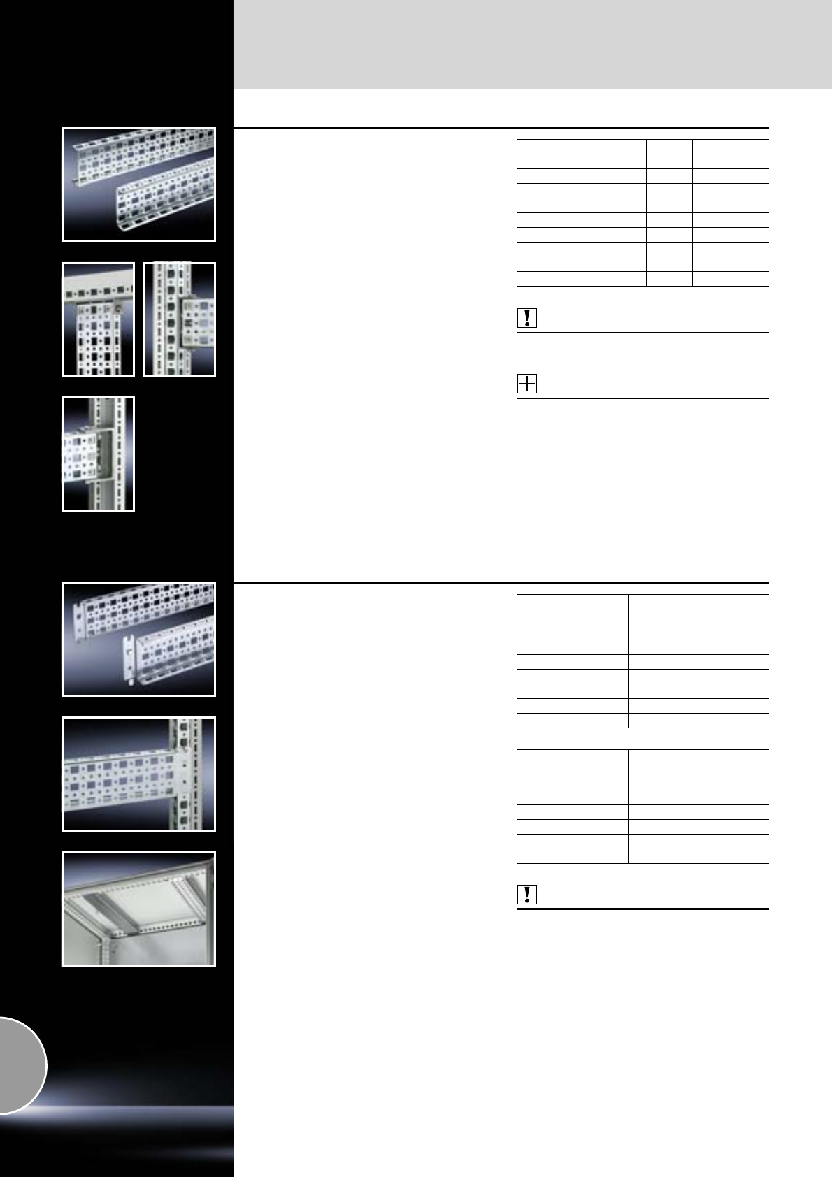
Interior installation
Rail systems
464 Rittal Catalogue 33/System accessories
PS punched section without
mounting flange, 23 x 73 mm
for TS, ES
Installation options:
●On the vertical enclosure section
−Directly via support brackets TS
−Via adaptor rail for PS compatibility in
conjunction with support brackets PS
●On the horizontal enclosure section
−Directly via support brackets PS
Material:
Sheet steel
Surface finish:
Zinc-plated
Also required:
Support brackets PS/TS,
see page 473.
Accessories:
−Screws, see page 478.
−Cable tie for fast assembly SZ 2597.000,
see page 530.
−U nuts, see page 477.
Configuration examples:
See page 458.
Length mm For WHD mm Packs of Model No. PS
295 400 4 4374.000
395 500 4 4375.000
495 600 4 4376.000
695 800 4 4377.000
895 1000 4 4382.000
1095 1200 4 4378.000
1695 1800 4 4379.000
1895 2000 4 4380.000
2095 2200 4 4381.000
PS punched section with
mounting flange 23 x 73 mm
for TS, ES
Variable, with 5 rows of holes for universal skele-
ton structures or partial assembly. Simply locate
into the system punchings and secure.
Installation options:
●On the vertical TS enclosure section
−Via adaptor rail for PS compatibility
●On the horizontal TS enclosure section
●On the ES system punchings, in the enclosure
depth
Material:
Sheet steel
Surface finish:
Zinc-plated
Supply includes:
Assembly screws.
Also required:
Adaptor rail for PS compatibility
(when mounting on the vertical enclosure section),
see page 463.
Configuration examples:
See page 458.
Installation in
enclosure width/depth
TS
mm
Packs of Model No. PS
400 4 8800.640
500 4 8800.650
600 4 4364.000
800 4 4365.000
1000 4 4373.000
1200 4 4367.000
Installation in
enclosure depth ES,
TP universal console,
CS modular enclosures
mm
Packs of Model No. PS
400 4 4369.000
500 4 4370.000
600 4 4371.000
800 4 4372.000
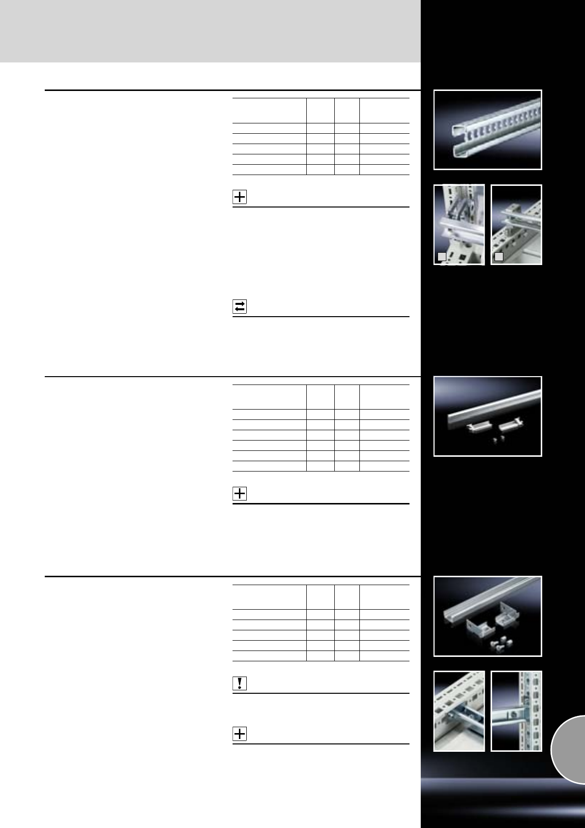
Rail systems
Interior installation
465Rittal Catalogue 33/System accessories
2
1
C rails 30/15
to EN 60 715 for TS, ES
Installation options:
●On the vertical TS enclosure section
−Via snap-on nut TS 8800.808 (Fig. 1)
−Via adaptor rail for PS compatibility
●On the horizontal TS enclosure section (Fig. 2)
●On the ES system punchings
●On base configuration rail for CM
Material:
Sheet steel
Surface finish:
Zinc-plated
Accessories:
−Cable clamps,
see page 529.
−Support bracket or spacer,
see page 474.
−Quick-assembly block,
see page 474.
−Snap-on nut M8, TS 8800.808,
see page 471.
−Adaptor rail,
see page 463.
Possible
alternative:
Rail for EMC shielding bracket and strain relief,
see page 498.
For
enclosure width/depth
mm
Length
mm Packs
of Model No. PS
500 455 6 4943.000
600 555 6 4944.000
800 755 6 4945.000
1000 955 6 4946.000
1200 1155 6 4947.000
C rails
for DK-TS, CS Toptec
For direct mounting on the vertical enclosure
section. Thanks to the universally designed
attachment piece, the C rails may optionally be
attached to the inner or outer level of the TS 8
frame.
Material:
Sheet steel
Surface finish:
Zinc-plated
Supply includes:
Assembly parts.
Accessories:
Cable clamps,
see page 529.
For
enclosure width/depth
mm
Length
mm Packs
of Model No. DK
400 298 4 7828.040
500 398 4 7828.050
600 498 4 7828.060
800 698 4 7828.080
1000 898 4 7828.100
1200 1098 4 7828.120
C rails
for DK-TS
Installation options:
●On the horizontal enclosure sections
●On the vertical TS enclosure section
−Via adaptor rail for PS compatibility
Material:
Sheet steel
Surface finish:
Zinc-plated
Supply includes:
Assembly parts.
Also required:
Adaptor rail for PS compatibility
(when mounting on the vertical enclosure section),
see page 463.
Accessories:
Cable clamps,
see page 529.
For
enclosure width/depth
mm
Length
mm Packs
of Model No. DK
400 290 6 7091.000
600 490 6 7095.000
800 690 6 7096.000
1000 890 6 7100.000
1200 1090 6 7102.000
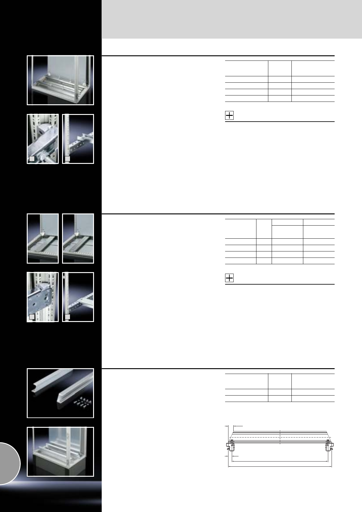
Interior installation
Rail systems
466 Rittal Catalogue 33/System accessories
2
1
System support rails
For heavy installed equipment such as transform-
ers. T-head screw and slot in the support rail
for any mounting position.
Installation options:
●On the vertical TS enclosure section
−Via snap-on nut TS 8800.808 (Fig. 1)
−Via adaptor rail for PS compatibility
−Offset in the height, via TS punched rail
25 x 38 mm (Fig. 2)
●On the horizontal TS enclosure section
−in width
−In the depth (without mounting plate)
●On the ES system punchings
−In the enclosure depth
●On base configuration rail for CM
Material:
Sheet steel
Surface finish:
Zinc-plated
Supply includes:
−2 system support rails (45 x 25 mm)
−4 T-head screws M12 x 60 mm
−Assembly parts
Accessories:
−Width divider e.g. for the installation of
2 system support rails (for 600 mm width)
in 1200 mm wide enclosures,
see page 376.
−Snap-on nut M8, TS 8800.808,
see page 471.
−Adaptor rail,
see page 463.
−TS punched rail 25 x 38 mm,
see page 461.
For
enclosure width
mm Packs of Model No. PS
600 2 4361.000
800 2 4362.000
1000 2 4347.000
1200 2 4363.000
2
1
Support rails
for TS, ES, CM
For heavy installations. Particularly suitable for the
installation of base isolators.
Installation options:
●On the vertical TS enclosure section
−Via snap-on nut TS 8800.808 (Fig. 1)
−Via adaptor rail for PS compatibility
−Offset in the height, via TS punched rail
25 x 38 mm (Fig. 2)
●On the horizontal TS enclosure section
−in width
−in depth
●On the ES system punchings, in the enclosure
depth
●On base configuration rail for CM
Material:
Sheet steel
Surface finish:
Zinc-plated
Supply includes:
Assembly parts.
Accessories:
−Snap-on nut M8, TS 8800.808,
see page 471.
−Adaptor rail,
see page 463.
−TS punched rail 25 x 38 mm,
see page 461.
Configuration examples:
See from page 453.
For
enclosure
width/depth
mm
Packs
of
Model No. PS Model No. TS
slotted unslotted
400 4 4394.000 –
500 4 4395.000 –
600 4 4396.000 4396.500
800 4 4398.000 4398.500
Support rail 65 x 42 mm
for TS, ES
Benefits:
●For heavy assemblies up to 5000 N per
support rail.
Permissible static load:
10000 N per enclosure
Material:
Steel
Surface finish:
Zinc-plated
Supply includes:
Assembly parts.
For
enclosure width
mm Packs of Model No. TS
600 2 8612.960
800 2 8612.980
28.5
20
535/735
575/775
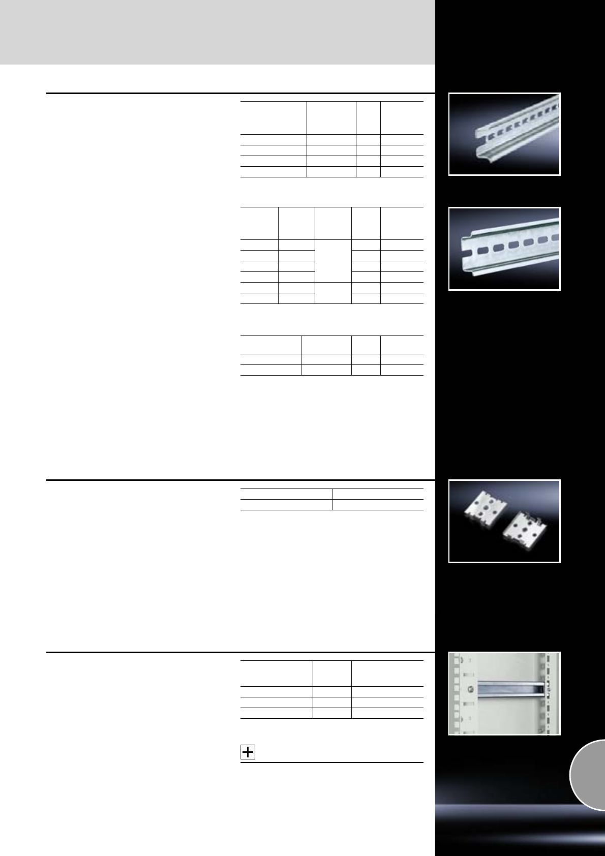
Rail systems
Interior installation
467Rittal Catalogue 33/System accessories
Support rails TS 35/15
to EN 60 715 for TS, ES
Mounting on the TS vertical section via
−Snap-on nut M8, TS 8800.808,
see page 471
−Assembly block see page 463 or
−Adaptor rail, see page 463.
For
enclosure
width/depth
mm
Support rails
length
mm
Packs
of Model No.
PS
500 455 6 4933.000
600 555 6 4934.000
800 755 6 4935.000
1200 1155 6 4937.000
Support rails TS 35/7.5
and TS 35/15
to EN 60 715 for KL, KL-HD, AE
Length sized to the enclosure width
For
enclosure
width
mm
Support
rails
length
mm
Design Packs
of Model No.
SZ
150 137
TS 35/7.5
10 2314.000
200 187 10 2315.000
300 287 10 2316.000
400 387 10 2317.000
500 487 TS 35/15 10 2318.000
600 587 10 2319.000
Support rails
to EN 60 715
Standard length 2 m
Design Length Packs
of Model No.
SZ
TS 35/15 2 m 6 2313.150
TS 35/7.5 2 m 6 2313.750
Mounting clip
for support rails
For fast, secure attachment of:
●Cable ducts
●Mounting plates
●Mounting angles
on support rail TS 35/7.5 and TS 35/15 to
EN 60 715.
Simply pre-assemble the mounting clip on the
part to be installed, then snap into position on the
support rail.
Packs of Model No. SZ
30 2309.000
C rails
for EL
For infinite adjustment of the mounting angles in
the depth.
Material:
Sheet steel
Supply includes:
Assembly parts.
Accessories:
Cable clamps,
see page 529.
For
centre part depth
mm Packs of Model No. EL
216 4 2238.0001)
316 4 2239.000
416 4 2237.000
1) Extended delivery times.
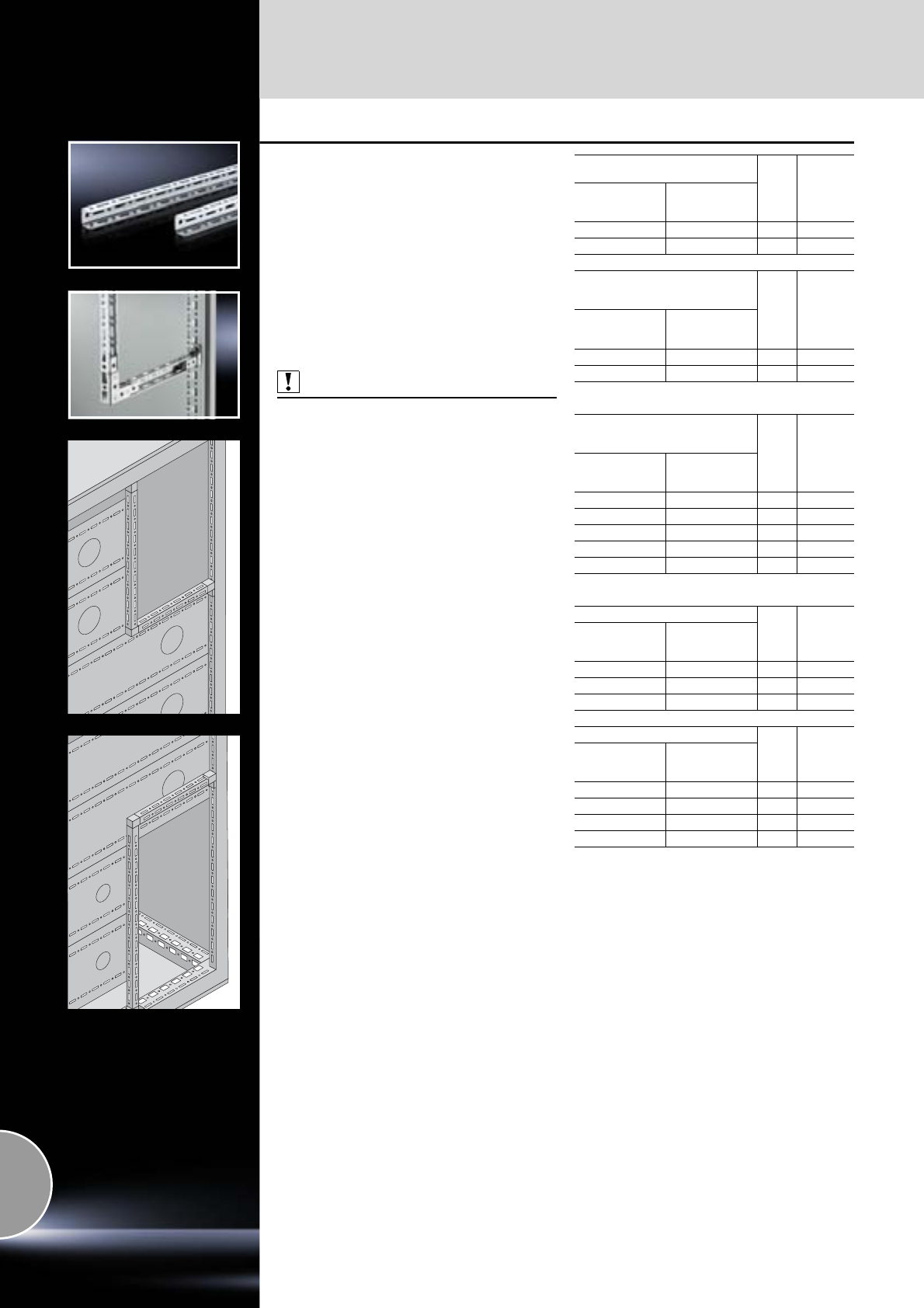
Interior installation
Rail systems
468 Rittal Catalogue 33/System accessories
TS punched rail 17 x 17 mm
for TS
Mounting angle with TS pitch on three sides.
Suitable for
●building an auxiliary construction for dividing
the busbar space,
●individual use as mounting frame for low and
medium loads,
●fastening to the internal or external mounting
level of the TS 8 enclosure.
Material:
Sheet steel, 1.5 mm
Surface finish:
Zinc-plated
Also required:
−Frame connector piece,
see page 475.
−T-connector piece,
see page 475.
−Corner connector,
see page 475.
For horizontal
busbar space separation Packs
of Model No.
SV
For functional
space depth
mm
Length
mm
425 62.5 12 9673.915
600 137.5 12 9673.920
For vertical separation
with busbar system
in the top rear section Packs
of Model No.
SV
For functional
space height
mm
Length
mm
450 – 5001) 487.5 12 9673.953
650 – 8001) 787.5 12 9673.983
1) Rails should be shortened where necessary.
For vertical separation
with busbar system
in the bottom rear section Packs
of Model No.
SV
For functional
space height
mm
Length
mm
350 412.5 12 9673.951
400 462.5 12 9673.960
450 512.5 12 9673.961
550 – 6501) 712.5 12 9673.981
700 – 8001) 862.5 12 9673.995
1) Rails should be shortened where necessary.
For external mounting level
Packs
of Model No.
SV
For enclosure
width/depth
mm
Length
mm
400 262.5 12 9673.940
500 362.5 12 9673.950
600 462.5 12 9673.960
For internal mounting level
Packs
of Model No.
SV
For enclosure
width/depth
mm
Length
mm
400 312.5 12 9673.941
500 412.5 12 9673.951
600 512.5 12 9673.961
800 712.5 12 9673.981
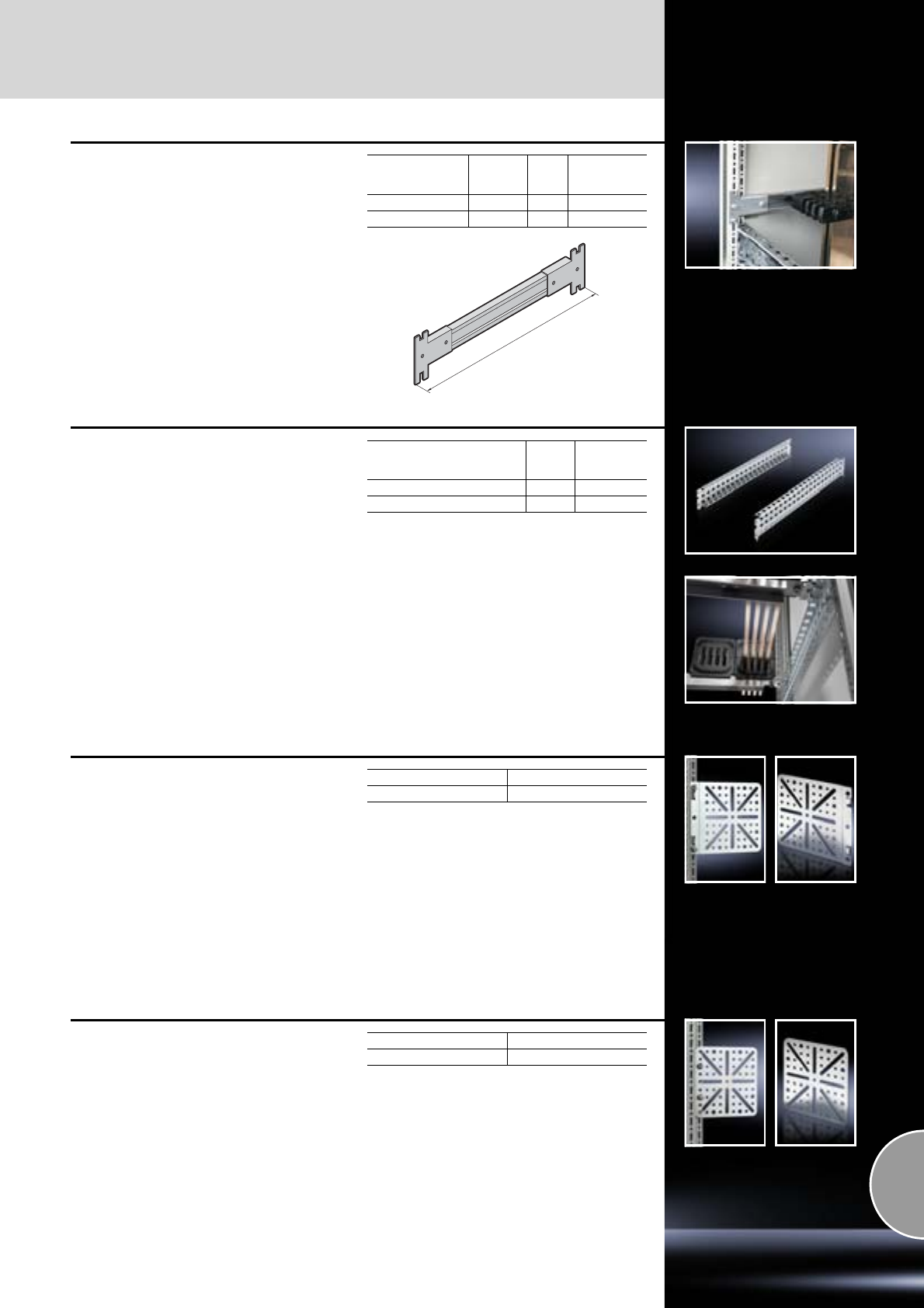
Rail systems
Interior installation
469Rittal Catalogue 33/System accessories
C rails
for cable chamber enclosures
For attaching cables and lines and for mounting
stacking insulators.
Material:
Sheet steel
Supply includes:
−4 C rails
−8 brackets
−Assembly parts
For TS enclosures
width/depth
mm
Length (L)
mm Packs
of Model No. SV
600 600 4 9660.210
800 800 4 9660.220
L
Punched sections
with mounting flanges
for coupling section
For assembling a Maxi-PLS or Flat-PLS busbar
system directly beneath or above the circuit-
breaker. This punched section with mounting
flange may be used without conflict in conjunc-
tion with the compartment space side panel
modules. It is attached to the outer level of the
TS 8 enclosure system, but thanks to the PS
punchings allows a mounting level as in the roof
or base frame, thereby facilitating the use of bus-
bar system attachment for the roof/base section.
Material:
Sheet steel
Surface finish:
Zinc-plated
Supply includes:
Assembly parts.
For TS enclosures
width/depth
mm
Packs
of Model No.
SV
600 2 9674.056
800 2 9674.058
Mounting plates
Locatable
on
●the vertical TS enclosure section
●TS punched section with mounting flange,
17 x 73 mm
●at the rear on the TE 482.6 mm (19˝) mounting
frame
Material:
Sheet steel
Surface finish:
Zinc-plated
Supply includes:
Assembly screws.
Detailed drawings:
Available on the Internet.
Packs of Model No. TS
48612.400
Mounting plates
Screw-fastened, large
On all enclosures and mounting parts with system
punchings on a 25 mm pitch pattern.
Material:
Sheet steel
Surface finish:
Zinc-plated
Supply includes:
Assembly screws.
Detailed drawings:
Available on the Internet.
Packs of Model No. TS
48612.410
Interior installation
Rail systems
470 Rittal Catalogue 33/System accessories
Mounting plates
Screw-fastened, small
Material:
Sheet steel
Surface finish:
Zinc-plated
Supply includes:
Assembly screws.
Detailed drawings:
Available on the Internet.
Packs of Model No. PS
44532.000
Mounting plate TS
with integral top-hat rail
For direct snap-mounting of components such as
speed control, enclosure internal thermostat and
hygrostat.
Material:
Sheet steel
Surface finish:
Zinc-plated
Supply includes:
Mounting plate (mounting accessories included).
Packs of Model No. DK
17526.964
Mounting bracket
May be screw-fastened onto all enclosures and
mounting parts with system punchings on a
25 mm pitch pattern.
Material:
Sheet steel
Surface finish:
Zinc-plated
Supply includes:
Assembly screws.
Accessories:
−Screws,
see page 478.
−Cable tie for fast assembly SZ 2597.000,
see page 530.
Detailed drawings:
Available on the Internet.
Packs of Model No. PS
44597.000
Mounting bracket
for interior installation
For installing punched sections with mounting
flanges and support strips in:
●Comfort Panel horizontal/vertical from 74 mm
installation depth
or for installing in:
●Optipanel from an installation depth of 100 mm
Material:
Sheet steel
Surface finish:
Zinc-plated
Supply includes:
Assembly parts.
Detailed drawings:
Available on the Internet.
Packs of Model No. CP
4 6205.100
Comfort Panel Page
Front plate width 482.6 mm (19˝)
Punched sections with mounting
flanges
Horizontal 8612.150 459
Vertical
Support strips Horizontal 4695.000 462
Vertical
Assembly components
Interior installation
471Rittal Catalogue 33/System accessories
1
2
3
4
5
Snap-on nut TS
Metric thread for vertical TS enclosure section.
To install, insert into slot and clip into position.
The snap-on nut is then secure. By tightening the
screw, it is securely tightened against the section,
and potential equalisation is automatically cre-
ated.
Installation options:
●On the vertical TS enclosure section
−with metric thread M6 or M8
−the alternative to metal screws
−particularly well-suited for dynamically loaded
connections.
Material:
Precision-cast stainless steel
Accessories for interior installation
Support rails,
see page 466
Cable clamp rails,
see page 527
C rails 30/15,
see page 465
System support rails,
see page 466
TS punched rail 25 x 38 mm,
see page 461
Accessories:
Multi-tooth screw M6 x 12 or M8 x 12,
see page 478.
1
2
3
4
5
Thread Packs of Model No. TS
M6 20 8800.806
M8 20 8800.808
Adaptor bracket TS
For external mounting of
●System lights
●Cable ducts
on the vertical TS enclosure section.
Material:
Sheet steel
Surface finish:
Zinc-plated
Supply includes:
Assembly screws.
Packs of Model No. TS
68800.360
Interior installation
Assembly components
472 Rittal Catalogue 33/System accessories
Mounting bracket TS
Offers variable mounting options for the punched
rail 23 x 23 mm, e.g. for supporting external
surfaces or creating an additional internal level.
Material:
Die-cast zinc
Supply includes:
24 screws 5.5 x 13 mm.
Accessories:
U nuts (recommendation: M6),
see page 477.
Installation options:
●On the vertical TS enclosure section
−flush with the outer edge of the enclosure or
−flush with the enclosure clearance width.
Packs of Model No. TS
24 8800.370
1
Support of the external surfaces with two
mounting options:
● Without mounting plate (photo)
● With mounting plate (drawing)
1
2
Two installation options for the inner mounting
level:
If there is no divider panel fitted.
2
3
With a divider panel fitted, and without or with
a mounting plate in a set forward position.
3
Mounting bracket PS
For variable attachment of punched rail
23 x 23 mm.
Installation options:
●Optionally flush with:
−Outer enclosure edge or
−Enclosure clearance width
●On the vertical TS enclosure section via
−Adaptor rail for PS compatibility,
see page 463
●On the horizontal TS enclosure section
●On enclosures and rails with rectangular
system punching 12.5 x 10.5 mm.
Material:
Die-cast zinc
Supply includes:
1 set =
1 mounitng bracket,
1 screw M6 x 12 mm,
1 cage nut M6.
Also required:
−U nuts for punched rails (recommended: M6),
see page 477.
−Multi-tooth screws M6 x 12 mm,
see page 478.
Packs of Model No. PS
24 set 4182.000
Assembly components
Interior installation
473Rittal Catalogue 33/System accessories
Angle bracket PS
For quick attachment of punched rails
23 x 23 mm.
Installation options:
●On the vertical TS enclosure section via
−Adaptor rail for PS compatibility,
see page 463
●On the horizontal TS enclosure section
●On enclosures and rails with rectangular
system punching 12.5 x 10.5 mm.
Material:
Sheet steel
Surface finish:
Zinc-plated
Supply includes:
1 set =
1 angle bracket, left,
1 angle bracket, right,
2 metal screws 5.5 x 13 mm.
Also required:
−U nuts for punched rails (recommended: M6),
see page 477.
−Multi-tooth screws M6 x 12 mm,
see page 478.
Packs of Model No. PS
12 set 4181.000
Support bracket TS
For the attachment of punched sections without
mounting flange 23 x 73 mm or punched rails
23 x 23 mm.
Installation options:
●On the vertical TS enclosure section
−on a 25 mm pitch pattern
−in 2 mm increments.
Material:
Die-cast zinc
Supply includes:
1 set =
1 support bracket,
1 stay,
3 metal screws 5.5 x 13 mm.
Also required:
−U nuts for punched rails (recommended: M6),
see page 477.
−Multi-tooth screws M6 x 12 mm,
see page 478.
Packs of Model No. TS
6 set 8800.330
Support bracket PS
For the attachment of punched sections without
mounting flange 23 x 73 mm or punched rails
23 x 23 mm.
Installation options:
●On the vertical TS enclosure section via
−Snap-on nut TS 8800.806,
see page 471 or
−Adaptor rail for PS compatibility,
see page 463
●On the horizontal TS enclosure section
●On enclosures and rails with rectangular
system punching 12.5 x 10.5 mm.
Material:
Die-cast zinc
Supply includes:
1 set =
1 support bracket,
2 countersunk screws,
2 serrated lock washers.
Also required:
−U nuts for punched rails (recommended: M6),
see page 477.
−Multi-tooth screws M6 x 12 mm,
see page 478.
−Adaptor rail for PS compatibility (when
mounting on the vertical enclosure section),
see page 463.
Packs of Model No. PS
24 set 4183.000
Interior installation
Assembly components
474 Rittal Catalogue 33/System accessories
Bracket/spacer
For fastening C rails, punched rails or cable
clamp rails (angle section). On the sides,
to accommodate square sections or tubes
(Ø 20 mm).
Attachment points with M8 thread.
Installation options:
●On the vertical TS enclosure section via
−Snap-on nut TS 8800.808,
see page 471, or
−Adaptor rail for PS compatibility,
see page 463
●On the horizontal TS enclosure section
●On enclosures and rails with rectangular
system punching 12.5 x 10.5 mm.
Material:
Die-cast zinc
Supply includes:
1 set =
1 bracket/spacer,
2 screws M8 x 16 mm,
2 spring lock washers,
2 cage nuts M8,
2 serrated lock washers,
2 metal screws.
Accessories:
Angle piece TS 4134.000,
see page 474.
Packs of Model No. TS
6 set 4199.000
Quick-assembly block
For a variety of installation options.
Installation options:
●On the vertical TS enclosure section via
−Snap-on nut TS 8800.808,
see page 471, or
−Adaptor rail for PS compatibility,
see page 463
●On the horizontal TS enclosure section
●On enclosures and rails with rectangular
system punching 12.5 x 10.5 mm.
Material:
Die-cast zinc
Supply includes:
−12 quick-assembly blocks
−12 threaded blocks M8
−24 screws M8 x 12 mm
−24 square nuts M8
Packs of Model No. TS
12 4133.000
Angle piece
For assembling punched rails and mounting
surfaces with a 45° incline.
Installation options:
●On the vertical TS enclosure section via
−Snap-on nut TS 8800.806,
see page 471 or
−Adaptor rail for PS compatibility,
see page 463
●On the horizontal TS enclosure section
●On enclosures and rails with rectangular
system punching 12.5 x 10.5 mm.
Material:
−Angle pieces: Die-cast zinc
−Insulating pieces: Plastic
Supply includes:
1 set =
1 angle piece,
1 insulating piece,
1 insulating screw,
2 assembly screws,
1 threaded block M6.
Packs of Model No. TS
12 set 4134.000
Assembly components
Interior installation
475Rittal Catalogue 33/System accessories
Frame connector piece
for TS punched rail 17 x 17 mm
Mounting part with integral M4 threads for attach-
ing the TS punched rail 17 x 17 mm to the hori-
zontal and vertical TS frame section (external
level). The frame adaptor piece can be used as a
self-holding construction aid in the TS pitch and
fastened with a screw to the frame. Can also be
used for fastening other sections with TS pitch.
Material:
Die-cast zinc
Supply includes:
Assembly parts.
Packs of Model No. SV
24 9673.901
T-connector piece
for TS punched rail 17 x 17 mm
Mounting piece with integral M4 threaded holes
for attaching the TS punched rail 17 x 17 mm
●to horizontal and vertical TS chassis
●to TS punched rail 17 x 17 mm
●to the vertical TS frame section (internal level).
The T-connector piece can be used as a self-hold-
ing construction aid in the TS pitch and fastened
with a screw to the frame. Can also be used for
fastening other sections with TS pitch.
Material:
Die-cast zinc
Supply includes:
Assembly parts.
Packs of Model No. SV
24 9673.903
Corner connector
for TS punched rail 17 x 17 mm
Mounting part with integral M4 threads for con-
necting two TS punched rails 17 x 17 mm at an
angle of 90° across the corner. Required for build-
ing the auxiliary construction for the busbar space
separation.
Material:
Die-cast zinc
Supply includes:
Assembly parts.
Packs of Model No. SV
10 9673.902
Interior installation
Assembly components
476 Rittal Catalogue 33/System accessories
Universal bracket
For installing
●Enclosure lights in
−Compact enclosures AE
●Door-operated switches in
−Compact enclosures AE
−TopConsole system TP
●Cable conduit holders SZ 2593.000 and
SZ 2591.000 in
−Compact enclosures AE
●Support rails for terminals in
−Command panels and command panel
housings with door.
Mounting screws are concealed when the door
is closed. Existing holes for mounting blocks or
hinges may be used with AE.
Material:
Sheet steel, zinc-plated
Supply includes:
Assembly parts.
Packs of Model No. SZ
62373.000
Ø 4.2
28
8
45
Rail mounting bracket
For individual rail mounting.
Material:
Sheet steel, zinc-plated
30
M5
Ø 7
60
73
35
M6
35°
Ø 7
81
47
60
Rail mounting bracket Packs of Model No. SZ
flat 20 2365.000
inclined 20 2366.000
Mounting block
for AE
As an accessory for additional interior installation,
e.g. mounting of cable ties, PS punched rails,
top hat rails and C rails (e.g. for a second pair of
mounting angles).
Supply includes:
Assembly parts.
Packs of Model No. SZ
20 2574.000
Assembly components
Interior installation
477Rittal Catalogue 33/System accessories
U nuts
For
●Punched rail 23 x 23 mm
●Punched section without mounting flange,
23 x 73 mm
●Punched section without mounting flange,
45 x 88 mm
●Punched section with mounting flange,
23 x 73 mm
For mounting punched rails and punched sec-
tions without mounting flanges on angle brackets,
mounting brackets and support brackets, we
recommend U nuts with M6 thread (PS 4179.000).
Accessories:
Multi-tooth screws M6 x 12 mm, (for PS 4179.000),
see page 478.
Thread Packs of Model No. PS
M4 20 4119.000
M5 20 4157.000
M6 20 4179.000
M8 20 4180.000
Captive nuts/threaded blocks
Installation options:
On enclosures and rails with rectangular system
punching 12.5 x 10.5 mm, such as:
●TS enclosure section
−vertically, via adaptor rail for PS compatibility
−horizontally, direct
●ES enclosure body, all-round
●Punched rail 23 x 23 mm
●Punched section without mounting flange,
23 x 73 mm
●Punched section without mounting flange,
45 x 88 mm
●Punched section with mounting flange,
23 x 73 mm
Possible
alternative:
On the vertical TS enclosure section
TS snap-on nuts, see page 471.
Captive nuts
The compression spring, designed as an inser-
tion aid, ensures reliable mechanical and electri-
cal connection in the system punchings.
Thread Packs of Model No. TS
M5 50 4166.000
M6 50 4164.000
M8 50 4165.000
Threaded block
With snap-off insertion aid, die-cast zinc. Thread Packs of Model No. TS
M6 50 4162.000
M8 50 4163.000
Captive nuts
The nuts are inserted from the same side as
screw-fastening takes place. Consequently,
attachment points in the same height or width may
also be used around corners.
The spring cage also ensures electrical connec-
tion in the system punchings.
Thread Packs of Model No. TS
M6 50 8800.340
M8 50 8800.350
Interior installation
Assembly components
478 Rittal Catalogue 33/System accessories
Spring nut M5
For
●Comfort Panel from an installation depth of
74 mm
●Optipanel from an installation depth of 100 mm
●Compact Panel
The spring ensures reliable protection against
unintentional displacement.
Further interior installation, e.g. with mounting
bracket PS 4597.000 (see page 470) or mounting
bracket CP 6205.100 (see page 470).
Material:
Sheet steel, zinc-plated
Packs of Model No. CP
50 6108.000
Threaded inserts M6
for KS
For securing installed equipment to the moulded
bosses in the door and in the enclosure rear
panel.
Screw length available for insertion: 8 mm.
Packs of Model No. KS
20 1482.000
Multi-tooth screws
M6 x 12 to fit:
●Snap-on nuts (TS 8800.806)
●U nuts for punched rails (PS 4179.000)
●Captive nuts (PS 4164.000)
●Threaded blocks (TS 4162.000)
M8 x 12 to fit:
●Snap-on nuts (TS 8800.808)
Multi-tooth drive for optimum transmission of
torques, an extended tool life and increased
safety and reliability when tightening and loosen-
ing screw connections.
Type of screw Dimensions
mm Packs
of Model No.
SZ
Multi-tooth screws M6 x 12
M8 x 12 300
300 2504.500
2504.800
Metal multi-tooth
screws 5.5 x 13 300 2486.500
Metal multi-tooth
screws for stainless
steel 5 x 13 300 2486.300
Self-tapping screws:
●
●
●
●
Hex screws
Posidrive raised
countersunk
screws
Pan-head screws,
posidrive
Multi-tooth
pan-head screws
M5 x 10
M5 x 12
M5 x 12
M5 x 12
500
500
500
500
2504.000
2488.000
2489.000
2489.500
Self-tapping screws ST 4.8 x 16 300 2487.000
Metal multi-tooth screws
For the round holes 4.5 mm diameter in the
enclosure section, punched rails and punched
sections without mounting flanges.
Self-tapping screws
For the round holes 4.5 mm diameter in the
enclosure section, punched rails and punched
sections without mounting flanges.
Self-tapping screws
Mark, drill and tighten in a single operation using
electric or pneumatic tools.
For metal thickness: 0.8 – 3 mm
Length: 16 mm
Usable length: 9.5 mm
Width across flats: 8 mm
Assembly components
Interior installation
479Rittal Catalogue 33/System accessories
TS adaptor for wiring systems
Adaptor rail for the Lütze LSC wiring system.
Supply includes:
1 set =
6 adaptor rails,
24 spring lock washers,
24 metal screws 5.5 x 13 mm.
Note:
Mounting parts for the LCS wiring system not
included with the supply.
For
enclosure depth
mm Packs of Model No. TS
500
1 set
8800.150
600 8800.160
800 8800.180
Installation kit for the Moeller MR 25 wiring
system.
Supply includes:
1 set =
2 baying clamps,
4 mounting rails, assembly parts.
For
enclosure depth
mm Packs of Model No. TS
400 1 set 8800.240
Kit
for separate frame TS
Every TS 8 frame is easily converted to a rack
suitable for dismantling. To this end, the frame
sections in the roof and base frame are separ-
ated, optionally in the width or depth. The four
connection components are inserted into the
frame section and screw-fastened. The external
dimensions of the frame remain unchanged.
Supply includes:
Assembly parts.
Note:
The maximum achievable IP protection category
is restricted by separation of the frame.
Packs of Model No. DK
47829.400
Interior installation
Component shelves for frame attachment
480 Rittal Catalogue 33/System accessories
1
3
4
2
Fastening bolts
Mounting rails
Installation kit
Telescopic slides
1
2
3
4
Component shelf
for frame attachment
Enclosure width 600 and 800 mm for TS
For installation in enclosures without 482.6 mm
(19˝) accommodation.
Max. depth of component shelves =
Enclosure depth – 100 mm.
Technical specifications:
−Mounting bolts or mounting rails may be
installed on a 25 mm pitch pattern in the
enclosure depth.
−Mounting hole for handles provided.
Material:
Sheet steel
Colour:
RAL 7035
Supply includes:
Assembly parts.
Enclosure width 600 mm
Enclosure width 800 mm
Load capacity kg
(static surface load) 50 50 50 50 100 100 100 100
Component shelf depth mm 400 500 600 700 400 500 600 700
Component shelf height mm 29 29 29 29 45 45 45 45
Model No. DK, slotted 7164.035 7165.035 7166.035 7166.735 7464.035 7465.035 7466.035 7466.735
Model No. DK, unslotted 7264.035 7265.035 7266.035 – – – – –
Load capacity kg
(static surface load) 50 50 50 50 100 100 100 100
Component shelf depth mm 400 500 600 700 400 500 600 700
Component shelf height mm 29 29 29 29 45 45 45 45
Model No. DK, slotted 7184.035 7185.035 7186.035 7186.735 7484.035 7485.035 7486.035 7486.735
Also required:
TS punched section
with mounting flange,
17 x 73 mm, as installa-
tion kit for enclosure
depth, see page 459
500 8612.050 8612.050 8612.050 8612.050 8612.050 8612.050 8612.050 8612.050
600 8612.060 8612.060 8612.060 8612.060 8612.060 8612.060 8612.060 8612.060
800 8612.080 8612.080 8612.080 8612.080 8612.080 8612.080 8612.080 8612.080
1000 8612.000 8612.000 8612.000 8612.000 8612.000 8612.000 8612.000 8612.000
1200 8612.020 8612.020 8612.020 8612.020 8612.020 8612.020 8612.020 8612.020
Accessories:
Telescopic slides,
see page 489 7061.000 7081.000 7161.000 7161.700 7064.000 7065.000 7066.000 7066.700
Handles for component shelves,
see page 490 3636.010 3636.010 3636.010 3636.010 3636.010 3636.010 3636.010 3636.010
Hinged cable support see page 490
Component shelf, pull-out
for TS, PC-TS, IW
For direct mounting on the vertical TS enclosure
section.
Load capacity:
40 kg surface load, static
Material:
Sheet steel
Colour:
RAL 7015
Supply includes:
2 telescopic slides.
For enclosures1) Support area
Model No.
IW
Width
mm Depth
mm Width
mm Depth
mm
600 600 465 545 6902.9602)
600 800 465 745 6902.980
1) For enclosures without a mounting plate.
2) May also be installed in 800 mm deep enclosures
based on TS (pull-out rear attachment).
Component shelves for frame attachment
Interior installation
481Rittal Catalogue 33/System accessories
Component shelf,
static installation
for TS
Locate the mounting pieces in the frame and
attach the component shelf. Attachment in the
TS enclosure section offers the greatest possible
support surface.
Dimensions:
−Height: 25 mm
−Width: Enclosure width minus 44 mm
−Depth: Enclosure depth minus 44 mm
Load capacity:
75 kg surface load, static
Material:
Sheet steel
Colour:
RAL 7035
Supply includes:
Assembly parts.
Note:
−Combined use with vertically divided doors
is not possible.
−Not suitable for combination with telescopic
slides.
For enclosures Model No. DK
Width mm Depth mm
600 600 7828.660
600 800 7828.680
600 1000 7828.6001)
800 600 7828.680
800 800 7828.880
800 1000 7828.800
1) Extended delivery times.
Component shelf,
static installation
for TS, PC-TS, IW
prepared for fan expansion kit
For direct mounting on the vertical TS enclosure
section. Simply located into 4 pre-fitted screws
and secure.
Load capacity:
40 kg surface load, static
Material:
Sheet steel
Colour:
RAL 7015
Supply includes:
Assembly parts.
Accessories:
Fan expansion kit DK 7980.XXX,
see page 222.
For enclosures1) Support area
Model No.
PC
Width
mm Depth
mm Width
mm Depth
mm
600 600 507 550 8800.900
600 800 507 750 8800.910
1) For enclosures without a mounting plate.
Drawer tray
pull-out
For enclosures with TS frame construction in
series IW, PC-TS.
Width 600 mm and depth 600 – 800 mm.
Tray height: 83 mm
Load capacity:
40 kg surface load, static
Material:
Sheet steel
Colour:
RAL 7035
Supply includes:
2 telescopic slides.
Packs of Model No. IW
16902.700
Interior installation
Component shelves for attachment to the 482.6 mm (19˝) section
482 Rittal Catalogue 33/System accessories
Component shelf,
482.6 mm (19˝) installation
Enclosures with two 482.6 mm (19˝) mounting
levels
Depending on their depth, the component shelves
have several attachment points, so the distance
between the 482.6 mm (19˝) mounting angles is
variable within certain limits. Each component
shelf secured in this way can be retrospectively
upgraded to full withdrawal using telescopic
slides. For this purpose, the telescopic slides are
screw-fastened in place of the spacers.
Load capacity:
50 kg surface load, static
Material:
Sheet steel
Supply includes:
Assembly parts.
Also required:
−Adaptor for L-shaped mounting angles TS,
see page 488.
−Installation kit, depth-variable, for installation
on mounting frames and L-shaped mounting
angles, see page 488.
Possible
alternative:
Component shelves, heavy-duty,
for 482.6 mm (19˝) installation,
see page 483 – 484.
50
T
200 (T 500)
10 0
50
29
T = Depth
Component shelf width mm 409 409 409 409 409 409 409 409
Component shelf depth mm 300 400 500 600 700 500 600 700
Distance between levels (X) 298 348/398 348/448/
498 448/548/
598 548/648/
698 348/448/
498 448/548/
598 548/648/
698
Colour RAL 7035 – – –
RAL 9005 – – – – –
Model No. DK 7143.035 7144.035 7145.035 7145.635 7145.735 7145.005 7145.605 7145.705
Accessories:
Telescopic slides for 50 kg,
see page 489 7051.000 7061.000 7081.000 7161.000 7161.700 7081.000 7161.000 7161.700
Handles for component shelf,
see page 490 3636.010 3636.010 3636.010 3636.010 3636.010 3636.010 3636.010 3636.010
Hinged cable support see page 490
For TS:
Note for installation in network enclosures
based on TS, cranked mounting angle:
The component shelves are mounted on the sides
of the 482.6 mm (19˝) cranked mounting angles
with spacers on a U pitch pattern.
1
2
X
For TS:
Note for installation in network enclosures
based on TS, L-shaped mounting angle:
If L-shaped mounting angles are used,
adaptor DK 7827.300 is required, see page 488.
3
X
1
2
For TE, TS, 482.6 mm (19˝) system punchings:
Note for installation between two mounting
frames or L-shaped mounting angles:
May be mounted directly on the 482.6 mm (19˝)
system punchings using the depth-variable instal-
lation kit, see page 488.
4
2
Spacers
Telescopic slides
Adaptor
Installation kit, depth-variable
Distance between angles
1
2
3
4
X
Component shelves for attachment to the 482.6 mm (19˝) section
Interior installation
483Rittal Catalogue 33/System accessories
Component shelf,
static installation
on the 482.6 mm (19˝) mounting frame
for TE, TS
The component shelf is attached directly to the
front and rear 482.6 mm (19˝) mounting angles.
Load capacity:
30 kg surface load, static
Material:
Sheet steel
Colour:
RAL 7035
Supply includes:
Assembly parts.
Note:
Not suitable for combination with telescopic
slides.
Width
mm Height
mm Depth
mm
Distance
between
482.6 mm (19˝)
levels
mm
Model No.
DK
511 22 413 495 7000.620
X
Component shelf, heavy-duty
for network enclosures TS
with cranked mounting angles
For static installation between two 482.6 mm (19˝)
mounting levels.
The component shelf is located directly onto the
cranked mounting angles.
Zinc-plated version:
Load capacity:
75 kg surface load, static
Material:
Sheet steel
Surface finish:
Zinc-plated
Supply includes:
Assembly parts.
Spray-finished version:
Load capacity:
100 kg surface load, static
Material:
Sheet steel
Colour:
RAL 7035
Supply includes:
Assembly parts.
Zinc-plated version:
Spray-finished version:
Note:
Not suitable for combination with telescopic
slides.
Possible
alternative:
Component shelf, heavy-duty, for 482.6 mm (19˝)
configuration, see page 484, may be combined
with telescopic slides, see page 489.
Dimensions Distance
between
levels (X)
mm
Model No.
DK
Width
mm Height
mm Depth
mm
452.5 20 478 498 7828.950
452.5 20 578 598 7828.960
452.5 20 678 698 7828.970
Dimensions Distance
between
levels (X)
mm
Model No.
DK
Width
mm Height
mm Depth
mm
453 44 470 498 7145.535

Interior installation
Component shelves for attachment to the 482.6 mm (19˝) section
484 Rittal Catalogue 33/System accessories
X
Component shelf, heavy-duty
for network enclosures TS with L-shaped
mounting angles
For static installation between two 482.6 mm (19˝)
mounting levels.
The component shelf is located directly onto the
L-shaped mounting angles.
Load capacity:
75 kg surface load, static
Material:
Sheet steel
Surface finish:
Zinc-plated
Supply includes:
Assembly parts.
Note:
Not suitable for combination with telescopic
slides.
Possible
alternative:
Component shelf, heavy-duty, for 482.6 mm (19˝)
configuration, see page 484, may be combined
with telescopic slides, see page 489.
Dimensions Distance
between
levels (X)
mm
Model No.
DK
Width
mm Height
mm Depth
mm
507.5 20 480 498 7828.951
507.5 20 580 598 7828.961
507.5 20 680 698 7828.971
Component shelf, heavy-duty
482.6 mm (19˝)
for TE, TS
●L-shaped mounting angles
●Mounting frame 482.6 mm (19˝)
Load capacity:
100 kg surface load, static
Material:
Sheet steel
Supply includes:
Assembly parts.
Colour: RAL 7035
Colour: RAL 9005
Also required:
Installation kit, depth-variable DK 7063.890,
see page 488.
Accessories:
−Telescopic slides (100 kg) for 482.6 mm (19˝)
component shelf, see page 489.
−Handles for component shelf, see page 490.
Width
mm Height
mm Depth
mm Model No.
409 45 500 7063.895
409 45 700 7063.897
Width
mm Height
mm Depth
mm Model No.
409 45 500 7063.8351)
409 45 700 7063.837
1) Extended delivery times.
Component shelves for attachment to the 482.6 mm (19˝) punchings
Interior installation
485Rittal Catalogue 33/System accessories
Component shelf 2 U
482.6 mm (19˝) for 482.6 mm (19˝)
system punchings
Suitable for installation in all enclosures with only
one 482.6 mm (19˝) recess and all swing frames
with flange mounting, 482.6 mm (19˝).
Load capacity:
25 kg surface load, static
Material:
Sheet steel
Colour:
RAL 7035
Supply includes:
Assembly parts.
Accessories:
−Telescopic slides for component shelf,
see page 489.
−Handles for component shelf,
see page 490.
Width
mm Depth
mm Model No. DK
390 300 7148.035
Component shelf 1 U,
depth-variable
482.6 mm (19˝) for 482.6 mm (19˝) system
punchings
For mounting between the front and rear 482.6 mm
(19˝) levels. The component shelf is infinitely
depth-adjustable from 488 mm to 750 mm.
Load capacity:
50 kg surface load, static
Material:
Sheet steel
Colour:
RAL 7035
Note:
Not suitable for combination with telescopic
slides.
Distance between levels
mm Model No. VR
488 – 750 3861.580
Component shelf 1/2 U,
depth-variable
482.6 mm (19˝) for 482.6 mm (19˝) system
punchings
For mounting between the front and rear 482.6 mm
(19˝) levels. The component shelf is infinitely
depth-adjustable from 488 mm to 750 mm.
Load capacity:
50 kg surface load, static
Material:
Sheet steel
Note:
Not suitable for combination with telescopic
slides.
Distance
between levels
mm Colour Model No. DK
400 – 600 RAL 7035 7063.710
600 – 900 RAL 7035 7063.720
600 – 900 RAL 9005 7063.725
Interior installation
Component shelves for attachment to the 482.6 mm (19˝) punchings
486 Rittal Catalogue 33/System accessories
Component shelf,
complete set, pull-out
482.6 mm (19˝) for 482.6 mm (19˝) system
punchings
Tailored to the distance between levels in enclo-
sures as per their supplied state of 495 mm, this
complete set contains a vented component shelf,
telescopic slides and a mounting kit for direct
attachment.
The mounting kit also offers depth-variable attach-
ment within 395 – 645 mm on a 25 mm pitch pat-
tern.
Load capacity:
50 kg, static
Material:
Base: Sheet steel
Surface finish:
−Base: Spray-finished
−Mounting kit/telescopic slides: Zinc-plated
Colour:
RAL 7035
Supply includes:
−1 component shelf
−Telescopic slides
−Installation kit
Accessories:
Handles for component shelf,
see page 490.
Base depth
mm Packs of Model No. DK
500 1 set 7000.625
Component shelf 1 U,
static installation
482.6 mm (19˝)/535 mm (metric) for
482.6 mm (19˝) system punchings
The ideal support surface for small active
components such as modems or mini-hubs in
482.6 mm (19˝) or metric levels.
Load capacity:
10 kg surface load, static
Material:
Sheet steel
Colour:
RAL 7035
Note:
Not suitable for combination with telescopic
slides.
Also required:
−Captive nuts,
see page 477.
−Screws,
see page 478.
Component
shelf depth
mm
Model No. DK
482.6 mm (19˝) Metric
140 7119.140 7119.1551)
1) Extended delivery times.
Component shelves for attachment to the 482.6 mm (19˝) punchings
Interior installation
487Rittal Catalogue 33/System accessories
Component shelf 2 U,
static installation
482.6 mm (19˝)/535 mm (metric)
for 482.6 mm (19˝)/metric system punchings
If only one 482.6 mm (19˝) or metric mounting
level is available for mounting a component shelf,
this variant offers a particularly cost-effective solu-
tion.
Load capacity:
25 kg surface load, static
Material:
Sheet steel
Colour:
RAL 7035
Note:
Not suitable for combination with telescopic
slides.
Also required:
−Captive nuts,
see page 477.
−Screws,
see page 478.
Component
shelf depth
mm
482.6 mm
(19˝) Metric Model No.
DK
250 – 7119.250
400 – 7119.400
250 – 7119.255
400 – 7119.455
Utility table
for location in the 482.6 mm (19˝) level
for 482.6 mm (19˝) system punchings
The utility table may be attached directly between
the 482.6 mm (19˝) mounting angles without any
additional assembly work. The utility table has a
height of 3 U and a support area of 450 x 295 mm;
it can be used as a support for measuring devices
or splicing equipment during maintenance and
wiring work.
Material:
Sheet steel
Colour:
RAL 7035
Supply includes:
Assembly parts.
Note:
Installation in enclosures with a TS trim frame is
not possible.
Support surface mm Model No. DK
450 x 295 7183.100
Shelf
for AE with pull-out frame
The vented shelf is inserted into the pull-out frame
of wall-mounted distributor DK 7644.000 and may
additionally be screw-fastened. In this way, an
additional support surface can be created with
very little effort. Captive nuts may be clipped into
the punchings of the frame, even after the shelf
has been inserted.
Material:
Sheet steel
Colour:
RAL 7035
Supply includes:
Assembly parts.
Width mm Depth mm Model No. DK
430 195 7644.400
Extended delivery times.
Interior installation
Installation kits for component shelves
488 Rittal Catalogue 33/System accessories
TS punched section with
mounting flange, 17 x 73 mm
as installation kit for component shelves
Simply locate and secure. One pack is sufficient
for 2 component shelves.
Load capacity:
100 kg surface load, static
Material:
Sheet steel
Surface finish:
Zinc-plated
Supply includes:
Assembly parts.
Installation
in enclosure depth
mm Packs of Model No. TS
500 4 8612.050
600 4 8612.060
800 4 8612.080
1000 4 8612.000
1200 4 8612.020
Installation kit, depth-variable
for 482.6 mm (19˝) component shelf
In conjunction with
●L-shaped mounting angles or
●Mounting frame 482.6 mm (19˝)
Infinitely adjustable to the spacing between the
two pairs of 482.6 mm (19˝) mounting angles.
Suitable for all 482.6 mm (19˝) component shelves
in 409 mm width.
Material:
Sheet steel
Surface finish:
Zinc-plated
Supply includes:
1 set =
2 mounting rails including assembly parts.
Accessories:
Telescopic slides,
see page 489.
Length mm Load capacity U Model No. DK
390 – 590 50 kg 1 7063.858
490 – 710 100 kg 1.5 7063.8921)
590 – 790 50 kg 1 7063.860
706.5 – 1006.5 100 kg 1.5 7063.890
1) Max. depth of component shelves: 500 mm
Adaptor for L-shaped
mounting angles
for TS network enclosures
For mounting component shelves and slide rails
on L-shaped mounting angles.
Material:
Sheet steel
Supply includes:
Assembly parts.
Packs of Model No. DK
47827.300
Installation kit
for component shelves and drawers,
with 482.6 mm (19˝) installation in TS
For installation between the front and rear adap-
tor sections or adaptor pieces, 482.6 mm (19˝) in
600 mm wide enclosures.
Material:
Sheet steel, zinc-plated
Supply includes:
Assembly parts.
Also required:
−Mounting angles, 482.6 mm (19˝),
see page 551.
−Adaptor pieces, 482.6 mm (19˝),
see page 552.
For
enclosure depth
mm Packs of Model No. TS
600 1 set 8800.560
800 1 set 8800.580
Max. depth of component shelves =
Enclosure depth minus 100 mm.
Accessories for component shelves
Interior installation
489Rittal Catalogue 33/System accessories
Side parts 3 U
for static installation of component shelves,
482.6 mm (19˝)
For the attachment of component shelves to a
single pair of 482.6 mm (19˝) mounting angles.
The component shelves are screw-fastened to the
3 U side part.
Either one or two component shelves may be
secured.
Load capacity:
30 kg surface load, static
Material:
Sheet steel
Colour:
RAL 7035
Supply includes:
2 side parts.
Note:
Not suitable for combination with telescopic
slides.
Note:
Component shelves, 482.6 mm (19˝),
see page 482.
Depth of
side parts
mm
For
component shelf
DK
Component
shelf depth
mm
Model No.
DK
400 7143.035 300
7147.035400 7144.035 400
400 7145.035 500
3
1
2
Fastening bolts
Mounting rails
Telescopic slides
1
2
3
Telescopic slides
for component shelves
Fixed component shelves are easily converted
to full withdrawal. For this purpose, the existing
fastening bolts or mounting rails (heavy-duty
version) are exchanged for the telescopic slides.
Technical specifications:
For installation and locking on a 25 mm pitch
pattern in the enclosure depth.
Load capacity:
50 kg/100 kg per set
Material:
Sheet steel, zinc-plated
Load capacity 50 kg
Load capacity 100 kg
For
component shelf depth
mm Packs of Model No. DK
300 2 7051.000
400 2 7061.000
500 2 7081.000
600 2 7161.000
700 2 7161.700
For
component shelf depth
mm Packs of Model No. DK
400 2 7064.000
500 2 7065.000
600 2 7066.000
700 2 7066.700
Interior installation
Accessories for component shelves
490 Rittal Catalogue 33/System accessories
Cable support
hinged, with clamp
For secure routing of connection cables from the
component shelf to the clamping point.
The attachment may be released on both sides
thanks to clamps.
Material:
Sheet steel, zinc-plated
Supply includes:
Assembly parts.
For enclosure depth mm Model No. DK
< 600 7163.500
> 600 7163.550
Cable support
hinged, with anti-kink device and clamp
For secure routing of connection cables from the
component shelf to the clamping point. Kink-free
cable routing in the central part via mobile chain
links. The attachment may be released on both
sides, thanks to clamps.
Material:
−Sheet steel, zinc-plated
−Centre part: Plastic
Supply includes:
Assembly parts.
For enclosure depth mm Model No. DK
< 600 7163.560
> 600 7163.565
Handles
for pull-out component shelves
The component shelves are prepared for the
attachment of handles.
Material:
Die-cast zinc
Surface finish:
Spray-finished, silver-grey
Supply includes:
Assembly parts.
Packs of Model No. RP
23636.010
Fastening bolts
for slotted component shelves
For non-slip attachment of your components.
The bolts are screwed into the slots of the com-
ponent shelf support surface. Consequently, they
are infinitely adjustable and can be adapted to
suit any appliance.
Packs of Model No. DK
47115.000
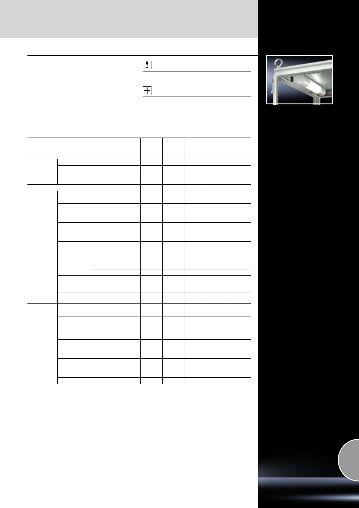
System lights
Interior installation
491Rittal Catalogue 33/System accessories
System lights
●for direct attachment in all large enclosures
●for mounting on compact enclosures,
wall-mounted enclosures and in the console
system with system accessories.
Protection category:
IP 20 to IEC 60 529
Also required:
Connection accessories,
see page 496.
Accessories:
−Adaptor bracket,
see page 471.
−Universal bracket,
see page 476.
−Rail for interior installation,
see page 459.
Technical comparison/equipment Standard
light Courtesy
light Universal
light Compact
light
LED
system
light
Page 492 492 492 493 494
Voltage
supply
100 – 240 V AC, 50/60 Hz – –
120 V AC, 60 Hz – – – –
230 V AC, 50 Hz – – – –
24 V DC – – –
Full-electronic ballast – –
Light
Fluorescent lamp, base G13 – – –
Compact fluorescent lamp, base G24q-3 – – – –
Fluorescent lamp T5 – – – –
LEDs, cold white – – – –
Protection
category
II (all-insulated) – – – –
III (SELV) – – – –
Installation
type
Screw-fastening
Clip attachment – – –
Magnetic attachment (accessory) – – –
Mounting
options
TS roof frame
(horizontal
section) direct
TS
vertical section
with adaptor bracket – –
direct – – –
AE, CM, TP
with universal bracket – –
with magnetic
attachment – – –
AE with rail for interior
installation – –
Connection
options
Infeed/connection cable 3)
Door-operated switch –
Through-wiring
(series connection of several lights) –
Approvals
UL/cUL 2) – 2) 2) –
1)
ENEC 2) – 2) –
VDE – – 2) – –
Equipment
Light cover –
Light cone adjustment – – –
Integral sockets, earthing-pin 2) – –
Integral sockets, USA 2) – – – –
Integral motion detector – – – –
Integral door-operated switch 2) 2) – – –
1) Safety extra-low voltage, not required by the standard.
2) Depending on the equipment.
3) Integral
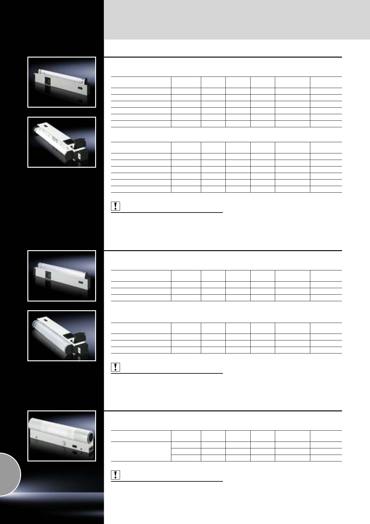
Interior installation
System lights
492 Rittal Catalogue 33/System accessories
Standard light
Without door-operated switch
With door-operated switch
Also required:
Connection accessories,
see page 496.
Technical specifications Socket Width
mm Height
mm Depth
mm Model No. SZ Approvals
14 kW, 230 V, 50 Hz Earthing-pin 452 117 50 4138.140 ENEC
18 kW, 230 V, 50 Hz Earthing-pin 682 117 50 4138.180 ENEC
30 kW, 230 V, 50 Hz Earthing-pin 987 117 50 4138.300 ENEC
14 kW, 120 V, 60 Hz USA 452 117 50 4138.240 cURus
18 kW, 120 V, 60 Hz USA 682 117 50 4138.280 cURus
30 kW, 120 V, 60 Hz USA 987 117 50 4138.400 cURus
Technical specifications Socket Width
mm Height
mm Depth
mm Model No. SZ Approvals
14 kW, 230 V, 50 Hz Earthing-pin 452 117 50 4138.150 ENEC
18 kW, 230 V, 50 Hz Earthing-pin 682 117 50 4138.190 ENEC
30 kW, 230 V, 50 Hz Earthing-pin 987 117 50 4138.350 ENEC
14 kW, 120 V, 60 Hz USA 452 117 50 4138.250 cURus
18 kW, 120 V, 60 Hz USA 682 117 50 4138.290 cURus
30 kW, 120 V, 60 Hz USA 987 117 50 4138.450 cURus
Courtesy light
Without door-operated switch
With door-operated switch
Also required:
Connection accessories,
see page 496.
Technical specifications Socket Width
mm Height
mm Depth
mm Model No. SZ Approvals
14 W, 100 – 240 V, 50/60 Hz Earthing-pin 452 117 50 4139.140 ENEC
18 W, 100 – 240 V, 50/60 Hz Earthing-pin 682 117 50 4139.180 ENEC
30 W, 100 – 240 V, 50/60 Hz Earthing-pin 987 117 50 4139.300 ENEC
Technical specifications Socket Width
mm Height
mm Depth
mm Model No. SZ Approvals
14 W, 100 – 240 V, 50/60 Hz Earthing-pin 452 117 50 4139.150 ENEC
18 W, 100 – 240 V, 50/60 Hz Earthing-pin 682 117 50 4139.190 ENEC
30 W, 100 – 240 V, 50/60 Hz Earthing-pin 987 117 50 4139.350 ENEC
Universal light
With integral motion detector
Also required:
Connection accessories,
see page 496.
Technical specifications Socket Width
mm Height
mm Depth
mm Model No. SZ Approvals
26 W, 110 – 240 V,
50 – 60 Hz
Earthing-pin 345 95 55 4155.100 VDE
– 345 95 55 4155.000 VDE
– 345 95 55 4155.500 UL
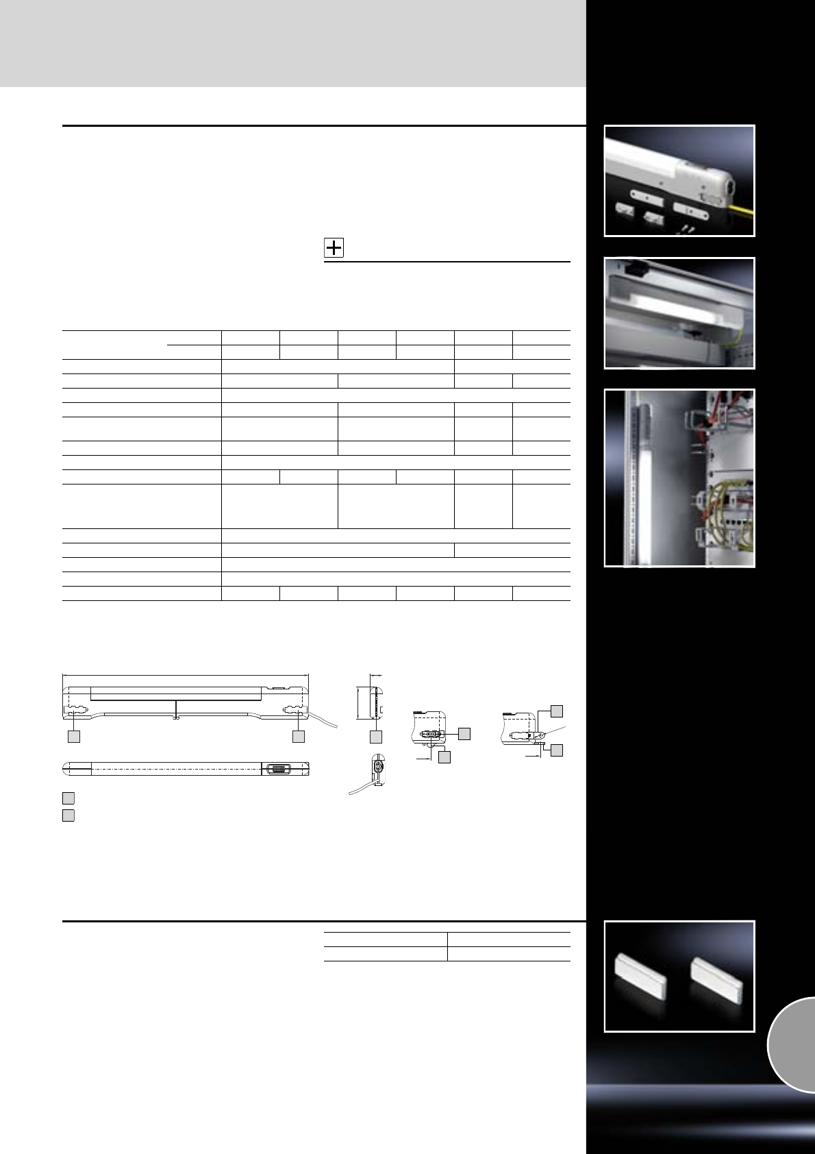
System lights
Interior installation
493Rittal Catalogue 33/System accessories
B3
Ø 6.5
Compact light
Slimmer – Faster – Brighter
●Slimmer: Around 50% less height and depth
and also around 75% less volume than conven-
tional lights.
●Faster: Universal fast attachment via clips,
screws, or powerful magnets (optional).
Simply slide in at the side or rear, fit the light,
and it's done!
●Brighter: Up to 75% greater luminous efficiency
from the lamp with the same power helps to cut
electricity costs.
●Door-operated switch can also be connected
via a 2-pole connection.
Colour:
Similar to RAL 7035
Protection category:
IP 20 to IEC 60 529
Supply includes:
Compact light with clip and screw mounting kits,
including assembly parts.
Accessories:
−Mounting kit magnet,
see page 493.
−Door-operated switch with connection cable,
see page 496.
B2
Clip/magnet
attachment Screw
attachment
B1
B
B
24
A
59
Rear fastening
Side attachment
A
B
Model No. SZ ENEC 24 4140.010 – 4140.020 – 4140.110 4140.120
cURus – 4140.2101) – 4140.2201) – –
Rated voltage 100 – 240 V AC ±10% at 50 – 60 Hz 24 V DC ±10%
Wattage 8 14 8 14
Protection category II (all-insulated)
Width (B1) mm 455 705 455 705
Mounting distance (B2) mm
Clip/magnet 400 650 400 650
Mounting distance (B3) mm 475 725 475 725
Connection cable 3 m (open end)
Cover colour Yellow Grey Yellow Grey Yellow Yellow
Rated current (A)
– at 230 V AC
– at 110 V AC
– at 24 V DC
0.045 – 0.088
0.083 – 0.149
–
0.073 – 0.127
0.149 – 0.216
–
–
–
0.35
–
–
0.57
Light Fluorescent lamp T5
Operating unit Wide-range electronic ballast Electronic ballast
Circuit-breakers Integral, on/off/door-operated switch mode
Light cover Transparent, grooved on the inside
Cable deflector across rear – –
1) Only for the North American market
B
A
B
A
Mounting kit magnet
For reliable adhesion on all sheet steel surfaces.
Packs of Model No. SZ
24140.000
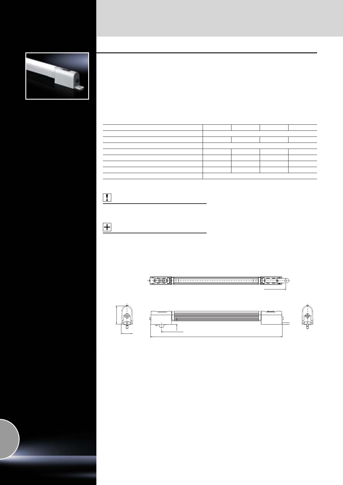
Interior installation
System lights
494 Rittal Catalogue 33/System accessories
LED system light
in 24 V DC version
●Max. EMC capacity
●Safe, thanks to use with safety extra-low voltage
●Economical energy use
●Low-maintenance thanks to the use of LEDs
●May be connected to a door-operated switch
●Integral through-wiring
●Universal attachment options
●Vertically hinged light cone
Material:
−Light body: Extruded aluminium
−Light cover: Polycarbonate (halogen-free)
−Light ends: PC-ABS
Colour:
Similar to RAL 7035
Protection category:
IP 20 to IEC 60 529
Supply includes:
System light with clip and screw mounting kits,
assembly parts.
Also required:
−LED connection cable, see page 495 or
−Door-operated switch with LED connection
cable, see page 495.
Accessories:
−Mounting kit magnet, see page 493.
−Door-operated switch with LED connection
cable, see page 495.
−LED connection cable, see page 495.
−Adaptor power pack, see page 495.
Note:
Only intended for use in enclosures and sealed
cases!
When using on customer-supplied power packs,
it is important to obtain the requisite approvals
depending on the application!
Model No. SZ 4140.810 4140.820 4140.830 4140.840
Rated voltage 24 V DC (± 10%)
No. of LEDs 10 20 30 40
Protection category III (SELV)
Width (B1) mm 230 330 430 530
Mounting distance CLIP (B2) mm 175 275 375 475
Mounting distance, screw attachment (B3) mm 250 350 450 550
Rated current (A)1) 0,04 0,08 0,12 0,16
Circuit-breakers Integral on/off/door-operated switch mode
1) Maximum baying up to a total rated current strength of 2 amps.
20.64
32.8
B1
8.2
B2
B3
System lights
Interior installation
495Rittal Catalogue 33/System accessories
1
2
3
4
5
Connection accessories
for LED system light
Layout diagram for LED system light 24 V DC:
Connection cable
Door-operated switch with LED connection cable (open end/cable bush)
Door-operated switch with LED connection cable
LED connection cable for through-wiring
Connection cable Length
mm Packs of Model No. SZ
LED connection cable 3000 1 4315.800
Door-operated switch Length
mm Packs of Model No. SZ
With LED connection cable 3000 1 4315.810
With LED interconnecting cable 1000 1 4315.820
Interconnecting cable Length
mm Packs of Model No. SZ
LED interconnecting cable
600 1 4315.830
1000 1 4315.840
3000 1 4315.850
Adaptor power pack Technical specifications Packs of Model No. SZ
Adaptor power pack 230 V AC/24 V DC, 1 A 1 4315.860
1
2
3
4
5
1
2
3
4
4
1
2
3
+ U
GND
Interior installation
System lights
496 Rittal Catalogue 33/System accessories
1
2
3
4
5
6
7
Connection accessories
The following components can be used for time-
saving and simple installation of the lights:
Accessories:
Cable ties for quick assembly,
see page 530.
Connection cable
for UL Length
mm Packs
of
Model No. SZ
Orange Grey
Power supply (with socket, without connector) 3000 5 4315.100 –
Power supply (with socket and strain relief,
without connector) 3000 1 – 4315.150
Through-wiring (with socket and connector) 600 1 – 4315.450
Through-wiring/power supply via
connection component SZ 2507.500
(with socket and connector)
600 54315.400 –
1000 4315.200 –
4000 1 4315.600 –
1
1
2
2
Door-operated switch
With mounting accessories UL Length
mm Technical
specifications Packs
of
Model No. SZ
Orange Yellow Grey
With connection cable
(not required for universal lights
and standard/courtesy lights
with integral door-operated
switch)
600
240 V AC, 6 A
125 V DC, 8 A
24 V AC, 6 A
24 V DC, 6 A
14315.520 – –
1000 1 4315.320 – –
600 1 – – 4315.550
1000 1 – – 4315.350
Without connection cable –14127.010
With connection cable
(for compact light)
600 1 – 4315.710 –
600 1 – – 4315.720
Also required
Mounting kit for installation in TE Model No. FR
7952.100
3
4
Door-operated switch
With toggle UL Technical
specifications Packs of Model No. SZ
Without connection cable, for TS enclosures with installed
large swing frame.
The toggle is actuated via the tubular door frame of the
sheet steel door, or in the case of glazed doors,
via an adaptor included with the supply.
240 V AC, 6 A
125 V DC, 8 A
24 V AC, 6 A
24 V DC, 6 A
14127.210
5
Connection component with circuit-breaker 10 A Packs of Model No. SZ
Reduce assembly costs:
Power is supplied rapidly and reliably to system and workstation lights
via connection cables.
For self-configured cables, connector SZ 2507.200 must be used.
Connection component to be snapped onto the top hat rail.
12507.500
6
For self-assembly Packs of Model No. SZ
Sockets for power supply through-wiring 5 2507.100
Connectors for connection component through-wiring 5 2507.200
T distributor with 2 sockets, 1 connector 5 2507.300
Connector for door-operated switch cable 5 2507.400
7
Connection cable for infeed
Connection cable for through-wiring/infeed
Door-operated switch with connection cable
1
2
3
12
3
System lights
Interior installation
497Rittal Catalogue 33/System accessories
Enclosure light, 48 V DC
With connection cable
Robust light. For attachment vertically or horizon-
tally in the frame section via spring brackets, or
may be used as a direct light source during main-
tenance work by inserting the plastic swivel hook.
Impact-resistant lamp housing of PMMA
(polymethylmethacrylate) protection category II.
Protection category:
IP 64
Supply includes:
−2 spring clips
−Assembly parts
Technical specifications:
−Luminosity: 11 W
−Luminous efficiency: 900 lm
−Fluorescent tube: TC-SEL 11 W, 4-pin
−Ambient temperature: –20°C to +40°C
−Voltage: 48 V DC ±10%
−Supply lead 3000 mm, H05RN – 2 x 1 mm,
without connectors, with crimped ferrules
−Length:
450 mm overall
Protective tube 320 mm
−Light outlet 195 mm
−Diameter:
62 mm overall
Protective tube 38 mm
Packs of Model No. CS
19765.150
Light 1 U
Complete ready-to-connect light for installation in
the 482.6 mm (19˝) mounting angles. The slot
attachment additionally allows it to be fastened to
the 25 mm system punchings.
Technical specifications:
−Fluorescent tube 8 kW, 230 V, 50 Hz
−Mains switch
−2.5 m connection cable
−Earthing-pin connector
Material:
−Aluminium, anodised
−Plastic
Packs of Model No. DK
17109.200
Interior installation
EMC
498 Rittal Catalogue 33/System accessories
Rail
for EMC shielding bracket and strain relief
Combined rail for strain relief and EMC contact-
ing of inserted cables.
Mounting options:
●On the horizontal/vertical TS, PC, ES enclosure
section
●On a mounting plate
May also be fitted without a retaining bracket.
Additional contacting on the left or right of the rail
via existing holes (9 mm diameter).
Material:
Sheet steel
Surface finish:
Zinc-plated
Supply includes:
−1 rail
−2 retaining brackets
−Assembly parts
Also required:
−EMC shielding bracket,
see page 498.
−Cable clamps for strain relief,
see page 529.
Accessories:
−Earth straps,
see page 501.
−Earthing strap,
see page 501.
Width mm Packs of Model No. SZ
600 1 2388.600
800 1 2388.800
1000 1 2388.000
1200 1 2388.120
25
43
5
31
13
12
Ø 9
Ø 6.5
6.5
553/753/963/1153
535/735/935/1135
525/725/925/1125
479/679/879/1079
80
2.5
20
10
25
45
75
95
80
86.5
95
Mounting positionRetaining bracket
Rail
19
Ø 4.5
25
Ø 7
25
15
EMC shielding bracket
Quick assembly without the use of tools:
Press the EMC shielding bracket against the
cable shield and clip into the rail.
Diameter changes are compensated in full by
the spring of the EMC shielding bracket.
Material:
Sheet steel
Surface finish:
Zinc-plated
For shield diameter
mm Packs of Model No. SZ
3 – 10 10 2388.100
4 – 15 10 2388.150
10 – 20 10 2388.200
15 – 28 10 2388.280
EMC
Interior installation
499Rittal Catalogue 33/System accessories
EMC gland plates
For shielded cables with a maximum diameter of
20 mm.
Combined EMC/IP seal provides low-resistance
contact between cable shield and gland plate.
For all 400, 500, 600 and 800 mm deep enclo-
sures in conjunction with standard gland plates.
Material:
Sheet steel
Surface finish:
Zinc-plated
Supply includes:
−1 gland plate with T-head punching
−1 sliding gland plate
−2 IP/EMC gaskets
Width mm Packs of Model No. TS
600 1 set 8800.660
800 1 set 8800.680
1000 1 set 8800.6001)
1200 1 set 8800.6201)
1) For one enclosure half only
EMC cable glands
The cable sheathing may optionally be inter-
rupted at the contact point or removed com-
pletely inside the enclosure.
The cable shield in the enclosure is retained.
The supplied lock nut cuts automatically into the
paint when screwed down, thus creating a con-
ductive connection.
Protection category:
IP 68 to IEC 60 529
IP 69K to DIN 40 050-9
Possible
alternative:
Cable gland Hygienic Design,
see page 521.
Cable glands, metric
Cable glands, PG
Size Cable
diameter
mm
Minimum1)
shield
diameter
mm
Packs
of Model No.
SZ
M16 4.5 – 10 3 5 2843.160
M20 6 – 12 5 5 2843.200
M25 11 – 17 8 5 2843.250
M32 15 – 21 10 1 2843.320
M40 19 – 28 15 1 2843.400
M50 27 – 38 19 1 2843.500
M63 34 – 44 30 1 2843.630
1) Minimum shield diameter =
cable diameter minus cable sheathing
PG
size
Cable
diameter
mm
Minimum1)
shield
diameter
mm
Packs
of Model No.
SZ
9 4 – 8 3 5 2411.090
11 5 – 10 4 5 2411.110
13.5 6 – 12 5 5 2411.140
16 10 – 14 8 5 2411.160
21 13 – 18 10 1 2411.210
29 18 – 25 15 1 2411.290
1) Minimum shield diameter =
cable diameter minus cable sheathing
EMC shield bus
Made of clear chromated steel strip,
75 mm2 cross section, for cable shield contact.
Supply includes:
Assembly parts.
Rail length
mm Connections Packs
of Model No. SZ
375 10 1 2413.375
550 16 1 2413.550
Interior installation
EMC
500 Rittal Catalogue 33/System accessories
EMC earth clamps
The clamps may be used directly on the device
or operating equipment on the mounting plate for
cable shield contact.
Material:
Sheet steel
Surface finish:
Zinc-plated
Size
mm Packs of Model No. SZ
4502367.040
6502367.060
8502367.080
12 50 2367.120
16 50 2367.160
20 25 2367.2001)
1) 2 assembly brackets
EMC baying seal
for TS
For baying enclosure systems.
Seal with all-round, electrically conductive
sheathing.
Supply includes:
3 seals, length 2 m each.
Cross section
mm Model No. TS
6.3 x 6.3 8800.690
EMC divider panel seal
This seal ensures optimum contact in bayed EMC
enclosure systems and when using a zinc-plated
divider panel.
Material:
PU foam with electrically conductive sheathing.
Supply includes:
1 roll (12.7 x 12.7 x 5300 mm).
Packs of Model No. SZ
14348.000
Contact cutter
The contact cutter enables EMC-compatible pre-
paration of the contact point e.g. for earthing
straps.
Plastic-bound abrasive with guide pin for round
system punchings.
With location point for drill, grinder etc.
For Model No. SM
Frame section 2414.000
Earthing bolts1) 2414.500
1) Not necessary with TS
Contact paint
Contact paint prevents the corrosion of conduc-
tive, unprotected contact points.
Contents:
12 ml
Packs of Model No. SZ
12415.000
Earthing
Interior installation
501Rittal Catalogue 33/System accessories
Earth straps
For configuring a reliable earthing connection with
perfect contact.
●With ring terminals in M6 and M8 to match the
earthing screw
●Length-optimised and ready to install
Enclosure
Connection facility
Door/lid Enclosure Mounting
plate
KL M6 M6 M8
EB/BG M6 M6/M81) –
AE M6 M62)/M8 M8
KE/KEL M8 M8 M8
AP/CM/TP M6 M8 M8
TS/ES M8 M8 M8
PC M8 M8 –
1) M8 with BG 1050.900
2) M6 with AE 1032.XXX/AE 1035.XXX
Connection Cross-
section
mm2
Length
mm Packs
of Model No.
SZ
M8 – M8 4 170 5 2564.000
M8 – M8 16 170 5 2565.000
M8 – M8 25 170 5 2566.000
M6 – M6 10 200 5 2565.100
M8 – M8 4 300 5 2567.000
M6 – M8 10 300 5 2565.110
M8 – M8 10 300 5 2565.120
M8 – M8 16 300 5 2568.000
M8 – M8 25 300 5 2569.000
Earthing strap
Tin-plated copper, in various lengths and cross-
sections with press-fitted contact rings. Earthing
straps counteract the current displacement effect
at high frequencies, whilst at the same time offer-
ing highly flexible connection opportunities.
For Cross-
section
mm2
Length
mm Packs
of Model No.
SZ
M6 10 200 10 2412.210
M8 16 200 10 2412.216
M8 25 200 10 2412.225
M6 10 300 10 2412.310
M8 16 300 10 2412.316
M8 25 300 10 2412.325
Assembly parts
for system punchings
For fastening the earth straps and earthing braids
to:
●Horizontal TS enclosure sections
●PS rail system
●ES system punchings.
Also required:
For mounting on the horizontal TS enclosure
section: Captive nut, see page 477.
Size Packs of Model No. SZ
M6 10 set 2570.000
M8 10 set 2559.000
Assembly parts
for gland plates
For fastening the earth straps and earthing braids
to:
●Gland plates
Fast assembly thanks to self-tapping screws.
Size Packs of Model No. SZ
M8 10 set 2570.200
Contact washers
Serrated contact washers facilitate secure PE
conductor connection. As a result, there is no
need to manually strip paint in the connection
area.
Size Packs of Model No. SZ
M5 100 2343.000
M6 100 2334.000
M8 100 2335.000
Interior installation
Earthing
502 Rittal Catalogue 33/System accessories
Earthing plate
For installation in:
●Comfort Panel
●Optipanel
●TS
●ES
One earthing cable can be screw-fastened to
the threaded bolt and can be distributed to up to
8 components via 6.3 mm flat-pin connectors.
Supply includes:
Assembly parts.
Packs of Model No. SZ
12570.500
Central earthing point
For connecting
●Earth straps
●Earthing braids
to the vertical and horizontal enclosure profile.
The connection bracket is connected to the
enclosure frame with 2 screws and is securely
contacted.
Earth connection is carried out via the threaded
bolt M8 x 20 mm.
Material:
Sheet steel, zinc-plated
Supply includes:
−1 connection bracket
−2 screws 5.5 x 13 mm
−2 serrated washers
−1 nut M8
−1 contact washer M8
−1 washer
Packs of Model No. DK
17829.200
Potential equalisation star
for 8 mm earthing bolt
The earthing connector is used for simple po-
tential equalisation on an 8 mm earthing bolt,
or in conjunction with central earthing point
DK 7829.200. Up to five flat connectors (6.3 mm)
may be contacted on one earthing point.
Supply includes:
−10 earthing connectors
−Assembly parts
Packs of Model No. DK
10 7548.210
Complete earthing kit
for TS
To DIN EN 60 950/VDE 0805, Ø 4 mm2, Imax. 40 A.
For system-compatible earthing of all enclosure
parts on the enclosure frame according to VDE.
The earth conductors are pre-assembled ready
for connection with connectors and cut to the
right length.
Supply includes:
−8 earth straps
−Central earthing point and assembly parts
Packs of Model No. DK
1 set 7829.150
Extension kit
for complete earthing kit
for TS
To DIN EN 60 950/VDE 0805, Ø 4 mm2, Imax. 40 A.
To extend the complete earthing kit DK 7829.150,
in order to keep additional components potential-
free.
Conductor length 300 mm in each case.
For 6.3 mm flat-pin connectors, 8 mm earthing
bolts or for attachment with contact washers and
screw.
Supply includes:
−5 earth straps
−Assembly parts and identification labels
Packs of Model No. DK
1 set 7829.152
Earthing
Interior installation
503Rittal Catalogue 33/System accessories
Complete earthing kit
for TE
To DIN EN 60 950/VDE 0805, Ø 4 mm2, Imax. 40 A.
For system-compatible earthing of all enclosure
parts on the enclosure frame according to VDE.
The earth conductors are pre-assembled ready
for connection with connectors and cut to the right
length.
Supply includes:
−Earthing strip
−4 earth straps, 300 mm
−4 earth straps, 550 mm
−Assembly parts
Packs of Model No. TE
1 set 7000.675
Earthing kit KE
For producing the required external potential
equalisation for painted series enclosures
●KL
●AE
●TS
For applications in Unit Group II, Category 3, in
compliance with Directive 94/9 EU-Appendix VIII,
internal production control.
Packs of Model No. KE
59214.000
Earthing kit
for KL
Consisting of all the screws, nuts, contact wash-
ers and earthing strip needed to earth the cover;
length 250 mm, cross-section 4 mm2.
Packs of Model No. KL
5 2570.100
Earthing kit
for QuickBox
Earth straps in the appropriate lengths to match
the enclosure depth are included in the earthing
set, for earthing all enclosure panels on the wall
mounting part. The earth strap is a fast-on con-
nector which is quickly disconnected and con-
veniently accessible when the door is open.
In this way, the enclosure cover can be removed
completely.
Supply includes:
−5 earthing leads 1.5 mm2
−4 cable retention clips
−Assembly parts
For
enclosure depth
mm Packs of Model No. QB
300/400 1 set 7502.240
500/600 1 set 7502.260
PE busbar
699 mm long PE busbar with pre-fitted screws,
including terminal clamps up to 6 mm2 (fine wire
conductors), 10 mm2 (single wire or multi-wire
conductors) and main terminal clamp up to
35 mm2.
Accessories:
Rail mounting bracket,
see page 476.
Packs of Model No. SZ
12364.000
Interior installation
Earthing
504 Rittal Catalogue 33/System accessories
Earth rail, horizontal
for TS
Potential equalisation rail
Current carrying capacity approx. 200 A.
Supply includes:
−Earth rail made from E-Cu 57 to DIN 12 163,
DIN EN 13 601, 15 x 5 mm
−20 connection points with M5 screws
−2 earth connections 25 mm2
−2 isolators, including assembly parts
Length mm Packs of Model No. DK
450 1 7113.000
Earthing kit, pre-assembled
for TS
For star earthing. With the pre-assembled earth
conductors on a potential equalisation rail, star
potential equalisation is easily integrated into net-
work enclosures.
Supply includes:
−Earth rail made from E-Cu 57 to
DIN EN 12 163, DIN EN 13 601
−16 earthing leads 6 mm2
−2 isolators
−Assembly parts
For TS enclosures
up to W x H x D mm Packs of Model No. DK
800 x 2000 x 800 1 set 7829.100
800 x 2200 x 1000 1 set 7829.110
Earth rail, vertical
for TS
Easily fitted to the 25 mm DIN pitch pattern of
distributors or to the 482.6 mm (19˝) mounting
angles. The supplied earth conductors facilitate
star earthing of the cable clamp straps in the
patch panels.
The earth terminals are fully adjustable.
Current carrying capacity of rail approx. 200 A.
Supply includes:
−Earth rail made from E-Cu 57 to
DIN 12 163, DIN EN 13 601, 15 x 5 mm
−16 conductor connection clamps 2.5 – 16 mm2
−15 earthing leads 6 mm2, L = 500 mm
−Assembly parts
For
enclosure
height
mm
Length
mm Packs of Model No.
DK
800 600 1 set 7541.000
1000 800 1 set 7542.000
1200 1000 1 set 7543.000
1400 1200 1 set 7544.000
1600 1400 1 set 7545.000
1800 1600 1 set 7546.000
2000 1800 1 set 7547.000
2200 2000 1 set 7548.000
Extension kit
for earth rail, vertical
For system-compatible expansion of the star
earthing on the vertical potential equalisation rail.
Supply includes:
−15 earthing leads 6 mm2, L = 500 mm,
−Preassembled, with ring terminal and wire end
ferrule
−Earth terminals, 2.5 – 16 mm2
−Assembly parts
Packs of Model No. DK
10 7549.000
ESD connection point
Dangerously high potential differences can occur
during maintenance or conversion work on the
enclosure. To protect sensitive electronic compo-
nents, this standardised connection point (push-
button) provides potential equalisation. The con-
nection point is directly conductively connected
to the enclosure frame via two screws.
Material:
Sheet steel, zinc-plated
Supply includes:
Assembly parts.
Packs of Model No. DK
17752.950
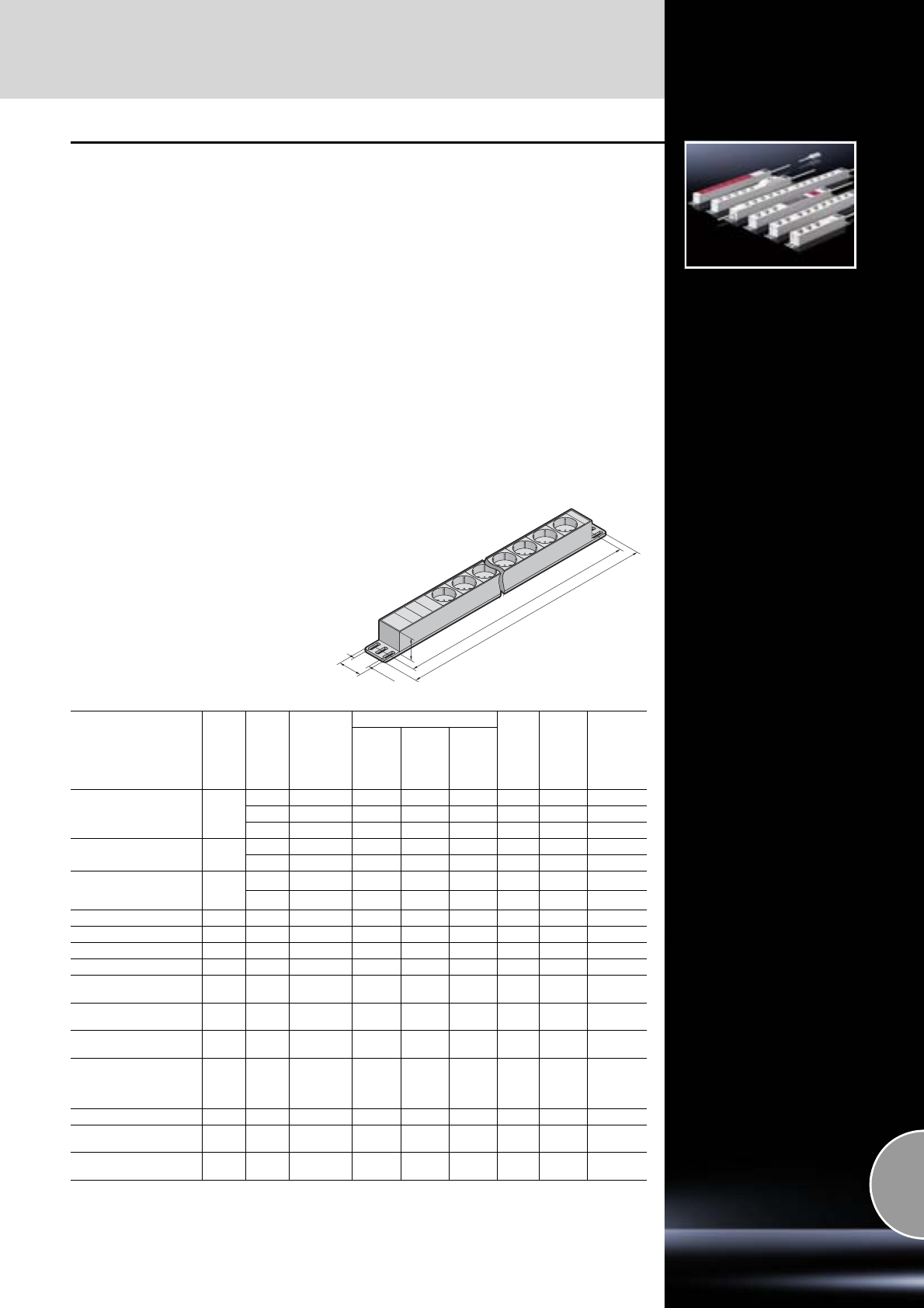
Socket strips
Voltage supply
505Rittal Catalogue 33/System accessories
Socket strips
The socket strips in the aluminium channel are
available in various lengths with different func-
tional elements. Special attention has been
devoted to practical, universal fastening:
With a bracket which may be used in four posi-
tions, there is a range of attachment options.
Hence, for example, the 482 mm long socket strip
may optionally be mounted on 482.6 mm (19˝)
mounting angles, the 482.6 mm (19˝) mounting
frame, on the enclosure frame, or in the rear
section of the wall-mounted distributor. Without
additional mounting accessories, the socket strip
may be inserted into all sections with a 25 mm
pitch pattern. This makes selection much easier,
as well as providing additional flexibility and
saving on warehousing. Provision has also been
made for cable routing of the infeed, and when
mounting in the 482.6 mm (19˝) section there is
adequate space to route the infeed between the
socket strip and the mounting angle without kinks.
The arrangement of the sockets at a 45° angle
allows unrestricted use of angular connectors.
Technical specifications:
−Rated voltage: 250 V
−Rated current: 10/16 A
−Connection cable: 2 m long H05VV-F3G1.5
Material:
−Aluminium section: Natural-anodised
−Socket inserts: Polycarbonate
Supply includes:
−Socket strip
−Two mounting brackets
−Assembly parts
Standards:
−Sockets:
DIN VDE 0620-1
−Sockets B/F:
UTE NFC 61-303, CEE 7/NV
−Overvoltage protection for low voltage:
DIN EN 61 643-11 (VDE 0675 Part 6-11)
−EMC interference suppression filter:
DIN EN 60 939-2 (VDE 0565 Part 3),
DIN VDE 0620-1 (VDE 06204-1)
Detailed drawings and further information:
Available on the Internet.
31.75
44
44
T2
T1
Design
Connec
-
tion
Number
of
sockets
Connector
type
Attachment
Length
(T1)
mm
Mounting
dimen-
sion
(T2)
mm1)
Model No.
DK
Frame
Wall-
mounted
distribu-
tor, hori-
zontal
482.6 mm
(19˝)
level
Without rocker switch Cable
3
Earthing-pin
– – 262.6 232.5 7240.110
7
Earthing-pin
482.6 452.5 7240.210
12
Earthing-pin
– – 658.6 628.5 7240.310
With rocker switch Cable 3
Earthing-pin
– 306.6 276.5 7240.120
7
Earthing-pin
482.6 452.5 7240.220
Overvoltage protection
and interference
suppression filter Cable 5
Earthing-pin
482.6 452.5 7240.230
9
Earthing-pin
– – 658.6 628.5 7240.330
Miniature circuit-breaker Cable 5
Earthing-pin
482.6 452.5 7240.240
Master-slave Cable 1 + 3
Earthing-pin
482.6 452.5 7240.250
UPS strip C14 7
Earthing-pin
482.6 452.5 7240.260
RCCB Cable 5
Earthing-pin
482.6 452.5 7240.280
RCCB and line protec-
tion Cable 5
Earthing-pin
482.6 452.5 7240.290
For IEC 320 connectors,
10 A Cable 12 C13 482.6 452.5 7240.200
For IEC 320 connectors
with IEC 320 input, 10 A C14 9 C13 482.6 452.5 7240.201
For IEC 320 connectors
with overvoltage protec-
tion
and interference
suppressor filter, 10 A
Cable 6 C13 482.6 452.5 7240.205
With 2 circuits Cable 6 + 6
Earthing-pin
– – 720.6 690.5 7240.370
B/F sockets
(Belgium, France) Cable 7
Earthing-pin
482.6 452.5 7240.510
B/F sockets
(Belgium, France) Cable 12
Earthing-pin
– – 658.6 628.5 7240.512
1) Variable attachment distance within a range of 5 mm, the distance given is hole centre – hole centre of
mounting bracket.
Voltage supply
Socket strips
506 Rittal Catalogue 33/System accessories
Socket strips
With C13/19 sockets
Socket strips with 2 m connection cable
H05VV-F3G6 1.5 (PVC) with wire end ferrules.
Detailed drawing:
Available on the Internet.
Design Number of
sockets
Attachment
Length
mm
Mounting
dimension
mm1)
Model No.
DK
Frame Wall-mounted
distributor,
horizontal
482.6 mm
(19˝) level
C13 IEC 320 socket3) 15 – – 592.6 562.5 7240.130
C13 IEC 320 socket3)
with 22) infeeds 9 + 9 – – 764.6 734.5 7240.150
C19 IEC 320 socket4) 6 482.6 452.5 7240.160
C19 IEC 320 socket4)
with overvoltage
protection device 4 482.6 452.5 7240.170
C19 IEC 320 socket4)
with 22) infeeds 3 + 3 478.6 448.5 7240.190
All socket strips may also be ordered with a Wieland GST infeed.
1) Variable attachment distance within a range of 5 mm, the distance given is hole centre – hole centre of
mounting bracket.
2) In order to make allowance for the higher output density e.g. in an IT environment, the socket strips are equipped
with 2 independent infeeds. This means it is possible to supply 2 x 16 A/250 V with one socket strip.
3) With IEC 320 socket to standard F EN 60 320-2-2
4) With IEC 320 socket to standard J EN 60 320-2-2
Socket strips 230 V
Technical specifications:
−Rated voltage 250 V AC
−Max. load
CH 10 A,
GB 13 A.
Material:
−Plastic, halogen-free
−Connection cable, 2 m long, without connector
H05VV-F3G1 (CH)
H05VV-F3G1,5 (GB)
−Unrestricted use, including angular connec-
tors, thanks to the long row arrangement of
plug-type contacts.
Number of sockets Length
mm Design Model No. DK
6470
1)
GB
7404.0 0 0
12 793 7408.510
18 1153 7412.5102)
6470
1) CH 7604.0002)
12 793 7608.5102)
1) The socket strips can be mounted horizontally at the rear of the DK wall-mounted distributor based on EL/AE.
2) Extended delivery times.
Socket strip TE
8-way socket strip for earthing-pin plug/version D.
The strip is made of plastic and may be mounted
vertically on the TE frame or in the rear 482.6 mm
(19˝) section. In the 482.6 mm (19˝) section, more
than 2 U of space is required. The sockets are
arranged at an angle of 45° so that angular con-
nectors are also easily used. The socket strip is
supplied with a 2 m connection cable. The con-
nection cable is contacted in a terminal slot in the
strip.
The terminal slot has a separate cover. The socket
strip has external terminals for separate earthing.
Technical specifications:
−Rated voltage: 230 Volt AC
−Rated current: Max. 16 A
−Connection cable: Length 2 m, H05VV-F3G1,
1.5 mm2, without connectors, with wire end
ferrules
Socket strip TE Model No. DK
8-way, earthing-pin 7000.630
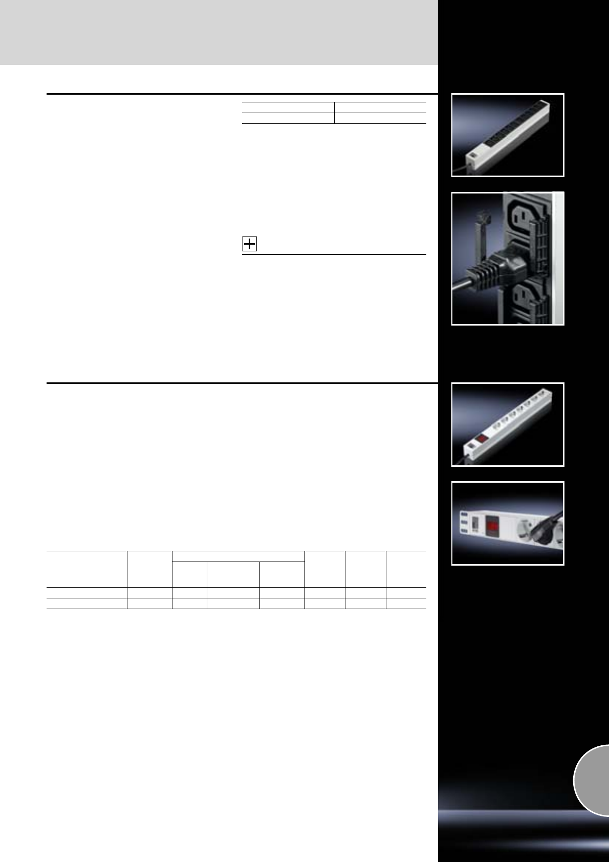
Socket strips
Voltage supply
507Rittal Catalogue 33/System accessories
Socket strip, 482.6 mm (19˝),
with fuse
with optional locking of the cable outlets
The socket strip constructed from an aluminium
channel, is 482.6 mm (19˝) wide and 1 U high,
and may be integrated into all standard 482.6 mm
(19˝) mounting frames.
Special attention has been devoted to practical,
universal fastening. The universal mounting
bracket creates variable mounting opportunities.
For example, the 439 mm long socket strip may
optionally be mounted on the 482.6 mm (19˝)
mounting angle or on the punched section with
mounting flange and enclosure frame.
Additionally, a locking option for the outgoing
cables to the equipment has now been inte-
grated. This protects the cables from uninten-
tional loosening, which in turn increases the se-
curity and availability of applications.
Technical specifications:
−10 A fuse/slow
−Cable type: H05VV
−Mains voltage: 250 V
−Rated current: 10/10 A
−Connection cable: 1.5 m
Supply includes:
−Socket strip
−Two mounting brackets
−Assembly parts
Accessories:
PSM cable lock,
see page 204.
Design Model No. DK
12 x C13 7240.600
Socket strips
with ammeter
The socket strip with ammeter measures the
active power of the connected equipment.
The two variants “earthing pin contact” and
“IEC 320 socket C13” provide the most com-
monly used plug-in contacts in data centres. The
482.6 mm (19˝) long socket strip may optionally
be mounted on the 482.6 mm (19˝) mounting
angles, on the 482.6 mm (19˝) mounting frame,
on the enclosure frame or in the rear section of
wall-mounted distributors. The installation bracket
may be mounted in four different positions for
variable mounting. Without additional mounting
accessories, the socket strip may be inserted into
all sections with a 25 mm pitch pattern.
Material:
−Aluminium section: Natural-anodised
−Socket inserts: Polycarbonate
Supply includes:
−Socket strip
−Two installation brackets
−Assembly parts
−1.5 m connection cable with open ends
Technical specifications:
−Mains voltage: 250 V
−Rated current: 16 A
−Connection cable: 1.5 m
Design Number of
sockets
Attachment
Length
mm
Mounting
dimension
mm1)
Model No.
DK
Frame Wall-mounted
distributor,
horizontal
482.6 mm
(19˝) level
Earthing-pin 6 482.6 464.1 7240.300
C13 IEC 320 socket 8 482.6 464.1 7240.305
1) Variable attachment distance within a range of 5 mm, the distance given is hole centre – hole centre of
mounting bracket.
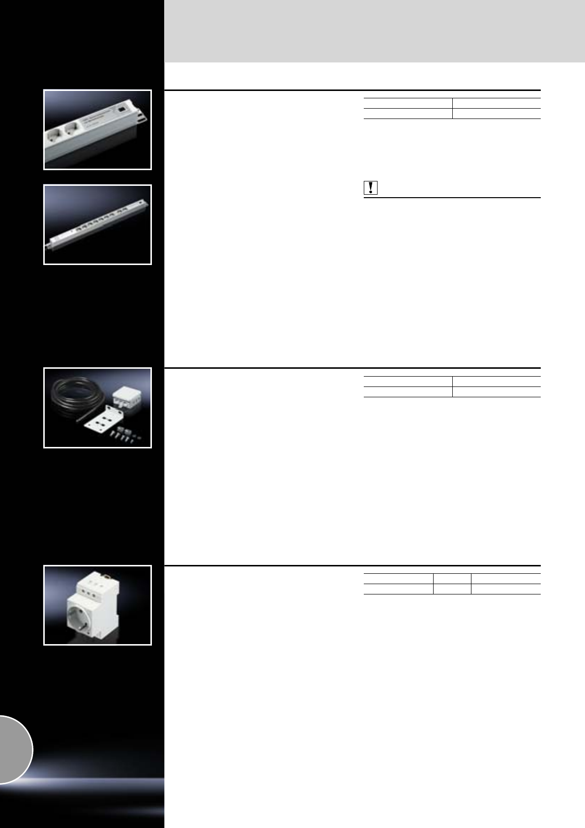
Voltage supply
Socket strips
508 Rittal Catalogue 33/System accessories
Socket strip CMC-TC
With integral
●interference suppressor filter
●Overvoltage protection
●Alarm contact
In the event of interference caused by overvolt-
age, the connected active network components
are protected. With the relay message contact,
undervoltage and any malfunctions caused by
overvoltage can be reported via the CMC-TC in
the network (SNMP trap). A green light on the strip
indicates that the device is operational. The sec-
ond protective device is the interference suppres-
sor filter which protects valuable equipment as a
passive component.
Technical specifications:
−Number of sockets: 9
−Length of strip: 650 mm
−Rated voltage: 230 V AC, 50/60 Hz
−Rated current: 16 A
−Relay alarm output: RJ 10 jack
−Relay load capacity: 50 Volt DC 100 mA
Technical specifications,
overvoltage protection:
−Arrester application category: D
−Surge current resistance per conductor: 2.5 kA
−Maximum surge current resistance: 8 kA
Also required:
For connecting the socket strip, the CMC III or
CMC III Compact and an RJ 10 connection cable
are required.
Packs of Model No. DK
17200.630
Junction box
with multi-functional bracket
The angle bracket can be installed in all network
enclosures in a system-compatible design. The
junction box serves as a transfer point for the
power supply to all equipment (fans, lamps and
socket strips). As well as being used as a junc-
tion box or interchange point, the bracket may
also accommodate the enclosure internal thermo-
stat (SK 3110.000) or the hygrostat (SK 3118.000)
thanks to its integral holes.
Material of bracket:
Sheet steel
Colour of bracket:
RAL 7035
Supply includes:
−1 bracket
−1 junction box
−6 m connection cable 3 x 1.5 mm2 (flexible)
Packs of Model No. DK
1 set 7280.035
Socket
●For mounting on support rails TS 35/7.5 and
TS 35/15 to EN 60 715
●Screw terminals uniformly from one side
●Enclosure width 45 mm
Technical specifications:
−Rated voltage: 250 V AC
−Rated current (AC): 16 A
Material:
Polyamide
Colour:
Grey
Standards:
−DIN VDE 0620-1
−DIN 49 440-1
Design Packs of Model No. SZ
Germany 2 2506.100
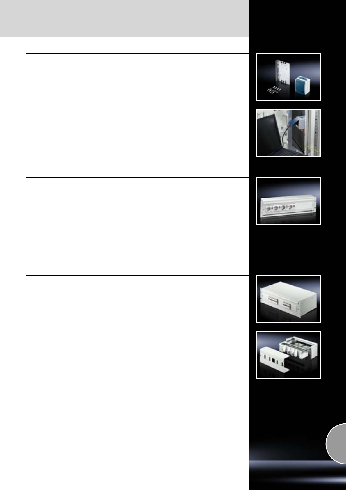
Socket strips
Voltage supply
509Rittal Catalogue 33/System accessories
Service socket
For enclosure frame attachment/16 A
Integration of a service socket within a separate
supply circuit, independently of the IT network
and UPS.
Simple installation via an angle bracket for attach-
ing to the enclosure frame.
Material:
−Angle bracket: Sheet steel
−Socket: Plastic
Surface finish:
Angle bracket: Zinc-plated
Supply includes:
−Angle bracket
−Damp-proof socket (IP 44)
−Assembly parts
Packs of Model No. DK
1 set 7280.100
Energy-Box, 482.6 mm (19˝)
Technical specifications:
A depth-variable top hat rail for installed equip-
ment to DIN 43 880, sizes 1 – 3 (e.g. to accommo-
date built-in sockets, miniature circuit-breakers
etc.). Cable clamping at the rear, one N and one
PE rail on an insulated plinth. Plastic cover includ-
ing extension cover (UL 94-V0), maximum accom-
modation of 22 installed devices (width 18 mm).
Maximum accommodation capacity = 22 HP
(22 x 18 mm = 396 mm).
Colour:
RAL 7035
Supply includes:
Energy-Box with plastic blanking covers.
Note:
Individual population with circuit-breakers at the
factory available on request.
Packs of U Model No. DK
137480.035
Energy-Box, 482.6 mm (19˝)
Pull-out
This Energy-Box is designed to accommodate
both DC and AC components. The pull-out com-
ponent front affords optimum access to the wiring
space from above and below.
Connection clamps for DC current:
2 clamps 35 mm2,
9 clamps 16 mm2 (per rail)
for AC current:
1 clamp 16 mm2 (PE or N),
20 clamps 4 mm2 (per rail)
Technical specifications:
Depth-adjustable top hat rail for snap-in attach-
ment of installed equipment to DIN 43 880 in sizes
1 – 3 (e.g. to accommodate built-in sockets, mini-
ature circuit-breakers etc. or entire installation
assemblies such as the ABB “smissline” system).
Cable clamping at the rear, two power distribution
rails with connection clamps on isolated base/
plinth. Plastic cover including extension cover,
maximum accommodation of 22 items of installed
equipment (width 18 mm).
Maximum accommodation capacity = 22 HP
(22 x 18 mm = 396 mm).
Depth: 220 mm.
Colour:
RAL 7035
Supply includes:
Energy-Box with plastic blanking covers.
UModel No. DK
37480.30 0
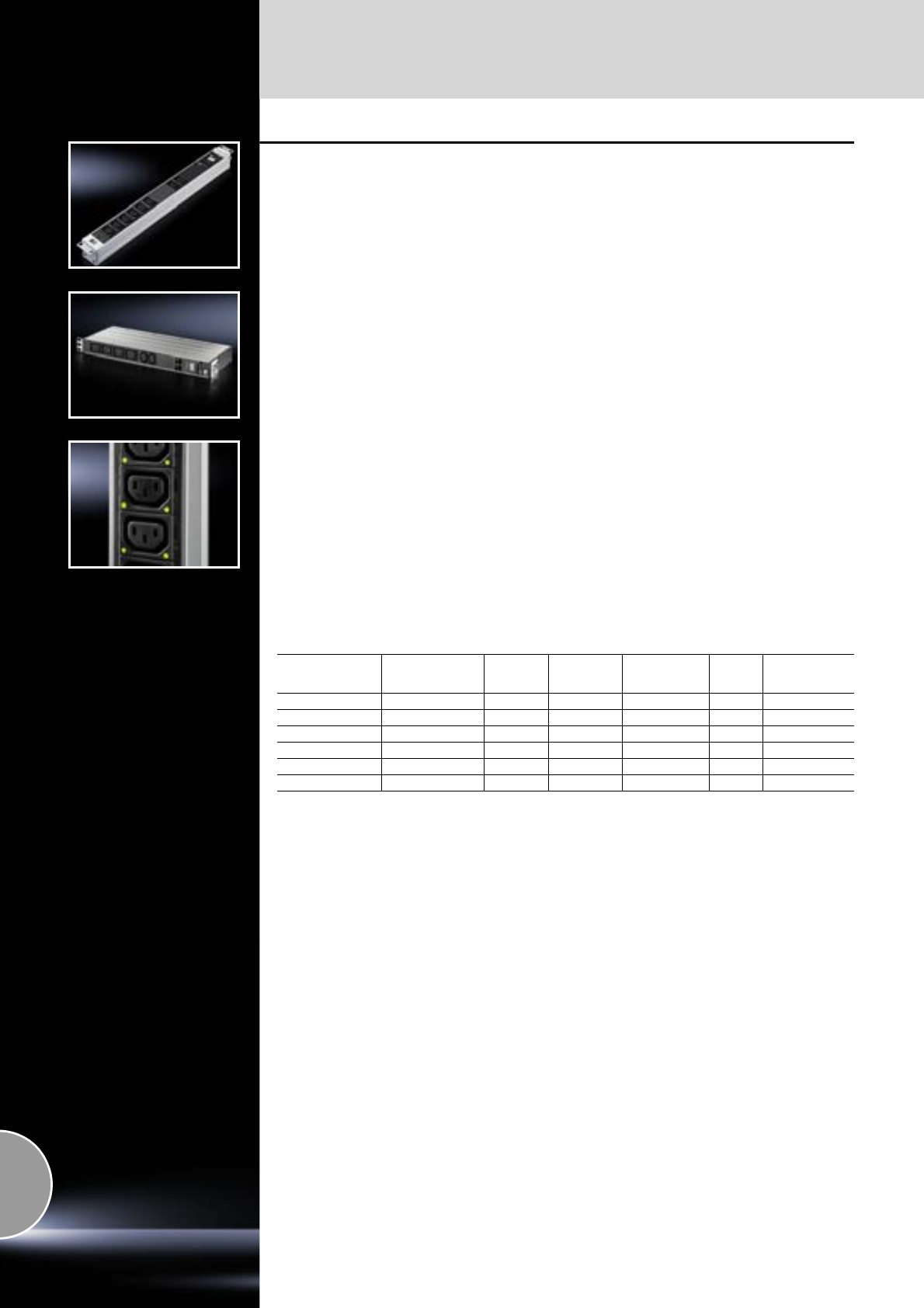
Voltage supply
Socket strips
510 Rittal Catalogue 33/System accessories
Rittal Power Control Unit (PCU)
Socket strip, IP-compatible, 1 U
Featuring 8 current outlets with IEC 320 C13 slots.
Each of the 8 slots is individually switchable (via
the CMC III system). Furthermore, a current indi-
cator, circuit display and thermal overload protec-
tion are integrated into the module. Installation on
the enclosure frame or in the 482.6 mm (19˝) sec-
tion (1 U) of a rack.
Operate the socket strip without CMC:
For operation of the socket strip, power pack
DK 7201.210 and a connection cable are
required. Up to 4 socket strips may be operated
with one power pack.
Available functions: Current display, circuit dis-
play, automatic selective activation.
Operate the socket strip with CMC:
No additional power pack is required: The PCU
is supplied via the CMC III system. You will need
the CMC III or CMC III Compact, plus a CMC III
CAN bus unit. See page 581 for details.
Available functions: Current display, automatic
selective activation via CMC III in the network:
Individual switching of the 8 current outlets,
current limit monitoring, delayed switching of the
individual current outlets, status display of the
module.
Description of functions:
●2-digit local LED 7-segment current display on
the PCU. Legibility rotates according to the
installation position.
●Measuring and monitoring of the current per
PCU. Min./max. limits may be set.
Measurement range 0 – 16 A.
●Alarm notifications via a flashing display.
●Monitoring of the thermo-fuse.
●PCUs may be combined via the bus system,
thereby enabling selective activation.
●In conjunction with the CMC III, the 8 individual
current outlets of the PCUs may be activated
and deactivated individually via HTTP and
SNMP.
●Remote administration of the power supply,
editing and monitoring of remote limits, SNMP
trap messages in case of alarm.
●8 IEC 320 C13 slots per PCU.
●User administration.
Dimensions:
Width: 465 mm (19˝)
Height: 44.5 mm (1 U)
Material:
Aluminium section with plastic cover
Supply includes:
−1 socket strip PCU 1 U
(max. 10 A per socket strip)
−1 bus cable
−1 infeed cable 24 V DC
−1 adaptor for power pack 24 V DC
−1 connector for power supply
−1 connection cable 0.3 m with Wieland
connector
Designation Pin pattern Number
of slots Switchable
outputs
With individual
current
measurement
Depth
mm Model No. DK
IEC 60 320 C13 8 yes – 60 7200.001
Earthing contact Earthing pin/C13 4/2 yes – 60 7856.2031)
IEC 60 320 C19/C13 4/2 yes – 60 7856.2041)
Earthing contact Earthing pin/C13 4/2 yes 160 7859.215
IEC 60 320 C13 8 yes 160 7859.225
IEC 60 320 C19/C13 4/2 yes 160 7859.235
1) Also required: PSM busbars, see page 202.
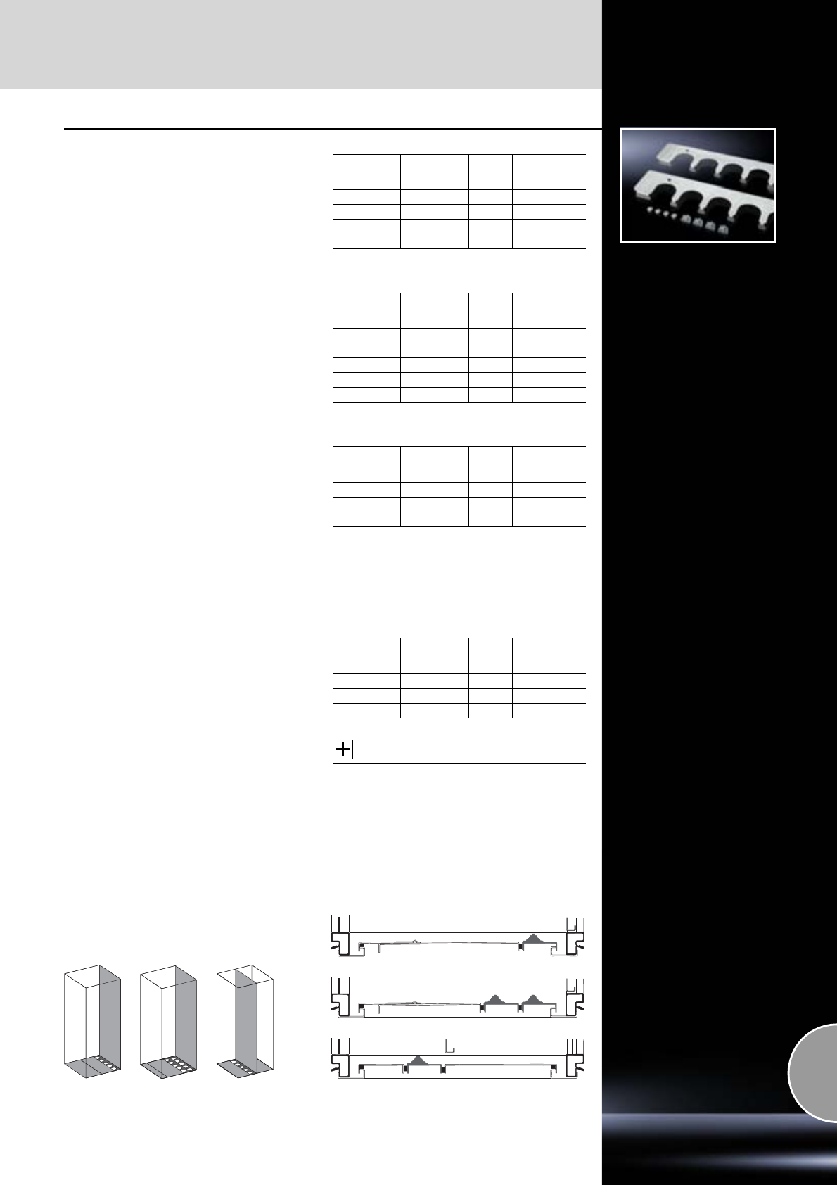
Cable entry
Cable management
511Rittal Catalogue 33/System accessories
Cable entry plates
For
●Cable entry grommets
●Connector grommets
instead of segments of the standard divided
gland plates.
Material:
Sheet steel
Surface finish:
Zinc-plated
Supply includes:
Assembly parts.
For installation in TS and PC enclosures
For installation in CM enclosures and
TP TopConsole system
For installation in ES enclosures and TP universal
console, CS Basic enclosure
Enclosure
width
mm
Cut-outs
per plate Packs
of Model No.
TS
600 5 2 8800.060
800 8 2 8800.080
1000 4 4 8800.100
1200 6 4 8800.120
Enclosure
width
mm
Cut-outs
per plate Packs
of Model No.
CM
600 5 1 5001.226
800 8 1 5001.227
1000 4 1 5001.228
1200 6 1 5001.229
1600 8 1 5001.237
Enclosure
width
mm
Cut-outs
per plate Packs
of1) Model No.
TS
600 5 2 4320.700
800 8 2 4321.700
1000 10 2 4323.700
1) Incl. compensating plate
For TS stainless steel
Material:
Stainless steel 1.4301 (AISI 304)
For installation in TS, stainless steel
Accessories:
Cable entry grommets,
see page 512.
Enclosure
width
mm
Cut-outs
per plate Packs
of Model No.
TS
600 5 2 8700.600
800 8 2 8700.800
1200 6 4 8700.120
Three examples from a wide range of
possibilities
The diagrams show three TS examples for the
positioning of cable entry plates instead of seg-
ments of the three-piece gland plates supplied as
standard. This facilitates positioning to fit the
mounting plate.
Thanks to the enclosure symmetry, where dimen-
sions permit, cable entry plates may also be
inserted in the enclosure depth, right and left,
analogous to the gland plates.
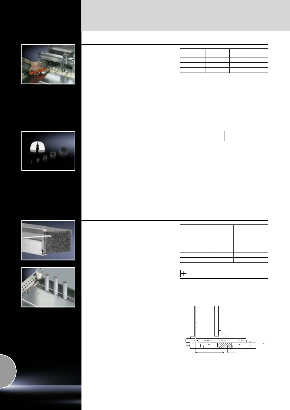
Cable management
Cable entry
512 Rittal Catalogue 33/System accessories
Cable entry grommets
In conjunction with the cable entry plate, simple
and fast sealing of cables inserted in the base
area of enclosures.
Material:
−Body: Polypropylene
−Cover: Thermoplastic elastomer
Protection category:
IP 55 subject to correct mounting.
Cables
per grommet Max. Ø mm Packs
of Model No.
PS
813254316.000
321254317.000
147254318.000
Connector grommets
Suitable for cable diameters from 8 to 36 mm.
Material:
−Outer cover: Polypropylene covered with
thermoplastic elastomer
−Seal: Cellular rubber
Protection category:
IP 55 subject to correct mounting.
Packs of Model No. PS
10 4311.000
Section for cable entry, centre
for TS, CM, TP
For top-mounting on gland plates. A superior
alternative to the foam rubber cable clamp strip,
thanks to:
●Easier mounting
●Full-surface support
●High level of sealing of cables inserted into the
enclosure
Material:
−Extruded aluminium section
−Seal: PU foam
−Cross-section: 30 x 25 mm
Protection category:
IP 55 subject to correct mounting.
Note:
1 set is sufficient for one base opening up to an
enclosure width of 800 mm.
From an enclosure width of 1000 mm, two base
openings are provided. 2 sets per enclosure may
be fitted.
Accessories:
−Cable clamp rails (right angle section),
see page 527
−C rail 30/15,
see page 465.
For
enclosure width
mm Packs of Model No. TS
600 1 set 8802.060
800 1 set 8802.080
1000 2 sets 8802.100
1200 2 sets 8802.120
1600 2 sets 8802.160
129.5
24.5
25.5
5
30 x 25
Y
Y = Mounting plate depth-adjustable
on a 25 mm pitch pattern (final pitch 30 mm).
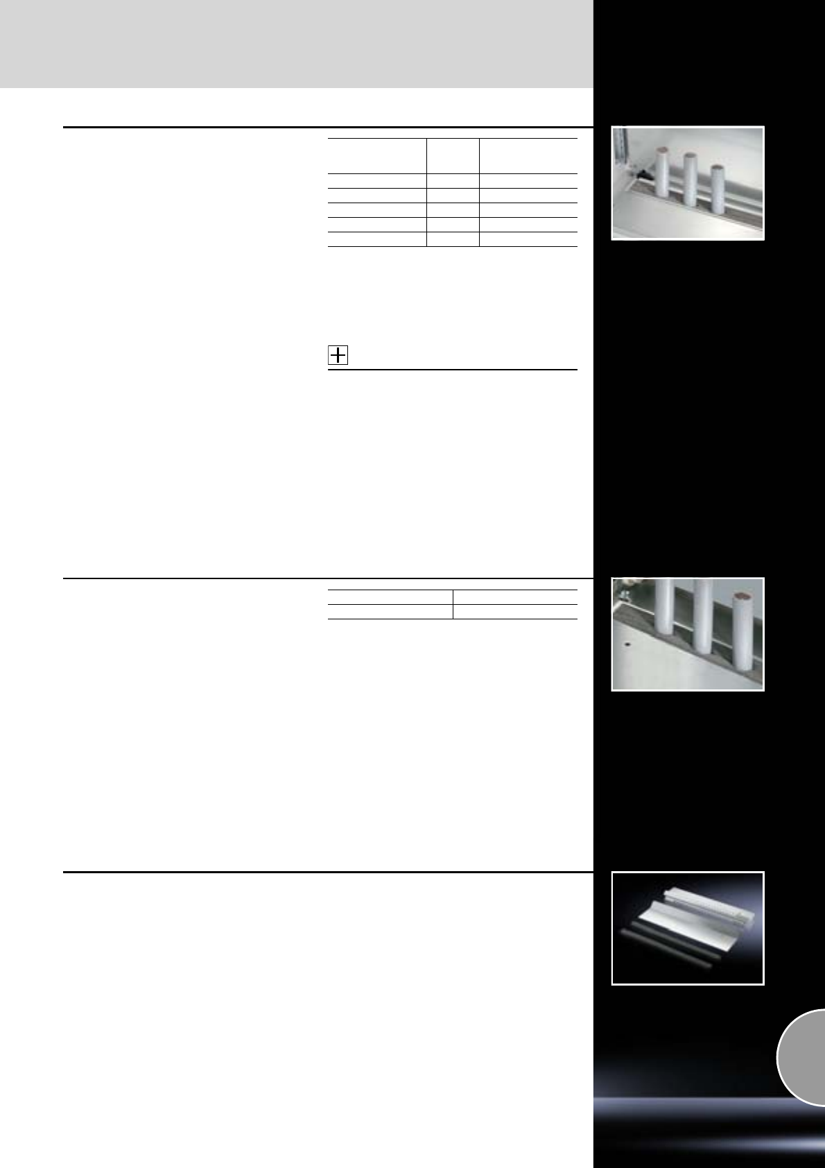
Cable entry
Cable management
513Rittal Catalogue 33/System accessories
Section for cable entry, rear
for TS, CM, TP
Unlike the section for cable entry, centre, the rear
section is mounted directly onto the base open-
ing. In this way, when installing the mounting plate
in the rearmost position (TS) or with CM, the
cables may be routed directly on a cable clamp-
ing rail with no large radii. In conjunction with the
cable clamp rail, optimum adjustment between
the cable entry and mounting plate can be
achieved.
Material:
−Extruded aluminium section
−Seal: PU foam
−Cross-section: 30 x 25 mm
Protection category:
IP 55 subject to correct mounting.
Note:
1 set is sufficient for one base opening up to an
enclosure width of 800 mm.
From an enclosure width of 1000 mm, two base
openings are provided. 2 sets per enclosure may
be fitted.
Accessories:
Cable clamp rail,
see page 527.
For
enclosure width
mm Packs of Model No. TS
600 1 set 8802.065
800 1 set 8802.085
1000 2 sets 8802.105
1200 2 sets 8802.125
1600 2 sets 8802.165
Foam rubber cable clamp strip
For sealing the cable entry between the gland
plates. Particularly suitable for identical cable
cross-sections.
Material:
−PU foam
−Cross-section: 30 x 30 mm
Protection category:
IP 55 subject to correct mounting.
Packs of Model No. SZ
3 m 2573.000
EMC gland plates
see page 499.
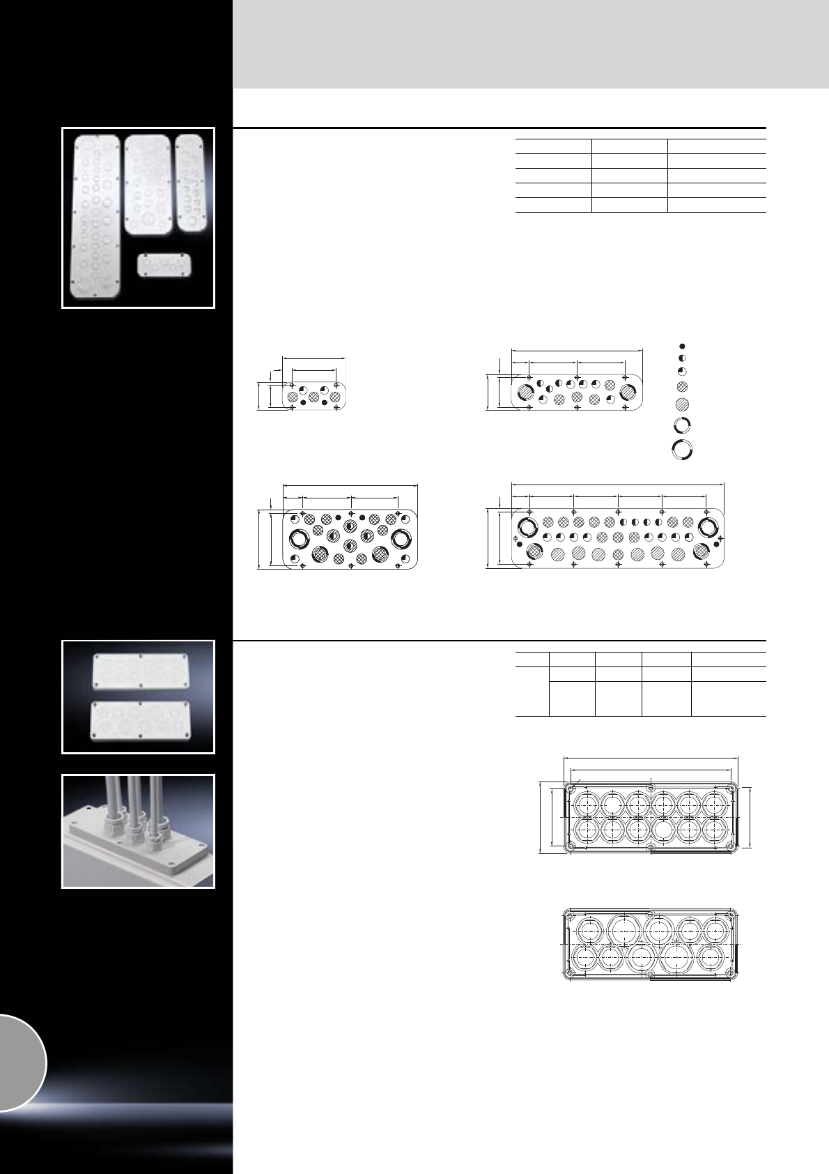
Cable management
Gland plates
514 Rittal Catalogue 33/System accessories
Plastic gland plates
With metric knockouts
With pre-punched holes for cable glands.
Used for sealing standard gland plates.
Temperature range:
May be used from –40°C to +70°C.
Colour:
RAL 7035
Note:
The applicable size may be taken from the
respective product ordering page.
Size Packs of Model No. SZ
1102560.010
3102561.010
452562.010
552563.010
7
70
56
110
25
160
120
330
45 120
75 7.5
90
339
120
120
49.5
8
133
149
110
45 110 110 110
530
8
133
149
M12
M16
M20
M25
M32
M40
M50
Size 1 Size 3
Size 4 Size 5
339
120
120
49.5
8
133
149
Plastic gland plates
With PG knockouts
With pre-punched PG holes for cable glands.
Used for sealing standard gland plates.
Temperature range:
May be used from –40°C to +70°C.
Material:
ABS
Colour:
RAL 7035
Note:
The applicable size may be taken from the
respective product ordering page.
Size PG Qty. Packs of Model No. KL
2
13.5 12 5 1581.000
13.5
16
21
6
2
251582.000
PG PG PG PG PG
PGPGPGPG
PG
13.5 13.5 13.5
13.513.513.5
21
21
16
16
PG
13.5
Ø5
76
202
72
220
90
KL 1582.000
KL 1581.000
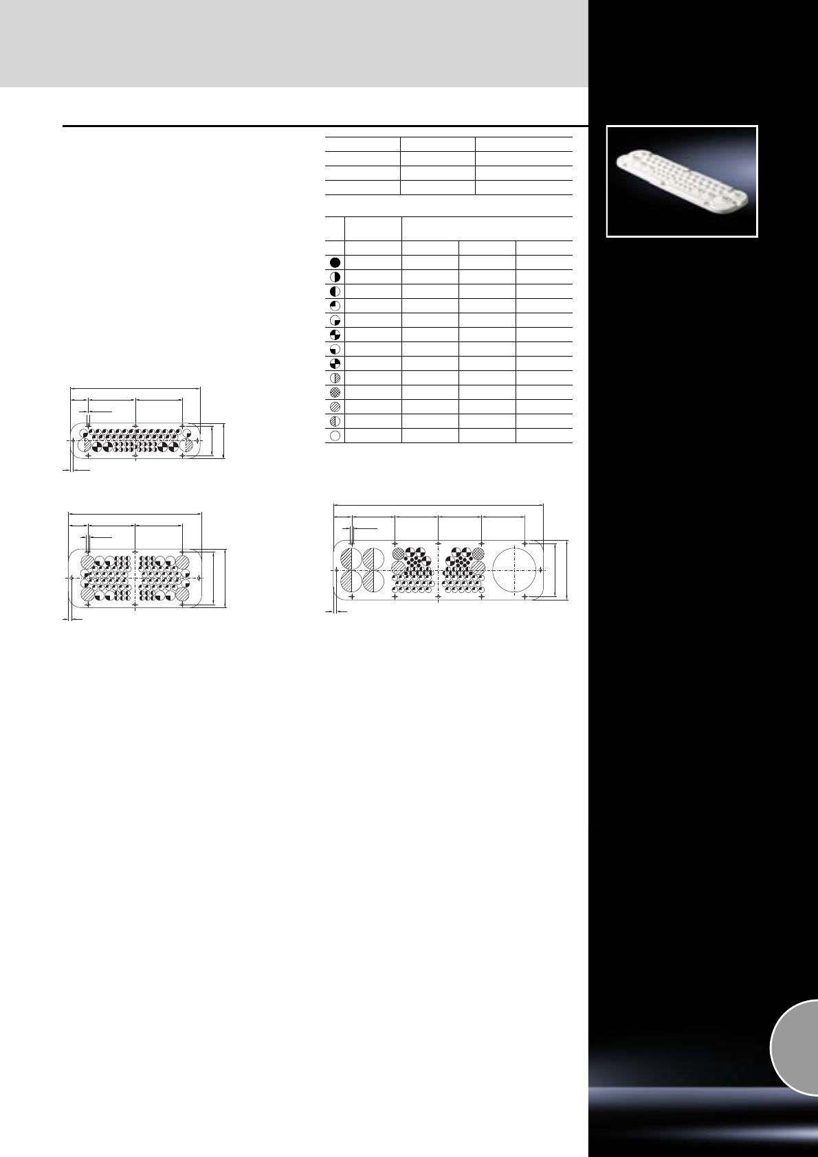
Gland plates
Cable management
515Rittal Catalogue 33/System accessories
Plastic gland plates
with membranes
Simply pierce the plastic with a sharp object,
and pull through the cable.
Material:
Plastic to UL 94-V0
Colour:
Similar to RAL 7035
Protection category:
IP 65 with careful cable entry.
Note:
The applicable size may be taken from the
respective product ordering page.
Ø 6
120
330
75
90
120
45
7.5
Size 3
339
120
Ø 6
133
149
120
49.5
8
Size 4
Size Packs of Model No. SZ
312561.500
412562.500
512563.500
Diameter
mm Number of cable entries for
Model No. SZ
2561.500 2562.500 2563.500
5 – 9 – – 18
6 – 11 17 – –
7 – 12 – 24 16
10 – 15 27 48 36
15 – 21 2 4 –
15 – 24 – – 6
15 – 25 – 8 –
16 – 25 4 – –
19 – 34 2 – –
23 – 30 – – 2
26 – 35 – 4 2
26 – 54 – – 4
50 – 110 – – 1
534
Ø 6
133
149
110
47 110 110 110
8
Size 5
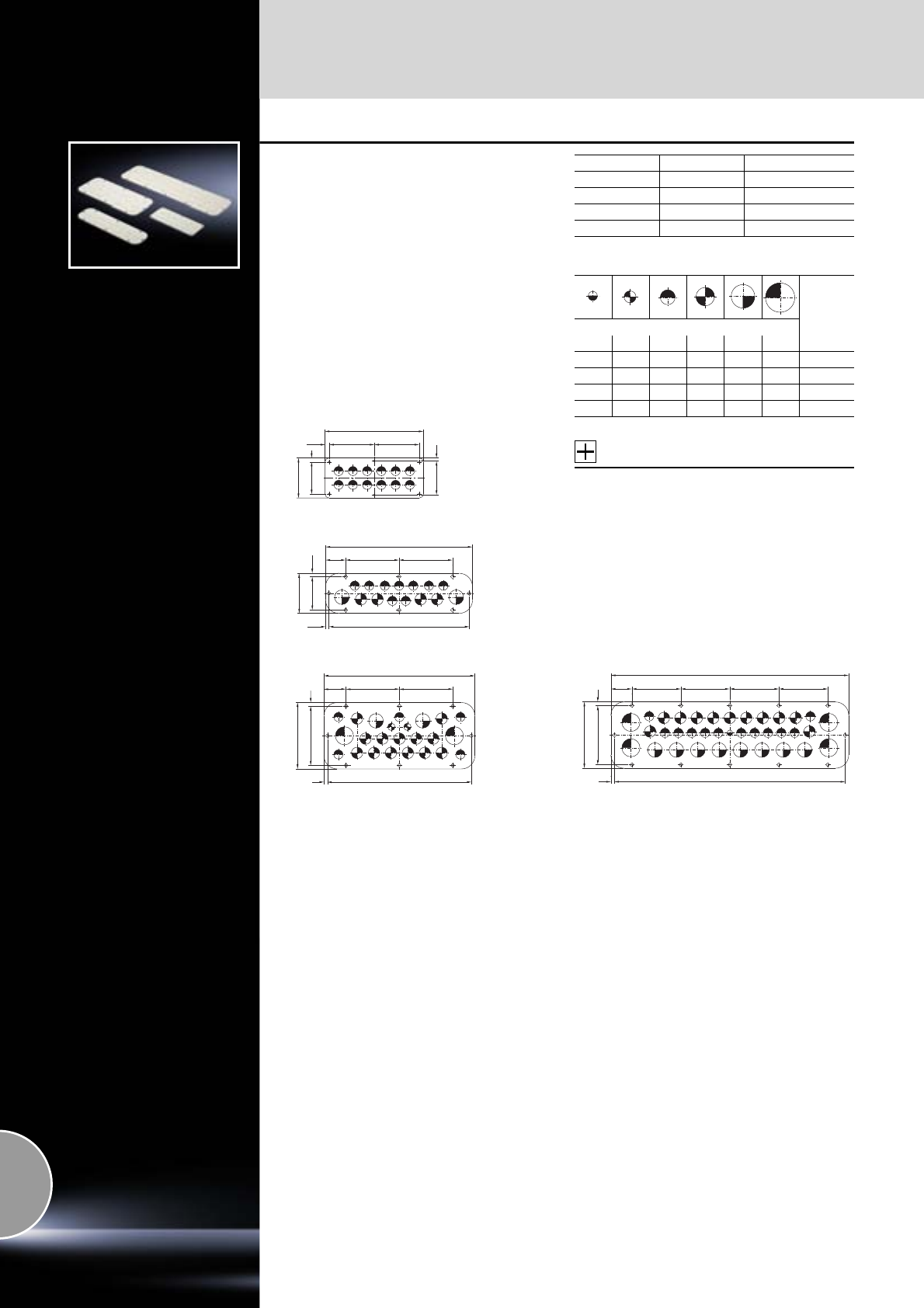
Cable management
Gland plates
516 Rittal Catalogue 33/System accessories
Metal gland plates
With metric knockouts
Simply knock out the holes for the cable glands
using a screwdriver.
Material:
Sheet steel
Colour:
RAL 7035
Protection category:
IP 66 when mounting in the usual position at the
bottom.
Note:
The applicable size may be taken from the
respective product ordering page.
Number of cable entries
Accessories:
Cable glands made from polyamide or brass,
see page 519.
221
9.5
90
72
101 101
7
76
9
Size 2
7.5 315
90
75 7.5
330
120120
45
Size 3
49.5 120
339
120
8
133
149
8323
Size 4
Size Packs of Model No. SZ
211581.100
312561.100
412562.100
512563.100
Model No.
SZ
Diameter
M12 M16 M20 M25 M32 M40
– – 12 – – – 1581.100
– – 9 4 2 – 2561.100
– 2 5 13 2 2 2562.100
1 – 12 11 8 4 2563.100
518
8
534
110110
110
110
47
149
133 8
Size 5
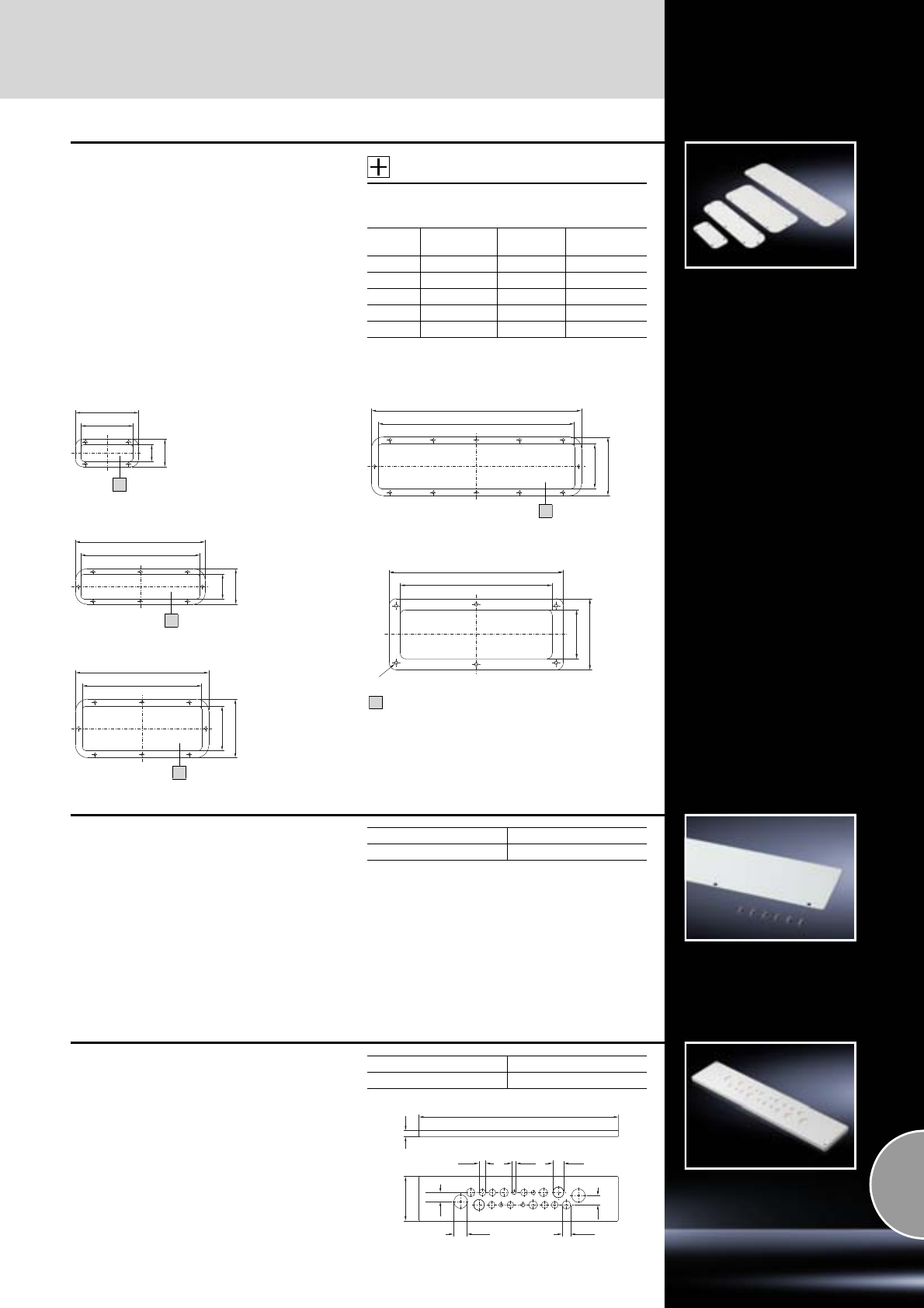
Gland plates
Cable management
517Rittal Catalogue 33/System accessories
Metal gland plates
As spare/replacement part for the standard gland
plates supplied loose.
Material:
Sheet steel
Colour:
RAL 7035
Protection category:
IP 66 when mounting in the usual position at the
bottom.
Note:
The applicable size may be taken from the
respective product ordering page.
Accessories:
Cable glands made from polyamide or brass,
see page 519.
Size Design Packs of Model No.
SZ/IN/KL
1 Solid 1 2560.400
2 Solid 6 1158.500
3 Solid 1 2561.400
4 Solid 1 2562.400
5 Solid 1 2563.150
160
133
70
43
330
303
90
63
339
303
149
113
534
500
149
113
SZ 2560.400
1
SZ 2561.400
SZ 2562.400
IN 2563.150
KL 1158.500
Area available for population
1
1
1
1
90
62
192
220
R9
Gland plate
solid, for QuickBox
To conceal the cable entry openings. In exchange
for the brush strip at the top and bottom that is
used as standard.
Material:
Sheet steel
Colour:
RAL 7035
Supply includes:
Assembly parts.
Packs of Model No. QB
27502.310
Gland plate
for metric cable glands, for EL
Folded gland plate with foamed-in seal and pre-
punched, knock-out holes for metric cable glands
M12, M20, M25, M32, M40.
Material:
Sheet steel, 1.5 mm
Colour:
RAL 7035
Protection category:
IP 55 to IEC 60 529
Packs of Model No. DK
17705.235
28
25.5
(5 x)
40.5
(2 x)
27
12.5
(4 x)
20.5
(7 x)
32.5
(2 x)
599
133.5 19
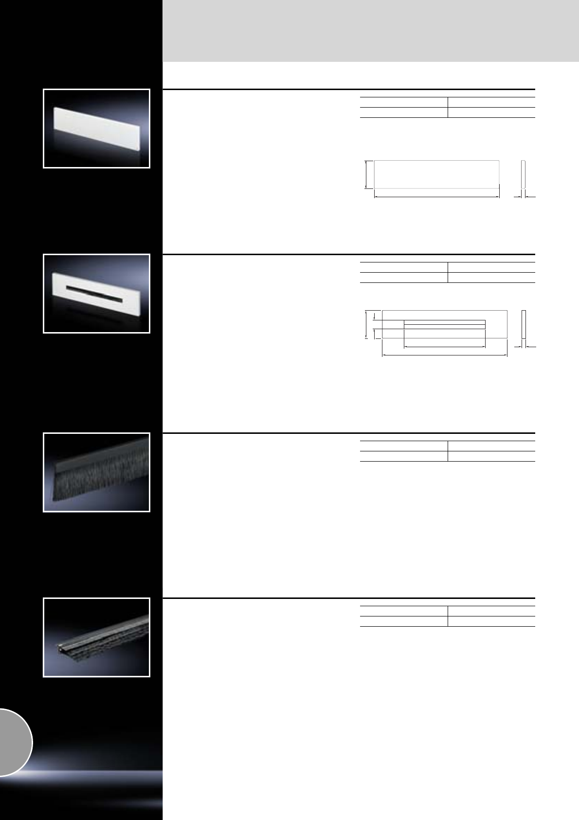
Cable management
Gland plates
518 Rittal Catalogue 33/System accessories
Gland plate
solid, for EL
Folded gland plate for the base box, with foamed-
in seal.
Material:
Sheet steel, 1.5 mm
Colour:
RAL 7035
Packs of Model No. EL
12235.135
Extended delivery times.
599
133.5
19
Gland plate
with brush insert, for EL
Folded gland plate with foamed-in seal and
plastic brush inserts for simple cable entry.
Material:
Sheet steel, 1.5 mm
Colour:
RAL 7035
Packs of Model No. DK
17705.035
19
40
390
599
133.5
Brush strip
For individual installation of enclosure panels,
gland plates and panels. Cut-outs for cable
routing at any given positions in the side panel,
rear panel, doors, roof and gland plate may be
finished off attractively by simply attaching the
brush strip.
Technical specifications:
−For metal thickness: 0.6 – 1.5 mm
−Bristle length: 30 mm
−Plastic sheathing: 18 mm
−Snap-on surface: 10 mm
−Maximum cut-out height: 38 mm
Packs of Model No. DK
2 m 7072.200
Brush strip, super-airtight
For individual installation of enclosure panels,
gland plates and panels. Cut-outs for cable
routing at any position in the side panel, rear
panel, doors, roof and base plate.
These special brush strips may be used to create
airtight entries for cable sections and conductors.
The brush strips arranged in an offset configura-
tion ensure good sealing from the routed cables
even with large quantities of cables. In this way,
unwanted system losses may be reduced to a
minimum.
Technical specifications:
−For metal thickness: 1.5 – 2 mm
−Bristle length: 58 mm
−Plastic sheathing: 14 mm
−Snap-on surface: 11.5 mm
−Cut-out width: 88 – 90 mm
Material:
Plastic, UL 94-V0
Supply includes:
1 brush strip each, 1 m in length,
right-hand and left-hand version.
Packs of Model No. DK
2 x 1 m 7825.375
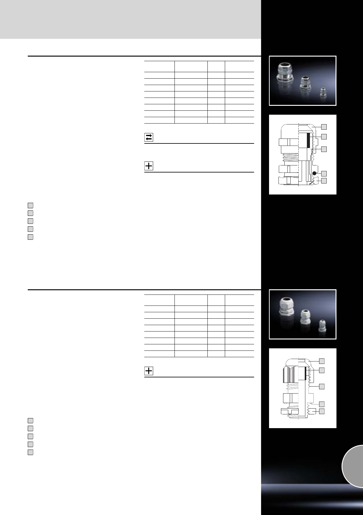
Cable glands
Cable management
519Rittal Catalogue 33/System accessories
3
4
5
2
1
Cable gland, brass
Benefits:
●Because the gland and lock nut are sold
together in a single pack, this saves additional
ordering and storage.
●Clamping membranes for even tightening and
strain relief which protects the cables.
●Insulation via plastic insert.
●Optimum seal on the connection thread,
thanks to O-ring.
●The lock nut cuts automatically into the spray-
finish, thereby creating a conductive connec-
tion.
Material:
−Brass
−Seal: Neoprene
Surface finish:
Nickel-plated
Protection category:
−IP 68 (5 bar, 30 min.) to IEC 60 529
−IP 69K to DIN 40 050-9
Approval:
VDE tested to EN 50 262
Cap nut
Neoprene seal
Plastic insert
O-ring
Lock nut
Possible
alternative:
Cable gland Hygienic Design,
see page 521.
Accessories:
−Sealing bungs,
see page 520.
−Multi-seal inserts,
see page 520.
1
2
3
4
5
Size Cable diameter
mm Packs
of Model No.
SZ
M12 x 1.5 3 – 6.5 15 2411.800
M16 x 1.5 4.5 – 10 15 2411.810
M20 x 1.5 6 – 12 10 2411.820
M25 x 1.5 11 – 17 10 2411.830
M32 x 1.5 15 – 21 5 2411.840
M40 x 1.5 19 – 28 4 2411.850
M50 x 1.5 27 – 38 2 2411.860
M63 x 1.5 34 – 44 1 2411.870
3
4
5
2
1
Cable gland, polyamide
Benefits:
●Because the gland and lock nut are sold
together in a single pack, this saves additional
ordering and storage.
●Clamping membranes for even tightening and
strain relief which protects the cables.
●Spray-moulded sealing lip ensures an optimum
seal against the enclosure.
●Trapezoid thread for secure screw-fastening of
the cap nut.
Material:
Polyamide 6, neoprene seal
Colour:
RAL 7035
Protection category:
IP 68 (5 bar, 30 min.) to IEC 60 529
Approval:
−VDE tested to EN 50 262
−CSA for USA and Canada
Cap nut
Neoprene seal
Trapezoid thread
Sealing lip
Lock nut
Accessories:
−Polyamide reducers,
see page 520.
−Sealing bungs,
see page 520.
−Multi-seal inserts,
see page 520.
1
2
3
4
5
Size Cable diameter
mm Packs
of Model No.
SZ
M12 x 1.5 3 – 6.5 50 2411.600
M16 x 1.5 4.5 – 10 50 2411.610
M20 x 1.5 6 – 12 50 2411.620
M25 x 1.5 11 – 17 25 2411.630
M32 x 1.5 15 – 21 15 2411.640
M40 x 1.5 19 – 28 5 2411.650
M50 x 1.5 27 – 38 5 2411.660
M63 x 1.5 34 – 44 3 2411.670
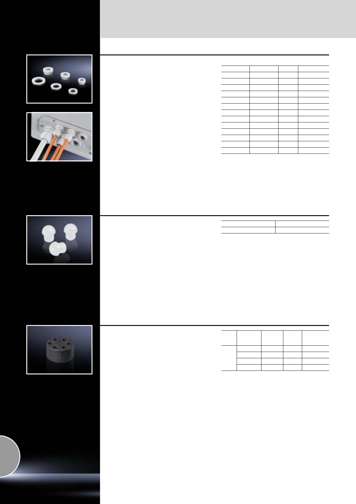
Cable management
Cable glands
520 Rittal Catalogue 33/System accessories
Polyamide reducers
for polyamide cable glands
For adapting metric cable glands to larger dia-
meter holes or threads.
Benefit:
Reducer and locking nut are sold together in a
single pack; this saves additional ordering and
storage.
Material:
Polyamide 6 GF30
Colour:
RAL 7035
Note:
Polyamide cable gland,
see page 519.
Thread
Exterior Inside Packs of Model No. SZ
M16 x 1.5 M12 x 1.5 50 2411.550
M20 x 1.5 M12 x 1.5 50 2411.551
M20 x 1.5 M16 x 1.5 50 2411.552
M25 x 1.5 M16 x 1.5 50 2411.553
M25 x 1.5 M20 x 1.5 50 2411.554
M32 x 1.5 M16 x 1.5 50 2411.555
M32 x 1.5 M20 x 1.5 50 2411.556
M32 x 1.5 M25 x 1.5 50 2411.557
M40 x 1.5 M25 x 1.5 25 2411.558
M40 x 1.5 M32 x 1.5 25 2411.559
M50 x 1.5 M40 x 1.5 5 2411.560
M63 x 1.5 M40 x 1.5 5 2411.561
M63 x 1.5 M50 x 1.5 5 2411.562
Sealing bung
for cable glands M20 x 1.5
For use in all situations where pre-installed cable
glands M20 x 1.5 must be kept free for future
installations but properly sealed. Simply loosen
the cap nut, mount the sealing bung, and
retighten.
Material:
Polyamide 6
Colour:
RAL 7035
Packs of Model No. SZ
25 2411.532
Multi-seal inserts
For the secure entry of several individual cables
into a single cable gland.
Material:
Neoprene
Size Cable
diameter
mm
Number
of cables Packs
of Model No.
SZ
M25
37252411.504
46252411.505
54252411.506
63252411.507
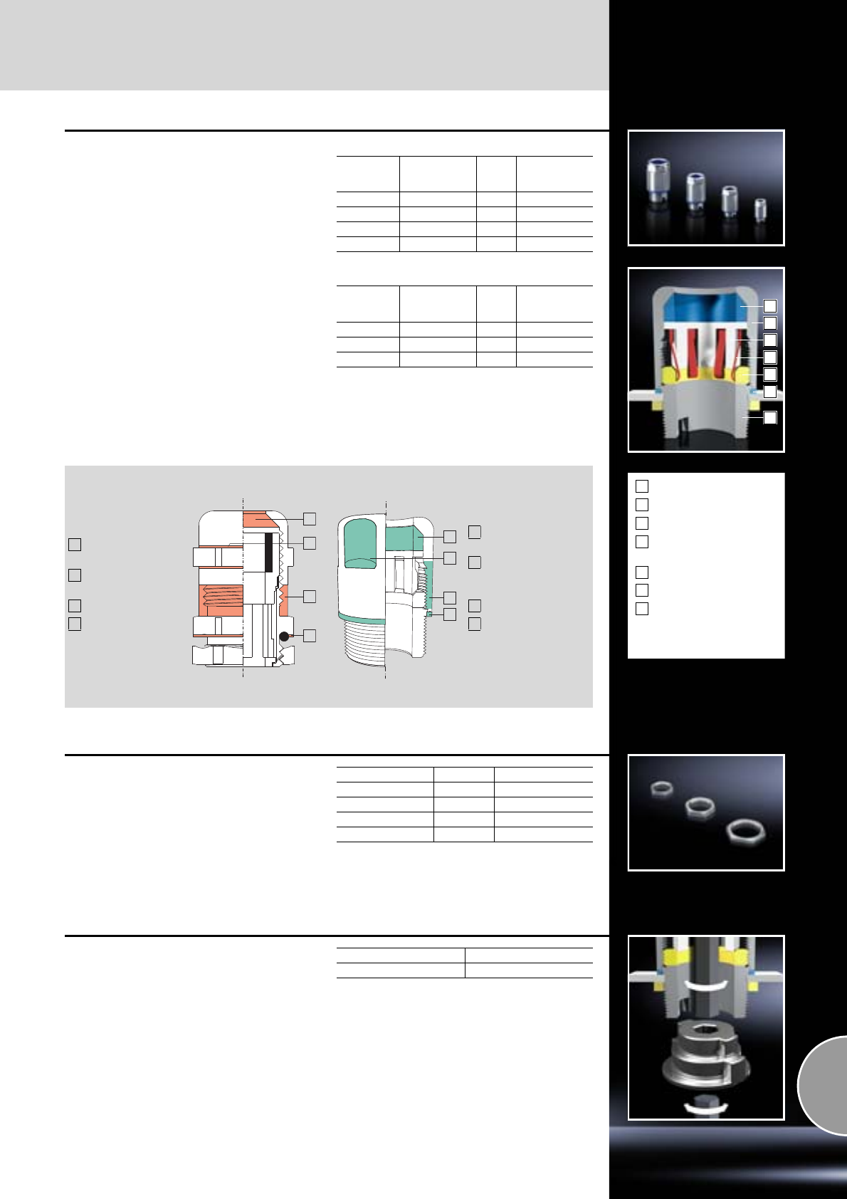
Cable glands
Cable management
521Rittal Catalogue 33/System accessories
1
2
3
4
5
6
7
Seal
Cap nut
Gripper jaws
Shield spring
(EMC version only)
Clamping ring
Enclosure seal
Base with locator for
assembly tool
1
2
3
4
5
6
7
Cable gland HD
Applications:
●Manufacturing and packaging of foodstuffs etc.
●Clean room technology (e.g. pharmaceuticals)
●Biotechnology
●Chemical industry
Benefits:
●Smooth, solid exterior surfaces effectively pre-
vent the depositing of harmful micro-organisms.
●Much easier, and therefore cheaper to clean
compared with conventional cable glands.
Material:
−Cap nut: Stainless steel 1.4305 (AISI 303)
−Seal: Conforms to FDA 21 CFR 177.2600
Protection category:
−IP 68 (5 bar, 30 min.) to IEC 60 529
−IP 69K to DIN 40 050-9
Standard version
EMC version
Size Cable
diameter
mm
Packs
of Model No.
HD
M12 x 1.5 3 – 6.5 5 2410.000
M16 x 1.5 4.5 – 10 5 2410.010
M20 x 1.5 6 – 12 5 2410.020
M25 x 1.5 11 – 17 5 2410.030
Size Cable
diameter
mm
Packs
of Model No.
HD
M16 x 1.5 5 – 10 5 2410.110
M20 x 1.5 6 – 12 5 2410.120
M25 x 1.5 12 – 17 5 2410.130
Critical points
with conventional
solutions
Cable entry in front
of seal
No minimum radii
on the hexagon
External thread
Gap caused by
O-ring on the
enclosure surface
1
2
3
4
Hygiene-compatible
design features
Seal directly at the
cable entry
Compliance with
minimum radii on
the hexagon
No external thread
Flush termination
between the cap nut
and the enclosure
1
2
3
4
3
4
2
1
3
4
2
1
Why hygiene-compatible cable glands?
Stainless steel lock nut
To match HD cable glands.
Material:
Stainless steel 1.4305 (AISI 303)
Size Packs of Model No. HD
M12 x 1.5 10 2410.200
M16 x 1.5 10 2410.210
M20 x 1.5 10 2410.220
M25 x 1.5 10 2410.230
Assembly tool
for HD cable glands
For attaching HD cable glands in an internal
thread or using lock nuts. This can be achieved
either from the inside or from the outside using an
Allen key.
Supply includes:
1 set = Adaptor for sizes from M12 – M25.
Packs of Model No. HD
1 set 2410.290
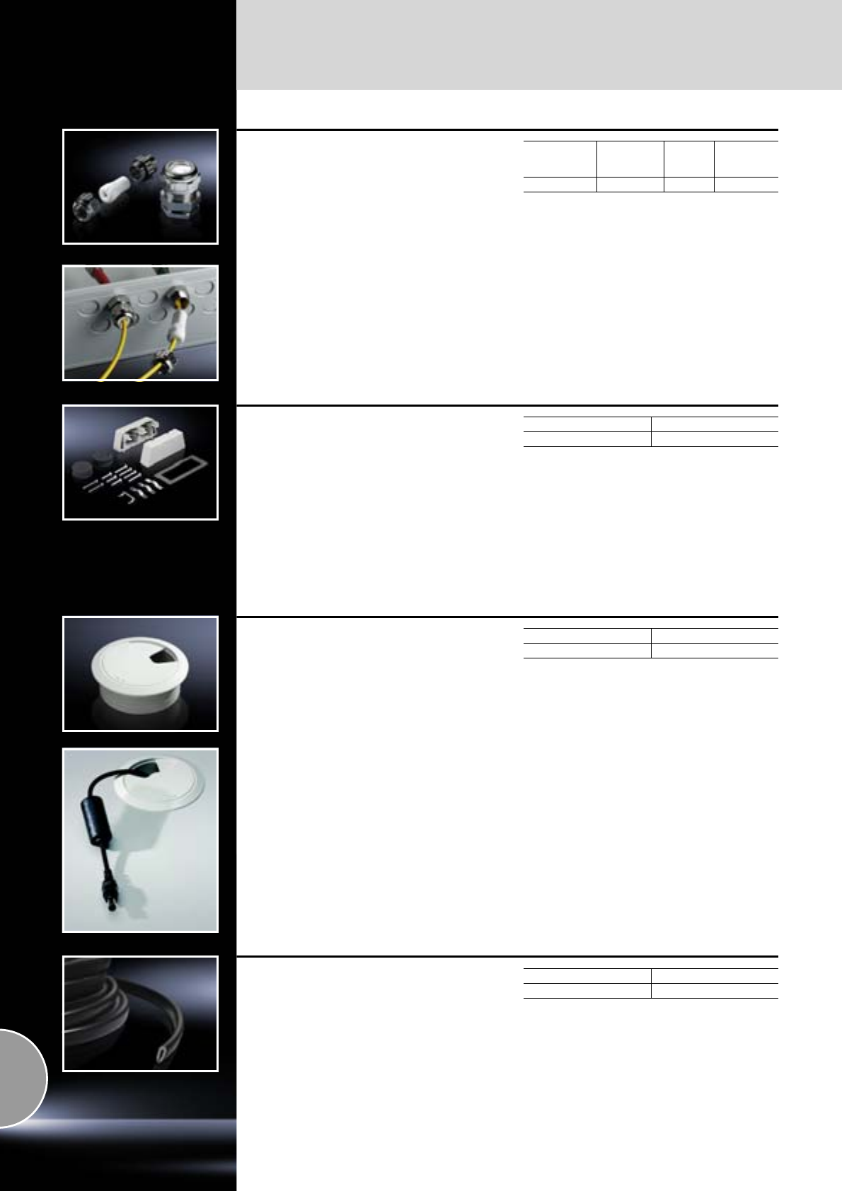
Cable management
Cable glands
522 Rittal Catalogue 33/System accessories
Cable glands
for fibre-optic technology
The common size PG 13.5 has a slotted interior
seal. This allows super-easy cable entry. Ideal for
routing break-out cables, as this eliminates
unnecessary bending of the fibre-optic cables.
Material:
−Cable gland: Brass
−Inner seal: Soft PVC insert
Surface finish:
Cable gland: Nickel-plated
Fibre-optic
cable gland
Cable
diameter
mm
Packs
of Model No.
DK
PG 13.5 2 x 3 12 7455.030
Connector gland
for connector cut-outs (24-pole)
For the entry of 2 pre-assembled cables in the
connector cut-out, without dismantling the con-
nector.
For cable diameter from 8 – 36 mm.
Material:
−Enclosure: Plastic
−Clamps: Sheet steel
Surface finish:
Clamps: Zinc-plated
Supply includes:
1 set =
2 half-shells, including seals,
with fastening clamp.
Packs of Model No. SZ
1 set 2400.000
Cable gland
for IW worktops
To fit drilled holes Ø 60 mm. For the entry of
cables with pre-assembled connectors, the
rotating flap and cover are easily removed.
Material:
Plastic
Colour:
RAL 7035
Detailed drawings:
Available on the Internet.
Packs of Model No. IW
16902.770
Edge protector
For covering sharp edges of cut-outs. Provides
protection from injuries and prevents damage
to inserted cables. The edge protector is suitable
for material thicknesses of approx. 1.0 – 2.0 mm,
and may be cut to length individually.
Material:
Plastic PVC
Colour:
Black
Packs of Model No. DK
10 m 7072.100
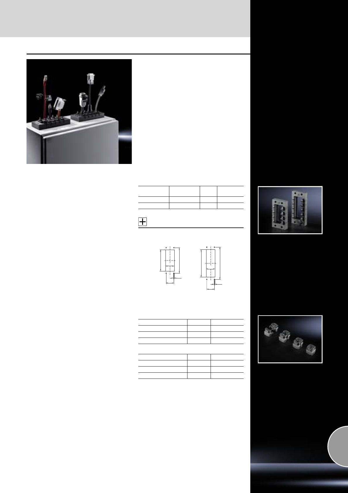
Cable glands
Cable management
523Rittal Catalogue 33/System accessories
The Rittal connector gland proves that sometimes
“less is more”: significantly faster installation, a
flexible sealing system for different cable diame-
ters, and simple cable entry with pre-assembled
cables. Low installation costs, a high degree of
protection and flexible cable management –
added value guaranteed with the latest genera-
tion of cable entry solutions from Rittal.
Benefits:
●Cable diameters 4 – 16 mm
●Simple cable entry for pre-assembled cables
●Individual cables can be added or replaced
without dismantling the sealing frame
●Sealing modules remain safely attached to
their cables
Sealing frame
For pre-assembled cables with connectors.
Mounting over 24-pole or 16-pole connector
cut-outs in:
●Module plates for TS divider panels
●Metal gland plates
Material:
−Front panel: Polyamide
−Flat seal: CR
Protection category:
IP 64 to IEC 60 529, complies with NEMA 12.
Supply includes:
Assembly parts.
Accessories:
Module plates for TS divider panel,
see from page 390.
For modules
20 x 20 mm For
cut-out Packs
of Model No.
SZ
10 24-pole 1 2400.900
8 16-pole 1 2400.910
M4
32
36
103
86
M4
32
36
112
130
16-pole 24-pole
Sealing module
To seal cables in conjunction with a sealing frame.
It is possible to combine 20 x 20 mm and
40 x 40 mm sealing modules.
Material:
−Hard shell: Polyamide
−Seal: TPE 2
Protection category:
IP 64 to IEC 60 529, complies with NEMA 12.
Sealing modules 20 x 20 mm
Diameter range Packs of Model No. SZ
4 – 6 mm 10 2400.920
6 – 9 mm 10 2400.930
Solid 10 2400.970
Sealing modules 40 x 40 mm
Diameter range Packs of Model No. SZ
9 – 12 mm 10 2400.940
12 – 16 mm 10 2400.950
Solid 10 2400.960
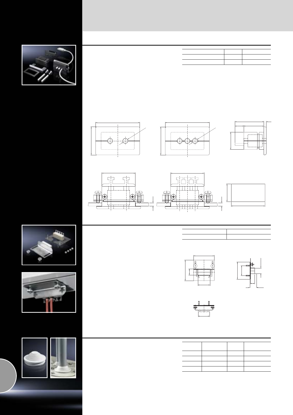
Cable management
Cable glands
524 Rittal Catalogue 33/System accessories
Connector gland, small
For pre-assembled cables with connectors.
●For use with material thickness of up to 4 mm.
●Strain relief of the pre-assembled cables can
be achieved with cable ties.
Material:
Plastic
Colour:
RAL 9005
Protection category:
IP 65 subject to correct mounting.
Supply includes:
Assembly parts.
To fit Packs of Model No. SZ
2 cables Ø 6 to Ø 8 mm 1 2400.300
3 cables Ø 4 to Ø 6 mm 5 2400.500
21.5
11 25
36 3
4
41.5
42
22
4
41.5
SZ 2400.500
Mounting cut-out
Ø 8
35
55
Ø 6
35
55
SZ 2400.300
Cable gland module
CP-L, Ø 130 mm
Use of the support arm cut-out CP-L, round, with
enclosures mounted on the wall, for sealed cable
entry. May also be mounted retrospectively with
the cables already inserted.
Fitted with T-heads for cable clamping. Particu-
larly well-suited to cables with identical cross-
sections.
Material:
Sheet steel
Surface finish:
Zinc-plated
Supply includes:
Assembly parts.
Packs of Model No. CP
1 6052.500
70
120
100 – 134
35
38.5
25
100
Ø 82
10 – 3 9
66
Stepped collar
For wall thicknesses from 1.5 to 4.5 mm
For cable entry, simply cut off at the required level
to match the cable diameter.
Material:
Plastic to UL 94-HB
Protection category:
IP 54 with careful cable entry.
For hole Sealing range
mm Packs of Model No. SZ
M20 5 – 16 100 2899.200
M25 5 – 21 50 2899.250
M32 13 – 26.5 25 2899.320
M40 13 – 34 20 2899.400
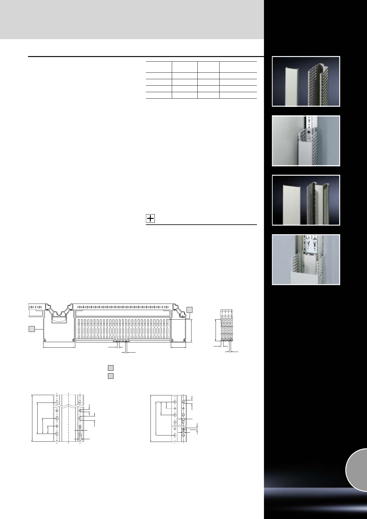
Cable management
525Rittal Catalogue 33/System accessories
Cable duct
for vertical TS section
For direct mounting on the vertical enclosure
section.
Width 50 mm
For assembly on a vertical enclosure section in
the area of the side panel.
Width 100 mm
For assembly on two bayed enclosure profiles in
the baying area. Baying brackets and baying
clamps which have already been fitted can be
covered over with the cable duct.
The nominal break points of the members are
also oriented towards combination with the cable
ducts for mounting plates; in addition a further
nominal break at the level of the mounting plate
enables direct insertion into the cable duct.
The cable duct fastening points are co-ordinated
with the TS system hole pattern; elaborate drilling,
as in the case of DIN ducts, is dispensed with.
Technical specifications:
−Depth: 80 mm
−Length:
1600 mm (for enclosure height 1800 mm)
1800 mm (for enclosure height 2000 mm)
May be shortened for other enclosure
dimensions
−Bar width: 5.5 mm
−Slot width: 4.5 mm
Material:
−Hard PVC
−Flame-resistant, self-extinguishing
−Temperature resistant to +60°C
Colour:
Similar to RAL 7030
Supply includes:
1 set =
1 cable duct with cover.
Accessories:
Aluminium rivet for attachment,
see page 526.
Width
mm Height
mm Packs of Model No. TS
50 1600 8 sets 8800.570
50 1800 8 sets 8800.520
100 1600 4 sets 8800.540
100 1800 4 sets 8800.510
4.5
5.5
71
72
5.5
100
4.5
48
2
1
5
6.5
8
14
1600/1800
1550 = 62 x 25/1750 = 70 x 25
25
50
6.5
5
50
1550 = 62 x 25/1750 = 70 x 25
25
1600/1800
14
8
TS 8800.570/TS 8800.520
TS 8800.540/TS 8800.510
1
2
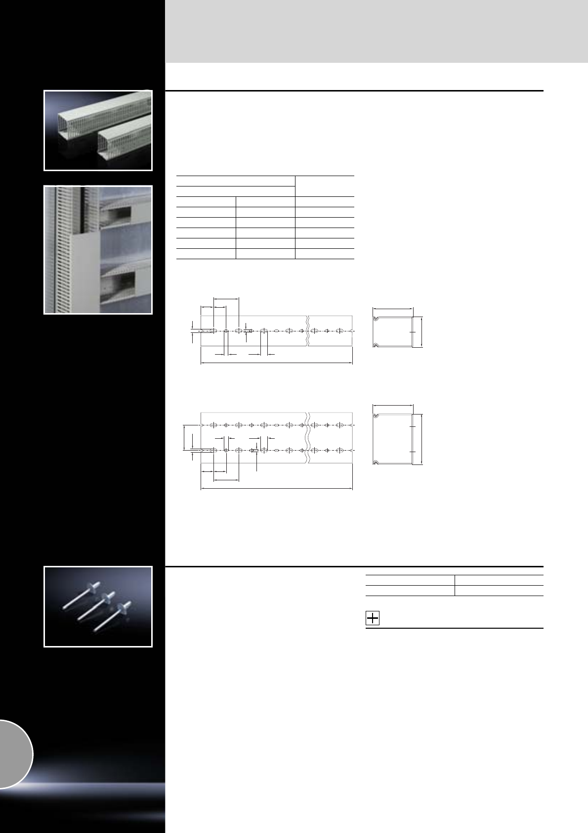
Cable management
526 Rittal Catalogue 33/System accessories
Cable duct
for mounting plate
●To fit the cable ducts for vertical TS sections.
If the TS mounting plate is installed in the rear-
most position, the horizontally mounted cable
ducts are flush with the vertical ones.
●For external mounting on surfaces.
Material:
−Hard PVC
−Flame-resistant, self-extinguishing
−Temperature resistant to +60°C
Colour:
Similar to RAL 7030
Supply includes:
1 set =
1 cable duct with cover.
Technical specifications:
−Depth: 80 mm
−Length: 2000 mm, may be cut to length
−Bar width: 5.5 mm
−Slot width: 4.5 mm
For enclosure width mm Fixed length
2000 mm
Length (L) mm
Width (B) mm Packs of Model No. TS
30 24 sets 8800.750
40 20 sets 8800.751
60 18 sets 8800.752
80 12 sets 8800.753
100 12 sets 8800.754
8
25
50
25
6.5
4.5
14
L
14
25 25
50
50
6.5
4.5
8
L
80
B
80
B
Width 30, 40 and 60 mm
Width 80 and 100 mm
Aluminium rivet
For secure assembly of cable ducts in conformity
with the relevant standards. Also suitable for
mounting support rails and punched rails.
To fit:
●TS system punchings
●Drilled hole Ø 4.5 mm.
Accessories:
−Cable ducts for vertical TS section,
see page 525.
−Cable ducts for mounting plate,
see page 526.
Packs of Model No. TS
100 8800.531
Cable management
527Rittal Catalogue 33/System accessories
Cable clamp rails
Mounting angle for TS, ES, PC,
TP universal console, base/plinths
For strain relief with cable entry. Depth-variable
mounting on a 25 mm pitch pattern on the hori-
zontal enclosure section or in side base/plinth trim
panels with assembly bolts.
Material:
Steel
Surface finish:
Zinc-plated
Supply includes:
Assembly parts.
Accessories:
Assembly bolts for base/plinth,
see page 364.
Enclosure width
mm Length
mm Packs
of Model No.
PS
400 385 2 4193.000
600 585 2 4191.000
800 785 2 4192.000
1000 985 2 4336.000
1200 1185 2 4196.000
1600 1585 2 4338.000
1800 1785 2 4339.000
Cable clamps,
for cable clamp rails
For fastening the cables to the cable clamp rails.
Material:
Sheet steel
Surface finish:
Zinc-plated
Supply includes:
Plastic insert.
Possible
alternative:
Rail for EMC shielding bracket and strain relief,
see page 498.
For
cable diameter
mm Packs of Model No.
SZ
6 – 12 25 2350.000
12 – 16 25 2351.000
14 – 18 25 2352.000
18 – 22 25 2353.000
22 – 26 25 2354.000
26 – 30 25 2355.000
30 – 34 25 2356.000
34 – 38 25 2357.000
38 – 42 25 2358.000
42 – 46 25 2359.000
46 – 50 25 2360.000
Cable clamp rails
C section
for TS, CM, TP
For strain relief with cable entry.
The length of the cable clamp rail is tailored to the
width of the mounting plate. The mounting bracket
included with the supply supports three different
installation situations on the mounting plate:
straight, at a distance of 23 mm from the
mounting plate
straight, at a distance of 10 mm from the
mounting plate
tilted, towards the mounting plate
Material:
Sheet steel
Surface finish:
Zinc-plated
Supply includes:
Two mounting brackets and assembly screws.
Accessories:
Cable clamps for C rails,
see page 529.
1
2
3
For
enclosure width
mm
Length
mm Packs
of Model No.
CM
600 499 1 5001.080
800 699 1 5001.081
1000 899 1 5001.082
1200 1099 1 5001.083
2
1
3
Cable management
528 Rittal Catalogue 33/System accessories
Cable clamping bracket
For installing in the operating housing with
mounting cut-out CP-L and CP-XL.
Cable clamping optionally via:
●Cable clamps
or
●Cable tie SZ 2597.000
●Commercially available cable ties.
Bracket height = 25 mm with fitted C rail 40 mm.
Material:
Sheet steel
Surface finish:
Zinc-plated
Supply includes:
C rail and screws.
Accessories:
−Cable clamps,
see page 529.
−Cable ties,
see page 530.
Packs of Model No. CP
1 set 6052.000
Cable clamp rails
see page 532.
Combination rails
for QuickBox
For cable clamping and routing.
Cables and leads can be fastened to the hammer
heads top and bottom with cable ties. In addition,
the C section of the combination rail will accom-
modate cable clamps with inserts. For producing
a contacting connection, the anodised coating of
the rail must be broken.
Material:
Aluminium
Surface finish:
Anodised
Supply includes:
Assembly parts.
Accessories:
−Cable clamps,
see page 529.
−Cable ties,
see page 530.
For
enclosure depth
mm
Length
mm Packs
of Model No.
QB
300/400 200 6 7502.302
500/600 400 6 7502.304
For
enclosure width
mm
Length
mm Packs
of Model No.
QB
600 400 6 7502.304
Cable management
529Rittal Catalogue 33/System accessories
Cascade cable routing
for chassis mounting
for TS
Professional cable routing system for cascading
of cables in several levels of the enclosure depth.
The cables are attached to the C rail by means of
clamps. Suitable for installation on the inner enclo-
sure level.
Material:
Sheet steel
Surface finish:
Zinc-plated
Supply includes:
−6 mounting brackets
−3 C rails
−Assembly parts
Accessories:
−TS punched section with mounting flange
for the inner mounting level,
see page 459.
−PS punched section without mounting flange
for vertical mounting in the enclosure frame,
see page 464.
−Cable clamps,
see page 529.
For
enclosure width
mm Packs of Model No. DK
600 3 7831.570
800 3 7831.571
Cable clamps
for C rails
For attaching the cables to the C rails.
Material:
Sheet steel
Surface finish:
Zinc-plated
Supply includes:
Plastic insert.
Note:
C rails,
see from page 465.
For
cable diameter
mm Packs of Model No. DK
6 – 14 25 7077.000
12 – 18 25 7078.000
18 – 22 25 7097.000
22 – 26 25 7097.220
26 – 30 25 7097.260
30 – 34 25 7097.300
34 – 38 25 7097.340
38 – 42 25 7098.000
42 – 56 25 7098.100
56 – 64 25 7099.000
Cable conduit and
cable conduit holder
For secure cable routing e.g. from the enclosure
or mounting plate to the door.
Attachment facility for standard commercially
available cable ties is provided on the cable con-
duit holder, so that cables may be attached upon
entry to/exit from the cable conduit.
Material:
−Cable conduit: Polythene
−Cable conduit holder: Polyamide
Cable conduit
Cable conduit holder
Internal Ø mm Packs of Model No. SZ
16 25 m 2595.000
29 25 m 2589.000
36 25 m 2596.000
48 25 m 2590.000
For cable conduit
Ø mm Packs of Model No. SZ
16 20 2593.0001)
29 20 2591.0001)
36 20 2594.000
48 20 2592.000
1) Installation in compact enclosures AE
with universal bracket SZ 2373.000, see page 476.
Cable management
530 Rittal Catalogue 33/System accessories
Cable attachment
For professional, secure fastening of cables and
conduits.
For fastening:
●Slide into the mounting rail 23 x 23 mm,
●Screw-fasten onto the round punchings of the
enclosures, as well as all punched rails and
punched sections.
As the fastening attachments are bayable, sev-
eral fastening attachments, even those of differ-
ent sizes, can be assembled by using just
2 screws.
Material:
Polyamide
Note:
Punched rail 23 x 23 mm,
see page 463.
Also required:
Posidrive raised countersunk screw M5 x 12 mm,
SZ 2488.000, for screw-fastening to the round
system punchings,
see page 478.
For
cable diameter
from – to
mm
Packs of Model No. PS
6 – 9 50 4319.090
9 – 12 50 4319.120
12 – 16 50 4319.160
16 – 20 50 4319.200
Cable ties
The super-fast solution for fastening cables to the
enclosure profile or mounting system parts.
Simply clip into the round system punchings.
Length
mm Packs of Model No. SZ
150 100 2597.000
Nylon loop
With the nylon loop, secured cables are easily
released, allowing individual cables to be added
or removed. Ideal for sensitive data cables
(fibre-optic/Cu), as it avoids indentations on the
cable sheathing.
In addition, the nylon loop may be screw-fas-
tened to the round system punchings or attached
using a quick-release fastener.
Colour:
Black
Supply includes:
Quick-release fastener.
Also required:
Screw SZ 2486.500 for screw-fastening to the
round system punchings,
see page 478.
Width
mm Length
mm
Max. cable
diameter
mm
Packs
of Model No.
DK
20 130 30 10 7072.220
20 200 50 10 7072.230
20 300 90 10 7072.240
Nylon loop
For tidy cable routing.
Supplied on a reel for cutting to the required
length.
Unlike cable ties,
●protects the cable sheathing
●easily reopened
●reusable
Length
mm Width
mm Packs
of Model No. IN
5000 16 1 2203.400
Cable management
531Rittal Catalogue 33/System accessories
Nylon loop cable holder
self-adhesive
Suitable for universal use in all network enclo-
sures and server racks, wall-mounted enclosures,
mounting plates and gland plates.
Material:
Woven polyamide 6.6
Colour:
Black
Size
length x width
mm Packs of Model No. DK
70 x 16 10 7111.350
Cable tie fastener
for round system punchings and VIP 6000
For all commercially available cable ties up to a
tie width of 4.8 mm.
Simply insert into the screw channel and secure
by hammering down the split rivet.
Material:
Polyamide 6.6
Packs of Model No. CP
100 6059.000
Cable tie fastener
for Comfort Panel, Optipanel and
Compact Panel
For secure cable routing of all standard commer-
cially available cable ties up to a tie width of
4.0 mm.
Simply insert into the T channel and secure by
rotating through 45°.
Material:
Polyamide 6.6
Packs of Model No. CP
100 6059.500
Snap-in cable routing
for clipping into the system punchings
Cable routing suitable for universal use,
for toolless, fast assembly, in two variants:
For locking:
●User-friendly opening for cable management
via locating points
●For cable diameters 14 – 19 mm
●For system punchings 6.2 mm
For twisting:
●User-friendly opening for cable management
●For cable diameters 10.2 – 12.7 mm
●For system punchings 4.7 mm
Material:
Polyamide 6.6, self-extinguishing to UL 94-V2
Colour:
Natural
Design Packs of Model No. DK
For locking for
system punchings 6.2 mm 10 7111.300
For twisting for
system punchings 4.7 mm 10 7111.310
Cable management
532 Rittal Catalogue 33/System accessories
Cable clamp rails
for TS and 482.6 mm (19˝) mounting frames
The cables may be attached to the cable clamp
rails with cable ties or nylon tapes. The cable
clamp rails are simply located onto the frame
section and may additionally be secured with
a screw.
Material:
Sheet steel
Supply includes:
Assembly parts.
For the inner mounting level
For the outer mounting level
Accessories:
−Cable ties,
see page 530.
−Nylon loop,
see page 530.
For enclosures Packs of Model No. DK
Width mm Depth mm
600 600 4 7828.061
800 800 4 7828.081
1000 1000 4 7828.101
1200 1200 4 7828.121
For enclosures Packs of Model No. DK
Width mm Depth mm
600 600 4 7828.062
800 800 4 7828.082
1000 1000 4 7828.102
1200 1200 4 7828.122
Cable clamp rails,
depth-variable
for TS and 482.6 mm (19˝) mounting frames
For strain relief of the routed cables. The cables
may be attached to the cable clamp rails with
cable ties or nylon tapes.
The cable clamp rails may be located directly on
a 482.6 mm (19˝) mounting frame horizontally at
the rear or in the enclosure depth between two
mounting frames. An additional screw fastening
secures the unit.
The depth variability of the rails facilitates flexible
adaptation of their length to the existing attach-
ment distance between the two 482.6 mm (19˝)
mounting frames.
Material:
Sheet steel
Supply includes:
Assembly parts.
Accessories:
−Cable ties,
see page 530.
−Nylon loop,
see page 530.
Mounting dimension1)
mm Packs of Model No. DK
325 – 575 4 7858.160
500 – 895 4 7858.162
1) Mounting dimensions + 120 mm =
distance between 482.6 mm (19˝) levels
1
2
Cable clamp, variable
for enclosure-independent mounting
Variable attachment from 450 to 800 mm for flexi-
ble cable clamping in two variants.
Supports attachment to punched sections with
and without mounting flanges and direct screw-
fastening onto mounting plates and other flat
surfaces.
Material:
Sheet steel, zinc-plated
Supply includes:
Assembly parts.
C rail
T-head rail
1
2
Design Packs of Model No. DK
C rail 1 7016.140
T-head rail 1 7016.150
Cable management
533Rittal Catalogue 33/System accessories
Cable manager
For system-compatible cable deflection while
complying with minimal bending radii and to
accommodate surplus cables and excess length.
The elements may optionally be used individually
or in combination for cable routing. They may be
combined into semi-circular or circular elements.
As the mounting distance between the elements
grows larger, the deflection radius of the cables
may optionally be enlarged, or the cable route
designed individually. The option of securing ele-
ments on their straight-edge side supports the
use of corners and edges, to allow protected
cable routing around them.
Mounting clips for use above the arc hold the
routed cables back within the elements. The ele-
ments are also bayable in an axial direction to
allow U-based cable routing to the mounting level,
or channelling of the cable sections.
Material:
Plastic, UL 94-V0
Colour:
RAL 7035
Supply includes:
Mounting clips and assembly parts.
Packs of Model No. DK
Basic kit 8 7064.100
Maxi kit 20 7064.110
50
50
44
75
75
Shunting ring, plastic
For flexible cable routing, in two materials and
three size variants.
Option of mounting on the 482.6 mm (19˝) enclo-
sure and swing frame section of the data distribu-
tor, on all patch panels, on the Rittal Data Rack
and all components on a 25 mm DIN pitch pattern.
1
Polyamide version:
Infinitely variable mounting thanks to a longitudi-
nal slot. The shunting ring DK 7218.035 may also
be used on 1 U patch panels.
Colour:
RAL 7035
Material Dimensions
mm Packs
of Model No.
DK
Polyamide 70 x 44 10 7218.035
Polyamide 105 x 70 10 7219.035
Polycarbonate 95 x 50 10 7228.035
1
1
2
2
Polycarbonate version:
Variable mounting. With 45° attachment, the cable
shunting ring may be attached to a 1 U panel.
Colour:
RAL 7035
Possible
alternative:
Cable management panel, 1 U,
see page 539.
Cable management
534 Rittal Catalogue 33/System accessories
Cable shunting ring
For flexible, system-compatible cable routing at
the side of the 482.6 mm (19˝) mounting frame or
on 482.6 mm (19˝) mounting angles.
Material:
Sheet steel, zinc-plated
Supply includes:
Assembly parts.
Dimensions
mm Packs of Model No. DK
125 x 85 10 7111.900
125 x 65 10 7111.000
85 x 43 10 7112.000
Anti-twist guard
for cable shunting rings
For individual attachment of cable shunting rings
(DK 7111.000, DK 7111.900, DK 7112.000) to
mounting angles, mounting frames or enclosure
panels. May be mounted on a 25 mm pitch pat-
tern of system punchings on mounting angles
and on the 10.5 x 12.5 mm system punchings of
the 482.6 mm (19˝) mounting frame. It may be
variably mounted and rotated on the system
punchings in 90° increments.
Form-fit accommodation of the shunting ring into
the integral channel allows large forces to be
accommodated in all directions.
Material:
Plastic
Colour:
RAL 7035
Packs of Model No. DK
10 7111.100
Shunting ring
To accommodate large quantities of cables.
Shunting ring for side attachment to 482.6 mm (19˝)
sections and mounting frames in 800 mm wide
network enclosures.
The ring is attached asymmetrically providing
approx. 110 mm free space in front of the
482.6 mm (19˝) level. This allows even large
quantities of cables to be effectively managed.
Material:
Round steel, zinc-plated
Supply includes:
Assembly parts.
Dimensions
mm Packs of Model No. DK
330 x 90/70 4 7220.600
Cable management
535Rittal Catalogue 33/System accessories
1
2
3
4
Fibre-optic shunting rings
The inner body is grooved, and fibre-optic shunt-
ing or jumper cables can be inserted into these.
A rubber ring holds different fibre-optic cables
with diameters of up to 4.5 mm. Strain relief and
bending radius are ensured.
Length: 120 mm.
Material:
Dual compound plastic
Colour:
−Exterior: RAL 7035
−Interior: Black
Supply includes:
−2 rubber rings
−Baying kit
−Mounting accessories
Assembly:
The supplied mounting brackets are suitable for
universal use; the fibre-optic cables can be routed
to the patch panel in all directions in various
mounting positions:
At the side, directly on the patch panel
In front of the patch panel
At the side next to the patch panel
In front of the patch panel
Possible
alternative:
Fibre-optic cable management panel, 1 U,
see page 541.
1
2
3
4
Packs of Model No. DK
27116.500
Cable clamp strap
for patch panels
To provide strain relief of incoming or outgoing
data cables. Optionally available with spring
brackets for accommodating and contacting the
cable screen. Connection to the patch panel is by
means of bolts on the panel itself.
Material:
Sheet steel, 2 mm, zinc-plated
Supply includes:
Assembly parts.
Design
Packs of
Model No. DK
Without cable screen contact
1 7610.000
With spring clips for
contacting the cable screen 1 7611.000
System supports
for cable routes
for TS
The depth-variable support system may be
attached to all 800 – 1200 mm deep TS enclo-
sures with external screw-fastening of the roof
plate. The integral system punchings, for screws
or captive nuts, support the attachment of most
common cable route systems.
Material:
Sheet steel
Surface finish:
Powder-coated
Colour:
RAL 7035
Accessories:
−Metal multi-tooth screws 5.5 x 13 mm,
SZ 2486.500,
see page 478.
−Captive nuts M6, TS 8800.340,
see page 477.
Packs of Model No. DK
27831.472
Cable management
536 Rittal Catalogue 33/System accessories
Cable route on the
mounting frame
The mounting kit facilitates rear, side attachment
of a cable tray to mounting frames inside enclo-
sure systems TE 7000, TS. This allows the integra-
tion of vertical cable management independently
of the enclosure frame.
Material:
Sheet steel, zinc-plated
Supply includes:
1 cable route 100 mm wide, 1700 mm high,
including mounting kit.
Packs of Model No. DK
1 7000.685
Cable route, vertical
for TS
For direct attachment between the roof and base
frame of a 2000 mm high frame structure.
Installation position optionally on the inner or outer
mounting level. Route width 200 mm.
With integral system punchings for the attach-
ment of various cable routing aids and hammer-
head attachment for nylon loops and cable ties.
Material:
Sheet steel, zinc-plated
Supply includes:
Assembly parts.
Packs of Model No. DK
17858.200
Cable route
for TS
For cable routing between two 482.6 mm (19˝)
mounting angles in bayed enclosure suites
(enclosure width 800 mm, mounting angles fitted
centrally). Suitable for L-shaped and cranked
mounting angles.
Material:
Sheet steel
Colour:
RAL 7035
Supply includes:
Assembly parts.
Packs of Model No. DK
17827.050
Surplus cable holder
For fastening at the rear area of the enclosure,
or at the side of network enclosures. The surplus
cable holder can be attached to all depth stays or
to punched sections and rails with a 25 mm pitch
pattern – mounting dimension 150 mm. Units may
also be fastened to each other.
Material:
Sheet steel
Colour:
RAL 7035
W x H x D mm Packs of Model No. DK
280 x 151 x 75 1 7220.500
Cable routing 482.6 mm (19˝)
Cable management
537Rittal Catalogue 33/System accessories
Cable routing bars
For structured routing of entire cable bundles,
the cable bars may be secured to a variety of
different positions inside the enclosure.
Material:
−Support: Sheet steel
−Cable routing bars, connection combs: Plastic
Colour:
RAL 9005
Supply includes:
−Cable routing bars
−Connection combs
482.6 mm (19˝) attachment
For horizontal cable routing within the distributor
level.
Thanks to their open mounting holes, they can also
be retrospectively slotted onto the 482.6 mm (19˝)
system punchings of the mounting level at any time
and secured with the existing mounting screws of
the installed components.
UNo.
of connection
combs Packs of Model No. DK
4247111.224
15107111.214
All-round attachment for universal use
For vertical and horizontal cable routing inside the
enclosure or within the distributor level. UNo.
of connection
combs Packs of Model No. DK
4247111.222
15107111.212
Connection comb
For connecting individual cable routing bars into
complete systems (included with the supply).
Cranked attachment
For mounting angles and mounting frames.
Horizontal, U-based cable routing to the distribu-
tor level.
UNo.
of connection
combs Packs of Model No. DK
4247111.220
15107111.210
Cable management
Cable routing 482.6 mm (19˝)
538 Rittal Catalogue 33/System accessories
1
Cable duct
for TS/TE
For laying cable in particularly high packaging
densities (high density network nodes), in the
optical fibre or copper cabling sector.
Large capacity. A wide range of cable routing,
cable clamping, channelling and cross-cabling
options creates the requirements for maximum
port density in the minimum possible space.
Individual U-based cable routing makes it pos-
sible to dispense with additional cable routing via
patch panels within the distributor level, thereby
equipping every U with connection points. This
increases port density by up to 50%.
The removable duct cover, hinged on both sides,
facilitates user-friendly access at any time. The
cable sections are held back by removable cross-
bars to protect them against falling out. Mounting
is either on mounting rails at the sides, and on
mounting angles and mounting frames in the
482.6 mm (19˝) distributor level. Two ducts may
also be secured back-to-back.
Material:
−Cable duct: Sheet steel, spray-finished
−Cable routing components: Plastic
−Front trim panel: Aluminium, spray-finished
Colour:
RAL 7035
Supply includes:
Hinged front trim panel and assembly parts.
Note:
When using the duct in conjunction with
482.6 mm (19˝) mounting frames and TS 8,
the inner mounting level in the vicinity of the
cable duct is not available.
Within the duct, additional cable ties may be
attached to accommodate spare cables and for
system-compatible cable deflection.
Accessories:
Cable ties for spare cables:
Size
W x D mm No. of
UPacks
of Model No. DK
95 x 235 24 1 7827.310
42 1 7827.320
Packs of Model No. DK
47827.330
1
1
2
Distributor clip
Material:
Sheet steel
Surface finish:
Zinc-plated
Supply includes:
Assembly parts.
Distributor clip
For structured cable routing of entire cable
bundles, the distributor clip may be secured
to a variety of different positions inside the
enclosure. It may be used for both horizontal
and vertical distribution of the cables.
Distributor clip, horizontal
For mounting angles and mounting frames.
Distribution of cables among the various
height units of the patch level.
1
2
Packs of Model No. DK
47111.252
47111.250
1
2
Cable routing 482.6 mm (19˝)
Cable management
539Rittal Catalogue 33/System accessories
Drawer 482.6 mm (19˝)
to accommodate surplus cables
The 1 U drawer offers a convenient opportunity for
storing surplus cables in an organised, compact
and secure way within the 482.6 mm (19˝) levels.
●With brush strip at the front for cable entry
●T-head rail in the rear section for cable clamp-
ing
●Ring-shaped kink-free routing of the conduc-
tors on adjustable elements in the interior
●May be fitted between two 482.6 mm (19˝)
levels at a distance of 435 – 750 mm
●Independent from the enclosure system
●Both on L-shaped and cranked mounting
angles and mounting frames.
Material:
Sheet steel
Colour:
RAL 7035
Supply includes:
Drawer including telescopic slides and
assembly parts.
Accessories:
Nylon loop DK 7072.220/DK 7072.230,
see page 530.
Distance between levels
mm Packs of Model No. DK
435 – 750 1 7063.200
Cable management panel
482.6 mm (19˝)
For horizontal management of the patch cables,
with 5 cable shunting rings.
Material:
−Panel: Sheet steel
−Ring: Polyamide
Colour:
RAL 7035
U Ring size mm Packs of Model No. DK
1 70 x 44 1 7159.0351)
1) Cable shunting rings supplied loose.
Material:
−Panel: Sheet steel
−Ring: Polycarbonate
Colour:
RAL 7035
U Ring size mm Packs of Model No. DK
1 95 x 50 1 7255.0351)
1) Cable shunting rings supplied loose.
Material:
−Panel: Sheet steel
−Ring: Steel
Surface finish:
Ring: Zinc-plated
Colour:
RAL 7035
U Ring size mm Packs of Model No. DK
1 105 x 43 1 7257.035
2 125 x 85 1 7257.100
1 43 x 55 1 7257.200
Material:
−Panel: Sheet steel
−Ring: Steel
Surface finish:
Ring: Zinc-plated
Colour:
RAL 9005 Note:
The sizes given are external dimensions.
U Ring size mm Packs of Model No. DK
1 105 x 43 1 7257.005
2 125 x 85 1 7257.1051)
1) Extended delivery times.
Cable management
Cable routing 482.6 mm (19˝)
540 Rittal Catalogue 33/System accessories
Cable management panel
with cable routing bars
482.6 mm (19˝)
For horizontal management of the patch cables
with cable routing bars. Opening the individual
cable routing bars allows user-friendly modifica-
tion and extension of the cabling.
Material:
−Panel: Sheet steel, spray-finished
−Cable routing bars: Plastic
Colour:
−Panel: RAL 7035
−Cable routing bars: Black
UBar depth
mm No. of
bars/U Packs of Model No.
DK
1 Approx. 80 5 1 7257.050
2 Approx. 80 4 1 7257.150
Cable management panel, 2 U
482.6 mm (19˝)
The cable routing chamber has cut-outs from
above, into which the patch cables can be
inserted. The cable management panel is
equipped with a flap and quick-release fasteners
at the front, for optimum access to the cables.
From the rear, the cables can be inserted via a
cut-out with brush strips. With accommodation
facility for cable clamp straps DK 7610.000 or
DK 7611.000.
Material:
Sheet steel
Colour:
RAL 7035
Accessories:
Cable clamp strap,
see page 535.
U Depth mm Packs of Model No. DK
285 17158.035
Cable routing channel
482.6 mm (19˝)
To hold the patching cables.
Material:
Sheet steel
Colour:
RAL 7035
U Depth mm Packs of Model No. DK
185 17149.135
3100 17149.035
Cable management panel, 2 U
To accommodate fibre-optic and copper cables.
Fibres from the patch panels are placed into the
tray via openings and may be distributed at the
sides. Rounded openings protect the cable
sheathing.
Material:
Sheet steel
Colour:
RAL 7035
UPacks ofModel No. DK
217269.135
Cable routing 482.6 mm (19˝)
Cable management
541Rittal Catalogue 33/System accessories
Cable management duct,
horizontal
482.6 mm (19˝)
The duct facilitates concealed, simple cable
routing of large quantities of cables to equipment
within the 482.6 mm (19˝) attachment level.
Large cut-outs ensure convenient, kink-free cable
routing to the components top and bottom.
For simple handling, the entire front panel may be
removed via quick-release fasteners. After attach-
ing the cables, these are held in position via nylon
ties, whilst the duct may be resealed.
Material:
Sheet steel
Colour:
RAL 7035
Supply includes:
5 nylon loops.
UPacks ofModel No. DK
217158.100
317158.1501)
1) Extended delivery times.
Cable tray, 2 U
For side routing and distribution of fibre-optic and
copper cables. In this way, cables inserted into
the roof area may be routed at the side of the
mounting angles in the upper section of the rack.
Depth 85 mm.
Material:
Sheet steel
Colour:
RAL 7035
UPacks ofModel No. DK
217269.235
Fibre-optic cable management
panel, 1 U
482.6 mm (19˝)
The four fibre-optic cable shunting rings inte-
grated into the front permit optimum management
of up to 48 fibres.
Material:
−Panel: Sheet steel
−Ring: Dual compound plastic
Colour:
−Panel: RAL 7035
−Cable shunting rings on the outside: RAL 7035,
black interior
Possible
alternative:
Fibre-optic support guide DK 7116.500,
see page 535.
UPacks ofModel No. DK
117256.035
Cable management
Cable routing 482.6 mm (19˝)
542 Rittal Catalogue 33/System accessories
Cable entry panel
482.6 mm (19˝)
Cut-out 390 x 40 mm (2 U) or 390 x 20 mm (1 U)
with brush insert. With accommodation facility for
cable clamp straps DK 7610.000 or DK 7611.000.
Material:
Sheet steel
Colour:
RAL 7035
Accessories:
Cable clamp strap,
see page 535.
UPacks ofModel No. DK
117140.535
217150.535
4
1
2
3
Cable routing across the
482.6 mm (19˝) mounting level
There are various different cable clamping
systems available for system-compatible cable
routing in 482.6 mm (19˝) systems with one or
two pairs of mounting angles:
Material:
Sheet steel
Surface finish:
Zinc-plated
C rail
for mounting between all pairs of
482.6 mm (19˝) mouting angles.
1
C rail Depth
in mm Packs
of Model No.
DK
482.6 mm (19˝) level – 6 7016.100
Cable clamp rails
for mounting between all pairs of
482.6 mm (19˝) mounting angles,
for cable ties.
2
Cable clamp rail Depth
in mm Packs
of Model No.
DK
482.6 mm (19˝) level – 6 7016.110
Cable clamp straps for large swing frames,
and Data Rack,
the cable clamp straps are mounted on the
frame at the rear, whilst the cables are
clamped 250 mm behind the 482.6 mm (19˝)
mounting angles.
Cable clamp strap for DK-TS mounting
angles,
with side lugs for suspending from the
cranked 482.6 mm (19˝) mounting angles.
Cable clamping is via cable ties.
Also required:
With L-shaped TS mounting angles,
adaptor DK 7827.300 is additionally required,
see page 488.
3
4
Cable clamp strap for Depth
in mm Packs
of Model No.
DK
Data Rack and
large swing frame 250 6 7016.120
DK-TS mounting angles 100 6 7016.130
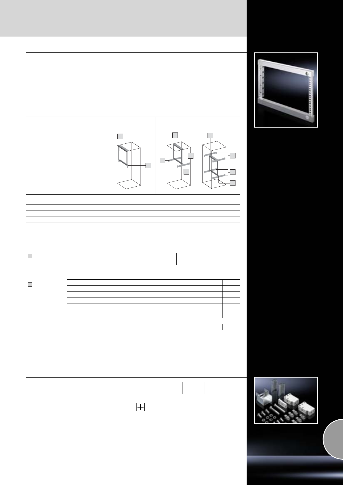
Swing frame
482.6 mm (19˝) installation system
543Rittal Catalogue 33/System accessories
Swing frame, small
Installation for 600 mm and 800 mm wide
enclosures
For mounting 482.6 mm (19˝) equipment.
Material:
Sheet steel
Surface finish:
Zinc-plated
Supply includes:
Cam with double-bit lock insert and parts
for attaching to the installation kit.
Technical information:
Available on the Internet.
Note:
The swing frame stay is required to lock the open swing frame,
see page 548.
Installation Front,
top/bottom Set back,
top/bottom Set back/front,
centre
UPacks
of Model No. SR
31 2377.030
61 2377.060
91 2377.090
12 1 2377.120
15 1 2377.150
18 1 2377.180
Also required:
Installation kit 1 set
For enclosure width
600 800
2377.860 2377.880
PS punched
section without
mounting flange,
2 or 4 required
For
enclosure depth
mm Page
400 4 4374.000 464
500 4 4375.000 464
600 4 4376.000 464
800 4 4377.000 464
Support bracket,
2 required per PS punched
section without mounting flange 6 sets 8800.330 473
Accessories
Lock inserts, type D 2484.000 421
1
1
1
2
1
2
1
2
2
1
1
2
Installation kit
for swing frame, small
in ES, TP universal console.
Accessories:
Depending on the installation position:
−Support bracket PS 4183.000,
see page 473 and
−PS punched section without mounting flange
in accordance with the enclosure depth,
see page 464.
Enclosure width mm Packs of Model No. SR
600 1 set 2377.460
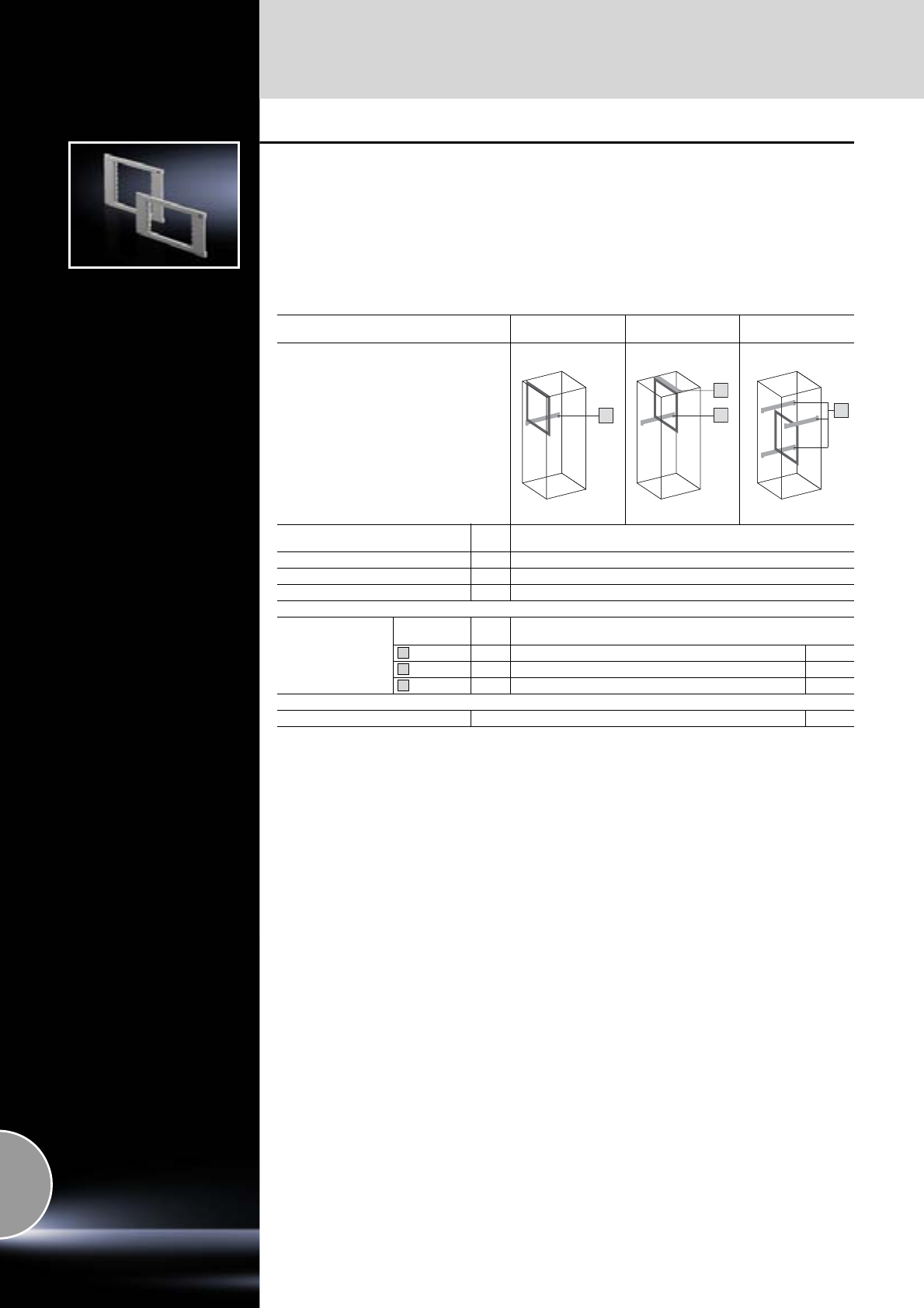
482.6 mm (19˝) installation system
Swing frame
544 Rittal Catalogue 33/System accessories
Vario swing frames
Installation for ES and CS modular enclosures,
800 mm wide enclosures
For the installation of 482.6 mm (19˝) equipment.
Material:
Sheet steel
Colour:
RAL 7035
Supply includes:
Double-bit lock insert and assembly parts.
Technical information:
Available on the Internet.
Installation Front1),
top Set back,
top Set back/front1),
centre
UPacks
of Model No. SR
61 2004.235
12 1 2008.235
18 1 2011.235
Also required:
PS punched section
with mounting flange
For enclosure
mm Page
400 depth 4 8800.640 464
500 depth 4 8800.650 464
800 width 4 4365.000 464
Accessories
Lock inserts, type D 2484.000 421
1) Max. installation depth for enclosure depth 400 mm: 305 mm
Max. installation depth for enclosure depth 500 mm: 405 mm
33
4
3
3
3
4
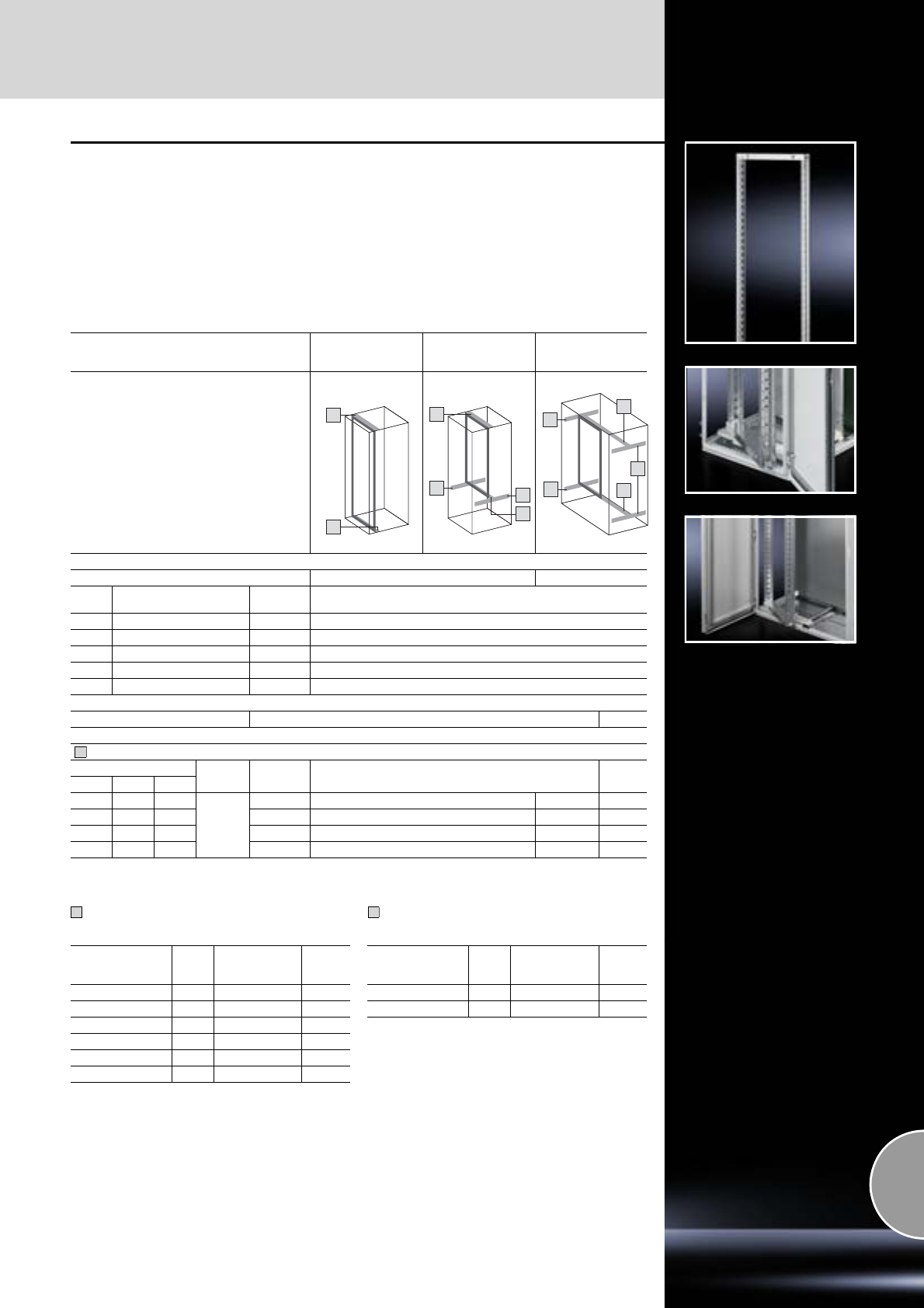
Swing frame
482.6 mm (19˝) installation system
545Rittal Catalogue 33/System accessories
Swing frame, large
Without trim panel, for 600 mm and 1200 mm
wide enclosures
For mounting 482.6 mm (19˝) equipment.
Material:
Sheet steel
Surface finish:
Zinc-plated
Supply includes:
Cam with double-bit lock insert and parts for
attaching to the installation kit.
Technical information:
Available on the Internet.
For TS:
TS punched section with mounting flange 23 x 73 mm,
2 or 4 required
For ES:
PS punched section with mounting flange 23 x 73 mm,
2 or 4 required
Note:
The swing frame stay is required to lock the open
swing frame,
see page 548.
Installation Full installation,
front/set back
Partial installation
top,
front/set back
Partial installation
centre,
front/set back
For enclosure width mm 600 1200
UFor min. enclosure height
mm Packs of Model No. SR
22 1200 1 2322.700
31 1600 1 2331.700
36 1800 1 2336.700
40 2000 1 2340.700
45 2200 1 2345.700
Accessories Page
Lock inserts, type D 2484.000 421
Also required:
Installation kits
For enclosure Hinge Load
capacity Packs of
TS ES CM
– –
130°
< 800 N 1985.500 – 1 set
– < 1500 N2) 1994.835 – 1 set
– < 1500 N2) – 1996.835 1 set
– – < 1500 N1) – 1996.535 1 set
1) Installation only possible with the mounting plate slide rail dismantled.
2) Maximum load 800 N with the TS mounting plate slide rail dismantled.
1
1
2
1
2
1
2
2
2
1
1
1
Installation in
enclosure depth
mm
Packs
of Model No. TS Page
400 4 8612.1401) 459
500 4 8612.550 460
600 4 8612.560 460
800 4 8612.580 460
1000 4 8612.500 460
1200 4 8612.520 460
1) TS punched section with mounting flange, 17 x 73 mm
2
Installation in
enclosure depth
mm
Packs
of Model No. TS Page
400 4 4369.000 464
500 4 4370.000 464
2
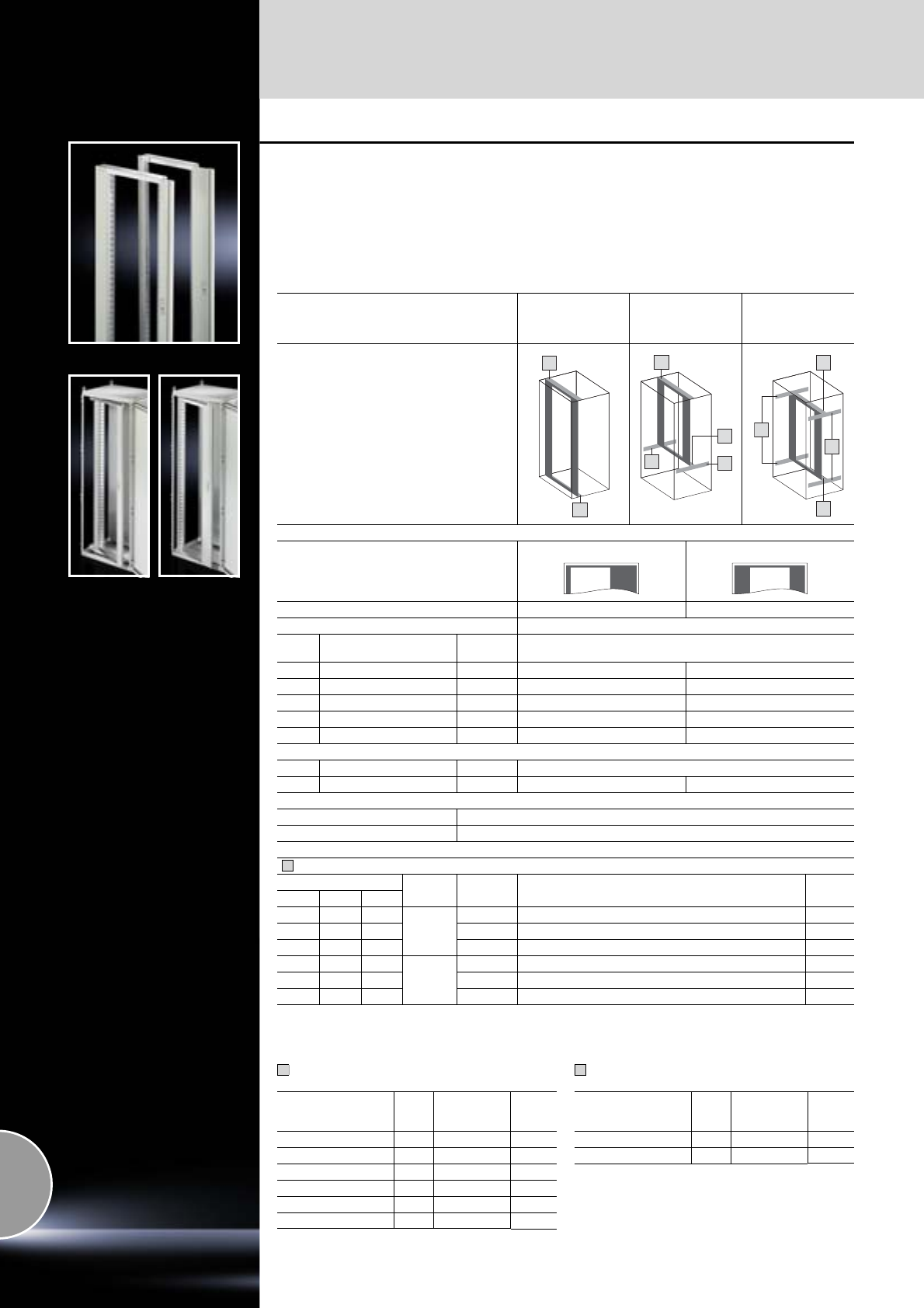
482.6 mm (19˝) installation system
Swing frame
546 Rittal Catalogue 33/System accessories
Swing frame, large
With trim panel, for 800 mm wide enclosures
For mounting 482.6 mm (19˝) equipment.
Material:
Sheet steel
Surface finish:
−Front panel: Zinc-plated
−Trim panel: Spray-finished
Colour:
RAL 7035
Supply includes:
Locking rod system with double-bit lock insert
and parts for attaching to the installation kit.
Technical information:
Available on the Internet.
For TS: TS punched section with mounting flange
23 x 73 mm, 2 or 4 required For ES: PS punched section with mounting flange
23 x 73 mm, 2 or 4 required
Note:
The swing frame stay is required to lock the
open swing frame,
see page 548.
Installation Full installation,
width 800 mm,
front/set back
Partial installation
top,
width 800 mm,
front/set back
Partial installation
centre (in the height),
width 800 mm
front/set back
Mounting position
side central
With hinge 130°/180° 180°
For enclosure width mm 800
UFor min. enclosure height
mm Packs of Model No. SR
22 1200 1 2323.235 2324.235
31 1600 1 2332.235 –
36 1800 1 2337.235 2338.235
40 2000 1 2341.235 2342.235
45 2200 1 2346.235 2347.235
Heavy-duty version1)
U For enclosure height mm Packs of Model No. SR
40 2000 1 7858.100 –
Accessories
Ergoform-S lock systems see page 419
Lock inserts, version A see page 421
Also required:
Installation kits
For enclosure Hinge Load
capacity Packs of
TS ES CM
– –
130°
< 800 N 1986.500 1 set
– < 1500 N3) 1995.235 1 set
– – < 1500 N2) 1995.835 1 set
– –
180°
< 800 N 1986.500 + 1978.200 1 set
– < 1200 N3) 1997.235 1 set
– – < 1200 N2) 1997.835 1 set
1) Load capacity 350 kg, including installation kit, for enclosure height 2000 mm.
2) Installation only possible with the mounting plate slide rail dismantled.
3) Maximum load 800 N with the TS mounting plate slide rail dismantled.
1
1
2
1
1
2
1
1
2
2
1
Installation in
enclosure width/depth
mm
Packs
of Model No.
TS Page
400 4 8612.1401) 459
500 4 8612.550 460
600 4 8612.560 460
800 4 8612.580 460
1000 4 8612.500 460
1200 4 8612.520 460
1) TS punched section with mounting flange, 17 x 73 mm
2
Installation in
enclosure width/depth
mm
Packs
of Model No.
TS Page
400 4 4369.000 464
500 4 4370.000 464
2
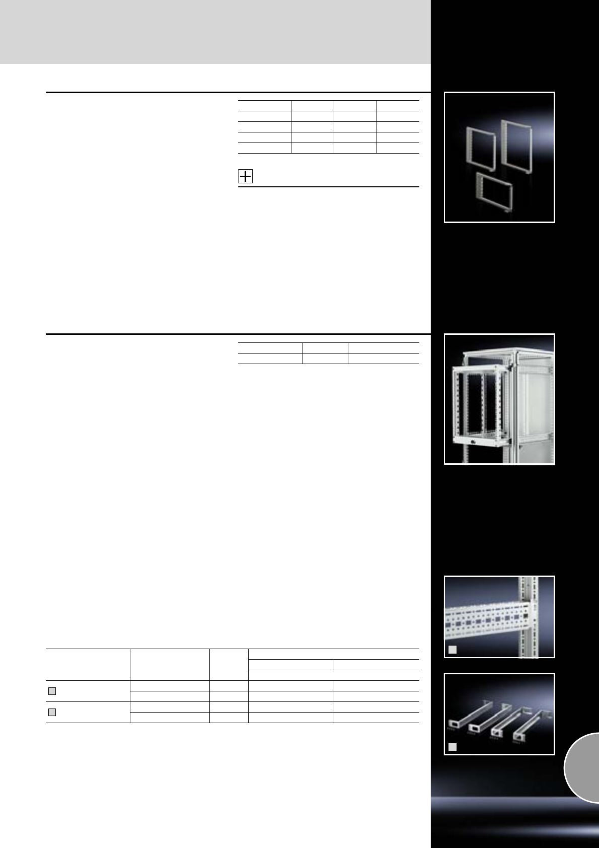
Swing frame
482.6 mm (19˝) installation system
547Rittal Catalogue 33/System accessories
Compact swing frames
for AE
For mounting slide-in electronic equipment,
482.6 mm (19˝), across the entire height.
Technical specifications:
Torsionally stiff frame, welded from rectangular
tube and triple-folded support section.
Material:
Sheet steel
Colour:
RAL 7035
Supply includes:
Double-bit lock insert and assembly parts.
Accessories:
41 mm lock insert, version C,
see page 421.
Detailed drawings:
Available on the Internet.
Width mm 600 600 600/760
Height mm 380 600 760
U 6 11 14
Packs of 1 1 1
Model No. SR 2026.200 2027.200 2034.200
Pull-out frame, 482.6 mm (19˝)
for TS
For the installation of a pull-out 482.6 mm (19˝)
front. For 600 and 800 mm wide TS enclosures,
from a depth of 800 mm.
−Overall depth: 525 mm
−Extension piece: 500 mm
−Distance: 300 mm
Load capacity:
50 kg
Colour:
RAL 7035
Supply includes:
Telescopic slides and assembly parts.
Note:
The slide rail DK 7963.310 (see page 560) can be
mounted directly in the pull-out frame to support
heavy equipment.
U Packs of Model No. DK
12 1 7124.035
1
2
Divider kits
for pull-out frame
Enclosure depth
mm Packs of
For enclosure width
600 mm 800 mm
Model No. TS
TS punched section
with mounting flange
800 4 8612.080 –
1000 4 8612.000 –
Depth stays 800 4 – 7827.800
1000 4 – 7827.000
1
2
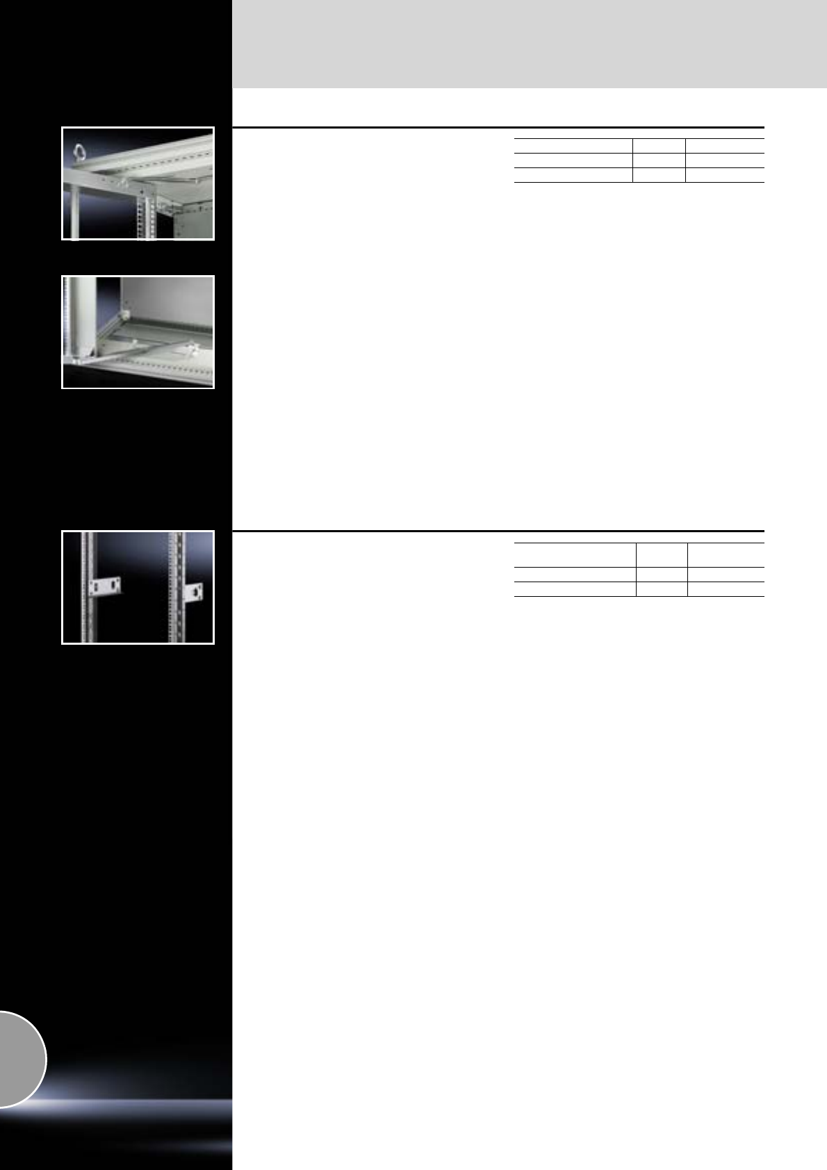
482.6 mm (19˝) installation system
Swing frame
548 Rittal Catalogue 33/System accessories
Swing frame stay
Holds the swing frame in the open position.
For mounting on:
Swing frame, large
●SR 1979.200, at the top of the enclosure
●SR 1980.200, at the bottom of the enclosure
(with safety stop at 160°)
Packs of Model No. SR
with 130° hinge 5 1979.200
with 180° hinge 1 1980.200
For mounting on:
Swing frame, small
●SR 1979.200, may be mounted at the top or
bottom of the installation kit.
Slide rails
To support heavy slide-in electronic equipment,
482.6 mm (19˝) in the swing frame.
Material:
Sheet steel
Surface finish:
Zinc-plated
For slide-in equipment
with max. installation depth
Packs of Model No. SR
D max. < 190 mm 10 1962.200
D max. > 190 mm 10 1963.200
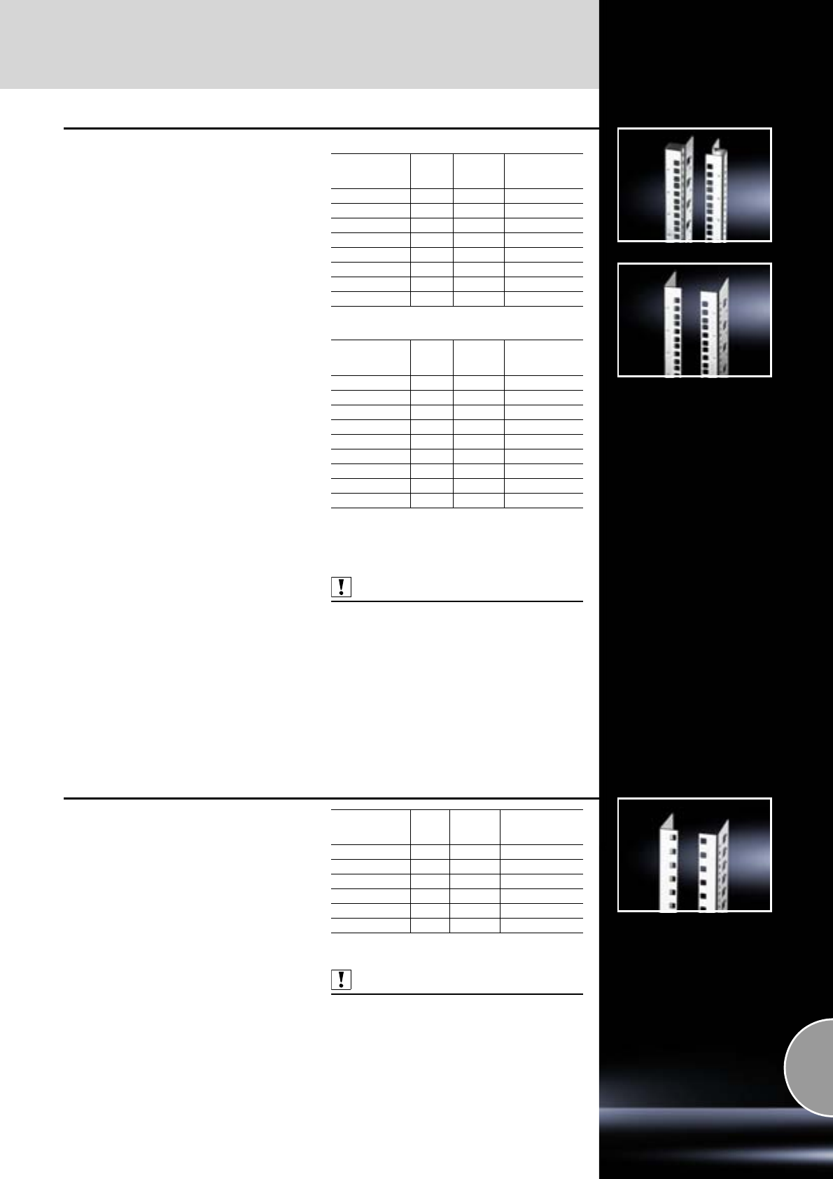
Mounting angles
482.6 mm (19˝) installation system
549Rittal Catalogue 33/System accessories
Mounting angles,
482.6 mm (19˝)
for TS, CS Toptec
Available in two versions:
Cranked
The integral U markings in the front facilitate
systematic assembly within the 482.6 mm (19˝)
attachment level.
L-shaped
The L-shaped mounting angles accommodate the
installation kits of server systems. The integral U
markings in the front facilitate systematic assem-
bly within the 482.6 mm (19˝) attachment level.
Technical specifications:
−2 mm sheet steel
−Integral 482.6 mm (19˝) punchings
(EIA standard)
−Side round and square punchings
−Clear chromated for conductive connection of
the 482.6 mm (19) installed equipment.
Supply includes:
Assembly parts.
Explanation of the mounting dimensions in
interior installations: See page 550.
Cranked
L-shaped
Note:
The mounting angles can also be used to accom-
modate 21˝, 23˝ and 24˝ attachment dimensions.
Also required:
−TS punched sections with mounting flanges
or depth stays as installation kit for
mounting angles,
see page 555 – 556.
−For L-shaped mounting angle variant:
for mounting slide rails or component shelves:
Adaptor DK 7827.300,
see page 488.
Full installation
rack height
mm U Packs of Model No. DK
800 15 2 7827.080
1000 20 2 7827.100
1200 24 2 7827.120
1400 29 2 7827.140
1600 33 2 7827.160
1800 38 2 7827.180
2000 42 2 7827.200
2200 47 2 7827.220
Full installation
rack height
mm U Packs of Model No. DK
600 11 2 7827.061
800 15 2 7827.081
1000 20 2 7827.101
1200 24 2 7827.121
1400 29 2 7827.141
1600 33 2 7827.161
1800 38 2 7827.181
2000 42 2 7827.201
2200 47 2 7827.221
Mounting angles, metric
for TS
The L-shaped mounting angles accommodate
metric assemblies and components. Depending
on the installation kit, mounting dimensions
465 mm and 515 mm can be configured.
Material:
Sheet steel
Surface finish:
Zinc-plated
Supply includes:
Assembly parts.
Explanation of the mounting dimensions in
interior installations: See page 550.
Also required:
TS punched sections with mounting flanges or
depth stays as installation kit for mounting angles,
see page 555 – 556.
Full installation
rack height
mm SU Packs of Model No. DK
–1727831.6111)
1000 37 2 7831.6211)
1200 43 2 7794.4201)
1600 59 2 7794.7401)
2000 76 2 7831.631
2200 84 2 7831.6411)
1) Extended delivery times.
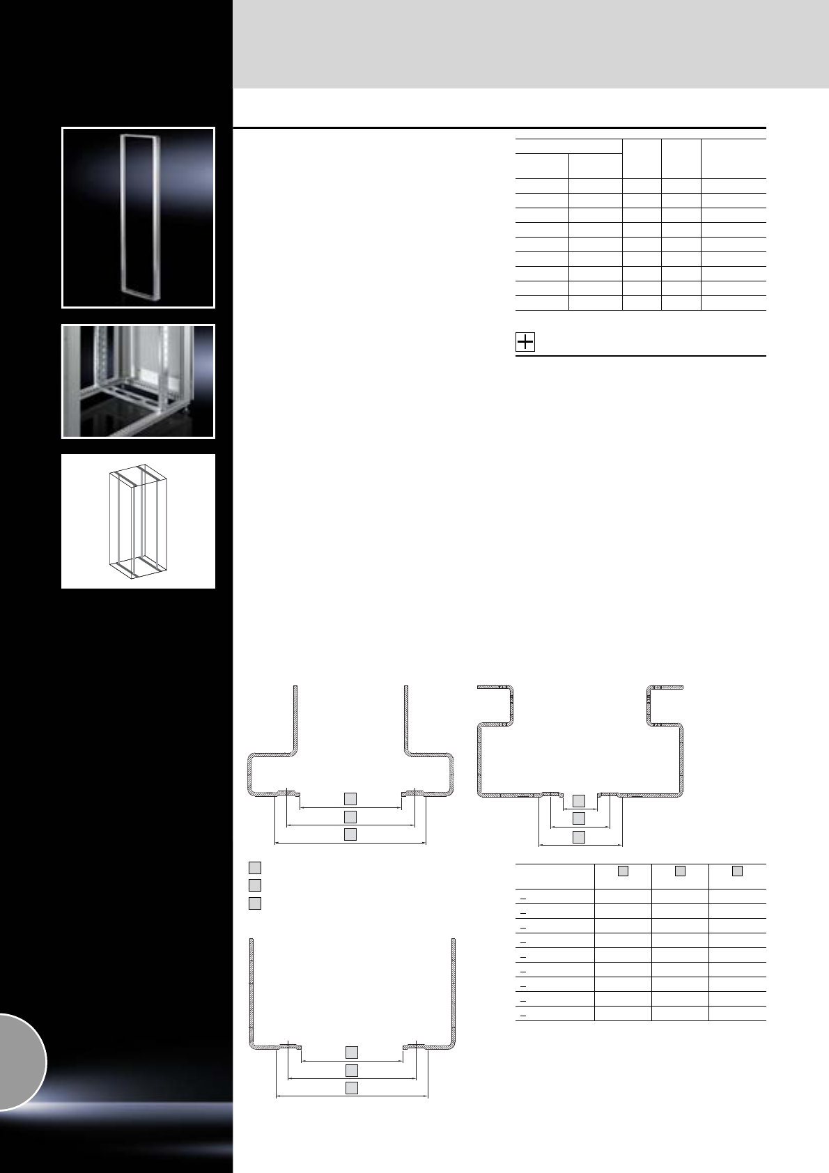
482.6 mm (19˝) installation system
Mounting angles
550 Rittal Catalogue 33/System accessories
Mounting frame, 482.6 mm (19˝)
for TS, CS Basic and modular enclosures
The welded 482.6 mm (19˝) mounting frame
may be attached with complete depth variability
and is used to structure the front and rear
482.6 mm (19˝) level.
The mounting frame has the same system punch-
ings as the TS 8 enclosure section at the sides
and rear, and therefore supports the mounting of
various TS 8 system accessories such as cable
clamp rails, cable shunting rings etc.
Load capacity:
Up to 1000 kg static load, with even load distri-
bution on two 482.6 mm (19˝) mounting frames,
with full installation.
Material:
Sheet steel
Surface finish:
Zinc-plated
Supply includes:
Assembly parts.
Note:
A combination of 482.6 mm (19˝) mounting frame
plus fan mounting plate is not possible. For active
ventilation, we recommend use with modular fan
roof.
Explanation of the mounting dimensions in
interior installations: See page 550.
Accessories:
−Captive nuts,
see page 567.
−Assembly screws,
see page 478.
−Cable clamp rails TS,
see page 532.
−C rails,
see page 465.
−Component shelves,
see from page 480.
−Fan roof, modular,
see page 223.
−TS divider kit, heavy-duty, width/depth-variable,
see page 555.
For enclosures
UPacks
of Model No.
DK
Width
mm Height
mm
600 600 11 1 7856.710
600 1200 24 1 7856.713
600 1800 38 1 7856.716
600 2000 42 1 7856.719
600 2200 47 1 7856.722
800 1200 24 1 7856.725
800 1800 38 1 7856.728
800 2000 42 1 7856.731
800 2200 47 1 7856.734
Explanation of the mounting dimensions in interior installations
A
B
C
A
B
C
Cranked section
= Clearance width
= Mounting dimension
= External dimension of the
rack-mounted equipment or
of the front panels
A
B
C
A
B
C
Mounting frame
Installation
width
mm
mm
mm
19˝ 450 465 482.6
21˝ 500 515 533.4
23˝ 552 567 584.2
24˝ 577 592 609.6
10˝/39 HP 221.4 236 254
1/2 19˝/42 HP 236.6 251.2 269.2
9.5˝ 208.7 223.3 241.3
18 SU 450 465 485
20 SU 500 515 535
A
B
C
>
>
>
>
>
>
>
>
>
L-shaped section
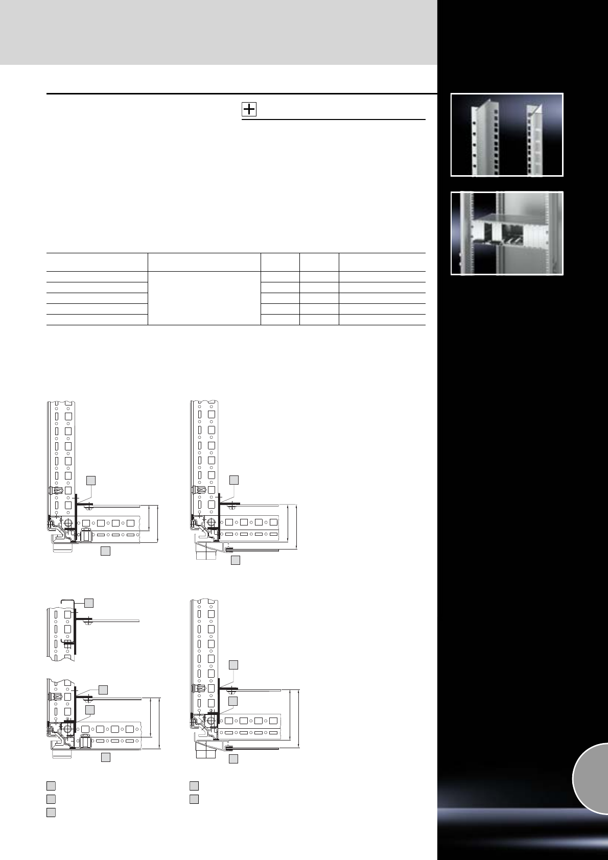
Mounting angles
482.6 mm (19˝) installation system
551Rittal Catalogue 33/System accessories
Adaptor sections,
482.6 mm (19˝)
for TS
For the installation of subracks and other equip-
ment.
Adaptor sections are easily shortened for partial
assemblies.
Supply includes:
Assembly parts.
Note:
The 482.6 mm (19˝) measurement is obtained
when mounting on the TS frame for enclosures
with width 600 mm.
Accessories:
−Infill panels, see page 552.
−Captive nuts, see page 477.
−Assembly screws, see page 478.
−Slide rails with one-sided mounting,
see page 561.
−Slide rails with two-sided mounting,
see page 561.
−Drawer installation kit, see page 563.
−Component shelf installation kit, see page 488.
For enclosure system TS1)
For enclosure height
mm Material U Packs of Model No. TS
1600
Extruded aluminium section
33 4 8613.060
1800 38 4 8613.080
2000 42 4 8613.000
2200 47 4 8613.020
For PC enclosure2) 17 4 8613.070
1) For the rear of electronic enclosures, see page 552.
2) Behind bottom door.
1
3
63
43
4
63
75.5
1
Drawing 1 and 2:
Adaptor section or adaptor
piece fitted in the foremost
installation position, directly
on the vertical section.
When installing slide rails with
two-sided mounting (see
page 561), the same adaptor
sections or adaptor pieces
must also be mounted on the
vertical section at the rear.
Drawing 1 Drawing 2
Assembly examples of TS:
3
5
66
86
1
2
4
86
98.5
1
2
Drawing 3:
Mounting on two vertically
installed PS punched sections
permits fully flexible use of the
enclosure depths.
Drawing 4 and 5:
Greater distance from the door
is achieved by mounting on
adaptor rails for PS compati-
bility.
In this position, the slide rails
can be fitted with one-sided
mounting.
Drawing 3 Drawing 5
Drawing 4
Adaptor section/piece
Adaptor rail
TS sheet steel door
TS glazed door
Punched section without
mounting flange
1
2
3
4
5
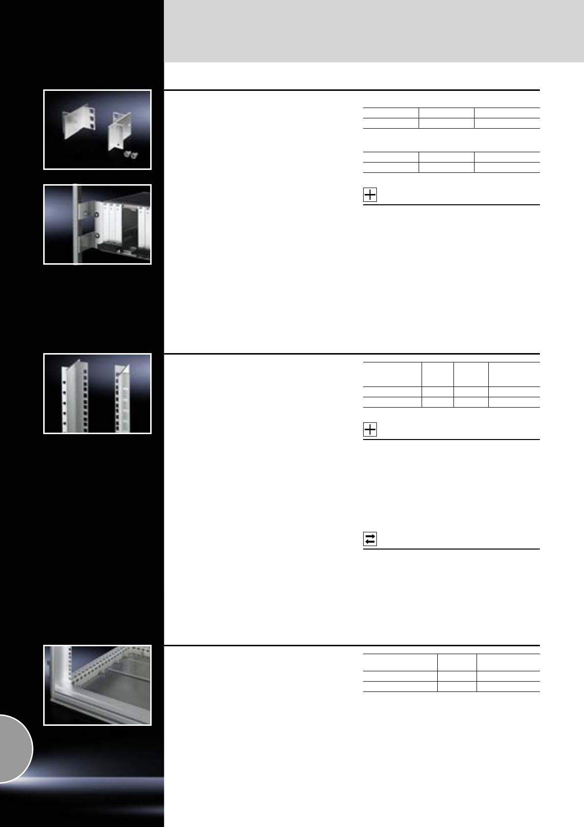
482.6 mm (19˝) installation system
Mounting angles
552 Rittal Catalogue 33/System accessories
Adaptor pieces, 482.6 mm (19˝)
for TS, ES
The “1 U” sub-section of adaptor sections.
For the installation of individual subracks and
other equipment.
Supply includes:
Assembly parts.
Assembly examples:
May be found on page 551.
Note:
The 482.6 mm (19˝) measurement is obtained
when mounting on the TS/ES frame for enclo-
sures with width 600 mm.
Adaptor set (DK 7246.100) for 800 mm wide
enclosures, see page 562.
For TS
For ES
Accessories:
−Captive nuts,
see page 477.
−Assembly screws,
see page 478.
−Slide rails with two-sided mounting,
see page 561.
−Drawer installation kit,
see page 563.
−Component shelf installation kit,
see page 488.
UPacks ofModel No. TS
148613.010
UPacks ofModel No. PS
184547.000
Adaptor sections,
482.6 mm (19˝)
for rear installation in TS electronic enclosures
For installing subracks at the front and back,
and for attaching the slide rails TS 8613.150,
TS 8613.160 and TS 8613.180 (see page 561).
Assembly is carried out on the inner mounting
level.
The outer mounting level can, e.g. still be used
for cable routing on depth-mounted TS punched
sections with mounting flange.
Material:
Extruded aluminium section
Supply includes:
Assembly parts.
Note:
Design similar to adaptor sections, 482.6 mm (19˝)
(see page 551), but asymmetrical height, suitable
for TS electronic enclosure.
Accessories:
−Captive nuts,
see page 477.
−Assembly screws,
see page 478.
−Slide rails with two-sided mounting,
see page 561.
−Drawer installation kit,
see page 563.
−Component shelf installation kit,
see page 488.
Possible
alternative:
Adaptor pieces, 482.6 mm (19˝),
see page 552.
For
enclosure height
mm U Packs of Model No. TS
1600 33 2 8613.360
2000 42 2 8613.300
Infill panels, 482.6 mm (19˝),
horizontal
for adaptor sections
To infill between installed 482.6 mm (19˝) equip-
ment positioned in the full enclosure height and
the enclosure clearance height.
Material:
Extruded aluminium section
Supply includes:
Assembly parts.
For enclosure height
mm Packs of Model No. TS
1600/2000 2 8613.040
1800/2200 2 8613.030
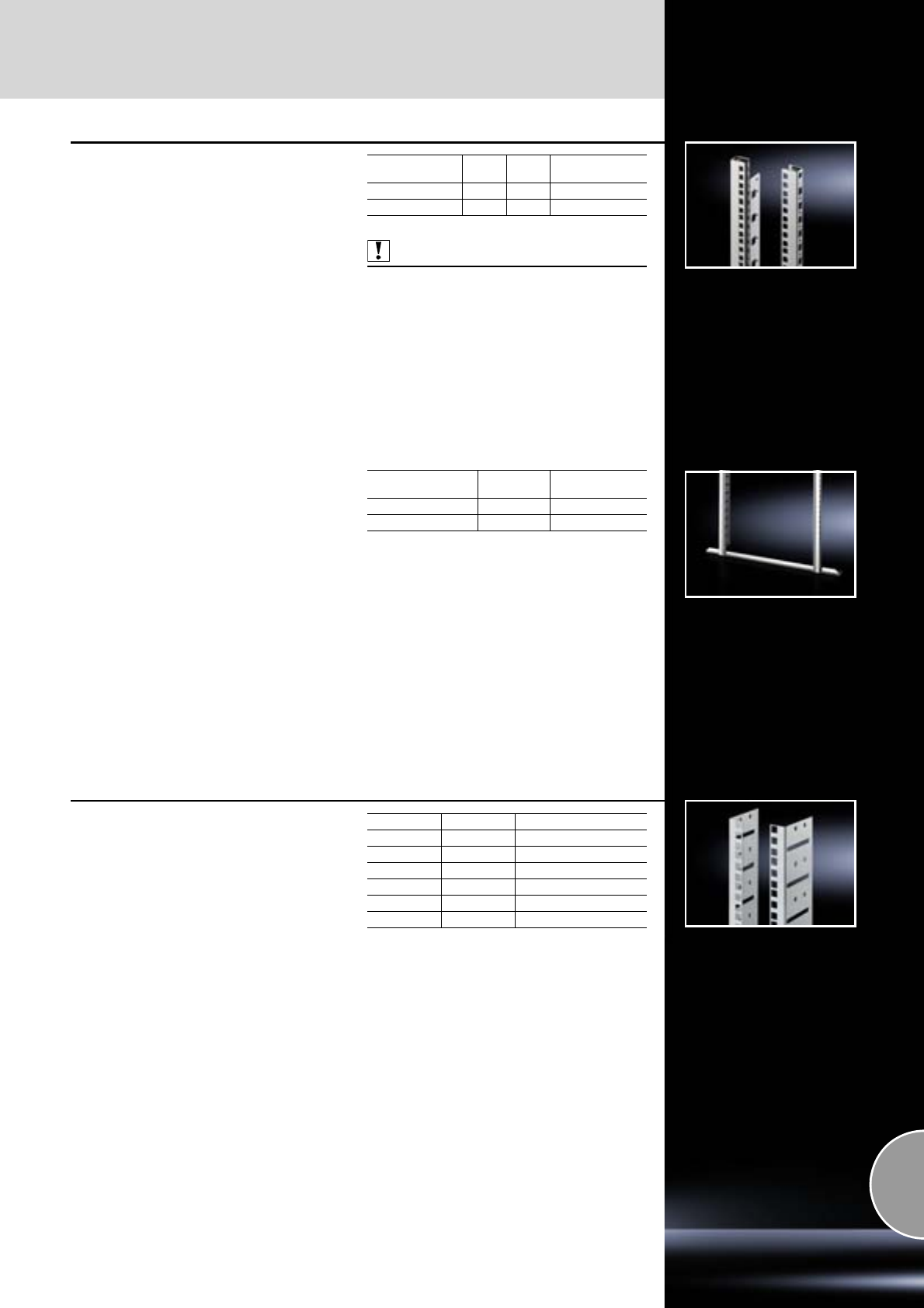
Mounting angles
482.6 mm (19˝) installation system
553Rittal Catalogue 33/System accessories
Mounting angles,
482.6 mm (19˝)
for CS basic and modular enclosures
For mounting 482.6 mm (19˝) components in Out-
door enclosures. The mounting angles are depth-
adjustable on a 25 mm pitch pattern. An installa-
tion bracket is required to attach the mounting
angles.
Material:
Sheet steel
Surface finish:
Zinc-plated
Supply includes:
Assembly parts.
Explanation of the mounting dimensions in
interior installations: See page 550.
Also required:
Installation bracket PS,
see page 553.
Enclosure height
mm UPacks
of Model No. DK
800 15 2 7685.000
1200 24 2 7688.000
Depth stay for PS
For mounting angles 482.6 mm (19˝)
Material:
Sheet steel
Surface finish:
Zinc-plated
Enclosure width
mm Packs of Model No.
DK
600/1200 2 7696.000
800 2 7698.0 00
Mounting angles,
482.6 mm (19˝)
for DK-EL
This mounting angle kit allows you to integrate a
second 482.6 mm (19˝) level into EL enclosures.
Material:
Sheet steel
Colour:
RAL 7035
Supply includes:
Assembly parts.
Explanation of the mounting dimensions in
interior installations: See page 550.
U Packs of Model No. DK
62 7705.706
92 7705.709
12 2 7705.712
15 2 7705.715
18 2 7705.718
21 2 7705.721
Extended delivery times.
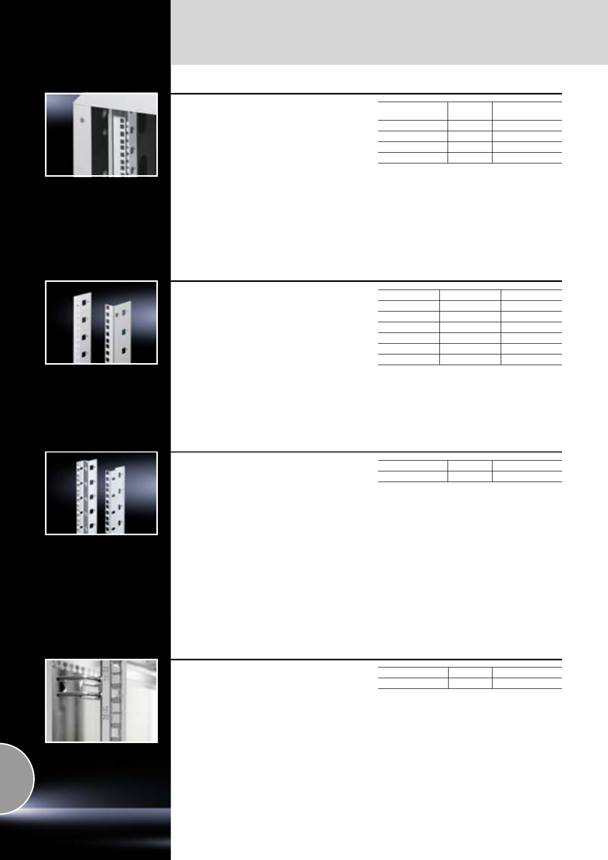
482.6 mm (19˝) installation system
Mounting angles
554 Rittal Catalogue 33/System accessories
Mounting angles,
482.6 mm (19˝)
for QuickBox
For the installation of 482.6 mm (19˝) rack-
mounted equipment.
Material:
Sheet steel
Colour:
RAL 7035
Supply includes:
Assembly parts.
For enclosures
UPacks of Model No. QB
12 2 7502.203
15 2 7502.204
18 2 7502.205
21 2 7502.206
Mounting angles,
482.6 mm (19˝)
for FlatBox
L-shaped bracket as 2nd attachment level.
Material:
Sheet steel
Supply includes:
Assembly parts for fast, toolless assembly.
Note:
The 2nd attachment level should always be
ordered in the same height as the basic enclo-
sure. Partial configuration is not possible.
U Packs of Model No. DK
627507.706
927507.709
12 2 7507.712
15 2 7507.715
18 2 7507.718
21 2 7507.721
Mounting angles,
482.6 mm (19˝)
for VerticalBox
For mounting at the side of the VerticalBox. With
these mounting angles, instead of 5 U vertically
at the side, up to 10 U may be used horizontally
if only a minimal installation depth is required.
Infinitely depth-variable positioning.
Material:
Sheet steel, spray-finished
Colour:
RAL 7035
Supply includes:
Assembly parts.
Note:
10 usable U.
U Packs of Model No. QB
12 2 7502.203
Adhesive measurement strip,
482.6 mm (19˝)
Made from robust aluminium foil, guarantees easy
handling and durability. With numerical labelling
on a 482.6 mm (19˝) pitch pattern for clear identi-
fication of the various height units. The double-
sided labelling allows the counting direction to be
freely selected, up to a maximum of 56 U. In this
way, clear documentation of the various mounting
parts is easily achieved.
Material:
Aluminium foil
Labelling range U Packs of Model No. DK
1 – 56 1 7950.100
Mounting angles/Mounting kits for mounting angles
482.6 mm (19˝) installation system
555Rittal Catalogue 33/System accessories
TS mounting kit, heavy-duty,
width-/depth-variable
for mounting frame 482.6 mm (19˝) in TS,
CS basic and modular enclosures
Installation in enclosure width 800 mm
The mounting kit allows depth- and width-variable
installation of a 600 mm wide mounting frame,
482.6 mm (19˝), in 800 mm wide enclosures.
Load capacity:
750/1500 kg static load per level/
per enclosure
Material:
Sheet steel
Surface finish:
Zinc-plated
Supply includes:
Assembly parts.
Packs of Model No. DK
1 set 7827.590
Additional
fastening attachment
for mounting angles
for 800 mm wide TS network enclosures
The additional fastening attachment counteracts
bending of the mounting angles mounted on
installation brackets in case of unevenly distri-
buted loads. It is attached directly to 482.6 mm
(19˝) mounting angles and to the punched sec-
tion with mounting flange fitted in the depth
(inner mounting level).
Material:
Sheet steel
Supply includes:
Assembly parts.
Also required:
TS punched section with mounting flange for the
inner mounting level,
see page 459 – 460.
Packs of Model No. DK
27284.135
TS punched section
with mounting flange
as installation kit
For
●Mounting angles, 482.6 mm (19˝)
●Mounting angles, metric,
Mounting dimension 465 mm
Installation in enclosure width 600 mm
The installation kit consists of 4 TS punched sec-
tions with mounting flange 17 x 73 mm to accom-
modate mounting angles. One pack is sufficient
for installing one or two 482.6 mm (19˝) attach-
ment levels. For exceptionally heavy installed
equipment, we recommend the installation of
additional punched sections in the centre.
Material:
Sheet steel
Surface finish:
Zinc-plated
Supply includes:
Assembly parts.
For enclosures
Packs of Model No. TS
Width
mm Depth
mm
600 600 4 8612.060
600 800 4 8612.080
600 1000 4 8612.000
600 1200 4 8612.020
482.6 mm (19˝) installation system
Mounting kits for mounting angles
556 Rittal Catalogue 33/System accessories
Depth stays for TS
for mounting angles into TS, 482.6 mm (19˝)
Installation in enclosure width 800 mm
Depth stays are screw-fastened to the enclosure
frame in the enclosure width.
The mounting angle is attached to the depth stay
at the top and bottom. The bracket ensures opti-
mum clearance at the sides for cable routing. For
partial enclosure configuration, the depth stays
may be attached to the TS punched sections with
mounting flanges 17 x 73 mm on the outer attach-
ment level of the enclosure frame. Fully depth-var-
iable attachment is facilitated by the attachment
slots. Either cranked or L-shaped mounting
angles may be used.
Material:
Sheet steel
Surface finish:
Zinc-plated
Supply includes:
Assembly parts.
Accessories:
For partial installation,
−TS punched section with mounting flange,
17 x 73 mm,
see page 459 – 460.
−Mounting angles, cranked or L-shaped,
see page 549.
Installation position Packs of Model No. DK
central 2 7827.480
side 2 7827.490
TS installation kit,
width-variable
482.6 mm (19˝)/metric in TS
Universal depth stays to which both L-shaped and
cranked mounting angles may be variably
mounted in the depth and width.
Divider kit for all width dimensions
●Imperial mounting dimensions 19˝/21˝/23˝/24˝
●Metric mounting dimensions 18/20 SU
Load capacity:
200 kg static load per level
Material:
Sheet steel
Surface finish:
Zinc-plated
Supply includes:
Assembly parts.
Accessories:
Mounting angles, 482.6 mm (19˝),
see page 549.
For enclosure depth
mm Packs of Model No. DK
800 1 set 7827.550
1000 1 set 7827.560
1200 1 set 7827.570
1 set = 4 stays
Depth stays as installation kit
for mounting angles, 482.6 mm (19˝)
Installation in enclosure width 800 mm
One installation kit consists of 4 depth stays to
accommodate mounting angles. One pack is
sufficient for installing one or two 482.6 mm (19˝)
attachment levels. For exceptionally heavy
installed equipment, we recommend the installa-
tion of an additional depth stay in the centre. The
front cut-out makes cable routing easier with full
configuration
Material:
Sheet steel
Surface finish:
Zinc-plated
Supply includes:
Assembly parts.
Possible
alternative:
Depth stays for TS for mounting angles,
see page 556.
For enclosures
Packs of Model No. DK
Width
mm Depth
mm
800 600 4 7827.600
800 800 4 7827.800
800 1000 4 7827.000
Mounting kits for mounting angles
482.6 mm (19˝) installation system
557Rittal Catalogue 33/System accessories
Depth stays as installation kit
for mounting angles, 482.6 mm (19˝),
mounting dimensions 23˝ and 24˝
Installation in enclosure width 800 mm
When using depth stays in 800 mm wide enclo-
sures, attachment spacings of 23˝ and 24˝
are achieved. Either cranked or L-shaped,
482.6 mm (19˝) mounting angles may be used.
Material:
Sheet steel
Surface finish:
Zinc-plated
Supply includes:
Assembly parts.
Mounting dimension 23˝
Mounting dimension 24˝
Accessories:
Mounting angles, cranked or L-shaped,
see page 549.
For enclosures
Packs of Model No. DK
Width
mm Depth
mm
800 800 4 7827.823
800 1000 4 7827.023
Extended delivery times.
For enclosures
Packs of Model No. DK
Width
mm Depth
mm
800 800 4 7827.824
800 1000 4 7827.024
Extended delivery times.
Mounting frame 54 U
for TS
The mounting frame allows configuration of a
side-offset 482.6 mm (19˝) level with 42 U useful
installation space plus the additional integration of
a further 12 U for vertical installation at the side.
The additional side extension is divided into three
installation levels arranged on top of one another,
each with 4 U.
The mounting frame may be installed at either the
front or rear.
Material:
Sheet steel
Surface finish:
−Mounting bracket: Zinc-plated
−Side trim panel: Spray-finished
Colour:
RAL 7035
Supply includes:
12 U mounting trim at the side.
Also required:
Mounting angles, 482.6 mm (19˝),
see page 549.
For enclosures Additional
vertical
installation
area
Packs
of Model No.
DK
Width
mm Height
mm
800 2000 12 U 1 set 7827.554
Extended delivery times.
Mounting kit, 2 U
for 482.6 mm (19˝) equipment
Facilitates fast, simple integration of additional 2 U
mounting space within an enclosure by attaching
to the enclosure frame or to the existing mounting
angles at the sides. The flexible slot fastening of
the brackets means that the distance between the
two installation brackets may be freely selected,
so that other 482.6 mm (19˝) attachment dimen-
sions may be implemented. The second row of
holes is used for the optional configuration of
additional mounting surfaces.
Material:
Sheet steel
Surface finish:
Zinc-plated
Supply includes:
Assembly parts.
Packs of Model No. DK
27246.420
482.6 mm (19˝) installation system
Accessories for Data Rack
558 Rittal Catalogue 33/System accessories
Second pair of mounting
angles
To accommodate 482.6 mm (19˝) network compo-
nents or for the attachment of component shelves
and slide rails.
482.6 mm (19˝) punched profile at the front,
hole centre distance 465 (470 mm at the rear),
tailored to the attachment of patch panels and
cable routing rails.
The mounting level may be positioned on a
50 mm pitch pattern.
Minimum distance between levels 150 mm,
maximum distance between levels 350 mm.
Material:
Sheet steel, 2 mm
Colour:
RAL 7035
Supply includes:
−1 torsionally stiff profile frame
−Mounting accessories
Detailed drawing:
Available on the Internet.
UPacks ofModel No. DK
31 1 7296.000
36 1 7297.000
40 1 7298.000
45 1 7299.000
50 mm pitch pattern
min. 150 – max. 350
Baying connector
For assembling rows of distributor frames,
or for cable routing between data racks.
Technical specifications:
Length: 53 mm
Colour:
RAL 7035
Packs of Model No. DK
37494.000
Roof plate with cable route
For optimised use of the Data Rack as a corridor
distributor or cable management rack. The size
of individual cable routes may be individually
dimensioned by sliding the guide plates. On all
Data Racks, the roof plate can be attached with
two mounting levels and a distance between the
levels of 350 mm.
Material:
Sheet steel, spray-finished
Colour:
RAL 7035
Supply includes:
−Roof plate
−Mounting accessories
Packs of Model No. DK
17411.0 0 0
Depth stays
For securing and stabilising two pairs of
482.6 mm (19˝) mounting angles in the Data Rack.
The length of the depth stays is adjustable,
and can accommodate the following spacings
of mounting angles: 250, 300 and 350 mm.
Material:
Sheet steel, spray-finished
Colour:
RAL 7035
Packs of Model No. DK
27401.000
Continuous slide rail
for two pairs of mounting angles,
482.6 mm (19˝)
To support heavy equipment in the Data Rack.
The mounting dimensions of the slide rails were
selected to enable them to be combined with
500 mm deep, 482.6 mm (19˝) component
shelves. The mounting distance of the 482.6 mm
(19˝) mounting angles is 350 mm.
Requirements:
Second pair of mounting angles
Material:
Sheet steel, zinc-plated
Accessories:
Component shelves, 500 mm deep,
see page 482.
Packs of Model No. DK
27402.000
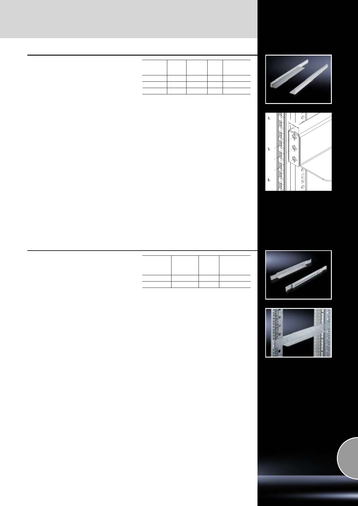
Slide rails
482.6 mm (19˝) installation system
559Rittal Catalogue 33/System accessories
11.5 7.5
Slide rails, depth-variable, 1 U
for TE, 482.6 mm (19˝) mounting frame,
flat mounting angles
The slide rail is pulled out to the required length
and secured between the front and rear mounting
level. Rear location lugs and front screw-fasten-
ing enable convenient one-man assembly. The
mounting component to be integrated is inserted
horizontally onto the slide rail and optionally
secured to the mounting level via its attachment
slots.
Load capacity:
80 kg/150 kg, static load
Material:
Sheet steel
Surface finish:
Zinc-plated
Supply includes:
Assembly parts.
Note:
The super-slimline design of the slide rail allows
it to be used in most integration cases for
482.6 mm (19˝) mounting components. Because
it is secured to the standardised mounting level,
it is manufacturer-independent.
The slide rail slightly reduces the installation
space below the slide rail so that the U below it
is only available for limited use.
Length
mm
Load
capacity
kg
Contact
surface
mm
Packs
of Model No.
DK
390 – 600 80 50 2 7063.882
590 – 930 80 50 2 7063.883
590 – 930 150 25 2 7063.884
Slide rails, depth-variable, 1 U
for server and network enclosures
with two 482.6 mm (19˝) mounting levels,
without additional loss of U
For mounting both on cranked and flat mounting
angles, 482.6 mm (19˝) mounting frames and on
TE. The slide rails are pulled out to the required
length and secured between the front and rear
mounting level on the 482.6 mm (19˝) pitch pat-
tern.
Load capacity:
20 kg static load
Material:
Sheet steel
Surface finish:
Zinc-plated
Supply includes:
Assembly parts.
Note:
Thanks to the thin support surface of only around
0.8 mm thickness, exceeding the U pitch pattern
is generally avoided, provided the components do
not exceed a maximum height of 43.5 mm. In this
way, several units may be easily arranged on top
of one another without offset.
Distance
between
19˝ levels
mm
Contact
surface
mm Packs of Model No. DK
390 – 550 30 2 7063.750
550 – 750 30 2 7063.752
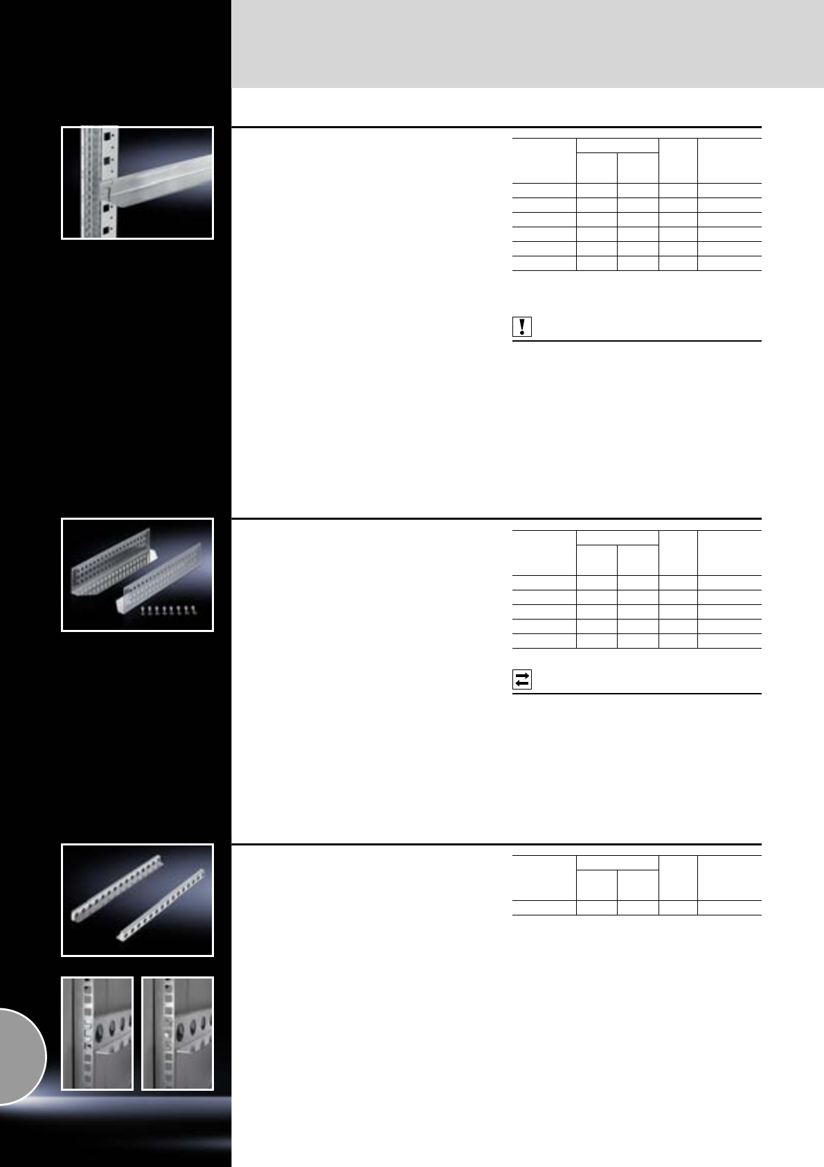
482.6 mm (19˝) installation system
Slide rails
560 Rittal Catalogue 33/System accessories
Slide rails, heavy-duty
for TS network enclosures
with two 482.6 mm (19˝) levels
To support heavy installed equipment. The slide
rails are simply located into the cranked mount-
ing angles and secured with screws. The com-
bined use with additional depth stays or, in case
of 80 mm wide enclosures, with the additional fas-
tening attachment counteracts possible bending
of the mounting angles in case of unevenly distri-
buted loads.
Load capacity:
80 kg, static load
Material:
Sheet steel
Surface finish:
Zinc-plated
Supply includes:
Assembly parts.
Note:
Not suitable for use in 482.6 mm (19˝) mounting
frames.
Also required:
For fastening to L-shaped TS mounting angles:
Adaptor DK 7827.300,
see page 488.
Distance
between
19˝ levels
mm
Contact surface Packs
of Model No.
DK
Width
mm Depth
mm
– 55 1521) 2 7063.000
298 55 261 2 7492.30 0
398 55 361 2 7492.40 0
498 55 461 2 7492.50 0
598 55 561 2 7492.060
698 55 661 2 7492.070
1) Side leg height 72 mm.
Load capacity: 50 kg, static load.
Slide rails
for TE, 482.6 mm (19˝) mounting frame
For mounting between a front and a rear pair of
mounting angles. The slide rails can be used to
support heavy 482.6 mm (19˝) components.
Load capacity:
80 kg, static load
Material:
Sheet steel
Surface finish:
Zinc-plated
Supply includes:
Assembly parts.
Possible
alternative:
Slide rail, depth-variable,
see page 559.
Distance
between
19˝ levels
mm
Contact surface Packs
of Model No.
DK
Width
mm Depth
mm
395 85 324 2 7963.310
495 85 424 2 7963.410
595 85 524 2 7963.510
695 85 624 2 7963.610
795 85 724 2 7963.710
Slide rails, heavy-duty
for TS, TE
With L-shaped mounting angles or 482.6 mm (19˝)
mounting frame and a clearance between levels
of 740 mm.
Easily and quickly installed thanks to locating
brackets for the rear level.
Load capacity:
100 kg, static load
Material:
Sheet steel
Surface finish:
Zinc-plated
Supply includes:
Assembly parts.
Distance
between
19˝ levels
mm
Contact surface Packs
of Model No.
DK
Width
mm Depth
mm
740 50 734 2 7063.740
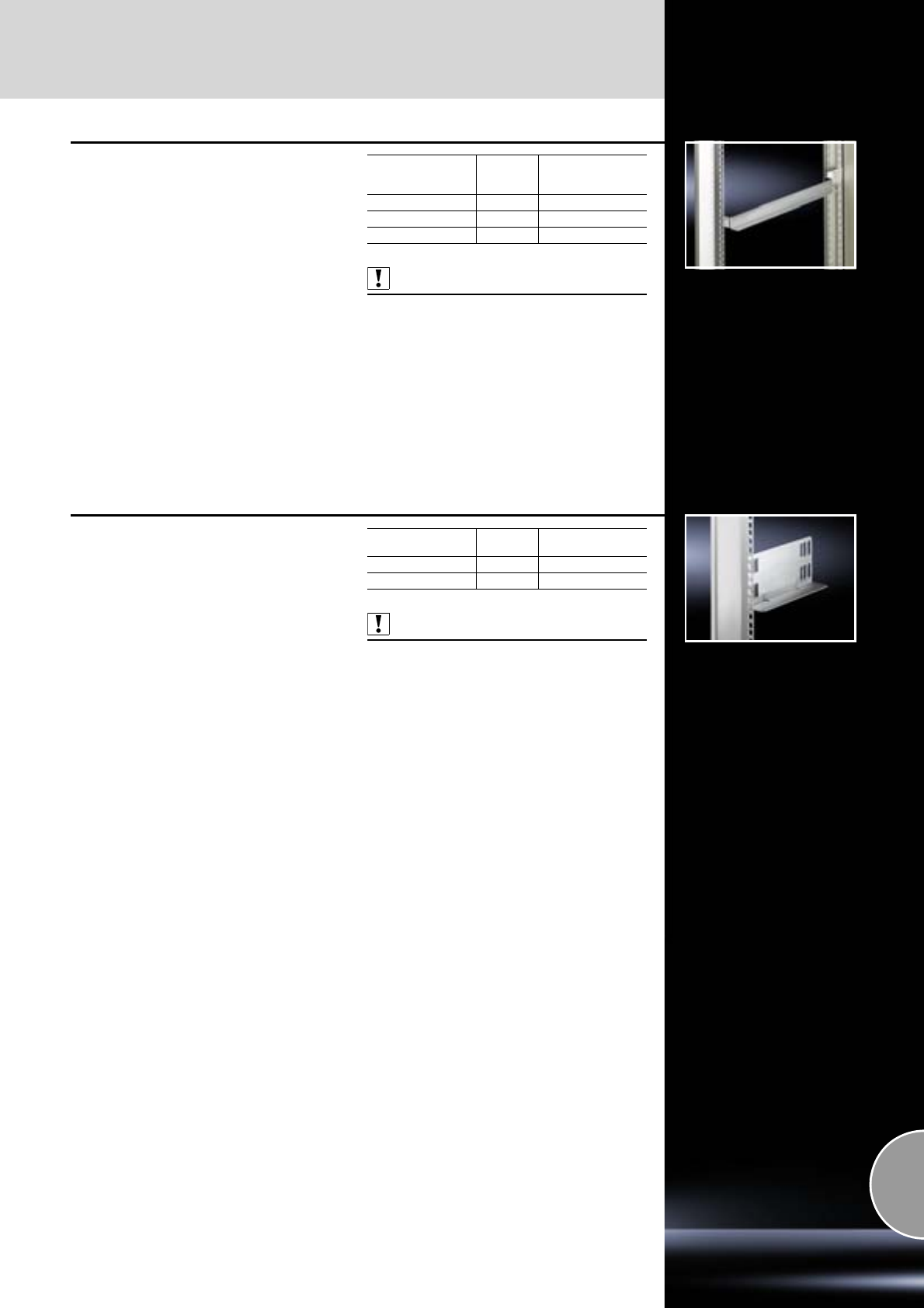
Slide rails
482.6 mm (19˝) installation system
561Rittal Catalogue 33/System accessories
Slide rails
for TS mounting angles
With two-sided mounting between the
482.6 mm (19˝) front and rear adaptor sections
or 482.6 mm (19˝) adaptor pieces.
Material:
Sheet steel
Surface finish:
Zinc-plated
Supply includes:
Assembly parts.
Also required:
−Adaptor sections, 482.6 mm (19˝),
see page 551, or
−Adaptor pieces, 482.6 mm (19˝),
see page 552.
For
enclosure depth
mm Packs of Model No. TS
500 10 8613.150
600 10 8613.160
800 10 8613.180
Slide rails
for TS mounting angles
With one-sided mounting on the 482.6 mm (19˝)
adaptor sections.
Material:
Sheet steel
Surface finish:
Zinc-plated
Supply includes:
Assembly parts.
Also required:
Adaptor sections, 482.6 mm (19˝),
see page 551.
Length
mm Packs of Model No. PS
185 10 4530.000
270 10 4531.000
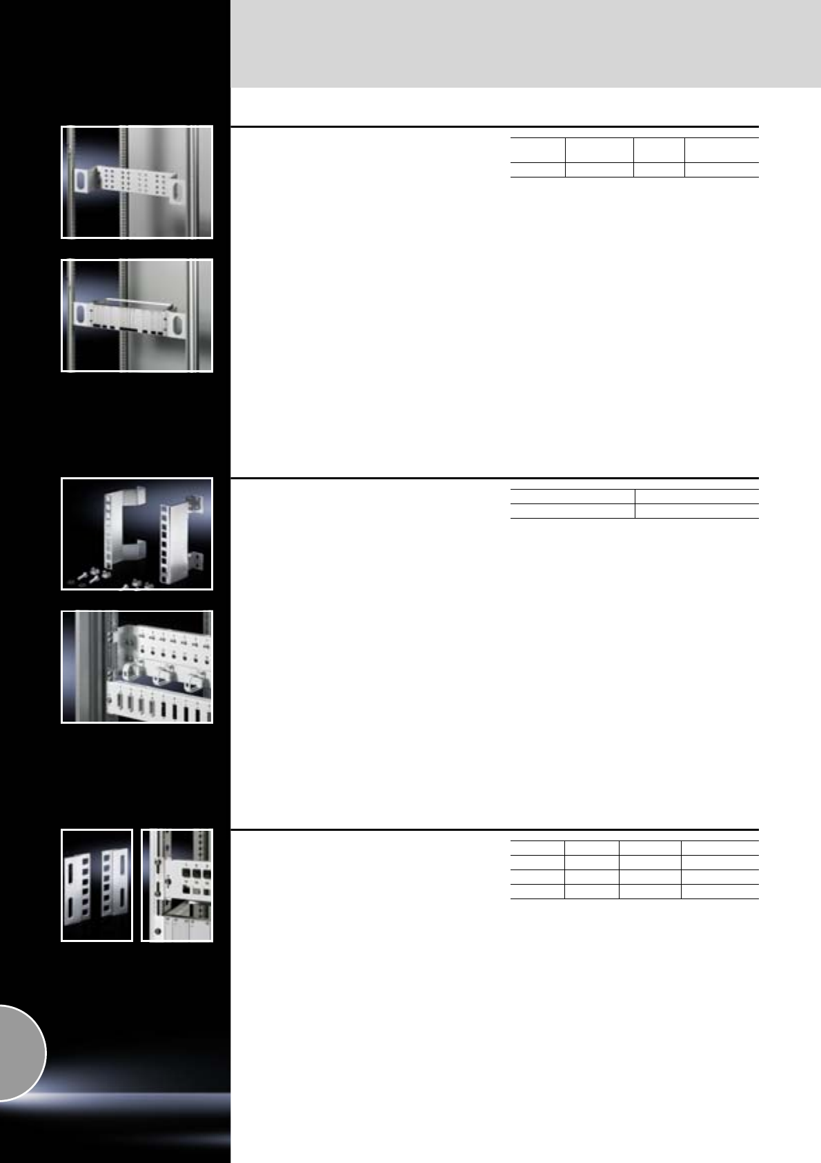
482.6 mm (19˝) installation system
482.6 mm (19˝) installation
562 Rittal Catalogue 33/System accessories
Adaptor kit, 3 U
for 800 mm wide TS enclosures
For fastening individual 482.6 mm (19˝) compo-
nents, or as an additional mounting facility at the
rear of the enclosure. The mounting level in the
adaptor angle can be adjusted in 25 mm incre-
ments by up to 100 mm in the depth, leaving
sufficient space for baying where patch panels
or splicing boxes are used. Attachment is on
the inner mounting level of the frame section or
a suitable chassis in the enclosure depth.
Material:
Sheet steel
Colour:
RAL 7035
Height Mounting
position Packs of Model No.
DK
3 U central 2 7246.100
Adaptor, 3 U
Depth offset 100 mm
This adaptor is used to recess 482.6 mm (19˝)
mounting of equipment inside enclosures with
482.6 mm (19˝) installation in the foremost posi-
tion, such as server or electronic enclosures. In
this way, sufficient space can be gained in front
of the mounting equipment to integrate patch
panels or switches, whilst at the same time
exploiting the maximum enclosure depth.
Material:
Sheet steel
Surface finish:
Zinc-plated
Supply includes:
Assembly parts.
Packs of Model No. DK
27246.400
Adaptor, metric to 21˝/19˝
With this adaptor, 482.6 mm (19˝) assemblies may
be fastened to metric (535 mm) mounting angles,
or combined systems may be configured.
Material:
Extruded aluminium section
Supply includes:
Assembly parts.
SU U Packs of Model No. DK
21 27246.010
63 27246.030
11 6 2 7246.060
482.6 mm (19˝) installation
482.6 mm (19˝) installation system
563Rittal Catalogue 33/System accessories
Drawer, 2 U, 3 U
for a 482.6 mm (19˝) mounting level
For front attachment to mounting angles,
482.6 mm (19˝). With cover and telescopic slides
to accommodate assignment lists, operating
manuals and small parts. The small version of the
2 U variant is also suitable for mounting inside a
swing frame.
Material:
Sheet steel
Colour:
RAL 7035
Supply includes:
Fully assembled, including assembly parts.
Height
Clearance
openings Installation
depth
mm
Packs
of Model No.
DK
Width
mm Depth
mm
2 U 411 244 250 1 7282.135
2 U 411 419 427 1 7282.035
3 U 411 419 427 1 7283.035
Drawer for 482.6 mm (19˝)
with adaptor sections
For keyboards, operating manuals etc. The per-
forated plate in the base helps air to circulate in
the enclosure. Load capacity 50 kg. The 1 U
drawer can be installed rotated through 180°
about its longitudinal axis, allowing it to be used
as a utility table.
Material:
−Drawer: Aluminium
−Telescopic slides: Sheet steel
Surface finish:
−Drawer: Anodised
−Telescopic slides: Zinc-plated
Supply includes:
Telescopic slides.
Also required:
Installation kit for enclosure system,
see page 563.
UPacks ofModel No. PS
114541.000
314542.000
Installation kit
for component shelves and drawers,
with 482.6 mm (19˝) installation in TS
For installation between the front and rear adap-
tor sections or adaptor pieces, 482.6 mm (19˝) in
600 mm wide enclosures.
Material:
Sheet steel
Surface finish:
Zinc-plated
Supply includes:
Assembly parts.
For enclosure system TS
Also required:
−Adaptor sections, 482.6 mm (19˝),
see page 551, or
−Adaptor pieces, 482.6 mm (19˝),
see page 552.
For enclosure depth
mm Packs of Model No. TS
600 1 set 8800.560
800 1 set 8800.580
Installation kit, depth-variable
for 482.6 mm (19˝) component shelves
Depending on the distance between the two
482.6 mm (19˝) mounting levels, the installation kit
is screw-fastened in the depth between the
cranked, L-shaped mounting angles or 482.6 mm
(19˝) mounting frame. Also suitable for TE.
Material:
Sheet steel
Surface finish:
Zinc-plated
Supply includes:
Assembly parts.
Distance between
19˝ levels
mm Packs of Model No. DK
550 – 850 2 7063.850
482.6 mm (19˝) installation system
482.6 mm (19˝) installation
564 Rittal Catalogue 33/System accessories
Blanking plate, 482.6 mm (19˝)
For installation in electronic enclosures or
housings.
Material:
Aluminium
Surface finish:
Natural-anodised
U Packs of Model No. VC
13 1931.200
23 1932.200
33 1933.200
43 1934.200
63 1936.200
73 1935.200
93 1939.200
12 3 1937.200
Blanking plate,
horizontally hinged
For installation in electronic enclosures or
housings.
Material:
−Blanking plate: 3 mm aluminium
−Hinge: Die-cast zinc
Surface finish:
−Blanking plate: Natural-anodised
−Hinge: Zinc-plated
Supply includes:
Assembly parts.
Width U Packs of Model No. EL
482.6 mm (19˝) 6 1 1945.000
Blanking plate,
vertically hinged
For installation in electronic enclosures or
housings.
Material:
−Blanking plate: 3 mm aluminium
−Hinge: Die-cast zinc
Surface finish:
−Blanking plate: Natural-anodised
−Hinge: Zinc-plated
Supply includes:
Assembly parts.
Width U Packs of Model No. EL
482.6 mm (19˝) 3 1 1940.000
482.6 mm (19˝) 6 1 1941.000
Hinge
for blanking plates
Material:
Die-cast zinc
Surface finish:
Zinc-plated
Supply includes:
Assembly parts.
Packs of Model No. EL
21950.000
Ventilated front panels
For venting enclosures and housings.
Material:
Aluminium
Surface finish:
Natural-anodised
Width U Packs of Model No. EL
482.6 mm (19˝) 1 3 2231.000
482.6 mm (19˝) 2 3 2232.000
482.6 mm (19˝) 3 3 2233.000
482.6 mm (19˝) installation
482.6 mm (19˝) installation system
565Rittal Catalogue 33/System accessories
Air baffle plates
for TS
Targeted air routing to the components. To pre-
vent bridges between hot and cold air. Energy
efficiency is boosted while retaining cooling output.
Mounted all-round on the 482.6 mm (19˝) installa-
tion between the 482.6 mm (19˝) mounting frame
and modular LCP, LCP rack, side panel or partition.
The width-variable air baffle plates may be indi-
vidually adapted to suit the requirements.
In the variant for 800 mm wide enclosures, vertical
482.6 mm (19˝) mounting holes of 3 x 1 U are
additionally integrated, which may be used for
configuration with additional components. Cable
glands with stepped collars distributed across
the height facilitate shielded cable routing between
the front and rear section.
In its delivered state, these openings are sealed
with a 1 U blanking panel with snap-in attachment.
Material:
−Air baffle plates: Sheet steel, spray-finished
−Stepped collar: Plastic, to UL 94-V0
−Blanking panel: Plastic, to UL 94-V0
Colour:
RAL 7035
Supply includes:
−2 air baffle plates, side, width-variable
−1 air baffle plate, top, horizontal
−With 800 mm width including blanking panel
and stepped collar
Note:
Mounting on the inner and outer mounting level
in the enclosure depth is not possible.
For enclosures
Packs of Model No. DK
Width
mm Height
mm
600 2000 2 7151.206
800 2000 2 7151.208
Infill panel, hinged
for 800 mm wide TS network enclosures
To cover the side cable chamber. The infill panel
is attached to the vertical enclosure frame at the
front. The generous curved design will conceal
even large quantities of cables, and facilitates
combined use with large-scale shunting rings
DK 7220.600, see page 534.
The infill panel has a hinged design and allows
easy access to the cabling level by simply swing-
ing it out. Locating points keep the panel in its
open and closed state.
With an offset 482.6 mm (19˝) mounting level the
panel may likewise be offset in the enclosure
depth and secured to TS punched sections with
mounting flange on the inner mounting level.
For mounting the 482.6 mm (19˝) attachment level
in the foremost mounting position, choose the ver-
sion with straight trim panel.
Material:
Sheet steel
Surface finish:
Spray-finished
Colour:
RAL 7035
Supply includes:
Assembly parts.
Trim panel curved
Trim panel straight
Accessories:
−TS punched section with mounting flange
17 x 73 mm for the inner mounting level,
see from page 459.
−PS punched section without mounting flange,
23 x 73 mm,
see page 464.
Note:
The installation of depth stays,
e.g. DK 7827.600/.800, is not possible.
For installation height
UPacks of Model No. TS
38 2 7827.5321)
42 2 7827.534
47 2 7827.536
1) Extended delivery times.
For installation height
UPacks of Model No. TS
42 2 7827.5201)
1) Extended delivery times.
482.6 mm (19˝) installation system
482.6 mm (19˝) installation
566 Rittal Catalogue 33/System accessories
Brush strip, vertical
for TS, TE
Within the network distributor, this serves as a flex-
ible infill panel which stylishly conceals the cable
management area to the side of the 482.6 mm (19˝)
mounting level. The brush strip facilitates con-
venient cable routing from the side and rear
distributor area to the front connection level.
The clearance required in front of the mounting
level is at least 75 mm.
Within the TS, the brush strip is mounted at the
side on the vertical frame section, on horizontal or
vertical punched sections. It may also be mounted
directly on the mounting level of the TS or TE 7000.
For direct mounting on the 482.6 mm (19˝) mount-
ing frame of the TS or TE, the brush strip should
be cut to length accordingly.
Material:
Aluminium section with brush strip:
Plastic, UL 94-V0
Supply includes:
1 set = 4 brush strips,
length 950 mm each.
For enclosure height
mm Packs of Model No. DK
2000 1 set 7827.544
Mounting panel
482.6 mm (19˝), 2 U
For fast integration of smaller mounting units
within the 482.6 mm (19˝) level, such as potential
equalisation rails, distributor boxes, small electri-
cal components etc.
Simple screw-fastening of the components to the
integral 25 mm system punchings.
Material:
Sheet steel
Surface finish:
Zinc-plated
Supply includes:
Assembly parts.
Panel height
UPanel width
mm Packs of Model No.
DK
2 450 1 7151.300
Support
for small appliances
For secure attachment of small, non-482.6 mm
(19˝)-conforming equipment such as modems,
power packs, routers etc. Angle-shaped support
for mounting in the empty space at the side
between the 482.6 mm (19˝) level and the side
panel on L-mounting angles, mounting frame or
chassis.
Attachment of the components and connection
cables can be achieved quickly and easily using
nylon tape or cable ties. Also suitable for cable
routing in the enclosure depth.
Material:
Sheet steel
Surface finish:
Zinc-plated
Supply includes:
Assembly parts.
Accessories:
Nylon loop, cable ties,
see page 530.
W x H x D mm Packs of Model No. DK
350 x 150 x 97 1 7246.500
482.6 mm (19˝) installation
482.6 mm (19˝) installation system
567Rittal Catalogue 33/System accessories
Mounting kit
for VerticalBox
The vertically hinged support plate offers even
more flexibility in interior installation for cable
routing, attachment of small appliances, socket
strips etc.
Depth-variable positioning on a 25 mm pitch
pattern.
Material:
Sheet steel
Surface finish:
Zinc-plated
Supply includes:
Assembly parts.
W x H mm Packs of Model No. DK
350 x 485 1 7501.100
Captive nuts M5/M6
For the attachment of rack-mounted electronic
equipment, 482.6 mm (19˝) installed equipment
and blanking plates to mounting angles,
482.6 mm (19˝).
For use with metal thickness from 0.8 – 2.0 mm.
In areas of narrow tolerance, captive nuts for
metal thicknesses of 1.2 – 1.5 mm should be
used. Optionally with or without contact of the
installed equipment to the 482.6 mm (19˝) section/
enclosure.
Captive nut M5
Captive nut M6
Design For metal
thicknesses
mm
Packs
of Model No.
EL
With contact 0.8 – 2.0 50 2094.500
Without contact 0.8 – 2.0 50 2092.500
Design For metal
thicknesses
mm
Packs
of Model No.
EL
With contact 0.8 – 2.0 50 2094.200
Without contact 0.8 – 2.0 50 2092.200
With contact 1.2 – 1.5 50 2094.300
Without contact 1.2 – 1.5 50 2092.300
Multi-tooth screws
M5 x 16 mm/M6 x 16 mm
For optimum transmission of torques, an extended
tool life and increased safety and reliability when
tightening and loosening screw connections.
Supply includes:
Plastic washers.
Bit size Packs of Model No. DK
M5 Multi-tooth 25 50 7094.130
M6 Multi-tooth 30 50 7094.140
482.6 mm (19˝) installation system
482.6 mm (19˝) installation
568 Rittal Catalogue 33/System accessories
Assembly screws
M5 x 16 mm/M6 x 16 mm
For electronic equipment, 482.6 mm (19˝)
installed components and blanking plates.
Supply includes:
Plastic washers.
Design Packs of Model No. EL
Phillips-head screw M5 50 7094.120
Cheese-head screw M6 50 7094.110
Phillips-head screw M6 50 7094.100
Cage nut – front mounting,
482.6 mm (19˝)
The cage nut consists of an expanding nut which
is simply inserted into the square attachment hole
at the front and then secured with the assembly
screw.
When tightening the screw, the cage expands
and thus secures the required components.
Clamping range from 1.2 – 4.5 mm. Multi-tooth
screw head, bit size T 30.
Material:
Sheet steel
Surface finish:
Zinc-plated
Supply includes:
−50 expanding nuts
−Assembly screws
−Plastic washers
Dimensions
mm
Size of
mounting hole
mm Packs of Model No.
DK
M6 x 16 9.5 x 9.5 50 2094.400
Spring nuts with screws
M6 x 10 mm for T-slot mounting angle
The spring nuts ensure flexible, secure mounting
of accessory components on the T-slot mounting
angles.
Supply includes:
50 spring nuts,
50 screws, 10 mm, self-locking.
Design Packs of Model No. DK
Phillips-head, M6 50 7000.990
Patch panels
482.6 mm (19˝) installation system
569Rittal Catalogue 33/System accessories
Top-hat rail module
Top-hat rail module with mounting clip for top-hat
rails to DIN 50 002, robust metal housing, with
strain relief.
Cat. 6, 2 x RJ 45, System Corning Future Com S
250 (cables are attached without the use of tools).
Design Cat. Packs of Model No.
DK
2 x Corning Future
Com S 250 63 7870.614
Data distributors
LSA-plus system
24 x RJ 45 jacks, shielded, cover with quick-
release fastener, with strain relief, earthing
connection and 12 patch cables STP, 0.6 m,
yellow.
U Cat. Packs of Model No. DK
1617870.830
14.8+0.1
20.1+0.1
For shielded RJ 45 modular
jacks
To accommodate shielded RJ 45 jacks.
Cut-outs and rear of patch panels electrically con-
ductive to contact the fitted jacks with the patch
panel and the zinc-plated 482.6 mm (19˝) mount-
ing angles.
With accommodation facility for cable clamp
straps DK 7610.000 or DK 7611.000.
Material:
Sheet steel
Surface finish:
Zinc-plated
Colour:
−Front: RAL 7035
−Reverse: Zinc-plated, passivated
Accessories:
Cable clamp strap DK 7610.000 or DK 7611.000,
see page 535.
UNumber
of locations Packs of Model No. DK
116 17394.035
L3
L2
L1
3.2
11
R1.5
For 24 V interfaces
For the installation of 16 sub-D (trapezoid) jacks
and connectors.
With accommodation facility for cable clamp
straps DK 7610.000 or DK 7611.000.
Material:
Sheet steel
Colour:
RAL 7035
Accessories:
Cable clamp strap DK 7610.000 or DK 7611.000,
see page 535.
L1 mm L2 mm L3 mm Packs of
25 21 16.5 1
33.3 29.2 24.7 1
47 43 38.5 1
UFor no.
of poles Number
of locations Model No. DK
29 16 7087.535
215 16 7086.535
225 16 7089.535
12+0.1
13+0.1
To accommodate BNC jacks
(version E)
With accommodation facility for cable clamp
straps DK 7610.000 or DK 7611.000.
Material:
Sheet steel
Colour:
RAL 7035
Accessories:
Cable clamp strap DK 7610.000 or DK 7611.000,
see page 535.
UNumber
of locations Packs of Model No. DK
332 17069.535
482.6 mm (19˝) installation system
Patch panels
570 Rittal Catalogue 33/System accessories
12.4
13.5+0.1
18
30-0.1
22-0.2
2.5 (6 x)
4
9.6+0.1
To accommodate E-2000,
E-2000 duplex, SC or LC
duplex fibre-optic couplings
For 1 U with accommodation facility for cable
clamp straps DK 7610.000 or DK 7611.000.
Material:
Sheet steel
Colour:
RAL 7035
Accessories:
Cable clamp strap DK 7610.000 or DK 7611.000,
see page 535.
UNumber
of locations single/
duplex Packs of Model No. DK
1 16/8 1 7433.035
Extended delivery times.
26.42
2.4
30.8
9.91
To accommodate SC duplex
and LC quad fibre-optic
couplings
With accommodation facility for cable clamp
straps DK 7610.000 or DK 7611.000.
Material:
Sheet steel
Colour:
RAL 7035
Accessories:
Cable clamp strap DK 7610.000 or DK 7611.000,
see page 535.
UNumber
of locations Packs of Model No. DK
112 17154.035
9.6+0.1
7.8+0.1
To accommodate ST fibre-optic
couplings
With accommodation facility for cable clamp
straps DK 7610.000 or DK 7611.000.
Material:
Sheet steel
Colour:
RAL 7035
Accessories:
Cable clamp strap DK 7610.000 or DK 7611.000,
see page 535.
UNumber
of locations Packs of Model No. DK
116 17437.035
Extended delivery times
Panel 1 U, 482.6 mm (19˝)
with solid tray
For the storage of fibre-optic coupling covers
or assembly parts.
Depth: 100 mm
Material:
Sheet steel
Colour:
RAL 7035
UPacks ofModel No. DK
117300.335
Patch panels
482.6 mm (19˝) installation system
571Rittal Catalogue 33/System accessories
Blanking panel, 482.6 mm (19˝)
As an extension cover or for population as
required.
Material:
Sheet steel
Colour: RAL 7035
Colour: RAL 9005
UInstallation height
mm Packs of Model No. DK
1 44 2 7151.035
1.5 66 2 7157.035
2 88 2 7152.035
3 132.5 2 7153.035
6 266 2 7156.035
UInstallation height
mm Packs of Model No. DK
1 44 2 7151.005
2 88 2 7152.005
3 132.5 2 7153.0051)
6 266 2 7156.0051)
1) Extended delivery times.
Blanking panel, 482.6 mm (1 U)
Toolless attachment, 482.6 mm (19˝)
The blanking panel is used to seal unused areas
within the 482.6 mm (19˝) mounting level. Quick
toolless attachment means that it is easily inte-
grated anywhere, and can also be removed again
if necessary. The consistent use of blanking
panels ensures targeted air routing in partially
configured racks.
Material:
Plastic, ABS
Fire protection:
Self-extinguishing to UL 94-V0, non-halogen-free
Supply includes:
10 blanking panels with integral quick-fastening.
Colour Packs of Model No. DK
RAL 7035 10 7151.110
RAL 9005 10 7151.105
Identification strips
for patch panels
For individual labelling of different slots,
self-adhesive.
Length: 210 mm, height: 10 mm.
Packs of Model No. DK
32 7167.000
482.6 mm (19˝) installation system
Splicing boxes
572 Rittal Catalogue 33/System accessories
Splicing cassette holder
To accommodate differently sized splicing cas-
settes with variable cassette accommodation.
Up to 8 splicing cassettes may be fitted in one
holder. The splicing cassette holder can be flexi-
bly secured to any mounting surface, and is par-
ticularly suitable for retro-fitting in small
fibre-optic distributors without patch panels.
Material:
Sheet steel
Colour:
RAL 7035
Supply includes:
−Holder with threaded bolts
−Variable bracket
−Cassette cover
−Knurled nut
−Assembly parts
Height
Packs of Model No.
DK
Overall height
mm Threaded bolts
mm
93 85 1 7450.035
Fibre-optic splicing box,
depth-variable
The 482.6 mm (19˝) splicing box is designed to
accommodate splicing cassettes and can be
installed in any network distributor with 482.6 mm
(19˝) accommodation and used as a fibre-optic
termination or distributor. The variable cassette fix-
ture permits twist-proof installation of all standard
splicing cassettes. The rear section of the splic-
ing box is completely open for cable entry; a rub-
ber cable clamp strip provides protection against
dust. The fibre-optic cables can be secured with
cable ties or cable clamps.
The splicing box is infinitely depth-adjustable up
to 100 mm within the 482.6 mm (19˝) flanges. In
addition, the splicing box may be fully withdrawn
from the 482.6 mm (19˝) flanges. Two strain relief
clips and cable routing clips for the fibre stock
provide a solution to suit any fibre-optic wiring
system.
Installation depth:
302 mm
Material:
Sheet steel
Colour:
RAL 7035
Supply includes:
−Splicing box
−Cable routing clips
−Cassette cover
−Mounting accessories for patch panel
Note:
Supplied without patch panel and splicing
cassettes.
UMaximum no. of
splicing cassettes Packs of Model No. DK
12 17241.005
24 17242.005
Fibre-optic breakout box, 1 U
For splice-free cabling of fibre-optic breakout
cables.
Cable bundles may be clamped on the hammer
heads at the rear. 4 self-adhesive cable clips are
supplied loose for cable clamping and for storing
excess lengths inside the box.
Material:
Sheet steel
Colour:
RAL 7035
Supply includes:
−Breakout box
−Cable routing clips
−Mounting accessories for patch panel
Installation depth Packs of Model No. DK
250 mm 1 7241.500
Splicing boxes
482.6 mm (19˝) installation system
573Rittal Catalogue 33/System accessories
Patch panels
For
●Fibre-optic splicing box, depth-variable
●Fibre-optic breakout box, 1 U
With cut-outs for population with fibre-optic
couplings.
Material:
Sheet steel
Colour:
RAL 7035
Note:
For drawings of the cut-outs,
see page 569/570.
For coupling
Number of
locations
UPacks
of Model No.
DK
ST
12 1 1 7241.015
16 1 1 7241.065
24 2 1 7242.015
E-2000,
E-2000 duplex1),
SC or
LC duplex
24 1 1 7241.024
SC duplex,
LC quad 12 1 1 7241.045
1) For E-2000 duplex only half of the locations
are available.
Fibre-optic splicing box
with telescopic pull-out
lockable
The 482.6 mm (19˝) splicing box is designed to
accommodate splicing cassettes and can be
installed in any network distributor with 482.6 mm
(19˝) accommodation and used as a fibre-optic
termination or distributor. The telescopic pull-out
provides optimum access to the splicing cas-
settes and cable clamp. The variable cassette fix-
ture permits twist-proof installation of all standard
splicing cassettes. The security lock fitted at the
front protects against unauthorised access. The
rear section of the splicing box is completely open
for cable entry; a rubber cable clamp strip pro-
vides protection against dust. The fibre-optic
cables can be secured with cable ties or cable
clamps; two strain relief clips and cable routing
clips for the fibre stock provide a solution to suit
any fibre-optic wiring system.
Installation depth:
363 mm
Material:
Sheet steel
Colour:
RAL 7035
Supply includes:
−Splicing box
−Cable routing clips
−Security lock
−Cassette cover
−Mounting accessories for patch panel
Note:
Supplied without patch panel and splicing
cassettes.
UMaximum no. of
splicing cassettes Packs of Model No. DK
12 17170.535
24 17470.535
36 17570.535
Patch panels
for fibre-optic splicing box, lockable
There is a choice of 20 panels with appropriate
cutouts for the installation of various fibre-optic
couplings, together with 3 blanking panels for
individual population or as a cover.
Material:
Sheet steel
Colour:
RAL 7035
Note:
For drawings of the cut-outs,
see page 569/570.
For coupling Number of locations U Packs of Model No. DK
ST
12 1 1 7174.5351)
24 2 1 7474.535
48 3 1 7574.5351)
E-2000,
E-2000 duplex2)
or SC, LC duplex 20
1 1 7178.535
2 1 7478.535
3 1 7578.5351)
SC duplex, LC quad 12 1 1 7169.535
24 2 1 7469.535
1) Extended delivery times.
2) For E-2000 duplex only half of the locations are available.
482.6 mm (19˝) installation system
Splicing boxes/LSA connection system
574 Rittal Catalogue 33/System accessories
Blanking cover
for fibre-optic cut-outs
To cover unused cut-outs in patch panels.
Material:
Plastic PA 6.6
Colour:
Black
Packs of Model No. DK
SC, E-2000,
LC duplex 20 7300.230
E-2000 duplex 20
SC duplex,
LC quad 20 7300.240
ST 20 7300.250
Fixture with rods, 3 U
for LSA strips
To accommodate 15 LSA profile dividing strips
2/10 on 2 rods, Ø 12 mm.
The fixture unit may be integrated in all 482.6 mm
(19˝) mounting levels. With cable clamp rail at the
rear.
Dimensions:
W x H x D:
482.6 mm (19˝) x 132.5 mm (3 U) x 180 mm
Material:
−Side panels: Aluminium plates
−482.6 mm (19˝) flange/horizontal rail:
Extruded aluminium section
Supply includes:
Fixture with rods as modular system.
UPacks ofModel No. DK
317050.200
Support unit, 3 U
for LSA-Plus strips, max. 150 paired wires
To accommodate a maximum of 15 LSA-Plus
strips (each with 10 paired wires). 3 x 5 LSA-Plus
connection strips 2/10, series 2, may be installed
horizontally. Strip length 124 mm, height pitch pat-
tern 22.5 mm. The support unit may be integrated
in all 482.6 mm (19˝) mounting levels. The mount-
ing level is recessed 75 mm behind the 482.6 mm
(19˝) flanges. Integral shunting rings enable tidy
routing and distribution of the telecommunication
cables.
Material:
Stainless steel
Supply includes:
Support unit, 8 shunting rings.
UPacks ofModel No. DK
317050.100
Accommodation system, 2 U
for LSA installation kit
To accommodate LSA mounting troughs/cable
retainers on the 482.6 mm (19˝) mounting angle.
Dimensions:
−Overall depth: 98.5 mm
−Height: 2 U
Material:
Sheet steel
Colour:
RAL 7035
Accessories:
FM universal mounting bracket,
see page 575.
UPacks ofModel No. DK
227050.035
LSA connection system
482.6 mm (19˝) installation system
575Rittal Catalogue 33/System accessories
FM universal mounting bracket
The universal mounting bracket for LSA-Plus
strips (8 or 10 paired wires) and other connection
systems are comprised of 2 brackets, which may
be combined with different systems depending
on their position in relation to one another. The
brackets also slide flexibly against each other so
that strips with different lengths can be used.
Material:
Sheet steel
Surface finish:
Zinc-plated
Supply includes:
−2 mounting brackets
−Support strips
−Assembly parts
Length
mm
Connection system LSA-Plus Other
connection systems Packs of Model No. DK
Pitch pattern in mm 22.5 17.5
275 No. of strips 12 15 1 set 7031.100
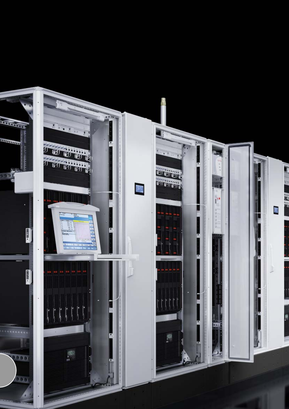
576
577
System accessories for monitoring
CMC III Processing Unit/Compact
CMC III system representation..................................................................578
CMC III system overview...........................................................................580
CMC III Processing Unit/Compact ............................................................582
CMC III sensors/accessories
Control units for CMC III Processing Unit..................................................583
CMC III sensors for direct connection.......................................................583
Interface for CMC II sensors .....................................................................583
Access System..........................................................................................583
Interface for PSM, PCU, FCS, DRC ...........................................................583
CMC III accessories
Power pack................................................................................................584
Programming cable...................................................................................584
CAN-Bus connection cable.......................................................................584
Connection cable/extension......................................................................585
Extension cable .........................................................................................585
CMC III mounting unit, 1 U ........................................................................585
CMC III mounting unit................................................................................585
Mounting unit, 1 U .....................................................................................586
Display Unit II ............................................................................................586
ISDN unit ...................................................................................................586
GSM unit, quad-band................................................................................587
Fan Control System FCS ...........................................................................587
Fan 24 V DC for FCS .................................................................................587
Universal lock unit .....................................................................................587
Door Control System
Door Control System .................................................................................588
Door control module..................................................................................589
Door kit ......................................................................................................589
Door comfort handle..................................................................................589
Door switch................................................................................................589
Monitor/keyboard unit
Monitor/keyboard unit................................................................................590
KVM switches
SSC view 8 USB ........................................................................................591
SSC view 32 Cat........................................................................................591
SSC compact 32 Cat ................................................................................591
SSC premium 2/16, 4/32, 8/32 ..................................................................592
SSC Duo 16 ...............................................................................................593
Console local.............................................................................................594
Console Cat 5............................................................................................594
Console IP .................................................................................................595
SSC cnverter .............................................................................................595
SSC converter VT100 (RS232) ..................................................................595
CPU cable .................................................................................................596
Cat 5 patch cable......................................................................................596
SSC Power Control ....................................................................................596
SSC Power Pack........................................................................................596
Dynamic Rack Control
RFID mounting frame ................................................................................597
RFID tags...................................................................................................597
RFID controller...........................................................................................597
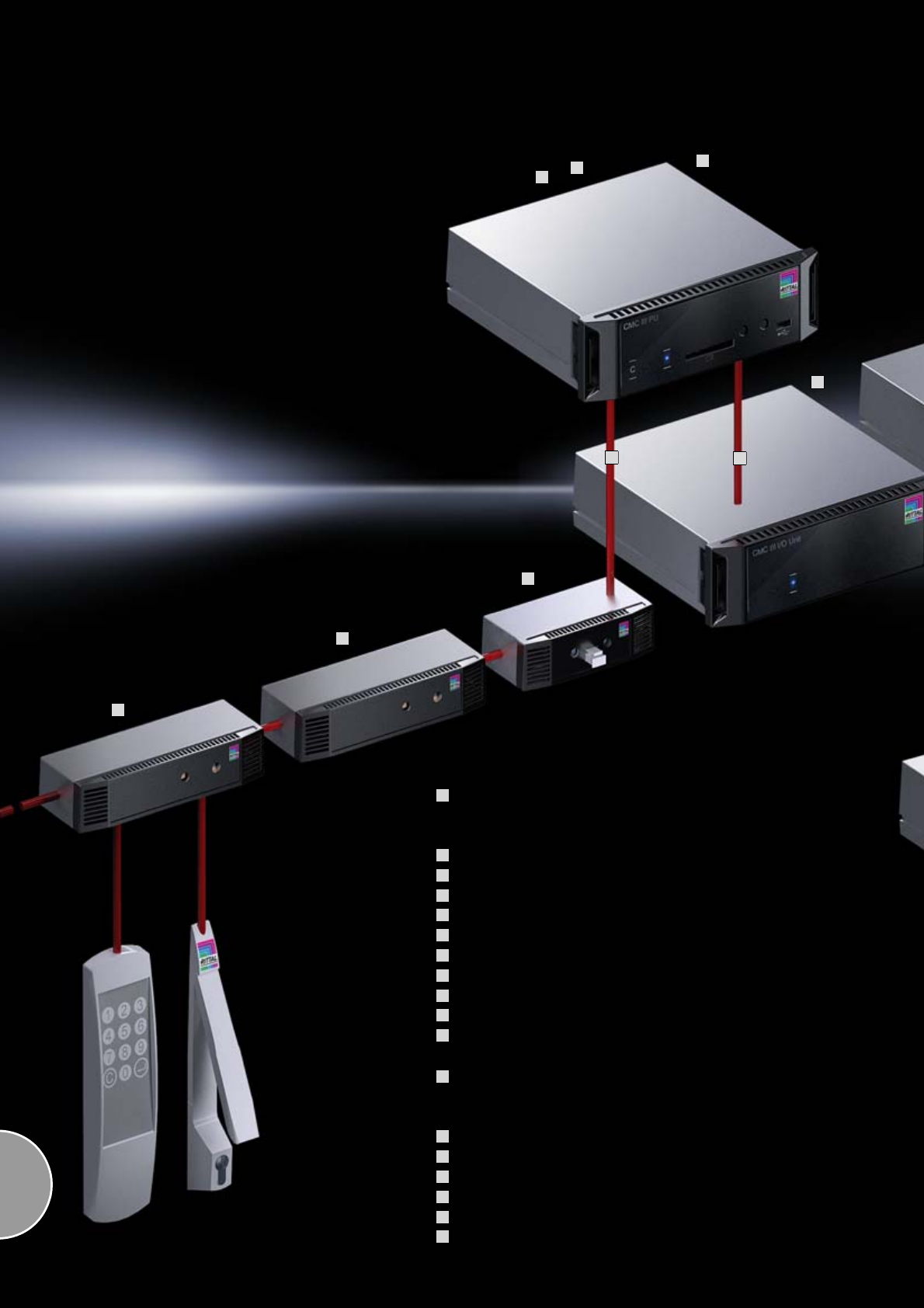
578
Monitoring system CMC III
CMC III Processing Unit
The powerful, professional monitoring solution for demanding
IT infrastructure environments, for up to 32 additional monitoring
components.
Power supply
Redundant power supply
CMC III I/O Unit
CMC III Power Unit
CMC III CAN-Bus Unit
Up to 16 CAN-Bus systems may be connected
CMC III sensors for direct connection
CMC III CAN-Bus sensor for connection of CMC II sensors
CMC III CAN-Bus access
Up to 16 CAN-Bus systems may be connected
CMC III Processing Unit Compact
The simple monitoring solution for applications in industry and building
monitoring or for smaller monitoring applications in IT for up to four
additional CAN-Bus monitoring components.
Power supply
Redundant power supply
CMC III sensors for direct connection
CAN-Bus sensor for connection of CMC II sensors
CMC III CAN-Bus access
Up to four CAN-Bus systems may be connected
1
2
3
4
5
6
7
8
9
10
11
12
13
14
15
16
17
18
7
2
3
CMC III Processing Unit
1
11
8
9
10
4
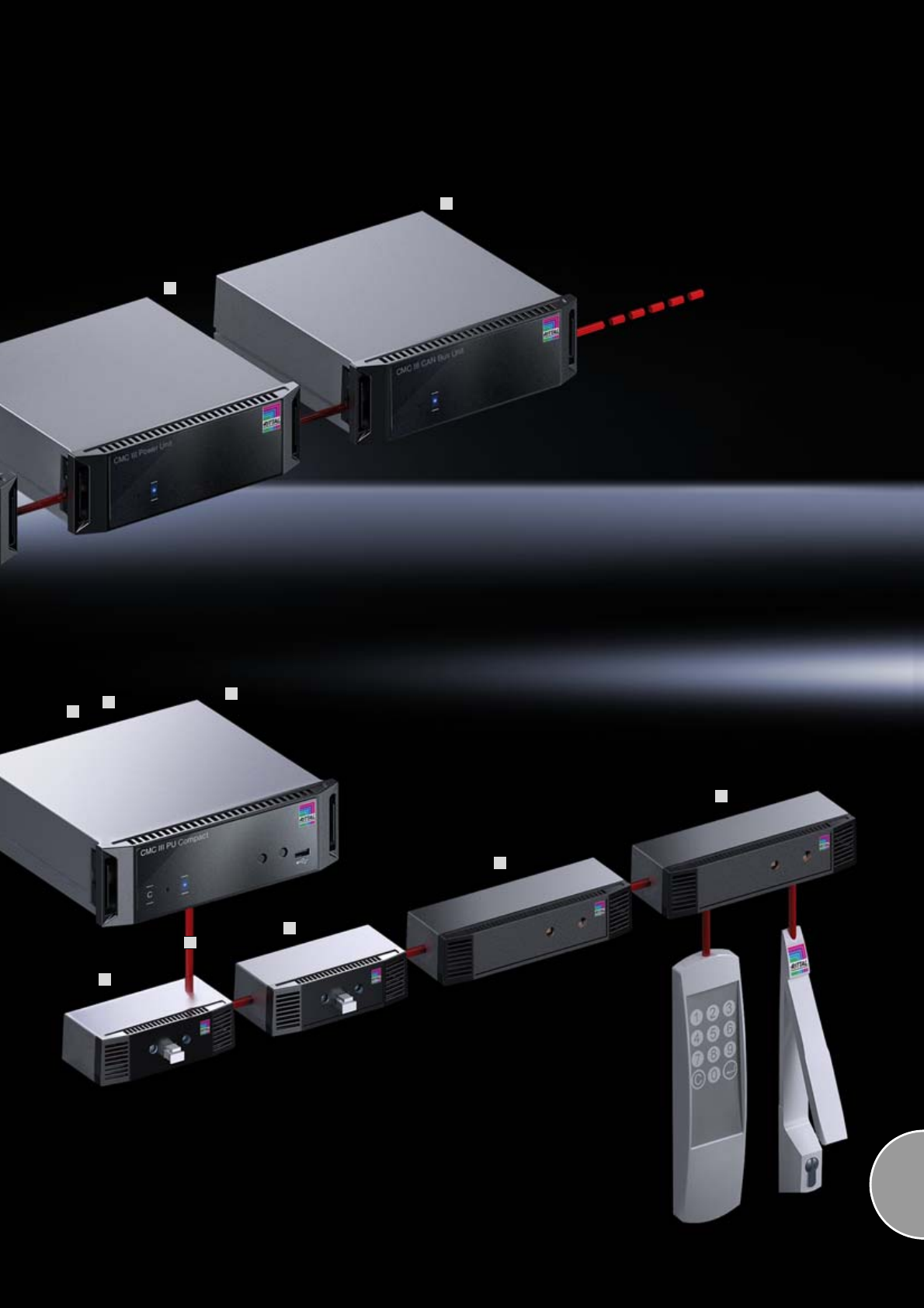
579
13
14
CMC III Processing Unit Compact
12
15
16
17
6
5
15
18
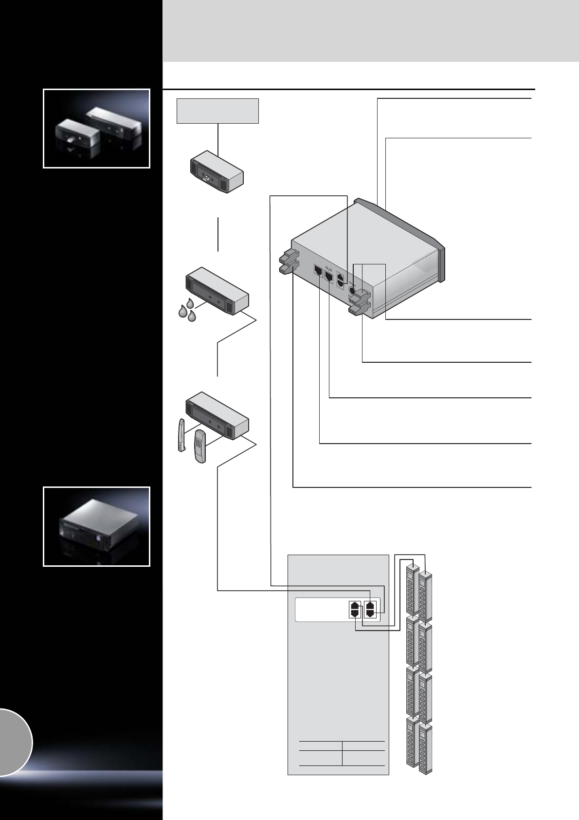
CMC III Processing Unit Compact
System overview
580 Rittal Catalogue 33/System accessories
Up to 4 CAN-Bus
components are
supported.1)
CMC III CAN-Bus sensor
CMC III CAN-Bus access
Two integral digital inputs
Integral sensors:
– Temperature sensor
– Infrared access sensor
Accessory modules RJ 12/RS232:
Display Unit DK 7320.491
ISDN Unit DK 7320.830
GSM Unit DK 7320.820
Ethernet 10/100 BaseT RJ 45 with PoE:
Ethernet interface to IEEE 802.3
Via 10/100 BaseT full-duplex 10/100 Mbit/s.
Voltage supply 24 V DC and redundant
voltage supply 24 V DC
Power packs/connection cables,
see page 584.
Alarm relay output:
Changeover contact for safety extra-low
voltage
1) Depending on the
power supply/connection
combinations,
see page 583.
CMC II
sensors
Mini USB:
The programming cable DK 7030.080
is required for programming.
CMC III sensors
for direct connection
CMC III Processing Unit
Compact
CMC III CAN-Bus Unit
Interfaces unit for
connecting CMC II
accessories
Connection for other
products,
see page 583.
Contains 2 channels of
the PU II Unit systems:
External 24 V DC supply
supported.
Model No. DK
CMC III
CAN-Bus Unit 7030.030
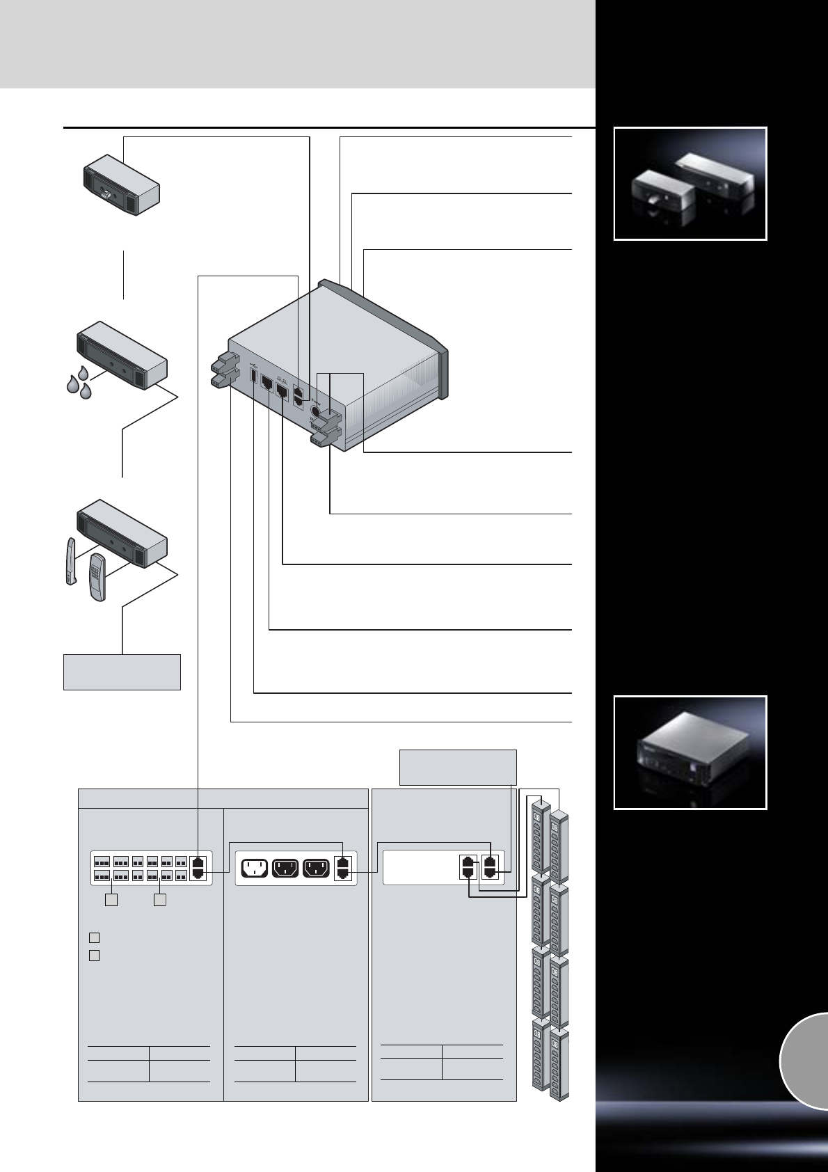
System overview
CMC III Processing Unit
581Rittal Catalogue 33/System accessories
Up to 16 CAN-Bus
systems are supported
.1)
CMC III sensors:
for direct connection
CMC III CAN-Bus sensor
CMC III CAN-Bus access
Two integral digital inputs
Integral sensors:
– Temperature sensor
– Infrared access sensor
Ethernet 10/100 BaseT RJ45 with PoE:
Ethernet interface to IEEE 802.3
Via 10/100 BaseT full-duplex 10/100 Mbit/s.
Voltage supply 24 V DC and redundant
voltage supply 24 V DC
Power packs/connection cables,
see page 584.
Alarm relay output:
Changeover contact for safety extra-low
voltage
CMC II
sensors
USB master for data logging and update
Mini USB:
The programming cable DK 7030.080
is required for programming.
Contains
8 digital inputs
and 4 relay outputs
1
2
Functions:
Switching and measurement
of voltage, power, output and
work.
With two outputs.
Also for the activation of
AC fans.
Interfaces unit for
connecting CMC II
accessories
Connection for other
products,
see page 583.
SD card insert:
for data logging
Accessory modules RJ 12/RS232:
Display Unit DK 7320.490
ISDN Unit DK 7320.830
GSM Unit DK 7320.820
Control units
CMC III I/O Unit CMC III Power Unit
CMC III CAN-Bus Unit
Model No. DK
CMC III
I/O Unit 7030.040
Model No. DK
CMC III
Power Unit 7030.050
Model No. DK
CMC III
CAN-Bus Unit 7030.030
Up to 16 CAN-Bus
systems are supported
.1)
1) Depending on the power supply/connection combinations, see page 583.
CMC III Processing Unit
2
1
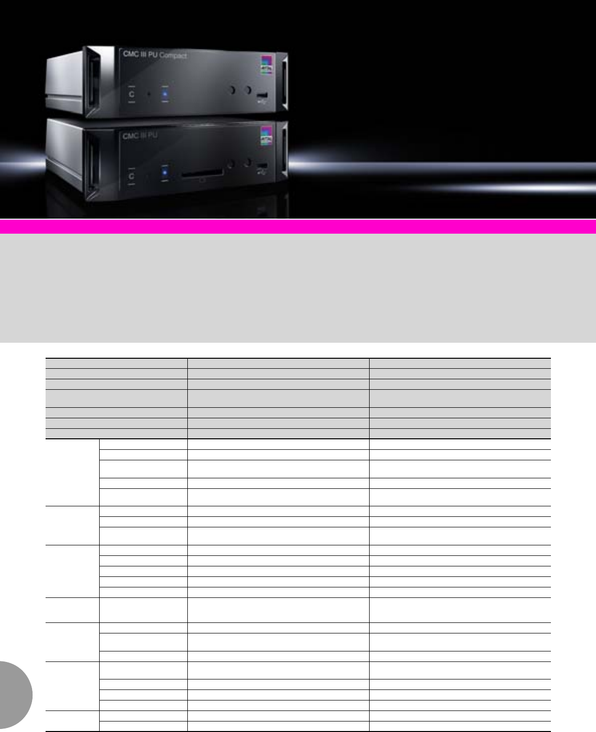
CMC III Processing Unit/Compact
582 Rittal Catalogue 33/System accessories
System overview Page 580/581 Basic modules and connection accessories Page 583
Application areas:
CMC III Processing Unit
Compact:
●Industrial and enclosure
monitoring
●Building monitoring
●Small monitoring applications
in IT
CMC III Processing Unit
●Larger monitoring applica-
tions in IT and industry
Material:
Plastic
Surface finish:
−Front: Smooth
−Enclosure: Textured
Colour:
−Front: RAL 9005
−Enclosure: RAL 7035
Protection category:
IP 30 to IEC 60 529
Supply includes:
−Basic system
−Quick-start instructions
−4 mounting feet
Photo shows a configuration
example with equipment not
included in the scope of supply.
CMC III Processing Unit Compact CMC III Processing Unit
W x H x D mm 138 x 40 (1 U) x 120 + 12 (front assembly) 138 x 40 (1 U) x 120 + 12 (front assembly)
Temperature range 0°C to +55°C 0°C to +55°C
Operating humidity range 5% to 95% relative humidity,
non-condensing 5% to 95% relative humidity,
non-condensing
Sensors/CAN-Bus connection units max. 4 max. 32
Max. overall cable length for CAN-Bus 1 x 50 m 2 x 50 m
Model No. DK 7030.010 7030.000
Interfaces
Network interface (RJ 45) Ethernet to IEEE 802.3 via 10/100BaseT with PoE Ethernet to IEEE 802.3 via 10/100BaseT with PoE
Front USB interface Mini USB for system setting Mini USB for system setting
Rear USB interface – for USB stick for data recording and
SW updates up to 32 GB
Front SD-HC slot – 1 x up to 32 GB for data recording
Rear serial RS232 (RJ 12) 1 x for connecting Display Unit DK 7320.491 or
GSM Unit DK 7320.820 or ISDN Unit DK 7320.830 1 x for connecting Display Unit DK 7320.491 or
GSM Unit DK 7320.820 or ISDN Unit DK 7320.830
Inputs and
outputs
Digital inputs (terminal) 2 2
Relay output (terminal) Changeover contact max. 24 V DC, 1 A Changeover contact max. 24 V DC, 1 A
CAN-Bus (RJ 45) 1 x for max. 4 sensors
(quantity restriction, see page 583) 2 x for max. 16 sensors each = 32 sensors in total
(quantity restriction, see page 583)
Operation/
signals
Push-button 1 x acknowledgement button 1 x acknowledgement button
Concealed reset button 1 x service button 1 x service button
Piezo signal generator 1 1
LED display 1 x multi-colour OK/warning/alarm 1 x multi-colour OK/warning/alarm
Rear LED 1 x for the network status 1 x for the network status
Protocols Ethernet TCP/IPv4, TCP/IPv6, SNMPv1, SNMPv3, Telnet, SSH,
FTP, SFTP, HTTP, HTTPS, NTP, DHCP, DNS server,
SMTP, XML, Syslog, LDAP
TCP/IPv4, TCP/IPv6, SNMPv1, SNMPv3, Telnet, SSH,
FTP, SFTP, HTTP, HTTPS, NTP, DHCP, DNS server,
SMTP, XML, Syslog, LDAP
Redundant
power supply
Input 24 V DC (jack) 1 x for connecting CMC III power pack 1 x for connecting CMC III power pack
Input 24 V DC (terminals) 1 x for direct connection or
for connecting CMC III power pack 1 x for direct connection or
for connecting CMC III power pack
Power over Ethernet 1 x 1 x
Functions
Time function Real-time clock, energy-buffered (24 h)
without battery/accumulator, with NTP Real-time clock, energy-buffered (24 h)
without battery/accumulator, with NTP
User administration LDAP LDAP
User interface Integral WEB server Integral WEB server
Control room connection Integral OPC server Integral OPC server
Integral
sensors
Temperature sensor NTC sensor in the enclosure front NTC sensor in the enclosure front
Access sensor Infrared technology in the enclosure front Infrared technology in the enclosure front
CMC III sensors/accessories
583Rittal Catalogue 33/System accessories
Control units for CMC III Processing Unit
CMC III sensors for direct connection
Interface for CMC II sensors
Access System
Interface for PSM, PCU, FCS, DRC
Model No.
DK
PU
Compact PU Page
Maximum quantity
CMC III I/O Unit, 8 digital inputs + 4 relay outputs 7030.0403) – 16 581
CMC III Power Unit, 1 input (C14) + 2 outputs (C13) 230 V, 50/60 Hz 7030.0503) – 16 581
Temperature sensor 7030.110 432–
Temperature/humidity sensor 7030.111 432–
Infrared access sensor 7030.120 432–
Vandalism sensor 7030.130 432–
Analog airflow sensor 7030.140 410
1) –
Analog differential pressure sensor 7030.150 432–
Universal sensor (digital input or 4-20 mA or
S0Bus power meter or Wiegand interface) 7030.190 432–
CMC III CAN-Bus sensor 7030.100 432 –
For connecting the following products:
5 x access sensors (packs of 2), connect a max. of 5 in series 7320.530 –
1 x smoke detector 7320.560 –
1 x motion detector 7320.570 –
1 x voltage monitor 48 V DC 7320.620 –
1 x leakage sensor 7320.630 –
1 x leakage sensor, with sensor length 15 m 7320.631 –
1/3 x fire detector and extinguisher system DET-AC Plus with 3 messages 7338.120 328
1/3 x early fire detection system DET-AC Plus with 3 messages 7338.220 328
1/2 x door control system with 2 enclosure channels 7320.790 589
CMC III CAN-Bus Access
(with integral infrared access sensor and interface for one reader III) 7030.200 2161) –
For connecting the following products:
1 x Ergoform-S handle (electro-magnetic) 7320.700 –
1 x Comfort handle TS 8 (electro-magnetic TS 8 handle with master key
function, with and without CCP) 7320.721 –
1 x universal lock 7320.730 587
1 x universal handle 7320.950 –
1 x CMC III coded lock 7030.220 216
1) –
1 x CMC III transponder reader 7030.230 216
1) –
CMC III CAN-Bus Unit for 2 unit channels 7030.0303) 1 42) 581
For connecting the following products (note: separate supply via power pack possible):
2 x Fan Control System FCS (DK 7320.812 fan 24 V DC for FCS) 7320.810 587
2 x fan mounting plate DC (universal fan roof W x D 800 x 800 mm
with FCS) 7858.488 224
2 x RFID controller DRC 7890.500 597
2 x 4 x Rittal Power Control Unit (PCU) 8-way 7200.001 510
2 x 4 x Rittal Power Control Unit (PCU) C13/earthing pin LED 6-way 7859.215 510
2 x 4 x Rittal Power Control Unit (PCU) C13 LED 8-way 7859.225 510
2 x 4 x Rittal Power Control Unit (PCU) C13/19 LED 6-way 7859.235 510
2 x 4 x PSM socket module active PSM C13 8-way 7856.201 203
2 x 4 x PSM socket module active PSM C13/earthing pin 6-way 7856.203 510
2 x 4 x PSM socket module active PSM C13/19 6-way 7856.204 510
2 x 4 x PSM socket module active PSM C13/earthing pin LED 6-way 7859.212 203
2 x 4 x PSM socket module active PSM C13 LED 8-way 7859.222 203
2 x 4 x PSM socket module active PSM C13/19 LED 6-way 7859.232 203
2 x PSM busbar with measurement 16 A 7856.016 202
2 x PSM busbar with measurement 32 A 7856.003 202
2 x PSM measurement module 16 A 7856.019 204
1) Max. 5 p. and 2) max. 1 p. for power supply with PoE or 48 V power pack.
3) Optional attachment see page 585.
CMC III accessories
584 Rittal Catalogue 33/System accessories
Power pack 230 V
The CMC III power pack may be integrated into
the CMC III assembly unit
CMC III power pack Model No. DK
CMC III power pack
Input voltage 100 – 240 V 50/60 Hz,
output voltage 24 V DC, 2 A 7030.0601)
1) Connection cable/extension required
D/F/B: 230 V, Model No. DK 7200.210
USA/CDN: 230/115 V, Model No. DK 7200.214
C13/C14: 230/115 V, Model No. DK 7200.215
Power pack 48 V/
Connection cable 24 V
for CMC III PU, PU Compact/FCS
An alternative power pack is designed for the
telecommunications sector (48 V battery volt-
ages) and is connected at the input end via a
terminal block.
The power pack includes an output cable,
1.65 m long.
Technical specifications DK 7320.435:
−Rated voltage: 20 – 72 V DC
−Rated current: max. 2.5 A
−Secondary range: 24 V DC, 1.3 A
Connection cable for CMC III/FCS for direct connec-
tion, provided the 24 V DC supply is available.
Primary input voltage Output voltage Model No. DK
48 V DC 24 V DC 7320.435
Packs of Length Model No. DK
12 m7320.813
Programming cable
The programming cable is required for com-
missioning of the Processing Unit (PU) or
PU Compact.
Model No. DK
CMC III programming cable USB 7030.080
CAN-Bus connection cable
This can be used to connect the PU with the
CAN-Bus sensors III, units III, control units III
as a bus. Also for cabling together.
Cable Length
(m) Packs
of Model No.
DK
CMC III CAN-Bus
connection cable RJ 45 0.5 1 7030.090
CMC III CAN-Bus
connection cable RJ 45 117030.091
CMC III CAN-Bus
connection cable RJ 45 1.5 1 7030.092
CMC III CAN-Bus
connection cable RJ 45 217030.093
CMC III CAN-Bus
connection cable RJ 45 517030.094
CMC III CAN-Bus
connection cable RJ 45 10 1 7030.095
CMC III accessories
585Rittal Catalogue 33/System accessories
Connection cable/extension
The cable is used to connect to:
●CMC III power pack C13
●CMC III power unit C13
●PCU
Technical specifications:
PVC cable, 3-pole, with IEC connector (non-heat-
ing appliances) with contact protection CEE22.
Length: at least 1.8 m
Country version Voltage
Volt Model No.
DK
D/F/B/C13 230 7200.210
USA/CDN/C13 230/115 7200.214
IEC 320 device
extension
C13/C14 230/115 7200.215
Connection cable
D/C19 230/115 7200.216
Connection cable
C19/C20 230/115 7200.217
Extension cable
for cable extension of CMC III sensors and
FCS fans
Connector/jack Length m Packs of Model No. DK
RJ 12 5 4 7200.450
RJ 12 1 2 7320.814
CMC III mounting unit, 1 U
To accommodate PU, PU Compact, control units,
CMC III CAN-Bus unit and CMC III power pack.
The mounting unit can accommodate up to 3 units
and is secured in the 482.6 mm (19˝) frame.
Accessories:
Cable clamp strap DK 7610.000,
see page 535.
Packs of Model No. DK
CMC III mounting unit, 1 U 1 7030.070
CMC III mounting unit
for enclosure frame
Can accommodate one unit and is mounted on
the enclosure frame.
Packs of Model No. DK
CMC III mounting unit
for enclosure frame 1 7030.071
CMC III accessories
586 Rittal Catalogue 33/System accessories
Mounting unit, 1 U
For display, ISDN and GSM unit, fan control
system, door control module, dynamic rack
control
For accommodating between two 482.6 mm (19˝)
mounting angles. Cable clamp straps DK 7610.000
or DK 7611.000 can be used for cable clamping.
Material:
Sheet steel
Surface finish:
Spray-finished
Colour:
RAL 7035
Mounting unit, 1 U
Single cover
Accessories:
Cable clamp strap, see page 535.
Packs of Model No. DK
17320.440
Packs of Model No. DK
27320.441
Display Unit II
The Display Unit II may be linked directly to the
CMC III. CMC alarms, status messages, tempera-
tures, voltages, currents etc. may be displayed
on the screen, depending on the monitoring appli-
cation.
Note:
The serial interface RS232 of the PU/PUC may
only be assigned to one accessory module.
Also required:
−Processing unit, see page 582.
−Mounting unit, see page 586.
Packs of Model No. DK
17320.491
ISDN unit
For configuring a redundant transmission channel
or, if there is no network infrastructure available,
for alarm forwarding. The alarm signal is designed
in SMS format. Power supply is via the process-
ing unit.
Requirements for the ISDN connection:
−DSS1 (Euro-ISDN) must also be provided when
connecting to the ISDN system
−Point-to-multi-point configuration
Supply includes:
Connection cable.
Note:
The serial interface RS232 of the PU/PUC may
only be assigned to one accessory module.
Also required:
−Processing unit, see page 582.
−Mounting unit, see page 586.
Components Model No. DK
ISDN unit 7320.8301)
1) Extended delivery times.
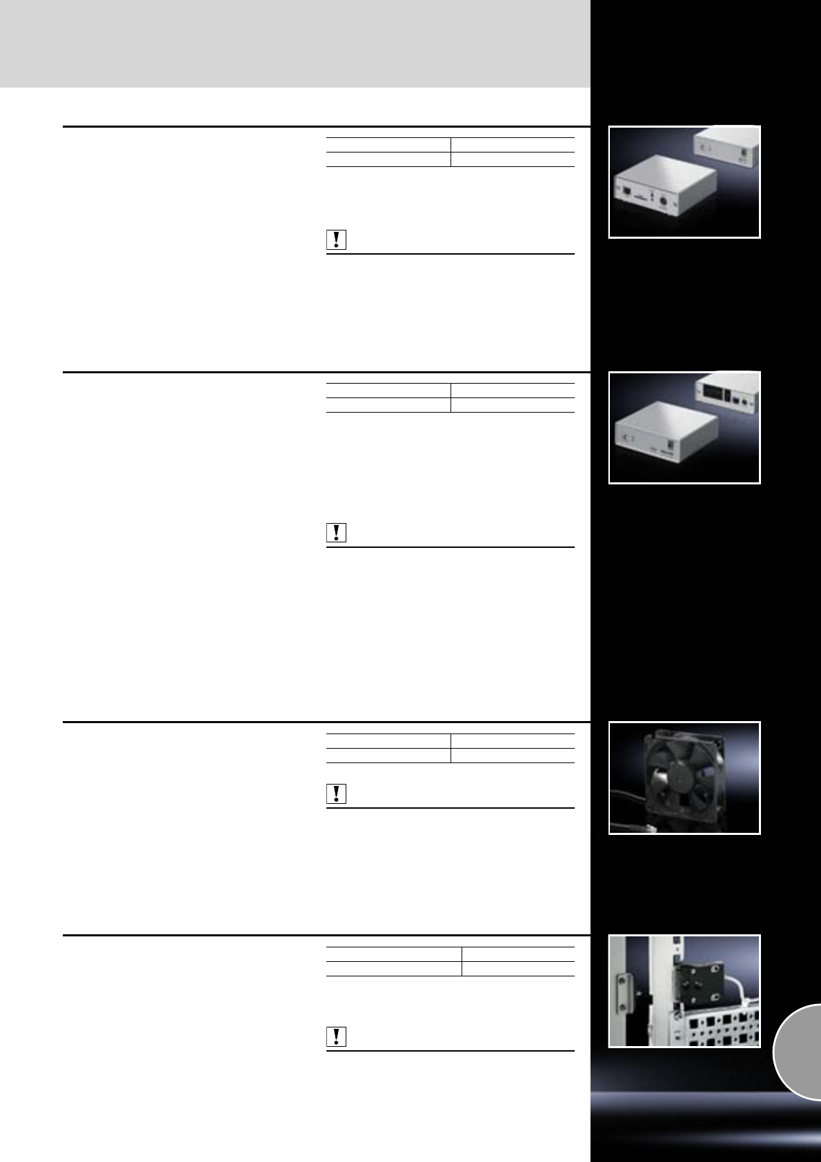
CMC III accessories
587Rittal Catalogue 33/System accessories
GSM unit quad-band
For configuring a redundant transmission channel
or, if there is no network infrastructure available,
the unit may be used for alarm forwarding.
The alarm signal is designed in SMS format.
The GSM Unit Quad-Band covers 4 GSM fre-
quencies: 850 MHz, 900 MHz, 1800 MHz and
1900 MHz.
A standard, commercially available SIM card
for GSM must be provided by the customer.
Note:
The serial interface RS232 of the PU may only
be assigned to one accessory module.
Also required:
−Processing unit, see page 582.
−Mounting unit, see page 586.
GSM unit quad-band Model No. DK
SMS function 7320.820
Fan Control System FCS
Speed-controlled fan system
The Fan Control System regulates and controls
the speed of up to 6 fans, 24 V DC. It may option-
ally be connected to the CMC III CAN-Bus unit
DK 7030.030.
Functions:
−Speed-regulated speed control
−Fan speed monitoring
−Optional connection via Web/SNMP
Note:
FCS fitted in fan roof, see page 224.
Also required:
−Power pack DK 7030.060,
see page 584.
−Connection cable DK 7200.210,
see page 585.
−Fan DK 7320.812,
see page 587.
−Extension DK 7320.814,
see page 585.
−1 U mounting unit 7320.440,
see page 586.
FCS Model No. DK
Without fan 7320.810
Fan 24 V DC for FCS
with speed monitoring
Fan with integral speed monitoring with RJ 12
connector/connection cable 0.6 m for connecting
to FCS DK 7320.810.
Technical specifications:
−Rated voltage: 24 V DC
−Rated current: 0.28 A (max.)
−Rated output: 6.72 W (max.)
−Air throughput (unimpeded air flow): 175 m3/h
−Speed: 2650 rpm
−Noise level: 45 dB (A)
Also required:
RJ 12 extension, 1 m, DK 7320.814,
see page 585.
Packs of Model No. DK
27320.812
Universal lock unit
The security lock consists of a base unit and a
lock counterpart. The base unit is attached to the
enclosure frame. The lock counterpart is attached
to the door.
Technical specifications:
−Rated voltage: 24 V DC
−Rated current: 140 mA
Note:
Supplied without mounting kit.
Also required:
CMC III CAN-Bus access DK 7030.200,
see page 583.
Packs of Model No. DK
1 set 7320.730
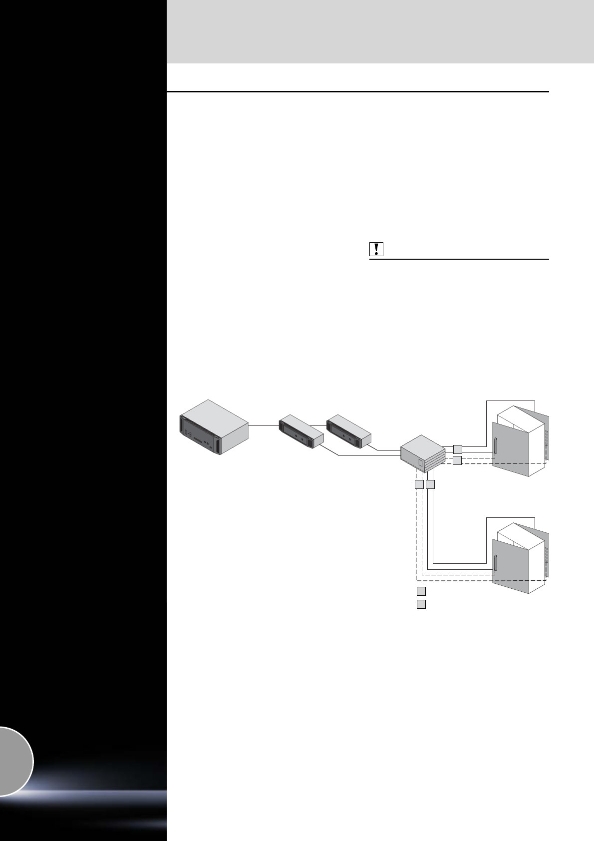
Door Control System
588 Rittal Catalogue 33/System accessories
Door Control System
For automatic opening of closed rack systems:
●In the event of cooling system failures.
●For extinguishing a fire using a fire extinguisher
system.
Note:
To be connected at rear:
−Door Kit
Up to 16/2 door kits may be connected for
automatic opening.
−Door comfort handle or Door switch
Up to 16/2 door comfort handles/door switches
may be connected for manual opening.
−Automatic opening is achieved by connecting
to the PU/PU Compact. Independently of this,
the doors may be opened using the door com-
fort handle/door switch.
−In the event of a power failure, the doors will
open.
−The front and rear door must always be
opened.
Also required:
CMC III Processing Unit/Compact,
see page 582.
System representation
Door Control System:
●A maximum of 16 door control systems per processing unit
●A maximum of 2 door control systems per processing unit may be connected
1
12
2
CMC III
– Processing Unit
– Processing Unit Compact
Door control
module
CAN-Bus unit
(DK 7030.100)
Door kit
Door comfort handles
1
2
Door 1/2
Door 3/4
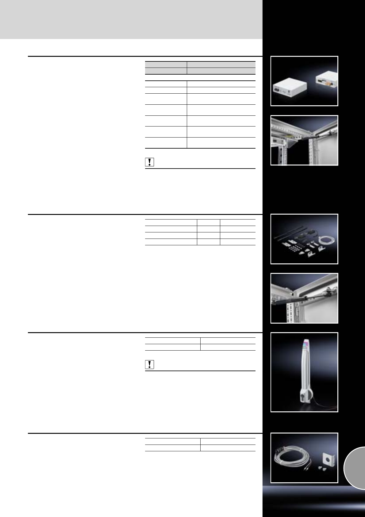
Door Control System
589Rittal Catalogue 33/System accessories
Door control module
For activation of up to 4 door kits There is 1 con-
trol channel available per 2 door kits (e.g. front
and rear door). There is optionally a normally-
closed contact integrated for each door output,
which is used to connect the automatic door
switch, door comfort handle or a customer-
specific system (e.g. room extinguisher system).
Also required:
−Mounting unit DK 7320.440, see page 586.
−AC power pack 230 V, see page 584.
−Connection cable, see page 585.
Model No. DK 7320.790
W x H x D mm 136 x 44 (1 U) x 129
Rated voltage 24 V DC
Door outputs 4 x 24 V DC, 400 mA
Ports for CMC III
CAN-Bus unit 2 x RJ 12
Normally closed
contacts Connection must be designed
for 30 V DC, 1 A
Temperature
application range +5°C to +45°C
Humidity
application range 5% to 95% relative humidity,
non-condensing
IP protection
category IP 40 to IEC 60 529
Door kit
●Fitting a standard door for the Door Control
System
●The door kit operates with a gas pressure
damper system, allowing the door to be
opened in any emergency situation. The doors
are kept closed by a magnet system, which
unlike mechanical lock systems will release the
door in every instance.
●The door kit is connected and activated
using the corresponding door control module
DK 7320.790.
Supply includes:
−Gas pressure damper
−Cable harness
−Magnetic lock
−Assembly parts
Version for Packs of Model No. DK
2-piece door 1 7320.792
1-piece glazed door 1 7320.795
1-piece sheet steel door 1 7320.796
Door comfort handle
with door opener function
By actuating the lock mechanism, the door is
released via the automatic door opening system.
Prepared for the installation of standard commer-
cially avaialble semi-cylinders, 40 mm, and SZ
lock and push-button inserts.
Length: 302 mm.
Technical specifications:
−Rated voltage: 24 V DC
−Rated current: max. 3 A
−Connection cable: Length 3 m
−Temperature application range: +5°C to +40°C
Also required:
Handle adaptor for mounting on glazed door
TS 8611.080,
see page 402.
Design Model No. DK
RAL 7035 7320.794
Door switch
Switch for connecting to the normally closed con-
tacts of the door control module (DK 7320.790)
for manual door opening.
It is mounted on the 25 mm pitch pattern of the
TS 8 frame section.
Technical specifications:
−Installation Ø 16.2 mm
−250 V/2 A
Supply includes:
−3 m connection cable
−Mounting bracket
−Assembly parts
Packs of Model No. DK
1 7320.793
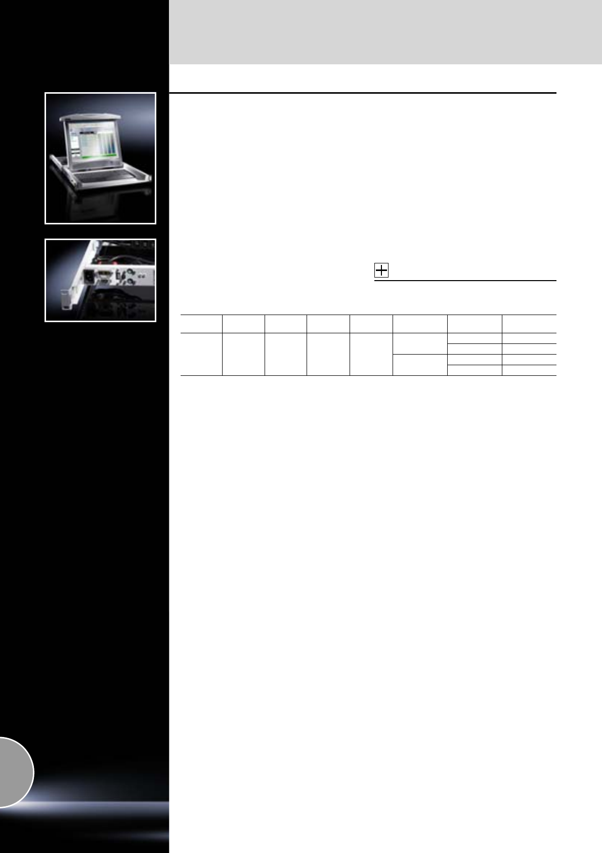
Monitor/keyboard unit
590 Rittal Catalogue 33/System accessories
Monitor/keyboard unit, 1 U
With 17˝ TFT display and VGA/DVI connection
Benefits:
●High-quality manufacturing
●Analog and digital video input
●Separate numerical keypad
●Optionally with integrated KVM switch for up
to 32 server connections in just 1 U
●Low energy consumption
●Simple, one-man installation
Technical design
−17˝ (432 mm) TFT display
−Native resolution 1280 x 1024
−Format 4 : 3
−16.7 million colours
−Brightness approx. 350 cd/m2 (typ.)
−Contrast ratio approx. 1000 : 1
−Mains voltage 100 – 240 V AC, 50 – 60 Hz
−Ambient temperature +5°C to +45°C
(in operation)
−Max. power consumption in operation,
without optional KVM switch: 32 W
−Max. power consumption when closed,
without optional KVM switch: < 1 W
−Rear connections: Mains power, VGA,
DVI-D, PS/2, USB, power supply for KVM
−Lockable at the front
−Cables are safely routed in the energy chain
Accessories:
For monitoring several servers:
KVM switches, see page 591.
Width
mm Height
UDepth
mm Installation
depth mm Packs of Colour Keyboard Model No. DK
482.6
(19˝) 1 680 680 – 850 1
RAL 7035 German 9055.310
English 9055.312
RAL 9005 German 9055.4101)
English 9055.4121)
Other country-specific versions available on request.
1) Extended delivery times.
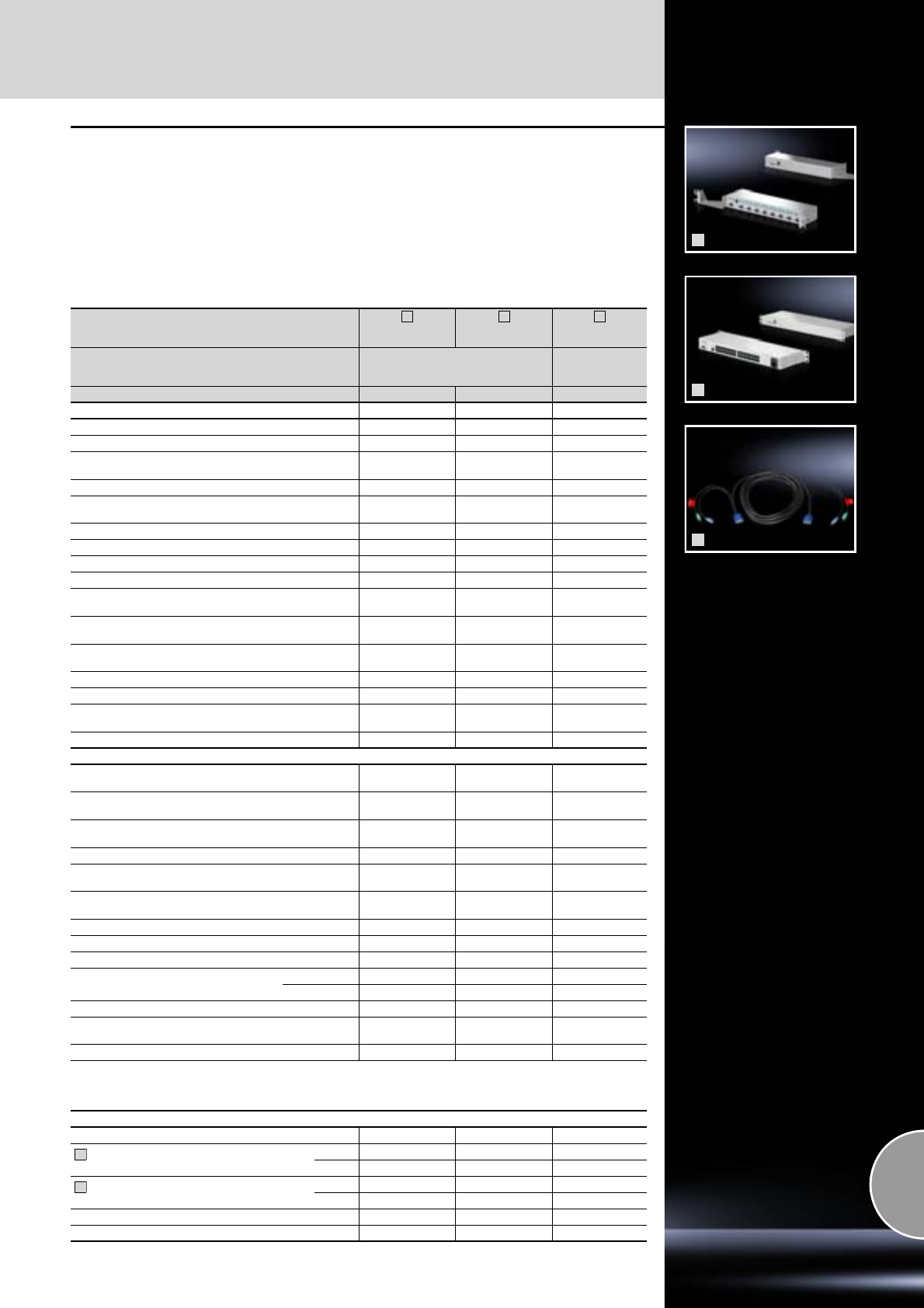
KVM switches
591Rittal Catalogue 33/System accessories
1
2
3
KVM switches
With these ultra-compact KVM switches for
482.6 mm (19˝) mounting or for mounting behind
a Rittal monitor/keyboard unit, space-saving
server administration becomes possible in any
IT rack. The Rittal SSC switching system grows
flexibly with your requirements. With the SSC com-
pact/view 32 Cat, the computers are connected
via Cat cables and converters (SSC converter).
The signals for video, keyboard and mouse are
transmitted via a shared cable.
Processor-controlled keyboard and mouse emu-
lation for each channel ensures fault-free booting
and reliable switching between the connected
computers. The SSC view optionally extends
the Rittal monitor/keyboard unit to include the
function of an 8- or 32-port KVM switch, without
requiring an additional U in the server rack for
mounting.
SSC view
8 USB
SSC view
32 Cat
SSC compact
32 Cat
Installation type For mounting behind
the monitor/keyboard unit
DK 9055.XXX
For mounting on
482.6 mm (19˝)
levels
Model No. DK 7552.002 7552.100 7552.110
Equipment 8 Port KVM 32 Port KVM 32 Port KVM
Number of computers in stand-alone mode 8 32 32
Number of users (with password protection) 1 1 1
Cascading2) as slave to SSC view/compact 32 Cat
(with OSD transfer) –
OSD menu with mouse operation (English)
OSD superimposed on computer screen
(may be de-activated)
OSD display of channels used
Hotkeys for computer selection
Autoscan
Autoskip (skip over unused channels)
Type of cable to computer or to SSC Connect VGA/HD15
and PS/2 Cat 5, 6 Cat 5, 6
Maximum cable length, SSC to computer
(depending on cable quality) 4 m 15 m (30 m) 15 m (30 m)
Port and system support PS/2 and USB PS/2, USB,
SUN-USB PS/2, USB,
SUN-USB
Automatic cable alignment (manually readjustable) – 1) 1)
LED displays (rear) None Power Power
Maximum video resolution (depending on cable length) 1280 x
1024@85 Hz 1920 x
1440@75 Hz 1920 x
1440@75 Hz
Bandwidth 200 MHz 250 MHz 250 MHz
Computer SUB-HD15 /
PS/2 / USB-B RJ 45 RJ 45
Strengthener SUB-HD15 /
PS/2 / USB-B SUB-HD15 /
PS/2 SUB-HD15 /
PS/2
Cascading port
(connection for slave, SSC compact only) – RJ 45 RJ 45
Service (for firmware update) – Jack 2.5 mm Jack 2.5 mm
12 V DC power supply
(from monitor/keyboard unit) –
Power supply 100 – 240 V, 50/60 Hz
(internal power pack, IEC 320, C14) – –
Power consumption (approx.) 10 W 13 W 13 W
Operating temperature +5 to +45°C +5 to +45°C +5 to +45°C
Protection category IP 20 IP 20 IP 20
Enclosure Material Sheet steel Sheet steel Sheet steel
Surface finish
Powder-coated Powder-coated Powder-coated
Colour RAL 9006 RAL 9006 RAL 7035
Dimensions (excluding protruding parts)
approx. W x H x D mm 482.6 x 44 x 140 482.6 x 44 x 140 482.6 x 44 x 140
Certification CE CE CE
1) With a cable length of max. 15 metres, there is no need for any manual video readjustments. Above and beyond this,
the maximum permissible cable length is approximately 30 metres (depending on the cable quality).
Here, manual readjustment may be required.
2) Up to 3 SSC compact/view 32 Cat may be cascaded to one master (max. 125 servers on 1 user).
Accessories
Mains connection cable (for SSC compact only) – – 7200.210
CPU cable VGA/PS/2 (with lockable
PS/2 connectors, at both ends)
2 m 7552.120 – –
4 m 7552.140 – –
CPU cable VGA/USB, USB-A (computer)
to USB-B (switch)
2 m 7552.122 – –
5 m 7552.142 – –
SSC converter PS/2 – 7552.201 7552.201
SSC converter USB – 7552.202 7552.202
1
1
2
3
3
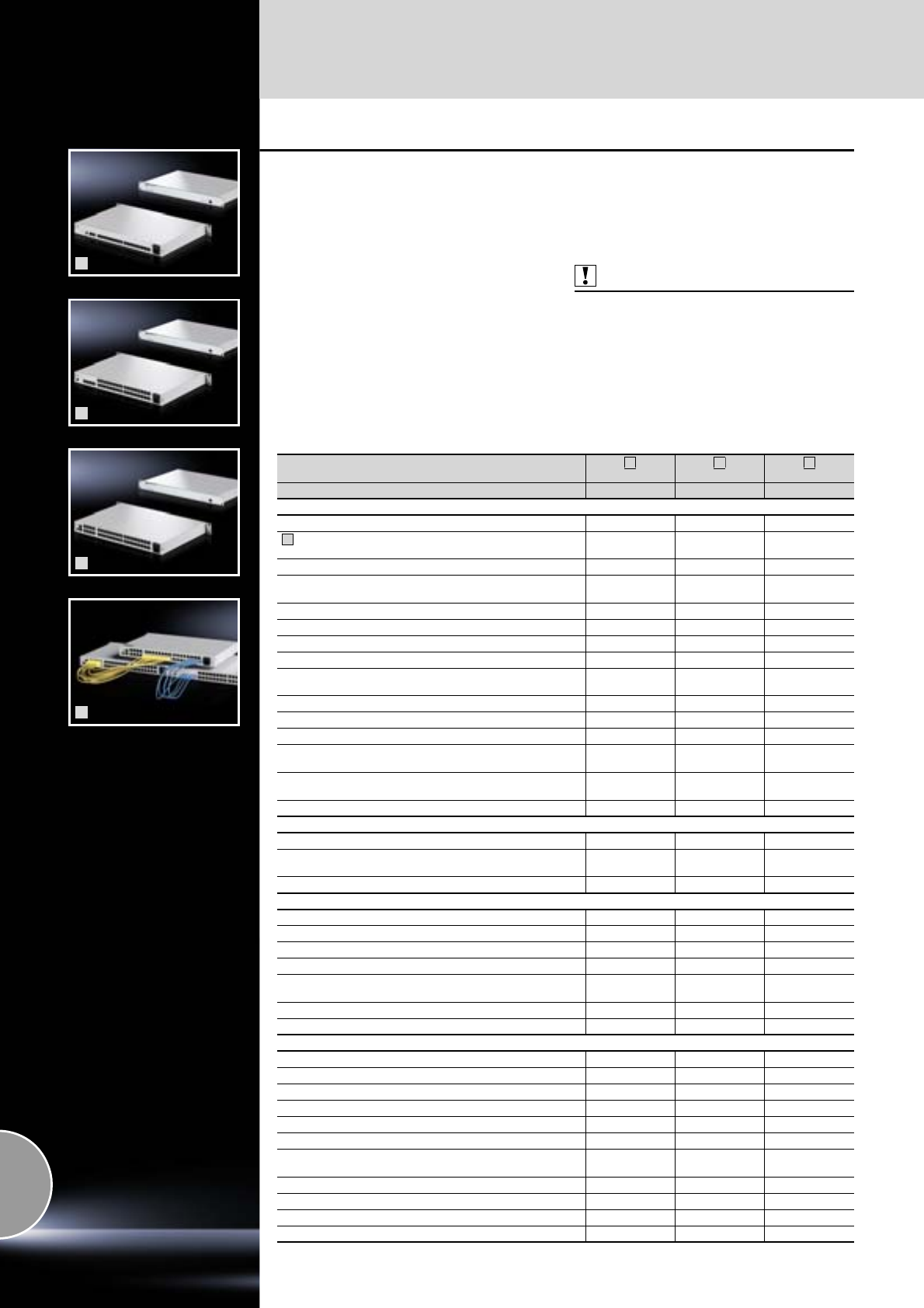
KVM switches
592 Rittal Catalogue 33/System accessories
1
2
3
4
SSC premium 2/16, 4/32, 8/32
Highly integrated KVM matrix based on
Cat technology
KVM switching technology which adapts flexibly
to your future requirements. Thanks to Cat tech-
nology (transmission of the signals for keyboard,
video and mouse via a Cat cable), the amount of
cabling work required can be significantly reduced.
Super-compact 1 U systems with up to 32 server
ports are supported. The full matrix switches offer
each of the connected users unrestricted, simul-
taneous access to the chosen computer system.
There are various console types available for
administration.
By separating the hardware switch and operating
console, the systems may be adapted to any
required computer environment. On the computer
side, conversion to standard PC interfaces is
achieved via separate converters which optimise
all signals (keyboard, video, mouse) for transmis-
sion via the Cat cable.
Material:
Sheet steel
Colour:
RAL 7035
Protection category:
IP 30
Also required:
−SSC converter (depending on the number of
computers) and at least one operator console,
see page 594/595.
−Mains connection cable (DK 7200.210),
see page 585.
Connection example:
Available on the Internet.
Rittal SSC premium
2/16
4/32
8/32
Model No. DK 7552.0201) 7552.0301) 7552.0401)
Equipment
Number of computers in stand-alone mode 16 32 32
Number of computers with cascading as full matrix
(max. 3 levels, type-identical SSC premium) 1024 2048 512
Number of users (local, remote, IP), mixed and simultaneous 2 4 8
Number of users that may be administered
(with allocation of rights) 128 128 128
Integral user/computer administration
Support of central directory services and authentication systems
––
OSD menu with mouse operation (English)
Display of system structure in the OSD per computer (path)
OSD superimposed on computer screen
(may be de-activated)
OSD display of channels used
Hotkeys for computer selection
Type of cable to SSC converter and SSC console Cat 5, 6 Cat 5, 6 Cat 5, 6
Maximum cable length console – computer
(depending on cable quality) 300 m 300 m 300 m
Port and system support (SSC converter) PS/2, USB,
SUN-USB/VT100 PS/2, USB,
SUN-USB/VT100 PS/2, USB,
SUN-USB/VT100
Automatic video/cable alignment (manually readjustable)
LED displays, front
Power/Power Redundant
System Ready (illuminates as soon as the system booting
process has been completed without error)
Status Switch (illuminates when the SSC is operational)
LED displays, rear
Computer port busy/connected yellow/green yellow/green yellow/green
Console port busy/connected yellow/green yellow/green yellow/green
Network port full duplex/half duplex – – yellow/flashing
Network port connection status/activity – – green/flashing
Maximum video resolution (depending on cable length) 1920 x 1440 @
75 Hz 1920 x 1440 @
75 Hz 1920 x 1440 @
75 Hz
Bandwidth 250 MHz 250 MHz 250 MHz
Activation of switchable socket strip (on/off)
Connections
Computers/consoles RJ 45 RJ 45 RJ 45
Service (front) for firmware update Jack 2.5 mm Jack 2.5 mm Jack 2.5 mm
RS232 (front) RJ 11 RJ 11 RJ 11
Network – – 2 x RJ 45
Power supply via IEC 320 connection (IEC 320 C13)
Redundant power supply (with SSC power pack) 4-pole mini-DIN 4-pole mini-DIN 4-pole mini-DIN
Power supply (internal power pack) 90 – 264 V/
47 – 63 Hz 90 – 264 V/
47 – 63 Hz 90 – 264 V/
47 – 63 Hz
External power supply, redundant 12 V/approx. 1 A 12 V/approx. 1 A
12 V/approx. 1 A
Power consumption (approx.) 12 W 13 W 16 W
Dimensions (excluding protruding parts) approx. W x H x D mm 482.6 x 44 x 286 482.6 x 44 x 286 482.6 x 44 x 286
Conformity CE CE CE
1) Extended delivery times.
1
2
3
4
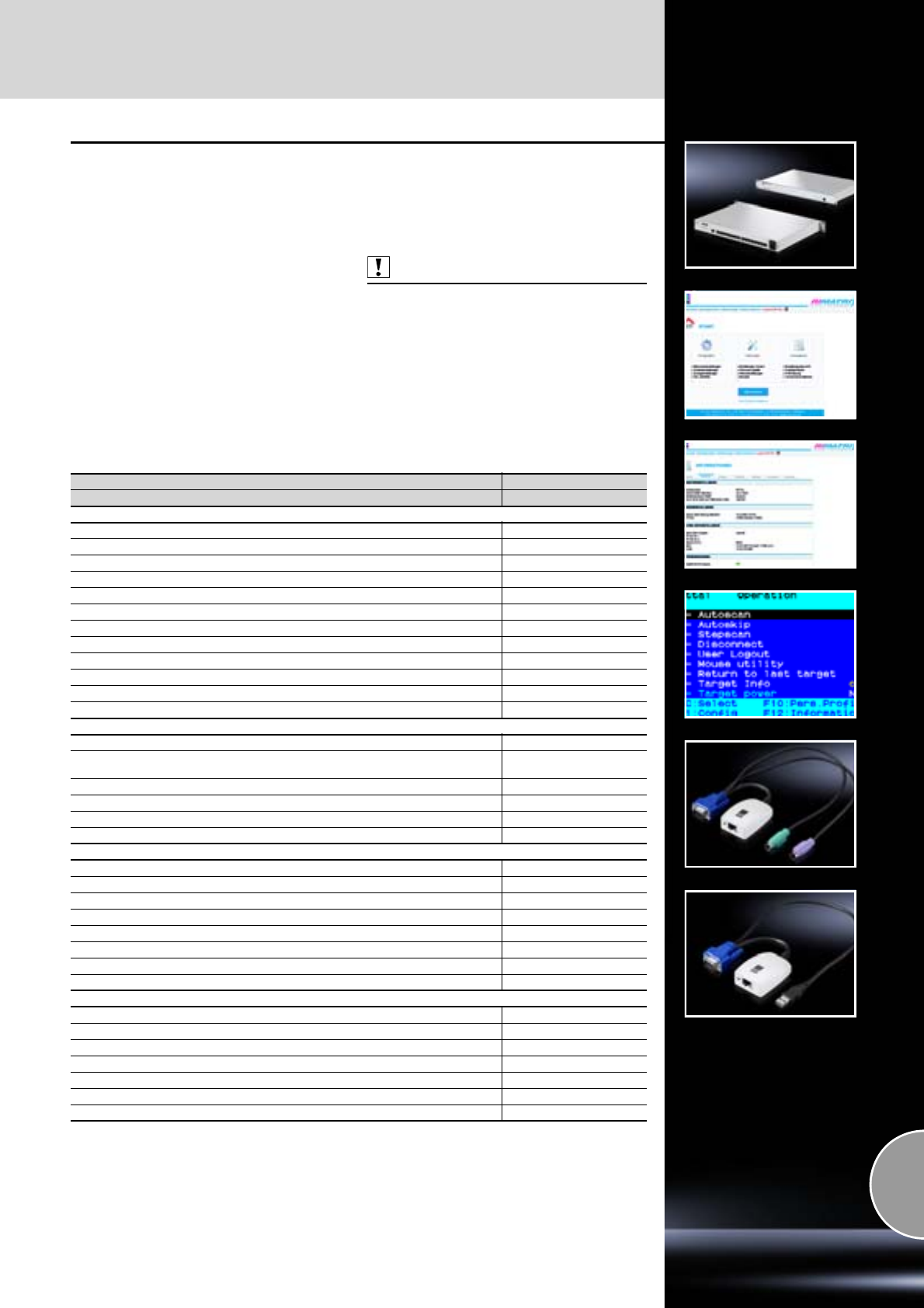
KVM switches
593Rittal Catalogue 33/System accessories
SSC Duo 16
Ultra-compact KVM switch with both a local
access and an IP access These two users are
able to access the connected servers in parallel/
simultaneously.
Up to 16 servers may be connected using Cat
cables and SSC converter adaptors (available in
a PS/2 and USB variant). Processor-controlled
keyboard and mouse emulation for each channel
ensures fault-free booting and reliable switching
between the connected computers. The integral
IP console supports location-independent access
to the servers down to BIOS level.
Access may be made both via the integral Web
interface (via Java client) and via client software
for Windows and selected Linux distributions,
available free of charge. The switch includes
rights administration for up to 16 user profiles.
Material:
Sheet steel, powder-coated
Colour:
RAL 7035
Protection category:
IP 40
Also required:
One SSC converter adaptor DK 7552.201 (PS/2)
or DK 7552.202 (USB) is required for each con-
nected computer, see page 595.
Note:
Software updates are available at
www.rittal.com
SSC Duo 16
Model No. DK 7552.510
Equipment
No. of computers that may be connected 16
Number of users (local, IP), mixed and simultaneous 2
Number of users that may be administered (with allocation of rights) 16
Integral user/rights administration (also via directory services)
OSD menu with mouse operation (English)
OSD superimposed on computer screen (may be de-activated)
OSD display of channels used
Hotkeys for computer selection
Type of cable to SSC converter and SSC console Cat 5, Cat 6
Maximum cable length SSC Duo 16 – computer (depending on cable quality) 30 m
Port and system support (SSC converter) PS/2, USB
Automatic video and cable alignment (manually readjustable)
LED displays
Power
System Ready
(illuminates as soon as the system booting process has been completed without error)
Status Switch (illuminates when the SSC is operational)
Network port (activity, connection status)
Maximum video resolution (depending on cable length) 1920 x 1440 @ 75 Hz
Bandwidth 250 MHz
Connections
Computers/consoles RJ 45
Service for firmware update Jack 2.5 mm
Network RJ 45
Power supply via IEC 320 connection (EN 60 320 C14)
Power supply (internal power pack) 90 – 264 V/47 – 63 Hz
Power consumption (approx.) 20 W
Dimensions approximately W x H x D mm 482.6 mm x 1 U x 290 mm
Certifications CE
Accessories
SSC converter PS/2 7552.201
SSC converter USB 7552.202
Cat 5 cable 2 m 7320.472
Cat 5 cable 5 m 7320.475
Cat 5 cable 10 m 7320.481
Cat 5 cable 15 m 7320.485
Mains connection cable (earthing-pin) 7200.210
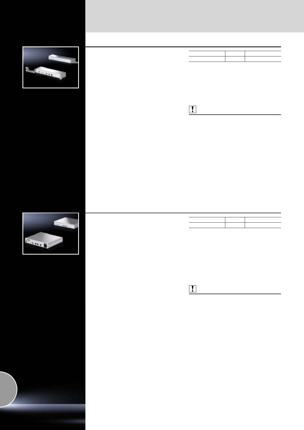
KVM switches
594 Rittal Catalogue 33/System accessories
Console local
for SSC premium
For installation in
●482.6 mm (19˝)
●at the rear of 15˝/17˝ monitor unit (9055.XXX)
As the link between the keyboard, monitor, mouse
(or the Rittal monitor/keyboard unit) and the SSC
premium. Via the console, the computer systems
connected to the switch may be conveniently
selected and administered using the OSD.
Power supply is optionally via the Rittal monitor/
keyboard unit or, in the case of stand-alone
482.6 mm (19˝) installation, via the SSC Power
Pack (DK 7552.220).
Material:
Sheet steel
Colour:
RAL 9006 (white aluminium)
Supply includes:
Assembly parts.
Technical specifications:
−Video resolution: Max. 1920 x 1440 @ 75 Hz
(depending on the cable length)
−Video bandwidth: 250 MHz
−Voltage supply: 12 V DC (from monitor/
keyboard unit) or via SSC Power Pack
DK 7552.220
−Dimensions:
W x H x D mm: 325 x 44 x 85 (stand-alone)
W x H x D mm: 482.6 x 44 x 140
(built into 482.6 mm/19˝)
Connections (jack):
−PS/2 (keyboard/mouse)
−USB-A (keyboard/mouse)
D15 (VGA-Video RGB & Sync.)
−RJ 45 (KVM matrix connection)
−Mini-DIN 4 (12 V power supply)
Also required:
−Only for 482.6 mm (19˝) installation without
monitor/keyboard unit:
SSC Power Pack DK 7552.220,
see page 596,
−Cat 5 patch cable,
see page 596.
Type Packs of Model No. DK
Console local 1 7552.200
Extended delivery times.
Console Cat 5
for SSC premium
This remote console forms the link between the
keyboard, monitor, mouse and the SSC premium.
Via the console, the computer systems con-
nected to the switch may be conveniently
selected and administered using the OSD. The
signals are forwarded via Cat cable, depending
on the cable quality up to 300 m, via the KVM
matrix to the connected computers. Additionally,
2 local PCs may be connected if required.
The console is designed as a compact desktop
enclosure with integral wide-range power pack
(482.6 mm (19˝) versions on request).
Material:
Sheet steel
Colour:
RAL 7035
Technical specifications:
−Video resolution: Max. 1920 x 1440 @ 75 Hz
(depending on the cable length)
−Video bandwidth: 250 MHz
−Power supply (internal power pack):
100 – 280 V, 50 – 60 Hz/0.2 A
−Dimensions:
W x H x D mm: 270 x 44 x 220
Connections (jack):
−PS/2 (keyboard/mouse) USB-A (keyboard/
mouse)
−SUB-HD15 (VGA video RGB & Sync.)
−2 x Cat (RJ 45) to connect 2 local PCs via
SSC converters (VGA, PS/2 or USB)
−RJ 45 (KVM matrix connection) IEC 320 C14
(power supply)
−Mini-DIN 4 (redundant power supply)
Also required:
−Cat 5 patch cable,
see page 596.
−SSC converter for local PCs,
see page 595.
−Mains connection cable (e.g. DK 7200.210),
see page 585.
Type Packs of Model No. DK
Console Cat 5 1 7552.212
Extended delivery times.
KVM switches
595Rittal Catalogue 33/System accessories
Console IP
for SSC premium (KVM-over-IP)
With the IP remote console, computers con-
nected to the KVM matrix may be accessed via
any given TCP/IP network. The SSC Console IP
is a hardware solution, and guarantees remote
monitoring of the computers even during the boot-
ing phase, down to BIOS level. With the system
operational, the target computers may be
accessed at any time via web browsers and Java
applets (irrespective of the operating system), or
if Java is not supported, via optimised client soft-
ware for common operating systems. This client
has extended functions (e.g. a setup mode) and
can be used throughout the company without
restriction. In addition to remote access via IP, the
SSC Console IP also has an integral local console
port (competing with IP access) for connecting
the keyboard, mouse and monitor locally in the
rack.
Access to the console is additionally password-
protected. KVM access to the web interface may
be encrypted via HTTPS (SSL 128-bit). In order
to further increase failsafeness, the SSC console
IP may also be extended with a redundant power
pack via the SSC Power Pack (DK 7552.220).
Material:
Sheet steel
Colour:
RAL 7035
Technical specifications:
−Video resolution: max. 1280 x 1024 @ 75 Hz
−Network: 10/100 MBit/s
−Power pack: 100 – 240 V AC, 50/60 Hz
−Dimensions:
W x H x D mm: approx. 440 x 44 x 380
Connections (jack):
−PS/2 (keyboard/mouse)
−SUB-HD15 (VGA video, RGB and Sync.)
−RJ 45 (KVM matrix connection)
−RJ 45 (Ethernet)
−Sub-D (RS232)
−IEC320 C14 (power supply)
−Mini-DIN 4 (redundant power supply)
Supply includes:
Includes client software for the latest Windows
operating systems (MS Windows XP Professional,
Server 2003, Server 2008, Windows 7) and
Linux Distribution (RedHat, Suse) in German
and English.
Also required:
−Mains connection cable (DK 7200.210),
see page 585.
−Cat 5 patch cable,
see page 596.
Type Packs of Model No. DK
Console IP 1 7552.214
Extended delivery times.
SSC converter
for SSC premium/Duo 16/view 32 cat
The SSC converters convert the signals for key-
board, video and mouse from the connected com-
puter to the Cat cable.
There is a choice of three different variants for
connecting PCs with PS/2 or USB ports, and a
separate version for use with SUN computers with
a USB port. One converter is required for each
computer. Every SSC converter has a unique
identification number (Unique ID).
Technical specifications:
−Video resolution: 1600 x 1200 @ 85 Hz
−Power supply:
5 V DC/approx. 150 mA (from computer)
−Certification: CE
−Dimensions: approx. 65 x 45 x 20 mm
SSC converter Packs of Model No. DK
PS/2 1 7552.201
USB 1 7552.202
SUN-USB (German) 1 7552.203
SUN-USB (US English) 1 7552.204
SSC converter VT100 (RS232)
for SSC premium/Duo 16
With this SSC adaptor, active network compo-
nents (such as an Ethernet switch) with a serial
management port which support the VT100
terminal mode may be integrated into the SSC
premium KVM system.
Connections:
−Sub-D 9-pole (RS232)
−RJ 45 (KVM matrix connection)
−Mini-DIN 4 (power supply)
Supply includes:
−Power pack
(100 – 240 V, 50/60 Hz/s secondary, 12 V/0.7 A)
−Mains connection cable DK 7200.210
Also required:
Cat 5 patch cable,
see page 596.
Packs of Model No. DK
SSC converter VT100 1 7552.205
Extended delivery times.
KVM switches
596 Rittal Catalogue 33/System accessories
CPU cable
for SSC view 8/USB, PS/2 and USB
Combination connection cable between SSC
view 8 and the individual servers, each with 2 HD
15 connectors for video, plus lockable PS/2 con-
nectors at both ends for the keyboard and mouse,
colour-coded.
USB cable with USB-A and USB-B connector
(connection switch) and VGA cable.
Connection Cable length Model No. DK
PS/2 2 m 7552.120
PS/2 4 m 7552.140
USB 2 m 7552.122
USB 5 m 7552.142
Cat 5 patch cable
Flexible, pre-configured Cat 5 STP patch cable
with shielded RJ45 connectors for connecting the
SSC converter and SSC console to the SSC pre-
mium switch. The cables are wired 1 : 1 to AT&T
258A/T568B and comply with ISO/IEC 11801,
UL E151955.
Colour:
Grey
Length m Packs of Model No. DK
247320.472
547320.475
10 1 7320.481
15 1 7320.4851)
1) Extended delivery times.
SSC Power Control
for SSC premium
With this adaptor, the Power Control Unit socket
strips (DK 7200.001) and the active PSM module
(DK 7856.201) may be switched individually or in
pairs (for servers with redundant power supply).
Control is via the OSD integrated into the SSC
premium.
Up to 8 PSM and PCU modules may be switched
(max. 64 EN 60 320 C13 slots).
Note:
−The connection cable between the SSC
premium and the SSC Power Control with
a length of 2.5 m is included with the supply.
−Only suitable for use with SSC premium
switches and modules 7856.201 and 7200.001.
Also required:
−Power pack (DK 7201.210).
−Mains cable (DK 7200.210),
see page 585.
−At least 1 active PSM/PCU module,
DK 7856.201 only, see page 203 and
DK 7200.001, see page 510.
−Cat 5 patch cable,
see page 596.
Packs of Model No. DK
SSC Power Control 1 7552.420
SSC Power Pack
In order to increase fail-safeness, we recommend
configuring a redundant power supply to the SSC
premium and the connected user consoles. This
compact wide-range power pack (AC: 100 – 240 V,
50/60 Hz, DC: 12 V/5 A) with IEC 320 socket
(EN 60 320) and Mini-DIN 4 connector is ideal for
this purpose. Should the first power supply of the
internal power pack fail, the functionality of the
KVM switch is maintained.
Supply includes:
Assembly parts.
Also required:
Connection cable for power pack,
see page 585.
SSC Packs of Model No. DK
SSC Power Pack 1 7552.220
Dynamic Rack Control
597Rittal Catalogue 33/System accessories
RFID mounting frame
for TS 8
With integral RFID reader (aerial) to accommo-
date the 482.6 mm (19˝) built-in components.
The mounting frame may be depth-variably
secured in the TS 8 and is used to structure the
front 482.6 mm (19˝) mounting level.
Position detection of the components is accurate
to within 1/3 U, therefore there are 3 aerial ele-
ments and signalling LEDs integrated into each U.
The installation position of the components is
correctly recognised even if they are not located
precisely in the height pitch pattern. Reading and
writing of the RFID tags is likewise signalled by
one LED in each case.
Load capacity:
Max. 1000 kg static load with even distribution
across two 482.6 mm (19˝) mounting levels.
Material:
Sheet steel, zinc-plated, passivated
Supply includes:
Assembly parts.
Also required:
A matching mounting frame without RFID reader
(see ordering table) to emulate the rear mounting
level.
The mounting frame must be connected to the
RFID controller DK 7890.500, see page 597.
For TS 8
U
RFID mounting
frame, front Mounting
frame, rear
Width
mm Height
mm Model No. DK Model No. DK
600 2000 42 7890.206 7856.719
800 2000 42 7890.208 7856.731
600 2200 47 7890.226 7856.722
800 2200 47 7890.228 7856.734
Other sizes available on request.
RFID tags
1 RFID tag is required for each component.
Each tag has a “Unique ID” (UID, not sequential),
which cannot be altered, data is stored on the
tag in conformity with ISO 15693. The tags are
unwritten in their delivered state. The tag is stuck
to the inside/right of the 482.6 mm (19˝) mounting
bracket. For this purpose, the tag has got an
adhesive surface. The component is later screw-
fastened to the 482.6 mm (19˝) level.
Passive, writable RFID tag (13.56 MHz)
Packs of Model No. DK
20 7890.020
RFID controller
This controller connects the RFID reader (aerial)
of the 482.6 mm (19˝) mounting frame to the CMC.
In this way, the CMC is able to notify automatic
changes, graphically depict the enclosure with
the built-in components, and list capacity man-
agement.
One RFID controller is required per rack.
Enclosure dimensions W x H x D:
136 x 44 (1 U) x 129 mm
Material:
Plastic
Rated voltage:
24 V DC
Connections:
−RJ 45 jack (connection to CMC)
−2 x Mini-DIN (connection of RFID
frame & floor-reader)
Also required:
Cat 5 patch cable,
see page 596.
Packs of Model No. DK
1 7890.500
598

599
System accessories for the
human/machine interface
Handles/external mounting accessories
Handle set .................................................................................................600
Handles .....................................................................................................602
Clipboard...................................................................................................603
Display board with wall bracket ................................................................603
Enclosure surface connector ....................................................................603
Front assembly
Front panels...............................................................................................604
Mounting kit ...............................................................................................605
Monitors
TFT monitor................................................................................................606
Power pack................................................................................................606
Connection cable ......................................................................................606
TFT holder .................................................................................................607
Keyboards, supports and drawers
Keyboards .................................................................................................608
Supports ....................................................................................................610
Drawers .....................................................................................................612
Interfaces
Interface box .............................................................................................616
Interface extension ....................................................................................616
Interface flaps............................................................................................617
Signal pillars
Signal pillars, LED compact ......................................................................618
Signal pillars, modular...............................................................................619
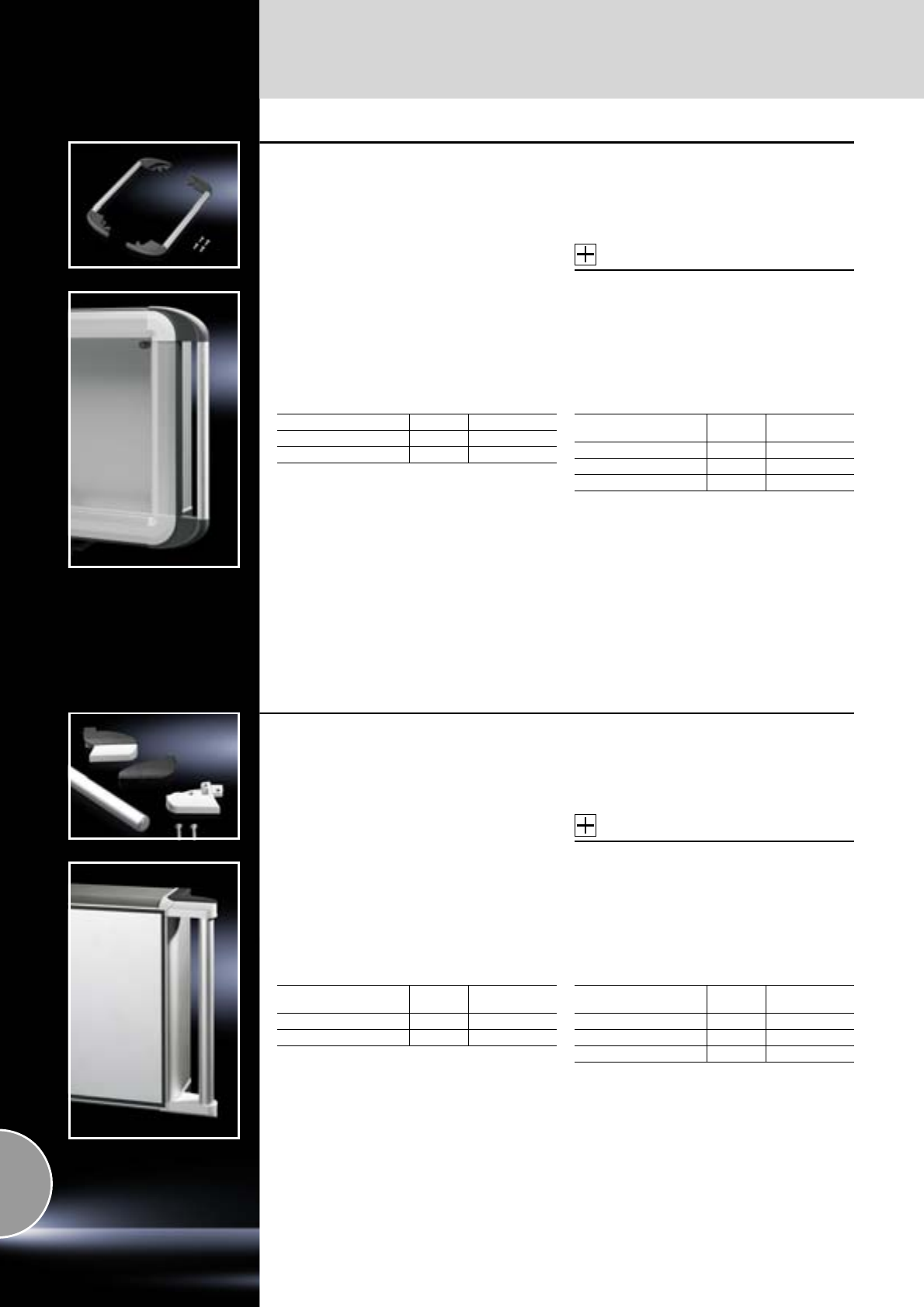
Handles
600 Rittal Catalogue 33/System accessories
Handle set
for Comfort Panel
For external mounting on corner pieces,
also suitable for retro-fitting.
Material:
−Handle tube: Aluminium
−Handle holder: Die-cast zinc
−Covers: Polyamide
Surface finish:
−Handle tube: Natural-anodised
−Handle holder: Powder-coated
Colour:
−Handle holder: RAL 7024
−Covers: Similar to RAL 7024
Note:
Shorter heights and widths can be achieved by
cutting the handle tube to length.
For enclosures with 74 mm depth, cannot be
mounted on the same side as the support arm
connection.
Accessories:
−Clipboard,
see page 603.
−Display board
see page 603.
For horizontal mounting
Supply includes:
−Handle tube, Ø 20 mm
−2 handle holders
−2 covers
−Assembly parts
For vertical mounting
Supply includes:
−2 handle tubes, Ø 20 mm
−4 handle holders
−4 covers
−Assembly parts
With front panel width Packs of Model No. CP
482.6 mm (19˝) 1 set 6375.010
520 mm 1 set 6375.000
With
front panel height Packs of Model No. CP
400 mm 1 set 6375.040
500 mm 1 set 6375.050
600 mm 1 set 6375.060
Handle set
for Optipanel
For external mounting on corner pieces,
also suitable for retro-fitting.
Material:
−Handle tube: Aluminium
−Handle holder: Die-cast zinc
−Covers: Polyamide
Surface finish:
−Handle tube: Natural-anodised
−Handle holder: Powder-coated
Colour:
−Handle holder: RAL 7035
−Covers: RAL 7024
Note:
Shorter heights and widths can be achieved by
cutting the handle tube to length.
For enclosures with 100 mm depth, cannot be
mounted on the same side as the support arm
connection.
Accessories:
−Clipboard,
see page 603.
−Display board
see page 603.
For horizontal mounting
Supply includes:
−Handle tube, Ø 25 mm
−2 handle holders
−2 covers
For vertical mounting
Supply includes:
−2 handle tubes, Ø 25 mm
−4 handle holders
−4 covers
With
front panel width Packs of Model No. CP
482.6 mm (19˝) 1 set 6385.010
520 mm 1 set 6385.000
With
front panel height Packs of Model No. CP
400 mm 1 set 6385.040
500 mm 1 set 6385.050
600 mm 1 set 6385.060
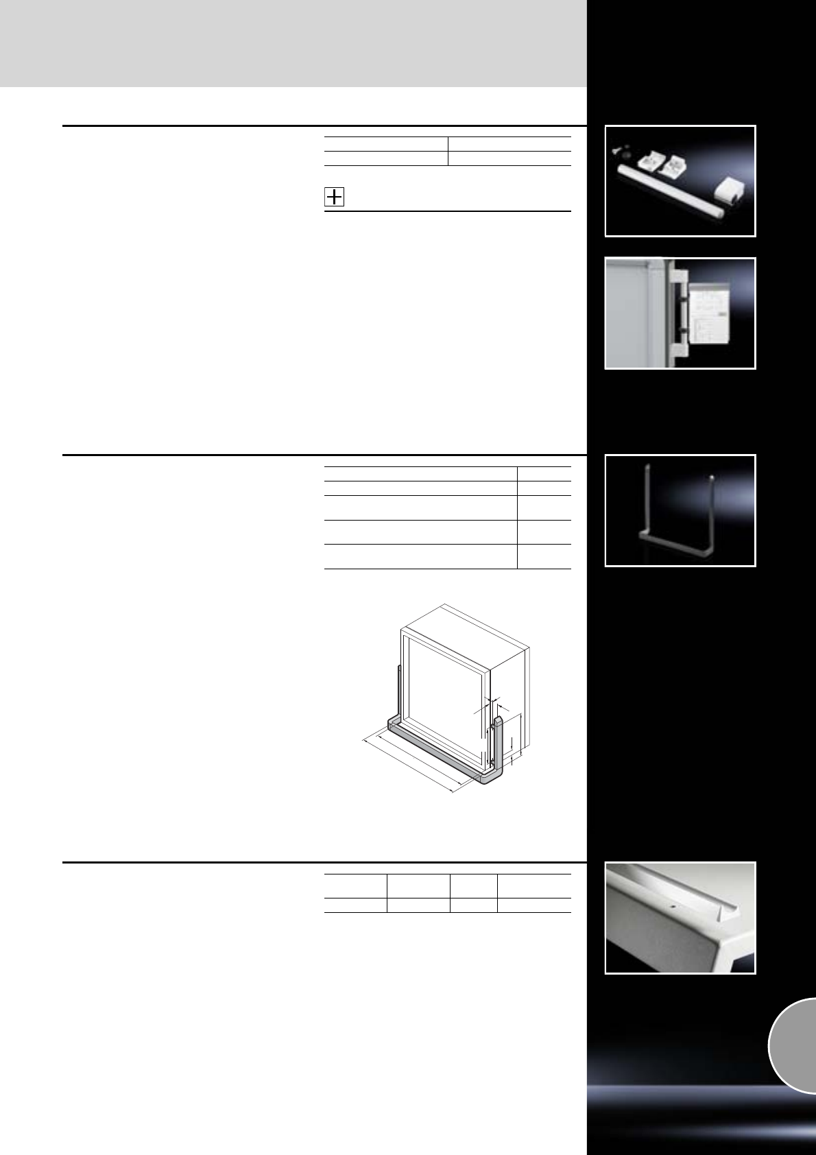
Handles
601Rittal Catalogue 33/System accessories
Handle set
For vertical and horizontal mounting on all
surfaces.
Overall length: 420 mm.
Material:
−Handle tube: Aluminium
−Tube holder: Die-cast zinc
Surface finish:
Handle tube: Natural-anodised
Colour:
Conduit holder: RAL 7035
Supply includes:
−4 conduit holders
−2 handle tubes
Accessories:
−Clipboard,
see page 603.
−Display board,
see page 603
Packs of Model No. SZ
1 set 2389.000
Handle frame
for operating housing with display panel front
Colour:
RAL 8019
Supply includes:
−Square aluminium tube
−Plastic corner bracket
−End caps
−Assembly parts
Note:
Command panel with display panel front
CP 6662.500,
see page 123.
Model No. CP 6190.000
Operating housing width (B1) mm 600
Width of the horizontal rectangular tube
(B2 = B1 + 48) mm 648
Height of the vertical rectangular tube
(H1) mm 299
Hole distance between the assembly
holes (H2) mm 249
25
19
30
H1
B2
B1
H2
Aluminium strip
For
●One-piece console
●Surfaces
Prevents wiring plans etc. from slipping.
For
console Length
mm Packs of Model No. AP
AP 1183 3 2682.000
May be cut to length for other dimensions.
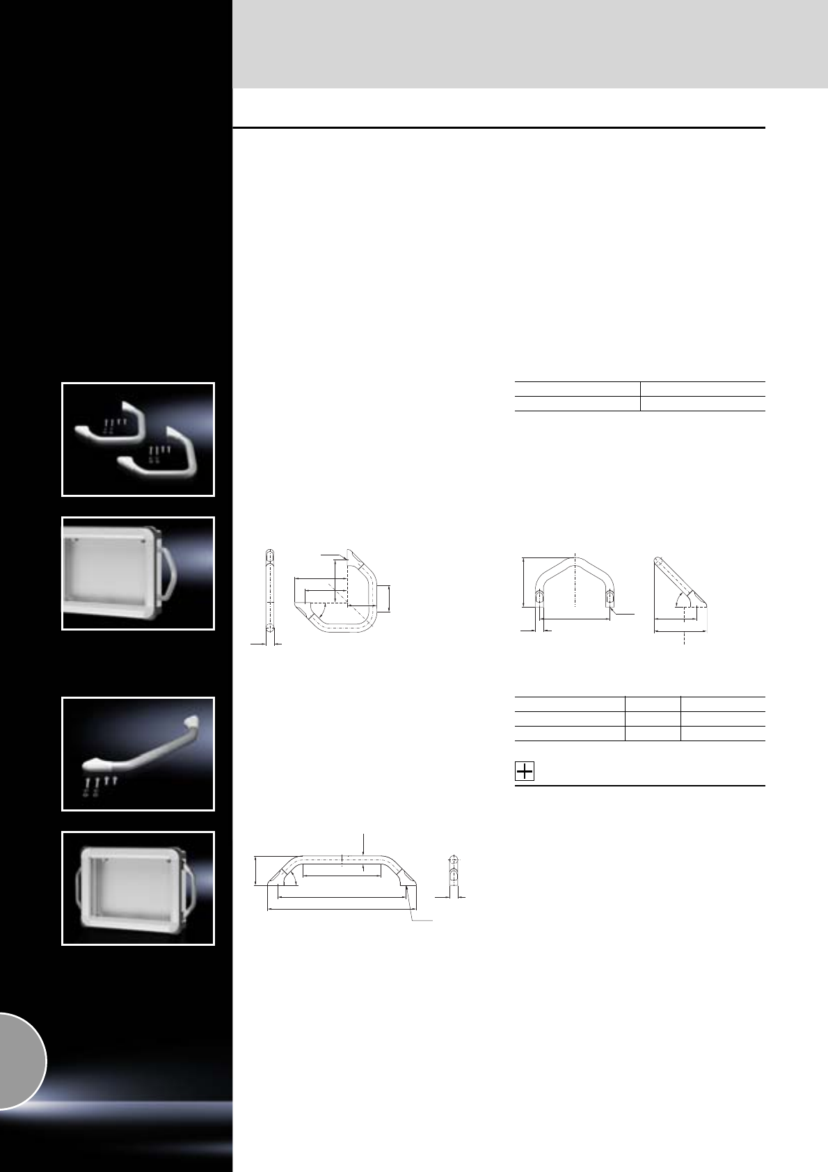
Handles, external mounting accessories
602 Rittal Catalogue 33/System accessories
Handles
For horizontal or vertical attachment to the
enclosure panel of:
●Comfort Panel,
●Optipanel,
●Other enclosures or
●Surfaces
Mounting holes and surfaces without fins are
required for assembly purposes.
For the Comfort Panel version with fins, selecta-
ble via configurators at www.rittal.com, corre-
sponding milling work may be carried out. To
this end, please specify “Prepared for handle set
CP 6107.XXX” for the command panel.
Material:
−Handle holder: Die-cast zinc
−Cover bungs: Plastic
−Handle tube: Aluminium
Surface finish:
Handle tube: Powder-coated
Colour:
−Handle holder: RAL 7035
−Cover bungs: Similar to RAL 7035
−Handle tube: Similar to RAL 9006
Corner handle
Supply includes:
−4 handle holders
−2 handle tubes
−Assembly parts
Packs of Model No. CP
1 set 6107.000
Mounting on enclosure corner For external mounting on straight surfaces
(90° rotation of handle holder)
25
Ø 6.5
(85)
45°
163
131.5
131.5
92
Ø 6.5
153
25
217
45°
163
132
U handle
Supply includes:
−2 handle holders
−1 handle tube
−Assembly parts
Accessories:
For CP 6107.200:
−Clipboard,
see page 603.
−Display board,
see page 603.
For front panel size Packs of Model No. CP
≥ 7 U 1 set 6107.100
482.6 mm (19˝) 1 set 6107.200
Ø 6.5
45°
92
458 (293)
395 (230)
240 (75)
Ø 25
25
Note:
Dimensions in brackets for CP 7 U.
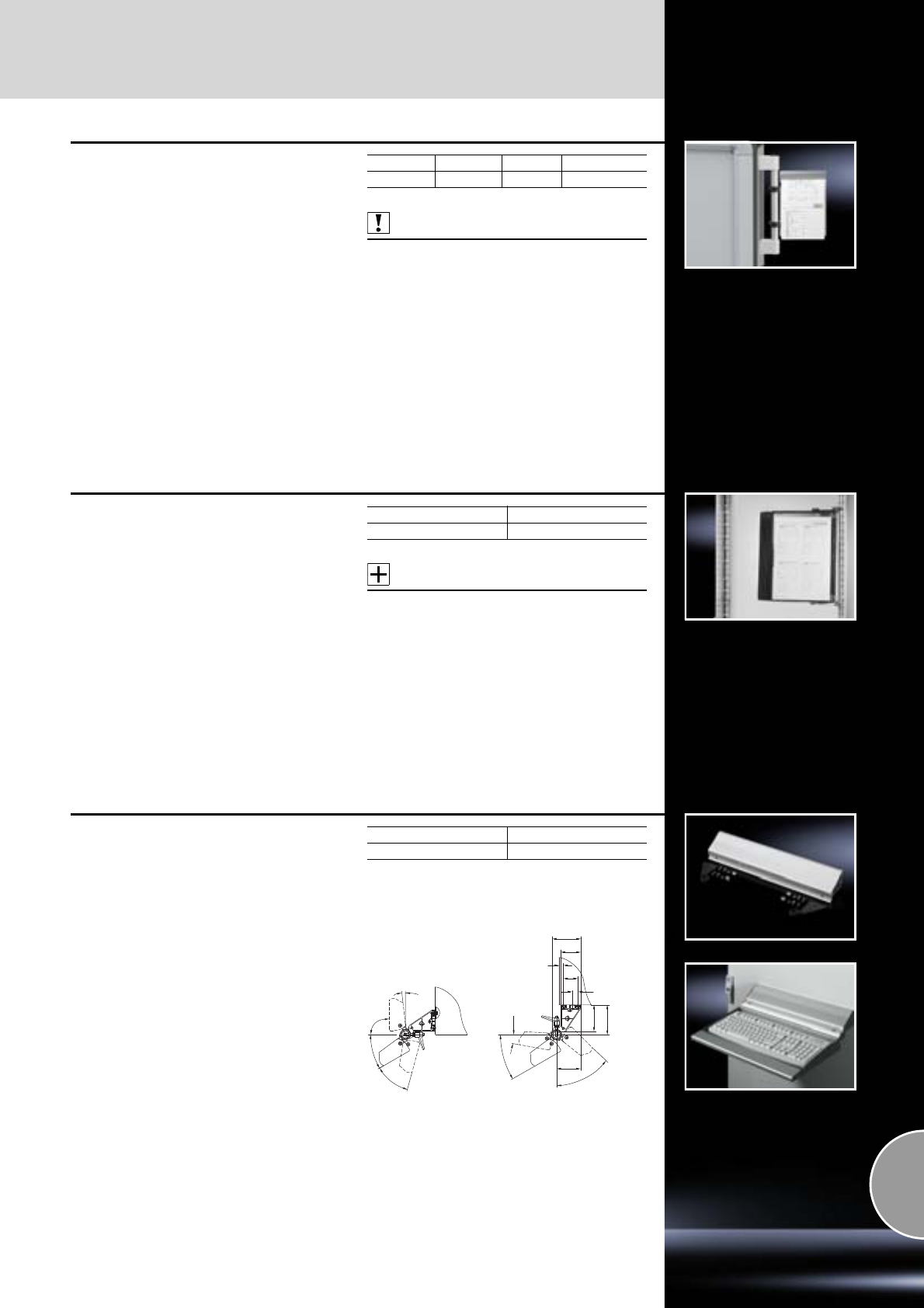
External mounting accessories
603Rittal Catalogue 33/System accessories
Clipboard
For securing operating instructions or plans
(A4 size) at eye level.
Prepared for mounting on the right-hand side;
mounting on the left is also possible by unscrew-
ing and moving the clip part.
For mounting purposes, a straight tube length of
≥200 mm, Ø 20 mm or Ø 25 mm, is required.
Material:
−Clipboard: Sheet steel
−Clip part: Aluminium
Surface finish:
Clip part: Natural-anodised
Colour:
RAL 7035
Also required:
−Handle set SZ 2389.000, see page 601
or
−Handle set for Comfort Panel, see page 600
or
−Handle set for Optipanel, see page 600
or
−U handle CP 6107.200, see page 602.
Width mm Height mm Packs of Model No. CP
225 315 1 6013.000
Display board with bracket
To accommodate test plans, documents etc. in
A4 format.
Assembly:
●On surfaces,
●On a 25 mm pitch pattern of the TS frame or rail
system,
●On handle set Ø 20 mm or Ø 25 mm.
Supply includes:
−Display boards
−Wall bracket
−Assembly parts
Accessories:
−Handle set SZ 2389.000, see page 601
or
−Handle set for Comfort Panel, see page 600
or
−Handle set for Optipanel, see page 600
or
−U handle CP 6107.200, see page 602.
Packs of Model No. CP
1 set 6013.100
Enclosure surface connector
To accommodate keyboard support
(SM 2383.000, see page 610).
Material:
−Surface connector: Extruded aluminium section
−Side cover: Sheet steel
Surface finish:
Surface connector: Natural-anodised
Colour:
RAL 7024
Supply includes:
Assembly parts.
Packs of Model No. SM
1 set 2383.010
90°
6°
30°
45°
79
56
73.5
83
67
45°
8
40
15
30°
10°
Mounting
on surfaces Mounting
underneath surfaces
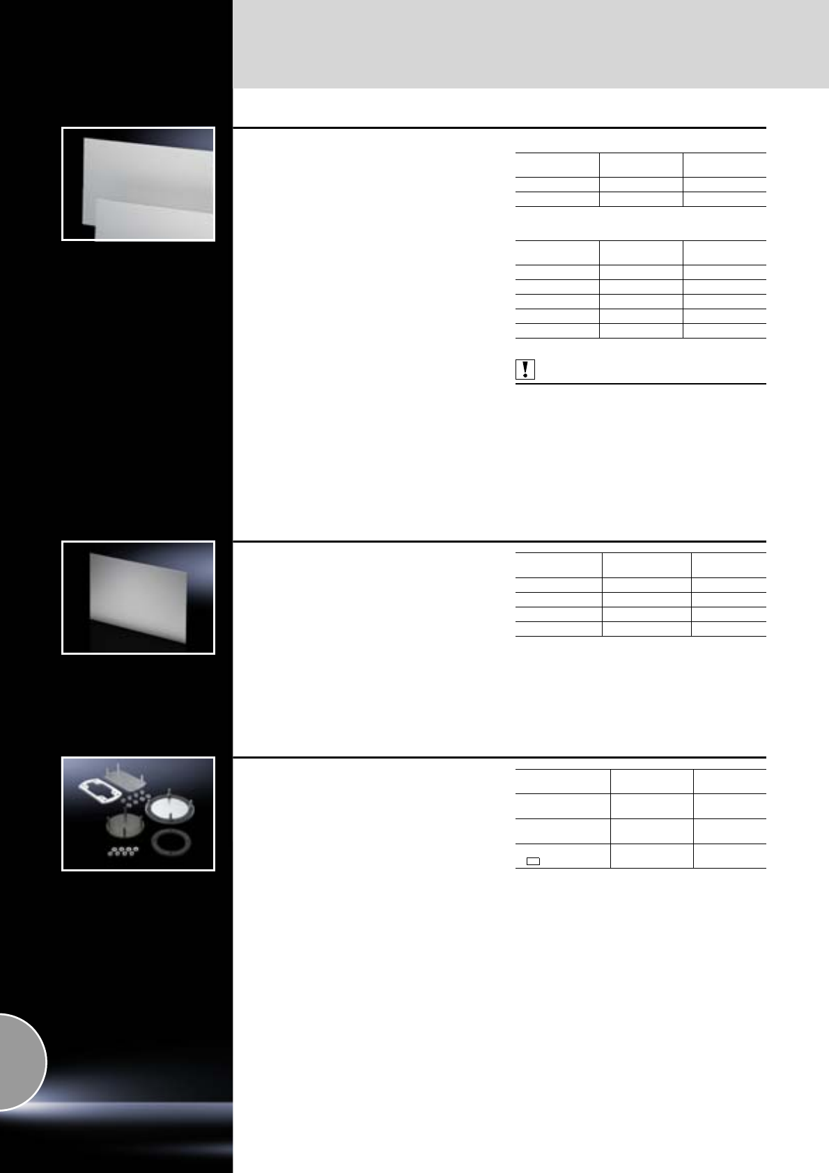
Front assembly
604 Rittal Catalogue 33/System accessories
Front panels
for Comfort Panel and Optipanel
Material:
Aluminium, 3 mm
Surface finish:
Natural-anodised
Note:
Mounting kits included with the supply of 520 mm
wide standard enclosures.
With mounting hole
With threaded bolts M5
Also required:
Mounting kit
−for Comfort Panel CP 6053.800,
see page 605,
−for Optipanel CP 6053.000/.500,
see page 605.
Width
mm Height
mm Model No. CP
482.6 (19˝) 155.0 (3.5 U) 6027.000
482.6 (19˝) 310.3 (7 U) 6028.000
Width
mm Height
mm Model No. CP
482.6 (19˝) 155.0 (3.5 U) 6027.010
482.6 (19˝) 310.3 (7 U) 6028.010
520 400 6028.014
520 500 6028.015
520 600 6028.016
Front panels
for Compact Panel
Material:
Aluminium, 3 mm
Surface finish:
Natural-anodised
Size
W x H mm To fit
Compact Panel Model No. CP
178 x 200 CP 6340.000 6028.500
178 x 350 CP 6340.100 6028.510
252 x 200 CP 6340.300 6028.530
252 x 350 CP 6340.400 6028.540
Cover plate
for support arm connection
For secure sealing of an unrequired support arm
connection in the enclosure.
Material:
Sheet steel
Supply includes:
Seal and assembly parts.
Note:
If with
●Comfort Panel
●Optipanel
●Compact Panel
command panels, there are already 2 support arm
cut-outs provided, a cover plate is included with
the supply of the enclosure.
Support arm
connection Surface finish Model No. CP
CP-S Spray-finished in
RAL 7024 6505.200
CP-L,
Ø 130 mm Zinc-plated,
passivated 6505.500
CP-L,
120 x 65 mm Zinc-plated,
passivated 6505.100
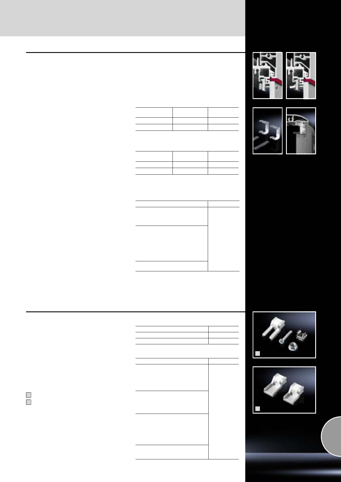
Front assembly
605Rittal Catalogue 33/System accessories
Mounting kit
for Optipanel
For installing
●Aluminium front panels
●Command panels
●Keyboards
For holes
Supply includes:
Packs of
30 retaining claws, captive nuts, screws
and sealing washers.
For
front panels Thread Model No. CP
Others M4 6058.000
Rittal and others M5 6053.000
For threaded bolts
Supply includes:
Packs of
10 retaining claws and cap screws.
For
front panels Thread Model No. CP
Others M4 6058.500
Rittal and others M5 6053.5001)
1) For the installation of TFT monitors 15˝, 17˝ and 19˝.
For screw clamp
Supply includes:
Packs of
4 pressure plates,
4 attachment strips.
Note:
Command panels
TP 277 6˝, OP 277 6˝, MP 277 10˝ Touch,
MP 377 12˝ Touch, MP 377 15˝ Touch
are installed using an adaptor plate (included
with the supply subject if selected accordingly,
or available on request).
For direct installation of Model No. CP
Siemens Sinumerik:
OP 010, OP 010C, OP 012, OP 015,
MCP 483, PP 012, Querty 19˝,
KB 483C, TP 015A
6053.210
Siemens Simatic:
Panel PC 477, 577, 677, 677B:
12.1˝ Touch, 15.1˝ Touch,
12.1˝ keys, 15.1˝ keys, 19˝ Touch1)
Panel PC 877:
15.1˝ Touch, 12.1˝ keys,
15.1˝ keys, 19˝ Touch1), Flat Panel1)
12˝, 15˝, 17˝, 19˝
Pro Face Industrial PC:
ALP 3600, ALP 3700, ALP 3900
The mounting set can only be installed vertically.
1) 2 packs are required.
1
2
Mounting kit
for Comfort Panel
For the installation of aluminium front panels,
command panels and keyboards.
Supply includes:
CP 6058.800, CP 6053.800:
20 each of retaining claws, captive nuts, screws,
nuts and sealing washers.
CP 6053.300:
8 medium retaining claws, 8 short retaining claws,
4 long retaining claws
6058.800, 6053.800
6053.300
For drilled holes/bolts/front panel mounting
from behind
For screw clamp
1
2
Thread Model No. CP
M4 6058.800
M5 6053.800
For installing Model No. CP
Siemens Sinumerik:
OP 010, OP 010 C, OP 012,
TP 012, OP 015, OP 015 A,
MCP 483 C, MCP 483, PP 012,
PP 012 extension, MCP,
KB 483 C, Querty 19˝
6053.300
Siemens Simatic:
Panel PC 477, 577, 677, 677B:
12.1˝ keys, 12.1˝ Touch,
15.1˝ keys, 15.1˝ Touch,
19˝ Touch
Panel PC 877:
12.1˝ keys, 15.1˝ keys,
15.1˝ Touch, 19˝ Touch,
TP 277 6˝
MP 377 15˝ Touch,
MP 377 12˝ Touch,
MP 377 19˝ Touch
B & R:
Automation Panel
Panel PC
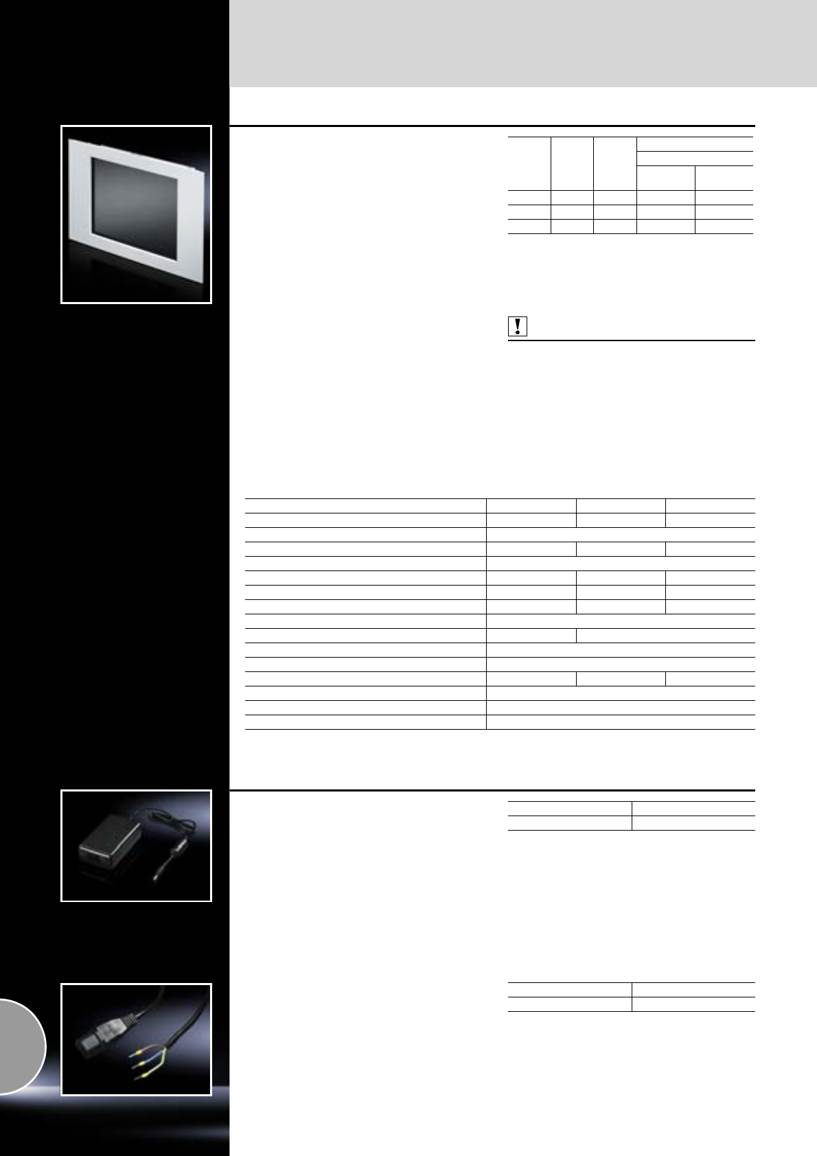
Monitors
606 Rittal Catalogue 33/System accessories
TFT monitor
Installation variant for surfaces and command
panels.
Benefits:
●High-quality industrial design
●Reduced installation work thanks to integral
front frame
●No additional ventilation required
●Very small installation depth (45 mm)
Resistive touchscreen for operation with a pen,
finger or glove.
Material:
Front frame: Aluminium
Surface finish:
Powder-coated
Colour:
RAL 7035
Protection category:
IP 65 to IEC 60 529 (front)
Supply includes:
Seal, hex nuts (for installation in surfaces),
VGA cables, rear threaded bolts M5 (14). Touch
variants additionally with integral connection
cable and driver CD-ROM.
Note:
Other variants as resistive touchscreen with
serial or USB interface available on request.
Also required:
Mounting kit CP 6053.800
(when installing in Comfort Panel), see page 605.
Mounting kit CP 6053.500
(when installing in VIP 6000 and Optipanel),
see page 605.
Power pack SM 6450.050, see page 606 and
connection cable SM 6450.060, see page 606,
if an operating voltage of only 100 – 240 V AC is
available instead of 12 V DC.
Detailed drawings:
Available on the Internet.
Size Width
mm Height
mm
Model No. SM
Touch
Without1) resistive,
USB
15˝ 430 343 6450.010 6450.070
17˝ 482.6 354.8 6450.020 –
19˝ 482.6 399.3 6450.170 –
1) With anti-reflection coated safety glass screen.
Technical specifications 15˝ 17˝ 19˝
Resolution of display (max. pixels) 1024 x 768 1280 x 1024 1280 x 1024
Resolution of controller/colours VGA-SXGA/16.2 million
Brightness (cd/m2) 400 300 250
Contrast ratio 500 : 1
Reading angle horizontal (right/left) 65°/65° 75°/75° 88°/88°
Reading angle vertical (top/bottom) 45°/65° 65°/65° 88°/88°
Lamp life1) (h) min. 35.000 typ. 50,000 min. 40,000
On-screen display (OSD) At rear
VGA input/DVI-D D-Sub HD 15-pole DVI-D jack
Operating temperature (°C)/storage temperature (°C) 0 to +50/–20 to +60
Voltage input 12 V DC
Power consumption (W) 30 35 40
H-Sync. (kHz)/V-sync. (Hz) 31.5 to 80/60 to 75
Humidity in operation (%) 20 to 80 (non-condensing)
Humidity in storage (%) 5 to 95 (non-condensing)
1) Until half the original brightness is reached.
Power pack
For TFT monitor
●With IEC 320 socket,
●With connection cable (1.5 m) and connector
for connecting to the TFT monitor.
Dimensions, W x H x D: 107 x 30 x 59 mm.
Technical specifications:
−Input voltage: 100 – 240 V AC
−Output voltage: 12 V DC
−Operating temperature: 10°C – 40°C
Material:
Enclosure: Plastic
Packs of Model No. SM
16450.050
Connection cable
for power pack
With IEC connector at one end.
Length: 1.5 m.
Packs of Model No. SM
16450.060
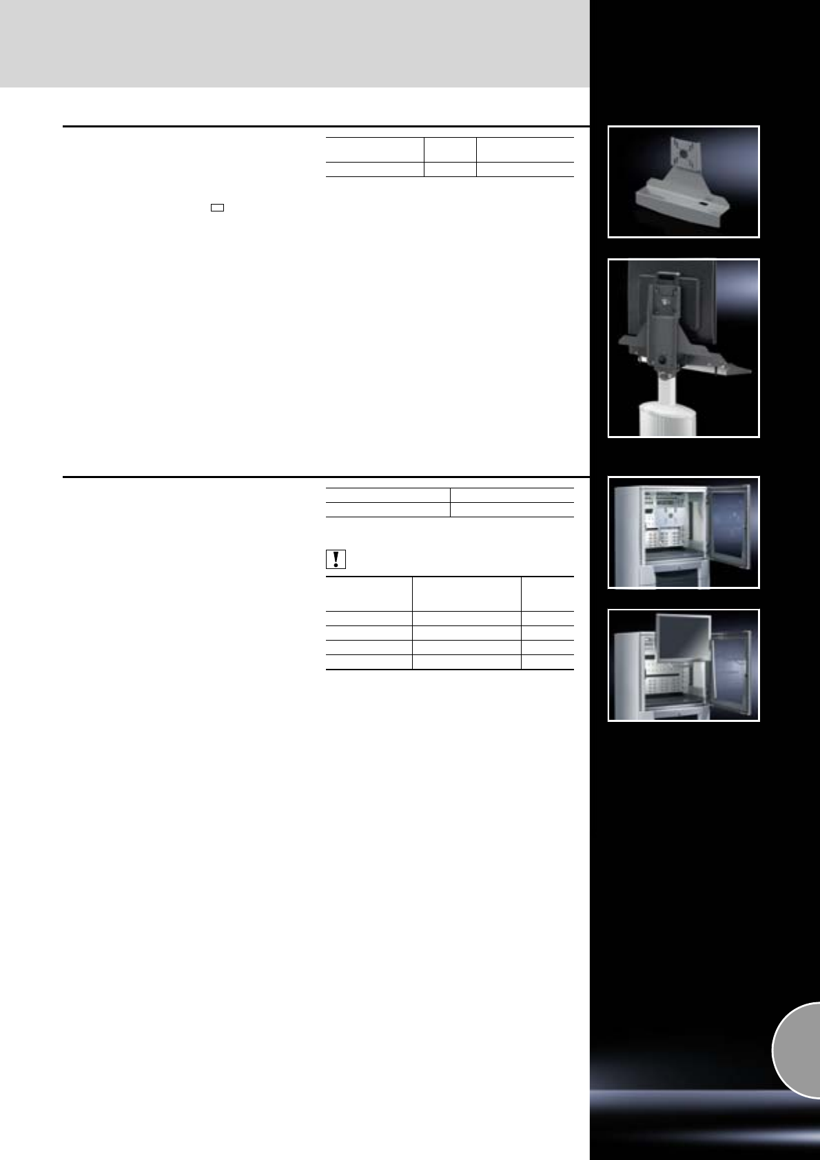
Monitors
607Rittal Catalogue 33/System accessories
TFT holder
Suitable for mounting TFTs with VESA 75/100
adaptation up to 21˝ on
●Housing coupling CP-S, CP 6501.050,
see page 129
●CP-L enclosure attachment 120 x 65 mm,
CP 6525.610, see page 133
●Vertical support arm via enclosure attachment,
tilting CP 6902.670, see page 129
Material:
Sheet steel
Surface finish:
Spray-finished
Colour:
RAL 7024
Detailed drawings:
Available on the Internet.
Dimensions
mm Packs of Model No. SM
477 x 372 x 110.5 1 2383.030
TFT holder
Vertically hinged
Suitable for mounting TFTs with VESA 75/100
adaptation up to 20.1˝ in
●PC enclosures
●Other enclosures based on TS
The TFT support is attached to the upper horizon-
tal enclosure section using appropriately fitted
bars and/or punched sections.
The integral swing mechanism allows the TFT to
be swung forwards out of the enclosure while
operational, to provide access to the equipment
behind it. The display on the TFT remains visible
even after it has been swung forwards. The length
of the actuator handle is adjustable to adapt to the
size of the TFT.
Material:
Sheet steel
Supply includes:
Assembly parts.
Detailed drawings:
Available on the Internet.
Packs of Model No. SM
12383.040
Also required:
For
enclosure depth
mm
Punched rail TS
18 x 38 mm Page
400 8612.240 462
500 8612.250 462
600 8612.260 462
800 8612.280 462
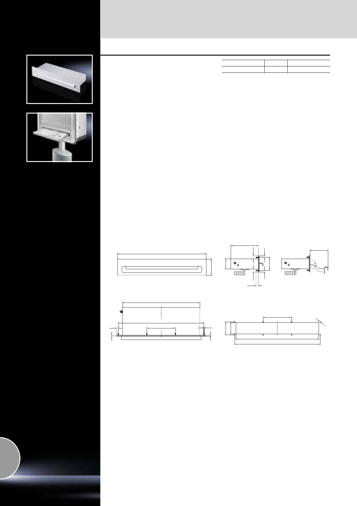
Keyboards, supports and drawers
608 Rittal Catalogue 33/System accessories
Keyboard, pull-out
with integral trackball
Super-slimline keyboard with cursor keys and
trackball. The handle also serves as a hand rest.
The 10° angled pullout ensures ergonomic
working.
For installation in:
●Any sufficiently large surface (e.g. door,
side panel)
●Front panels
●Directly in Comfort Panel and Optipanel of
a suitable size, selectable via configurators –
see www. rittal.com
Material:
Sheet steel
Surface finish:
Front panel: Powder-coated
Colour:
RAL 7035
Technical specifications:
Keyboard:
−84 short-stroke keys, IBM-AT compatible (MF2),
incl. cursor keys
−With integral 16 mm trackball
−Interface: 2 x 6-pole PS/2 DIN connector
−Operating temperature: +5°C to +50°C
−Storage temperature: –10°C to +60°C
−Humidity: max. 95% (non-condensing)
Protection category:
IP 65 (front, solid) to IEC 60 529
Keyboard layout Packs of Model No. SM
German 1 6002.100
420
465 ± 0.3
155
3
5
8.5 M4
150
16.516.5
8.58.5
(71)
(55)
12.5
88
482.6
ca. 155
10°
155
465
450
71
62
Ø 5
Mounting cut-out
SM 6002.100
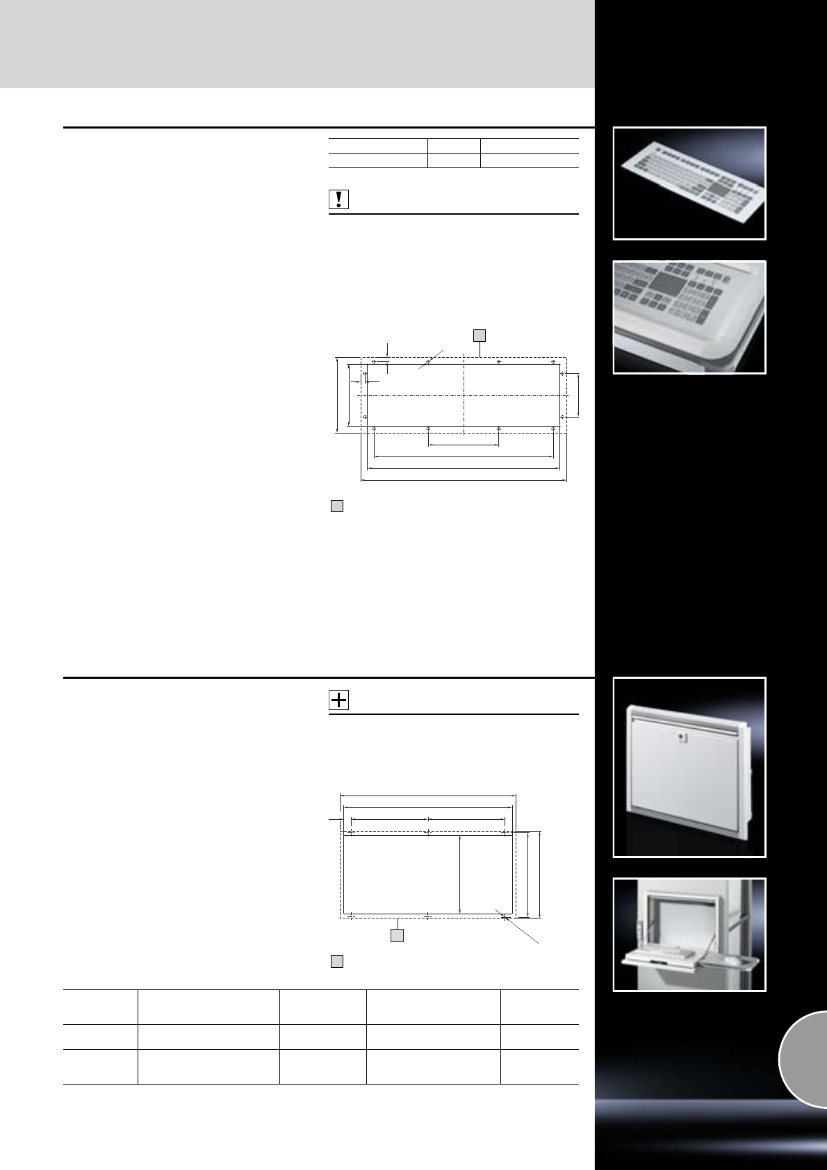
Keyboards, supports and drawers
609Rittal Catalogue 33/System accessories
Built-in keyboard 19˝/4 U
with integrated touchpad
The integral touchpad means that the installation
of an additional, correct protection category
mouse is no longer required, and cabling is also
reduced. The short stroke keys are easily identi-
fied by edge embossing, less force is required to
operate them and they have good positive key
actuation.
Benefits:
●The separate number pad enables the
parameters to be entered quickly
●Sealed, wipeable surface finish
●High level of mechanical and chemical
resistance as per DIN 42 115.
Technical specifications:
−Number of keys: 105
−Front panel dimensions: 482.6 x 177.0 mm
(482.6 mm (19˝) x 4 U)
−Installation depth: 23 mm
−12 M5 x 20 threaded bolts at back
−Actuation travel/force: 0.3 mm/2.6 N
−Service life: 3 million switching cycles
−Operating temperature: –40°C to +90°C
−Touchpad resolution, capacitive: 40 pixels/mm
−Interfaces: 2 x PS/2 (1 USB adaptor supplied
loose)
Material:
Front panel: Aluminium
Protection category:
IP 65 to IEC 60 529 (front)
Supply includes:
−Y connection cable, length 1.8 m
−PS/2 connector
−USB adaptor
−Seal
−Drilling template
−Assembly parts for surfaces
Also required:
Mounting kit CP 6053.800 (when installing in
Comfort Panel), see page 605.
Mounting kit CP 6053.500 (when installing in
Optipanel), see page 605.
Keyboard layout Packs of Model No. SM
German 1 6446.020
177
420
451
165
482.6
10
10
Ø 7
145
101.6
Contact surface
1
1
Fold-out tray
for keyboard and mouse
For installation in
●600 and 800 mm wide doors
●482.6 mm (19˝) swing frames and enclosures
Standard double-bit lock insert which may be
exchanged for lock inserts 27 mm, version A,
see page 421 and for lock cylinder SZ 2571.000,
see page 422.
Material:
−Flap: Sheet steel
−Side parts: Cast aluminium
−Tray: Extruded aluminium section
Surface finish:
−Cover, side parts: Textured paint
−Tray: Natural-anodised
Colour:
Cover, side parts: RAL 7035
Protection category:
IP 55 to IEC 60 529
Accessories:
Mousepad support, pull-out,
see page 610.
305
324
Ø 5.5 (6x)
195 (295)
454 (654)
482.6 (682.6)
32 195 (295)
1
Contact surface
1
Mounting cut-out
355 (8 U)
For door width
mm Dimensions W x H x D
mm Installation depth
mm
Max. keyboard dimensions
W x H x D
mm Model No. SZ
600 482.6 (19˝) x 355 (8 U) x 126 93 405 x 50 x 250
405 x 50 x 1951) 2379.600
800 682.6 x 355 (8 U) x 126 93 605 x 50 x 250
605 x 50 x 1951)
4751) x 50 x 250 2379.800
1) Maximum keyboard size with holder for mouse.
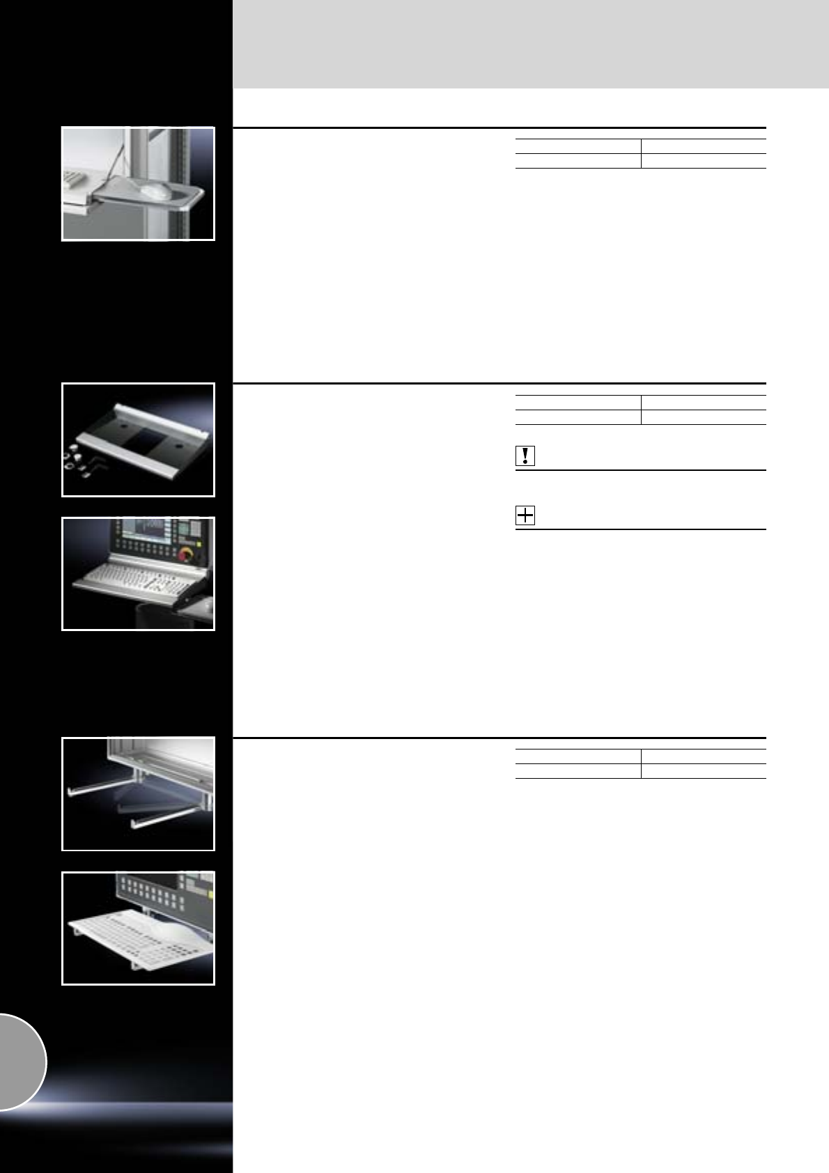
Keyboards, supports and drawers
610 Rittal Catalogue 33/System accessories
Support for mousepad,
pull-out
with mouse holder
For screw-fastening into the fold-out tray
SZ 2379.600/SZ 2379.800, see page 609.
To fit all standard mousepads up to 250 x 205 mm.
Supply includes:
Assembly parts.
Packs of Model No. SZ
1 set 2379.900
Support
for keyboards
for max. 473 x 210 mm.
Prepared for
●Cable gland
●Support for mousepad, vertically hinged
(SM 2383.020)
Material:
−Side parts: Sheet steel
−Front and rear: Extruded aluminium section
Surface finish:
−Side parts: Textured paint
−Front and rear: Natural-anodised
Colour:
Side parts: RAL 7024
Supply includes:
2 clamping screws, end stoppers, cover plate,
cable entry grommet and nylon loop tape.
Also required:
For external mounting on surfaces using
enclosure surface connectors, see page 603.
Accessories:
Mousepad support, swivelling,
see page 615.
Packs of Model No. SM
1 set 2383.000
Utility bars, vertically hinged
To support standard keyboards during program-
ming and servicing work.
Mounting distance of utility bars for problem-free
insertion at least 300 mm.
Depth adequate for keyboards up to max.
210 mm.
For mounting beneath:
●Comfort Panel1)
●Optipanel2)
●Any sufficiently large surface, such as:
−Worktops IW
−Operating housing
−Command panel housing with door
on:
●Vertical services (doors/side panels)
Min. front panel width
1) 385 mm
2) 405 mm
After use, the utility bars fit securely and neatly
under the mounting surface, thus giving the
operator more space to move around.
Material:
Sheet steel
Surface finish:
Zinc-plated
Supply includes:
Assembly parts.
Packs of Model No. CP
1 set 6514.200
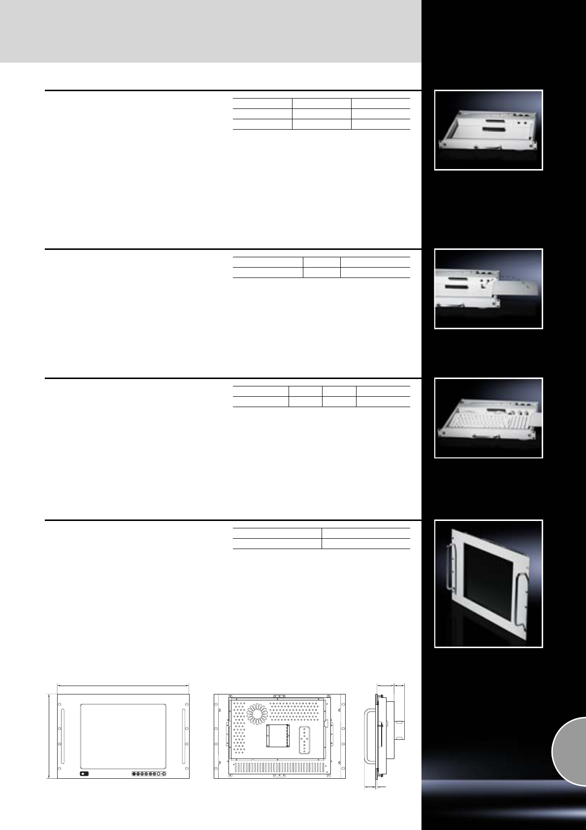
Keyboards, supports and drawers
611Rittal Catalogue 33/System accessories
Keyboard rack, 482.6 mm (19˝)
●19˝ rack-mounted chassis 1 U, 430 mm deep
●Prepared for the installation of 482.6 mm (19˝)
keyboards with touchpad or trackball and
mouse with the following dimensions:
max. height: 39 mm,
max. width: 417 mm,
max. depth: 210 mm
●Solid, lockable front
●Telescopic slides with integral clamp
●Prepared for installation of a mousepad
Material:
Sheet steel
Colour:
RAL 7035
Supply includes:
−482.6 mm (19˝) chassis excluding keyboard,
−Connection cable,
−Mounting bracket for 800 and 900 mm
enclosure depth,
−Assembly parts.
Design Packs of Model No. RP
PS/2 1 3659.520
USB 1 3659.680
Mousepad
for keyboard rack
●For optional mounting on the left, right or front
of the keyboard rack (fold-away design)
●Maybe folded into the keyboard drawer after
use
●Only suitable for use in conjunction with
482.6 mm (19˝) keyboards with a total height
of max. 39 mm (Model No. RP 9911.396)
Material:
Sheet steel
Colour:
RAL 7035
Supply includes:
Assembly parts.
Assembly Packs of Model No. RP
right/left 1 3659.620
Keyboard, 482.6 mm (19˝)
with PS/2 connections
●482.6 mm (19˝) keyboard for installation in the
482.6 mm (19˝) keyboard rack in conjunction
with the mousepad
●German keyboard layout
●36/38.9 mm high keys facilitate installation
in 1 U keyboard drawers
●PS/2 connector
●105 keys (including WIN 95 keys)
●Operating temperature: 0°C to +50°C
Protection category:
IP 20
Supply includes:
Connection cable.
W x H x D mm Design Packs of Model No. RP
403 x 36 x 171 German 1 9911.396
TFT display, 15˝
●482.6 mm (19˝) front panel, 7 U
●TFT LCD 15.1˝
●Anti-reflection coated safety glass screen
●Brightness: 250 cd/m2
●On-screen display
●Colours: 16.7 million
●Power pack: Input voltage: 100 – 240 V AC,
output: 12 V DC/3.75 A
●OSD membrane keyboard
●VGA + SVGA, non-interlaced
●Maximum resolution 1024 x 768 pixels
●Contrast ratio: 300 : 1
●Viewing angle: 160° (H+V)
●Video input 15-pin D-SUB (analog RGB)
●RS232 monitor interface
Material:
Front panel: Aluminium, powder-coated
Colour:
RAL 7035
Protection category:
Tested to EN 60 950 and EMC directive
89/336/EEC.
Note:
Depth varies according to the display design
(protective glass, touchscreen etc.).
Packs of Model No. RP
13659.440
OSDOSDOSD
310.3
482.5 65-75 37
40 2.5
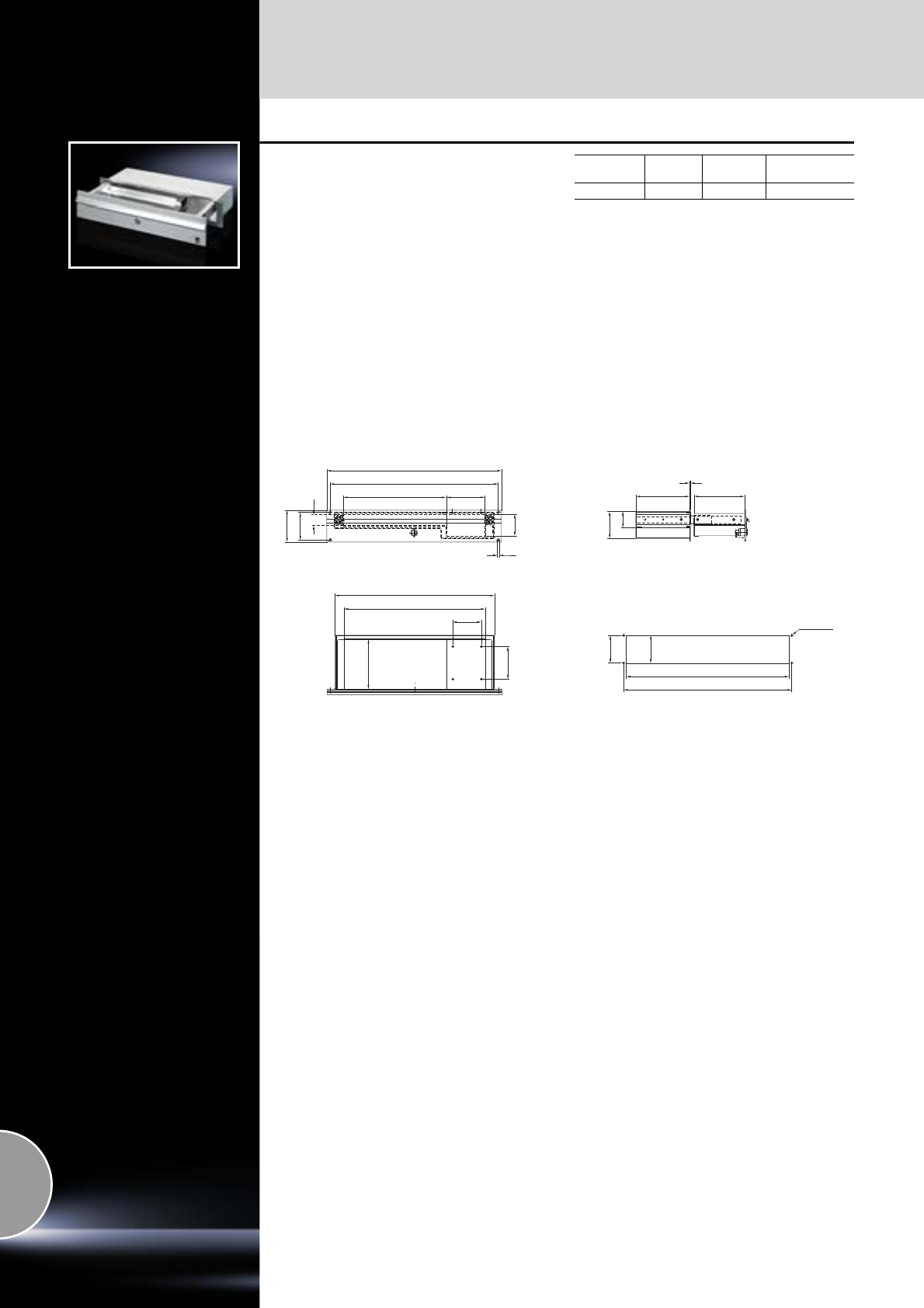
Keyboards, supports and drawers
612 Rittal Catalogue 33/System accessories
Drawer 482.6 mm (19˝)/2 U
for keyboard and mouse
For installation in:
●Any sufficiently large surface (e.g. door,
side panel)
●482.6 mm (19˝) system punchings
●Front panels
●Directly in Comfort-Panel and Optipanel of
a suitable size, selectable via configurators –
see www. rittal.com
Suitable for
●Accommodation of keyboards up to max.
390 x 32 x 139 mm.
●Support of standard commercially available
mouse or trackball.
Design:
−Drawer: With stay
−Front panel: With security lock (lock no. 12321)
and handle strip
Material:
−Drawer housing: Sheet steel
−Drawer and front panel: Aluminium
Surface finish:
−Drawer housing: Zinc-plated
−Drawer and front panel: Natural-anodised
Supply includes:
Assembly parts for installation in Comfort Panel/
Optipanel command panel.
Width
mm U Depth
mm Model No.
CP
482.6 (19˝) 2 150 6002.000
139
90
79
441
390
71.4
482.6
88
31
465
4.5
60
284 106
Ø 4.5/M4
465
77
450
71.4
75
2
139
148.5
46
Mounting cut-out
(for installation in surfaces)
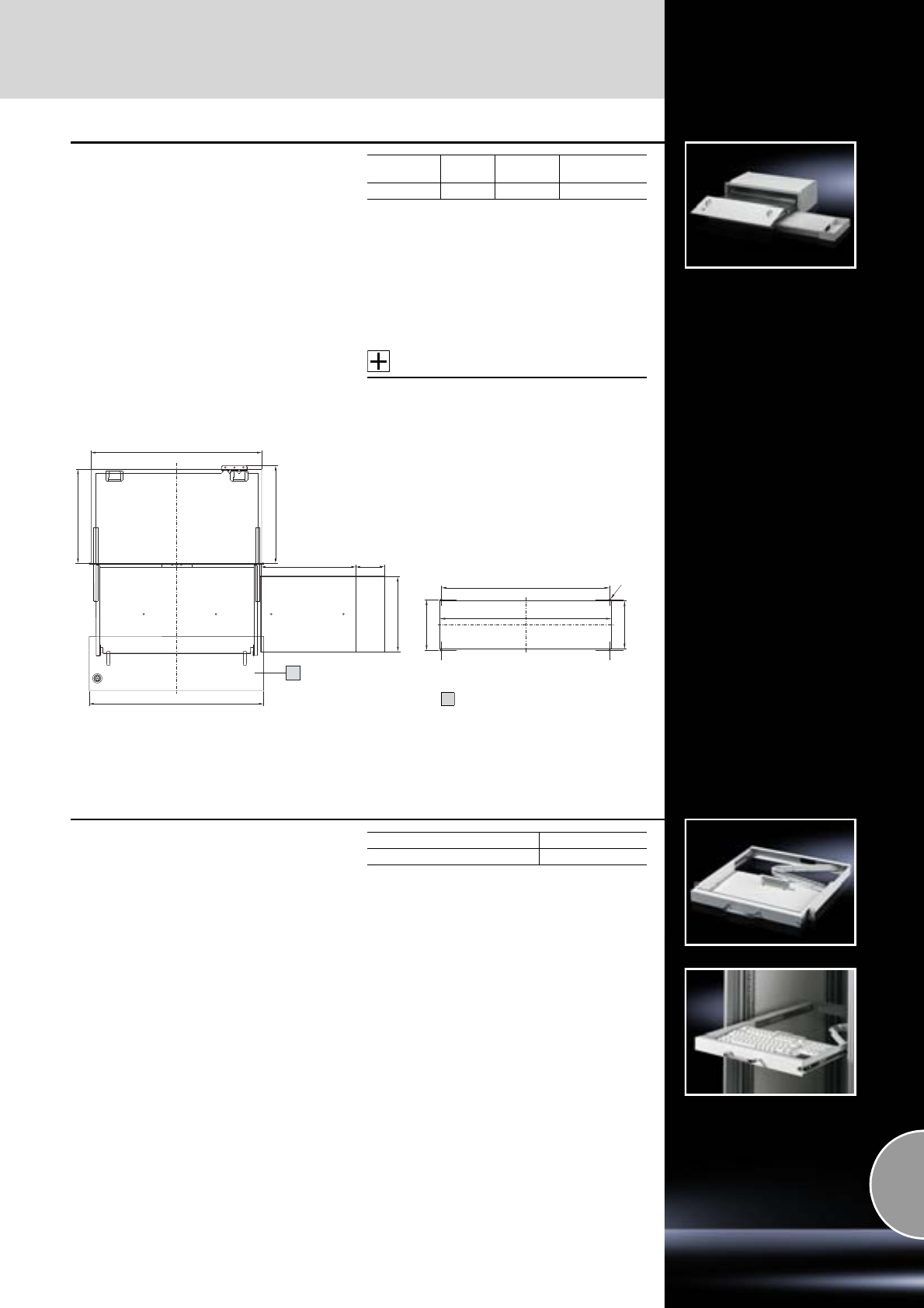
Keyboards, supports and drawers
613Rittal Catalogue 33/System accessories
Drawer for keyboard and
mouse
with mousepad support
For installation in:
●Any sufficiently large surface (e.g. door,
side panel)
●482.6 mm (19˝) system punchings
●Front panels
Suitable for accommodating
●Keyboards up to a maximum of
460 x 42 x 170 mm.
●Standard mouse and mousepad.
Design:
−Drawer and enclosure: With side pull-out
mousepad support and tray
−Front panel: With 3 mm double-bit lock insert,
folds out as handrest
Material:
−Drawer and enclosure: Sheet steel
−Front panel: Aluminium
Surface finish:
−Drawer and enclosure: Textured paint
−Front panel: Natural-anodised
Supply includes:
Assembly parts.
Accessories:
Standard double-bit lock insert may be
exchanged for 27 mm lock inserts, version A,
see page 421.
Width
mm U Depth
mm Model No. CP
482.6 (19˝) 3.5 261 6003.000
80
260
206
482.6 (19˝)
270
260
472
1
467
141
475
133
Ø 5.5/M5
Mounting cut-out
for installation in surfaces
Front trim panel
1
Keyboard drawer 1 U
for 482.6 mm (19˝) attachment level
This space-saving keyboard drawer is screw-
fastened to the front and rear 482.6 mm (19˝)
attachment level.
The installation spacing is infinitely adjustable
from 460 – 800 mm.
It is fully extendible, lockable, with strain relief and
hinged cable support.
The drawer is suitable to accommodate 482.6 mm
(19˝) keyboards.
Interior dimensions:
W x H x D approx. 420 x 40 x 220 mm
Material:
Sheet steel
Colour:
RAL 7035
Supply includes:
Assembly parts, excluding keyboard.
Note:
Monitor/keyboard unit, 1 U,
see page 590.
Distance between levels mm Model No. DK
460 – 800 7281.2001)
1) Delivered without keyboard.
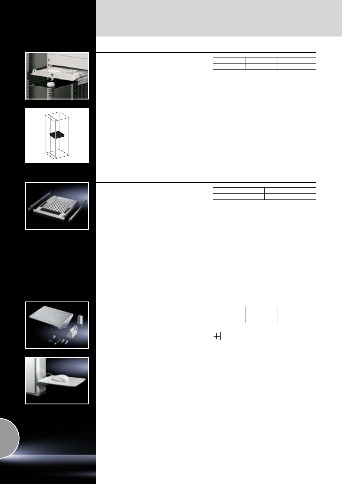
Keyboards, supports and drawers
614 Rittal Catalogue 33/System accessories
Keyboard drawer 2 U
for a 482.6 mm (19˝) mounting level
For keyboards up to 430 mm wide and 250 mm
deep with the front panel folded over.
Material:
Sheet steel with aluminium front
Surface finish:
Spray-finished
Colour:
RAL 7035
Supply includes:
−Lockable drawer with handles,
−Folding front,
−Pull-out mousepad,
−Mouse support,
−Practical cable entry
−and strain relief.
Height Packs of Model No. DK
2 U 1 7281.035
Installation depth: 390 mm.
Drawer 482.6 mm (19˝)
for keyboard
For attaching to the 482.6 mm (19˝) mounting
angles front and rear. Suitable for standard
keyboards > 482.6 mm (19˝). Keyboard support
with non-slip base, plus wrist support.
Depth-variable installation from 610 – 950 mm.
Clearance opening W x H x D: 408 x 40 x 550 mm.
Material:
Sheet steel
Colour:
RAL 7035
Supply includes:
Assembly parts, excluding keyboard.
Note:
Installation only possible on L-shaped and
cranked 482.6 mm (19˝) mounting angles and/or
482.6 mm (19˝) mounting frames.
Packs of Model No. DK
17063.888
Support for mousepad
for command panels and surfaces
The angle of the mousepad support is indi-
vidually adjustable.
Two holes are needed on the enclosure for
attachment purposes.
Material:
Sheet steel
Surface finish:
Zinc-plated
Supply includes:
Assembly parts.
Accessories:
Holder for mouse,
see page 615.
Weight
kg Packs of Model No. SM
1.0 1 2381.000
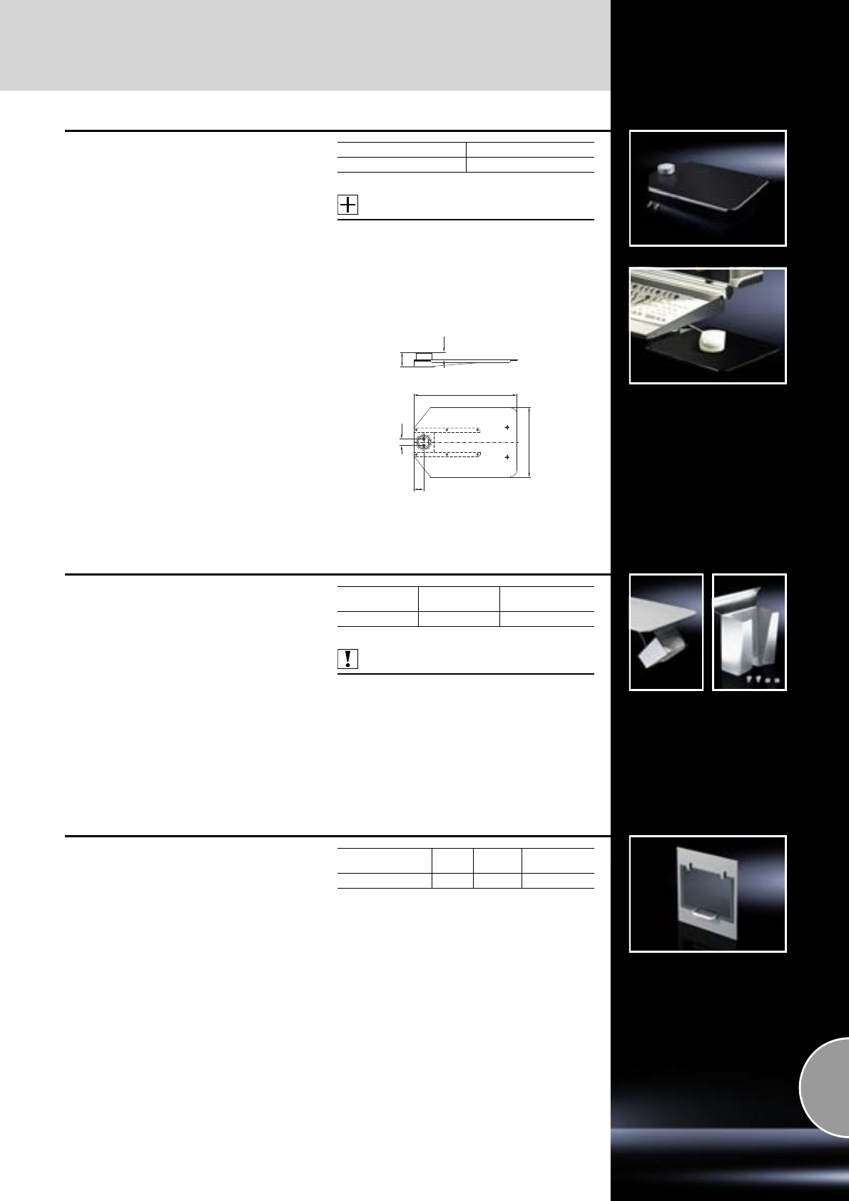
Keyboards, supports and drawers
615Rittal Catalogue 33/System accessories
Support for mousepad,
vertically hinged
For mounting on the left/right, beneath support
for keyboards. Latches home automatically, both
when retracted and extended. With mounting
holes for mouse holder (SM 2382.000).
With cutouts for cable routing and holes for
attachment via cable ties, for fast assembly
(SZ 2597.000).
Material:
Sheet steel
Surface finish:
Zinc-plated
Supply includes:
Assembly parts and mousepad, stuck on
with adhesive.
Accessories:
Holder for mouse, see page 615.
Cable ties, see page 530.
Packs of Model No. SM
12383.020
44
23
312
211
30
20
Holder for mouse
To fit mousepad support and for secure accom-
modation of a standard mouse.
Material:
Sheet steel
Surface finish:
Zinc-plated
Supply includes:
Assembly parts.
Also required:
Support for mousepad,
see page 614.
Weight
kg Packs of Model No. SM
0.3 1 2382.000
Paper removal flap
For installation in surfaces
Facilitates easy removal of pages from the printer
without opening the enclosure door. Plexiglass
flap with magnetic lock.
Paper removal flap Colour
RAL Packs of Model No. IW
DIN A4 7015 1 6903.200
Interfaces
616 Rittal Catalogue 33/System accessories
Base
for tubular door frame
The space-saving alternative instead of com-
ponent shelves to accommodate tower PCs
(maximum 20 kg).
For screw-fastening to the tubular door frame
of 600 mm wide enclosures based on TS.
Load capacity: 20 kg.
Material:
Sheet steel
Surface finish:
Spray-finished
Colour:
RAL 7015
Supply includes:
Retaining strap and assembly parts.
Also required:
TS support strips for direct screw-fastening to
the tubular door frame, see page 462.
Width x height x depth
mm Packs of Model No. IW
495 x 159 x 230 1 6902.950
Interface box
For secure accommodation for all common com-
puter ports, 3 1/2˝ disk drives and sockets. The
lockable metal cover provides a high mechanical
load-bearing capacity, protects against unauthor-
ised access and ensures an increased shielding
effect for the installed equipment.
Material:
−Front panel: Extruded aluminium section
−Mounting tray: Aluminium, 1.5 mm
−Flap: Aluminium, 3.0 mm
Surface finish:
−Front panel: Powder-coated
−Mounting tray: Powder-coated
−Flap: Natural-anodised
Colour:
RAL 7035
Supply includes:
−Frame with hinged flap
−Cam with security lock (No. 12321)
−Mounting tray including seal and assembly
parts
Weight
kg Packs of Model No.
SZ
0.8 1 2482.000
Interface extension
with wall connection and
built-in RJ 45 module
For extending the internal enclosure interfaces –
e.g. from industrial PCs and switches – up to the
outside of the enclosure. The wall connection only
needs the same space as a switch.
Benefits:
●Rapid access for maintenance work
●The protection category of the enclosure is
preserved
●The lock nut cuts automatically into the spray-
finish or eloxal layer, thereby creating a con-
ductive connection
●Captive protective cap
Material:
−Enclosure: Brass
−Cover: Aluminium
−Seal: Polyamide
Surface finish:
−Enclosure: Nickel-plated
−Cover: Natural-anodised
Protection category:
IP 66/67 to IEC 60 529
(with the protective cap closed)
20.8
Ø 22.3Ø 22.3
Anti-twist guard
Material thickness: 1 – 6 mm
without
(USB/RJ 45) with
(USB only)
Design Wall connection Inside Length
mPacks of Model No. SZ
USB Type A jack Type A connector
0.5 1 2482.210
1.0 1 2482.220
2.0 1 2482.230
RJ 45 Jack Connector
0.5 1 2482.700
1.0 1 2482.710
2.0 1 2482.720
RJ 45 Jack Jack – 1 2482.730
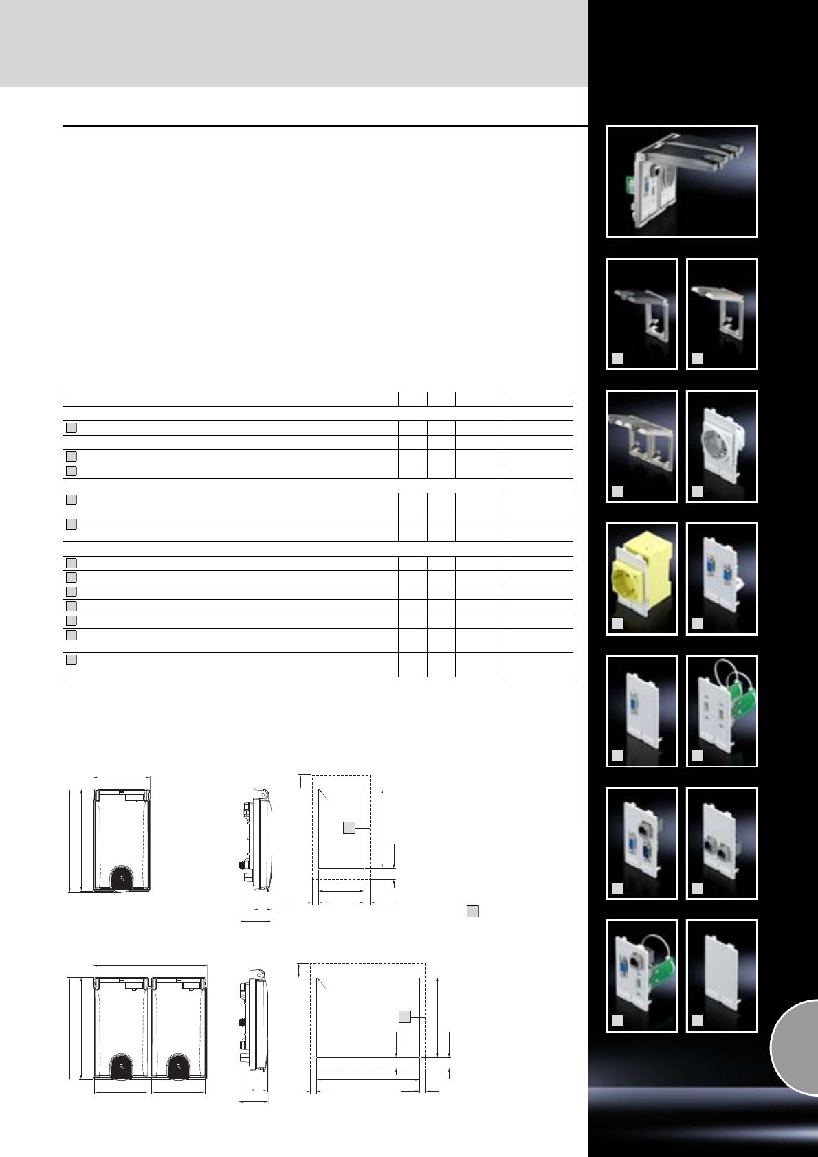
Interfaces
617Rittal Catalogue 33/System accessories
1
2
3
4
5
6
7
8
9
10
11
12
Interface flaps, modular
For universal use in all situations where rapid
access to interfaces and sockets is needed.
The affected enclosure remains closed and is
therefore protected from ambient influences and
unauthorised access.
Space-saving installation e.g.
●in small enclosures and compact enclosures
as a programming interface for controllers
●in IT and industrial enclosures as mainte-
nance access for networks
●in PC enclosures and console systems for the
temporary connection of additional equipment
●in mobile Industrial Workstations for rapid
connection to existing network structures
●in Command Panel systems for programming
and maintenance of integral components.
The mounting frame has a flap which snaps into
position in various stages at opening angles of
90 to 180°. A snap fastener ensures a reliable
seal. This may be locked if required.
Material:
−Mounting frame and metal flap:
Fine die-cast zinc
−Plastic flap: Polycarbonate (semi-transparent)
−Lock: Polycarbonate, RAL 7024
Surface finish:
Mounting frame and metal flap: Matt nickel-plated
Colour:
Lock: RAL 7024
Protection category:
IP 65 to IEC 60 529 with sealed flap and proper
assembly.
Description cUL UL Packs of Model No. SZ
Mounting frame1)
Single, with plastic flap (semi-transparent) 1 2482.300
Double, with plastic flap (semi-transparent) 1 2482.310
Single, with metal flap 1 2482.320
Double, with metal flap 1 2482.330
Socket modules
Germany (VDE), spring-action terminals max. 2 x 2.5 mm2,
connection at rear 12482.4003)
Germany (VDE), screw terminals max. 6 mm2,
connection at rear, colour:
yellow (RAL 1016), for installation in front of main switch 12482.4103)
Interface inserts
2 x SUB-D9 (jack/pin) 1 2482.500
SUB-D9 (jack/jack) 1 2482.510
2 x USB A (jack/jack) 1 2482.5402)
RJ 45 (jack/jack, Cat. 5e), SUB-D9 (jack/jack), SUB-D9 (pin/pin) 1 2482.550
2 x RJ 45 (jack/jack, Cat. 5e) 1 2482.5602)
USB A (jack/jack), RJ 45 (jack/jack, Cat. 5e), SUB-D9
(jack/pin) 1 2482.5702)
Blanking plate (slimline), for individual population, usable area:
45 x 75 mm 1 2482.590
1) Electrically conductive.
2) Conductively linked to mounting frame.
3) Rated voltage: 250 V AC, rated current: 10 – 16 A
All SUB-D interfaces may be rotated while in use.
Other socket modules and interface inserts available on request.
1
2
3
4
5
6
7
8
9
10
11
12
open
lock
open
lock
open
lock
A
91
117
Interface flap, single
Interface flap, double Mounting cut-out
Permissible material
thickness:
1 – 5 mm
Contact surface
A
Approx. 120
Approx. 65
Approx. 116
Appr.
21
Approx. 38
Approx. 120
Approx. 130
Approx. 116
Approx. 61 Approx. 61
max. R2
Approx. 16
Approx. 12
Approx. 7
Approx. 7
Approx. 12
A
91
52
Approx. 16
Approx. 12
max. R2
Approx. 7Approx. 7
Appr. 35
Appr.
21
Mounting cut-out
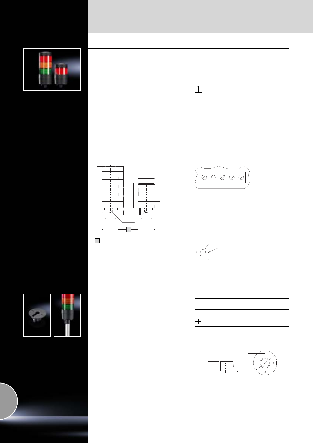
Signal pillars
618 Rittal Catalogue 33/System accessories
Signal pillars, LED compact
Benefits:
●Complete, ready-to-connect solution
●Minimal build height
●Extremely long service life of the LEDs
(at least 70,000 h) – therefore maintenance-free
●Minimal assembly work and warehousing costs
Technical specifications:
−Operating voltage: 24 V AC/DC
−Electrical connection: Screw terminals
−Light: LED
−Transmission angle: 3 x 120°
−Operating temperature: –20 to +70°C
−Flashing function: Controllable via PLC
−Cable entry: Metric screwed cable gland
M12 x 1.5 for cable diameter 3.0 – 6.5 mm
Protection category:
IP 65 to IEC 60 529
Also required:
−For wall mounting:
Bracket for wall mounting, see page 622.
−For conduit mounting/support arm systems:
Connection adaptor, see page 618.
−Other mounting components,
see page 623/624.
Design Packs of H
mm Model No. SG
3-stage,
red, yellow, green 1 177 2372.100
1-stage, red 1 107 2372.130
GND L1 L2 L3
Connection picture SG 2372.100/.130/.140
GND – 0 V (Ground)
L1 – L3 – +24 V DC (LED light stages, from bottom
to top, unneeded contacts are left free)
Ø 72
2135
35
35
22
2910
54
M4
177
1
Ø 72
21
35
22
29
10
54
M4
M12 x 1.5
107
54
Ø 20
Ø 4.5
Seal
1
Mounting cut-out
Connection adaptors
for signal pillar, LED compact
For conduit mounting and mounting on support
arm systems.
Material:
Plastic
Colour:
Black
Accessories:
−Mounting components for conduit mounting,
see page 624.
−Mounting components for support arm system,
see page 623.
Packs of Model No. SG
12372.120
Ø 54
Ø 70
Ø 25
31
Signal pillars
619Rittal Catalogue 33/System accessories
Signal pillars, modular
Benefits:
●Simple assembly and contact via bayonet fas-
tener.
●Configuration of up to five components with
the same voltage.
●Flashing and stroboscopic light element incl.
lamp, suitable for direct use.
●Components are available in a range of colours
and voltages.
For modular configuration of
●Connection components
●AS interface element
●Optical components
●Incandescent lamps/LED lamps
●Acoustic components
●Label panel
Connection component
for signal pillars, modular
Optionally for conduit or wall/base mounting.
Screw terminals in the connection component.
With cover for optical components. Contact
hazard protection to VDE.
Material:
Enclosure of polyamide
Colour:
Black
Protection category:
IP 54
Accessories:
−Mounting components for wall/base mounting,
see page 622.
−Mounting components for conduit mounting,
see page 624.
−Mounting components for support arm system,
see page 623.
Connection component Model No. SG
For conduit mounting 2368.000
For wall/base mounting 2368.010
Ø 25
Ø 17.7
13
25
30
Ø 68.5
Ø 70
Ø 4.2
Ø 25
Ø 17.7
4.2
1.75
18.7521.5
13
Ø 70
Ø 68.5
25
30
1
Connection component
for conduit mounting
SG 2368.000
Connection component
for wall/base mounting
SG 2368.010
Seal
1
0
1
2
3
4
5
Connection diagram
Shared conductor
Stage 5
Stage 4
Stage 3
Stage 2
Stage 1
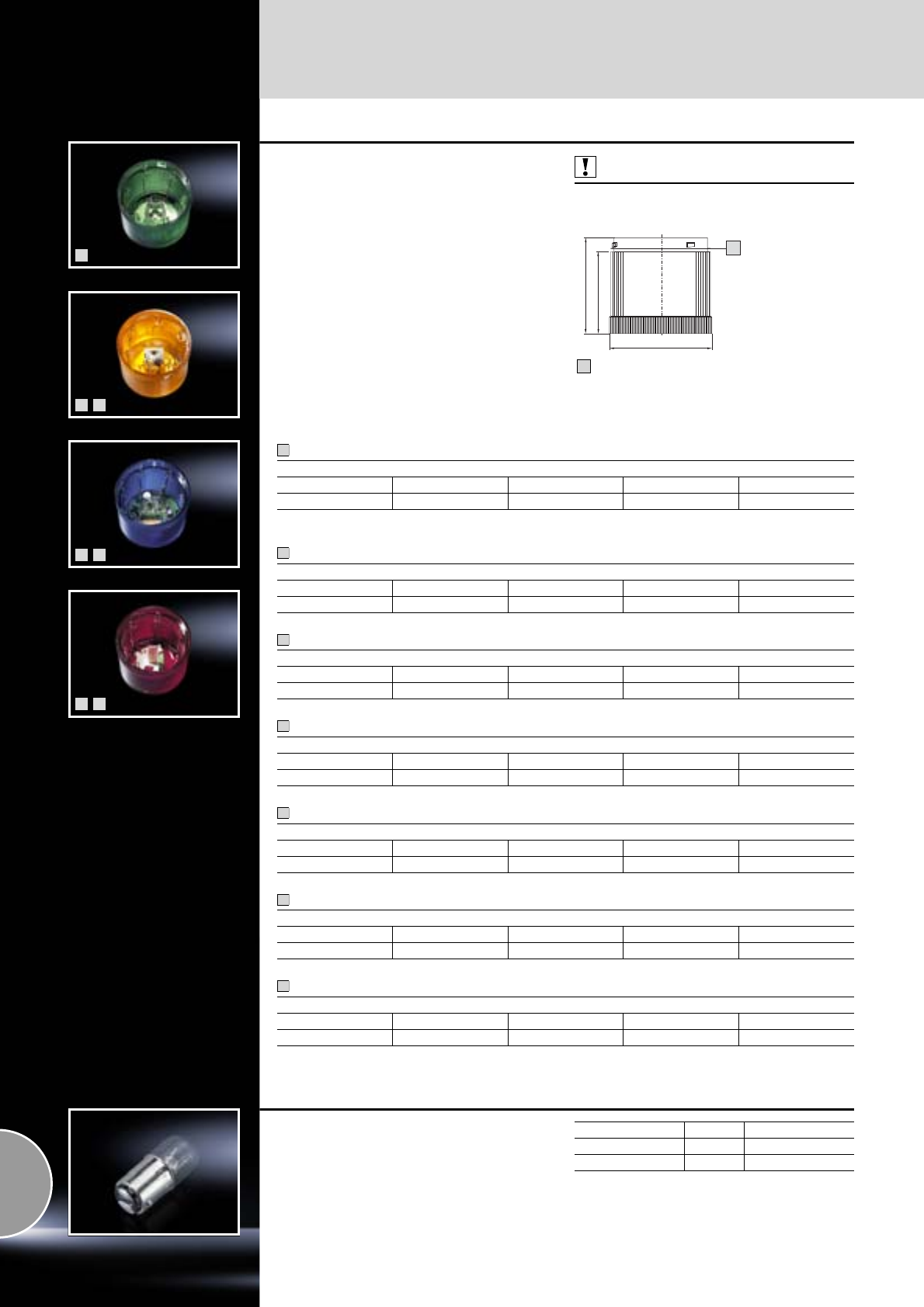
Signal pillars
620 Rittal Catalogue 33/System accessories
1
2
3
4
5
6
7
Optical components
for signal pillars, modular
With 360° signal transmission thanks to optimised
prism system.
No. of potential stages =
5 components, with identical voltage.
Material:
−Enclosure: Polyamide
−Cap: Transparent polycarbonate
Protection category:
IP 54 if a cover or acoustic component is fitted at
the top.
Also required:
Incandescent lamps for steady light component,
see page 620.
Ø 70
65.5
56
A
Pre-configured seal
A
Steady light component 12 – 240 V AC/DC1)
LED steady light component 24 V AC/DC, 25 mA
LED steady light component 230 V AC/DC
LED flashing light component 24 V AC/DC
LED flashing light component 230 V AC/DC
Stroboscopic light component 24 V DC, 125 mA
Stroboscopic light component 230 V DC, 15 mA
Model No. SG
Red Green Yellow Clear Blue
2369.000 2369.010 2369.020 2369.030 2369.040
1) Incandescent lamps not included with the supply.
Model No. SG
Red Green Yellow Clear Blue
2372.000 2372.010 2372.020 2372.030 2372.040
Model No. SG
Red Green Yellow Clear Blue
2370.150 2370.160 2370.170 2370.180 2370.190
Model No. SG
Red Green Yellow Clear Blue
2370.500 2370.510 2370.520 2370.530 2370.540
Model No. SG
Red Green Yellow Clear Blue
2370.550 2370.560 2370.570 2370.580 2370.590
Model No. SG
Red Green Yellow Clear Blue
2371.000 2371.010 2371.020 2371.030 2371.040
Model No. SG
Red Green Yellow Clear Blue
2371.050 2371.060 2371.070 2371.080 2371.090
1
2
3
4
5
6
7
Incandescent lamps
for steady light components
With BA 15d base/plinth.
Incandescent lamp Packs of Model No. SG
24 V, 5 W 3 2374.060
230 V, 5 W 3 2374.070
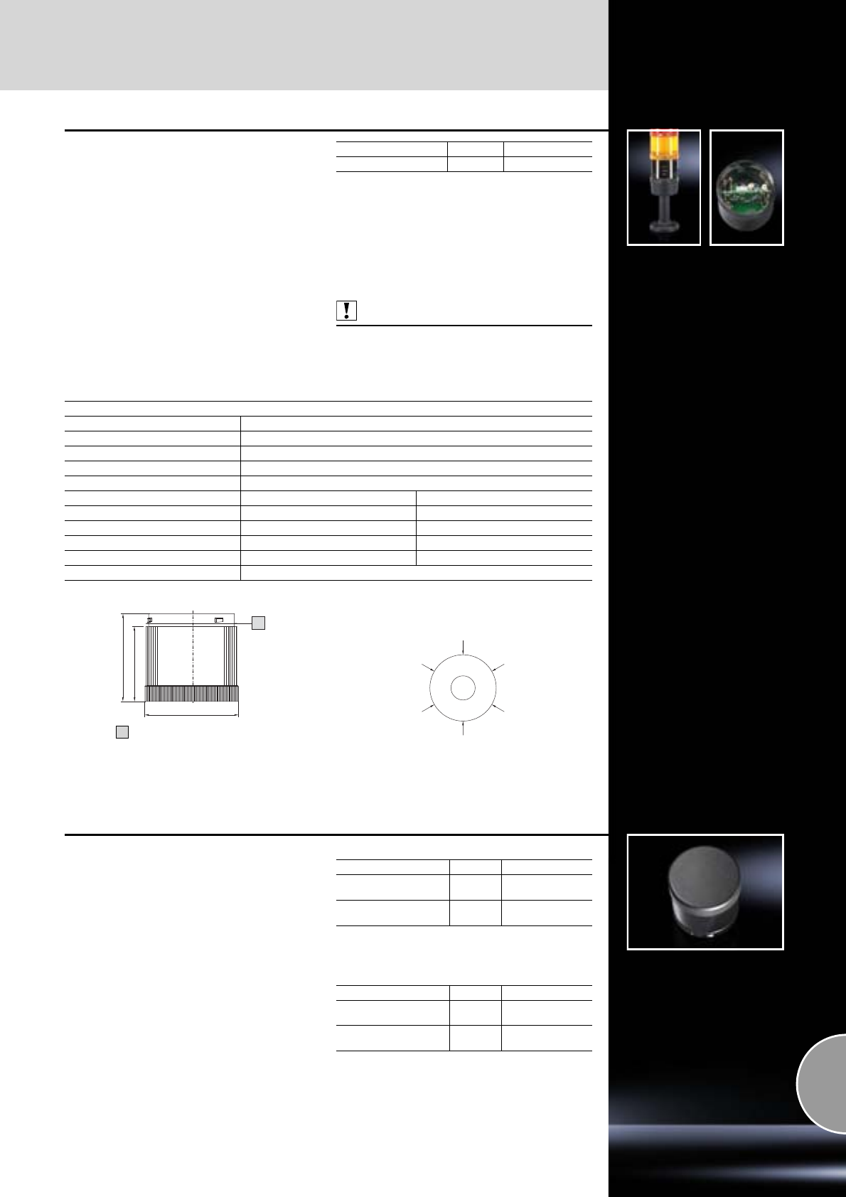
Signal pillars
621Rittal Catalogue 33/System accessories
AS interface element
for signal pillars, modular
User-friendly activation of the signal pillar levels
via AS interface.
Benefits:
●Standard slave.
●Max. 31 addresses.
●Up to 4 signal levels may be activated.
●Power supply may be switched from internal
bus supply to external auxiliary voltage.
●With programming interface.
●Wiring and commissioning work is significantly
reduced.
●For mounting directly on the connection com-
ponent of the signal pillar.
Material:
Polycarbonate
Colour:
Black, transparent
Protection category:
IP 54 to IEC 60 529
Also required:
Connection element,
see page 619.
Design Packs of Model No. SM
24 V DC 1 2376.100
Extended delivery times.
Technical specifications:
Voltage supply
AS interface element Via bus cable
Operating voltage 18.5 V DC to 31.6 V DC (to AS interface specification)
Polarity reversal protection Built-in
Watchdog Built-in
External auxiliary voltage 24 V DC +/– 10%
Auxiliary voltage internal external
Current carrying capacity max. 200 mA 200 mA per element
Current rating max. 250 mA 75 mA
Voltage on signal element 18 – 31 V DC 24 V DC +/– 10%
Short-circuit/overload protection Built-in Pre-fuse M 1.6 A
Temperature range –20°C to +50°C
Ø 70
65.5
56
A
Pre-configured seal
A
3
4
5
0
1
2
Connection diagram
U external (–)
ASI (+)
ASI (–)
U external (+)
Acoustic components
for signal pillars, modular
To indicate warnings or malfunctions.
Material:
Enclosure: Polyamide
Colour:
Black
Note:
Mounting only on the upper end of the optical
components or directly on the connection com-
ponent.
24 V AC/DC
230 V AC
Acoustic components Packs of Model No. SG
85 dB1)
max. 25 mA 1 2376.000
100 dB2)
max. 25 mA 1 2376.010
1) Continuous tone or pulsating
2) Volume and 8 tones may be set
Acoustic components Packs of Model No. SG
85 dB1)
max. 25 mA 1 2376.020
100 dB2)
max. 25 mA 1 2376.030
1) Continuous tone or pulsating
2) Volume and 8 tones may be set
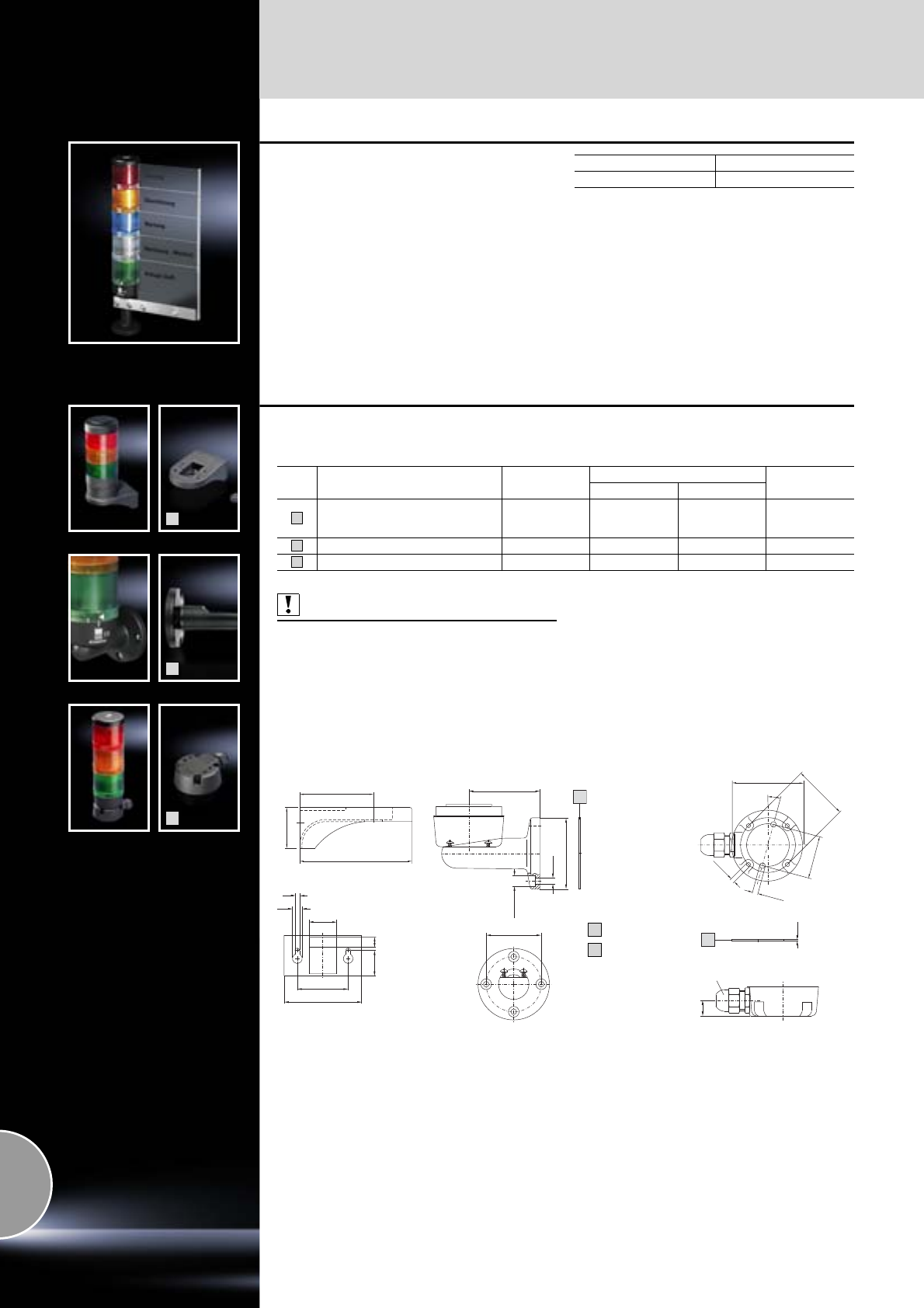
Signal pillars
622 Rittal Catalogue 33/System accessories
Label panel
for signal pillars, modular
For text additions for up to 5 optical components,
with break point for any fields that are not required
(50 x 150 mm), including clamping section for
base or tube with a diameter of 25 mm.
Material:
Acrylic, transparent
Label panel Model No. SG
For 5 optical components 2374.150
1
2
3
Mounting components
for wall/base mounting
Also required:
1) Connection component SG 2368.010,
see page 619.
Fig. Mounting component Colour Suitable for signal pillar Model No. SG
LED compact modular
Bracket for wall mounting,
including rubber gland for
concealed cable routing Black 2372.110
Bracket for connection component Black 1) 2374.040
For side cable outlet Black 1) 2374.080
1
2
3
70
Ø 10.5
Ø 57
Ø 5.5
A
Ø 54
15
M16 x 1.5
1.5
B
Ø 70
Ø 54
Ø 42
Ø 5.5
Ø 4.2
15
Seal
Flat seal
A
B
Bracket for
connection component For
side cable outlet
73
40
110
50
76
25 10
27
4
10
Bracket for
wall mounting

Signal pillars
623Rittal Catalogue 33/System accessories
4
5
6
7
Mounting components
for support arm systems
Also required:
1) Connection adaptor SG 2372.120,
see page 618.
2) Connection component SG 2368.000,
see page 619.
Fig. Mounting component Colour Suitable for signal pillar Model No. SG
LED compact modular
For support arm system CP-L
– Angle piece CP 6524.0X0
– Angle coupling CP 6526.0X0
RAL 9017
(traffic black) 1) 2) 2375.000
For support arm system CP-L
– Intermediate hinge CP 6523.0X0
– Wall-mounted hinge CP 6521.0X0
– Top-mounted joint CP 6522.0X0
RAL 9017
(traffic black) 1) 2) 2375.020
For support arm system CP-S
– Angle piece 90° CP 6501.140 RAL 7024
(graphite grey) 1) 2) 2375.030
For support arm system CP-C
– Angle coupling 90° CP 6071.200
– Angle piece 90° CP 6071.400
– Intermediate hinge CP 6071.800
– Wall-mounted hinge CP 6072.500
– Top-mounted joint CP 6072.600
RAL 7024
(graphite grey) 1) 2) 6073.000
4
5
6
7
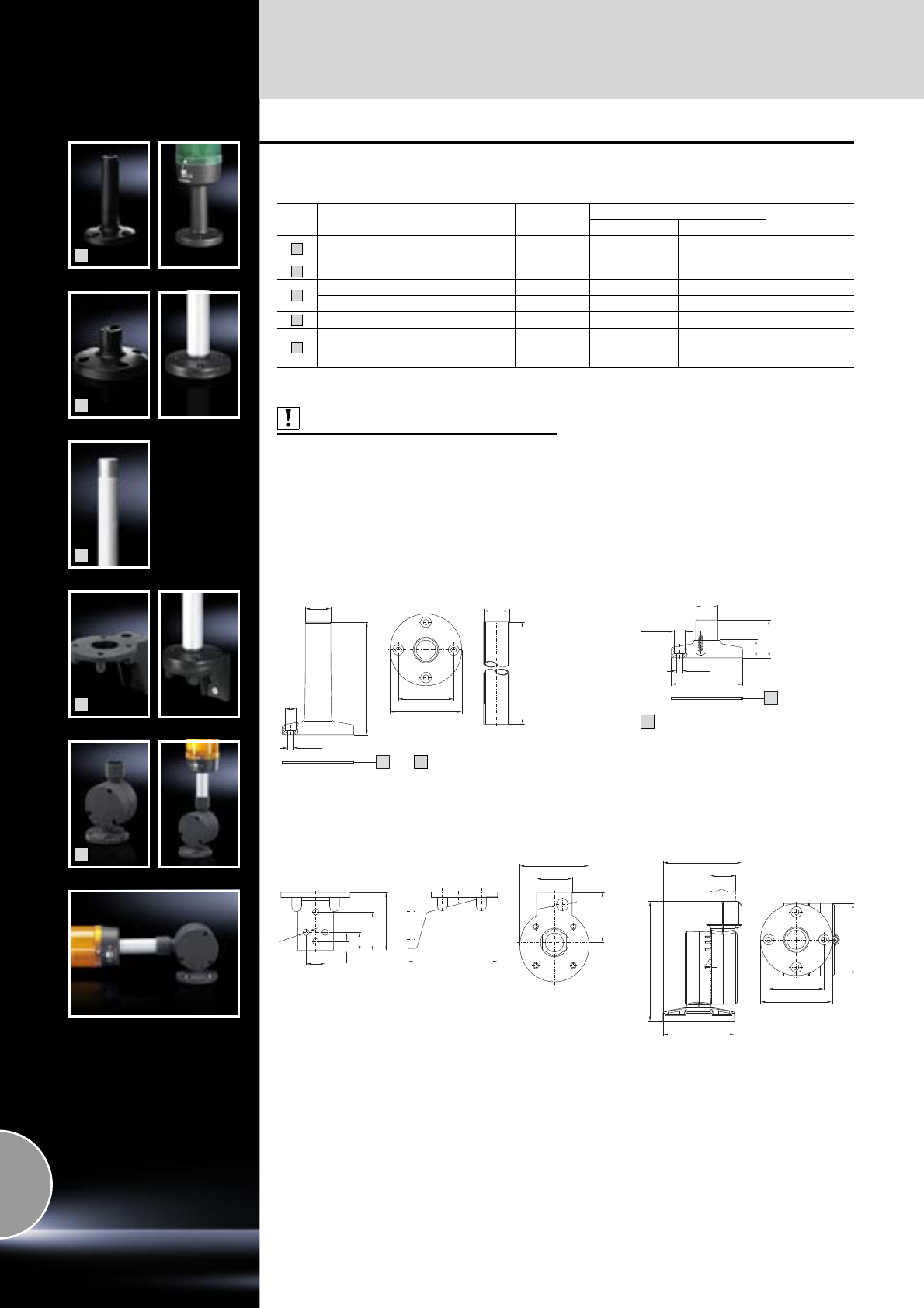
Signal pillars
624 Rittal Catalogue 33/System accessories
8
9
10
11
12
Mounting components
for conduit mounting
Also required:
1) Connection adaptor SG 2372.120,
see page 618.
2) Connection component SG 2368.000,
see page 619.
Fig. Mounting component Colour Suitable for signal pillar Model No. SG
LED compact modular
Base with integral conduit, Ø 25 mm,
110 mm long Black 1) 2) 2374.000
Individual base Black 2374.010
Single conduit, 250 mm long Aluminium 1) 2) 2374.020
Single conduit, 400 mm long Aluminium 1) 2) 2374.030
Angle bracket for conduit mounting Black 2374.050
Base, tiltable from 0° – 90°
in 7.5° increments. Simple cable entry
up to a cable diameter of 14 mm. Black 1) 2) 2374.0903)
3) Extended delivery times.
8
9
10
11
12
Ø 10.5
110
25
Ø 5.5
A
Ø 54
Ø 70
250 (400)
Ø 25
Seal
A
Base with integral conduit Single conduit
Ø 10.5
Ø 70
Ø 5.5
Ø 21.7
37
17
A
Ø 6.2
19
18
57
38
9
Ø12
52.5
Ø 70
36
Individual base, plastic
Angle bracket for conduit mounting
Seal
A
87.5
Ø 54
Ø 70
71
117
Ø 25
Ø 70
77
Base, tiltable

625Rittal Catalogue 33
List of model numbers
1001.600 to 2102.180
Model No. Page
1001.60 0 162
1002.500 162
1002.600 162
1003.600 162
1004.600 162
1005.500 163
1005.600 163
1006.500 163
1006.600 163
1007.600 163
1008.600 163
1009.600 163
1010.500 163
1010.600 163
1011.600 162
1012.600 163
1013.600 163
1014.600 164
1015.600 163
1016.600 164
1017.600 164
1018.600 164
1019.500 164
1019.600 164
1030.500 44
1031.500 44
1032.500 44
1033.500 44
1034.500 44
1035.500 44
1038.500 45
1039.500 45
1045.500 45
1050.500 45
1054.500 45
1055.500 46
1057.500 45
1058.500 45
1060.500 45
1073.500 46
1076.500 45
1077.500 46
1090.500 45
110 0 .5 0 0 46
1101.110 165
1101.120 165
1101.130 165
1101.140 165
1101.8 0 0 429
1101.910 406
1101.920 406
1101.930 406
1101.940 406
1110 .5 0 0 46
1114 .50 0 46
113 0.5 0 0 46
115 8.5 0 0 517
118 0.5 0 0 46
119 9. 10 0 400
1213.500 46
1228.010 368
1228.110 368
1228.310 368
1260.500 46
1280.500 46
1302.600 155
1306.600 155
1307.600 155
1308.600 155
1310.600 155
1316.600 155
1317.600 155
1320.600 155
1338.500 45
1339.500 45
1350.500 45
1360.500 45
1376.500 45
1380.500 44
1400.500 51
1423.500 50
1432.500 50
1434.500 50
1444.500 50
1446.500 50
1448.500 50
1449.500 50
1453.500 50
1454.500 51
1466.500 51
1467.500 51
1468.500 51
1469.500 51
1479.500 51
1480.500 51
1481.000 446
1482.000 478
1483.010 440
1484.000 420
1484.001 420
1485.000 421
1486.000 421
1487.000 421
1488.000 421
1489.000 421
1490.010 419
1491.000 446
1492.000 421
1500.510 35
1501.510 35
1502.510 35
1503.510 35
1504.510 35
1505.510 36
1507.510 35
1508.510 35
1509.510 36
1511.510 35
1514.510 34
1515.510 34
1516.510 34
1517.510 34
1518.510 34
1521.010 161
1522.010 161
1523.010 161
1524.010 161
1525.010 161
Model No. Page
1526.010 161
1527.010 161
1528.010 161
1528.510 34
1529.010 161
1529.510 35
1530.010 161
1530.510 35
1531.510 35
1532.510 35
1533.510 36
1535.510 35
1536.510 35
1537.510 36
1539.510 35
1548.500 37
1549.500 37
1550.500 37
1553.500 37
1554.500 37
1555.500 37
1556.500 37
1557.500 37
1558.010 161
1558.510 40
1559.010 161
1559.510 40
1560.700 443
1561.700 443
1562.700 443
1563.700 443
1564.700 443
1565.700 443
1567.700 443
1568.700 443
1569.700 443
1571.700 443
1575.700 443
1576.700 443
1577.450 40
1577.500 38
1577.520 40
1577.530 40
1577.550 40
1577.560 40
1578.450 41
1578.500 38
1578.520 41
1578.530 41
1578.550 41
1578.560 41
1579.450 41
1579.500 38
1579.520 41
1579.530 41
1579.550 41
1579.560 41
1580.000 439
1581.000 514
1581.100 516
1582.000 514
1583.010 161
1583.520 39
1584.010 161
Model No. Page
1584.520 39
1585.010 161
1585.520 39
1586.520 39
1589.510 35
1590.000 439
1591.000 425
1592.000 425
1592.010 425
1594.000 439
1605.520 40
1606.520 40
1609.510 41
1611.510 41
1670.600 154
1671.600 154
1672.600 154
1674.600 154
1675.600 154
1676.600 154
1782.135 205
1919.500 64
1920.500 64
1926.500 64
1931.200 564
1932.200 564
1933.200 564
1934.200 564
1935.200 564
1936.200 564
1937.200 564
1939.200 564
1940.000 564
1941.000 564
1945.000 564
1950.000 564
1962.200 548
1963.200 548
1978.200 546
1979.200 548
1980.200 548
1985.500 545
1986.500 546
1994.835 545
1995.235 546
1995.835 546
1996.535 545
1996.835 545
1997.235 546
1997.835 546
2004.235 544
2008.235 544
2011.235 544
2026.200 547
2027.200 547
2034.200 547
2092.200 567
2092.300 567
2092.500 567
2094.200 567
2094.300 567
2094.400 568
2094.500 567
2102.180 223
Model No. Page

626 Rittal Catalogue 33
List of model numbers
2102.190 to 2412.210
2102.190 223
2102.320 223
2102.400 223
2102.410 223
2102.490 223
2203.400 530
2231.000 564
2232.000 564
2233.000 564
2235.135 518
2237.000 467
2238.000 467
2239.000 467
2243.605 62
2246.605 62
2249.605 62
2252.605 62
2253.605 63
2255.605 62
2256.605 63
2258.605 62
2259.605 63
2261.605 62
2262.605 63
2265.605 63
2268.605 63
2271.605 63
2304.000 421
2304.010 156
2305.000 409
2307.000 421
2308.000 424
2309.000 467
2310.038 427
2310.076 427
2310.100 427
2310.120 427
2311.225 426
2311.250 426
2313.150 467
2313.750 467
2314.000 467
2315.000 467
2316.000 467
2317.000 467
2318.000 467
2319.000 467
2322.700 545
2323.235 546
2324.235 546
2325.000 426
2326.000 426
2327.000 426
2328.000 426
2331.700 545
2332.235 546
2334.000 501
2335.000 501
2336.700 545
2337.235 546
2338.235 546
2340.700 545
2341.235 546
2342.235 546
Model No. Page
2343.000 501
2345.700 545
2346.235 546
2347.235 546
2350.000 527
2351.000 527
2352.000 527
2353.000 527
2354.000 527
2355.000 527
2356.000 527
2357.000 527
2358.000 527
2359.000 527
2360.000 527
2361.000 431
2362.000 431
2363.000 431
2364.000 503
2365.000 476
2366.000 476
2367.040 500
2367.060 500
2367.080 500
2367.120 500
2367.160 500
2367.200 500
2368.000 619
2368.010 619
2369.000 620
2369.010 620
2369.020 620
2369.030 620
2369.040 620
2370.150 620
2370.160 620
2370.170 620
2370.180 620
2370.190 620
2370.500 620
2370.510 620
2370.520 620
2370.530 620
2370.540 620
2370.550 620
2370.560 620
2370.570 620
2370.580 620
2370.590 620
2371.000 620
2371.010 620
2371.020 620
2371.030 620
2371.040 620
2371.050 620
2371.060 620
2371.070 620
2371.080 620
2371.090 620
2372.000 620
2372.010 620
2372.020 620
2372.030 620
2372.040 620
Model No. Page
2372.100 618
2372.110 622
2372.120 618
2372.130 618
2373.000 476
2373.210 459
2373.250 459
2373.300 459
2373.350 459
2374.000 624
2374.010 624
2374.020 624
2374.030 624
2374.040 622
2374.050 624
2374.060 620
2374.070 620
2374.080 622
2374.090 624
2374.150 622
2375.000 623
2375.020 623
2375.030 623
2376.000 621
2376.010 621
2376.020 621
2376.030 621
2376.100 621
2377.030 543
2377.060 543
2377.090 543
2377.120 543
2377.150 543
2377.180 543
2377.460 543
2377.860 543
2377.880 543
2379.600 609
2379.800 609
2379.900 610
2381.000 614
2382.000 615
2383.000 610
2383.010 603
2383.020 615
2383.030 607
2383.040 607
2384.010 160
2384.020 160
2384.030 160
2384.040 160
2388.000 498
2388.100 498
2388.120 498
2388.150 498
2388.200 498
2388.280 498
2388.600 498
2388.800 498
2389.000 601
2400.000 522
2400.300 524
2400.500 524
2400.900 523
Model No. Page
2400.910 523
2400.920 523
2400.930 523
2400.940 523
2400.950 523
2400.960 523
2400.970 523
2401.000 392
2402.000 392
2403.000 409
2404.000 409
2410.000 521
2410.010 521
2410.020 521
2410.030 521
2410.110 521
2410.120 521
2410.130 521
2410.200 521
2410.210 521
2410.220 521
2410.230 521
2410.290 521
2411.090 499
2411.110 499
2411.140 499
2411.160 499
2411.210 499
2411.290 499
2411.504 520
2411.505 520
2411.506 520
2411.507 520
2411.532 520
2411.550 520
2411.551 520
2411.552 520
2411.553 520
2411.554 520
2411.555 520
2411.556 520
2411.557 520
2411.558 520
2411.559 520
2411.560 520
2411.561 520
2411.562 520
2411.600 519
2411.610 519
2411.620 519
2411.630 519
2411.640 519
2411.650 519
2411.660 519
2411.670 519
2411.800 519
2411.810 519
2411.820 519
2411.830 519
2411.840 519
2411.850 519
2411.860 519
2411.870 519
2412.210 501
Model No. Page

627Rittal Catalogue 33
List of model numbers
2412.216 to 2786.000
2412.216 501
2412.225 501
2412.310 501
2412.316 501
2412.325 501
2413.375 499
2413.550 499
2414.000 500
2414.500 500
2415.000 500
2415.100 430
2415.500 447
2416.000 423
2418.000 423
2419.000 423
2420.000 421
2422.000 438
2423.000 438
2424.100 432
2425.100 432
2426.100 432
2426.500 432
2427.100 432
2430.000 421
2432.000 425
2433.000 439
2433.500 439
2435.000 419
2436.732 388
2436.735 388
2437.000 388
2438.735 388
2439.000 420
2440.735 388
2446.000 427
2449.000 425
2450.000 419
2450.010 419
2451.000 419
2452.000 419
2453.000 419
2454.000 419
2455.000 419
2455.010 419
2456.500 419
2459.000 384
2459.500 384
2460.000 421
2460.650 421
2461.000 421
2462.000 421
2463.000 421
2464.000 421
2465.000 421
2466.000 421
2467.000 416
2468.000 416
2469.000 416
2470.000 431
2471.000 431
2472.000 431
2473.000 431
2474.000 431
2475.000 431
Model No. Page
2476.000 423
2477.000 392
2478.000 392
2479.000 392
2480.000 392
2481.000 392
2482.000 616
2482.210 616
2482.220 616
2482.230 616
2482.300 617
2482.310 617
2482.320 617
2482.330 617
2482.400 617
2482.410 617
2482.500 617
2482.510 617
2482.540 617
2482.550 617
2482.560 617
2482.570 617
2482.590 617
2482.700 616
2482.710 616
2482.720 616
2482.730 616
2483.000 421
2484.000 421
2485.000 420
2485.100 420
2486.300 478
2486.500 478
2487.000 478
2488.000 478
2489.000 478
2489.500 478
2493.000 422
2493.500 423
2501.500 431
2502.500 431
2503.010 439
2504.000 478
2504.500 478
2504.800 478
2505.510 440
2506.100 508
2507.100 496
2507.200 496
2507.300 496
2507.400 496
2507.500 496
2508.010 439
2508.100 439
2509.000 438
2509.500 438
2510.000 428
2511.500 431
2512.000 428
2513.000 428
2514.000 428
2514.500 428
2514.600 428
2514.800 428
Model No. Page
2515.000 428
2518.000 429
2519.000 429
2519.200 429
2520.000 421
2521.000 424
2522.000 421
2523.000 421
2525.000 422
2526.000 421
2527.000 421
2528.000 421
2530.000 421
2531.000 424
2532.000 424
2533.000 420
2534.100 422
2534.500 422
2535.000 420
2536.000 420
2537.000 418
2537.010 418
2540.500 421
2541.235 298
2542.235 298
2543.235 298
2545.000 424
2546.000 424
2547.000 424
2548.000 424
2549.000 424
2549.500 424
2549.510 156
2549.600 156
2559.000 501
2560.010 514
2560.400 517
2561.010 514
2561.100 516
2561.400 517
2561.500 515
2562.010 514
2562.100 516
2562.400 517
2562.500 515
2563.010 514
2563.100 516
2563.150 517
2563.500 515
2564.000 501
2565.000 501
2565.100 501
2565.110 501
2565.120 501
2566.000 501
2567.000 501
2568.000 501
2569.000 501
2570.000 501
2570.100 503
2570.200 501
2570.500 502
2571.000 422
2572.000 420
Model No. Page
2573.000 513
2574.000 476
2575.000 420
2576.000 420
2581.000 388
2583.010 440
2584.000 441
2589.000 529
2590.000 529
2591.000 529
2592.000 529
2593.000 529
2594.000 529
2595.000 529
2596.000 529
2597.000 530
2599.000 420
2682.000 601
2683.600 170
2684.600 170
2685.600 170
2686.600 170
2694.500 107
2695.500 107
2696.500 107
2730.000 408
2731.000 408
2732.000 408
2733.000 408
2734.000 408
2735.250 407
2735.500 407
2735.510 407
2735.520 407
2735.530 407
2735.540 407
2735.560 407
2735.570 407
2735.580 407
2735.590 407
2736.500 407
2736.510 407
2736.520 407
2736.530 407
2736.540 407
2740.000 410
2741.000 410
2742.000 410
2743.000 410
2744.000 410
2745.000 410
2746.000 410
2749.000 410
2760.000 408
2761.000 408
2762.000 408
2763.000 408
2772.000 408
2780.000 408
2781.000 408
2782.000 408
2784.000 408
2785.000 408
2786.000 408
Model No. Page

628 Rittal Catalogue 33
List of model numbers
2787.000 to 3244.140
2787.000 408
2788.000 408
2789.000 408
2791.000 410
2792.000 410
2793.560 409
2796.000 408
2801.200 369
2802.200 369
2804.200 369
2805.200 369
2807.200 369
2808.200 369
2816.200 369
2817.000 364
2818.200 369
2819.000 364
2819.200 364
2823.200 369
2824.200 369
2826.200 369
2828.200 369
2829.200 369
2830.200 369
2836.200 369
2837.200 369
2839.200 369
2840.200 369
2843.160 499
2843.200 499
2843.250 499
2843.320 499
2843.400 499
2843.500 499
2843.630 499
2855.000 370
2856.000 370
2859.000 374
2860.000 370
2865.000 370
2866.000 370
2867.000 370
2868.000 370
2869.000 370
2870.000 370
2875.000 370
2876.000 370
2878.000 370
2879.000 370
2880.000 370
2885.000 370
2886.000 370
2887.000 370
2889.000 371
2890.000 371
2891.000 364
2892.000 364
2899.200 524
2899.250 524
2899.320 524
2899.400 524
2903.200 369
2904.200 369
2905.200 369
Model No. Page
2906.200 369
2907.000 367
2908.000 367
2909.200 369
2910.200 369
2913.000 367
3020.500 341
3105.310 289
3105.320 289
3105.330 289
3105.340 289
3105.350 289
3105.360 289
3105.370 289
3105.380 289
3105.390 289
3105.400 289
3105.410 289
3105.420 289
3105.430 289
3108.024 221
3108.100 221
3108.115 221
3110.000 294
3110.200 294
3114.200 293
3118.000 294
3120.200 295
3121.000 341
3124.100 295
3124.200 295
3125.800 226
3126.100 227
3126.115 227
3126.230 325
3126.240 325
3126.270 326
3126.410 228
3126.424 228
3127.100 227
3127.115 227
3128.100 227
3128.115 227
3128.410 228
3128.424 228
3129.100 227
3129.115 227
3129.410 228
3129.424 228
3129.800 226
3130.100 227
3130.115 227
3130.410 228
3130.424 228
3144.000 218
3145.000 218
3148.007 220
3149.007 220
3149.410 219
3149.420 219
3149.440 219
3149.810 219
3149.820 219
3149.840 219
Model No. Page
3159.100 347
3164.115 220
3164.230 220
3164.610 220
3164.620 220
3165.024 225
3165.048 225
3165.115 225
3165.230 225
3165.615 225
3165.624 225
3165.630 225
3165.648 225
3165.815 225
3165.824 225
3165.830 225
3165.848 225
3169.007 220
3171.100 301
3172.100 301
3173.100 301
3174.000 301
3175.000 304
3176.000 304
3177.000 299
3181.100 302
3182.100 302
3183.100 302
3201.040 302
3201.050 301
3201.070 295
3201.200 232
3201.300 232
3201.900 304
3201.910 304
3209.100 252
3209.104 253
3209.500 252
3209.504 253
3210.100 253
3210.104 254
3210.140 253
3210.500 253
3210.504 254
3210.540 253
3212.024 255
3212.115 255
3212.230 255
3213.310 293
3213.320 293
3213.330 293
3214.100 255
3215.100 255
3216.480 258
3232.700 272
3232.710 272
3232.720 272
3232.730 272
3232.740 272
3232.750 272
3232.760 272
3232.770 272
3232.780 272
3232.790 272
Model No. Page
3232.800 273
3232.810 273
3232.820 273
3232.830 273
3232.840 273
3232.850 273
3232.860 273
3232.870 273
3232.880 273
3232.890 273
3235.440 294
3236.124 222
3237.020 303
3237.060 303
3237.066 301
3237.080 303
3237.100 212
3237.110 212
3237.124 212
3237.200 303
3237.600 212
3238.020 303
3238.055 302
3238.060 303
3238.066 301
3238.080 303
3238.100 212
3238.110 212
3238.124 212
3238.200 303
3238.600 212
3239.020 303
3239.060 303
3239.066 301
3239.080 303
3239.100 213
3239.110 213
3239.124 213
3239.200 303
3239.600 213
3240.020 303
3240.060 303
3240.066 301
3240.080 303
3240.100 214
3240.110 214
3240.124 214
3240.200 303
3240.600 214
3241.100 214
3241.110 214
3241.124 214
3241.600 214
3243.020 303
3243.060 303
3243.066 301
3243.080 303
3243.100 215
3243.110 215
3243.200 303
3243.600 215
3244.100 215
3244.110 215
3244.140 215
Model No. Page

629Rittal Catalogue 33
List of model numbers
3244.600 to 3351.024
3244.600 215
3245.080 303
3245.500 216
3245.510 216
3245.600 216
3248.000 229
3253.000 299
3253.010 299
3253.200 300
3253.220 300
3254.000 299
3254.200 300
3267.100 299
3267.200 300
3273.500 246
3273.515 246
3284.200 300
3284.210 300
3285.000 299
3285.200 300
3286.000 299
3286.100 299
3286.110 299
3286.120 300
3286.200 300
3286.210 300
3286.230 300
3286.240 300
3286.250 300
3286.260 297
3286.270 297
3286.280 297
3286.300 299
3286.310 300
3286.400 299
3286.410 300
3286.500 299
3286.510 300
3286.520 300
3286.530 300
3286.540 300
3286.550 300
3286.600 299
3286.610 300
3286.700 297
3286.780 292
3286.800 297
3286.850 292
3286.860 292
3286.870 291
3286.880 292
3286.900 297
3286.970 291
3286.980 292
3286.990 291
3288.200 300
3289.200 300
3294.100 299
3294.200 300
3300.040 249
3300.050 249
3300.060 249
3300.070 249
3300.080 249
Model No. Page
3300.090 249
3300.110 249
3300.120 249
3300.160 278
3300.170 278
3300.180 278
3300.260 305
3300.261 305
3300.262 305
3300.263 305
3300.270 278
3300.280 278
3300.290 305
3300.291 305
3300.292 305
3300.293 305
3300.294 305
3300.295 305
3300.296 305
3300.297 305
3300.310 274
3300.320 274
3300.330 274
3300.340 274
3300.353 276
3300.354 276
3300.355 276
3300.356 276
3300.360 276
3300.370 276
3300.510 276
3300.560 276
3300.710 276
3300.760 276
3301.221 283
3301.320 283
3301.370 283
3301.380 283
3301.390 283
3301.421 283
3301.560 302
3301.570 302
3301.580 302
3301.590 302
3301.600 302
3301.606 303
3301.608 303
3301.610 303
3301.612 303
3301.620 274
3301.660 274
3301.800 246
3301.830 274
3301.870 274
3301.900 304
3301.910 304
3301.920 304
3301.930 304
3301.940 304
3301.950 305
3301.955 305
3301.957 305
3301.960 305
3301.965 305
Model No. Page
3301.967 305
3302.100 234
3302.110 234
3302.200 234
3302.210 234
3302.300 233
3302.310 233
3303.500 235
3303.504 242
3303.510 235
3303.514 242
3303.530 243
3303.600 235
3303.610 235
3304.500 237
3304.504 242
3304.510 237
3304.514 242
3304.530 243
3304.540 237
3304.544 242
3304.560 243
3304.600 237
3304.610 237
3304.640 237
3305.500 238
3305.504 242
3305.510 238
3305.514 242
3305.530 243
3305.540 238
3305.544 242
3305.560 243
3305.600 238
3305.610 238
3305.640 238
3307.700 248
3307.710 248
3307.740 248
3310.700 248
3310.710 248
3310.740 248
3311.010 279
3311.020 280
3311.030 283
3311.040 283
3311.050 283
3311.060 283
3311.110 279
3311.130 279
3311.210 280
3311.230 279
3311.260 279
3311.310 283
3311.400 281
3311.530 280
3311.560 280
3311.600 282
3318.600 264
3318.610 264
3319.600 264
3319.610 264
3320.600 265
3321.700 301
Model No. Page
3322.700 301
3327.700 301
3328.500 239
3328.504 243
3328.510 239
3328.514 243
3328.540 239
3328.544 243
3328.600 239
3328.610 239
3328.640 239
3329.500 240
3329.504 243
3329.510 240
3329.514 243
3329.540 240
3329.544 243
3329.600 240
3329.610 240
3329.640 240
3329.903 301
3329.904 301
3332.540 240
3332.640 240
3334.600 265
3334.660 265
3335.590 267
3335.600 267
3335.610 267
3335.620 267
3335.630 267
3335.640 267
3335.650 267
3335.660 267
3336.100 268
3336.200 268
3336.300 268
3336.500 268
3336.600 268
3336.650 268
3336.700 269
3336.710 269
3336.720 269
3336.730 269
3336.740 269
3336.750 269
3339.100 269
3339.200 269
3339.250 269
3339.280 269
3340.024 217
3340.115 217
3340.230 217
3341.024 217
3341.115 217
3341.230 217
3342.024 217
3342.115 217
3342.230 217
3342.500 217
3350.024 218
3350.115 218
3350.230 218
3351.024 218
Model No. Page

630 Rittal Catalogue 33
List of model numbers
3351.115 to 4597.000
3351.115 218
3351.230 218
3352.024 218
3352.115 218
3352.230 218
3352.500 218
3355.100 218
3356.100 218
3357.100 218
3359.500 245
3359.510 245
3359.540 245
3359.600 245
3359.610 245
3359.640 245
3360.100 266
3360.250 266
3360.470 266
3361.500 236
3361.510 236
3361.540 236
3361.600 236
3361.610 236
3361.640 236
3363.100 256
3363.104 259
3363.500 256
3363.504 259
3364.100 256
3364.104 259
3364.500 256
3364.504 259
3366.500 241
3366.510 241
3366.540 241
3366.600 241
3366.610 241
3366.640 241
3373.100 257
3373.104 260
3373.500 257
3373.504 260
3374.100 257
3374.104 260
3374.500 257
3374.504 260
3375.100 258
3375.104 261
3375.500 258
3375.504 261
3377.000 297
3382.500 244
3382.510 244
3382.600 244
3382.610 244
3383.500 245
3383.510 245
3383.540 245
3383.600 245
3383.610 245
3383.640 245
3384.500 246
3384.510 246
3384.540 246
Model No. Page
3384.600 246
3384.610 246
3384.640 246
3385.500 247
3385.510 247
3385.540 247
3385.600 247
3385.610 247
3385.640 247
3386.540 247
3386.640 247
3387.540 247
3387.640 247
3636.010 490
3659.440 611
3659.520 611
3659.620 611
3659.680 611
3861.580 485
4000.100 156
4000.200 156
4000.210 156
4114.000 429
4115.000 429
4115.500 429
4116.000 429
4116.500 429
4118.000 429
4118.500 429
4119.000 477
4120.000 427
4123.000 429
4124.000 429
4127.010 496
4127.210 496
4131.700 449
4132.700 449
4133.000 474
4134.000 474
4137.700 449
4138.140 492
4138.150 492
4138.180 492
4138.190 492
4138.240 492
4138.250 492
4138.280 492
4138.290 492
4138.300 492
4138.350 492
4138.400 492
4138.450 492
4139.140 492
4139.150 492
4139.180 492
4139.190 492
4139.300 492
4139.350 492
4140.000 493
4140.010 493
4140.020 493
4140.110 493
4140.120 493
4140.210 493
Model No. Page
4140.220 493
4140.810 494
4140.820 494
4140.830 494
4140.840 494
4155.000 492
4155.100 492
4155.500 492
4156.000 425
4157.000 477
4162.000 477
4163.000 477
4164.000 477
4165.000 477
4166.000 477
4169.000 463
4170.000 463
4171.000 463
4172.000 463
4173.000 463
4174.000 463
4175.000 463
4176.000 463
4177.000 463
4178.000 463
4179.000 477
4180.000 477
4181.000 473
4182.000 472
4183.000 473
4189.000 425
4190.000 425
4191.000 527
4192.000 527
4193.000 527
4196.000 527
4198.000 438
4199.000 474
4309.000 462
4311.000 512
4315.100 496
4315.150 496
4315.200 496
4315.320 496
4315.350 496
4315.400 496
4315.450 496
4315.520 496
4315.550 496
4315.600 496
4315.710 496
4315.720 496
4315.800 495
4315.810 495
4315.820 495
4315.830 495
4315.840 495
4315.850 495
4315.860 495
4316.000 512
4317.000 512
4318.000 512
4319.090 530
4319.120 530
Model No. Page
4319.160 530
4319.200 530
4320.700 511
4321.700 511
4323.700 511
4333.120 447
4333.160 447
4333.180 447
4336.000 527
4338.000 527
4339.000 527
4347.000 466
4348.000 500
4361.000 466
4362.000 466
4363.000 466
4364.000 464
4365.000 464
4367.000 464
4369.000 464
4370.000 464
4371.000 464
4372.000 464
4373.000 464
4374.000 464
4375.000 464
4376.000 464
4377.000 464
4378.000 464
4379.000 464
4380.000 464
4381.000 464
4382.000 464
4393.000 463
4394.000 466
4395.000 466
4396.000 466
4396.500 466
4398.000 466
4398.500 466
4530.000 561
4531.000 561
4532.000 470
4538.000 430
4540.000 398
4541.000 563
4542.000 563
4547.000 552
4568.000 438
4570.000 370
4576.000 445
4579.000 462
4582.000 398
4582.500 398
4583.000 429
4583.500 429
4590.700 443
4591.700 443
4592.700 443
4593.000 445
4594.000 462
4595.000 440
4596.000 462
4597.000 470
Model No. Page
631Rittal Catalogue 33
List of model numbers
4598.000 to 6510.340
4598.000 462
4599.000 462
4611.000 374
4612.000 373
4638.600 427
4638.800 427
4650.000 171
4694.000 462
4695.000 462
4696.000 462
4697.000 462
4757.500 107
4911.000 393
4911.100 393
4912.000 393
4916.000 393
4918.000 393
4920.000 393
4933.000 467
4934.000 467
4935.000 467
4937.000 467
4943.000 465
4944.000 465
4945.000 465
4946.000 465
4947.000 465
5001.000 425
5001.050 459
5001.051 459
5001.052 459
5001.053 459
5001.054 459
5001.060 416
5001.061 416
5001.062 416
5001.070 446
5001.075 447
5001.080 527
5001.081 527
5001.082 527
5001.083 527
5001.130 381
5001.140 381
5001.150 381
5001.160 381
5001.210 378
5001.211 378
5001.212 378
5001.213 378
5001.214 378
5001.215 378
5001.216 378
5001.217 378
5001.218 378
5001.219 378
5001.220 378
5001.221 378
5001.222 379
5001.223 379
5001.224 379
5001.225 379
5001.226 511
5001.227 511
Model No. Page
5001.228 511
5001.229 378
5001.233 378
5001.234 378
5001.235 378
5001.236 379
5001.237 511
5001.310 431
5001.330 431
5001.350 431
5001.360 431
5001.370 461
5001.371 461
5110.500 48
5111.5 0 0 48
5112.500 48
5113.500 48
5114.500 48
5115.500 48
5116.500 48
5117.500 48
5118.500 49
5119.500 49
5120.500 49
5121.500 49
5122.500 49
5123.500 49
6002.000 612
6002.100 608
6003.000 613
6005.500 442
6013.000 603
6013.100 603
6016.200 441
6016.600 145
6016.700 145
6023.010 141
6027.000 604
6027.010 604
6028.000 604
6028.010 604
6028.014 604
6028.015 604
6028.016 604
6028.500 604
6028.510 604
6028.530 604
6028.540 604
6040.010 141
6050.000 141
6050.500 141
6052.000 528
6052.500 524
6053.000 605
6053.210 605
6053.300 605
6053.500 605
6053.800 605
6058.000 605
6058.500 605
6058.800 605
6059.000 531
6059.500 531
6070.000 137
Model No. Page
6070.200 137
6071.000 142
6071.200 137
6071.400 137
6071.600 143
6071.800 137
6072.000 137
6072.200 137
6072.400 137
6072.500 137
6072.600 137
6072.800 137
6073.000 623
6074.000 137
6074.100 137
6074.300 137
6074.500 137
6075.100 137
6075.300 137
6075.500 137
6100.000 141
6100.500 141
6107.000 602
6107.100 602
6107.200 602
6108.000 478
6110.010 141
6110.100 141
6120.010 141
6130.010 141
6130.510 141
6130.610 141
6135.000 148
6136.000 148
6136.500 148
6137.035 147
6137.535 147
6140.010 141
6141.100 148
6141.200 148
6143.200 147
6143.210 151
6143.310 151
6144.100 151
6146.100 147
6146.200 147
6146.300 147
6146.400 147
6147.000 151
6148.000 374
6160.010 141
6170.010 141
6180.010 141
6190.000 601
6200.000 141
6200.500 141
6205.000 143
6205.100 470
6214.000 150
6214.500 149
6215.000 149
6220.000 150
6340.000 120
6340.100 120
Model No. Page
6340.300 120
6340.400 120
6341.000 442
6372.541 116
6372.542 116
6372.543 116
6372.551 116
6372.552 116
6372.553 116
6372.561 116
6372.562 116
6372.563 116
6375.000 600
6375.010 600
6375.020 600
6375.029 600
6375.040 600
6375.050 600
6375.060 600
6380.000 118
6380.020 118
6380.040 118
6380.050 118
6380.400 118
6380.410 118
6380.500 118
6380.510 118
6380.600 118
6380.610 118
6385.000 600
6385.010 600
6385.040 600
6385.050 600
6385.060 600
6442.500 123
6446.020 609
6450.010 606
6450.020 606
6450.050 606
6450.060 606
6450.070 606
6450.170 606
6462.500 123
6501.000 129
6501.020 129
6501.050 129
6501.070 129
6501.090 146
6501.110 129
6501.120 129
6501.130 129
6501.140 129
6501.150 129
6501.160 129
6503.000 151
6505.100 604
6505.200 604
6505.500 604
6508.010 133
6508.020 142
6509.000 133
6510.210 144
6510.330 144
6510.340 144
Model No. Page

632 Rittal Catalogue 33
List of model numbers
6511.000 to 7072.220
6511.000 133
6513.000 133
6513.050 133
6514.200 610
6515.000 133
6519.000 145
6520.010 133
6520.510 133
6521.010 133
6522.010 133
6523.010 133
6524.010 133
6524.210 133
6525.010 133
6525.110 133
6525.210 133
6525.510 133
6525.610 133
6526.010 133
6527.010 133
6527.110 133
6528.010 142
6528.110 146
6528.210 143
6528.410 144
6528.450 142
6528.510 142
6529.010 133
6530.200 122
6531.200 122
6532.200 122
6533.200 122
6534.000 121
6535.000 121
6535.010 167
6536.000 121
6536.010 167
6537.000 121
6538.000 121
6538.010 167
6539.010 167
6540.200 122
6544.000 121
6552.500 123
6660.010 169
6660.050 169
6662.500 123
6663.000 169
6663.400 169
6663.500 169
6664.000 169
6664.100 169
6664.300 169
6664.500 169
6665.000 169
6665.500 169
6680.000 166
6681.000 166
6700.500 101
6701.500 102
6702.500 103
6703.500 104
6704.500 101
6705.500 102
Model No. Page
6706.500 103
6707.500 104
6710.500 101
6711.500 102
6712.500 103
6713.500 104
6714.500 101
6715.500 102
6716.500 103
6717.500 104
6720.100 101
6720.200 101
6720.500 101
6721.100 102
6721.200 102
6721.500 102
6722.100 103
6722.200 103
6722.500 103
6723.100 104
6723.200 104
6723.500 104
6730.030 105
6730.100 105
6730.110 105
6730.120 105
6730.130 105
6730.310 450
6730.330 450
6730.340 450
6730.400 105
6730.410 105
6730.600 298
6740.500 106
6742.500 106
6746.500 106
6748.500 106
6900.000 111
6900.100 111
6900.300 109
6900.400 111
6900.410 111
6901.100 111
6902.100 111
6902.300 111
6902.310 148
6902.400 111
6902.500 111
6902.640 143
6902.670 145
6902.700 481
6902.770 522
6902.920 371
6902.950 616
6902.960 480
6902.980 480
6903.200 615
7000.390 86
7000.410 86
7000.430 86
7000.440 86
7000.450 87
7000.460 87
7000.500 86
Model No. Page
7000.510 86
7000.520 87
7000.530 87
7000.532 87
7000.560 86
7000.570 86
7000.580 87
7000.590 87
7000.592 87
7000.620 483
7000.625 486
7000.630 506
7000.640 400
7000.652 388
7000.653 388
7000.663 388
7000.670 224
7000.672 375
7000.675 503
7000.676 460
7000.678 460
7000.680 224
7000.684 204
7000.685 536
7000.840 85
7000.850 85
7000.852 85
7000.875 95
7000.882 95
7000.885 95
7000.892 95
7000.895 95
7000.940 88
7000.944 88
7000.990 568
7016.100 542
7016.110 542
7016.120 542
7016.130 542
7016.140 532
7016.150 532
7030.000 582
7030.010 582
7030.030 580
7030.040 581
7030.050 581
7030.060 584
7030.070 585
7030.071 585
7030.080 584
7030.090 584
7030.091 584
7030.092 584
7030.093 584
7030.094 584
7030.095 584
7030.100 583
7030.110 583
7030.111 583
7030.120 583
7030.130 583
7030.140 583
7030.150 583
7030.190 583
Model No. Page
7030.200 583
7030.220 583
7030.230 583
7031.100 575
7040.010 191
7040.020 191
7040.030 191
7040.040 191
7040.060 192
7040.065 192
7040.070 193
7040.075 193
7040.110 191
7040.120 191
7040.201 191
7040.202 191
7040.204 191
7040.211 191
7040.212 191
7040.214 191
7040.301 192
7040.305 192
7040.311 192
7040.315 192
7040.361 193
7040.500 198
7050.035 574
7050.100 574
7050.200 574
7051.000 489
7061.000 489
7063.000 560
7063.200 539
7063.710 485
7063.720 485
7063.725 485
7063.740 560
7063.750 559
7063.752 559
7063.835 484
7063.837 484
7063.850 563
7063.858 488
7063.860 488
7063.882 559
7063.883 559
7063.884 559
7063.888 614
7063.890 488
7063.892 488
7063.895 484
7063.897 484
7064.000 489
7064.100 533
7064.110 533
7065.000 489
7066.000 489
7066.700 489
7067.100 400
7067.200 400
7069.535 569
7072.100 522
7072.200 518
7072.220 530
Model No. Page

633Rittal Catalogue 33
List of model numbers
7072.230 to 7463.100
7072.230 530
7072.240 530
7077.000 529
7078.000 529
7081.000 489
7086.535 569
7087.535 569
7089.535 569
7091.000 465
7094.100 568
7094.110 568
7094.120 568
7094.130 567
7094.140 567
7095.000 465
7096.000 465
7097.000 529
7097.220 529
7097.260 529
7097.300 529
7097.340 529
7098.000 529
7098.100 529
7099.000 529
7100.000 465
7102.000 465
7109.035 293
7109.200 497
7111.0 0 0 534
7111.100 534
7111.210 537
7111.212 537
7111.214 537
7111.22 0 537
7111.22 2 537
7111.22 4 537
7111.25 0 538
7111.25 2 538
7111.300 531
7111.310 531
7111.35 0 531
7111.900 534
7112.000 534
7113.000 504
7115.000 490
7116.500 535
7119.140 486
7119.155 486
7119.250 487
7119.255 487
7119.400 487
7119.455 487
7124.035 547
7140.535 542
7143.035 482
7144.035 482
7145.005 482
7145.035 482
7145.535 483
7145.605 482
7145.635 482
7145.705 482
7145.735 482
7147.035 489
Model No. Page
7148.035 485
7149.035 540
7149.135 540
7150.535 542
7151.005 571
7151.035 571
7151.105 571
7151.110 571
7151.206 565
7151.208 565
7151.300 566
7152.005 571
7152.035 571
7153.005 571
7153.035 571
7154.035 570
7156.005 571
7156.035 571
7157.035 571
7158.035 540
7158.100 541
7158.150 541
7159.035 539
7161.000 489
7161.700 489
7163.500 490
7163.550 490
7163.560 490
7163.565 490
7164.035 480
7165.035 480
7166.035 480
7166.735 480
7167.000 571
7169.535 573
7170.535 573
7174.535 573
7178.535 573
7183.100 487
7184.035 480
7185.035 480
7186.035 480
7186.735 480
7200.001 510
7200.210 585
7200.214 585
7200.215 585
7200.216 585
7200.217 585
7200.450 585
7200.630 508
7200.800 417
7200.810 417
7218.035 533
7219.035 533
7220.500 536
7220.600 534
7228.035 533
7240.110 505
7240.120 505
7240.130 506
7240.150 506
7240.160 506
7240.170 506
Model No. Page
7240.190 506
7240.200 505
7240.201 505
7240.205 505
7240.210 505
7240.220 505
7240.230 505
7240.240 505
7240.250 505
7240.260 505
7240.280 505
7240.290 505
7240.300 507
7240.305 507
7240.310 505
7240.330 505
7240.370 505
7240.510 505
7240.512 505
7240.600 507
7241.005 572
7241.015 573
7241.024 573
7241.045 573
7241.065 573
7241.500 572
7242.005 572
7242.015 573
7246.010 562
7246.030 562
7246.060 562
7246.100 562
7246.400 562
7246.420 557
7246.500 566
7255.035 539
7256.035 541
7257.005 539
7257.035 539
7257.050 540
7257.100 539
7257.105 539
7257.150 540
7257.200 539
7264.035 480
7265.035 480
7266.035 480
7269.135 540
7269.235 541
7280.035 508
7280.100 509
7281.035 614
7281.200 613
7282.035 563
7282.135 563
7283.035 563
7284.135 555
7296.000 558
7297.000 558
7298.000 558
7299.000 558
7300.230 574
7300.240 574
7300.250 574
Model No. Page
7300.335 570
7320.435 584
7320.440 586
7320.441 586
7320.472 596
7320.475 596
7320.481 596
7320.485 596
7320.491 586
7320.530 583
7320.560 583
7320.570 583
7320.620 583
7320.630 583
7320.631 583
7320.700 583
7320.721 583
7320.730 587
7320.790 589
7320.792 589
7320.793 589
7320.794 589
7320.795 589
7320.796 589
7320.810 587
7320.812 587
7320.813 584
7320.814 585
7320.820 587
7320.830 586
7320.950 583
7338.120 328
7338.130 328
7338.160 329
7338.161 329
7338.162 329
7338.163 329
7338.164 329
7338.165 329
7338.166 329
7338.167 329
7338.168 329
7338.170 329
7338.171 329
7338.220 328
7338.320 328
7391.000 89
7394.035 569
7396.000 89
740 0 .0 0 0 89
7401.000 558
7402.000 558
7404.000 506
7408.510 506
7411. 0 0 0 558
7412.510 506
7433.035 570
7437.035 570
7445.000 89
7450.035 572
745 1.0 0 0 67
7455.030 522
7462.000 67
746 3. 10 0 67
Model No. Page

634 Rittal Catalogue 33
List of model numbers
7463.200 to 7824.282
7463.200 67
7464.035 480
7465.035 480
7466.035 480
7466.735 480
7469.535 573
7470.535 573
7474.535 573
7478.535 573
7480.035 509
7480.300 509
7484.035 480
7485.035 480
7486.035 480
7486.735 480
7492.060 560
7492.070 560
7492.300 560
7492.400 560
7492.500 560
7493.000 373
749 3. 10 0 373
7493.230 373
7494.000 558
7495.000 374
7501.000 54
7501.100 567
7502.013 57
7502.014 57
7502.016 57
7502.024 57
7502.026 57
7502.034 57
7502.035 57
7502.036 57
7502.044 58
7502.045 58
7502.046 58
7502.054 58
7502.056 58
7502.064 58
7502.066 58
7502.114 58
7502.124 58
7502.126 58
7502.136 58
7502.144 58
7502.146 58
7502.166 58
7502.203 554
7502.204 554
7502.205 554
7502.206 554
7502.220 424
7502.240 503
7502.260 503
7502.302 528
7502.304 528
7502.310 517
7502.436 57
7502.446 58
7502.630 59
7502.660 59
7507.000 55
Model No. Page
7507.010 55
7507.020 56
7507.030 56
7507.100 55
7507.110 55
7507.120 56
7507.200 56
7507.210 56
7507.220 56
7507.706 554
7507.709 554
7507.712 554
7507.715 554
7507.718 554
7507.721 554
7507.740 374
7507.750 371
7507.755 371
7507.760 222
7526.050 424
7526.750 383
7526.755 383
7526.760 383
7526.770 383
7526.780 383
7526.785 383
7526.790 383
7526.795 383
7526.800 383
7526.807 436
7526.820 383
7526.827 436
7526.829 383
7526.834 383
7526.850 383
7526.860 383
7526.964 470
7541.000 504
7542.000 504
7543.000 504
7544.000 504
7545.000 504
7546.000 504
7547.000 504
7548.000 504
7548.210 502
7549.000 504
7552.002 591
7552.020 592
7552.030 592
7552.040 592
7552.100 591
7552.110 591
7552.120 596
7552.122 596
7552.140 596
7552.142 596
7552.200 594
7552.201 595
7552.202 595
7552.203 595
7552.204 595
7552.205 595
7552.212 594
Model No. Page
7552.214 595
7552.220 596
7552.420 596
7552.510 593
7561.500 366
7570.535 573
7574.535 573
7578.535 573
7581.500 366
7582.500 366
7604.000 506
7608.510 506
7610.000 535
7611.000 535
7641.000 65
7643.000 65
7644.000 66
7644.400 487
7645.000 65
7685.000 553
7688.000 553
7696.000 553
7698.000 553
7705.035 518
7705.110 418
7705.120 418
7705.235 517
7705.706 553
7705.709 553
7705.712 553
7705.715 553
7705.718 553
7705.721 553
7706.135 61
7709.135 61
7709.535 60
7709.735 60
7712.135 61
7715.135 61
7715.535 60
7715.735 60
7718.135 61
7721.135 61
7721.535 60
7721.735 60
7752.950 504
7794.420 549
7794.740 549
7816.120 387
7816.200 387
7816.360 404
7816.362 404
7816.380 404
7816.382 404
7820.100 83
7820.200 83
7820.300 83
7820.340 83
7820.350 83
7820.410 83
7820.500 83
7820.510 83
7820.600 84
7820.610 84
Model No. Page
7820.650 84
7820.700 84
7820.710 84
7820.730 84
7820.740 84
7820.750 84
7820.770 84
7820.800 84
7820.810 84
7820.850 84
7821.100 83
7821.200 83
7821.300 83
7821.340 83
7821.410 83
7821.500 83
7821.510 83
7821.600 84
7821.610 84
7821.650 84
7821.700 84
7821.710 84
7821.730 84
7821.740 84
7821.750 84
7821.770 84
7821.800 84
7821.810 84
7821.850 84
7824.086 387
7824.106 387
7824.120 387
7824.126 387
7824.127 403
7824.128 387
7824.130 406
7824.132 406
7824.146 387
7824.148 387
7824.166 387
7824.168 387
7824.180 387
7824.183 403
7824.186 387
7824.188 387
7824.200 387
7824.201 403
7824.202 403
7824.203 403
7824.204 403
7824.205 403
7824.206 387
7824.207 403
7824.208 387
7824.220 387
7824.222 403
7824.223 403
7824.224 403
7824.225 403
7824.226 387
7824.227 403
7824.228 387
7824.280 404
7824.282 404
Model No. Page

635Rittal Catalogue 33
List of model numbers
7824.310 to 7856.719
7824.310 388
7824.312 388
7824.360 404
7824.362 404
7824.380 404
7824.382 404
7824.490 404
7824.510 388
7824.520 425
7824.522 425
7824.525 425
7824.540 400
7824.560 389
7824.580 389
7824.650 392
7825.150 372
7825.250 372
7825.260 372
7825.342 377
7825.350 382
7825.360 382
7825.361 382
7825.364 381
7825.365 381
7825.366 382
7825.367 383
7825.375 518
7825.380 382
7825.381 382
7825.382 381
7825.384 381
7825.385 381
7825.386 382
7825.387 383
7825.388 382
7825.601 361
7825.603 361
7825.605 361
7825.607 365
7825.608 365
7825.610 381
7825.612 381
7825.620 382
7825.622 383
7825.660 381
7825.680 381
7825.801 361
7825.803 361
7825.805 361
7825.807 365
7825.808 365
7825.810 381
7825.812 381
7825.860 381
7825.880 381
7825.900 375
7826.245 436
7826.360 223
7826.366 223
7826.368 223
7826.480 223
7826.486 223
7826.488 223
7826.588 437
Model No. Page
7826.605 436
7826.625 436
7826.645 436
7826.665 436
7826.669 437
7826.685 436
7826.689 437
7826.750 296
7826.760 437
7826.766 437
7826.768 437
7826.780 437
7826.786 437
7826.788 437
7826.805 436
7826.806 437
7826.809 437
7826.825 436
7826.845 436
7826.865 436
7826.866 437
7826.869 437
7826.885 436
7826.886 437
7826.889 437
7827.000 556
7827.023 557
7827.024 557
7827.050 536
7827.061 549
7827.080 549
7827.081 549
7827.100 549
7827.101 549
7827.120 549
7827.121 549
7827.140 549
7827.141 549
7827.160 549
7827.161 549
7827.180 549
7827.181 549
7827.200 549
7827.201 549
7827.220 549
7827.221 549
7827.300 488
7827.310 538
7827.320 538
7827.330 538
7827.480 556
7827.490 556
7827.520 565
7827.532 565
7827.534 565
7827.536 565
7827.544 566
7827.550 556
7827.554 557
7827.560 556
7827.570 556
7827.590 555
7827.600 556
7827.800 556
Model No. Page
7827.823 557
7827.824 557
7828.040 465
7828.050 465
7828.060 465
7828.061 532
7828.062 532
7828.080 465
7828.081 532
7828.082 532
7828.100 465
7828.101 532
7828.102 532
7828.120 465
7828.121 532
7828.122 532
7828.600 481
7828.660 481
7828.680 481
7828.800 481
7828.880 481
7828.950 483
7828.951 484
7828.960 483
7828.961 484
7828.970 483
7828.971 484
7829.100 504
7829.110 504
7829.150 502
7829.152 502
7829.200 502
7829.300 417
7829.400 479
7830.100 80
7830.110 80
7830.130 81
7830.200 80
7830.202 81
7830.230 81
7830.240 81
7830.250 81
7830.260 82
7830.270 81
7830.330 81
7830.335 81
7830.380 81
7830.550 82
7830.670 82
7830.850 80
7831.429 323
7831.433 92
7831.438 92
7831.442 92
7831.446 92
7831.453 93
7831.463 93
7831.472 535
7831.481 92
7831.485 92
7831.570 529
7831.571 529
7831.611 549
7831.621 549
Model No. Page
7831.631 549
7831.641 549
7831.723 390
7831.724 390
7831.726 390
7831.800 94
7831.802 94
7831.803 94
7831.810 94
7831.812 94
7831.813 94
7855.340 372
7855.342 372
7856.003 202
7856.005 202
7856.006 202
7856.008 202
7856.010 202
7856.011 204
7856.013 204
7856.014 204
7856.015 201
7856.016 202
7856.017 201
7856.018 201
7856.019 204
7856.020 202
7856.022 204
7856.023 204
7856.025 204
7856.026 204
7856.027 204
7856.030 204
7856.043 202
7856.070 203
7856.080 203
7856.081 201
7856.082 203
7856.090 203
7856.095 203
7856.100 203
7856.101 201
7856.110 203
7856.120 203
7856.130 203
7856.140 203
7856.150 203
7856.160 203
7856.170 204
7856.180 203
7856.190 203
7856.201 203
7856.203 510
7856.204 510
7856.220 203
7856.230 203
7856.231 201
7856.240 203
7856.321 202
7856.323 202
7856.710 550
7856.713 550
7856.716 550
7856.719 550
Model No. Page

636 Rittal Catalogue 33
List of model numbers
7856.722 to 8600.665
7856.722 550
7856.725 550
7856.728 550
7856.731 550
7856.734 550
7857.130 200
7857.150 200
7857.180 200
7857.190 200
7857.300 200
7857.310 200
7857.320 200
7857.321 200
7857.350 200
7857.364 193
7857.366 198
7857.372 198
7857.410 196
7857.420 198
7857.421 347
7857.423 347
7857.424 347
7857.430 190
7857.431 190
7857.432 190
7857.433 190
7857.434 190
7857.435 196
7857.437 196
7857.440 196
7857.441 196
7857.442 196
7857.443 197
7857.444 197
7857.445 197
7857.448 197
7857.482 190
7857.483 190
7857.488 196
7857.800 199
7857.801 199
7857.802 199
7857.803 199
7858.100 546
7858.160 532
7858.162 532
7858.200 536
7858.488 224
7859.120 203
7859.130 203
7859.212 203
7859.215 510
7859.222 203
7859.225 510
7859.232 203
7859.235 510
7870.614 569
7870.830 569
7885.000 223
7885.100 223
7885.200 223
7886.000 223
7886.100 223
7886.200 223
Model No. Page
7890.020 597
7890.206 597
7890.208 597
7890.226 597
7890.228 597
7890.500 597
7950.100 554
7950.150 430
7950.200 430
7952.100 496
7963.310 560
7963.410 560
7963.510 560
7963.610 560
7963.710 560
7966.035 221
7967.000 438
7968.035 221
7980.000 222
7980.100 222
7980.148 222
7986.035 221
7988.035 221
7990.012 346
7990.014 346
7990.101 345
7990.103 345
7990.201 345
7990.203 345
7990.205 345
7990.206 345
7990.207 345
7990.208 345
7990.209 345
7990.210 345
7990.211 345
7990.213 346
7990.301 345
7990.303 345
7990.305 345
7990.306 345
7990.307 345
7990.308 345
7990.309 345
7990.310 345
7990.311 345
7990.313 346
7995.969 323
7995.992 322
7999.892 323
7999.893 323
7999.896 324
7999.897 324
7999.898 322
7999.961 326
7999.962 326
7999.963 326
7999.964 326
7999.965 326
7999.966 326
7999.970 323
7999.977 324
7999.978 324
7999.979 324
Model No. Page
7999.980 324
7999.981 324
7999.982 324
7999.983 324
7999.984 324
7999.985 324
7999.986 324
7999.987 324
7999.988 324
7999.989 324
7999.990 324
7999.991 326
7999.992 326
7999.999 322
8000.100 359
8000.500 359
8001.040 358
8001.050 358
8001.060 358
8001.240 358
8001.250 358
8001.260 358
8001.280 358
8001.450 358
8001.460 358
8001.601 358
8001.605 358
8001.621 358
8001.625 358
8001.650 358
8001.660 358
8001.661 358
8001.665 358
8001.680 358
8001.681 358
8001.685 358
8001.800 358
8001.801 358
8001.805 358
8001.821 358
8001.825 358
8001.840 358
8001.850 358
8001.861 358
8001.880 358
8001.881 358
8001.885 358
8001.940 358
8001.950 358
8004.500 73
8005.500 73
8006.500 74
8080.500 71
8084.500 71
8100.235 385
8104.235 385
8104.500 386
8105.235 385
8105.500 386
8106.235 385
8106.500 386
8106.580 76
8108.235 385
8108.500 386
Model No. Page
8115.235 385
8126.235 385
8126.500 386
8128.235 385
8145.235 385
8146.235 385
8148.235 385
8165.235 385
8166.235 385
8168.235 385
8170.235 385
8173.235 385
8174.235 385
8175.235 385
8176.235 385
8180.235 385
8184.235 385
8184.500 386
8185.235 385
8185.500 386
8186.235 385
8186.500 386
8188.235 385
8204.500 73
8205.500 73
8206.500 74
8208.500 74
8226.500 75
8245.500 70
8265.500 71
8284.500 71
8285.500 72
8286.500 72
8360.920 366
8366.000 108
8366.100 108
8366.200 108
8366.300 108
8366.400 108
8368.000 108
8368.100 108
8404.300 401
8450.600 172
8450.680 76
8451.600 172
8452.600 172
8453.600 172
8454.600 172
8455.600 172
8456.600 172
8457.600 172
8484.300 401
8504.300 401
8505.300 401
8584.300 401
8585.300 401
8600.255 363
8600.265 363
8600.455 363
8600.465 363
8600.510 363
8600.520 363
8600.655 363
8600.665 363
Model No. Page

637Rittal Catalogue 33
List of model numbers
8600.855 to 8800.080
8600.855 363
8600.865 363
8601.000 361
8601.010 362
8601.015 362
8601.025 362
8601.026 362
8601.030 362
8601.040 362
8601.050 362
8601.060 362
8601.065 362
8601.080 362
8601.085 362
8601.086 362
8601.100 362
8601.110 365
8601.130 365
8601.140 365
8601.200 361
8601.300 361
8601.400 361
8601.450 370
8601.500 361
8601.600 361
8601.602 361
8601.605 361
8601.640 77
8601.660 77
8601.680 370
8601.800 361
8601.802 361
8601.805 361
8601.850 361
8601.860 77
8601.905 361
8601.915 361
8601.920 361
8601.980 361
8602.000 361
8602.015 362
8602.025 362
8602.030 362
8602.040 362
8602.050 362
8602.060 362
8602.065 362
8602.080 362
8602.085 362
8602.100 361
8602.200 361
8602.400 361
8602.500 361
8602.600 361
8602.605 361
8602.800 361
8602.805 361
8602.850 361
8602.905 361
8602.915 361
8602.920 361
8602.980 361
8604.300 401
8604.500 73
Model No. Page
8605.300 401
8605.500 73
8606.300 401
8606.500 74
8608.500 74
8609.020 392
8609.030 392
8609.040 389
8609.050 389
8609.060 389
8609.080 389
8609.100 390
8609.110 390
8609.120 390
8609.130 390
8609.140 391
8609.150 391
8609.160 391
8609.170 391
8609.190 391
8609.260 389
8609.390 391
8609.840 389
8609.850 389
8609.860 389
8610.600 402
8610.620 402
8610.680 402
8610.800 402
8610.820 402
8610.880 402
8611.010 415
8611.020 415
8611.030 415
8611.040 415
8611.045 415
8611.050 415
8611.060 415
8611.070 415
8611.080 402
8611.100 421
8611.110 421
8611.120 421
8611.130 421
8611.140 421
8611.150 421
8611.160 421
8611.170 421
8611.180 416
8611.190 416
8611.200 416
8611.210 418
8611.220 421
8611.250 415
8611.260 415
8611.270 415
8611.280 415
8611.290 415
8611.300 402
8611.330 415
8611.340 415
8611.350 415
8611.360 415
8611.370 417
Model No. Page
8612.000 459
8612.010 460
8612.020 459
8612.030 459
8612.040 459
8612.050 459
8612.060 459
8612.080 459
8612.100 459
8612.120 459
8612.130 459
8612.140 459
8612.150 459
8612.160 459
8612.180 459
8612.200 450
8612.240 462
8612.250 462
8612.260 462
8612.280 462
8612.400 469
8612.410 469
8612.500 460
8612.520 460
8612.550 460
8612.560 460
8612.580 460
8612.600 450
8612.650 461
8612.660 461
8612.680 461
8612.750 461
8612.760 461
8612.780 461
8612.960 466
8612.980 466
8613.000 551
8613.010 552
8613.020 551
8613.030 552
8613.040 552
8613.060 551
8613.070 551
8613.080 551
8613.150 561
8613.160 561
8613.180 561
8613.300 552
8613.360 552
8613.640 77
8613.660 77
8613.860 77
8614.040 448
8614.050 448
8614.060 448
8614.100 449
8614.180 451
8614.200 451
8614.240 448
8614.250 448
8614.260 448
8614.640 448
8614.650 448
8614.660 448
Model No. Page
8614.675 448
8614.680 448
8614.840 448
8614.850 448
8614.880 448
8616.602 262
8616.622 262
8616.700 263
8616.710 263
8616.720 263
8616.750 263
8616.760 263
8616.761 263
8616.762 263
8616.772 263
8616.773 263
8616.802 262
8616.822 262
8626.300 401
8626.500 75
8645.500 70
8665.500 71
8684.300 401
8684.500 71
8685.300 401
8685.500 72
8686.300 401
8686.500 72
8700.000 396
8700.010 76
8700.060 385
8700.120 511
8700.140 399
8700.150 399
8700.160 399
8700.600 511
8700.680 76
8700.800 511
8700.840 385
8700.850 385
8701.000 367
8701.040 367
8701.050 367
8701.060 367
8701.180 425
8701.200 367
8701.600 367
8701.800 367
8702.000 367
8702.040 367
8702.050 367
8702.060 367
8702.200 367
8702.600 367
8702.800 367
8800.020 425
8800.030 425
8800.040 402
8800.050 444
8800.060 511
8800.070 418
8800.071 386
8800.075 377
8800.080 511
Model No. Page

638 Rittal Catalogue 33
List of model numbers
8800.090 to 9665.780
8800.090 444
8800.100 511
8800.110 387
8800.120 511
8800.130 462
8800.150 479
8800.160 479
8800.170 399
8800.180 479
8800.190 425
8800.200 376
8800.210 376
8800.220 375
8800.230 425
8800.240 479
8800.280 445
8800.290 375
8800.300 463
8800.310 463
8800.320 463
8800.330 473
8800.340 477
8800.350 477
8800.360 471
8800.370 472
8800.380 463
8800.390 363
8800.400 395
8800.410 395
8800.420 396
8800.430 397
8800.470 398
8800.490 396
8800.500 395
8800.510 525
8800.520 525
8800.531 526
8800.540 525
8800.560 488
8800.570 525
8800.580 488
8800.590 395
8800.600 499
8800.610 444
8800.620 499
8800.630 444
8800.640 464
8800.650 464
8800.660 499
8800.670 399
8800.680 499
8800.690 500
8800.710 425
8800.750 526
8800.751 526
8800.752 526
8800.753 526
8800.754 526
8800.806 471
8800.808 471
8800.830 377
8800.840 399
8800.850 399
8800.860 399
Model No. Page
8800.880 399
8800.892 399
8800.900 481
8800.910 481
8800.920 366
8800.950 425
8801.000 405
8801.010 405
8801.310 296
8801.320 296
8801.330 296
8801.340 296
8801.350 296
8801.380 296
8801.450 405
8801.735 433
8801.745 433
8801.755 433
8801.765 433
8801.775 433
8802.060 512
8802.065 513
8802.080 512
8802.085 513
8802.100 512
8802.105 513
8802.120 512
8802.125 513
8802.160 512
8802.165 513
8802.220 446
8802.260 446
8802.280 446
8804.300 401
8804.500 73
8805.300 401
8805.500 73
8806.300 401
8806.500 74
8806.580 76
8808.500 74
8826.500 75
8845.500 70
8865.500 71
8880.500 72
8881.500 72
8884.500 71
8885.500 72
8886.500 72
8900.050 393
8900.060 393
8900.840 393
8900.850 393
9055.310 590
9055.312 590
9055.410 590
9055.412 590
9100.210 32
9101.210 32
9102.210 32
9103.210 32
9104.210 32
9105.210 32
9105.700 33
Model No. Page
9106.210 32
9107.210 32
9108.210 32
9108.700 33
9110.210 32
9110.700 33
9111.210 32
9112.210 32
9112.700 33
9113.210 32
9113.700 33
9114.210 32
9114.700 33
9116.210 32
9116.700 33
9117.210 32
9117.700 33
9118.210 32
9118.700 33
9119.210 32
9121.122 33
9121.160 33
9121.230 33
9123.000 33
9201.600 177
9202.600 177
9203.600 177
9204.600 177
9205.600 177
9206.600 177
9207.600 177
9208.600 177
9209.600 177
9214.000 503
9266.000 440
9301.000 176
9302.000 176
9303.000 176
9304.000 176
9305.000 176
9306.000 176
9401.600 176
9402.600 176
9403.600 176
9404.600 176
9405.600 176
9406.600 176
9407.600 176
9408.600 176
9409.600 176
9500.000 28
9500.050 30
9502.000 28
9504.000 28
9505.000 28
9506.000 28
9507.000 28
9508.000 28
9508.050 30
9508.100 28
9509.000 28
9509.100 28
9510.000 28
9510.100 28
Model No. Page
9511.000 29
9511.100 29
9512.000 29
9512.100 29
9513.000 29
9513.100 29
9514.000 29
9514.050 30
9514.100 29
9515.000 29
9515.100 29
9516.000 29
9516.100 29
9517.000 29
9517.100 29
9518.000 29
9518.100 29
9519.000 29
9519.100 29
9520.000 29
9520.100 29
9521.000 29
9521.050 30
9521.100 29
9522.000 29
9522.100 29
9523.000 29
9523.100 29
9524.000 29
9524.100 29
9530.000 30
9531.000 30
9545.000 31
9547.000 31
9548.000 31
9549.000 31
9550.000 31
9564.000 31
9565.000 31
9566.000 31
9567.000 31
9568.000 31
9580.000 31
9581.000 31
9582.000 31
9583.000 31
9659.525 434
9659.535 434
9659.545 434
9659.555 434
9660.210 469
9660.220 469
9660.235 434
9660.245 434
9660.255 434
9660.265 434
9660.935 434
9660.945 434
9660.955 434
9660.965 434
9665.750 435
9665.760 435
9665.770 435
9665.780 435
Model No. Page
639Rittal Catalogue 33
List of model numbers
9665.785 to 9911.396
9665.785 435
9665.903 434
9665.913 434
9665.923 434
9665.943 434
9665.953 434
9665.963 434
9671.446 434
9671.448 434
9671.468 434
9671.488 434
9671.536 434
9671.538 434
9671.546 434
9671.548 434
9671.568 434
9671.586 434
9671.588 434
9671.636 434
9671.638 434
9671.646 434
9671.648 434
9671.666 434
9671.668 434
9671.686 434
9671.688 434
9671.736 434
9671.738 434
9671.746 434
9671.748 434
9671.766 434
9671.768 434
9671.786 434
9671.788 434
9671.846 434
9671.848 434
9673.901 475
9673.902 475
9673.903 475
9673.915 468
9673.920 468
9673.940 468
Model No. Page
9673.941 468
9673.950 468
9673.951 468
9673.953 468
9673.960 468
9673.961 468
9673.981 468
9673.983 468
9673.995 468
9674.056 469
9674.058 469
9751.015 186
9751.025 186
9751.035 186
9751.045 187
9751.055 187
9751.065 187
9751.075 186
9751.085 187
9752.015 187
9752.025 187
9753.015 186
9753.025 187
9753.035 186
9753.045 186
9753.055 186
9753.065 187
9753.075 186
9753.085 186
9753.095 186
9753.105 187
9753.115 186
9753.125 186
9753.135 186
9753.145 187
9753.155 186
9753.165 186
9753.175 186
9753.185 186
9753.195 186
9753.205 186
9754.015 186
Model No. Page
9754.025 186
9754.035 187
9754.045 187
9755.015 186
9755.025 187
9755.035 187
9755.045 187
9755.055 187
9755.065 186
9756.015 186
9756.025 187
9756.035 187
9756.045 187
9756.055 187
9756.065 186
9757.015 186
9757.025 187
9757.035 187
9757.045 187
9757.055 187
9757.065 186
9758.015 186
9758.025 187
9758.035 187
9758.045 187
9758.055 187
9761.212 287
9762.212 287
9764.040 287
9765.051 287
9765.071 368
9765.072 368
9765.082 368
9765.083 368
9765.084 368
9765.085 368
9765.086 368
9765.087 368
9765.088 368
9765.089 368
9765.090 451
9765.092 451
Model No. Page
9765.095 451
9765.096 451
9765.097 451
9765.120 441
9765.150 497
9765.182 368
9765.191 451
9768.152 287
9774.105 185
9774.205 185
9774.305 185
9774.405 185
9776.102 286
9776.152 286
9776.500 286
9776.550 286
9783.510 183
9783.520 183
9783.530 183
9783.540 183
9783.550 183
9783.610 183
9784.520 184
9784.540 184
9784.620 184
9784.640 184
9785.040 416
9785.042 416
9785.511 384
9785.512 384
9785.513 384
9785.514 384
9791.015 182
9791.025 182
9791.035 182
9791.045 182
9911.396 611
Model No. Page

640 Rittal Catalogue 33
Index
A
Access sensor 583
Accessories 355 – 624
– Climate control 291 – 305
– for cast aluminium enclosures GA 33
– for Data Rack 558
– for polycarbonate enclosures PK 31
– for Power System Module 204
– for UPS 196 – 199
– Hygienic Design 156, 157
– Support arm systems 142 – 146
– TopConsole 105
Accommodation system, 2 U
– for LSA installation kit 574
Acoustic components
– for signal pillars, modular 621
Acrylic glazed cover 408
Active kit for TE 224
Adaptor
– 3 U 562
– for levelling feet 375
– for L-shaped mounting angles 488
– for Siemens Pro-Panel 142
– for twin castors 375
– Metric to 482.6 mm (19˝) 562
Adaptor bracket
– for TS 471
Adaptor frame
– for wall-mounted cooling units 298
Adaptor kit, 3 U 562
Adaptor pieces, 482.6 mm (19˝)
– for TS, ES 552
Adaptor power pack
for LED system light 495
Adaptor rail
– for PS compatibility 463
Adaptor sections, 482.6 mm (19˝)
– for TS 551
– for TS electronic enclosures 552
Adaptor sleeve, Flex-Block 359
Adaptors
– for connector cut-outs 392
Add-on cover 283
Add-on unit
– GSM unit quad-band 587
Adhesive measurement strip 554
Adjacent door latch for TS 417
Adjustable frame
– for air/air heat exchangers 297
Adjustment set for support section 143
AE
– Compact enclosures 44 – 46
– Wall-mounted distributors 65, 66
AE Laser Express 337
Air baffle plates for TS 565
Air diverter 293
Air duct system
– for roof-mounted cooling units
and air/water heat exchangers 291
Air/air heat exchangers 226 – 229
– Wall-mounted,
railway-compatible version 228
Air/water heat exchangers 252 – 261
Aisle containment 278
All-glass door for DK-TS 404
Alternate frame, magnetic 430
Aluminium rivet 526
Aluminium strip 601
Analog airflow sensor 583
Analog differential pressure sensor 583
Angle adaptor 90° 146
Angle bracket PS 473
Angle piece 474
Angular baying brackets 397, 398
Anti-twist guard
for cable shunting ring 534
AP universal consoles 107
AS interface element
– for signal pillars, modular 621
Assembly block for TS 463
Assembly parts
– for system punchings 501
Assembly screws 568
Assembly tool
– for HD cable gland 521
Attachment
– for punched section
with mounting flange TS 460
– for wall mounting HD 156
– Pole clamp 441
Auto Range power pack 302
B
Base
– for tubular door frame 616
Base configuration rail for CM 461
Base frame, divided 377
Base module for cable entry 383
Base mount
– for cast feet 151
Base mounting bracket 376
Base mounting plate
– for base/plinth 364
Base/plinth
– Complete, sheet steel 369
– Complete, stainless steel 370
– for areas at risk from earthquakes 77
– for FlatBox 371
– Stationary 366
Base/plinth adaptor
– for levelling feet 375
– for twin castors 375
Base/plinth baying brackets 362
Base/plinth cap 365
Base/plinth components
– Front and rear, sheet steel 361
– Front and rear, stainless steel 367
Base/plinth trim panels
– Side, sheet steel 362
– Side, stainless steel 367
– with brush strip 365
– with designer trim panels 366
Base/plinth trim, modular 367
Basic enclosures CS 183, 184
Basic modules
– CMC III Processing Unit 580
– CMC III Processing Unit Compact 580
Basic Safe 322
Battery Manager RiBat 199
Battery packs
– for PMC 12 196
Baying attachment 399
Baying brackets
– for TS base/plinth 362
– for TS/TS and TS/PS 398
Baying clamp 395, 396
– for back-to-back mounting 399
Baying clip, Flex-Block 359
Baying connector
– for Data Rack 558
– for TS 396, 400
Baying cover, top 399
Baying kit
– for KL, AE 400
– for TE/TE 400
Baying seal, EMC 500
Baying system 394 – 401
Baying systems TS 8 70 – 77
– IP 66/NEMA 4X 76
– Stainless steel 172
Bit HD 156
Blanking cover
– for fan-and-filter units/outlet filters 303
– for fibre-optic cut-outs 574
Blanking panel 571
Blanking plates, 482.6 mm (19˝) 564
Bottom-mounted adaptor
– for enclosure internal thermostat
and hygrostat 294
Bracket
– Wall bracket KS 440
– Wall bracket TS/ES 440
Bracket/spacer 474
Brush strip 518
– Vertical 566
Built-in keyboard 19˝/4 U 609
Bus enclosures BG 39 – 41
– Stainless steel 161
BUS system SK 295
C
C rails 465 – 467
– for cable chamber enclosures 469
Cable attachment 530
Cable chamber for TS 363
Cable clamp rails
– C rail 527
– Depth-variable 532
– for TS and 482.6 mm (19˝)
mounting frames 532
– Mounting angle 527
Cable clamp strap
– for patch panels 535
Cable clamp, variable 532
Cable clamping bracket 528
Cable clamps
– for cable clamp rails 527
– for C rails 529
Cable conduit/cable conduit holder 529
Cable duct
– for mounting plate 526
– for TS/TE 538
– for vertical TS section 525
Cable entry
– on gland plate for TS, CM, TP 512, 513
Cable entry glands 435
Cable entry grommets 512
Cable entry module CP-L, round 524
Cable entry panel
– 482.6 mm (19˝) 542
Cable entry plates 511
Cable gland plates
– Metal 516, 517
– Plastic 514, 515
Cable glands
– Brass 519
– EMC 499
– for fibre-optic technology 522
– for IW worktops 522
– Polyamide 519
– Stainless steel, HD 521
Cable lock PSM 204
Cable management 525 – 536
Cable management duct
– Horizontal, 482.6 mm (19˝) 541
Cable management panel 539 – 541
– 2 U 540
– for DK-TS 389
Cable manager 533
Cable route
– for TS 536
– Vertical, for TS 536
Cable routing
– 482.6 mm (19˝) mounting level 537 – 542
– Snap-in 531
Cable routing bars 537
Cable routing channel
– 482.6 mm (19˝) 540
Cable shunting ring 534
Cable support, hinged 490
Cable tie fastener 531
Cable ties 530
Cable tray
– on the mounting frame 536

641Rittal Catalogue 33
Index
Cable tray, 2 U 541
Cage nut – front mounting,
482.6 mm (19˝) 568
Cam lock HD 156
Cam locks 421
– for operating panel 410
Captive nuts M5/M6 567
Captive nuts/threaded blocks 477
Cast aluminium enclosures GA 32, 33
Cast feet 371
Castors 374
Cat 5 patch cable 596
CD/disk box 427
Central earthing point 502
Chillers for IT cooling 272
Chillers for water
– in floor-standing enclosure 268, 269
– TopTherm 264 – 267
Circuit-breaker 10 A
– Connection component 496
Clamp rails for cables 527
Clamp strip, foam rubber 513
Client Access licence 346
Climate control
– Modular Safe/Extend 325, 326
Climate control doors 249
Climate control system CW 274
Climate control system DX 276
Climate control units
– for CS Toptec 286
Clipboard 603
Clips for gland plate 377
CM base configuration rail 461
CM compact system enclosures 48, 49
CM configurator 343
CMC III
– CAN-Bus connection cable 584
– CAN-Bus Unit 580
– I/O Unit 581
– Monitoring system 578
– Mounting unit 585
– Power Unit 581
– Processing Unit 582
– Processing Unit Compact 582
Cold Plate
– for frequency converters 262
Combination angle 398
Combination rails 528
Comfort handle 415, 589
Comfort Panel 116, 117
Command panel
– Stainless steel 166, 167
– With display panel front 123
Command panel configurator 343
Command panel housing with door 121
Compact climate control Modular Safe 325
Compact enclosures
–AE 44 – 46
– EMC 179
– HD 155
Compact light 493
Compact Panel 120
– Wall mounting bracket 442
Compact swing frame
– for AE 547
Compact system enclosures CM 48, 49
Compensating panel for TS 400
Complete earthing kit 503
– Extension kit 502
Component shelf
– 482.6 mm (19˝) installation 482
– for attachment to the 482.6 mm (19˝)
system punchings 485 – 487
– for frame attachment 480, 481
– Heavy-duty 483, 484
– Installation kits 488
– Static installation on the
482.6 mm (19˝) mounting frame 483
Concrete base/plinth 368
Condensate collecting bottle 302
Condensate discharge 384
Condensate hose 303
Condenser unit 283
Connecting plinth trim 365
Connection accessories
– CMC III 583
– for LED system light 495
– for lights 496
Connection adaptor
– CP-L to CP-L 142
– CP-L to CP-XL 142
– for signal pillar, LED compact 618
Connection cable/extension 585
Connection cables 596
–CAN-Bus 584
– for LED system lights 495
– for lights 496
– for power pack, TFT monitor 606
– for PSM busbar 204
Connection component
– for signal pillars, modular 619
Connection console CP-L
– for Beckhoff Control-Panels 142
Connection cover 604
Connection element
– with air circuit-breaker 496
Connection hose, bottom and top 283
Connection kit 305
Connection plates CP-L 143
Connector gland 522, 524
– Sealing frame 523
– Sealing modules 523
Connector grommets 512
Connector pieces
– for TS punched rail 17 x 17 mm 475
– Frame connector piece for TS 475
Connectors
– Enclosure surface connector 603
– for enclosures 441
– for frame 442
– for TS punched rail 17 x 17 mm 475
Console for SSC 594, 595
Consoles
– One-piece consoles AP 170
– One-piece consoles TP 106
– TopConsole 98 – 105
– Universal consoles TP 107
Contact cutter 500
Contact paint 500
Contact washers 501
Control unit for EC fan-and-filter units 294
Converter for SSC 595
Cooling medium for recooling systems 305
Cooling modules “Blue e” 248
Cooling units
– for CS modular enclosures 287
– for CS Toptec 286
– Roof-mounted 244, 247
– Wall-mounted 233, 243
Corner connectors
– for TS punched rail 17 x 17 mm 475
Corner enclosures TS 8 401
Corner handle 602
Courtesy light 492
Cover
– Acrylic glazed 408
Cover cap
– for TS base/plinth components 365
Cover hinge
–for KL 425
Cover plates
– for connector cut-outs 392
– for fan panels FlatBox 222
– for support arm connection 604
Cover retainer
–for KL 425
Cover with door for TS 392
CP housing couplings
for desktop mounting 144
CP-C support arm system 134 – 137
CP-L support arm system 130 – 133
CP-L to CP-L 142
CP-S, steel, support arm system 126 – 129
CPU cable for SSC 596
CP-XL support arm system 138 – 141
CRAC system CW 274, 275
CRAC system DX 276, 277
Crane bracket 398
Cross member
– adjustable 370
Cross-brace
– for mounting plates, for TS, ES 447
CS
– Modular enclosures 186, 187
– New Basic enclosures 183, 184
– Toptec 185
– Wall-mounted enclosures 182
D
Data Centre Container DCC 327
Data distributors 569
Data Rack 88
DC fan mounting plate
– for TS 224
Deflector 90° for air duct system 291
Depth stay for mounting angles
– PS 553
Depth stays
– for Data Rack 558
Depth stays as installation kit
– for mounting angles 556, 557
Depth stays for mounting angles
– TS 556
Digital enclosure internal
temperature display and thermostat 293
Display board with bracket 603
Display Unit II 586
Distributor clip 538
Distributor racks
– Data Rack 88, 558
– TE 7000 open 88
Divider kit
– for pull-out frame 547
Divider panel
– for module plates TS 390
– for TS 389
Divider panel seal, EMC 500
Document clip, magnetic 430
Door comfort handle 589
Door control module 589
Door Control System 588
Door kit 589
Door latch mechanism
– for bayed suites 393
Door stay for escape routes for TS 429
Door switch 589
Door-mounted fan
– for server enclosures TS, TE 225
Door-operated switch 495, 496
Door variants 402 – 406
Drawer
– 482.6 mm (19˝) 563, 609
– 482.6 mm (19˝), for keyboard
and mouse 612, 613
– 482.6 mm (19˝), for keyboards 614
– 482.6 mm (19˝) to accommodate
surplus cable length 539
– Installation kits 563
– Tray 481
Dust guard trim
– for AE, CM, EB, KL, BG 432
– for TS, ES 432

642 Rittal Catalogue 33
Index
E
Earth clamps, EMC 500
Earth rails 504
Earth straps 501
Earthing kit
– for KL 503
– for QuickBox 503
– KE, for KL, AE, TS 503
– Pre-assembled, for DK-TS 504
Earthing kit, complete
– for DK-TS 502
– for TE 503
Earthing plate 502
Earthing point, central 502
Earthing strap 501
Earthquake base/plinth 77
Earthquake kit, TS 8 77
E-Box EB 37, 38
– EMC 178
Edge protector 522
EL wall-mounted distributors 60 – 64
Electric condensate evaporator 302
EMC
– Compact enclosures AE 179
– Earth clamps 500
– E-Box EB 178
– Gland plates 499
– Shield bus 498, 499
– Shielding bracket 498
EMC cable glands 499
EMC seals
– Baying seal 500
– Divider panel seal 500
Enclosure attachment
– Tilting, base mounting CP-L,
rectangular 143
– Tilting, top mounting 145
Enclosure connector, adjustable 441
Enclosure flange 151
Enclosure for tower PC 109
Enclosure heaters 289
Enclosure internal fan
– for TS 221
Enclosure internal thermostat 294
Enclosure keys 424
– Hygienic Design 156
Enclosure light 497
Enclosure panel fasteners, internal
– for TS 386
Enclosure reinforcement 151
Enclosure suites 394
Enclosure surface connector 603
Enclosure systems
– PC 108, 109
– Stainless steel 171, 172
–TS 69 – 77
Energy-Box 509
Energy-saving extractor plenum 305
Entry grommets
– for cables 512
– for connectors 512
EPLAN platform 338, 339
Ergoform-S lock system 419
ESD connection point 504
Ex enclosures 174 – 177
– Plastic 177
– Stainless steel 176
Explosion-proof cooling units 243
Extension cable 585
Extension kit
– for complete earthing kit 502
– for earth rail, vertical 504
Eyebolts 438
F
Fan
– 24 V DC with speed monitoring 587
Fan Control System FCS 587
Fan expansion kit 222
– for door-mounted fan TS 225
Fan mounting plate
– for TS 221, 224
Fan roof, modular, two-piece
– for TS 223
Fan systems
– for TS 219
Fan unit, active
– for TE 224
Fan-and-filter units
– Accessories
for filter technology 299 – 302
– TopTherm 212 – 216
Fastener
for support arm connection 604
Fastening bolts
– for base/plinth 364
– for component shelves 490
Feet 371, 373, 374
Fibre-optic
– Blanking cover 574
– Breakout box, 1 U 572
– Cable management panel 541
– Patch panels 570, 573
– Shunting ring 535
– Small distributor, polycarbonate 67
– Splicing boxes and accessories 572, 573
– Splicing cassette holder 572
Filter holder for roof ventilation 304
Filter mats
– for base/plinth component, vented 366
– for climate control door/section door 300
– for cooling units 299, 300
– for discontinued cooling units 299
– for heat exchangers 300
– for one-piece gland plate 382
– for tangential fans/front outlet grilles 299
Fine filter mats
– for discontinued fan-and-filter
units/outlet filters 302
– for fan-and-filter units 302
Fire alarm and extinguisher
system DET-AC 328 – 329
Fixture with rods, 3 U
– for LSA strips 574
Flat screen 606
FlatBox 55, 56
FlatBox base/plinth 371
Flex-Block 358
Flex-Block base/plinth system 358
Flexible hose 263
Flow regulator valve 304
Fluid distribution manifold 263
FM
– Universal mounting bracket 575
Foam rubber cable clamp strip 513
Folding keyboard 609
Folding lever handle
–for CM 416
Fold-out tray
– for keyboard and mouse 609
Frame connector
– for Comfort Panel 442
Frame connector piece
– for TS punched rail 17 x 17 mm 475
Front cover 283
Front outlet grille 2 U
– for tangential fans 304
Front panels
– for Comfort Panel and Optipanel 604
– for Compact Panel 604
Fuel cell system 205
G
Gas pressurised spring
– for viewing window 408
Gland plate
– for CM, TP 378 – 380
Gland plate modules for DK-TS 382
Gland plate modules, vented 382
Gland plates 514 – 518
– EMC 499
– for cable entry 435
– for CS New Basic enclosures 384
– for DK-TS, multi-piece 381
– for TS, one-piece 381
– Metal 516 – 518
– Plastic 514, 515
– with membranes, plastic 515
Glazed door
– for DK-TS 403
– for TS 402
Grommets
– for cable entry 512
– for connector entry 512
GSM unit quad-band 587
Guide
– for mounting plate 446
H
Handle adaptor 402
Handle frame
– for operating housings 601
Handle set 601
– for Comfort Panel 600
– for Optipanel 600
Handles
– Corner handle 602
– Folding lever handle 416
– for component shelves 490
– for mounting plates 447
– Plastic handles 420
– Security handle with code 417
– Swivel handle 417
– T handles 420
– U handles 602
Heat exchangers 226
– Air/air 226 – 229
– Air/water 252 – 261
– for CS modular enclosures 287
– for CS Toptec 286
– LCP Inline CW and DX 280
– LCP Passive CW 282
– LCP rack CW and DX 279
– LCP T3+ CW 281
High density cable duct 538
Hinge attachment
– for partial mounting plate TS 449
Hinge pin remover 425
Hinged blanking plate 564
Hinged cable support 490
Hinged lid for interfaces 617
Hinges
– 130°/180° 425
– exterior, for GA 33
– for blanking plates 564
– for PK 31
– for TS side panel 387
Holder
– for cable conduit 529
– for mouse 615
– for protective bar 405
– for TFT 607
Horizontally hinged FT stay 408
Hose-proof hood 303
Housing coupling
– CP-XL for desktop mounting 144

643Rittal Catalogue 33
Index
HPC racks
– for High Performance Cooling 94
Hygienic Design HD
– Accessories 156, 157
– Bit 156
– Cable gland 521
– Cam lock 156
– Compact enclosures 155
– Enclosure key 156
– Levelling feet 156
– Rails for interior installation 157
– Terminal boxes 154
– Wall spacer bracket 156
Hygrostat 294
I
Identification strips 409, 432
– for patch panels 571
Incandescent lamps
– for steady and flashing light
components 620
Industrial Workstations 110, 111
– Base for tubular door frame 616
– Cast feet 371
Infill panels
– for adaptor sections 552
– for TS network enclosures 565
Infrared acess sensor 583
Installation examples,
rail systems 456 – 458
Installation kit
– Depth-variable 488, 563
– for back-to-back mounting plates TS 445
– for component shelves 488, 563
– for drawers 488, 563
– for mounting angles 555 – 557
– for swing frame, small 543
– TS, width-variable 556
Integrated louvres 298
Interconnecting cables
– for lights 495
Interface box 616
Interface board 295
Interface extension with wall connection
and built-in RJ 45 module 616
Interface flaps
– modular 617
Interior door for AE IP 69K 406
Interior installation
– Rails for CM, TP 459
– Rails for AE 459
Internal latch
– for side panel, lockable 388
IP 66 baying systems TS 76
IP console
– for SSC premium 595
ISDN unit 586
Isolator door cover 393
IT configurator 343
J
Junction box
– with multi-functional bracket 508
K
Key 424
Keyboard
– Built-in keyboard with touchpad 609
– Pull-out 608
Keyboard drawer 612 – 614
Keyboard rack, 482.6 mm (19˝) 611
Keyboard support 610
Keyboard, 482.6 mm (19˝) 611
Kit for separate frame TS 479
KVM switches 591 – 596
L
Label panel
– for signal pillars, modular 622
Latch for adjacent door TS 417
LCP Inline CW and DX 280
LCP Passive CW 282
LCP rack CW and DX 279
LCP T3+ CW 281
Leakage sensor 583
Levelling component
for TS base/plinth 364
Levelling feet 371, 373, 374
– Hygienic Design 156
Lid for interfaces 617
Lights
–1 U 497
– Compact light 493
– Courtesy light 492
– Enclosure light 497
–LED 494
– Standard light 492
– System lights 491
– Universal light 492
Lint screen 301
Liquid Cooling Package 279 – 283
Locating adaptor 143
Lock components for frame TS 402
Lock cover 422, 423
Lock cylinder inserts 422
Lock inserts 416, 421
Lock nut, stainless steel 521
Lock systems
– for compact enclosures,
sheet steel 411
– for console systems and
industrial workstation, sheet steel 413
– for enclosures and cases,
stainless steel 414
– for large enclosures, sheet steel 412
Lockable and adjacent door for TS 405
Locking bar latch 418
Louvred grille
– for lint screen 301
M
Master/slave adaptor
for Thermoelectric Cooler 295
Measurement module PSM 204
Mechanical maintenance bypass 196
Membrane gland plate 515
Metal filters for climate control units 300
Metal gland plates 516
Microsoft Operations Manager 346
Mini-comfort handle 418
Mini-chillers 264, 265
Mini-fan 222
Modular climate control concept 248, 249
Modular enclosures CS 186, 187
Modular Safe 323
Modular Safe Extend 324
Module plates 391
– for TE 383
Monitor frame 409
Monitor switches 591, 592
Monitor, flat 606
Monitor/keyboard unit, 1 U 590
Monitoring 577
Monitoring system CMC III 578
Motion detector 583
Mounting
– Wall mounting bracket 441
Mounting angles
– Additional fastening attachment 555
– C rails 465, 467, 469
– for CS Basic and modular
enclosures 553
– for CS Toptec 549
– for DK-EL 553
– for FlatBox 554
– for QuickBox 554
– for TS 549
– for VerticalBox 554
– Installation kits 553, 555 – 557
– Metric 549
Mounting block for AE 476
Mounting bracket 470, 472
– FM universal mounting bracket 575
– for CP 470
Mounting clip for support rails 467
Mounting components
– for signal pillar 622 – 624
Mounting frame
– 482.6 mm (19˝) 550
– for TS 557
Mounting kit
– for cable trays 536
– for Comfort Panel 605
– for Optipanel 605
– for VerticalBox 567
– Magnet 493
– TS, width-/depth-variable 555
Mounting kit PSM
– for busbar 204
Mounting kit, 2 U 557
Mounting panel 482.6 mm (19˝), 2 U 566
Mounting plates 443, 469, 470
– Adjustment bracket for KS 446
– Attachment 444, 445
– Attachment for CM 447
– Cross-brace for TS, ES 447
– for cast aluminium enclosures GA 33
– for CS Basic and modular enclosures
and for CS Toptec 451
– for KL and KL-HD 443
– for polycarbonate enclosures 31
– for TS 451
– Infill for TS 443
– Slide block for CM 446
– Slide rail for TS 446
– Small 450
– Transport handles for TS, ES 447
Mounting unit
– for enclosure frame 585
Mounting unit, 1 U 586
Mouse holder 615
Mousepad
– for keyboard rack 611
– Support 610, 614, 615
Multiple lock 423
Multi-seal inserts 520
Multi-tooth screws 478, 567

644 Rittal Catalogue 33
Index
N
NEMA 4X, NEMA 4
– Enclosures TS 76
– Wall-mounted cooling units 242
Network cable 596
Network distribution enclosures 78 – 89
Network enclosures
– Based on Rittal TE 7000 85 – 87
– Based on Rittal TS 8 80 – 84
New Basic enclosures CS 183 – 184
Noise protection kit for TS 392
Nuts 477
– for TS section 471
Nylon loop 530
Nylon loop cable holder 531
O
One-piece consoles
– AP, stainless steel 170
– TP, sheet steel 106
Operating housing
– With handle strips 122
Operating panel 410
Optical components
– for signal pillars, modular 620
Optipanel 118, 119
Outdoor climate control
– Modular Safe 326
Outdoor enclosures 181 – 187
Outlet filter 303
Overflow valve 304
Overvoltage protection PSM 204
P
Pair of mounting angles, second 558
Panel 540
– with solid tray 570
Paper removal flap 615
Parallel hot swap chassis UPS 197
Partial mounting plates
– for ES, CS Basic
and modular enclosures 449
– for TS, CS Toptec 448
– Locatable 450
Partition 390
Patch cable, Cat 5 596
Patch panels 67, 569 – 571, 573
PC enclosure systems 108, 109
– Stainless steel 171
PE busbar 503
Pedestal, complete 148
Pedestal, modular 147
Perforated mounting strip
– for AE stainless steel,
TP universal console 427
Perforated plate
– Base/plinth trim, modular 367
Pillar 150
– Small 149
Pivot CP-L 145
Plastic
– Base/plinth 358, 359
– Cable gland plates 514
– Enclosures KS 50, 51
– Ex enclosures 177
– Gland plates 515
– Handles 420
Plate
– for base mounting 364
Plug-in PSM modules for busbar 201
PMC 12 relay card 196
PMC UPS accessories 196 – 199
Pole clamp 441
Polyamide reducers
– for cable glands 520
Polycarbonate enclosures PK 28 – 31
Potential equalisation rail 504
Potential equalisation star 502
Power Control for SSC 596
Power Control Unit 510
Power Distribution Rack/Module 200
Power engineering software 341
Power packs
– 24 V (DC) 302
– CMC III 584
– for PU II/Basic CMC/FCS 584
– for SSC 596
– for TFT monitor 606
Power System Module 201 – 204
Premium Panel 166
Pressure relief stoppers 384
Primer/paint 388
– Contact paint 500
Processing Unit Compact, CMC III 582
Processing Unit, CMC III 582
Programming cable 584
Protective bar
– for TS 405
PSM busbar 201, 202
PSM socket modules 201 – 203
Pull-out frame, 482.6 mm (19˝) 547
Punched rails
– 17 x 17 mm for TS 468
– 18 x 38 mm, TS 462
– 23 x 23 mm, PS 463
– 23 x 73 mm, PS 464
– 25 x 38 mm, TS 461
Punched section with mounting flange
– 17 x 73 mm, TS 459, 460, 488
– 23 x 73 mm, PS 464
– 23 x 73 mm, TS 460
– for coupling section 469
Punched section without mounting flange
– 23 x 73 mm, PS 464
– 45 x 88 mm, TS 461
Q
Quality management 353
Quick-action vent valve 263
Quick-assembly block 474
QuickBox 57 – 59
Quick-change frame
– for roof-mounted cooling units 297
Quick-fit baying clamps 395
Quick-release fastener 304
– for QuickBox 424
R
Rack-mounted fans 217 – 218
Rail mounting bracket 476
Rail systems 456 – 470
Rails
– Base configuration rail for CM 461
– for EMC shielding bracket
and strain relief 498
– for interior installation 157
– for interior installation AE 459
– for interior installation CM, TP 459
– Support rails for TS, CM, PC, TP 450
Rain canopies
– for AE, CM 431
RCCMD software 347
Reinforcement
– for enclosure 151
Reinforcement bracket
– for TS, SE, TP universal console 377
Relay card PMC 12 196
RFID
– Controller 597
– Mounting frame 597
– Tags 597
RiBat, Battery Manager 199
RiCAD 3D 337
RiCell Flex fuel cell system 205
Ride-up roller
– for TS, ES, PC 430
RiDiag II 347
RiZone software 345, 346
RJ 45
– Installation module and extension 616
Roof 431 – 438
Roof mounting screw 438
Roof plates
– for Data Rack 558
– for DK-TS 436, 437
– for SV-TS 434
– Multi-piece 436
– TS for cooling units 296
Roof vent 220
Roof-mounted
– Cooling units 244 – 247
– Fans 219, 220
– Heat exchangers air/air 229
– Heat exchangers air/water 252 – 254
S
Screen, flat 606
Screws 478, 567, 568
Sealing bungs
– for cable glands 520
Second pair of mounting angles 558
Section doors for cooling modules 249
Section for cable entry
– for TS, CM, TP 512, 513
Security handle with code 417
Security lock 423
Security rooms 331
Self-tapping screws 478
Semi-cylinder lock 422
Server enclosures
– Based on Rittal TS 7000 95
– Based on TS 8 92, 93
– for High Performance Cooling 94
Server Switch Control 591
Service socket 509
Shallow air duct system 292
Shallow duct extension 292
Sheet steel door for DK-TS
– Vented 403
– Vertically divided 404
Sheet steel glazed door,
vertically divided
– for TS 404
Shelves
– for AE with pull-out frame 487
– See component shelves 480 – 490
Shield bus, EMC 499
Shielding
– Vertical 283
Shunting ring 533, 534
Shunting ring fibre-optic 535
Side panels
– Asymmetrical, for TS 386
– for cable chamber 363
– for TE 388
– for top mounting module 433
– Lockable, for TS 387
– Plug-type, divided 388
– Screw-fastened, for TS,
sheet steel 385
– Screw-fastened, for TS,
stainless steel 385

645Rittal Catalogue 33
Index
Side parts for static installation
of component shelves 489
Signal pillars 618, 619
– Optical components 620
Single-phase connection cable 204
SK BUS system 295
Slide rails 558 – 561
– for mounting plate TS 446
– for swing frames 548
Small distributor
– Fibre-optic, polycarbonate 67
Smoke detector 583
Snap-in cable routing 531
Snap-on nut TS 471
Socket strips 505 – 507, 510
– CMC 508
Sockets 508, 509
Software 337 – 347
Spacers 426
– for roof plate TS 438
Spare filter mat
– for base/plinth component 366
– for EMC fan-and-filter unit 301
– for fan-and-filter units/outlet filters 301
– for filter holder 301
– for gland plate modules 382, 383
– for thermoelectric cooler 301
Spare key 424
Speed control 295
Spring nut
– M5 478
Spring nuts
– M6 568
Spring washer 418
SSC
– compact 591
– Console Cat 5 594
– Console IP 595
– Console local 594
– Converter 595
– Converter VT100 595
– Duo 16 593
– Power Control for SSC premium 596
– Power Pack 596
– premium 592
– view 591
Stabiliser bracket for base/plinth TS 372
Stabiliser for TS server enclosures 372
Stainless steel 158 – 172, 176
– AE protection category IP 69K 165
– Base/plinth 370
– Baying systems TS 8 172
– Bus enclosures BG 161
– Cable entry plates 511
– Cable gland 521
– Command panel housing with door 167
– Compact enclosures AE 162 – 164
– Cooling units – roof-mounted 244 – 247
– Cooling units – wall-mounted 234 – 243
– Ex enclosures 176
– One-piece consoles AP 170
– PC enclosure systems 171
– Premium Panel 166
– Support arm system CP-S 168, 169
– Switch housing 160
– Terminal boxes KL 161
– Viewing window 409
Stand systems 147 – 151
Standard light 492
Stationary base/plinth 366
Stay
– Door stay for escape routes 429
– for door 429
– for viewing window 408
Stepped collar 524
Stoppers
– for roof-mounted cooling units 292
Straps, earth straps 501
Strengthener
– for desk unit 105
Sub-distribution UPS 197, 198
Subracks
– Configurator 343
Supplementary unit
– ISDN unit 586
Support
– for keyboards 610
– for mousepad 610, 614, 615
– for small appliances 566
Support arm bracket 90° CP-L 145
Support arm configurator 343
Support arm system
– Accessories 142 – 146
– CP-C 134 – 137
– CP-L 130 – 133
– CP-S, steel 126 – 129
– CP-XL 138 – 141
Support arm, height adjustable,
for support arm system CP-L/CP-C 144
Support bracket 473
Support rail, locatable 450
Support rails 467
– 65 x 42 mm for TS, ES 466
– for polycarbonate enclosures 31
– for TS, ES, CM 466
Support strips
–for AE 426
– for TS, CM, ES, TP 426, 462
Support unit, 3 U 574
Surface connector for enclosures 603
Surplus cable holder 536
Swing frame
– Installation kit 543
– Large, with trim panel 546
– Large, without trim panel 545
–Small, for TS 543
–Stay 548
– Vario, for ES
and CS modular enclosures 544
Switches 591 – 596
Swivel handle
for sheet steel door DK-TS 417
System accessories 355 – 624
System attachment
– for frequency converters 263
System lights 491, 494
System support rails 466
System supports
– for cable routes 535
System window 407
T
T handles 420
Tangential fans 482.6 mm (19˝) 217, 218
T-connector piece 475
TE 7000
– Network enclosures 85 – 87
– Open, distributor racks 88
– Server enclosures 95
Telescopic slides
– for component shelves 489
Temperature display
and thermostat 293, 294
Temperature sensor 583
Temperature/humidity sensor 583
Terminal boxes KL 34 – 36
– Cover hinge 425
– Cover retainer 425
–HD 154
TFT
– Monitor 606
TFT display, 15˝ 611
TFT holder 607
TFT holder, vertically hinged 607
Therm software 341
Thermoelectric cooler 232
Threaded adaptor 304
Threaded inserts M6 for KS 478
Three-phase connection cable
for PSM busbar 204
Top mounting module for TS 433
TopConsole system TP 98 – 105
– Accessories 105
Top-hat rail module 569
Top-hat rails 467
TopTherm
– Chillers 264 – 267
– Fan-and-filter units 212 – 216
– LCP 279 – 282
– Wall-mounted cooling units 233, 234
TopTherm “Blue e”
– for office and IT applications 246
– Roof-mounted cooling units 244 – 247
– Wall-mounted cooling units 235 – 243
Touchscreen 606
Touchscreen display
– for LCP rack, Inline, T3+ 283
TP
– One-piece consoles 106
– Universal consoles 107
Transport and mounting handle
– for TS/ES doors 430
Transport bracket 398
Transport castors
– for base/plinth, complete,
sheet steel 370
– for TE 375
– for TS base/plinth 363
Transport handles for mounting plates
– for TS, ES 447
Transport kit for DK-TS 375
Transport plinth 368
Tray, drawer tray 481
Trim frame
– for slimline cooling units 297
– for TS 8 406
Trim panels
– for base/plinth 366
– for cast feet 151
– for CM 381
– for pedestal 151
– for TP 105
TS
– Adaptor rail for wiring systems 479
– Assembly block 463
– Punched rail 461, 462
– Punched section
with mounting flange 459, 460
– Punched section
without mounting flange 461
– Support strips 462
TS 8 configurator 343
TS 8 enclosures 68 – 77
– Corner enclosures 401
– Door locking 393
– IP 66/NEMA 4X and NEMA 4 76
– Isolator door cover 393
– Network enclosures 80 – 84
– Server enclosures 90 – 94
– Stainless steel 172
Turn-lock fastener
– for PK 31
Twin castors 374
U
U handles 602
U nuts 477
Under-floor frame
– for DK-TS 372
Universal bracket 476
Universal consoles TP 107
Universal light 492
Universal lock 583
Universal lock unit 587
Universal mounting bracket FM 575
646 Rittal Catalogue 33
Index
Universal sensor 583
UPS
– PMC 12 190
– PMC 120 193
– PMC 200 194
– PMC 40 (type 1-4) 191
– PMC 40 (type 5) 192
– PMC 800 195
UPS monitoring card (SNMP card) 198
USB extension 616
Utility bars, vertically hinged 610
Utility lectern 427
Utility table for 482.6 mm (19˝) 487
V
Vandalism sensor 583
Variable modular climate
control concept 405
Vario swing frame
– for ES and CS modular enclosures 544
Vent attachment 219
– TS 296
Vent cover 296
Ventilated front panels 564
VerticalBox 54
Viewing window 408
– for operating panel 410
– stainless steel 409
Voltage monitor 583
Voltage supply 505 – 510
W
Wall angle 440
Wall bracket for TS, ES 440
Wall mounting bracket 439, 440
– for Compact Panel 442
– for CS wall-mounted enclosures 441
– Vertically hinged 442
Wall mounting bracket for AE 439
Wall mounting brackets
– for cast aluminium enclosures 33
– for polycarbonate enclosures 31
Wall spacer bracket HD 156
Wall-mounted cooling units 233 – 243
Wall-mounted enclosures
– AE 65, 66
– CS 182
–EL 60 – 64
– QuickBox 57 – 59
– Small fibre-optic distributors 67
Wall-mounted heat exchangers
– Air/air 226 – 228
– Air/water 255 – 261
Wall-mounted network distributors 53 – 67
Washers, contact washers 501
Width divider 376
Window
– Viewing window 408, 409
– Viewing window
for operating panel 410
Windows
– System window 407
Wiring plan lectern 427
Wiring plan pockets 428, 429
RAL colours
Colour
RAL Designation
5002 ultramarine blue
5018 turquoise blue
7015 slate grey
7022 umbra grey
7024 graphite grey
7030 stone grey
7032 pebble grey
7033 cement grey
7035 pale grey
8019 grey brown
9005 jet black
9006 white aluminium
9011 graphite black
9017 traffic black
We reserve the right to further develop-
ments and technical modifications of our
products. Such modifications, along with
errors and printing errata, shall not con-
stitute grounds for compensation.
We refer customers to our Terms of Sale
and Delivery.

2012 /2013
Catalogue 33
RITTAL GmbH & Co. KG
Postfach 1662 䡠 D-35726 Herborn
Phone +49(0)2772 505-0 䡠 Fax +49(0)2772 505-2319
E-mail: info@rittal.de 䡠 www.rittal.com
䡲Enclosures
䡲Power Distribution
䡲Climate Control
䡲IT Infrastructure
䡲Software & Services
12.2011 / E913
Catalogue 33
Edition 2012 /2013
ENCLOSURES POWER DISTRIBUTION CLIMATE CONTROL IT INFRASTRUCTURE SOFTWARE & SERVICES
