Couverture_V7.0 EN 489956 Catalog
111721-Catalog 1 111721-Catalog_1 111721-Catalog_1 783510 Batch5 unilog cesco-content
2014-07-05
: Pdf 489956-Catalog 489956-Catalog 785901 Batch5 unilog
Open the PDF directly: View PDF ![]() .
.
Page Count: 376 [warning: Documents this large are best viewed by clicking the View PDF Link!]
The essential guide
of Automation
& Control
helping you easily
select the right product
2010

The go to guide
for the most efficient selection
Make the most of your energy

Detection
p Photo-electric, inductive and ultrasonic sensors
p Limit switches
p Sensors for pressure control
p Rotary encoders and radio frequency identification
Operator dialog
p Control and signalling units
p Human/Machine Interfaces
Automation
p Relays
p Programmable controllers
p Automation platforms
p Configuration software
Motion and Drives
p Soft starters and variable speed drives
p Motion controllers and servo drives
Motor control
p Motor control components
p Components for power control applications
Power supplies
p Power supplies
p Transformers
p Connection
Interfaces and I/O
p Distributed Inputs/Outputs
p Interfaces
p Accessories and Cabling
Networks connectivity and Web servers
p
ConneXium cabling system
p
AS-Interface cabling system
p
Servers and Gateways
Machine safety
p Safety solutions provide maximum protection in all the safety
functions of your automation system
Explosive atmospheres
p Detection
p Operator dialog
p Machine safety
p Automation
Contents
2
1
3
4
5
6
7
9
10
8
Innovative and simple products for all Auto
m
Interfaces & I/O
Connectors
Cable-ends, terminal blocs
Interfaces
Plug-in relays, analog
converters, discrete
interfaces
Pre-wired interfaces,
IP20/IP67 distributed I/O
AS-Interface
IP20/IP67 interfaces,
cables, repeaters,
accessories,adressing and
adjustment terminals
Machine safety
Safety monitors and
controllers on AS-Interface
Software
Software to design and
install AS-Interface system,
safety monitors and
controllers on AS-Interface
programming software
Systems &
Architectures
Connecting Ethernet
devices
Web-enabling PLCs
on Ethernet
Application protocols
and field buses
Mounting systems
Enclosures
Wall mounted enclosures
Floor standing enclosures,
suite type cubicles
Industrial boxes
Equipment and accessories
Thermal control equipment
Power splitter blocks
Mounting accessories
Automation
Relays
Plug-in relays, electronic
timers, control relays,
counts
Smart relays
PLCs, PC based control,
distributed I/O
Programmable controllers
PLC platforms
PC based control
Distributed I/O, I/O
controllers
AS-Interface
Master modules for
Modicon PLCs
Machine safety
Safety PLCs, controllers
and modules
Software
PLCs and safety controllers
programming software
Power supplies
Power supplies
Switch mode power
supplies
Filtered rectified power
supplies, transformers
AS-Interface
Power supplies
m
ation and Control functions
Motion & Drives
Soft starters, drives
and linear axes
Soft starters
Variable speed drives
Motion controllers
Servo drives and motors
Stepper drives and motors
Integrated drives
Single axes and multi-axis
systems
Software
Setup and Programming
software
Motor control
Motor starters
Contactors
Circuit breakers, fuse carriers
Thermal relays
Combinations,
motor controllers
Mounting solutions
Motor starter mounting kit
AS-Interface
Motor controllers,
enclosures, variable speed
drives
Machine safety
Switch disconnectors,
thermal-magnetic motor
circuit breakers, enclosed
starters
Software
Motor control programming
software
Operator dialog
Control & signalling units
Control and signalling units,
Cam switches,
Beacons and indicator banks
Human machine interfaces
Operator interface terminals,
industrial PCs, Web servers,
HMI and SCADA PC-based
software
Control stations, mounting
solutions
Control and pendant stations,
front panels mounting kits
AS-Interface
Control stations, keypads,
beacons
Machine safety
Emergency stops, control
stations, enabling switches,
foot switches
Software
Operator terminal software
Detection
Sensors
Limit switches
Proximity sensors
Photo-electric and ultrasonic
sensors
Pressure switches
Rotary encoders
RFID
Inductive identification
Machine safety
Switches, light curtains,
mats
Software
Safety mats configuration
software
Software tools
Global software
Generation of application
systems
Application control
Collaborative development
Dedicated software
See Software in other
functions
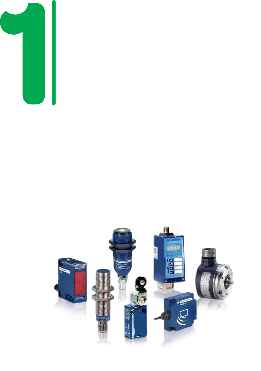
OsiSense
It’s the schneider Electric range name
of all the detection products.
Select the sensor according to your
specific requirements
A selection of 1500 products, with the
top 500 selling products (referenced
in bold characters in this document).
A complete offer for resolving your most
commonly encountered detection problems:
• product selection simplified
• product availability simplified
• installation and setting-up simplified
• maintenance simplified
•
detection simplified using a single supplier.
Improved simplicity for improved
productivity.

This document is a selection of
the top selling products.
Detection
1/1
2
1
3
4
5
6
7
8
9
10
Limit switches .....................................................................................................................................1/2 to 1/11
Detection by contact of rigid objects
Object speed ≤ 1.5 m/s, OsiSense XC
Sensors for pressure control ................................................................................................... 1/12 to 1/17
Detection by contact with fluid
Electronic or electromechanical pressure and vacuum switches,
pressure sensors, OsiSense XM
Inductive proximity sensors ...................................................................................................... 1/18 to 1/28
Detection without contact of metal objects
Sensor / object distance ≤ 60 mm, OsiSense XS
Capacitive proximity sensors .............................................................................................................. 1/29
Detection of insulating materials or conductive materials
Specific products for particular applications, OsiSense XT
Photo-electric sensors .................................................................................................................. 1/30 to 1/41
Detection without contact of any object
Detection from a few millimetres to several tens of metres, OsiSense XU
Ultrasonic sensors ........................................................................................................................ 1/42 and 1/43
Detection without contact of any object of any material
Detection from a few millimetres up to 8 metres, OsiSense XX
Rotary encoders ............................................................................................................................... 1/44 and 1/45
Opto-electronic detection
Incremental or absolute - single turn and multiturn, OsiSense XCC
Radio frequency identification ............................................................................................. 1/46 and 1/47
13.56 MHz RFID detection
Complete range of RFID tags and compact stations, OsiSense XG
Sensors for explosive atmospheres
See chapter 10 “Explosive Atmospheres”
Other versions: please consult your Schneider Electric agency.
13
14
22 21
BK
WH
BK
BU
BN
GN-YE
BK
WH
BK
BU
BN
GN-YE
ISO entry
(
to EN 50262)
13
14
22 21
1314
22 21
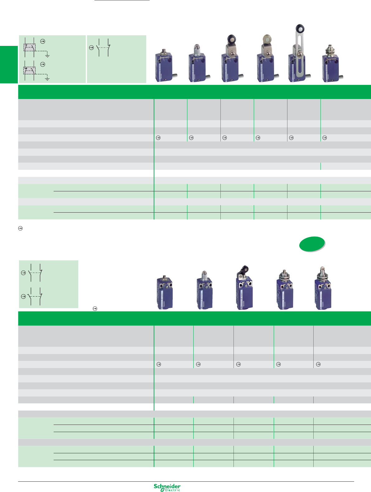
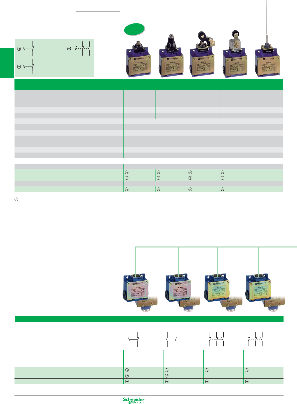
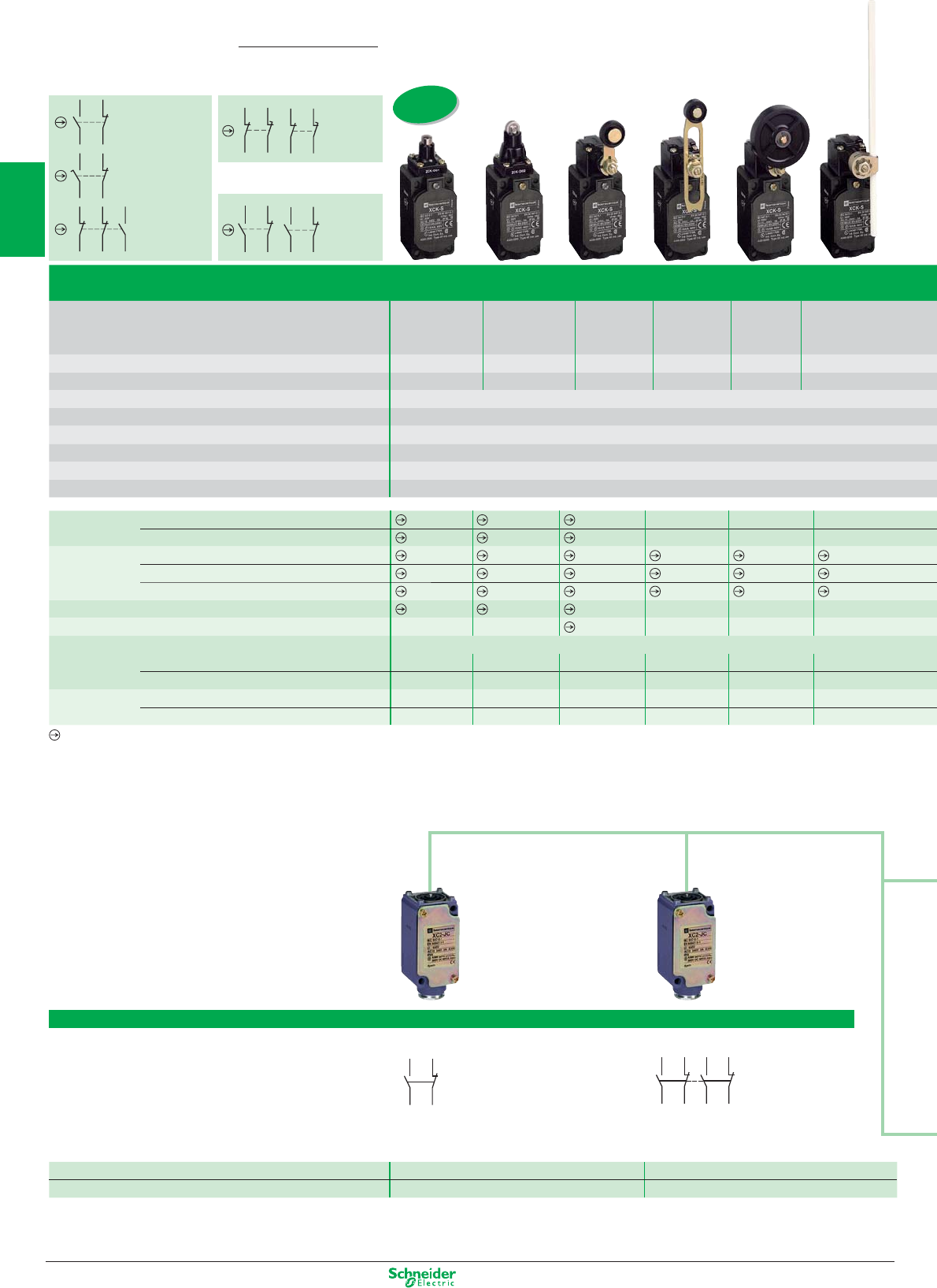
Limit switches
Compact and miniature, complete switches
(variable composition, see pages 34-35)
XCMD
2-pole contact
NC+NO
snap action
2-pole contact
NC+NO
slow break
XCKT
2-pole contact
NC+NO
snap action
XCKP/XCKD
2-pole contact
NC+NO
snap action
2-pole contact
NC+NO
slow break
OsiSense XC
Compact XCKD metal and XCKP plastic conforming to standard EN 50047
Type of operator Metal
end plunger
Steel
roller plunger
Thermoplastic
roller lever plunger,
horizontal actuation
in 1 direction
M18 head
metal
end plunger
M18 head
steel
roller plunger
Mechanical durability (millions of operating cycles) 15 10 15 10 10
Actuation speed (in m/s) 0.5 0.5 1 0.5 0.5
Switches conforming to standard IEC 947-5-1 section 3
Product certifi cation CE - CSA - CCC - GOST
Degree of protection conforming to IEC 60529 IP 66 and IP 67
Rated operational characteristics AC-15; A300 (Ue = 240 V, Ie = 3 A) / DC-13; Q300 (Ue = 250 V, Ie = 0.27 A)
Cable entry 1 tapped entry for ISO M16 x 1.5 cable gland (3) or M12 connector
Fixing centres (mm) 20 20 20 M18 x 1 M18 x 1
Body dimensions (mm) W x D x H 31 x 30 x 65
Metal switches
Complete switch 2-pole NC+NO snap action XCKD2110P16 XCKD2102P16 XCKD2121P16 XCKD21H0P16 XCKD21H2P16
2-pole NC+NO break before make, slow break XCKD2510P16 XCKD2502P16 XCKD2521P16 XCKD25H0P16 XCKD25H2P16
2-pole NC+NO snap action (M12-5 pins) XCKD2110M12 XCKD2102M12 XCKD2121M12 XCKD21H0M12 XCKD21H2M12
Plastic, double insulated switches
Complete switch 2-pole NC+NO snap action XCKP2110P16 XCKP2102P16 XCKP2121P16 XCKP21H0P16 XCKP21H2P16
2-pole NC+NO break before make, slow break XCKP2510P16 XCKP2502P16 XCKP2521P16 XCKP25H0P16 XCKP25H2P16
2-pole NC+NO snap action (M12-4 pins) XCKP2110M12 XCKP2102M12 XCKP2121M12 XCKP21H0M12 XCKP21H2M12
(3) For Pg 11 cable entries, replace P16 by G11. Example: XCKD2110P16 becomes XCKD2110G11.
For other cable entries, see customised assembly on page 1/34.
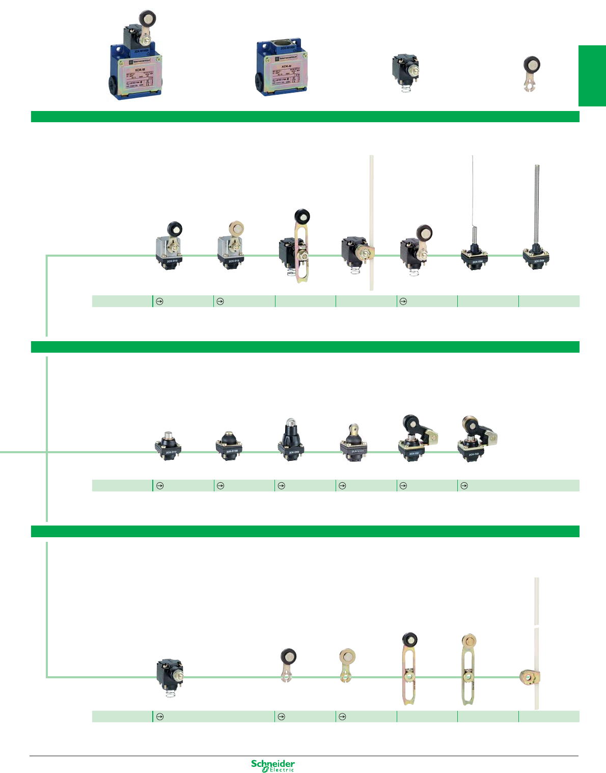
Miniature XCMD metal, pre-cabled; fi xing by the body or by the head
Type of operator Metal
end plunger
Steel roller
plunger
Thermoplastic
roller lever
Steel
roller lever
Variable length
thermoplastic
roller lever
M12 head
metal
end plunger
Mechanical durability (millions of operating cycles) 10 10 10 10 10 10
Actuation speed (in m/s) 0.5 0.5 1.5 1.5 1.5 0.5
Switches conforming to standard IEC 947-5-1 section 3
Product certifi cation CE - UL - CSA - CCC
Degree of protection conforming to IEC 60529 IP 66 and IP 67
Rated operational characteristics AC-15; B300 (Ue = 240 V, Ie = 1.5 A) / DC-13; R300 (Ue = 250 V, Ie = 0.1 A)
Fixing centres (mm) 20 M12 x 1
Body dimensions (mm) W x D x H 30 x 16 x 50
Connection Cable Pre-cabled, adjustable direction, length = 1 m (other lengths available on request)
Complete switch 2-pole NC+NO snap action XCMD2110L1 XCMD2102L1 XCMD2115L1 XCMD2116L1 XCMD2145L1 XCMD21F0L1
2-pole NC+NO break before make, slow break XCMD2510L1 XCMD2502L1 XCMD2515L1 XCMD2516L1 XCMD2545L1 XCMD25F0L1
Connector M12
Complete switch NC+NO snap action (M12-5 pins) XCMD2110C12 XCMD2102C12 XCMD2115C12 XCMD2116C12 XCMD2145C12 XCMD21F0C12
1C/O snap action (M12-4 pins) (1) XCMD2110M12 XCMD2102M12 XCMD2115M12 XCMD2116M12 XCMD2145M12 XCMD21F0M12
(1) Although their design is identical to the pre-cabled switches, the switches incorporating an M12 4-pin connector cannot be marked with the symbol because they are single-pole C/O.
Positive opening operation.
Positive opening operation.
1/2
2
1
3
4
5
6
7
8
9
10
Other versions: please consult your Schneider Electric agency.
ISO entry
(
to EN 50262)
ISO entry
(
to EN 50262)
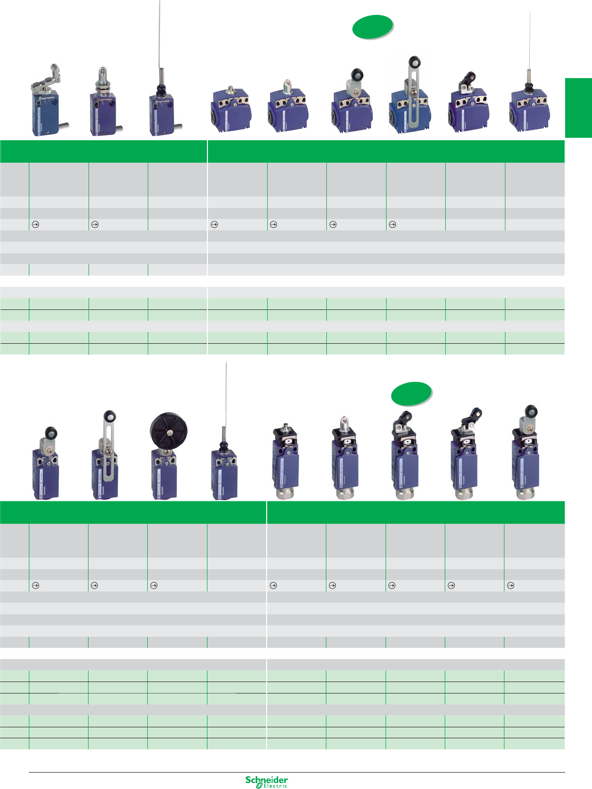
Application - XCPR and XCDR with manual reset
Thermoplastic
roller lever
Variable length
Thermoplastic
roller lever
Thermoplastic
roller lever
Ø 50 mm
“Cat’s whisker” Metal
end plunger
Steel
roller plunger
Thermoplastic
roller lever plunger,
horizontal actuation
in 1 direction
Thermoplastic
roller lever plunger,
vertical actuation
in 1 direction
Thermoplastic
roller lever
10 10 10 5 1 1 1 1 1
1.5 1.5 1.5 1 0.5 0.5 1 1 1.5
–
CE - CSA - CCC - GOST
IP 66 and IP 67
AC-15; A300 (Ue = 240 V, Ie = 3 A) / DC-13; Q300 (Ue = 250 V, Ie = 0.27 A)
1 tapped entry for ISO M20 x 1.5 cable gland (4)
20 20 20 20 20 20 20 20 20
31 x 30 x 95
XCKD2118P16 XCKD2145P16 XCKD2139P16 XCKD2106P16 XCDR2110P20 XCDR2102P20 XCDR2121P20 XCDR2127P20 XCDR2118P20
XCKD2518P16 XCKD2545P16 XCKD2539P16 XCKD2506P16 XCDR2510P20 XCDR2502P20 XCDR2521P20 XCDR2527P20 XCDR2518P20
XCKD2118M12 XCKD2145M12 XCKD2139M12 XCKD2106M12 – – – – –
XCKP2118P16 XCKP2145P16 XCKP2139P16 XCKP2106P16 XCPR2110P20 XCPR2102P20 XCPR2121P20 XCPR2127P20 XCPR2118P20
XCKP2518P16 XCKP2545P16 XCKP2539P16 XCKP2506P16 XCPR2510P20 XCPR2502P20 XCPR2521P20 XCPR2527P20 XCPR2518P20
XCKP2118M12 XCKP2145M12 XCKP2139M12 XCKP2106M12 – – – – –
(4) For Pg 13.5 cable entries, replace P20 by G13. Example: XCDR2110P20 becomes XCDR2110G13.
For other cable entries, see customised assembly on page 1/34.
Compact XCKT plastic, 2 cable entries
Retractable
steel roller lever
plunger
M12 head
steel
roller plunger
“Cat’s whisker” Metal
end plunger
Steel
roller plunger
Thermoplastic
roller lever
Thermoplastic
roller lever
plunger, horizon-
tal actuation
“Cat’s whisker” “Cat’s whisker”
10 105 151010155 5
0,5 0.1 1 0.5 0.5 1.5 1 1 1
– ––
CE - CSA - CCC - GOST
IP 66 and IP 67
AC-15; A300 (Ue = 240 V, Ie = 3 A) / DC-13; Q300 (Ue = 250 V, Ie = 0.27 A)
20 M12 x 1 20 20 or 40
58 x 30 x 51
2 tapped entries for ISO M16 x 1.5 cable gland (2)
XCMD2124L1 XCMD21F2L1 XCMD2106L1 XCKT2110P16 XCKT2102P16 XCKT2118P16 XCKT2145P16 XCKT2121P16 XCKT2106P16
XCMD2524L1 XCMD25F2L1 XCMD2506L1 – –––––
XCMD2124C12 XCMD21F2C12 XCMD2106C12 – –––––
XCMD2124M12 XCMD21F2M12 XCMD2106M12 – –––––
(2) For Pg 11 cable entries, replace P16 by G11. Example: XCKT2110P16 becomes XCKT2110G11.
1/3
2
1
3
4
5
6
7
8
9
10
Other versions: please consult your Schneider Electric agency.
BK
WH
BK
BU
BN
GN-YE
RD
WH
RD
BU
BN
GN-YE
BK
WH
BK
BK
WH
BK
BU
BN
GN-YE
RD
WH
RD
BU
BN
GN-YE
BK
WH
BK
BK
WH
BK
BU
BN
GN-YE
RD-WH RD
VT
VT-WH
GN-YE
BK-WH BK
BU
BN
Reference ZCE01 ZCY15 (2) ZCY16 (2) ZCY25 (2) ZCY25 (2)
Limit switches
Customised assembly of miniature and compact
Thermoplastic
roller lever plunger,
horizontal actuation
Metal
end plunger
Steel
roller plunger
Retractable steel
roller lever plunger
Metal end plunger
with protective
elastomer boot
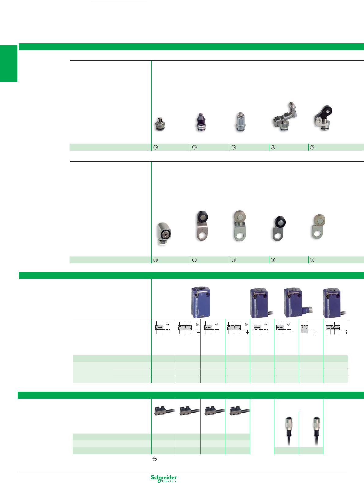
Metal plunger and multi-directional heads
Heads - common to miniature and compact bodies
Description
Metal rotary heads and levers
Rotary head
without lever,
spring return, for
actuation from
LH or RH side
Steel
roller lever,
track:
24/31 mm (ZCMD)
29/36 mm (ZCD/P/T)
Thermoplastic
roller lever,
track:
16/39 mm (ZCMD)
21/44 mm (ZCD/P/T)
Steel
roller lever,
track:
16/39 mm (ZCMD)
21/44 mm (ZCD/P/T)
Thermoplastic
roller lever,
track:
24/31 mm (ZCMD)
29/36 mm (ZCD/P/T)
Description
(1) Recommended for use with bodies: ZCD... / ZCP... / ZCT... (2)
Recommended for use with bodies: ZCMD...
Bodies
Reference ZCE10 ZCE11 ZCE02 ZCE24 (2) ZCE21
OsiSense XC
Specifi c pre-cabled
connection components
Option: pre-wired M12
connector, L = 2 m
5-pin 4-pin
for
ZCMD21
for
ZCMD39
for
ZCMD25
for
ZCMD37
L = 1 m ZCMC21L1 ZCMC39L1 ZCMC25L1 ZCMC37L1
L = 2 m ZCMC21L2 ZCMC39L2 ZCMC25L2 ZCMC37L2
L = 5 m ZCMC21L5 ZCMC39L5 ZCMC25L5 ZCMC37L5
XZCP1164L2 XZCP1141L2
Miniature
Positive opening operation.
Type of contact
2-pole
NO+NC
Snap action
3-pole
NC+NC+NO
Snap action
2-pole
NC+NO
Slow break
3-pole
NC+NC+NO
Slow break
2-pole
NO+NC
Snap action
2-pole
NC+NO
Snap action
Connector 5 pin
1-pole
1C/O
Snap action
Connector 4 pin
4-pole
NC+NC+NO+NO
Snap action
Reference of metal body ZCMD21 ZCMD39 ZCMD25 ZCMD37 –
ZCMD21C12 ZCMD21M12
–
Cable L = 1 m ––––
ZCMD21L1 (3)
––
ZCMD41L1
L = 2 m ––––
ZCMD21L2 (3)
––
ZCMD41L2
L = 5 m ––––
ZCMD21L5 (3)
––
ZCMD41L5
(3) For contact 2-pole NC+NO slow break, replace 21 by 25. Example: ZCMD21L1 becomes ZCMD25L1
Connection of miniature bodies
1/4
2
1
3
4
5
6
7
8
9
10
Other versions: please consult your Schneider Electric agency.
13
14
22 21
32 31
22 21
1314
13
14
22 21
13
14
22 21
13
14
22 21
13
14
22 21
32 31
22 21
1314
22 21
12 11
22 21
12 11
2324
1314
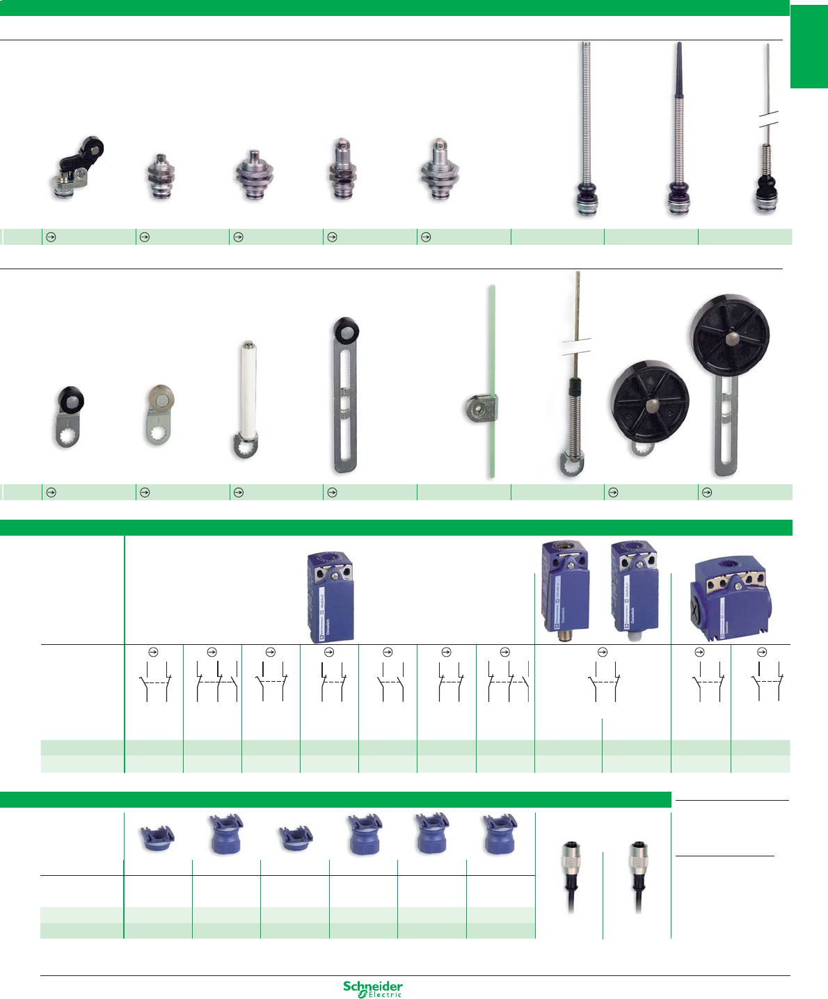
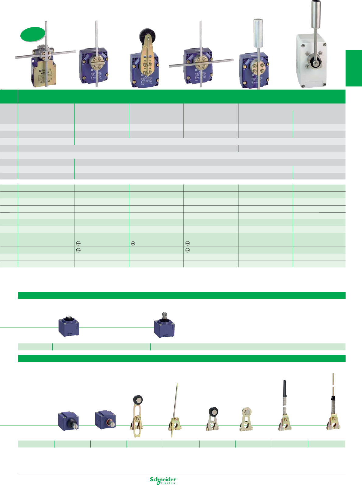
switches
Thermoplastic
roller lever plunger,
vertical actuation
M12 head
metal
end plunger
M18 head
metal
end plunger
M12 head
steel
roller plunger
M18 head
steel
roller plunger
Spring rod Spring rod with
plastic end
“Cat’s whisker”
Thermoplastic
roller lever,
track:
20/36 mm (ZCMD)
24/40 mm (ZCD/P/T)
Steel
roller lever,
track:
20/36 mm (ZCMD)
24/40 mm (ZCD/P/T)
Ceramic
roller lever
Variable length
thermoplastic
roller lever
Round,
glass fi bre
rod lever
Ø 3 mm
L = 125 mm
Metal
spring-rod
lever
Thermoplastic
roller lever
Ø 50 mm
Adjustable thermo-
plastic roller lever
Ø 50 mm
Interchangeable
outlet for cable
gland
Option: pre-wired M12 connector,
L = 2 m
5-pin 4-pin
XZCP1164L2 XZCP1141L2
ZCY18(1) ZCY19(1) ZCY22 ZCY45 ZCY55 ZCY91 ZCY39 ZCY49
ZCE27 ZCEF0(2) ZCEH0(1) ZCEF2(2) ZCEH2(1) ZCE08 ZCE07 ZCE06
Connection of compact bodies
Description For ISO M16 For ISO M20 For Pg 11 For Pg 13.5 For 1/2" NPT
For PF 1/2 (G12)
cable gland cable gland cable gland cable gland cable gland cable gland
Metal ZCDEP16 ZCDEP20 ZCDEG11 ZCDEG13 ZCDEN12 ZCDEF12
Plastic ZCPEP16 ZCPEP20 ZCPEG11 ZCPEG13 ZCPEN12 ZCPEF12
Compact
Type of contact
2-pole NC+NO
Snap action
3-pole
NC+NC+NO
Snap action
2-pole NC+NO
Slow break
2-pole NC+NC
Slow break
2-pole
NO+NO
Slow break
2-pole
NC+NC
Snap action
3-pole
NC+NC+NO
Slow break
2-pole NC+NO - Snap action
2-pole
NC+NO
Snap action
2-pole
NC+NO
Slow break
Connector
5-pin
Connector
4-pin
Ref. metal body ZCD21 ZCD39 ZCD25 ZCD27 ZCD28 ZCD29 ZCD37 ZCD21M12 – – –
Ref. plastic body ZCP21 ZCP39 ZCP25 ZCP27 ZCP28 ZCP29 ZCP37 – ZCP21M12
ZCT21P16
(1)
ZCT25P16
(1)
(1)
ZCT Pg 11 cable gland versions:
replace the suffi x P16 by G11
.
Example:
ZCT21P16 becomes ZCT21G11
ZCT 1/2" NPT versions:
replace the suffi x P16 by
N12 (adaptor).
Example:
ZCT21P16 becomes ZCT21N12
1 Cable entry 1/2" NPT
1 Cable entry Pg11
1/5
2
1
3
4
5
6
7
8
9
10
Other versions: please consult your Schneider Electric agency.
22 21
13
14
22 21
13
14
32 31
22 21
1314
32 31
22 21
1314
13
14
22 21
1314
22 21
13
14
22 21
1314
22 21
31
32
21
22
14 13
31
32
21
22
14 13
Limit switches
Classic - XCKM, XCKL, complete switches
XCKM
2-pole contact
NC+NO
snap action
2-pole contact
NC+NO
slow break
3-pole contact
NC+NC+NO
snap action
ISO entry
(
to EN 50262)
OsiSense XC
Classic - XCKM, XCKL,
Customised assembly - Body/contact sub-assemblies
Type XCKM metal, 3 cable entries, XCKL metal, 1 cable entry
Type of operator Metal
end plunger
Steel
roller plunger
Roller lever plunger,
horizontal actuation
in 1 direction
Thermoplastic
roller lever
“Cat’s whisker”
Mechanical durability (millions of operating cycles) 20 20 20 15 10
Actuation speed (in m/s) 0.5 0.5 1.5 1.5 0.5
Product certifi cation CE - UL - CSA - CCC - GOST - C-TICK - BV
Degree of protection conforming to IEC 60529 IP 665
Rated operational characteristics AC-15; A300 (Ue = 240 V, Ie = 3 A) / DC-13; Q300 (Ue = 250 V, Ie = 0.27 A)
Cable entry (1) XCKM 3 tapped entries for ISO M20 x 1.5 cable gland (2 entries fi tted with blanking plugs)
XCKL 1 cable entry with cable gland
Fixing centres (mm) 41
Body dimensions (mm) W x D x H XCKM / XCKL 64 x 30 x 64 / 52 x 30 x 72
Complete switch XCKM
2-pole NC+NO snap action XCKM110H29 XCKM102H29 XCKM121H29 XCKM115H29 XCKM106H29
2-pole NC+NO, break before make, slow break XCKM510H29 XCKM502H29 XCKM521H29 XCKM515H29 –
Complete switch XCKL
2-pole NC+NO snap action XCKL110 XCKL102 XCKL121 XCKL115 XCKL106
(1) For Pg 13.5 cable entries delete the reference suffi x H29. Example: XCKM110H29 becomes XCKM110.
Positive opening operation.
Type XCKM metal, 3 cable entries
Type of contact
2-pole
NC+NO
snap action
2-pole
NC+NO
slow break
3-pole
NC+NC+NO
snap action
3-pole
NC+NC+NO
slow break
Reference of body with contact block ZCKM1H29 ZCKM5H29 ZCKMD39H29 ZCKMD37H29
XCKL reference of body with contact block (2) ZCKL1 ZCKL5 ––
Reference of contact block only XE2SP2151 XE2NP2151 XE3SP2141 XE3NP2141
(2) For cable entry 1/2" NPT, add H7. Example: XCKL1 becomes XCKL1H7
1/6
2
1
3
4
5
6
7
8
9
10
Other versions: please consult your Schneider Electric agency.
Complete switch = Body/contact assembly + Head + Lever
Rotary or multi-directional heads
with thermoplastic
roller lever (2)
with steel roller
lever (2)
with variable length
thermoplastic
roller lever (2)
with Ø 6 mm
thermoplastic rod
L = 200 mm (3)
with thermoplastic
roller lever (3)
for actuation from
left AND right
or
left OR right
with “Cat’s
whisker”
with spring rod
Reference ZCKD15 ZCKD16 ZCKD41 ZCKD59 ZCKD31 ZCKD06 ZCKD08
Plunger heads
with metal
end plunger
with metal end
plunger and
protective boot
with steel
roller plunger
with steel roller
plunger and
protective boot
with thermoplastic
roller lever plunger,
horizontal actuation
in 1 direction
with steel
roller lever plunger,
horizontal actuation
in 1 direction
Reference ZCKD10 ZCKD109 ZCKD02 ZCKD029 ZCKD21 ZCKD23
Rotary heads and separate levers
spring return,
for actuation from
left AND right
or
left OR right
lever with
thermoplastic
roller (2)
lever with
steel roller (2)
variable length
lever with
thermoplastic
roller
(2)
variable length
lever with
steel roller (2)
rod, Ø 6 mm
thermoplastic
L = 200 mm (3)
Reference ZCKD05 ZCKY31 ZCKY33 ZCKY41 ZCKY43 ZCKY59
(2) Adjustable throughout 360° in 5° steps, or in 90° steps by reversing the notched washer.
(3) Adjustable throughout 360° in 5° steps, or in 45° steps by reversing the lever mounting.
Operating heads,
complete or for customer assembly
1/7
2
1
3
4
5
6
7
8
9
10
Other versions: please consult your Schneider Electric agency.
31
32
21
22
14 13
31
32
21
22
14 13
13
14
22 21
1314
22 21
13
14
22 21
1314
22 21
22 21
23
24
13
14
11
12
22 21
13
14
22 21
13
14
32 31
22 21
1314
32 31
22 21
1314
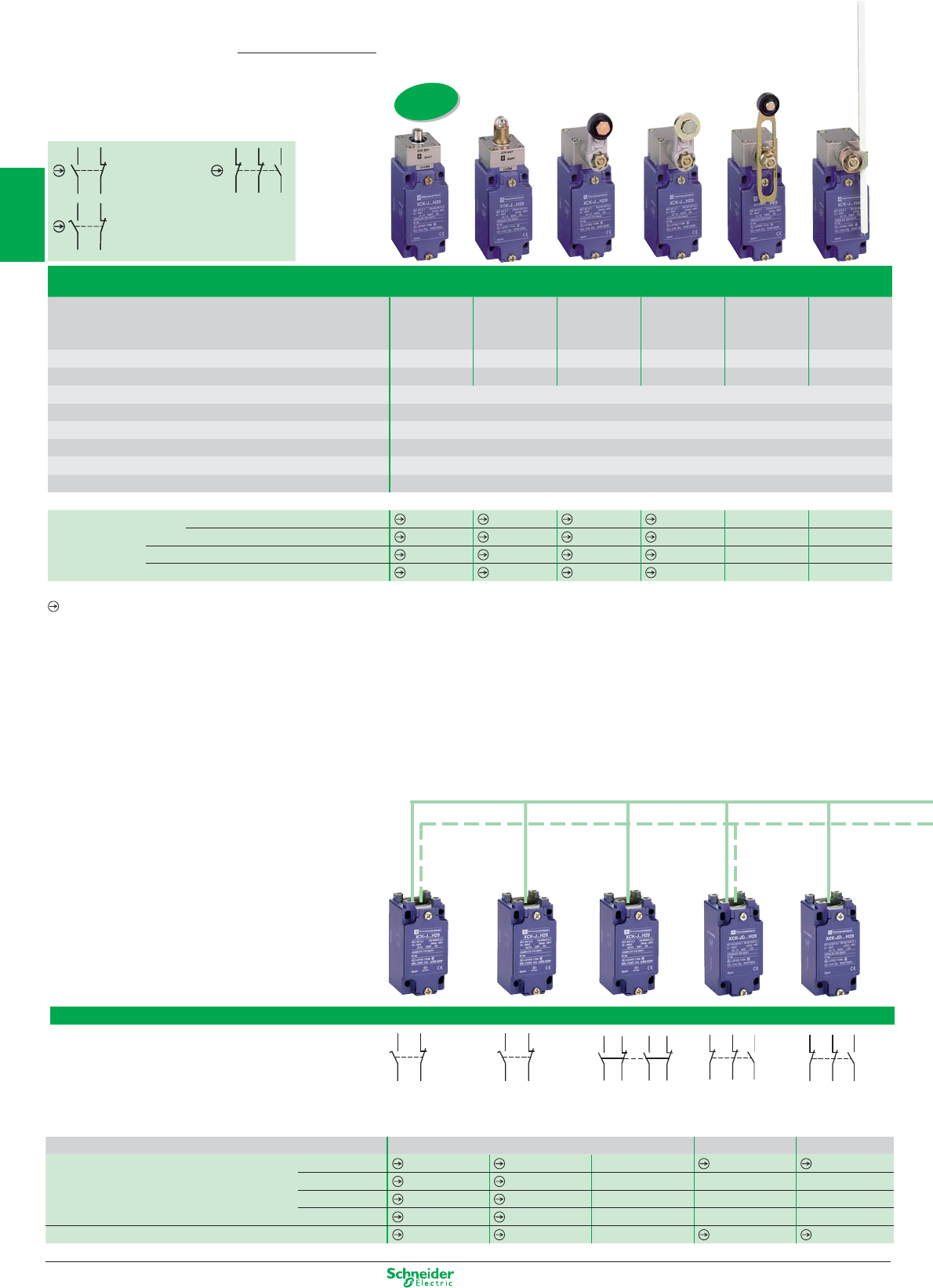
Type XCKJ metal, fixed body, conforming to standard EN 50041
Type of operator Metal
end plunger
Steel
roller plunger
Thermoplastic
roller lever
Steel
roller lever
Variable length
thermoplastic
roller lever
Polyamide Ø 6
mm rod lever
L = 200 mm
Mechanical durability (millions of operating cycles) 30 25 30 30 30 30
Actuation speed (in m/s) 0.5 1 1.5 1,5 1.5 1.5
Product certification CE - UL - CSA - CCC - GOST - C-TICK - BV
Degree of protection conforming to IEC 60529 IP 667
Rated operational characteristics AC-15; A300 (Ue = 240 V, Ie = 3 A) / DC-13; Q300 (Ue = 250 V, Ie = 0.27 A)
Cable entry (1) 1 tapped entry for ISO M20 x 1.5 cable gland
Fixing centres (mm) 30 x 60
Body dimensions (mm) W x D x H 40 x 44 x 77
Complete switch
M20
N2-pole NC+NO snap action
XCKJ161H29
XCKJ167H29
XCKJ10511H29
XCKJ10513H29 XCKJ10541H29 XCKJ10559H29
2-pole NC+NO break before make, slow break
XCKJ561H29
XCKJ567H29
XCKJ50511H29
XCKJ50513H29 XCKJ50541H29 XCKJ50559H29
1/2" NPT
2-pole NC+NO snap action XCKJ161H7 XCKJ167H7
XCKJ10511H7
XCKJ10513H7
XCKJ10541H7 XCKJ10559H7
M12 5P
2-pole NC+NO snap action XCKJ161D XCKJ167D XCKJ10511D XCKJ10513D XCKJ10541D XCKJ10559D
(1) For Pg 13.5 cable entry delete the reference suffix H29. Example: XCKJ161H29 becomes XCKJ161.
Positive opening operation.
Limit switches
Industrial - XCKJ, complete switches
XCKJ
2-pole contact
NC+NO
snap action
2-pole contact
NC+NO
slow break
3-pole contact
NC+NC+NO
snap action
ISO entry
(
to EN 50262)
OsiSense XC
2-pole
NC+NO
snap action
2-pole
NC+NO
slow break
2 C/O
snap action
Simultaneous
3-pole
NC+NC+NO
snap action
3-pole
NC+NC+NO
slow break
Cable entry (1) 1 tapped entry for ISO M20 x 1.5 cable gland
Reference of body with contact block M20 ZCKJ1H29 ZCKJ5H29 ZCKJ2H29 ZCKJD39H29 ZCKJD37H29
Pg13 ZCKJ1 ZCKJ5 ZCKJ2 – –
1/2" NPT ZCKJ1H7 ZCKJ5H7 ZCKJ2H7 – –
M12 (5 pin) ZCKJ1D ZCKJ5D –––
Reference of contact block only XE2SP2151 XE2NP2151 – XE3SP2141 XE3NP2141
Type XCKJ metal, 1 cable entry
Type of contact
Industrial - XCKJ,
Customised assembly - Body/contact sub-assemblies
1/8
2
1
3
4
5
6
7
8
9
10
Other versions: please consult your Schneider Electric agency.
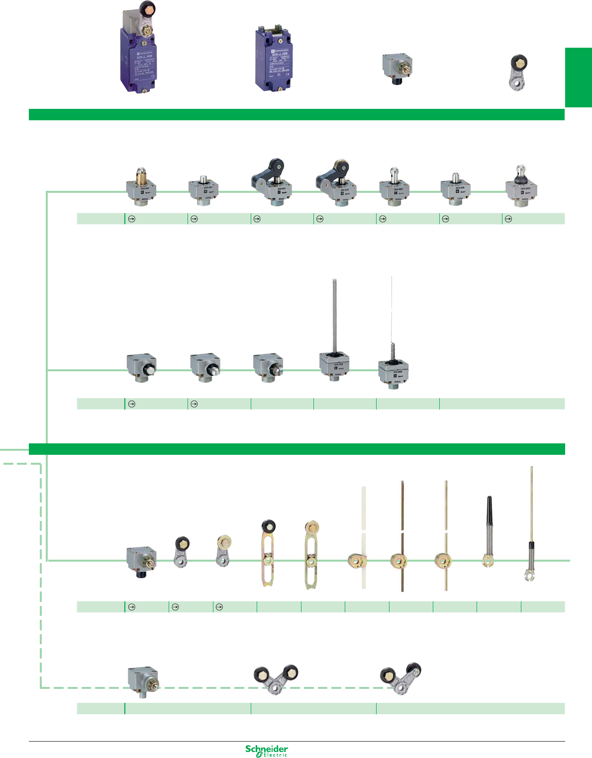
Operating heads,
complete or for customer assembly
Complete switch
= Body/contact assembly + Head
+ Lever
Plunger or multi-directional heads
with reinforced
steel roller
end plunger
with metal
end plunger
with thermoplastic
roller lever plunger,
1 direct. of actuation
with steel
roller lever plunger,
1 direct. of actuation
with steel roller
end plunger
with steel
ball bearing
end plunger
End steel roller
plunger with
protective boot
Référence ZCKE67 ZCKE61 ZCKE21 ZCKE23 ZCKE62 ZCKE66 ZCKE629
with metal
side plunger
Side steel roller
plunger,
horizontal
Side steel roller
plunger,
vertical
with spring rod with “Cat’s whisker”
Reference ZCKE63 ZCKE64 ZCKE65 ZCKE08 ZCKE06
Separate rotary heads and levers
spring return
for actuation
from
left AND right
or
left OR right
lever with
thermoplastic
roller (2)
lever with
steel roller (2)
variable length
lever with
thermoplastic
roller (2)
variable length
lever with
steel roller (2)
rod, Ø 6 mm
thermoplastic
L = 200 mm (2)
square rod lever,
steel, U 3 mm
L = 125 mm (2)
round rod lever,
steel, Ø 3 mm
L = 125 mm (2)
spring lever
with
thermoplastic
end (3)
spring-metal
rod lever
(3)
Reference ZCKE05 ZCKY11 ZCKY13 ZCKY41 ZCKY43 ZCKY59 ZCKY51 ZCKY53 ZCKY81 ZCKY91
stay put
for actuation from
left AND right
forked arm lever
with thermoplastic
rollers, 1 track (2)
forked arm lever
with thermoplastic
rollers, 2 track (2)
Reference ZCKE09 ZCKY71 ZCKY61
(2) Adjustable throughout 360° in 5° steps, or in 45° steps by reversing the lever mounting.
(3) Adjustable throughout 360° in 5° steps, or in 90° steps by reversing the notched washer.
1/9
2
1
3
4
5
6
7
8
9
10
Other versions: please consult your Schneider Electric agency.
22 21
23
24
12 11
13
14
12 11
13
14
13
14
22 21
1314
22 21
31
32
21
22
14 13
13
14
22 21
1314
22 21
11
12
22 21
1112
22 21
ISO entry
(
to EN 50262)
Limit switches
Classic - XCKS, complete switches
Type XCKS plastic, double insulated, conforming to standard EN 50041
Type of operator Metal
end plunger
Steel
roller plunger
Thermoplastic
roller lever
Variable length
thermoplastic
roller lever
Rubber
roller lever
Ø 50 mm
Polyamide
Ø 6 mm
rod lever
L = 200 mm
Mechanical durability (millions of operating cycles) 25 15 20 20 20 20
Actuation speed (in m/s) 0.5 0.5 1.5 1.5 1 1
Product certification CE - UL - CSA - CCC - GOST - C-TICK
Degree of protection conforming to IEC 60529 IP 653
Rated operational characteristics AC-15; A300 (Ue = 240 V, Ie = 3 A) / DC-13; Q300 (Ue = 250 V, Ie = 0.27 A)
Cable entry (1) 1 tapped entry for ISO M20 x 1.5 cable gland
Fixing centres (mm) 30 x 60
Body dimensions (mm) W x D x H 40 x 36 x 72.5
Complete switch 2-pole NC+NO snap action
XCKS101H29
XCKS102H29
XCKS131H29 XCKS141H29 XCKS139H29 XCKS159H29
2-pole NC+NO break before make, slow break
XCKS501H29
XCKS502H29
XCKS531H29 XCKS541H29 XCKS539H29 XCKS559H29
Body 2-pole NC+NO snap action ZCKS1H29 ZCKS1H29 ZCKS1H29 ZCKS1H29 ZCKS1H29 ZCKS1H29
2-pole NC+NO break before make, slow break ZCKS5H29 ZCKS5H29 ZCKS5H29 ZCKS5H29 ZCKS5H29 ZCKS5H29
3-pole NC+NC+NO snap action
ZCKSD39H29
ZCKSD39H29
ZCKSD39H29
ZCKSD39H29
ZCKSD39H29
ZCKSD39H29
Associated head (including operator) ZCKD01 ZCKD02 ZCKD31 ZCKD41 ZCKD39 ZCKD59
Operating lever for rotary head –– ZCKY31 ZCKY41 ZCKY39 ZCKY59
Complete switch
with 2-pole snap action contacts
2 x NC+NO contacts actuated in each direction –– – – – –
1 x NC+NO contact actuated in each direction – –––––
Complete switch 2 x single-pole C/O snap action contacts –– – – – –
2 x 2-pole NC+NC staggered, slow break contacts
–– – – – –
Positive opening operation.
(1)
For Pg 13.5 cable entry delete the reference suffix H29. Example: XCKJ161H29 becomes XCKJ161.
For severe applications - XC2J,
Customised assembly - Body/contact sub-assemblies
Type XC2J metal, fixed body, 1 cable entry incorporating cable gland
Type of contact
Single-pole
1 C/O contact
snap action
Double-pole
2 C/O simultaneous contacts
snap action
Reference of body with contact block ZC2JC1 ZC2JC2
Reference of contact block only XCKZ01 XESP1021
XCKS
2-pole contact
NC+NO
snap action
2-pole contact
NC+NO
slow break
3-pole
NC+NC+NO
snap action
XCR
2 x 2-pole
contacts,
snap action
XCKMR
2 x 2-pole
contacts
NC+NC
staggered,
slow break
OsiSense XC
1/10
2
1
3
4
5
6
7
8
9
10
Other versions: please consult your Schneider Electric agency.
Types XCKMR and XCR “Application - hoisting, materials handling, conveying”
Square rod levers Square rod lever Large roller rod lever Square rod levers Conveyor belt shift monitoring switches
6 mm, “crossed” 6 mm Ø 50 mm 6 mm, “crossed” or “T” Galvanised steel
operating lever
Stainless steel
operating lever
2 10 10 10 0.3 0.3
1.5 1.5 1.5 1.5 1.5 1.5
CE - UL - CSA - GOST CE - CSA - CCC - GOST
IP 545 IP 665
AC-15; A300 (Ue = 240 V, Ie = 3 A) / DC-13; Q300 (Ue = 250 V, Ie = 0.27 A)
3 x ISO M20 x 1.5 entries 1 tapped entry for n° 13 cable gland (for ISO M20 x 1.5, adaptor DE9RA1620 must be ordered separately)
61.5 85 x 75 105 x 70
118 x 59 x 77 85 x 75 x 95 85 x 87 x 146
– –––––
– –––––
– –––––
– –––––
– –––––
– –––––
– –––––
– XCRA11(2) XCRA15 XCRE18(2) ––
– XCRB11(2) – XCRF17(3) ––
– XCRT115 XCRT315 (4)
XCKMR54D1H29 (2) –––––
(2) Steel rods, L = 200 mm (3) Steel “T” rods, L = 200 mm, W = 300 mm. (4) Polyester enclosure
Operating heads, complete or for customer assembly
Plunger heads
with metal end plunger with steel roller end plunger
Reference ZC2JE61 ZC2JE62
Rotary heads and separate levers
spring return
for actuation from
left AND right
spring return
for actuation from
left OR right
variable length lever
with thermoplastic
roller (1)
rigid rod
3 mm, steel
L = 125 mm (1)
lever with
thermoplastic roller
(1)
lever with
steel roller (1)
spring lever
(1)
spring-rod lever
Reference ZC2JE01 ZC2JE05 ZC2JY31 ZC2JY51 ZC2JY11 ZC2JY13 ZC2JY81 ZC2JY91
ry head(1) Adjustable throughout 360°. s and separate levers
ISO entry
(
to EN 50262)
Severe duty for hoisting and materials handling applications
XCKMR and XCR, complete switches
1/11
2
1
3
4
5
6
7
8
9
10
Other versions: please consult your Schneider Electric agency.
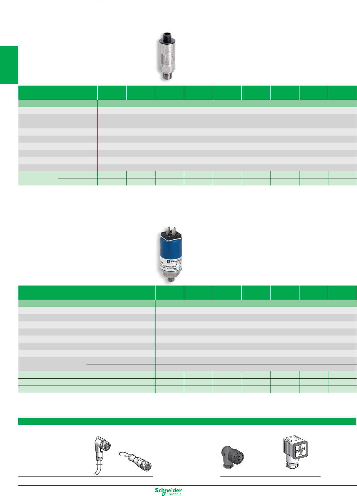
Sensors for pressure control
Electronic sensors XMLG
Electrical connection by M12 connector
Pressure range
(bar) (1)
-1…0 0…1 0…6 0…10 0…16 0…25 0…100 0…250 0…400
Fluids controlled Hydraulic oils, air, fresh water, sea water, corrosive fluids from -15…+125°C
Ambient air temperature - 15…+ 85°C
Degree of protection
(conforming to IEC 60529)
IP 66 and IP 67
Product certification CE - UL - CSA - GOST
Voltage limits 12…24 V DC, 8…33 V DC for 4…20 mA, 11.4…33V DC for 0…10 V
Dimensions (mm) Ø x L Ø 22.8 x 70 (not including connector)
Fluid connection (2) G 1/4" A (male)
Electrical connection (3) M12 connector
Type of output (4) 4…20 mA, 2-wire technique, 0…10V, 3-wire technique
Analogue output 4…20 mA
XMLGM01D21
XMLG001D21 XMLG006D21 XMLG010D21 XMLG016D21 XMLG025D21 XMLG100D21 XMLG250D21 XMLG400D21
0…10 V
XMLGM01D71
XMLG001D71 XMLG006D71 XMLG010D71 XMLG016D71 XMLG025D71 XMLG100D71 XMLG250D71 XMLG400D71
Available in bulk packs for selling in lots, please consult us.
The XMLG range also includes pressure switches, please consult us.
Electronic sensors XMLE
Electrical connection by DIN 43650 connector
Setting range
(bar) (1)
-1…0 0…1 0…10 0…25 0…100 0…250 0…600
Fluids controlled Hydraulic oils, air, fresh water, sea water, corrosive fluids from -15…+80°C
Ambient air temperature - 15…+ 80°C
Degree of protection (conforming to IEC 60529) IP 65
Product certification CE - UL - CSA - GOST
Voltage limits 24 V DC, 11…33 V DC
Dimensions (mm) Ø x L Ø 40 x 90 (not including connector)
Fluid connection (2) G 1/4" A (male)
Electrical connection (3) DIN 43650 connector
Type of output (4) Transmitter 4…20 mA, 2-wire technique
Pressure switch PNP or NPN, normally closed (NC)
Analogue output 4…20 mA
XMLEM01U1C21 XMLE001U1C21 XMLE010U1C21 XMLE025U1C21 XMLE100U1C21 XMLE250U1C21 XMLE600U1C21
NPN output
XMLEM01U1C31 XMLE001U1C31 XMLE010U1C31 XMLE025U1C31 XMLE100U1C31 XMLE250U1C31 XMLE600U1C31
PNP output
XMLEM01U1C41 XMLE001U1C41 XMLE010U1C14 XMLE025U1C41 XMLE100U1C41 XMLE250U1C41 XMLE600U1C41
(1) Other sizes, please consult us. (3) Other types of connection, please consult us.
(2) Other fluid connections, please consult us. (4) Other types of output; 0…5 V, 0…10 V, etc., please consult us.
Suitable female plug-in connectors
Pre-wired connectors, L = 5 m (without LED) Other connectors
elbowed straight Screw terminal DIN 43650A
M12 XZCP1241L5 XZCP1141L5 XZCC12FCM40B XZCC43FCP40B
OsiSense XM
1/12
2
1
3
4
5
6
7
8
9
10
Other versions: please consult your Schneider Electric agency.
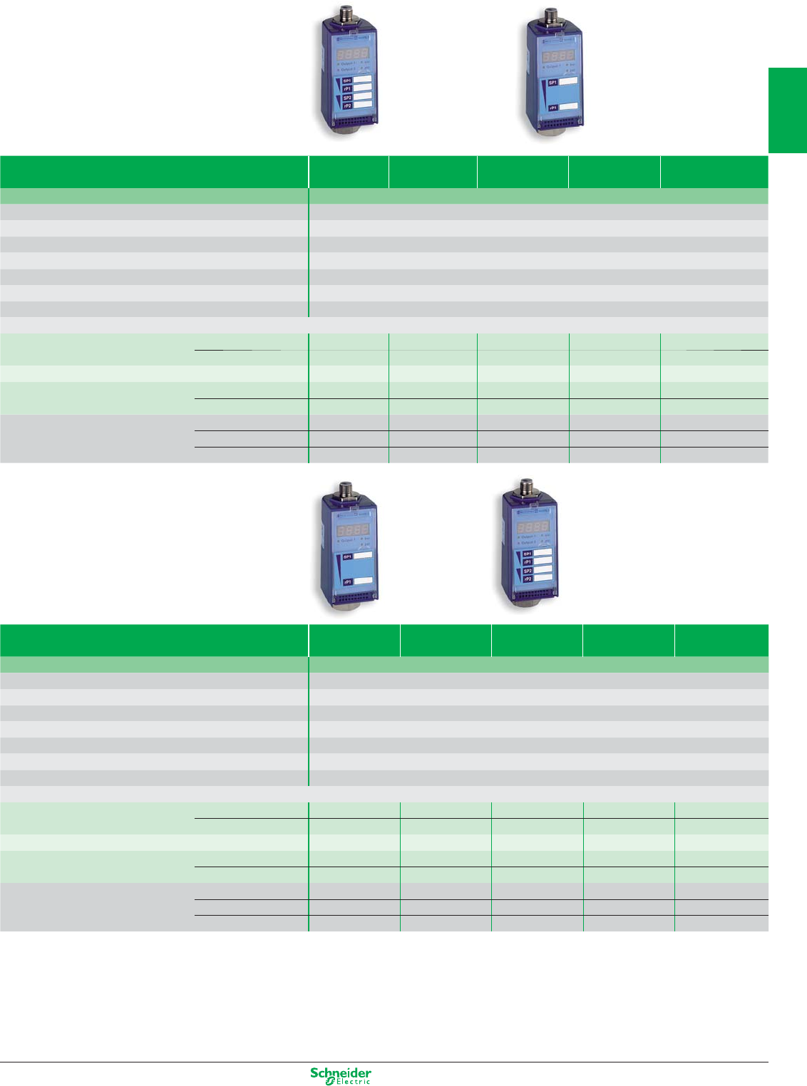
Electronic sensors XMLF
Setting range
(bar)
of lower limit (PB):
of upper limit (PH):
vacuum switches
pressure switches -0.08…-1 0.08...1 0.2…2.5 0.8…10 3.2...40
Fluids controlled Hydraulic oils, air, fresh water, sea water, corrosive fluids from -15…+80°C
Ambient air temperature - 25…+ 80°C
Degree of protection (conforming to IEC 60529) IP 67
Product certification CE - UL - CSA - VIT-SEPRO - GOST
Voltage limits (V) 24 V DC (17…33 V DC)
Dimensions (mm) H x W x D 113 x 46 x 58
Fluid connection G 1/4" (female) (1)
Electrical connection M12 connector (2)
Configurable with digital display, connection by M12 connector (3)
Universal sensors, 4...20 mA XMLFM01D2025 XMLF001D2025 XMLF002D2025 XMLF010D2025 XMLF040D2025
solid-state output, 200 mA (4) 0...10 V XMLFM01D2125 XMLF001D2125 XMLF002D2125 XMLF010D2125 XMLF040D2125
Dual stage pressure switches, solid-state output, 200 mA XMLFM01D2035 XMLF001D2035 XMLF002D2035 XMLF010D2035 XMLF040D2035
Analogue sensors 4...20 mA XMLFM01D2015 XMLF001D2015 XMLF002D2015 XMLF010D2015 XMLF040D2015
0...10 V XMLFM01D2115 XMLF001D2115 XMLF002D2115 XMLF010D2115 XMLF040D2115
Possible differential (bar) Min. at low setting 0.03 0.03 0.08 0.3 1.2
(pressure switches) Min. at high setting 0.03 0.03 0.08 0.3 1.2
Max. at high setting 0.95 0.95 2.38 9.5 38
Setting range
(bar)
of upper limit (PH): pressure switches 8…100 12.8...160 20...250 32...400 48...600
Fluids controlled Hydraulic oils, air, fresh water, sea water, corrosive fluids from -15…+80°C
Ambient air temperature - 25…+ 80°C
Degree of protection (conforming to IEC 60529) IP 67
Product certification CE - UL - CSA - VIT-SEPRO - GOST
Voltage limits (V) 24 V DC (17…33 V DC)
Dimensions (mm) H x W x D 113 x 46 x 58
Fluid connection G 1/4" (female) (1)
Electrical connection M12 connector (2)
Configurable with digital display, connection by M12 connector (3)
Universal sensors, 4...20 mA XMLF100D2025 XMLF160D2025 XMLF250D2025 XMLF400D2025 XMLF600D2025
solid-state output, 200 mA (4) 0...10 V XMLF100D2125 XMLF160D2125 XMLF250D2125 XMLF400D2125 XMLF600D2125
Dual stage pressure switches, solid-state output, 200 mA XMLF100D2035 XMLF160D2035 XMLF250D2035 XMLF400D2035 XMLF600D2035
Analogue sensors 4...20 mA XMLF100D2015 XMLF160D2015 XMLF250D2015 XMLF400D2015 XMLF600D2015
0...10 V XMLF100D2115 XMLF160D2115 XMLF250D2115 XMLF400D2115 XMLF600D2115
Possible differential (bar) Min. at low setting 3 4.8 7.5 12 18
(pressure switches) Min. at high setting 3 4.8 7.5 12 18
Max. at high setting 95 152 237.5 380 570
(1) Available with other fluid connections: 1/4" NPT female and SAE 7/16-20 UNF.
(2) For M12 connection accessories, see previous page.
(3) AC 120 V version with 2.5 A relay output and SAE 7/8-16 UN connector also available.
(4) Programmable NPN or PNP and NO or NC.
1/13
2
1
3
4
5
6
7
8
9
10
Other versions: please consult your Schneider Electric agency.
ISO entry
(
to EN 50262)
ISO entry
(
to EN 50262)
12 11
13
14
22 21
23
24
12 11
13
14
22 21
23
24
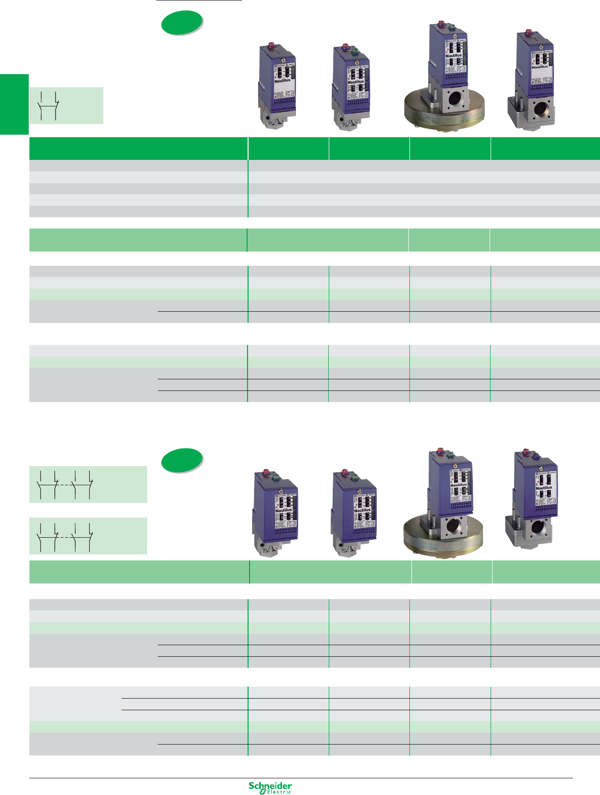
Sensors for pressure control
Electromechanical pressure and vacuum switches
XMLA and B
Size (bar) -1 5 1 2.5
Environmental characteristics Ambient air temperature (°C): - 25…+ 70 Degree of protection (conforming to IEC 60529): IP 66
Rated operational characteristics AC-15; B300 (Ue = 240 V, Ie = 1.5 A - Ue = 120 V, Ie = 3 A) / DC-13; R300 (Ue = 250 V, Ie = 0.1 A)
Product certification CE - UL - CSA - CCC - BV - LROS - RINA - GL - DNV - VIT-SEPRO - GOST
Fluid connection G 1/4" (female) (other connections possible, please consult us)
Electrical connection Screw terminals (1), tapped entry for ISO M20 x 1.5 cable gland - For n° 13 (DIN Pg 13.5) cable gland
Fluids controlled Hydraulic oils, fresh water,
sea water, air up to 70°C
Hydraulic oils,
air up to 160°C
Hydraulic oils
, fresh water,
sea water, air up to 70°C
Type XMLA - fixed differential, single threshold detection
Setting range (bar) of upper limit (PH): pressure switches -0.28…-1 (4) – 0.03…1 0.15…2.5
Dimensions (mm) H x W x D 113 x 35 x 75 113 x 35 x 75 162 x 110 x 110 158 x 55 x 77.5
With setting scale 1 C/O single-pole, snap action contact XMLAM01V2S12 – XMLA001R2S12 XMLA002A2S12
Natural differential (bar) at low setting 0.24 (2) – 0.02 0.13
subtract from PH to give PB at high setting 0.24 (2) – 0.04 0.13
Type XMLB - adjustable differential, regulation between 2 thresholds
Setting range (bar) of upper limit (PH): pressure switches -0.14...-1 (4) -0.5...5 0.05...1 0.3...2.5
With setting scale 1 C/O single-pole, snap action contact XMLBM02V2S12 XMLBM05A2S12 XMLB001R2S12 XMLB002A2S12
Possible differential (bar) Min. at low setting 0.13 (3) 0.5 0.04 0.16
subtract from PH to give PB Min. at high setting 0.13 (3) 0.5 0.06 0.21
Max. at high setting 0.8 (3) 6 0.75 1.75
XMLC and D
Fluids controlled Hydraulic oils, fresh water,
sea water, air up to 70°C
Hydraulic oils,
air up to 160°C
Hydraulic oils
, fresh water,
sea water, air up to 160°C
Type XMLC - adjustable differential, regulation between 2 thresholds
Setting range (bar) of upper limit (PH): pressure switches -0.14...-1 (4) -0.55...5 0.05...1 0.3...2.5
Dimensions (mm) H x W x D 113 x 46 x 85 113 x 46 x 85 175 x 110 x 110 158 x 55 x 90
With setting scale 2 C/O single-pole, snap action contacts XMLCM02V2S12 XMLCM05A2S12 XMLC001R2S12 XMLC002B2S12
Possible differential (bar) Min. at low setting 0.13 (4) 0.45 0.03 0.13
subtract from PH to give PB Min. at high setting 0.14 (4) 0.45 0.04 0.17
Max. at high setting 0.8 (4) 6 0.8 2
Type XMLD - fixed differential, dual stage, for detection at each threshold
Setting range
(bar)
2
nd
stage switching point (PB2) -0.12...-1 (4) – 0.12...1 0.34...2.5
1
st
stage switching point (PB1) -0.10...-0.98 – 0.04...0.92 0.2...2.36
Spread between 2 stages (PB2 – PB1) -0.02...-0.88 – 0.08...0.73 0.14...1.5
Without setting scale
2 C/O single-pole, snap action contacts (1 per stage)
XMLDM02V1S12 – XMLD001R1S12 XMLD002B1S12
Natural differential (bar) at low setting 0.1 (2) – 0.03 0.14
subtract from PH 1/2 to give PB 1/2 at high setting 0.1 (2) – 0.07 0.19
12 11
13
14
1 C/O
single-pole
contact,
snap action
2 C/O single-pole
contacts,
snap action
(1 per stage)
2 C/O single-pole
contacts,
simultaneous
snap action
XMLD
XMLC
OsiSense XM
1/14
2
1
3
4
5
6
7
8
9
10
Other versions: please consult your Schneider Electric agency.
4 10 20 35 70 160 300 500
conforming to IEC 947-5-1 Appendix A, EN 60 947-5-1
tapped entry, replace the last number of the reference (2) by 1 (example: XMLA010A2S12 becomes XMLA010A2S11)
Hydraulic oils, fresh water,
sea water, air up to 70°C
Hydraulic oils up to 160°C
0.4…4 0.6…10 1…20 1.5…35 5…70 10…160 20…300 30…500
113 x 35 x 75 113 x 35 x 75 113 x 35 x 75 113 x 35 x 75 113 x 35 x 75 113 x 35 x 75 113 x 35 x 75 113 x 35 x 75
XMLA004A2S12 XMLA010A2S12 XMLA020A2S12 XMLA035A2S12 XMLA070D2S12 XMLA160D2S12 XMLA300D2S12 XMLA500D2S12
0.35 0.5 0.4 1.25 3 5.5 16.5 20
0.35 0.5 1 1.25 7.5 18 35 45
0.25...4 0.7...10 1.3...20 3.5...35 7...70 10...160 22...300 30...500
XMLB004A2S12 XMLB010A2S12 XMLB020A2S12 XMLB035A2S12 XMLB070D2S12 XMLB160D2S12 XMLB300D2S12 XMLB500D2S12
0.02 0.57 1 1.7 4.7 9.3 19.4 23
0.25 0.85 1.6 2.55 8.8 20.8 37 52.6
2.4 7.5 11 20 50 100 200 300
(1) For electrical connection by DIN 43650A connector (IP 65), replace the suffix “S12” in the reference by “C11”. Example: XMLB010A2S12 becomes XMLB010A2C11.
(2) For vacuum switch: natural differential to be added to PB to give PH.
(3) For vacuum switch: possible differential to be added to PB to give PH.
(4) Setting range (bar) of lower limit (PB): vacuum switch.
Hydraulic oils, fresh water,
sea water, air up to 160°C
Hydraulic oils up to 160°C
0.3...4 0.7...10 1.3...20 3.5...35 7...70 12...160 22...300 30...500
113 x 46 x 85 113 x 46 x 85 113 x 46 x 85 113 x 46 x 85 113 x 46 x 85 113 x 46 x 85 113 x 46 x 85 113 x 46 x 85
XMLC004B2S12 XMLC010B2S12 XMLC020B2S12 XMLC035B2S12 XMLC070D2S12 XMLC160D2S12 XMLC300D2S12 XMLC500D2S12
0.15 0.45 0.7 1 4.5 9 16 19
0.17 0.7 1 1.5 8.9 21 35 52
2.5 8 11 22 60 110 240 340
0.40...4 1.2...10 2.14...20 4.4...35 9.4...70 16.5...160 36...300 41...500
0.19...3.79 0.52...9.32 0.9...18.76 1.9...32.5 6.6...67.2 10.5...154 25...289 25...484
0.21...2.18 0.68...5.8 1.24...9.55 2.5...20.4 2.8...46 6...83 11...189 16...244
XMLD004B1S12 XMLD010B1S12 XMLD020B1S12 XMLD035B1S12 XMLD070D1S12 XMLD160D1S12 XMLD300D1S12 XMLD500D1S12
0.15 0.45 0.7 1.5 5 8.8 17 21
0.19 0.6 1.3 2.6 9.5 20 42 65
1/15
2
1
3
4
5
6
7
8
9
10
Other versions: please consult your Schneider Electric agency.
22 21
13
14
22 21
13
14
22 21
13
14
22 21
13
14
Setting range of upper limit (PH) (bar) 1…6 1.3…12 3.5…25
Fluids controlled Air, water (fresh water, sea water) from 0…+70°C
Ambient air temperature - 25…+ 70°C
Degree of protection (conforming to IEC 60529) IP 54
Rated operational characteristics AC-15; B300 (Ue = 240 V, Ie = 1.5 A - Ue = 120 V, Ie = 3 A) / DC-13; R300 (Ue = 250 V, Ie = 0.1 A)
Product certification CE - UL - CSA - CCC
Dimensions (mm) H x W x D 106 x 57 x 98 126 x 57 x 98
Fluid connection 1/4" BSP female
Electrical connection Screw terminals, 2 tapped entries for n° 13 (DIN Pg 13.5) cable gland
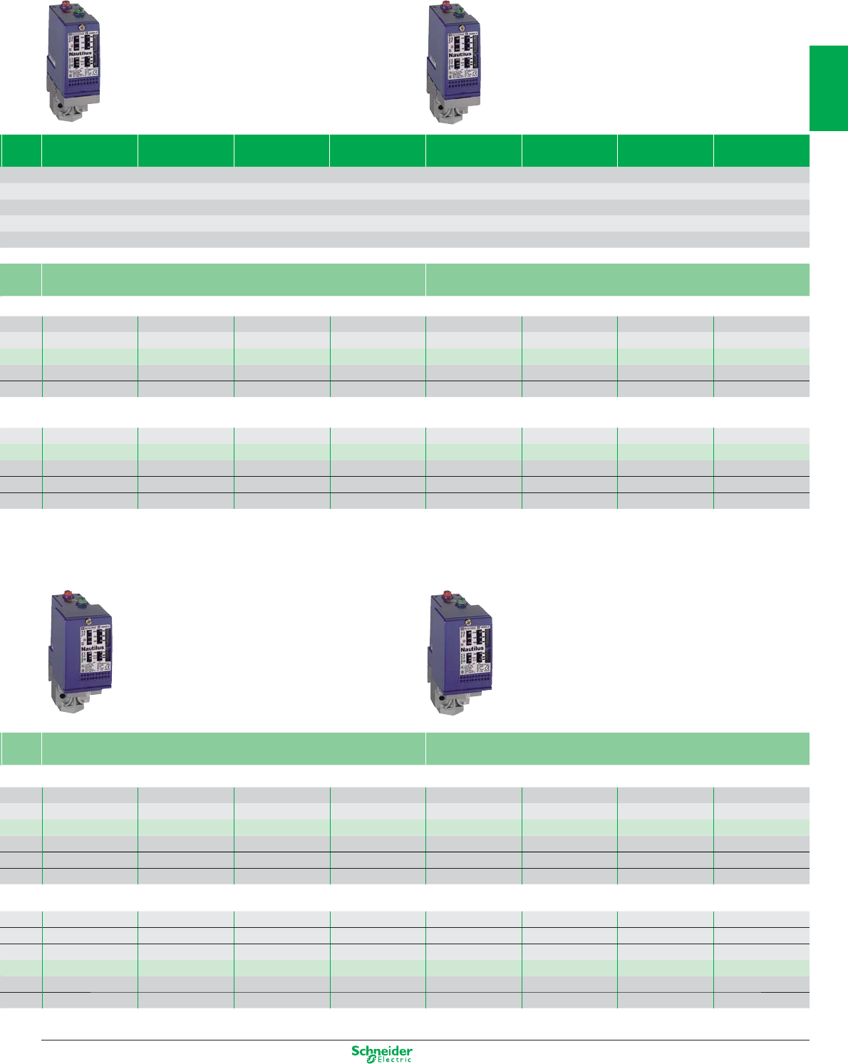
Type XMX with internal setting screw
Without setting scale, screw terminal connections
1 C/O single-pole, snap action contact XMXA06L2135 XMXA12L2135 XMXA25L2135
Possible differential (bar) Min. at low setting 0.8 1 3.4
subtract from PH to give PB Min. at high setting 1.2 1.7 4.5
Max. at high setting 4.2 8.4 20
Setting range of upper limit (PH) (bar) 1…6 1.3…12 3.5…25
Fluids controlled Air, water (fresh water, sea water) from 0…+70°C
Ambient air temperature - 25…+ 70°C
Degree of protection (conforming to IEC 60529) IP 54
Rated operational characteristics AC-15; B300 (Ue = 240 V, Ie = 1.5 A - Ue = 120 V, Ie = 3 A) / DC-13; R300 (Ue = 250 V, Ie = 0.1 A)
Product certification CE - UL - CSA - CCC
Dimensions (mm) H x W x D 113 x 57 x 98 133 x 57 x 98
Fluid connection 1/4" BSP female
Electrical connection Screw terminals, tapped entry for n° 13 (DIN Pg 13.5) cable gland
Type XMA with external setting screw (transparent cover)
Without setting scale, screw terminal connections
1 C/O single-pole, snap action contact XMAV06L2135 XMAV12L2135 XMAV25L2135
Possible differential (bar) Min. at low setting 0.8 1 3.4
subtract from PH to give PB Min. at high setting 1.2 1.7 4.5
Max. at high setting 4.2 8.4 20
Sensors for pressure control
Electromechanical pressure switches XMX, XMA
1 C/O
single-pole
contact,
snap action
1 C/O
single-pole
contact,
snap action
OsiSense XM
1/16
2
1
3
4
5
6
7
8
9
10
Other versions: please consult your Schneider Electric agency.
34
12
34
12
56
34
12
56
34
12
34
12
34
12
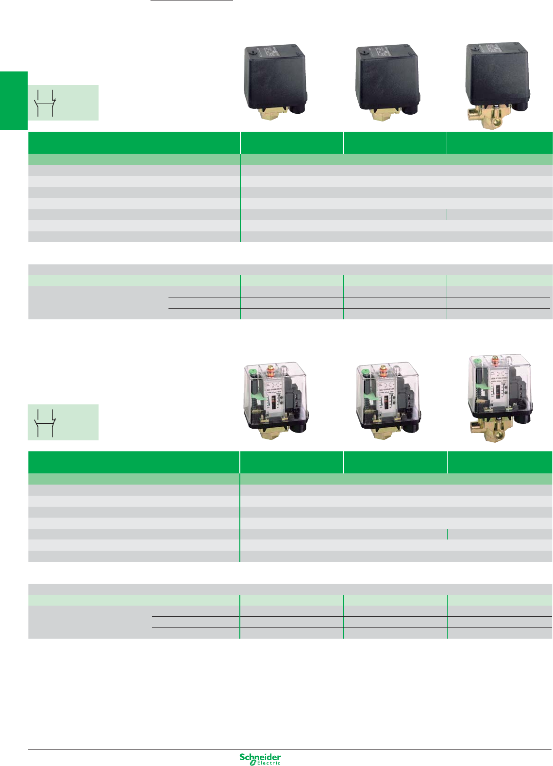
Electromechanical pressure switches
for power circuits, adjustable differential
for regulation between 2 thresholds
2 NC 2-pole
contact, snap action
2 NC 2-pole con-
tact, snap action
3 NC 3-pole con-
tact, snap action
Degree of protection IP 20 IP 65
Size (bar) 4.6 7 10.5 4.6 7 10.5
Setting range of upper limit (PH) (bar) 1.4…4.6 2.8…7 5.6…10.5 1.4…4.6 2.8…7 5.6…10.5
Fluids controlled Water (fresh water, sea water) from 0…+55°C
Electrical connection Screw terminals, 2 cable entries with grommet Screw terminals, 2 tapped entries
for n° 13 (DIN Pg 13.5) cable gland
Product certification CE
Ambient air temperature For operation: 0…+ 50°C. For storage: - 30…+ 80°C
Rated operational characteristics Ie = 10 A, Ue = 250 V AC
Power rating 110 V AC 2-pole, single-phase 0.75 kW (1 HP) 0.75 kW (1 HP)
of controlled AC 2-pole, 3-phase 1.1 kW (1.5 HP) 1.1 kW (1.5 HP)
motors 230 / 400 V AC 2-pole, single-phase 1.5 kW (2 HP) 1.5 kW (2 HP)
AC 2-pole, 3-phase 2.2 kW (3 HP) 2.2 kW (3 HP)
Dimensions (mm) H x W x D
96/105 x 72 x 102
94 x 72 x 102 115 x 72 x 106 115 x 72 x 106
Fluid connection G 1/4 (BSP female) FSG2 FYG22 FYG32 FSG2NE FYG22NE FYG32NE
R 1/4 (BSP male) FSG9 FYG29 FYG39 – – –
G 3/8 (BSP female) rotating nut – – – FSG2NEG – –
Possible differential (bar) At low setting
1 min. - 2.1 max. 1.2 min. - 2.3 max. 1.9 min. - 3 max. 1 min. - 2.1 max. 1.2 min. - 2.3 max. 1.9 min. - 3 max.
subtract from PH to give PB At middle setting
1.1 min. - 2.2 max. 1.4 min. - 2.5 max. 2.1 min. - 3.2 max. 1.1 min. - 2.2 max. 1.4 min. - 2.5 max. 2.1 min. - 3.2 max.
At high setting
1.2 min. - 2.3 max. 1.6 min. - 2.7 max. 2.3 min. - 3.4 max. 1.2 min. - 2.3 max. 1.6 min. - 2.7 max. 2.3 min. - 3.4 max.
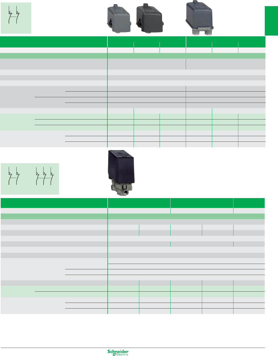
Size (bar) 6 12 25
Setting range of upper limit (PH) (bar) 1…6 1.3.…12 3.5…25
Fluids controlled Air, water (fresh water, sea water) from 0…+70°C
Ambient air temperature For operation: - 25…+ 70°C. For storage: - 40…+ 70°C
Decompression valve / ONOff knob without with without with without
Fluid connection G 1/4 (BSP female)
4 x G 1/4 (BSP female)
G 1/4 (BSP female)
4 x G 1/4 (BSP female)
G 1/4 (BSP female)
Electrical connection Screw terminals, 2 tapped entries for n° 13 (DIN Pg 13.5) cable gland
Degree of protection IP 54 IP 54 IP 54
Product certification CE - CCC
Rated insulation voltage Ui = 500 V
Electrical Power 1.5 kW 400 V AC 3-phase: 1 000 000 operating cycles
durability 230 V AC 3-phase: 600 000 operating cycles
2.2 kW 400 V AC 3-phase: 700 000 operating cycles
3 kW 400 V AC 3-phase: 500 000 operating cycles
Dimensions (mm) H x W x D 106 x 57 x 97.5 138 x 57 x 97.5 106 x 57 x 97.5 138 x 57 x 97.5 126 x 57 x 97.5
Type of contacts 2 NC 2-pole, snap action contact XMPA06B2131 XMPE06B2431 XMPA12B2131 XMPE12B2431 XMPA25B2131
3 NC 3-pole, snap action contact XMPA06C2131 XMPE06C2431 XMPA12C2131 XMPE12C2431 XMPA25C2131
Possible differential (bar) Min. at low setting 0.8 0.8 1 1 3.4
subtract from PH to give PB Min. at high setting 1.2 1.2 1.7 1.7 4.5
Max. at high setting 4.2 4.2 8.4 8.4 20
1/17
2
1
3
4
5
6
7
8
9
10
Other versions: please consult your Schneider Electric agency.
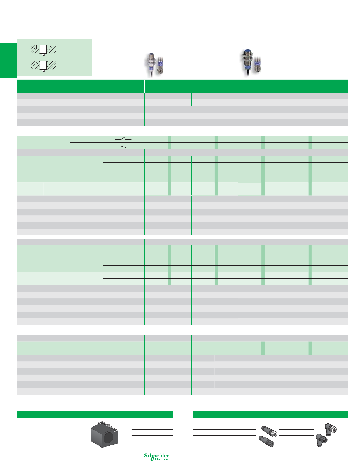
Non flush
mountable
Flush
mountable
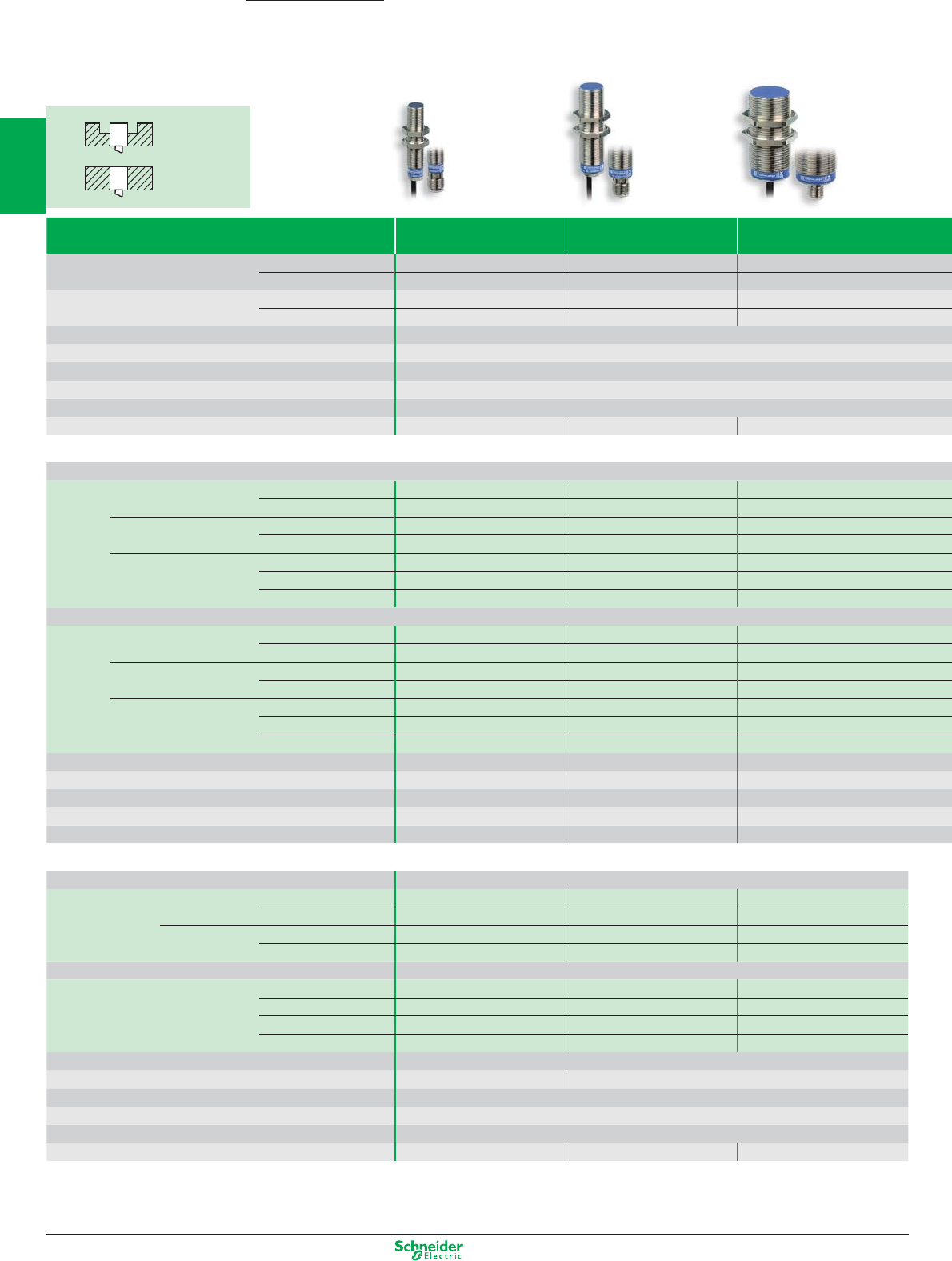
Inductive proximity sensors
Cylindrical metal
Flush standard and increased range
M8 M12
Nominal sensing distance Sn 1.5 mm 2.5 mm 2 mm 4 mm
Usable sensing distance S (mm) flush mountable / non flush mountable
0…1.2 0…2 0…1.6 0…3.2
Temperature range (°C) - 25…+ 70
Product certification
CE - UL - CSA - CCC (in progress) - C-TICK
Degree of protection (conforming to IEC 60529) IP 67 pre-cabled: IP 69K conforming to DIN 40050, IP 68
Sensors for DC applications
Output function
NO A A A A
NC BBBB
Dimensions (mm) Ø x L Cable / Connector M8 x 33 / M8 x 42 M12 x 35 / M12 x 50
3-wire PNP Cable (2 m) XS508B1PAL2 XS108B3PA L2 XS512B1PAL2 XS112B3PAL2
Connector M8 / M12 XS508B1PAM8 XS108B3PA M8 XS512B1PAM12 XS112B3P A M12
NPN Cable (2m) XS508B1NAL2 XS108B3NAL2 XS512B1NA L2 XS112B3NA L2
Connector M8 / M12 XS508B1N
A
M8 XS108B3N
A
M8 XS512B1N
A
M12 XS112B3N
A
M12
2-wire non Cable (2 m) XS508BSC
A
L2 XS608B3C
A
L2 XS512BSD
A
L2 XS612B3D
A
L2
polarised (1) Connecteur M12 XS508BSC
A
L01M12 XS608B3C
A
L01M12 XS512BSD
A
M12 XS612B3D
A
M12
Supply voltage limits, min./max. (V) including ripple 10…36 10…36 10…36 10…36
Switching capacity, max. (mA) 3-wire / 2-wire 200 / 100 200 / 100 200 / 100 200 / 100
Overload and short-circuit prot
ection (g) / LED outpu
t
state indicator
(⊗)
g / ⊗g / ⊗g / ⊗g / ⊗
Residual current, open state (mA) ≤ 0.5 ≤ 0.5 ≤ 0.5 ≤ 0.5
Voltage drop, closed state (V) at I nominal 3-wire / 2-wire ≤ 2 / ≤ 4 ≤ 2 / ≤ 4 ≤ 2 / ≤ 4 ≤ 2 / ≤ 4
Switching frequency (Hz) 3-wire / 2-wire 5000 / 4000 2500 / 3000 5000 / 4000 2500 / 2000
Dimensions (mm) Ø x L Cable / connector M8 x 51 / M8 x 62 M12 x 53 / M12 x 62
3-wire PNP Cable (2 m) XS508BLPAL2 XS608B1P A L2 XS512BLPA L2 XS612B1PA L2
Connector M12 XS508BLPA M12 XS608B1PAM12 XS512BLP A M12 XS612B1PA M12
NPN Cable (2 m) XS508BLNAL2 XS608B1NA L2 XS512BLN A L2 XS612B1NA L2
Connector M12 XS508BLN
A
M12 XS608B1N
A
M12 XS512BLN
A
M12 XS612B1N
A
M12
2-wire non Cable (2 m) XS508B1D
A
L2 XS608B1D
A
L2 XS512B1D
A
L2 XS612B1D
A
L2
polarised Connector M12 XS508B1D
A
M12 XS608B1D
A
M12 XS512B1D
A
M12 XS612B1D
A
M12
Supply voltage limits, min./max. (V) including ripple 10…58 10…58 10…58 10…58
Switching capacity, max. (mA) 3-wire / 2-wire 200 / 100 200 / 100 200 / 100 200 / 100
Overload and short-circuit protection (g) / LED output state indicator
(⊗)
g / ⊗g / ⊗g / ⊗g / ⊗
Residual current, open state (mA) 2-wire ≤ 0.5 ≤ 0.5 ≤ 0.5 ≤ 0.5
Voltage drop, closed state (V) at I nominal 3-wire / 2-wire ≤ 2 / ≤ 4 ≤ 2 / ≤ 4 ≤ 2 / ≤ 4 ≤ 2 / ≤ 4
Switching frequency (Hz) 3-wire / 2-wire 5000 / 4000 2500 / 3000 5000 / 4000 2500 / 2000
Multi-current/multi-voltage sensors for AC/DC applications
Dimensions (mm) Ø x L Cable / connector – – M12 x 53 / M12 x 62
2-wire Cable (2 m) ––XS512B1M
AL2
XS612B1M
AL2
Connector 1/2"-20 UNF
– – XS512B1M
A U20
XS612B1M
A U20
Supply voltage limits, min./max. (V) including ripple – – 20…264 20…264
Switching capacity, max. (mA) – – 200 200
LED output state indicator
(⊗)
––
⊗⊗
Residual current, open state (mA) – – ≤ 0,8 ≤ 0,8
Voltage drop, closed state (V) at I nominal – – ≤ 5.5 ≤ 5.5
Switching frequency (Hz) – – 25 AC / 1000 DC 25 AC / 1000 DC
(1) polarised for M8 short
OsiSense XS
Accessories
Fixing for cylindrical sensors
Suitable female plug-in connectors
M8 Straight Elbowed
Fixing clamp with indexing pin
for cylindrical sensors
M8 XSZB108 Metal ring XZCC8FDM30S XZCC8FCM30S
M12 XSZB112 M12 (4 pin)
M18 XSZB118 Metal ring XZCC12FDM40B XZCC12FCM40B
M30 XSZB130 Plastic ring XZCC12FDP40B XZCC12FCP40B
1/18
2
1
3
4
5
6
7
8
9
10
Other versions: please consult your Schneider Electric agency.
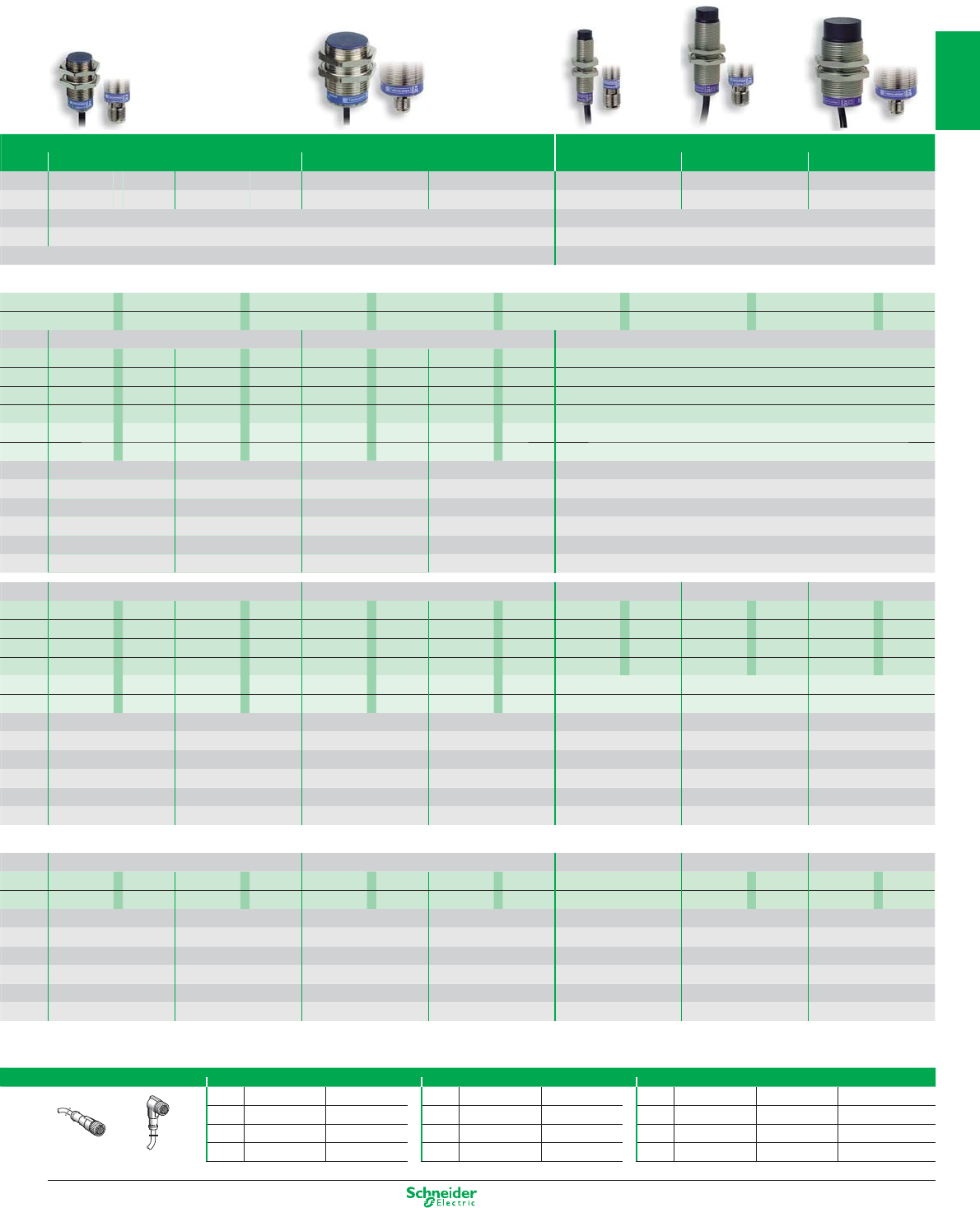
Non flush increased range
M18 M30 M12 M18 M30
5 mm 8 mm 10 mm 15 mm 7 mm 12 mm 22 mm
0…4 0…6.4 0…8 0…12 0…5.6 0…9.6 0…17.6
- 25…+ 70 - 25…+ 70
CE - UL - CSA - CCC (in progress) - C-TICK CE - UL - CSA - CCC (in progress) - C-TICK
(with connector: IP 67) pre-cabled: IP 69K conforming to DIN 40050, IP 68 (with connector: IP 67)
AAAAAAA
BBBBBBB
M18 x 39 / M18 x 50 M30 x 43 / M30 x 55 –
XS518B1P A L2 XS118B3P A L2 XS530B1P A L2 XS130B3P A L2
–
XS518B1P A M12 XS118B3P A M12 XS530B1P A M12 XS130B3P A M12
–
XS518B1N A L2 XS118B3N A L2 XS530B1N A L2 XS130B3N A L2
–
XS518B1N A M12 XS118B3N A M12 XS530B1N A M12 XS130B3N A M12
–
XS518BSD A L2 XS618B3D A L2 XS530BSD A L2 XS630B3D A L2
–
XS518BSD A M12 XS618B3D A M12 XS530BSD A M12 XS630B3D A M12
–
10…36 10…36 10…36 10…36 –
200 / 100 200 / 100 200 / 100 200 / 100 –
g / ⊗g / ⊗g / ⊗g / ⊗–
≤ 0.5 ≤ 0.5 ≤ 0.5 ≤ 0.5 –
≤ 2 / ≤ 4 ≤ 2 / ≤ 4 ≤ 2 / ≤ 4 ≤ 2 / ≤ 4 –
2000 / 3000 1000 / 1000 1000 / 2000 500 / 500 –
M18 x 62 / M18 x 74 M30 x 62 M12 x 55 / M12 x 65 M18 x 62 / M18 x 74 M30 x 62 / M30 x 74
XS518BLP A L2 XS618B1P A L2 XS530BLP A L2 XS630B1P A L2
XS612B4P
A
L2 XS618B4P
A
L2 XS630B4P
A
L2
XS518BLP A M12 XS618B1P A M12 XS530BLP A M12 XS630B1P A M12
XS612B4P
A
M12 XS618B4P
A
M12 XS630B4P
A
M12
XS518BLN AL2 XS618B1N AL2 XS530BLN AL2 XS630B1N AL2
XS612B4N
A
L2 XS618B4N
A
L2 XS630B4N
A
L2
XS518BLN AM12 XS618B1N AM12 XS530BLN AM12 XS630B1N AM12
XS612B4N
A
M12 XS618B4N
A
M12 XS630B4N
A
M12
XS518B1D AL2 XS618B1D AL2 XS530B1D AL2 XS630B1D AL2
–––
XS518B1D AM12 XS618B1D AM12 XS530B1D AM12 XS630B1D AM12
–––
10…58 10…58 10…58 10…58 10…58 10…58 10…58
200 / 100 200 / 100 200 / 100 200 / 100 200 / – 200 / – 200 / –
g / ⊗g / ⊗g / ⊗g / ⊗g / ⊗g / ⊗g / ⊗
≤ 0.5 ≤ 0.5 ≤ 0.5 ≤ 0.5 –––
≤ 2 / ≤ 4 ≤ 2 / ≤ 4 ≤ 2 / ≤ 4 ≤ 2 / ≤ 4 ≤ 2 / – ≤ 2 / – ≤ 2 / –
2000 / 3000 1000 / 1000 1000 / 2000 500 / 500 2500 / – 1000 / – 500 / –
M18 x 62 / M18 x 73 M30 x 62 / M30 x 73 – M18 x 60 / M18 x 72 M30 x 63 / M30 x 74
XS518B1M A L2 XS618B1M A L2 XS530B1M A L2 XS630B1M A L2
–XS618B4M
A
L2 XS630B4M
A
L2
XS518B1M A U20 XS618B1M A U20 XS530B1M A U20 XS630B1M A U20
–XS618B4M
A
U20 XS630B4M
A
U20
20…264 20…264 20…264 20…264 – 20…264 20…264
300 AC / 200 DC 300 AC / 200 DC 300 AC / 200 DC 300 AC / 200 DC – 300 AC / 200 DC 300 AC / 200 DC
⊗⊗⊗⊗
–
⊗⊗
≤ 0.8 ≤ 0.8 ≤ 0.8 ≤ 0.8 – ≤ 0.8 ≤ 0.8
≤ 5.5 ≤ 5.5 ≤ 5.5 ≤ 5.5 – ≤ 5.5 ≤ 5.5
25 AC / 1000 DC 25 AC / 1000 DC 25 AC / 500 DC 25 AC / 500 DC – 25 AC / 1000 DC 25 AC / 300 DC
Pre-wired connectors M8 (3 pin) 1/2" M12 (4 pin)
Straight Elbowed Straight Elbowed
Straight Elbowed Elbowed PNP LED
2 m XZCP0566L2 XZCP0666L2 2 m XZCP1865L2 XZCP1965L2 2 m XZCP1141L2 XZCP1241L2 XZCP1340L2
5 m XZCP0566L5 XZCP0666L5 5 m XZCP1865L5 XZCP1965L5 5 m XZCP1141L5 XZCP1241L5 XZCP1340L5
10 m XZCP0566L10 XZCP0666L10 10 m XZCP1865L10 XZCP1965L10 10 m XZCP1141L10 XZCP1241L10 XZCP1340L10
Straight Elbowed
1/19
2
1
3
4
5
6
7
8
9
10
Other versions: please consult your Schneider Electric agency.
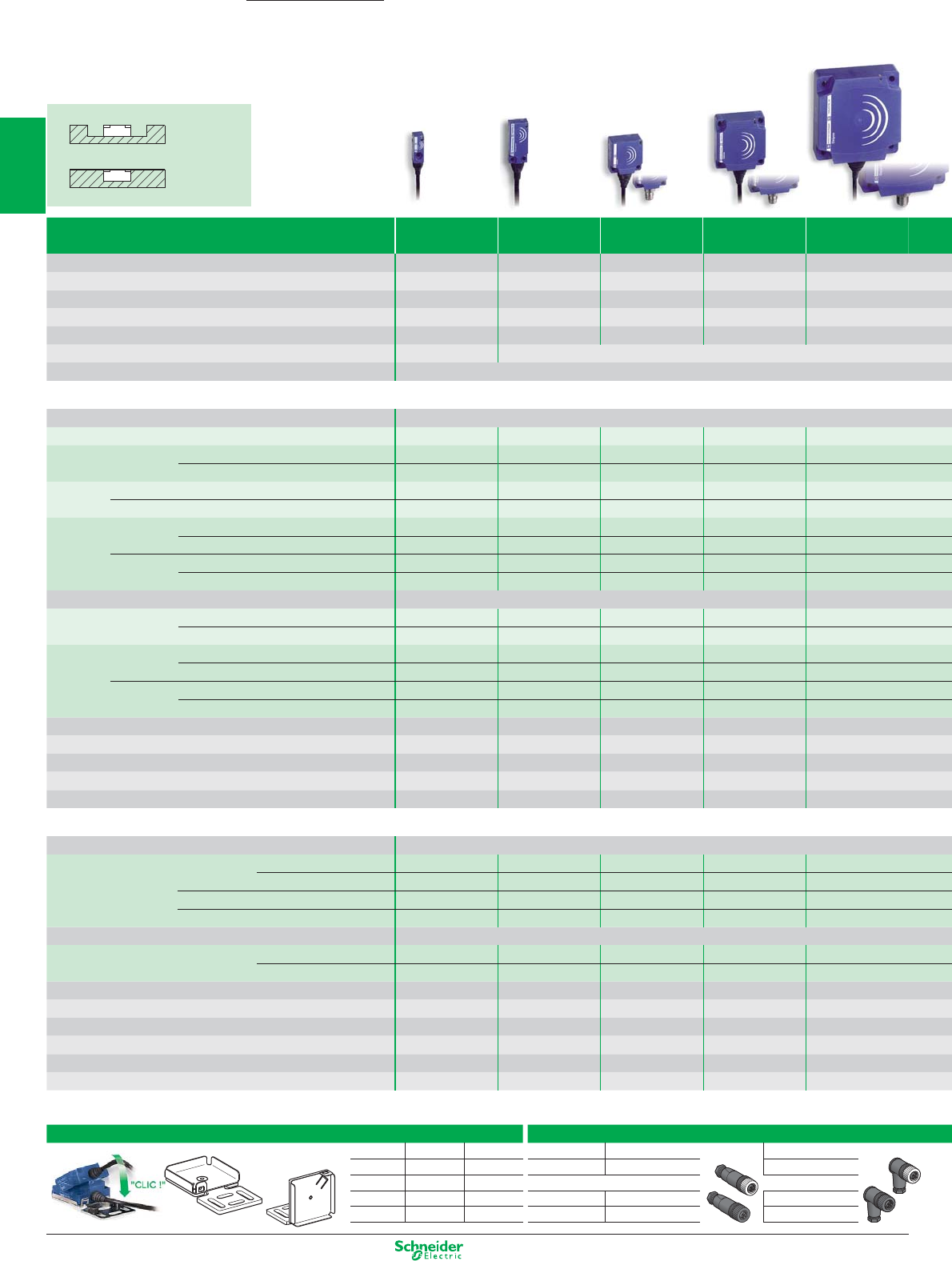
Non fl ush
mountable
Flush
mountable
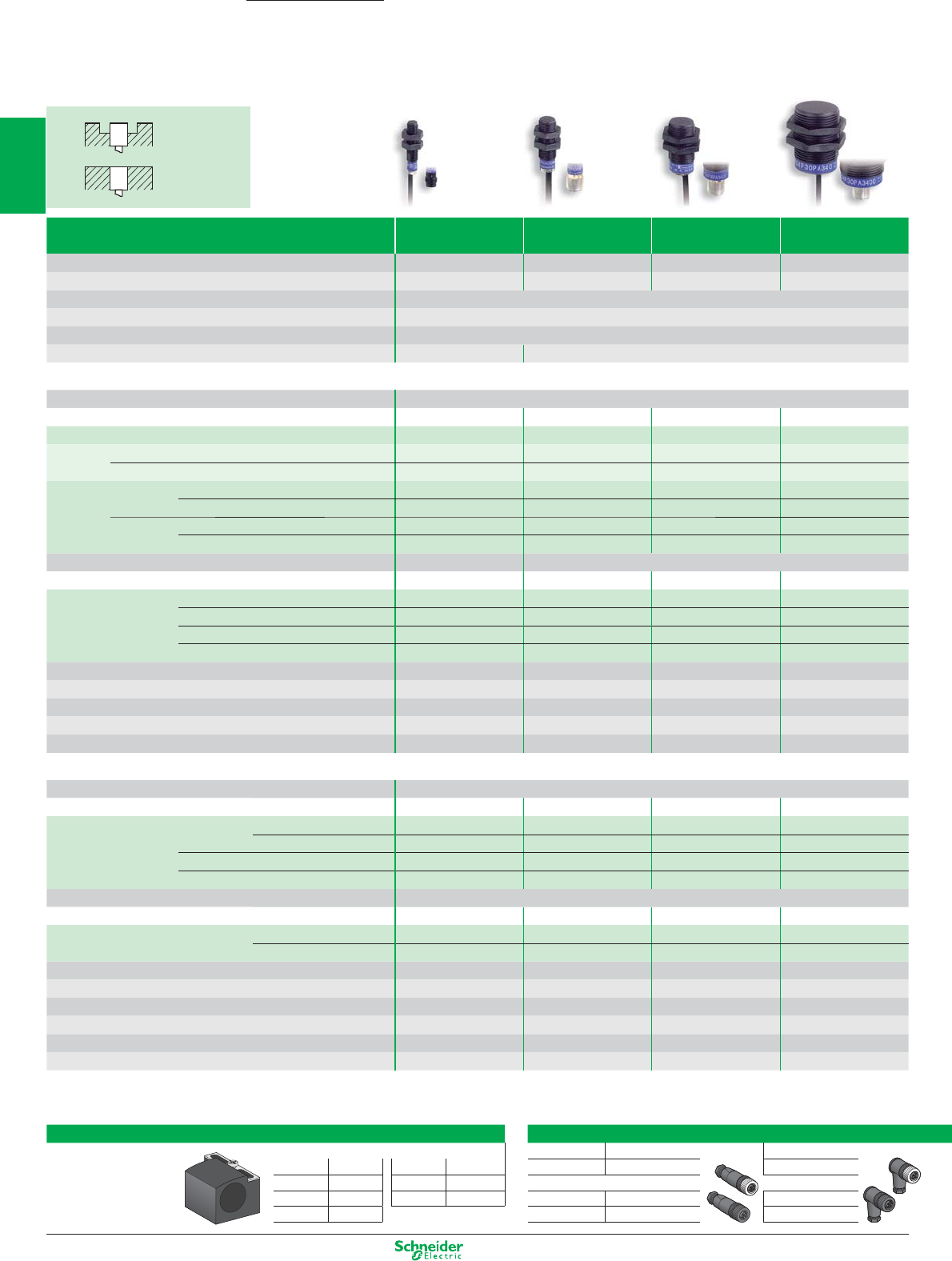
Inductive proximity sensors
Rectangular plastic
U 8 x 22 x 8 U 15 x 32 x 8 U 26 x 26 x 13 U 40 x 40 x 15 U 80 x 80 x 26
Nominal sensing distance Sn 2.5 mm 5 mm 10 mm 15 mm 40 mm
Usable sensing distance S (mm) fl ush mountable / non fl ush mountable
0...2 0...4 0…8 0…12 0…32
Fine adjustment zone (mm) fl ush mountable / non fl ush mountable – – – – –
Suitability for fl ush mounting (metal environment) fl ush mountable fl ush mountable fl ush mountable fl ush mountable fl ush mountable
Temperature range (°C) - 25…+ 70 - 25…+ 70 - 25…+ 70 - 25…+ 70 - 25…+ 70
Product certifi cation CE CE - UL - CSA - C-TICK
Degree of protection (conforming to IEC 60529) pre-cabled: IP 68 (with connector: IP 67)
Sensors for DC applications
Connection Pre-cabled, PvR (2 m)
2-wire (non polarised) NO or NC programmable –––––
2-wire non
polarised NO function XS7J1A1DAL2 XS7F1A1DAL2 XS7E1A1DAL2 XS7C1A1DAL2 XS7D1A1DAL2
NC function XS7J1A1DBL2 XS7F1A1DBL2 XS7E1A1DBL2 XS7C1A1DBL2 XS7D1A1DBL2
4-wire PNP NO + NC complementary outputs –––––
NPN NO + NC complementary outputs –––––
3-wire PNP NO function XS7J1A1PAL2 XS7F1A1PAL2 XS7E1A1PAL2 XS7C1A1PAL2 XS7D1A1PAL2
NC function XS7J1A1PBL2 XS7F1A1PBL2 XS7E1A1PBL2 XS7C1A1PBL2 XS7D1A1PBL2
NPN NO function XS7J1A1NAL2 XS7F1A1NAL2 XS7E1A1NAL2 XS7C1A1NAL2 XS7D1A1NAL2
NC function XS7J1A1NBL2 XS7F1A1NBL2 XS7E1A1NBL2 XS7C1A1NBL2 XS7D1A1NBL2
Connection M8 connector M12 connector
2-wire non
polarised NO function
XS7J1A1DAL01M8 (1) XS7F1A1DAL01M8 (1)
XS7E1A1DAM8 XS7C1A1DAM8 XS7D1A1DAM12
NC function
XS7J1A1DBL01M8 (1) XS7F1A1DBL01M8 (1)
XS7E1A1DBM8 XS7C1A1DBM8 XS7D1A1DBM12
3-wire PNP NO function
XS7J1A1PAL01M8 (1) XS7F1A1PAL01M8 (1)
XS7E1A1PAM8 XS7C1A1PAM8 XS7D1A1PAM12
NC function
XS7J1A1PBL01M8 (1) XS7F1A1PBL01M8 (1)
XS7E1A1PBM8 XS7C1A1PBM8 XS7D1A1PBM12
NPN NO function
XS7J1A1NAL01M8 (1) XS7F1A1NAL01M8 (1)
XS7E1A1NAM8 XS7C1A1NAM8 XS7D1A1NAM12
NC function
XS7J1A1NBL01M8 (1) XS7F1A1NBL01M8 (1)
XS7E1A1NBM8 XS7C1A1NBM8 XS7D1A1NBM12
Supply voltage limits, min./max. (V) including ripple 10…36 10…36 10…36 10…36 10…36
Switching capacity, max. (mA) 100 100 100 100 100
Short-circuit protect. (g) / LED output
state indicator (⊗) / Power on LED
(⊗)
g / ⊗ / – g / ⊗ / – g / ⊗ / – g / ⊗ / – g / ⊗ / –
Voltage drop, closed state (V) at I nominal cable / Connector ≤ 4 / ≤ 2 ≤ 4 / ≤ 2 ≤ 2 ≤ 2 ≤ 2
Switching frequency (Hz) cable / Connector 4000 / 2000 5000 / 2000 1000 1000 100
Multi-current/multi-voltage sensors for AC/DC applications
Connection
2-wire AC/DC NO function –––––
NC function –––––
AC NO or NC programmable –––––
AC/DC NO or NC programmable –––––
Connection
2-wire AC/DC NO function –––––
NC function –––––
Supply voltage limits, min./max. (V) including ripple –––––
Switching capacity, max. (mA) –––––
Short-circuit protect. (g) / LED output
state indicator (⊗) / Power on LED
(⊗)
–––––
Residual current, open state (mA) –––––
Voltage drop, closed state (V) at I nominal –––––
Switching frequency (Hz) –––––
(1) M8 connector on fl ying lead (L = 0.15 m).
OsiSense XS
Accessories
Fixing for fl at sensors
Suitable female plug-in connectors
fl at 90° M8 Straight Elbowed
8x22x8 XSZBJ00 XSZBJ90 Metal ring XZCC8FDM30S XZCC8FCM30S
15x32x8 XSZBF00 XSZBF90 M12 (4 pin)
26x26x13 XSZBE00 XSZBE90 Metal ring XZCC12FDM40B XZCC12FCM40B
40x40x15 XSZBC00 XSZBC90 Plastic ring XZCC12FDP40B XZCC12FCP40B
fl a t 90°
1/20
2
1
3
4
5
6
7
8
9
10
Other versions: please consult your Schneider Electric agency.
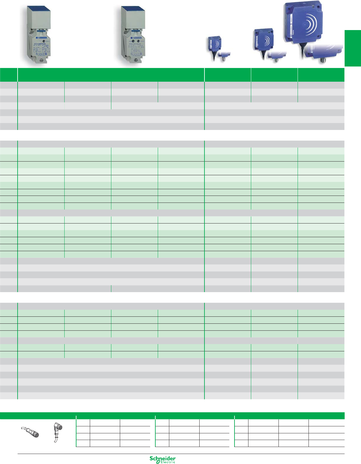
U 40 x 40 x 117 U 26 x 26 x 13 U 40 x 40 x 15 U 80 x 80 x 26
15 mm
20 mm increased range
20 mm
40 mm increased range
15 mm 25 mm 60 mm
0…12 0…16 0…16 0…32 0…8 / 0...12 0…12 / 0...20 0…32 / 0...48
5...10 / 5...15 8...15 / 8...25 20...40 / 20...60
fl ush mountable non fl ush mountable fl ush mountable or non fl ush mountable via teach mode
- 25…+ 70 - 25…+ 70
CE - UL - CSA - CCC - C-TICK CE - UL - CSA - CCC - C-TICK
IP 67 pre-cabled: IP 68 (with connector: IP 67)
Screw terminals (2) Pre-cabled (2 m)
XS7C40DP210 – XS8C40DP210 – – – –
XS7C40DA210 – XS8C40DA210 – – – –
–––––––
XS7C40PC440 XS7C40PC449 XS8C40PC440 XS8C40PC449 – – –
XS7C40NC440 XS7C40NC449 XS8C40NC440 XS8C40NC449 – – –
– – – – XS8E1A1PAL2 XS8C1A1PAL2 XS8D1A1PAL2
– – – – XS8E1A1PBL2 XS8C1A1PBL2 XS8D1A1PBL2
– – – – XS8E1A1NAL2 XS8C1A1NAL2 XS8D1A1NAL2
– – – – XS8E1A1NBL2 XS8C1A1NBL2 XS8D1A1NBL2
M8 connector M8 connector M12 connector
–––––––
–––––––
– – – – XS8E1A1PAM8 XS8C1A1PAM8 XS8D1A1PAM12
– – – – XS8E1A1PBM8 XS8C1A1PBM8 XS8D1A1PBM12
– – – – XS8E1A1NAM8 XS8C1A1NAM8 XS8D1A1NAM12
– – – – XS8E1A1NBM8 XS8C1A1NBM8 XS8D1A1NBM12
12…48 10…36 10…36 10…36
4-wire version = 200 – 2-wire version = 1.5…100 100 200 200
4-wire version = g / ⊗ / ⊗ – 2-wire version = g / ⊗ / – g / ⊗ / ⊗g / ⊗ / ⊗g / ⊗ / ⊗
4-wire version = ≤ 2 – 2-wire version = ≤ 4 ≤ 2 ≤ 2 ≤ 2
2-wire = 1500 / 4-wire = 1000 2-wire = 800 / 4-wire = 1000 (20mm) 500 (40mm) 2000 1000 150
Screw terminals (2) Pre-cabled (2 m)
– – – – XS8E1A1MAL2 XS8C1A1MAL2 XS8D1A1MAL2
– – – – XS8E1A1MBL2 XS8C1A1MBL2 XS8D1A1MBL2
XS7C40FP260 – XS8C40FP260 – – – –
XS7C40MP230 – XS8C40MP230 – – – –
1/2"-20 UNF connector
– – – – XS8E1A1MAL01U20 XS8C1A1MAL01U20 XS8D1A1MAU20
– – – – XS8E1A1MBL01U20 XS8C1A1MBL01U20 XS8D1A1MBU20
20…264 20…264 20…264 20…264
AC version = 500 – AC/DC version = 300 / 200 200 AC or DC 300 AC / 200 DC 300 AC / 200 DC
– / ⊗ / – – / ⊗ / ⊗– / ⊗ / ⊗– / ⊗ / ⊗
AC version = ≤ 1.5 – AC/DC version = ≤ 0.8 / 1.5 ≤ 1.5 ≤ 1.5 ≤ 1.5
≤ 5.5 ≤ 5.5 ≤ 5.5 ≤ 5.5
25 AC / 50 DC 2000 1000 150
(2) Sensors supplied without cable gland. Suitable cable gland: 13P. Also available in M20, 1/2" NPT output and M12, 7/8" connectors.
Pre-wired connectors M8 (3 pin) 1/2" M12 (4 pin)
Straight Elbowed Straight Elbowed
Straight Elbowed Elbowed PNP LED
2 m XZCP0566L2 XZCP0666L2 2 m XZCP1865L2 XZCP1965L2 2 m XZCP1141L2 XZCP1241L2 XZCP1340L2
5 m XZCP0566L5 XZCP0666L5 5 m XZCP1865L5 XZCP1965L5 5 m XZCP1141L5 XZCP1241L5 XZCP1340L5
10 m XZCP0566L10 XZCP0666L10 10 m XZCP1865L10 XZCP1965L10 10 m XZCP1141L10 XZCP1241L10 XZCP1340L10
Straight Elbowed
1/21
2
1
3
4
5
6
7
8
9
10
Other versions: please consult your Schneider Electric agency.
Non flush
mountable
Flush
mountable
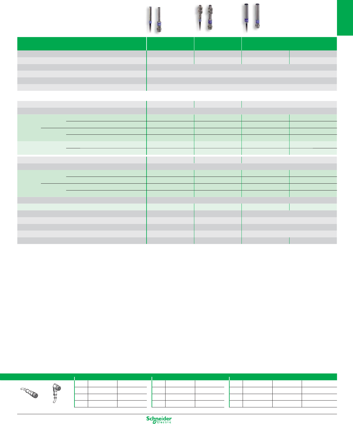
Inductive proximity sensors
Cylindrical Plastic
M8 M12 M18 M30
Nominal sensing distance Sn 2.5 mm 4 mm 8 mm 15 mm
Operating zone (mm) 0…2 0…3.2 0…6.4 0…12
Suitability for flush mounting (metal environment) non flush mountable
Temperature range (°C) - 25…+ 70
Product certification CE - UL - CSA - CCC - C-TICK
Degree of protection (conforming to IEC 60529) IP 67 pre-cabled: IP 68 (with connector: IP 67)
Sensors for DC applications
Connection Pre-cabled, PvR (2 m)
Dimensions (mm) Ø x L or W x H x D M8 x 33 M12 x 33 M18 x 33.5 M30 x 40.5
2-wire (non polarised) NO or NC programmable ––––
4-wire PNP NO + NC complementary outputs ––––
NPN NO + NC complementary outputs ––––
3-wire PNP NO function XS4P08PA340 XS4P12PA340 XS4P18PA340 XS4P30PA340
NC function XS4P08PB340 XS4P12PB340 XS4P18PB340 XS4P30PB340
NPN NO function XS4P08NA340 XS4P12NA340 XS4P18NA340 XS4P30NA340
NC function XS4P08NB340 XS4P12NB340 XS4P18NB340 XS4P30NB340
Connection M8 connector M12 connector
Dimensions (mm) Ø x L or W x H x D M8 x 42 M12 x 48 M18 x 48 M30 x 50
3-wire PNP NO function XS4P08PA340S XS4P12PA340D XS4P18PA340D XS4P30PA340D
NC function XS4P08PB340S XS4P12PB340D XS4P18PB340D XS4P30PB340D
NPN NO function XS4P08NA340S XS4P12NA340D XS4P18NA340D XS4P30NA340D
NC function XS4P08NB340S XS4P12NB340D XS4P18NB340D XS4P30NB340D
Supply voltage limits, min./max. (V) including ripple 10…38 10…38 10…38 10…38
Switching capacity, max. (mA) 200 200 200 200
Short-circuit protect. (g) / LED output state indicator (⊗)g / ⊗g / ⊗g / ⊗g / ⊗
Voltage drop, closed state (V) at I nominal ≤ 2 ≤ 2 ≤ 2 ≤ 2
Switching frequency (Hz) 5000 5000 2000 1000
Multi-current/multi-voltage sensors for AC/DC applications
Connection Pre-cabled, PvR (2 m)
Dimensions (mm) Ø x L or W x D x H M8 x 50 M12 x 50 M18 x 60 M30 x 60
2-wire AC/DC NO function XS4P08MA230 XS4P12MA230 XS4P18MA230 XS4P30MA230
not short-circuit protected (1)
NC function XS4P08MB230 XS4P12MB230 XS4P18MB230 XS4P30MB230
AC NO or NC programmable ––––
AC/DC NO or NC programmable ––––
Connection 1/2" connector
Dimensions (mm) Ø x L or W x H x D M8 x 61 M12 x 61 M18 x 70 M30 x 70
2-wire AC/DC NO function XS4P08MA230K XS4P12MA230K XS4P18MA230K XS4P30MA230K
not short-circuit protected (1)
NC function XS4P08MB230K XS4P12MB230K XS4P18MB230K XS4P30MB230K
Supply voltage limits, min./max. (V) including ripple 20…264 20…264 20…264 20…264
Switching capacity, max. (mA) 100 200 300 AC / 200 DC 300 AC / 200 DC
LED output state indicator (⊗)⊗⊗⊗⊗
Residual current, open state (mA) ≤ 0.6 ≤ 0.6 ≤ 0.6 ≤ 0.6
Voltage drop, closed state (V) at I nominal ≤ 5.5 ≤ 5.5 ≤ 5.5 ≤ 5.5
Switching frequency (Hz) 25 AC / 3000 DC 25 AC / 3000 DC 25 AC / 2000 DC 25 AC / 1000 DC
(1) For these sensors without short-circuit protection, it is essential to connect a 0.4 A quick-blow fuse in series with the load.
OsiSense XS
Accessories
Fixing for cylindrical sensors
Suitable female plug-in connectors
Fixing clamp with indexing pin
for cylindrical sensors
M8 Straight Elbowed
M4 XSZB104 M12 XSZB112 Metal ring XZCC8FDM30S XZCC8FCM30S
M5 XSZB105 M18 XSZB118 M12 (4 pin)
M6.5 XSZB165 M30 XSZB130 Metal ring XZCC12FDM40B XZCC12FCM40B
M8 XSZB108 Plastic ring XZCC12FDP40B XZCC12FCP40B
1/22
2
1
3
4
5
6
7
8
9
10
Other versions: please consult your Schneider Electric agency.
Miniature cylindrical metal (assembly)
Pre-wired connectors M8 (3 pin) 1/2" M12 (4 pin)
Straight Elbowed Straight Elbowed
Straight Elbowed Elbowed PNP LED
2 m XZCP0566L2 XZCP0666L2 2 m XZCP1865L2 XZCP1965L2 2 m XZCP1141L2 XZCP1241L2 XZCP1340L2
5 m XZCP0566L5 XZCP0666L5 5 m XZCP1865L5 XZCP1965L5 5 m XZCP1141L5 XZCP1241L5 XZCP1340L5
10 m XZCP0566L10 XZCP0666L10 10 m XZCP1865L10 XZCP1965L10 10 m XZCP1141L10 XZCP1241L10 XZCP1340L10
Straight Elbowed
Ø 4 M5 Ø 6.5
Nominal sensing distance Sn 1 mm 1 mm 1.5 mm 2.5 mm
Operating zone (mm) 0…0.8 0…0.8 0…1.2 0…2
Suitability for flush mounting (metal environment) flush mountable
Temperature range (°C) - 25…+ 70
Product certification CE - UL - CSA - CCC - C-TICK
Degree of protection (conforming to IEC 60529) IP 67
Sensors for DC applications
Dimensions (mm) Ø x L Ø 4 x 29 M5 x 29 Ø 6.5 x 33
Connection Pre-cabled, PvR (2 m)
3-wire PNP NO function XS1L04PA310 XS1N05PA310 XS506B1PAL2 XS106B3PAL2
NC function – – XS506B1PBL2 XS106B3PBL2
NPN NO function XS1L04NA310 XS1N05NA310 XS506B1NAL2 XS106B3NAL2
NC function – – XS506B1NBL2 XS106B3NBL2
2-wire (polarised) NO function – – XS506BSCAL2 XS606B3CAL2
NC function – – XS506BSCBL2 XS606B3CBL2
Dimensions (mm) Ø x L Ø 4 x 41 M5 x 41 Ø 6.5 x 42
Connection M8
3-wire PNP NO function XS1L04PA310S XS1N05PA311S (1) XS506B1PAM8 XS106B3PAM8
NC function – – XS506B1PBM8 XS106B3PBM8
NPN NO function XS1L04NA310S XS1N05NA311S (1) XS506B1NAM8 XS106B3NAM8
NC function – – XS506B1NBM8 XS106B3NBM8
Connection M12
2-wire (polarised) fonction NO – – XS506BSCAL01M12 XS506B3CAL01M12
Supply voltage limits, min./max. (V) including ripple 5…30 5…30 10…36
Switching capacity, max. (mA) 3-wire / 2-wire 100 / – 100 / – 200 / 100
Short-circuit protect. (g) / LED output state indicator (⊗)g / ⊗g / ⊗g / ⊗
Voltage drop, closed state (V) at I nominal 3-wire / 2-wire ≤ 2 / – ≤ 2 / – ≤ 2 / ≤ 4
Switching frequency (Hz) 3-wire / 2-wire 5000 / – 5000 / – 5000 / 4000 2500 / 3000
(1) Stainless steel sensors, Sn = 0.8 mm
1/23
2
1
3
4
5
6
7
8
9
10
Other versions: please consult your Schneider Electric agency.
Non flush
mountable
Flush
mountable
Inductive proximity sensors
Multi-voltage with short-circuit protection
M12 M18 M30
Sensing distance Sn flush mountable
2 mm 5 mm 10 mm
non flush mountable 4 mm 8 mm 15 mm
Operating zone (mm)
flush mountable 0…1.6 0…4 0…8
non flush mountable 0…3.2 0…6.4 0…12
Suitability for flush mounting (metal environment) flush mountable or non flush mountable depending on model
Case M (metal) P (plastic) M
Temperature range (°C) - 25…+ 70
Degree of protection (conforming to IEC 60529) IP 68 (with connector: IP 67)
Product certification CE - UL - CSA - CCC - C-TICK
Dimensions (mm) Ø x L Cable (Connector) M12 x 55 (M12 x 66) M18 x 60 (M18 x 72) M30 x 60 (M30 x 72)
Sensors for DC applications
Connection
4-wire PNP NO + NC flush mountable –––
non flush mountable –––
NPN NO + NC flush mountable –––
non flush mountable –––
PNP+NPN NO/NC flush mountable (metal) –––
programmable non flush mntbl. (metal) –––
non flush mntbl. (plastic) –––
Connection
4-wire PNP NO + NC flush mountable –––
non flush mountable –––
NPN NO + NC flush mountable –––
non flush mountable –––
PNP+NPN NO/NC flush mountable (metal) –––
programmable non flush mntbl. (metal) –––
non flush mntbl. (plastic) –––
Supply voltage limits, min./max. (V) including ripple –––
Switching capacity, max. (mA) –––
Short-circuit protection (g) / LED output state indicator (⊗)–––
Voltage drop, closed state (V) at I nominal –––
Switching frequency (Hz) –––
Multi-current/multi-voltage sensors for AC/DC applications
Connection Pre-cabled, PvR (2 m)
2-wire AC/DC
NO function flush mountable XS1M12MA250 XS1M18MA250 XS1M30MA250
non flush mountable XS2M12MA250 XS2M18MA250 XS2M30MA250
NC function flush mountable XS1M12MB250 XS1M18MB250 XS1M30MB250
non flush mountable XS2M12MB250 XS2M18MB250 XS2M30MB250
Connection 1/2"-20 UNF connector
2-wire AC/DC
NO function flush mountable XS1M12MA250K XS1M18MA250K XS1M30MA250K
non flush mountable XS2M12MA250K XS2M18MA250K XS2M30MA250K
NC function flush mountable XS1M12MB250K XS1M18MB250K XS1M30MB250K
non flush mountable XS2M12MB250K XS2M18MB250K XS2M30MB250K
Supply voltage limits, min./max. (V) 50-60 Hz 20…264
Switching capacity, max. (mA) 5…200 5…200 AC, 5…300 DC
LED output state indicator (⊗) / Power on LED (⊗)⊗ / ⊗
Residual current, open state (mA) ≤ 1.5
Voltage drop, closed state (V) at I nominal ≤ 5.5
Switching frequency (Hz) 25 AC, 4000 DC 25 AC, 2000 DC 25 AC, 2000 DC (1)
(1) 25 AC, 1000 DC for non flush mountable Ø 30 mm.
OsiSense XS
1/24
2
1
3
4
5
6
7
8
9
10
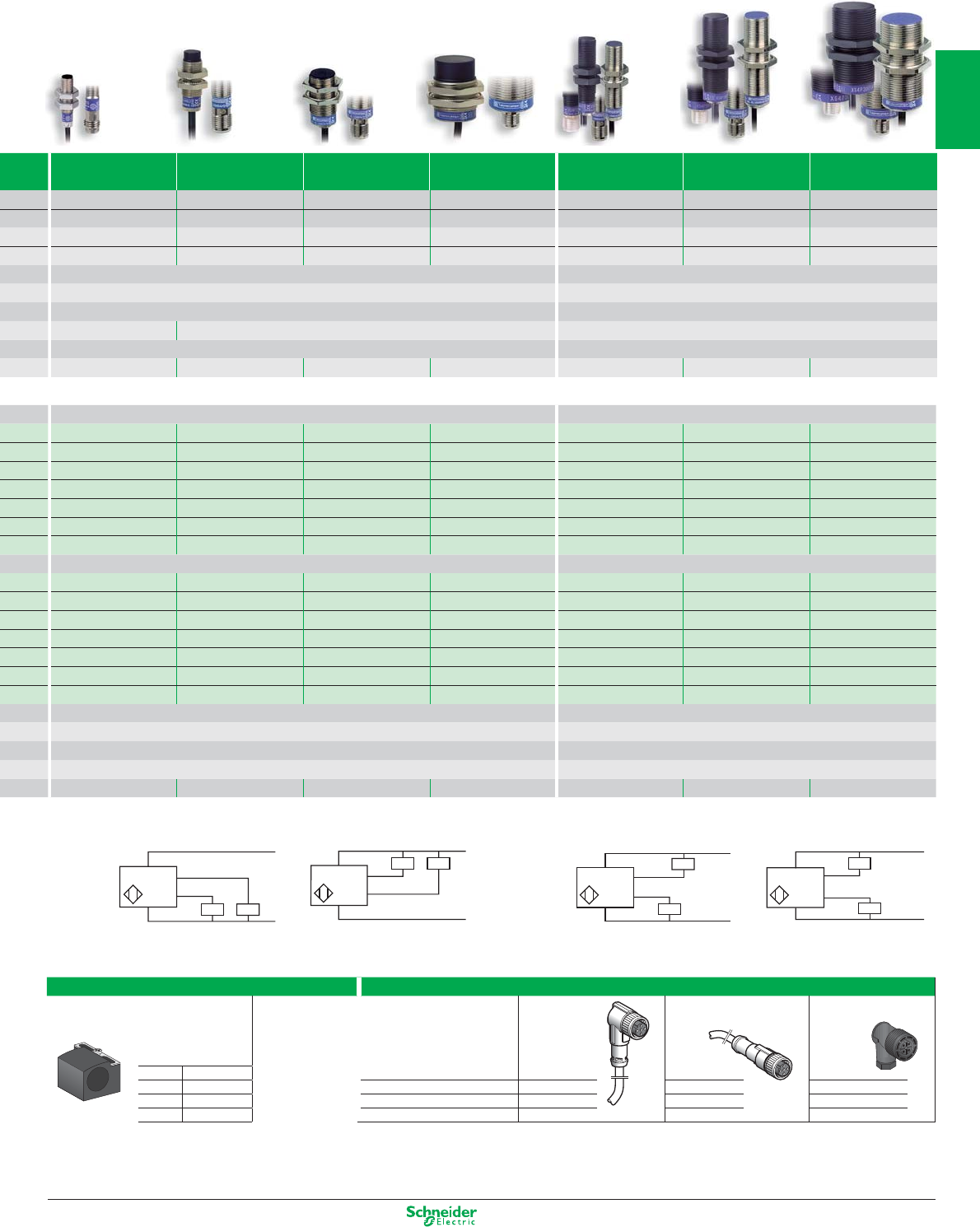
Other versions: please consult your Schneider Electric agency.
PNP NPN
NO +
–
NC
PNP
+
–
NC
NPN NO
NO NC
NPN
+ BN/1
- BU/3
+ BU/3
- BN/1
PNP
NPN
PNP
Fixing clamps Suitable female plug-in connectors, including pre-wired versions
With indexing pin for cylindrical sensors length 5 m
without LED
pre-wired,
elbowed
pre-wired,
straight
screw terminal
M8 XSZB108
M12 XSZB112 M8 (or S) XZCP0666L5 XZCP0566L5 XZCC8FCM30S
M18 XSZB118 M12 (or D) XZCP1241L5 XZCP1141L5 XZCC12FCM40B
M30 XSZB130 1/2" (or K) XZCP1965L5 XZCP1865L5 XZCC20FCM30B
PNP or NPN
NO + NC Complementary outputs PNP + NPN outputs,
NO or NC programmable
M8 M12 M18 M30 M12 M18 M30
1.5 mm 2 mm 5 mm 10 mm 2 mm 5 mm 10 mm
2.5 mm 4 mm 8 mm 15 mm 4 mm 8 mm 15 mm
0…1.2 0…1.6 0…4 0…8 0…1.6 0…4 0…8
0…2 0…3.2 0…6.4 0…12 0…3.2 0…6.4 0…12
flush mountable or non flush mountable depending on model flush mountable or non flush mountable depending on model
M M or P depending on model
- 25…+ 70 - 25…+ 70
IP 67 IP 68 (with connector: IP 67) IP 68 (with connector: IP 67)
CE - UL - CSA - CCC - C-TICK CE - UL - CSA - CCC - C-TICK
M8 x 50 (M8 x 61) M12 x 33 (M12 x 48) M18 x 36.5 (M18 x 49) M30 x 40.5 (M30 x 53) M12 x 50 (M12 x 61) M18 x 60 (M18 x 72) M30 x 60 (M30 x 72)
Pre-cabled, PvR (2 m) Pre-cabled, PvR (2 m)
XS1M08PC410 XS1N12PC410 XS1N18PC410 XS1N30PC410 – – –
XS2M08PC410 XS2N12PC410 XS2N18PC410 XS2N30PC410 – – –
XS1NM08NC410 XS1N12NC410 XS1N18NC410 XS1N30NC410 – – –
XS2M08NC410 XS2N12NC410 XS2N18NC410 XS2N30NC410 –
– – – – XS1M12KP340 XS1M18KP340 XS1M30KP340
– – – – XS2M12KP340 XS2M18KP340 XS2M30KP340
– – – – XS4P12KP340 XS4P18KP340 XS4P30KP340
M12 connector M12 connector
XS1M08PC410D XS1N12PC410D XS1N18PC410D XS1N30PC410D – – –
XS2M08PC410D XS2N12PC410D XS2N18PC410D XS2N30PC410D – – –
XS1M08NC410D XS1N12NC410D XS1N18NC410D XS1N30NC410D – – –
XS2M08NC410D XS2N12NC410D XS2N18NC410D XS2N30NC410D – – –
– – – – XS1M12KP340D XS1M18KP340D XS1M30KP340D
– – – – XS2M12KP340D XS2M18KP340D XS2M30KP340D
– – – – XS4P12KP340D XS4P18KP340D XS4P30KP340D
10…36 10…36
200 200
g / ⊗g / –
≤ 2 ≤ 2.6
5000 5000 2000 1000 5000 2000 1000
Accessories
1/25
2
1
3
4
5
6
7
8
9
10
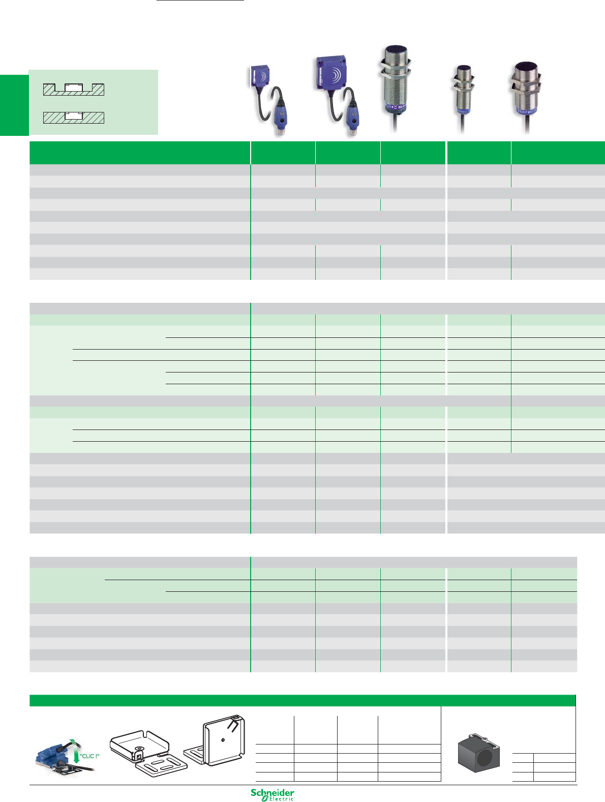
Other versions: please consult your Schneider Electric agency.
26 x 26 x 13 40 x 40 x 15 M30 M18 M30
Nominal sensing distance Sn 10 mm 15 mm 10 mm 5 mm 10 mm
Operating zone (mm) 0...8 0...12 0...8 0...4 0...8
Suitability for flush mounting (metal environment) flush mountable flush mountable
Case M (metal) P (plastic) PP M MM
Temperature range (°C) - 25…+ 70 0…+ 50
Degree of protection (conforming to IEC 60529) IP 67 pre-cabled: IP 68 (with connector: IP 67)
Product certification CE - UL - CSA - CCC - C-TICK CE - UL - CSA - CCC - C-TICK
Dimensions (mm) Ø x L or W x H x D Cable (Connector) 26 x 26 x 13 40 x 40 x 15 M30 x 81
M18 x 60 (M18 x 70)
M30 x 60
Maximum speed of passing object (impulses/min) 48000 48000 6000...48000 (1) – –
Adjustable frequency range (impulses/min) 6...6000 6...6000
6...150 / 120...3000 (1)
––
Sensors for DC applications
Connection Pre-cabled, PvR (2 m)
4-wire PNP/NPN NO/NC programmable – – – XS1M18KPM40 XS1M30KPM40
3-wire PNP NC function slow version – – XSAV11373 – –
fast version – – XSAV12373 – –
0…10 V output plastic –– – ––
4…20 mA output metal, flush mountable –– – ––
plastic, flush mountable –– – ––
plastic, non flush mountable
–– – ––
Connection M8 or M12 connector
M12 on 0.8 m flying lead
4-wire PNP/NPN NO/NC programmable – – – XS1M18KPM40D XS1M30KPM40LD
3-wire PNP NC function
XS9E11RPBL01M12 (3) XS9C11RPBL01M12 (3)
–––
0…10 V output – – – – –
4…20 mA output – – – – –
Supply voltage limits, min./max. (V) including ripple 10...36 10...36 10...58 10...38
Switching capacity, max. (mA) 100 200 200 200
Short-circuit protect. (g) / LED output state indicator (⊗) / Power on LED (⊗)
(⊗)g / ⊗ / ⊗g / ⊗ / ⊗g / ⊗ / – g / ⊗ / –
Linearity error –– – –
Voltage drop, closed state (V) at I nominal ≤ 2 ≤ 2 ≤ 2 ≤ 2.6
Switching frequency (Hz) – – – 1000
Operating frequency (Hz) –– – –
Multi-current/multi-voltage sensors for AC/DC applications
Connection Pre-cabled, PvR (2 m)
2-wire AC/DC NC function
XS9E11RMBL01U20 (5) XS9C11RMBL01U20 (5)
–––
not short-circuit protected (2)
NC function slow version – – XSAV11801 – –
fast version – – XSAV12801 – –
Supply voltage limits, min./max. (V) 50-60 Hz 20...264 20...264 20...264 – –
Switching capacity, max. (mA) 100 300 AC / 200 DC 300 AC / 200 DC – –
LED output state indicator (⊗) / Power on LED (⊗)⊗ / ⊗⊗ / ⊗⊗ / – ––
Residual current, open state (mA) ≤ 1.5 ≤ 1.5 ≤ 1.5 ––
Voltage drop, closed state (V) at I nominal ≤ 5.5 ≤ 5.5 ≤ 5.7 ––
Switching frequency (Hz) –– – ––
Accessories
Fixing
for flat sensors substitution Fixing clamp with indexing pin
of block type for cylindrical sensors
flat 90° sensors
XSE / XSC / XSD
8x22x8 XSZBJ00 XSZBJ90 –
15x32x8 XSZBF00 XSZBF90 XSZBE10 M12 XSZB112
26x26x13 XSZBE00 XSZBE90 XSZBC10 M18 XSZB118
40x40x15 XSZBC00 XSZBC90 XSZBD10 M30 XSZB130
Inductive proximity sensors - Application
Rotation control
Non flush
mountable
Flush
mountable
Fixed sensing distance
(for ferrous or non ferrous materials)
flat
90°
OsiSense XS
1/26
2
1
3
4
5
6
7
8
9
10
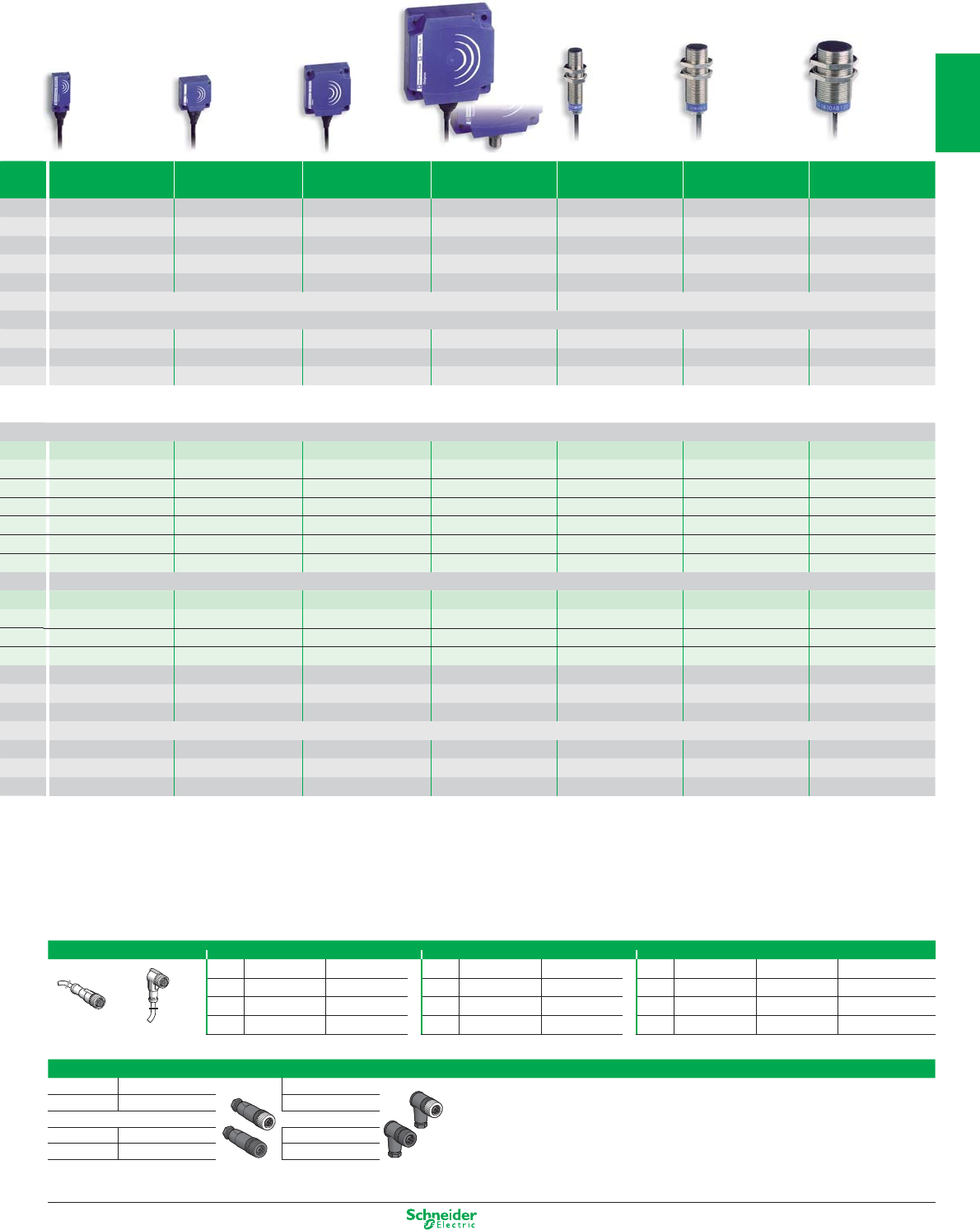
Other versions: please consult your Schneider Electric agency.
8 x 32 x 8 26 x 26 x 13 40 x 40 x 15 80 x 80 x 26 M12 M18 M30
5 mm 10 mm 15 mm 40 mm M: 2 mm / P: 4 mm M: 5 mm / P: 8 mm M: 10 mm / P: 15 mm
1...4 1...10 2...15 5...40 M: 0.2…2 / P: 0.4…4 M: 0.5…5 / P: 0.8…8 M: 1…10 / P: 1.5…15
flush mountable flush mountable flush mountable flush mountable
flush / non flush mountable flush / non flush mountable flush / non flush mountable
P P P P M or P M or P M or P
- 25…+ 70 - 25…+ 70 - 25…+ 70 - 25…+ 70 - 25…+ 70 - 25…+ 70 - 25…+ 70
pre-cabled: IP 68 (with connector: IP 67) IP 67
CE - UL - CSA - CCC - C-TICK
15 x 32 x 8 26 x 26 x 13 40 x 40 x 15 80 x 80 x 26 Ø 12 x 50 Ø 18 x 50 Ø 30 x 52.5
–––––––
–––––––
–––––––
–––––––
–––––––
XS9F111A1L2 XS9E111A1L2 XS9C111A1L2 XS9D111A1L2 XS4P12AB110 XS4P18AB110 XS4P30AB110
– – – – XS1M12AB120 XS1M18AB120 XS1M30AB120
XS9F111A2L2 XS9E111A2L2 XS9C111A2L2 XS9D111A2L2 – – –
– – – – XS4P12AB120 XS4P18AB120 XS4P30AB120
M8 or M12 connector
–––––––
–––––––
XS9F111A1L01M8 (4) XS9E111A1L01M12 (4) XS9C111A1L01M12 (4) XS9D111A1M12 – – –
XS9F111A2L01M8 (4) XS9E111A2L01M12 (4) XS9C111A2L01M12 (4) XS9D111A2M12 – – –
10...36 10...36 10...36 10...36 10…38 10…38 10…38
–––––––
–––––––
± 1 V for 0…10 V version / ± 2 mA for 4…20 mA version
–––––––
–––––––
2000 1000 1000 100 1500 500 300
(1) 6...150 and 6000 impulses/min for XSAV11373 and XSAV11801 (slow version); 120...3000 and 48000 impulses/min for XSAV12373 and XSAV12801 (fast version).
(2) For these sensors without short-circuit protection, it is essential to connect a 0.4 A quick-blow fuse in series with the load.
(3) Flying lead (L = 0.15 m) with end mounted remote control incorporating M12 connector.
(4) Flying lead (L = 0.15 m) with end connector.
(5) Flying lead (L = 0.15 m) with end mounted remote control incorporating 1/2"-20 UNF connector.
Analogue (Position control)
Accessories
Pre-wired connectors M8 (3 pin) 1/2" M12 (4 pin)
Straight Elbowed Straight Elbowed
Straight Elbowed Elbowed PNP LED
2 m XZCP0566L2 XZCP0666L2 2 m XZCP1865L2 XZCP1965L2 2 m XZCP1141L2 XZCP1241L2 XZCP1340L2
5 m XZCP0566L5 XZCP0666L5 5 m XZCP1865L5 XZCP1965L5 5 m XZCP1141L5 XZCP1241L5 XZCP1340L5
10 m XZCP0566L10 XZCP0666L10 10 m XZCP1865L10 XZCP1965L10 10 m XZCP1141L10 XZCP1241L10 XZCP1340L10
Suitable female plug-in connectors
M8 Straight Elbowed
Steel ring XZCC8FDM30S XZCC8FCM30S
M12 (4 pin)
Steel ring XZCC12FDM40B XZCC12FCM40B
Plastic ring XZCC12FDP40B XZCC12FCP40B
Straight Elbowed
1/27
2
1
3
4
5
6
7
8
9
10
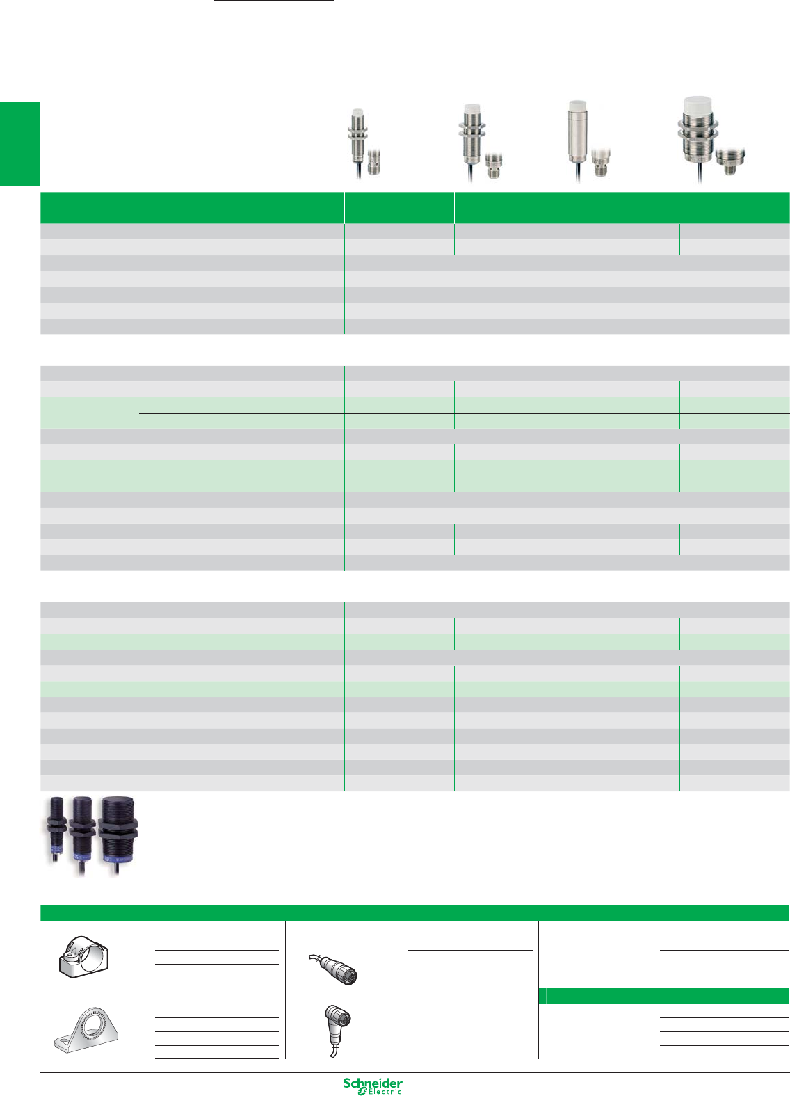
Other versions: please consult your Schneider Electric agency.
Inductive proximity sensors - Application
Food and beverage processing
Type M12 M18 Ø 18 plain M30
Nominal sensing distance Sn 7 mm 12 mm 12 mm 22 mm
Operating zone (mm) 0 …5.6 0 … 9.6 0 … 9.6 0 … 17.6
Suitability for flush mounting (metal environment) non flush mountable
Case M (metal) (1) M stainless steel 316 L
Product certification CE - UL - CSA - CCC - C-TICK
Temperature range (°C) - 25…+ 85
Degree of protection (conforming to IEC 60529) pre-cabled: IP 68 (with connector: IP 67) and IP 69K conforming to DIN 40050
Sensors for DC applications (solid-state output: transistor)
Connection Pre-cabled, non poisonous PVC (2 m)
Dimensions (mm) M12 x 55 M18 x 60 Ø 18 x 60 M30 x 62
3-wire PNP NO function XS212SAPAL2 XS218SAPAL2 XS2L2SAPAL2 XS230SAPAL2
NPN NO function XS212SANAL2 XS218SANAL2 XS2L2SANAL2 XS230SANAL2
Connection M12 connector
Dimensions (mm) M12 x 61 M18 x 70 Ø 18 x 70 M30 x 70
3-wire PNP NO function XS212SAPAM12 XS218SAPAM12 XS2L2SAPAM12 XS230SAPAM12
NPN NO function XS212SANAM12 XS218SANAM12 XS2L2SANAM12 XS230SANAM12
Supply voltage limits, min./max. (V) including ripple 10…36
Switching capacity, max. (mA) ≤ 200
Switching frequency (Hz) 2500 1000 1000 500
Short-circuit protection (g) / LED output state indicator (⊗)g / ⊗g / ⊗g / ⊗g / ⊗
Voltage drop, closed state (V) at I nominal ≤ 2
Multi-current/multi-voltage sensors for AC/DC applications
Connection Pre-cabled, non poisonous PVC (2 m)
Dimensions (mm) – M18 x 60 – M30 x 62
2-wire (2) AC/DC NO function – XS218SAMAL2 – XS230SAMAL2
Connection 1/2"-20 UNF connector
Dimensions (mm) – M18 x 72 – M30 x 74
2-wire (2) AC/DC NO function – XS218SAMAU20 – XS230SAMAU20
Supply voltage limits, min./max. (V) 50-60 HZ – 20 … 264 – 20 … 264
Switching capacity, max. (mA) – 300 AC / 200 DC – 300 AC / 200 DC
Switching frequency (Hz) – 25 AC / 1000 DC – 25 AC / 300 DC
LED output state indicator (⊗)–⊗–⊗
Voltage drop, closed state (V) at I nominal –≤ 5.5 –≤ 5.5
Residual current, open state (mA) –≤ 0.8 –≤ 0.8
(1) Plastic range available. M12, M18, M30: (2) For these sensors without short-circuit protection, it is essential to connect a
To order, replace the second letter S in the reference by A 0.4 A quick-blow fuse in series with the load.
(example: XS212SAPAL2 becomes XS212AAPAL2).
Accessories
Fixing clamps M12 pre-wired connector M12 jumper cable
Plastic fixing centres 24.1 mm, with locking screw female, 4-pin, stainless steel clamping ring male, 3-pin, stainless steel clamping ring
for sensor Straight connector 5 m cable XZCPA1141L5 Straight connector 5 m XZCRA151140A5
Ø 18 plain XUZB2005
Stainless steel Elbowed connector 5 m cable XZCPA1241L5 1/2" pre-wired connector
for sensor
Ø 12 XSZBS12 Straight 5 m XZCP1865L5
Ø 18 XUZA118 Elbowed 5 m XZCP1965L5
Ø 30 XSZBS30
OsiSense XS
1/28
2
1
3
4
5
6
7
8
9
10
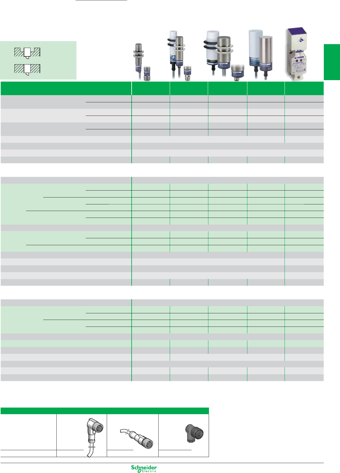
Other versions: please consult your Schneider Electric agency.
Capacitive proximity sensors
Detection of insulating materials or
conductive materials
Suitability for flush
mtg.
M12 M18 M30 Ø 32 40 x 40 x 117
Nominal sensing distance Sn flush mountable 2 mm 5 mm 10 mm 15 mm 15 mm
non flush mountable –8 mm 15 mm 20 mm –
Operating zone Sa (mm) (2) flush mountable 0…1.44 0…3.6 0…7.2 0…10 0…11
non flush mountable – 0…5.8 0…11 0…15 –
Case M (metal) P (plastic) flush mountable MMM MP
non flush mountable –PP P–
Product certification CE CE - UL - CSA
Temperature range (°C) - 25…+ 70
Degree of protection (conforming to IEC 60529) IP 67
Dimensions (mm) Ø x L or H x W x D M12 x 70 M18 x 80 M30 x 80 M32 x 80 117 x 40 x 40
Sensors for DC applications
Connection Pre-cabled, PVC (2 m)
3-wire PNP NO function flush mountable XT112S1PAL2 XT118B1PAL2 XT130B1PAL2 – –
non flush mountable – XT218A1PAL2 XT230A1PAL2 – –
NO + NC functions flush mountable XT112S1PCL2 XT118B1PCL2 XT130B1PCL2 – –
non flush mountable ––– ––
NPN NO function flush mountable XT112S1NAL2 XT118B1NAL2 XT130B1NAL2 – –
non flush mountable – XT218A1NAL2 XT230A1NAL2 – –
Connection M12 connector Screw terminals
3-wire PNP NO + NC functions flush mountable XT112S1PCM12 XT118B1PCM12 XT130B1PCM12 – XT7C40PC440 (3)
non flush mountable – XT218A1PCM12 XT230A1PCM12 – –
NPN NO + NC functions flush mountable – – – – XT7C40NC440 (3)
Supply voltage limits, min./max. (V) including ripple 10...38 10...58
Switching capacity, max. (mA) 200 200
Short circuit-protection (g) / LED output state indicator (⊗)g / ⊗g / ⊗
Voltage drop, closed state (V) at I nominal ≤ 2 ≤ 2
Switching frequency (Hz) 300
100 (XT2) / 200 (XT1) 100 (XT2) / 150 (XT1)
– 100
Multi-current/multi-voltage sensors for AC applications
Connection Pre-cabled, PVC (2 m)
2-wire AC (1) NO function flush mountable – XT118B1FAL2 XT130B1FAL2 XT132B1FAL2 –
non flush mountable – XT218A1FAL2 XT230A1FAL2 XT232A1FAL2 –
NO function flush mountable – XT118B1FBL2 XT130B1FBL2 XT132B1FBL2 –
non flush mountable – – XT230A1FBL2 XT232A1FBL2 –
Connection Screw terminals
2-wire AC (1) NO or NC
programmable
flush mountable – – – – XT7C40FP262
Supply voltage limits, min./max. (V) 50-60 Hz – 20…264 20…264 20…264 20…264
Switching capacity, max. (mA) – 300 350
LED output state indicator (⊗) / Power on LED (⊗)⊗ / –
Voltage drop, closed state (V) at I nominal –≤ 5.5 ≤ 5.5 ≤ 9 ≤ 5.5
Switching frequency (Hz) –25252525
(1) For these sensors without short-circuit protection, it is essential to connect a 0.4 A quick-blow fuse in series with the load.
(2) The operating distance depends on the objet material.
(3) Only for detecting insulating materials.
Accessories
Suitable female plug-in connectors, including pre-wired versions
length 5 m pre-wired, pre-wired, screw terminal
without LED elbowed straight
M12 XZCP1241L5 XZCP1141L5 XZCC12FCM40B
Non flush mountable
(plastic)
Flush mountable
(metal)
OsiSense XT
1/29
2
1
3
4
5
6
7
8
9
10
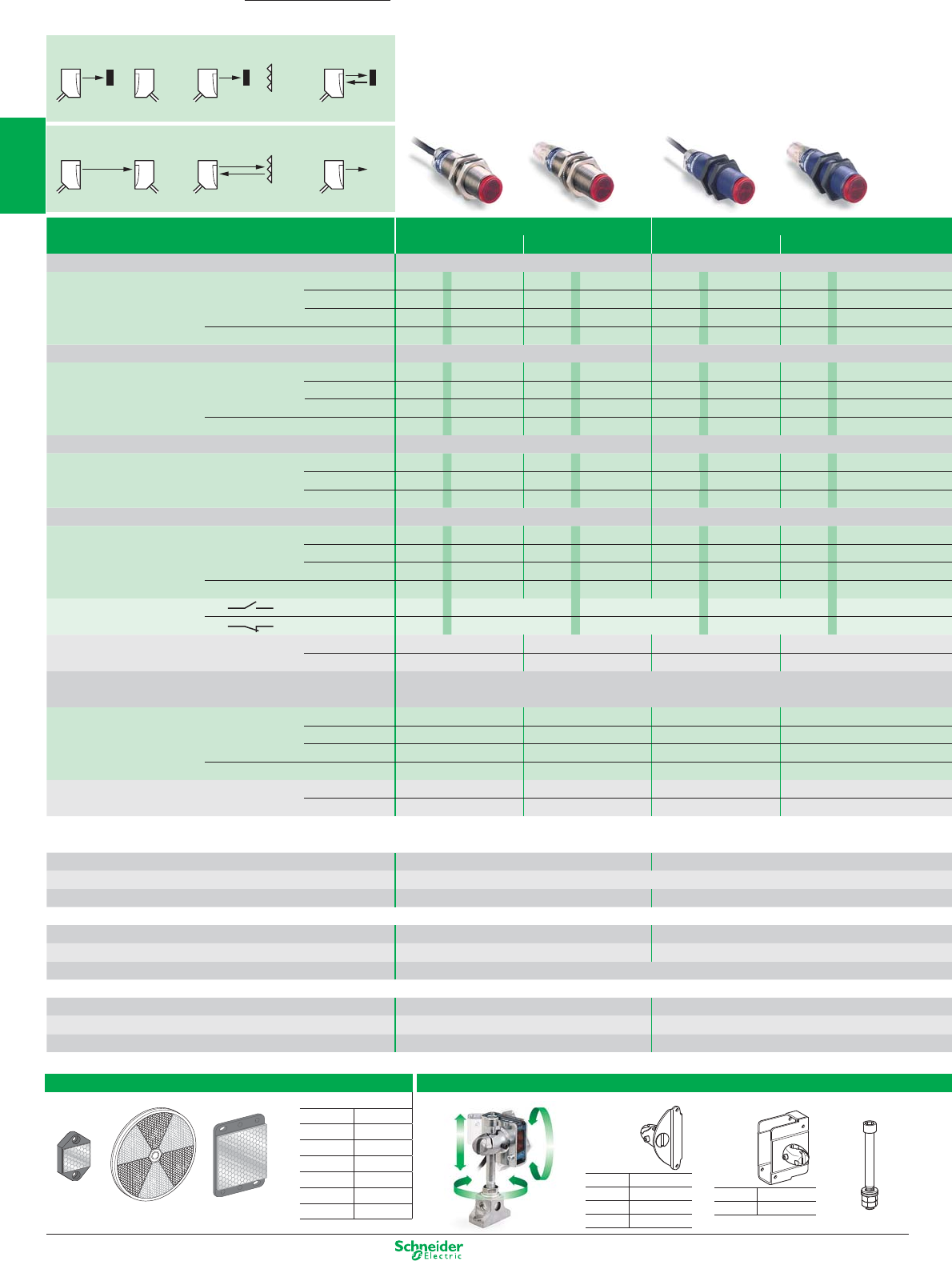
Other versions: please consult your Schneider Electric agency.
Photo-electric sensors
General Purpose
OsiSense XU
M18 Metal (1) M18 Plastic
Cable M12 connector Cable M12 connector
Diffuse Sensing distance 0.6 m (2) (3) 0.6 m (2) (3)
Output type DC3 NO PNP XUB5BP ANL2 XUB5BP ANM12 XUB5AP A NL2 XUB5AP ANM12
NPN XUB5BNANL2 XUB5BNANM12 XUB5AN ANL2 XUB5AN ANM12
PNP/NPN ––––
AC/DC 1C/O relay ––––
Refl ex Polarised Sensing distance (4) 2 m 2 m
Output type DC3 NO PNP XUB9BP ANL2 XUB9BP ANM12 XUB9AP ANL2 XUB9AP ANM12
NPN XUB9BNANL2 XUB9BNANM12 XUB9AN ANL2 XUB9AN ANM12
PNP/NPN ––––
AC/DC 1C/O relay ––––
Refl ex Sensing distance (4) 4 m 4 m
Output type DC3 NO PNP XUB1BP ANL2 XUB1BP ANM12 XUB1AP ANL2 XUB1AP ANM12
NPN XUB1BNANL2 XUB1BNANM12 XUB1AN ANL2 XUB1AN ANM12
AC/DC 1C/O relay ––––
Thru beam Sensing distance 15 m 15 m
Output type DC3 NO PNP XUB2BP ANL2R XUB2BP ANM12R XUB2AP ANL2R XUB2AP ANM12R
NPN XUB2BNANL2R XUB2BNANM12R XUB2ANANL2R XUB2ANANM12R
PNP/NPN ––––
AC/DC 1C/O relay ––––
Output function NO AAAA
NC BBBB
Thru beam Transmitter DC XUB2BKSNL2T XUB2BKSNM12T XUB2AKSNL2T XUB2AKSNM12T
AC/DC ––––
Multimode Sensing distance Background suppression: 0.12 m - Diffuse: 0.3 m
Refl ex polarised: 2 m - Thru beam: 18 m
Output type DC3 NO/NC PNP XUB0BPSNL2 XUB0BPSNM12 XUB0APSNL2 XUB0APSNM12
NPN XUB0BNSNL2 XUB0BNSNM12 XUB0ANSNL2 XUB0ANSNM12
PNP/NPN ––––
AC/DC 1C/O relay ––––
Thru beam Transmitter DC XUB0BKSNL2T XUB0BKSNM12T XUB0AKSNL2T XUB0AKSNM12T
AC/DC ––––
(1) Brass metal, aivailable also in stainless steel, see page food/beverage processing series
(2) For a sensing distance 0,1 m without sensitivity adjustment, change digit 5 by 4 into the reference (ex: XUB5BPANL2 becomes XUB4BPANL2)
Fixing M18 x1 M18 x1
Dimensions M18 x 64 mm / M18 x 78 mm
Product certifi cations CE, UL, CSA, C-Tick CE, UL, CSA, C-Tick
DC common characteristics
Supply voltage limits, min./max. (V) including ripple 10…36 10…36
Switching frequency (Hz) 500 500
Common characteristics for DC versions Switching capacity, max. (mA): 100 / Overload and short-circuit protection (g) / LED output state
AC/DC common characteristics
Supply voltage limits, min./max. (V) including ripple ––
Switching frequency (Hz) ––
LED output state indicator (⊗) / power on LED (⊗)––
NO function: Object present / Output ON
Thru-beam Refl ex Diffuse
(T) (R) (T/R) (T/R)
NC function: No object present / Output ON
Thru-beam Refl ex Diffuse
(T) (R) (T/R) (T/R)
Accessories
Refl ectors
XUZC24 XUZC80 XUZC50
3D fi xings with ball joint
Refl ectors (mm)
Ø 21 XUZC21
24 x 21 XUZC24
11 x 33 XUZC08
Ø 39 XUZC39
Ø 80 XUZC80
50 x 50 XUZC50
100 x 100
XUZC100
Bracket with ball joint
for sensors and
refl ector
XUZC50
for
XUK… XUZK2004
XUX… XUZX2004
for
XUB… XUZB2003
XUM0…
XUZM2003
XUK… XUZK2003
XUX… XUZX2003
XUZ2001
Protective housing
with ball joint
M12 rod for
ball joint
1/30
2
1
3
4
5
6
7
8
9
10
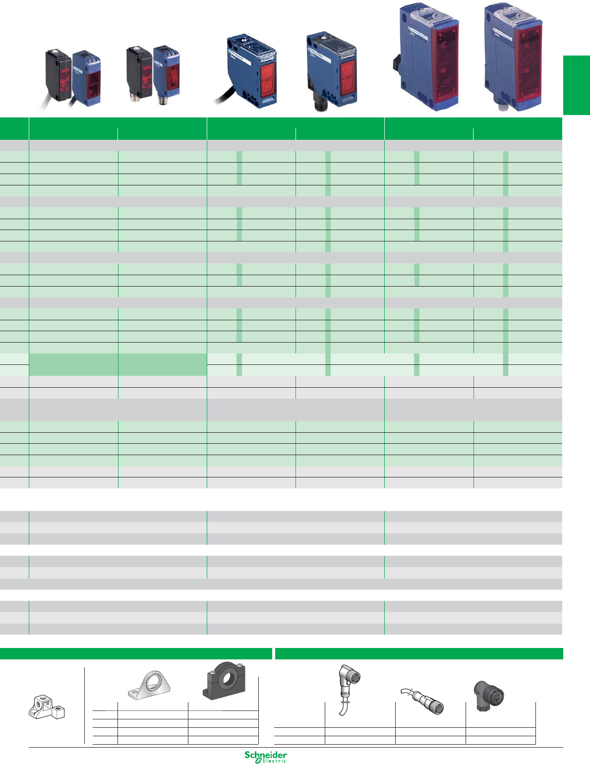
Other versions: please consult your Schneider Electric agency.
length 5 m
without LED pre-wired, elbowed pre-wired, straight screw terminal
M8 XZCP1041L5 XZCP0941L5 XZCC8FCM40S
M12 XZCP1241L5 XZCP1141L5 XZCC12FCM40B
Suitable female plug-in connectors, including pre-wired versions
XUZ2003
Fixing
support for
M12 rod
Single bracket
for standard with ball joint
XUB... XUZA118
(stnls. steel)
XUZA218 (plastic)
XUM... XUZAM02 –
XUK... XUZA51 –
XUX... XUZX2000 –
Simple fi xings
Miniature Compact 50 x 50 mm Compact 92 x 71 mm
Cable M8 connector Cable M12 connector Screw terminal M12 connector
1 m (3) 1 m (3) 2.1 m (3)
– – XUK5AP ANL2 XUK5AP ANM12 XUX5AP ANT16 XUX5AP ANM12
– – XUK5AN ANL2 XUK5AN ANM12 XUX5AN ANT16 XUX5AN ANM12
XUM5APCNL2 XUM5APCNM8 ––––
– – XUK5ARCNL2 – XUX5ARCNT16 –
5 m (3) 5 m 11 m (3)
– – XUK9AP ANL2 XUK9AP ANM12 XUX9AP ANT16 XUX9AP ANM12
– – XUK9ANANL2 XUK9ANANM12 XUX9AN ANT16 XUX9AN ANM12
XUM9APCNL2 XUM9APCNM8 – – – –
– – XUK9ARCNL2 – XUX9ARCNT16 –
–7 m 14 m (3)
– – XUK1AP ANL2 XUK1AP ANM12 XUX1AP ANT16 XUX1AP ANM12
– – XUK1AN ANL2 XUK1AN ANM12 XUX1AN ANT16 XUX1AN ANM12
– – XUK1ARCNL2 – XUX1ARCNT16 –
15 m (3) 30 m 40 m (3)
– – XUK2AP ANL2R XUK2AP ANM12R XUX2AP ANT16R XUX2AP ANM12R
– – XUK2ANANL2R XUK2ANANM12R XUX2AN ANT16R XUX2AN ANM12R
XUM2APCNL2R XUM2APCNM8R – – – –
– – XUK2ARCNL2R – XUX2ARCNT16R –
NO or NC NO or NC AAAA
BBBB
XUM2AKCNL2T XUM2AKCNM8T XUK2AKSNL2T XUK2AKSNM12T XUX0AKSAT16T XUX0AKSAM12T
– – XUK2ARCNL2T – XUX2ARCTT16T –
Background suppression: 0.1 m - Diffuse: 0.4 m Background suppression: 0.28 m - Diffuse: 0.8 m Background suppression: 1.3 m - Diffuse: 2 m
Refl ex polarised: 3 m - Thru beam: 10 m Refl ex polarised: 4 m - Thru beam: 30 m Refl ex polarised: 11 m - Thru beam: 40 m
XUM0APSAL2 XUM0APSAM8 – – – –
XUM0ANSAL2 XUM0ANSAM8 – – – –
– – XUK0AKSAL2 XUK0AKSAM12 XUX0AKSAT16 XUX0AKSAM12
– – XUK0ARCTL2 – XUX0ARCTT16 –
XUM0AKSAL2T XUM0AKSAM8T XUK0AKSAL2T XUK0AKSAM12T XUX0AKSAT16T XUX0AKSAM12T
– – XUK0ARCTL2T – XUX0ARCTT16T –
(3) With sensitivity adjustment
(4) With refl ector XUZC50
Direct fi xing centres 25.5, M3 screws Direct fi xing centres 40 x 40, M4 screws Direct fi xing centres 30/38 to 40/50/74, M5 screws
12 x 34 x 20 18 x 50 x 50 30 x 92 x 71
CE, UL, CSA, C-Tick CE, UL, CSA, CCC, C-Tick CE, UL, CSA, CCC, C-Tick
10…30 10…30 10…36
1000 500 500
indicator (⊗): yes / power on LED (⊗): yes
– 20…264 20…264
–2020
–⊗ / ⊗ ⊗ / ⊗
1/31
2
1
3
4
5
6
7
8
9
10
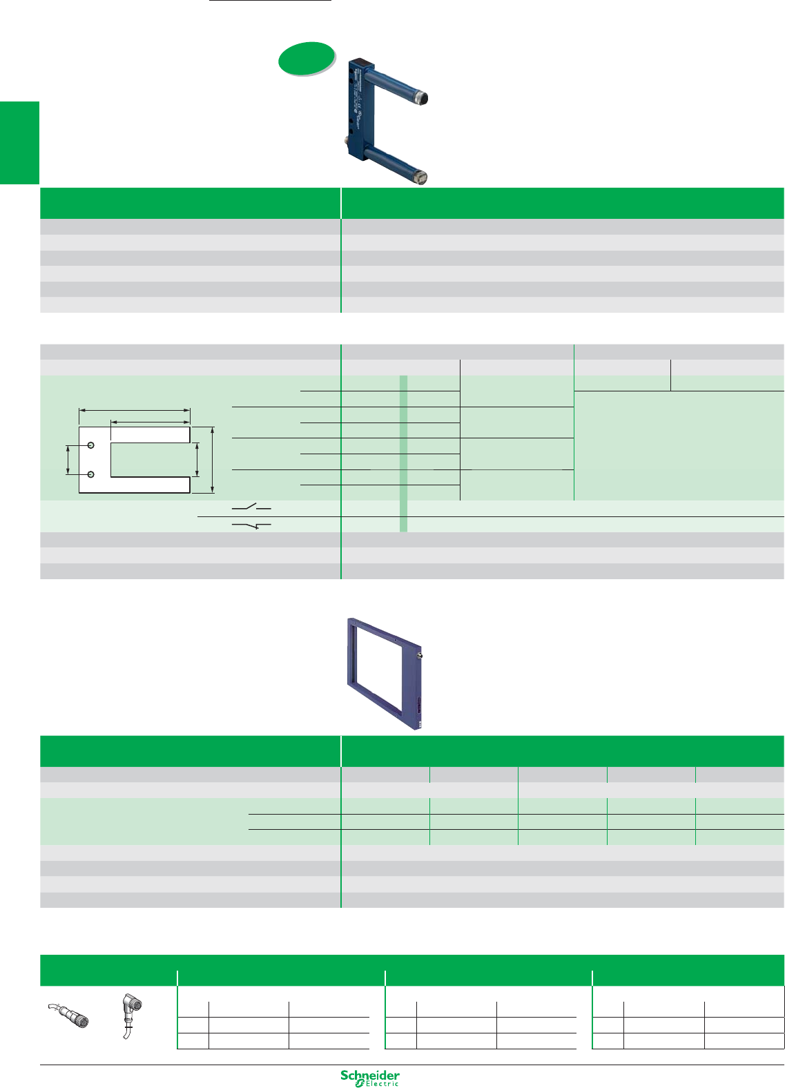
Other versions: please consult your Schneider Electric agency.
System Thru-beam with modular red LED light source
Sensing distance 2…180 mm
Fixing (mm) (see column E below)
Minimum size of objet detected 0,8 mm
Case M (metal) M
Temperature range (°C) / Degree of protection (conforming to IEC 60529)
- 10…+ 60 / IP65 & IP67
Product certification CE - cULus
Sensors for DC applications (solid-state output: transistor)
Connection M8 connector 3-pin Pre-cabled L = 2 m.
Dimensions (mm) ABCDE ABCDE
Transmitter / Receiver 3 wire NO function PNP XUVR0605P ANM8 50 60 74 77,5 40 XUVR0303PANL2 30 40 54 57,5 30
NPN XUVR0605NANM8
NO function PNP XUVR0608P ANM8 80 60 104 77,5 70
NPN XUVR0608NA NM8
NO function PNP XUVR1212P ANM8 120 120 144 142 100
NPN XUVR1212NANM8
NO function PNP XUVR1218P ANM8 180 120 204 142 152
NPN XUVR1218NANM8
Output function NO A
NC B
Supply voltage limits, min./max. (V) including ripple 10…30
Switching capacity, max. (mA) / Switching frequency (Hz) 100/4kHz
Overload and short-circuit protection (g) / LED output state indicator
(⊗)g / ⊗
Photo-electric sensors
Optical forks without setting and frames
New
B
D
A CE
OsiSense XU
System Thru-beam with infrared emission
Passageway dimensions 30 x 30 mm 60 x 60 mm 200 x 120 mm 200 x 180 mm 200 x 250 mm
Connection M8 (4 pin) M12 (4 pin)
Minimum size of object to be detected Ø 2 mm XUVF30M8 XUVF60M8 – – –
Ø 4 mm – – XUVF120M12 XUVF180M12 XUVF250M12
Ø 10 mm – – XUYFRS120S XUYFRS180S XUYFRS250S
Type and output function 4-wire, PNP and NPN Output function ON or OFF on passage of object, programmable
Supply voltage limits, min./max. (V) including ripple 18…30
Switching capacity, max. (mA) / Switching frequency (Hz) ≤ 100 mA / 500 Hz
Overload and short-circuit protection (g) / LED output state indicator
(⊗)g / ⊗
Accessories
Suitable female pre-wired plug-in connectors
M8 (3 pin) M8 (4 pin) M12 (4 pin)
For optical forks without setting For optical forks and frame with setting For frame with setting
Straight Elbowed Straight Elbowed Straight Elbowed
2 m XZCP0566L2 XZCP0666L2 2 m XZCP0941L2 XZCP1041L2 2 m XZCP1141L2 XZCP1241L2
5 m XZCP0566L5 XZCP0666L5 5 m XZCP0941L5 XZCP1041L5 5 m XZCP1141L5 XZCP1241L5
Straight Elbowed
1/32
2
1
3
4
5
6
7
8
9
10
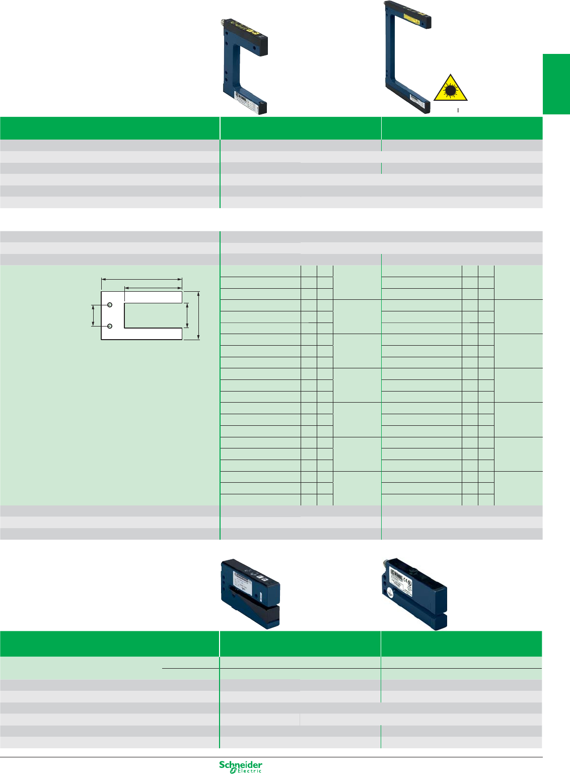
Other versions: please consult your Schneider Electric agency.
System, with teach mode Thru-beam Thru-beam laser
Sensing distance 2…120 mm 2…120 mm
Fixing (mm) (see column E below)
Minimum size of objet detected 0,2 mm 0,05 mm
Case M (metal) / Setting-up assistance LEDs ⊗M / ⊗
Temperature range (°C) / Degree of protection (conforming to IEC 60529)
- 25…+ 60 / IP 65
Product certification CE - cULus
Sensors for DC applications (solid-state output: transistor)
Connection M8 connector - 4 Pin
Type of output 3-wire PNP/NPN programmable NO/NC
Dimensions (mm) ABCDE ABCDE
Transmitter / Receiver XUYFANEP40002 242
32 57 14 XUYFALNEP40002 242
41 57 14
XUYFANEP60002 259 77 XUYFALNEP60002 259 77
XUYFANEP100002 295 110 XUYFALNEP100002 295 110
XUYFANEP40005 542
35 57 14 XUYFALNEP40005 542
44 57 14
XUYFANEP60005 559 77 XUYFALNEP60005 559 77
XUYFANEP100005 595 110 XUYFALNEP100005 595 110
XUYFANEP40015 15 42 45 57 27 XUYFALNEP40015 15 42 54 57 27
XUYFANEP60015 15 59 77 XUYFALNEP60015 15 59 77
XUYFANEP100015 15 95 110 XUYFALNEP100015 15 95 110
XUYFANEP40030 30 42 60 57 42 XUYFALNEP40030 30 42 69 57 42
XUYFANEP60030 30 59 77 XUYFALNEP60030 30 59 77
XUYFANEP100030 30 95 110 XUYFALNEP100030 30 95 110
XUYFANEP40050 50 42 80 57 40 XUYFALNEP40050 50 42 89 57 40
XUYFANEP60050 50 59 77 XUYFALNEP60050 50 59 77
XUYFANEP100050 50 95 110 XUYFALNEP100050 50 95 110
XUYFANEP40080 80 42 110 57 70 XUYFALNEP40080 80 42 119 57 70
XUYFANEP60080 80 59 77 XUYFALNEP60080 80 59 77
XUYFANEP100080 80 95 110 XUYFALNEP100080 80 95 110
XUYFANEP40120 120 42 150 57 110 XUYFALNEP40120 120 42 159 57 110
XUYFANEP60120 120 59 77 XUYFALNEP60120 120 59 77
XUYFANEP100120 120 95 110 XUYFALNEP100120 120 95 110
Supply voltage limits, min./max. (V) including ripple 10…30 10…30
Switching capacity, max. (mA) / Switching frequency (Hz) 100/10 kHz 100/10 kHz
Overload and short-circuit protection (g) / LED output state indicator
(⊗)g / ⊗g / ⊗
(1) To order a fork without teach mode, delete A of the reference. Ex: XUYFANEP40002 becomes XUYFNEP40002
System Ultrasonic thru-beam Thru-beam
Special transparent labels For all other opaque labels
Sensing distance 3 mm version XUVU06M3KCNM8 XUYFA983003COS
5 mm version –XUYFA983005COS
Switching frequency (Hz) 500 10 000
Sensitivity adjustment Numerical +/- button Teach button
Connection M8 (4 pin)
Case M (metal) / Setting-up assistance LEDs ⊗M / ⊗
Temperature range (°C) / Degree of protection (conforming to IEC 60529)
- 5…+ 55 / IP 65 - 20…+ 60 / IP 65
Product certification CE CE - cULus
Laser
class
B
D
A CE
Forks with teach mode (1)
1/33
2
1
3
4
5
6
7
8
9
10
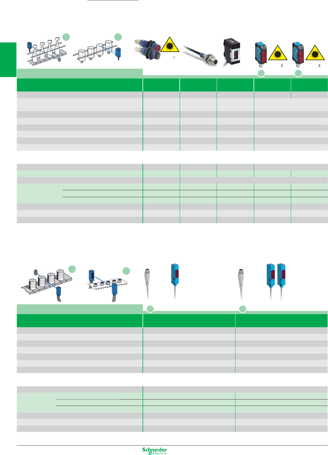
Other versions: please consult your Schneider Electric agency.
Laser
class
Laser
class
Laser
class
Photo-electric sensors - Application
Assembly series
Application Robustness and compactness
System Thru-beam Diffuse Diffuse (1) Refl ex Diffuse
contrast
Sensing distance 100 m (2) 0.07 m0.07 m
10…1000 mm (3)
40…150 mm
Fixing (mm) M18 x 1 M8 x 1 Direct, 2 M3 holes,
fxg. ctrs. 20 mm
Direct, 2 M3 holes, fi xing centres 24 mm
Sensitivity adjustment Teach mode – Potentiometer Teach mode
Case M (metal) P (plastic) / Setting-up assistance LEDs ⊗P / ⊗M / – M / ⊗P
Temperature range (°C) / Degree of protection (conforming to IEC 60529)
- 10…+ 45°C - 25…+ 55
- 25…+ 60
- 20…+ 60°C
Degree of protection (conforming to IEC 60529)
IP 67 IP 67 IP 67,
IP 69K
IP 67
Product certifi cation CE - UL - CSA CE - cULus
CE - cULus - C-TICK
CE - cULus
Dimensions (mm) Ø x L or H x W x D Ø 18 x 64 Ø 8 x 40 40.8 x 16.2 x 29.5 35.8 x 12 x 20
Sensors for DC applications (solid-state output: transistor)
Connection Pre-cabled PVR (2 m) PVC (2 m)
Transmitter / Receiver 3-wire PNP NO function – XUAH0515 XUM5BPANL2 ––
Connection Connector M12 M8 4-pin
Transmitter / Receiver 3-wire PNP NO function – XUAH0515S – ––
3-wire PNP
programmable NO / NC
XUBLAPCNM12 – – XUYBCO929LSP XUYPCCO929LSP
3-wire NPN
programmable NO / NC
XUBLANCNM12 – – – –
Supply voltage limits, min./max. (V) including ripple 10…30 10…30 10…30 10…30 10…30
Switching capacity, max. (mA) / Switching frequency (Hz) 100 / 1500 100 / 700 100 / 1000 100 / 1000 100 / 1000
Overload and short-circuit protection (g) / LED output state indicator (⊗)
g / ⊗g / ⊗g / ⊗g / ⊗g / ⊗
(1) Refl ex and thru-beam systems also available.
(2) or min. size of object: 0.2 mm
(3) With specifi c refl ector XUY1111, format 50 x 50 mm. To be ordered separately.
OsiSense XU
Accurate detection
or very long sensing
distance
Application
System Polarised refl ex Thru-beam
50 x 50 refl ector included
Sensing distance 1…1.5 m4 m
Fixing (mm) 2 x Ø 3 holes / fi xing centres 9.5 3 x Ø 3 holes / fi xing centres 9.5
Sensitivity adjustment Potentiometer Potentiometer
Case P (plastic) / Setting-up assistance LEDs ⊗P / ⊗P / ⊗
Temperature range (°C) / Degree of protection (conforming to IEC 60529)
0…+ 50 / IP 65 & IP 67 0…+ 50 / IP 65 & IP 67
Product certifi cation CE - cULus CE - cULus
Dimensions (mm) H x W x D 40 x 10 x 13.5 40 x 10 x 13.5
Sensors for DC applications (solid-state output: transistor)
Connection M8 connector (1)
- 4 Pin
PNP NO function XUYBCO989SP XUYRCO989SP (receiver)
NPN NO function XUYBCO989SN XUYRCO989SN (receiver)
PNP/NPN
programmable NO / NC
– XUYECO989 (transmitter)
Supply voltage limits, min./max. (V) including ripple 10…30 10…30
Switching capacity, max. (mA) / Switching frequency (Hz) 100 / 500 100 / 500
Overload and short-circuit protection (g) / LED output state indicator (⊗)
g / ⊗g / ⊗
(1) For 2 m pre-cabled version delete CO from the reference. Example: XUYPSCO989SP becomes XUYPS989SP.
Miniature series sensors
C D
D
C
A B
A B
1/34
2
1
3
4
5
6
7
8
9
10
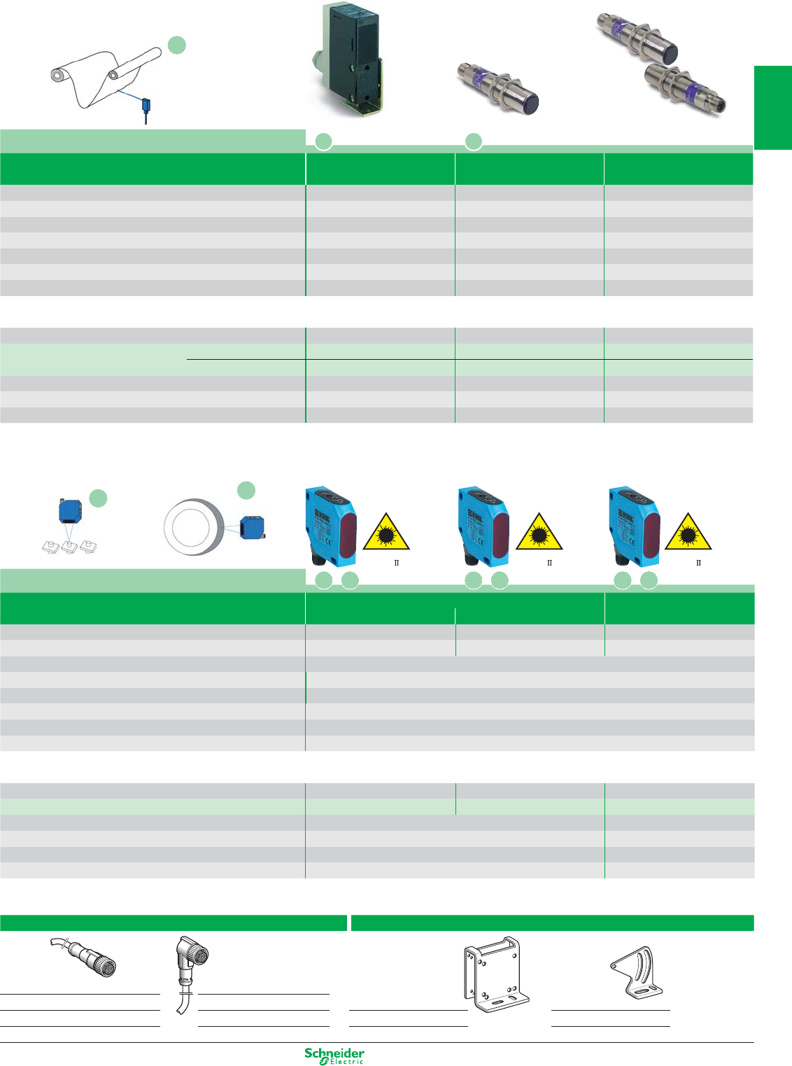
Other versions: please consult your Schneider Electric agency.
Laser
class
Laser
class
Laser
class
Accessories
Suitable female pre-wired plug-in connectors Fixing, for XUYPCO925
M8 straight M12 straight M8 elbowed M12 elbowed
2 m XZCP0941L2 XZCP1141L2 XZCP1041L2 XZCP1241L2 With protective cover Simple
5 m XZCP0941L5 XZCP1141L5 XZCP1041L5 XZCP1241L5 XUY 9251-DF525567 XUY 925-DF525568
Materials handing series - Analogue output
Application
System Diffuse Diffuse Thru-beam
Sensing distance 0.20...0.80 m0.05...0.40 m50 m
Fixing (mm) fi xing ctrs: 30 - 11P cable gland M18 x 1 M18 x 1
Sensitivity adjustment – Potentiometer Potentiometer
Case M (metal) P (plastic) / Setting-up assistance LEDs ⊗P / ⊗M / ⊗M / ⊗
Temperature range (°C) / Degree of protection (conforming to IEC 60529)
- 25…+ 60 / IP 67 - 25…+ 55 / IP 67 - 25…+ 55 / IP 67
Product certifi cation CE - UL - CSA CE - UL - CSA CE - UL - CSA - C-TICK
Dimensions (mm) Ø x L or H x W x D 86 x 27 x 83 M18 x 95 M18 x 95
Sensors for DC applications
Connection Screw terminals M12 connector M12 connector
Transmitter / Receiver
analogue 4-20 mA / 0-10 V XUJK803538 (5) ––
analogue 4-20 mA – XU5M18AB20D XU2M18AP20D (5)
Supply voltage limits, min./max. (V) including ripple 20…30 10…30 10…30
Switching capacity, max. (mA) / Switching frequency (Hz) max: 20, min: 4 / 10000 max: 20, min: 4 / 20 100 / 30
Overload and short-circuit protection (g) / LED output state indicator (⊗)
g / ⊗g / ⊗g / ⊗
(5) With 3-wire PNP output.
Application
System Diffuse, 0-10 V analogue output Diffuse,
Sensing distance 1 Sensing distance 2 4-20 mA analogue output
Sensing distance 40...60 mm 45...85 mm 80...300 mm
Minimum size of object 1 mm 0.8 mm 1.5 x 3.5 mm
Fixing (mm) direct: 3 M4 holes, fi xing centres 40 mm
Sensitivity adjustment Potentiometer
Case P (plastic) / Setting-up assistance LEDs ⊗P / ⊗
Temperature range (°C) 0…+ 45°
Product certifi cation CE - cULus
Dimensions (mm) H x W x D 50 x 17 x 50
Sensors for DC applications (solid-state output: transistor)
Connection M12 connector M12 connector M12 connector
Transmitter / Receiver 0…10 V XUYPCO925L1ANSP XUYPCO925L2ANSP XUYPCO925L3ANSP
Supply voltage limits, min./max (V) including ripple 18…28 18…28
Switching capacity, max. 3 mA / 0…10 V analogue output 3 mA / 4…20 mA analogue output
Switching frequency (Hz) 40 40
Overload and short-circuit protection (g) / LED output state indicator
(⊗)g / ⊗g / ⊗
High access gain for resistance
to accumulation of dirt
Analogue output
Position control
E
FG
E
E
F G F G F G
1/35
2
1
3
4
5
6
7
8
9
10
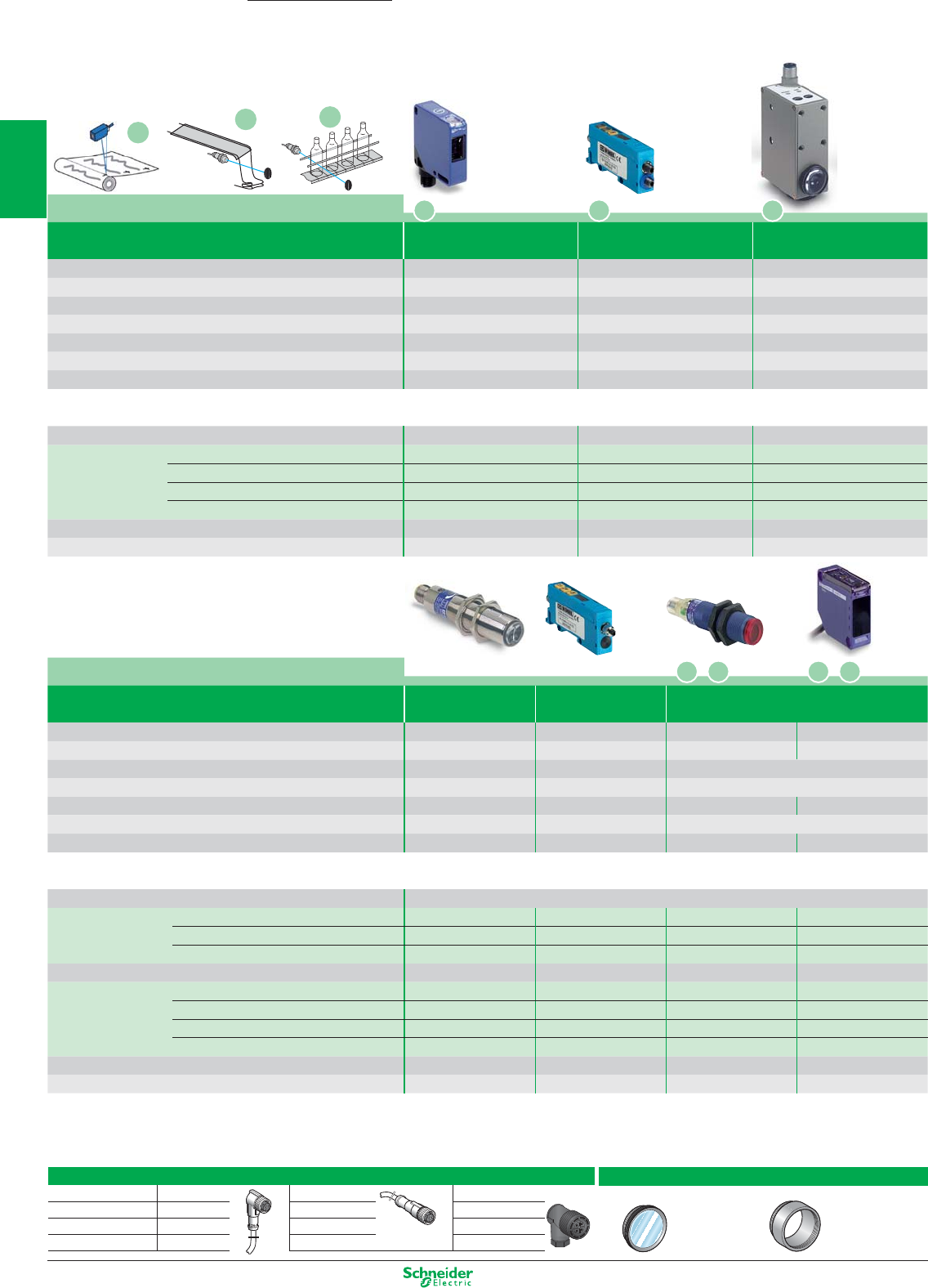
Other versions: please consult your Schneider Electric agency.
Accessories
Suitable female plug-in connectors, including pre-wired versions
L = 5 m, without LED
Wired, elbowed
Wired, straight Screw terminal
M8 (or S) 4 pin XZCP0666L5 XZCP0566L5 XZCC8FCM30S
M12 (or D) 4 pin XZCP1241L5 XZCP1141L5 XZCC12FCM40B
M12 8 pin – XSZMCR03 (3 m) –
Lenses for colour mark
Lens for 18 mm sensing distance Lens for 7 mm sensing distance
XURZ01 XURZ02
Photo-electric sensors - Application
Packaging series
Application
System Diffuse Lum. detection Reflex (with teach mode)
(manual) via fibre optics (50 x 50 reflector included)
Sensing distance 0.02…0.08 m
dpg. on fibre & fitting
(3) 0…1.4 m (4) 1.5 m
Fixing (mm) M18 x 1 DIN rail M18 x 1
direct: fixing ctrs. 40 x 40
Sensitivity adjustment Potentiometer
+/- numeric potentiometer
Teach button
Case M (metal) P (plastic) / Setting-up assistance LEDs ⊗
M / ⊗P / ⊗P / ⊗
Temperature range (°C) / Degree of protection (conforming to IEC 60529)
- 25…+ 55 / IP 67 0 … + 60 / IP 65 0…+ 55 / IP 67 - 25…+ 55 / IP 65
Product certification CE - CSA - UL CE - cULus CE - UL - CSA - C-TICK
Dimensions (mm) Ø x L or H x W x D Ø 18 x 95 30 x 13 x 60 Ø 18 x 64 50 x 18 x 50
Sensors for DC applications (solid-state output: transistor
)
Connection Pre-cabled, PVC (2 m)
Transmitter / Receiver
3-wire PNP
programmable NO / NC
– – XUBTAPSNL2 (5) –
3-wire NPN
programmable NO / NC
– – XUBTANSNL2 (5) –
3-wire PNP / NPN
programmable NO / NC
– – – XUKT1KSML2
Connection
M12 connector M8 connector M12 connector M12 connector
Transmitter / Receiver
3-wire PNP fonction NO XU5M18U1D – – –
3-wire PNP
programmable NO / NC
– – XUBTAPSNM12 (5) –
3-wire NPN
programmable NO / NC
– – XUBTANSNM12 (5) –
3-wire PNP / NPN
programmable NO / NC
– XUYAFLCO966S – XUKT1KSMM12
Supply voltage limits, min./max. (V) including ripple 10…30 10…30 10…32 10…30
Switching capacity, max. (mA) / Switching frequency (Hz) 100 / 1000 100 / 5 100 / 1000 100 / 1500
(3) Suitable fibre optics, to be ordered separately (usable
Ø 1 mm):
(L = 10 m: XUFZ910) (L = 20 m: XUFZ920) (L = 50 m: XUFZ950). End fittings see the fibre optic page
(4) 0…0.8 m for versions with 90° head, to order replace the 8
e
digit N by W. Example XUBTAPSNL2 becomes XUBTAPSWL2
(5) Also available in stainless steel for food and beverage processing applications. To order, replace the letter A by S in the ref. Example: XUBTAPSNL2 becomes XUBTSPSNL2.
Application Contrast sensors
System Diffuse Sensor with Diffuse
(with teach mode) plastic fibre optics (1) (with teach mode)
Sensing distance 19 mm 18 mm 9 mm (2)
Fixing (mm) direct: fixing centres 40 x 40 DIN rail direct: 21 x 28, M5 screws
Sensitivity adjustment Teach button Teach button Teach button
Case M (metal) P (plastic) / Setting-up assistance LEDs ⊗
P / ⊗P / ⊗M / ⊗
Temperature range (°C) / Degree of protection (conforming to IEC 60529)
- 10…+ 55 / IP 65 0 … + 40 / IP 65 - 10…+ 55 / IP 67
Product certification CE - cULus CE - cULus CE
Dimensions (mm) Ø x L or H x W x D 50 x 15 x 50 30 x 13 x 60 96 x 31 x 64
Sensors for DC applications (solid-state output: transistor)
Connection
M12 connector
M8
connector M12 connector
Transmitter / Receiver
3-wire PNP NO function XUKR1PSMM12 – –
3-wire NPN NO function XUKR1NSMM12 – –
3-wire PNP / NPN programmable NO / NC – – XURK1KSMM12
NPN NO function XUYDCFCO966S –
Supply voltage limits, min./max. (V) including ripple 10…30 10…30 10…30
Switching capacity, max. (mA) / Switching frequency (Hz) 100 / 5000 100 / 20 k 200 / 10000
(1) Suitable fibre optics, to be ordered separately:
Sensing distance: 18 mm (L = 0.6 m: XUYFPDC61),
60 mm (L = 1 m: XUYFPDC101)
18 mm (L = 0.6 m / M8: XUYFPDCM861),
60 mm (L = 1 m / M8: XUYFPDCM8101).
(2) 7 mm with XURZ02; 18 mm with XURZ01.
OsiSense XU
H
H H
I J
Luminescence sensors Detection of transparent materials
IJ
I J
H
1/36
2
1
3
4
5
6
7
8
9
10
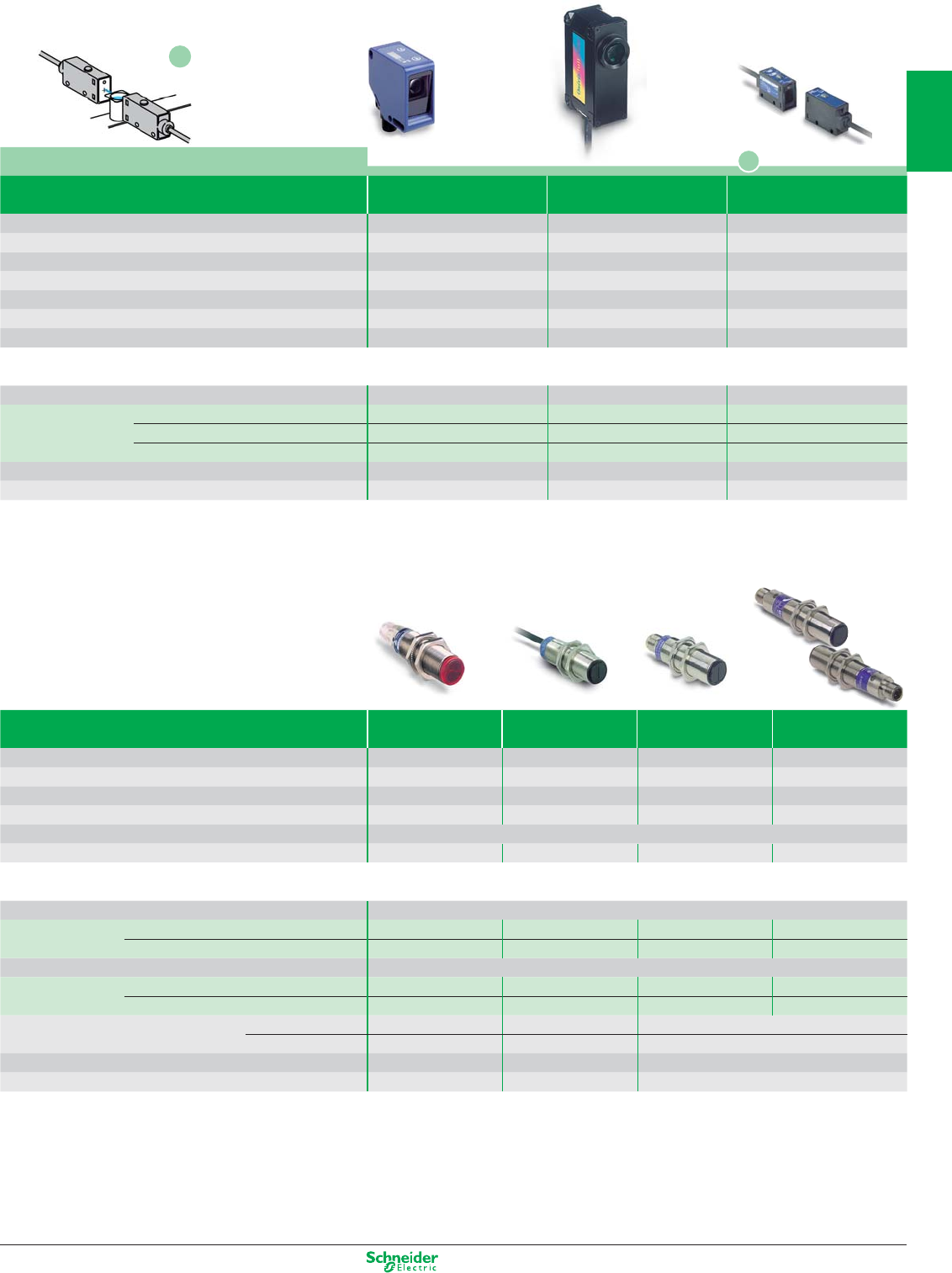
Other versions: please consult your Schneider Electric agency.
Application Colour sensors
Detection of aqueous liquids
System Diffuse Diffuse Thru-beam
(with integral amplifi er) infrared
Sensing distance 0.02 m0.040...0.060 m0.2 m (1)
Fixing (mm) direct: fi xing ctrs. 40x40
drct: fxg ctrs. 68x42, M5 screws
direct: fi xing ctrs. 20
Sensitivity adjustment Teach button Teach button Potentiometer
Case M (metal) P (plastic) / Setting-up assistance LEDs ⊗
P / ⊗M / ⊗P / ⊗
Temperature range (°C) / Degree of protection (conforming to IEC 60529)
- 10…+ 55 / IP 65 - 10…+ 55 / IP 67 0…+ 40 / IP 65
Product certifi cation CE - cULus CE CE
Dimensions (mm) Ø x L or H x W x D 50 x 25 x 50 80 x 30 x 57 47 x 13 x 33
Sensors for DC applications (solid-state output: transistor
)
Connection M12 connector - 8 pin Pre-cabled (2 m) Pre-cabled (2 m)
Transmitter / Receiver 3-wire PNP NO function XUKC1PSMM12 XURC3PPML2 –
3-wire NPN NO function XUKC1NSMM12 XURC3NPML2 –
3-wire PNP / NPN
programmable NO / NC
– – XUMW1KSNL2
Supply voltage limits, min./max. (V) including ripple 10…30 10…30 10.8…26.4
Switching capacity, max. (mA) / Switching frequency (Hz) 100 / 1500 100 / 1200 100 / 1000
(1) Nominal sensing distance 50 m. Use between 10 and 20 cm, depending on application.
Stainless steel version for resistance to harsh agents
System Multimode (3) Polarised relex (2) Diffuse (2) Thru-beam (2)
Sensing distance (4) 3 / 2 m0.15 / 0.10 m20 / 15 m
Fixing (mm) M18 x 1 M18 x 1 M18 x 1 M18 x 1
Case M (metal)
M (stainless steel) M (stainless steel) M (stainless steel) M (stainless steel)
Temperature range (°C) / Degree of protection (conforming to IEC 60529)
- 25…+ 55 / IP 67 - 25…+ 55 / IP 67 - 25…+ 55 / IP 67
Product certifi cation CE - UL - CSA - C-TICK
Dimensions (mm) Ø x L Ø 18 x 64 Ø 18 x 62 Ø 18 x 62 Ø 18 x 64
Sensors for DC applications (solid-state output: transistor
)
Connection Pre-cabled, PvR (2 m)
Transmitter / Receiver 3-wire PNP
programmable NO / NC
XUB0SPSNL2 XU9N18PP341 XU5N18PP341 XU2N18PP341
3-wire NPN
programmable NO / NC
XUB0SNSNL2 XU9N18NP341 XU5N18NP341 XU2N18NP341
Connection M12 connector
Transmitter / Receiver 3-wire PNP
programmable NO / NC
XUB0SPSNM12 XU9N18PP341D XU5N18PP341D XU2N18PP341D
3-wire NPN
programmable NO / NC
XUB0SNSNM12 XU9N18NP341D XU5N18NP341D XU2N18NP341D
Thru-beam transmitter accessory pre-cabled (2 m) XUB0SKSNL2T – –
connector XUB0SKSNM12T – –
Supply voltage limits, min./max. (V) including ripple 10…36 10…30 10…30
Switching capacity, max. (mA) / Switching frequency (Hz) 100 / 250 100 / 500 100 / 500
(2) Also available with 90° head. To order, add the letter W after the numbers 341 in the reference. Example: XU9N18PP341 becomes XU9N18PP341W or XU9N18PP341DW.
(3) 0…0.8 m for versions with 90° head, to order replace the 8
e
digit N by W. Example XUB0SPSNL2 becomes XUB0SPSWL2
(4) Background suppression: 0.12 m - Diffuse: 0.3 m - Refl ex polarised: 2 m - Thru beam: 18 m
Food/beverage processing series
Packaging series
N
N
1/37
2
1
3
4
5
6
7
8
9
10
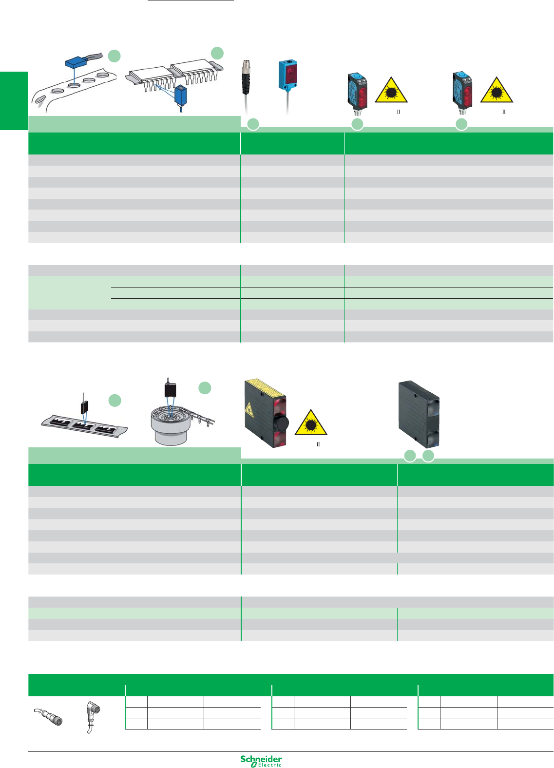
Other versions: please consult your Schneider Electric agency.
Laser
class
Laser
class
Laser
class
Application
System Background
suppression
Background
suppression, 2 chnls.
Sensing distance 50…300 mm 50…600 mm
Minimum size of object 0.5 mm –
Fixing (mm) direct: 2 M4 holes, ctrs. 54 mm 2 x Ø 4 holes, fi xing ctrs. 54
Sensitivity adjustment Potentiometer Potentiometer
Case P (plastic) / Setting-up assistance LEDs ⊗P / ⊗P / ⊗
Temperature range (°C) / Degree of protection (conforming to IEC 60529)
0…+ 50 / IP 65 0…+ 60 / IP 40
Product certifi cation CE - cULus
Dimensions (mm) H x W x D 60 x 18 x 60 60 x 18 x 60
Sensors for DC applications (solid-state output: transistor). Sensors with overload and short-circuit protection
Connection M8 connector
Transmitter / Receiver 3-wire PNP / NPN programmable NO / NC XUYPS1LCO965S XUYPS2CO945S
Supply voltage limits, min./max. (V) including ripple 10…30 10…30
Switching capacity, max. (mA) / Switching frequency (Hz) 100 / 5000 100 / 370
Accessories
Pre-wired connectors
M8 (4 pin) M12 (4 pin) 7/8" (5 pin)
Straight Elbowed Straight Elbowed Straight
2 m XZCP0941L2 XZCP1041L2 2 m XZCP1141L2 XZCP1241L2 2 m XZCP1764L2
5 m XZCP0941L5 XZCP1041L5 5 m XZCP1141L5 XZCP1241L5 5 m XZCP1764L5
Straight Elbowed
Photo-electric sensors
with background suppression
OsiSense XU
Application
System Background Diffuse with background suppression
suppression Sensing distance 1 Sensing distance 2
Sensing distance 1.5…80 mm 10…60 mm 30…110 mm
Minium size of object – 0.3 mm 0.7 mm
Fixing (mm)
2 x Ø 3 holes / fxg. ctrs. 14.5
direct: 2 M3 holes, fi xing centres 24 mm
Sensitivity adjustment Potentiometer Teach mode
Case P (plastic) / Setting-up assistance LEDs ⊗
P / ⊗P
Temperature range (°C) / Degree of protection (conforming to IEC 60529)
0…+ 50 / IP 65 & IP 67 - 20…+ 60°C / IP 67
Product certifi cation CE - cULus CE - cULus
Dimensions (mm) H x W x D 32 x 13 x 20 35.8 x 12 x 20
Sensors for DC applications (solid-state output: transistor)
Connection M8 connector (1)
- 4 Pin
M8 connector
- 4 Pin
M8 connector
- 4 Pin
Transmitter / Receiver
PNP NO function XUYPSCO989SP – –
NPN NO function XUYPSCO989SN – –
PNP
programmable NO / NC
– XUYPSCO929L1SP XUYPSCO929L2SP
Supply voltage limits, min./max. (V) including ripple 10…30 10…30 10…30
Switching capacity, max. (mA) / Switching frequency (Hz) 100 / 500 100 / 1000 100 / 1000
Overload and short-circuit protection (g) / LED output state indicator (⊗)
g / ⊗g / ⊗g / ⊗
(1) For 2 m pre-cabled connection delete CO from the reference. Example: XUYPSCO989SP becomes XUYPS989SP.
K
KP
P K
M
M
L
L
1/38
2
1
3
4
5
6
7
8
9
10
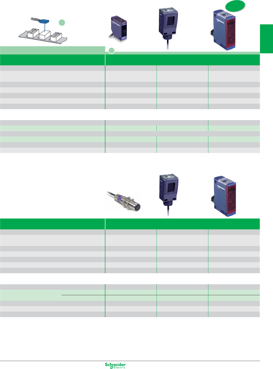
Other versions: please consult your Schneider Electric agency.
Application
System Diffuse
with adjustable background suppression
Sensing distance 0…1 m 1.2 m 2 m
Fixing (mm)
direct:
fixing ctrs. 40 x 40
M30 x 1.5 or M5,
fixing
ctrs. 30
direct: fixing ctrs. 30/38
to 40/50/74 M5 screw
Sensitivity adjustment – Potentiometer –
Case P (plastic) / Setting-up assistance LEDs ⊗
P / ⊗P / ⊗P / ⊗
Temperature range (°C) / Degree of protection (conforming to IEC 60529)
- 25…+ 55 / IP 65
- 25…+ 55 / IP 67, Nema 4X
- 25...+ 55 / IP 67
Product certification
CE - UL - CSA CE - UL - CSA CE - UL - CSA
Dimensions (mm) H x W x D 50 x 18 x 50 95 x 45 x 44 92 x 30,5 x 71
Sensors for DC applications (solid-state output: transistor). Sensors with overload and short-circuit protection
Connection Pre-cabled, PVC (2 m) Screw terminals
Transmitter / Receiver
3-wire PNP / NPN
programmable NO / NC
XUK8AKSNL2 XUC8AKSNL2 (3) XUX8AKSAT16 (3)
Connection M12 connector
Transmitter / Receiver
3-wire PNP / NPN
programmable NO / NC
XUK8AKSNM12 XUC8AKSNM12 (3) XUX8AKSAM12
Supply voltage limits, min./max. (V) including ripple 10…36 10…38 10…36
Switching capacity, max. (mA) / Switching frequency (Hz) 100 / 250 100 / 500 100 / 150
Système Diffuse
with adjustable background suppression
Sensing distance 70…120 mm 1.2 m 2 m
Fixing (mm) M18 x 1 M30 x 1.5 or M5, fixing ctrs. 30 direct: fixing ctrs. 30/38
to 40/50/74 M5 screw
Sensitivity adjustment Potentiometer Potentiometer –
Case M (metal) P (plastic) / Setting-up assistance LEDs ⊗M / ⊗P / ⊗P / ⊗
Temperature range (°C) / Degree of protection (conforming to IEC 60529)
- 25…+ 55°C / IP 67 - 25…+ 55 / IP 67, Nema 4X - 25...+ 55 / IP 67
Product certification CE - UL - CSA CE - UL - CSA CE - UL - CSA
Dimensions (mm) Ø x L or H x W x D M18 x 82 95 x 45 x 44 92 x 30,5 x 71
Multi-current/multi-voltage sensors for AC/DC applications
Connection Cable L = 2m Cable 2m / Connector 7/8" Screw terminals
Transmitter / Receiver AC/DC NO function XU8M18MA230 – –
programmable NO / NC
– XUC8ARCTL2 / XUC8ARCTU78 XUX8ARCTT16
Supply voltage limits, min./max. (V) including ripple 20…264 20…264 20…264
Switching capacity, max. (mA) / Switching frequency (Hz) 200 / 25 3000 / 20 3000 / 20
Overload and short-circuit protection (g) / LED output state indicator (⊗)
(2) / ⊗––
(2) Sensor not short-circuit protected. Therefore, it is essential to connect a 0.4 A quick-blow fuse in series with the load.
New
Q
Q
Objets sur convoyeur
1/39
2
1
3
4
5
6
7
8
9
10
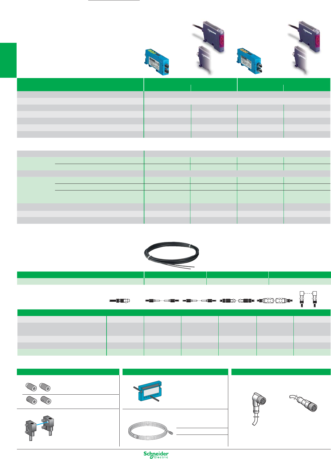
Other versions: please consult your Schneider Electric agency.
Photo-electric sensors, fibre optic
Amplifier
+/- potentiometer Teach Teach + Timer Teach + Timer
Max. / usable sensing distance Depending on fibre used, plastic only
Fixing (mm) DIN rail or direct: fixing centres 25, M3 screws
Sensitivity adjustment
+/- numeric potentiometer
using teach mode
+/- numeric potentiometer
using teach mode
Case P (plastic) / Setting-up assistance LEDs ⊗P / ⊗P / ⊗P / ⊗P / ⊗ and 4-digit display
Temperature range (°C) / Degree of protection (conforming to IEC 60529)
0…+ 60 / IP 65 - 10…+ 55 / IP 65 (1) 0…+ 60 / IP 65 - 10…+ 55 / IP 65 (1)
Product certification CE - cULus CE - cULus - cURus CE - cULus CE - cULus - cURus
Dimensions (mm) L x H x W 60 x 30 x 13 65 x 40 x 10 60 x 30 x 13 65 x 40 x 10
Sensors for DC applications (solid-state output: transistor)
Connection Pre-cabled, PVC (2 m)
References 3-wire PNP programmable NO / NC – XUDA1PSML2 – XUDA2PSML2
Amplifier 3-wire NPN programmable NO / NC – XUDA1NSML2 – XUDA2NSML2
Connection M8 connector - 4 Pin
References 3-wire PNP programmable NO / NC – XUDA1PSMM8 – XUDA2PSMM8
Amplifier 3-wire NPN programmable NO / NC – XUDA1NSMM8 – XUDA2NSMM8
3-wire PNP/NPN programmable NO / NC XUYAFVCO966S (Glass) –XUYAFVCO946S (Glass) –
XUYAFPCO966S (Plastic) –XUYAFPCO946S (Plastic) –
Supply voltage limits, min./max. (V) including ripple 10…30 10.8...26.4 10…30 10.8...26.4
Switching capacity, max. (mA) / Switching frequency (Hz) 100 / 1000 100 / 1000 100 / 1000
time delayable
100 / 1000
time delayable
Overload and short-circuit protection (g) / LED output state indicator (⊗)
g / ⊗g / ⊗g / ⊗g / ⊗
(1) IP 65 with Ø 1 fibre/ IP 64 with Ø 0.5 fibre.
Ecofibre system, assemble your own plastic fibres
End fittings
Sensing distance (mm) 70 200 800 1200 4000 1200
Type with threaded end
with plain end fitting, with plain end fitting,
with threaded end with threaded end 90° mirror, with
fitting Ø 3, L = 9 mm Ø 3, L = 9 mm fitting fitting threaded end fitting
Thread M8 x 1, L = 10 mm – – M6 x 1, L = 10 mm M6 x 1, L = 10 mm
M6 x 1, L = 3 to 10 mm
Lens yes no yes yes yes yes
References XUYA110 XUYA210 XUYA211 XUYA212 XUYA212 XUYA220
Accessories
For thru-beam system plastic fibre optics
Lenses For increasing
sensing distance (pair) XUFZ01
With 90° mirror
(pair) XUFZ02
Fixing clamp with lens (set of 2)
Front screw fixing
for fibre optics
XUFZ920 XUFZ04
For all system plastic fibre optics
Fibre trimmer For trimming fibres to
length (included with
all fibre optics) XUFZ11
Protective metal tubing
Length 1 m, for fibres
with threaded end fittings
For M4 thread XUFZ210
For M6 thread XUFZ310
Plug-in pre-wired female connectors
Cable length 5 m, without LED
pre-wired, elbowed pre-wired, straight
XZCP1041L5 XZCP0941L5
OsiSense XU
Fibre Ø 1 mm Length = 10 m Length = 20 m Length = 50 m
References XUFZ910 XUFZ920 XUFZ950
1/40
2
1
3
4
5
6
7
8
9
10
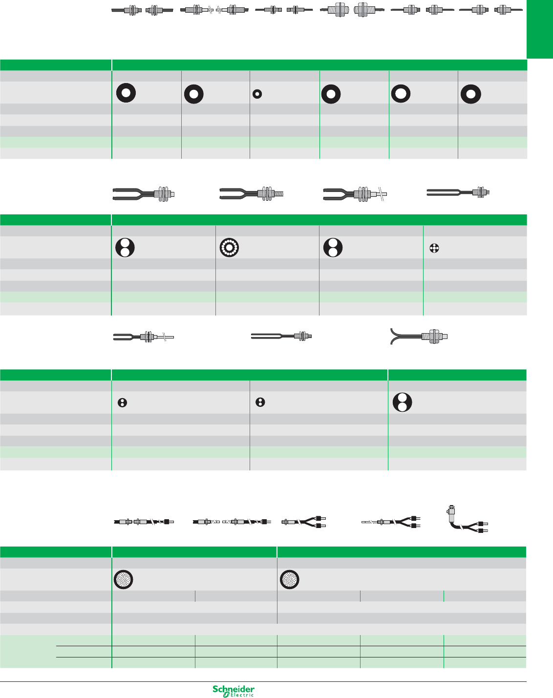
Other versions: please consult your Schneider Electric agency.
System Diffuse
Sensing distance (mm) 70 60 60 15
Fibre cross-section
Fibre Ø (mm) Ø 1 Ø 1+16 Ø 0.265 Ø 1 Ø 0.5 + 4 Ø 0.23
Sheath Ø (mm) Ø 2.2 x 2 Ø 2.2 x 2 Ø 2.2 x 2 Ø 1 x 2
Temperature range (°C) - 25...+ 60 - 25...+ 60 - 25...+ 60 - 25...+ 60
References XUFN05321 XUFN05323 XUFN05331 XUFN02323
Fixing M6 x 0.75 M6 x 0.75 / M4 x 0.7 M6 x 0.75 M4 x 0.7
Plastic fibre optic light guides (length 2 m)
Long range fibres
with integrated lens Long range fibres Flexible fibres
M4 / M2.6 (1) M4 / L = 90 mm M3 / M2.6 (1) M8 / L = 20 mm M4 / M2.6 (1) M4 / M2.6 (1)
System Thru-beam
Sensing distance (mm) 200 or 1500 (2) 180 50 or 1000 (2) 2500 300 or 2000 (2) 100 or 750 (2)
Fibre cross-section
Fibre Ø (mm) Ø 1 Ø 1 Ø 0.5 Ø 1 Ø 1.5 Ø 1
Sheath Ø (mm) Ø 2.2 Ø 2.2 Ø 1 Ø 2.2 Ø 2.2 Ø 2.2
Temperature range (°C) - 25...+ 60 - 25...+ 60 - 25...+ 60 - 25...+ 60 - 25...+ 60 - 25...+ 60
References XUFN12301 XUFN12311 XUFN35301 XUFN2L01L2 XUFN2P01L2 XUFN2S01L2
Fixing M4 x 0.7 M4 x 0.7 M3 x 0.5 M8 x 1.25 M2.6 x 0.45 / M4 x 0.7 M2.6 x 0.45 / M4 x 0.7
(1) Can be used with 90° mirror XUFZ02 (see preceding page).
(2) With lens accessory XUFZ01 (see preceding page)
System Diffuse
Sensing distance (mm) 18 18 95
Fibre cross-section
Fibre Ø (mm) Ø 0.5 Ø 0.5 Ø 1.5
Sheath Ø (mm) Ø 1 x 2 Ø 1 x 2 Ø 2.2 x 2
Temperature range (°C) - 25...+ 60 - 25...+ 60 - 25...+ 60
References XUFN01331 XUFN01321 XUFN5P01L2
Fixing M4 x 0.7 M4 x 0.7 M6 x 0.75
M4 M4 / Ø 2.5 x 89 M4 M4 / Ø 2.5 x 89 M4
System Thru-beam Diffuse
Sensing distance (mm) 200 80
Fibre cross- section
End fitting Straight Adaptable Straight Adaptable 90°
Fibre Ø (mm) 1 1
Sheath Ø (mm) 2.2 2.2
Temperature range (°C) PVC sheath: - 25…+ 60 / Metal wound: - 25…+ 120 / Flexible stainless steel: - 25…+ 200
References PVC sheath XUYFVERSD61 XUYFVERSC61 XUYFVPSD61 XUYFVPSC61 XUYFVPSL61
Metal wound XUYFVERMD61 XUYFVERSC61 XUYFVPMD61 XUYFVPMC61 XUYFVPML61
Flexible stnl. steel XUYFVERTD61 XUYFVERTC61 XUYFVPTD61 XUYFVPTC61 XUYFVPTL61
Glass fibre optic light guides (length 0.6 m)
M6 M4 / M6 M6/L = 90 mm M4 / M2.6
Long range fibres
M4 / L = 90 mm M4 / M2.6 M6 / L = 15 mm
1/41
2
1
3
4
5
6
7
8
9
10
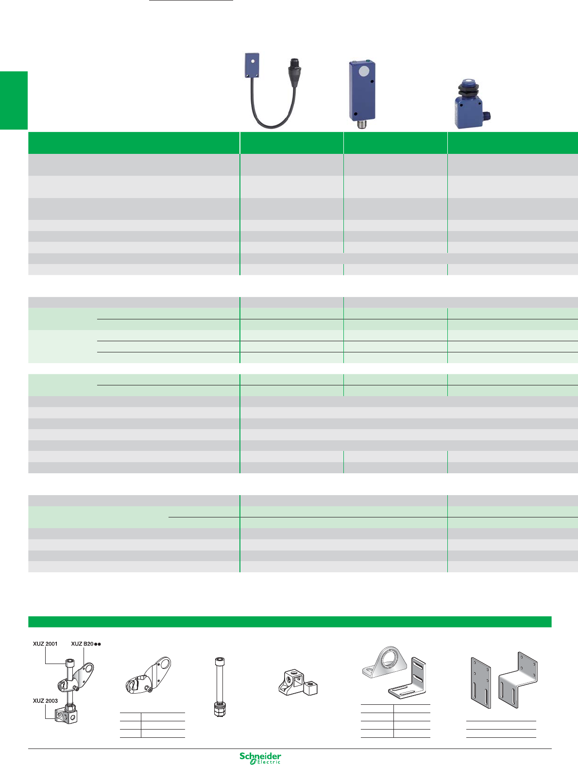
Other versions: please consult your Schneider Electric agency.
Ultrasonic sensors
Detection of any material
Mini fl at Flat Combined
multi-fi xing
Nominal sensing distance Sn 10 cm 25 cm 50 cm
Operating zone (cm) 0.62…10.2 5.1…25.4 5.1…50.8
–––
Sensitivity adjustment Fixed Fixed Adjustable using
remote control
Case P (plastic) PPP
Product certifi cation CE CE CE
Temperature range (°C) - 20…+ 65 0…+ 50 - 20…+ 65
Degree of protection (conforming to IEC 60529) IP 67
Dimensions (mm) Ø x L or H x W x D 33 x 19 x 7.6 74 x 30 x 16 M 18 / 18 x 33 x 60
Sensors with “Discrete” output for DC applications (24 V)
Connection
M12 on 0.15 m fl ying lead
M12 connector
3-wire PNP NO function XX7F1A2PAL01M12 XX7K1A2PAM12 XX7V1A1PAM12
NPN NO function XX7F1A2NAL01M12 XX7K1A2NAM12 XX7V1A1NAM12
4-wire PNP/NPN NO function –––
PNP NO + NC function –––
NPN NO + NC function –––
Application - monitoring levels
2 emptying levels PNP NO function –––
2 fi lling levels PNP NO function –––
Supply voltage limits, min./max. (V) including ripple 10…28
Switching capacity, max. (mA) <100
Short-circuit protection (g)g
LED output state indicator (⊗) / Power on LED (⊗)⊗ / ⊗
Voltage drop, closed state (V) at I nominal <1
Switching frequency (Hz) 100 80 40
Transmission frequency (Hz) 500 500 300
Sensors with “Analogue” output for DC applications (24 V)
Connection –M12 connector
4-wire Analogue 0…10 V output –XX9V1A1F1M12
4…20 mA output –XX9V1A1C2M12
Supply voltage limits, min./max. (V) including ripple – 10…28
Short-circuit protection (g)– g
LED output state indicator (⊗) / Power on LED (⊗)–⊗ / ⊗
Transmission frequency (Hz) – 300
Accessories
Fixings
3D fi xings with ball joint Simple fi xings
Bracket with ball joint for
M12 rod for Fixing support for
90° fi xing brackets Mounting plates for XX7K
cylindrical sensors
ball joint M12 rod
for
for Ø 12 XXZ12
Ø 12 XUZB2012 Ø 18 XUZA118
Ø 18 XUZB2003 Ø 30 XXZ30 fl a t XXZ3074F
3D kit example Ø 30 XUZB2030 XUZ2001 XUZ2003 XX7F XXZ1933 cranked XXZ3074S
OsiSense XX
1/42
2
1
3
4
5
6
7
8
9
10

Other versions: please consult your Schneider Electric agency.
M12 M18 M30 M30
Long range
5 or 10 cm 15 or 50 cm 1 m1 m2 m8 m
depending on model depending on model
0.64…5.1 (XX512A1…)
1.9…15.2 (XX518A1…) 10…100 5.1…99.1 12…200 20.3…800
0.64…10.2 (XX512A2…)
5.1…50.8 (XX518A3…) – – –
Fixed Adjustable using Adjustable using
remote control teach mode
PP P P
CE CE CE CE
- 20…+ 65 0…+ 50 (XX518A1…) / - 20…+ 65 (XX518A3…) 0…+ 70 0…+ 70 - 20…+ 60
IP 67 IP 67 IP 65
M12 x 50 M18 x 65 M30 x 78 M30 x 85 M30 x 106
M8 connector M12 connector Pre-cabled, PVC (2 m) M12 connector M12 connector
XX512A2PAM8
(10 cm)
XX518A3PAM12
(50 cm)
XX518A3PAL2 XX6V3A1PAM12 – – –
XX512A2NAM8
(10 cm)
XX518A3NAM12
(50 cm)
XX518A3NAL2 XX6V3A1NAM12 – – –
XX512A1KAM8
(5 cm)
XX518A1KAM12
(15 cm)
– – XX630A1KAM12 – –
– – – – XX630A1PCM12 (1) – XX630A3PCM12
– – – – XX630A1NCM12 (1) – XX630A3NCM12
– XX218A3PHM12 (3) – – XX230A10PA00M12 (2) XX230A20PA00M12 (2) –
– XX218A3PFM12 (3) – – XX230A11PA00M12 (2) XX230A21PA00M12 (2) –
10...28
<100
g
⊗ / ⊗
⊗ / ⊗ except XX518A1.. (- / -)
⊗ / ⊗⊗ / ⊗⊗ / ⊗
<1
125 40 / 80 (XX518A1..) 70 10 2
500 300 180 200 75
M12 connector
– XX918A3F1M12 – XX9V3A1F1M12 XX930A1A1M12 (1) – XX930A3A1M12
– XX918A3C2M12 – XX9V3A1C2M12 XX930A1A2M12 (1) – XX930A3A2M12
– 10…28 – 10…28 10…28 – 10…28
–g–gg–g
–⊗ / ⊗–⊗ / ⊗⊗ / ⊗–⊗ / ⊗
– 300 – 180 200 – 75
(1) Stainless steel 303 version also available. To order, replace the fi rst letter A in the reference by S. Example: XX630A1PCM12 becomes XX630S1PCM12.
(2) 2 NO
(3) 1 NO
Programming Suitable female plug-in connectors
Remote control Pre-wired connectors
Other connectors
teach button for use with elbowed straight screw terminal
sensors XXp18A3ppp,
XXpV1ppp and XXpV3ppp
L = 5 m (without LED)
M8 for XX512A1… XZCP1041L5 XZCP0941L5 XZCC8FCM40V
for XX512A2… XZCP0666L5 XZCP0566L5 XZCC8FCM30V
XXZPB100 M12
for all sensors except XX512...
XZCP1241L5 XZCP1141L5 XZCC12FCM40B
New
1/43
2
1
3
4
5
6
7
8
9
10
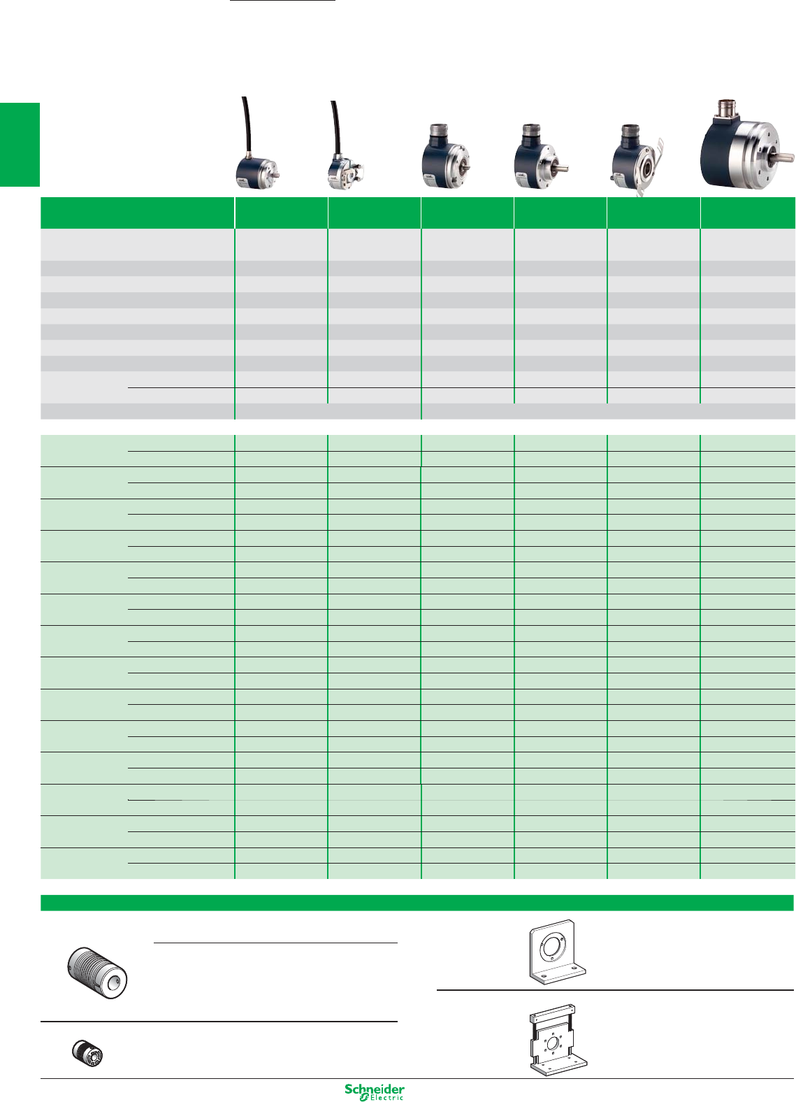
Other versions: please consult your Schneider Electric agency.
Opto-electronic rotary encoders
Incremental
Diameter of housing (mm) Ø 40 Ø 40 Ø 58 Ø 58 Ø 58 Ø 90
Parametrable
Shaft Ø (mm) Ø 6 Ø 6 Ø 6 Ø 10 Ø 14 (1) Ø 12
Type of shaft (2) solid shaft through shaft solid shaft solid shaft through shaft solid shaft
Maximum rotational speed (rpm) 9000 9000 9000 9000 6000 6000
Maximum frequency (kHz) 100 100 300 300 300 100
Maximum load (daN) 2 2 10 10 5 20
Torque (N.cm) 0.2 0.25 0.4 0.4 0.6 1
Product certification CE CE CE CE CE CE
Temperature range (°C) - 20…+ 80 - 20…+ 80 - 30…+ 100 - 30…+ 100 - 30…+ 70 - 20…+ 80
Degree of protection (conforming to IEC 60529)
IP 54 IP 52 IP 65 / IP 67 (3) IP 65 / IP 67 (3) IP 65 IP 66
Supply voltage 5 V, RS 422 4.5…5.5 V 4.5…5.5 V 4.75…30 V 4.75…30 V 4.75…30 V 4.5…5.5 V
Push-pull 11…30 V 11…30 V 5…30 V 5…30 V 5…30 V 11…30 V
Connection Pre-cabled (2 m), radial M23 male connector, radial
R
esolution (Points)
Output stage
100 5 V, RS 422 XCC1406PR01R XCC1406TR01R XCC1506PS01X XCC1510PS01X – XCC1912PS01RN
Push-pull XCC1406PR01K XCC1406TR01K XCC1506PS01Y XCC1510PS01Y – XCC1912PS01KN
360 5 V, RS 422 XCC1406PR03R XCC1406TR03R XCC1506PS03X XCC1510PS03X – XCC1912PS03RN
Push-pull XCC1406PR03K XCC1406TR03K XCC1506PS03Y XCC1510PS03Y – XCC1912PS03KN
500 5 V, RS 422 XCC1406PR05R XCC1406TR05R XCC1506PS05X XCC1510PS05X – XCC1912PS05RN
Push-pull XCC1406PR05K XCC1406TR05K XCC1506PS05Y XCC1510PS05Y – XCC1912PS05KN
1000 5 V, RS 422 XCC1406PR10R XCC1406TR10R XCC1506PS10X XCC1510PS10X – XCC1912PS10RN
Push-pull XCC1406PR10K XCC1406TR10K XCC1506PS10Y XCC1510PS10Y – XCC1912PS10KN
1024 5 V, RS 422 XCC1406PR11R XCC1406TR11R XCC1506PS11X XCC1510PS11X – XCC1912PS11RN
Push-pull XCC1406PR11K XCC1406TR11K XCC1506PS11Y XCC1510PS11Y – XCC1912PS11KN
2500 5 V, RS 422 – – XCC1506PS25X XCC1510PS25X – XCC1912PS25RN
Push-pull – – XCC1506PS25Y XCC1510PS25Y – XCC1912PS25KN
3600 5 V, RS 422 – – – – – XCC1912PS36RN
Push-pull – – – – – XCC1912PS36KN
256…4096 5 V, RS 422 – – – – XCC1514TSM02X –
Push-pull – – – – XCC1514TSM02Y –
5000 5 V, RS 422 – – XCC1506PS50X XCC1510PS50X – XCC1912PS50RN
Push-pull – – XCC1506PS50Y XCC1510PS50Y – XCC1912PS50KN
360…5760 5 V, RS 422 – – – – XCC1514TSM03X –
Push-pull – – – – XCC1514TSM03Y –
500…8000 5 V, RS 422 – – – – XCC1514TSM05X –
Push-pull – – – – XCC1514TSM05Y –
10 000 5 V, RS 422 – – – – – XCC1912PS00RN
Push-pull – – – – – XCC1912PS00KN
1024…16 384 5 V, RS 422 – – – – XCC1514TSM11X –
Push-pull – – – – XCC1514TSM11Y –
5000…80 000 5 V, RS 422 – – – – XCC1514TSM50X –
Push-pull – – – – XCC1514TSM50Y –
Accessories
Shaft couplings Fixing brackets
with spring Bore diameter Bore diameter Reference Plain bracket for Ø 58 mm XCCRE5SN
(encoder side) (machine side) for Ø 90 mm XCCRE9SN
6 mm 6 mm XCCRAR0606
6 mm 8 mm XCCRAR0608
6 mm 10 mm XCCRAR0610
10 mm 10 mm XCCRAR1010 Bracket with play compensator for Ø 58 mm XCCRE5RN
10 mm 12 mm XCCRAR1012 for Ø 90 mm XCCRE9RN
elastic 6 mm 6 mm XCCRAE0606
OsiSense XCC
1/44
2
1
3
4
5
6
7
8
9
10
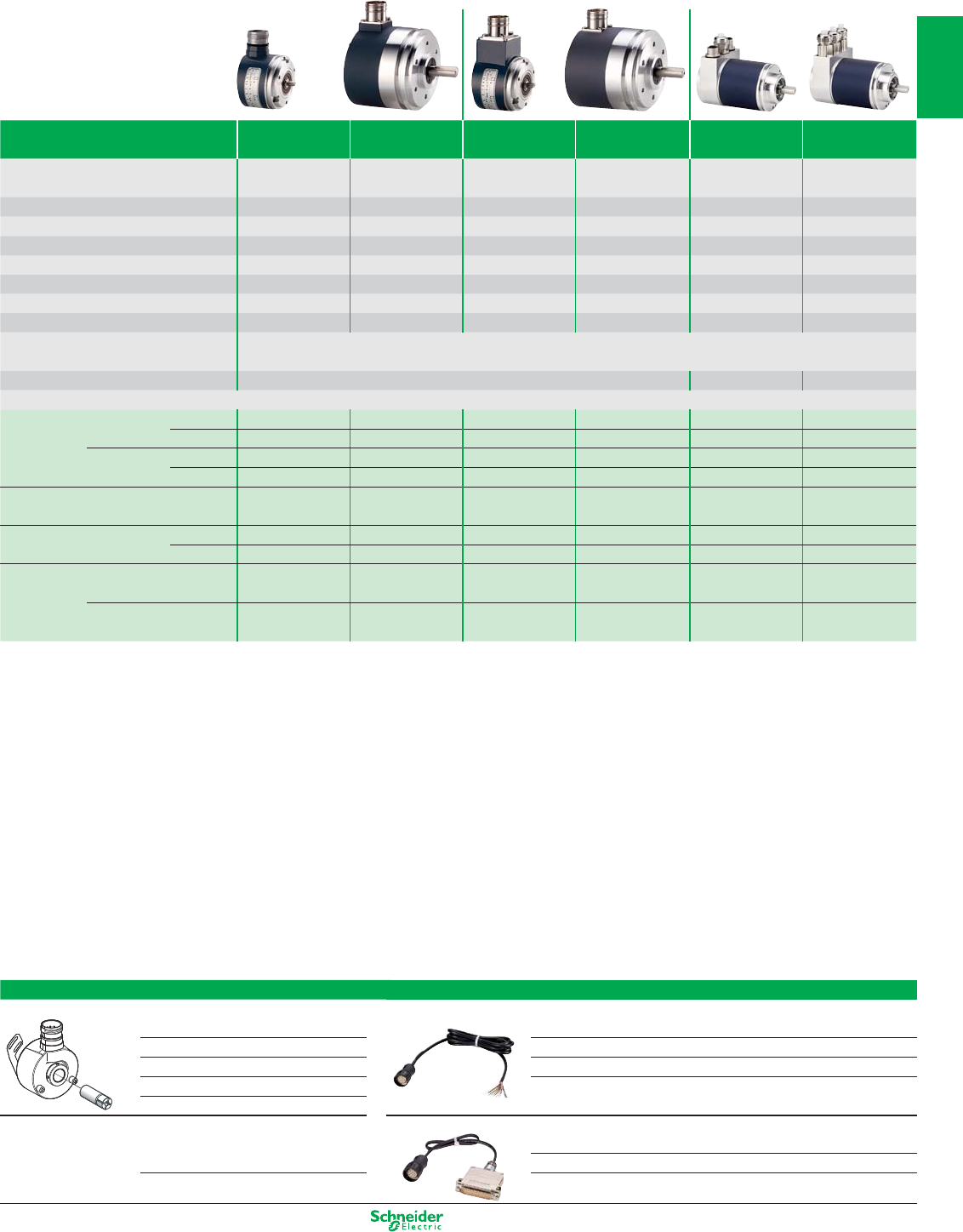
Other versions: please consult your Schneider Electric agency.
Absolute Absolute Communicating
- single turn - multiturn multiturn absolute
Diameter of housing (mm) Ø 58 Ø 90 Ø 58 Ø 90 Ø 58
CANopen
Ø 58
PROFIBUS-DP
Shaft Ø (mm) Ø 6 Ø 12 Ø 10 Ø 12 Ø 10 Ø 10
Type of shaft (2) solid shaft solid shaft solid shaft solid shaft solid shaft (4) solid shaft (4)
Maximum rotational speed (rpm) 9000 6000 6000 6000 6000 6000
Maximum frequency (kHz) 100 100 (1000 SSI) 100 (500 SSI) 100 (500 SSI) 800 800
Maximum load (daN) 10 20 10 20 11 11
Torque (N.cm) 0.4 1 0.4 1 0.3 0.3
Product certification CE CE CE CE CE CE
Temperature range (°C) - 20…+ 90 - 20…+ 85 - 20…+ 85 - 20…+ 85 - 40…+ 85 - 40…+ 85
Degree of protection (conforming to IEC 60529)
IP 65 IP 66 IP 65 / IP 67 (3) IP 66 IP 64 IP 64
Supply voltage 11…30 V
Connection M23 male connector, radial 2 x M12 + 1 x Pg 9 3 x Pg 9
Resolution Output stage Code
… 8192 points Push-pull Binary XCC2506PS81KB XCC2912PS81KBN – – – –
Gray XCC2506PS81KGN XCC2912PS81KGN – – – –
SSI, 13-bit Binary XCC2506PS81SBN XCC2912PS81SBN – – – –
Gray XCC2506PS81SGN XCC2912PS81SGN – – – –
4096 points /
8192 turns SSI, 25-bit (5) Gray ––XCC3510PS48SGN – – –
8192 points /
4096 turns
SSI, 25-bit (5) Binary XCC3510PS84SBN XCC3912PS84SBN
Gray – – XCC3510PS84SGN XCC3912PS84SGN
8192 points /
4096 turns
CANopen,
25-bit Binary – – XCC3510PS84CB –
PROFIBUS-DP,
25-bit Binary – – – – – XCC3510PV84FB
(1) Anti-rotation device included with through shaft version encoders. To achieve Ø 6, 8, 10 or 12 mm through shafts, use the reduction collars.
(2) All versions are also available with through shaft and anti-rotation device.
(3) IP 67 with sealed collar XCCRB3.
(4) Versions available with hollow shaft and anti-rotation device.
(5) “Parallel” outputs possible for multiturn absolute encoders using derserialisation jumper cables XCCRM23SUB37pp.
Reduction collars
For Ø 58 mm incremental encoders with through shaft
Ø 14 to Ø 6 mm XCCR158RDA06
Ø 14 to Ø 8 mm XCCR158RDA08
Ø 14 to Ø 10 mm XCCR158RDA10
Ø 14 to Ø 12 mm XCCR158RDA12
IP 67 sealed collar
For encoders XCC1510, 2510, 3510
Ø 58 mm XCCRB3
Pre-wired connectors and jumper cables
Pre-wired M23 female connectors (cable length 5 m)
8-wire for SSI encoders XCCPM23122L5
10-wire for incremental encoders XCCPM23121L5
16-wire for parallel single turn absolute encoders XCCPM23161L5
Deserialisation jumper cables (M23 F - SUB-D37 M) (L = 0.5 m)
SSI Gray - // Gray PNP XCCRM23SUB37PG
SSI binary - // binary NPN XCCRM23SUB37PB
1/45
2
1
3
4
5
6
7
8
9
10
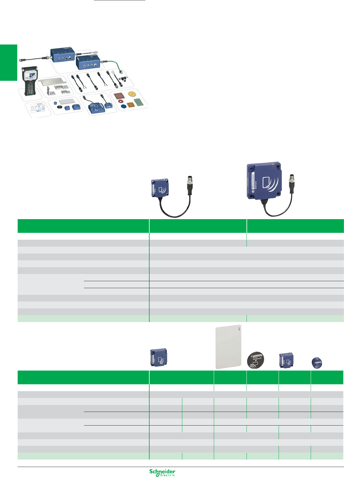
Other versions: please consult your Schneider Electric agency.
Radio frequency identification
13.56 MHz RFID
Presentation
OsiSense XG is open to the majority of ISO 18000-3, ISO 15693 and ISO 14443 electronic tags.
OsiSense XG integrates Modbus RTU, Uni-Telway, Modbus TCP/IP (using Ethernet box XGSZ33ETH) and
Profibus DP (with box XGSZ33PDP) protocols.
The OsiSense XG RFID offer comprises:
- 2 models of 13.56 MHz compact stations (read/write)
- 6 models of 13.56 MHz electronic tags
- 1 portable RFID diagnostics terminal
- 3 models of network connection boxes plus connection and mounting accessories.
Setting-up
OsiSense XG compact stations are simple to set-up:
- Integrated RFID and network functions
- No programming
- Automatic detection of the RFID electronic tags (read or write)
- Automatic setting of the communication parameters (speed, format, parity, protocol, etc.)
- Configuration of the network address (1 to 15) using badge included with the station
- Low sensitivity to metal environments.
Installation
OsiSense XG stations easily integrate in flexible manufacturing production lines:
- quick connection using M12 connector
- screw fixing or clip-on mounting.
Compact stations, 13.56 MHz C format D format
Dimensions (mm), W x H x D 40 x 40 x 15 80 x 80 x 26
Nominal sensing distance depending on tag (mm) 18 to 70 20 to 100
Type of associated tag ISO 15693 and ISO 14443 standard tags. Automatic detection of the type of tag.
Display 1 dual colour LED for the communication network, 1 dual colour LED for the RFID communication
Conformity to standards CE, EN 301489-1, EN 301489-3, ETS 300330-1 and ETS 300330-2, FCC part 15 - UL
Degree of protection conforming to IEC 60529 IP 67
Serial link Type RS 485
Protocol Modbus and Uni-Telway
Speed (Bauds) 9600…115 200 (automatic detection)
Ambient air temperature (°C) For operation: - 25…+ 70 °C, for storage: - 40…+ 85 °C
Nominal supply voltage 24 VDC PELV (Protective Extra Low Voltage)
Connection
M12, 5-pin male, shielded connector on flying lead. Only for connection to the communication network and the supply
References XGCS4901201 XGCS8901201
Electronic tags C format ISO badge
(1)
Disc E format Cylindrical
Dimensions (mm), W x H x D 40 x 40 x 15 54 x 85.5 x 0.8 Ø 30 x 3 26 x 26 x 13 M18 x 1 x 12
Type of memory EEPROM
Memory capacity (bytes) 3 408 13 632 256 112 256 256
Nominal sensing distance (mm) With station XGCS49
p
33 30 70 48 40 18
(Read/Write) With station XGCS89
p
48 40 100 65 55 20
Time (ms) Read
9.25 + 0.375 x n (2)
16.25 + 0.375 x n (2)
12 + 0.825 x n (2)
Write 13 + 0.8 x n (2) 20 + 0.8 x n (2)
20 + 11.8 x n (2)
12 + 5.6 x n (2) 20 + 11.8 x n (2) 19 + 4.1 x n (2)
Degree of protection conforming to IEC 60529 IP 68 IP 65 IP 68
Standard supported ISO 14443 ISO 15693
Mounting on metal support Yes No Yes No
References XGHB444345 XGHB445345 XGHB90E340 XGHB320345 XGHB221346 XGHB211345
(1) Customised versions on request. (2) n = number of 16-bit words.
OsiSense XG
1/46
2
1
3
4
5
6
7
8
9
10
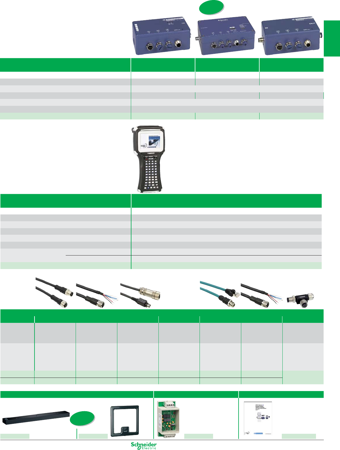
Other versions: please consult your Schneider Electric agency.
Connection boxes Ethernet box Profibus box Tap-off box
Dimensions (mm), W x H x D 130 x 80 x 51 130 x 80 x 51
Protocols Modbus TCP/IP Profibus DP Modbus, Uni-Telway
Supply voltage 24 VDC PELV. M12, 4-pin male, A coding, connector
Conformity to standards CE - UL CE CE - UL
Station connection M12, 5-pin female, A coding, connector
Degree of protection conforming to IEC 60529 IP 65
References XGSZ33ETH XGSZ33PDP TCSAMT31FP
Terminal Portable 13.56 MHz RFID diagnostics terminal
Dimensions (mm), W x H x P 120 x 250 x 62
Function Read/Write operations on electronic tags and diagnostics on compact stations
Operating system Microsoft® Windows CE.NET Professional® version 4.2
Conformity to standards CE, FCC class A, Part 15225
Display 72 x 54 mm colour touchscreen; QVGA TFT, 320 x 240 pixels resolution
Degree of protection conforming to IEC 60529 IP 65
Memory RAM 64 Mb SDRAM
Storage Internal Compact Flash (512 Mb standard, expandable to 128 Mb) + Slot for Compact Flash card
Reference XGSTP401 (Battery, battery charger, carrying case and 3 styluses included with terminal)
Connection accessories
for Modbus network for Profibus for Ethernet
Pre-wired connector
“T” connector
Description Modbus connecting
cable M12 connec-
tors Male / Female
Pre-wired connector
M12 male / Bare
wires
Modbus connecting
cable M12 female /
Mini-DIN 8
Profibus connecting
cables M12 connec-
tors Male / Female
Ethernet ConneXium
connecting cable
M12 male / RJ 45
Pre-wired
supply connector
M12 female
Network M12
“T” connector
1 male / 2 female
Application
RS485 connection
between a compact sta-
tion and a Modbus box or
between 2 Modbus boxes
Connection between
a Modbus box and a
Modbus / Uni-Telway
network
Connection between
a Modbus box and
a PLC
Connection between
Profibus box and
Profibus network
Connection between
an Ethernet box and
the Ethernet network
24 VDC supply to
connection boxes
For RS 485 network
L = 2 m TCSMCN1M1F2 TCSMCN1F2 TCSMCN1F9M2P FTXDP1220 TCSECL1M3M3S2 (3) XGSZ09L2 TCSCTN011M11F
L = 5 m TCSMCN1M1F5 TCSMCN1F5 – FTXDP1250 TCSECL1M3M5S2 XGSZ09L5
(3) L = 3 m
Field expander RS232/RS485 converter Technical documentation
To be associated with a compact station XGCS4901201 for conveying
and handling applications
For connecting a PC to
an OsiSense XG station
OsiSense XG compact
stations guide
50 x 400 mm
XGFEC540
250 x 250 mm
XGFEC2525 XGSZ24 DIA4ED3051001
New
New
1/47
2
1
3
4
5
6
7
8
9
10
Rely on the expertise and know-how
of the worldwide leader in operator
dialogue components
Our extensive ranges of Harmony and
Magelis Human/Machine Interfaces
guarantee simple integration and
efficient configuration of your dialogue
applications.
HMI Magelis
A complete, robust and scalable HMI offer
from Panels to Industrial PCs, to answer
your needs in a wide range of applications.
Thanks to its added value capacities, the
Magelis range, ensures the availability of
your installation.
Harmony
Tried-and-tested throughout the entire world and
characterised by extreme robustness, groomed
ergonomics and maximum installation simplicity,
the Harmony control and signalling ranges provide
the ideal solution for your varying application
requirements due to an offer that is unmatched in
its extensiveness.

Operator dialog
This document is a selection of
the top selling products.
2/1
2
1
3
4
5
6
7
8
9
10
Control and signalling units
Pushbuttons, switches, pilot lights & control stations
Ø 16, plastic bezel, Harmony XB6 .............................................................................. 2/2 to 2/4
Ø 8 & 12, pilot lights, Harmony XVL ..................................................................................... 2/5
Ø 22, metal bezel, Harmony XB4 / Control stations Harmony XAP ........................... 2/6 to 2/9
Ø 22, plastic bezel, Harmony XB5 / Control stations Harmony XAL ..................... 2/10 to 2/13
Ø 22, plastic bezel - Monolithic, Harmony XB7 ....................................................... 2/14 to 2/15
Ø 30, metal and plastic bezel, Harmony 9001K, 9001SK ....................................... 2/16 to 2/19
Cam switches
Harmony K series ................................................................................................... 2/20 to 2/21
Signalling solutions
Ø 40, 60, 100 mm monolithic tower lights, Harmony XVC .................................................. 2/22
Ø 45 mm monolithic beacons and tower lights, accessories, Harmony XVDLS / XVC ....... 2/23
Ø 70 mm modular tower lights (IP 66), Harmony XVB ........................................................ 2/24
Ø 70 mm modular tower lights (up to IP 54), Harmony XVE ............................................... 2/25
Ø 45, 50 mm modular tower lights (up to IP 54), Harmony XVM / XVP .............................. 2/26
Modular tower lights accessories, Harmony XV .................................................................. 2/27
Ø 84, 106, 120, 130 mm rotating mirror beacons, Harmony XVR ....................................... 2/28
Rotating mirrors accessories and sound solutions, Harmony XVR / XVS ........................... 2/29
Components for hoisting applications
Pendant control stations, Harmony XAC ................................................................. 2/30 to 2/31
Human/Machine Interfaces
Display units, terminals, Industrial PCs
Small Panels, Magelis STO/STU, XBT N / R / RT .................................................... 2/32 to 2/34
Advanced Panels, Magelis XBT GT, GK, GTW, GH ................................................ 2/35 to 2/39
HMI Controllers, Compact Magelis XBT GC ........................................................................ 2/40
PC Panels, Magelis Smart, Magelis Compact iPC ............................................................ 2/41
Embedded Box and PC Box, Magelis Smart BOX, Compact BOX & Flex PC BOX .......... 2/42
Front Panels, for Flex PC BOX ............................................................................................. 2/43
Industrial Display, Magelis iDisplay ..................................................................................... 2/43
Configuration software
For Magelis XBT N / R / RT,
Vijeo Designer Lite ....................................................................................................... 2/44
For Magelis STO/STU, XBT GT, GK, GTW, GH, Magelis Smart, Compact iPC, PC BOX,
Vijeo Designer .............................................................................................................. 2/45
Dialog operator for Explosive atmospheres
See Chapter 10 “Explosive atmospheres”
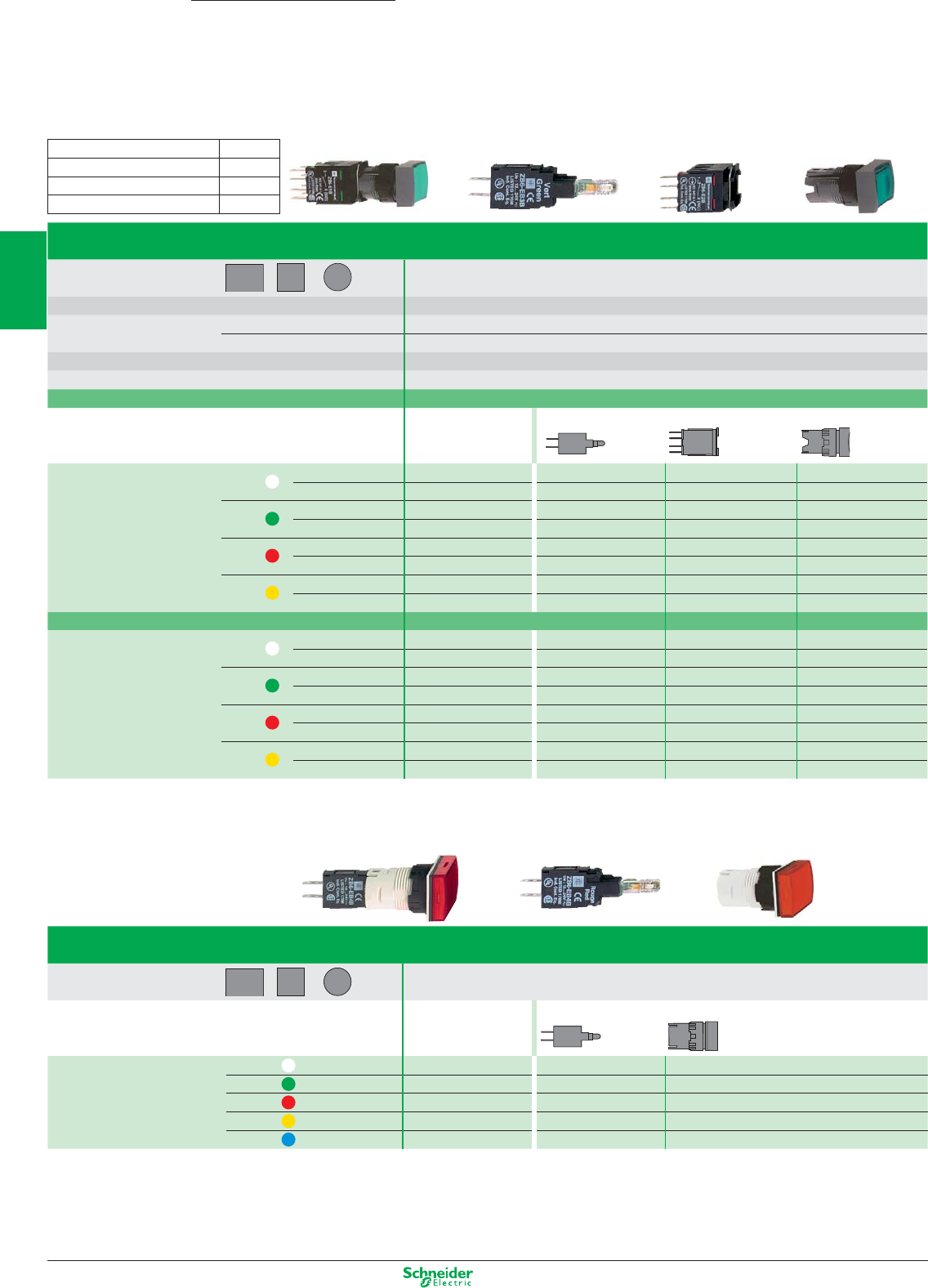
Other versions: please consult your Schneider Electric agency.
Illuminated pushbuttons
Type of head Flush push
Shape of head rectangular (2)
Degree of protection IP 65 / Nema 4, 4X, 13 / Class II
Mounting (mm) panel cut-out Ø 16.2
mounting centres 24 x 18 with rectangular head, 18 x 18 with square or circular head
Dimensions (mm) W x H x D (below head) 24 x 18 x 50 with rectangular head, 18 x 18 x 50 with square or circular head
Connection (3) Tags for 2.8 x 0.5 Faston connectors or for soldering
Type of push Spring return
Complete products
12 … 24 V AC/DC
Products for user assembly
References white N/O XB6 DW1B1B ZB6 Ep1B (1) ZB6 Z1B ZB6 DW1
N/C + N/O XB6 DW1B5B ZB6 Ep1B (1) ZB6 Z5B ZB6 DW1
green N/O XB6 DW3B1B ZB6 Ep3B (1) ZB6 Z1B ZB6 DW3
N/C + N/O XB6 DW3B5B ZB6 Ep3B (1) ZB6 Z5B ZB6 DW3
red N/C XB6 DW4B2B ZB6 Ep4B (1) ZB6 Z2B ZB6 DW4
N/C + N/O XB6 DW4B5B ZB6 Ep4B (1) ZB6 Z5B ZB6 DW4
yellow N/O – ZB6 Ep5B (1) ZB6 Z1B ZB6 DW5
N/C + N/O XB6 DW5B5B ZB6 Ep5B (1) ZB6 Z5B ZB6 DW5
Type of push Latching
References white N/O – ZB6 Ep1B (1) ZB6 Z1B ZB6 DF1
N/C + N/O XB6 DF1B5B ZB6 Ep1B (1) ZB6 Z5B ZB6 DF1
green N/O XB6 DF3B1B ZB6 Ep3B (1) ZB6 Z1B ZB6 DF3
N/C + N/O XB6 DF3B5B ZB6 Ep3B (1) ZB6 Z5B ZB6 DF3
red N/C XB6 DF4B2B ZB6 Ep4B (1) ZB6 Z2B ZB6 DF4
N/C + N/O XB6 DF4B5B ZB6 Ep4B (1) ZB6 Z5B ZB6 DF4
yellow N/O – ZB6 Ep5B (1) ZB6 Z1B ZB6 DF5
N/C + N/O – ZB6 Ep5B (1) ZB6 Z5B ZB6 DF5
Pilot lights
Type of head Smooth lens cap
Shape of head rectangular (2)
Complete products Products for user assembly
12 … 24 V AC/DC
References white XB6 DV1BB ZB6 Ep1B (1) ZB6 DV1
green XB6 DV3BB ZB6 Ep3B (1) ZB6 DV3
red XB6 DV4BB ZB6 Ep4B (1) ZB6 DV4
yellow XB6 DV5BB ZB6 Ep5B (1) ZB6 DV5
blue – ZB6 Ep6B (1) ZB6 DV6
(1) Basic reference, to be completed by the letter B, G or M indicating the required voltage. See voltage table above.
(2) For products with a square head, replace the letter D in the reference by the letter C (XB6 DW1B1B becomes XB6 CW1B1B).
For products with a circular head, replace the letter D in the reference by the letter A (XB6 DW1B1B becomes XB6 AW1B1B).
(3) Alternative connection: 1 x 0.5 pins for printed circuit boards.
Pushbuttons, switches and pilot lights Ø 16
with plastic bezel
Contact functions and light functions
with integral LED
(1):
Voltage Letter (p)
12…24 V AC/DC (15 mA) B
48…120 V AC (25 mA) G
230…240 V AC (25 mA) M
+ 0.2
0
Harmony
XB6
=++
=+
2/2
2
1
3
4
5
6
7
8
9
10
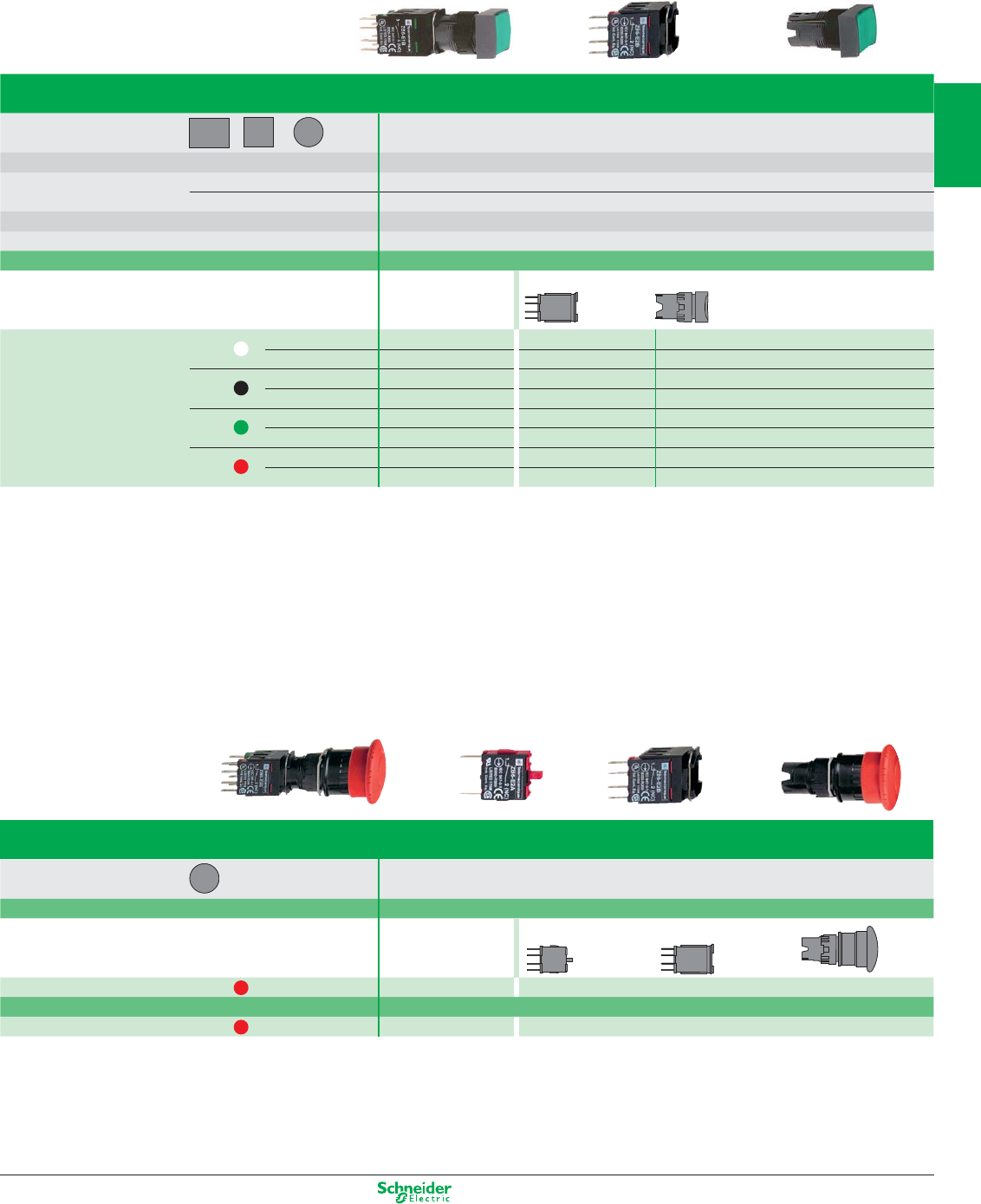
Other versions: please consult your Schneider Electric agency.
Pushbuttons
Type of head Flush push
Shape of head rectangular (1)
Degree of protection IP 65 / Nema 4, 4X, 13 / Class II
Mounting (mm) panel cut-out Ø 16.2
mounting centres 24 x 18 with rectangular head, 18 x 18 with square or circular head
Dimensions (mm) W x H x D (below head) 24 x 18 x 50 with rectangular head, 18 x 18 x 50 with square or circular head
Connection (2) Tags for 2.8 x 0.5 Faston connectors or for soldering
Type of push Spring return
Complete products Products for user assembly
References white N/O XB6 DA11B ZB6 Z1B ZB6 DA1
N/C + N/O XB6 DA15B ZB6 Z5B ZB6 DA1
black N/O – ZB6 Z1B ZB6 DA2
N/C + N/O XB6 DA25B ZB6 Z5B ZB6 DA2
green N/O XB6 DA31B ZB6 Z2B ZB6 DA3
N/C + N/O XB6 DA35B ZB6 Z5B ZB6 DA3
red N/O – ZB6 Z1B ZB6 DA4
N/C + N/O XB6 DA45B ZB6 Z5B ZB6 DA4
(1) For products with a square head, replace the letter D in the reference by the letter C (XB6 DA11B becomes XB6 CA11B).
For products with a circular head, replace the letter D in the reference by the letter A (XB6 DA11B becomes XB6 AA11B).
(2) Alternative connection: 1 x 0.5 pins for printed circuit boards.
Ø 30 mushroom head Emergency stop pushbuttons (3)
Type of head Trigger action (EN/ISO 13850: 2006)
Shape of head cylindrical
Type of push Turn to release
Complete products Products for user assembly
References red 2 N/C + 1 N/O XB6 AS8349B ZB6 E2B ZB6 Z5B ZB6 AS834
Type of push Key release, Ronis 200
References red 2 N/C + 1 N/O XB6 AS9349B ZB6 E2B ZB6 Z5B ZB6 AS934
(3) Emergency stop trigger action and mechanical latching pushbuttons conform to standards EN/IEC 60204-1 and EN/ISO 13850: 2006, to Machinery Directive 98/37/EC and to
standard EN/IEC 60947-5-5. Please consult your Regional Sales Office for a full explanation of these standards and directives.
+ 0.2
0
Contact functions
=+
=+ +
2/3
2
1
3
4
5
6
7
8
9
10
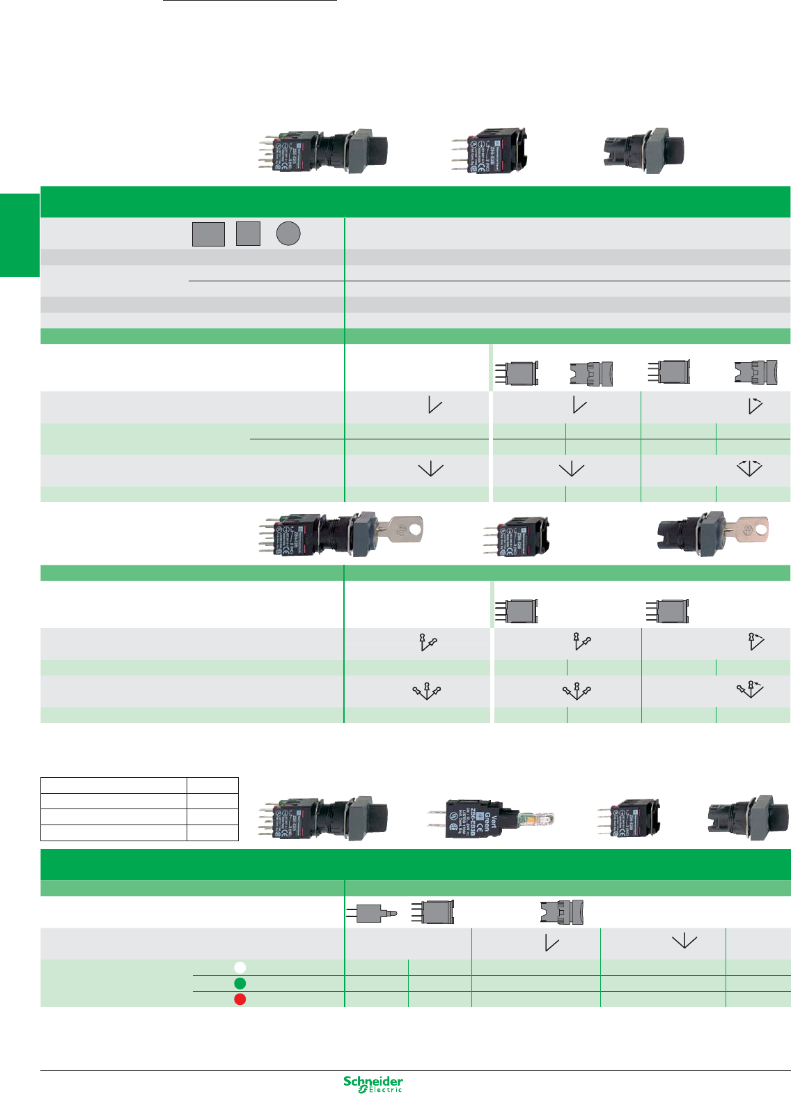
Other versions: please consult your Schneider Electric agency.
Selector switches and key switches
Type of head Black handle
Shape of head rectangular (2)
Degree of protection IP 66 / Nema 4, 4X, 13 / Class II
Mounting (mm) panel cut-out Ø 16.2
mounting centres 24 x 18 with rectangular head, 18 x 18 with square or circular head
Dimensions (mm) W x H x D (below head) 24 x 18 x 50 with rectangular head, 18 x 18 x 50 with square or circular head
Connection (3) Tags for 2.8 x 0.5 Faston connectors or for soldering
Type of operator Black handle
Complete products Products for user assembly
Number and type of positions 2 positions 2 positions 2 positions
stay put stay put spring return to centre
References N/O XB6 DD221B ZB6 Z1B ZB6 DD22 ZB6 Z1B ZB6 DD24
N/C + N/O XB6 DD225B ZB6 Z5B ZB6 DD22 ZB6 Z5B ZB6 DD24
Number and type of positions 3 positions 3 positions 3 positions
stay put stay put spring return to centre
References N/O XB6 DD235B ZB6 Z5B ZB6 DD23 ZB6 Z5B ZB6 DD25
Type of operator Ronis key, n° 200
Complete products Products for user assembly
Number and type of positions 2 positions 2 positions 2 positions
stay put stay put spring return to centre
References N/C + N/O XB6 DGC5B ZB6 Z5B ZB6 DGC ZB6 Z5B ZB6 DGB
Number and type of positions 3 positions 3 positions 3 positions
stay put stay put spring return to centre
References N/C + N/O XB6 DGH5B ZB6 Z5B ZB6 DGH ZB6 Z5B ZB6 DGS
Illuminated selector switches
Type of operator Coloured handle
Products for user assembly
Number and type of positions 2 positions 3 positions
stay put stay put
References white N/C + N/O
ZB6 Ep1B (1)
ZB6 Z5B ZB6 DD02 ZB6 DD03 ZB6 YK1
green N/C + N/O
ZB6 Ep3B (1)
ZB6 Z5B ZB6 DD02 ZB6 DD03 ZB6 YK3
red N/C + N/O
ZB6 Ep4B (1)
ZB6 Z5B ZB6 DD02 ZB6 DD03 ZB6 YK4
(1) Basic reference, to be completed by the letter B, G or M indicating the required voltage. See voltage table above.
(2) For products with a square head, replace the letter D in the reference by the letter C (XB6 DD221B becomes XB6 CD221B).
For products with a circular head, replace the letter D in the reference by the letter A (XB6 DD221B becomes XB6 AD221B).
(3) Alternative connection: 1 x 0.5 pins for printed circuit boards.
(1):
Voltage Letter (p)
12…24 V AC/DC (15 mA) B
48…120 V AC (25 mA) G
230…240 V AC (25 mA) M
+ 0.2
0
Harmony
XB6
60° 45°
60°
60° 45°
60°60° 45°
60°
70° 45°70°
70° 45°70°70° 45°70°
60° 60° 60°
Pushbuttons, switches and pilot lights Ø 16
with plastic bezel
Contact functions and light functions
with integral LED
=+
=+
=++
2/4
2
1
3
4
5
6
7
8
9
10
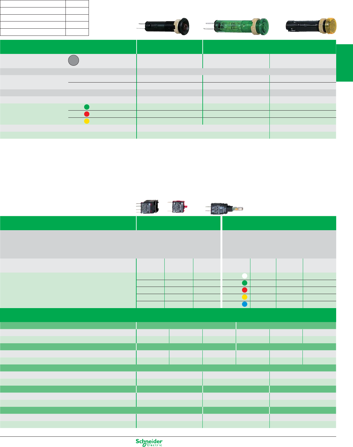
Other versions: please consult your Schneider Electric agency.
LED pilot lights With black bezel With integral lens cap
Type of head Protruding LED, Ø 8 mm Covered LED, Ø 8 mm Covered LED, Ø 12 mm
Degree of protection IP 40, IP 65 with seal (2)
Mounting (mm) panel cut-out Ø 8.2 mm Ø 8.2 mm Ø 12.2 mm
mounting centres 12.5 x 12.5 mm 10.5 x 10.5 mm 16.5 x 16.5 mm
Dimensions (mm) Ø x Depth (below head) Ø 12 x 32 Ø 10 x 34 Ø 16 x 45
Connection Tags (3) Tags (3) Threaded connectors
References (1) green XVL A1p3 XVL A2p3 XVL A3p3
red XVL A1p4 XVL A2p4 XVL A3p4
yellow XVL A1p5 XVL A2p5 XVL A3p5
Tightening key For Ø 8 mm pilot lights For Ø 12 mm pilot lights
References XVL X08 XVL X12
(1) Basic reference, to be completed by the number 1, 2, 3 or 4 indicating the required voltage. See voltage table above.
(2) For an IP 65 degree of protection, include the seals: XVL Z911 for pilot lights XVL A1pp and XVL A2pp; XVL Z912 for pilot lights XVL A3pp.
(3) Tags for 2.8 x 0.5 Faston connectors or for soldering.
Sub-assemblies & accessories for Ø 16
plastic bezel control and signalling units
Sub-assemblies Bodies for pushbuttons and
selector switches
Bodies for pilot lights
Rated operational characteristics, AC-15: Ue = 240 V and Ie = 1.5 A or Ue = 120 V and Ie = 3 A Consumption
Positive operation of contacts conforming to IEC/EN 60947-5-1: N/C contacts with positive opening operation, 15 mA 12…24 V AC/DC
positive opening force 20 N 25 mA 48…120 V AC
25 mA 230…240 V AC
Type of Fixing collar Contacts Pilot light 12 … 24 V 48 … 120 V 230 … 240 V
contact + contacts bodies
References N/O ZB6 Z1B ZB6 E1B White ZB6 EB1B ZB6 EG1B ZB6 EM1B
N/C ZB6 Z2B ZB6 E2B Green ZB6 EB3B ZB6 EG3B ZB6 EM3B
2 N/O ZB6 Z3B – Red ZB6 EB4B ZB6 EG4B ZB6 EM4B
2 N/C ZB6 Z4B – Yellow ZB6 EB5B ZB6 EG5B ZB6 EM5B
N/O + N/C ZB6 Z5B – Blue ZB6 EB6B ZB6 EG6B ZB6 EM6B
LED pilot lights Ø 8 and 12
(1):
Voltage
Number
(p)
5 V (25 mA) 1
12 V (18 mA) 2
24 V (18 mA) 3
48 V (10 mA) 4
Accessories
Legend holders 24 x 28 mm (8 x 21 mm legend) 24 x 36 mm (16 x 21 mm legend)
Blank legend Background colour without legend yellow or white black or red without legend yellow or white black or red
References (10)* ZB6 YD20 ZB6 YD21 ZB6 YD22 ZB6 YD30 ZB6 YD31 ZB6 YD32
Blank legends for legend holders 8 x 21 mm (24 x 28 mm legend holder) 16 x 21 mm (24 x 36 mm legend holder)
Background colour – yellow or white black or red – yellow or white black or red
References (20)* –ZB6 Y1001 ZB6 Y2001 – ZB6 Y4001 ZB6 Y3001
Ø 45 mm yellow legend for mushroom head Emergency stop pushbutton
Marking Blank, for engraving EMERGENCY STOP ARRET D’URGENCE
References ZB6 Y7001 ZB6 Y7330 ZB6 Y7130
Body/fixing collar Plate Tightening tool Dismantling tool
anti-rotation and slackening, for fixing nut for removal of contact blocks
References ZB6 Y009 (10)* ZB6 Y003 (10)* ZB6 Y905 (2)* ZB6 Y018 (5)*
Protective shutter for pushbuttons and switches Connector Blanking plug
for rectangular heads for circular and square heads Faston, female IP 65
References ZB6 YD001 ZB6 YA001 ZB6 Y004 (100)* ZB6 Y005 (10)*
* sold in lots of
2/5
2
1
3
4
5
6
7
8
9
10
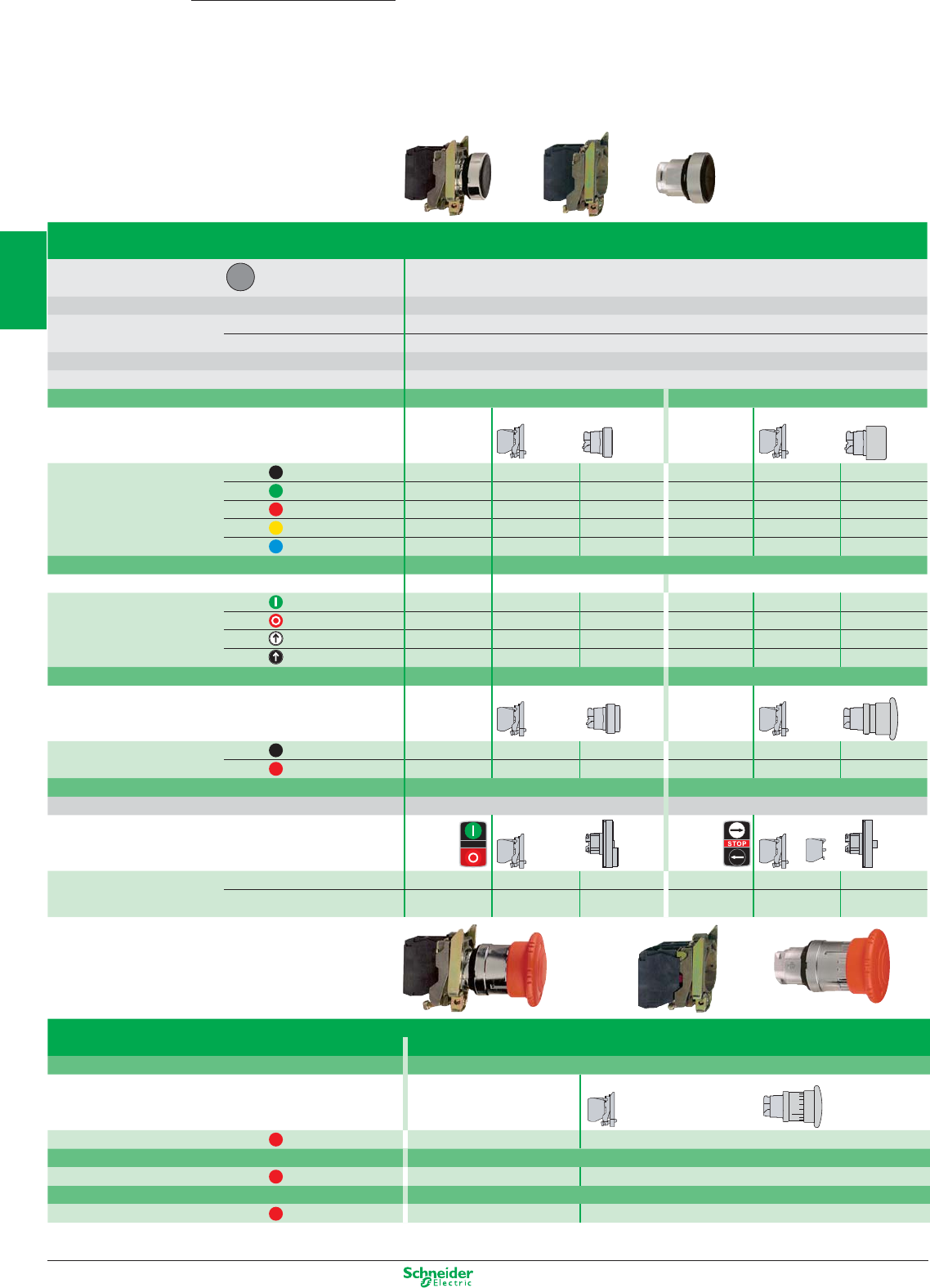
Other versions: please consult your Schneider Electric agency.
Pushbuttons, spring return
Type of head Chromium plated circular bezel
Degree of protection IP 66 / Nema 4X, 13 / Class I
Mounting (mm) panel cut-out Ø 22.5 (22.4 recommended)
mounting centres 30 (horizontal) x 40 (vertical)
Depth (mm) below head 43
Connection (1) Screw clamp terminals
Type of push Flush Flush, booted
Unmarked Products Complete For user assembly Complete For user assembly
References black N/O XB4 BA21 ZB4 BZ101 ZB4 BA2 XB4 BP21 ZB4 BZ101 ZB4 BP2
green N/O XB4 BA31 ZB4 BZ101 ZB4 BA3 XB4 BP31 ZB4 BZ101 ZB4 BP3
red N/C XB4 BA42 ZB4 BZ102 ZB4 BA4 XB4 BP42 ZB4 BZ102 ZB4 BP4
yellow N/O XB4 BA51 ZB4 BZ101 ZB4 BA5 XB4 BP51 ZB4 BZ101 ZB4 BP5
blue N/O XB4 BA61 ZB4 BZ101 ZB4 BA6 XB4 BP61 ZB4 BZ101 ZB4 BP6
Type of push Flush
With international marking Products Complete For user assembly
References green N/O XB4 BA3311 ZB4 BZ101 ZB4 BA331 – – –
red N/C XB4 BA4322 ZB4 BZ102 ZB4 BA432 – – –
white N/O XB4 BA3341 ZB4 BZ101 ZB4 BA334 –––
black N/O XB4 BA3351 ZB4 BZ101 ZB4 BA335 ___
Type of push Projecting Mushroom head, Ø 40 mm
Unmarked Products Complete For user assembly Complete For user assembly
References black N/O – – – XB4 BC21 ZB4 BZ101 ZB4 BC2
red N/C XB4 BL42 ZB4 BZ102 ZB4 BL4 – – –
Type of push Double-headed pushbuttons Triple-headed pushbuttons
Degree of protection IP 66 - IP 69K IP 66 - IP 69K
With international marking Products
Complete
For user assembly
Complete
For user assembly
(A) (B)
References (A) “N/C” + “N/O” XB4 BL73415 ZB4 BZ105 ZB4 BL7341 – – –
(B)
“N/O” + “N/C” + “N/O”
––– XB4 BA711237 ZB4 BZ103 +
ZBE 102
ZB4 BA71123
(1) Alternative connections: plug-in connector,
Faston connectors (6.35 and 2 x 2.8).
Ø 40 mm mushroom head Emergency stop pushbuttons (2)
Trigger action (EN/ISO 13850: 2006)
Type of push Push-pull (N/C + N/O)
Unmarked Products Complete For user assembly
References red N/C or N/C + N/O XB4 BT845 ZB4 BZ105 ZB4 BT84
Type of push Turn to release (N/C + N/O)
References red N/C or N/C + N/O XB4 BS8445 ZB4 BZ105 ZB4 BS844
Type of push Key release (N/C + N/O)
References red N/C or N/C + N/O XB4 BS9445 ZB4 BZ105 ZB4 BS944
(2) Emergency stop trigger action and mechanical latching pushbuttons conform to standards EN/IEC 60204-1 and EN/ISO 13850: 2006, to Machinery Directive 98/37/EC and to
standard EN/IEC 60947-5-5. Please consult your Regional Sales Office for a full explanation of these standards and directives.
Harmony
XB4
+ 0.4
0
Pushbuttons, switches and pilot lights Ø 22
with metal bezel
Contact functions
+
=+
=+
2/6
2
1
3
4
5
6
7
8
9
10
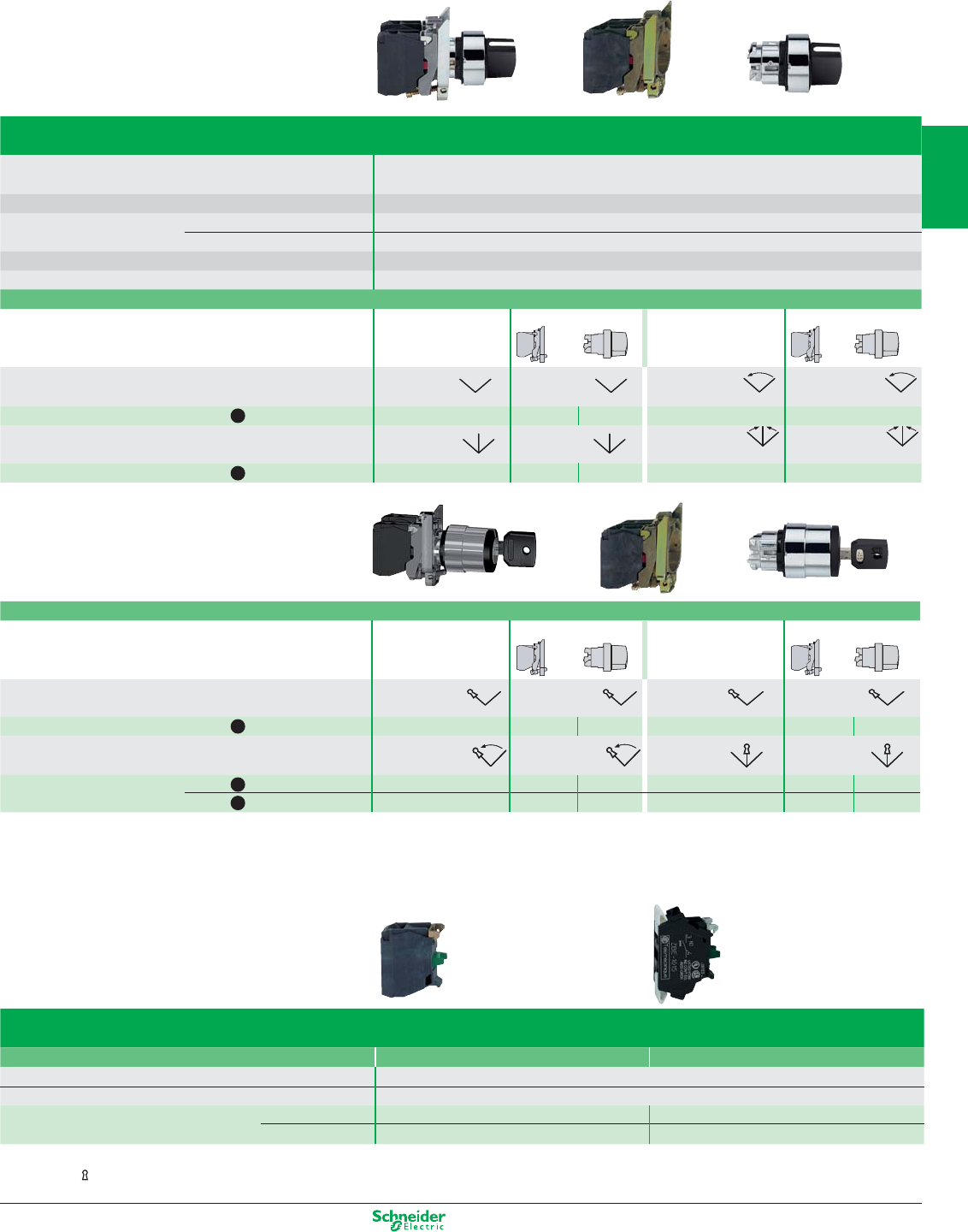
Other versions: please consult your Schneider Electric agency.
Contact functions
Selector switches and key switches
Type of head Chromium plated circular bezel
Degree of protection IP 66 / Nema 4X, 13 / Class I
Mounting (mm) panel cut-out Ø 22.5 (22.4 recommended)
mounting centres 30 (horizontal) x 40 (vertical)
Depth (mm) below head 43
Connection (1) Screw clamp terminals
Type of operator Key, n° 455
Products Complete For user assembly Complete For user assembly
Number and type of positions (2) 2 positions 2 positions 2 positions 2 positions
stay put stay put stay put stay put
References black N/O XB4 BG21 ZB4 BZ101 ZB4 BG2 XB4 BG41 ZB4 BZ101 ZB4 BG4
Number and type of positions 2 positions 2 positions 3 positions 3 positions
spring return to left spring return to left stay put stay put
References black N/O XB4 BG61 ZB4 BZ101 ZB4 BG6 – – –
black N/O + N/O – – – XB4 BG33 ZB4 BZ103 ZB4 BG3
Electrical blocks
Single contact blocks Screw clamp terminals Spring clamp terminal
Rated operational characteristics AC-15, 240 V - 3 A
Positive operation of contacts conforming to IEC/EN 60947-5-1 All functions incorporating a N/C contact are positive opening operation
References (5)* N/O ZBE 101 ZBE 1015
N/C ZBE 102 ZBE 1025
(1) Alternative connections: plug-in connector, Faston connectors (6.35 and 2 x 2.8), spring clamp terminal.
(2) The symbol indicates key withdrawal position.
* sold
in
lots of
+ 0.4
0
Type of operator Handle
Products Complete For user assembly Complete For user assembly
Number and type of positions 2 positions 2 positions 2 positions 2 positions
stay put stay put spring return to left spring return to left
References black N/O XB4 BD21 ZB4 BZ101 ZB4 BD2 XB4 BD41 ZB4 BZ101 ZB4 BD4
Number and type of positions 3 positions 3 positions 3 positions 3 positions
stay put stay put spring return to centre spring return to centre
References black N/O + N/O XB4 BD33 ZB4 BZ103 ZB4 BD3 XB4 BD53 ZB4 BZ103 ZB4 BD5
Separate components
=+
=+
2/7
2
1
3
4
5
6
7
8
9
10
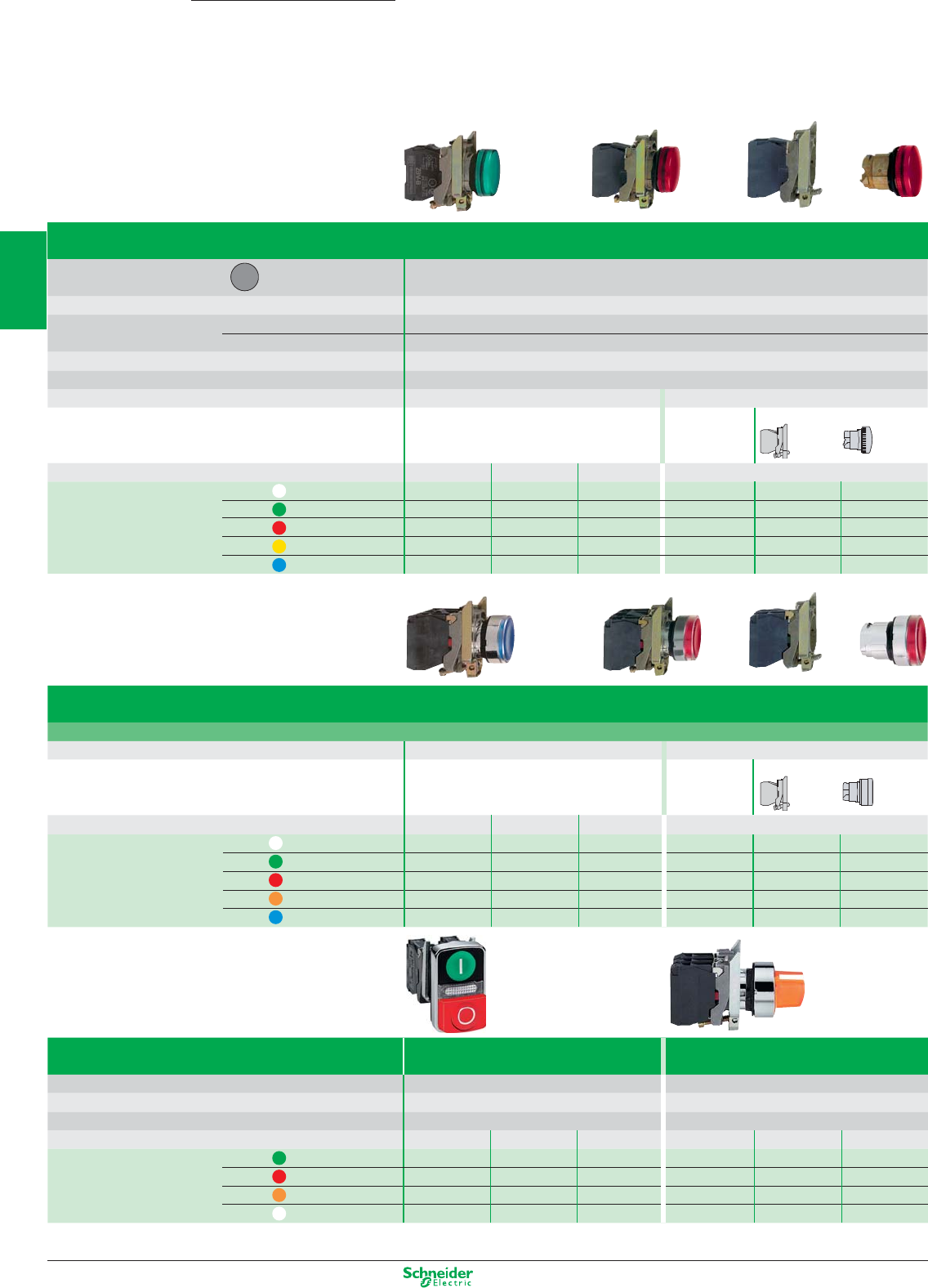
Other versions: please consult your Schneider Electric agency.
Type
Double-headed pushbuttons with LED pilot light
Illuminated selector switches
(1 flush green push, 1 projecting red push) (2 position stay put)
Degree of protection IP 66 - IP 69K IP 66
Light source Integral LED Integral LED
Products Complete Complete
Supply voltage
24 V AC/DC 48…120 V AC
230…240 V AC
24 V AC/DC 48…120 V AC 230…240 V AC
References green N/C + N/O – – – XB4 BK123B5 XB4 BK123G5 XB4 BK123M5
red N/C + N/O –– – XB4 BK124B5 XB4 BK124G5 XB4 BK124M5
orange N/C + N/O – – – XB4 BK125B5 XB4 BK125G5 XB4 BK125M5
White N/C + N/O
XB4 BW73731B5 XB4 BW73731G5 XB4 BW73731M5
–––
(1) Alternative connections: plug-in connector, Faston connectors (6.35 and 2 x 2.8), spring clamp terminal.
Harmony
XB4
Pushbuttons, switches and pilot lights Ø 22
with metal bezel
Light functions
Pilot lights
Type of head Circular bezel
Smooth lens cap
Degree of protection IP 66 / Nema 4X, 13 / Class I
Mounting (mm) panel cut-out Ø 22.5 (22.4 recommended)
mounting centres 30 (horizontal) x 40 (vertical)
Depth below head 43
Connection (1) Screw clamp terminals
Light source Integral LED Direct supply for BA 9s bulb (not included)
Products Complete Complete For user assembly
Supply voltage 24 V AC/DC 48…120 V AC
230…240 V AC
250 V max., 2.4 W max.
References white XB4 BVB1 XB4 BVG1 XB4 BVM1 XB4 BV61 ZB4 BV6 ZB4 BV01
green XB4 BVB3 XB4 BVG3 XB4 BVM3 XB4 BV63 ZB4 BV6 ZB4 BV03
red XB4 BVB4 XB4 BVG4 XB4 BVM4 XB4 BV64 ZB4 BV6 ZB4 BV04
yellow XB4 BVB5 XB4 BVG5 XB4 BVM5 XB4 BV65 ZB4 BV6 ZB4 BV05
blue XB4 BVB6 XB4 BVG6 XB4 BVM6 –––
+ 0.4
0
Illuminated pushbuttons and selector switches
Type Flush push, spring return, illuminated pushbuttons
Light source Integral LED Direct supply for BA 9s bulb (not included)
Products Complete Complete For user assembly
Supply voltage 24 V AC/DC 48…120 V AC
230…240 V AC
250 V max., 2.4 W max.
References white N/C + N/O XB4 BW31B5 XB4 BW31G5 XB4 BW31M5 XB4 BW3165 ZB4 BW065 ZB4 BW31
green N/C + N/O XB4 BW33B5 XB4 BW33G5 XB4 BW33M5 XB4 BW3365 ZB4 BW065 ZB4 BW33
red N/C + N/O XB4 BW34B5 XB4 BW34G5 XB4 BW34M5 XB4 BW3465 ZB4 BW065 ZB4 BW34
orange N/C + N/O XB4 BW35B5 XB4 BW35G5 XB4 BW35M5 XB4 BW3565 ZB4 BW065 ZB4 BW35
blue N/C + N/O XB4 BW36B5 XB4 BW36G5 XB4 BW36M5 – ––
=+
=+
2/8
2
1
3
4
5
6
7
8
9
10
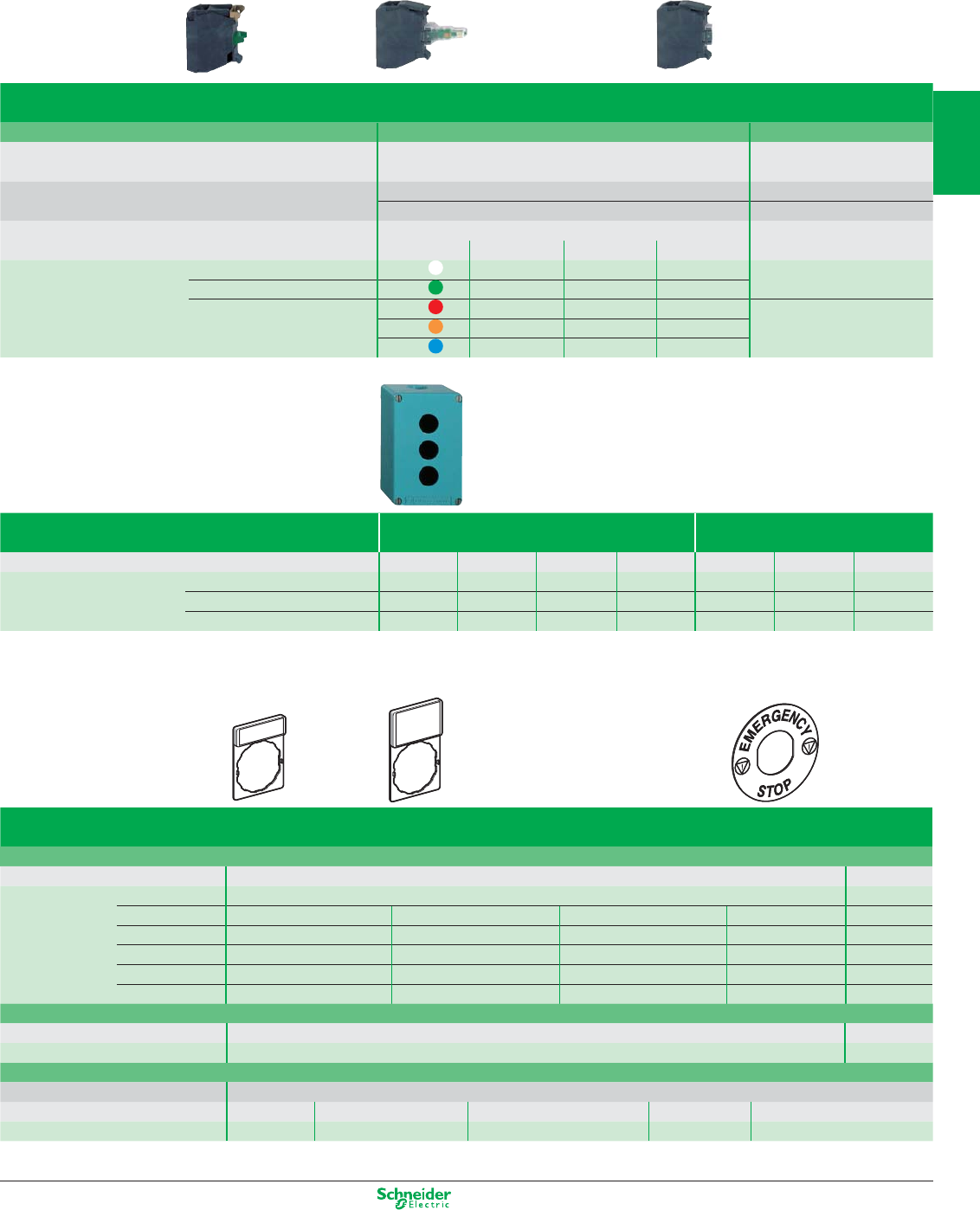
Other versions: please consult your Schneider Electric agency.
Separate components and accessories
Electrical blocks (1)
Single contact blocks Light blocks with integral LED Light block, direct supply
Rated operational characteristics AC-15, 240 V - 3 A Consumption
18 mA 24 V AC/DC
Positive operation of contacts N/C contacts with positive 14 mA 120 V AC
conforming to IEC/EN 60947-5-1 opening operation 14 mA 240 V AC
To combine with heads for integral LED For BA 9s bulb (not included)
24 V AC/DC 48…120 V AC 230…240 V AC 250 V max., 2.4 W max.
References (5)* N/O ZBE 101 white ZBV B1 ZBV G1 ZBV M1 ZBV 6
N/C ZBE 102 green ZBV B3 ZBV G3 ZBV M3 Colour provided by lens
red ZBV B4 ZBV G4 ZBV M4
orange ZBV B5 ZBV G5 ZBV M5
blue ZBV B6 ZBV G6 ZBV M6
Diecast metal enclosures
(Zinc alloy, usable depth 49 mm) 1 vertical row 2 vertical rows
Number of cut-outs Front face dimensions 1 2 3 4 2 4 6
References 80 x 80 mm XAP M1201 – – – XAP M1202 – –
80 x 130 mm – XAP M2202 XAP M2203 – – XAP M2204 –
80 x 175 mm – – XAP M3203 XAP M3204 – – XAP M3206
Accessories
Legend holders, 30 x 40 mm, for 8 x 27 mm legends
Marking Background colour: black or red white or yellow
References (10)* Blank ZBY 2101 ZBY 4101
International 0 (red background) ZBY 2931 I ZBY 2147 AUTO ZBY 2115 STOP ZBY 2304 –
English OFF ZBY 2312 ON ZBY 2311 START ZBY 2303 – –
French
ARRET (red b/grnd)
ZBY 2104 ARRET-MARCHE ZBY 2166 MARCHE ZBY 2103 – –
German AUS ZBY 2204 AUS-EIN ZBY 2266 EIN ZBY 2203 – –
Spanish
PARADA (red b/grnd)
ZBY 2404 PARADA-MARCHA ZBY 2466 MARCHA ZBY 2403 – –
Legend holders, 30 x 50 mm, for 18 x 27 mm legends
Background colour black or red white or yellow
References (10)* Blank ZBY 6101 ZBY 6102
Ø 60 mm legend for mushroom head Emergency stop pushbutton
Background colour yellow
Marking Blank EMERGENCY STOP ARRET D’URGENCE NOT HALT PARADA DE EMERGENCIA
References ZBY 9140 ZBY 9330 ZBY 9130 ZBY 9230 ZBY 9430
(1) Alternative connections: plug-in connector, Faston connectors (6.35 and 2 x 2.8), spring clamp terminal.
* sold in lots of
2/9
2
1
3
4
5
6
7
8
9
10
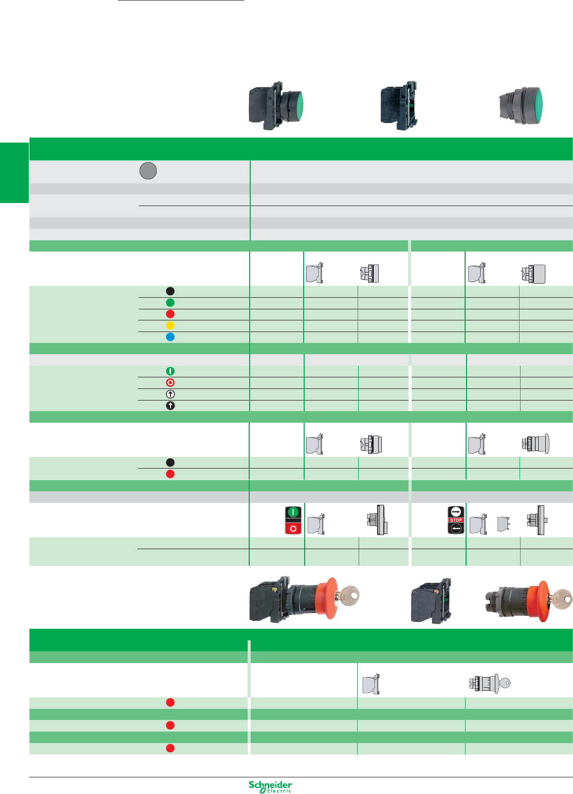
Other versions: please consult your Schneider Electric agency.
Type of push Double-headed pushbuttons Triple-headed pushbuttons
Degree of protection IP 66 - IP 69K IP 66 - IP 69K
With international marking Products
Complete
(A)
For user assembly
Complete
(B)
For user assembly
References (A) N/C + N/O XB5 AL73415 ZB5 AZ105 ZB5 AL7341 – – –
(B) N/O + N/C + N/O – – – XB5 AA711237 ZB5 AZ103 +
ZBE 102
ZB5 AA71123
(1) Alternative connections: plug-in connector,
Faston connectors (6.35 and 2 x 2.8).
Harmony
XB5
Pushbuttons, switches and pilot lights Ø 22
with plastic bezel
Contact functions
Pushbuttons, spring return
Type of head Circular bezel
Degree of protection IP 66 / Nema 4X, 13 / Class II
Mounting (mm) panel cut-out Ø 22.5 (22.4 recommended)
mounting centres 30 (horizontal) x 40 (vertical)
Depth (mm) below head 43
Connection (1) Screw clamp terminals
+ 0.4
0
Type of push Flush Flush, booted
Unmarked Products Complete For user assembly Complete For user assembly
References black N/O XB5 AA21 ZB5 AZ101 ZB5 AA2 XB5 AP21 ZB5 AZ101 ZB5 AP2
green N/O XB5 AA31 ZB5 AZ101 ZB5 AA3 XB5 AP31 ZB5 AZ101 ZB5 AP3
red N/C XB5 AA42 ZB5 AZ102 ZB5 AA4 XB5 AP42 ZB5 AZ102 ZB5 AP4
yellow N/O XB5 AA51 ZB5 AZ101 ZB5 AA5 XB5 AP51 ZB5 AZ101 ZB5 AP5
blue N/O XB5 AA61 ZB5 AZ101 ZB5 AA6 XB5 AP61 ZB5 AZ101 ZB5 AP6
Type of push Flush
With international marking Products Complete For user assembly Complete For user assembly
References green N/O XB5 AA3311 ZB5 AZ101 ZB5 AA3311 – – –
red N/C XB5 AA4322 ZB5 AZ102 ZB5 AA4322 – – –
white N/O XB5 AA3341 ZB5 AZ101 ZB5 AA334 – – –
black N/O XB5 AA3351 ZB5 AZ101 ZB5 AA335 – – –
Type of push Projecting Mushroom head, Ø 40 mm
Unmarked Products Complete For user assembly Complete For user assembly
References black N/O – – – XB5 AC21 ZB5 AZ101 ZB5 AC2
red N/C XB5 AL42 ZB5 AZ102 ZB5 AL4 – – –
Ø 40 mm mushroom head Emergency stop pushbuttons (2)
Trigger action (EN/ISO 13850: 2006)
Type of push Push-pull (N/C + N/O)
Unmarked Products Complete For user assembly
References red N/C or N/C + N/O XB5 AT845 ZB5 AZ105 ZB5 AT84
Type of push
Turn to release (N/C + N/O)
References red N/C or N/C + N/O XB5 AS8445 ZB5 AZ105 ZB5 AS844
Type of push Key release (N/C + N/O)
References red N/C or N/C + N/O XB5 AS9445 ZB5 AZ105 ZB5 AS944
(2) Emergency stop trigger action and mechanical latching pushbuttons conform to standards EN/IEC 60204-1 and EN/ISO 13850: 2006, to Machinery Directive 98/37/EC and to
standard EN/IEC 60947-5-5. Please consult your Regional Sales Office for a full explanation of these standards and directives.
+
=+
=+
2/10
2
1
3
4
5
6
7
8
9
10
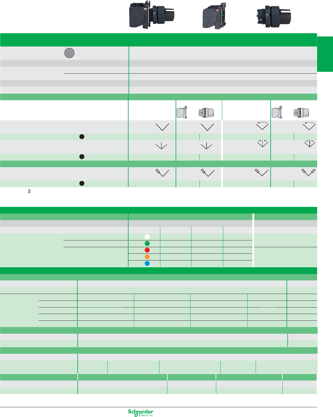
Other versions: please consult your Schneider Electric agency.
Separate components and accessories
Contact functions
Selector switches and key switches
Type of head Circular bezel
Degree of protection IP 66 / Nema 4X, 13 / Class II
Mounting (mm) panel cut-out Ø 22.5 (22.4 recommended)
mounting centres 30 (horizontal) x 40 (vertical)
Depth (mm) below head 43
Connection (1) Screw clamp terminals
Type of operator Handle
Products Complete For user assembly Complete For user assembly
Number and type of positions 2 positions 2 positions 2 positions 2 positions
stay put stay put spring return to left spring return to left
References black N/O XB5 AD21 ZB5 AZ101 ZB5 AD2 XB5 AD41 ZB5 AZ101 ZB5 AD4
Number and type of positions 3 positions 3 positions 3 positions 3 positions
stay put stay put spring return to centre spring return to centre
References black N/O + N/O XB5 AD33 ZB5 AZ103 ZB5 AD3 XB5 AD53 ZB5 AZ103 ZB5 AD5
Type of operator Key, n° 455
Number and type of positions (2) 2 positions 2 positions 2 positions 2 positions
stay put stay put stay put stay put
References black N/O XB5 AG21 ZB5 AZ101 ZB5 AG2 XB5 AG41 ZB5 AZ101 ZB5 AG4
(2) The symbol indicates key withdrawal position.
Electrical blocks (1)
Single contact blocks Light blocks with integral LED Light block, direct supply
To combine with heads for integral LED For BA 9s bulb (not included)
24 V AC/DC 48…120 V AC
230…240 V AC
250 V max., 2.4 W max.
References (5)* N/O ZBE 101 white ZBV B1 ZBV G1 ZBV M1 ZBV6
N/C ZBE 102 green ZBV B3 ZBV G3 ZBV M3 Colour provided by lens
red ZBV B4 ZBV G4 ZBV M4
orange
ZBV B5 ZBV G5 ZBV M5
blue ZBV B6 ZBV G6 ZBV M6
Accessories
Legend holders, 30 x 40 mm, for 8 x 27 mm legends
Marking Background colour: black or red white or yellow
References (10)*
Blank
ZBY 2101 ZBY 4101
References International 0 (red background) ZBY 2931 IZBY 2147 AUTO ZBY 2115 STOP ZBY 2304
–
English OFF ZBY 2312 ON ZBY 2311 START ZBY 2303
––
French
ARRET (red b/grnd)
ZBY 2104 ARRET-MARCHE ZBY 2166 MARCHE ZBY 2103
––
German AUS ZBY 2204 AUS-EIN ZBY 2266 EIN ZBY 2203
––
Spanish
PARADA (red b/grnd)
ZBY 2404 PARADA-MARCHA ZBY 2466 MARCHA ZBY 2403
––
Legend holders, 30 x 50 mm, for 18 x 27 mm legends
Background colour black or red white or yellow
References (10)* Blank ZBY 6101 ZBY 6102
Ø 60 mm legend for mushroom head Emergency stop pushbutton
Background colour yellow
Marking Blank EMERGENCY STOP ARRET D’URGENCE NOT HALT PARADA DE EMERGENCIA
References ZBY 9140 ZBY 9330 ZBY 9130 ZBY 9230 ZBY 9430
Body/fixing collar Fixing nut Bezel tool Plate
for electrical block (contact or light) for head for tightening fixing nut ZB5 AZ901 anti-rotation
References ZB5 AZ009 (10)* ZB5 AZ901 (10)* ZB5 AZ905 ZB5 AZ902
(1) Alternative connections: plug-in connector, Faston connectors (6.35 and 2 x 2.8), spring clamp terminal.
* sold in lots of
+ 0.4
0
=+
2/11
2
1
3
4
5
6
7
8
9
10
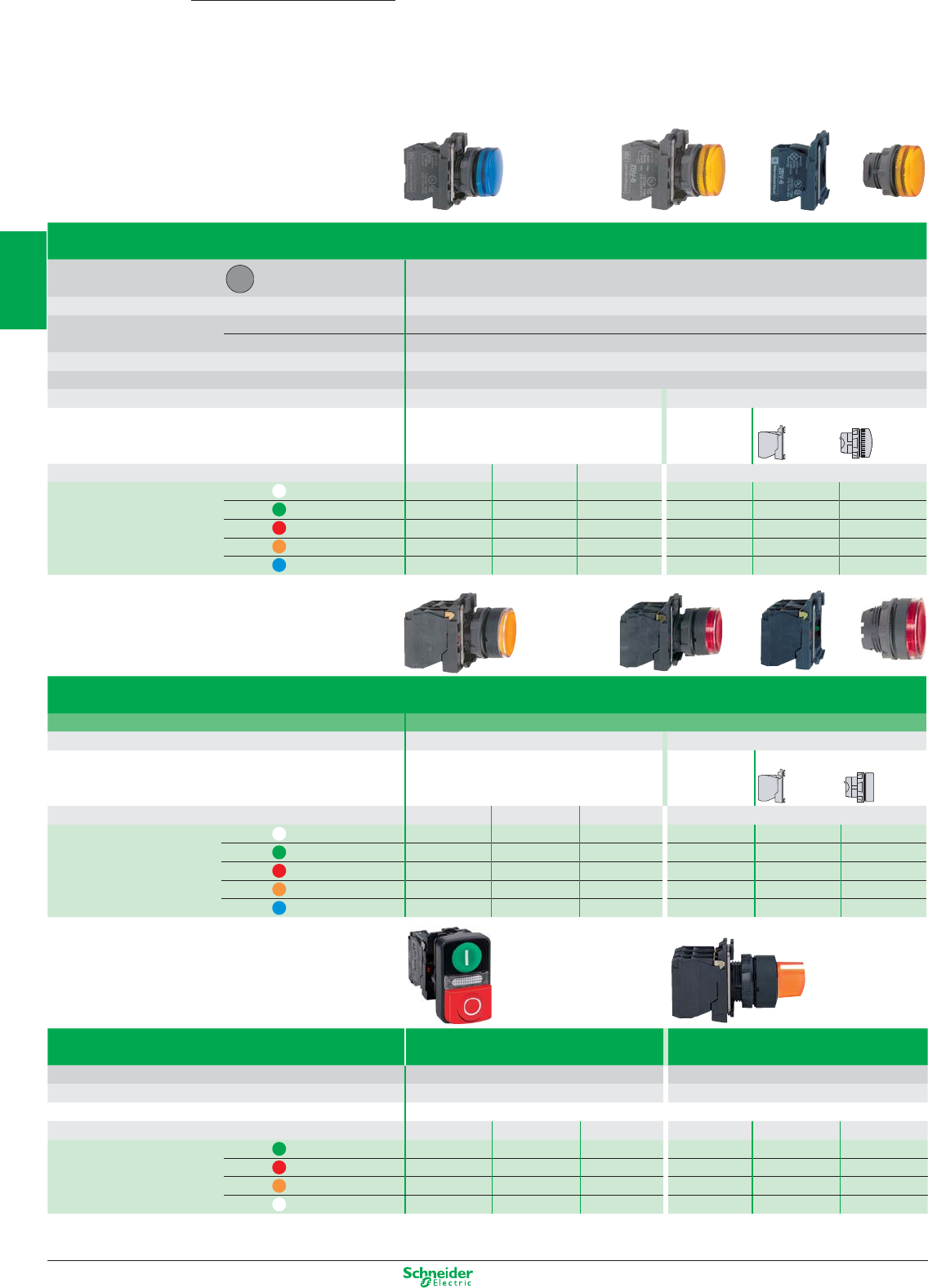
Other versions: please consult your Schneider Electric agency.
Harmony
XB5
Pushbuttons, switches and pilot lights Ø 22
with plastic bezel
Light functions
Pilot lights
Type of head Circular bezel
Smooth lens cap
Degree of protection IP 66 / Nema 4X, 13 / Class II
Mounting (mm) panel cut-out Ø 22.5 (22.4 recommended)
mounting centres 30 (horizontal) x 40 (vertical)
Depth below head 43
Connection (1) Screw clamp terminals
Light source Integral LED
Direct supply for BA 9s bulb (not included)
Products Complete Complete For user assembly
Supply voltage 24 V AC/DC 48…120 V AC
230…240 V AC
250 V max., 2.4 W max.
References white XB5 AVB1 XB5 AVG1 XB5 AVM1 XB5 AV61 ZB5 AV6 ZB5 AV01
green XB5 AVB3 XB5 AVG3 XB5 AVM3 XB5 AV63 ZB5 AV6 ZB5 AV03
red XB5 AVB4 XB5 AVG4 XB5 AVM4 XB5 AV64 ZB5 AV6 ZB5 AV04
orange XB5 AVB5 XB5 AVG5 XB5 AVM5 XB5 AV65 ZB5 AV6 ZB5 AV05
blue XB5 AVB6 XB5 AVG6 XB5 AVM6 –––
Illuminated pushbuttons and selector switches
Type Flush push, spring return, illuminated pushbuttons
Light source Integral LED Direct supply for BA 9s bulb (not included)
Products Complete Complete For user assembly
Supply voltage 24 V AC/DC 48…120 V AC
230…240 V AC
250 V max., 2.4 W max.
References white N/C + N/O XB5 AW31B5 XB5 AW31G5 XB5 AW31M5 XB5 AW3165 ZB5 AW065 ZB5 AW31
green N/C + N/O XB5 AW33B5 XB5 AW33G5 XB5 AW33M5 XB5 AW3365 ZB5 AW065 ZB5 AW33
red N/C + N/O XB5 AW34B5 XB5 AW34G5 XB5 AW34M5 XB5 AW3465 ZB5 AW065 ZB5 AW34
orange N/C + N/O XB5 AW35B5 XB5 AW35G5 XB5 AW35M5 XB5 AW3565 ZB5 AW065 ZB5 AW35
blue N/C + N/O XB5 AW36B5 XB5 AW36G5 XB5 AW36M5 –––
Type
Double-headed pushbuttons with LED pilot light
Illuminated selector switches
(1 flush green push, 1 projecting red push) (2 position stay put)
Degree of protection IP 66 - IP 69K IP 66
Light source Integral LED Integral LED
Products Complete Complete
Supply voltage
24 V AC/DC 48…120 V AC 230…240 V AC 24 V AC/DC 48…120 V AC 230…240 V AC
References green N/C + N/O – – – XB5 AK123B5 XB5 AK123G5 XB5 AK123M5
red N/C + N/O – – – XB5 AK124B5 XB5 AK124G5 XB5 AK124M5
orange N/C + N/O – – – XB5 AK125B5 XB5 AK125G5 XB5 AK125M5
white N/C + N/O
XB5 AW73731B5 XB5 AW73731G5 XB5 AW73731M5
–– –
(1) Alternative connections: plug-in connector, Faston connectors (6.35 and 2 x 2.8), spring clamp terminal.
Separate components and accessories: see previous page.
+ 0.4
0
=+
=+
2/12
2
1
3
4
5
6
7
8
9
10
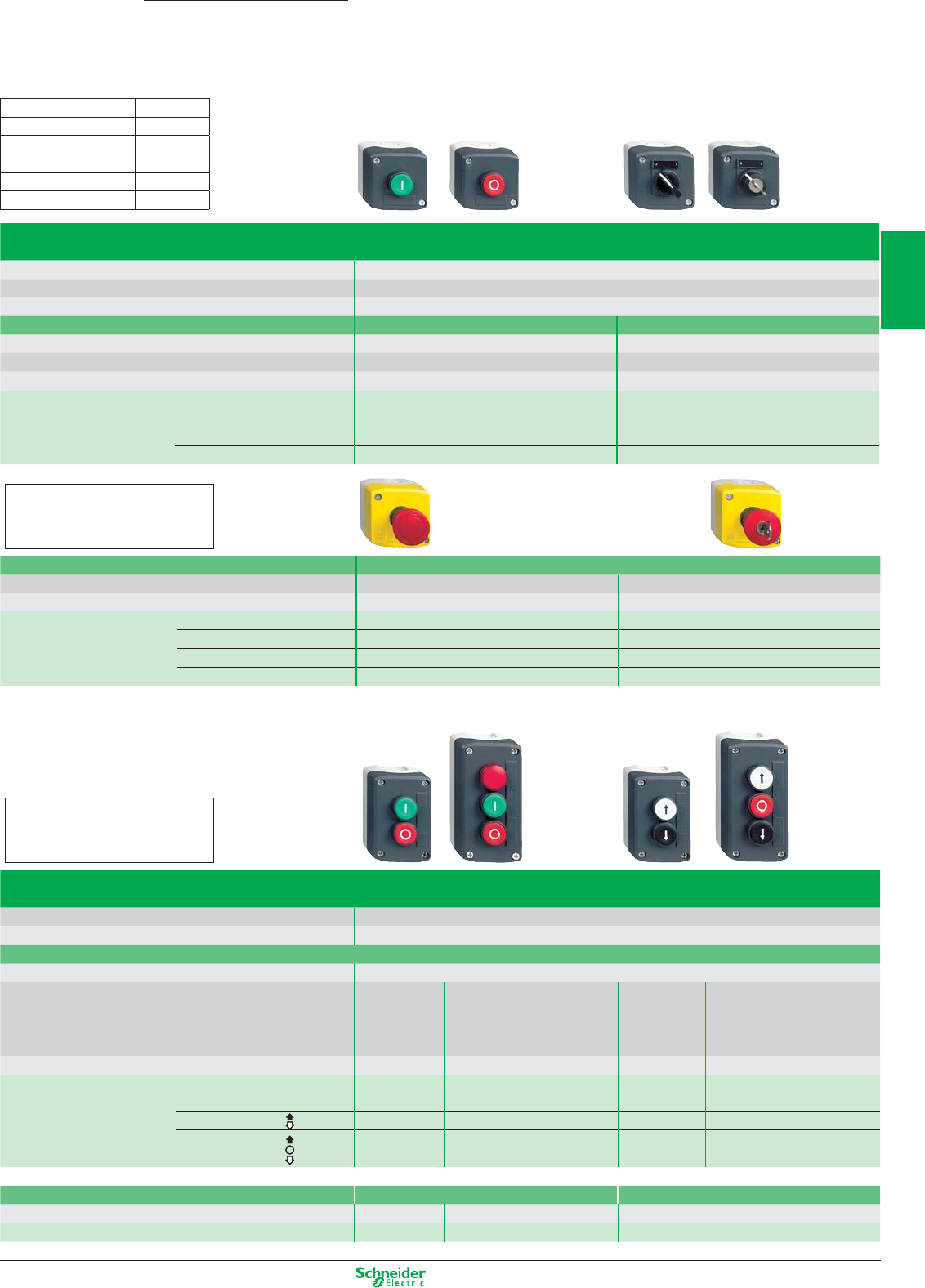
Other versions: please consult your Schneider Electric agency.
Control stations
For XB5 pushbuttons, switches and pilot lights
Ø 22 with plastic bezel
Harmony
XAL
(1) Empty enclosures:
Basic reference: XAL K0p, replace the p
by the number of cut-outs required (see
cut-out table above)
(1):
Number of cut-outs Number (p)
11
22
33
44
55
Complete stations with 1 pushbutton, selector switch or key switch
(light grey RAL 7035 base with dark grey RAL 7016 lid)
Degree of protection IP 65 / Nema 4X and 13 / Class II
Dimensions (mm) W x H x D 68 x 68 x 113 max. (with key release Ø 40 mushroom head pushbutton)
Fixing (mm) 2 x Ø 4.3 on 54 mm centres
Function 1 Start or Stop function 1 Start-Stop function
Marking On spring return push On legend holder and legend below head
Number and type of pushbutton/selector switch/key switch
1 flush green p/b
1 flush red p/b
1 projecting red p/b
1 2 position stay
put selector switch or key switch
Black handle
Key n° 455 (key withdrawal LH pos.)
References N/O I XAL D102 –– ––
Start XAL D103 –– ––
O - I –––XAL D134 XAL D144
N/C O–XAL D112 XAL D115 ––
Function Emergency stop (2) (light grey RAL 7035 base with yellow RAL 1012 lid)
Number and type of mushroom head pushbutton 1 red Ø 40 head, turn to release 1 red Ø 40 head, key release
Latching mechanism Trigger action (EN/ISO 13850: 2006) Trigger action (EN/ISO 13850: 2006)
References N/C XAL K178 XAL K188
N/C + N/C XAL K178F XAL K188F
N/C + N/O XAL K178E XAL K188E
N/C + N/C + N/O XAL K178G XAL K188G
(2) Emergency stop trigger action and mechanical latching pushbuttons conform to standards EN/IEC 60204-1 and EN/ISO 13850: 2006, to Machinery Directive 98/37/EC and to
standard EN/IEC 60947-5-5. Please consult your Regional Sales Office for a full explanation of these standards and directives.
(1) Empty enclosures:
Basic reference: XAL D0p, replace the p
by the number of cut-outs required (see
cut-out table above)
Complete stations with 2 and 3 pushbuttons or 2 pushbuttons + 1 pilot light
(light grey RAL 7035 base with dark grey RAL 7016 lid)
Dimensions (mm) W x H x D 2-way control stations: 68 x 106 x 62; 3-way control stations: 68 x 136 x 87
Fixing (mm) 2-way control stations: 2 x Ø 4.3 on 54 x 68 centres; 3-way control stations: 2 x Ø 4.3 on 54 x 98 centres
Function Start-Stop functions 2 functions 3 functions
Marking On spring return push
Number and type of pushbutton/pilot light
1 flush green p/b
1 flush green pushbutton
1 flush white p/b 1 flush white p/b 1 flush white p/b
1 flush red p/b
1 flush red pushbutton
1 flush black p/b 1 flush red p/b 1 Ø 30 red mush-
1 red pilot light with integral LED
1 flush black p/b room head p/b
1 flush black p/b
24 V AC/DC 230 V AC
References N/O + N/C I - O XAL D213 XAL D363B XAL D363M –––
Start - Stop XAL D215 –– – – –
N/O + N/O – – – XAL D222 ––
N/O + N/C + N/O – – – – XAL D324 XAL D328
Accessories Standard contact blocks Light blocks with integral LED, colour red
Description N/O contact N/C contact 24 V AC/DC 230 V AC
References ZEN L1111 ZEN L1121 ZAL VB4 ZAL VM4
2/13
2
1
3
4
5
6
7
8
9
10
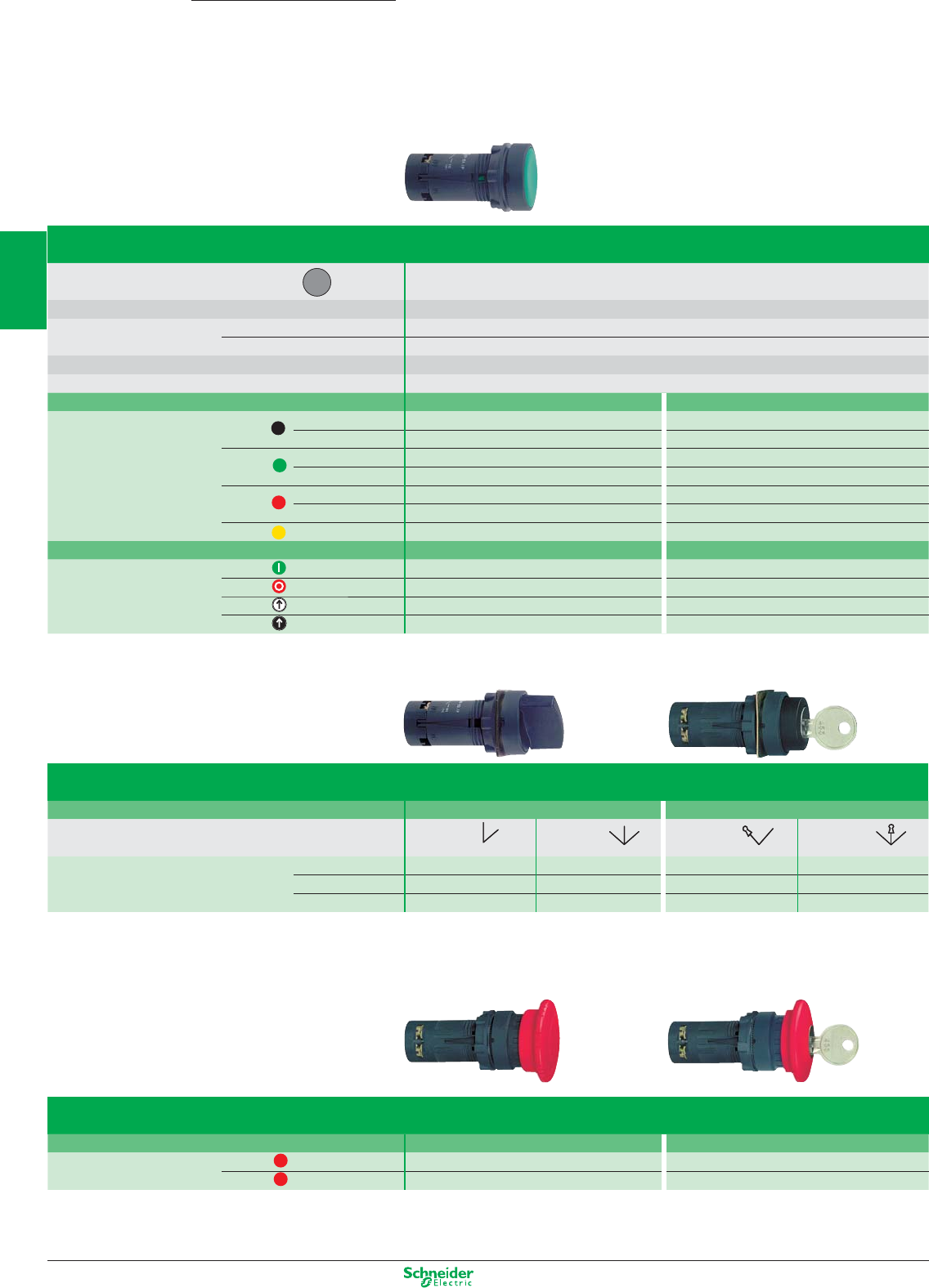
Other versions: please consult your Schneider Electric agency.
Pushbuttons
Type of head Flush or projecting push
circular
Degree of protection IP 54, class II
Mounting (mm) panel cut-out Ø 22.4 (0 +0.1)
mounting centres 30 (horizontal) x 40 (vertical)
Dimensions (mm) Ø x Depth (below head) Ø 29 x 41.5 (Ø 40 x 41.5 for Emergency stop)
Connection (1) Screw clamp terminals, 1 x 0.34 mm
2
to 1 x 1.5 mm
2
Type of push Flush, spring return Flush, push and push-to-release
References (10)* black N/O XB7 EA21P XB7 EH21P
C/O XB7 EA25P XB7 EH25P
green N/O XB7 EA31P XB7 EH31P
C/O XB7 EA35P XB7 EH35P
red N/C XB7 EA42P –
C/O XB7 EA45P –
yellow N/O XB7 EA51P –
Type of push Flush, spring return Projecting, spring return
References green N/O XB7 EA3131P –
red N/C – XB7 EL4232P
white N/O + C/O XB7 EA11341P –
black N/O + C/O XB7 EA21341 –
(1) Alternative connection: 1 x 6.35 and 2 x 2.8 mm Faston connectors.
Selector switches and key switches
Type of operator Black handle Ronis key, n° 455
Number and
type of positions
2 positions 3 positions 2 positions 3 positions
stay put stay put stay put stay put
References (10*) N/O XB7 ED21P –XB7 EG21P –
N/C + N/O XB7 ED25P – – –
2 N/O – XB7 ED33P – XB7 EG33P
Ø 40 mushroom head pushbuttons (2)
Type of push Turn to release Key release, Ronis 455
References (10)* red N/C XB7 ES542P XB7 ES142P
red N/C + N/O XB7 ES545P XB7 ES145P
(2) Mushroom head switching off mechanical latching pushbuttons conform to standard IEC 60364-5-53 and EN/IEC 60947-5-5. For mushroom trigger action and mechanical
latching head Emergency stop pushbuttons conforming to standard EN/IEC 60204-1 and EN/ISO 13850: 2006, to Machinery directive 98/37/EC and standard EN/IEC 60947-5-5,
use an Emergency stop type XB5 Ap8ppp or XB5 AS9ppp from the Harmony® range. See page 2/10.
* sold in lots of 10
Harmony
XB7
Pushbuttons, switches and pilot lights Ø 22
with plastic bezel - Monolithic
Contact functions
2/14
2
1
3
4
5
6
7
8
9
10
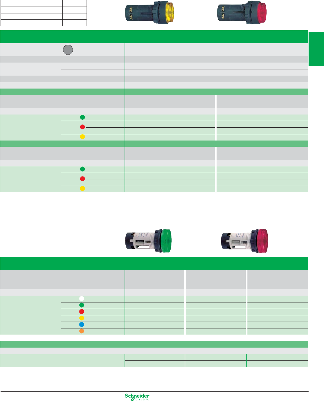
Other versions: please consult your Schneider Electric agency.
Illuminated pushbuttons
Type of head Projecting push
circular
Degree of protection IP 54, class II
Mounting (mm) panel cut-out Ø 22.4 (0 +0.1)
mounting centres 30 (horizontal) x 40 (vertical)
Dimensions (mm) Ø x Depth (below head) Ø 29 x 41.5, (Ø 40 x 41.5 for Emergency stop)
Connection (2) Screw clamp terminals, 1 x 0.34 mm
2
to 1 x 1.5 mm
2
Type of push Spring return
Light source Integral LED Incandescent bulb
direct supply (bulb not included)
Supply voltage 24 V DC or 230 V AC 6 or 24 V DC, or 130 V AC
References (10)* green N/O XB7 EW33p1P (1) XB7 EW3361P
red N/O XB7 EW34p1P (1) XB7 EW3461P
N/C XB7 EW34p2P (1) –
yellow N/O XB7 EW35p1P (1) XB7 EW3561P
Type of push Push and push-to-release
Light source Integral LED Incandescent bulb
direct supply (bulb not included)
Supply voltage 24 V DC or 230 V AC 6 or 24 V DC, or 130 V AC
References (10)* green N/O XB7 EH03p1P (1) XB7 EH0361P
red N/O XB7 EH04p1P (1) XB7 EH0461P
N/C XB7 EH04p2P (1) –
yellow N/O XB7 EH05p1P (1) XB7 EH0561P
Pilot lights
Light source Integral LED Incandescent bulb Incandescent bulb
direct supply direct through resistor
(bulb not included) (bulb included)
Supply voltage
24VAC/DC or 120VAC or 230…240VAC
6 or 24 V DC, or 130 V AC 230 V AC
References (10)* white XB7 EV01pP (1) XB7 EV61P XB7 EV71P
green XB7 EV03pP (1) XB7 EV63P XB7 EV73P
red XB7 EV04pP (1) XB7 EV64P XB7 EV74P
yellow XB7 EV05pP (1) XB7 EV65P XB7 EV75P
blue XB7 EV06pP (1) XB7 EV66P XB7 EV76P
orange XB7 EV08pP (1) XB7 EV68P XB7 EV78P
Incandescent bulbs, long life
BA 9s base fitting, Ø 11 mm max., length 28 mm max.
6 V (1.2 W) 24 V (2 W) 130 V (2.4 W)
References DL1 CB006 DL1 CE024 DL1 CE130
(1) Basic reference, to be completed by the letter B, G or M indicating the required voltage. See voltage table above.
(2) Alternative connection: 1 x 6.35 and 2 x 2.8 mm Faston connectors.
* sold in lots of 10
Contact functions and light functions
(1):
Voltage Letter (p)
24 V AC/DC B
120 V AC G
230 V AC M
2/15
2
1
3
4
5
6
7
8
9
10
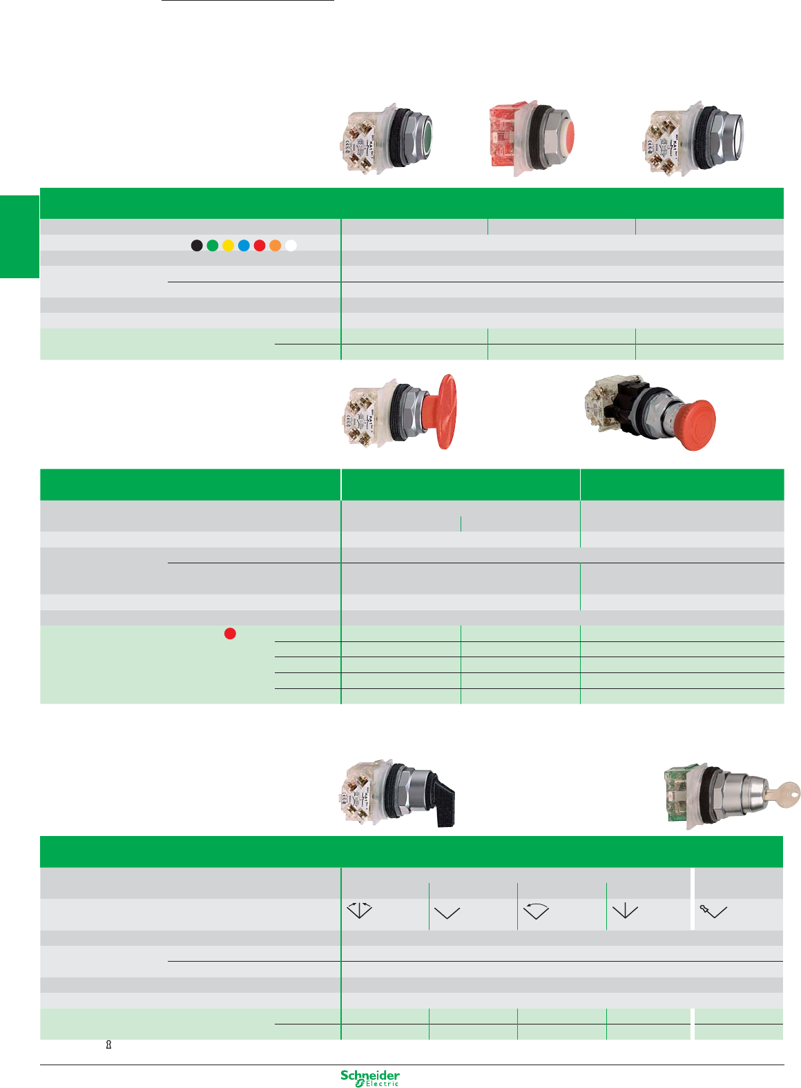
Other versions: please consult your Schneider Electric agency.
Pushbuttons, spring return
Type of push Flush Projecting Projecting (high guard)
Colour of push Multi-colour (set of 7 clip-in coloured caps)
Degree of protection IP 66 / Nema 1, 2, 3, 3R, 4, 6, 12 and 13 / Class II
Mounting (mm) panel cut-out Ø 31
mounting centres 57.2 x 44.5 (with legend 9001KN2pp), 57.2 x 50.8 (with legend 9001KN3pp)
Depth below head (mm) 42
Connection Screw clamp terminals
References C/O 9001KR1UH13 9001KR3UH13 9001KR2UH13
N/O 9001KR1UH5 9001KR3UH5 9001KR2UH5
Mushroom head pushbuttons, latching (1) Emergency switching off Emergency stop
Type of push Push-pull Turn-to-Release, trigger action
Ø 41 mushroom head Ø 35 mushroom head Ø 40 red mushroom head
Degree of protection IP 66 / Nema 1, 2, 3, 3R, 4, 6, 12 and 13 / Class II
IP 66 / Nema 1, 2, 3, 3R, 4, 6, 12 and 13 / Class III
Mounting (mm) panel cut-out Ø 31
mounting centres 57.2 x 44.5 (with legend 9001KN2pp),
57.2 x 50.8 (with legend 9001KN3pp)
57,2 x 44,5 (without legend plate),
100 x 100 ((with legend plate 9001KN8330) (2)
Depth below head (mm) 42 60
Connection Screw clamp terminals
References – – – 9001KR16
C/O 9001KR9R94H13 9001KR9R20H13 –
N/C 9001KR9RH6 9001KR9R20H6 –
2“N/O” + 2“N/C”
––9001KR16H2
“N/O” – – 9001KR16H13
(1) Mushroom head switching off mechanical latching pushbuttons conform to standard IEC 60364-5-53 and EN/IEC 60947-5-5. Mushroom trigger action and mechanical
latching head Emergency stop pushbuttons conforming to standard EN/IEC 60204-1 and EN/ISO 13850: 2006, to Machinery directive 98/37/EC and standard EN/IEC 60947-5-5.
(2) For yellow circular Emergency Stop legend plates: see page 2/19
Selector switches and key switches
Type of operator Long black handle Key, n° 455
positions (2) 3 - spring return 2 - stay put 2 - spring return 3 - stay put 2 - stay put
Number and type
of positions
Degree of protection IP 66 / Nema 1, 2, 3, 3R, 4, 6, 12 and 13 / Class II
Mounting (mm) panel cut-out Ø 31
mounting centres 57.2 x 44.5 (with legend 9001KN2pp), 57.2 x 50.8 (with legend 9001KN3pp)
Depth below head (mm) 42
Connection Screw clamp terminals
References N/O – 9001KS11FBH5 9001KS34FBH5 ––
C/O 9001KS53FBH1 –– 9001KS43FBH1 9001KS11K1RH1
(2) The symbol indicates key withdrawal position.
Harmony
9001K/SK
Pushbuttons, switches and pilot lights Ø 30
with metal bezel
Contact functions
2/16
2
1
3
4
5
6
7
8
9
10
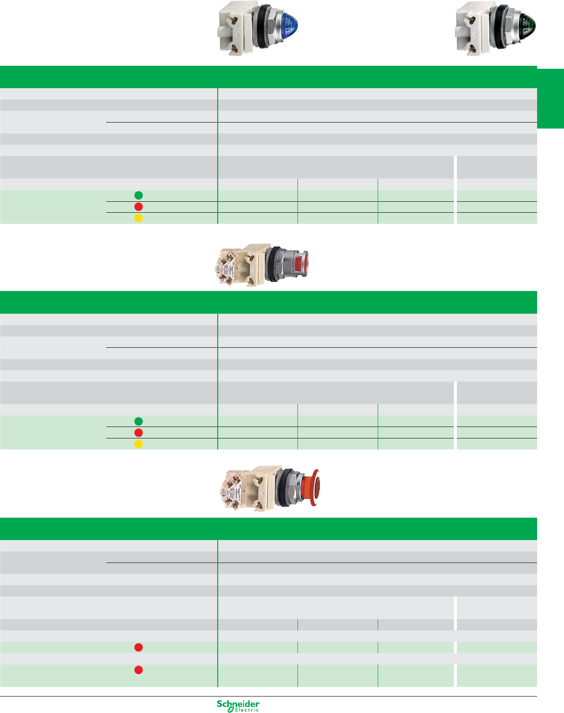
Other versions: please consult your Schneider Electric agency.
Pilot lights
Type of head Smooth lens cap
Degree of protection IP 66 / Nema 1, 2, 3, 3R, 4, 6, 12 and 13 / Class II
Mounting (mm) panel cut-out Ø 31
mounting centres 57.2 x 44.5 (with legend 9001KN2pp), 57.2 x 50.8 (with legend 9001KN3pp)
Depth below head (mm) 42
Connection Screw clamp terminals
Type of light block With high luminosity LED (included) Incandescent BA 9s bulb
(included)
24 V AC/DC 48 V AC/DC 120 V AC/DC 230 V AC
References green 9001KP35LGG9 9001KP36LGG9 9001KP38LGG9 9001KP7G9
red 9001KP35LRR9 9001KP36LRR9 9001KP38LRR9 9001KP7R9
yellow 9001KP35LYA9 9001KP36LYA9 9001KP38LYA9 9001KP7A9
Illuminated pushbuttons, spring return
Type of head Spring return flush push
Degree of protection IP 66 / Nema 1, 2, 3, 3R, 4, 6, 12 and 13 / Class II
Mounting (mm) panel cut-out Ø 31
mounting centres 57.2 x 44.5 (with legend 9001KN2pp), 57.2 x 50.8 (with legend 9001KN3pp)
Depth below head (mm) 42
Connection Screw clamp terminals
Type of light block With high luminosity LED (included) Incandescent BA 9s bulb
(included)
24 V AC/DC 48 V AC/DC 120 V AC/DC 230 V AC
References green C/O 9001K3L35LGGH13 9001K3L36LGGH13 9001K3L38LGGH13 9001K2L7RH13
red C/O 9001K3L35LRRH13 9001K3L36LRRH13 9001K3L38LRRH13 9001K2L7GH13
yellow C/O 9001K3L35LYAH13 9001K3L36LYAH13 9001K3L38LYAH13 9001K2L7AH13
Illuminated Ø 41 mushroom head pushbuttons, latching, high luminosity LED
Degree of protection IP 66 / Nema 1, 2, 3, 3R, 4, 6, 12 and 13 / Class II
Mounting (mm) panel cut-out Ø 31
mounting centres 57.2 x 44.5 (with legend 9001KN2pp), 57.2 x 50.8 (with legend 9001KN3pp)
Depth below head (mm) 42
Connection Screw clamp terminals
Type of light block With high luminosity LED (included) Incandescent BA 9s bulb
(included)
24 V AC/DC 48 V AC/DC 120 V AC/DC 230 V AC/DC
Type of head 2 position, push-pull
References red C/O 9001KR9P35RH13 9001KR9P36RH13 9001KR9P38RH13 9001KR9P7RH13
Type of head 3 position, push-pull (pull: spring return, centre: stay put, push: spring return)
References red N/C + N/C
late break
9001KR8P35RH25 9001KR8P36RH25 9001KR8P38RH25 9001KR8P7RH25
Light functions
2/17
2
1
3
4
5
6
7
8
9
10
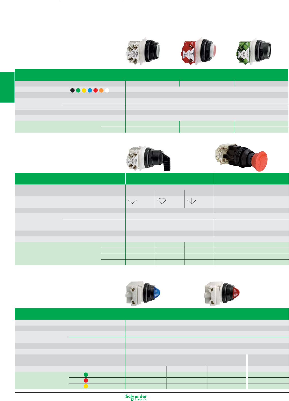
Other versions: please consult your Schneider Electric agency.
Pushbuttons, spring return
Type of push Flush Projecting Projecting (high guard)
Colour of push Multi-colour (set of 7 clip-in coloured caps)
Degree of protection IP 66 / Nema 1, 2, 3, 3R, 4, 4X, 12 and 13 / Class II
Mounting (mm) panel cut-out Ø 31
mounting centres 57.2 x 44.5 (with legend 9001KN2pp), 57.2 x 50.8 (with legend 9001KN3pp)
Depth below head (mm) 42
Connection Screw clamp terminals
References C/O 9001SKR1UH13 9001SKR3UH13 9001SKR2UH13
N/O 9001SKR1UH5 9001SKR3UH5 9001SKR2UH5
Type Selector switches Mushroom head pushbuttons (1)
Emergency stop
Type of operator Long black handle Turn-to-Release, trigger action
positions 2 - stay put 2 - spring return 3 - stay put Ø 40 red mushroom head
Number and type
of positions
Degree of protection IP 66 / Nema 1, 2, 3, 3R, 4, 4X, 12 and 13 / Class II
IP 66 / Nema 1, 2, 3, 3R, 4, 4X, 6, 12 and 13 / Class III
Mounting (mm) panel cut-out Ø 31
mounting centres 57.2 x 44.5 (with legend 9001KN2pp),
57.2 x 50.8 (with legend 9001KN3pp)
57,2 x 44,5 (without legend plate),
100 x 100 ((with legend plate 9001KN8330) (2)
Depth below head (mm) 42 60
Connection Screw clamp terminals
References – – – – 9001SKR16
N/O 9001SKS11FBH5 9001SKS34FBH5 –9001SKR16H13
C/O – –
9001SKS43FBH1
–
2“N/O” + 2“N/C”
–––9001SKR16H2
(1) Mushroom trigger action and mechanical latching head Emergency stop pushbuttons conforming to standard EN/IEC 60204-1 and EN/ISO 13850: 2006, to Machinery directive
98/37/EC and standard EN/IEC 60947-5-5.
(2) For yellow circular Emergency Stop legend plates: see page 2/19
Pilot lights
Type of head Smooth lens cap
Degree of protection IP 66 / Nema 1, 2, 3, 3R, 4, 4X, 12 and 13 / Class II
Mounting (mm) panel cut-out Ø 31
mounting centres 57.2 x 44.5 (with legend 9001KN2pp), 57.2 x 50.8 (with legend 9001KN3pp)
Depth below head (mm) 42
Connection Screw clamp terminals
Type of light block With high luminosity LED (included) Incandescent BA 9s bulb
(included)
24 V AC/DC 48 V AC/DC 120 V AC/DC 230 V AC
References green 9001SKP35LGG9 9001SKP36LGG9 9001SKP38LGG9 9001SKP7G9
red 9001SKP35LRR9 9001SKP36LRR9 9001SKP38LRR9 9001SKP7R9
yellow 9001SKP35LYA9 9001SKP36LYA9 9001SKP38LYA9 9001SKP7A9
Harmony
9001K/SK
Pushbuttons, switches and pilot lights Ø 30
with plastic bezel
Contact functions and light functions
2/18
2
1
3
4
5
6
7
8
9
10
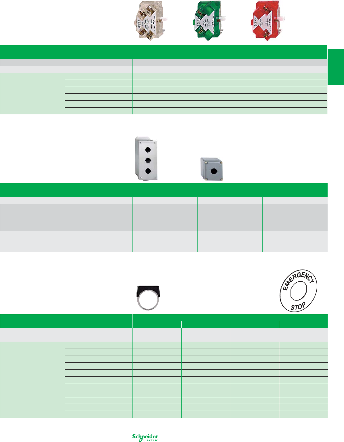
Other versions: please consult your Schneider Electric agency.
Contact blocks with protected terminals
Type of contact Single contact blocks
Connection Screw clamp terminals
References C/O 9001KA1
N/O 9001KA2
N/C 9001KA3
C/O, late break 9001KA4
N/C, late break 9001KA5
N/O, early make 9001KA6
Enclosures
Type Number of Ø 30 mm cut-outs NEMA ratings Reference
Aluminium 1 1, 3, 4, 6, 12, 13 9001KY1
2 1, 3, 4, 6, 12, 13 9001KY2
3 1, 3, 4, 6, 12, 13 9001KY3
4 1, 3, 4, 6, 12, 13 9001KY4
Stainless steel 1 1, 3, 4, 4X, 13 9001KYSS1
2 1, 3, 4, 4X, 13 9001KYSS2
3 1, 3, 4, 4X, 13 9001KYSS3
Legends
44 x 43 mm 57 x 57 mm Ø 60 Ø 90
Type Aluminium Plastic Plastic
Colour of legend black background white background Yellow background
Marking Blank 9001KN200 9001KN100WP 9001KN9100 9001KN8100
START 9001KN201 9001KN101WP – –
STOP (red background) 9001KN202 9001KN102RP – –
FORWARD 9001KN206 9001KN106WP – –
REVERSE 9001KN207 9001KN107WP – –
RESET 9001KN223 9001KN123WP –
PULL TO START/ 9001KN379 9001KN179WP – –
PUSH TO STOP
EMERGENCY STOP – – 9001KN9330 9001KN8330
ARRET D’URGENCE – – 9001KN9330F 9001KN8330F
PARADA DE EMERGENCIA – – 9001KN9330S 9001KN8330S
Accessories
2/19
2
1
3
4
5
6
7
8
9
10
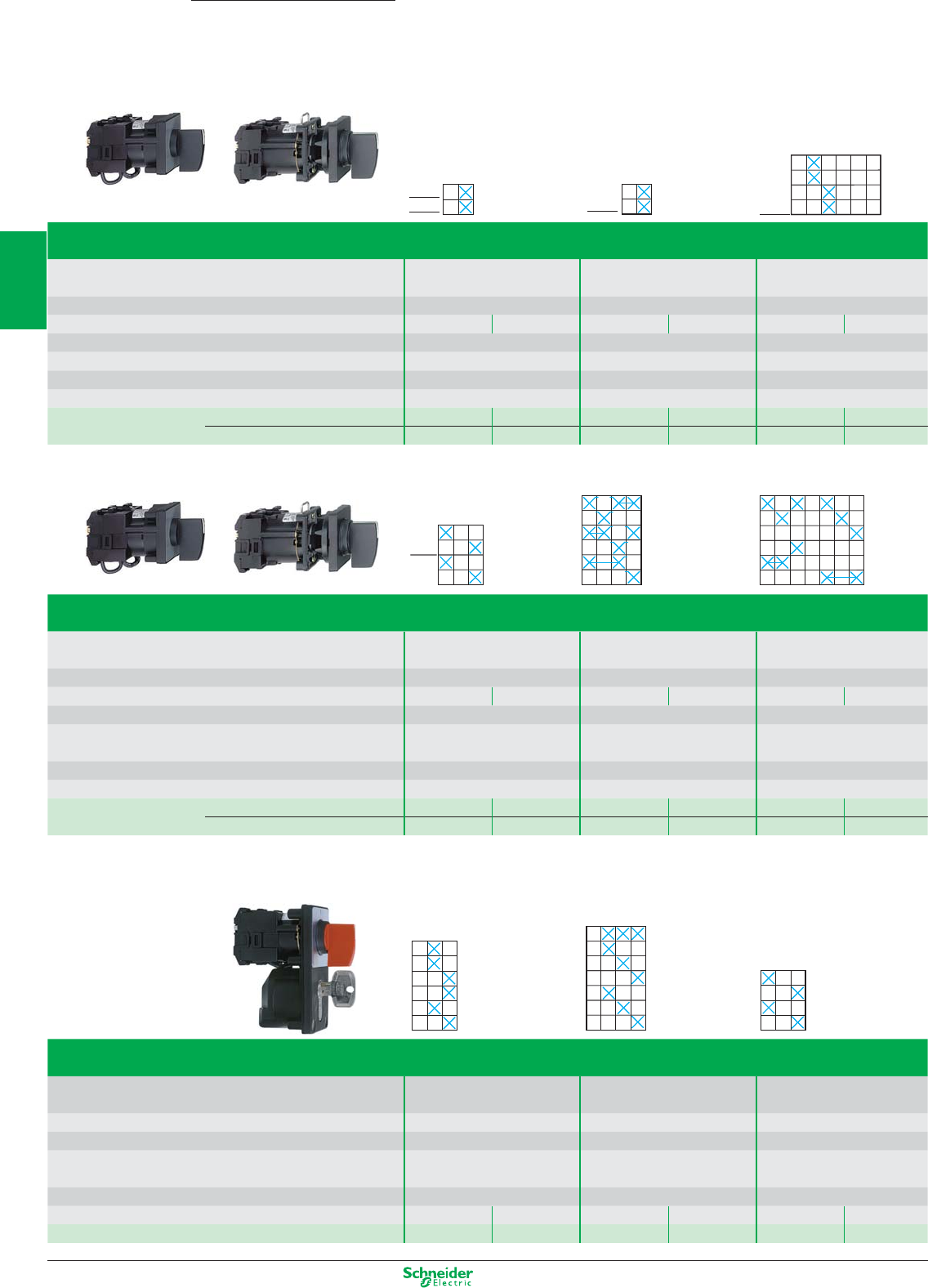
Other versions: please consult your Schneider Electric agency.
Cam switches
12 and 20 A ratings
Harmony
K series
positions (°)
Cam switches, K1 / K2 series
Function Switches ON-OFF switches Stepping switches
45° switching angle 90° switching angle with “0” position
Degree of protection front face IP 65 (1) IP 65 (1) IP 65 (1)
Conventional thermal current (Ith) 12 A 20 A 12 A 20 A 12 A 20 A
Rated insulation voltage (Ui) conforming to IEC60947-1 690 V 690 V 690 V
Number of positions 2 2 2 + “0” position
Number of poles 222
Dimensions of front plate (mm) 45 x 45 45 x 45 45 x 45
Front mounting method Multifixing plate, 45 x 45 mm K1B 002ALH K2B 002ALH K1B 1002HLH K2B 1002HLH K1D 012QLH K2D 012QLH
Plastic mounting plate for Ø 22 mm hole K1B 002ACH K2B 002ACH K1B 1002HCH K2B 1002HCH K1D 012QCH K2D 012QCH
positions (°)
Cam switches, K1 / K2 series
Function Changeover switches Ammeter switches Voltmeter switches
Degree of protection front face IP 65 (1) IP 65 (1) IP 65 (1)
Conventional thermal current (Ith) 12 A 20 A 12 A 20 A 12 A 20 A
Rated insulation voltage (Ui) conforming to IEC60947-1 690 V 690 V 690 V
Number of positions 2 + “0” position 3 + “0” position 6 + “0” position (measurements
(3 circuits + “0” position) between 3 phases & N + “0” pos.)
Number of poles 247
Dimensions of front plate (mm) 45 x 45 45 x 45 45 x 45
Front mounting method Multifixing plate, 45 x 45 mm K1D 002ULH K2D 002ULH K1F 003MLH to be compiled * K1F 027MLH to be compiled *
Plastic mounting plate for Ø 22 mm hole K1D 002UCH K2D 002UCH K1F 003MCH to be compiled * K1F 027MCH to be compiled *
(1) With seal KZ73 for switch with Multifixing plate, with seal KZ65 for Ø 22 mm hole mounting switches. Seal to be ordered separately.
(*) Please consult your Schneider Electric agency.
positions (°)
Cam switches with key operated lock, K1 series
Function Stepping switches Run switches Changeover switches + “0” pos.
Degree of protection front face IP 65 IP 65 IP 65
Conventional thermal current (Ith) 12 A 12 A 12 A
Rated insulation voltage (Ui) conforming to IEC60947-1 690 V 690 V 690 V
Number of positions 2 + “0” position 3 + “0” position 2 + “0” position
Number of poles 322
Dimensions of front plate (mm) 55 x 100 55 x 100 55 x 100
Colour of handle red black red black red black
Front mounting method Ø 22 mm hole + Ø 43.5 mm hole K1F 022QZ2 K1F 022QZ4 K1G 043RZ2 K1G 043RZ4 K1D 002UZ2 K1D 002UZ4
1
2
450
3
4
1-pole
2-pole
1
2
450
3
4
1-pole
2-pole
1
2
900
3
4
2-pole
1
2
900
3
4
2-pole
90
1
450
2
3
4
5
6
7
8
135 180 225
2-pole
90
1
450
2
3
4
5
6
7
8
135 180 225
2-pole
45
1
0315
2
3
4
5
6
7
8
1-pole
2-pole
45
1
0315
2
3
4
5
6
7
8
1-pole
2-pole
180
1
2
3
4
900 270
5
6
7
8
9
10
11
12
180
1
2
3
4
900 270
5
6
7
8
9
10
11
12
0
1
2
3
4
315270
5
6
7
8
225
9
10
45 90
11
12
1350
1
2
3
4
315270
5
6
7
8
225
9
10
45 90
11
12
135
0
1
2
3
4
5
6
7
8
9
10
11
12
60 1200
1
2
3
4
5
6
7
8
9
10
11
12
60 120 1
2
3
4
5
6
7
8
9
10
11
12
13
14
120 180060
1
2
3
4
5
6
7
8
9
10
11
12
13
14
120 180060
300
1
2
3
4
5
6
7
8
060300
1
2
3
4
5
6
7
8
060
2/20
2
1
3
4
5
6
7
8
9
10
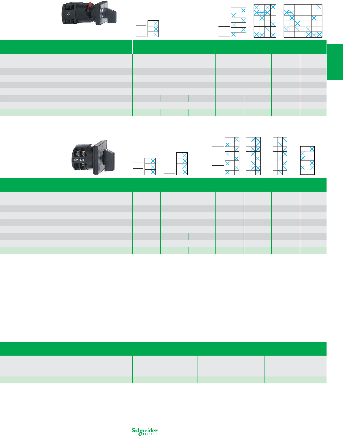
Other versions: please consult your Schneider Electric agency.
10 to 150 A ratings
positions (°)
Cam switches, K10 series
Function Switches Changeover switches Ammeter Voltmeter
60° switching angle with “0” position switches switches
Degree of protection front face IP 65 IP 65 IP 65 IP 65
Conventional thermal current (Ith) 10 A 10 A 10 A 10 A
Rated insulation voltage (Ui) conforming to IEC60947-1 440 V 440 V 440 V 440 V
Number of positions 2 2 + “0” position
3 + “0” pos. (1)
6 + “0” pos. (2)
Number of poles 1 23233 3
Dimensions of front plate (mm) 30 x 30 30 x 30 30 x 30 30 x 30
Front mounting method By Ø 16 mm or 22 mm hole
K10 A001ACH K10 B002ACH K10 C003ACH K10 D002UCH K10F003UCH K10 F003MCH K10 F027MCH
(1) (3 circuits + “0” position).
(2) (Measurements between 3 phases and N + “0” position).
positions (°)
Cam switches, K30 series
Function Switches Switches Changeover Starting Starting Reversing
ON-OFF
with “0” position
star-delta 2-speed
Degree of protection front face IP 40 IP 40 IP 40 IP 40 IP 40 IP 40
Conventional thermal current (Ith) 32 A 32 A 32 A 32 A 32 A 32 A
Rated insulation voltage (Ui) conforming to IEC60947-1 690 V 690 V 690 V 690 V 690 V 690 V
Number of positions 22 3333
Number of poles 3344333
Dimensions of front plate (mm) 64 x 64 64 x 64 64 x 64 64 x 64 64 x 64 64 x 64
Front mounting method Multifixing
K30 C003AP
(3)
K30 C003HP
(3)
K30 D004HP
(3)
K30 H004UP
(3)
K30 H001YP
(3)
K30 H004PP
(3)
K30 E003WP
(3)
(3) To order switches with other thermal current ratings (50, 63, 115, 150 A): replace the number 30 in the reference by 50, 63, 115 or 150 respectively.
Example: a switch with a 32 A current rating, for example K30 C003AP, becomes K50 C003AP for a current rating of 50 A.
Accessories for cam switches K1/K2
Rubber seals
for IP 65 degree of protection
For use with heads with 45 x 45 mm front plate with 60 x 60 mm front plate with 45 x 45 mm front plate
Ø 22 mm hole or 4 hole front mtg. Ø 22 mm hole or 4 hole front mtg. multifixing
References (5)* KZ 65 KZ 66 KZ 73
* sold in lots of
0
1
2
3
4
5
6
60
1-pole
2-pole
3-pole
0
1
2
3
4
5
6
60
1-pole
2-pole
3-pole
01
2
60
3
4
300
5
6
7
8
9
10
11
12
1-pole
2-pole
3-pole
01
2
60
3
4
300
5
6
7
8
9
10
11
12
1-pole
2-pole
3-pole
90
1
2
180
3
4
0 270
5
6
7
8
9
10
11
12
90
1
2
180
3
4
0 270
5
6
7
8
9
10
11
12
300 1
2
330
3
4
270 0 30 60 90
5
6
7
8
9
10
11
12
300 1
2
330
3
4
270 0 30 60 90
5
6
7
8
9
10
11
12
0
1
2
3
4
5
6
60
1-pole
2-pole
3-pole
0
1
2
3
4
5
6
60
1-pole
2-pole
3-pole
0
1
2
3
4
5
6
7
8
90
1-pole
2-pole
0
1
2
3
4
5
6
7
8
90
1-pole
2-pole
01
2
60
3
4
1
2
3
4
300
5
6
7
8
9
10
11
12
13
14
15
16
1-pole
2-pole
3-pole
4-pole
01
2
60
3
4
1
2
3
4
300
5
6
7
8
9
10
11
12
13
14
15
16
1-pole
2-pole
3-pole
4-pole
01
2
60
3
4
1
2
3
4
300
5
6
7
8
9
10
11
12
13
14
15
16
01
2
60
3
4
1
2
3
4
300
5
6
7
8
9
10
11
12
13
14
15
16
01
2
60
3
4
1
2
3
4
300
5
6
7
8
9
10
11
12
13
14
15
16
01
2
60
3
4
1
2
3
4
300
5
6
7
8
9
10
11
12
13
14
15
16
01
2
60
3
4
1
2
3
4
300
5
6
7
8
9
10
11
12
01
2
60
3
4
1
2
3
4
300
5
6
7
8
9
10
11
12
2/21
2
1
3
4
5
6
7
8
9
10
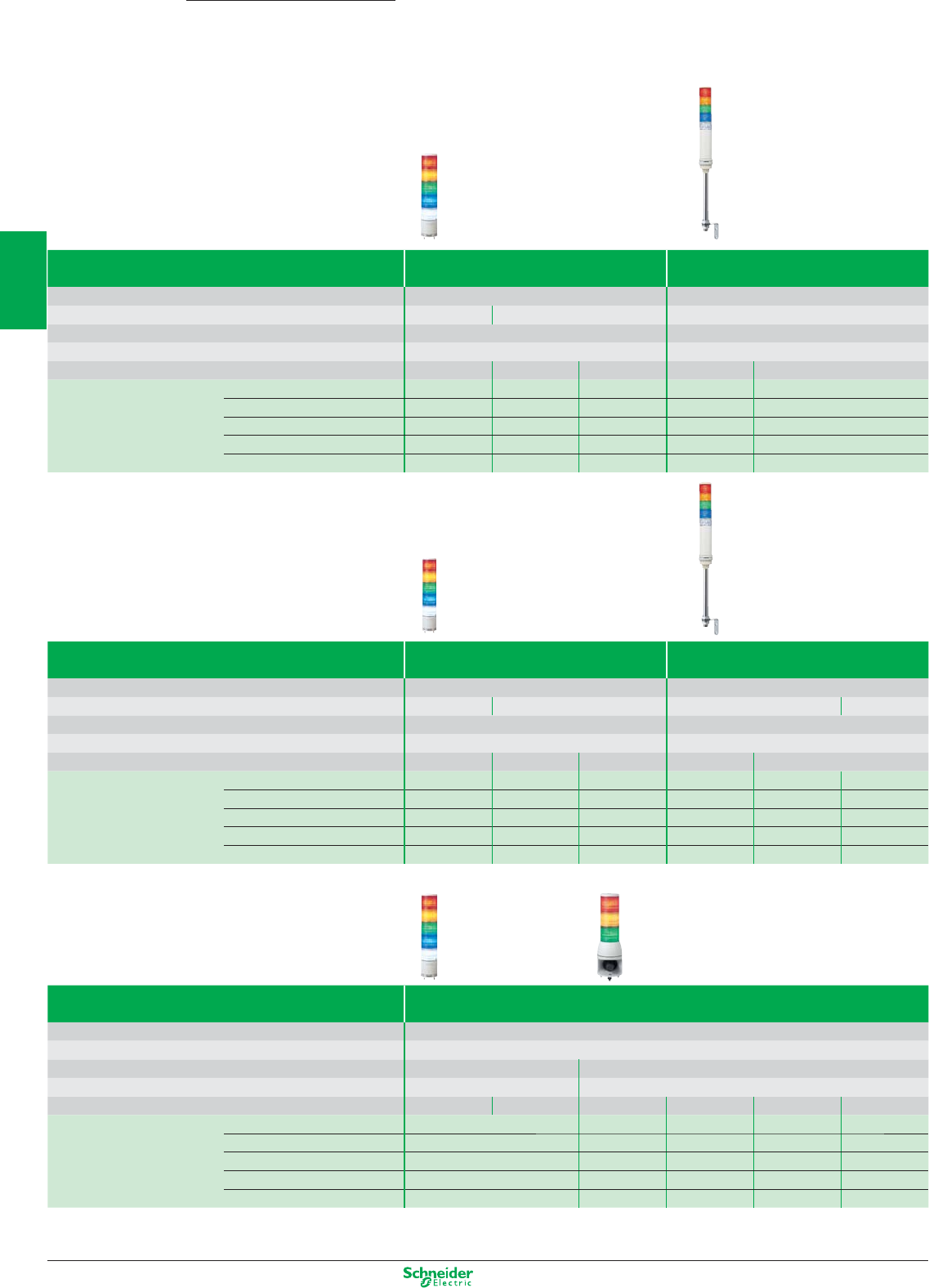
Other versions: please consult your Schneider Electric agency.
Monolithic tower lights
Ø 40, Ø 60, Ø 100 mm, complete, pre-wired
tower lights
Harmony
XVC
Ø 40 mm / Up to IP54
Complete, pre-wired tower lights Steady light Steady / Flashing light (1)
Light source (included)
LEDs LEDs
Base mount
Base mounting Support tube mounting, 17 mm Support tube mounting, 17 mm
Buzzer
Without buzzer With buzzer + flashing light
Degree of protection
up to IP54 up to IP54
Voltage
24V AC/DC 24V AC/DC 100-240V AC 24V AC/DC 100 - 240V AC
References (2)
Red
XVC4B1K XVC4B1 XVC4M1 XVC4B15S XVC4M15S
Red / orange
XVC4B2K XVC4B2 XVC4M2 XVC4B25S XVC4M25S
Red / Orange / green
XVC4B3K XVC4B3 XVC4M3 XVC4B35S XVC4M35S
red / orange / green / blue
XVC4B4K XVC4B4 XVC4M4 XVC4B45S XVC4M45S
red / orange / green / blue / Clear
XVC4B5K XVC4B5 XVC4M5 XVC4B55S XVC4M55S
Ø 60 mm / Up to IP54
Complete, pre-wired tower lights Steady light Steady / Flashing light (1)
Light source (included) LEDs LEDs
Base mount Base mounting Support tube mounting, 22 mm Support tube mounting, 22 mm Base mounting
Buzzer Without buzzer With buzzer + flashing light
Degree of protection up to IP54 up to IP54
Voltage 24V AC/DC 24V AC/DC 100-240V AC 24V AC/DC 100 - 240V AC
References (2) Red XVC6B1K XVC6B1
XVC6M1
(3)
XVC6B15S
(3)
XVC6M15S XVC6M15SK
Red / orange XVC6B2K XVC6B2 XVC6M2
(3)
XVC6B25S
(3)
XVC6M25S XVC6M25SK
Red / Orange / green XVC6B3K XVC6B3 XVC6M3
(3)
XVC6B35S
(3)
XVC6M35S XVC6M35SK
red / orange / green / blue XVC6B4K XVC6B4 XVC6M4
(3)
XVC6B45S
(3)
XVC6M45S XVC6M45SK
red / orange / green / blue / Clear XVC6B5K XVC6B5 XVC6M5
(3)
XVC6B55S
(3)
XVC6M55S XVC6M55SK
(3) To order products for base mounting, add the letter K to the end of the reference (ex. XVC6M1K)
Ø 100 mm / Up to IP54
Complete, pre-wired tower lights Steady / Flashing light (1)
Light source (included) LEDs
Base mount Base mounting
Buzzer Without buzzer With buzzer + flashing light
Degree of protection up to IP54 up to IP54
Voltage 24V DC 100-240V AC 24V DC 100-240V AC 24V DC 100 - 240V AC
References (2) Red XVC1B1K XVC1M1K XVC1B1SK XVC1M1SK XVC1B1HK XVC1M1HK
Red / orange XVC1B2K XVC1M2K XVC1B2SK XVC1M2SK XVC1B2HK XVC1M2HK
Red / Orange / green XVC1B3K XVC1M3K XVC1B3SK XVC1M3SK XVC1B3HK XVC1M3HK
red / orange / green / blue XVC1B4K XVC1M4K XVC1B4SK XVC1M4SK - -
red / orange / green / blue / Clear XVC1B5K XVC1M5K XVC1B5SK XVC1M5SK - -
(1) Flashing function can be simply selected/programmed by wiring
(2) The colours are listed in the same order as the mounting order of the illuminated units (from top to bottom)
2/22
2
1
3
4
5
6
7
8
9
10
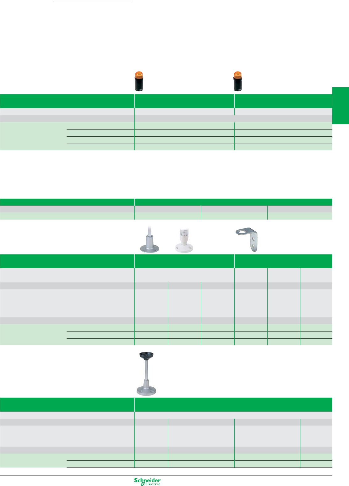
Other versions: please consult your Schneider Electric agency.
Monolithic tower lights and accessories
Ø 45 mm, complete illuminated beacons
Harmony
XVDLS / XVC
Ø 45 mm / IP40
Illuminated beacons XVDLS Steady light Flashing light
Light source Incandescent BA 15d bulb, 5 W max. (not included) “Flash” discharge tube, 0.5 J
Degree of protection IP 40
References (1) 24…230 V AC/DC XVDLS3p–
24 V AC/DC – XVDLS6Bp
120 V AC – XVDLS6Gp
230 V AC – XVDLS6Mp
(1) To obtain the complete reference, replace the p by the number designating the colour as follow: 3 = green , 4 = red , 5 = orange, 6 = blue, 7 = clear, 8 = yellow.
Accessories
XVDLS
Incandescent bulbs, with BA 15d base Beacons XVDLS
Description 24 V, 4 W 120 V, 5 W 230 V, 5 W
References DL1BEBS DL1BEGS DL1BEMS
XVC4 / XVC6
Mounting accessories Tower lights Ø 40 mm, XVC4 Tower lights Ø 60 mm, XVC6
Description Support tube mounting Support tube
mounting
Base mounting Support tube
mounting
Diameter (mm) Ø 90 Ø 84 – Ø 100 Ø 84 –
For use with – – – XVC6ppand
XVC6pp5S
XVC6ppK and
XVC6pp5SK
XVC6Bpand
XVC6Bpp5S,
XVC6Mpand
XVC6M
p
5S
Height to be added (mm) 32 24,5 82 30 21,6 82
References Metal fixing plate XVCZ11 – – XVCZ02 XVCZ12 –
Plastic fixing plate – XVCZ01 – – – –
Wall mounting bracket – – XVCZ31 – – XVCZ32
XVC1
Mounting accessories Tower lights Ø 100 mm, XVC1
Description Vertical support
Diameter (mm) Ø 140 Ø 140 – –
For use with XVC1ppK
and
XVC1ppSK
XVC1ppHK (with siren) XVC1ppK and XVC1ppSK
XVC1
pp
HK
(with siren)
Height to be added (mm) 300 306 – –
References Metal fixing plate (2) XVCZ13 XVCZ14 – –
Metal fixing bracket – – XVCZ23 XVCZ24
(2) Chromium plated-steel extension tube
2/23
2
1
3
4
5
6
7
8
9
10
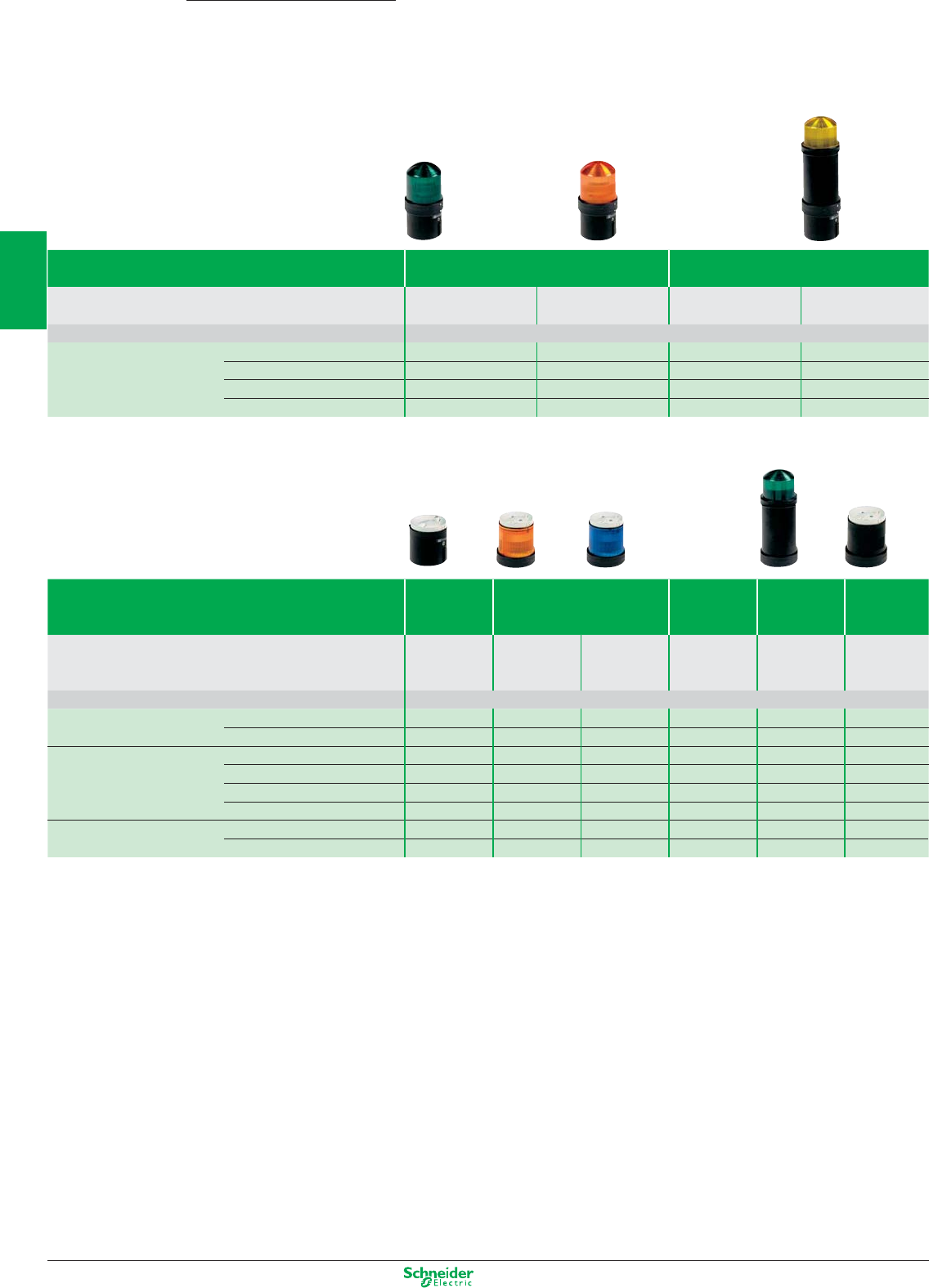
Other versions: please consult your Schneider Electric agency.
Modular tower lights
Ø 70 mm, for customer assembly
Harmony
XVB
Ø 70 mm / Up to IP66
Illuminated beacons XVBL Steady light Flashing light
Light source
Incandescent BA 15d bulb,
Protected BA 15d LED Protected BA 15d LED “Flash” discharge tube
10 W max. (not included) (included) (included) 5 J (2)
Degree of protection IP 66
References (1) 12…250 V AC/DC XVBL3p–––
24 V AC/DC – XVBL0BpXVBL1BpXVBL6Bp
120 V AC – XVBL0GpXVBL1GpXVBL6Gp
230 V AC – XVBL0MpXVBL1MpXVBL6Mp
Ø 70 mm / Up to IP66
Tower lights XVBC
comprising 2 to 5 signalling units (3)
Base units Steady light Flashing
light
“Flash”
light
Audible
units (90 db
at 1 m)
Light source – Incandescent Integral Integral “Flash” –
BA 15d bulb, 10 W
protected LED protected LED discharge tube
max. (not included)
5 J (2)
Degree of protection IP 66
Base unit references with cover XVBC21 (4) – – – – –
without cover XVBC07 (5) – – – – –
References (2) 12… 230 V AC/DC – XVBC3p––––
24 V AC/DC – – XVBC2BpXVBC5BpXVBC6Bp–
120 V AC – – XVBC2GpXVBC5GpXVBC6Gp–
230 V AC – – XVBC2MpXVBC5MpXVBC6Mp–
Audible unit references 12…48 V AC/DC – – – – – XVBC9B
unidirectional 120…230 V AC – – – – – XVBC9M
(1) To obtain the complete reference, replace thep by the number designating the colour as follow: 3 = green , 4 = red , 5 = orange, 6 = blue, 7 = clear, 8 = yellow.
(2) To order a lens unit with a 10 J discharge tube, replace the number 6 by 8 in the reference (example: XVBL6Bp becomes XVBL8Bp).
(3) A tower light comprises: 1 base unit + 1 to 5 signalling units maximum.
(4) For connection on AS-Interface, order base unit XVBC21A (side cable entry) or XVBC21B (bottom cable entry with M12 connector on flying lead).
(5) For indicator banks with “flash” discharge tube unit.
2/24
2
1
3
4
5
6
7
8
9
10
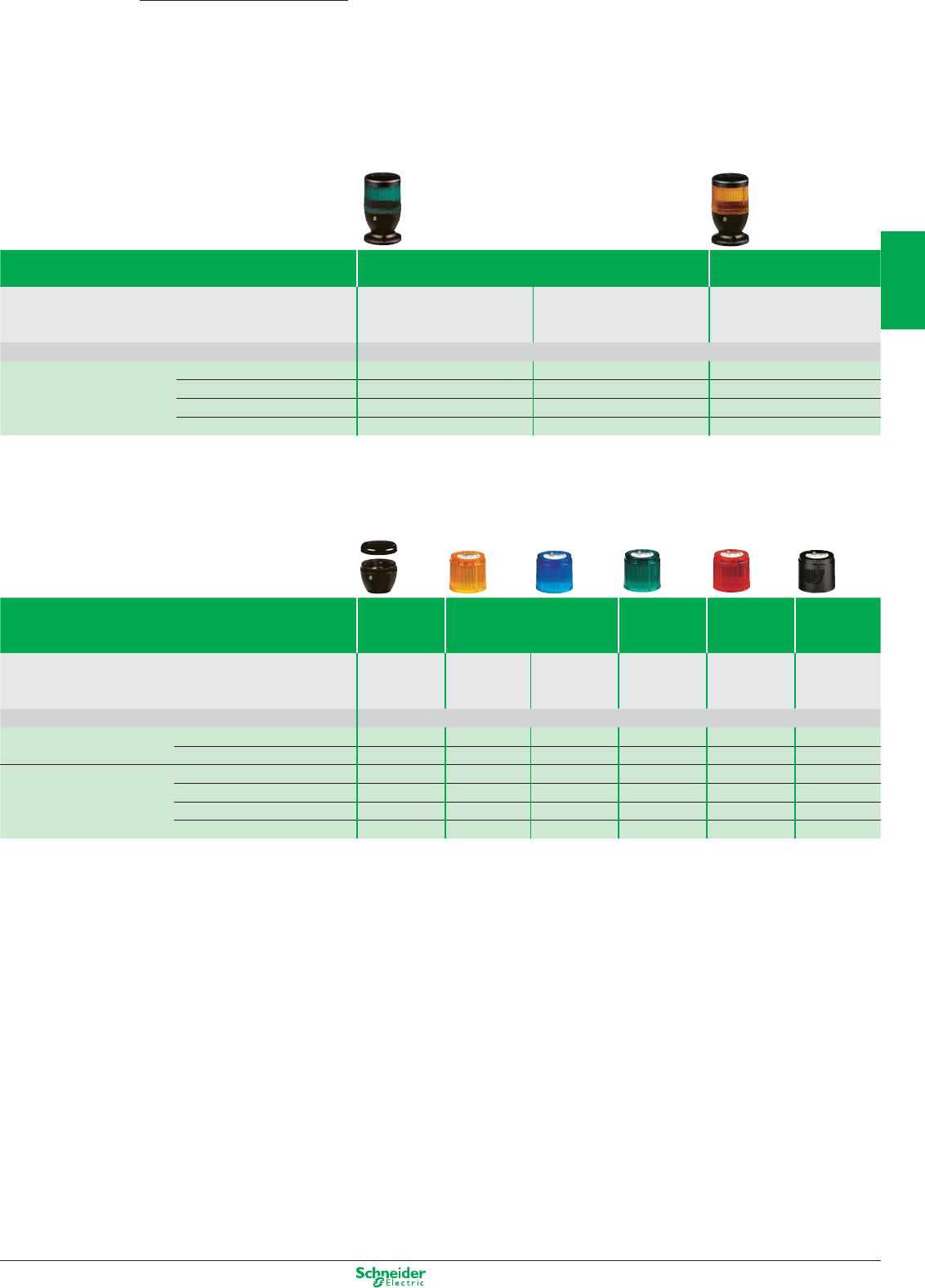
Other versions: please consult your Schneider Electric agency.
Modular tower lights
Ø 70 mm, for customer assembly
Harmony
XVE
Ø 70 mm / Up to IP54
Illuminated beacons XVEL Steady light Flashing light
Light source Incandescent Integral “Flash” discharge tube, 1 J
BA 15d bulb, 5 W max. LED
(not included)
Degree of protection IP 42/IP 54 (with sealing kit)
References (1) 24… 240 V AC/DC XVEL3p–
24 V AC/DC – XVEL2BpXVEL6Bp
120 V AC – XVEL2GpXVEL6Gp
230 V AC – XVEL2MpXVEL6Mp
Ø 70 mm / Up to IP54
Indicator banks XVEC
comprising 2 to 5 signalling units (2)
Base units Steady light Flashing
light
“Flash”
light
Audible
units (85 db
at 1 m)
Light source – Incandescent Integral Integral “Flash” –
BA 15d bulb, 5 W
LED LED discharge tube
max. (not included)
1 J
Degree of protection IP 42/IP 54 (with sealing kit)
Base unit references IP 42 XVEC21 – – – – –
IP 54 XVEC21P – – – – –
Lens unit references (1) 24…230 V AC/DC – XVEC3p–
24 V AC/DC – – XVEC2BpXVEC5BpXVEC6BpXVEC9B
120 V AC – – XVEC2GpXVEC5GpXVEC6GpXVEC9G
230 V AC – – XVEC2MpXVEC5MpXVEC6MpXVEC9M
(1) To obtain the complete reference, replace thep by the number designating the colour as follow: 3 = green , 4 = red , 5 = orange, 6 = blue, 7 = clear, 8 = yellow.
(2) A tower light comprises: 1 base unit + 1 to 5 signalling units maximum.
2/25
2
1
3
4
5
6
7
8
9
10
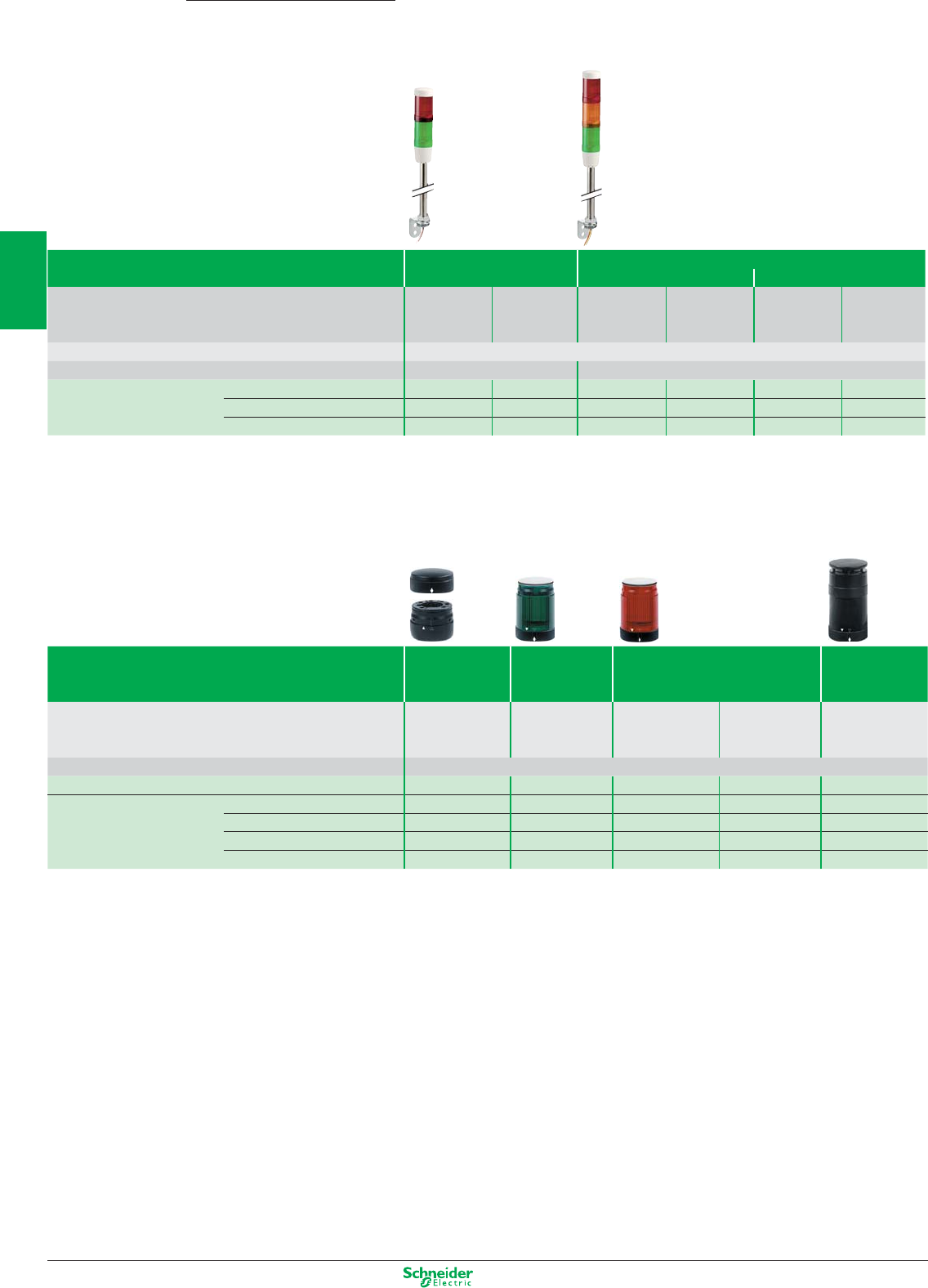
Other versions: please consult your Schneider Electric agency.
Modular tower lights
Ø 45, Ø 50 mm, complete or
for customer assembly
Harmony
XVM / XVP
Ø 45 mm / IP42
Complete, pre-wired tower light XVM (1)
2 s
i
g. units + integral buzzer (2)
Steady light
3 signalling units + integral buzzer (2)
Steady light
Steady light + “flash”
(3)
Light source (included) Incandescent BA 15d Incandescent BA 15d Incandescent BA 15d
BA 15d bulb, 5 W
“Super bright”
LED
BA 15d bulb, 5 W
“Super bright”
LED
BA 15d bulb, 5 W
“Super bright”
LED
max. max. max.
Degree of protection IP 54
Signalling colours Red - Green Red - Orange - Green
References 24 V AC/DC
XVMB1RGS XVMB2RGSSB XVMB1RAGS XVMB2RAGSSB
XVMB1R6AGS
XVMB2R6AGSSB
120 V AC/DC (bulb) - 120 V AC (LED)
XVMG1RGS XVMG2RGSSB XVMG1RAGS XVMG2RAGSSB
XVMG1R6AGS
XVMG2R6AGSSB
2
30 V AC/DC (bulb) - 230 V AC (LED)
XVMM1RGS XVMM2RGSSB XVMM1RAGS XVMM2RAGSSB
XVMM1RA6GS
XVMM2R6AGSSB
(1) Tower lights XVM are also available as separate components for customised assembly by the user: please refer to www.schneider-electric.com.
(2) To order products without an integral buzzer, delete the letter S at the end of the reference (example: XVMB2RGS becomes XVMB2RG).
(3) Flash signalling colour: red - 0.8 J.
Ø 50 mm / IP65
Tower lights XVP
comprising 2 to 5 signalling units (4),
black clamping ring (5)
Base unit Steady or
flashing light
signalling
“Flash” light signalling Audible units
(55…85 dB
at 1 m)
Light source – Incandescent “Flash” “Flash” –
BA 15d bulb, 7 W discharge tube discharge tube
max. (not included) 0.3 J 0.6 J
Degree of protection IP 65
Base unit with cover XVPC21 –– ––
References (6) 250 V max. – XVPC3p–––
24 V AC/DC (flash) - 24 V DC (buzzer)
––XVPC6Bp–XVPC09B
120 V AC – – – XVPC6GpXVPC09G
230 V AC – – – XVPC6MpXVPC09M
(4) A tower light comprises: 1 base unit + 1 to 5 signalling units maximum.
(5) To order products with a cream clamping ring, add the letter W to the end of the reference (example: base unit + green lens unit: XVPC21W + XVPC33W etc.).
(6) To obtain the complete reference, replace thep by the number designating the colour as follow: 3 = green , 4 = red , 5 = orange, 6 = blue, 7 = clear, 8 = yellow.
2/26
2
1
3
4
5
6
7
8
9
10
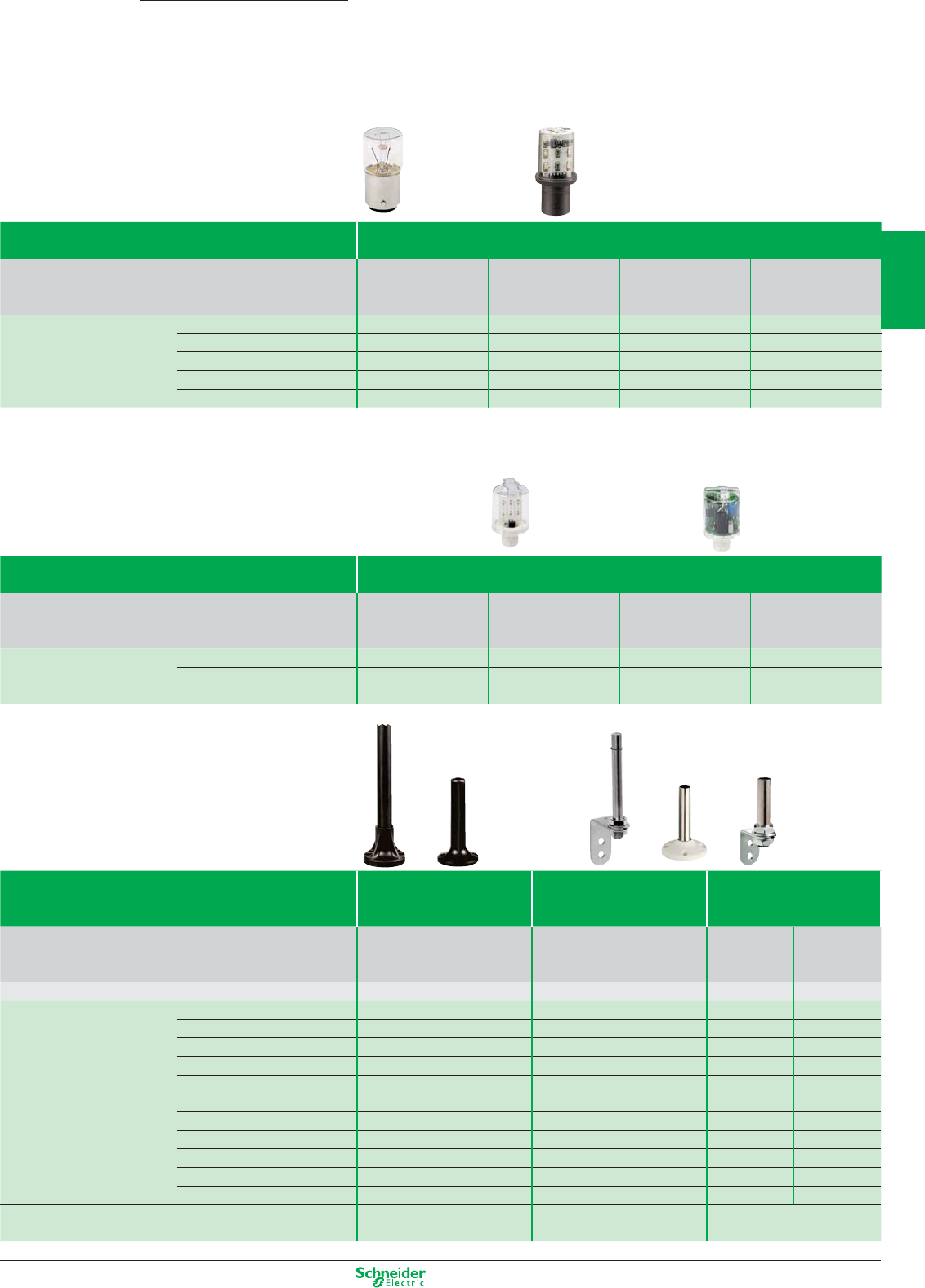
Other versions: please consult your Schneider Electric agency.
Bulbs Beacons and tower lights
XVB / XVP (1)
Type of light source Incandescent Incandescent LED (2) Flashing
BA 15d base BA 15d base BA 15d base LED (2)
7 W 10 W (not XVP) BA 15d base
References 12 V DL1BEJ DL1BLJ – –
24 V DL1BEB DL1BLB DL1BDBpDL1BKBp
48 V DL1BEE DL1BLE – –
120 V DL1BEG DL1BLG DL1BDGpDL1BKGp
230 V DL1BEM DL1BLM DL1BDMpDL1BKMp
(1) Tower lights XVP can be fitted with 5 W incandescent bulbs: see beacons XVDLS / XVE.
(2) To obtain the complete reference, replace the p by the number designating the colour as follow: 1 = white, 3 = green , 4 = red , 5 = orange, 6 = blue, 8 = yellow.
Bulbs Tower lights
XVM / XVE
Type of light source Incandescent LED (3) Flashing “Flash” discharge
BA 15d base BA 15d base LED (3) tube, 0.8 Joule
5 W BA 15d base BA 15d base
References 24 V DL1EDBS DL2EDBpDL1EKBpDL6BB
120 V DL1EDGS DL2EDGpDL1EKGpDL6BG
230 V DL1EDMS DL2EDMpDL1EKMpDL6BM
(3) To obtain the complete reference, replace the p by the number designating the colour as follows: 1 = white, 3 = green , 4 = red , 6 = blue, 8 = orange.
Mounting accessories Beacons and
tower lights
XVB / XVE
Tower lights Tower lights
XVP XVM
Description
Aluminium tube Plastic tube Aluminium tube Aluminium tube Aluminium tube Aluminium tube
with integral black with integral black with integral black with steel fixing
with integral cream
with steel fixing
plastic fixing base plastic fixing base plastic fixing base bracket plastic fixing base bracket
Diameter (mm) Ø 25 Ø 25 Ø 20 Ø 20 Ø 20 Ø 20
Support tubes 60 mm XVEZ13
–––––
100 mm
–– –
XVPC02T XVMZ02 XVMZ02T
112 mm
––
XVPC02 (4)
–––
120 mm XVBZ02
–––––
140 mm
–
XVDC02
–– ––
250 mm
–– –
XVPC03T XVMZ03 XVMZ03T
260 mm
––
XVPC03 (4)
–––
400 mm
–– –
XVPC04T XVMZ04 XVMZ04T
410 mm
––
XVPC04 (4)
–––
420 mm XVBZ03
–––––
820 mm XVBZ04
–––––
Fixing plates, for vertical support XVBC12 XVPC12 (4)
–
for horizontal support XVBZ01
–
XVMZ06
(4) To order an aluminium support tube with integral cream fixing base, add the letter W to the end of the reference (example: XVPC02W).
Modular tower lights accessories
For XVB, XVP, XVE, XVM
Harmony
XV
2/27
2
1
3
4
5
6
7
8
9
10
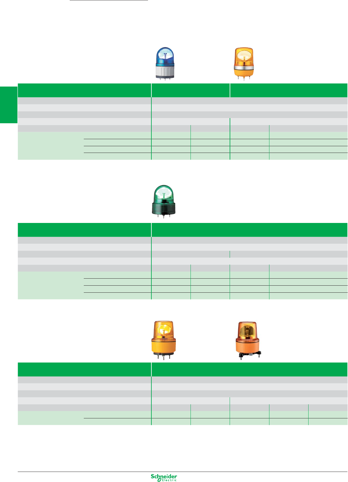
Other versions: please consult your Schneider Electric agency.
Rotating mirror beacons
Ø 84, 106, 120, 130 mm rotating mirror beacons
Harmony
XVR
Ø 84 / 106 mm
Complete, pre-wired rotating mirror beacons Ø 84 mm Ø 106 mm
Light source (included) “ Super bright “ LEDs
Base mount 3 x Ø 05
Buzzer Without buzzer
Degree of protection IP23 (IP 65 with accessories) IP23 (IP 65 with accessories)
Voltage 12V AC/DC 12V AC/DC 12V AC/DC 12V AC/DC
References Red XVR08J04 XVR08B04 XVR10J04 XVR10B04
Orange XVR08J05 XVR08B05 XVR10J05 XVR10B05
Green XVR08J03 XVR08B03 XVR10J03 XVR10B03
Blue XVR08J06 XVR08B06 XVR10J06 XVR10B06
Ø 120 mm
Complete, pre-wired rotating mirror beacons Ø 120 mm
Light source (included) “ Super bright “ LEDs
Base mount 3 x M5
Buzzer Without buzzer With buzzer
Degree of protection IP23
Voltage 12V AC/DC 24V AC/DC 12V AC/DC 24V AC/DC
References Red XVR12J04 XVR12B04 XVR12J04S XVR12B04S
Orange XVR12J05 XVR12B05 XVR12J05S XVR12B05S
Green XVR12J03 XVR12B03 XVR12J03S XVR12B03S
Blue XVR12J06 XVR12B06 XVR12J06S XVR12B06S
Ø 130 mm
Complete, pre-wired rotating mirror beacons Ø 130 mm
Light source (included) “ Super bright “ LEDs
Base mount 3 x Ø 09
Buzzer Without buzzer
Degree of protection IP66 - Resistant to vibration IP66 and IP67
Voltage 12V DC 24V DC 24V AC/DC 120V AC 230V AC
References Red XVR13J04 XVR13B04 XVR13B04L XVR13G04L XVR13M04L
Orange XVR13J05 XVR13B05 XVR13B05L XVR13G05L XVR13M05L
2/28
2
1
3
4
5
6
7
8
9
10
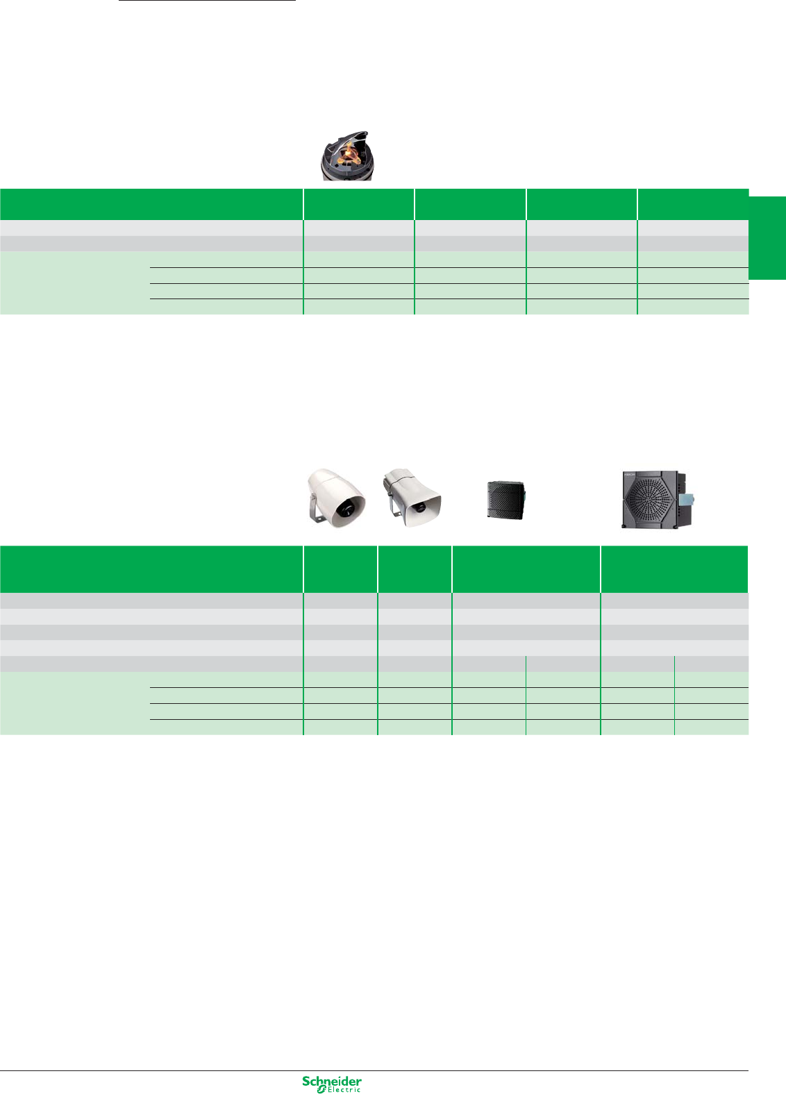
Other versions: please consult your Schneider Electric agency.
Accesories for rotating mirrors Reflecting prism Rubber base Metal angle
bracket
Metal fixing plate
To be used for/with – Increasing the IP degree Horizontal support Horizontal support
Height (mm) – – – 300
References Ø 84 mm XVRZR1 XVRZ081 XVCZ23 –
Ø 106 mm XVRZR2 XVRZ082 XVCZ23 XVCZ13
Ø 120 mm XVRZR3 – XVCZ23 XVCZ13
Ø 130 mm XVRZR3 – XVR012L –
Electronic alarms and multisound sirens
Sirens and electronic alarms Sirens Multisound
sirens
pre-wired
Electronic alarms
Panel Mount DIN72
Electronic alarms
Panel Mount DIN96
Sound level 106 dB 105 dB 90 dB 96 dB
Tones 24316 16
Channels –84 4
Degree of protection IP 65 IP53 IP 54 IP 54
Colors White White Black White Black White
References 12/24V AC/DC XVS10BMW – XVS72BMBp (1)
XVS72BMW
p
(1)
XVS96BMBp
(1) XVS96BMW
p
(1)
12/24V DC – XVS14BMW – – – –
120V AC XVS10GMW XVS14GMW – – – –
230V AC XVS10MMW XVS14MMW – – – –
(1) To obtain a complete reference, replace the p by the letter as follow: P = PNP, N = NPN (ex. XVS72BMBP)
Rotating mirror beacons accessories
and sound solutions
Accessories for rotating mirror beacons
Harmony
XVR / XVS
2/29
2
1
3
4
5
6
7
8
9
10
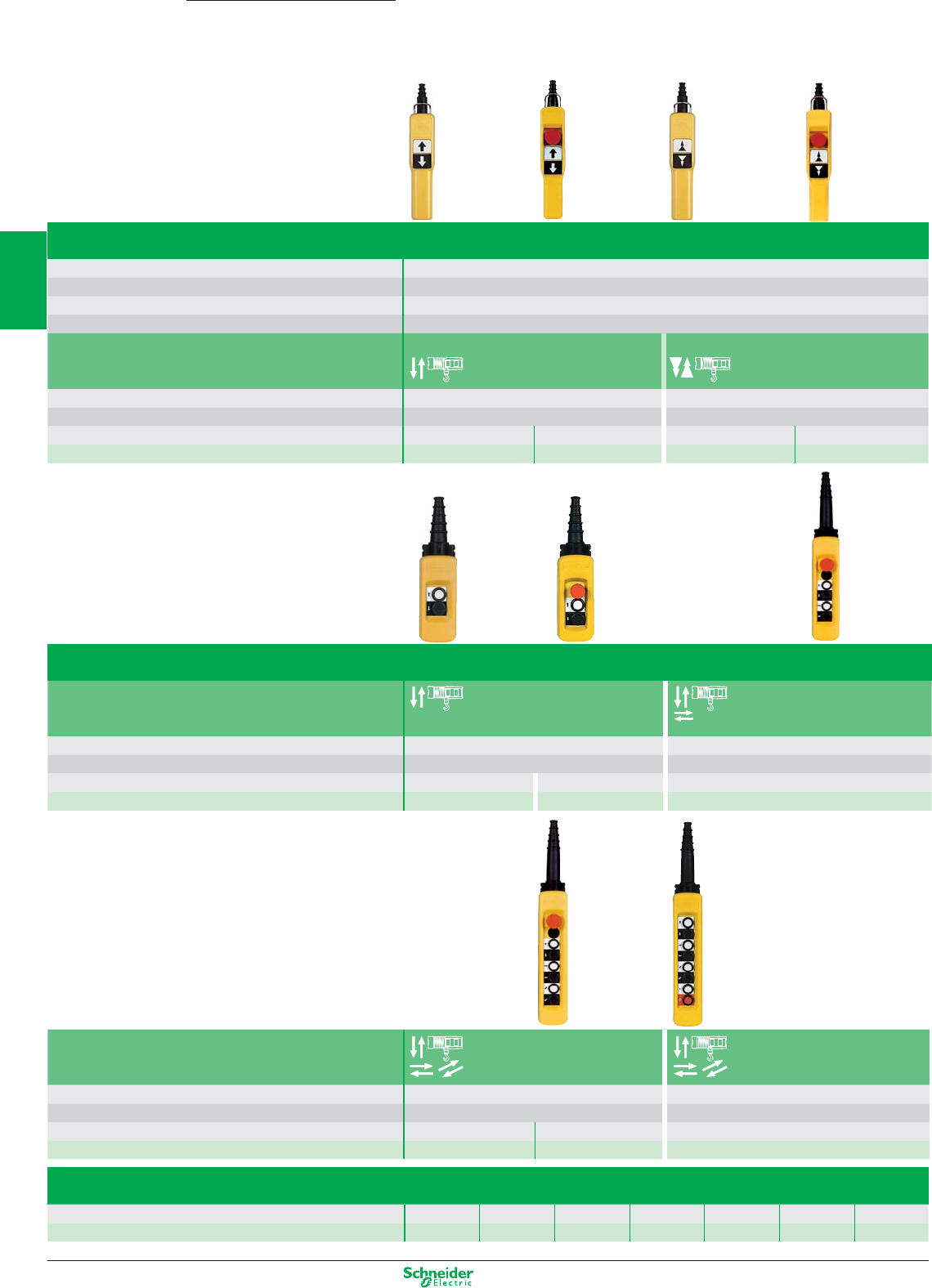
Other versions: please consult your Schneider Electric agency.
Type XAC A “Pistol grip”
Degree of protection IP 65 / Nema 4, 4X / Class II
Rated operational characteristics AC 15 (240 V 3 A), DC 13
Conventional thermal current Ithe 10 A
Connection Screw clamp terminals, 1 x 2.5 mm
2
or 2 x 1.5 mm
2
For control of single-speed motors 2-speed motors
Dimensions (mm) W x H x D 52 x 295 x 71 (x 85 with ZA2 BS834) 52 x 295 x 71 (x 85 with ZA2 BS834)
Number of operators mechanically interlocked 22
Emergency stop without ZA2 BS834 without ZA2 BS834
References XAC A201 XAC A2014 XAC A207 XAC A2074
Type XAC A
For control of single-speed motors
Dimensions (mm) W x H x D 80 x 314 x 70 (x 90 with ZA2 BS834) 80 x 440 x 70 (x 90 with ZA2 BS844)
Number of operators
mechanically interlocked between pairs
24
Emergency stop without ZA2 BS834 without ZA2 BS844
References XAC A271 XAC A2714 XAC A471 XAC A4714
For control of single-speed motors + I / O
Dimensions (mm) W x H x D 80 x 500 x 70 (x 90 with ZA2 BS844) 80 x 560 x 70
Number of operators
mechanically interlocked between pairs
68
Emergency stop without ZA2 BS844 without
References XAC A671 XAC A6714 XAC A871
Empty enclosures type XAC A
Number of ways 2 3 456812
References XAC A02 XAC A03 XAC A04 XAC A05 XAC A06 XAC A08 XAC A12
Pendant control stations
for control circuits
Ready to use
Harmony
XAC
2/30
2
1
3
4
5
6
7
8
9
10
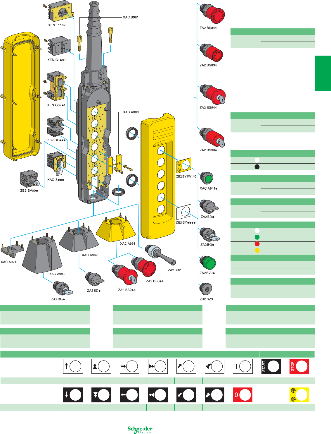
Other versions: please consult your Schneider Electric agency.
(1) Trigger action mechanically latching Emergency stop pushbuttons conform to standards EN/IEC 60204-32, EN/ISO 13850: 2006, Machinery directive 98/37/EC and standard
EN/IEC 60947-5-5.
Legends, 30 x 40 mm With symbols conforming to NF E 52-124 With text
References ZB2 BY4901 ZB2 BY4903 ZB2 BY4907 ZB2 BY4909 ZB2 BY4913 ZB2 BY4915 ZB2 BY4930 ZB2 BY2303 ZB2 BY2304
References ZB2 BY2904 ZB2 BY2906 ZB2 BY2910 ZB2 BY2912 ZB2 BY2916 ZB2 BY2918 ZB2 BY2931 ZB2BY1W140
blank
white or yellow
background
Separate components (for mounting in enclosures XAC A)
Booted operators
white XAC A9411
black XAC A9412
Mushroom head, latching, trigger action (1)
turn to release Ø 40 ZA2 BS844
Ø 30 ZA2 BS834
Mushroom head, latching, trigger action (1)
key release Ø 40 ZA2 BS944
Ø 30 ZA2 BS934
Selector switch
2 pos. stay put ZA2 BD2
3 pos. stay put ZA2 BD3
Key switch
key n° 455 2 pos. stay put ZA2 BG4
3 pos. stay put ZA2 BG5
Blanking plug
with seal and ZB2SZ3
fixing nut
Pilot light heads
white ZA2 BV01
green ZA2 BV03
red ZA2 BV04
yellow ZA2 BV05
Pilot light bodies
direct supply ZB2 BV006
direct supply, through resistor ZB2 BV007
Protective guard (for base mounted units)
For selector switch XAC A982/983
For emergency stop pushbutton XAC A984
Contact blocks
Single-speed N/O ZB2 BE101
Single-speed N/C ZB2 BE102
Contacts blocks for XAC A941p
Single-speed N/C + N/O XEN G1491
2-speed N/C + N/O + N/O XEN G1191
Contact blocks (for mounting in enclosure base)
N/O XAC S101
N/C + N/O XAC S105
Isolating switch, slow break, for front mounting
Emergency stop «N/C+N/C+N/C»
with positive opening operation
XEN T1192
Double blocks latching, slow break
Single-speed N/O + N/O
XEN G3781
Single-speed N/O + N/C
XEN G3791
2/31
2
1
3
4
5
6
7
8
9
10
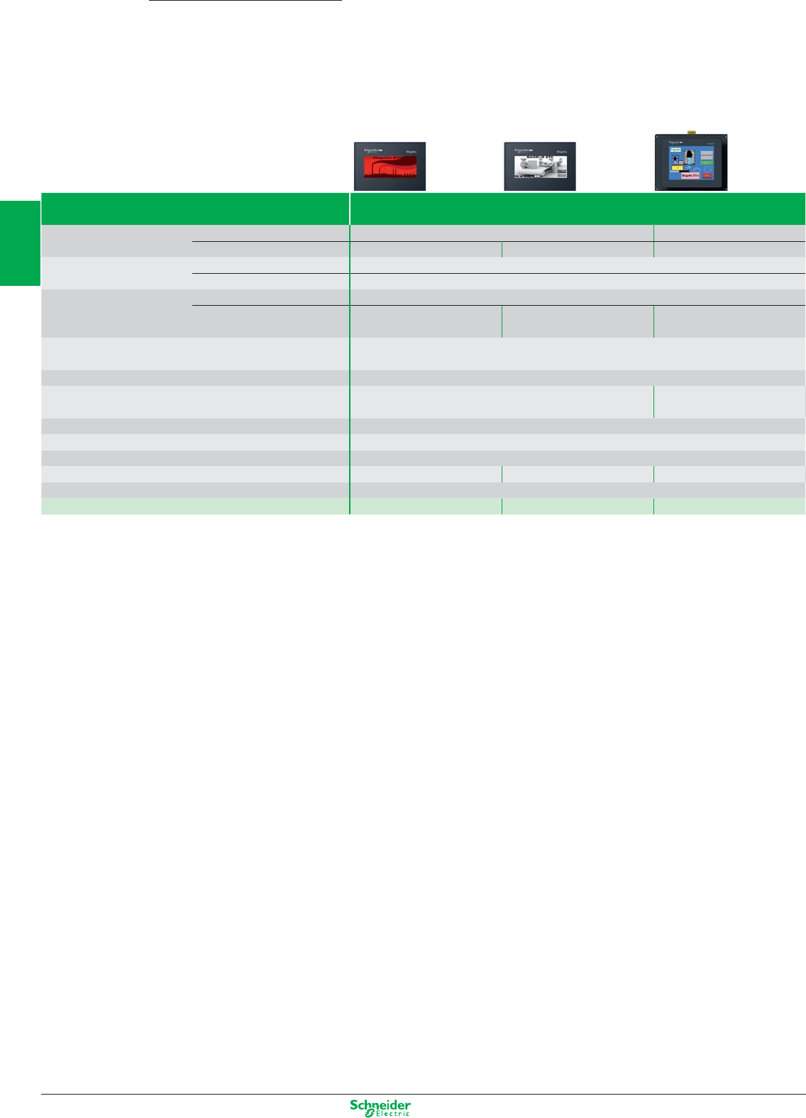
Other versions: please consult your Schneider Electric agency.
Type Characteristics
Display LCD screen size / Resolution 3.4” / monochrome (200 X 80 pixels) 3.5” / QVGA (320 X 240 pixels)
Type Green, orange, red White, pink, red TFT 65 536 colours
Functions Representation of variables Alphanumeric, bitmap, bargraph, gauge, button, light, clock, fl ashing light, keypad
Curves / Alarm logs Yes, with log / Yes, incorporated
Communication Serial link 1 RJ45 (RS 232 - RS 485)
Networks – – Ethernet, IEEE 802.3
10/100 BASE-T, RJ45
Downloadable protocols Mitsubishi (Melsec), Omron (Sysmac), Rockwell Automation (Allen Bradley), Siemens (Simatic)
Uni-TE, Modbus, Modbus TCP
Development software Vijeo Designer VJDpppTGpVppM (on Windows XP, Vista and 7) or Vijeo Designer Limited Edition
Dimensions W x D x H 113×28×78mm Front : 98×16×81mm
Rear : 118×30×98mm
Compatibility with PLCs Twido, Modicon TSX Micro, Modicon Premium, Modicon Quantum, Modicon M340
«Compact Flash» card slot No
USB port 1 Host type A + 1 Device type miniB
Built-in Ethernet TCP/IP No No Yes
Supply voltage 24 VDC
References HMI STO511 HMI STO512 HMI STU655
Magelis Small Panels
Magelis STO/STU
with graphic screen
2/32
2
1
3
4
5
6
7
8
9
10
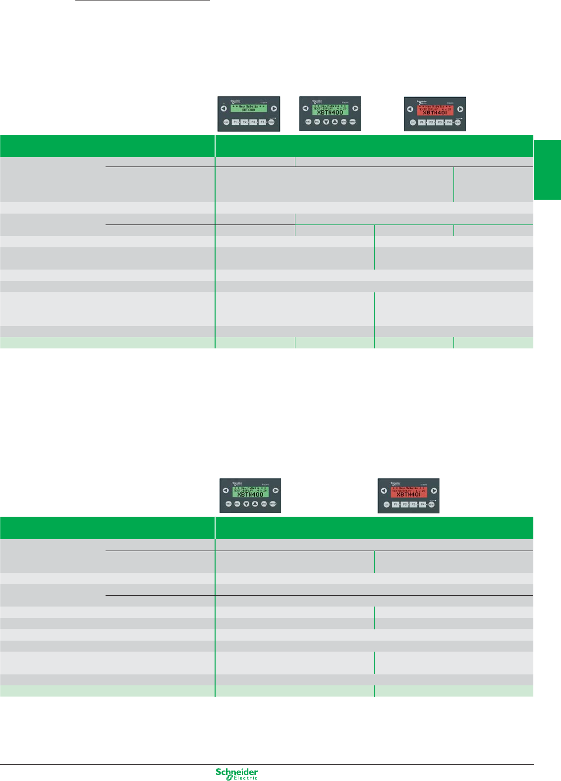
Other versions: please consult your Schneider Electric agency.
Magelis Small Panel
Magelis XBT N
with matrix, semi-graphic screen (1)
Type Characteristics
Display Capacity
2 lines, 20 characters
1 to 4 lines, 5 to 20 characters
Type Back-lit LCD Back-lit LCD
green 3 colours
green, orange, red
Data entry Via keypad with 8 keys (4 customizable keys)
Function Representation of variables Alphanumeric Alphanumeric, bargraph, curves, button and light
Alarm log No Yes Yes Yes
Communication Serial link 1 RJ45 (RS 232 - RS 485) 1 Sub-D25 (RS 232 - RS 485) + 1 miniDin RS232 (2)
Downloadable protocols Uni-TE, Modbus Master Uni-TE, Modbus Master, Siemens,
Rockwell,Omron, Mitsubishi, Zelio (2)
Development software Vijeo Designer Lite (on Windows XP and Vista)
Dimensions W x D x H 132 x 37 x 74 mm
Compatibility with PLCs Twido, Modicon TSX Micro,
Modicon Premium, Modicon M340
Twido, Modicon TSX Micro,
Modicon Premium, Modicon Quantum, Modicon
Momentum, Modicon M340, Zelio (2)
Supply voltages 5 VDC or PLC power supply 24 VDC
References XBTN200 XBTN400 XBTN410 XBTN401
(1) Except XBTN200: alphanumeric screen.
(2) For XBTN401 only
Type Characteristics
Display Capacity 1 to 4 lines, 5 to 20 characters
Type Back-lit LCD Back-lit LCD
green 3 colours (green, orange, red)
Data entry Via keypad with 8 keys
Function Representation of variables Alphanumeric, bargraph, curves, button and light
Alarm log Yes
Communication Serial link 1 Sub-D25 1 miniDin RS232 + 1 Sub-D25
Downloadable protocols Modbus Zelio
Development software Vijeo Designer Lite (on Windows XP and Vista)
Dimensions W x D x H 132 x 37 x 74 mm
Compatibility with PLCs Motor starter
Tesys Model U
Zelio
(including connection cable)
Supply voltages 24 VDC
References XBTNU400 XBTNSR2 (3)
(3) Including : 1 XBTN401 + 1 cable SR2CBL08 for Zelio
Magelis XBT N
with matrix, semi-graphic screen, dedicated
2/33
2
1
3
4
5
6
7
8
9
10
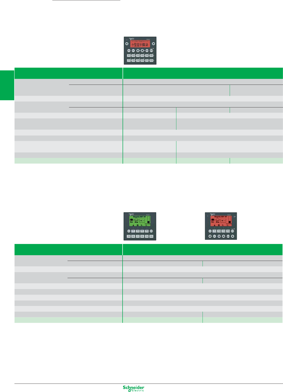
Other versions: please consult your Schneider Electric agency.
Magelis
Type Characteristics
Display Capacity 4 lines, 20 characters
Type Back-lit LCD
green
Back-lit LCD, 3 colours
green, orange, red
Data entry Via keypad with 20 keys (12 customizable keys)
Function Representation of variables Alphanumeric, bargraph, curves, button and light
Alarm log Yes Yes Yes
Communication Serial link 1 RJ45 (RS 232 - RS 485) 1 Sub-D25 (RS 232 - RS 485) + 1 miniDin (RS232)
Downloadable protocols Uni-TE, Modbus Master Uni-TE,Modbus Master/Slave (1), Siemens, Rockwell,
Omron, Mitsubishi, Zelio (1)
Development software Vijeo Designer Lite (on Windows XP and Vista)
Dimensions W x D x H 137 x 37 x 118 mm
Compatibility with PLCs Twido, Modicon TSX Micro,
Modicon Premium, Modicon M340
Twido, Modicon TSX Micro, Modicon Premium, Modicon Quantum,
Modicon Momentum, Modicon M340, Zelio (1)
Supply voltages 5 VDC or PLC power supply 24 VDC
References XBTR400 XBTR410 XBTR411
(1) For XBTR411 only
Magelis XBT RT
with semi-graphic and touchscreen
Type Characteristics
Display Capacity 10 lines, 33 characters
Type Back-lit LCD green Back-lit LCD green, orange, red
Data entry Via keypad with 12 keys (10 customizable keys) or touchscreen
Functions Representation of variables Alphanumeric, bargraph, curves, button and light
Alarm log Yes Yes
Communication Serial link 1 RJ45 (RS 232 - RS 485) + 1 miniDin (RS232) (2)
Downloadable protocols Uni-TE, Modbus Master, Siemens, Rockwell,Omron, Mitsubishi
Development software Vijeo Designer Lite (on Windows XP and Vista)
Dimensions W x D x H 137 x 37 x 118 mm
Compatibility with PLCs Twido, Modicon TSX Micro, Modicon Premium, Modicon M340, Modicon Quantum, Zelio (2)
Supply voltages 5 VDC or PLC power supply 24 VDC
References XBTRT500 XBTRT511
(2) For XBTRT511 only
Small Panel
Magelis XBT R
with matrix, semi-graphic screen (1)
2/34
2
1
3
4
5
6
7
8
9
10
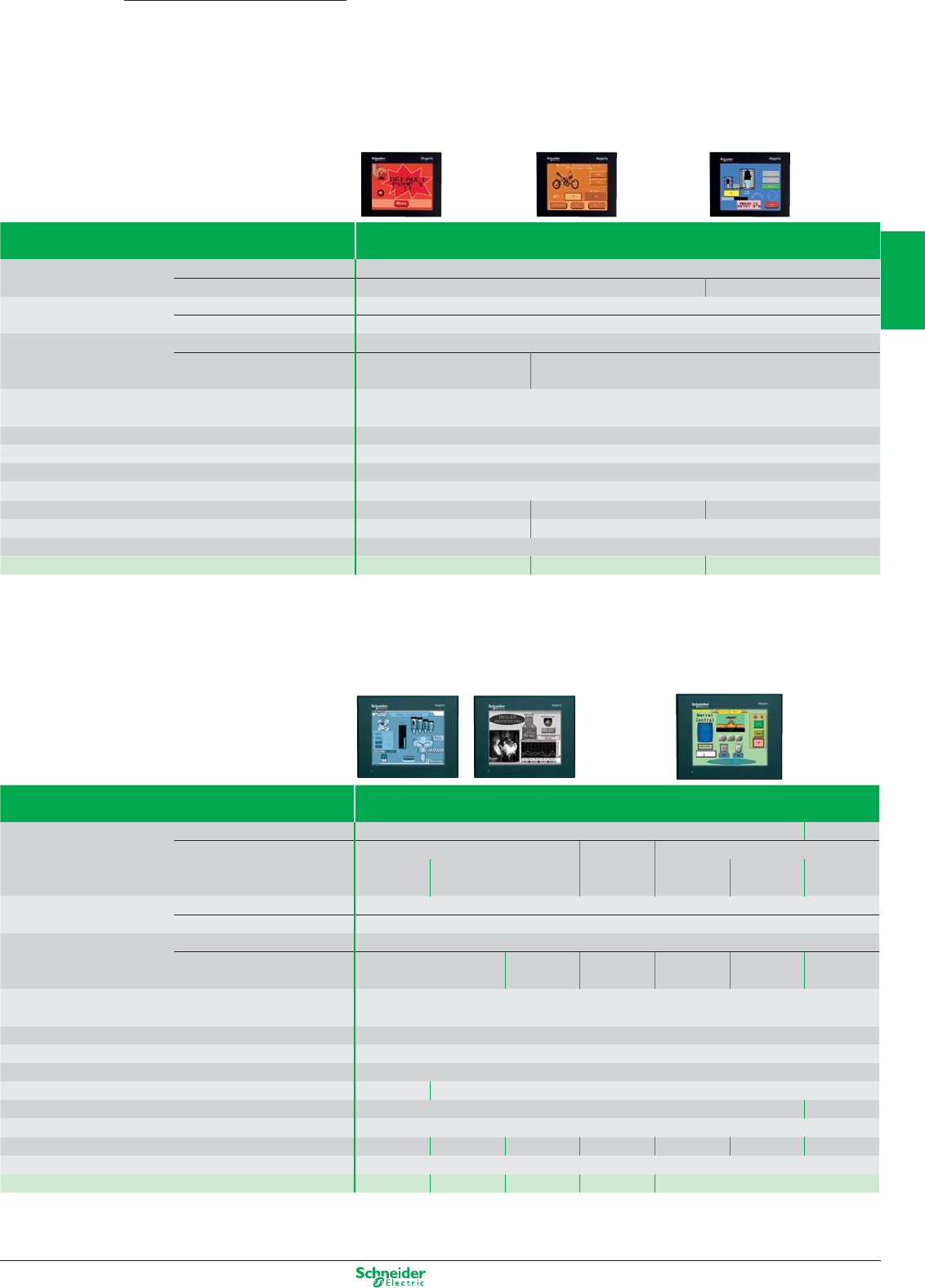
Other versions: please consult your Schneider Electric agency.
Magelis Advanced Panel
Magelis XBT GT
with 3.8” touchscreen
Type Characteristics
Display LCD screen size / Resolution 3.8” / QVGA
Type STN monochrome, amber or red TFT 256 colour
Functions Representation of variables Alphanumeric, bitmap, bargraph, gauge, button, light, clock, flashing light, keypad
Curves / Alarm logs Yes, with log / Yes, incorporated
Communication Serial link 1 RJ45 (RS 232 - RS 485)
Networks – Ethernet, IEEE 802.3
10/100 BASE-T, RJ45
Downloadable protocols Mitsubishi (Melsec), Omron (Sysmac), Rockwell Automation (Allen Bradley), Siemens (Simatic)
Uni-TE, Modbus, Modbus TCP
Development software Vijeo Designer VJDpppTGpVppM (on Windows XP, Vista and 7)
Dimensions W x D x H 130x41x104mm
Compatibility with PLCs Twido, Modicon TSX Micro, Modicon Premium, Modicon Quantum, Modicon M340
«Compact Flash» card slot No
USB port Host type A 1 1 1
Built-in Ethernet TCP/IP No Yes
Supply voltage 24 VDC
References XBTGT1105 XBTGT1135 XBTGT1335
Magelis XBT GT
with 5.7” touchscreen
Type
Type Characteristics
Display LCD screen size / Resolution 5.7” / QVGA 5.7” / VGA
Type STN Monochrome STN, colour TFT, colour 65536 colours
Blue
backlighting
Black and White
backlighting
4096 colours
High brightness
backlighting
Functions Representation of variables Alphanumeric, bitmap, bargraph, gauge, button, light, clock, flashing light, keypad
Curves / Alarm logs Yes, with log / Yes, incorporated
Communication Serial link 1 Sub-D9 (RS 232/RS 422 - RS 485) + 1 RJ45 (RS 485)
Networks
–
Ethernet, IEEE 802.3
–
Ethernet, IEEE 802.3 Ethernet Ethernet, IEEE 802.3
10/100 BASE-T, RJ45 10/100 BASE-T, RJ45 10/100 BASE-T 10/100 BASE-T, RJ45
Downloadable protocols Mitsubishi (Melsec), Omron (Sysmac), Rockwell Automation (Allen Bradley), Siemens (Simatic)
Uni-TE, Modbus, Modbus TCP/IP
Development software Vijeo Designer VJDpppTGpVppM (on Windows XP, Vista and 7)
Dimensions W x D x H 167.5x60x135mm
Compatibility with PLCs Twido, Modicon TSX Micro, Modicon Premium, Modicon Quantum, Modicon M340, Modicon Momentum
«Compact Flash» card slot No Yes
USB port Host type A 1 2
Video in No
Built-in Ethernet TCP/IP No No Yes No Yes Yes Yes
Supply voltage 24 VDC
References XBTGT2110 XBTGT2120 XBTGT2130 XBTGT2220 XBTGT2330 XBTGT2930 XBTGT2430
2/35
2
1
3
4
5
6
7
8
9
10
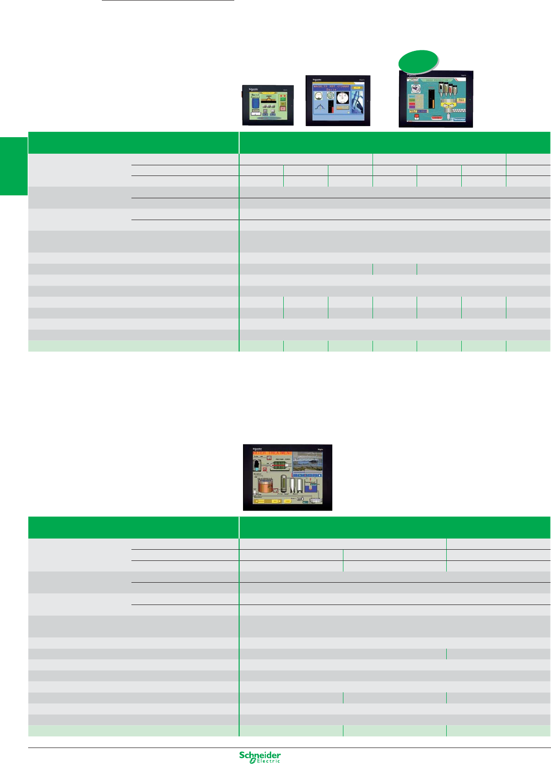
Other versions: please consult your Schneider Electric agency.
Magelis Advanced Panel
Magelis XBT GT
with 7.5” and 10.4” touchscreen
Type Characteristics
Display LCD screen size / Resolution 7.5” / VGA 10.4” / VGA 10,4” / SVGA
Type (colour) STN TFT TFT STN TFT TFT TFT
Number of colours 4096 65536 65536 4096 65536 65536 65536
Functions Representation of variables Alphanumeric, bitmap, bargraph, gauge, button, light, clock, flashing light, keypad
Curves / Alarm logs Yes, with log / Yes, incorporated
Communication Serial link 1 Sub-D9 (RS 232/RS 422 - RS 485) + 1 RJ45 (RS 485)
Networks Ethernet, IEEE 802.3 10/100 BASE-T, RJ 45
Downloadable protocols Mitsubishi (Melsec), Omron (Sysmac), Rockwell Automation (Allen Bradley), Siemens (Simatic)
Uni-TE, Modbus, Modbus TCP/IP
Development software Vijeo Designer VJDpppTGpVppM (on Windows XP, Vista and 7)
Dimensions W x D x H (mm) 215x60x170 313x56x239 271x57x213
Compatibility with PLCs Twido, Modicon TSX Micro, Modicon Premium, Modicon Quantum, Modicon M340
«Compact Flash» card slot Yes
USB port Host type A 1112222
Video in No No Yes No No Yes No
Built-in Ethernet TCP/IP Yes
Supply voltage 24 VDC
References XBTGT4230 XBTGT4330 XBTGT4340 XBTGT5230 XBTGT5330 XBTGT5340 XBTGT5430
Magelis XBT GT
with 12.1” and 15” touchscreen
Type Characteristics
Display LCD screen size / Resolution 12,1” / SVGA 15” / XGA
Type (colour) TFT TFT TFT
Number of colours 65536 65536 65536
Functions Representation of variables Alphanumeric, bitmap, bargraph, gauge, button, light, clock, flashing light, keypad
Curves / Alarm logs Yes, with log / Yes, incorporated
Communication Serial link 1 Sub-D9 (RS 232/RS 422 - RS 485) + 1 RJ45 (RS 485)
Networks Ethernet, IEEE 802.3 10/100 BASE-T, RJ 45BASE-T, RJ 45
Downloadable protocols Mitsubishi (Melsec), Omron (Sysmac), Rockwell Automation (Allen Bradley), Siemens (Simatic)
Uni-TE, Modbus, Modbus TCP/IP
Development software Vijeo Designer VJDpppTGpVppM (on Windows XP, Vista and 7)
Dimensions W x D x H (mm) 313x56x239 395x60x294
Compatibility with PLCs Twido, Modicon TSX Micro, Modicon Premium, Modicon Quantum, Modicon M340
«Compact Flash» card slot Yes
USB port Host type A 2
Video in No Yes Yes
Built-in Ethernet TCP/IP Yes
Supply voltage 24 VDC
References XBTGT6330 XBTGT6340 XBTGT7340
New
2/36
2
1
3
4
5
6
7
8
9
10
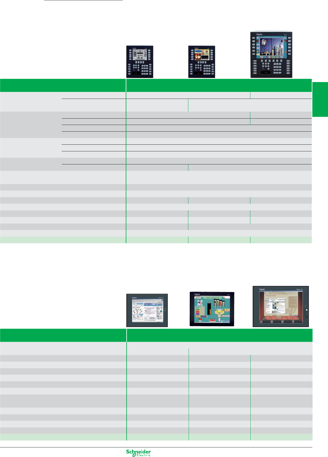
Other versions: please consult your Schneider Electric agency.
Magelis
Type Characteristics
Pre-installed Software
OS: Windows XP Embedded, Internet Explorer, Office & Acrobat Reader, .NET, Vijeo Designer Run Time unlimited
– Vijeo Citect Web Client
Touchscreen 8.4 LCD TFT 12 LCD TFT 15 LCD TFT
Resolution SVGA 800 x 600 SVGA 800 x 600 XGA 1024 x 768
Font panel ports – 1 x USB 1 x USB
Processor Celeron M @ 600 MHz Celeron M @ 1 GHz Celeron M @ 600 MHz
RAM 512MB ► 1024MB 512MB ► 1024MB 512MB ► 1024MB
Storage CF 1GB expandable to 4GB CF 2GB expandable to 4GB CF 2GB expandable to 4GB
Extension – 1 x PCMCIA slot
(for 1 type II card)
1 PCMCIA slot (for 1 type III card
or 2 type I cards)
Ethernet ports 2 (10/100/1G + 10/100) 2 (10/100/1G + 10/100) 2 (10/100/1G + 10/100)
Ports I/O 4 x USB, 2 x RS232 4 x USB, 1 x RS232 4 x USB, 2 x RS232
Power supply 24 VDC 24 VDC 24 VDC
Dimension 230 x 177 x 65 313 x 239 x 60 395 x 294 x 65
References XBTGTW450 XBTGTW652 XBTGTW750
Advanced Panel
Magelis XBT GK
with touchscreen and keypad
Magelis XBT GTW
with 8.4”, 12”, 15” touchscreen
Type Characteristics
Display Screen size / Resolution 5.7” / QVGA 10.4” / VGA
Type STN monochrome
black and white
TFT Colour
65536 colours
Data entry Soft function keys with LED 14 18
Static function keys with LED 10 + legends 12 + legends
Service keys / Alphanumeric keys 8 / 12
Touchscreen and industrial pointer Yes
Functions Representation of variables Alphanumeric, bitmap, bargraph, gauge, button, light, clock, flashing light, keypad
Curves Yes, with log
Alarm logs Yes
Communication Serial link 1 Sub-D9 (RS 232/RS 422 - RS 485) + 1 RJ45 (RS 485)
Networks – Ethernet, IEEE 802.3 10/100 BASE-T, RJ 45
Downloadable protocols Mitsubishi (Melsec), Omron (Sysmac), Rockwell Automation (Allen Bradley), Siemens (Simatic)
Uni-TE, Modbus, Modbus TCP/IP
Development software Vijeo Designer VJDpppTGpVppM (on Windows XP, Vista and 7)
«Compact Flash» card slot Yes
Dimensions W x D x H 220,3x88x265mm 296x91x332mm 197x92,6x147mm
Compatibility with PLCs Twido, Modicon TSX Micro, Modicon Premium, Modicon Quantum, Modicon M340
USB port 112
Video in No No No
Built-in Ethernet TCP/IP No Yes
Supply voltage 24 VDC
References XBTGK2120 XBTGK2330 XBTGK5330
2/37
2
1
3
4
5
6
7
8
9
10
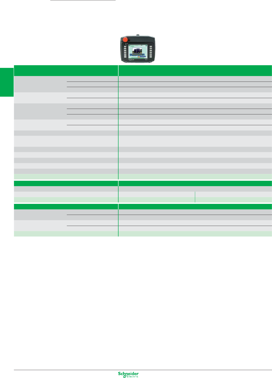
Other versions: please consult your Schneider Electric agency.
Magelis
Type
Characteristics
+
Screen
Display screen size / Resolution
5,7" / VGA
Type (colour)
TFT
Number of colours
65 536
Data entry Function keys 11 + label
Operaton key 1 with LED (validation touchscreen)
Safety components Key Switch Yes for ON/OFF
3 positions Enable switch Yes, OK signal in intermediate position only
Emergency stop Yes, red with 2 safe contacts and one auxiliary contact
Functions Representation of variables Alphanumeric, bitmap, bargraph, gauge, button, light, clock, fl ashing light, keypad
Curves / Alarm historic Yes, with log / Yes, incorporated
Connection 24-pins connector (communication, alimentation, I/O)
Downloadable protocols Mitsubishi (Melsec), Omron (Sysmac), Rockwell Automation (Allen Bradley), Siemens (Simatic)
Uni-TE, Modbus, Modbus TCP/IP
Development software Vijeo Designer VJDpppTGpVppM (on Windows XP, Vista and 7)
«Compact Flash» card slot
Yes
Dimensions W x D x H (mm)
224 x 174 x 87,1
USB port
1
Supply voltage
24 VDC
Reference
XBT GH2460
+Cable interface connection with junction box
Type of connector 2 x 24-pins speed connectors
Length 3 m 10 m
Reference XBTZGHL3 XBTZGHL10
+Junction box connection with PLCs
Communcation Serial link 1 SubD9 (RS232 / RS422 - RS 425)
Network 1 Ethernet RJ45 IEEE 802.3 10/100 T-BASE,
Connection 24 pins connector Interface cable 3 or 10 m
Screw terminals blocks For alimentation 24 VDC, state of I/O safety components
Reference XBTZGJBOX
Advanced Panel
Magelis XBT GH
with 5.7” touchscreen
2/38
2
1
3
4
5
6
7
8
9
10
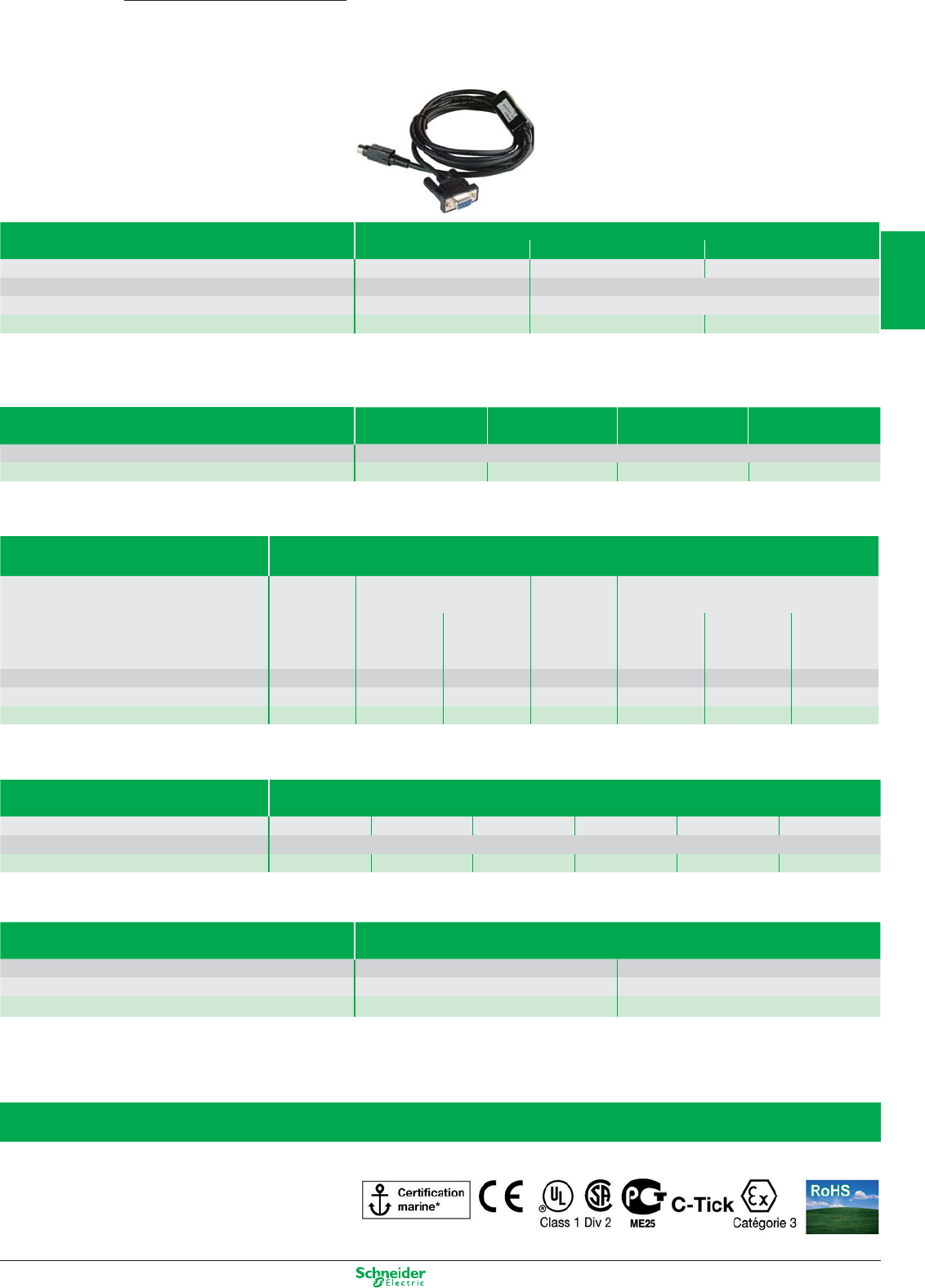
Other versions: please consult your Schneider Electric agency.
Magelis
All in One
Advanced Panel
Accessories
Connection cables PC to Magelis transfer cables
2.5 m 2 m 1,8 m
Application PC to
XBTN / R / RT
PC to
XBTGT / GK / GTW
PC to HMI STO/STU
Type of connector RJ45/RJ45 USB/USB
Physical link RS 485 –
References XBTZ925 (1) XBTZG935 BMXXCAUSBH018
(1) Adaptor TSXCUSB485 for linking USB port of PC, to be used with connecting cables XBTZ925
Cards and gateways for fieldbus Modbus Plus FIPWAY / FIPIO Profibus DP Device Net
Application XBTGT/GK
References XBTZGUMP TSXCUSBFIP XBTZGPDP XBTZGDVN
Connection cables PLC connection cables (2.5 m)
Application XBTN401,
XBTR411,
XBTRT511,
Zelio
XBTGT, GK, N200, N400, R400
XBTGT,GK,GTW
XBT N410, N401, R410, R411
RT, HMI STO/STU to: to:
Modicon M340 Twido,
Modicon Quantum
Twido
Modicon Quantum
Modicon M340
Modicon TSX Micro, Modicon TSX Micro,
Modicon Premium Modicon Premium
Type of connector
miniDin, Zelio port
RJ45/RJ45 RJ45 / MiniDin
SUB D 9 / SUB D 9 MiniDin / SUB D 25
SUB D 9 / SUB D 25
RJ45 / SUB D 25
Physical link RS 232 RS 485 RS 485 RS 232 RS 485 RS 232 RS 485
References SR2CBL08 XBTZ9980 XBTZ9780 990NAA26320 XBTZ968 XBTZ9710 XBTZ938
«Compact Flash» card
Memory 128 Mo 256 Mo 512 Mo 1 Go 2 Go 4 Go
Application XBT GT / GK / GH / GTW
References XBTZGM128 XBTZGM256 MPCYN00CFE00N MPCYN00CF100N MPCYN00CF200N MPCYN00CF400N
Connection cables off-set USB
Application XBT GT / GC / GK / GTW and HMI STO / STU HMI STO/STU
Type of connector USB A / USB A USB miniB / USB miniB
Reference XBTZGUSB HMIZSUSBB
Certifications Magelis XBT range: Depending on model*
* For more information, consult your HMI catalog.
2/39
2
1
3
4
5
6
7
8
9
10
Other versions: please consult your Schneider Electric agency.
Magelis
All in One
HMI Controllers
Magelis XBT GC
Compact HMI Controller
Type Characteristics
Display LCD screen size / Resolution 3,8” / QVGA 5,7” / QVGA
Type STN monochrome, amber or red STN monochrome, gray STN 4096 colours
Functions Representation of variables Alphanumeric, bitmap, bargraph, gauge, button, light, clock, flashing light, keypad
Curves / Alarm logs Yes, with log / Yes, incorporated
Control 5 languages IEC
Communication Serial link – 1 Sub9 (RS 232/RS 422 - RS 485)
Networks – –
Ethernet, IEEE 802.3
10/100 BASE-T, RJ45
Downloadable protocols Mitsubishi (Melsec), Omron (Sysmac), Rockwell Automation (Allen Bradley), Siemens (Simatic)
Uni-TE, Modbus, Modbus TCP
Development software SoMachine (on Windows XP and Vista)
Dimensions W x D x H 130x76x104mm 207x76x157mm
Compatibility with PLCs Twido, Modicon TSX Micro, Modicon Premium, Modicon Quantum, Modicon M340
«Compact Flash» card slot No
USB port Host type A 111
Built-in Ethernet TCP/IP No No Yes
Integrated I/O 12I/6O 24 VDC 16I/16O 24 VDC
Extensions 2 modules TM2
or CANopen module
3 modules TM2
or CANopen module
Supply voltage 24 VDC
References
Source Output
XBTGC1100T XBTGC2120T XBTGC2230T
Sink Output
XBTGC1100U XBTGC2120U XBTGC2230U
Extensions
Type of module CANopen Master
Characteristics Class M10 limited 16 slaves, Standard DS301 V4.O2
References XBTZGCCAN
Type of module Digitals Inputs / Outputs
Characteristics 8I
24 VDC
Screw terminal
16I
24 VDC
Screw terminal
16I
24 VDC
HE10
32I
24 VDC
HE10
8I
120 VAC
Screw terminal
4I 24 VDC
4O Relays
Screw terminal
16I 24 VDC
8O Relays
Screw terminal
References TM2DDI8DT TM2DDI16DT TM2DDI16DK TM2DDI32DK TM2DAI8DT TM2DMM8DRT
TM2DMM24DRF
Type of module Digitals Inputs / Outputs
Characteristics 8O Transistor
24 VDC
Screw terminal
16O Transistor
24 VDC
HE10
32O Transistor
24 VDC
HE10
8O Relays
230 VAC 30 VDC
Screw terminal
16O Relays
230 VAC 30 VDC
Screw terminal
References
Source Output
TM2DD08TT TM2DD016TK TM2DD032TK TM2DRA8RT TM2DRA16RT
Sink Output
TM2DD08UT TM2DD016UK TM2DD032UK ––
Type of module Analog Inputs / Outputs
Characteristics 2I Current/Voltage 2I Thermocouple 4I Current/Voltage
Temperature
8I Current/Voltage 8I Temperature 8I PTC
References TM2AMI2HT TM2AMI2LT TM2AMI4LT TM2AMI8HT TM2ARI8LRJ
TM2ARI8LT
TM2ARI8HT
Type of module Analog Inputs / Outputs
Characteristics 1O Current/Voltage 2O Voltage 2I Current/Voltage
1O Current/Voltage
2I Temperature
1O Current/Voltage
4I Current/Voltage
2O Current/Voltage
References TM2AMO1HT TM2AVO2HT TM2AMM3HT TM2ALM3LT TM2AMM6HT
2/40
2
1
3
4
5
6
7
8
9
10
Other versions: please consult your Schneider Electric agency.
Magelis
All in One
Compact Compact Compact
iPC 8.4” iPC 12” iPC 15”
Pre-installed Software
Windows XP PRO, Vijeo Designer Run Time Demo
Touch screen
8.4” LCD TFT 12” LCD TFT 15” LCD TFT
Resolution
SVGA 800x600 XGA 1024x768 XGA 1024x768
Front side port
– 1 x USB 1 x USB
Processor
Celeron M@1GHz Celeron M@1.5 GHz Pentium M@1.6GHz
RAM
512MB ► 1024MB 512MB ► 1024MB 512MB ► 2GB
1,5GB ► 2GB
Drive devices – – DVD writer
Storage
HDD ≥ 80 GB
HDD ≥ 160 GB or
Flash
disk
15 GB
HDD ≥ 80 GB or
Flash
disk
15 GB
Extension
–
1 PCMCIA slot
(for 1 type II card)
1 PCMCIA slot (for 1 type III card or 2 type I card)
Ethernet ports
2 (10/100/1G + 10/100) 2 (10/100/1G + 10/100) 2 (10/100/1G + 10/100)
I/O ports
4 x USB, 2 x RS 232 4 x USB, 1 x RS 232 4 x USB, 4 x RS 232
Certification
UL508, CSA
UL508, CSA
UL508, CSA, UL1604 (Haz-Loc Class 1, Div 2)
Dimensions 230 x 177 x 120 313 x 239 x 100 395 x 294 x 100
General Purpose
License VJDSNRTMPC for Vijeo
Designer Run Time ≥ 5.1,
unlimited,
to be ordered separately.
AC MPCKT12NAX00N
MPCKT22NAX20N
MPCKT55NAX20N –
(Hard Drive) DC – – MPCKT55NDX20N –
Heavy Duty
AC – MPCKT22MAX20N MPCKT55MAX20N –
(
Flash disk
)SCADA Edition (Vijeo Citect)
AC
Vijeo Citect Lite 1200 I/O
–––
MPCKT55MAX20L
Vijeo Citect Full 500 I/O
–––
MPCKT55MAX20V
Magelis Compact iPC
with 8.4”, 12”, 15” touchscreen
Smart 8.4 Smart 12 Smart 15
Pre-installed Software
OS: Windows XP Embedded, Internet Explorer, Office & Acrobat Reader, .NET
– Vijeo Designer Runtime demo, Vijeo Citect Web Client
Touch screen
8.4” LCD TFT 12” LCD TFT 15” LCD TFT
Resolution SVGA 800x600 SVGA 800x600 XGA 1024x768
Front side port
– 1 x USB 1 x USB
Processor Celeron M@600MHz Celeron M@1GHz Celeron M@600MHz
RAM 512MB ► 1024MB 512MB ► 1024MB 512MB ► 1024MB
Storage
CF 1GB expandable to 4GB CF 2GB expandable to 4GB CF 2GB expandable to 4GB
Extension – 1 x PCMCIA slot
(for 1 type II card)
1 PCMCIA slot (for 1 type III card
or 2 type I cards)
Ethernet ports
2 (10/100/1G + 10/100) 2 (10/100/1G + 10/100) 2 (10/100/1G + 10/100)
I/O ports
4 x USB, 2 x RS 232 4 x USB, RS 232 4 x USB, RS 232
Certification UL 508, CSA 142, Marine (1) UL 508, CSA 142
UL1604 (Haz-Loc Class 1 Div 2)
(1)
Dimensions 230 x 177 x 65 313 x 239 x 60 395 x 294 x 65
iPC without maintenance License VJDSNRTMPC for Vijeo
Designer Run Time ≥ 5.1,
unlimited,
to be ordered separately.
AC MPCST11NAJ00T MPCST21NAJ20T MPCST52NAJ20T
(
Compact Flash disk
)DC MPCST11NDJ00T MPCST21NDJ20T MPCST52NDJ20T
(1) DC version, only
PC Panels
Magelis Smart
with 8.4”, 12”, 15” touchscreen
2/41
2
1
3
4
5
6
7
8
9
10
Other versions: please consult your Schneider Electric agency.
Magelis
BOX
Embedded BOX and PC BOX
Magelis Smart BOX,
Magelis Compact PC BOX
Smart BOX Compact PC BOX
Pre-installed Software
Windows XP PRO, Vijeo Designer Run Time Demo
Processor Celeron M@600MHz Celeron M@1GHz
RAM Default ► Max 256MB ► 1024MB 512MB ► 1024MB
Storage CF 1 GB HDD ≥ 80 GB
Drives ––
Extension – 1 x PCI
Video ports 1 x RGB 1 x RGB
Ethernet ports 2 (10/100/1G + 10/100) 2 (10/100/1G + 10/100)
I/O ports 4 x USB, 2 x RS 232 4 x USB, 2 x RS 232
Certification UL508, CSA, UL1604 (Haz-Loc Class 1 Div 2),
ATEX2-22, Marine DNV (1)
UL508, CSA
Connection for iDisplay Ye s Ye s
for Front Panel No No
Dimensions 218 x 165 x 65 218 x 165 x 115
iPC General Purpose License VJDSNRTMPC for Vijeo
Designer Run Time ≥ 5.1,
unlimited,
to be ordered separately.
AC – MPCKN02NAX00N
(Hard Drive)
iPC without maintenance License VJDSNRTMPC for Vijeo
Designer Run Time ≥ 5.1,
unlimited,
to be ordered separately.
AC MPCSN01NAJ00T (2) –
(Compact Flash disk) DC MPCSN01NDJ00T –
(1) Marine DNV and Atex 2-22 on DC version only
(2) With delivered external alimentation adaptator
Flex PC BOX F Flex PC BOX H
Pre-installed Software
Windows XP PRO, Vijeo Designer Run Time Demo
Processor Celeron
M1,86Ghz
Core Duo 2Ghz Celeron
M1,86Ghz
Core Duo 2Ghz
RAM Default ► Max 512MB>2GB 1GB>2GB 2GB 512MB>2GB 1GB>2GB 2GB
Storage HDD ≥ 160GB with option RAID
or Flash Disk 15GB
HDD ≥ 160GB with option RAID
or Flash Disk 15GB
Drives Reader DVD Engraver DVD Reader DVD
Extension 2PCI 4PCI
Video ports 1 x DVI-I (RGB)
Ethernet ports 2 (10/100/1 G + 10/100)
I/O ports 4 x USB, 4 x RS 232
Certification UL508, cUL, UL1604 (Haz-Loc Class 1 Div 2), ATEX2-22 (1)
Connection for iDisplay Yes
for Front Panel Yes
Dimensions 243 x 160 x 289 243 x 205 x 289
iPC General Purpose License VJDSNRTMPC for Vijeo
Designer Run Time ≥ 5.1,
unlimited,
to be ordered separately.
AC
MPCFN02NAX00N MPCFN05NAX00N
–
MPCHN02NAX00N MPCHN05NAX00N
–
(Hard Drive) DC
MPCFN02NDX00N MPCFN05NDX00N
–
MPCHN02NDX00N MPCHN05NDX00N
–
Heavy Duty (Flash disk) AC
–
MPCFN05MAX00N
––
MPCHN05MAX00N
–
Heavy Duty (Flash disk) Vijeo Citect full 500 I/O AC
––
MPCFN05MAX00V
––
MPCHN05MAX00V
(1) Atex 2/22 for DC version only
Magelis Flex PC BOX
2/42
2
1
3
4
5
6
7
8
9
10
Other versions: please consult your Schneider Electric agency.
Front Panel
Magelis iPC
To be connected only with Magelis Flex PC BOX
15
”
touch & keypad 15
”
touch 19
”
touch
Touchscreen
15” LCD TFT 15” LCD TFT 19” LCD TFT
Resolution XGA 1024x768 XGA 1024x768 SXGA 1280x1024
Front side port
1 x USB 1 x USB 1 x USB
Video ports
1 x VGA & 1 x DVI 1 x VGA & 1 x DVI 1 x VGA & 1 x DVI
Touchscreen ports
1 x USB & 1 x RS 232 1 x USB & 1 x RS 232 1 x USB & 1 x RS 232
Power supply 100…240VAC 100…240VAC 100…240VAC
Certification UL508, CSA UL508, CSA UL508, CSA
Dimensions 483 x 365 x 65 395 x 294 x 60 460 x 390 x 65
References MPCNB50NAN00N MPCYT50NAN00N MPCYT90NAN00N
Magelis
Front Panel
12” touch & keypad 15” touch & keypad
15
”
touch 19
”
touch
Touchscreen
12” LCD TFT 15” LCD TFT 15” LCD TFT 19” LCD TFT
Resolution SVGA 800x600 XGA 1024x768 XGA 1024x768 SXGA 1280x1024
Front side port
1 x USB 1 x USB 1 x USB 1 x USB
Dimensions 420 x 320 x 31 483 x 365 x 31 420 x 320 x 31 460 x 390 x 44
References MPCYB20NNN00N MPCYB50NNN00N MPCYT50NNN00N MPCYT90NNN00N
Industrial Display
Magelis iDisplay
with 15”, 19” touchscreen
2/43
2
1
3
4
5
6
7
8
9
10
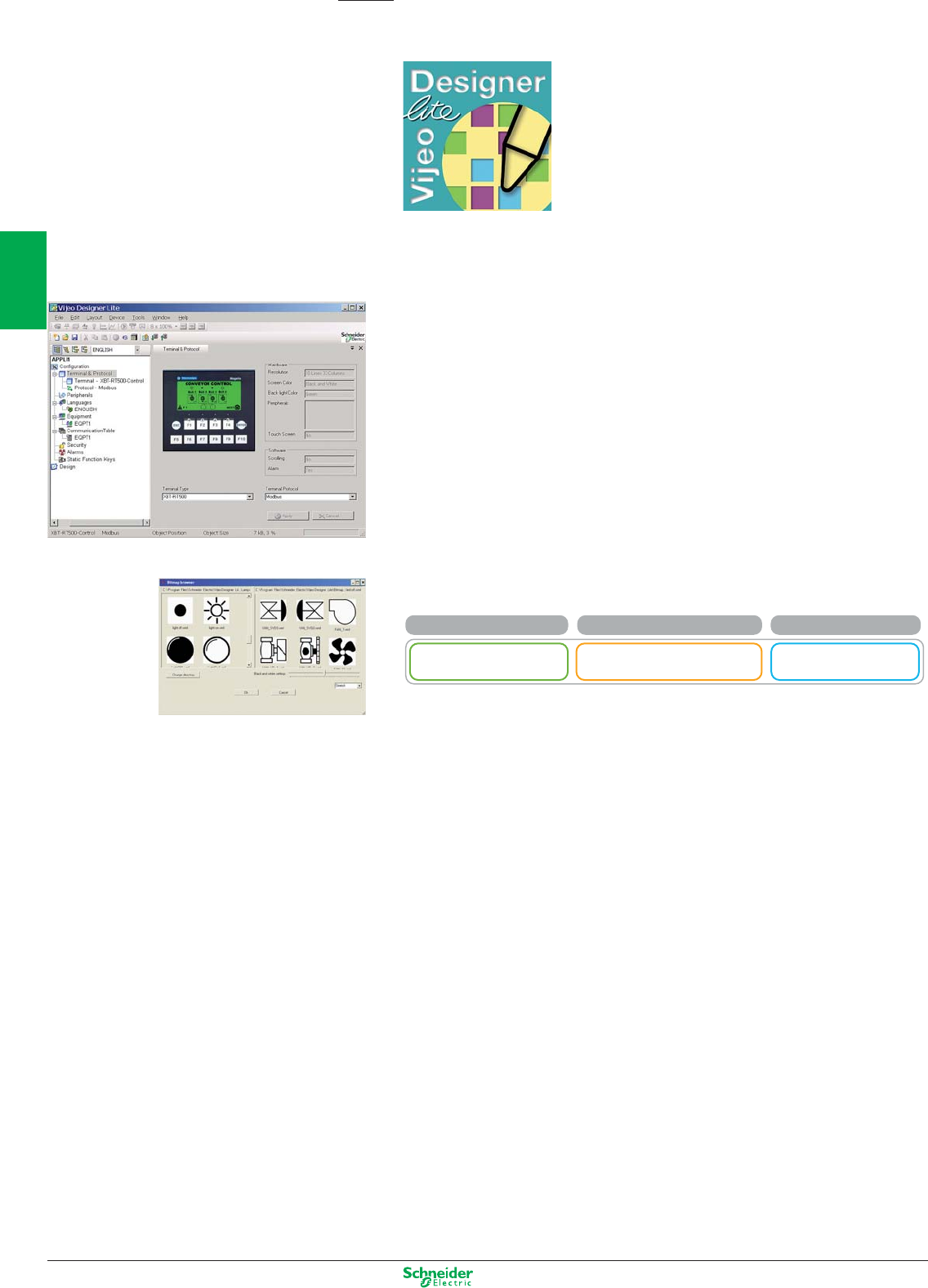
Other versions: please consult your Schneider Electric agency.
Vijeo Designer Lite
Selection guide
Number of licenses Composition References
Single (1) Without cable VJDSNDTMSVppM
With USB cable VJDSUDTMSVppM
Configuration software
Magelis XBT N, R, RT
Vijeo Designer Lite configuration software enables the creation of simple operator dialogue applications
on Magelis XBT N, R and RT Small Panel ranges.
It also enables transparent recovery of all applications for Magelis XBT N and R produced using its
predecessor: XBT L1000.
For simplified installation and improved consistency, Vijeo Designer Lite retains the main characteristics
of Vijeo Designer software (ergonomics, interface ...) which has become the reference in the HMI field.
Configuration
Vijeo Designer Lite software enables fast and easy creation of different types of pages (application page,
alarm pages, help pages...) and the installation of navigation between pages.
It offers:
- Graphic objects developed for Magelis XBT RT (bar charts, trend curves...)
- Character fonts Byzantine, simplified Chinese, Cyrillic, Japanese
- Project reports
- Application simulation on PC
- Six languages : English, French, German, Italian, Spanish and Chinese.
Software is delivered on CD-ROM and can be executed under Windows 2000, XP and Vista.
pp represents version number.
These references are downlodable on Schneider-Electric.com
2/44
2
1
3
4
5
6
7
8
9
10
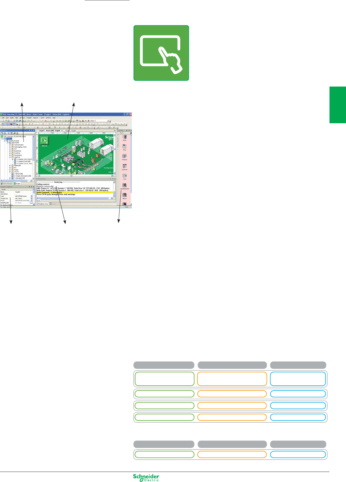
Other versions: please consult your Schneider Electric agency.
Configuration software
Magelis STO/STU, XBT GT, GK, GTW, GH
Magelis Smart, Compact iPC and PC BOX*
Vijeo Designer
Vijeo Designer configuration software enables creation of automated system control operator dialogue
applications for Magelis STO/STU, XBT GT, GK, GTW, GH terminals and Smart & Compact iPC and
PC BOX. It also enables management of the multimedia functions of XBT GTW and Smart & Compact
iPC (video and audio) and offers users of Ethernet terminals and iPC remote access via a Web browser
(WEB Gate function).
Configuration
Vijeo Designer configuration software enables fast, simple processing of operator dialogue projects
thanks to its ergonomics, developed around 6 configurable windows.
It also offers comprehensive application management tools:
. Project creation; projects comprising one or several targets (terminal or iPC).
. Recipe editor (32 groups of 256 recipes of max. 1024 ingredients).
. User action list (eg. script) for application adaptability.
. Application variable cross-referencing.
. Vectorial graphic library for more attractive graphic screens.
. Application block diagram documentation.
. Simulation mode for simple design office application testing.
. High-performance graphic editor for simple block diagram creation (over 30 animated preconfigured generic
objects).
. Support of layers and masks for faster development.
. Data sharing (up to 300 variables on 8 terminals).
. Management of 40 alphabet (including simplified Chinese, Korean, Arabic and Hebrew) with the
opportunity to have 15 languages per application and dynamic change.
. Programmable controller database sharing (Unity Pro, PL7, Concept, TwidoSoft, ProWORX, ModSoft),
process variables or operators actions
. Advanced traceability function (periodic, at event or on request).
. Project backup on terminal for simple maintenance.
. User-friendly data recovery tool.
. Support of standard USB peripherals (USB key up to 4 GB).
. Support of external USB keyboards and mice.
. Integration with Schneider Electric equipment (buffer diag., variables access, Unity DDT and unlocated
variables.)
. Event-triggered e-mail funtion
. Over 35 third party protocols
. Multilingual software : English, French, German, Italian, Spanish, Portuguese and Simplified Chinese.
. Printing function
The Vijeo Designer Limited Edition, downloadable or free access allows you to configure the Magelis
STO/STU.
* Available with Vijeo Designer ≥ 5.0
Navigator Application
Property
Inspector
Feedback zone Animated
graphical
objects
library
Selection guide
The software is supplied on DVD and runs under Windows XP, Windows Vista and Windows 7.
pp represent the version number.
Number of licences Composition References
Single (1) Without cable VJDSNDTGSVppM
With USB cable VJDSUDTGSVppM
Group (3) Without cable VJDGNDTGSVppM
Team (10) Without cable VJDTNDTGSVppM
Facility (Unlimited) Without cable VJDFNDTGSVppM
Runtime pour Magelis iPC Composition References
Single (1) Without cable VJDSNRTMPC
2/45
2
1
3
4
5
6
7
8
9
10
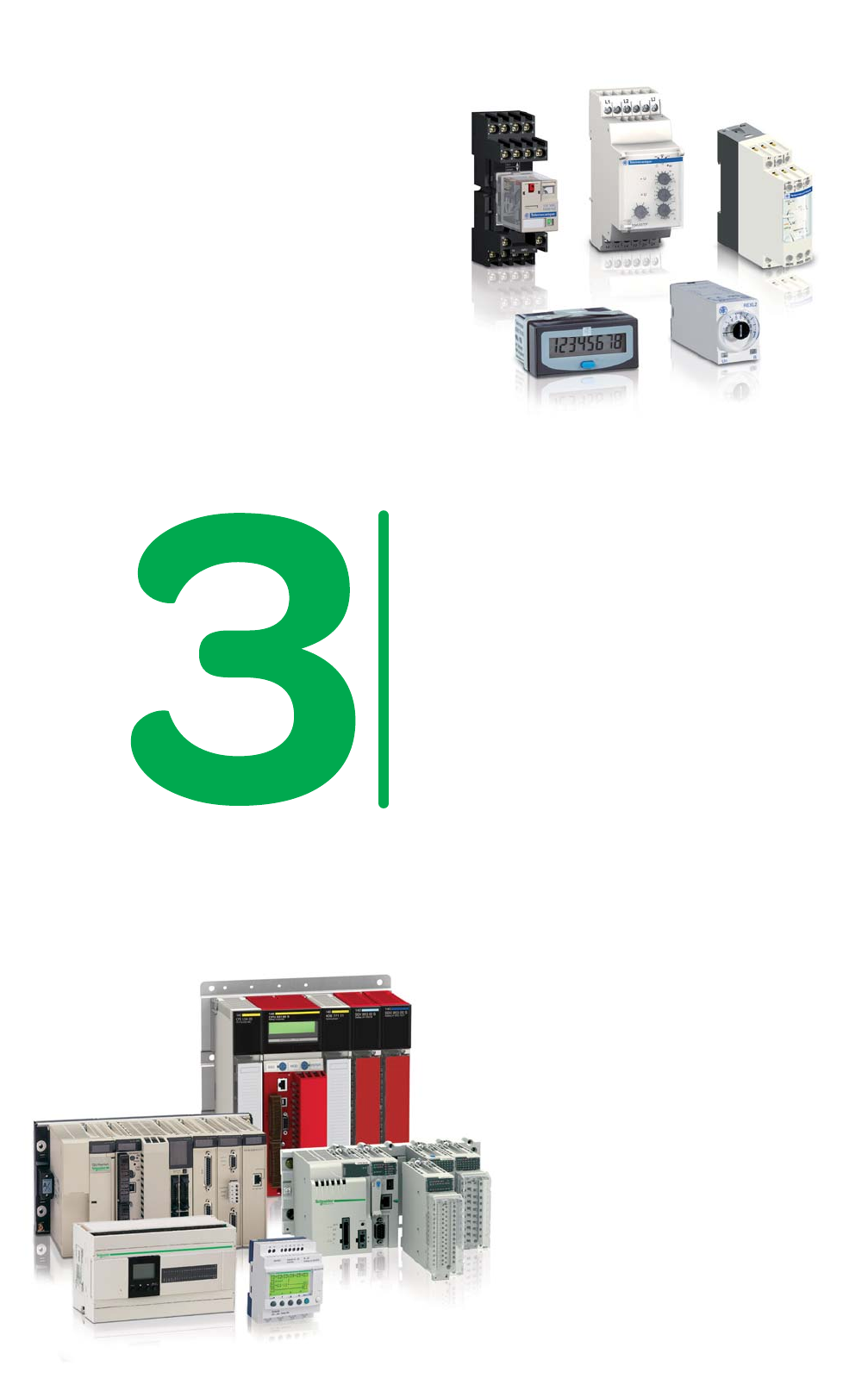
Today automation is everywhere.
To answer your needs Schneider Electric
provides a very complete offer of
automation products, in a wide range
of applications.
Benefit from competitive and efficient
products tailor-made to reduce your
energy consumption and increase the
safety of personnel and equipment while
protecting the environment.
Zelio
Intended for all automation applications using
cabled logic and for complementing PLCs using
simple functions (counting, monitoring and
measurement…), the Zelio relay offer assures
optimum results due to its single-function
products.
Modicon
Increase productivity, optimize flexibility, and
ensure the safety of humans and machines are
the main objectives in industrial competition
today.
The Modicon automation platforms incorporate
the latest performing technology, in conformity
with the international standards. They are easy
to use and ready to integrate your automated
systems.

Automation
This document is a selection of
the top selling products.
3/1
2
1
3
4
5
6
7
8
9
10
Relays
Electromechanical plug-in relays, Zelio Relay .................................................................. 3/2 to 3/4
Solid-state relays, Zelio Relay .................................................................................................... 3/5
Control and measurement relays, Zelio Control ............................................................ 3/6 to 3/10
Counters, Zelio Count ...............................................................................................................3/11
Timing relays, Zelio Time .............................................................................................. 3/12 to 3/13
Analog interface, Zelio analog ...................................................................................... 3/14 to 3/15
Smart relays, Zelio Logic .............................................................................................. 3/16 to 3/17
Programmable controllers
Programmable controllers, Twido ................................................................................. 3/18 to 3/21
Programmable Automation Controllers
Programmable Automation Controllers, Modicon M340 ............................................... 3/22 to 3/29
Programmable Automation Controllers, Modicon Premium ......................................... 3/30 to 3/37
Programmable Automation Controllers, Modicon Quantum ........................................ 3/38 to 3/45
Software
Programming software, Zelio Soft 2 ......................................................................................... 3/17
Programming software, Twido Suite ......................................................................................... 3/20
Configuration software, Unity Pro ................................................................................. 3/46 to 3/47
Programming software, PL7, Concept, ProWORX32 .................................................. 3/48 to 3/49
SCADA software, Vijeo Citect .................................................................................................. 3/50
Reporting software, Vijeo Historian ......................................................................................... 3/51
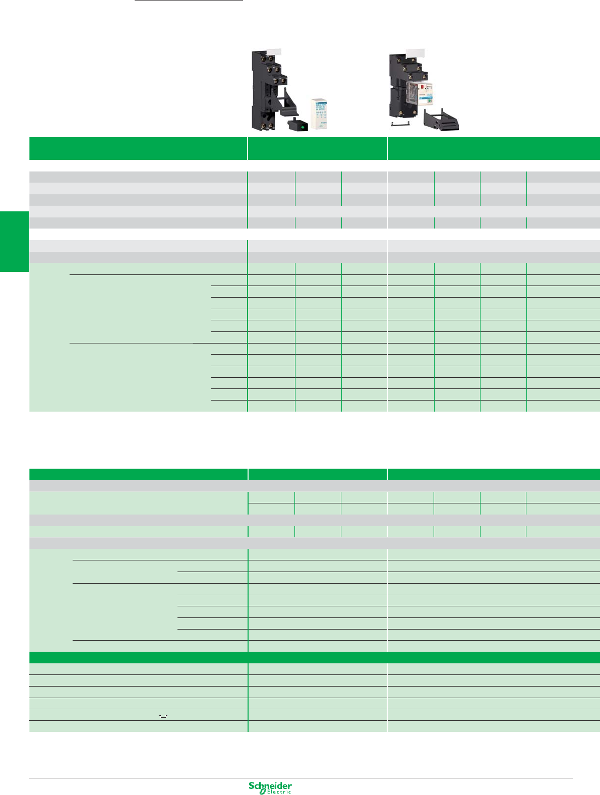
Other versions: please consult your Schneider Electric agency.
Electromechanical plug-in relays
Interface and miniature relays
Type of relay Interface relays Miniature relays
RSB RXM
Contact characteristics
Thermal current Ith in A (temperature ≤ 55°C) 81216121063
Number of contacts 2 “C/O” 1 “C/O” 1 “C/O” 2 “C/O” 3 “C/O” 4 “C/O” 4 “C/O”
Contact material AgNi AgNi AgNi AgNi AgNi AgNi AgAu
Switching voltage, min. / max. 5 / 250 VAC/DC 12 / 250 VAC/DC
Switching capacity, min. / max. (mA / VA) 5 / 2000 5 / 3000 5 / 4000 10 / 3000 10 / 2500 10 / 1500 2 / 1500
Coil characteristics
Average consumption, inrush, 0.75 VA / 0.45 W 1.2 VA / 0.9 W
Permissible voltage variation 0.8/0.85…1.1 Un (50/ 60Hz or =) 0.8…1.1 Un (50 / 60Hz or =)
References (1) (1) (1) (2) (2) (2)
Coil supply voltage 6 VDC
RSB2A080RD RSB1A120RD RSB1A160RD
––––
on DC 12 VDC
RSB2A080JD RSB1A120JD RSB1A160JD RXM2AB2JD RXM3AB2JD RXM4AB2JD RXM4GB2JD
24 VDC
RS
B2A080BD RSB1A120BD RSB1A160BD RXM2AB2BD RXM3AB2BD RXM4AB2BD RXM4GB2BD
48 VDC
RSB2A080ED RSB1A120ED RSB1A160ED RXM2AB2ED RXM3AB2ED RXM4AB2ED RXM4GB2ED
60 VDC
RSB2A080ND RSB1A120ND RSB1A160ND
––––
110 VDC
RSB2A080FD RSB1A120FD RSB1A160FD RXM2AB2FD RXM3AB2ED RXM4AB2ED RXM4GB2ED
Coil supply voltage 24 VAC
RSB2A080B7 RSB1A120B7 RSB1A160B7 RXM2AB2B7 RXM3AB2B7 RXM4AB2B7 RXM4GB2B7
on AC 48 VAC
RSB2A080E7 RSB1A120E7 RSB1A160E7 RXM2AB2E7 RXM3AB2E7 RXM4AB2E7 RXM4GB2E7
120 VAC
RSB2A080F7 RSB1A120F7 RSB1A160F7 RXM2AB2F7 RXM3AB2F7 RXM4AB2F7 RXM4GB2F7
220 VAC
RSB2A080M7 RSB1A120M7 RSB1A160M7
––––
230 VAC
RSB2A080P7 RSB1A120P7 RSB1A160P7 RXM2AB2P7 RXM3AB2P7 RXM4AB2P7 RXM4GB2P7
240 VAC
RSB2A080U7 RSB1A120U7 RSB1A160U7
–––RXM4GB2U7
Sockets for relays
Type of socket For interface relays RSB For miniature relays RXM
Mixed input/output type sockets with location for protection module
–––
RXZE2M114(5)
–RXZE2M114 RXZE2M114
–––
RXZE2M114M(5)
–
RXZE2M114M RXZE2M114M
Separate input/output type sockets with location for protection module
RSZE1S48M RSZE1S35M
RSZE1S48M(3)
RXZE2S108M RXZE2S111M RXZE2S114M RXZE2S114M
Protection modules
Diode 6…230 VDC RZM040W RXM040W
RC circuit 24…60 VAC RZM041BN7 RXM041BN7
110…240 VAC RZM041FU7 RXM041FU7
Varistor 6…24 VDC or AC RZM021RB (6) RXM021RB
24…60 VDC or AC RZM021BN (6) RXM021BN
110…230 VDC or AC RZM021FP (6) RXM021FP
24 VDC or AC ––
240 VDC or AC ––
Multifunction timer module 24…230 VDC or AC ––
Accessories
Plastic maintaining clamp RSZR215 RXZR335
Metal maintaining clamp –RXZ400
Label for socket RSZL300 RXZL420 (except RXZE2M114)
Bus jumper 2 poles – RXZS2
DIN rail adapter –RXZE2DA
Panel mounting adapter –RXZE2FA
(1)
References for relays without socket, for relays with socket, add the letter S to the end of the selected reference. (Example: RSB2A080B7 becomes RSB2A080B7S).
(2) References for relays with LED, for relays without LED, replace the number 1 in the reference by 2. (Example: RXM2AB2JD becomes RXM2AB1JD)
(3) To use RSB 1A160 pp relay with socket, terminals must be interconnected
Zelio Relay
3/2
2
1
3
4
5
6
7
8
9
10
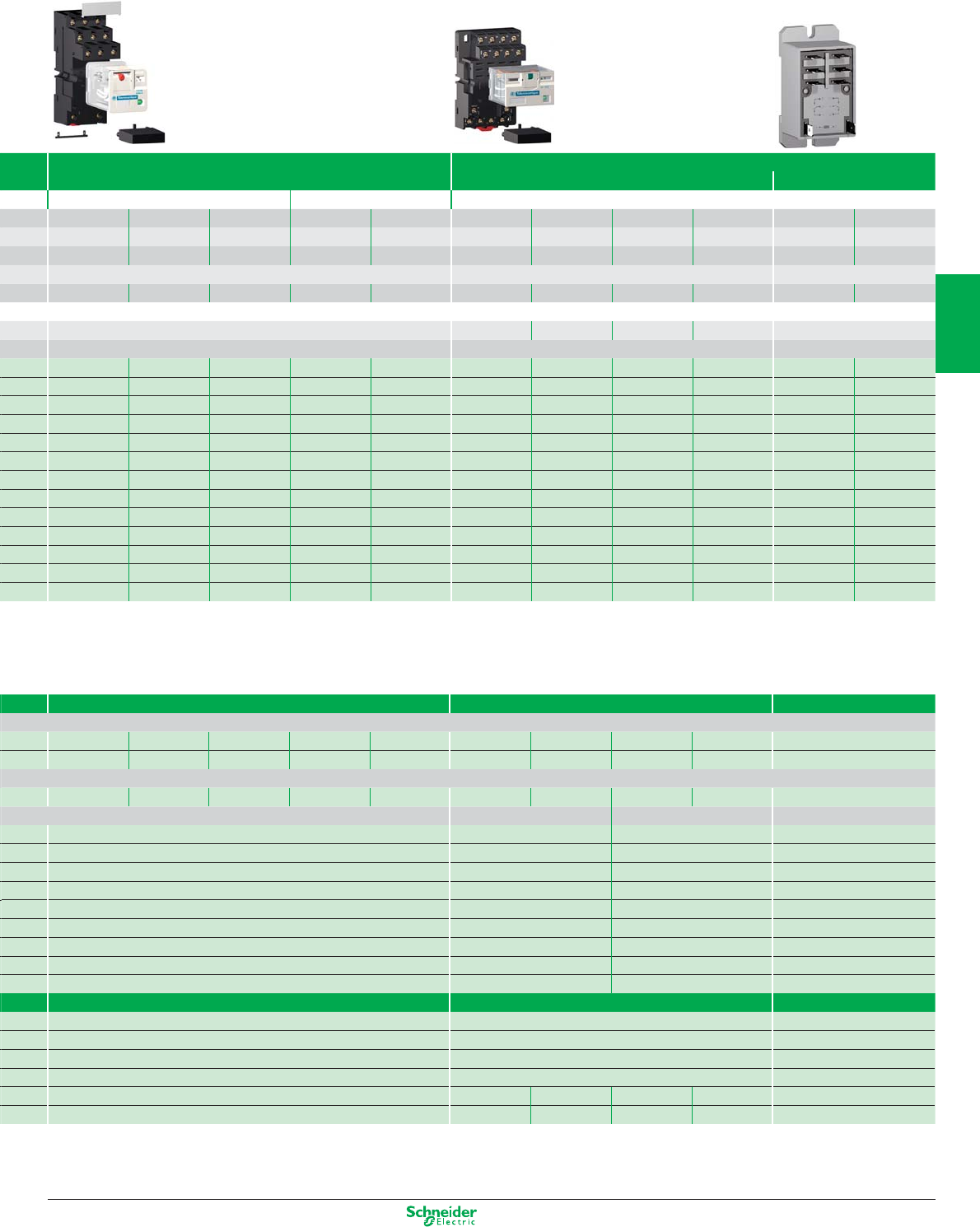
Other versions: please consult your Schneider Electric agency.
Universal and power relays
Universal relays Power relays
RUM RPM RPF
Cylindrics Faston
10 10 3 10 10 15 15 15 15 30 (4) 30 (4)
2 “C/O” 3 “C/O” 3 “C/O” 2 “C/O” 3 “C/O” 1 “C/O” 2 “C/O” 3 “C/O” 4 “C/O” 2 “N/O” 2 “C/O”
AgNi AgNi AgAu AgNi AgNi AgNi AgNi AgNi AgNi AgSnO
2
AgSnO
2
12 / 250 VAC/DC 12 / 250 VAC/DC 12 / 250 VAC/DC
10 / 2500 10 / 2500 3 / 750 10 / 2500 10 / 2500 100 / 3750 100 / 3750 100 / 3750 100 / 3750 100 / 7200 100 / 7200
2…3 VA / 1.4 W 0.9 VA / 0.7 W 1.2 VA / 0.9 W 1.5 VA / 1.7 W 1.5 VA / 2 W 4 VA / 1.7 W
(2) (2) – (2) (2) (2) (2) (2) (2) – –
–––––––––––
RUMC2AB2JD RUMC3AB2JD –RUMF2AB2JD RUMF3AB2JD RPM12JD RPM22JD RPM32JD RPM42JD RPF2AJD RPF2BJD
RUMC2AB2BD RUMC3AB2BD RUMC3GB2BD RUMF2AB2BD RUMF3AB2BD RPM12BD RPM22BD RPM32BD RPM42BD RPF2ABD RPF2BBD
RUMC2AB2ED RUMC3AB2ED RUMC3GB2ED RUMF2AB2ED RUMF3AB2ED RPM12ED RPM22ED RPM32ED RPM42ED
––
–––––––––––
RUMC2AB2FD RUMC3AB2FD –RUMF2AB2FD RUMF3AB2FD RPM12FD RPM22FD RPM32FD RPM42FD RPF2AFD RPF2BFD
RUMC2AB2B7 RUMC3AB2B7 RUMC3GB2B7 RUMF2AB2B7 RUMF3AB2B7 RPM12B7 RPM22B7 RPM32B7 RPM42B7 RPF2AB7 RPF2BB7
RUMC2AB2E7 RUMC3AB2E7 RUMC3GB2E7 RUMF2AB2E7 RUMF3AB2E7 RPM12E7 RPM22E7 RPM32E7 RPM42E7
––
RUMC2AB2F7 RUMC3AB2F7 RUMC3GB2F7 RUMF2AB2F7 RUMF3AB2F7 RPM12F7 RPM22F7 RPM32F7 RPM42F7 RPF2AF7 RPF2BF7
–––––––––––
RUMC2AB2P7 RUMC3AB2P7 RUMC3GB2P7 RUMF2AB2P7 RUMF3AB2P7 RPM12P7 RPM22P7 RPM32P7 RPM42P7 RPF2AP7 RPF2BP7
–––––––––––
For universal relays RUM For power relays RPM For power relays
RPF
RUZC2M RUZC3M RUZC3M ––RPZF1 RPZF2 RPZF3 RPZF4 –
––––––––––
RUZSC2M RUZSC3M RUZSC3M RUZSF3M RUZSF3M –––––
1 and 2 poles 3 and 4 poles
RUW240BD RXM040W RUW240BD –
–RXM041BN7 ––
RUW241P7 RXM041FU7 RUW241P7 –
–RXM021RB ––
–RXM021BN ––
–RXM021FP ––
RUW242B7 RUW242B7 ––
RUW242P7 – RUW242P7 –
RUW101MW –RUW101MW –
–––
RUZC200 RPZF1 (for 1 pole relays) –
RUZL420 ––
RUZS2 ––
–RPZ1DA RXZE2DA RPZ3DA RPZ4DA –
–RPZ1FA RXZE2FA RPZ3FA RPZ4FA –
(4) 30A with 13 mm space between relays; 25 A when relay mounting side by side
(5) Max 10 A operating
(6) With LED
3/3
2
1
3
4
5
6
7
8
9
10
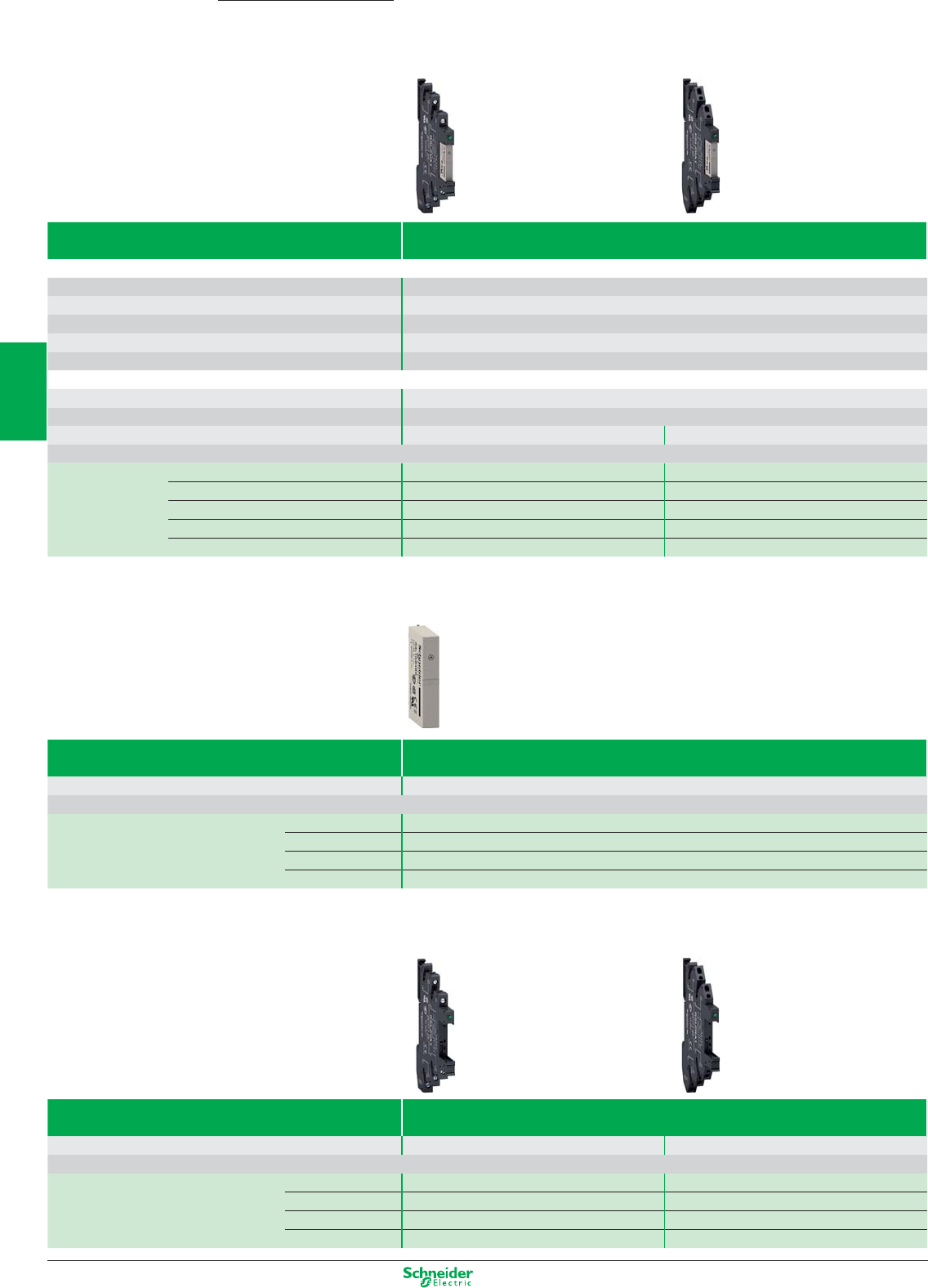
Other versions: please consult your Schneider Electric agency.
Electromechanical plug-in relays
RSL relays mounted on sockets
Zelio Relay
Type of relay Pre-assembled equipped with LED and protection circuit
Sold in lots of 10
Contact characteristics
Thermal current Ith in A 6
Number of contacts 1 C/O
Contact material AgSnO2
Switching voltage, min/max 12 / 300 V AC/DC
Switching capacity min/max (mA /VA) 100 / 1500
Coil characteristics
Average consumption, inrush 0.17 W
permissible voltage variation -10% / +15%
Socket connexion Screw connector Spring terminal
Socket supply voltage Coil supply voltage
References 12 V AC/DC 12 V DC RSL1PVJU RSL1PRJU
24 V AC/DC 24 V DC RSL1PVBU RSL1PRBU
48 V AC/DC 48 V DC RSL1PVEU RSL1PREU
110 V AC/DC 60 V DC RSL1PVFU RSL1PRFU
230 V AC/DC 60 V DC RSL1PVPU RSL1PRPU
RSL relays
Type of relay Relay for customer assembly
Sold in lots of 10
Number of contacts 1 C/O
Coil supply voltage
References 12 V DC RSL1AB4JD
24 V DC RSL1AB4BD
48 V DC RSL1AB4ED
60 V DC RSL1AB4ND
Sockets
Type of socket Sockets for customer assembly with LED and protection circuit
Sold in lots of 10
Socket connection Screw connector Spring terminal
Socket supply voltage
References 12 and 24 V AC/DC RSLZVA1 RSLZRA1
48 and 60 V AC/DC RSLZVA2 RSLZRA2
110 V AC/DC RSLZVA3 RSLZRA3
230 V AC/DC RSLZVA4 RSLZRA4
3/4
2
1
3
4
5
6
7
8
9
10
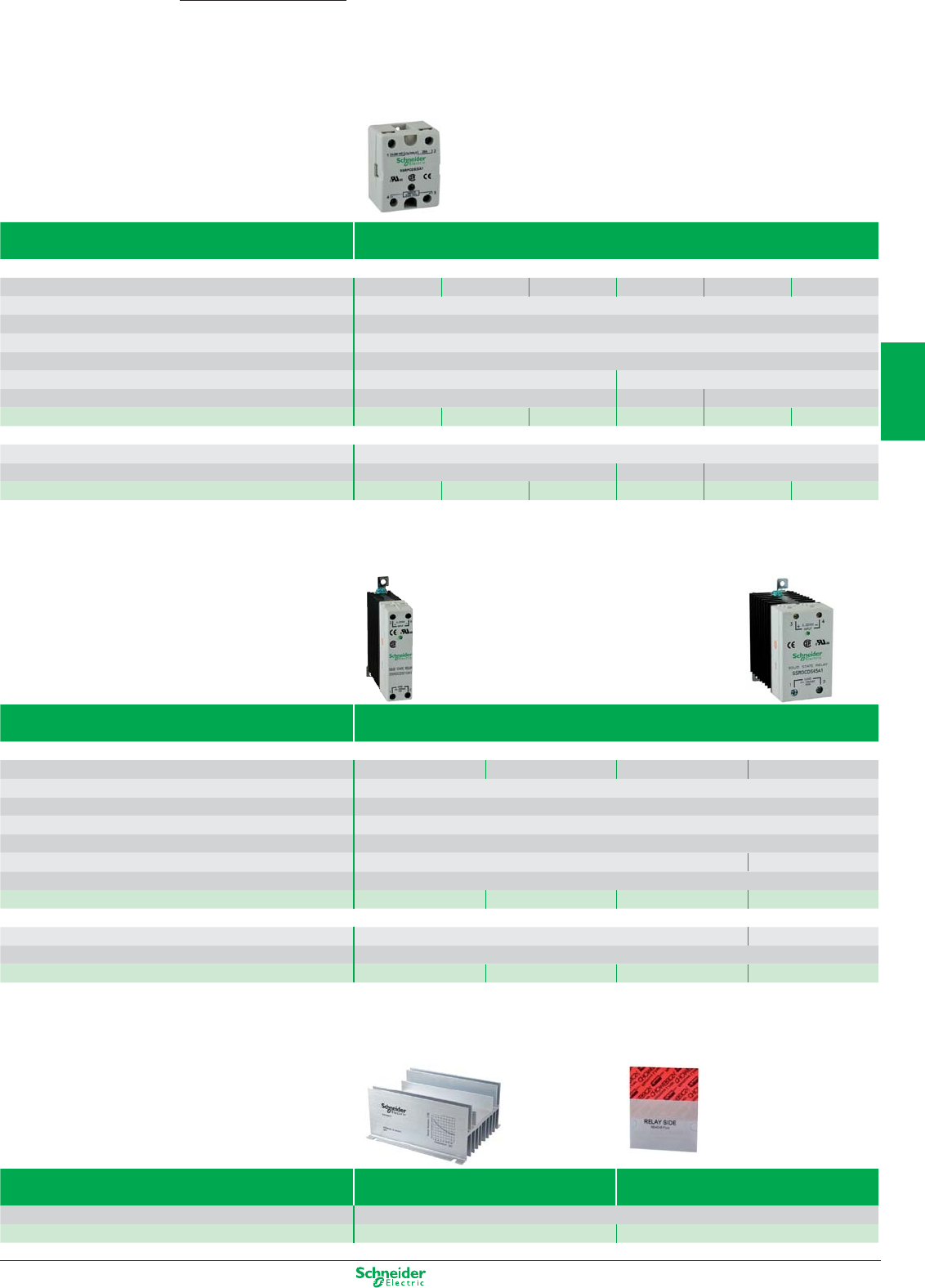
Other versions: please consult your Schneider Electric agency.
Solid-state relays
SSRP relays
Zelio Relay
Type of relay Panel mounted
without heat sink and thermal interface
Contact characteristics
Thermal current Ith in A 10 25 50 75 90 125
Number of contacts 1 NO
Type if switching Zero voltage switching
Output SPST contact
Connection Screw connector
Control voltage range 3…32 V DC 4…32 V DC
Operating voltage 24…280 VAC 48…530 V AC 48…660 V AC
References
SSRPCDS10A1 SSRPCDS25A1 SSRPCDS50A1 SSRPCDS75A2 SSRPCDS90A3
SSRPCDS125A3
Control voltage range 90…280 V AC
Operating voltage 24…280 VAC 80…530 V AC 48…660 V AC
References
SSRPP8S10A1 SSRPP8S25A1 SSRPP8S50A1 SSRPP8S75A2 SSRPP8S90A3 SSRPP8S125A3
SSRD relays
Type of relay Rail DIN mounted
With integrated heat sink
Contact characteristics
Thermal current Ith in A 10 20 30 45
Number of contacts 1 NO
Type if switching Zero voltage switching
Output SPST contact
Connection Screw connector
Control voltage range 4…32 V DC 3…32 V DC
Operating voltage 24…280 VAC
References
SSRDCDS10A1 SSRDCDS20A1 SSRDCDS30A1 SSRDCDS45A1
Control voltage range 90…280 V AC 90…140 V AC
Operating voltage 24…280 VAC
References
SSRDP8S10A1 SSRDP8S20A1 SSRDP8S30A1 SSRDP8S45A1
Accessories
Type of accessory Heat sink Thermal interface
For relay SSRP
References SSRAH1 SSRAT1
3/5
2
1
3
4
5
6
7
8
9
10
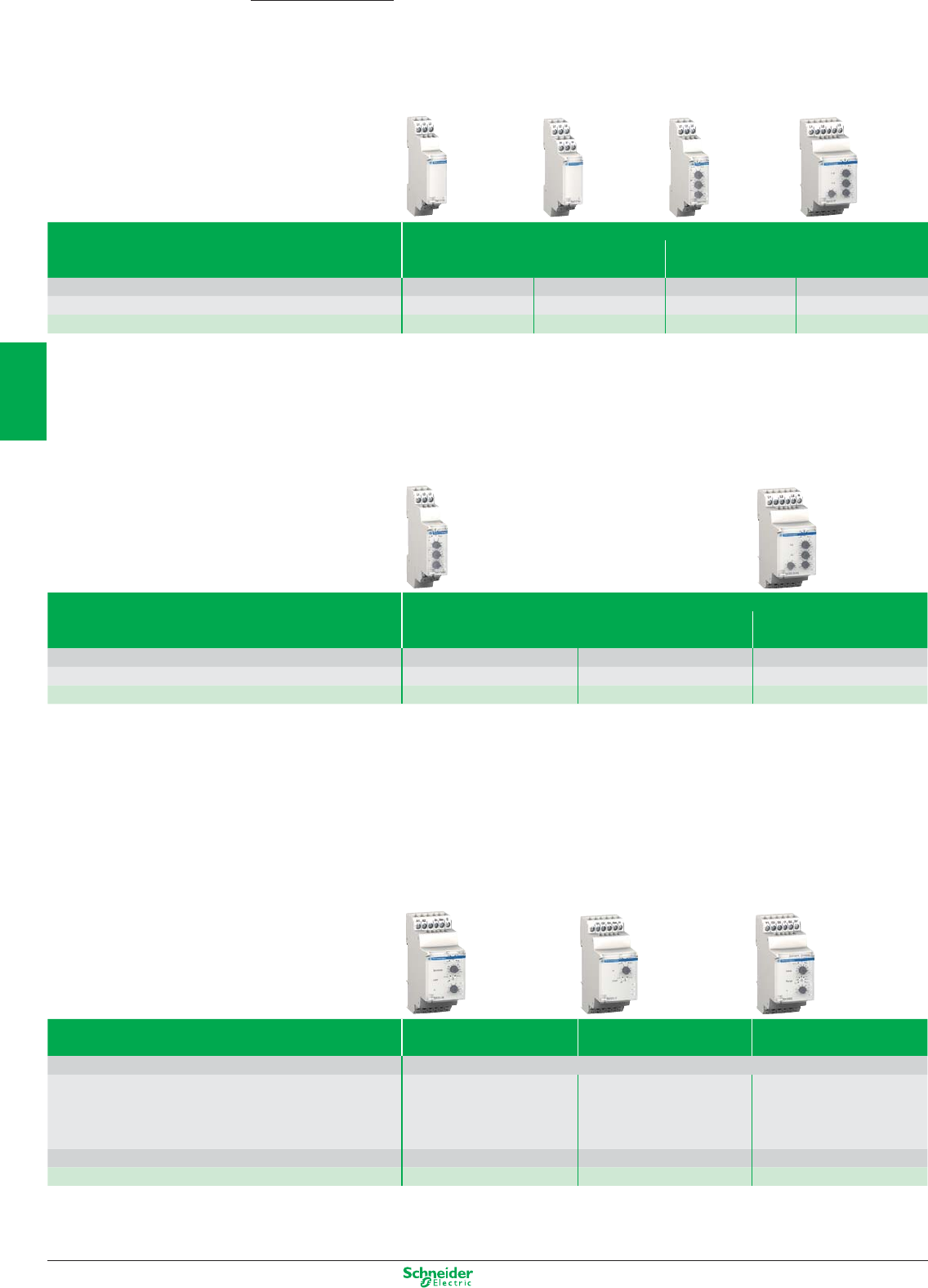
Other versions: please consult your Schneider Electric agency.
Relays
3-phase monitoring relays
Zelio Control
Function presence of phase
+phase sequence +phase sequence, +regeneration
+phase unbalance, +under/over voltage
Monitoring voltage range 208…480 VAC 208…440 VAC 208…480 VAC 220 … 440 VAC
Outputs 1 C/O 2 C/O 1 C/O 2 C/O
References RM17TG00 RM17TG20 RM17TE00 RM35TF30
Function presence of phase
+under/over voltage +presence of neutral
+under/over voltage
Monitoring voltage range 208…480 VAC 220…480 VAC 120…277 VAC (phase-neutral)
Outputs 1 C/O 2 C/O 2 C/O
References RM17UB310 RM35UB330 RM35UB3N30
Level / Speed monitoring relays
Function
Conductive liquid Non-conductive material Over/under
level monitoring level monitoring Speed monitoring
Power supply 24…240 VAC/DC
Monitoring range 0,25…5 KΩInput of sensor : Interval between pulses:
5…100 KΩContact / PNP / NPN 0.05…0.5 s, 0.1…1 s, 0.5…5 s
0,05…1 MΩ1…10 s, 0.1…1 mn, 0.5…5 mn
1…10 mn
Output 2 C/O 1 C/O 1 C/O
Reference RM35LM33MW RM35LV14MW RM35S0MW
3/6
2
1
3
4
5
6
7
8
9
10
Other versions: please consult your Schneider Electric agency.
Current / Voltage /Frequency monitoring relays
Function Voltage Monitoring
Under or Over Voltage
Power Supply 24…240 VAC/DC 50/60Hz
Monitoring range 0.05…0.5 V 1…10 V 15…150 V
0.3…3 V 5…50 V 30…300 V
0.5…5 V 10…100 V 60…600 V
Outputs 2 C/O 2 C/O 2 C/O
References RM35UA11MW RM35UA12MW RM35UA13MW
Function Voltage Monitoring
Under or Over Voltage Under and Over Voltage
Power Supply self powered self powered
Monitoring range 9…15 VDC 20…80 VAC/DC 65…260 VAC/DC 20…80 VAC/DC 65…260 VAC/DC
Outputs 1 C/O 1 C/O 1 C/O 1 C/O 1 C/O
References RM17UAS14 RM17UAS16 RM17UAS15 RM17UBE16 RM17UBE15
Function
Current Monitoring
Frequency Monitoring
Over or under frequency
over curent over or under current
Power supply 24…240 VAC/DC 24…240 VAC/DC 50/60 Hz 120…277 VAC 50/60 Hz
Monitoring range 2…20 A 2…20 mA 0.15…1.5 A 50 Hz ± 10 Hz
built-in CT 10…100 mA 0.5…5 A or
50…500 mA 1.5…15 A 60 Hz ± 10Hz
Output 1 C/O 2 C/O 2 C/O 2 C/O
Reference RM17JC00MW RM35JA31MW RM35JA32MW RM35HZ21FM
3/7
2
1
3
4
5
6
7
8
9
10
Other versions: please consult your Schneider Electric agency.
Relays
Lift / Pump / Motor monitoring relays
Zelio Control
Function Lift motor room temperature monitoring
+phase presence
+phase sequence
Power supply 24…240 VAC/DC 50/60Hz
Monitoring range input PT100 3 wires 208…480 VAC 50/60Hz
Under -1…+11 °C input PT100 3 wires
Over +34…+46 °C Under -1…+11 °C
Over +34…+46 °C
Output 1 C/O 2 NO 2 C/O
Reference RM35ATL0MW RM35ATR5MW RM35ATW5MW
Function Pump protection Motor Protection
Winding Temperature monitor
+3 phase monitor
Current monitor
+3 phase monitor
Power supply self powered 24…240 VAC/DC
(single phase :230 VAC 50/60 Hz)
Monitoring range Current: 0.1…10 A Winding Temperature: PTC sensor
Voltage (three phase): Three phase voltage: 208…480 VAC 50/60Hz
208…480 VAC 50/60Hz
Output 1 C/O 2 NO 2 NO
Reference RM35BA10 RM35TM50MW RM35TM250MW
3/8
2
1
3
4
5
6
7
8
9
10
Other versions: please consult your Schneider Electric agency.
Control relays for 3-phase supplies
Function Rotational direction and presence of phases
+ Undervoltage
+ Over and undervoltage + Asymmetry
Adjustable time delay without without 0.1…10 s 0.1…10 s fixed, 0.5 s 0.1…10 s
Supply voltage 220…440V 380…440V 400V 380…440V 380…440V 380…440V
Output 2 C/O 2 C/O 2 C/O 2 C/O 1 C/O 2 C/O
References RM4TG20 RM4TU02 RM4TR34 (1) RM4TR32 (2) RM4TA02 RM4TA32
(1) Relay with fixed voltage thresholds.
(2) Relay with adjustable voltage thresholds.
Current and voltage measurement relays
Function Detection of
over and undercurrent over and undercurrent
Measuring range 3…30 mA 0.3…1.5 A 0.05 …0.5 V 1…10 V 30…300 V 180…270 V
10…100 mA 1…5 A 0.3 …3 V 5…50 V 50…500 V
0.1…1 A 3…15 A 0.5…5 V 10…100 V
Adjustable time delay 0.05…30 s 0.05…30 s 0.05…30 s 0.05…30 s 0.05…30 s 0.1…10 s
Output 2 C/O 2 C/O 2 C/O 2 C/O 2 C/O 2 C/O
References RM4JA31•• (3) RM4JA32•• (3) RM4UA31•• (3) RM4UA32•• (3) RM4UA33•• (3) RM4UB35
Liquid level control relays
Control relays Empty or fill
Sensitivity scale 5 ... 100 kΩ0.25 ... 5 kΩ
2.5 ... 50 kΩ
25 ... 500 kΩ
Time delay without adjustable, 0.1 to 10 s
Output 1 C/O 2 C/O
References RM4LG01• (4) RM4LA32•• (4)
Liquid level control probe type Measuring electrode and
reference electrode
1 simple stainless steel electrode
in PVC protective casing
Mounting suspended suspended
Maximum operating temperature 100°C 100°C
References LA9RM201 RM79696043
(4) Basic reference. To be completed with the letters
indicating the required voltage, as shown below:
RM4-LG01 RM4-LA32
Voltage VAC, 50/60 Hz VAC, 50/60 Hz VDC
24 V BB –
24…240 V –MWMW
110…130 V FF –
220…240 V MM –
380…415 V QQ –
(3) Basic reference. To be completed with the letters
indicating the required voltage, as shown below:
Voltage VAC, 50/60 Hz VDC
24…240 V MW MW
110…130 V F–
220…240 V M–
380…415 V Q–
3/9
2
1
3
4
5
6
7
8
9
10
Other versions: please consult your Schneider Electric agency.
Measurement and control relays
REG temperature control relays
Zelio Control
Type of relay Size 24 x 48 mm - 1/32 DIN
Input type Thermocouple PT100 probe Voltage/Current 1...5 V / 4…20 mA
Integrated functions Hysteresis, PID, auto-tuning, fuzzy logic, rampe 8 steps, automatic operating mode
Alarm output –1––
Communication ModBus – ModBus ModBus
Supply voltage 100...240 VAC 24 V AC/DC 100...240 VAC 24 V AC/DC
References Number/Output type 1/relay REG24PTP1RHU REG24PTP1ARHU REG24PTP1RLU REG24PUJ1RHU REG24PUJ1RLU
1/solid-state REG24PTP1LHU REG24PTP1ALHU REG24PTP1LLU REG24PUJ1LHU REG24PUJ1LLU
1/4-20 mA REG24PTP1JHU –REG24PTP1JLU ––
Type of relay Format 48 x 48 mm - 1/16 DIN
Input type Universal
Integrated functions Hysteresis, PID, auto-tuning, fuzzy logic, rampe 16 steps, automatic and manual operating mode
Alarm output 2
Communication ModBus – ModBus
Supply voltage 100...240 VAC 24 V AC/DC
References Number/Output type 1/relay REG48PUN1RHU REG48PUNL1ARHU REG48PUN1RLU
2/relay REG48PUN2RHU –REG48PUN2RLU
1/solid-state REG48PUN1LHU REG48PUNL1LHU REG48PUN1LLU
1 + 1 solid-state REG48PUN2RLHU –REG48PUN2RLLU
1/4-20 mA REG48PUN1JHU –REG48PUN1JLU
1/solid-state + 1/4-20 mA
REG48PUN2LJHU –REG48PUN2LJLU
Type of relay Size 96 x 48 mm - 1/8 DIN
Input type Universal
Integrated functions Hysteresis, PID, auto-tuning, fuzzy logic, rampe 16 steps, automatic and manual operating mode
Alarm output 3
Communication ModBus – ModBus
Supply voltage 100...240 VAC 24 V AC/DC
References Number/Output type 1/relay REG96PUN1RHU REG96PUNL1RHU REG96PUN1RLU
2/relay REG96PUN2RHU –REG96PUN2RLU
1/solid-state REG96PUN1LHU REG96PUNL1LHU REG96PUN1LLU
1 + 1 solid-state REG96PUN2RLHU –REG96PUN2RLLU
1/4-20 mA REG96PUN1JHU –REG96PUN1JLU
1/solid-state + 1/4-20 mA
REG96PUN2LJHU –REG96PUN2LJLU
3/10
2
1
3
4
5
6
7
8
9
10
Other versions: please consult your Schneider Electric agency.
Display Mechanical
LCD
Supply voltage 24 VDC Battery
Number of digits displayed 56 6 88
Counting frequency 20 Hz 10 Hz 25 Hz 25 Hz 7.5 kHz
Type of zero reset Manual Without Manual Without Manual
(1)
Front face dimensions, W x H 41.5 x 31 mm 30 x 20 mm 60 x 50 mm 60 x 50 mm 48 x 24 mm
References XBKT50000U10M XBKT60000U00M XBKT60000U10M XBKT80000U00M XBKT81030U33E
(1) With electrical interlocking.
Compteurs horaires
Display Mechanical LCD
Supply voltage 24 VAC 230 VAC Battery
Number of digits / display 7 (99,999.99 h) 7 (99,999.99 h) 8 (999,999.99 h)
Supply frequency 50 Hz 50 Hz Mode: 1/100 hour
Type of zero reset Without Without Manual (1)
Front face dimensions, W x H 48 x 48 mm 48 x 48 mm 48 x 24 mm
References XBKH70000004M XBKH70000002M XBKH81000033E
Totalisers
Display LCD LED
Number of digits displayed 6
Counting frequency 5 kHz
Type of reset Manual, electric and automaticn
Front face dimensions, W x H 48 x 48 mm
Preselection number 1212
References Supply voltage 24 VDC XBKP61130G30E XBKP61230G30E XBKP62130G30E XBKP62230G30E
115 VAC XBKP61130G31E XBKP61230G31E – –
230 VAC XBKP61130G32E XBKP61230G32E XBKP62130G32E XBKP62230G32E
Counters
Multifunction counters
Zelio Count
3/11
2
1
3
4
5
6
7
8
9
10
Other versions: please consult your Schneider Electric agency.
Type of modular timer
width 17.5 mm, relay output
On-delay Multifunction
External control no – –
Supply voltage 24 VDC - 24 ...240 VAC 24 VDC - 24 ...240 VAC 12 ... 240VAC/DC
Timing range 0.1 s…100 h 0.1 s…100 h 0.1 s…10 h 0.1 s…100 h
Output 1 C/O 1 C/O 1 C/O 1 C/O
References RE11RAMU RE11RMMU (1) RE11RMEMU (2) RE11RMMW (1)
(1) Multifunction: On-delay, Off-delay, Totaliser, Symmetrical flashing, Chronometer, Pulse on energisation, Pulse output, Timing after closing/opening of control contact.
(2) Multifunction: On-delay, Off-delay, Totaliser, Symmetrical flashing, Chronometer, Pulse on energisation.
Type of modular timer
width 17.5 mm, relay output
Asymmetrical
flashing
Pulse on
energisation
Off delay Timing on
impulse
External control ––– –
Supply voltage 24 VDC - 24…240 VAC 24 VDC - 24…240 VAC 24 VDC - 24…240 VAC 24 VDC - 24…240 VAC
Timing range 0.1 s…100 h 0.1 s…100 h 0.1 s…100 h 0.1 s…100 h
Output 1 C/O 1 C/O 1 C/O 1 C/O
References RE11RLMU RE11RHMU RE11RCMU RE11RBMU
Type of modular timer
width 17.5 mm, solid-state output
On-delay Off-delay Multifunction (3)
Supply voltage 24…240 VAC/DC 24…240 VAC 24…240 VAC
Timing range 0.1 s…100 h 0.1 s…100 h 0.1 s…100 h
Output solid-state solid-state solid-state
References RE11LAMW RE11LCBM RE11LMBM
(3) Multifunction: On-delay, Off-delay, Totaliser, Symmetrical flashing, Chronometer, Pulse on energisation, Pulse output, Timing after closing/opening of control contact.
Panel-mounted relays Timer on-delay Asymmetrical
flasher
Multifunction (4) Multifunction (5)
Power supply 24…240 VAC/DC
Time range 0,02 s…300 h
Output 2 relay 5 A
Reference RE48ATM12MW RE48ACV12MW RE48AMH13MW (6) RE48AML12MW
Back panel mounting socket RUZC2M RUZC3M RUZC2M RUZC3M
Front panel mounting socket RE48ASOC8SOLD RE48ASOC11SOLD RE48ASOC8SOLD RE48ASOC11SOLD
(4) Timer on-delay / pulse on energization
(5) Timer on-delay / calibrator / timer off-delay / symmetrical flasher
(6) 1 selectable in instantaneous
Timing relays
Modular timers
Zelio Time
3/12
2
1
3
4
5
6
7
8
9
10
Other versions: please consult your Schneider Electric agency.
Industrial timers
Type of single function relay
width 22.5 mm, relay output
On-delay
Off-delay
External control no yes no yes yes
Supply voltage 24 VAC/DC 24 VAC/DC 24...240 VAC/DC 24 VAC/DC 24 VAC/DC
110…240 VAC 42…48 VAC/DC 42…48 VAC/DC 42…48 VAC/DC
110…240 VAC 110…240 VAC 110…240 VAC
Timing range 0.05 s...300 h 0.05 s...300 h 0.05 s...10 mn 0.05 s...300 h 0.05 s...300 h
Output 1 C/O 2 C/O
(1)
1 C/O 2 C/O (1) 1 C/O
References RE7TL11BU RE7TP13BU RE7RB11MW RE7RL13BU RE7RM11BU
(1) 1 selectable in instantaneous mode.
Type of relay
width 22.5 mm, relay output
Single function Multifunction
Asymmetrical flashing Pulse on energisation 6 functions (2) 8 functions (3)
External control yes no – –
Supply voltage 24 VAC/DC 24 VAC/DC 24 VAC/DC 24 VAC/DC
42…48 VAC/DC 110…240 VAC 42…48 VAC/DC 110…240 VAC
110…240 VAC 110…240 VAC
Timing range 0.05 s...300 h 0.05 s...300 h 0.05 s...300 h 0.05 s...300 h
Output 1 C/O 1 C/O 1 C/O 2 C/O (4)
References RE7CV11BU RE7PE11BU RE7ML11BU RE7MY13BU
(2) RE7ML11BU functions: On-delay, Off-delay, Pulse on energisation with start on energisation, Pulse on energisation with start on opening of remote control contact, Flashing with
start during the OFF period, Flashing with start during the ON period.
(3)
REMY13BU functions: On-delay, Off-delay, Pulse on energisation with start on energisation, Pulse on energisation with start on opening of remote control contact, Flashing with
start during the OFF period, Flashing with start during the ON period, Star-delta starting with double On-delay timing, Star-delta starting with contact for switching to star connection.
(4) 1 selectable in instantaneous mode
Miniature plug-in relays, relay output
Functions
Timing ranges 7 switchable ranges 0.1 s…1 s - 1 s…10 s - 0.1 min…1 min - 1 min…10 min - 0.1 h…1 h - 1 h…10 h - 10 h…100 h
Relay output 4 timed C/O contacts 2 timed C/O contacts
Rated current 3 AC 5 A AC 5 A
Voltages 24 VDC RE XL4TMBD RE XL2TMBD
24 VAC 50/60 Hz RE XL4TMB7 RE XL2TMB7
120 VAC 50/60 Hz RE XL4TMF7 RE XL2TMF7
230 VAC 50/6 0 Hz RE XL4TMP7 RE XL2TMP7
Socket with mixed contact terminals
With screw clamp RXZE2M114 RXZE2M114
With connector RXZE2M114M RXZE2M114M
3/13
2
1
3
4
5
6
7
8
9
10
Other versions: please consult your Schneider Electric agency.
Analog Interface
Universal Thermocouple
Type Thermocouple
Temperature range 0…150 °C 0…300 °C 0…600 °C 0…600 °C 0…1200 °C
32…302 °F 32…572 °F 32…1112 °F 32…1112 °F 32…2192 °F
Output range 0…10 V / 0…20 mA - 4…20 mA Switchable
Dimensions H x W x D 80 x 22,5 x 80 mm
Voltage 24 VDC - Non isolated
References
RMTJ40BD RMTJ60BD RMTJ80BD RMTK80BD RMTK90BD
Universal PT 100
Type PT 100
Temperature range -40…40 °C -100…100 °C 0…100 °C 0…250 °C 0…500 °C
-40…104 °F -148…212 °F 32…212 °F 32…482 °F 32…932 °F
Output range 0…10 V / 0…20 mA - 4…20 mA Switchable
Dimensions H x W x D 80 x 22,5 x 80 mm
Voltage 24 VDC - Non isolated
References
RMPT10BD RMPT20BD RMPT30BD RMPT50BD RMPT70BD
Zelio Analog
3/14
2
1
3
4
5
6
7
8
9
10
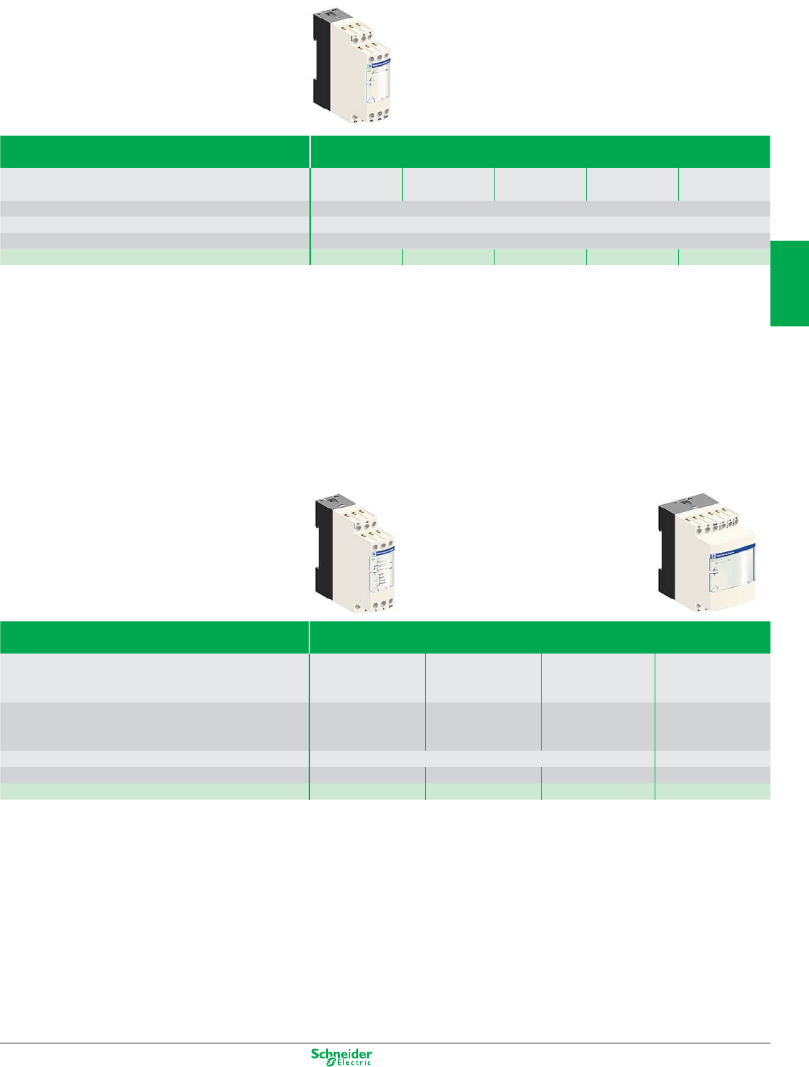
Other versions: please consult your Schneider Electric agency.
Type PT 100
Temperature range -40…40 °C -100…100 °C 0…100 °C 0…250 °C 0…500 °C
-40…104 °F -148…212 °F 32…212 °F 32…482 °F 32…932 °F
Output range 0…10 V
Dimensions H x W x D 80 x 22,5 x 80 mm
Voltage 24 VDC - Non isolated
References
RMPT13BD RMPT23BD RMPT33BD RMPT53BD RMPT73BD
Universal Analog Converter
Type Analog Converter
Input range 0…10 V or 4…20 mA 0…10 V / -10…+10 V 0…50 V / 0…300 V 0…1,5 A / 0…5 A
0…20 mA 0…500 V 0…15 A
4…20 mA
Output range 0…10 V or 4…20 mA 0…10 V / -10…+10 V 0…10 V 0…10 V or 0…20 mA
0…20 mA 0…20 mA ou 4…20 mA
4…20 mA Switchable 4…20 mA Switchable
Dimensions H x W x D 80 x 22,5 x 80 mm 80 x 45 x 80 mm
Voltage 24 VDC - Non isolated 24 VDC - Isolated 24 VDC - Isolated 24 VDC - Isolated
References
RMCN22BD RMCL55BD RMCV60BD RMCA61BD
Optimum PT 100
3/15
2
1
3
4
5
6
7
8
9
10
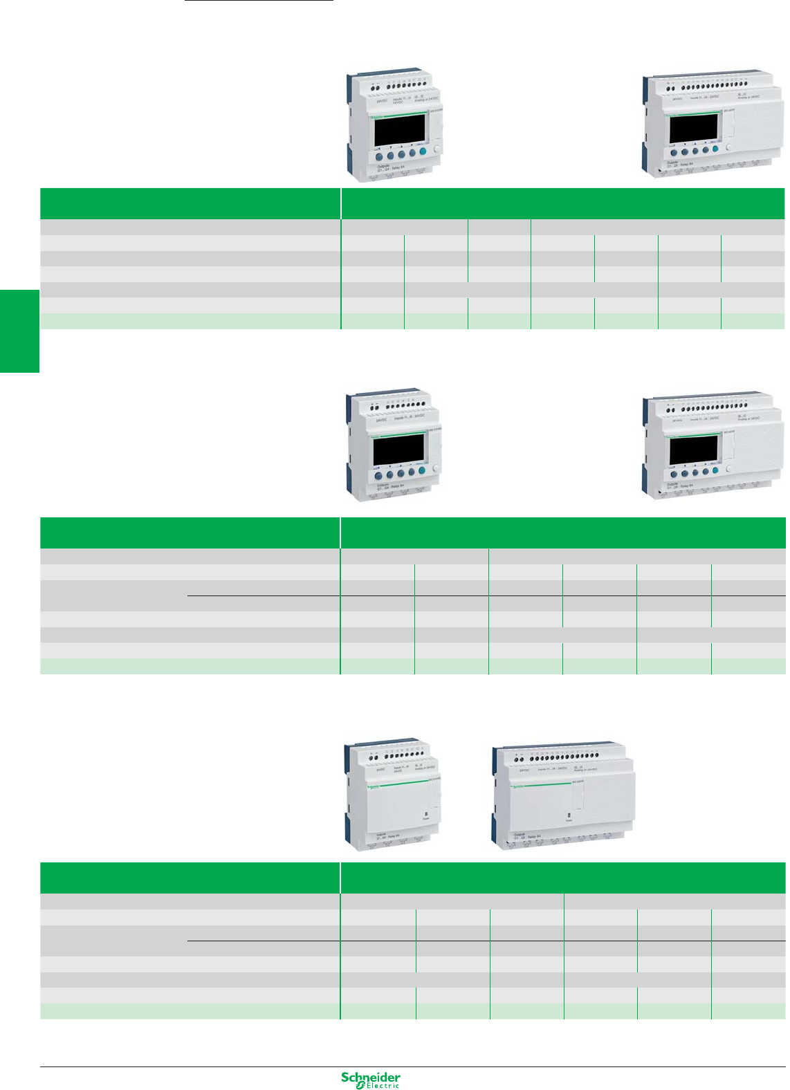
Other versions: please consult your Schneider Electric agency.
Smart relays
Compact, SR2
Compact smart relays With display, a.c. power supply
Supply voltage 24 VAC 48 VAC 100…240 VAC
Number of inputs/outputs 12 20 20 10 12 20 20
Number of inputs Discrete inputs 8 12 12 6 8 12 12
Number of outputs 4 relay 8 relay 8 relay 4 relay 4 relay 8 relay 8 relay
Dimensions, W x D x H (mm)
71.2x59.5x107.6
124.6x59.5x107.6 71.2x59.5x107.6 124.6x59.5x107.6
Clock yes yes no no yes no yes
References
SR2B121B SR2B201B
SR2A201E
SR2A101FU (1)
SR2B121FU
SR2A201FU (1)
SR2B201FU
(1) Programming on smart relay in LADDER language only
Compact smart relays With display, d.c. power supply
Supply voltage 12 VDC 24 VDC
Number of inputs/outputs 12 20 10 12 20 20
Number of inputs Discrete inputs 8 12 6 8 12 12
including 0-10 V analogue inputs 46 - 42 6
Number of outputs 4 relay 8 relay 4 relay 4 8 relay 8
Dimensions, W x D x H (mm)
71.2x59.5x107.6 124.6x59.5x107.6 71.2x59.5x107.6 124.6x59.5x107.6
Clock yes yes no yes no yes
References
SR2B121JD SR2B201JD SR2A101BD (1) SR2B12pBD (2) SR2A201BD (1) SR2B20pBD (2)
(1) Programming on smart relay in LADDER language only
(2) Replace the
p
by number 1 to order a smart relay with relay output or by 2 for a smart relay with transistor output (Example: SR2B121BD)
Compact smart relays Without display and without buttons
Supply voltage 100…240 VAC 24 VDC
Number of discrete inputs/outputs 10 12 20 10 12 20
Number of inputs Discrete inputs 6 8 12 6 8 12
including 0-10 V analogue inputs ––––46
Number of outputs 4 relay 4 relay 8 relay 4 relay 4 relay 8 relay
Dimensions, W x D x H (mm)
71.2x59.5x107.6 124.6x59.5x107.6 71.2x59.5x107.6
124.6x59.5x107.6
Clock no yes yes no yes yes
References SR2D101FU (1) SR2E121FU SR2E201FU SR2D101BD (1) SR2E121BD (3) SR2E201BD (3)
(1) Programming on smart relay in LADDER language only
(3) To order a smart relay for a 24 VAC supply (no analogue inputs), delete the letter D from the end of the reference (SR2E121B and SR2E201B)
Zelio Logic
3/16
2
1
3
4
5
6
7
8
9
10
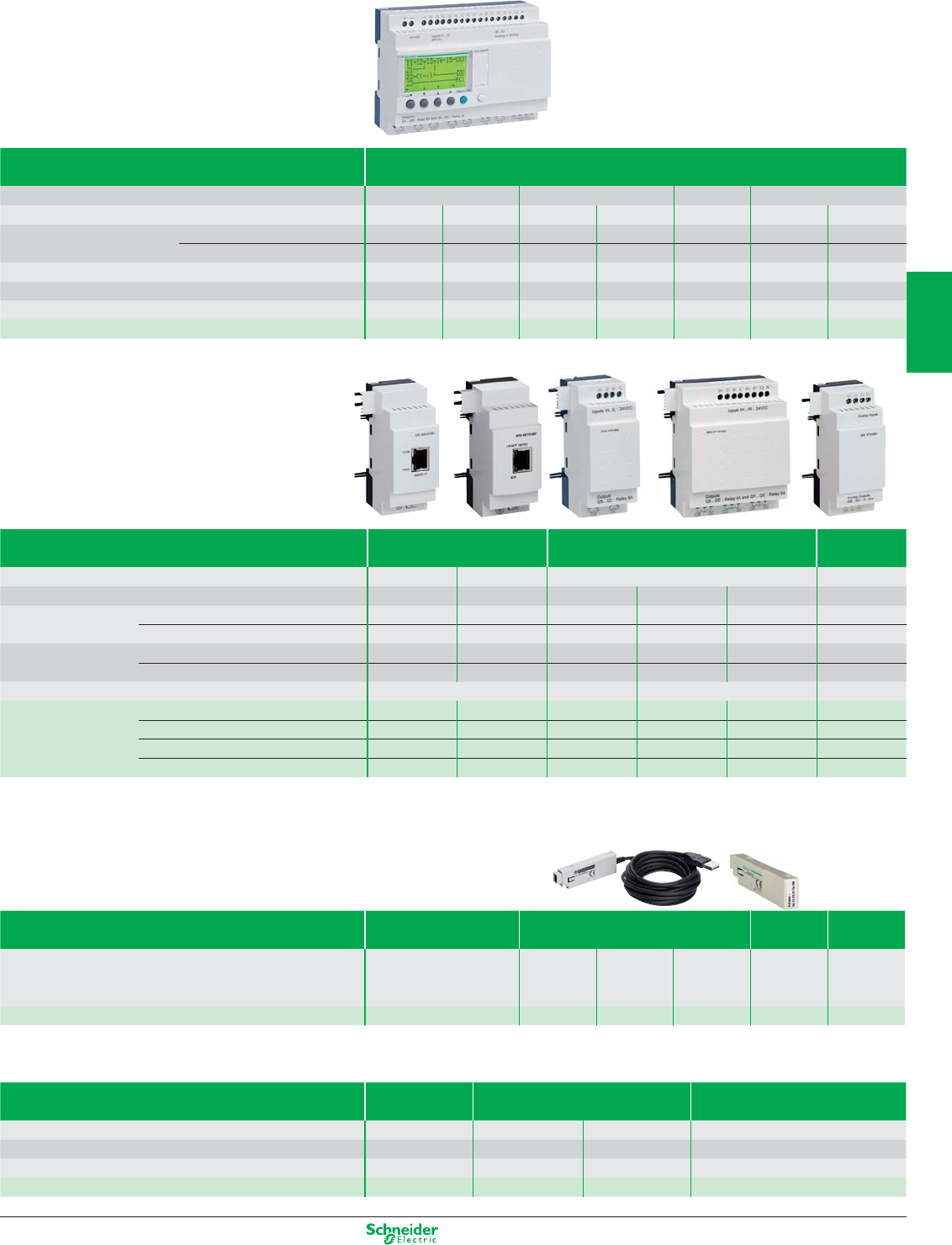
Other versions: please consult your Schneider Electric agency.
Modular, SR3
Modular smart relays* With display
Supply voltage 24 VAC 100…240 VAC 12 VDC 24 VDC
Number of inputs/outputs 10 26 10 26 26 10 26
Number of inputs Discrete inputs 6 16 6 16 16 6 16
including 0-10 V analogue inputs ––––646
Number of outputs 4 relay 10 relay 4 relay 10 relay 10 relay 4 10
Dimensions, W x D x H (mm)
71.2x59.5x107.6 124.6x59.5x107.6 71.2x59.5x107.6 124.6x59.5x107.6 124.6x59.5x107.6 71.2x59.5x107.6 124.6x59.5x107.6
Clock yes yes yes yes yes yes yes
References
SR3B101B SR3B261B SR3B101FU SR3B261FU SR3B261JD
SR3B10pBD (1)
SR3B26pBD(1)
*The modular base can be fitted with one I/O extension module. The 24 VDC modular base can be fitted with one communication module and/or one I/O extension module
(1) Replace the
p
by number 1 to order a smart relay with relay output (SR3B101BD) or by 2 for a smart relay with transistor output (SR3B102BD)
Extension modules for Zelio Logic SR3Bppppp (2) Communication
Discrete Inputs/Outputs Analogue
Inputs/Output
s
Network Modbus Ethernet ––
Number of inputs/outputs ––6 10144
Number of inputs Discrete – – 468–
Analogue (0…10 V, 0…20 mA, PT100) –––––
2
(1 PT100 max.)
Number of outputs Relay – – 2 relay 4 relay 6 relay –
Analogue (0…10 V) –––––2
Dimensions, W x D x H (mm) 35.5x59.5x107.6 35.5x59.5x107.6 72x59.5x107.6 35.5x59.5x107.6
References 24 VAC – – SR3XT61B SR3XT101B SR3XT141B –
100…240 VAC ––SR3XT61FU SR3XT101FU SR3XT141FU –
12 VDC ––SR3XT61JD SR3XT101JD SR3XT141JD –
24 VDC SR3MBU01BD SR3NET01BD SR3XT61BD SR3XT101BD SR3XT141BD SR3XT43BD
(2) The power supply of the extension modules is provided via the Zelio Logic modular relays
Zelio Soft 2 software and programming tools
Zelio Soft 2 software, connecting cables,
wireless connecting, memory
Multilingual
programming software
Connecting cables
Wireless
connection
Back-up
memory
Description CD ROM PC (Windows 98,
NT, 2000, XP, Vista available
1
st
quarter 2010) (3)
Serial
PC/Smart
relay
USB
PC/Smart
relay
XBT N/R
Interface
Bluetooth
interface
EEPROM
References SR2SFT01 SR2CBL01 SR2USB01 SR2CBL08 SR2BTC01 SR2MEM02
(3) CD-ROM including Zelio Soft 2 programming software, an application library, a self-training manual, installation instructions and a user’s manual
Communication interface for SR2/SR3
Interface, modems, Zelio Logic Alarm software
Communication
interface
Modems (4) Alarm management software
Supply voltage 12…24 VDC 12…24 VDC 12…24 VDC –
Description – Analogue modem GSM modem PC CD-ROM (Windows 98, NT, 2000, XP)
Dimensions, W x D x H (mm) 72x59.5x107.6 120.7x35x80.5 111x 25.5x54.5 –
References SR2COM01 SR2MOD01 SR2MOD02 SR2SFT02
(4) Must be used in conjunction with communication interface SR2COM01
3/17
2
1
3
4
5
6
7
8
9
10
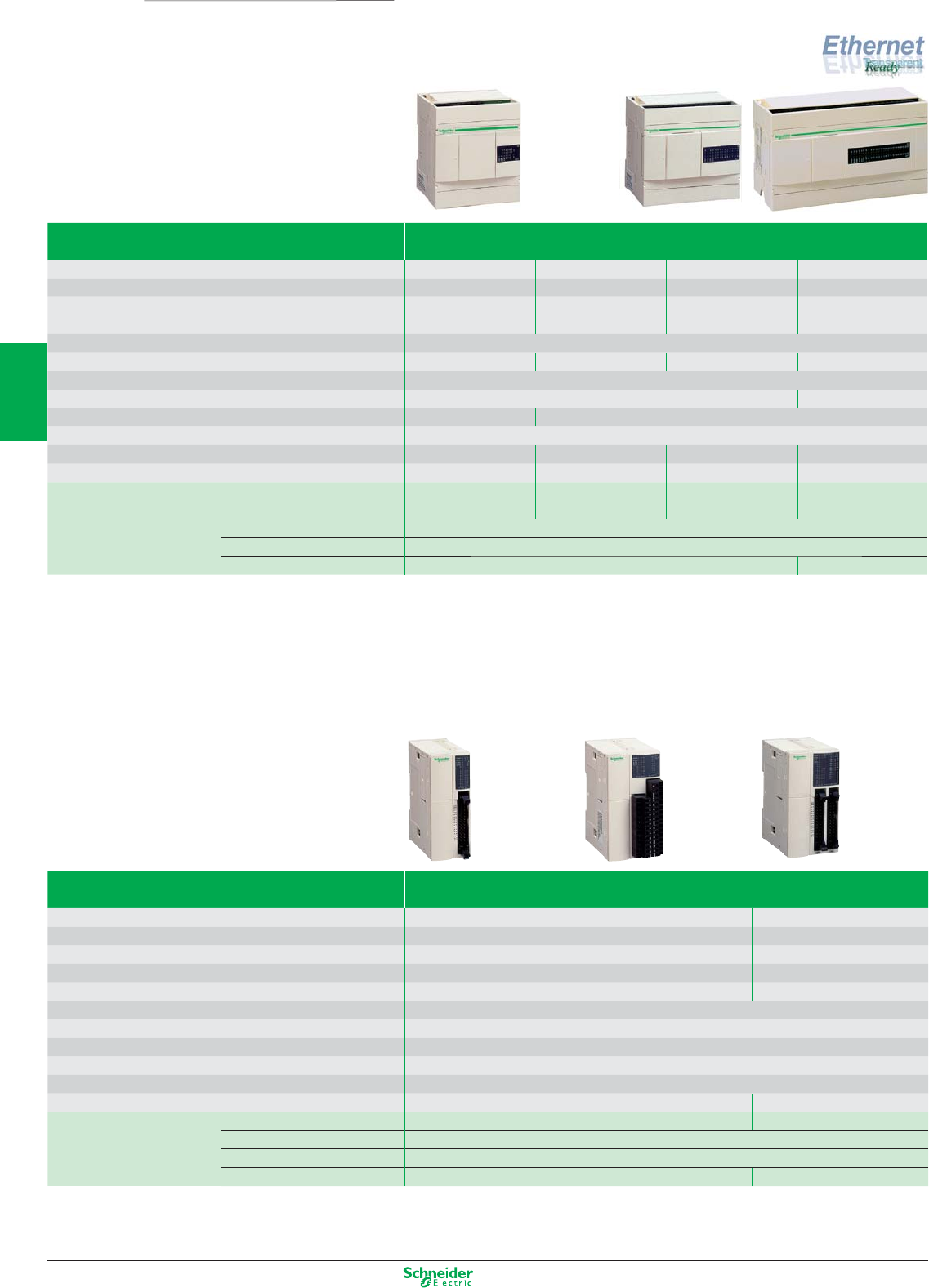
Other versions: please consult your Schneider Electric agency.
Programmable controllers
Bases
Twido
Type of base Compact
Number of digital i/O 10 16 24 40
Number of digital inputs (24 VDC) 6 sink/source 9 sink/source 14 sink/source 24 sink/source
Number of digital outputs 4 relay (2 A) 7 relay (2 A) 10 relay (2 A) 14 relay (2 A),
2 solid-state (1 A)
Type of connection Screw terminals (non removable)
Possible I/O expansion modules ––47
Counting 3 x 5 kHz, 1 x 20 kHz
PWM positioning – 2 x 7 kHz
Serial ports 1 x RS 485 1 x RS 485; option: 1 x RS 232C or RS 485
Protocol Modbus master/slave, ASCII, I/O relocation
Ethernet port – – – RJ45 Ethernet
Dimensions, W x D x H 80 x 70 x 90 mm 80 x 70 x 90 mm 95 x 70 x 90 mm 157 x 70 x 90 mm
References Supply voltage 100…240 VAC TWDLCAA10DRF TWDLCAA16DRF TWDLCAA24DRF TWDLCAE40DRF (1)
Supply voltage 19.2…30 VDC TWDLCDA10DRF TWDLCDA16DRF TWDLCDA24DRF TWDLCDE40DRF (1)
Real-time clock (option) TWDXCPRTC
Display unit (option) TWDXCPODC
Memory cartridge (option) TWDXCPMFK32 (3) TWDXCPMFK64 (4)
(1) 40 I/O version without Ethernet also available: TWDLCAA40DRF and TWDLCDA40DRF
Type of base Modular
Number of digital i/O 20 40
Number of digital inputs (24 VDC) 12 sink/source 12 sink/source 24 sink/source
Number of digital outputs 8 transistor, source (0.3 A)
6 relay (2 A) & 2 trans., source (0.3 A)
16 transistor, source (0.3 A)
Type of connection HE10 connector Removable screw terminals HE10 connector
Possible I/O expansion modules 47 7
Supply voltage 24 VDC
Counting 2 x 5 kHz, 2 x 20 kHz
PLS/PWM positioning 2 x 7 kHz
Serial ports 1 x RS 485; option: 1 x RS 232C or RS 485
Protocol Modbus master/slave, ASCII, I/O relocation
Dimensions, W x D x H 35.4 x 70 x 90 mm 47.5 x 70 x 90 mm 47.5 x 70 x 90 mm
References TWDLMDA20DTK (2) TWDLMDA20DRT TWDLMDA40DTK (2)
Real-time clock (option) TWDXCPRTC
Display unit (option) TWDXCPODM
Memory cartridge (option) TWDXCPMFK32 (3) TWDXCPMFK64 (4)
(2) Sink version transistor outputs also available: TWDLMDA20DUK and TWDLMDA40DUK
(3) Application backup, program transfer
(4) Memory expansion, application backup, program transfer
3/18
2
1
3
4
5
6
7
8
9
10
Other versions: please consult your Schneider Electric agency.
Programmable controllers
I/O modules
Type of module Analogue inputs
Number of inputs 2 I 2 I 4 I 8 I 8 I 8 I 8 I
Connection Removable screw terminals RJ11
Inputs Range
Thermocouples
0…10 V (1) 0…10 V (1) 0…10 V (1) PTC/NTC Thermo probe
Pt100 / Pt1000
- 200...+ 600 °C
type K, J, T 4…20 mA (2) 0…20 mA (2) 0…20 mA (2)
θ °C
Resolution 12 bits (4096 points) 10 bits (1024 points) 12 bits (4096 points)
Supply voltage 24 VDC
Dimensions, W x D x H 23.5 x 70 x 90 mm 39.1x70x90 mm
References TM2AMI2LT TM2AMI2HT TM2AMI4LT TM2AMI8HT TM2ARI8HT TM2ARI8LT TM2ARI8LRJ
(1) Non differential
(2) Differential
Type of module Analogue Outputs, Inputs/Outputs (mixed)
Number of inputs and/or outputs 1 O 2 O 2 I / 1 O 2 I / 1 O 4 I / 2 O
Connection Removable screw terminals
Inputs Range – – 0…10 V (1)
Thermocouple type K, J & T
0…10 V (1)
4…20 mA (2)
3-wire Pt 100 thermal probe
4…20 mA (2)
Resolution – – 12 bits (4096 points) 12 bits (4096 points) 12 bits (4096 points)
Outputs Range 0…10 V (1) ± 10 V 0…10 V (1) 0…10 V (1) 0…10 V (1)
4…20 mA (2) 4…20 mA (2) 4…20 mA (2) 4…20 mA (2)
Resolution 12 bits 11 bits + sign 12 bits 12 bits 12 bits
Supply voltage 24 VDC
Dimensions, W X D x H 23.5 x 70 x 90 mm
References TM2AMO1HT TM2AVO2HT TM2AMM3HT TM2ALM3LT TM2AMM6HT
(1) Non differential
(2) Differential
Type of module Digital Inputs/Outputs
Number of inputs and/or outputs 8 16 16 32 4 I / 4 O 16 I / 8 O
Connection Removable screw terminals HE10 connectors Removable
Spring terminals
screw terminals
(non removable)
References Inputs 24 VDC sink TM2DDI8DT –––––
24 VDC sink/source – TM2DDI16DT TM2DDI16DK TM2DDI32DK
120 V sink TM2DAI8DT –––––
Outputs Relay (2 A) TM2DRA8RT TM2DRA16RT –––
Transistor, source 0.5 A TM2DD08TT –––––
Transistor, source 0.4 A – – TM2DD016TK TM2DD032TK ––
Transistor, sink 0.1 A TM2DDO8UT –TM2DDO16UK TM2DDO32UK ––
Inputs, 24 VDC + Outputs, Relais 2 A
––––TM2DMM8DRT
TM2DMM24DRF
New
Range
3/19
2
1
3
4
5
6
7
8
9
10
Other versions: please consult your Schneider Electric agency.
Type of module Serial interface Serial interface adaptor
Physical layer (non isolated) RS 232C RS 485 RS 232C RS 485
Connection Mini-DIN connector
Screw terminals
Mini-DIN connector
Screw terminals
Protocol Modbus master/slave, ASCII, I/O relocation
Twido base compatibility Modular base TWDLMDA Compact base TWDLCAA16/24DRF
Modular base via integrated display module TWDXCPODM
References TWDNOZ232D TWDNOZ485D TWDNOZ485T TWDNAC232D TWDNAC485D TWDNAC485T
Type of module Modem for
Twido
CANopen
expansion
Ethernet
interface
Modbus
isolation
module
Modbus
junction
module
AS-Inter-
face
master
Number of modules –11––2 (1)
Connection – SUB-D9 RJ45 RJ45 RJ45 Removable
screw terminals
Twido base compatibility – 20, 24 or 40 I/O
base
All models All models All models 20, 24 or 40 I/O
base
References SR2MOD03 TWDNCO1M 499TWD01100 TWDXCAISO TWDXCAT3RJ TWDNOI10M3
(1) 2 modules max., 62 digital slaves max., 7 analogue slaves max., AS-Interface/M3, V 2.11 (profile S.7.4 not supported)
Programming software
Software, connecting cables, interfaces TwidoSuite
software
EN/FR
Connecting cables Bluetooth®
USB adaptor
Bluetooth®
gateway
Application
PC with Windows
XP or Vista
Twido/PC
USB port
Twido/PC
serial port
For PC not fitted
with Bluetooth®
For Twido
controller
References TWDBTFU10M TSXCUSB485 +
TSXCRJMD25
TSXPCX1031 (2)
VW3A8115 VW3A8114
(2) For Twido Extreme: order the reference VW3A8106
Programmable controllers
Communication modules for
Twido Compact and Modular bases
Twido
3/20
2
1
3
4
5
6
7
8
9
10
Other versions: please consult your Schneider Electric agency.
Type of base Twido Extreme
Number of I/O 41
Degree of protection IP67
Temperature -40…+110°C, storage -55…+155°C
Relative humidity 90% without condensation
Number of inputs Digital 13 (short-circuit protected)
Analogue 8 (including 1 input configurable to PWM)
PWM 1
Number of outputs Digital 16* (short-circuit protected)
PWM or PLS 3
Supply voltage 12 or 24 VDC
Counting 1 x 10 kHz
Communication ports RS 485, CAN J1939, CANopen master
Serial link protocols Modbus RTU master/slave, ASCII
Dimensions, W x D x H 165.51 x 45.70 x 225 mm
References TWDLEDCK1
* 16 outputs in 12 VDC. Limited to 8 outputs in 24 VDC.
Fixing and connection Fixing kit 70-pin connector Pre-wired 70-pin
connector
Details 4 spacers, 80 pins, Pre-wired with 1.5 m long cable,
8 washers, 80 blanking plugs, free wires other end
8 shock mounts 1 cover
Degree of protection – IP67 IP67
References TWDXMTK4 TWDFCNK70 TWDFCWK70L015
Separate components Crimping tool RJ45 programming
connector
Application Crimping wires onto pins
of 70-pin connector
Connecting Twido Extreme
to a programming PC
References TWDXMTCT TWDNAK70P
Programmable controllers
Bases
3/21
2
1
3
4
5
6
7
8
9
10
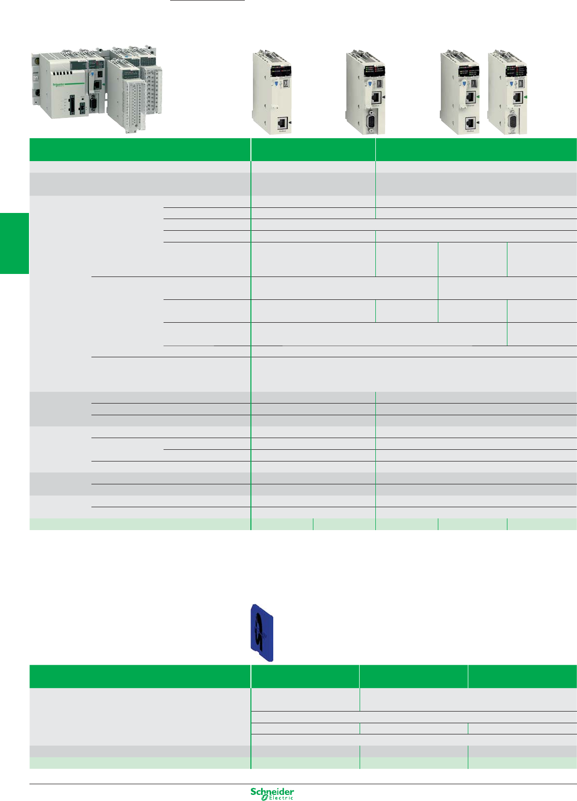
Other versions: please consult your Schneider Electric agency.
Programmable Automation Controller
Processor modules
Modicon M340
Type of processor Standard High-performance
Number of racks 2 (4, 6, 8 or 12 slots) 4 (4, 6, 8 or 12 slots)
Maximum confi guration
Maximum 24 slots for processor and
modules (excluding power supply module)
Maximum 48 slots for processor and
modules (excluding power supply module)
Functions Max. no. (1) Discrete I/O 512 1024
Analog I/O 128 256
Control channels Programmable loops (via CONT-CTL process control EFB library)
Counter channels 20 36
Motion control – Independent axes
on CANopen bus
(via MFB library)
– Independent axes
on CANopen bus
(via MFB library)
Integrated
connections
Ethernet TCP/IP –
1 RJ45 port, 10/100 MBps, with Transparent
Ready class B10 standard web server
CANopen master bus
Integrated port – 1 (SUB-D9) – 1 (SUB-D9)
Serial link 1 RJ45 port, Modbus master/slave RTU/ASCII or character mode –
(non isolated RS 232C/RS 485), 0.3...19.2 kBps
USB port 1 port, 12 MBps
Communication Ethernet TCP/IP 1 RJ45 port, 10/100 MBps with:
module - Transparent Ready class B30 standard web server with BMX NOE 0100 module
- Transparent Ready class C30 confi guration web server with BMX NOE 0110 module
Internal user Total capacity 2048 Kb 4096 Kb
RAM Program, constants and symbols 1792 Kb 3584 Kb
Data 128 Kb 256 Kb
Execution time for
Boolean 0.18 µs 0.12 µs
one instruction
On words or fi xed point
Single-length words 0.38 µs 0.25 µs
arithmetic Double-length words 0.26 µs 0.17 µs
On fl oating points 1.74 µs 1.16 µs
No. of K instructions
100% Boolean 5.4 Kinst/ms 8.1 Kinst/ms
executed per ms
65% Boolean and 35% fi xed arithmetic 4.2 Kinst/ms 6.4 Kinst/ms
System Master task 1.05 ms 0.70 ms
overhead Fast task 0.20 ms 0.13 ms
References BMX P341000 BMX P342000 BMX P3420102 BMX P342020 BMX P3420302
(1) Only affects in-rack modules. The remote I/O on the CANopen bus are not included in these maximum numbers.
Memory cards
Type of card 8 MB memory card 8 MB memory card
+ 8 MB fi les
8 MB memory card
+ 128 MB fi les
Use Supplied as standard with each
processor. Used for:
As replacement for the memory card supplied as
standard with each processor, used for:
Backup of program, constants, symbols and data
– File storage, 8 MB File storage, 128 MB
Activation of class B10 web server
Compatibility BMX P34 1000/20... BMX P34 20...
References BMX RMS 008MP BMX RMS 008MPF BMX RMS 0128MFP
3/22
2
1
3
4
5
6
7
8
9
10
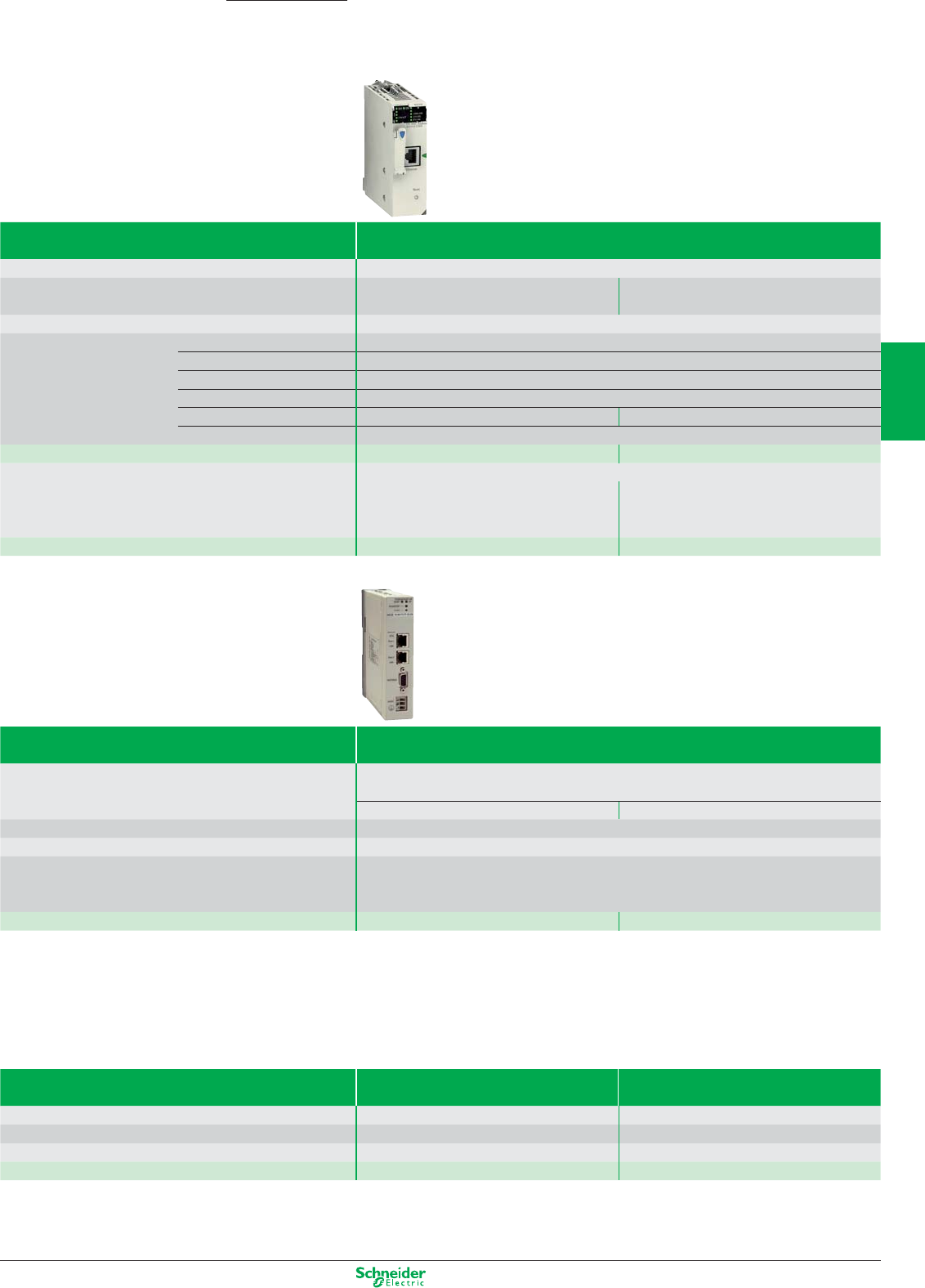
Other versions: please consult your Schneider Electric agency.
Programmable Automation Controller
Communication modules
Modicon M340
Type of module Ethernet TCP/IP network
Speed 10/100 MBps
Standard services Modbus TCP/IP
messaging
TCP/IP
(Uni-TE, Modbus)
Conformity class Transparent Ready class B30
Communication service I/O Scanning service Yes
Transparent Ready FDR service Yes (client/server)
SNMP network management service
Yes
Global Data service Yes
SOAP/XML Web service No Server
Bandwidth management Yes
References BMX NOE 0100 BMX NOE 0110
Memory card Use Provides services conforming to Transparent Ready:
Class B Class C
32 MB available for
user web pages
References BMX RWS B000M BMX RWS FC032M
Type of module PROFIBUS DP V1
Designation PROFIBUS Remote Master (Ethernet Modbus TCP/PROFIBUS DP V1) compatible with all
programmable automation under UNITY and supporting the I/O scanning service
Standard version 0…65° Hardened version -25…70°, varnished
Speed 9.6 Kb…12 Mb
Interface RS485 isolated (Sub-D 9 pin female connector)
PROFIBUS Services Master Class 1 and 2, support for 125 slaves, Sync & Freeze, Extended diagnostics.
Delivered with communication DTM allowing any FDT tool to access the PROFIBUS slaves from the
Ethernet network by way of the PROFIBUS Remote Master
References TCSEGPA23F14F TCSEGPA23F14FK
Type of module Serial link
(1)
AS-Interface
(1)
Number of interfaces 21
Speed 115 Kbits/s –
Profile – M4 (AS-i V3)
References BMX NOM 0200 BMX EIA 0100
(1) For BMX NOC 0400 (Ethernet IP), Profibus DP Gateway TSX EGPA23F14F, Modbus Plus Gateway TCS EGDB23F24FA: Available 1Q 2010
3/23
2
1
3
4
5
6
7
8
9
10
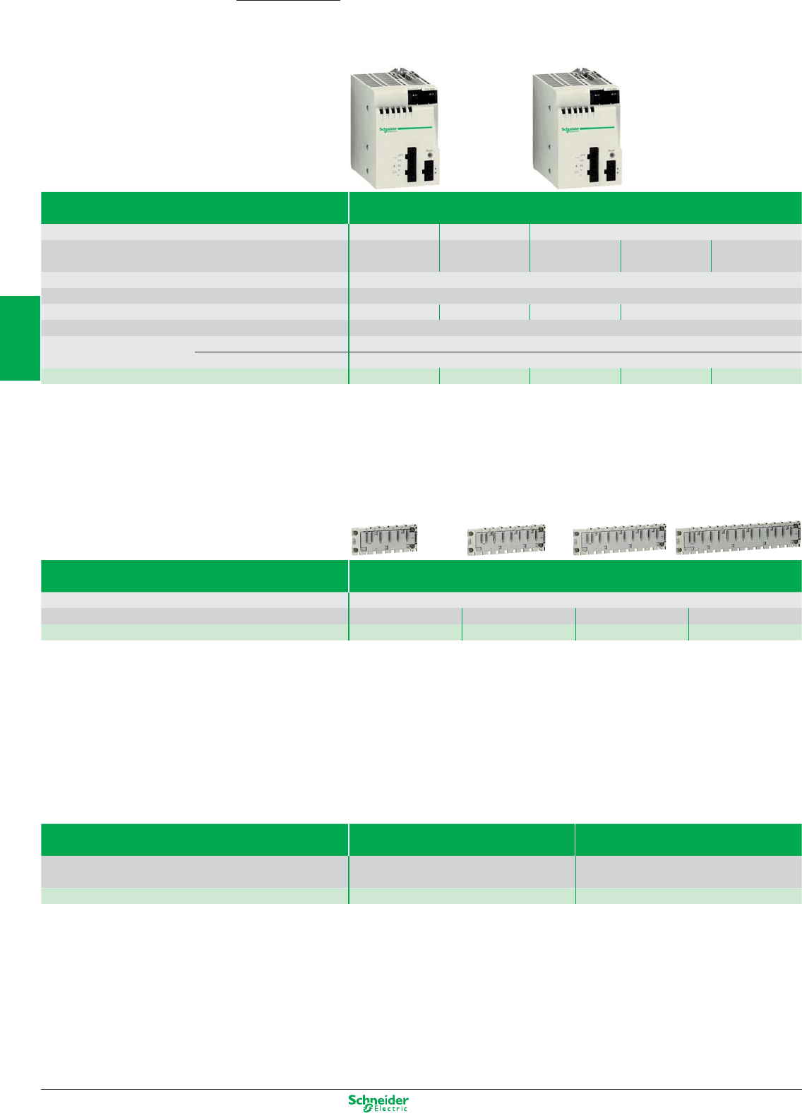
Other versions: please consult your Schneider Electric agency.
Programmable Automation Controller
Power supply modules
Modicon M340
Type of module Power supply modules
Voltage 24 VDC isolated
24…48 VDC isolated
100…240 VAC
Nominal input current 1A at 24 VDC
1.65 A at 24 VDC
0.61 A at 115 VAC 1.04 A at 0.52 A 100...150 VDC
0.83 A at 48 VDC
0.31 A at 220 VDC
Micro-break duration ≤ 1
Integrated protection Via internal fuse (not accessible)
Max. useful power 17W 32 W 20 W 36 W
Max. dissipated power 8.5 W
Removable connectors
(set of 2)
supplied as standard BMX XTS CPS10 (cage clamp)
to be ordered separately BMX XTS CPS20 (spring-type)
References BMX CPS 2010 BMX CPS 3020 BMX CPS 2000 BMX CPS 3500 BMX CPS 3504 (1)
(1) Available 1Q 2010
Racks
Designation Racks
Type of modules to be installed
BMX CPS power supply, BMX P34 processor, I/O modules and application-specifi c modules (counter, communication)
No. of slots
46812
References
BMX XBP 0400 BMX XBP 0600 BMX XBP 0800 BMX XBP 1200
Rack extensions
Designation Rack extension module Kit for rack extension
Standard module to interconnect rack A complete assembly kit for to racks distant from
0.8 m or less
References
BMX XBE 1000 BMX XBE 2005
3/24
2
1
3
4
5
6
7
8
9
10
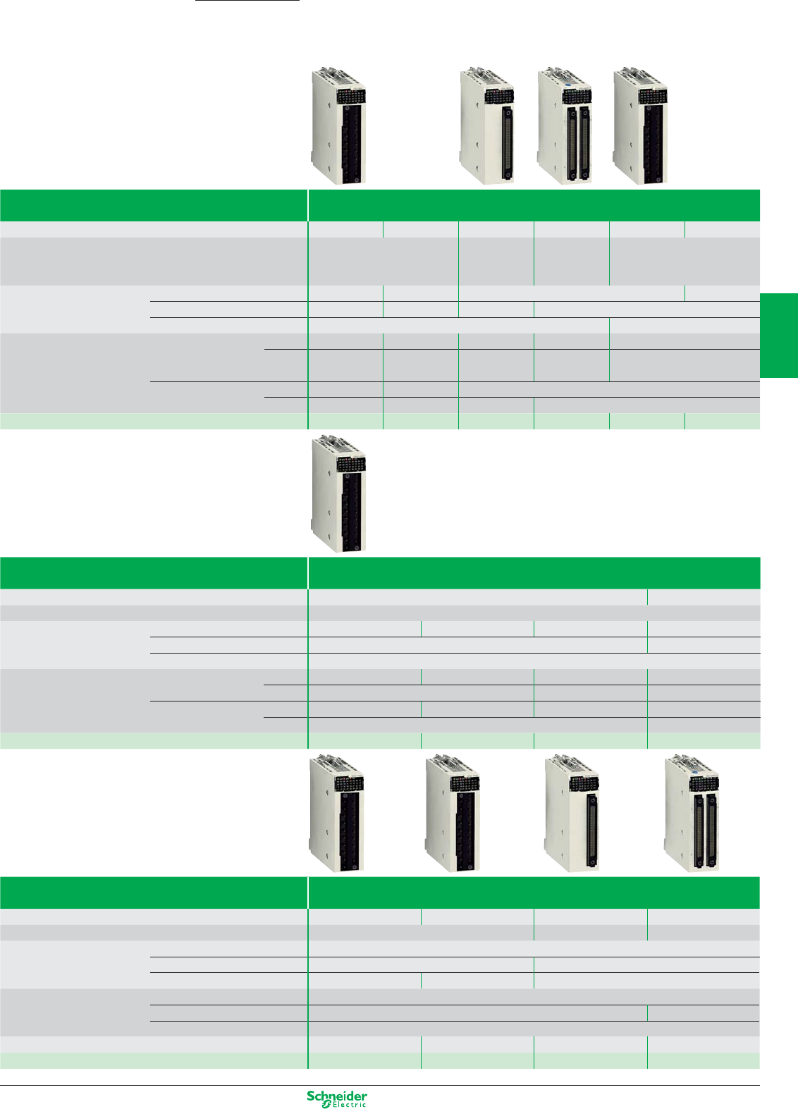
Other versions: please consult your Schneider Electric agency.
Programmable Automation Controller
Discrete I/O modules
Type of module DC input modules
Number of inputs 16 16 32 64 16 16
Connection Screw or spring-type 1 connector 2 connectors Screw or spring-type
20-way removable
terminal block
20-way removable 40-way 40-way
terminal block
Nominal input values Voltage 24 V 48 V 24 V 125 VDC
Current 3.5 mA 2.5 mA 1 mA 3 mA
Logic Positive (sink) Negative (source)
Input limit values At state 1 Voltage ≥11 V ≥34 V ≥11 V ≥15 V ≥14 V
Current > 2 mA > 2 mA > 2 mA > 1 mA > 2 mA
(for U ≥11 V) (for U ≥34 V) (for U ≥11 V) (for U ≥5 V) (for U ≥15 V)
At state 0 Voltage < 5 V < 10 V < 5 V
Current ≥1.5 mA ≥0.5 mA ≥1.5 mA ≥0.5 mA
References BMX DDI 1602 BMX DDI 1603 BMX DDI 3202K BMX DDI 6402K BMX DAI 1602
BMX DDI 1604 (1)
(1) Available 1Q 2010
Type of module AC input modules
Number of inputs 16 8
Connection Screw or spring-type 20-way removable terminal block
Nominal input values Voltage 24 VAC 48 AC 100…120 VAC 200...240 VAC
Current 3 mA 10.4 mA
Frequency 50/60 Hz
Input limit values At state 1 Voltage ≥15 V ≥34 V ≥74 V ≥159 V
Current ≥2 mA ≥2.5 mA ≥6 mA
At state 0 Voltage ≤5 V ≤10 V ≤20 V ≤40 V
Current ≤1 mA ≤4 mA
References BMX DAI 1602 BMX DAI 1603 BMX DAI 1604 BMX DAI 0805 (2)
(2) Available 1Q 2010
Type of module DC solid state output modules
Number of inputs 16 16 32 64
Connection Screw or spring-type 20-way removable terminal block One 40-way connector Two 40-way connectors
Nominal output values Voltage 24 VDC
Current 0.5 V 0.1 V
Logic Positive (source) Negative (sink) Positive (source)
Output limit values Voltage (ripple included) 19…30 (possible up to 34 V, limited to 1 hour in every 24 hours)
Current per channel 0.625 A 0.125 A
Current per module
Maximum dissipated power 4 2.26 3.6 6.85
References BMX DDO 1602 BMX DDO 1612 BMX DDO 3202K BMX DDO 6402K
Modicon M340
3/25
2
1
3
4
5
6
7
8
9
10
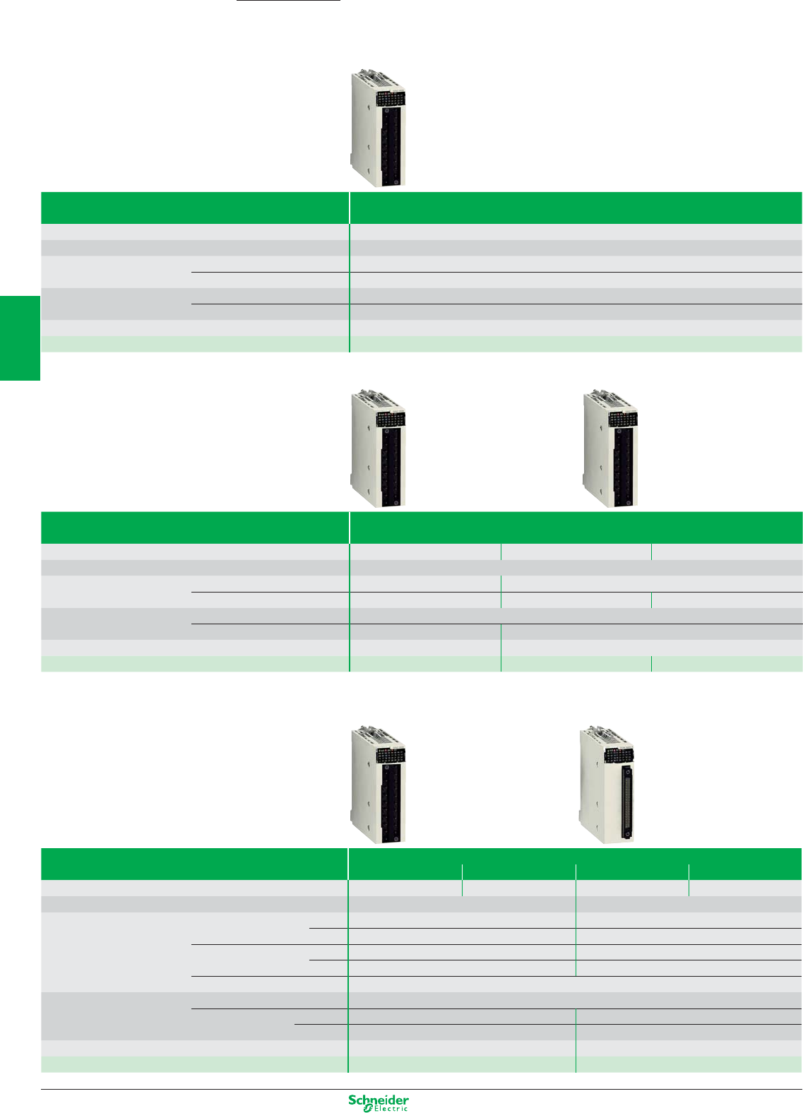
Other versions: please consult your Schneider Electric agency.
Programmable Automation Controller
Discrete I/O modules
Type of module Triac output modules
Number of inputs 16
Connection Screw or spring-type 20-way removable terminal block
Operating voltage Nominal 100…240 VAC
Limit 85…288 VAC
Currents Maximum 0.6 per channel, 2.4 per common, 4.8 for all 4 commons.
Minimum 25 mA at 100 V a, 25 mA at 240 V a.
Maximum inrush current ≤ 20/cycle
Reference BMX DAO1605
Type of module Relay output modules
Number of inputs 8168
Connection Screw or spring-type 20-way removable terminal block
Max. operating voltage DC 10…34 VDC 24…125 VDC (resistive load)
AC 10…264 VAC 200…264 VAC (Cosϕ = 1) 100...150 VDC
Response time Activation < 10 ms
Deactivation < 8 ms < 12 ms
Dissipated power 2.7 W max 3 W
References BMX DRA 0805 BMX DRA 1605 BMX DRA 0804 (1)
(1) Available 1Q 2010
Type of module 24 VDC mixed I/O modules
Inputs Solid state outputs Inputs Solid state outputs
Number of I/O 8 8 16 16
Connection
Screw or spring-type 20-way removable terminal block
One 40-way connector
Input limit values At state 1 Voltage ≥11V ≥11V
Current ≥3 mA (for U ≥11) ≥2 mA (for U ≥11)
At state 0 Voltage 5 V 5 V
Current ≤1.5 mA ≤1.5 mA
Sensor power supply (ripple included)
19…30 V (possible up to 30 V, limited to 1 hour in every 24 hours)
Output limit values Voltage (ripple included) 19…30 (possible up to 30 V, limited to 1 hour in every 24 hours)
Current per channel 0.625 A 0.125 A
per module 5 A 3.2 A
Maximum dissipated power 3.7 W 4 W
References BMX DDM 16022 BMX DDM 3202K
Modicon M340
3/26
2
1
3
4
5
6
7
8
9
10
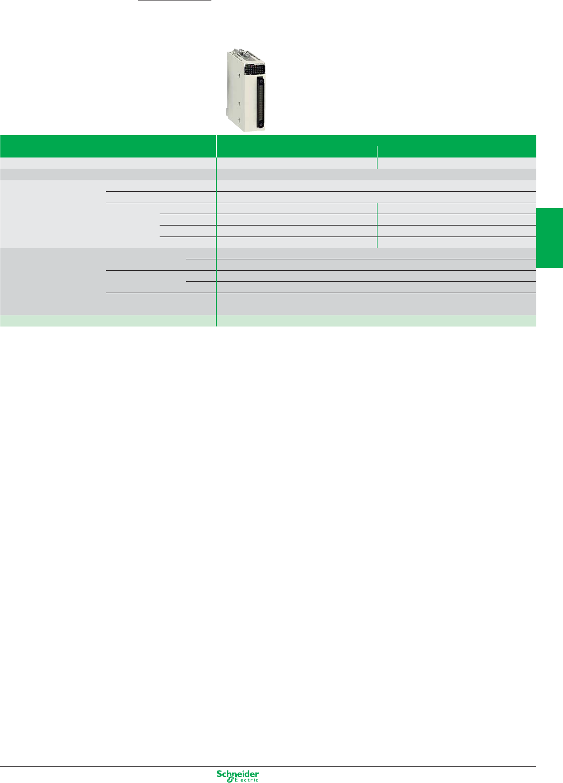
Other versions: please consult your Schneider Electric agency.
Type of module Mixed input/relay output modules
24 VDC inputs 24 VDC or 24…240 VAC relay outputs
Number of I/O 88
Connection Screw or spring-type 20-way removable terminal block
Nominal values Inputs Voltage 24 VDC (positive logic)
Current 3.5 mA
Outputs DC voltage 24 VDC
DC 2 (resistive load)
AC voltage 220 VAC, Cosϕ = 1
AC 2 A
Input limit values At state 1 Voltage ≥11V
Current ≥2 mA (for U ≥ 11 V)
At state 0 Voltage 5 V
Current ≤1.5 mA
Sensor power supply (ripple included)
19…30 V (possible up to 30 V, limited to 1 hour in every 24 hours)
Maximum dissipated power 3.1 W
Reference BMX DDM 16025
Programmable Automation Controller
Discrete I/O modules
Modicon M340
3/27
2
1
3
4
5
6
7
8
9
10
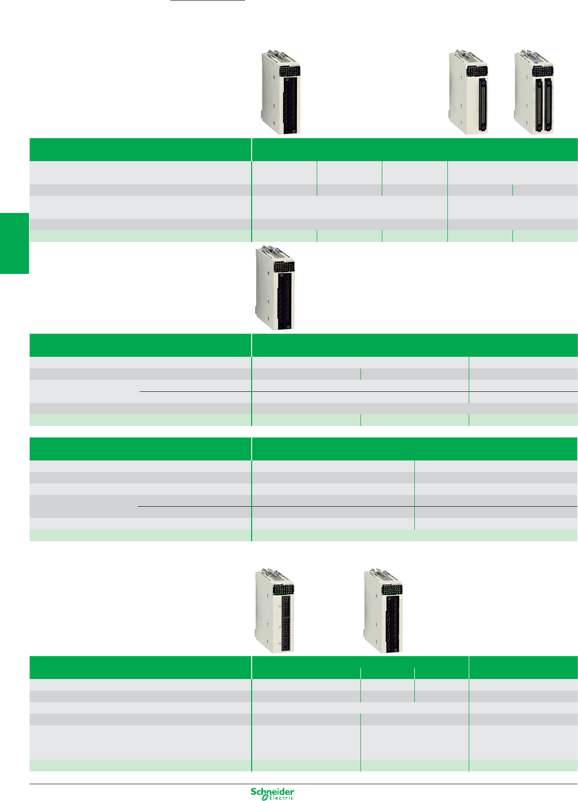
Other versions: please consult your Schneider Electric agency.
Programmable Automation Controller
Analog I/O modules
Type of module Analog input module
Input type Isolated high-level
inputs
Isolated high-level
inputs
Non isolated
high-level inputs
Isolated inputs, low-level voltage, resis-
tors, temperature probes, thermocouples
Number of channels 48848
Nature of inputs ± 10 V, ± 5 V, 0…5 V, 0…10 V, 1…5 V
0…20 mA, 4…20 mA , ± 20 mA
±40 mV, ±80 mV, ±160 mV, ±320 mV,
±640 mV, ±1.28 V
Resolution 0.35 mV/0.92 µA 15 mV + sign
Reference BMX AMI 0410 BMX AMI 0810 (1) BMX AMI 0800 (1) BMX ART 0414 BMX ART 0814
(1) Available 1Q 2010
Type of module Analog output module
Output type Isolated high-level outputs Non isolated high-level outputs
Number of channels 248
Range Voltage ± 10 V –
Current 0…20 mA and 4…20 mA –
Resolution 15 bits + sign
Reference BMX AMO 0210 BMX AMO 0410 (1) BMX AMO 0802 (1)
(1) Available 1Q 2010
Type of module Mixed analog I/O module
Channel type Non-isolated high-level inputs Non-isolated high-level outputs
Number of channels 42
Ranges ±10 V, 0…5 V, 0…10 V, 1…5 V, 0…20 mA, 4…20 mA ±10 V, 0…20 mA, 4…20 mA
Maximum conversion value Voltage ± 11.25 V ± 11.25 V
Current 0…30 0…24 mA
Resolution 14 bits, 12 bits, 13 bits, 12 bits 12 bits, 11 bits
Reference BMX AMM 0600
Counter and motion control modules
Type of module Counter module Motion Control
Module
32 bits 16 bits 32 bits
Modularity 2 channels 8 channels 4 channels 4 channels
No. of sensor inputs 6 per channel 2 per channel 3 per channel 4 auxiliary inputs
No. of actuator outputs 2 per channel 2 auxiliary outputs
Module cycle time 1 ms 5 ms –
Applications Upcounting, downcounting,
measurement, frequency meter,
frequency generator, axis following
Upcounting, downcounting,
measurement
Frequency generator, Move,
set position
References BMX EHC 0200 BMX EHC 0800 BMX MSP 0200
Modicon M340
3/28
2
1
3
4
5
6
7
8
9
10
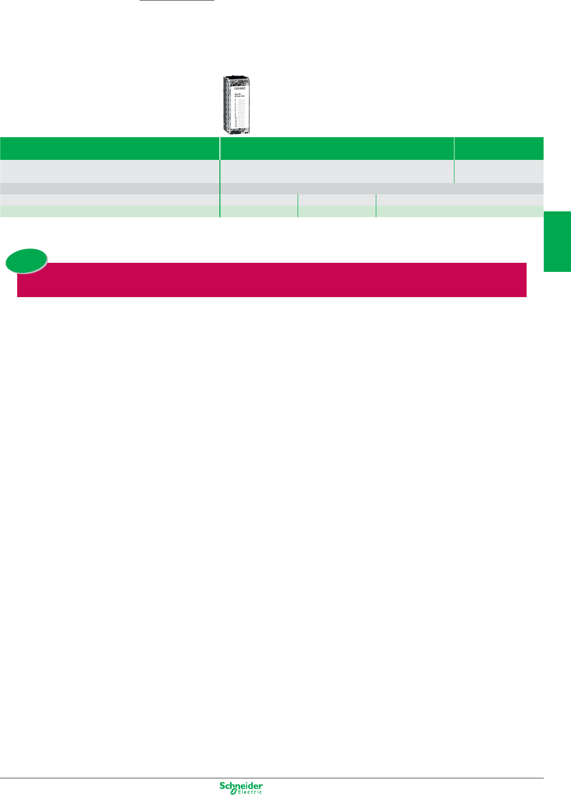
Other versions: please consult your Schneider Electric agency.
Programmable Automation Controller
Connection accessories
Modicon M340
Removable terminal blocks 20-way 28-way
For use with modules BMX AMI 0410 - BMX AM0 0210 - BMX AMM 0600 - BMX EHC 0800 BMX MSP 200,
BMX AMI 0800 / AMI 0810
For use with TOR modules All 8 and 16 channel modules
Composition Cage clamp Screw clamp Spring-type
Reference BMX FTB 2000 BMX FTB 2010 BMX FTB 2020 BMX FTB 2820
Some racks, power supply, communication modules and specific modules, plus all the analog
modules are now available in «ruggedized version». The references of these products end by a H.
New
3/29
2
1
3
4
5
6
7
8
9
10
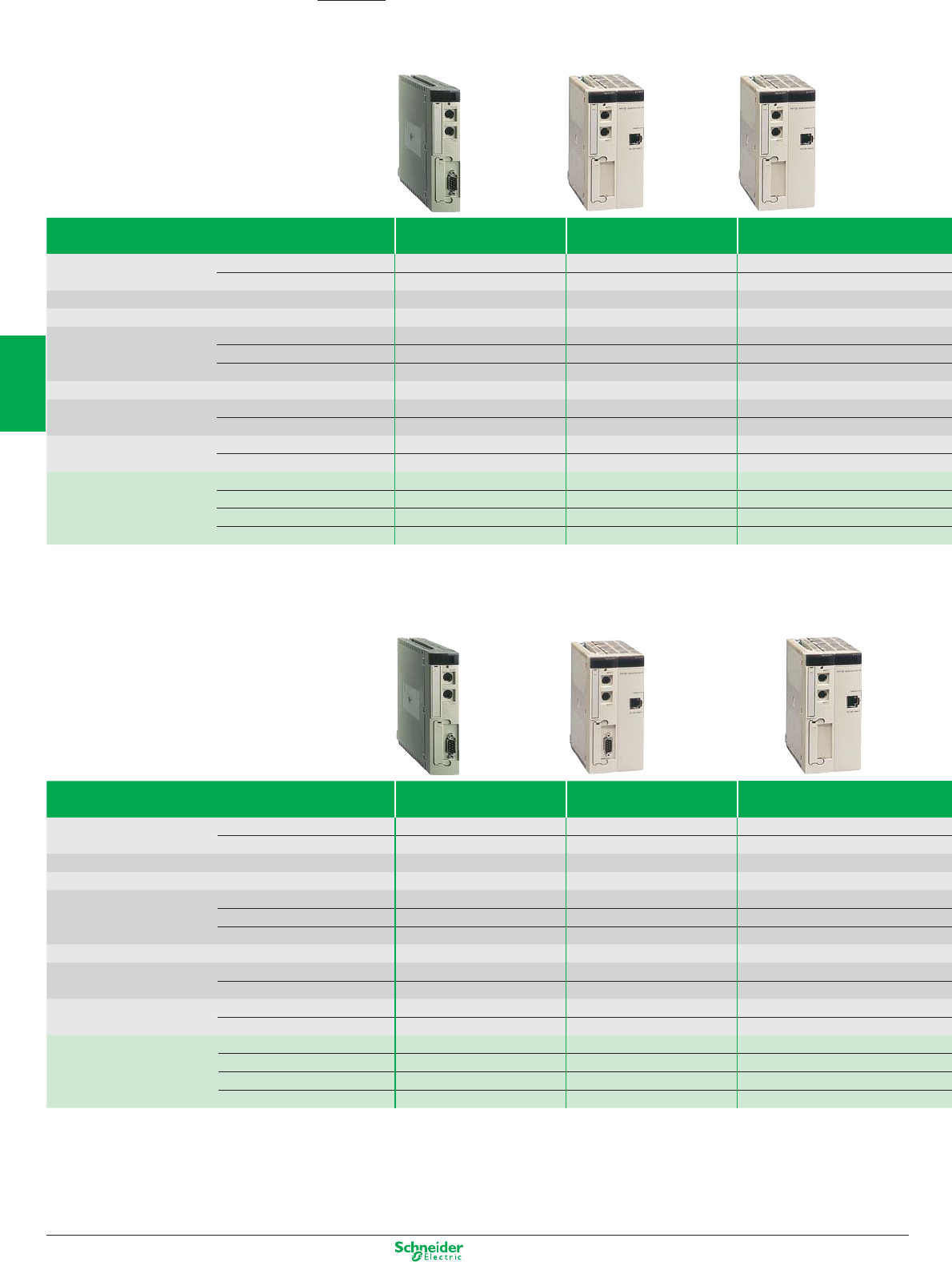
Other versions: please consult your Schneider Electric agency.
Programmable Automation Controller
Processors under Unity Pro software
Type of processor TSX 5710
4 racks max.
TSX 5720
16 racks max.
TSX 5730
16 racks max.
Number of I/O Discrete 512 1024 1024
in racks Analog 24 80 128
Integrated process control No / Yes 30 loops / Yes 45 loops / Yes
Application-specific channels (counter, position control, weighing) 8 24 32
Bus AS-Interface cabling system 2 4 8
CANopen machine bus 1 1 1
INTERBUS, Profibus DP fieldbus – 1 3
Networks (Ethernet, Modbus Plus, Fipway) 1 2 3
Memory capacity Without PCMCIA extension 96 Kb data/prog. 160/192 Kb data/prog. (1) 192/208 Kb data/prog. (1)
With PCMCIA extension 96 Kb data/224 Kb prog. 160/192 Kb data (1)/768 Kb prog. 192/208 Kb data (1)/1,75 MB prog.
Execution time for one Boolean 0.19 µs 0.19 µs 0.12 µs
instruction without ext. PCMCIA On word or arithmetic 0.25 µs 0.25 µs 0.17 µs
Reference Without integrated port TSXP57104M (6) TSXP57204M (6) TSXP57304M (6)
Integrated Ethernet TSXP571634M (2) (6) TSXP572634M (6) TSXP573634M (6)
Integrated CANopen –––
Integrated Fipio TSXP57154M (6) TSXP57254M (6) TSXP57354M (6)
Processors under PL7 software
Type of processor TSX 5710
4 racks max.
TSX 5720
16 racks max.
TSX 5730
16 racks max.
Number of I/O Discrete 512 1024 1024
in racks Analog 24 80 128
Integrated process control No 30 loops 45 loops
Application-specific channels (counter, position control, weighing) 8 24 32
Bus AS-Interface cabling system 2 4 8
CANopen machine bus 1 (with TSXP57103M) 1 1
INTERBUS, Profibus DP fieldbus – 1 2
Networks (Ethernet, Modbus Plus, Fipway) 1 1 3
Memory capacity Without PCMCIA extension 32 K words data/prog. 48 K words data/prog. (4) 64/80 K words data/prog. (4)
With PCMCIA extension
32 K words data/64 K words prog.
32 K words data (4)/160 K words prog.
80/96 K words data (4)/384 K words prog.
Execution time for one Boolean 0.19 µs 0.19 µs 0.12 µs
instruction without ext. PCMCIA On word or arithmetic 0.25 µs 0.25 µs 0.17 µs
Reference Without integrated port TSXP57103M (6) TSXP57203M (6) TSXP57303AM (6)
Integrated Ethernet – TSXP572623M (6) TSXP573623AM (6)
Integrated Fipio TSXP57153M (6) TSXP57253M (6) TSXP57353AM (6)
Integrated Ethernet and Fipio – TSXP572823M (6) –
(1) The second value corresponds to the integrated memory capacity when the processor is equipped with a Fipio manager integrated link
(2) Processor with double format
(3) PC format card on PCI bus
(4) The second value corresponds to the processor with integrated Fipio bus manager link.
(5) with PL7 V4.4 min.
(6) For coated version add C at the end of the reference: example TSXP571634M becomes TSXP571634MC
Modicon Premium
3/30
2
1
3
4
5
6
7
8
9
10
Other versions: please consult your Schneider Electric agency.
TSX 5740
16 racks max.
TSX 5750
16 racks max.
TSX 5760
16 racks
TSXH5724M
16 racks
TSXH5744M
16 racks
2048 2048 2048 512 512
256 512 512 80 128
60 loops / Yes 90 loops / Yes 90 loops / Yes 30 loops / Yes 60 loops / Yes
64 64 64 16 (serial communication) 16 (serial communication)
88800
11100
45500
44424
320 Kb data/prog. 1024 Kb data/prog. 2048 Kb data/prog. 192 Kb 440 Kb
440 Kb data/2 MB prog. 1024 Kb data/7 MB prog. 2048 Kb data/7 MB prog. 192 Kb data/768 Kb prog. 440 Ko data/2 MB prog.
0.06 µs 0.037 µs 0,037 µs 0,039 µs 0,039 µs
0.07 µs 0.045 µs 0,045 µs 0,054 µs 0,054 µs
– – – TSXH5724M (6) TSXH5744M (6)
TSXP574634M (6) TSXP575634M (6) TSXP576634M (6)
–––
TSXP57454M (6) TSXP57554M (6) –
Atrium slot-PLCs under Unity Pro software
TSX 5740
16 racks max.
PCI 5720
16 racks max.
PCI 5730
16 racks max.
2048 1024 1024
256 80 128
60 loops 30 loops / Yes 45 loops / Yes
64 24 32
84 8
11 1
21 3
4 3 (6) 4
96 K words data/prog. 160 Kb data/prog. (1) 208 Kb data/prog. (1)
176 K words data/992 K words prog. (5) 160 Kb data/768 Kb prog.
208 Kb data (1)/1,75 MB prog.
0.06 µs 0.19 µs 0.12 µs
0.08 µs 0.25 µs 0.17 µs
– TSXPCI57204M (3) –
–– –
TSXP57453AM (6) ––
TSXP574823AM (6) – TSXPCI57354M (3)
HotStandBy offer
3/31
2
1
3
4
5
6
7
8
9
10
Other versions: please consult your Schneider Electric agency.
Programmable Automation Controller
Memory extensions for Unity Pro processors
Type of PCMCIA card Application Additional data
Technology SRAM Flash EPROM only SRAM
Memory size 96 Kb – TSXMFPB096K (3) –
128 Kb TSXMRPP128K TSXMFPP128K –
224 Kb TSXMRPP224K / TSXMCPC224K TSXMFPP224K –
384 Kb TSXMRPP384K TSXMFPP384K –
448 Kb TSXMRPC448K (1) – –
512 Kb –
TSXMCPC512K (2) / TSXMFPP512K
–
768 Kb TSXMRPC768K (1) – –
1 MB TSXMRPC001M (1) (6) TSXMFPP001M –
1.7 MB TSXMRPC01M7 ––
2 MB TSXMRPC002M (1)
TSXMCPC002M
(2) /
TSXMFPPC002M
–
3 MB TSXMRPC003M (1) (6) – –
4 MB – TSXMFPP004M TSXMRPF004M
7 MB TSXMRPC007M (1) (6) – –
8 MB – – TSXMRPF008M
(1) By configuration, the user can reserve part of the memory space for data storage (recipes, production data) on request.
(2) These cards have an additional SRAM area for storing data (recipes, production data).
(3) Backup cartridge of the program when this one reside entirely in PLC internal memory.
Memory extensions for PL7 processors
Type of PCMCIA card Application Additional data
Technology SRAM Flash EPROM only SRAM
Memory size (4) 32 K words TSXMRPP128K TSXMFPP128K –
64 K words TSXMRPP224K TSXMFPP224K –
64 K words/128 K words TSXMRPP384K TSXMCPC224K –
96 K words – TSXMFPB096K –
128 K words TSXMRPC448K TSXMFPP384K –
128 K words/128 K words TSXMRPC768K (5) – –
256 K words TSXMRPC001M (6) – –
256 K words/640 K words TSXMRPC01M7 (5) – –
384 K words/640 K words TSXMRPC002M ––
512 K words TSXMRPC003M (5) (6) – –
992 K words/640 K words TSXMRPC007M (6) – –
2048 K words – – TSXMRPF004M
(4) The 1
st
value corresponds to the size of the application area, the second to the size of the additional data area for storing data (recipes, production data, etc).
(5) These cards have an additional SRAM area for storing application object symbols.
(6) For coated version add C at the end of the reference: example TSXMRPC001M becomes TSXMRPC001MC
Modicon Premium
3/32
2
1
3
4
5
6
7
8
9
10
Other versions: please consult your Schneider Electric agency.
Power supply modules (1)
Type of power supply module for Premium
Atrium (2)
Input voltage 24 VDC 100…240 VAC 100…120/200…240 VAC 24 VDC
Output voltage 5 VDC/24 VDC 5 VDC
Total useful power 26 W 50 W 26 W 50 W 77 W 26 W
Format Standard Double Standard Double Double –
Reference
TSXPSY1610M (4) TSXPSY3610M (4) TSXPSY2600M (4) TSXPSY5500M (4) TSXPSY8500M (4)
TSXPSI2010
(1) Process power supplies see chapter 6 “Power supply”
(2) Only for Atrium slot-PLCs under Unity
Racks
Type of rack Non extendable
Extendable
For configuration Mono-rack Multi-rack (16 max.)
Dimensions WxDxP
Reference 4 positions 188 x 160 x 151,5 mm (3) – TSXRKY4EX (4)
6 positions 261,6 x 160 x 151,5 mm (3) TSXRKY6 (4) TSXRKY6EX (4)
8 positions 335,3 x 160 x 151,5 mm (3) TSXRKY8 (4) TSXRKY8EX (4)
12 positions 482,6 x 160 x 151,5 mm (3) TSXRKY12 (4) TSXRKY12EX (4)
(3) Hight of I/O modules : 151,5 mm with HE 10 or SUB-D connectors, 165 mm with screw terminals
(4) For coated version add C at the end of the reference: example TSXPSY1610M becomes TSXPSY1610MC
Connection accessories
Type Bus X daisy chaining cable for
extendable racks
Line terminators and accessories
–Set of 2
Reference –TSXTLYEX
–TSXTVSY100 (2 Bus X Transcient voltage
suppressor) (5)
L = 1 m TSXCBY010K –
L = 3 m TSXCBY030K –
L = 5 m TSXCBY050K –
L = 12 m TSXCBY120K –
L = 18 m TSXCBY180K –
L = 28 m TSXCBY280KT –
L = 38 m TSXCBY380KT –
L = 50 m TSXCBY500KT –
L = 72 m TSXCBY720KT –
L = 100 m TSXCBY1000KT –
(5) Available 1Q 2010.
3/33
2
1
3
4
5
6
7
8
9
10
Other versions: please consult your Schneider Electric agency.
Programmable Automation Controller
Discrete I/O modules
Type of module Discrete inputs
Connection By screw terminals TSXBLY01 (1) By HE 10 connector (2) high density
Number of isolated channels 8 16 16 (3) 32 64
Input voltage 24 VDC TSXDEY08D2 (5) TSXDEY16D2 (5) TSXDEY16FK (5) TSXDEY32D2K (5) TSXDEY64D2K (5)
48 VDC – TSXDEY16D3 (5) – TSXDEY32D3K (5) –
24 VAC –
TSXDEY16A2 (4) (5)
–––
48 VAC – TSXDEY16A3 (5) –––
100…120 VAC – TSXDEY16A4 (5) –––
200…240 VAC – TSXDEY16A5 (5) –––
(1) Terminal block to be ordered separately
(2) For use with Advantys Telefast ABE7 wiring system
(3) Module with high-speed isolated inputs (filtering from 0.1 to 7.5 ms) able to activate the event-triggered task
(4) Module also compatible with 24 VDC negative logic
Type of module Discrete outputs
Solid state Relay Triac
Connection
By screw terminals TSXBLY01 (1)
By HE10 conn. (2) By screw terminals TSXBLY01 (1)
Number of protected channels 8163264816816
Output voltage/current 24 VDC/0,5 A
TSXDSY08T2 (5) TSXDSY16T2 (5)
––––––
24 VDC/2 A
TSXDSY08T22 (5)
–––––––
24 VDC/0.1 A
––
TSXDSY32T2K (5) TSXDSY64T2K (5)
––––
48 VDC/1 A
TSXDSY08T31 (5)
–––––––
48 VDC/0.25 A
–
TSXDSY16T3 (5)
––––––
24…48 VDC-24…240 VAC/5 A Th.c
––––
TSXDSY08R5A (5)
–––
24…120 VAC/5 A Th.c
––––
TSXDSY08R4D (5)
–––
24…120 VAC/1 A
–––––––
TSXDSY16S4 (5)
48…240 VAC/1 A
–––––––
TSXDSY16S5
48…240 VA /2 A
––––––
TSXDSY08S5
–
24 VDC-24…240 VAC/3A
––––
TSXDSY08R5 (5) TSXDSY16R5 (5)
––
(1) Terminal block to be ordered separately
(2) For use with Advantys Telefast ABE7 wiring system
Type of module Discrete I/O
Connection By HE 10 connector (2) high density
Number of inputs 16 high-speed
Number of protected outputs 12 solid state 12 reflex or timed
Output voltage/current 24 VDC/0.5 A TSXDMY28FK (5) TSXDMY28RFK (5)
(2) For use with Advantys Telefast ABE7 wiring system
(5) For coated version add C at the end of the reference: example
TSXDEY08D2
becomes
TSXDEY08D2
C
Connection accessories: See www.schneider-electric.com
Modicon Premium
3/34
2
1
3
4
5
6
7
8
9
10
Other versions: please consult your Schneider Electric agency.
Analog I/O modules
Type of module Analog input
High level with common point
High level isolated
Low level isolated
Connection By 25-way SUB-D connector
By terminal block (1)
Number of channels 4 high-speed 8 16 8 16 4
Resolution 16 bits 12 bits 16 bits 16 bits 16 bits
Isolation Between channels Common point Common point Common point ± 200 VDC ± 100 VDC ± 2830 Vrms
Between channels and earth ~ 1000 Vrms ~ 1000 Vrms ~ 1000 Vrms ~ 1000 Vrms ~ 1000 Vrms ~ 1780 Vrms
Reference High level input (2)
TSXAEY420 (7) TSXAEY800 (7) TSYAEY1600 (7)
TSXAEY810 (7) ––
Multi-range
– – – – TSXAEY1614 (3)(7) TSXAEY414 (4) (7)
(1) Screw terminals TSXBLY01 to be ordered separately
(2) ± 10 V, 0…10 V, 0…5 V, 1…5 V, 0…20 mA, 4…20 mA
(3) ± 63 mV thermocouple (B, E, J, K, L, N, R, S, T, U)
(4) ± 10 V, ± 5 V, 0…10 V, 0…5 V, 1…5 V, 0…20 mA, 4…20 mA, -13…+63 mV, 0…400 W, 0…3850 W, thermal probe, thermocouple
Type of module Analog output
Isolated With common point
Connection By screw terminals TSXBLY01 (5) By 25-way SUB-D connector
Number of channels 48
Resolution 11 bits + sign 13 bits + sign
Isolation Between channels ~ 1500 Vrms Common point
Between channels and earth ~ 1500 Vrms ~ 1000 Vrms
Reference Input signal (6) TSXASY410 (7) TSXASY800 (7)
(5) Terminal block to be ordered separately
(6) ± 10 V, 0…10 V, 0…20 mA, 4…20 mA.
(7) For coated version add C at the end of the reference: example
TSXAEY420
becomes
TSXAEY420
C
Connection accessories: See www.schneider-electric.com
3/35
2
1
3
4
5
6
7
8
9
10
Other versions: please consult your Schneider Electric agency.
Programmable Automation Controller
Counter modules
Type of module Counter
Counter/measurement
Electronic cam
Type of inputs for Sensors (2) Sensors (2) Incremental encoders (3)
Incremental encoders (3) Encoders (3)(4) Absolute encoders (5)
Counting 40 kHz 500 kHz/200 kHz (5)
Cycle time module 5 ms 10 ms 1 ms –
Number of channels 2 4 2 128 cams
Number of axes –––1
Reference TSXCTY2A (1) TSXCTY4A (1) TSXCTY2C (1) TSXCCY1128 (1)
(1) For coated version add C at the end of the reference: example TSXCTY2A becomes TSXCTY2AC
(2) For 2/3-wire PNP/NPN 24 VDC sensors
(3) For 5 VDC RS422, 10…30 VDC Totem Pole incremental encoders
(4) For SSI serial or parallel output absolute encoders
(5) For RS485 serial or parallel output absolute encoders
Module type For translators For analog control servomotors
(amplifier for stepper motor) (for asynchronous and brushless motors)
Control outputs RS 422 +/- 10 V
Compatible with drives Lexium 05, Twin Line Lexium 05 / 15 LP, MP and HP, Twin Line, Lexium 32
Functions Linear axes – Limited Limited or infinite
Limited or infinite(6)
Slave axes – With static ratio With dynamic ratio –
Frequency for each axis 187 kHz 500 kHz with incremental encoder, 200 kHz with absolute encoder (7)
Number of axes 1224243
Reference TSXCFY11 (1) TSXCFY21 (1) TSXCAY21 (1) TSXCAY41 (1) TSXCAY22 (1) TSXCAY42 (1) TSXCAY33 (1)
(6) With linear interpolation on 2 or 3 axes
(7) SSI serial or with parallel outputs
Module type Servomotors with SERCOS® digital ring
(for brushless motors)
Control outputs SERCOS® network ring
Compatible with ranges Lexium 15 LP, MP, HP and Lexium 32 modular drive
Functions Linear or infinite independent axes, slave axes with cam profile or ratio
Processing 4 sets of axes with linear
interpolation from 2 to 8 axes
4 sets of axes with linear and circular
interpolation
from 2 to 3 axes (8)
4 sets of axes with linear
interpolation from 2 to 8 axes
Frequency for each axis 4 MB SERCOS® network ring
Number of axes 8 (9) 8 (9) 16 (10)
Reference TSXCSY84 TSXCSY85 TSXCSY164
(8) TSXCSY85 module supplied with TJE trajectory editor: linear trajectories with links between segments according to polynomial or circular interpolation and circular trajectories.
(9) 8 real axes, 4 imaginary axes and 4 remote axes
(10) 16 axes (real axes, imaginary and remote axes)
Type of module ISP Plus
supplied uncalibrated supplied calibrated and offer
Load cell inputs / outputs 50 measurements (for 1 to 8 load cells) / 2 discrete and 1 RS 485 for display unit
Reference Without display unit TSXISPY101 (1) Please consult your Schneider-electric agency
With display unit TSXXBTN410 TSXISPY121 Please consult your Schneider-electric agency
Connection accessories: See www.schneider-electric.com
Modicon Premium
Weighing modules
Motion control modules
3/36
2
1
3
4
5
6
7
8
9
10
Other versions: please consult your Schneider Electric agency.
Communication modules
Type of module Ethernet TCP/IP Ethernet IP
Speed 10 MBps 10/100 MBps
Standard services
Ethway, TCP/IP
(Uni-TE, Modbus)
TCP/IP
(Uni-TE, Modbus)
IP/CIP IP/CIP
Modbus TCP
Transparent Ready Class C10 B30 B30 C30 D10 – –
Global Data – Yes Yes Yes – – –
I/O Scanning – Yes Yes Yes – Yes Yes
TCP Open Yes – – Yes – – –
Web server Standard services Yes Yes Yes Yes Yes Yes Yes
FactoryCast services Yes – – Yes – – –
FactoryCast HMI services – – – – Yes – –
Reference
TSXETY110WS
(4)
TSXP57
(1)
TSXETY4103
(4)
TSXETY5103
(4)
TSXWMY100
(4)
TSXETC100
(2)
TSXETC101
(2)
(1) References: see pages 3/30 and 3/31, Premium processors with integrated Ethernet TCP/IP port
(2) Seamless integration of Modbus and Ethernet/IP environments. Full integration in Unity (FDT/DTM technology). Available in 2010 Unity V5
Profibus DPV1 is available for Modicon Premium Please refer to page 3/23
Type of module AS-Interface
cabling system
CANopen
machine bus
Fipio manager
fieldbus
I
NTER
B
US
fieldbus
Profibus DP
fieldbus
Name and description In-rack PCMCIA Integrated port In-rack In-rack
Speed 167 kBps 20 K…1 MBps 1 MBps 0.5 MBps 9.6 K…12 MBps
Reference TSXSAY1000 (4) TSXCPP110 (4) TSXP57 (2) TSXIBY100 (4) TSXPBY100
(2) References: see pages 3/30 and 3/31, Premium processors with integrated Fipio port
Type of module Serial links
Uni-Telway Modbus ASCII
Name and description Integrated port In-rack PCMCIA In-rack PCMCIA PCMCIA
Speed 19.2 kBps 19.2 kBps 1.2...19.2 kBps 19.2 kBps 1.2...19.2 kBps 1.2...19.2 kBps
Reference With interface RS 485 TSXP57 (1)
TSXSCY21601 (2) (4)
TSXSCP114 (4)
TSXSCY11601 (4)
TSXSCP114 (4)
TSXSCP114 (4)
RS 232D –
–
TSXSCP111 (4)
–
TSXSCP111 (4)
TSXSCP111 (4)
20mA CL –
–
TSXSCP112 (4)
–
TSXSCP112 (4)
TSXSCP112 (4)
(1) References: see pages 3/30 and 3/31, Premium processors with integrated Ethernet TCP/IP port
(2) Also designed for Modbus serial (channel 0).
Type of module Other networks
Modbus Plus Fipway Fipio (agent function)
Name and description PCMCIA card PCMCIA card PCMCIA card
Speed 1 MBps 1 MBps 1 MBps
Reference TSXMBP100 (4) TSXFPP20 (4) TSXFPP10 (4)
(4) For coated version add C at the end of the reference: example TSXETY110WS becomes TSXETY110WSC
Connection accessories: See www.schneider-electric.com
3/37
2
1
3
4
5
6
7
8
9
10
Other versions: please consult your Schneider Electric agency.
Programmable Automation Controller
Processors under Unity Pro software
Type of processor Simple applications Simple and medium
complexity applications
Max. number of
discrete I/O (1)
Local Unlimited (27 slots max.)
Remote/distributed 31744 inputs (RIO)/8000 inputs (DIO) and 31744 outputs (RIO)/8000 outputs (DIO)
Max. number of
analog I/O (1)
Local Unlimited (27 slots max.)
Remote/distributed 1984 inputs (RIO)/500 inputs (DIO) and 1984 outputs (RIO)/500 outputs (DIO)
Type of application-specific I/O Intrinsically safe I/O, counter, motion control, high-speed interrupt inputs,
time-stamp, serial link, AS-Interface sensor/actuator bus
Communication ports (2) Integrated Modbus 2 RS 232/RS 485 2 RS 232
Modbus Plus 1 integrated, 2 in local rack 1 integrated, 6 in local rack
Ethernet TCP/IP 2 in local rack 6 in local rack
Fieldbus Profibus DP: 2 in local rack Profibus DP: 6 in local rack
Memory capacity Internal RAM 548 KB 1056 KB
With PCMCIA extension – –
Data storage – –
Reference 140CPU31110 (4) 140CPU43412U (4)
Processors under Concept/ProWORX software
Type of processor Simple applications
Max. number of
discrete I/O (1)
Local 1024 (27 slots max.)
Decentralized/distributed 31744 inputs (RIO)/8000 inputs (DIO) and 31744 outputs (RIO)/8000 outputs (DIO)
Max. number of
analog I/O (1)
Local Unlimited (27 slots max.)
Decentralized/distributed 1984 inputs (RIO)/500 inputs (DIO) and 1984 outputs (RIO)/500 outputs (DIO)
Type of application-specific I/O Intrinsically safe I/O, counter, motion control, high-speed interrupt inputs,
time-stamp, serial link, AS-Interface sensor/actuator bus
Communication ports (2) Integrated Modbus 1 RS 232
Modbus Plus 1 integrated, 2 in local rack
Ethernet TCP/IP 2 in local rack
Fieldbus INTERBUS/Profibus DP: 2 in local rack
Memory capacity Internal RAM 109 KB 368 KB
Reference Concept/ProWORX 140CPU11302 (4) 140CPU11303 (4)
(1) The maximum values for the number of discrete or analog I/O are not cumulative
(2) The numbers of communication modules are not cumulative, 2 or 6 in local rack, depending on model
(3) Processor compatible with Unity Pro software after updating its firmware (via OS-Loader included in Unity Pro)
(4) For coated version add C at the end of the reference: example T140CPU31110 becomes 140CPU31110C
(5) Suitable for safety related application up to SIL2 and SIL3
Modicon Quantum
3/38
2
1
3
4
5
6
7
8
9
10
Other versions: please consult your Schneider Electric agency.
Complex applications Hot Standby
redundant applications
Unlimited (26 slots max.) Unlimited (13 slots max.) Unlimited (26 slots max.) Unlimited (13 slots max.)
31744 inputs (RIO)/8000 inputs (DIO) and 31744 outputs (RIO)/8000 outputs (DIO) 31744 inputs and 31744
outputs
31744 inputs (RIO)/8000
inputs (DIO) and 31744 out-
puts (RIO)/8000 outputs (DIO)
31744 inputs and 31744
outputs
Unlimited (27 slots max.) Unlimited (13 slots max.) Unlimited (27 slots max.) Unlimited (13 slots max.)
1984 inputs (RIO)/500 inputs (DIO) and 1984 outputs (RIO)/500 outputs (DIO) 1984 inputs and 1984
outputs
1984 inputs (RIO)/500 inputs
(DIO) and 1984 outputs
(RIO)/500 outputs (DIO)
1984 inputs and 1984
outputs
Intrinsically safe I/O, counter, motion control, high-speed interrupt inputs, time-stamp,
serial link, AS-Interface sensor/actuator bus
––
1 RS 232/485 1 RS 232/485 1 RS 232/485 1 RS 232/485
1 integrated, 6 in local rack 1 integrated 1 integrated, 6 in local rack 1 integrated
1 integrated, 6 in local rack 1 integrated, 6 in local rack 6 in local rack 1 integrated, 6 in local rack
Profibus DP: 6 in local rack – Profibus DP: 6 in local rack –
768 KB 1024 KB 3072 KB 1024 KB 1024 KB 1024 MB
7 MB 7 MB 7 MB 7 MB 7 MB 7 MB
8 MB 8 MB 8 MB – 8 MB –
140CPU65150 (4) 140CPU65160 (4) 140CPU65260 (4) 140CPU65160S (5) 140CPU67160 (4) 140CPU67160S (5)
Simple and medium
complexity applications
Complex applications
1024 (27 slots max.)
31744 inputs (RIO)/8000 inputs (DIO) and 31744 outputs (RIO)/8000 outputs (DIO)
Unlimited (27 slots max.)
1984 inputs (RIO)/500 inputs (DIO) and 1984 outputs (RIO)/500 outputs (DIO)
Intrinsically safe I/O, counter, motion control, high-speed interrupt inputs, time-stamp, serial link, AS-Interface sensor/actuator bus
2 RS 232
1 integrated, 6 in local rack
6 in local rack
INTERBUS/Profibus DP: 6 in local rack
896 KB 2,5 MB
140CPU43412A (3) (4) 140CPU53414B (3) (4)
3/39
2
1
3
4
5
6
7
8
9
10
Other versions: please consult your Schneider Electric agency.
Programmable Automation Controller
Power supply modules (1)
Type of power supply module for Quantum
Input voltage 24 VDC 48…60 VDC 100…150 VDC 120…130 VAC 115/230 VAC
Output current 8 A/3 A (5) 8 A 8 A/3 A 8 A/3 A 11 A
Reference Type Standalone (2) 140CPS21100 (6) – 140CPS51100 (6) 140CPS11100 (6) –
Summable 140CPS21400 (6) 140CPS41400 (6) – – 140CPS11420 (6)
Redundant 140CPS22400 (6) 140CPS42400 (6) 140CPS52400 (6) – 140CPS12420 (6)
(1) Process power supplies see chapter 6 “Power supply”
(2) The output current for the standalone power supply modules is 3 A
PCMCIA memory extensions
Type of PCMCIA card
for Unity processors 140CPU65/67
Application Additional data
Technology SRAM Flash EPROM SRAM
Memory size 512 Kb/512 Kb (4) – TSXMCPC512K (3) –
1 MB (5) TSXMRPC001M (6) TSXMFPP001M –
2 MB (5) TSXMRPC002M TSXMFPP002M –
2 MB/1 MB (4) – TSXMCPC002M –
3 MB (5) TSXMRPC003M (6) ––
4 MB – TSXMFPP004M TSXMRPF004M
7 MB (5) TSXMRPC007M (6) ––
8 MB – – TSXMRPF008M
(3) These cards have an additional SRAM area for storing data (recipes, production data).
(4) The 1
st
value corresponds to the size of the application area, the second to the size of the additional data area for storing data (recipes, production data, etc)
(5) By configuration the user can reserve part of the memory space for data storage (recipes, production data, etc)
(6) For coated version add C at the end of the reference: example TSXMRPC001M becomes TSXMRPC001MC
Modicon Quantum
3/40
2
1
3
4
5
6
7
8
9
10
Other versions: please consult your Schneider Electric agency.
Type Racks
Dimensions WxDxH
References 2 slots 104x104x290 mm 140XBP00200 (2)
3 slots 143x104x290 mm 140XBP00300 (2)
4 slots 184x104x290 mm 140XBP00400 (2)
6 slots 265x104x290 mm 140XBP00600 (2)
10 slots 428x104x290 mm 140XBP01000 (2)
16 slots 671x104x290 mm 140XBP01600 (2)
Rack extension module 140XBE10000 (1) (2)
(1) Local extension module, to be placed in main rack and secondary rack.
(2) For coated version add C at the end of the reference: example 140XBP00200 becomes 140XBP00200C
Connection accessories (3)
Type Cable for extension racks (main and secondary)
References L = 1 m 140XCA71703
L = 2 m 140XCA71706
L = 3 m 140XCA71709
(3) Other accessories: See www.schneider-electric.com
Racks
3/41
2
1
3
4
5
6
7
8
9
10
Other versions: please consult your Schneider Electric agency.
Programmable Automation Controller
Discrete I/O modules
Modicon Quantum
Type of module (5) Discrete inputs
Connection By screw terminals 140XTS00200 (to be ordered separately)
Number of isolated channels 16 4 groups of 8 3 groups of 8 2 groups of 8 6 groups of 16 8 groups of 2
Input voltage 5 VDC TTL (negative logic) – 140DDI15310 ––––
24 VDC –
140DDI35300
(1)(2)
––140DDI36400 –
10…60 VDC –140DDI85300 –––140DDI84100
20…30 VDC – 140DSI35300
(1)
––––
125 VDC –– 140DDI67300 –––
24 VAC 140DAI34000 140DAI35300 ––––
48 VAC 140DAI44000 140DAI45300 ––––
115 VAC 140DAI54000 140DAI55300 –140DAI54300 ––
230 VAC 140DAI74000 140DAI75300 ––––
(1) For negative logic, replace 00 at the end of the reference with 10, for example 140DDI35300 becomes 140DDI35310.
(2) Non-interfering module in safety related application
Type of module (5) Discrete outputs
Solid state
Connection By screw terminals 140XTS00200 (to be ordered separately)
Number of protected channels 16 4 groups of 8 4 groups of 4 2 groups of 8 6 groups of 16 2 groups of 6
Output voltage/current 5 VDC TTL/0.075 A (3) –
140DDO15310
––––
24 VDC/0.5 A –
140DDO35301(1)
140DDO35300(2)
––––
10…30 VDC/0.5 A (4) –140DVO85300 ––––
19.2…30 VDC/0.5 A –– – –140DDO36400 –
10…60 VDC/2 A –– – 140DDO84300 ––
24...125 VDC/0.75 A –– – –– 140DDO88500
24…48 VAC/4 A – – 140DAO84220 –––
24…115 VAC/4 A
140DAO84010
–––––
24…230 VAC/ 4-3 A
140DAO84000
140DAO85300 ––––
100...230 VAC/4-3 A –– 140DAO84210 –––
(1) For negative logic, replace 01 at the end of the reference with 10, for example 140DDO35301 becomes 140DDO35310.
(2) Non-interfering module in safety related application
(3) Negative logic
(4) Controlled outputs
Type of module (5) Discrete I/O Discrete outputs
Solid state Relay
Connection By screw terminals 140XTS00200 (to be ordered separately) –
Number of I/O 2 groups of 8/2 groups of 4 1 group of 4/
4 isolated
–/16 NO –/8 NO/NC
Input voltage 24 VDC 115 VAC 125 VDC – –
Output voltage/current 24 VDC / 4 A 115 VAC / 8 A 24...125 VDC / 16 A 2 A 5 A
Reference 140DDM39000 140DAM59000 140DDM69000 140DRA84000 140DRC83000
(5) For coated version add C at the end of the reference: example 140DDI15310 becomes 140DDI15310 C
Connection accessories: See www.schneider-electric.com
3/42
2
1
3
4
5
6
7
8
9
10
Other versions: please consult your Schneider Electric agency.
Analog I/O modules
Type of module (4) Analog inputs
Connection By screw terminals 140XTS00200 (to be ordered separately)
Number of channels 8168
Input signal 4…20 mA 0…25/20 mA (1) Thermal probe Thermocouple
1…5 V 4…20 mA Pt, Ni (2)
Resolution 12 bits 0…25000 points 16 bits 12 bits + sign 16 bits
Reference 140ACI03000 140ACI04000 (3) 140AVI03000 140ARI03010 140ATI03000
(1) 0…25 mA, ± 20 mA, 4…20 mA, 0…10 V, ± 10 V, 0…5 V, ± 5 V, 1…5 V.
(2) Type B, E, J, K, R, S, T, mV
(3) Non-interfering module in safety related application
Type of module (4) Analog output
Connection By screw terminals 140XTS00200 (to be ordered separately)
Number of channels 48 4
Input signal 4…20 mA 0…25/20 mA 0…10 V, ± 10 V
4…20 mA 0…5 V, ± 5 V
Resolution 12 bits 0…25000 points 12 bits
Reference 140ACO02000 (3) 140ACO13000 140AVO02000
(3) Non-interfering module in safety related application
Type of module (4) Analog I/O
Connection By screw terminals 140XTS00200 (to be ordered separately)
Number of inputs 4
Number of outputs 2
Input signal 0…20 mA, ± 20 mA, 4…20 mA, 0…10 V, ± 10 V, 0…5 V, ± 5 V, 1…5 V.
Resolution Inputs 16 bits, outputs 12 bits
Reference 140AMM09000
(4) For coated version add C at the end of the reference: example 140ACI03000 becomes 140ACI03000C
Connection accessories: See www.schneider-electric.com
3/43
2
1
3
4
5
6
7
8
9
10
Other versions: please consult your Schneider Electric agency.
Programmable Automation Controller
Intrinsically safe I/O modules
Type of module I/O
Discrete Analog
Connection By screw terminal 140XTS33200 (to be ordered separately)
Number of inputs 8–8 –
Number of outputs –8– 8
Input signal – – Thermal probe 0…25/20 mA
Thermocouple (1) 4…25 mA
Resolution – – 12 bits + sign 0…25000 points 15 bits
Reference 140DII33000 140DIO33000 140AII33000 140AII33010 140AIO33000
(1) Type J, K, E, T, S, R, B, mV
Counter and special purpose modules
Type of module High-speed counter
High-speed inputs
with
interrupt
Time-stamp
system
Type of inputs for Incremental encoders Discrete 24 VDC (2) Discrete
24…125 VDC
Counting frequency 100 kHz 500 kHz – –
Number of channels 521632
Reference 140EHC10500 140EHC20200 140HLI34000 140ERT85410 (4)
(2) 3 operating modes: Interrupt, latch, high-speed inputs, on rising or falling edge.
Safety I/O modules
Type of modules Analog Discrete
Connection Screw terminal
Number of inputs 8 analog inputs 16 discrete inputs –
Number of outputs – – 16 discrete outputs
Input signal 4…20mA 24VDC –
Output voltage – – 24VDC
Resolution 16 bits – –
Certification Suitable for safety related application up to SIL2 and SIL3, UL, CE, CSA, Haz-loc
Reference 140SAI94000S 140SDI95300S 140SDO95300S
Connection accessories: See www.schneider-electric.com
Modicon Quantum
3/44
2
1
3
4
5
6
7
8
9
10
Other versions: please consult your Schneider Electric agency.
Communication modules
Type of module Ethernet TCP/IP network Ethernet IP
Speed
10/100 MBps
Standard services TCP/IP(Modbus)
SNMP
BootP/server
DHCP
Transparent Ready Class B30 B30 C30 D10
Global Data Yes Yes Yes –
I/O Scanning Yes Yes Yes –
FDR server Yes Yes Yes –
SNMP protocol Yes Yes Yes Yes
Web server Standard services Yes Yes Yes Yes
FactoryCast services – – Yes Yes
FactoryCast HMI services – – – Yes
Reference 140CPU651* 140NOE77101 140NOE77111 140NWM10000 140NOC77100
* 140 CPU 651 50, 140 CPU 651 60, 140 CPU 652 60, 140 CPU 671 60
Profibus DPV1 is available for Modicon Quantum Please refer to page 3/23
Type of module Modbus Plus
network
AS-Interface
cabling system
Fieldbus
I
NTER
B
US
Profibus DP Master V1 (1)
Modnet fielbus
Name and description Integrated link In-rack In-rack In-rack In-rack
Speed 1 MBps 167 kBps 0,5 MBps to 12 MBps 375 Kbit/s
Reference 140CPU* 140EIA92100 140NOA62200 PTQ PDP MV1 140NOG11100
(1) from your partner Prosoft, www.prosoft-technology.com
* 140 CPU 311 10, 140 CPU 434 12U, 140 CPU 651 50, 140 CPU 651 60, 140 CPU 652 60, 140 CPU 671 60
Type of module Serial link
Modbus ASCII
Name and description Integrated link In-rack
Speed 19.2 kBps 19.2 kBps
Reference 140CPU* (2) 140ESI06210
(2) RS 232/RS 485 on 140CPU651pp and 140CPU67160 processors and RS 232 on 140CPU31110, 140CPU43412A, 140CPU53414A processors.
* 140 CPU 311 10, 140 CPU 434 12U, 140 CPU 651 50, 140 CPU 651 60, 140 CPU 652 60, 140 CPU 671 60
To operate in a corrosive environment, Quantum modules can be ordered with a conformal coating applied to components of the product.
Conformal coating will extend its life and enhance its environmental performance capabilities.
To order conformal coating append a C to the standard catalog number. For example, 140CPS 11420 > 140CPS 114 20C
Connection accessories: See www.schneider-electric.com
3/45
2
1
3
4
5
6
7
8
9
10
Other versions: please consult your Schneider Electric agency.
Unity Pro, a SoCollaborative software
For Modicon M340, Premium, and Quantum
Software type Unity Pro Small version 4.1
License type version 4.1 Single (1 workstation) Group (3 workstations) Team (10 workstations) Site (> 10 workstations)
References Software pack UNYSPUSFUCD41 UNYSPUSFGCD41 UNYSPUSFTCD41 –
Update (1) UNYSPUSZUCD41 UNYSPUSZGCD41 UNYSPUSZTCD41 –
Software type Unity Pro Medium version 4.1
License type version 4.1 Single (1 workstation) Group (3 workstations) Team (10 workstations) Site (> 10 workstations)
References Software pack UNYSPUMFUCD41 UNYSPUMFGCD41 UNYSPUMFTCD41 –
Update (2) UNYSPUMZUCD41 UNYSPUMZGCD41 UNYSPUMZTCD41 –
Software type Unity Pro Large version 4.1
License type version 4.1 Single (1 workstation) Group (3 workstations) Team (10 workstations) Site (> 10 workstations)
References Software pack UNYSPULFUCD41 UNYSPULFGCD41 UNYSPULFTCD41 UNYSPULFFCD41
Update (3) UNYSPULZUCD41 UNYSPULZGCD41 UNYSPULZTCD41 UNYSPULZFCD41
Software type Unity Pro Extra Large version 4.1
License type version 4.1 Single (1 workstation) Group (3 workstations) Team (10 workstations) Site (> 10 workstations)
References Software pack UNYSPUEFUCD41 UNYSPUEFGCD41 UNYSPUEFTCD41 UNYSPUEFFCD41
Update (4) UNYSPUEZUCD41 UNYSPUEZGCD41 UNYSPUEZTCD41 UNYSPUEZFCD41
(1) From Concept S, PL7 Micro, ProWORX NxT Lite and ProWORX 32 Lite
(2) From Concept S/M, PL7 M/J, ProWORX NxT Lite and ProWORX 32 Lite
(3) From Concept S /M, PL7 M/J/P, ProWORX NxT Lite and ProWORX 32 Lite
(4) From all models Concept, PL7, ProWORX NxT and ProWORX 32
Unity Pro, a SoCollaborative software, is common programming software for debugging and opera-
tion of Modicon M340, Premium, and Quantum programmable controller ranges. Unity Pro takes the
recognized usage values of PL7 and Concept software and offers a complete set of new functions for
improved productivity and opening to other software.
Five IEC61131-3 languages are supported as standard in Unity Pro with all debugging functions, either
on the simulator or directly online with the programmable controller.
Thanks to symbolic variables independent of memory, structured data and user function blocks,
application objects are a direct reflection of the automated process application components.
Unity Pro operator screens are user-configured in the application from graphic libraries. Operator
accesses are simple and direct.
Unity V 5.0 (Unity V5.0 available 2Q 2010) integrates the PLCopen standard MFB (Motion Function
Block) library, simplifying
installation of motion controllers on CANopen machine buses: Altivar 31, Altivar 71, Lexium 05,
Lexium 15 LP, MP and HP, IclA.
Debugging and maintenance are simplified by animated graphic objects.
For diagnostics, a window clearly and chronologically displays all system and application faults with
timestamping at source.
The fault cause search navigation function enables precise location of the source of missing conditions.
XML format, the Web standard for data exchange, has been adopted as Unity application source
format. By simple import/export, all or part of the application can be exchanged with other project
software.
Finally, the converters integrated in Unity Pro automatically convert PL7 and Concept IEC 61131-3
standards and applications.
Automation systems
3/46
2
1
3
4
5
6
7
8
9
10

Other versions: please consult your Schneider Electric agency.
Unity software
Specialized software
Integrator system dedicated software
Software type Unity Pro XL Alliance V3.0
License type version 3.0 Single (1 workstation) Team (10 workstations)
References Software pack UNYSPUEFUAL30 UNYSPUEFTAL30
Old generation upgrade (1) UNYSPUEZUAL30 UNYSPUSZTCD30
Unity update UNYSPUQZUAL30 UNYSPUQZTAL30
Software type PLC Suite Alliance V3.0
License type version 3.0 Single (1 workstation) Team (10 workstations)
References Pack (1) UNYSPUQFUAL30 UNYSPUQFTAL30
(1) Including Unity Pro XL Alliance, Concept, PL7, ProWORX
Unity Pro application comparison software
Software type Unity Dif
License type version 2.1 Single (1 workstation), French and English languages (software and documentation)
Reference Software extension (1) UNYSDUDFUCD20
(1) Requires version Unity Pro XL >/ V2.1
PLC application and Modicon M340 embedded software update
Software type Unity Loader
License type version 2.1 Single (1 workstation)
Reference Software pack (1) UNYSMUZUCD21
(1) This software is also included in all Unity Pro software packs
SFC View application diagnostic and monitoring software
Software type Unity SFC View
License type version 2.0 Single (1 workstation)
References Software pack UNYSDUMFUCD20
EF/EFB function development software in C language
Software type Unity EFB Toolkit
License type version 3.1 Single (1 workstation), English language (software and documentation)
References Software pack UNYSPUZFUCD31E
Renewal UNYCSPSPUZBU
Process application design and generation software
Software type Unity UAG (Unity Application Generator)
License type version 3.2 Single (1 workstation) Site (> 10 workstations)
References Software pack UAGSEWLFUCD32 UAGSEWLFFCD23
Specific Unity Pro solution design software pack
Software type Unity UDE (Unity Developer’s Edition)
License type Single (1 workstation), English language (software and documentation)
Reference Software pack UNYUDEVFUCD21E
Specific libraries according to the software used
Library type Control Libraries
Designation Predictive Control
Library (for Unity
Pro and Concept)
Fuzzy Control
Library (for Unity
Pro)
TeSys Library (for
Unity Pro)
HVAC Library (for
Unity Pro)
Flow Calculation
Library (for Unity
Pro)
License type Single License (1 work station)
Reference UNYLPCZAUCD10 UNYLFZZAUWB12 UNYLTSZAUWB10 UNYLHVZAUWB10 UNYLAGZAUWB10
Library type System Libraries
Designation Device and Process Library (for UAG) Process Application Library (for UAG)
License type Single License (1 workstation)
Reference UAGSBTDFUWB10 UAGSBTXFUWB20
*Includes Process Application Library (PAL) V2.0 and Device and Process Library (DPL) V1.0
3/47
2
1
3
4
5
6
7
8
9
10
Other versions: please consult your Schneider Electric agency.
Programming software
For Modicon Premium slot-PLCs
PL7 is the common programming, debugging and operating software for the TSX Micro and Premium
ranges of PLCs as well as Atrium coprocessors (see pages 3/12, 3/18 and 3/26).
PL7 offers 4 IEC languages: Instruction List (IL), Ladder Diagram (LD), Structured Text (ST) and
Sequential Function Chart (SFC). You can use the most suitable language for each function in your
application, making use of the multi-tasking structure of the processors.
For using application-specific functions, PL7 directly integrates the application-specific screens
required for configuration and adjustment as well as supervisory and diagnostics activities.
Type of software PL7 Micro for TSX Micro platform
Type of license version 4.5 Single (1 station) Single with SyCon V2.8 Group (3 stations) Open Team (10 stations)
Reference Software package TLXCDPL7MP45 TLXCDPL7MPC45 TLXCD3PL7MP45 TLXOTPL7MP45M
Update (1) TLXRCDPL7MP45M TLXRCDPL7MPC45M TLXRCD3PL7MP45M –
PL7 Junior for TSX Micro/Premium and Atrium coprocessor platforms
Type of license version 4.5 Single (1 station) Group (3 stations)
Reference Software package TLXCDPL7JP45 TLXCD3PL7JP45
Update (1) TLXRCDPL7JP45M TLXRC3DPL7JP45M
Upgrade (2) TLXUCDPL7JP45M TLXUCD3PL7JP45M
PL7 Pro for TSX Micro/Premium and Atrium coprocessor platforms
Type of license version 4.5 Single (1 station) Group (3 stations) Open Team (10 stations) Open Site
Reference Software package TLXCDPL7PP45 TLXCD3PL7PP45 TLXOTPL7PP45M TLXOSPL7PP45M
Update (1) TLXRCDPL7PP45M TLXRCD3PL7PP45M – –
Upgrade (2) TLXUCDPL7PP45M TLXUCD3PL7PP45M – –
(1) From the previous software version.
(2) From lower level, earlier version software.
Specialist tools
EF function development software in C language
Type of software PL7 SDKC for EF function development software in C language
PL7 SDKC software extension For PL7 Micro/Junior/Pro
Reference TLXLSDKCPL741M
Development of applications in C language
Type of software PL7 FUZ for processing process applications using fuzzy logic
PL7 FUZ software extension For PL7 Micro/Junior/Pro, TSX Micro/Premium
Reference TLXLPL7FUZ34M
Comparison of PL7 applications
Type of software PL7 DIF for comparison of applications
PL7 DIF software extension For PL7 Pro, TSX Micro/Premium
Type of license Single (1 station) Site (> 10 stations)
Reference TLXCDPL7DIF42 TLXOSPL7DIF42
Availability of control systems based on Premium platforms
Type of software Warm Standby redundant
Warm Standby software extension For PL7 Junior/Pro
Type of license Single (1 station)
Reference TLXCDWSBYP40F / E
Automation
3/48
2
1
3
4
5
6
7
8
9
10
Other versions: please consult your Schneider Electric agency.
Programming software
For Modicon Quantum, Momentum
Concept is the IEC programming software for the Momentum and Quantum range of PLCs. It provides
advanced Microsoft Windows based tools that deliver a multi-language development environment for
control system programming.
Uses familiar, standardized editors, bundled in a single application to create and integrate PLC control,
communication and diagnostic logic.
Five IEC editors give users the freedom to choose the programming language that fits their application
requirements: Function Block Diagram (FBD), Ladder Diagram (LD), Sequential Function Chart (SFC),
Structured Text (ST) and Instruction List (IL).
Type of software Concept for Quantum/Momentum platforms
Type of license version 2.6 Single (1 station) Group (3 stations) 10 users (10 stations) Site
Software references Concept S 372SPU47101V26 – – –
Concept M 372SPU47201V26 – – –
Concept XL 372SPU47401V26 372SPU47411V26 372SPU47421V26 372SPU47431V26
Update references Concept S (3) 372ESS47101 – – –
Concept M (3) 372ESS47201 – – –
Concept XL (3) 372ESS47401 372ESS47403 372ESS47410 372ESS47400
(3) From an earlier software version.
Specialist tools
EF/EFB function development software in C language
Type of software Concept EFB Toolkit
Type of license Version 2.6 Upgrade version 2.6
Reference Software package 332SPU47001V26 372ESS47001
Concept service version limited to application loading
Type of software Concept Application Loader
Type of license Version 2.6
Reference Software package 372SPU47701V26
Software for designing and generating batch/process applications
Type of software Unity UAG (Unity Application Generator)
Type of license version 3.0 Single (1 station) Site
Reference Medium Software package UAGSEWMFUCD22 UAGSEWMFFCD22
Large Software package UAGSEWLFUCD22 UAGSEWLFFCD22
ProWORX for Modicon Quantum, Momentum
ProWORX 32 is the flexible, easy-to-use cross-platform LL984-programming software for Modicon range
PLCs. It gives you the power to program your Modicon controllers online or offline, manage your I/O
subsystems, and analyze your plant’s activity in real-time, all in a familiar Windows environment.
ProWORX 32 provides client/server capabilities to organize user-groups and -rights, store projects at a
central location and realize office-plant floor bridging.
The project emulator provides the ability to test projects prior to running them in the PLC run-time
environment to ensure your system will run at peak efficiency.
Type of software ProWORX for Quantum/Momentum platforms
Type of license version 2.1 Single (1 station) Group (3 stations) Multi-user (10 stations) Site
Software references ProWORX 32 Server 372SPU78001PSEV – – –
ProWORX 32 Suite 372SPU78001PSSV – – –
ProWORX 32 Client, Full Dev. 372SPU78001PDEV 372SPU78001PSTH 372SPU78001PSTE 372SPU78001SITE
ProWORX 32 Online 372SPU78101PONL – – –
ProWORX 32 Lite 372SPU71001PLDV 372SPU71001PLTH 372SPU71001PLTE –
Upgrade to ProWORX 32references (4) 372SPU78401LPUP 372SPU78401LPTH 372SPU78401LPTE –
(4) Only possible for customers, who are “up-to-date” with CSP (continuing support program)
3/49
2
1
3
4
5
6
7
8
9
10
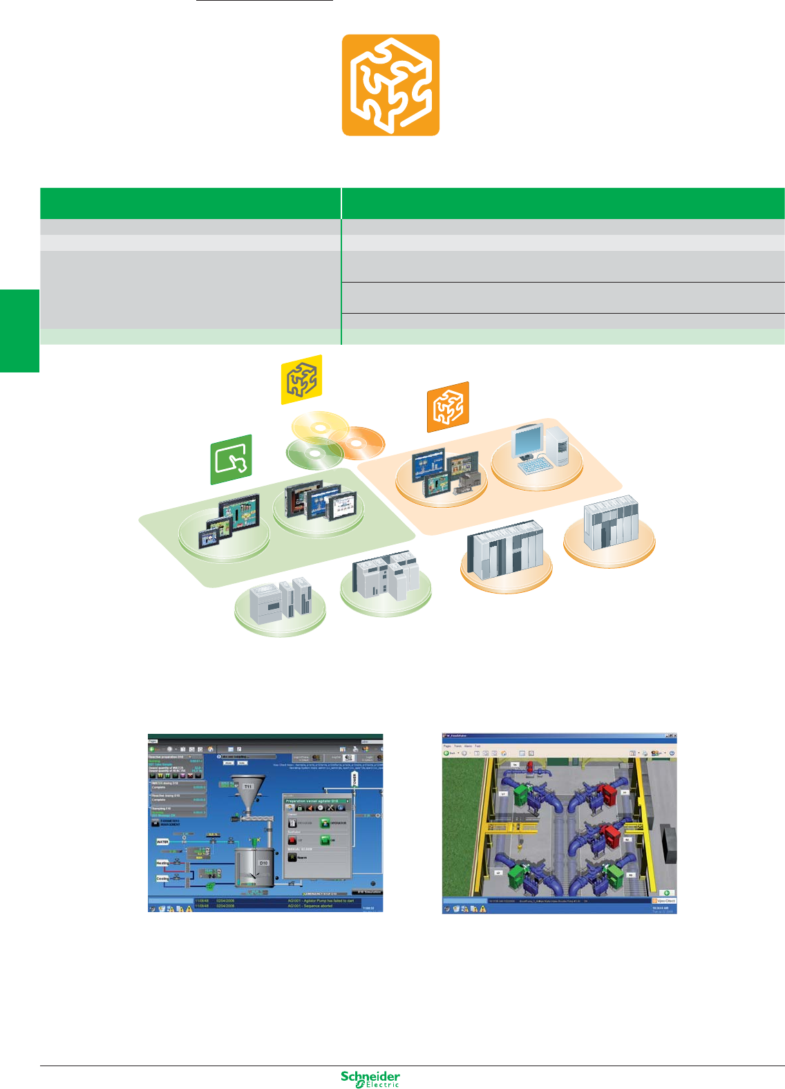
Other versions: please consult your Schneider Electric agency.
Vijeo Citect
Twido Modicon M340Modicon Premium Modicon Quantum
Magelis Smart & Compact iPCMagelis Compact & iPC
Modular iPC
Magelis XBT GT
Vijeo Designer
PC
Vijeo Historian
a SoCollaborative software – (SCADA)
Vijeo Citect
Type Supervisory control and data acquisition (SCADA) software
Compatibility All Schneider Electric automation platforms and third party devices
Operating system Windows XP, Windows Vista and Windows server 2003 & 2005
Versions The development licence (without network connectivity) allows free communication with PLCs for 10
minutes at a time.
Vijeo Citect full server licences are available in 75 points, 150 points, 500 points, 1500 points, 5000
points, 15000 points and unlimited points
Vijeo Citect Lite (without network connectivity) is available in 100 - 1200 points
References Please contact your local sales representative
Vijeo Citect is a SoCollaborative software for operating and monitoring. With its powerful visualisation capabilities and operational features, it delivers actionable insight faster,
enabling operators to respond quickly to process disturbances, thereby increasing their effectiveness. Its easy-to-use configuration tools and powerful features enable you to
quickly develop and deploy solutions for any size application.
Benefits at a glance:
• Full-redundancy for reliable architecture: Vijeo Citect’s in-built redundancy greatly reduces lost data and downtime, tolerating failure anywhere in your system.
• Powerful graphics: Vijeo Citect lets you develop true colour, easy-to-use graphics that provide the operator with an intuitive, consistent user interface.
• Intuitive Process Analysis tool: Vijeo Citect Process Analyst is an intuitive process analysis tool that sits directly in the SCADA system, providing a complete story of
your plant and delivering actionable insight to the operators faster, thereby improving their efficiency and productivity.
• Object-based configuration for rapid development: Developing your control system is made quick and easy by Vijeo Citect’s object-based configuration tools such
as page templates, Genies, Super Genies, and SpeedLink.
• Engineering with ease: Vijeo Citect offers flexible and targeted system engineering tools to help you be more efficient. It accelerates your control system configuration
process, significantly reducing your engineering time and costs and minimising your project risk.
Vijeo Suite; The best HMI/SCADA offer.
Designed to offer optimum integration
with Schneider Electric equipment.
3/50
2
1
3
4
5
6
7
8
9
10
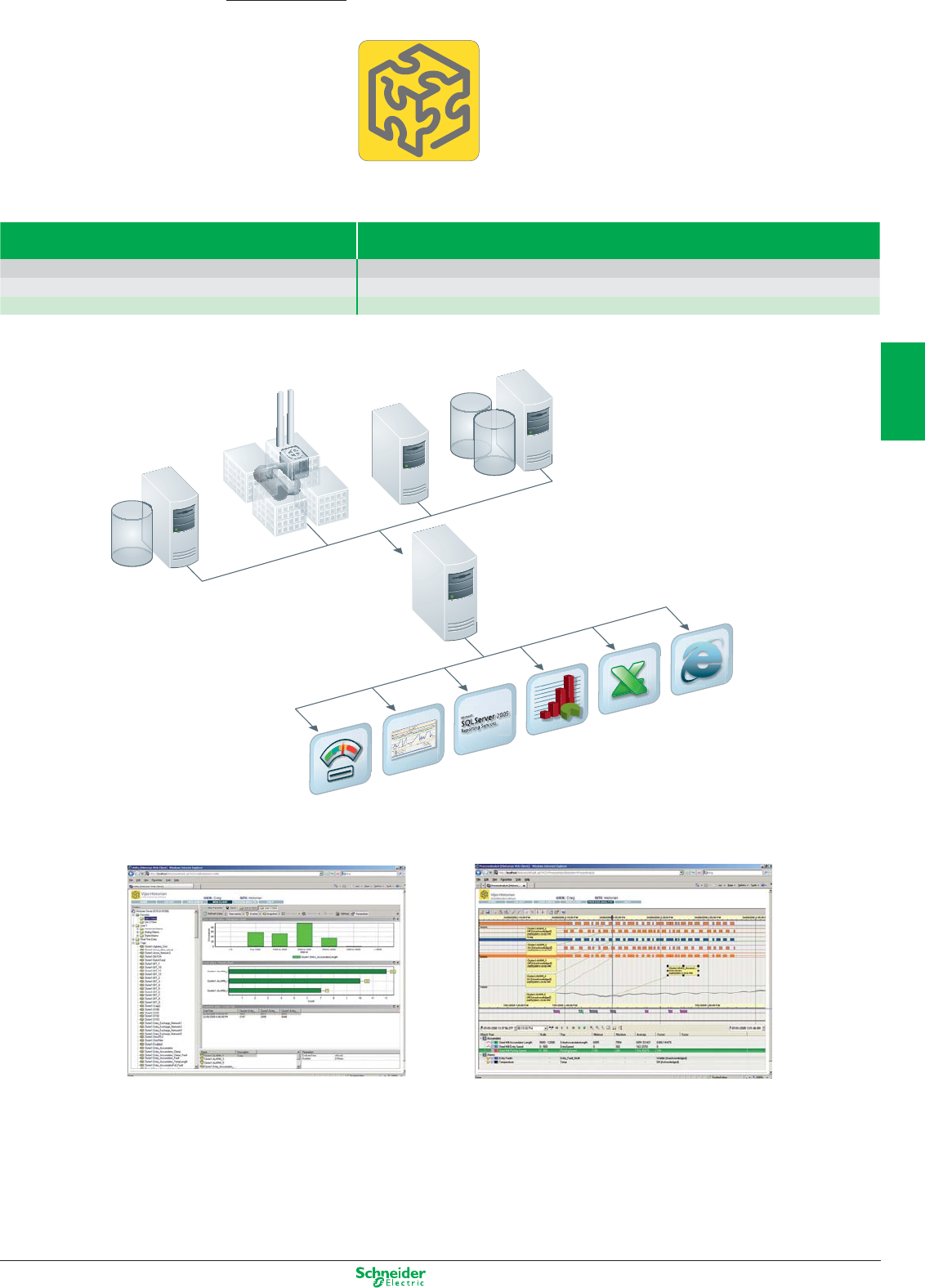
Other versions: please consult your Schneider Electric agency.
MES Process A
nalyst Microsoft SQL Server
2005 Re
p
ortin
g
Se
r
vic
e
s
Hist
orian Reports
De
ployment
Manager
Vi
jeo His
t
orian
Excel Client
Vijeo His
t
or
i
an
Web Client
CADA Sy s em
S
t
Historian
OPC
MS SQL Server/Oracle
Vijeo Historian Server
Vijeo Historian a SoCollaborative software
Type Historian software
Compatibility All Schneider Electric automation platforms and third party devices
Operating system Windows XP, Windows Vista and Windows server 2003 & 2005
References CD-ROM PC Please contact your local sales representative
Vijeo Historian is a SoCollaborative software for the information management. It comprises the historian and portal functionalities of the solution, enabling you to accurately store
data for long-term reporting while connecting your production and business systems through its active data transfers and simple, easy-to-use reporting.
Benefits at a glance:
• Business systems integration: Vijeo Historian reduces the complexity and cost of bridging the divide between senior management and plant operations through its simple,
easy-to-use interface and its active data transfers that push data from the control systems up to the business systems.
• An open data store: Vijeo Historian utilises 100% Microsoft SQL Server 2005 as its embedded historical data store. Its open, industry-standard technology and trusted secu-
rity integrate effortlessly into your business in a way that lowers your total cost of ownership.
• Enterprise-wide reporting: A range of reports can be produced using a convenient built-in historian in the familiar, open Microsoft user interface. Vijeo Historian also comes
with a standard set of pre-configured reports, simplifying basic alarm and tag reporting.
• Alarm management: Pre-configured alarm reports based on the EEMUA (Engineering Equipment & Materials Users Association) 191 alarm management guidelines.
• Going ‘green’ with the energy reports: Energy reports help you perform a comprehensive energy assessment of your plant to determine how much energy is being consu-
med and how much could potentially be saved.
3/51
2
1
3
4
5
6
7
8
9
10
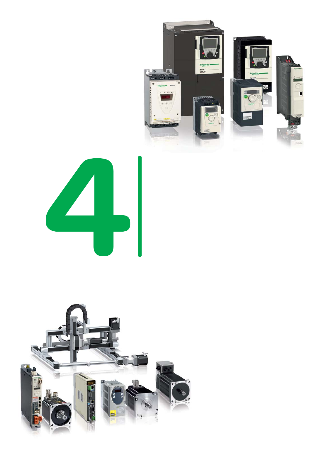
Improve machine effi ciency, reduce
energy consumption and optimise
dynamics with the Altistart, Altivar
and Lexium ranges. Easy to install and
offering intuitive programming and
extensive communication options, they
can be integrated seamlessly into your
control system architectures.
Altistart and Altivar
Start your motors smoothly and protect your installation's
mechanics using Altistart soft starters and Altivar variable
speed drives.
Lexium
Motion controllers, drives, motors and
linear motion axes - Schneider Electric
offers a complete range of motion
products and solutions for your specifi c
applications. All our motion products
are designed for maximum ease
over the entire machine lifecycle to
reduce costs and make your machine
processes even more productive.

Motion control
This document is a selection of
the top selling products.
4/1
2
1
3
4
5
6
7
8
9
10
Soft starters and variable speed drives
Selection guide ......................................................................................................... 4/3 and 4/7
Starters
Altistart 01 .................................................................................................................. 4/8 and 4/9
Altistart 22 ...............................................................................................................4/10 and 4/11
Altistart 48 .............................................................................................................. 4/12 and 4/13
Drives
Altivar 12 ............................................................................................................................... 4/14
Altivar 21 ............................................................................................................................... 4/15
Altivar 312 ............................................................................................................................. 4/16
Altivar 31C ............................................................................................................................. 4/17
Altivar 32 ................................................................................................................ 4/18 and 4/19
Altivar 61 ................................................................................................................... 4/20 to 4/27
Altivar 71 ................................................................................................................... 4/28 to 4/36
Dialogue and communication ........................................................................... 4/37 to 4/39
Controllers, drives, motors and linear motion axes
Selection Guide ....................................................................................................... 4/40 to 4/42
Lexium Motion Controller ............................................................................................... 4/43
Lexium Servo Drives and Motors ..................................................................... 4/44 to 4/51
Lexium 32 servo drives
Lexium BMH and Lexium BSH servo motors
Lexium Stepper Drives and Motors ............................................................................ 4/52
Lexium SD2/Lexium SD3 stepper drives
Lexium BRS2/Lexium BRS3 stepper motors
Lexium Integrated Drives .................................................................................... 4/53 to 4/55
Lexium ILA/ILE/ILS/ILT/ILP
Lexium Linear Motion ........................................................................................ 4/56 and 4/57
Lexium PAS/CAS/TAS/MAX
Other versions: Please consult your Schneider Electric sales offi ce.
New products
Altivar 32
So slim, So smart!
More innovations
> Slim shape product (45 mm wide)
> Circuit-breaker connected directly to the product
> Mounting can be vertical or on the side
> Integrated safety functions
> Integrated programmable logic functions
> Built-in Bluetooth®: remote adjustment and parameter
setting via mobile phone or PC
> Confi guration with the power off in its original packaging
More openness
> Application-oriented: predefi ned settings and
combinations of functions
> Modbus and CANopen integrated as standard
> Access to the majority of industrial communication
networks
> Tools adapted to each stage in the product lifecycle
More energy savings
> New control profi le for synchronous motors in speed
control mode
> Control profi les to optimise energy
Altistart 22
Cut your costs with an integrated bypass function*
More innovative
More economical
Safer
> Reduction in your operating costs
> Simplifi ed wiring
> Protection of your electrical installation
> Space savings with a fully equipped product
* bypass = shunt
4/2
2
1
3
4
5
6
7
8
9
10
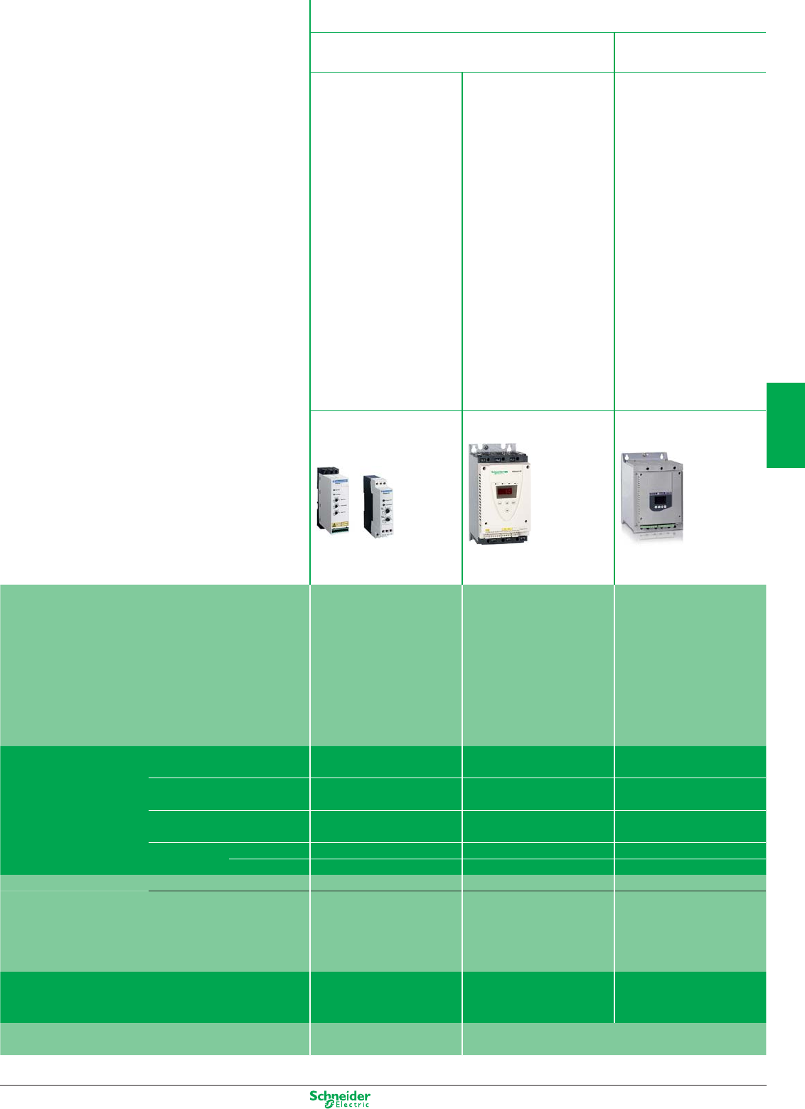
Other versions: Please consult your Schneider Electric sales offi ce.
Selection guide
Starters - Low voltage
Simple machines
Complex machines/
Special machines
CApplications:
Compressors, fans,
pumps, conveyors, car
wash gantries, etc.
CApplications:
Pumps, fans, turbines,
compressors, conveyors,
conveyor belts, lifting
screws, escalators, etc.
CApplications:
Pumps, high inertia
fans and machines,
compressors, conveyors,
agitators, mixers,
escalators, etc.
Altistart 01 Altistart 22 Altistart 48
Soft start units and soft start/soft
stop units
Soft start/soft stop units Soft start/soft stop units
Description Compact
Simple: easy mounting,
wiring and adjustment
Effi cient: limiting of current
peaks on starting, reduction of
mechanical shocks, increased
service life for your machines.
Energy saving
• Innovative with its integrated
Bypass
• Cost-effective
• Compact dimensions
• Quick setup
• Protection of motor and
starter
• Energy saving
Torque control system:
controlled torque, prevention of
pressure surges and limiting of
temperature rises
Simple: quick setup
Protection of motor and starter:
thermal protection, phase loss
detection, locked rotor detection
Energy saving
Technical information Power range for
50…60 Hz supply
0.37...15 kW 4... 400 kW 4...1200 kW
Voltage Single-phase 110…480 V Three-phase 208…600 V Three-phase 208…690 V
Three-phase 110…480 V Three-phase 230…440 V
Drive/Output frequency – – –
Motor type Asynchronous Yes Yes Yes
Synchronous No No No
Communication Integrated – Modbus Modbus
As an option Can be used with TeSys U
motor starter-controller to
create a complete motor
starter solution
– DeviceNet, Fipio, PROFIBUS DP
Standards and certifi cations IEC/EN 60947-4-2, C-Tick, CSA,
UL, CE
IEC/EN 60947-4-2, C-Tick, CSA,
UL, CE, GOST, CCC
Class A EMC
IEC/EN 60947-4-2, C-Tick, CSA,
UL, CE, DNV, GOST, CCC, NOM,
SEPRO and TCF
Classes A and B EMC
Intended use Building, simple machines. Machines, infrastructures and buildings
4/3
2
1
3
4
5
6
7
8
9
10
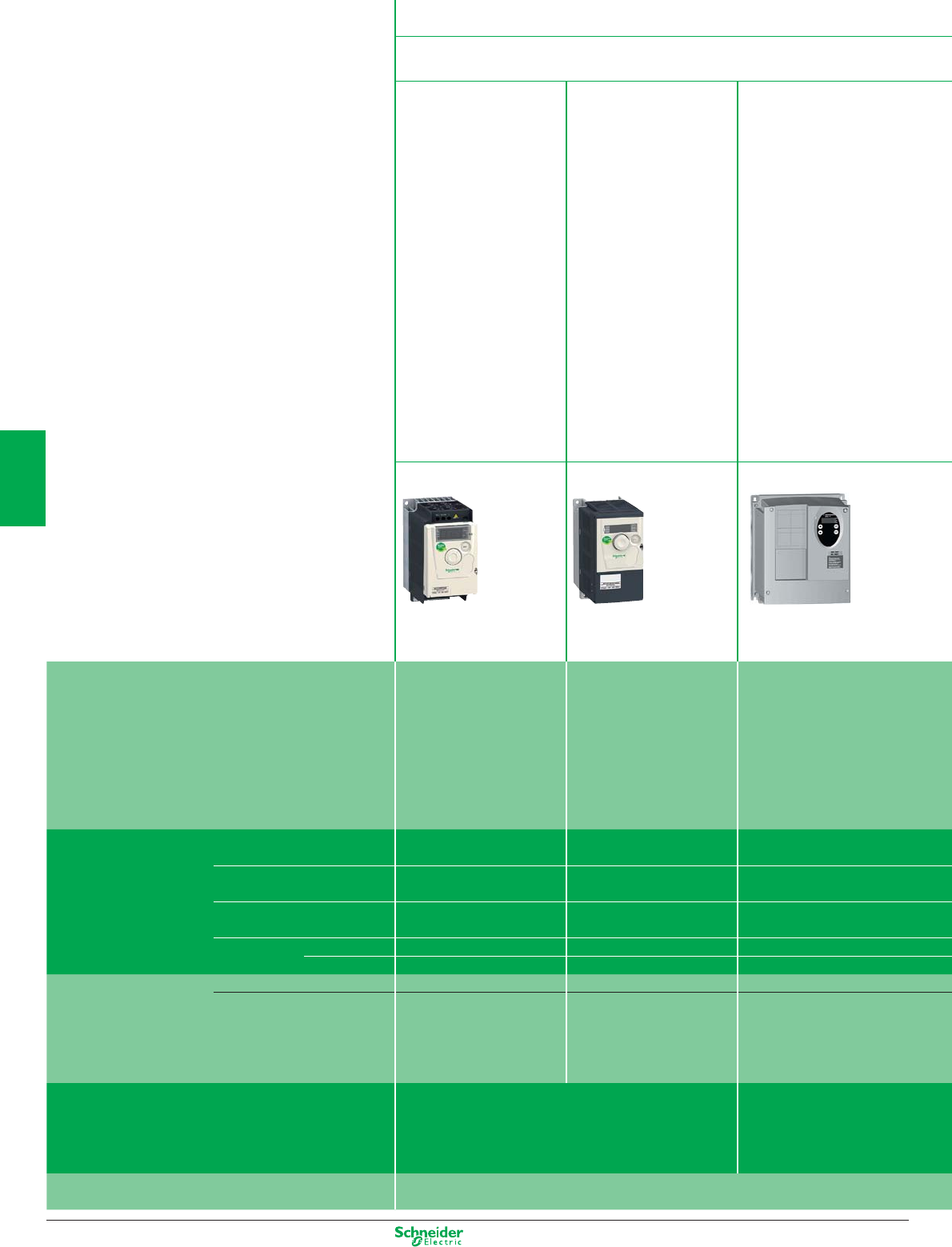
Other versions: Please consult your Schneider Electric sales office.
Selection guide
Standard drives - Low voltage
Simple machines
CApplications:
• Simple machines for
industry (small handling
applications, packaging,
pumps, fans, etc.)
• Simple consumer
machines (access barriers,
rotating advertising
hoardings, medical beds,
treadmills, dough mixers,
etc.)
• Other types of application:
- Mobile machines and
small appliances equipped
with a power socket
- Applications which
traditionally use other
solutions (2-speed DC
motors, mechanical drives,
etc.).
C Applications:
Simple industrial machines
(material handling
and packaging, textile
machines, special
machines, pumps and
fans).
C Applications:
Simple industrial machines
(material handling and
packaging, textile machines,
special machines, pumps
and fans).
Altivar 12 Altivar 312 Altivar 31C IP54
Variable speed drives for small
machines with 240 V three-phase
asynchronous motor
Variable speed drives for three-
phase asynchronous motors
Variable speed drives for three-
phase asynchronous motors for
machines in harsh environments.
Description • Compact
• Easy to set up
(Plug & Play)
• Reliable, cost-effective
solution for compact machines
• Open: large number of
communication cards available
as options
• User-friendly: simplified
interface
• Autotuning:
maximum performance
• Rugged even in the most hostile
environments:
- Installed as close as possible to the
motor
- Integrated functions for applications
requiring IP54 degree of protection
- Modbus and CANopen
communication protocols
• Flexibility to adapt to each machine:
- Customisable depending on the
model
- Easy configuration
Technical information Power range for
50…60 Hz supply
0.18...4 kW 0.18...15 kW 0.18...15 kW
Voltage Single-phase 100…240 V Single-phase 200…240 V Single-phase 200…240 V
Three-phase 200…240 V Three-phase 200…600 V Three-phase 380…500 V
Drive/Output frequency
0.5…400 Hz 0.5…500 Hz 0.5…500 Hz
Motor type Asynchronous Yes Yes Yes
Synchronous No No No
Communication Integrated Modbus Modbus and CANopen Modbus and CANopen
As an option – CANopen Daisy chain,
DeviceNet, PROFIBUS DP,
Modbus TCP, Fipio
DeviceNet, Ethernet TCP/IP, Fipio,
Profibus DP
Standards and certifications IEC/EN 61800-5-1, IEC/EN 61800-3 (environments 1 and 2,
categories C1 to C3)
CE, UL, CSA, C-Tick, GOST, NOM
IEC/EN 61800-5-1, IEC/EN 61800-
3 (environments 1 and 2, categories
C1 to C3)
CE, UL, CSA, C-Tick, GOST
Intended use Machines
4/4
2
1
3
4
5
6
7
8
9
10
Other versions: Please consult your Schneider Electric sales offi ce.
Complex machines
Complex machines/
Special machines
HVAC Pumps and
Fans
Lifts
C Applications:
Industrial machines:
hoisting, packaging,
material handling, textile
machines, special
machines (wood-
working machines, metal
processing machinery,
etc.).
C Applications:
High performance
applications:
• Material handling
• Hoisting
• Wood-working machines
• Process machinery
• Textile machines
• Packaging
C Applications:
Range specifi cally for
HVAC applications
(heating, ventilation, air
conditioning) in buildings.
C Applications:
Range specifi cally for high
performance pumps and
fans for the industrial and
building markets.
C Applications:
Lifts
Altivar 32 Altivar 71 Altivar 21 Altivar 61 Altivar Lift
Variable speed drives for
asynchronous motors and
open-loop synchronous motors
For three-phase synchronous and
asynchronous motors.
Constant torque applications.
Variable speed drives for three-
phase asynchronous motors.
Variable torque building HVAC
applications.
Variable speed drives for three-
phase asynchronous motors.
Variable torque applications.
Variable speed drives for lifts and
hoists.
• Compact: "Book" format
• Integrated safety functions
• Open: communication cards
available as options
• Integrated programmable
logic functions
• Simple setup
• Wide range
• Quick start-up and easy
diagnostics: multi-language
graphic display terminal
• Open to most industrial
communication buses
• Integrated safety functions
• Motor control: high-
performance in open-loop and
closed loop mode
• Compact size: side-by-side
mounting
• Simple: "plug&drive" function and
"local remote" key
• Open communication:
communication cards specifi cally
for building applications
• EMC fi lters built-in
• Reduction of the total
harmonic distortion THDI<30%
• Wide range
• Easy setup and diagnostics
with the multi-language graphic
display terminal
• Open to the main
communication buses
• Quick start-up and
easy diagnostics with the multi-
language graphic display terminal
• Specifi cally designed for lift
applications for greater comfort
and safety
• High-performance motor
control in open-loop and closed
loop mode
0.18...15 kW 0.37...630 kW 0.75...75 kW 0.37...800 kW 4...22 kW
Single-phase 200…240 V Single-phase 200…240 V Three-phase 200…480 V Single-phase 200…240 V Single-phase 200…240 V
Three-phase 380…480 V Three-phase 200…690 V Three-phase 200…690 V Three-phase 200…480 V
0.5…800 Hz 0.5…1600 Hz up to 37 kW
0.5…500 Hz from 45…630 kW
0.5…200 Hz 0.5…1600 Hz up to 37 kW
0.5…500 Hz from 45…800 kW
0.5…1600 Hz
Yes Yes Yes Yes Yes
Yes Yes No Yes No
Modbus and CANopen Modbus and CANopen Modbus Modbus and CANopen Modbus and CANopen
EtherNet/IP, Modbus TCP,
PROFIBUS DP V1, PROFIBUS
DP V0, DeviceNet
Modbus TCP, Fipio,
Modbus/Uni-Telway, Modbus
Plus, EtherNet/IP, DeviceNet,
PROFIBUS DP, PROFIBUS DP
V1, INTERBUS S, CC-Link,
Lonworks, METASYS N2,
APOGEE FLN, BACnet
Modbus TCP, Fipio, Modbus/Uni-
Telway, Modbus Plus, EtherNet/IP,
DeviceNet, PROFIBUS DP,
PROFIBUS DP V1, INTERBUS
S, CC-Link, Lonworks, METASYS
N2, APOGEE FLN, BACnet
Modbus TCP, Fipio, Modbus/Uni-
Telway, Modbus Plus,EtherNet/IP,
DeviceNet, PROFIBUS DP,
PROFIBUS DP V1, INTERBUS S,
CC-Link
IEC/EN 61800-5-1, IEC/EN 61800-3
(environments 1 and 2, Categories
C2 and C3), UL508C, EN 954-1
Category 3, ISO/EN 13849-1/- 2
Category 3 (PLd), IEC 61800-5-2, IEC
61508 (parts 1&2) level SIL1 SIL2 SIL3,
draft standard EN 50495E, CE, UL,
CSA, C-Tick, GOST, NOM.
IEC/EN 61800-3, EN 55011,
EN 55022, CSA, UL, C-TICK,
CE, NOM, DNV, GOST
IEC/EN 61800-3, EN 55011,
EN 55022, CSA, UL, C-TICK,
CE, NOM
IEC/EN 61800-3, EN 55011,
EN 55022, CSA, UL, C-TICK,
CE, NOM, DNV, GOST
IEC/EN 61800-3, EN55011,
EN 55022, CSA, UL, C-TICK,
CE, NOM
Machines Machines, industrial processes
and infrastructures
Buildings Buildings and infrastructures Machines
4/5
2
1
3
4
5
6
7
8
9
10
Other versions: Please consult your Schneider Electric sales offi ce.
Selection guide
Integrated variable speed control solutions
Pumps and Fans
Low voltage
Pumps and Fans
High voltage
C Applications:
• Fans
• Pumps
• Compressors
• Screw feeders
C Applications:
• Energy: fans, pumps, turbine starters
• Oil and gas: pumps, compressors,
aerators, extruders
• Mines and Minerals: conveyors,
crushers, fans, pumps
• Water treatment: pumps, aerators.
Altivar 61 Plus Altivar 1100
High power low voltage variable speed drives for
buildings and infrastructures.
Variable torque
Medium power variable speed drives for
asynchronous motors (request quotation)
Description A simple, open range:
• Greater fl exibility: numerous possible options and
communication on most industrial networks
• Easy confi guration
• Ready to use
Maximum safety: the Altivar Plus range has a
cooling system and components that have been
tested in extreme conditions.
Time savings on:
• Devising quotes
• Placing orders
• Installation and start-up
Environmentally-friendly and Cost-effective:
• Perfect integration in the line supply
• No disturbance of the motor and the driven load
• High effi ciency
Easy to install and set up
Compact
Technical information Power range for
50…60 Hz supply
90…2400 kW 0.3…10 MW
Voltage Three-phase 380…690 V 3.3 kV
6.6 kV
10 kV
Drive/Output frequency
0.5…500 Hz Standard: 0.2…60 Hz
Option: 0.2…120 Hz
Number of quadrants 2 and 4 2 and 4 (optional)
Cooling system Air or water cooled Air or water cooled
Protection class IP23/IP54
IP55 (water cooled)
IP31
IP41 (optional)
Motor type Asynchronous Yes Yes
Synchronous Yes No
Communication Integrated Modbus and CANopen Profi bus, Modbus
As an option Modbus TCP, Fipio, Modbus/Uni-Telway, Modbus
Plus, EtherNet/IP, DeviceNet, PROFIBUS DP,
PROFIBUS DP V1, INTERBUS S, CC-Link,
Lonworks, METASYS N2, APOGEE FLN, BACnet
Ethernet, Devicenet, CANopen
Standards and certifi cations IEC/EN 61800-5-1, IEC/EN 61800-3
(environments 1 and 2), IEC/EN 61000-4-2, -4-3,
-4-5, -4-6 (level 3), IEC/EN 61000-4-4 (level 4),
IEC/EN 60529, IEC 60721-3-3 class 3C2 and 3S2,
CE. DNV, GOST
IEC/EN 61800-5-1, IEC/EN 61800-4,
IEC/EN 61800-3 (environments 1 and 2,
categories C1 to C3), IEEE 519
Intended use Buildings and infrastructures Infrastructures
4/6
2
1
3
4
5
6
7
8
9
10
Other versions: Please consult your Schneider Electric sales offi ce.
Complex machines/Special machines
Low voltage
Complex machines/Special machines
Medium voltage
C Applications:
• Fans
• Pumps
• Compressors
• Screw feeders
C Applications:
• Energy: fans, pumps, turbine starters
• Oil and gas: pumps, compressors, aerators, extruders
• Mines and Minerals: conveyors, crushers, fans, pumps
• Water treatment: pumps, aerators.
Altivar 71 Plus Altivar 1000
High power low voltage variable speed drives for industry.
Constant torque
Medium power variable speed drives for asynchronous motors
(request quotation)
A simple, open range:
• Greater fl exibility: numerous possible options and communication on most industrial
networks
• Easy confi guration
• Ready to use
Maximum safety: the Altivar Plus range has a cooling system and components that
have been tested in extreme conditions.
Time savings on:
• Devising quotes
• Placing orders
• Installation and start-up
High effi ciency
For use in harsh environments
Open to all communication networks
90…2400 kW 0.5…10 MW
Three-phase 380…690 V 2.4 kV
3.3 kV
0.5…500 Hz Standard: 5…670 Hz
Option: 5…140 Hz
2 and 4 2 and 4
Air or water cooled Air or water cooled
IP23/IP54
IP55 (water cooled)
IP41 (air cooled)
IP54 (water cooled)
Yes Yes
Yes No
Modbus and CANopen Ethernet, Profi bus, Modbus
Modbus TCP, Fipio, Modbus/Uni-Telway, Modbus Plus, EtherNet/IP, DeviceNet,
PROFIBUS DP, PROFIBUS DP V1, INTERBUS S, CC-Link
Devicenet, CANopen
IEC/EN 61800-5-1, IEC/EN 61800-3 (environments 1 and 2), IEC/EN 61000-4-2,
-4-3, -4-5, -4-6 (level 3), IEC/EN 61000-4-4 (level 4), IEC/EN 60529, IEC 60721-3-3
class 3C2 and 3S2, CE. DNV and GOST
IEC/EN 61800-5-1, IEC/EN 61800-4,
IEC/EN 61800-3 (environments 1 and 2,
categories C1 to C3), CE
Machines, industrial processes and infrastructures Machines, industrial processes and infrastructures
4/7
2
1
3
4
5
6
7
8
9
10
Other versions: Please consult your Schneider Electric sales office.
Type Soft start units Soft stop units
Motor power 0.37 to 15 kW 0.75 to 15 kW
Degree of protection IP20
Reduction of current peaks 2 controlled phases 2 controlled phases
Adjustable starting time 1…5 s 1…10 s
Adjustable deceleration time No: freewheel stop Yes: 1... 10 s
Adjustable breakaway torque 30…80% of DOL motor starting torque
Logic inputs
–
3 logic inputs (start, stop and startup boost)
Logic outputs – 1 logic output
Relay outputs – 1 relay output
Control supply voltage
110... 220 VAC ± 10%, 24 VDC ± 10%
Built into the starter
Supply voltage
Single-phase 110…230 V
Motor power
230 V Nominal current
kW (IcL)
0.37 3 A ATS01N103FT
0.75 6 A ATS01N106FT
1.1 9 A ATS01N109FT
1.5 12 A ATS01N112FT
2.2 25 A ATS01N125FT
Supply voltage
Three-phase 110…480 V Three-phase 200…240 V Three-phase 380…415 V Three-phase 440…480 V
Motor power
210 V 230 V 400 V 460 V Nominal current
HP kW HP kW HP (IcL)
– 0.37-0.55 0.5/– 1.1 0.5-1.5 3 A ATS01N103FT – – –
0.5 0.75-1.1 1-1.5 2.2-3 2-3 6 A ATS01N106FT ATS01N206LU ATS01N206QN ATS01N206RT
11.5 2 4 5 9 A ATS01N109FT ATS01N209LU ATS01N209QN ATS01N209RT
1.5 2.2 3 5.5 7.5 12 A ATS01N112FT ATS01N212LU ATS01N212QN ATS01N212RT
– 4-5.5 5-7.5 7.5-11 10-15 22 A – ATS01N222LU ATS01N222QN ATS01N222RT
2-3 3-4-5.5 5-7.5
7
.
5-9-11
10-15 25A ATS01N125FT – – –
– 7.5 10 15 20 32 A – ATS01N232LU ATS01N232QN ATS01N232RT
Altistart 01
0.37…15 kW
Simple machines
Starters
Dimensions (in mm) width x height x depth
ATS01 N103FT/N106 FT 22.5 x 100 x 100.4
N109FT/N112 FT/N125 FT 45 x 124 x 130.7
N206pp/N209pp/N212pp
N222pp/N232pp 45 x 154 x 130.7
4/8
2
1
3
4
5
6
7
8
9
10
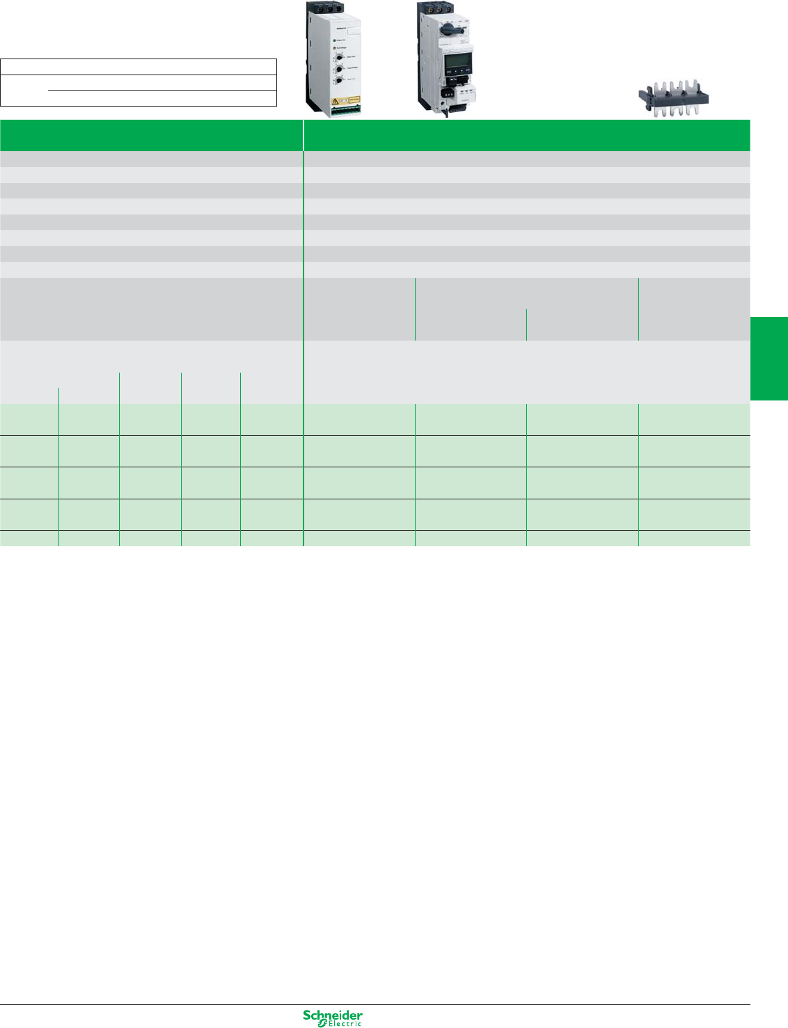
Other versions: Please consult your Schneider Electric sales office.
Starters with TeSys model U
Type Soft stop units
Motor power 0.75 to 15 kW
Degree of protection IP20
Reduction of current peaks Yes
Adjustable starting and stopping times 1…10 s
Adjustable breakaway torque 30.... 80% of DOL motor starting torque
Logic inputs 3 logic inputs (start, stop and startup boost)
Logic outputs 1 logic output
Relay outputs 1 relay output
Control supply voltage 24 VDC, 100 mA, ± 10%
References Soft start/soft stop
units
TeSys starter-controller Power connector
model U
Power base Control unit (1) between ATSU and
TeSys model U
Supply voltage Three-phase 200…480 V
Motor power
230 V 400 V 460 V
Nominal
current (IcL)
kW HP kW HP
0.75 1 1.5 2 6 A ATSU01N206LT LUB12 LUCp05BL VW3G4104
1.1 1.5 2.2/3 3 6 A ATSU01N206LT LUB12 LUCp12BL
1.5 2 – 6 9 A ATSU01N209LT LUB12 LUCp12BL VW3G4104
– – 4 – 9 A ATSU01N209LT LUB12 LUCp12BL
2.2 3 5.5 7.5 12 A ATSU01N212LT LUB12 LUCp12BL VW3G4104
3 – – – 12 A ATSU01N212LT LUB32 LUCp18BL
4 5 7.5 10 22 A ATSU01N222LT LUB32 LUCp18BL VW3G4104
5.5 7.5 11 15 22 A ATSU01N222LT LUB32 LUCp32BL
7.5 10 15 20 32 A ATSU01N232LT LUB32 LUCp32BL VW3G4104
(1) To compose your reference, replace p in the reference with: «A» for a standard control unit, «M» for a multifunction unit and «B» for an advanced unit.
Dimensions (in mm) width x height x depth
ATSU01 N206LT/N209LT/N212LT 45 x 124 x 130.7
N222LT/N232LT 45 x 154 x 130.7
4/9
2
1
3
4
5
6
7
8
9
10
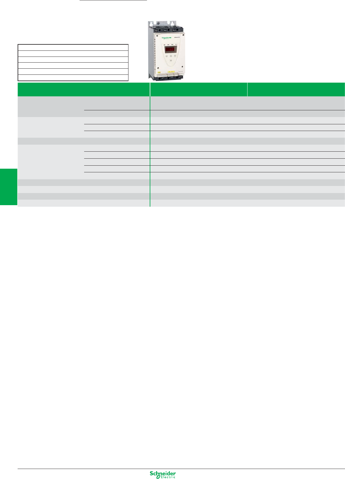
Other versions: Please consult your Schneider Electric sales offi ce.
Altistart 22
4…400 kW
Simple machines
Soft start/soft stop units
Supply voltage Three-phase 208…600 V (1) Three-phase 230…440 V
Protection Degree of protection IP20: for ATS 22D17pppD88 starters
IP00: for ATS 22C11pppC59 starters (protection of terminals available as an option)
Motor thermal protection Class 10, 20 or 30
Drive Number of controlled phases 3
Types of control Confi gurable voltage ramp, torque ramp
Operating cycle Standard
Functions Bypass (integrated)
Number of I/O Analog inputs 1 PTC probe
Logic inputs 3
Logic outputs –
Analog outputs –
Relay outputs 2
Dialogue Integrated display terminal, SoMove Lite setup software
Communication Integrated Modbus
Standards and certifi cations IEC/EN 60947-4-2, class A EMC, CE, UL, CSA, C-Tick, GOST, CCC
Motor connection Possible to connect the starter in the motor delta connection
(1) Possible to connect the starter in the motor delta connection
Dimensions (en mm) width x height x depth
Size A: 130 x 265 x 169
Size B: 145 x 295 x 207
Size C: 150 x 356 x 229
Size D: 206 x 425 x 299
Size E: 304 x 455 x 340
4/10
2
1
3
4
5
6
7
8
9
10
Other versions: Please consult your Schneider Electric sales office.
Connection in the motor power supply line Soft start/soft stop unit 230…440 V - 50/60 Hz
Motor
Power indicated on rating plate
230 V 400 V 440 V Nominal current
kW kW kW starter (IcL) Reference Size
4 7.5 7.5 17 ATS 22D17Q Size A
7.5 15 15 32 ATS 22D3Q Size A
11 22 22 47 ATS 22D47Q Size A
15 30 30 62 ATS 22D62Q Size B
18.5 37 37 75 ATS 22D75Q Size B
22 45 45 88 ATS 22D88Q Size B
30 55 55 110 ATS 22C11Q Size C
37 75 75 140 ATS 22C14Q Size C
45 90 90 170 ATS 22C17Q Size C
55 110 110 210 ATS 22C21Q Size D
75 132 132 250 ATS 22C25Q Size D
90 160 160 320 ATS 22C32Q Size D
110 220 220 410 ATS 22C41Q Size E
132 250 250 480 ATS 22C48Q Size E
160 315 355 590 ATS 22C59Q Size E
Connection in the motor power supply line Soft start/soft stop unit 230…440 V - 50/60 Hz
Motor
Power indicated on rating plate
230 V 400 V 440 V 500 V Nominal current
kW kW kW kW starter (IcL) Reference Size
4 7.5 7.5 9 17 ATS 22D17S6 Size A
7.5 15 15 18.5 32 ATS 22D32S6 Size A
11 22 22 30 47 ATS 22D47S6 Size A
15 30 30 37 62 ATS 22D62S6 Size B
18.5 37 37 45 75 ATS 22D75S6 Size B
22 45 45 55 88 ATS 22D88S6 Size B
30 55 55 75 110 ATS 22C11S6 Size C
37 75 75 90 140 ATS 22C14S6 Size C
45 90 90 110 170 ATS 22C17S6 Size C
55 110 110 132 210 ATS 22C21S6 Size D
75 132 132 160 250 ATS 22C25S6 Size D
90 160 160 220 320 ATS 22C32S6 Size D
110 220 220 250 410 ATS 22C41S6 Size E
132 250 250 315 480 ATS 22C48S6 Size E
160 315 355 400 590 ATS 22C59S6 Size E
The Altistart 22 soft start/soft stop unit is also available with a 110 VDC control power supply, reference ATS 22…S6U
4/11
2
1
3
4
5
6
7
8
9
10
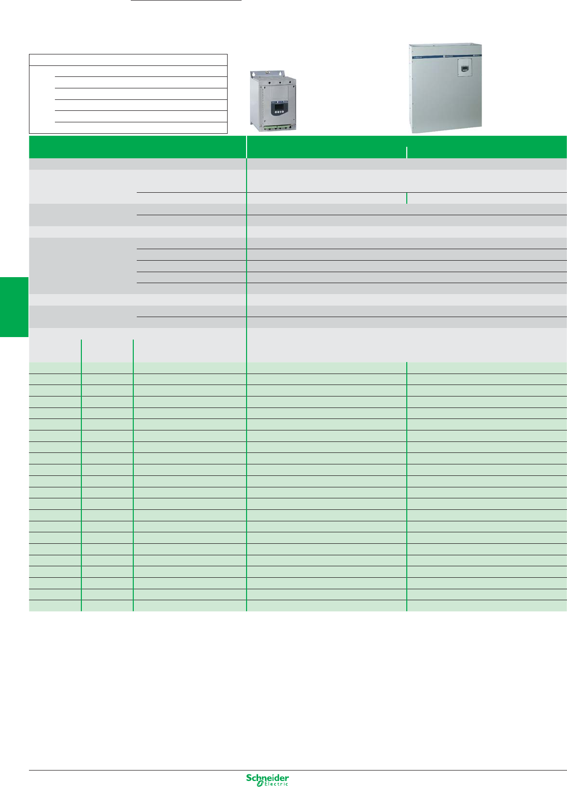
Other versions: Please consult your Schneider Electric sales office.
Altistart 48
4…1200 kW
Pumping and ventilation machines
Soft start/soft stop units
Supply voltage Three-phase 230…415 V (1)
Type of application Standard Severe (2)
Starter control supply voltage 220…415 V
Protection Degree of protection IP20: ATS48D17p to ATS48C11p starters
IP00: ATS48C14p to ATS48M12p starters
Motor thermal protection Class 10 Class 20 and 30
EMC Class A On all starters
Class B On all starters up to 170 A
Starting mode Torque control (patented TCS: Torque Control System)
I/O Analog inputs 1 PTC probe
Logic inputs 4 logic inputs, 2 of which are configurable
Logic outputs 2 configurable logic outputs
Analog outputs 1 analog output
Relay outputs 3 relay outputs, 2 of which are configurable
Dialogue Integrated or remote display terminal (in option), PowerSuite software workshop
Communication Integrated Modbus
As an option DeviceNet, Ethernet TCP/IP, Fipio, Profibus DP
Motor power
230 V 400 V Nominal current
kW kW (IcL)
3 5.5 12 A – ATS48D17Q Size A
4 7.5 17 A ATS48D17Q Size A ATS48D22Q Size A
5.5 11 22 A ATS48D22Q Size A ATS48D32Q Size A
7.5 15 32 A ATS48D32Q Size A ATS48D38Q Size A
9 18.5 38 A ATS48D38Q Size A ATS48D47Q Size A
11 22 47 A ATS48D47Q Size A ATS48D62Q Size B
15 30 62 A ATS48D62Q Size B ATS48D75Q Size B
18.5 37 75 A ATS48D75Q Size B ATS48D88Q Size B
22 45 88 A ATS48D88Q Size B ATS48C11Q Size B
30 55 110 A ATS48C11Q Size B ATS48C14Q Size C
37 75 140 A ATS48C14Q Size C ATS48C17Q Size C
45 90 170 A ATS48C17Q Size C ATS48C21Q Size D
55 110 210 A ATS48C21Q Size D ATS48C25Q Size D
75 132 250 A ATS48C25Q Size D ATS48C32Q Size D
90 160 320 A ATS48C32Q Size D ATS48C41Q Size E
110 220 410 A ATS48C41Q Size E ATS48C48Q Size E
132 250 480 A ATS48C48Q Size E ATS48C59Q Size E
160 315 590 A ATS48C59Q Size E ATS48C66Q Size E
– 355 660 A ATS48C66Q Size E ATS48C79Q Size F
220 400 790 A ATS48C79Q Size F ATS48M10Q Size F
250 500 1000 A ATS48M10Q Size F ATS48M12Q Size F
355 630 1200 A ATS48M12Q Size F –
(1) Possible to connect the starter in the motor delta connection
(2) Starting time greater than 30 seconds (fans, high inertia machines and compressors)
Dimensions (in mm) width x height x depth
ATS48 D17Q to D47Q Size A: 160 x 275 x 190
D62Q to C11Q Size B: 190 x 290 x 235
C14Q to C17Q Size C: 200 x 340 x 265
C21Q to C32Q Size D: 320 x 380 x 265
C41Q to C66Q Size E: 400 x 670 x 300
C79Q to M12Q Size F: 770 x 890 x 315
4/12
2
1
3
4
5
6
7
8
9
10
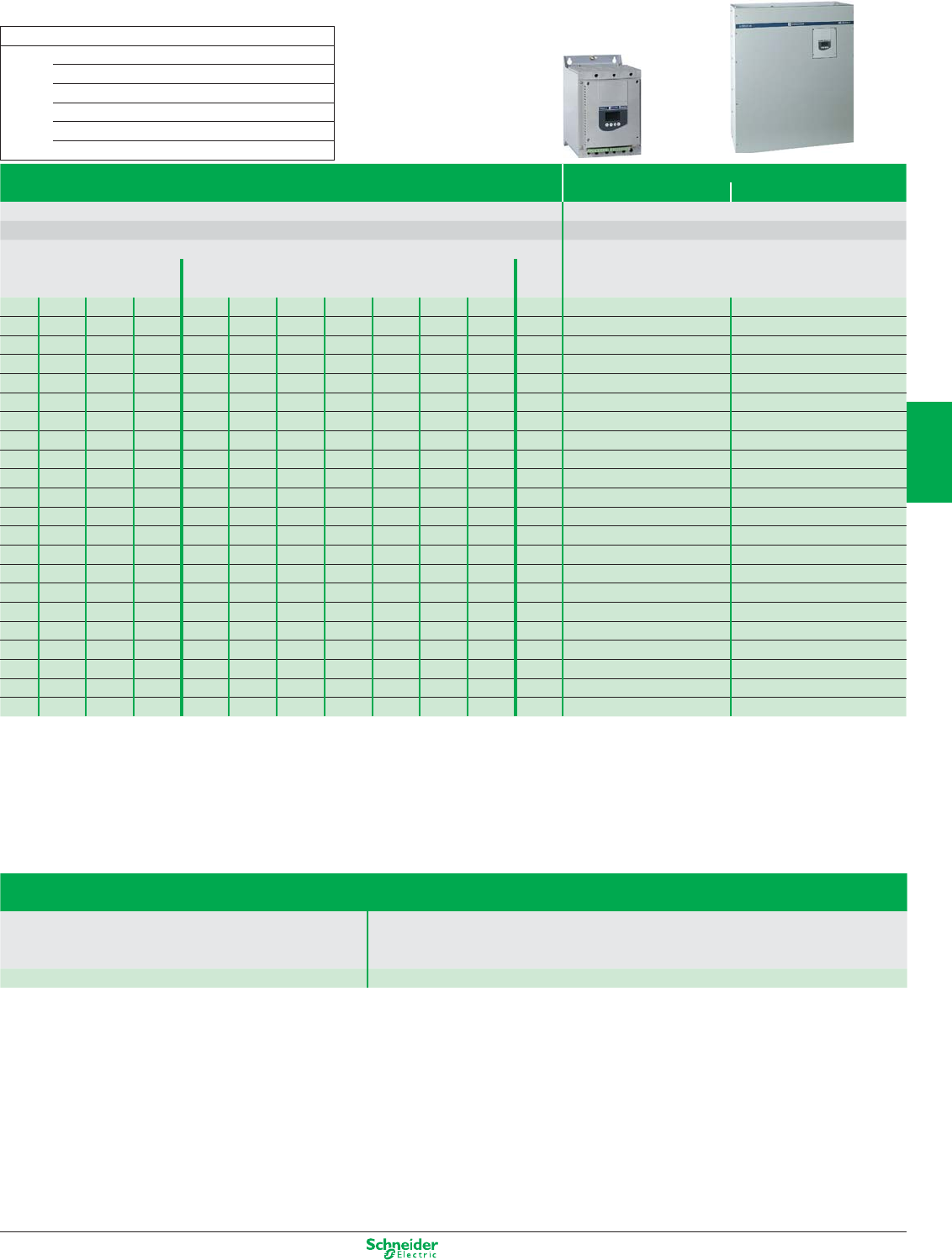
Other versions: Please consult your Schneider Electric sales office.
Soft start/soft stop units
Supply voltage Three-phase 208…690 V (1)
Type of application Standard Severe (2)
Starter control supply voltage 110…230 V
Characteristics Identical to 230…415 V starters
Motor power
Nominal
current
(IcL)
208 V 230 V 460 V 575 V 230 V 400 V 440 V 500 V 525 V 660 V 690 V
HP kW
2 3 7.5 10 3 5.5 5.5 7.5 7.5 9 11 12 A – ATS48D17Y Size A
3 5 10 15 4 7.5 7.5 9 9 11 15 17 A ATS48D17Y Size A ATS48D22Y Size A
5 7.5 15 20 5.5 11 11 11 11 15 18.5 22 A ATS48D22Y Size A ATS48D32Y Size A
7.5 10 20 25 7.5 15 15 18.5 18.5 22 22 32 A ATS48D32Y Size A ATS48D38Y Size A
10 – 25 30 9 18.5 18.5 22 22 30 30 38 A ATS48D38Y Size A ATS48D47Y Size A
–1530401122223030373747 AATS48D47Y Size A ATS48D62Y Size B
15 20 40 50 15 30 30 37 37 45 45 62 A ATS48D62Y Size B ATS48D75Y Size B
20 25 50 60 18.5 37 37 45 45 55 55 75 A ATS48D75Y Size B ATS48D88Y Size B
25 30 60 75 22 45 45 55 55 75 75 88 A ATS48D88Y Size B ATS48C11Y Size B
30 40 75 100 30 55 55 75 75 90 90 110 A ATS48C11Y Size B ATS48C14Y Size C
40 50 100 125 37 75 75 90 90 110 110 140 A ATS48C14Y Size C ATS48C17Y Size C
50 60 125 150 45 90 90 110 110 132 160 170 A ATS48C17Y Size C ATS48C21Y Size D
60 75 150 200 55 110 110 132 132 160 200 210 A ATS48C21Y Size D ATS48C25Y Size D
75 100 200 250 75 132 132 160 160 220 250 250 A ATS48C25Y Size D ATS48C32Y Size D
100 125 250 300 90 160 160 220 220 250 315 320 A ATS48C32Y Size D ATS48C41Y Size E
125 150 300 350 110 220 220 250 250 355 400 410 A ATS48C41Y Size E ATS48C48Y Size E
150 – 350 400 132 250 250 315 315 400 500 480 A ATS48C48Y Size E ATS48C59Y Size E
– 200 400 500 160 315 355 400 400 560 560 590 A ATS48C59Y Size E ATS48C66Y Size E
200 250 500 600 – 355 400 – – 630 630 660 A ATS48C66Y Size E ATS48C79Y Size F
250 300 600 800 220 400 500 500 500 710 710 790 A ATS48C79Y Size F ATS48M10Y Size F
350 350 800 1000 250 500 630 630 630 900 900 1000 A ATS48M10Y Size F ATS48M12Y Size F
400 455 1000 1200 355 630 710 800 800 – – 1200 A ATS48M12Y Size F –
(1) Starter connection in the motor delta connection: up to 500 V only, add "S316" at the end of the reference
Accessories and options available
Type of accessory
Description Remote display terminal
DNV kit
Line choke
Reference Please refer to the Schneider Electric catalogue
Dimensions (in mm) width x height x depth
ATS48 D17Y to D47Y Size A: 160 x 275 x 190
D62Y to C11Y Size B: 190 x 290 x 235
C14Y to C17Y Size C: 200 x 340 x 265
C21Y to C32Y Size D: 320 x 380 x 265
C41Y to C66Y Size E: 400 x 670 x 300
C79Y to M12Y Size F: 770 x 890 x 315
4/13
2
1
3
4
5
6
7
8
9
10
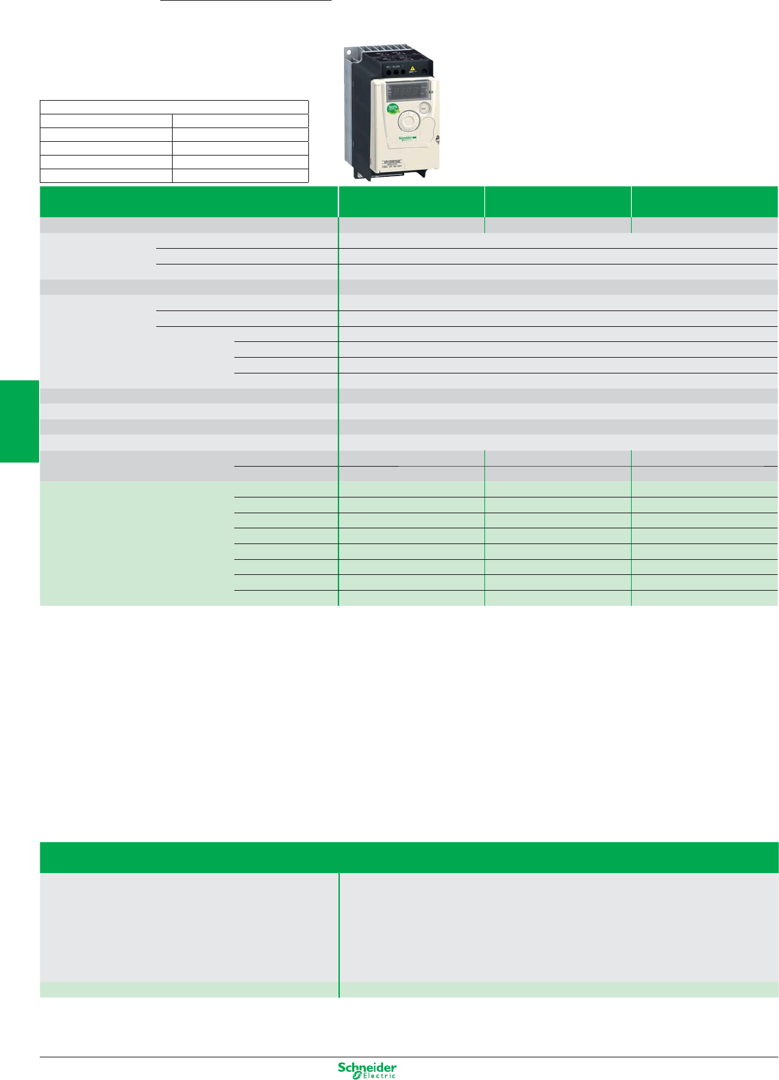
Other versions: Please consult your Schneider Electric sales office.
Altivar 12
0.18…4 kW
Simple machines
Ultra-compact drives
Type of drive Single-phase Single-phase Three-phase
Supply voltage 120 V 240 V 240 V
Degree of protection IP20
Drive Output frequency 0.5… 400 Hz
Type of control Asynchronous motor U/F, sensorless flux vector control, quadratic U/F
Transient overtorque 150…170
Speed range 1 to 20
Functions Number of functions 40
Number of preset speeds 8
Number of I/O Analog inputs 1 configurable analog input
Logic inputs 4 assignable logic inputs
Analog outputs 1 configurable analog output
Relay outputs 1 protected relay logic output
Dialogue
Integrated or remote display terminal, SoMove software workshop, or mobile phone via Bluetooth©
Communication Integrated Modbus
Cards (available as an option)
Reduction of current harmonics
EMC filter Integrated C1 EMC
As an option
Motor power kW/HP 0.18/0.25 ATV12H018F1 (1) 1C1 ATV12H018M2 (1) (2) 1C2 ATV12H018M3 (1) 1C3
0.37/0.5 ATV12H037F1 1C1 ATV12H037M2 (2) 1C1 ATV12H037M3 1C3
0.55/0.75 – ATV12H055M2 (2) 1C2 –
0.75/1 ATV12H075F1 2C1 ATV12H075M2 (2) 1C2 ATV12H075M3 1C3
1.5/2 – ATV12HU15M2 (2) 2C2 ATV12H015M3 2F3
2.2/3 – ATV12HU22M2 (2) 2C2 ATV12H022M3 2F3
3/3 – – ATV12H030M3 3F3
4/5 – – ATV12H040M3 3F3
(1) Because of the poor heat dissipation, the ATV12H018.. is only supplied on a base plate
(2) Also exists as a multipack
Accessories and options available
Type of accessory
Description Remote display terminal
Multi-Loader, Simple Loader
Additional EMC input filter
Plates
Braking resistors and braking unit
Line chokes
Ferrite suppressors for downstream contactor opening
Reference Please refer to the Schneider Electric catalogue
Dimensions (in mm) width x height x depth
1C1: 72 x 143 x 102.2 2F3: 105 x 143 x 131.2
1C2: 72 x 143 x 102.2 3F3: 140 x 184 x 141.2
1C3: 72 x 143 x 121.2
2C1: 105 x 142 x 156.2
2C2: 105 x 142 x 156.2
4/14
2
1
3
4
5
6
7
8
9
10
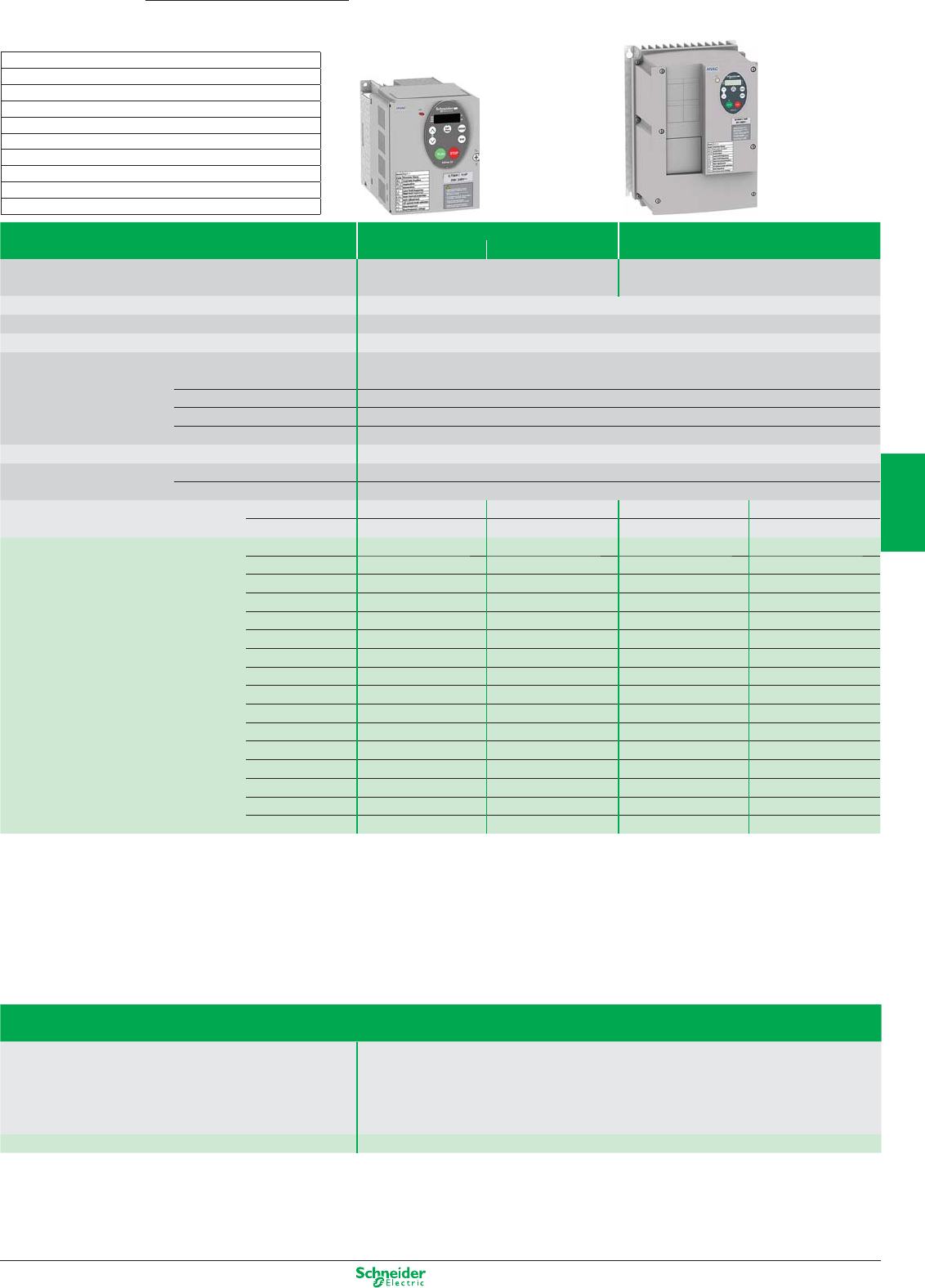
Other versions: Please consult your Schneider Electric sales offi ce.
Altivar 21
0.75…75 kW
Building
Drives for HVAC applications
Type of drive IP20 IP54
380…480 V
Supply voltage Three-phase 200…240 V 380…480 V
Degree of protection IP21 and IP41 on the upper part
IP54 drive available in two manufacturing variants,
ATV21W…N4 C1 EMC or ATV21W…N4C C2 EMC
Output frequency 0.5…200 Hz
Type of control
Kn2 quadratic ratio, sensorless fl ux vector control, voltage/frequency ratio (2 points), energy saving ratio
Speed range 1 to 10
I/O Analog inputs 1 switch-confi gurable current or voltage analog input and 1 voltage analog input, confi gurable as a PTC
probe input
Logic inputs 3 programmable logic inputs
Analog outputs 1 switch-confi gurable current or voltage analog output
Relay outputs 2 relay logic outputs
Dialogue
Integrated display terminal with local controls (1) or remote display terminal or PC software (3)
Communication
(see page 4/11)
Integrated Modbus RTU
As an option HVAC protocols: LonWorks, METASYS N2, APOGEE FLN, BACnet
EMC fi lter Integrated – C2 EMC C2 EMC C1 EMC
Available as an option C2 EMC C1 EMC – –
Motor power kW/HP 0.75/1 ATV21H075M3X T1A ATV21H075N4 T1A ATV21W075N4 T1 ATV21W075N4C T1
1.5/2 ATV21HU15M3X T1A ATV21HU15N4 T1A ATV21WU15N4 T1 ATV21WU15N4C T1
2.2/3 ATV21HU22M3X T1A ATV21HU22N4 T1A ATV21WU22N4 T1 ATV21WU22N4C T1
3/– ATV21HU30M3X T2A ATV21HU30N4 T2A ATV21WU30N4 T2 ATV21WU30N4C T2
4/5 ATV21HU40M3X T2A ATV21HU40N4 T2A ATV21WU40N4 T2 ATV21WU40N4C T2
5.5/7.5 ATV21HU55M3X T3A ATV21HU55N4 T2A ATV21WU55N4 T2 ATV21WU55N4C T2
7.5/10 ATV21HU75M3X T3A ATV21HU75N4 T3A
ATV21WU75N4
T2 ATV21WU75N4C T2
11/15 ATV21HD11M3X T4A ATV21HD11N4 T3A
ATV21WD11N4
T3 ATV21WD11N4C T3
15/20 ATV21HD15M3X T4A ATV21HD15N4 T4A
ATV21WD15N4
T3 ATV21WD15N4C T3
18.5/25 ATV21HD18M3X T4A ATV21HD18N4 T4A
ATV21WD18N4
T4 ATV21WD18N4C T4
22/30 ATV21HD22M3X T5A ATV21HD22N4 (2) T5A
ATV21WD22N4
T5 ATV21WD22N4C T5
30/40 ATV21HD30M3X T6A ATV21HD30N4 (2) T5A
ATV21WD30N4
T5 ATV21WD30N4C T5
37/50 – ATV21HD37N4 T7A ATV21WD37N4 T6 ATV21WD37N4C T6
45/60 – ATV21HD45N4 T7A ATV21WD45N4 T6 ATV21WD45N4C T6
55/75 – ATV21HD55N4 T8A ATV21WD55N4 T7 ATV21WD55N4C T7
75/100 – ATV21HD75N4 T8A ATV21WD75N4 T7 ATV21WD75N4C T7
(1) Drive with local controls, Run/Stop, Loc/Rem. keys
(2) For references ATV21HD22N4 and ATV21HD30N4, please refer to the Schneider Electric catalogue.
(3) Refer to the Schneider Electric catalogue.
Accessories and options available
Type of accessory
Description Remote display terminal
Additional EMC input fi lters
Communication cards
Connection accessories
PC software for Altivar 21 drive
Reference Please refer to the Schneider Electric catalogue
Dimensions (in mm) width x height x depth
IP20 IP54
T1A: 107 x 143 x 150 T1: 215 x 297 x 192
T2A: 142 x 184 x 150 T2: 230 x 340 x 208
T3A: 180 x 232 x 170 T3: 290 x 560 x 315
T4A: 245 x 329.5 x 190 T4: 310 x 665 x 315
T5A: 240 x 420 x 210 T5: 284 x 720 x 315
T6A: 320 x 630 x 290 T5: 284 x 880 x 343
T7A: 240 x 550 x 266 T5: 362 x 1000 x 364
T8A: 320 x 630 x 290
4/15
2
1
3
4
5
6
7
8
9
10
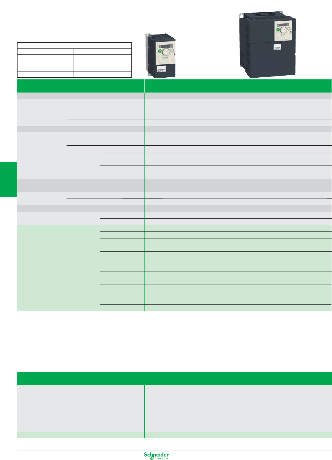
Other versions: Please consult your Schneider Electric sales office.
Altivar 312
0.18…15 kW
Simple industrial machines
High performance drives
Dimensions (in mm) width x height x depth
T 1: 72 X 145 X 122 T 6: 107 X 143 X 152
T 2: 72 X 145 X 132 T 7: 142 X 184 X 152
T 3: 72 X 145 X 132 T 8: 180 X 232 X 172
T 4: 72 X 145 X 142 T 9: 245 X 330 X 192
T 5: 105 X 143 X 132
Type of drive Single-phase 240 V Three-phase 240 V Three-phase 500V Three-phase 600V
Supply voltage
with integrated EMC filters
without EMC filter
with integrated EMC filters
without EMC filter
Degree of protection IP20
Drive Output frequency 0.5…500 Hz
Type of control Asynchronous motor Standard (voltage / frequency) - Performance (sensorless flux vector control)
Energy saving ratio
Transient overtorque 170 ... 200% of the nominal motor torque
Speed range 1 to 50
Functions Number of functions 50
Number of preset speeds 16
Number of I/O Analog inputs 3
Logic inputs 6
Analog outputs 1
Logic outputs –
Relay outputs 2
Dialogue Integrated 4-digit display, remote terminals (IP54 or IP65), Altivar 61/71 remote graphic display terminal
Communication Integrated Modbus and CANopen
As an option CANopen Daisy chain, Modbus TCP, DeviceNet, PROFIBUS DP, Fipio
Reduction of current harmonics
EMC filter Integrated C2 EMC
External as an option
Integrated C2(1) or C3 EMC
External as an option
As an option C1 EMC – – –
Motor power kW/HP 0.18/0.25 ATV312H018M2 T3 ATV312H018M3 T1 – –
0.37/0.5 ATV312H037M2T3ATV312H037M3 T1 ATV312H037N4 T5 –
0.55/0.75 ATV312H055M2 T4 ATV312H055M3 T2 ATV312H055N4 T5 –
0.75/1 ATV312H075M2 T4 ATV312H075M3 T2 ATV312H075N4 T6 ATV312H075S6 T6
1.1/1.5 ATV312HU11M2 T6 ATV312HU11M3 T5 ATV312HU11N4 T6 –
1.5/2 ATV312HU15M2 T6 ATV312HU15M3 T5 ATV312HU15N4 T6 ATV312HU15S6 T6
2.2/3 ATV312HU22M2
(2)
T7 ATV312HU22M3 T6 ATV312HU22N4 T7 ATV312HU22S6 T7
3/- – ATV312HU30M3 T7 ATV312HU30N4 T7 –
4/5 – ATV312HU40M3 T7 ATV312HU40N4 T7 ATV312HU40S6 T7
5.5/7.5 – ATV312HU55M3 T8 ATV312HU55N4 T8 ATV312HU55S6 T8
7.5/10 – ATV312HU75M3 T8 ATV312HU75N4 T8 ATV312HU75S6 T8
11/15 – ATV312HD11M3 T9 ATV312HD11N4 T9 ATV312HD11S6 T9
15/20 – ATV312HD15M3 T9 ATV312HD15N4 T9 ATV312HD15S6 T9
(1) C2 up to 4 kW
(2) Supplied with integrated C3 EMC filter
Accessories and options available
Type of accessory
Description Remote graphic display terminal
Multi-Loader, Simple Loader
Additional EMC input filter
Plates
Braking resistors and braking unit
Line chokes
Ferrite suppressors for downstream contactor opening
Reference Please refer to the Schneider Electric catalogue
4/16
2
1
3
4
5
6
7
8
9
10
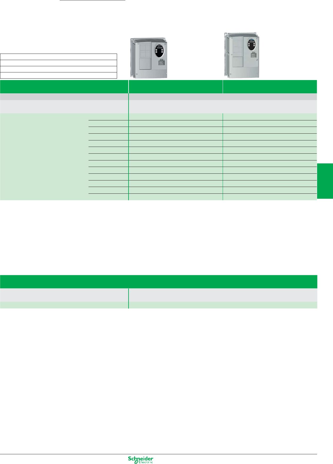
Other versions: Please consult your Schneider Electric sales office.
Supply voltage Single-phase 200…240 V Three-phase 380…500 V
Degree of protection IP54
Description Enclosure equipped with an ATV31 drive with external heatsink. Removable covers for adding 1 switch-
disconnector or 1 circuit-breaker, 3 buttons and/or LEDs, 1 potentiometer
Motor power kW/HP 0.18/0.25 ATV31C018M2 Size 1 –
0.37/0.5 ATV31C037M2 Size 1 ATV31C037N4 Size 2
0.55/0.75 ATV31C055M2 Size 1 ATV31C055N4 Size 2
0.75/1 ATV31C075M2 Size 1 ATV31C075N4 Size 2
1.1/1.5 ATV31CU11M2 Size 2 ATV31CU11N4 Size 2
1.5/2 ATV31CU15M2 Size 2 ATV31CU15N4 Size 2
2.2/3 ATV31CU22M2 Size 3 ATV31CU22N4 Size 3
3/– – ATV31CU30N4 Size 3
4/5 – ATV31CU40N4 Size 3
5.5/7.5 – ATV31CU55N4 (1) Size 4
7.5/10 – ATV31CU75N4 (1) Size 4
11/15 – ATV31CD11N4 (1) Size 5
15/20 – ATV31CD15N4 (1) Size 5
(1) Drive in metal enclosure without cover.
Accessories and options available
Type of accessory
Description Additional EMC input filters
Line chokes
Reference Please refer to the Schneider Electric catalogue
Dimensions (in mm) width x height x depth
Size 1: 210 x 240 x 163 / Size 2: 215 x 297 x 192
Size 3: 230 x 340 x 208 / Size 4: 320 x 512 x 282
Size 5: 440 x 625 x 282
Altivar 31C
0.18…15 kW
Simple machines
Enclosed drives
4/17
2
1
3
4
5
6
7
8
9
10
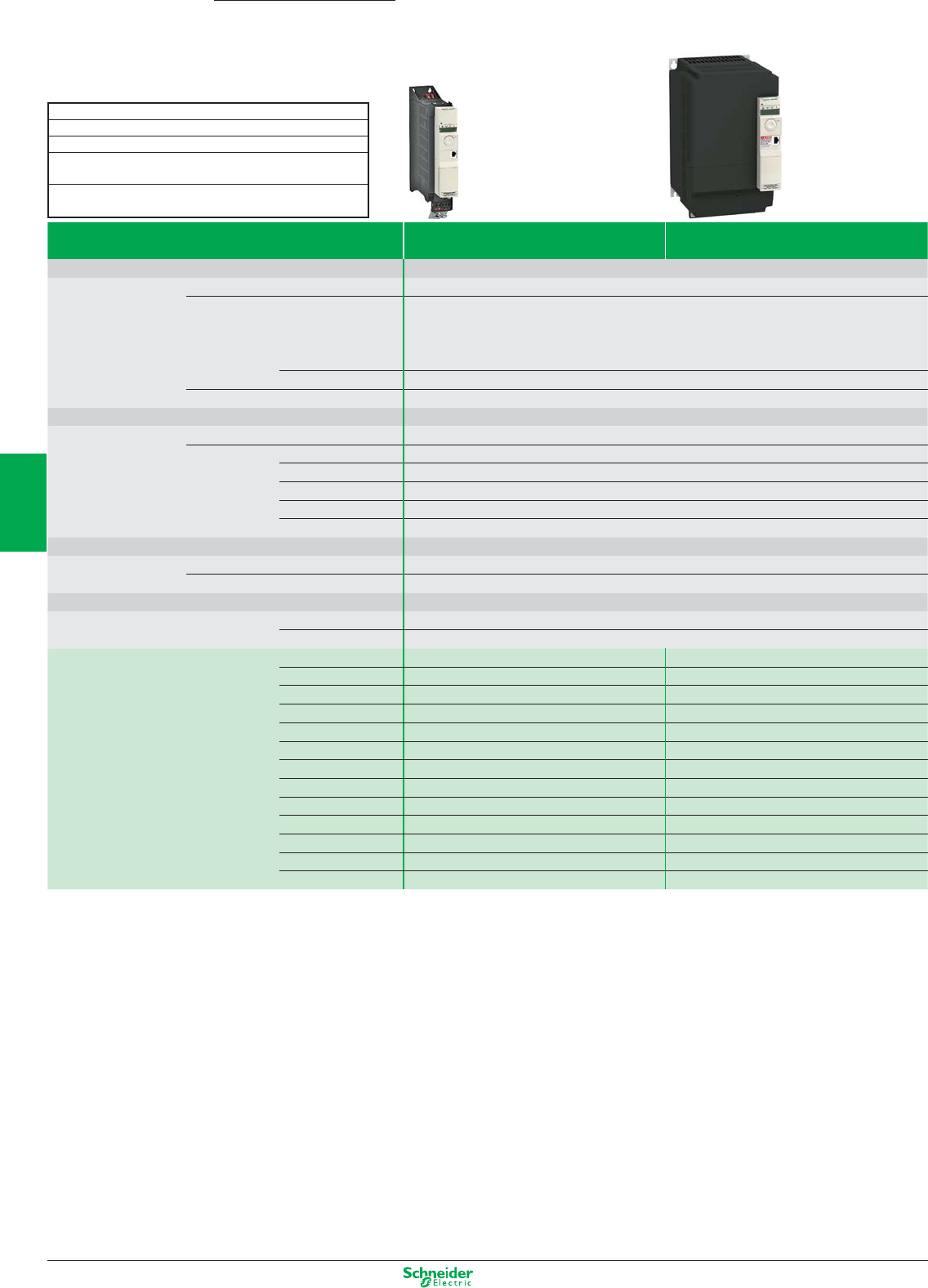
Other versions: Please consult your Schneider Electric sales offi ce.
Type of drive Single-phase Three-phase
240 V with integrated EMC fi lter 500 V with integrated EMC fi lter
Degree of protection IP20
Drive Output frequency 0.5…599 Hz
Type of control Asynchronous motor Standard (voltage/frequency)
Performance (sensorless fl ux vector control)
Pump/fan (Kn² quadratic ratio)
Energy saving ratio
Synchronous motor Profi le for open loop synchronous motor
Transient overtorque 170...200% of the nominal motor torque
Speed range 1 to 50
Functions Number of functions 150
Number of I/O Analog inputs 3
Logic inputs 6
Analog outputs 1
Logic outputs 1: confi gurable as voltage (0-10 V) or current (0-20 mA)
Relay outputs 2
Dialogue 4-digit display, remote display terminal (IP54 or IP55), remote graphic display terminal.
Communication Integrated Modbus and CANopen - Bluetooth® link
As an option DeviceNet, PROFIBUS DP V1, EtherNet/IP, Modbus TCP, EtherCat
Reduction of current harmonics
EMC fi lter Integrated C2 EMC
As an option C1 EMC
Motor power kW/HP 0.18/1/4 ATV32H018M2 T1 –
0.37/1/2 ATV32H037M2 T1 ATV32H037N4 T1
0.55/3/4 ATV32H055M2 T1 ATV32H055N4 T1
0.75/1 ATV32H075M2 T1 ATV32H075N4 T1
1.1/11/2 ATV32HU11M2 T2 ATV32HU11N4 T1
1.5/2 ATV32HU15M2 T2 ATV32HU15N4 T1
2.2/3 ATV32HU22M2 T2 ATV32HU22N4 T2
3/- – ATV32HU30N4 T2
4/5 – ATV32HU40N4 T2
5.5/71/2 – ATV32HU55N4 T4
7.5/10 – ATV32HU75N4 T4
11/15 – ATV32HD11N4 T5
15/20 – ATV32HD15N4 T5
Dimensions (in mm) width x height x depth
T1: 45 x 317 x 245
T2: 60 x 317 x 245
T4: 150 x 308 x 232 (EMC plate installed)
T4: 150 x 232 x 232 (EMC plate not installed)
T5: 180 x 404 x 232 (EMC plate installed)
T5: 180 x 330 x 232 (EMC plate not installed)
Altivar 32
0.18…15 kW
Complex machines
Compact drives
4/18
2
1
3
4
5
6
7
8
9
10

Other versions: Please consult your Schneider Electric sales office.
Accessories and options available
Type of accessory
Description Panel cut-out adaptor for mounting control unit at 90°
Mechanical base kit for mounting GV2 circuit-breaker
IP54 remote display terminal
IP65 remote display terminal
Remote graphic display terminal
Simple Loader tool
Multi-Loader tool
USB/RJ45 cable for programming via SoMove software
EMC filters
Motor chokes
Braking resistors
Communication modules
DC bus cable
Reference Please refer to the Schneider Electric catalogue
4/19
2
1
3
4
5
6
7
8
9
10
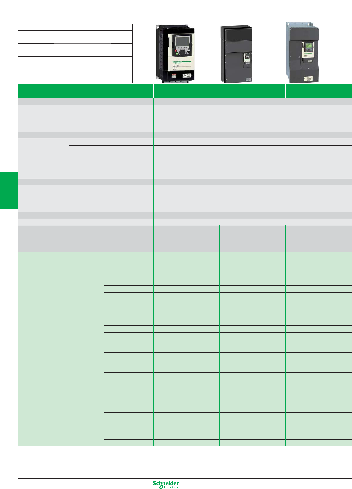
Other versions: Please consult your Schneider Electric sales offi ce.
Pumping and ventilation machines
Drives for industry and infrastructure
Altivar 61
0.37…800 kW
Type of drive
Supply voltage
Single-phase
200…240 V
Three-phase
200…240 V
Three-phase
380…480 V
Degree of protection IP20 for unprotected drives and IP41 on the upper part
Drive Output frequency 0.5…1600 Hz up to 37 kW; 0.5…500 Hz from 45 to 800 kW
Type of control Asynchronous motor
Kn2 quadratic ratio, fl ux vector control with or without sensor, voltage/frequency ratio (2 or 5 points), energy saving ratio
Synchronous motor Vector control without speed feedback
Transient overtorque 120…130% of the nominal drive current for 60 seconds
Speed range 1…100 in open loop mode
Functions Number of functions > 150
Number of preset speeds 16
Number of I/O Analog inputs 2…4/Logic inputs 6…20
Analog outputs 1…3/Logic outputs 0…8
Relay outputs 2…4
Safety input 1
Dialogue Remote graphic display terminal or SoMove software workshop
Communication Integrated Modbus and CANopen
As an option HVAC protocols: LonWorks, BACnet, METASYS N2, APOGEE FLN
Industrial: Modbus TCP, Modbus/Uni-Telway, Fipio, Modbus Plus, Profi bus DP, PROFIBUS DPV1,
DeviceNet, Ethernet IP, CC-Link, INTERBUS
Cards (available as an option) Multi-pump cards, I/O extension cards, “Controller Inside” programmable card
Reduction of current harmonics DC choke integrated or supplied with the drive
EMC fi lter Integrated C2 EMC C2 EMC up to 7.5 kW C2 EMC up to 4 kW
C3 EMC from 5.5 to 630 kW
As an option C1 EMC C1 EMC C1 EMC
from 0.75 to 630 kW
Motor power kW/HP 0.37/0.5 ATV61H075M3 T2 – –
0.75/1 ATV61HU15M3 T2 ATV61H075M3 T2 ATV61H075N4
T2
1.5/2 ATV61HU22M3 T3 ATV61HU15M3 T2 ATV61HU15N4
T2
2.2/3 ATV61HU30M3 T3 ATV61HU22M3 T3 ATV61HU22N4
T2
3/– ATV61HU40M3 (1) T3 ATV61HU30M3 T3 ATV61HU30N4
T3
4/5 ATV61HU55M3 (1) T4 ATV61HU40M3 T3 ATV61HU40N4
T3
5.5/7.5 ATV61HU75M3 (1) T5A ATV61HU55M3 T4 ATV61HU55N4
T4
7.5/10 – ATV61HU75M3 T5A ATV61HU75N4
T4
11/15 – ATV61HD11M3X
(2)
T5B ATV61HD11N4
T5A
15/20 – ATV61HD15M3X
(2)
T5B ATV61HD15N4
T5B
18.5/25 – ATV61HD18M3X
(2)
T6 ATV61HD18N4
T5A
22/30 – ATV61HD22M3X
(2)
T6 ATV61HD22N4
T6
30/40 – ATV61HD30M3X
(2)
T7B ATV61HD30N4
T7A
37/50 – ATV61HD37M3X
(2)
T7B ATV61HD37N4
T7A
45/60 – ATV61HD45M3X
(2)
T7B ATV61HD45N4
T8
55/75 – ATV61HD55M3X
(2)
T9 ATV61HD55N4
T8
75/100 – ATV61HD75M3X
(2)
T9 ATV61HD75N4
T8
90/125 – ATV61HD90M3X
(2)
T10 ATV61HD90N4
T9
110/150 – – ATV61HC11N4
T9
132/200 – – ATV61HC13N4
T10
160/250 – – ATV61HC16N4
T11
200/300 – – ATV61HC20N4
T12
220/350 – – ATV61HC22N4
T12
250/400 – – ATV61HC25N4
T13
280/450 – – ATV61HC28N4
T13
315/500 – – ATV61HC31N4
T13
400/600 – – ATV61HC40N4
T14
500/700 – – ATV61HC50N4
T14
630/900 – – ATV61HC63N4
T15
(1) Must be used with a line choke, refer to the Schneider Electric catalogue.
(2) Drive supplied without EMC fi lter
For all other variants, please refer to the Schneider Electric catalogue.
Dimensions (in mm) width x height x depth
T2 : 130 x 230 x 175 T3 : 155 x 260 x 187
T4 : 175 x 295 x 187 T5A : 210 x 295 x 213
T5B : 230 x 400 x 213 T6 : 240 x 420 x 236
T7A : 240 x 550 x 266 T7B : 320 x 550 x 266
T8 : 320 x 630 x 290 T9 : 320 x 920 x 377
T10 : 360 x 1022 x 377 T11 : 340 x 1190 x 377
T12 : 440 x 1190 x 377 T13 : 595 x 1190 x 377
T14 : 890 x 1390 x 377 T15 : 1120 x 1390 x 377
4/20
2
1
3
4
5
6
7
8
9
10
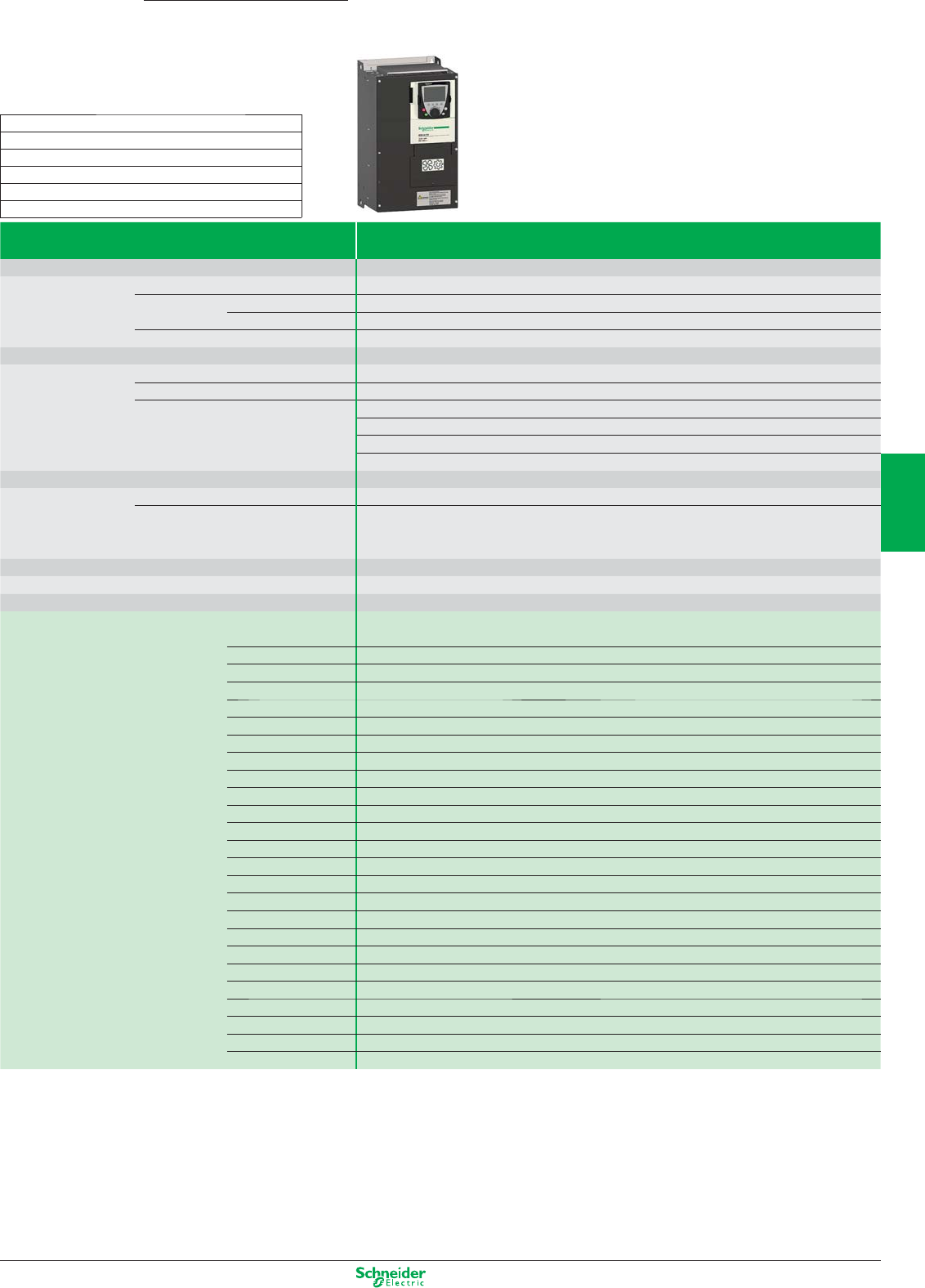
Other versions: Please consult your Schneider Electric sales offi ce.
Pumping and ventilation machines
Drives for industry and infrastructure
Altivar 61
0.37…800 kW
Type of drive
Supply voltage
Three-phase
500...690 V
Degree of protection IP20 and IP41 on the upper part
Drive Output frequency 0.5…1600 Hz up to 37 kW; 0.5…500 Hz from 45 to 800 kW
Type of control Asynchronous motor
Kn2 quadratic ratio, fl ux vector control with or without sensor, voltage/frequency ratio (2 or 5 points), energy saving ratio
Synchronous motor Vector control without speed feedback
Transient overtorque 120…130% of the nominal drive current for 60 seconds
Speed range 1…100 in open loop mode
Functions Number of functions > 150
Number of preset speeds 16
Number of I/O Analog inputs 2…4/Logic inputs 6…20
Analog outputs 1…3/Logic outputs 0…8
Relay outputs 2…4
Safety input 1
Dialogue Remote graphic display terminal or SoMove software workshop
Communication Integrated Modbus and CANopen
As an option HVAC protocols: LonWorks, BACnet, METASYS N2, APOGEE FLN
Industrial: Modbus TCP, Modbus/Uni-Telway, Fipio, Modbus Plus, Profi bus DP, PROFIBUS DPV1,
DeviceNet, Ethernet IP, CC-Link, INTERBUS
Cards (available as an option) Multi-pump cards, I/O extension cards, “Controller Inside” programmable card
Reduction of current harmonics DC choke integrated or supplied with the product
EMC fi lter Integrated C3 EMC
Motor power kW/HP 500 V 575 V 690 V
kW HP kW
2.2 3 3 ATV61HU30Y T6
3–4ATV61HU40Y T6
4 5 5.5 ATV61HU55Y T6
5.5 7.5 7.5 ATV61HU75Y T6
7.5 10 11 ATV61HD11Y T6
11 15 15 ATV61HD15Y T6
15 20 18.5 ATV61HD18Y T6
18.5 25 22 ATV61HD22Y T6
22 30 30 ATV61HD30Y T6
30 40 37 ATV61HD37Y T8
37 50 45 ATV61HD45Y T8
45 60 55 ATV61HD55Y T8
55 75 75 ATV61HD75Y T8
75 100 90 ATV61HD90Y T8
90 125 110 ATV61HC11Y T11
110 150 132 ATV61HC13Y T11
132 – 160 ATV61HC16Y T11
160 200 200 ATV61HC20Y T11
200 250 250 ATV61HC25Y T13
250 350 315 ATV61HC31Y T13
315 450 400 ATV61HC40Y T13
400 550 500 ATV61HC50Y T15
500 700 630 ATV61HC63Y T15
630 800 800 ATV61HC80Y T15
For all other variants, please refer to the Schneider Electric catalogue.
Dimensions (in mm) width x height x depth
T6 : 240 x 420 x 236
T8 : 320 x 630 x 290
T11 : 340 x 1190 x 377
T13 : 595 x 1190 x 377
T15 : 1120 x 1390 x 377
4/21
2
1
3
4
5
6
7
8
9
10
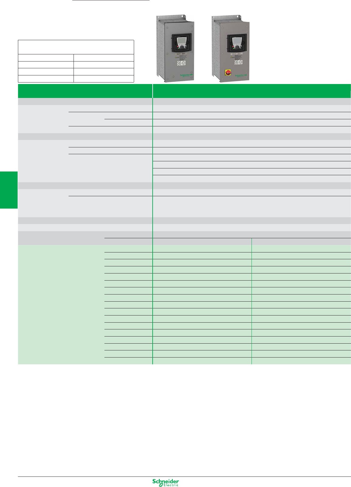
Other versions: Please consult your Schneider Electric sales offi ce.
Type of drive Three-phase 380…480 V
Degree of protection Type 12 (1) / IP54
Drive Output frequency 0.5…1600 Hz up to 37 kW; 0.5…500 Hz from 45 to 800 kW
Type of control Asynchronous motor
Kn2 quadratic ratio, fl ux vector control with or without sensor, voltage/frequency ratio (2 or 5 points), energy saving ratio
Synchronous motor Vector control without speed feedback
Transient overtorque 120…130% of the nominal drive current for 60 seconds
Speed range 1…100 in open loop mode
Functions Number of functions > 150
Number of preset speeds 16
Number of I/O Analog inputs 2…4/Logic inputs 6…20
Analog outputs 1…3/Logic outputs 0…8
Relay outputs 2…4
Safety input 1
Dialogue Remote graphic display terminal or SoMove software workshop
Communication Integrated Modbus and CANopen
As an option HVAC protocols: LonWorks, BACnet, METASYS N2, APOGEE P1
Industrial: Modbus TCP, Modbus/Uni-Telway, Fipio, Modbus Plus, Profi bus DP, Profi bus DPv1,
DeviceNet, Ethernet IP, CC-Link INTERBUS
Cards (available as an option) Multi-pump cards, I/O extension cards, “Controller Inside” programmable card
Reduction of current harmonics Integrated DC choke
EMC fi lter Integrated C2 EMC
As an option – –
Motor power kW/HP 0.75/1 ATV61W075N4 TA2 ATV61E5075N4 TA2
1.5/2 ATV61WU15N4 TA2 ATV61E5U15N4 TA2
2.2/3 ATV61WU22N4 TA2 ATV61E5U22N4 TA2
3/– ATV61WU30N4 TA3 ATV61E5U30N4 TA3
4/5 ATV61WU40N4 TA3 ATV61E5U40N4 TA3
5.5/7.5 ATV61WU55N4 TB ATV61E5U55N4 TB
7.5/10 ATV61WU75N4 TB ATV61E5U75N4 TB
11/15 ATV61WD11N4 TC ATV61E5D11N4 TC
15/20 ATV61WD15N4 TD ATV61E5D15N4 TD
18.5/25 ATV61WD18N4 TD ATV61E5D18N4 TD
22/30 ATV61WD22N4 TE ATV61E5D22N4 TE
30/40 ATV61WD30N4 TF ATV61E5D30N4 TF
37/50 ATV61WD37N4 TF ATV61E5D37N4 TF
45/60 ATV61WD45N4 TG ATV61E5D45N4 TG
55/75 ATV61WD55N4 TG ATV61E5D55N4 TG
75/100 ATV61WD75N4 TG ATV61E5D75N4 TG
90/125 ATV61WD90N4 TG ATV61E5D90N4 TG
Drive with integrated C1 fi lter: add the letter C at the end of the reference For example, ATV61W075N4 becomes ATV61W075N4C
For other variants, please refer to the Schneider Electric catalogue.
(1) For ATV61W... range only.
Dimensions (in mm) width x height x depth
ATV61W…
TA2
:
235 x 490 x 272 TD
:
310 x 665 x 315
TA3
:
235 x 490 x 286 TE
:
284 x 720 x 315
TB
:
255 x 525 x 286 TF
:
284 x 880 x 343
TC
:
290 x 560 x 315 TG
:
362 x 1000 x 364
Pumping and ventilation machines
IP54 drives
Altivar 61
0.37…800 kW
4/22
2
1
3
4
5
6
7
8
9
10
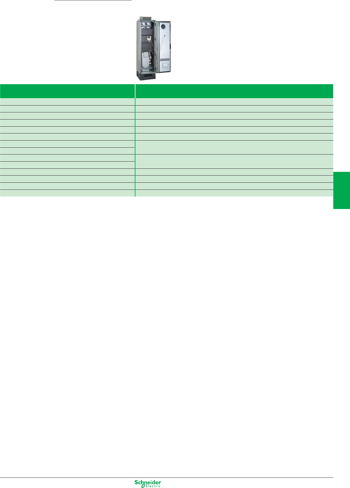
Other versions: Please consult your Schneider Electric sales offi ce.
Pumping and ventilation machines
IP54 Altivar 61 kit with preassembled enclosure
Altivar 61
0.37…2400 kW
Drive Kit
ATV61HC11N4 VW3A9541
ATV61HC13N4 VW3A9542
ATV61HC16N4 VW3A9543
ATV61HC22N4 VW3A9544
ATV61HC25N4 VW3A9545
ATV61HC31N4
ATV61HC25N4 VW3A9546
ATV61HC31N4
ATV61HC40N4 VW3A9547
ATV61HC50N4
ATV61HC63N4 VW3A9548
VW3A7102 braking unit VW3A9549
Additional empty enclosure (600 mm)
VW3A9550
Additional empty enclosure (800 mm)
VW3A9551
4/23
2
1
3
4
5
6
7
8
9
10
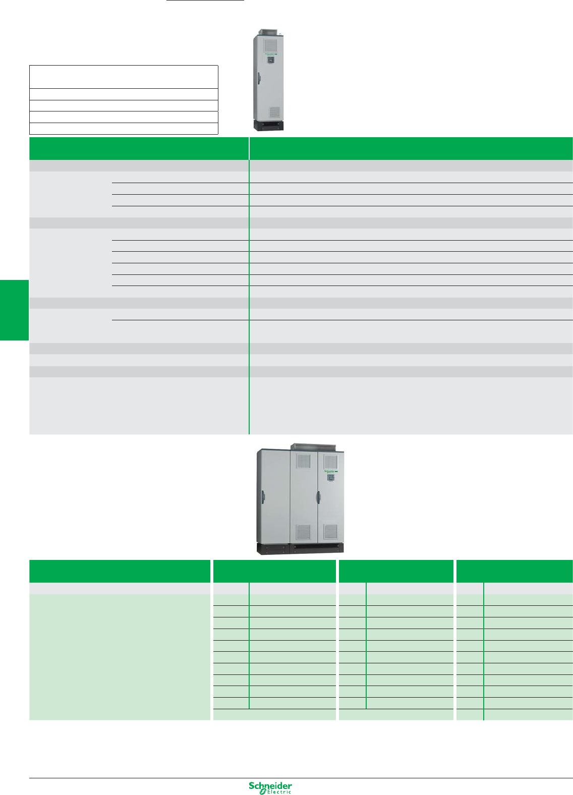
Other versions: Please consult your Schneider Electric sales offi ce.
Enclosure types Three-phase 380…480 V - 500 V - 690 V
(1)
Degree of protection
Drive Output frequency 0.5…1600 Hz up to 37 kW; 0.5…500 Hz from 45…2400 kW
Type of control Asynchronous motor
Kn2 quadratic ratio, fl ux vector control with or without sensor, voltage/frequency ratio (2 or 5 points), energy saving ratio
Synchronous motor Vector control without speed feedback
Transient overtorque 120…130% of the nominal drive current for 60 seconds
Speed range 1…100 in open loop mode
Functions Number of functions > 150
Number of preset speeds 16
Number of I/O Analog inputs 2…4/Logic inputs 6…20
Analog outputs 1…3/Logic outputs 0…8
Relay outputs 2…4
Safety input 1
Dialogue Remote graphic display terminal or SoMove software workshop
Communication Integrated Modbus and CANopen
As an option HVAC protocols: LonWorks, BACnet, METASYS N2, APOGEE P1
Industrial: Modbus TCP, Modbus/Uni-Telway, Fipio, Modbus Plus, Profi bus DPv1, DeviceNet, INTERBUS
Cards (available as an option) Multi-pump cards, I/O extension cards, “Controller Inside” programmable card
Reduction of current harmonics Integrated DC choke
EMC fi lter Integrated C2 EMC
Equipment A wide range of options listed in the catalogue provides add-ons for the standard offer as required.
As well as the options listed in the catalogue, it is possible to customise the equipment. Just contact our
teams of experts direct.
- Water cooling solution
- Integration of specifi c options
IP23 Three-phase
380…415 V
Three-phase
500 V
Three-phase
690 V
kW/HP Dimensions kW Dimensions kW Dimensions
– 90 ATV61 EXC2D90N E1 –
110/150 ATV61EXC2C11N4 E1 110 ATV61 EXC2C11N E1 110 ATV61 EXC2C11Y E1
132/200 ATV61EXC2C13N4 E1 132 ATV61 EXC2C13N E1 132 ATV61 EXC2C13Y E1
160/250 ATV61EXC2C16N4 E1 160 ATV61 EXC2C16N E1 160 ATV61 EXC2C16Y E1
220/350 ATV61EXC2C22N4 E1 200 ATV61 EXC2C20N E2 200 ATV61 EXC2C20Y E1
250/400 ATV61EXC2C25N4 E2 250 ATV61 EXC2C25N E2 250 ATV61 EXC2C25Y E2
315/500 ATV61EXC2C31N4 E2 315 ATV61 EXC2C31N E2 315 ATV61 EXC2C31Y E2
400/600 ATV61EXC2C40N4 E3 400 ATV61 EXC2C40N E4 400 ATV61 EXC2C40Y E2
500/700 ATV61EXC2C50N4 E3 500 ATV61 EXC2C50N E4 500 ATV61 EXC2C50Y E4
630/900 ATV61EXC2C63N4 E4 630 ATV61 EXC2C63N E4 630 ATV61 EXC2C63Y E4
800 ATV61 EXC2C80Y E4
(1) The Altivar 61 range in ready-assembled enclosure consists of:
– An ATV61H… drive
– A switch and fast-acting fuses
– An IP65 remote mounting kit for graphic display terminal
IP23 offer available up to 2400 kW. For ratings above 800 kW, please consult your Regional Sales Offi ce.
Dimensions (in mm) width x height x depth
ATV61EXC2C…
E1
:
616 x 2159 x 659
E2
:
816 x 2159 x 659
E3
:
1016 x 2159 x 659
E4
:
1220 x 2159 x 659
Pumping and ventilation machines
Solutions in IP23 and IP54 ready-assembled enclosures
Altivar 61 Plus
90…2400 kW
4/24
2
1
3
4
5
6
7
8
9
10
Other versions: Please consult your Schneider Electric sales office.
IP54 Three-phase
380…415 V
Three-phase
500 V
Three-phase
690 V
Compact floor-standing enclosure
kW/HP Dimensions kW Dimensions kW Dimensions
– 90 ATV61EXC5D90N E5 –
110/150 ATV61EXC5C11N4 E5 110 ATV61EXC5C11N E5 110 ATV61EXC5C11Y E5
132/200 ATV61EXC5C1 3N4 E5 132 ATV61EXC5C13N E5 132 ATV61EXC5C13Y E5
160/250 ATV61EXC5C16N4 E5 160 ATV61EXC5C16N E5 160 ATV61EXC5C16Y E5
220/350 ATV61EXC5C22N4 E5 200 ATV61EXC5C20N E6 200 ATV61EXC5C20Y E5
250/400 ATV61EXC5C25N4 E6 250 ATV61EXC5C25N E6 250 ATV61EXC5C25Y E6
315/500 ATV61EXC5C31N4 E6 315 ATV61EXC5C31N E6 315 ATV61EXC5C31Y E6
400/600 ATV61EXC5C40N4 E7 400 ATV61EXC5C40N E8 400 ATV61EXC5C40Y E6
500/700 ATV61EXC5C50N4 E7 500 ATV61EXC5C50N E8 500 ATV61EXC5C50Y E8
630/900 ATV61EXC5C63N4 E8 630 ATV61EXC5C63N E8 630 ATV61EXC5C63Y E8
800 ATV61EXC5C80Y E8
IP54 Three-phase
380…415 V
Three-phase
500 V
Three-phase
690 V
Separate air flow kW/HP Dimensions kW Dimensions kW Dimensions
– 90 ATV61EXS5D90N E11 –
110/150 ATV61EXS5C11N4 E9 110 ATV61EXS5C11N E11 110 ATV61EXS5C11Y E11
132/200 ATV61EXS5C13N4 E9 132 ATV61EXS5C13N E11 132 ATV61EXS5C13Y E11
160/250 ATV61EXS5C16N4 E9 160 ATV61EXS5C16N E11 160 ATV61EXS5C16Y E11
220/350 ATV61EXS5C22N4 E9 200 ATV61EXS5C20N E12 200 ATV61EXS5C20Y E11
250/400 ATV61EXS5C25N4 E10 250 ATV61EXS5C25N E12 250 ATV61EXS5C25Y E12
315/500 ATV61EXS5C31N4 E10 315 ATV61EXS5C31N E12 315 ATV61EXS5C31Y E12
400/600 ATV61EXS5C40N4 E13 400 ATV61EXS5C40N E14 400 ATV61EXS5C40Y E12
500/700 ATV61EXS5C50N4 E13 500 ATV61EXS5C50N E14 500 ATV61EXS5C50Y E14
630/900 ATV61EXS5C63N4 E14 630 ATV61EXS5C63N E14 630 ATV61EXS5C63Y E14
800 ATV61EXS5C80Y E14
Dimensions (in mm) width x height x depth
ATV61EX…
E5 : 616 x 2264 x 659 E9 : 616 x 2359 x 659
E6 : 816 x 2264 x 659 E10 : 816 x 2359 x 659
E7 : 1016 x 2264 x 659 E11 : 608 x 2359 x 659
E8 : 1216 x 2264 x 659 E12 : 808 x 2359 x 6590
E13 : 1008 x 2359 x 659
E14 : 1208 x 2359 x 659
Pumping and ventilation machines
Solutions in IP23 and IP54 ready-assembled enclosures
Altivar 61 Plus
90…2400 kW
4/25
2
1
3
4
5
6
7
8
9
10
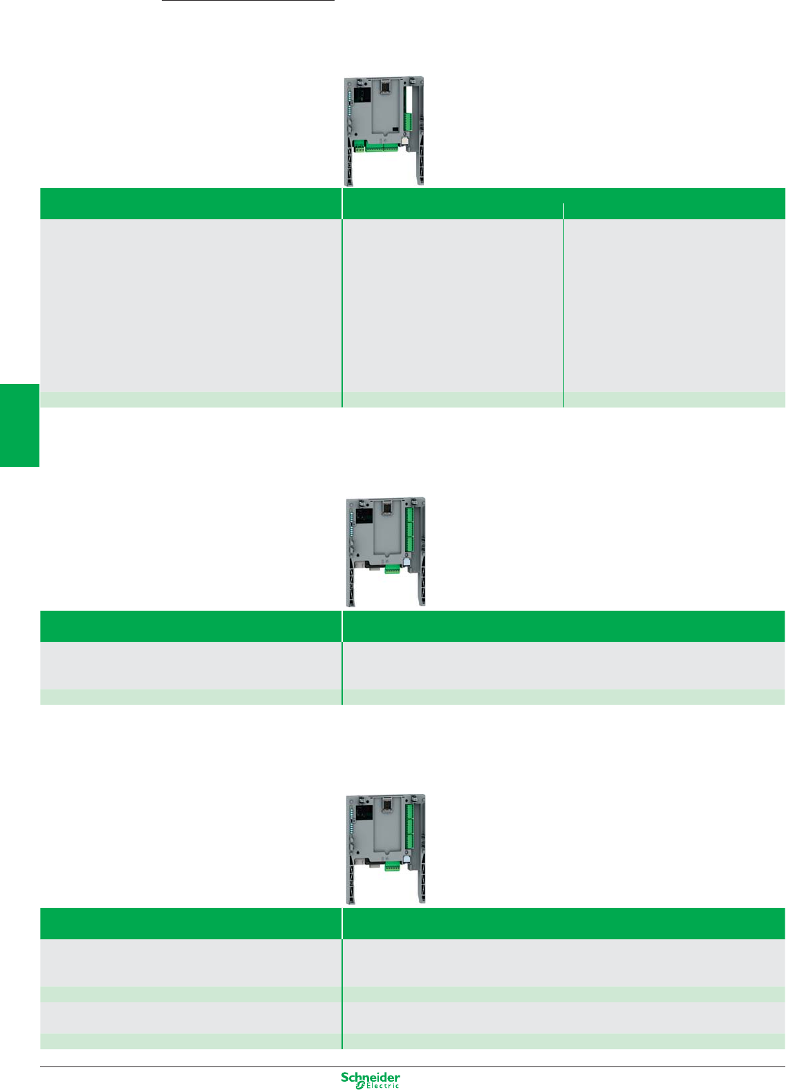
Other versions: Please consult your Schneider Electric sales office.
Altivar 61
0.37…2400 kW
Pumping and ventilation machines
I/O extension and specific cards
Type of card I/O extension
Logic Extended
Description 1 relay logic output (“C/O” contact)
4 x 24 VDC positive or negative logic inputs
2 x 24 VDC open collector positive or negative logic
outputs
1 input for PTC probes
1 x 0…20 mA differential current analog input
1 software-configurable voltage (0…10 VDC) or
current (0…20 mA) analog input
2 software-configurable voltage (±10V, 0…10 VDC)
or current (0…20 mA) analog inputs
1 relay logic output (“C/O” contact)
4 x 24 VDC positive or negative logic inputs
2 x 24 VDC open collector positive or negative logic
outputs
1 input for PTC probes
1 frequency control input
Reference VW3A3201 VW3A3202
"Controller Inside" programmable card
Type of card Programmable “Controller Inside”
Description
10 logic inputs, 2 of which can be used for 2 counters or 4 of which can be used for 2 incremental encoders
2 analog inputs, 6 logic outputs, 2 analog outputs, a master port for the CANopen bus, a PC port for
programming with the PS 1131 software workshop.
Reference VW3A3501
Multi-pump cards
Type of card Multi-pump
Description The pump switching card ensures compatibility of
applications developed on the Altivar 38.
This card is specific to pump switching.
It ensures optimum flow for an impeccable quality of service.
Its algorithm both saves energy and prolongs equipment service life.
Reference VW3A3502
Description The VWA3503 “Water Solution” card can be used
to support all multi-pump applications.
This card offers all the functions needed to manage a pumping, booster, irrigation station, etc with the
operational safety of a control and monitoring system.
Reference VW3A3503
4/26
2
1
3
4
5
6
7
8
9
10
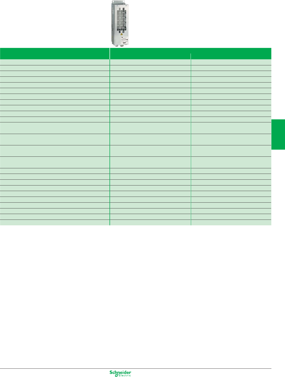
Other versions: Please consult your Schneider Electric sales office.
Accessories and options
Braking resistors
The network braking unit can be used to restore the following to the
line supply:
p The energy from the motor
p The energy from the motors controlled by several drives connected
on the same DC bus
Type of drive Three-phase
Supply voltage 200…240 V 50/60 Hz 380…480 V 50/60 Hz
ATV61H075M3 VW3A7701 –
ATV61HU15M3, HU22M3 VW3A7702 –
ATV61HU30M3, HU40M3 VW3A7703 –
ATV61HU55M3, HU75M3 VW3A7704 –
ATV61HD11M3X VW3A7705 –
ATV61HD15M3X VW3A7706 –
ATV61HD18M3X, HD22M3X VW3A7707 –
ATV61HD30M3X VW3A7708 –
ATV61HD37M3X, HD45M3X VW3A7709 –
ATV61HD55M3X, HD75M3X VW3A7713 –
ATV61HD90M3X VW3A7714 –
ATV61H075N4…HU40N4, ATV61W075N4…WU55N4, – VW3A7701
ATV61W075N4C…WU55N4C
ATV61HU55N4, HU75N4, ATV61WU75N4, WD11N4, – VW3A7702
ATV61WU75N4C, WD11N4C
ATV61HD11N4, HD15N4, ATV61WD15N4, WD18N4, – VW3A7703
ATV61WD15N4C, WD18N4C
ATV61HD18N4…HD30N4, ATV61WD22N4…WD37N4, – VW3A7704
ATV61WD22N4C…WD37N4C
ATV61HD37N4, ATV61WD45N4, WD45N4C – VW3A7705
ATV61WD55N4…WD90N4, ATV61WD55N4C…WD90N4C – VW3A7706
ATV61HD45N4…HD75N4 – VW3A7707
ATV61HD90N4, HC11N4 – VW3A7710
ATV61HC13N4, HC16N4, E5C16N4 – VW3A7711
ATV61HC22N4 – VW3A7712
ATV61HC25N4 – VW3A7715
ATV61HC31N4 – VW3A7716
ATV61HC40N4, HC50N4, E5C50N4 – VW3A7717
ATV61HC63N4 – VW3A7718
Other accessories (see references in the Schneider Electric Catalogue)
> Resistance braking units (integrated in ATV61 drives up to 220 kW)
> Additional EMC input filters
> AC line chokes
> Optional DC chokes
> Passive filters
> Sinus filters
> Motor chokes
4/27
2
1
3
4
5
6
7
8
9
10
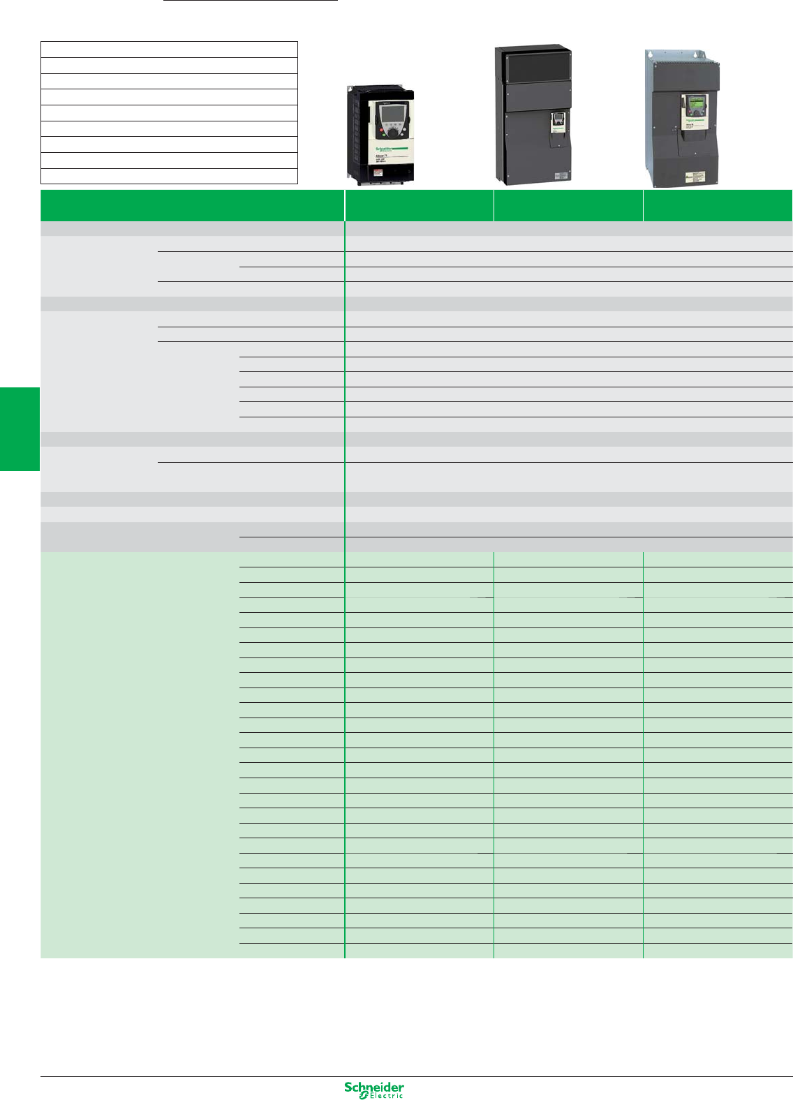
Other versions: Please consult your Schneider Electric sales offi ce.
Complex, high-power machines
High performance drives
Type of drive Single-phase Three-phase Three-phase
Supply voltage 200…240 V (3) (4) 200…240 V (3) (4) 380…480 V (3)
Degree of protection IP20 for unprotected drives and IP41 on the upper part
Drive Output frequency 0.1…1600 Hz up to 37 kW, 0.1…500 Hz from 45 to 500 kW
Type of control Asynchronous motor Flux vector control with or without sensor, voltage/frequency ratio (2 or 5 points), ENA System
Synchronous motor Vector control with and without speed feedback (…383)
Transient overtorque 220% of nominal motor torque for 2 seconds, and 170% for 60 seconds
Speed range 1…1000 in closed loop mode with encoder feedback, 1…100 in open loop mode
Functions Number of functions > 150
Number of preset speeds 16
Number of I/O Analog inputs 2…4
Logic inputs 6…20
Analog outputs 1…3
Logic outputs 0…8
Relay outputs 2…4
Safety input 1
Dialogue Remote graphic display terminal or SoMove software workshop
Communication Integrated Modbus and CANopen
As an option Modbus TCP, Modbus/Uni-Telway, Fipio, Modbus Plus, Profi bus DP, PROFIBUS DPV1, DeviceNet,
Ethernet IP, CC-Link, INTERBUS
Cards (available as an option)
Encoder interface cards, I/O extension cards, “Controller Inside” programmable card, “Crane” card
Reduction of current harmonics DC choke integrated or supplied with the product
EMC fi lter Integrated C2 EMC up to 4 kW
As an option External C2 EMC from 5.5 kW
Motor power kW/HP 0.37/0.5
ATV71H075M3 T2 ATV71H037M3 T2 –
0.75/1
ATV71HU15M3 T2 ATV71H075M3 T2 ATV71H075N4 T2
1.5/2
ATV71HU22M3 T3 ATV71HU15M3 T2 ATV71HU15N4 T2
2.2/3
ATV71HU30M3 T3 ATV71HU22M3 T3 ATV71HU22N4 T2
3/–
ATV71HU40M3 (1) T3 ATV71HU30M3 T3 ATV71HU30N4 T3
4/5
ATV71HU55M3 (1) T4 ATV71HU40M3 T3 ATV71HU40N4 T3
5.5/7.5
ATV71HU75M3 (1) T5A ATV71HU55M3 T4 ATV71HU55N4 T4
7.5/10
–ATV71HU75M3 T5A ATV71HU75N4 T4
11/15
–ATV71HD11M3X (2) T5B ATV71HD11N4 T5A
15/20
–ATV71HD15M3X (2) T5B ATV71HD15N4 T5B
18.5/25
–ATV71HD18M3X (2) T6 ATV71HD18N4 T5B
22/30
–ATV71HD22M3X (2) T6 ATV71HD22N4 T6
30/40
–ATV71HD30M3X (2) T7B ATV71HD30N4 T7A
37/50
–ATV71HD37M3X (2) T7B ATV71HD37N4 T7A
45/60
–ATV71HD45M3X (2) T7B ATV71HD45N4 T8
55/75
–ATV71HD55M3X (2) T9 ATV71HD55N4 T8
75/100
–ATV71HD75M3X (2) T10 ATV71HD75N4 T8
90/125
––ATV71HD90N4 T9
110/150
––ATV71HC11N4 T10
132/200
––ATV71HC13N4 T11
160/250
––ATV71HC16N4 T12
200/300
––ATV71HC20N4 T13
220/350
––ATV71HC25N4 T13
280/450
––ATV71HC28N4 T13
315/500
––ATV71HC31N4 T14
355/–
––ATV71HC40N4 T14
500/700
––ATV71HC50N4 T15
(1) Must be used with a line choke, Refer to the Schneider Electric catalogue.
(2) Drive supplied without EMC fi lter.
(3) A three-phase 380...480 V range on base plate is available from 0.75 to 11 kW. Please refer to the Schneider Electric catalogue.
Dimensions (in mm) width x height x depth
T2 : 130 x 230 x 175 T3 : 155 x 260 x 187
T4 : 175 x 295 x 187 T5A : 210 x 295 x 213
T5B : 230 x 400 x 213 T6 : 240 x 420 x 236
T7A : 240 x 550 x 266 T7B : 320 x 550 x 266
T8 : 320 x 630 x 290 T9 : 320 x 920 x 377
T10 : 360 x 1022 x 377 T11 : 340 x 1190 x 377
T12 : 440 x 1190 x 377 T13 : 595 x 1190 x 377
T14 : 890 x 1390 x 377 T15 : 1120 x 1390 x 377
Altivar 71
0.37…630 kW
4/28
2
1
3
4
5
6
7
8
9
10
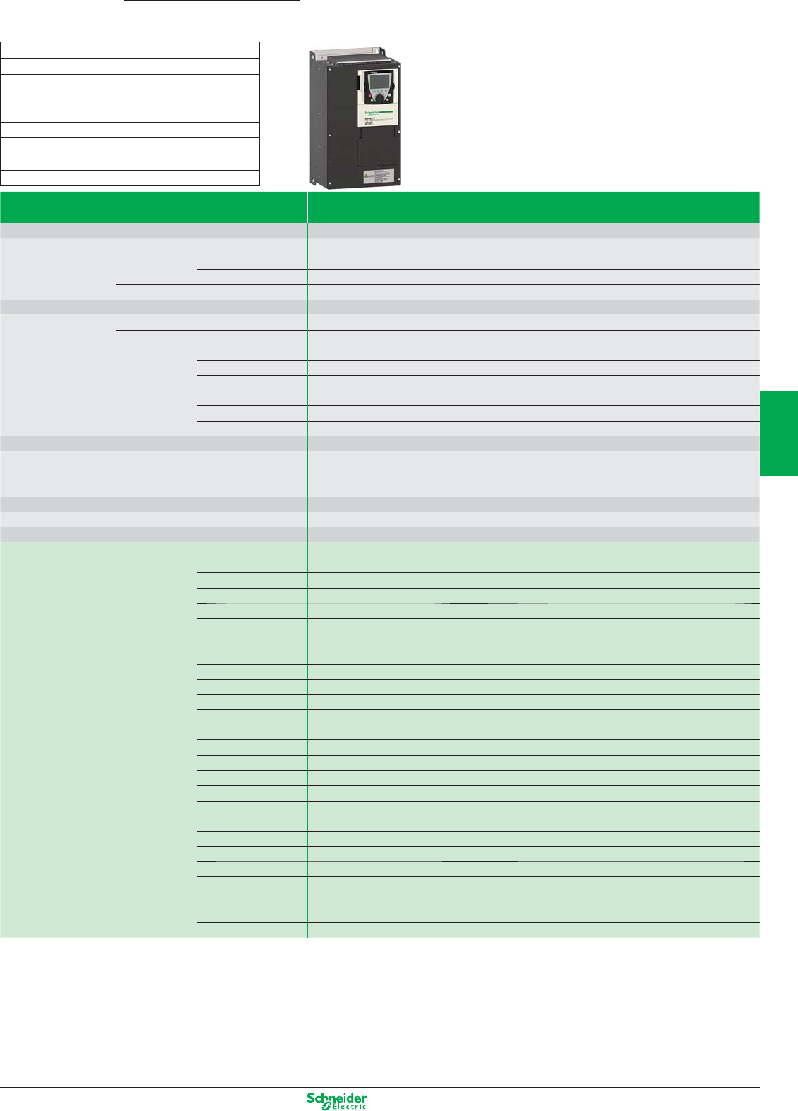
Other versions: Please consult your Schneider Electric sales offi ce.
Complex, high-power machines
High performance drives
Type of drive Three-phase
Supply voltage 500... 690 V
Degree of protection IP20 for unprotected drives and IP41 on the upper part
Drive Output frequency 0.1…1600 Hz up to 37 kW, 0.1…500 Hz from 45 to 630 kW
Type of control Asynchronous motor Flux vector control with or without sensor, voltage/frequency ratio (2 or 5 points), ENA System
Synchronous motor Vector control with and without speed feedback (…383)
Transient overtorque 220% of nominal motor torque for 2 seconds, and 170% for 60 seconds
Speed range 1…1000 in closed loop mode with encoder feedback, 1…100 in open loop mode
Functions Number of functions > 150
Number of preset speeds 16
Number of I/O Analog inputs 2…4
Logic inputs 6…20
Analog outputs 1…3
Logic outputs 0…8
Relay outputs 2…4
Safety input 1
Dialogue Remote graphic display terminal or SoMove software workshop
Communication Integrated Modbus and CANopen
As an option Modbus TCP, Modbus/Uni-Telway, Fipio, Modbus Plus, Profi bus DP, PROFIBUS DPV1, DeviceNet, Ethernet
IP, CC-Link, INTERBUS
Cards (available as an option)
Encoder interface cards, I/O extension cards, “Controller Inside” programmable card, “Crane” card
Reduction of current harmonics DC choke integrated or supplied with the drive
EMC fi lter Integrated C3 EMC
Motor power kW/HP 500 V 575 V 690 V
kW HP kW
1.5 2 2.2 ATV71HU22Y T6
2.2 3 3 ATV71HU30Y T6
3 – 4 ATV71HU40Y T6
4 5 5.5 ATV71HU55Y T6
5.5 7.5 7.5 ATV71HU75Y T6
7.5 10 11 ATV71HD11Y T6
11 15 15 ATV71HD15Y T6
15 20 18.5 ATV71HD18Y T6
18.5 25 22 ATV71HD22Y T6
22 30 30 ATV71HD30Y T6
30 40 37 ATV71HD37Y T8
37 50 45 ATV71HD45Y T8
45 60 55 ATV71HD55Y T8
55 75 75 ATV71HD75Y T8
75 100 90 ATV71HD90Y T8
90 125 110 ATV71HC11Y T11
110 150 132 ATV71HC13Y T11
132 – 160 ATV71HC16Y T11
160 200 200 ATV71HC20Y T13
200 250 250 ATV71HC25Y T13
250 350 315 ATV71HC31Y T13
315 450 400 ATV71HC40Y T15
400 550 500 ATV71HC50Y T15
500 700 630 ATV71HC63Y T15
For all other variants, please refer to the Schneider Electric catalogue.
Dimensions (in mm) width x height x depth
T2 : 130 x 230 x 175 T3 : 155 x 260 x 187
T4 : 175 x 295 x 187 T5A : 210 x 295 x 213
T5B : 230 x 400 x 213 T6 : 240 x 420 x 236
T7A : 240 x 550 x 266 T7B : 320 x 550 x 266
T8 : 320 x 630 x 290 T9 : 320 x 920 x 377
T10 : 360 x 1022 x 377 T11 : 340 x 1190 x 377
T12 : 440 x 1190 x 377 T13 : 595 x 1190 x 377
T14 : 890 x 1390 x 377 T15 : 1120 x 1390 x 377
Altivar 71
0.37…630 kW
4/29
2
1
3
4
5
6
7
8
9
10
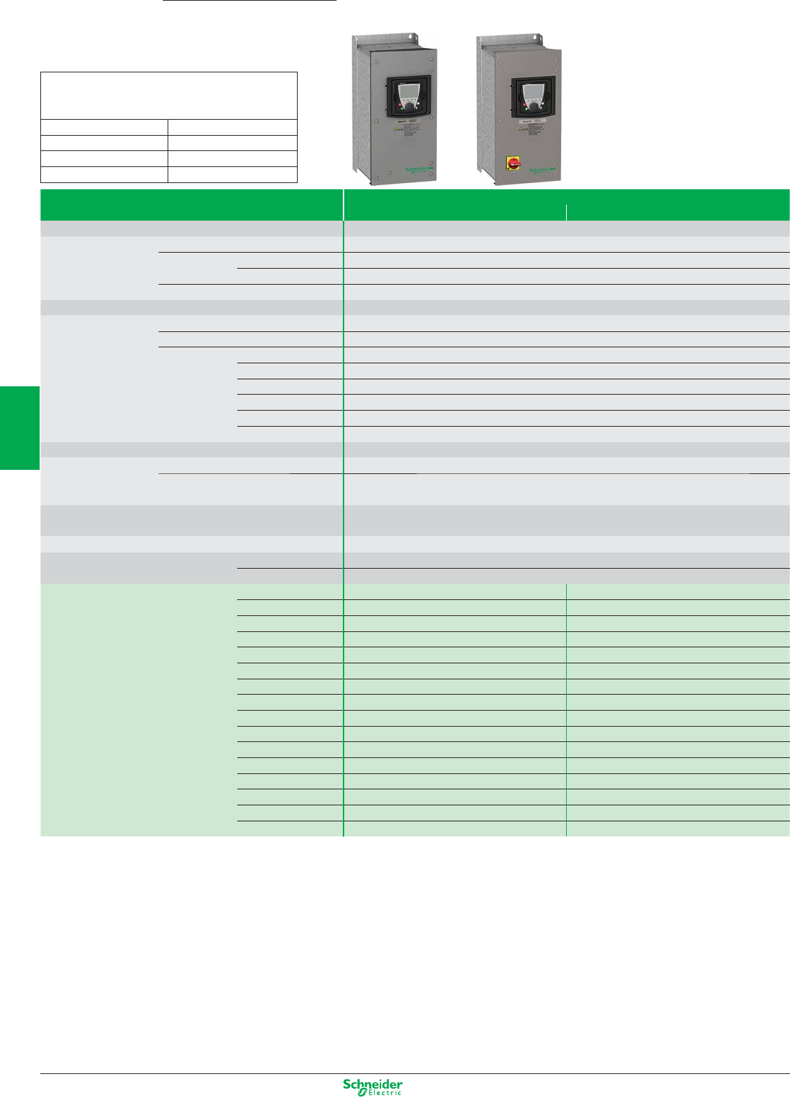
Other versions: Please consult your Schneider Electric sales offi ce.
Type of drive Three-phase 380…480 V
(3) With switch
Degree of protection UL Type 12 (1) / IP54
Drive Output frequency 0.1…1600 Hz up to 37 kW, 0.1…500 Hz from 45…75 kW
Type of control Asynchronous motor Flux vector control with or without sensor, voltage/frequency ratio (2 or 5 points), ENA System
Synchronous motor Vector control without speed feedback
Transient overtorque 220% of nominal motor torque for 2 seconds, and 170% for 60 seconds
Speed range 1…1000 in closed loop mode with encoder feedback, 1…100 in open loop mode
Functions Number of functions > 150
Number of preset speeds 16
Number of I/O Analog inputs 2…4
Logic inputs 6…20
Analog outputs 1…3
Logic outputs 0…8
Relay outputs 2…4
Safety input 1
Dialogue Remote graphic display terminal or SoMove software workshop
Communication Integrated Modbus and CANopen
As an option Modbus TCP, Modbus/Uni-Telway, Fipio, Modbus Plus, Profi bus DP, Profi bus DPv1, DeviceNet, INTERBUS,
CC-Link, Ethernet IP
Cards (available as an option) Encoder interface cards, I/O extension cards, “Controller Inside” programmable card,
“Crane” card
Reduction of current harmonics Optional chokes and passive fi lters
EMC fi lter Integrated C2 EMC
As an option External C1 EMC
Motor power kW/HP 0.75/1 ATV71W075N4 TA2 ATV71E5075N4 TA2
1.5/2 ATV71WU15N4 TA2 ATV71E5U15N4 TA2
2.2/3 ATV71WU22N4 TA2 ATV71E5U22N4 TA2
3/– ATV71WU30N4 TA3 ATV71E5U30N4 TA3
4/5 ATV71WU40N4 TA3 ATV71E5U40N4 TA3
5.5/7.5 ATV71WU55N4 TB ATV71E5U55N4 TB
7.5/10 ATV71WU75N4 TB ATV71E5U75N4 TB
11/15 ATV71WD11N4 TC ATV71E5D11N4 TC
15/20 ATV71WD15N4 TD ATV71E5D15N4 TD
18.5/25 ATV71WD18N4 TD ATV71E5D18N4 TD
22/30 ATV71WD22N4 TD ATV71E5D22N4 TD
30/40 ATV71WD30N4 TF ATV71E5D30N4 TF
37/50 ATV71WD37N4 TF ATV71E5D37N4 TF
45/60 ATV71WD45N4 TG ATV71E5D45N4 TG
55/75 ATV71WD55N4 TG ATV71E5D55N4 TG
75/100 ATV71WD75N4 TG ATV71E5D75N4 TG
(1) For ATV71W... range only.
Dimensions (in mm) width x height x depth
ATV71W…, ATV71E5…
up to 75 kW
TA2
:
235 x 490 x 272 TD
:
310 x 665 x 315
TA3
:
235 x 490 x 286 TE
:
284 x 720 x 315
TB
:
255 x 525 x 286 TF
:
284 x 880 x 343
TC
:
290 x 560 x 315 TG
:
362 x 1000 x 364
Complex, high-power machines
IP54 drives
Altivar 71
0.37…630 kW
4/30
2
1
3
4
5
6
7
8
9
10
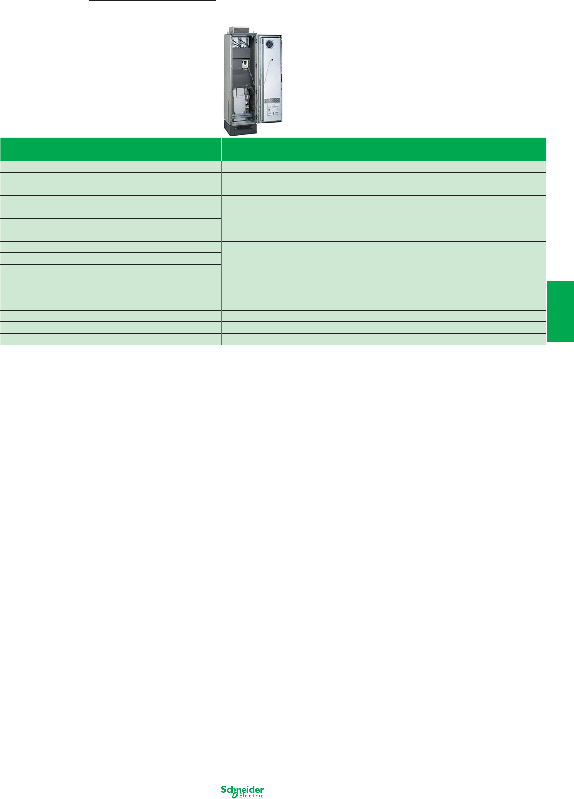
Other versions: Please consult your Schneider Electric sales offi ce.
Complex, high-power machines
IP54 Altivar 71 kit with preassembled enclosure
Altivar 71
0.37…500 kW
Drive Kit
ATV71HD90N4 VW3A9541
ATV71HC11N4 VW3A9542
ATV71HC13N4 VW3A9543
ATV71HC16N4 VW3A9544
ATV71HC20N4 VW3A9545
ATV71HC25N4
ATV71HC28N4
ATV71HC20N4 With VW3A7101 braking unit VW3A9546
ATV71HC25N4 With VW3A7101 braking unit
ATV71HC28N4 With VW3A7101 braking unit
ATV71HC31N4 Without braking unit VW3A9547
ATV71HC40N4
ATV71HC50N4 VW3A9548
VW3A7102 braking unit VW3A9549
Additional empty enclosure (600 mm)
VW3A9550
Additional empty enclosure (800 mm)
VW3A9551
4/31
2
1
3
4
5
6
7
8
9
10
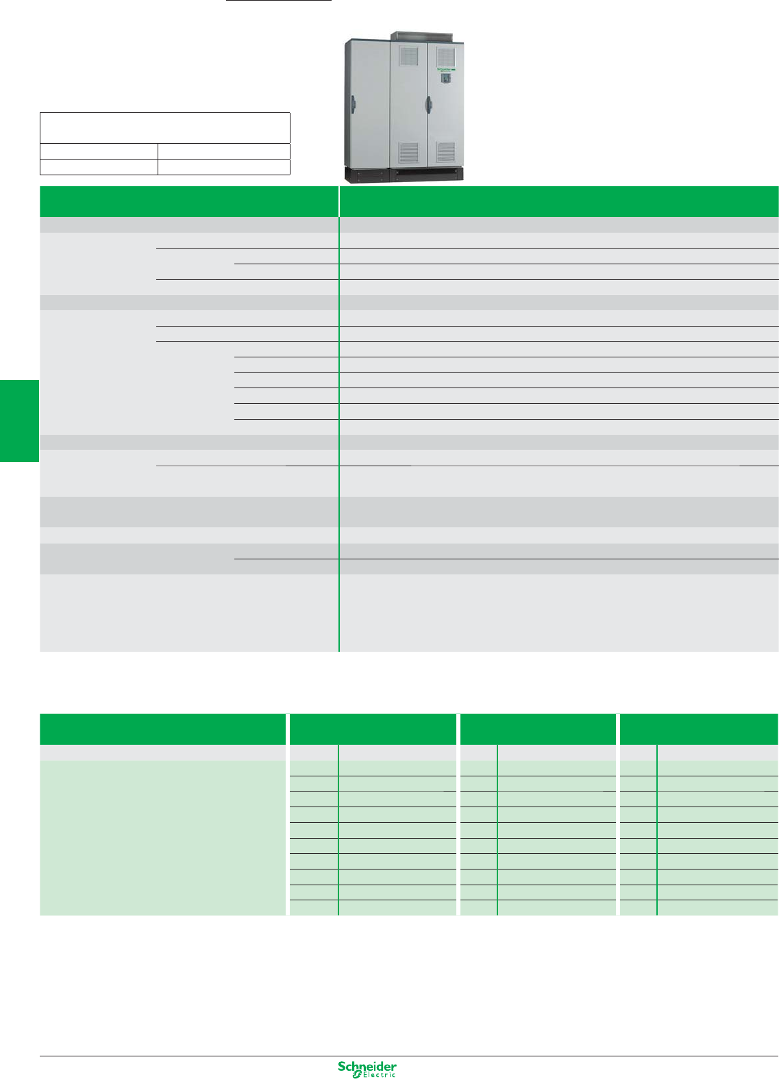
Other versions: Please consult your Schneider Electric sales office.
Type of drive Three-phase 380…480 V
(1)
Degree of protection
Drive Output frequency 0.1…1600 Hz up to 37 kW, 0.1…500 Hz from 45…2000 kW
Type of control Asynchronous motor Flux vector control with or without sensor, voltage/frequency ratio (2 or 5 points), ENA System
Synchronous motor Vector control without speed feedback
Transient overtorque 220% of nominal motor torque for 2 seconds, and 170% for 60 seconds
Speed range 1…1000 in closed loop mode with encoder feedback, 1…100 in open loop mode
Functions Number of functions > 150
Number of preset speeds 16
Number of I/O Analog inputs 2…4
Logic inputs 6…20
Analog outputs 1…3
Logic outputs 0…8
Relay outputs 2…4
Safety input 1
Dialogue Remote graphic display terminal or SoMove software workshop
Communication Integrated Modbus and CANopen
As an option Modbus TCP, Modbus/Uni-Telway, Fipio, Modbus Plus, Profibus DP, Profibus DPv1, DeviceNet,
INTERBUS, CC-Link, Ethernet IP.
Cards (available as an option) Encoder interface cards, I/O extension cards, “Controller Inside” programmable card,
“Crane” card
Reduction of current harmonics Optional chokes and passive filters
EMC filter Integrated C2 EMC
As an option External C1 EMC
Equipment A wide range of options listed in the catalogue provides add-ons for the standard offer as required.
As well as the options listed in the catalogue, it is possible to customise the equipment. Just contact our
teams of experts direct.
- Water cooling solution
- Integration of specific options
IP23 Three-phase
380…415 V
Three-phase
500 V
Three-phase
690 V
kW/HP Dimensions kW Dimensions kW Dimensions
90/125 ATV71EXC2D90N4 E1 90 ATV71 EXC2D90N E1 –
110/150 ATV71EXC2C11N4 E1 110 ATV71 EXC2C11N E1 110 ATV71 EXC2C11Y E1
132/200 ATV71EXC2C13N4 E1 132 ATV71 EXC2C13N E1 132 ATV71 EXC2C13Y E1
160/250 ATV71EXC2C16N4 E1 160 ATV71 EXC2C16N E2 160 ATV71 EXC2C16Y E1
200/300 ATV71EXC2C20N4 E2 200 ATV71 EXC2C20N E2 200 ATV71 EXC2C20Y E2
250/400 ATV71EXC2C25N4 E2 250 ATV71 EXC2C25N E2 250 ATV71 EXC2C25Y E2
280/450 ATV71EXC2C28N4 E2 – –
315/500 ATV71EXC2C31N4 E3 315 ATV71 EXC2C31N E4 315 ATV71 EXC2C31Y E2
400/600 ATV71EXC2C40N4 E3 400 ATV71 EXC2C40N E4 400 ATV71 EXC2C40Y E4
500/700 ATV71EXC2C50N4 E4 500 ATV71 EXC2C50N E4 500 ATV71 EXC2C50Y E4
(1) The Altivar 71 range in ready-assembled enclosure consists of:
– An ATV71H… drive
– A switch and fast-acting fuses
– An IP65 remote mounting kit for graphic display terminal
IP23 offer available up to 2000 kW. For ratings above 630 kW, please consult your Regional Sales Office.
Complex, high-power machines
Solutions in IP23 and IP54 ready-assembled enclosures
Altivar 71 Plus
90…2000 kW
Dimensions (in mm) width x height x depth
ATV71EXC2C…
E1 : 616 x 2159 x 659 E3 : 1016 x 2159 x 659
E2 : 816 x 2159 x 659 E4 : 1216 x 2159 x 659
4/32
2
1
3
4
5
6
7
8
9
10
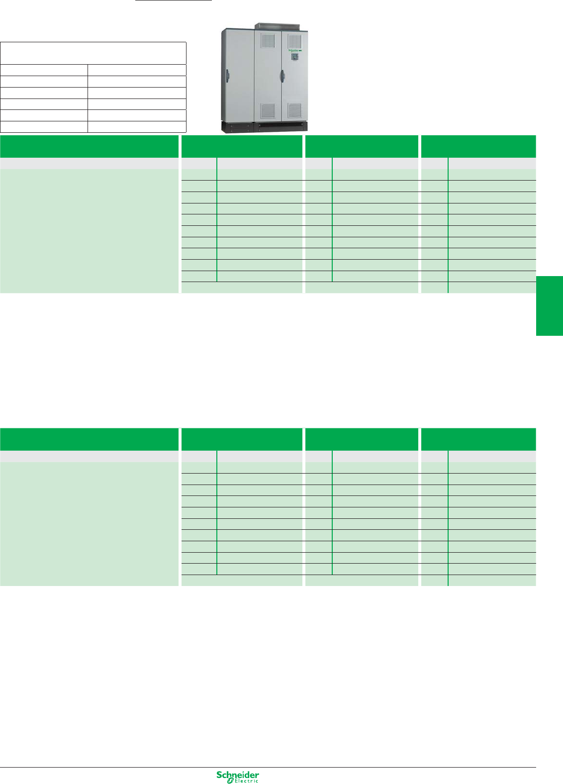
Other versions: Please consult your Schneider Electric sales office.
Complex, high-power machines
Solutions in IP23 and IP54 ready-assembled enclosures
Altivar 71 Plus
90…2000 kW
IP54 Three-phase
380…415 V
Three-phase
500 V
Three-phase
690 V
Compact floor-standing enclosure
kW/HP Dimensions kW Dimensions kW Dimensions
90/125 ATV71EXC5D90N4 E5 90 ATV71EXC5D90N E5 –
110/150 ATV71EXC5C11N4 E5 110 ATV71EXC5C11N E5 110 ATV71EXC5C11Y E5
132/200 ATV71EXC5C13N4 E5 132 ATV71EXC5C13N E5 132 ATV71EXC5C13Y E5
160/250 ATV71EXC5C16N4 E5 160 ATV71EXC5C16N E6 160 ATV71EXC5C16Y E5
220/350 ATV71EXC5C20N4 E6 200 ATV71EXC5C20N E6 200 ATV71EXC5C20Y E6
250/400 ATV71EXC5C25N4 E6 250 ATV71EXC5C25N E6 250 ATV71EXC5C25Y E6
280/450 ATV71EXC5C28N4 E6 – –
315/500 ATV71EXC5C31N4 E7 315 ATV71EXC5C31N E8 315 ATV71EXC5C31Y E6
400/600 ATV71EXC5C40N4 E7 400 ATV71EXC5C40N E8 400 ATV71EXC5C40Y E8
500/700 ATV71EXC5C50N4 E8 500 ATV71EXC5C50N E8 500 ATV71EXC5C50Y E8
630 ATV71EXC5C63Y E8
IP54 Three-phase
380…415 V
Three-phase
500 V
Three-phase
690 V
Separate air flow kW/HP Dimensions kW Dimensions kW Dimensions
90/125 ATV71EXS5D90N4 E9 90 ATV71EXS5D90N E11 –
110/150 ATV71EXS5C11N4 E9 110 ATV71EXS5C11N E11 110 ATV71EXS5C11Y E11
132/200 ATV71EXS5C13N4 E9 132 ATV71EXS5C13N E11 132 ATV71EXS5C13Y E11
160/250 ATV71EXS5C16N4 E9 160 ATV71EXS5C16N E12 160 ATV71EXS5C16Y E11
220/350 ATV71EXS5C20N4 E10 200 ATV71EXS5C20N E12 200 ATV71EXS5C20Y E12
250/400 ATV71EXS5C25N4 E10 250 ATV71EXS5C25N E12 250 ATV71EXS5C25Y E12
280/450 ATV71EXS5C28N4 E10 – –
315/500 ATV71EXS5C31N4 E13 315 ATV71EXS5C31N E14 315 ATV71EXS5C31Y E12
400/600 ATV71EXS5C40N4 E13 400 ATV71EXS5C40N E14 400 ATV71EXS5C40Y E14
500/700 ATV71EXS5C50N4 E14 500 ATV71EXS5C50N E14 500 ATV71EXS5C50Y E14
630 ATV71EXS5C63Y E14
Dimensions (in mm) width x height x depth
ATV71EX…
E5 : 616 x 2264 x 659 E9 : 616 x 2359 x 659
E6 : 816 x 2264 x 659 E10 : 816 x 2359 x 659
E7 : 1016 x 2264 x 659 E11 : 608 x 2359 x 659
E8 : 1216 x 2264 x 659 E12 : 808 x 2359 x 6590
E13 : 1008 x 2359 x 659
E14 : 1208 x 2359 x 659
4/33
2
1
3
4
5
6
7
8
9
10
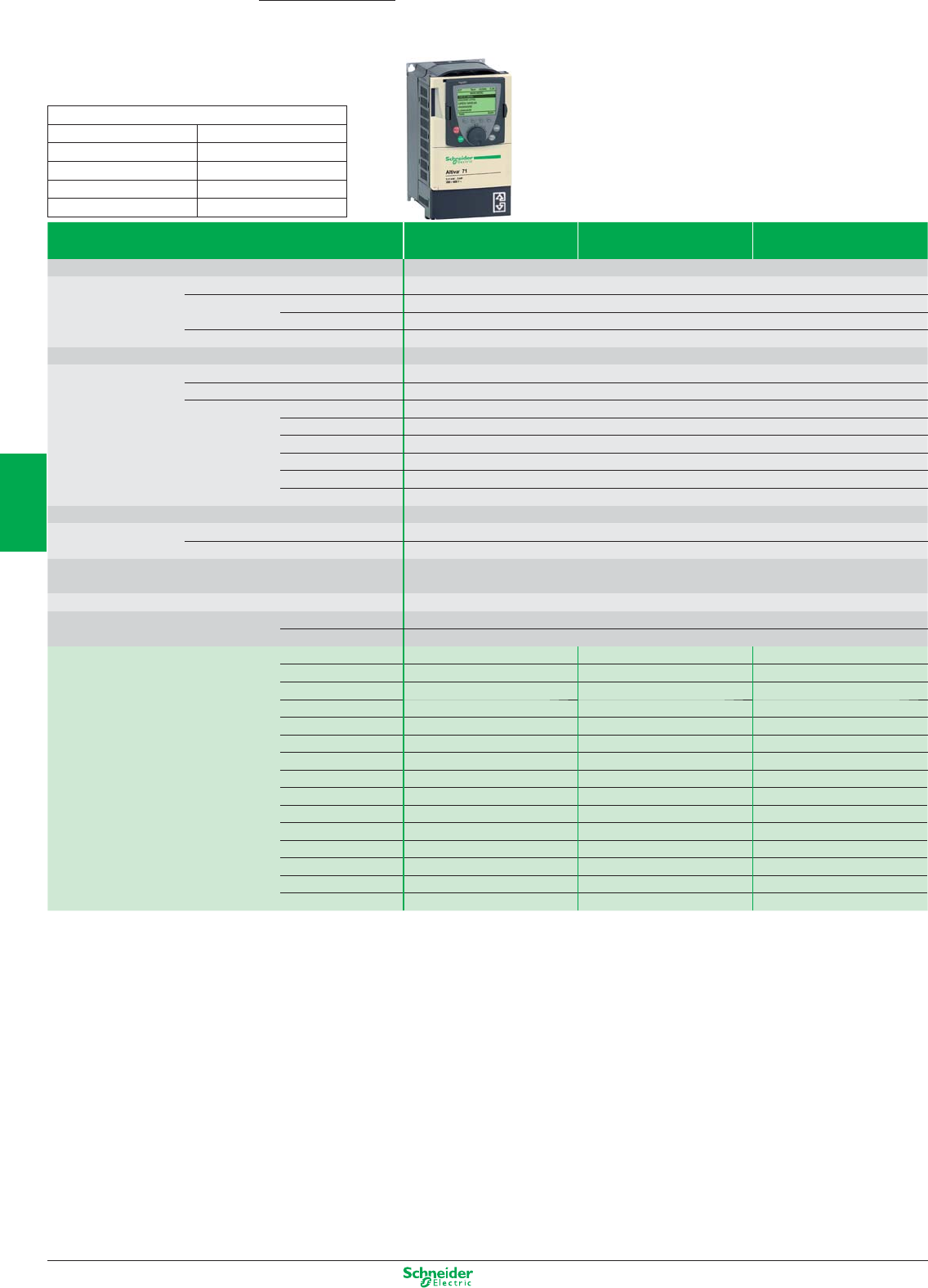
Other versions: Please consult your Schneider Electric sales offi ce.
Complex, high-power machines
Drives for lifts
Type of drive Single-phase
200 V
Three-phase
200 V
Three-phase
380 V
Supply voltage
Degree of protection IP20 for unprotected drives and IP41 on the upper part
Drive Output frequency 0.1…1600 Hz up to 37 kW, 0.1…500 Hz from 45 to 500 kW
Type of control Asynchronous motor Flux vector control with or without sensor, voltage/frequency ratio
Synchronous motor Vector control with and without speed feedback
Transient overtorque 220% of nominal motor torque for 2 seconds, and 170% for 60 seconds
Speed range 1…1000 in closed loop mode with encoder feedback, 1…100 in open loop mode
Functions Number of functions > 150
Number of preset speeds 16
Number of I/O Analog inputs 2…4
Logic inputs 6…20
Analog outputs 1…3
Logic outputs 0…8
Relay outputs 2…4
Safety input 1
Dialogue Remote graphic display terminal or SoMove software workshop
Communication Integrated Modbus and CANopen
As an option Fipio, Ethernet, Modbus Plus, Profi bus DP, DeviceNet, Uni-Telway, InterBus
Cards (available as an option) Encoder interface cards, I/O extension cards, “Controller Inside” programmable card,
Encoder emulation card
Reduction of current harmonics DC choke integrated or supplied with the product
EMC fi lter Integrated C2 EMC up to 5.5 kW
As an option External C2 EMC from 7.5 kW
Motor power kW/HP 1.5/2 ATV71LU22M3Z T3 – –
2.2/3 ATV71LU30M3Z T3 ATV71LU22M3Z T3 –
3/– ATV71LU40M3Z T3 ATV71LU30M3Z T3 ATV71LU30N4Z T3
4/5 ATV71LU55M3Z T4 ATV71LU40M3Z T3 ATV71LU40N4Z T3
5.5/7.5 ATV71LU75M3Z T5A ATV71LU55M3Z T4 ATV71LU55N4Z T4
7.5/10 – ATV71LU75M3Z T5A ATV71LU75N4Z T4
11/15 – ATV71LD11M3XZ T5B ATV71LD11N4Z T5A
15/20 – ATV71LD15M3XZ T5B ATV71LD15N4Z T5B
18.5/25 – ATV71LD18M3XZ T6 ATV71LD18N4Z T5B
22/30 – ATV71LD22M3XZ T6 ATV71LD22N4Z T6
30/40 – ATV71LD30M3XZ T6 ATV71LD30N4Z T7A
37/50 – ATV71LD37M3XZ T7B ATV71LD37N4Z T7A
45/60 – ATV71LD45M3XZ T7B ATV71LD45N4Z T8
55/75 – – ATV71LD55N4Z T8
75/100 – – ATV71LD75N4Z T8
Dimensions (in mm) width x height x depth
T2
:
130 x 230 x 175 T3
:
155 x 260 x 187
T4
:
175 x 295 x 187 T5A
:
210 x 295 x 213
T5B
:
230 x 400 x 213 T6
:
240 x 420 x 236
T7A
:
240 x 550 x 266 T7B
:
320 x 550 x 266
T8
:
320 x 630 x 290
Altivar 71 Lift
2.2…75 kW
4/34
2
1
3
4
5
6
7
8
9
10
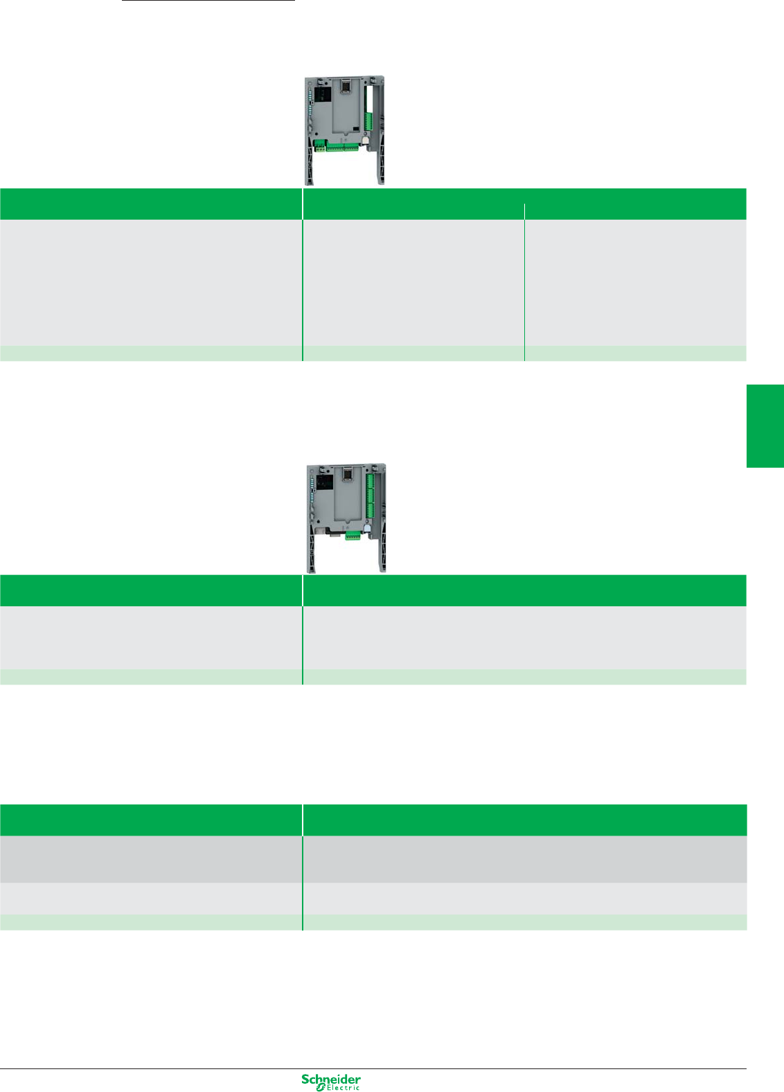
Other versions: Please consult your Schneider Electric sales office.
Altivar 71
0.37…2000 kW
Complex, high-power machines
I/O extension and specific cards
Type of card I/O extension
Logic Extended
Description 1 relay logic output (“C/O” contact)
4 x 24 VDC positive or negative logic inputs
2 x 24 VDC open collector positive or negative logic
outputs
1 input for PTC probes
1 x 0…20 mA differential current analog input
1 software-configurable voltage (0…10 VDC) or
current (0…20 mA) analog input
2 software-configurable voltage (±10V, 0…10 VDC)
or current (0…20 mA) analog inputs
1 relay logic output (“C/O” contact)
4 x 24 VDC positive or negative logic inputs
2 x 24 VDC open collector positive or negative logic
outputs, 1 input for PTC probes, 1 frequency control
input
Reference VW3A3201 VW3A3202
"Controller Inside" programmable card
Type of card Programmable “Controller Inside”
Description 10 logic inputs, 2 of which can be used for 2 counters or
4 of which can be used for 2 incremental encoders
2 analog inputs, 6 logic outputs, 2 analog outputs, a master port for the CANopen bus, a PC port for
programming with the PS 1131 software workshop
Reference VW3A3501
“Crane” cards
Type of card “Crane” card for overhead cranes
Description 10 logic inputs, 2 of which can be used for 2 counters or
4 of which can be used for 2 incremental encoders
2 analog inputs, 6 logic outputs, 2 analog outputs, a master port for the CANopen bus
Application-specific functions
Sensorless:
Management of load sway up to heights of 30 m
Management of the stop and slowdown limit switches on translational and directional movements
References VW3A3510
4/35
2
1
3
4
5
6
7
8
9
10

Other versions: Please consult your Schneider Electric sales office.
Complex, high-power machines
Encoder interface cards
Type of card Encoder interface with
Differential outputs (RS422)
Open collector outputs (NPN)
Push-pull outputs
Operating frequency 300 kHz
Reference 5 V VW3A3401 ––
12 V – VW3A3403 VW3A3405
15 V VW3A3402 VW3A3404 VW3A3406
24 V – – VW3A3407
Type of card Resolver Universal Sincos Absolute
Incremental with
emulation
Speed feedback resolution 12 bits 16 bits 16 bits 10,000
Encoder type supported Resolver with
2, 4, 6 or 8 poles
"SinCos,
SinCosHiperface
EnDat, SSI"
Sincos Absolute "Incremental
RS 422 - 5 V or 15 V"
References VW3A3408 VW3A3409 VW3A3410 VW3A3411
Altivar 71
0.37…2000 kW
4/36
2
1
3
4
5
6
7
8
9
10
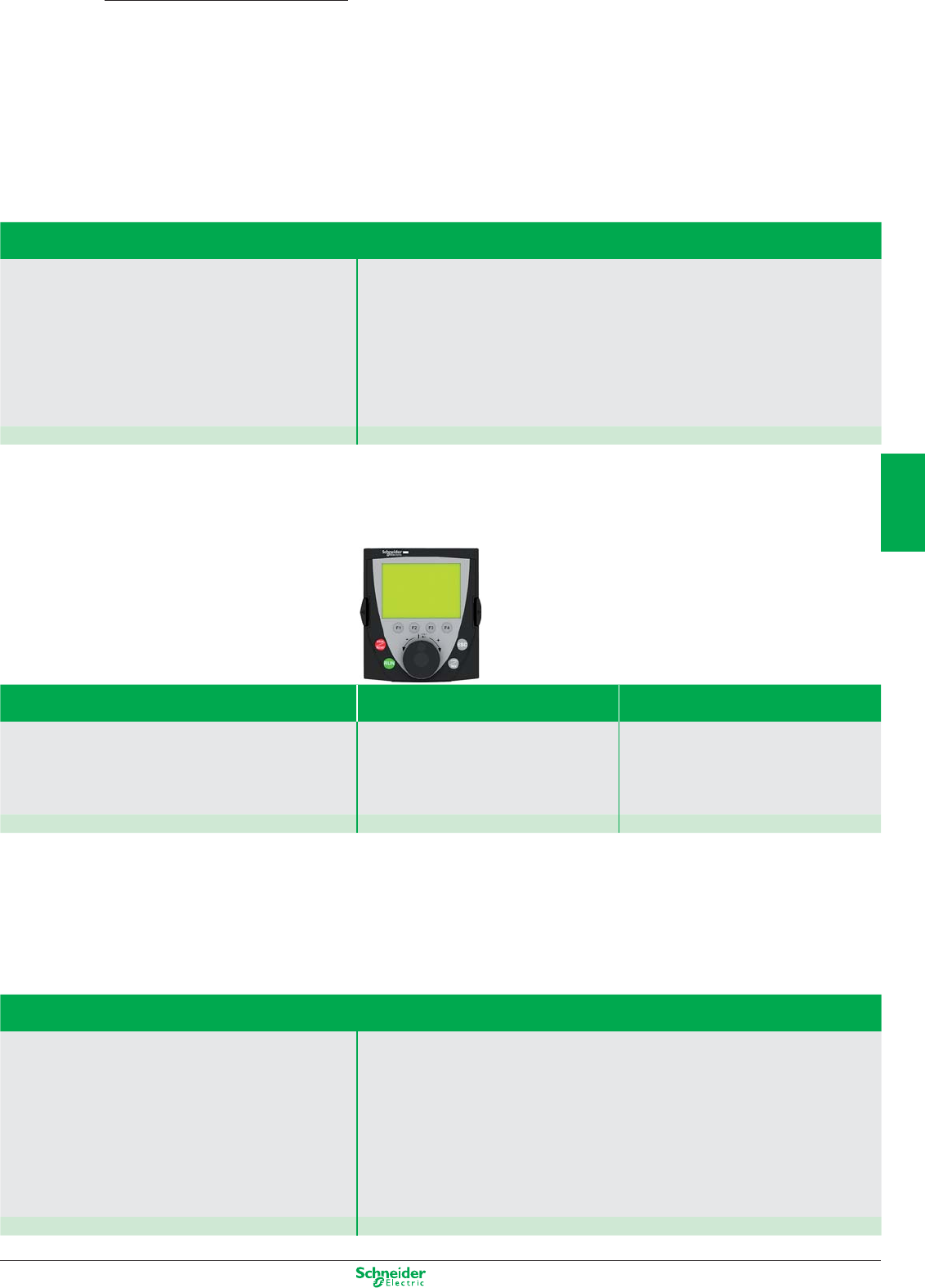
Other versions: Please consult your Schneider Electric sales offi ce.
Altivar Accessories and options available
Options
Type of accessory
Description Additional EMC input fi lters
AC line chokes
Optional DC chokes
Passive fi lters
Sinus fi lters
Motor chokes
Braking units
Braking resistors
Reference Please refer to the Schneider Electric catalogue
Communication accessories
Type of accessory Remote graphic display terminal Remote mounting kit (1)
Description
This display terminal is attached to the front of the drive.
It includes the integrated 7-segment display terminal for
drives supplied without a graphic display terminal.
A remote mounting kit for mounting on an enclosure
door with IP54 degree of protection.
It includes:
b All the mechanical fi ttings
b Fixing accessories
References VW3A1101 VW3A1102
(1) Use a VW3A1104Rpp remote-mounting cordset, to be ordered separately (please refer to the Schneider Electric catalogue.)
Other accessories available
Type of accessory
Description Multi-Loader confi guration tool
Simple Loader confi guration tool
Bluetooth adaptor
SoMove multilingual confi guration software workshop for PC
SoMobile software for mobile phones
Connection accessories for CANopen communication bus
(tap junctions, adaptor, connector, cables, etc.)
Modbus connection accessories
(communication module, gateways, splitter boxes, cordsets and cables, etc.)
Reference Please refer to the Schneider Electric catalogue
4/37
2
1
3
4
5
6
7
8
9
10
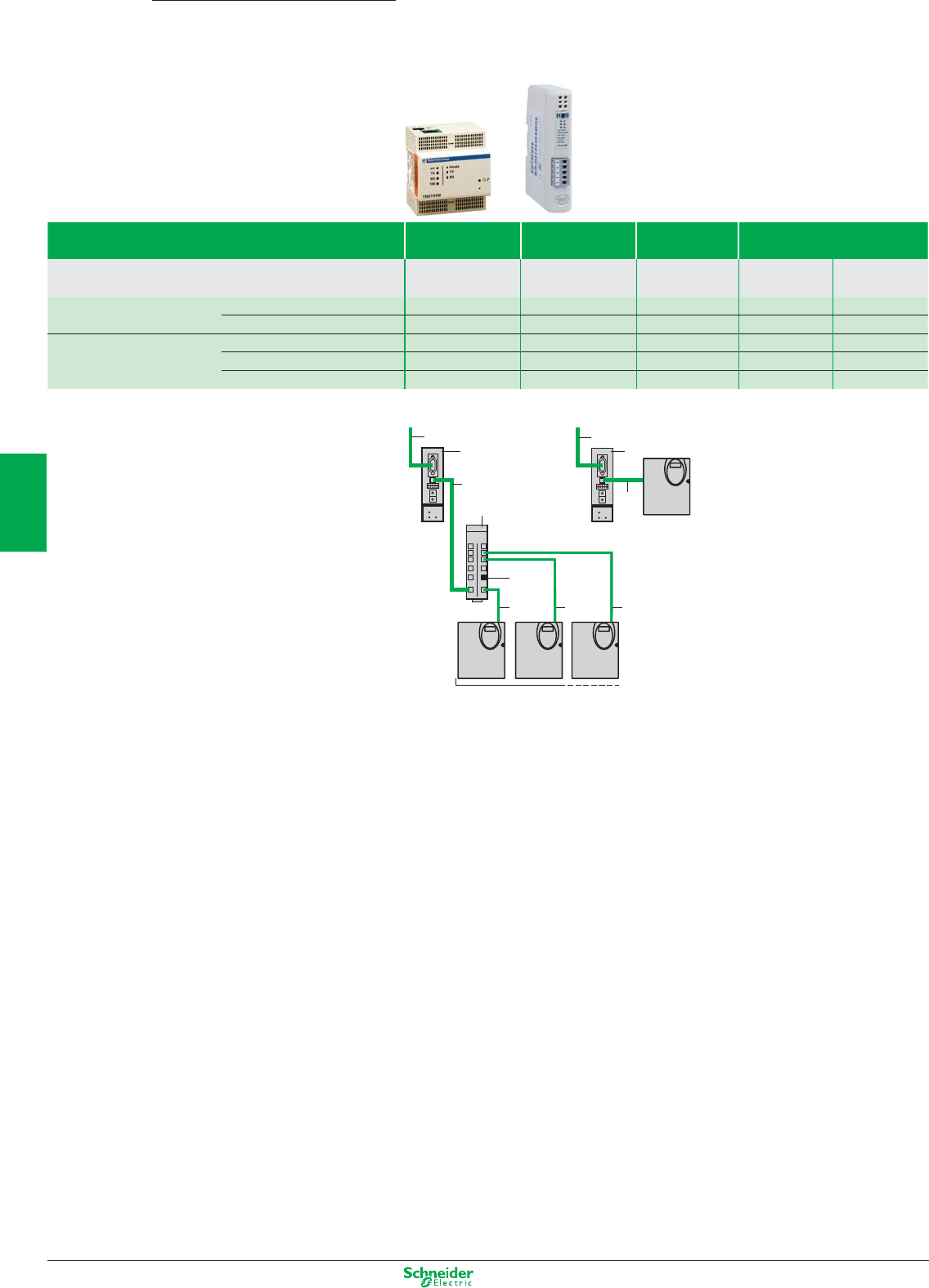
Other versions: Please consult your Schneider Electric sales office.
2
1
6
55 5
3
4
2
1
3
2
1
6
55 5
3
4
2
1
3
Dialogue and communication
Communication modules
Altivar
1 To network
2 Communication modules
3 PLC cables VW3A8 306 Rpp,
VW3 P07 306 R10
4 Modbus splitter box LU9 GC3
5 Modbus drop cables
VW3A8 306 Rpp
6 Line terminator
VW3A8 306 RC
Altistart 48/Altivar 31
starters/drives
Ethernet/
Modbus
DeviceNet/
Modbus
Fipio/Modbus Profibus DP/Modbus
Parameter setting – – – Standard
configurator
ABC configurator
program
References Bridge TSXETG100 ––––
Gateway – LUFP9 LUFP1 LA9P307 LUFP7
Cable references L = 0.3 m – VW3A8306R03 VW3A8306R03 – VW3A8306R03
L = 1 m – VW3A8306R10 VW3A8306R10 VW3P07306R10 VW3A8306R10
L = 3 m VW3A8306D30 VW3A8306R30 VW3A8306R30 –VW3A8306R30
4/38
2
1
3
4
5
6
7
8
9
10
Other versions: Please consult your Schneider Electric sales office.
Dialogue and communication
Communication cards and modules
Drives
Altivar 61, Altivar 71
Modbus TCP Modbus TCP Daisy
Chain
Modbus/Uni-Telway Fipio
Maximum number of drives controlled ––––
Transmission speed 10/100 Mbps 10/100 Mbps 147/247 Mbps 62 Mbps
References VW3A3310 VW3A3310d VW3A3303 VW3A3311
Drives
Altivar 61, Altivar 71
Modbus Plus Profibus DP Profibus DPv1 I
NTER
B
US
Maximum number of drives controlled 64 126 126 64
Transmission speed 1 Mbps 9600 bps...12 Mbps 9600 bps...12 Mbps 1 Mbps
References VW3A3302 VW3A3307 VW3A3307S371 VW3A3304
Drives
Altivar 61, Altivar 71
CC-Link Ethernet/IP DeviceNet
Maximum number of drives controlled 64 – 63
Transmission speed …10 Mbps 10/100 Mbps 125/250/500 Kbps
References VW3A3317 VW3A3316 VW3A3309
Drives
Altivar 61
L
ON
W
ORKS
METASYS N2 APOGEE FLN BACnet
Connector
1 removable 3-way screw 1 removable
4-way screw 1 removable 4-way screw 1 removable 4-way screw
terminal block terminal block terminal block terminal block
Transmission speed 78 Kbps – – –
References VW3A3312 VW3A3313 VW3A3314 VW3A3315
For other connection accessories, please refer to the Schneider Electric catalogue.
Altivar
Transparent
Ready
4/39
2
1
3
4
5
6
7
8
9
10
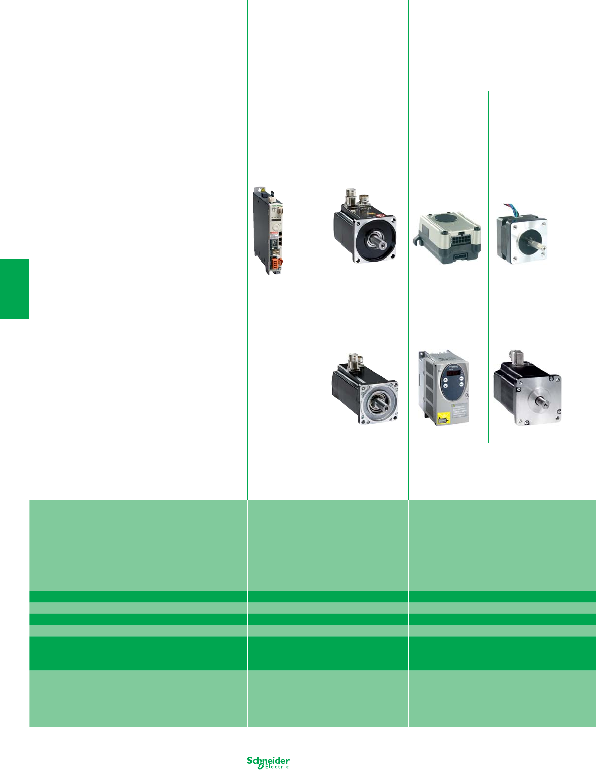
Other versions: Please consult your Schneider Electric sales offi ce.
Selection guide
C Applications :
Lexium 32 is the perfect drive
system for applications involving
high-precision, dynamic positioning.
C Applications :
Lexium SDx stepper drives and
motors are used for short-distance
positioning applications requiring
maximum accuracy and high torque.
Servo Drives Servo Motors Stepper Drives Stepper Motors
Lexium 32 Lexium BMH Lexium SD2 Lexium BRS2
Lexium BSH Lexium SD3 Lexium BRS3
Machines Packaging machines
Material handling machines
Material working machines
Assembling machines
Printing machines
Labelling machines
Screen printing machines
Description The Lexium 32 servo range consists of three
high-performance book-size servo drive
models – Lexium 32 Compact, Lexium 32
Advanced and Lexium 32 Modular – and
two motor families – the versatile medium-
inertia Lexium BMH and the dynamic low-
inertia Lexium BSH.
The Lexium SDx stepper motor drive range
consists of two high-precision stepper drive
lines – the three-phase stepper drives
Lexium SD3 and the two-phase stepper
drives Lexium SD2. These drive lines are
complemented by two perfectly matched
stepper motor families – Lexium BRS3 three-
phase stepper motors and Lexium BRS2
two-phase stepper motors.
Power range 0.15…7 kW up to 750 W
Voltage range 115…240 VAC, 400…480 VAC 24…48 VDC, 115…240 VAC
Speed up to 8000 rpm up to 1000 rpm
Torque up to 84 Nm up to 16.5 Nm
Communication interfaces CANopen, CANmotion, PROFIBUS DP,
DeviceNet, EtherNet/IP
CANopen, CANmotion, PROFIBUS DP or
Pulse/Direction
Safety function (STO) on board
Enhanced Safety Module (SS1, SS2, SLS,
SOS)
Encoder module for digital and analog
encoders and resolvers
Safety function (STO) on board
(Lexium SD3 28)
4/40
4
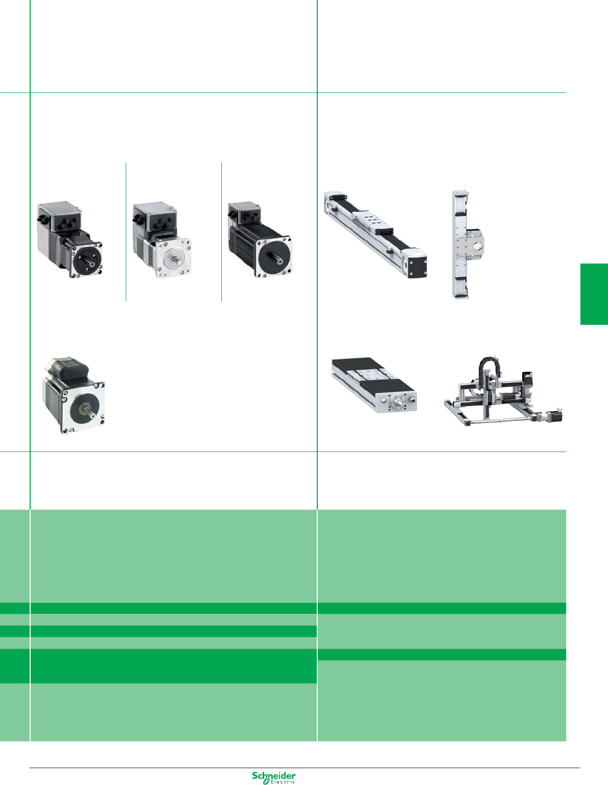
Other versions: Please consult your Schneider Electric sales offi ce.
C Applications :
Lexium Integrated Drives allow for extremely space-saving
decentralised motion solutions.
C Applications :
The Lexium Linear Motion products are designed
for maximum fl exibility, performance and
cost-effectiveness. This range offers products
for all linear movements in the automation
industry from single-axis to multi-axis systems.
Integrated Drives Linear Motion
Lexium ILA Lexium ILE Lexium ILS Lexium PAS Lexium CAS
Lexium ILP / ILT Lexium TAS Lexium MAX
Format adjustment
Printing machines
Material handling machines
Material handling machines
Material working machines
On-the-fl y working machines
Assembling machines
The Lexium ILx Integrated Drives comprise motor, positioning controller,
power electronics, fi eldbus and “Safe Torque Off” safety function in an
extremely compact single device. Lexium ILx Integrated Drives are available
with all important motor technologies (servo, brushless DC, stepper).
Lexium Linear Motion is a comprehensive linear motion range
comprising Lexium PAS portal axes, Lexium TAS linear tables,
Lexium CAS cantilever and telescopic axes and Lexium MAX
multi-axis systems.
100…370 W Single axes:
24…48 VDC, 115 to 240 VAC Stroke up to 5.5 m
up to 9000 rpm Load up to 150 kg
up to 12 Nm Speed up to 8 m/s
RS485, CANopen, PROFIBUS DP, DeviceNet, EtherNet/IP, EtherCAT,
Ethernet POWERLINK, Modbus TCP, Pulse/Direction
Multi axes:
Stroke up to 5.5 m
Load up to 300 kg
Safety function (STO) on board
(Lexium ILA, Lexium ILE, Lexium ILS)
Stand-alone device with controller inside (Lexium ILP)
Speed up to 8 m/s
Available as individual components or completely
pre-assembled, customised systems with drives and motors
4/41
4
Other versions: Please consult your Schneider Electric sales office.
Selection guide
C Applications :
Lexium Motion Controllers can be used as a stand-alone motion and
automation controllers for machines without a PLC or as pure motion
controllers for machines in which a PLC takes care of automation control.
Axis controller
Lexium Motion Controllers
Machines Packaging machines
Material handling machines
Material working machines
Assembling machines
Description The compact LMC Lexium Motion Controllers are used to control multiple synchronised
axes via a motion bus and feature high performance coupled with economy.
Technical information Synchronisation of up to 4 axes in 2 ms
Synchronisation of up to 8 axes in 4 ms
PLCopen function blocks single / multi axis control
Application function blocks (Rotary knife, Flying shear, Clamping, Grouping/Ungrouping)
Communication interfaces Modbus, CANmotion, Profibus DP, DeviceNet, Ethernet TCP/IP (for programming)
4/42
4
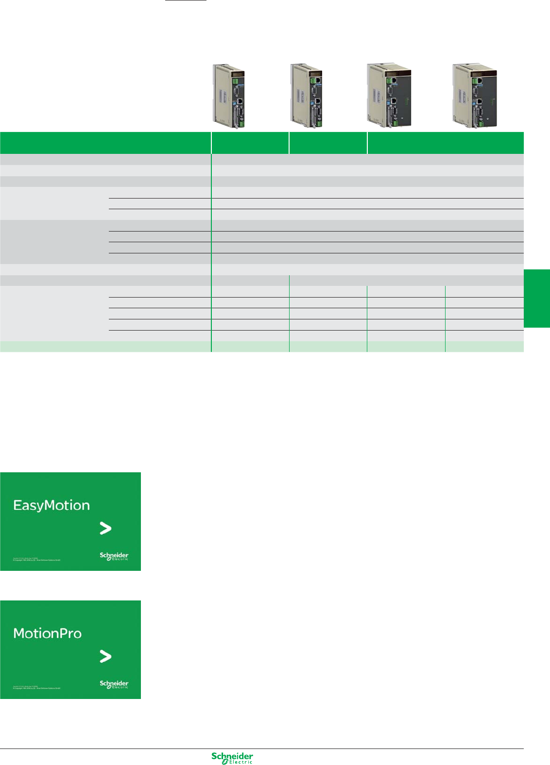
Other versions: Please consult your Schneider Electric sales office.
Motion control
Motion controller
Lexium Controller
Controller type Optimised Standard Extended
Drive synchronisation Up to 4 axes 2 ms
CAN Motion bus Up to 8 axes 4 ms
Interpolation of drive position loops 250 µs
Internal memory RAM 1 MB
Flash Eeprom 1 MB
Protected RAM 60 Kb
Expert application Application function blocks yes
Single-axis PLCopen control yes
Multi-axis PLCopen control yes
2D interpolation yes
Number of logic inputs 8 + 4 Fast inputs
Number of logic outputs 8 8
Communication Modbus yes yes yes yes
CANopen automation – yes yes yes
Ethernet TCP/IP – yes yes yes
Profibus DP V1 – – yes –
Device Net – – – yes
Reference LMC10 LMC20 LMC20A1307 LMC20A1309
Software solutions
Easy Motion… for configuring
motion control functions
b Axis parameter setting
b Drive and controller adjustment and diagnostics
b Creation of position registers via the Teach function
b Management of axis operating modes and manual control
b Configuration of positioning tasks
b Editing cam profiles
b Application back up and restore
Motion Pro… for configuring and programming
motion control functions
b Retains the same benefits as Easy Motion mode for motion control
b Creates the whole application, control system function and motion control
function, using the programming editor conforming to standard IEC 61131
b Saves the machine signature
b Protection of application programs
4/43
4
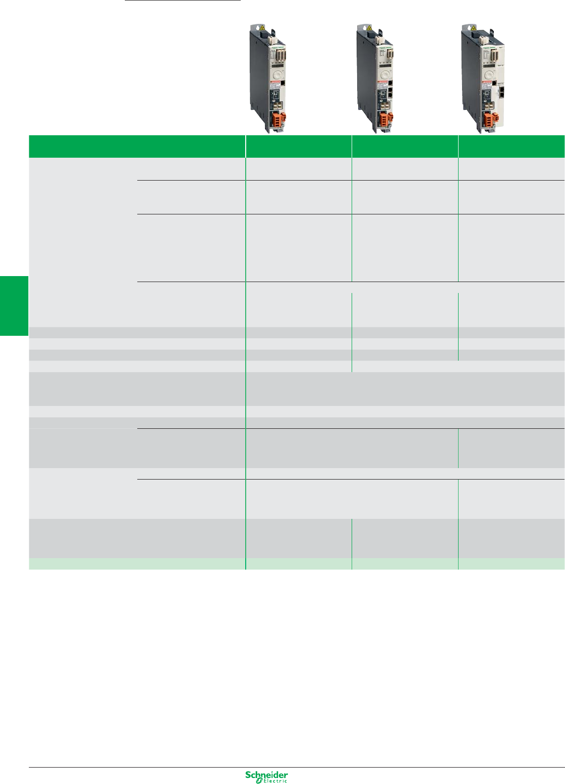
Other versions: Please consult your Schneider Electric sales office.
Lexium 32 Motion control
Lexium 32 Servo Drives and Motors
Main functions Lexium 32 Compact Lexium 32 Advanced Lexium 32 Modular
Communication Integrated Modbus serial link
Pulse train
Modbus serial link
CANopen, CANmotion machine bus
Modbus serial link
Pulse train
As an option – – CANopen, CANmotion machine
bus, DeviceNet, EtherNet/IP,
PROFIBUS DP
Operating modes Manual mode (JOG)
Electronic gearbox
Speed control
Current control
Homing
Manual mode (JOG)
Speed control
Current control
Position control
Homing
Manual mode (JOG)
Motion sequence
Electronic gearbox
Speed control
Current control
Position control
Functions Auto-tuning, monitoring, stopping, conversion
– Stop window
Rapid entry of position values
Stop window
Rapid entry of position values
Rotary axes
Position register
24 V c logic inputs 6, reassignable 3, reassignable 4, reassignable
24 V c capture inputs (1) (2) –12
24 V c logic outputs (1) 5, reassignable 2, reassignable 3, reassignable
Analog inputs 2–
Pulse control input 1, configurable as: RS 422 link
5 V or 24 V push-pull
5 V or 24 V open collector
ESIM PTO output RS 422 link
Safety functions Integrated “Safe Torque Off” STO
As an option – Safe Stop 1 (SS1) and Safe Stop 2
(SS2)
Safe Operating Stop (SOS)
Safe Limited Speed (SLS)
Sensor Integrated SinCos Hiperface
®
sensor
As an option – Resolver encoder
Analog encoder
Digital encoder
Architecture Control via:
Logic or analog I/O
Control via:
Motion controller via CANopen
and CANmotion machine bus
Control via:
Schneider Electric or third-party
PLCs via communication buses
and networks
Type of servo drive LXM 32C LXM 32A LXM 32M
4/44
2
1
3
4
5
6
7
8
9
10
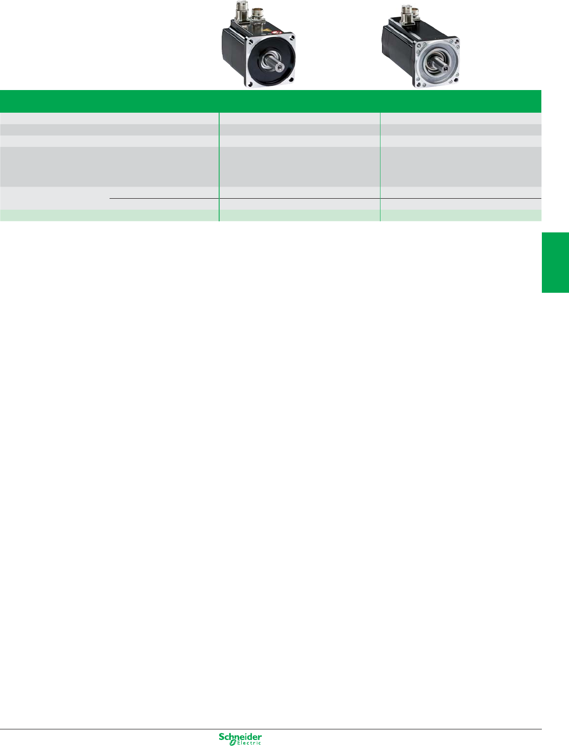
Other versions: Please consult your Schneider Electric sales office.
Main functions
Application type
High load, With robust adjustment of the movement High dynamic range, Power density
Flange size
70, 100, 140 and 205 mm 55, 70, 100 and 140 mm
Continuous stall torque
1.2 to 84 Nm 0.5 to 33.4 Nm
Encoder type Single turn SinCos: 32,768 points/turn
and 131,072 points/turn
Multiturn SinCos: 32,768 points/turn x 4096 turns
and 131,072 points/turn x 4096 turns
Single turn SinCos: 131,072 points/turn
Multiturn SinCos: 131,072 points/turn x 4096 turns
Degree of protection
Casing IP 65 (IP 67 conformity kit as an option) IP 65
Shaft end IP 50 or IP 65 (IP 67 conformity kit as an option) IP 50 or IP 65
Type of servo motor Lexium BMH Lexium BSH
4/45
2
1
3
4
5
6
7
8
9
10
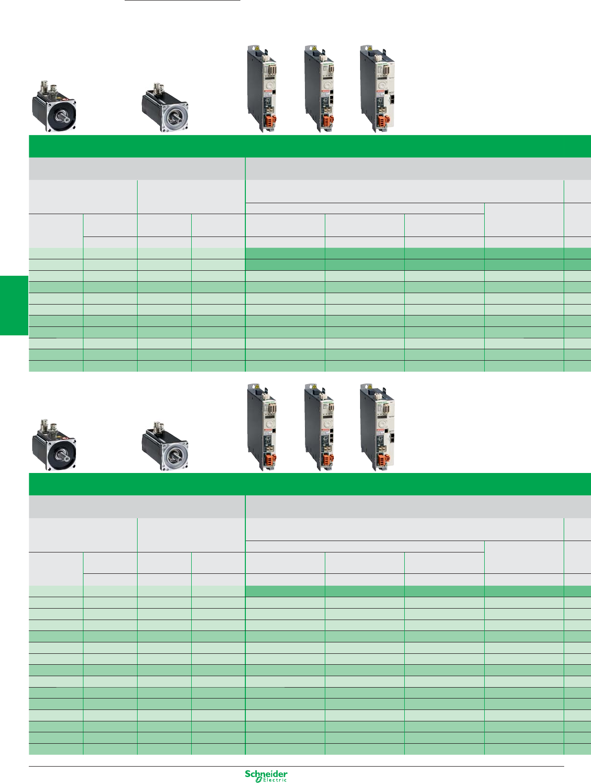
Other versions: Please consult your Schneider Electric sales office.
Lexium 32 servo drive/BMH or BSH servo motor combinations
Servo motors Lexium 32C, 32A and 32M servo drives
200…240 V single-phase supply voltage with integrated EMC filter
BMH
(IP 50, IP65 or IP 67)
BSH
(IP 50 or IP 65)
LXM 32pU45M2
Continuous output current: 1.5 A rms
Nominal operating point Stall torques
Type of
servo motor
Rotor
inertia
Type of
servo motor
Rotor
inertia
Nominal
torque
Nominal
speed
Nominal
power
M
0
/M
max
kgcm
2
kgcm
2
Nm rpm W Nm/Nm
BSH 0551T 0.06 0.45 6000 300 0.5/1.4
BSH 0552T 0.10
BSH 0553T 0.13
BSH 0701T 0.25
BMH 0701T 0.59
BSH 0702T 0.41
BSH 0703T 0.58
BMH 0702T 1.13
BSH 1001T 1.40
BMH 0703T 1.67
BMH 1001T 3.2
BSH 1002T 2.31
BMH 1002T 6.3
BMH 1003T 9.4
BMH 1401P 16.5
Lexium 32 servo drive/BMH or BSH servo motor combinations
Servo motors Lexium 32C, 32A and 32M servo drives
100…120 V single-phase supply voltage with integrated EMC filter
BMH
(IP 50, IP65 or IP 67)
BSH
(IP 50 or IP 65)
LXM 32pU90M2
Continuous output current: 3 A rms
Nominal operating point Stall torques
Type of
servo motor
Rotor
inertia
Type of
servo motor
Rotor
inertia
Nominal
torque
Nominal
speed
Nominal
power
M
0
/M
max
kgcm
2
kgcm
2
Nm rpm W Nm/Nm
BSH 0551T 0.06 0.49 3000 150 0.5/1.5
BSH 0552T 0.10 0.77 3000 250 0.8/1.9
BSH 0553T 0.13
BMH 0701T 0.59
BSH 0701T 0.25
BSH 0702T 0.41
BMH 0702T 1.13
BMH 0703T 1.67
BSH 1001T 1.40
BMH1001T 3.2
BMH1002T 6.3
Lexium 32 Lexium 32 motion control
Servo drive/servo motor combinations
4/46
2
1
3
4
5
6
7
8
9
10

Other versions: Please consult your Schneider Electric sales office.
LXM 32pU18M2
Continuous output current: 6 A rms
LXM 32pD30M2
Continuous output current: 10 A rms
Nominal operating point Stall torques Nominal operating point Stall torques
Nominal
torque
Nominal
speed
Nominal
power
M0/Mmax Nominal
torque
Nominal
speed
Nominal
power
M0/Mmax
Nm rpm W Nm/Nm Nm rpm W Nm/Nm
1.14 3000 350 1.2/3.3
1.35 2500 350 1.4/4.2
1.36 2500 350 1.4/3.5
2.07 2500 550 2.2/6.1
2.3 2500 600 2.5/6.4
3.1 2000 650 3.4/8.7
2.75 2500 700 3.3/6.3
3.3 2000 700 3.4/8.9
3.5 2000 750 6/10.3
LXM 32pU90 M2
Continuous output current: 3 A rms
LXM 32pD18M2
Continuous output current: 6 A rms
LXM 32pD30M2
Continuous output current: 10 A rms
Nominal operating point Stall torques Nominal operating point Stall torques Nominal operating point Stall torques
Nominal
torque
Nominal
speed
Nominal
power
M
0
/M
max
Nominal
torque
Nominal
speed
Nominal
power
M
0
/M
max
Nominal
torque
Nominal
speed
Nominal
power
M
0
/M
max
Nm rpm W Nm/Nm Nm rpm W Nm/Nm Nm rpm W Nm/Nm
0.74 6000 450 0.8/2.5
0.84 6000 550 1.2/3
0.94 5000 500 1.3/3.5
1.1 4000 450 1.4/4
1.8 5000 950 2.2/7.2
2.1 4000 900 2.6/7.4
2.1 4000 900 2.5/7.4
2.2 4000 900 2.7/7.5
2.9 3000 900 3.4/10.2
2.8 3000 900 3.4/10.2
3.7 4000 1500 5.8/16.4
4.6 3000 1450 6/18.4
5.6 2500 1450 8.2/22.8
6.9 2000 1450 10.3/30.8
4/47
2
1
3
4
5
6
7
8
9
10
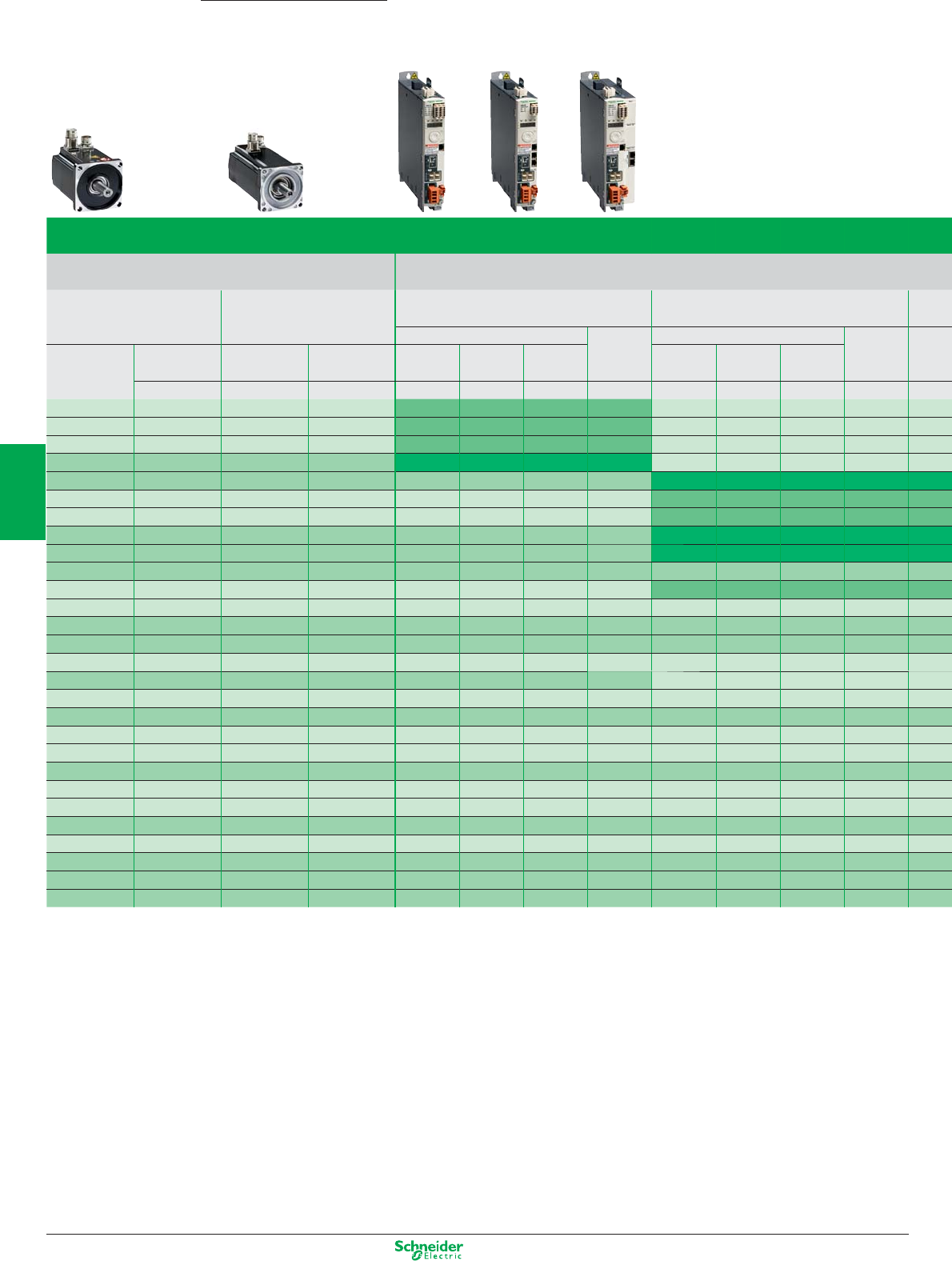
Other versions: Please consult your Schneider Electric sales office.
Lexium 32 servo drive/BMH or BSH servo motor combinations
Servo motors Lexium 32C, 32A and 32M servo drives
380…480 V three-phase supply voltage with integrated EMC filter
BMH
(IP 50, IP65 or IP 67)
BSH
(IP 50 or IP 65)
LXM 32pU60N4
Continuous output current: 1.5 A rms
LXM 32pD12N4
Continuous output current: 3 A rms
Nominal operating point
Stall torques
Nominal operating point
Stall torques
Type of
servo motor
Rotor
inertia
Type of
servo motor
Rotor
inertia
Nominal
torque
Nominal
speed
Nominal
power
M
0
/M
max
Nominal
torque
Nominal
speed
Nominal
power
M
0
/M
max
kgcm
2
kgcm
2
Nm rpm W Nm/Nm Nm rpm W Nm/Nm
BSH 0551P 0.06 0.48 6000 300 0.5/1.5
BSH 0552P 0.10 0.65 6000 400 0.8/2.5
BSH 0553P 0.13 0.65 6000 400 1.05/3.5
BMH 0701P 0.59 1.1 3000 350 1.2/4.2
BMH 0701P 0.59 1.3 5000 700 1.4/4.2
BSH 0701P 0.25 1.32 5000 700 1.4/3.5
BSH 0702P 0.41 1.64 5000 850 2.2/7.6
BMH 1001P 3.2 1.9 4000 800 3.3/10.8
BMH 0702P 1.13 2.2 3000 700 2.5/7.4
BMH 0703P 1.67
BSH 0703P 0.58
BSH 1001P 1.40
BMH 1001P 3.2
BMH 1002P 6.3
BSH 1002P 2.31
BMH 1003P 9.4
BSH 1003P 3.2
BMH 1401P 16.5
BSH 1004P 4.2
BSH 1401P 7.4
BMH 1402P 32.0
BSH 1402T 12.7
BSH 1403T 17.9
BMH 1403P 47.5
BSH 1404P 23.7
BMH 2051P 71.4
BMH 2052P 129
BMH 2053P 190
Lexium 32 Lexium 32 motion control
Servo drive/servo motor combinations
4/48
2
1
3
4
5
6
7
8
9
10

Other versions: Please consult your Schneider Electric sales office.
LXM 32pD18N4
Continuous output current: 6 A rms
LXM 32pD30N4
Continuous output current: 10 A rms
LXM 32pD72N4
Continuous output current: 24 A rms
Nominal operating point Stall torques Nominal operating point Stall torques Nominal operating point Stall torques
Nominal
torque
Nominal
speed
Nominal
power
M
0
/M
max
Nominal
torque
Nominal
speed
Nominal
power
M
0
/M
max
Nominal
torque
Nominal
speed
Nominal
power
M
0
/M
max
Nm rpm W Nm/Nm Nm rpm W Nm/Nm Nm rpm W Nm/Nm
2.4 5000 1300 3.4/10.2
2.44 5000 1300 3.1/11.3
2.7 4000 1100 3.3/9.6
3.1 4000 1300 3.4/10.2
3.9 4000 1600 6.2/18.4
4 4000 1700 5.8/18.3
5.2 5000 2700 8.4/25.1
6.3 3000 2000 8/28.3
7.7 3000 2400 10.3/30.8
8.3 2500 2100 10/37.9
9.5 2500 2500 11.1/27
11.2 3000 3500 18.5/55.3
12.3 3000 3900 19.5/59.3
12.9 3000 4100 27.8/90.2
14.9 3000 4700 24/75
19 2500 5000 33.4/103.6
25.8 2000 5400 34.4/103.4
41.6 1500 6500 62.5/170
52.2 1200 6500 84/232
4/49
2
1
3
4
5
6
7
8
9
10
Other versions: Please consult your Schneider Electric sales office.
Multi-Loader configuration tool
Use For downloading configurations from a PC or drive and duplicating them on another drive.
The drives do not need to be powered-up.
Supplied with:
1 cordset equipped with 2 RJ45 connectors
1 cordset equipped with one type A USB connector and one mini B USB connector
1 x 2 GB SD memory card
1 x female/female RJ 45 adaptor
4 AA 1.5 V LR6 round batteries
Reference VW3 A8 121
Single memory card Pack of 25 memory cards
Use Used to store parameters of the Lexium 32 servo drive.
Another Lexium 32 servo drive can be commissioned immediately if the application is undergoing
maintenance or duplication.
Reference VW3 M8 705 VW3 M8 704
Memory card recorder
Use Writes data from the Lexium 32 servo drive to the memory card.
This recorder is not supplied by Schneider Electric.
Reference See the User's manual
Motion Control
Configuration tools
Lexium 32
4/50
2
1
3
4
5
6
7
8
9
10
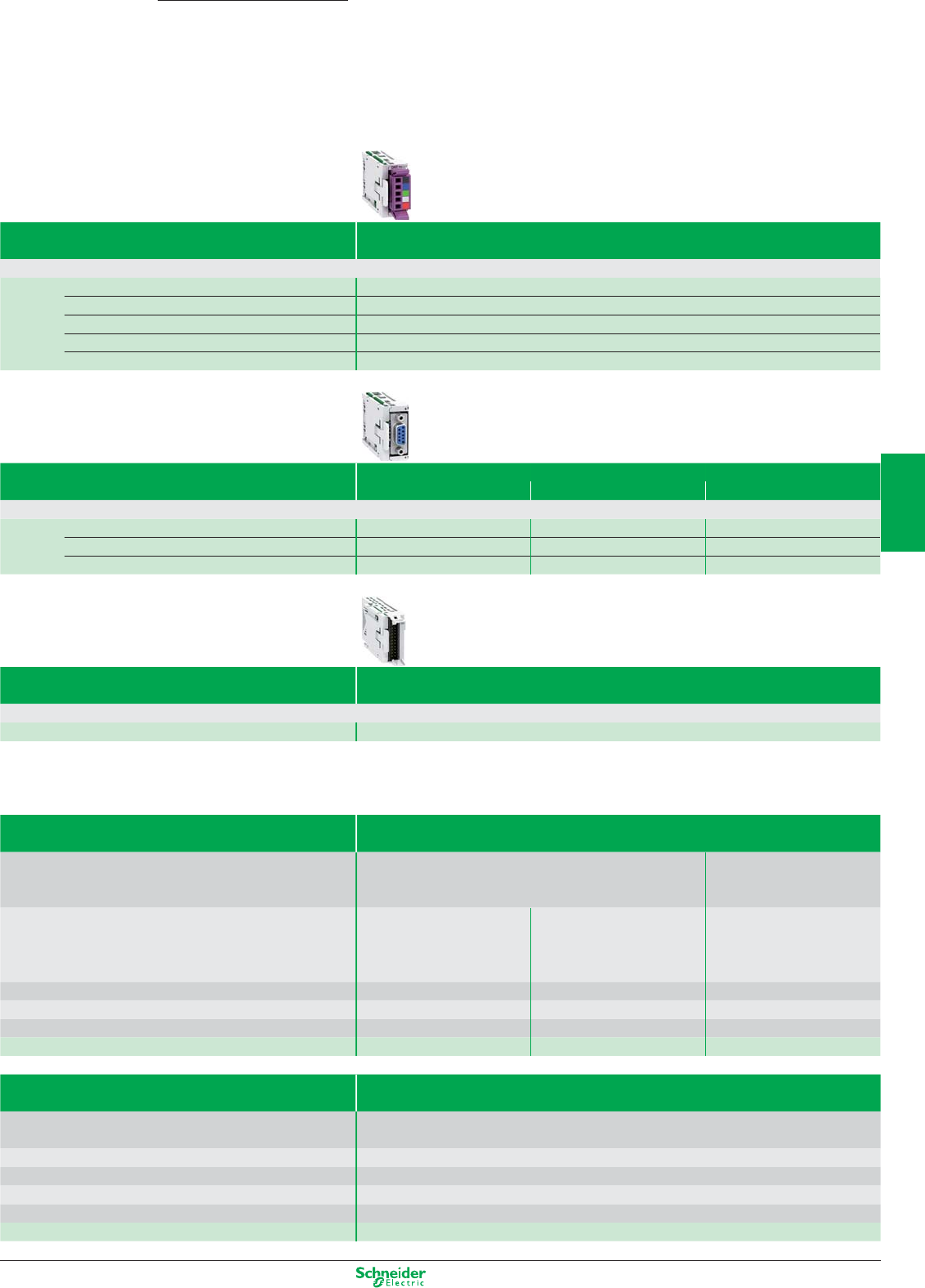
Other versions: Please consult your Schneider Electric sales offi ce.
Communication modules
Lexium 32M can be connected to the following communication buses and networks: CANopen and CANmotion, DeviceNet, Profi bus DP V1, EtherNet/IP
Reference CANopen / CANmotion module with 2 * RJ 45 connectors VW3 A3 608
CANopen / CANmotion module with SUB-D 9 connector VW3 A3 618
DeviceNet module VW3 M3 301
Profi bus DP V1 module VW3 A3 607
EtherNet/IP module VW3 A3 616
Second encoder modules
Machine Motor
Lexium 32M has an input for an additional encoder to connect third party motor (motor encoder) or to improve positioning accuracy (machine encoder)
Reference Module for resolver encoder VW3 M3 401 x
Module for digital encoder (A/B/I, BiSS, EndDat 2.2, SSI) VW3 M3 402 x
Module for analog encoder (1 Vpp/Hall, 1 Vpp, Hiperface) VW3 M3 403 x (Hiperface only) x
Safety module
eSM safety module allows Lexium 32M servo drives to access additionnal IEC/EN 61800-5-2 safety functions: SS1, SS2, SLS, SOS
Reference eSM safety module allows VW3 M3 501
Connection elements
Power cordsets
Description Cables equipped with one M23 industrial connector
(servo motor end)
Cables equipped with one
M40 industrial connector
(servo motor end)
From servo motor BMH 070pp, BMH 100pp,
BMH 1401P, BSH 055pp,
BSH 070pp, BSH 100pp,
BSH 1401P
BMH 1402P, BMH 1403P BMH 205pP,
BSH 1402T
,
BSH 1403T, BSH 1404P
To servo drive LXM 32pppppp
LXM 32pD72N4 LXM 32pD72N4
Composition [(4 x 1.5 mm
2
) + (2 x 1 mm
2
)]
[(4 x 2.5 mm2) + (2 x 1 mm2)] [(4 x 4 mm2) + (2 x 1 mm2)]
Length 3 m 3 m 3 m
Reference VW3 M5 101 R30
VW3 M5 102 R30 VW3 M5 103 R30
Encoder cordsets
Description
SinCos Hiperface® encoder cables equipped with an M23 industrial connector (servo motor end)
and an RJ45 connector with 8 + 2 contacts (servo drive end)
From servo motor
BMH ppppp, BSH ppppp
To servo drive
LXM 32pppppp
Composition
[3 x (2 x 0.14 mm2) + (2 x 0.34 mm2)]
Length 3 m
Reference
VW3 M8 102 R30
Motion Control
Modules for Lexium 32M
Lexium 32
4/51
2
1
3
4
5
6
7
8
9
10
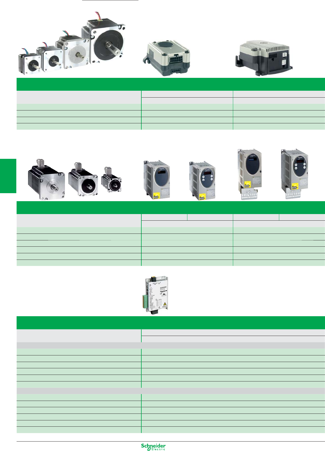
Other versions: Please consult your Schneider Electric sales offi ce.
Assignment of BRS3 3-phase stepper motors and SD3 stepper motor drives
BRS3 3-phase stepper motors SD326pU25 SD328pU25 SD326pU68 SD328pU68
115 V / 230 V; 2.5 A; including mains fi lter 115 V / 230 V; 6.8 A; including mains fi lter and fan
BRS368 1.7 Nm / 1.5 Nm –
BRS397 2.3 Nm / 2.0 Nm –
BRS39A 4.5 Nm / 4.0 Nm –
BRS39B 6.8 Nm / 6.0 Nm –
BRS3AC –13.5 Nm / 12.0 Nm
BRS3AD –19.7 Nm / 16.5 Nm
Lexium SDpMotion Control
Stepper drives and stepper motors
Assignment of BRS2 2-phase stepper motors and SD2 stepper motor drives
BRS2 2-phase stepper motors SD21ppU20C SD21ppU50C
24…48 V; 3 A 24…48 V; 5 A
BRS236 0.07 Nm –
BRS242 0.23…0.53 Nm –
BRS257 0.64…1.69 Nm 0.64…1.69 Nm
BRS285 –2.96…9.20 Nm
Assignment of stepper motors, stepper motor drives SD3 15
3-phase stepper motors SD3 15
24…48 VDC; max. 10 A
Motors with F winding
BRS 364F 0.46 Nm / 0.40 Nm
BRS 366F 0.92 Nm / 0.80 Nm
BRS 368F 1.50 Nm / 1.30 Nm
BRS 397F 2.00 Nm / 1.85 Nm
BRS 39AF 4.20 Nm / 3.40 Nm
BRS 39BF 5.55 Nm / 4.80 Nm
Motors with H winding
BRS 364H 0.51 Nm / 0.45 Nm
BRS 366H 1.02 Nm / 0.90 Nm
BRS 368F 1.70 Nm / 1.50 Nm
BRS 397H 2.26 Nm / 2.00 Nm
BRS 39AH 4.80 Nm / 4.00 Nm
BRS 39BH 6.50 Nm / 5.75 Nm
4/52
2
1
3
4
5
6
7
8
9
10
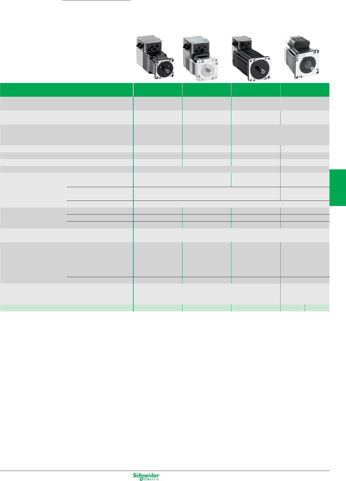
Other versions: Please consult your Schneider Electric sales office.
Integrated Drives Lexium ILA Lexium ILE Lexium ILS Lexium ILP / ILT
Type of process Dynamic process and
accurate positioning
Automatic format
adjustement
Short distance movements with accurate positioning
Type of technology Integrated drive with
servo motor
Integrated drive with
dc brushless motor
Integrated drive with
three-phase stepper motor
Integrated drive with
two-phase stepper motor
Main characteristics Highly dynamic
Compact
Integrated holding
brake in option
Hight holding torque
without power
Integrated gearbox
in option
Hight torque at low speed
Dynamic gggg gg ggg ggg
Precision and stability gggg gg gggg gggg
Energy saving ggggg gggg gg gg
Motor inertia Medium
Control interface Control signals Input/output Pulse/direction
Input/output
Pulse/direction
Input/output
Bus and networks CANopen, PROFIBUS DP, RS 485 serial link, DeviceNet, EtherCAT, Modbus
TCP, Ethernet Powerlink, EtherNet/IP
CANopen, RS485
Motion bus –
Association
Drive/motor
combinations
Nominal power 150...370W 100...350W 100...350W 100...350W
Nominal speed 500...9000 min
-1
1500...7000 min
-1
0...1000 min
-1
0...1000 min
-1
Nominal torque 0.26...0.78 Nm 0.18...0.5 Nm 0.45...6 Nm 0.11...5.87 Nm
Drive
characteristics
Safety function “Safe Torque Off”
Motor characteristics Type of sensor (resolution) (1) Single turn SinCos
encoder
(16.384 increments/turn)
Multiturn SinCos encoder
(16.384 increments/turn
× 4096 turns)
Absolute value encoder
(12...1380 increments/turn)
Index pulse monitoring Index pulse monitoring
Motor flange size 57 66 57, 85 36, 42, 57, 85
Accessories Cable, Connector kits, Installation sets, Commissioning tools, Planetary
gearboxes
Cable, Connector kits,
Installation sets,
Commissioning tools
References ILA ILE ILS ILP ILT
Lexium ILpMotion Control
Lexium Integrated Drives
4/53
2
1
3
4
5
6
7
8
9
10
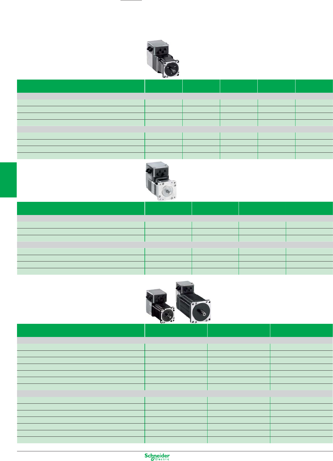
Other versions: Please consult your Schneider Electric sales offi ce.
Lexium ILA/ILE/ILS Motion Control
Lexium Integrated Drives
Lexium ILA with Servo Motor
Nominal Torque
(Nm)
Maximum Torque
(Nm)
Nominal Speed
(Rpm)
Maximum Speed
(Rpm)
Nominal Power
(W)
ILS1 for CANopen, PROFIBUS DP, RS485, Pulse-Direction, Motion Sequence Mode
ILA1p571P 0.26 0.6 5500 7500 150
ILA1p571T 0.26 0.43 7500 11500 200
ILA1p572P 0.45 0.72 4300 6200 200
ILA1p572T 0.41 0.61 5000 7500 215
ILA2 for DeviceNet, EtherCAT, EtherNet/IP, Modbus TCP, Ethernet Powerlink
ILA2p571P 0.44 0.62 5100 7000 235
ILA2p571T 0.31 0.45 7000 9000 255
ILA2p572P 0.78 1.62 3400 4300 275
ILA2p572T 0.57 0.85 5100 6800 305
Lexium ILE with included spurwheel gearbox.
Ratios:18:1, 38:1, 54:1, 115:1
Lexium ILE with included worm gearbox with hollow shaft.
Ratios: 24:1, 54:1, 92:1, 115:1
Lexium ILE with Brushless DC Motor Nominal Torque
(Nm)
Detent Torque
(Nm)
Nominal Speed
(Rpm)
Maximum Speed
(Rpm)
ILE1 for CANopen, PROFIBUS DP, RS485
ILE1p661 0.24 0.08 4800 5000
ILE1p661 spurwheel gearing up to 11.0 up to 8.0 44 44
ILE1p661 worm gearing up to 10.6 up to 16.7 44 44
ILA2 for DeviceNet, EtherCAT, EtherNet/IP, Modbus TCP, Ethernet Powerlink
ILE2p661 0.26 0.08 6000 7000
ILE2p661 spurwheel gearing up to 12 up to 9.19 44 44
ILE2p661 worm gearing up to 10.6 up to 16.7 44 44
ILE2p662 0.5 0.106 5000 7000
Lexium ILS with three-phase Stepper Motor Maximum Torque
(Nm)
Holding Torque
(Nm)
Speed
(Rpm)
ILS1 for CANopen, PROFIBUS DP, RS485, Pulse-Direction, Motion Sequence Mode
ILS1p571p0.45 0.51 1000
ILS1p572p0.9 1.02 600
ILS1p573p1.5 1.7 450
ILS1p851
p
2.0 2.0 450
ILS1p852
p
4.0 4.0 200
ILS1p853P 6.0 6.0 120
ILS1p853T 4.5 4.5 300
ILS1 for CANopen, PROFIBUS DP, RS485, Pulse-Direction, Motion Sequence Mode
ILS2p571p0.45 0.51 1100
ILS2p572
p
0.9 1.02 900
ILS2p573
p
1.5 1.7 600
ILS2p851
p
2.0 2.0 600
ILS2p852p4.0 4.0 380
ILS2p853P 6.0 6.0 200
ILS2p853T 4.5 4.5 300
4/54
2
1
3
4
5
6
7
8
9
10
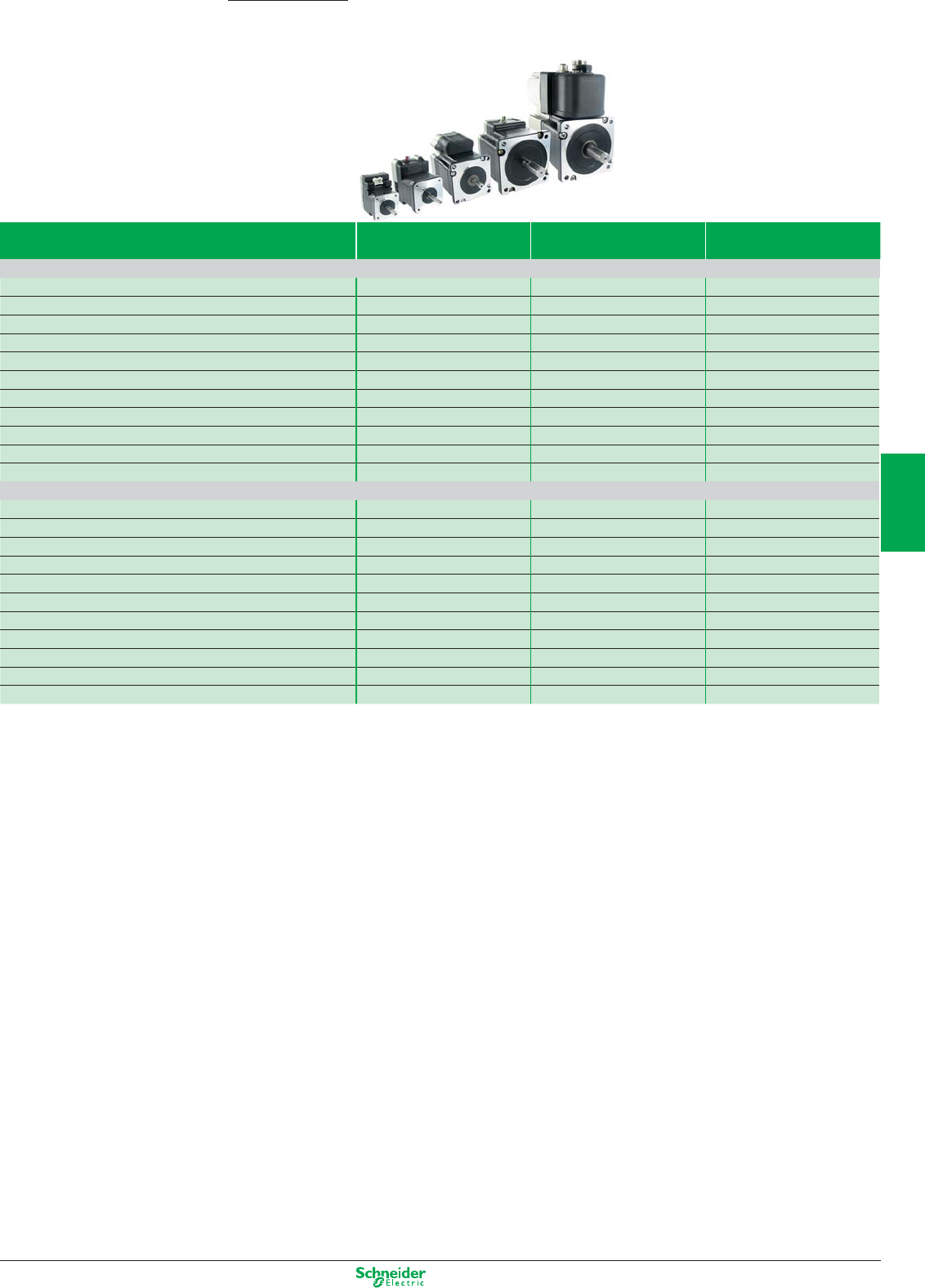
Other versions: Please consult your Schneider Electric sales office.
Lexium ILP/ILT Motion Control
Lexium Integrated Drives
Lexium ILP, Lexium ILT with two-phase Stepper Motor Nominal Torque
(Nm)
Holding Torque
(Nm)
Maximum Speed
(Rpm)
ILP for RS485 with programmable interface
ILP2R361 0.11 0.11 1800
ILP2R421 0.19 0.19 1500
ILP2R422 0.33 0.33 1500
ILP2R423 0.39 0.39 1500
ILP2R571 0.63 0.63 1500
ILP2R572 0.86 0.86 1500
ILP2R573 1.44 1.44 1500
ILP2R574 1.77 1.77 1500
ILP2R851 2.13 2.13 1000
ILP2R852 3.12 3.12 1000
ILP2R853 5.87 5.87 1000
ILT for Pulse/Direction, CANopen
ILT2p361 0.11 0.11 1800
ILT2p421 0.19 0.19 1500
ILT2p422 0.33 0.33 1500
ILT2p423 0.39 0.39 1500
ILT2p571 0.63 0.63 1500
ILT2p572 0.86 0.86 1500
ILT2p573 1.44 1.44 1500
ILT2p574 1.77 1.77 1500
ILT2p851 2.13 2.13 1000
ILT2p852 3.12 3.12 1000
ILT2p853 5.87 5.87 1000
4/55
2
1
3
4
5
6
7
8
9
10
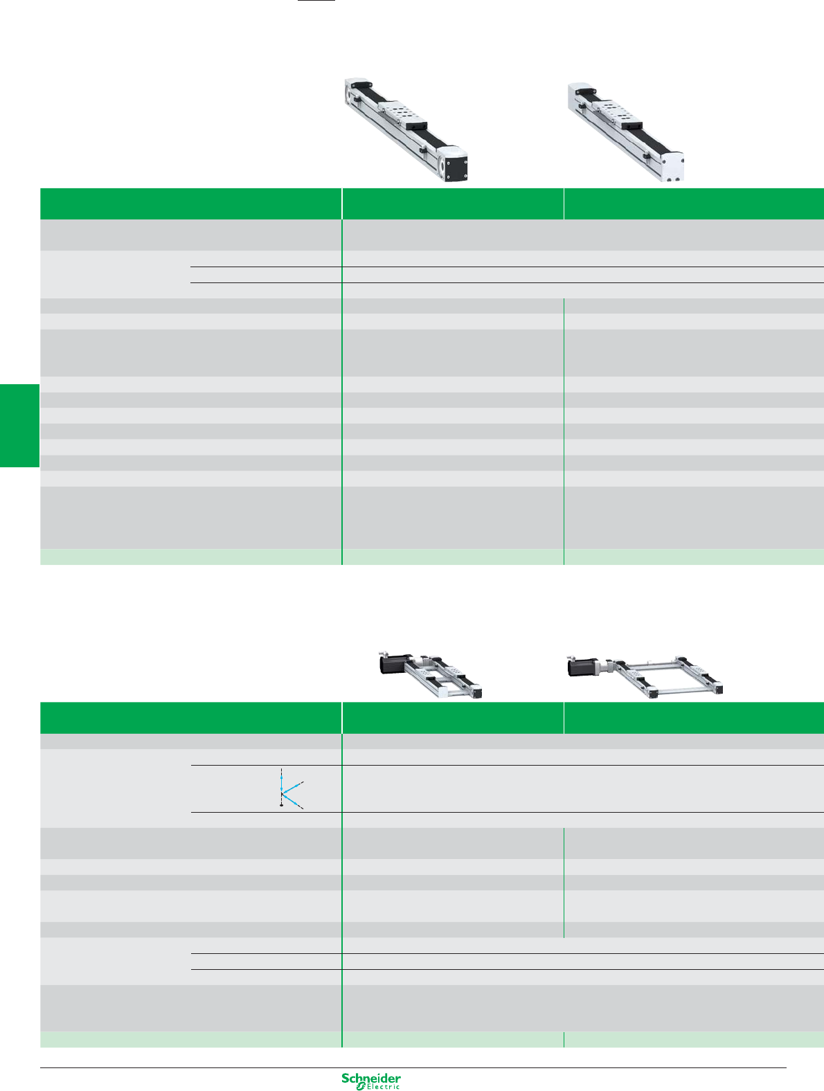
Other versions: Please consult your Schneider Electric sales office.
Lexium Linear Motion
Motion Control
Linear axes
Product Lexium PAS S Lexium PAS B
Axis type Portal axes
Movement Number of directions 1
Movement type Typically horizontal
Position of the load On carriage
Drive Toothed belt Ballscrew
Type of guide Ball or roller Ball
Main characteristics High dynamic response, Long stroke length, High
positioning speed
High precision movement (positioning, repeatability,
guiding), High feed forces, High rigidity
Dynamic response ggggg ggg
Precision ggg ggggg
Maximum payload 100 kg 100 kg
Maximum driving force 2600 N 4520 N
Maximum speed of movement of the load 8 m/s 1.25 m/s
Maximum working stroke 5500 mm 3000 mm
Repeatability ± 0.05 mm ± 0.02 mm
Options Choice of guide type: Ball (for applications requiring
high forces and torques) or roller (simple, cost-
effective solution), Wide range of sensors, Choice of
carriage type for adapting to the load, Option to add
carriages, Protective metal strip.
Choice of pitch , Protective metal strip, Wide range of
sensors, Choice of carriage type for adapting to the
load, Option to add carriages, Option to add
ballscrew supports for longer axes
Reference PAS 4pB PAS 4pS
Multi-axis systems
Product Lexium MAX H Lexium MAX S
Axis type Double portal axes
Movement Number of directions 1
Movement type Combination of two parallel axes
Position of the load On two parallel carriages
Multi-axis system type PAS 4pB axes + PAS 4pH support axis
(driven by the load)
PAS 4pB + PAS 4pB axes
(shaft-driven)
Drive Toothed belt on one axis Toothed belt on both axes
Type of guide Ball or roller Ball or roller
Main characteristics Long stroke length, High dynamic response, High
precision movement (positioning, guiding)
Long stroke length, High precision movement
(positioning, guiding), High feed forces
Maximum payload 250 kg 300 kg
Maximum working
stroke
On the X-axis 5500 mm
On the Y-axis –
On the Z-axis –
Options Choice of guide type: Ball (for applications requiring high forces and torques) or roller (simple, cost-effective
solution), Protective metal strip, Anti-corrosion version, Anti-static belt, Wide range of sensors, Several
different motor mounting options, Variable distance between the two axes
Reference MAX H MAX S
Z
X
Y
4/56
2
1
3
4
5
6
7
8
9
10
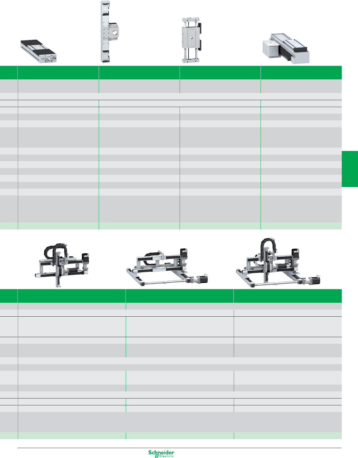
Other versions: Please consult your Schneider Electric sales office.
Lexium TAS Lexium CAS 4 Lexium CAS 3 Lexium CAS 2
Linear tables Cantilever axes with mobile structure on
profile
Cantilever axes with mobile structure on
parallel rods
Telescopic axes
1
Typically horizontal Typically vertical Typically horizontal
On carriage
On the side of the profile or on the 2 end blocks
On the 2 end blocks On carriage
Ballscrew Toothed belt Toothed belt or rack Toothed belt
Double, ball Ball or roller Ball Ball or roller
High precision movement (positioning,
repeatability, guiding), High feed forces,
High rigidity, Feed movement without
mechanical backlash
Long stroke length, High feed forces, Option
to mount the load on the side of the profile or
on the end blocks, High rigidity
Compact, Mobile structure with light travel
weight
Long stroke length from a compact unit,
High rigidity, High dynamic response
gg gggg gggg gggg
gggggg ggg ggg gg
150 kg 50 kg 18 kg 35 kg
2580 N 2150 N 705 N 1500 N
1 m/s 3 m/s 3 m/s 3 m/s
1500 mm 1200 mm 500 mm 2400 mm
± 0.02 mm ± 0.05 mm ± 0.05 mm ± 0.1 mm
Choice of pitch , Several different motor
mounting options
Choice of guide type: Ball (for applications
requiring high forces and torques) or roller
(simple, cost-effective solution), Protective
metal strip, Anti-corrosion version, Wide
range of sensors
Anti-corrosion version, Anti-static belt Choice of guide type: Ball (for applications
requiring high forces and torques) or roller
(simple, cost-effective solution), Choice of
carriage type for adapting to the load
TAS 4 CAS 4 CAS 3 CAS 2
Lexium MAX P Lexium MAX R2 Lexium MAX R3
Linear positioners Portal robots
2 3
Horizontal and vertical: Combination of one X-axis and one
Z-axis
Horizontal: Combination of two perpendicular axes X and Y Horizontal and vertical: Combination of two perpendicular
axes X and Y and one Z-axis
On the side or on the end blocks of the Z-axis profile On the Y-axis carriage On the side or on the end blocks of the Z-axis profile
MAX S + CAS 4 axes
MAX S + CAS 3 axes
MAX S + MAX H axes
MAX S + PAS 4pB axes
MAX S + MAX H + CAS 4 axes
MAX S + MAX H + CAS 3 axes
Toothed belt on each axis
Ball or roller
Dynamic load positioning Long stroke length on both axes Long stroke length on three axes
50 kg 130 kg 50 kg
5500 mm
– 1500 mm 1500 mm
1200 mm – 1200 mm
Choice of guide type: Ball (for applications requiring high forces and torques) or roller (simple, cost-effective solution), Wide range of sensors
Supplied as standard: Protective metal strip , Anti-corrosion version
MAX P MAX Rp2 MAX Rp3
4/57
2
1
3
4
5
6
7
8
9
10
Leader in the motor starter
market for more than
80 years, Schneider Electric
puts efficiency at the heart
of its innovation strategy
and, with TeSys, offers a wide
range of solutions for power
control and protection.
TeSys
It’s a comprehensive range of products that
meets requirements for power control
and protection, motor starters and
advanced protection of the machine
or process.

Motor control
This document is a selection of
the top selling products.
5/1
2
1
3
4
5
6
7
8
9
10
Motor control components
TeSys contactors ......................................................................................................5/2 to 5/11
Contactors, TeSys K, D, F, B
Variable composition contactors, TeSys CV
TeSys protection components ......................................................................... 5/12 to 5/33
Thermal-magnetic circuit-breakers
Magnetic circuit-breakers
Fuse carriers, switch-disconnector-fuses
Thermal overload relays
Electronic thermal overload relays
Electronic overload relays
Starter-controller, TeSys T
Multifunction protection relays
Switch disconnectors Mini Vario and Vario
TeSys starters ......................................................................................................... 5/34 to 5/41
Combination motor starters
Starter-controller, TeSys U
Controller, TeSys U
Enclosed motor starters
TeSys installation system .................................................................................. 5/42 to 5/43
For motor starter components with spring terminals,
TeSys Quickfit technology
Components for power control applications ................................................................ 5/44 to 5/50
Lighting, capacitor switching, heating and changeover contactor pairs
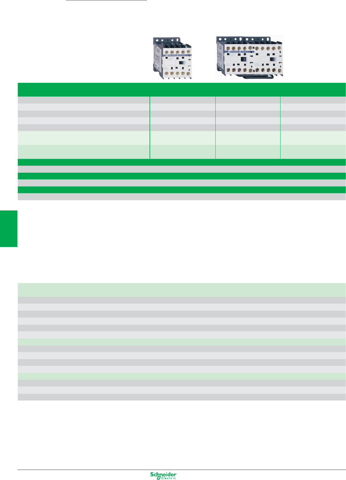
Other versions: please consult your Schneider Electric agency.
Connections
N screw clamp terminals
Rated operational current Ie max AC-3 (Ue ≤ 440 V) 6 A 9 A 12 A
Ie AC-1 (θ ≤ 40° C) - 20 A -
Rated operational power 220/240 V 1.5 kW 2.2 kW 3 kW
in category AC3 380/400 V…415/440 V 2.2 kW 4 kW 5.5 kW
660/690 V…500 V 3 kW 4 kW 4 kW
Contactor type (1)* a LC1-K06•• LC1-K09•• LC1-K12••
cLP1-K06•• or LP4-K06•• LP1-K09 or LP4-K09•• LP1-K12 or LP4-K12••
Reversing contactor type *a LC2-K06 LC2-K09 LC2-K12
with mechanical interlock cLP2-K06 or LP5-K06 LP2-K09 or LP5-K09 LP2-K12 or LP5-K12
b spring terminals
Add the figure 3 before the voltage code. Example: LC1-K0610•• becomes LC1-K06103••
b Faston connectors, 1 x 6.35 or 2 x 2.8
Add the figure 7 before the voltage code. Example: LC1-K0610•• becomes LC1-K06107••
b solder pins for printed circuit boards
Add the figure 5 before the voltage code. Example: LC1-K0610•• becomes LC1-K06105••
(1) Basic reference, to be completed by adding 01 for N/C auxiliary contact, or 10 for N/O auxiliary contact.
* Basic reference to be completed by adding the coil voltage code
Standard control circuit voltages
a supply
Contactors LC1-K (0.8…1.15 Uc) (0.85…1.1 Uc)
Volts 12 20 24 36 42 48 110 115 120 127 200/208 220/230 230 230/240
50/60 Hz J7 Z7 B7 C7 D7 E7 F7 FE7 G7 FC7 L7 M7 P7 U7
Volts 256 277 380/400 400 400/415 440 480 500 575 600 660/690
50/60 Hz W7 UE7 Q7 V7 N7 R7 T7 S7 SC7 X7 Y7
Example of complete reference: LC1-K0910P7
c supply
Contactors LP1-K (0.8…1.15 Uc)
Volts 12 20 24 36 48 60 72 100 110 125 155 174 200 220 230 240 250
Code JD ZD BD CD ED ND SD KD FD GD PD QD LD MD MPD MUD UD
Coil with integral suppression device available, add 3 to the code required. Example: JD3
Low consumption
Contactors LP4-K (0.7…1.30 Uc), coil suppression as standard
Volts 12 20 24 48 72 110 120
Code JW3 ZW3 BW3 EW3 SW3 FW3 GW3
Example of complete reference: LC1-K0910BD
TeSys K Contactors
0.06…5.5 kW
5/2
2
1
3
4
5
6
7
8
9
10
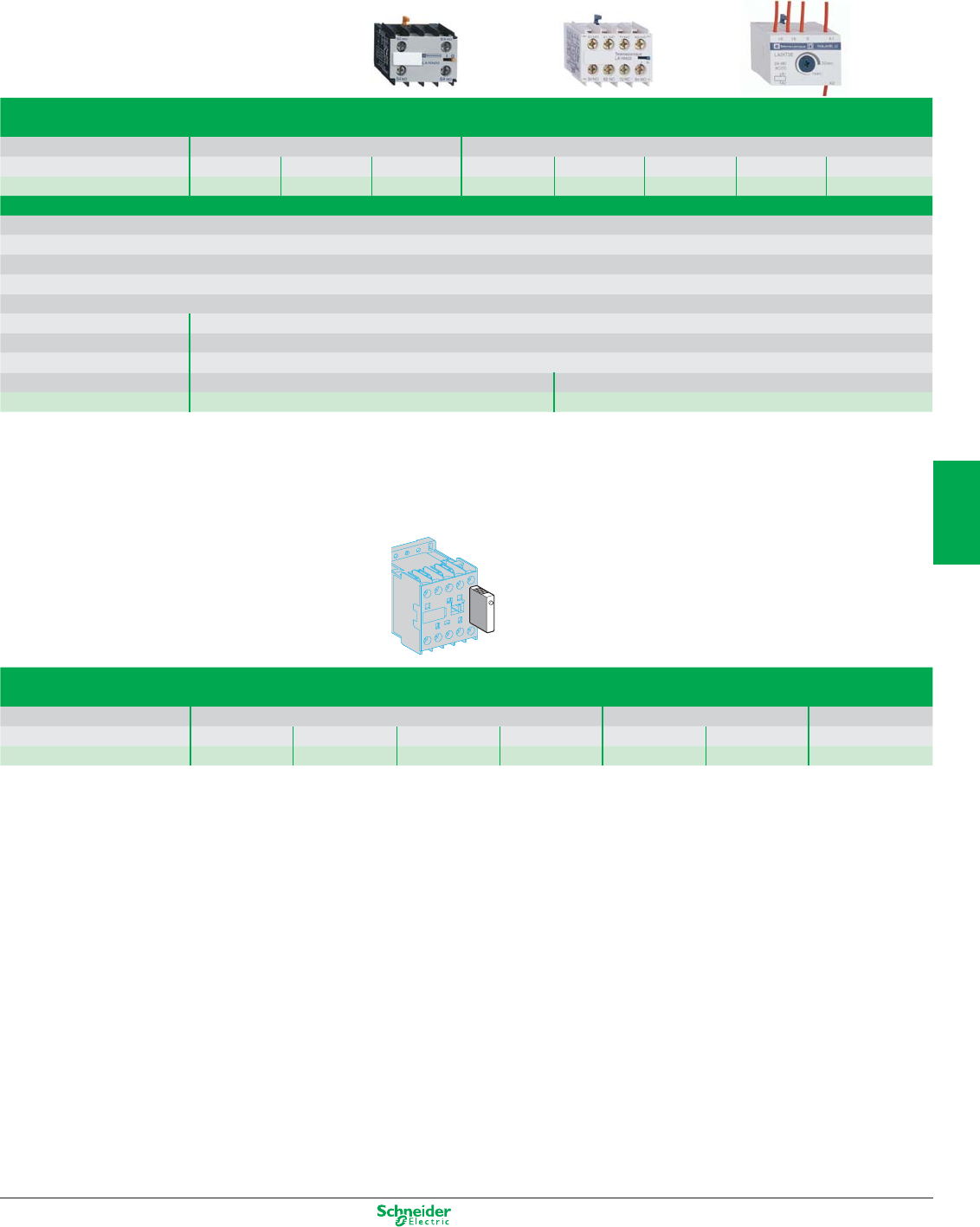
Other versions: please consult your Schneider Electric agency.
Auxiliary contact blocks
N instantaneous, screw clamp connections
N for LC1, LP1-K, LP4 N for LC1, LP1-K
Composition 2N/O - 2N/C 1N/O 1N/C 4N/O 3N/O 1N/C 2N/C 2N/C 1N/O 3N/C - 4N/C
Reference LA1-KN20 LA1-KN02 LA1-KN11 LA1-KN40 LA1-KN31 LA1-KN22 LA1-KN13 LA1-KN04
N electronic time delay
Relay outputs, with common point changeover contact, a or c 24…48, 2 A maximum
Control voltage 0.85…1.1 Uc
Maximum switching capacity 250 VA or 150 W
Operating temperature -10…+ 60°C
Reset time: 1.5 s during the time delay period, 0.5 s after time delay period
Type On-delay
Timing range 1…30 s
Composition 1
Voltage a or c 24…48 V a 110…240
Reference LA2-KT2E LA2-KT2U
Suppressor modules
For LC1, LP1-K
Type Varistor (a and c) Diode (c) + Zener RC (a)
Voltage 12…24 V 32…48 V 50…129 V 130…250 V 12…24 V 32…48 V 220…250 V
Reference LA4-KE1B LA4-KE1E LA4-KE1FC LA4-KE1UG LA4-KC1B LA4-KC1E LA4-KA1U
5/3
2
1
3
4
5
6
7
8
9
10
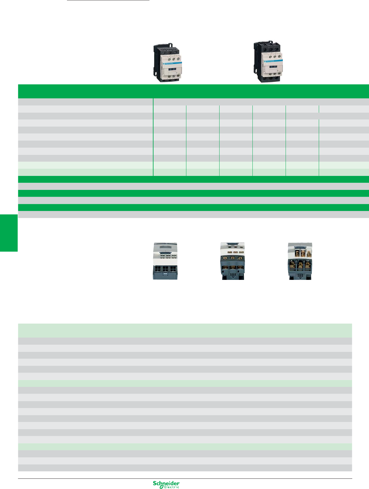
Other versions: please consult your Schneider Electric agency.
Connections
N screw clamp terminals or connectors
Rated operational voltage 690 V
Rated operational current Ie max AC-3 (Ue ≤ 440 V) 9 A 12 A 18 A 25 A 32 A 38 A
Ie AC-1 (θ ≤ 60° C) 25 A 32 A 40 A 50 A
Rated operational power 220/240 V 2.2 kW 3 kW 4 kW 5.5 kW 7.5 kW 9 kW
in category AC3 380/400 V 4 kW 5.5 kW 7.5 kW 11 kW 15 kW 18.5 kW
415/440 V 4 kW 5.5 kW 9 kW 11 kW 15 kW 18.5 kW
500 V 5.5 kW 7.5 kW 10 kW 15 kW 18.5 kW 18.5 kW
660/690 V 5.5 kW 7.5 kW 10 kW 15 kW 18.5 kW 18.5 kW
1000 V ––––––
Contactor type * LC1-D09 LC1-D12 LC1-D18 LC1-D25 LC1-D32 LC1-D38
Reversing contactor type * with mechanical interlock LC2-D09 LC2-D12 LC2-D18 LC2-D25 LC2-D32 LC2-D38
N spring terminals (1)
Add the figure 3 before the voltage code. Example: LC1-D09P7 becomes LC1-093P7
N lug-clamps (2)
Add the figure 6 before the voltage code. Example: LC1-D09P7 becomes LC1-096P7
N Faston connectors (3) 2 x 6.35 (power) and 1 x 6.35 (control) up to D12 only
Add the figure 9 before the voltage code. Example: LC1-D09P7 becomes LC1-099P7
* Basic reference to be completed by adding the coil voltage code
Standard control circuit voltages
a supply
Volts 24 42 48 110 115 220 230 240 380 400 415 440 500
Contactors LC1-D09…D150 (coils D115 and D150 with integral suppression device fitted as standard)
50/60 Hz B7 D7 E7 F7 FE7 M7 P7 U7 Q7 V7 N7 R7 S7
Contactors LC1-D80…D115
50 Hz B5 D5 E5 F5 FE5 M5 P5 U5 Q5 V5 N5 R5 S5
60 Hz B6-E6F6-M6-U6Q6--R6-
c supply
Volts 12 24 36 48 60 72 110 125 220 250 440
Contactors LC1-D09…D65A (coils with integral suppression device fitted as standard)
U 0.75…1.25 Uc JD BD CD ED ND SD FD GD MD UD RD
Contactors LC1-D80…D95
U 0.85…1.1 Uc JD BD CD ED ND SD FD GD MD UD RD
U 0.75…1.2 Uc JW BW CW EW - SW FW - MW - -
Contactors LC1-D115 and D150 (coils with integral suppression device fitted as standard)
U 0.75…1.2 Uc - BD - ED ND SD FD GD MD UD RD
Low consumption
Contactors LC1-D09…D38 (coils with integral suppression device fitted as standard)
Volts c5 12 20 24 48 110 120 250
U 0.7…1.25 Uc AL JL ZL BL EL FL ML UL
Example of complete reference: LC1-D09P7
TeSys DContactors
0.06…75 kW
(1) (3)(2)
5/4
2
1
3
4
5
6
7
8
9
10
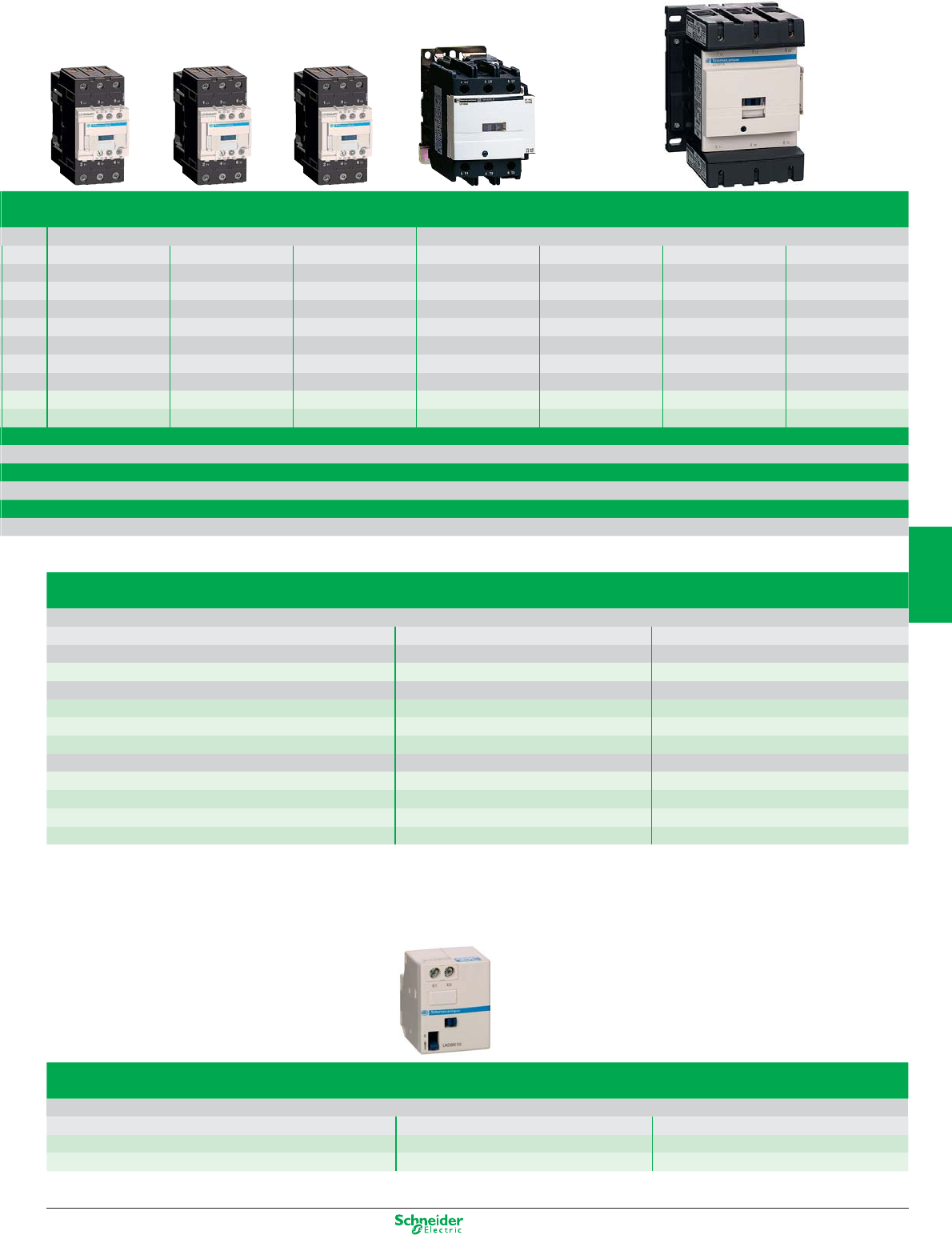
Other versions: please consult your Schneider Electric agency.
Mounting accessories for 3-pole reversing contactors
2 identical contactors with screw clamp terminals or connectors, horizontally mounted
Mechanical interlock Set of connections Mechanical interlock
N with an electrical interlocking kit for the contactors
LC1-D09…D38 LAD-9R1V included
N with integral electrical interlocking
LC1-D80 and D95 (a)LA9-D8069 LA9-D4002
LC1-D80 and D95 (c)LA9-D8069 LA9-D8002
LC1-D115 and D150 LA9-D11569 LA9-D11502
N without electrical interlocking
LC1-D09…D38 LA9-9R1 included
LC1-D40A…D65A LAD-9R3 included
LC1-D80 and D95 (a)LA9-D8069 LA9-D50978
LC1-D80 and D95 (c)LA9-D8069 LA9-D80978
Mechanical latch blocks
Clip-on front mounting, manual or electrical unlatching control
For use on contactor Reference Standard control circuit voltages
LC1-D09…D65A a or c, LC1-DT20…DT80 a or cLAD-6K10• B E F M Q
LC1-D80…D150 3P a, LC1-D80 and D115 3P a, LC1-D115 4P cLA6-DK20• B E F M Q
690 V 1000 V on a supply, 690 V on c supply
40 A 50 A 65 A 80 A 95 A 115 A 150 A
60 A 80 A 80 A 125 A 200 A
11 kW 15 kW 18.5 kW 22 kW 25 kW 30 kW 40 kW
18.5 kW 22 kW 30 kW 37 kW 45 kW 55 kW 75 kW
22 kW 25 kW 30 kW 45 kW 45 kW 59 kW 80 kW
22 kW 30 kW 37 kW 55 kW 55 kW 75 kW 90 kW
30 kW 33 kW 37 kW 45 kW 45 kW 80 kW 100 kW
– – – 45 kW 45 kW 75 kW 90 kW
LC1-D40A LC1-D50A LC1-D65A LC1-D80 LC1-D95 LC1-D115 LC1-D150
LC2-D40A LC2-D50A LC2-D65A LC2-D80 LC2-D95 LC2-D115 LC2-D150
5/5
2
1
3
4
5
6
7
8
9
10
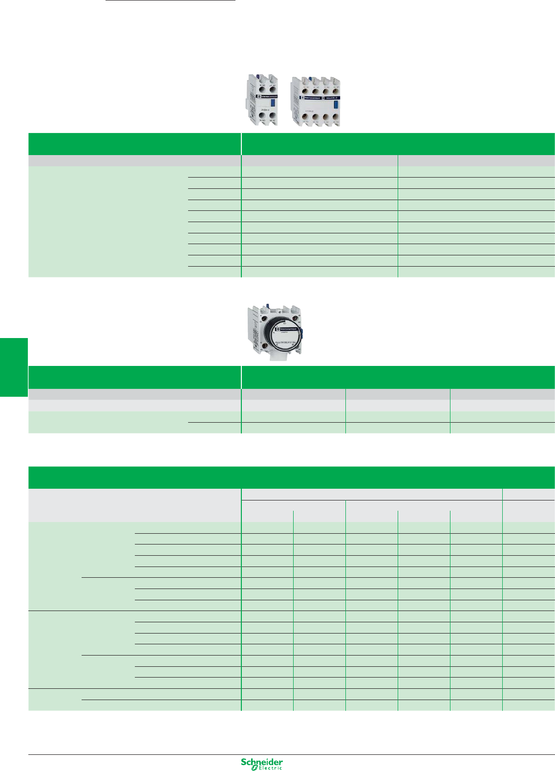
Other versions: please consult your Schneider Electric agency.
TeSys DContactors
Auxiliary contacts
Contact type instantaneous, connection by screw terminals
Block mounting Front mounting Side mounting
References Contact 1 N/O LADN10 –
1 N/C LADN01 –
1 N/O + 1 N/C LADN11 LAD8N11
2 N/O LADN20 LAD8N20
2 N/C LADN02 LAD8N02
2 N/O + 2 N/C LADN22 –
1 N/O + 3 N/C LADN13 –
3 N/O + 1 N/C LADN31 –
4 N/O LADN40 –
4 N/C LADN04 –
Contact type Time delay, connection by screw terminals
Block mounting Front mounting
Temporisation 0.1…3 s 0.1…30 s 10…180 s
References On-delay LADT0 LADT2 LADT4
Off-delay LADR0 LADR2 LADR4
Maximum number of auxiliary contacts that can be fitted
Instantaneous Time delay
Type Number of poles Side mounting Front mounting Front
and size on left side on right side 1 contact 2 contacts 4 contacts mounting
AC 3P LC1D09…D38 1 – and – 1 or 1 or 1
LC1D40A…D65A 1 or 1 and – 1 or 1 or 1
LC1D80…95 (50/60 Hz) 1 1 or 2 and 1 or 1 or 1
LC1D80…95 (50 or 60 Hz) 1 1 and 2 and 1 or 1 or 1
LC1D115 and D150 1 – and – 1 or 1 or 1
4P LC1DT20…DT40 1 – and – 1 or 1 or 1
LC1DT60A…D80A 1 or 1 and – 1 or 1 or 1
LC1D115 1 1 and 1 or 1 or 1 or 1
DC 3P LC1D09…D38 – – – 1 or 1 or 1
LC1D40A…D65A 1 or 1 and – 1 or 1 or 1
LC1D80 and 95 – – 1 or 1 or 1 or 1
LC1D115 and D150 1 – and – 1 or 1 or 1
4P LC1DT20…DT40 – – – 1 or 1 or 1
LC1DT60A…D80A – – – 1 or 1 or 1
LC1D115 1 1 – and 1 or 1 or 1
DC low
consumption
3P LC1D09…D38 – – – 1 – –
4P LC1DT20…DT40 – – – 1 – –
5/6
2
1
3
4
5
6
7
8
9
10
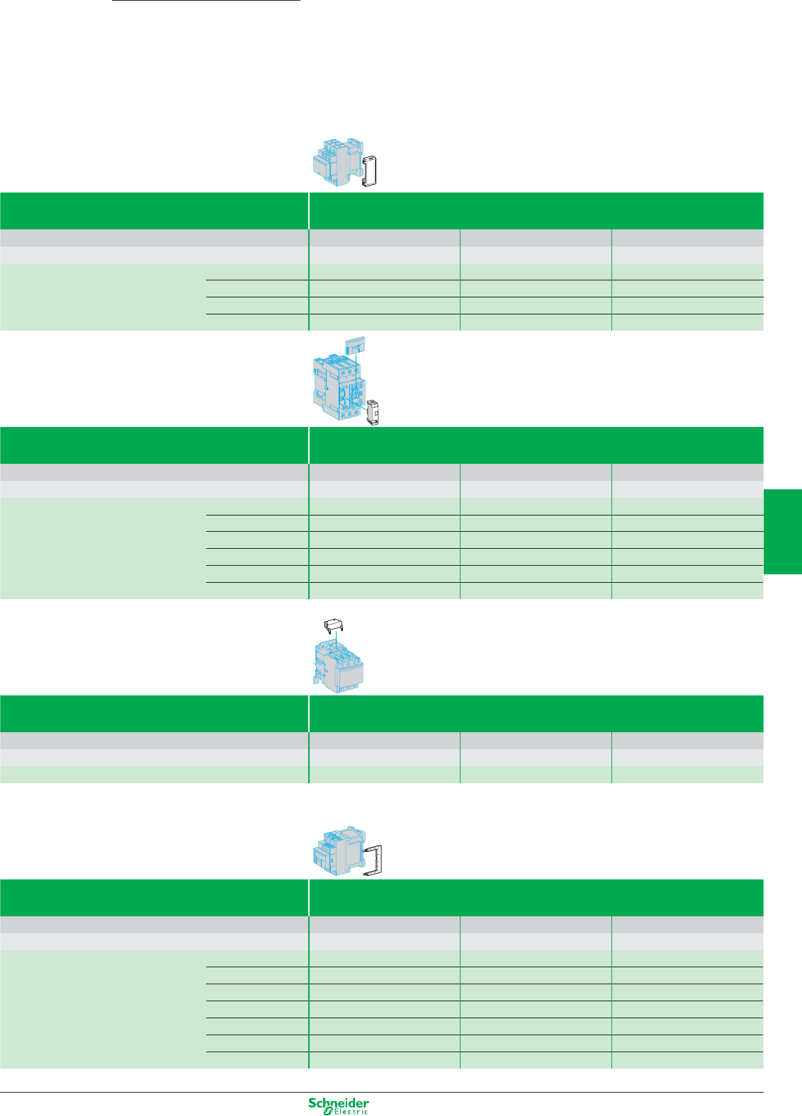
Other versions: please consult your Schneider Electric agency.
Type of module RC circuits (Resistor-Capacitor)
Mounting Side clip-on Front clip-on Screw fixing
For use with contactor D09…D38(3P) DT20…DT40(4P)
D40A…D65A(3P) DT60A…DT80A(4P)
D80…D150(3P) D40…D115(4P)
References Voltage 24…48 VAC LAD4RCE LAD4RC3E LA4DA2E
50…127 VAC LAD4RCG LAD4RC3G LA4DA2G
110…240 VAC LAD4RCU LAD4RC3U LA4DA2U
380…415 VAC –LAD4RC3N LA4DA2N
Type of module Varistors (peak limiting)
Mounting Side clip-on Front clip-on Screw fixing
For use with contactor D09…D38(3P) DT20…DT40(4P)
D40A…D65A(3P) DT60A…DT80A(4P)
D80…D150(3P) D40…D115(4P)
References Voltage 24…48 VAC LAD4VE LAD4V3E LA4DE2E
50…127 VAC LAD4VG LAD4V3G LA4DE2G
110…240 VAC LAD4VU LAD4V3U LA4DE2U
24…48 VDC – – LAD4DE3E (AC and DC)
50…127 VDC – –LAD4DE3G (AC and DC)
110…240 VDC – –LAD4DE3U (AC and DC)
Type of module Flywheel diodes
Mounting Side clip-on Front clip-on Screw fixing
For use with contactor D09…D38(3P) DT20…DT40(4P)
D40A…D65A(3P) DT60A…DT80A(4P)
D80…D150(3P) D40…D115(4P)
References Voltage 24…250 VDC LAD4DDL LAD4D3U LAD4DC3U
Type of module Bidirectional peak limiting diode
Mounting Side clip-on Front clip-on Screw fixing
For use with contactor D09…D38(3P) DT20…DT40(4P)
D40A…D65A(3P) DT60A…DT80A(4P)
D80…D150(3P) D40…D115(4P)
References Voltage 24 VAC LAD4TB LAD4T3B LA4DB2B
24 VDC LAD4TBDL LAD4T3B LA4DB2S
72 VAC LAD4TS LAD4T3S LA4DB3B
72 VDC LAD4TSDL LAD4T3S LA4DB3S
125 VDC LAD4TGDL LAD4T3G (AC and DC) –
250 VDC LAD4TUDL LAD4T3U (AC and DC) –
600 VDC LAD4TXDL LAD4T3R (AC and DC) –
TeSys DContactors
Suppressor modules
5/7
2
1
3
4
5
6
7
8
9
10
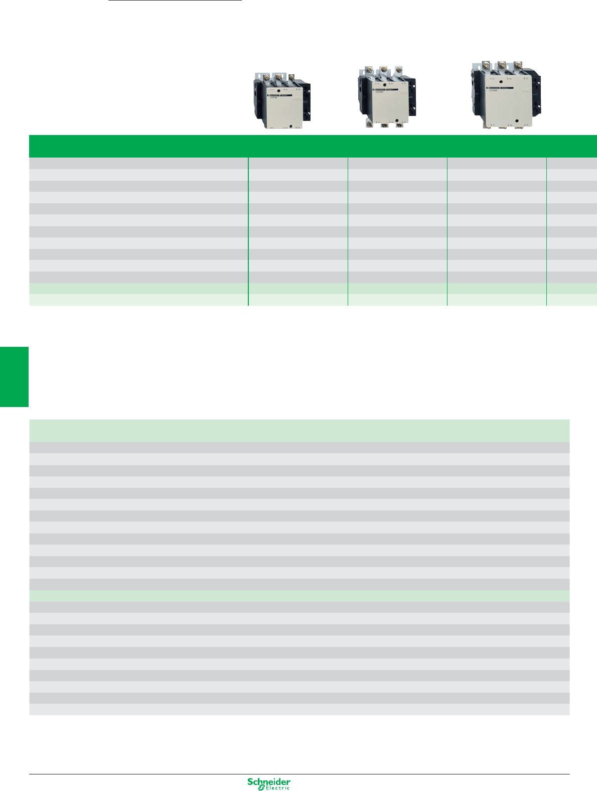
Other versions: please consult your Schneider Electric agency.
Rated operational current Ie max AC-3 (Ue ≤ 440 V) 185 A 225 A 265 A 330 A
Ie AC-1 (θ ≤ 40° C) 275 A 315 V 350 A 400 A
Rated operational voltage 1 000 V 1 000 V 1 000 V 1 000 V
Number of poles 3 or 4 3 or 4 3 or 4 3 or 4
Rated operational power 220/240 V 55 kW 63 kW 75 kW 100 kW
in category AC3 380/400 V 90 kW 110 kW 132 kW 160 kW
415 V 100 kW 110 kW 140 kW 180 kW
440 V 100 kW 110 kW 140 kW 200 kW
500 V 110 kW 129 kW 160 kW 200 kW
660/690 V 110 kW 129 kW 160 kW 220 kW
1000 V 100 kW 100 kW 147 kW 160 kW
Contactor type* LC1-F185 LC1-F225 LC1-F265 LC1-F330
Reversing contactor type* LC2-F185 LC2-F225 LC2-F265
* Basic reference to be completed by adding the coil voltage code
Standard control circuit voltages
a supply
Volts 24 48 110 115 120 208 220 230 240 380 400 415 440
Contactors LC1-F115…F225 (0.85…1.1 Uc)
50 Hz (coil LX1) B5 E5 F5 FE5 - - M5 P5 U5 Q5 V5 N5 -
60 Hz (coil LX1) - E6 F6 - G6 L6 M6 - U6 Q6 - - R6U7
40…400 Hz (coil LX9) - E7 F7 FE7 G7 L7 M7 P7 U7 Q7 V7 N7 R7
Contactors LC1-F265…F330U7
40…400 Hz (coil LX1) B7 E7 F7 FE7 G7 L7 M7 P7 U7 Q7 V7 N7 R7
Contactors LC1-F400…F630U7
40…400 Hz (coil LX1) - E7 F7 FE7 G7 (1) L7 M7 P7 U7 Q7 V7 N7 R7
Contactor LC1-F780U7
40…400 Hz (coil LX1) - - F7 FE7 F7 L7 M7 P7 U7 Q7 V7 N7 R7
Contactor LC1-F800U7
40…400 Hz (coil LX1) - - FE7FE7FE7- P7P7P7V7V7V7V7Y7
c supply
Volts 24 48 110 125 220 230 250 400 440
Contactors LC1-F115…F330 (0.85…1.1 Uc)
(coil LX4-F) BD ED FD GD MD MD UD - RD
Contactors LC1-F400…F630 (0.85…1.1 Uc)
(coil LX4-F) -EDFDGDMD-UD-RD
Contactor LC1-F780 (0.85…1.1 Uc)
(coil LX4-F) --FDGDMD-UD-RD
Contactor LC1-F800 (0.85…1.1 Uc)
(coil LX4-F) - - FWFWMWMW- QW-
Example: For a 630 A contactor with a 110 V a coil, order LC1-F630F7
(1) F7 for LC1-F630
TeSys FContactors
90…450 kW
5/8
2
1
3
4
5
6
7
8
9
10
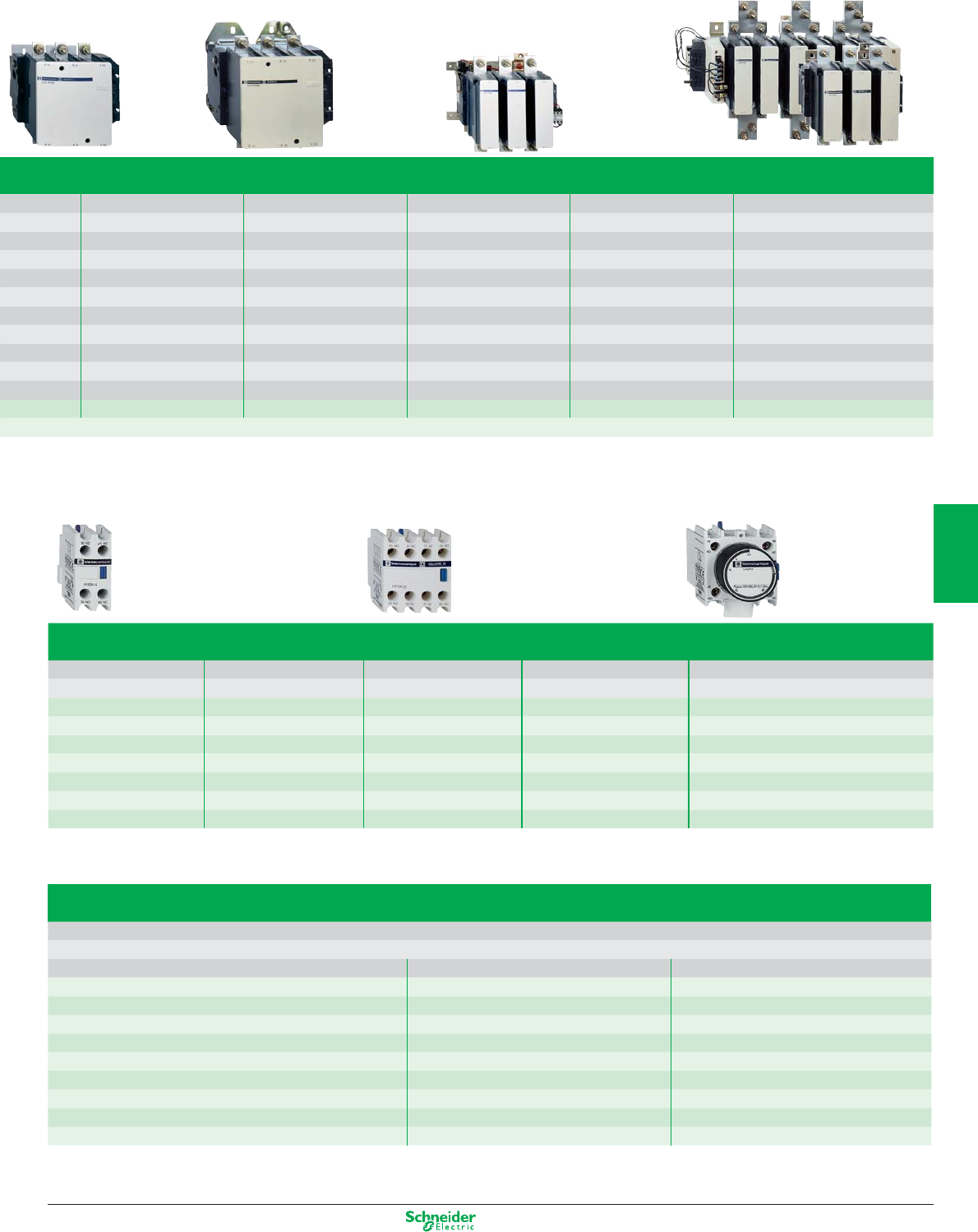
Other versions: please consult your Schneider Electric agency.
Auxiliary contact blocks
N instantaneous
dust & damp protected contacts
N time delay 1 N/O + 1 N/C
Composition Reference Composition Reference Composition Reference Composition Reference Type Range Reference
N/O N/C N/O N/C N/O N/C N/O N/C
1 -LAD-N10 1 1 LAD-N11 2 2 LAD-N22 2 - - - LA1-DX20 On-delay 0.1…3 s LAD-T0
- 1 LAD-N01 2 - LAD-N20 1 3 LAD-N13 2 2 - - LA1-DY20 0.1…30 s LAD-T2
- 2 LAD-N02 4 - LAD-N40 2 - 2 - LA1-DZ40 10…180 s LAD-T4
- 4 LAD-N04 2 - 1 1 LA1-DZ31 1…30 s LAD-S2
3 1 LAD-N31 Off-delay 0.1…3 s LAD-R0
2 2 LAD-C22 0.1…30 s LAD-R2
10…180 s LAD-R4
Mounting accessories for 3-pole reversing contactors for motor control
2 identical contactors, horizontally mounted
Mechanical interlock with an electrical interlocking kit for the contactors
Contactor type Set of connections Mechanical interlock
LC1-F115 LA9-FF976 LA9-FF970
LC1-F150 LA9-F15076 LA9-FF970
LC1-F185 LA9-FG976 LA9-FG970
LC1-F225 LA9-F22576 LA9-FG970
LC1-F265 LA9-FH976 LA9-FJ970
LC1-F330 LA9-FJ976 LA9-FJ970
LC1-F400 LA9-FJ976 LA9-FJ970
LC1-F500 LA9-FK976 LA9-FJ970
LC1-F630 or LC1-F800 LA9-FL976 LA9-FL970
400 A 500 A 630 A 780 A 800 A
500 A 700 A 1 000 A 1 600 A 1 000 A
1 000 V 1 000 V 1 000 V 1 000 V 1 000 V
2, 3 or 4 2, 3 or 4 2, 3 or 4 3 or 4 3
110 kW 147 kW 200 kW 220 kW 250 kW
200 kW 250 kW 335 kW 400 kW 450 kW
220 kW 280 kW 375 kW 425 kW 450 kW
250 kW 295 kW 400 kW 425 kW 450 kW
257 kW 355 kW 400 kW 450 kW 450 kW
280 kW 335 kW 450 kW 475 kW 475 kW
185 kW 335 kW 450 kW 450 kW 450 kW
LC1-F400 LC1-F500 LC1-F630 LC1-F780 LC1-F800
For customer assembly
5/9
2
1
3
4
5
6
7
8
9
10
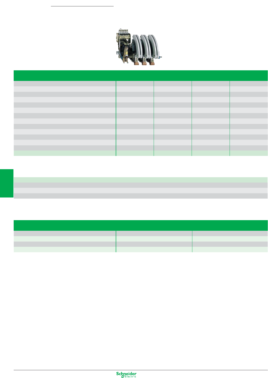
Other versions: please consult your Schneider Electric agency.
Standard control circuit voltages (for other voltages, please consult your Regional Sales Office)
Volts 48 110 125 127 220 230 240 380 400 415 440 500
a 50…400 Hz -F-GMPUQVNRS
cEDFDGD-MD-----RD-
Example: To order a 1500 A contactor with 127 V c coil with 3 N/O + 1 N/C, select LC1-BP33G31
Mounting accessories
Description For contactor Reference
Bar support bracket LC1-BL to BR LA9-B103
for mounting on 120 or 150 mm centres
Mechanical interlock and locking device components LC1-B EZ2-LB0601
Rated operational current Ie max AC-3 (Ue ≤ 440 V) 750 A 1000 A 1500 A 1800 A
Ie AC-1 (θ ≤ 40° C) 800 A 1250 V 2000 A 2750 A
Rated operational voltage 1 000 V 1 000 V 1 000 V 1 000 V
Number of poles 1 to 4 1 to 4 1 to 4 1 to 4
Rated operational power 220/240 V 220 kW 280 kW 425 kW 500 kW
in category AC3 380/400 V 400 kW 500 kW 750 kW 900 kW
415 V 425 kW 530 kW 800 kW 900 kW
440 V 450 kW 560 kW 800 kW 900 kW
500 V 500 kW 600 kW 700 kW 900 kW
660/690 V 560 kW 670 kW 750 kW 900 kW
1000 V 530 kW 530 kW 670 kW 750 kW
4 instantaneous contact configurations
2 N/C + 2 N/O, 3 N/O + 1 N/C, 1 N/O + 3 N/C or 4 N/O
Contactor type* LC1-BL LC1-BM LC1-BP LC1-BR
* Basic reference to be completed by adding the coil voltage code, followed by the instantaneous contact configuration.
TeSys BContactors
400…900 kW
5/10
2
1
3
4
5
6
7
8
9
10

Other versions: please consult your Schneider Electric agency.
Reference to compiled by the customer
Contactor type, according to required use
a supply 690 V, c supply 220 V/pole CV1-B
a supply 1000 V, c supply 440 V/pole CV3-B
Contactor rating CV1: 80 A CV3: 80 A F
CV1: 200 A CV3: 170 A G
CV1: 300 A CV3: 250 A H
CV1: 470 A CV3: 320 A J
CV1: 630 A CV3: 500 A K
CV1: 1000 A L
Number of poles (PN1 main poles for CV1 and PA3 main poles for CV3)
Normally Open main poles 1 N/O 1
2 N/O 2
3 N/O 3
4 N/O 4
5 N/O 5
Normally Closed main poles 1 N/C 1
2 N/C 2
3 N/C 3
No main poles 0Z0Z
Operational current 10 A EE
20 A NN
40 A PP
80 A FF
125 A RR
170 A WW
200 A GG
250 A SS
300 A HH
320 A TT
470 A JJ
500 A VV
630 A KK
1000 A LL
Control circuit voltage 48 V E
110 V F
120 V K
208 V L
220 V M
230 V P
240 V U
380 V Q
400 V V
440 V R
Operating frequency 50 Hz 5
60 Hz 6
50/60 Hz 7
cD
c + economy resistor R
Instantaneous auxiliary contacts
Normally Open 1 N/O 1
2 N/O 2
3 N/O 3
4 N/O 4
Normally Closed 1 N/C 1
2 N/C 2
3 N/C 3
4 N/C 4
Without instantaneous contact 00
On-delay 1 C/O J
Off-delay 1 C/O N
Example 1/ for single-phase capacitor switching: 400 V - 80 A - 1 N/O pole - Control circuit 220 V / 50 Hz, 1 N/O and 1 N/C auxiliary contacts: CV1-BF1F0ZM511.
2/ for heating circuits, d.c. supply 800 V - 150 A - 2 N/O poles - Control circuit 48 V c , 1 N/O + 1 N/O On-delay auxiliary contacts: CV3-BG2W0ZED10J
TeSys
CV1-B, CV3-B
Contactors, variable composition
CV1-B: 80…1000 A, CV3-B: 80…500 A
5/11
2
1
3
4
5
6
7
8
9
10
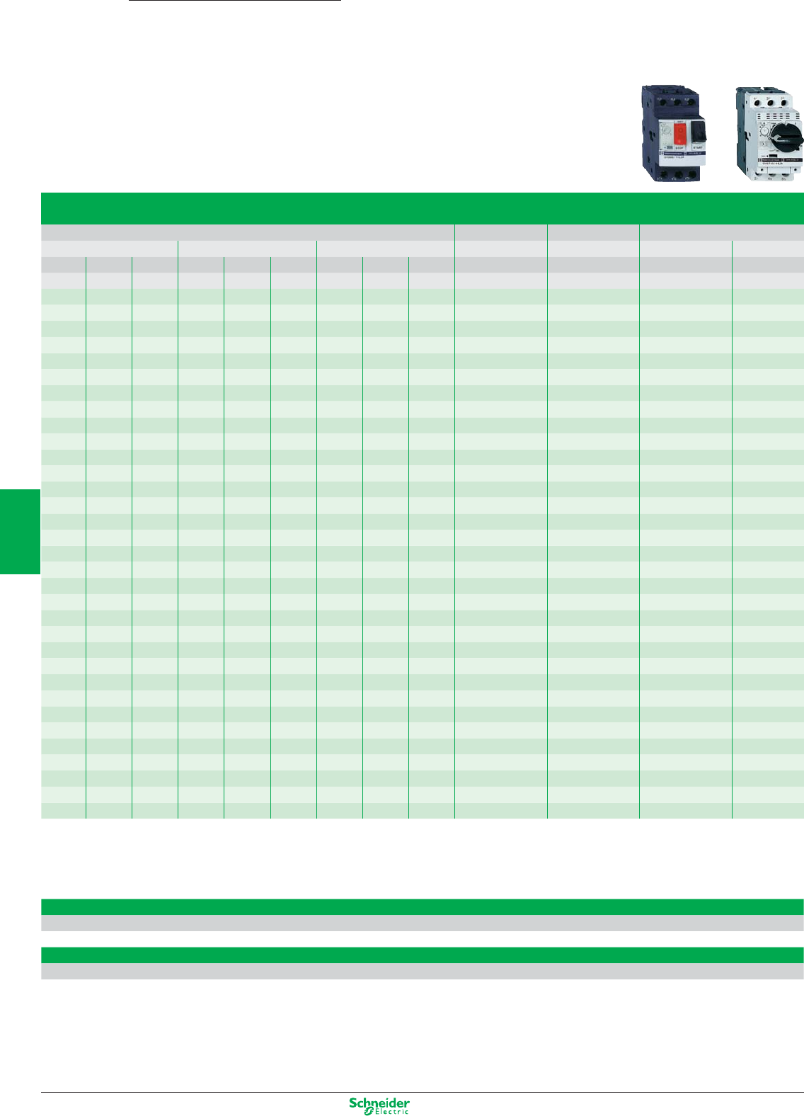
Other versions: please consult your Schneider Electric agency.
Thermal-magnetic circuit-breakers GV2-ME and GV2-P for connection by screw clamp terminals
GV2-ME with pushbutton control, GV2-P control by rotary knob
Standard power ratings of 3-phase motors 50/60 Hz in category AC-3 Setting range Magnetic Reference
400/415 V 500 V 690 V of thermal tripping
P Icu Ics (1) P Icu Ics (1) P Icu Ics (1) trips current
kW kA kW kA kW kA A A (d ± 20%)
---------0.1…0.16 1.5 GV2-ME01 GV2-P01
0.06 ((------0.16…0.25 2.4 GV2-ME02 GV2-P02
0.09 ((------0.25…0.40 5 GV2-ME03 GV2-P03
0.12 ((- - - 0.37 (( 0.40…0.63 8 GV2-ME04 GV2-P04
0.18 ((------0.40…0.63 8 GV2-ME04 GV2-P04
0.25 ((- - - 0.55 ((-0.63…1 13 GV2-ME05 GV2-P05
0.37 ((0.37 ((- - - 1…1.6 22.5 GV2-ME06 GV2-P06
0.55 ((0.55 ((0.75 (( 1…1.6 22.5 GV2-ME06 GV2-P06
- - - 0.75 ((1.1 (( 1…1.6 22.5 GV2-ME06 GV2-P06
0.75 ((1.1 ((1.5 3 75 1.6…2.5 33.5 GV2-ME07
0.75 ((1.1 ((1.5 8 100 1.6…2.5 33.5 GV2-P07
1.1 ((1.5 ((2.2 3 75 2.5…4 51 GV2-ME08
1.1 ((1.5 ((2.2 8 100 2.5…4 51 GV2-P08
1.5 ((2.2 ((3 3 75 2.5…4 51 GV2-ME08
1.5 ((2.2 ((3 3 100 2.5…4 51 GV2-P08
2.2 ((3 50 100 4 3 75 4…6.3 78 GV2-ME10
2.2 ((3((4 6 100 4…6.3 78 GV2-P10
3((4 10 100 5.5 3 75 6…10 138 GV2-ME14
3((4 50 100 5.5 6 100 6…10 138 GV2-P14
4((5.5 10 100 7.5 3 75 6…10 138 GV2-ME14
4((5.5 50 100 7.5 6 100 6…10 138 GV2-P14
5.5 15 50 7.5 6 75 9 3 75 9…14 170 GV2-ME16
5.5 ((7.5 42 75 9 6 100 9…14 170 GV2-P16
- - - - - - 11 3 75 9…14 170 GV2-ME16
- - - - - - 11 6 100 9…14 170 GV2-P16
7.5 15 50 9 6 75 15 3 75 13…18 223 GV2-ME20
7.5 50 50 9 10 75 15 4 100 13…18 223 GV2-P20
9 15 40 11 4 75 18.5 3 75 17…23 327 GV2-ME21
9 50 50 11 10 75 18.5 4 100 17…23 327 GV2-P21
11 15 40 15 4 75 - - - 20…25 327 GV2-ME22 (2)
11 50 50 15 10 75 - - - 20…25 327 GV2-P22
15 10 50 18.5 4 75 22 3 75 24…32 416 GV2-ME32
15 50 50 18.5 10 75 22 4 100 24…32 416 GV2-P32
H > 100 kA
(1) as % of Icu
(2) combined with a recommended contactor
Thermal-magnetic circuit-breakers GV2-ME for connection by spring terminals
Add the figure 3 to the end of the reference. Example: GV2-ME22 becomes GV2-ME223
Thermal-magnetic circuit-breakers GV2-ME for connection by ring terminals
Add the figure 6 to the end of the reference. Example: GV2-ME32 becomes GV2-ME326
Common accessories GV2 / GV3, see page 5/15
TeSys
GV2-ME, GV2-P
Thermal-magnetic circuit-breakers
0.06…15 kW
5/12
2
1
3
4
5
6
7
8
9
10
Other versions: please consult your Schneider Electric agency.
Magnetic circuit-breakers GV2-LE and GV2-L for connection by screw clamp terminals
GV2-LE control by rocker lever, GV2-L control by rotary knob
Standard power ratings of 3-phase motors 50/60 Hz in category AC-3 Magnetic Tripping Use in association Reference
400/415 V 500 V 690 V protection current with thermal
P Icu Ics (1) P Icu Ics (1) P Icu Ics (1) rating d ± 20% overload relay
kW kA kW kA kW kA A A
0.06 ((- - - - - - 0.4 5 LR2-K0302 GV2-LE03
0.09 ((- - - - - - 0.4 5 LR2-K0304 GV2-LE03
or LRD-03 GV2-L03
0.12 ((- - - 0.37 ((0.63 8 LR2-K0304 GV2-LE04
or LRD-04 GV2-L04
0.18 ((- - - - - - 0.63 8 LR2-K0305 GV2-LE04
or LRD-04 GV2-L04
- - - - - - 0.55 ((1 13 LR2-K0305 GV2-LE05
or LRD-05 GV2-L05
0.25 ((- - - - - - 1 13 LR2-K0306 GV2-LE05
or LRD-05 GV2-L05
- - - - - - 0.75 ((1 13 LR2-K0306 GV2-LE05
or LRD-06 GV2-L05
0.37 ((0.37 ((- - - 1 13 LR2-K0306 GV2-LE05
or LRD-05 GV2-L05
0.55 ((0.55 ((1.1 ((1.6 22.5 LR2-K0307 GV2-LE06
or LRD-06 GV2-L06
- - - 0.75 ((- - - 1.6 22.5 LR2-K0307 GV2-LE06
or LRD-06 GV2-L06
0.75 ((1.1 ((1.5 3 75 2.5 33.5 LR2-K0308 GV2-LE07
0.75 ((1.1 ((1.5 4 100 2.5 33.5 LRD-07 GV2-L07
1.1 ((- - - - - - 2.5 33.5 LR2-K0308 GV2-LE08
or LRD-08 GV2-L08
1.5 ((1.5 ((3 3 75 4 51 LR2-K0310 GV2-LE08
1.5 ((1.5 ((3 4 100 4 51 LRD-08 GV2-L08
- - - 2.2 ((- - - 4 51 LR2-K0312 GV2-LE08
or LRD-08 GV2-L08
2.2 ((3 50 100 4 3 75 6.3 78 LR2-K0312 GV2-LE10
2.2 ((3((4 4 100 6.3 78 LRD-10 GV2-L10
3((4 10 100 5.5 3 75 10 138 LR2-K0314 GV2-LE14
3((4 10 100 5.5 4 100 10 138 LRD-12 GV2-L14
4((5.5 10 100 - - - 10 138 LR2-K0316 GV2-LE14
or LRD-14 GV2-L14
- - - - - - 7.5 3 75 10 138 LRD-14 GV2-LE14
- - - - - - 7.5 4 100 10 138 LRD-14 GV2-L14
- - - - - - 9 3 75 14 170 LRD-16 GV2-LE16
- - - - - - 9 4 100 14 170 LRD-16 GV2-L16
5.5 15 50 7.5 6 75 11 3 75 14 170 LR2-K0321 GV2-LE16
5.5 50 50 7.5 10 75 11 4 100 14 170 LRD-16 GV2-L16
7.5 15 50 9 6 75 15 3 75 18 223 LRD-21 GV2-LE20
7.5 50 50 9 10 75 15 4 100 18 223 LRD-21 GV2-L20
9 15 40 11 4 75 18.5 3 75 25 327 LRD-22 GV2-LE22
9 50 50 11 10 75 18.5 4 100 25 327 LRD-22 GV2-L22
11 15 40 15 4 75 - - - 25 327 LRD-22 GV2-LE22
11 50 50 15 10 75 - - - 25 327 LRD-22 GV2-L22
15 10 50 18.5 4 75 22 3 75 32 416 LRD-32 GV2-LE32
15 50 50 18.5 10 75 22 4 100 32 416 LRD-32 GV2-L32
H > 100 kA
(1) as % of Icu
Common accessories GV2 / GV3, see page 5/15
TeSys
GV2-L, GV2-LE
Magnetic circuit-breakers
0.06 to 15 kW
5/13
2
1
3
4
5
6
7
8
9
10
Other versions: please consult your Schneider Electric agency.
Thermal-magnetic circuit-breakers GV3-P for connection by EverLink terminal blocks (2)
Control by rotary knob
Standard power ratings of 3-phase motors 50/60 Hz in category AC-3 Setting range Reference
400/415 V 500 V 660/690 V of thermal
P Icu Ics (1) P Icu Ics (1) P Icu Ics (1) trips
kW kA kW kA kW kA A
5.5 100 50 7.5 12 50 11 6 50 9…13 GV3-P13
7.5 100 50 11 12 50 15 6 50 12…18 GV3-P18
11 100 50 15 12 50 18.5 6 50 17…25 GV3-P25
15 100 50 18.5 12 50 22 6 50 23…32 GV3-P32
18.5 50 50 22 10 50 30 5 60 30…40 GV3-P40
22 50 50 30 10 50 37 5 60 37…50 GV3-P50
30 50 50 37 10 50 45 5 60 48…65 GV3-P65
(1) as % of lcu
Thermal-magnetic circuit-breakers GV3-P for connection by ring terminals
Add the figure 6 to the end of the reference. Example: GV3-P13 becomes GV3-P136
Thermal-magnetic circuit-breakers GV3-P for connection by only 1 EverLink terminal block
Add the figure 1 to the end of the reference. Example: GV3P65 becomes GV3P651
Magnetic 11…30 kW
with EverLink
terminal blocks
Magnetic circuit-breakers GV3-L for connection by EverLink terminal blocks (2)
Control by rotary knob
Standard power ratings of 3-phase motors 50/60 Hz in category AC-3 Associated equipment Circuit-breaker
400/415 V 500 V 690 V Thermal Short-circuit
P Icu Ics P Icu Ics P Icu Ics overload protection
kW kA kW kA kW kA relay Rating A Reference
11 100 50 15 12 50 18.5 6 50 LRD-325 25 GV3-L25
15 100 50 18.5 12 50 22 6 50 LRD-332 32 GV3-L32
18.5 50 50 22 10 50 30 5 60 LRD-340 40 GV3-L40
22 50 50 30 10 50 45 5 60 LRD-350 50 GV3-L50
30 50 50 37 10 50 45 5 60 LRD-365 65 GV3-L65
Magnetic circuit-breakers GV3-L for connection by ring terminals
Add the figure 6 to the end of the reference. Example: GV3-L25 becomes GV3-L256
Magnetic circuit-breakers GV3-L for connection by only 1 EverLink terminal block
Add the figure 1 to the end of the reference. Example: GV3L65 becomes GV3L651
(2) 4 mm BTR screw
Add-on blocks and accessories
(3)
Add-on blocks (front) Fault signalling contact + instantaneous auxiliary contact
Contact type N/O (fault) + N/C N/O (fault) + N/O
References (4) GV-AED011 GV-AED101
Accessories Cover Busbars
Type IP20 for lug
type terminals
IP20 for lug
type terminals
when used with
contactor
“Wide spacing”
UL 508 type E
Set of 3-pole
115 A busbars
for 2
circuit-breakers
Set of 3-pole
115 A busbars
for 3
circuit-breakers
“S” form for side
by side mounted
circuit-breaker/
contactor
References LAD96570 LAD96575 GV3G66 GV3G264 GV3G364 GV3S
(3) Common add-on blocks and accessories GV2 / GV3, see page 5/15
(4) For spring terminal version add 3 to the end of the reference. Example: GV-AED011 becomes GV-AED0113
TeSys
GV3-P/GV3-L
Circuit-breakers
Thermal-magnetic 5.5…30 kW
with EverLink
terminal blocks
5/14
2
1
3
4
5
6
7
8
9
10
Other versions: please consult your Schneider Electric agency.
Accessories GV2
Combination block
For mounting on LC1-K or LP1-K LC1-D09…D38 LAD-31 and LC1-D09…D38
GV2-AF01 GV2-AF3 GV2-AF4
Sets of 3-pole busbars
63 A Pitch 45 mm 54 mm 72 mm
Number of tap-offs 2 GV2-G245 GV2-G254 GV2-G272
3 GV2-G345 GV2-G354
4 GV2-G445 GV2-G454 GV2-G472
5 GV2-G554
Protective end cover
For unused busbar outlets GV1-G10
Terminal blocks
For supply to one or more GV2-G busbar sets connection from the top can be fitted with current limiter GV1-L3 (GV2-ME and GV2-P)
GV1-G09 GV1-G05
Padlockable external operator for GV2 and GV3 (150 to 290 mm)
Padlocking In “On” and “Off” position In “Off” position
Handle black red
Legend plate blue yellow
IP 54 For GV2-ME/P/L GV2-AP01 GV2-AP02
For GV2-LE GV2-AP03 –
For GV3-P/L GV3-AP01 GV3-AP02
Add-on blocks common to GV2 / GV3
Contact blocks
Contact types N/O or N/C N/O + N/C N/O + N/O (fault) + N/C (fault) + N/O C/O common
Instantaneous auxiliary contacts point
Mounting front GV-AE1 GV-AE11 GV-AE20
LH side GV-AN11 GV-AN20
Fault signalling contact + instantaneous auxiliary contact
LH side N/O (fault) GV-AD1001 GV-AD1010
N/C (fault) GV-AD0101 GV-AD0110
Short-circuit signalling contact
LH side GV-AM11
Electric trips
Undervoltage or shunt trips (1)
Side mounting (1 block on RH side of circuit-breaker) 50 Hz 60 Hz
Voltage 24 V GV-A•025 GV-A•026
48 V GV-A•055 GV-A•056
100 V GV-A•107
100…110 V GV-A•107
110…115 V GV-A•115 GV-A•116
120…127 V GV-A•125
127 V GV-A•115
200 V GV-A•207
200…220 V GV-A•207
220…240 V GV-A•225 GV-A•226
380…400 V GV-A•385 GV-A•386
415…440 V GV-A•415
415 V GV-A•416
Padlocking device
For use with up to 4 padlocks (padlocks not supplied) Ø 6 mm shank max GV2-V03
(1) Undervoltage trips: replace the • with U, shunt trips: replace the • with S
TeSys
GV2/GV3
Circuit-breakers
Accessories
5/15
2
1
3
4
5
6
7
8
9
10
Other versions: please consult your Schneider Electric agency.
TeSys
GV7-R
Thermal-magnetic circuit-breakers
0.75…90 kW
Thermal-magnetic circuit-breakers GV7-R for connection by screw clamp terminals
Control by rocker lever
Standard power ratings of 3-phase motors 50/60 Hz in category AC-3 Setting range Reference
400/415 V 500 V 660/690 V of thermal
P Icu Ics (1) P Icu Ics (1) P Icu Ics (1) trips
kW kA kW kA kW kA A
7.5 25 100 9 18 100 11 8 100 12…20 GV7-RE20
9 25 100 11 18 100 15 8 100
7.5 70 100 9 50 100 11 10 100 12…20 GV7-RS20
9 70 100 11 50 100 15 10 100
9 25 100 11 18 100 15 8 100 15…25 GV7-RE25
11 25 100 15 18 100 18.5 8 100
9 70 100 11 50 100 15 10 100 15…25 GV7-RS25
11 70 50 15 50 100 18.5 10 100
18.5 25 100 18.5 18 100 22 8 100 25…40 GV7-RE40
22 18 100
18.5 70 100 18.5 50 100 22 10 100 25…40 GV7-RS40
22 25 100 30 18 100 30 8 100 30…50 GV7-RE50
37 25 100 45 18 100 55 8 100 48…80 GV7-RE80
55 18 100
37 70 100 45 50 100 55 10 100 48…80 GV7-RS80
55 50 100
45 25 100 - 18 100 75 8 100 60…100 GV7-RE100
45 70 100 - 50 100 75 10 100 60…100 GV7-RS100
55 35 100 75 30 100 90 8 100 90…150 GV7-RE150
75 70 100 90 30 100 110 8 100
55 70 100 75 50 100 90 10 100 90…150 GV7-RS150
75 70 100 90 50 100 110 10 100
90 35 100 110 30 100 160 8 100 132…220 GV7-RE220
110 35 100 132 30 100 200 8 100
160 30 100
90 70 100 110 50 100 160 10 100 132…220 GV7-RS220
(1) as % of Icu
5/16
2
1
3
4
5
6
7
8
9
10
Other versions: please consult your Schneider Electric agency.
Add-on blocks
Contact blocks
Auxiliary contacts
Contact type C/O
GV7-AE11
Thermal or magnetic fault discrimination
z 24…48 V or c 24…72 V z 110…240 V
GV7-AD111 GV7-AD112
Electric trips
Voltage 50/60 Hz 48 V 110… 130 V 200… 240 V 380…440 V
50 Hz 525 V
Undervoltage trip (1) GV7-AU055 GV7-AU107 GV7-AU207 GV7-AU387 GV7-AU525
Shunt trip (1) GV7-AS055 GV7-AS107 GV7-AS207 GV7-AS387 GV7-AS525
(1) For mounting of a GV7-AD or a GV7-AU or AS
Accessories
Terminal shields IP 405
Supplied with sealing accessory GV7-AC01
Phase barriers
Safety accessories GV7-AC04
used when fitting of shields is impossible
Insulating screens
Ensure insulation between GV7-AC05
the connections and the backplate
Kit for combination with contactor
Allowing link between the circuit-breaker and the contactor LC1-F115 to F185 LC1-F225 and F26 LC1-D115 and D150
GV7-AC06 GV7-AC07 GV7-AC08
Rotary handles
Handle black red
Legend plate black yellow
N direct IP 40 GV7-AP03 GV7-AP04
N extended IP 55 GV7-AP01 GV7-AP02
Conversion accessory
for mounting on enclosure door IP 43 GV7-AP05
Locking device
For circuit-breaker not fitted with a rotary handle GV7-V01
5/17
2
1
3
4
5
6
7
8
9
10
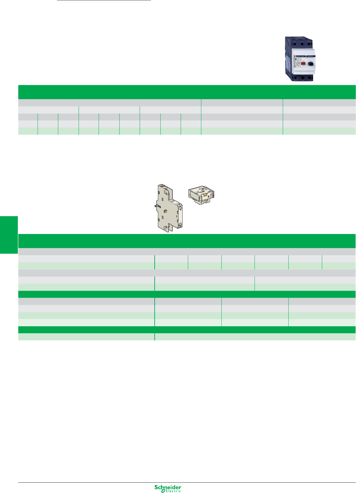
Other versions: please consult your Schneider Electric agency.
TeSys
GV3-ME
Thermal-magnetic circuit-breakers
37 kW
Thermal-magnetic circuit-breakers GV3-ME for connection by screw clamp terminals
Pushbutton control
Standard power ratings of 3-phase motors 50/60 Hz in category AC-3 Setting range Reference
400/415 V 500 V 660/690 V of thermal
P Icu Ics (1) P Icu Ics (1) P Icu Ics (1) trips
kW kA kW kA kW kA A
37 15 50 45 4 100 55 2 100 56…80 GV3-ME80
(1) as % of Icu
Add-on blocks for GV3-ME
Contact blocks
Instantaneous auxiliary contacts (1 per breaker)
Normal early break type contacts N/C + N/O N/O + N/O N/C + N/O + N/O N/O + N/O + N/O N/O + N/O (1) N/C + N/O (1)
GV3-A01 GV3-A02 GV3-A03 GV3-A05 GV3-A06 GV3-A07
Fault signalling contact
Normal early break type contacts N/C N/O
GV3-A08 GV3-A09
Electric trips
Voltage 50 Hz 110, 120, 127 V 220, 240 V 380, 415 V
60 Hz 120, 127 V 277 V 440, 480 V
Undervoltage trip GV3-B11 GV3-B22 GV3-B38
Shunt trip GV3-D11 GV3-D22 GV3-D38
Padlocking device
Start button (for bare device) GV1-V02
(1) + 2 volt free terminals
5/18
2
1
3
4
5
6
7
8
9
10
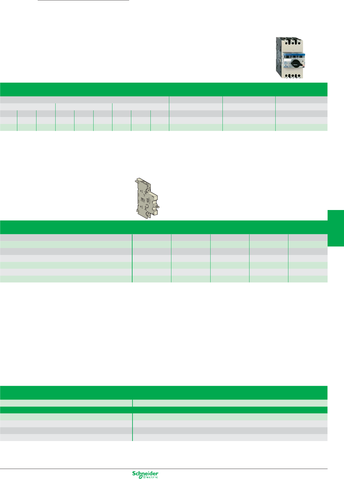
Other versions: please consult your Schneider Electric agency.
TeSys
GK3-EF
Magnetic circuit-breakers
37 kW
Magnetic circuit-breakers GK3-EF for connection by screw clamp terminals
Control by rotary knob
Standard power ratings of 3-phase motors 50/60 Hz in category AC-3 Associated equipment Circuit-breaker
400/415 V 500 V 690 V Thermal Short-circuit
P Icu Ics P Icu Ics P Icu Ics overload relay protection
kW kA kW kA kW kA min. size Rating A Reference
37 35 25 45 15 30 - - - LRD-3363 80 GK3-EF80
Add-on blocks for GK3
Contact blocks
Contact type N/O N/O + N/O N/C + N/O N/C N/O
On-Off signalling contacts GK2-AX10 GK2-AX20 GK2-AX50
and “Control circuit test” function (1 or 2 blocks per device)
mounted on RH side of GK3-EF
Instantaneous fault signalling contacts GK2-AX12 GK2-AX22 GK2-AX52
(1 or 2 blocks per device) mounted on LH side of GK3-EF
Fault signalling contact (1) GV3-A08 GV3-A09
(1) 1 trip OR 1 fault signalling contact to be fitted inside the circuit-breaker.
Accessories for GK3
Padlocking device
for padlocking the operator with up to 3 padlocks (padlocks not supplied) GK3-AV01
External operator
for mounting on enclosure door. GK3-AP03
Red Ø 40 pushbutton on yellow plate, can be locked in
position O by means of up to 3 padlocks with door locked in
position I, and door locked in position O when padlocked
5/19
2
1
3
4
5
6
7
8
9
10
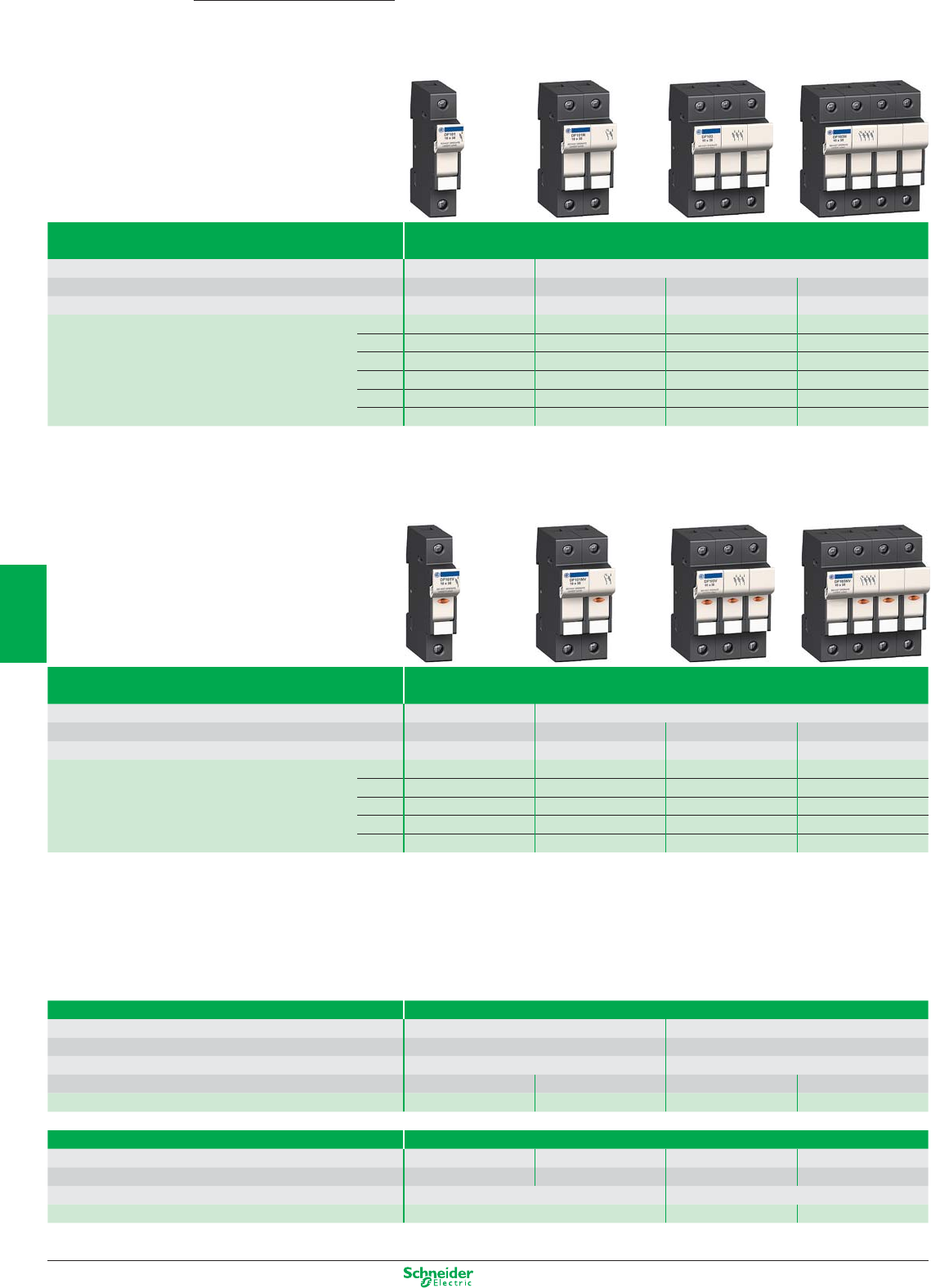
Other versions: please consult your Schneider Electric agency.
TeSys DF Fuse carriers
0…125 A
Type Fuse carriers without “blown fuse” indicator
Rated insulation voltage (Ui) 500 V 690 V
Fuse size 8.5 x 31.5 mm 10 x 38 mm 14 x 51 mm 22 x 58 mm
Conventional thermal current (Ith) 25 A 32 A 50 A 125 A
References Number of poles 1P DF81 DF101 DF141 DF221
NDF10N DF10N DF14N DF22N
1P+N DF81N DF101N DF141N DF221N
2P DF82 DF102 DF142 DF222
3P DF83 DF103 DF143C DF223C
3P+N DF83N DF103N DF143NC DF223NC
Type Fuse carriers with “blown fuse” indicator
Rated insulation voltage (Ui) 500 V 690 V
Fuse size 8.5 x 31.5 mm 10 x 38 mm 14 x 51 mm 22 x 58 mm
Conventional thermal current (Ith) 25 A 32 A 50 A 125 A
References Number of poles 1P DF81V DF101V DF141V DF221V
1P + N DF81NV DF10NV DF14NV DF22NV
2P DF82V DF102V DF142V DF222V
3P DF83V DF103V DF143VC DF223VC
3P + N DF83NV DF103NV DF143NVC DF223NVC
Accessories
Type Auxiliary early break and blown fuse signalling contacts
Fuse carrier to be equipped DF14 DF22
Fuse size 14 x 51 mm 22 x 58 mm
Number of poles 3P or 3P + N 3P or 3P + N
Number of contacts 1212
References DF14AM1 DF14AM2 DF22AM1 DF22AM2
Type Fuse carrier assembly kits
Fuse carrier to be assembled DF8 DF10 DF14 DF22
Fuse size 8.5 x 31.5 mm 10 x 38 mm 14 x 51 mm 22 x 58 mm
Kit contents 1 pin, 2 clips 1 pin, 3 clips
References DF10AP DF14AP DF22AP
5/20
2
1
3
4
5
6
7
8
9
10
Other versions: please consult your Schneider Electric agency.
TeSys
LS1, GK1
Fuse carriers
0…125 A
Type 3-pole fuse carriers
Rated insulation voltage (Ui) 690 V
Rating 25 A 32 A 50 A 125 A
Fuse size 10 x 38 10 x 38 14 x 51 22 x 58
Connection
Spring terminals Screw clamp terminals or connectors
Single-phase protection device Without Without Without With Without With
Number of early break contacts –– 11
Reference LS1D323 LS1D32 GK1K GK1EV GK1FK GK1FV
Number of early break contacts 22
Reference GK1ES GK1EW GK1FS GK1FW
Type 4-pole fuse carriers
Rated insulation voltage (Ui) 690 V
Rating 32 A 50 A 125 A
Fuse size 10 x 38 14 x 51 22 x 58
Connection
Screw clamp terminals or connectors
Single-phase protection device Without Without With Without With
Number of early break contacts –11
Reference LS1D32 + LA8-D324 GK1EM GK1EY GK1FM GK1FY
Number of early break contacts 22
Reference GK1ET GK1EX GK1FT GK1FX
5/21
2
1
3
4
5
6
7
8
9
10
Other versions: please consult your Schneider Electric agency.
TeSys
LS1, GK1
Fuse carriers
Accessories
Type Early break auxiliary contact blocks
Fuse carrier rating 32 A 25 A
For use with fuse carrier LS1D32 LS1D323
Contact type N/O + N/C N/O + N/O N/O + N/C N/O + N/O
References GVAE11 GVAE20 GVAE113 GVAE203
Type Direct operator handle
Fuse carrier rating
125 A 32, 50, 125 A
For mounting on RH side LH side Front
References
GK1AP07 GK1AP08 Fitted as standard
Type External operator handle
Fuse carrier rating 32 A 50 A 125 A
For mounting on RH side LH side RH side LH side RH side LH side
References LS1-D32005 LS1-D32006 GK1-AP05 GK1-AP06 GK1-AP07 GK1-AP08
Type Padlocking devices
Fuse carrier rating 32 A 50 A
Number of poles 3 or 4 3 4
Single-phase protection device Without Without With Without With
References Integrated GK1-AV07 GK1-AV08 GK1-AV08 GK1-AV09
Type Tubular link
Fuse carrier rating 32 A 50 A 125 A
References DK1-CB92 DK1-EB92 DK1-FA9
5/22
2
1
3
4
5
6
7
8
9
10
Other versions: please consult your Schneider Electric agency.
TeSys GS Switch-disconnector-fuses
Handles
Type IP65 handles for external front-mounted operators
Switch rating 32…63 A 100…400 A 630…800 A 1250 A
References Black/grey GS2AH510 (1) GS2AH530 (1) GS2AH550 GS2AH570
Red/yellow GS2AH520 (1) GS2AH540 (1) GS2AH560 GS2AH580
(1) For external front operators with Test facility, insert the letter T in the reference. Example: GS2AH510 becomes GS2AHT510
Type IP65 handles for external RH side-mounted operators (2)
Switch rating 32…63 A 100…400 A 630…1250 A
References Black/grey GS2AH210 GS2AH230 GS2AH250
Red/yellow GS2AH220 GS2AH240 GS2AH260
(2) For external LH side-mounted operators, replace the number 2 in the reference by 3. Example: GS2AH210 becomes GS2AH310
Type Shafts for external operators
Switch rating 32 A 50…400 A 630…1250 A
References Length of shaft 200 mm GS2AE82 GS2AE22 GS2AE52
320 mm GS2AE8 GS2AE2 GS2AE5
400 mm GS2AE81 GS2AE21 GS2AE51
Type Handles for direct operators
Switch rating 32 A 50 and 63 A 100…400 A 630 and 800 A 1250 A
Type of operator Front RH side RH side Front Front
References GS1AH103 GS1AH01 GS1AH02 GS2AH104 GS2AH105
5/23
2
1
3
4
5
6
7
8
9
10
Other versions: please consult your Schneider Electric agency.
TeSys GS Switch-disconnector-fuses
32…1250 A
Type Switch-disconnector-fuse switch bodies for use with NF C or DIN fuses
Handle to be ordered separately (see previous page)
Rated insulation voltage (Ui) 690 V
Conventional thermal current (Ith) 32 A 50 A 63 A 100 A
Fuse size 10 x 38 14 x 51 Size 00C (1) 22 x 58
External front-mounted and 3-pole GS1DD3 GS2F3 GS2G3 GS2J3
RH side-mounted operator 4-pole GS1DD4 (2) GS2F4 GS2G4 GS2J4
External LH side-mounted 3-pole GS1DD3 GS2FG3 GS2GG3 GS2JG3
operator 4-pole GS1DD4 (2) GS2FG4 GS2GG4 GS2JG4
Direct RH side-mounted 3-pole GS1DD3 (3) GS1FD3 GS1GD3 GS1JD3
operator 4-pole GS1DD4 (2) (3) GS1FD4 GS1GD4 GS1JD4
(1) Compact fuse for German market
(2) 3-pole + switched neutral
(3) Direct front-mounted operator
Type Switch-disconnector-fuse switch bodies for use with BS fuses
Handle to be ordered separately (see previous page)
Rated insulation voltage (Ui) 690 V
Conventional thermal current (Ith) 32 A 32 A 63 A 100 A
Fuse size A1 A1 A2-A3 A4 (Ø ≤ 31 mm)
External front-mounted and 3-pole GS1DDB3 GS2DB3 GS2GB3 GS2JB3
RH side-mounted operator 4-pole GS1DDB4 (2) GS2DB4 GS2GB4 GS2JB4
Accessories
Type Auxiliary contacts
Early break and/or O, I and Test signalling O and I signalling
Switch rating 32…1250 A 50…1250 A
Number of contacts 1 NO 1 NC 1 NO + NC 2 NO + 2 NC
Operator external front-mounted or RH side-mounted GS1AM110 GS1AM101 GS1AN11 GS1AN22
external LH side-mounted GS1AM110 GS1AM101 GS1AN11G GS1AN22G
direct RH side-mounted – – GS1AN11 GS1AN22
direct front-mounted – – – –
Type Auxiliary “blown fuse” signalling contacts for use with NF C and DIN fuses
Number of contacts 1 NO/NC
Switch rating 50 A 100 and 125 A 160 A 250 and 400 A
Fuse size 14 x 51 22 x 58 Size 0 Size 1 and Size 2
References 3-pole GS1AF1 GS1AF23 GS1AF33 GS1AF43
4-pole GS1AF1 GS1AF24 GS1AF34 GS1AF44
5/24
2
1
3
4
5
6
7
8
9
10
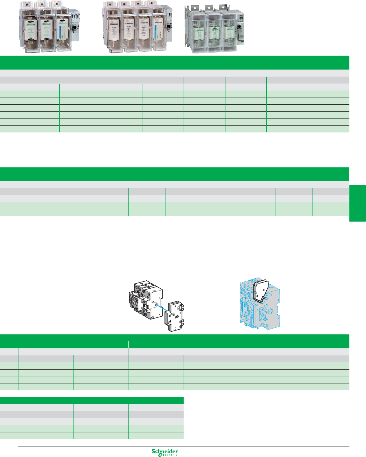
Other versions: please consult your Schneider Electric agency.
125 A 160 A 250 A 400 A 630 A 1250 A
22 x 58 Size 00 Size 00 Size 0 Size 1 Size 2 Size 3 Size 4
GS2K3 GS2KK3 GS2LL3 GS2L3 GS2N3 GS2QQ3 GS2S3 GS2V3
GS2K4 GS2KK4 GS2LL4 GS2L4 GS2N4 GS2QQ4 GS2S4 GS2V4
GS2KG3 GS2KKG3 GS2LLG3 GS2LG3 GS2NG3 GS2QQG3 GS2SG3 GS2VG3
GS2KG4 GS2KKG4 GS2LLG4 GS2LG4 GS2NG4 GS2QQG4 GS2SG4 GS2VG4
GS1KD3 GS1KKD3 GS1LLD3 GS1LD3 GS1ND3 GS1QQD3 GS2S3 (3) GS2V3 (3)
GS1KD4 GS1KKD4 GS1LLD4 GS1LD4 GS1ND4 GS1QQD4 GS2S4 (3) GS2V4 (3)
160 A 200 A 250 A 315 A 400 A 630 A 800 A 1250 A
A4 B1-B2 B1-B2 B1…B3 B1…B3 B1…B4 C1-C2 C1…C3 D1
GS2LLB3 GS2LB3 GS2MMB3 GS2NB3 GS2PPB3 GS2QQB3 GS2SB3 GS2TB3 GS2VB3
GS2LLB4 GS2LB4 GS2MMB4 GS2NB4 GS2PPB4 GS2QQB4 GS2SB4 GS2TB4 GS2VB4
O, I and Test signalling Early break and O and I signalling
50…400 A 32 A 50…400 A
1 NO + NC 2 NO + 2 NC 1 NO/NC 2 NO/NC 1 NO/NC 2 NO/NC
GS1ANT11 GS1ANT22 ––––
––––––
––––GS1AM1 GS1AM2
––GS1AM111 GS1AM211 ––
2
nd
NO/NC
630 A 1250 A 50…1250 A
Size 3 Size 4 –
GS2AF63 GS2AF73 GS1AF
GS2AF64 GS2AF74 GS1AF
5/25
2
1
3
4
5
6
7
8
9
10
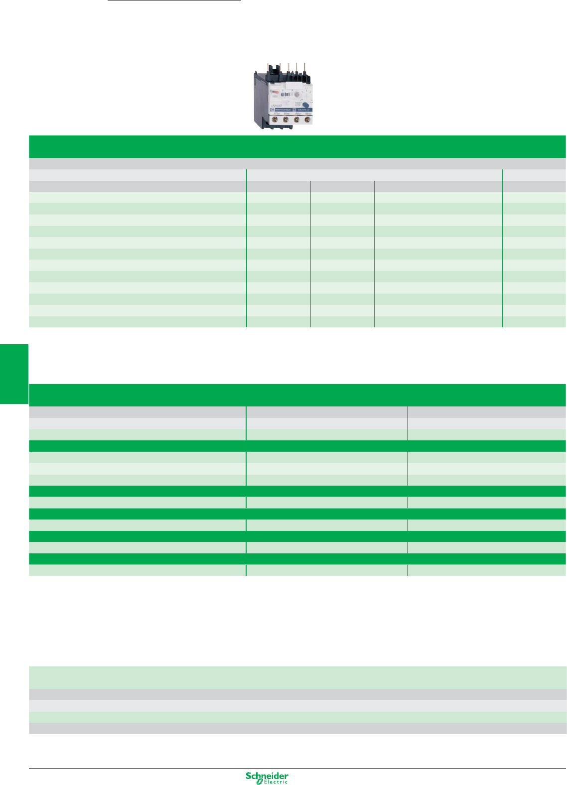
Other versions: please consult your Schneider Electric agency.
Thermal overload relays, TeSys K
adjustable from 0.11 to 12 A
Connection by screw clamp terminals, direct mounting on contactors LC1-K, manual or automatic reset
Relay setting range Fuses to be used with selected relay Reference
Class 10A aM gG BS88
0.11…0.16 A 0.25 A 0.5 A - LR2-K0301
0.16…0.23 A 0.25 A 0.5 A - LR2-K0302
0.23…0.36 A 0.5 A 1 A - LR2-K0303
0.36…0.54 A 1 A 1.6 A - LR2-K0304
0.54…0.8 A 1 A 2 A - LR2-K0305
0.8…1.2 A 2 A 4 A 6 A LR2-K0306
1.2…1.8 A 2 A 6 A 6 A LR2-K0307
1.8…2.6 A 2 A 6 A 10 A LR2-K0308
2.6…3.7 A 4 A 10 A 16 A LR2-K0310
3.7…5.5 A 6 A 16 A 16 A LR2-K0312
5.5…8 A 8 A 20 A 20 A LR2-K0314
8…11.5 A 10 A 25 A 20 A LR2-K0316
Thermal overload relays for use on class 10A unbalanced loads: for above references LR2-K0305 to LR2-K0316 only, replace the prefix LR2 with LR7.
Example: LR7-K0310.
Accessories
Prewiring kit
Allowing direct connection of the N/C contact For use on
of relay LRD-01…35 or LR3-D01… D35 to the contactor LC1-D09…D18 LAD-7C1
LC1-D25…D38 LAD-7C2
Terminal blocks (1)
For clip-on mounting on 35 mm mounting rail (AM1-DP200) LRD-01…35 and LR3-D01…D35 LAD-7B10
or screw fixing LRD-3•••, LR3-D3•••, LRD-35•• LA7-D3064
(2)
For independent mounting of the relay LR2-K•••• LA7-K0064
EverLink Terminal blocks
Separate terminal block LRD-313… LRD-365 LAD-9R3
Terminal block adapter
For mounting a relay beneath an LC1-D115 or D150 contactor LRD-3•••, LR3-D3•••, LRD-35•• LA7-D3058
Stop or electrical reset
Remote
(3) LRD-01…35 and LR3-D01…D35 LAD-703•
(4)
Tripping or electrical reset device
Remote
(3) All relays except LRD-01…35 and LR3-D01…D35 LA7-D03•
(4)
(1) Terminal blocks are supplied with terminals protected against direct finger contact and screws in the open “ready-to-tighten” position.
(2) To order a terminal block for connection by lug-clamps, the reference becomes LA7-D30646.
(3) The time for which the coil of remote tripping or electrical resetting device LA7-D03 or LAD-703 can remain energised depends on its rest time: 1 s pulse duration with 9 s rest
time; maximum pulse duration of 20 s with a rest time of 300 s. Minimum pulse time 200 ms.
(4) Reference to be completed by adding the code indicating the control circuit voltage.
Standard control circuit voltages
a supply
Volts 12 24 48 96 110 220/230 380/400 415/440
50/60 Hz. Consumption, inrush and sealed < 100 VA -BE-FM Q N
c supply
Consumption, inrush and sealed < 100 W JBEDDFM - -
TeSys KThermal overload relays
0.11…11.5 A
5/26
2
1
3
4
5
6
7
8
9
10
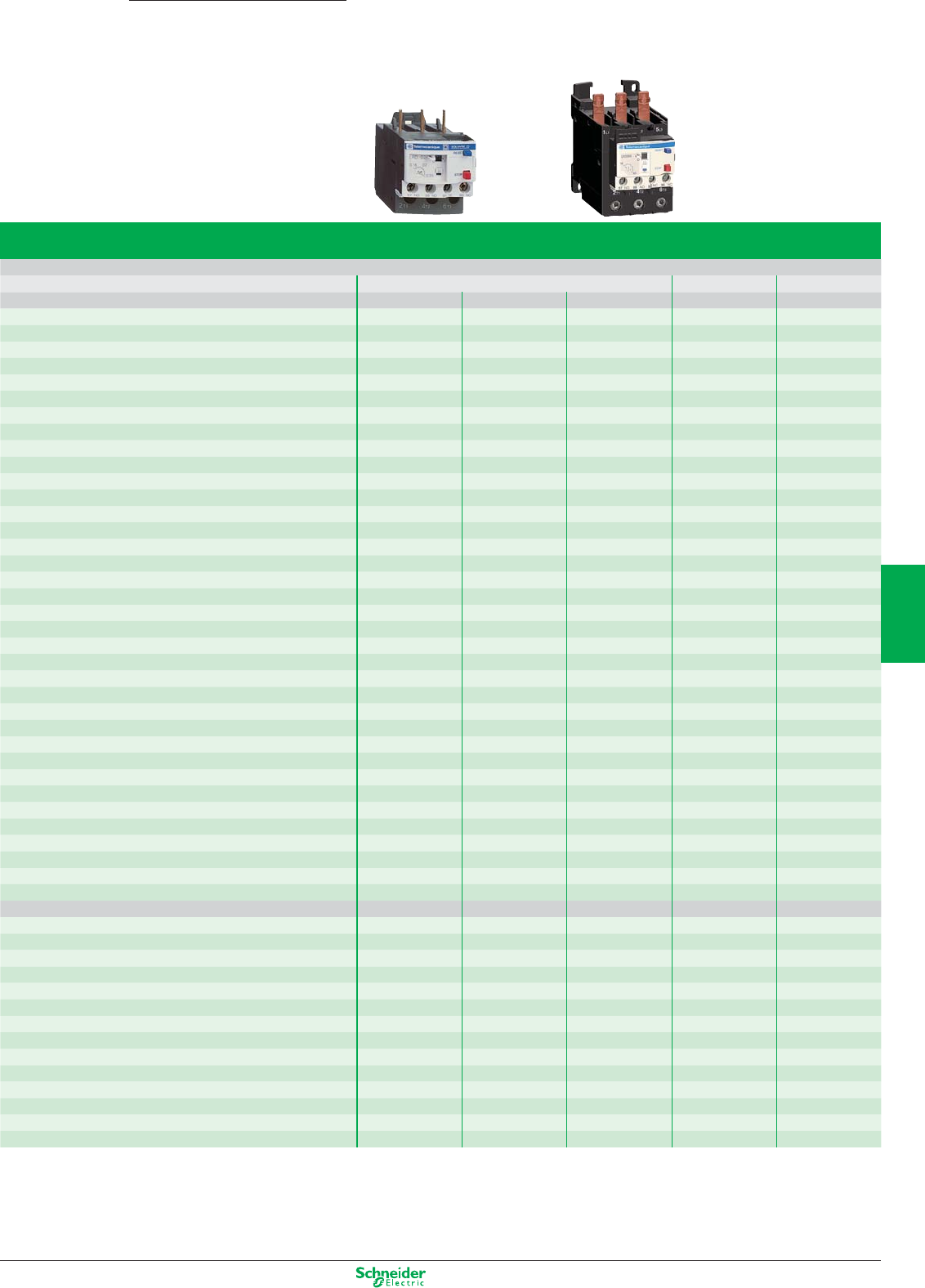
Other versions: please consult your Schneider Electric agency.
TeSys DThermal overload relays
0.1…140 A
Thermal overload relays, TeSys D
adjustable from 0.1 to 140 A
Compensated relays with manual or automatic reset, with relay trip indicator, for a.c. or d.c.
Relay setting range Fuses to be used with selected relay With contactor Reference
Connection by screw clamp terminals or connectors aM gG BS88
Class 10A 0.10…0.16 A 0.25 A 2 A - LC1-D09…D38 LRD 01 (1)
0.16…0.25 A 0.5 A 2 A - LC1-D09…D38 LRD 02 (1)
0.25…0.40 A 1 A 2 A - LC1-D09…D38 LRD 03 (1)
0.40…0.63 A 1 A 1.6 A - LC1-D09…D38 LRD 04 (1)
0.63…1 A 2 A 4 A - LC1-D09…D38 LRD 05 (1)
1…1.7 A 2 A 4 A 6 A LC1-D09…D38 LRD 06 (1)
1.6…2.5 A 4 A 6 A 10 A LC1-D09…D38 LRD 07 (1)
2.5…4 A 6 A 10 A 16 A LC1-D09…D38 LRD 08 (1)
4…6 A 8 A 16 A 16 A LC1-D09…D38 LRD 10 (1)
5.5…8 A 12 A 20 A 20 A LC1-D09…D38 LRD 12 (1)
7…10 A 12 A 20 A 20 A LC1-D09…D38 LRD 14 (1)
9…13 A 16 A 25 A 25 A LC1-D12…D38 LRD 16 (1)
12…18 A 20 A 35 A 32 A LC1-D18…D38 LRD 21 (1)
16…24 A 25 A 50 A 50 A LC1-D25…D38 LRD 22 (1)
23…32 A 40 A 63 A 63 A LC1-D25…D38 LRD 32 (1)
30…38 A 50 A 80 A 80 A LC1-D32 and D38 LRD 35 (1)
55…70 A 80 A 125 A 125 A D50…D95 LRD 3361 (1)
63…80 A 80 A 125 A 125 A D65…D95 LRD 3363 (1)
80…104 A 100 A 160 A 160 A D80 and D95 LRD 3365 (1)
80…104 A 125 A 200 A 160 A D115 and D150 LRD 4365 (1)
95…120 A 125 A 200 A 200 A D115 and D150 LRD 4367 (1)
110…140 A 160 A 250 A 200 A D150 LRD 4369 (1)
80…104 A 100 A 160 A 160 A Independent mtg. LRD 33656 (1)
95…120 A 125 A 200 A 200 A Independent mtg. LRD 33676 (1)
110…140 A 160 A 250 A 200 A Independent mtg. LRD 33696 (1)
Class 20 6 A 10 A 16 A LC1-D09…D32 LRD 1508 (1)
4…6 A 8 A 16 A 16 A LC1-D09…D32 LRD 1510 (1)
5.5…8 A 12 A 20 A 20 A LC1-D09…D32 LRD 1512 (1)
7…10 A 16 A 20 A 25 A LC1-D09…D32 LRD 1514 (1)
9…13 A 16 A 25 A 25 A LC1-D12…D32 LRD 1516 (1)
12…18 A 25 A 35 A 40 A LC1-D18…D32 LRD 1521 (1)
17…25 A 32 A 50 A 50 A LC1-D25 and D32 LRD 1522 (1)
23…28 A 40 A 63 A 63 A LC1-D25 and D32 LRD 1530 (1)
25…32 A 40 A 63 A 63 A LC1-D25 and D32 LRD 1532 (1)
55…70 A 100 A 125 A 125 A D65…D95 LR2 D3561 (1)
63…80 A 100 A 160 A 125 A D80 and D95 LR2 D3563 (1)
Connection by EverLink terminal blocks, with BTR screws
Class 10A 9…13 A 16 A 25 A 25 A LC1-D40A…D65A LRD 313 (2)
12…18 A 20 A 32 A 35 A LC1-D40A…D65A LRD 318 (2)
17…25 A 25 A 50 A 50 A LC1-D40A…D65A LRD 325 (2)
23…32 A 40 A 63 A 63 A LC1-D40A…D65A LRD 332 (2)
30…40 A 40 A 80 A 80 A LC1-D40A…D65A LRD 340 (2)
37…50 A 63 A 100 A 100 A LC1-D40A…D65A LRD 350 (2)
48…65 A 63 A 100 A 100 A LC1-D40A…D65A LRD 365 (2)
Class 20 9…13 A 20 A 32 A 35 A LC1-D40A…D65A LRD 313L (2)
12…18 A 25 A 40 A 40 A LC1-D40A…D65A LRD 318L (2)
17…25 A 32 A 50 A 50 A LC1-D40A…D65A LRD 325L (2)
23…32 A 40 A 63 A 63 A LC1-D40A…D65A LRD 332L (2)
30…40 A 50 A 80 A 80 A LC1-D40A…D65A LRD 340L (2)
37…50 A 63 A 100 A 100 A LC1-D40A…D65A LRD 350L (2)
48…65 A 80 A 125 A 125 A LC1-D40A…D65A LRD 365L (2)
Class 10A with connection by lug-clamps:
Select overload relay with screw clamp terminals or connectors from the table above and add
one of the following suffixes:
b figure 6 for relays LRD 01 to LRD 35 and LRD 313 to LRD 365.
b A66 for relays LRD 3361 to LRD 3365.
Relays LRD 43 are suitable as standard, for use with lug-clamps.
Thermal overload relays for use with unbalanced loads Class 10A
with connection by screw clamp terminals and lug-clamp terminals:
In the reference selected above, change LRD (except LRD 4ppp) to LR3D
Example: LRD 01 becomes LR3D 01
Example with EverLink terminals: LRD 340 becomes LR3D 340
Example with lug-clamp terminals: LRD 3406 becomes LR3D 3406
(1) For independent mounting on a DIN rail, order an EverLink LAD7B106 terminal block. (2) For independent mtg. on a DIN rail, order an EverLink LAD96560 terminal block.
5/27
2
1
3
4
5
6
7
8
9
10
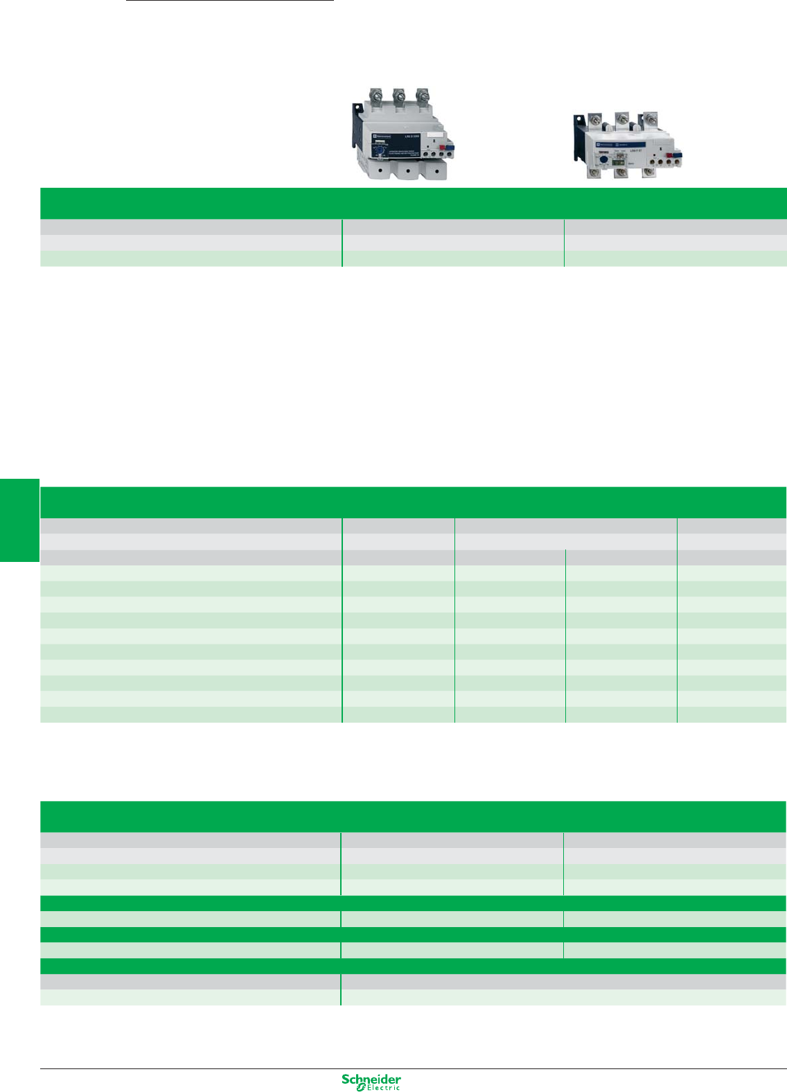
Other versions: please consult your Schneider Electric agency.
For use with contactor LC1-D LC1-F
Motor current 60…150 A 30…630 A
Basic reference, to be completed LR9-D LR9-F
Relay setting range Fuse to be used with selected relay For mounting Compensated and differential With alarm
beneath contactor LC1-
aM gG Class 10 Class 20 Class 10 or 20
60…100 100 160 D115 and D150 LR9-D5367 LR9-D5567
90…150 160 250 D115 and D150 LR9-D5369 LR9-F5569
30…50 50 80 F115…F185 LR9-F5357 LR9-F5557 LR9-F57
48…80 80 125 F115…F185 LR9-F5363 LR9-F5563 LR9-F63
60…100 100 200 F115…F185 LR9-F5367 LR9-F5567 LR9-F67
90…150 160 250 F115…F185 LR9-F5369 LR9-F5569 LR9-F69
132…220 250 315 F185…F400 LR9-F5371 LR9-F5571 LR9-F71
200…330 400 500 F225…F500 LR9-F7375 LR9-F7575 LR9-F75
300…500 500 800 F225…F500 LR9-F7379 LR9-F7579 LR9-F79
380…630 630 800 F400…F630 and F800 LR9-F7381 LR9-F7581 LR9-F81
Accessories
Remote control
Function Reset Stop and/or Reset
Electrical reset (1) LA7-D03•
(2)
Reset by flexible cable (length 0.5 m) LA7-D305
Adapter for door interlock mechanism LA7-D1020
Operating head for pushbutton
Spring return ZA2-BL639 ZA2-BL432
Rod with snap-off end
Adjustable from 17 to 120 mm ZA2-BZ13
Insulated terminal blocks
For relays LR9-F5•57, F5•63, F5•67, F5•69, F57, F63, F67 and F69 Set of 2 blocks
LA9-F103
(1) The time for which the coil of remote electrical reset device LA7-D03 can remain energised depends on its rest time: 1 s pulse with 9 s rest time; 5 s pulse duration with 30 s
rest time; 10 s pulse duration with 90 s rest time: maximum pulse duration 20 s with rest time of 300 s. Minimum pulse time: 200 ms.
(2) Reference to be completed by adding the coil voltage code, see page 5/27
TeSys
LR9
Electronic thermal overload relays
60…630 A
5/28
2
1
3
4
5
6
7
8
9
10
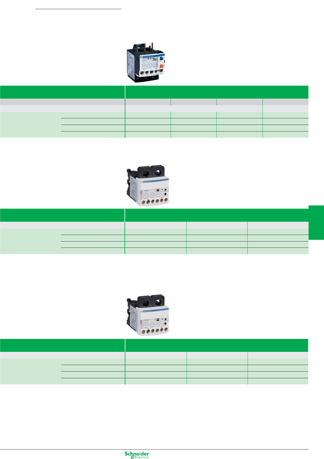
Other versions: please consult your Schneider Electric agency.
Relay type Electronic overcurrent relays
TeSys LR97D
Relay setting range 0.3…1.5 A 1.2…7 A 5…25 A 20…38 A
For use with contactor LC1D09…D38 LC1D25…D38
References 200… 240 VAC LR97D015M7 LR97D07M7 LR97D025M7 LR97D038M7
100… 120 VAC LR97D015F7 LR97D07F7 LR97D025F7 LR97D038F7
24 VAC/DC LR97D015B LR97D07B LR97D025B LR97D038B
48 VAC/DC LR97D015E LR97D07E LR97D025E LR97D038E
0.5…60 A
Relay type Electronic overcurrent relays
TeSys LT47 with manual reset
Relay setting range 0.5…6 A 3…30 A 5…60 A
References 200… 240 VAC LT4706M7S LT47D30M7S LT4760M7S
100… 120 VAC LT47D06F7S LT47D30F7S LT4760F7S
24 VAC/DC LT47D06BS LT47D30BS LT4760BS
48 VAC/DC LT47D06ES LT47D30ES LT4760ES
Relay type Electronic overcurrent relays
TeSys LT47 with automatic reset
Relay setting range 0.5…6 A 3…30 A 5…60 A
References 200… 240 VAC LT4706M7A LT47D30M7A LT4760M7A
100… 120 VAC LT47D06F7A LT47D30F7A LT4760F7A
24 VAC/DC LT47D06BA LT47D30BA LT4760BA
48 VAC/DC LT47D06EA LT47D30EA LT4760EA
Accessories: please consult your Schneider Electric agency.
TeSys
LR/LT
Electronic overcurrent relays
0.3…38 A
5/29
2
1
3
4
5
6
7
8
9
10
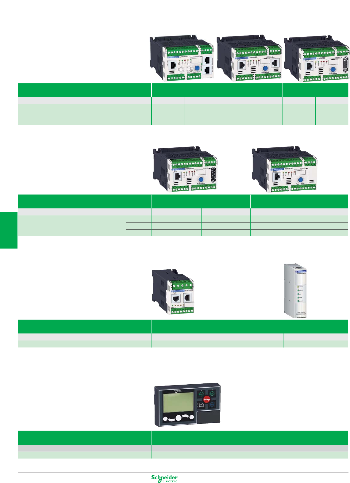
Other versions: please consult your Schneider Electric agency.
Type of fieldbus Ethernet Modbus Profibus DP
Supply voltage 24 VDC 100…240 VAC 24 VDC 100…240 VAC 24 VDC 100…240 VAC
References Current range 0.4…8 A LTMR08EBD LTMR08EFM LTMR08MBD LTMR08MFM LTMR08PBD LTMR08PFM
1.35…27 A LTMR27EBD LTMR27EFM LTMR27MBD LTMR27MFM LTMR27PBD LTMR27PFM
5…100 A LTMR100EBD LTMR100EFM LTMR100MBD LTMR100MFM LTMR100PBD LTMR100PFM
Type of fieldbus CANopen DeviceNet
Supply voltage 24 VDC 100…240 VAC 24 VDC 100…240 VAC
References Current range 0.4…8 A LTMR08CBD LTMR08CFM LTMR08DBD LTMR08DFM
1.35…27 A LTMR27CBD LTMR27CFM LTMR27DBD LTMR27DFM
5…100 A LTMR100CBD LTMR100CFM LTMR100DBD LTMR100DFM
Extension module
Type of module Extension
4 additional inputs + voltage measuring
Ethernet external port
Modbus RTU / Modbus TCP/IP
Inputs voltage 24 VDC 100…240 VAC 24 VDC
References LTMEV40BD LTMEV40FM TCSEQM113M13M
Control unit
Type of terminal Compact display
Supply voltage 24 VDC
Reference LTMCU
Motor management system
Controllers
TeSys T
5/30
2
1
3
4
5
6
7
8
9
10
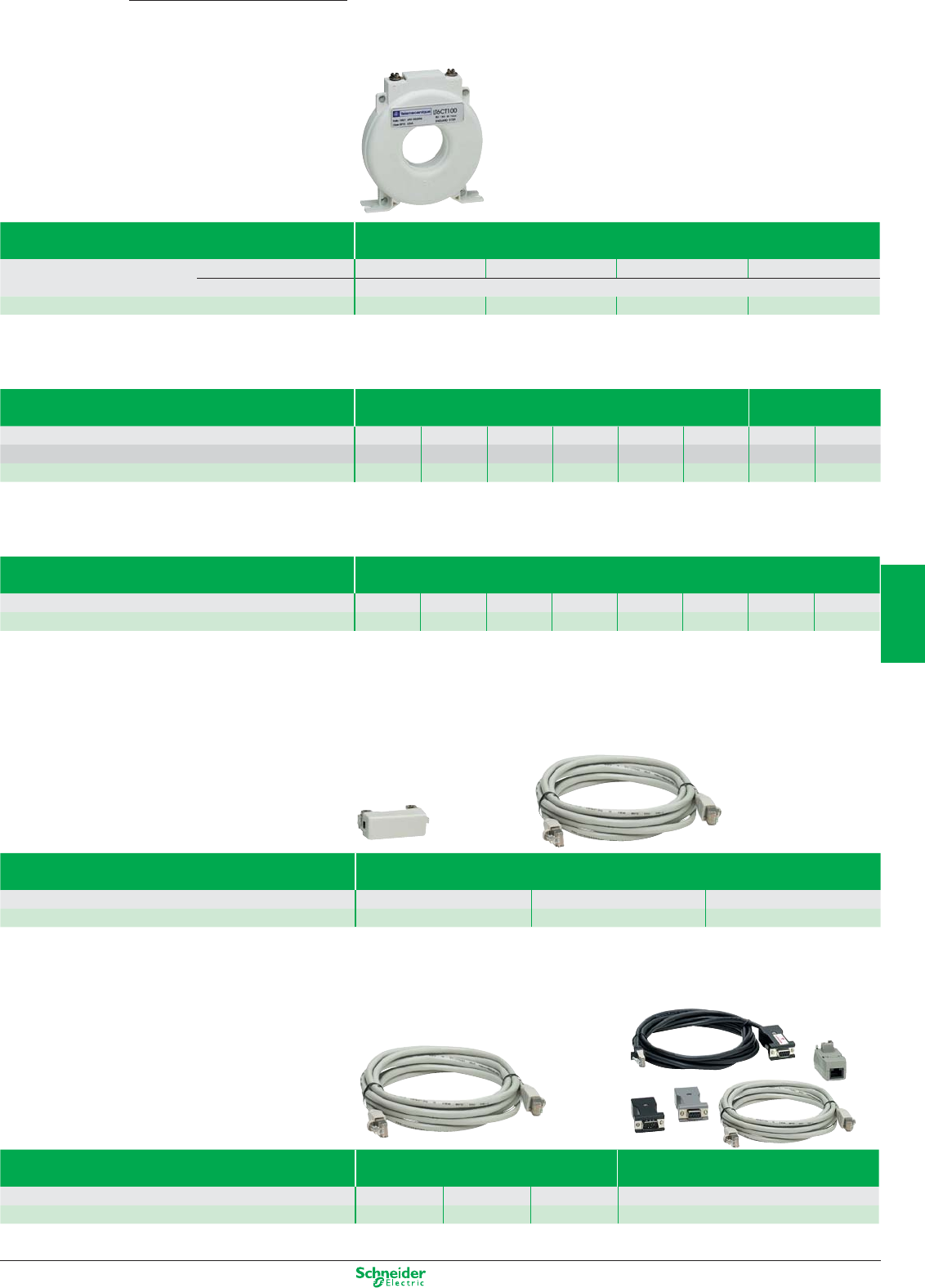
Other versions: please consult your Schneider Electric agency.
Type of transformer External
Operational current primary 100 A 200 A 400 A 800 A
secondary 1 A
References LT6CT1001 LT6CT2001 LT6CT4001 LT6CT8001
Earth fault toroids
Type of toroid Closed Split
Maximum current 65 A 85 A 160 A 250 A 400 A 630 A 85 A 250 A
Internal diameter Ø 30 Ø 50 Ø 80 Ø 120 Ø 200 Ø 300 Ø 46 Ø 110
References TA30 PA50 IA80 MA120 SA200 GA300 POA GOA
PTC thermistor probe
Type of probe Triple
Operating temperature 90°C 110°C 120°C 130°C 140°C 150°C 160°C 170°C
References DA1TT090 DA1TT110 DA1TT120 DA1TT130 DA1TT140 DA1TT150 DA1TT160 DA1TT170
Accessories (1)
Type of accessory Connecting cable
Controller / Extension module
Length of cable 0.04 m 0.3 m 1 m
References LTMCC004 LU9R03 LU9R10
Type of accessory Connecting cable
Controller/ Display
Connection kit
PC serial port
Length of cable 1 m 3 m 5 m –
References VW3A1104R10 VW3A1104R30 VW3A1104R50 VW3A8106
(1) For other connection accessories, see www.schneider-electric.com
Motor management system
Current transformers
TeSys T
5/31
2
1
3
4
5
6
7
8
9
10
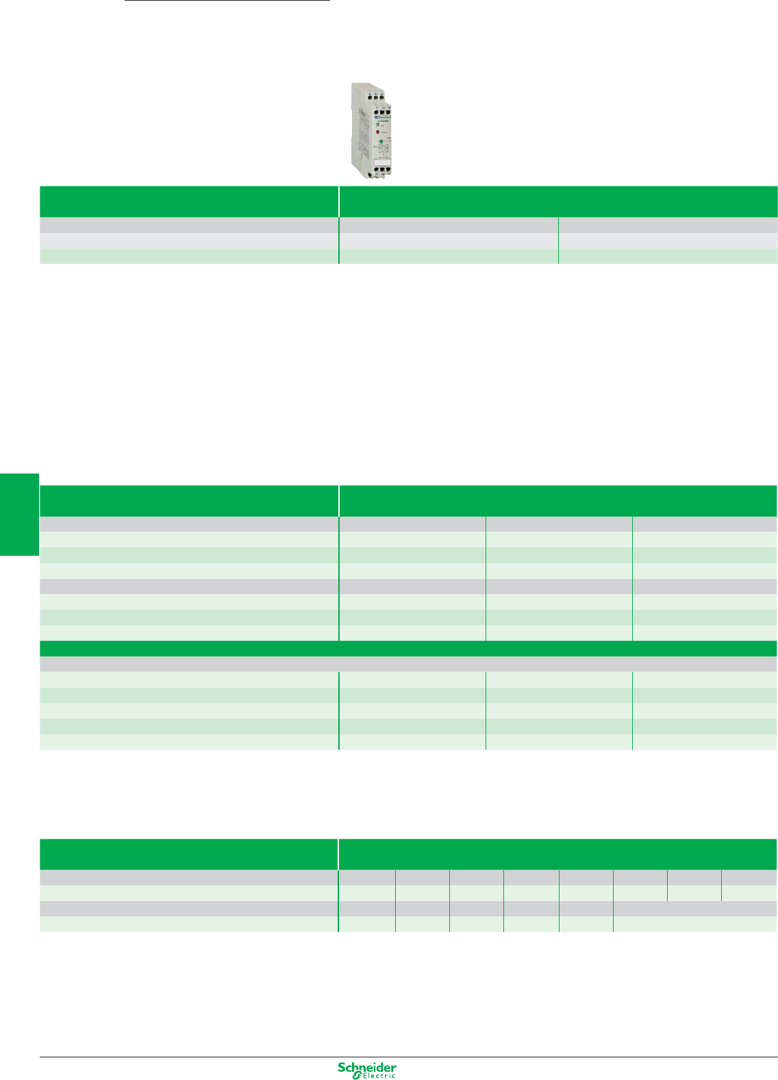
Other versions: please consult your Schneider Electric agency.
TeSys
LT3, LT6
Electronic protection relays for use
with PTC thermistor probes
0…800 A
Relay type
PTC thermistor probes
For use with contactor LC1-D or LC1-F LC1-D or LC1-F
Motor current No limit 1…5 A
Basic reference, to be completed LT3-S LT6-P0M0•5FM
Protection unit
Type with automatic reset with thermistor short-circuit detection
without fault memory
Connection Voltage Output contact Reference
by cage connectors a 50/60 Hz 115 V N/C LT3-SE00F
230 V N/C LT3-SE00M
c24 V N/C LT3-SE00F
On front panel: fault and voltage signalling indicator
a 50/60 Hz 115/230 V N/C + N/O LT3-SA00M
c24/48 V N/C + N/O LT3-SA00ED
a 50/60 Hz or c24…230 V 2 C/O LT3-SA00MW
with fault memory
On front panel: fault and voltage signalling indicator, Test and Reset button
a 50/60 Hz 400 V N/C + N/O LT3-SM00V
24/48 V N/C + N/O LT3-SM00E
115/230 V N/C + N/O LT3-SM00M
c24/48 V N/C + N/O LT3-SM00ED
a 50/60 Hz or c24…230 V 2 C/O LT3-SM00MW
Accessories
Type PTC thermistor probes for LT3 relays
Normal operating temperature (NOT) 90 °C 110 °C 120 °C 130 °C 140 °C 150 °C 160 °C 170 °C
Integrated triple probes DA1-TT090 DA1-TT110 DA1-TT120 DA1-TT130 DA1-TT140 DA1-TT150 DA1-TT160 DA1-TT170
Normal operating temperature (NOT) 60 °C 70 °C 80 °C 90 °C 100 °C
Surface probes DA1-TS060 DA1-TS070 DA1-TS080 DA1-TS090 DA1-TS100
5/32
2
1
3
4
5
6
7
8
9
10
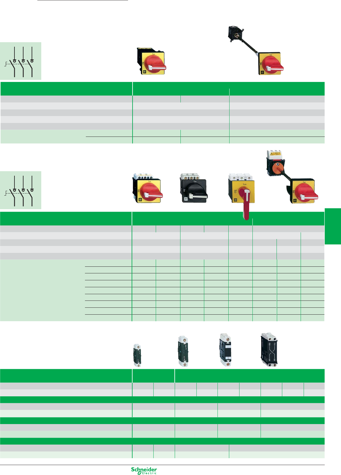
Other versions: please consult your Schneider Electric agency.
1/L12/T1
3/L24/T2
5/L36/T3
1/L12/T1
3/L24/T2
5/L36/T3
1/L12/T1
3/L24/T2
5/L36/T3
1/L12/T1
3/L24/T2
5/L36/T3
Switch disconnectors
12…175 A
Type
Mini-Vario for standard applications
Door mounting
Backplate mounting in enclosure
Colour: Handle /
Front plate
Red / Yellow Black / Black Red / Yellow
Front plate dimensions (mm)
60 x 60 60 x 60
Fixing
Ø 22.5 mm Ø 22.5 mm
Degree of protection
IP 20 IP 20
Rated insulation voltage (Ui) 690 V 690 V
Thermal current in open air (Ith)
12 A VCDN12 VBDN12 VCCDN12
20 A VCDN20 VBDN20 VCCDN20
Type Vario for high performance applications
Door mounting
Backplate mounting in enclosure
Colour: Handle /
Front plate
Red / Yellow Black / Black Red / Yellow Black / Black Red / Yellow Red / Yellow
Front plate dimensions (mm)
60 x 60 60 x 60 90 x 90 60 x 60 90 x 90
Fixing
Ø 22.5 mm 4 screws 4 screws Ø 22.5 mm 4 screws 4 screws
Degree of protection
IP 20 IP 20 IP 20 IP 20 IP 20 IP 20
Rated insulation voltage (Ui) 690 V 690 V 690 V 690 V 690 V 690 V
Thermal current in open air (Ith)
12 A VCD02 VBD02 VCF02 VBF02 – VCCD02 VCCF02 –
20 A VCD01 VBD01 VCF01 VBF01 – VCCD01 VCCF01 –
25 A VCD0 VBD0 VCF0 VBF0 – VCCD0 VCCF0 –
32 A VCD1 VBD1 VCF1 VBF1 – VCCD1 VCCF1 –
40 A VCD2 VBD2 VCF2 VBF2 – VCCD2 VCCF2 –
63 A – – VCF3 VBF3 – – VCCF3 –
80 A – – VCF4 VBF4 – – VCCF4 –
125 A –– –– VCF5 – – VCCF5
175 A –– –– VCF6 – – VCCF6
Add-on modules For mini-Vario For Vario
Main pole modules
Switch rating 12 A 20 A 12 A 20 A 25 A 32 A 40 A 63 A 80 A
References VZN12 VZN20 VZ02 VZ01 VZ0 VZ1 VZ2 VZ3 VZ4
Neutral pole module with early make and late break contacts
Switch rating 12…20 A 12…40 A 63 and 80 A 125 and 175 A
References VZN11 VZ11 VZ12 VZ13
Earthing module
Switch rating 12…20 A 12…40 A 63 and 80 A 125 and 175 A
References VZN14 VZ14 VZ15 VZ16
Auxiliary contact block modules
Contact type N/O N/C N/O + N/C N/O + N/O
References VZN05 VZN06 VZ7 VZ20
TeSys
Vario
5/33
2
1
3
4
5
6
7
8
9
10
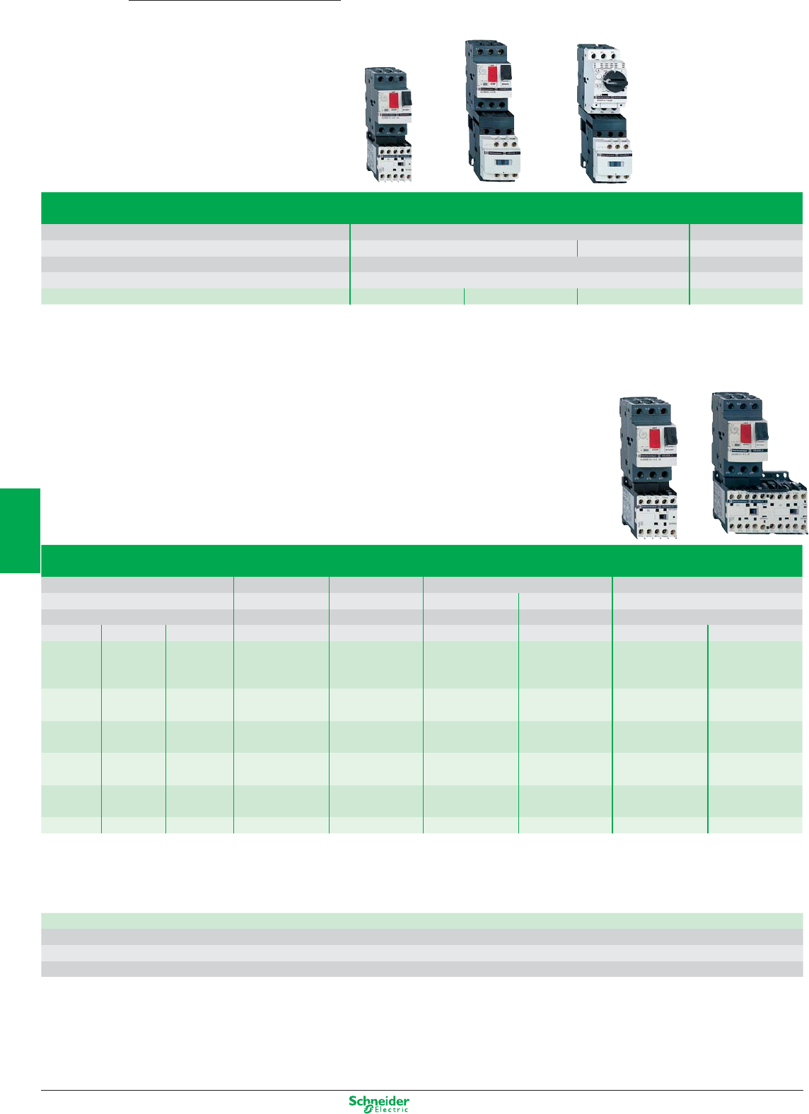
Other versions: please consult your Schneider Electric agency.
Starters GV2-ME
Non-reversing Reversing
Standard power ratings Setting Fixed For customer assembly Factory assembled
of 3-phase motors range of magnetic Motor Contactor Basic reference, to be completed with
50/60 Hz in category AC-3 (kW) thermal trips tripping current circuit-breaker code indicating control circuit voltage
400/415 V 440 V 500 V 13 Irth
0.37 0.37 0.37 1…1.6 22.5 GV2-ME06 LC1-K06 GV2-ME06K1•• GV2-ME06K2••
0.55 0.55 0.55
- - 0.75
0.75 0.75 - 1.6…2.5 33.5 GV2-ME07 LC1-K06 GV2-ME07K1•• GV2-ME07K2••
-1.11.1
1.1 - 1.5 2.5…4 51 GV2-ME08 LC1-K06 GV2-ME08K1•• GV2-ME08K2••
1.5 1.5 2.2
2.2 2.2 - 4…6.3 78 GV2-ME10 LC1-K06 GV2-ME10K1•• GV2-ME10K2••
-- 3
3 - 4 6…10 138 GV2-ME14 LC1-K09 GV2-ME14K1•• GV2-ME14K2••
4 4 5.5
5.5 5.5 7.5 9…14 170 GV2-ME16 LC1-K12 GV2-ME16K1•• GV2-ME16K2••
TeSys
GV2, LC
Combination motor starters
0.06…15 kW
D.O.L. starters
with circuit-breaker with fuse protection
Level of service Coordination: Type 1 Type 2
Power at 400 V Up to: 5.5 kW 15 kW 37 kW
Type of components Combination automatic motor starter with overload protection Fuse carrier +
incorporated in the circuit-breaker plate-mounted contactor
Basic reference, to be completed GV2-ME GV2-DM GV2-DP LC4-D
Standard control circuit voltages (for other voltages, please consult your Regional Sales Office)
Volts 24 110 220/230 230 230/240 380/400
a 50…400 Hz B7 F7 M7 P7 U7 Q7
c (1) BW3 - - - - -
(1) Low consumption coil (1.5 W), wide range (0.7…1.3 Uc) and with integral suppression device as standard.
5/34
2
1
3
4
5
6
7
8
9
10
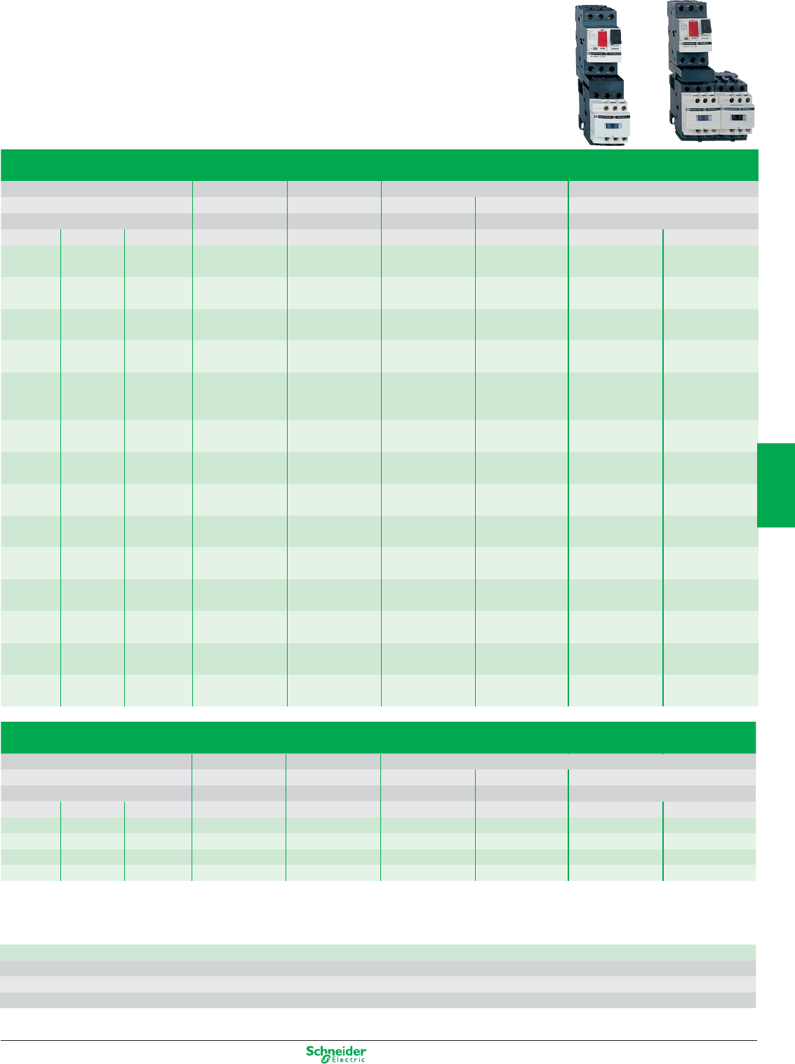
Other versions: please consult your Schneider Electric agency.
D.O.L. starters GV2-DM and GV3-DP
Non-reversing Reversing
Standard power ratings Setting Fixed For customer assembly Factory assembled
of 3-phase motors range of magnetic Motor Contactor Basic reference, to be completed with
50/60 Hz in category AC-3 (kW) thermal trips tripping current circuit-breaker code indicating control circuit voltage
400/415 V 440 V 500 V 13 Irth
0.06 0.06 - 0.16…0.25 2.4 GV2-ME02 LC1-D09•• GV2-DM102•• GV2-DM202••
GV2-P02 LC1-D09•• GV2-DP102•• GV2-DP202••
0.09 0.09 - 0.25…0.40 5 GV2-ME03 LC1-D09•• GV2-DM103•• GV2-DM203••
- 0.12 - GV2-P03 LC1-D09•• GV2-DP103•• GV2-DP203••
0.12 - - 0.40…0.63 8 GV2-ME04 LC1-D09•• GV2-DM104•• GV2-DM204••
0.18 0.18 - GV2-P04 LC1-D09•• GV2-DP104•• GV2-DP204••
0.25 0.25 - 0.63…1 13 GV2-ME05 LC1-D09•• GV2-DM105•• GV2-DM205••
0.37 0.37 - GV2-P05 LC1-D09•• GV2-DP105•• GV2-DP205••
- - 0.37 1…1.6 22.5 GV2-ME06 LC1-D09•• GV2-DM106•• GV2-DM206••
0.55 0.55 0.55 GV2-P06 LC1-D09•• GV2-DP106•• GV2-DP206••
- - 0.75
0.75 0.75 - 1.6…2.5 33.5 GV2-ME07 LC1-D09•• GV2-DM107•• GV2-DM207••
- 1.1 1.1 GV2-P07 LC1-D09•• GV2-DP107•• GV2-DP207••
1.1 - 1.5 2.5…4 51 GV2-ME08 LC1-D09•• GV2-DM108•• GV2-DM208••
1.5 1.5 2.2 GV2-P08 LC1-D09•• GV2-DP108•• GV2-DP208••
2.2 2.2 - 4…6.3 78 GV2-ME10 LC1-D09•• GV2-DM110•• GV2-DM210••
- 3 3 GV2-P10 LC1-D09•• GV2-DP110•• GV2-DP210••
3 - 4 6…10 138 GV2-ME14 LC1-D09•• GV2-DM114•• GV2-DM214••
4 4 5.5 GV2-P14 LC1-D09•• GV2-DP114•• GV2-DP214••
5.5 5.5 7.5 9…14 170 GV2-ME16 LC1-D12•• GV2-DM116•• GV2-DM216••
- 7.5 9 GV2-P16 LC1-D25•• GV2-DP116•• GV2-DP216••
7.5 9 - 13…18 223 GV2-ME20 LC1-D18•• GV2-DM120•• GV2-DM220••
GV2-P20 LC1-D25•• GV2-DP120•• GV2-DP220••
9 11 11 17…23 327 GV2-ME21 LC1-D25•• GV2-DM121•• GV2-DM221••
GV2-P21 LC1-D25•• GV2-DP121•• GV2-DP221••
11 - 15 20…25 327 GV2-ME22 LC1-D25•• GV2-DM122•• GV2-DM222••
GV2-P22 LC1-D25•• GV2-DP122•• GV2-DP222••
15 15 18.5 24…32 416 GV2-ME32 LC1-D32•• GV2-DM132•• GV2-DM232••
GV2-P32 LC1-D32•• GV2-DP132•• GV2-DP232•
Standard control circuit voltages (for other voltages, please consult your Regional Sales Office)
Volts 24 220 230
a 50…400 Hz B7 M7 P7
c (3) BD ––
(3) Low consumption coil, wide range (0.7 to 1.25 Uc) and with suppression device as standard (bidirectional peak limiting diode).
D.O.L. starters GV3 + LC1D
Non-reversing Reversing
Standard power ratings Setting Fixed For customer assembly
of 3-phase motors range of magnetic Motor Contactor Reference of accessory to be ordered
50/60 Hz in category AC-3 (kW) thermal trips tripping current circuit-breaker for assembly of motor starter (2)
400/415 V 440 V 500 V 13 Irth
18,5 18,5 – 30…40 560 GV3-P401 (1) LC1-D40A•• – LAD9R3
– 22 22 30…40 560 GV3-P401 (1) LC1-D40A•• – LAD9R3
22 – 30 37…50 700 GV3-P501 (1) LC1-D50A•• – LAD9R3
30 30 37 48…65 910 GV3-P651 (1) LC1-D65A•• – LAD9R3
(1) Circuit-breaker GV3P without downstream EverLink terminal block. A standard GV3P can also be used by removing the downstream terminal block.
(2) For side by side circuit-breaker/contactor mounting, order accessory GV3S.
5/35
2
1
3
4
5
6
7
8
9
10
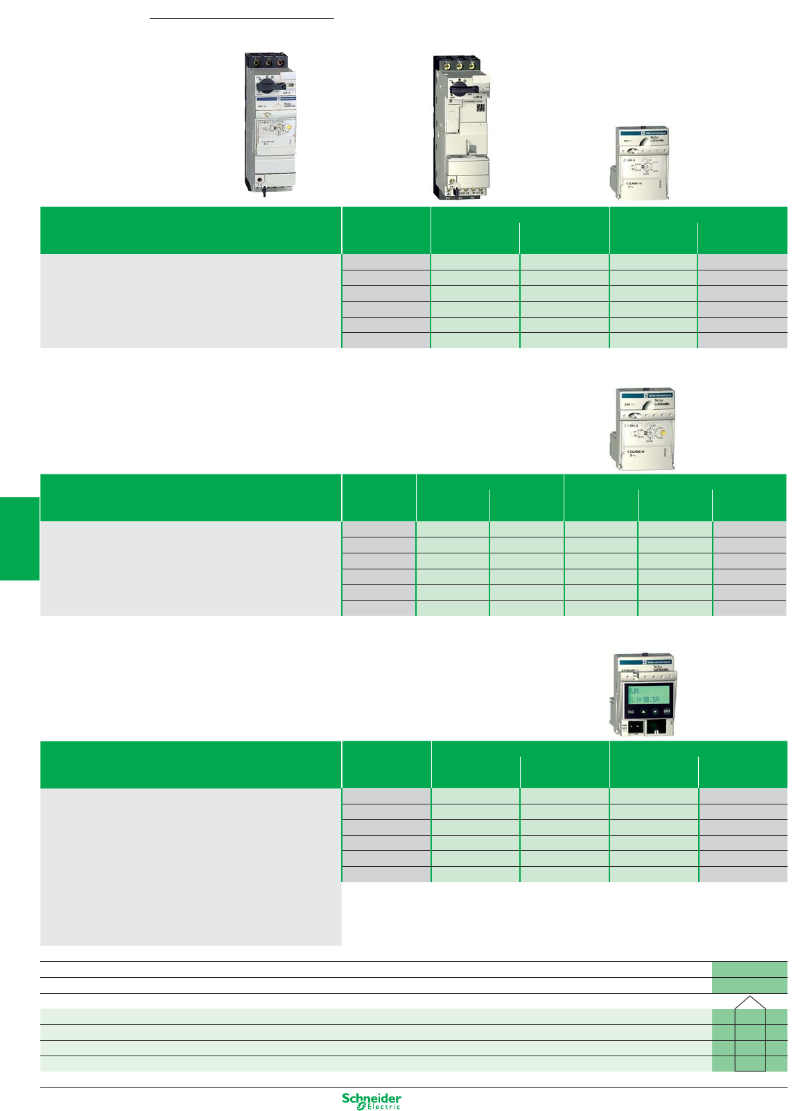
Other versions: please consult your Schneider Electric agency.
=+
ADVANCED motor starter
MULTIFUNCTION motor starter
TeSys UStarter-controller for 3-phase motors
STANDARD motor starter
Function characteristics, LUB… + LUCA… Maximum Power base Standard control unit
motor power Non-reversing Reversing Class 10 Setting range
< 400/415 V (1) (2)
- Thermal overload protection against: 0.09 kW LUB12 LU2B12pp LUCA6Xpp 0.15…0.6 A
short-circuit, overcurrent, 0.25 kW LUB12 LU2B12pp LUCA1Xpp 0.35…1.4 A
phase failure or imbalance, 1.5 kW LUB12 LU2B12pp LUCA05pp 1.25…5 A
insulation breaks (equipment only). 5.5 kW LUB12 LU2B12pp LUCA12pp 3…12 A
- Manual reset following thermal fault. 7.5 kW LUB32 LU2B32pp LUCA18pp 4.5…18 A
15 kW LUB32 LU2B32pp LUCA32pp 8…32 A
Function characteristics, LUB… + LUCA… Maximum Power base Advanced control unit
motor power
Non-reversing Reversing Class 10 Class 20 Setting range
< 400/415 V (1) (2) (3) (2)
- Thermal overload protection against: 0.09 kW LUB12 LU2B12pp LUCB6Xpp LUCD6Xpp 0.15…0.6 A
short-circuit, overcurrent, 0.25 kW LUB12 LU2B12pp LUCB1Xpp LUCD1Xpp 0.35…1.4 A
phase failure or imbalance, 1.5 kW LUB12 LU2B12pp LUCB05pp LUCD05pp 1.25…5 A
insulation breaks (equipment only). 5.5 kW LUB12 LU2B12pp LUCB12pp LUCD12pp 3…12 A
- Manual reset following thermal fault. 7.5 kW LUB32 LU2B32pp LUCB18pp LUCD18pp 4.5…18 A
- Thermal overload test function. 15 kW LUB32 LU2B32pp LUCB32pp LUCD32pp 8…32 A
(3) For single-phase-motors, replace LUCBpppp by LUCCpppp.
Function characteristics, LUB… + LUCA…
- Thermal overload protection against:
short-circuit, overcurrent,
phase failure or imbalance,
insulation breaks (equipment only).
- Manual, automatic or remote reset,
- Thermal overload test function,
- Overtorque and no-load running, alarm,
- Motor operation log,
- Motor parameters display on LUCM.., PC or HMI,
- Integrated Modbus communication.
Maximum Power base Multifunction control unit
motor power
Non-reversing Reversing Class 5 to 30 Setting range
< 400/415 V (1)
0.09 kW LUB12 LU2B12pp LUCM6XBL 0.15…0.6 A
0.25 kW LUB12 LU2B12pp LUCM1XBL 0.35…1.4 A
1.5 kW LUB12 LU2B12pp LUCM05BL 1.25…5 A
5.5 kW LUB12 LU2B12pp LUCM12BL 3…12 A
7.5 kW LUB32 LU2B32pp LUCM18BL 4.5…18 A
15 kW LUB32 LU2B32pp LUCM32BL 8…32 A
(1) Complete the references of the power bases according to the following table. Example: LU2B12 pp
(2) Complete the references of the control units according to the following table. Example: LUCA/B/D/M6X pp
Standard control circuit voltages
24 V DC BL
24 V AC B
48 V AC / 48…72 V DC ES
110…240 V AC / 110…220 V DC FU
5/36
2
1
3
4
5
6
7
8
9
10
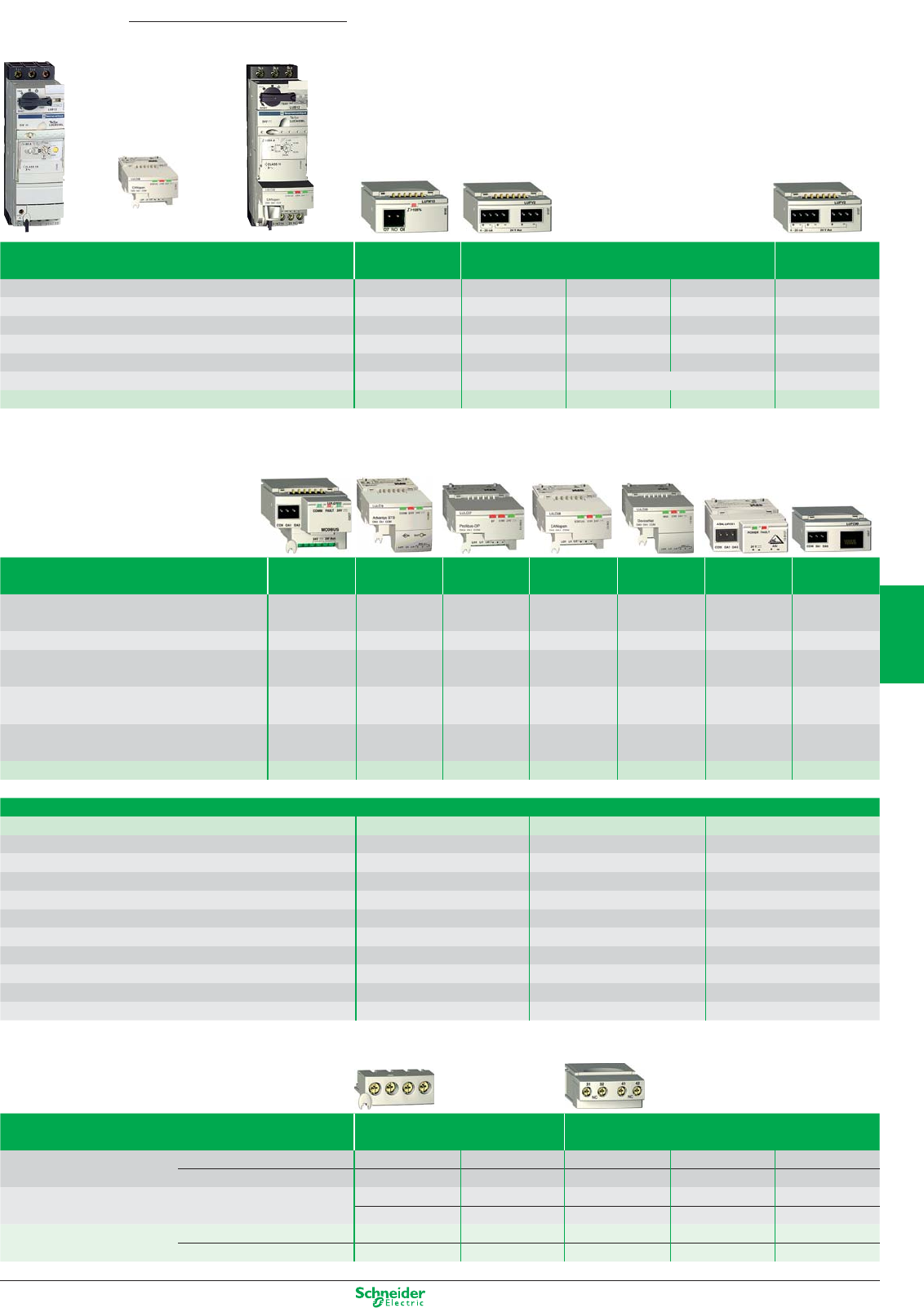
Other versions: please consult your Schneider Electric agency.
=
+
Communication modules
Contact blocks
TeSys UStarter-controller for 3-phase motors
Function modules
Type of optional function
Thermal
Thermal fault signalling Motor load
overload alarm
indication
Compatible with LUCA NO NO NO NO NO
Compatible with LUCL NO NO NO NO NO
Compatible with LUCB, LUCD YES YES YES YES YES
Compatible with LUCM NO NO NO NO YES
Output signal 1 NO 1 NO +1 NC 1 NC 1 NO 4…20 mA
Reset NA Manual Automatic or remote NA
References LUFW10 LUFDH11 LUFDA01 LUFDA10 LUFV2
Type of communication Modbus Advantys Profibus DP CANopen DeviceNet AS-Interface Parallel
STB wiring
Only compatible with 24 V DC control units YES YES YES YES YES YES YES
LUCA..BL, LUCB..BL, LUCD..BL, LUCM..BL
Transfer speed 19.2 Kbps Dpg. on NIM (1) 9.6…12 Mbps 20 K…1 Mbps
125…500 Kbaud
167 Kbps NA
Number of slaves 31 per Modbus
Dpg. on Network
125 per Profibus DP
128 per CANopen 63 per DeviceNet
62 per AS-Interface
8 per LU9GC02
master
Interface Module
module module module master splitter box
Pre-wired coil connection (A1 A2) LU9BN11C, LU9BN11L, LU9BN11L, LU9BN11L, LU9BN11L, LU9BN11C, LU9Rxx
LU9MRC LU9MRL LU9MRL LU9MRL LU9MRL LU9MRC
Connecting cable to PC
VW3 A8 306 Rpp
LU9RCDpp, TSXPBSCApp TSXCANCpp DeviceNet XZCG0142 TSXCDPppp
LU9RDDpp standard
References LUFC033 LULC15 LULC07 LULC08 LULC09 ASILUFC51 LUFC00
(1) Network Interface Module.
Information carried by the Modbus, Advantys STB or CANopen bus
Type of control unit LUCAppBL LUCBppBL, LUCDppBL LUCMppBL
Start and Stop commands XX X
Starter status (ready, running, fault) XX X
Thermal alarm XX
Remote reset via the bus XX
Indication of motor load XX
Signalling and fault differentiation XX
Alarms (overcurrent, …) X
Remote programming and monitoring of all the functions X
“Log” function X
Monitoring function X
Type of contact block Add-on Auxiliary
Signalling contacts of any fault NC (95-96) NO (97-98) – – –
position of control handle NO (17-18) NO (17-18) – – –
2 auxiliary contacts module – – NO (33-34) NC (31-32) NC (31-32)
– – NO (43-44) NO (43-44) NC (41-42)
References Screw clamp terminals LUA1C11 LUA1C20 LUFN20 LUFN11 LUFN02
Without connections LUA1C110 LUA1C200 –––
5/37
2
1
3
4
5
6
7
8
9
10
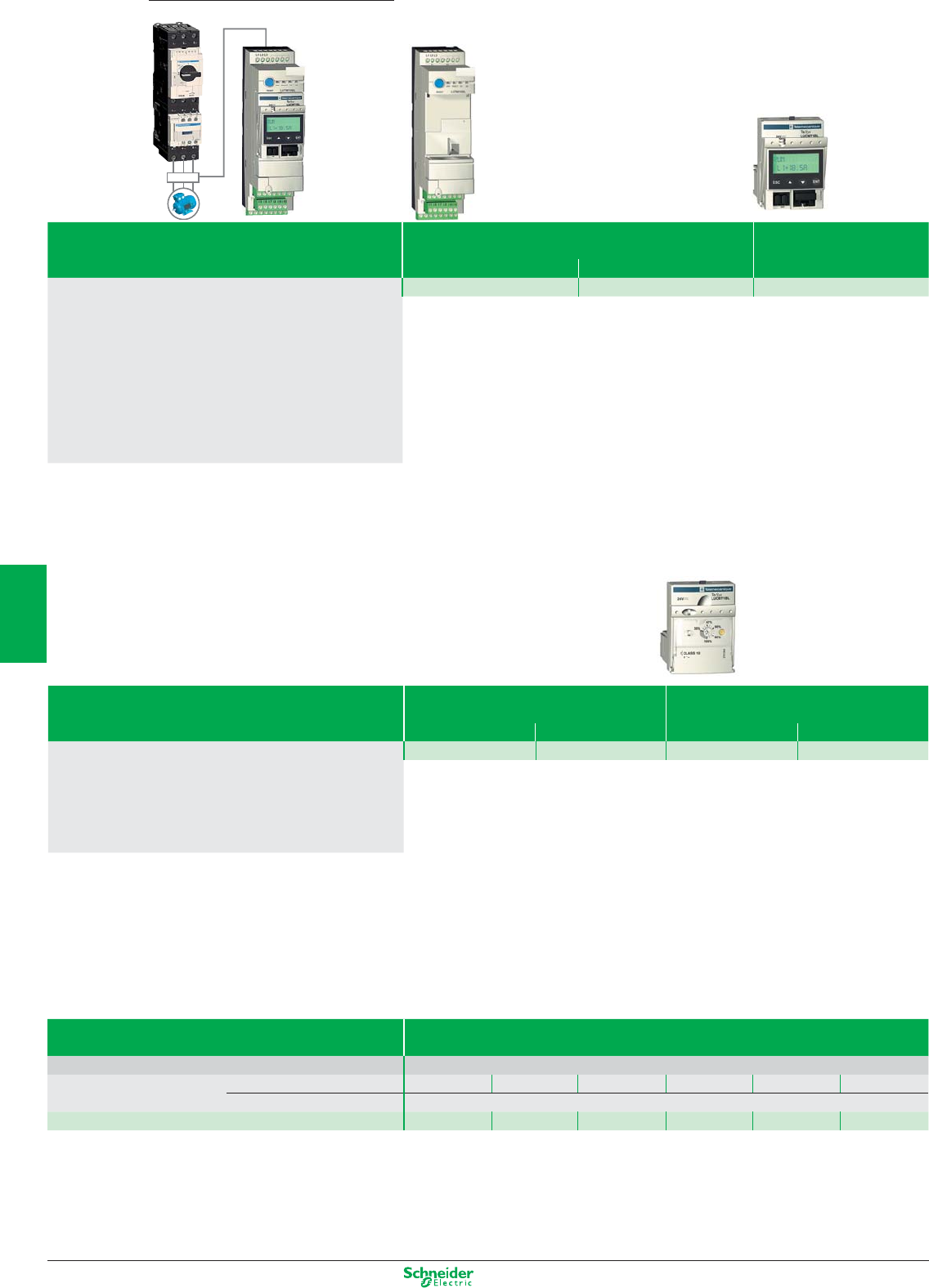
Other versions: please consult your Schneider Electric agency.
=+
TeSys GV3L
TeSys LC1D
Contactor
Circuit-breakers
TeSys GV3L
TeSys LC1D
Contactor
Circuit-breakers
ADVANCED protection
Current transformers
TeSys
LUTM
Controller for 3-phase motors
MULTIFUNCTION protection
Function characteristics Control base for use Multifunction
with contactors control unit
TeSys D (LC1D..) TeSys F (LC1F..) Class 5 to 35
- Thermal overload protection against: LUTM10BL LUTM20BL LUCMT1BL
short-circuit, overcurrent,
phase failure or imbalance,
insulation breaks (equipment only).
- Manual, automatic or remote reset,
- Thermal overload test function,
- Overtorque and no-load running, alarm,
- Motor operation log,
- Motor parameters display on LUCM.., PC or HMI,
- Integrated Modbus communication.
Function characteristics Control base for use Advanced
with contactors control unit
TeSys D (LC1D..) TeSys F (LC1F..) Class 10 Class 20
- Thermal overload protection against: LUTM10BL LUTM20BL LUCBT1BL LUCDT1BL
short-circuit, overcurrent,
phase failure or imbalance,
insulation breaks (equipment only).
- Manual reset following thermal fault.
- Thermal overload test function.
Type of transformer
Supply voltage 24 V DC
Operating current Primary 30 A 50 A 100 A 200 A 400 A 800 A
Secondary 1 A
References LUTC0301 LUTC0501 LUTC01001 LUTC02001 LUTC04001 LUTC05001
Above 32 A, the TeSys U controller provides a motor starter management system solution identical to that provided by the TeSys U starter-controller.
Used in conjunction with a short-circuit protection device and a contactor, it provides a motor starter whose functions are the same as those of a TeSys U starter-controller
and, in particular, provides the following functions: overload protection, motor starter control and application monitoring.
It comprises a control unit, whose adjustment range is compatible with the secondary of current transformers, and a control base that also enables the fitting of a function module or
communication module.
It requires a 24 V DC external power supply.
5/38
2
1
3
4
5
6
7
8
9
10
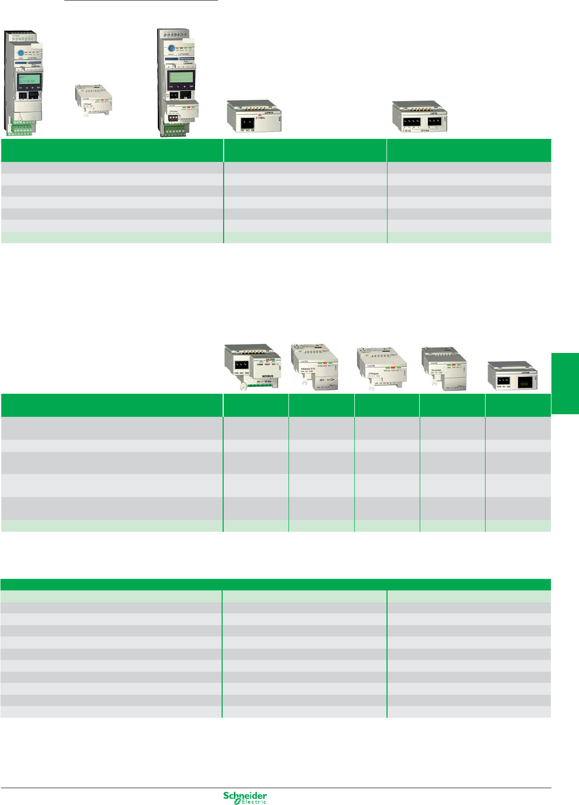
Other versions: please consult your Schneider Electric agency.
=
+
Communication modules
TeSys
LUTM
Controller for 3-phase motors
Function modules
Type of optional function Thermal overload alarm Motor load indication
Compatible with LUCA NO NO
Compatible with LUCL NO NO
Compatible with LUCB, LUCD YES YES
Compatible with LUCM NO YES
Output signal 1 NO 4…20 mA
Reset NA NA
References LUFW10 LUFV2
Type of communication Modbus Advantys STB CANopen DeviceNet Parallel
wiring
Only compatible with 24 V DC control units YES YES YES YES YES
LUCA..BL, LUCB..BL, LUCD..BL, LUCM..BL
Transfer speed 19.2 Kbps Dpg. on NIM (1) 20 K…1 Mbps
125…500 Kbaud
NA
Number of slaves 31 per Modbus Dpg. on Network 128 per CANopen
63 per DeviceNet
8 per LU9GC02
master Interface Module module module splitter box
Pre-wired coil connection (A1 A2) LU9BN11C, LU9BN11L, LU9BN11L, LU9BN11L, LU9Rxx
LU9MRC LU9MRL LU9MRL LU9MRL
Connecting cable to PC VW3 A8 306 Rpp LU9RCDpp TSXCANCpp DeviceNet TSXCDPppp
LU9RDDpp standard
References LUFC033 LULC15 LULC08 LULC09 LUFC00
Information carried by the Modbus, Advantys STB or CANopen bus
Type of control unit LUCBT1BL, LUCDT1BL LUCMT1BL
Start and Stop commands XX
Starter status (ready, running, fault) XX
Thermal alarm XX
Remote reset via the bus XX
Indication of motor load XX
Signalling and fault differentiation XX
Alarms (overcurrent, …) X
Remote programming and monitoring of all the functions X
“Log” function X
Monitoring function X
5/39
2
1
3
4
5
6
7
8
9
10
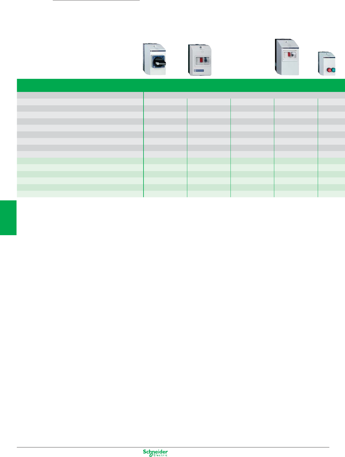
Other versions: please consult your Schneider Electric agency.
Starters
N D.O.L.
N standard
Standard power ratings of 3-phase motors in category AC3 400/415 V 4…37 kW 0.06…37 kW 0.55…30 kW 0.37…5.5 kW 0.25…45 kW
Starters manual LLL--
auto ---LL
Isolating device switch-disconnector-fuse L----
circuit-breaker -LLL-
fuse carrier -----
Protection short-circuit -LLL-
overload -L-LL
Communication -----
Basic reference Non-reversing V•F•GE GV2-ME GV2-LC LE1-GVME LE1-M
VCFN•GE GV3-PC GV-NGC LE1-D
V•FXGE• GV3-CE
Reversing LE2-K
LE2-D
TeSys Enclosed motor starters
0.06…132 kW
5/40
2
1
3
4
5
6
7
8
9
10
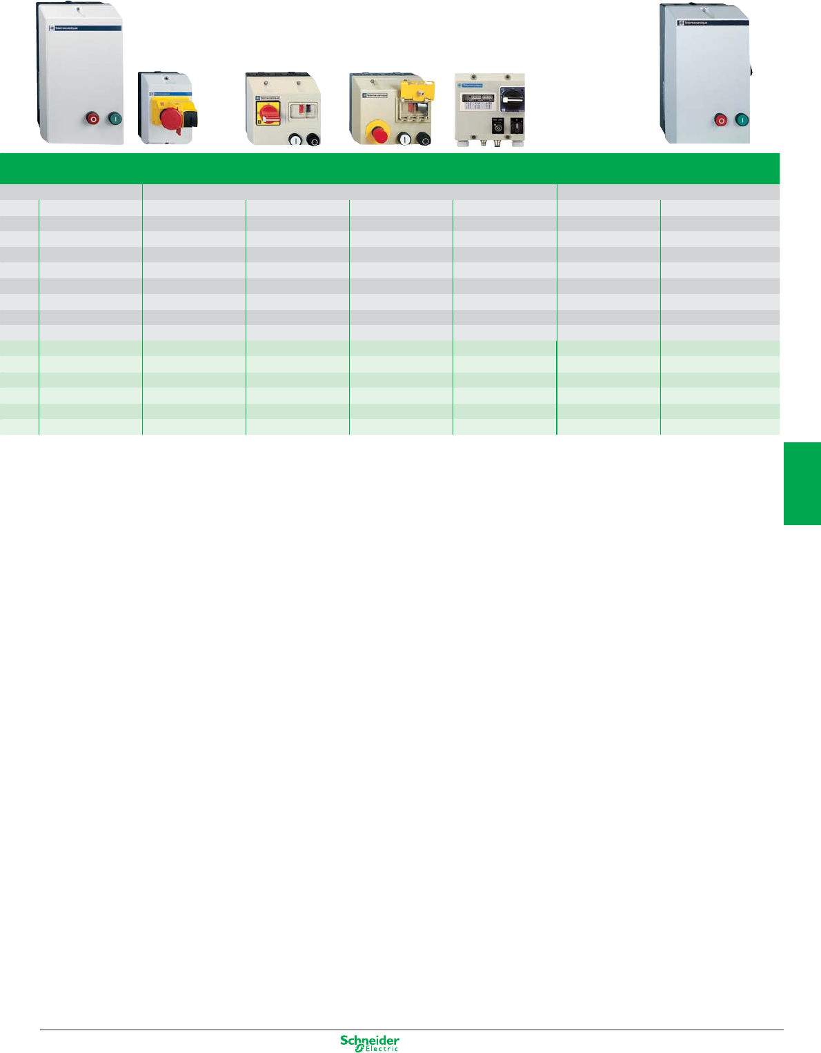
Other versions: please consult your Schneider Electric agency.
N 2 stage
N safety applications N AS-Interface bus standard star-delta
2.2…45 kW 0.06…11 kW 0.06…9 kW 0.06…9 kW 0.06…5.5 kW 5.5…132 kW 7.5…75 kW
-L-----
L-LLLLL
--L----
-LLLL--
L-----L
LLLLL-L
LLLLLLL
----L--
LE4-K GV2-ME LG1-K LG7-K LF3-M LE3-K LE6-D
LE4-D LG1-D LG7-D LF3-P LE3-D LE3-D
LJ7-K LF7-P LE3-F
LE8-K LG8-K LF4-M
LE8-D LJ8-K LF4-P
LE2-D LF8-P
5/41
2
1
3
4
5
6
7
8
9
10
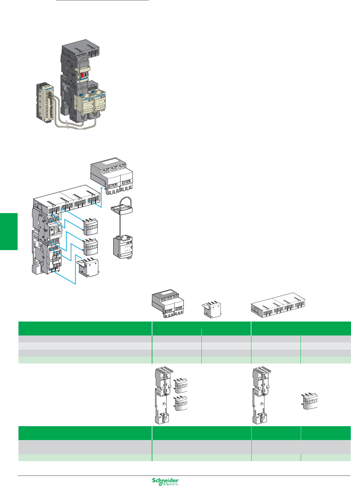
Other versions: please consult your Schneider Electric agency.
TeSys
Quickfit
Installation system
Presentation
TeSys Quickfit is a modular system which standardises and simplifies the implementation of motor start-
ers with its pre-wired control and power circuits.
Installation of a motor starter becomes quick, simple, safe and flexible.
In addition, this system:
b enables the motor starter to be customised at a later date,
b reduces maintenance time and
b optimises panel space by reducing the number of terminals and intermediate interfaces and the amount
of ducting.
The motor starters concerned are those created by combining:
– GV2 ME or GV3 P circuit-breakers, with an operating limit of 80% of the maximum current at an ambient
temperature of 60 °C, up to 690 V
– with 9 to 65 A TeSys D (LC1) contactors.
This offer comprises components for pre-wiring
b the power part,
b the control part.
Components for pre-wiring the power part
b a power kit comprising, for each starter, a plate for mounting the contactor and the circuit-breaker, and
two power connection modules,
b a power splitter box for 2 or 4 starters,
b an upstream terminal block for a power supply up to 60 A (16 mm
2
),
b a downstream terminal block for connecting the motor power supply cables and the earth cables
(6 mm
2
).
Components for pre-wiring the control part
b a control circuit connection module that mounts directly on the contactor and the circuit-breaker of
each starter. This module integrates the status and control information of this particular motor starter.
b a parallel wiring module enabling grouping of the information relating to each motor starter:
v HE 10, intended for centralised applications. The information is transmitted to the PLC via the Advantys
Telefast pre-wired system.
v STB, intended for decentralised automation architectures. This module is integrated in an Advantys STB
configuration for connection to the PLC via a fieldbus.
9…25 A power pre-wiring components
Type Terminal block 60 A power splitter box
Upstream Downstream Extension by LAD32p
Maximum c.s.a. of connection 16 mm
2
6 mm
2
––
Use Splitter boxes supply Motor cables – –
Number of starters ––24
Reference LAD3B1 LAD331 LAD322 LAD324
Type Connection kit Mounting plate for Power connection
For D.O.L. starter (1) GV2 ME & contactor module
Composition 1 mounting plate LAD311 for GV2ME For 1 motor starter
2 power connection modules LAD341
Reference LAD252 LAD311 LAD341
(1) For a reversing starter order 2 connection kits LAD252
5/42
2
1
3
4
5
6
7
8
9
10
Other versions: please consult your Schneider Electric agency.
Type Connection module
TeSys D coil voltage 12…250 V AC or 5…130 V DC 24 V DC
Type of coil control relay Electronic Without relay
Type of motor starter Direct Reversing Direct Reversing
Reference LAD9AP31 LAD9AP32 LAD9AP3D1 LAD9AP3D2
Type 24 V DC parallel wiring module
Splitter box Advantys STB parallel interface module
PLC/motor starter side connectors 2 x HE10/8 x RJ45 –/4 x RJ45
Reference LU9G02 STBEPI2145
Accessories
Type Connecting cables
(1) From splitter box LU9G02 to the PLC
Connectors 2 x RJ45 2 HE10 Bare wires and HE10
Gauge / c.s.a. – 22 / 0.324 mm
2
28 / 0.080 mm
2
22 / 0.324 mm
2
Reference L = 0.3 m LU9R03 –––
0.5 m – TSXCDP053 ––
1 m LU9R10 TSXCDP103 ABFH20H100 –
2 m – TSXCDP203 ABFH20H200 –
3 m LU9R30 TSXCDP303 ABFH20H300 TSXCDP301
5 m – TSXCDP503 –TSXCDP301
(1) From connection module LAD9AP3p to splitter box LU9G02 or module STBEPI2145
Type Connectors Connecting cable
Spring terminals Self-stripping
Use External contact, auxiliary power supply Between communication module APP1Cp and
splitter box LU9GG02
Reference APE1PRE21 APE1PAD21 APP2AH40H060
Control-command pre-wiring components
5/43
2
1
3
4
5
6
7
8
9
10

Other versions: please consult your Schneider Electric agency.
Sodium vapour lamps
N low pressure
Non-corrected With parallel compensation
P (W) 3- 55 90 135 150 180 200 35 55 90 135 150 180 200
IB (A) 1.2 1.6 2.4 3.1 3.2 3.3 3.4 0.3 0.4 0.6 0.9 1 1.2 1.3
C (µF) - - - - - - - 17 17 25 36 36 36 36 LC1-
Max. number of lamps 6 5 3 2 2 2 2 - - - - - - - K09
according to P (W), per contactor 10 7 5 3 3 3 3 40 30 - - - - - D09, D12
12 9 6 4 4 4 4 503725- - - - D18
15 117 6 5 5 5 63473121191514D25
21 16 10 8 8 7 7 86654328262120D32, D38
27 20 13 10 10 10 9 110 82 55 36 33 27 25 D40A
35 26 17 13 13 12 12 140 105 70 46 42 35 32 D50A, D65A
50 37 25 19 18 18 17 200 150 100 66 60 50 46 D80, D95
100 75 50 38 36 36 34 400 300 200 132 120 100 92 D115, D150
140 104 70 54 52 50 48 560 420 280 186 168 140 128 F185
152 114 76 58 56 54 54 606 454 302 202 182 152 140 F225
174 130 88 68 66 64 62 700 524 350 232 210 174 162 F265
198 148 98 76 74 72 70 792 594 396 264 238 198 182 F330
250 188 124 96 94 90 88 1002 752 502 334 300 250 252 F400
338 254 168 130 126 122 118 1352 1014 676 450 406 338 312 F500
496 372 248 192 186 180 174 1982 1488 992 660 594 496 458 F600, F800
N high pressure
P (W) 150 250 400 700 1000 150 250 400 700 1000
IB (A) 1.9 3.2 5 8.8 12.4 0.84 1.4 2.2 3.9 5.5
C (µF) - - - - - 20 32 48 96 120 LC1-
Max. number of lamps 4 2 1 - - - - - - - K09
according to P (W), per contactor 6 3 2 1 - - - - - - D09, D12
74311 17---- D18
10 5321 22138- - D25
13 8522 3018116- D32, D38
17 10 632 39231586 D40A
22138 4 3 503019107 D50A, D65A
31 18 12 6 4 71 42 27 15 10 D80, D95
62 36 24 12 8 142 84 54 30 20 D115, D150
88 52 34 18 14 200 120 76 42 30 F185
96 56 36 20 16 216 130 82 46 32 F225
110 66 42 24 18 250 150 94 54 38 F265
124 74 48 26 20 282 170 108 60 42 F330
158 94 60 34 24 358 214 136 76 54 F400
214 126 80 46 32 482 290 184 104 74 F500
312 186 118 68 48 708 424 270 152 108 F630, F800
Metal iodine vapour lamps
P (W) 250 400 1000 2000 250 400 1000 2000
IB (A) 2.5 3.6 9.5 20 1.4 2 5.3 11.2
C (µF) - - - - 32 32 64 140 LC1-
Max. number of lamps 3 2 - - - - - - K09
according to P (W), per contactor 4 3 1 - - - - - D09, D12
641- - - - - D18
752- 139- - D25
10 721 18134- D32, D38
13 931 23166- D40A
16 11 4 2 30 21 7 - D50A, D65A
24 16 6 3 42 30 11 5 D80, D95
48 32 12 6 84 60 22 10 D115, D150
66 46 18 8 120 84 32 14 F185
72 50 20 10 130 90 34 16 F225
84 58 22 12 150 104 40 18 F265
94 66 24 14 170 118 44 20 F330
120 84 32 16 214 150 56 26 F400
162 112 42 20 290 202 76 36 F500
238 164 62 30 424 298 112 52 F630, F800
Components Lighting applications (AC5)
5/44
2
1
3
4
5
6
7
8
9
10

Other versions: please consult your Schneider Electric agency.
Incandescent and halogen lamps
P (W) 60 75 100 150 200 300 500 750 1000
IB (A) 0.27 0.34 0.45 0.68 0.91 1.40 2.30 3.40 4.60 LC1-
Max. number of lamps 35 28 21 14 10 6 4 2 2 K09
according to P (W), per contactor 59 47 35 23 17 11 7 4 3 D09, D12
77 61 46 30 23 15 9 6 4 D18
92 73 55 36 27 18 11 7 5 D25
129 103 77 51 38 25 15 10 7 D32, D38
163 129 97 64 48 31 19 13 9 D40A
207 164 124 82 62 40 24 16 12 D50A, D65A
296 235 177 117 88 57 34 23 17 D80, D95
430 340 256 170 126 82 50 34 24 D115
466 370 280 184 138 90 54 36 26 D150
710 564 426 282 210 136 82 56 40 F185
770 610 462 304 228 148 90 60 44 F225
888 704 532 352 262 170 104 70 52 F265
1006 800 604 400 298 194 118 80 58 F330
1274 1010 764 504 378 244 148 100 74 F400
1718 1364 1030 682 508 330 200 136 100 F500
2328 1850 1396 924 690 448 272 184 136 F600
2776 2204 1666 1102 824 534 326 220 162 F800
Fluorescent lamps with starter
N single fitting
Non-corrected With parallel correction
P (W) 20 40 65 80 110 20 40 65 80 110
IB (A) 0.39 0.45 0.70 0.80 1.2 0.17 0.26 0.42 0.52 0.72
C (µF) - - - - - 5 5 7 7 16 LC1-
Max. number of lamps 24 21 13 12 8 56 36 22 18 - K09
according to P (W), per contactor 41 35 22 20 13 94 61 38 30 22 D09, D12
53 46 30 26 17 123 80 50 40 29 D18
66 57 37 32 21 152 100 61 50 36 D25
89 77 50 43 29 205 134 83 67 48 D32, D38
112 97 62 55 36 258 169 104 84 61 D40A
143 124 80 70 46 329 215 133 107 77 D50A, D65A
205 177 114 100 66 470 367 190 153 111 D80, D95
410 354 228 200 132 940 614 380 306 222 D115, D150
492 426 274 240 160 1128 738 456 368 266 F185
532 462 296 260 172 1224 800 490 400 288 F225
614 532 342 300 200 1412 922 570 462 332 F265
696 604 388 340 226 1600 1046 648 522 378 F330
882 764 490 430 286 2024 1322 818 662 478 F400
1190 1030 662 580 386 2728 1724 1104 892 644 F500
1612 1398 698 786 524 3700 2418 1498 1210 874 F630, F800
N twin fitting
P (W) 2x20 2x40 2x65 2x80 2x110 2x20 2x40 2x65 2x80 2x110
IB (A) 2x0.22 2x0.41 2x0.67 2x0.82 2x1.1 2x0.13 2x0.24 2x0.39 2x0.48 2x0.65 LC1-
Max. number of lamps 2x21 2x11 2x7 2x5 2x4 2x36 2x20 2x12 2x10 2x7 K09
according to P (W), per contactor 2x36 2x18 2x10 2x8 2x6 2x60 2x32 2x20 2x16 2x12 D09, D12
2x46 2x24 2x14 2x12 2x8 2x80 2x42 2x26 2x20 2x16 D18
2x58 2x30 2x18 2x14 2x10 2x100 2x54 2x32 2x26 2x20 D25
2x78 2x42 2x26 2x20 2x14 2x134 2x72 2x44 2x36 2x26 D32, D38
2x100 2x52 2x32 2x26 2x18 2x168 2x90 2x56 2x44 2x32 D40A
2x126 2x68 2x40 2x34 2x24 2x214 2x116 2x70 2x58 2x42 D50A, D65A
2x180 2x96 2x58 2x48 2x36 2x306 2x166 2x10² 2x82 2x60 D80, D95
2x360 2x194 2x118 2x96 2x72 2x614 2x332 2x204 2x166 2x122 D115, D150
2x436 2x234 2x142 2x116 2x86 2x738 2x400 2x246 2x200 2x148 F185
2x472 2x254 2x154 2x126 2x94 2x800 2x432 2x266 2x216 2x160 F225
2x544 2x292 2x178 2x146 2x10⁸ 2x922 2x500 2x308 2x250 2x184 F265
2x618 2x332 2x202 2x166 2x124 2x1046 2x566 2x348 2x282 2x208 F330
2x782 2x420 2x256 2x210 2x156 2x1322 2x716 2x440 2x358 2x264 F400
2x1054 2x566 2x346 2x282 2x210 2x1784 2x966 2x594 2x482 2x356 F500
2x1430 2x766 2x468 2x384 2x286 2x2418 2x1310 2x806 2x654 2x484 F630, F800
5/45
2
1
3
4
5
6
7
8
9
10

Other versions: please consult your Schneider Electric agency.
On-load capacitor switching
for bar-mounted contactors, a.c. control circuit
Without damping resistor With damping resistor
Rated operational voltage (V) Number of poles Max. operational Basic reference, Number of poles Max. operational Basic reference,
current (A) to be completed current (A) to be completed
50 Hz 180 Hz 50 Hz 180 Hz
1300 18060CE5-FB11•11 1 + 1 staggered pole 80 60 CE6-FB12•11
160 125 CE5-GB11•11 160 125 CE6-GB12•11
240 190 CE5-HB11•11 240 190 CE6-HB12•11
2 80x2 60x2 CE5-FB21•11
160x2 125x2 CE5-GB21•11
240x2 190x2 CE5-HB21•11 2 + 2 staggered poles 240x2 190x2 CE6-HB22•11
3 80x3 60x3 CE5-FB31•11
160x3 125x3 CE5-GB31•11
240x3 190x3 CE5-HB31•11 1 + 2 staggered poles
1500 2 poles in series 160 125 CE5-GB12•11 160 125 CE6-GB13•11
280 220 CE5-HB12•11 280 220 CE6-HB13•11
2 x 2 poles in series 280x2 220x2 CE5-HB22•11
2000 2 poles in series 240 190 CS5-HB12•11 1 + 2 staggered poles 240 190 CS6-HB13•11
2 x 2 poles in series 240x2 190x2 CS5-HB22•11
3000 3 poles in series 280 220 CS5-HB13•11 1 + 3 staggered poles 280 220 CS6-HB14•11
Components Capacitor switching
0…1000 kVAR
Standard control circuit voltages
a supply
Volts 110 125 127 200 220 240 250 380 415 440 500
50 Hz (coil LX1) F-GL MU-QNRS
5/46
2
1
3
4
5
6
7
8
9
10
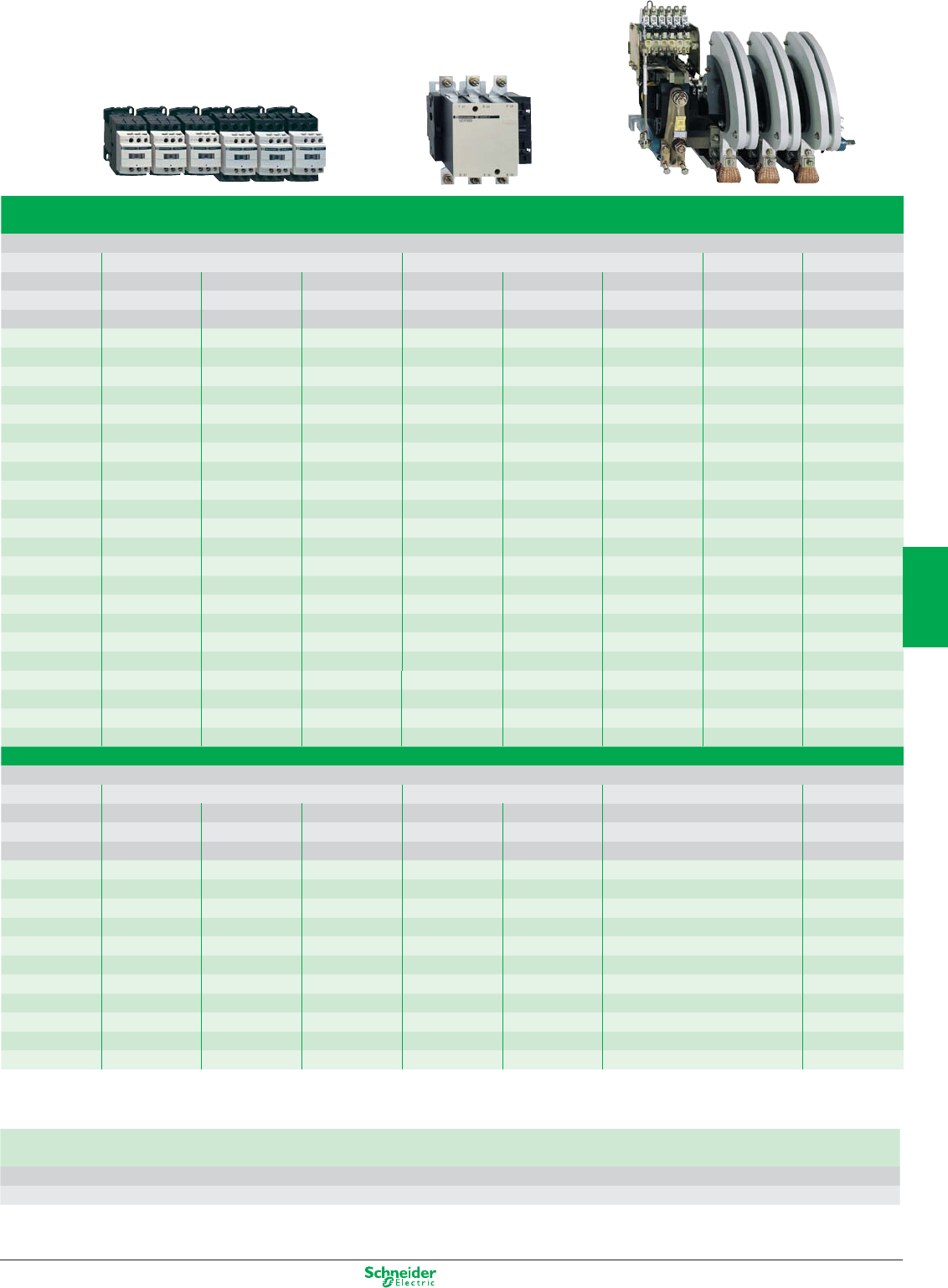
Other versions: please consult your Schneider Electric agency.
Maximum operational power of contactors
N standard contactors
Operational power at 50/60 Hz
θ ≥ 40 °C θ ≥ 55 °C Peak current Contactor
220 V 400 V 600 V 220 V 400 V 600 V size
240 V 440 V 690 V 240 V 440 V 690 V
kVAR kVAR kVAR kVAR kVAR kVAR A
6 11 15 6 11 15 560 LC1-D09, D12
9 15 20 9 15 20 850 LC1-D18
11 20 25 11 20 25 1600 LC1-D25
14 25 30 14 25 30 1900 LC1-D32, D38
17 30 37 17 30 37 2160 LC1-D40A
22 40 50 22 40 50 2160 LC1-D50A
22 40 50 22 40 50 3040 LC1-D65A
35 60 75 35 60 75 3040 LC1-D80, D95
50 90 125 38 75 80 3100 LC1-D115
60 110 135 40 85 90 3300 LC1-D150
70 125 160 50 100 100 3500 LC1-F185
80 140 190 60 110 110 4000 LC1-F225
90 160 225 75 125 125 5000 LC1-F265
100 190 275 85 140 165 6500 LC1-F330
125 220 300 100 160 200 8000 LC1-F400
180 300 400 125 220 300 10000 LC1-F500
250 400 600 190 350 500 12000 LC1-F630
250 400 600 190 350 500 14200 LC1-F800
200 350 500 180 350 500 25000 LC1-BL
300 550 650 250 500 600 25000 LC1-BM
500 8350 950 400 750 750 25000 LC1-BP
600 1100 1300 500 1000 1000 25000 LC1-BR
N special contactors
Operational power at 50/60 Hz
θ ≥ 55 °C
Instantaneous auxiliary contacts Tightening torque on cable end Basic reference,
220 V 400 V 660 V to be completed
240 V 440 V 690 V
kVAR kVAR kVAR N/O N/C N.m
6.7 12.5 18 1 1 1.2 LC1-DFK11••
-21.2 LC1-DFK02••
8.5 16.7 24 1 1 1.7 LC1-DGK11••
-21.7 LC1-DGK02••
10 20 30 1 1 1.9 LC1-DLK11••
-21.9 LC1-DLK02••
15 25 36 1 1 2.5 LC1-DMK11••
- 2 2.5 LC1-DMK02••
20 33.3 48 1 2 5 LC1-DPK12••
25 40 58 1 2 5 LC1-DTK12••
40 60 92 1 2 9 LC1-DWK12••
Standard control circuit voltages
a supply
Volts 24 42 48 110 115 220 230 240 380 400 415 440
50/60 Hz (coil LX1) B7 D7 E7 F7 FE7 M7 P7 U7 Q7 V7 N7 R7
5/47
2
1
3
4
5
6
7
8
9
10
Other versions: please consult your Schneider Electric agency.
Maximum operational current (device in open air)
Contactors LC1-/LP1- LC1-/LP1- LC1- LC1- LC1- LC1- LC1- LC1- LC1- LC1-
N 3-pole K09 K12 D09 D12 D18 D25 D32 D38 D40A
N 4-pole DT20 DT25 DT32 DT40
LC2- changeover contactor pairs, factory assembled K09004 K12004 DT20 DT25 DT32 DT40 DT60A
Operational current in AC-1, in A, ≤ 40°C A 20 20 25 20 25 32 40 50 50 60
according to ambient temperature ≤ 60°C A 20 20 25 20 25 32 40 50 50 60
≤ 70°C
Maximum operational 220/230 V kW 8 8 9 8 9 11 14 18 18 21
power ≤ 60°C 240 V kW 8 8 9 8 9 12 15 19 19 23
380/400 V kW 14 14 15 14 15 20 25 31 31 37
415 V kW 14 14 17 14 17 21 27 34 34 41
440 V kW 15 15 18 15 18 23 29 36 36 43
500 V kW 17 17 20 17 20 23 33 41 41 49
660/690 V kW 22 22 27 22 27 34 43 54 54 65
Increase in operational current
by parallel connection of poles
Apply the following coefficients to the currents or powers above;
these coefficients take into account an often unbalanced distribution
of current between the poles:
N 2 poles in parallel K = 1.6
N 3 poles in parallel K = 2.25
N 4 poles in parallel K = 2.8
Connection accessories for heating applications
Paralleling links for: Reference
N TeSys K 2 poles with screw clamp terminals LA9-E01
4 poles with screw clamp terminals LA9-E02
N TeSys D 2 poles D09…D38 LA9-D2561
DT20 and DT25 (4P) LA9-D1261
DT32…DT40 (4P) LAD-D96061
D40A…D65A LAD-9P32
D80 LA9-D80961
3 poles D09…D38 LAD-9P3 (1)
D40A…D65A LAD-9P33
D80 LA9-D80962
4 poles DT20…DT25 LA9-D1263
D40A…D65A 2 x LAD-9P33
D80 LA9-D80963
N TeSys F 2 to 2 LC1-F1154 LA9-FF602
LC1-F1504, F1854 LA9-FG602
LC1-F2254, F2654, F3304, F4004 LA9-FH602
LC1-F5004 LA9-FK602
LC1-F6304 LA9-FL602
(1) Link that can be split, allowing parallel connection of 2 poles
Heating applications and changeover
contactor pairs
0…2750 A
Components
5/48
2
1
3
4
5
6
7
8
9
10
Other versions: please consult your Schneider Electric agency.
LC1- LC1- LC1- LC1- LC1- LC1- LC1- LC1- LC1- LC1- LC1- LC1- LC1- LC1- LC1- LC1- LC1-
D50A D65A D80 D115 F185 F225 F265 F330 F400 F500 F630 F780 F800 BL BM BP BR
DT80A D80004 D115004 F1854 F2254 F2654
80 80 125 250 275 315 350 400 500 700 1000 1600 1000 800 1250 2000 2750
80 80 125 200 275 280 300 360 430 580 850 1350 850 700 1100 1750 2400
180 200 250 290 340 500 700 1100 700 600 900 1500 2000
29 29 45 80 90 100 120 145 170 240 350 550 350 300 425 700 1000
31 31 49 83 100 110 125 160 180 255 370 570 370 330 450 800 1100
50 50 78 135 165 175 210 250 300 430 600 950 600 500 800 1200 1600
54 54 85 140 170 185 220 260 310 445 630 1000 630 525 825 1250 1700
58 58 90 150 180 200 230 290 330 370 670 1050 670 550 850 1400 2000
65 65 102 170 200 220 270 320 380 660 750 1200 750 600 900 1500 2100
86 86 135 235 280 300 370 400 530 740 1000 1650 1000 800 1100 1900 2700
5/49
2
1
3
4
5
6
7
8
9
10

Other versions: please consult your Schneider Electric agency.
Accessories for changeover contactor pairs
0…2750 A
Components
Mounting accessories for changeover contactor pairs
(for customer assembly)
Contactor type Set of power connections Mechanical Contactor type Set of power connections Mechanical
interlock interlock
2 contactors, vertically mounted
N 4-pole changeover pairs with locking device components
LC1-B –EZ2-LB0601 –––
2 identical contactors, horizontally mounted
N with electrical interlocking kit for the contactors
LC1-DT20…DT40 LAD-T9R1V
(1) – – – –
N mechanical interlock with integral electrical interlocking
LP1-D80004 LA9-D8070 LA9-D8002 LC1-D115004 LA9-D11570 LA9-D11502
N without electrical interlocking
(2)
LC1-DT20…DT40 LAD-T9R1
(2) – – – –
LC1DT60A & LC1DT80A –LAD4CM
(3) LP1-D80004 LA9-D8070 LA9-D80978
2 contactors of identical rating, horizontally mounted
N 4-pole changeover pairs
LC1-F1154 LA9-FF977 LA9-FF970 LC1-F1504 LA9-F15077 LA9-FF970
LC1-F1854 LA9-FG977 LA9-FG970 LC1-F2254 LA9-F22577 LA9-FG970
LC1-F2654 LA9-FH977 LA9-FJ970 LC1-F3304 LA9-FJ977 LA9-FJ970
LC1-F4004 LA9-FJ977 LA9-FJ970 LC1-F5004 LA9-FK977 LA9-FJ970
LC1-F6304 LA9-FL977 LA9-FL970 –––
N 3-pole changeover pairs with electrical interlocking
LC1-D115 et D150 LA9-D11571 LA9-D11502 –––
reversers assembled using 2 contactors, vertically mounted
N 4-pole changeover pairs using contactors of identical rating (3) N 3 or 4-pole changeover pairs using contactors of different rating
At bottom At top
LC1-F1154 or F1505 (3) LA9-FF4F LC1-F115 or F1154 LC1-F185 or F1854 LA9-FG4F
LC1-F1854 (3) LA9-FG4G or LC1-F150 or F1504 LC1-F225 or F2254 LA9-FG4F
LC1-F2254 (3) LA9-FG4G LC1-F265 or F2654 LA9-FH4F
LC1-F2654 or F3304 (3) LA9-FH4H LC1-F300 or F3304 LA9-FH4F
LC1-F4004 (3) LA9-FJ4J LC1-F400 or F4004 LA9-FJ4F
LC1-F5004 (3) LA9-FK4K LC1-F500 or F5004 LA9-FK4F
LC1-F6304 (3) LA9-FL4L LC1-F630, F6304 or F800 LA9-FL4F
LC1-F7804
(4) LA9-FX971
(4) LC1-F185 or F1854 LC1-F265 or F2654 LA9-FH4G
or LC1-F225 or F2254 LC1-F330 or F3304 LA9-FH4G
LC1-F400 or F4004 LA9-FJ4G
LC1-F500 or F5004 LA9-FK4G
LC1-F630, F6304 or F800 LA9-FL4G
LC1-F265 or F2654 LC1-F400 or F4004 LA9-FJ4H
or LC1-F330 or F3304 LC1-F500 or F5004 LA9-FK4H
LC1-F630, F6304 or F800 LA9-FL4H
LC1-F400 or F4004 LC1-F500 or F5004 LA9-FK4J
LC1-F630, F6304 or F800 LA9-FL4J
LC1-F500 or F5004 LC1-F630, F6304 or F800 LA9-FL4K
(1) Including mechanical interlock.
(2) Order separately 2 auxiliary contact blocks LAD-N•1 t o obtain electrical interlocking between the two contactors.
(3) Power connections to be made by the customer.
(4) Double mechanical interlock mechanism with 2 interlock connecting rods and 4 power connecting links.
5/50
2
1
3
4
5
6
7
8
9
10

Other versions: please consult your Schneider Electric agency.
TeSys Notes
5/51
2
1
3
4
5
6
7
8
9
10
Power your processes in DC or AC,
with our switch mode power supplies,
fi ltered rectifi ed power supplies and
transformers products.
Schneider Electric sums up all your
expectations to provide you with the
energy you require through a
compact and complete range.
Phaseo
Designed and adapted to correspond as
closely as possible with your requirements,
the wide operating range of our switch
mode power supplies, together with
the integration of a large number of new
functions, make them the new reference
in power supplies.

Power Supplies
This document is a selection of
the top selling products.
6/1
2
1
3
4
5
6
7
8
9
10
Power supplies
Modular, Optimum, Universal Power supplies,
Phaseo ABL7, ABL8 ................................................................................................... 6/2 to 6/5
Slim Power supplies,
Phaseo ABL4 ........................................................................................................................ 6/6
Dedicated, Filtered Rectified Power supplies,
Phaseo ABL1, ABL8 ............................................................................................................. 6/7
Transformers
Phaseo ABL6, ABT7 .................................................................................................................. 6/8
Connection
Terminal blocks
AB1 ...................................................................................................................................... 6/10
Cable ends
DZ5/AZ5 ................................................................................................................................6/11
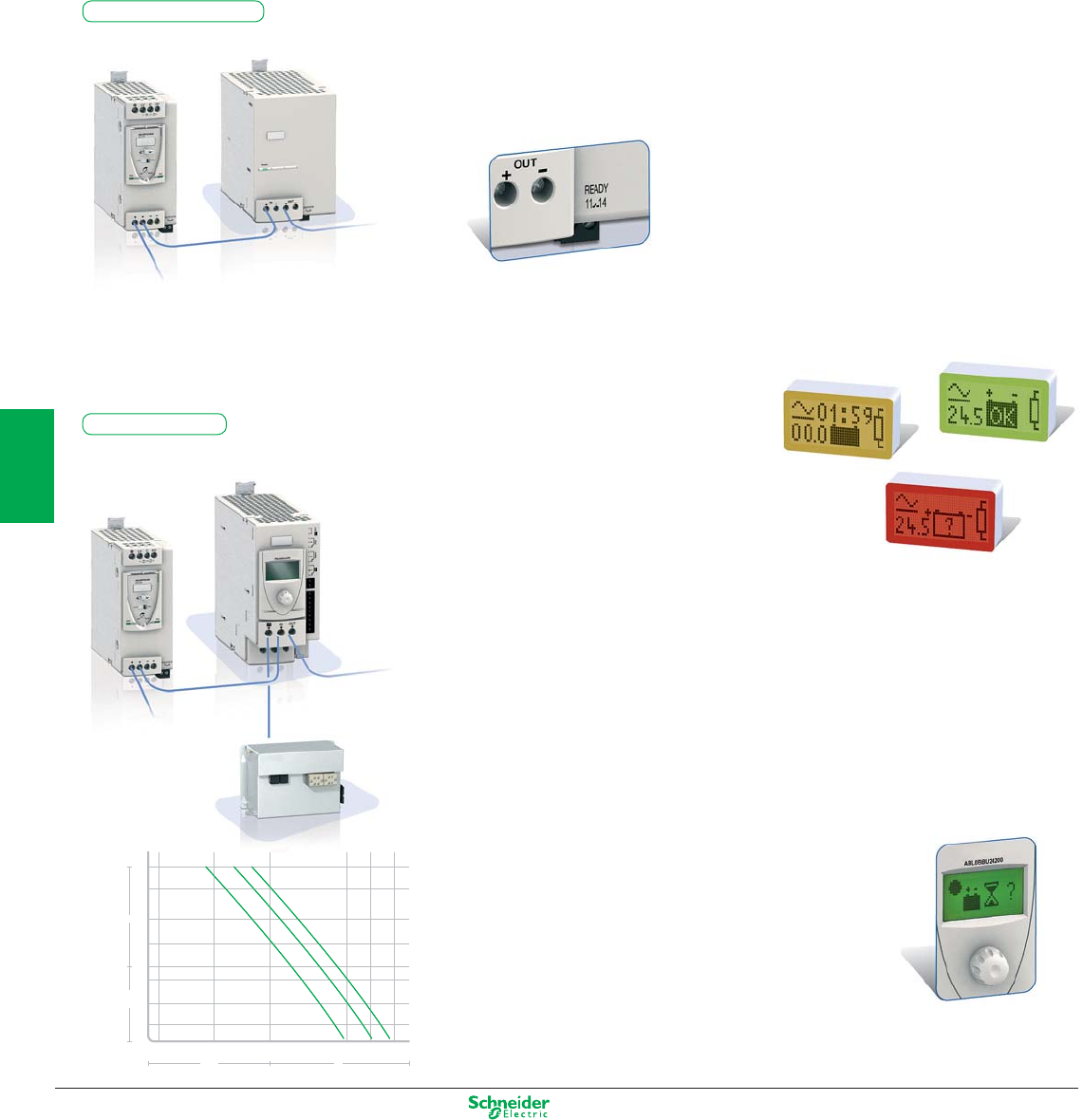
Other versions: please consult your Schneider Electric agency.
1000 10 20 40200
mA
40
10
20
40
60
2
4
10
20 3,2AH 7AH 12AH
BACKUP CURRENT
BACKUP TIME
mn h
A
1000 10 20 40200
mA
40
10
20
40
60
2
4
10
20 3,2AH 7AH 12AH
BACKUP CURRENT
BACKUP TIME
mn h
A
More service…
Network voltage interrupts create equipment
operating irregularity that can result in production
losses and even require maintenance team
intervention for restarting.
Phaseo universal solutions can:
p Render microcuts «transparent» for equipment
p Enable equipment stop with necessary data backup, so allowing restart without
problems at return of network voltage.
Buffer module solution
Simple and efficient
p No setting required
p Diagnostic relay contact (module charge state)
p Standard and backup circuit separation possible.
Buffer module
Battery backup solution
Total confidence
p Battery state automatic test
p Advanced and user-friendly diagnostics:
- Power supply operation
- Battery operation
- Fault presence.
Flexible and adaptable
p 2 current supply modules are available:
- Backup until complete battery discharge (battery is however disconnected
before overdischarge)
- Backup for an adjustable time period, keeping energy
in reserve in case of a closely following cut.
Quick installation
p Copy of configuration between 2 modules using
memory cartridge
p Quick configuration of battery control module by a
single selector switch and display pictograms.
Microcuts < few secondes
+ OUT
+ IN
+
Cuts > few secondes
+ OUT
+ IN
+
Battery module
Control module
Network cuts
6/2
2
1
3
4
5
6
7
8
9
10
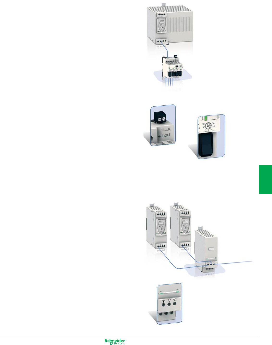
Other versions: please consult your Schneider Electric agency.
Starter protection solution
Protection module
Disponi-
bilité
On certain equipment, the consequences of a 24 V
control voltage breakdown can be extremely detrimental
and can justify paralleling 2 or more power supplies to
maintain faultless operating continuity.
The Phaseo solution consists of coupling 2 universal
power supplies with an electronic redundancy
module.
The primaries of these power supplies can be on the
same or on different networks.
Service continuity in total confidence
p Advanced diagnostics by LED
p C/O contact enables signalling of fault in one of the 2 power sup-
plies and alerts maintenance.
Protection of circuits supplied in DC low voltage has
traditionally been by fuses or electromechanical circuit-
breakers. In certain cases (notably short-circuits) this
protection is not sufficiently selective, and electronic
protection of the power supply suspends low voltage
supply before downstream protections can react.
The Phaseo solution is a 4-starter electronic protec-
tion module, dedicated to ABL 8R/W Universal power
supplies.
Each of these starters is adjustable from 1 to 10 A.
High-performance solution ensuring
service continuity
p Selectivity enabling isolation of fault circuits only
p Advanced diagnostics by LED and relay contact
p Manual opening of each circuit by switch
p Lead-sealed settings.
Minimised stock levels
p 1 product reference each covering 1 to 10 A.
Redundancy solution
Redundancy module
24 VDC circuit overload
Availability
6/3
2
1
3
4
5
6
7
8
9
10
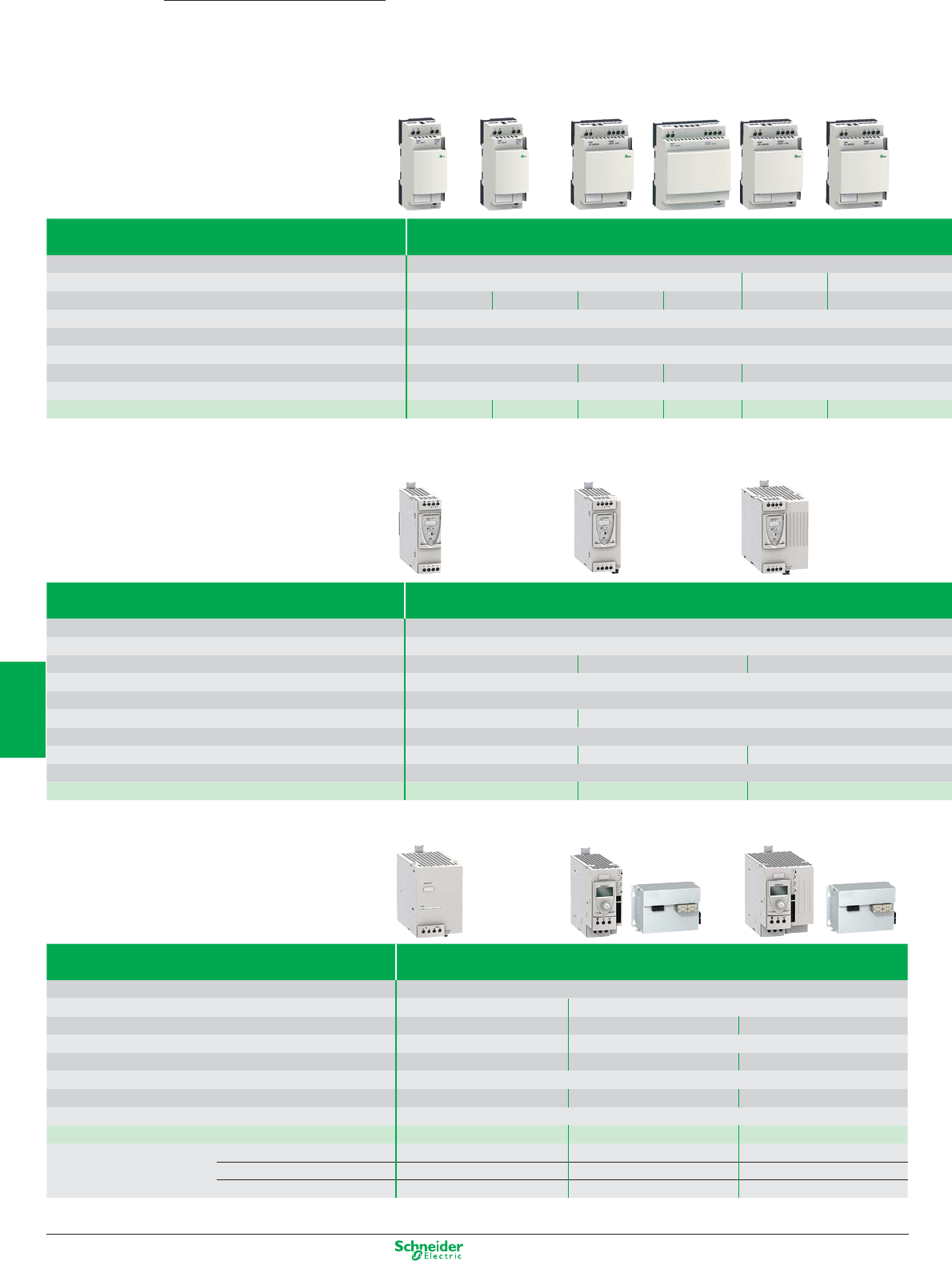
Other versions: please consult your Schneider Electric agency.
Phaseo Power supplies
Modular, Optimum, Universal,
Type of power supply Modular, regulated switch mode with automatic reset
Rated input voltage 100…240 VAC
Rated output voltage 24 V 5 V 12 V
Rated power / Rated current 7.5 W / 0.3 A 15 W / 0.6 A 30 W / 1.2 A 60 W / 2.5 A 20 W / 4 A 25 W / 2 A
Reset Auto
Conformity to IEC 61000-3-2 Without
Certifications cULus, cCSAus, TUV, CE, C-Tick
Dimensions (mm) 36x59x90 54x59x90 72x59x90 54x59x90
Fixing (mm) DIN rail 35x7.5 or 35x15 or on panel mount by screw
References
ABL8MEM24003 ABL8MEM24006 ABL8MEM24012 ABL7RM24025 ABL8MEM05040 ABL8MEM12020
Type of power supply Universal, regulated switch mode with automatic or manual reset
Rated input voltage 100…120 VAC and 200…500 VAC
Rated output voltage 24 V
Rated power / Rated current 72 W / 3 A 120 W / 5 A 240 W / 10 A
Permissible temporary inrush current (boost) 1.5 In during 4 s
Conformity to IEC 61000-3-2 Yes
Diagnostic relay (output voltage > 21.6V) No Yes
Certifications cCSAus, CB scheme, CE
Dimensions (mm) 44x120x143 56x120x143 85x140x143
Fixing (mm) DIN rail 35x7.5 or 35x15
References ABL8RPS24030 ABL8RPS24050 ABL8RPS24100
Type of module Microcuts and cuts network solutions. Fixing Omega rail clip-in (1)
Compatibility Output connection of Universal power supplies ABL8RPS24… and ABL8WPS24…
Technology Buffer module battery backup module + battery
Rated voltage 40 A 20 A 40 A
Holding time 1A 2 s typique adjustable from 10 s to 24 H (battery depending)
Holding time for maximum current 100 ms typique
adjustable from 10 s to 30 mn (battery depending) adjustable from 10 to 10 mn (battery depending)
Certifications cCSAus, CB scheme, CE
Dimensions (mm) 85x140x146 86x175x143 86x175x143
Fixing (mm) DIN rail 35x7.5 or 35x15 (1)
References Control module ABL8BUF24400 ABL8BBU24200 ABL8BBU24400
References battery 3,2AH (2) – ABL8BPK24A03 ABL8BPK24A03
7AH (2) – ABL8BPK24A07 ABL8BPK24A07
12AH (2) –ABL8BPK24A12 ABL8BPK24A12
(1) Battery module except 7AH and 12AH. For battery module 3.2AH with ABL1A02 kit.
(2) Battery to be chosen according to the graph page 6/2
6/4
2
1
3
4
5
6
7
8
9
10
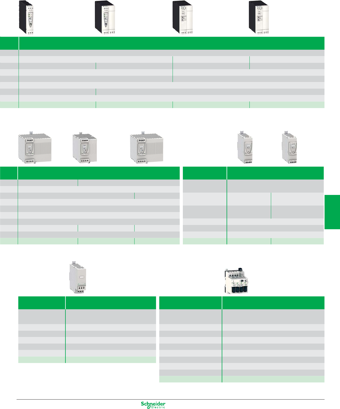
Other versions: please consult your Schneider Electric agency.
Optimums, regulated switch mode
100…240 VAC
24 V 12 V 48 V
72 W / 3 A 120 W / 5 A 60 W / 5 A 144 W / 2.5 A
Auto Auto or manual
No Yes
cULus, cCSAus, TUV, CE, C-Tick
27x120x120 54x120x120
DIN rail 75x7.5, 35x7.5 or 35x15
ABL8REM24030 ABL8REM24050 ABL7RP1205 ABL7RP4803
Universal, regulated switch mode with automatic or manual reset Type of module Converters DC/DC
100…120 VAC and 200…240 VAC
3 x 380…500 VAC Compatibility Output connection of Universal power supplies
ABL8RPS24… and ABL8WPS24…
24 V
480 W / 20 A 960 W / 40 A Rated output
voltage
5 V 12 V
1.5 In during 4 s
Yes Rated output
current
6 A 2 A
Yes
cCSAus, CB scheme, CE Certifications cCSAus, CB scheme, CE
145x140x143 95x155x143 165x155x143 Dimensions (mm) 44x140x146
DIN rail 35x7.5 or 35x15 Fixing (mm) DIN rail 35x7.5 or 35x15
ABL8RPM24200 ABL8WPS24200 ABL8WPS24400 References ABL8DCC05060 ABL8DCC12020
Type of module Redundancy power supplies solutions Type of module Starter protection solution
Compatibility Connection of 2 power supplies inputs
up to 20 A (1 power supply 40A)
Compatibility Output connection of Universal power supplies
ABL8RPS24100..., ABL8RPM24200..., ABL8WPS24...
Rated output voltage 24 V Rated output current 10A par voie
Rated output current 40 A Calibres 1 / 2.5 / 4 / 5 / 7 / 8 / 10 A
Certifications cCSAus, CB scheme, CE Nombre de voies 4
Dimensions (mm) 44x140x146 Relais de défaut Yes
Fixing (mm) DIN rail 35x7.5 ou 35x15
Coupure manuelle (1 par voie)
Two-pole
References ABL8RED24400 Certifications cCSAus, CB scheme, CE
Dimensions (mm) 71x109x110
Fixing (mm) DIN rail 35x7.5 or 35x15 or on panel mount by screw
References ABL8PRP24100
6/5
2
1
3
4
5
6
7
8
9
10
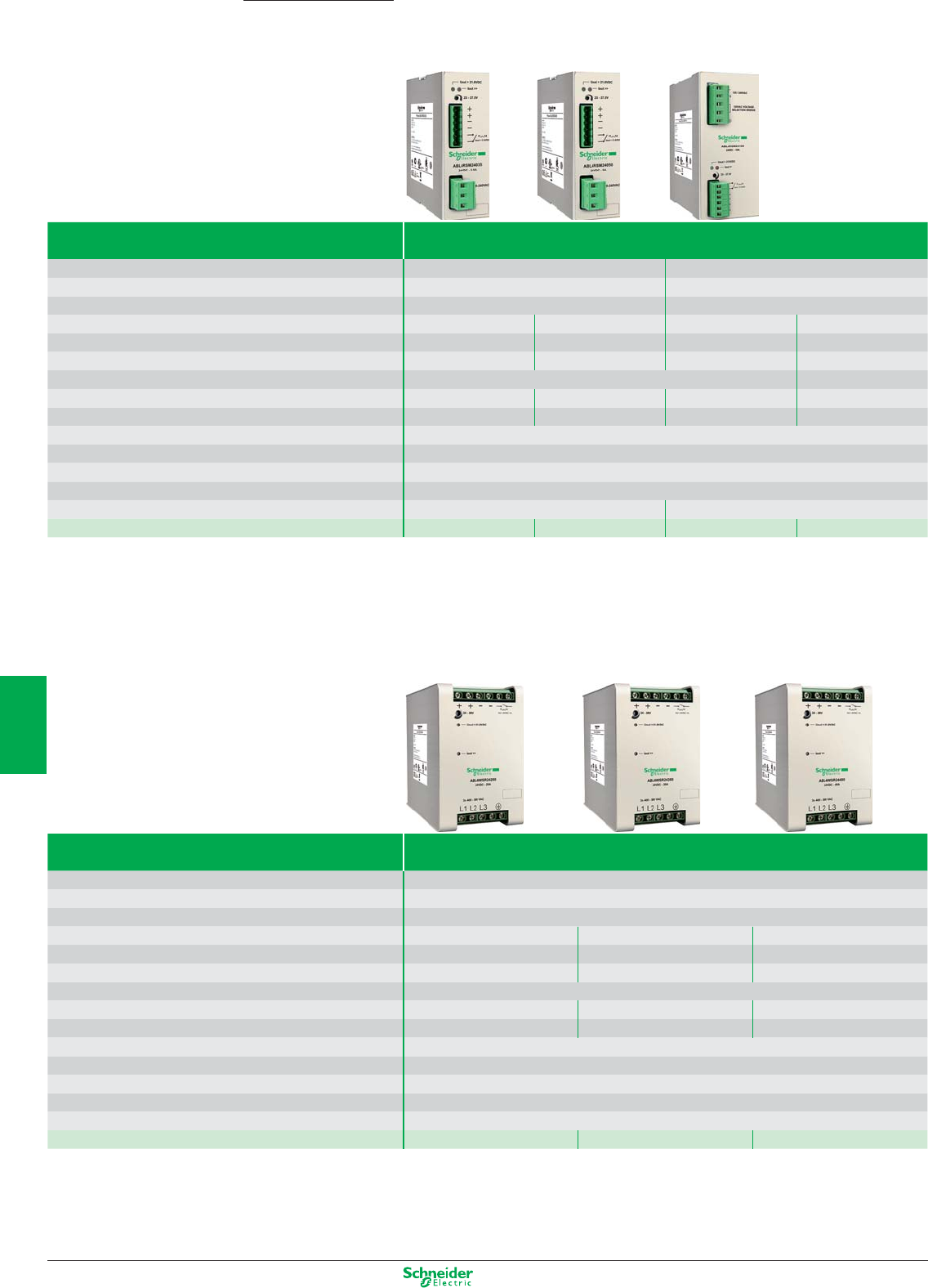
Other versions: please consult your Schneider Electric agency.
Power supplies
Single phase
Rated Input Voltage AC 120…230V 50/60Hz 120/230V
Permissible input voltage AC 90…264V 47…63 Hz 90…132V / 185…264V 47…63 Hz
Rated Input Voltage DC 100…370V 300…350 V
Input current (120/230 VAC) 1,6A / 0,9A 1,9A / 1,1A 3,5A / 1,8A 4,1A / 2A
Efficiency (120/230 VAC) >85% / >89% >86% / >90% >88% / >90% >90% / >92%
Dissipated power max 15W 19W 32W 55W
Output Voltage 24V rated adjustable 23…27,5 V 24V rated 24…28V
Rated Output current 3,5A 5A 10A 20A
Permissible output current 6A for 30s 8A for 30s 15A for 30s 30A for 5s
Reset after overload Auto
Diagnostic relay Yes
Operating temperature -20…+60°C with derating above 50°C
Certifications UL
Dimensions (mm) 39x115x134 64x140x139
References ABL4RSM24035 ABL4RSM24050 ABL4RSM24100 ABL4RSM24200
Three phase
Rated Input Voltage AC 400 … 500V 50/60 Hz
Permissible input voltage AC 340 … 550V 47…63 Hz
Working on 2 phases Possible with output current = 75% of the nominal output current.
Input current (400/500 VAC) 1A / 0,6A 1,4A / 1,1A 2,2A / 1,1A
Efficiency (400/500 VAC) >93% / >94% >93% / >94% >91% / >91%
Dissipated power max 36W 36W 95W
Output Voltage 24V rated 24…28V
Rated Output current 20A 30A 40A
Permissible output current 30A for 5s 45A for 5s 60A for 5s
Reset after overload Auto
Diagnostic relay Yes
Operating temperature -20…+60°C with derating above 50°C
Certifications UL
Dimensions (mm) 80x127x146
References ABL4WSR24200 ABL4WSR24300 ABL4WSR24400
Phaseo Slim
6/6
2
1
3
4
5
6
7
8
9
10
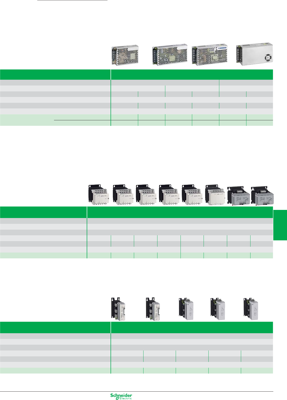
Other versions: please consult your Schneider Electric agency.
Phaseo Power supplies
Dedicated
Type of power supply Dedicated, regulated switch mode
Input voltage 85…264 VAC 85…132 VAC / 170…264 VAC
Output voltage 12 VDC 24 VDC 24 VDC
Power / rated current 60 W / 5 A 100 W / 8.3 A 60 W / 2.5 A 100 W / 4.2 A 150 W / 6.2 A 240 W / 10 A
Certifications UL, c CSA us, CE, Ctick
Dimensions WxDxH (mm) 150x38x98 200x38x98 150x38x98 200x38x98 200x50x98 200x65x98
Fixing (mm) Panel mount by scew, by bracket ABL1A01 (1) , on DIN rail 35mm by panel ABL1A02 (1).
References Without filter
ABL1REM12050 – ABL1REM24025 ABL1REM24042 ABL1REM24062
ABL1REM24100
With filter (2) –
ABL1RPM12083 – ABL1RPM24042 ABL1RPM24062
ABL1RPM24100
(1) has to order separately.
(2) Anti harmonic IEC/EN 61000-3-2
Filtered rectified
Type of power supply Filtered rectified single-phase or two-phase
Input voltage 215/230/245 V or 385/400/415 VAC
Rated output voltage 24 V
Certifications cULus, ENEC
Rated power / Rated current 12 W / 0.5 A 24 W / 1 A 48 W / 2 A 96 W / 4 A 144 W / 6 A 240 W / 10 A 360 W / 15 A 480 W / 20 A
Dimensions (mm)
87x124x108 87x124x108 87x142x108 87x165x108 123x153x153 123x185x153 135x185x138 175x215x128
Fixing (mm) DIN rail 35x7.5 or 35x15 or on panel mount by screw On panel mount by screw
References
ABL8FEQ24005 ABL8FEQ24010 ABL8FEQ24020 ABL8FEQ24040 ABL8FEQ24060 ABL8FEQ24100 ABL8FEQ24150 ABL8FEQ24200
Type of power supply Filtered rectified three-phase
Input voltage 3x 380 / 400 / 420 V
Rated output voltage 24 V
Certifications cULus, ENEC
Rated power / Rated current 240 W / 10 A 480 W / 20 A 720 W / 30 A 960 W / 40 A 1440 W / 60 A
Dimensions (mm) 185x190x78 220x215x104 240x252x108 310x310x140 310x310x154
Fixing (mm) On panel mount by screw
References ABL8TEQ24100 ABL8TEQ24200 ABL8TEQ24300 ABL8TEQ24400 ABL8TEQ24600
6/7
2
1
3
4
5
6
7
8
9
10
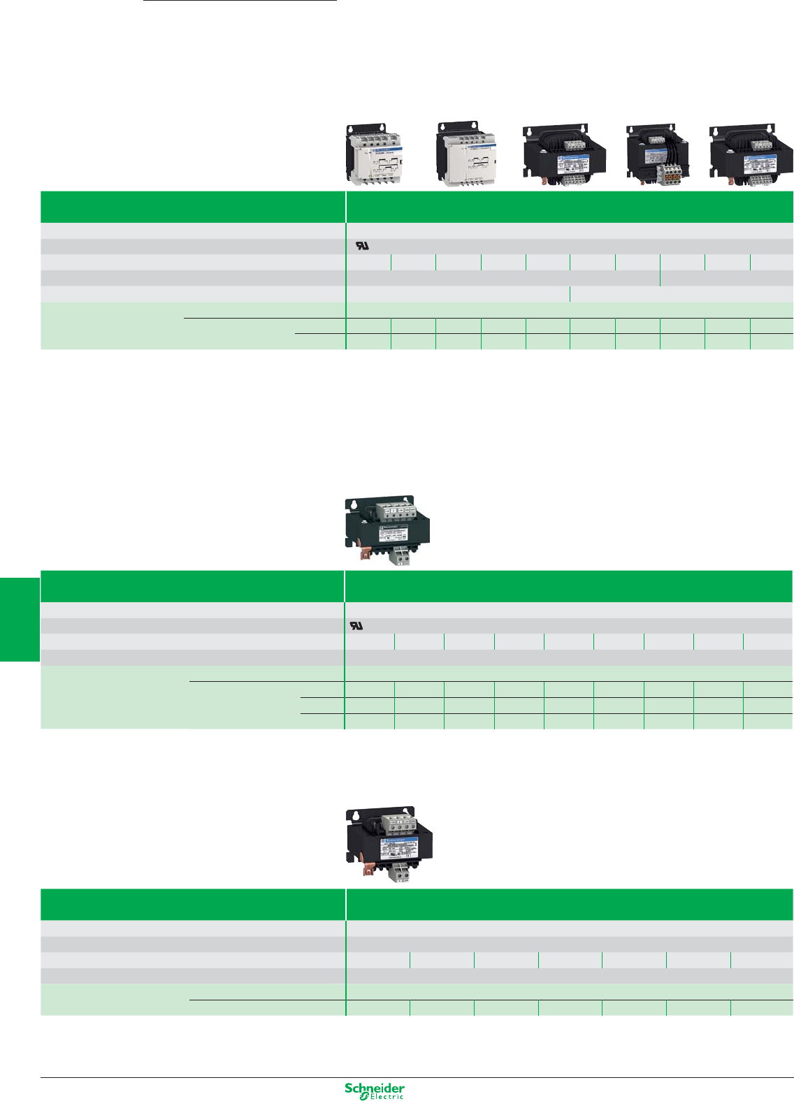
Other versions: please consult your Schneider Electric agency.
Type of transformer Universal range, double winding operating temperature +60°C
Rated input voltage 230/400 VAC (±15 V) 1-phase
Certifications c us, ENEC
Rated power / Rated current 25 VA 40 VA 63 VA 100 VA 160 VA 250 VA 320 VA 400 VA 630 VA 1000 VA
Visualization LED display of voltage presenceat primary Without
Fixing (mm) DIN rail 35x15 or on panel mount by screw On panel mount by screw
References ABT7PDU•••(1)
Rated output voltage 24/48 V 002B 004B 006B 010B 016B 025B 032B 040B 063B 100B
115/230 V 002G 004G 006G 010G 016G 025G 032G 040G 063G 100G
(1) Complete the reference according to the power and voltage using the table below (example: ABL6TS02J)
Type of transformer Optimum range, single winding operating temperature +50°C
Rated input voltage 230/400 VAC (±15 V) 1-phase
Certifications
Nominal power 25 VA 40 VA 63 VA 100 VA 160 VA 250 VA 400 VA 630 VA 1000 VA
Fixing (mm) On panel mount by screw
References
ABL6TS•••(1)
Rated output voltage
24 V 02B 04B 06B 10B 16B 25B 40B 63B 100B
115 V 02G 04G 06G 10G 16G 25G 40G 63G 100G
230 V 02U 04U 06U 10U 16U 25U 40U 63U 100U
(1) Complete the reference according to the power and voltage using the table below (example: ABL6TS02J)
Type of transformer Economy range, single winding operating temperature +40°C
Rated input voltage 230 VAC (±15 V) 1-phase
Certifications Without
Rated power / Rated current 40 VA 63 VA 100 VA 160 VA 250 VA 320 VA 400 VA
Fixing (mm) On panel mount by screw
References ABT7ESM•••(1)
Rated output voltage 24 V 004B 006B 010B 016B 025B 032B 040B
(1) Complete the reference according to the power and voltage using the table below (example: ABL6TS02J)
Transformers
Phaseo
6/8
2
1
3
4
5
6
7
8
9
10

Other versions: please consult your Schneider Electric agency.
Phaseo Notes
6/9
2
1
3
4
5
6
7
8
9
10
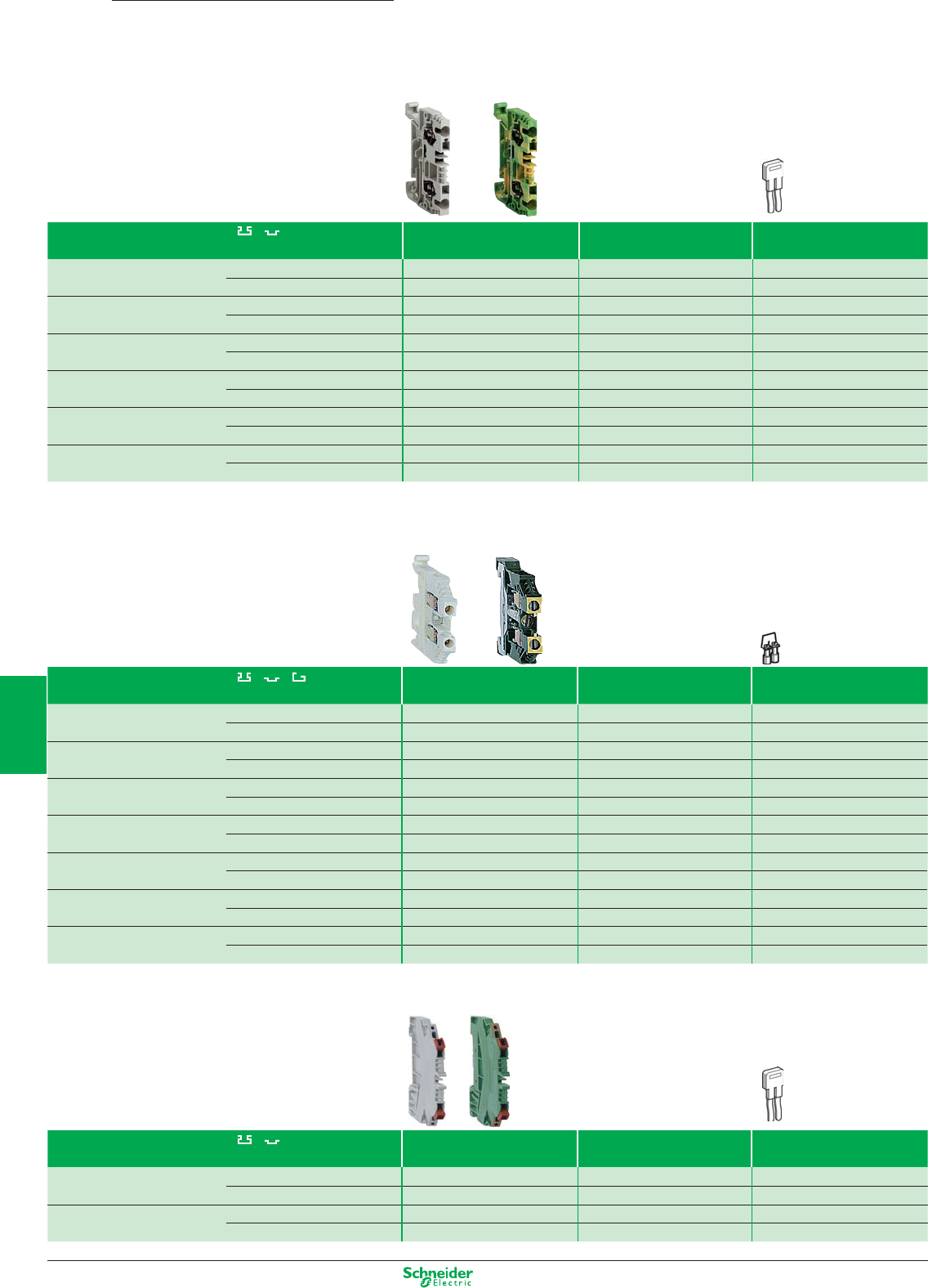
Other versions: please consult your Schneider Electric agency.
Terminal blocks
Spring clamp technology
AB1
Clip-on mounting on 35 mm rails Terminal blocks
(sold in lots of 100)
End covers
(sold in lots of 100)
Commoning link
(sold in lots of 100)
2.5 mm
2
c.s.a. Conducting AB1RRN235U2GR AB1RRNAC242GR AB1RRAL22 (1)
Protective earth conductor AB1RRNTP235U2 AB1RRNTPAC242 –
4 mm
2
c.s.a. Conducting AB1RRN435U2GR AB1RRNAC442GR AB1RRAL42 (1)
Protective earth conductor AB1RRNTP435U2 AB1RRNTPAC442 –
6 mm
2
c.s.a. Conducting AB1RRN635U2GR AB1RRNAC642GR AB1RRNAL62 (2)
Protective earth conductor AB1RRNTP635U2 AB1RRNTPAC642 –
10 mm
2
c.s.a. Conducting AB1RRN1035U2GR (3) AB1RRNAC1042GR AB1RRNAL102
Protective earth conductor AB1RRNTP1035U2 (3) AB1RRNTPAC1042 –
16 mm
2
c.s.a. Conducting AB1RRN1635U2GR (3) AB1RRNAC1642GR AB1RRNAL162
Protective earth conductor AB1RRNTP1635U2 (3) AB1RRNTPAC1642 –
35 mm
2
c.s.a. Conducting AB1RRN3535U2GR (4) – AB1RRAL352
Protective earth conductor AB1RRNTP3535U2 (4) – –
(1) For a 3, 4, 5 or 10-pole commoning link replace the last number of the reference (2) by 3, 4, 5 or 10 respectively. (Example: AB1RRAL22 becomes A1BRRAL23)
(2) For a 3, 4, 5 or 10-pole commoning link replace the last number of the reference (2) by 3, 4, 5 or 10 respectively. (Example: AB1RRNAL62 becomes A1BRRNAL64)
(3) Sold in lots of 50
(4) Sold in lots of 10
Clip-on mounting on 35 mm rails Terminal blocks End covers
Commoning link
(sold in lots of 100) (sold in lots of 100) (sold in lots of 100)
2.5 mm
2
c.s.a. Conducting AB1VV235U AB1AC24 AB1ALN22 (1)
Protective earth conductor AB1TP235U AB1AC25 –
4 mm
2
c.s.a. Conducting AB1VV435U AB1AC24 AB1ALN42 (1)
Protective earth conductor AB1TP435U – –
6 mm
2
c.s.a. Conducting AB1VV635U AB1AC6 AB1ALN62 (1)
Protective earth conductor AB1TP635U – –
10 mm
2
c.s.a. Conducting AB1VVN1035U (2) AB1ACN10 AB1ALN102 (1)
Protective earth conductor AB1TP1035U (2) – –
16 mm
2
c.s.a. Conducting AB1VVN1635U (2) AB1ACN16 AB1ALN162 (1)
Protective earth conductor AB1TP1635U (2) – –
35 mm
2
c.s.a. Conducting AB1VVN3535U (3) _ AB1ALN352 (1)
Protective earth conductor AB1TP3535U (3) – –
70 mm
2
c.s.a. Conducting AB1VVN7035U (3) _ AB1ALN702
150 mm
2
c.s.a. Conducting AB1VVN15035U (4) _ AB1ALN1502 (1)
(1) For a 3, 4, 5 or 10-pole commoning link replace the last number of the reference (2) by 3, 4, 5 or 10 respectively. (Example: AB1ALN22 becomes AB1ALN23)
(2) Sold in lots of 50
(3) Sold in lots of 20
(2) Sold in lots of 10
Clip-on mounting on 35 mm rails 2-way terminal blocks End covers
2-pole commoning link (1)
(sold in lots of 100) (sold in lots of 10) (sold in lots of 10)
1 mm
2
c.s.a. Conducting AB1AA135U2GR AB1AAAC122GR AB1RRAL22
Protective earth conductor AB1AATP135U2 AB1AAAC122VE –
2.5 mm
2
c.s.a. Conducting AB1AA235U2GR AB1AAAC122GR AB1RRAL22
Protective earth conductor AB1AATP235U2 AB1AAAC122VE –
(1) For a 3, 4, 5 or 10-pole commoning link replace the last number of the reference (2) by 3, 4, 5 or 10 respectively. (Example: AB1RAL22 becomes AB1RAL23).
Screw clamp technology
Insulation displacement technology
6/10
2
1
3
4
5
6
7
8
9
10
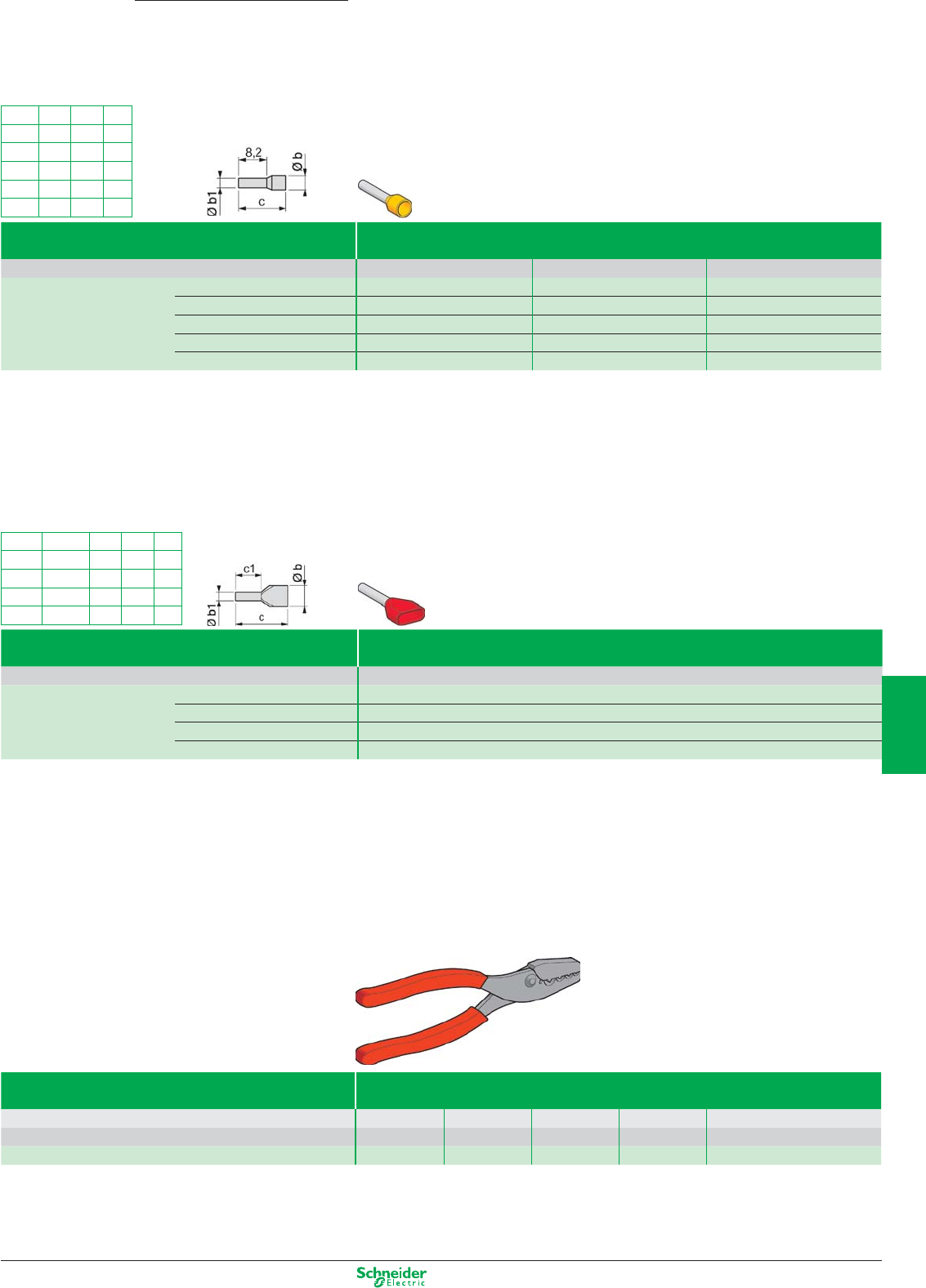
Other versions: please consult your Schneider Electric agency.
Insulated cable ends
Conforming to DIN 46228 (1)
mm
2
Øb Øb1 c c1
0.75 2.8 x 5 1.8 15 8
1
3.4 x 5.4
2.05 15 8
1.5
3.6 x 6.6
2.3 15 8
2.5
4.2 x 7.8
2.9 18.5 10
mm
2
Øb Øb1 c
0.5 3 1.4 13
0.75 3.1 1.6 13
13.4 1.8 13.5
1.5 4 2.1 13.5
2.5 4.6 2.7 14.5
DZ5/AZ5
Type Single cable ends
Sold in lots of 10 x 100
Packaging Individual or “strings” of bags Dispenser pack Strips of 50 in bag
Conductor c.s.a. 0.5 White DZ5CE005D AZ5CE005D DZ5CEB005D
in mm
2
0.75 Grey DZ5CE007D AZ5CE007D DZ5CEB007D
1Red DZ5CE010D AZ5CE010D DZ5CEB010D
1.5 Black DZ5CE015D AZ5CE015D DZ5CEB015D
2.5 Blue DZ5CE025D AZ5CE025D DZ5CEB025D
Type Double cable ends
Sold in lots of 5 x 100
Packaging Dispenser pack
Conductor c.s.a. 2 x 0.75 Grey AZ5DE007D
in mm
2
2 x 1 Red AZ5DE010D
2 x 1.5 Black AZ5DE015D
2 x 2.5 Blue AZ5DE025D
(1) For insulated cable ends conforming to standard NF C 63-023 , please refer to your Schneider Electric agency.
Accessoires de câblage
Type Pliers/cutters
Functions Stripping
Cutting/stripping
Crimping
Crimping (ratchet)
Cutting/stripping/crimping (2)
For cable c.s.a. 0.08 to 4 mm
2
0.4 to 4 mm
2
0.5 to 16 mm
2
0.25 to 6 mm
2
0.5 to 2.5 mm
2
References AT1PA7 AT2PE1 AT1PA2 AT2PA5 AT2TRIF01
(2) For use with cable ends packed in strips of 50.
6/11
2
1
3
4
5
6
7
8
9
10
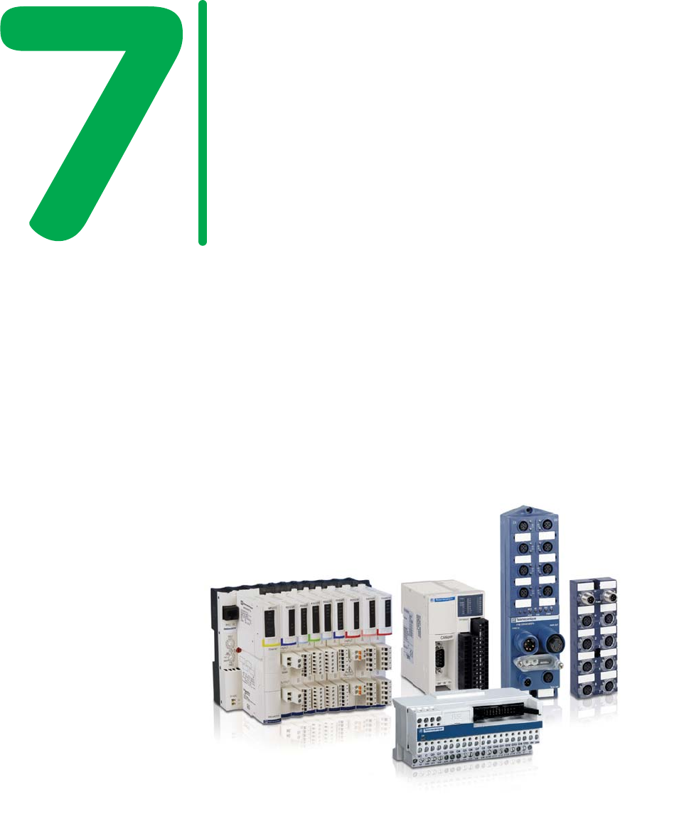
Advantys is a complete range of
interfaces, inputs/outputs and system
integration platforms for all types of
applications. From simple pre-wired
systems to I/O integration platforms,
from monobloc products to modular
solutions…the Advantys range
provides a solution whatever your
requirements.
Advantys
- Simplified maintenance,
- Reduced set-up and commissioning,
- Reduced enclosure sizes,
- Reduced cabling costs & errors.

Interfaces and I/O
This document is a selection of
the top selling products.
7/1
2
1
3
4
5
6
7
8
9
10
Distributed I/O
IP20
Expandable Block I/O, Advantys OTB .................................................................................. 7/2
Modular I/O with device integration capabilities, Advantys STB ................................ 7/ 3 to 7/6
IP67
Block I/O, Advantys FTB ....................................................................................................... 7/7
Modular I/O, Advantys FTM .................................................................................................. 7/8
Distributed I/O with embedded control
IP20
Block I/O, Modicon Momentum ................................................................................ 7/9 to 7/12
Interfaces
IP20
Passive I/O sub-bases, Advantys Telefast ABE7 .............................................................. 7/13
Relay-based I/O sub-bases, Advantys Telefast ABE7 ....................................................... 7/14
Twido I/O sub-bases, Advantys Telefast ABE7 .................................................................. 7/15
IP67
Embases E/S passives, Advantys Telefast ABE9 .............................................................. 7/16
Accessories and Cabling
Connection cables and jumper cables ..................................................................... 7/17 to 7/19
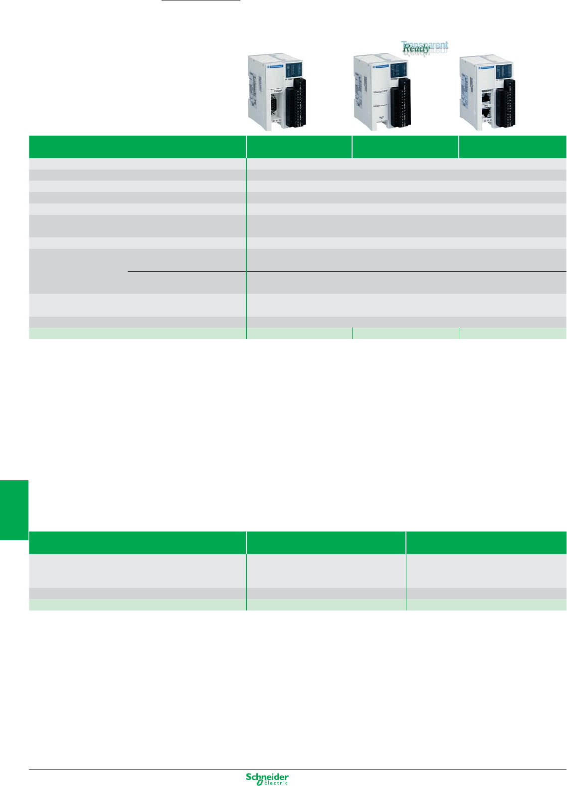
Other versions: please consult your Schneider Electric agency.
IP 20 distributed I/O, optimised block
Interface modules
Advantys OTB
Discrete Type of bus CANopen Ethernet TCP/IP Modbus Series
Machine bus network (2) network
Number of I/Os 20 I/O
Number of inputs 12 inputs 24 VDC IEC type 1
Number of outputs 6 relay outputs and 2 solid state 24 VDC outputs
Connection method Removable terminal block
Number of I/O expansion modules (1) 7 discrete or analogue input/output modules, or connection accessories
Maximum I/O configuration With interface module base: 132 with screw terminal I/O expansion;
244 with HE10 connector I/O expansion; up to 48 analogue channels
Supply voltage 24 VDC
Counting 5 kHz 2 channels, 32 bits (0…4 294 967 295 points)
dedicated discrete inputs -up counting/down counting with preset
20 kHz 2 channels, 32 bits (0…4 294 967 295 points)
up/down counting, up counting, down counting, frequency meter
Pulse generator, 7 kHz 2 PWM function channels (output with pulse width modulation)
or PLS function (pulse generator output)
Dimension (WxDxH) 55x70x90 mm
References OTB1C0DM9LP OTB1E0DM9LP OTB1S0DM9LP
(1) for the references of discrete I/O and analogue expansion modules, refer to the Twido or Advantys OTB catalogue
(2) Transparent Ready : Class A10
Accessories
Type of accessory Commoning modules Documentation
Usage For grouping input or
output commons, max 8 A
User guides for Advantys hardware and software,
and Advantys Configuration Software for Advantys
OTB/FTB/FTM. Provided on CD.
Positioning Inter-module –
Référence OTB9ZZ61JP FTXES01
7/2
2
1
3
4
5
6
7
8
9
10
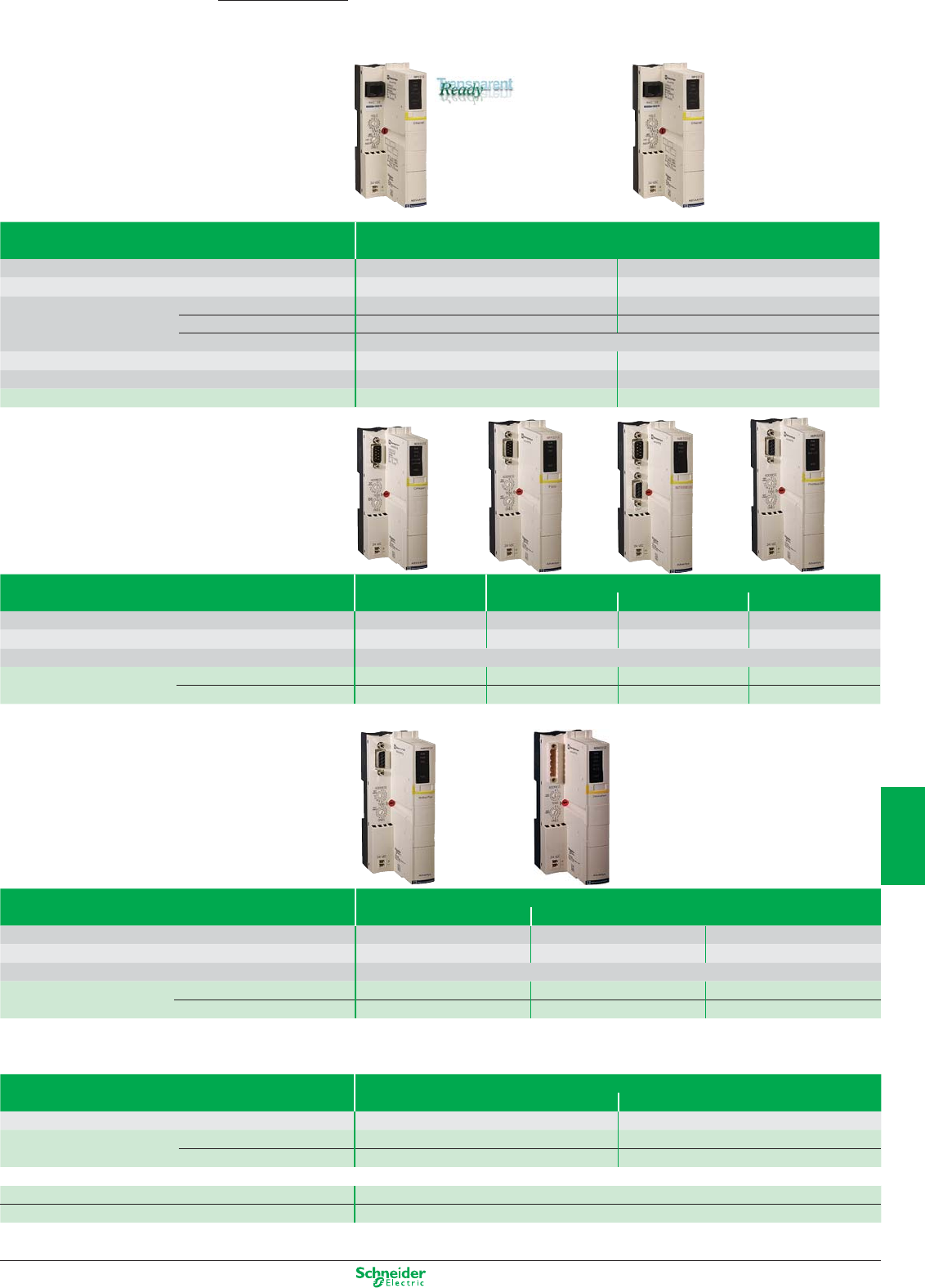
Other versions: please consult your Schneider Electric agency.
IP 20 Distributed I/O, modular system
Communication modules
Type of module NIM EtherNet TCP/IP network EtherNet/IP network
Binary speed 10 Mbps 10/100 Mbps
Protocol Modbus TCP/IP EtherNet/IP
Transparent Ready Class B20 N/A
Embedded Web server Standard services Standard services
Ethernet services
SNMP agent, FDR client (replacement of faulty equipment), BOOTP (allocation of IP addresses by a server)
Max. number of addressable I/O modules 32 per island 32 per island
Dimensions (WxDxH) 40x70x128,3 mm 40x70x128,3 mm
Reference Standard STBNIP2212 STBNIC2212
Type of module NIM Machine bus Fieldbus
CANopen Fipio I
NTER
B
US
Profibus DP
Max. number of addressable I/O modules 32 per island (1) (2) 32 per island (1) 32 per island (1) (2) 32 per island (1) (2)
Binary speed 10 K…1 Mbps 1 Mbps 0.5 Mbps 9.6 K…12 Mbps
Dimensions (WxDxH) 40x70x128,3 mm
Reference Standard STBNCO2212 STBNFP2212 STBNIB2212 STBNDP2212
Basic STBNCO1010 – STBNIB1010 STBNDP1010
(1) On 7 segments max.
(2) 12 per island on 1 segment max for basic versions.
Type of module Other networks
Modbus Plus DeviceNet
Max. number of addressable I/O modules 32 per island 32 per island 12 per island
Speed 1 Mbps 125, 250 or 500 Kbps 125, 250 or 500 Kbps
Dimensions (WxDxH) 40x70x128,3 mm
Reference Standard STBNMP2212 STBNDN2212 –
Basic – – STBNDN1010
Connection accessories
Type of accessory Removable terminals for
24 VDC power supply DeviceNet
Use All communication modules Network link DeviceNet module
Reference Screw terminals STBXTS1120 (1) STBXTS1111
Spring terminals STBXTS2120 (1) STBXTS2111
(1) To be ordered separately, sold in lots of 10 only for spares parts.(STBXTSp120 are delivered systematicaly with STBNpppppp)
Marking label sheets STBXMP6700
Screwdriver STBXTT0220
Connection accessories: See www.schneider-electric.com
Advantys STB
7/3
2
1
3
4
5
6
7
8
9
10
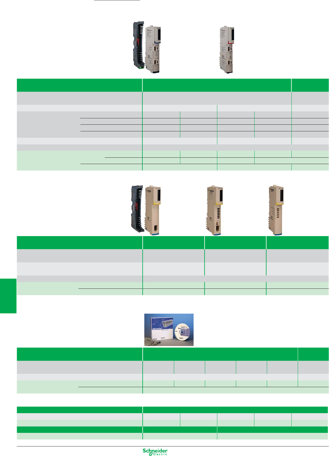
Other versions: please consult your Schneider Electric agency.
Type of module PDM Auxiliary
Power supply
Connection by removable terminals Screw STBXTS1130 (2) (3)
Screw STBXTS1120 (2)
Spring STBXTS2130 (2) (3)
Spring STBXTS2120 (2)
Supply voltage 24 VDC 115…230 VAC 24 VDC
Maximum current Inputs (4)
4 A at 30°C, 2.5 A at 60°C – 5 A at 30°C, 2.5 A at 60°C – –
Outputs (4)
8 A at 30°C, 5 A at 60°C – 10 A at 30°C, 2.5 A at 60°C – –
Inputs/Outputs (4)
– 4 A at 30°C, 2.5 A at 60°C – 5 A at 30°C, 2.5 A at 60°C –
Logique interne 5 V – – – – 1.2 A
Sensor/actuator bus voltage range 19.2…30 VDC 85…265 VAC –
Dimensions (WxDxH) 18.4x70x128.3 mm
Reference Module Standard STBPDT3100 –STBPDT2100 –STBCPS2111
Basic – STBPDT3105 – STBPDT2105
Base STBXBA2200 STBXBA2200 STBXBA2100
(1) Process power supplies see chapter 6 “Power supply”
(2) To be ordered separately, sold in lots of 10.
(3) PDM connector keying pin kit STBXMP7810.
(4) PDM fuse kit STBXMP5600.
Type of module “EOS” “BOS”
Extension for CANopen
End of segment Beginning of segment connection devices
Connection by removable terminals – Screw STBXTS1120 (2) Screw STBXTS1110 (3)
–Spring STBXTS2120 (2) Spring STBXTS2110 (3)
Use For placing at end of segment For placing at head of each For placing at end of last
(except for the last) extension segment segment
Dimensions (WxDxH) 18.4x70x128.3 mm
Reference Module Standard STBXBE1100 STBXBE1300 STBXBE2100
Base STBXBA2300 STBXBA2300 STBXBA2000
(2) To be ordered separately, sold in lots of 10. (3) To be ordered separately, sold in lots of 20.
Software and memory card
Type Advantys STB, OTB, FTM, FTB configuration software Removable
(PC connection cable supplied)
memory card
Software User Guide Single station 3 pack 10 pack Unlimited Site System Aliance –
Integrator
Memory size – 32 Ko
Reference STBSPU1000 STBSPU1003 STBSPU1011 STBSPU1130 STBSPU1010 STBXMP4440
Hardware User Guide STBSUS8800
Connection accessories
Type of accessory Câble d’extention de bus d’ilot
Length 0.3 m 1 m 4.5 m 10 m 14 m
Reference STBXCA1001 STBXCA1002 STBXCA1003 STBXCA1004 STBXCA1006
Bus termination module or plug Programmation connection cable L= 2 m
Reference STBXMP1100 STBXCA4002
Connection accessories: See www.schneider-electric.com
Bus extension modules for standard range
IP 20 Distributed I/O, modular system
Power distribution modules (1)
Advantys STB
7/4
2
1
3
4
5
6
7
8
9
10
Other versions: please consult your Schneider Electric agency.
Discrete modules
Type of module Discrete inputs
Connection by removable terminals (1) Screw (2) STBXTS1100 STBXTS1180 STBXTS1110
Spring (2) STBXTS2100 STBXTS2180 STBXTS2110
Number of channels 2 4 6 16 2 2 (isolated) 2
Input voltage 24 VDC 115 VAC 230 VAC
Dimensions (WxDxH) 13.9x70x128.3 mm 18.4x70x128.3 mm
Reference Module Standard STBDDI3230 STBDDI3420 STBDDI3610 – STBDAI5230 STBDAI5260 STBDAI7220
Basic – STBDDI3425 STBDDI3615
STBDDI3725 (4)
–––
Base (3) STBXBA1000 STBXBA3000 STBXBA2000
Type of module Discrete solid state outputs
Connection by removable terminals (1) Screw (2) STBXTS1100 STBXTS1180
Spring (2) STBXTS2100 STBXTS2100
Number of channels 24616
Output voltage 24 VDC 24 VDC 24 VDC 24 VDC
Output current 0.5 A 2 A 0.25 A 0.5 A 0.25 A 0.5 A 0.5 A
Dimensions (WxDxH) 13.9x70x128.3 mm
Reference Module Standard
STBDDO3200 STBDDO3230 – STBDDO3410 – STBDDO3600 –
Basic
– – STBDDO3415 – STBDDO3605 –
STBDDO3705 (5)
Base (3)
STBXBA1000 STBXBA3000
Type of module Discrete outputs
Triac Relay
Connection by removable terminals (1) Screw (2) STBXTS1100
Spring (2) STBXTS2100
Number of channels 2 2 (isolated) 2 “OF” 2 “O+F”
Output voltage 115…230 VAC 115 VAC 24 VDC ou 115…230 VAC
Output current 2 A à 30°C, 1 A à 60°C 2 A par contact 7 A par contact
Dimensions (WxDxH) 18.4x70x128.3 mm 28.1x70x128.3 mm
Reference Module Standard STBDAO8210 STBDAO5260 STBDRC3210 STBDRA3290
Base (3) STBXBA2000 STBXBA3000
(1) To be ordered separately, sold in lots of 20.
(2) I/O connector keying pin kit STBXMP7800
(3) Module keying pin kit STBXMP7700
(4) if connection on Telefast2 order STBXTS6510 or connection on Telefast Twido order STBXTS5510
(5) if connection on Telefast2 order STBXTS6610 or connection on Telefast Twido order STBXTS5610
Connection accessories: See www.schneider-electric.com
7/5
2
1
3
4
5
6
7
8
9
10
Other versions: please consult your Schneider Electric agency.
Type of module (1) Analog inputs
Connection by removable terminals Screw STBXTS1100 (2) / Spring STBXTS2100 (2)
Number of channels 2482
Input signal - 10…+10 V 0…+10 V 0…20 mA 4…20 mA
4…20 / 0…20 mA
Selectable Selectable
Multigamme (3)
Resolution 9 bits + sign 10 bits 12 bits 10 bits 15 bits + sign
Dimensions (WxDxH) (mm) 13,9x70x128,3 18,4x70x128,3
13,9x70x128,3
Reference Module
Standard
––STBACI1230 –STBACI0320 STBAVI0300 STBACI1400 (5) STBART0200
––––
STBACI8320 (4)
–
STBAVI1400 (6)
–
Basic STBAVI1275 STBAVI1255 –STBACI1225 ––– –
Base STBXBA1000 STBXBA2000 STBXBA1000
Type of module (1) Analog outputs
Connection by removable terminals Screw STBXTS1100 (2) / Spring STBXTS2100 (2)
Number of channels 12
Output signal
4…20 mA
- 0…+10 , - 10…+10 V
0…+10 V -10 V…+10 V 0…20 mA 4…20 mA 4…20 mA
Selectable (6)
Resolution 15 bits + sign
11 bits + sign or 12 bits
10 bits 9 bits + sign 12 bits 10 bits 15 bits + sign
Dimensions (WxDxH) (mm) 18,4x70x128,3 13,9x70x128,3 18,4x70x128,3
Reference Module Standard STBACO0120 STBAVO1250 – – STBACO1210 – STBACO0220 STBAVO0200
Basic ––STBAVO1255 STBAVO1265 – STBACO1225 – –
Base STBXBA2000 STBXBA1000 STBXBA2000
Application-specific modules
Type of module (1) For motor starters
TeSys model U
Counter
Connection by connector 4 RJ45 Spring STBXTS2150 (2)
Number of inputs/outputs 12 E / 8 S 4 E / 2 S
Input voltage 24 VDC 24 VDC
Output voltage/current 24 VDC/0.1 A per channel 24 VDC/0.5 A
Number of channels 4 starters-controllers 1 counter channel 40 kHz
Dimensions (WxDxH) (mm) 28.1x70x128.3
Reference Module Standard STBEPI2145 STBEHC3020
Base STBXBA3000
Connection cables (7) –
(7) –
(1) Grounding kit (conseilled for counter > 40 kHz): STBXSP3000 (connecting support) + STBXSP3010 (1.5…6 mm
2
cables) + STBXSP3020 (5…11 mm
2
cables)
(2) To be ordered separately, sold in lots of 20.
(3) Multirange temperature probe thermocouples B, E, J, K, R, S, T. Thermal probe Pt 100, Pt 1000, Ni 100, Ni 1000, cu 10, ± 80 mV.
(4) 4 HART-tolerant channels (5) Input signal selectable / channel 0…20 mA and 4…20 mA (6) Input signal selectable / channel 1…5 VDC, 0…5 VDC, 0…10 VDC, ± 5 VDC and ± 10 VDC
(7) LU9R03 (0,3 m), LU9R10 (1 m), 490NTW00002 (2 m), LU9R30 (3 m), 490NTW00005 (5 m), 490NTW00012 (12 m)
IP 20 Distributed I/O, modular system
Analog modules
Advantys STB
7/6
2
1
3
4
5
6
7
8
9
10
Other versions: please consult your Schneider Electric agency.
IP 67 distributed I/O, optimised block
Interface modules, plastic enclosure
Type of module CANopen
machine bus
DeviceNet
Fieldbus
ProfiBus
Fieldbus
InterBus
Fieldbus
Number of channels 16
Type of female connector M12, 5-pin
Max. voltage / current of inputs 24 VDC type 2/200 mA
Max. voltage / current of outputs 24 VDC/1.6 A
Max. current per splitter box 8 A
Product certification cULus
Dimensions, W X D x H 63 x 50.5 x 220 mm 63 x 69 x 220 mm
Diagnostics Splitter boxes By LED for: bus and I/O undervoltage + I/O short-circuit + I/O power supply
Channels By LED for: I/O short-circuit + wire breakage fault + I/O fault
References 16 inputs FTB1CN16EP0 FTB1DN16EP0 FTB1DP16EP0 FTB1IB16EP0
8 inputs/8 outputs FTB1CN08E08SP0 FTB1DN08E08SP0 FTB1DP08E08SP0 FTB1IB08E08SP0
12 inputs/4 outputs FTB1CN12E04SP0 FTB1DN12E04SP0 FTB1DP12E04SP0 FTB1IB12E04SP0
16 configurable inputs/outputs FTB1CN16CP0 FTB1DN16CP0 FTB1DP16CP0 FTB1IB16CP0
Interface modules, metal enclosure
Type of module CANopen DeviceNet ProfiBus
Number of channels 8
Type of female connector M12, 5-pin
Max. voltage / current of inputs 24 VDC type 2/200 mA
Max. voltage / current of outputs 24 VDC/1.6 A
Max. current per splitter box 8 A
Product certification cULus
Dimensions (WxDxH) 62.7 x 38.9 x 224.7 mm
Diagnostics Splitter boxes By LED for: bus and I/O undervoltage + I/O short-circuit + I/O power supply
Channels By LED for: I/O short-circuit + wire breakage fault + I/O fault
References 16 inputs FTB1CN16EM0 FTB1DN16EM0 FTB1DP16EM0
8 inputs/8 outputs/configurable outputs FTB1CN08E08CM0 FTB1DN08E08CM0 FTB1DP08E08CM0
16 configurable inputs/outputs FTB1CN16CM0 FTB1DN16CM0 FTB1DP16CM0
Advantys FTB
7/7
2
1
3
4
5
6
7
8
9
10
Other versions: please consult your Schneider Electric agency.
IP 67 distributed I/O, modular system
Interface modules
Advantys FTM
Type of bus module CANopen
machine bus
DeviceNet
fieldbus
Profibus
fieldbus
Max. number of Discrete I/O 256
Max. number of splitter boxes 16
Bus module supply voltage 24 V DC
Bus module max. supply current 9 A
Product certification UL/CSA CULus
Dimensions (WxDxH) 50 x 50.3 x 151 mm
References FTM1CN10 FTM1DN10 FTM1DP10
Splitter boxes
Type of splitter box Discrete inputs/outputs
Compact Expandable
Input voltage 24 V DC/type 2/200 mA 24 V DC/type 2/200 mA
Output voltage 24 V DC 24 V DC
Type of output Solid-state Solid-state
Output current 0.5 A 0.5 A
Maximum supply current by internal bus 4 A 4 A
Diagnostics Short-circuit on I/O, wire breakage fault, sensor/actuator fault
Dimensions (WxDxH) 30 x 34.5 x 126 mm 30 x 34.5 x 151 mm
I/O connection M8 connector M12 connector M8 connector M12 connector
References 8 inputs FTM1DE08C08 FTM1DE08C12 FTM1DE08C08E FTM1DE08C12E
8 configurable inputs/outputs FTM1DD08C08 FTM1DD08C12 FTM1DD08C08E FTM1DD08C12E
16 inputs – FTM1DE16C12 (1) – FTM1DE16C12E (1)
16 configurable inputs/outputs – FTM1DD16C12 (1) – FTM1DD16C12E (1)
(1) Dimensions: 50 x 34.5 x 126 mm.
Type of splitter box Analogue inputs/outputs
Compact
Type of inputs/outputs Current Voltage
Measuring range 0…20 mA/4…20 mA ± 10 V DC/0…10 V DC
Diagnostics Short-circuit on I/O, wire breakage fault, sensor/actuator fault
Conversion time ≤ 2 ms per channel
Dimensions (WxDxH) 30 x 34.5 x 126 mm
Resolution 16 bit 12 bit 15 bit + sign 11 bit + sign
References 4 inputs FTM1AE04C12C – FTM1AE04C12T –
4 outputs – FTM1AS04C12C – FTM1AS04C12T
7/8
2
1
3
4
5
6
7
8
9
10
Other versions: please consult your Schneider Electric agency.
Distributed I/O and processors
Discrete I/O modules
Type of module Multibus discrete inputs
Connection By screw terminals 170XTS00100 or spring terminals 170XTS00200 (to be ordered separately)
Input voltage 24 VDC 120 VAC 230 VAC
Number of channels 16 (1 common point) 32 (2 common points) 16 (2 common points)
Dimensions (WxDxH) 125 x 47.5 x 141.5 mm (with communication modules or processors)
144 x 70 x 141.5 mm (with M1/M1E processors and optional modules)
Reference 170ADI34000 170ADI35000 170ADI54050 170ADI74050
Type of module Multibus discrete outputs
Solid state Triac
Connection By screw terminals 170XTS00100 or spring terminals 170XTS00200 (to be ordered separately)
Output voltage 24 VDC 120 VAC 230 VAC
Number of protected channels 16 32 8 16 8 16
(2 common pts) (2 common pts) (2 common pts) (2 common pts) (2 common pts) (2 common pts)
Output current Per channel 0,5 A 0,5 A 2 A 0,5 A 2 A 0,5 A
Per group of channels
4 A 8 A 4 A 4 A 4 A 4 A
Per module 8 A 16 A 8 A 8 A 8 A 8 A
Dimensions (WxDxH) 125 x 47.5 x 141.5 mm (with communication modules or processors)
144 x 70 x 141.5 mm (with M1/M1E processors and optional modules)
Reference 170ADO34000 170ADO35000 170ADO53050 170ADO54050 170ADO73050 170ADO74050
Type of module Multibus discrete I/O
Solid state Relay Triac
Connection By screw terminals 170XTS00100 or spring terminals 170XTS00200 (to be ordered separately)
Number of channels Inputs
16 (1 common pt)
16 (4 com. pts) 16 (1 com. pt)
10
(1 common pt)
Input logic Positive Positive (2) Negative Positive –
Outputs
16 (1
common pt
)
16 (2 common pts)
8/4 (1
com. pt
)
12 8 (2 common pts) 8 (1 com. pt)
Input voltage 12…48 VDC 24 VDC 120 VAC
Output voltage 12…48 VDC 24 VDC 24…230 VAC/20…115 VDC 120 VAC
Output current Per output 0,5 A 0,5 A 2 A 0,5 A 2 A 0,5 A
Per group of channels
– 4 A 4 A 4/2 A 8 A 4 A
Per module 8 A 8 A 8 A 6 A 16 A 4 A
Dimensions (WxDxH) 125 x 47.5 x 141.5 mm (with communication modules or processors)
144 x 70 x 141.5 mm (with M1/M1E processors and optional modules)
Reference
170ADM85010 170ADM35010 170ADM35015 170ADM37010 170ADM39010 170ADM39030 170ARM37030 170ADM69051
(2) For a version with high-speed positive logic, replace 0 at the end of the reference with 1. E.g. 170ADM35010 becomes 170ADM35011
Connection accessories: See www.schneider-electric.com
Modicon Momentum
7/9
2
1
3
4
5
6
7
8
9
10
Other versions: please consult your Schneider Electric agency.
Type of module Multibus analog inputs
Connection By screw terminals 170XTS00100 or spring terminals 170XTS00200 (to be ordered separately)
Number of channels 8 isolated 16 with common point 4 isolated
Input signal ± 5 V, ± 10 V, ± 20 mA, ± 5 V, ± 10 V, 4...20 mA Multi-range ± 25 mV, ± 10 mV
1…5 V, 4…20 mA (1)
Resolution 14 bits + sign, 15 bits unipolar 12 bits + sign 15 bits + sign
Dimensions (WxDxH) 125 x 47.5 x 141.5 mm (with communication modules or processors)
144 x 70 x 141.5 mm (with M1/M1E processors and optional modules)
Reference 170AAI03000 170AAI14000 170AAI52040
(1) Temperature probe: Pt 100, Pt 1000, Ni 100, Ni 1000, Thermocouple: B, E, J, K, N, R, S, T.
Type of module Multibus analog outputs
Analog I/O and
multibus discrete I/O
Connection By screw terminals 170XTS00100 or spring terminals 170XTS00200 (to be ordered separately)
Number of channels Inputs – 4 differential + 4 discrete
6 with com pt + 8 discrete (24 VDC)
Outputs 4
2 + 2 discrete (24VDC) 2 + 2 discrete (12VDC)
4 with com pt + 8 discrete (24 VDC)
Input signal
± 10 V, 0...20 mA ± 10 V, 4...20 mA
± 5 V, ± 10 V, ± 20 mA,
1…5 V, 4…20 mA
0…10 V ± 10 V
Output signal – ± 10 V, 4...20 mA 0…10 V ± 10 V
Resolution 12 bits + sign 12...14 bits dep. on signal 14 bits 14 bits
Dimensions (WxDxH) 125 x 47.5 x 141.5 mm (with communication modules or processors)
144 x 70 x 141.5 mm (with M1/M1E processors and optional modules)
Reference 170AAO12000 170AAO92100 170AMM09000 170AMM09001 170ANR12090 170ANR12091
Application-specific I/O modules
Type of module High-speed counter Discrete I/O
with Modbus port
Connection By screw terminals 170XTS00100 or spring terminals 170XTS00200 (to be ordered separately)
Type of inputs for Incremental or absolute encoders RS 485 Modbus port
Operating voltage 24 VDC 120 VAC
Counting frequency 200 kHz –
Number of channels 2 independent –
Number of discrete I/O 2 x 3 inputs/2 x 2 outputs 6 inputs/3 outputs
Dimensions (WxDxH) 125 x 47.5 x 141.5 mm (with communication modules or M1/M1E processors)
144 x 70 x 141.5 mm (with M1/M1E processors and optional modules)
Reference 170AEC92000 170ADM54080
Distributed I/O and processors
Analog I/O modules
Modicon Momentum
7/10
2
1
3
4
5
6
7
8
9
10
Other versions: please consult your Schneider Electric agency.
Distributed I/O and processors
Communication modules
Type of module Ethernet Fipio I
NTER
B
US
(1) Profibus DP
TCP/IP network fieldbus fieldbus fieldbus
Speed 10 Mbps 10/100 Mbps 1 Mbps 0.5 Mbps 9.6 K…12 Mbps
Manager PLC – Premium - -
Redundancy No No No No
Standard services Modbus TCP/IP – – –
Reference 170ENT11002 170ENT11001 170FNT11001 170INT11000 (1) 170DNT11000
(1) Generation 4, twisted pair medium: 170INT11003, with optical fiber medium: 170INT12000
Type of module Other networks
Modbus Plus DeviceNet
Speed 1 Mbps 0.5 Mbps
Manager PLC Premium or Quantum Quantum –
Redundancy No Yes No
Standard services –––
Reference 170PNT11020 170PNT16020 170LNT71000
Optional modules for M1/M1E processors
Type of module (2) Modbus Plus Asynchronous serial link
Communication ports 1 Modbus Plus 2 redundant Modbus Plus RJ45
Real-time clock Integrated, ± 13 sec/day accuracy
Connection By 9-way SUB-D connector
Reference 172PNN21022 172PNN26022 172JNN21032
(2) Include save battery of the M1/M1E processors application and data memories.
Connection accessories
Type RS 232C communication cable
Length 1 m 3 m 6 m
Reference 110XCA28201 110XCA28202 110XCA28203
Power supply module (3)
Type of power supply module for
Momentum processors
Input voltage 120 or 230 VAC (selected by jumper)
Output voltage 24 VDC
Output current 0.7 A
Dimensions (WxDxH) 73 x 44.5 x 146 mm
Reference 170CPS11100
(3) Process power supplies see chapter 6 “Power supply”
Modicon Momentum
7/11
2
1
3
4
5
6
7
8
9
10
Other versions: please consult your Schneider Electric agency.
Type of processor M1
Number of I/O Discrete 2048 I/O 2048 I/2048 Q 8192 I/O
Registers 2048 words 4096 words 26048 words
Integrated communication ports
Modbus 1 RS 232C
1 RS 232C + 1 RS 485
1 RS 232C
1 RS 232C + 1 RS 485
Ethernet TCP/IP –
I/O bus (1) – 1 I/O port –
Transparent Ready Embedded Web server –
Memory capacity RAM 64 Kb 256 Kb 512 Kb
Flash 256 Kb 256 Kb 512 Kb
User, 984 LL language (2) 2.4 K 12 K 18 K
User, IEC language (3) – 160 K 240 K
Data 2 K 4 K 24 K
Cycle time 1 ms/K 1 ms/K 0.63 ms/K 1 ms/K
Reference 171CCS70000 171CCS78000 171CCS76000 171CCC78010
(1) I/O bus derived from INTERBUS bus.
(2) ProWORX 32 or Concept programming software.
(3) Concept programming software.
Type of processor M1 M1E
Number of I/O Discrete 8192 I/O
Registers 26048 words
Integrated communication ports
Modbus 1 RS 232C 1 RS 485 –
Ethernet TCP/IP – 1 integrated Ethernet port
I/O bus (1) 1 I/O port – 1 I/O port
Transparent Ready Embedded Web server – Standard services (class A10)
Memory capacity RAM 512 Kb 544 Kb
Flash 512 Kb 1 Mb 512 Kb 1 Mb
User, 984 LL language (2) 18 K
User, IEC language (3) 240 K – 200 K – 200 K
Data 24 K
Cycle time 1 ms/K 0.3 ms/K
Reference 171CCC76010 171CCC98020 171CCC98030 171CCC96020 171CCC96030
Type of processor 171 CBB97030
Integrated communication ports
Modbus 1 RS 232/485
Ethernet TCP/IP 4 integrated Ethernet port
Transparent Ready Embedded Web server Standard services (class B)
Memory capacity RAM 512 Kb
Flash 1 Mb
User, 984 LL language (2) 18 K
User, IEC language (3) 200 K
Data 24 K
Cycle time 0.25 ms/K
Reference 171CBB97030
Connection accessories: See www.schneider-electric.com
Distributed I/O and processors
M1/M1E processors
Modicon Momentum
7/12
2
1
3
4
5
6
7
8
9
10
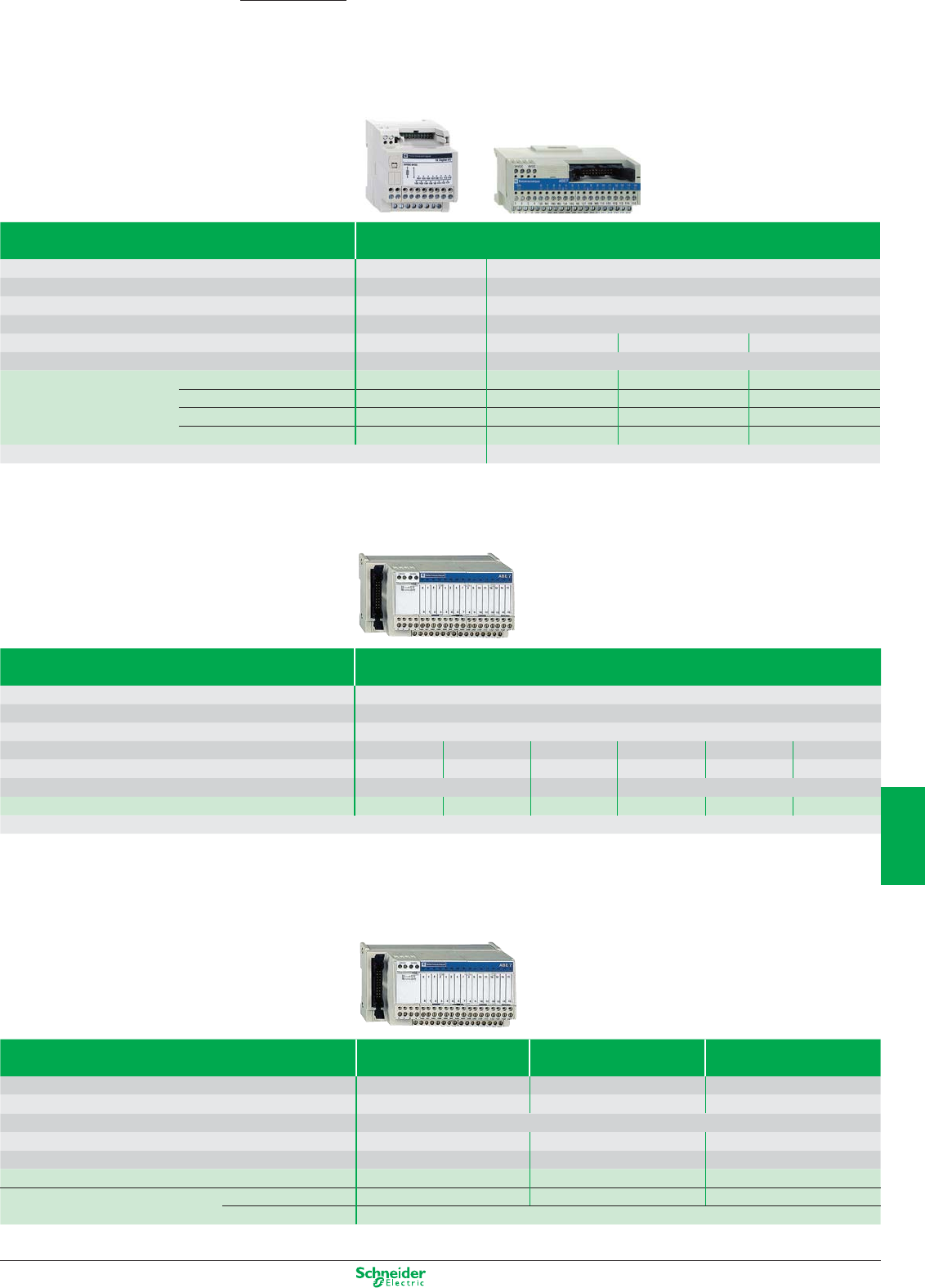
Other versions: please consult your Schneider Electric agency.
Telefast® pre-wired system
Passive I/O sub-bases «Discrete»
Type of connection sub-base Optimum
Number of channels 16 16
Max. current per channel 0.5 A 0.5 A
Control voltage / output voltage 24 VDC / 24 VDC 24 VDC / 24 VDC
LED per channel – With
Number of terminals per channel/on row number 1/2 1/1 2/2 3/3
Dimensions (WxDxH) 55 x 59 x 67 mm 106 x 60 x 49 mm
References – ABE7H16C11 ABE7H16C21 ABE7H16C31
Cable L = 1 m ABE7H20E100 (1) –––
Cable L = 2 m ABE7H20E200 (1) –––
Cable L = 3 m ABE7H20E300 (1) –––
Connection cable recommended for Modicon, TSX Micro and Premium PLCs, L = 1 m (2) ABFH20H100
(1) Connection cable supplied for PLCs.
(2) For a 2 m length cable, replace the number 1 in the reference by 2, and for a 3 m length, by 3. (Example: ABFH20H100 becomes ABFH20H200).
Type of connection sub-base Universal
Number of channels 16
Max. current per channel 0.5 A
Control voltage / output voltage 24 VDC / 24 VDC
LED per channel – With ––With With
Number of terminals per channel/on row number 1/1 1/1 1/2 2/2 2/2 3/3
Dimensions (WxDxH)
125 x 58 x 70 mm
84 x 58 x 70 mm
125 x 58 x 70 mm
References ABE7H16R10 ABE7H16R11 ABE7H16R50 ABE7H16R20 ABE7H16R21 ABE7H16R31
Connection cable recommended for Modicon, TSX Micro and Premium PLCs, L = 1 m: ABFH20H100 (2)
(2) For a 2 m length cable, replace the number 1 in the reference by 2, and for a 3 m length, by 3. (Example: ABFH20H100 becomes ABFH20H200).
Type of connection sub-base For counter and Passive distribution Distribution and supply
analogue channels with shielding continuity of analogue channels
Number of channels 1 counter channel (3) 8 8
Max. current per channel 25 mA 25 mA 25 mA
Control voltage / output voltage 24 VDC / 24 VDC
Number of terminals per channel 2 2 or 4 2 or 4
Dimensions (WxDxH) 143 x 58 x 70 mm 125 x 58 x 70 mm 125 x 58 x 70 mm
References ABE7CPA01 ABE7CPA02 ABE7CPA03
Connection cable recommended
for Modicon PLCs (4)
TSX Micro L = 2.5 m TSXCCPS15 ––
Premium L = 3 m TSXCAP030
(3) Or 8 inputs + 2 outputs, analogue .
(4) Connection cables available for other PLCs, please refer to your Schneider Electric agency.
Advantys ABE7
7/13
2
1
3
4
5
6
7
8
9
10
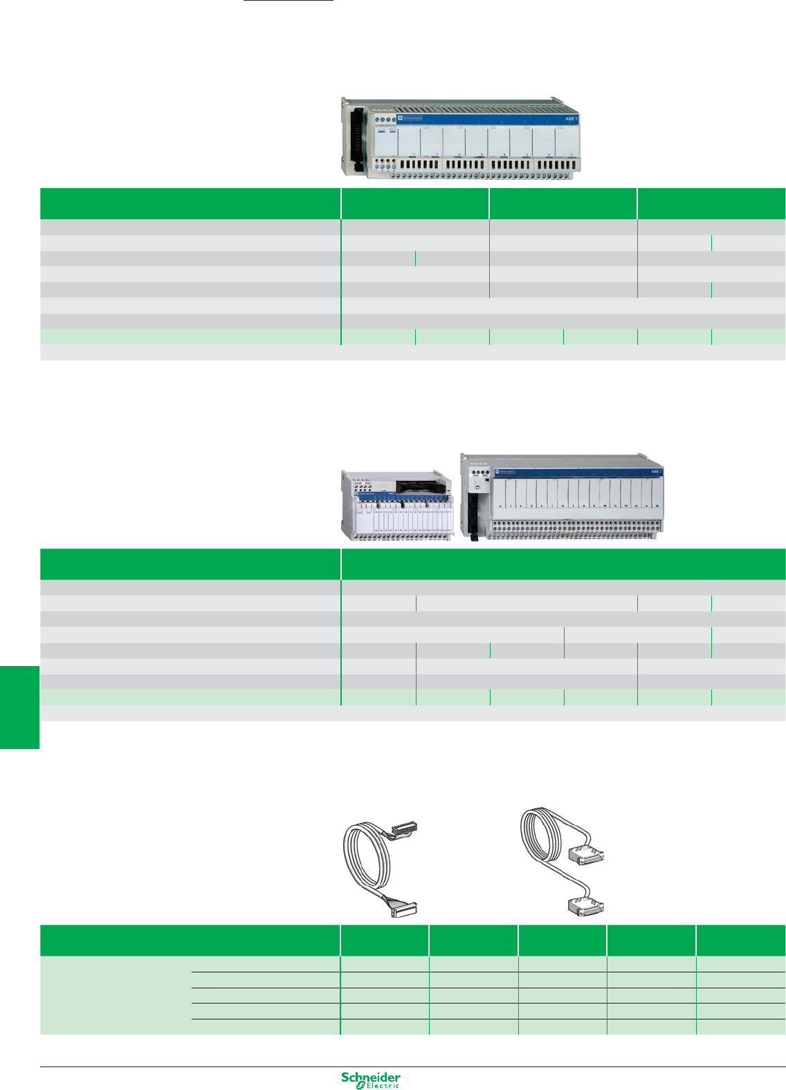
Other versions: please consult your Schneider Electric agency.
Type of connection sub-base With soldered solid-state
relay inputs
With soldered solid-state With soldered electro-
relay outputs mechanical relay outputs
Number of channels 16 16 16
Max. current per channel 12 mA 0.5 A 2 A 5 A
Input voltage / output voltage 24 VDC / - 110 VAC / - - / 24 VDC - / 5…30 VDC, 250 VAC
Number of contacts – – 1 N/O
Polarity distribution – – (1) Volt-free
Number of terminals per channel 2
Dimensions (WxDxH) 206 x 58 x 77 mm
References ABE7S16E2B1 ABE7S16E2F0
ABE7S16S2B0(2)
ABE7S16S1B2 ABE7R16S111 ABE7R16S210
Connection cable recommended for Modicon, TSX Micro and Premium PLCs, L = 1 m: ABFH20H100 (3)
(1) Contact common per group of 8 channels.
(2) With fault detection signal (can only be used with modules with protected outputs).
(3) For a 2 m length cable, replace the number 1 in the reference by 2, and for a 3 m length, by 3. (Example: ABFH20H100 becomesABFH20H200).
Type of connection sub-base With plug-in electromechanical relays
Number of channels 16
Max. current per channel 5 A 2.5 A 4 A 5 A
Control voltage / output voltage 24 VDC / 5…24 VDC, 230 VAC
Number of contacts 1 N/O 1 C/O 2 C/O
Polarity distribution (4) (5) Volt-free
Number of terminals per channel 2 2 or 3 2 to 6
Dimensions (WxDxH) 110x54x89 mm 211 x 64 x 89 mm 272 x 74 x 89 mm
References ABE7R16T111 ABE7R16T212 ABE7R16T210 ABE7R16T230 ABE7R16T330 ABE7R16T370
Connection cable recommended for Modicon, TSX Micro and Premium PLCs, L = 1 m: ABFH20H100 (6)
(4) Contact common per group of 4 channels.
(5) Common on both poles.
(6) For a 2 m length cable, replace the number 1 in the reference by 2, and for a 3 m length, by 3. (Example: ABFH20H100 becomes ABFH20H200).
Connection cables for PLCs (7)
Input/Output functions Discrete Analogue Analogue
and counter
Counter Axis control
References Cable L = 1 m ABFH20H100 – – – –
Cable L = 2 m ABFH20H200 ABFY25S200 – – TSXCXP213
Cable L = 2.5 m – – TSXCCPS15 TSXCCPH15 –
Cable L = 3 m ABFH20H300 TSXCAP030 – – –
Cable L = 6 m – – – – TSXCXP613
(7) Modicon, TSX Micro and Premium PLCs.
For other connection cables and accessories, please refer to your Schneider Electric agency.
Telefast® pre-wired system
Sockets with plug-in relays and terminals
Advantys ABE7
7/14
2
1
3
4
5
6
7
8
9
10
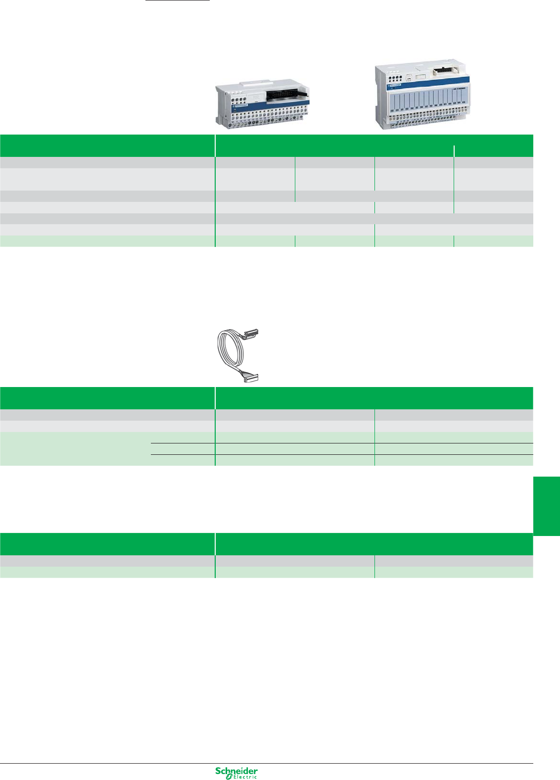
Other versions: please consult your Schneider Electric agency.
Telefast® connection interfaces
Sub-bases for input/output module
Advantys ABE7
Type of connection sub-base Discrete outputs
Relay
Number of channels 16 16 16 16
Type of outputs 16 I 16 O 16 O, fuse protected 16 O
(1 common for 16 channels) (1 common for 16 channels) (1 common for 16 channels) (1 common for 4 channels)
Voltage / current of outputs 24 VDC / 5 mA 24 VDC / 0.1 A
Relay: 5…30 VDC, 250 VAC / 3 A
LED per channel – With –
Number of terminals per channel/row number 2/2
Dimensions (WxDxH) 106 x 60 x 49 mm 130 x 62.5 x 83 mm
References ABE7E16EPN20 ABE7E16SPN20 ABE7E16SPN22 ABE7E16SRM20
Connection cables for Twido
Type of cable For linking Twido and Telefast sub-base
For use with TWDLMDA20DTK/40DTK TWDDI16DK/32DK/DDO16TK/32TK
Type of connectors HE10, 26-pin, at either end HE10, 20-pin, at either end
References Cable L = 0.5 m ABFT26B050 ABFT20E050
L = 1 m ABFT26B100 ABFT20E100
L = 2 m ABFT26B200 ABFT20E200
Accessories
Type of accessory Optional clip-in terminals
Number of linked terminals 20 12 + 8
References ABE7BV20 ABE7BV20TB
7/15
2
1
3
4
5
6
7
8
9
10
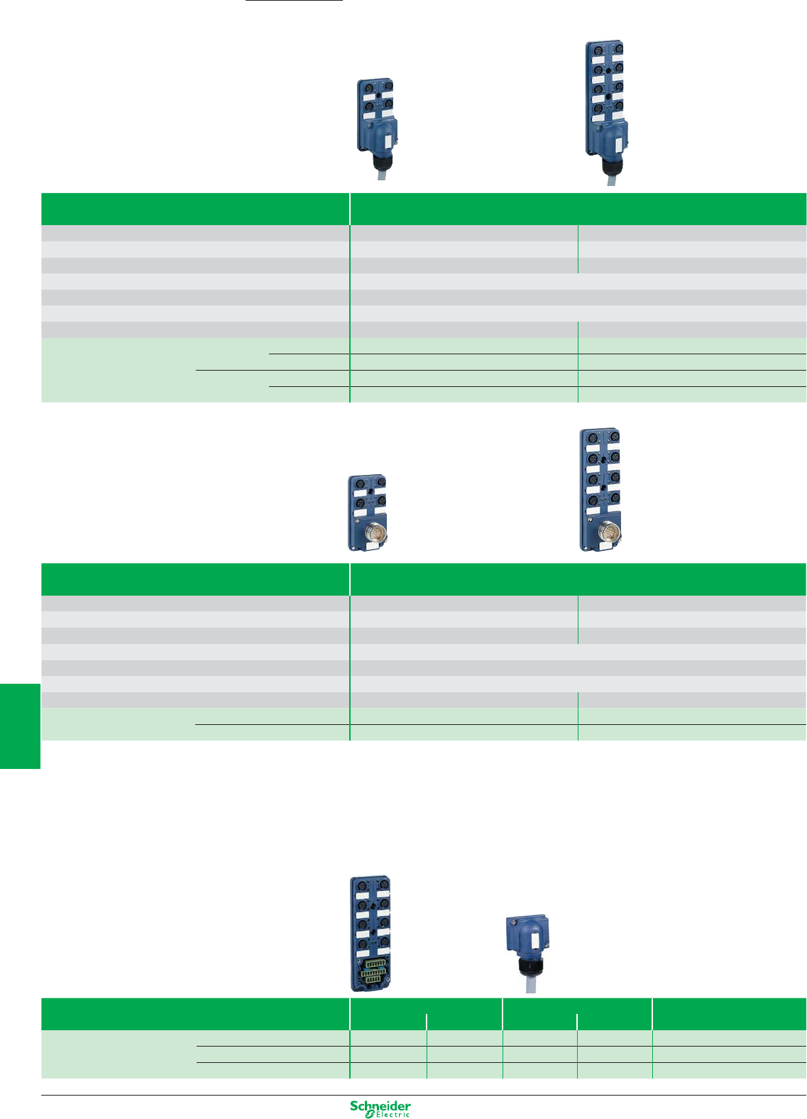
Other versions: please consult your Schneider Electric agency.
Passive splitter boxes
IP 67
Advantys ABE9
Type of connection To PLC using multicore cable
Number of channels 48
Type of female connector M12, 5-pin M12, 5-pin
Max. number of signals 816
Max. current per channel 4 A
Max. current per splitter box 16 A (1 mm
2
)
Product certification cULus
Dimensions (WxDxH) 50.2 x 42 x 92.2 mm 50.2 x 42 x 149.2 mm
References Without LEDs Cable L = 5 m ABE9C1240L05 ABE9C1280L05
Cable L = 10 m ABE9C1240L10 ABE9C1280L10
With LEDs (1) Cable L = 5 m ABE9C1241L05 ABE9C1281L05
Cable L = 10 m ABE9C1241L10 ABE9C1281L10
(1) Green LED: power supply status, yellow LED: channel status.
Type of connection To PLC using M23 connector
Number of channels 48
Type of female connector M12, 5-pin M12, 5-pin
Max. number of signals 816
Max. current per channel 4 A
Max. current per splitter box 16 A
Product certification cULus
Dimensions, W X D x H 50.2 x 36.5 x 92.2 mm 50.2 x 36.5 x 149.2 mm
References Without LEDs ABE9C1240C23 ABE9C1280C23
With LEDs (1) ABE9C1241C23 ABE9C1281C23
(1) Green LED: power supply status, yellow LED: channel status.
Accessories
Type of accessory Splitter boxes w/o cable Terminal connectors Sealing plugs
Without LEDs With LEDs Cable L = 5 m
Cable L = 10 m
(sold in lots of 10)
References 4-channel ABE9C1240M ABE9C1241M ABE9XCA1405 ABE9XCA1410 –
8-channel ABE9C1280M ABE9C1281M ABE9XCA1805 ABE9XCA1810 –
for Ø12 connector – – – – FTXCM12B
7/16
2
1
3
4
5
6
7
8
9
10
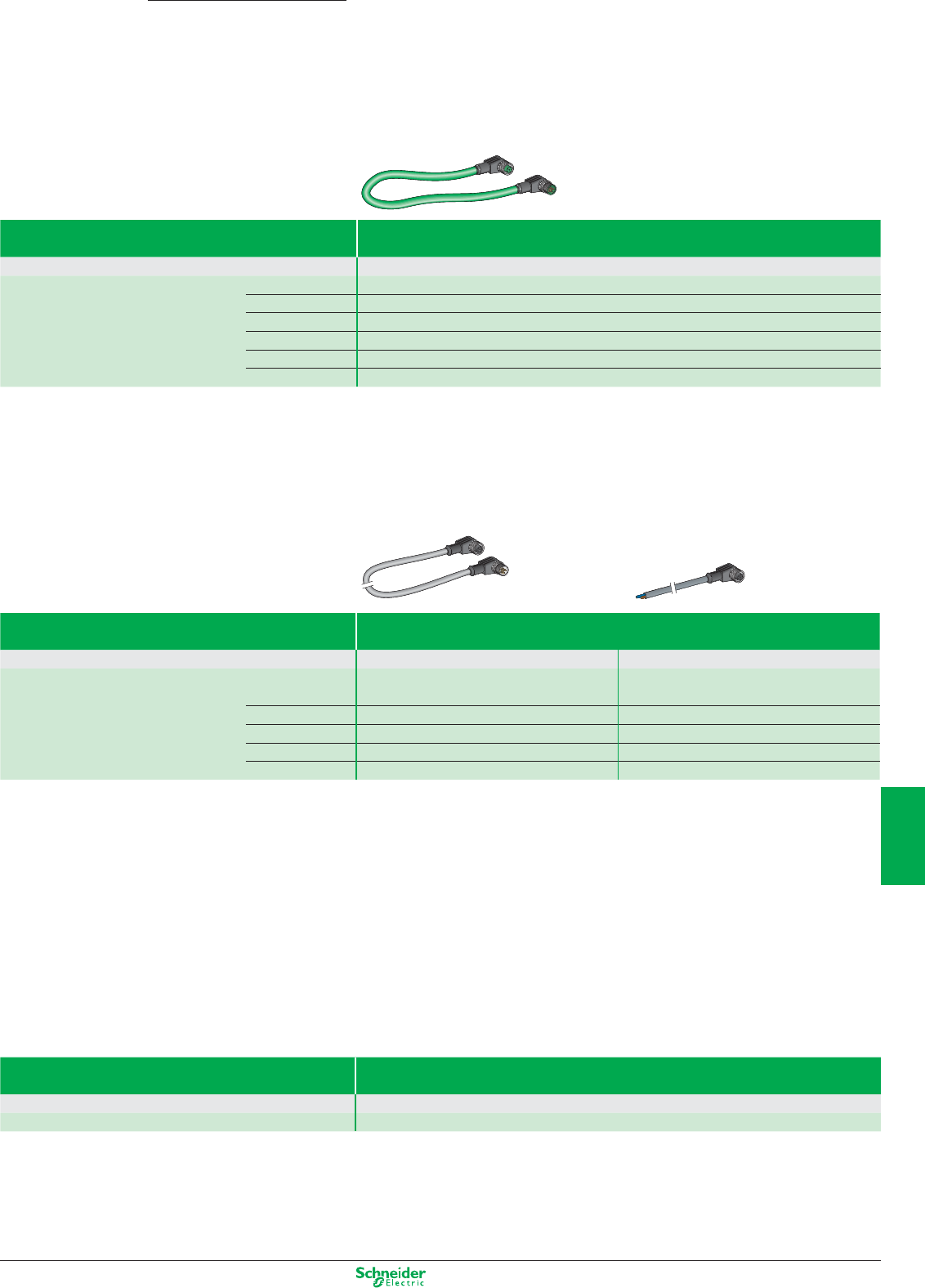
Other versions: please consult your Schneider Electric agency.
Accessories for distributed I/O FTM (1)
Internal bus connection cables
(1) For sensor/actuator cabling accessories, see page 7/13
Type of cable For linking bus module and splitter boxes
Type of connector Elbowed M12, 6-pin, at either end
References Cable L = 0.3 m FTXCB3203
L = 0.6 m FTXCB3206
L = 1 m FTXCB3210
L = 2 m FTXCB3220
L = 3 m FTXCB3230
L = 5 m FTXCB3250
Auxiliary power supply connection cables
Type of cable For connection of 24 V DC auxiliary power supply
Type of connector Elbowed M12, 6-pin, at either end Elbowed M12, 6-pin, at one end (other end free)
References Cable L = 0.3 m FTXCA3203 FTXCA3103
L = 0.6 m FTXCA3206 FTXCA3106
L = 1 m FTXCA3210 FTXCA3110
L = 2 m FTXCA3220 FTXCA3120
L = 3 m FTXCA3230 FTXCA3130
L = 5 m FTXCA3250 FTXCA3150
Accessories
Type Line terminator for end of internal bus
Type of connector M12
References FTXCBTL12
Advantys
7/17
2
1
3
4
5
6
7
8
9
10
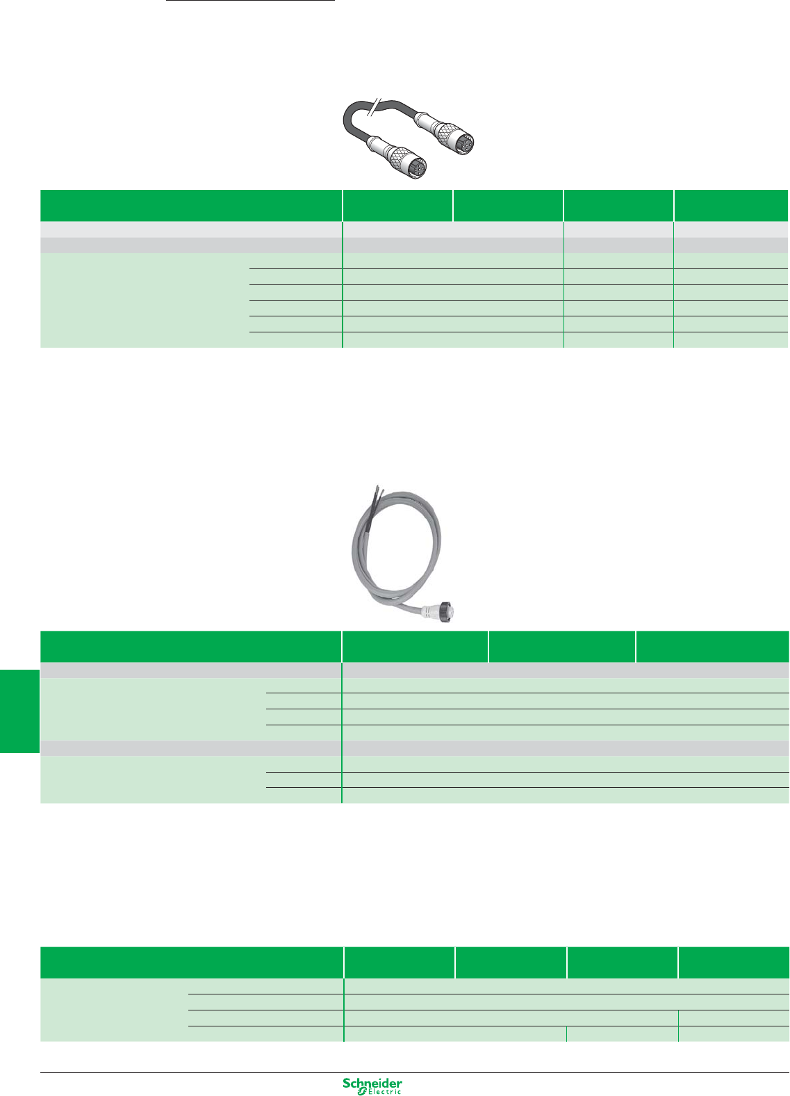
Other versions: please consult your Schneider Electric agency.
Accessories for distributed I/O FTB/FTM (1)
Bus connection cables
Power supply connection cables
Type of bus CANopen DeviceNet ProfiBus
machine bus fieldbus fieldbus
Type of female connector Type 7/8, 5-pin, at either end
References Cable L = 0.6 m FTXDP2206
L = 1 m FTXDP2210
L = 2 m FTXDP2220
L = 5 m FTXDP2250
Type of female connector Type 7/8, 5-pin, at one end (other end free)
Cable L = 1.5 m FTXDP2115
References L = 3 m FTXDP2130
L = 5 m FTXDP2150
Accessories
Type of bus CANopen DeviceNet ProfiBus I
NTER
B
US
machine bus fieldbus fieldbus fieldbus
References Configuration CD-ROM FTXES00
Diagnostics M12 adaptor FTXDG12
Power supply T-connector FTXCNCT1 –
Line terminator FTXCNTL12 FTXDPTL12 –
(1) For sensor and actuator cabling accessories:
see page 7/17
Advantys
Type of bus CANopen DeviceNet ProfiBus I
NTER
B
US
machine bus fieldbus fieldbus fieldbus
Type of female connector M12, 5-pin, at either end –
Connector coding A encoded B encoded –
References Cable L = 0.3 m FTXCN3203 FTXDP3203 –
L = 0.6 m FTXCN3206 FTXDP3206 FTXIB1206 (2)
L = 1 m FTXCN3210 FTXDP3210 FTXIB1210 (2)
L = 2 m FTXCN3220 FTXDP3220 FTXIB1220 (2)
L = 3 m FTXCN3230 FTXDP3230 –
L = 5 m TXCN3250 FTXDP3250 FTXIB1250 (2)
(2) Reference includes the Bus connection cable + the power supply cable.
7/18
2
1
3
4
5
6
7
8
9
10
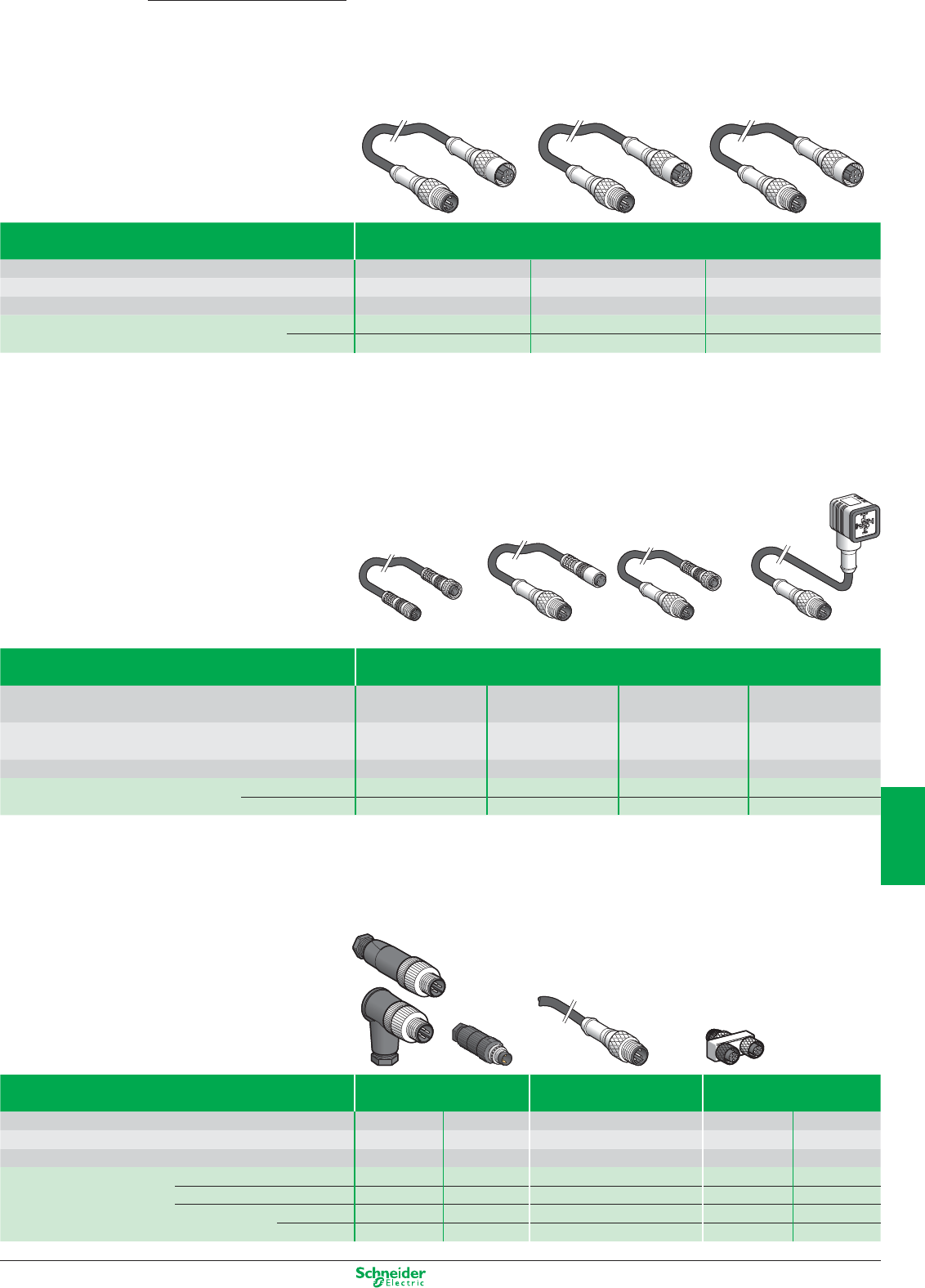
Other versions: please consult your Schneider Electric agency.
Accessories for sensors/actuators
M12 / M12 jumper cables
Type Male / Female jumper cables
Type of male connector, interface side M12, 4-pin, straight, screw thread M12, 4-pin, straight, screw thread M12, 5-pin, straight, screw thread
Type of female connector, sensor side M12, 3-pin, straight, screw thread M12, 4-pin, straight, screw thread M12, 5-pin, straight, screw thread
Cable PUR, black PUR, black PUR, black
References Cable L = 1 m XZCR1511040A1 XZCR1511041C1 XZCR1511064D1
L = 2 m XZCR1511040A2 XZCR1511041C2 XZCR1511064D2
M8/M8, M8/M12 and M12/DIN jumper cables
M8/M8, M8/M12 and M12/DIN jumper cables
Type Male / Female jumper cables
Type of male connector, interface side M8, 3-pin M12, 3-pin M12, 3-pin M12, 3-pin
straight, screw thread straight, screw thread straight, screw thread straight, screw thread
Type of female connector, sensor side M8, 3-pin M8, 3-pin M8, 3-pin DIN 43650A
straight, screw thread straight, clip together straight, screw thread elbowed, screw thread
Cable PUR, black PUR, black PUR, black PUR, black
References Cable L = 1 m XZCR2705037R1 XZCR1501040G1 XZCR1509040H1 XZCR1523062K1
L = 2 m XZCR2705037R2 XZCR1501040G2 XZCR1509040H2 XZCR1523062K2
Pre-wired connectors and splitter box
Type Connectors Pre-wired connectors Splitter box “Y”
Type of male connector, interface side M12, 4-pin M8, 3-pin M12, 5-pin, straight, screw thread 1 x M12 1 x M12
Type of female connector, sensor side –––2 x M12 2 x M8
Cable – – PUR, black –
References Straight connector, screw thread
XZCC12MDM40B XZCC8MDM30V
– FTXCY1212 FTXCY1208
Elbowed connector, screw thread
XZCC12MCM40B
–– – –
Cable L = 0.5 m – – XZCP1564L05 – –
L = 2 m – – XZCP1564L2 – –
Advantys
7/19
2
1
3
4
5
6
7
8
9
10
Schneider Electric provides you with indus-
trial networking communication solutions.
With the intelligent remote or embedded
modules for PLCs, devices and standalone
equipments, you benefit from many advan-
ced features, services and tools, that keep a
close eye on your automation applications,
giving you consistant information for an ac-
curate control and maintenance.
FactoryCast
The scalable
FactoryCast and
FactoryCast Gateway ranges,
tailored to meet all your
needs, bring you open
solutions for a multiplicity
of services.
AS-Interface
A quick and expandable
cabling system:
• Only 1 cable for connecting
all the components of an
automation system
• Management of communications integrated in
the products.
ConneXium
ConneXium products are fully interoper-
able with other Schneider Electric auto-
mation products, so you are assured of
reliable, dependable performance when
integrated as a part of a complete
Schneider Electric automation solution.

Networks connectivity
and Web servers
This document is a selection of
the top selling products.
8/1
2
1
3
4
5
6
7
8
9
10
ConneXium cabling system
Hub, Transceiver, IP 67 Switch ............................................................................................... 8/2
Switches ....................................................................................................................... 8/3 to 8/6
Gateways & Converters ......................................................................................................... 8/7
ConneXview Software ............................................................................................................ 8/8
Cables & Connectors ............................................................................................................. 8/9
AS-Interface cabling system
Advantys interfaces for generic products .................................................8/10 and 8/11
IP20 interfaces
IP67 interfaces
Dedicated components .................................................................................... 8/12 and 8/13
For control
For dialogue
Installation system ................................................................................................ 8/14 to 8/16
Master modules, power supply units
Cables, repeaters
Accessories
Tools ....................................................................................................................................... 8/17
Adjustment and addressing terminals
Safety solutions
Safety monitors
Safety interfaces
see Chapter 9 “Machine safety”
Servers and Gateways
Data server software,
OPC Factory Server ................................................................................................................. 8/18
Embedded Web Servers,
FactoryCast and FactoryCast HMI ......................................................................................... 8/19
Web Gateways for Remote control,
FactoryCast Gateway and FactoryCast HMI Gateway ........................................... 8/20 and 8/21
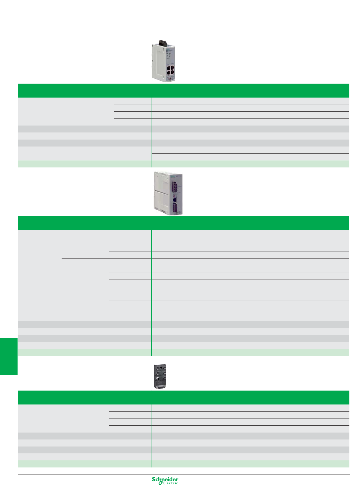
Other versions: please consult your Schneider Electric agency.
Ethernet TCP/IP, Transparent Ready
Cabling system: ConneXium Hub, Transceiver
and Switch
Hub
Interfaces Copper cable ports Number and type 4 x 10BASE-T ports
Shielded connectors
RJ45
Medium Shielded twisted pair, category CAT 5E
Total length of pair 100 m
Power supply Voltage 24 V (18…32) DC, safety extra low voltage (SELV)
Degree of protection IP 30
Dimensions W x H x D 40 x 125 x 80 mm
Conformity to standards cUL 60950, UL 508 and CSA 142, UL 1604 and CSA 213 Class 1 Division 2, e, GL
FM 3810, FM 3611 Class 1 Division 2 , C-TICK
Reference 499 NEH 104 10
Transceiver
Interfaces Copper cable ports Number and type 1 x 100BASE-TX port
Shielded connectors RJ45
Medium Shielded twisted pair, category CAT 5E
Total length of pair 100 m
Fiber optic ports Number and type 1 x 100BASE-FX port
Connectors SC
Medium Multimode optical fiber
Length of optical fiber
50/125 µm fiber 3000 m (1)
62.2/125 µm fiber 3000 m (1)
Attenuation analysis
50/125 µm fiber 8 dB:
62.2/125 µm fiber 11 dB:
Power supply Voltage 24 V (18…32) DC, safety extra low voltage (SELV)
Degree of protection IP 20
Dimensions W x H x D 47 x 135 x 111 mm
Conformity to standards cUL 60950, UL 508 and CSA 142, UL 1604 and CSA 213 Class 1 Division 2, e, GL , C-TICK
Reference 499 NTR 101 00
(1) Length dependent on the attenuation analysis and attenuation of the optical fiber (typical value: 2000 m).
IP 67 switch Twisted pair, unmanaged
Interfaces Copper cable ports Number and type 5 x 10BASE-T/100BASE-TX ports
Shielded connectors M12 (type D)
Medium Shielded twisted pair, category CAT 5E
Total length of pair 100 m with rated cable
Power supply Voltage 24 VDC (18…32 VDC), safety extra low voltage (SELV)
Degree of protection IP 65/67
Dimensions W x H x D 60 x 126 x 31 mm
Conformity to standards cUL 508 and CSA 22.2 14 , C-TICK
Reference TCS ESU 051 F0
ConneXium
8/2
2
1
3
4
5
6
7
8
9
10
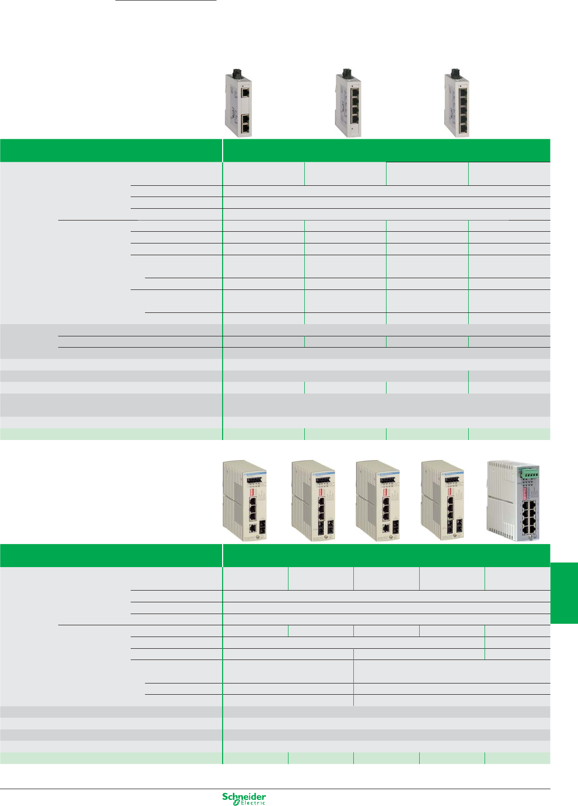
Other versions: please consult your Schneider Electric agency.
Ethernet TCP/IP, Transparent Ready
Cabling system: ConneXium unmanaged switches
ConneXium
Switches Copper twisted pair, unmanaged
Interfaces Copper cable ports Number and type
3 x 10BASE-T/ 100BASE-TX
ports
4 x 10BASE-T/ 100BASE-TX
ports
5 x 10BASE-T/ 100BASE-TX
ports
8 x 10BASE-T/ 100BASE-TX
ports
Shielded connectors Type RJ45
Medium Shielded twisted pair, category CAT 5E
Total length of pair 100 m
Fiber optic ports Number and type – 1 x 100BASE-FX ports – –
Connectors – Duplex SC – –
Medium – Multimode optical fiber – –
Length of optical fiber
50/125 µm fiber – 5000 m (1) – –
62,2/125 µm fiber – 4000 m (1) – –
Attenuation analys
50/125 µm fiber – 8 dB – –
62,2/125 µm fiber – 11 dB – –
Power supply Voltage, safety extra low voltage (SELV) c 24 VDC (c 9,6…32 VDC)
Power consumption Max. 2,2 W Max. 3,9 W Max. 2,2 W Max. 4,1 W
Connector 3 way removable connector
Degree of protection IP 30
Dimensionss W x H x D 25 x 114 x 79 mm 35 x 138 x 121 mm
Weight 0,113 kg 0,120 kg 0,113 kg 0,246 kg
Conformity to standards UL 508 and CSA 22.2 N° 142
IEC/EN 61131-2, IEC 60825-1 class 1, CISPR 11A
Alarm relay –
Reference TCS ESU 033FN0 TCS ESU 043F1N0 TCS ESU 053FN0 TCS ESU 083FN0
(1) Length dependent on the attenuation analysis and attenuation of the fi ber optic (typical value: 2,000 m).
Switches Copper twisted pair and fibre optic, unmanaged
Interfaces Copper cable ports Number and type 4 x 10BASE-T/
100BASE-TX ports
3 x 10BASE-T/
100BASE-TX ports
4 x 10BASE-T/
100BASE-TX ports
3 x 10BASE-T/
100BASE-TX ports
8 x 10BASE-T/
100BASE-TX ports
Shielded connectors RJ45
Medium Shielded twisted pair, category CAT 5E
Total length of pair 100 m
Fiber optic ports Number and type
1 x 100BASE-FX port 2 x 100BASE-FX ports 1 x 100BASE-FX port 2 x 100BASE-FX ports
–
Connectors SC –
Medium Multimode optical fiber Single mode optical fiber –
Length of optical fiber
5000 m (1)
––
50/125 µm fiber
62.2/125 µm fiber 4000 m (1) – –
9/125 µm fiber – 32 500 m (2) –
Power supply Voltage 24 VDC (18…32), safety extra low voltage (SELV)
Degree of protection IP 20
Dimensions W x H x D 47 x 135 x 111 mm
Conformity to standards cUL 60950, cUL 508 and CSA 142, UL 1604 and CSA 213 Class 1 Division 2, e, GL , C-TICK
References 499 NMS 251 01 499 NMS 251 02 499 NSS 251 01 499 NSS 251 02 499 NES 181 00
(1) Length dependent on the attenuation analysis and attenuation of the fiber optic (typical value: 2,000 m).
(2) Length dependent on the attenuation analysis and attenuation of the fiber optic (typical value: 15,000 m).
8/3
2
1
3
4
5
6
7
8
9
10
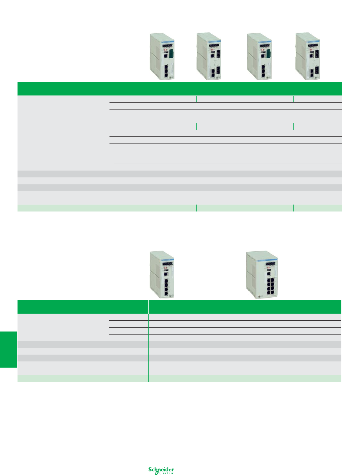
Other versions: please consult your Schneider Electric agency.
Ethernet TCP/IP, Transparent Ready
Cabling system: ConneXium managed switches
ConneXium
Switches Copper twisted pair and fiber optic, managed
Interfaces Copper cable ports Number and type 3 x 10/100BASE-TX ports 2 x 10/100BASE-TX ports 3 x 10/100BASE-TX ports 2 x 10/100BASE-TX ports
Shielded connectors RJ45
Medium Shielded twisted pair, category CAT 5E
Total length of pair 100 m
Fiber optic ports Number and type 1 x 100BASE-FX port 2 x 100BASE-FX ports 1 x 100BASE-FX port 2 x 100BASE-FX ports
Connectors Duplex SC
Medium Multimode optical fiber Single mode optical fiber
Length of optical fiber
50/125 µm fiber 5,000 m (1) –
62.2/125 µm fiber 4,000 m (1) –
9/125 µm fiber – 32,500 m (2)
Power supply Voltage Operation 9.6...60 VDC/18…30 VAC, safety extra low voltage (SELV)
Degree of protection IP 20
Dimensions W x H x D 47 x 131 x 111 mm
Conformity to standards IEC 61131-2, IEC 61850-3, UL 508, UL 1604 Class 1 Division 2, CSA C22.2 14 (cUL),
CSA C22.2 213 Class 1 Division 2 (cUL), e, GL , C-TICK
References TCS ESM 043F1CU0 TCS ESM 043F2CU0 TCS ESM 043F1CS0 TCS ESM 043F2CS0
(1) Length dependent on the attenuation analysis and attenuation of the fiber optic (typical value: 2,000 m).
(2) Length dependent on the attenuation analysis and attenuation of the fiber optic (typical value: 15,000 m).
Switches Copper twisted pair, managed
Interfaces Copper cable ports Number and type 4 x 10/100BASE-TX ports 8 x 10/100BASE-TX ports
Shielded connectors RJ45
Medium Shielded twisted pair, category CAT 5E
Total length of pair 100 m
Power supply Voltage Operation 9.6...60 VDC/18…30 VAC, safety extra low voltage (SELV)
Degree of protection IP 20
Dimensions W x H x D 47 x 131 x 111 mm 74 x 131 x 111 mm
Conformity to standards IEC 61131-2, IEC 61850-3, UL 508, UL 1604 Class 1 Division 2, CSA C22.2 14 (cUL),
CSA C22.2 213 Class 1 Division 2 (cUL), e, GL , C-TICK
References TCS ESM 043F23F0 TCS ESM 083F23F0
8/4
2
1
3
4
5
6
7
8
9
10
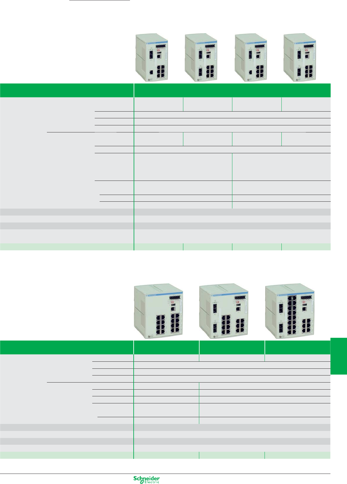
Other versions: please consult your Schneider Electric agency.
Ethernet TCP/IP, Transparent Ready
Cabling system: ConneXium managed switches
ConneXium
Switches Copper twisted pair and fiber optic, managed
Interfaces Copper cable ports Number and type 7 x 10/100BASE-TX
ports
6 x 10/100BASE-TX
ports
7 x 10/100BASE-TX
ports
6 x 10/100BASE-T
ports
Shielded connectors RJ45
Medium Shielded twisted pair, category CAT 5E
Total length of pair 100 m
Fiber optic ports Number and type 1 x 100BASE-FX 2 x 100BASE-FX 1 x 100BASE-FX 2 x 100BASE-FX
port port port port
Connectors Duplex SC
Medium Multimode optical fiber (MM) Single mode optical fiber (SM)
Length of optical fiber
5,000 m (1)
–
50/125 µm fiber
62.2/125 µm fiber 4,000 m (1) –
9/125 µm fiber – 32,500 m (2)
Power supply Voltage Operation 9.6...60 VDC/18…30 VAC, safety extra low voltage (SELV)
Degree of protection IP 20
Dimensions W x H x D 74 x 131 x 111 mm
Conformity to standards IEC 61131-2, IEC 61850-3, UL 508, UL 1604 Class 1 Division 2, CSA C22.2 14 (cUL),
CSA C22.2 213 Class 1 Division 2 (cUL), e, GL , C-TICK
References
TCSESM083F1CU0 TCSESM 083F2CU0 TCSESM 083F1CS0 TCSESM 083F2CS0
(1) Length dependent on the attenuation analysis and attenuation of the fiber optic (typical value: 2,000 m).
(2) Length dependent on the attenuation analysis and attenuation of the fiber optic (typical value: 15,000 m).
Switches Copper twisted pair,
managed
Copper twisted pair and
fiber optic, managed
Copper twisted pair and
fiber optic, managed
Interfaces Copper cable ports Number and type 16 x 10/100BASE-TX ports 14 x 10/100BASE-TX ports 22 x 10/100BASE-TX ports
Shielded connectors RJ45
Medium Shielded twisted pair, category CAT 5E
Total length of pair 100 m
Fiber optic ports Number and type – 2 x 100BASE-FX ports
Connector – Duplex SC
Medium – Multimode optical fiber
Length of optical fiber
–
5,000 m (1)
50/125 µm fiber
62.2/125 µm fiber – 4,000 m (1)
Power supply Voltage Operation 9.6...60 VDC/18…30 VAC, safety extra low voltage (SELV)
Degree of protection IP 20
Dimensions W x H x D 111 x 131 x 111 mm
Conformity to standards cUL 60950, UL 508 and CSA 142, UL 1604 and CSA 213 Class 1 Division 2, e, GL , C-TICK
References TCSESM 163F23F0 TCSESM 163F2CU0 TCSESM 243F2CU0
(1) Length dependent on the attenuation analysis and attenuation of the fiber optic (typical value: 2,000 m).
8/5
2
1
3
4
5
6
7
8
9
10
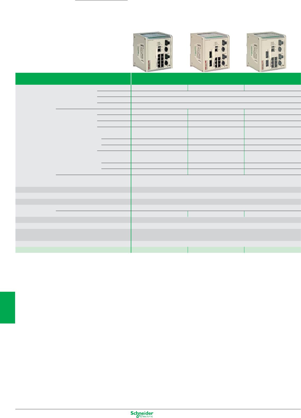
Other versions: please consult your Schneider Electric agency.
Ethernet TCP/IP, Transparent Ready
Cabling system: ConneXium managed switches
ConneXium
Switches Copper twisted pair and fi bre optic, managed - extended features
Interfaces Copper cable ports Number and type 8 x 10/100 BASE-TX ports 6 x 10/100 BASE-TX ports 6 x 10/100 BASE-TX ports
Shielded connectors RJ45
Medium Shielded twisted pair, category CAT 5E
Total length of pair 100 m
Fiber optic ports Number and type – 2 x 100BASE-FX ports 2 x 100BASE-FX ports
Connectors – Duplex SC Duplex SC
Medium – Multi mode optical fi bre Single mode optical fi bre
Length of optical fi ber
– 5,000 m (1) –
50/125 µm fi ber
62.2/125 µm fi ber – 4,000 m (1) –
9/125 µm fi ber – – 32,500 m (2)
Attentuation analysis
– 8 dB –
50/125 μm fi bre
62.2/125 µm fi ber – 11 dB –
9/125 µm fi ber – – 16 dB
Ethernet services
FDR, SMTP V3, SNTP client, multicast fi ltering for optimization of the Global Data protocol, confi guration via Web
access, VLAN, IGMP Snooping, RSTP (Rapid Scanning Tree Protocol), priority port, data stream control, secure port.
Topology Number of switches Cascaded Unlimited
Redundant in a ring max. 50
Redundancy Redundant power supplies, redundant single ring, ring coupling
Power supply Voltage Operation 18 - 60 V safety extra low voltage (SELV)
Power consumption 10 W 12 W 12 W
Degree of protection IP30
Dimensions W x H x D 120 x 137 x 115 mm
Conformity to standards IEC/EN 61131-2, IEC 61850-3, UL 508, UL ISA-12.12.-01 Class 1 Div 2 Group A, B, C, D, CSA 22.2 No.
142 (cUL), CSA 22.2 No. 213 Class 1 Division 2 (cUL), CE, GL, C-Tick
Alarm relay Power supply fault, Ethernet network fault or communication port fault (2 A max. volt-free contact at 30 VDC)
References
TCSESM083F23F1 TCSESM063F2CU1 TCSESM063F2CS1
(1) Length dependent on the attenuation analysis and attenuation of the fi lber optic (typical value: 2,000 m).
(2) Length dependent on the attenuation analysis and attenuation of the fi lber optic (typical value: 15,000 m).
8/6
2
1
3
4
5
6
7
8
9
10
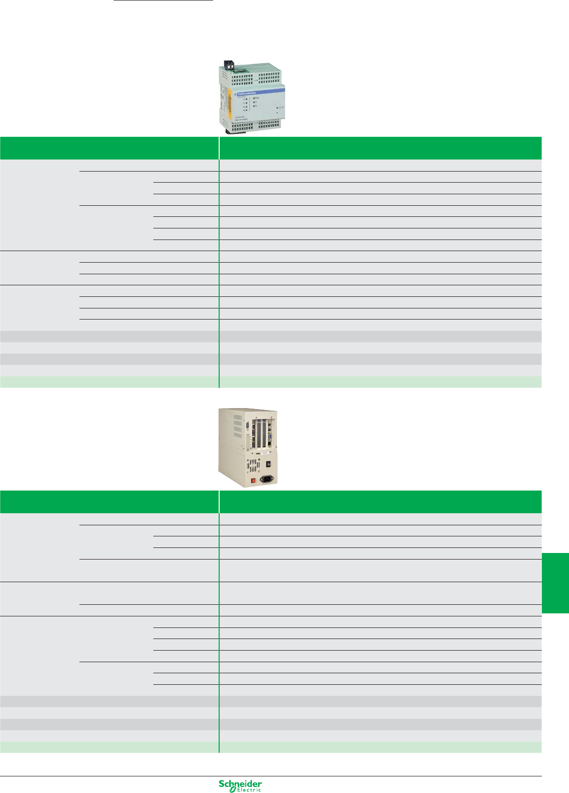
Other versions: please consult your Schneider Electric agency.
Ethernet gateways
Ethernet/Modbus gateway and
Ethernet/Modbus Plus gateway/router
ConneXium
Type of gateway TSX ETG 100
Transparent Ready
services
Class B10
Standard Web
services
Configuration Predefined Web pages
Read/Write Acces to connected products list, reading of Modbus devices registers
Diagnostic Via predefined Web pages : diagnostic on Ethernet and Modbus links
Ethernet TCP/IP
communication
management
services
Modbus messaging Read/Write Modbus registers of connected devices
SNMP SNMP Agent, device administration with a SNMP manager
BOOTP protocol FDR Client (replacement of defective product)
Security Miniature firewall on-board (IP address filtering) and password protection
Ethernet connectivity Physical interface 10BASE-T/100BASE-TX (RJ45)
Data rate 10/100 Mbps with automatic recognition
Medium Twisted pair
Modbus connectivity Type of port RS 485 (2 or 4-wire) or RS 232
Protocol Modbus (RTU and ASCII)
Maxi transmission speed 38,4 Kbps (RS 485), 57,6 Kbps (RS 232)
Number of devices 32 max.
Power supply 24 VDC, 4 W or by power supply device PoE (Power Over Ethernet - IEEE 802.3af)
Degree of protection IP 30
Dimensions W x H x D 72 x 81 x 76 mm, mounting on symmetrical DIN rail
Conformity to standards UL, cUL (conforming to CSA C22-2 no. 14-M91), UL508 , C-TICK, e
Reference TSX ETG 100 (1)
(1) Fonctions: Twido, Compact, Momentum, TSX Micro, Altivar, Altistart, Magelis, ... All products compatible with Modbus standard.
Type of gateway Ethernet/Modbus Plus gateway/router Class B10
Transparent Ready
services
Class B10
Standard Web
services
Configuration Predefined Web pages
Read/Write Acces to connected products list, reading of Modbus Plus devices registers
Diagnostic Via predefined Web pages : diagnostic on Ethernet and Modbus Plus links
Standard Ethernet TCP/IP communication Modbus TCP messaging
services SNMP Agent
Functions Communication gateway Ethernet/Modbus Plus
(many-to-many Modbus Plus)
Interface for programming Ethernet/Modbus Plus
Interfaces Ethernet TCP/IP port Type 1 x 10BASE-T/100BASE-TX
Shielded connectors RJ45
Medium Shielded twisted pair
Max. distances 100 m (327 ft)
Serial port Type 1 x Modbus Plus
Shielded connectors 9-way SUB-D connector
Medium Shielded twisted pair (single or double)
Power supply Voltage 110/220 VAC (93.5 VAC…242 VAC), 47…63 Hz
Degree of protection IP 20
Dimensions W x H x D 122 x 229 x 248 mm
Conformity to standards UL 508, CSA 142, e
Reference 174 CEV 200 40 (2)
(2) Fonctions: 1 Ethernet port, 10BASE-T/100BASE-TX, 1 Modbus Plus port
8/7
2
1
3
4
5
6
7
8
9
10
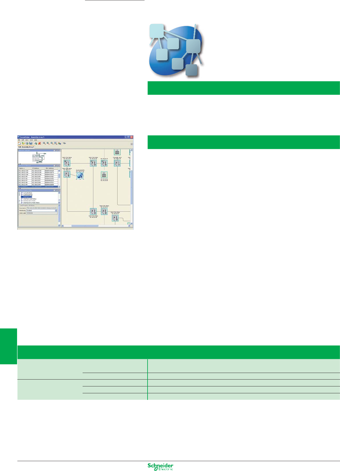
Other versions: please consult your Schneider Electric agency.
ConneXview V2.0
Ethernet Network Diagnostic Software
ConneXium
Introduction
ConneXview is a user friendly software tool used to diagnose industrial Ethernet networks. It provides a
very easy and intuitive interface for network operators and maintenance personnel, plus a set of features
and advanced functions that are of great value to system integrators and controls engineers.
Product features and functions
Automatic discovery of connected devices
ConneXview performs an automatic discovery of IP devices connected on an Ethernet network and then
automatically maps the network topology and devices, providing a green/ yellow/ red color coding of links
and devices to enable users to quickly evaluate the status of the network.
Client/ server architecture
ConnexView v2.0 now provides a client/ server architecture, giving you the ability to monitor your
network, make routine checks on performance and troubleshoot problems, from anywhere you have
access to a PC and a browser.
Alarm Notification
In the event of an alarm, you can choose to be automatically notified by eMail, pager or text message,
and even get a list of all alarms and their severity.
Network Assistant
The Network Assistant is a context-sensitive help file containing topics describing every network alarm
and warning reported by ConneXview. Selecting an alarm and clicking on the help button will launch the
Network Assistant where you will find the alarm text message, a definition of the alarm, a list of the
possible causes of the alarm, and a series of recommended actions to clear the alarm.
Device Type Editor (DTE)
ConneXview has a device-type library that enables it to identify a large number of Schneider devices.
The DTE can also be used to add 3rd party devices that are not already in the library.
Product References
ConneXview
Server Single License TCSEAZ01PSFM20S
Client Single License TCSEAZ01PSFM20C
Subscription services
Single Server Subscription TCSEAZ01PSSM20S
Single Client Subscription TCSEAZ01PSSM20C
8/8
2
1
3
4
5
6
7
8
9
10
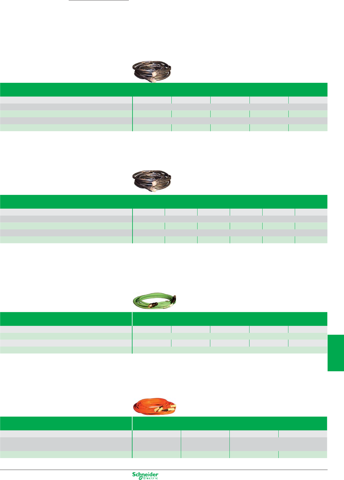
Other versions: please consult your Schneider Electric agency.
Ethernet TCP/IP, Transparent Ready
Cabling system: Connection components
Shielded copper connection cables
ConneXium shielded connection cables are available in two versions to meet the various current standards
and approvals:
ConneXium
These cables conform to:
- EIA/TIA-568 standard, category CAT 5E,
- IEC 11801/EN 50173 standard, class D.
Their fire resistance conforms to:
- NFC 32070# C2 classification
- IEC 322/1 standards
- Low Smoke Zero Halogen (LSZH).
EIA/TIA 568 shielded twisted pair cables
EIA/TIA 568 shielded twisted pair cables for CE market
Length m / (ft) 2 (6.6) 5 (16.4) 12 (39.4) 40 (131.2) 80 (262.5)
Straight cables Preformed at both ends 2 RJ45 connectors for connection to terminal devices (DTE)
References
490 NTW 000 02 490 NTW 000 05 490 NTW 000 12 490 NTW 000 40 490 NTW 000 80
Crossed cord cables Preformed at both ends 2 RJ45 connectors for connections between hubs, switches and transceivers
References Reerences
–490 NTC 000 05 –490 NTC 000 40 490 NTC 000 80
EIA/TIA 568 shielded twisted pair cables
Cable material is :
- CEC type FT-1
- NEC type CM
EIA/TIA shielded twisted pair cables for UL markets
Length m / (ft) 2 (6.6) 5 (16.4) 12 (39.4) 15 (49.2) 40 (131.2) 80 (262.5)
Straight cables Preformed at both ends 2 RJ45 connectors for connection to terminal devices (DTE)
References
490 NTW 000 02U 490 NTW 000 05U 490 NTW 000 12U
–
490 NTW 000 40U 490 NTW 000 80U
Crossed cord cables Preformed at both ends 2 RJ45 connectors for connections between hubs, switches and transceivers
References
–
490 NTC 000 05U
–
490 NTC 000 12U 490 NTC 000 40U 490 NTC 000 80U
Cables M12
Cables M12
M12 / M12 Length (m) 1 3 10 25 40
Reference TCSECL1M1M
pp
S2
pp
RJ45 / M12 Length(m) 1 3 10 25 40
Reference TCSECL1M3M
pp
S2
pp
Glass fiber optic cables
These glass fiber optics are for making connections:
- To a terminal device (DTE)
- Between hubs, transceivers and switches
Glass fiber optic cables
Length m / (ft) 5 (16.4) 5 (16.4) 3 (9.8) 5 (16.4)
Glass fiber optic cables Preformed at both ends 1 SC connector
1 ST connector (BFOC)
2 MT-RJ connectors
1 MT-RJ connector 1 MT-RJ connector
References 490 NOC 000 05 490 NOT 000 05 490 NOR 000 03 490 NOR 000 05
8/9
2
1
3
4
5
6
7
8
9
10
Other versions: please consult your Schneider Electric agency.
AS-Interface Advantys interfaces for generic products
IP20 for mounting in enclosure
Modular interface, width 25 mm Analogue Digital
V2.1 with standard addressing
Number of inputs 2 (0…10V) 2 (0/4…20mA) 4 4 4 isolated
Number of outputs – – 4 relay, 2A 4 solid state, 0.5A 4 solid state, 0.5A
Type of addressing Standard
Supply by AS-Interface Inputs and sensor supply (200 mA max.) –
Supply by 24 VDC external source (black AUX cable) – – – Outputs (2)
AS-Interface profile S.7.3.F.D S.7.3.F.D S.7.0.F.E S.7.0.F.E S.7.0.F.E
Maximum consumption from AS-Interface (excluding sensor supply) 60 mA 60 mA 110 mA 50 mA 20 mA
Dimensions (WxDxH) 25x77x87 mm 25x77x87 mm 25x77x87 mm 25x77x87 mm 25x77x87 mm
References ASI20MA2VU ASI20MA2VI ASI20MT4I4OR ASI20MT4I4OS ASI20MT4I4OSA
Accessory (1) for connection to flat cables TCSATN01N2 TCSATN01N2 TCSATN01N2 TCSATV01N2 TCSATV01N2
(1) Or direct screw terminal connection (without accessory).
(2) Inputs, outputs and sensor supply (200 mA max.).
Modular interface, width 25 mm Digital
V2.1 with Extended (A/B) addressing
Number of inputs 4 2 4 4 4 isolated
Number of outputs – 1 triac, 2A 3 relay, 2A 3 solid state, 0.5A 3 solid state, 0.5A
Type of addressing Extended (A/B)
Supply by AS-Interface Inputs and sensor supply (200 mA max.) (3) –
Supply by 24 VDC external source (black AUX cable) – – – Outputs (2)
AS-Interface profile S.0.A.7.0 S.3.A.7.0 S.7.A.7.0 S.7.A.7.0 S.7.A.7.0
Maximum consumption from AS-Interface (excluding sensor supply) 50 mA 40 mA 90 mA 50 mA 20 mA
Dimensions (WxDxH) 25x77x87 mm 25x77x87 mm 25x77x87 mm 25x77x87 mm 25x77x87 mm
References ASI20MT4IE ASI20MT2I1OTE ASI20MT4I3ORE ASI20MT4I3OSE
ASI20MT4I3OSAE
Accessory (1) for connection to flat cables TCSATN01N2 TCSATN01N2 TCSATN01N2 TCSATV01N2 TCSATV01N2
(1) Or direct screw terminal connection (without accessory).
(2) Inputs, outputs and sensor supply (200 mA max.).
(3) Except ASI20MT4I3ORE (170 mA max.).
8/10
2
1
3
4
5
6
7
8
9
10
Other versions: please consult your Schneider Electric agency.
IP67 for mounting on machine
Interface Digital
V2.1 with extended (A/B) addressing
Number of inputs 4 2 – 4 4 4 8
Input cabling Standard (1 x M12)
"Y" (2 x M12) "Y" (4 x M12)
Number of outputs –
2 solid-state, 2A 3 solid-state, 2A 3 solid-state, 2A
–
3 solid-state, 2A
–
Type of addressing Extended (A/B)
Supply by AS-Interface Inputs and sensor supply (200 mA max. except ASI67FFP22•: 100 mA)
Supply by 24 VDC external source (black AUX cable) – Outputs – Outputs – Outputs –
AS-Interface profile S.0.A.7.0 S.B.A.7.0 S.8.A.7.0 S.7.A.7.0 S.0.A.7.2 S.7.A.7.E S.0.A.7.2 (2x)
Maximum consumption from AS-Interface (excluding sensor supply) 45 mA 32 mA 18 mA 48 mA 45 mA 48 mA 90 mA
Dimensions (WxDxH)
45X42X80mm 45X42X80mm 45X42X80mm
60x30,5X151mm
45X42X80mm
60x30,5X151mm 60x30,5X151mm
Connection IDC Interface
ASI67FFP40E ASI67FFP22E ASI67FFP03E ASI67FFP43E ASI67FFP40EY ASI67FFP43EY ASI67FFP80EY
Standard connection base
ASI67FFB01 (1) ASI67FFB01 (1) ASI67FFB01 (1) ASI67FFB03 ASI67FFB01 (1) ASI67FFB03 ASI67FFB03
M12 connector Interface + Connection base
ASI67FMP40E ASI67FMP22E ASI67FMP03E ASI67FMP43E ASI67FMP40EY ASI67FMP43EY
–
(1) A connection base with fixing centres that are compatible with the ASIB4VM12 connection base is available. Reference ASI67FFB02.
Interface Digital
V2.1 with standard addressing
Number of inputs 4 2 – 4 4 8
Input cabling Standard (1 x M12)
"Y" (2 x M12) "Y" (4 x M12)
Number of outputs
– 2 solid-state, 2A 4 solid-state, 2A 4 solid-state, 2A 4 solid-state, 2A
–
Type of addressing Standard
Supply by AS-Interface Inputs and sensor supply (200 mA max. except ASI67FFP22•: 100 mA)
Supply by 24 VDC external source (black AUX cable) – Outputs Outputs Outputs Outputs –
AS-Interface profile S.0.0.F.E S.3.0.F.E S.8.0.F.E S.7.0.F.E S.7.1.F.E S.0.1.F.F (2x)
Maximum consumption from AS-Interface (excluding sensor supply) 45 mA 32 mA 19 mA 49 mA 49 mA 90 mA
Dimensions (WxDxH) 45X42X80mm 45X42X80mm 45X42X80mm
60x30,5X151mm 60x30,5X151mm 60x30,5X151mm
Connection IDC Interface
ASI67FFP40D ASI67FFP22D ASI67FFP04D ASI67FFP44D ASI67FFP44DY ASI67FFP80DY
Standard connection base
ASI67FFB01 (1) ASI67FFB01 (1) ASI67FFB01 (1) ASI67FFB03 ASI67FFB03 ASI67FFB03
M12 connector Interface + Connection base
ASI67FMP40D ASI67FMP22D ASI67FMP04D ASI67FMP44D ASI67FMP44DY
–
(1) A connection base with fixing centres that are compatible with the ASIB4VM12 connection base is available. Reference ASI67FFB02.
Interface Digital
V2.1 (V1 compatible) with standard addressing
Number of inputs 4 2 – 4
Input cabling Standard (1 x M12 input)
Number of outputs – 2 solid-state, 2A 4 solid-state, 2A 4 solid-state, 2A
Type of addressing Standard
Supply by AS-Interface Inputs and sensor supply (200 mA max. except ASI67FFP22•: 100 mA)
Supply by 24 VDC external source (black AUX cable) – Outputs Outputs Outputs
AS-Interface profile S.0.0.F.F S.3.0.F.F S.8.0.F.F S.7.0.F.F
Maximum consumption from AS-Interface (excluding sensor supply) 45 mA 32 mA 19 mA 49 mA
Dimensions (WxDxH) 45x42x80 mm 45x42x80 mm 45x42x80 mm 60x30.5x151 mm
Connection IDC Interface ASI67FFP40A ASI67FFP22A ASI67FFP04A ASI67FFP44A
Standard connection base ASI67FFB01 ASI67FFB01 ASI67FFB01 ASI67FFB03
8/11
2
1
3
4
5
6
7
8
9
10
Other versions: please consult your Schneider Electric agency.
AS-Interface Dedicated components
For control
Starter in insulated enclosure (1) Control by
V1
Black rotary knob (blue bkgrnd.)
Pushbuttons
Type of addressing Standard
Supply by AS-Interface Inputs, sensor supply (2)
Supply by 24 VDC external source (black AUX cable) (2)
AS-Interface profile S.7.F.F. (LF3....) / S.7.A.7.0. (LF4....)
Maximum consumption from AS-Interface 20 mA
Dimensions (WxDxH) 175x175x195 mm
References (3) Non reversing LF3PppD LF3MppD
(see table below) Reversing LF4PppD LF4MppD
Connection to AS-Interface and external supply (AUX) by accessory for flat cable: TCSATN011F1 (AS-Interface and AUX cables) or TCSATV011F1 (AS-Interface cable).
(1) For an LF3 or LF4 starter in a metal enclosure, add the letter M after the 3
rd
digit in the references listed above (example: LF3P02D becomes LF3MP02D).
(2) Contactors supplied by AS-Interface or external source, configurable directly on terminal block.
(3) To complete the reference, replace pp by the numbers indicated in the table below. (Example: LF3PppD becomes LF3P00D).
kW= Motor power ratings in category AC-3, 400/415V, in kilowatts.
A= Adjustable range of circuit-breaker thermal trips, in amperes.
Communication interface for TeSys U
V2.1
Type of addressing Standard Extended (A/B)
Supply by AS-Interface ––
Supply by external source (AUX) Coil Coil
AS-Interface profile S.7.D.F.0 7.A.7.E
Maximum consumption from AS-Interface 30 mA 30 mA
Dimensions (WxDxH) depending on LU model depending on LU model
References ASILUFC5 ASILUFC51
Recommended accessory for connection to AS-Interface cable (4) TCSATV01N2 TCSATV01N2
(4) Or direct screw terminal connection to AS-Interface and external supply (AUX).
kW A pp kW A pp
– without MCB 00 0.75 1.6…2.5 07
0.06 0.16…0.25 02 1.1 / 1.5 2.5…4 08
0.09 0.25…0.40 03 2.2 4…6.3 10
0.12 / 0.18 0.40…0.63 04 3 / 4 6…10 14
0.25 0.63…1 05 5.5 9…14 16
0.37/ 0.55 1…1.6 06
8/12
2
1
3
4
5
6
7
8
9
10
Other versions: please consult your Schneider Electric agency.
For dialogue
–
Control stations Control stations with 2 pushbuttons
V2.1 Black and white Green and red Green and red illuminated
Type of addressing Extended (A/B) Extended (A/B) Extended (A/B)
Supply by AS-Interface Buttons Buttons Buttons and pilot lights
Supply by external source (AUX) –––
AS-Interface profile S.B.A.E. S.B.A.E. S.B.A.E.
Consumption from AS-Interface < 45 mA < 45 mA < 80 mA
Dimensions (WxDxH) 68x62x118 mm 68x62x118 mm 68x65x118 mm
References XALS2001H XALS2002H XALS2003H
Recommended accessory for connection to AS-Interface cable (5) TCSATN011F1 TCSATN011F1 TCSATN011F1
(5) Or direct screw terminal connection to AS-Interface and external supply (AUX).
Interface (6) For 2 control units and 2 pilot lights
V2.1
Number of pages available –
Number of inputs 2
Number of outputs 2 solid state, 0.5 A
Type of addressing Standard
Supply by AS-Interface Inputs and pilot lights
AS-Interface profile S.B.A.E.
Maximum consumption from AS-Interface 80 mA
Dimensions (WxDxH) 52x15x38 mm
References XALSZ1E
(6) Direct screw terminal connection to AS-Interface or by accessory for flat cable: TCSATN01N2.
Indicator banks, Ø 70 mm (9) Base units and cover Illuminated units Audible
V2.1 “Flash” discharge tube Steady light unit
Type of addressing Standard Standard – – –
Connection to AS-Interface cable and AUX (male M12 connector) yes
yes, remote L=1m
–––
Supply by AS-Interface (7) (7) – – –
Supply by external source (AUX) (7) (7) – – –
AS-Interface profile S.7.F S.7.F – – –
Consumption from AS-Interface, supply by AS-Interface / external 250 / 30 mA 250 / 30 mA –––
Light source – – 5 Joule LED –
Buzzer – – – –
70
…
80
dB at 1m
References XVBC21A XVBC21B XVBC6Bp (8) XVBC2Bp (8) XVBC9B
Recommended accessory for connection to AS-Interface cable & AUX
TCSATN011F1
TCSATN011F ––
(7) Illuminated units supplied by AS-Interface or externally, configurable by shunt.
(8) To complete the reference, replace the p by the following number designating the colour: green: 3, red: 4, orange: 5, blue: 6, clear: 7, yellow: 8.
(9) To obtain a complete indicator bank, order a base unit + the illuminated or audible units (5 units maximum).
8/13
2
1
3
4
5
6
7
8
9
10
Other versions: please consult your Schneider Electric agency.
1
Current in A at 30 V AS-Interface
Current in A at 24 V
0
1
2
3
4
5
65,8
4,5
3
7
2 3 4 51
Current in A at 30 V AS-Interface
Current in A at 24 V
0
1
2
3
4
5
65,8
4,5
3
7
2 3 4 5
AS-Interface Installation system
Master modules
Type of supply AS-Interface AS-Interface + Auxiliary
Input voltage 100…240 VAC 100…240 VAC 100…240 VAC
AS-Interface output voltage 30 VDC 30 VDC 30 VDC
Auxiliary output voltage – – 24 VDC
AS-Interface nominal power 73 W 146 W 73 W
Auxiliary nominal power – – 72 W
AS-Interface nominal current 2.4 A 4.8 A 2.4 A
AUX nominal current – – 3 A
Direct connection to AS-Interface cable by terminal block by terminal block by terminal block
Dimensions (WxDxH) 54x120x120 mm 81x120x120 mm 81x120x120 mm
References without earth fault detection ASIABLB3002 ASIABLB3004 ASIABLM3024
with earth fault detection ASIABLD3002 ASIABLD3004 –
(2) Power supply unit with constant maximum output, see curve above.
Insulation control relay
Platform Twido Premium Micro Quantum Ethernet GW
Maximum number of master modules per PLC 2 2, 4 or 8 depending 1 8 (1) –
on processor
Compatibility with AS-Interface interfaces and components V1 / V2.1 V1 / V2.1 V1 V1 V1 / V2.1 / V3.0
Direct connection to AS-Interface cable by terminal block by terminal block by terminal block by terminal block by terminal block
Maximum number of addresses 62 62 31 31 62
Type of addressing Standard / Standard / Standard Standard Standard /
Extended (A/B) Extended (A/B) Extended (A/B)
Compatibility with analogue interfaces Yes Yes – – Yes
Compatibility with safety interfaces Yes Yes Yes Yes Yes
AS-Interface profi le M.3 M.2.E M.2 M.2 M.4
References TWDNOI10M3 TSXSAY1000 TSXSAZ10 140EIA92100 TCSAGEA1SF13F
(1) 4 per local rack, 4 per remote I/O, 2 per distributed I/O.
Power supply units
Type For AS-Interface line
Degree of protection IP20
Number of C/O contacts 2 relays, each with 1 N/O contact
Rated operational voltage 50 VDC
Dimensions (WxDxH) 90x58x76 mm
References RM0PAS101 (3)
(3) Provided with an impedance adapter.
8/14
2
1
3
4
5
6
7
8
9
10
Other versions: please consult your Schneider Electric agency.
Cables, repeater and line extension
Type Yellow AS-Interface
cable
Black Auxiliary
cable
Repeater (5) Line Extension
Wire c.s.a. 2 x 1.5 mm
2
2 x 1.5 mm
2
––
References Cable L = 20 m XZCB10201 (4) XZCB10202 (4) – –
L = 50 m XZCB10501 (4) XZCB10502 (4) – –
L = 100 m XZCB11001 (4) XZCB11002 (4) – –
Reference of repeater – – ASIRPT01 TCSARR011M
(4) Standard cable. For TPE cable (oil and vapour resistant) add the letter H to the end of the reference, example: XZCB10201 becomes XZCB10201H.
(5) Enables an AS-Interface network to be extended by 100 m. Direct connection to the AS-Interface yellow cable by IDC
Tap-offs for flat cable
(For connecting interfaces and components)
Connection to cable by IDC AS-Interface AS-Interface + Auxiliary
IP67 IP67
Connection to the AS-Interface component M12 connector (6) Bared wires (7) M12 connector (6) Bared wires (8)
References Cable L = 1 m TCSATN011F1 –TCSATV011F1 –
L = 2 m TCSATN011F2 TCSATN01N2 TCSATV011F2 TCSATV01N2
(6) Female 5-pin M12 end connector, screw threaded for connection with M12 male connector.
(7) 2 x 0.34 mm2 for product with terminal block.
(8) 4 x 0.34 mm2 for product with terminal block.
T connectors
Connection to cable by IDC T connector Branch
AS-Interface or Auxiliaires IP 67
AS-Interface IP 67
Connection to the AS-Interface sensor or actuator 1 x M12 connector 5-pin female, screw threaded Extension for 2 flat cables
References TCSATN011F TCSATN02V
8/15
2
1
3
4
5
6
7
8
9
10
Other versions: please consult your Schneider Electric agency.
AS-Interface Installation system
Jumper cables M12 / M12
Type Male / Female jumper cable
Male connector type, interface side M12, 3-pin, straight, screw thread. M12, 4-pin, straight, screw thread.
M12, 5-pin, straight, screw thread.
Female connector type, sensor side M12, 3-pin, straight, screw thread. M12, 4-pin, straight, screw thread.
M12, 5-pin, straight, screw thread.
Cable PUR, black PUR, black PUR, black
References Cable L = 1 m XZCR1511040A1 XZCR1511041C1 XZCR1511064D1
L = 2 m XZCR1511040A2 XZCR1511041C2 XZCR1511064D2
Jumper cables M12 / M8 or DIN
Type Male / Female jumper cable
Male connector type, interface side M12, 3-pin, straight, screw thread. M12, 3-pin, straight, screw thread.
M12, 3-pin, straight, screw thread.
Female connector type, sensor side M8, 3-pin, straight (1) M8, 3-pin, straight, screw thread.
DIN 43650A, elbowed, screw thrd.
Cable PUR, black PUR, black PUR, black
References Cable L = 1 m XZCR1501040G1 XZCR1509040H1 XZCR1523062K1
L = 2 m XZCR1501040G2 XZCR1509040H2 XZCR1523062K2
(1) Clip together connector.
Connectors, splitter box
Type Connectors Pre-wired connectors Splitter box
Male connector type, interface side M12, 4-pin M12, 5-pin, straight, screw thread. 1 x M12, 5-pin, straight, screw thrd.
Female connector type, sensor side – – 2 x M12, 5-pin, straight, screw thrd.
Cable – PUR, black –
References Straight connector, screw thread.
XZCC12MDM40B
– FTXCY1212
Elbowed connector, screw thread.
XZCC12MCM40B
––
Cable L = 0.5 m – XZCP1564L05 –
Cable L = 2 m – XZCP1564L2 –
8/16
2
1
3
4
5
6
7
8
9
10
Other versions: please consult your Schneider Electric agency.
Tools
Adjustment and addressing terminals
Display 25 mm LCD screen
Degree of protection IP40
AS-Interface voltage / current measurement yes
Addresses stored in memory yes
Access to functions direct by selector switch
Compatibility V1/V2
Operating time 2500 addressing operations
References ASITERV2
Reference with set of 7 leads + protective cover for terminal ASITERV2SET
Addressing accessories for terminals ASITERV2
and XZMC11
Product connection Infrared addressing Socket
For products ASISSL… ABE8… / APP1 / ASILUF… /
XBZS43 / ASI20M
References ASITERIR1 XZMG12
Product connection M12, male M12, female Jack plug
For products (2) ASI67FMP
XVB… / XAL… / LF…
ASI20M… / ASI67FFP…
References ASITERACC1M ASITERACC1F ASITERACC
(2) Possibility to connect AS-Interface cable using T connector TCSATN011F.
8/17
2
1
3
4
5
6
7
8
9
10
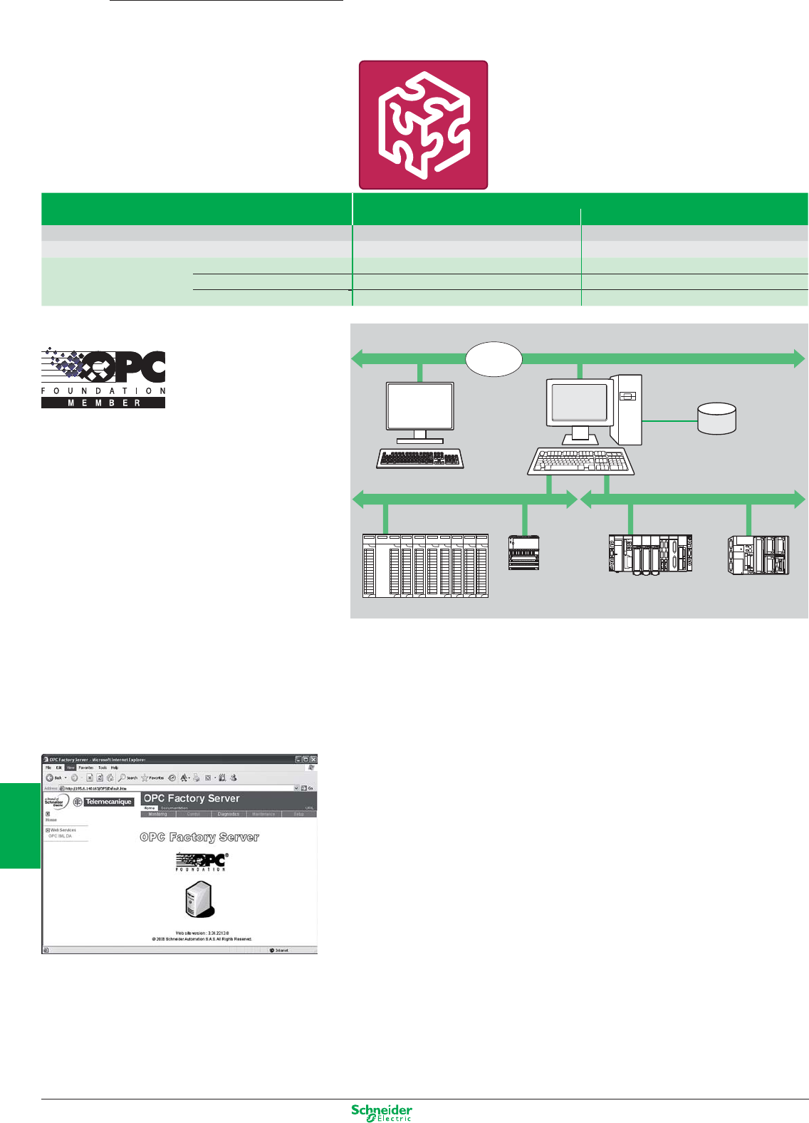
Other versions: please consult your Schneider Electric agency.
Type OPC data server
OFS Small OFS Large
Items number 1000 items Unlimited
OPC protocols OPC DA OPC DA, OPC XML DA,
References Single station li cence TLX CD SU OFS 33 TLX CD LU OFS
10 stations licence TLX CD ST OFS 33 TLX CD LT OFS 33
200 stations licence – TLX CD LF OFS 33
Description:
Based on the OPC protocols, Schneider-Electric’s OFS software (OPC Factory Server) enables local or
remote OPC client applications such as SCADA, supervisors or custom interfaces, to access Schneider
devices and PLCs data in real time.
OFS software is a multi-device data server which provides simultaneous use of various communication
protocols, and allows client applications to access control data via physical addresses or via symbols
Supported devices :
p Modicon Quantum, Premium, Micro, Compact and Momentum PLCs
p TSX Series 7 and April Series 1000 Schneider-Electric PLCs
p Serial Modbus or Uni-Telway devices connected via Schneider-Electric and Merlin Gerin gateways
TSX ETG 10xx, EGX xxx ranges etc.
Supported networks and protocols :
p Modbus: Serial Modbus, Modbus Plus, Modbus TCP/IP.
p XWAY/UNI-TE: Uni-Telway, FIPWAY, ETHWAY, ISAWAY, PCIWAY.
Openess:
OFS V3.3, integrates the most recent specifications of the OPC Foundation:
p OPC-DA (OPC Data Access)
p .NET API interface
p OPC XML-DA V1.0 (OPC XML Data Access)
The development of specialized interfaces is even more easy and open.
Developers and System integrators can develop custom applications (in Visual Basic, VBA for Excel,
C++, etc) requiring access to Schneider Electric control devices. The OPC XML-DA V1.0 interface is
designed to provide an interface for Windows and non-Windows client applications and remote access via
the Internet through firewalls.
OPC data server software
OFS
Remote client
application
program
DCOM ou
HTTP OFS station
Local client
application
program
Ethernet TCP/IP network
Data symbol
(Concept, PL 7 or Unity pro
X-Way networkModbus network
Quantum
Momentum Premium TSX Micro
8/18
2
1
3
4
5
6
7
8
9
10
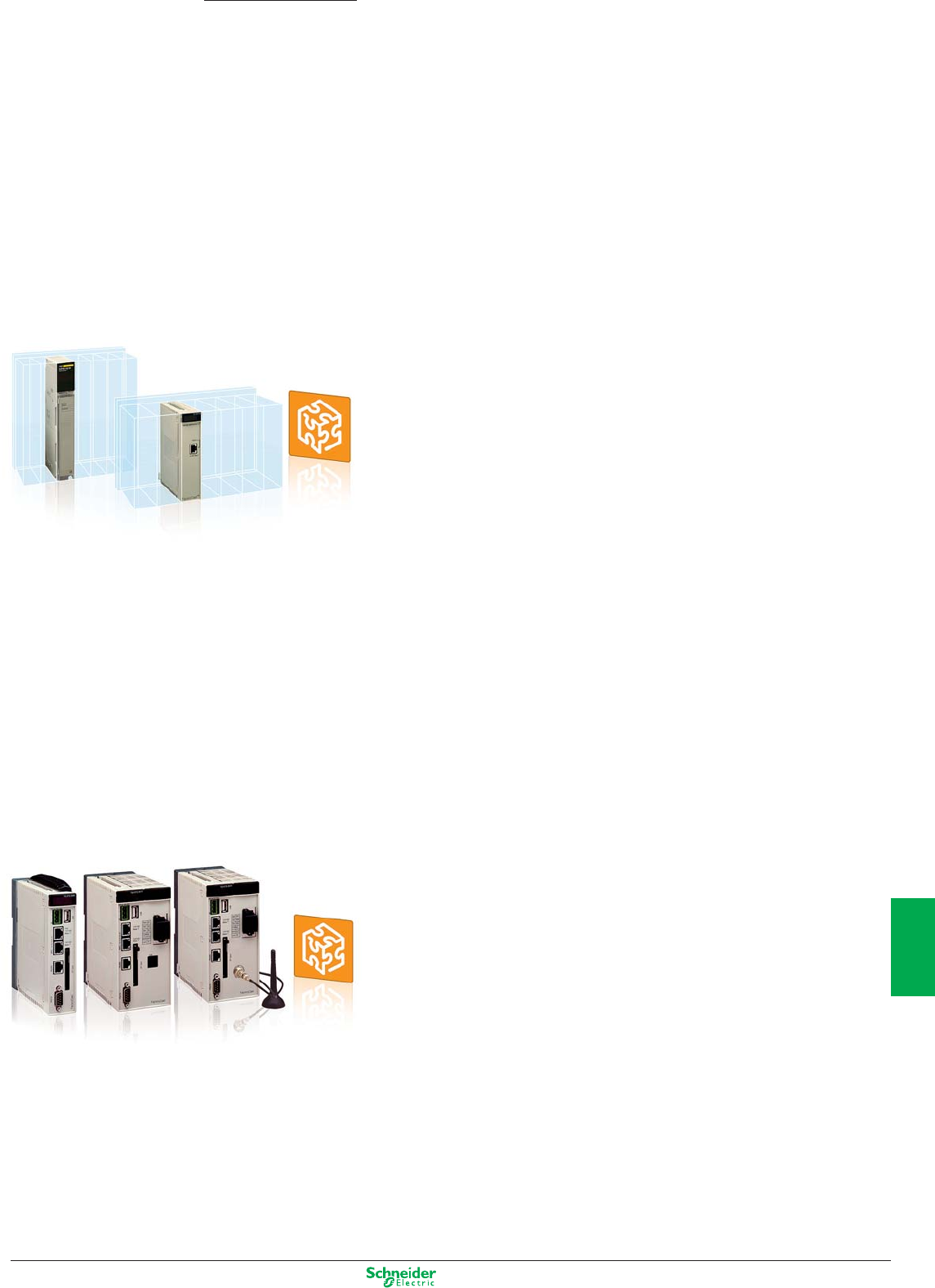
Other versions: please consult your Schneider Electric agency.
Web servers and Gateways
FactoryCast
FactoryCast modules for PLC
“ Ready to use” diagnostic and monitoring functions embedded in a PLC module accessible
remotely via a simple Internet browser:
b Real-time communication based on Ethernet TCP/IP (Modbus and Uni-TE)
b Secure access to the PLC system and application diagnostics
b Numerical or graphical data monitoring and control
b E-mail notifications
b Web server open to user customization and creation of Web pages for diagnostics suited
to your needs
b Library of animated graphic objects
b Open communications using SOAP/XML protocol as a server interface (Web services)
FactoryCast HMI modules for PLC
Diagnostic functions Identical as FactoryCast modules + Built-in HMI / SCADA functions
embedded in a PLC module:
b Visualization of Unity Pro PLC program and Operator screens via Web pages
b PLC data acquisition
b Calculations scripts for data-processing Real-time database (1000 variables)
b Alarm and report notifications via E-mail
b Archiving of data directly into database servers (SQL, Oracle, MySQL)
b Data logging in CSV files in the module.
b Recipe management with read Database
b Dynamic HTML Reporting function
b Web server open to user Web pages customization
b Built-in Supervision via graphic screens and custom Web pages
b Data monitoring and Graphic monitoring (read/write)
b Library of animated graphic objects
b Open communication using SOAP/XML protocol as a server interface (Web services)
Embedded in the TCP/IP communication modules for Modicon M340,
Premium and Quantum PLCs, FactoryCast Web servers provide se-
cured access to the diagnotics, monitoring and maintenance functions
of your automation installations via a simple web browser.
FactoryCast Gateways - ETG 1000 / 10.. modules
Cost-effective web gateways offer integrating in a stand-alone module:
b All Communications network interfaces: Ethernet TCP/IP, Modbus and Uni-Telway
b Remote access functions, RAS server,
b Transparent gateway / Router functions
b Notification of alarms via E-mail
b Data monitoring and Graphic monitoring (read/write)
b A user customizable Web server for creating an interface fully adapted to your needs
b Library of animated graphic objects
FactoryCast HMI Gateways - ETG 3000 / 30.. modules
“All in one” Web gateway module integrating in a stand-alone device:
b a built-in modem (PSTN or GSM/GPRS) depending on the reference
b Secured access : VPN, data encryption and IP filtering.
b A Remote Access server function (RAS)
b 2 Ethernet ports and a Modbus serial port
b Transparent gateway router functions NAT to Ethernet or Modbus serial devices
b I/O card : 6 discrete inputs/ 2 discrete outputs
b Operating temperature : -25°C to +75°C
b User customizable Web server
b Built-in Supervision via graphic screens and custom Web pages
b Data monitoring and Graphic monitoring (read/write)
b Data Acquisition, Data Processing and Data logging in the module (CSV files)
b Archiving of data directly into database servers (SQL, Oracle, MySQL)
b Alarms and reports via E-mail / SMS
b Open communication using SOAP/XML protocol as a server interface
In the areas of distributed infrastructures, transport, RTU installa-
tions, industry and machines, ETG 1000 / 3000 modules more than
satisfy your requirements for remote diagnotics and maintenance,
remote monitoring and control, and remote programming.
8/19
2
1
3
4
5
6
7
8
9
10
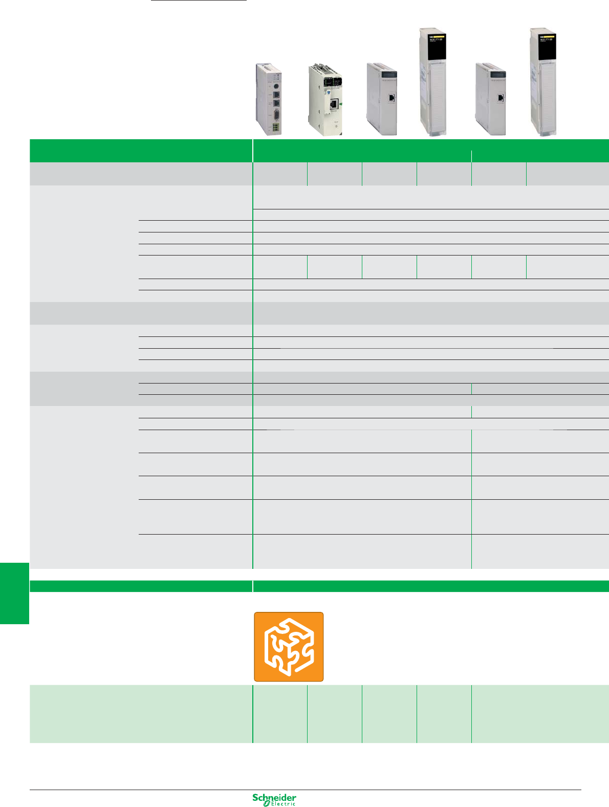
Other versions: please consult your Schneider Electric agency.
FactoryCast PLC
Embedded Web Servers
FactoryCast
Applications Web Server modules for PLCs
FactoryCast FactoryCast HMI
Target devices Type TSX Micro
PLCs
Modicon M340
PLCs
Modicon
Premium PLCs
Modicon
Quantum PLCs
Modicon
Premium PLCs
Modicon
Quantum PLCs
Network & Remote access
services
Remote access Intranet or via external RAS/modem
Remote programming, downloading via FTP, access to Web server via Internet browser
Gateway function –
Serial protocols –
Ethernet protocols Modbus TCP,
Uni-TE
Modbus TCP Modbus TCP,
Uni-TE
Modbus TCP Modbus TCP,
Uni-TE
Modbus TCP
TCP/IP protocols BootP/DHCP, DNS, SNMP agent, SMTP client, NTP client, FTP
Security Protection by IP address filtering and passwords
Web server Characteristics HTTP and FTP server, 8 Mb memory available for user, hosting of user Web pages and documents (Doc,
Pdf, Excel)
Predefined services Configuration Via Web Designer software or predefined Web pages
Diagnostics System, rack and PLC I/O diagnostics via predefined Web pages
Monitoring of variables Monitoring of devices and application via animated data (read/write variables)
Alarm management PLCs and applications alarms monitoring via predefined Web pages
Customizable services Graphic views Graphic monitoring via animated pages (integrated graphic editor)
Unity Pro operator screen – Display in the form of Web pages
User Web pages Graphic monitoring via animated Web pages created by the user
Advanced services and HMI Calculation scripts – Arithmetic and logical scripts
E-mail service Alarm notification by E-mail
Data logging – Data logging in the module with
time stamping (CSV files)
Database connection – Direct logging in an SQL,
Oracle, MySQL database servers
Report service –
Dynamic HTML report management
Recipe service – Management of “Recipe” data
(storage and read locally or on
remote database)
PLC programme visualization
by Web page
–
All the languages supported by
Unity Pro, are accessible by Web
page on Runtime, without Unity Pro
Application development sofware Web Designer
Supplied with each module
References TSXETZ510 BMXNOE0110 TSXETY5103 140NOE77111 TSXWMY100 140NWM10000
8/20
2
1
3
4
5
6
7
8
9
10
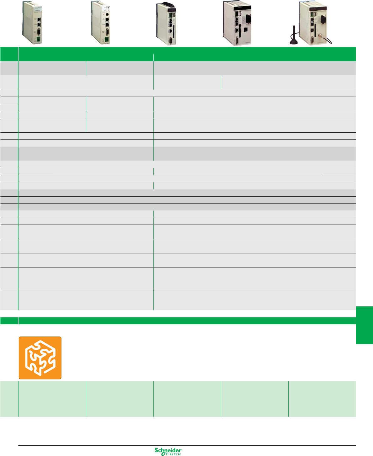
Other versions: please consult your Schneider Electric agency.
FactoryCast Gateway
Web Gateways for Remote control
Standalone Gateway, Web Server for Remote Access
FactoryCast Gateway ETG 10p0 FactoryCast HMI Gateway ETG30pp
All equipment supporting
Modbus
All equipment supporting
Uni-Telway
All Modicon PLCs and third-party equipment supporting Modbus
Intranet or via external Modem, integrated RAS function Intranet or Modem
External modem, integrated RAS
Intranet or Modem
Integrated PSTN/RTC/GSM modem and RAS modem, NAT
Remote programming, downloading via FTP, access to Web server via Internet browser
Ethernet to Modbus serial
Modem to Modbus serial and Ethernet
Ethernet to Uni-Telway serial
Modem to Uni-Telway and Ethernet
Ethernet to Modbus serial
Modem to Modbus serial and Ethernet (Modbus, UNITE)
Modbus (Master) Uni-Telway (Slave) Modbus (Master)
Modbus TCP Modbus TCP, Uni-TE (Modicon
Premium, Modicon TSX Micro)
Modbus TCP
Uni-TE TCP
BootP/DHCP, SNMP agent, SMTP client, NTP client, FTP DHCP, DNS, SNMP agent, SMTP client, NTP client, FTP
Protection by IP address fi ltering and password Protection by IP address filtering and password + Tunnels VPN & encryption of the datas.
HTTP and FTP server, 8 Mb memory available for user, hosting of
user Web pages and documents (Doc, Pdf, Excel)
HTTP and FTP server, 32 Mb memory available for user Web pages, memory extension using Compact
Flash cards 1 Gb max., hosting of user Web pages and documents (Doc, Pdf, Excel)
Via Web Designer software or predefined Web pages
Diagnostics of serial devices via predefined Web pages Network diagnostics, diagnostics of serial devices and Ethernet via predefined Web pages
Monitoring of devices and application via data tables (read/write variables)
Via E-mail Via E-mail/SMS
Graphic monitoring via animated views (integrated graphic editor)
–
Graphic monitoring via animated Web pages created by the user
– Arithmetic and logical scripts
Alarm notification by E-mail Alarm notification by E-mail/SMS
– Data logging in the module with time stamping (CSV files)
– Direct recording in SQL, Oracle, MySQL database servers
– Dynamic HTML report management
– Management of “Recipe” data (storage and revad locally or on remote database)
– –
Web Designer
Supplied with each module
TSXETG1000 TSXETG1010 TSXETG3000 TSXETG3010 (Modem RTC) TSXETG3021
Modem GSM/GPRS
(Bands 900/1800MHz)
TSXETG3022
Modem GSM/GPRS
(Bands 850/1900 MHz)
8/21
2
1
3
4
5
6
7
8
9
10

Your
machine
Risk
assesment
analysis
Implemen-
tation &
Certification
Conception
& Design
Mainten
nance /
Inspection
& Audit
Safety must be taken into account
right from the design stage and must
be kept in mind at all stages in the life
of a machine: design, manufacture,
installation, adjustment, operation,
maintenance and eventual scrapping.
Preventa, the safety attitude around your machine life cycle
Preventa
As well as the moral obligation to avoid
harming anyone, there are laws that require
machines to be safe, and sound economic
reasons for avoiding accidents.

> New machines - the Machinery Directive
The Machinery Directive 98/37/EC is to compel manufacturers to guarantee a minimum safety level for machinery
and equipment sold within the European Union.
From 29 December 2009, the new European Machinery Directive 2006/42/EC will be effective. Machines have to
comply with the Essential Health and Safety Requirements (EHSRs) listed in Annex I of the Directive, thus setting a
common minimum level of protection across the EEA (European Economic Area).
Machine manufacturers, or their authorised representatives within the EU, must ensure that the machine is compliant,
the Technical File can be made available to the enforcing authorities on request, the CE marking is affixed, and a
Declaration of Conformity has been signed, before the machine may be placed on the market within the EU.
This document is a selection of
the top selling products.
Machine safety
9/1
2
1
3
4
5
6
7
8
9
10
Safety standards ..................................................................................................................................9/2 to 9/11
Automation ........................................................................................................................................... 9/12 to 9/17
Safety PLCs
Safety controllers and modules
AS-Interface Safety at work ................................................................................................... 9/18 and 9/19
Safety monitors and interfaces
Detection ................................................................................................................................................. 9/20 to 9/27
Safety switches
Safety limit switches
Coded magnetic technology
Safety mats
Safety light curtains
Operator dialogue ............................................................................................................................ 9/28 to 9/32
Emergency stops
Foot switches
Control units
Products for explosive atmospheres (see chapter 10 “Explosive Atmospheres”)
Motor control .................................................................................................................................. 9/33 to 9/35
Switch disconnectors
TeSys motor starters

Functional safety
«Helping you to reach easily your safety
machinery and standard level required»
Thanks to directives and standards as guidelines.
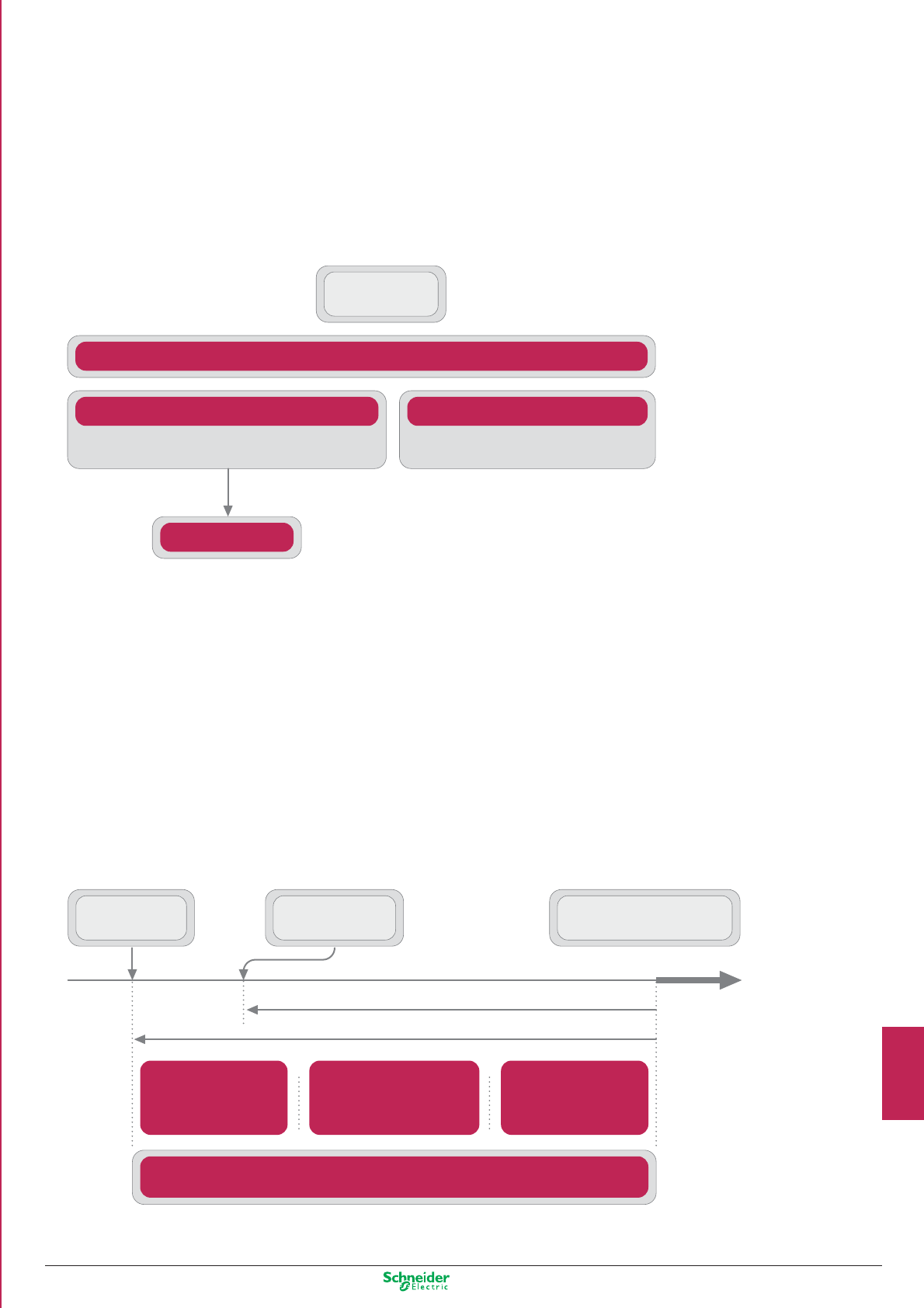
EN/IEC 61508
SAFETY OF SYSTEMS AND EQUIPMENT
Functional safety of electrical / electronic /
programmable electronic safety-related systems
EN/ISO 13849-1
Safety related parts of control systems
MACHINES
EN/IEC 62061
Risk reduction achieved by all safety-related systems
and external risk reduction facilities
Practical risk covered
by other technology
safety-related
systems
Practical risk covered
by electrical / electronic /
programmable electronic
safety-related systems
Practical risk covered
by external risk
reduction facilities
Necessary risk reduction
RESIDUAL
RISK
TOLERABLE
RISK
EQUIPMENT UNDER
CONTROL RISK
Actual risk reduction
Functional safety
> Safety integrity level (SIL), Performance level (PL)
Risk reduction according to EN/IEC 61508 and EN/ISO 13849-1
• Safety is achieved by risk reduction (for those hazards that cannot be designed-out).
• Residual risk is the risk remaining after protective measures have been taken.
• Protective measures realised by E/E/PE* safety related systems contribute to risk reduction.
* Electric / Electronic / Programmable electronic
9/3
2
1
3
4
5
6
7
8
9
10
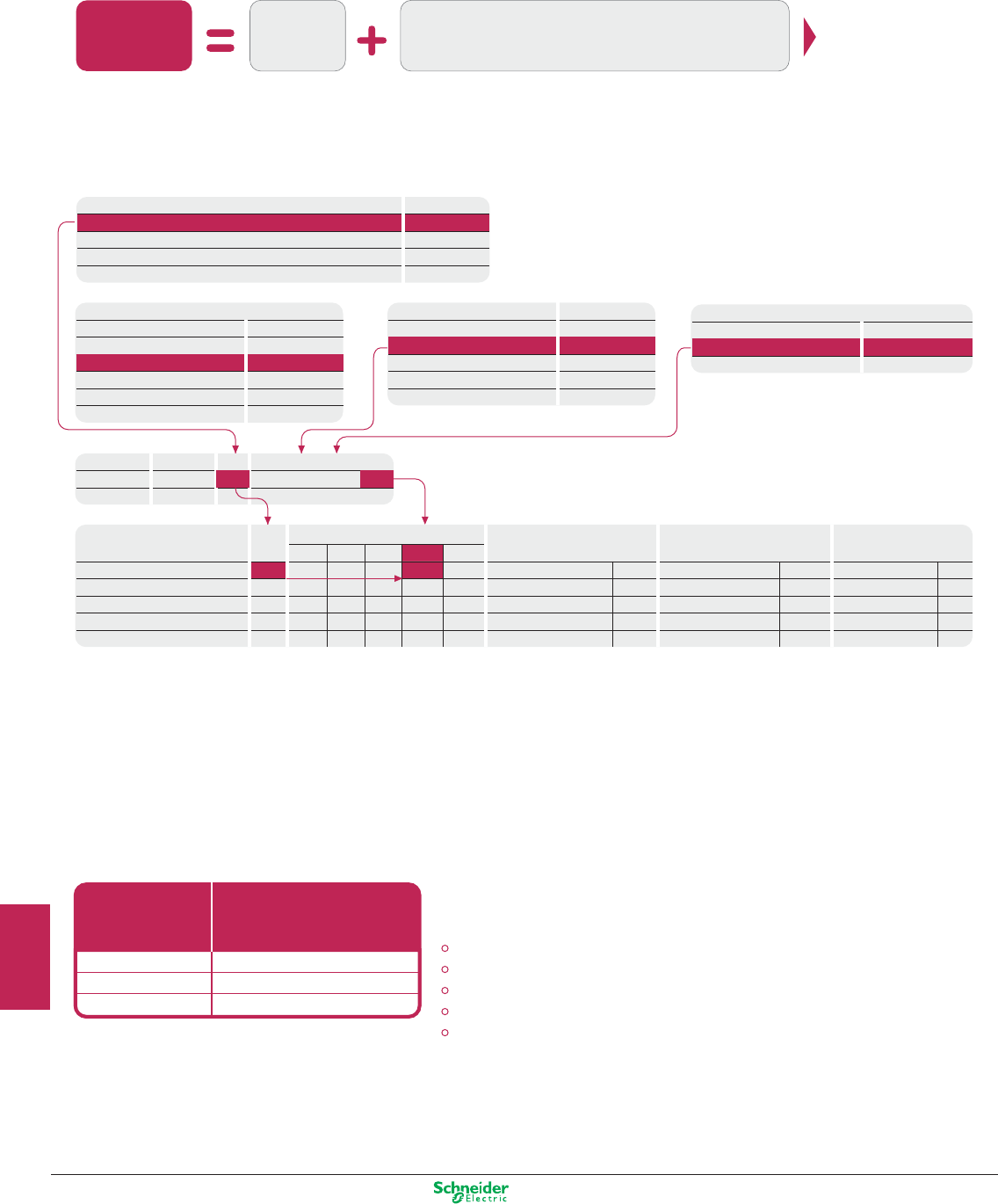
Other versions: please consult your Schneider Electric agency.
Risk related to
the identified
hazard
Severity of
the possible
harm
Fr
Pr
Av
Probability of
occurrence of
that harm
Frequency and duration of exposure
Probability of occurrence of a hazardous event
Probability of avoiding or limiting harm
Serial no.
1
Hazard
Hazard X
Se Fr
5+ + =
Pr
4
Av
3
CI
2
Death, losing an eye or arm
Permanent, losing fingers
Reversible, medical attention
Reversible, first aid
4
3
2
1
SIL 2
3-4
SIL 2
5-7
Class CI
Fr
Frequency and duration
OM
<= 1 hour
> 1 h to <= 1 day
> 1 day to <= 2 wks
2 wks to <= 1 year
> 1 year
5
5
4
3
2
Pr
Probability of hzd. Event
Common
Likely
Possible
Rarely
Negligible
5
4
3
2
1
Av
Avoidance
Impossible
Possible
Likely
5
3
1
SIL 2
SIL 1
OM
SIL 3
SIL 2
SIL 1
OM
SIL 3
8-10 11-13 14-15
SIL 3
SIL 2
SIL 1
Consequences (Se)
Consequences
Reversible: requiring attention from a medical practitioner
Reversible: requiring first aid
Severity (Se)
3
2
1
Irreversible: broken limb(s), losing a finger(s)
Irreversible: death, losing an eye or arm 4
412
Frequency and duration of exposure (Fr)
> 1 day to 2 weeks
5
4
1 h
> 2 weeks to 1 year 3
> 1 year 2
Frequency of exposure > 10 min
> 1 h to 1 day 5
Probability of occurrence
Rarely
Probability (Pr)
2
Negligible 1
Very high 5
Possible 3
4Likely
Probability of a voiding or limiting harm (Av)
Impossible 5
1
Probable
Rarely 3
Safety
integrity level
(SIL)
3
2
1
>10-8 to <10-7
>10-7 to <10-6
>10-6 to <10-5
Probability of a dangerous
Failure per Hour
PFHD
Functional safety of machinery
> Approach according to EN/IEC 62061
Risk estimation for SIL assignment
Example of SIL assignment
This assignment should be carried by determining the risk parameters that are shown below in an example.
Determination of the SIL level achieved by the Safety-related control function (SRCF)
According to standard EN/IEC 62061 for each safety related control function, the SIL level is linked to:
• a target failure value for the probability of dangerous failure by hour of the SRCF: PFHD
• architectural constraints (hardware fault tolerance, diagnosis)
• a set of requirements related to the lifecycle of the safety related electrical control system
λs= rate of safe failures,
λdd= rate of detected dangerous failures,
λdu= rate of undetected dangerous failures
In practice, detected dangerous failure are dealt with by fault
• The rate of failures λ can be expressed as follows: λ= λs+ λdd +λdu
• The calculation of the PFHD for a system
or subsystem depends on several parameters:
the dangerous failure rate (
λ
d) of the subsystem elements
the fault tolerance (e.g. redundancy) of the system
the diagnostic test interval (T2)
the proof test interval (T1) or lifetime whichever is smaller
the susceptibility to common cause failures (β)
• For each of the four different logical architectures A to D there is a
different formula to calculate the PFHD. (see EN/IEC 62061)
• For a simple system without redondancy and without diagnostic:
PFHD = λd x 1h λd = λdd +λdu
In this example the SIL 3 must be achieved by the safety-related control function intended to reduce the risk related
to the identified hazard.
9/4
2
1
3
4
5
6
7
8
9
10
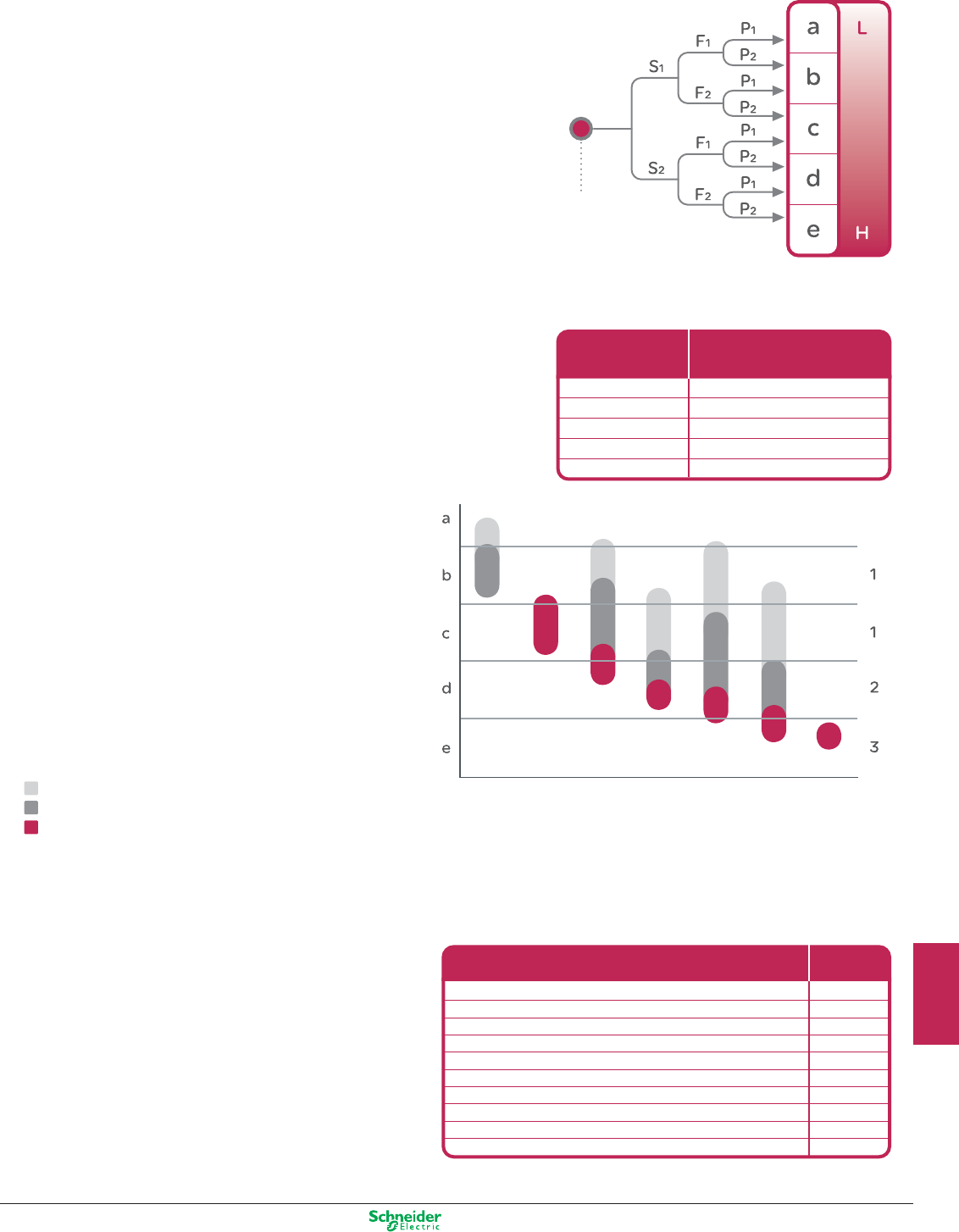
Other versions: please consult your Schneider Electric agency.
Required
performance
level PLr
Starting point for
the evaluation of the
contribution to the
risk reduction of a
safety function
Performance
level (PL)
a
b
c
d
e
10-5 ... < 10-4
3 x 10⁻⁶ ... <10-5
10-6…< 3 x 10⁻⁶
10-7…< 10-6
10-8…< 10-7
Probability of a dangerous
Failure per Hour
Performance level “EN / ISO 13849-1”
Safety Integrity Level “EN / IEC 62061”
Safety category level according to EN/ISO 13849-1
Cat. B
DCavg =
0
MTTFd of each channel = low
MTTFd of each channel = medium
MTTFd of each channel = high
Cat. 4
DCavg =
high
Cat. 3
DCavg =
medium
Cat. 3
DCavg =
low
Cat. 2
DCavg =
medium
Cat. 2
DCavg =
low
Cat. 1
DCavg =
low
Electromechanical components
Emergency stop push-button Ø22 mm XB4 & XB5 (mushroom head)
Emergency stop trip wire switches XY2 C
Pushbutton Ø22 mm XB4 & XB5
Safety Limit switches with plunger or roller lever head XSC
Safety switches with key (guard switches) XCS
Safety switches with key (electromagnet guard switches) XCS
Safety switches with rotary opening head XCS
Safety coded magnetic switches XCS DMC/DMP/DMR at 10mA
contactors with nominal load
contactors with mechanical load
1 500 000
50 000
25 000 000
50 000 000
5 000 000
5 000 000
5 000 000
50 000 000
1 300 000
20 000 000
B10d
> Approach according to EN/ISO 13849-1
Determination of the Performance Level requested (PLr)
This determination could be done using the risk graph.
S = Severity of injury
S1 = Slight (normally reversible injury)
S2 = Serious (normally irreversible) injury including death
F = Frequency and/or exposure time to the hazard
F1 = Seldom to less often and/or the exposure time is short
F2 = Frequent to continuous and/or the exposure time is long
P = Possibility of avoiding the hazard or limiting the harm
P1 = Possible under specific conditions
P2 = Scarcely possible
L = Low contribution to risk reduction
H = High contribution to risk reduction
Determination of the PL achieved by the
Safety-related parts of control systems (SRP/CS)
According to standard EN/ISO 13849-1,
the Performance level (PL) is linked to a target
failure value of probability of dangerous failure
per hour for each safety related control function.
Functional safety and manufacturer
reliability data of electromechanical
components according to
EN/ISO 13849-1 and EN/IEC 62061
Preventa, Harmony, Tesys -
B10d values of electromechanical components.
The following values apply to high or continuous
demand mode of operations used in machinery
applications.
The B10d value is given to a lifetime of 10 years,
but is mainly limited by mechinacal or contact wear.
For a SRP/CS (or a combination of
SRP/CS) designed according the
requirements of the article 6, the PL
could be estimated with the figure
below after estimation of several
factors such as system structure
(categories), mechanism of failures
detection [Diagnosis Coverage (DC)],
components reliability [mean time to
dangerous failure (MTTFd), Common
Cause Failure (CCF)]…
9/5
2
1
3
4
5
6
7
8
9
10
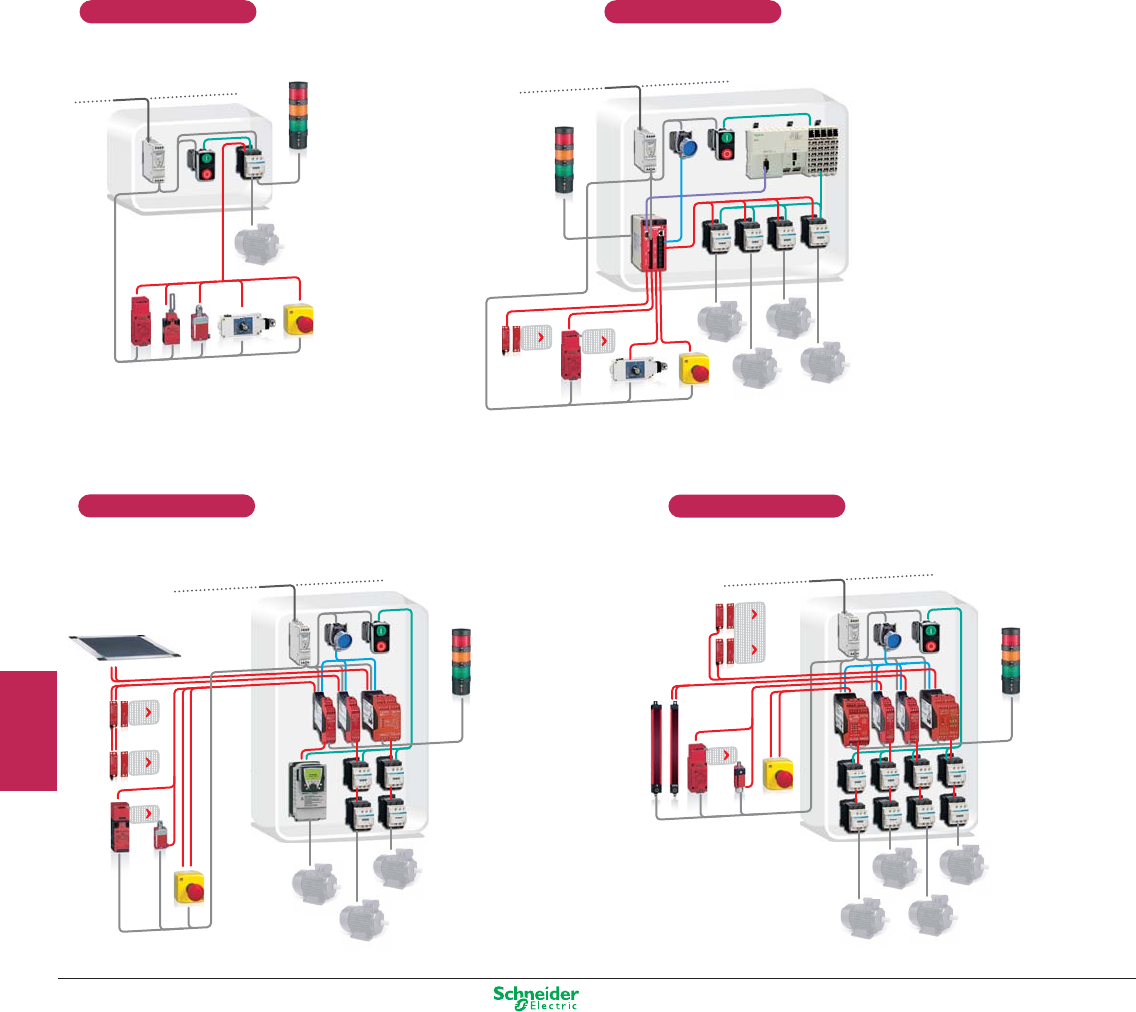
Other versions: please consult your Schneider Electric agency.
Certified safety chain solutions from
an market leader in automation!
The concept:
Combination of products interoperating like
a complete safety chain system to provide
several safety functions for different safety
levels which are certified by an external
notified body
Its are made by:
> Layout of solution indicating performance level (PL),
category and safety integrity level (SIL)
> Bill of materials and the system description file
> Example of calculation of the PL and SIL for each safety function
> Complete electrical diagram in detail
> Certification of all product combination from a notify body
PL=b, Cat 1 / SIL 1
PL=d, Cat 3 / SIL 2 PL=e, Cat 4 / SIL 2
PL=c, Cat 2 / SIL 1
9/6
2
1
3
4
5
6
7
8
9
10
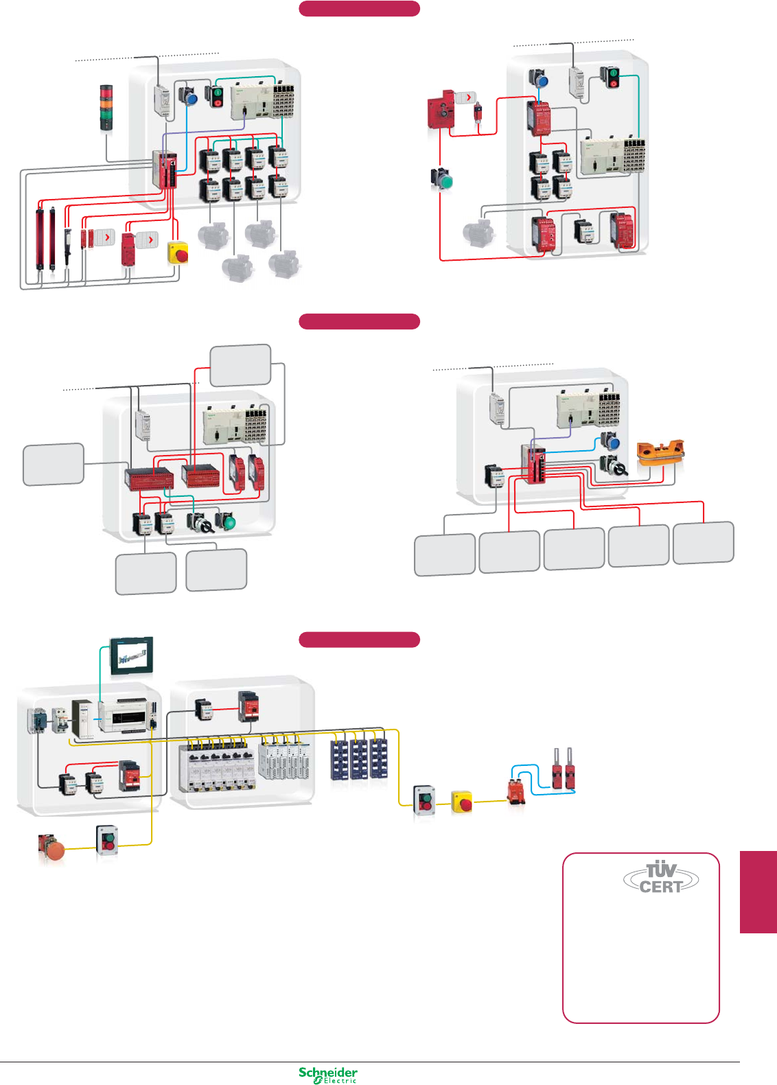
Other versions: please consult your Schneider Electric agency.
SAFETY
VALVES
VALVE
CONTROL
CH1
VALVE
CONTROL
CH2
CAM
ENCLOSURE
VALVE
CONTROL
CH1
MAIN
MOVEMENT
CAM
ENCLOSURE
SAFETY
VALVES
VALVE
CONTROL
CH2
Be confident by using certified safety chain
solutions provided by an automation leader
> Save cost by avoiding external safety experts engineering
> Reduce design time by our examples of calculation of the safety
level for each safety function
PL=e, Cat 4 / SIL 3
PL=e, Cat 4 / SIL 3
PL=e, Cat 4 / SIL 3
9 Safety
chain solutions
Certified on
the right safety
level required
9/7
2
1
3
4
5
6
7
8
9
10
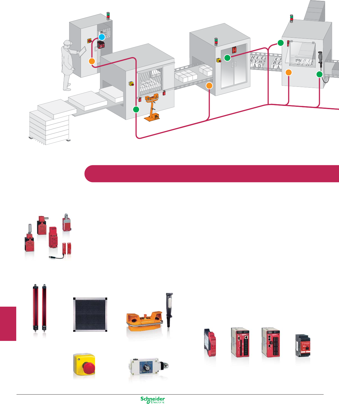
Other versions: please consult your Schneider Electric agency.
Safe signal transmission
Save cost and time with our Preventa offer...
Acquire the information:
> Protective devices used as part of safeguarding
systems to control the access under specific conditions
of reduced risk.
> Light curtains and safety mats to detect approach
to dangerous and limited areas.
> Two hand control stations and enabling switches
for starting and enabling of dangerous movements.
> Generic protective measures - Emergency stop.
Monitor and processing:
> Safety relays modules with a specific safety function
to monitor input signals from safety devices and to
interface with contactors and drives by switch off the
output safety contacts.
> Safety Controller: configurable safety device capable
of centralized a generic range of safety monitoring
functions.
> Safety PLCs: programmable electronic systems to
carry out safety or non-safety related tasks for machi-
nery and equipment.
> «As-i safety at work»: safety field bus network
certified to work with safety devices to provide safety
functions.
Safety
relays
Safety
Controller
Safety
PLCs
As-i safety
at work
Protective devices
Safety mats Two hand control stations
and enabling switches
Emergency stop Tripwire switch
Light curtains
9/8
2
1
3
4
5
6
7
8
9
10
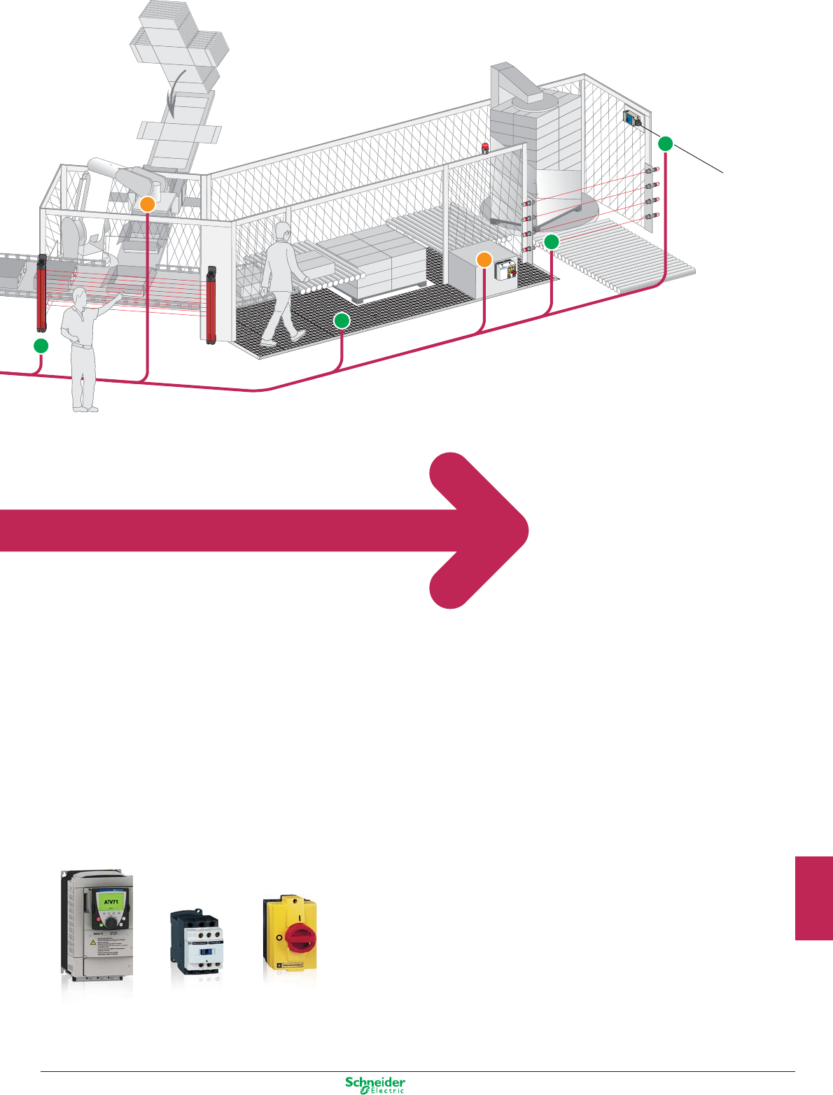
Other versions: please consult your Schneider Electric agency.
Stop the machine:
> Contactors to cut-off the electrical power supply to
the motors with mechanically linked mirror auxiliary
contacts integrated for the feedback loop diagnosis of
safety modules.
> Variable Speed Drives controlled stopping of the
dangerous movement by safety certified power removal
function integrated.
> Rotary switch disconnectors:
for equipment isolation from the electrical supply and
for emergency stop by direct interruption of the power
supply.
Variable
Speed Drives
Rotary switch
disconnectors
Contactors
1 Complete
& upgraded
safety offer:
Improve safety level
requirement
Save costs by optimizing
electrical panel space
Reduce installation time
by easy and quick wiring
Up to 50%
of space
optimization
Increase the compactness
by reducing size
Save up
to 30%
on installation
time
Thanks to cage clamp,
option included in our
new products range
9/9
2
1
3
4
5
6
7
8
9
10

Other versions: please consult your Schneider Electric agency.
SoSafety software
SoSafety software incorporates 4 software applications for machine safety.
It is available in 4 complete versions and 3 update versions, adapted to your
particular needs:
Protect Area Design
Safety mats configuration
software
SoSafety comprising Protect Area Design (full version) and
demo versions of the 3 other software applications.
SoSafety comprising Protect Area Design and ASI SWIN (full
versions) and demo versions of the other 2 software applications.
Reference: ASISWIN2
ASISWIN update version comprising the new ASISWIN 2+, only if
the previous version of Safety Suite V1 with ASISWIN2 version 2.0.3
(ref: ASISWIN) have been already installed.
Reference: SSVASISWINUP
SoSafety comprising Protect Area Design, ASI SWIN and
XPS MCWIN (full versions) and demo version of XPS MFWIN.
Reference: XPSMCWIN
XPSMCWIN update version comprising the new XPSMCWIN 2.10,
only if the previous version of Safety Suite V1 with XPSMCWIN
version 2.0 (ref: XPSMCWIN) have been already installed.
Reference: SSVXPSMCWINUP
SoSafety comprising Protect Area Design, ASI SWIN,
XPS MCWIN and XPS MFWIN (full versions).
Reference: SSV1XPSMFWIN
XPSMFWIN update version comprising the new XPSMFWIN 4.1
build 6150, only if the previous version of Safety Suite V1 with
XPSMFWIN version 4.1 (ref: SSV1XPSMFWIN) have been already
installed.
Reference: SSVXPSMFWINUP
ASI SWIN
AS-Interface safety
monitor configuration
software.
XPS MCWIN
XPS MC safety controllers
configuration software.
XPS MFWIN
XPS MF safety PLCs
programming software.
9/10
2
1
3
4
5
6
7
8
9
10

Other versions: please consult your Schneider Electric agency.
Notes
9/11
2
1
3
4
5
6
7
8
9
10
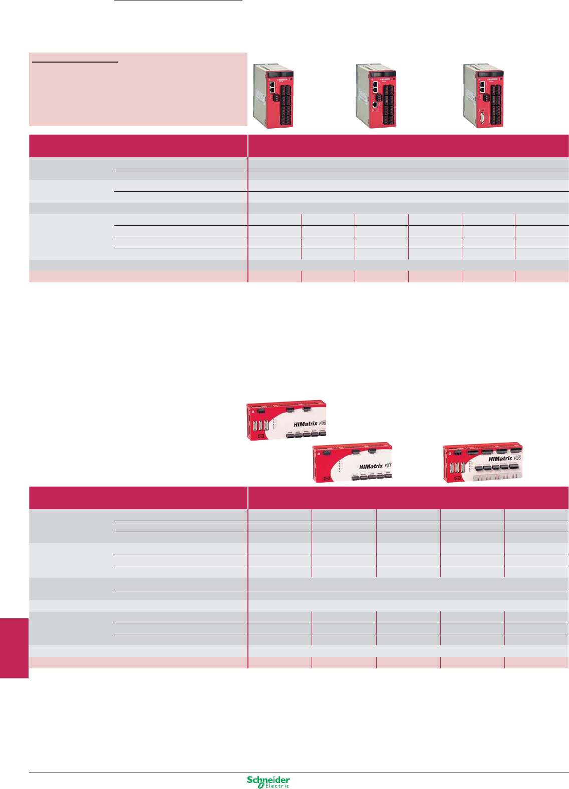
Other versions: please consult your Schneider Electric agency.
Safety PLC type Compact
Number of inputs/outputs Digital
(configurable with XPSMFWIN software)
24
Pulsed (1) 2x4
Memory capacity Application 250 Kb
Data 250 Kb
Supply External 24 VDC supply (with separate protection conforming to IEC 61131-2)
Communication
On Ethernet network with safe Ethernet protocol
Integrated (2xRJ45) Integrated (2xRJ45) Integrated (2xRJ45) Integrated (2xRJ45) Integrated (2xRJ45) Integrated (2xRJ45)
On Modbus TCP/IP –
Integrated (2xRJ45)
–
Integrated (2xRJ45)
–
Integrated (2xRJ45)
On Modbus (Serial link)
–
–
Integrated (1xRJ45) Integrated (1xRJ45)
–
–
On Profibus DP –
–
–
–
Integrated (SUB-D9) Integrated (SUB-D9)
Input/output connections Removable screw terminal blocks or removable cage clamp terminal blocks coded with locating device
References XPSMF4000 XPSMF4002 XPSMF4020 XPSMF4022 XPSMF4040 XPSMF4042
(1) They outputs are not safety outputs.
Compact
Safety PLC type Compact
Number of inputs Digital 20 20 24 24 24
Analogue – – 888
Counting – – 222
Number of outputs Digital 88888
Analogue – – – – –
Relay – – – – –
Memory capacity Application 250 Kb
Data 250 Kb
Supply External 24 VDC supply (with separate protection conforming to IEC 61131-2)
Communication On Ethernet network (Modbus TCP/IP)
Integrated
(4xRJ45)
Integrated
(4xRJ45)
Integrated
(4xRJ45)
Integrated
(4xRJ45) Integrated (4xRJ45)
On Modbus (Serial link)
Integrated (SUB-D9)
––
Integrated (SUB-D9)
–
On Profibus DP – – – – Integrated (SUB-D9)
Input/output connections Removable screw terminal blocks, coded with locating device
References (2) XPSMF3022 XPSMF31222 XPSMF3502 XPSMF3522 XPSMF3542
(2) Products referenced XPSMF30/MF31/MF35 are marked Himatrix F30, F31 and F35.
Safety PLCs
Compact
Preventa
Automation
For all XPSMF PLCs
p
Maximum category of the solution .................................. Category 4
(EN 954-1)
p
Max performance level for the solution .......................... PL e
(EN ISO 13849-1)
p
Max safety integrity level for the solution ........................ SIL 3
(EN IEC 62061)
9/12
2
1
3
4
5
6
7
8
9
10
Other versions: please consult your Schneider Electric agency.
Type CPU Power supply
module
Rack
with 6 slots
Software
Memory capacity Application 500 Kb – – For XPSMF PLCs
Data 500 Kb – –
Supply –
External 24 VDC, integrated
–
Communication On Ethernet network (Modbus TCP/IP) Integrated (4xRJ45) – – Complete version
On Modbus bus (Serial link) Integrated (SUB-D9) – – SSV1XPSMFWIN
Power connections Screw terminal blocks Screw terminal blocks – (1)
Dimensions W x D x H – – 257 x 239 x 310 mm Update version
References XPSMFCPU22 XPSMFPS01 XPSMFGEH01 SSVXPSMFWINUP
I/O module type For modular safety PLC
Analogue Digital Relay
Number of inputs Digital – – – 24 32 24 –
Analogue 8––––––
Counting – – 2––––
Number of outputs Digital – – 4––16 –
Analogue – 8–––––
Relay – – ––––8
Supply Removable screw terminal blocks, coded with locating device
References
XPSMFAI801 XPSMFAO801 XPSMFCIO2401 XPSMFDI2401 XPSMFDI3201 XPSMFDIO241601 XPSMFDO801
Decentralised safety I/O modules
Module type Inputs/Ouputs
Digital
Number of inputs Digital 16 8+2 16 20
Number of outputs Digital – 8 8 8
Pulsed 4 2 2 –
Supply External 24 VDC supply (with separate protection conforming to IEC 61131-2)
Communication On Safe Ethernet network (Modbus TCP/IP) Integrated (2xRJ45)
Input/output connections Removable screw terminal blocks, coded with locating device
References (2) XPSMF1DI1601 XPSMF3DIO8801 XPSMF3DIO16801 XPSMF3DIO20802
I/O module type Inputs/Outputs
Analogue
Outputs
Digital Relay
Number of inputs Analogue 8 – – – –
Number of outputs Digital – 4 16 – –
Analogue (not safety) 4 – – – –
Relay – – – 8 16
Supply External 24 VDC supply (with separate protection conforming to IEC 61131-2)
Communication On Safe Ethernet network (Modbus TCP/IP) Integrated (2xRJ45)
Input/output connections Removable screw terminal blocks, coded with locating device
References (2) XPSMF3AIO8401 XPSMF2DO401 XPSMF2DO1601 XPSMF2DO801 XPSMF2DO1602
(1) To be ordered only if the previous version of have been already installed.
(2) Products referenced XPSMF1/MF2/MF3 are marked Himatrix F1, F2 and F3.
For all XPSMF PLCs
p
Maximum category of the solution .................................. Category 4
(EN 954-1)
p
Max performance level for the solution .......................... PL e
(EN ISO 13849-1)
p
Max safety integrity level for the solution ........................ SIL 3
(EN IEC 62061)
9/13
2
1
3
4
5
6
7
8
9
10
Other versions: please consult your Schneider Electric agency.
Universal
Universal
Universal
Preventa
Automation
Safety controllers for monitoring
emergency stops and limit switches
For all XPSMC controllers
p
Max performance level for the solution (EN ISO 13849-1) ...................PL e
p
Max safety integrity level for the solution (EN IEC 62061) ....................SIL 3
Maximum category of the solution Category 4
(EN 954-1)
Number of circuits Safety 2 x 2N/O + 6 solid-state 2 x 3N/O per function
Additional – 3 solid-state
Display (number of LEDs) 30 12
Width of housing 74 mm 45 mm
Communication interface Modbus Modbus, CANopen Modbus, Profibus DP –
Universal solutions: safety controllers (for monitoring several safety functions simultaneously)
Supply voltage 24 VDC XPSMC32Z (1) (2) XPSMC32ZC (1) (2) XPSMC32ZP (1) (2) XPSMP11123P (3)
coded magnetic switches
enabling switch
Maximum category of the solution Category 4
(EN 954-1)
For monitoring magnetic switches and enabling switch
Number of circuits Safety 2 x 2N/O + 6 solid-state 2 x 3N/O per function
Additional – 3 solid-state
Display (number of LEDs) 30 12
Width of housing 74 mm 45 mm
Communication interface Modbus Modbus, CANopen Modbus, Profibus DP –
Universal solutions: safety controllers (for monitoring several safety functions simultaneously)
Supply voltage 24 VDC XPSMC32Z (1)(2) XPSMC32ZC (1)(2) XPSMC32ZP (1)(2) XPSMP11123P (3)
safety mats and edging
Maximum category of the solution Category 3
(EN 954-1)
Number of circuits Safety 2 x 2N/O + 6 solid-state 2 x 3N/O per function
Additional – 3 solid-state
Display (number of LEDs) 30 12
Width of housing 74 mm 45 mm
Communication interface Modbus Modbus, CANopen Modbus, Profibus DP –
Universal solutions: safety controllers (for monitoring several safety functions simultaneously)
Supply voltage 24 VDC XPSMC32Z (1)(2) XPSMC32ZC (1)(2) XPSMC32ZP (1)(2) XPSMP11123P (3)
(1) Version with 32 inputs. For version with 16 inputs, replace 32 in the reference by 16 (example: XPSMC32Z becomes XPSMC16Z).
(2) Configuration software XPSMCWIN (complete version) or SSVXPSMCWINUP (update version), connecting cable, adaptor and set of screw terminal plug-in connectors
XPSMCTS16 and XPSMCTS32 or set of spring clip terminal plug-in connectors XPSMCTC16 and XPSMCTC32 to be ordered separately.
(3) For fixed connector version, delete the letter P from the end of the reference (example: XPSMP11123P becomes XPSMP11123).
9/14
2
1
3
4
5
6
7
8
9
10
Other versions: please consult your Schneider Electric agency.
Safety modules for monitoring
emergency stops and limit switches
Maximum category of the solution Category 3 Category 4
(EN 954-1)
Number of circuits Safety 3N/O 3N/O 3N/O 7N/O
3N/O+3N/O time del. 2N/O+3N/O time del.
Additional
1 solid-state
–
1N/C + 4 solid-state 2N/C + 4 solid-state 3 solid-state 4 solid-state
Display (number of LEDs) 2 3 4 4 11 4
Width of housing 22.5 mm 22.5 mm 45 mm 90 mm 45 mm 45 mm
Optimum solutions: safety modules (for monitoring 1 safety function)
Supply voltage (1)
24 VDC – – – – XPSAV11113P –
24 VAC/DC XPSAC5121P XPSAF5130P XPSAK311144P XPSAR311144P –XPSATE5110P
230 VAC – – – – – XPSATE3710P
(1) For version with non removable terminal block, delete the letter P from the end of the reference (example: XPSAV11113P becomes XPSAV11113).
coded magnetic switches
enabling switch
Maximum category of the solution Category 4
(EN 954-1)
For monitoring 2 coded magnetic 6 coded magnetic enabling switch
switches maximum switches maximum
Number of circuits Safety 2N/O 2N/O 2N/O
Additional 2 solid-state 2 solid-state 2 solid-state
Display (number of LEDs) 3 15 3
Width of housing 22.5 mm 45 mm 22.5 mm
Optimum solutions: safety modules (for monitoring 1 safety function)
Supply voltage 24 VDC XPSDMB1132P (1) XPSDME1132P (1) XPSVC1132P (1)
(1) For version with non removable terminal block, delete the letter P from the end of the reference (example: XPSDMB1132P becomes XPSDMB1132).
safety mats and edging
Maximum category of the solution Category 3
(EN 954-1)
Number of circuits Safety 3N/O
Additional 1N/C + 4 solid-state
Display (number of LEDs) 4
Width of housing 45 mm
Optimum solutions: safety modules (for monitoring 1 safety function)
Supply voltage 24 VAC/DC XPSAK311144P (1)
(1) For version with non removable terminal block, delete the letter P from the end of the reference (example: XPSAK311144P becomes XPSAK311144).
9/15
2
1
3
4
5
6
7
8
9
10
Other versions: please consult your Schneider Electric agency.
0,0
0,2
0,4
0,6
0,8
1,0
0,0
0,2
0,4
0,6
0,8
1,0
Universal
Universal
Universal
Preventa
Automation
Safety controllers for monitoring
two-hand control
For all XPSMC controllers
p
Max performance level for the solution (EN ISO 13849-1) ...................PL e
p
Max safety integrity level for the solution (EN IEC 62061) ....................SIL 3
Maximum category of the solution Category 4
(EN 954-1)
Number of circuits Safety 2 x 2N/O + 6 solid-state
Additional –
Display (number of LEDs) 30
Width of housing 74 mm
Communication interface Modbus Modbus, CANopen Modbus, Profibus DP
Universal solutions: safety controllers (for monitoring several safety functions simultaneously)
Supply voltage 24 VDC XPSMC32Z (1)(2) XPSMC32ZC (1)(2) XPSMC32ZP (1)(2)
light curtains
Maximum category of the solution Category 4 2 light curtains
(EN 954-1) monitoring max.
Number of circuits Safety 2 x 2N/O + 6 solid-state 2x3N/O per function 6 PNP solid-state
Additional – 3 solid-state 1 PNP + 1 NPN
Display (number of LEDs) 30 12
14 + double display units
Width of housing 74 mm 45 mm 100 mm
Integral Muting function Yes No Yes
Communication interface Modbus Modbus, CANopen Modbus, Profibus DP – –
Universal solutions: safety controllers (for monitoring several safety functions simultaneously)
Supply voltage 24 VDC XPSMC32Z
(1)(2)
XPSMC32ZC
(1)(2)
XPSMC32ZP
(1)(2)
XPSMP11123P (3) XPSLCM1150 (4)
(1) Version with 32 inputs, for version with 16 inputs, replace 32 in the reference by 16 (example: XPSMC32Z becomes XPSMC16Z).
(3) For version with non removable terminal block, delete the letter P from the end of the reference (example: XPSMP11123P becomes XPSMP11123).
(4) Removable terminal blocks
zero speed, time delay
Maximum category of the solution Category 4
(EN 954-1)
For monitoring Motor zero speed condition
Number of circuits Safety 2 x 2N/O + 6 solid-state
Additional –
Display (number of LEDs) 30
Width of housing 74 mm
Communication interface Modbus Modbus, CANopen Modbus, Profibus DP
Universal solutions: safety controllers (for monitoring several safety functions simultaneously)
Supply voltage 24 VDC XPSMC32Z (5) (2) XPSMC32ZC (5) (2) XPSMC32ZP (5) (2)
(2) Configuration software XPSMCWIN (complete version) or SSVXPSMCWINUP (update version), connecting cable, adaptor and set of screw terminal plug-in connectors
XPSMCTS16 and XPSMCTS32 or set of spring clip terminal plug-in connectors XPSMCTC16 and XPSMCTC32 to be ordered separately.
(5) Plug-in connector version only.
9/16
2
1
3
4
5
6
7
8
9
10
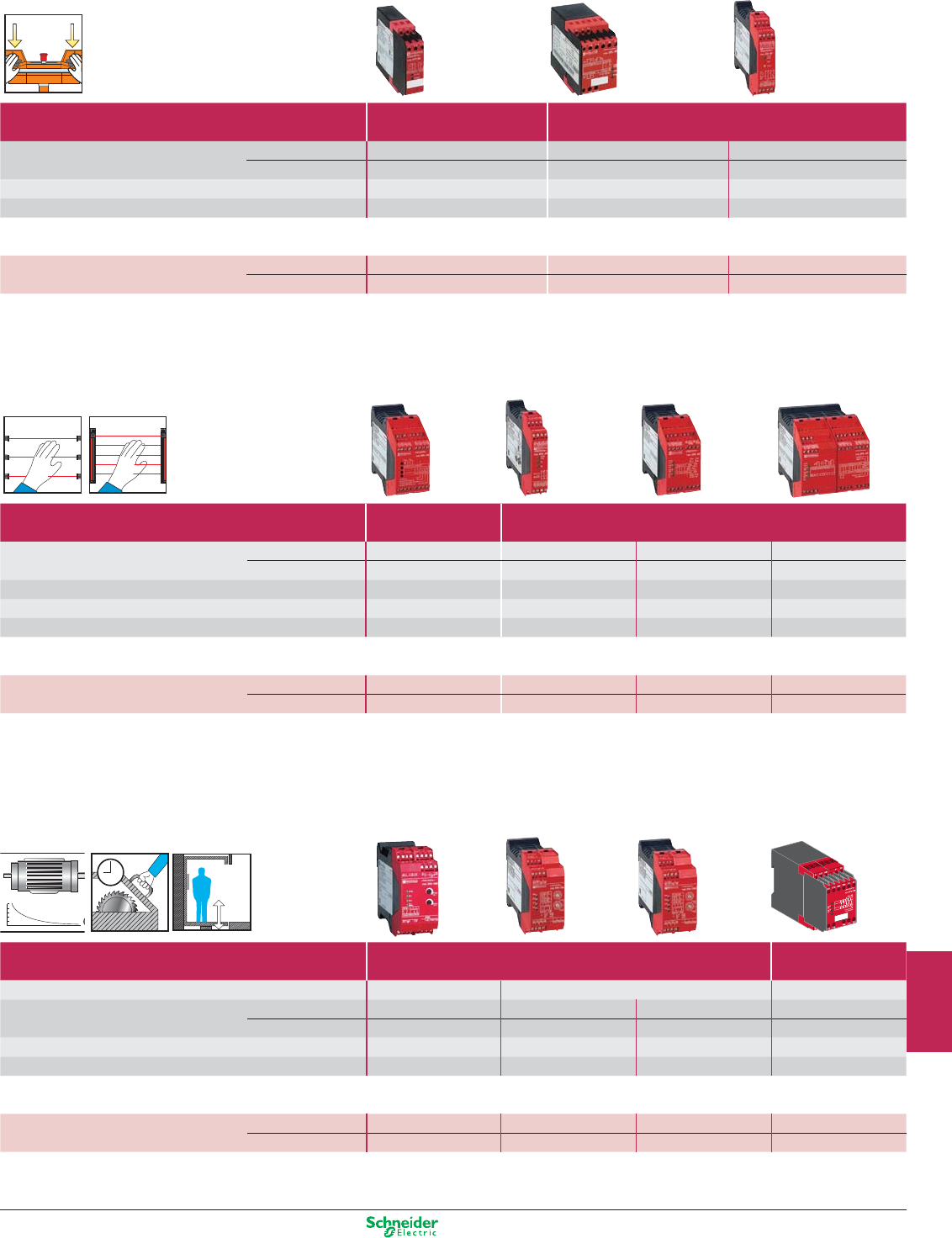
Other versions: please consult your Schneider Electric agency.
0,0
0,2
0,4
0,6
0,8
1,0
Safety modules for monitoring
two-hand control
Maximum category of the solution Category 1 Category 4
(EN 954-1) (type IIIA to EN 574) (type IIIC to EN 574)
Number of circuits Safety 1N/O 2N/O 2N/O
Additional 1N/C 1N/C 2 solid-state
Display (number of LEDs) 2 3 3
Width of housing 22.5 mm 45 mm 22.5 mm
Optimum solutions: safety modules (for monitoring 1 safety function)
Supply voltage 24 VDC – XPSBC1110 XPSBF1132P (1)
24 VAC/DC XPSBA5120 ––
(1) For version with non removable terminal block, delete the letter P from the end of the reference (example: XPSBF1132P becomes XPSBF1132).
light curtains
Maximum category of the solution Category 2 Category 4
(EN 954-1)
Number of circuits Safety 2N/O 3N/O 3N/O 7N/O
Additional 4 solid-state – 1N/C + 4 solid-state 1N/C + 4 solid-state
Display (number of LEDs) 4 3 4 4
Width of housing 45 mm 22.5 mm 45 mm 90 mm
Integral Muting function Yes No No No
Optimum solutions: safety modules (for monitoring 1 safety function)
Supply voltage 24 VDC XPSCM1144P (1) – – –
24 VAC/DC –XPSAFL5130P (1) XPSAK311144P (1) XPSAR311144P (1)
(1) For version with non removable terminal block, delete the letter P from the end of the reference (example: XPSCM1144P becomes XPSCM1144).
zero speed, time delay and lifts
Maximum category of the solution Category 3 Category 4
(EN 954-1)
For monitoring
Motor zero speed condition
Safety time delay Lifts
Number of circuits Safety 1N/O + 1N/C 1N/O time delay 1N/O pulse 2N/O
Additional 2 solid-state 2N/C + 2 solid-state 2N/C + 2 solid-state 2 solid-state
Display (number of LEDs) 4 4 4 4
Width of housing 45 mm 45 mm 45 mm 45 mm
Optimum solutions: safety modules (for monitoring 1 safety function)
Supply voltage 24 VDC XPSVNE1142P (1) – – –
24 VAC/DC –XPSTSA5142P (2) XPSTSW5142P (2) XPSDA5142
(1) Motor frequency ≤ 60 Hz.. For frequencies ≥ 60 Hz, please refer to the “Safety solution” catalogue.
(2) Removable terminal block version only.
9/17
2
1
3
4
5
6
7
8
9
10
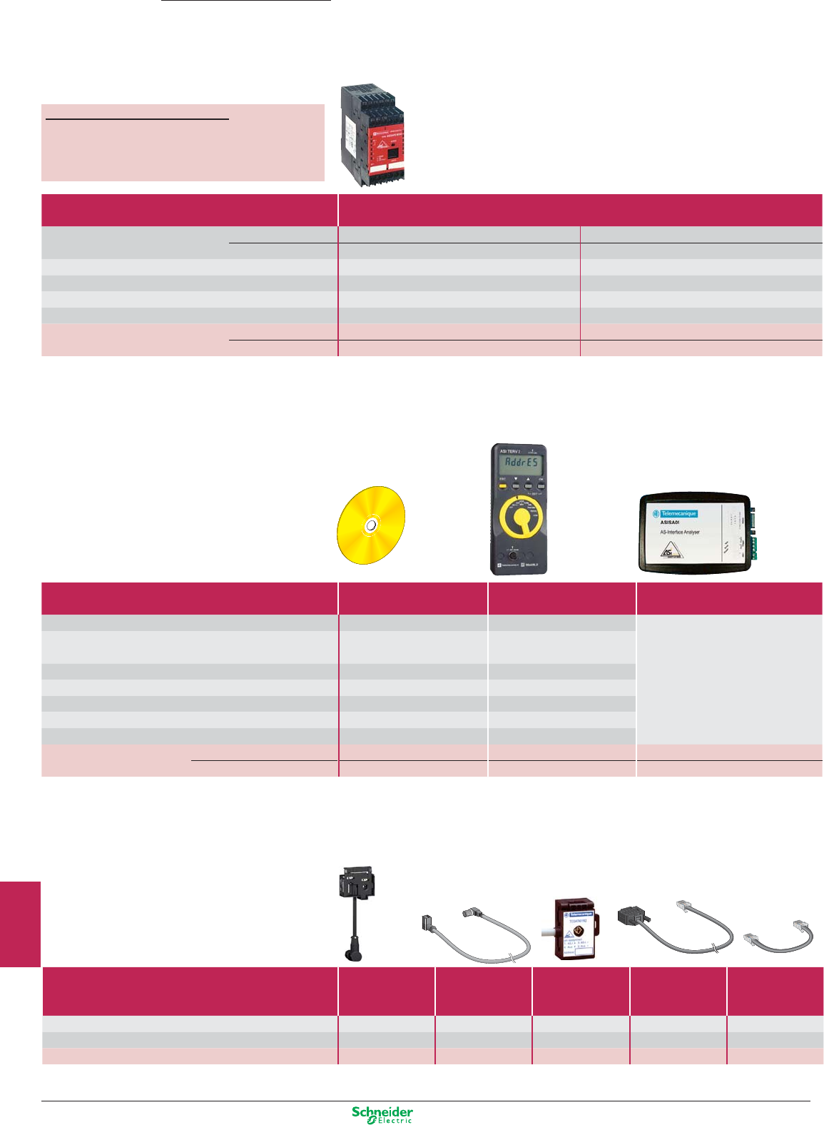
Other versions: please consult your Schneider Electric agency.
Preventa
AS-Interface safety at work
Safety monitors
Monitors
Configuration software, adjustment terminal and
AS-Interface analyser
Maximum category of the solution
(EN 954-1)
Category 4
Number of circuits
Safety
2N/O 2 x 2N/O
Auxiliary 1 solid-state 2 solid-state
Display (number of LEDs) 5 8
Width of housing 45 mm 45 mm
AS-Interface profile S.7.F S.7.F
Master module compatibility V1 / V2.1 V1 / V2.1
References of monitor with
enhanced functions
ASISAFEMON1B ASISAFEMON2B
standard functions ASISAFEMON1 ASISAFEMON2
(1) CD-ROM with hardware and software user guides.
(2) For addressing safety interfaces, use the infrared adaptor ASITERIR1 or the standard adaptor ASISAD1.
(3)
To be ordered only if a previous version of ASISWIN have been already installed.
Accessories
Type
Adaptor
for the adressing
of safety interfaces
Infrared adaptor
for adjustment terminal
Tap-off
for AS-Interface cable
Cable
for monitor
parametering, RS 232
Cable
for monitor to monitor
transfer
Degree of protection – IP 67 IP 67 IP 20 IP 20
Cable length – 1 m 2 m 2 m 0.2 m
References ASISAD1 ASITERIR1 TCSATN01N2 ASISCPC ASISCM
Type
“Safety Suite”
configuration software
(1)
Adjustment terminal (2)
AS-Interface Analyser
Multilingual EN / FR / DE / ES / IT / PT –
b Analysis and diagnostics of AS-Interface
For use with ASISAFEMON1/2, –
line and Safety at Work
ASISAFEMON1B/2B
b Complements the diagnostic functions of
Media CD-ROM PC –
the local AS-Interface master
Environment Windows –
b Maintenance or validation of AS-Interface
Degree of protection –IP 40
lines
Supply – 4 x LR6 batteries
b Print-out of
AS-Interface line tests
Dimensions W x D x H – 70 x 50 x 170 mm 92 x 28 x 139 mm
References
Complete version
ASISWIN2 ASITERV2 ASISA01
Update version
(3)
SSVASISWINUP – –
For all ASISAFEMON monitors
p
Max performance level for the solution ......................... PL e
(EN ISO 13849-1)
p
Max safety integrity level for the solution ........................ SIL 3
(EN IEC 62061)
9/18
2
1
3
4
5
6
7
8
9
10
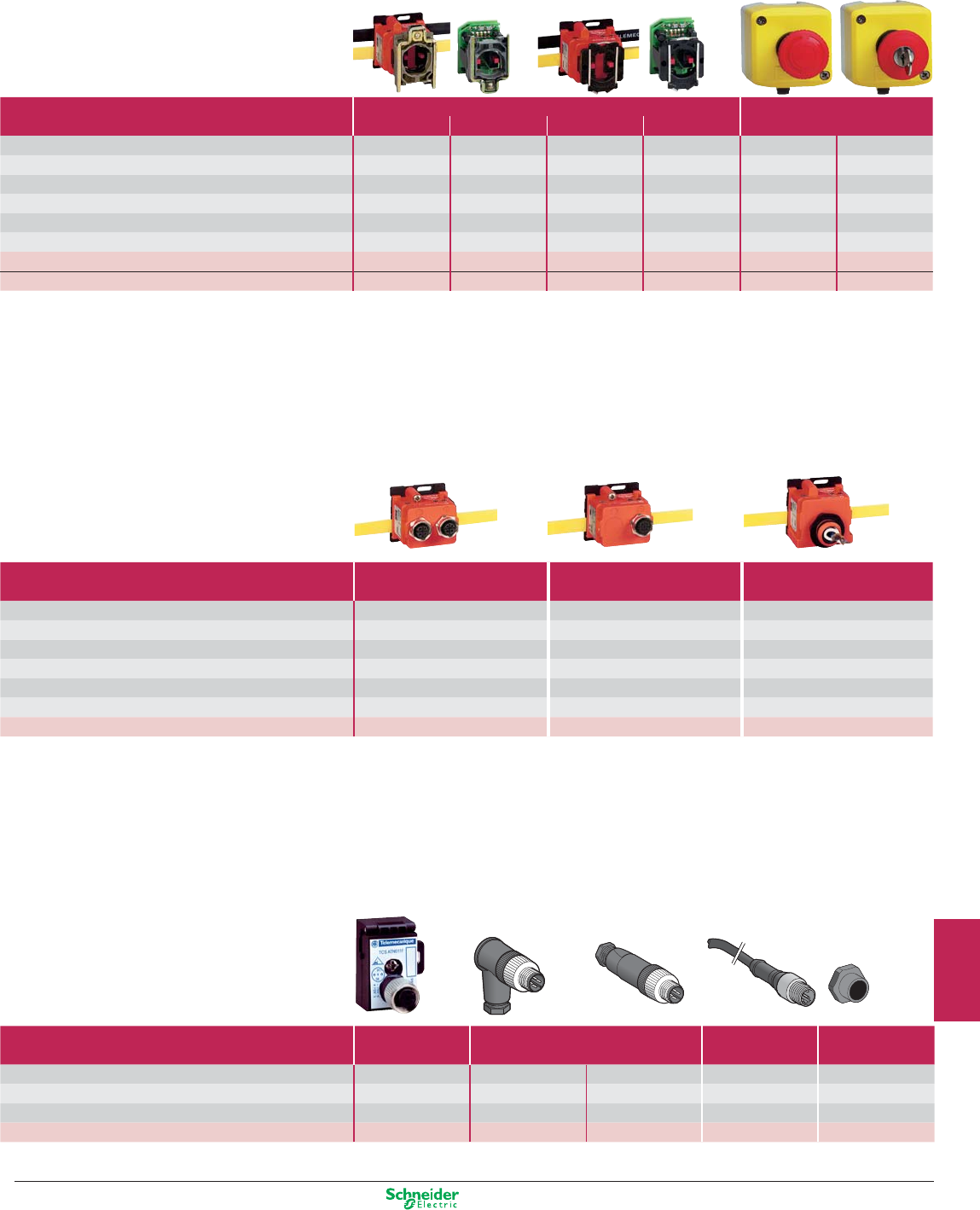
Other versions: please consult your Schneider Electric agency.
Accessories
(6) For connection using 2 pre-wired connectors, or 1 pre-wired connector + 1 connector.
(7) For 1 x ISO M20 entry, use adaptor shown below.
Type of entry 2 x M12 entries (6) 1 x M12 entry 1 x ISO M16 entry (7)
Degree of protection IP 67 IP 67 IP 67
Dimensions W x D x H 40 x 40 x 58 mm 40 x 40 x 58 mm 40 x 40 x 57.5 mm
AS-Interface profile S.0.B.F.F S.0.B.F.F S.0.B.F.F
Consumption from AS-Interface 45 mA 45 mA 45 mA
Infrared addressing Yes Ye s Yes
Connection on AS-Interface IDC (1) IDC (1) IDC (1)
References ASISSLC2 ASISSLC1 ASISSLLS
Safety interfaces
For Ø 22 Emergency stop
Interface type
For mushroom head pushbuttons
Control stations
Metal (1) Plastic (1) Plastic
Degree of protection
IP 20 IP 20 IP 20 IP 20 IP 65 IP 65
Dimensions W x D x H
(mm) 40 x 90 x 68 40 x 80 x 40 40 x 90 x 64 40 x 90 x 40 66 x 95 x 78 66 x 95 x 78
AS-Interface profile
S.0.B.F.F S.0.B.F.F S.0.B.F.F S.0.B.F.F S.0.B.F.F S.0.B.F.F
Consumption from AS-Interface
45 mA 45 mA 45 mA 45 mA 45 mA 45 mA
Infrared addressing
Yes No Yes No No No
Connection on AS-Interface IDC (2) Connector IDC (2) Connector M12 connector M12 connector
Reference with N/C + N/C contact (head not included)
ASISSLB4 ASISSLE4 ASISSLB5 ASISSLE5 ASISEA1C ASISEK1C
Reference of head
(Ø40 latching mushroom head, turn to release)
ZB4BS844 (3) ZB4BS844 (3) ZB4AS844 (3) ZB5AS844 (3) Integrated (4) Integrated (5)
(1) For installation in enclosures.
(2) IDC: Insulation Displacement Connector
.
(3) Head to be ordered separately. For other heads, please refer to www.schneider-electric.com.
(4) Turn to release latching mushroom head.
(5) Key release (n° 455) latching mushroom head. For other safety products with
M12 connector outputs or ISO M16/20
Type
Tap-off for
AS-Interface cable
Connectors
Pre-wired
connector
Adaptor
(sold in lots of 5)
Description
M12
female, threaded
elbowed straight straight ISO M16/M20
Degree of protection IP 67 IP 67 IP 67 IP 67 IP 67
Length of cable –––2 m–
References
TCSATN011F
XZCC12MCM40B XZCC12MDM40B XZCP1541L2 DE9RI2016
9/19
2
1
3
4
5
6
7
8
9
10
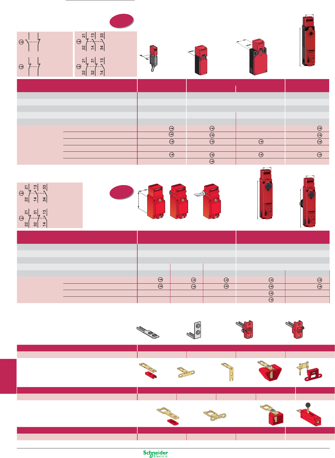
Other versions: please consult your Schneider Electric agency.
20/2220/22
60
30
60
30
20/2220/22
30
153.3
20/22
40,3
30
153.3
30
153.3
2-pole contact
Slow break
(N/C + N/O)
2-pole contact
Slow break
(N/C + N/C)
3-pole contact
Slow break
(N/C + N/O + N/O)
3-pole contact
Slow break
(N/C + N/C + N/O)
Preventa
Detection
Safety switches
and actuators
Plastic, double insulated switches
Type XCSMP Type XCSPA and TA Type XCSLE
pre-cabled, L = 2 m 1xISO M16 entry. (2) 2xISO M16 entries. (2)
3 x ISO M20 cable entries
Actuation speed (min → max) 0,05 m/s → 1,5 m/s 0,1 m/s → 0,5 m/s 0,1 m/s → 0,5 m/s
Degree of protection IP 67 IP 67 IP 67 + IP 66
Rated operational characteristics (conforming to EN IEC 60947-5-1) AC 15, C 300 / DC 13, Q 300 AC 15, A 300 / DC 13, Q 300
AC 15, B 300 / DC 13, Q 300
Dimensions (body + head) W x D x H 30 x 15 x 87 mm 30 x 30 x 93,5 mm 52 x 30 x 114,5 mm 43,6 x 205 x 50,6 mm
Solenoid supply voltage – – – 24 VAC/DC
Complete switch N/C+N/O N/O stag. slow break XCSMP59L2 (3) XCSPA592 – XCSLE2525312
N/C+N/C slow break XCSMP79L2 (3) XCSPA792 – XCSLE2727312
N/C+N/O+N/O 2 N/O stag. slow break XCSMP70L2 (3) XCSPA892 XCSTA592 XCSLE3535312
N/C+N/O+N/O snap action ––––
N/C+N/C+N/O N/O stag. slow break XCSMP80L2 (3) XCSPA992 XCSTA792 XCSLE3737312
N/C+N/C+N/O snap action –XCSPA492 ––
Without locking Locking on de-energisation
of solenoid (1)
3-pole contact
Slow break
(N/C + N/O + N/O)
3-pole contact
Slow break
(N/C + N/C + N/O)
Without locking With interlocking, manual unlocking
By button By key lock
Locking on de-energisation
of solenoid (1)
(1) For locking on energisation of solenoid, please refer to www.schneider-electric.com.
(2) With entry for n° 11 (Pg 11) cable gland, replace the last digit in the reference by 1 (example: XCSPA592 becomes XCSPA591).
(3) For other models, please refer to www.schneider-electric.com.
Metal switches Type XCSA/B/C
1 x ISO M20 cable entry (2)
Type XCSLF
3 x ISO M20 cable entries
Actuation speed (min → max) 0.1 m/s → 0.5 m/s 0.1 m/s → 0.5 m/s
Degree of protection IP 67 IP 67 + IP 66
Rated operational characteristics (conforming to EN IEC 60947-5-1)
AC 15, A 300 / DC 13, Q 300
AC 15, B 300 / DC 13, Q 300
Dimensions (body + head) W x D x H
40 x 44 x 113.5 mm 52 x 44 x 113.5 mm 52 x 44 x 113.5 mm
43,6 x 205 x 50,6 mm
Solenoid supply voltage – – – 24 VAC/DC 24 VAC/DC
Complete switch N/C+N/O+N/O
2 N/O stag. slow break
XCSA502
XCSB502
XCSC502
XCSLF3535312
XCSLF3535412
N/C+N/C+N/O
N/O stag. slow break
XCSA702
XCSB702
XCSC702
XCSLF3737312
XCSLF3535412
N/C+N/O
N/O stag. slow break
XCSLF2525312
N/C+N/C
snap break
XCSLF2727312
(1) For locking on energisation of solenoid, please refer to www.schneider-electric.com.
(2) With entry for n° 13 (Pg 13.5) cable gland, replace the last digit in the reference by 1 (example: XCSA502 becomes XCSA501).
Accessories
Straight actuator
Wide actuator L=40 mm (1)
Right-angled actuator
Pivoting actuator
Straight actuator Right-angled actuator
Pivoting actuator, RH door Pivoting actuator, LH door
Guard/door retainer
Straight actuator Wide actuator Pivoting actuator
ISO entry
(to EN 50262)
ISO entry
(to EN 50262)
1314
22 21
11
12
22 21
1314
22 21
11
12
22 21
For safety switches XCSMP Actuators
References XCSZ81 XCSZ84 XCSZ83 XCSZ85
For safety switches XCSPA/TA/TE Actuators
Retaining device
References XCSZ11 XCSZ12 XCSZ14 XCSZ13 XCSZ21
For safety switches XCSA/B/C/LE/LF Actuators Door lock
References XCSZ01 XCSZ02 XCSZ03 XCSZ05
(1) For L = 29 mm, reference = XCSZ15.
9/20
2
1
3
4
5
6
7
8
9
10
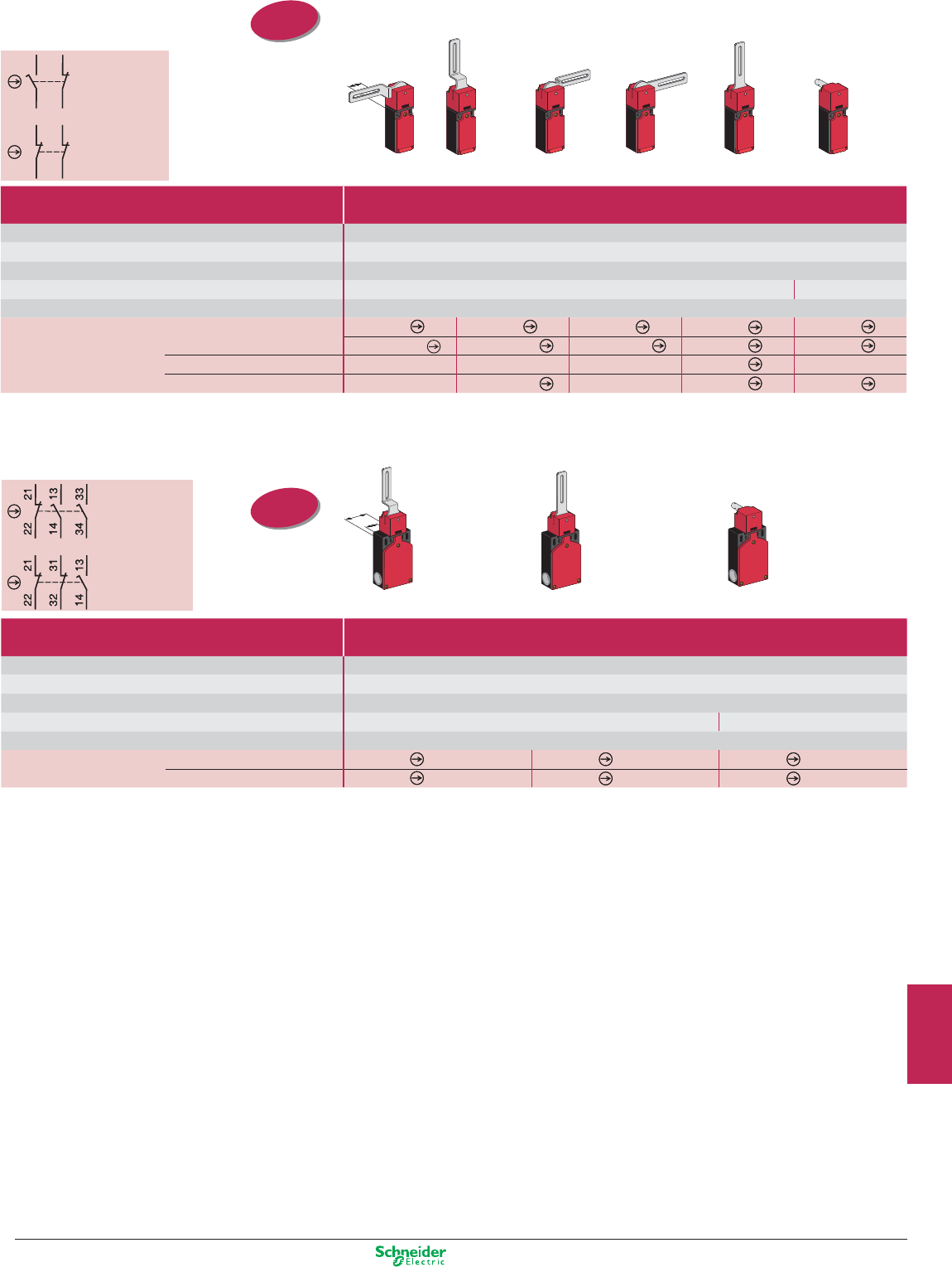
Other versions: please consult your Schneider Electric agency.
20/2220/22
20/22
40,3
20/22
40,3
2-pole contact
Slow break
(N/C + N/O)
2-pole contact
Slow break
(N/C + N/C)
Safety switches
with rotary lever or spindle
Stainless steel, elbowed (flush with rear of switch) lever Stainless steel straight lever Stainless steel
Lever to left Lever centred Lever to right
Lever to left or right
Lever centred
spindle, L = 30 mm
Plastic switches Type XCSPL with rotary lever or XCSPR with spindle
1 x ISO M16 cable entry (1)
Minimum torque (actuation / positive opening) 0,1 / 0,25 N.m
Degree of protection IP 67
Rated operational characteristics AC 15, A 300 / DC 13, Q 300 (selon EN IEC 60947-5-1)
Dimensions (body + head) W x D x H 30 x 30 x 160 mm 30 x 30 x 96 mm
Tripping angle 5°
Complete switch “N/C+N/O” stag. slow break XCSPL592 XCSPL582 XCSPL572 XCSPL562 XCSPR552
“N/C+N/C” slow break XCSPL791 (2) XCSPL781 (2) XCSPL771 (2) XCSPL762 XCSPR752
“N/C+N/C+N/C” slow break – – – XCSPL862 –
“N/C+N/C+N/C” slow break – XCSPL981 (2) – XCSPL962 XCSPR952
3-pole contact
Slow break
(N/C + N/O + N/O)
3-pole contact
Slow break
(N/C + N/C + N/O)
Stainless steel, elbowed (flush with
Stainless steel straight lever
Stainless steel spindle
rear of switch) lever - Lever centred Lever centred Length 30 mm
Plastic switches Type XCSTL with rotary lever or XCSTR with spindle
2 x ISO M16 cable entries (1)
Minimum torque (actuation / positive opening) 0.1 / 0.45 N.m
Degree of protection IP 67
Rated operational characteristics AC 15, A 300 / DC 13, Q 300 (conforming to EN IEC 60947-5-1)
Dimensions (body + head) W x P x H 52 x 30 x 180 mm 52 x 30 x 117 mm
Tripping angle 5°
Complete switch
N/C + N/O + N/O, 2 N/O staggered slow break
XCSTL582
XCSTL552
XCSTR552
N/C + N/C + N/O, N/O staggered slow break
XCSTL782
XCSTL752
XCSTR752
(1) With entry for n° 11 (Pg 11) cable gland, replace the last digit in the reference by 1 (example: XCSPL592 becomes XCSPL591).
(2) For entry for ISO M20 cable gland, also order adaptor DE9RA1620 (sold in lots of 5).
(1) With entry for n° 11 (Pg 11) cable gland, replace the last digit in the reference by 1 (example: XCSTL582 becomes XCSTL581).
ISO entry
(to EN 50262)
ISO entry
(to EN 50262)
1314
22 21
11
12
22 21
1314
22 21
11
12
22 21
9/21
2
1
3
4
5
6
7
8
9
10
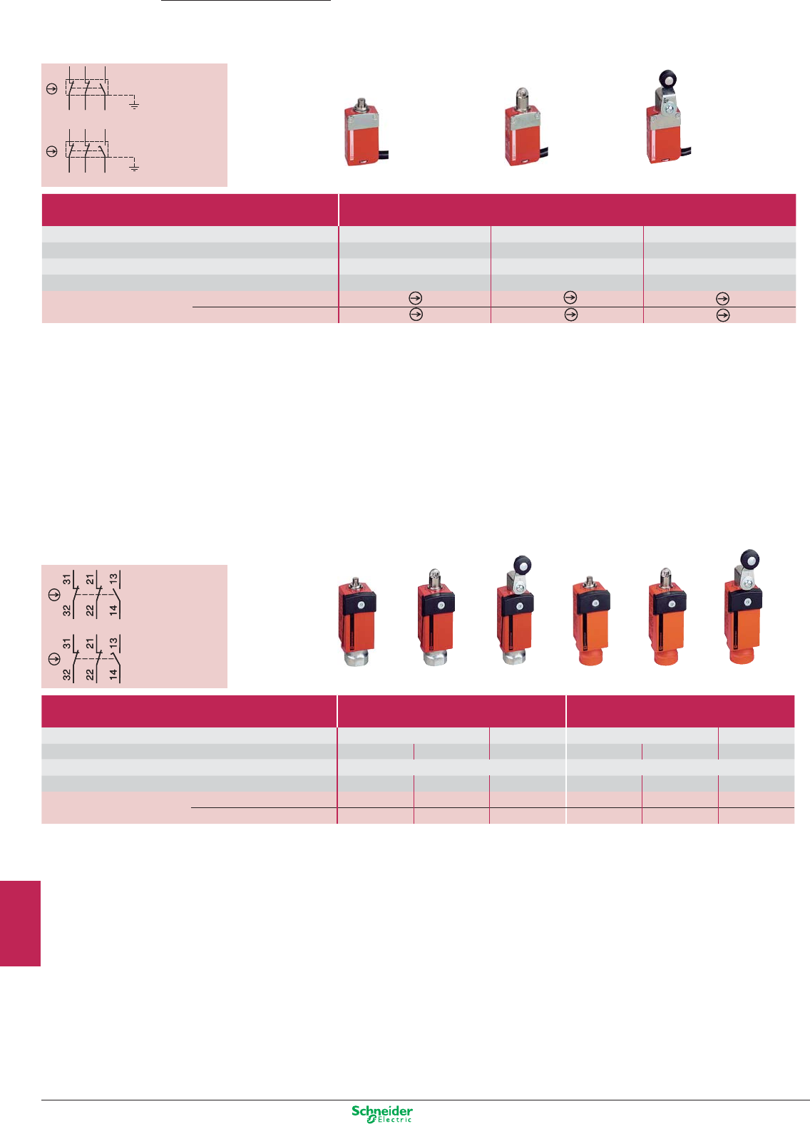
Other versions: please consult your Schneider Electric agency.
RD-WH
RD
BU
BN
GN-YE
BK-WH
BK
RD-WH
RD
BU
BN
GN-YE
BK-WH
BK
RD-WH
RD
BU
BN
GN-YE
BK-WH
BK
RD-WH
RD
BU
BN
GN-YE
BK-WH
BK
Preventa
Detection
Limit switches
Safety limit switches
3-pole contact
N/C + N/C + N/O
Slow break
3-pole contact
N/C + N/C + N/O
Snap action
3-pole contact
N/C + N/C + N/O
Slow break
3-pole contact
N/C + N/C + N/O
Snap action
Metal Roller plunger Thermoplastic
end plunger roller lever
Metal Roller Thermoplastic Metal Roller Thermoplastic
end plunger plunger roller lever end plunger plunger roller lever
Miniature switches Type XCSM, metal
pre-cabled, L = 1 m (1)
Maximum actuation speed 0.5 m/s 0.5 m/s 1.5 m/s
Minimum force or torque (actuation / positive opening) 8.5 N / 42.5 N 7 N / 35 N 0.5 N.m / 0.1 N.m
Degree of protection IP 66 + IP 67 + IP 68 IP 66 + IP 67 + IP 68 IP 66 + IP 67 + IP 68
Dimensions (body + head) W x D x H 30 x 16 x 60 mm 30 x 16 x 70.5 mm 30 x 32 x 92.5 mm
Complete switch N/C + N/C + N/O snap action XCSM3910L1 XCSM3902L1 XCSM3915L1
N/C + N/C + N/O slow break XCSM3710L1 XCSM3702L1 XCSM3715L1
(1) For a 2 m long cable, replace the last digit of the reference by 2 (example: XCSM3910L1 becomes XCSM3910L2).
For a 5 m long cable, replace the last digit of the reference by 5 (example: XCSM3910L1 becomes XCSM3910L5).
Compact switches Type XCSD, metal Type XCSP, plastic
1 x ISO M20 x 1.5 cable entry (2) 1 x ISO M20 x 1.5 cable entry (2)
Maximum actuation speed
0.5 m/s 1.5 m/s 0.5 m/s 1.5 m/s
Minimum force or torque (actuation / positive opening)
15 N / 45 N 12 N / 36 N 10 N.m / 0.1 N.m 15 N / 45 N 12 N / 36 N 10 N.m / 0.1 N.m
Degree of protection
IP 66 + IP 67 IP 66 + IP 67
Dimensions (body + head) W x D x H
(mm) 34 x 34.5 x 89 34 x 34.5 x 99.5 34 x 43 x 121.5 34 x 34.5 x 89 34 x 34.5 x 99.5 34 x 43 x 121.5
Complete switch N/C + N/C + N/O snap action
XCSD3910P20 XCSD3902P20 XCSD3918P20 XCSP3910P20 XCSP3902P20 XCSP3918P20
N/C + N/C + N/O slow break
XCSD3710P20 XCSD3702P20 XCSD3718P20 XCSP3710P20 XCSP3702P20 XCSP3718P20
(2) For Pg 13.5 and 1/2" NPT cable entries, refer to www.schneider-electric.com.
9/22
2
1
3
4
5
6
7
8
9
10
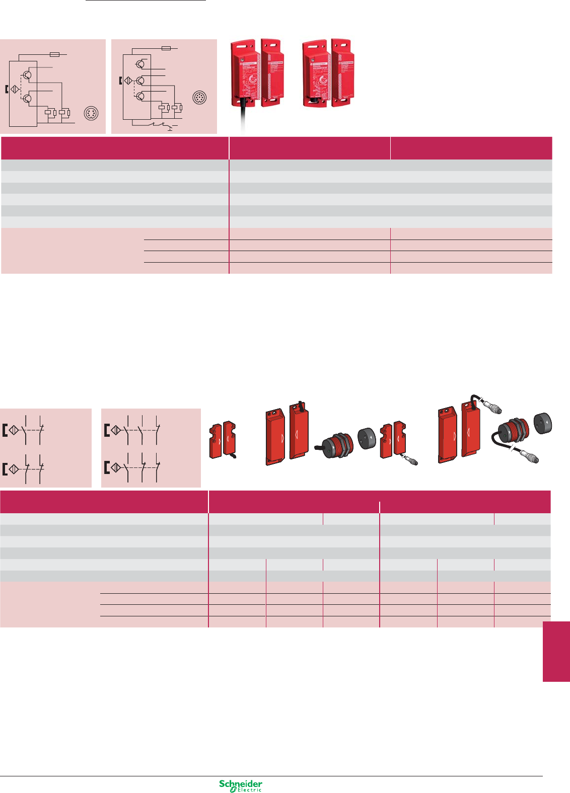
Other versions: please consult your Schneider Electric agency.
1/BN
NO
NO
I1
I2
O1
O2
7/GY
4/BK
6/PK
2/WH
3/BU
K1K2
+
+
+
–
1
7
64
3
2
F1
2 A
1/BN
NO
NO
I1
I2
O1
O2
7/VTEr
5/GY
4/BK
6/PK
2/WH
3/BU
K1
K2
K1K2
+
+
+
–
8/OG
+
Diag
1
7
64
5
3
2
8
+
F1
2 A
Contact
(N/C + N/O,
N/C
staggered)
Contact
(N/O + N/O,
1N/O
staggered)
Contact
(N/C + N/C
+ N/O, 1N/C
staggered)
Contact
(N/C + N/O
+ N/O, 1N/O
staggered)
(1) (1)
BK
BU
WH
BN
BK
BU
WH
BN
BK
BU
WH
BN
BK
BU
WH
BN
PK GY
BK WH
BU BN
PK GY
BK WH
BU BN
PK GY
BK WH
BU BN
PK GY
BK WH
BU BN
Rectangular Rectangular Cylindrical Rectangular Rectangular Cylindrical
Without LED (2) Without LED (2) Without LED (2) Without LED (2) Without LED (2) Without LED (2)
Coded magnetic
Plastic switches Type XCSDM coded magnetic
Pre-cabled, L = 2 m Connector on flying lead, L = 10 cm (3)
Switches for actuation
Face to face, face to side, side to side Face to face
Face to face, face to side, side to
side Face to face
Degree of protection
IP 66 + IP 67 IP 66 + IP 67
Type of contact
REED REED
Rated operational characteristics
Ue = 24 VDC, Ie = 100 mA Ue = 24 VDC, Ie = 100 mA
Dimensions W x D x H
16 x 7 x 51 mm 25 x 13 x 88 mm M30 x 38,5 mm 16 x 7 x 51 mm 25 x 13 x 88 mm M30 x 38.5 mm
Operating zone (4)
Sao = 5 / Sar
= 15 Sao = 8 / Sar = 20
Sao = 5 / Sar = 15
Sao = 8 / Sar = 20
Switch with coded magnet
N/C + N/O, N/C staggered XCSDMC5902 XCSDMP5902 XCSDMR5902
XCSDMC590L01M8
XCSDMP590L01M12
XCSDMR590L01M12
N/O + N/O, 1N/O staggered XCSDMC7902 XCSDMR7902 XCSDMR7902
XCSDMC790L01M8
XCSDMP790L01M12
XCSDMR790L01M12
N/C + N/C + N/O, 1N/C staggered
–XCSDMP5002 ––
XCSDMP500L01M12
–
N/C + N/O + N/O, 1N/O staggered
–XCSDMP7002 ––
XCSDMP700L01M12
–
(1) NB. Contact states shown are with the magnet present.
(2) For version with LED indicator, replace the last 0 in the reference by 1 (example: XCSDMC5902 becomes XCSDMC5912).
(3) For associated pre-wired female connectors, please refer to the “Safety solution” catalogue.
(4) Sao: assured operating distance. Sar: assured release distance.
Type of system SIL2/Category 3 Sil3/Category 4
With integrated safety module XCSDM3 XCSDM4
Switches for actuation
Face to face, face to side, side to side
Degree of protection
Pre-cabled: IP66 / IP67, IP69K, connector: IP67
Type of contact
2 solid-state output PNP/NO, 1,5 A / 24VDC (2 A up to 60°C)
Rated operational characteristics
Ub: 24 VDC +10% - 20%
Dimensions W x D x H
34 x 27 x 100 mm
Operating zone
Sao= 10 mm / Sar= 20 mm
References Connection for cable L= 2m XCSDM379102 XCSDM480102
for cable L= 5m XCSDM379105 XCSDM480105
for cable L= 10m XCSDM379110 XCSDM480110
for connector M12 XCSDM3791M12 XCSDM4801M12
Preventa
Detection
Coded magnetic technology
Plastic coded magnetic system
(1) (1)
XCSDM3 XCSDM4
9/23
2
1
3
4
5
6
7
8
9
10
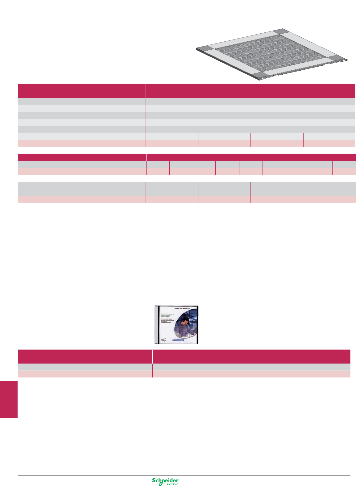
Other versions: please consult your Schneider Electric agency.
(2) For associated jumper cable and pre-wired connector, please refer to www.Schneider-electric.com.
Maximum category usage Category 3
(EN 954-1)
Degree of protection IP 67
Response time (s) Mat itself: 20 ms, with module: XPSAK ≤ 40 ms, XPSMP < 30 ms
Sensitivity Single mat > 20 kg / Group of mats > 35 kg
Maximum load 2000 N/cm2
Connection (2) By M8 jumper cable (1 male / 1 female), L = 100 mm
Dimensions W x D x H 500 x 500 x 11 mm 500 x 750 x 11 mm 750 x 750 x 11 mm 750 x 1250 x 11 mm
References XY2TP1 XY2TP2 XY2TP3 XY2TP4
(2) For associated jumper cable and pre-wired connector, please refer to www.schneider-electric.com
Accessories
Rails (set of 2) Length 194 mm 394 mm 444 mm 494 mm 644 mm 694 mm 744 mm 1194 mm 1244 mm
References XY2TZ10 XY2TZ20 XY2TZ30 XY2TZ40 XY2TZ50 XY2TZ60 XY2TZ70 XY2TZ80 XY2TZ90
Corners and rail connectors
External corners Internal corner Rail connectors, L = 56 mm Rail connectors, L = 6 mm
(set of 4) + external corner with outlet for cable (set of 2) (set of 2)
References XY2TZ4 XY2TZ5 XY2TZ1 XY2TZ2
(1) For simplification of installation, see the “Protect Area design”
software configuration tool. Reference: SISCD104200
Preventa
Detection
Mats
Safety mats
(1)
Selection guidance software
Protect Area Design (2)
For light curtains XUSLT, XUSLM
Reference XUSLPDM
(2) "Protect Area Design" sofware is integrated in SafetySuite V2
9/24
2
1
3
4
5
6
7
8
9
10
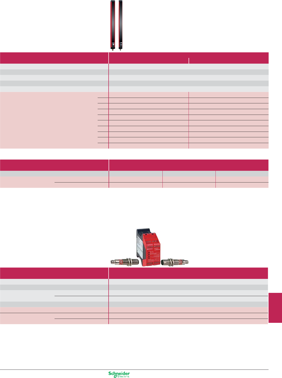
Other versions: please consult your Schneider Electric agency.
Light curtains
Type 2 conforming to IEC 61496-2
Light curtain functions
• Auto/Manual,
• Monitoring of external switching devices
(EDM: External Devices Monitoring),
• LED display of operating modes
Type Multi-beam, infrared transmission
Slim range Manual starting Automatic starting
Nominal sensing distance (Sn) 0.3…15 m
Detection capacity 30 mm “hand”
Number of safety circuits 2 solid-state PNP
Response time (depending on model) 14…24 ms
Connection M12 Connector
Height protected (mm) 150 XUSLNG5D0150 XUSLNG5C0150
300 XUSLNG5D0300 XUSLNG5C0300
450 XUSLNG5D0450 XUSLNG5C0450
600 XUSLNG5D0600 XUSLNG5C0600
750 XUSLNG5D0750 XUSLNG5C0750
900 XUSLNG5D0900 XUSLNG5C0900
1050 XUSLNG5D1050 XUSLNG5C1050
1200 XUSLNG5D1200 XUSLNG5C1200
1350 XUSLNG5D1350 XUSLNG5C1350
1500 XUSLNG5D1500 XUSLNG5C1500
Accessories
Cable length 3 m 10 m 30 m
Pre-wired connector for XUSLN For receiver XSZNCR03 XSZNCR10 XSZNCR30
(screened cable) For transmitter XSZNCT03 XSZNCT10 XSZNCT30
Type 2 conforming to IEC 61496-1 et 2
Type Single-beam, infrared transmission
Height protected (conforming to prEN 999) 750…1200 mm (1 to 4 beams)
Nominal sensing distance (Sn) 8 m
Number of circuits Safety 2N/O
Additional 4 solid-state
Response time < 25 ms
Modules (integral muting function) 24 VDC XPSCM1144P (1)
Thru-beam pairs, Pre-cabled, L = 5m PNP XU2S18PP340L5 (2)
axially aligned M12 connector
PNP XU2S18PP340D (2)
(1) For version with non removable terminal block, delete the letter P from the end of the reference. Example: XPSCM1144P becomes XPSCM1144).
(2) For alignment at 90° to the mounting axes, insert the letter W in the reference before the last letter. Example: XU2S18PP340L5 becomes XU2S18PP340WL5).
Light curtain functions
• Auto/Manual,
• Monitoring of external switching devices
(EDM: External Devices Monitoring),
• LED display of operating modes
• Integral muting function.
9/25
2
1
3
4
5
6
7
8
9
10
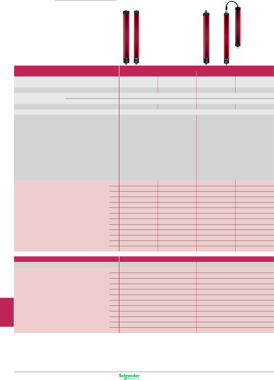
Other versions: please consult your Schneider Electric agency.
Preventa
Detection
Light curtains
Type 4 conforming to IEC 61496-2
Type Multi-beam, infrared transmission
Light curtains Cascadable light curtains
Nominal sensing distance (Sn) 0,3…7 or 3 m with
PDM Box (2)
0,3…8 or 20 m with
PDM Box (2)
0,3…7 or 3 m with
PDM Box (2)
0,3…20 or 8 m with
PDM Box (2)
Detection capacity 14 mm "finger" 30 mm "hand" 14 mm "finger" 30 mm "hand"
Number of circuits Safety 2 solid-state PNP 2 solid-state PNP
Auxiliary (alarm) 1 solid-state PNP 1 solid-state PNP or NPN
Response time (depending on model) 23…41 ms 23…32 ms 23…41 ms 23…32 ms
Connection M12 connector
Functions accessible via programming and diagnostic module b Auto/Manual
b Monitoring of external switching devices
(EDM: External Device Monitoring)
b Test (MTS : Monitoring Test Signal),
b Light beam coding (A or B)
b Sensing distance (short, long)
b Programming and downloading of configuration
settings, via programming and diagnostic
module (PDM)
b Display of operating modes and faults by LED
and/or PDM (2)
b Auto/Manual, manual 1st cycle
b Monitoring of external switching devices
(EDM: External Device Monitoring)
b Test (MTS : Monitoring Test Signal),
b Blanking (ECS/B), Monitored Blanking,
Floating Blanking (FB)
b Reduction of resolution
b Response time (normal, slow)
b Light beam coding (A or B)
b Sensing distance (short, long)
b Auxiliary output (alarm or status signalling,
PNP or NPN)
b Start button (N/O or N/C, 0 V or 24 V)
b Muting
b Display of operating modes and faults by LED
and/or PDM (2)
Transmitter + receiver (1) Height protected (mm) 280 XUSLBQ6A0280 –XUSLDMQ6A0280 –
320 – – XUSLDMQ6A0320 –
360 XUSLBQ6A0360 XUSLBR5A0360 –XUSLDMY5A0360
440 XUSLBQ6A0440 –XUSLDMQ6A0440 –
520 XUSLBQ6A0520 XUSLBR5A0520 XUSLDMQ6A0520 XUSLDMY5A0520
600 XUSLBQ6A0600 –XUSLDMQ6A0600 –
680 –XUSLBR5A0680 –XUSLDMY5A0680
(1) Other height protected, see catalog:
"Preventa safety Solutions"
720 XUSLBQ6A0720 –XUSLDMQ6A0720 –
880 XUSLBQ6A0880 XUSLBR5A0880 XUSLDMQ6A0880 XUSLDMY5A0880
(2) PDM module : Programming and Diagnostic Module,
see following page.
1040 –XUSLBR5A1040 –XUSLDMY5A1040
1200 –XUSLBR5A1200 ––
1400 –XUSLBR5A1400 –XUSLDMY5A1400
1560 –XUSLBR5A1560 –XUSLDMY5A1560
Type Segments for cascadable light curtains
Detection capacity 14 mm "finger" 30 mm "hand"
Transmitter + receiver Height protected (mm) 280 XUSLDSQ6A0280 –
320 XUSLDSQ6A0320 –
360 –XUSLDSY5A0360
440 XUSLDSQ6A0440 –
520 XUSLDSQ6A0520 XUSLDSY5A0520
600 XUSLDSQ6A0600 –
680 –XUSLDSY5A0680
720 XUSLDSQ6A0720 –
880 XUSLDSQ6A0880 XUSLDSY5A0880
1040 –XUSLDSY5A1040
1400 –XUSLDSY5A1400
1560 –XUSLDSY5A1560
Functions accessible by cabling alone
b Automatic start
b Auxiliary output (PNP, status signalling)
b Alignment aid by display of each light beam broken
b LED display of operating modes and faults
9/26
2
1
3
4
5
6
7
8
9
10
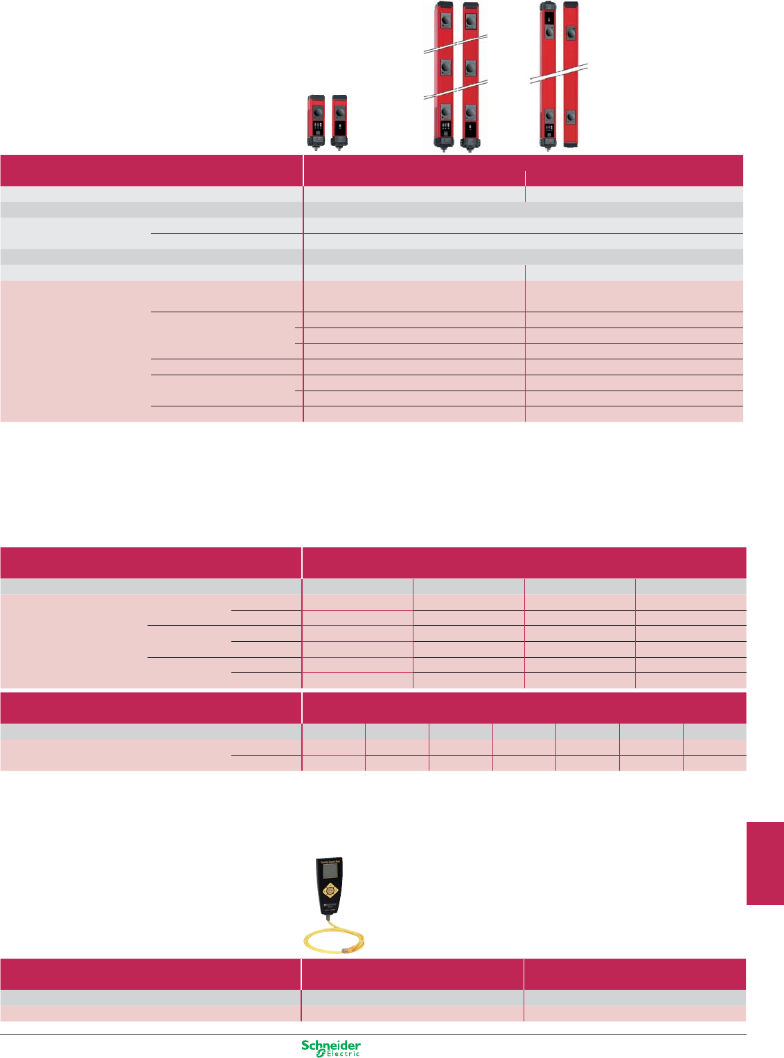
Other versions: please consult your Schneider Electric agency.
Type 4 conforming to IEC 61496-2
Light curtain functions
b
Auto/Manual/Manual 1st cycle
b
Monitoring of external switching devices
(EDM: External Devices Monitoring),
b
Test input (MTS: Monitoring Test Signal),
b
Alignment aid by LED display of each light beam broken,
b
LED display of operating modes and alarms,
b
Coding of the beams
Type Single-beam and multi-beam, infrared transmission
Compact range Transmitter/receiver Transmitter/passive receiver
Nominal sensing distance (Sn) 0.8…20 ou 70 m (according to config) 0.8…8 m
Detection capacity Body
Number of circuits Safety 2 solid-state PNP
Auxiliary (alarm or following) 1 solid-state PNP
Response time (depending on model) 16…24 ms
Connection M12 Connector (1) M12 Connector
Beam Interval Number
–1XUSLPZ1AM –
300 mm 4 XUSLPZ4A300M –
5XUSLPZ5A300M –
6XUSLPZ6A300M –
400 mm 3XUSLPZ3A400M –
500 mm 2 XUSLPZ2A500M XUSLPB2A500M
3XUSLPZ3A500M –
600 mm 2XUSLPZ2A600M XUSLPB2A600M
(1) Light curtain with M12 connector output, for terminal block output, replace M from the end of the reference by B. Example : XUSLPZ1AM becomes XUSLPZ1AB
Cabling accessories
Type Pre-wired connectors
Cable length 5 m 10 m 15 m 30 m
Pre-wired connector for XUSLT For receiver XSZTCR05 XSZTCR10 XSZTCR15 XSZTCR30
(screened cable) For transmitter XSZTCT05 XSZTCT10 XSZTCT15 XSZTCT30
XUSLB/XUSLDM For receiver XSZBCR05 XSZBCR10 XSZBCR15 XSZBCR30
For transmitter XSZBCT05 XSZBCT10 XSZBCT15 XSZBCT30
XUSLP For receiver XSZPCR05 XSZPCR10 XSZPCR15 XSZPCR30
For transmitter XSZPCT05 XSZPCT10 XSZPCT15 XSZPCT30
Type Jumper cables for segments XUS LDS
Cable length 0,3 m 0,5 m 1 m 2 m 2 m 5 m 10 m
Reference For receiver XSZDCR003 XSZDCR005 XSZDCR010 XSZDCR020 XSZDCR030 XSZDCR050 XSZDCR100
For transmitter XSZDCT003 XSZDCT005 XSZDCT010 XSZDCT020 XSZDCT030 XSZDCT050 XSZDCT100
Setting-up accessories
Type Programming and Diagnostic Module Laser alignment tool
For light curtains XUSLB / XUSLDM All type XUSL
Reference XUSLPDM XUSLAT1
9/27
2
1
3
4
5
6
7
8
9
10
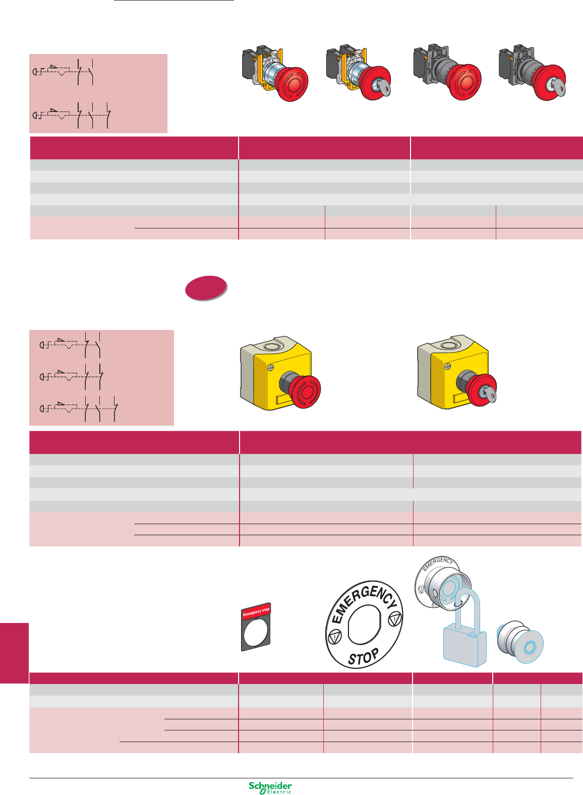
Other versions: please consult your Schneider Electric agency.
1314
22 21
1314
22 21
32 31
1314
22 21
1314
22 21
32 31
1314
22 2122 21
32 31
1314
22 21
32 31
1314
22 2122 21
32 31
1314
22 21
32 31
ISO entry
(to EN 50262)
Key release
(key n° 455)
Preventa
Operator dialog
Emergency stops
Ø 22 trigger action latching pushbuttons
Turn to release Turn to release
Key release
(key n° 455)
N/C + N/O
contact
N/C + N/O + N/C
contact
Key release (key n° 455)
Turn to release
Ø 22 trigger action latching pushbutton stations
N/C + N/O
contact
N/C + N/C
contact
N/C + N/O + N/C
contact
Pushbuttons Metal Plastic
Mechanical life (millions of operating cycles) 0.3 0.3
Shock / vibration resistance 10 gn / 5 gn 10 gn / 5 gn
Degree of protection IP 65 IP 65
Rated operational characteristics AC 15, A 600 / DC 13, Q 600 (conforming to EN IEC 60947-5-1)
Dimensions Ø x Depth Ø 40 x 82 mm Ø 40 x 104 mm Ø 40 x 81.5 mm Ø 40 x 103 mm
Contact N/C + N/O XB4BS8445 XB5AS8445 XB5AS8445 XB5AS9445
2 N/C + 1 N/O XB4BS84441 – – ZB5AS944 + ZB5AZ141
Enclosure Plastic
2 x ISO M20 cable entries or n° 13 (Pg 13.5) cable gland
Mechanical life (millions of operating cycles) 0.1 0.1
Shock / vibration resistance 10 gn / 5 gn 10 gn / 5 gn
Degree of protection IP 65 IP 65
Rated operational characteristics AC 15, A 600 / DC 13, Q 600 (conforming to EN IEC 60947-5-1)
Dimensions W x D x H 68 x 91 x 68 mm 68 x 113 x 68 mm
Contact N/C + N/O XALK178E XALK188E
N/C + N/C XALK178F XALK188F
2 N/C + 1 N/O – XALK188G
Accessories
Type Étiquettes Padlocking kit Bellows seals
Colour Red with white lettering Yellow with black lettering Yellow Red Silicone
Black EPDM
Dimensions 30 x 40 mm (1) Ø 60 mm
Références
Marking: “Emergency stop”
ZBY2130 ZBY9130 – – –
“Arrêt d'urgence”
ZBY2330 ZBY9330 – – –
“Not Halt” ZBY2230 ZBY9230 – – –
– – ZBZ3605 ZBZ48 ZBZ28
(1) circular appearance
With legend holder
9/28
2
1
3
4
5
6
7
8
9
10
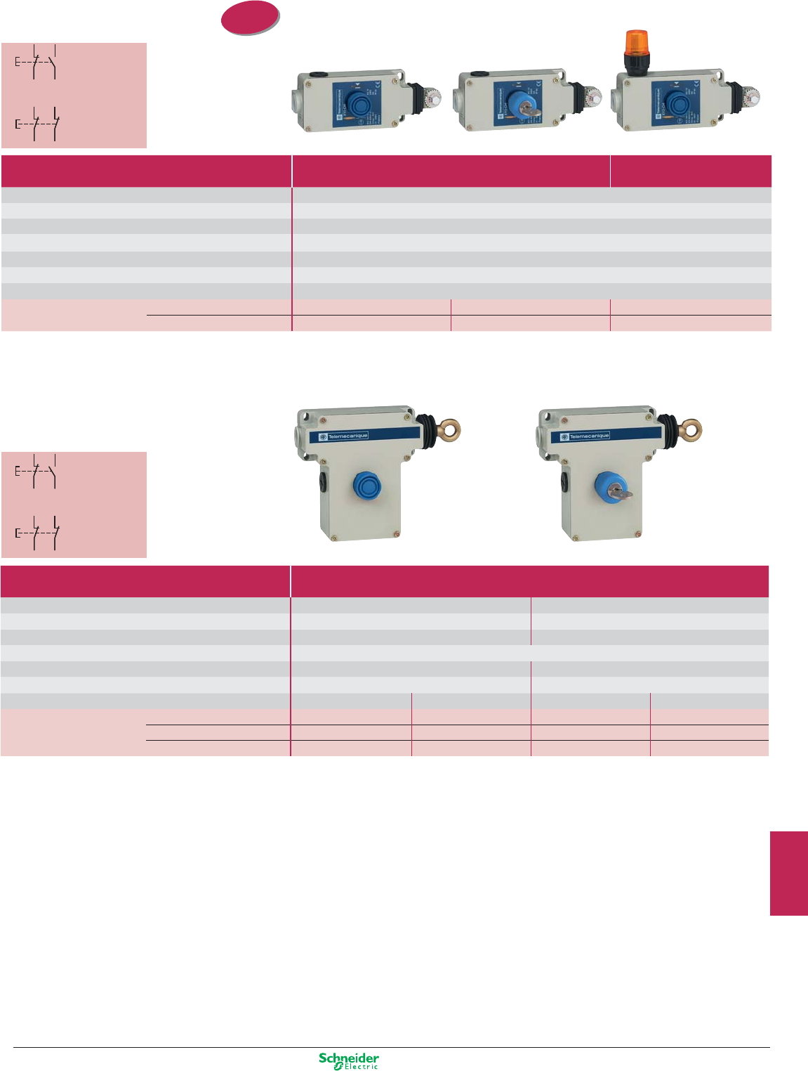
Other versions: please consult your Schneider Electric agency.
12 11
22 21
12 11
14 13
12 11
22 21
12 11
14 13
ISO entry
(to EN 50262)
12 11
22 21
12 11
14 13
12 11
22 21
12 11
14 13
Emergency stops
Cable (tripwire) operated
Booted pushbutton reset Key release pushbutton reset (key n° 421)
N/C + N/O contact
slow break
N/C + N/C contact
slow break
Booted pusbutton reset Key release pushbutton reset (key n° 421)
N/C + N/O contact
slow break
N/C + N/C contact
slow break
For operating cable length ≤ 15 m Latching, without indicator light with indicator light
1 x ISO M20 cable entry (1)
Mechanical life (millions of operating cycles) 0.01
Shock / vibration resistance 50 gn / 10 gn
Degree of protection IP 65
Rated operational characteristics AC-15, A300 / DC-13, Q300 (conforming to EN IEC 60947-5-1)
Dimensions W x D x H 201 x 71 x 68 mm
Operating cable length ≤ 15 m
Operating cable anchoring point To right or to left
Contact 1 “N/C + N/O” slow break XY2CH13250H29 XY2CH13450H29 XY2CH13253
1 “N/C + N/C” slow break XY2CH13270H29 XY2CH13470H29 XY2CH13273
(1) With entry for n° 13 (Pg 13.5) cable gland, delete H29 from the end of the reference (example: XY2-CH13250H29 becomes XY2-CH13250).
For operating cable length ≤ 50 m Latching, without indicator light
3 x ISO M20 cable entries or n° 13 (Pg 13.5) cable gland
Mechanical life (millions of operating cycles) 0.01 0.01
Shock / vibration resistance 50 gn / 10 gn 50 gn / 10 gn
Degree of protection IP 65 IP 65
Rated operational characteristics AC-15, A300 / DC-13, Q300 (conforming to EN IEC 60947-5-1)
Dimensions W x D x H 229 x 82 x 142 mm 229 x 82 x 142 mm
Operating cable length ≤ 50 m ≤ 50 m
Operating cable anchoring point To left To right To left To right
Contact 1 “N/C + N/O” slow break XY2CE2A250 XY2CE1A250 XY2CE2A450 XY2CE1A450
1 “N/C + N/C” slow break XY2CE2A270 XY2CE1A270 XY2CE2A470 XY2CE1A470
2 “N/C + N/O” slow break XY2CE2A290
(2)
XY2CE1A290
(2)
XY2CE2A490
(2)
XY2CE1A290
(2)
(2) With 24V, 48 V, 130 V pilot lights, BA9S bulb not included, add 6 at the end of the reference. (example : XY2CE1A290 becomes XY2CE1A296).
With 230 V pilot lights, BA9S bulb included, add 7 at the end of the reference. (example : XY2CE1A290 becomes XY2CE1A297).
9/29
2
1
3
4
5
6
7
8
9
10
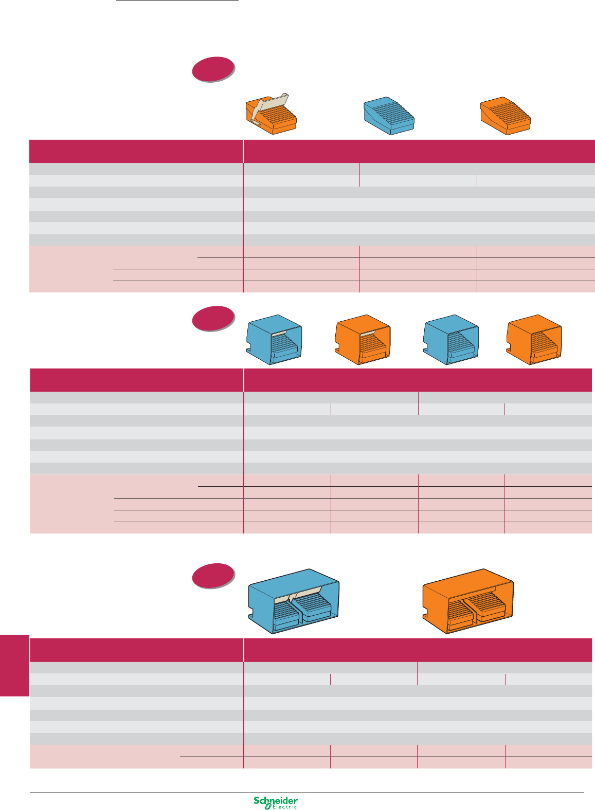
Other versions: please consult your Schneider Electric agency.
ISO entry
(to EN 50262)
ISO entry
(to EN 50262)
ISO entry
(to EN 50262)
Foot switches - metal
Single pedal switches
Preventa
Operator dialog
Double pedal switches
Type Foot switches without protective cover
2 cable entries for n° 16 (Pg 16) cable gland (1)
Trigger mechanism
With (positive operating action reqd.)
Without
Colour Orange Blue Orange
Mechanical life (millions of operating cycles) 15
Degree of protection IP 66
Shock resistance 100 joules
Rated operational characteristics AC 15, A 300 / DC 13, Q 300 (conforming to EN IEC 60947-5-1)
Dimensions W x D x H 104 x 172 x 59 mm
Contact operation 1 step 1 N/C + N/O XPER810 XPEM110 XPER110
2 N/C + N/O XPER811 XPEM111 XPER111
2 step 2 N/C + N/O XPER911 XPEM211 XPER211
Analogue output 2 N/C + N/O XPER929 – XPER229
(1) For entry for ISO M20 cable gland, also order adaptor DE9RA1620 (sold in lots of 5).
Type Foot switches without protective cover
2 cable entries for n° 16 (Pg 16) cable gland (1)
Trigger mechanism
With (positive operating action reqd.)
Without
Colour Blue Orange Blue Orange
Mechanical life (millions of operating cycles) 15
Degree of protection IP 66
Shock resistance 100 joules
Rated operational characteristics AC 15, A 300 / DC 13, Q 300 (conforming to EN IEC 60947-5-1)
Dimensions W x D x H 160 x 186 x 152 mm
Contact operation 1 step 1 N/C + N/O XPEM510 XPER510 XPEM310 XPER310
2 N/C + N/O XPEM511 XPER511 XPEM311 XPER311
1 step latching 1 N/C + N/O – – XPEM410 XPER410
2 step 2 N/C + N/O XPEM711 XPER711 XPEM611 XPER611
Analogue output 2 N/C + N/O XPEM529 XPER529 XPEM329 –
(1) For entry for ISO M20 cable gland, also order adaptor DE9RA1620 (sold in lots of 5).
Type Foot switches without protective cover
2 cable entries for n° 16 (Pg 16) cable gland (1)
Trigger mechanism
With (positive operating action reqd.)
Without
Colour Blue Orange Blue Orange
Mechanical life (millions of operating cycles) 15
Degree of protection IP 66
Shock resistance 100 joules
Rated operational characteristics AC 15, A 300 / DC 13, Q 300 (conforming to EN IEC 60947-5-1)
Dimensions W x D x H 295 x 190 x 155 mm
Contact operation 1 step 2 x 1 N/C + N/O XPEM5100D XPER510D XPEM3100D XPER3100D
2 x 2 N/C + N/O XPEM5110D XPER5110D XPEM3110D XPER3110D
(1) For entry for ISO M20 cable gland, also order adaptor DE9RA1620 (sold in lots of 5).
9/30
2
1
3
4
5
6
7
8
9
10
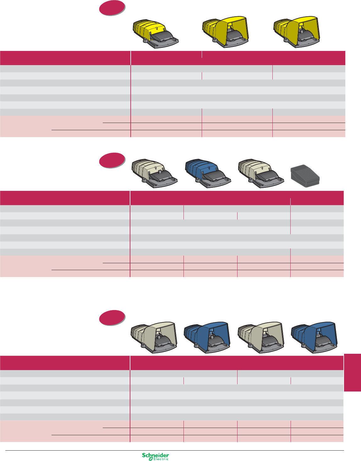
Other versions: please consult your Schneider Electric agency.
ISO entry
(to EN 50262)
ISO entry
(to EN 50262)
ISO entry
(to EN 50262)
Foot switches - plastic
Single pedal switches
Type Without protective cover With protective cover
2 cable entries for ISO M20 cable gland
Trigger mechanism Without
With (positive operating action reqd.)
Colour Yellow Yellow Yellow
Mechanical life (millions of operating cycles) 5
Degree of protection IP 55
Shock resistance 30 joules
Rated operational characteristics AC 15, A 300 / DC 13, Q 300 (conforming to EN IEC 60947-5-1)
Dimensions W x D x H 160 x 280 x 70 mm 160 x 280 x 162 mm 160 x 280 x 162 mm
Contact operation 1 step 1 N/C + N/O XPEY110 XPEY310 XPEY510
2 N/C + N/O – XPEY311 XPEY511
2 step 2 N/C + N/O XPEY211 XPEY611 XPEY711
Type Foot switches without protective cover
2 cable entries for ISO M20 cable gland 1 entry (1)
Trigger mechanism
With (positive operating action reqd.)
Without Without
Colour Grey+ Blue Grey Black
Mechanical life (millions of operating cycles) 10 2
Degree of protection IP 66 IP 43
Shock resistance 100 joules
Rated operational characteristics AC 15, A 300 / DC 13, Q 300 (conforming to EN IEC 60947-5-1)
Dimensions W x D x H 160 x 280 x 70 mm 94 x 161 x 54 mm
Contact operation 1 step 1 N/C + N/O XPEG810 XPEB110 XPEG110 XPEA110
2 N/C + N/O – XPEB111 XPEG111 XPEA111
2 step 2 N/C + N/O XPEG911 XPEB211 XPEG211 –
(1) Cable entry for ISO M16 or n° 9 (Pg 9) cable gland and for ISO M20 or n° 13 (Pg 13.5) cable gland.
Type Foot switches with protective cover
2 cable entries for ISO M20 cable gland
Trigger mechanism With (positive operating action reqd.) Without
Colour Grey Blue Grey Blue
Mechanical life (millions of operating cycles) 10
Degree of protection IP 66
Shock resistance 100 joules
Rated operational characteristics AC 15, A 300 / DC 13, Q 300 (conforming to EN IEC 60947-5-1)
Dimensions W x D x H 180 x 280 x 162 mm
Contact operation 1 step 1 N/C + N/O XPEG510 XPEB510 XPEG310 XPEB310
2 N/C + N/O XPEG511 XPEB511 XPEG311 XPEB311
2 step 2 N/C + N/O XPEG711 XPEB711 XPEG611 XPEB611
9/31
2
1
3
4
5
6
7
8
9
10
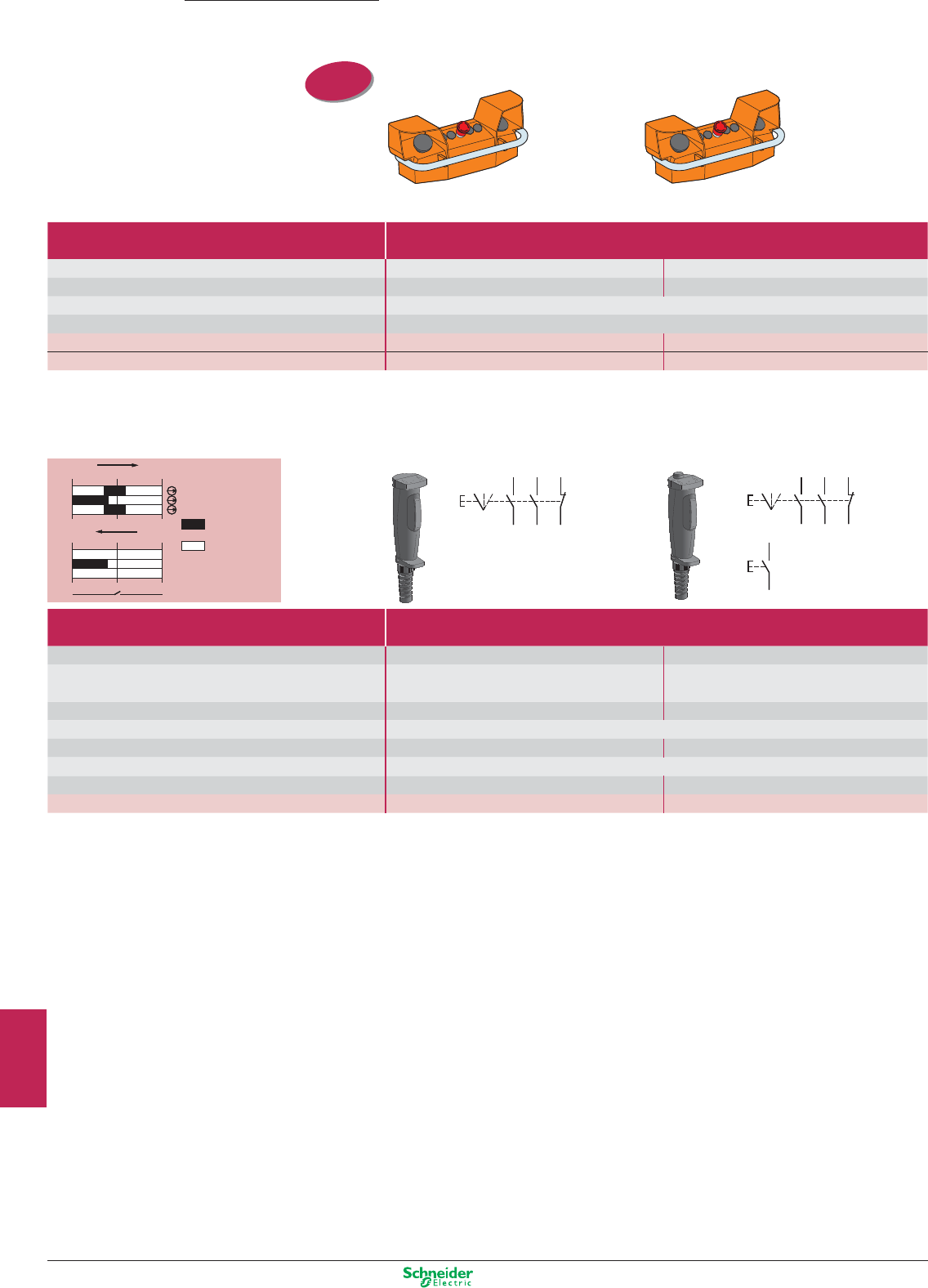
Other versions: please consult your Schneider Electric agency.
ISO entry
(to EN 50262)
012
1-2
5-6
3-4
012
7 8 (XY2-AU2)
1-2
5-6
3-4
012
1-2
5-6
3-4
012
7 8 (XY2-AU2)
1-2
5-6
3-4
2
0
12
1
34
65
2
0
12
1
34
65
2
0
12
1
34
65
78
2
0
12
1
34
65
78
Preventa
Operator dialog
Control units
Two-hand control
Type Two-hand control stations
2 cable entries for ISO M20 or n° 13 (Pg 13.5) cable gland, 1 cable entry for n° 21 (Pg 21) cable gland (2)
Mechanical life (millions of operating cycles) 1 1
Degree of protection IP 65 IP 65
Rated operational characteristics AC 15, A 600 / DC 13, Q 600 (conforming to EN IEC 60947-5-1)
Dimensions W x D x H 455 x 170 x 188.5 mm
Red emergency stop (N/C + N/C slow break) XY2SB71 (1) XY2SB72 (1)
Yellow lock out (N/C + N/O break before make) XY2SB75 XY2SB76
2 control pushbuttons and 1 mushroom head
Emergency stop or Lock out pushbutton
(1) To order a two-hand control station with pedestal XY2SB90, add 4 to the end of the reference (example: XY2SB71 becomes XY2SB714).
2 control pushbuttons and 1 mushroom head Emergency
stop or Lock out pushbutton, with pre-wired terminal block
Enabling switch
Contact states
(2) For entry for ISO M25 cable gland, also order adaptor DE9RA2125 + fixing nut DE9EC21 (sold in lots of 5).
For fixing accessories, please refer to www.schneider-electric.com.
Contact closed
Contact open
Type Plastic grip
Entry for Ø 7 to 13 mm cable
Number of contacts 3 3
Type of contacts 2 “NO” + 1 “NC” 2 “NO” + 1 “NC”
1 "NO" auxiliary
Description 3 positions 3 positions with button for N/O contact (auxiliary)
Shock / vibration resistance 10 gn / 6 gn
Degree of protection IP 66 IP 65
Rated operational characteristics AC 15, C300 / DC 13, R300 (conforming to EN IEC 60947-5-1)
Dimensions W x D x H 46 x 58 x 261 mm 46 x 58 x 269 mm
References XY2AU1 XY2AU2
9/32
2
1
3
4
5
6
7
8
9
10
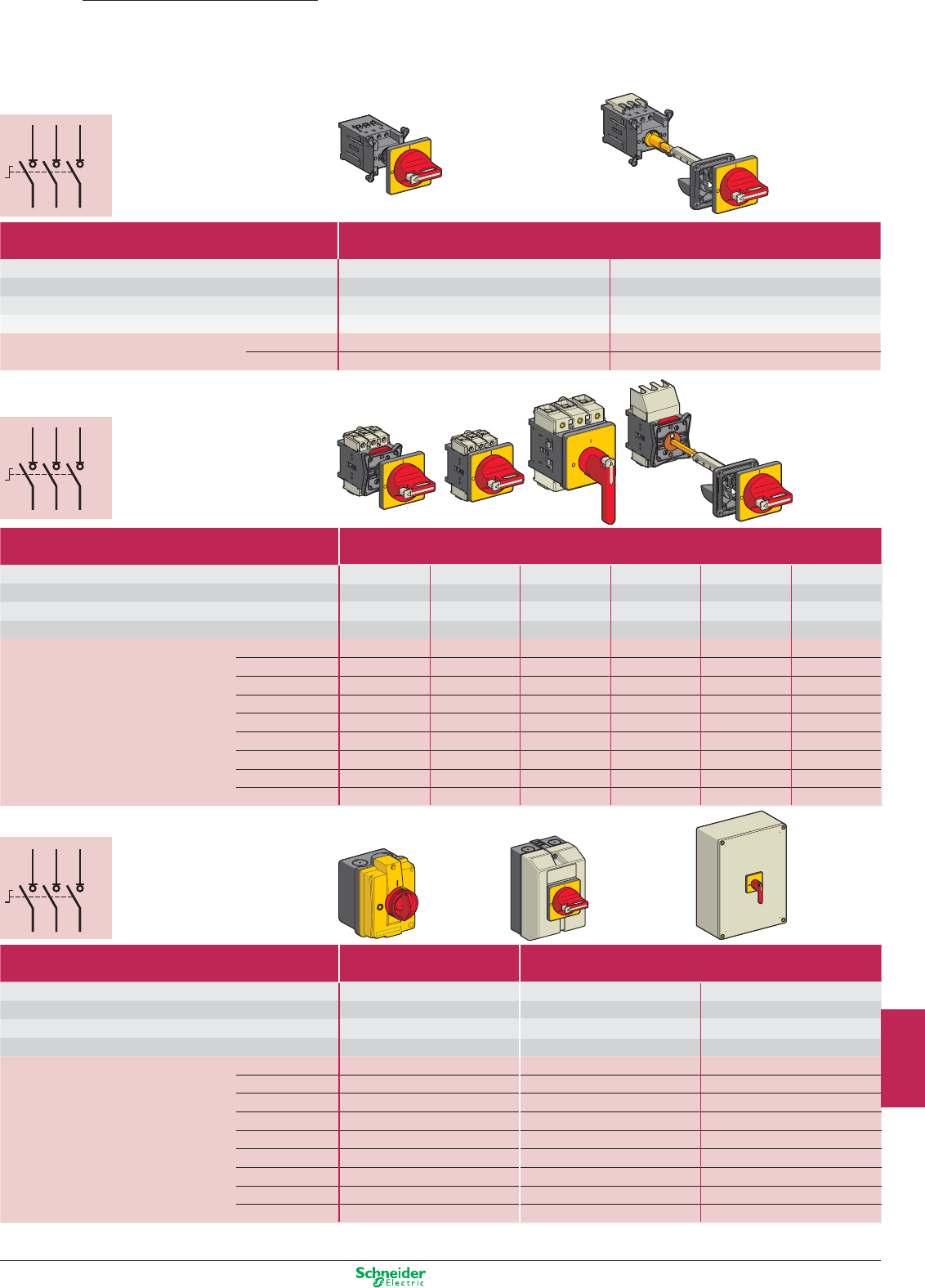
Other versions: please consult your Schneider Electric agency.
1/L12/T1
3/L24/T2
5/L36/T3
1/L12/T1
3/L24/T2
5/L36/T3
1/L12/T1
3/L24/T2
5/L36/T3
1/L12/T1
3/L24/T2
5/L36/T3
1/L12/T1
3/L24/T2
5/L36/T3
1/L12/T1
3/L24/T2
5/L36/T3
Vario
Motor control
Switch disconnectors
Front mounting
Door mounting
Door mounting
Backplate
mounting in
enclosure
(1) Dimensions W x D x H: 150 x 152 x 170 mm.
Enclosed
Backplate
mounting in
enclosure
Type Mini-Vario for standard applications
Front plate dimensions (mm) 60 x 60 60 x 60
Fixing Ø 22.5 mm Ø 22.5 mm
Degree of protection IP 20 IP 20
Rated operational voltage (Ue) 690 V 690 V
Thermal current in open air (Ith) 12 A VCDN12 VCCDN12
20 A VCDN20 VCCDN20
Type Vario for high performance applications
Front plate dimensions (mm) 60 x 60 60 x 60 90 x 90 60 x 60 60 x 60 90 x 90
Fixing Ø 22.5 mm 4 screws 4 screws Ø 22.5 mm 4 screws 4 screws
Degree of protection IP 20 IP 20 IP 20 IP 20 IP 20 IP 20
Rated operational voltage (Ue) 690 V 690 V 690 V 690 V 690 V 690 V
Thermal current in open air (Ith) 12 A VCD02 VCF02 – VCCD02 VCCF02 –
20 A VCD01 VCF01 – VCCD01 VCCF01 –
25 A VCD0 VCF0 – VCCD0 VCCF0 –
32 A VCD1 VCF1 – VCCD1 VCCF1 –
40 A VCD2 VCF2 – VCCD2 VCCF2 –
63 A – VCF3 – – VCCF3 –
80 A – VCF4 – – VCCF4 –
125 A – – VCF5 – – VCCF5
175 A – – VCF6 – – VCCF6
Type Mini-Vario Vario
Front plate dimensions (mm) 60 x 60 60 x 60 90 x 90
Dimensions W x D x H 82.5 x 106 x 131 mm 90 x 131 x 146 mm 241 x 191 x 291 mm
Degree of protection IP 55 IP 65 IP 65
Rated operational voltage (Ue) 690 V 690 V 690 V
Thermal current in enclosure (Ithe) 10 A VCFN12GE VCF02GE –
16 A VCFN20GE VCF01GE –
20 A VCFN25GE VCF0GE –
25 A VCFN32GE VCF1GE –
32 A VCFN40GE VCF2GE –
50 A – VCF3GE (1) –
63 A – VCF4GE (1) –
100 A – – VCF5GEN
140 A – – VCF6GEN
9/33
2
1
3
4
5
6
7
8
9
10
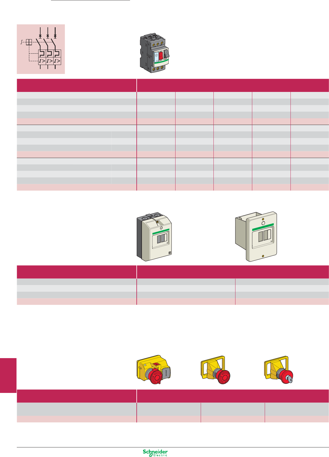
Other versions: please consult your Schneider Electric agency.
T
1
T
2
T
3
1/L1
3/L2
5/L3
T
1
T
2
T
3
1/L1
3/L2
5/L3
Motor starters
Enclosed thermal-magnetic motor circuit-breakers
Complete circuit-breaker: circuit-breaker
+ enclosure + safety device.
Ex.: GV2ME01 + GV2MC02 + GV2K04.
(1) Dimensions with safety device GV2K04 fitted.
Enclosure
Safety device
TeSys
Motor control
Type Thermal-magnetic motor circuit-breakers
Motor power kW (on 400 V) – 0.06 0.09 0.12…0.18 0.25…0.37
Setting range A 0.1…0.16 0.16…0.25 0.25…0.40 0.40…0.63 0.63…1
Current Id ± 20% A 1.5 2.4 5 8 13
Current Ithe (in enclosure) A 0.16 0.25 0.40 0.63 1
Reference GV2ME01 GV2ME02 GV2ME03 GV2ME04 GV2ME05
Motor power kW (on 400 V) 0.37…0.55 0.75 1.1…1.5 2.2 3…4
Setting range A 1…1.6 1.6…2.5 2.5…4 4…6.3 6…10
Current Id ± 20% A 22.5 33.5 51 78 138
Current Ithe (in enclosure) A 1.6 2.5 4 6.3 9
Reference GV2ME06 GV2ME07 GV2ME08 GV2ME10 GV2ME14
Motor power kW (on 400 V) 5.5 7.5 9…11 11 15
Setting range A 9…14 13…18 17…23 20…25 24…32
Current Id ± 20% A 170 223 327 327 416
Current Ithe (in enclosure) A 13 17 21 23 24
Reference GV2ME16 GV2ME20 GV2ME21 GV2ME22 GV2ME32
Type Empty enclosure
Mounting Surface mounting Flush mounting
Degree of protection IP 55 IP 55 (front face)
Dimensions W x D x H (1) 93 x 145.5 x 147 mm 93 x 55 x 126 mm
References GV2MC02 GV2MP02
Type Safety devices
With red mushroom head Turn to release Turn to release Key release
Padlockable in “Off” position (key n° 455)
References GV2K04 GV2K031 GV2K021
9/34
2
1
3
4
5
6
7
8
9
10
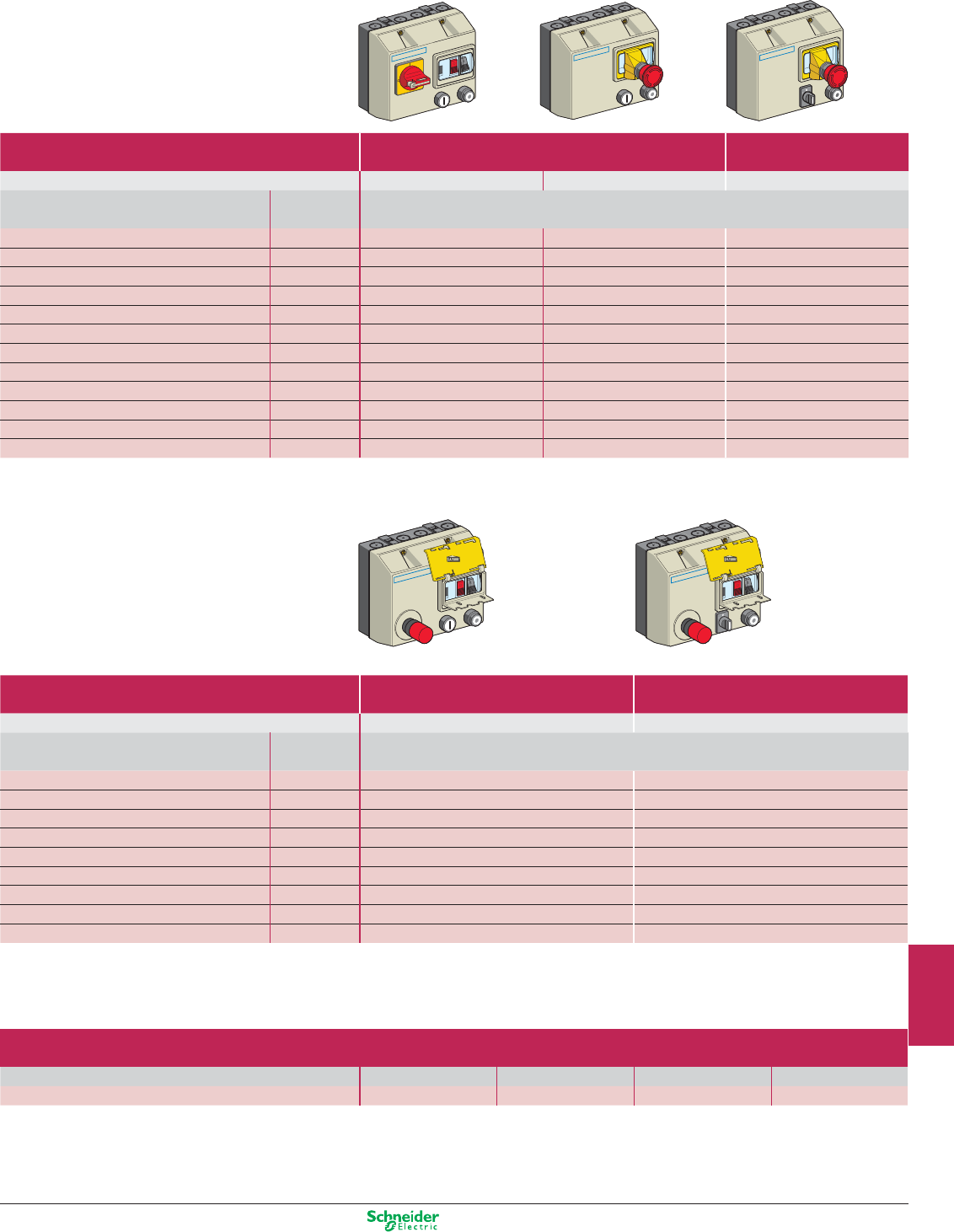
Other versions: please consult your Schneider Electric agency.
With integral control transformer, 400/24 V With integral control transformer, 400/24 V
The control circuit must be cabled by the user.
Type Non reversing Reversing
Degree of protection IP 657 IP 657 IP 657
Standard motor power ratings (kW), category AC3 Ith setting
Basic reference, to be completed by code indicating voltage (1)
220/230 V 400/415 V 440 V
range (A)
– 0.06 0.06 0.16…0.25 LG1K065pp02 LG7K06pp02 LG8K06pp02
0.06 0.09 0.12 0.25…0.40 LG1K065pp03 LG7K06pp03 LG8K06pp03
– 0.18 0.18 0.40…0.63 LG1K065pp04 LG7K06pp04 LG8K06pp04
0.12 0.25 0.25 0.63…1 LG1K065pp05 LG7K06pp05 LG8K06pp05
0.25 0.55 0.55 1…1.6 LG1K065pp06 LG7K06pp06 LG8K06pp06
0.37 0.75 1.1 1.6…2.5 LG1K065pp07 LG7K06pp07 LG8K06pp07
0.75 1.5 1.5 2.5…4 LG1K065pp08 LG7K06pp08 LG8K06pp08
1.1 2.2 3 4…6.3 LG1K065pp10 LG7K06pp10 LG8K06pp10
1.5 4 4 6…10 LG1K095pp14 LG7K09pp14 LG8K09pp14
3 5.5 5.5 9…14 LG1D122pp16 LG7D12pp16 LG8K12pp16
4 7.5 9 13…18 LG1D182pp20 LG7D18pp20 –
4 9 9 17…23 LG1D182pp21 LG7D18pp21 –
Type Non reversing Reversing
Degree of protection IP 657 IP 657
Standard motor power ratings (kW), category AC3 Ith setting
Basic references
380/400 V
range (A)
(The code Q7 (380/400 V) designates the power supply voltage to which the starter will be connected)
0.06 0.16…0.25 LJ7K06Q702 LJ8K06Q702
0.09 0.25…0.40 LJ7K06Q703 LJ8K06Q703
0.18 0.40…0.63 LJ7K06Q704 LJ8K06Q704
0.25 0.63…1 LJ7K06Q705 LJ8K06Q705
0.55 1…1.6 LJ7K06Q706 LJ8K06Q706
0.75 1.6…2.5 LJ7K06Q707 LJ8K06Q707
1.5 2.5…4 LJ7K06Q708 LJ8K06Q708
2.2 4…6.3 LJ7K06Q710 LJ8K06Q710
4 6…10 LJ7K09Q714 LJ8K09Q714
Control circuit voltages available
Volts 50/60 Hz 24 V 230 V 400 V 415 V
(1) Voltage code B7 P7 V7 N7
9/35
2
1
3
4
5
6
7
8
9
10
ZONE 20
ZONE 22
ZONE 21
Implementation of European Directives
Directive 99/92/EC
This requires that a risk analysis be performed for all industrial processes.
If there is any risk of an explosion:
p the zones are defined and physically identified,
p the installation is classified by governing bodies.
Directive 94/9/EC
This requires certification of the products in accordance with the classification of the zones of
use
Dust zones
p Zone 20: area where an explosive atmosphere exists in the form of combustible clouds of dust
in the air, either permanently, for long periods or frequently.
p Zone 21: area where an explosive atmosphere exists in the form of combustible clouds of dust in
the air during normal operation occasionally.
p Zone 22: area where an explosive atmosphere in the form of combustible clouds of dust
in the air is unlikely to occur during normal operation but, if it does occur, it is only for a short
period.
The products in
this catalogue
are certified by a
European Union
Commission
notified body.
A reference for installations in ATEX Dust
explosive atmospheres.
What is an explosive atmosphere according
to the Directive?
It is the mixing with air, in atmospheric conditions, of flammable
substances in the form of gas, vapour, mist or dust which, in
the event of combustion, spreads throughout the non burning mix.
A selection of certified
products, conforming to
the European Directive
ATEX94/9/EC, to ensure
maximum safety for your
installations in a zone where
the risk of explosion or fire is
high.
2
1
3
4
5
6
7
8
9
10

Explosive atmospheres
This document is a selection of
the top selling products.
2
1
3
4
5
6
7
8
9
10
10/1
Detection
Inductive proximity sensors ......................................................................................... 10/2
Universal and Analog, XS
Proximity sensors ............................................................................................... 10/3 and 10/4
Rotation monitoring, XS, Namur XS
Intrinsically safe enclosures ......................................................................................... 10/5
Processing module, NY3
Limit switches .......................................................................................................... 10/6 to 10/9
Miniature, XCM
Compact, XCKD
Classic, XCKM
Applications: Hoisting, Handling and Conveying
Pressure and vacuum switches ................................................................10/10 and 10/11
Adjustable differential, XMLB
Operator dialog
Control and signalling units
Pushbuttons and mushroom heads Ø 22, Harmony XB4 ................................................. 10/12
Selector switches and key switches Ø 22, Harmony XB4 ................................................. 10/13
Illuminated pushbuttons and pilot lights Ø 22, Harmony XB4 ........................................... 10/14
Control stations, Harmony XAW ........................................................................................ 10/15
Human/Machine Interface
Small Panels and Advanced Panels, Magelis XBT N, R, RT, GT ........................ 10/16 to 10/19
Machine safety
Tripwire operated Emergency stops, Preventa XY2 .......................................................... 10/20
Foot switches, Preventa XPE ............................................................................................ 10/20
Safety switches, Preventa XCS ......................................................................................... 10/21
Automation
Weighing system, Modicon Premium ............................................................................... 10/22
I/O modules, Modicon Quantum ....................................................................................... 10/22
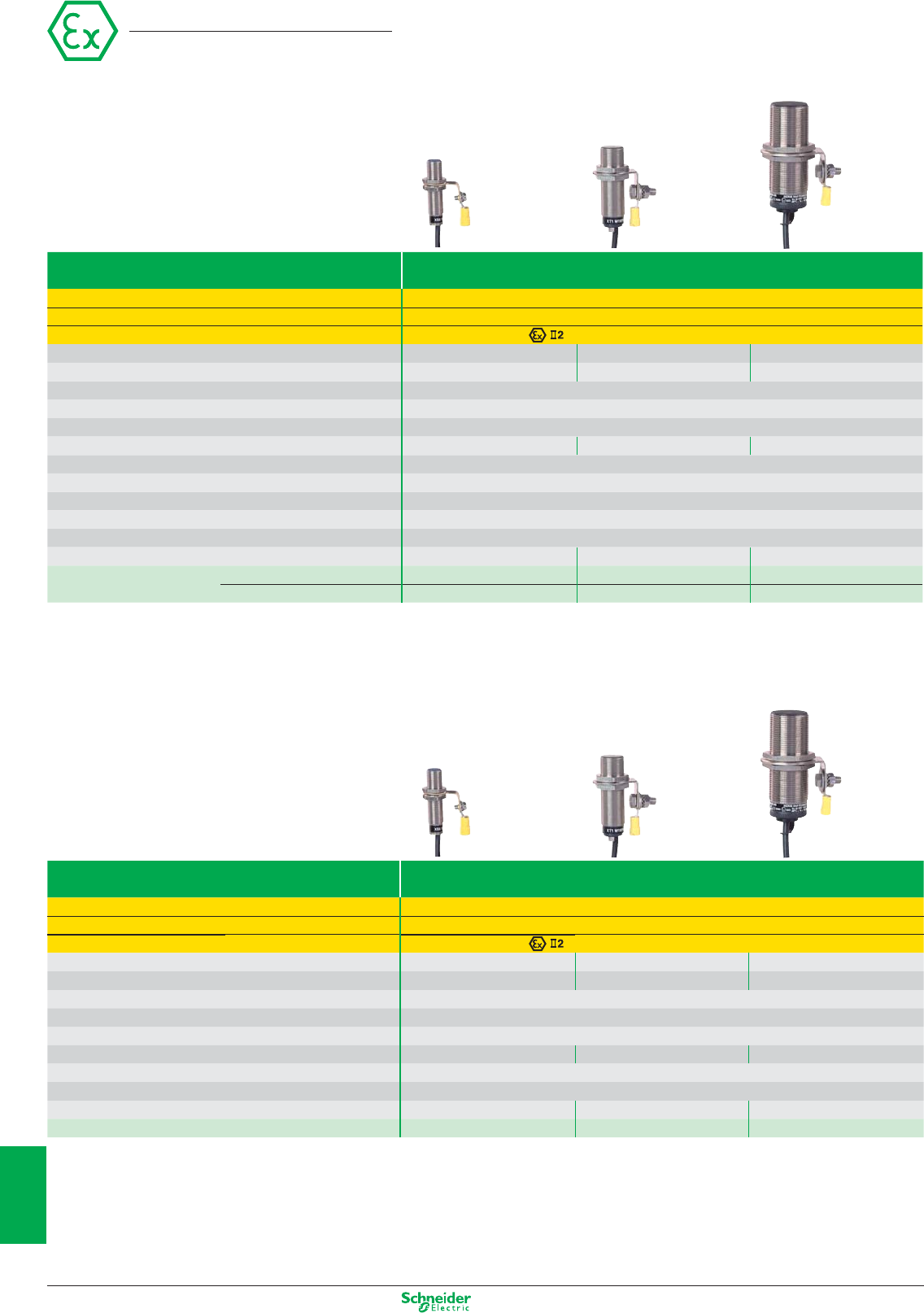
Other versions: please consult your Schneider Electric agency.
Inductive proximity sensors
Universal, metal case
Sensor type 3-wire DC PNP, flush mountable in metal
Conformity Directive ATEX 94/9/EC, EN 50014, EN 50281-1-1, pr IEC 61241-0, pr IEC 61241-1
Zone D (dust) 21 - 22
EC type examination certificate number / marking INERIS 04ATEX0022X / D-Ex tD A21 IP68 T90°C
Nominal sensing distance Sn 4 mm 8 mm 15 mm
Operating zone 0...3.2 mm 0...6.4 mm 0...12 mm
Temperature range – 20...+ 60°C
Degree of protection (conforming to IEC 60529) IP68
Connection Pre-cabled, PvR, L = 10 m
Dimensions M12 x 50 mm M18 x 60 mm M30 x 60 mm
Supply voltage (including ripple) 10...58 VDC
Maximum switching capacity 200 mA
Overload and short-circuit protection Yes
LED output state indicator Yes
Voltage drop, closed state, at I nominal ≤ 2 V
Switching frequency 2500 Hz 1000 Hz 500 Hz
References NO function XS612B1PAL10EX XS618B1PAL10EX XS630B1PAL10EX
NC function XS612B1PBL10EX XS618B1PBL10EX XS630B1PBL10EX
Analog, metal case
Sensor type Analogue, 2-wire AC/DC, flush mountable in metal
Conformity Directive ATEX 94/9/EC, EN 50014, EN 50281-1-1, pr IEC 61241-0, pr IEC 61241-1
Zone D (dust) 21 - 22
EC type examination certificate number / marking INERIS 04ATEX0022X / D-Ex tD A21 IP67 T90°C
Nominal sensing distance Sn 2 mm 5 mm 10 mm
Operating zone 0.2...2 mm 0.5…5 mm 1...10 mm
Temperature range – 20...+ 60°C
Degree of protection (conforming to IEC 60529) IP67
Connection Pre-cabled, PvR, L = 2 m
Dimensions M12 x 50 mm M18 x 60 mm M30 x 60 mm
Supply voltage (including ripple) 10…38 VAC/DC
Linearity error 10%
Operating frequency 1500 Hz 500 Hz 300 Hz
References 4…20 mA output XS1M12AB120EX XS1M18AB120EX XS1M30AB120EX
Other characteristics: please refer to the “Global Detection” catalogue
Osiprox
M12 M18 M30
M12 M18 M30
10/2
2
1
3
4
5
6
7
8
9
10
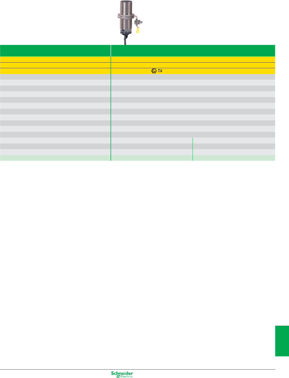
Other versions: please consult your Schneider Electric agency.
Sensor type 3-wire DC PNP, flush mountable in metal
Conformity Directive ATEX 94/9/EC, EN 50014, EN 50281-1-1, pr IEC 61241-0, pr IEC 61241-1
Zone D (dust) 21 - 22
EC type examination certificate number / marking INERIS 04ATEX0022X / D-Ex tD A21 IP67 T90°C
Nominal sensing distance Sn 10 mm
Operating zone 0…8 mm
Temperature range – 20...+ 60°C
Degree of protection (conforming to IEC 60529) IP67
Connection Pre-cabled, PvR, L = 2 m
Dimensions M30 x 81 mm
Supply voltage (including ripple) 10...58 VDC
Maximum switching capacity 200 mA
Overload and short-circuit protection Yes
LED output state indicator Yes
Voltage drop, closed state, at I nominal ≤ 2 V
Version Slow Fast
Maximum speed of passing object 6000 impulses/minute 48,000 impulses/minute
Adjustable frequency range 6…150 impulses/minute 120…3000 impulses/minute
References NC function XSAV11373EX XSAV12373EX
Proximity sensors
Rotation monitoring, metal case
M30
10/3
2
1
3
4
5
6
7
8
9
10
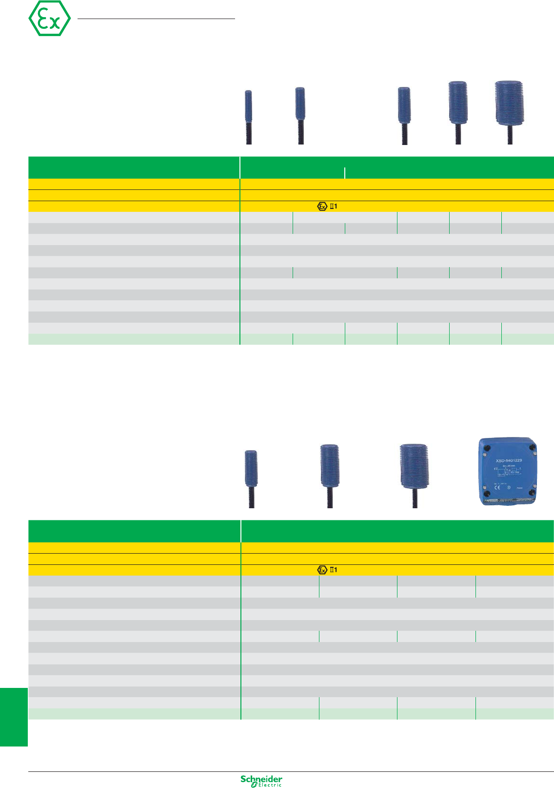
Other versions: please consult your Schneider Electric agency.
Namur inductive sensors
Metal or plastic case
Sensor type
Case type
2-wire DC, flush mountable in metal
Metal Plastic
Conformity Directive ATEX 94/9/EC, EN 50014, EN 50281-1-1, EN 50020, EN 50284, pr IEC 61241-0, pr IEC 61241-1
Zone D (dust) 20 (to be used in conjunction with intrinsically safe enclosures, see page 5)
EC type examination certificate number / marking INERIS 04ATEX0016X / D-Ex iaD 20 IP66/67 T85°C
Nominal sensing distance Sn 0.8 mm 1.5 mm 2 mm 5 mm 10 mm
Operating zone 0…0.6 mm 0…0.8 mm 0…1.2 mm 0…1.6 mm 0…4 mm 0…8 mm
Temperature range – 20...+ 60°C
Degree of protection (conforming to IEC 60529) IP67
Connection Pre-cabled, PvR, L = 2 m
Dimensions M5 x 30 mm M8 x 26.5 mm M12 x 38.5 mm M18 x 41 mm M30 x 43.5 mm
Supply voltage (including ripple) 7…12 VDC
Maximum switching capacity ≤ 1 mA
Overload and short-circuit protection Yes
Residual current, open state ≥ 3 mA
Switching frequency 1500 Hz 1000 Hz 800 Hz 500 Hz 300 Hz
References NC function XSMN08122EX XSAN01122EX XSPN01122EX XSPN02122EX XSPN05122EX XSPN10122EX
Plastic case
M12 M18 M30 Forme D
Sensor type
Case type
2-wire DC, non flush mountable in metal
Plastic
Conformity Directive ATEX 94/9/EC, EN 50014, EN 50281-1-1, EN 50020, EN 50284, pr IEC 61241-0, pr IEC 61241-1
Zone D (dust) 20
EC type examination certificate number / marking INERIS 04ATEX0016X / D-Ex iaD 20 IP66/67 T85°C
Nominal sensing distance Sn 4 mm 8 mm 15 mm 40 mm
Operating zone 0…3.2 mm 0…6.4 mm 0…12 mm 0…32 mm
Temperature range – 20...+ 60°C
Degree of protection (conforming to IEC 60529) IP67
Connection Pre-cabled, PvR, L = 2 m
Dimensions M12 x 38.5 mm M18 x 41 mm M30 x 43.5 mm 100 x 80 x 40 mm
Supply voltage (including ripple) 7…12 VDC
Maximum switching capacity ≤ 1 mA
Overload and short-circuit protection Yes
LED output state indicator Yes
Residual current, open state ≥ 3 mA
Switching frequency 400 Hz 300 Hz 200 Hz 25 Hz
References NC function XSPN04122EX XSPN08122EX XSPN15122EX XSDN401229EX
(1) Flush mountable in metal
Other characteristics: please refer to the “Global Detection” catalogue
M5 M8 M12 M18 M30
Osiprox
10/4
2
1
3
4
5
6
7
8
9
10
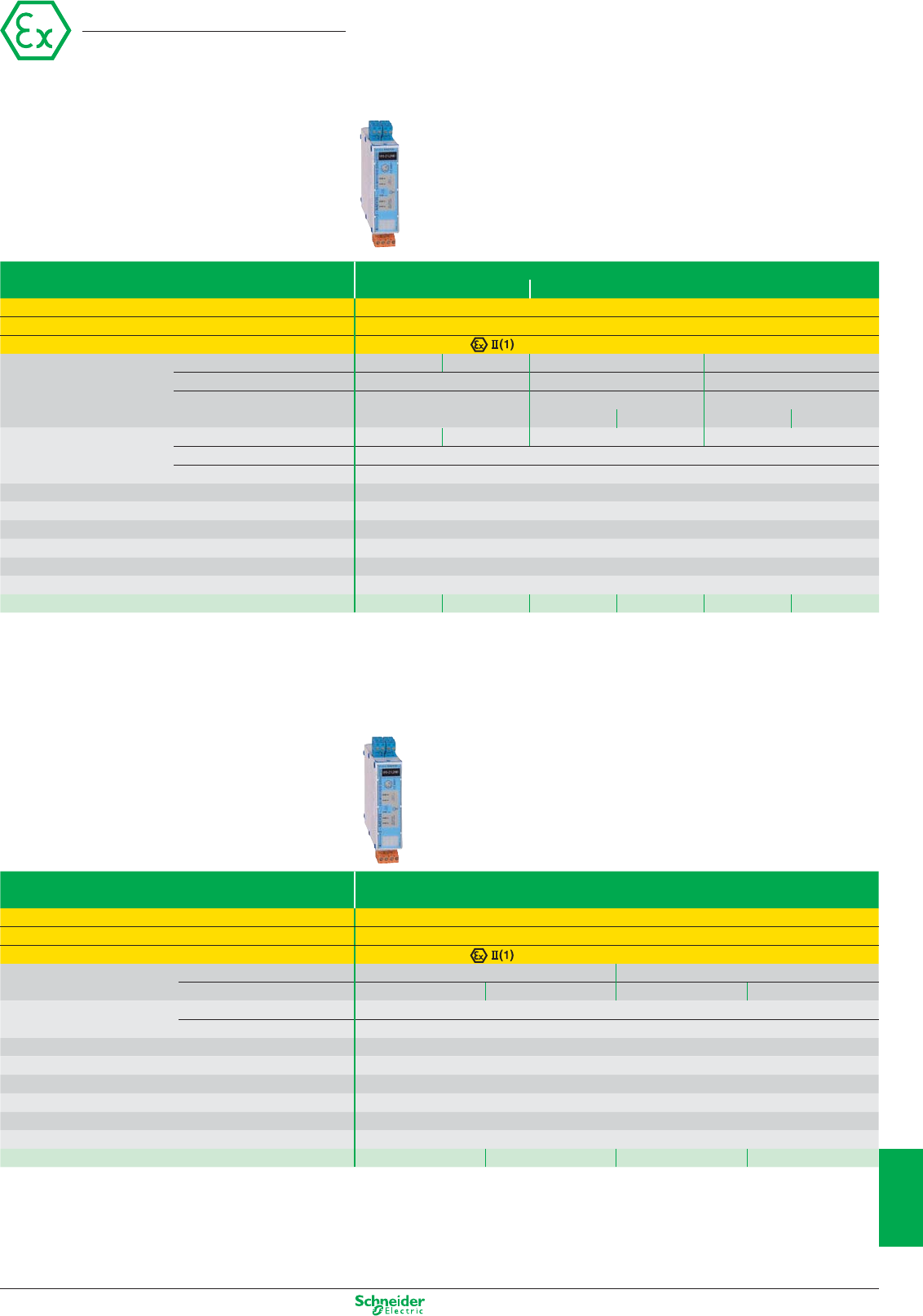
Other versions: please consult your Schneider Electric agency.
Module type Discrete
Inputs Relay inputs/outputs
Conformity Directive ATEX 94/9/EC, EN 50014, EN 50020, EN 50021-1&2, EN 50082-1&2
Zone D (dust) Mounted outside zone (to be used in conjunction with products for zone 20, 21 or 22)
EC type examination certificate number / marking LCIE 00ATEX6034X / G/D-[EEx ia] IIC
Zone 20 Number of input channels 2 4 2 2
Number of output channels –11
Type of output channel, –
Low consumption solenoid valve, < 7 mA High consumption solenoid valve, < 40 mA
load excitation – with hysteresis – with hysteresis
Outside zone Number of recopying channels 2 4 2 2
Switching voltage 5…230 VAC; 5…24 VDC
Switching current 10 mA…0.5 A (AC); 10 mA…0.5 A, L/R 48 ms (DC)
Temperature range – 20...+ 60°C
Connection Removable screw terminal blocks
Mounting On 35 mm DIN rail
Dimensions, W x D x H 29.5 x 120 x 90 mm
Supply voltage (including ripple) 24 VDC (0.95…1.1 Un)
Consumption 5 W
References NY320N2RB1 NY340N4RB1 NY321L2RB1 NY321L1RB1 NY321H2RB1 NY321H1RB1
Module type Discrete
Load excitation outputs
Conformity Directive ATEX 94/9/EC, EN 50014, EN 50020, EN 50021-1&2, EN 50082-1&2
Zone D (dust) Mounted outside zone (to be used in conjunction with products for zone 20, 21 or 22)
EC type examination certificate number / marking LCIE 00ATEX6034X / G/D-[EEx ia] IIC
Zone 20
Number of load excitation channels
24
Maximum current < 7 mA < 40 mA < 7 mA < 40 mA
Outside zone Control voltage 24 VDC ± 10%
Control current State 1 = 6.5 < I < 9 mA and 21.6 < U < 26.4 V; State 0 = I ≤ 0.4 mA and U ≤ 1.2 V
Temperature range – 20...+ 60°C
Connection Removable screw terminal blocks
Mounting On 35 mm DIN rail
Dimensions, W x D x H 29.5 x 120 x 90 mm
Supply voltage (including ripple) 24 VDC (0.95…1.1 Un)
Consumption 5 W
References NY302L0NB1 NY302H0NB1 NY304L0NB1 NY304H0NB1
Intrinsically safe module
Processing module
10/5
2
1
3
4
5
6
7
8
9
10
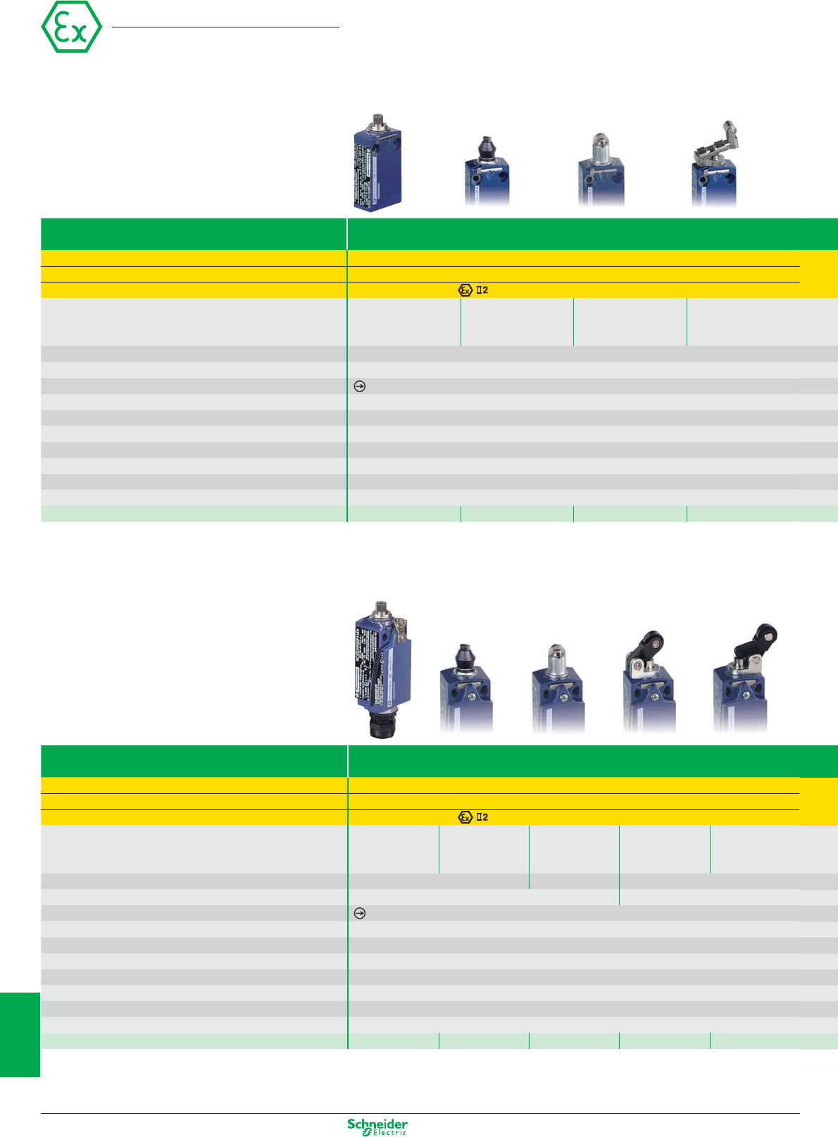
Other versions: please consult your Schneider Electric agency.
Limit switches
Miniature, fixing by the body
Osiswitch
Limit switch type XCMD metal, pre-cabled
With head for movement Linear (plunger)
Conformity Directive ATEX 94/9/EC, EN 50014, EN 50281-1-1, pr IEC 61241-0, pr IEC 61241-1
Zone D (dust) 21 - 22
EC type examination certificate number / marking INERIS 04ATEX0014X / D-Ex tD A21 IP66/67 T85°C
Type of operator Metal end Metal end Steel roller Retractable
plunger plunger with plunger steel roller
elastomer boot lever plunger
Mechanical durability (millions of operating cycles) 10
Actuation speed 0.5 m/s
Switches conforming to standard IEC 947-5-1 section 3
Temperature range – 20...+ 60°C
Degree of protection (conforming to IEC 60529) IP66 and IP67
Rated operational characteristics AC15; C300 (Ue = 240 V, Ie = 0.75 A)/DC13; R300 (Ue = 250 V, Ie = 0.1 A)
Short-circuit protection By 6 A cartridge fuse type gG (gl)
Cable entry Pre-cabled, adjustable direction, length = 5 m
Fixing centres 20 mm
Body dimensions, W x D x H 30 x 16 x 50 mm
References 2 N/C + 2 N/O snap action XCMD4110L5EX XCMD4111L5EX XCMD4102L5EX XCMD4124L5EX
Compact, fixing by the body
Limit switch type XCKD metal conforming to standard EN 500047
With head for movement Linear (plunger)
Conformity Directive ATEX 94/9/EC, EN 50014, EN 50281-1-1, pr IEC 61241-0, pr IEC 61241-1
Zone D (dust) 21 - 22
EC type examination certificate number / marking INERIS 04ATEX0014X /D-Ex tD A21 IP66/67 T85°C
Type of operator Metal end Metal end Steel roller Thermoplastic roller Thermoplastic roller
plunger plunger with plunger
lever plunger, horiz. lever plunger, vert.
elastomer boot actuation in 1 direct. actuation in 1 direct.
Mechanical durability (millions of operating cycles) 15 10 15
Actuation speed 0.5 m/s 1 m/s
Switches conforming to standard IEC 947-5-1 section 3
Temperature range – 20...+ 60°C
Degree of protection (conforming to IEC 60529) IP66 and IP67
Rated operational characteristics AC15; B300 (Ue = 240 V, Ie = 1.5 A)/DC13; R300 (Ue = 250 V, Ie = 0.1 A)
Short-circuit protection By 6 A cartridge fuse type gG (gl)
Cable entry 1 entry fitted with ISO M16 cable gland
Fixing centres 20 mm
Body dimensions, W x D x H 31 x 30 x 65 mm
References N/C + N/C + N/O snap action XCKD3910P16EX XCKD3911P16EX XCKD3902P16EX XCKD3921P16EX XCKD3927P16EX
Other characteristics: please refer to the “Global Detection” catalogue
10/6
2
1
3
4
5
6
7
8
9
10
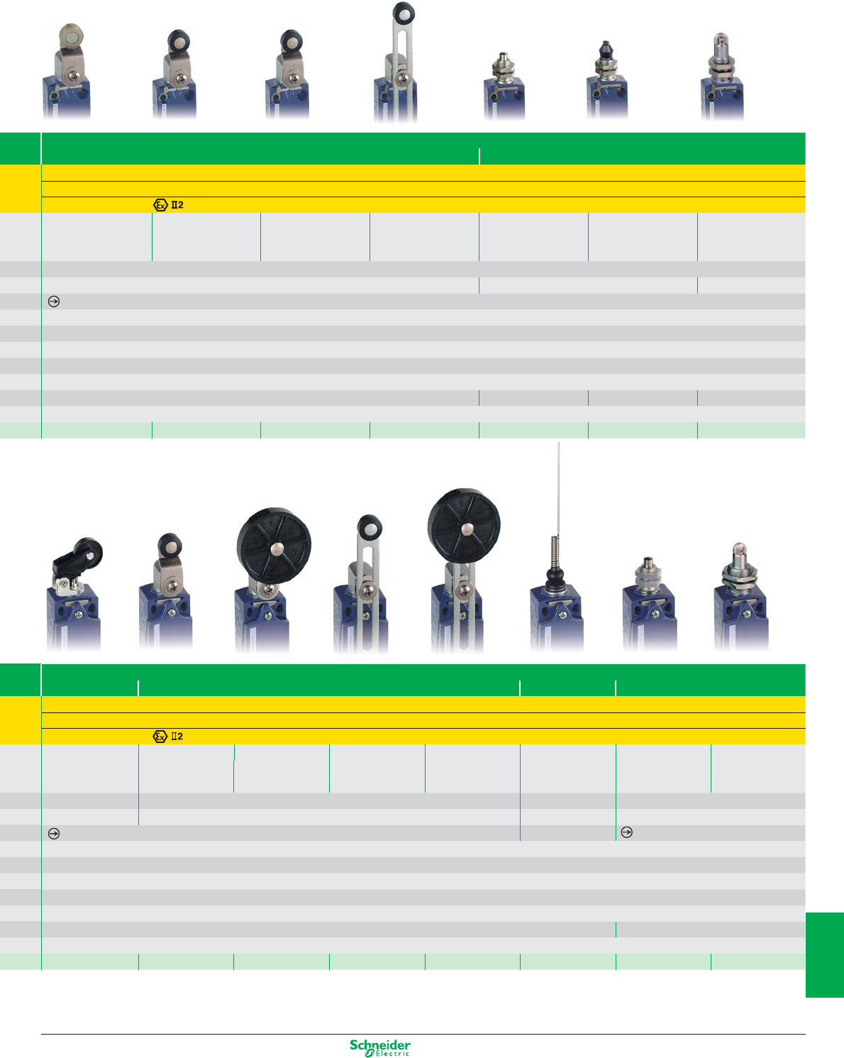
Other versions: please consult your Schneider Electric agency.
Miniature, fixing by the head
XCMD metal, pre-cabled
Rotary (lever) Linear (plunger)
Directive ATEX 94/9/EC, EN 50014, EN 50281-1-1, pr IEC 61241-0, pr IEC 61241-1
21 - 22
INERIS 04ATEX0014X / D-Ex tD A21 IP66/67 T85°C
Steel roller Thermoplastic roller Roller lever Variable length M12 with metal M16 with metal M12 with steel
lever lever with ball bearing thermoplastic end plunger end plunger with roller plunger
mounted roller roller lever elastomer boot
10
1.5 m/s 0.5 m/s 0.1 m/s
– 20...+ 60°C
IP66 and IP67
AC15; C300 (Ue = 240 V, Ie = 0.75 A)/DC13; R300 (Ue = 250 V, Ie = 0.1 A)
By 6 A cartridge fuse type gG (gl)
Pre-cabled, adjustable direction, length = 5 m
20 mm M12 x 1 M16 x 1 M12 x 1
30 x 16 x 50 mm
XCMD4116L5EX XCMD4115L5EX XCMD4117L5EX XCMD4145L5EX XCMD41F0L5EX XCMD41G1L5EX XCMD41F2L5EX
Compact, fixing by
the head
XCKD metal conforming to standard EN 500047
Linear (plunger) Rotary (lever)
Multi-directional Linear (plunger)
Directive ATEX 94/9/EC, EN 50014, EN 50281-1-1, pr IEC 61241-0, pr IEC 61241-1
21 - 22
INERIS 04ATEX0014X / D-Ex tD A21 IP66/67 T85°C
Thermoplastic roller Thermoplastic Thermoplastic Variable length Variable length “Cat’s whisker” M18 with metal M18 with steel
lever plunger, horiz. or
roller lever roller lever, thermoplastic thermoplastic end plunger roller plunger
vert. actuation in 1 dir.
Ø 50 mm roller lever roller lever, Ø 50 mm
15 10 510
1 m/s 1.5 m/s 1 m/s 0.5 m/s
–
– 20...+ 60°C
IP66 and IP67
AC15; B300 (Ue = 240 V, Ie = 1.5 A)/DC13; R300 (Ue = 250 V, Ie = 0.1 A)
By 6 A cartridge fuse type gG (gl)
1 entry fitted with ISO M16 cable gland
20 mm M18 x 1
30 x 16 x 50 mm
XCKD3928P16EX XCKD3918P16EX XCKD3939P16EX XCKD3945P16EX XCKD3949P16EX XCKD3906P16EX XCKD39H0P16EX XCKD39H2P16EX
10/7
2
1
3
4
5
6
7
8
9
10
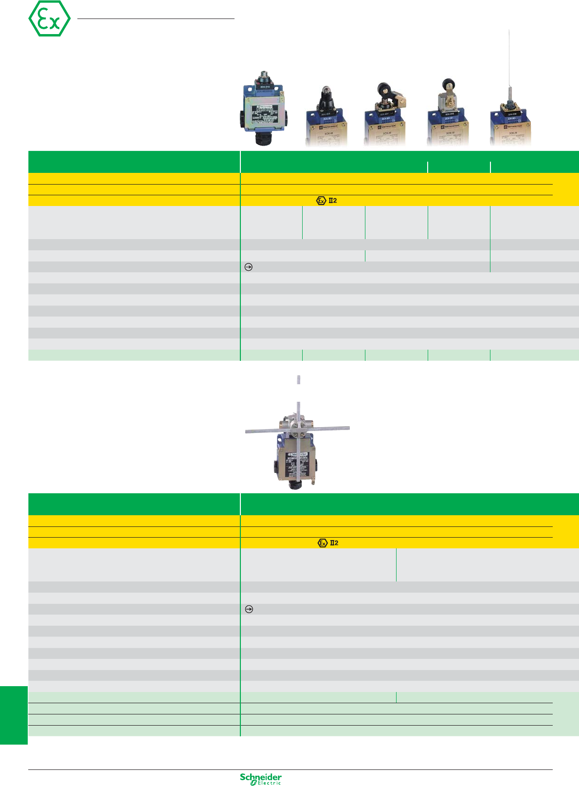
Other versions: please consult your Schneider Electric agency.
Limit switches
Classic, fixing by the body
Osiswitch
Limit switch type XCKM metal, 3 cable entries
With head for movement Linear (plunger)
Rotary (lever) Multi-directional
Conformity Directive ATEX 94/9/EC, EN 50014, EN 50281-1-1, pr IEC 61241-0, pr IEC 61241-1
Zone D (dust) 21 - 22
EC type examination certificate number / marking INERIS 04ATEX0014X / D-Ex tD A21 IP66/67 T85°C
Type of operator Metal end Steel roller Thermoplastic roller Thermoplastic “Cat’s whisker”
plunger plunger
lever plunger, horiz.
roller lever
actuation in 1 direct.
Mechanical durability (millions of operating cycles) 20 10
Actuation speed 0.5 m/s 1.5 m/s 0.5 m/s
Switches conforming to standard IEC 947-5-1 section 3 –
Temperature range – 20...+ 60°C
Degree of protection (conforming to IEC 60529) IP66
Rated operational characteristics AC15; B300 (Ue = 240 V, Ie = 1.5 A)/DC13; R300 (Ue = 250 V, Ie = 0.1 A)
Short-circuit protection By 6 A cartridge fuse type gG (gl)
Cable entry 3 tapped entries for ISO M20 cable gland (1)
Fixing centres 41 mm
Body dimensions, W x D x H 63 x 30 x 64 mm
References N/C + N/C + N/O snap action XCKM3910H29EX XCKM3902H29EX XCKM3921H29EX XCKM3915H29EX XCKM3906H29EX
(1) 2 entries fitted with blanking plugs, 1 entry fitted with ISO M20 cable gland
Application - hoisting, handling, conveying
Limit switch type XCKMR metal, 3 cable entries
With head for movement Rotary (lever)
Conformity Directive ATEX 94/9/EC, EN 50014, EN 50281-1-1, pr IEC 61241-0, pr IEC 61241-1
Zone D (dust) 21 - 22
EC type examination certificate number / marking INERIS 04ATEX0014X / D-Ex tD A21 IP66/67 T85°C
Type of operator Metal rod levers, ”crossed” Metal rod levers, ”crossed”
reversed head
Mechanical durability (millions of operating cycles) 2
Actuation speed 1.5 m/s
Switches conforming to standard IEC 947-5-1 section 3
Temperature range – 20...+ 60°C
Degree of protection (conforming to IEC 60529) IP66
Rated operational characteristics AC15; A300 (Ue = 240 V, Ie = 3 A)/DC13; Q300 (Ue = 125 V, Ie = 0.55 A)
Short-circuit protection By 10 A cartridge fuse type gG (gl)
Cable entry 3 tapped entries for ISO M20 cable gland (1)
Fixing centres 61.5 mm
Body dimensions, W x D x H 118 x 59 x 77 mm
2 x N/C + N/C staggered, slow break contacts XCKMR54D1H29EX XCKMR54D2H29EX
2 x N/C + N/O snap action contacts, both actuated in each direction
–
2 x N/C + N/O snap action contacts, 1 actuated in each direction
–
2 x single-pole C/O snap action contacts –
(1) 2 entries fitted with blanking plugs, 1 entry fitted with ISO M20 cable gland
Other characteristics: please refer to the “Global Detection” catalogue
10/8
2
1
3
4
5
6
7
8
9
10
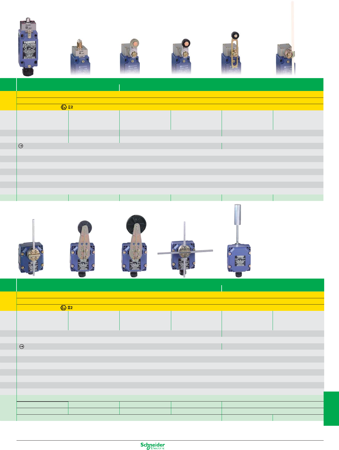
Other versions: please consult your Schneider Electric agency.
XCKJ metal, fixed body, conforming to standard EN 50041
Linear (plunger) Rotary (lever)
Directive ATEX 94/9/EC, EN 50014, EN 50281-1-1, pr IEC 61241-0, pr IEC 61241-1
21 - 22
INERIS 04ATEX0014X / D-Ex tD A21 IP66/67 T85°C
Metal end Steel roller Steel roller Thermoplastic roller Variable length Polyamide rod
plunger plunger lever lever thermoplastic lever, Ø 6 x 200 mm
roller lever
30 25 30 20
0.5 m/s 1 m/s 1.5 m/s
–
– 20...+ 60°C
IP66
AC15; B300 (Ue = 240 V, Ie = 1.5 A)/DC13; R300 (Ue = 250 V, Ie = 0.1 A)
By 6 A cartridge fuse type gG (gl)
1 entry fitted with ISO M20 cable gland
30 x 60 mm
40 x 44 x 77 mm
XCKJ3961H29EX XCKJ3967H29EX XCKJ390513H29EX XCKJ390511H29EX XCKJ390541H29EX XCKJ390559H29EX
XCR metal
Rotary (lever) Conveyor belt shift monitoring switches
Directive ATEX 94/9/EC, EN 50014, EN 50281-1-1, pr IEC 61241-0, pr IEC 61241-1
21 - 22
INERIS 04ATEX0024X / D-Ex tD A21 IP65 T85°C
Square (6 mm) Thermoplastic roller Large thermoplastic roller Metal rod levers, Galvanised steel Stainless steel
rod lever, spring (Ø 30 mm) lever, spring (Ø 50 mm) lever, spring ”crossed”, stay put operating lever operating lever
return to off position return to off position return to off position
10 0.3
1.5 m/s
–
– 20...+ 60°C
IP65
AC15; A300 (Ue = 240 V, Ie = 3 A)/DC13; Q300 (Ue = 250 V, Ie = 0.27 A)
By 10 A cartridge fuse type gG (gl)
1 entry fitted with n° 13 cable gland
85 x 75 mm
85 x 75 x 95 mm
–
XCRA111EX XCRA121EX XCRA151EX XCRE181EX (2) –
XCRB111EX XCRB121EX XCRB151EX XCRF171EX (3) –
–XCRT115EX XCRT215EX
(2) “Crossed” rods (3) “T” rods
10/9
2
1
3
4
5
6
7
8
9
10
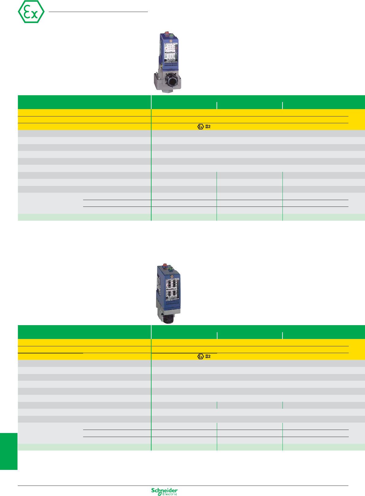
Other versions: please consult your Schneider Electric agency.
Electromechanical pressure & vacuum switches
Adjustable differential, regulation between 2 thresholds
Type Vacuum switches and vacu-pressure switches with setting scale
Size - 1 bar - 0.2 bar 5 bar
Conformity Directive ATEX 94/9/EC, EN 50014, EN 50281-1-1, pr IEC 61241-0, pr IEC 61241-1
Zone D (dust) 21 - 22
EC type examination certificate number / marking INERIS 04ATEX0058 / D-Ex tD A21 IP66 T85°C
Fluid connection 1/4” BSP female
Electrical connection Screw terminals, 1 entry fitted with ISO M20 cable gland
Temperature range – 20...+ 60°C
Degree of protection IP66
Rated operational characteristics AC15; B300 (Ue = 240 V, Ie = 1.5 A; Ue = 120 V, Ie = 3 A)/DC13; R300 (Ue = 250 V, Ie = 0.1 A)
Short-circuit protection By 10 A cartridge fuse type gG (gl)
Setting range of upper limit (PH) –0.14…–1 bar –0.02…–0.2 bar –0.5…5 bar
Body dimensions, W x D x H 55 x 77.5 x 158 mm 150 x 155.5 x 145 mm 113 x 35 x 75 mm
Fluids controlled Oil, water, air, up to +70°C Oil, air, up to +160°C Oil, water, air, up to +70°C
Possible differential Min. at low setting 0.13 bar 0.018 bar 0.5 bar
(subtract from PH Min. at high setting 0.13 bar 0.018 bar 0.5 bar
to give PB) (1) Max. at high setting 0.8 bar 0.18 bar 6 bar
Single-pole snap action contact XMLBM02V2S12EX XMLBM03R2S12EX XMLBM05A2S12EX
(1) For XMLBM02V2S12EX and XMLBM03R2S12EX vacuum switches add to PB to give PH
Type Pressure switches with setting scale
Size 10 bar 20 bar 35 bar
Conformity Directive ATEX 94/9/EC, EN 50014, EN 50281-1-1, pr IEC 61241-0, pr IEC 61241-1
Zone D (dust) 21 - 22
EC type examination certificate number / marking INERIS 04ATEX0058 / D-Ex tD A21 IP66 T85°C
Fluid connection 1/4” BSP female
Electrical connection Screw terminals, 1 entry fitted with ISO M20 cable gland
Temperature range – 20...+ 60°C
Degree of protection IP66
Rated operational characteristics AC15; B300 (Ue = 240 V, Ie = 1.5 A; Ue = 120 V, Ie = 3 A)/DC13; R300 (Ue = 250 V, Ie = 0.1 A)
Short-circuit protection By 10 A cartridge fuse type gG (gl)
Setting range of upper limit (PH) 0.7…10 bar 1.3…20 bar 3.5…35 bar
Body dimensions, W x D x H 35 x 75 x 113 mm
Fluids controlled Oil, water, air, up to +70°C
Possible differential Min. at low setting 0.57 bar 1 bar 1.7 bar
(subtract from PH Min. at high setting 0.85 bar 1.6 bar 2.55 bar
to give PB) Max. at high setting 7.5 bar 11 bar 20 bar
Single-pole snap action contact XMLB010A2S12EX XMLB020A2S12EX XMLB035A2S12EX
Other characteristics: please refer to the “Global Detection” catalogue
Nautilus
10/10
2
1
3
4
5
6
7
8
9
10
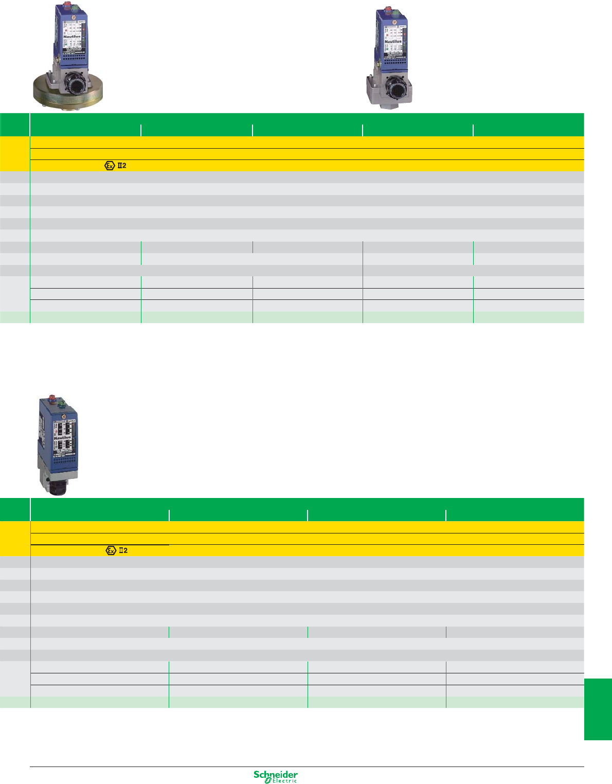
Other versions: please consult your Schneider Electric agency.
Pressure switches with setting scale
0.05 bar 0.35 bar 1 bar 2.5 bar 4 bar
Directive ATEX 94/9/EC, EN 50014, EN 50281-1-1, pr IEC 61241-0, pr IEC 61241-1
21 - 22
INERIS 04ATEX0058 / D-Ex tD A21 IP66 T85°C
1/4” BSP female
Screw terminals, 1 entry fitted with ISO M20 cable gland
– 20...+ 60°C
IP66
AC15; B300 (Ue = 240 V, Ie = 1.5 A; Ue = 120 V, Ie = 3 A)/DC13; R300 (Ue = 250 V, Ie = 0.1 A)
By 10 A cartridge fuse type gG (gl)
0.026…0.05 bar 0.045…0.35 bar 0.05…1 bar 0.3…2.5 bar 0.25…4 bar
200 x 204 x 145 mm 110 x 110 x 162 mm 55 x 77.5 x 158 mm 55 x 77.5 x 158 mm
Oil, air, up to +160°C Oil, water, air, up to +70°C
0.0014 bar 0.042 bar 0.04 bar 0.16 bar 0.2 bar
0.004 bar 0.05 bar 0.06 bar 0.21 bar 0.25 bar
0.04 bar 0.3 bar 0.75 bar 1.75 bar 2.4 bar
XMLBL05R2S12EX XMLBL35R2S12EX XMLB001R2S12EX XMLB002A2S12EX XMLB004A2S12EX
Pressure switches with setting scale
70 bar 160 bar 300 bar 500 bar
Directive ATEX 94/9/EC, EN 50014, EN 50281-1-1, pr IEC 61241-0, pr IEC 61241-1
21 - 22
INERIS 04ATEX0058 / D-Ex tD A21 IP66 T85°C
1/4” BSP female
Screw terminals, 1 entry fitted with ISO M20 cable gland
– 20...+ 60°C
IP66
AC15; B300 (Ue = 240 V, Ie = 1.5 A; Ue = 120 V, Ie = 3 A)/DC13; R300 (Ue = 250 V, Ie = 0.1 A)
By 10 A cartridge fuse type gG (gl)
7…70 bar 10…160 bar 22…300 bar 30…500 bar
35 x 75 x 113 mm
Oil, up to +160°C
4.7 bar 9.3 bar 19.4 bar 23 bar
8.8 bar 20.8 bar 37 bar 52.6 bar
50 bar 100 bar 200 bar 300 bar
XMLB070D2S12EX XMLB160D2S12EX XMLB300D2S12EX XMLB500D2S12EX
10/11
2
1
3
4
5
6
7
8
9
10
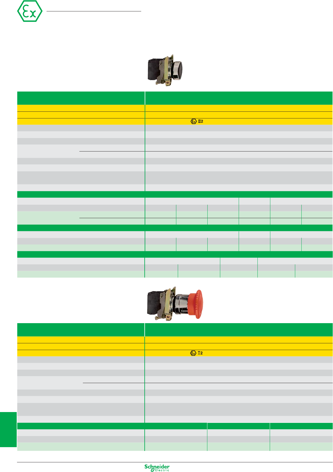
Other versions: please consult your Schneider Electric agency.
Pushbuttons and mushroom heads
Contact functions
Type Ø 22 pushbuttons with metal bezel
Conformity Directive ATEX D 94/9/EC, EN 50014, EN 50281-1-1, pr IEC 61241-0, pr IEC 61241-1
Zone D (dust) 21 - 22
EC type examination certificate number / marking INERIS 04ATEX9004U / D-Ex tD A21 IP65/66
Mechanical durability (millions of operating cycles) 5
Temperature range – 20...+ 60°C
Degree of protection IP65 and IP66
Mounting Panel cut-out Ø 22.5 mm (22.4
0
+0.4
recommended
)
Mounting centres 30 x 40 mm
Depth below head 43 mm
Connection Screw clamp terminals
Rated operational characteristics AC15; A600 (Ue = 600 V, Ie = 1.2 A or Ue = 240 V, Ie = 3 A or Ue = 120 V, Ie = 6 A
DC13; Q600 (Ue = 600 V, Ie = 0.1 A or Ue = 250 V, Ie = 0.27 A or Ue = 125 V, Ie = 0.55 A)
Short-circuit protection By 10 A cartridge fuse type gG (gl)
Pushbutton type Flush with transparent silicone boot
Contact N/O N/C N/O
Colour of push p white p black p green p red p yellow p blue
References Insertion of legend not possible – XB4BP21EX XB4BP31EX XB4BP42EX XB4BP51EX XB4BP61EX
Insertion of legend possible XB4BP181EX – XB4BP381EX XB4BP482EX XB4BP581EX XB4BP681EX
Pushbutton type Flush with coloured silicone boot
Contact N/O N/C N/O
Colour of silicone boot p white p black p green p red p yellow p blue
References XB4BPS11EX XB4BPS21EX XB4BPS31EX XB4BPS42EX XB4BPS51EX XB4BS61EX
Ø 40 mushroom head pushbutton type Spring return
Contact N/O N/C N/O
Colour of push p black p green p red p yellow p blue
References XB4BC21EX XB4BC31EX XB4BC42EX XB4BC51EX XB4BC61EX
Type Ø 40 mushroom head Emergency stop pushbuttons
Conformity
Directive ATEX D 94/9/EC, EN 50014, EN 50281-1-1, pr IEC 61241-0, pr IEC 61241-1, IEC/EN 60947-5-5
Zone D (dust) 21 - 22
EC type examination certificate number / marking INERIS 04ATEX9004U / D-Ex tD A21 IP65/66
Mechanical durability (millions of operating cycles) 0.3
Temperature range – 20...+ 60°C
Degree of protection IP65
Mounting Panel cut-out Ø 22.5 mm (22.4
0
+0.4
recommended
)
Mounting centres 30 x 40 mm
Depth below head 43 mm
Connection Screw clamp terminals
Rated operational characteristics AC15; A600 (Ue = 600 V, Ie = 1.2 A or Ue = 240 V, Ie = 3 A or Ue = 120 V, Ie = 6 A
DC13; Q600 (Ue = 600 V, Ie = 0.1 A or Ue = 250 V, Ie = 0.27 A or Ue = 125 V, Ie = 0.55 A)
Short-circuit protection By 10 A cartridge fuse type gG (gl)
Ø 40 latching mushroom head pushbutton type Push-pull with trigger action Key release ( n° 455) Turn to release
Contact(s) N/C + N/O N/C N/C
Colour of push p red p red p red
References XB4BT845EX XB4BS142EX XB4BS542EX
Other characteristics: please refer to the “Human-Machine Interface components” catalogue
Harmony
10/12
2
1
3
4
5
6
7
8
9
10
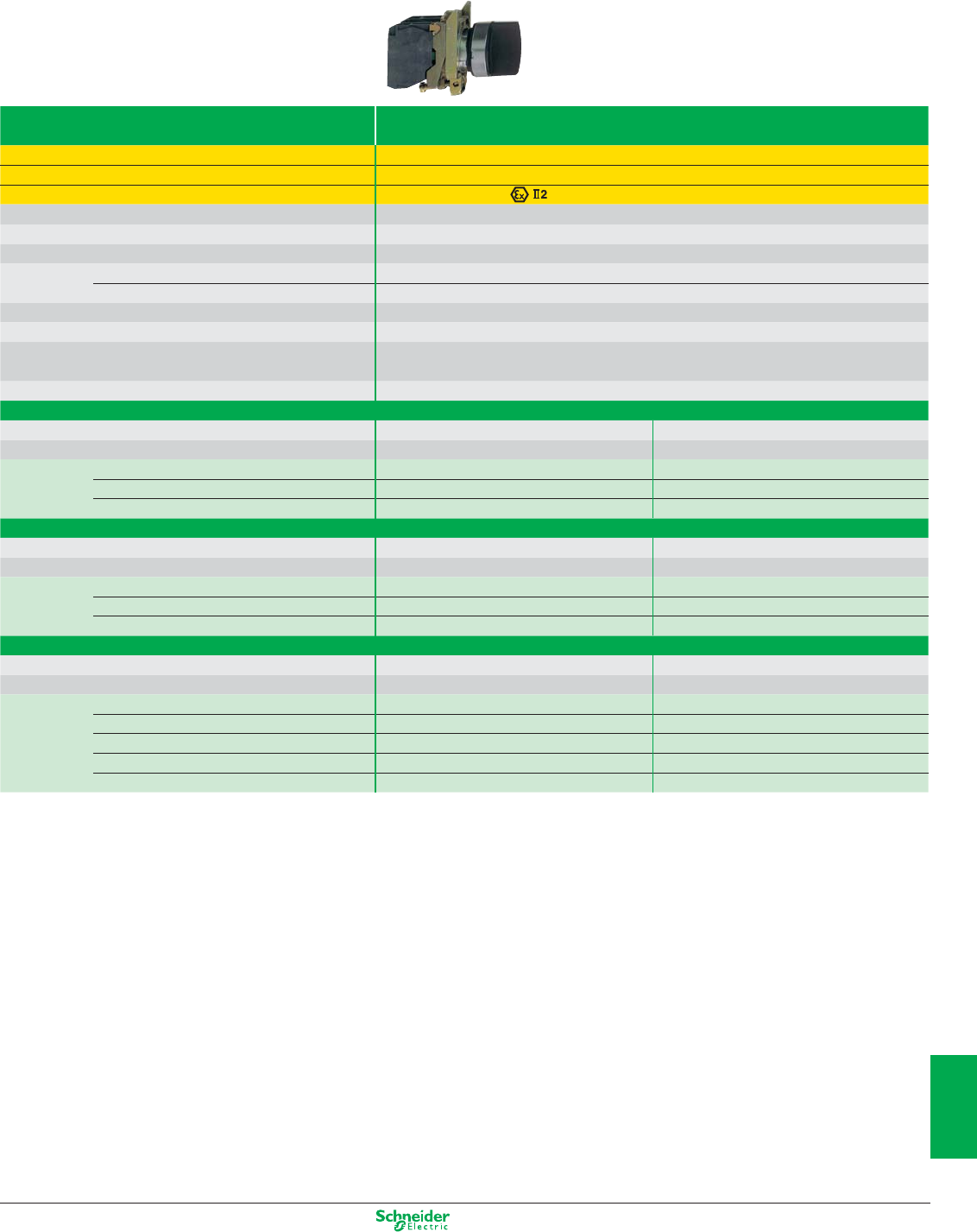
Other versions: please consult your Schneider Electric agency.
Type Ø 22 selector switches and key switches with metal bezel
Conformity Directive ATEX D 94/9/EC, EN 50014, EN 50281-1-1, pr IEC 61241-0, pr IEC 61241-1
Zone D (dust) 21 - 22
EC type examination certificate number / marking INERIS 04ATEX9004U / D-Ex tD A21 IP65/66
Mechanical durability (millions of operating cycles) 3
Temperature range – 20...+ 60°C
Degree of protection IP65
Mounting Panel cut-out Ø 22.5 mm (22.4
0
+0.4
recommended
)
Mounting centres 30 x 40 mm
Depth below head 43 mm
Connection Screw clamp terminals
Rated operational characteristics AC15; A600 (Ue = 600 V, Ie = 1.2 A or Ue = 240 V, Ie = 3 A or Ue = 120 V, Ie = 6 A
DC13; Q600 (Ue = 600 V, Ie = 0.1 A or Ue = 250 V, Ie = 0.27 A or Ue = 125 V, Ie = 0.55 A)
Short-circuit protection By 10 A cartridge fuse type gG (gl)
Selector switch type Standard handle
Contacts N/C + N/O N/O + N/O
Colour p black p black
References 2 position stay put XB4BD25EX –
3 position stay put – XB4BD33EX
3 position spring return to centre – XB4BD53EX
Selector switch type Long handle
Contact(s) N/O N/O + N/O
Colour p black p black
References 2 position stay put XB4BJ21EX –
3 position stay put – XB4BJ33EX
3 position spring return to centre – XB4BJ53EX
Key switch type Key n° 455
Contact(s) N/O N/O + N/O
Colour p black p black
References 2 position stay put, key withdrawal in LH position XB4BG21EX –
2 position stay put, key withdrawal in both positions XB4BG41EX –
2 position spring return, key withdrawal in LH position
XB4BG61EX –
3 position stay put, key withdrawal in centre position – XB4BG33EX
3 position stay put, key withdrawal in all 3 positions – XB4BG03EX
Other characteristics: please refer to the “Human-Machine Interface components” catalogue
Selector switches and key switches
Contact functions
10/13
2
1
3
4
5
6
7
8
9
10
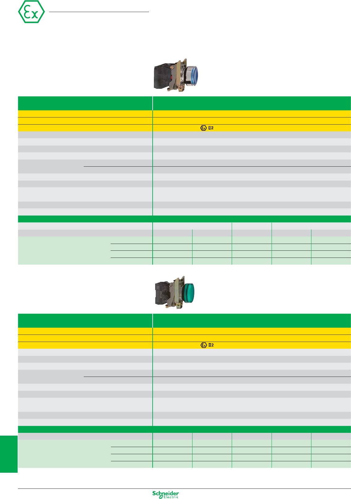
Other versions: please consult your Schneider Electric agency.
Illuminated pushbuttons and pilot lights
Contact and light functions (integral LED)
Type Ø 22 illuminated pushbuttons with metal bezel
Conformity Directive ATEX 94/9/EC, EN 50014, EN 50281-1-1, pr IEC 61241-0, pr IEC 61241-1
Zone D (dust) 21 - 22
EC type examination certificate number / marking INERIS 04ATEX9004U / D-Ex tD A21 IP65/66
Mechanical durability (millions of operating cycles) 5
Service life 100,000 hours at ambient temperature
Temperature range – 20...+ 60°C
Degree of protection IP65
Mounting Panel cut-out Ø 22.5 mm (22.4
0
+0.4
recommended
)
Mounting centres 30 x 40 mm
Depth below head 43 mm
Connection Screw clamp terminals
Rated operational characteristics AC15; A600 (Ue = 600 V, Ie = 1.2 A or Ue = 240 V, Ie = 3 A or Ue = 120 V, Ie = 6 A
DC13; Q600 (Ue = 600 V, Ie = 0.1 A or Ue = 250 V, Ie = 0.27 A or Ue = 125 V, Ie = 0.55 A)
Short-circuit protection By 10 A cartridge fuse type gG (gl)
Light source Integral LED
Illuminated pushbutton type, with integral LED Flush with transparent silicone boot
Contact N/O N/C N/O
Colour of push p white p green p red p yellow p blue
References LED voltage 24 VAC/DC XB4BP183B5EX XB4BP383B5EX XB4BP483B5EX XB4BP583B5EX XB4BP683B5EX
110…120 VAC XB4BP183G5EX XB4BP383G5EX XB4BP483G5EX XB4BP583G5EX XB4BP683G5EX
240 VAC XB4BP183M5EX XB4BP383M5EX XB4BP483M5EX XB4BP583M5EX XB4BP683M5EX
24…120 VAC/DC XB4BP183BG5EX XB4BP383BG5EX XB4BP483BG5EX XB4BP583BG5EX XB4BP683BG5EX
Type Ø 22 pilot lights with metal bezel
Conformity Directive ATEX 94/9/EC, EN 50014, EN 50281-1-1, pr IEC 61241-0, pr IEC 61241-1
Zone D (dust) 21 - 22
EC type examination certificate number / marking INERIS 04ATEX9004U / D-Ex tD A21 IP65/66
Service life 100,000 hours at ambient temperature
Temperature range – 20...+ 60°C
Degree of protection IP65
Mounting Panel cut-out Ø 22.5 mm (22.4
0
+0.4
recommended
)
Mounting centres 30 x 40 mm
Depth below head 43 mm
Connection Screw clamp terminals
Rated operational characteristics AC15; A600 (Ue = 600 V, Ie = 1.2 A or Ue = 240 V, Ie = 3 A or Ue = 120 V, Ie = 6 A
DC13; Q600 (Ue = 600 V, Ie = 0.1 A or Ue = 250 V, Ie = 0.27 A or Ue = 125 V, Ie = 0.55 A)
Short-circuit protection By 10 A cartridge fuse type gG (gl)
Light source Integral LED
Pilot light type Pilot lights with integral LED, plain lens
Colour of LED p white p green p red p yellow p blue
References LED voltage 24 VAC/DC XB4BVB1EX XB4BVB3EX XB4BVB4EX XB4BVB5EX XB4BVB6EX
110…120 VAC XB4BVG1EX XB4BVG3EX XB4BVG4EX XB4BVG5EX XB4BVG6EX
240 VAC XB4BVM1EX XB4BVM3EX XB4BVM4EX XB4BVM5EX XB4BVM6EX
24…120 VAC/DC XB4BVBG1EX XB4BVBG3EX XB4BVBG4EX XB4BVBG5EX XB4BVBG6EX
Other characteristics: please refer to the “Human-Machine Interface components” catalogue
Harmony
10/14
2
1
3
4
5
6
7
8
9
10
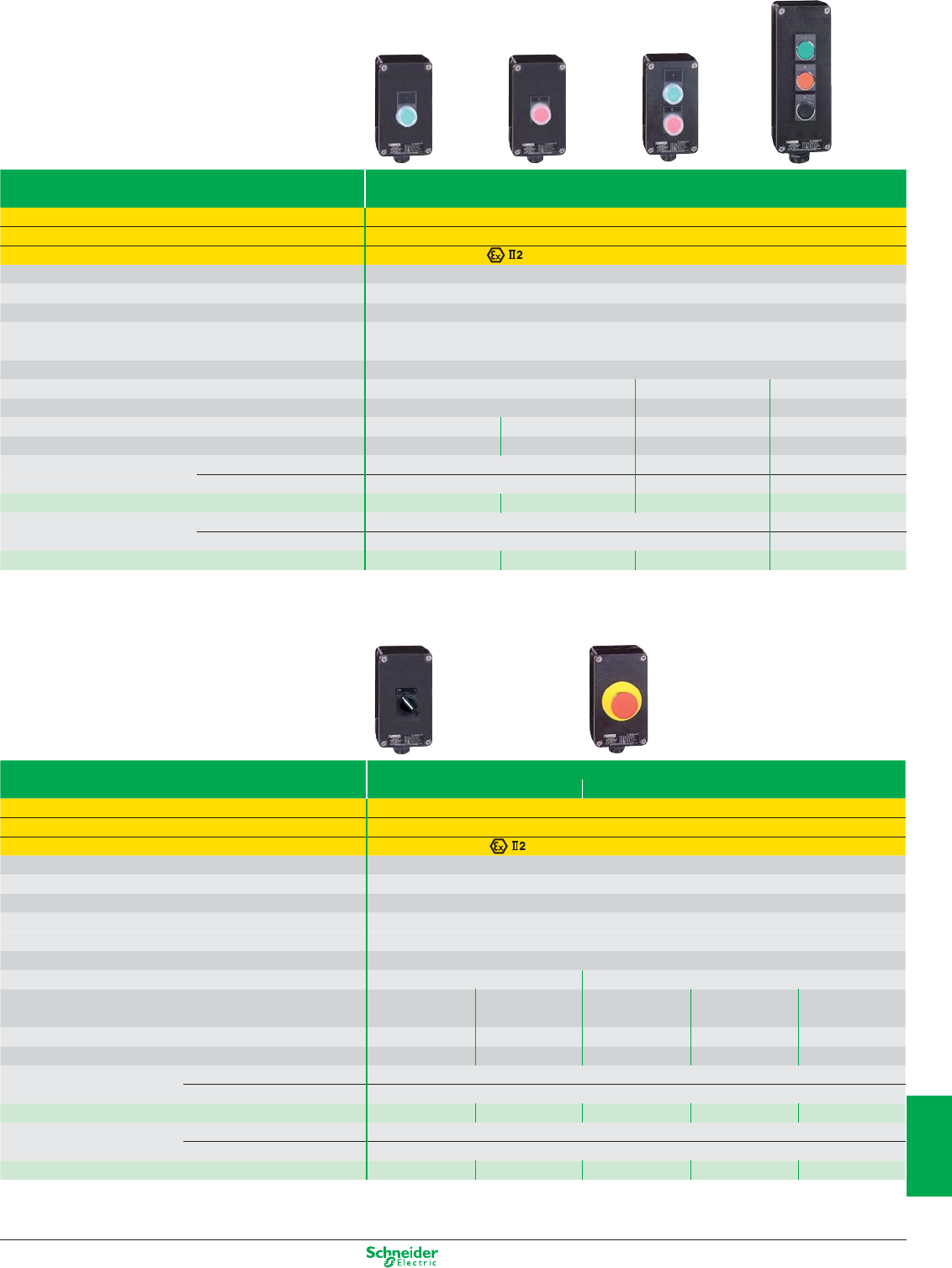
Other versions: please consult your Schneider Electric agency.
Control stations
Complete stations, metal or plastic
Type Complete control stations
Type of operators Ø 22 flush pushbuttons
Conformity Directive ATEX 94/9/EC, EN 50014, EN 50281-1-1, pr IEC 61241-0, pr IEC 61241-1
Zone D (dust) 21 - 22
EC type examination certificate number / marking INERIS 04ATEX0023/ D-Ex tD A21 IP65 T85°C
Temperature range – 20...+ 60°C
Degree of protection IP65
Connection 1 entry fitted with ISO M20 cable gland
Rated operational characteristics of contact blocks AC15; A600 (Ue = 600 V, Ie = 1.2 A or Ue = 240 V, Ie = 3 A or Ue = 120 V, Ie = 6 A
DC13; Q600 (Ue = 600 V, Ie = 0.1 A or Ue = 250 V, Ie = 0.27 A or Ue = 125 V, Ie = 0.55 A)
Short-circuit protection By 10 A cartridge fuse type gG (gl)
Function 1 function, Start or Stop 2 functions, Start - Stop 3 functions
Composition 1 spring return pushbutton 2 spring ret. pushbuttons 3 spring ret. pushbuttons
Contact(s) N/O N/C N/O + N/C N/O + N/C + N/O
Colour of pushbutton(s) p green p red p green + p red p green + p red + p black
Metal control stations Dimensions, W x D x H 80 x 77 x 80 mm 80 x 77 x 130 mm 80 x 77 x 175 mm
Fixings: 4 x Ø 5.6 mm, centres 50 x 65 mm 50 x 115 mm 50 x 160 mm
References XAWF100EX XAWF110EX XAWF210EX XAWF310EX
Plastic control stations Dimensions, W x D x H 85 x 70 x 146 mm 85 x 70 x 226 mm
Fixings: 4 x Ø 5.6 mm, centres 70 x 105 mm 70 x 108 mm
References XAWG100EX XAWG110EX XAWG210EX XAWG310EX
Type Complete control stations
Type of operator
Ø 22 selector switch or key switch with metal bezel Ø 40 mushroom head Emergency stop
Conformity Directive ATEX 94/9/EC, EN 50014, EN 50281-1-1, pr IEC 61241-0, pr IEC 61241-1
Zone D (dust) 21 - 22
EC type examination certificate number / marking INERIS 04ATEX0023 / D-Ex tD A21 IP65 T85°C
Temperature range – 20...+ 60°C
Degree of protection IP65
Connection 1 entry fitted with ISO M20 cable gland
Rated operational characteristics of contact blocks AC15; A600 (Ue = 600 V, Ie = 1.2 A or Ue = 240 V, Ie = 3 A or Ue = 120 V, Ie = 6 A
DC13; Q600 (Ue = 600 V, Ie = 0.1 A or Ue = 250 V, Ie = 0.27 A or Ue = 125 V, Ie = 0.55 A)
Short-circuit protection By 10 A cartridge fuse type gG (gl)
Function 1 function, Start/Stop Emergency stop
Composition
1 selector switch (1) 1 key switch (1) 1 Ø 40 mushroom head 1 Ø 40 mushroom head
1 push/pull Ø 40
standard black handle key n° 455 turn to release key release
with trigger action
Contact N/O + N/C N/O + N/C N/C + N/C N/C + N/C N/C + N/C
Colour of operator p black p black p red p red p red
Metal control stations Dimensions, W x D x H 80 x 77 x 80 mm
Fixings: 4 x Ø 5.6 mm, centres 50 x 65 mm
References XAWF130EX XAWF140EX XAWF174EX XAWF184EX XAWF198EX
Plastic control stations Dimensions, W x D x H 80 x 70 x 146 mm
Fixings: 4 x Ø 5.6 mm, centres 70 x 105 mm
References XAWG130EX XAWG140EX XAWG174EX XAWG184EX XAWG198EX
(1) 2 position stay put
Other characteristics: please refer to the “Human-Machine Interface components” catalogue
10/15
2
1
3
4
5
6
7
8
9
10
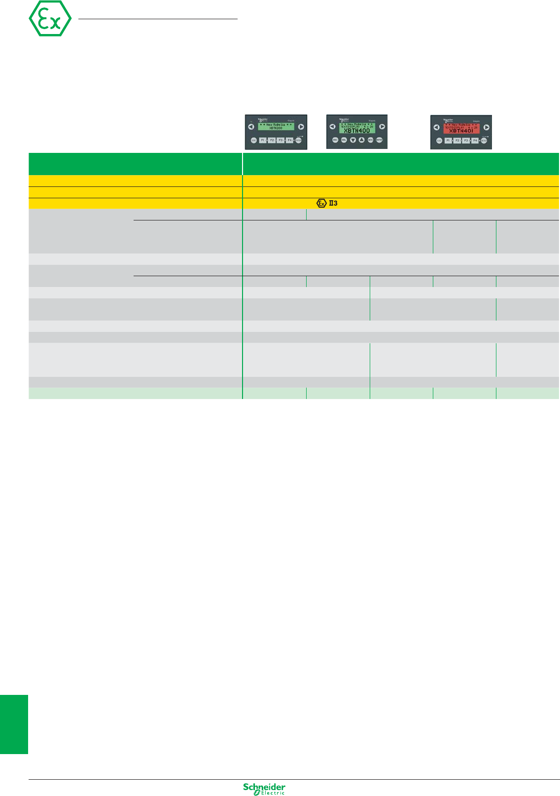
Other versions: please consult your Schneider Electric agency.
Type Characteristics
Conformity Directive ATEX 94/9/CE, EN 60079-15, EN 50281-1-1 + A1, IEC 61241-0, EN 61241-1
Zone D (dust) 22
EC type examination certificate number / marking
INERIS 05ATEX3016X / G D EEx nA nC IIC T5 - Ex tD A22 IP65 T100°C
Display Capacity
2 lines, 20 characters
1 to 4 lines, 5 to 20 characters
Type Back-lit LCD Back-lit LCD Back-lit LCD
green 3 colours green
green, orange, red
Data entry Via keypad with 8 keys (4 customizable keys)
Function Representation of variables Alphanumeric
Alarm log No Yes Yes Yes Yes
Communication Serial link 1 RJ45 (RS 232 - RS 485) 1 Sub-D25 (RS 232 - RS 485)
Downloadable protocols Uni-TE, Modbus Master Uni-TE, Modbus Master, Siemens,
Rockwell,Omron, Mitsubishi
Modbus
Development software Vijeo Designer Lite (on Windows 2000 and XP)
Dimensions W x D x H 132 x 37 x 74 mm
Compatibility with PLCs Twido, Modicon TSX Micro,
Modicon Premium, Modicon M340
Twido, Modicon TSX Micro,
Modicon Premium, Modicon Quantum,
Modicon Momentum, Modicon M340
Motor starter
Tesys Model U
Supply voltages 5 VDC or PLC power supply 24 VDC
References XBTN200 XBTN400 XBTN410 XBTN401 XBTNU400
(1) Except XBTN200: alphanumeric screen.
Magelis
Small Panel
Magelis XBT N
with matrix screen (1)
10/16
2
1
3
4
5
6
7
8
9
10
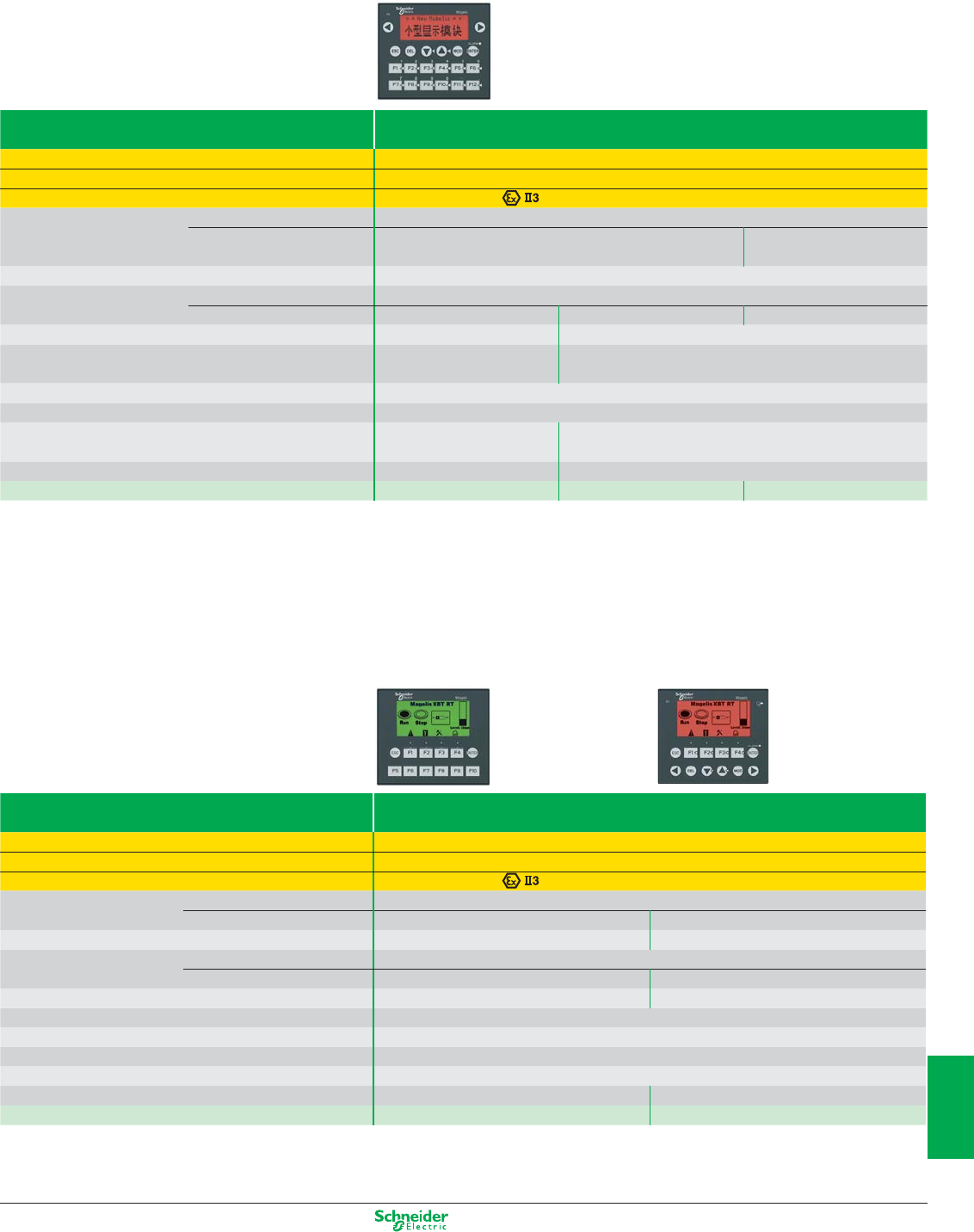
Other versions: please consult your Schneider Electric agency.
Type Characteristics
Conformity Directive ATEX 94/9/CE, EN 60079-15, EN 50281-1-1 + A1, IEC 61241-0, EN 61241-1
Zone D (dust) 22
EC type examination certificate number / marking
INERIS 05ATEX3016X / G D EEx nA nC IIC T5 - Ex tD A22 IP65 T100°C
Display Capacity 4 lines, 20 characters
Type Back-lit LCD
green
Back-lit LCD, 3 colours
green, orange, red
Data entry Via keypad with 20 keys (12 customizable keys)
Function Representation of variables Alphanumeric
Alarm log Yes Yes Yes
Communication Serial link 1 RJ45 (RS 232 - RS 485) 1 Sub-D25 (RS 232 - RS 485)
Downloadable protocols Uni-TE, Modbus Master Uni-TE,Modbus Master/Slave (1), Siemens, Rockwell,
Omron, Mitsubishi
Development software Vijeo Designer Lite (on Windows 2000 and XP)
Dimensions W x D x H 137 x 37 x 118 mm
Compatibility with PLCs Twido, Modicon TSX Micro,
Modicon Premium, Modicon M340
Twido, Modicon TSX Micro, Modicon Premium, Modicon Quantum,
Modicon Momentum, Modicon M340
Supply voltages 5 VDC or PLC power supply 24 VDC
References XBTR400 XBTR410 XBTR411
(1) for XBTR411 only
Magelis XBT RT
with semi-graphic and touchscreen
Type Characteristics
Conformity Directive ATEX 94/9/CE, EN 60079-0, EN 60079-15, EN 61241-0, EN 61241-1
Zone D (dust) 22
EC type examination certificate number / marking
INERIS 07ATEX3019X / G D Ex nA nC IIC T6 - Ex tD A22 IP64 T85°C
Display Capacity 10 lines, 33 characters
Type Back-lit LCD green Back-lit LCD green, orange, red
Data entry Via keypad with 12 keys (10 customizable keys) Via keypad with 12 customizable keys
Functions Representation of variables Alphanumeric, bargraph, curves, button and light
Alarm log Yes Yes
Communication Serial link 1 RJ45 (RS 232 - RS 485) 1 RJ45 (RS 232 - RS 485)
Downloadable protocols Uni-TE, Modbus Master, Siemens, Rockwell,Omron, Mitsubishi
Development software Vijeo Designer Lite (on Windows 2000 and XP)
Dimensions W x D x H 137 x 37 x 118 mm
Compatibility with PLCs Twido, Modicon TSX Micro, Modicon Premium, Modicon M340, Modicon Quantum
Supply voltages 5 VDC or PLC power supply 24 VDC
References XBTRT500 XBTRT511
Small Panel
Magelis XBT R
with matrix screen
10/17
2
1
3
4
5
6
7
8
9
10
Other versions: please consult your Schneider Electric agency.
Type Characteristics
Conformity Directive ATEX 94/9/CE, EN 60079-15, EN 61241-0, EN 61241-1, EN 60079-0 (1)
Zone D (dust) 22
EC type examination certificate number / marking
INERIS 06ATEX3024X / INERIS 08ATEX3024X / INERIS 06ATEX3024X / INERIS 08ATEX3024X / INERIS 08ATEX3024X /
G D EEx nA nC IIC T4 - Ex tD A22 IP64 T135°C
Display LCD screen size 3.8”
Type STN monochrome, amber or red TFT colour
Functions Representation of variables Alphanumeric, bitmap, bargraph, gauge, button, light, clock, flashing light, keypad
Curves / Alarm logs Yes, with log / Yes, incorporated
Communication Serial link 1 RJ45 (RS 232 - RS 485)
Networks –
Ethernet, IEEE 802.3
10 BASE-T, RJ45
Ethernet, IEEE 802.3
10/100 BASE-T, RJ45
Downloadable protocols Mitsubishi (Melsec), Omron (Sysmac), Rockwell Automation (Allen Bradley), Siemens (Simatic)
Uni-TE, Modbus, Modbus TCP
Development software Vijeo Designer VJDpppTGpVppM (on Windows Vista, XP and 2000)
Dimensions W x D x H 130x41x104mm
Compatibility with PLCs Twido, Modicon TSX Micro, Modicon Premium, Modicon Quantum, Modicon M340
«Compact Flash» card slot No
USB port –1–11
Built-in Ethernet TCP/IP No Yes
Supply voltage 24 VDC
References XBTGT1100 XBTGT1105 XBTGT1130 XBTGT1135 XBTGT1335
(1) Does not take effect for XBTG1100 and XBTG1130
Magelis XBT GT with 5.7” touchscreen
Type
Type Characteristics
Conformity Directive ATEX 94/9/CE, EN 60079-15, EN 61241-0, EN 61241-1
Zone D (dust) 22
EC type examination certificate number / marking INERIS 06ATEX3024X
/
G D EEx nA nC IIB T3 - Ex tD A22 IP64 T200°C
Display LCD screen size 5.7”
Type Back-lit STN, monochrome STN, colour TFT, colour
blue black and white 4096 colours 65536 colours
Functions Representation of variables Alphanumeric, bitmap, bargraph, gauge, button, light, clock, flashing light, keypad
Curves / Alarm logs Yes, with log / Yes, incorporated
Communication Serial link 1 Sub-D9 (RS 232/RS 422 - RS 485) + 1 RJ45 (RS 485)
Networks
– Ethernet, IEEE 802.3 – Ethernet, IEEE 802.3
10/100 BASE-T, RJ45 10/100 BASE-T, RJ45
Downloadable protocols Mitsubishi (Melsec), Omron (Sysmac), Rockwell Automation (Allen Bradley), Siemens (Simatic)
Uni-TE, Modbus, Modbus TCP/IP
Development soft ware Vijeo Designer VJDpppTGpVppM (on Windows Vista, XP and 2000)
Dimensions W x D x H 167.5x60x135mm
Compatibility with PLCs Twido, Modicon TSX Micro, Modicon Premium, Modicon Quantum, Modicon M340, Modicon Momentum
«Compact Flash» card slot No Yes
USB port 1
Video in No
Built-in Ethernet TCP/IP No No Yes No Yes
Supply voltage 24 VDC
References XBTGT2110 XBTGT2120 XBTGT2130 XBTGT2220 XBTGT2330
Magelis
Advanced Panel
Magelis XBT GT
with 3.8” touchscreen
10/18
2
1
3
4
5
6
7
8
9
10

Other versions: please consult your Schneider Electric agency.
Type Characteristics
Conformity Directive ATEX 94/9/CE, EN 60079-15, EN 61241-0, EN 61241-1
Zone D (dust) 22
EC type examination certificate number / marking
INERIS 06ATEX3024X / G D
EEx nA nC IIB T4 - Ex tD A22 IP64 T135°C
INERIS 06ATEX3024X / D
Ex tD A22 IP64 T135°C
Display LCD screen size 7.5” 10.4” 12.1” 15”
Type (colour) STN TFT TFT STN TFT TFT TFT TFT TFT
Number of colours 4096 65536 65536 4096 65536 65536 65536 65536 65536
Functions Representation of variables Alphanumeric, bitmap, bargraph, gauge, button, light, clock, flashing light, keypad
Curves / Alarm logs Yes, with log / Yes, incorporated
Communication Serial link 1 Sub-D9 (RS 232/RS 422 - RS 485) + 1 RJ45 (RS 485)
Networks Ethernet, IEEE 802.3 10/100 BASE-T, RJ 45
Downloadable protocols Mitsubishi (Melsec), Omron (Sysmac), Rockwell Automation (Allen Bradley), Siemens (Simatic)
Uni-TE, Modbus, Modbus TCP/IP
Development software Vijeo Designer VJDpppTGpVppM (on Windows Vista, XP and 2000)
Dimensions W x D x H (mm)
215x60x170 313x56x239 271x57x213 313x56x239 395x60x294
Compatibility with PLCs Twido, Modicon TSX Micro, Modicon Premium, Modicon Quantum, Modicon M340
«Compact Flash» card slot Yes
USB port 111222222
Video in No No Yes No No Yes No Yes Yes
Built-in Ethernet TCP/IP Yes
Supply voltage 24 VDC
References
XBTGT4230 XBTGT4330 XBTGT4340 XBTGT5230 XBTGT5330 XBTGT5340 XBTGT6330 XBTGT6340 XBTGT7340
Advanced Panel
Magelis XBT GT
with 7.5”, 10.4”, 12.1”,15” touchscreen
10/19
2
1
3
4
5
6
7
8
9
10
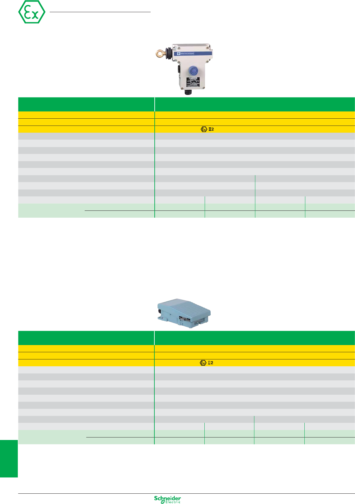
Other versions: please consult your Schneider Electric agency.
Emergency stops and foot switches
Cable (tripwire) operated Emergency stops
For operating cable up to 50 m long
Latching, without indicator light
Conformity Directive ATEX 94/9/EC, EN 50014, EN 50281-1-1, pr IEC 61241-0, pr IEC 61241-1
Zone D (dust) 21 - 22
EC type examination certificate number / marking INERIS 04ATEX0015 / D-Ex tD A21 IP65 T85°C
Mechanical durability (millions of operating cycles) 0.01
Temperature range – 20...+ 60°C
Degree of protection IP65
Connection 3 entries for ISO M20 cable gland
Rated operational characteristics AC15; A300 (Ue = 240 V, Ie = 3A)/DC13; Q300 (Ue = 250 V, Ie = 0.27 A)
Short-circuit protection By 10 A cartridge fuse type gG (gl)
Dimensions, W x D x H 229 x 82 x 142 mm 229 x 105 x 142 mm
Reset By booted pushbutton By key release pushbutton (key n° 421)
Operating cable length ≤ 50 m ≤ 50 m
Operating cable anchoring point To left To right To left To right
References N/C + N/O slow break XY2CE2A250EX XY2CE1A250EX XY2CE2A450EX XY2CE1A450EX
N/C + N/C slow break XY2CE2A270EX XY2CE1A270EX XY2CE2A470EX XY2CE1A470EX
Foot switches, metal
Type Single pedal switches
Conformity Directive ATEX 94/9/EC, EN 50014, EN 50281-1-1, pr IEC 61241-0, pr IEC 61241-1
Zone D (dust) 21 - 22
EC type examination certificate number / marking INERIS 04ATEX0025 / D-Ex tD A21 IP65 T85°C
Mechanical durability (millions of operating cycles) 5
Temperature range – 20...+ 60°C
Degree of protection IP66
Connection 2 entries for n° 16 (Pg 16) cable gland (1)
Rated operational characteristics AC15; A300 (Ue = 240 V, Ie = 3 A)/DC13; Q300 (Ue = 250 V, Ie = 0.27 A)
Short-circuit protection By 10 A cartridge fuse type gG (gl)
Dimensions, W x D x H 104 x 172 x 59 mm
Colour Blue Orange
Contact operation 1 step 2 step 1 step 2 step
References 1 N/C + N/O XPEM110EX – XPER110EX –
2 N/C + N/O XPEM111EX XPEM211EX XPER111EX XPER211EX
(1) 1 entry fitted with blanking plug, 1 entry fitted with n° 16 (Pg 16) cable gland
Other characteristics: please refer to the “Machine safety” catalogue
Preventa
10/20
2
1
3
4
5
6
7
8
9
10
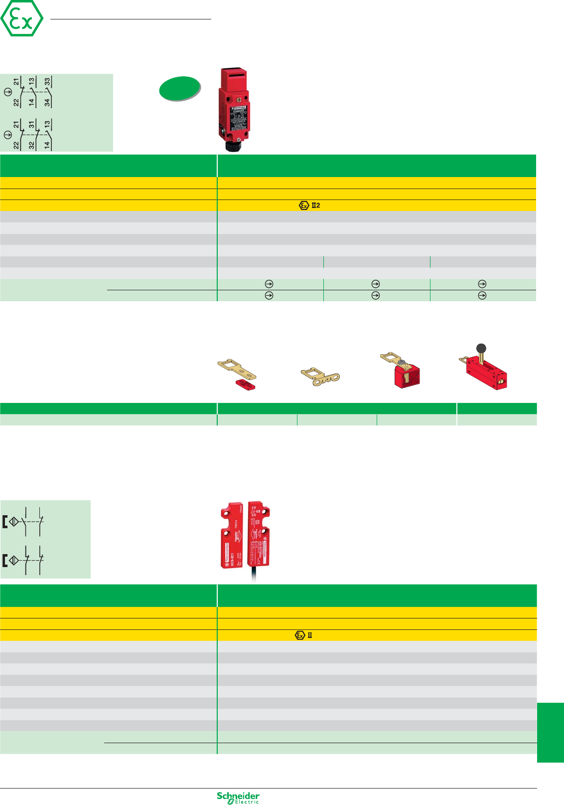
Other versions: please consult your Schneider Electric agency.
Safety switches
and actuators
Preventa
3-pole contact
Slow break
(N/C + N/O + N/O)
3-pole contact
Slow break
(N/C + N/C + N/O)
Metal switches type XCSA/B/C, 1 x ISO M20 cable entry
With head Without locking Interlocking, unlocking by button Interlocking, unlocking by key lock
Conformity Directive ATEX 94/9/CE, EN 50014, EN 50281-1-1, pr IEC 61241-0, pr IEC 61241-1
Zone D (dust) 21 - 22
EC type examination certificate number / marking
INERIS 04ATEX0014X / D-Ex tD A21 IP67 T85°C
Actuation speed (min → max) 0,1 m/s → 0,5 m/s
Degree of protection IP 67
Rated operational characteristics (conforming to EN IEC 60947-5-1) AC 15, A 300 / DC 13, Q 300
Temperature range
-20…+60°C
Dimensions (body + head) W x D x H 40 x 44 x 113.5 mm 52 x 44 x 113.5 mm 52 x 44 x 113.5 mm
Short-circuit protection By 10 A cartridge fuse type gG (gl)
Complete switch N/C + N/O + N/O
XCSA502EX XCSB502EX XCSC502EX
N/C + N/C + N/O
XCSA702EX XCSB702EX XCSC702EX
Accessories
Straight actuator Wide actuator Pivoting actuator
For safety switches XCSA/B/C/E Actuators Door lock
References XCSZ01 XCSZ02 XCSZ03 XCSZ05
ISO entry
(to EN 50262)
Coded magnetic
Plastic switches type XCSDM coded magnetic, Pre-cabled, L = 2 m
Rectangular without LED
Conformity
Directive Atex 94/9/CE, EN 50281-1.1 & 1.2, EN/IEC 61241-0, EN/IEC 61241-1, EN/IEC 60304, EN 1088, EN954-1
Zone D (dust) 0-1-2/20-21-22*(according to protection mode, mD or ia).
EC type examination certificate number / marking
INERIS 04ATEX0036 / GD-Ex tD A21 IP67 T135°C
Switches for actuation Face to face, face to side, side to side
Degree of protection IP 66 + IP 67
Type of contact REED
Rated operational characteristics Ue = 24 VDC, Ie = 100 mA
Temperature range
-20…+60°C
Dimensions W x D x H 16 x 7 x 51 mm
Operating zone (4) Sao = 5 / Sar = 15
Short-circuit protection By 10 A cartridge fuse type gG (gl)
Switch with coded magnet N/C + N/O, N/C staggered XCSDMC5902EX
N/O + N/O, 1N/O staggered XCSDMC7902EX
Contact
(N/C + N/O,
N/C
staggered)
Contact
(N/O + N/O,
1N/O
staggered)
BK
BU
WH
BN
BK
BU
WH
BN
BK
BU
WH
BN
BK
BU
WH
BN
10/21
2
1
3
4
5
6
7
8
9
10
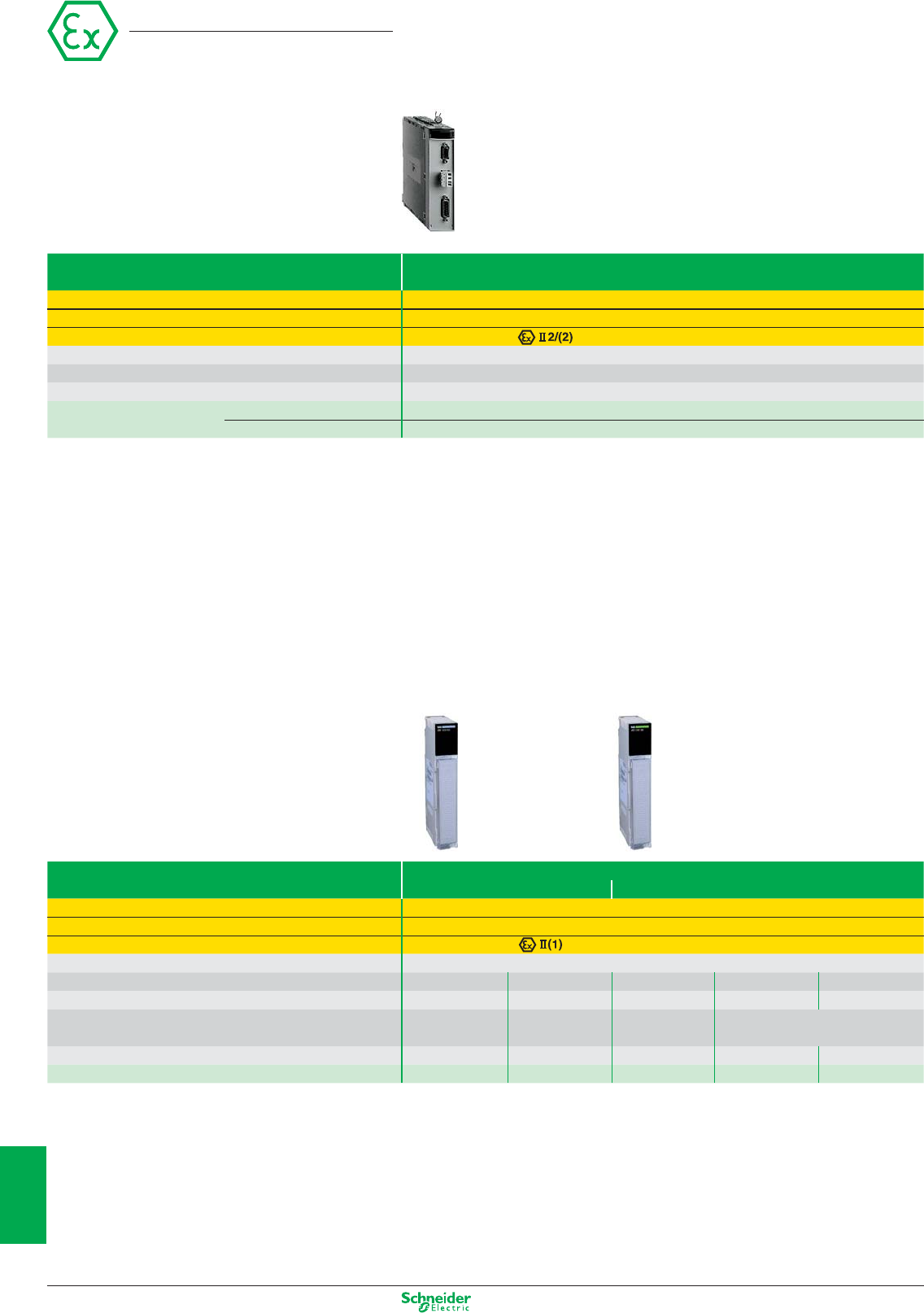
Other versions: please consult your Schneider Electric agency.
Automation platform
Weighing system for Modicon Premium
Module type ISP Plus
Supplied calibrated
Conformity Directive ATEX 94/9/EC, EN 50014, EN 50020, EN 50039, EN 50284, EN 50281-1-1
Zone D (dust) Mounted outside zone (to be used in conjunction with products for zone 21 or 22)
EC type examination certificate number / marking LCIE 03ATEX6399X / SYST GD-EEx ib IIC T6 or IIB T6
Connection By connectors: Sub-D 15-way male for sensors and Sub-D 9-way male for transfer of weights
Load cell inputs 50 measurements (for 1 to 8 load cells)
Outputs 2 discrete and 1 RS 485 for display
References Without display TSXISPY101
With display TSXXBTH100 TSXISPY111
Intrinsically safe I/O modules for Modicon
Quantum
Module type Inputs/outputs
Discrete Analogue
Conformity Directive ATEX 94/9/EC, EN 50014, EN 50020, EN 50284, EN 50281-1-1
Zone D (dust) Mounted outside zone (to be used in conjunction with products for zone 20, 21 or 22)
EC type examination certificate number / marking SIRA 02ATEX2345X / GD-[EEx ia] IIC; Ta = - 20…+ 60 °C
Connection By screw terminal block 140XTS33200 (to be ordered separately)
Number of inputs 8–8 –
Number of outputs –8– 8
Signal inputs – – Thermal probes 0…25/20 mA
Thermocouple (1) 4…25 mA
Resolution 12 bits + sign 0…25,000 points 15 bits
References 140DII33000 140DIO33000 140AII33000 140AII33010 140AIO33000
(1) Type J, K, E, T, S, R, B, mV
10/22
2
1
3
4
5
6
7
8
9
10

Other versions: please consult your Schneider Electric agency.
Notes
10/23
2
1
3
4
5
6
7
8
9
10
02/2010
- V7.0ART. 960015
DIA1ED2040506EN
Head Office
35, rue Joseph Monier - CS 30323
F92500 Rueil-Malmaison Cedex
France
www.schneider-electric.com
The information provided in this documentation contains general descriptions and/or technical
characteristics of the performance of the products contained herein. This documentation is not
intended as a substitute for and is not to be used for determining suitability or reliability of these
products for specific user applications. It is the duty of any such user or integrator to perform the
appropriate and complete risk analysis, evaluation and testing of the products with respect to the
relevant specific application or use thereof. Neither Schneider Electric nor any of its affiliates or
subsidiaries shall be responsible or liable for misuse of the information contained herein.
Design : IGS-CP
Photos : Schneider Electric
Print :
Schneider Electric Industries SAS
