Product Detail Manual
117839-Attachment 117839-Attachment 117839-Attachment 784572 Batch7 unilog cesco-content
687470-Catalog 687470-Catalog 687470-Catalog 784572 Batch12 unilog cesco-content
350256-Catalog 350256-Catalog 350256-Catalog 784572 Batch6 unilog cesco-content
29281-Attachment 29281-Attachment 29281-Attachment Batch9 unilog cesco-content
2014-11-11
: Pdf 50253-Attachment 50253-Attachment 784572 Batch12 unilog
Open the PDF directly: View PDF ![]() .
.
Page Count: 52
Meter Mounting Equipment
Wisconsin Area

MILBANK OVERVIEW
MILBANK OVERVIEW
2
2
Milbank: Quality Metering Products for 80+ Years
ilbank Manufacturing
Company was estab-
lished in 1927 by
Charles A. Milbank.
Originally, the company manu-
factured high voltage switches;
however, by 1941 Milbank devot-
ed itself primarily to the manufac-
ture of sheet metal enclosures
and related equipment for the
electrical generation and distribu-
tion industry. Today we are an
industry leader in the manufac-
ture of electrical meter sockets.
Through a national network of
manufacturer’s representatives we
provide wholesale electrical dis-
tributors with quality electrical
products for the utility, contractor,
industrial and OEM markets.
As the meter standards have
changed, Milbank has been suc-
cessful in adapting its product
line to these changes. Our full
scale engineering department
designs products to meet cus-
tomer specifications and satisfy
all utility requirements.
Milbank’s employee base of over
1,000 workers, along with our
five manufacturing facilities com-
prising almost 550,000 square
feet give us the flexibility to
schedule, produce, and ship
orders quickly. Currently,
Milbank manufactures over
10,000 different catalog items,
and this list continues to grow.
Our unique product offering
includes: Residential &
Commercial Meter Sockets;
Residential & Commercial Meter
Pedestals; RV/MH Power Outlets,
Service Pedestals, and
Transformers; Commercial &
Industrial Electrical Enclosures;
Circuit Breakers; Disconnects &
Safety Switches; Safety Sockets;
Utility & Residential Secondary
Pedestals; Hubs, and related
accessories. If you don’t find a
unit in this catalog to service your
needs, send us your specifications
and we will be happy to work
with you.
Our success has come from a
loyal customer base that can rely
on us to build quality products at
a fair price in a timely manner.
Our willingness and ability to
design and produce new products
to meet our customer demands is
an important factor to remain
competitive in today’s electrical
market.
Milbank has been serving the
electric utility & wholesale distri-
bution industries for more than
80 years with innovative, qual-
ity engineered products. So
remember us for all of your meter
mounting and related require-
ments, and we will be happy to
serve you as we have in the
past–with dependable service and
quality products!
We take great pride in being
one of the few family-owned
businesses left in our industry.
We are a third generation run
business and truly believe that...
FAMILY MAKES A
DIFFERENCE!
M
Charles A. Milbank
1879-1966 Bill Martin
1916-1998
Robert F. Waldrop
1922-2002 Robert F. Waldrop, II
Chairman
Katrina Waldrop Henke
Vice Chairman

3
3
CATALOG NUMBER LOGIC . . . . . . . . . . . . . . . . . . . . . . . . . . . . . . . . . . . . . . . . . . . . . . . . . . . . . . . . . . . . . . . . . . . . . . . . . 4
DISCONNECTS
AIR CONDITIONER DISCONNECTS . . . . . . . . . . . . . . . . . . . . . . . . . . . . . . . . . . . . . . . . . . . . . . . . . . . . . . . . . . . . . . . . . . . 5
AIR CONDITIONER DISCONNECT WITH GFCI RECEPTACLE . . . . . . . . . . . . . . . . . . . . . . . . . . . . . . . . . . . . . . . . . . . . . . 6
HOT TUB DISCONNECT . . . . . . . . . . . . . . . . . . . . . . . . . . . . . . . . . . . . . . . . . . . . . . . . . . . . . . . . . . . . . . . . . . . . . . . . . . . . . 6
SINGLE POSITION
125 AMP, 4 & 5 TERMINAL, RINGLESS . . . . . . . . . . . . . . . . . . . . . . . . . . . . . . . . . . . . . . . . . . . . . . . . . . . . . . . . . . . . . . . . . 7
125 AMP, 7 TERMINAL, RINGLESS, LEVER BYPASS . . . . . . . . . . . . . . . . . . . . . . . . . . . . . . . . . . . . . . . . . . . . . . . . . . . . . 8
200 AMP, 4 & 5 TERMINAL, RINGLESS . . . . . . . . . . . . . . . . . . . . . . . . . . . . . . . . . . . . . . . . . . . . . . . . . . . . . . . . . . . . . . . . . 9
200 AMP, 5 & 7 TERMINAL, RINGLESS, HEAVY LEVER BYPASS . . . . . . . . . . . . . . . . . . . . . . . . . . . . . . . . . . . . . . . . . . 10
200 AMP, 7 TERMINAL, RINGLESS, LEVER BYPASS . . . . . . . . . . . . . . . . . . . . . . . . . . . . . . . . . . . . . . . . . . . . . . . . . . . . 11
320 AMP, 4, 5 & 7 TERMINAL, RINGLESS, LEVER BYPASS . . . . . . . . . . . . . . . . . . . . . . . . . . . . . . . . . . . . . . . . . . . . . . . 12
MULTIPLE POSITION
100 AMP / POSITION, HORIZONTAL GANG SOCKETS, 4 & 5 TERMINAL . . . . . . . . . . . . . . . . . . . . . . . . . . . . . . . . . 13-14
100 AMP / POSITION, VERTICAL GANG SOCKETS, 4 TERMINAL . . . . . . . . . . . . . . . . . . . . . . . . . . . . . . . . . . . . . . . . . . 15
200 AMP / POSITION, HORIZONTAL GANG SOCKETS, 4 & 5 TERMINAL . . . . . . . . . . . . . . . . . . . . . . . . . . . . . . . . . . . . 16
200 AMP / POSITION, HORIZONTAL GANG SOCKETS, 5 TERMINAL, LEVER BYPASS . . . . . . . . . . . . . . . . . . . . . . . . . 17
200 AMP / POSITION, HORIZONTAL GANG SOCKETS, 7 TERMINAL, LEVER BYPASS . . . . . . . . . . . . . . . . . . . . . . . . 18
CONDOMINIUM METERING BANKS (MULTIPLE POSITION)
125 AMP / POSITION . . . . . . . . . . . . . . . . . . . . . . . . . . . . . . . . . . . . . . . . . . . . . . . . . . . . . . . . . . . . . . . . . . . . . . . . . . . . . . 19
200 AMP / POSITION . . . . . . . . . . . . . . . . . . . . . . . . . . . . . . . . . . . . . . . . . . . . . . . . . . . . . . . . . . . . . . . . . . . . . . . . . . . . . . 19
DIMENSIONAL INFORMATION . . . . . . . . . . . . . . . . . . . . . . . . . . . . . . . . . . . . . . . . . . . . . . . . . . . . . . . . . . . . . . . . . . . . . . 20
METER MAINS
100 AMP, 4 & 5 TERMINAL, RINGLESS . . . . . . . . . . . . . . . . . . . . . . . . . . . . . . . . . . . . . . . . . . . . . . . . . . . . . . . . . . . . . . . . 21
200 AMP, 4 & 5 TERMINAL, RINGLESS . . . . . . . . . . . . . . . . . . . . . . . . . . . . . . . . . . . . . . . . . . . . . . . . . . . . . . . . . . . . . . . . 21
200 AMP, 4 & 5 TERMINAL WITH LOAD CENTER, RINGLESS . . . . . . . . . . . . . . . . . . . . . . . . . . . . . . . . . . . . . . . . . . . . . 21
SERVICE PEDESTALS
320 AMP, 4 TERMINAL WITH BREAKER PROVISION, RINGLESS . . . . . . . . . . . . . . . . . . . . . . . . . . . . . . . . . . . . . . . . . . 22
320 AMP, 4 & 5 TERMINAL, WITHOUT BREAKER PROVISION, RINGLESS . . . . . . . . . . . . . . . . . . . . . . . . . . . . . . . . . . . 22
100 / 200 AMP, 4 TERMINAL, METER MAIN PEDESTAL . . . . . . . . . . . . . . . . . . . . . . . . . . . . . . . . . . . . . . . . . . . . . . . . . . 23
TEMP-TO-FINAL SERVICE PEDESTAL AND UNIVERSAL ALL-IN-ONE PEDESTAL . . . . . . . . . . . . . . . . . . . . . . . . . . . . 24
100/200 AMP, 4 & 5 TERMINAL, RINGLESS . . . . . . . . . . . . . . . . . . . . . . . . . . . . . . . . . . . . . . . . . . . . . . . . . . . . . . . . . . . . 25
JOINT USE TERMINATION CABINET . . . . . . . . . . . . . . . . . . . . . . . . . . . . . . . . . . . . . . . . . . . . . . . . . . . . . . . . . . . . . . . . . 26
100/200 AMP, RINGLESS METERED PEDESTAL . . . . . . . . . . . . . . . . . . . . . . . . . . . . . . . . . . . . . . . . . . . . . . . . . . . . . . . . 27
200 AMP, 5 & 7 TERMINAL, RINGLESS, HEAVY DUTY LEVER BYPASS . . . . . . . . . . . . . . . . . . . . . . . . . . . . . . . . . . . . . 28
200 AMP, 4 TERMINAL RINGLESS MOBILE HOME PEDESTAL . . . . . . . . . . . . . . . . . . . . . . . . . . . . . . . . . . . . . . . . . . . . 29
C.T. RATED (WITH TEST SWITCH PROVISION)
20 AMP, SINGLE POSITION, RINGLESS . . . . . . . . . . . . . . . . . . . . . . . . . . . . . . . . . . . . . . . . . . . . . . . . . . . . . . . . . . . . . . . 30
20 AMP, DOUBLE POSITION, RING TYPE . . . . . . . . . . . . . . . . . . . . . . . . . . . . . . . . . . . . . . . . . . . . . . . . . . . . . . . . . . . . . 30
MISCELLANEOUS
POLYPHASE ENCLOSURES, SINGLE & MULTIPLE POSITIONS . . . . . . . . . . . . . . . . . . . . . . . . . . . . . . . . . . . . . . . . . . . 31
K-TYPE, 4 & 7 TERMINAL METER SOCKETS . . . . . . . . . . . . . . . . . . . . . . . . . . . . . . . . . . . . . . . . . . . . . . . . . . . . . . . . 32-35
COMMERCIAL METER PEDESTALS . . . . . . . . . . . . . . . . . . . . . . . . . . . . . . . . . . . . . . . . . . . . . . . . . . . . . . . . . . . . . . . 36-37
ACCESSORIES . . . . . . . . . . . . . . . . . . . . . . . . . . . . . . . . . . . . . . . . . . . . . . . . . . . . . . . . . . . . . . . . . . . . . . . . . . . . . . . . 38-39
CONDUIT AND AMPACITY INFORMATION . . . . . . . . . . . . . . . . . . . . . . . . . . . . . . . . . . . . . . . . . . . . . . . . . . . . . . . . . . . . . 40
SHORT CIRCUIT CURRENT RATING CHART . . . . . . . . . . . . . . . . . . . . . . . . . . . . . . . . . . . . . . . . . . . . . . . . . . . . . . . . . . 41
ENERGIZATION OF ELECTRICAL EQUIPMENT . . . . . . . . . . . . . . . . . . . . . . . . . . . . . . . . . . . . . . . . . . . . . . . . . . . . . . . . . 42
MATERIALS & FINISHES . . . . . . . . . . . . . . . . . . . . . . . . . . . . . . . . . . . . . . . . . . . . . . . . . . . . . . . . . . . . . . . . . . . . . . . . . . . 43
METER FORMS (WIRING DIAGRAMS) . . . . . . . . . . . . . . . . . . . . . . . . . . . . . . . . . . . . . . . . . . . . . . . . . . . . . . . . . . . . . . . . 44
APPROVING UTILITIES . . . . . . . . . . . . . . . . . . . . . . . . . . . . . . . . . . . . . . . . . . . . . . . . . . . . . . . . . . . . . . . . . . . . . . . . . . 45-47
INDEX . . . . . . . . . . . . . . . . . . . . . . . . . . . . . . . . . . . . . . . . . . . . . . . . . . . . . . . . . . . . . . . . . . . . . . . . . . . . . . . . . . . . . . . . . . 48
OTHER MILBANK PRODUCTS . . . . . . . . . . . . . . . . . . . . . . . . . . . . . . . . . . . . . . . . . . . . . . . . . . . . . . . . . . . . . . . . . . . . . . . 49
TABLE OF CONTENTS
TABLE OF CONTENTS
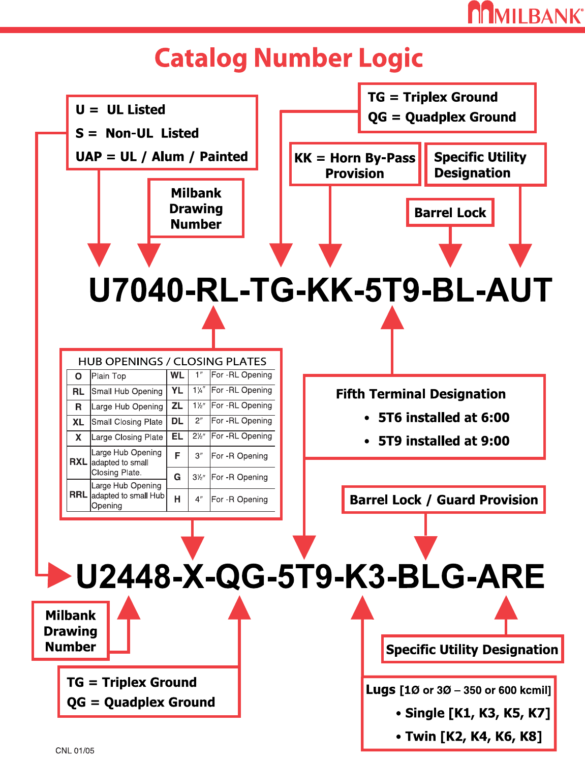
CATALOG NUMBER LOGIC
4
CATALOG NUMBER LOGIC
4
Utility requirements for this equipment may vary. Always consult the serving utility for their requirements before ordering or
installing equipment in this catalog.
5
30 & 60 AMP–FUSIBLE / NON-FUSIBLE–AIR CONDITIONER DISCONNECTS
DISCONNECTS
30 & 60 AMP–FUSIBLE / NON-FUSIBLE–AIR CONDITIONER DISCONNECTS
5
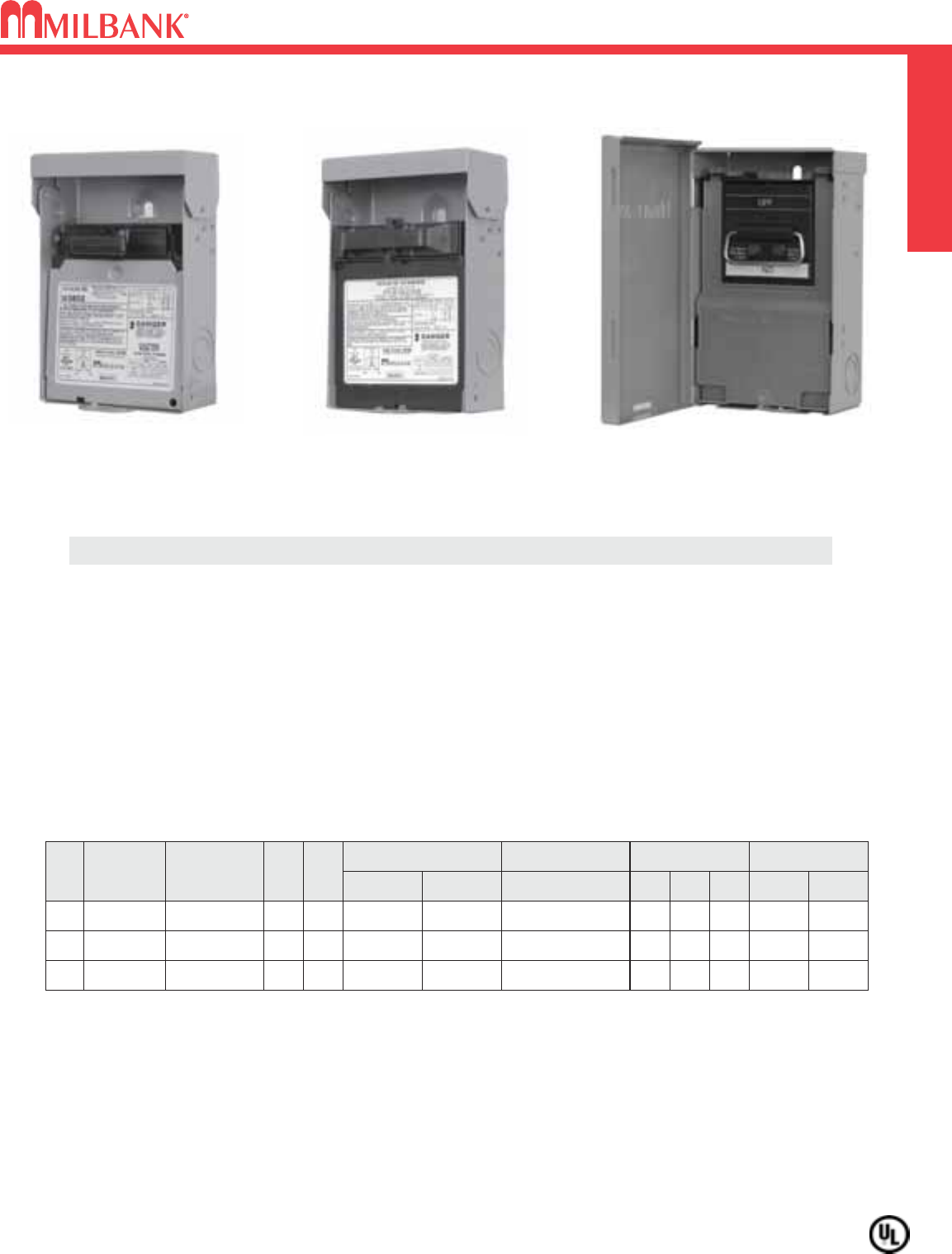
U3860
Milbankʼs air conditioner disconnect has a removable hinged cover which makes wiring a breeze.
Our compact design meets all wire bending space requirements in the NEC and, also, complies
with article 440-14 in the NEC. To insure the safest conditions, we designed our disconnect pullers
to be removable or they may be reinstalled in the off position. Another safety feature is the padlock
provision on the front cover. As with all Milbank products, our enclosure is constructed of G90U
galvanized steel and finished with an attractive, light gray, baked powder coating. Our state of the
art finish combines epoxy and polyester hybrid resins into a hybrid powder coating which is then
electrostatically applied. This offers a durable, nonfading finish.
TECHNICAL INFORMATION
AMP TYPE CATALOG
NUMBER
MAX
H.P.
WT.
@
#
30 FUSIBLE U3832 32.5
60 FUSIBLE U3860 10 3.3
LINE & LOAD
WIRE RANGE
GROUND
WIRE RANGE DIMENSIONS WIRE RATING
CU AL CU/AL
#14-#3
AWG #14-#3
AWG #14-3 AWG
#14-#3
AWG #14-#3
AWG #14-3 AWG
D" W" H" CU °CAL °C
2-1/8 5760°/75°60°
3 5 9-1/4 60°/75°60°/75°
60
NON FUSIBLE
U3802 10 3.25 #14-#2
AWG #12-#2
AWG #14-4 AWG 2-1/2 57-1/2 60°/75°60°/75°
PROFILE
✓ UL Listed as Enclosed Pullout Switch
✓ 1∅, 240 VAC
✓ Type 3R Rainproof
✓ One-inch concentric knockouts
U3832
U3802
AC DISCONNECT / SPA BOX
6
AC DISCONNECT / SPA BOX DISCONNECTS
6
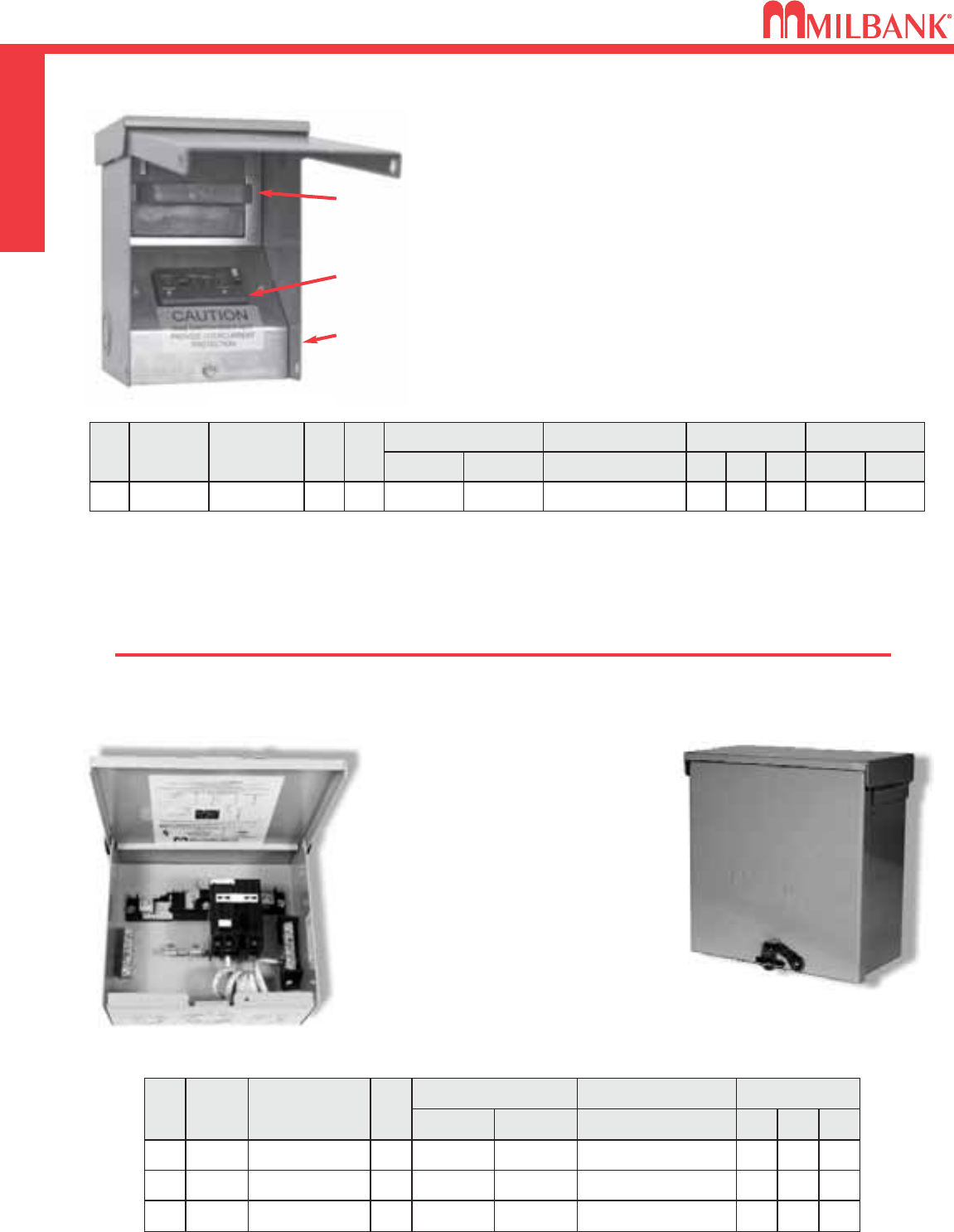
• Meets NEC #210.63 Requirements*
• UL Listed as Power Outlet
• Type 3R Enclosure
• In-Use Cover**
• Duplex Ground Connector
• 1” Concentric Knockouts
AC DISCONNECT
•1
∅
, 240 Volt
• 60 amp, Non-Fused
GFCI RECEPTACLE
• 20 amp
• Reset/Test Button
• Weather Resistant/Tamper Resistant
• Meets NEC #406.8 Requirements*
Combination AC Disconnect / 20 Amp GFCI Receptacle–Together in 1 Box
To ensure the safest conditions, Milbank disconnect pullers are designed to be reversible so they may be reinstalled in the OFF position.
All units are designed with a padlock provision on the cover for security.
**Note: U3822-20GWR cover rated as
IN-USE COVER
(Cover may be closed with cords plugged into receptacle).
Units supplied with WRTR receptacle.
*Reprinted with permission from NFPA 70-2002, National Electrical Code®, Copyright 2001, National Fire Protection Association, Quincy, MA 02269. This reprinted material is not the complete
and official position of the NFPA on the referenced subject, which is represented only by the standard in its entirety. National Electrical Code®and NEC®are registered trademarks of the
National Fire Protection Association, Quincy, MA.
* NEC®#210.63 Heating,
Air-Conditioning and
Refrigeration Equipment
Outlet.
...The receptacle shall be
located on the same level
and within 7.5 m (25 ft.) of
the heating, air-conditioning
and refrigeration equipment.
* NEC®#210.68 Ground-
Fault Circuit – Interruptor
protection for personnel.
* NEC®#406.8 receptacles
in damp or wet locations.
U4881-O-50GB
AMP TYPE CATALOG
NUMBER
WT.
@
#
–
BREAKER
PROVISION
U4881-O 7
LINE & LOAD CONNECTOR
WIRE RANGE
GROUND CONNECTOR
WIRE RANGE DIMENSIONS
CU AL CU/AL
#14-1/0 #14-1/0 #14-1/0
D″W″H″
3 3
⁄
471
⁄
281
⁄
2
50
60
BREAKER
BREAKER
U4881-O-50GB
U4881-O-60GB
8
8
#14-1/0
#14-1/0
#14-1/0
#14-1/0
#14-1/0
#14-1/0
3 3
⁄
4
3 3
⁄
4
71
⁄
2
71
⁄
2
81
⁄
2
81
⁄
2
•
240 Volt ground fault protection
•
UL listed, Type 3R rainproof
•
Milbank reliability
•
Easy installation
•
2 pole, 50 amp GFCI breaker protection
•
Compact size:
8-1/2” H x 7-1/2” W x 3-3/4” D
•
3 or 4 wire installation
•
1
∅
, 120 / 240 VAC
•
Standard package of 12
•
2 extra one-pole breaker spaces
•
100 amp overall rating
Sub Panel Breaker Enclosure
•
Use as a 100 amp, 4 circuit sub pane enclosure
• U4881-O has provision for (2) 2-pole or
(4) 1-pole small frame breakers
Hot Tub Disconnect or Sub Panel Breaker Enclosure–Type 3R
Spa Box with GFCI Protection
U3822-20GWR
60 amp,
Non-Fused
AC Disconnect
Duplex 20 amp
GFCI Receptacle
WR-TR
Type 3R Enclosure
with In-Use Cover
AMP TYPE CATALOG
NUMBER
MAX
H.P.
WT.
@
#
60
NONFUSIBLE
U3822-20GWR
10 6
LINE & LOAD CONNECTOR
WIRE RANGE
GROUND CONNECTOR
WIRE RANGE DIMENSIONS WIRE RATING
CU AL CU/AL
#14-#2
AWG #12-#2
AWG #14-4 AWG
D″W″H″CU °CAL °C
4.8 5.25 7.4 60°/75°60°/75°
7
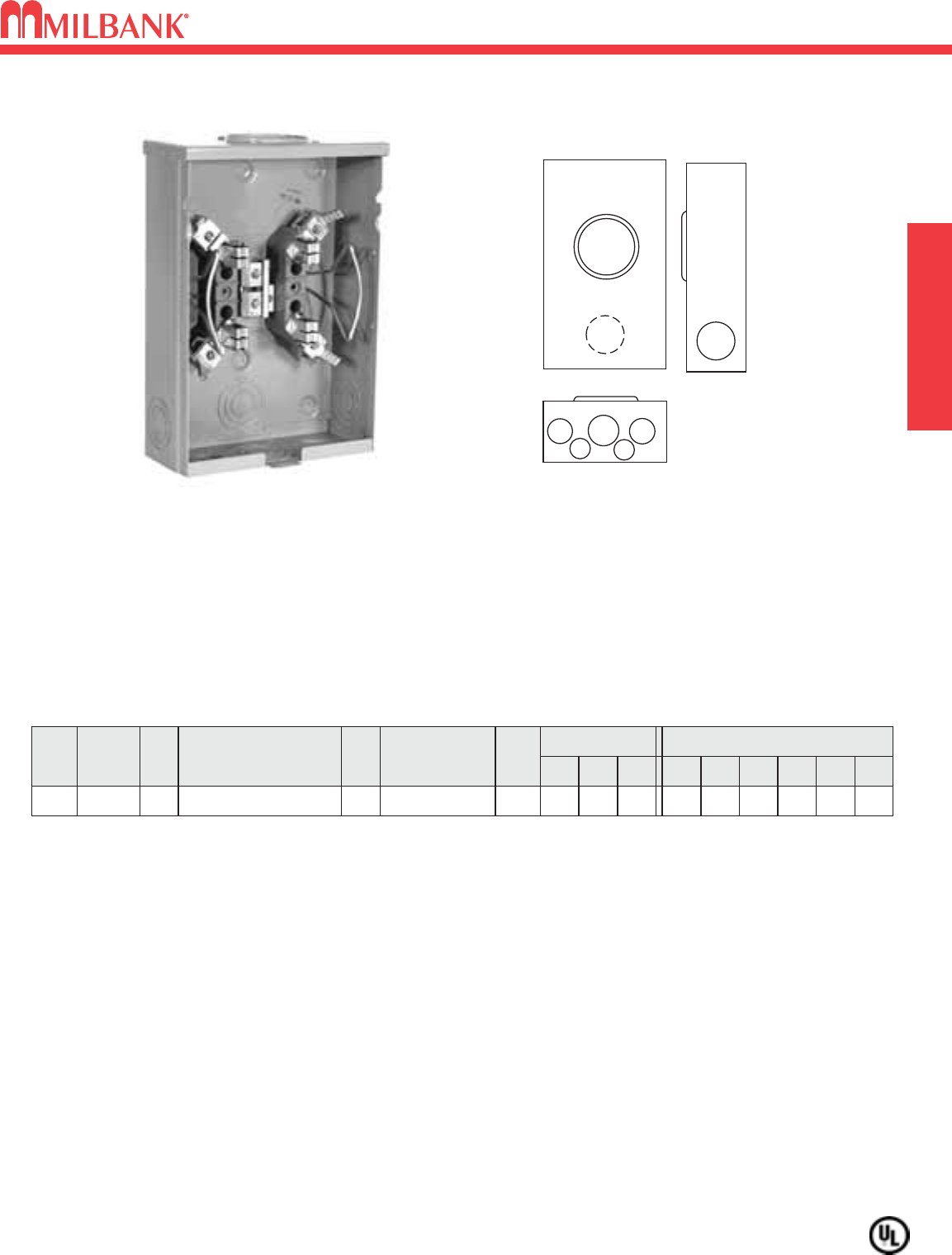
125 AMP–4 & 5 TERMINAL–RINGLESS–600 VAC
SINGLE POSITION
125 AMP–4 & 5 TERMINAL–RINGLESS–600 VAC
Utility requirements for this equipment may vary. Always consult the serving utility for their requirements before ordering or
installing equipment in this catalog.
7
12
5
3
4
4
6
AMP
SERVICE
TERMS.
OH
CATALOG
NUMBER
HUB
CONNECTORS
CU / AL
BY-
PASS
DIMENSIONS
CONCENTRIC K.O.ʼS
1 2 3 4 5 6D″W″H″
4125
U7487-RL-TG-KK*
H.O.
#6-2/0
HORN 11
⁄
211
⁄
2211
⁄
4—1
⁄
4
35
⁄
16 8111
⁄
2
125 AMP—4 & 5 TERMINAL*—RINGLESS—1∅3W
HUBS: For proper hub selection see the hub suffix chart on the accessory page.
BYPASS: The -KK, horn type bypass is factory installed and permits changing and testing of the meter without interrupting
customer service when used with utility-supplied jumpers.
CONNECTORS: Extruded aluminum connectors are tin plated. Units are supplied with triplex neutral.
*FIFTH TERMINAL: For field mounted fifth terminal, order catalog number 5T8K2 (must be bolted in).
U7487-RL-TG-KK
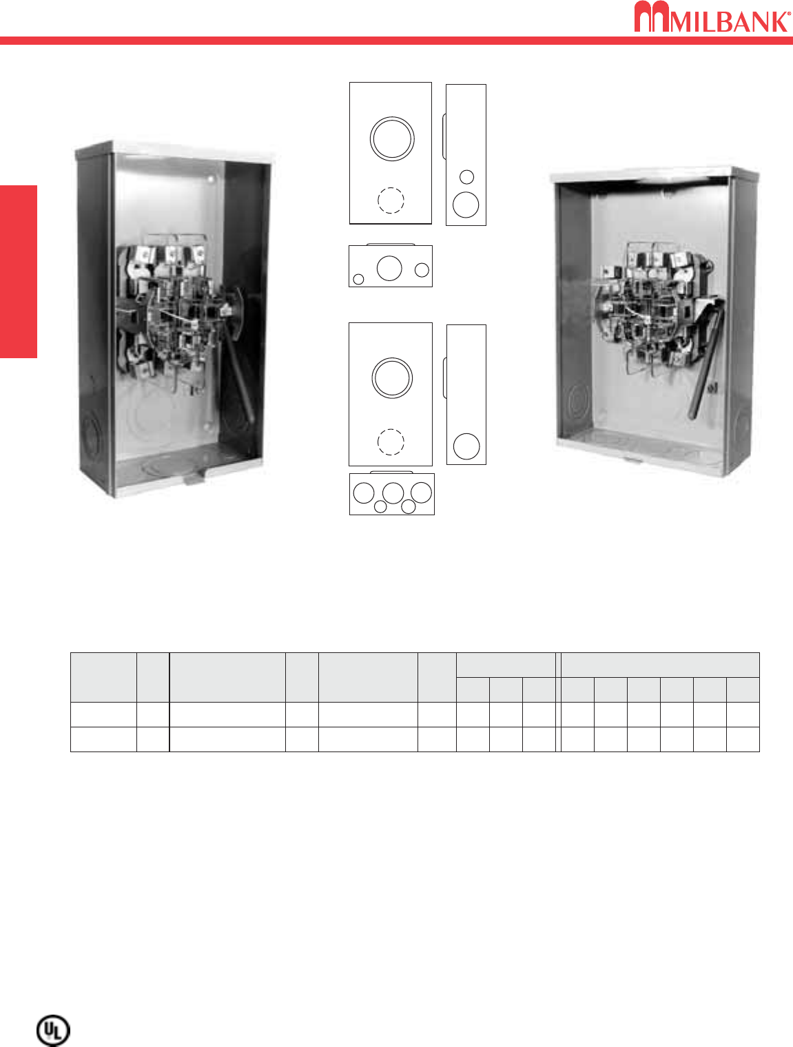
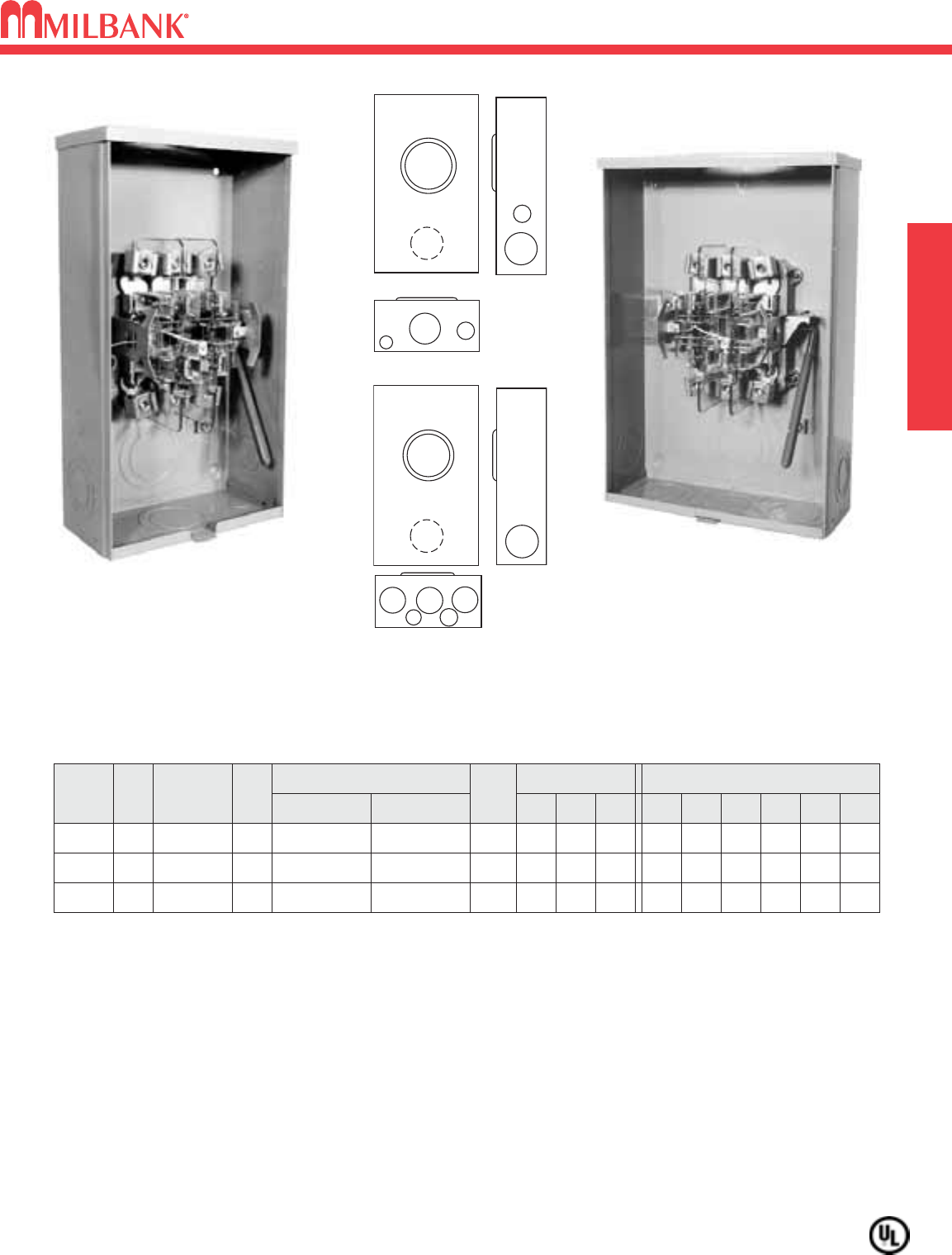
125 AMP–7 TERMINAL–LEVER BYPASS–NON JAW CLAMPING–RINGLESS–3
∅
–600 VAC
8
125 AMP–7 TERMINAL LEVER BYPASS–NON JAW CLAMPING–RINGLESS–3
∅
–600 VAC SINGLE POSITION
8
Utility requirements for this equipment may vary. Always consult the serving utility for their requirements before ordering or
installing equipment in this catalog.
12
3
56
6
12
3
44
65
U7573-RL
U9320-RXL
7573
9320
AMPSERVICE
OH
OH/UG
125
CATALOG
NUMBER
U7573-RL
HUB
H.O.
CONNECTORS
CU/AL
BY-
PASS
#6-2/0
LEVER
DIMENSIONS CONCENTRIC K.O.ʼS
123456D″W″H″
2 2 2 — 1
⁄
4,1
⁄
23
⁄
4
47
⁄
810 181
⁄
2
125 U9320-RXL C.P. #6-2/0
LEVER
321
⁄
23 3 1
⁄
41
⁄
4,1
⁄
2
47
⁄
813 19
125 AMP—7 TERMINAL—RINGLESS—3∅4W
HUBS: For proper hub selection see the hub suffix chart on the accessory page.
BYPASS: Lever operates bypass only; does not provide clamping action on meter spades.
CONNECTORS: Units are supplied with extruded aluminum connectors and bonded, triplex neutral.
Utility requirements for this equipment may vary. Always consult the serving utility for their requirements before ordering or
installing equipment in this catalog.
9
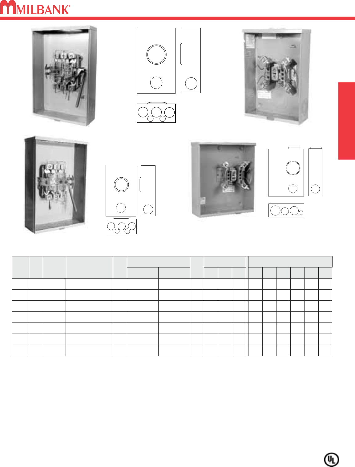
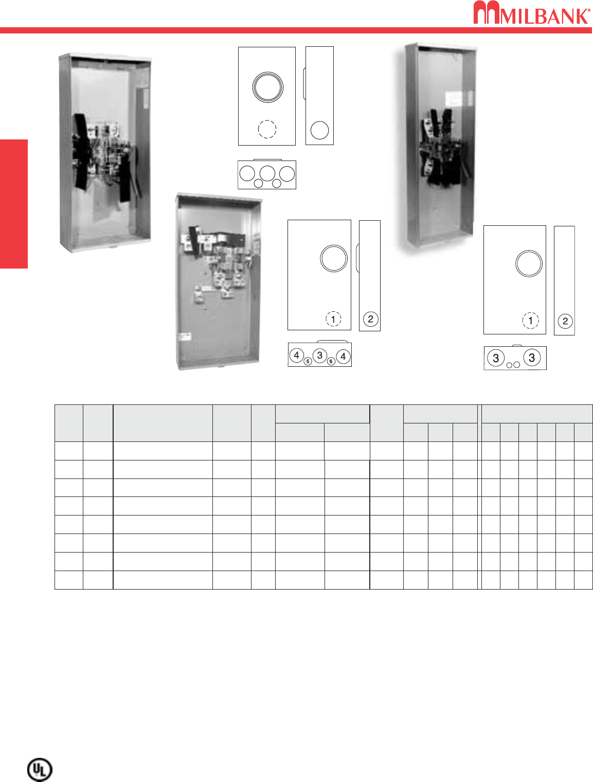
200 AMP–4 & 5 TERMINAL–RINGLESS–600 VAC
SINGLE POSITION
200 AMP–4 & 5 TERMINAL–RINGLESS–600 VAC
9
200
200
200
200
200
OH/UG
OH/UG
UG
UG
UG
U4801-XL**
U4801-XL-5T9①**
U4801-O**
U4801-O-5T9①**
U3850-O-TG-KK*
C.P.
C.P.
BLANK
BLANK
BLANK
LEVER
LEVER
LEVER
HORN
3
3
3
3
21
⁄
2
21
⁄
2
21
⁄
2
21
⁄
2
21
⁄
2
21
⁄
2
3
3
3
3
11
⁄
2
3
3
3
3
3
1
⁄
4
1
⁄
4
1
⁄
4
1
⁄
4
1
⁄
4,1
⁄
2
1
⁄
4,1
⁄
2
1
⁄
4,1
⁄
2
1
⁄
4,1
⁄
2
1
⁄
4,1
⁄
2
—
47
⁄
8
47
⁄
8
47
⁄
8
47
⁄
8
41
⁄
2
13
13
13
13
13
19
19
19
19
151
⁄
4
#6-350 kcmil
#6-350 kcmil
#6-350 kcmil
#6-350 kcmil
#6-350 kcmil
#6-350 kcmil
#6-350 kcmil
#6-350 kcmil
#6-350 kcmil
#6-350 kcmil
4
5
4
5
4
LEVER
AMP
SERVICE
CATALOG
NUMBER
HUB
CONNECTORS
CU/AL
LINE LOAD
BY-
PASS
DIMENSIONS
CONCENTRIC K.O.ʼS
1 2 3 4 5 6D″W″H″
200
OH
U1211-RXL**
C.P.
LEVER
321
⁄
23 3 1
⁄
41
⁄
4,1
⁄
247
⁄
813 19
#6-350 kcmil #6-350 kcmil
200
OH
U1773-XL-TG-KK
**
C.P. HORN 21
⁄
221
⁄
221
⁄
221
⁄
21
⁄
4,1
⁄
21
⁄
441
⁄
811 151
⁄
2
#6-350 kcmil #6-350 kcmil
200 AMP—4 & 5 TERMINAL—RINGLESS—1∅3W
1
5
5
3
4
6
2
4
1211
1773
HUBS: For proper hub selection see the hub suffix chart on the accessory page.
BYPASS: U1211: Lever operates bypass device only; does not provide clamping action on meter spades. On the U1773 &
U3850, the -KK, horn type bypass permits changing and testing of the meter without interrupting customer service when used
with utility-supplied jumpers. The U4801 is a heavy duty lever bypass and the lever supplies clamping action on jaws.
CONNECTORS: Units are supplied with extruded aluminum connectors and bonded, triplex neutral.
FIFTH TERMINAL: For field mounted fifth terminal, order as extra K3866 for the U1211,U4801-XL &U4801-O. For field
mounted fifth terminal for the U1773 & U3850, order catalog number K5T to fit into square opening at the 9 oʼclock position.
①FACTORY-INSTALLED FIFTH TERMINAL: Includes factory installed fifth terminal in the 9 oʼclock position for use on Alliant
Energy lines when a fifth terminal is required.
* SHORT CIRCUIT CURRENT RATING: 10,000 RMS sym amps 600 VAC
** SHORT CIRCUIT CURRENT RATING: See chart on page 41
TERMS.
4
4
U1773-XL-TG-KK
U1211-RXL
U4801-XL
12
3
44
65
4801
1
3
5
2
4
2
3850
U3850-O-TG-KK
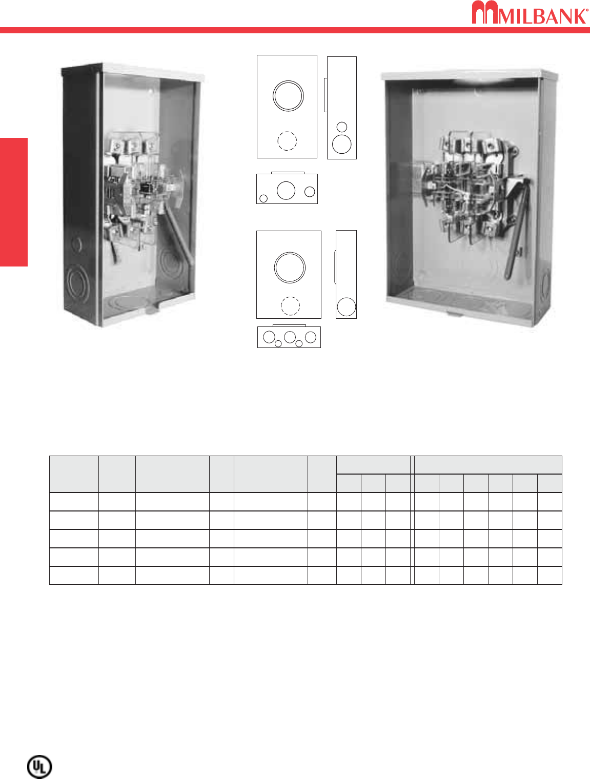
200 AMP–5 & 7 TERMINAL–LEVER BYPASS–HEAVY DUTY–RINGLESS–600 VAC
10
200 AMP–5 & 7 TERMINAL–LEVER BYPASS–HEAVY DUTY–RINGLESS–600 VAC SINGLE POSITION
Utility requirements for this equipment may vary. Always consult the serving utility for their requirements before ordering or
installing equipment in this catalog.
12
3
56
6
12
6
54
3
4
#
OF
TERMS
SERVICE
OH
UG
5
CATALOG
NUMBER
U9550-DL
≠
**
HUB
2″
CONNECTORS
CU/AL
BY-
PASS
#6-350 kcmil
LEVER
DIMENSIONS CONCENTRIC K.O.ʼS
123456D″W″H″
321
⁄
23 — 1
⁄
4,1
⁄
23
⁄
4
47
⁄
810 181
⁄
2
5U9551-O
≠
**
BLANK
#6-350 kcmil
LEVER
321
⁄
23 3 1
⁄
41
⁄
4,1
⁄
2
47
⁄
813 19
OH/UG 5
①
U8624-RXL** C.P. #6-350 kcmil LEVER
✝321
⁄
23 3 1
⁄
41
⁄
4,1
⁄
2
47
⁄
813 19
OH 7 U9700-RRL** H.O. #6-350 kcmil
LEVER
321
⁄
23 — 1
⁄
4,1
⁄
23
⁄
4
47
⁄
810 181
⁄
2
OH/UG 7U9701-RXL** C.P. #6-350 kcmil
LEVER
321
⁄
23 3 1
⁄
41
⁄
4,1
⁄
2
47
⁄
813 19
200 AMP—5 TERMINAL—RINGLESS—1∅ or 3∅3W
200 AMP—7 TERMINAL—RINGLESS—3∅4W
①
Supplied with sliding link neutral disconnect.
≠
Grounded B Phase (may be field isolated).
✝WARNING LABEL: A warning label is placed on the upper center of the shield to indicate proper use of the link for
various circuits.
ISOLATED NEUTRAL: For field installed insulated neutral in the U9701 wide units, order as extra catalog number K1047.
HUBS: For proper hub selection see the hub suffix chart on the accessory page.
BYPASS: Lever operates bypass device and provides clamping action on meter spades.
CONNECTORS: Supplied with internal hex connectors. Extruded aluminum connectors are tin plated.
** SHORT CIRCUIT CURRENT RATING: See chart on page 41
U9550-RL
(Shown w/o Hub)
U9701-RXL
9550
9700
9551
8624
9701
10
11
200 AMP–7 TERMINAL–LEVER BYPASS–RINGLESS–3
∅
–600 VAC
SINGLE POSITION
200 AMP–7 TERMINAL–LEVER BYPASS–RINGLESS–3
∅
–600 VAC
Utility requirements for this equipment may vary. Always consult the serving utility for their requirements before ordering or
installing equipment in this catalog.
11
12
3
56
6
12
3
44
65
U7421-RL
U7423-XL
7421
7423
4701
AMPSERV-
ICE
OH
OH/UG
200
CATALOG
NUMBER
U7421-RL
*
HUB
H.O.
CONNECTORS
LINE LOAD
BY-
PASS
#6-350 kcmil
LEVER
DIMENSIONS CONCENTRIC K.O.ʼS
123456D″W″H″
321
⁄
23 — 1
⁄
4,1
⁄
23
⁄
4
47
⁄
810 181
⁄
2
200
U7423-XL
①
*C.P. #6-350 kcmil
LEVER
321
⁄
23 3 1
⁄
41
⁄
4,1
⁄
2
47
⁄
813 19
OH/UG 200
U4701-XL
①
**
C.P. #6-350 kcmil
#6-350 kcmil
#6-350 kcmil
#6-350 kcmil
LEVER
321
⁄
23 3 1
⁄
41
⁄
4,1
⁄
2
47
⁄
813 19
200 AMP—7 TERMINAL—RINGLESS—3∅4W
HUBS: For proper hub selection see the hub suffix chart on the accessory page.
BYPASS: For units U7421 and U7423 the lever operates bypass only; does not provide clamping action on meter spades.
For the U4701-XL the lever operates bypass, and provides clamping action on meter spades.
CONNECTORS: Units are supplied with extruded aluminum connectors and bonded, triplex neutral. U4701 is supplied with
external hex connectors. U7421 and U7423 are supplied with internal hex connectors.
①
ISOLATED NEUTRAL: For field installed isolated neutral order as extra catalog number K1047.
* SHORT CIRCUIT CURRENT RATING: 10,000 RMS sym amps 600 VAC
** SHORT CIRCUIT CURRENT RATING: See chart on page 41
320 AMP–4, 5 & 7 TERMINAL–LEVER BYPASS–HEAVY DUTY–RINGLESS–600 VAC
12
320 AMP–4, 5 & 7 TERMINAL–LEVER BYPASS–HEAVY DUTY–RINGLESS–600 VAC SINGLE POSITION
Utility requirements for this equipment may vary. Always consult the serving utility for their requirements before ordering or
installing equipment in this catalog.
12
320
320
≠
320
≠
1
5
5
3
4
6
2
4
U4363-X-QG
U3000-O-K3L-K2L
AMPS CATALOG
NUMBER
SERVICE
HUB
CONNECTORS
CU/AL
LINE
3⁄8″x 16 STUD
LOAD
3⁄8″x 16 STUD
BY-
PASS
DIMENSIONS CONCENTRIC K.O.ʼS
123456D″W″H″
320
320
≠
320
≠
320
≠
320
≠
U4363-X-QG**
U3000-O-K3L**
U3000-O-K3L-K2L**
U3000-O-5T9-K3L-K2L
①**
U1779-RRL-K3**
U1779-RRL-5T9-K3①
**
U2594-X-K7**
U2120-X-K7**
C.P.
BLANK
BLANK
BLANK
H.O.
H.O.
C.P.
C.P.
3⁄8″x 16 STUD
(2)#6-350 kcmil
(2)#6-350 kcmil
3⁄8″x 16 STUD
3⁄8″x 16 STUD
3⁄8″x 16 STUD
3⁄8″x 16 STUD
#4-600 kcmil (1)
1/0-250 kcmil (2)
#4-600 kcmil (1)
1/0-250 kcmil (2)
#4-600 kcmil (1)
1/0-250 kcmil (2)
#4-600 kcmil (1)
1/0-250 kcmil (2)
#4-600 kcmil (1)
1/0-250 kcmil (2)
#4-600 kcmil (1)
1/0-250 kcmil (2)
#4-600 kcmil (1)
1/0-250 kcmil (2)
LEVER
LEVER
LEVER
LEVER
LEVER
LEVER
LEVER
LEVER
3
3
3
3
3
3
—
4
3
3
3
3
21
⁄
2
21
⁄
2
3
3
3
3
3
3
3
3
4
4
3
3
3
3
3
3
—
—
1
⁄
4
1
⁄
4
1
⁄
4
1
⁄
4
1
⁄
4
1
⁄
4
1
⁄
4
1
⁄
4
1
⁄
4,1
⁄
2
1
⁄
4,1
⁄
2
1
⁄
4,1
⁄
2
1
⁄
4,1
⁄
2
1
⁄
4,1
⁄
2
1
⁄
4,1
⁄
2
1
1
47
⁄
8
47
⁄
8
47
⁄
8
47
⁄
8
47
⁄
8
47
⁄
8
61
⁄
2
61
⁄
2
13
15
15
15
13
13
19
173
⁄
4
281
⁄
4
30
30
30
383
⁄
4
383
⁄
4
341
⁄
8
313
⁄
4
OH/UG
UG
UG
UG
OH
OH
OH/UG
UG
320 AMP CONTINUOUS*—4, 5 & 7 TERMINAL—HEAVY DUTY—RINGLESS—600 VAC
HUBS: For proper hub selection see the hub suffix chart on the accessory page.
BYPASS: The lever supplies clamping action and also operates bypass device.
CONNECTORS: Stud type units supplied with 3/8″-16 hex head nuts with Belleville washers. For connector kits, order as extra
K1540 (600 kcmil). For twin lug connectors order as extra: K1350 (350 kcmil). (NOTE: U4363 is UL Listed based on Parallel 250
conductors only. Use K1540 with (2) 250 conductors.)
FIFTH TERMINAL: For field installed fifth terminal, order as extra K3865.
①FACTORY-INSTALLED FIFTH TERMINAL: Includes factory installed fifth terminal in the 9 oʼclock position for use on Alliant
Energy lines when a fifth terminal is required.
≠
300 amp continuous when used on Alliant Energy lines.
** SHORT CIRCUIT CURRENT RATING: See chart on page 41
4363
1779
3000
U1779-RRL-K3
(Shown w/o K3
connectors)
TERMS.
4
4
4
5
4
5
7
7
6
5
2120
2594
13
100 AMP / POSITION–4 & 5 TERMINAL–HORIZONTAL GANGS–RINGLESS
300 VAC
Utility requirements for this equipment may vary. Always consult the serving utility for their requirements before ordering or
installing equipment in this catalog.
13
MULTIPLE POSITION
100 AMP / POSITION–4 & 5 TERMINAL–HORIZONTAL GANGS–RINGLESS–300 VAC
CENTER WIREWAY
SERVICE
OH/UG
CATALOG
NUMBER
U8032-XL-KK
HUB
C.P.
#
OF
POS
2
OH/UG U8033-XL-KK C.P.3
OH/UG4U8034-XL-KK C.P.
OH/UG U8035-XL-KK C.P.5
OH/UG U8036-XL-KK C.P.6
U8032-XL-KK
3
3
455
2
11
L572-XL-KK
L572-6
SIDE WIREWAY
CONNECTORS: Extruded aluminum connectors are tin plated.
BUSSING: Supplied with 5/16″ x 1″aluminum bussing.
FIFTH TERMINAL: For field installed fifth terminal, order as extra catalog number 5T8K2 for the 6 oʼclock position, and Kit #K9959 for the
9 oʼclock position.
EXTRA WIRE SPACE: Extra wire space of 4″provided on the left end of 2 and 3 position gangs. Furnished on both ends of 4, 5, and 6
position gangs.
MAIN BUS RATING: For main bus rating, see the conduit and ampacity information on page 40 of this catalog.
BYPASS: The -KK horn type bypass is factory installed and permits changing and testing of the meter without interrupting customer service
when used with utility-supplied jumpers.
SERVICE
OH
OH
CATALOG
NUMBER
L572-XL-KK
HUB
C.P.
CONNECTORS
CU/AL
LINE LOAD
BY-
PASS
#2-350 kcmil HORN
DIMENSIONS CONCENTRIC K.O.ʼS
1 2 3 4 5D″W″H″
22221
⁄
21
⁄
4,1
⁄
2
41
⁄
2205
⁄
16 16
L573-XL-KK C.P. #2-350 kcmil HORN 22221
⁄
21
⁄
4,1
⁄
241
⁄
2281
⁄
216
OH L574-XL-KK C.P. #2-350 kcmil HORN 22221
⁄
21
⁄
4,1
⁄
2
41
⁄
2
4011⁄16
16
OH L575-XL-KK C.P. #2-350 kcmil HORN 22221
⁄
21
⁄
4,1
⁄
241
⁄
2487
⁄
816
OH
#
OF
POS
2
3
4
5
6L576-XL-KK C.P. #2-350 kcmil HORN 22221
⁄
21
⁄
4,1
⁄
241
⁄
2571
⁄
16 16
#6-2/0
#6-2/0
#6-2/0
#6-2/0
#6-2/0
100 AMP/POSITION—4 & 5 TERMINAL—SIDE WIREWAY—RINGLESS–1∅3W
CONNECTOR
CU/AL BY-
PASS
HORN
DIMENSIONS CONCENTRIC K.O.ʼS
1
2 2 21
⁄
221
⁄
21
⁄
4,1
⁄
2
2 3 4 5 6D″
41
⁄
2
W″
241
⁄
2
H″
16
LINE
#6-350
kcmil
LOAD
#6-2/0
HORN 2 2 21
⁄
221
⁄
21
⁄
4,1
⁄
2
41
⁄
2407
⁄
816
#6-350
kcmil #6-2/0
HORN 2 2 21
⁄
221
⁄
21
⁄
4,1
⁄
2
41
⁄
2571
⁄
416
#6-350
kcmil #6-2/0
5
⁄
16
HORN 2 2 21
⁄
221
⁄
21
⁄
4,1
⁄
2
41
⁄
2
3211⁄16
16
#6-350
kcmil #6-2/0 5
⁄
16
7
5
⁄
16
HORN 2 2 21
⁄
221
⁄
21
⁄
4,1
⁄
2
41
⁄
2491
⁄
16 16
#6-350
kcmil #6-2/0 5
⁄
16
5
⁄
16
112
3
556
644
77
77
1
8032-6
100 AMP/POSITION—4 & 5 TERMINAL—CENTER WIREWAY–RINGLESS—1∅3W
100 AMP / POSITION–4 & 5 TERMINAL–HORIZONTAL GANG–RINGLESS–300 VAC
14
100 AMP / POSITION–4 & 5 TERMINAL–HORIZONTAL GANG–RINGLESS
300 VAC MULTIPLE POSITION
14
Utility requirements for this equipment may vary. Always consult the serving utility for their requirements before ordering or
installing equipment in this catalog.
CONNECTORS: Extruded aluminum connectors are tin plated.
BUSSING: Supplied with 5/16″ x 1″aluminum bussing.
FIFTH TERMINAL: For field installed fifth terminal, order as extra catalog number 5T8K2 for the 6 oʼclock position, and kit
#K9959 for the 9 oʼclock position.
MAIN BUS RATING: For main bus rating, see the conduit and ampacity information on page 40 of this catalog.
BYPASS: The -KK horn type bypass is factory installed and permits changing and testing of the meter without interrupting
customer service when used with utility-supplied jumpers.
OH
CATALOG
NUMBER
U7362-RL-KK
HUB
H.O.
CONNECTORS
CU/AL
LINE LOAD
BY-
PASS
#2-350 kcmil HORN
DIMENSIONS CONCENTRIC K.O.ʼS
1234D″W″H″
2221
⁄
4,1
⁄
241
⁄
2165
⁄
16 16
#
OF
POS
2#6-2/0
100 AMP—4 & 5 TERMINAL—RINGLESS—1∅3W
OH U7363-RL-KK H.O. #2-350 kcmil HORN 2221
⁄
4,1
⁄
241
⁄
2241
⁄
216
3#6-2/0
OH4 U7364-RL-KK H.O. #2-350 kcmil HORN 2221
⁄
4,1
⁄
241
⁄
2
3211⁄16
16
#6-2/0
OH U7365-RL-KK H.O. #2-350 kcmil HORN 2221
⁄
4,1
⁄
241
⁄
2407
⁄
816
5#6-2/0
OH U7366-RL-KK H.O. #2-350 kcmil HORN 2221
⁄
4,1
⁄
241
⁄
2491
⁄
16 16
6#6-2/0
U7363-RL-KK
(shown without -KK bypass)
SERVICE
7362-6
15
100 AMP / POSITION–4 TERMINAL–VERTICAL GANG–RINGLESS–300 VAC
Utility requirements for this equipment may vary. Always consult the serving utility for their requirements before ordering or
installing equipment in this catalog.
15
CONNECTORS: Extruded aluminum connectors are tin plated.
BUSSING: Supplied with 5/16″ x 1″aluminum bussing.
FIFTH TERMINAL: For field installed fifth terminal, order as extra catalog number 5T8K2 for the 9 oʼclock position.
MAIN BUS RATING: For main bus rating, see the conduit and ampacity information on page 40 of this catalog.
BYPASS: The -KK horn type bypass is factory installed and permits changing and testing of the meter without interrupting
customer service when used with utility-supplied jumpers.
12
434
5
SERVICE
OH
CATALOG
NUMBER
U2692-XL-KK
HUB
C.P.
CONNECTORS
CU/AL
LINE LOAD
BY-
PASS
#2-350 kcmil HORN
DIMENSIONS CONCENTRIC K.O.ʼS
1 2 3 4 5D″W″H″
11
⁄
211
⁄
221
⁄
211
⁄
41
⁄
4
41
⁄
88251
⁄
4
#6-2/0
100 AMP—4 TERMINAL—RINGLESS—1∅3W
U2692-XL
(shown without -KK bypass)
100 AMP / POSITION–4 TERMINAL–VERTICAL GANG–RINGLESS–300 VAC
MULTIPLE POSITION
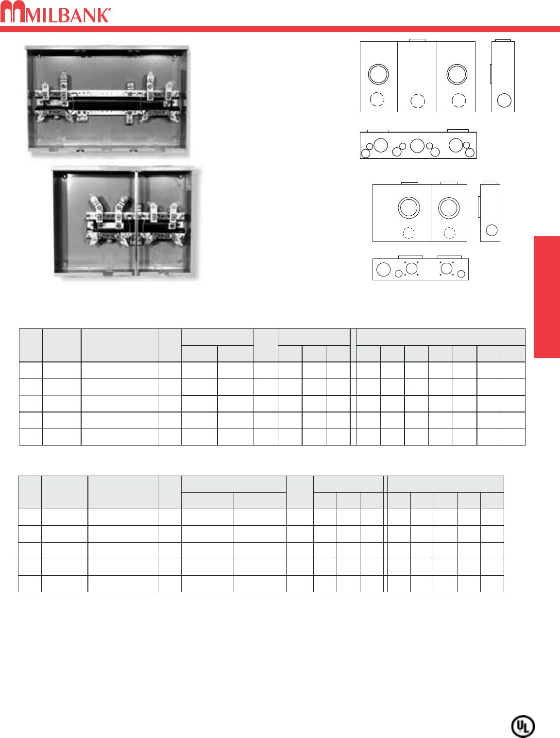
200 AMP / POSITION–4 & 5 TERMINAL–HORIZONTAL GANGS–RINGLESS–300 VAC
16
200 AMP / POSITION–4 & 5 TERMINAL–HORIZONTAL GANGS–RINGLESS
300 VAC MULTIPLE POSITION
Utility requirements for this equipment may vary. Always consult the serving utility for their requirements before ordering or
installing equipment in this catalog.
1 1 2
3
4 4
1 1 2
3
4
5 6 4
5
7
1 1 2
3
4
5 6
7
1
4 4
5 5
200 AMP / POSITION—4 & 5 TERMINAL—RINGLESS—1∅3W—OH/UG
NO.
OF
POS.
CATALOG
NUMBER
HUB
CONNECTOR
CU/AL
BY-
PASS
DIMENSIONS
CONCENTRIC K.O.ʼS
1 2 3 4 5 6 7D″W″H″
LINE LOAD
2
**U1252-X-KK
C.P. HORN 21
⁄
221
⁄
2321
⁄
21
⁄
211
⁄
4
51
⁄
8261
⁄
214
3/8″-16
STUD
#6-350
kcmil
3
**U1253-X-KK
C.P. HORN 21
⁄
221
⁄
2321
⁄
21
⁄
211
⁄
4
51
⁄
8
343⁄4
14
3/8″-16
STUD
#6-350
kcmil
4
**U1254-X-KK
C.P. HORN 21
⁄
221
⁄
2321
⁄
21
⁄
211
⁄
4
51
⁄
8427
⁄
816
3/8″-16
STUD
#6-350
kcmil
2
U1252-X-KK-K1-PED*
C.P. HORN 21
⁄
221
⁄
2PED 21
⁄
2— — —
51
⁄
8261
⁄
214
#6-350
kcmil
#6-350
kcmil
3
U1253-X-KK-K3-PED*
C.P. HORN 21
⁄
221
⁄
2PED 21
⁄
2— — —
51
⁄
8
343⁄4
A
#2-600
kcmil
#6-350
kcmil
4
SERVICE
OH
OH
OH
UG
UG
UG
U1254-X-KK-K3-PED*
C.P. HORN 21
⁄
221
⁄
2PED 21
⁄
2— — —
51
⁄
8427
⁄
816
(2)#2-600
kcmil
#6-350
kcmil
5
U1255-X-KK-K4-PED*
C.P. HORN 21
⁄
221
⁄
2PED 21
⁄
2— — —
51
⁄
8547
⁄
816
(2)#2-600
kcmil
#6-350
kcmil
6
**U1256-X-KK-PED*
C.P. HORN 21
⁄
221
⁄
2PED 21
⁄
2— — —
51
⁄
8631
⁄
16 18
3/8″-16
STUD
3/8″-16
STUD
UG
UG
HUB: For proper hub selection refer to the hub suffix chart on the accessory page. Two hub openings are supplied (5 & 6 position
only) and the extra opening is closed with a closing plate as standard. To use hub less than 3”, the S8324 adaptor is required.
FIFTH TERMINAL: For field mounted fifth terminal, order catalog number K5T for the 9 oʼclock position.
*PEDESTAL: Units may be used with a S2291-TO pedestal raceway, see page 20. Order separately. A 12″pedestal extension
kit is also available. Order catalog number S2571.
**CONNECTORS: Units supplied with 3/8″-16 hex head nuts with Belleville washers on line side. Order connector kits as extra:
K1539 (350 kcmil), K1540 (600 kcmil) or K1541 ((2) 600 kcmil).
BUSSING: Supplied with 5/16”x1” aluminum bussing on the U1252-1253 units. Supplied with 3/8" x 1″aluminum bussing on
the U1254-1256 units.
MAIN BUS RATING: For main bus rating, see the conduit and ampacity information on page 40 of this catalog.
BYPASS: The -KK horn type bypass is factory installed and permits changing and testing of the meter without interrupting
customer service when used with utility-supplied jumpers.
1252
1253-6
1252-6
U1252-X-KK
16
Utility requirements for this equipment may vary. Always consult the serving utility for their requirements before ordering or
installing equipment in this catalog.
17
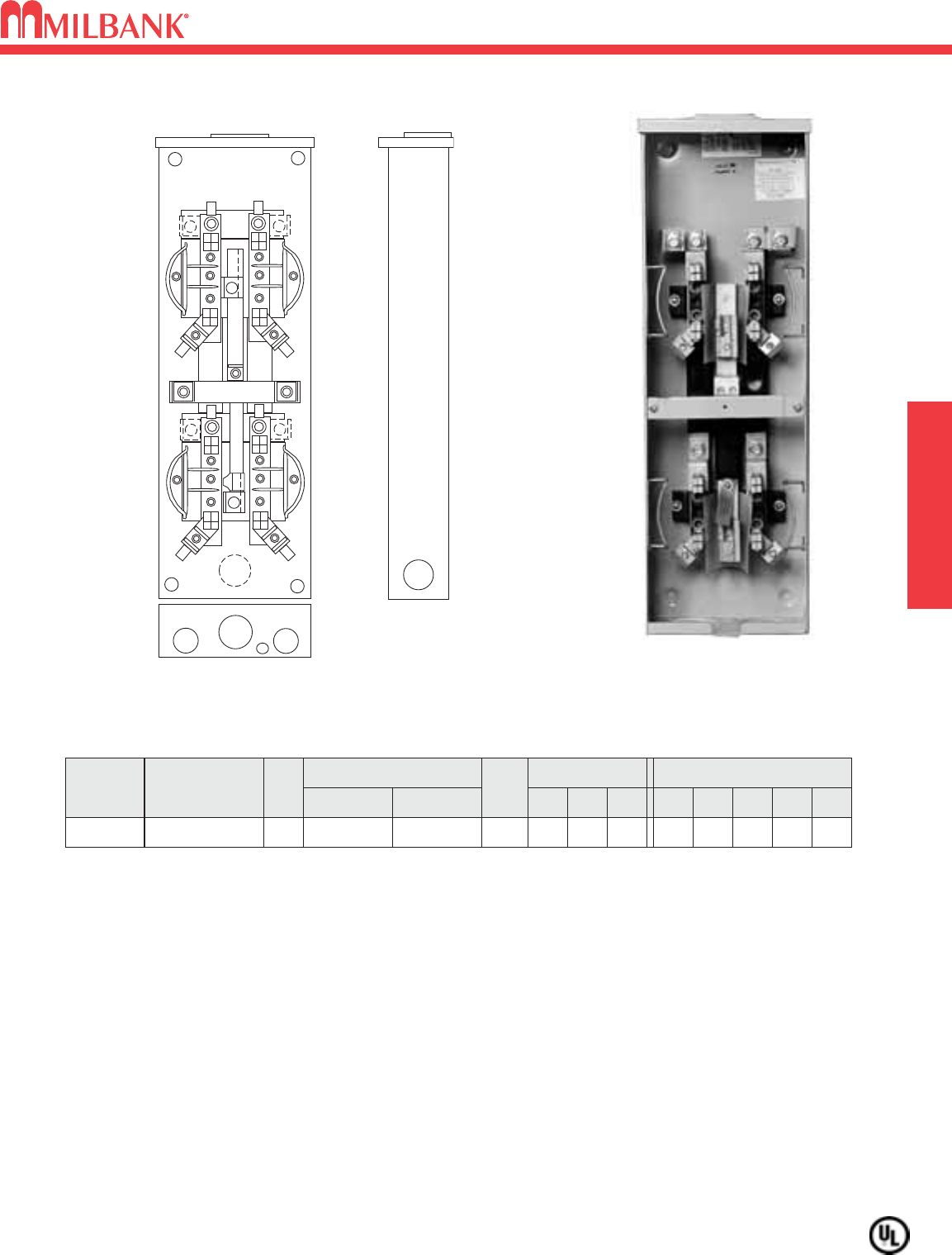
200 AMP / POSITION–5 TERMINAL–LEVER BYPASS–HORIZONTAL GANGS
600 VAC
MULTIPLE POSITION
200 AMP / POSITION–5 TERMINAL–LEVER BYPASS–HORIZONTAL GANGS–600 VAC
17
CONNECTORS: Units supplied with 3/8″-16 hex head nuts with Belleville washers on line side. For single lug
connector kits, order as extra: K1539 (350 kcmil) or K1540 (600 kcmil). For twin lug connectors order: K1350
(350 kcmil) or K1541 (600 kcmil).
①LINE SIDE CONNECTORS: Includes #4-600 kcmil connectors factory installed on line side.BYPASS: Lever
supplies clamping action on meter spades and also operates bypass device.
MAIN BUS RATING: For main bus rating, see the conduit and ampacity information on page 40 of this catalog.
U2873-XT
200 AMP / POSITION—5 TERMINAL—RINGLESS—1∅3W—OH
NO.
OF
POS.
CATALOG
NUMBER HUB
CONNECTOR
CU/AL
BY-
PASS
DIMENSIONS CONCENTRIC K.O.ʼS
12345D″W″H″LINE LOAD
2U2872-XT (2)C.P.
LEVER
21
⁄
221
⁄
2421
⁄
2
1
⁄
2,1
⁄
4
6321
⁄
8251
⁄
4
3/8″-16
STUD
#6-350
kcmil
2
2
U2872-XT-K3①
U2872-XT-5T9-K3①
(2)C.P.
(2)C.P.
LEVER
LEVER
21
⁄
2
21
⁄
2
21
⁄
2
21
⁄
2
4
4
21
⁄
2
21
⁄
2
1
⁄
2,1
⁄
4
1
⁄
2,1
⁄
4
6
6
321
⁄
8
321
⁄
8
251
⁄
4
251
⁄
4
#4-600
kcmil
#4-600
kcmil
#6-350
kcmil
#6-350
kcmil
3U2873-XT (2)C.P.
LEVER
21
⁄
221
⁄
2421
⁄
2
1
⁄
2,1
⁄
4
6423
⁄
16 251
⁄
4
3/8″-16
STUD
#6-350
kcmil
3U2873-XT-K3①(2)C.P.
LEVER
21
⁄
221
⁄
2421
⁄
2
1
⁄
2,1
⁄
4
6423
⁄
16 251
⁄
4
#4-600
kcmil
#6-350
kcmil
4U2874-XT (2)C.P.
LEVER
21
⁄
221
⁄
2421
⁄
2
1
⁄
2,1
⁄
4
6521
⁄
4251
⁄
4
3/8″-16
STUD
#6-350
kcmil
4U2874-XT-K3①(2)C.P.
LEVER
21
⁄
221
⁄
2421
⁄
2
1
⁄
2,1
⁄
4
6521
⁄
4251
⁄
4
#4-600
kcmil
#6-350
kcmil
2872-4
18
18
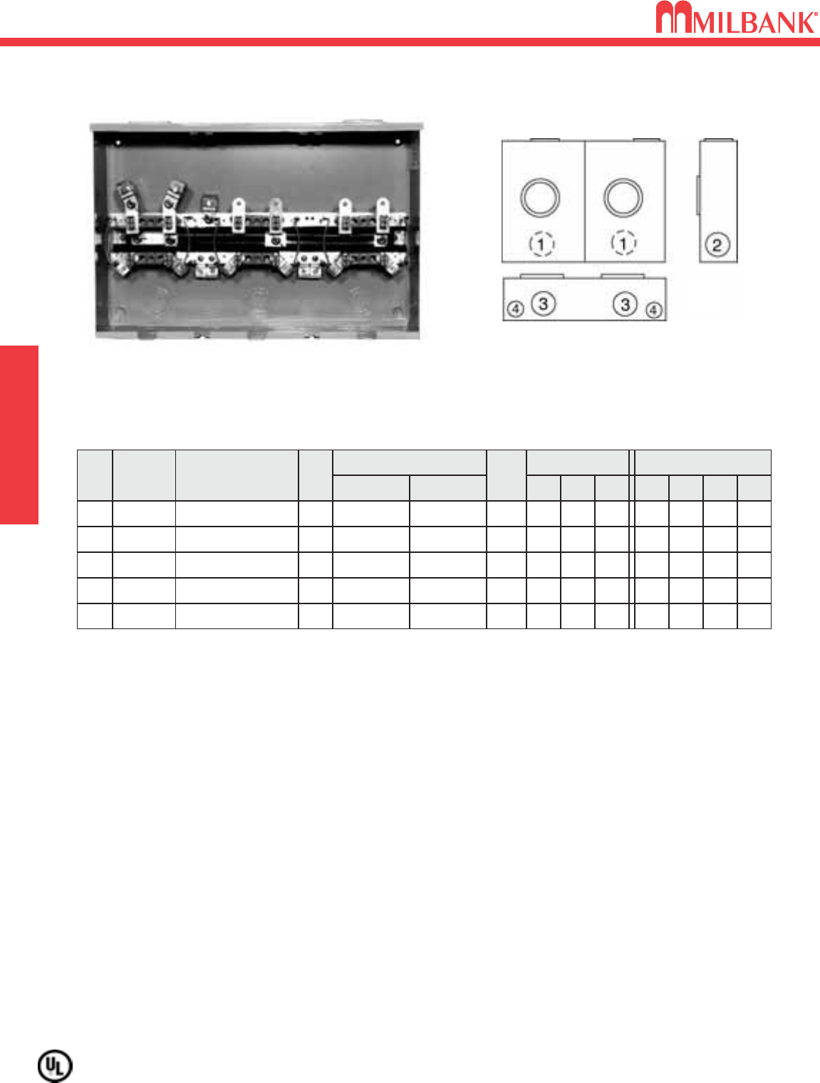
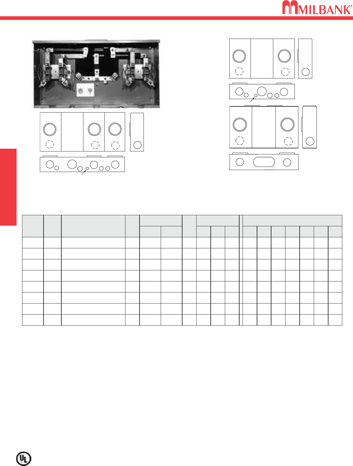
200 AMP / POSITION–7 TERMINAL–HORIZONTAL GANG
LEVER BYPASS–RINGLESS–600 VAC
200 AMP / POSITION–7 TERMINAL–HORIZONTAL GANG
LEVER BYPASS–RINGLESS–600 VAC
2
CATALOG
NUMBER
U2732-XT-PED
HUB
(2)C.P.
CONNECTOR
CU/AL
BY-
PASS
LEVER
DIMENSIONS CONCENTRIC K.O.ʼS
1
21
⁄
221
⁄
2PED 21
⁄
21⁄4,1⁄2
2345D″
6
W″
321⁄8
H″
251⁄4
LINE
3/8″-16
STUD
LOAD
#6-350
kcmil
2U2732-XT-PED-K7≠(2)C.P.
LEVER
21
⁄
221
⁄
2PED 21
⁄
21⁄4,1⁄2
6321⁄8251⁄4
#4-600
kcmil
#6-350
kcmil
3U2733-XT-PED (2)C.P.
LEVER
21
⁄
221
⁄
2PED 21
⁄
21⁄4,1⁄2
6423⁄16 251⁄4
3/8″-16
STUD
#6-350
kcmil
3U2733-XT-PED-K7≠(2)C.P.
LEVER
21
⁄
221
⁄
2PED 21
⁄
21⁄4,1⁄2
6423⁄16 251⁄4
#4-600
kcmil
#6-350
kcmil
4U2734-XT-PED (2)C.P.
LEVER
21
⁄
221
⁄
2PED 21
⁄
21⁄4,1⁄2
6521⁄4311⁄4
3/8″-16
STUD
#6-350
kcmil
OH/UG
OH/UG
OH/UG
OH/UG
OH/UG
AMPS
200
200
200
200
200
200 AMP —7 TERMINAL—RINGLESS—3∅4W—OVERHEAD / UNDERGROUND*
4U2734-XT-PED-K7≠(2)C.P.
LEVER
21
⁄
221
⁄
2PED 21
⁄
21⁄4,1⁄2
6521⁄4251⁄4
#4-600
kcmil
#6-350
kcmil
5U2735-XT-PED (2)C.P.
LEVER
21
⁄
221
⁄
2PED 21
⁄
21⁄4,1⁄2
6625⁄16 251⁄4
3/8″-16
STUD
#6-350
kcmil
5U2735-XT-PED-K7≠(2)C.P.
LEVER
21
⁄
221
⁄
2PED 21
⁄
21⁄4,1⁄2
6625⁄16 251⁄4
#4-600
kcmil
#6-350
kcmil
6U2736-XT-PED (2)C.P.
LEVER
21
⁄
221
⁄
2PED 21
⁄
21⁄4,1⁄2
6723⁄8251⁄4
3/8″-16
STUD
#6-350
kcmil
6U2736-XT-PED-K7≠
(2)C.P.
LEVER
21
⁄
221
⁄
2PED 21
⁄
21⁄4,1⁄2
6723⁄8311⁄4
#4-600
kcmil
#6-350
kcmil
OH/UG
OH/UG
OH/UG
OH/UG
OH/UG
200
200
200
200
200
HUBS: Units supplied with two closing plates. To order hubs as extra refer to the hub suffix chart on the accessory page.
BYPASS: Lever supplies clamping action on meter spades and also operates bypass device.
CONNECTOR KITS: Line wire sections supplied with studs. For connector kits order K3082 (single-350 kcmil), K3441
(single-600 kcmil). For twin connectors order K3442 (twin-350 kcmil) or K3083 (twin-600 kcmil). Line connectors can be
reversed to change from OH to UG service.
≠ LINE SIDE CONNECTORS: Includes #4-600 kcmil connectors factory installed on line side.
UNDERGROUND PEDESTALS: For underground service order S2291-TO pedestal raceway, see page 20. A 12″pedestal
extension kit is also available. Order catalog number S2571.
BUSSING: Bussing is 3/8″x 1″aluminum.
MAIN BUS RATING: For main bus rating, see the conduit and ampacity information on page 40 of this catalog.
1 1
3
12
4
5
4
U2732-XT-PED
(shown without pedestal
or line connectors)
CENTER
WIREWAY
NO.
OF
POS.
SERVICE
2732-6
MULTIPLE POSITION
Utility requirements for this equipment may vary. Always consult the serving utility for their requirements before ordering or
installing equipment in this catalog.
19
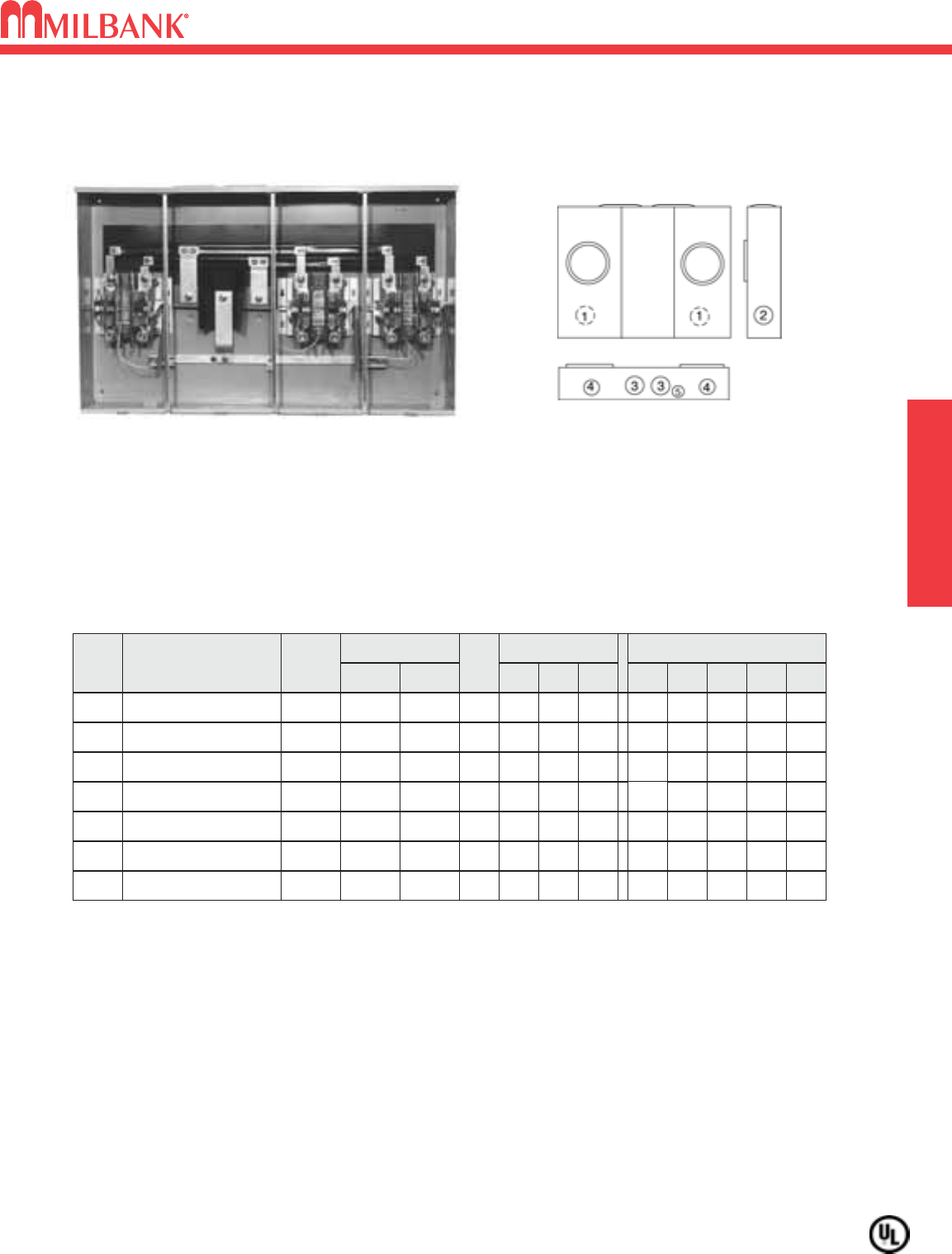
100A/200A–240VAC–4 TERMINAL–METERING BANKS
Utility requirements for this equipment may vary. Always consult the serving utility for their requirements before ordering or
installing equipment in this catalog.
19
100A/200A–240VAC–4 TERMINAL–METERING BANKS
U5882
CATALOG NUMBER AMP POSITIONS TERM SERVICE LINE LOAD WT (#)
U5902-X-KK-K1-PED
100 2 4 OH/UG 1/0-350 #6-350 58
U5902-X-KK-K1*
100 2 4 OH/UG 1/0-350 #6-350 58
U5903-X-KK-K1-PED
100 3 4 OH/UG 1/0-350 #6-350 88
U5903-X-KK-K1*
100 3 4 OH/UG 1/0-350 #6-350 88
U5904-X-KK-K1-PED
100 4 4 OH/UG 1/0-350 #6-350 107
U5904-X-KK-K1*
100 4 4 OH/UG 1/0-350 #6-350 107
U5905-X-KK-K1-PED
100 5 4 OH/UG 1/0-350 #6-350 128
U5905-X-KK-K1*
100 5 4 OH/UG 1/0-350 #6-350 128
U5906-X-KK-K1-PED
100 6 4 OH/UG 1/0-350 #6-350 146
U5906-X-KK-K1*
100 6 4 OH/UG 1/0-350 #6-350
WIDTH
26-1/2
26-1/2
34-9/16
34-9/16
42-13/16
42-13/16
51-1/16
51-1/16
59-5/16
59-5/16 146
* For Alliant Energy.
UNDERGROUND PEDESTALS: For underground service order S2291-TO pedestal raceway, see page 20. A 12″ pedestal
extension kit is also available. Order catalog number S2571.
AIC RATING: All models are rated 22K AIC with Siemens breakers.
HUB: Units supplied with one (1) closing plate. Order hubs separately, see accesory page.
FIFTH TERMINAL: For field installed fifth terminal, order K5T. Installs in the 9 oʼclock position.
MAIN BUS RATING: For main bus rating, see the conduit and ampacity information on page 40 of this catalog.
CATALOG NUMBER AMP POSITIONS TERM SERVICE LINE LOAD WT (#)
U5882-X-KK-K1-PED
200 2 4 OH/UG 1/0-350 #6-350 58
U5882-X-KK-K1*
200 2 4 OH/UG 1/0-350 #6-350 58
U5883-X-KK-K1-PED
200 3 4 OH/UG 1/0-350 #6-350 88
U5883-X-KK-K1*
200 3 4 OH/UG 1/0-350 #6-350 88
U5884-X-KK-K1-PED
200 4 4 OH/UG 1/0-350 #6-350 107
U5884-X-KK-K1*
200 4 4 OH/UG 1/0-350 #6-350 107
U5885-X-KK-K1-PED
200 5 4 OH/UG 1/0-350 #6-350 128
U5885-X-KK-K1*
200 5 4 OH/UG 1/0-350 #6-350 128
U5886-X-KK-K1-PED
200 6 4 OH/UG 1/0-350 #6-350 146
U5886-X-KK-K1*
200 6 4 OH/UG 1/0-350 #6-350
WIDTH
26-1/2
26-1/2
34-9/16
34-9/16
42-13/16
42-13/16
51-1/16
51-1/16
59-5/16
59-5/16 146
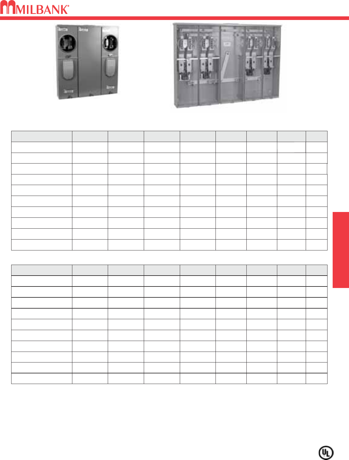
200A / POSITION
U5884
CONDOMINIUM METERING BANKS
125A / POSITION
CONDOMINIUM
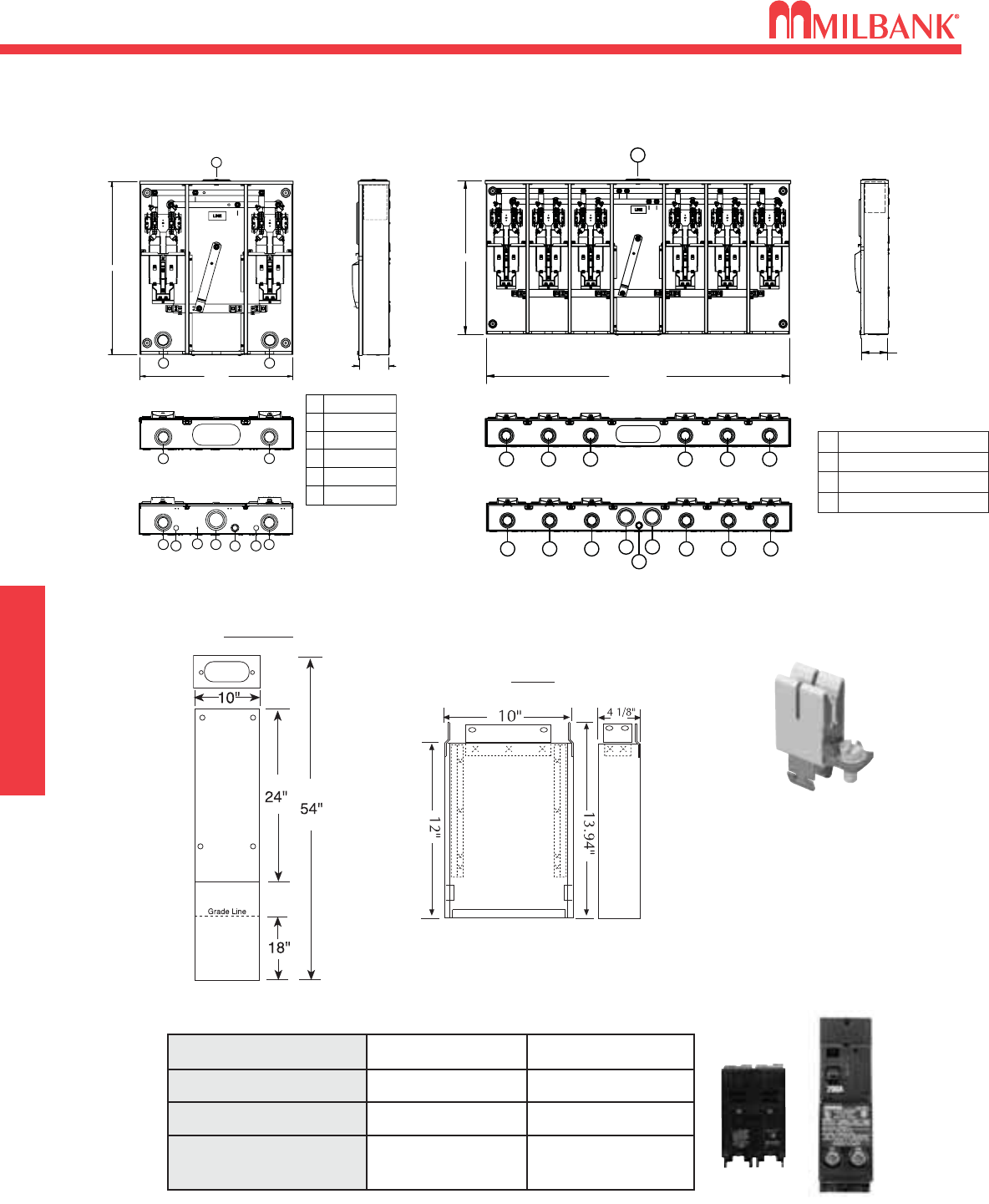
CONDOMINIUM METERING BANK–DIMENSIONAL INFORMATION
20
CONDOMINIUM METERING BANK
DIMENSIONAL INFORMATION
20
PED
PEDESTAL OPTION
Pedestal Raceway
S2291-TO PEDESTAL OPTION
Pedestal Extension Unit
S2571
CONDOMINIUM
59 5/16"
O.D.
30"
5 1/8"
I.D.
1
2 2 2 2 2 2
2 2 2 2 2
33
4
2
PED 1 4” HUB
2 2.5” CONC K.O.
3 3” CONC K.O.
4 1” CONC K.O.
200 amp
FIFTH TERMINAL
K5T
(Block with square hole)
30"
26 1/2"
5 1/8"
I.D.
14” HUB
2
3
2.5” CONC K.O.
3” CONC K.O.
4
5
1” CONC K.O.
7/8” SOLID K.O.
61/4” SOLID K.O.
1
2
2 23
6455
2
22
PED
CONDOMINIUM METERING BANKS
U5882 U5886
BRANCH CIRCUIT BREAKER CHART
Manufacturer 10K Models 22K Models
Siemens QP, QN QPH, QNH
Cutler-Hammer BR, HPQ, QPGF —
Square D Homeline —
G.E. (50 Amp Max.) THQL, THQL-GF —
22
PED
2 23
6455
U5882-X-KK-K1-2/200-PED
U5882-X-KK-K1-2/200
2 2 2 2 2 2
PED
2 2 2 2 2
33
4
2
U5886-X-KK-K1-2/200-PED
U5886-X-KK-K1-2/200
1 LARGE HUB OPENING W/CP
2 2.5” CONC K.O.
3 3” CONC K.O.
4 1” CONC K.O.
21
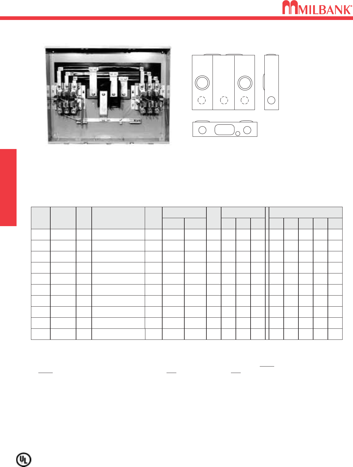
METER MAIN
100 / 200 AMP–4 & 5 TERMINAL–METER MAIN–1
∅
- 120 / 240 VAC
200 AMP–4 & 5 TERMINAL–LOAD CENTER
Utility requirements for this equipment may vary. Always consult the serving utility for their requirements before ordering or
installing equipment in this catalog.
21
100 / 200 AMP—4 & 5 TERMINAL—RINGLESS—1∅3W–HORN BYPASS
AMP CATALOG
NUMBER HUB
LINE
CONNECTORS
CU/AL
BY-
PASS
DIMENSIONS CONCENTRIC K.O.ʼS
1234D″W″H″
OH100 U5842-RL-100-KK H.O. HORN 11
⁄
411
⁄
411
⁄
41
⁄
4,1
⁄
2
4.13 830#6-2/0
5
—
OH
OH
200
200
U5842-RL-200-KK
U5168-XTL-200-KK
H.O.
C.P.
HORN
HORN
2
2
2
2
2
3
1
⁄
4,1
⁄
2
21
⁄
2
—
1
⁄
2,3
⁄
4, 1
4.13
41
⁄
2
8
141
⁄
8
30
32
#6-350 kcmil
#6-350 kcmil
—
1
⁄
2,3
⁄
4
6
—
BREAKERS: Rated 22K AIC with Siemens main installed.
HUBS: Meter mains supplied with hub opening only. For proper hub selection, refer to the accessory page.
FIFTH TERMINAL: For field mounted fifth terminal, order catalog number K5T for U5842 & U5168 in 9 oʼclock position only.
BYPASS: The -KK horn type bypass is factory installed and permits changing and testing of the meter without interrupting
customer service when used with utility-supplied jumpers.
NOTE: U5168 has provisions for 8 single pole breakers and sub-feed lugs.
SERVICE
2
3
5
4
5
11
5
6
6
5
6
U5168-XL-200-KK
U5842
UAP5024-XL-KK
5168
HUBS: Supplied with standard hub opening in top with closing plate.
BUSSING: Load side bus bars and circuit breaker interior are made from plated copper.
WIREWAY: Provided with underground pull section wireway with removable cover.
BREAKERS: Breaker section has provision for six double pole “plug-in” type circuit breakers. All circuit breakers will be
parallel. To comply with NEC wire bending space requirements, the maximum single breaker amperage is 200 amps
restricted to 3/0 copper conductor.
2
11
4
3
4 TERMINAL–RINGLESS–METER SOCKET / CB COMBO–ALUMINUM CONSTRUCTION
SERVICE CATALOG
NUMBER HUB
CONNECTORS
CU/AL
LINE
BY-
PASS
DIMENSIONS CONCENTRIC K.O.ʼS
1 2 3 4 5 6D″W″H″
OH UAP5024-XL-KK C.P. HORN 2 2 3 21
⁄
2
1⁄2,3⁄4,1
1
⁄
2,3
⁄
4
7
1
⁄
4,1
⁄
2
41
⁄
2141
⁄
824
#6-350 kcmil
AMPS
200
5024
100 / 200 AMP–4 & 5 TERMINAL–METER MAIN–1
∅
- 120 / 240 VAC
200 AMP–4 & 5 TERMINAL–LOAD CENTER
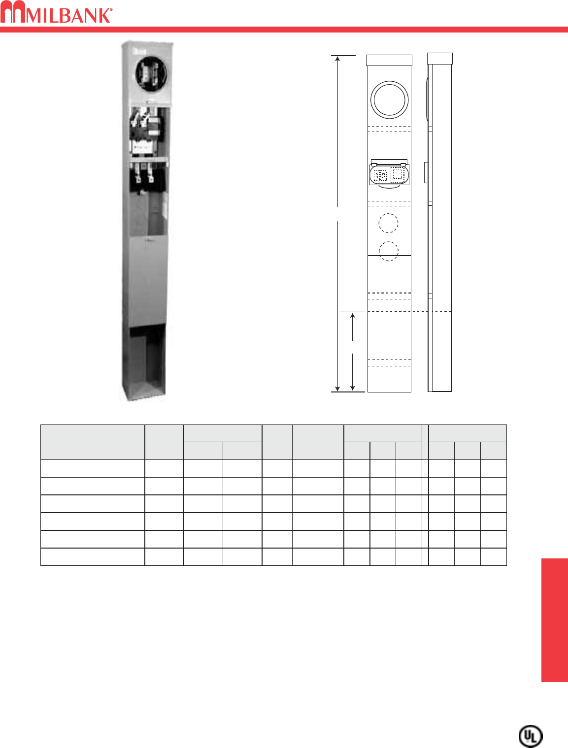
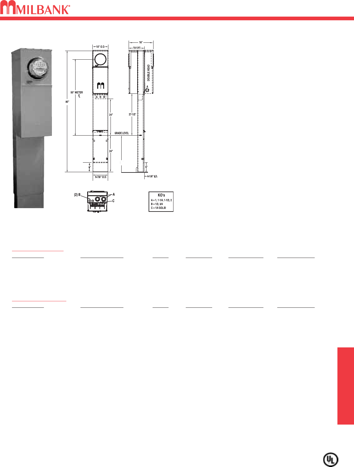
320 AMP–4 & 5 TERMINAL–METER MAIN–RINGLESS–1
∅
22
320 AMP–4 & 5 TERMINAL–METER MAIN–RINGLESS–1
∅
22
18"
Grade Line
1 2
Grade Line
3
MILBANK
3
3 3
2
3
18"
Grade Line
11
1 1
3
33
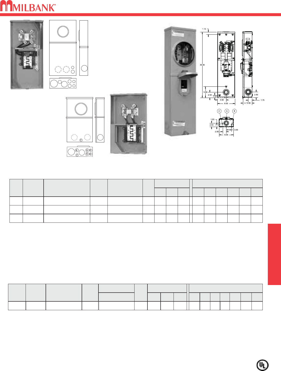
400 AMP MAX
320 AMP
CONTINUOUS DUTY
U3849-O-2/200
120/240 VAC
U1748-O-WI
(Shown w/o line side
connectors) 600 VAC
320 AMP—4 TERMINAL—METER MAIN WITH BREAKER—RINGLESS—1∅3W—120 / 240V
#
OF
TERM
SERVICE CATALOG
NUMBER HUB
CONNECTOR
CU/AL
BY-
PASS
DIMENSIONS CONCENTRIC K.O.ʼS
1234D″W″H″LINE LOAD
4UG U3849-O-200/100①**
BLANK
LEVER
21
⁄
221
⁄
25
⁄
16 —
47
⁄
813 64
3/8″- 16
STUDS
1/0-300
kcmil
4UG U3849-O-2/150①**
BLANK
LEVER
21
⁄
221
⁄
25
⁄
16 —
47
⁄
813 64
3/8″- 16
STUDS
1/0-300
kcmil
4UG U3849-O-2/200①**
BLANK
LEVER
21
⁄
221
⁄
25
⁄
16 —
47
⁄
813 64
3/8″- 16
STUDS
1/0-300
kcmil
BREAKERS: ①Supplied from factory with 2 double-pole, Milbank UQFB or UQFBH (22,000 AIC) bolt-on circuit
breakers.
CONNECTORS: The line wire section is supplied with 3/8”-16 studs with hex nuts and captive Bellville washers. For line side connec-
tors, order as extra catalog numbers K1539 (single-350 kcmil), or K1540 (single-600 kcmil), or for twin K1350 (twin-350 kcmil). Order
one kit per unit.
EXTENSION KIT: For extension kit order as extra catalog number S1848.
BYPASS: Lever supplies clamping action on meter spades and also operates bypass device.
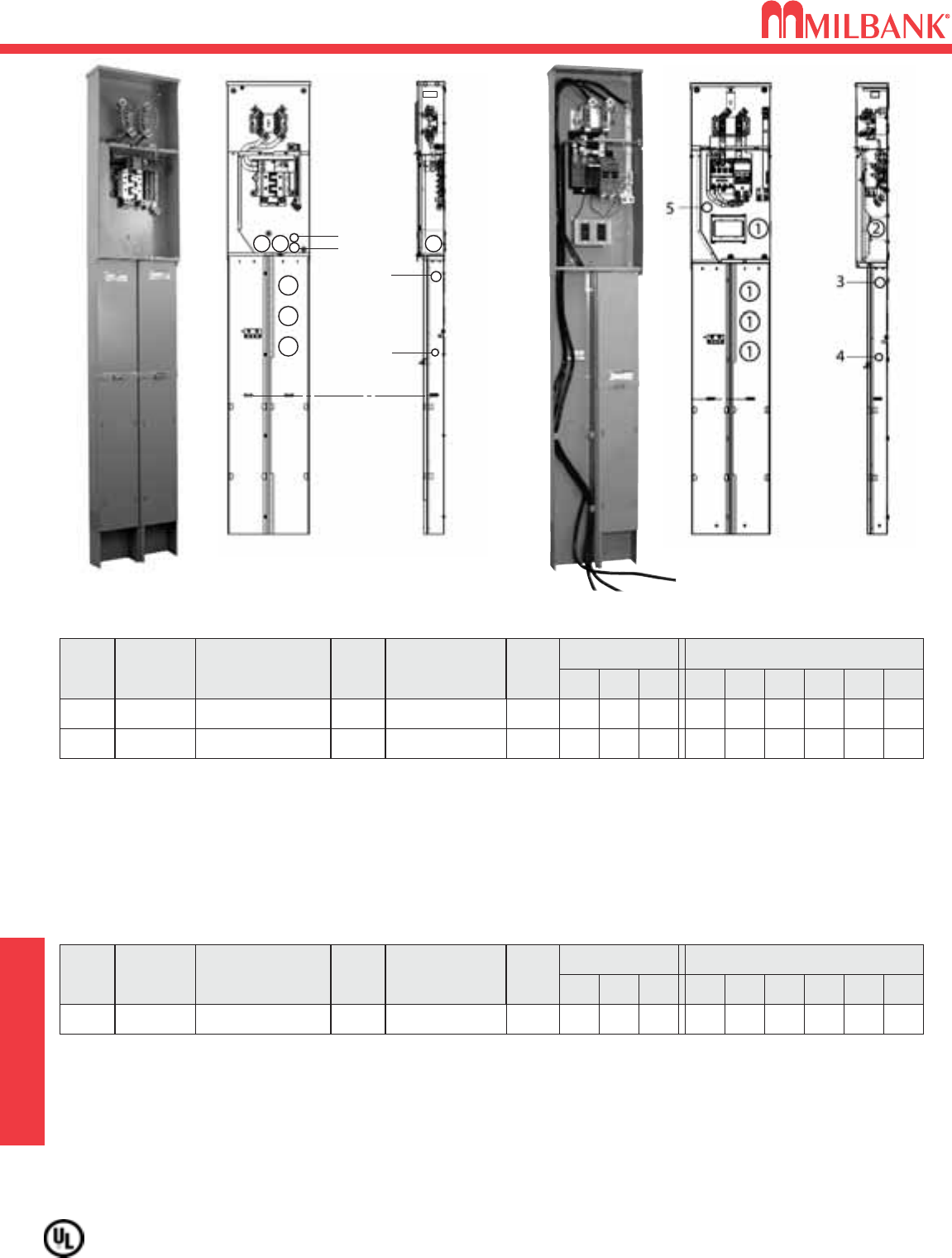
BYPASS: Lever supplies clamping action on meter spades and also operates bypass device.
EXTENSION KIT: For extension kit order as extra catalog number S1848.
HANGING HOOK: Units supplied with hanger hooks for easy mounting.
CONNECTORS: On the U1748-O-WI and U1748-O-5T9-WI, the connectors K1539 (single-350 kcmil) are factory installed on the
line side. Load side is furnished with K1350 (twin-350 kcmil).
①FACTORY-INSTALLED FIFTH TERMINAL: Includes factory installed fifth terminal in the 9 oʼclock position for use on Alliant
Energy lines when a fifth terminal is required.
** SHORT CIRCUIT CURRENT RATING: See chart on page 41
13"
16 7/8"
15"
4 27/32"
3849
1748
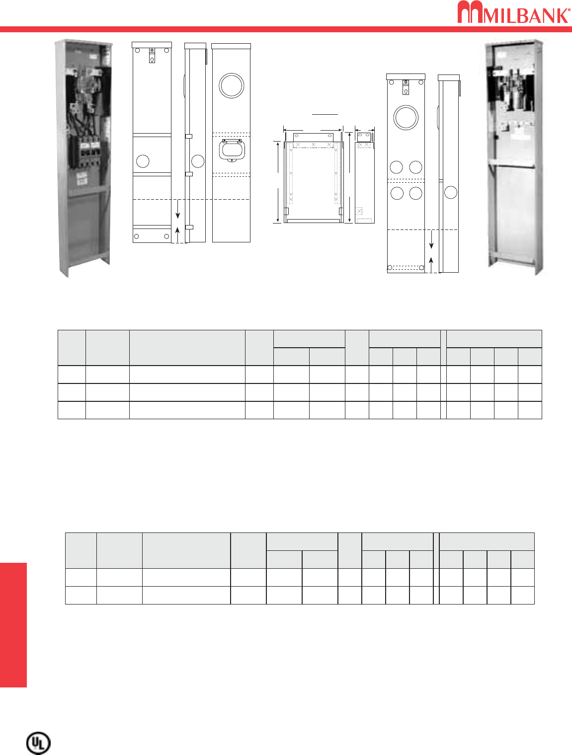
PEDESTAL OPTION
Extension Unit
S1848
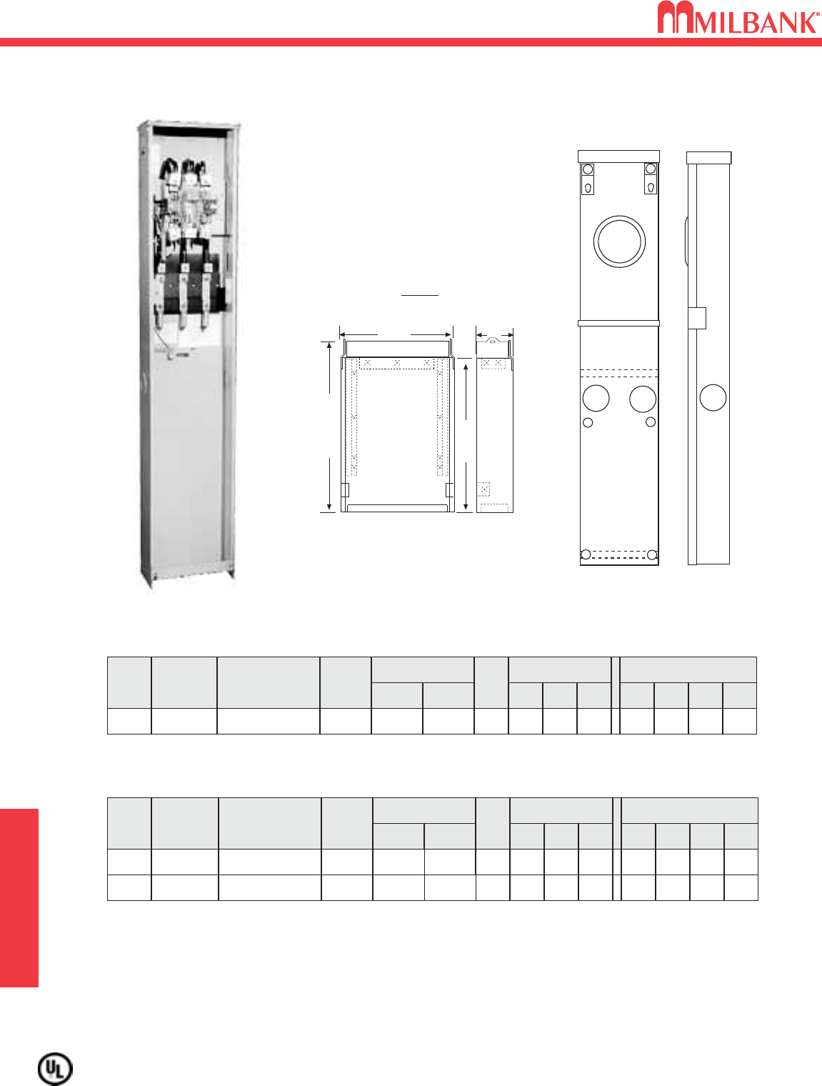
320 AMP—4 & 5 TERMINAL—WITHOUT BREAKER PROVISION—RINGLESS—1∅3W
#
OF
TERM
SERVICE CATALOG
NUMBER HUB
CONNECTOR
CU/AL
BY-
PASS
DIMENSIONS CONCENTRIC K.O.ʼS
1234D″W″H″LINE LOAD
4
5
UG
UG
U1748-O-WI**
U1748-O-5T9-WI①**
BLANK
BLANK
LEVER
LEVER
21
⁄
2
21
⁄
2
21
⁄
2
21
⁄
2
5
⁄
16
5
⁄
16
—
—
47
⁄
8
47
⁄
8
13
13
64
64
#6-350
kcmil
#6-350
kcmil
(2)#6-350
kcmil
(2)#6-350
kcmil
SERVICE PEDESTALS
Utility requirements for this equipment may vary. Always consult the serving utility for their requirements before ordering or
installing equipment in this catalog.
23
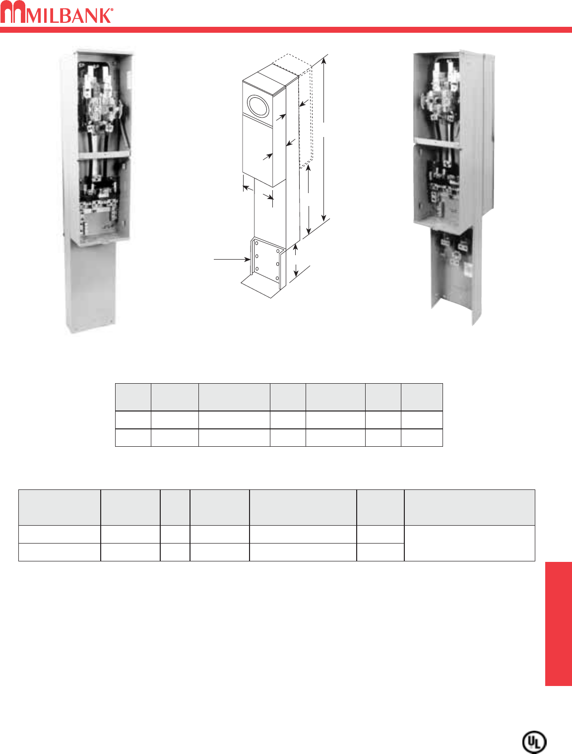
100 / 200 AMP–4 TERMINAL–METER PEDESTAL–PARALLEL MAIN–1
∅
–120 / 240 VAC
100 / 200 AMP–4 TERMINAL–METER PEDESTAL–PARALLEL MAIN–1
∅
–120 / 240 VAC
Utility requirements for this equipment may vary. Always consult the serving utility for their requirements before ordering or
installing equipment in this catalog.
23
MILBANK
1
2
Grade Line
STD = 79"
-LP = 70"
STD = 36"
-LP = 24"
NU8980-O-KK
100 / 200 AMP—1∅3W—RINGLESS–UNDERGROUND FEED
HUB
CONNECTOR
CU/AL
LINE LOAD
BLANK
#6-350
KCMIL CB
CATALOG NUMBER
NU8980-O-KK
NU8980-O-KK-LP
BLANK
#6-350
KCMIL CB
BLANK
#6-350
KCMIL
#6-1/0
NU8980-O-SF100-KK
NU8980-O-SF100-KK-LP
NU8980-O-200-KK
NU8980-O-200-KK-LP
MAIN
BREAKER
— *
— *
Q2100H
Q2100H
UQFPH
UQFPH
BLANK
BLANK
BLANK
DIMENSIONS
CONCENTRIC K.O.ʼS
1 2 3D″W″H″
21
⁄
221
⁄
2—6 9 79
21
⁄
221
⁄
2—6 9 79
21
⁄
221
⁄
2—6 9 70
21
⁄
2
21
⁄
2
21
⁄
2
21
⁄
2
21
⁄
2
21
⁄
2
—
—
—
6
6
6
9
9
9
70
79
70
#6-350
KCMIL
#6-350
KCMIL
#6-350
KCMIL
#6-1/0
1/0-300
1/0-300
* FIELD INSTALLED CIRCUIT BREAKER REQUIRED.
MAIN CIRCUIT BREAKERS: All main breakers are parallel connected. For series wired main order wire kit #K4714
and UQFPH-M type circuit breaker. See Milbank circuit breaker chart on accessory page.
BRANCH CIRCUIT BREAKERS: Branch Interior accepts most manufacturers small frame plug-in type circuit
breakers (GE, Siemens, Cutler-Hammer, Murray).
SF in catalog number has small frame plug-in type circuit breaker installed on middle stabs of 4 circuit interior. Only
two single pole spaces available.
FIFTH TERMINAL: For field installed 5th terminal order K5T. Mounts in 9 o'clock position only.
BYPASS: All pedestals have horn-type bypass installed for meter testing or replacement without interrupting
customer service.
EXTENSION KIT: Available for low profile (-LP) units only. Order kit # K4694. See accessory page.
BY-
PASS
HORN
HORN
HORN
HORN
HORN
HORN
SERVICE PEDESTALS
24
24
Utility requirements for this equipment may vary. Always consult the serving utility for their requirements before ordering or
installing equipment in this catalog.
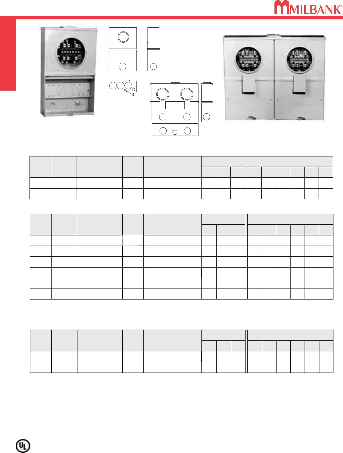
U5925 AND U5706 PEDESTALS–120/240V
U5925 AND U5706 PEDESTALS–120/240V
SERVICE PEDESTALS
BYPASSAMP
100
200
HORN
CATALOG
NUMBER
U5925-O-100-KK
TERM
4
LINE
CONNECTORS
CU/AL
LBS.
#6-350 75
DIMENSIONS CONCENTRIC K.O.ʼS
123456D″W″H″
21⁄22 1 1⁄2, 3⁄41⁄2, 3⁄4–37⁄16 14 78
HORN U5925-O-200-KK 4#6-350 75 21⁄22 1 1⁄2, 3⁄41⁄2, 3⁄4–37⁄16 14 78
100/200 AMP—4 TERMINAL—RINGLESS—HORN BYPASS
FIFTH TERMINAL: For field installed 5th terminal, order K5T. Installs in the 9 oʼclock position.
INTERLOCK KIT: For generator auxiliary circuit breaker interlock for large frame QN with small frame Qorder K5815; for larger
frame QN with larger frame QN order K5820; for small frame Qwith small frame Qorder K5830.
BRANCH CIRCUIT BREAKERS: Branch Interior accepts most manufacturers small frame plug-in type circuit
breakers (GE, Siemens, Cutler-Hammer, Murray).
NOTE: Ten additional single pole spaces for 100A version and eight additional single pole spaces for 200A version.
BYPASSAMP
200 HORN
CATALOG
NUMBER
U5706-O-200S-KK
MAIN
WIRED
SERIES
LINE
CONNECTORS
CU/AL
LBS.
#6-350 79
DIMENSIONS CONCENTRIC K.O.ʼS
123456D″W″H″
21⁄22 1 1⁄4, 1⁄21–31⁄214 80
200 AMP—4 TERMINAL–RINGLESS—HORN BYPASS
Up to two receptacle/circuit breaker kits can be factory installed. Contact factory for factory installed kits.
To increase pedestal height, order field-installed post extension kit K5708.
For field installed fifth terminal in the 9 oʼclock position, order kit K5T.
For field converting from parallel to series wired, order kit K5194. For field converting from series to parallel wired, order kit K5193.
Units are parallel wired from the factory.
NOTE: Four additional single pole spaces.
SOLID
GRADE LINE
1
4
3
3
5
22 2
1
1
U5706-O-200S-KKU5925-O-200-KK
Utility requirements for this equipment may vary. Always consult the serving utility for their requirements before ordering or
installing equipment in this catalog.
25
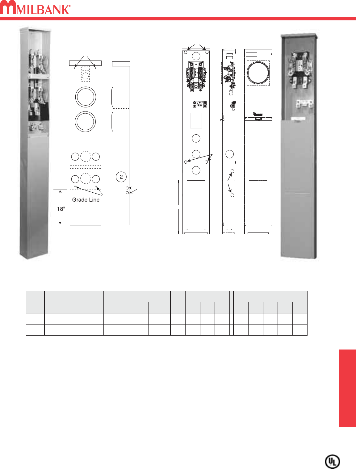
100 / 200 AMP–4 & 5 TERMINAL–600V–PEDESTAL–RINGLESS SERVICE PEDESTALS
100 / 200 AMP–4 & 5 TERMINAL–600V–PEDESTAL–RINGLESS
25
100/200 AMP / POSITION—4 & 5 TERMINAL—600V—RINGLESS—1∅3W—UG
NO.
OF
POS.
CATALOG
NUMBER HUB
CONNECTOR
CU/AL
BY-
PASS
DIMENSIONS CONCENTRIC K.O.ʼS
12345D"W"H"LINE LOAD
1U3358-O-KK BLANK HORN 2 2 5
⁄
16 1
⁄
22
41
⁄
8962
#6-350
kcmil
#6-350
kcmil
2U1783-O-KK BLANK HORN 21
⁄
221
⁄
25
⁄
16 1
⁄
211
⁄
4
41
⁄
285
⁄
874
#6-350
kcmil
#6-350
kcmil
EXTENSION UNIT: For 15" burial applications, order extension unit K5800; for 30" burial applications, order
(2) catalog # K5800 for the U3358. Order catalog number S8988 for the U1783.
CONNECTORS: Extruded aluminum connectors are tin plated.
FIFTH TERMINAL: For a field mounted fifth terminal, order as extra catalog number K5T in the 9 oʼclock position.
BYPASS: The -KK horn type bypass is factory installed and permits changing and testing of the meter without
interrupting customer service when used with utility-supplied jumpers.
UTILITY APPROVAL: Wisconsin utility approved.
U1783-O-KK
U3358-O-KK
5
11
11
4
3
3
3.50
18.00
GRADE LINE
1
2
2
5
3
2
3
4
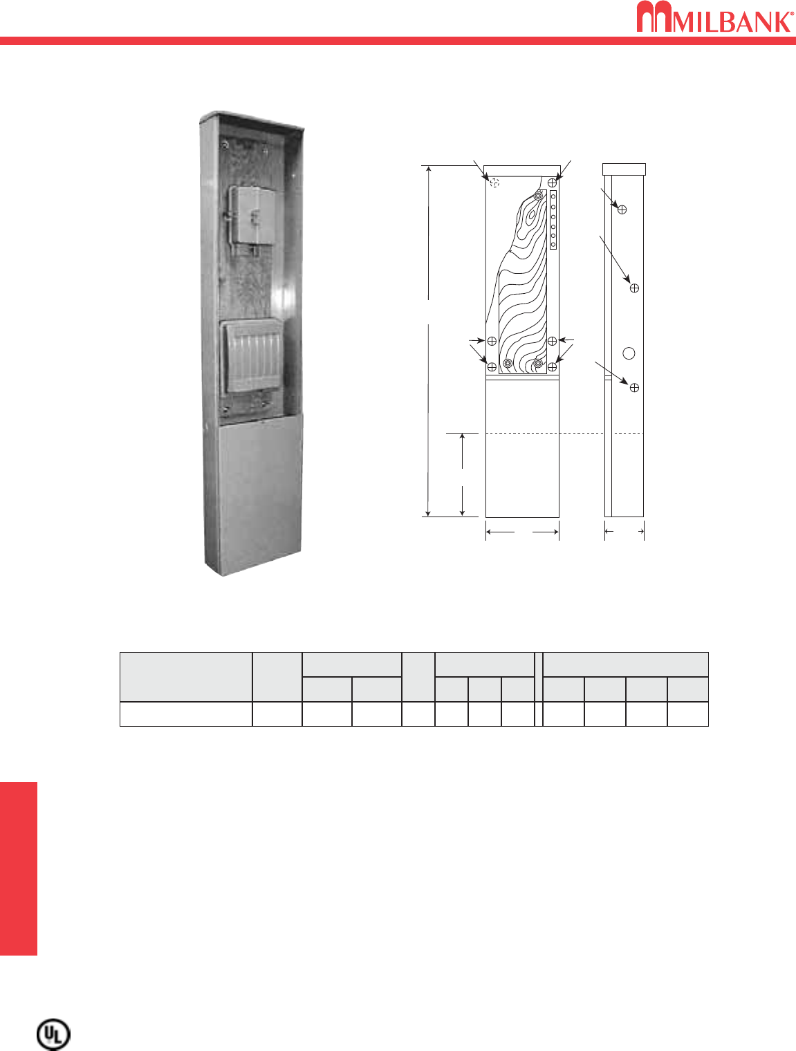
JOINT USE TERMINATION CABINET
26
JOINT USE TERMINATION CABINET
SERVICE PEDESTALS
Utility requirements for this equipment may vary. Always consult the serving utility for their requirements before ordering or
installing equipment in this catalog.
26
Grade Line
12"
11
4
3
2
58"
1
1
13" 41/2"
2
JOINT USE TERMINATION CABINET
CATALOG
NUMBER HUB
CONNECTOR
CU/AL
BY-
PASS
DIMENSIONS CONCENTRIC K.O.ʼS
1234D"W"H"LINE LOAD
U4329-O BLANK
NONE
17
⁄
16 1
⁄
21
⁄
2, 141
⁄
213 58
NONE NONE
TELEPHONE AND CABLE CONDUCTORS: This unit will accommodate both telephone and cable
conductors, eliminating the use of multiple, unsightly network interface devices on the outer structure of
the home, while providing tamper resistance to the communication modules.
SINGLE LOCATION POINT OF SERVICE: The U4329-O combined with the Milbank meter pedestal
provides a single location point of service making access for utility service personel convenient and
efficient.
APPROVED: The U4329-O is recommended by all major WISCONSIN UTILITIES.
U4329
Utility requirements for this equipment may vary. Always consult the serving utility for their requirements before ordering or
installing equipment in this catalog.
27
200 AMP–SERIES U5136 & U5137–RINGLESS–METERED PEDESTAL SERVICE PEDESTALS
200 AMP–SERIES U5136 & U5137–RINGLESS–METERED PEDESTAL
27
• UL Listed File E90945.
• 200 amp maximum, 120/240 V, 1∅3W.
• Ringless type meter socket with horn bypass and
stainless steel latch.
• Short circuit withstand rating 10K AIC, for 22K AIC, order
with “22” suffix.
• Type 3R construction for durable outdoor use.
• Milbank grey polyester powder coat finish.
• Wire terminations accept copper or aluminum conductors.
• Line & Neutral: (2) #6-350 kcmil per phase.
• Line Ground: (4) #14-1/0.
• Load (CB): 1/0 to 300 kcmil per pole.
• Load Neutral: (1) #6-350 kcmil.
• Load Ground: (2) #14-1/0, (4) #14/6.
• Commercial grade, plug-in main circuit breaker. Available
in 100, 125, 150 & 200 amp. Type UQFP-M.
• 4 circuit plated copper interior accepts (2) 2-pole or (4)
1-pole standard plug-in type circuit breakers. Branch
circuit rated to 125 amps max. Acceptable manufacturers:
Milbank, Cutler-Hammer, GE or Siemens.
• Factory installed receptacle bridge and receptacle / circuit
breaker available. See below or consult factory for more
options.
U5136-O-200S
SINGLE PEDESTAL
CATALOG #MAIN BREAKER AMPS INTERIOR WEIGHT (lbs)RECEPTACLE
U5136-O-100S UQFP-M-100 100 4 Circuit 82 NONE
U5136-O-100S-10GR UQFP-M-100 100 4 Circuit 82 (1) 520GR
U5136-O-200S UQFP-M-200 200 4 Circuit 82 NONE
U5136-O-200S-11GR UQFP-M-200 200 4 Circuit 82 (2) 520GR
DOUBLE PEDESTAL
CATALOG #MAIN BREAKER AMPS INTERIOR WEIGHT (lbs)RECEPTACLE
U5137-O-100S (2) UQFP-M-100 Series 100 4 Circuit 115 NONE
U5137-O-100S-10GR (2) UQFP-M-100 Series 100 4 Circuit 115 (1) 520GR
U5137-O-200S (2) UQFP-M-200 Series 200 4 Circuit 115 NONE
U5137-O-200S-11GR (2) UQFP-M-200 Series 200 4 Circuit 115 (2) 520GR
• A maximum of two receptacle / circuit breaker kits can be installed in each power head. Order from above. Other kits available.
Consult factory for factory-installed receptacle kits.
• Pedestals are stocked with series wired main circuit breakers. Order K5193 kit to field convert to parallel main lug circuit
breaker. For parallel wired main circuit breakers, change “S” suffix to “P” (Ex.: U5136-O-100P).
•K5415 Stabilizer Foot sold separately. Recommended for double pedestals.
• Pad mount pedestals available. Order U5138 (single meter) or U5139 (double meter) prefix. K5035 pad mount kit required.
Order separately.
24”
200 AMP–5 & 7 TERMINAL–HEAVY DUTY–RINGLESS–600 VAC
28
200 AMP–5 & 7 TERMINAL–HEAVY DUTY–RINGLESS–600 VAC
SERVICE PEDESTALS
Utility requirements for this equipment may vary. Always consult the serving utility for their requirements before ordering or
installing equipment in this catalog.
28
112
3
3
MILBANK
33
33
200 AMP—5 TERMINAL—RINGLESS—3∅3W—UG
#
OF
TERM
SERVICE CATALOG
NUMBER HUB
CONNECTOR
CU/AL
BY-
PASS
DIMENSIONS CONCENTRIC K.O.ʼS
1 2 3 4D″W″H″LINE LOAD
5UG U9108-O** BLANK
LEVER
21
⁄
221
⁄
25
⁄
16 —
611 58
3/0-4/0 #6-350
kcmil
100 / 200 AMP—7 TERMINAL—RINGLESS—3∅4W—UG
#
OF
TERM
SERVICE CATALOG
NUMBER HUB
CONNECTOR
CU/AL
BY-
PASS
DIMENSIONS CONCENTRIC K.O.ʼS
1234D″W″H″LINE LOAD
7
7
UG
UG
U9107-O
U9107-O-K5*
BLANK
BLANK
LEVER
LEVER
21
⁄
2
21
⁄
2
21
⁄
2
21
⁄
2
5
⁄
16
5
⁄
16
—
—
6
6
11
11
58
58
3/0-4/0
#6-350
kcmil
#6-350
kcmil
#6-350
kcmil
EXTENSION UNIT: For a field mounted, 15″extension unit, order catalog number S3488.
GROUND: U9108-O is supplied with a bonded ground which may be isolated when desired.
BYPASS: Lever supplies clamping action on meter spades and also operates bypass device.
*INCLUDES: #6-350 kcmil connectors on line side for Alliant Energy.
**NEUTRAL: The U9108-O is supplied with a center disconnect neutral.
U9107-O
PEDESTAL OPTION
Extension Unit
S3488
11"
15"
16 15/16"
6"
9107
9108
Utility requirements for this equipment may vary. Always consult the serving utility for their requirements before ordering or
installing equipment in this catalog.
29
200 AMP–4 TERMINAL
MOBILE HOME METER PEDESTALS–RINGLESS–120/240 VAC
SERVICE PEDESTALS
200 AMP–4 TERMINAL
MOBILE HOME METER PEDESTALS–RINGLESS–120/240 VAC
29
METER
POSITIONS
BY-
PASS
MOUNTING
TYPE
TWIN
LINE CONNECTORS
CU/AL
CIRCUIT
PROV.
SINGLE LEVER
LEVER
POST #6 AWG-350 kcmil 6
6DOUBLE POST #6 AWG-350 kcmil
CATALOG
NUMBER
U4322-O-5T9
U4323-O-5T9
DESCRIPTION
Provisions for Main with
Branch or Parallel Breakers
LEVER BYPASS: Lever provides clamping action on meter spades and also operates bypass device.
APPLICATION: The U4322 & U4323 pedestals are suitable for use as service equipment or mobile home service equipment.
K5081 / K3188 for direct burial application is included with unit. K5151 for pad mount application must be ordered as extra.
BREAKERS: These units are wired as parallel mains and have provisions for six circuits: six single-pole or three double-pole
breakers.
FIFTH TERMINAL: For field installed fifth terminal order catalog number K3866 (with neutral wire). May be installed in 6 oʼclock
or 9 oʼclock position.
200 AMP—4 TERMINAL—RINGLESS
U4322-O
U4323-O
STABILIZER
FOOT 12"
21"
55"
10"
5 1/2"
4 1/8"
U4322 &
U4323
PLUG-IN BREAKER COMPATIBILITY CHART
AMPS MILBANK
CUTLER-HAMMER
(WESTINGHOUSE)
SIEMENS
(ITE)
SIEMENS
MURRAY /
CROUSE-HINDS
G.E. SQ-D
125-200 Q / QN HQP / BR / WBJ Q / QN MD Q LINE —
≤ 100 Q QUICKLAG P /
BR / HQP QP MP Q LINE
HOMELINE
20 AMP–TRANSFORMER RATED–5, 6, 8 & 13 TERMINAL
SINGLE & DOUBLE POSITION–RINGLESS / RING TYPE–600 VAC
30
20 AMP–TRANSFORMER RATED–5, 6, 8 & 13 TERMINAL
SINGLE & DOUBLE POSITION–RINGLESS / RING TYPE–600 VAC
CT-- RATED
Utility requirements for this equipment may vary. Always consult the serving utility for their requirements before ordering or
installing equipment in this catalog.
30
20 AMP—TRF RATED—DOUBLE POSITION—2 PIECE COVER—RING TYPE—OH/UG
NO.
OF
TERMS
METER
FORM
CATALOG
NUMBER HUB CONNECTORS
CU
DIMENSIONS CONCENTRIC K.O.ʼS
123456D″W″H″
85S UC2427-XL** C.P. #14 - #2MAX 11
⁄
411
⁄
41
⁄
4,1
⁄
211
⁄
4— —
41
⁄
8241
⁄
16 20
13 6, 8, 9 &
(ALT) 10S UC2428-XL** C.P. #14 - #2MAX 11
⁄
411
⁄
41
⁄
4,1
⁄
211
⁄
4— —
41
⁄
8241
⁄
16 20
20 AMP—TRF RATED—1 & 2 PIECE COVER—RINGLESS—OH/UG
NO.
OF
TERMS
METER
FORM
CATALOG
NUMBER HUB CONNECTORS
CU
64S UC7532-XL*
C.P.
#14 - #2MAX
DIMENSIONS CONCENTRIC K.O.ʼS
123456
11
⁄
411
⁄
411
⁄
411
⁄
4—1
⁄
4,1
⁄
2
D″W″H″
41
⁄
812 20
85S UC1962-XL C.P. #14 - #2MAX 11
⁄
211
⁄
211
⁄
411
⁄
4—1
⁄
4,1
⁄
241
⁄
812 20
85S UC7448-XL C.P. #14 - #2MAX 11
⁄
411
⁄
411
⁄
411
⁄
4—1
⁄
4,1
⁄
241
⁄
812 20
13 6, 8, 9 &
(ALT) 10S UC7449-XL C.P. #14 - #2MAX 11
⁄
411
⁄
411
⁄
411
⁄
4—1
⁄
4,1
⁄
241
⁄
812 20
85S UC3887-XL* ①C.P. #14 - #2MAX 11
⁄
411
⁄
411
⁄
411
⁄
4—1
⁄
4,1
⁄
2
513 19
13 6, 8, 9 &
(ALT) 10S UC3889-XL* ①C.P. #14 - #2MAX 11
⁄
411
⁄
411
⁄
411
⁄
4—1
⁄
4,1
⁄
2
513 19
HUBS: For proper hub selection see the hub suffix chart on the accessory page.
** SEALING RINGS: Ring type units are supplied with one MR-4, screw type, sealing ring.
PREWIRING: If standard factory pre-wiring is required, refer to wiring diagrams in the general engineering section of this
catalog. Determine appropriate diagram and send copy with order. If custom factory prewiring is required, specify on order.
Be sure to include meter socket catalog number, test switch model and number, and meter form number. Please be sure
to provide a copy of your wiring diagram.
SERVICE: Units are rated for overhead or underground feed.
UC7449-XL
UC2428-XL
1
434
6
2
* Approved for use with Wisconsin Electric Power Company only.
① UC3887-XL and UC3889-XL have 1-piece cover.
3
44
112
20 AMP—RINGLESS—PLUNGER BYPASS
NO.
OF
TERMS
METER
FORM
CATALOG
NUMBER HUB CONNECTORS
CU
DIMENSIONS CONCENTRIC K.O.ʼS
123456D″W″H″
55S UC1290-RL H.O. #14 - #2 11
⁄
211
⁄
2211
⁄
41
⁄
4—
35
⁄
16 814
66, 8, 9 &
(ALT) 10S UC1299-RL H.O. #14 - #2 11
⁄
211
⁄
2211
⁄
41
⁄
4—
35
⁄
16 814
2427
2428
1290
1299
7532
1962
7448
7449
3887
3889
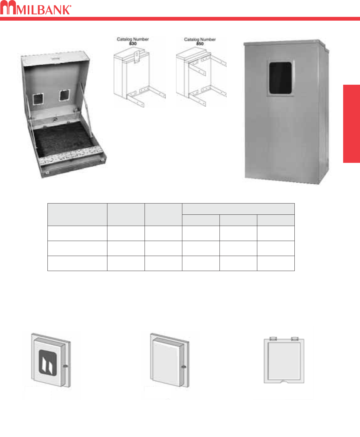
31
POLYPHASE ENCLOSURES FOR “A” BASE METERS
MISC
POLYPHASE ENCLOSURES FOR “A” BASE METERS
31
NEW
CATALOG
NUMBER
S9995-B-XL
S9996-B-XL
S9997-B-XL
NUMBER
OF
POSITIONS
1C.P. 11 15 26
1C.P. 11 15 30 11⁄16
2C.P. 11 27 30 11⁄16
HUB
DIMENSIONS
D″W″H″
BRIDGE AND MOUNTING BOARD: Units are supplied with board and bridge.
WINDOWS AND COVERS: Units supplied with one 41
⁄
2″x 6″glass window per meter position. If glass demand reset window
is desired, add suffix -CW to the catalog number. If metal demand reset cover is desired, add suffix -C to the catalog
number. If window shield is desired, add suffix -WS to the catalog number.
HUBS: Above units supplied with closing plate. Order hub as extra. Refer to accessory page.
GLASS WINDOW
DEMAND RESET COVER
(41
⁄
2″x 6″)
Catalog No. SDRCW
ALL METAL
DEMAND RESET COVER
(41
⁄
2″x 6″)
Catalog No. SDRC
WINDOW SHIELD
Catalog No. WS
POLE MOUNTING BRACKETS
Order #830 for one pair (2 pcs.) with keyhole
bracket and mounting hardware.
Order #850 for two pair (4 pcs.) with
mounting hardware.
FIELD INSTALLED ACCESSORIES
POLYPHASE ENCLOSURE ORDERING INFORMATION
S9995-B-XL
S9997-B-XL
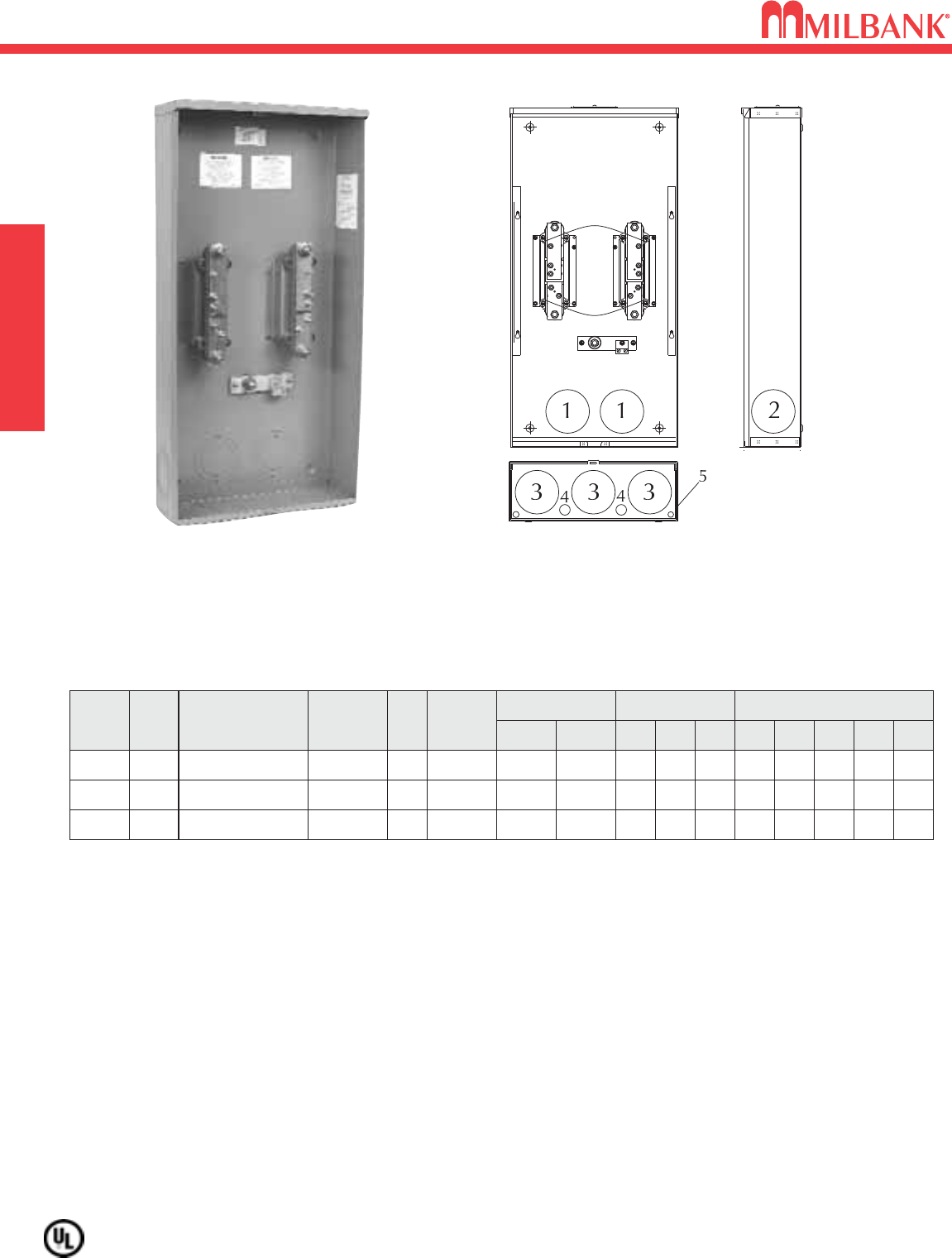
4 TERMINAL–TYPE K4 METER MOUNTING DEVICE
1
∅
3–480 AMPERES CONTINUOUS–300 VAC
32
4 TERMINAL–TYPE K4 METER MOUNTING DEVICE
1
∅
3–480 AMPERES CONTINUOUS–300 VAC
MISC.
Utility requirements for this equipment may vary. Always consult the serving utility for their requirements before ordering or
installing equipment in this catalog.
32
APPLICATION: For use with 1∅3W self-contained Type MS-K watthour meters.
CAPACITY: 480 amperes continuous / 600 amperes maximum.
CONNECTORS: 1/2"-20 plated steel studs with nuts and captive Belleville washers to accommodate various bolt-on type lugs for
conductors from #6 to 800 kcmil CU or AL. Use 3/4" insulated wrench to fasten connectors to block.
① Phase and neutral connectors included if lug kit number is shown in table as installed. For lugs refer to page 34 of this
catalog.
ENCLOSURE: Constructed of 14-gauge galvanized steel suitable for indoor or outdoor installations.
BYPASS: Rated 50%, separate manual type, order Milbank kit #K4687 (kit includes 2 bypasses).
METER MOUNTING: Two position stud type. One set of studs provides out-of-service storage. The in-service studs are
positioned so the meter cannot be installed upside-down. Full travel meter opening slide plate eliminates the need for
repositioning the slide plate for the “IN” or “OUT OF SERVICE” position.
BLOCKS: Glass fiber reinforced polyester plastic. High arc withstand strength and track resistant. Provisions for lightning
arresters.
* SHORT CIRCUIT CURRENT RATING: 10,000 RMS sym amps 600 VAC
CATALOG
NUMBER
U4664-X-8502*
HUB
L&G
NUMBER
(1) Large
C.P. (-X)
CONNECTOR
CU/AL DIMENSIONS CONCENTRIC K.O.ʼS
(INCHES)
1
3,31⁄2,4 3,31⁄2,4 3,31⁄2,4 1⁄2,3⁄41⁄4
2345D″
6
W″
173⁄4
H″
36
LINE
TWIN
6-350 KCMIL
LOAD
TWIN
6-350 KCMIL
SVC.
OH/UG
UTILITY
WPS
U4664-X-8507*
U4664-XT-9507*
(1) Large
C.P. (-X)
(2) Large
C.P. (-X)
LUG
KIT
①
Installed
NONE
NONE
9810-8502
9810-8507
9810-9507
3,31⁄2,4
3,31⁄2,4
3,31⁄2,4
3,31⁄2,4
3,31⁄2,4
3,31⁄2,4
1⁄2,3⁄4
1⁄2,3⁄4
1⁄4
1⁄4
6
6
173⁄4
173⁄4
36
36
1/2"-20
STUD
1/2"-20
STUD
1/2"-20
STUD
1/2"-20
STUD
OH/UG
OH/UG
WPS
WPS
400 AMP—4 TERMINAL—RINGLESS—1∅3W—OVERHEAD / UNDERGROUND
U4664-X-(*)
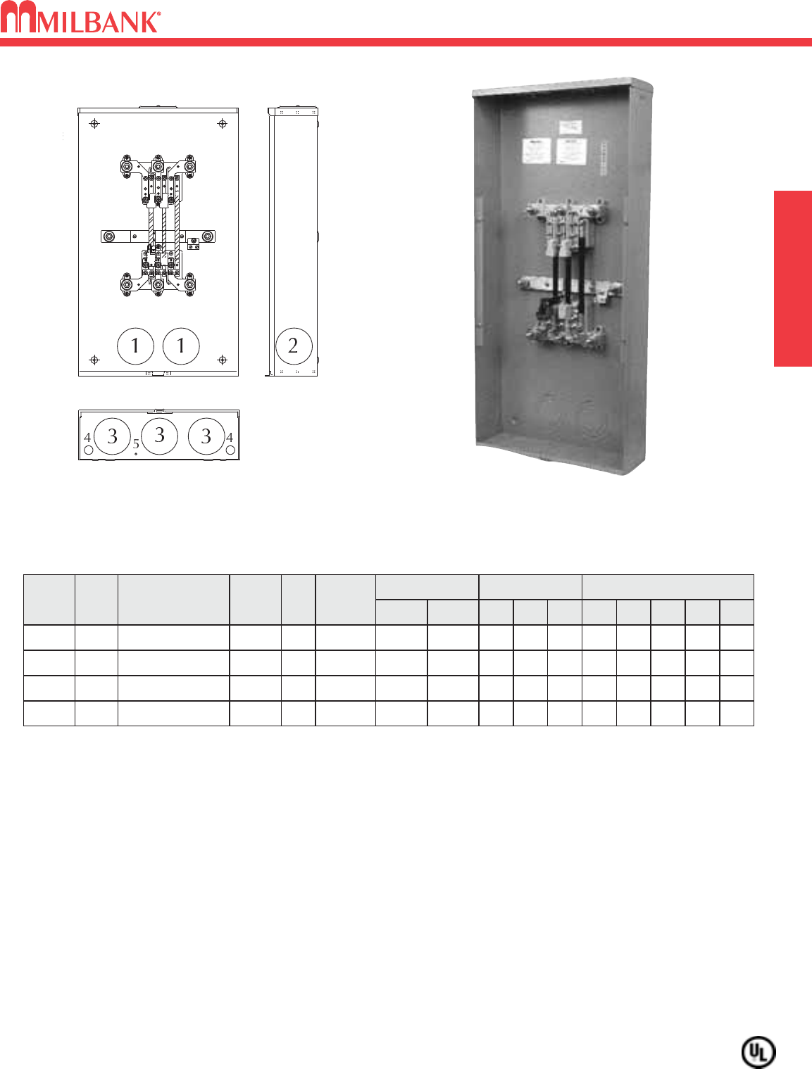
Utility requirements for this equipment may vary. Always consult the serving utility for their requirements before ordering or
installing equipment in this catalog.
33
7 TERMINAL–TYPE K7 METER MOUNTING DEVICE
3
∅
4W–480 AMPERES CONTINUOUS–600 VAC
MISC.
7 TERMINAL–TYPE K7 METER MOUNTING DEVICE
3
∅
4W–480 AMPERES CONTINUOUS–600 VAC
33
APPLICATION: For use with self-contained Type MT-K watthour meters on 3∅4W Wye or 4-wire delta services.
CAPACITY: 480 amperes continuous / 600 amperes maximum.
CONNECTORS: 1/2"-20 plated steel studs with nuts and captive Belleville washers to accommodate various bolt-on type lugs
for conductors from #6 to 800 kcmil CU or AL. Use 3/4" insulated wrench to fasten connectors to block.
① Phase and neutral connectors included if lug kit number is shown in table as installed. For lugs refer to page 34 of this
catalog.
ENCLOSURE: Constructed of 14-gauge galvanized steel suitable for indoor or outdoor installations.
BYPASS: Rated 50%, separate manual type, order Milbank kit #K4688 (kit includes 3 bypasses).
METER MOUNTING: The meter is mounted on 6 studs using 5/16"-24 studs with nuts with captive Belleville washers. The upper
studs are positioned so that the meter cannot be installed upside down. Use 1/2" insulated wrench. Another set of studs
provides on site “OUT OF SERVICE” storage. Full travel meter opening slide plate eliminates the need for repositioning the
slide plate for the “IN” or “OUT OF SERVICE” position.
* SHORT CIRCUIT CURRENT RATING: 10,000 RMS sym amps 600 VAC
CATALOG
NUMBER
U4667-X-8512*
HUB
Large
C.P
CONNECTOR
CU/AL DIMENSIONS CONCENTRIC K.O.ʼS
(INCHES)
1
3,31⁄2,4 3,31⁄2,4 3,31⁄2,4 1⁄2,3⁄41⁄4
2 3 4 5D″
6
W″
201⁄4
H″
43
LINE
TWIN
4-500 KCMIL
LOAD
TWIN
4-500 KCMIL
SVC.
OH/UG
UTILITY
WPS
U4667-XT-9504*
U4667-XT-9506*
U4667-X-8013*
Large
C.P.
Large
C.P. (x2)
Large
C.P.
L&G
NUMBER
9817-8512
9817-9504
9817-9506
9817-8013
LUG
KIT
①
Installed
NONE
Installed
Installed
3,31⁄2,4
3,31⁄2,4
3,31⁄2,4
3,31⁄2,4
3,31⁄2,4
3,31⁄2,4
3,31⁄2,4
3,31⁄2,4
3,31⁄2,4
1⁄2,3⁄4
1⁄2,3⁄4
1⁄2,3⁄4
1⁄4
1⁄4
1⁄4
6
6
6
201⁄4
201⁄4
201⁄4
43
43
34
1/2"-20
STUD
TWIN
4-500 KCMIL
TWIN
4-500 KCMIL
1/2"-20
STUD
TWIN
4-500 KCMIL
TWIN
4-500 KCMIL
OH/UG
OH/UG
OH/UG
WPS
WPS
WPS
480 AMP—7 TERMINAL—RINGLESS—3∅4W—OVERHEAD / UNDERGROUND
U4667-X-8013
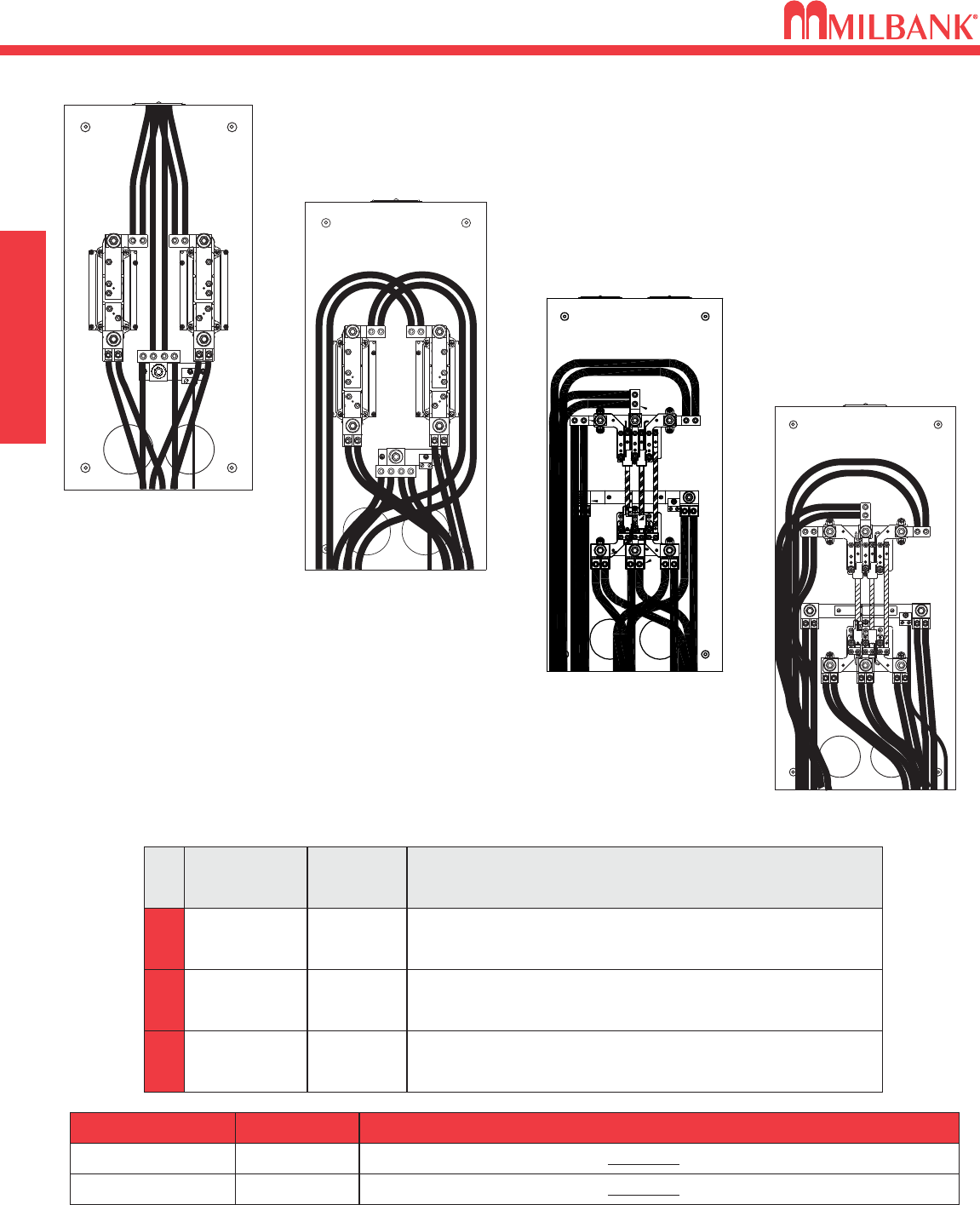
K4 / K7 SERIES SCHEMATICS
34
K4 / K7 SERIES SCHEMATICS MISC.
34
K4
K7 DESCRIPTION
(2) Twin #6-350 kcmil connector (Phase)
(2) Twin #6-350 kcmil connector (Phase)
(1) Quad #6-350 connector (Neutral)
K
7
K
7
LINE / LOAD
FEED —
OH/UG
Parallel
Line/Load
OH/UG
MILBANK
CONN.
NUMBER
K
4
Z703917-AC
Z705456-AC
Z705420-AC
(3) Twin #2-500 kcmil connector (Phase)
(5) Twin #4-500 kcmil connector (Phase)
(3) Twin #6-350 kcmil connector (Phase)
(5) Twin #4-350 kcmil connector (Phase)
Parallel
Line/Load
UG
Parallel
Line/Load
UG
Z704693-AC
Z704694-AC
Z703919-AC
Z703918-AC
MILBANK BYPASS L&G BYPASS DESCRIPTION
K4687 56495 Manual By-pass for K-4 Series (U4664)—Kit includes 2
K4688 58888 Manual By-pass for K-7 Series (U4667)—Kit inlcudes 3
OVERHEAD
K4 Lug Kit
K4 Lug Kit
K7 Lug Kit
UNDERGROUND
UNDERGROUND
K7 Lug Kit
UNDERGROUND
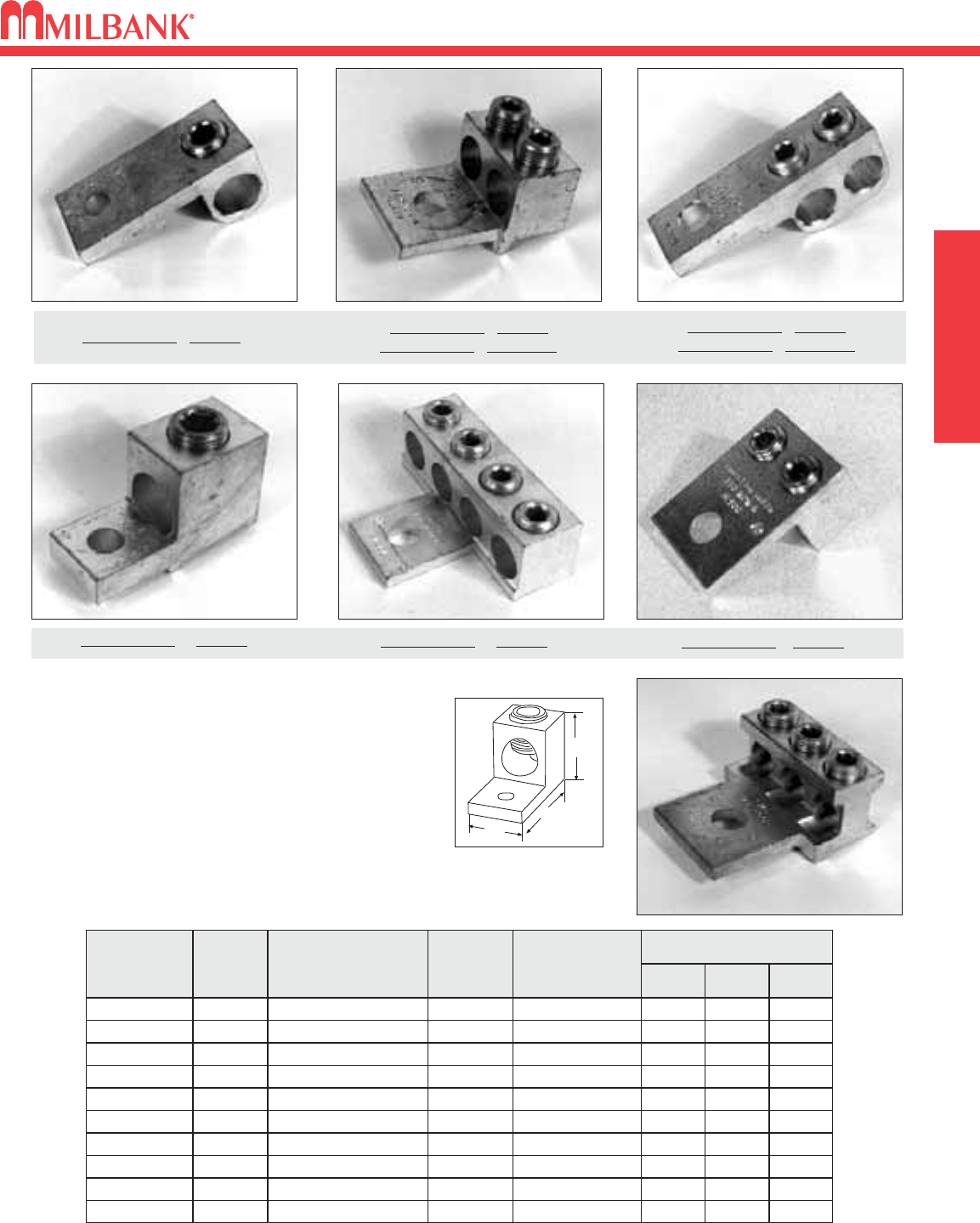
35
LUGS FOR K-SERIES–L & G CROSS-REFERENCE
MISC.
LUGS FOR K-SERIES–L & G CROSS-REFERENCE
35
H
L
W
Bolt-on type lugs for Milbank stud type meter mounting devices
are made of 6061-T6 aluminum to provide high strength and high
conductivity. All lugs are tin-plated to ensure low contact resist-
ance and to reduce corrosion. Allen or hex head pressure
screws are furnished to provide excellent conductor spread for
maximum binding action with the lug.
NO. OF
CONDUCTORS &
SIZE
STUD
OPENING
PRESSURE
SCREW HEAD
DIMENSIONS
L" W" H"
3/0-800 kcmil 9/16" 1/2" Allen 3 15⁄16 1 3⁄41 13⁄16
MILBANK
CONN. #
Z703916-AC
L&G
CONN
NO.
58852
Two #6-350 kcmil 9/16" 5/16" Allen 4 5⁄16 1 1⁄82 1⁄16
Z703917-AC 56427
3/0-800 kcmil 9/16" 1/2" Allen 3 1⁄41 5⁄16 1 13⁄16
Two #4-350 kcmil 9/16" 5/16" Allen 2 7⁄81 59⁄64 1 1⁄4
Z703921-AC
Z703918-AC
Z703919-AC
Two #6-350 kcmil 9/16" 5/16" Allen 2 7⁄81 57⁄64 1 1⁄4
Four #6-350 kcmil 17/32" 5/16" Allen 2 7⁄83 15⁄16 19⁄16
Z705456-AC
Z705420-AC
56425
Three #6-250 kcmil 9/16" 5/16" Allen 2 7⁄82 1⁄21 5⁄16
Z708145-AC 68752-1
56426
56476
Two #2-500 kcmil 9/16" 3/8" Allen 4 1⁄41 1⁄81 13⁄16
Z704693-AC 56427-M
Two #4-500 kcmil 9/16" 3/8" Allen 2 13⁄16 2 5⁄32 1 13⁄16
Z704694-AC 56732-M
56732
58853 Two #6-350 kcmil 9/16" 5/16" Allen 3 15⁄16 1 1⁄81 1⁄2
#Z703918-AC #56732
#Z704694-AC #56732-M
#Z703916-AC #58852 #Z703919-AC #58853
#Z704693-AC #56427-M
#Z708145-AC
#Z703921-AC #56476 #Z705420-AC #56426 #Z705456-AC #56425
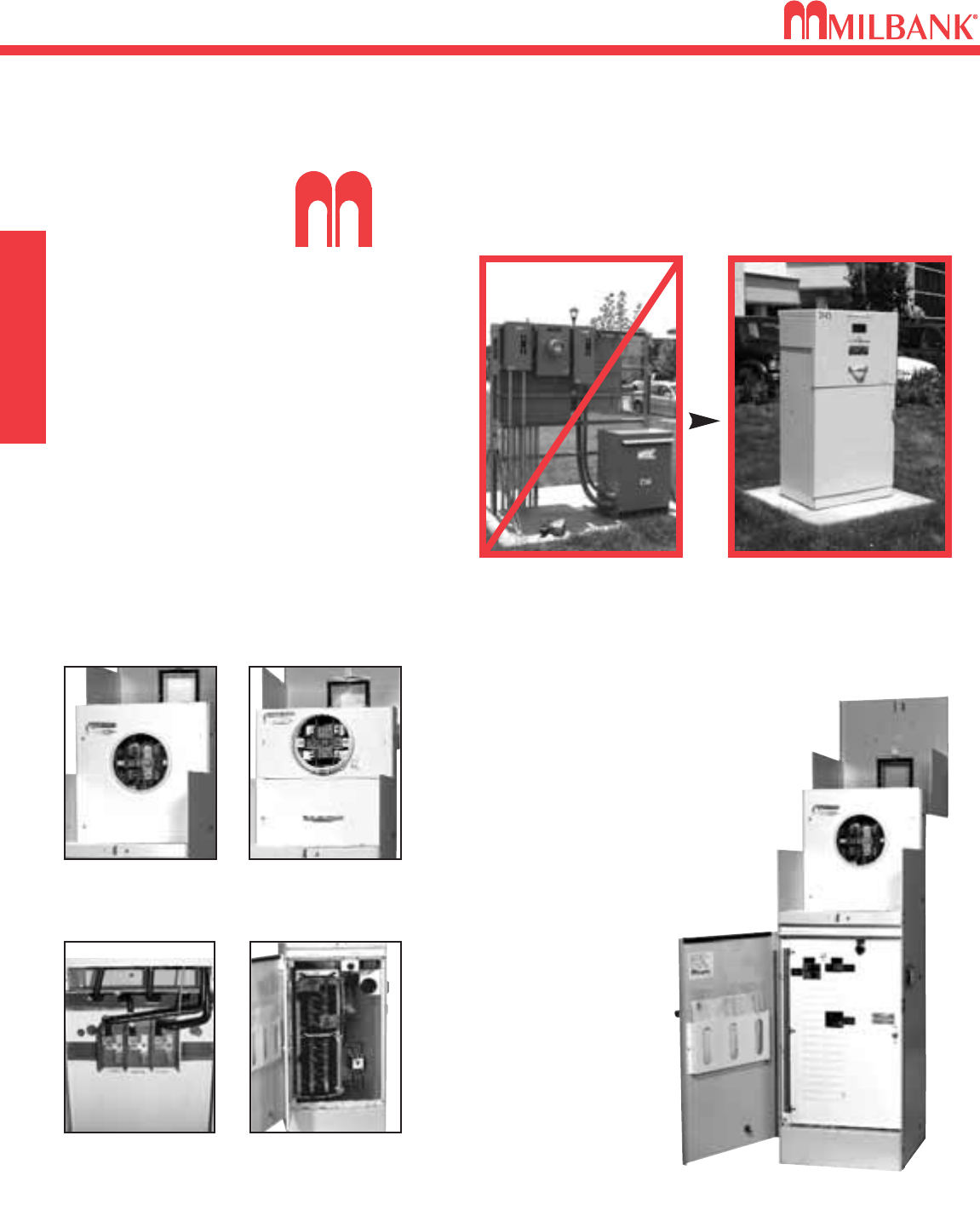
COMMERCIAL METER PEDESTALS OVERVIEW
36
COMMERCIAL METER PEDESTALS OVERVIEW MISC.
36
ilbank Commercial Pedestals are pad-mounted, weatherproof electrical
enclosures consisting of a utility pull section with optional meter socket, and
a customer section containing distribution and control equipment. Milbank
Commercial Pedestals
are an attractive, secure,
easy to install and cost-
effective solution when
underground remote
site power distribution
and control equipment
is required, replacing
unsightly and inefficient
strut and backboard
structures.
Un-Strut
Your
Stuff...
Commercial Pedestals
• Attractive • Easy to install • Secure • Cost effective
STANDARD FEATURES –COMMERCIAL PEDESTALS
• Type 3R rainproof, vandal-resistant cabinet of
polyurethane powder-coated steel (aluminum or
stainless steel also available)
• UL listed
• Isolated, lockable & sealable utility metering &
lug landing sections
• Lockable customer section for distribution &
control equipment with internal deadfront
• Print pocket inside customer section door
contains wiring schematics and installation
instructions
• Most load centers are UL
listed for use with various
manufacturers’ circuit
breakers
• All stainless steel external
hardware (screws, bolts,
hinges, handles, hasps and
sealing screws)
Ringless Socket Ring-type Socket
Utility Lug Landing Customer Interior
Strut and backboard design Commercial Pedestal
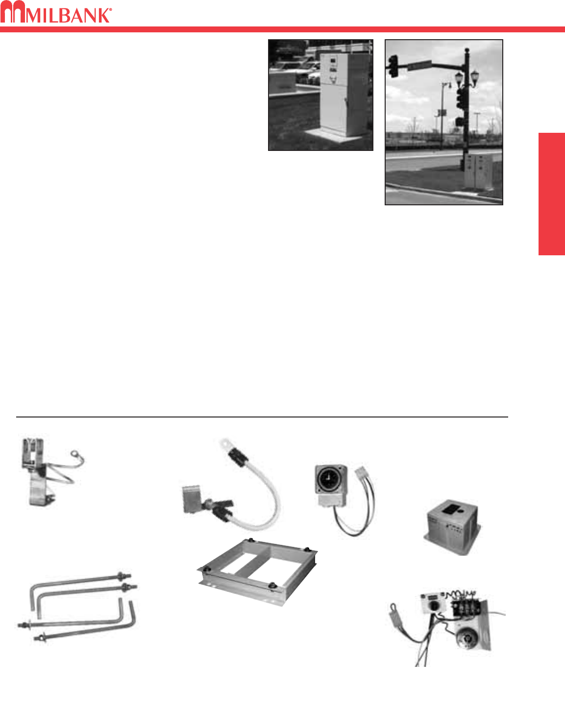
37
MISC.
APPLICATIONS & ACCESSORIES
37
CP-16PDMNT-CALT
Pedestal mounting base for 16" pedestal
CP-24PDMNT-CALT
Pedestal mounting base for 24" pedestal
(includes mounting hardware)
CP-32PDMNT
Pedestal mounting base for 32" pedestal
(includes mounting hardware)
CP-ABK5/8
Anchor bolt kit (includes four 5/8-
13 x 18" anchor bolts)
CP-PE-HOA-3POS
HOA switch – for field
installation
ACCESSORIES
CP-TC7D 7-day time clock kit
CP-TC24H 24-hour time clock kit
CP-TCWIRE Male four-pin connector and
wiring harness for use with
time clocks other than shown
K3865
Fifth terminal kit for
use with ringless
meter sockets
• Meter sockets – ring type or ringless, to 400 amp (unmetered
and dual-metered pedestals also available)
• Main and branch breakers or T fuses
• Distribution – copper load centers & panel boards
• Clocks / timers / relays
• Photoelectric cells and controls
• Power receptacles – pin & sleeve, twist lock or straight blade
• Contactors – definite purpose, electrical or mechanically
held, IEC and mercury types
• Surge protection & lightning arrestors
• Reserve inlet generator receptacle with interlocked circuit
breakers
• Motor starters, relays
• Push button controls
• Thermostat controls, fans and heating strips
• Power blocks and terminal blocks
• Steel, aluminum and plywood back boards
• Transformers
• Interlock devices for circuit breakers
• Available in steel, aluminum (raw painted or anodized) or
stainless steel construction with powder-coated finish avail-
able in 8 standard colors or special ordered RAL colors –
consult factory.
• Available for applications up to 400 amp, 120V, 208V,
240V, 277V, 480V – 1Ø or 3Ø.
APPLICATIONS
These units are ideal for controlling and metering:
• Traffic signals
• Street lighting
• Irrigation / sprinkler systems
• Cell towers / telephone vaults
• Pump stations
• Temporary power for fairgrounds, swap meets, outdoor
markets, portable offices, holiday lights, etc.
• Outdoor lighting for athletic fields, tennis and basketball courts, parking lots,
landscaping and subdivision entrances, etc.
AVAILABLE FACTORY-INSTALLED OPTIONS
105J
Fifth terminal
kit for use
with ring-type
meter sockets
CP-16FPAD
Fiberglass pedestal mounting base
for 16" pedestal (direct buried)
APPLICATIONS & ACCESSORIES
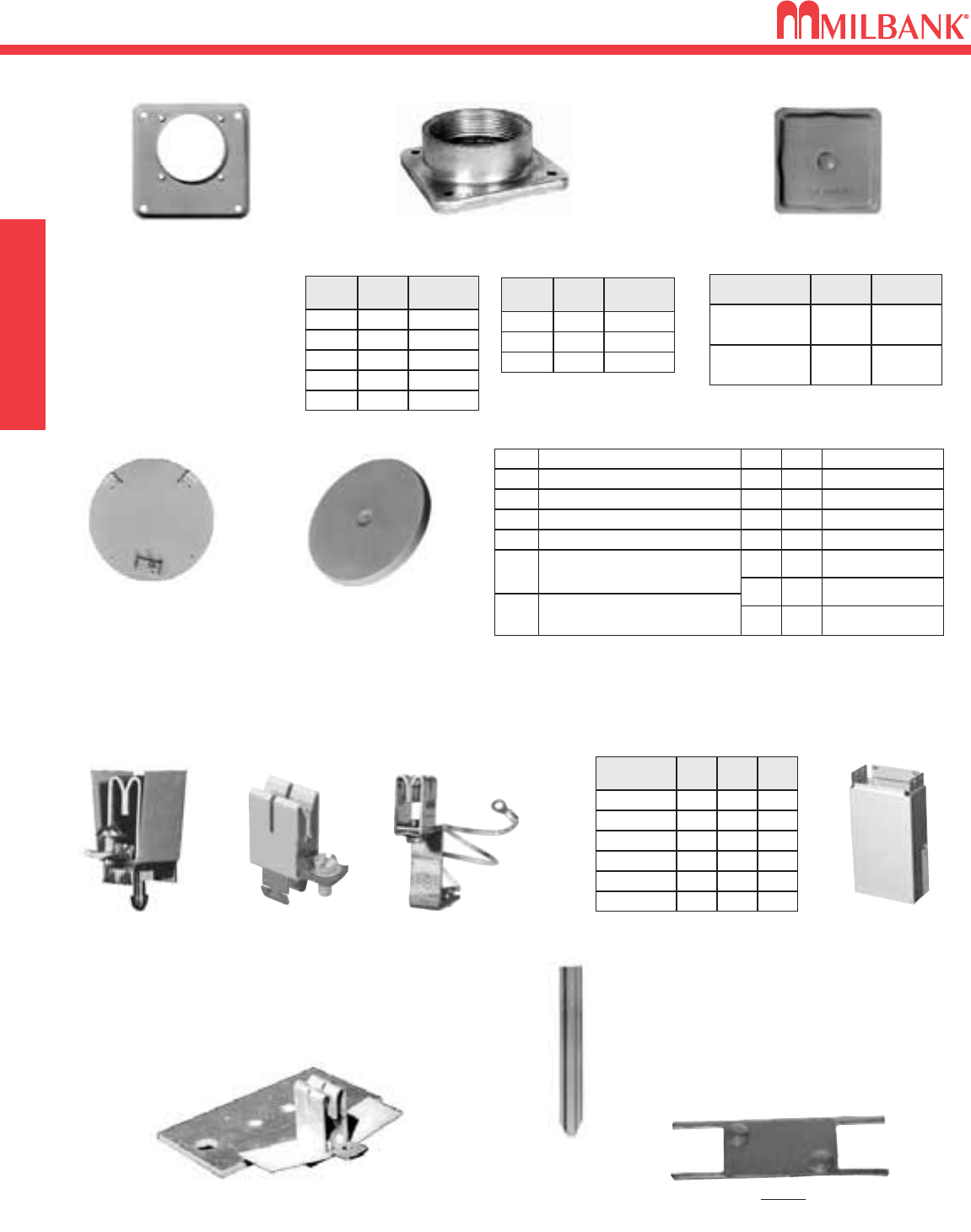
MILBANK ACCESSORIES
38
MILBANK ACCESSORIES MISC.
38
4 1
⁄
28 3
⁄
16 15
S8988
CATALOG
NUMBER D″W″H″
S3488
S2571
S1848
611 15
4 1
⁄
8
4 7
⁄
8
10
13
12
15
K4694
K5800
6
4 1
⁄
8
9
9
24
15
INTERCHANGEABLE UNIT HUBS
CLOSING COVERS
METAL CLOSING PLATE
(for ringless sockets)
CP-21
METER CLOSING PLATE
(Grey Plastic)
6003
HUB
ADAPTER PLATE
(Converts 4″opening to
21
⁄
2″opening.)
S8324
FIFTH TERMINALS
100 amp
“PLUG-IN” FIFTH
TERMINAL
5T8K2
(Round hole
9 oʼclock position)
100-200 amp
FIFTH TERMINAL
K5T
(New style block
with square hole in
9 oʼclock position)
HEAVY
DUTY JAW
CLAMPING
K3865
FOR CONDO METERING BANKS
(125-200 amp) K2381
PEDESTAL EXTENSION UNITS
HUB SUFFIX CHART
OPlain Top WL 1″For -RL Opening
YL 11
⁄
4″For -RL Opening
ZL 11
⁄
2″For -RL Opening
DL 2″For -RL Opening
EL
F
G
H
21
⁄
2″For -RL Opening
3″For -R Opening
31
⁄
2″For -R Opening
4″For -R Opening
RL Small Hub Opening
RLarge Hub Opening
XL Small Closing Plate
X
RXL Large Hub Opening
adapted to small Closing Plate
RRL Large Hub Opening
adapted to small Hub Opening
Large Closing Plate
REMOVABLE HUB
CLOSING PLATE
DESCRIPTION SUFFIX CAT. #
STANDARD
(for -RL opening)
-XL A7551
LARGE
(for -R opening)
-X A9064
1″
WL
SIZESUFFIX MILBANK
NO.
YL
ZL
DL
EL
A7514
11
⁄
4″A7515
11
⁄
2″A7516
2″A7517
21
⁄
2″A7518
3″
F
SIZESUFFIX MILBANK
NO.
G
H
A8110
31
⁄
2″A8111
4″A8112
SMALL “RL"OPENING
(STANDARD)
LARGE “R” OPENING
(HEAVY DUTY)
#K3235
STAKE KIT
Suitable for use
with pedestals
for extra support
ANTI-INVERSION CLIP
K4802
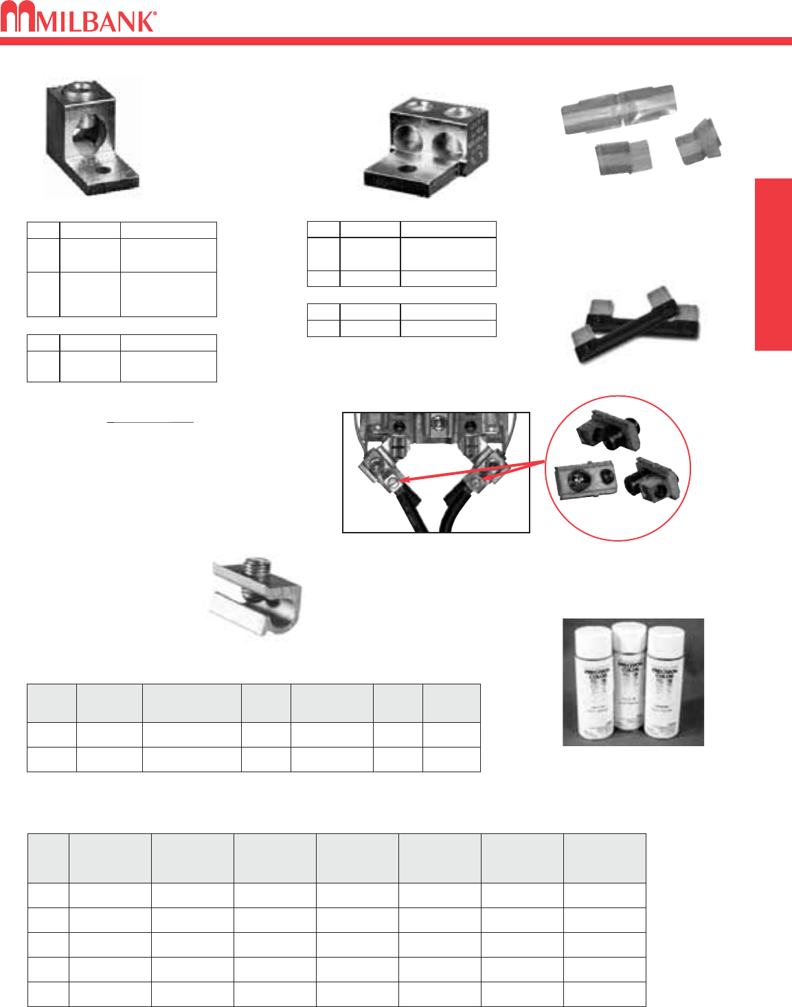
39
MILBANK ACCESSORIES
MISC.
MILBANK ACCESSORIES
39
MILBANK
2-POLE—200 AMP LARGE FRAME—10,000 AIC & 22,000 AIC
AMP
S
100 UQFP-100
125 UQFP-125
150 UQFP-150
175 UQFP-175
200 UQFP-200
10,000 AIC
PLUG-IN
UQFPH-100
UQFPH-125
UQFPH-150
UQFPH-175
UQFPH-200
UQFB-100
UQFB-125
UQFP-150
UQFB-175
UQFB-200
10,000 AIC
BOLT-ON
22,000 AIC
PLUG-IN
UQFP-M-100
UQFP-M-125
UQFP-M-150
UQFP-M-175
UQFP-M-200
10,000 AIC
PLUG-IN
UQFPH-M-100
UQFPH-M-125
UQFPH-M-150
UQFPH-M-175
UQFPH-M-200
22,000 AIC
PLUG-IN
UQFB-100-X1
UQFB-125-X1
UQFP-150-X1
UQFB-175-X1
UQFB-200-X1
10,000 AIC
BOLT-ON
UQFBH-100
UQFBH-125
UQFBH-150
UQFBH-175
UQFBH-200
22,000 AIC
BOLT-ON
TOUCH-UP PAINT
A-GP Light Gray
TRIPLEX GROUND
K1190
(For factory installed triplex
ground add suffix “-TG to
the catalog number.)
BYPASS LINK
K8180
(Bypass links are
sold in pairs)
DISCONNECT SLEEVE
M5-144
PLUG-IN BREAKER COMPATIBILITY CHART
AMPS MILBANK
CUTLER-HAMMER
(WESTINGHOUSE)
SIEMENS
(ITE)
SIEMENS
MURRAY /
CROUSE-HINDS
G.E. SQ-D
125-200 Q / QN HQP / BR / WBJ Q / QN MD Q LINE —
≤ 100 Q QUICKLAG P /
BR / HQP QP MP Q LINE
HOMELINE
CONNECTOR KITS
For use with 3/8”-16
stud type units only
SINGLE
TWIN
K1350K2 6-350 kcmil
K1350L
K1541
K2L
K4
6-350 kcmil
Non-rotating
4-600 kcmil
CATALOG #SUFFIX (3 per set) – 1 ∅
K3442K6 6-350 kcmil
K3083K8 4-600 kcmil
CATALOG #SUFFIX (4 per set) – 3 ∅
K3082K5 6-350 kcmil
K3441K7 4-600 kcmil or
(2) 1/0-250 kcmil
CATALOG #SUFFIX (4 per set) – 3 ∅
K1539K1 6-350 kcmil
K1540
K1540L
K3
K3L
4-600 kcmil or
(2) 1/0-250 kcmil
4-600 kcmil or
(2) 1/0-250 kcmil
Non-rotating
CATALOG #SUFFIX (3 per set) – 1 ∅
Replaces the load or line side slide-in nut assembly
on Milbank 200 amp sockets. Allows for a 100 amp
tap location in addition to the #6-350 kcmil load-side
connector. K5022 Includes Safety Barrier Extensions –
for applications over 300 VAC. Three lugs per kit.
K4977-INT INTERNAL HEX
K5022-INT INTERNAL HEX
TAP CONNECTORS (3 per set)
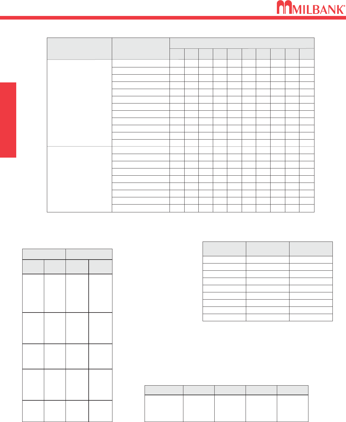
CONDUIT AND AMPACITY INFORMATION
40
CONDUIT AND AMPACITY INFORMATION MISC.
TYPE
THHN,
THWN,
THWN-2
CONDUCTOR
SIZE
(AWG / kcmil)
12
10
8
6
4
3
2
1
1/0
2/0
3/0
4/0
4
2
1/0
2/0
4/0
250
350
500
750
CONDUIT TRADE SIZES (INCHES)
1
⁄
23
⁄
41 11
⁄
411
⁄
22 21
⁄
23 31
⁄
24
9
6
3
2
1
1
1
1
1
0
0
0
1
1
1
0
0
0
0
0
0
16
10
6
4
2
1
1
1
1
1
1
1
2
1
1
1
1
0
0
0
0
26
17
9
7
4
3
3
1
1
1
1
1
4
3
1
1
1
1
1
0
0
46
29
16
12
7
6
5
4
3
2
1
1
7
5
3
2
1
1
1
1
0
62
39
22
16
10
8
7
5
4
3
3
2
10
7
4
3
2
1
1
1
1
102
64
37
27
16
14
11
8
7
6
5
4
16
12
7
6
4
3
2
1
1
146
92
53
38
23
20
17
12
10
8
7
6
24
17
10
9
6
5
3
2
1
225
142
82
59
36
31
26
19
16
13
11
9
37
26
16
13
9
7
6
4
3
301
189
109
79
48
41
34
25
21
18
15
12
49
35
22
18
12
10
7
5
4
387
244
140
101
62
53
44
33
27
23
19
16
63
45
28
23
16
13
10
7
5
XHH,
XHHW,
XHHW-2
u
This table is for concentric stranded conductors only. For cables with compact conductors refer to NEC.
Refer to latest NEC Code or Local Codes for updated requirements.
*CU
A
18
16
14
12
10
8
6
4
3
2
1
1/0
2/0
3/0
4/0
250
300
350
400
500
600
700
750
255
285
310
335
380
420
460
475
–
–
20✝
25✝
35✝
50
65
85
100
115
130
150
175
200
230
B
250
300
350
400
500
600
700
750
–
–
–
12
10
8
6
4
3
2
1
1/0
2/0
3/0
4/0
A
AL or **Cu-Clad AL
205
230
250
270
310
340
375
385
–
–
–
20✝
30✝
40
50
65
75
90
100
120
135
155
180
C
AMBIENT
TEMP.C°
CORRECTION
FACTOR
AMBIENT
TEMP.F°
21 - 25 1.05 70 - 77
26 - 30 1.00 78 - 86
31 - 35 .94 87 - 95
36 - 40 .88 96 - 104
41 - 45 .82 105 - 113
46 - 50 .75 114 - 122
51 - 55 .67 123 - 131
56 - 60 .58 132 - 140
61 - 65 .33 141 - 158
*ALLOWABLE AMPACITIES OF INSULATED COPPER &
** ALUMINUM CONDUCTORS (3W IN CONDUIT) 75°C (167°F)
AMPACITY CORRECTION FACTORS
Overall ampere ratings of U/L listed Milbank multiple position meter sockets are based on 2008 N.E.C.
Handbook Article 220-84 and ANSI / UL-414 (except where restricted by line connector size.) These
requirements provide for a diversity factor / demand factor being utilized in determining the overall (main
bus / lug) rating of a gang socket. All Milbank U/L listed gang sockets meet or exceed these diversity
factor/demand factor requirements. Standard overall ampacity ratings for U/L listed and non U/L listed
gang sockets are as shown in the chart below. Ampere ratings of meter sockets are based on the meter
socket being wired with 75°C insulated wire conductor, sized in accordance with Table 310-16 of the
National Electric Code.
NO. OF METER
POSITIONS 100A / POS.
AMPACITY 125A / POS.
AMPACITY 150A / POS.
AMPACITY 200A / POS.
AMPACITY
2
3
4
5
6
200A
200A
200A
225A
270A
200A
225A
250A
285A
330A
200A
225A
270A
338A
396A
400A
270A
360A
450A
528A
MAXIMUM NUMBER OF CONDUCTORS IN CONDUIT
u
Table from 2008 NEC Code Reference: Rigid Metal Conduit
A = Size: AWG/MCM
*B = Ampere Rating for
Insulation Types:
FEPW, RH, RHW, THW,
THWN, XHHW, USE, 2W.
**C = Ampere Rating for
Insulation Types:
RH, RHW, THW, THWN,
XHHW, USE
(Per NEC table 310-16)
✝Unless otherwise permitted elsewhere in the Code, the overcurrent protection for conductor types marked with an obelisk (✝) shall not
exceed 15 amps for 14 AWG, 20 amps for 12 AWG, and 30 amps for 10 AWG copper: or 15 amps for 12 AWG and 25 amps for 10 AWG
aluminum and copper-clad aluminum after any correction factors for ambient temperature and number of conductors have been applied.
GANG SOCKET OVERALL AMPACITIES
40
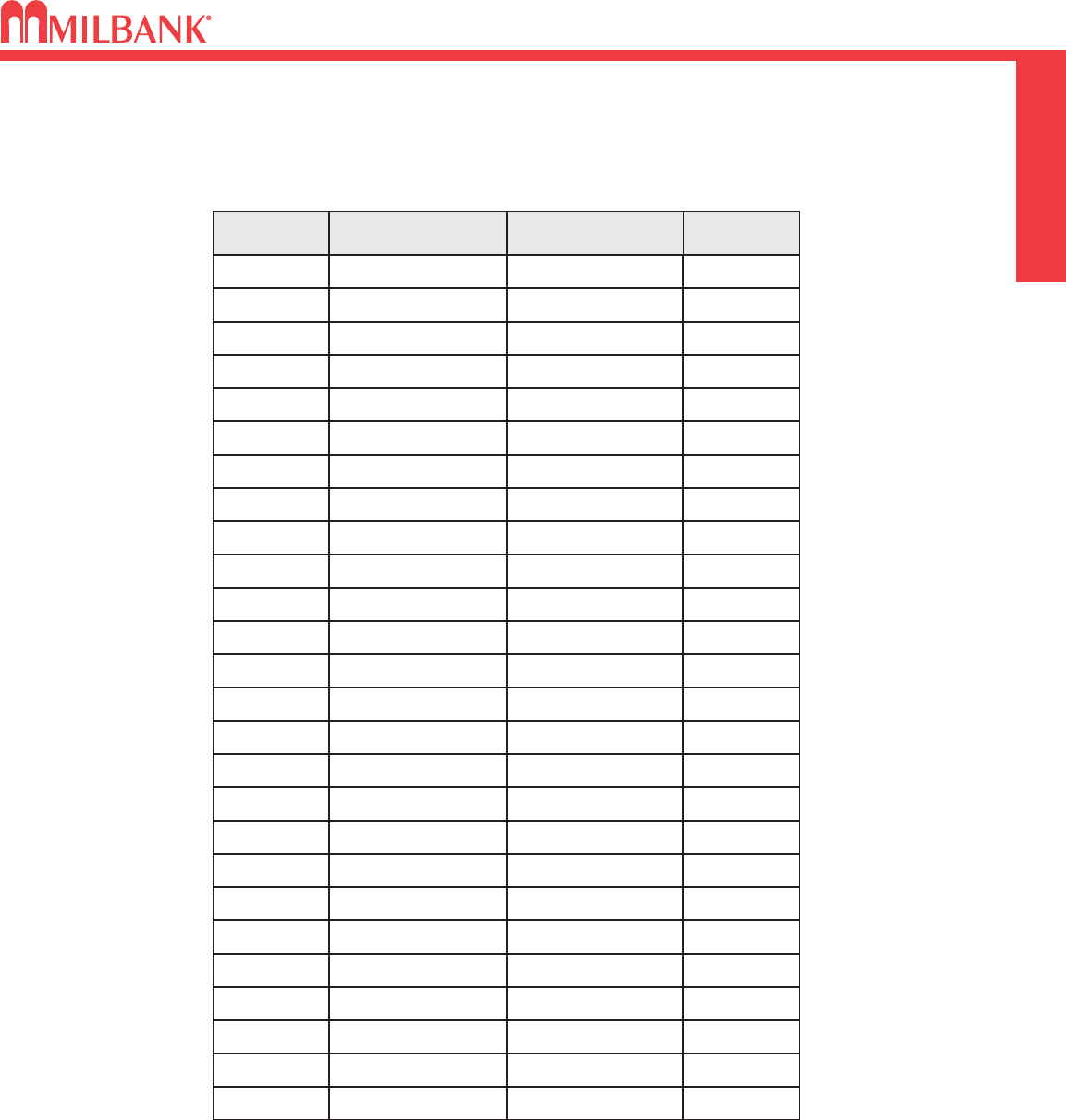
41
SHORT CIRCUIT CURRENT RATING CHART
SWITCHES
SHORT CIRCUIT CURRENT RATING CHART
41
PAGE CATALOG NUMBER RATING LABEL SCCR
9U1773 1000072 22K
9U3850 1000071 10K
9U1211 1001286 22K
9U4801 1001286 22K
10 U9550 1121254 22K
10 U9551 1121254 22K
10 U8624 1121254 22K
10 U9700 1121257 22K
10 U9701 1121257 22K
11 U7421 1128487 10K
11 U7423 1128487 10K
11 U4701 1121257 22K
12 U4363 1111015 22K
12 U3000 1001319 22K
12 U1779 1025096 22K
12 U2594 1025334 22K
12 U2120 1025346 22K
22 U3849 1032540 22K
22 U1748 1110577 22K
32 U4664-X-8502 1003374 10K
32 U4664-X-8507 1003370 10K
32 U4664-X-9507 1092698 10K
33 U4667-X-8512 1102031 10K
33 U4667-X-9504 1003405 10K
33 U4667-X-9506 1109612 10K
33 U4667-X-8013 1128451 10K
SHORT CIRCUIT CURRENT RATING CHART
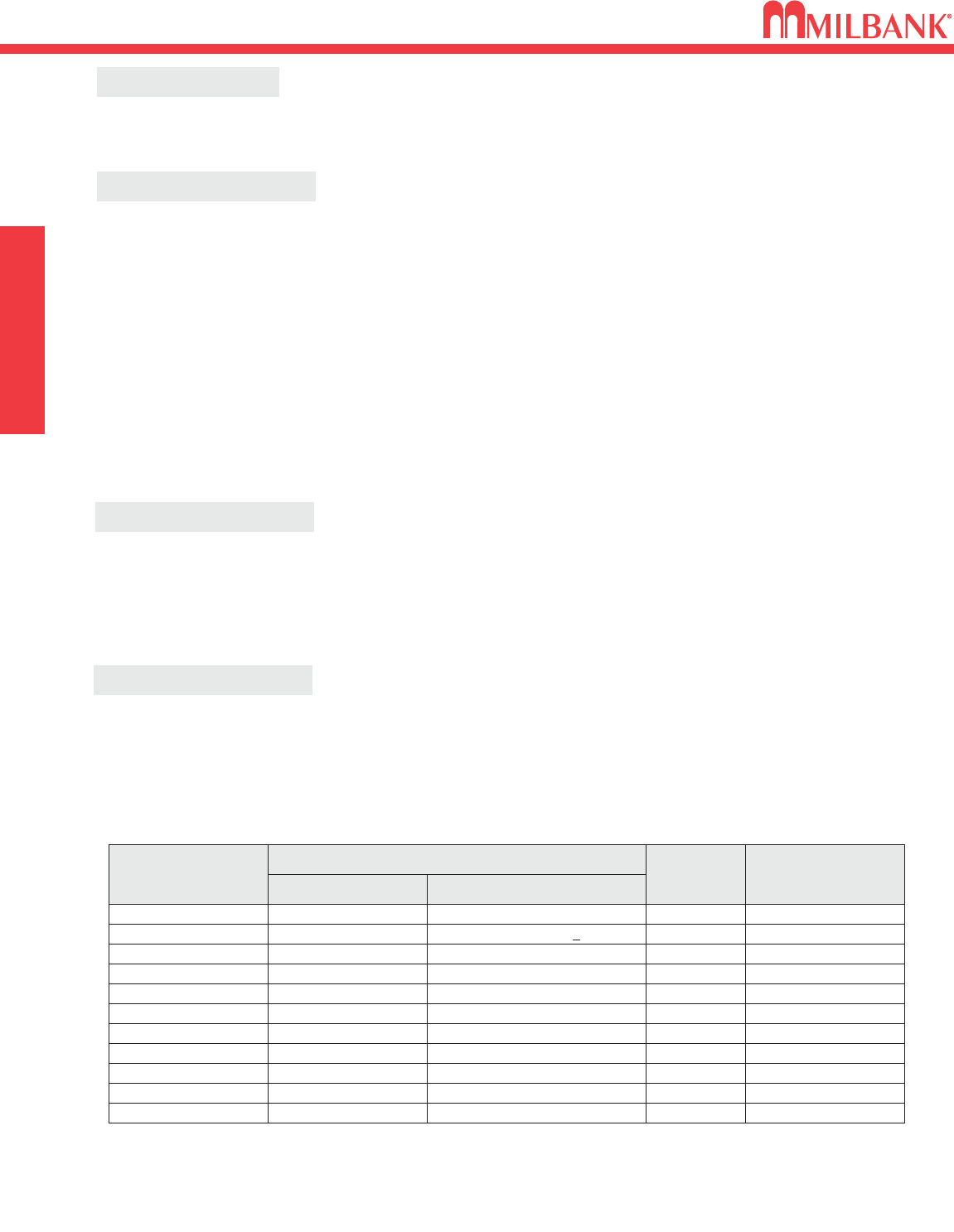
ENERGIZATION OF ELECTRICAL EQUIPMENT
42
ENERGIZATION OF ELECTRICAL EQUIPMENT MISC.
42
BEFORE ENERGIZING
IMPORTANT NOTE
WHEN ENERGIZING
AFTER ENERGIZING
A. Give equipment a thorough visual examination to determine that:
1) No shipping or installation damage exists.
2) Proper clearances have been maintained.
3) All connections have been made.
4) Equipment is clean and dry.
B. Make a thorough examination to verify:
1) Tightness of all bolted connections (see table below).
2) Manually operate all circuit breakers, switches, relays, etc.
3) Check rigidity of all mountings, bus bars and components.
4) Use test equipment to check continuity of circuitry and integrity of insulation.
C. All switches and circuit breakers should be in the “off” position.
D. Verify that manual meter bypass (if applicable) is in non-bypass position.
E. Install cover and/or close doors.
F. If installation is not being energized at this time, follow “after-energizing” steps listed below. These
steps will secure the installation in case of accidental energization.
A. Use caution and follow established safety procedures:
1) Wear safety apparel.
2) Use safety equipment.
3) Take action to prevent injury to yourself and others in the event of failure of the installation.
4) Take action to prevent/decrease damage to property in the event of failure of the installation.
5) If you are unsure how to safely energize the installation, get someone who is knowledgeable to do it.
A. Secure the installation:
1) To prevent accidental contact with energized parts, cover all openings with approved filler devices.
2) To prevent unauthorized access, secure all covers and/or doors with approved security devices.
3) Attach/post information to advise others of potential hazards associated with the installation.
NOMINAL
SIZE
10
10
10
12
12
1/4
1/4
5/16
JOINT DESCRIPTION
SCREW NUT
BRASS
STEEL
STEEL
STEEL
STEEL
STEEL
STEEL
STEEL
Brass Nut or Extruded Hole
CU or AL Busbar <1/8″
Steel Nut or EH; CU or AL Busbar >1/8″
Aluminum Extruded Hole
Steel Nut or Extruded Hole
Aluminum Extruded Hole
Steel Nut or EH; CU or AL Busbar
Aluminum Extruded Hole
ALL
ALL
ALL
ALL
ALL
ALL
ALL
HEX
20-25 in. lbs.
25-30 in. lbs
30-35 in. lbs
30-35 in. lbs
40-50 in. lbs.
40-50 in. lbs.
50-60 in. lbs.
60-70 in. lbs.
5/16 STEEL Steel Nut or EH; CU or AL Busbar HEX 100-150 in. lbs.
3/8 STEEL Steel Nut HEX 150-200 in. lbs.
1/2 STEEL Steel Nut HEX 200-250 in. lbs.
HEAD TYPE TORQUE
( INCH LBS. )
*Interior labels typically indicate the required torque for wire connectors and studs, and should be referenced first.
EH: Extruded Hole
CU: Copper
AL: Aluminum
RECOMMENDED TORQUE FOR GENERAL APPLICATIONS*
In addition to national and local electrical codes, many utilities have specific requirements for metering equip-
ment. Always consult the serving utility for their specifications and requirements prior to ordering or installing
Milbank meter mounting equipment.

43
MATERIALS AND FINISHES
MISC.
MATERIALS AND FINISHES
43
MATERIALS
STEEL SHEET
STEEL QUALITY
ALUMINUM EXTRUSION
ALUMINUM SHEET
COPPER SHEET & BUS
INSULATING MATERIALS
PROCESS
METAL FASTENERS
The meter equipment listed in this catalog is made of galvanized steel (AISI* G90) to afford the
best possible weather proofing. *American Iron and Steel Institute.
Light gray “state of the art” electrostatically applied powder paint offers a durable, non-fading
finish. For further information concerning the chemical analysis of the weather resistant finish,
please contact the factory.
Wire-Terminals: Alloy; 6061-T6, Tin-plated for CU/AL wire.
Bus Bar: Alloy; 6101-o & 6063-O
3000 series aluminum sheet, H14, or 5052 series aluminum sheet, H32. Where applicable thick-
nesses range from .064 — .125
Electrolytic copper with tin plating in most applications.
Zinc-coated with a chromate dip.
• In most units, support bases for current-carrying components are molded from fiberglass rein-
forced high-strength, track resistant, thermoset polyester molding compounds.
• Clear or black safety shields and polarity barriers are molded from high-strength, track resistant,
polycarbonate molding compounds.
• Various sheet insulating materials, as appropriate for the application are utilized in the fabrica-
tion of flat, formed and punched component parts and barriers.
16 gauge, galvanized, sheet: 0.90 oz./ sq.ft. class zinc-coated.
(AISI G90)
14 gauge, galvanized, sheet: 0.90 oz./ sq.ft. class zinc-coated.
FINISH
NEMA RATING
All Milbank meter sockets, CT cans and meter socket / breaker units have a NEMA 3R rating.
RATING
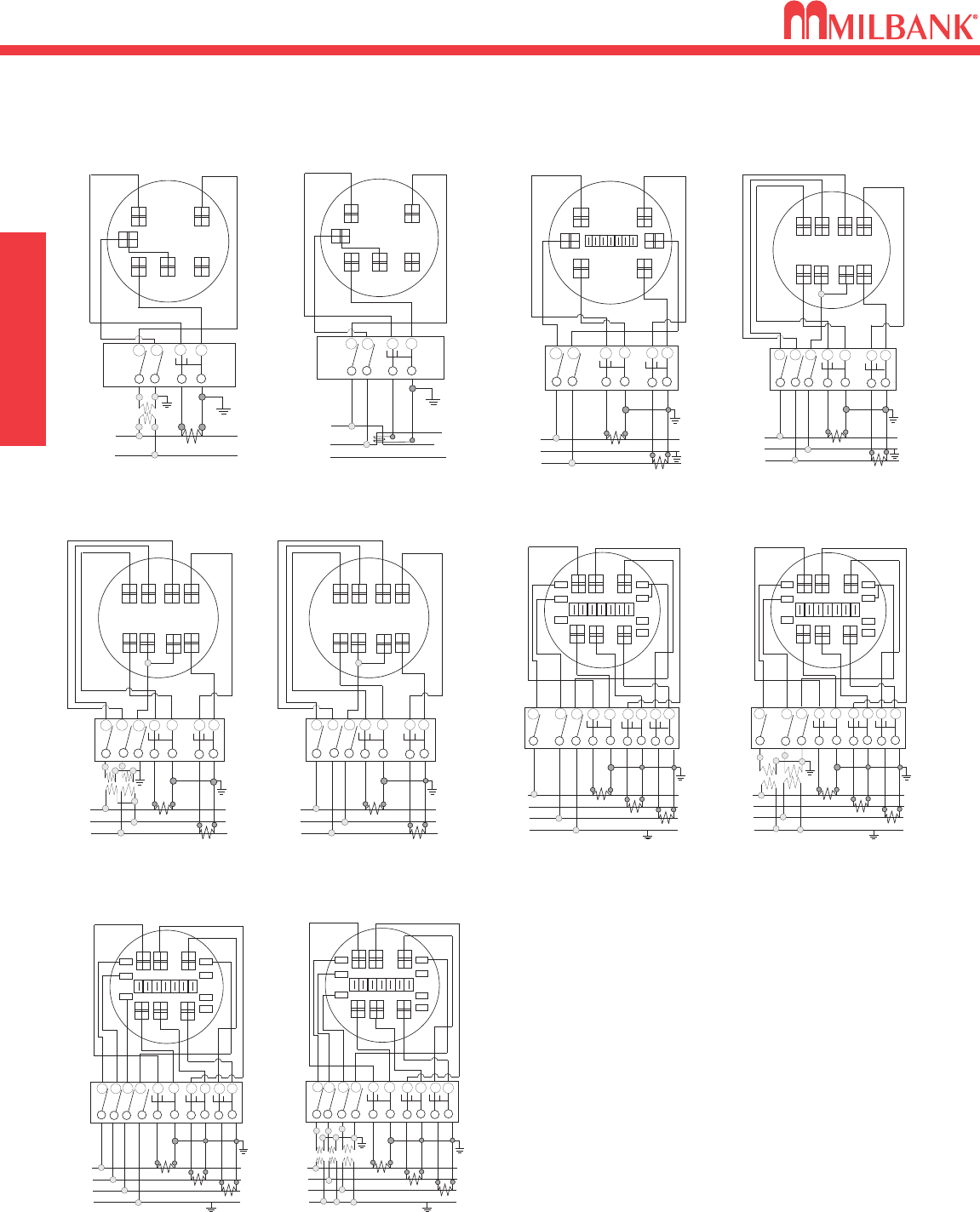
METER FORMS
44
METER FORMS SWITCHES
44
DIAGRAM A
(ALT.LOC.)
+
+
+
+
I
LINE
(BONDED)
NC.T. LOAD
P1PNC+
1C1
P. T.
+
+
1
LINE
C.T.
LOAD
2
P1C+
1
++
3
+
+
PT PT
DIAGRAM E
P3P2C1C+
3C3
C.T.
+
+
1
LINE
C.T.
LOAD
2
P1C+
1
++
3
DIAGRAM F
P3P2C1C+
3C3
C.T.
+
+
1
LINE
C.T.
LOAD
2
P1
+
+
3
PNC
+
N
C.T.
C.T.
+
+
(BONDED)
++
PT PT
+
+
P3
PT
++
DIAGRAM J
P2CC
+CC+C
+
+
C.T.
LOAD
P1
+
+
P3
P
N
C+
C+
C.T.
C.T.
++
(BONDED)
DIAGRAM G
CC
C+
C
1
LINE 2
3
N
+
+
1
LINE
C.T.
LOAD
2
P1
+
+
3
P3
P
N
C+
N
C.T.
C.T.
++
(BONDED)
++
PT
PT
++
DIAGRAM H
CC
+
C+C
C
+
+
1
LINE
C.T.
LOAD
2
P1
+
+
3
P3PNC+
N
C.T.
C.T.
++
(BONDED)
P2
DIAGRAM I
CC+CC+C
(ALT.LOC.)
+
+
I
LINE
(BONDED)
NC.T. LOAD
2
DIAGRAM B
P
1
PNC+
1C1
+
+
I
LINE (BONDED)
N
C.T.
LOAD
2
P
1
P2C+
1C+
2C2
C+
2
++
DIAGRAM C
C.T.
+
+
I
LINE (BONDED)
N
C.T.
LOAD
2++
DIAGRAM D
P1P2C+
1C2
C+
2
PNC1
C.T.
DIAGRAM D
1∅3W or 3W Network with 2 C.T.ʼs
2 Stator Meter - Form 5S
8T Socket, Test Switch #TS07-0105
DIAGRAM E
3∅3W “Δ” with 2 P.T.ʼs & 2 C.T.ʼs
2 Stator Meter - Form 5S
8T Socket, Test Switch #TS07-0105
DIAGRAM F
3∅3W “Δ” with 2 C.T.ʼs
2 Stator Meter - Form 5S
8T Socket, Test Switch #TS07-0105
DIAGRAM G
3∅4W “Y” with 3 C.T.ʼs
2 1
⁄
2Stator Meter - Form 6S
13T Socket, Test Switch #TS10-0109
DIAGRAM H
3∅4W “Y” with 2 P.T.ʼs & 3 C.T.ʼs
2 1
⁄
2Stator Meter - Form 6S
13T Socket, Test Switch #TS10-0109
DIAGRAM I
3∅4W “Y” or “Δ” with 3 C.T.ʼs
“Y” 3 Stator Meter - Form 9S
“Δ” 2 Stator Meter - Form 8S
13T Socket, Test Switch #TS10-0109
DIAGRAM J
3∅4W “Y” with 3 P.T.ʼs & 3 C.T.ʼs
3 Stator Meter - Form 9S
13T Socket, Test Switch #TS10-0109
DIAGRAM A
1∅2W with 1 P.T. & 1 C.T.
Single Stator Meter(2W1∅) - Form 3S
5T Socket, Test Switch #TS04-0101
DIAGRAM B
1∅3W with 1 C.T.
Single Stator Meter(2W1∅) - Form 3S
5T Socket, Test Switch #TS04-0101
DIAGRAM C
1∅3W with 2 C.T.ʼs
Single Stator Meter(3W1∅) - Form 4S
6T Socket, Test Switch #TS07-0105
PREWIRING: If standard factory prewiring is
required, refer to wiring diagrams on this page.
Determine appropriate diagram and send a
copy with order. If custom factory prewiring is
required, specify on order. Be sure to include
meter socket catalog number, test switch make
and catalog number, meter form number and
provide a copy of your wiring diagram.

45
APPROVING UTILITIES
SWITCHES
APPROVING UTILITIES
45
L572-XK-KK X X X 13
L573-XK-KK X X X 13
L574-XK-KK X X X 13
L575-XK-KK X X X 13
L576-XK-KK X X X 13
NU8980-O-200-KK X X X 23
NU8980-O-200-KK-LP X X X 23
NU8980-O-KK X X X 23
NU8980-O-KK-LP X X X 23
NU8980-O-SF100-KK XXXX23
NU8980-O-SF100-KK-LP XXXX23
S2291-TO XXXX20
S2571 XXXX20, 38
S9995-B-XL X X X 31
S9996-B-XL X X X 31
S9997-B-XL X X X 31
SDRC X X X 31
SDRCW X X X 31
U1211-RXL X X X 9
U1252-X-KK XXXX16
U1252-X-KK-K1-PED XXXX16
U1253-X-KK XXXX16
U1253-X-KK-K3-PED XXXX16
U1254-X-KK XXXX16
U1254-X-KK-K3-PED XXXX16
U1255-X-KK-K4-PED XXXX16
U1256-X-KK-K4-PED XXXX16
U1748-O-5T9-WI X 22
U1748-O-WI XXXX22
U1773-XL-TG-KK XXXX9
U1779-RRL-5T9-K3 X 12
U1779-RRL-K3 X 12
U1783-O-KK XXXX25
U2120-X-K7 X 12
U2594-X-K7 X 12
U2692-XL-KK X X X 15
U2732-XT-PED X X X 18
U2732-XT-PED-K7 X 18
U2733-XT-PED X X X 18
U2733-XT-PED-K7 X 18
U2734-XT-PED X X X 18
U2734-XT-PED-K7 X 18
U2735-XT-PED X X X 18
U2735-XT-PED-K7 X 18
U2736-XT-PED X X X 18
U2736-XT-PED-K7 X 18
U2872-XT X X X 17
CATALOG ALLIANT WI ELECTRIC PUBLIC SERVICE MADISON GAS & ELE. PG.NO.
NUMBER ENERGY ENERGY (WE) OF WI MGE

APPROVING UTILITIES
46
APPROVING UTILITIES MISC.
46
CATALOG ALLIANT WI ELECTRIC PUBLIC SERVICE MADISON GAS & ELE. PG.NO.
NUMBER ENERGY ENERGY (WE) OF WI MGE
U2872-XT-K3 X 17
U2873-XT X X X 17
U2873-XT-K3 X 17
U2874-XT X X X 17
U2874-XT-K3 X 17
U3000-O-5T9-K3L-K2L X 12
U3000-O-K3L X 12
U3358-O-KK XXXX25
U3849-O-200/100 XXXX22
U3849-O-2/150 XXXX22
U3849-O-2/200 XXXX22
U3850-O-TG-KK X 9
U4322-O-XXX X 29
U4323-O-XXX X 29
U4329-O XXXX26
U4363-X-QG X X X 12
U4664-X-8502 X32
U4664-X-8507 X32
U4664-XT-9507 X32
U4667-X-8013 X33
U4667-X-8512 X33
U4667-XT-9504 X33
U4667-XT-9506 X33
U4701-XL X X X 11
U4801-XL X 9
U4801-XL-5T9 X 9
U5136-O-100S XXXX27
U5136-O-100S-10GR XXXX27
U5136-O-200S XXXX27
U5136-O-200S-11GR XXXX27
U5137-O-100S XXXX27
U5137-O-100S-10GR XXXX27
U5137-O-200S XXXX27
U5137-O-200S-11GR XXXX27
U5706-O-200S-KK X 24
U5842-RL-100-KK XXXX21
U5842-RL-200-KK XXXX21
U5882-X-KK-K1-PED X 19
U5882-X-KK-K1 X X X 19
U5883-X-KK-K1-PED X 19
U5883-X-KK-K1 X X X 19
U5884-X-KK-K1-PED X 19
U5884-X-KK-K1 X X X 19
U5885-X-KK-K1-PED X 19
U5885-X-KK-K1 X X X 19
U5886-X-KK-K1-PED X 19
U5886-X-KK-K1 X X X 19

47
APPROVING UTILITIES
MISC.
APPROVING UTILITIES
47
CATALOG ALLIANT WI ELECTRIC PUBLIC SERVICE MADISON GAS & ELE. PG.NO.
NUMBER ENERGY ENERGY (WE) OF WI MGE
U5902-X-KK-K1-PED X 19
U5902-X-KK-K1 X X X 19
U5903-X-KK-K1-PED X 19
U5903-X-KK-K1 X X X 19
U5904-X-KK-K1-PED X 19
U5904-X-KK-K1 X X X 19
U5905-X-KK-K1-PED X 19
U5905-X-KK-K1 X X X 19
U5906-X-KK-K1-PED X 19
U5906-X-KK-K1 X X X 19
U5925-O-100-KK X 24
U5925-O-200-KK X 24
U7362-RL-KK XXXX14
U7363-RL-KK XXXX14
U7364-RL-KK XXXX14
U7365-RL-KK XXXX14
U7366-RL-KK XXXX14
U7421-RL X X X 11
U7423-XL X X X 11
U7487-RL-TG-KK XXXX7
U7573-RL X X X 8
U8032-XL-KK XXXX13
U8033-XL-KK X X X 13
U8034-XL-KK X X X 13
U8035-XL-KK XXXX13
U8036-XL-KK XXXX13
U8624-RXL X X X 10
U9107-O X X X 28
U9107-O-K5 X 28
U9108-O X X X 28
U9320-RXL X X X 8
U9550-DL X X X 10
U9551-O X X X 10
U9700-RRL XXXX10
U9701-RXL XXXX10
UC1290-RL X 30
UC1299-RL X 30
UC1962-XL X X X 30
UC2427-XL X X X 30
UC2428-XL X X X 30
UC3887-XL X X X 30
UC3889-XL X X X 30
UC7448-XL X X X 30
UC7449-XL XXXX30
UC7532-XL X X X 30
WS XXX31

INDEX
48
INDEX
48
CAT NO. PG CAT NO. PG CAT NO. PG CAT NO. PG
6003 . . . . . . . . . . . . . . . . . . . 38
5T8K2 . . . . . . . . . . . . . . . . . . 38
A7514 . . . . . . . . . . . . . . . . . . 38
A7515 . . . . . . . . . . . . . . . . . . 38
A7516 . . . . . . . . . . . . . . . . . . 38
A7517 . . . . . . . . . . . . . . . . . . 38
A7518 . . . . . . . . . . . . . . . . . . 38
A7551 . . . . . . . . . . . . . . . . . . 38
A8110 . . . . . . . . . . . . . . . . . . 38
A8111 . . . . . . . . . . . . . . . . . . 38
A8112 . . . . . . . . . . . . . . . . . . 38
A9064 . . . . . . . . . . . . . . . . . . 38
A-GP . . . . . . . . . . . . . . . . . . . 39
CP-21 . . . . . . . . . . . . . . . . . . 38
K1190 . . . . . . . . . . . . . . . . . . 39
K1350 . . . . . . . . . . . . . . . . . . 39
K1350L . . . . . . . . . . . . . . . . . 39
K1539 . . . . . . . . . . . . . . . . . . 39
K1540 . . . . . . . . . . . . . . . . . . 39
K1540L . . . . . . . . . . . . . . . . . 39
K1541 . . . . . . . . . . . . . . . . . . 39
K2381 . . . . . . . . . . . . . . . . . . 38
K3082 . . . . . . . . . . . . . . . . . . 39
K3083 . . . . . . . . . . . . . . . . . . 39
K3235 . . . . . . . . . . . . . . . . . . 38
K3441 . . . . . . . . . . . . . . . . . . 39
K3442 . . . . . . . . . . . . . . . . . . 39
K3865 . . . . . . . . . . . . . . . . . . 38
K4687 . . . . . . . . . . . . . . . . . . 34
K4688 . . . . . . . . . . . . . . . . . . 34
K4694 . . . . . . . . . . . . . . . . . . 38
K4977-INT . . . . . . . . . . . . . . 39
K5022-INT . . . . . . . . . . . . . . 39
K5035 . . . . . . . . . . . . . . . . . . 27
K5193 . . . . . . . . . . . . . . . . . . 27
K5400-1450 . . . . . . . . . . . . . 27
K5400-520 . . . . . . . . . . . . . . 27
K5400-520GR. . . . . . . . . . . . 27
K5400-BRIDGE-1POS . . . . . 27
K5400-BRIDGE-2POS . . . . . 27
K5400-TT30 . . . . . . . . . . . . . 27
K5415 . . . . . . . . . . . . . . . . . . 27
K5800 . . . . . . . . . . . . . . . . . . 38
K5T . . . . . . . . . . . . . . . . . . . . 38
K8180 . . . . . . . . . . . . . . . . . . 39
L572-XL-KK . . . . . . . . . . . . . 13
L573-XL-KK . . . . . . . . . . . . . 13
L574-XL-KK . . . . . . . . . . . . . 13
L575-XL-KK . . . . . . . . . . . . . 13
L576-XL-KK . . . . . . . . . . . . . 13
M5-144 . . . . . . . . . . . . . . . . . 39
NU8980-O-100-KK . . . . . . . . 23
NU8980-O-100-KK-LP . . . . . 23
NU8980-O-200-KK . . . . . . . . 23
NU8980-O-200-KK-LP . . . . . 23
NU8980-O-KK. . . . . . . . . . . . 23
NU8980-O-KK-LP . . . . . . . . . 23
NU8980-O-SF100-KK. . . . . . 23
NU8980-O-SF100-KK-LP . . . 23
S1848 . . . . . . . . . . . . . . . . . . 38
S2291-TO . . . . . . . . . . . . . . . 20
S2571 . . . . . . . . . . . . . . . 20, 38
S3488 . . . . . . . . . . . . . . . . . . 38
S8324 . . . . . . . . . . . . . . . . . . 38
S8988 . . . . . . . . . . . . . . . . . . 38
S9995-B-XL . . . . . . . . . . . . . 31
S9996-B-XL . . . . . . . . . . . . . 31
S9997-B-XL . . . . . . . . . . . . . 31
SDRC . . . . . . . . . . . . . . . . . . 31
SDRCW . . . . . . . . . . . . . . . . 31
U1211-RXL . . . . . . . . . . . . . . . 9
U1252-X-KK . . . . . . . . . . . . . 16
U1252-X-KK-5T-K1-PED . . . 16
U1252-X-KK-K1-PED . . . . . . 16
U1253-X-KK . . . . . . . . . . . . . 16
U1253-X-KK-5T-K1-PED . . . 16
U1253-X-KK-K3-PED . . . . . . 16
U1254-X-KK . . . . . . . . . . . . . 16
U1254-X-KK-5T-K1-PED . . . 16
U1254-X-KK-K3-PED . . . . . . 16
U1255-X-KK-5T-K1-PED . . . 16
U1255-X-KK-K4-PED . . . . . . 16
U1256-X-KK-5T-K1-PED . . . 16
U1256-X-KK-PED . . . . . . . . . 16
U1748-O-5T9-WI . . . . . . . . . 22
U1748-O-WI . . . . . . . . . . . . . 22
U1773-XL-TG-KK . . . . . . . . . . 9
U1779-RRL-5T9-K3 . . . . . . . 12
U1779-RRL-K3 . . . . . . . . . . . 12
U1783-O-KK . . . . . . . . . . . . . 25
U2120-X-K7 . . . . . . . . . . . . . 12
U2594-X-K7 . . . . . . . . . . . . . 12
U2692-XL-KK . . . . . . . . . . . . 15
U2732-XT-PED. . . . . . . . . . . 18
U2732-XT-PED-K7 . . . . . . . . 18
U2733-XT-PED. . . . . . . . . . . 18
U2733-XT-PED-K7 . . . . . . . . 18
U2734-XT-PED. . . . . . . . . . . 18
U2734-XT-PED-K7 . . . . . . . . 18
U2735-XT-PED. . . . . . . . . . . 18
U2735-XT-PED-K7 . . . . . . . . 18
U2736-XT-PED. . . . . . . . . . . 18
U2736-XT-PED-K7 . . . . . . . . 18
U2872-XT . . . . . . . . . . . . . . . 17
U2872-XT-5T9-K3 . . . . . . . . 17
U2872-XT-K3 . . . . . . . . . . . . 17
U2873-XT . . . . . . . . . . . . . . . 17
U2873-XT-K3 . . . . . . . . . . . . 17
U2874-XT . . . . . . . . . . . . . . . 17
U2874-XT-K3 . . . . . . . . . . . . 17
U3000-O-5T9-K3L-K2L. . . . . 12
U3000-O-K3L . . . . . . . . . . . . 12
U3000-O-K3L-K2L . . . . . . . . 12
U3358-O-KK . . . . . . . . . . . . . 25
U3802 . . . . . . . . . . . . . . . . . . . 5
U3822-20GWRTR . . . . . . . . . 6
U3832 . . . . . . . . . . . . . . . . . . . 5
U3849-O-200/100 . . . . . . . . . 22
U3849-O-2/150 . . . . . . . . . . . 22
U3849-O-2/200 . . . . . . . . . . . 22
U3850-O-TG-KK . . . . . . . . . . . 9
U3860 . . . . . . . . . . . . . . . . . . . 5
U4322-O-5T9 . . . . . . . . . . . . 29
U4323-O-5T9 . . . . . . . . . . . . 29
U4329-O . . . . . . . . . . . . . . . . 26
U4363-X-QG. . . . . . . . . . . . . 12
U4664-X-8502 . . . . . . . . . . . 32
U4664-X-8507 . . . . . . . . . . . 32
U4664-XT-9507 . . . . . . . . . . 32
U4667-X-8013 . . . . . . . . . . . 33
U4667-X-8512 . . . . . . . . . . . 33
U4667-XT-9504 . . . . . . . . . . 33
U4667-XT-9506 . . . . . . . . . . 33
U4701-XL . . . . . . . . . . . . . . . 11
U4801-O . . . . . . . . . . . . . . . . . 9
U4801-O-5T9 . . . . . . . . . . . . . 9
U4801-XL . . . . . . . . . . . . . . . . 9
U4801-XL-5T9 . . . . . . . . . . . . 9
U4881-O . . . . . . . . . . . . . . . . . 6
U4881-O-50GB. . . . . . . . . . . . 6
U4881-O-60GB. . . . . . . . . . . . 6
U5136-O-100S . . . . . . . . . . . 27
U5136-O-100S-10GR . . . . . . 27
U5136-O-200S . . . . . . . . . . . 27
U5136-O-200S-11GR . . . . . . 27
U5137-O-100S . . . . . . . . . . . 27
U5137-O-100S-10GR . . . . . . 27
U5137-O-200S . . . . . . . . . . . 27
U5137-O-200S-11GR . . . . . . 27
U5168-XTL-200-KK . . . . . . . 21
U5706-O-200S-KK . . . . . . . . 24
U5842-RL-100-KK . . . . . . . . 21
U5842-RL-200-KK . . . . . . . . 21
U5882-X-KK-K1-PED . . . . . . 19
U5882-X-KK-K1 . . . . . . . . . . 19
U5883-X-KK-K1-PED . . . . . . 19
U5883-X-KK-K1 . . . . . . . . . . 19
U5884-X-KK-K1-PED . . . . . . 19
U5884-X-KK-K1 . . . . . . . . . . 19
U5885-X-KK-K1-PED . . . . . . 19
U5885-X-KK-K1 . . . . . . . . . . 19
U5886-X-KK-K1-PED . . . . . . 19
U5886-X-KK-K1 . . . . . . . . . . 19
U5902-X-KK-K1-PED . . . . . . 19
U5902-X-KK-K1 . . . . . . . . . . 19
U5903-X-KK-K1-PED . . . . . . 19
U5903-X-KK-K1 . . . . . . . . . . 19
U5904-X-KK-K1-PED . . . . . . 19
U5904-X-KK-K1 . . . . . . . . . . 19
U5905-X-KK-K1-PED . . . . . . 19
U5905-X-KK-K1 . . . . . . . . . . 19
U5906-X-KK-K1-PED . . . . . . 19
U5906-X-KK-K1 . . . . . . . . . . 19
U5925-O-100-KK . . . . . . . . . 24
U5925-O-200-KK . . . . . . . . . 24
U7362-RL-KK . . . . . . . . . . . . 14
U7363-RL-KK . . . . . . . . . . . . 14
U7364-RL-KK . . . . . . . . . . . . 14
U7365-RL-KK . . . . . . . . . . . . 14
U7366-RL-KK . . . . . . . . . . . . 14
U7421-RL . . . . . . . . . . . . . . . 11
U7423-XL . . . . . . . . . . . . . . . 11
U7487-RL-TG-KK . . . . . . . . . . 7
U7573-RL . . . . . . . . . . . . . . . . 8
U8032-XL-KK . . . . . . . . . . . . 13
U8033-XL-KK . . . . . . . . . . . . 13
U8034-XL-KK . . . . . . . . . . . . 13
U8035-XL-KK . . . . . . . . . . . . 13
U8036-XL-KK . . . . . . . . . . . . 13
U8624-RXL . . . . . . . . . . . . . . 10
U9107-O . . . . . . . . . . . . . . . . 28
U9107-O-K5 . . . . . . . . . . . . . 28
U9108-O . . . . . . . . . . . . . . . . 28
U9320-RXL . . . . . . . . . . . . . . . 8
U9550-DL . . . . . . . . . . . . . . . 10
U9551-O . . . . . . . . . . . . . . . . 10
U9700-RRL. . . . . . . . . . . . . . 10
U9701-RXL . . . . . . . . . . . . . . 10
UAP5024-XL-KK. . . . . . . . . . 21
UC1290-RL. . . . . . . . . . . . . . 30
UC1299-RL. . . . . . . . . . . . . . 30
UC1962-XL . . . . . . . . . . . . . . 30
UC2427-XL . . . . . . . . . . . . . . 30
UC2428-XL . . . . . . . . . . . . . . 30
UC3887-XL . . . . . . . . . . . . . . 30
UC3889-XL . . . . . . . . . . . . . . 30
UC7448-XL . . . . . . . . . . . . . . 30
UC7449-XL . . . . . . . . . . . . . . 30
UC7532-XL . . . . . . . . . . . . . . 30
UQFB-100. . . . . . . . . . . . . . . 39
UQFB-100-X1 . . . . . . . . . . . . 39
UQFB-125. . . . . . . . . . . . . . . 39
UQFB-125-X1 . . . . . . . . . . . . 39
UQFB-150. . . . . . . . . . . . . . . 39
UQFB-150-X1 . . . . . . . . . . . . 39
UQFB-175. . . . . . . . . . . . . . . 39
UQFB-175-X1 . . . . . . . . . . . . 39
UQFB-200. . . . . . . . . . . . . . . 39
UQFB-200-X1 . . . . . . . . . . . . 39
UQFBH-100 . . . . . . . . . . . . . 39
UQFBH-125 . . . . . . . . . . . . . 39
UQFBH-150 . . . . . . . . . . . . . 39
UQFBH-175 . . . . . . . . . . . . . 39
UQFBH-200 . . . . . . . . . . . . . 39
UQFP-100. . . . . . . . . . . . . . . 39
UQFP-125. . . . . . . . . . . . . . . 39
UQFP-150. . . . . . . . . . . . . . . 39
UQFP-175. . . . . . . . . . . . . . . 39
UQFP-200. . . . . . . . . . . . . . . 39
UQFPH-100 . . . . . . . . . . . . . 39
UQFPH-125 . . . . . . . . . . . . . 39
UQFPH-150 . . . . . . . . . . . . . 39
UQFPH-175 . . . . . . . . . . . . . 39
UQFPH-200 . . . . . . . . . . . . . 39
UQFPH-M-100 . . . . . . . . . . . 39
UQFPH-M-125 . . . . . . . . . . . 39
UQFPH-M-150 . . . . . . . . . . . 39
UQFPH-M-175 . . . . . . . . . . . 39
UQFPH-M-200 . . . . . . . . . . . 39
UQFP-M-100 . . . . . . . . . . . . 39
UQFP-M-125 . . . . . . . . . . . . 39
UQFP-M-150 . . . . . . . . . . . . 39
UQFP-M-175 . . . . . . . . . . . . 39
UQFP-M-200 . . . . . . . . . . . . 39
WS . . . . . . . . . . . . . . . . . . . . 31
Z703916-AC . . . . . . . . . . . . . 34
Z703917-AC . . . . . . . . . . . . . 34
Z703918-AC . . . . . . . . . . . . . 34
Z703919-AC . . . . . . . . . . . . . 34
Z703921-AC . . . . . . . . . . . . . 34
Z704693-AC . . . . . . . . . . . . . 34
Z704694-AC . . . . . . . . . . . . . 34
Z705420-AC . . . . . . . . . . . . . 34
Z705456-AC . . . . . . . . . . . . . 34
Z708145-AC . . . . . . . . . . . . . 34
Z917799-AC . . . . . . . . . . . . . 34
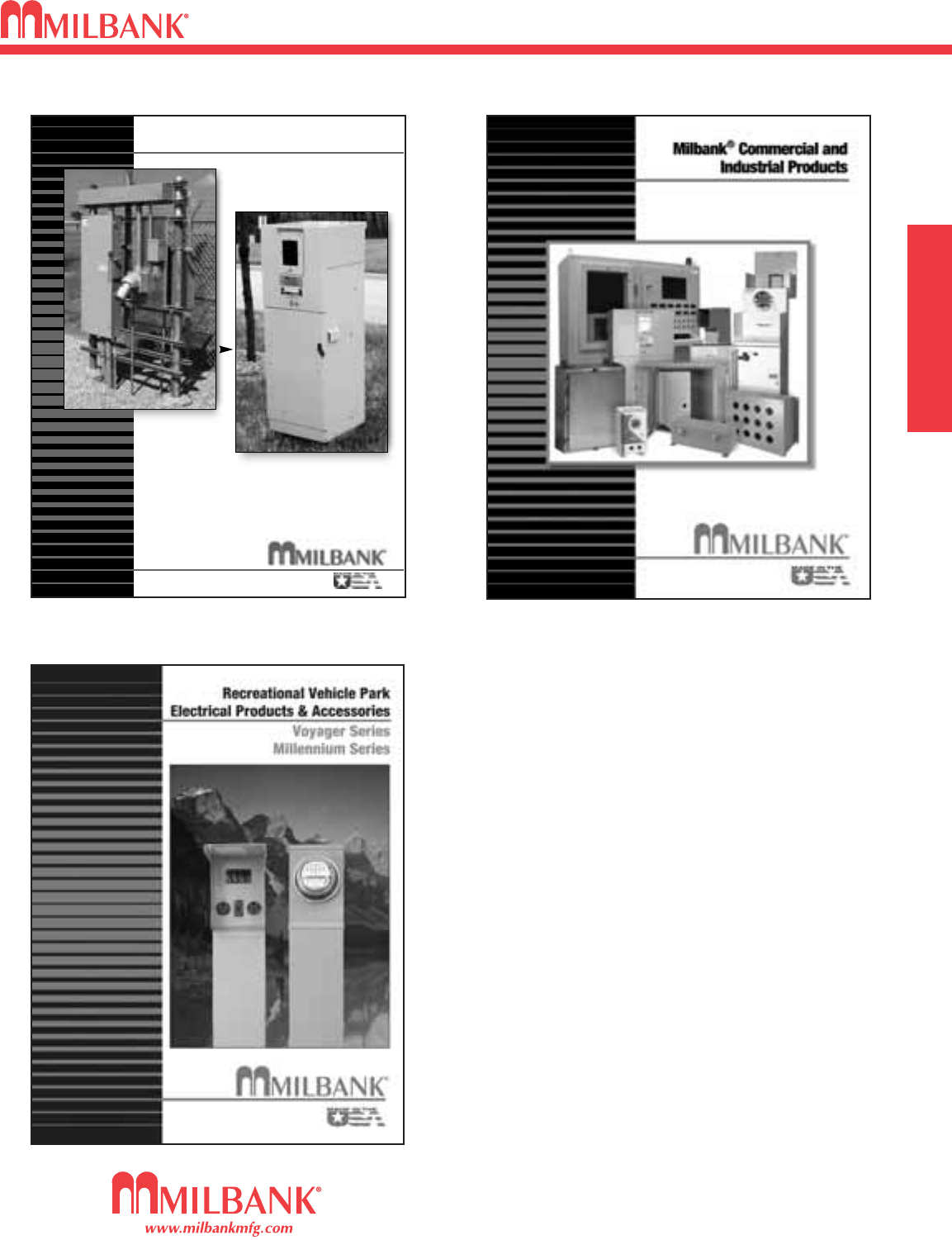
49
ADDITIONAL MILBANK PRODUCTS
MISC.
ADDITIONAL MILBANK PRODUCTS
49
In addition to your local utility’s meter mounting
equipment, Milbank also manufactures
supporting products, such as...
Air Conditioner Disconnects
Hot Tub Disconnects
RV/Mobile Home Power Outlets
Terminal Boxes
Temporary Power Outlets
Commercial Pedestals
Commercial Enclosures
CT Enclosures
Circuit Breakers
Enclosed Circuit Breakers
Safety Switches
Test Switches
Contact your local distributor or go to
www.milbankmfg.com
to find additional product literature.
Other quality products available from Milbank
Un-
Strut Your
Stuff...
Commercial Pedestals
• Attractive • Easy to install
• Secure • Cost effective
www.milbankmfg.com
816.483.6357 fax
816.483.5314 phone
ComPed 2/09 (7.5K)

NOTES
50
NOTES
50

51
NOTES
NOTES
51
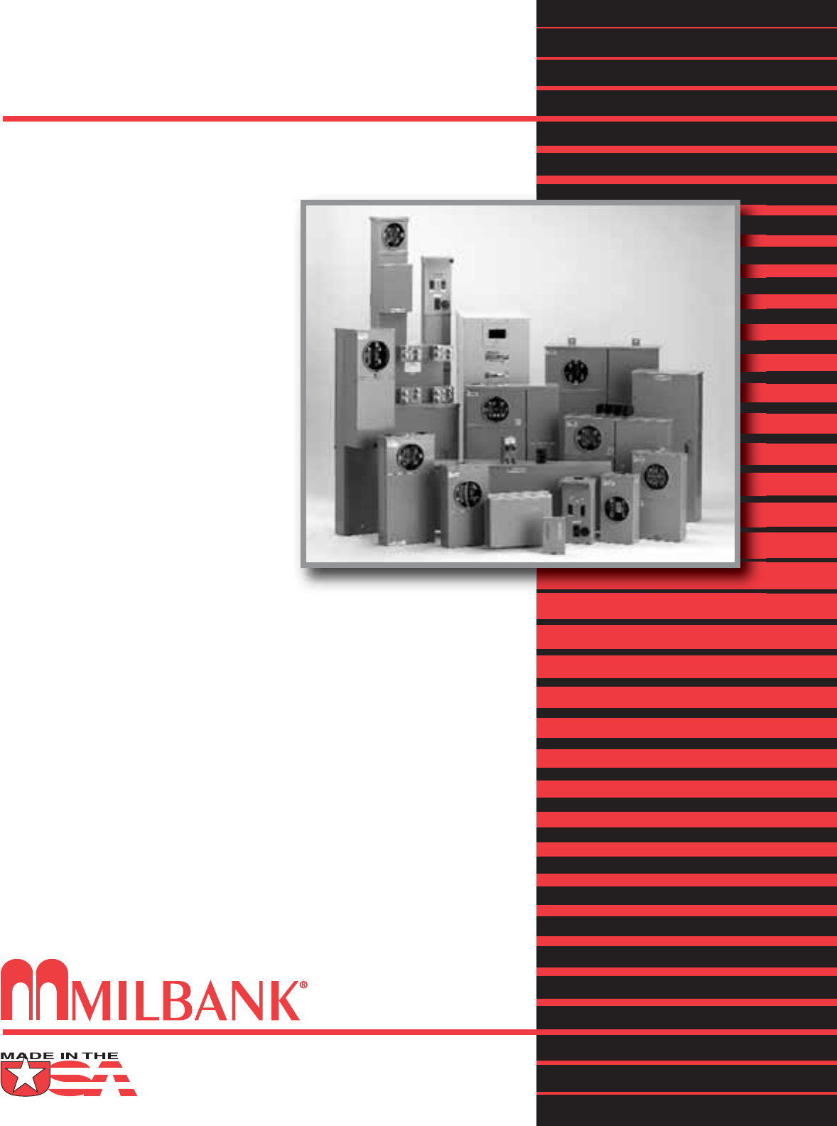
Meter Mounting Equipment & More!
Commercial Electrical Enclosures
Residential & Commercial Metering
Commercial Meter Pedestals
Disconnect Devices
Current Transformer Enclosures
RV/MH Pedestals
Temporary Power Outlets
Circuit Breakers
Distribution Unit Substations
Enclosed Circuit Breakers
Safety Switches
Test Switches
REPRESENTATIVE
WAC 1/11 (2.5K)
www.milbankmfg.com
MILBANK MFG. CO.
PO Box 419028
Kansas City, MO 64141-0028
Tel: 816-483-5314 Fax: 816-483-6357
Toll Free: 877-483-5314
www.milbankmfg.com
