510 0372 T143 1999 06 20150514
User Manual: Pdf Instruction Sheets | S&S Cycle
Open the PDF directly: View PDF ![]() .
.
Page Count: 11
S&S® Cycle, Inc.
14025 Cty Hwy G PO Box 215
Viola, Wisconsin 54664
Phone: 608-627-1497 • Fax: 608-627-1488
Technical Service Phone: 608-627-TECH (8324)
Technical Service Email: sstech@sscycle.com
Website: www.sscycle.com
Installation Guide: S&S® T143 Long Block Engine For
1999-’06 Harley-Davidson® Big Twin Except 2006 Dyna® Models
IMPORTANT NOTICE:
Statements in this instruction sheet preceded by the following words are of
special signicance.
WARNING
Means there is the possibility of injury to yourself or others.
CAUTION
Means there is the possibility of damage to the part or motorcycle.
NOTE
Other information of particular importance has been placed in italic type.
S&S recommends you take special notice of these items.
WARRANTY:
The T143 is guaranteed to the original purchaser to be free of manufacturing
defects in materials and workmanship for a period of six (6) months from the
date of purchase. Merchandise that fails to conform to these conditions will
be repaired or replaced at S&S’s option if the parts are returned to us by the
purchaser within the 6 month warranty period or within 10 days thereafter.
In the event warranty service is required, the original purchaser must call or
write S&S immediately with the problem. Some problems can be rectied by a
telephone call and need no further course of action.
A part that is suspect of being defective must not be replaced by a Dealer
without prior authorization from S&S. If it is deemed necessary for S&S to
make an evaluation to determine whether the part was defective, a return
authorization number must be obtained from S&S. The parts must be packaged
properly so as to not cause further damage and be returned prepaid to S&S
with a copy of the original invoice of purchase and a detailed letter outlining
the nature of the problem, how the part was used and the circumstances at
the time of failure. If after an evaluation has been made by S&S and the part
was found to be defective, repair, replacement or refund will be granted.
ADDITIONAL WARRANTY PROVISIONS:
(1) S&S shall have no obligation in the event an S&S part is modied by any
other person or organization.
(2) S&S shall have no obligation if an S&S part becomes defective in whole or
in part as a result of improper installation, improper maintenance, improper
use, abnormal operation, or any other misuse or mistreatment of the S&S part.
(3) S&S shall not be liable for any consequential or incidental damages
resulting from the failure of an S&S part, the breach of any warranties, the
failure to deliver, delay in delivery, delivery in non-conforming condition, or
for any other breach of contract or duty between S&S and a customer.
(4) S&S parts are designed exclusively for use in Harley-Davidson® and other
American v-twin motorcycles. S&S shall have no warranty or liability obligation
if an S&S part is used in any other application.
SAFE INSTALLATION AND OPERATION RULES:
Before installing your new S&S part it is your responsibility to read and follow
the installation and maintenance procedures in these instructions and
follow the basic rules below for your personal safety.
• Gasoline is extremely ammable and explosive under certain conditions
and toxic when breathed. Do not smoke. Perform installation in a well
ventilated area away from open ames or sparks.
• If motorcycle has been running, wait until engine and exhaust pipes
have cooled down to avoid getting burned before performing any
installation steps.
• Before performing any installation steps disconnect battery to eliminate
potential sparks and inadvertent engagement of starter while working
on electrical components.
• Read instructions thoroughly and carefully so all procedures are
completely understood before performing any installation steps.
Contact S&S with any questions you may have if any steps are unclear or
any abnormalities occur during installation or operation of motorcycle
with a S&S part on it.
• Consult an appropriate service manual for your motorcycle for correct
disassembly and reassembly procedures for any parts that need to be
removed to facilitate installation.
• Use good judgment when performing installation and operating
motorcycle. Good judgment begins with a clear head. Don’t let
alcohol, drugs or fatigue impair your judgment. Start installation when
you are fresh.
• Be sure all federal, state and local laws are obeyed with the installation.
• For optimum performance and safety and to minimize potential damage
to components, use all mounting hardware that is provided and follow
all installation instructions.
• Motorcycle exhaust fumes are toxic and poisonous and must not be
breathed. Run motorcycle in a well ventilated area where fumes can
dissipate.
DISCLAIMER:
S&S parts are designed for high performance, closed course, racing
applications and are intended for the very experienced rider only. The
installation of S&S parts may void or adversely aect your factory warranty.
In addition such installation and use may violate certain federal, state, and
local laws, rules and ordinances as well as other laws when used on motor
vehicles used on public highways, especially in states where pollution laws
may apply. Always check federal, state, and local laws before modifying your
motorcycle. It is the sole and exclusive responsibility of the user to determine
the suitability of the product for his or her use, and the user shall assume all
legal, personal injury risk and liability and all other obligations, duties, and
risks associated therewith.
The words Harley®, Harley-Davidson®, H-D®, Sportster®, Evolution®, and all
H-D part numbers and model designations are used in reference only. S&S
Cycle is not associated with Harley-Davidson, Inc.
Instruction 510-0372
05-12-0-15
Copyright © 2015
by S&S® Cycle, Inc.
All rights reserved.
Printed in the U.S.A.
Please read these instructions carefully before starting work.
Proceed with the installation only after the instructions
are completely understood. These instructions should be
supplemented by the appropriate OEM service manual for your
motorcycle. Follow all safety information.
1. Introduction
Installation can be performed by any repair shop equipped to do
complete Harley-Davidson® engine overhauls.
No special tools, other than those used in normal engine installation
operations, are required.
NOTES
S&S® T-Series instructions often refer to procedures described
in other S&S instructions or a Harley-Davidson® Service Manual.
These materials should be cross-referenced as necessary.
IMPORTANT
Before proceeding, verify that serial numbers on crankcases
match numbers on packing carton and certicate of origin.
Contact S&S immediately if numbers do not match.
NOTE - Valid certicate of origin is required for any transfer or sale
of longblock assemblies. Certicate of origin is required to title any
motorcycle.
2. Modication Notes
Modifying S&S engines in any fashion voids all manufacturer warranties.
NOTE - Modication includes but is not limited to appearance changes
such as painting, powdercoating, plating, and polishing. Proper
preparation for these procedures as well as the processes themselves may
require the use of polishing compounds, chemicals or procedures that are
potentially harmful to crankcases.
•
CAUTION
Passages and internal cavities may become obstructed
by residues from materials used to polish, paint, plate or
powdercoat surfaces. Additionally, surface nishing processes
can damage critical machined surfaces. Any of the above may
cause premature wear, damage or failure of other engine
components as well as the crankcases themselves.
• Glass bead and polishing residues are abrasive and can be
dicult to remove from recesses and small passages. Abrasive
residues can cause oil contamination and extensive engine
damage. Engine damage caused by powder coating, polishing,
glass bead blasting, or other modication will not be covered
under warranty.
Powder Coating - Subjecting heat-treated alloys such as those used
in S&S crankcases to excessive heat can drastically alter their strength
and their critical properties. The degree of change depends upon
the temperatures reached and the duration of exposure. Under no
circumstances should parts be heated past 400°F!
S&S strongly recommends trial-tting every engine before frame
is painted or powder coated.
3. Engine To Frame Assembly
NOTES
• The engine should be installed into the frame before the ignition, fuel,
exhaust, and oil system components are installed.
• The engine must be tted to the frame it is installed into. It must rest
squarely on its attachment points, and bolted solidly to the mounts
without stressing the engine case at any point.
Failure to correctly mount the engine can cause problems not
covered under warranty including but not limited to, excessive
vibration, driveline mis-alignment, and broken castings.
A. Clean frame engine mounts and carefully remove any
irregularities from mounting surfaces. Also inspect crankcase
mounting bosses for burrs.
B. Position engine in frame, check for clearance at frame, and
alignment to transmission. It is a good idea to replace rubber
engine mounts at this time. Old mounts deform over time and
can induce unwanted stresses on the engine case
CAUTION
Improper alignment of engine and frame mounts may cause
abnormal stresses resulting in damage to crankcases or other
parts
4. Fuel system installation and tuning
NOTES - S&S® Engine assemblies for 1999-’06 big twins do not include a
fuel system.
S&S T143 engines are equipped with S&S B3 Special Application cylinder
heads which require a special intake manifold/throttle body or carb due
to the shape and location of the intake ports. S&S oers a special 70mm
throttle body and air cleaner kit for fuel injected applications, and
carb kits for carbureted applications. Contact your S&S Customer
Service Representative for details.
A. Install fuel system.
1. Install carburetor or throttle body, fuel injectors, and intake
according to instructions included with fuel system.
B. Re-install and connect fuel tank.
1. Refer to appropriate service manual. Inspect fuel lines and clamps
- replace as necessary.
2. Check fuel line connections and routing. Avoid hot surfaces. Make
certain that the protective cover has been placed over fuel line,
and that it is clear from sharp edges and abrasive surfaces.
3. Fill the fuel tank with a sucient quantity of gasoline for the initial
start-up procedure.
4. Double check that all fuel line connections have been made
correctly and there is no gas leakage at any point in the system.
5. Oil Line Installation
CAUTION
Instruction contents:
1. Introduction
2. Modication notes
3. Engine to frame assembly
4. Fuel system
5. Oil line installation
6. Exhaust system
7. Engine break-in
8. Tuning guidelines
9. Service intervals
2
7. Mount the oil line block on the crankcase using ⁄-18 x 1¾” long
screw (S&S PN50-0437)—do not nal tighten as it will be removed
again.
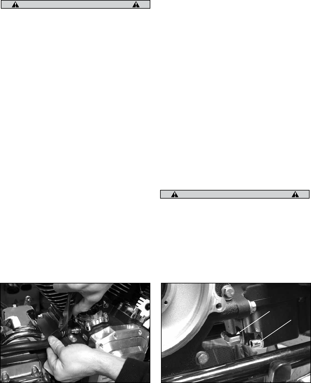
8. The next step is to measure and then cut the oil hoses. The straight
hose connects the 90˚ ttings of the oil line block and oil pan. The
bent hose runs between the oil return ttings on the oil line block
and oil pan. See Picture 4, next page.
9. Remove the oil line block from the engine case. Install the supplied
clamps (S&S PN 50-8293) on the lines between the ttings. See
Picture 5, next page.
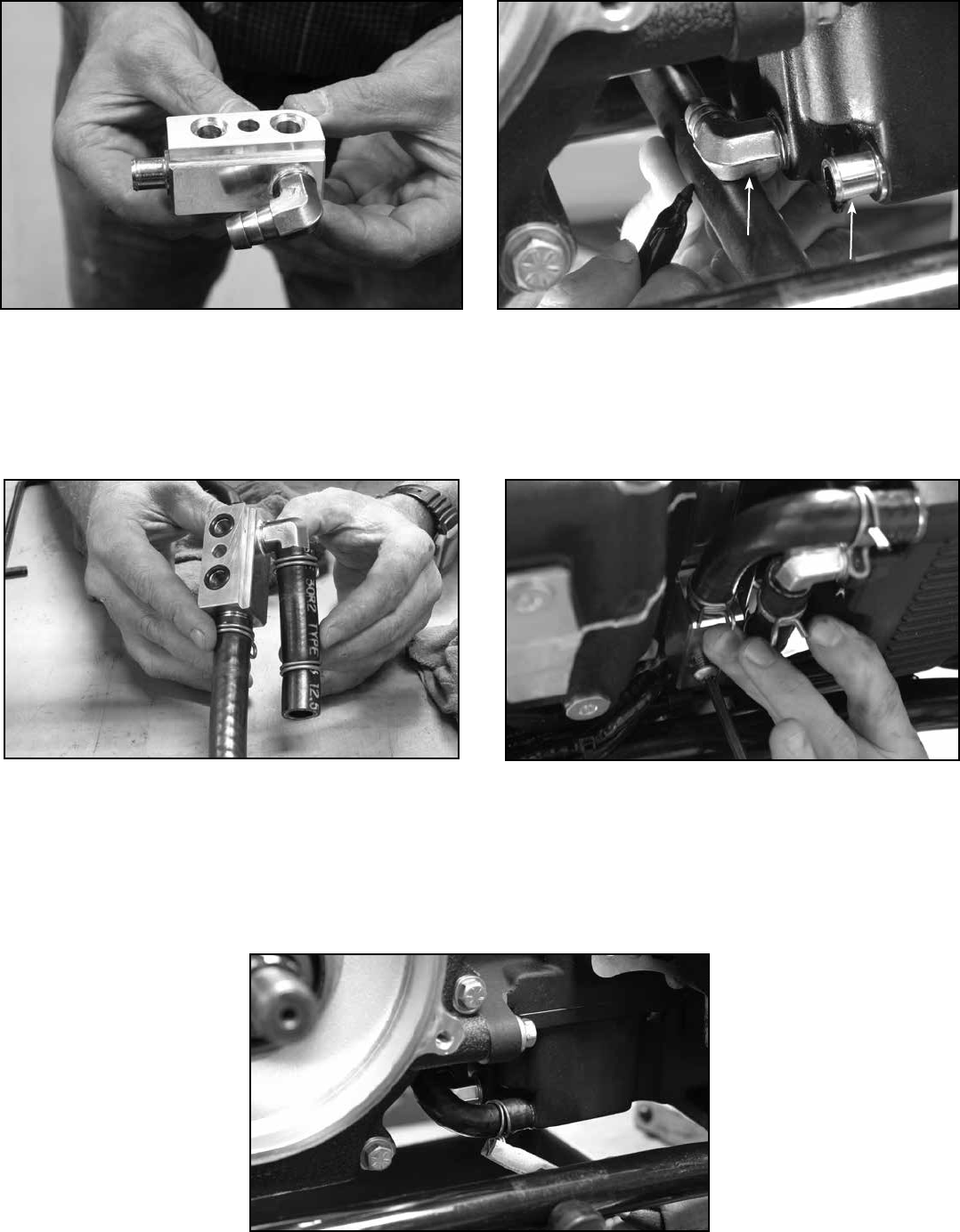
10. Install O-Rings (S&S PN 50-8066) in the counter bores of the oil
line block. Position the oil line block on the engine case and
tighten the screw to 18 ft-lbs. of torque with blue threadlock on
the threads. See Picture 6, next page.
11. Position hose clamps over the ttings.
12. Rell oil reservoir.
13. Start engine and check for oil leaks.
To Change Engine Oil in the Future
1. Slide hose clamp o of tting along hose. See Picture 7, next
page.
2. Place an oil drain pan under front of oil pan.
3. Remove hose from tting to drain oil.
4. Reinstall hose and clamp.
5. Continue with recommended oil change procedure.
NOTE: If an S&S engine or crankcase is to be installed in a motorcycle, which
has had a catastrophic engine failure, or if for any reason it is suspected
that debris or contaminants have been introduced into the oiling system,
the oil pan must be thoroughly cleaned or replaced. In order to ensure that
all debris is removed from the oil pan, the bae must be removed
.
CAUTION
Failure to remove debris or contaminants from the oil pan may
result in serious damage to the engine.
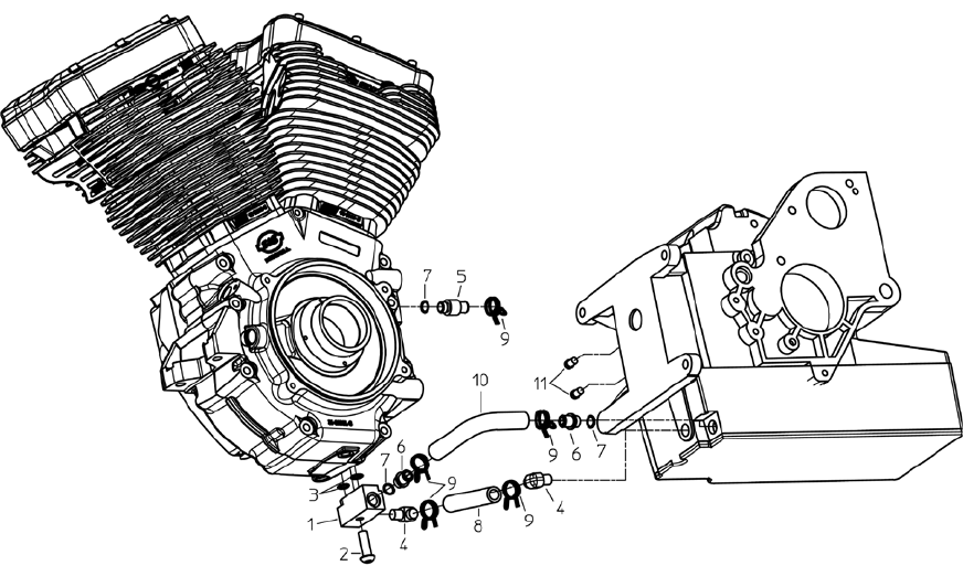
A. FOR 1999-2006 HARLEY-DAVIDSON® FL MODELS - OIL LINE
KIT PN 31-0425
CAUTION
Oil line installation is crucial to engine life. If you are not sure that
you can properly perform this operation, please contact the S&S
Tech Department for a referral to a shop in your area.
NOTE: Installation instructions are based on an engine and transmission
already in the chassis.
NOTE: Apply thread sealant to all tapered pipe threads.
1. Remove the stock oil supply and return ttings from the
transmission.
2. Install two supplied ⁄ NPT pipe plugs (S&S PN50-8330) in the oil
tting location.
NOTE: Apply thread sealant to all tapered pipe threads.
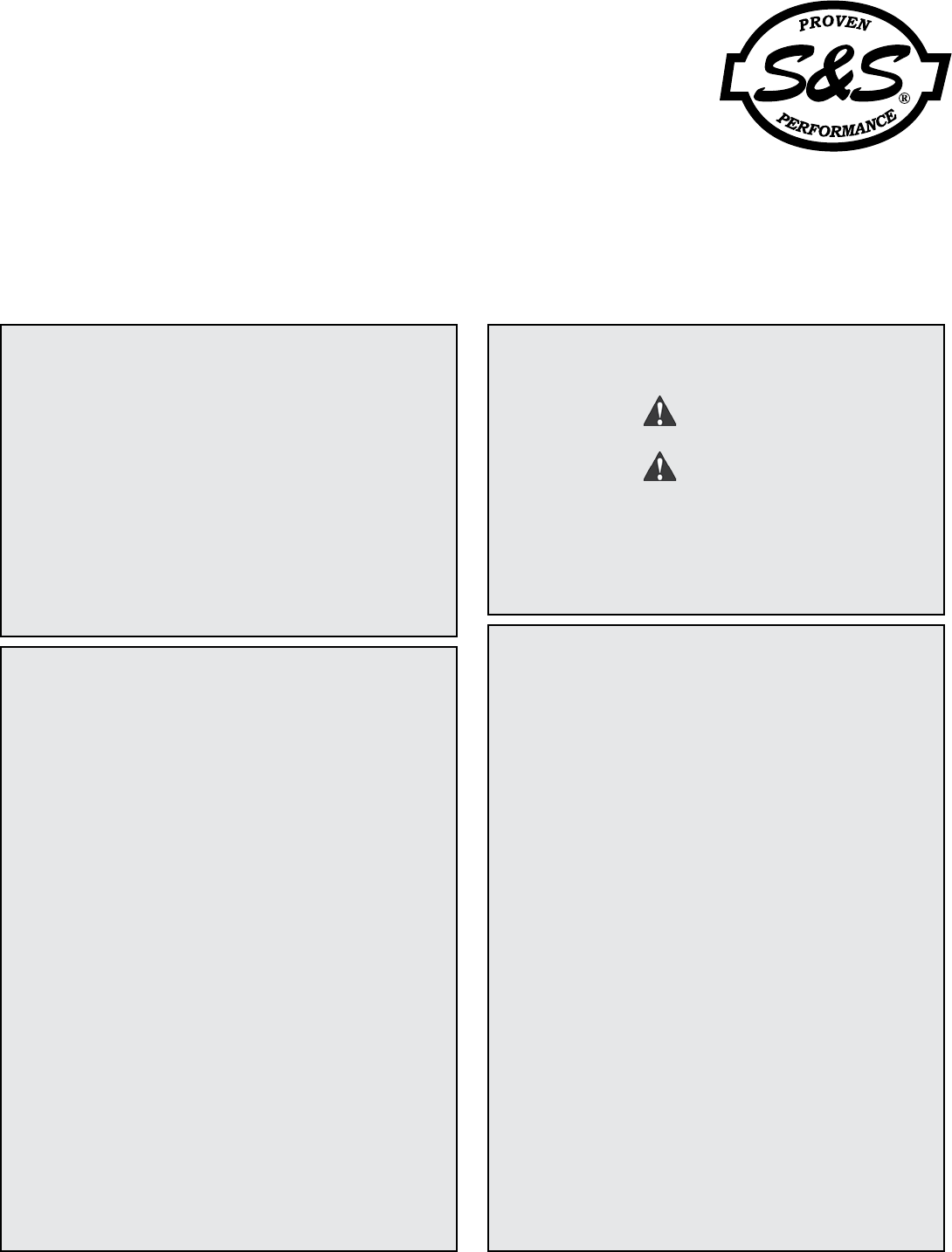
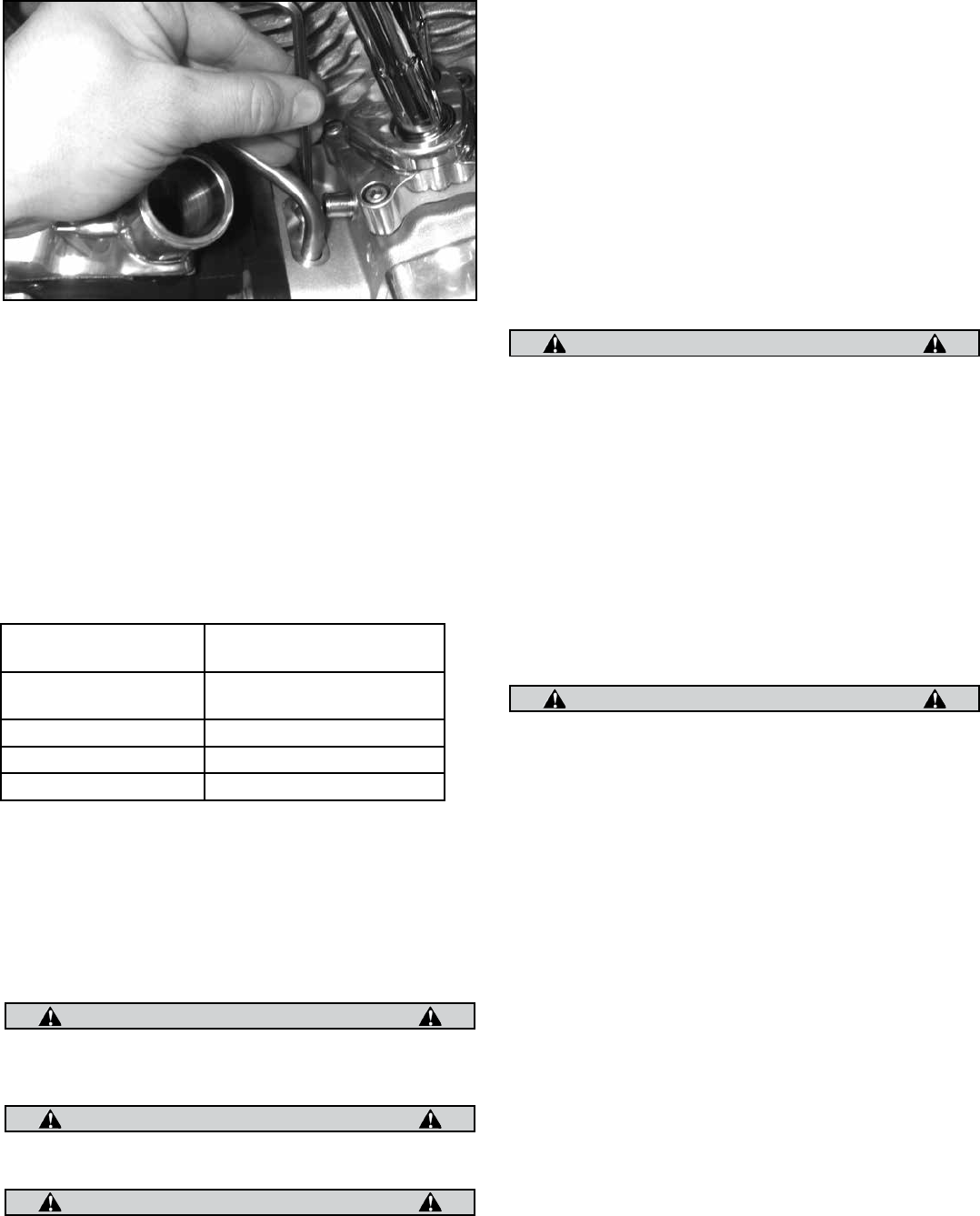
3. Remove crankcase vent tting (S&S PN 50-0451) and set aside
for later use. Install supplied vent tting (S&S PN 50-0449 is for
use with 2002-’06 with ⁄ ID vent hose or 50-0454 is for use with
1999-’01 with ⁄ ID vent hose) with O-ring installed on tting. See
Picture 1.
4. Install the vent hose and clamp (S&S PN 50-8293 or 50-8076-S) on
the new tting.
NOTE: The stock vent hose is reused in this step.
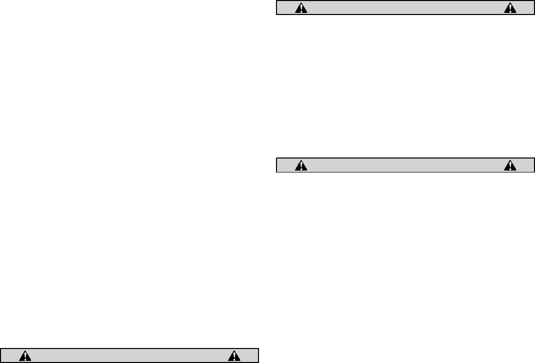
5. Position a drain container in front of the oil pan. Next, locate and
remove the two plugs on the forward face of the oil pan allowing
the oil to drain. Once the oil is completely drained, replace the
⁄” pipe-plug with a 90˚ tting (S&S PN 106-1170). Position barb
of tting toward right side of bike at an angle slightly above
horizontal as shown in Picture 2. Next, install the oil return tting
(S&S PN 50-0451) with O-ring (S&S PN 50-8008) in the drain plug
location.
6. Remove cover plate that was shipped on crankcase from the
bottom surface of the rear motor mount. The oil line block
will be installed in this location. Assemble the oil line block by
installing the 90˚ tting (S&S PN 106-1170) and the oil return
tting (S&S PN50-0451) with O-ring (S&S PN 50-8008) into the
block, as shown in Picture 3, next page.
Picture 1 (2002-'06) Picture 2
Supply
Return
3
Picture 5 Picture 6
Picture 7
Picture 3 Picture 4
Supply
Return
4
8- Hose, oil supply .................................................................. 50-8157
9- Clamp
Double wire spring .......................................................... 50-8293
Hose, spring .................................................................... 50-8076-S
10- Hose, return oil line, 90˚ bend ...................................... 50-8292
11- Plug, pipe (⁄ NPT) ............................................................ 50-8330
1- Block, oil line .................................................................................N/A
2- BHSHCS, ⁄-18 x 1¾ .........................................................50-0437
3- O-ring
(10 pack) .....................................................................50-8066
4- Fitting, pipe, 90˚ (2 pack) ..................................................10 6 -1170
5- Fitting
⁄ (2002-’06) .......................................................................50-0449
⁄ (1999-’01) .........................................................................50-0454
6- Fitting, ½ ..............................................................................50-0451
7- O-ring .................................................................................... 50-8008
S&S® Oil Line Installation Kit Replacement Parts for Harley-Davidson® FL Models
5

B. FOR 1999-’05 HARLEY-DAVIDSON® DYNA® MODELS
(PN31-0424)
CAUTION
Oil Line installation is crucial to engine life. If you are not sure
that you can properly perform this operation, please contact the
S&S® Tech Department for a referral to a shop in your area.
NOTE: Installation instructions are based on an engine and transmission
already in the chassis.
1. Remove the stock oil supply and return ttings from the
transmission.
2. Install two supplied ⁄ NPT pipe plugs (S&S PN 50-8330) in the oil
tting location.
NOTE: Apply thread sealant to all tapered pipe threads.
3. Drain the oil from the oil pan—see the proper factory service
manual for instructions—and then remove the oil pan from the
motorcycle.
4. Place the supplied template (106-1188) over the oil pan bae
and use a scribe to mark the location of the ½" hole as shown in
Picture 8, above left. Use a drill press to machine the ½" hole as
marked in Picture 9, above right. Use a small le or deburring
tool to make sure no chips or pieces are left on the ½" hole and
then clean the oil pan and bae with solvent before reinstalling
the pan with a new gasket on the motorcycle.
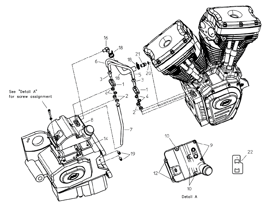
5. Remove the transmission top cover. Remove the neutral indicator
switch, vent line and tting from the transmission top cover.
6. Install the neutral indictor switch, vent line and tting on the new
S&S transmission top cover (S&S PN 106-3886).
7. Slide the oil feed line (S&S PN 31-0449) through the hole in the
top cover closest to the oil ller/dipstick boss. Place a new top
cover gasket (S&S PN 56-1261)on the transmission case and
position the new S&S top cover on it. Rotate the oil feed line so
it will pass through the ½" hole in the bae. Be sure the bend in
the oil feed line orientation is to the rear of the motorcycle. See
Picture 10, below left.
8. Install the transmission top cover screws and washers according
to Detail A. Use blue threadlock on the screws, but leave them
loose at this time. See Detail A in exploded view of replacement
parts for Harley-Davidson® Dyna® on page 7.
9. Remove the oil line retention plate, plugs and seals from the
top of the engine crankcase. Remove seals from the plugs.
Discard the plugs.
10. To install the oil lines (S&S PN 31-0447 and 31-0448), orient the
ends and openings so they are parallel. Insert the lines through
the oil line retention plates, then the included washers (S&S PN
50-0439) and, last the seals (S&S PN50-8271) on each line end.
The ends of the lines should protrude through the seals about ⁄
inch. See Picture 11, below right.
11. Position oil line assembly on both the transmission top cover
and crankcase and press down until lines are rmly seated in
the counterbores in the crankcase and transmission cover. See
Picture 12.
Picture 10 Picture 11
Picture 8 Picture 9
6
Picture 12
12. Press the oil line retention plates into place until they seat. Install
the two screws (⁄-18 x ¾ button head, S&S PN 106-1178) through
the oil line retention plates. First screw goes in the transmission
top cover and the second mounts into the crankcase near the rear
motor mount. Treat both screws with blue threadlock and tighten
to 18-ft-lbs.
13. Tighten transmission top cover screws to 100-120 in-lbs.
14. Install the vent line (S&S PN 50-8292) with clamps
(S&S PN 50-8293).
15. Reconect neutral switch wires.
16. Check function of neutral switch.
C. Oil recommendations
NOTES
• S&S® Cycle recommends the use of S&S V-Twin 20W-50 synthetic oil in our
engines for normal operating conditions. See chart above for additional
recommendations.
• S&S Cycle recommends the use of S&S® oil lters, PN 31-4103 (black), or PN
31-4104 (chrome).
•
D. Verify oiling system operation before starting
CAUTION
If engine is run with foreign material in the oil tank, engine
damage will occur. Engine damage caused by foreign material in
the oil tank is not covered under the S&S warranty.
CAUTION
Restricted oil ow may result in extensive engine damage not
covered under warranty.
CAUTION
Improper installation of oil lines or ttings may result in parts
damage not covered under warranty.
MOTOR OIL VISCOSITY TYPICAL AMBIENT
TEMPERATURE
SAE 20W50 RECOMMENDED FOR
MOST APPLICATIONS
ABOVE 30° F 1° C
SAE 25W60 ABOVE 40° F 4° C
SAE 50 ABOVE 60° F 16° C
SAE 60 Above 80° F (27° C)
1. Fill the oil tank to the proper level.
2. Remove spark plugs. Ground plug wires to cylinder head with
either a jumper wire or through a test plug.
3. Turn ignition on and turn the engine over with the starter motor
until oil pressure light goes o.
4. Verify that engine oil is returning to oil tank.
5. Start motorcycle. Verify oil pressure by watching oil pressure light.
NOTES
• If oil pressure fails to indicate within 30 seconds of starter operation, allow
the starter to cool. Verify that oil line routing is correct and that the oil
tank is full to the proper level.
• Oil pressure indicator lamp should light when ignition is turned on. Lamp
will go out after engine is started and there is oil pressure at the switch in
the crankcase.
CAUTION
Avoid excessive time of starter engagement. Overheating of
starter motor will result in damage. Oil pump should prime and
deliver oil to the oil sender hole within 30 seconds.
6. Exhaust System
1. Contact S&S for exhaust systems specically designed for T143
engines.
2. Inspect the exhaust pipe header anges and retaining rings.
Replace if distorted, warped, or otherwise damaged.
3. Apply a high-temp. anti-seize lubricant to threads of exhaust
studs at cylinder heads.
4. Install exhausts to cylinder heads. Hand tighten exhaust stud nuts.
5. Attach exhausts to lower mounting bracket. Shim if necessary.
Hand tighten mounting hardware.
6. Tighten exhaust ange nuts at head to 60-80 in-lbs.
WARNING
In some instances, brake master cylinder must be spaced out from
frame to clear crankcase. UNDER NO CIRCUMSTANCES SHOULD
MASTER CYLINDER OR BRAKE LINE BE ALLOWED TO CONTACT
EXHAUST PIPE IN FINAL INSTALLATION. Heat transferred to brake
uid may expand and cause brakes to seize, resulting in possible
re hazard and loss of control of motorcycle with injury or death
to rider and others.
NOTE - Make certain that the exhaust system is not pre-loaded, or in a
bind, at the lower mounting points. Make all spacing adjustments prior to
nal-tightening of the upper exhaust mounting hardware at the cylinder
heads. Failure to follow this procedure may cause excessive vibration and
result in failure of exhaust pipes or mounting hardware.
7
17
1- Clamp, Hold Down ......................................................................10 6 -1176
2- Seal .................................................................................................... 50-8271
3- BHSHCS ⁄-18 x ¾ (10 pack) ......................................................... 10 6 -117 8
4- Washer .............................................................................................50-0439
5- Line, oil supply ..............................................................................31-0447
6- Line, oil return ............................................................................... 31-0448
7- Line assembly, Oil feed .............................................................. 31-0449
8- Top cover .........................................................................................106-3886
9- SHC - ¼-20 x 1½" ........................................................................... 50-0267-S
10- SHC - ¼-20 x 2¼" ........................................................................... 50-8455-S
11- SHC - ¼-20 x 1¾" ........................................................................... 50-8458-S
12- SHC - ¼-20 x 1¼" ........................................................................... 50-0257-S
13- Washer .............................................................................................50-7017
14- Gasket, tranny top cover ...........................................................56-1261
S&S® Oil Line Installation Kit Replacement Parts for Harley-Davidson® Dyna® Models
16- Fitting ............................................................................................... 50-8289
17- Vent hose, 90˚ bend .................................................................... 50-8292
18- Clamp ...............................................................................................50-8293
19- Plug, pipe (⁄ NPT) ....................................................................... 50-8330
20- O-ring ............................................................................................... 50-8008
21- Fitting ............................................................................................... 50-0451
22- Drill Template ................................................................................ 10 6 -118 8
11
8

7. Engine Break-In
NOTE - Engines are designed for high performance and as such are not
as tolerant of inadequate break-in as stock or lower performance engines.
Correct break-in will assure longer engine life and will prevent unnecessary
engine damage. Engine damage caused by improper break-in is not
covered under the S&S® warranty.
A. Initial Start Up and Break-in Procedure
1. For the initial start up, a baseline calibration for a T143 should be
downloaded to the ECU (base tune les for S&S VFI system and
Dyno Jet® Powervision® tuner are available from the S&S website)
This is adequate for the initial start-up and heat-cycling of the
engine.
2. Run engine approximately one minute at 1250-1750 RPM. DO NOT
crack throttle or subject to any loads during this period as head
gaskets are susceptible to failure at this time. During this time,
check to see that oil pressure is normal, that oil is returning the oil
tank, and that no leaks exist.
3. Shut o engine and thoroughly check for any leaks or other
problems. Let engine cool to the touch.
4. After engine has cooled, start up again and allow the motor to
build some heat. Engine should be run no longer than three to
four minutes. When the cylinders become warm/hot to the touch
(approximately 150°F) shut the motor down and let it cool to room
temp. Follow the same cautions as for the initial start-up, and
continue to check for problems.
5. First 50 Miles:
6. Street: Ride normally, do not lug the engine. Avoid high heat
conditions and vary the RPM while riding. No stop and go trac,
extended idle periods, or high load or high RPM conditions. Max
of 3,500 RPM or 60 MPH.
7. Dyno: A chassis dynamometer can be used to put the rst 50 miles
on a new engine. See the notes and procedure below for chassis
dyno break-in.
8. 50–100 Miles: Ride normally, do not lug the engine. Avoid high
heat conditions, no stop and go trac or extended idle periods.
Limited short bursts of throttle can aid in ring seating from this
point forward during the break-in, but avoid continuous high
speed or load conditions. Max of 4,250 RPM/70 MPH.
9. 100–500 Miles: Avoid lugging the engine and high heat conditions.
Max of 5,000 RPM. Change oil at 500 miles.
10. 500–1,000 miles: Ride bike normally, but avoid continuous high
load operation and high heat conditions.
11. From 1,000 miles on: Break-in is complete, enjoy!
B. Dyno Procedure for the rst 50 miles
1. Follow the same procedure outlined above for initial start-up and
heat cycling the engine.
2. Run the bike for 25 miles on the dyno under varying speeds and
loads while going up and down through the gears. Keep engine
RPM below 3,500 RPM but do not lug the engine. The dyno must
be operated so the engine runs under a load roughly equal to the
power needed to move the bike down the road, this would be
about 12 hp at 55 MPH. Keep engine head temperatures below
200°F at the temp sensor or surface of the head. Stop and cool the
engine if needed.
3. Allow the engine to cool down to room temperature.
4. Run the bike for 25 more miles (50 miles total) under varying
speeds, loads, and gears as before. Make sure there is some load
on the engine. Keep engine speed below 4,250 RPM but do not
lug the engine. Limited short bursts of throttle can aid in ring
seating as long as the calibration/tune keeps the AFR in control.
Keep engine head temperatures below 225°F at the temp sensor
or surface of the head.
5. After the rst 50 miles on the dyno, it is recommended the normal
break-in schedule be followed under normal riding conditions on
the street. See Step 5 under BREAK-IN PROCEDURE.
NOTES FOR COMPLETING INITIAL 50 MILE BREAK-IN AND INITIAL
TUNING ON A CHASSIS DYNO
• When running the bike on the dyno it is critical that engine tempera-
tures are monitored, AFR is kept between 12.5–14.7 and the engine
is not overheated. Fans must be used to keep the engine cool. When
tuning under higher loads stop regularly and allow the engine to cool.
• A load must be placed on the engine to properly seat the rings. Run-
ning a new engine continually with no load will result in cylinder glaz-
ing and poor ring seal. The engine should be loaded to simulate close
to the weight of the bike, a load of 10–15% on a Dyno jet 250i is usu-
ally sucient. It is not recommended to use an inertia only dyno to
break-in an engine as no load can be placed on the engine.
• Initial tuning on the engine can be completed during the initial 50
miles of dyno break-in. It is recommended the engine be run on the
street for a minimum of 500 miles prior to completing tuning at full
power. Monitor engine temperature during tuning to ensure the en-
gine is not overheated.
GENERAL BREAK-IN NOTES
• Remember that these are air-cooled engines. Sucient air movement
is required to keep engine temperatures within safe operating limits.
• Avoid heavy trac and congestion or extended idle periods
whenever possible.
• S&S v-twin performance engines are designed for, and happiest
when running between 2750-3500 at normal highway speeds.
• Today’s heavier bikes and taller gearing can easily push a high
performance engine into a lugging condition which increases loads
on engine components, causes detonation, builds excessive heat,
and increases fuel consumption. If the engine does not accelerate
easily when given some throttle, downshift to a lower gear.
• S&S engines benet from a warm-up period any time they are
started, allow engine to reach operating temperature before being
subjected to heavy loads or quick throttle revs.
CAUTION
Lugging or running engine prematurely at sustained high rpm
may result in damage to pistons and other engine components.
S&S voids it’s guarantee if engine is not broken in properly.
9
8. Tuning Guidelines
Ignition timing and fuel injection tuning are responsibilities of the
customer. If not thoroughly familiar with these procedures, contact a
professional mechanic.
Exhaust Systems
Mued exhaust systems.
The S&S T143 engine comes with S&S B3 Special Application
cylinder heads. Due to the unique exhaust port conguration,
stock Harley-Davidson® exhaust pipes will not t, and a special
exhaust system is required. An exhaust system specially for
the T143 engine is available for some models from S&S Cycle.
There are also components available to help you build your own
exhaust system. See below, or contact your S&S Customer Service
Representative for more information.
Drag pipes
While drag pipes can be used with good results to achieve top
end horsepower, they are generally not recommended for low
and midrange power applications. Fuel injection calibration is
generally easier for engines with mued exhaust systems.
A. Gearing
Gearing depends on the total weight of the machine and rider,
the size of the engine, cam, exhaust system and type of riding.
Most high performance engines, and particularly those with larger
displacements, are capable of pulling more gear. We suggest you
break the engine in with stock gearing to minimize the load on the
engine. After the engine is broken in, you will have a better feel of
its potential and can change gearing accordingly.
The following formula will determine nal drive gear ratio:
Engine Revolutions Per One Revolution of Rear Wheel=
(Clutch Sprocket*) x (Rear Wheel Sprocket*)
(Motor Sprocket*) x (Transmission Sprocket*)
*Number of teeth on each sprocket
9. Service Intervals
S&S® RECOMMENDED REGULAR SERVICE INTERVALS
ITEM INTERVAL
Engine Oil & Filter Change at 500, 2,500 miles, and every
2,500 miles thereafter.1
Air Cleaner Inspect at 50 and 500 miles, every 2,500
miles thereafter.2
Petcock, Lines, & Fittings.
Vacuum Lines
Inspect at 50 and 500 miles, every 2,500
miles thereafter.
Fuel Filters Every 5,000 miles.
Engine Idle Speed Adjust as required.
Throttle & Enrichment
Device Control
Inspect and lubricate throttle cables
at 500 miles and every 2,500 miles
thereafter.
Spark Plugs (Champion
RA8HC or equiv.)
Inspect every 5,000 miles. Replace
every 10,000 miles or as needed.
Ignition Timing - 28 deg.
total advance max.
Inspect every 5,000 miles.
Engine Mounts Inspect every 500 miles and every 5,000
miles thereafter.
External Fasteners
(except cyl. head bolts)
Re-torque at 500 miles and every 5,000
miles thereafter.
1
S&S recommends that petroleum-based oil not specically
formulated for aircooled motorcycles should be changed every
1,000 miles.
2
Replace more frequently if required or if engine is operated in a
dusty enviroment.
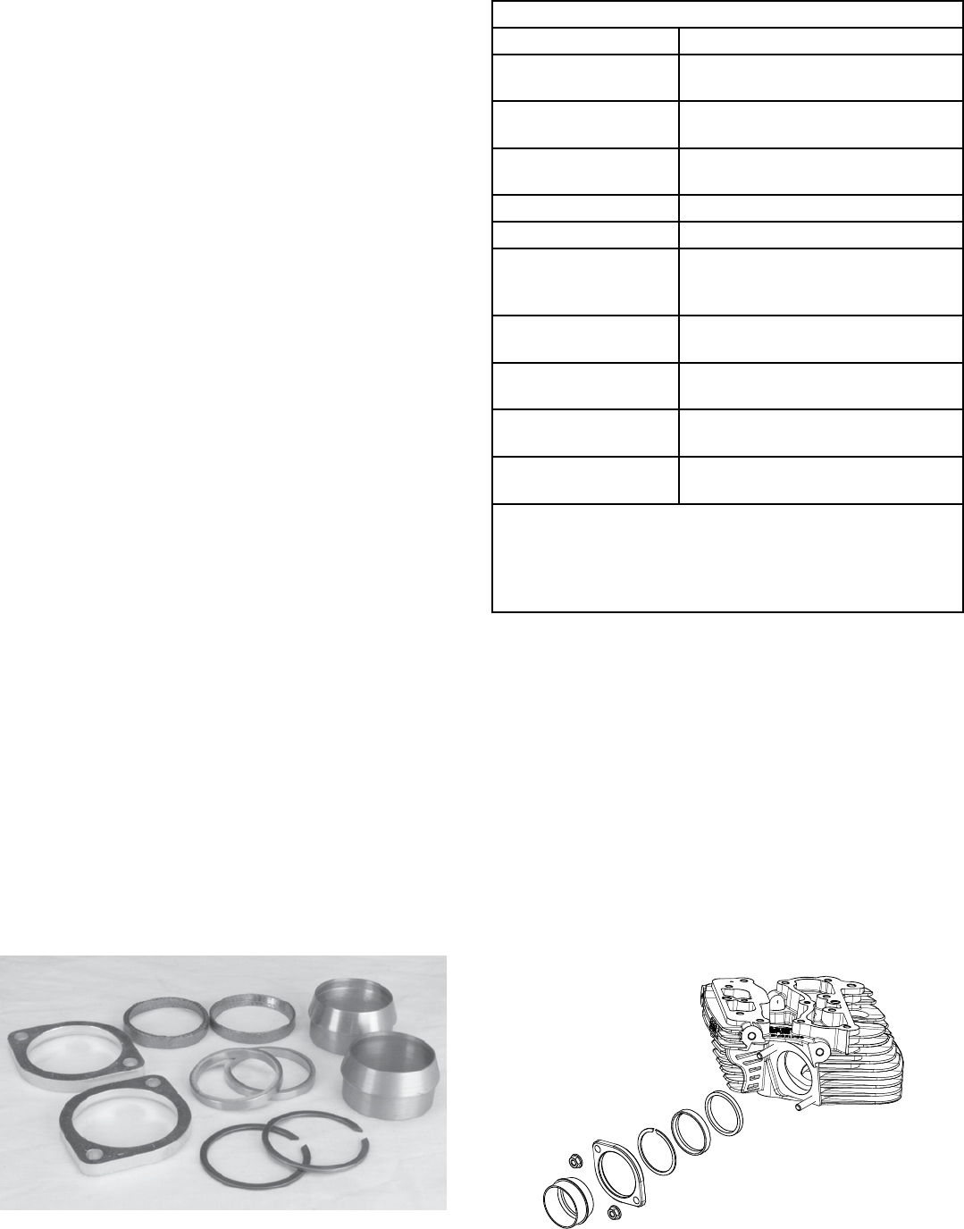
550-0216
S&s Exhaust Flange Mounting Kit #550-0216 includes weld-on adaptors, snap rings and anges to make it easy to adapt an existing 2” exhaust system to
the s&s B3 cylinder heads on the T143 engine, or to fabricate a whole new system.
10
11
